Rational Application Developer V7.5 Programming Guide RAD
User Manual:
Open the PDF directly: View PDF ![]() .
.
Page Count: 1434 [warning: Documents this large are best viewed by clicking the View PDF Link!]
- Go to the current abstract on ibm.com/redbooks
- Front cover
- Contents
- Figures
- Tables
- Examples
- Notices
- Preface
- Summary of changes
- Part 1 Introduction to Rational Application Developer
- Chapter 1. Introduction
- Chapter 2. Programming technologies
- Desktop applications
- Static Web sites
- Dynamic Web applications
- Enterprise JavaBeans and Java Persistence API (JPA)
- Web services
- Messaging systems
- Summary
- Chapter 3. Workbench setup and preferences
- Chapter 4. Perspectives, views, and editors
- Integrated development environment (IDE)
- Application Developer Help
- Available perspectives
- Crystal Reports perspective
- CVS Repository Exploring perspective
- Data perspective
- Database Debug perspective
- Database Development perspective
- Debug perspective
- Java perspective
- Java Browsing perspective
- Java EE perspective
- Java Type Hierarchy perspective
- JavaScript perspective
- Jazz Administration perspective
- JPA perspective
- Plug-in Development perspective
- Profiling and Logging perspective
- Report Design perspective
- Requirement perspective
- Resource perspective
- Team Synchronizing perspective
- Test perspective
- Web perspective
- Work items perspective
- Progress view
- Summary
- Chapter 5. Projects
- Part 2 Architecture and modeling
- Chapter 6. RUP, patterns, and SOA
- Chapter 7. Unified Modeling Language (UML)
- Overview
- Constructing and visualizing applications using UML
- Working with UML class diagrams
- Exploring relationships in applications
- Describing interactions with UML sequence diagrams
- More information on UML
- Part 3 Basic Java and XML development
- Chapter 8. Develop Java applications
- Java perspectives, views, and editor overview
- Java perspective
- Java Browsing perspective
- Java Type Hierarchy perspective
- Developing the ITSO Bank application
- ITSO Bank application overview
- ITSO Bank application step-by-step development guide
- Creating a Java project
- Creating a UML class diagram
- Creating Java packages
- Creating Java interfaces
- Creating Java classes
- Creating Java attributes (fields) and getter and setter methods
- Adding method declarations to an interface
- Adding constructors and Java methods to a class
- Creating relationships between Java types
- Implementing the classes and methods
- Running the ITSO Bank application
- Creating a run configuration
- Understanding the sample code
- Additional features used for Java applications
- Using scripting inside the JRE
- Analyzing source code
- Debugging a Java application
- Using the Java scrapbook
- Generating Javadoc
- Java editor and rapid application development
- Navigating through the code
- Using the Outline view to navigate the code
- Using the Package Explorer to navigate the code
- Using bookmarks to navigate the code
- Source folding
- Type hierarchy
- Smart insert
- Marking occurrences
- Smart compilation
- Java and file search
- Working sets
- Quick fix
- Quick assist
- Content assist
- Import generation
- Adding constructors
- Delegate method generator
- Refactoring
- More information
- Chapter 9. Accelerate development using patterns
- Chapter 10. Develop XML applications
- XML overview and associated technologies
- Rational Application Developer XML tools
- More information
- Part 4 Persistence application development
- Chapter 11. Develop database applications
- Introduction
- Connecting to the ITSOBANK database
- Connecting to databases
- Creating SQL statements
- Developing a Java stored procedure
- Developing SQLJ applications
- Data modeling
- More information
- Chapter 12. Persistence using the Java Persistence API (JPA)
- Introducing the Java Persistence API
- Developing JPA entities
- Visualizing the JPA entities
- Testing JPA entities
- Preparing the entities for deployment in the server
- Summary
- Part 5 Enterprise application development
- Chapter 13. Develop Web applications using JSPs and servlets
- Introduction to Java EE Web applications
- Web development tooling
- Summary of new features in v7.5
- RedBank application design
- Implementing the RedBank application
- Creating the Web project
- Importing the Java RedBank model
- Defining the Web site navigation and appearance
- Create frameset pages
- Customize frameset Web page areas
- Customize a style sheet
- Verify the site navigation and page templates
- Developing the static Web resources
- Developing the dynamic Web resources
- Working with servlets
- Adding RAD75Java as a Web Library project
- Adding the ListAccounts servlet to the Web project
- Implementing the ListAccounts servlet
- Implementing the UpdateCustomer servlet
- Implementing the AccountDetails servlet
- Implementing the Logout servlet
- Implementing the PerformTransaction command classes
- Implementing the PerformTransaction servlet
- Working with JSPs
- Testing the Web application
- RedBank Web application conclusion
- More information
- Chapter 14. Develop EJB applications
- Introduction to Enterprise JavaBeans
- Sample application overview
- Preparing for the sample
- Developing an EJB application
- Implementing the session facade
- Testing the session EJB and the entities
- Writing an EJB 3.0 Web application
- Adding a remote interface
- Complete EJB application interchange file
- More information
- Chapter 15. Develop Web applications using Struts
- Introduction to Struts
- Preparing for the sample application
- Developing a Web application using Struts
- Completing the application
- Running the Struts Bank Web application
- Developing a Struts Web application using Tiles
- Importing the final sample application
- More information
- Chapter 16. Develop Web applications using JSF
- Introduction to JSF
- Preparing for the sample
- Developing a Web application using JSF and JPA
- Project setup
- Structure of the JSF Web application
- Editing the Faces JSP pages
- Editing the login page
- Creating a JPA manager bean
- Editing the customer details page
- Editing the account details page
- Adding navigation between the pages
- Implementing deposit and withdraw
- Running the JSF application
- Web Diagram
- Drop-down menu for customer login
- Adding a deluxe pager
- Using the data source in the server
- Cleanup
- Final code
- More information on JSF and AJAX
- Chapter 17. Develop Java EE application clients
- Introduction to Java EE application clients
- Overview of the sample application
- Preparing for the sample application
- Developing the Java EE application client
- Creating the Java EE application client projects
- Configuring the Java EE application client projects
- Importing the graphical user interface and control classes
- Creating the BankDesktopController class
- Completing the BankDesktopController class
- Creating an EJB reference and binding
- Registering the BankDesktopController class as the main class
- Testing the Java EE application client
- Packaging the Java EE application client
- Chapter 18. Develop Web services applications
- Introduction to Web services
- JAX-WS programming model
- Web services development approaches
- Web services tools in Application Developer
- Preparing for the samples
- Creating bottom-up Web services from a JavaBean
- Creating a synchronous Web service JSP client
- Creating a Web service JSF client
- Creating a Web service thin client
- Creating asynchronous Web service clients
- Creating Web services from an EJB
- Creating a top-down Web service from a WSDL
- Creating Web services with Ant tasks
- Sending binary data using MTOM
- Web services security
- WS-Policy
- WS-MetadataExchange (WS-MEX)
- More information
- Chapter 19. Develop Web applications using Web 2.0
- Introduction to Web 2.0
- Web 2.0 features in Application Developer v7.5
- Preparing for the sample
- Developing a Web 2.0 using JSF, Ajax Proxy, and JPA
- Developing a Web 2.0 application using Dojo and RPC
- Project setup
- Architecture of the Web 2.0 application
- Exposing an RPC Adapter service
- RPC Adapter Configuration Editor
- Creating an RPC Converter
- Creating a service using a servlet
- Testing the services
- Creating the Web page
- Examining the Dojo components
- Application flow
- Logging
- Running the application
- Cleanup
- Final code
- More information on Web 2.0 and JSF
- Chapter 20. Develop applications to connect to enterprise information systems
- Introduction to Java EE Connector Architecture
- Application development for EIS
- What is new in Application Developer v7.5
- Sample application overview
- CICS outbound scenario
- CICS Channel outbound scenario
- SAP outbound scenario
- More information
- Chapter 21. Develop portal applications
- Introduction to portal technology
- Developing applications for WebSphere Portal
- New Websphere portal and portlet development tools in Rational Application Developer v7.5
- Developing portal solutions using portal tools
- More information
- Part 6 Test and debug applications
- Chapter 22. Servers and server configuration
- Introduction to server configurations
- Understanding WebSphere Application Server v7.0 profiles
- WebSphere Application Server v7.0 installation
- Using WebSphere Application Server v7.0 profiles
- Adding and removing applications to and from a server
- Configuring application and server resources
- Configuring security
- Developing automation scripts
- More information
- Chapter 23. Test using JUnit
- Chapter 24. Debug local and remote applications
- Summary of new features in v7.5
- Overview of Application Developer debugging tools
- Debugging a Web application on a local server
- Debugging a Web application on a remote server
- Jython debugger
- Debug extension for Rational Team Concert Client (Team Debug)
- More information
- Part 7 Deploy and profile applications
- Chapter 25. Build applications with Ant
- Introduction to Ant
- Ant features in Application Developer
- Preparing for the sample
- Creating a build file
- Project definition
- Global properties
- Build targets
- Content assist
- Code snippets
- Formatting an Ant script
- Defining the format of an Ant script
- Problems view
- Building a simple Java application
- Running Ant
- Ant console
- Rerun Ant
- Forced build
- Classpath problem
- Running the sample application to verify the Ant build
- Building a Java EE application
- Running Ant outside of Application Developer
- Using the Rational Application Developer Build Utility
- More information on Ant
- Chapter 26. Deploy enterprise applications
- Introduction to application deployment
- Preparing for the deployment of the EJB application
- Packaging the application for deployment
- Manual deployment of enterprise applications
- Automated deployment using Jython based wsadmin scripting
- More information
- Chapter 27. Profile applications
- Introduction to profiling
- Preparing for the profiling sample
- Profiling a Java application
- Profiling a Web application running on the server
- Importing the sample project interchange file
- Publishing and running sample application
- Starting the server in profiling mode
- Profile on server: Execution Time Analysis
- Run the sample application to collect profiling data
- Statistic views
- Execution statistics
- Execution flow
- UML sequence diagrams
- Refreshing the views and resetting data
- Ending the profiling session
- Profile on server: Memory and thread analysis
- More information
- Part 8 Management and team development
- Chapter 28. CVS integration
- Introduction to CVS
- CVS support within Application Developer
- CVSNT Server installation and implementation
- CVS client configuration for Application Developer
- Configuring CVS in Application Developer
- Development scenario
- Create and share the project (step 1 - cvsuser1)
- Adding a shared project to the workspace (step 2a - cvsuser2)
- Modifying the servlet (step 2b - cvsuser1)
- Synchronizing with the repository (step 3a - cvsuser1)
- Synchronizing with the repository (step 3b - cvsuser2)
- Parallel development (step 4 - cvsuser1 and cvsuser2)
- Creating a version (step 5 - cvsuser1)
- CVS resource history
- Comparisons in CVS
- Annotations in CVS
- Branches in CVS
- Working with patches
- Disconnecting a project
- Team Synchronizing perspective
- More information
- Chapter 29. Rational Team Concert
- Part 9 Appendixes
- Appendix A. Product installation
- Appendix B. Additional material
- Abbreviations and acronyms
- Related publications
- Index
- Back cover

ibm.com/redbooks
Draft Document for Review December 30, 2008 1:05 pm SG24-7672-00
Rational Application
Developer V7.5
Programming Guide
Ueli Wahli
Miguel Gomes
Brian Hainey
Ahmed Moharram
Juan Pablo Napoli
Marco Rohr
Develop application using Java EE 5
Test, debug, and profile with
local and remote servers
Deploy applications to
WebSphere servers
Front cover
Henry Cui
Patrick Gan
Celso Gonzalez
Pinar Ugurlu
Lara Ziosi
This is the second draft

Rational Application Developer V7.5 Programming
Guide
December 2008
International Technical Support Organization
Draft Document for Review December 9, 2008 2:44 pm 7672edno.fm
SG24-7672-00

7672edno.fm Draft Document for Review December 9, 2008 2:44 pm
© Copyright International Business Machines Corporation 2008. All rights reserved.
Note to U.S. Government Users Restricted Rights -- Use, duplication or disclosure restricted by GSA ADP
Schedule Contract with IBM Corp.
First Edition (December 2008)
This edition applies to IBM Rational Application Developer for WebSphere Software Version 7.5
and to IBM WebSphere Application Server Version 7.0.
This document created or updated on December 9, 2008.
Note: Before using this information and the product it supports, read the information in
“Notices” on page liii.
© Copyright IBM Corp. 2008. All rights reserved. iii
Draft Document for Review December 9, 2008 2:44 pm 7672TOC.fm
Contents
Figures . . . . . . . . . . . . . . . . . . . . . . . . . . . . . . . . . . . . . . . . . . . . . . . . . . . . .xxvii
Tables . . . . . . . . . . . . . . . . . . . . . . . . . . . . . . . . . . . . . . . . . . . . . . . . . . . . . . xlvii
Examples. . . . . . . . . . . . . . . . . . . . . . . . . . . . . . . . . . . . . . . . . . . . . . . . . . . . xlix
Notices . . . . . . . . . . . . . . . . . . . . . . . . . . . . . . . . . . . . . . . . . . . . . . . . . . . . . . liii
Trademarks . . . . . . . . . . . . . . . . . . . . . . . . . . . . . . . . . . . . . . . . . . . . . . . . . . . liv
Preface . . . . . . . . . . . . . . . . . . . . . . . . . . . . . . . . . . . . . . . . . . . . . . . . . . . . . . . lv
The team that wrote this book . . . . . . . . . . . . . . . . . . . . . . . . . . . . . . . . . . . . . lvi
Become a published author . . . . . . . . . . . . . . . . . . . . . . . . . . . . . . . . . . . . . . . lix
Comments welcome. . . . . . . . . . . . . . . . . . . . . . . . . . . . . . . . . . . . . . . . . . . . . .lx
Summary of changes. . . . . . . . . . . . . . . . . . . . . . . . . . . . . . . . . . . . . . . . . . . lxi
December 2008, First Edition. . . . . . . . . . . . . . . . . . . . . . . . . . . . . . . . . . . . . . lxi
Part 1. Introduction to Rational Application Developer. . . . . . . . . . . . . . . . . . . . . . . . . . . . . 1
Chapter 1. Introduction. . . . . . . . . . . . . . . . . . . . . . . . . . . . . . . . . . . . . . . . . . 3
Concepts . . . . . . . . . . . . . . . . . . . . . . . . . . . . . . . . . . . . . . . . . . . . . . . . . . . . . . 4
IBM Rational Software Delivery Platform . . . . . . . . . . . . . . . . . . . . . . . . . . . 4
Eclipse and IBM Rational Software Delivery Platform . . . . . . . . . . . . . . . . . 7
Eclipse Project . . . . . . . . . . . . . . . . . . . . . . . . . . . . . . . . . . . . . . . . . . . . . . . 7
Eclipse Software Developer Kit (SDK) . . . . . . . . . . . . . . . . . . . . . . . . . . . . . 9
Application development challenges. . . . . . . . . . . . . . . . . . . . . . . . . . . . . . . 9
Product packaging . . . . . . . . . . . . . . . . . . . . . . . . . . . . . . . . . . . . . . . . . . . . . . 10
Rational Developer supported platforms and databases . . . . . . . . . . . . . . 10
Application Developer v7.5 eAssembly. . . . . . . . . . . . . . . . . . . . . . . . . . . . 12
Product tools and features . . . . . . . . . . . . . . . . . . . . . . . . . . . . . . . . . . . . . . . . 13
Tools . . . . . . . . . . . . . . . . . . . . . . . . . . . . . . . . . . . . . . . . . . . . . . . . . . . . . . 13
Summary of new features in Application Developer v7.5 . . . . . . . . . . . . . . 14
Specification versions . . . . . . . . . . . . . . . . . . . . . . . . . . . . . . . . . . . . . . . . . 18
Installation and licensing . . . . . . . . . . . . . . . . . . . . . . . . . . . . . . . . . . . . . . . . . 20
Installation . . . . . . . . . . . . . . . . . . . . . . . . . . . . . . . . . . . . . . . . . . . . . . . . . . 20
Licensing . . . . . . . . . . . . . . . . . . . . . . . . . . . . . . . . . . . . . . . . . . . . . . . . . . . 21
Updates. . . . . . . . . . . . . . . . . . . . . . . . . . . . . . . . . . . . . . . . . . . . . . . . . . . . 21
Uninstall . . . . . . . . . . . . . . . . . . . . . . . . . . . . . . . . . . . . . . . . . . . . . . . . . . . 22
Migration and coexistence . . . . . . . . . . . . . . . . . . . . . . . . . . . . . . . . . . . . . . . . 22
7672TOC.fm Draft Document for Review December 9, 2008 2:44 pm
iv Rational Application Developer V7.5 Programming Guide
Migration . . . . . . . . . . . . . . . . . . . . . . . . . . . . . . . . . . . . . . . . . . . . . . . . . . . 22
Compatibility with previous versions . . . . . . . . . . . . . . . . . . . . . . . . . . . . . . 23
Sample code . . . . . . . . . . . . . . . . . . . . . . . . . . . . . . . . . . . . . . . . . . . . . . . . . . 24
Summary . . . . . . . . . . . . . . . . . . . . . . . . . . . . . . . . . . . . . . . . . . . . . . . . . . . . . 24
Chapter 2. Programming technologies . . . . . . . . . . . . . . . . . . . . . . . . . . . . 25
Desktop applications . . . . . . . . . . . . . . . . . . . . . . . . . . . . . . . . . . . . . . . . . . . . 26
Simple desktop applications . . . . . . . . . . . . . . . . . . . . . . . . . . . . . . . . . . . . 26
Database access. . . . . . . . . . . . . . . . . . . . . . . . . . . . . . . . . . . . . . . . . . . . . 29
Graphical user interfaces . . . . . . . . . . . . . . . . . . . . . . . . . . . . . . . . . . . . . . 30
Extensible Markup Language (XML). . . . . . . . . . . . . . . . . . . . . . . . . . . . . . 33
Static Web sites . . . . . . . . . . . . . . . . . . . . . . . . . . . . . . . . . . . . . . . . . . . . . . . . 35
Hypertext Transfer Protocol (HTTP) . . . . . . . . . . . . . . . . . . . . . . . . . . . . . . 35
HyperText Markup Language (HTML) . . . . . . . . . . . . . . . . . . . . . . . . . . . . 37
Dynamic Web applications . . . . . . . . . . . . . . . . . . . . . . . . . . . . . . . . . . . . . . . . 38
Simple Web applications. . . . . . . . . . . . . . . . . . . . . . . . . . . . . . . . . . . . . . . 39
Struts. . . . . . . . . . . . . . . . . . . . . . . . . . . . . . . . . . . . . . . . . . . . . . . . . . . . . . 46
JavaServer Faces (JSF) and persistence using SDO or JPA. . . . . . . . . . . 48
Web 2.0 Development. . . . . . . . . . . . . . . . . . . . . . . . . . . . . . . . . . . . . . . . . 51
Portal applications. . . . . . . . . . . . . . . . . . . . . . . . . . . . . . . . . . . . . . . . . . . . 54
Enterprise JavaBeans and Java Persistence API (JPA) . . . . . . . . . . . . . . . . . 56
EJB 3.0 specification - What is new? . . . . . . . . . . . . . . . . . . . . . . . . . . . . . 57
Different types of EJBs . . . . . . . . . . . . . . . . . . . . . . . . . . . . . . . . . . . . . . . . 58
Java Persistence API (JPA) . . . . . . . . . . . . . . . . . . . . . . . . . . . . . . . . . . . . 59
Other EJB and JPA features . . . . . . . . . . . . . . . . . . . . . . . . . . . . . . . . . . . . 60
Java EE Application Clients . . . . . . . . . . . . . . . . . . . . . . . . . . . . . . . . . . . . 62
Web services . . . . . . . . . . . . . . . . . . . . . . . . . . . . . . . . . . . . . . . . . . . . . . . . . . 65
Web services in Java EE 5 . . . . . . . . . . . . . . . . . . . . . . . . . . . . . . . . . . . . . 66
Messaging systems . . . . . . . . . . . . . . . . . . . . . . . . . . . . . . . . . . . . . . . . . . . . . 70
Java Message Service (JMS) . . . . . . . . . . . . . . . . . . . . . . . . . . . . . . . . . . . 71
Message-driven EJBs (MDBs) . . . . . . . . . . . . . . . . . . . . . . . . . . . . . . . . . . 71
Requirements for the development environment . . . . . . . . . . . . . . . . . . . . 72
Summary . . . . . . . . . . . . . . . . . . . . . . . . . . . . . . . . . . . . . . . . . . . . . . . . . . . . . 73
Chapter 3. Workbench setup and preferences . . . . . . . . . . . . . . . . . . . . . . 75
Workbench basics . . . . . . . . . . . . . . . . . . . . . . . . . . . . . . . . . . . . . . . . . . . . . . 76
Workspace basics . . . . . . . . . . . . . . . . . . . . . . . . . . . . . . . . . . . . . . . . . . . . 79
Application Developer logging. . . . . . . . . . . . . . . . . . . . . . . . . . . . . . . . . . . 84
Preferences . . . . . . . . . . . . . . . . . . . . . . . . . . . . . . . . . . . . . . . . . . . . . . . . . . . 86
Automatic builds . . . . . . . . . . . . . . . . . . . . . . . . . . . . . . . . . . . . . . . . . . . . . 87
Manual builds . . . . . . . . . . . . . . . . . . . . . . . . . . . . . . . . . . . . . . . . . . . . . . . 88
Capabilities . . . . . . . . . . . . . . . . . . . . . . . . . . . . . . . . . . . . . . . . . . . . . . . . . 88
File associations . . . . . . . . . . . . . . . . . . . . . . . . . . . . . . . . . . . . . . . . . . . . . 92
Contents v
Draft Document for Review December 9, 2008 2:44 pm 7672TOC.fm
Local history . . . . . . . . . . . . . . . . . . . . . . . . . . . . . . . . . . . . . . . . . . . . . . . . 93
Perspectives preferences . . . . . . . . . . . . . . . . . . . . . . . . . . . . . . . . . . . . . . 95
Web Browser preferences. . . . . . . . . . . . . . . . . . . . . . . . . . . . . . . . . . . . . . 96
Internet preferences . . . . . . . . . . . . . . . . . . . . . . . . . . . . . . . . . . . . . . . . . . 97
Java development preferences . . . . . . . . . . . . . . . . . . . . . . . . . . . . . . . . . . . . 98
Java classpath variables . . . . . . . . . . . . . . . . . . . . . . . . . . . . . . . . . . . . . . . 98
Appearance of Java elements. . . . . . . . . . . . . . . . . . . . . . . . . . . . . . . . . . 100
Code style and formatting . . . . . . . . . . . . . . . . . . . . . . . . . . . . . . . . . . . . . 102
Java editor settings . . . . . . . . . . . . . . . . . . . . . . . . . . . . . . . . . . . . . . . . . . 109
Compiler options . . . . . . . . . . . . . . . . . . . . . . . . . . . . . . . . . . . . . . . . . . . . 114
Installed JREs . . . . . . . . . . . . . . . . . . . . . . . . . . . . . . . . . . . . . . . . . . . . . . 115
Summary . . . . . . . . . . . . . . . . . . . . . . . . . . . . . . . . . . . . . . . . . . . . . . . . . . . . 117
Chapter 4. Perspectives, views, and editors. . . . . . . . . . . . . . . . . . . . . . . 119
Integrated development environment (IDE) . . . . . . . . . . . . . . . . . . . . . . . . . . 120
Perspectives . . . . . . . . . . . . . . . . . . . . . . . . . . . . . . . . . . . . . . . . . . . . . . . 120
Views. . . . . . . . . . . . . . . . . . . . . . . . . . . . . . . . . . . . . . . . . . . . . . . . . . . . . 121
Editors . . . . . . . . . . . . . . . . . . . . . . . . . . . . . . . . . . . . . . . . . . . . . . . . . . . . 121
Perspective layout. . . . . . . . . . . . . . . . . . . . . . . . . . . . . . . . . . . . . . . . . . . 122
Switching perspectives . . . . . . . . . . . . . . . . . . . . . . . . . . . . . . . . . . . . . . . 123
Specifying the default perspective . . . . . . . . . . . . . . . . . . . . . . . . . . . . . . 124
Organizing and customizing perspectives. . . . . . . . . . . . . . . . . . . . . . . . . 124
Application Developer Help . . . . . . . . . . . . . . . . . . . . . . . . . . . . . . . . . . . . . . 127
Available perspectives . . . . . . . . . . . . . . . . . . . . . . . . . . . . . . . . . . . . . . . . . . 129
Crystal Reports perspective . . . . . . . . . . . . . . . . . . . . . . . . . . . . . . . . . . . 130
CVS Repository Exploring perspective . . . . . . . . . . . . . . . . . . . . . . . . . . . 130
Data perspective . . . . . . . . . . . . . . . . . . . . . . . . . . . . . . . . . . . . . . . . . . . . 132
Database Debug perspective . . . . . . . . . . . . . . . . . . . . . . . . . . . . . . . . . . 134
Database Development perspective . . . . . . . . . . . . . . . . . . . . . . . . . . . . . 135
Debug perspective . . . . . . . . . . . . . . . . . . . . . . . . . . . . . . . . . . . . . . . . . . 136
Java perspective . . . . . . . . . . . . . . . . . . . . . . . . . . . . . . . . . . . . . . . . . . . . 138
Java Browsing perspective . . . . . . . . . . . . . . . . . . . . . . . . . . . . . . . . . . . . 139
Java EE perspective . . . . . . . . . . . . . . . . . . . . . . . . . . . . . . . . . . . . . . . . . 140
Java Type Hierarchy perspective . . . . . . . . . . . . . . . . . . . . . . . . . . . . . . . 142
JavaScript perspective . . . . . . . . . . . . . . . . . . . . . . . . . . . . . . . . . . . . . . . 143
Jazz Administration perspective . . . . . . . . . . . . . . . . . . . . . . . . . . . . . . . . 144
JPA perspective . . . . . . . . . . . . . . . . . . . . . . . . . . . . . . . . . . . . . . . . . . . . 146
Plug-in Development perspective . . . . . . . . . . . . . . . . . . . . . . . . . . . . . . . 147
Profiling and Logging perspective . . . . . . . . . . . . . . . . . . . . . . . . . . . . . . . 149
Report Design perspective . . . . . . . . . . . . . . . . . . . . . . . . . . . . . . . . . . . . 150
Requirement perspective . . . . . . . . . . . . . . . . . . . . . . . . . . . . . . . . . . . . . 151
Resource perspective . . . . . . . . . . . . . . . . . . . . . . . . . . . . . . . . . . . . . . . . 152
Team Synchronizing perspective . . . . . . . . . . . . . . . . . . . . . . . . . . . . . . . 153
7672TOC.fm Draft Document for Review December 9, 2008 2:44 pm
vi Rational Application Developer V7.5 Programming Guide
Test perspective . . . . . . . . . . . . . . . . . . . . . . . . . . . . . . . . . . . . . . . . . . . . 154
Web perspective . . . . . . . . . . . . . . . . . . . . . . . . . . . . . . . . . . . . . . . . . . . . 155
Work items perspective. . . . . . . . . . . . . . . . . . . . . . . . . . . . . . . . . . . . . . . 158
Progress view . . . . . . . . . . . . . . . . . . . . . . . . . . . . . . . . . . . . . . . . . . . . . . 159
Summary . . . . . . . . . . . . . . . . . . . . . . . . . . . . . . . . . . . . . . . . . . . . . . . . . . . . 160
Chapter 5. Projects . . . . . . . . . . . . . . . . . . . . . . . . . . . . . . . . . . . . . . . . . . . 161
The Java Enterprise Edition 5 platform . . . . . . . . . . . . . . . . . . . . . . . . . . . . . 162
Enterprise application modules . . . . . . . . . . . . . . . . . . . . . . . . . . . . . . . . . 164
Web modules . . . . . . . . . . . . . . . . . . . . . . . . . . . . . . . . . . . . . . . . . . . . . . 165
EJB modules . . . . . . . . . . . . . . . . . . . . . . . . . . . . . . . . . . . . . . . . . . . . . . . 165
Application client modules. . . . . . . . . . . . . . . . . . . . . . . . . . . . . . . . . . . . . 165
Resource adapter modules . . . . . . . . . . . . . . . . . . . . . . . . . . . . . . . . . . . . 166
Java Utility Libraries . . . . . . . . . . . . . . . . . . . . . . . . . . . . . . . . . . . . . . . . . 166
Project basics . . . . . . . . . . . . . . . . . . . . . . . . . . . . . . . . . . . . . . . . . . . . . . . . . 166
Creating a new project . . . . . . . . . . . . . . . . . . . . . . . . . . . . . . . . . . . . . . . 166
Project properties . . . . . . . . . . . . . . . . . . . . . . . . . . . . . . . . . . . . . . . . . . . 171
Deleting projects . . . . . . . . . . . . . . . . . . . . . . . . . . . . . . . . . . . . . . . . . . . . 172
Project interchange files . . . . . . . . . . . . . . . . . . . . . . . . . . . . . . . . . . . . . . 173
Closing projects. . . . . . . . . . . . . . . . . . . . . . . . . . . . . . . . . . . . . . . . . . . . . 173
Java EE 5 project types . . . . . . . . . . . . . . . . . . . . . . . . . . . . . . . . . . . . . . . . . 174
Project wizards . . . . . . . . . . . . . . . . . . . . . . . . . . . . . . . . . . . . . . . . . . . . . . . . 176
Sample projects . . . . . . . . . . . . . . . . . . . . . . . . . . . . . . . . . . . . . . . . . . . . . . . 179
Help system samples . . . . . . . . . . . . . . . . . . . . . . . . . . . . . . . . . . . . . . . . 179
Example Projects wizard. . . . . . . . . . . . . . . . . . . . . . . . . . . . . . . . . . . . . . 182
Summary . . . . . . . . . . . . . . . . . . . . . . . . . . . . . . . . . . . . . . . . . . . . . . . . . . . . 183
Part 2. Architecture and modeling. . . . . . . . . . . . . . . . . . . . . . . . . . . . . . . . . . . . . . . . . . . . . . 1
Chapter 6. RUP, patterns, and SOA . . . . . . . . . . . . . . . . . . . . . . . . . . . . . . . . 3
Rational Unified Process . . . . . . . . . . . . . . . . . . . . . . . . . . . . . . . . . . . . . . . . . . 4
RUP installation in Application Developer. . . . . . . . . . . . . . . . . . . . . . . . . . . 7
Process Browser . . . . . . . . . . . . . . . . . . . . . . . . . . . . . . . . . . . . . . . . . . . . . . 7
Process Advisor . . . . . . . . . . . . . . . . . . . . . . . . . . . . . . . . . . . . . . . . . . . . . . 9
Process Search. . . . . . . . . . . . . . . . . . . . . . . . . . . . . . . . . . . . . . . . . . . . . . . 9
Process preferences . . . . . . . . . . . . . . . . . . . . . . . . . . . . . . . . . . . . . . . . . . 10
Patterns . . . . . . . . . . . . . . . . . . . . . . . . . . . . . . . . . . . . . . . . . . . . . . . . . . . . . . 12
GoF patterns . . . . . . . . . . . . . . . . . . . . . . . . . . . . . . . . . . . . . . . . . . . . . . . . 12
Architectural patterns . . . . . . . . . . . . . . . . . . . . . . . . . . . . . . . . . . . . . . . . . 14
Enterprise patterns . . . . . . . . . . . . . . . . . . . . . . . . . . . . . . . . . . . . . . . . . . . 15
SOA . . . . . . . . . . . . . . . . . . . . . . . . . . . . . . . . . . . . . . . . . . . . . . . . . . . . . . . . . 16
Services . . . . . . . . . . . . . . . . . . . . . . . . . . . . . . . . . . . . . . . . . . . . . . . . . . . 17
Web services interoperability . . . . . . . . . . . . . . . . . . . . . . . . . . . . . . . . . . . 17
Web Service Business Process Execution Language (WS-BPEL). . . . . . . 18
Contents vii
Draft Document for Review December 9, 2008 2:44 pm 7672TOC.fm
Additional information. . . . . . . . . . . . . . . . . . . . . . . . . . . . . . . . . . . . . . . . . . . . 18
Chapter 7. Unified Modeling Language (UML) . . . . . . . . . . . . . . . . . . . . . . 21
Overview . . . . . . . . . . . . . . . . . . . . . . . . . . . . . . . . . . . . . . . . . . . . . . . . . . . . . 22
Constructing and visualizing applications using UML . . . . . . . . . . . . . . . . . . . 22
Unified Modeling Language . . . . . . . . . . . . . . . . . . . . . . . . . . . . . . . . . . . . 25
Working with UML class diagrams . . . . . . . . . . . . . . . . . . . . . . . . . . . . . . . . . . 28
Creating class diagrams . . . . . . . . . . . . . . . . . . . . . . . . . . . . . . . . . . . . . . . 28
Creating, editing, and viewing Java elements in UML class diagrams . . . . 29
Creating, editing, and viewing EJBs in UML class diagrams . . . . . . . . . . . 34
Creating, editing, and viewing WSDL elements in UML class diagrams. . . 38
Class diagram preferences . . . . . . . . . . . . . . . . . . . . . . . . . . . . . . . . . . . . . 48
Exploring relationships in applications . . . . . . . . . . . . . . . . . . . . . . . . . . . . . . . 49
Browse diagrams . . . . . . . . . . . . . . . . . . . . . . . . . . . . . . . . . . . . . . . . . . . . 49
Topic diagrams . . . . . . . . . . . . . . . . . . . . . . . . . . . . . . . . . . . . . . . . . . . . . . 51
Describing interactions with UML sequence diagrams. . . . . . . . . . . . . . . . . . . 54
Creating sequence diagrams . . . . . . . . . . . . . . . . . . . . . . . . . . . . . . . . . . . 56
Creating lifelines . . . . . . . . . . . . . . . . . . . . . . . . . . . . . . . . . . . . . . . . . . . . . 56
Creating messages . . . . . . . . . . . . . . . . . . . . . . . . . . . . . . . . . . . . . . . . . . . 58
Creating combined fragments . . . . . . . . . . . . . . . . . . . . . . . . . . . . . . . . . . . 60
Creating references to external diagrams . . . . . . . . . . . . . . . . . . . . . . . . . . 62
Exploring Java methods by using static method sequence diagrams. . . . . 63
Sequence diagram preferences . . . . . . . . . . . . . . . . . . . . . . . . . . . . . . . . . 64
More information on UML. . . . . . . . . . . . . . . . . . . . . . . . . . . . . . . . . . . . . . . . . 66
Part 3. Basic Java and XML development . . . . . . . . . . . . . . . . . . . . . . . . . . . . . . . . . . . . . . 67
Chapter 8. Develop Java applications. . . . . . . . . . . . . . . . . . . . . . . . . . . . . 69
Java perspectives, views, and editor overview . . . . . . . . . . . . . . . . . . . . . . . . 70
Java perspective . . . . . . . . . . . . . . . . . . . . . . . . . . . . . . . . . . . . . . . . . . . . . . . 71
Package Explorer view . . . . . . . . . . . . . . . . . . . . . . . . . . . . . . . . . . . . . . . . 71
Hierarchy view. . . . . . . . . . . . . . . . . . . . . . . . . . . . . . . . . . . . . . . . . . . . . . . 72
Outline view. . . . . . . . . . . . . . . . . . . . . . . . . . . . . . . . . . . . . . . . . . . . . . . . . 73
Problems view. . . . . . . . . . . . . . . . . . . . . . . . . . . . . . . . . . . . . . . . . . . . . . . 73
Declaration view . . . . . . . . . . . . . . . . . . . . . . . . . . . . . . . . . . . . . . . . . . . . . 75
Console view. . . . . . . . . . . . . . . . . . . . . . . . . . . . . . . . . . . . . . . . . . . . . . . . 75
Call Hierarchy view . . . . . . . . . . . . . . . . . . . . . . . . . . . . . . . . . . . . . . . . . . . 76
Java Browsing perspective. . . . . . . . . . . . . . . . . . . . . . . . . . . . . . . . . . . . . . . . 76
Java Type Hierarchy perspective . . . . . . . . . . . . . . . . . . . . . . . . . . . . . . . . . . . 77
Developing the ITSO Bank application. . . . . . . . . . . . . . . . . . . . . . . . . . . . . . . 78
ITSO Bank application overview . . . . . . . . . . . . . . . . . . . . . . . . . . . . . . . . . . . 78
Packaging structure . . . . . . . . . . . . . . . . . . . . . . . . . . . . . . . . . . . . . . . . . . 78
Interfaces and classes overview . . . . . . . . . . . . . . . . . . . . . . . . . . . . . . . . . 79
Interfaces and classes structure . . . . . . . . . . . . . . . . . . . . . . . . . . . . . . . . . 79
7672TOC.fm Draft Document for Review December 9, 2008 2:44 pm
viii Rational Application Developer V7.5 Programming Guide
Interfaces and classes fields and getter & setters. . . . . . . . . . . . . . . . . . . . 80
Interfaces and classes methods . . . . . . . . . . . . . . . . . . . . . . . . . . . . . . . . . 82
Class constructors and methods. . . . . . . . . . . . . . . . . . . . . . . . . . . . . . . . . 82
Class diagram . . . . . . . . . . . . . . . . . . . . . . . . . . . . . . . . . . . . . . . . . . . . . . . 85
ITSO Bank application step-by-step development guide . . . . . . . . . . . . . . . . . 86
Creating a Java project . . . . . . . . . . . . . . . . . . . . . . . . . . . . . . . . . . . . . . . . 87
Creating a UML class diagram . . . . . . . . . . . . . . . . . . . . . . . . . . . . . . . . . . 90
Creating Java packages . . . . . . . . . . . . . . . . . . . . . . . . . . . . . . . . . . . . . . . 91
Creating Java interfaces . . . . . . . . . . . . . . . . . . . . . . . . . . . . . . . . . . . . . . . 92
Creating Java classes . . . . . . . . . . . . . . . . . . . . . . . . . . . . . . . . . . . . . . . . . 94
Creating Java attributes (fields) and getter and setter methods . . . . . . . . . 97
Adding method declarations to an interface . . . . . . . . . . . . . . . . . . . . . . . 101
Adding constructors and Java methods to a class . . . . . . . . . . . . . . . . . . 104
Creating relationships between Java types. . . . . . . . . . . . . . . . . . . . . . . . 105
Implementing the classes and methods . . . . . . . . . . . . . . . . . . . . . . . . . . 108
Running the ITSO Bank application . . . . . . . . . . . . . . . . . . . . . . . . . . . . . 109
Creating a run configuration . . . . . . . . . . . . . . . . . . . . . . . . . . . . . . . . . . . 110
Understanding the sample code . . . . . . . . . . . . . . . . . . . . . . . . . . . . . . . . 112
Additional features used for Java applications . . . . . . . . . . . . . . . . . . . . . 116
Using scripting inside the JRE . . . . . . . . . . . . . . . . . . . . . . . . . . . . . . . . . 116
Analyzing source code . . . . . . . . . . . . . . . . . . . . . . . . . . . . . . . . . . . . . . . 118
Debugging a Java application . . . . . . . . . . . . . . . . . . . . . . . . . . . . . . . . . . 122
Using the Java scrapbook . . . . . . . . . . . . . . . . . . . . . . . . . . . . . . . . . . . . . . . 122
Plugable Java Runtime Environment (JRE) . . . . . . . . . . . . . . . . . . . . . . . 124
Exporting Java applications to a JAR file . . . . . . . . . . . . . . . . . . . . . . . . . 125
Running Java applications external to Application Developer . . . . . . . . . 126
Importing Java resources from a JAR file into a project . . . . . . . . . . . . . . 127
Javadoc tooling . . . . . . . . . . . . . . . . . . . . . . . . . . . . . . . . . . . . . . . . . . . . . 128
Generating Javadoc . . . . . . . . . . . . . . . . . . . . . . . . . . . . . . . . . . . . . . . . . . . . 128
Generate Javadoc. . . . . . . . . . . . . . . . . . . . . . . . . . . . . . . . . . . . . . . . . . . 129
Generate Javadoc from an Ant script . . . . . . . . . . . . . . . . . . . . . . . . . . . . 130
Generate Javadoc with diagrams from existing tags . . . . . . . . . . . . . . . . 131
Generate Javadoc with diagrams automatically . . . . . . . . . . . . . . . . . . . . 132
Java editor and rapid application development . . . . . . . . . . . . . . . . . . . . . . . 133
Navigating through the code . . . . . . . . . . . . . . . . . . . . . . . . . . . . . . . . . . . 134
Using the Outline view to navigate the code . . . . . . . . . . . . . . . . . . . . . . . 134
Using the Package Explorer to navigate the code . . . . . . . . . . . . . . . . . . 135
Using bookmarks to navigate the code . . . . . . . . . . . . . . . . . . . . . . . . . . . 135
Source folding . . . . . . . . . . . . . . . . . . . . . . . . . . . . . . . . . . . . . . . . . . . . . . 136
Type hierarchy . . . . . . . . . . . . . . . . . . . . . . . . . . . . . . . . . . . . . . . . . . . . . 137
Smart insert. . . . . . . . . . . . . . . . . . . . . . . . . . . . . . . . . . . . . . . . . . . . . . . . 137
Marking occurrences. . . . . . . . . . . . . . . . . . . . . . . . . . . . . . . . . . . . . . . . . 137
Smart compilation . . . . . . . . . . . . . . . . . . . . . . . . . . . . . . . . . . . . . . . . . . . 138
Contents ix
Draft Document for Review December 9, 2008 2:44 pm 7672TOC.fm
Java and file search . . . . . . . . . . . . . . . . . . . . . . . . . . . . . . . . . . . . . . . . . 138
Working sets . . . . . . . . . . . . . . . . . . . . . . . . . . . . . . . . . . . . . . . . . . . . . . . 141
Quick fix . . . . . . . . . . . . . . . . . . . . . . . . . . . . . . . . . . . . . . . . . . . . . . . . . . 142
Quick assist. . . . . . . . . . . . . . . . . . . . . . . . . . . . . . . . . . . . . . . . . . . . . . . . 144
Content assist . . . . . . . . . . . . . . . . . . . . . . . . . . . . . . . . . . . . . . . . . . . . . . 144
Import generation . . . . . . . . . . . . . . . . . . . . . . . . . . . . . . . . . . . . . . . . . . . 145
Adding constructors . . . . . . . . . . . . . . . . . . . . . . . . . . . . . . . . . . . . . . . . . 146
Delegate method generator . . . . . . . . . . . . . . . . . . . . . . . . . . . . . . . . . . . 148
Refactoring . . . . . . . . . . . . . . . . . . . . . . . . . . . . . . . . . . . . . . . . . . . . . . . . 151
More information . . . . . . . . . . . . . . . . . . . . . . . . . . . . . . . . . . . . . . . . . . . . . . 155
Chapter 9. Accelerate development using patterns. . . . . . . . . . . . . . . . . 157
Introduction to pattern implementation . . . . . . . . . . . . . . . . . . . . . . . . . . . . . . 158
Pattern specification and pattern implementation . . . . . . . . . . . . . . . . . . . 158
Pattern implementation and Application Developer . . . . . . . . . . . . . . . . . 158
Prepare for the sample . . . . . . . . . . . . . . . . . . . . . . . . . . . . . . . . . . . . . . . 160
Creating a pattern implementation . . . . . . . . . . . . . . . . . . . . . . . . . . . . . . . . . 161
Create a new JET Transform project . . . . . . . . . . . . . . . . . . . . . . . . . . . . 161
Populating the transformation model . . . . . . . . . . . . . . . . . . . . . . . . . . . . 164
Adding and deriving attributes. . . . . . . . . . . . . . . . . . . . . . . . . . . . . . . . . . 166
Generate and edit templates. . . . . . . . . . . . . . . . . . . . . . . . . . . . . . . . . . . 170
Applying the pattern . . . . . . . . . . . . . . . . . . . . . . . . . . . . . . . . . . . . . . . . . . . . 179
Facade pattern . . . . . . . . . . . . . . . . . . . . . . . . . . . . . . . . . . . . . . . . . . . . . . . . 183
Importing the facade example. . . . . . . . . . . . . . . . . . . . . . . . . . . . . . . . . . 183
Facade transformation . . . . . . . . . . . . . . . . . . . . . . . . . . . . . . . . . . . . . . . 183
Running the transformation examples . . . . . . . . . . . . . . . . . . . . . . . . . . . 184
More information . . . . . . . . . . . . . . . . . . . . . . . . . . . . . . . . . . . . . . . . . . . . . . 184
Chapter 10. Develop XML applications . . . . . . . . . . . . . . . . . . . . . . . . . . . 185
XML overview and associated technologies . . . . . . . . . . . . . . . . . . . . . . . . . 186
XML processors . . . . . . . . . . . . . . . . . . . . . . . . . . . . . . . . . . . . . . . . . . . . 186
DTDs and XML schemas . . . . . . . . . . . . . . . . . . . . . . . . . . . . . . . . . . . . . 187
XSL . . . . . . . . . . . . . . . . . . . . . . . . . . . . . . . . . . . . . . . . . . . . . . . . . . . . . . 188
XML namespaces . . . . . . . . . . . . . . . . . . . . . . . . . . . . . . . . . . . . . . . . . . . 188
XPath . . . . . . . . . . . . . . . . . . . . . . . . . . . . . . . . . . . . . . . . . . . . . . . . . . . . 189
Rational Application Developer XML tools . . . . . . . . . . . . . . . . . . . . . . . . . . . 189
Creating an XML schema . . . . . . . . . . . . . . . . . . . . . . . . . . . . . . . . . . . . . 190
Generating HTML documentation from an XML schema file . . . . . . . . . . 199
Generating an XML file from an XML schema . . . . . . . . . . . . . . . . . . . . . 200
Editing an XML file . . . . . . . . . . . . . . . . . . . . . . . . . . . . . . . . . . . . . . . . . . 200
Working with XSL transformation files . . . . . . . . . . . . . . . . . . . . . . . . . . . 202
Transforming an XML file into an HTML file . . . . . . . . . . . . . . . . . . . . . . . 207
XML mapping . . . . . . . . . . . . . . . . . . . . . . . . . . . . . . . . . . . . . . . . . . . . . . 208
7672TOC.fm Draft Document for Review December 9, 2008 2:44 pm
x Rational Application Developer V7.5 Programming Guide
Generating JavaBeans from an XML schema . . . . . . . . . . . . . . . . . . . . . 216
Service Data Objects and XML . . . . . . . . . . . . . . . . . . . . . . . . . . . . . . . . . 220
More information . . . . . . . . . . . . . . . . . . . . . . . . . . . . . . . . . . . . . . . . . . . . . . 224
Part 4. Persistence application development. . . . . . . . . . . . . . . . . . . . . . . . . . . . . . . . . . . 225
Chapter 11. Develop database applications . . . . . . . . . . . . . . . . . . . . . . . 227
Introduction. . . . . . . . . . . . . . . . . . . . . . . . . . . . . . . . . . . . . . . . . . . . . . . . . . . 228
Connecting to the ITSOBANK database . . . . . . . . . . . . . . . . . . . . . . . . . . . . 228
Connecting to databases . . . . . . . . . . . . . . . . . . . . . . . . . . . . . . . . . . . . . . . . 229
Creating a connection to the ITSOBANK database . . . . . . . . . . . . . . . . . 229
Browsing a database with the Data Source Explorer . . . . . . . . . . . . . . . . 233
Creating SQL statements . . . . . . . . . . . . . . . . . . . . . . . . . . . . . . . . . . . . . . . . 235
Creating a data development project . . . . . . . . . . . . . . . . . . . . . . . . . . . . 235
Populating the transactions table . . . . . . . . . . . . . . . . . . . . . . . . . . . . . . . 236
Creating a select statement . . . . . . . . . . . . . . . . . . . . . . . . . . . . . . . . . . . 237
Running the SQL query. . . . . . . . . . . . . . . . . . . . . . . . . . . . . . . . . . . . . . . 243
Developing a Java stored procedure . . . . . . . . . . . . . . . . . . . . . . . . . . . . . . . 244
Creating a Java stored procedure. . . . . . . . . . . . . . . . . . . . . . . . . . . . . . . 244
Deploying a Java stored procedure . . . . . . . . . . . . . . . . . . . . . . . . . . . . . 248
Running the stored procedure. . . . . . . . . . . . . . . . . . . . . . . . . . . . . . . . . . 249
Developing SQLJ applications . . . . . . . . . . . . . . . . . . . . . . . . . . . . . . . . . . . . 249
Creating SQLJ files . . . . . . . . . . . . . . . . . . . . . . . . . . . . . . . . . . . . . . . . . . 250
Examining the generated SQLJ file. . . . . . . . . . . . . . . . . . . . . . . . . . . . . . 253
Testing the SQLJ program . . . . . . . . . . . . . . . . . . . . . . . . . . . . . . . . . . . . 254
Data modeling . . . . . . . . . . . . . . . . . . . . . . . . . . . . . . . . . . . . . . . . . . . . . . . . 255
Creating a data design project . . . . . . . . . . . . . . . . . . . . . . . . . . . . . . . . . 256
Creating a physical data model. . . . . . . . . . . . . . . . . . . . . . . . . . . . . . . . . 257
Modeling with diagrams . . . . . . . . . . . . . . . . . . . . . . . . . . . . . . . . . . . . . . 260
Generating DDL from physical data model and deploy. . . . . . . . . . . . . . . 263
Analyzing the data model . . . . . . . . . . . . . . . . . . . . . . . . . . . . . . . . . . . . . 265
More information . . . . . . . . . . . . . . . . . . . . . . . . . . . . . . . . . . . . . . . . . . . . . . 266
Chapter 12. Persistence using the Java Persistence API (JPA) . . . . . . . 267
Introducing the Java Persistence API . . . . . . . . . . . . . . . . . . . . . . . . . . . . . . 268
Entities . . . . . . . . . . . . . . . . . . . . . . . . . . . . . . . . . . . . . . . . . . . . . . . . . . . 268
Mapping the table and columns . . . . . . . . . . . . . . . . . . . . . . . . . . . . . . . . 270
Relationships. . . . . . . . . . . . . . . . . . . . . . . . . . . . . . . . . . . . . . . . . . . . . . . 271
Entity inheritance. . . . . . . . . . . . . . . . . . . . . . . . . . . . . . . . . . . . . . . . . . . . 275
Persistence units. . . . . . . . . . . . . . . . . . . . . . . . . . . . . . . . . . . . . . . . . . . . 275
Object-relational mapping through orm.xml . . . . . . . . . . . . . . . . . . . . . . . 276
Persistence provider . . . . . . . . . . . . . . . . . . . . . . . . . . . . . . . . . . . . . . . . . 276
Entity manager . . . . . . . . . . . . . . . . . . . . . . . . . . . . . . . . . . . . . . . . . . . . . 277
JPA query language . . . . . . . . . . . . . . . . . . . . . . . . . . . . . . . . . . . . . . . . . 278
Contents xi
Draft Document for Review December 9, 2008 2:44 pm 7672TOC.fm
Developing JPA entities . . . . . . . . . . . . . . . . . . . . . . . . . . . . . . . . . . . . . . . . . 281
Setting up the ITSOBANK database . . . . . . . . . . . . . . . . . . . . . . . . . . . . . 282
Creating a JPA project . . . . . . . . . . . . . . . . . . . . . . . . . . . . . . . . . . . . . . . 282
Generating JPA entities from database tables . . . . . . . . . . . . . . . . . . . . . 285
Generated JPA entities . . . . . . . . . . . . . . . . . . . . . . . . . . . . . . . . . . . . . . . 286
Adding business logic . . . . . . . . . . . . . . . . . . . . . . . . . . . . . . . . . . . . . . . . 290
Adding named queries . . . . . . . . . . . . . . . . . . . . . . . . . . . . . . . . . . . . . . . 291
Visualizing the JPA entities . . . . . . . . . . . . . . . . . . . . . . . . . . . . . . . . . . . . . . 293
Testing JPA entities . . . . . . . . . . . . . . . . . . . . . . . . . . . . . . . . . . . . . . . . . . . . 295
Creating the Java project for entity testing . . . . . . . . . . . . . . . . . . . . . . . . 295
Creating a Java class for entity testing . . . . . . . . . . . . . . . . . . . . . . . . . . . 295
Setting up the build path for OpenJPA . . . . . . . . . . . . . . . . . . . . . . . . . . . 296
Setting up the persistence.xml file . . . . . . . . . . . . . . . . . . . . . . . . . . . . . . 298
Creating the test . . . . . . . . . . . . . . . . . . . . . . . . . . . . . . . . . . . . . . . . . . . . 299
Running the JPA entity test. . . . . . . . . . . . . . . . . . . . . . . . . . . . . . . . . . . . 303
Displaying the SQL statements. . . . . . . . . . . . . . . . . . . . . . . . . . . . . . . . . 306
Adding inheritance . . . . . . . . . . . . . . . . . . . . . . . . . . . . . . . . . . . . . . . . . . 307
Preparing the entities for deployment in the server . . . . . . . . . . . . . . . . . . . . 312
Summary . . . . . . . . . . . . . . . . . . . . . . . . . . . . . . . . . . . . . . . . . . . . . . . . . . . . 313
More information . . . . . . . . . . . . . . . . . . . . . . . . . . . . . . . . . . . . . . . . . . . . 313
Part 5. Enterprise application development . . . . . . . . . . . . . . . . . . . . . . . . . . . . . . . . . . . . 315
Chapter 13. Develop Web applications using JSPs and servlets. . . . . . 317
Introduction to Java EE Web applications . . . . . . . . . . . . . . . . . . . . . . . . . . . 318
Java EE applications. . . . . . . . . . . . . . . . . . . . . . . . . . . . . . . . . . . . . . . . . 319
Model-view-controller (MVC) pattern . . . . . . . . . . . . . . . . . . . . . . . . . . . . 323
Web development tooling. . . . . . . . . . . . . . . . . . . . . . . . . . . . . . . . . . . . . . . . 324
Web perspective and views . . . . . . . . . . . . . . . . . . . . . . . . . . . . . . . . . . . 325
Web Site Navigation Designer . . . . . . . . . . . . . . . . . . . . . . . . . . . . . . . . . 327
Web Diagram . . . . . . . . . . . . . . . . . . . . . . . . . . . . . . . . . . . . . . . . . . . . . . 328
Page Designer . . . . . . . . . . . . . . . . . . . . . . . . . . . . . . . . . . . . . . . . . . . . . 329
Page templates . . . . . . . . . . . . . . . . . . . . . . . . . . . . . . . . . . . . . . . . . . . . . 330
CSS Designer . . . . . . . . . . . . . . . . . . . . . . . . . . . . . . . . . . . . . . . . . . . . . . 331
Security Editor. . . . . . . . . . . . . . . . . . . . . . . . . . . . . . . . . . . . . . . . . . . . . . 331
File creation wizards . . . . . . . . . . . . . . . . . . . . . . . . . . . . . . . . . . . . . . . . . 332
Summary of new features in v7.5. . . . . . . . . . . . . . . . . . . . . . . . . . . . . . . . . . 334
RedBank application design. . . . . . . . . . . . . . . . . . . . . . . . . . . . . . . . . . . . . . 335
Model . . . . . . . . . . . . . . . . . . . . . . . . . . . . . . . . . . . . . . . . . . . . . . . . . . . . 335
View layer . . . . . . . . . . . . . . . . . . . . . . . . . . . . . . . . . . . . . . . . . . . . . . . . . 336
Controller layer . . . . . . . . . . . . . . . . . . . . . . . . . . . . . . . . . . . . . . . . . . . . . 337
Implementing the RedBank application . . . . . . . . . . . . . . . . . . . . . . . . . . . . . 339
Creating the Web project . . . . . . . . . . . . . . . . . . . . . . . . . . . . . . . . . . . . . 340
7672TOC.fm Draft Document for Review December 9, 2008 2:44 pm
xii Rational Application Developer V7.5 Programming Guide
Importing the Java RedBank model . . . . . . . . . . . . . . . . . . . . . . . . . . . . . 345
Defining the Web site navigation and appearance . . . . . . . . . . . . . . . . . . 346
Create frameset pages . . . . . . . . . . . . . . . . . . . . . . . . . . . . . . . . . . . . . . . 351
Customize frameset Web page areas. . . . . . . . . . . . . . . . . . . . . . . . . . . . 353
Customize a style sheet . . . . . . . . . . . . . . . . . . . . . . . . . . . . . . . . . . . . . . 355
Verify the site navigation and page templates . . . . . . . . . . . . . . . . . . . . . 357
Developing the static Web resources . . . . . . . . . . . . . . . . . . . . . . . . . . . . 358
Developing the dynamic Web resources. . . . . . . . . . . . . . . . . . . . . . . . . . 361
Working with JSPs . . . . . . . . . . . . . . . . . . . . . . . . . . . . . . . . . . . . . . . . . . 369
Testing the Web application . . . . . . . . . . . . . . . . . . . . . . . . . . . . . . . . . . . . . . 381
Prerequisites to run the sample Web application . . . . . . . . . . . . . . . . . . . 381
Running the sample Web application . . . . . . . . . . . . . . . . . . . . . . . . . . . . 381
Verifying the RedBank Web application . . . . . . . . . . . . . . . . . . . . . . . . . . 381
RedBank Web application conclusion . . . . . . . . . . . . . . . . . . . . . . . . . . . . . . 385
More information . . . . . . . . . . . . . . . . . . . . . . . . . . . . . . . . . . . . . . . . . . . . . . 385
Chapter 14. Develop EJB applications . . . . . . . . . . . . . . . . . . . . . . . . . . . 387
Introduction to Enterprise JavaBeans . . . . . . . . . . . . . . . . . . . . . . . . . . . . . . 388
EJB 3.0 specification. . . . . . . . . . . . . . . . . . . . . . . . . . . . . . . . . . . . . . . . . 388
EJB 3.0 simplified model. . . . . . . . . . . . . . . . . . . . . . . . . . . . . . . . . . . . . . 388
EJB types and their definition . . . . . . . . . . . . . . . . . . . . . . . . . . . . . . . . . . 390
Best practices for developing EJBs. . . . . . . . . . . . . . . . . . . . . . . . . . . . . . 395
Message-driven bean . . . . . . . . . . . . . . . . . . . . . . . . . . . . . . . . . . . . . . . . 396
Web services. . . . . . . . . . . . . . . . . . . . . . . . . . . . . . . . . . . . . . . . . . . . . . . 397
Life cycle events . . . . . . . . . . . . . . . . . . . . . . . . . . . . . . . . . . . . . . . . . . . . 397
Interceptors . . . . . . . . . . . . . . . . . . . . . . . . . . . . . . . . . . . . . . . . . . . . . . . . 399
Dependency injection . . . . . . . . . . . . . . . . . . . . . . . . . . . . . . . . . . . . . . . . 400
Using deployment descriptors. . . . . . . . . . . . . . . . . . . . . . . . . . . . . . . . . . 405
EJB 3.0 application packaging . . . . . . . . . . . . . . . . . . . . . . . . . . . . . . . . . 405
EJB features in Application Developer . . . . . . . . . . . . . . . . . . . . . . . . . . . 405
Sample application overview . . . . . . . . . . . . . . . . . . . . . . . . . . . . . . . . . . . . . 406
Preparing for the sample . . . . . . . . . . . . . . . . . . . . . . . . . . . . . . . . . . . . . . . . 408
Required software . . . . . . . . . . . . . . . . . . . . . . . . . . . . . . . . . . . . . . . . . . . 408
Enabling the EJB development capability . . . . . . . . . . . . . . . . . . . . . . . . . 409
Creating and configuring the EJB projects . . . . . . . . . . . . . . . . . . . . . . . . 409
Creating an EJB project . . . . . . . . . . . . . . . . . . . . . . . . . . . . . . . . . . . . . . 409
Make the JPA entities available to the EJB project. . . . . . . . . . . . . . . . . . 412
Setting up the ITSOBANK database . . . . . . . . . . . . . . . . . . . . . . . . . . . . . 413
Configuring the data source for the ITSOBANK . . . . . . . . . . . . . . . . . . . . 413
Developing an EJB application. . . . . . . . . . . . . . . . . . . . . . . . . . . . . . . . . . . . 415
Implementing the session facade. . . . . . . . . . . . . . . . . . . . . . . . . . . . . . . . . . 415
Preparing an exception . . . . . . . . . . . . . . . . . . . . . . . . . . . . . . . . . . . . . . . 415
Creating the EJBBank session bean. . . . . . . . . . . . . . . . . . . . . . . . . . . . . 416
Contents xiii
Draft Document for Review December 9, 2008 2:44 pm 7672TOC.fm
Defining the business interface . . . . . . . . . . . . . . . . . . . . . . . . . . . . . . . . . 418
Completing the session bean . . . . . . . . . . . . . . . . . . . . . . . . . . . . . . . . . . 419
Testing the session EJB and the entities . . . . . . . . . . . . . . . . . . . . . . . . . . . . 425
Testing with the Universal Test Client. . . . . . . . . . . . . . . . . . . . . . . . . . . . 426
Creating a test Web application . . . . . . . . . . . . . . . . . . . . . . . . . . . . . . . . 428
Visualizing the test application . . . . . . . . . . . . . . . . . . . . . . . . . . . . . . . . . 433
Writing an EJB 3.0 Web application . . . . . . . . . . . . . . . . . . . . . . . . . . . . . . . . 433
Implementing the RAD75EJBWeb application . . . . . . . . . . . . . . . . . . . . . 434
Running the Web application . . . . . . . . . . . . . . . . . . . . . . . . . . . . . . . . . . 436
Cleanup. . . . . . . . . . . . . . . . . . . . . . . . . . . . . . . . . . . . . . . . . . . . . . . . . . . 441
Adding a remote interface . . . . . . . . . . . . . . . . . . . . . . . . . . . . . . . . . . . . . . . 441
Complete EJB application interchange file. . . . . . . . . . . . . . . . . . . . . . . . . . . 442
More information . . . . . . . . . . . . . . . . . . . . . . . . . . . . . . . . . . . . . . . . . . . . . . 443
Chapter 15. Develop Web applications using Struts . . . . . . . . . . . . . . . . 445
Introduction to Struts . . . . . . . . . . . . . . . . . . . . . . . . . . . . . . . . . . . . . . . . . . . 446
Model-view-controller (MVC) pattern with Struts. . . . . . . . . . . . . . . . . . . . 447
Application Developer support for Struts. . . . . . . . . . . . . . . . . . . . . . . . . . 450
Preparing for the sample application . . . . . . . . . . . . . . . . . . . . . . . . . . . . . . . 451
Setting up the sample database . . . . . . . . . . . . . . . . . . . . . . . . . . . . . . . . 451
Configuring the data source in the WebSphere Server 7.0. . . . . . . . . . . . 451
Activating Struts development capabilities . . . . . . . . . . . . . . . . . . . . . . . . 451
ITSO Bank Struts Web application overview . . . . . . . . . . . . . . . . . . . . . . 452
Creating a dynamic Web project with Struts support . . . . . . . . . . . . . . . . 454
Developing a Web application using Struts . . . . . . . . . . . . . . . . . . . . . . . . . . 457
Creating the Struts components . . . . . . . . . . . . . . . . . . . . . . . . . . . . . . . . 457
Realizing the Struts components . . . . . . . . . . . . . . . . . . . . . . . . . . . . . . . 464
Modify application resources. . . . . . . . . . . . . . . . . . . . . . . . . . . . . . . . . . . 464
Using the Struts validation framework. . . . . . . . . . . . . . . . . . . . . . . . . . . . 465
Page Designer and the Struts tag library . . . . . . . . . . . . . . . . . . . . . . . . . 467
Completing the logon action . . . . . . . . . . . . . . . . . . . . . . . . . . . . . . . . . . . 471
Using the Struts Configuration Editor . . . . . . . . . . . . . . . . . . . . . . . . . . . . 473
Completing the application . . . . . . . . . . . . . . . . . . . . . . . . . . . . . . . . . . . . . . . 477
Complete the Web Diagram . . . . . . . . . . . . . . . . . . . . . . . . . . . . . . . . . . . 477
Completing the application resources . . . . . . . . . . . . . . . . . . . . . . . . . . . . 478
Complete the form beans . . . . . . . . . . . . . . . . . . . . . . . . . . . . . . . . . . . . . 478
Complete the actions . . . . . . . . . . . . . . . . . . . . . . . . . . . . . . . . . . . . . . . . 478
Complete the JSPs . . . . . . . . . . . . . . . . . . . . . . . . . . . . . . . . . . . . . . . . . . 479
Complete the Web Diagram and Struts configuration file . . . . . . . . . . . . . 480
Study the sample code . . . . . . . . . . . . . . . . . . . . . . . . . . . . . . . . . . . . . . . 480
Running the Struts Bank Web application . . . . . . . . . . . . . . . . . . . . . . . . . . . 482
Developing a Struts Web application using Tiles . . . . . . . . . . . . . . . . . . . . . . 485
Enable the Struts Tiles support . . . . . . . . . . . . . . . . . . . . . . . . . . . . . . . . . 486
7672TOC.fm Draft Document for Review December 9, 2008 2:44 pm
xiv Rational Application Developer V7.5 Programming Guide
Building the Tiles application extension . . . . . . . . . . . . . . . . . . . . . . . . . . 487
Running the Tiles application . . . . . . . . . . . . . . . . . . . . . . . . . . . . . . . . . . 490
Importing the final sample application . . . . . . . . . . . . . . . . . . . . . . . . . . . . . . 491
More information . . . . . . . . . . . . . . . . . . . . . . . . . . . . . . . . . . . . . . . . . . . . . . 492
Chapter 16. Develop Web applications using JSF . . . . . . . . . . . . . . . . . . 493
Introduction to JSF . . . . . . . . . . . . . . . . . . . . . . . . . . . . . . . . . . . . . . . . . . . . . 494
JavaServer Faces (JSF) overview . . . . . . . . . . . . . . . . . . . . . . . . . . . . . . 494
Preparing for the sample . . . . . . . . . . . . . . . . . . . . . . . . . . . . . . . . . . . . . . . . 498
Setting up the sample database . . . . . . . . . . . . . . . . . . . . . . . . . . . . . . . . 499
Configuring the data source . . . . . . . . . . . . . . . . . . . . . . . . . . . . . . . . . . . 499
Developing a Web application using JSF and JPA . . . . . . . . . . . . . . . . . . . . 500
Project setup . . . . . . . . . . . . . . . . . . . . . . . . . . . . . . . . . . . . . . . . . . . . . . . 500
Structure of the JSF Web application . . . . . . . . . . . . . . . . . . . . . . . . . . . . 503
Editing the Faces JSP pages . . . . . . . . . . . . . . . . . . . . . . . . . . . . . . . . . . 509
Editing the login page . . . . . . . . . . . . . . . . . . . . . . . . . . . . . . . . . . . . . . . . 509
Creating a JPA manager bean . . . . . . . . . . . . . . . . . . . . . . . . . . . . . . . . . 514
Editing the customer details page . . . . . . . . . . . . . . . . . . . . . . . . . . . . . . . 520
Editing the account details page . . . . . . . . . . . . . . . . . . . . . . . . . . . . . . . . 525
Adding navigation between the pages . . . . . . . . . . . . . . . . . . . . . . . . . . . 528
Implementing deposit and withdraw . . . . . . . . . . . . . . . . . . . . . . . . . . . . . 530
Running the JSF application . . . . . . . . . . . . . . . . . . . . . . . . . . . . . . . . . . . 532
Web Diagram . . . . . . . . . . . . . . . . . . . . . . . . . . . . . . . . . . . . . . . . . . . . . . 534
Drop-down menu for customer login . . . . . . . . . . . . . . . . . . . . . . . . . . . . . 535
Adding a deluxe pager . . . . . . . . . . . . . . . . . . . . . . . . . . . . . . . . . . . . . . . 536
Using the data source in the server . . . . . . . . . . . . . . . . . . . . . . . . . . . . . 538
Cleanup. . . . . . . . . . . . . . . . . . . . . . . . . . . . . . . . . . . . . . . . . . . . . . . . . . . 541
Final code . . . . . . . . . . . . . . . . . . . . . . . . . . . . . . . . . . . . . . . . . . . . . . . . . 541
More information on JSF and AJAX . . . . . . . . . . . . . . . . . . . . . . . . . . . . . . . . 541
Chapter 17. Develop Java EE application clients. . . . . . . . . . . . . . . . . . . 543
Introduction to Java EE application clients. . . . . . . . . . . . . . . . . . . . . . . . . . . 544
Overview of the sample application . . . . . . . . . . . . . . . . . . . . . . . . . . . . . . . . 546
Preparing for the sample application . . . . . . . . . . . . . . . . . . . . . . . . . . . . . . . 547
Importing the base EJB enterprise application sample . . . . . . . . . . . . . . . 547
Setting up the sample database . . . . . . . . . . . . . . . . . . . . . . . . . . . . . . . . 548
Configuring the data source . . . . . . . . . . . . . . . . . . . . . . . . . . . . . . . . . . . 548
Testing the imported code. . . . . . . . . . . . . . . . . . . . . . . . . . . . . . . . . . . . . 548
Developing the Java EE application client . . . . . . . . . . . . . . . . . . . . . . . . . . . 549
Creating the Java EE application client projects . . . . . . . . . . . . . . . . . . . . 549
Configuring the Java EE application client projects . . . . . . . . . . . . . . . . . 551
Importing the graphical user interface and control classes . . . . . . . . . . . . 551
Creating the BankDesktopController class . . . . . . . . . . . . . . . . . . . . . . . . 553
Contents xv
Draft Document for Review December 9, 2008 2:44 pm 7672TOC.fm
Completing the BankDesktopController class. . . . . . . . . . . . . . . . . . . . . . 554
Creating an EJB reference and binding . . . . . . . . . . . . . . . . . . . . . . . . . . 555
Registering the BankDesktopController class as the main class . . . . . . . 557
Testing the Java EE application client . . . . . . . . . . . . . . . . . . . . . . . . . . . . . . 558
Packaging the Java EE application client. . . . . . . . . . . . . . . . . . . . . . . . . . . . 561
Running the deployed application client . . . . . . . . . . . . . . . . . . . . . . . . . . 562
Chapter 18. Develop Web services applications . . . . . . . . . . . . . . . . . . . 563
Introduction to Web services . . . . . . . . . . . . . . . . . . . . . . . . . . . . . . . . . . . . . 564
Service-oriented architecture (SOA) . . . . . . . . . . . . . . . . . . . . . . . . . . . . . 564
Web services as an SOA implementation. . . . . . . . . . . . . . . . . . . . . . . . . 565
Related Web services standards . . . . . . . . . . . . . . . . . . . . . . . . . . . . . . . 567
JAX-WS programming model. . . . . . . . . . . . . . . . . . . . . . . . . . . . . . . . . . . . . 569
Better platform independence for Java applications . . . . . . . . . . . . . . . . . 569
Annotations . . . . . . . . . . . . . . . . . . . . . . . . . . . . . . . . . . . . . . . . . . . . . . . . 570
Invoking Web services asynchronously . . . . . . . . . . . . . . . . . . . . . . . . . . 570
Data binding with JAXB 2.0 and 2.1 . . . . . . . . . . . . . . . . . . . . . . . . . . . . . 572
Dynamic and static clients. . . . . . . . . . . . . . . . . . . . . . . . . . . . . . . . . . . . . 572
MTOM support . . . . . . . . . . . . . . . . . . . . . . . . . . . . . . . . . . . . . . . . . . . . . 572
Multiple payload structures . . . . . . . . . . . . . . . . . . . . . . . . . . . . . . . . . . . . 573
SOAP 1.2 support . . . . . . . . . . . . . . . . . . . . . . . . . . . . . . . . . . . . . . . . . . . 573
Web services development approaches . . . . . . . . . . . . . . . . . . . . . . . . . . . . 573
Web services tools in Application Developer . . . . . . . . . . . . . . . . . . . . . . . . . 574
Creating a Web service from existing resources. . . . . . . . . . . . . . . . . . . . 574
Creating a skeleton Web service . . . . . . . . . . . . . . . . . . . . . . . . . . . . . . . 574
Client development . . . . . . . . . . . . . . . . . . . . . . . . . . . . . . . . . . . . . . . . . . 575
Testing tools for Web services . . . . . . . . . . . . . . . . . . . . . . . . . . . . . . . . . 575
Preparing for the samples . . . . . . . . . . . . . . . . . . . . . . . . . . . . . . . . . . . . . . . 576
Import the sample . . . . . . . . . . . . . . . . . . . . . . . . . . . . . . . . . . . . . . . . . . . 576
Test the application . . . . . . . . . . . . . . . . . . . . . . . . . . . . . . . . . . . . . . . . . . 577
Creating bottom-up Web services from a JavaBean . . . . . . . . . . . . . . . . . . . 577
Creating a Web service using annotations . . . . . . . . . . . . . . . . . . . . . . . . 578
Creating Web services using the Web Service wizard . . . . . . . . . . . . . . . 586
Resources generated by the Web Service wizard . . . . . . . . . . . . . . . . . . 591
Creating a synchronous Web service JSP client . . . . . . . . . . . . . . . . . . . . . . 592
Resources generated by the Web Service client wizard. . . . . . . . . . . . . . 596
Creating a Web service JSF client . . . . . . . . . . . . . . . . . . . . . . . . . . . . . . . . . 598
Creating a Web service thin client . . . . . . . . . . . . . . . . . . . . . . . . . . . . . . . . . 603
Creating asynchronous Web service clients . . . . . . . . . . . . . . . . . . . . . . . . . 606
Polling client . . . . . . . . . . . . . . . . . . . . . . . . . . . . . . . . . . . . . . . . . . . . . . . 606
Callback client . . . . . . . . . . . . . . . . . . . . . . . . . . . . . . . . . . . . . . . . . . . . . . 608
Asynchronous message exchange client . . . . . . . . . . . . . . . . . . . . . . . . . 610
Creating Web services from an EJB . . . . . . . . . . . . . . . . . . . . . . . . . . . . . . . 612
7672TOC.fm Draft Document for Review December 9, 2008 2:44 pm
xvi Rational Application Developer V7.5 Programming Guide
Creating a top-down Web service from a WSDL . . . . . . . . . . . . . . . . . . . . . . 614
Designing the WSDL using the WSDL editor . . . . . . . . . . . . . . . . . . . . . . 615
Generating the skeleton JavaBean Web service . . . . . . . . . . . . . . . . . . . 620
Test the generated Web service . . . . . . . . . . . . . . . . . . . . . . . . . . . . . . . . 621
Creating Web services with Ant tasks . . . . . . . . . . . . . . . . . . . . . . . . . . . . . . 622
Running the Web service Ant task . . . . . . . . . . . . . . . . . . . . . . . . . . . . . . 623
Sending binary data using MTOM . . . . . . . . . . . . . . . . . . . . . . . . . . . . . . . . . 623
Create a Web service project and import the WSDL . . . . . . . . . . . . . . . . 624
Generate the Web service and client . . . . . . . . . . . . . . . . . . . . . . . . . . . . 625
Implement the JavaBean skeleton . . . . . . . . . . . . . . . . . . . . . . . . . . . . . . 627
Test and monitor the MTOM enabled Web service. . . . . . . . . . . . . . . . . . 629
Enabling MTOM on the client . . . . . . . . . . . . . . . . . . . . . . . . . . . . . . . . . . 631
Web services security . . . . . . . . . . . . . . . . . . . . . . . . . . . . . . . . . . . . . . . . . . 633
Authentication . . . . . . . . . . . . . . . . . . . . . . . . . . . . . . . . . . . . . . . . . . . . . . 633
Message integrity . . . . . . . . . . . . . . . . . . . . . . . . . . . . . . . . . . . . . . . . . . . 634
Message confidentiality. . . . . . . . . . . . . . . . . . . . . . . . . . . . . . . . . . . . . . . 634
Policy set. . . . . . . . . . . . . . . . . . . . . . . . . . . . . . . . . . . . . . . . . . . . . . . . . . 635
Apply WS-Security to Web service and client . . . . . . . . . . . . . . . . . . . . . . 635
WS-I Reliable Secure Profile. . . . . . . . . . . . . . . . . . . . . . . . . . . . . . . . . . . 640
WS-Policy. . . . . . . . . . . . . . . . . . . . . . . . . . . . . . . . . . . . . . . . . . . . . . . . . . . . 641
Configuring a service provider to share its policy configuration . . . . . . . . 642
Configuring the client policy using a service provider policy . . . . . . . . . . . 643
WS-MetadataExchange (WS-MEX) . . . . . . . . . . . . . . . . . . . . . . . . . . . . . . . . 645
More information . . . . . . . . . . . . . . . . . . . . . . . . . . . . . . . . . . . . . . . . . . . . . . 647
Chapter 19. Develop Web applications using Web 2.0 . . . . . . . . . . . . . . 649
Introduction to Web 2.0 . . . . . . . . . . . . . . . . . . . . . . . . . . . . . . . . . . . . . . . . . 650
Web 2.0 definition . . . . . . . . . . . . . . . . . . . . . . . . . . . . . . . . . . . . . . . . . . . 650
Web 2.0 application architecture. . . . . . . . . . . . . . . . . . . . . . . . . . . . . . . . 650
Supporting technologies . . . . . . . . . . . . . . . . . . . . . . . . . . . . . . . . . . . . . . 653
Web 2.0 features in Application Developer v7.5 . . . . . . . . . . . . . . . . . . . . . . 656
Preparing for the sample . . . . . . . . . . . . . . . . . . . . . . . . . . . . . . . . . . . . . . . . 657
Setting up the sample database . . . . . . . . . . . . . . . . . . . . . . . . . . . . . . . . 657
Create a database connection . . . . . . . . . . . . . . . . . . . . . . . . . . . . . . . . . 657
Configuring the data source . . . . . . . . . . . . . . . . . . . . . . . . . . . . . . . . . . . 658
Developing a Web 2.0 using JSF, Ajax Proxy, and JPA . . . . . . . . . . . . . . . . 658
Project setup . . . . . . . . . . . . . . . . . . . . . . . . . . . . . . . . . . . . . . . . . . . . . . . 658
Structure of the Web 2.0 application . . . . . . . . . . . . . . . . . . . . . . . . . . . . . 660
Adding type-ahead control to the login page. . . . . . . . . . . . . . . . . . . . . . . 661
Adding Ajax refresh submit behavior . . . . . . . . . . . . . . . . . . . . . . . . . . . . 667
Cleanup. . . . . . . . . . . . . . . . . . . . . . . . . . . . . . . . . . . . . . . . . . . . . . . . . . . 673
Developing a Web 2.0 application using Dojo and RPC . . . . . . . . . . . . . . . . 673
Project setup . . . . . . . . . . . . . . . . . . . . . . . . . . . . . . . . . . . . . . . . . . . . . . . 673
Contents xvii
Draft Document for Review December 9, 2008 2:44 pm 7672TOC.fm
Architecture of the Web 2.0 application . . . . . . . . . . . . . . . . . . . . . . . . . . 674
Exposing an RPC Adapter service . . . . . . . . . . . . . . . . . . . . . . . . . . . . . . 675
RPC Adapter Configuration Editor . . . . . . . . . . . . . . . . . . . . . . . . . . . . . . 678
Creating an RPC Converter . . . . . . . . . . . . . . . . . . . . . . . . . . . . . . . . . . . 679
Creating a service using a servlet . . . . . . . . . . . . . . . . . . . . . . . . . . . . . . . 679
Testing the services . . . . . . . . . . . . . . . . . . . . . . . . . . . . . . . . . . . . . . . . . 681
Creating the Web page . . . . . . . . . . . . . . . . . . . . . . . . . . . . . . . . . . . . . . . 682
Examining the Dojo components . . . . . . . . . . . . . . . . . . . . . . . . . . . . . . . 688
Application flow . . . . . . . . . . . . . . . . . . . . . . . . . . . . . . . . . . . . . . . . . . . . . 688
Logging . . . . . . . . . . . . . . . . . . . . . . . . . . . . . . . . . . . . . . . . . . . . . . . . . . . 692
Running the application. . . . . . . . . . . . . . . . . . . . . . . . . . . . . . . . . . . . . . . 693
Cleanup. . . . . . . . . . . . . . . . . . . . . . . . . . . . . . . . . . . . . . . . . . . . . . . . . . . 695
Final code . . . . . . . . . . . . . . . . . . . . . . . . . . . . . . . . . . . . . . . . . . . . . . . . . 695
More information on Web 2.0 and JSF. . . . . . . . . . . . . . . . . . . . . . . . . . . . . . 696
Chapter 20. Develop applications to connect to enterprise information
systems . . . . . . . . . . . . . . . . . . . . . . . . . . . . . . . . . . . . . . . . . . . 697
Introduction to Java EE Connector Architecture . . . . . . . . . . . . . . . . . . . . . . 698
System contracts. . . . . . . . . . . . . . . . . . . . . . . . . . . . . . . . . . . . . . . . . . . . 698
Resource adapter . . . . . . . . . . . . . . . . . . . . . . . . . . . . . . . . . . . . . . . . . . . 700
Common Client Interface . . . . . . . . . . . . . . . . . . . . . . . . . . . . . . . . . . . . . 701
WebSphere Adapters . . . . . . . . . . . . . . . . . . . . . . . . . . . . . . . . . . . . . . . . 701
Application development for EIS . . . . . . . . . . . . . . . . . . . . . . . . . . . . . . . . . . 702
Importers . . . . . . . . . . . . . . . . . . . . . . . . . . . . . . . . . . . . . . . . . . . . . . . . . . 702
J2C wizards. . . . . . . . . . . . . . . . . . . . . . . . . . . . . . . . . . . . . . . . . . . . . . . . 702
What is new in Application Developer v7.5 . . . . . . . . . . . . . . . . . . . . . . . . . . 704
Tooling for WebSphere Adapters . . . . . . . . . . . . . . . . . . . . . . . . . . . . . . . 704
Deployment of Websphere Adapters to WebSphere Application Server . 705
J2C Java bean deployment: EJB 2.1 and 3.0 support . . . . . . . . . . . . . . . 706
J2C Java bean deployment: Web services support . . . . . . . . . . . . . . . . . 706
CICS container link support . . . . . . . . . . . . . . . . . . . . . . . . . . . . . . . . . . . 707
MFS support for IMS . . . . . . . . . . . . . . . . . . . . . . . . . . . . . . . . . . . . . . . . . 707
Sample application overview . . . . . . . . . . . . . . . . . . . . . . . . . . . . . . . . . . . . . 707
CICS outbound scenario . . . . . . . . . . . . . . . . . . . . . . . . . . . . . . . . . . . . . . . . 708
Prerequisites . . . . . . . . . . . . . . . . . . . . . . . . . . . . . . . . . . . . . . . . . . . . . . . 708
Creating the Java data binding class . . . . . . . . . . . . . . . . . . . . . . . . . . . . 709
Creating the J2C bean . . . . . . . . . . . . . . . . . . . . . . . . . . . . . . . . . . . . . . . 710
Deploying the J2C bean as an EJB 3.0 session bean . . . . . . . . . . . . . . . 713
Generating a JSF client. . . . . . . . . . . . . . . . . . . . . . . . . . . . . . . . . . . . . . . 714
Running the JSF client . . . . . . . . . . . . . . . . . . . . . . . . . . . . . . . . . . . . . . . 717
CICS Channel outbound scenario . . . . . . . . . . . . . . . . . . . . . . . . . . . . . . . . . 718
Creating the Java data binding for the channel and containers . . . . . . . . 718
Creating the J2C bean that accesses the channel . . . . . . . . . . . . . . . . . . 722
7672TOC.fm Draft Document for Review December 9, 2008 2:44 pm
xviii Rational Application Developer V7.5 Programming Guide
Develop a Web service to invoke the COBOL program . . . . . . . . . . . . . . 724
Testing the Web service with CICS access . . . . . . . . . . . . . . . . . . . . . . . 727
SAP outbound scenario . . . . . . . . . . . . . . . . . . . . . . . . . . . . . . . . . . . . . . . . . 729
Required software and configuration . . . . . . . . . . . . . . . . . . . . . . . . . . . . 729
Creating a Connector Project and J2C bean . . . . . . . . . . . . . . . . . . . . . . 729
Generating the sample Web application . . . . . . . . . . . . . . . . . . . . . . . . . . 736
Testing the Web application . . . . . . . . . . . . . . . . . . . . . . . . . . . . . . . . . . . 737
More information . . . . . . . . . . . . . . . . . . . . . . . . . . . . . . . . . . . . . . . . . . . . . . 738
Chapter 21. Develop portal applications. . . . . . . . . . . . . . . . . . . . . . . . . . 739
Introduction to portal technology . . . . . . . . . . . . . . . . . . . . . . . . . . . . . . . . . . 740
Portal concepts and definitions . . . . . . . . . . . . . . . . . . . . . . . . . . . . . . . . . 740
IBM WebSphere Portal . . . . . . . . . . . . . . . . . . . . . . . . . . . . . . . . . . . . . . . 743
Portal and portlet development features in Application Developer . . . . . . 744
Setting up Application Developer with the Portal test environment. . . . . . 745
Developing applications for WebSphere Portal . . . . . . . . . . . . . . . . . . . . . . . 745
Portal samples and tutorials . . . . . . . . . . . . . . . . . . . . . . . . . . . . . . . . . . . 746
Development strategy . . . . . . . . . . . . . . . . . . . . . . . . . . . . . . . . . . . . . . . . 746
Portal tools for developing portals. . . . . . . . . . . . . . . . . . . . . . . . . . . . . . . 749
New Websphere portal and portlet development tools in Rational Application
Developer v7.5 . . . . . . . . . . . . . . . . . . . . . . . . . . . . . . . . . . . . . . . . . . . . 755
Developing portal solutions using portal tools . . . . . . . . . . . . . . . . . . . . . . . . 762
Developing eventing portlets. . . . . . . . . . . . . . . . . . . . . . . . . . . . . . . . . . . 762
Deploying and running the event handling portlets . . . . . . . . . . . . . . . . . . 767
Creating Ajax and Web 2.0 portlets . . . . . . . . . . . . . . . . . . . . . . . . . . . . . 770
Deploying and running the application . . . . . . . . . . . . . . . . . . . . . . . . . . . 773
More information . . . . . . . . . . . . . . . . . . . . . . . . . . . . . . . . . . . . . . . . . . . . . . 774
Part 6. Test and debug applications . . . . . . . . . . . . . . . . . . . . . . . . . . . . . . . . . . . . . . . . . . 775
Chapter 22. Servers and server configuration . . . . . . . . . . . . . . . . . . . . . 777
Introduction to server configurations . . . . . . . . . . . . . . . . . . . . . . . . . . . . . . . 778
Application servers supported by Rational Application Developer 7.5 . . . 778
Local and remote test environments . . . . . . . . . . . . . . . . . . . . . . . . . . . . . 780
Understanding WebSphere Application Server v7.0 profiles . . . . . . . . . . . . . 781
Types of profiles . . . . . . . . . . . . . . . . . . . . . . . . . . . . . . . . . . . . . . . . . . . . 782
WebSphere Application Server v7.0 installation . . . . . . . . . . . . . . . . . . . . . . 783
Using WebSphere Application Server v7.0 profiles . . . . . . . . . . . . . . . . . . . . 784
Creating a new profile using the WebSphere Profile wizard . . . . . . . . . . . 784
Verifying the new WebSphere profile . . . . . . . . . . . . . . . . . . . . . . . . . . . . 787
Deleting a WebSphere profile . . . . . . . . . . . . . . . . . . . . . . . . . . . . . . . . . . 789
Defining the new server in Application Developer. . . . . . . . . . . . . . . . . . . 789
Customizing a server . . . . . . . . . . . . . . . . . . . . . . . . . . . . . . . . . . . . . . . . 792
Sharing a WebSphere profile between developers. . . . . . . . . . . . . . . . . . 795
Contents xix
Draft Document for Review December 9, 2008 2:44 pm 7672TOC.fm
Defining a server for each workspace. . . . . . . . . . . . . . . . . . . . . . . . . . . . 797
Adding and removing applications to and from a server . . . . . . . . . . . . . . . . 797
Adding an application to the server. . . . . . . . . . . . . . . . . . . . . . . . . . . . . . 797
Removing an application from a server. . . . . . . . . . . . . . . . . . . . . . . . . . . 798
Configuring application and server resources . . . . . . . . . . . . . . . . . . . . . . . . 799
Creating a data source in the enhanced EAR. . . . . . . . . . . . . . . . . . . . . . 802
Setting substitution variable . . . . . . . . . . . . . . . . . . . . . . . . . . . . . . . . . . . 806
Configuring server resources . . . . . . . . . . . . . . . . . . . . . . . . . . . . . . . . . . 806
Configuring security . . . . . . . . . . . . . . . . . . . . . . . . . . . . . . . . . . . . . . . . . . . . 807
Configuring security in the server . . . . . . . . . . . . . . . . . . . . . . . . . . . . . . . 807
Configuring security in the Workbench . . . . . . . . . . . . . . . . . . . . . . . . . . . 809
Developing automation scripts . . . . . . . . . . . . . . . . . . . . . . . . . . . . . . . . . . . . 810
Creating a Jython project . . . . . . . . . . . . . . . . . . . . . . . . . . . . . . . . . . . . . 810
Creating Jython script files . . . . . . . . . . . . . . . . . . . . . . . . . . . . . . . . . . . . 810
Editing Jython script files. . . . . . . . . . . . . . . . . . . . . . . . . . . . . . . . . . . . . . 811
Running administrative script files on WebSphere Application Server . . . 811
Generating WebSphere admin commands for Jython scripts. . . . . . . . . . 813
Debugging Jython scripts . . . . . . . . . . . . . . . . . . . . . . . . . . . . . . . . . . . . . 816
Jython script for application deployment . . . . . . . . . . . . . . . . . . . . . . . . . . 816
More information . . . . . . . . . . . . . . . . . . . . . . . . . . . . . . . . . . . . . . . . . . . . . . 817
Chapter 23. Test using JUnit . . . . . . . . . . . . . . . . . . . . . . . . . . . . . . . . . . . 819
Introduction to application testing. . . . . . . . . . . . . . . . . . . . . . . . . . . . . . . . . . 820
Test concepts. . . . . . . . . . . . . . . . . . . . . . . . . . . . . . . . . . . . . . . . . . . . . . . . . 820
Test phases. . . . . . . . . . . . . . . . . . . . . . . . . . . . . . . . . . . . . . . . . . . . . . . . 820
Test environments. . . . . . . . . . . . . . . . . . . . . . . . . . . . . . . . . . . . . . . . . . . 822
Calibration . . . . . . . . . . . . . . . . . . . . . . . . . . . . . . . . . . . . . . . . . . . . . . . . . 823
Test case execution and recording results . . . . . . . . . . . . . . . . . . . . . . . . 823
Benefits of unit and component testing . . . . . . . . . . . . . . . . . . . . . . . . . . . . . 823
Benefits of testing frameworks . . . . . . . . . . . . . . . . . . . . . . . . . . . . . . . . . 824
Test & Performance Tools Platform (TPTP). . . . . . . . . . . . . . . . . . . . . . . . . . 825
JUnit testing [without using TPTP] . . . . . . . . . . . . . . . . . . . . . . . . . . . . . . . . . 825
JUnit fundamentals . . . . . . . . . . . . . . . . . . . . . . . . . . . . . . . . . . . . . . . . . . 826
What is new in JUnit 4.x? . . . . . . . . . . . . . . . . . . . . . . . . . . . . . . . . . . . . . 826
Prepare the JUnit sample. . . . . . . . . . . . . . . . . . . . . . . . . . . . . . . . . . . . . . . . 830
Creating a JUnit test case . . . . . . . . . . . . . . . . . . . . . . . . . . . . . . . . . . . . . 831
Creating a JUnit test suite . . . . . . . . . . . . . . . . . . . . . . . . . . . . . . . . . . . . . 835
Running the JUnit test case or JUnit test suite . . . . . . . . . . . . . . . . . . . . . 837
JUnit testing of JPA entities . . . . . . . . . . . . . . . . . . . . . . . . . . . . . . . . . . . . . . 838
Prepare the JPA unit testing sample. . . . . . . . . . . . . . . . . . . . . . . . . . . . . 838
Setting up the ITSOBANK database . . . . . . . . . . . . . . . . . . . . . . . . . . . . . 839
Configure the RAD75JUnit project . . . . . . . . . . . . . . . . . . . . . . . . . . . . . . 839
Creating a JUnit test case for a JPA entity . . . . . . . . . . . . . . . . . . . . . . . . 840
7672TOC.fm Draft Document for Review December 9, 2008 2:44 pm
xx Rational Application Developer V7.5 Programming Guide
Setting up the persistence.xml file . . . . . . . . . . . . . . . . . . . . . . . . . . . . . . 841
Running the JPA unit test . . . . . . . . . . . . . . . . . . . . . . . . . . . . . . . . . . . . . 842
JUnit testing using TPTP . . . . . . . . . . . . . . . . . . . . . . . . . . . . . . . . . . . . . . . . 844
Creating the TPTP JUnit sample. . . . . . . . . . . . . . . . . . . . . . . . . . . . . . . . 844
Running the TPTP JUnit test. . . . . . . . . . . . . . . . . . . . . . . . . . . . . . . . . . . 848
Analyzing the test results . . . . . . . . . . . . . . . . . . . . . . . . . . . . . . . . . . . . . 848
Web application testing . . . . . . . . . . . . . . . . . . . . . . . . . . . . . . . . . . . . . . . . . 851
Preparing for the sample. . . . . . . . . . . . . . . . . . . . . . . . . . . . . . . . . . . . . . 851
Recording a test . . . . . . . . . . . . . . . . . . . . . . . . . . . . . . . . . . . . . . . . . . . . 852
Editing the test . . . . . . . . . . . . . . . . . . . . . . . . . . . . . . . . . . . . . . . . . . . . . 854
Generating an executable test . . . . . . . . . . . . . . . . . . . . . . . . . . . . . . . . . 856
Running the test . . . . . . . . . . . . . . . . . . . . . . . . . . . . . . . . . . . . . . . . . . . . 856
Analyzing the test results . . . . . . . . . . . . . . . . . . . . . . . . . . . . . . . . . . . . . 856
Generating test reports . . . . . . . . . . . . . . . . . . . . . . . . . . . . . . . . . . . . . . . 858
Cleaning the workspace . . . . . . . . . . . . . . . . . . . . . . . . . . . . . . . . . . . . . . . . . 860
Chapter 24. Debug local and remote applications . . . . . . . . . . . . . . . . . . 861
Summary of new features in v7.5. . . . . . . . . . . . . . . . . . . . . . . . . . . . . . . . . . 862
Overview of Application Developer debugging tools . . . . . . . . . . . . . . . . . . . 862
Supported languages and environments . . . . . . . . . . . . . . . . . . . . . . . . . 862
Basic Java debugging features . . . . . . . . . . . . . . . . . . . . . . . . . . . . . . . . . 863
XSLT debugging . . . . . . . . . . . . . . . . . . . . . . . . . . . . . . . . . . . . . . . . . . . . 867
Remote debugging . . . . . . . . . . . . . . . . . . . . . . . . . . . . . . . . . . . . . . . . . . 869
Stored procedure debugging for DB2 V9 . . . . . . . . . . . . . . . . . . . . . . . . . 870
Collaborative debugging using Rational Team Concert Client . . . . . . . . . 870
Debugging a Web application on a local server . . . . . . . . . . . . . . . . . . . . . . . 871
Importing the sample application . . . . . . . . . . . . . . . . . . . . . . . . . . . . . . . 871
Running the sample application in debug mode . . . . . . . . . . . . . . . . . . . . 872
Setting breakpoints in a Java class. . . . . . . . . . . . . . . . . . . . . . . . . . . . . . 873
Debug perspective . . . . . . . . . . . . . . . . . . . . . . . . . . . . . . . . . . . . . . . . . . 875
Watching variables . . . . . . . . . . . . . . . . . . . . . . . . . . . . . . . . . . . . . . . . . . 876
Evaluating and watching expressions . . . . . . . . . . . . . . . . . . . . . . . . . . . . 877
Using the Display view . . . . . . . . . . . . . . . . . . . . . . . . . . . . . . . . . . . . . . . 878
Working with breakpoints . . . . . . . . . . . . . . . . . . . . . . . . . . . . . . . . . . . . . 878
Set breakpoints in a JSP. . . . . . . . . . . . . . . . . . . . . . . . . . . . . . . . . . . . . . 879
Debugging a JSP . . . . . . . . . . . . . . . . . . . . . . . . . . . . . . . . . . . . . . . . . . . 880
Debugging a Web application on a remote server . . . . . . . . . . . . . . . . . . . . . 882
Exporting the RedBank as an EAR file . . . . . . . . . . . . . . . . . . . . . . . . . . . 883
Deploying the RedBank application . . . . . . . . . . . . . . . . . . . . . . . . . . . . . 883
Configuring debug on a remote WebSphere Application Server . . . . . . . 884
Attaching to the remote server in Application Developer . . . . . . . . . . . . . 885
Debugging a remote application . . . . . . . . . . . . . . . . . . . . . . . . . . . . . . . . 887
Uninstalling the remote application . . . . . . . . . . . . . . . . . . . . . . . . . . . . . . 887
Contents xxi
Draft Document for Review December 9, 2008 2:44 pm 7672TOC.fm
Jython debugger. . . . . . . . . . . . . . . . . . . . . . . . . . . . . . . . . . . . . . . . . . . . . . . 888
Debugging a sample Jython script . . . . . . . . . . . . . . . . . . . . . . . . . . . . . . 888
Debug extension for Rational Team Concert Client (Team Debug). . . . . . . . 890
Introduction . . . . . . . . . . . . . . . . . . . . . . . . . . . . . . . . . . . . . . . . . . . . . . . . 891
Supported environments . . . . . . . . . . . . . . . . . . . . . . . . . . . . . . . . . . . . . . 892
Prerequisites . . . . . . . . . . . . . . . . . . . . . . . . . . . . . . . . . . . . . . . . . . . . . . . 892
Sharing a Java debug session by transferring it to another user . . . . . . . 893
Sharing a WebSphere Application Server Debug session by parking it on the
server . . . . . . . . . . . . . . . . . . . . . . . . . . . . . . . . . . . . . . . . . . . . . . . 897
More information . . . . . . . . . . . . . . . . . . . . . . . . . . . . . . . . . . . . . . . . . . . . . . 899
Part 7. Deploy and profile applications. . . . . . . . . . . . . . . . . . . . . . . . . . . . . . . . . . . . . . . . 901
Chapter 25. Build applications with Ant . . . . . . . . . . . . . . . . . . . . . . . . . . 903
Introduction to Ant . . . . . . . . . . . . . . . . . . . . . . . . . . . . . . . . . . . . . . . . . . . . . 904
Ant build files. . . . . . . . . . . . . . . . . . . . . . . . . . . . . . . . . . . . . . . . . . . . . . . 904
Ant tasks . . . . . . . . . . . . . . . . . . . . . . . . . . . . . . . . . . . . . . . . . . . . . . . . . . 905
Ant features in Application Developer . . . . . . . . . . . . . . . . . . . . . . . . . . . . . . 905
Preparing for the sample. . . . . . . . . . . . . . . . . . . . . . . . . . . . . . . . . . . . . . 906
Creating a build file . . . . . . . . . . . . . . . . . . . . . . . . . . . . . . . . . . . . . . . . . . 907
Project definition . . . . . . . . . . . . . . . . . . . . . . . . . . . . . . . . . . . . . . . . . . . . 908
Global properties. . . . . . . . . . . . . . . . . . . . . . . . . . . . . . . . . . . . . . . . . . . . 909
Build targets . . . . . . . . . . . . . . . . . . . . . . . . . . . . . . . . . . . . . . . . . . . . . . . 909
Content assist . . . . . . . . . . . . . . . . . . . . . . . . . . . . . . . . . . . . . . . . . . . . . . 911
Code snippets . . . . . . . . . . . . . . . . . . . . . . . . . . . . . . . . . . . . . . . . . . . . . . 911
Formatting an Ant script . . . . . . . . . . . . . . . . . . . . . . . . . . . . . . . . . . . . . . 914
Defining the format of an Ant script. . . . . . . . . . . . . . . . . . . . . . . . . . . . . . 914
Problems view. . . . . . . . . . . . . . . . . . . . . . . . . . . . . . . . . . . . . . . . . . . . . . 916
Building a simple Java application . . . . . . . . . . . . . . . . . . . . . . . . . . . . . . 917
Running Ant . . . . . . . . . . . . . . . . . . . . . . . . . . . . . . . . . . . . . . . . . . . . . . . 917
Ant console . . . . . . . . . . . . . . . . . . . . . . . . . . . . . . . . . . . . . . . . . . . . . . . . 920
Rerun Ant . . . . . . . . . . . . . . . . . . . . . . . . . . . . . . . . . . . . . . . . . . . . . . . . . 920
Forced build . . . . . . . . . . . . . . . . . . . . . . . . . . . . . . . . . . . . . . . . . . . . . . . 920
Classpath problem . . . . . . . . . . . . . . . . . . . . . . . . . . . . . . . . . . . . . . . . . . 921
Running the sample application to verify the Ant build . . . . . . . . . . . . . . . 921
Building a Java EE application . . . . . . . . . . . . . . . . . . . . . . . . . . . . . . . . . . . . 921
Java EE application deployment packaging . . . . . . . . . . . . . . . . . . . . . . . 922
Preparing for the sample. . . . . . . . . . . . . . . . . . . . . . . . . . . . . . . . . . . . . . 922
Creating the build script . . . . . . . . . . . . . . . . . . . . . . . . . . . . . . . . . . . . . . 923
Running the Ant Java EE application build . . . . . . . . . . . . . . . . . . . . . . . . 925
Running Ant outside of Application Developer . . . . . . . . . . . . . . . . . . . . . . . . 927
Preparing for the headless build . . . . . . . . . . . . . . . . . . . . . . . . . . . . . . . . 927
Running the headless Ant build script. . . . . . . . . . . . . . . . . . . . . . . . . . . . 928
7672TOC.fm Draft Document for Review December 9, 2008 2:44 pm
xxii Rational Application Developer V7.5 Programming Guide
Using the Rational Application Developer Build Utility . . . . . . . . . . . . . . . . . . 929
Example of using the build utility. . . . . . . . . . . . . . . . . . . . . . . . . . . . . . . . 929
More information on Ant . . . . . . . . . . . . . . . . . . . . . . . . . . . . . . . . . . . . . . . . . 932
Chapter 26. Deploy enterprise applications . . . . . . . . . . . . . . . . . . . . . . . 933
Introduction to application deployment. . . . . . . . . . . . . . . . . . . . . . . . . . . . . . 934
Common deployment considerations . . . . . . . . . . . . . . . . . . . . . . . . . . . . 934
Java EE application components and deployment modules. . . . . . . . . . . 935
Deployment descriptors . . . . . . . . . . . . . . . . . . . . . . . . . . . . . . . . . . . . . . 935
WebSphere deployment architecture . . . . . . . . . . . . . . . . . . . . . . . . . . . . 939
Java and WebSphere class loader . . . . . . . . . . . . . . . . . . . . . . . . . . . . . . 946
Preparing for the deployment of the EJB application . . . . . . . . . . . . . . . . . . . 950
Reviewing the deployment scenarios . . . . . . . . . . . . . . . . . . . . . . . . . . . . 950
Installing the prerequisite software . . . . . . . . . . . . . . . . . . . . . . . . . . . . . . 951
Importing the sample application project interchange files . . . . . . . . . . . . 952
Sample database . . . . . . . . . . . . . . . . . . . . . . . . . . . . . . . . . . . . . . . . . . . 952
Packaging the application for deployment . . . . . . . . . . . . . . . . . . . . . . . . . . . 953
Removing the enhanced EAR data source . . . . . . . . . . . . . . . . . . . . . . . . 953
Generating the deploy code . . . . . . . . . . . . . . . . . . . . . . . . . . . . . . . . . . . 954
Exporting the EAR files . . . . . . . . . . . . . . . . . . . . . . . . . . . . . . . . . . . . . . . 954
Manual deployment of enterprise applications . . . . . . . . . . . . . . . . . . . . . . . . 955
Configuring the data source in the application server . . . . . . . . . . . . . . . . 956
Installing the enterprise applications. . . . . . . . . . . . . . . . . . . . . . . . . . . . . 962
Starting the enterprise applications. . . . . . . . . . . . . . . . . . . . . . . . . . . . . . 965
Verifying the application after manual installation . . . . . . . . . . . . . . . . . . . 966
Uninstalling the application . . . . . . . . . . . . . . . . . . . . . . . . . . . . . . . . . . . . 967
Automated deployment using Jython based wsadmin scripting. . . . . . . . . . . 968
Overview of wsadmin . . . . . . . . . . . . . . . . . . . . . . . . . . . . . . . . . . . . . . . . 968
Overview of Jython . . . . . . . . . . . . . . . . . . . . . . . . . . . . . . . . . . . . . . . . . . 969
Developing a Jython script to deploy the ITSO Bank . . . . . . . . . . . . . . . . 970
Executing the Jython script . . . . . . . . . . . . . . . . . . . . . . . . . . . . . . . . . . . . 978
Verifying the application after automatic installation . . . . . . . . . . . . . . . . . 980
Generation Jython source code for wsadmin commands . . . . . . . . . . . . . 981
More information . . . . . . . . . . . . . . . . . . . . . . . . . . . . . . . . . . . . . . . . . . . . . . 981
Chapter 27. Profile applications. . . . . . . . . . . . . . . . . . . . . . . . . . . . . . . . . 983
Introduction to profiling . . . . . . . . . . . . . . . . . . . . . . . . . . . . . . . . . . . . . . . . . . 984
Profiling features . . . . . . . . . . . . . . . . . . . . . . . . . . . . . . . . . . . . . . . . . . . . 984
Profiling architecture . . . . . . . . . . . . . . . . . . . . . . . . . . . . . . . . . . . . . . . . . 987
Profiling and Logging perspective . . . . . . . . . . . . . . . . . . . . . . . . . . . . . . . 989
Preparing for the profiling sample . . . . . . . . . . . . . . . . . . . . . . . . . . . . . . . . . 990
Prerequisite software installation . . . . . . . . . . . . . . . . . . . . . . . . . . . . . . . 990
Enabling the Profiling and Logging capability . . . . . . . . . . . . . . . . . . . . . . 990
Contents xxiii
Draft Document for Review December 9, 2008 2:44 pm 7672TOC.fm
Profiling a Java application. . . . . . . . . . . . . . . . . . . . . . . . . . . . . . . . . . . . . . . 992
Importing the sample project interchange file . . . . . . . . . . . . . . . . . . . . . . 992
Creating a profiling configuration . . . . . . . . . . . . . . . . . . . . . . . . . . . . . . . 993
Running the EntityTester application . . . . . . . . . . . . . . . . . . . . . . . . . . . . 995
Analyzing profiling data . . . . . . . . . . . . . . . . . . . . . . . . . . . . . . . . . . . . . . . 995
Execution statistics . . . . . . . . . . . . . . . . . . . . . . . . . . . . . . . . . . . . . . . . . . 996
Execution flow . . . . . . . . . . . . . . . . . . . . . . . . . . . . . . . . . . . . . . . . . . . . . 1000
UML sequence diagrams . . . . . . . . . . . . . . . . . . . . . . . . . . . . . . . . . . . . 1001
Memory statistics . . . . . . . . . . . . . . . . . . . . . . . . . . . . . . . . . . . . . . . . . . 1002
Thread analysis. . . . . . . . . . . . . . . . . . . . . . . . . . . . . . . . . . . . . . . . . . . . 1004
Reports . . . . . . . . . . . . . . . . . . . . . . . . . . . . . . . . . . . . . . . . . . . . . . . . . . 1005
Clean up . . . . . . . . . . . . . . . . . . . . . . . . . . . . . . . . . . . . . . . . . . . . . . . . . 1005
Profiling a Web application running on the server . . . . . . . . . . . . . . . . . . . . 1005
Importing the sample project interchange file . . . . . . . . . . . . . . . . . . . . . 1005
Publishing and running sample application. . . . . . . . . . . . . . . . . . . . . . . 1006
Starting the server in profiling mode . . . . . . . . . . . . . . . . . . . . . . . . . . . . 1007
Profile on server: Execution Time Analysis. . . . . . . . . . . . . . . . . . . . . . . 1008
Run the sample application to collect profiling data . . . . . . . . . . . . . . . . 1009
Statistic views . . . . . . . . . . . . . . . . . . . . . . . . . . . . . . . . . . . . . . . . . . . . . 1010
Execution statistics . . . . . . . . . . . . . . . . . . . . . . . . . . . . . . . . . . . . . . . . . 1010
Execution flow . . . . . . . . . . . . . . . . . . . . . . . . . . . . . . . . . . . . . . . . . . . . . 1012
UML sequence diagrams . . . . . . . . . . . . . . . . . . . . . . . . . . . . . . . . . . . . 1014
Refreshing the views and resetting data . . . . . . . . . . . . . . . . . . . . . . . . . 1014
Ending the profiling session . . . . . . . . . . . . . . . . . . . . . . . . . . . . . . . . . . 1015
Profile on server: Memory and thread analysis. . . . . . . . . . . . . . . . . . . . 1015
More information . . . . . . . . . . . . . . . . . . . . . . . . . . . . . . . . . . . . . . . . . . . . . 1015
Part 8. Management and team development . . . . . . . . . . . . . . . . . . . . . . . . . . . . . . . . . . 1017
Chapter 28. CVS integration. . . . . . . . . . . . . . . . . . . . . . . . . . . . . . . . . . . 1019
Introduction to CVS . . . . . . . . . . . . . . . . . . . . . . . . . . . . . . . . . . . . . . . . . . . 1020
CVS features. . . . . . . . . . . . . . . . . . . . . . . . . . . . . . . . . . . . . . . . . . . . . . 1020
CVS support within Application Developer. . . . . . . . . . . . . . . . . . . . . . . . . . 1021
CVSNT Server installation and implementation . . . . . . . . . . . . . . . . . . . . . . 1022
Installing the CVS server. . . . . . . . . . . . . . . . . . . . . . . . . . . . . . . . . . . . . 1023
Configuring the CVS server repository . . . . . . . . . . . . . . . . . . . . . . . . . . 1024
Creating the Windows users and groups used by CVS . . . . . . . . . . . . . 1026
Verifying the CVSNT installation . . . . . . . . . . . . . . . . . . . . . . . . . . . . . . . 1027
Creating CVS users . . . . . . . . . . . . . . . . . . . . . . . . . . . . . . . . . . . . . . . . 1028
CVS client configuration for Application Developer . . . . . . . . . . . . . . . . . . . 1029
Configuring the CVS team capability . . . . . . . . . . . . . . . . . . . . . . . . . . . 1029
Accessing the CVS repository. . . . . . . . . . . . . . . . . . . . . . . . . . . . . . . . . 1030
Configuring CVS in Application Developer. . . . . . . . . . . . . . . . . . . . . . . . . . 1031
7672TOC.fm Draft Document for Review December 9, 2008 2:44 pm
xxiv Rational Application Developer V7.5 Programming Guide
Label decorations . . . . . . . . . . . . . . . . . . . . . . . . . . . . . . . . . . . . . . . . . . 1032
File content . . . . . . . . . . . . . . . . . . . . . . . . . . . . . . . . . . . . . . . . . . . . . . . 1032
Ignored resources . . . . . . . . . . . . . . . . . . . . . . . . . . . . . . . . . . . . . . . . . . 1034
CVS-specific settings . . . . . . . . . . . . . . . . . . . . . . . . . . . . . . . . . . . . . . . 1036
CVS keyword substitution . . . . . . . . . . . . . . . . . . . . . . . . . . . . . . . . . . . . 1037
Development scenario . . . . . . . . . . . . . . . . . . . . . . . . . . . . . . . . . . . . . . . . . 1040
Create and share the project (step 1 - cvsuser1) . . . . . . . . . . . . . . . . . . 1041
Adding a shared project to the workspace (step 2a - cvsuser2) . . . . . . . 1044
Modifying the servlet (step 2b - cvsuser1) . . . . . . . . . . . . . . . . . . . . . . . 1048
Synchronizing with the repository (step 3a - cvsuser1). . . . . . . . . . . . . . 1048
Synchronizing with the repository (step 3b - cvsuser2). . . . . . . . . . . . . . 1050
Parallel development (step 4 - cvsuser1 and cvsuser2) . . . . . . . . . . . . . 1050
Creating a version (step 5 - cvsuser1) . . . . . . . . . . . . . . . . . . . . . . . . . . 1056
CVS resource history . . . . . . . . . . . . . . . . . . . . . . . . . . . . . . . . . . . . . . . . . . 1056
Comparisons in CVS . . . . . . . . . . . . . . . . . . . . . . . . . . . . . . . . . . . . . . . . . . 1058
Comparing a workspace file with the repository . . . . . . . . . . . . . . . . . . . 1058
Comparing two revisions in repository . . . . . . . . . . . . . . . . . . . . . . . . . . 1059
Annotations in CVS . . . . . . . . . . . . . . . . . . . . . . . . . . . . . . . . . . . . . . . . . . . 1061
Branches in CVS . . . . . . . . . . . . . . . . . . . . . . . . . . . . . . . . . . . . . . . . . . . . . 1062
Branching . . . . . . . . . . . . . . . . . . . . . . . . . . . . . . . . . . . . . . . . . . . . . . . . 1062
Merging . . . . . . . . . . . . . . . . . . . . . . . . . . . . . . . . . . . . . . . . . . . . . . . . . . 1067
Working with patches . . . . . . . . . . . . . . . . . . . . . . . . . . . . . . . . . . . . . . . . . . 1070
Disconnecting a project . . . . . . . . . . . . . . . . . . . . . . . . . . . . . . . . . . . . . . . . 1070
Team Synchronizing perspective . . . . . . . . . . . . . . . . . . . . . . . . . . . . . . . . . 1072
Custom configuration of resource synchronization . . . . . . . . . . . . . . . . . 1072
Schedule synchronization . . . . . . . . . . . . . . . . . . . . . . . . . . . . . . . . . . . . 1075
More information . . . . . . . . . . . . . . . . . . . . . . . . . . . . . . . . . . . . . . . . . . . . . 1076
Chapter 29. Rational Team Concert. . . . . . . . . . . . . . . . . . . . . . . . . . . . . 1077
Introduction to IBM Rational Team Concert . . . . . . . . . . . . . . . . . . . . . . . . . 1078
Editions . . . . . . . . . . . . . . . . . . . . . . . . . . . . . . . . . . . . . . . . . . . . . . . . . . 1078
Architecture . . . . . . . . . . . . . . . . . . . . . . . . . . . . . . . . . . . . . . . . . . . . . . . 1080
Getting started: Setup a project area . . . . . . . . . . . . . . . . . . . . . . . . . . . . . . 1085
Creating a repository connection and project area . . . . . . . . . . . . . . . . . 1086
Predefined work items: Define team members . . . . . . . . . . . . . . . . . . . . 1088
Predefined work items: Define iterations and iteration plans . . . . . . . . . 1091
Process configuration: Define preconditions. . . . . . . . . . . . . . . . . . . . . . 1093
New work item: Create components . . . . . . . . . . . . . . . . . . . . . . . . . . . . 1095
Creating a repository workspace. . . . . . . . . . . . . . . . . . . . . . . . . . . . . . . 1096
Setting up team areas . . . . . . . . . . . . . . . . . . . . . . . . . . . . . . . . . . . . . . . 1097
Source control scenarios . . . . . . . . . . . . . . . . . . . . . . . . . . . . . . . . . . . . . . . 1099
Sharing existing projects . . . . . . . . . . . . . . . . . . . . . . . . . . . . . . . . . . . . . 1099
Connecting to the repository and loading projects . . . . . . . . . . . . . . . . . 1103
Contents xxv
Draft Document for Review December 9, 2008 2:44 pm 7672TOC.fm
Managing conflicts . . . . . . . . . . . . . . . . . . . . . . . . . . . . . . . . . . . . . . . . . 1105
Building with Team Concert and the Application Developer Build Utility . . . 1110
Creating a build user . . . . . . . . . . . . . . . . . . . . . . . . . . . . . . . . . . . . . . . . 1110
Creating a repository workspace owned by the build user . . . . . . . . . . . 1111
Starting the Jazz build engine . . . . . . . . . . . . . . . . . . . . . . . . . . . . . . . . . 1111
Preparing the Ant build file . . . . . . . . . . . . . . . . . . . . . . . . . . . . . . . . . . . 1112
Creating a build engine and a build definition . . . . . . . . . . . . . . . . . . . . . 1113
Requesting a build . . . . . . . . . . . . . . . . . . . . . . . . . . . . . . . . . . . . . . . . . 1115
Running reports (Standard edition only). . . . . . . . . . . . . . . . . . . . . . . . . . . . 1117
Collaborative debugging. . . . . . . . . . . . . . . . . . . . . . . . . . . . . . . . . . . . . . . . 1118
More information . . . . . . . . . . . . . . . . . . . . . . . . . . . . . . . . . . . . . . . . . . . . . 1118
Part 9. Appendixes . . . . . . . . . . . . . . . . . . . . . . . . . . . . . . . . . . . . . . . . . . . . . . . . . . . . . . . 1119
Appendix A. Product installation. . . . . . . . . . . . . . . . . . . . . . . . . . . . . . . 1121
Launchpad . . . . . . . . . . . . . . . . . . . . . . . . . . . . . . . . . . . . . . . . . . . . . . . . . . 1122
IBM Installation Manager . . . . . . . . . . . . . . . . . . . . . . . . . . . . . . . . . . . . . . . 1123
Installing IBM Rational Application Developer . . . . . . . . . . . . . . . . . . . . . . . 1124
Installing the license for Rational Application Developer . . . . . . . . . . . . 1128
Updating Rational Application Developer . . . . . . . . . . . . . . . . . . . . . . . . 1129
Uninstalling Rational Application Developer . . . . . . . . . . . . . . . . . . . . . . 1129
Installing the WebSphere Portal v6.1 test environment . . . . . . . . . . . . . . . 1131
Installing WebSphere Portal v6.1 . . . . . . . . . . . . . . . . . . . . . . . . . . . . . . 1131
Adding WebSphere Portal v6.1 to Application Developer. . . . . . . . . . . . 1133
Optimizing the Portal Server for development . . . . . . . . . . . . . . . . . . . . 1137
Verify development mode . . . . . . . . . . . . . . . . . . . . . . . . . . . . . . . . . . . . 1137
Enable debugging service. . . . . . . . . . . . . . . . . . . . . . . . . . . . . . . . . . . . 1138
Stop the server . . . . . . . . . . . . . . . . . . . . . . . . . . . . . . . . . . . . . . . . . . . . 1138
Installing IBM Rational Team Concert . . . . . . . . . . . . . . . . . . . . . . . . . . . . . 1139
Installing Rational Team Concert Express-c server . . . . . . . . . . . . . . . . 1139
Installing Rational Team Concert Build Engine and Build Toolkit . . . . . . 1146
Installing the client and the debug extensions . . . . . . . . . . . . . . . . . . . . 1146
Installing Rational Application Developer Build Utility . . . . . . . . . . . . . . . . . 1148
Appendix B. Additional material . . . . . . . . . . . . . . . . . . . . . . . . . . . . . . . 1149
Locating the Web material . . . . . . . . . . . . . . . . . . . . . . . . . . . . . . . . . . . . . . 1150
System requirements for downloading the Web material . . . . . . . . . . . . 1150
Using the sample code. . . . . . . . . . . . . . . . . . . . . . . . . . . . . . . . . . . . . . . . . 1150
Unpacking the sample code . . . . . . . . . . . . . . . . . . . . . . . . . . . . . . . . . . 1150
Description of the sample code. . . . . . . . . . . . . . . . . . . . . . . . . . . . . . . . 1151
Interchange files with final code . . . . . . . . . . . . . . . . . . . . . . . . . . . . . . . 1152
Importing sample code from a project interchange file. . . . . . . . . . . . . . . . . 1152
Setting up the ITSOBANK database . . . . . . . . . . . . . . . . . . . . . . . . . . . . . . 1154
Derby. . . . . . . . . . . . . . . . . . . . . . . . . . . . . . . . . . . . . . . . . . . . . . . . . . . . 1154
7672TOC.fm Draft Document for Review December 9, 2008 2:44 pm
xxvi Rational Application Developer V7.5 Programming Guide
DB2 . . . . . . . . . . . . . . . . . . . . . . . . . . . . . . . . . . . . . . . . . . . . . . . . . . . . . 1155
Configuring the data source in WebSphere Application Server . . . . . . . . . . 1155
Starting the WebSphere Application Server . . . . . . . . . . . . . . . . . . . . . . 1155
Configuring the environment variables . . . . . . . . . . . . . . . . . . . . . . . . . . 1156
Configuring J2C authentication data . . . . . . . . . . . . . . . . . . . . . . . . . . . . 1156
Configuring the JDBC provider . . . . . . . . . . . . . . . . . . . . . . . . . . . . . . . . 1157
Creating the data source. . . . . . . . . . . . . . . . . . . . . . . . . . . . . . . . . . . . . 1158
Abbreviations and acronyms . . . . . . . . . . . . . . . . . . . . . . . . . . . . . . . . . . 1159
Related publications . . . . . . . . . . . . . . . . . . . . . . . . . . . . . . . . . . . . . . . . . 1163
IBM Redbooks . . . . . . . . . . . . . . . . . . . . . . . . . . . . . . . . . . . . . . . . . . . . . . . 1163
Online resources . . . . . . . . . . . . . . . . . . . . . . . . . . . . . . . . . . . . . . . . . . . . . 1163
How to get Redbooks . . . . . . . . . . . . . . . . . . . . . . . . . . . . . . . . . . . . . . . . . . 1164
Help from IBM . . . . . . . . . . . . . . . . . . . . . . . . . . . . . . . . . . . . . . . . . . . . . . . 1165
Index . . . . . . . . . . . . . . . . . . . . . . . . . . . . . . . . . . . . . . . . . . . . . . . . . . . . . . 1167
© Copyright IBM Corp. 2008. All rights reserved. xxvii
Draft Document for Review December 9, 2008 2:44 pm 7672LOF.fm
Figures
1-1 IBM Rational Software Delivery Platform life cycle categories and products4
1-2 Eclipse Project overview . . . . . . . . . . . . . . . . . . . . . . . . . . . . . . . . . . . . . . . 8
1-3 Backward compatibility feature . . . . . . . . . . . . . . . . . . . . . . . . . . . . . . . . . 23
2-1 Simple Web application. . . . . . . . . . . . . . . . . . . . . . . . . . . . . . . . . . . . . . . 46
2-2 JSF and SDO . . . . . . . . . . . . . . . . . . . . . . . . . . . . . . . . . . . . . . . . . . . . . . 50
2-3 Ajax overview . . . . . . . . . . . . . . . . . . . . . . . . . . . . . . . . . . . . . . . . . . . . . . 52
2-4 Portal applications. . . . . . . . . . . . . . . . . . . . . . . . . . . . . . . . . . . . . . . . . . . 56
2-5 EJBs as part of an enterprise application . . . . . . . . . . . . . . . . . . . . . . . . . 61
2-6 Java EE Application Client . . . . . . . . . . . . . . . . . . . . . . . . . . . . . . . . . . . . 65
2-7 Web services foundation technologies . . . . . . . . . . . . . . . . . . . . . . . . . . . 67
2-8 Web services. . . . . . . . . . . . . . . . . . . . . . . . . . . . . . . . . . . . . . . . . . . . . . . 70
2-9 Messaging systems. . . . . . . . . . . . . . . . . . . . . . . . . . . . . . . . . . . . . . . . . . 72
3-1 Application Developer Workbench Welcome page . . . . . . . . . . . . . . . . . . 76
3-2 Welcome page preferences . . . . . . . . . . . . . . . . . . . . . . . . . . . . . . . . . . . 78
3-3 J2EE perspective in Rational Application Developer . . . . . . . . . . . . . . . . 79
3-4 Setting the default workspace on startup . . . . . . . . . . . . . . . . . . . . . . . . . 81
3-5 Setting the prompt dialog box for workspace selection on startup . . . . . . 83
3-6 Logging preferences: General tab. . . . . . . . . . . . . . . . . . . . . . . . . . . . . . . 84
3-7 Logging preferences: Loggers tab . . . . . . . . . . . . . . . . . . . . . . . . . . . . . . 85
3-8 Workbench Preferences . . . . . . . . . . . . . . . . . . . . . . . . . . . . . . . . . . . . . . 86
3-9 Workbench Preferences: Automatic builds . . . . . . . . . . . . . . . . . . . . . . . . 87
3-10 Enable Team capability or role in the Welcome page. . . . . . . . . . . . . . . 89
3-11 Setting the Team capability using Windows preferences: Part 1 . . . . . . 90
3-12 Setting the Team capability using Windows preferences: Part 2 . . . . . . 91
3-13 Enable capability by opening a perspective . . . . . . . . . . . . . . . . . . . . . . 92
3-14 File associations preferences . . . . . . . . . . . . . . . . . . . . . . . . . . . . . . . . . 93
3-15 Local history preferences . . . . . . . . . . . . . . . . . . . . . . . . . . . . . . . . . . . . 94
3-16 Perspectives preferences . . . . . . . . . . . . . . . . . . . . . . . . . . . . . . . . . . . . 96
3-17 Web Browser preferences. . . . . . . . . . . . . . . . . . . . . . . . . . . . . . . . . . . . 97
3-18 Internet proxy settings preferences. . . . . . . . . . . . . . . . . . . . . . . . . . . . . 98
3-19 Classpath variables preferences. . . . . . . . . . . . . . . . . . . . . . . . . . . . . . . 99
3-20 New Variable Entry dialog. . . . . . . . . . . . . . . . . . . . . . . . . . . . . . . . . . . 100
3-21 Java appearance settings . . . . . . . . . . . . . . . . . . . . . . . . . . . . . . . . . . . 101
3-22 Code style preferences . . . . . . . . . . . . . . . . . . . . . . . . . . . . . . . . . . . . . 103
3-23 Formatter preferences. . . . . . . . . . . . . . . . . . . . . . . . . . . . . . . . . . . . . . 105
3-24 Formatter preferences: Eclipse profile . . . . . . . . . . . . . . . . . . . . . . . . . 106
3-25 Formatter: Braces . . . . . . . . . . . . . . . . . . . . . . . . . . . . . . . . . . . . . . . . . 107
3-26 Formatter: White Space . . . . . . . . . . . . . . . . . . . . . . . . . . . . . . . . . . . . 108
7672LOF.fm Draft Document for Review December 9, 2008 2:44 pm
xxviii Rational Application Developer V7.5 Programming Guide
3-27 Formatter: Control Statements . . . . . . . . . . . . . . . . . . . . . . . . . . . . . . . 109
3-28 Java editor preferences. . . . . . . . . . . . . . . . . . . . . . . . . . . . . . . . . . . . . 110
3-29 Java Editor: Content Assist preferences . . . . . . . . . . . . . . . . . . . . . . . . 111
3-30 Java Editor: Folding preferences . . . . . . . . . . . . . . . . . . . . . . . . . . . . . 112
3-31 Java Editor: Mark Occurrences preferences. . . . . . . . . . . . . . . . . . . . . 112
3-32 Using templates for content assist . . . . . . . . . . . . . . . . . . . . . . . . . . . . 113
3-33 Java Editor: Templates preferences . . . . . . . . . . . . . . . . . . . . . . . . . . . 113
3-34 Creating a new template . . . . . . . . . . . . . . . . . . . . . . . . . . . . . . . . . . . . 114
3-35 Java: Compiler preferences . . . . . . . . . . . . . . . . . . . . . . . . . . . . . . . . . 115
3-36 Java: Installed JRE preferences . . . . . . . . . . . . . . . . . . . . . . . . . . . . . . 116
4-1 Perspective layout. . . . . . . . . . . . . . . . . . . . . . . . . . . . . . . . . . . . . . . . . . 122
4-2 Open perspective dialog . . . . . . . . . . . . . . . . . . . . . . . . . . . . . . . . . . . . . 123
4-3 Buttons to switch between perspectives . . . . . . . . . . . . . . . . . . . . . . . . . 124
4-4 Customize Perspective dialog. . . . . . . . . . . . . . . . . . . . . . . . . . . . . . . . . 125
4-5 Help window . . . . . . . . . . . . . . . . . . . . . . . . . . . . . . . . . . . . . . . . . . . . . . 127
4-6 Context sensitive help when Java editing . . . . . . . . . . . . . . . . . . . . . . . . 128
4-7 Select Search Scope dialog for help. . . . . . . . . . . . . . . . . . . . . . . . . . . . 129
4-8 CVS Repository Exploring perspective . . . . . . . . . . . . . . . . . . . . . . . . . . 131
4-9 Data perspective . . . . . . . . . . . . . . . . . . . . . . . . . . . . . . . . . . . . . . . . . . . 133
4-10 Database Debug perspective . . . . . . . . . . . . . . . . . . . . . . . . . . . . . . . . 134
4-11 Database Development perspective . . . . . . . . . . . . . . . . . . . . . . . . . . . 135
4-12 Debug perspective . . . . . . . . . . . . . . . . . . . . . . . . . . . . . . . . . . . . . . . . 136
4-13 Java perspective . . . . . . . . . . . . . . . . . . . . . . . . . . . . . . . . . . . . . . . . . . 138
4-14 Java Browsing perspective . . . . . . . . . . . . . . . . . . . . . . . . . . . . . . . . . . 140
4-15 Java EE perspective . . . . . . . . . . . . . . . . . . . . . . . . . . . . . . . . . . . . . . . 141
4-16 Java Type Hierarchy perspective with Hierarchy view . . . . . . . . . . . . . 143
4-17 JavaScript perspective . . . . . . . . . . . . . . . . . . . . . . . . . . . . . . . . . . . . . 144
4-18 JPA perspective . . . . . . . . . . . . . . . . . . . . . . . . . . . . . . . . . . . . . . . . . . 146
4-19 JPA Details view . . . . . . . . . . . . . . . . . . . . . . . . . . . . . . . . . . . . . . . . . . 147
4-20 Plug-in Development perspective . . . . . . . . . . . . . . . . . . . . . . . . . . . . . 148
4-21 Profiling perspective . . . . . . . . . . . . . . . . . . . . . . . . . . . . . . . . . . . . . . . 149
4-22 Report Design perspective . . . . . . . . . . . . . . . . . . . . . . . . . . . . . . . . . . 150
4-23 Resource perspective . . . . . . . . . . . . . . . . . . . . . . . . . . . . . . . . . . . . . . 152
4-24 Synchronizing resources using the Team Synchronizing perspective . 153
4-25 Test perspective . . . . . . . . . . . . . . . . . . . . . . . . . . . . . . . . . . . . . . . . . . 155
4-26 Web perspective . . . . . . . . . . . . . . . . . . . . . . . . . . . . . . . . . . . . . . . . . . 156
4-27 Web Diagram editorr. . . . . . . . . . . . . . . . . . . . . . . . . . . . . . . . . . . . . . . 157
4-28 Progress view . . . . . . . . . . . . . . . . . . . . . . . . . . . . . . . . . . . . . . . . . . . . 159
4-29 Process information in status bar . . . . . . . . . . . . . . . . . . . . . . . . . . . . . 160
4-30 Progress view . . . . . . . . . . . . . . . . . . . . . . . . . . . . . . . . . . . . . . . . . . . . 160
5-1 Java EE Architecture Containers . . . . . . . . . . . . . . . . . . . . . . . . . . . . . . 163
5-2 Java EE 5 module structure . . . . . . . . . . . . . . . . . . . . . . . . . . . . . . . . . . 164
5-3 New Project dialog with Enterprise Application Project selected . . . . . . 167
Figures xxix
Draft Document for Review December 9, 2008 2:44 pm 7672LOF.fm
5-4 New EAR Application Project: Create a EAR Application. . . . . . . . . . . . 168
5-5 New EAR Application Project: Project Facets. . . . . . . . . . . . . . . . . . . . . 169
5-6 New EAR Application Project: Configure enterprise application settings 170
5-7 Create default Java EE module . . . . . . . . . . . . . . . . . . . . . . . . . . . . . . . 171
5-8 Prompt to open relevant perspective . . . . . . . . . . . . . . . . . . . . . . . . . . . 171
5-9 Project properties for an Enterprise Application Project . . . . . . . . . . . . . 172
5-10 Project Delete Resources dialog. . . . . . . . . . . . . . . . . . . . . . . . . . . . . . 173
5-11 Java EE projects in Application Developer . . . . . . . . . . . . . . . . . . . . . . 174
5-12 Help System samples . . . . . . . . . . . . . . . . . . . . . . . . . . . . . . . . . . . . . . 180
5-13 JPA JSF Employee List Sample . . . . . . . . . . . . . . . . . . . . . . . . . . . . . . 181
5-14 Import Employee List sample . . . . . . . . . . . . . . . . . . . . . . . . . . . . . . . . 182
5-15 Example projects in the New Project dialog . . . . . . . . . . . . . . . . . . . . . 183
6-1 Overview of the Rational Unified Process. . . . . . . . . . . . . . . . . . . . . . . . . . 5
6-2 Process Browser . . . . . . . . . . . . . . . . . . . . . . . . . . . . . . . . . . . . . . . . . . . . . 8
6-3 Process Advisor displaying RUP content for a selected context. . . . . . . . . 9
6-4 Process Search. . . . . . . . . . . . . . . . . . . . . . . . . . . . . . . . . . . . . . . . . . . . . 10
6-5 Process preferences . . . . . . . . . . . . . . . . . . . . . . . . . . . . . . . . . . . . . . . . . 11
6-6 Classes before refactoring to apply the Singleton pattern . . . . . . . . . . . . 13
6-7 Classes after refactoring to apply the Singleton pattern . . . . . . . . . . . . . . 14
6-8 Selecting the Struts facet for a the Web project . . . . . . . . . . . . . . . . . . . . 15
6-9 Applying the Session Facade pattern for an entity bean. . . . . . . . . . . . . . 16
7-1 Example workspace when using the UML visualization capabilities. . . . . 25
7-2 A new class diagram . . . . . . . . . . . . . . . . . . . . . . . . . . . . . . . . . . . . . . . . . 29
7-3 A Java class with action bar and modeling assistant arrows visible . . . . . 30
7-4 Using the Modeling Assistant to create a relationship . . . . . . . . . . . . . . . 31
7-5 Viewing related Java elements using the modeling assistant. . . . . . . . . . 31
7-6 Show Related elements dialog . . . . . . . . . . . . . . . . . . . . . . . . . . . . . . . . . 33
7-7 Class diagram showing different UML elements. . . . . . . . . . . . . . . . . . . . 33
7-8 Visualization of an EJB 3.0 Enterprise JavaBeans . . . . . . . . . . . . . . . . . . 34
7-9 Class diagram showing an EJB 3.0 session bean and a JPA entity . . . . . 35
7-10 Class diagram showing three EJB 3.0 session beans with relationships.36
7-11 Show Related Elements dialog for EJB 3.0 session beans . . . . . . . . . . 36
7-12 Declare the roles dialog and diagram stereotype . . . . . . . . . . . . . . . . . . 37
7-13 EJB 3.0 bean with method permissions on getCustomersAll method . . 38
7-14 Graphical representation of a Web Service . . . . . . . . . . . . . . . . . . . . . . 39
7-15 New WSDL Service wizard . . . . . . . . . . . . . . . . . . . . . . . . . . . . . . . . . . . 40
7-16 Visualization of a WSDL service component . . . . . . . . . . . . . . . . . . . . . 41
7-17 Port wizard . . . . . . . . . . . . . . . . . . . . . . . . . . . . . . . . . . . . . . . . . . . . . . . 41
7-18 Port properties shown in the Properties view . . . . . . . . . . . . . . . . . . . . . 42
7-19 New WSDL Port Type wizard . . . . . . . . . . . . . . . . . . . . . . . . . . . . . . . . . 43
7-20 Class diagram representation of a port type . . . . . . . . . . . . . . . . . . . . . . 43
7-21 New WSDL Message wizard. . . . . . . . . . . . . . . . . . . . . . . . . . . . . . . . . . 44
7-22 Representation of a WSDL message in a class diagram . . . . . . . . . . . . 44
7672LOF.fm Draft Document for Review December 9, 2008 2:44 pm
xxx Rational Application Developer V7.5 Programming Guide
7-23 Properties view showing the properties of a part. . . . . . . . . . . . . . . . . . . 45
7-24 Complex types with attributes . . . . . . . . . . . . . . . . . . . . . . . . . . . . . . . . . 45
7-25 Using XSD complex types as the type for WSDL messages parts . . . . . 46
7-26 WSDL Input Message wizard . . . . . . . . . . . . . . . . . . . . . . . . . . . . . . . . . 46
7-27 Class diagram showing a port type with messages . . . . . . . . . . . . . . . . 47
7-28 Class diagram showing a binding between a port and its port type . . . . 47
7-29 Properties view showing binding properties . . . . . . . . . . . . . . . . . . . . . . 48
7-30 Browse diagram example . . . . . . . . . . . . . . . . . . . . . . . . . . . . . . . . . . . . 50
7-31 Topic Diagram wizard (1) . . . . . . . . . . . . . . . . . . . . . . . . . . . . . . . . . . . . 52
7-32 Topic Diagram wizard (2) . . . . . . . . . . . . . . . . . . . . . . . . . . . . . . . . . . . . 52
7-33 Topic Diagram wizard (3) . . . . . . . . . . . . . . . . . . . . . . . . . . . . . . . . . . . . 53
7-34 Overview of a sequence diagram . . . . . . . . . . . . . . . . . . . . . . . . . . . . . . 55
7-35 Different representations of lifelines on a sequence diagram . . . . . . . . . 57
7-36 Sending a create message to create a new lifeline during an interaction 58
7-37 Destroying a lifeline during an interaction . . . . . . . . . . . . . . . . . . . . . . . . 59
7-38 Synchronous message invocation . . . . . . . . . . . . . . . . . . . . . . . . . . . . . 59
7-39 Sequence diagram with an alternative combined fragment . . . . . . . . . . 60
7-40 Empty combined fragment with two interaction operands. . . . . . . . . . . . 62
7-41 Creating a reference to another diagram . . . . . . . . . . . . . . . . . . . . . . . . 63
7-42 static method sequence diagram example . . . . . . . . . . . . . . . . . . . . . . . 64
7-43 Sequence diagram preferences . . . . . . . . . . . . . . . . . . . . . . . . . . . . . . . 65
8-1 Views in the Java perspective [customized] . . . . . . . . . . . . . . . . . . . . . . . 70
8-2 Package Explorer view . . . . . . . . . . . . . . . . . . . . . . . . . . . . . . . . . . . . . . . 71
8-3 Hierarchy view for a selected class. . . . . . . . . . . . . . . . . . . . . . . . . . . . . . 72
8-4 Outline view. . . . . . . . . . . . . . . . . . . . . . . . . . . . . . . . . . . . . . . . . . . . . . . . 73
8-5 Problems view with warnings notification . . . . . . . . . . . . . . . . . . . . . . . . . 74
8-6 Configure Contents of Problems view. . . . . . . . . . . . . . . . . . . . . . . . . . . . 74
8-7 Declaration view . . . . . . . . . . . . . . . . . . . . . . . . . . . . . . . . . . . . . . . . . . . . 75
8-8 Console view with standard outputs and an exception . . . . . . . . . . . . . . . 75
8-9 Call Hierarchy view [Callee Hierarchy] . . . . . . . . . . . . . . . . . . . . . . . . . . . 76
8-10 Views in the Java Browsing perspective . . . . . . . . . . . . . . . . . . . . . . . . . 77
8-11 UML class diagram: ITSO Bank application . . . . . . . . . . . . . . . . . . . . . . 86
8-12 New Project dialog . . . . . . . . . . . . . . . . . . . . . . . . . . . . . . . . . . . . . . . . . 87
8-13 New Java Project: Create a Java project and Java Settings . . . . . . . . . 88
8-14 Visualizer Class Diagram editor with Java Drawer in the Palette . . . . . . 91
8-15 Create a Java package . . . . . . . . . . . . . . . . . . . . . . . . . . . . . . . . . . . . . . 92
8-16 Action box - add Java class and interface. . . . . . . . . . . . . . . . . . . . . . . . 93
8-17 Create a Java interface . . . . . . . . . . . . . . . . . . . . . . . . . . . . . . . . . . . . . . 93
8-18 Superclass Selection dialog . . . . . . . . . . . . . . . . . . . . . . . . . . . . . . . . . . 95
8-19 Implemented Interfaces Selection dialog . . . . . . . . . . . . . . . . . . . . . . . . 95
8-20 New Java Class dialog . . . . . . . . . . . . . . . . . . . . . . . . . . . . . . . . . . . . . . 96
8-21 Create Java Field dialog . . . . . . . . . . . . . . . . . . . . . . . . . . . . . . . . . . . . . 98
8-22 Encapsulate Field dialog. . . . . . . . . . . . . . . . . . . . . . . . . . . . . . . . . . . . 100
Figures xxxi
Draft Document for Review December 9, 2008 2:44 pm 7672LOF.fm
8-23 Generate Getters and Setters dialog . . . . . . . . . . . . . . . . . . . . . . . . . . 101
8-24 Create Java Method dialog . . . . . . . . . . . . . . . . . . . . . . . . . . . . . . . . . . 103
8-25 Create Association dialog . . . . . . . . . . . . . . . . . . . . . . . . . . . . . . . . . . . 107
8-26 Importing the classes . . . . . . . . . . . . . . . . . . . . . . . . . . . . . . . . . . . . . . 109
8-27 Console view with output of the ITSO Bank application . . . . . . . . . . . . 110
8-28 Run configuration dialog . . . . . . . . . . . . . . . . . . . . . . . . . . . . . . . . . . . . 111
8-29 Executing the BankClient with scripting . . . . . . . . . . . . . . . . . . . . . . . . 117
8-30 Software Analyzer Results for a Java project . . . . . . . . . . . . . . . . . . . . 119
8-31 Analysis: Create, manage, and run configurations . . . . . . . . . . . . . . . . 120
8-32 Analysis: Domains and rules. . . . . . . . . . . . . . . . . . . . . . . . . . . . . . . . . 120
8-33 Software Analyzer Results view . . . . . . . . . . . . . . . . . . . . . . . . . . . . . . 121
8-34 Run JRE configuration tab . . . . . . . . . . . . . . . . . . . . . . . . . . . . . . . . . . 124
8-35 JAR Export . . . . . . . . . . . . . . . . . . . . . . . . . . . . . . . . . . . . . . . . . . . . . . 125
8-36 Output from running ITSOBankApplication.jar in Command Prompt . . 127
8-37 Javadoc view: Context sensitive (BigDecimal) . . . . . . . . . . . . . . . . . . . 128
8-38 Javadoc Generation dialog . . . . . . . . . . . . . . . . . . . . . . . . . . . . . . . . . . 129
8-39 Javadoc output generated from the Javadoc wizard. . . . . . . . . . . . . . . 130
8-40 Generate Javadoc with Diagrams Automatically dialog . . . . . . . . . . . . 133
8-41 Java editor - Outline view for navigation . . . . . . . . . . . . . . . . . . . . . . . . 134
8-42 Java Editor with a bookmark . . . . . . . . . . . . . . . . . . . . . . . . . . . . . . . . . 135
8-43 Bookmarks view . . . . . . . . . . . . . . . . . . . . . . . . . . . . . . . . . . . . . . . . . . 135
8-44 Java Editor with source folding . . . . . . . . . . . . . . . . . . . . . . . . . . . . . . . 136
8-45 Java Editor with quick type hierarchy view . . . . . . . . . . . . . . . . . . . . . . 137
8-46 Java Editor with mark occurrences (methods exits) . . . . . . . . . . . . . . . 138
8-47 Search dialog [customized] . . . . . . . . . . . . . . . . . . . . . . . . . . . . . . . . . . 139
8-48 Java Search dialog . . . . . . . . . . . . . . . . . . . . . . . . . . . . . . . . . . . . . . . . 140
8-49 File Search dialog . . . . . . . . . . . . . . . . . . . . . . . . . . . . . . . . . . . . . . . . . 141
8-50 New Java Working Set dialog . . . . . . . . . . . . . . . . . . . . . . . . . . . . . . . . 142
8-51 Java Editor with quick fix. . . . . . . . . . . . . . . . . . . . . . . . . . . . . . . . . . . . 143
8-52 Java Editor with quick assist . . . . . . . . . . . . . . . . . . . . . . . . . . . . . . . . . 144
8-53 Java Editor with content assist . . . . . . . . . . . . . . . . . . . . . . . . . . . . . . . 145
8-54 Java Editor with import generation . . . . . . . . . . . . . . . . . . . . . . . . . . . . 146
8-55 Generate Constructors from Superclass dialog . . . . . . . . . . . . . . . . . . 147
8-56 Generate Constructor using Fields dialog. . . . . . . . . . . . . . . . . . . . . . . 147
8-57 Simple car example class diagram (before method delegation) . . . . . . 148
8-58 Generate Delegate Method dialog . . . . . . . . . . . . . . . . . . . . . . . . . . . . 150
8-59 Simple car example class diagram (after method delegation . . . . . . . . 150
8-60 Refactor - Rename Compilation Unit wizard . . . . . . . . . . . . . . . . . . . . . 154
9-1 Create a JET Transform project with exemplar authoring. . . . . . . . . . . . 162
9-2 JET Transformation Project . . . . . . . . . . . . . . . . . . . . . . . . . . . . . . . . . . 162
9-3 Transformation Scope. . . . . . . . . . . . . . . . . . . . . . . . . . . . . . . . . . . . . . . 163
9-4 Exemplar Authoring Editor . . . . . . . . . . . . . . . . . . . . . . . . . . . . . . . . . . . 164
9-5 Artifacts added to the transformation model under the client type . . . . . 165
7672LOF.fm Draft Document for Review December 9, 2008 2:44 pm
xxxii Rational Application Developer V7.5 Programming Guide
9-6 Create Project Properties . . . . . . . . . . . . . . . . . . . . . . . . . . . . . . . . . . . . 166
9-7 Insert Model Reference. . . . . . . . . . . . . . . . . . . . . . . . . . . . . . . . . . . . . . 167
9-8 . . . . . . . . . . . . . . . Final definition of the projectName derived attribute167
9-9 Final project name variable . . . . . . . . . . . . . . . . . . . . . . . . . . . . . . . . . . . 168
9-10 Adding a reference to the .project path variable . . . . . . . . . . . . . . . . . . 168
9-11 Attribute deriving the directory path from the package attribute . . . . . . 169
9-12 Final version of the BankClient.java path parameter . . . . . . . . . . . . . . 169
9-13 Final model for the JET transformation . . . . . . . . . . . . . . . . . . . . . . . . . 170
9-14 New generated templates . . . . . . . . . . . . . . . . . . . . . . . . . . . . . . . . . . . 170
9-15 Launching Find/Replace with JET Model Reference . . . . . . . . . . . . . . 171
9-16 Replacing the project name with the attribute . . . . . . . . . . . . . . . . . . . . 171
9-17 Creating the varName derived attribute . . . . . . . . . . . . . . . . . . . . . . . . 173
9-18 Replace all occurrences of customer . . . . . . . . . . . . . . . . . . . . . . . . . . 174
9-19 Client generated by transformation . . . . . . . . . . . . . . . . . . . . . . . . . . . . 180
9-20 Creating the run configuration. . . . . . . . . . . . . . . . . . . . . . . . . . . . . . . . 182
10-1 XML schema Editor: Design view, Detailed . . . . . . . . . . . . . . . . . . . . . 191
10-2 Account complex type . . . . . . . . . . . . . . . . . . . . . . . . . . . . . . . . . . . . . . 192
10-3 Regular Expression Wizard. . . . . . . . . . . . . . . . . . . . . . . . . . . . . . . . . . 193
10-4 Properties view with constraint . . . . . . . . . . . . . . . . . . . . . . . . . . . . . . . 194
10-5 new Type dialog . . . . . . . . . . . . . . . . . . . . . . . . . . . . . . . . . . . . . . . . . . 195
10-6 Account type complete . . . . . . . . . . . . . . . . . . . . . . . . . . . . . . . . . . . . . 195
10-7 XML schema Validator preferences . . . . . . . . . . . . . . . . . . . . . . . . . . . 198
10-8 Design view, Source view, and Outline view. . . . . . . . . . . . . . . . . . . . . 201
10-9 Snippets view, XSL drawer . . . . . . . . . . . . . . . . . . . . . . . . . . . . . . . . . . 203
10-10 XSL Table Wizard, Select XML files . . . . . . . . . . . . . . . . . . . . . . . . . . 204
10-11 XSL Table wizard, Add A Table To XSL file . . . . . . . . . . . . . . . . . . . . 205
10-12 XSL stylesheet transformation result . . . . . . . . . . . . . . . . . . . . . . . . . 207
10-13 Selecting an input root for the mapping . . . . . . . . . . . . . . . . . . . . . . . 210
10-14 XML sample input . . . . . . . . . . . . . . . . . . . . . . . . . . . . . . . . . . . . . . . . 211
10-15 Workbench layout for the XML Mapping editor . . . . . . . . . . . . . . . . . . 212
10-16 Inline map . . . . . . . . . . . . . . . . . . . . . . . . . . . . . . . . . . . . . . . . . . . . . . 212
10-17 Account mapping . . . . . . . . . . . . . . . . . . . . . . . . . . . . . . . . . . . . . . . . 213
10-18 Concatenation mapping . . . . . . . . . . . . . . . . . . . . . . . . . . . . . . . . . . . 214
10-19 Substring mapping . . . . . . . . . . . . . . . . . . . . . . . . . . . . . . . . . . . . . . . 215
10-20 Custom mapping . . . . . . . . . . . . . . . . . . . . . . . . . . . . . . . . . . . . . . . . . 215
10-21 Custom mapping using XPath. . . . . . . . . . . . . . . . . . . . . . . . . . . . . . . 216
10-22 XSD to Java Dialog . . . . . . . . . . . . . . . . . . . . . . . . . . . . . . . . . . . . . . . 217
10-23 Accounts data graph . . . . . . . . . . . . . . . . . . . . . . . . . . . . . . . . . . . . . . 222
11-1 New Connection: Connection Parameters . . . . . . . . . . . . . . . . . . . . . . 230
11-2 New Connection: Filter . . . . . . . . . . . . . . . . . . . . . . . . . . . . . . . . . . . . . 231
11-3 Connection with schema and tables in Data Source Explorer . . . . . . . 232
11-4 Customer table with columns . . . . . . . . . . . . . . . . . . . . . . . . . . . . . . . . 233
11-5 Sample contents of Customer table . . . . . . . . . . . . . . . . . . . . . . . . . . . 234
Figures xxxiii
Draft Document for Review December 9, 2008 2:44 pm 7672LOF.fm
11-6 Data Development Project: Select Connection . . . . . . . . . . . . . . . . . . . 236
11-7 New SQL and Editor page . . . . . . . . . . . . . . . . . . . . . . . . . . . . . . . . . . 237
11-8 SQL Builder. . . . . . . . . . . . . . . . . . . . . . . . . . . . . . . . . . . . . . . . . . . . . . 237
11-9 Add table . . . . . . . . . . . . . . . . . . . . . . . . . . . . . . . . . . . . . . . . . . . . . . . . 239
11-10 Create select statement: Tables . . . . . . . . . . . . . . . . . . . . . . . . . . . . . 239
11-11 Create select statement: Columns and table joins . . . . . . . . . . . . . . . 240
11-12 Create select statement: Expression Builder (1). . . . . . . . . . . . . . . . . 241
11-13 Create select statement: Expression Builder (2). . . . . . . . . . . . . . . . . 241
11-14 Create select statement: Columns . . . . . . . . . . . . . . . . . . . . . . . . . . . 242
11-15 Create select statement: Conditions . . . . . . . . . . . . . . . . . . . . . . . . . . 242
11-16 Create select statement: Groups . . . . . . . . . . . . . . . . . . . . . . . . . . . . 243
11-17 Query results. . . . . . . . . . . . . . . . . . . . . . . . . . . . . . . . . . . . . . . . . . . . 244
11-18 Create stored procedure: Name and Language . . . . . . . . . . . . . . . . . 245
11-19 Create stored procedure: Joins. . . . . . . . . . . . . . . . . . . . . . . . . . . . . . 246
11-20 Create stored procedure: Conditions . . . . . . . . . . . . . . . . . . . . . . . . . 246
11-21 Deploy Routines . . . . . . . . . . . . . . . . . . . . . . . . . . . . . . . . . . . . . . . . . 248
11-22 Stored procedure results. . . . . . . . . . . . . . . . . . . . . . . . . . . . . . . . . . . 249
11-23 New SQLJ File . . . . . . . . . . . . . . . . . . . . . . . . . . . . . . . . . . . . . . . . . . 251
11-24 Select the output columns. . . . . . . . . . . . . . . . . . . . . . . . . . . . . . . . . . 252
11-25 Specify Runtime Database Connection Information . . . . . . . . . . . . . . 253
11-26 Data Project Explorer: Data Design project layout . . . . . . . . . . . . . . . 257
11-27 New Physical Data Model: Create from reverse engineering . . . . . . . 258
11-28 New Physical Data Model: Options. . . . . . . . . . . . . . . . . . . . . . . . . . . 258
11-29 Data Design Project with physical model and diagram . . . . . . . . . . . . 259
11-30 Overview diagram . . . . . . . . . . . . . . . . . . . . . . . . . . . . . . . . . . . . . . . . 259
11-31 Add key, column, index, and trigger . . . . . . . . . . . . . . . . . . . . . . . . . . 261
11-32 Edit the key . . . . . . . . . . . . . . . . . . . . . . . . . . . . . . . . . . . . . . . . . . . . . 261
11-33 Data diagram with two tables . . . . . . . . . . . . . . . . . . . . . . . . . . . . . . . 262
11-34 Add relationship between tables . . . . . . . . . . . . . . . . . . . . . . . . . . . . . 262
11-35 Key migration . . . . . . . . . . . . . . . . . . . . . . . . . . . . . . . . . . . . . . . . . . . 262
11-36 Relationship Details page . . . . . . . . . . . . . . . . . . . . . . . . . . . . . . . . . . 263
11-37 Relationship with verbs . . . . . . . . . . . . . . . . . . . . . . . . . . . . . . . . . . . . 263
11-38 Generate DDL . . . . . . . . . . . . . . . . . . . . . . . . . . . . . . . . . . . . . . . . . . . 264
11-39 Save and Run DDL . . . . . . . . . . . . . . . . . . . . . . . . . . . . . . . . . . . . . . . 264
11-40 Analyze Model. . . . . . . . . . . . . . . . . . . . . . . . . . . . . . . . . . . . . . . . . . . 265
12-1 New JPA Project . . . . . . . . . . . . . . . . . . . . . . . . . . . . . . . . . . . . . . . . . . 283
12-2 JPA Facet . . . . . . . . . . . . . . . . . . . . . . . . . . . . . . . . . . . . . . . . . . . . . . . 284
12-3 Generate Entities: Database Connection . . . . . . . . . . . . . . . . . . . . . . . 285
12-4 Generate Entities: Tables . . . . . . . . . . . . . . . . . . . . . . . . . . . . . . . . . . . 286
12-5 Class diagram with JPA Palette . . . . . . . . . . . . . . . . . . . . . . . . . . . . . . 293
12-6 Customer class visualized. . . . . . . . . . . . . . . . . . . . . . . . . . . . . . . . . . . 294
12-7 JPA class diagram . . . . . . . . . . . . . . . . . . . . . . . . . . . . . . . . . . . . . . . . 294
12-8 Java Build Path of Java project: Source . . . . . . . . . . . . . . . . . . . . . . . . 296
7672LOF.fm Draft Document for Review December 9, 2008 2:44 pm
xxxiv Rational Application Developer V7.5 Programming Guide
12-9 Java Build Path of Java project: Libraries . . . . . . . . . . . . . . . . . . . . . . . 296
12-10 Extending a variable . . . . . . . . . . . . . . . . . . . . . . . . . . . . . . . . . . . . . . 297
12-11 Selecting a runtime JAR file . . . . . . . . . . . . . . . . . . . . . . . . . . . . . . . . 297
12-12 Library tab with five extra JAR files . . . . . . . . . . . . . . . . . . . . . . . . . . . 298
12-13 Run configuration arguments . . . . . . . . . . . . . . . . . . . . . . . . . . . . . . . 304
12-14 Creating the Credit class. . . . . . . . . . . . . . . . . . . . . . . . . . . . . . . . . . . 308
12-15 Complete class diagram of JPA entities . . . . . . . . . . . . . . . . . . . . . . . 312
13-1 Java EE related technologies . . . . . . . . . . . . . . . . . . . . . . . . . . . . . . . . 319
13-2 Structure of EAR and WAR files . . . . . . . . . . . . . . . . . . . . . . . . . . . . . . 321
13-3 Java EE Web component classes. . . . . . . . . . . . . . . . . . . . . . . . . . . . . 322
13-4 Web perspective . . . . . . . . . . . . . . . . . . . . . . . . . . . . . . . . . . . . . . . . . . 325
13-5 Web Diagram . . . . . . . . . . . . . . . . . . . . . . . . . . . . . . . . . . . . . . . . . . . . 328
13-6 Page Designer Split Tab . . . . . . . . . . . . . . . . . . . . . . . . . . . . . . . . . . . . 330
13-7 Security Editor example . . . . . . . . . . . . . . . . . . . . . . . . . . . . . . . . . . . . 332
13-8 Class diagram for RedBank model . . . . . . . . . . . . . . . . . . . . . . . . . . . . 336
13-9 ListAccounts sequence diagram . . . . . . . . . . . . . . . . . . . . . . . . . . . . . . 338
13-10 PerformTransaction sequence diagram . . . . . . . . . . . . . . . . . . . . . . . 339
13-11 New Dynamic Web Project . . . . . . . . . . . . . . . . . . . . . . . . . . . . . . . . . 341
13-12 Dynamic Web Project Facets . . . . . . . . . . . . . . . . . . . . . . . . . . . . . . . 342
13-13 New Dynamic Web Project, Web Module settings . . . . . . . . . . . . . . . 343
13-14 New Dynamic Web Project, Page Templates . . . . . . . . . . . . . . . . . . . 344
13-15 Web project directory structure . . . . . . . . . . . . . . . . . . . . . . . . . . . . . . 345
13-16 Web Site Designer: Navigation view . . . . . . . . . . . . . . . . . . . . . . . . . . 347
13-17 Web Site Navigation after adding pages. . . . . . . . . . . . . . . . . . . . . . . 351
13-18 Creating a frameset page . . . . . . . . . . . . . . . . . . . . . . . . . . . . . . . . . . 352
13-19 Properties of a frame. . . . . . . . . . . . . . . . . . . . . . . . . . . . . . . . . . . . . . 354
13-20 Frame design . . . . . . . . . . . . . . . . . . . . . . . . . . . . . . . . . . . . . . . . . . . 355
13-21 CSS Designer: gray.css . . . . . . . . . . . . . . . . . . . . . . . . . . . . . . . . . . . 356
13-22 ITSO RedBank Web site . . . . . . . . . . . . . . . . . . . . . . . . . . . . . . . . . . . 357
13-23 Preview of welcome.html . . . . . . . . . . . . . . . . . . . . . . . . . . . . . . . . . . 359
13-24 Preview the rates.html page . . . . . . . . . . . . . . . . . . . . . . . . . . . . . . . . 360
13-25 Preview of Insurance.html. . . . . . . . . . . . . . . . . . . . . . . . . . . . . . . . . . 360
13-26 Preview of redbank.html . . . . . . . . . . . . . . . . . . . . . . . . . . . . . . . . . . . 361
13-27 Java EE Module Dependencies dialog . . . . . . . . . . . . . . . . . . . . . . . . 363
13-28 New Servlet wizard (1) . . . . . . . . . . . . . . . . . . . . . . . . . . . . . . . . . . . . 364
13-29 New Servlet wizard (2) . . . . . . . . . . . . . . . . . . . . . . . . . . . . . . . . . . . . 364
13-30 New Servlet wizard page (3) . . . . . . . . . . . . . . . . . . . . . . . . . . . . . . . . 365
13-31 Inserting the Customer JavaBean. . . . . . . . . . . . . . . . . . . . . . . . . . . . 371
13-32 Inserting the accounts JavaBean . . . . . . . . . . . . . . . . . . . . . . . . . . . . 372
13-33 Configuring the AccountDetails URL. . . . . . . . . . . . . . . . . . . . . . . . . . 373
13-34 Adding parameters to c:url tags . . . . . . . . . . . . . . . . . . . . . . . . . . . . . 374
13-35 Inserting a custom tag. . . . . . . . . . . . . . . . . . . . . . . . . . . . . . . . . . . . . 376
13-36 listAccounts.jsp finished . . . . . . . . . . . . . . . . . . . . . . . . . . . . . . . . . . . 377
Figures xxxv
Draft Document for Review December 9, 2008 2:44 pm 7672LOF.fm
13-37 Completed accountDetails.jsp in preview view . . . . . . . . . . . . . . . . . . 379
13-38 Completed listTransactions.jsp in preview view . . . . . . . . . . . . . . . . . 380
13-39 Completed showException.jsp in the preview view. . . . . . . . . . . . . . . 380
13-40 ITSO RedBank Login page . . . . . . . . . . . . . . . . . . . . . . . . . . . . . . . . . 382
13-41 Display of customer accounts . . . . . . . . . . . . . . . . . . . . . . . . . . . . . . . 382
13-42 Details for a selected account . . . . . . . . . . . . . . . . . . . . . . . . . . . . . . . 383
13-43 List of transactions for an account . . . . . . . . . . . . . . . . . . . . . . . . . . . 384
13-44 Withdraw over the limit error . . . . . . . . . . . . . . . . . . . . . . . . . . . . . . . . 384
14-1 EJB 3.0 architecture . . . . . . . . . . . . . . . . . . . . . . . . . . . . . . . . . . . . . . . 389
14-2 EJB 2.x component interfaces . . . . . . . . . . . . . . . . . . . . . . . . . . . . . . . 391
14-3 EJB 2.x home interfaces . . . . . . . . . . . . . . . . . . . . . . . . . . . . . . . . . . . . 391
14-4 EJB is a POJO exposing a POJI. . . . . . . . . . . . . . . . . . . . . . . . . . . . . . 392
14-5 How to organize the EJB component interface . . . . . . . . . . . . . . . . . . . 394
14-6 EJB module class diagram for the sample application . . . . . . . . . . . . . 406
14-7 Application component model and workflow . . . . . . . . . . . . . . . . . . . . . 407
14-8 Create an EJB project wizard (1) . . . . . . . . . . . . . . . . . . . . . . . . . . . . . 410
14-9 Create an EJB project wizard (3) . . . . . . . . . . . . . . . . . . . . . . . . . . . . . 411
14-10 EAR deployment editor . . . . . . . . . . . . . . . . . . . . . . . . . . . . . . . . . . . . 412
14-11 EAR module dependencies. . . . . . . . . . . . . . . . . . . . . . . . . . . . . . . . . 413
14-12 EAR enhanced deployment descriptor . . . . . . . . . . . . . . . . . . . . . . . . 415
14-13 Creating a session bean (1) . . . . . . . . . . . . . . . . . . . . . . . . . . . . . . . . 417
14-14 Creating a session bean (2) . . . . . . . . . . . . . . . . . . . . . . . . . . . . . . . . 417
14-15 Universal Test Client home . . . . . . . . . . . . . . . . . . . . . . . . . . . . . . . . . 426
14-16 UTC JNDI Explorer . . . . . . . . . . . . . . . . . . . . . . . . . . . . . . . . . . . . . . . 427
14-17 UTC Retrieve a customer . . . . . . . . . . . . . . . . . . . . . . . . . . . . . . . . . . 427
14-18 Class diagram of the test Web application . . . . . . . . . . . . . . . . . . . . . 433
14-19 Web site navigation. . . . . . . . . . . . . . . . . . . . . . . . . . . . . . . . . . . . . . . 434
14-20 RedBank: Login. . . . . . . . . . . . . . . . . . . . . . . . . . . . . . . . . . . . . . . . . . 437
14-21 RedBank: Customer with accounts . . . . . . . . . . . . . . . . . . . . . . . . . . . 438
14-22 RedBank: Account details . . . . . . . . . . . . . . . . . . . . . . . . . . . . . . . . . . 438
14-23 RedBank: Transactions. . . . . . . . . . . . . . . . . . . . . . . . . . . . . . . . . . . . 439
14-24 RedBank: Transactions added . . . . . . . . . . . . . . . . . . . . . . . . . . . . . . 440
14-25 RedBank: New customer and new account . . . . . . . . . . . . . . . . . . . . 441
15-1 Struts components in the MVC architecture . . . . . . . . . . . . . . . . . . . . . 447
15-2 Struts request sequence . . . . . . . . . . . . . . . . . . . . . . . . . . . . . . . . . . . . 449
15-3 Struts Web Diagram: ITSO Bank sample . . . . . . . . . . . . . . . . . . . . . . . 453
15-4 Create a Struts-based dynamic Web project: Facets . . . . . . . . . . . . . . 455
15-5 Web project with Struts support . . . . . . . . . . . . . . . . . . . . . . . . . . . . . . 456
15-6 Web Diagram with the Struts drawer (Web Parts) open in the Palette . 458
15-7 Struts Components - Create Struts action . . . . . . . . . . . . . . . . . . . . . . 459
15-8 Struts components: Adding a Struts form bean . . . . . . . . . . . . . . . . . . 461
15-9 Struts components: Create Web pages . . . . . . . . . . . . . . . . . . . . . . . . 462
15-10 Struts components: Creating connections . . . . . . . . . . . . . . . . . . . . . 463
7672LOF.fm Draft Document for Review December 9, 2008 2:44 pm
xxxvi Rational Application Developer V7.5 Programming Guide
15-11 Struts tag library support: Page Designer Struts tag drawers . . . . . . . 468
15-12 Struts tags: Struts errors tag rendered by Page Designer . . . . . . . . . 469
15-13 Page Data view with form bean . . . . . . . . . . . . . . . . . . . . . . . . . . . . . 469
15-14 Creating the logon JSP with a form. . . . . . . . . . . . . . . . . . . . . . . . . . . 470
15-15 Struts Configuration Editor . . . . . . . . . . . . . . . . . . . . . . . . . . . . . . . . . 473
15-16 Struts Configuration Editor: Creating new forward . . . . . . . . . . . . . . . 474
15-17 Web Diagram action with and without the action form . . . . . . . . . . . . 480
15-18 Running the sample: Logon.jsp. . . . . . . . . . . . . . . . . . . . . . . . . . . . . . 482
15-19 Running the sample: Account listing . . . . . . . . . . . . . . . . . . . . . . . . . . 483
15-20 Running the sample: Account details . . . . . . . . . . . . . . . . . . . . . . . . . 483
15-21 Running the sample: Performing transactions . . . . . . . . . . . . . . . . . . 484
15-22 Running the sample: Transaction listing . . . . . . . . . . . . . . . . . . . . . . . 484
15-23 Running the sample: More transactions . . . . . . . . . . . . . . . . . . . . . . . 485
15-24 Actions for Tiles. . . . . . . . . . . . . . . . . . . . . . . . . . . . . . . . . . . . . . . . . . 487
15-25 Editing the Forward Config for local forwards . . . . . . . . . . . . . . . . . . . 487
15-26 Customer with accounts and new links . . . . . . . . . . . . . . . . . . . . . . . . 490
15-27 Tiles page: Contact Us . . . . . . . . . . . . . . . . . . . . . . . . . . . . . . . . . . . . 490
15-28 Tiles page: About Us. . . . . . . . . . . . . . . . . . . . . . . . . . . . . . . . . . . . . . 490
15-29 Complete Web Diagram with Tiles actions . . . . . . . . . . . . . . . . . . . . . 491
16-1 JSF application architecture . . . . . . . . . . . . . . . . . . . . . . . . . . . . . . . . . 495
16-2 JSF application structure within Application Developer . . . . . . . . . . . . 496
16-3 Web project for JSF . . . . . . . . . . . . . . . . . . . . . . . . . . . . . . . . . . . . . . . 501
16-4 Web project facets for JSF . . . . . . . . . . . . . . . . . . . . . . . . . . . . . . . . . . 502
16-5 JSF Web Diagram completed . . . . . . . . . . . . . . . . . . . . . . . . . . . . . . . . 534
16-6 Navigation rules in faces-config.xml . . . . . . . . . . . . . . . . . . . . . . . . . . . 535
16-7 Adding a deluxe pager . . . . . . . . . . . . . . . . . . . . . . . . . . . . . . . . . . . . . 537
16-8 Display of customer accounts . . . . . . . . . . . . . . . . . . . . . . . . . . . . . . . . 537
16-9 Details for a selected account with transactions . . . . . . . . . . . . . . . . . . 538
16-10 Deployment of JDBC connection . . . . . . . . . . . . . . . . . . . . . . . . . . . . 539
16-11 Runtime connection details . . . . . . . . . . . . . . . . . . . . . . . . . . . . . . . . . 539
16-12 Deployment of the runtime connection . . . . . . . . . . . . . . . . . . . . . . . . 540
17-1 Java applications using Java EE server resources. . . . . . . . . . . . . . . . 544
17-2 Interface for the sample application client. . . . . . . . . . . . . . . . . . . . . . . 546
17-3 Class diagram for the Bank Java EE application client. . . . . . . . . . . . . 547
17-4 New Application Client Project . . . . . . . . . . . . . . . . . . . . . . . . . . . . . . . 550
17-5 Application Client module . . . . . . . . . . . . . . . . . . . . . . . . . . . . . . . . . . . 550
17-6 Java EE Module Dependencies . . . . . . . . . . . . . . . . . . . . . . . . . . . . . . 551
17-7 Import existing GUI class . . . . . . . . . . . . . . . . . . . . . . . . . . . . . . . . . . . 552
17-8 Create class BankDesktopController . . . . . . . . . . . . . . . . . . . . . . . . . . 553
17-9 Create an EJB reference. . . . . . . . . . . . . . . . . . . . . . . . . . . . . . . . . . . . 556
17-10 Create an EJB binding . . . . . . . . . . . . . . . . . . . . . . . . . . . . . . . . . . . . 557
17-11 Create a new run configuration for the application client . . . . . . . . . . 559
17-12 Login to the secure server. . . . . . . . . . . . . . . . . . . . . . . . . . . . . . . . . . 559
Figures xxxvii
Draft Document for Review December 9, 2008 2:44 pm 7672LOF.fm
17-13 Bank Desktop opens . . . . . . . . . . . . . . . . . . . . . . . . . . . . . . . . . . . . . . 560
17-14 Bank Desktop results . . . . . . . . . . . . . . . . . . . . . . . . . . . . . . . . . . . . . 560
17-15 Application client export . . . . . . . . . . . . . . . . . . . . . . . . . . . . . . . . . . . 562
18-1 Service-oriented architecture . . . . . . . . . . . . . . . . . . . . . . . . . . . . . . . . 564
18-2 Content assist for Web service annotation . . . . . . . . . . . . . . . . . . . . . . 578
18-3 Annotate method. . . . . . . . . . . . . . . . . . . . . . . . . . . . . . . . . . . . . . . . . . 579
18-4 Test JAX-WS Web service using Web Services Explorer. . . . . . . . . . . 582
18-5 JAX-WS Web service test result with Web Services Explorer\ . . . . . . . 583
18-6 Web Service wizard: Web Services page . . . . . . . . . . . . . . . . . . . . . . . 586
18-7 Web Service wizard: Service Deployment Configuration . . . . . . . . . . . 588
18-8 Web Service wizard: Service Endpoint Interface Selection . . . . . . . . . 589
18-9 WebSphere JAX-WS WSDL Configuration page . . . . . . . . . . . . . . . . . 590
18-10 Web Service wizard: Test Web Service . . . . . . . . . . . . . . . . . . . . . . . 590
18-11 Generate Web service client . . . . . . . . . . . . . . . . . . . . . . . . . . . . . . . . 592
18-12 Generate Web service client . . . . . . . . . . . . . . . . . . . . . . . . . . . . . . . . 593
18-13 JAX-WS Web Service Client Configuration. . . . . . . . . . . . . . . . . . . . . 593
18-14 Web Service Client Test . . . . . . . . . . . . . . . . . . . . . . . . . . . . . . . . . . . 594
18-15 Sample JSP results. . . . . . . . . . . . . . . . . . . . . . . . . . . . . . . . . . . . . . . 595
18-16 TCP/IP Monitor . . . . . . . . . . . . . . . . . . . . . . . . . . . . . . . . . . . . . . . . . . 596
18-17 Web service client artifacts . . . . . . . . . . . . . . . . . . . . . . . . . . . . . . . . . 597
18-18 New Faces Project . . . . . . . . . . . . . . . . . . . . . . . . . . . . . . . . . . . . . . . 599
18-19 Drag and drop Web Service to JSF design view. . . . . . . . . . . . . . . . . 600
18-20 Add Web service . . . . . . . . . . . . . . . . . . . . . . . . . . . . . . . . . . . . . . . . . 600
18-21 Web Services Discovery Dialog: Web Services from your workspace 601
18-22 Web Services Discovery Dialog: Add to Project . . . . . . . . . . . . . . . . . 601
18-23 Select Web service method . . . . . . . . . . . . . . . . . . . . . . . . . . . . . . . . 602
18-24 Web service input form . . . . . . . . . . . . . . . . . . . . . . . . . . . . . . . . . . . . 602
18-25 JSF page with Web service invocation . . . . . . . . . . . . . . . . . . . . . . . . 603
18-26 JSF client run . . . . . . . . . . . . . . . . . . . . . . . . . . . . . . . . . . . . . . . . . . . 603
18-27 Generating a thin client . . . . . . . . . . . . . . . . . . . . . . . . . . . . . . . . . . . . 604
18-28 Web service thin client build path . . . . . . . . . . . . . . . . . . . . . . . . . . . . 604
18-29 Enable asynchronous invocation for generated client. . . . . . . . . . . . . 607
18-30 Create Router Module. . . . . . . . . . . . . . . . . . . . . . . . . . . . . . . . . . . . . 613
18-31 Create Router Project . . . . . . . . . . . . . . . . . . . . . . . . . . . . . . . . . . . . . 614
18-32 New WSDL File wizard . . . . . . . . . . . . . . . . . . . . . . . . . . . . . . . . . . . . 615
18-33 WSDL editor . . . . . . . . . . . . . . . . . . . . . . . . . . . . . . . . . . . . . . . . . . . . 616
18-34 Schema editor: Start . . . . . . . . . . . . . . . . . . . . . . . . . . . . . . . . . . . . . . 616
18-35 Schema editor: Index view . . . . . . . . . . . . . . . . . . . . . . . . . . . . . . . . . 617
18-36 Schema editor: Account . . . . . . . . . . . . . . . . . . . . . . . . . . . . . . . . . . . 617
18-37 Schema editor: Customer . . . . . . . . . . . . . . . . . . . . . . . . . . . . . . . . . . 618
18-38 Schema editor: Global elements . . . . . . . . . . . . . . . . . . . . . . . . . . . . . 618
18-39 Schema editor: Output message. . . . . . . . . . . . . . . . . . . . . . . . . . . . . 618
18-40 Specify Binding Details wizard . . . . . . . . . . . . . . . . . . . . . . . . . . . . . . 619
7672LOF.fm Draft Document for Review December 9, 2008 2:44 pm
xxxviii Rational Application Developer V7.5 Programming Guide
18-41 BankWS.wsdl . . . . . . . . . . . . . . . . . . . . . . . . . . . . . . . . . . . . . . . . . . . 619
18-42 Create Ant files . . . . . . . . . . . . . . . . . . . . . . . . . . . . . . . . . . . . . . . . . . 622
18-43 Enable MTOM support . . . . . . . . . . . . . . . . . . . . . . . . . . . . . . . . . . . . 626
18-44 WS-I warning against MTOM . . . . . . . . . . . . . . . . . . . . . . . . . . . . . . . 627
18-45 Invoking the MTOM Web service sendImage method . . . . . . . . . . . . 629
18-46 SOAP traffic when MTOM is only enabled for the Web service . . . . . 630
18-47 SOAP message with MTOM enabled for both client and server. . . . . 633
18-48 Manage Policy Set Attachment . . . . . . . . . . . . . . . . . . . . . . . . . . . . . . 637
18-49 Configure Policy Set and Binding . . . . . . . . . . . . . . . . . . . . . . . . . . . . 637
18-50 Client Side Policy Set Attachment. . . . . . . . . . . . . . . . . . . . . . . . . . . . 638
18-51 Apply WS-I RSP profile . . . . . . . . . . . . . . . . . . . . . . . . . . . . . . . . . . . . 640
18-52 Configure Policy Sharing. . . . . . . . . . . . . . . . . . . . . . . . . . . . . . . . . . . 642
18-53 Use Provider Policy. . . . . . . . . . . . . . . . . . . . . . . . . . . . . . . . . . . . . . . 644
18-54 TCP/IP Monitor shows retrieve of WSDL . . . . . . . . . . . . . . . . . . . . . . 644
18-55 Share policy set using WS-MetadataExchange . . . . . . . . . . . . . . . . . 645
19-1 Web 1.0 application architecture. . . . . . . . . . . . . . . . . . . . . . . . . . . . . . 651
19-2 Web 2.0 application architecture. . . . . . . . . . . . . . . . . . . . . . . . . . . . . . 651
19-3 Sample using Web 2.0 technologies. . . . . . . . . . . . . . . . . . . . . . . . . . . 657
19-4 Project Facets for Web 2.0 . . . . . . . . . . . . . . . . . . . . . . . . . . . . . . . . . . 659
19-5 Ajax Proxy related files . . . . . . . . . . . . . . . . . . . . . . . . . . . . . . . . . . . . . 660
19-6 Testing the Ajax type-ahead feature . . . . . . . . . . . . . . . . . . . . . . . . . . . 666
19-7 Web 2.0 RPC dojo application structure . . . . . . . . . . . . . . . . . . . . . . . . 674
19-8 Exposing an RPC Adapter Service . . . . . . . . . . . . . . . . . . . . . . . . . . . . 675
19-9 Exposing a service . . . . . . . . . . . . . . . . . . . . . . . . . . . . . . . . . . . . . . . . 676
19-10 Configure Methods . . . . . . . . . . . . . . . . . . . . . . . . . . . . . . . . . . . . . . . 676
19-11 RPC Adapter with an exposed service . . . . . . . . . . . . . . . . . . . . . . . . 677
19-12 RPC Adapter Configuration Editor . . . . . . . . . . . . . . . . . . . . . . . . . . . 678
19-13 RPC Adapter - Converter Details . . . . . . . . . . . . . . . . . . . . . . . . . . . . 679
19-14 Dojo drawers in the Palette . . . . . . . . . . . . . . . . . . . . . . . . . . . . . . . . . 682
19-15 Dojo application flow . . . . . . . . . . . . . . . . . . . . . . . . . . . . . . . . . . . . . . 688
19-16 Input validation and type-ahead . . . . . . . . . . . . . . . . . . . . . . . . . . . . . 689
19-17 Web 20.0 dojo application run. . . . . . . . . . . . . . . . . . . . . . . . . . . . . . . 693
19-18 Selecting a customer using type-ahead or drop-down . . . . . . . . . . . . 694
19-19 Welcome message . . . . . . . . . . . . . . . . . . . . . . . . . . . . . . . . . . . . . . . 694
19-20 Customer with list of accounts . . . . . . . . . . . . . . . . . . . . . . . . . . . . . . 694
19-21 Account transactions. . . . . . . . . . . . . . . . . . . . . . . . . . . . . . . . . . . . . . 695
20-1 Java EE component connecting to EIS through JCA resource adapter 698
20-2 System contract, application server, resource adapter integration . . . . 699
20-3 J2C wizards. . . . . . . . . . . . . . . . . . . . . . . . . . . . . . . . . . . . . . . . . . . . . . 703
20-4 CICS Terminal showing the installed COBOL program taderc99.cbl . . 708
20-5 Selection of the resource adapter . . . . . . . . . . . . . . . . . . . . . . . . . . . . . 710
20-6 Connection Properties. . . . . . . . . . . . . . . . . . . . . . . . . . . . . . . . . . . . . . 711
20-7 Adding a new Java Method to a J2C Java Bean . . . . . . . . . . . . . . . . . 712
Figures xxxix
Draft Document for Review December 9, 2008 2:44 pm 7672LOF.fm
20-8 InteractionSpec properties . . . . . . . . . . . . . . . . . . . . . . . . . . . . . . . . . . 712
20-9 Generate an EJB from a J2C bean (1) . . . . . . . . . . . . . . . . . . . . . . . . . 713
20-10 Generate an EJB from a J2C bean (2) . . . . . . . . . . . . . . . . . . . . . . . . 713
20-11 Generate an EJB from a J2C bean (3) . . . . . . . . . . . . . . . . . . . . . . . . 714
20-12 New data component dialog . . . . . . . . . . . . . . . . . . . . . . . . . . . . . . . . 715
20-13 Creation of an EJB reference in the Web project . . . . . . . . . . . . . . . . 716
20-14 Add Session Bean. . . . . . . . . . . . . . . . . . . . . . . . . . . . . . . . . . . . . . . . 716
20-15 Page data view with Service bean to expose EJB 3 . . . . . . . . . . . . . . 717
20-16 JSF Output from calling a CICS system . . . . . . . . . . . . . . . . . . . . . . . 718
20-17 Selection of Mapping COBOL CICS Channel to Java . . . . . . . . . . . . 719
20-18 Discovery of the containers defined in the COBOL file . . . . . . . . . . . . 719
20-19 Definition of the CICS Channel name and related class name. . . . . . 720
20-20 Definition of the DATECONTAINER . . . . . . . . . . . . . . . . . . . . . . . . . . 721
20-21 J2C Java Bean Output Properties for CICSChannel . . . . . . . . . . . . . 722
20-22 Adding a Java method with channel record as input and output. . . . . 723
20-23 Specify the function name in the InteractionSpec (COBOL program). 723
20-24 Link to online help in the Web Service wizard. . . . . . . . . . . . . . . . . . . 724
20-25 Web Service wizard . . . . . . . . . . . . . . . . . . . . . . . . . . . . . . . . . . . . . . 726
20-26 Enterprise Explorer after generation of bottom-up Web service . . . . . 727
20-27 Web Services Explorer . . . . . . . . . . . . . . . . . . . . . . . . . . . . . . . . . . . . 728
20-28 New J2C Bean - Resource Adapter Selection . . . . . . . . . . . . . . . . . . 730
20-29 New J2C Bean - Connector Import . . . . . . . . . . . . . . . . . . . . . . . . . . . 730
20-30 New J2C Bean - Connector Setting . . . . . . . . . . . . . . . . . . . . . . . . . . 731
20-31 New J2C Bean - Adapter Style . . . . . . . . . . . . . . . . . . . . . . . . . . . . . . 731
20-32 New J2C Bean - Discovery Configuration. . . . . . . . . . . . . . . . . . . . . . 732
20-33 New J2C Bean - Object Discovery and Selection . . . . . . . . . . . . . . . . 732
20-34 New J2C Bean - Object Discovery and Selection . . . . . . . . . . . . . . . . 733
20-35 New J2C Bean - Configure Composite Properties . . . . . . . . . . . . . . . 734
20-36 New J2C Bean - Configure Composite Properties . . . . . . . . . . . . . . . 734
20-37 J2C Bean Creation and Deployment Configuration dialog . . . . . . . . . 735
20-38 J2C Java bean selection . . . . . . . . . . . . . . . . . . . . . . . . . . . . . . . . . . . 736
20-39 Deployment Information . . . . . . . . . . . . . . . . . . . . . . . . . . . . . . . . . . . 736
20-40 Simple JSP Creation . . . . . . . . . . . . . . . . . . . . . . . . . . . . . . . . . . . . . . 737
21-1 Portlets laid out on the Portal Welcome Page. . . . . . . . . . . . . . . . . . . . 741
21-2 Portal and portlet development technology samples . . . . . . . . . . . . . . 746
21-3 New Portal Project wizard . . . . . . . . . . . . . . . . . . . . . . . . . . . . . . . . . . . 751
21-4 Portal Designer Workbench . . . . . . . . . . . . . . . . . . . . . . . . . . . . . . . . . 753
21-5 New Skin wizard . . . . . . . . . . . . . . . . . . . . . . . . . . . . . . . . . . . . . . . . . . 754
21-6 New Theme wizard . . . . . . . . . . . . . . . . . . . . . . . . . . . . . . . . . . . . . . . . 755
21-7 create a portal page with static layout. . . . . . . . . . . . . . . . . . . . . . . . . . 756
21-8 Friendly URL feature . . . . . . . . . . . . . . . . . . . . . . . . . . . . . . . . . . . . . . . 757
21-9 Enabling Client Side Capabilities in New Portlet Project. . . . . . . . . . . . 758
21-10 Enabling client side support in new Web Pages . . . . . . . . . . . . . . . . . 759
7672LOF.fm Draft Document for Review December 9, 2008 2:44 pm
xl Rational Application Developer V7.5 Programming Guide
21-11 Click-to-Action properties . . . . . . . . . . . . . . . . . . . . . . . . . . . . . . . . . . 759
21-12 Insert Person menu. . . . . . . . . . . . . . . . . . . . . . . . . . . . . . . . . . . . . . . 760
21-13 New tabs in the Portlet Deployment Descriptor . . . . . . . . . . . . . . . . . 761
21-14 Ajax Proxy support . . . . . . . . . . . . . . . . . . . . . . . . . . . . . . . . . . . . . . . 762
21-15 Portlet Deployment Descriptor: Events . . . . . . . . . . . . . . . . . . . . . . . . 764
21-16 Enabling a portlet to publish evens . . . . . . . . . . . . . . . . . . . . . . . . . . . 764
21-17 Browser with CityPortlet . . . . . . . . . . . . . . . . . . . . . . . . . . . . . . . . . . . 767
21-18 Edit Page Properties . . . . . . . . . . . . . . . . . . . . . . . . . . . . . . . . . . . . . . 768
21-19 Edit Page Layout. . . . . . . . . . . . . . . . . . . . . . . . . . . . . . . . . . . . . . . . . 768
21-20 Portlet Wiring Tool (compressed) . . . . . . . . . . . . . . . . . . . . . . . . . . . . 769
21-21 Application with event handling between portlets . . . . . . . . . . . . . . . . 769
21-22 Portlet with Ajax support . . . . . . . . . . . . . . . . . . . . . . . . . . . . . . . . . . . 770
21-23 Resource serving portlet to add city hotels . . . . . . . . . . . . . . . . . . . . . 770
21-24 Portlet application with Ajax . . . . . . . . . . . . . . . . . . . . . . . . . . . . . . . . 773
22-1 Downloading additional server adapters . . . . . . . . . . . . . . . . . . . . . . . . 780
22-2 System management topology: Standalone server (Base and Express)781
22-3 Server Preferences page . . . . . . . . . . . . . . . . . . . . . . . . . . . . . . . . . . . 785
22-4 Profile Management Tool window . . . . . . . . . . . . . . . . . . . . . . . . . . . . . 785
22-5 Profile options . . . . . . . . . . . . . . . . . . . . . . . . . . . . . . . . . . . . . . . . . . . . 786
22-6 Application servers list in the admin console . . . . . . . . . . . . . . . . . . . . 788
22-7 Define New Server dialog . . . . . . . . . . . . . . . . . . . . . . . . . . . . . . . . . . . 790
22-8 New Server dialog, WebSphere Server Settings page . . . . . . . . . . . . . 791
22-9 Server overview window . . . . . . . . . . . . . . . . . . . . . . . . . . . . . . . . . . . . 793
22-10 Server Configuration Backup dialog . . . . . . . . . . . . . . . . . . . . . . . . . . 796
22-11 Server Configuration Restore dialog . . . . . . . . . . . . . . . . . . . . . . . . . . 796
22-12 Add and Remove Projects . . . . . . . . . . . . . . . . . . . . . . . . . . . . . . . . . 798
22-13 Enhanced EAR . . . . . . . . . . . . . . . . . . . . . . . . . . . . . . . . . . . . . . . . . . 800
22-14 Enterprise application deployment descriptor: Enhanced EAR. . . . . . 801
22-15 JAAS Authentication Entry . . . . . . . . . . . . . . . . . . . . . . . . . . . . . . . . . 802
22-16 Creating a JDBC provider (page 1). . . . . . . . . . . . . . . . . . . . . . . . . . . 803
22-17 Creating a JDBC provider (page 2). . . . . . . . . . . . . . . . . . . . . . . . . . . 804
22-18 Create a data source (1) . . . . . . . . . . . . . . . . . . . . . . . . . . . . . . . . . . . 804
22-19 Create a data source (2) . . . . . . . . . . . . . . . . . . . . . . . . . . . . . . . . . . . 805
22-20 Create a data source (3) . . . . . . . . . . . . . . . . . . . . . . . . . . . . . . . . . . . 806
22-21 Configuring security . . . . . . . . . . . . . . . . . . . . . . . . . . . . . . . . . . . . . . 808
22-22 Security setting in server editor. . . . . . . . . . . . . . . . . . . . . . . . . . . . . . 809
22-23 Secured Administrative Console . . . . . . . . . . . . . . . . . . . . . . . . . . . . . 809
22-24 Running an administrative script . . . . . . . . . . . . . . . . . . . . . . . . . . . . . 812
22-25 Administrative Scripting Commands . . . . . . . . . . . . . . . . . . . . . . . . . . 814
22-26 WebSphere Administration Command View . . . . . . . . . . . . . . . . . . . . 815
23-1 JUnit Test Case Wizard . . . . . . . . . . . . . . . . . . . . . . . . . . . . . . . . . . . . 832
23-2 Select test methods. . . . . . . . . . . . . . . . . . . . . . . . . . . . . . . . . . . . . . . . 833
23-3 JUnit view: Both test methods passed the assert verifications . . . . . . . 837
Figures xli
Draft Document for Review December 9, 2008 2:44 pm 7672LOF.fm
23-4 JUnit view with failure . . . . . . . . . . . . . . . . . . . . . . . . . . . . . . . . . . . . . . 838
23-5 JUnit Test Case Wizard . . . . . . . . . . . . . . . . . . . . . . . . . . . . . . . . . . . . 840
23-6 Run configuration arguments . . . . . . . . . . . . . . . . . . . . . . . . . . . . . . . . 843
23-7 JUnit JPA test case was successful . . . . . . . . . . . . . . . . . . . . . . . . . . . 843
23-8 New JUnit Test source code dialog. . . . . . . . . . . . . . . . . . . . . . . . . . . . 845
23-9 TPTP JUnit Test editor [Behavior tab]. . . . . . . . . . . . . . . . . . . . . . . . . . 846
23-10 Package Explorer view containing test execution results . . . . . . . . . . 848
23-11 TPTP JUnit test execution result. . . . . . . . . . . . . . . . . . . . . . . . . . . . . 849
23-12 Test Pass report . . . . . . . . . . . . . . . . . . . . . . . . . . . . . . . . . . . . . . . . . 850
23-13 Recorder Control view. . . . . . . . . . . . . . . . . . . . . . . . . . . . . . . . . . . . . 854
23-14 TPTP URL Test dialog: Overview tab . . . . . . . . . . . . . . . . . . . . . . . . . 855
23-15 TPTP URL Test dialog: Behavior tab . . . . . . . . . . . . . . . . . . . . . . . . . 855
23-16 Test Log Overview tab . . . . . . . . . . . . . . . . . . . . . . . . . . . . . . . . . . . . 857
23-17 Test Log Events tab . . . . . . . . . . . . . . . . . . . . . . . . . . . . . . . . . . . . . . 858
23-18 HTTP Page Response Time report. . . . . . . . . . . . . . . . . . . . . . . . . . . 859
23-19 HTTP Page Hit Rate report . . . . . . . . . . . . . . . . . . . . . . . . . . . . . . . . . 860
24-1 Typical application running in the Debug perspective. . . . . . . . . . . . . . 864
24-2 Drop to Frame Button in the Debug view. . . . . . . . . . . . . . . . . . . . . . . . 867
24-3 Debugging XSLT. . . . . . . . . . . . . . . . . . . . . . . . . . . . . . . . . . . . . . . . . . 868
24-4 Setting Debug UI Daemon options . . . . . . . . . . . . . . . . . . . . . . . . . . . . 870
24-5 Customer details for the RedBank application . . . . . . . . . . . . . . . . . . . 872
24-6 Setting a breakpoint in Java . . . . . . . . . . . . . . . . . . . . . . . . . . . . . . . . . 873
24-7 Breakpoint properties . . . . . . . . . . . . . . . . . . . . . . . . . . . . . . . . . . . . . . 874
24-8 Displaying variables . . . . . . . . . . . . . . . . . . . . . . . . . . . . . . . . . . . . . . . 876
24-9 Inspect Pop-up window . . . . . . . . . . . . . . . . . . . . . . . . . . . . . . . . . . . . . 877
24-10 Inspecting a variable in Expressions view. . . . . . . . . . . . . . . . . . . . . . 877
24-11 Expression and evaluated result in display view. . . . . . . . . . . . . . . . . 878
24-12 Enabling/Disabling Breakpoints . . . . . . . . . . . . . . . . . . . . . . . . . . . . . 879
24-13 Adding a breakpoint to a JSP page. . . . . . . . . . . . . . . . . . . . . . . . . . . 880
24-14 Debugging a JSP . . . . . . . . . . . . . . . . . . . . . . . . . . . . . . . . . . . . . . . . 881
24-15 JSP Implicit variables in Variable view . . . . . . . . . . . . . . . . . . . . . . . . 882
24-16 Debug config for Remote debugging . . . . . . . . . . . . . . . . . . . . . . . . . 886
24-17 Debugging perspective while remote debugging . . . . . . . . . . . . . . . . 886
24-18 Jython debugging configuration . . . . . . . . . . . . . . . . . . . . . . . . . . . . . 889
24-19 Debug perspective when debugging a Jython script. . . . . . . . . . . . . . 890
24-20 Workflow for transferring Java Debug session . . . . . . . . . . . . . . . . . . 891
24-21 Debug configuration for a Java Application to be added to team
repository . . . . . . . . . . . . . . . . . . . . . . . . . . . . . . . . . . . . . . . . . . . . . . . . 894
24-22 Team Debugging. . . . . . . . . . . . . . . . . . . . . . . . . . . . . . . . . . . . . . . . . 895
24-23 Invitation to accept an incoming debug session from another user . . 896
24-24 Appearance of a debug session added to a Team Repository . . . . . . 898
24-25 Search for parked debug sessions . . . . . . . . . . . . . . . . . . . . . . . . . . . 898
24-26 Team Debug view showing a parked debug session . . . . . . . . . . . . . 899
7672LOF.fm Draft Document for Review December 9, 2008 2:44 pm
xlii Rational Application Developer V7.5 Programming Guide
25-1 Import a Java class . . . . . . . . . . . . . . . . . . . . . . . . . . . . . . . . . . . . . . . . 907
25-2 Create the build.xml file. . . . . . . . . . . . . . . . . . . . . . . . . . . . . . . . . . . . . 908
25-3 Content assist in Ant editor . . . . . . . . . . . . . . . . . . . . . . . . . . . . . . . . . . 911
25-4 Customizing snippets . . . . . . . . . . . . . . . . . . . . . . . . . . . . . . . . . . . . . . 912
25-5 New Customize Palette dialog . . . . . . . . . . . . . . . . . . . . . . . . . . . . . . . 913
25-6 Insert Template dialog. . . . . . . . . . . . . . . . . . . . . . . . . . . . . . . . . . . . . . 914
25-7 Ant preferences. . . . . . . . . . . . . . . . . . . . . . . . . . . . . . . . . . . . . . . . . . . 915
25-8 Problems in the Ant editor. . . . . . . . . . . . . . . . . . . . . . . . . . . . . . . . . . . 916
25-9 Problems view displaying Ant problems . . . . . . . . . . . . . . . . . . . . . . . . 916
25-10 Ant example dependencies. . . . . . . . . . . . . . . . . . . . . . . . . . . . . . . . . 917
25-11 Selecting Ant targets to run. . . . . . . . . . . . . . . . . . . . . . . . . . . . . . . . . 918
25-12 Ant output in the Console . . . . . . . . . . . . . . . . . . . . . . . . . . . . . . . . . . 919
25-13 Launching Ant to generate complete build . . . . . . . . . . . . . . . . . . . . . 920
25-14 Launch Ant to build and export a J2EE project (EAR) . . . . . . . . . . . . 926
26-1 J2EE EAR file structure. . . . . . . . . . . . . . . . . . . . . . . . . . . . . . . . . . . . . 936
26-2 Deployment Descriptor editor for an EJB project . . . . . . . . . . . . . . . . . 938
26-3 Deployment Descriptor editor for Bindings . . . . . . . . . . . . . . . . . . . . . . 938
26-4 Deployment architecture . . . . . . . . . . . . . . . . . . . . . . . . . . . . . . . . . . . . 940
26-5 Enhanced EAR Deployment Descriptor Editor . . . . . . . . . . . . . . . . . . . 942
26-6 Enhanced EAR: resources.xml . . . . . . . . . . . . . . . . . . . . . . . . . . . . . . . 943
26-7 WebSphere Rapid Deployment modes. . . . . . . . . . . . . . . . . . . . . . . . . 945
26-8 Java class loaders hierarchy. . . . . . . . . . . . . . . . . . . . . . . . . . . . . . . . . 947
26-9 WebSphere class loaders hierarchy . . . . . . . . . . . . . . . . . . . . . . . . . . . 948
26-10 Choices for exporting an EAR file . . . . . . . . . . . . . . . . . . . . . . . . . . . . 955
26-11 Welcome page of the administrative console . . . . . . . . . . . . . . . . . . . 958
26-12 WebSphere Variable: DERBY_JDBC_DRIVER _PATH \ . . . . . . . . . . 958
26-13 Create a JDBC provider . . . . . . . . . . . . . . . . . . . . . . . . . . . . . . . . . . . 959
26-14 Basic configuration for the data source. . . . . . . . . . . . . . . . . . . . . . . . 960
26-15 Enter the database path or name . . . . . . . . . . . . . . . . . . . . . . . . . . . . 961
26-16 Test connection of the data source . . . . . . . . . . . . . . . . . . . . . . . . . . . 961
26-17 Enterprise application installation: Specify the path to the EAR file . . 962
26-18 Enterprise application installation: Installation options . . . . . . . . . . . . 963
26-19 Enterprise application installation: Map modules to servers . . . . . . . . 963
26-20 Summary page for the Install Application wizard . . . . . . . . . . . . . . . . 964
26-21 Start the newly deployed Enterprise application . . . . . . . . . . . . . . . . . 965
26-22 ITSO RedBank: Home page . . . . . . . . . . . . . . . . . . . . . . . . . . . . . . . . 966
26-23 ITSO RedBank: Login page . . . . . . . . . . . . . . . . . . . . . . . . . . . . . . . . 966
26-24 ITSO RedBank: Accounts page . . . . . . . . . . . . . . . . . . . . . . . . . . . . . 967
26-25 Structure of a Jython script . . . . . . . . . . . . . . . . . . . . . . . . . . . . . . . . . 970
26-26 Enabling a data source to be used in CMP. . . . . . . . . . . . . . . . . . . . . 976
26-27 Select the runtime and the WebSphere profile . . . . . . . . . . . . . . . . . . 979
27-1 Profiling architecture of IBM Rational Application Developer V7.0 . . . . 988
27-2 Profiling and Logging views . . . . . . . . . . . . . . . . . . . . . . . . . . . . . . . . . 990
Figures xliii
Draft Document for Review December 9, 2008 2:44 pm 7672LOF.fm
27-3 Enable Profiling and Logging capability (1). . . . . . . . . . . . . . . . . . . . . . 991
27-4 Enable Profiling and Logging capability (2). . . . . . . . . . . . . . . . . . . . . . 992
27-5 Profile Configuration: Arguments . . . . . . . . . . . . . . . . . . . . . . . . . . . . . 993
27-6 Profile Configuration: Monitor . . . . . . . . . . . . . . . . . . . . . . . . . . . . . . . . 994
27-7 Profiling options for execution time analysis . . . . . . . . . . . . . . . . . . . . . 994
27-8 EntityTester run in profiling mode . . . . . . . . . . . . . . . . . . . . . . . . . . . . . 995
27-9 Profiling statistics icons . . . . . . . . . . . . . . . . . . . . . . . . . . . . . . . . . . . . . 996
27-10 Execution time Statistics: Summary . . . . . . . . . . . . . . . . . . . . . . . . . . 996
27-11 Execution Time Statistics: Expanded . . . . . . . . . . . . . . . . . . . . . . . . . 997
27-12 Execution Time Analysis: Call Tree . . . . . . . . . . . . . . . . . . . . . . . . . . 998
27-13 Execution Time Analysis: Method Invocation Details . . . . . . . . . . . . . 999
27-14 Execution Time Analysis: Method invocation . . . . . . . . . . . . . . . . . . . 999
27-15 Execution Flow . . . . . . . . . . . . . . . . . . . . . . . . . . . . . . . . . . . . . . . . . 1000
27-16 UML2 Interaction. . . . . . . . . . . . . . . . . . . . . . . . . . . . . . . . . . . . . . . . 1001
27-17 Object Allocations . . . . . . . . . . . . . . . . . . . . . . . . . . . . . . . . . . . . . . . 1002
27-18 Object Allocation Details . . . . . . . . . . . . . . . . . . . . . . . . . . . . . . . . . . 1003
27-19 Memory Statistics . . . . . . . . . . . . . . . . . . . . . . . . . . . . . . . . . . . . . . . 1003
27-20 Object References . . . . . . . . . . . . . . . . . . . . . . . . . . . . . . . . . . . . . . 1003
27-21 profiling Monitor with three runs . . . . . . . . . . . . . . . . . . . . . . . . . . . . 1004
27-22 Thread Analysis: Thread Statistics . . . . . . . . . . . . . . . . . . . . . . . . . . 1004
27-23 Thread Analysis: Visualizer. . . . . . . . . . . . . . . . . . . . . . . . . . . . . . . . 1005
27-24 Profile on server . . . . . . . . . . . . . . . . . . . . . . . . . . . . . . . . . . . . . . . . 1008
27-25 Profiling Monitor . . . . . . . . . . . . . . . . . . . . . . . . . . . . . . . . . . . . . . . . 1009
27-26 Execution Statistics . . . . . . . . . . . . . . . . . . . . . . . . . . . . . . . . . . . . . . 1010
27-27 Execution Statistics by methods of a class . . . . . . . . . . . . . . . . . . . . 1011
27-28 Method Invocation Details. . . . . . . . . . . . . . . . . . . . . . . . . . . . . . . . . 1012
27-29 Execution Flow . . . . . . . . . . . . . . . . . . . . . . . . . . . . . . . . . . . . . . . . . 1013
27-30 Execution Flow zoomed in . . . . . . . . . . . . . . . . . . . . . . . . . . . . . . . . 1013
27-31 UML2 Class Interactions . . . . . . . . . . . . . . . . . . . . . . . . . . . . . . . . . . 1014
28-1 Stop the CVSNT services . . . . . . . . . . . . . . . . . . . . . . . . . . . . . . . . . . 1024
28-2 Add repository . . . . . . . . . . . . . . . . . . . . . . . . . . . . . . . . . . . . . . . . . . . 1025
28-3 Compatibility options . . . . . . . . . . . . . . . . . . . . . . . . . . . . . . . . . . . . . . 1025
28-4 CVSNT Server Settings . . . . . . . . . . . . . . . . . . . . . . . . . . . . . . . . . . . 1027
28-5 Verify Team capability CVS Support is enabled . . . . . . . . . . . . . . . . . 1030
28-6 Add the CVS repository to the workspace . . . . . . . . . . . . . . . . . . . . . 1031
28-7 CVS Repositories view . . . . . . . . . . . . . . . . . . . . . . . . . . . . . . . . . . . . 1031
28-8 CVS Label Decoration preferences. . . . . . . . . . . . . . . . . . . . . . . . . . . 1032
28-9 Team File Content preferences. . . . . . . . . . . . . . . . . . . . . . . . . . . . . . 1033
28-10 Resources that will be ignored when saving to the repository . . . . . 1035
28-11 CVS Keyword expansion setting. . . . . . . . . . . . . . . . . . . . . . . . . . . . 1037
28-12 Setup of a common code template for Java files . . . . . . . . . . . . . . . 1039
28-13 CVS Repositories view . . . . . . . . . . . . . . . . . . . . . . . . . . . . . . . . . . . 1041
28-14 Create Servlet wizard . . . . . . . . . . . . . . . . . . . . . . . . . . . . . . . . . . . . 1042
7672LOF.fm Draft Document for Review December 9, 2008 2:44 pm
xliv Rational Application Developer V7.5 Programming Guide
28-15 Verification of resources add under CVS revision control. . . . . . . . . 1043
28-16 Adding new file types on check-in. . . . . . . . . . . . . . . . . . . . . . . . . . . 1043
28-17 Creating the View1 view bean. . . . . . . . . . . . . . . . . . . . . . . . . . . . . . 1045
28-18 Creating setters and getters for class View1. . . . . . . . . . . . . . . . . . . 1046
28-19 Synchronizing RAD75CVSGuide after creating the viewbean View1 1047
28-20 Verifying committing of resources into repository . . . . . . . . . . . . . . . 1047
28-21 User cvsuser1 merging with CVS repository. . . . . . . . . . . . . . . . . . . 1049
28-22 Adding comment for changes to ServletA. . . . . . . . . . . . . . . . . . . . . 1050
28-23 Parallel concurrent development of same resource by multiple
developers . . . . . . . . . . . . . . . . . . . . . . . . . . . . . . . . . . . . . . . . . . . . . . 1051
28-24 Synchronize view with conflicting changes . . . . . . . . . . . . . . . . . . . . 1053
28-25 The changes between the local and remote repository . . . . . . . . . . 1054
28-26 Merging changes from right to left. . . . . . . . . . . . . . . . . . . . . . . . . . . 1055
28-27 Tagging the project as a version . . . . . . . . . . . . . . . . . . . . . . . . . . . . 1056
28-28 Repository view showing new project revision . . . . . . . . . . . . . . . . . 1056
28-29 CVS History view for ServletA.java . . . . . . . . . . . . . . . . . . . . . . . . . . 1057
28-30 Comparison between current ServletA.java and revision 1.1 . . . . . . 1059
28-31 Highlight the two versions to compare . . . . . . . . . . . . . . . . . . . . . . . 1060
28-32 Comparisons of two revisions from the repository . . . . . . . . . . . . . . 1060
28-33 CVS Annotation view . . . . . . . . . . . . . . . . . . . . . . . . . . . . . . . . . . . . 1061
28-34 Branching with two streams . . . . . . . . . . . . . . . . . . . . . . . . . . . . . . . 1062
28-35 Creating a new CVS Branch . . . . . . . . . . . . . . . . . . . . . . . . . . . . . . . 1063
28-36 Branch information for a project in the local workspace . . . . . . . . . . 1064
28-37 List of branches. . . . . . . . . . . . . . . . . . . . . . . . . . . . . . . . . . . . . . . . . 1064
28-38 Refreshed Branch list . . . . . . . . . . . . . . . . . . . . . . . . . . . . . . . . . . . . 1065
28-39 Code checked into the branch . . . . . . . . . . . . . . . . . . . . . . . . . . . . . 1066
28-40 Selection of the merge start point . . . . . . . . . . . . . . . . . . . . . . . . . . . 1068
28-41 Files required to be merged . . . . . . . . . . . . . . . . . . . . . . . . . . . . . . . 1069
28-42 CVS updates to HEAD from the merge. . . . . . . . . . . . . . . . . . . . . . . 1069
28-43 Disconnect confirmation . . . . . . . . . . . . . . . . . . . . . . . . . . . . . . . . . . 1071
28-44 Reconnect to repository with original CVS meta information . . . . . . 1071
28-45 Selecting ServletA.java for synchronization . . . . . . . . . . . . . . . . . . . 1074
28-46 List of synchronizations created . . . . . . . . . . . . . . . . . . . . . . . . . . . . 1074
28-47 Drop-down selection for scheduling synchronization . . . . . . . . . . . . 1075
28-48 Setting synchronization schedule . . . . . . . . . . . . . . . . . . . . . . . . . . . 1075
29-1 Kernel and Optional components . . . . . . . . . . . . . . . . . . . . . . . . . . . . 1080
29-2 Local and Workspace Repository and their relationship to a Stream . 1084
29-3 Work Items perspective. . . . . . . . . . . . . . . . . . . . . . . . . . . . . . . . . . . . 1086
29-4 Create a Jazz repository connection. . . . . . . . . . . . . . . . . . . . . . . . . . 1086
29-5 Create RedBank project area . . . . . . . . . . . . . . . . . . . . . . . . . . . . . . . 1087
29-6 Select the OpenUp process for the project area . . . . . . . . . . . . . . . . . 1088
29-7 View of work items initially created . . . . . . . . . . . . . . . . . . . . . . . . . . . 1088
29-8 Work Item view . . . . . . . . . . . . . . . . . . . . . . . . . . . . . . . . . . . . . . . . . . 1089
Figures xlv
Draft Document for Review December 9, 2008 2:44 pm 7672LOF.fm
29-9 Assign members to the project and process roles to the members . . 1090
29-10 Send Team Invitation to new members of a project area . . . . . . . . . 1090
29-11 Define development lines, iterations, dates for the phases of the project.
1092
29-12 My Work View after completing a few work items. . . . . . . . . . . . . . . 1093
29-13 Available preconditions . . . . . . . . . . . . . . . . . . . . . . . . . . . . . . . . . . . 1094
29-14 Preconditions on Operation Behavior in the project area . . . . . . . . . 1094
29-15 Team Artifacts view showing stream, component and work item history .
1095
29-16 Creation of additional components . . . . . . . . . . . . . . . . . . . . . . . . . . 1096
29-17 Create a repository workspace for the current user . . . . . . . . . . . . . 1097
29-18 Creation of new Team Are for the Java Team . . . . . . . . . . . . . . . . . 1098
29-19 Team Organization view with team areas and team members . . . . . 1098
29-20 Share an existing project with Jazz Source Control . . . . . . . . . . . . . 1099
29-21 Select a component from a repository workspace to share a project 1100
29-22 Package Explorer after sharing a project . . . . . . . . . . . . . . . . . . . . . 1100
29-23 Associate a work item to a change set . . . . . . . . . . . . . . . . . . . . . . . 1101
29-24 Pending changes view after sharing a project . . . . . . . . . . . . . . . . . 1101
29-25 History view shows the baselines of the component. . . . . . . . . . . . . 1102
29-26 Methods to load existing projects from a repository workspace . . . . 1103
29-27 Loading specific projects into the local Eclipse workspace. . . . . . . . 1103
29-28 Check-in operation from Pending Changes view . . . . . . . . . . . . . . . 1104
29-29 Pending Changes view after check-in and change set creation . . . . 1104
29-30 Team Advisor with reasons why a deliver operation is not completed1105
29-31 Conflicts in the pending Changes view . . . . . . . . . . . . . . . . . . . . . . . 1106
29-32 Auto-Resolve Conflicts dialog . . . . . . . . . . . . . . . . . . . . . . . . . . . . . . 1107
29-33 Unresolved conflict in Pending Changes view . . . . . . . . . . . . . . . . . 1107
29-34 Possible options for resolving conflicts . . . . . . . . . . . . . . . . . . . . . . . 1108
29-35 Compare Editor . . . . . . . . . . . . . . . . . . . . . . . . . . . . . . . . . . . . . . . . . 1109
29-36 Assign a Build System license to the build user . . . . . . . . . . . . . . . . 1111
29-37 New build definition of type Command Line - Jazz Build Engine . . . 1114
29-38 Builds view after completion of some builds . . . . . . . . . . . . . . . . . . . 1116
29-39 Build Details editor . . . . . . . . . . . . . . . . . . . . . . . . . . . . . . . . . . . . . . 1116
29-40 Report based on the open vs closed work items template . . . . . . . . 1117
A-1 Launchpad . . . . . . . . . . . . . . . . . . . . . . . . . . . . . . . . . . . . . . . . . . . . . . 1122
A-2 Installation Manager . . . . . . . . . . . . . . . . . . . . . . . . . . . . . . . . . . . . . . . 1123
A-3 Install Packages . . . . . . . . . . . . . . . . . . . . . . . . . . . . . . . . . . . . . . . . . . 1124
A-4 Shared Resource Directory . . . . . . . . . . . . . . . . . . . . . . . . . . . . . . . . . 1125
A-5 Installation location for package group . . . . . . . . . . . . . . . . . . . . . . . . . 1125
A-6 Select the features you want to install . . . . . . . . . . . . . . . . . . . . . . . . . 1126
A-7 Configuration options . . . . . . . . . . . . . . . . . . . . . . . . . . . . . . . . . . . . . . 1127
A-8 Import Activation Kit . . . . . . . . . . . . . . . . . . . . . . . . . . . . . . . . . . . . . . . 1128
A-9 Update Packages . . . . . . . . . . . . . . . . . . . . . . . . . . . . . . . . . . . . . . . . . 1129
7672LOF.fm Draft Document for Review December 9, 2008 2:44 pm
xlvi Rational Application Developer V7.5 Programming Guide
A-10 Uninstall Application Developer . . . . . . . . . . . . . . . . . . . . . . . . . . . . . 1130
A-11 Location of the install image of WebSphere Portal Setup Disk 1 . . . . 1131
A-12 Installing the WebSphere Portal v6.1 test environment . . . . . . . . . . . 1132
A-13 WebSphere Portal v6.1 summary. . . . . . . . . . . . . . . . . . . . . . . . . . . . 1133
A-14 Define a Portal Server . . . . . . . . . . . . . . . . . . . . . . . . . . . . . . . . . . . . 1134
A-15 List of Installed Server Runtime Environments. . . . . . . . . . . . . . . . . . 1134
A-16 WebSphere Settings. . . . . . . . . . . . . . . . . . . . . . . . . . . . . . . . . . . . . . 1135
A-17 WebSphere Portal Settings . . . . . . . . . . . . . . . . . . . . . . . . . . . . . . . . 1136
A-18 Publishing Settings . . . . . . . . . . . . . . . . . . . . . . . . . . . . . . . . . . . . . . . 1136
A-19 Portal Server added to Application Developer . . . . . . . . . . . . . . . . . . 1137
A-20 Running the setup after starting Tomcat. . . . . . . . . . . . . . . . . . . . . . . 1140
A-21 Selecting Fast Path Setup . . . . . . . . . . . . . . . . . . . . . . . . . . . . . . . . . 1141
A-22 Setting up the user Registry . . . . . . . . . . . . . . . . . . . . . . . . . . . . . . . . 1142
A-23 Creating the first user account . . . . . . . . . . . . . . . . . . . . . . . . . . . . . . 1143
A-24 Assigning developer licenses . . . . . . . . . . . . . . . . . . . . . . . . . . . . . . . 1144
A-25 Summary . . . . . . . . . . . . . . . . . . . . . . . . . . . . . . . . . . . . . . . . . . . . . . 1145
A-26 Verify that the debug extension is active on the Team Concert Server1147
B-1 Import a project interchange file . . . . . . . . . . . . . . . . . . . . . . . . . . . . . . 1153
B-2 Import projects from an interchange file . . . . . . . . . . . . . . . . . . . . . . . . 1153
© Copyright IBM Corp. 2008. All rights reserved. xlvii
Draft Document for Review December 9, 2008 2:44 pm 7672LOT.fm
Tables
1-1 Application development challenges. . . . . . . . . . . . . . . . . . . . . . . . . . . . . . 9
1-2 Technology versions comparison . . . . . . . . . . . . . . . . . . . . . . . . . . . . . . . 19
2-1 Some basic HTML tags. . . . . . . . . . . . . . . . . . . . . . . . . . . . . . . . . . . . . . . 37
2-2 Examples of JSP scripting elements. . . . . . . . . . . . . . . . . . . . . . . . . . . . . 42
3-1 Welcome page assistance capabilities . . . . . . . . . . . . . . . . . . . . . . . . . . . 77
3-2 Startup parameters . . . . . . . . . . . . . . . . . . . . . . . . . . . . . . . . . . . . . . . . . . 82
3-3 Local history settings. . . . . . . . . . . . . . . . . . . . . . . . . . . . . . . . . . . . . . . . . 94
3-4 Description of appearance settings for Java views . . . . . . . . . . . . . . . . . 100
3-5 Description of code style settings . . . . . . . . . . . . . . . . . . . . . . . . . . . . . . 104
3-6 Description of Java editor settings . . . . . . . . . . . . . . . . . . . . . . . . . . . . . 110
8-1 ITSO Bank application packages . . . . . . . . . . . . . . . . . . . . . . . . . . . . . . . 78
8-2 ITSO Bank application interfaces . . . . . . . . . . . . . . . . . . . . . . . . . . . . . . . 79
8-3 ITSO Bank application classes . . . . . . . . . . . . . . . . . . . . . . . . . . . . . . . . . 80
8-4 Fields of the interfaces . . . . . . . . . . . . . . . . . . . . . . . . . . . . . . . . . . . . . . . 80
8-5 Fields and getter and setter methods of the classes. . . . . . . . . . . . . . . . . 81
8-6 Method declarations of the Bank interface. . . . . . . . . . . . . . . . . . . . . . . . . 82
8-7 Constructors and methods of the classes of the ITSO Bank application . 83
8-8 New Java Project - Create a Java Project options . . . . . . . . . . . . . . . . . . 88
8-9 New Java Project - Java Settings options. . . . . . . . . . . . . . . . . . . . . . . . . 89
8-10 Refactor actions . . . . . . . . . . . . . . . . . . . . . . . . . . . . . . . . . . . . . . . . . . 152
9-1 Files specific to a JET transform project . . . . . . . . . . . . . . . . . . . . . . . . . 161
10-1 Available mapping transformations . . . . . . . . . . . . . . . . . . . . . . . . . . . . 208
12-1 Relationship concept in two different worlds . . . . . . . . . . . . . . . . . . . . . 271
12-2 How to create a Query instance . . . . . . . . . . . . . . . . . . . . . . . . . . . . . . 279
13-1 Web pages of the RedBank application . . . . . . . . . . . . . . . . . . . . . . . . 348
13-2 Request scope variables for each JSP . . . . . . . . . . . . . . . . . . . . . . . . . 378
15-1 Struts components realization resultstt . . . . . . . . . . . . . . . . . . . . . . . . . 464
15-2 Web Diagram connections . . . . . . . . . . . . . . . . . . . . . . . . . . . . . . . . . . 477
18-1 Mapping between MIME type and Java type . . . . . . . . . . . . . . . . . . . . 625
23-1 JUnit 4.x annotation overview . . . . . . . . . . . . . . . . . . . . . . . . . . . . . . . . 826
23-2 JUnit Assert class: Static methods overview. . . . . . . . . . . . . . . . . . . . . 829
26-1 Enhanced EAR resources supported and their scope . . . . . . . . . . . . . 942
26-2 Product mapping for deployment . . . . . . . . . . . . . . . . . . . . . . . . . . . . . 951
27-1 Basic memory analysis views . . . . . . . . . . . . . . . . . . . . . . . . . . . . . . . . 985
27-2 Execution time analysis views. . . . . . . . . . . . . . . . . . . . . . . . . . . . . . . . 985
27-3 Method code coverage view . . . . . . . . . . . . . . . . . . . . . . . . . . . . . . . . . 986
27-4 Types of probes available with Probekit . . . . . . . . . . . . . . . . . . . . . . . . 987
28-1 Category of CVS settings available. . . . . . . . . . . . . . . . . . . . . . . . . . . 1036
7672LOT.fm Draft Document for Review December 9, 2008 2:44 pm
xlviii Rational Application Developer V7.5 Programming Guide
28-2 CVS keywords. . . . . . . . . . . . . . . . . . . . . . . . . . . . . . . . . . . . . . . . . . . 1038
28-3 Sample development scenario . . . . . . . . . . . . . . . . . . . . . . . . . . . . . . 1040
28-4 CVS resource history terminology. . . . . . . . . . . . . . . . . . . . . . . . . . . . 1057
29-1 Feature Comparison of the three editions of Rational Team Concert. 1079
29-2 Main features of Team Concert process templates . . . . . . . . . . . . . . 1081
B-1 Sample code description . . . . . . . . . . . . . . . . . . . . . . . . . . . . . . . . . . . 1151
© Copyright IBM Corp. 2008. All rights reserved. xlix
Draft Document for Review December 9, 2008 2:44 pm 7672LOE.fm
Examples
3-1 Example snippet of code generation output for getters. . . . . . . . . . . . . . 103
8-1 BankClient class (abbreviated) . . . . . . . . . . . . . . . . . . . . . . . . . . . . . . . . 112
8-2 ITSOBank class . . . . . . . . . . . . . . . . . . . . . . . . . . . . . . . . . . . . . . . . . . . 113
8-3 Customer class . . . . . . . . . . . . . . . . . . . . . . . . . . . . . . . . . . . . . . . . . . . . 114
8-4 Account class . . . . . . . . . . . . . . . . . . . . . . . . . . . . . . . . . . . . . . . . . . . . . 114
8-5 Transaction class . . . . . . . . . . . . . . . . . . . . . . . . . . . . . . . . . . . . . . . . . . 115
8-6 Credit class . . . . . . . . . . . . . . . . . . . . . . . . . . . . . . . . . . . . . . . . . . . . . . . 115
8-7 Java scrapbook examples. . . . . . . . . . . . . . . . . . . . . . . . . . . . . . . . . . . . 122
8-8 BankClient class with a @viz.diagram tag . . . . . . . . . . . . . . . . . . . . . . . 131
8-9 Generated constructor code . . . . . . . . . . . . . . . . . . . . . . . . . . . . . . . . . . 148
8-10 Car, Engine, and PoorDriver classes (compressed) . . . . . . . . . . . . . . . 148
8-11 Car and HappyDriver class . . . . . . . . . . . . . . . . . . . . . . . . . . . . . . . . . . 150
9-1 Template code containing the account and transaction parametrization 176
9-2 Final version of BankClient.java.jet . . . . . . . . . . . . . . . . . . . . . . . . . . . . . 177
9-3 Sample.xml to run the transformation . . . . . . . . . . . . . . . . . . . . . . . . . . . 180
9-4 Sample2.xml transformation . . . . . . . . . . . . . . . . . . . . . . . . . . . . . . . . . . 181
10-1 Accounts.xsd file . . . . . . . . . . . . . . . . . . . . . . . . . . . . . . . . . . . . . . . . . . 196
10-2 Generated Accounts.xsl file . . . . . . . . . . . . . . . . . . . . . . . . . . . . . . . . . 203
10-3 Accounts.xsl file . . . . . . . . . . . . . . . . . . . . . . . . . . . . . . . . . . . . . . . . . . 206
10-4 Final output showing the balanceSum attribute . . . . . . . . . . . . . . . . . . 216
10-5 AccountTest program . . . . . . . . . . . . . . . . . . . . . . . . . . . . . . . . . . . . . . 218
10-6 Generated accounts.xml file . . . . . . . . . . . . . . . . . . . . . . . . . . . . . . . . 219
10-7 Code to load an XML document . . . . . . . . . . . . . . . . . . . . . . . . . . . . . . 221
10-8 Java code for navigating the SDO data graph . . . . . . . . . . . . . . . . . . . 222
10-9 Updating an SDO data graph . . . . . . . . . . . . . . . . . . . . . . . . . . . . . . . . 223
11-1 CustomerTransactions.sql . . . . . . . . . . . . . . . . . . . . . . . . . . . . . . . . . . 243
11-2 AddCredit.java. . . . . . . . . . . . . . . . . . . . . . . . . . . . . . . . . . . . . . . . . . . . 247
11-3 Snippet to give $100 credit to each account . . . . . . . . . . . . . . . . . . . . . 247
11-4 Embedded SQLJ. . . . . . . . . . . . . . . . . . . . . . . . . . . . . . . . . . . . . . . . . . 253
11-5 TestSQLJ.java. . . . . . . . . . . . . . . . . . . . . . . . . . . . . . . . . . . . . . . . . . . . 254
12-1 Simple entity class with annotations . . . . . . . . . . . . . . . . . . . . . . . . . . . 269
12-2 Entity with mapping to a database table . . . . . . . . . . . . . . . . . . . . . . . . 270
12-3 Extract of a persistence.xml file . . . . . . . . . . . . . . . . . . . . . . . . . . . . . . 276
12-4 Extract of an orm.xml file to define an entity mapping . . . . . . . . . . . . . 276
12-5 Account entity . . . . . . . . . . . . . . . . . . . . . . . . . . . . . . . . . . . . . . . . . . . . 286
12-6 Customer entity . . . . . . . . . . . . . . . . . . . . . . . . . . . . . . . . . . . . . . . . . . . 287
12-7 Transaction entity . . . . . . . . . . . . . . . . . . . . . . . . . . . . . . . . . . . . . . . . . 288
12-8 Processing credit and debit transactions . . . . . . . . . . . . . . . . . . . . . . . 291
7672LOE.fm Draft Document for Review December 9, 2008 2:44 pm
l Rational Application Developer V7.5 Programming Guide
12-9 Persistence.xml file for OpenJPA . . . . . . . . . . . . . . . . . . . . . . . . . . . . . 298
12-10 Testing JPA entities using a Java program. . . . . . . . . . . . . . . . . . . . . 300
12-11 Sample output of entity tester . . . . . . . . . . . . . . . . . . . . . . . . . . . . . . . 304
12-12 Credit class . . . . . . . . . . . . . . . . . . . . . . . . . . . . . . . . . . . . . . . . . . . . . 308
12-13 Debit class. . . . . . . . . . . . . . . . . . . . . . . . . . . . . . . . . . . . . . . . . . . . . . 309
12-14 Processing credit or debit transactions . . . . . . . . . . . . . . . . . . . . . . . . 310
12-15 Persistence.xml file with data source specification . . . . . . . . . . . . . . . 313
13-1 JSP code with JSTL tags to display accounts (formatted) . . . . . . . . . . 374
14-1 Applying an interceptor . . . . . . . . . . . . . . . . . . . . . . . . . . . . . . . . . . . . . 399
14-2 Injecting an EJB reference inside a servlet . . . . . . . . . . . . . . . . . . . . . . 402
14-3 Field injection technique for a data source . . . . . . . . . . . . . . . . . . . . . . 403
14-4 Setter injection technique for a data source . . . . . . . . . . . . . . . . . . . . . 404
14-5 Business interface of the session bean. . . . . . . . . . . . . . . . . . . . . . . . . 418
14-6 Session bean getCustomer method . . . . . . . . . . . . . . . . . . . . . . . . . . . 420
14-7 Session bean getCustomers method . . . . . . . . . . . . . . . . . . . . . . . . . . 420
14-8 Session bean updateCustomer method . . . . . . . . . . . . . . . . . . . . . . . . 421
14-9 Session bean getAccounts method. . . . . . . . . . . . . . . . . . . . . . . . . . . . 421
14-10 Session bean getTransactions method. . . . . . . . . . . . . . . . . . . . . . . . 422
14-11 Session bean deposit method. . . . . . . . . . . . . . . . . . . . . . . . . . . . . . . 422
14-12 Session bean transfer method . . . . . . . . . . . . . . . . . . . . . . . . . . . . . . 423
14-13 Session bean openAccount method . . . . . . . . . . . . . . . . . . . . . . . . . . 423
14-14 Session bean closeAccount method . . . . . . . . . . . . . . . . . . . . . . . . . . 424
14-15 Session bean addCustomer method. . . . . . . . . . . . . . . . . . . . . . . . . . 424
14-16 Session bean deleteCustomer method . . . . . . . . . . . . . . . . . . . . . . . . 424
14-17 Servlet to test the EJB 3.0 module (abbreviated) . . . . . . . . . . . . . . . . 429
14-18 Servlet output . . . . . . . . . . . . . . . . . . . . . . . . . . . . . . . . . . . . . . . . . . . 431
14-19 Remote interface of the session bean. . . . . . . . . . . . . . . . . . . . . . . . . 442
15-1 ApplicationResources.properties snippet . . . . . . . . . . . . . . . . . . . . . . . 465
15-2 validation.xml snippet - LogonForm . . . . . . . . . . . . . . . . . . . . . . . . . . . 466
15-3 validator-rules.xml snippet - Rule configuration for the required rule . . 467
15-4 Struts tags:- Logon.jsp snippet of the tag in the source view . . . . . . . . 470
15-5 Skeleton action class (compressed) . . . . . . . . . . . . . . . . . . . . . . . . . . . 471
15-6 Completed execute method of the logon action class. . . . . . . . . . . . . . 471
15-7 Struts configuration file: struts-config.xml . . . . . . . . . . . . . . . . . . . . . . . 475
15-8 Plug-in configuration for Tiles in struts-config.xml file . . . . . . . . . . . . . . 486
15-9 Controller configuration for Tiles . . . . . . . . . . . . . . . . . . . . . . . . . . . . . . 486
16-1 Logout class . . . . . . . . . . . . . . . . . . . . . . . . . . . . . . . . . . . . . . . . . . . . . 507
16-2 Logon action code. . . . . . . . . . . . . . . . . . . . . . . . . . . . . . . . . . . . . . . . . 519
16-3 Row action logic . . . . . . . . . . . . . . . . . . . . . . . . . . . . . . . . . . . . . . . . . . 529
16-4 Logout action. . . . . . . . . . . . . . . . . . . . . . . . . . . . . . . . . . . . . . . . . . . . . 530
16-5 Deposit and withdraw action logic. . . . . . . . . . . . . . . . . . . . . . . . . . . . . 531
17-1 Complete actionPerformed method . . . . . . . . . . . . . . . . . . . . . . . . . . . 555
18-1 JAX-WS annotation. . . . . . . . . . . . . . . . . . . . . . . . . . . . . . . . . . . . . . . . 570
Examples li
Draft Document for Review December 9, 2008 2:44 pm 7672LOE.fm
18-2 Asynchronous Methods in the Web service interface . . . . . . . . . . . . . . 571
18-3 Asynchronous callback handler . . . . . . . . . . . . . . . . . . . . . . . . . . . . . . 571
18-4 Asynchronous polling . . . . . . . . . . . . . . . . . . . . . . . . . . . . . . . . . . . . . . 571
18-5 Web service annotation template . . . . . . . . . . . . . . . . . . . . . . . . . . . . . 579
18-6 Annotate JavaBean Web service . . . . . . . . . . . . . . . . . . . . . . . . . . . . . 579
18-7 WebMethod template . . . . . . . . . . . . . . . . . . . . . . . . . . . . . . . . . . . . . . 579
18-8 WebMethod annotation . . . . . . . . . . . . . . . . . . . . . . . . . . . . . . . . . . . . . 580
18-9 Annotate the method input and output . . . . . . . . . . . . . . . . . . . . . . . . . 580
18-10 Validate Web services annotations . . . . . . . . . . . . . . . . . . . . . . . . . . . 581
18-11 JAX-WS annotation processor validation results . . . . . . . . . . . . . . . . 581
18-12 Dynamically generated WSDL snippet . . . . . . . . . . . . . . . . . . . . . . . . 584
18-13 WSThinClientTest . . . . . . . . . . . . . . . . . . . . . . . . . . . . . . . . . . . . . . . . 605
18-14 BankPortProxy asynchronous methods . . . . . . . . . . . . . . . . . . . . . . . 607
18-15 BankPollingClient . . . . . . . . . . . . . . . . . . . . . . . . . . . . . . . . . . . . . . . . 607
18-16 RetrieveCustomerCallbackHandler. . . . . . . . . . . . . . . . . . . . . . . . . . . 609
18-17 BankCallbackClient . . . . . . . . . . . . . . . . . . . . . . . . . . . . . . . . . . . . . . . 610
18-18 BankCallbackMEPClient . . . . . . . . . . . . . . . . . . . . . . . . . . . . . . . . . . . 611
18-19 SOAP request for asynchronous message exchange . . . . . . . . . . . . 612
18-20 Annotate a stateless session EJB. . . . . . . . . . . . . . . . . . . . . . . . . . . . 613
18-21 Implementation of the Generated JavaBean skeleton . . . . . . . . . . . . 620
18-22 Extract of ProcessDocument.wsdl . . . . . . . . . . . . . . . . . . . . . . . . . . . 624
18-23 ProcessDocumentPortBindingImpl.java . . . . . . . . . . . . . . . . . . . . . . . 627
18-24 SOAP response message and HTTP header with MTOM enabled . . 630
18-25 Enable MTOM on the client. . . . . . . . . . . . . . . . . . . . . . . . . . . . . . . . . 632
18-26 WS-Policy in WSDL . . . . . . . . . . . . . . . . . . . . . . . . . . . . . . . . . . . . . . 643
18-27 WS-MEX request . . . . . . . . . . . . . . . . . . . . . . . . . . . . . . . . . . . . . . . . 646
19-1 Ajax Proxy servlet . . . . . . . . . . . . . . . . . . . . . . . . . . . . . . . . . . . . . . . . . 661
19-2 Suggestions for customer keys . . . . . . . . . . . . . . . . . . . . . . . . . . . . . . . 663
19-3 Ajax getWelcome method . . . . . . . . . . . . . . . . . . . . . . . . . . . . . . . . . . . 668
19-4 RpcAdapterConfig.xml file (formatted) . . . . . . . . . . . . . . . . . . . . . . . . . 677
19-5 Servlet doGet method . . . . . . . . . . . . . . . . . . . . . . . . . . . . . . . . . . . . . . 680
19-6 Retrieving all customers and return a JSON object . . . . . . . . . . . . . . . 680
19-7 CustomerServlet execution result . . . . . . . . . . . . . . . . . . . . . . . . . . . . . 681
19-8 JSON result of getCustomer request . . . . . . . . . . . . . . . . . . . . . . . . . . 682
19-9 HTML source with dojo imports. . . . . . . . . . . . . . . . . . . . . . . . . . . . . . . 683
19-10 Edit the FilteringSelect source . . . . . . . . . . . . . . . . . . . . . . . . . . . . . . 684
19-11 Complete index.html file with dojo tags highlighted . . . . . . . . . . . . . . 685
19-12 JavaScript getCustomerInformation function in redBank.js . . . . . . . . 689
19-13 JavaScript function dojo.js for logging. . . . . . . . . . . . . . . . . . . . . . . . . 692
19-14 JavaScript code for logging (in fillAccountGrid function). . . . . . . . . . . 692
20-1 DFHCOMMAREA of COBOL program . . . . . . . . . . . . . . . . . . . . . . . . . 709
20-2 Definition of Containers in the COBOL file ec03.cpp . . . . . . . . . . . . . . 720
20-3 Channel name is expected in input in ec03.ccp . . . . . . . . . . . . . . . . . . 721
7672LOE.fm Draft Document for Review December 9, 2008 2:44 pm
lii Rational Application Developer V7.5 Programming Guide
20-4 Ec03Wrapper.java. . . . . . . . . . . . . . . . . . . . . . . . . . . . . . . . . . . . . . . . . 725
20-5 Web service response (formatted for readability) . . . . . . . . . . . . . . . . . 728
21-1 CityPortlet class processAction method . . . . . . . . . . . . . . . . . . . . . . . . 765
21-2 CityInfoPortlet processEvent method . . . . . . . . . . . . . . . . . . . . . . . . . . 765
21-3 CityPortlet class processAction method (updated) . . . . . . . . . . . . . . . . 766
21-4 CityInfoPortlet class processEvent method (updated) . . . . . . . . . . . . . 766
21-5 CityInfoPortlet class doView method. . . . . . . . . . . . . . . . . . . . . . . . . . . 766
21-6 Implementing ResourceServingPortlet . . . . . . . . . . . . . . . . . . . . . . . . . 771
21-7 CityInfoPortlet serveResource method . . . . . . . . . . . . . . . . . . . . . . . . . 772
21-8 CityInfoPortlet doView method . . . . . . . . . . . . . . . . . . . . . . . . . . . . . . . 772
21-9 Hotels button and div tag . . . . . . . . . . . . . . . . . . . . . . . . . . . . . . . . . . . 772
22-1 List JDBC providers using a Jython script (listJDBCProviders.py) . . . . 811
23-1 Simple JUnit 4.x test case class . . . . . . . . . . . . . . . . . . . . . . . . . . . . . . 827
23-2 Simple JUnit 4.x test suite class . . . . . . . . . . . . . . . . . . . . . . . . . . . . . . 830
23-3 ITSOBankTest class: testTransfer method . . . . . . . . . . . . . . . . . . . . . . 834
23-4 ITSOBankTest class: testInvalidTransfer . . . . . . . . . . . . . . . . . . . . . . . 835
23-5 AllTests class: A JUnit 4.x test suite class . . . . . . . . . . . . . . . . . . . . . . 836
23-6 JUnit test case for JPA . . . . . . . . . . . . . . . . . . . . . . . . . . . . . . . . . . . . . 840
23-7 JPA persistence.xml configured for Derby using OpenJPA . . . . . . . . . 842
23-8 ITSOBankTest class . . . . . . . . . . . . . . . . . . . . . . . . . . . . . . . . . . . . . . . 846
25-1 J2EE Ant build.xml script . . . . . . . . . . . . . . . . . . . . . . . . . . . . . . . . . . . 923
25-2 Snippet of the itsoRunAnt.bat (modified runAnt.bat). . . . . . . . . . . . . . . 928
25-3 BUbuild.xml for the build utility”. . . . . . . . . . . . . . . . . . . . . . . . . . . . . . . 930
25-4 Contents of ITSOBUBuild.bat . . . . . . . . . . . . . . . . . . . . . . . . . . . . . . . . 932
26-1 Jython snippet . . . . . . . . . . . . . . . . . . . . . . . . . . . . . . . . . . . . . . . . . . . . 969
26-2 Create a JDBC provider using the template for Derby JDBC Provider (XA)
973
26-3 Create a data source. . . . . . . . . . . . . . . . . . . . . . . . . . . . . . . . . . . . . . . 974
26-4 Add resource property set to the data source . . . . . . . . . . . . . . . . . . . . 975
26-5 Enable the data source for container-managed persistence. . . . . . . . . 976
26-6 Install or update an enterprise application . . . . . . . . . . . . . . . . . . . . . . 977
26-7 Start an enterprise application . . . . . . . . . . . . . . . . . . . . . . . . . . . . . . . 978
26-8 Output of the Jython script . . . . . . . . . . . . . . . . . . . . . . . . . . . . . . . . . . 979
28-1 Example of CVS keywords used in Java . . . . . . . . . . . . . . . . . . . . . . 1038
28-2 Contents of Java file after check in and check out from CVS . . . . . . . 1039
28-3 Add two private attributes to the View1 class . . . . . . . . . . . . . . . . . . . 1045
28-4 ServeltA gets a static attribute . . . . . . . . . . . . . . . . . . . . . . . . . . . . . . 1048
28-5 cvsuser2 completes the ServletA as well . . . . . . . . . . . . . . . . . . . . . . 1052
29-1 E-mail generated by Team Concert to invite new team member . . . . 1090
29-2 Sample batch file to start the Team Concert Build Engine . . . . . . . . . 1112
Draft Document for Review December 9, 2008 2:44 pm 7672spec.fm
© Copyright IBM Corp. 2008. All rights reserved. liii
Notices
This information was developed for products and services offered in the U.S.A.
IBM may not offer the products, services, or features discussed in this document in other countries. Consult
your local IBM representative for information on the products and services currently available in your area.
Any reference to an IBM product, program, or service is not intended to state or imply that only that IBM
product, program, or service may be used. Any functionally equivalent product, program, or service that
does not infringe any IBM intellectual property right may be used instead. However, it is the user's
responsibility to evaluate and verify the operation of any non-IBM product, program, or service.
IBM may have patents or pending patent applications covering subject matter described in this document.
The furnishing of this document does not give you any license to these patents. You can send license
inquiries, in writing, to:
IBM Director of Licensing, IBM Corporation, North Castle Drive, Armonk, NY 10504-1785 U.S.A.
The following paragraph does not apply to the United Kingdom or any other country where such
provisions are inconsistent with local law: INTERNATIONAL BUSINESS MACHINES CORPORATION
PROVIDES THIS PUBLICATION "AS IS" WITHOUT WARRANTY OF ANY KIND, EITHER EXPRESS OR
IMPLIED, INCLUDING, BUT NOT LIMITED TO, THE IMPLIED WARRANTIES OF NON-INFRINGEMENT,
MERCHANTABILITY OR FITNESS FOR A PARTICULAR PURPOSE. Some states do not allow disclaimer
of express or implied warranties in certain transactions, therefore, this statement may not apply to you.
This information could include technical inaccuracies or typographical errors. Changes are periodically made
to the information herein; these changes will be incorporated in new editions of the publication. IBM may
make improvements and/or changes in the product(s) and/or the program(s) described in this publication at
any time without notice.
Any references in this information to non-IBM Web sites are provided for convenience only and do not in any
manner serve as an endorsement of those Web sites. The materials at those Web sites are not part of the
materials for this IBM product and use of those Web sites is at your own risk.
IBM may use or distribute any of the information you supply in any way it believes appropriate without
incurring any obligation to you.
Information concerning non-IBM products was obtained from the suppliers of those products, their published
announcements or other publicly available sources. IBM has not tested those products and cannot confirm
the accuracy of performance, compatibility or any other claims related to non-IBM products. Questions on
the capabilities of non-IBM products should be addressed to the suppliers of those products.
This information contains examples of data and reports used in daily business operations. To illustrate them
as completely as possible, the examples include the names of individuals, companies, brands, and products.
All of these names are fictitious and any similarity to the names and addresses used by an actual business
enterprise is entirely coincidental.
COPYRIGHT LICENSE:
This information contains sample application programs in source language, which illustrate programming
techniques on various operating platforms. You may copy, modify, and distribute these sample programs in
any form without payment to IBM, for the purposes of developing, using, marketing or distributing application
programs conforming to the application programming interface for the operating platform for which the
sample programs are written. These examples have not been thoroughly tested under all conditions. IBM,
therefore, cannot guarantee or imply reliability, serviceability, or function of these programs.

7672spec.fm Draft Document for Review December 9, 2008 2:44 pm
liv Rational Application Developer V7.5 Programming Guide
Trademarks
IBM, the IBM logo, and ibm.com are trademarks or registered trademarks of International Business
Machines Corporation in the United States, other countries, or both. These and other IBM trademarked
terms are marked on their first occurrence in this information with the appropriate symbol (® or ™),
indicating US registered or common law trademarks owned by IBM at the time this information was
published. Such trademarks may also be registered or common law trademarks in other countries. A current
list of IBM trademarks is available on the Web at http://www.ibm.com/legal/copytrade.shtml
The following terms are trademarks of the International Business Machines Corporation in the United States,
other countries, or both:
CICS®
ClearCase®
ClearQuest®
Cloudscape®
DB2 Universal Database™
DB2®
developerWorks®
i5/OS®
IBM®
IMS™
Informix®
Jazz™
Lotus®
Rational Rose®
Rational Unified Process®
Rational®
Redbooks®
Redbooks (logo) ®
RequisitePro®
RUP®
Sametime®
WebSphere®
z/OS®
The following terms are trademarks of other companies:
Adobe, and Portable Document Format (PDF) are either registered trademarks or trademarks of Adobe
Systems Incorporated in the United States, other countries, or both.
SUSE, the Novell logo, and the N logo are registered trademarks of Novell, Inc. in the United States and
other countries.
Oracle, JD Edwards, PeopleSoft, Siebel, and TopLink are registered trademarks of Oracle Corporation
and/or its affiliates.
BAPI, SAP, and SAP logos are trademarks or registered trademarks of SAP AG in Germany and in several
other countries.
EJB, Enterprise JavaBeans, J2EE, J2SE, Java, JavaBeans, Javadoc, JavaMail, JavaScript, JavaServer,
JDBC, JDK, JMX, JNI, JRE, JSP, JVM, MySQL, Sun, Sun Java, and all Java-based trademarks are
trademarks of Sun Microsystems, Inc. in the United States, other countries, or both.
Excel, Expression, Internet Explorer, Microsoft, PowerPoint, SQL Server, Windows NT, Windows Server,
Windows Vista, Windows, and the Windows logo are trademarks of Microsoft Corporation in the United
States, other countries, or both.
Intel Pentium, Intel, Pentium, Intel logo, Intel Inside logo, and Intel Centrino logo are trademarks or registered
trademarks of Intel Corporation or its subsidiaries in the United States, other countries, or both.
UNIX is a registered trademark of The Open Group in the United States and other countries.
Linux is a trademark of Linus Torvalds in the United States, other countries, or both.
Other company, product, or service names may be trademarks or service marks of others.
© Copyright IBM Corp. 2008. All rights reserved. lv
Draft Document for Review December 10, 2008 11:54 am 7672pref.fm
Preface
IBM® Rational® Application Developer for WebSphere® Software v7.5 (for short,
Rational Application Developer) is the full function Eclipse 3.4 based
development platform for developing Java™ Standard Edition Version 6 (Java SE
6) and Java Enterprise Edition Version 5 (Java EE 5) applications with a focus on
applications to be deployed to IBM WebSphere Application Server and IBM
WebSphere Portal. Rational Application Developer provides integrated
development tools for all development roles, including Web developers, Java
developers, business analysts, architects, and enterprise programmers.
Rational Application Developer is part of the IBM Rational Software Delivery
Platform (SDP), which contains products in four life cycle categories:
Architecture management, which includes integrated development
environments (Application Developer is here)
Change and release management
Process and portfolio management
Quality management
This IBM Redbooks® publication is a programming guide that highlights the
features and tooling included with Rational Application Developer v7.5. Many of
the chapters provide working examples that demonstrate how to use the tooling
to develop applications, as well as achieve the benefits of visual and rapid
application development. This publication is an update of Rational Application
Developer V7 Programming Guide, SG24-7501.
This book consists of nine parts:
Introduction to Rational Application Developer
Architecture and modeling
Basic Java and XML development
Persistence application development
Enterprise application development
Test and debug applications
Deploy and profile applications
Management and team development
Appendixes
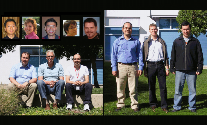
7672pref.fm Draft Document for Review December 10, 2008 11:54 am
lvi Rational Application Developer V7.5 Programming Guide
The team that wrote this book
This book was produced by a team of specialists from around the world working
at the International Technical Support Organization, San Jose Center, and
remotely from Canada, Netherlands, Turkey, and the USA.
Local team
Ueli Wahli is a Consultant IT Specialist at the IBM International Technical
Support Organization in San Jose, California. Before joining the ITSO over 20
years ago, Ueli worked in technical support at IBM Switzerland. He writes
extensively and teaches IBM classes worldwide about WebSphere Application
Server, and WebSphere and Rational application development products. In his
ITSO career, Ueli has produced more than 40 IBM Redbooks. Ueli holds a
degree in Mathematics from the Swiss Federal Institute of Technology.
Miguel Vieira Ferreira Lopes Gomes is an IT Architect working for IBM Global
Business Services, Brazil, and an active member of the Systems Integration /
Engineering Group. He has 10 years of experience in the enterprise application
development field mainly in the public sector. He holds IBM products, Java, and
SOA certifications. He holds a degree in Computer Science from Sao Judas
University, Sao Paulo. His areas of expertise include software architecture, Java
EE, Web 2.0, Web services, digital signature, Rational Application Developer,
Rational Software Architect, WebSphere Aplication Server, and WebSphere
Portal Server.
Henry Pinar Patrick Lara Celso
Brian Ueli Juan Ahmed Marco Miguel
Preface lvii
Draft Document for Review December 10, 2008 11:54 am 7672pref.fm
Brian Hainey is a Senior Lecturer at Glasgow Caledonian University in Scotland,
United Kingdom (UK). He currently teaches on the undergraduate and
postgraduate programs offered in the School of Engineering and Computing. In
addition, he teaches training courses in enterprise software development and
Java. He holds a Master of Science degree in electronic engineering from
Heriot-Watt University, Edinburgh. He has more than 20 years experience in the
field of software development and has worked at companies such as National
Westminster Bank, Hewlett-Packard, QA Training, and IBM. He holds industry
certifications in Java and enterprise software development. His areas of
expertise include Java enterprise systems, Web services, XML, UML modelling,
Rational Unified Process®, Rational Rose®, Rational Application Developer,
Rational Software Architect, and WebSphere Application Server.
Ahmed Moharram is a Software Engineer at the Cairo Technology Development
Center (C-TDC) in IBM Egypt. He holds a degree, and completed post graduate
studies, in Computer Science from Cairo University. He has been working in IBM
since 2005. He provides bidirectional scripts (Bidi) and globalization support for
different IBM products and platforms. Currently, he is a technical lead in Rational
multicultural support team with expertise in different areas including Java
technologies, Web services, XML, UML modeling, Web 2.0, WebSphere
Application Server, WebSphere Portal Server, and Microsoft® .Net. Recently, he
has been chosen as a committer in Business Intelligence Reporting Tools
(BIRT), one of the Eclipse Open Source projects.
Juan Pablo Napoli is a WebSphere Consultant IT Specialist at IBM Software
Group Organization in Sofia, Bulgaria. Juan delivers consulting services since 4
years in IBM regions of Latin America, Eastern Europe, and Middle East,
specially focused in banking and governmental sectors. Juan leads the IBM
Academic Initiative before entering IBM, and he has senior skills throughout all
the roles in the software development life cycle, from J2EE™ development to
current middleware architecture leadership in visible projects in the European
Union. He teaches SSME post-graduate curricula at Sofia University and holds a
degree of Computer Science from the University of Cordoba, Argentina.
Marco Rohr is an Advisory IT Specialist working for IBM Global Business
Services in Zurich, Switzerland. He is also an Education Specialist for the
application development and WebSphere segment of the IBM training
department. He has six years of experience in the enterprise application
development field mainly in the public sector. He studied Computer Science at
the Engineering School of Rapperswil, Switzerland and he holds a Swiss Federal
Certificate in Didactic and Methodology. His areas of expertise include
object-oriented analysis and design with UML, implementation of OO concepts in
Java SE, and development of the presentation layer of Java EE applications.
7672pref.fm Draft Document for Review December 10, 2008 11:54 am
lviii Rational Application Developer V7.5 Programming Guide
Remote team
Henry Cui is a Software Developer working at the IBM Toronto lab. Henry has
been in the IBM Rational Application Developer service and support team for six
years. He has helped many customers resolve design, development, and
migration issues with Java EE development. His areas of expertise include
developing Java EE applications using Rational tools, configuring WebSphere
Application Servers, EJBs, application security, Web services and SOA. Henry is
a frequent contributor of developerWorks® articles. He also co-authored two IBM
Redbooks, Rational Application Developer v7 Programming Guide , SG24-7501,
and Web Services Feature Pack for WebSphere Application Server V6.1,
SG24-7618. Henry holds a degree in Computer Science from York University.
Patrick Gan is a Senior IT Specialist who works for IBM Global Services,
Application Innovation Services Center of Excellence, US. He has eight years of
experience and expertise in OOAD/Java Design best practices, J2EE
development, SOA, software development methods, and tools. In his current
capacity, Patrick's primary responsibility in customer facing engagements is
solution design and delivery of custom enterprise solutions. In addition, he has
also been involved in the design and development of IBM assets and has
authored articles on developerWorks. Patrick has a Computer Science degree
from California Polytechnic State University, Pomona.
Celso Gonzalez has been working on software engineering for the last 13 years.
He is one of the Rational World Wide Architecture Management leaders. His role
is to provide is expertise in domains ranging from business modeling to J2EE
development, including requirements management, architecture, and design, to
IBM customers and internal resources. Lately Celso has been focusing on SOA
and on accelerating development using patterns-based engineering. Before
joining the Worldwide Community of Practice team, Celso was part of the
Rational Unified Process development team where he contributed to areas like
business modeling, requirements, analysis & design, and legacy evolution. Celso
holds degrees in Computer Science, Mathematics, and Philosophy.
Pinar Ugurlu is an Advisory IT Specialist in the IBM Software Group, Turkey.
She has six years of experience in application design, development, and
consulting. She holds a degree in Computer Engineering from Bilkent University.
Her areas of expertise include service-oriented architecture, J2EE programming,
portals, and e-business integration. She has written extensively on Java EE
clients, Ant, profiling, and Java Connector Architecture.
Lara Ziosi is an Advisory Software Engineer in IBM Netherlands. She holds a
Doctorate in computational methods of Physics from the University of Bologna,
Italy. She has nine years of experience in Rational client support. Her areas of
expertise include Java Enterprise, object-oriented analysis and design with UML,
the extensibility of the modeling features of Rational Software Architect and the

Preface lix
Draft Document for Review December 10, 2008 11:54 am 7672pref.fm
integration of Rational Software Architect with configuration management tools,
such as Rational ClearCase® and Rational Team Concert. Lara is a frequent
contributor of Rational Application Developer, Rational Software Architect, and
Rational Software Modeler technotes.
Thanks to the following people for their contributions to this project:
Kevin Sutter, Randy Schnier, and Jody Grassel, IBM Rochester
Matthew Perrins, IBM UK
Samantha Chan, Ellen Chen, Ivy Ho, Mike Melick, and Elson Yuen, IBM
Toronto
Eric Jodet and Philippe J. Krief, IBM France
Bruno Tavares, IBM Brazil
Thanks to the authors of the previous editions of this book.
Authors of the previous edition, Rational Application Developer V7
Programming Guide, published in September 2007, were: Henry Cui, Craig
Fleming, Maan Mehta, Marco Rohr, Pinar Ugurlu, Patrick Gan, Celso
Gonzalez, Daniel M Farrell, and Andreas Heerdegen.
Become a published author
Join us for a two- to six-week residency program! Help write a book dealing with
specific products or solutions, while getting hands-on experience with
leading-edge technologies. You will have the opportunity to team with IBM
technical professionals, Business Partners, and Clients.
Your efforts will help increase product acceptance and customer satisfaction. As
a bonus, you will develop a network of contacts in IBM development labs, and
increase your productivity and marketability.
Find out more about the residency program, browse the residency index, and
apply online at:
ibm.com/redbooks/residencies.html
7672pref.fm Draft Document for Review December 10, 2008 11:54 am
lx Rational Application Developer V7.5 Programming Guide
Comments welcome
Your comments are important to us!
We want our books to be as helpful as possible. Send us your comments about
this book or other IBM Redbooks in one of the following ways:
Use the online Contact us review Redbooks form found at:
ibm.com/redbooks
Send your comments in an e-mail to:
redbooks@us.ibm.com
Mail your comments to:
IBM Corporation, International Technical Support Organization
Dept. HYTD Mail Station P099
2455 South Road
Poughkeepsie, NY 12601-5400

© Copyright IBM Corp. 2008. All rights reserved. lxi
Draft Document for Review December 30, 2008 9:48 am 7672chang.fm
Summary of changes
This section describes the technical changes made in this edition of the book and
in previous editions. This edition may also include minor corrections and editorial
changes that are not identified.
Summary of changes for Rational Application Developer V7.5 Programming
Guide, SG24-7672-00, as created or updated on December 30, 2008.
This book is an update of the IBM Redbooks publication, Rational Application
Developer V7 Programming Guide, SG24-7501.
December 2008, First Edition
This revision reflects the addition, deletion, or modification of new and changed
information described below.
RUP®, Patterns, and SOA: New chapter on architecture
Persistence Using the Java Persistence API (JPA): New chapter
Develop EJB™ applications: Use of the EJB 3.0 specification and JPA for
database access
Develop Web applications using JSF: Use of JPA for database access
Develop Web services applications: Use of JAX-WS exclusively, and added
WS-Policy and WS-MetadataExchange
Develop rich Web 2.0 applications: New chapter using Ajax and Dojo
Develop applications to connect to enterprise information systems: New
chapter with JCA access to CICS® and SAP®
Develop Portal applications: ??
Debug local and remote applications: New section on debug extension for
Rational Team Concert Client
Rational Team Concert: New chapter for team development
Product installation: New sections for Rational Team Concert and Rational
Build Utility
Removed chapters on GUI development, EGL development, and Rational
Clear Case
7672chang.fm Draft Document for Review December 30, 2008 9:48 am
lxii Rational Application Developer V7.5 Programming Guide

© Copyright IBM Corp. 2008. All rights reserved. 1
Draft Document for Review December 9, 2008 2:44 pm 7672-intro-0-p1.fm
Part 1 Introduction to
Rational Application
Developer
In this part of the book, we introduce IBM Rational Application Developer for
WebSphere Software.
The introduction includes packaging, product features, the Eclipse base,
installation, licensing, migration, and an overview of the tools.
We then discuss setting up the Workbench, the perspectives, views, and editors,
and the different type of projects.
Part 1
7672-intro-0-p1.fm Draft Document for Review December 9, 2008 2:44 pm
2 Rational Application Developer V7.5 Programming Guide

© Copyright IBM Corp. 2008. All rights reserved. 3
Draft Document for Review November 6, 2008 1:11 pm 7672-intro-1-intro.fm
Chapter 1. Introduction
IBM Rational Application Developer for WebSphere Software v7.5 is an
integrated development environment and platform for building Java Platform
Standard Edition (Java SE) and Java Platform Enterprise Edition (Java EE)
applications with a focus on applications to be deployed to IBM WebSphere
Application Server and IBM WebSphere Portal.
This chapter contains an introduction to the concepts, packaging, and features of
the IBM Rational Application Developer V7.5 product.
The chapter is organized into the following sections:
Concepts
Product packaging
Product tools and features
Installation and licensing
Migration and coexistence
Sample code
1

7672-intro-1-intro.fm Draft Document for Review November 6, 2008 3:01 pm
16 Rational Application Developer V7.5 Programming Guide
Concepts
This section provides an introduction to the IBM Rational Software Delivery
Platform, Eclipse, and Application Developer.
The Rational product suite helps businesses and organizations manage the
entire software development process. Software modelers, architects, developers,
and testers can use the same team-unifying Rational Software Delivery Platform
tooling to be more efficient in exchanging assets, following common processes,
managing change and requirements, maintaining status, and improving quality.
IBM Rational Software Delivery Platform
The IBM Rational Software Delivery Platform offers an array of products,
services, and best practices. It is an open, modular, and proven solution that
spans the entire software and systems delivery life cycle. Its products are
comprised in five life cycle categories. Figure 1-1 shows each of the five life cycle
categories with a selection of the embedded Rational tooling.
Figure 1-1 IBM Rational Software Delivery Platform life cycle categories and products
Governance and Lifecycle Management
Integrated Requirements Management
Process & Portfolio Management
Rational Method Composer
Rational Portfolio Manager
Rational RequisitePro
Rational Software Architect
Architecture Management
Rational Software Modeler
Rational Application Developer
Rational Business
Developer Extension
Change & Release Management
Rational ClearQuest
Rational ClearCase
Quality Management
Rational Functional Tester
Rational Performance Tester
Rational Service Tester for SOA Quality
Rational Quality
Manager
WebSphere Business Modeler Rational Team Concert
Rational Asset
Manager
Chapter 1. Introduction 15
Draft Document for Review November 6, 2008 3:01 pm 7672-intro-1-intro.fm
The following is a brief description of the products included in the IBM Rational
Software Delivery Platform:
Rational Software Modeler v7.5
The Software Modeler is a UML 2.0-based visual modeling and design tool for
system analysts, software architects, and designers who need to clearly
define and communicate their architectural specifications to stakeholders.
New in version 7.5 you can create and leverage your own domain specific
modeling languages (DSMLs) to represent your unique business problem and
solution domains.
Rational Software Architect v7.5
The Software Architect is a design and construction tool that leverages
model-driven development with UML 2.0 to create well-architected
applications, including those based on service-oriented architecture (SOA). It
unifies modeling, Java structural review, Web services, Java SE, Java EE,
database, XML, Web development, and process guidance for architects and
senior developers creating applications in Java.
New in version 7.5 it comes with a comprehensive support for simpler, new
and emerging programming models including Web 2.0, Java EE 5.0, EJB 3.0
and Java Persistence API (JPA).
Rational Application Developer
The Application Developer is a full suite of development, analysis and test,
and deployment tools for rapidly implementing Java SE and EE, Portal, Web
and Web 2.0, Web services and SOA applications.
New in version 7.5 it supports Java EE 5.0, EJB 3.0, JPA, and Web 2.0 with
Ajax and Dojo development.
Rational Business Developer Extension v7.5
The Business Developer Extension is an Eclipse 3.4 based workbench
featuring Enterprise Generation Language (EGL) for delivering multi-platform
applications.
Rational Asset Manager v7.1
The Asset Manager helps create, modify, govern, find and reuse any type of
development assets, including SOA and system development assets.
Rational Team Concert
The Team Concert is a Jazz™-based collaborative software delivery
environment that empowers project teams to simplify, automate and govern
software delivery. Automated data collection and reporting reduces
administrative overhead and provides the real-time insight required to
effectively govern software projects. It extends the capabilities of the team

7672-intro-1-intro.fm Draft Document for Review November 6, 2008 3:01 pm
16 Rational Application Developer V7.5 Programming Guide
with integrated work item, build, software configuration management (SCM)
and the collaborative infrastructure of the Jazz Team Server.
Rational Functional Tester v8.0
The Functional Tester is a tooling for automated functional, regression, GUI
and data-driven testing. It provides the capability to record robust scripts that
can be played back to validate new builds of an application.
Rational Performance Tester v8.0
The Performance Tester is a multi-user system performance test product
designed to test Web applications, and focuses on scalability.
Rational Service Tester for SOA Quality
The Service Tester for SOA Quality tooling provides tester with script-free
testing capabilities for functional, regression, and performance testing of
GUI-less Web services.
Rational Quality Manager
The Quality Manager is a web-based centralized test management
environment for business, system and IT decision makers and quality
professionals who seek a collaborative and customizable solution for test
planning, workflow control, tracking and metrics reporting capable of
quantifying how project decisions and deliverables impact and align with
business objectives.
Rational Method Composer
The Method Composer is a flexible process management platform. It includes
a rich process library to help companies implement effective processes for
successful software and IT projects.
Rational Portfolio Manager
The Portfolio Manager helps businesses to align their IT and system
investments with business priorities. It provides optimization of investment
funding decisions, cost containment, and maximizing value across the entire
portfolio.
Note: Jazz is IBM Rational’s new technology platform for collaborative
software delivery. It is an extensible framework that dynamically integrates
and synchronizes people, processes and assets associated with software
development projects. More information about Jazz technology platform
can be found here:
http://www.ibm.com/software/rational/jazz/
Chapter 1. Introduction 15
Draft Document for Review November 6, 2008 3:01 pm 7672-intro-1-intro.fm
Rational RequisitePro®
RequisitePro is a requirements management tool for project teams who want
to manage their requirements, write good use cases, improve traceability,
strengthen collaboration, reduce project risks, and increase quality.
Rational ClearQuest®
ClearQuest is a software change management tooling. It provides defect, task
and change request tracking, process automation, reporting and lifecycle
traceability for better visibility and control of the software development
lifecycle.
Rational ClearCase
ClearCase is a complete software configuration management tooling. It
provides a sophisticated version control, workspace management, parallel
development support and build auditing to improve productivity.
WebSphere Business Modeler
The WebSphere Business Modeler belongs to the WebSphere brand, but is
an important product of the Rational Software Delivery Platform. WebSphere
Business Modeler targets the business analyst who models business
processes. WebSphere Business Modeler can be used to generate Business
Process Execution Language (BPEL) definitions to be imported into
WebSphere Integration Developer to create applications for WebSphere
Process Server. BPEL from WebSphere Business Modeler provides a more
seamless move to implementation and eliminates the need to create paper
diagrams for the developer.
Eclipse and IBM Rational Software Delivery Platform
This section provides an overview of the Eclipse Project, as well as how Eclipse
relates to the IBM Rational Software Delivery Platform and Application Developer
v7.5.
Eclipse Project
The Eclipse Project is an open source software development project devoted to
creating a development platform and integrated tooling. Figure 1-2 shows the
high-level Eclipse Project architecture and shows the relationship of the following
sub projects:
Eclipse Platform
Eclipse Java Development Tools (JDT)
Eclipse Plug-in Development Environment (PDE)

7672-intro-1-intro.fm Draft Document for Review November 6, 2008 3:01 pm
16 Rational Application Developer V7.5 Programming Guide
Figure 1-2 Eclipse Project overview
With a common public license that provides royalty free source code and
world-wide redistribution rights, the Eclipse Platform provides tool developers
with great flexibility and control over their software technology.
Industry leaders like IBM, Borland, Merant, QNX Software Systems, RedHat,
SuSE, TogetherSoft, and WebGain formed the initial eclipse.org board of
directors of the Eclipse open source project.
More detailed information on Eclipse can be found at:
http://www.eclipse.org
Eclipse Platform
The Eclipse Platform provides a framework and services that serve as a
foundation for tools developers to integrate and extend the functionality of the
platform. The platform includes a workbench, concept of projects, user interface
libraries (JFace, SWT), built-in help engine, and support for team development
and debug. The platform can be leveraged by a variety of software development
purposes including modeling and architecture, integrated development
environment (Java, C/C++, Cobol), testing, and so forth.
Note: IBM Rational Application Developer v7.5 is based on Eclipse v3.4.
Platform Runtime
Workspace
Help
Team
Workbench
JFace
SWT
Eclipse Project
Java
Development
Tools
(JDT)
Their
Tool
Your
Tool
Another
Tool
Plug-in
Development
Environment
(PDE)
Eclipse Platform
Debug

Chapter 1. Introduction 15
Draft Document for Review November 6, 2008 3:01 pm 7672-intro-1-intro.fm
Eclipse Java Development Tools (JDT)
The JDT provides the plug-ins for the platform specifically for a Java-based
integrated development environment, as well as the development of plug-ins for
Eclipse. The JDT adds the concepts of Java projects, s, views, editors, wizards,
and refactoring tools to extend the platform.
Eclipse Plug-in Development Environment (PDE)
The PDE provides the tools to facilitate the development of Eclipse plug-ins.
Eclipse Software Developer Kit (SDK)
The Eclipse SDK consists of the software created by the Eclipse Project
(Platform, JDT, PDE), which can be licensed under the Eclipse Common Public
License agreement, as well as other open source third-party licensed software.
Application development challenges
To better grasp the business value that Application Developer v7.5 provides, it is
important to understand the challenges businesses face in application
development.
Table 1-1 highlights the key application development challenges as well as
desired development tooling solutions.
Table 1-1 Application development challenges
Note: The Eclipse SDK does not include a Java Runtime Environment
(JRE™) and must be obtained separately and installed for Eclipse to run. IBM
Java Runtime Environment 6.0 is used in Application Developer v7.5.
Challenges Solution tooling
Application development is
complex, time consuming,
and error prone.
Raise productivity by automating time consuming and
error prone tasks.
Highly skilled developers are
required and in short supply.
Assist less knowledgeable developers where possible
by providing wizards, on-line context sensitive help, an
integrated environment and visual tooling.
Learning curves are long. Shorten learning curves by providing Rapid Application
Development (RAD) tooling (visual layout and design,
re-usable components, code generators) and ensure
development tools have consistent way of working.
7672-intro-1-intro.fm Draft Document for Review November 6, 2008 3:01 pm
16 Rational Application Developer V7.5 Programming Guide
Product packaging
This section highlights the product packaging for Application Developer V7.5.
Rational Developer supported platforms and databases
This section describes the platforms and databases supported by the Rational
Developer products.
Supported operating system platforms
Application Developer v7.5 supports the following operating systems:
– Microsoft Windows® XP Professional (x32 / x64)
– Microsoft Windows Server® 2003 Standard / Enterprise Edition (x32 / x64)
– Microsoft Windows Vista® Business / Enterprise Ultimate (x32 / x64)
– Microsoft Windows Server 2008 Standard / Enterprise Edition (x32 / x64)
– Red Hat Enterprise Linux® Version 4.0/5.0 AS / ES (x32 / x64)
– Red Hat Enterprise Linux Desktop Version 4.0/5.0 (x32)
– SUSE® Linux Enterprise Server (SLES) Version 9/10 (x32 / x64)
– SUSE Linux Enterprise Desktop (SLED) Version 9/10 (x32 / x64)
– Citrix Presentation Server Version 4.x
– VMWare environment
Test server environments
Application Developer v7.5 supports a wide range of server environments for
running, testing, and debugging application code.
The following lists the application servers that are compatible with Application
Developer v7.5:
IBM WebSphere Application Server, Version 6.0 (included)
(optionally with Feature Pack for Web 2.0)
IBM WebSphere Application Server, Version 6.1 (included)
(optionally with Feature Pack for Web 2.0 / EJB 3.0 / Web Services)
IBM WebSphere Application Server, Version 7.0 (included)
(optionally with Feature Pack for Web 2.0)
IBM WebSphere Portal, Version 6.0
IBM WebSphere Portal, Version 6.1 (included)
IBM HTTP Servers

Chapter 1. Introduction 15
Draft Document for Review November 6, 2008 3:01 pm 7672-intro-1-intro.fm
The following list of server adapters from the Web Tools Platform 3.0 based on
Eclipse technology are included in Application Developer V7.5:
HTTP Preview
Java EE Preview
Apache Tomcat, Versions 3.2, 4.0, 4.1, 5.0, 5.5, and 6.0
JBoss, Versions 3.2.3, 4.0, 4.2, and 5.0
ObjectWeb Java Open Application Server (JOnAS), Version 4
Oracle® Containers for J2EE (OC4J) Standalone Server, V10.1.3 and
10.1.3.n
Supported databases
The following databases are compatible with the Application Developer v7.5
workbench:
IBM Cloudscape®, Version 5.1
Derby, Versions 10.0, 10.1, and 10.2
IBM DB2® Database for Linux, UNIX® and Windows,
Versions 7.2, 8.1, 8.2, 9.1, and 9.5
IBM DB2 for i5/OS®, Versions 5R2, 5R3, and 5R4
IBM DB2 for z/OS® Versions 7, 8, 9 (compatibility mode)
and 8, 9 (new function mode)
IBM Informix® Dynamic Server, Versions 9.2, 9.3, 9.4, 10.0, and 11.0
HSQLDB, Version 1.8
Microsoft SQL Server® Enterprise, Versions 7, 2000, and 2005
MySQL™, Versions 4.0, 4.1, 5.0, and 5.1
Oracle, Versions 8, 9, 10, and 11
SAP MaxDB, Versions 7.6 and 7.7
Sybase Adaptive Server Enterprise, Versions 12.x, and 15.0
Generic JDBC™ Version 1.0
Note: IBM Rational Deployment Toolkit for WebLogic Server provides a
seamless integration of BEA WebLogic Server, Versions 6.1, 7.0, and 8.1
within Application Developer. More information can be found here:
http://www.ibm.com/developerworks/rational/downloads/08/toolkit_weblogicv7
Note: Additional to the compatibility mode, the new function mode includes
the generated data model that has all the new catalog features of DB2 for
z/OS v8 and v9. Use the new function mode if you plan to work with the
generated data models available in IBM Rational Software Delivery
Platform products.

7672-intro-1-intro.fm Draft Document for Review November 6, 2008 3:01 pm
16 Rational Application Developer V7.5 Programming Guide
Application Developer v7.5 eAssembly
IBM Rational Application Developer for WebSphere Software V7.5 is comprised
of the following two eAssemblies:
IBM Rational Application Developer for WebSphere V7.5 Multilingual
Multiplatform eAssembly (Core)
– Quick Start Guide
– License Activation Kit
– Application Developer V7.5 Core (6 parts)
– WebSphere Application Server Test Environment V6.0 (2 parts)
– WebSphere Application Server Test Environment V6.1 (4 parts)
– WebSphere Application Server Test Environment V7.0 (4 parts)
– Java Runtime Environment V1.6 SR2
IBM Rational Application Developer for WebSphere V7.5 Multilingual
Multiplatform eAssembly (Optional)
– Application Developer Build Utility V7.5 (5 parts)
– Rational Enterprise Deployment V7.5 for Windows / Linux (each 1 part)
(includes License Server, Installation Manager and Packaging Utility)
– IBM WebSphere Portal V6.1 for Windows / Linux (each 9 parts)
– Crystal Reports Server XI Release 2 Windows / Linux (each 2 parts)
– IBM WebSphere Application Server for Developers V7.0 for Windows /
Linux (each 1 part)
– IBM CICS Transaction Gateway V7.1.0.2 Windows / Linux (each 1 part)
– Rational Debug Extension for IBM Rational Team Concert Server
– Rational Agent Controller V8.0
Note: At minimum, the six core parts and the license activation kit are
required.
Note: Rational Agent Controller 8.0 is for IBM WebSphere Application
Server 7.0. However, for IBM WebSphere Application Server V6.0 and
V6.1, Rational Agent Controller V7.0.3.1 is needed.

Chapter 1. Introduction 15
Draft Document for Review November 6, 2008 3:01 pm 7672-intro-1-intro.fm
Product tools and features
This section gives you a summary of the tools and new features of Application
Developer v7.5. We provide more detailed information on the tooling and features
throughout the chapters of this book.
Tools
Application Developer v7.5 includes a wide array of tooling to simplify or
eliminate tedious and error-prone tasks, and provide the ability for Rapid Web
Development. We have listed the key areas of tooling included with Application
Developer:
Java development tools (JDT)
Relational database tools
XML tools
Web development tools
Web 2.0 development tools
Struts tools
JSF development tools
SDO development tools
Enterprise Generation Language tools
EJB tools
JPA tools
Portal tools
Web services tools
Team collaboration tools
Debugging tools
Performance profiling and analysis tools
Server configuration tools
Testing tools
Crystal Report tools
Deployment tools
Plug-in development tools
Note: Each of the chapters of this book provides a description of the tools
related to the given topic and demonstrates how to use the Application
Developer tooling.
7672-intro-1-intro.fm Draft Document for Review November 6, 2008 3:01 pm
16 Rational Application Developer V7.5 Programming Guide
Summary of new features in Application Developer v7.5
There are lots of new features in Version 7.5, many of which we highlight in detail
in the remaining chapters of this book. The objective of this section is to
summarize the new features in Application Developer v7.5:
Eclipse 3.4 integration: Includes all Eclipse 3.4 features and extends this
functionality with visual development tools and IBM WebSphere support
Web based help system with option to run locally
Productivity enhancement features:
– Flexible installation provides access to only the features you need
– Cheat sheets for common development patterns
Specification versions: Full support for Java EE 5.0, Java SE 6.0, and IBM
WebSphere Application Server v7.0.
Web tooling:
– JavaServer™ Pages (JSP™) 2.1 and servlet 2.5 wizards
– Ability to split the page designer into a designer and source view
– Ability to position the widget to an absolute position on the page
– Struts 1.3 support: Wildcards in action mappings and ability to extend
Struts artifacts
– Web Diagram Editor enhancements: Use the new References framework
for refactoring, provide a preview before actually committing changes, and
show incoming and outgoing links on a node.
– Support for links from data grids: Row action added to a data table in a
Faces JSP is now displayed in Web Diagram.
– Enhanced link indexing, validation and refactoring support
For more detailed information, refer to
– Chapter 13, “Develop Web applications using JSPs and servlets” on
page 317,
– Chapter 15, “Develop Web applications using Struts” on page 445
JavaServer Faces (JSF) tooling:
– JavaServer Faces (JSF) 1.2 components and visual tools
– JSF-based report viewing component for embedding reports into Web
applications
– Integration of third party JSF libraries: Allow users to generate a project
containing a definition of how to integrate tooling for the library into
Application Developer
Chapter 1. Introduction 15
Draft Document for Review November 6, 2008 3:01 pm 7672-intro-1-intro.fm
– Custom Component Library Builder: Allow users to build a JSF component
library from existing components and integrate that library into the tools
– JSF Widget Library: Built-in Ajax-like capabilities and Dojo support
– OpenAjax compliance and co-existence with other Ajax libraries
For more detailed information, refer to Chapter 16, “Develop Web applications
using JSF” on page 493.
Web 2.0 tooling:
– Support for developing Ajax and Dojo based applications
– Visual tools for Ajax proxy
– Java Script Editor with Outline view, content assist, validation, and
refactoring
– Java Script Debugger: Firebug integration
– Dojo widget content assist, validation, palette items, property views
– Drag and drop of Dojo widgets from the palette to Page Designer Source
view
– WebSphere Web 2.0 Feature Pack support: RPC Adapter configuration
– Expose Java beans as REST-style services
– Supports JSON and XML data interchange
– Integrate ATOM and RSS feeds
For more detailed information, refer to Chapter 19, “Develop Web applications
using Web 2.0” on page 649.
Enterprise JavaBeans™ (EJB) and Java Persistence API (JPA) tooling:
– As-you-type syntactic validation and code assist for annotations
– EJB 3.0 semantic validation on save
– EJB 3.0 and JPA deployment descriptor editor enhancements
– WAS binding files and deployment descriptors are XML based
– EJB Visualizer updated to view and edit EJB 3.0
– Beans can be annotation or XML deployment descriptor based
– Tool to map JPA beans to database tables
– Enhanced JSF client support for EJB 3.0 and JPA beans
– Support for adding EJB 3.0 modules to existing applications that have
J2EE 1.4 deployment descriptors
For more detailed information, refer to Chapter 12, “Persistence using the
Java Persistence API (JPA)” on page 267 and Chapter 14, “Develop EJB
applications” on page 387.
7672-intro-1-intro.fm Draft Document for Review November 6, 2008 3:01 pm
16 Rational Application Developer V7.5 Programming Guide
Java Annotation support:
– Java Editor
• Content assist for annotations, injected for simple java projects and
component defining annotations, for example @Stateless or
@WebService
• Template based to provide prefilled attribute values based on the
annotation’s java context
• Indicates where annotation attribute values may be overridden
• Hovering on indicator provides the value from the deployment
descriptor file
– Annotation View
• Editing for annotations without definitions
• Annotation attributes of type annotations and array of annotations
supported
• Integrated JPA editing
• EJB deployment descriptor override indicators
• Integrated with EJB Visualizer
– Tracing and Logging
• Java Annotation Index
Portal application development:
– Support of IBM WebSphere Portal 6.1
– Creation of JSR 286 Portlet projects and support for portlet events: JSR
286 allows the portlets to declare events it wants to publish (send), and
events it wants to process (receive)
– Portlet Deployment Descriptor editor has new tabs to accommodate for
JSR 286 specification.
– Support for client-side programming model: Enables Web 2.0 functionality,
reduces repeated round trips to server, user actions in the browser cause
JavaScript™ to execute, script communicates directly with the server
(XmlHttpRequest or hidden IFRAME)
– Ajax support: WYSIWYG editor for Ajax proxy configurations
– Web 2.0 theme support
– Allows creation of portal pages using static HTML templates
– Friendly URL names: developers can assign simple easy to remember
URLs for particular page
For more detailed information, refer to Chapter 21, “Develop portal
applications” on page 739.
Chapter 1. Introduction 15
Draft Document for Review November 6, 2008 3:01 pm 7672-intro-1-intro.fm
Web services:
– Full support for Java API for XML Web Services (JAX-WS 2.0), Java
Architecture for XML Binding (JAXB 2.0), SOAP 1.2, SOAP with
Attachments API for Java (SAAJ 1.3), UDDI 3.0, Web Services Reliable
Messaging (WS RM), Web Services Addressing (WS Addressing) and
SOAP Message Transmission Optimization Mechanism (MTOM)
– WS-I Basic Profile 1.2 and 2.0
– EJB 3.0 Web services
– Enhanced annotation support: Trigger annotations, templatized auto
completions, implicit attributes, implied annotations (@WebService implies
@BindingType for implementation beans)
– Quick fixes for unresolved annotations, for example useful after import of a
module with source using JAX-WS 2.0 annotations, where Web Services
Feature Pack Facet was not selected
– Extended WSDL validation: detect and warn about issues that frequently
occur
For more detailed information, refer to Chapter 18, “Develop Web services
applications” on page 563.
Data tooling:
– Two views replaced (Database Explorer is now Data Source Explorer,
Output View is now SQL Results)
– New connection wizard: need to be associated with the right driver and
DB2 is version less
– SQL Result view: allow for nested display, timestamp support, and history
persisted with the workspace
– New SQL and XQuery Editor: Error reporting, syntax and reference
parsers, content assist, and include a DML formatter
For more detailed information, refer to Chapter 11, “Develop database
applications” on page 227.
Build utility:
– A scriptable, automated, headless application build tool
– Used for automation of production builds
– Builds and exports are consistent to those from Application Developer
– Based on ANT with specialized Application Developer ANT tasks
– Input is Application Developer projects, and the output is compiled and
packaged code in the form of JARs, WARs, and EARs
7672-intro-1-intro.fm Draft Document for Review November 6, 2008 3:01 pm
16 Rational Application Developer V7.5 Programming Guide
Line level coverage:
– Commonly used for measuring and comparing test coverage
– Java classes are statically instrumented after compilation (reversible and
portable)
– Code coverage statistics are stored locally for each application launch
– Indicators and enhanced reports to display levels of covered, uncovered,
or partially covered lines
Team debugging:
– Rational Team Concert capabilities allow to transfer a live debug session
to another user, so he can continue analysis from where you have left off
Server tooling:
– Stable server connection for server status update
– Auto detect connection type
– Test connection to diagnose server connection problem
– Improved usability of pop-up menu in the Servers View
– Improved developer experience for server start and stop
– Support for WebSphere Feature Packs and class paths
– EJB 3.0 and JPA universal test clients (UTC) available for WebSphere
Application Server (WAS) v7.0
– Adopt new WAS runtime bundle structure
– WAS v7.0 Jython Library Support
– Exploiting the new WAS v7.0 Jython libraries in the Jython editor
– Two new Java Management Extensions (JMX™) connection types: IPC
connection type and JSR 160 RMI
Specification versions
This section highlights the specification versions found in Application Developer
v7.5.
Table 1-2 is a comparison of the technology versions supported by Application
Developer v7.5 and v7.0. Most of the listed technologies are part of the Java EE
5.0 specification.
Chapter 1. Introduction 15
Draft Document for Review November 6, 2008 3:01 pm 7672-intro-1-intro.fm
Table 1-2 Technology versions comparison
Specification Application
Developer v7.5
Application
Developer v7.0
IBM Java Runtime Environment (JRE) 1.6 1.5
JavaServer Pages (JSP) 2.1 2.0
Java Servlet 2.5 2.4
Enterprise JavaBeans (EJB) 3.0 2.1
Java Message Service (JMS) 1.1 1.1
Java Transaction API (JTA) 1.1 1.0
JavaMail™ 1.4.1 1.3
Java Activation Framework (JAF) 1.1.1 1.1
Java API for XML Processing (JAXP) 1.4
incl. Java SE 6
1.2
incl. Java SE 1.4
Java EE Connector 1.5 1.5
Java API for XML-based RPC (JAX-RPC) 1.1 1.1
SOAP with Attachments API for Java (SAAJ) 1.3 1.2
Java API for XML Web Services (JAX-WS) 2.0 optional feature
Java Architecture for XML Binding (JAXB) 2.0 optional feature
Java Authentication and Authorization Service
(JAAS)
incl. Java SE 6 incl. Java SE 1.4
Java Database Connectivity API (JDBC) 4.0
incl. Java SE 6
3.0
incl. Java SE 1.4
Java API for XML Registries (JAXR) 1.0 1.0
Java EE Management 1.1 1.0
Java Management Extensions (JMX) 1.2
incl. Java SE 6
1.2
incl. Java SE 1.4
Java EE Deployment 1.2 1.1
Java Authorization Service Provider Contract
for Containers (JACC)
1.1 1.0
JavaServer Pages Debugging 1.0 n/a
JavaServer Pages Standard Tag Library (JSTL) 1.2 1.2

7672-intro-1-intro.fm Draft Document for Review November 6, 2008 3:01 pm
16 Rational Application Developer V7.5 Programming Guide
Installation and licensing
This section provides a summary for licensing, installation, product updates, and
uninstallation for Application Developer v7.5. Licensing, installation, product
updates, and uninstallation are achieved through the IBM Installation Manager
(which is installed along with Application Developer v7.5). It is important to note
that whenever using IBM Installation Manager on a previously installed product,
that particular product must not be in use when making updates.
Installation
The system hardware requirements are as follows:
Intel® Pentium® III 800 MHz or higher
1 GB RAM minimum, 2 GB RAM works well
1024 x 768 video resolution or higher
3.5 GB free hard disk space
2 GB temp space during install
What is new in Application Developer v7.5
Support non-admin install
Help configuration
WebSphere Application Server Test Environment are extensions, not features
Option on profile creation for WAS Test Environment install
Web Services Metadata 2.0 n/a
JavaServer Faces 1.2 1.1
Common Annotations 1.0 n/a
Streaming API for XML (StAX) 1.0 n/a
Java Persistence API (JPA) 1.0 n/a
Service Data Objects (SDO) 2.0 1.0
Struts 1.3 1.1
Specification Application
Developer v7.5
Application
Developer v7.0
Installation: The detailed steps to install Application Developer v7.5 are
described in “Installing IBM Rational Application Developer” on page 1124.

Chapter 1. Introduction 15
Draft Document for Review November 6, 2008 3:01 pm 7672-intro-1-intro.fm
Licensing
Types of licenses
IBM Rational offers three types of product licenses: an Authorized User License,
an Authorized User Fixed Term License (FTL) and a Floating License. The best
choice for your organization depends upon how many people use the product,
how often they require access, and how you prefer to purchase your software.
Authorized User License
An IBM Rational Authorized User License permits a single, specific individual to
use a Rational software product. Purchasers must obtain an Authorized User
License for each individual user who accesses the product in any manner. An
Authorized User License can not be reassigned unless the purchaser replaces
the original assignee on a long-term or permanent basis.
Authorized User Fixed Term License
An IBM Rational Authorized User Fixed Term License (FTL) permits a single,
specific individual to use a Rational software product for a specific length of time
(the term). Purchasers must obtain an Authorized User FTL for each individual
user who accesses the product in any manner. An Authorized User FTL can not
be reassigned unless the purchaser replaces the original assignee on a
long-term or permanent basis.
Floating license
An IBM Rational Floating License is a license for a single software product that
can be shared among multiple team members; however, the total number of
concurrent users can not exceed the number of floating licenses you purchase.
To use floating licenses, you must obtain floating license keys and install them on
a Rational License Server. The server responds to end-user requests for access
to the license keys; it will grant access to the number of concurrent users that
matches the number of licenses the organization purchased.
Updates
Once Application Developer V7.5 has been installed, the Installation Manager
provides and interface to update the product.
License installation: Once you have obtained a license, invoke the IBM
Installation Manager. The detailed steps to import a license are described in
“Installing the license for Rational Application Developer” on page 1128.

7672-intro-1-intro.fm Draft Document for Review November 6, 2008 3:01 pm
16 Rational Application Developer V7.5 Programming Guide
Refer to “Updating Rational Application Developer” on page 1129 for detailed
instructions.
Uninstall
Application Developer v7.5 can be uninstalled interactively through the IBM
Installation Manager.
Refer to “Uninstalling Rational Application Developer” on page 1129 for detailed
instructions.
Migration and coexistence
This section highlights the Application Developer v7.5 migration features, and the
coexistence and compatibility with Application Developer v6.0.x and v7.0.x.
Migration
Migration includes the migration of Application Developer v6.0.x and v7.0.x as
well as Java EE projects and code assets.
What is new in Application Developer V7.5
No more stealth auto-migration
– A plug-in can determine if migration is required for a project
New migration wizard
– Displays projects and resources
– Ensures resources are read-write
– User has the option to not migrate all projects
– Closes any projects which are not migrated
Important: Much of this book was researched and written using Application
Developer v7.5.0 iFix001.
For more information, refer to the following link, which contains information on
the latest fixes available for Application Developer:
http://www.ibm.com/software/awdtools/developer/application/support/

Chapter 1. Introduction 15
Draft Document for Review November 6, 2008 3:01 pm 7672-intro-1-intro.fm
– Allows you to remove the server resources that are no longer required
from the workspace
– Provides choices for migration of undefined server runtimes
– Displays messages for the user before migration begins
New migration results verification tool
– Runs automatically at completion of migration
– Provides a view of the results
Forward migration from version 6.0.x or version 7.0.x:
Open an old workspace in v7.5
Import projects into vv7.5
Check-out projects from a source code management system
Compatibility with previous versions
Application Developer v7.5 includes a compatibility option to facilitate sharing
projects with Application Developer v7.0.x.
Projects can be shared with Application Developer v7.0.x developers through a
SCM (such as Rational Team Concert or CVS) or using project interchange zip
files.
Metadata and project structure are not updated to the new Application Developer
format. A .compatibility file is added to projects and is used to track the
timestamps of resources.
Compatibility support can be removed when finished developing in a mixed
environment.
The compatibility feature can be accessed by selecting Windows →
Preferences → Backward Compatibility (Figure 1-3).
Figure 1-3 Backward compatibility feature
7672-intro-1-intro.fm Draft Document for Review November 6, 2008 3:01 pm
16 Rational Application Developer V7.5 Programming Guide
Sample code
The chapters are written so that you can follow along and create the code from
scratch. In places where there is lots of typing involved, we have provided
snippets of code to cut and paste.
Alternatively, you can import the completed sample code from a project
interchange file. For details on the sample code (download, unpack, description,
import interchange file, create databases), refer to Appendix B, “Additional
material” on page 1149.
Summary
This chapter introduced the concepts behind Application Developer and gave an
overview of the features of the various members of the Rational product suite,
and where Application Developer fits with regard to the other products. A
summary of the version numbers of the various features was given and the
Installation Manager was introduced.

© Copyright IBM Corp. 2008. All rights reserved. 25
Draft Document for Review December 9, 2008 2:44 pm 7672-intro-2-prog.fm
Chapter 2. Programming technologies
This chapter describes a number of example application development scenarios,
based on a simple banking application. Throughout these examples, we will
review the Java and supporting technologies, as well as highlight the tooling
provided by Application Developer V7.5, which can be used to facilitate
implementing the programming technologies.
This chapter is organized into the following sections:
Desktop applications
Static Web sites
Dynamic Web applications
Enterprise JavaBeans and Java Persistence API (JPA)
Java EE Application Clients
Web services
Messaging systems
2
7672-intro-2-prog.fm Draft Document for Review December 9, 2008 2:44 pm
26 Rational Application Developer V7.5 Programming Guide
Desktop applications
By desktop applications we mean applications in which the application runs on a
single machine and the user interacts directly with the application using a user
interface on the same machine.
When this idea is extended to include database access, some work might be
performed by another process, possibly on another machine. Although this
begins to move us into the client-server environment, the application is often only
using the database as a service—the user interface, business logic, and control
of flow are still contained within the desktop application. This contrasts with full
client-server applications in which these elements are clearly separated and
might be provided by different technologies running on different machines.
This type of application is the simplest type we will consider. Many of the
technologies and tools involved in developing desktop applications, such as the
Java editor and the XML tooling, are used widely throughout all aspects of
Application Developer.
The first scenario deals with a situation in which a bank requires an application to
allow workers in a bank call center to be able to view and update customer
account information. We will call this the Call Center Desktop.
Simple desktop applications
A starting point for the Call Center Desktop might be a simple stand-alone
application designed to run on desktop computers.
Java Platform, Standard Edition (Java SE) provides all the elements necessary
to develop such applications. It includes, among other elements, a complete
object-oriented programming language specification, a wide range of useful
classes to speed development, and a runtime environment in which programs
can be executed.
The complete Java SE specification can be found at:
http://java.sun.com/javase/
Java language
Java is a general purpose, object-oriented language. The basic language syntax
is similar to C and C++, although there are significant differences. Java is a
higher-level language than C or C++, in that the developer is presented with a
more abstracted view of the underlying computer hardware and is not expected
to take direct control of issues such as memory management. The compilation
Chapter 2. Programming technologies 27
Draft Document for Review December 9, 2008 2:44 pm 7672-intro-2-prog.fm
process for Java does not produce directly executable binaries, but rather an
intermediate byte code, which can be executed directly by a virtual machine or
further processed by a just-in-time compiler at runtime to produce
platform-specific binary output.
What is new in Java Platform, Standard Edition, Version 6.0
Version 6 of the Java Platform, Standard Edition, includes a bunch of useful new
features. Here are the top 10 things you need to know about the release:
Web Services: New support for writing XML Web service client applications.
APIs can be exposed as .NET interoperable web services using annotation.
Moreover, parsing and XML to Java object-mappings APIs, previously only
available in the Java Web Services Pack and Java EE platform
implementations, is now added to Java SE.
– JSR 173 Streaming API for XML (StAX): Java based API for pull-parsing
XML (http://jcp.org/en/jsr/detail?id=173).
– JSR 181 Web Services Metadata: An annotated Java format to enable
easy definition of Java Web Services in a Java EE container
(http://jcp.org/en/jsr/detail?id=181).
– JSR 222 Java Architecture for XML Binding (JAXB) 2.0: Next generation of
the API that makes it easier to access XML documents from Java
applications (http://jcp.org/en/jsr/detail?id=222).
– JSR 224 Java API for XML-based Web Services (JAX-WS) 2.0: Next
generation web services API replacing JAX-RPC 1.0
(http://jcp.org/en/jsr/detail?id=224).
Scripting: JavaScript technology source code can now be mixed with normal
Java source code. That may be useful for prototyping purpose.
– JSR 223 Scripting for the Java Platform: Scripting language programs can
access information developed in Java and allows to use scripting language
pages in Java server-side applications
(http://jcp.org/en/jsr/detail?id=223).
More Desktop APIs: SwingWorker utility helps GUI developers with threading
GUI applications, JTable got sorting, filtering and highlighting possibilities,
and a new facility for quick splash screens to users.
Database: JDK™ co-bundles the Java DB, a pure Java JDBC database,
based on Apache Derby. JDBC 4.0 API was updated: It supports now XML as
an SQL data type and integrates better Binary Large Objects (BLOBs) and
Character Large Objects (CLOBs).
– JSR 221 JDBC 4.0: Java application access to SQL stores
(http://jcp.org/en/jsr/detail?id=221).
7672-intro-2-prog.fm Draft Document for Review December 9, 2008 2:44 pm
28 Rational Application Developer V7.5 Programming Guide
Monitoring and Management: More diagnostic information are added and
the memory-heap analysis tool jhat for forensic explorations of core dumps is
included
(http://java.sun.com/javase/6/docs/technotes/tools/share/jhat.html).
Compiler Access: Java development tool and framework creators get a
programmatic access to javac for in-process compilation of dynamically
generated Java code.
– JSR 199 Java Compiler API: Service provider that allows a Java program
to select and invoke a Java Language Compiler programmatically
(http://jcp.org/en/jsr/detail?id=199).
Pluggable Annotations: It allows you to define your own annotations and
gives you core support for plug-in and executing the processors.
– JSR 269 Pluggable Annotation Processing API: Creating and processing
of custom annotations (http://jcp.org/en/jsr/detail?id=269).
Desktop Deployment: Better platform look-and-feel in Swing, LCD text
rendering, higher GUI performance, better integration of native platforms, new
access to the platform’s system tray and start menu, and unification of Java
Plug-in technology and Java WebStart engines.
Security: XML Digital Signature API is added to create and manipulate digital
signatures. Simplified access to native security services, such as native
Public Key Infrastructure (PKI), cryptographic services on Microsoft Windows
for secure authentication and communication, Java Generic Security Services
(Java GSS), and Kerberos services for authentication, and access to LDAP
servers.
– JSR 105 XML Digital Signature APIs (XML-DSIG): Implementation of the
W3C specification (http://jcp.org/en/jsr/detail?id=105).
Libraries (Quality, Compatibility, Stability): Array relocation, new collection
type Deque (double ended queue - a linear collection that supports element
insertion and removal at both ends), sorted sets and maps with bidirectional
navigation, new core IEEE754 (floating point) functions, new password
prompting feature, and update of Java Class File specification.
– JSR 202 Java Class File Specification Update: Increases class file size
limits and adds split verification support
(http://jcp.org/en/jsr/detail?id=202).
Java Virtual Machine
The Java Virtual Machine (JVM™) is a runtime environment designed for
executing compiled Java byte code, contained in the .class files, which result
from the compilation of Java source code. Several different types of JVM exist,
ranging from simple interpreters to just-in-time compilers that dynamically
translate byte code instructions to platform-specific instructions as required.
Chapter 2. Programming technologies 29
Draft Document for Review December 9, 2008 2:44 pm 7672-intro-2-prog.fm
Requirements for the development environment
The developer of the Call Center Desktop should have access to a development
tool, providing a range of features to enhance developer productivity:
A specialized code editor, providing syntax highlighting.
Assistance with completing code and correcting syntactical errors.
Facilities for visualizing the relationships between the classes in the
application.
Assistance with documenting code.
Automatic code review functionality to ensure that code is being developed
according to recognized best practices.
A simple way of testing applications.
Application Developer v7.5 provides developers with an integrated development
environment with these features.
Database access
It is very likely that the Call Center Desktop will have to access data residing in a
relational database, such as IBM DB2 Universal Database™.
Java SE 6.0 includes several integration technologies:
JDBC is the Java standard technology for accessing data stores.
Java Remote Method Invocation (RMI) is the standard way of enabling remote
access to objects within Java.
Java Naming and Directory Interface (JNDI) is the standard Java interface for
naming and directory services.
Java IDL is the Java implementation of the Interface Definition Language
(IDL) for the Common Object Request Broker Architecture (CORBA), allowing
Java programs to access objects hosted on CORBA servers.
We focus on the Java DataBase Connectivity (JDBC) technology in this section.
JDBC
Java SE 6.0 includes JDBC 4.0. The specification can be downloaded here:
http://jcp.org/aboutJava/communityprocess/final/jsr221/index.html
Although JDBC supports a wide range of data store types, it is most commonly
used for accessing relational databases using SQL. Classes and interfaces are
provided to simplify database programming, such as:
7672-intro-2-prog.fm Draft Document for Review December 9, 2008 2:44 pm
30 Rational Application Developer V7.5 Programming Guide
java.sql.DriverManager and javax.sql.DataSource can be used to obtain a
connection to a database system.
java.sql.Connection represents the connection that an application has to a
database system.
java.sql.Statement, PreparedStatement, and CallableStatement represent
executable statements that can be used to update or query the database.
java.sql.ResultSet represents the values returned from a statement that has
queried the database.
Various types such as java.sql.Date and java.sql.Blob are Java
representations of SQL data types that do not have a directly equivalent
primitive type in Java.
Requirements for the development environment
The development environment should provide access to all the facilities of JDBC
4.0. However, because JDBC 4.0 is an integral part of Java SE 6.0, this
requirement has already been covered in “Simple desktop applications” on
page 26. In addition, the development environment should provide:
A way of viewing information about the structure of an external database.
A mechanism for viewing sample contents of tables.
Facilities for importing structural information from a database server so that it
can be used as part of the development process.
Wizards and editors allowing databases, tables, columns, relationships, and
constraints to be created or modified.
A feature to allow databases created or modified in this way to be exported to
an external database server.
A wizard to help create and test SQL statements.
These features allow developers to develop test databases and work with
production databases as part of the overall development process. They can also
be used by database administrators to manage database systems, although they
might prefer to use dedicated tools provided by the vendor of their database
systems.
IBM Rational Application Developer v7.5 includes these features.
Graphical user interfaces
A further enhancement of the Call Center Desktop is to make the application
easier to use by providing a graphical user interface (GUI).

Chapter 2. Programming technologies 31
Draft Document for Review December 9, 2008 2:44 pm 7672-intro-2-prog.fm
Abstract Window Toolkit (AWT)
The Abstract Window Toolkit (AWT) is the original GUI toolkit for Java. It has
been enhanced since it was originally introduced, but the basic structure remains
the same. The AWT includes the following items:
A wide range of user interface components, represented by Java classes
such as [java.awt.] Frame, Button, Label, Menu, and TextArea.
An event-handling model to deal with events such as button clicks, menu
choices, and mouse operations.
Classes to deal with graphics and image processing.
Layout manager classes to help with positioning components in a GUI.
Support for drag-and-drop functionality in GUI applications.
The AWT is implemented natively for each platform’s JVM. AWT interfaces
typically perform relatively quickly and have the same look-and-feel as the
operating system, but the range of GUI components that can be used is limited to
the lowest common denominator of operating system components, and the
look-and-feel cannot be changed.
More information on the AWT can be found at:
http://java.sun.com/javase/6/docs/technotes/guides/awt/
Swing
Swing is a newer GUI component framework for Java. It provides Java
implementations of the components in the AWT and adds a number of more
sophisticated GUI components, such as tree views and list boxes. For the basic
components, Swing implementations have the same name as the AWT
component with a J prefix and a different package structure, for example,
java.awt.Button becomes javax.swing.JButton in Swing.
Swing GUIs do not normally perform as quickly as AWT GUIs, but have a richer
set of controls and have a pluggable look-and-feel.
More information on Swing can be found at:
http://java.sun.com/javase/6/docs/technotes/guides/swing/
Standard Widget Toolkit
The Standard Widget1 Toolkit (SWT) is the GUI toolkit provided as part of the
Eclipse Project and used to build the Eclipse GUI itself. The SWT is written
entirely in Java and uses the Java Native Interface (JNI™) to pass the calls
1 In the context of windowing systems, a widget is a reusable interface component, such as a menu,
scroll bar, button, text box, or label.
7672-intro-2-prog.fm Draft Document for Review December 9, 2008 2:44 pm
32 Rational Application Developer V7.5 Programming Guide
through to the operating system where possible. This is done to avoid the lowest
common denominator problem. The SWT uses native calls where they are
available and builds the component in Java where they are not.
In many respects, the SWT provides the best of both worlds (AWT and Swing):
It has a rich, portable component model, like Swing.
It has the same look-and-feel as the native operating system, like the AWT.
GUIs built using the SWT perform well, like the AWT, since most of the
components simply pass through to operative system components.
A disadvantage of the SWT is that, unlike the AWT and Swing, it is not a
standard part of Java SE V6.0. Consequently, any application that uses the SWT
has to be installed along with the SWT class libraries. However, the SWT, like the
rest of the components that make up Eclipse, is open source and freely
distributable under the terms of the Common Public License.
More information on the SWT can be found at:
http://www.eclipse.org/swt/
Another popular technology based on SWT and Eclipse is the Eclipse Rich Client
Platform. The architecture of Eclipse allows that its components can be used to
create any kind of client applications.
More information about Eclipse RCP can be found here:
http://wiki.eclipse.org/index.php/Rich_Client_Platform
Java components providing a GUI
There are two types of Java components that might provide a GUI:
Stand-alone Java applications: Launched in their own process (JVM). This
category would include Java EE Application Clients, which we will come to
later.
Java applets: Normally run in a JVM provided by a Web browser or a Web
browser plug-in.
An applet normally runs in a JVM with a very strict security model, by default.
The applet is not allowed to access the file system of the machine on which it is
running and can only make network connections back to the machine from which
it was originally loaded. Consequently, applets are not normally suitable for
applications that require access to databases, since this would require the
database to reside on the same machine as the Web server. If the security
restrictions are relaxed, as might be possible if the applet was being used only on
a company intranet, this problem is not encountered.

Chapter 2. Programming technologies 33
Draft Document for Review December 9, 2008 2:44 pm 7672-intro-2-prog.fm
An applet is downloaded on demand from the Web site that is hosting it. This
gives an advantage in that the latest version is automatically downloaded each
time it is requested, so distributing new versions is trivial. On the other hand, it
also introduces disadvantages in that the applet will often be downloaded several
times even if it has not changed, pointlessly using bandwidth, and the developer
has little control over the environment in which the applet will run.
Requirements for the development environment
The development environment should provide a specialized editor that allows a
developer to design GUIs using a variety of component frameworks (such as the
AWT, Swing, or the SWT). The developer should be able to focus mainly on the
visual aspects of the layout of the GUI, rather than the coding that lies behind it.
Where necessary, the developer should be able to edit the generated code to
add event-handling code and business logic calls. The editor should be dynamic,
reflecting changes in the visual layout immediately in the generated code and
changes in the code immediately in the visual display. The development
environment should also provide facilities for testing visual components that
make up a GUI, as well the entire GUI.
Extensible Markup Language (XML)
Communication between computer systems is often difficult because different
systems use different data formats for storing data. XML has become a common
way of resolving this problem.
It can be desirable for the Call Center Desktop application to be able to exchange
data with other applications. For example, we might want to be able to export
tabular data so that it can be read into a spreadsheet application to produce a
chart, or we might want to be able to read information about a group of
transactions that can then be carried out as part of an overnight batch operation.
A convenient technology for exchanging information between applications is
XML, which is a standard, simple, flexible way of exchanging data. The structure
of the data is described in the XML document itself, and there are mechanisms
for ensuring that the structure conforms to an agreed format—these are known
as Document Type Definitions (DTDs) and XML schemas (XSDs).
Note: Application Developer v7.0.x has a visual editor with this functionality
included, however in Application Developer v7.5 the tooling is not yet
available.
7672-intro-2-prog.fm Draft Document for Review December 9, 2008 2:44 pm
34 Rational Application Developer V7.5 Programming Guide
XML is increasingly also being used to store configuration information for
applications. For example, many aspects of Java EE 5 use XML for configuration
files called deployment descriptors, and WebSphere Application Server V7.0
uses XML files for storing its configuration settings.
For more information on XML, see the home of XML—the World Wide Web
Consortium (W3C) at:
http://www.w3.org/XML/
Using XML in Java code
Java SE 6.0 includes the Java API for XML Processing (JAXP). JAXP contains
several elements:
A parser interface based on the Document Object Model (DOM) from the
W3C, which builds a complete internal representation of the XML document
The Simple API for XML Parsing (SAX), which allows the document to be
parsed dynamically using an event-driven approach
XSL Transformations (XSLT), which uses Extensible Stylesheet Language
(XSL) to describe how to transform XML documents from one form into
another
Since JAXP is a standard part of Java SE V6.0, all these features are available in
any Java code running in a JVM.
Requirements for the development environment
In addition to allowing developers to write code to create and parse XML
documents, the development environment should provide features that allow
developers to create and edit XML documents and related resources. In
particular:
An XML editor that checks the XML document for well-formedness
(conformance with the structural requirements of XML) and for consistency
with a DTD or XML Schema.
Wizards for:
– Creating XML documents from DTDs and XML schemas.
– Creating DTDs and XML schemas from XML documents.
– Converting between DTDs and XML schemas.
– Generating JavaBeans to represent data stored in XML documents.
– Creating XSL.
An environment to test and debug XSL transformations.
Application Developer v7.5 includes all these features.
Chapter 2. Programming technologies 35
Draft Document for Review December 9, 2008 2:44 pm 7672-intro-2-prog.fm
Static Web sites
A static Web site is one in which the content viewed by users accessing the site
using a Web browser is determined only by the contents of the file system on the
Web server machine. Because the user’s experience is determined only by the
content of these files and not by any action of the user or any business logic
running on the server machine, the site is described as static.
In most cases, the communication protocol used for interacting with static Web
sites is the Hypertext Transfer Protocol (HTTP).
In the context of our sample scenario, the bank might want to publish a static
Web site in order to inform customers of bank services, such as branch locations
and opening hours, and to inform potential customers of services provided by the
bank, such as account interest rates. This kind of information can safely be
provided statically, since it is the same for all visitors to the site and it changes
infrequently.
Hypertext Transfer Protocol (HTTP)
HTTP follows a request/response model. A client sends an HTTP request to the
server providing information about the request method being used, the requested
Uniform Resource Identifier (URI), the protocol version being used, various other
header information and often other details, such as details from a form
completed on the Web browser. The server responds by returning an HTTP
response consisting of a status line, including a success or error code, and other
header information followed by a the HyperText Markup Language (HTML) code
for the static page requested by the client.
Full details of HTTP can be found at:
http://www.w3.org/Protocols/
Information on HTML can be found at:
http://www.w3.org/html/
Methods
HTTP 1.1 defines several request methods: GET, HEAD, POST, PUT, DELETE,
OPTIONS, and TRACE. Of these, only GET and POST are commonly used in
Web applications:
GET requests are normally used in situations where the user has entered an
address into the address or location field of a Web browser, used a bookmark
or favorite stored by the browser, or followed a hyperlink within an HTML
document.
7672-intro-2-prog.fm Draft Document for Review December 9, 2008 2:44 pm
36 Rational Application Developer V7.5 Programming Guide
POST requests are normally used when the user has completed an HTML
form displayed by the browser and has submitted the form for processing.
This request type is most often used with dynamic Web applications, which
include business logic for processing the values entered into the form.
Status codes
The status code returned by the server as the first line of the HTTP response
indicates the outcome of the request. In the event of an error, this information can
be used by the client to inform the user of the problem. In some situations, such
as redirection to another URI, the browser will act on the response without any
interaction from the user. The classes of status code are:
1xx: Information—The request has been received and processing is
continuing.
2xx: Success—The request has been correctly received and processed; an
HTML page accompanies a 2xx status code as the body of the response.
3xx: Redirection—The request did not contain all the information required or
the browser needs to take the user to another URI.
4xx: Client error—The request was incorrectly formed or could not be fulfilled.
5xx: Server error—Although the request was valid, the server failed to fulfill it.
The most common status code is 200 (OK), although 404 (Not Found) is very
commonly encountered. A complete list of status codes can be found at the W3C
site mentioned above.
Cookies
Cookies are a general mechanism that server-side connections can use to both
store and retrieve information on the client side of the connection. Cookies can
contain any piece of textual information, within an overall size limit per cookie of 4
kilobytes. Cookies have the following attributes:
Name: The name of the cookie.
Value: The data that the server wants passed back to it when a browser
requests another page.
Domain: The address of the server that sent the cookie and that receives a
copy of this cookie when the browser requests a file from that server. The
domain can be set to equal the subdomain that contains the server so that
multiple servers in the same subdomain receive the cookie from the browser.
Path: Used to specify the subset of URLs in a domain for which the cookie is
valid.
Expires: Specifies a date string that defines the valid lifetime of that cookie.

Chapter 2. Programming technologies 37
Draft Document for Review December 9, 2008 2:44 pm 7672-intro-2-prog.fm
Secure: Specifies that the cookie is only sent if HTTP communication is taking
place over a secure channel (known as HTTPS).
A cookie's life cycle proceeds as follows:
The user gets connected to a server that wants to record a cookie.
The server sends the name and the value of the cookie in the HTTP
response.
The browser receives the cookie and stores it.
Every time the user sends a request for a URL at the designated domain, the
browser sends any cookies for that domain that have not expired with the
HTTP request.
Once the expiration date has been passed, the cookie crumbles.
Non-persistent cookies are created without an expiry date—they will only last for
the duration of the user’s browser session. Persistent cookies are set once and
remain on the user’s hard drive until the expiration date of the cookie. Cookies
are widely used in dynamic Web applications, which we address later in this
chapter, for associating a user with server-side state information.
More information on cookies can be found at:
http://www.cookiecentral.com/faq
HyperText Markup Language (HTML)
HTML is a language for publishing hypertext on the Web. HTML uses tags to
structure text into headings, paragraphs, lists, hypertext links, and so forth.
Table 2-1 lists some of the basic HTML tags.
Table 2-1 Some basic HTML tags
Tag Description
<html> Tells the browser that the following text is marked up in HTML. The closing
tag </html> is required and is the last tag in your document.
<head> Defines information for the browser that might or might not be displayed to
the user. Tags that belong in the <head> section are <title>, <meta>,
<script>, and <style>. The closing tag </head> is required.
<title> Displays the title of your Web page, and is usually displayed by the browser
at the top of the browser pane. The closing tag </title> is required.
<body> Defines the primary portion of the Web page. Attributes of the <body> tag
enables setting of the background color, the text color, the link color, and the
active and visited link colors. The closing tag </body> is required.
7672-intro-2-prog.fm Draft Document for Review December 9, 2008 2:44 pm
38 Rational Application Developer V7.5 Programming Guide
Cascading style sheets (CSS)
Although Web developers can use HTML tags to specify styling attributes, the
best practice is to use a cascading style sheet (CSS). A CSS file defines a
hierarchical set of style rules that the creator of an HTML (or XML) file uses in
order to control how that page is rendered in a browser or viewer, or how it is
printed.
CSS allows for separation of presentation content of documents from the content
of documents. A CSS file can be referenced by an entire Web site to provide
continuity to titles, fonts, and colors.
Below is a rule for setting the H2 elements to the color red. Rules are made up of
two parts: Selector and declaration. The selector (H2) is the link between the
HTML document and the style sheet, and all HTML element types are possible
selectors. The declaration has two parts: Property (color) and value (red):
H2 { color: red }
More information on CSS can be found at:
http://www.w3.org/Style/CSS/
Requirements for the development environment
The development environment should provide:
An editor for HTML pages, providing WYSIWYG (what you see is what you
get), HTML code, and preview (browser) views to assist HTML page
designers.
A CSS editor.
A view showing the overall structure of a site as it is being designed.
A built-in Web server and browser to allow Web sites to be tested.
IBM Rational Application Developer v7.5 provides all of these features.
Dynamic Web applications
By Web applications we mean applications that are accessed using HTTP
(Hypertext Transfer Protocol), usually using a Web browser as the client-side
user interface to the application. The flow of control logic, business logic, and
generation of the Web pages for the Web browser are all handled by software
running on a server machine. Many different technologies exist for developing
this type of application, but we will focus on the Java technologies that are
relevant in this area.
Chapter 2. Programming technologies 39
Draft Document for Review December 9, 2008 2:44 pm 7672-intro-2-prog.fm
Because the technologies are based on Java, most of the features discussed in ,
“Desktop applications” on page 26, are relevant here as well (the GUI features
are less significant). In this section we focus on the additional features required
for developing Web applications.
In the context of our example banking application, thus far we have provided
workers in the bank’s call center with a desktop application to allow them to view
and update account information and members of the Web browsing public with
information about the bank and its services. We will now move into the Internet
banking Web application, called RedBank in this document. We want to extend
the system to allow bank customers to access their account information online,
such as balances and statements, and to perform some transactions, such as
transferring money between accounts and paying bills.
Simple Web applications
The simplest way of providing Web-accessible applications using Java is to use
Java servlets and JavaServer Pages (JSPs). These technologies form part of the
Java Enterprise Edition (Java EE), although they can also be implemented in
systems that do not conform to the Java EE specification, such as Apache
Jakarta Tomcat:
http://jakarta.apache.org/tomcat/
Information on these technologies (including specifications) can be found at the
following locations:
Servlets:
http://java.sun.com/products/servlet/
JSPs:
http://java.sun.com/products/jsp/
In this book we discuss Java EE 5, because this is the version supported by
Application Developer v7.5 and IBM WebSphere Application Server v7.0. Java
EE 5 supports Servlet 2.5 and JSP 2.1 specifications. Full details of Java EE 5
can be found at:
http://java.sun.com/javaee/
Servlets
A servlet is a Java class that is managed by server software known as a Web
container (sometimes referred to as a servlets container or servlets engine). The
purpose of a servlet is to read information from an HTTP request, perform some
processing, and generate some dynamic content to be returned to the client in an
HTTP response.
7672-intro-2-prog.fm Draft Document for Review December 9, 2008 2:44 pm
40 Rational Application Developer V7.5 Programming Guide
The Servlet Application Programming Interface includes a class,
javax.servlet.http.HttpServlet, which can be subclassed by a developer. The
developer needs to override methods such as the following to handle different
types of HTTP requests (in these cases, POST and GET requests; other
methods are also supported):
public void doPost (HttpServletRequest request, HttpServletResponse response)
public void doGet (HttpServletRequest request, HttpServletResponse response)
When a HTTP request is received by the Web container, it consults a
configuration file, known as a deployment descriptor, to establish which servlets
class corresponds to the URL provided. If the class is already loaded in the Web
container and an instance has been created and initialized, the Web container
invokes a standard method on the servlets class:
public void service (HttpServletRequest request, HttpServletResponse response)
The service method, which is inherited from HttpServlet, examines the HTTP
request type and delegates processing to the doPost or doGet method as
appropriate. One of the responsibilities of the Web container is to package the
HTTP request received from the client as an HttpServletRequest object and to
create an HttpServletResponse object to represent the HTTP response that will
ultimately be returned to the client.
Within the doPost or doGet method, the servlet developer can use the wide range
of features available within Java, such as database access, messaging systems,
connectors to other systems, or Enterprise JavaBeans.
If the servlet has not already been loaded, instantiated, and initialized, the Web
container is responsible for carrying out these tasks. The initialization step is
performed by executing the method:
public void init ()
And there is a corresponding method:
public void destroy ()
This is called when the servlet is being unloaded from the Web container.
Within the code for the doPost and doGet methods, the usual processing pattern
is:
Read information from the request. This often includes reading cookie
information and getting parameters that correspond to fields in an HTML form.
Check that the user is in the appropriate state to perform the requested
action.
Delegate processing of the request to the appropriate type of business object.
Chapter 2. Programming technologies 41
Draft Document for Review December 9, 2008 2:44 pm 7672-intro-2-prog.fm
Update the user’s state information.
Dynamically generate the content to be returned to the client.
The last step could be carried out directly in the servlet code by writing HTML to
a PrintWriter object obtained from the HttpServletResponse object:
PrintWriter out = response.getWriter();
out.println("<html><head><title>Page title</title></head>");
out.println("<body>The page content:");
// ......
This approach is not recommended, because the embedding of HTML within the
Java code means that HTML page design tools, such as those provided by
Rational Application Developer, cannot be used. It also means that development
roles cannot easily be separated—Java developers must maintain HTML code.
The best practice is to use a dedicated display technology, such as JSP, covered
next.
The Servlet 2.5 specification introduces the following changes:
Dependency on Java SE 5.0—Java SE 5.0 is the minimum platform
requirement (because of annotations).
Support for annotations—Annotations can be used as an alternative to XML
entries which would otherwise go in the web.xml deployment descriptor or
they can act as requests for the container to perform tasks that otherwise the
servlet would have to perform itself.
web.xml conveniences—Several changes in the file format of web.xml
deployment descriptor to make its use more convenient, like servlet name
wild carding or multiple patterns in mappings.
Removed restrictions—Few restrictions around error handling and session
tracking have been removed. Error pages are now allowed to call setStatus()
to alter the error code that triggered them. Included servlets can now call
request.getSession(), which might implicitly create a session-tracking
cookie header. This change is important for the Portlet specification.
Clarifications—Several edge cases were clarified to make servlets more
portable and guaranteed to work as desired.
JavaServer Pages (JSPs)
JSPs provide a server-side scripting technology that enables Java code to be
embedded within Web pages, so JSPs have the appearance of HTML or XML
pages with embedded Java code. When the page is executed, the Java code can
generate dynamic content to appear in the resulting Web page. JSPs are
compiled at runtime into servlets that execute to generate the resulting HTML or
XML. Subsequent calls to the same JSP simply execute the compiled servlet.
7672-intro-2-prog.fm Draft Document for Review December 9, 2008 2:44 pm
42 Rational Application Developer V7.5 Programming Guide
JSP scripting elements (some of which are shown in Table 2-2) are used to
control the page compilation process, create and access objects, define
methods, and manage the flow of control.
Table 2-2 Examples of JSP scripting elements
The JSP scripting elements can be extended, using a technology known as tag
extensions (or custom tags), to allow the developer to make up new tags and
associate them with code that can carry out a wide range of tasks in Java. Tag
extensions are grouped in tag libraries, which we will discuss shortly.
Some of the standard JSP tags are only provided in an XML-compliant version,
such as <jsp:useBean ... />. Others are available in both traditional form (for
example, <%= ... %> for JSP expressions) or XML-compliant form (for example,
<jsp:expression ... />). These XML-compliant versions have been introduced
in order to allow JSPs to be validated using XML validators.
Element Meaning
Directive Instructions that are processed by the JSP engine when the page is
compiled to a servlet
<%@ ... %> or <jsp:directive.page ... />
Declaration Allows variables and methods to be declared
<%! ... %> or <jsp:declaration> ... </jsp:declaration>
Expression® Java expressions, which are evaluated, converted to a String and
entered into the HTML
<%= ... %> or <jsp:expression ... />
Scriptlet Blocks of Java code embedded within a JSP
<% ... %> or <jsp:scriptlet> ... </jsp:scriptlet>
Use bean Retrieves an object from a particular scope or creates an object and
puts it into a specified scope
<jsp:useBean ... />
Get property Calls a getter method on a bean, converts the result to a String, and
places it in the output
<jsp:getProperty ... />
Set property Calls a setter method on a bean
<jsp:setProperty ... />
Include Includes content from another page or resource
<jsp:include ... />
Forward Forwards the request processing to another URL
<jsp:forward ... />
Chapter 2. Programming technologies 43
Draft Document for Review December 9, 2008 2:44 pm 7672-intro-2-prog.fm
JSPs generate HTML output by default—the Multipurpose Internet Mail
Extensions (MIME) type is text/html. It might be desirable to produce XML
(text/xml) instead in some situations. For example, a developer might want to
produce XML output, which can then be converted to HTML for Web browsers,
Wireless Markup Language (WML) for wireless devices, or VoiceXML for
systems with a voice interface. Servlets can also produce XML output in this
way—the content type being returned is set using a method on the
HttpServletResponse object.
The JSP 2.1 specification defines now annotations for dependency injection on
JSP tag handlers and context listeners. Moreover, the Unified Expression
Language (EL) got some key additions:
A pluggable API for resolving variable references into Java objects and for
resolving the properties applied to these Java objects.
Support for deferred expressions, which may be evaluated by a tag handler
when needed.
Support for Ivalue expression. An EL expression used as an Ivalue represents
a reference to a data structure.
Tag libraries
Tag libraries are a standard way of packaging tag extensions for applications
using JSPs.
Tag extensions address the problem that arises when a developer wishes to use
non-trivial processing logic within a JSP. Java code can be embedded directly in
the JSP using the standard tags described above. This mixture of HTML and
Java makes it difficult to separate development responsibilities (the HTML/JSP
designer has to maintain the Java code) and makes it hard to use appropriate
tools for the tasks in hand (a page design tool will not provide the same level of
support for Java development as a Java development tool). This is essentially the
reverse of the problem described when discussing servlets above. To address
this problem, developers have documented the View Helper design pattern, as
described in Core J2EE Patterns: Best Practices and Design Strategies by Crupi,
et al. The pattern catalog contained in this book is also available at:
http://java.sun.com/blueprints/corej2eepatterns
Tag extensions are the standard way of implementing View Helpers for JSPs.
Using tag extensions, a Java developer can create a class that implements some
view-related logic. This class can be associated with a particular JSP tag using a
tag library descriptor (TLD). The TLD can be included in a Web application, and
the tag extensions defined within it can then be used in JSPs. The JSP designer
can use these tags in exactly the same way as other (standard) JSP tags. The
JSP specification includes classes that can be used as a basis for tag extensions
7672-intro-2-prog.fm Draft Document for Review December 9, 2008 2:44 pm
44 Rational Application Developer V7.5 Programming Guide
and a simplified mechanism for defining tag extensions that does not require
detailed knowledge of Java.
Many convenient tags are provided in the JSP Standard Tag Library (JSTL),
which actually includes several tag libraries:
Core tags: Flow control (such as loops and conditional statements) and
various general purpose actions.
XML tags: Allow basic XML processing within a JSP.
Formatting tags: Internationalized data formatting.
SQL tags: Database access for querying and updating.
Function tags: Various string handling functions.
Tag libraries are also available from other sources, such as those from the
Jakarta Taglibs Project (http://jakarta.apache.org/taglibs/), and it is also
possible to develop tag libraries yourself.
Expression Language
Expression Language (EL) was originally developed as part of the JSTL, but it is
now a standard part of JSP (from V2.0). EL provides a standard way of writing
expressions within a JSP using implicit variables, objects available in the various
scopes within a JSP and standard operators. EL is defined within the JSP V2.0
specification.
Filters
Filters are objects that can transform a request or modify a response. They can
process the request before it reaches a servlet, and/or process the response
leaving a servlet before it is finally returned to the client. A filter can examine a
request before a servlet is called and can modify the request and response
headers and data by providing a customized version of the request or response
object that wraps the real request or response. The deployment descriptor for a
Web application is used to configure specific filters for particular servlets or
JSPs. Filters can also be linked together in chains.
Life cycle listeners
Life cycle events enable listener objects to be notified when servlet contexts and
sessions are initialized and destroyed, as well as when attributes are added or
removed from a context or session.
Any listener interested in observing the ServletContext life cycle can implement
the ServletContextListener interface, which has two methods,
contextInitialized (called when an application is first ready to serve requests)
and contextDestroyed (called when an application is about to shut down).
Chapter 2. Programming technologies 45
Draft Document for Review December 9, 2008 2:44 pm 7672-intro-2-prog.fm
A listener interested in observing the ServletContext attribute life cycle can
implement the ServletContextAttributesListener interface, which has three
methods, attributeAdded (called when an attribute is added to the
ServletContext), attributeRemoved (called when an attribute is removed from
the ServletContext), and attributeReplaced (called when an attribute is
replaced by another attribute in the ServletContext).
Similar listener interfaces exist for HttpSession and ServletRequest objects:
javax.servlet.http.HttpSessionListener: HttpSession life cycle events.
javax.servlet.HttpSessionAttributeListener: Attributes events on an
HttpSession.
javax.servlet.HttpSessionActivationListener: Activation or passivation of
an HttpSession.
javax.servlet.HttpSessionBindingListener: Object binding on an
HttpSession.
javax.servlet.ServletRequestListener: Processing of a ServletRequest
has begun.
javax.servlet.ServletRequestAttributeListener: Attribute events on a
ServletRequest.
Requirements for the development environment
The development environment should provide:
Wizards for creating servlets, JSPs, listeners, filters, and tag extensions.
An editor for JSPs that enables the developer to use all the features of JSP in
an intuitive way, focussing mainly on page design.
An editor for Web deployment descriptors allowing these components to be
configured.
Validators to ensure that all the technologies are being used correctly.
A test environment that allows dynamic Web applications to be tested and
debugged.
Application Developer v7.5 includes all these features.
Figure 2-1 shows the interaction between the Web components and a relational
database, as well as the desktop application discussed in “Desktop applications”
on page 26.
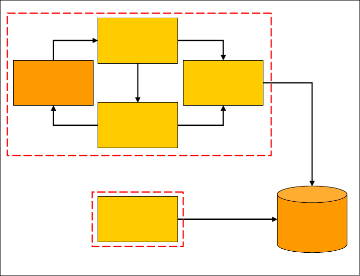
7672-intro-2-prog.fm Draft Document for Review December 9, 2008 2:44 pm
46 Rational Application Developer V7.5 Programming Guide
Figure 2-1 Simple Web application
Struts
The model-view-controller (MVC) architecture pattern is used widely in
object-oriented systems as a way of dividing applications into sections with
well-defined responsibilities:
Model: Manages the application domain’s concepts, both behavior and state.
It responds to requests for information about its state and responds to
instructions to change its state.
View: Implements the rendering of the model, displaying the results of
processing for the use, and manages user input.
Controller: Receives user input events, determines which action is
necessary, and delegates processing to the appropriate model objects.
In dynamic Web applications, the servlet normally fills the role of controller, the
JSP fills the role of view and various components, and JavaBeans or Enterprise
JavaBeans fill the role of model. The MVC pattern and Struts are is described in
in Chapter 15, “Develop Web applications using Struts” on page 445.
JavaServer
Page
Java
Servlet
Java
Application
JavaBean
Web
Browser
Relational
Database
Desktop
Application
Simple Web
Application
Chapter 2. Programming technologies 47
Draft Document for Review December 9, 2008 2:44 pm 7672-intro-2-prog.fm
In the context of our banking scenario, this technology does not relate to any
change in functionality from the user’s point of view. The problem being
addressed here is that, although many developers might want to use the MVC
pattern, Java EE 5 does not provide a standard way of implementing it. The
developers of the RedBank Web application want to design their application
according to the MVC pattern, but do not want to have to build everything from
the ground up.
Struts was introduced as a way of providing developers with an MVC framework
for applications using the Java Web technologies—servlets and JSPs. Complete
information on Struts is available at:
http://struts.apache.org/
Struts provides a controller servlets, called ActionServlet, which acts as the
entry point for any Struts application. When the ActionServlet receives a
request, it uses the URL to determine the requested action and uses an
ActionMapping object, created when the application starts up, based on
information in an XML file called struts-config.xml. From this ActionMapping
object, the Struts ActionServlet determines the action-derived class that is
expected to handle the request.
The Action object is then invoked to perform the required processing. This
Action object is provided by the developer using Struts to create a Web
application and can use any convenient technology for processing the request.
The Action object is the route into the model for the application. Once processing
has been completed, the Action object can indicate what should happen
next—the ActionServlet uses this information to select the appropriate
response agent (normally a JSP) to generate the dynamic content to be sent
back to the user. The JSP represents the view for the application.
Struts provides other features, such as form beans, to represent data entered
into HTML forms and JSP tag extensions to facilitate Struts JSP development.
Requirements for the development environment
Because Struts applications are also Web applications, all the functionality
described in “Simple Web applications” on page 39, is relevant in this context as
well. In addition, the development environment should provide:
Wizards to create:
– A Struts and Tiles enabled dynamic Web application
– A new Struts Action class and corresponding ActionMapping
–A new ActionForm bean
– A new Struts exception type
– A new Struts module
7672-intro-2-prog.fm Draft Document for Review December 9, 2008 2:44 pm
48 Rational Application Developer V7.5 Programming Guide
An editor to modify the struts-config.xml file.
A graphical editor to display and modify the relationship between Struts
elements, such as actions, action forms, and view components.
In addition, the basic Web application tools should be Struts-aware. The wizard
for creating Web applications should include a simple mechanism for adding
Struts support, and the wizard for creating JSPs should offer to add the
necessary Struts tag libraries.
IBM Rational Application Developer v7.5 provides all of these features.
Figure 2-1 on page 46 still represents the structure of a Web application using
Struts. Although Struts provides us with a framework on which we can build our
own applications, the technology is still the same as for basic Web applications.
JavaServer Faces (JSF) and persistence using SDO or JPA
When we build a GUI using stand-alone Java applications, we can include
event-handling code, so that when UI events take place they can be used
immediately to perform business logic processing or update the UI. Users are
familiar with this type of behavior in desktop applications, but the nature of Web
applications has made this difficult to achieve using a browser-based interface;
the user interface provided through HTML is limited, and the request-response
style of HTTP does not naturally lead to flexible, event-driven user interfaces.
Many applications require access to data, and there is often a requirement to be
able to represent this data in an object-oriented way within applications. Many
tools and frameworks exist for mapping between data and objects, but often
these are proprietary or excessively heavy weight systems.
In the RedBank Web application we want to make the user interface richer, while
still allowing us to use the MVC architecture described in “Struts” on page 46. In
addition, our developers want a simple, lightweight, object-oriented database
access system, which will remove the need for direct JDBC coding.
JavaServer Faces (JSF)
JavaServer Faces 1.2 is a framework for developing Java Web applications. The
JSF framework aims to unify techniques for solving a number of common
problems in Web application design and development, such as:
User interface development: JSF allows direct binding of user interface (UI)
components to model data. It abstracts request processing into an
event-driven model. Developers can use extensive libraries of prebuilt UI
components that provide both basic and advanced Web functionality.
Chapter 2. Programming technologies 49
Draft Document for Review December 9, 2008 2:44 pm 7672-intro-2-prog.fm
Navigation: JSF introduces a layer of separation between business logic and
the resulting UI pages; stand-alone flexible rules drive the flow of pages.
Session and object management: JSF manages designated model data
objects by handling their initialization, persistence over the request cycle, and
cleanup.
Validation and error feedback: JSF allows direct binding of reusable
validators to UI components. The framework also provides a queue
mechanism to simplify error and message feedback to the application user.
These messages can be associated with specific UI components.
Internationalization: JSF provides tools for internationalizing Web
applications, supporting number, currency, time, and date formatting, and
externalizing of UI strings. JSF is easily extended in a variety of ways to suit
the requirements of your particular application. You can develop custom
components, renderers, validators, and other JSF objects and register them
with the JSF runtime.
More information about JSF framework can be found here:
http://java.sun.com/javaee/javaserverfaces/
Service Data Objects (SDO)
SDO is a data programming architecture and API for the Java platform that
unifies data programming across data source types; provides robust support for
common application patterns; and enables applications, tools, and frameworks to
more easily query, view, bind, update, and introspect data.
SDO was originally developed by IBM and BEA Systems and is now the subject
of a Java specification request (JSR 235), but has not yet been standardized
under this process.
SDOs are designed to simplify and unify the way in which applications handle
data. Using SDO, application programmers can uniformly access and manipulate
data from heterogeneous data sources, including relational databases, XML data
sources, Web services, and enterprise information systems.
The SDO architecture consists of three major components:
Data object: The data object is designed to be an easy way for a Java
programmer to access, traverse, and update structured data. Data objects
have a rich variety of strongly and loosely typed interfaces for querying and
updating properties. This enables a simple programming model without
sacrificing the dynamic model required by tools and frameworks. A data
object can also be a composite of other data objects.
Data graph: SDO is based on the concept of disconnected data graphs. A
data graph is a collection of tree-structured or graph-structured data objects.
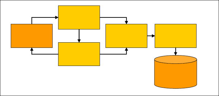
7672-intro-2-prog.fm Draft Document for Review December 9, 2008 2:44 pm
50 Rational Application Developer V7.5 Programming Guide
Under the disconnected data graphs architecture, a client retrieves a data
graph from a data source, mutates the data graph, and can then apply the
data graph changes to the data source. The data graph also contains some
meta data about the data object, including change summary and meta data
information. The meta data API allows applications, tools, and frameworks to
introspect the data model for a data graph, enabling applications to handle
data from heterogeneous data sources in a uniform way.
Data mediator: The task of connecting applications to data sources is
performed by a data mediator. Client applications query a data mediator and
get a data graph in response. Client applications send an updated data graph
to a data mediator to have the updates applied to the original data source.
This architecture allows applications to deal principally with data graphs and
data objects, providing a layer of abstraction between the business data and
the data source.
More information about SDO can be found here:
http://www.osoa.org/display/Main/Service+Data+Objects+Home
Requirements for the development environment
The development environment should provide tooling to create and edit pages
based on JSF, to modify the configuration files for JSF applications, and to test
them. For SDO, the development environment should provide wizards to create
SDOs from an existing database (bottom-up mapping) and should make it easy
to use the resulting objects in JSF and other applications.
IBM Rational Application Developer v7.5 includes these features.
Figure 2-2 shows how JSF and SDO can be used to create a flexible, powerful
MVC-based Web application with simple database access.
Figure 2-2 JSF and SDO
JSP using
JSF
JSF
Servlet SDO
Mediator
SDO
Web
Browser
Relational
Database
Chapter 2. Programming technologies 51
Draft Document for Review December 9, 2008 2:44 pm 7672-intro-2-prog.fm
JSF and Java Persistence API (JPA)
Application Developer v7.5 provides comprehensive tooling to develop JSF
applications that use JPA for persistence in relational databases.
Refer to Chapter 12, “Persistence using the Java Persistence API (JPA)” on
page 267 for information about JPA, and Chapter 16, “Develop Web applications
using JSF” on page 493 for an example of a JSF application with JPA.
Web 2.0 Development
IBM Rational Application Developer v7.5 comes with features to aid the
development of reponsive Rich Internet Applications.
More information about Web 2.0 development can be found in the redbook
Building Dynamic Ajax Applications Using WebSphere Feature Pack for Web 2.0,
SG24-7635.
Ajax
Ajax is an acronym that stands for Asynchronous JavaScript and XML. Ajax is a
Web 2.0 development technique used for creating interactive Web applications.
The intent is to make Web pages feel more responsive by exchanging small
amounts of data with the server behind the scenes. Technically, in order to send
and process a request to the server-side, the Web page will not require a reload.
JavaScript is utilized to gather DOM values on the page and data is transmitted
from the browser to the server through the XMLHTTPRequest object.
Figure 2-3 illustrates the overall Ajax interaction between the client browser and
the server-side application. The generic sequence of steps that get executed on
a typically Ajax submission are:
JavaScript functional invocation—Typically, when a Ajax call takes place,
the first step is to emulate what typically happens in a synchronous GET or
POST. That is, collect the information from the page that is necessary for
processing the server-side request. In the case of Ajax, the collection of these
values occurs through a JavaScript function (and retrieves DOM values).
XMLHttpRequest.send—Once we have collected all the necessary
information from the DOM, a JavaScript object is created and eventually
stores all the collected DOM values. In Mozilla-based browsers, this
JavaScript object is a XMLHttpRequest object. Once fully configured, the
XMLHttpRequest object is sent to the server-side via HTTP Request.

7672-intro-2-prog.fm Draft Document for Review December 9, 2008 2:44 pm
52 Rational Application Developer V7.5 Programming Guide
Server-side processing—Assuming that the application is based on Java
EE, from a Web tier, the Ajax request can either be handled by one of the
following Web technologies: Servlet, JSF or Portlet. Once received, the Ajax
request from the server-side will continue to execute as usual (accessing a
data store, executing business logic, and so forth).
XML response—Once the server completes processing, the resulting data is
returned in a response, typically in XML format.
XMLHttpRequest.callback—The callback function processes the response.
As part of the response, JavaScript function would have to take the response
values and update the page (by changing/updating DOM values).
Figure 2-3 Ajax overview
More information about Ajax can be found here:
http://www.ibm.com/developerworks/ajax
Application Developer v7.5 supports Ajax development with DOJO Toolkit and
IBM extensions.
Information about the DOJO Toolkit are here:
http://www.dojotoolkit.org
XMLHttpRequest
send()/callback() WebSphere
Application Server
DOM/User Interface data stores
JavaScript
function
invocation DOM
updates
HTTP Request
XML Response
Client Server-side
updates
Chapter 2. Programming technologies 53
Draft Document for Review December 9, 2008 2:44 pm 7672-intro-2-prog.fm
REST (Representational State Transfer)
Roy Thomas Fielding describes REST in a dissertation as a collection of
architecture principles and a software architecture style to build network-enabled
systems which define and access resources. It is often used like a framework to
transmit data over a protocol such as HTTP without adding additional semantic
layers or session management.
REST defines a strict separation of concerns between components that
participate in a client-server system that simplifies the implementation of actors
involved. REST also strives to simplify communication semantics in a network
system to increase scalability and improve performance. REST relies on
autonomous requests, between participants in a message exchange which
implies that requests must include all information that a client or server requires
to understand the context of the request. In a REST-based system, you use
minimal sets of possible requests to exchange standard media types.
The REST principle uses uniform resource identifiers (URIs) to locate and
access a given representation of a resource. The resource representation,
known as representational state, can be created, retrieved, modified, or deleted.
One of the defining principles of REST is that it can exploit existing technologies,
standards, and protocols pertaining to the Web, such as HTTP. This reliance on
existing technologies and protocols makes REST easier to learn and simpler to
use than most other Web-based messaging standards, because little additional
overhead is required to enable effective information exchange.
A REST-based conversation operates within stateless conversations, thereby
making it a prime facilitator for subscription-based technologies, such as RSS,
RDF, OWL, and Atom, in which content is delivered to pre-subscribed clients.
Roy Thomas Fielding’s dissertation Architectural Styles and the Design of
Network/based Software Architectures can be found here:
http://www.ics.uci.edu/~fielding/pubs/dissertation/fielding_dissertation.pdf
Application Developer v7.5 includes the tooling to create REST services to
access server-side artifacts through Web remote interfaces and to integrate
Atom and RSS feeds.
JSON (JavaScript Object Notation)
JSON is a lightweight data-interchange format. It is easy for humans to read and
write and for machines to parse and generate. It is based on a subset of the
JavaScript Programming Language and is built on two structures: A collection of
name/value pairs and an ordered list of values.
Further information is available at: http://www.json.org
7672-intro-2-prog.fm Draft Document for Review December 9, 2008 2:44 pm
54 Rational Application Developer V7.5 Programming Guide
Portal applications
Portal applications run on a Portal Server and consist of portal pages that are
composed of portlets. Portlets can share and exchange resources and
information to provide a seamless Web interface.
Portal applications have several important features:
They can collect content from a variety of sources and present them to the
user in a single unified format.
The presentation can be personalized so that each user sees a view based
on their own characteristics or role.
The presentation can be customized by the user to fulfill their specific needs.
They can provide collaboration tools, which allow teams to work in a virtual
office.
They can provide content to a range of devices, formatting and selecting the
content appropriately according to the capabilities of the device.
In the context of our sample scenario, we can use a portal application to enhance
the user experience. The RedBank Web application can be integrated with the
static Web content providing information about branches and bank services. If
the customer has credit cards, mortgages, personal loans, savings accounts,
shares, insurance, or other products provided by the bank or business partners,
these could also be seamlessly integrated into the same user interface, providing
the customer with a convenient single point of entry to all these services.
The content or these applications can be provided from a variety of sources, with
the portal server application collecting the content and presenting it to the user.
The user can customize the interface to display only the required components,
and the content can be varied to allow the customer to connect using a Web
browser, a personal digital assistant (PDA), or mobile phone.
Within the bank, the portal can also be used to provide convenient intranet
facilities for employees. Sales staff can use a portal to receive information on the
latest products and special offers, information from human resources, leads from
colleagues, and so on.
IBM WebSphere Portal
WebSphere Portal runs on top of WebSphere Application Server, using the Java
EE standard services and management capabilities of the server as the basis for
portal services. WebSphere Portal provides its own deployment, configuration,
administration, and communication features.
Chapter 2. Programming technologies 55
Draft Document for Review December 9, 2008 2:44 pm 7672-intro-2-prog.fm
Java Portlet specification
Based on its history there are different Portlet specifications in use:
IBM Portlet API—The IBM Portlet API is being deprecated for WebSphere
Portal v6.0, but still supported. No new functionality will be added and its
recommended you use the Standard Portlet API.
(http://publib.boulder.ibm.com/infocenter/wpdoc/v6r0)
JSR 168 Portlet Specification—Defines a set of APIs for Portal computing
addressing the areas of aggregation, personalization, presentation and
security. (http://www.jcp.org/en/jsr/detail?id=168)
JSR 286 Portlet Specification 2.0—Since its release in 2003, JSR 168 has
gone through many real-life tests in portal development and deployment.
Gaps identified by the community take time to evolve and become available to
the public as a standard. Meanwhile, many portal vendors have been filling
those gaps with their own custom solutions, which unfortunately cause
portlets to be not portable. That is the main reason for a new standard.
(http://www.jcp.org/en/jsr/detail?id=286)
Requirements for the development environment
The development environment should provide wizards for creating portal
applications and the associated components and configuration files, as well as
editors for all these files. A test environment should be provided to allow portal
applications to be executed and debugged.
Application Developer v7.5 includes the required tooling and is compatible with
WebSphere Portal v6.0 and v6.1 unit test environments.
Figure 2-4 shows how portal applications fit in with other technologies mentioned
in this chapter.

7672-intro-2-prog.fm Draft Document for Review December 9, 2008 2:44 pm
56 Rational Application Developer V7.5 Programming Guide
Figure 2-4 Portal applications
Enterprise JavaBeans and Java Persistence API (JPA)
Now that the RedBank Web application is up and running, more issues arise.
Some of these relate to the services provided to customers and bank workers
and some relate to the design, configuration, and functionality of the systems that
perform the back-end processing for the application.
First, we want to provide the same business logic in a new application that will be
used by administration staff working in the bank’s offices. We would like to be
able to reuse the code that has already been generated for the RedBank Web
application without introducing the overhead of having to maintain several copies
of the same code. Integration of these business objects into a new application
should be made as simple as possible.
Next, we want to reduce development time by using an object-relational mapping
system that will keep an in-memory, object-oriented view of data with the
relational database view automatically, and provide convenient mapping tools to
set up the relationships between objects and data. This system should be
Web
Browser PDA Mobile
Phone
WebSphere
Portal
Security
Services
Portal Portal Portal Portal
Collaboration
Application
Legacy
Application
Web
Service
Web
Application
Chapter 2. Programming technologies 57
Draft Document for Review December 9, 2008 2:44 pm 7672-intro-2-prog.fm
capable of dealing with distributed transactions, since the data might be located
on several different databases around the bank’s network.
Since we are planning to make business logic available to multiple applications
simultaneously, we want a system that will manage such issues as
multithreading, resource allocation, and security so that developers can focus on
writing business logic code without having to worry about infrastructure matters
such as these.
Finally, the bank has legacy systems, not written in Java, that we would like to be
able to update to use the new functionality provided by these business objects.
We would like to use a technology that will allow this type of interoperability
between different platforms and languages.
We can get all this functionality by using Enterprise JavaBeans (EJBs) and Java
Persistence API (JPA) to provide our back-end business logic and access to
data. Later, we will see how EJBs can also allow us to integrate messaging
systems and Web services clients with our application logic.
EJB 3.0 specification - What is new?
Enterprise JavaBeans 3.0 is a major enhancement to EJB specification,
introducing a new plain old Java object (POJO)-based programming model that
greatly simplifies development of Java EE applications. The main features are as
follows:
EJBs are now POJOs that expose regular business interfaces (plain old Java
interfaces - POJI), and there is no requirement for home interfaces.
Deployment descriptor information are replaced by annotations.
A complete new persistence model is provided (JPA) which supersedes
EJB 2.x entity beans.
Interceptor facility invokes user methods at the invocation of business
services or at life cycle events.
Adopts a annotation-based dependency injection pattern to obtain Java EE
resources (JDBC data sources, JMS factories and queues, and EJB
references).
Default values are provided whenever possible (“configuration by exception”
approach).
Usage of checked exceptions are reduced.
All life cycle methods are optional now.

7672-intro-2-prog.fm Draft Document for Review December 9, 2008 2:44 pm
58 Rational Application Developer V7.5 Programming Guide
More information about EJB 3.0 and JPA can be found in the IBM Redbooks
publication WebSphere Application Server V6.1 Feature Pack for EJB 3.0,
SG24-7611, in Chapter 12, “Persistence using the Java Persistence API (JPA)”
on page 267, in Chapter 14, “Develop EJB applications” on page 387, and here:
http://java.sun.com/products/ejb
Different types of EJBs
This section describes the two types of EJB 3.0: Session beans (stateless and
stateful) and Message-driven beans.
Session EJBs
Session EJBs are task-oriented objects, which are invoked by a client code. They
are non-persistent and will not survive an EJB container shutdown or crash.
Session beans often act as the external face of the business logic provided by
EJBs. The session facade pattern, described in many pattern catalogs including
Core J2EE Patterns: Best Practices and Design Strategies by Crupi, et al.,
describes this idea. The client application that needs to access the business logic
provided by some EJBs sees only the session beans. The low-level details of the
persistence mechanism are hidden behind these session beans (the session
bean layer is known as the session facade). As a result of this, the session beans
that make up this layer are often closely associated with a particular application
and might not be reusable between applications.
It is also possible to design reusable session beans, which might represent a
common service that can be used by many applications.
Stateless session EJBs
Stateless session EJBs are the preferred type of session EJB, because they
generally scale better than stateful session EJBs. Stateless beans are pooled by
the EJB container to handle multiple requests from multiple clients. In order to
permit this pooling, stateless beans cannot contain any state information that is
specific to a particular client. Because of this restriction, all instances of a
stateless bean are equivalent, allowing the EJB container to assign an instance
to any client. Stateless session EJBs are marked with the @Stateless annotation
and its business interface is annotated with the @Local (default) or @Remote
annotation.
Note: Entity beans as specified in Enterprise JavaBeans specification 2.x
have been replaced by Java Persistence API entities.
Chapter 2. Programming technologies 59
Draft Document for Review December 9, 2008 2:44 pm 7672-intro-2-prog.fm
Stateful session EJBs
Stateful session EJBs are useful when an EJB client needs to call several
methods and store state information in the session bean between calls. Each
stateful bean instance must be associated with exactly one client, so the
container is unable to pool stateful bean instances. Stateful session EJBs are
annotated with the @Stateful annotation.
Message-driven EJBs (MDBs)
MDBs are designed to receive and process messages. They can be accessed
only by sending a message to the messaging server that the bean is configured
to listen to. MDBs are stateless and can be used to allow asynchronous
communication between a client EJB logic via some type of messaging system.
MDBs are normally configured to listen to Java Message Service (JMS)
resources, although from EJB 2.1, other messaging systems can also be
supported. MDBs are normally used as adapters to allow logic provided by
session beans to be invoked via a messaging system; as such, they can be
thought of as an asynchronous extension of the session facade concept
described above, known as the message facade pattern. Message-driven beans
can only be invoked in this way and therefore have no specific client interface.
Message-driven EJBs are annotated with the @MessageDriven annotation.
Java Persistence API (JPA)
The Java Persistence API (JPA) provides an object-relational mapping facility for
managing relational data in Java applications. Entity beans as specified in the
EJB 2.x specification have been replaced by JPA entity classes. These classes
are annotated with the @Entity annotation. Entities may either use persistent
fields (mapping annotation is applied to entity’s instance variable) or persistent
properties (mapping annotation is applied to getter methods for JavaBeans-style
properties. All fields of a entity not annotated with the @Transient annotation or
not marked with the transient Java keyword will be persisted to the data store.
The object-relational mapping annotation must be applied to the instance
variables. The primary key field is simply annotated with the @Id annotation.
There are four types of multiplicities in entity relationships:
One-to-one (@OneToOne): Each entity instance is related to a single
instance of another entity.
One-to-many (@OneToMany): An entity instance can be related to multiple
instances of the other entities.
Many-to-one (@ManyToOne): Multiple instances of entity can be related to a
single instance of another entity.
7672-intro-2-prog.fm Draft Document for Review December 9, 2008 2:44 pm
60 Rational Application Developer V7.5 Programming Guide
Many-to-many (@MayToMany): The entity instances can be related to
multiple instances of each other.
Entities are managed by the entity manager. The entity manager is an instance
of javax.persistence.EntityManager and is associated with persistence
context. A persistence context defines the scope under which particular entity
instances are created, persisted, and removed. The EntityManager API creates
and removes persistent entity instances, finds entities by its primary key, and
allows queries to be run on entities. There are two kind of entity managers
available:
Container-managed entity manager: The persistence context is
automatically propagated by the container to all application components that
use the EntityManager instance within a single Java Transaction Architecture
(JTA) transaction. To obtain an EntityManager instance, inject the entity
manager into the application component:
@PersistenceContext
EntityManager em;
Application-managed entity manager: Used when applications need to
access a persistence context that is not propagated with the JTA transaction
across EntityManager instances in a particular persistence unit. In this case,
each EntityManager creates a new, isolated persistence context. To obtain an
EntityManager instance, inject an EntityManagerFactory into the application
component by means of the @PersistenceUnit annotation:
@PersistenceUnit
EntityManagerFactory emf;
Then, obtain an EntityManager from the EntityManagerFactory instance:
EntityManager em = emf.createEntityManager();
Other EJB and JPA features
This section describes other EJB features not discussed previously.
JPA query language (JPQL)
Java Persistence API specifies a query language that allows to define queries
over entities and their persistent state. The Java persistence query language
(JPQL) gives a way to specify the semantics of queries in a portable way,
independent of the particular database used in the enterprise environment.
JPQL is an extension of the Enterprise JavaBeans query language (EJB QL) and
is designed to combine the syntax and simple query semantics of SQL with the
expressiveness of an object-oriented expression language.
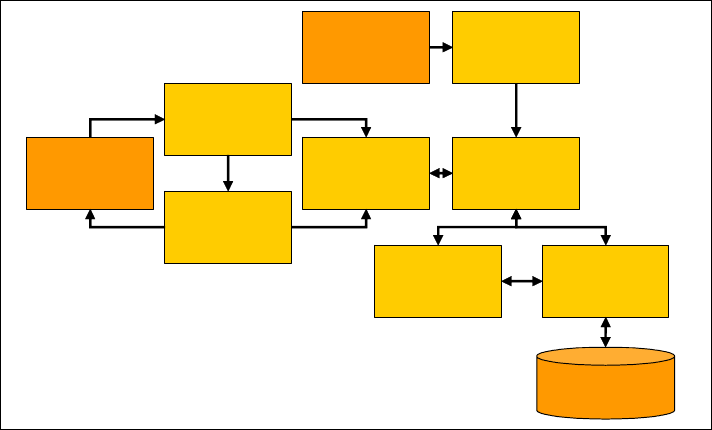
Chapter 2. Programming technologies 61
Draft Document for Review December 9, 2008 2:44 pm 7672-intro-2-prog.fm
Further information about JPQL can be found in the Java EE 5 Tutorial:
http://java.sun.com/javaee/5/docs/tutorial/doc/bnbtg.html
EJB timer service
The EJB timer service was introduced with EJB 2.1. A bean provider can choose
to implement the javax.ejb.TimedObject interface, which requires the
implementation of a single method, ejbTimeout. The bean creates a Timer object
by using the TimerService object obtained from the bean’s EJBContext. Once the
Timer object has been created and configured, the bean will receive messages
from the container according to the specified schedule; the container calls the
ejbTimeout method at the appropriate interval.
New in EJB 3.0 instead of implementing the javax.ejb.TimedObject interface,
the method that gets called by the timer service can be just annotated with the
@Timeout annotation.
Requirements for the development environment
The development environment should provide wizards for creating the various
types of EJB, tools for mapping JPA entities to relational database systems and
test facilities.
IBM Rational Application Developer v7.5 provides all these features.
Figure 2-5 shows how EJBs work with other technologies already discussed.
Figure 2-5 EJBs as part of an enterprise application
JavaServer
Page
Java
Servlet
Session
Bean
JavaBean
Web
Browser
Relational
Database
Message
Driven Bean
JMS
Provider
JPA
Entity
Entity
Manager
7672-intro-2-prog.fm Draft Document for Review December 9, 2008 2:44 pm
62 Rational Application Developer V7.5 Programming Guide
Java EE Application Clients
Java EE Application Clients are one of the four types of components defined in
the Java EE specification—the others being EJBs, Web components (servlets
and JSPs), and Java applets. They are stand-alone Java applications that use
resources provided by a Java EE application server, such as EJBs, data sources
and JMS resources.
In the context of our banking sample application, we want to provide an
application for bank workers who are responsible for creating accounts and
reporting on the accounts held at the bank. Since a lot of the business logic for
accessing the bank’s database has now been developed using EJBs, we want to
avoid duplicating this logic in our new application. Using a Java EE Application
Client for this purpose will allow us to develop a convenient interface, possibly a
GUI, while still allowing access to this EJB-based business logic. Even if we do
not want to use EJBs for business logic, a Java EE Application Client will allow us
to access data sources or JMS resources provided by the application server and
will allow us to integrate with the security architecture of the server.
Required Java EE Client Container APIs
The Java EE specification (available from http://java.sun.com/javaee/)
requires the following APIs to be provided to Java EE Application Clients:
In Java Platform, Standard Edition 5.0:
Java Interface Definition Language (IDL)
Java Data Base Connectivity (JDBC) 3.0
Java Remote Method Invocation over Internet Inter-Orb Protocol (RMI-IIOP)
Java Naming and Directory Interface (JNDI)
Java API for XML Processing (JAXP) 1.3
Java Authentication and Authorization Service (JAAS)
Java Management Extension (JMX)
Additional packages:
Enterprise JavaBeans (EJB) 3.0 Client API
Java Message Service (JMS) 1.1
JavaMail 1.4
Java Activation Framework (JAF) 1.1
Web Services 1.2
Java API for XML-Based RPC (JAX-RPC) 1.1
Java API for XML Web Services (JAX-WS) 2.0
Java Architecture for XML Binding (JAXB) 2.0
SOAP with Attachments API for Java (SAAJ) 1.3
Java API for XML Registries (JAXR) 1.0
Java EE Management 1.1
Chapter 2. Programming technologies 63
Draft Document for Review December 9, 2008 2:44 pm 7672-intro-2-prog.fm
Java EE Deployment 1.2
Web Services Metadata 2.0
Common Annotations 1.0
Streaming API for XML (StAX) 1.0
Java Persistence API (JPA) 1.0
Security
The Java EE specification requires that the same authentication mechanisms
should be made available for Java EE Application Clients as for other types of
Java EE components. The authentication features are provided by the Java EE
Application Client container, as they are in other containers within Java EE. A
Java EE platform can allow the Java EE Application Client container to
communicate with an application server to use its authentication services;
WebSphere Application Server allows this.
Naming
The Java EE specification requires that Java EE Application Clients should have
exactly the same naming features available as are provided for Web components
and EJBs. Java EE Application Clients should be able to use the Java Naming
and Directory Interface (JNDI) to look up objects using object references as well
as real JNDI names. The reference concept allows a deployer to configure
references that can be used as JNDI names in lookup code. The references are
bound to real JNDI names at deployment time, so that if the real JNDI name is
subsequently changed, the code does not have to be modified or
recompiled—only the binding needs to be updated.
References can be defined for:
EJBs (for Java EE Application Clients, only remote references, because the
client cannot use local interfaces)
Resource manager connection factories
Resource environment values
Message destinations
User transactions
ORBs
Code to look up an EJB might look like this (this is somewhat simplified):
accountHome = (AccountHome)initialContext
.lookup("java:comp/env/ejb/account");
java:comp/env/ is a standard prefix used to identify references, and ejb/account
would be bound at deployment time to the real JNDI name used for the Account
bean.
7672-intro-2-prog.fm Draft Document for Review December 9, 2008 2:44 pm
64 Rational Application Developer V7.5 Programming Guide
Deployment
The Java EE specification only specified the packaging format for Java EE
Application Clients, not how these should be deployed—this is left to the Platform
provider. The packaging format is specified, based on the standard Java JAR
format, and it allows the developer to specify which class contains the main
method to be executed at run time.
Java EE application clients for the WebSphere Application Server platform run
inside the Application Client for WebSphere Application Server. This is a product
that is available for download from developerWorks, as well the WebSphere
Application Server installation CD.
Refer to the WebSphere Application Server Information Center for more
information about installing and using the Application Client for WebSphere
Application Server.
The Application Client for WebSphere Application Server provides a
launchClient command, which sets up the correct environment for Java EE
Application Clients and runs the main class.
Requirements for the development environment
In addition to the standard Java tooling, the development environment should
provide a wizard for creating Java EE Application Clients, editors for the
deployment descriptor for a Java EE Application Client module, and a
mechanism for testing the Java EE Application Client.
Application Developer v7.5 provides these features.
Figure 2-6 shows how Java EE Application Clients fit into the picture. Because
these applications can access other Java EE resources, we can now use the
business logic contained in our session EJBs from a stand-alone client
application. Java EE Application Clients run in their own JVM, normally on a
different machine from the EJBs, so they can only communicate using remote
interfaces.

Chapter 2. Programming technologies 65
Draft Document for Review December 9, 2008 2:44 pm 7672-intro-2-prog.fm
Figure 2-6 Java EE Application Client
Web services
The bank’s computer system is now quite sophisticated, comprising:
A database for storing the bank’s data.
A Java application allowing bank employees to access the database.
A static Web site, providing information on the bank’s branches, products, and
services.
A Web application, providing Internet banking facilities for customers, with
various technology options available.
An EJB back-end, providing:
– Centralized access to the bank’s business logic through session beans.
– Transactional, object-oriented access to data in the bank’s database
through JPA entities.
A Java EE Application Client that can use the business logic in session
beans.
JavaServer
Page
Java
Servlet
Session
Bean
JavaBean
Web
Browser
Relational
Database
Message
Driven Bean
JMS
Provider
JPA
Entity
Entity
Manager
Java EE
Application
Client
7672-intro-2-prog.fm Draft Document for Review December 9, 2008 2:44 pm
66 Rational Application Developer V7.5 Programming Guide
So far, everything is quite self-contained. Although clients can connect from the
Web to use the Internet banking facilities, the business logic is all contained
within the bank’s systems, and even the Java application and Java EE
Application Client are expected to be within the bank’s private network.
The next step in developing our service is to enable mortgage agents, who
search many mortgage providers to find the best deal for their customers, to
access business logic provided by the bank to get the latest mortgage rates and
repayment information. While we want to enable this, we do not want to
compromise security, and we need to take into account that fact that the
mortgage brokers might not be using systems based on Java at all.
The League of Agents for Mortgage Enquiries has published a description of
services that its members might use to get this type of information. We want to
conform to this description in order to allow the maximum number of agents to
use our bank’s systems.
We might also want to be able to share information with other banks; for
example, we might want to exchange information on funds transfers between
banks. Standard mechanisms to perform these tasks have been provided by the
relevant government body.
These issues are all related to interoperability, which is the domain addressed by
Web services. Web services will allow us to enable all these different types of
communication between systems. We will be able to use our existing business
logic where applicable and develop new Web services easily where necessary.
Web services in Java EE 5
Web services provide a standard means of communication among different
software applications. Because of the simple foundation technologies used in
enabling Web services, it is very simple to provide a Web service regardless of
the platform, operating system, language, or technology used to implement it.
A service provider creates a Web service and publishes its interface and access
information to a service registry (or service broker). A service requestor locates
entries in the service registry, then binds to the service provider in order to invoke
its Web service.
Web services use the following standards:
Simple Object Access Protocol (SOAP): A protocol for exchanging
XML-based messages over computer networks, normally using HTTP or
HTTPS.

Chapter 2. Programming technologies 67
Draft Document for Review December 9, 2008 2:44 pm 7672-intro-2-prog.fm
Web Services Description Language (WSDL): Describes Web service
interfaces and access information.
Universal Description, Discovery, and Integration (UDDI): A standard
interface for service registries, which allows an application to find
organizations and services.
The specifications for these technologies are available at:
http://www.w3.org/TR/soap/
http://www.w3.org/TR/wsdl/
http://uddi.xml.org
Figure 2-7 shows how these technologies fit together.
Figure 2-7 Web services foundation technologies
Since Java EE 1.4, Web services are included in the specification, so all Java EE
application servers that support Java EE 1.4 or higher have exactly the same
basic level of support for Web services; some will also provide enhancements as
well.
Web Service
Description
Web Service
Web Service
Client
Web Service
Registry
create
use
reference
register
locate
search
retrieve
communicate
UDDI
SOAP
SOAP
7672-intro-2-prog.fm Draft Document for Review December 9, 2008 2:44 pm
68 Rational Application Developer V7.5 Programming Guide
Java EE 5 provides full support for both clients of Web services as well as web
services providers. The following Java technologies work together to provide
support for Web services:
Java API for XML Web Services (JAX-WS) 2.0: It is the primary API for Web
services and it is a follow-on to Java API for XML-based Remote Procedure
Call (JAX-RPC). JAX-WS offers extensive Web services functionality, with
support for multiple bindings/protocols and RESTful Web services. JAX-WS
and JAX-RPC are fully interoperable when using SOAP 1.1 over HTTP
protocol as constrained by the WS-I basic profile specification
(http://www.jcp.org/en/jsr/detail?id=224).
Java Architecture for XML Binding (JAXB) 2.0: It provides a convenient
way to bind an XML shema to a representation in Java code as used in SOAP
calls. This makes it easy to incorporate XML data and processing functions in
Java applications without having to know much about XML itself
(http://www.jcp.org/en/jsr/detail?id=222).
SOAP with Attachments API for Java (SAAJ) 1.3: Describes the standard
way to send XML documents as SOAP documents over the Internet from the
Java platform. It supports SOAP 1.2
(http://www.jcp.org/en/jsr/detail?id=67).
Streaming API for XML (StAX) 1.0: It is a streaming Java-based,
event-driven, pull-parsing API for reading and writing XML documents. StAX
enables to create bidirectional XML parsers that are fast, relatively easy to
program, and have a light memory footprint
(http://www.jcp.org/en/jsr/detail?id=173).
Web Services Metadata for the Java Platform: The Web Service Metadata
specification defines Java annotations that make it easier to develop Web
services (http://www.jcp.org/en/jsr/detail?id=186).
Java API for XML Registries (JAXR) 1.0: It provides client access to XML
registry and repository servers (http://www.jcp.org/en/jsr/detail?id=93).
Java API for XML Web Services Addressing (JAX-WSA) 1.0: It is an API
and framework for supporting transport-neutral addressing of Web services
(http://www.jcp.org/en/jsr/detail?id=261).
SOAP Message Transmission Optimization Mechanism (MTOM): It
enables SOAP bindings to optimize the transmission and/or wire format of a
SOAP message by selectively encoding portions of the message, whilst still
presenting an XML infoset to the SOAP application
(http://www.w3.org/TR/soap12-mtom/).
Web Services Reliable Messaging (WS-RM): It is a protocol that allows
messages to be delivered reliably between distributed applications in the
presence of software component, system, or network failures
(http://www.ibm.com/developerworks/library/specification/ws-rm/).
Chapter 2. Programming technologies 69
Draft Document for Review December 9, 2008 2:44 pm 7672-intro-2-prog.fm
Web Services for Java EE defines the programming and deployment model
for Web services in Java EE. It includes details of the client and server
programming models, handlers (a similar concept to servlets filters),
deployment descriptors, container requirements, and security
(http://www.jcp.org/en/jsr/detail?id=109) and
(http://www.jcp.org/en/jsr/detail?id=921).
Since interoperability is a key goal in Web services, an open, industry
organization known as the Web Services Interoperability Organization (WS-I,
http://ws-i.org/) has been created to allow interested parties to work together
to maximize the interoperability between Web services implementations. WS-I
has produced the following set of interoperability profiles:
WS-I Basic Profile 1.1
http://ws-i.org/Profiles/BasicProfile-1.1.html
WS-I Simple SOAP Binding Profile 1.0
http://ws-i.org/Profiles/SimpleSoapBindingProfile-1.0.html
WS-I Basic Security Profile 1.0
http://ws-i.org/Profiles/BasicSecurityProfile-1.0.html
WS-I Attachments Profile 1.0
http://ws-i.org/Profiles/AttachmentsProfile-1.0.html
Requirements for the development environment
The development environment should provide facilities for creating Web services
from existing Java resources—both JAX-WS or JAX-RPC service endpoint
implementations and stateless session EJBs. As part of the creation process, the
tools should also produce the required deployment descriptors and WSDL files.
Editors should be provided for WSDL files and deployment descriptors.
The tooling should also allow skeleton Web services to be created from WSDL
files and should provide assistance in developing Web services clients, based on
information obtained from WSDL files.
A range of test facilities should be provided, allowing a developer to test Web
services and clients as well as UDDI integration.
Application Developer v7.5 provides all this functionality.
Figure 2-8 shows how the Web services technologies fit into the overall
programming model we have been discussing.

7672-intro-2-prog.fm Draft Document for Review December 9, 2008 2:44 pm
70 Rational Application Developer V7.5 Programming Guide
Figure 2-8 Web services
Messaging systems
The bank has several automatic teller machines (ATMs) with an user interface
and communication support. The ATMs are designed to communicate with the
bank’s central computer systems using a secure, reliable, highly scalable
messaging system. We would like to integrate the ATMs with our system so that
transactions carried out at an ATM can be processed using the business logic we
have already implemented. Ideally, we would also like to have the option of using
EJBs to handle the messaging for us.
Many messaging systems exist that provide features like these. IBM’s solution in
this area is IBM WebSphere MQ, which is available on many platforms and
provides application programming interfaces in several languages. From the
point of view of our sample scenario, WebSphere MQ provides Java interfaces
that we can use in our applications—in particular, we will consider the interface
that conforms to the Java Message Service (JMS) specification. The idea of JMS
is similar to that of JDBC—a standard interface providing a layer of abstraction
for developers wishing to use messaging systems without being tied to a specific
implementation.
JavaServer
Page
Java
Servlet
Session
Bean
JavaBean
Web
Browser
Relational
Database
Web Service Web Service
Client
JPA
Entity
Entity
Manager
Web Service
Chapter 2. Programming technologies 71
Draft Document for Review December 9, 2008 2:44 pm 7672-intro-2-prog.fm
Java Message Service (JMS)
JMS defines (among other things):
A messaging model: The structure of a JMS message and an API for
accessing the information contained within a message. The JMS interface is,
javax.jms.Message, implemented by several concrete classes, such as
javax.jms.TextMessage.
Point-to-point (PTP) messaging: A queue-based messaging architecture,
similar to a mailbox system. The JMS interface is javax.jms.Queue.
Publish/subscribe (Pub/Sub) messaging: A topic-based messaging
architecture, similar to a mailing list. Clients subscribe to a topic and then
receive any messages that are sent to the topic. The JMS interface is
javax.jms.Topic.
More information on JMS can be found at:
http://java.sun.com/products/jms/
Message-driven EJBs (MDBs)
MDBs were introduced into EJB 2.0 and have been extended in EJB 2.1. MDBs
are designed to consume incoming messages sent from a destination or
endpoint system the MDB is configured to listen to. From the point of view of the
message-producing client, it is impossible to tell how the message is being
processed—whether by a stand-alone Java application, a MDB, or a
message-consuming application implemented in some other language. This is
one of the advantages of using messaging systems; the message-producing
client is very well decoupled from the message consumer (similar to Web
services in this respect).
From a development point of view, MDBs are the simplest type of EJB, since they
do not have clients in the same sense as session and entity beans. The only way
of invoking an MDB is to send a message to the endpoint or destination that the
MDB is listening to. In EJB 2.0, MDBs only dealt with JMS messages, but in
EJB 2.1 this is extended to other messaging systems. The development of an
MDB is different depending on the messaging system being targeted, but most
MDBs are still designed to consume messages through JMS, which requires the
bean class to implement the javax.jms.MessageListener interface, as well as
javax.ejb.MessageDrivenBean.

7672-intro-2-prog.fm Draft Document for Review December 9, 2008 2:44 pm
72 Rational Application Developer V7.5 Programming Guide
A common pattern in this area is the message facade pattern, as described in
EJB Design Patterns: Advanced Patterns, Processes and Idioms by Marinescu.
This book is available for download from:
http://theserverside.com/articles/
According to this pattern, the MDB simply acts as an adapter, receiving and
parsing the message, then invoking the business logic to process the message
using the session bean layer.
Requirements for the development environment
The development environment should provide a wizard to create MDBs and
facilities for configuring the MDBs in a suitable test environment. The test
environment should also include a JMS-compliant server.
Testing MDBs is challenging, since they can only be invoked by sending a
message to the messaging resource that the bean is configured to listen to.
However, WebSphere Application Server v7.0, which is provided as a test
environment within Rational Application Developer, includes an embedded JMS
messaging system that can be used for testing purposes. A JMS client must be
developed to create the test messages.
Figure 2-9 shows how messaging systems and MDBs fit into the application
architecture.
Figure 2-9 Messaging systems
Messaging
Server
Session
Bean
Message-Driven
Bean
Message
Producer
Application
Relational
Database
Web Service
Client
JPA
Entity
Entity
Manager
Web Service
Chapter 2. Programming technologies 73
Draft Document for Review December 9, 2008 2:44 pm 7672-intro-2-prog.fm
Summary
In this chapter we reviewed the basic technologies supported by Application
Developer: Desktop applications, static Web sites, dynamic Web applications,
Enterprise JavaBeans, Web services, and messaging.
7672-intro-2-prog.fm Draft Document for Review December 9, 2008 2:44 pm
74 Rational Application Developer V7.5 Programming Guide

© Copyright IBM Corp. 2008. All rights reserved. 75
Draft Document for Review December 9, 2008 2:44 pm 7672-intro-3-workbench.fm
Chapter 3. Workbench setup and
preferences
After installing IBM Rational Application Developer V7.0, the Workbench is
configured with a default configuration to make it easier to navigate for new
users. Developers are made aware of enabling the capabilities of Application
Developer, if needed. Alternatively, developers can configure the Workbench
preferences for their needs manually at any time. This chapter describes the
most commonly used Application Developer preferences.
The chapter is organized into the following sections:
Workbench basics
Preferences
Java development preferences
3
7672-intro-3-workbench.fm Draft Document for Review December 9, 2008 2:44 pm
76 Rational Application Developer V7.5 Programming Guide
Workbench basics
After starting Application Developer, after the installation, you see a single
window with the Welcome page (Figure 3-1). The Welcome page can be
accessed subsequently by selecting Help → Welcome from the Workbench
menu bar. The Welcome page is provided to guide a new user of Application
Developer to the various aspects of the tool.
Figure 3-1 Application Developer Workbench Welcome page
The Welcome page presents six icons, each including a description that is visible
through hover help (moving the mouse over an icon to display a description).
Table 3-1 provides a summary of each icon.
Chapter 3. Workbench setup and preferences 77
Draft Document for Review December 9, 2008 2:44 pm 7672-intro-3-workbench.fm
Table 3-1 Welcome page assistance capabilities
The Welcome page appearance can also be customized through the preferences
page. You can click the Customize Page icon on the top right corner of the
Welcome page to open the Preferences dialog (Figure 3-2). You can use this
preference page to select one of the pre-defined themes, which affects the
overall look of the welcome. You can also select which pages will be displayed,
and the visibility, layout, and priority of the items within each page.
Icon Image Name Description
Overview Provides an overview of the key functions in
Application Developer.
What’s New A description of the major new features and
highlights of the product.
Tutorials Tutorial screens to learn how to use key features
Application Developer. Provides a link to Tutorials
Gallery.
Samples Sample code for the user to begin working with
“live” examples with minimal assistance. Provides a
link to Samples Gallery
First Steps Step-by-step guidance to help first-time users to
perform some key tasks.
Web Resources URL links to Web pages where you can find
relevant and timely tips, articles, updates, and
references to industry standards.
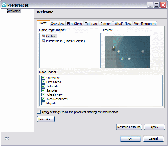
7672-intro-3-workbench.fm Draft Document for Review December 9, 2008 2:44 pm
78 Rational Application Developer V7.5 Programming Guide
Figure 3-2 Welcome page preferences
Users experienced with Application Developer or the concepts that the product
provides can close the Welcome page by clicking the X for the view to close it
down, or clicking the icon in the top right corner arrow. They will then be
presented with the default perspective, the J2EE perspective. Each perspective
in Application Developer contains multiple views, such as the Enterprise Explorer
view, Outline view, and others. More information regarding perspectives and
views are provided in Chapter 4, “Perspectives, views, and editors” on page 119.
The top right of the window has a shortcut icon (Figure 3-3), which allows you to
open available perspectives, and places them in the shortcut bar next to it. Once
the icons are on the shortcut bar, you are able to navigate between perspectives
that are already open. The name of the active perspective is shown in the title of
the window, and its icon is in the shortcut bar on the right side as a pushed
button.
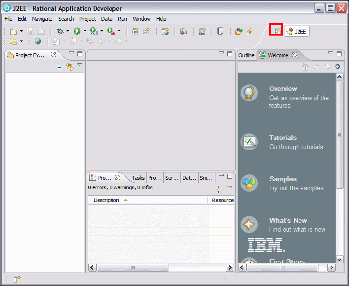
Chapter 3. Workbench setup and preferences 79
Draft Document for Review December 9, 2008 2:44 pm 7672-intro-3-workbench.fm
Figure 3-3 J2EE perspective in Rational Application Developer
The term Workbench refers to the desktop development environment. Each
Workbench window of Application Developer contains one or more perspectives.
Perspectives contain views and editors and control what appears in certain
menus and toolbars.
Workspace basics
When you start up Application Developer, you are prompted to provide a
workspace to start up. On the first startup, the path looks something like the
following sample, depending on the installation path:
c:\Documents and Settings\<user>\IBM\rationalsdp7.0\workspace
Where <user> is the Windows user ID you used to login.
The Application Developer workspace is a private work area created for the
individual developer, and it holds the following information:

7672-intro-3-workbench.fm Draft Document for Review December 9, 2008 2:44 pm
80 Rational Application Developer V7.5 Programming Guide
Application Developer environment meta data, such as configuration
information and temporary files
Projects that they have created, which includes source code, project
definition, or configuration files, and generate files, such as class files
Resources that are modified and saved are reflected on the local file system.
Users can have many workspaces on their local file system to contain different
projects that they are working on, or different versions. Each of these
workspaces can be configured differently, because they have their own copy of
meta data with configuration data for that workspace.
Application Developer allows you to open more than one Workbench at a time.
It opens another window into the same workspace, allowing you to work in two
differing perspectives. Changes that are made in one window are reflected to the
other windows. You are not permitted to work in more than one window at a time,
that is, you cannot switch between windows while in the process of using a
wizard in one window.
Opening a new Workbench in another window is done by selecting Window →
New Window, and a new Workbench with the same perspective will open in a
new window. As well as opening a perspective inside the current Workbench
window, new perspectives can also be opened in their own window. By default,
new perspectives are opened in the current window. This default behavior can be
configured using Window → Preferences → General → Perspectives (see
“Perspectives preferences” on page 95).
The default workspace can be started on first startup of Application Developer by
specifying the workspace location on the local machine and selecting the check
box Use this as the default and do not ask again, as shown in Figure 3-4.
This ensures that on the next startup of Application Developer that the
workspace automatically uses the directory specified initially, and it will not
prompt for the workspace in the future.
Important: Although workspace meta data stores configuration information,
this does not mean that the meta data can be transferred between
workspaces. In general, we do not recommend copying or using the meta data
in one workspace, with another workspace. The recommended approach is to
create a new workspace and then configure it appropriately.
Note: See “Setting the workspace with a prompt dialog” on page 83
describing how to reconfigure Application Developer prompting for the
workspace at startup.

Chapter 3. Workbench setup and preferences 81
Draft Document for Review December 9, 2008 2:44 pm 7672-intro-3-workbench.fm
Figure 3-4 Setting the default workspace on startup
The other way to enforce the use of a particular workspace is by using the -data
<workspace> command-line argument on Application Developer, where
<workspace> is a path name on the local machine where the workspace is
located, and should be a full path name to remove any ambiguity of location of
the workspace.
By using the -data argument, you can start a second instance of Application
Developer that uses a different workspace. For example, if your second instance
should use the MyWorkspace folder, you can launch Application Developer with
this command (assuming that the product has been installed in the default
installation directory):
c:\Program Files\IBM\SDP70\eclipse.exe -data c:\MyWorkspace
There are a number of arguments that you can add when launching Application
Developer; some useful arguments are explained in Table 3-2. More advanced
arguments can be found by searching for Running Eclipse in Help → Help
Contents.
Tip: On a machine where there are multiple workspaces used by the
developer, a shortcut would be the recommended approach in setting up the
starting workspace location. The target would be:
"<RAD Install Dir>\eclipse.exe" -product com.ibm.rational.rad.product.ide
-data <workspace>

7672-intro-3-workbench.fm Draft Document for Review December 9, 2008 2:44 pm
82 Rational Application Developer V7.5 Programming Guide
Table 3-2 Startup parameters
Memory considerations
Use the -vmargs argument to set limits to the memory that is used by Application
Developer. For example, with 1 GB RAM, you might be able to get better
performance by limiting the memory:
-vmargs -Xmx512M
Command Description
-configuration
configurationFileURL
The location for the Platform configuration file, expressed as
a URL. The configuration file determines the location of the
Platform, the set of available plug-ins, and the primary
feature. Note that relative URLs are not allowed. The
configuration file is written to this location when Application
Developer is installed or updated.
-consolelog Mirrors the Eclipse platform's error log to the console used
to run Eclipse. Handy when combined with -debug.
-data
<workspace directory>
Starts Application Developer with a specific workspace
located in <workspace directory>.
-debug [optionsFile] Puts the platform in debug mode and loads the debug
options from the file at the given location, if specified. This
file indicates which debug points are available for a plug-in
and whether or not they are enabled. If a file location is not
given, the platform looks in the directory that eclipse was
started from for a file called .options. Both URLs and file
system paths are allowed as file locations.
-refresh Option for performing a global fresh of the workspace on
startup to reconcile any changes made on the file system
since the platform was last run.
-showlocation
[workspaceName]
Option for displaying the location of the workspace in the
window title bar. In 3.2, an optional workspace name
argument was added that displays the provided name in the
window title bar instead of the location of the workspace.
-vm vmPath This optional option allows you to set the location of Java
Runtime Environment (JRE) to run Application Developer.
Relative paths are interpreted relative to the directory that
Eclipse was started from.
-vmargs -Xmx512M For large-scale development, you should modify your VM
arguments to make more heap available. This example
allows the Java heap to grow to 256 MB. This might not be
enough for large projects.

Chapter 3. Workbench setup and preferences 83
Draft Document for Review December 9, 2008 2:44 pm 7672-intro-3-workbench.fm
You can also modify VMArgs initialization parameters in the eclipse.ini file
(under the installation directory):
VMArgs=-Xms256M -Xmx512M
These arguments significantly limit the memory utilization. Setting the -Xmx
argument below 512M does begin to degrade performance.
Setting the workspace with a prompt dialog
The default behavior on installation is that Application Developer prompts for the
workspace on startup. If you selected the check box on the startup screen to not
ask again (Figure 3-4 on page 81), there is a procedure to turn on this option,
described as follows:
Select Window → Preferences.
In the Preferences dialog select General → Startup and Shutdown.
Select Prompt for workspace on startup and click OK (Figure 3-5).
Figure 3-5 Setting the prompt dialog box for workspace selection on startup
On the next startup of Application Developer, the workspace prompt dialog
appears, asking the user which workspace to use.

7672-intro-3-workbench.fm Draft Document for Review December 9, 2008 2:44 pm
84 Rational Application Developer V7.5 Programming Guide
Application Developer logging
Application Developer provides logging functionality for plug-in developers to log
and trace important events, primarily expected or unexpected errors. Log files
are a crucial part of the Application Developer problem determination process.
The primary reason to use log files is if you encounter unexpected program
behavior. In some cases, an error message tells you explicitly to look at the error
log.
The logging functionality provided by Application Developer Log and Trace
Analyzer implements common logging, which enables plug-ins to log events in a
common logging log file and logging agent. The Log and Trace Analyzer provides
a preferences window to configure the logging level for each of the plug-ins that
are configured to log events to the common log file and logging agent. To set the
level of records reported to the common log file and logging agent, do these
steps:
Select Window → Preferences, and select Logging.
Select a default logging level for the workbench from the Default logging level
list (Figure 3-6). You can also set the number of days after which archived log
files will be deleted. The default is 7 days. If you specify 0 for the number of
days, the archived files is never deleted.
Figure 3-6 Logging preferences: General tab
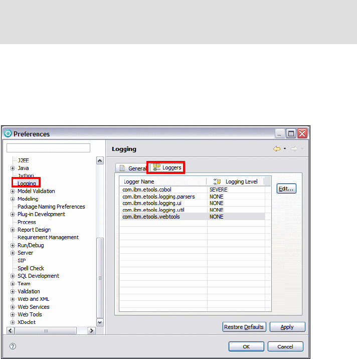
Chapter 3. Workbench setup and preferences 85
Draft Document for Review December 9, 2008 2:44 pm 7672-intro-3-workbench.fm
Select the Loggers tab.
For each plug-in, you can select the logging level. Only messages with the
same or higher logging level than the logging level selected will be logged
(Figure 3-7).
Figure 3-7 Logging preferences: Loggers tab
Log files
There are two main log files in the .metadata directory of the workspace folder:
CommonBaseEvents.xml: This log file is usually of interest to plug-in
developers. A new CommonBaseEvents.xml file is created every time you start
the workbench and the previous CommonBaseEvents.xml file is archived.
Archived file names have the form CommonBaseEventstimestamp.xml where
timestamp is the standard Java timestamp.
This log file can be imported into Log and Trace Analyzer for viewing,
analysis, sorting, filtering, and correlation.
Note: Logging is turned off by default unless plug-ins explicitly define a
logging level in their plugin.xml file. Changing the message level from NONE to
any other level will enable logging.

7672-intro-3-workbench.fm Draft Document for Review December 9, 2008 2:44 pm
86 Rational Application Developer V7.5 Programming Guide
.log: The .log file is used by the Application Developer to capture errors and
any uncaught exceptions from plug-ins. The .log file is cumulative, as each
new session of Application Developer appends its messages to the end of the
.log file without deleting any previous messages. This enables you to see a
history of past messages over multiple Application Developer sessions, each
one starting with the !SESSION string. This file is an ASCII file and can be
viewed with a text editor.
Preferences
The Application Developer Workbench preferences can be modified by selecting
Window → Preferences (Figure 3-8).
Figure 3-8 Workbench Preferences
In the left pane you can navigate through category of preferences. Each
preference has its own page, where you can change the initial options. The
Preferences dialog pages can be searched using the filter function.

Chapter 3. Workbench setup and preferences 87
Draft Document for Review December 9, 2008 2:44 pm 7672-intro-3-workbench.fm
This section describes the most important workbench preferences. Application
Developer contains a complete description of all the options available in the
preferences dialogs and Application Developer’s help.
Automatic builds
Builds, or a compilation of Java code in Application Developer, are done
automatically whenever a resource has been modified and saved. If you require
more control regarding builds, you can disable the automatic build feature, then
to perform a build you have to explicitly start it. This might be desirable in cases
where you know that building is of no value until you finish a large set of changes.
If you want to turn off the automatic build feature, select Windows
→
Preferences
→
General
→
Workspace and clear Build automatically
(Figure 3-9).
Figure 3-9 Workbench Preferences: Automatic builds
Tip: Each page of Application Developer’s preferences dialog contains a
Restore Defaults button (see Figure 3-8 on page 86). If the button is clicked,
Application Developer restores the settings of the current dialog to their initial
values.
7672-intro-3-workbench.fm Draft Document for Review December 9, 2008 2:44 pm
88 Rational Application Developer V7.5 Programming Guide
In this same dialog you can specify whether you want unsaved resources to be
saved before performing a manual build. Select Save automatically before
build to enable this feature.
Manual builds
Although the automatic build feature might be adequate for many developers,
there are a couple of scenarios in which a developer might want to perform a
build manually. First, some developers do not want to build automatically
because it can slow down development. In this case the developer needs a
method of building at the time of their choosing. Second, there are cases when
you want to force a build of a project or all projects to resolve build errors and
dependency issues. To address these types of issues, Application Developer
provides the ability to perform a manual build, known as a clean build.
To perform a manual build, do these steps:
Select the desired project in the Enterprise Explorer.
Select Project → Build Automatically to clear the check associated with that
selection. Manual build option is only available when the automatic build is
disabled.
Select Project → Build Project. Alternatively, select Project → Build All to
build all projects in the workspace. Both of these commands search through
the projects and only build the resources that have changed since the last
build.
To build all resources, even those that have not changed since the last build, do
these steps:
Select the desired project in the Enterprise Explorer.
Select Project → Clean.
In the Clean dialog select one of the following options and click OK:
– Clean all projects: This performs a build of all projects.
– Clean selected projects: <project> (The project selected in the previous
step is selected by default or you can select it from the projects list.)
Capabilities
Application Developer has the ability to enable and disable capabilities in the
tooling. The default setup does not enable some of the capabilities, such as team
support for Rational ClearCase, Web services development, or profiling and
logging.

Chapter 3. Workbench setup and preferences 89
Draft Document for Review December 9, 2008 2:44 pm 7672-intro-3-workbench.fm
Capabilities can be enabled in a number of ways in Application Developer. We
describe how to enable capabilities through the following mechanisms:
Welcome page
Windows preferences
Opening a perspective
Enable capability through the Welcome page
The Welcome page provides an icon in the shape of a human figure in the
bottom right-hand corner used to enable roles (Figure 3-10). These assist in
setting up available capabilities for the user of the tool through the following
process.
The scenario that we will attempt is enable the team capability or role so that the
developer can save their resources in a repository.
In the Welcome page move the mouse to the bottom right corner over the
human figure. Click the icon.
Move the mouse until it is over the desired capability or role, and click the
icon. For example, move the mouse over the Team capability or role so
that it is highlighted and a matching text is shown at the top (Figure 3-10), and
click the icon; this enables the Team capability.
Figure 3-10 Enable Team capability or role in the Welcome page
Tip: You can display the Welcome page by selecting Help → Welcome.
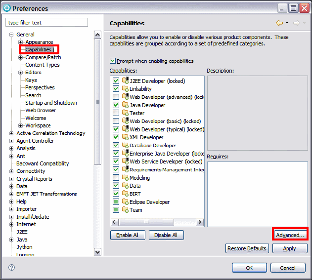
7672-intro-3-workbench.fm Draft Document for Review December 9, 2008 2:44 pm
90 Rational Application Developer V7.5 Programming Guide
Enable capability through Windows Preferences
To enable the Team capability using the preferences dialog, do these steps:
Select Window → Preferences → General → Capabilities and click
Advanced (Figure 3-11).
Figure 3-11 Setting the Team capability using Windows preferences: Part 1
In the Advanced dialog expand Team.
Select the Team check box, and this selects the check boxes for all
components under this tree (Figure 3-12).
Click Apply and then click OK. Now all Team capability is enabled.

Chapter 3. Workbench setup and preferences 91
Draft Document for Review December 9, 2008 2:44 pm 7672-intro-3-workbench.fm
Figure 3-12 Setting the Team capability using Windows preferences: Part 2
Enable a capability by opening a perspective
A capability can be enabled by opening the particular perspective required by the
capability. To enable the Profiling and Logging capability by opening a
perspective, do these steps:
Select Window → Open Perspective → Other.
Select Show all and select Profiling and Logging (Figure 3-13).
Click OK.
In the Confirm Enablement dialog click OK, and optionally select Always
enable capabilities and don’t ask me again.
This enables the Profiling and Logging capability and open the Profiling and
Logging perspective.
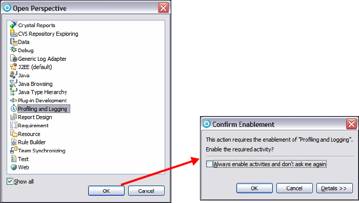
7672-intro-3-workbench.fm Draft Document for Review December 9, 2008 2:44 pm
92 Rational Application Developer V7.5 Programming Guide
Figure 3-13 Enable capability by opening a perspective
File associations
The File Associations preferences page enables you to add or remove file types
recognized by the Workbench. You can also associate editors or external
programs with file types in the file types list. To open the preferences page, do
these steps:
Select Window → Preferences → General → Editors → File Associations
(Figure 3-14).
The top right pane allows you to add and remove the file types. The bottom right
pane allows you to add or remove the associated editors.
To add a file association, do these steps:
We add the Internet Explorer® as an additional program to open .ddl
(database definition language) files. Select *.ddl from the file types list and
click Add next to the associated editors pane.
In the Editor Selection dialog select External Programs and click Browse.
Locate iexplore.exe in the folder where Internet Explorer is installed (for
example, C:\Program Files\Internet Explorer), and click Open.
Click OK in the Editor Selection dialog and the program is added to the
editors list.
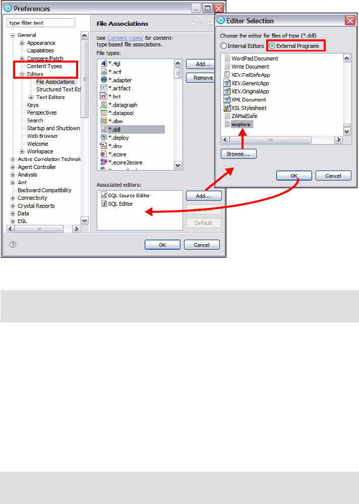
Chapter 3. Workbench setup and preferences 93
Draft Document for Review December 9, 2008 2:44 pm 7672-intro-3-workbench.fm
Figure 3-14 File associations preferences
Now you can open a .ddl file by using the context menu on the file and selecting
Open With, and selecting the appropriate program.
Local history
A local history of a file is maintained when you create or modify a file. A copy is
saved each time you edit and save the file. This allows you to replace the current
file with a previous edition or even restore a deleted file. You can also compare
the content of all the local editions. Each edition in the local history is uniquely
represented by the data and time the file has been saved.
Note: Optionally, you can set this program as the default program for this file
type by clicking Default.
iexplore
Note: Only files have local history. Projects and folders do not have a local
history.
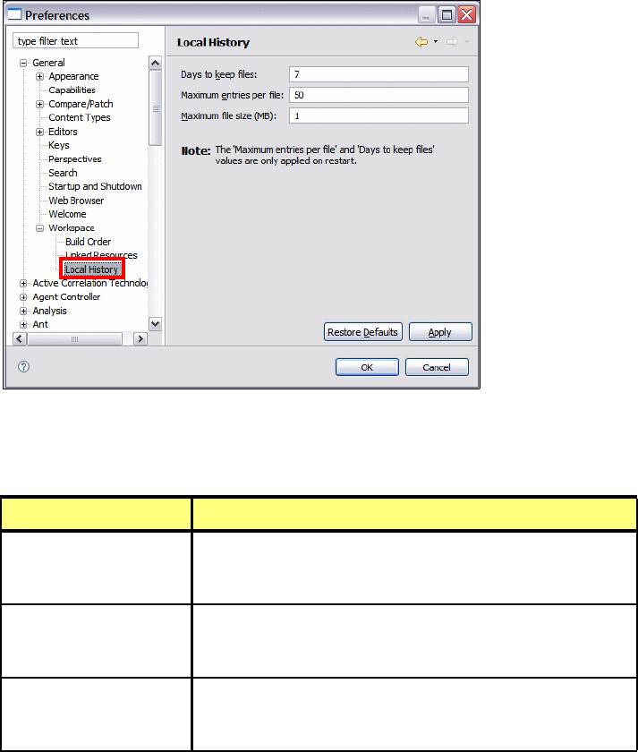
7672-intro-3-workbench.fm Draft Document for Review December 9, 2008 2:44 pm
94 Rational Application Developer V7.5 Programming Guide
To configure local history settings, select Window → Preferences → General →
Workspace → Local History to open its preferences page (Figure 3-15).
Figure 3-15 Local history preferences
Table 3-3 explains the options for the local history preferences.
Table 3-3 Local history settings
Compare, replace, and restore local history
To compare a file with the local history, do these steps:
This procedure assumes that you have a Java file in your workspace. If you
do not, you should add or create a file.
Option Description
Days to keep files Indicates for how many days you want to maintain changes
in the local history. History states older than this value are
lost.
Maximum entries per
file
Indicates how many history states per resource you want to
maintain in the local history. If you exceed this value, you will
lose older history to make room for new history.
Maximum file size (MB) Indicates the maximum size of individual states in the history
store. If a resource is over this size, no local history is kept
for that resource.
Chapter 3. Workbench setup and preferences 95
Draft Document for Review December 9, 2008 2:44 pm 7672-intro-3-workbench.fm
Select the Java file, right-click, and select Compare With → Local History.
In the upper pane of the Compare with Local History dialog, all available
editions of the file in the local history are displayed.
Select an edition in the upper pane to view the differences between the
selected edition and the edition in the workbench.
If you are done with the comparison, click OK.
To replace a file with an edition from the local history, do these steps:
This assumes you have a Java file in your workspace. If you do not, add or
create a file.
Select the file, right-click, and select Replace With → Local History.
Select the desired file time stamp and then click Replace.
To restore a deleted file from the local history, do these steps:
Select the folder or project into which you want to restore the deleted file.
Right-click and select Restore from Local History.
Select the files that you want to restore and click Restore.
Perspectives preferences
The Perspectives preferences page enables you to manage the various
perspectives defined in the Workbench. To open the page, select Window →
Preferences → General → Perspectives (Figure 3-16).
You can change the following options in the Perspective preferences:
Open a new perspective in the same or in a new window.
Open a new view within the perspective or as a fast view (docked to the side
of the current perspective).
The option to always switch, never switch, or prompt when a particular project
is created to the appropriate perspective.
There is also a list with all available perspectives where you can select the
default perspective. If you have added one or more customized perspectives, you
can delete them from here.
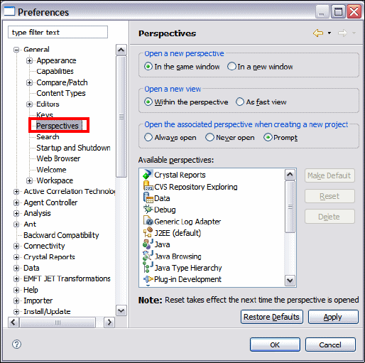
7672-intro-3-workbench.fm Draft Document for Review December 9, 2008 2:44 pm
96 Rational Application Developer V7.5 Programming Guide
Figure 3-16 Perspectives preferences
Web Browser preferences
The Web browser settings allow the user to select which Web browser is the
default browser used by Application Developer for displaying Web information.
To change the Web browser settings,, do these steps:
Select Window → Preferences → General → Web Browser (Figure 3-17).
The default option is to use the internal Web browser. To change, select Use
external Web browser and select a browser from the available list; otherwise
you can click New to add a new Web browser.
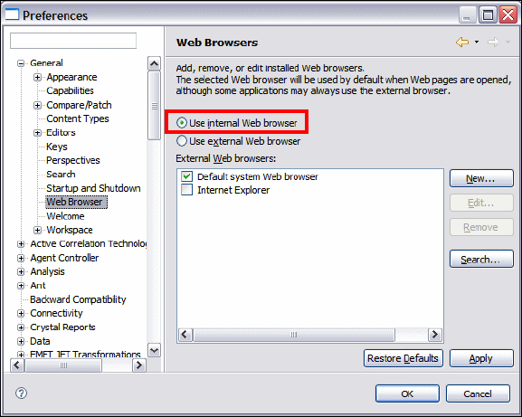
Chapter 3. Workbench setup and preferences 97
Draft Document for Review December 9, 2008 2:44 pm 7672-intro-3-workbench.fm
Figure 3-17 Web Browser preferences
Internet preferences
The Internet preferences in Application Developer have three types of settings
available to be configured:
Cache
FTP
Proxy settings
Only proxy settings is covered in this section, with the other two settings you can
refer to Application Developer’s help.
Proxy settings
When using Application Developer and working within an intranet, you might
want to use a proxy server to get across a company firewall to access the
Internet.
To set the preferences for the HTTP proxy server within the Workbench to allow
Internet access from Application Developer, do these steps:
Select Window → Preferences → Internet → Proxy Settings (Figure 3-18).
Select Enable Proxy and enter the proxy host and port. There are additional
optional settings for the use of SOCKS and enabling proxy authentication.
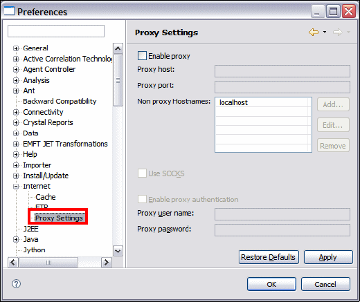
7672-intro-3-workbench.fm Draft Document for Review December 9, 2008 2:44 pm
98 Rational Application Developer V7.5 Programming Guide
Click Apply and then OK.
Figure 3-18 Internet proxy settings preferences
Java development preferences
Application Developer provides a number of preferences in different categories
such as Java, Web tools, XML, SQL development, and plug-in development. This
section only covers the most commonly used Java development preferences.
More information about the other preferences are provided in relevant chapters
of this book.
Java classpath variables
Application Developer provides a number of default classpath variables that can
be used in a Java build path to avoid a direct reference to the local file system in
a project. This method ensures that the project only references classpaths using
the variable names and not specific local file system directories or paths. This is
a good programming methodology when developing within a team and using
multiple projects using the same variables. This means that all team members
have to set the variables required for a project, and this data is maintained in the
workspace.
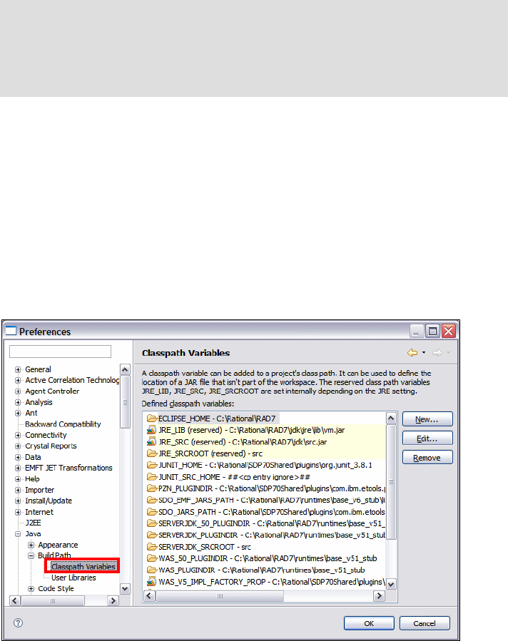
Chapter 3. Workbench setup and preferences 99
Draft Document for Review December 9, 2008 2:44 pm 7672-intro-3-workbench.fm
Depending on the type of Java coding you plan to do, you might have to add
variables pointing to other code libraries. For example, this can be driver classes
to access relational databases or locally developed code that you want to reuse
in other projects. Once you have created a Java project, you can add any of
these variables to the project’s classpath.
To configure the default classpath variables, do these steps:
Select Window → Preferences → Java → Build Path → Classpath
Variables.
A list of the existing classpath variables is displayed (Figure 3-19).
Figure 3-19 Classpath variables preferences
Creation, editing, or removing of variables can be performed in this screen.
Click New to add a new variable.
In the New Variable Entry dialog, enter the name of the variable and browse
for the path and click OK (Figure 3-20).
Tip: We recommend that you standardize the Application Developer
installation path for your development team. Many files within the projects
have absolute paths based on the Application Developer installation path, thus
when you import projects from a team repository such as CVS or ClearCase,
you will get errors even when using classpath variables.
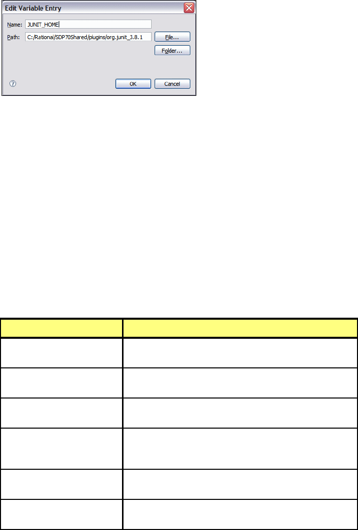
7672-intro-3-workbench.fm Draft Document for Review December 9, 2008 2:44 pm
100 Rational Application Developer V7.5 Programming Guide
Figure 3-20 New Variable Entry dialog
Certain class path variables are set internally and cannot be changed in the
Classpath variables preferences:
JRE_LIB: The archive with the runtime JAR file for the currently used JRE.
JRE_SRC: The source archive for the currently used JRE.
JRE_SRCROOT: The root path in the source archive for the currently used JRE.
Appearance of Java elements
The appearance and the settings of associated Java elements in views, such as
methods, members, and their access types, can be configured:
Select Window → Preferences → Java → Appearance.
The Appearance preferences page is displayed (Figure 3-21) with
appearance check boxes as described in Table 3-4.
Table 3-4 Description of appearance settings for Java views
Appearance setting Description
Show method return types If selected, methods displayed in views show the return
type.
Show method type
parameters
If selected, methods displayed in views show their type
parameters.
Show categories If selected, method, field, and type labels contain the
categories specified in their Javadoc™ comment.
Show members in Package
Explorer
If selected, displays the members of the class and their
scope such as private, private or protected, including
others.
Fold empty packages in
hierarchical layout
If selected, folds the empty packages that do not
contain resources or other child elements.
Compress package name
segments
If selected, compresses the name of the package based
on a pattern supplied in the dialog below the check box.
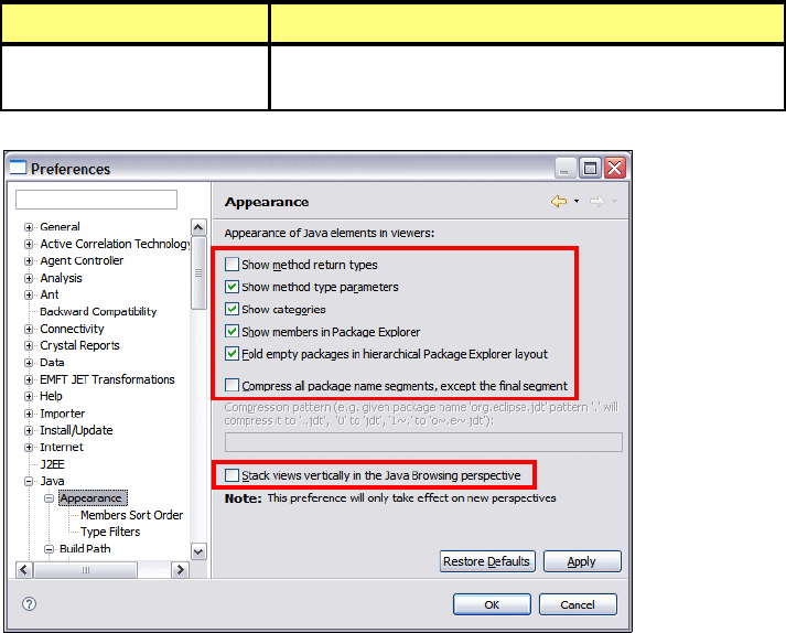
Chapter 3. Workbench setup and preferences 101
Draft Document for Review December 9, 2008 2:44 pm 7672-intro-3-workbench.fm
Figure 3-21 Java appearance settings
To change the appearance of the order of the members to be displayed in the
Java viewers, do these steps:
In the Preferences dialog select Java → Appearance → Members Sort
Order. This preference allows you to display the members in the order you
prefer, as well as the order of scoping within that type of member.
Select the order in which members will be displayed using the Up and Down
buttons. You can also sort in same category by visibility.
Click Apply and then OK.
To specify types and packages to hide in the Open Type dialog and content
assist or quick fix proposals, do these steps:
In the Preferences dialog select Java → Appearance → Type Filters.
You can either create a new filter or add packages to the type filter list. The
default is to hide nothing.
Stack views vertically in the
Java Browsing perspective
If selected, displays the views in the Java Browsing
perspective vertically rather than horizontally.
Appearance setting Description

7672-intro-3-workbench.fm Draft Document for Review December 9, 2008 2:44 pm
102 Rational Application Developer V7.5 Programming Guide
Code style and formatting
The Java editor in the Workbench can be configured to format code and coding
style in conformance to personal preferences or team-defined standards. When
setting up the Workbench, you can decide what formatting style should be
applied to the Java files created using the wizards, as well as how the Java
editors operate to assist what has been defined.
Code style
The Java code style preferences allow you to configure naming conventions,
style rules and comment settings.
To demonstrate setting up a style, we define a sample style in which the following
conventions are defined:
Member attributes or fields will be prefixed by an m.
Static attributes or fields will be prefixed by an s.
Parameters of methods will be prefixed by a p.
Local variables can have any name.
Boolean getter methods will have a prefix of is.
To configure the customized style, do these steps:
Select Windows → Preferences → Java → Code Style (Figure 3-22).
Select the Fields row and click Edit.
In the Field Name Conventions dialog enter m in the Prefix list field and click
OK.
Repeat the same steps for all the conventions defined above.
Important: Working in a team environment requires a common understanding
between all the members of the team regarding the style of coding and
conventions such as class, member, and method name definitions. The coding
standards have to be documented and agreed upon to ensure a consistent
and standardized method of operation.
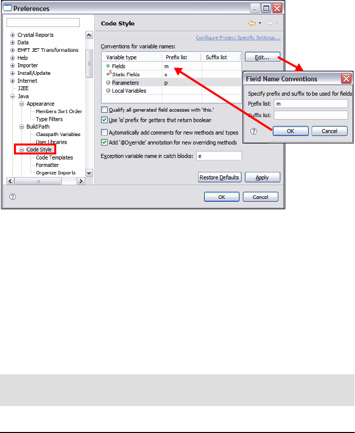
Chapter 3. Workbench setup and preferences 103
Draft Document for Review December 9, 2008 2:44 pm 7672-intro-3-workbench.fm
Figure 3-22 Code style preferences
These coding conventions are used in the generation of setters and getters for
Java classes:
Whenever a prefix of m followed by a capital letter is found on an attribute, this
would ignore the prefix and generate a getter and setter without the prefix.
If the prefix is not found followed by a capitalized letter, then the setter and
getter would be generated with the first letter capitalized followed by the rest
of the name of the attribute.
An example of the outcome of performing code generation of a getter is shown in
Example 3-1 for some common examples of attributes.
Example 3-1 Example snippet of code generation output for getters
private long mCounter;
private String maddress;
private float m_salary;
private int zipcode;
/**
* @return the m_salary
*/
public float getM_salary() {
Note: The capitalization of getters in Application Developer is based on the
way the attributes are named.
7672-intro-3-workbench.fm Draft Document for Review December 9, 2008 2:44 pm
104 Rational Application Developer V7.5 Programming Guide
return m_salary;
}
/**
* @return the maddress
*/
public String getMaddress() {
return maddress;
}
/**
* @return the counter
*/
public long getCounter() {
return mCounter;
}
/**
* @return the zipcode
*/
public int getZipcode() {
return zipcode;
}
The settings described in Table 3-5 specify how newly generated code should
look like. These settings are configured in the Code Style preferences page
(Figure 3-22 on page 103).
Table 3-5 Description of code style settings
Action Description
Qualify all generated field
accesses with 'this.'
If selected, field accesses are always prefixed with
this., regardless whether the name of the field is
unique in the scope of the field access or not.
Use 'is' prefix for getters that
return boolean
If selected, the names of getter methods of boolean
type are prefixed with is rather than get.
Automatically add comments
for new methods and types
If selected, newly generated methods and types are
automatically generated with comments where
appropriate.
Add '@Override' annotation
for overriding methods
If selected, methods which override an already
implemented method are annotated with an @Override
annotation.
Exception variable name in
catch blocks
Specify the name of the exception variable declared in
catch blocks.
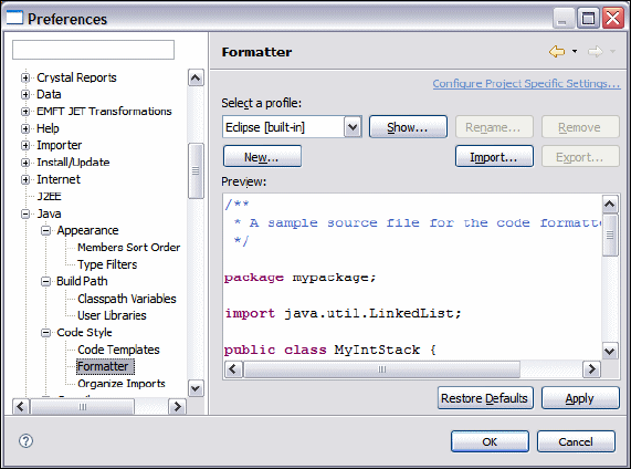
Chapter 3. Workbench setup and preferences 105
Draft Document for Review December 9, 2008 2:44 pm 7672-intro-3-workbench.fm
Formatter
The formatter preferences in Application Developer are used to ensure that the
format of the Java code meets the standard defined for a team of developers
working on code. There are three profiles built-in with Application Developer with
the option of creating new profiles specific for your project:
Eclipse (default profile on startup for Application Developer)
Eclipse 2.1 (similar to WebSphere Studio V5)
Java Conventions
To configure the formatter, do these steps:
Select Window → Preferences → Java → Code Style → Formatter
(Figure 3-23).
To display the information about a profile, click Show, or to create a new
profile click New.
An existing profile can also be loaded by clicking Import.
Figure 3-23 Formatter preferences
Enforcing coding standards
The code formatting rules are enforced on code when a developer has entered
code using their own style, and which does not conform to the team-defined
standard. When this is the case, after the code has been written and tested and
preferably before adding the code to the team repository, we recommend that the
code is formatted.

7672-intro-3-workbench.fm Draft Document for Review December 9, 2008 2:44 pm
106 Rational Application Developer V7.5 Programming Guide
The procedure to perform this operation is described here:
In the Java editor, right-click, and select Source → Format. This formatting
uses the rules that have been defined in the formatter preferences.
Creating a user-defined profile
User-defined profiles are established from one of the existing built-in profiles,
which can be exported to the file system to share with team members. If the
existing profile is modified then you are prompted to create a new profile. Any
profile that is created can be exported as an XML file that contains the
standardized definitions required for your project. This can then be stored in a
team repository and imported by each member of the team.
A profile consists of a number of sections that are provided as tab sections to
standardize on the format and style that the Java code is written (Figure 3-24).
Each of these tab sections are self-explanatory and provide a preview of the
code after selection of the required format.
Figure 3-24 Formatter preferences: Eclipse profile
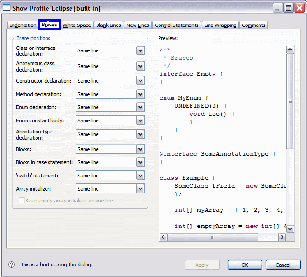
Chapter 3. Workbench setup and preferences 107
Draft Document for Review December 9, 2008 2:44 pm 7672-intro-3-workbench.fm
The definition of these tabs are described as follows:
Indentation: Specifies the indentations that you wish on your Java code in
the Workbench (Figure 3-24). The area it covers includes:
–Tab spacing
– Alignment of fields
– Indentation of code
Braces: Formats the Java style of where braces are placed for a number of
Java language concepts. A preview is provided as you select the check boxes
to ensure that it fits in with the guidelines established in your team
(Figure 3-25).
Figure 3-25 Formatter: Braces
White Space: Format where the spaces are placed in the code based on a
number of Java constructs (Figure 3-26).

7672-intro-3-workbench.fm Draft Document for Review December 9, 2008 2:44 pm
108 Rational Application Developer V7.5 Programming Guide
Figure 3-26 Formatter: White Space
Blank Lines: Specify where you want to place blank lines in the code for
readability or style guidelines, for example:
– Before and after package declaration
– Before and after import declaration
– Within a class:
• Before first declaration
• Before field declarations
• Before method declarations
• At the beginning of a method body
New Lines: Specifies the option of where you want to insert a new line, for
example:
– In empty class body
– In empty method body
– In empty annotation body
– At end of file
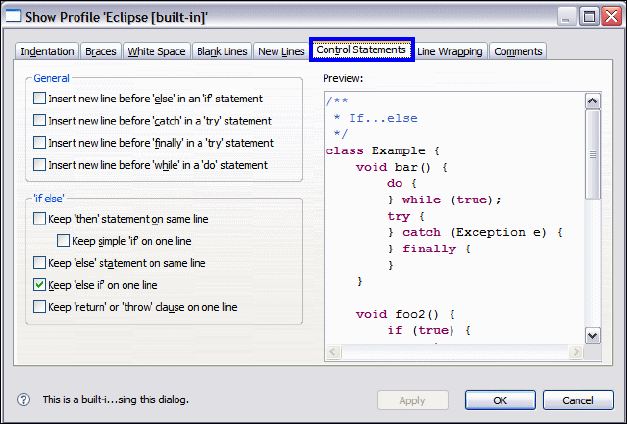
Chapter 3. Workbench setup and preferences 109
Draft Document for Review December 9, 2008 2:44 pm 7672-intro-3-workbench.fm
Control Statements: Control the insertion of lines in control statements, as
well as the appearance of if else statements of the Java code (Figure 3-27).
Figure 3-27 Formatter: Control Statements
Line Wrapping: Provides the style rule on what should be performed with the
wrapping of code, for example:
– Maximum line width (default is 80)
– Default indentation (2)
– How declarations, constructors, function calls, and expressions are
wrapped
Comments: Determine the rules of the look of general comments and of
Javadoc that are in the Java code.
Java editor settings
The Java editor has a number of settings that assist in the productivity of the user
in Application Developer. Most of these options relate to the look and feel of the
Java editor in the Workbench. To configure Java editor preferences, do these
steps:
Select Windows → Preferences → Java → Editor (Figure 3-28).

7672-intro-3-workbench.fm Draft Document for Review December 9, 2008 2:44 pm
110 Rational Application Developer V7.5 Programming Guide
Figure 3-28 Java editor preferences
The main Java editor settings are described in Table 3-6.
Table 3-6 Description of Java editor settings
Note: Some options that are generally applicable to text editors can be
configured on the text editor preference page under General → Editors →
Text Editors.
Option Description
Smart caret positioning at
line start and end
If selected, the Home and End commands jump to the
first and last non white space character on a line.
Smart caret positioning in
Java names (overrides
platform behavior)
If selected, there are additional word boundaries inside
|Camel|Case| Java names.
Report problems as you
type
If selected, the editor marks errors and warnings as you
type, even if you do not save the editor contents. The
problems are updated after a short delay.
Highlight matching
brackets
If selected, whenever the cursor is next to a parenthesis,
bracket or curly braces, its opening or closing counter
part is highlighted. The color of the bracket highlight is
specified with Appearance color options.
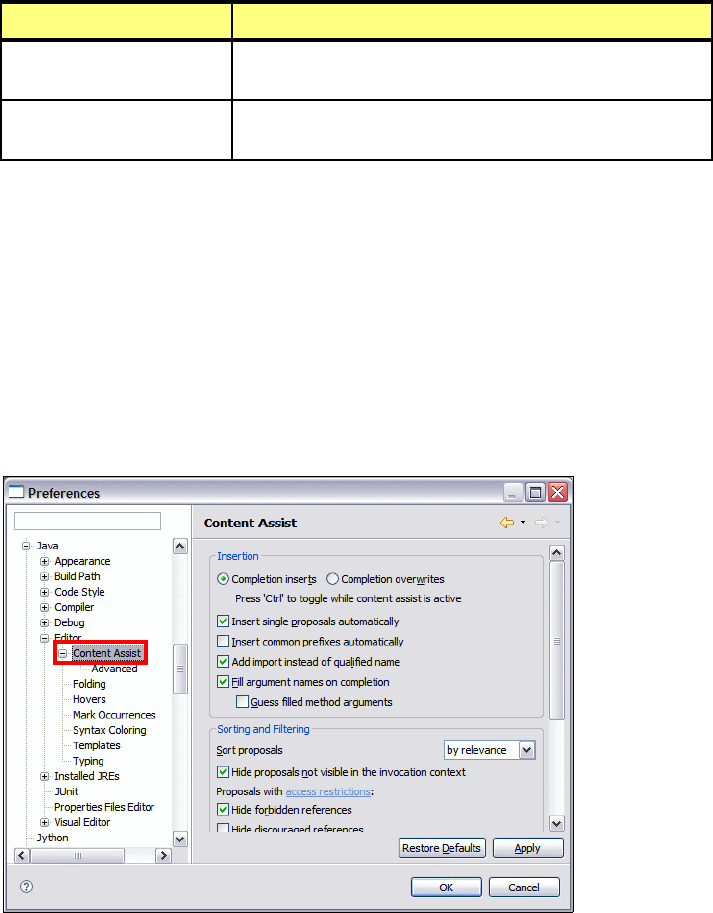
Chapter 3. Workbench setup and preferences 111
Draft Document for Review December 9, 2008 2:44 pm 7672-intro-3-workbench.fm
Some of Java editor preferences sub-pages are described as follows. A detailed
description of each sub-page can be found in the Application Developer help.
Content assist
The content assist feature in Application Developer is used in assisting a
developer in writing their code rapidly and reducing the errors in what they are
writing. It is a feature that is triggered by pressing Ctrl+Spacebar, and assists
the developer in completion of a variable or method name when coding.
To configure content assist, select Windows → Preferences → Java →
Editor → Content Assist (Figure 3-29).
Figure 3-29 Java Editor: Content Assist preferences
Folding
When enabled, a user of the Workbench can collapse a method, comments, or
class into a concise single line view.
Light bulb for quick
assists
If selected, a light bulb shows up in the vertical ruler
whenever a quick assist is available.
Appearance color options The colors of various Java editor appearance features are
specified here.
Option Description
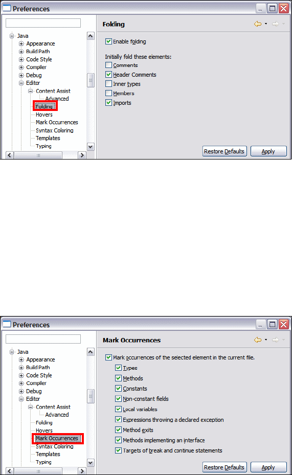
7672-intro-3-workbench.fm Draft Document for Review December 9, 2008 2:44 pm
112 Rational Application Developer V7.5 Programming Guide
To configure folding preferences, select Windows → Preferences → Java →
Editor → Folding (Figure 3-30).
Figure 3-30 Java Editor: Folding preferences
Mark occurrences
When enabled, this highlights all occurrences of the types of entities described in
the screen (Figure 3-31). In the Java editor, by selecting an attribute (for
example), the editor displays in the far right-hand context bar all occurrences in
the resource of that attribute. This can be navigated to by selecting the highlight
bar in that context bar.
To configure mark occurrences preferences, select Windows → Preferences →
Java → Editor → Mark Occurrences (Figure 3-31).
.
Figure 3-31 Java Editor: Mark Occurrences preferences
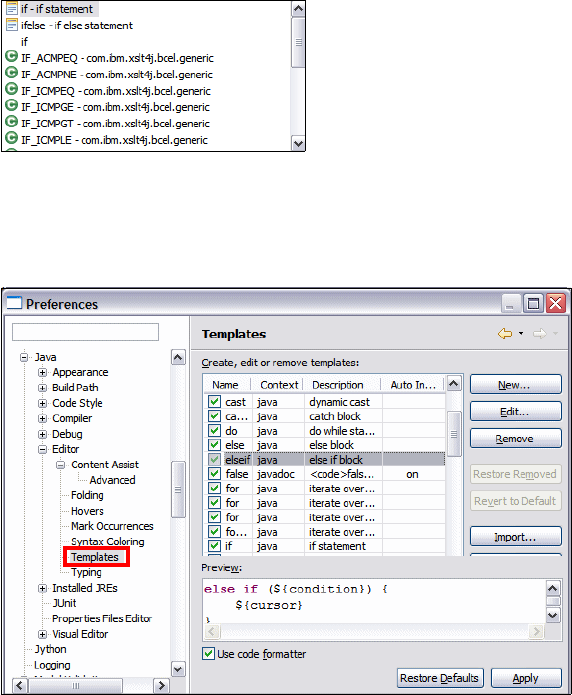
Chapter 3. Workbench setup and preferences 113
Draft Document for Review December 9, 2008 2:44 pm 7672-intro-3-workbench.fm
Templates
A template is a convenience that allows the programmer to quickly insert often
reoccurring source code patterns. Application Developer has pre-defined
templates and allows you to create new and edit existing templates.
The templates can be used by typing a part of the statement you want to add;
and then by pressing Ctrl+Spacebar in the Java editor, a list of templates
matching the key will appear in the presented list. Note that the list is filtered as
you type, so typing the few first characters of a template name will reveal it.
The symbol in front of each template (Figure 3-32), in the code assist list is
colored yellow, so you can distinguish between a template and a Java statement
entry.
Figure 3-32 Using templates for content assist
To configure templates, select Windows → Preferences → Java → Editor →
Templates (Figure 3-33).
Figure 3-33 Java Editor: Templates preferences

7672-intro-3-workbench.fm Draft Document for Review December 9, 2008 2:44 pm
114 Rational Application Developer V7.5 Programming Guide
Click New to add a new template and, for example, enter the information to
create a new template for a multi-line if-then-else statement, and click OK
(Figure 3-34).
Figure 3-34 Creating a new template
The template is now available for use in the Java editor.
There are also some predefined variables available that can be added in the
template. These variables can be inserted by clicking Insert Variable. This
brings up a list and a brief description of the variable.
Templates that have been defined can be exported and later imported into
Application Developer to ensure that a common environment can be set up
among a team of developers.
Compiler options
Problems detected by the compiler are classified as either warnings or errors.
The existence of a warning does not affect the execution of the program. The
code executes as if it had been written correctly. Compile-time errors (as
specified by the Java Language Specification) are always reported as errors by
the Java compiler.
For some other types of problems you can, however, specify if you want the Java
compiler to report them as warnings, errors, or to ignore them.
To configure the compiler options, select Window → Preferences → Java →
Compiler (Figure 3-35).
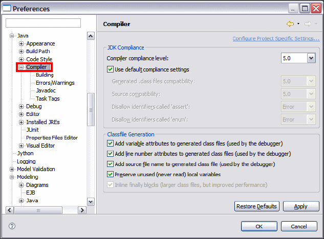
Chapter 3. Workbench setup and preferences 115
Draft Document for Review December 9, 2008 2:44 pm 7672-intro-3-workbench.fm
Figure 3-35 Java: Compiler preferences
The compiler preferences page includes four sub-pages that allow you to set the
appropriate behavior required to ensure that you obtain the required information
from the compiler:
Building: Indicates your preferences for the Building settings, such as build
path problems, output folder, and so on.
Errors/Warnings: Defines the level the errors and warnings in several
categories such as code style, potential programming problems, unnecessary
code, annotations, and so on.
Javadoc: Provides configuration settings on how to deal with Javadoc
problems that might arise and what to display as errors.
Task Tags: Enables you to create, edit and remove Java task tags.
Installed JREs
Application Developer allows you to specify which Java Runtime Environment
(JRE) should be used by the Java builder. By default, the standard Java VM that
comes with the product is used; however, to ensure that your application is
targeted for the correct platform, the same JRE or at least the same version of
the JRE should be used to compile the code. If the application is targeted for a
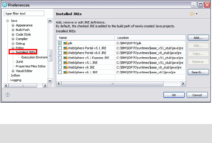
7672-intro-3-workbench.fm Draft Document for Review December 9, 2008 2:44 pm
116 Rational Application Developer V7.5 Programming Guide
WebSphere Application Server V6.1, then the JRE should be set to use the JRE
associated with this environment in Application Developer.
To configure the installed JREs, select Windows → Preferences → Java →
Installed JREs (Figure 3-36).
Figure 3-36 Java: Installed JRE preferences
By default, the JRE used to run the Workbench will be used to build and run Java
programs. It appears selected in the list of installed JREs. If the target JRE that
the application will run under is not in the list of JREs, then this can be installed
on the machine and added onto the list. You can add, edit, or remove a JRE.
Let us assume that the application you are writing requires the latest JRE 1.6
located in the directory C:\Program Files\Java\jre1.6\. The procedure to add a
new JRE is as follows:
Click Add.
In the Add JRE dialog, enter the following items:
– JRE type: A drop-down box indicating whether a Standard VM or Standard
1.1.x VM. In most circumstances this will be set to Standard VM.
– JRE name: Any name for the JRE to identify it.
– JRE home directory: The location of the root directory of the install for the
JRE: C:\Program Files\Java\jre1.6\
Note: Changing the JRE used for running does not affect the way Java source
is compiled. You can adjust the build path to compile against custom libraries.
Chapter 3. Workbench setup and preferences 117
Draft Document for Review December 9, 2008 2:44 pm 7672-intro-3-workbench.fm
– Default VM arguments: Arguments that are required to be passed to the
JRE.
– JRE system libraries: List of Jar files required for the JRE. Add Jar files
under the C:\Program Files\Java\jre1.6\lib and
C:\Program Files\Java\jre1.6\lib\ext directories.
Click OK to add.
Select the JRE in the list of installed JREs to set it as the default JRE, click
OK, and rebuild all the projects in the workspace.
Summary
In this chapter we described how to configure the Workbench preferences in
regard to logging, automatic builds, development capabilities, and Java
development.
7672-intro-3-workbench.fm Draft Document for Review December 9, 2008 2:44 pm
118 Rational Application Developer V7.5 Programming Guide

© Copyright IBM Corp. 2008. All rights reserved. 119
Draft Document for Review December 9, 2008 2:44 pm 7672-intro-4-perspective.fm
Chapter 4. Perspectives, views, and
editors
Rational Application Developer supports a role-based development model, which
means that the development environment provides different tools, depending on
the role of the user. It does this by providing several different perspectives that
contain different editors and views necessary to work on tasks associated with
each role.
This chapter starts with an introduction to the common structures and features
applicable to all perspectives in Application Developer and then describes its
help facility. Following this we provide a brief overview of the main features of
each perspective available in IBM Rational Application Developer V7.5. Most of
these perspectives are described in detail in the chapters within this book.
The chapter is organized into the following sections:
Integrated development environment (IDE)
Application Developer Help
Available perspectives
Summary
4
7672-intro-4-perspective.fm Draft Document for Review December 9, 2008 2:44 pm
120 Rational Application Developer V7.5 Programming Guide
Integrated development environment (IDE)
An integrated development environment is a set of software development tools
such as source editors, compilers and debuggers, that are accessible from a
single user interface.
In Rational Application Developer, the IDE is called the Workbench. Rational
Application Developer’s Workbench provides customizable perspectives that
support role-based development. It provides a common way for all members of a
project team to create, manage, and navigate resources easily.
Views provide different ways of looking at the resources you are working on and
editors allow you to create and modify the resources. perspectives are a
combination of views and editors that show various aspects of the project
resource, and are organized by developer role or task. For example, a Java
developer would work most often in the Java perspective, while a Web designer
would work in the Web perspective.
Several default perspectives are provided in Rational Application Developer and
team members also can customize them according to their current role and
personal preference. More than one perspective can be opened at a time and
users can switch perspectives while working with Application Developer. If you
find that a particular perspective does not contain the views or editors you
require, you can add them to the perspective and position them to suit your
requirements.
Perspectives
Perspectives provide a convenient grouping of views and editors that match a
particular way of using Rational Application Developer. A different perspective
can be used to work on a given workspace depending on the role of the
developer or the task that has to be done.
For each perspective, Application Developer defines an initial set and layout of
views and editors for performing a particular set of development activities. For
example, the Java EE perspective contains views and editors applicable for EJB
development. The layout and the preferences in each perspective can be
changed and saved as a customized perspective and used again later. This is
described in “Organizing and customizing perspectives” on page 124.

Chapter 4. Perspectives, views, and editors 121
Draft Document for Review December 9, 2008 2:44 pm 7672-intro-4-perspective.fm
Views
Views provide different presentations of resources or ways of navigating through
the information in your workspace. For example, The Enterprise Explorer view
provides a hierarchical view of the resources in the Workbench. From here, you
can open files for editing or select resources for operations such as exporting,
while the Outline view displays an outline of a structured file that is currently open
in the editor area, and lists structural elements. Rational Application Developer
provides synchronization between views and editors, so that changing the focus
or a value in an editor or view can automatically update another. In addition,
some views display information obtained from other software products, such as
database systems or software configuration management (SCM) systems.
A view can appear by itself or stacked with other views in a tabbed notebook
arrangement. To quickly move between views in a given perspective, you can
select Ctrl-F7 (and hold down Ctrl), which will show all the open views and let the
user move quickly to the desired view. Press F7 until the required view is
selected, then release to move to that view.
Editors
When you open a file, Rational Application Developer automatically opens the
editor that is associated with that file type. For example, the Page Designer is
opened for .html, .htm, and .jsp files, while the Java editor is opened for .java
and .jpage files.
Editors that have been associated with specific file types will open in the editor
area of the Workbench. By default, editors are stacked in a notebook
arrangement inside the editor area. If there is no associated editor for a resource,
Rational Application Developer will open the file in the default editor, which is a
text editor. It is also possible to open a resource in another editor by using the
Open With option from the context menu.
To quickly move between editors open on the workspace, you can select Ctrl-F6
(and hold down Ctrl) which will show all the open editors and let the user move
quickly to the desired one. Press F6 until the required editor is selected, then
release.
The following icons appear in the Toolbar of a perspective to speed up navigation
between editors:
Next and Previous cursor location ( and )—Moves the focus
around recent cursor positions.
Last Edit Location ( )— Reveals the location where the last edit occurred.

7672-intro-4-perspective.fm Draft Document for Review December 9, 2008 2:44 pm
122 Rational Application Developer V7.5 Programming Guide
Next and Previous Annotation ( and )—Depending on the
options selected in the associated drop-down menu, this moves the cursor to
the next and previous annotation in the associated list. For example, if errors
are chosen, these buttons will move the cursor to the next or previous source
code error in the resource being edited.
Perspective layout
Many of Rational Application Developer’s perspectives use a similar layout.
Figure 4-1 shows the general layout that is used for most default perspectives.
Figure 4-1 Perspective layout
Toolbar
Enterprise Explorer
Editor
Outline
Tasks
Palette
Problems

Chapter 4. Perspectives, views, and editors 123
Draft Document for Review December 9, 2008 2:44 pm 7672-intro-4-perspective.fm
On the left side are views for navigating through the workspace. In the middle of
the Workbench is larger pane, where the main editors are shown. The right pane
usually contains Outline or Palette views of the file in the main editor. In some
perspectives the editor pane is larger and the outline view is located at the
bottom left corner of the perspective. At the bottom right is a tabbed series of
views including the Tasks view, the Problems view, and the Properties view. This
is where smaller miscellaneous views not associated with navigation, editing, or
outline information are shown.
Switching perspectives
There are two ways to open another:
Click the Open a perspective icon ( ) in the top right corner of the
Workbench working area and select the appropriate perspective from the list.
Select Window → Open Perspective and select one from the drop-down list
shown.
In both cases there is also an Other option, which when selected displays the
Open Perspective dialog that shows list of s (see Figure 4-2). To show the
complete list of perspectives, check the Show all check box, if exists. Here the
user can select the required perspective and click OK.
Figure 4-2 Open perspective dialog
7672-intro-4-perspective.fm Draft Document for Review December 9, 2008 2:44 pm
124 Rational Application Developer V7.5 Programming Guide
In all perspectives, a group of buttons appears in the top right corner of the
Workbench (an area known as the shortcut bar). Each button corresponds to an
open perspective and the >> icon will show a list if there are too many (see
Figure 4-2). Clicking on one of these will move to the associated perspective.
Figure 4-3 Buttons to switch between perspectives
Specifying the default perspective
The Java EE perspective is Rational Application Developer’s default perspective,
but this can be changed using the Preferences dialog:
From the Workbench, select Window → Preferences.
Expand General and select Perspectives. Note that the Java EE perspective
has default after it.
Select the perspective that you want to define as the default, and click Make
Default.
Click OK.
Organizing and customizing perspectives
Rational Application Developer allows you to open, customize, reset, save, and
close perspectives. These actions can be found in the Window menu.
To customize the commands and shortcuts available within a perspective, select
Window → Customize Perspective. The Customize Perspective dialog opens
(Figure 4-4).
Tips:
The name of the perspective is shown in the window title area along with
the name of the file open in the editor, which is currently at the front.
To close a perspective, right-click the perspective's button on the shortcut
bar (top right) and select Close.
To display only the icons for the perspectives, right-click somewhere in the
shortcut bar and clear the Show Text option.
Each perspective requires memory, so it is good practice to close s that are
perspective not used to improve performance.
Show all open perspectives
Open another perspective
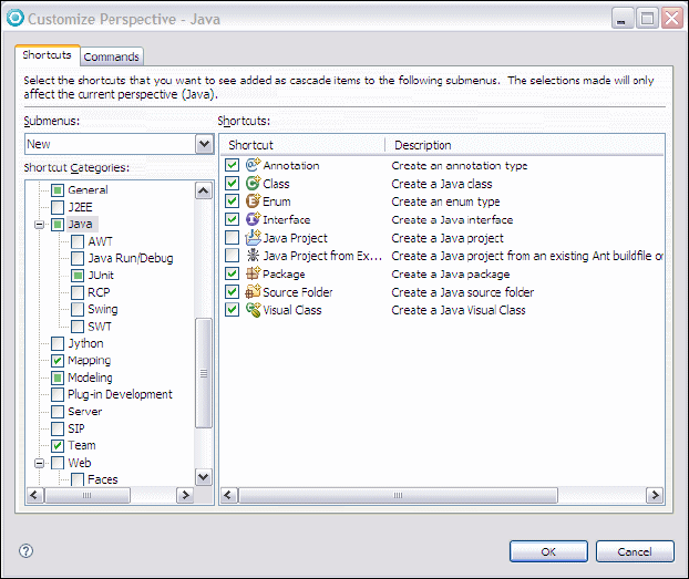
Chapter 4. Perspectives, views, and editors 125
Draft Document for Review December 9, 2008 2:44 pm 7672-intro-4-perspective.fm
Figure 4-4 Customize Perspective dialog
The Shortcuts tab provides the facility to specify which options are shown on the
New, Open Perspective, and Show View menu options within the current.
Select the menu you want to customize from the Submenus drop-down window
and check the boxes for whichever options you want to appear. Note that items
you do not select are still accessible by clicking the Other menu option, which is
always present for these options.
The Commands tab of the dialog allows you to select command groups that will
be added to the menu bar or tool bar for Rational Application Developer in this
perspective.
In addition to customizing the Command and options available as shortcuts, it is
also possible to reposition any of the views and editors and to add or remove
other editors as desired. The following features are available to do this:
Adding and Removing Views—To add a view to the perspective, select
Window → Show View and select the view you would like to add to the
currently open perspective. To remove a view, simply close it from its title bar.
Move—You can move a view to another pane by using drag and drop. To do
this, select its title bar and drag the view to another place on the workspace.

7672-intro-4-perspective.fm Draft Document for Review December 9, 2008 2:44 pm
126 Rational Application Developer V7.5 Programming Guide
While you drag the view, the mouse cursor changes into a drop cursor, which
indicates where the view will appear when it is released. In each case, the
area that is filled with the dragged view is highlighted with a rectangular
outline.
The drop cursor will look like one of the following:
The view will dock below the view under the cursor.
The view will dock to the left of the view under the cursor.
The view will dock to the right of the view under the cursor.
The view will dock above the view under the cursor.
The view will appear as a tab in the same pane as the view under
the cursor.
The view will dock in the status bar (at the bottom of the Rational
Application Developer window) and become a Fast View (see
below). This icon will appear when a view is dragged to the bottom
left corner of a work-space.
The view becomes a separate child window of the main Rational
Application Developer window. This icon will appear when you drag
a view to an area outside the work-space. To return the view back
into the work-space, right click its title bar and clear the Detached
menu item.
Fast View—A Fast View appears as a button in the status bar of Rational
Application Developer in the bottom left corner of the workspace. Clicking the
button will toggle whether or not the view is displayed on top of the other
views in the perspective.
Maximize and minimize a view—To maximize a view to fill the whole
working area of the Workbench, you can double-click the title bar of the view,
press Ctrl+M, or click the Maximize icon ( )in the view’s toolbar. To restore
the view double-click the title bar, select the restore button ( ) or press
Ctrl+M again. The Minimize button in the toolbar of a view minimizes the tab
group so that only the tabs are visible; click the Restore button or one of the
view tabs to restore the tab group.
Save—Once you have configured the perspective to your preferences, you
can save it as your own perspective by selecting Window → Save
Perspective As and type a new name. The new perspective now appears as
an option on the Open Perspective window.
Restore—To restore the currently open perspective to its original layout,
select Window → Reset Perspective.
Chapter 4. Perspectives, views, and editors 127
Draft Document for Review December 9, 2008 2:44 pm 7672-intro-4-perspective.fm
Application Developer Help
The Rational Application Developer Help system lets you browse, search,
bookmark, and print help documentation. The documentation is organized into
sets of information that are analogous to books. The help system also supplies a
text search capability for finding the information you need by search phrase or
keyword, and context-sensitive help for finding information to describe the
particular function you are working with.
The Help contents can be displayed in a separate window, by selecting Help →
Help Contents from the menu bar (Figure 4-5).
Figure 4-5 Help window
In the Help window you see the available books in the left pane and the content in
the right pane. When you select a book ( ) in the left pane, the appropriate
table of contents opens up and you can select a topic ( ) within the book.
When a page ( ) is selected, the page content is displayed in the right pane.
7672-intro-4-perspective.fm Draft Document for Review December 9, 2008 2:44 pm
128 Rational Application Developer V7.5 Programming Guide
You can navigate through the help documents by clicking Go Back and Go
Forward ( ) in the toolbar of the right pane.
The following buttons are also available in the toolbar:
Show in Table of Contents ( )—Synchronizes the navigation frame with
the current topic, which is helpful when the user follows several links to related
topics in several files, and wants to see where the current topic fits into the
navigation path.
Bookmark Document ( )—Adds a bookmark to the Bookmarks view,
which is one of the tabs on the left pane.
Print Page ( )—Provides the option to print the page current displayed in
the right-hand window.
Maximize ( )—Maximizes the right hand pane to fill the whole help window.
Note that when this pane is maximized, the icon changes to Restore()
which allows the user to return the page back to normal.
Also, the left hand pane of the help window can be tabbed between the
Contents, Index, Search Results, and Bookmarks views, which provide
different methods of accessing information the help contents.
Rational Application Developer’s help system contains a lot of useful information
about the tools and technologies available from the workbench, and is loosely
arranged around different types of development possible (for example Java, Web,
XML and many others). While performing any task within Application Developer,
you can press F1 at any time and the Help view displays the context help
showing a list of relevant topics for the current view or editor. For example,
Figure 4-6 shows the context help when editing normal Java code.
Figure 4-6 Context sensitive help when Java editing
Chapter 4. Perspectives, views, and editors 129
Draft Document for Review December 9, 2008 2:44 pm 7672-intro-4-perspective.fm
Also, at any time it is possible to display the Help contents as a view within the
workspace, by selecting Window → Show View → Other → Help → Help.
The Search field allows you to do a search which will be through all the Help
contents by default. Clicking the Search Scope link opens a dialog box where
you can select a scope for your search (Figure 4-7). This will show any previously
defined search scopes and give the user the opportunity to create a new one.
Figure 4-7 Select Search Scope dialog for help
Once the search list has been saved, it can be selected as a search scope from
the main search page.
Clicking Go performs the search across the selected scope and display the
results in the Search Results view, and from there the user can open the pages
within the Help facility.
Available perspectives
In this section all the perspectives that are available in Rational Application
Developer are briefly described. The perspectives are covered in alphabetical
order which is how they appear in the Open Perspective dialog.
Rational Application Developer allows a developer to disable or enable
capabilities to simplify the interface or make it more capable for specific types of
development work respectively. This is described in “Capabilities” on page 88.
For this section, all capabilities have been enabled in the product. If this is not
done, certain perspectives, associated with specific capabilities, may not
available.
IBM Rational Application Developer v7.5 includes the following perspectives:
Crystal Reports perspective
CVS Repository Exploring perspective
Data perspective
Pre-defined search scope
7672-intro-4-perspective.fm Draft Document for Review December 9, 2008 2:44 pm
130 Rational Application Developer V7.5 Programming Guide
Database Debug perspective
Database Development perspective
Debug perspective
Java perspective
Java Browsing perspective
Java EE perspective
Java Type Hierarchy perspective
JavaScript perspective
Jazz Administration perspective
JPA perspective
Plug-in Development perspective
Profiling and Logging perspective
Report Design perspective
Requirement perspective
Resource perspective
Team Synchronizing perspective
Test perspective
Web perspective
Work items perspective
Crystal Reports perspective
The Crystal Reports features are an optional extra that can be selected when
installing Application Developer. If this is installed, then the Crystal Reports
perspective provides the tools to work with a database and produce simple or
complex reports (using Crystal reports) which can be published to the Web or
incorporated into an application. The main editor uses a Layout page where
report elements can be placed on report templates from the Palette view and a
Preview page to show what a report will look like. These work with the Data
Source Explorer View and the Field Explorer View to position various fields from
results of queries and database tables onto the report.
The Rational Application Developer Help has a large section on the details of
using this perspective.
CVS Repository Exploring perspective
The CVS Repository Exploring perspective (Figure 4-8) lets you connect to
Concurrent Versions System (CVS) repositories and to inspect the revision
history of resources in those repositories.
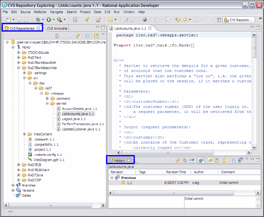
Chapter 4. Perspectives, views, and editors 131
Draft Document for Review December 9, 2008 2:44 pm 7672-intro-4-perspective.fm
Figure 4-8 CVS Repository Exploring perspective
CVS Repositories view—Shows the CVS repository locations that have
been added to the Workbench. Expanding a location reveals the main trunk
(HEAD), project versions, and branches in that repository. You can further
expand the project versions and branches to reveal the folders and files
contained within them.
The context menu for this view also allows you to specify new repository
locations. The CVS Repositories view can be used to check out resources
from the repository to the Workbench, configure the branches and versions
shown by the view, view a resource’s history and compare resource versions.
Editor—Files that exist in the repositories can be viewed by double-clicking
them in a branch or version. This opens the version of the file specified in the
editor pane. Note that the contents of the editor are read-only.

7672-intro-4-perspective.fm Draft Document for Review December 9, 2008 2:44 pm
132 Rational Application Developer V7.5 Programming Guide
CVS Resource History view—Displays a detailed history of each file
providing a list of all the revisions of it in the repository. From this view you can
also compare two revisions or open an editor on a revision.
CVS Annotation view—To show this view, select a resource in the CVS
Repositories view, right-click and select Show Annotation. The CVS
Annotate view will come to the front and will display a summary of all the
changes made to the resource since it came under the control of the CVS
server. The CVS Annotate view will link with the main editor, showing which
CVS revisions apply to which source code lines.
More details about using the CVS Repository Exploring perspective, and other
aspects of CVS functionality in Rational Application Developer, can be found in
Chapter 28, “CVS integration” on page 1019.
Data perspective
The Data perspective (Figure 4-9) lets you access a set of relational database
tools, where you can create and manipulate the database definitions for your
projects.
The important views are as follows:
Data Project Explorer—The main navigator view in the Data perspective
showing only the data projects in the workspace. This view lets you work
directly with data definitions and define relational data objects. It can hold
local copies of existing data definitions imported from the DB Servers view,
designs created by running DDL scripts, or new designs that you have
created directly in the Workbench.
Data Source Explorer view—This view provides a list of configured
connection profiles. If the Show Category button is selected, you can see
the list grouped into categories, for example, Databases and ODA Data
Sources. Use the Data Source Explorer to connect to, navigate, and interact
with resources associated with the selected connection profile. It also
provides import and export capabilities to share connection profile definitions
with other Workbenches.
Tasks view—The Tasks view displays system-generated errors, warnings, or
information associated with a resource, typically produced by builders. Tasks
can also be added manually and optionally associated with a resource in the
Workbench.
Navigator view—The optional Navigator view provides a hierarchical view of
all the resources in the Workbench. By using this view you can open files for
editing or select resources for operations such as exporting. The Navigator
view is essentially a file system view, showing the contents of the workspace
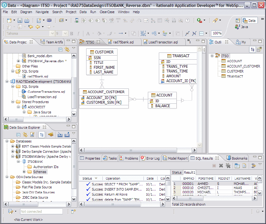
Chapter 4. Perspectives, views, and editors 133
Draft Document for Review December 9, 2008 2:44 pm 7672-intro-4-perspective.fm
and the directory structures used by any projects that have been created
outside the workspace.
Figure 4-9 Data perspective
Console view—The Console view shows the output of a process and allows
you to provide keyboard input to a process. The console shows three different
kinds of text, each in a different color: Standard output, standard error, and
standard input.
SQL Results view—The SQL Results view displays information about
actions that are related to running SQL statements, stored procedures, and
user-defined functions (UDFs), or creating database objects. For example,
when you run a stored procedure on the database server, the SQL Results
view displays messages, parameters, and the results of any SQL statements
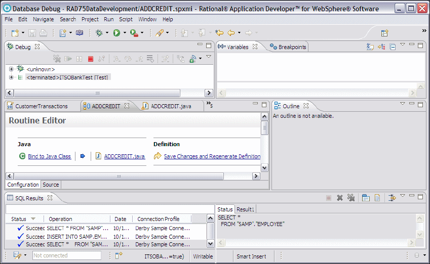
7672-intro-4-perspective.fm Draft Document for Review December 9, 2008 2:44 pm
134 Rational Application Developer V7.5 Programming Guide
that are run by the stored procedure. The SQL Results view also displays
results when you sample the contents of a selected table. The SQL Results
view consists of a history pane and a details pane. The history pane displays
the history for past queries. The details pane displays the status and results of
the last run. Use the view pull-down menu to filter history results and set
preferences.
SQL Builder/Editor—This view shows specialized wizards for creating and
editing of SQL statements.
Data Diagram Editor—This view shows an Entity Relationship diagram of
the selected database.
More details about using the Data perspective can be found in Chapter 11,
“Develop database applications” on page 227.
Database Debug perspective
The Database Debug perspective (Figure 4-10) lets you debug your database
stored procedures where you can watch the values of the variables and monitor
the breakpoints.
Figure 4-10 Database Debug perspective
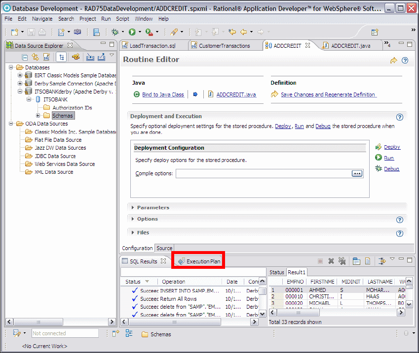
Chapter 4. Perspectives, views, and editors 135
Draft Document for Review December 9, 2008 2:44 pm 7672-intro-4-perspective.fm
This perspective includes the views: Debug, Variables, Breakpoints, Outline, and
SQL Results which have been already discussed earlier in this chapter.
Database Development perspective
The Database Development perspective (Figure 4-11) is a simpler version of the
Data perspective with only one view added which is the Execution Plan view.
This view displays your current SQL execution plans which helps you optimize
the execution of your queries, displays execution plans history, and can read SQL
execution plans from files. More details about this perspective are in Chapter 11,
“Develop database applications” on page 227.
Figure 4-11 Database Development perspective
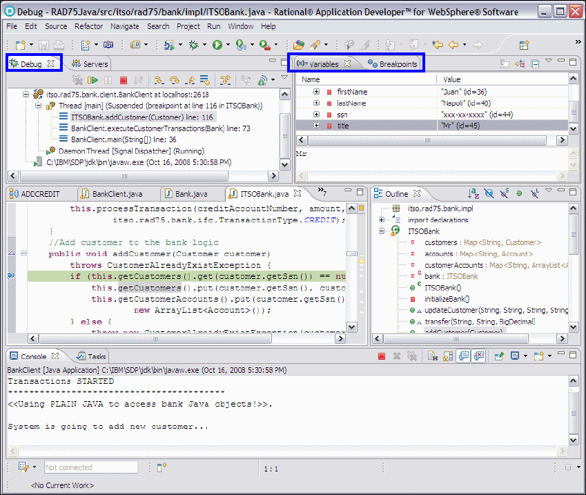
7672-intro-4-perspective.fm Draft Document for Review December 9, 2008 2:44 pm
136 Rational Application Developer V7.5 Programming Guide
Debug perspective
By default, the Debug perspective (Figure 4-12) contains five panes with the
following views:
Top left—Shows Debug and Servers views
Top right—Shows Breakpoints and Variables views.
Middle left—Shows the editor for the resource being debugged.
Middle right—Shows the Outline view of the resource being debugged.
Bottom—Shows the Console and the Tasks view
Figure 4-12 Debug perspective
Chapter 4. Perspectives, views, and editors 137
Draft Document for Review December 9, 2008 2:44 pm 7672-intro-4-perspective.fm
The important views while debugging are as follows:
Debug view—The Debug view displays the stack frame for the suspended
threads for each target you are debugging. Each thread in your program
appears as a node in the tree. If the thread is suspended, its stack frames are
shown as child elements.
If the resource containing a selected thread is not open and/or active, the file
opens in the editor and becomes active, focusing on the point in the source
where the thread is currently positioned.
The Debug view contains a number of command buttons which enable users
to perform actions such as start, terminate, and step-by-step debug actions.
Variables view—The Variables view displays information about the variables
in the currently selected stack frame.
Breakpoints view—The Breakpoints view lists all the breakpoints you have
set in the Workbench projects. You can double-click a breakpoint to display its
location in the editor. In this view, you can also enable or disable breakpoints,
remove them, change their properties, or add new ones. This view also lists
Java exception breakpoints, which suspend execution at the point where the
exception is thrown.
Servers view—The Servers view lists all the defined servers and their status.
Right-clicking a server displays the server context menu, which allows the
server to be started, stopped, and to republish the current applications.
Outline view—The Outline view shows the elements (imports, class, fields,
and methods) that exist in the source file in the front editor. Clicking an item in
the outline will position you in the editor view at the line where that structure
element is defined.
Problems view—This view shows all errors, warnings, and information
messages related to resources in the workspace. The items listed in this view
can be used to navigate to the line of code containing error, warning, or
information point.
The Console and Tasks views have already been discussed in earlier sections of
this chapter.
More information about the Debug perspective can be found in Chapter 24,
“Debug local and remote applications” on page 861.
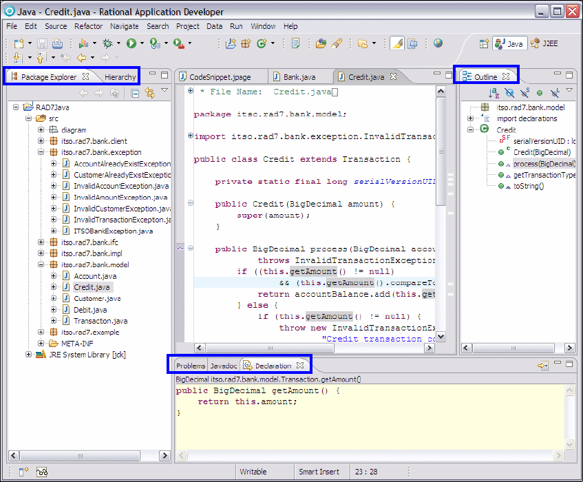
7672-intro-4-perspective.fm Draft Document for Review December 9, 2008 2:44 pm
138 Rational Application Developer V7.5 Programming Guide
Java perspective
The Java perspective (Figure 4-13) supports developers with the tasks of
creating, editing, and compiling Java code.
Figure 4-13 Java perspective
It consists of a main editor area and displays by default, the following views:
Package Explorer view—Shows the Java element hierarchy of all the Java
projects in your Workbench. This is a Java-specific view of the resources
shown in the Navigator view (which is not shown by default in the Java
perspective). For each project, its source folders and referenced libraries are
shown in the tree view and from here it is possible to open and browse the
contents of both internal and external JAR files.

Chapter 4. Perspectives, views, and editors 139
Draft Document for Review December 9, 2008 2:44 pm 7672-intro-4-perspective.fm
Hierarchy view—Can be opened for a selected type to show its
super-classes and subclasses. It offers three different ways to look at a class
hierarchy, by selecting the icons buttons at the top of the view:
–The Type Hierarchy icon ( ) displays the type hierarchy of the selected
type. This includes its position in the hierarchy along with all its superclass
and subclasses.
–The Supertype Hierarchy icon ( ) displays the supertype hierarchy of
the selected type and any interfaces the type implements.
–The Subtype Hierarchy icon ( ) displays the subtype hierarchy of the
selected type or, for interfaces, displays classes that implement the type.
More information about the Hierarchy view is provided in , “Java Type
Hierarchy perspective” on page 142.
Javadoc view—This view shows the Javadoc comments associated with the
element selected in the editor or outline view.
Declarations view—Shows the source code declaration of the element
selected in the editor, in the hierarchy view or in outline view.
The Outline and Problems views are also applicable to the Java perspective and
have already been discussed in earlier sections of this chapter.
Refer to Chapter 8, “Develop Java applications” on page 69 for more information
about how to work with the Java, Java Browsing, and Java Type Hierarchy
perspectives.
Java Browsing perspective
The Java Browsing perspective is also for Java development (Figure 4-14), but it
provides different views from the Java perspective.
The Java Browsing perspective has a larger editor area and several views to
select the programming element you want to edit:
Projects view—Lists all Java projects
Packages view—Shows the Java packages within the selected project
Types view—Shows the types defined within the selected package
Members view—Shows the members of the selected type
The Toggle Mark occurrences button ( ) when toggled on highlights all
occurrences of the previously search text within the current editor.
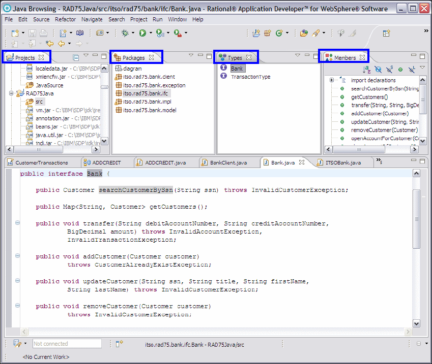
7672-intro-4-perspective.fm Draft Document for Review December 9, 2008 2:44 pm
140 Rational Application Developer V7.5 Programming Guide
Figure 4-14 Java Browsing perspective
Java EE perspective
The Java EE perspective (Figure 4-15) includes workbench views that you can
use when developing resources for enterprise applications, EJB modules, Web
modules, application client modules, and connector projects or modules.

Chapter 4. Perspectives, views, and editors 141
Draft Document for Review December 9, 2008 2:44 pm 7672-intro-4-perspective.fm
Figure 4-15 Java EE perspective
The Java EE perspective contains the following views typically used when
developing Java EE applications:
Enterprise Explorer view—This view provides an integrated view of your
projects and their artifacts related to Java EE development. You can show or
hide your projects based on working sets. This view displays navigable
models of Java EE deployment descriptors, Java artifacts (source folders,
packages, and classes), navigable models of the available Web services, and
specialized views of Web modules to simplify the development of dynamic
Web applications. In addition, EJB database mapping and the configuration of
projects for a Java EE application server are made readily available.
7672-intro-4-perspective.fm Draft Document for Review December 9, 2008 2:44 pm
142 Rational Application Developer V7.5 Programming Guide
Annotations view—The Annotations view, new in this release, provides a
way for you to create, edit, browse, and generally keep track of the
annotations that you use in your applications.
Snippets view—The Snippets view lets you catalog and organize reusable
programming objects, such as Web services, EJB, and JSP code snippets.
The view can be extended based on additional objects that you define and
include. The available snippets are arranged in drawers. and the drawers can
be customized by right-clicking a drawer and selecting Customize.
Properties view—This view provides a tabular view of the properties and
associated values of objects in files you have open in an editor. The format of
this view differs depending on what is selected in the editor, and by default it
shows the file properties (last modification date, file path and so on).
The Outline, Servers, Problems, Tasks, and Data Source Explorer views are also
relevant to the Java EE perspective and have already been discussed in earlier
sections of this chapter.
More details about using the Java EE perspective can be found in Chapter 14,
“Develop EJB applications” on page 387.
Java Type Hierarchy perspective
This perspective is also for Java developers and allows users to explore the type
hierarchy. It can be opened on types, compilation units, packages, projects, or
source folders and consists of the Hierarchy view and an editor.
The Hierarchy view shows only an information message until you select a type:
To display the type hierarchy, select a type (for example, in the outline view or
in the editor), and select the 'Open Type Hierarchy' menu option. Alternatively,
you can drag and drop an element (for example, project, package, type) onto
this view.
To open a type in the Hierarchy view, open the context menu for a Java class in
any view or editor (for example, the main source code editor) and select Open
Type Hierarchy. The type hierarchy is displayed in the Hierarchy view.
Figure 4-16 shows the Hierarchy view of the DebitBean class from Chapter 14,
“Develop EJB applications” on page 387.
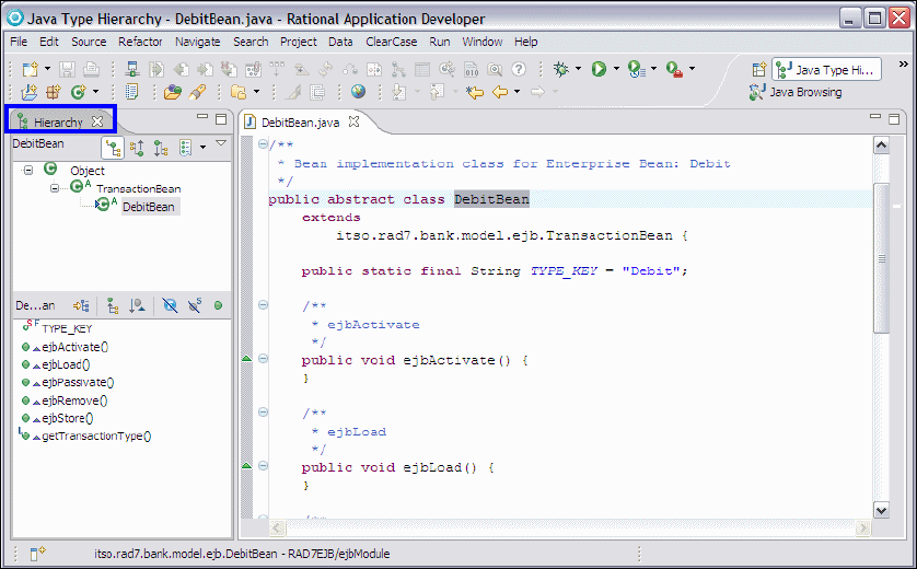
Chapter 4. Perspectives, views, and editors 143
Draft Document for Review December 9, 2008 2:44 pm 7672-intro-4-perspective.fm
Figure 4-16 Java Type Hierarchy perspective with Hierarchy view
Although the Hierarchy view is also present in the Java perspective and the Java
Type perspective only contains two views, it is useful as it provides a way for
developers to explore and understand complex object hierarchies without the
clutter of other information.
JavaScript perspective
The JavaScript perspective (Figure 4-17) is mainly used in coding, exploring, and
documenting JavaScript.
The important view of this perspective are as follows:
Script Explorer view—Shows the resources in a folder view and explores
object orient JavaScript code in a tree view.
Jsdoc view—Shows the JavaScript documentation for the selected
JavaScript element in the Editor view or in the Outline view.
The Outline and the Declaration views appear in this perspective and they have
been already discussed earlier in this chapter
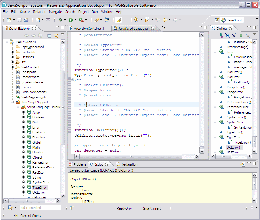
7672-intro-4-perspective.fm Draft Document for Review December 9, 2008 2:44 pm
144 Rational Application Developer V7.5 Programming Guide
More details about working with JavaScript is provided in Chapter 19, “Develop
Web applications using Web 2.0” on page 649.
Figure 4-17 JavaScript perspective
Jazz Administration perspective
The Jazz is IBM Rational's new technology platform for collaborative software
delivery. Uniquely attuned to global and distributed teams, the Jazz platform is
designed to transform how people work together to build software-making
software delivery more collaborative, productive and transparent. You can think
of Jazz technology as an extensible framework that dynamically integrates and

Chapter 4. Perspectives, views, and editors 145
Draft Document for Review December 9, 2008 2:44 pm 7672-intro-4-perspective.fm
synchronizes people that have a role to play in the successful delivery of
software - not just software professionals, processes and assets associated with
software development projects.
Jazz is a technology platform, not a product. IBM’s Product offerings that are built
on the Jazz platform to leverage a rich set of capabilities for team-based software
development and delivery is The Rational Team Concert.
The important views of this perspective are as follows:
Team Organization view—Manages Connections to project areas and
create new ones, and helps you organize larger team members with multiple
development lines and subteams.
Process Templates view—Manages your process templates. There are
several predefined processes to choose from: Agile, Eclipse Way, Scrum,
OpenUp, and Simple. But you can also define your own processes or modify
an existing one.
Team Artifacts view—Manages your connections to a repository and a
project area. When you are connected to a project area you can access its
artifacts. The artifacts are grouped into different nodes.
Team Advisor view—Opens when you execute an operation that violates a
process configuration. This view tells you what went wrong and often provides
a quick fix for the problem.
ClearCase Synchronized Streams view—Creates, manages and monitors
ClearCase Synchronization streams and also lets the user switch between
different team areas.
Work Items view—Shows you the work items returned from a work item
query.
More details about using this perspective in Chapter 29, “Rational Team Concert”
on page 1077.
Also for more information about Jazz, see the IBM Rational Team Concert link in
Rational Application Developer Welcome page and the Jazz Community Site:
http://jazz.net
Author Comment: A screenshot to be added after the finish of the team concert chapter
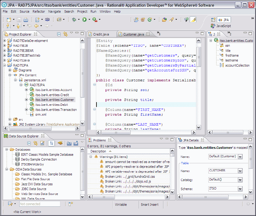
7672-intro-4-perspective.fm Draft Document for Review December 9, 2008 2:44 pm
146 Rational Application Developer V7.5 Programming Guide
JPA perspective
The JPA perspective (Figure 4-18) provides you with the ability to manage
relational data in Java applications using Java Persistence API by introducing
new capabilities such as defining and editing object-relational mappings for EJB
3.0 JPA entities and adding JPA Support to a plain Java project.
Figure 4-18 JPA perspective
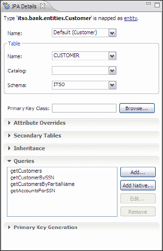
Chapter 4. Perspectives, views, and editors 147
Draft Document for Review December 9, 2008 2:44 pm 7672-intro-4-perspective.fm
The important view of this perspective are as follows:
JPA Structure view—Displays an outline of the structure (its attributes and
mappings) of the entity that is currently selected or opened in the editor.
JPA Details view— the JPA Details view (Figure 4-19) displays the
persistence information for the currently selected entity and show different
tabs depending on whether the selection is on entity, attribute, or orm.xml.
You can work with JPA properties in either the JPA Details view or the
Annotations view, so that you don't need to keep both views open at once. For
clarity, the Annotations view distinguishes between implied and specified
annotation attributes.
Figure 4-19 JPA Details view
More details about working with JPA in Chapter 12, “Persistence using the Java
Persistence API (JPA)” on page 267.
Plug-in Development perspective
The ability to write extra features and plug-ins is an important part of the
philosophy of the Eclipse framework. Using this perspective, you can develop
your own Application Developer or Eclipse tools.
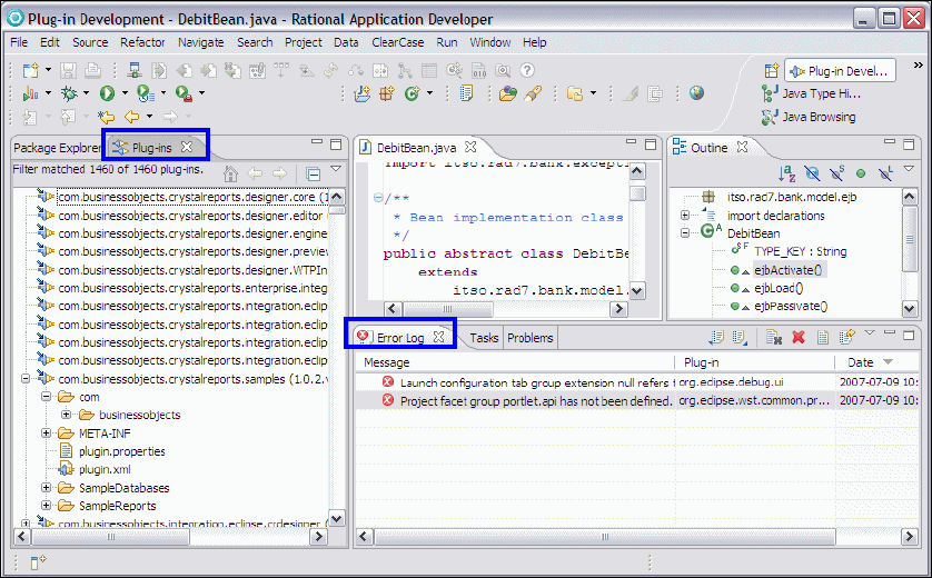
7672-intro-4-perspective.fm Draft Document for Review December 9, 2008 2:44 pm
148 Rational Application Developer V7.5 Programming Guide
The Plug-in Development perspective (Figure 4-20) includes:
Plug-ins view—Shows the combined list of workspace and external plug-ins.
Error Log view—Shows the error log for the software development platform,
allowing a plug-in developer to diagnose problems with plug-in code.
The perspective also includes Package Explorer, Outline, Tasks, and Problems
views, which have already been described earlier in this chapter.
Figure 4-20 Plug-in Development perspective
This book does not cover how to develop plug-ins for Rational Application
Developer or Eclipse. To learn more about plug-in development, refer to the
IBM Redbooks publication, Eclipse Development using the Graphical Editing
Framework and the Eclipse Modeling Framework, SG24-6302, or The Java
Developer’s Guide to Eclipse-Second Edition, by D’Anjou et al (refer to
http://jdg2e.com).
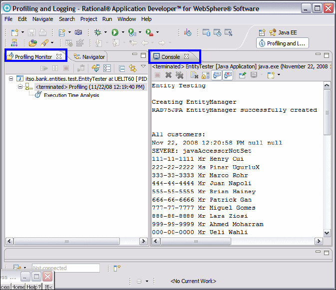
Chapter 4. Perspectives, views, and editors 149
Draft Document for Review December 9, 2008 2:44 pm 7672-intro-4-perspective.fm
Profiling and Logging perspective
The Profiling and Logging perspective (Figure 4-21) provides a number of views
for working with logs and for profiling applications:
Profiling Monitor view—This view shows the process that can be controlled
by the profiling features of Rational Application Developer. Performance and
statistical data can be collected from processes using this feature and
displayed in various specialized views and editors.
Figure 4-21 Profiling perspective
In addition to this, there are several editors for viewing the results of profiling, for
example the Memory Statistics view and the Object References view. More
details about these views and the techniques required to use them can be found
in Chapter 27, “Profile applications” on page 983.
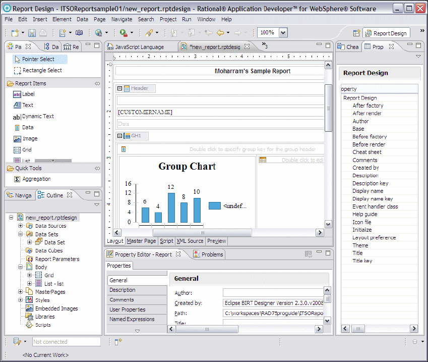
7672-intro-4-perspective.fm Draft Document for Review December 9, 2008 2:44 pm
150 Rational Application Developer V7.5 Programming Guide
Report Design perspective
The Report Design perspective (Figure 4-22) allows developers to design and
develop report templates using the Business Intelligence and Reporting Tools
(BIRT) framework, which is an Eclipse-based open source reporting system for
Web applications, especially those based on Java and Java EE.
Figure 4-22 Report Design perspective
The BIRT system also includes a runtime component to process these reports
which can be added to an Application Server. The Reports Designer editor
provides the facility to layout the fields on the report template and to map these
fields with data from XML schemas, Web Services, flat files, or database
definitions and to test them within Application Developer.

Chapter 4. Perspectives, views, and editors 151
Draft Document for Review December 9, 2008 2:44 pm 7672-intro-4-perspective.fm
For more information about using Rational Application Developer for generating
reports with BIRT, see the Help or visit the following link which is a reference to
the Eclipse project for providing the functionality of this perspective:
http://eclipse.org/birt/phoenix/project
Requirement perspective
This perspective defines an initial set and layout of views in the Workbench
window. The Requirement perspective includes a set of views that supports
access to Rational RequisitePro requirements, documents, query results,
properties, and traceability.
The Requirement perspective includes the following views:
Requirement Explorer view—Manages the set of requirement available in
the Rational RequisitePro server.
Requirement Link Problems view—This view can be used to review and
resolve link problems between requirements and domain elements.
Association (or link) problems occur when associated artifacts are moved,
deleted, or are otherwise unavailable.
Requirement Query Results view—Using this view you can create a view of
query results for a particular requirement type. You can filter the view by
searching, sorting, or displaying specific requirement attributes or properties.
Link Clipboard view—Using this view, system architects or development
managers can create association with the requirements in linkable domains
such as Java EE.
Requirement Trace view—In this view and modify traceability relationships
in the Requirement Trace view.
Requirement traceability is a relationship between two requirements that
implies the source, derivation, or dependencies between the artifacts
Requirement Text view—Displays the name and description of the selected
requirement.
Requirement Editor view—In this view you can edit the name, description,
and attributes for requirements.
Important: Rational RequisitePro has to be installed on your machine in order
to have the requirement management capability enabled in Rational
Application Developer v7.5 on the same machine. This is clear in the message
box which appears when you switch to the Requirement perspective and
Rational RequisitePro is not installed on your machine.

7672-intro-4-perspective.fm Draft Document for Review December 9, 2008 2:44 pm
152 Rational Application Developer V7.5 Programming Guide
Resource perspective
The Resource perspective is a very simple perspective (Figure 4-23). By default
it contains only Navigator, Outline, and Tasks views and an editor area. It can
be useful when it is necessary to view the underlying files and folders present for
a project without any extra information added. All the views in this perspective
are available in other perspectives and have been described previously.
Figure 4-23 Resource perspective
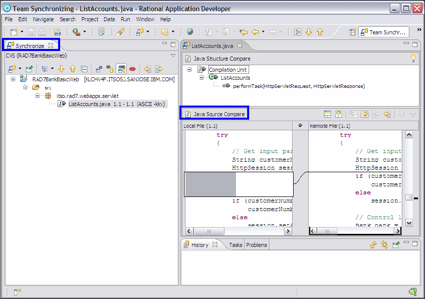
Chapter 4. Perspectives, views, and editors 153
Draft Document for Review December 9, 2008 2:44 pm 7672-intro-4-perspective.fm
Team Synchronizing perspective
The Team Synchronizing perspective provides the features necessary to
synchronize the resources in the workspace with resources held on an SCM
repository system. This perspective is used with CVS and ClearCase
repositories, plus any other source code repository which might run as an
additional plug-in to Application Developer.
Figure 4-23 shows a typical layout while working in the Team Synchronizing
perspective.
Figure 4-24 Synchronizing resources using the Team Synchronizing perspective
The following views are important when working in this perspective:
Synchronize view—For any resource with is under source control, the user
can select Team → Synchronize, which prompts the user to move to the
Team Synchronizing and show the Synchronize view. It displays the list of
synchronization items that result from the analysis of the differences between

7672-intro-4-perspective.fm Draft Document for Review December 9, 2008 2:44 pm
154 Rational Application Developer V7.5 Programming Guide
the local and repository versions of your projects. Double-clicking an item will
open the comparison view to help you in completing the synchronization.
Source Code Comparison editor—This editor appears in the main editor
area and shows a line by line comparison of two revisions of the same source
code.
Also present in the Team Synchronizing perspective is the History view to show
the revision history of a given resource file and the Tasks and Problems view.
More details about these views on this perspective and how to use them can be
found in Chapter 28, “CVS integration” on page 1019.
Test perspective
The Test perspective (Figure 4-25) provides a framework for defining and
executing test cases and test suites. Note that the focus here is on running the
tests and examining the results rather than building the code contained in JUnit
tests. Building JUnit tests involves writing sometimes complex Java code and is
best done in the Java perspective.
The following views are important when working in this perspective:
Test Navigator—The main navigator view for browsing and editing test suites
and reviewing test results. It has two main options to structure the display of
these resources. The Show the Resource test navigator () option shows
the resources based around the file system but with the test suites displayed
at the bottom can containing their associated test cases. The Show the
Logical test navigator ( ) option shows the resources arranged by Test
suites, source code and test results.
Test Log view—If the user clicks on a test result, this view is shown in the
main editor area showing the date/time and result of the test.
Test editor—Shows a summary of a test suite and its contained tests.
The Tasks, Properties, and Outline views are also present and useful when
working in the Test perspective. These have already been covered in this
chapter.
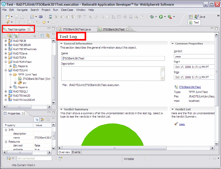
Chapter 4. Perspectives, views, and editors 155
Draft Document for Review December 9, 2008 2:44 pm 7672-intro-4-perspective.fm
Figure 4-25 Test perspective
More information about Component Testing is located in Chapter 23, “Test using
JUnit” on page 819.
Web perspective
Web developers can use the Web to build and edit Web resources, such as
servlets, JSPs, HTML pages, style sheets and images as well as the deployment
descriptor web.xml. Figure 4-26 shows a typical layout while developing in this
perspective.
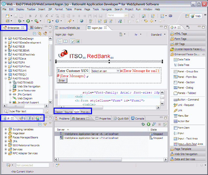
7672-intro-4-perspective.fm Draft Document for Review December 9, 2008 2:44 pm
156 Rational Application Developer V7.5 Programming Guide
Figure 4-26 Web perspective
The Web perspective contains the following views and editors:
Page Designer—Page Designer allows you to work with HTML files, JSP
files, and embedded JavaScript. Within the Page Designer, you can move
among three tabs that provide different ways for you to work with the file that
you are editing. This editor is synchronized with the Outline and Properties
views, so that the selected HTML or JSP element always appears in these
views. The main tabs provided by Page Designer are as follows:
–Design—The Design page of Page Designer is the WYSIWYG mode for
editing HTML and JSP files. As you edit in the Design page, your work
reflects the layout and style of the Web pages you build without the added
complexity of source tagging syntax, navigation, and debugging. Although

Chapter 4. Perspectives, views, and editors 157
Draft Document for Review December 9, 2008 2:44 pm 7672-intro-4-perspective.fm
all tasks can also be done in the Source page, the Design view should
allow most operations to be done more efficiently and without requiring a
detailed knowledge of HTML syntax.
–Source—The Source page enables you to view and work with a file's
source code directly.
–Split—Combines the Source page and either the Design page or the
Preview page in a split screen view. Changes that you make in one part of
the split screen can immediately be seen in the other part of the split
screen. You can split the screen horizontally or vertically.
–Preview—Shows how the current page is likely to look when viewed in a
Web browser. JSPs shown in this view will contain only static HTML
output.
Web Diagram editor —Use the Web diagram editor (Figure 4-27) to design
and construct the logic of a Web application.From within the Web diagram
editor you can configure your Web application by creating a navigation
structure, adding data to pages, and creating actions and connections. The
palette allows you to add visual representations called nodes for Web pages,
Web projects, connections, and JSF and Struts resources (if you have these
facets added to your Web project).
Figure 4-27 Web Diagram editorr
Gallery view—Contains a variety of catalogs of reusable files that can be
applied to Web pages. The file types available include images, wallpaper,
Web art, sound files and style sheet files.
Page Data view—Allows you manage data from a variety of sources such as
Enterprise JavaBeans, JavaBeans, Service Data Objects, Java Persistence
7672-intro-4-perspective.fm Draft Document for Review December 9, 2008 2:44 pm
158 Rational Application Developer V7.5 Programming Guide
API, and Web Services, which can be configured and dropped onto a JSP
page.
Services view—Lists all of the services available to all of your projects
including Web services and RPC Adapter services. This view does not
require you to open a Web page in the editor in order to view the services
specific to that particular page.
Styles view—Provides guided editing for cascading style sheets and
individual style definitions for HTML elements.
Thumbnails view—Shows thumbnails of the images in the selected project,
folder, or file. This view is especially valuable when used with the Gallery view
to add images from the artwork libraries supplied by Application Developer to
your page designs. When used with the Gallery view, thumbnail also displays
the contents of a selected folder. You can drag and drop from this view into
the Enterprise Explorer view or to the Design or Source page of Page
Designer.
Quick Edit view—Allows you to edit small bits of code, including adding and
editing actions assigned to tags. This view is synchronized with what element
is selected in the Page Designer. You can drag and drop items from the
Snippets view into the Quick Edit view.
Palette view—Contains expandable drawers of drag and drop objects. Allows
you to drag objects, such as tables or form buttons, onto the Design or Source
page of the Page Designer.
The Enterprises Explorer, Outline, Properties, Servers, Console, Problems, and
Snippets views are also present in the Web perspective and have already been
discussed in this chapter.
More information about developing JSPs and other Web application components
in the Web persecutive can be found in Chapter 13, “Develop Web applications
using JSPs and servlets” on page 317.
Work items perspective
The Work Items perspective enables team members to easily see and track work
assigned to them and submitted against the categories for which they are
responsible. Project managers can use this perspective to plan development
work for iterations and obtain metrics that indicate the progress the team is
making towards its development and quality goals. This perspective is similar to
the Jazz Administration perspective with more focus on team members’ work
items.
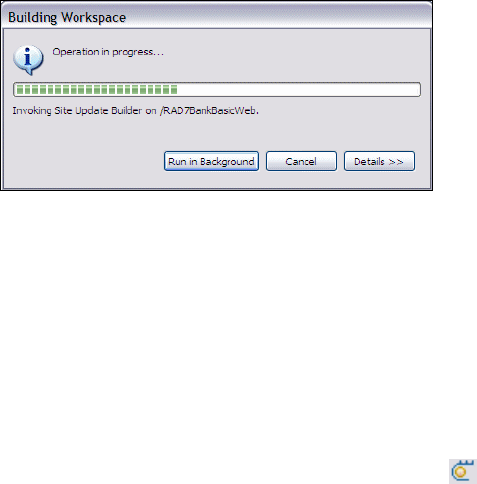
Chapter 4. Perspectives, views, and editors 159
Draft Document for Review December 9, 2008 2:44 pm 7672-intro-4-perspective.fm
The views of this perspective are as follows:
My Work view—Use this view to triage new work items assigned to you;
manage work items in progress; and manage work items that you plan to
resolve in a future iteration.
Team Central view—This view is organized into multiple News, Events, and
Queries sections that are updated continually with the latest developments,
such as build operations, change set deliveries, and work item modifications
that affect your project.
Tag Cloud view—Use this view to create a tag cloud. For a given query, a tag
cloud displays the number of work items by tag attribute.
Team Artifact and Work Items views are also present in this perspective and
have been already discussed earlier in this chapter.
Progress view
The Progress view is not part of any perspective by default, but is a very useful
tool when using Rational Application Developer. When Rational Application
Developer is carrying out a task that takes a substantial amount of time, a prompt
might appear with two options available (Figure 4-28).
Figure 4-28 Progress view
The user can either watch the dialog until the operation completes, or the user
can click Run in Background and the task continues in the background. If the
second option is selected, Rational Application Developer runs more slowly, but
the developer can carry out other tasks while waiting. Examples of tasks that
might be worth running in the background would be publishing and running an
enterprise application, checking a large project into CVS, or rebuilding a complex
set of projects.
If Run in Background is clicked, then the Progress view can be shown again to
review the status of the running task by clicking the icon in the bottom right of
the workspace. Note that this icon only shows if there are processes running in
the background.
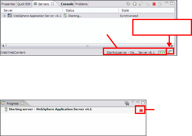
7672-intro-4-perspective.fm Draft Document for Review December 9, 2008 2:44 pm
160 Rational Application Developer V7.5 Programming Guide
Some processes do not prompt the user with a dialog and run in the background
when they are initiated. In these cases, the Progress view can be accessed in the
same way.
For example, when a Web application is published to the test server and the
server has to be started, this process might take some time. By default this
condition shows as a flashing status bar in the bottom left of the workspace and
the icon to show the Progress view appears (Figure 4-29).
Figure 4-29 Process information in status bar
If the user becomes concerned about the time the deployment process is taking,
then the Progress view can be opened, the current process reviewed, and if
necessary, stopped (Figure 4-30).
Figure 4-30 Progress view
Summary
In this chapter, the perspectives available within Application Developer and the
main views associated were described. Parts 2, 3, 4, and 5 of this book
demonstrate in detail the use of most of these perspectives for various
development scenarios.
Web Server start-up status indicator
Click here to show
the Progress view
Click here to stop
this process

© Copyright IBM Corp. 2008. All rights reserved. 161
Draft Document for Review December 9, 2008 2:44 pm 7672-intro-5-projects.fm
Chapter 5. Projects
This chapter provides an overview of the types of projects that can be created
with Rational Application Developer and the main features of each project type.
Since many of the available project types are used when constructing Java
Enterprise Edition 5 (Java EE 5) applications the chapter starts with a review of
the main features of the Java EE 5 platform, including the packaging of project
code for deployment to an application server.
Basic techniques for the manipulation of projects including project creation and
deletion are covered next, followed by a section listing all the project wizards
provided by Application Developer for the creation of new projects. Finally, there
is a discussion of the sample projects provided.
The chapter is organized into the following sections:
The Java Enterprise Edition 5 platform
Java EE 5 project types
Project basics
Project wizards
Sample projects
Summary
5
7672-intro-5-projects.fm Draft Document for Review December 9, 2008 2:44 pm
162 Rational Application Developer V7.5 Programming Guide
The Java Enterprise Edition 5 platform
Java EE is platform used to host enterprise applications ensuring that they highly
available, reliable, scalable, and secure. Java EE 5 is the latest version of the
Java Enterprise Edition platform and is fully supported by Rational Application
Developer V7.5.
The Java EE 5 specification, along with many other resources relating to Java EE
5, are available at
http://java.sun.com/javaee/index.jsp
The Java EE architecture is composed of a set of containers each of which is a
runtime environment that hosts specific Java EE components and provides
services to those components. The details of the services provided by each
container are documented in the Java EE specification document available at:
http://jcp.org/aboutJava/communityprocess/final/jsr244/index.html
The four containers which comprise the Java EE architecture are:
The Enterprise JavaBeans (EJB) container. This container hosts EJB
components which are typically used to provide business logic functionality
with full transactional support. This container runs on the application server.
The Web container. This container hosts Web components such as servlets
and JavaServer Pages which are executed in response to HTTP requests
from a Web client application such as a Web browser. This container runs on
the application server.
The Application Client container. This container hosts standard Java
applications, with or without a GUI and provides the services required for
those applications to access enterprise components in an EJB container.This
container runs on a client machine.
The Applet container. This container hosts Java applets. Applets are GUI
applications that are typically presented by a Web browser. The applet
container runs on a client machine under the control of a Web browser.
The Java EE architecture containers are shown in Figure 5-1. The diagram also
includes a database which is typically used for the persistence of enterprise
application data. It is not necessary to employ all of the containers in a specific
enterprise application. In some enterprise applications only the Web container is
employed. All business logic and persistence functionality executes in the Web
container along with the code which presents the user interface. In other
enterprise applications only the Web container and EJB container are employed.
The user interface is presented by components in the Web container with all
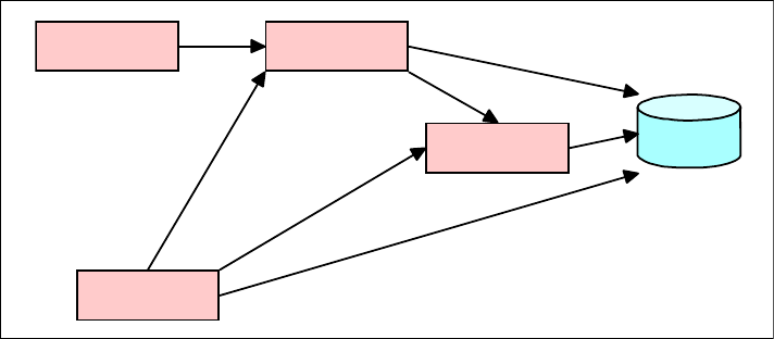
Chapter 5. Projects 163
Draft Document for Review December 9, 2008 2:44 pm 7672-intro-5-projects.fm
business logic and persistence functionality delegated to the EJB container and
the EJB components it contains.
Figure 5-1 Java EE Architecture Containers
A Java EE enterprise application is assembled from one or more Java EE
modules. Java EE modules contain one or more enterprise application
components. An optional deployment descriptor, which describes the module
and the components it contains may also be included in the module. The
following sections provide a summary of the purpose served by each of the
modules and the types of component typically contained in the module.
Subsequent sections describe the types of projects within Application Developer
that are used to create each module.
A high level view of the module structure of a Java EE enterprise application is
shown in Figure 5-2.
Database
Applet Container
Application
Client Container
Web Container
EJB Container
see Java EE 5 spec
fig EE.2-1
7672-intro-5-projects.fm Draft Document for Review December 9, 2008 2:44 pm
164 Rational Application Developer V7.5 Programming Guide
Figure 5-2 Java EE 5 module structure
Enterprise application modules
Enterprise application modules contain one or more of the other types of Java EE
modules. They act as the highest level enterprise application packaging unit in
that they do not themselves contain any components, just modules. Modules
contained in an enterprise application are deployed as a unit to the WebSphere
Application Server. Enterprise application modules are packaged as EAR files
with the extension .ear. EAR files are standard Java archive files which have a
defined directory structure. An optional deployment descriptor called
application.xml may be included.
An enterprise application module can include zero or more of the following
modules:
Web modules—WAR files with the extension .war
EJB modules—EJB JAR files with the extension .jar
Application client modules—Application client JAR files with the extension
.jar
Java EE Application
(EAR File)
Includes:
- application.xml (deployment descriptor)
- *.jar (ejb, application client, and utility jar)
- *.war (web applications)
- *.rar (resource adaptors)
Web Application Module
(WAR File)
Includes:
- web.xml (Web deployment descriptor)
- *.class files (including servlets and any other Java utility class)
- *.jsp files
- *.html, *.jpeg and any other resource available from the web app
EJB Module
(JAR File)
Includes:
- ejb-jar.xml (EJB deployment descriptor)
- *.class files (including the EJBs any other Java utility class)
Java Utility Library
(JAR File)
Includes:
- *.class files
Application Client Module
(JAR File)
Includes:
- application-client.xml (application client deployment descriptor)
- *.class files (required to work with the EAR, plus for application itself)
Resource Adapter Module
(RAR File)
Includes:
- ra.xml (resource deployment descriptor)
- *.class files
- other application resources applicable to
what is being adpated
contains
0 or more
contains
0 or more contains
0 or more
contains
0 or more
contains
0 or more
PG: can WAR
contain JARs
Chapter 5. Projects 165
Draft Document for Review December 9, 2008 2:44 pm 7672-intro-5-projects.fm
Resource adapter modules—Resource adapter archive files with the
extension .rar
Utility Libraries—JAR files with the extension .jar which are shared by all the
other modules packaged in the EAR.
Web modules
Web modules contain all the components that are part of a specific Web
application. These components often include:
HyperText Markup Language (HTML) files
Cascading style sheets (CSS) files
JavaServer Pages (JSP) files
Compiled Java servlet classes
Other compiled Java classes
Image files
Portlets (portal applications)
Web modules are packaged as WAR files with the extension .war. WAR files
have a defined directory structure and include a deployment descriptor called
web.xml, which contains the configuration information for the Web module. The
web.xml is optional if the module only contains JSP files. Each Web module has
a defined context root which determines the URL required to access the
components present in the Web module.
EJB modules
An EJB module contains EJB components. EJB modules are packaged as JAR
files with the extension .jar. EJB JAR files have a defined directory structure and
include an optional deployment descriptor called ejb-jar.xml, which contains
configuration information for the EJB module. Alternatively, the configuration can
be defined using annotations in the Java classes.
Application client modules
An Application Client module contains enterprise application client code.
Application client modules are packaged as JAR files with the extension .jar. An
application client module typically includes the classes and interfaces to allow a
client application to access EJB components in an EJB module. Code in an
application client module can also access components in a Web module. The file
has a defined directory structure and includes an optional deployment descriptor
called application-client.xml.
7672-intro-5-projects.fm Draft Document for Review December 9, 2008 2:44 pm
166 Rational Application Developer V7.5 Programming Guide
Resource adapter modules
A Resource Adapter (RA) module contains resource adapters. Resource adapter
modules are packaged as .rar files. Resource adapters provide access to
back-end resources using services provided by the application server. Resource
adapters are often provided by vendors of Enterprise Information Systems such
as SAP and PeopleSoft® to facilitate access from Java EE 5 applications.
Resource adapter modules can be installed as a stand-alone modules within the
application server, allowing them to be shared by several enterprise applications.
They may also be included in a specific EAR in which case they are only
available to the modules contained within that EAR. A .rar file has a defined
directory structure and contains a deployment descriptor is called ra.xml.
Java Utility Libraries
Java utility libraries can be included in a Java EE enterprise application so that all
the modules included in the application can share the code they contain. Java
utility libraries are packaged as standard Java JAR files with the extension .jar.
Project basics
Within Rational Application Developer projects are contained in a workspace. A
project must be present in a workspace before it can be accessed and used.
Many different types of projects can be created as required for a specific
application. Projects are typically created or imported using one of the wizards
available in Rational Application Developer. The full set of available project
wizards is listed in “Project wizards” on page 176.
Unless otherwise specified, projects are stored in the Application Developer
workspace directory. A workspace is chosen when Rational Application
Developer is started although it is also possible to switch workspaces at a later
time by selecting File → Switch Workspace.
Creating a new project
Development on a new application is usually started by creating one or more
projects. The projects required should be planned beforehand, and then relevant
project wizards should be used to create a skeleton set of projects for the
application under construction. It is also possible to open existing projects if they
are to be used as part of the current application.
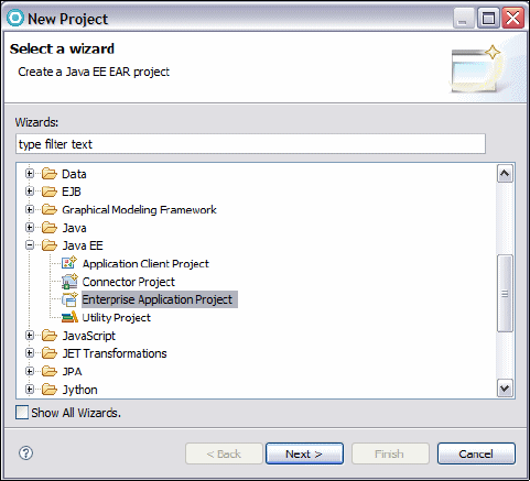
Chapter 5. Projects 167
Draft Document for Review December 9, 2008 2:44 pm 7672-intro-5-projects.fm
As an example of the new project creation process, the following instructions
demonstrate the New Enterprise Application wizard:
To launch this wizard, select File → New → Project.
Select Java EE → Enterprise Application Project and click Next. The New
Project dialog with Enterprise Application Project selected is shown in
(Figure 5-3).
Figure 5-3 New Project dialog with Enterprise Application Project selected
The first dialog of the Enterprise Application Project wizard is shown in
Figure 5-4.

7672-intro-5-projects.fm Draft Document for Review December 9, 2008 2:44 pm
168 Rational Application Developer V7.5 Programming Guide
Figure 5-4 New EAR Application Project: Create a EAR Application
On this dialog you can specify:
–Project Name—The project name, Example in this case.
–Project contents—By default, projects are stored in a subdirectory that is
created for the project in the workspace directory. Using this option,
another location can be specified.
–Target Runtime—An enterprise application project is targeted to run on
an Application Server. This option allows the user to configure the target
runtime environment.
–EAR Version—An enterprise application can be created for a specific
version of Java EE such as 1.4 or 5. In this case version 5 is selected from
the drop down list.
–Configuration—This drop-down provides a list of saved configurations
which have been created for previous enterprise application projects. A
configuration can include a specific set of features and available versions
and it is often a good idea to make sure all similar projects use the same
configuration. An existing configuration can be chosen or <custom> can be
selected. When <custom> is selected the user has the opportunity to
specify their own configuration. Clicking the Modify button allows a
configuration to be modified.
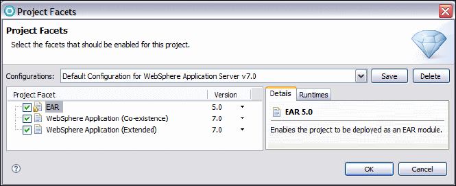
Chapter 5. Projects 169
Draft Document for Review December 9, 2008 2:44 pm 7672-intro-5-projects.fm
If the Modify button is clicked the Project Facets dialog is presented
(Figure 5-5).
This dialog allows the user to customize which features and versions of a
feature will be available in the new project. It is also possible to save the
configuration so that it can be used for subsequent projects. This project
facets page is also used when creating a new Web, EJB, and connector
project but the facet options available are applicable to the type of project
being created.
Figure 5-5 New EAR Application Project: Project Facets
The final dialog (Figure 5-6) gives the user the opportunity to select any other
projects that are to be part of this new enterprise application. This dialog
includes select boxes for all the Java, EJB, Web and Application Client
projects in the current workspace, which, if selected, will be included in the
project references for the new project.
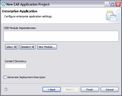
7672-intro-5-projects.fm Draft Document for Review December 9, 2008 2:44 pm
170 Rational Application Developer V7.5 Programming Guide
Figure 5-6 New EAR Application Project: Configure enterprise application settings
On this dialog you can specify:
–Content Directory—This specifies the folder within the Enterprise
Application project under which the contents will be stored. This can be left
empty meaning that all contents will be stored under the root directory.
–New Module—This button provides the ability to automatically create
empty projects referenced by the new Enterprise Application project.
Clicking New Module displays the dialog shown in Figure 5-7. Since the
current workspace in this example does not contain any other projects the
existing modules list is empty. If other projects are available they are listed
and can be selected or deselected as required.
–Generate Deployment Descriptor—Because the deployment descriptor
file, application.xml, is optional, you can choose whether you want one
included or not.
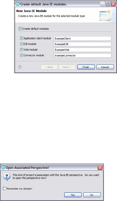
Chapter 5. Projects 171
Draft Document for Review December 9, 2008 2:44 pm 7672-intro-5-projects.fm
Figure 5-7 Create default Java EE module
– Click Cancel if you decide not to create any default Java EE modules.
– Select the boxes for the projects you want to create, change the names if
desired, and click Finish.
Click Finish in the New EAR Application Project wizard, Configure enterprise
application settings dialog, and the new project (and associated projects) are
created.
If the project you have created is associated with a particular perspective, in this
case with the Java EE perspective, but you currently have a different perspective
selected, Rational Application Developer prompts to ask if you wish to switch
over to the relevant perspective (Figure 5-8).
Figure 5-8 Prompt to open relevant perspective
Project properties
To make changes to the properties of a project, right-click the project and select
Properties from the context menu. Figure 5-9 shows the Properties dialog for an
Enterprise Application project.
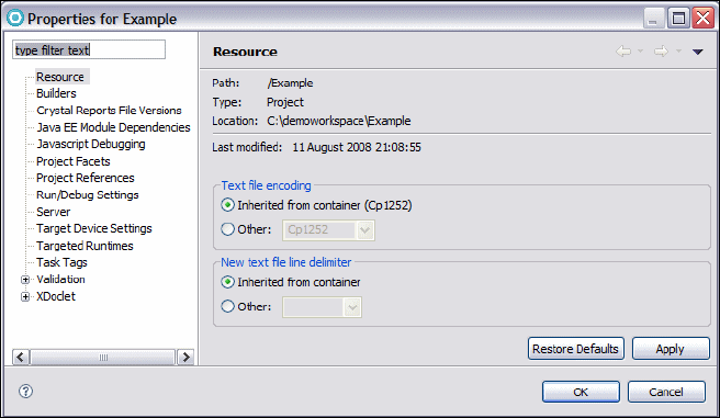
7672-intro-5-projects.fm Draft Document for Review December 9, 2008 2:44 pm
172 Rational Application Developer V7.5 Programming Guide
Figure 5-9 Project properties for an Enterprise Application Project
In the Properties dialog you can edit most project attributes, Each type of project
has different available options.
The options available for an Enterprise Application project include:
Java EE Module Dependencies—Other projects (Web, Java, or Resource)
which this project is dependent upon.
Project Facets—Shows the facets available for this project and provides the
opportunity to add or remove facets.
Project References—Used to configure project dependencies and classpath
entries.
Server—Specifies the default application server to use when running this
application.
Validation—Indicates whether to run any non-default validation tools, and if
so, which ones to run after making changes.
Java Build Path (not for an enterprise application)—Specifies the build path
used to compile the Java code of the project.
Deleting projects
To delete a project from the workspace, right-click the project and select Delete
from the context menu. When deleting projects from a workspace, Rational
Application Developer offers the option to delete the project contents on disk.
Figure 5-10 shows the Delete Resources dialog presented when deleting a
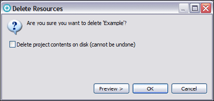
Chapter 5. Projects 173
Draft Document for Review December 9, 2008 2:44 pm 7672-intro-5-projects.fm
project. The default only removes the project from the workspace and leaves the
project files on disk intact. Select the option box if you wish to remove the project
completely. Its important to realize that deleting a project from disk is permanent
and the project cannot be opened again. If a project is only removed from the
workspace then it can later be imported by selecting File → Import →
General → Existing Projects Into Workspace. A project that has been deleted
from the workspace takes up no memory and is not examined during the build
process. Deleting projects from the workspace can improve the performance of
Rational Application Developer.
Figure 5-10 Project Delete Resources dialog
Project interchange files
Projects can be transferred between workspaces as project interchange files. A
project interchange file is a ZIP format file used to encapsulate a project. To
create a project interchange file for any project simply select File → Export →
Other → Project Interchange and specify which projects to export and to which
location. To import projects, stored as a project interchange file, into another
workspace select File → Import → Other → Project Interchange. Note that
when exporting and importing a project, the project interrelationships are also
transferred but not the referenced projects. It might therefore also be necessary
to export all the related projects.
Closing projects
It is also possible to close projects present in a workspace. Closing a project
locks it so that it cannot be edited or referenced from another project. This can be
done se;ecting either Close Project or Close Unrelated Projects from the
Enterprise Explorer context menu. Closed projects are still visible in the
workspace but they cannot be expanded.
Closing non-important projects can speed up compilation times as the underlying
application builders only have to check for resources in open projects. Closed
projects can be re-opened by selecting Open Project from the context menu.
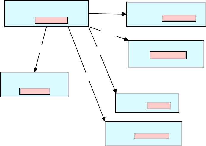
7672-intro-5-projects.fm Draft Document for Review December 9, 2008 2:44 pm
174 Rational Application Developer V7.5 Programming Guide
Java EE 5 project types
Rational Application Developer complies with the Java EE 5 specifications for the
development of enterprise applications.
Module packaging into files as described in “The Java Enterprise Edition 5
platform” on page 162, is only applied by Rational Application Developer when a
Java EE project is exported or deployed.
While working within Rational Application Developer only the projects present in
the workspace are edited. The relationships between the enterprise application
projects, and the modules they contain, are managed by Rational Application
Developer, and are applied on export or deployment to produce a properly
packaged EAR file.
The arrangement between projects and their associated outputs is shown in
Figure 5-11. Note that this diagram relates to Figure 5-2 on page 164, where the
relationships between various Java EE modules are reflected in the Application
Developer project references.
Figure 5-11 Java EE projects in Application Developer
EAR File
Enterprise Application Project
WAR File
Dynamic Web Project
JAR File
EJB Project
Project
Reference Utility Project
JAR File
Application Client Project
JAR File
Project
Reference
RAR File
Connector Project Project
Reference
Project
Reference Project
Reference
Chapter 5. Projects 175
Draft Document for Review December 9, 2008 2:44 pm 7672-intro-5-projects.fm
Enterprise application project
Enterprise Application projects contain the resources needed for enterprise
applications and can contain references to a combination of Web projects, EJB
projects, application client projects, resource adapter projects and utility library
projects.
The relationships can be specified when creating a new Enterprise Application
project through the wizard as previously shown or through the project properties.
For more information on developing Java EE enterprise applications, see
Chapter 14, “Develop EJB applications” on page 387.
Application client project
Application Client projects contain the resources needed for application client
modules. An application client module is used to contain a fully-functioning client
Java application (non-Web-based) that connects to and uses the resources in an
enterprise application and an application server. By holding a reference to the
associated enterprise application, it shares information such as the Java Naming
and Directory Interface (JNDI) references to EJBs and to data sources.
The wizard allows the Java EE version, the target server, and the associated
enterprise application to be specified. For more information on developing
application clients, refer to Chapter 17, “Develop Java EE application clients” on
page 543.
Dynamic Web project
A dynamic Web project contains the resources needed for Web applications,
such as JSPs, Java Servlets, HTML and other files. The dynamic Web project
wizard provides the capability to configure the version of the Java servlet
specification, target server, EAR file name, and context root. The wizard also
allows various other features to be added to the dynamic Web project, including:
A CSS file
Struts support
A Web diagram
JSP tag libraries
Web page templates
Struts support
JSP support
When building a dynamic Web project, the user is prompted for the facets which
are to be used by the new project, and then the wizard automatically adds the
supporting libraries and configuration files to the new project. By selecting the
appropriate facets, it is possible to create a project which uses Struts or
JavaServer Faces as the framework for building a Web application.
7672-intro-5-projects.fm Draft Document for Review December 9, 2008 2:44 pm
176 Rational Application Developer V7.5 Programming Guide
For more information on developing Web applications, see Chapter 13, “Develop
Web applications using JSPs and servlets” on page 317.
EJB project
EJB projects contain the resources for EJB applications. This includes the
classes and interfaces for the EJB components, the deployment descriptor for
the EJB module, IBM extensions, and bindings files, and files describing the
mapping between entity beans in the project and relational database resources.
The wizard allows the EJB version, target server, and EAR file to be specified as
well as a selection of facet features applicable for EJBs. An EJB Client JAR can
also be created, which includes all the resources needed by client code to
access the EJB module (the interfaces and stubs).
For more information on developing EJBs, see Chapter 14, “Develop EJB
applications” on page 387.
Connector project
A connector project contains the resources required for a Java EE resource
adapter. The wizard allows a set of facets (including the J2EE Connector
Architecture (JCA) version) and associated EAR file to be specified.
Utility project
A Utility project is Java project containing Java packages and Java code as .java
files and .class files. They have an associated Java builder that incrementally
compiles Java source files as they are changed and can be exported as JAR files
or into a directory structure.
Project wizards
The following list describes many of the wizards that can be used to create
projects within Application Developer. To invoke a wizard, simply use File →
New → Project and select the appropriate project wizard. A wizard prompts the
user for the required information as appropriate for the type of project.
Project (General)—This is the simplest project which just contains a
collection of files and folders. It contains no builders and is useful for creating
a project which has no application code, for example, a project to store XML
or XSD files or to store application configuration information.
Faceted Project (General)—Allows a project to be created using a specific
pre-existing configuration or using a selection of facets selected when the
wizard is executed.
Chapter 5. Projects 177
Draft Document for Review December 9, 2008 2:44 pm 7672-intro-5-projects.fm
Report Project (Business Intelligence and Reporting tools, BIRT)—The
BIRT system (refer to http://eclipse.org/birt/phoenix/project) is an
initiative to build an open source reporting system in Java. This wizard
creates a report project which has facilities to combine database information
or content from XML into report templates.
Crystal Reports Web project (Crystal Reports)—This creates a Web
project with Crystal reports features activated. The new project includes the
libraries for the Java Reporting Component and support for Crystal Reports
Viewer pages, which is built on JSP technology. Note that support for Crystal
reports must be selected on installation of Application Developer for this to be
available.
User Function Library (Crystal Reports)—This type of project allows Java
code to be called from a Crystal reports formula. The wizard creates a project
very similar to a Java project but with links to the Crystal Reports Java
libraries.
Projects from CVS (CVS)—This wizard guides the user through the creation
of a new project by checking out an existing project within CVS. It is possible
to check-out a complete project from CVS, or to create a new project as part
of the check-out process.
Data Design Project (Data)—This wizard creates a project to store data
design artifacts, including data design models and SQL statements.
Data Development Project (Data)—This wizard creates a project which
stores a connection to a given database. From within such a project it is
possible to create resources to interrogate and manipulate the associated
database. Initially the wizard creates folders to store SQL scripts and stored
procedures.
Existing RAD6.x Data Definition Project (Data)—The tooling which
supports database definitions has changed since Application Developer
V6.0.X and V5.1.2. Therefore, any data project which contain database
definitions or other database objects created in the Data definition view from
previous versions of Application Developer must be migrated to work with
V7.5. This wizard takes a project folder in the old format and migrates it for
V7.5.
EJB Project (EJB)—Guides the user through the process of creating a
project suitable for containing EJB components. This procedure also creates
an empty EJB deployment descriptor and associates the project with an
enterprise application project.
Application Client Project (Java EE)—Guides the user through the creation
of an empty Application Client project. The wizard prompts for the associated
EAR project and presents a list of facets applicable for Java EE Application
Client projects.
7672-intro-5-projects.fm Draft Document for Review December 9, 2008 2:44 pm
178 Rational Application Developer V7.5 Programming Guide
Connector Project (Java EE)—Guides the user through the creation of a
Java EE connector project, which includes specifying the associated
enterprise application project and a set of facets applicable to this type of
project.
Enterprise Application Project (Java EE)—Creates a new EAR project.
Includes options for creating associated Web, EJB, and Application Client
projects.
Utility Project (Java EE)—Assists in the construction of a Java utility library
project which is associated with an Enterprise Application project. Code
present in a Java utility library that is present in a Java EE application is
shared between the modules present in the application.
Java Project (Java)—A simple wizard use to create a Java application
project. The wizard allows the class path including project dependencies to be
specified.
Java Project from Existing Ant Buildfile (Java)—It is possible to export the
build settings of a project as an Ant file (use File → Export → General →
Ant Buildfiles). Given such an Ant build file, this wizard can be used to
create a new project based on the instructions contained within it.
Jython Project (Jython)—Creates an empty project for developing Jython
resources.
JPA Project (JPA)—Creates a Java Persistence API (JPA) project. JPA is a
Java EE 5 standardized object-relational mapping framework taht works
together with the EJB 3.0 standard.
Feature Patch, Feature Project, Fragment Project, Plug-in from Existing
JAR Archives, Plug-in Project and Update Site Project (Plug-in
Development)—These wizards assist in the creation of Eclipse plug-ins,
features, and fragments, which can enhance existing Eclipse (or Application
Developer) perspectives or create entirely new ones. The Rational Application
developer help system has a section on how to use these wizards, and the
Eclipse plugin central home page (http://www.eclipseplugincentral.com)
has information on many plug-ins already built and tutorials on building new
ones.
SIP 1.0 Project (SIP)—The Session Initiation Protocol (SIP) is an extension
to the Java EE servlets API intended for telecommunications applications
using technologies such as Voice Over IP (VOIP). This wizard creates a Web
project with the appropriate facets selected to allow the construction of SIP
applications.
Dynamic Web Project (Web)—Create a project for a Web application, which
can include JSPs, servlets, and other dynamic content.

Chapter 5. Projects 179
Draft Document for Review December 9, 2008 2:44 pm 7672-intro-5-projects.fm
Static Web Project (Web)—Creates a project for a Web application
containing only images, HTML files, and other static Web resources. A static
Web project contains no dynamic content.
Each wizard will create an empty project of the specified type with the structures,
files, folders, supporting libraries, and references to support such a project. Once
created, it is still possible to change aspects of the project through the project
properties.
Sample projects
Rational Application Developer provides a wide range of sample applications that
can help you to explore the features provided by the software development
platform and the different types of projects that can be created.
The samples can be accessed in two ways:
The Help → Samples option from the main menu. This displays the
application developer help system samples page.
The welcome screen, presented when a new workspace is started. On the
welcome screen you can click the Samples icon (a grey circle containing a
yellow ball, blue cube, and green pyramid) . This presents a samples page
which links to samples present in the application developer help system.
Help system samples
The help system samples can be selected from a hierarchical list in the left-hand
pane (Figure 5-12).
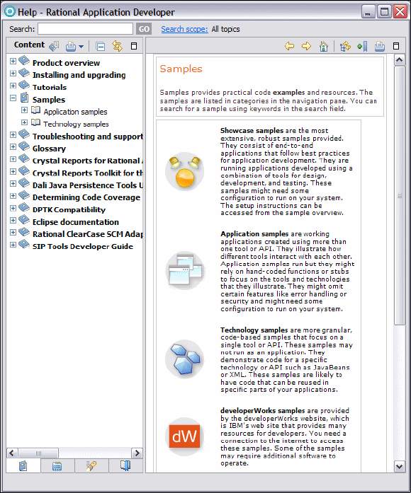
7672-intro-5-projects.fm Draft Document for Review December 9, 2008 2:44 pm
180 Rational Application Developer V7.5 Programming Guide
Figure 5-12 Help System samples
The samples are arranged in four main categories:
Showcase samples—The most extensive samples provided. These contain
complete multi-tier, end-to-end applications that follow best practices for
application development.
Application samples—Applications created using more than one tool or API,
showing how different tools within Rational Application Developer interact with
each other.
Technology samples—Smaller, code-based samples that focus on a single
tool or API.
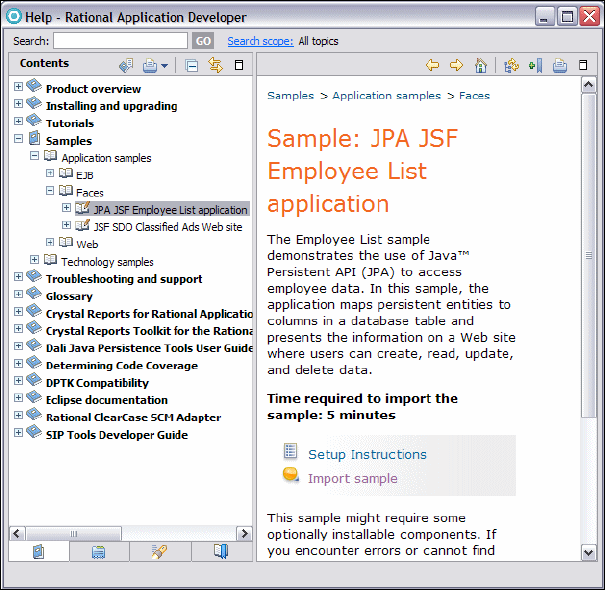
Chapter 5. Projects 181
Draft Document for Review December 9, 2008 2:44 pm 7672-intro-5-projects.fm
developerWorks samples—These samples are linked to the IBM
developerWorks Web site and contain the latest samples published on this
site. An internet connection is required to access these samples.
For example, the JPA JSF Employee List application is one of the Faces
Application samples. The starting page for this sample provides an introduction
and links to setting up the sample, getting the sample code, running the sample,
and references for further information. Figure 5-13 shows the starting page for
the JPA JSF Employee List sample application.
Figure 5-13 JPA JSF Employee List Sample
The Import sample link shows the user the sample projects that can be
imported to the current workspace (Figure 5-14).
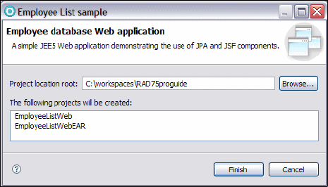
7672-intro-5-projects.fm Draft Document for Review December 9, 2008 2:44 pm
182 Rational Application Developer V7.5 Programming Guide
Figure 5-14 Import Employee List sample
Click Finish to import the sample projects (in this case two projects) and build
them. The user is now free to run, modify, and experiment with the imported code
as required.
Example Projects wizard
An additional way to access sample projects is through the New Project dialog.
Application Developer provides a number of example projects wizards that can
be used to add sample projects to a workspace. Select New → Project →
Examples, and choose one of the sample projects from the list (Figure 5-15).
For example, the sample projects provide model solutions for application logging
and XML processing. Running the wizard adds the example project to the
workspace and also displays an entry from Application Developer help
describing the sample.
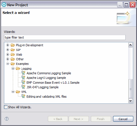
Chapter 5. Projects 183
Draft Document for Review December 9, 2008 2:44 pm 7672-intro-5-projects.fm
Figure 5-15 Example projects in the New Project dialog
Summary
In this chapter we discussed the main types of project that can be created with
Application Developer, in particular, those used in the development of Java EE
applications.
We also presented the basic techniques for handling projects within an
Application Developer workspace, looked at the range of wizards available for the
creation of projects and provided an introduction to the samples that are supplied
with Application Developer.
In the remaining chapters of this book we discuss in more detail the use of the
each different type of projects in Application Developer and the specific features
available in each project type when building different types of applications.
7672-intro-5-projects.fm Draft Document for Review December 9, 2008 2:44 pm
184 Rational Application Developer V7.5 Programming Guide

© Copyright IBM Corp. 2008. All rights reserved. 1
Draft Document for Review December 9, 2008 2:44 pm 7672-arch-0-p2.fm
Part 2 Architecture and
modeling
In this part of the book we introduce the Rational Unified process (RUP),
patterns, service-oriented architecture, and the Unified Modeling Language
(UML).
Part 2
7672-arch-0-p2.fm Draft Document for Review December 9, 2008 2:44 pm
2 Rational Application Developer V7.5 Programming Guide

© Copyright IBM Corp. 2008. All rights reserved. 3
Draft Document for Review December 9, 2008 2:44 pm 7672-arch-1-mod.fm
Chapter 6. RUP, patterns, and SOA
This chapter provides an overview of topics which underpin all modern software
development. To begin with the chapter illustrates how a software development
project can ensure that quality software is delivered on time and on budget by
using the Rational Unified Process (RUP). Support for RUP is built into Rational
Application Developer so its very easy to access and use.
In addition, the chapter looks at patterns. Patterns are so widely used nowadays,
on practically every software development project, that its important to have at
least some familiarity with them. Support is provided in Rational Application for
the refactoring of software to apply specific patterns.
Finally, the chapter looks briefly at the software-oriented architecture (SOA)
approach to architecting software systems. This approach is being used by
enterprises both internally to coordinate their own business processes and
externally to allow inter-enterprise software functionality.
The chapter is organized into the following sections:
Rational Unified Process
Patterns
SOA
Additional information
6
7672-arch-1-mod.fm Draft Document for Review December 9, 2008 2:44 pm
4 Rational Application Developer V7.5 Programming Guide
Rational Unified Process
A software development process provides a structured approach to the building,
deploying and maintenance of software. A process provides an answer to the
question: Who is doing what and when. Many different processes are currently in
use and many share similar characteristics. A popular software development
process, that is supported by Rational Application Developer 7.5, is the Rational
Unified Process (RUP).
RUP is a software development process that provides best practice and guidance
for successful software development. It describes a set of tasks, work products
(artifacts), roles and responsibilities that can be applied to a software
development project to ensure the production of high quality software that meets
the client’s requirements within a predictable schedule and budget.
The Rational Unified Process combines the following commonly accepted six
best practices into a cohesive and well documented process description:
Adapt the process. The RUP can be used for projects large and small. Its
important to use the parts of RUP that are appropriate to the project being
undertaken.
Balance competing stakeholder priorities. When undertaking software
development the needs of stakeholders must always be considered. It is
however important to balance the needs of stakeholders, because often their
needs are in conflict and must be resolved.
Collaborate across teams. Since most software systems are complex,
software development is undertaken by teams of developers rather that a
single developer working alone. Its important that a proper collaborative
environment is in place to support adequate communication between team
members.
Demonstrate value iteratively. RUP is an iterative software development
process. An iterative development process can deal with the inevitable
requirements changes that occur while development is taking place and
allows the changes to be accommodated. Risk reduction is one of the main
benefits of working iteratively.
Elevate level of abstraction. Modern software systems are inherently
complex. Working at a high level of abstraction can help to minimize
complexity. Software reuse, modeling, and development of a stable
architecture as soon as possible can all help with this.
Focus continuously on quality. The production of high quality software is
one of the main reasons that a software development process is followed.
Dealing with issues of quality at some specific point during the process
perhaps at the end of development does not work. Quality is something that
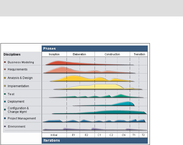
Chapter 6. RUP, patterns, and SOA 5
Draft Document for Review December 9, 2008 2:44 pm 7672-arch-1-mod.fm
must be consider throughout development. The fact that one of the key
principles of RUP is that software be developed iteratively helps this to be
achieved.
The diagram shown in Figure 6-1 is the RUP lifecycle diagram. The diagram
shows the RUP Disciplines and the RUP Phases.
Figure 6-1 Overview of the Rational Unified Process
Disciplines
The RUP disciplines are shown on the vertical axis. They represents the
groupings of the tasks that must be undertaken to provide the artifacts that are
produced while following the process. Consider for example the Implementation
discipline. Many tasks are undertaken in this discipline such as Implement
Design Elements (coding) where the artifact programming language source code
is produced and Implement Developer Test where test scripts are created and
perhaps implemented as actual test code using a framework such as JUnit.
Often developers specialize in a specific RUP discipline but some have expertise
in more than one discipline.
Note: The six tried and tested best practices that underpin RUP have evolved
over the years. The set presented here are the culmination of that evolution.
7672-arch-1-mod.fm Draft Document for Review December 9, 2008 2:44 pm
6 Rational Application Developer V7.5 Programming Guide
Phases
The RUP phases are shown on the horizontal axis. RUP is an incremental
process where the time spent on working on a project is broken down into
phases and iterations.
A phase marks a major stage in the process where specific disciplines are
emphasized and specific artifacts are produced. Each phase is broken down
into iterations which are time boxed and may vary in duration from one week
to many weeks depending on the project.
The number of iterations in each phase also varies depending on the specific
project. Typically there are more iterations in the Elaboration and Construction
phases than in the Inception and Transition phases. Inception is typical one
iteration, but in very large projects may be more than one.
The graphs give an indication of the effort expended in each discipline at each
phases and iteration. Effort may be expended in each discipline in any
iteration and in any phase but as can be seen from the graphs disciplines
have peaks and troughs depending on the specific phase. Tasks undertaken
as part of the requirements discipline typically peak during inception but can
still be undertaken even towards the end of construction. The implementation
discipline tasks peak in the construction phase because they are concerned
mainly with the creation and testing of source code.
Each RUP phase has a specific purpose;
Inception. This is the first phase of RUP. The main purpose of this phase is to
achieve concurrence among all stakeholders on the life cycle objectives for
the project.
Elaboration. This is the second phase of RUP. The main purpose of this
phase is to baseline the architecture of the system and provide a stable basis
for the bulk of the design and implementation effort in the next phase.
Construction. This is the third phase of RUP. The main purpose of this phase
is to complete the development of the system based upon the baselined
architecture.
Transition. This is the fourth and final phase of RUP. The main purpose of
this phase is to ensure that software is ready for delivery to its users.
One of the ways in which RUP guarantees the development of quality software is
that it requires that at the end of each iteration a build of the application is
available (working software) with certain known functionality.
RUP describes in detail the individual artifacts to be produced by the tasks which
are undertaken in each discipline as well as the specific roles involved with each
task. One task mentioned previously was Implement Design Elements. The role
involved with this task is Implemetor, and one of the artifacts produced is

Chapter 6. RUP, patterns, and SOA 7
Draft Document for Review December 9, 2008 2:44 pm 7672-arch-1-mod.fm
Implementation Element. Implementation element artifacts, as stated in the RUP
documentation, are the physical parts that make up an implementation, including
both files and directories. They include software code files (source, binary or
executable), data files, and documentation files, such as online help files.
RUP is not only a process framework that can be used to organize and structure
a software development project. RUP is also a complete description of the
process itself and provides:
Guidelines for all team members. Guidance is provided for both the
high-level thought process, as well as for more tedious day to day activities.
The guidance is published in HTML form for easy platform independent
access on your desktop.
Tool mentors. Tool mentors provide additional guidance when working with
any of the software development tools offered by IBM Rational, such as
Rational Application Developer for software development and Rational
ClearCase for configuration management.
Templates and examples. These are provided for all major process artifacts.
RUP installation in Application Developer
Rational Application Developer facilitates the use of the Rational Unified Process
though its Process Browser, Process Advisor, and Process Search features.
Process Browser
The Process Browser window displays the full set of RUP process content from
the installed process configuration and provides the ability to navigate to topics
with the use of the two tabs: Developer and Team as shown in Figure 6-2.
To launch the Process Browser, select Help → Process Browser.
Important: To have RUP available in Application Developer, you must select
the RUP feature at installation time: Select Team integrations→ Rational
Unified Process (RUP) Process Advisor and Process Browser.
You can add the feature later by using the Installation Manager.

7672-arch-1-mod.fm Draft Document for Review December 9, 2008 2:44 pm
8 Rational Application Developer V7.5 Programming Guide
Figure 6-2 Process Browser
The Process Views tab shows two individual process views. A process view
is the hierarchical set of process elements associated with a particular role or
major category. Process views are used to group and customize the various
elements of the installed process configuration including templates, guidelines
and examples.
The default process configuration provides two predefined tabs: Team and
Developer. While the Team tab contains the full method content, the Developer
tab provides the subset of elements suitable for developers.
If you want to adapt this configuration to your own requirements, you can create
one or more new process views and customize them by using the toolbar buttons
at the top of the window. Select a view you want to start with and select Save
View As to create your own copy. This view can then be modified by adding
nodes or selecting the desired information for display.
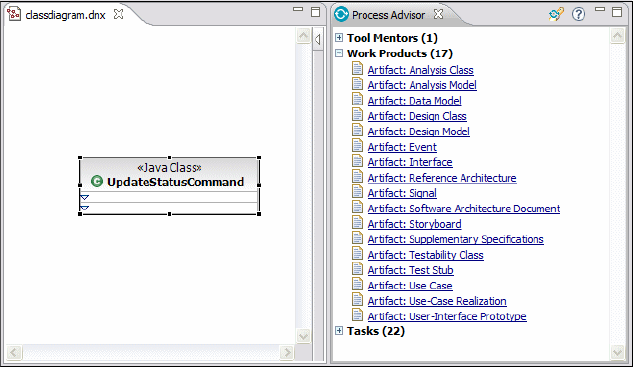
Chapter 6. RUP, patterns, and SOA 9
Draft Document for Review December 9, 2008 2:44 pm 7672-arch-1-mod.fm
Process Advisor
This feature provides seamless integration of the development process into the
Rational Application Developer development environment. It provides context
sensitive information based on the elements being worked with within the
environment. The Process Advisor is accessed by selecting Help → Process
Advisor.
Figure 6-3 shows a UML class diagram and a class selected in that diagram. The
figure also shows the Process Advisor window. Because the element selected in
this case is a class, the information provided in the Process Advisor is RUP
specific information that is relevant to a class. You can see that artifacts such as
Design Class and Design Model are listed. Clicking on one of these opens the
Process Browser at the relevant page in the RUP documentation. It is therefore
possible for a developer to jump quickly to the RUP guidance documentation for
any specific element they are working with.
Figure 6-3 Process Advisor displaying RUP content for a selected context
Process Search
An important feature for quickly finding information is Process Search. This
feature provides search capabilities with advanced filtering and is tightly
integrated with the standard Rational Application Developer search capabilities.
You can access this tool either by clicking Process Search in the Process
Advisor toolbar or directly from the menu by selecting Search → Search and
then selecting the Process Search tab. The Process Search dialog is shown in
Figure 6-4.

7672-arch-1-mod.fm Draft Document for Review December 9, 2008 2:44 pm
10 Rational Application Developer V7.5 Programming Guide
Process Search allows you to customize the search results. By selecting the
appropriate check boxes you can specify the relevant topics you want to include
in your search results.
Figure 6-4 Process Search
Process preferences
Process Advisor allows you to select different process configurations or to set
content filtering options for dynamic searches displayed in Process Advisor. This
is achieved through the Process page of the Preferences dialog (Figure 6-5).
The Process preferences page is accessible from within Rational Application
Developer by selecting Window → Preferences.

Chapter 6. RUP, patterns, and SOA 11
Draft Document for Review December 9, 2008 2:44 pm 7672-arch-1-mod.fm
Figure 6-5 Process preferences
Rational Application Developer provides a default process configuration that
focuses on the needs of application developers. This process configuration is a
subset of the full process information available in the standard configuration of
the RUP.
In addition to this default process configuration, you can use specific process
configurations that you create and publish with IBM Rational Method Composer.
You can then point to these process configurations with the process advisor. You
can do this in the preferences page shown in Figure 6-5. To do this you click on
the Browse button to point the Process Advisor to the published process
configuration.
Another essential part of the Process Advisor feature is the ability to select filters
to determine what context based content will appear in the Process Advisor view.
On the process preferences page you can select the roles and topics you are
interested in by selecting the appropriate check boxes.
7672-arch-1-mod.fm Draft Document for Review December 9, 2008 2:44 pm
12 Rational Application Developer V7.5 Programming Guide
Patterns
Designing a software system from scratch is not easy. Over the years software
developers became aware of the fact that each time a new system was
developed similar design solutions to the problems encounter during
development were found. These tried and proven design solutions to recurring
problems in a specific software development context came to be know as Design
Patterns. Catalogs of design patterns have been developed over the years which
in effect act as handbooks of best practice when designing software. One of the
most widely known and applied patterns catalog is the Gang of Four (GoF)
patterns catalog. This catalog was first publicized in the book Design Patterns:
Elements of Reusable Object-Oriented Software by Erich Gamma, Richard
Helm, Ralph Johnson, and John Vlissides. The name GoF came about because
the book had four authors and still widely used today to describe the patterns set
and specific patterns from this set.
Design patterns deal with small sections of the overall architecture of a software
application typically involving only a few classes. They are different from
architectural patterns which deal with the architecture of a complete application
or software system. We discuss architectural patterns later as well as other
patterns applicable to enterprise systems development.
GoF patterns
The GoF design patterns catalog organizes the design patterns into three
groups:
Creational Patterns. The patterns in this group deal with the instantiation of
objects within a system. Examples of patterns in this group are Factory
Method and Singleton.
Structural Patterns. The patterns in this group deal with the organization of a
classes within a system. Examples of patterns in this group are Facade and
Adapter.
Behavioral Patterns. The patterns in this group deal with the assignment of
responsibility to the classes present in an application, how information is
passed around the system and the flow of control within the system.
Examples of patterns in this group are Command and Observer.
It is beyond the scope of this chapter to look in detail at each of the GoF patterns,
but it is important to look at how patterns might be applied when using Rational
Application Developer. Patterns can be applied from the outset when designing a
system but often a design in arrived at and must be refactored so that the design
is improved by the application of a specific GoF pattern. The comprehensive

Chapter 6. RUP, patterns, and SOA 13
Draft Document for Review December 9, 2008 2:44 pm 7672-arch-1-mod.fm
support built into Rational Application Developer for the refactoring of code can
be put to good use when applying patterns. In addition the ability to visualize
classes in UML class diagrams is invaluable when applying patterns and looking
for classes within an application that require a pattern to be applied. Additional
support for patterns, through the Pattern Explorer view, is available in Rational
Software Architect and Rational Software Modeler.
To demonstrate the kind of refactoring that would be undertaken using Rational
Application Developer when applying a specific pattern, we consider an existing
design example where the application of the Singleton pattern improves the
design. Refactoring is the process of changing software so that it performs the
same function as before but where the software structure has been. Refactoring
includes changing the names of methods in a class, changing the name of a
class or adding and removing classes.
Figure 6-6 shows a class diagram which includes two classes present in an
application.
Figure 6-6 Classes before refactoring to apply the Singleton pattern
In this case both classes take responsibility for creating their own connection to a
database. A better design is to delegate the creation the database connections to
an object which is guaranteed to be present only once within the system. It is
decided by the developer, in this case, that the Singleton pattern should be
applied in the form of a database manager class that manages the creation of
database connections. Figure 6-7 shows the class diagram after refactoring to
apply the Singleton pattern.

7672-arch-1-mod.fm Draft Document for Review December 9, 2008 2:44 pm
14 Rational Application Developer V7.5 Programming Guide
Figure 6-7 Classes after refactoring to apply the Singleton pattern
Architectural patterns
Architectural patterns are similar to design patterns except that they are applied
at the architectural level and typically involve many classes or a complete
application. Some widely applied architectural patterns are layers, multi-tier,
model-view-controller, and service-oriented architecture. Rational Application
Developer provides support for many architectural patterns though the types of
projects it supports and the frameworks that may be used within projects.
The multi-tier architectural pattern is a feature of Java Enterprise Edition (Java
EE). When the multi-tier architecture is applied, applications are partitioned so
that the components present in a particular partition are hosted in a specific tier.
Example tiers in Java EE are the Web or presentation tier and the business or
EJB tier. Rational Application Developer supports the multi-tier architectural
pattern by allowing developers to create EJB projects for the development of EJB
business tier components and Dynamic Web projects for the development of
Web components such as servlets and JSP pages.
Another example of architectural pattern support in Rational Application
Developer concerns Dynamic Web applications. Dynamic Web applications can
be configured using facets. One facet which is available is the Struts facet. Struts
is a Web application framework that uses the model-view-controller architectural
pattern. Figure 6-8 shows the project properties dialog with the Struts facet
selected.
Note: Additional support for patterns, specifically the automatic application of
patterns, is available in Rational Application Developer through Exemplar
Authoring and Java Emitter Templates (JET). This is covered in detail in
Chapter 9, “Accelerate development using patterns” on page 157.
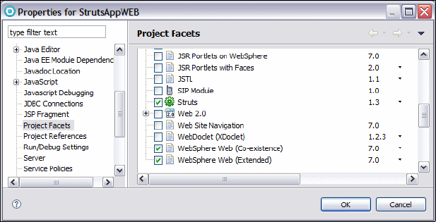
Chapter 6. RUP, patterns, and SOA 15
Draft Document for Review December 9, 2008 2:44 pm 7672-arch-1-mod.fm
Figure 6-8 Selecting the Struts facet for a the Web project
Enterprise patterns
Enterprise design patterns build on the GoF design patterns discussed
previously and catalog design patterns that are applicable for distributed
enterprise systems. In a similar way to the GoF patterns, they have come about
from the fact that developers found tried and proven design solutions to recurring
problems in the contexts found in distributed enterprise systems. They are widely
applied when creating Java EE systems.
The original enterprise pattern catalog was produced when Java 2 Enterprise
Edition (J2EE) was widely used. Although J2EE has evolved to become Java EE
5 many of the patterns are still relevant.
The enterprise patterns catalog organizes the patterns into three groups based
on the fact that enterprise applications use the multi-tier architectural pattern and
most enterprise patterns are specific to a particular tier:
Presentation (Web) Tier Patterns. The patterns in this group are concerned
with the management of views and the presentation of information to clients.
Example patterns in this group are Front Controller and View Helper.
Business (EJB) Tier Patterns. The patterns in this group are concerned with
persistence and the processing of business information (business logic).
Example patterns in this group are Session Facade, Service Locator and
Business Delegate.
Integration Tier Patterns. The patterns in this group are concerned with the
integration of one enterprise system with another and the integration of
enterprise systems with other systems such as database servers. Example
patterns in this group are: Data Access Object and Service Activator.

7672-arch-1-mod.fm Draft Document for Review December 9, 2008 2:44 pm
16 Rational Application Developer V7.5 Programming Guide
Some support is available within Rational Application Developer for enterprise
design patterns. This is in addition to the refactoring facilities and the use of class
diagrams as discussed previously for the GoF patterns. One example concerns
EJB 2.1 entity beans. It is possible to select an EJB 2.1 entity bean in the
Enterprise Explorer, and through the context menu apply the Session Facade
pattern to automatically generate a session bean facade for the entity bean.
Figure 6-9 shows the context menu and the Create Session Bean Facade entry
in the menu.
Figure 6-9 Applying the Session Facade pattern for an entity bean
SOA
Service-oriented architecture (SOA) is an architectural pattern used for the
construction of systems that support business processes with software services
as the fundamental architectural component. A service is a specific unit of
business functionality which is reused again and again during normal business
operations. Example units of business functionality that qualify as services are
opening a bank account and verifying a credit card. When using SOA, business
processes are therefore a collection of services connected as required to provide
required business functionality.
SOA uses open standards for the representation of the services that are
combined to form the business processes. The service interfaces and the
Chapter 6. RUP, patterns, and SOA 17
Draft Document for Review December 9, 2008 2:44 pm 7672-arch-1-mod.fm
assembly of services into usable business processes is the main focus rather
than how the functionality present in the service behind the interface is actually
provided. Typically services are implemented using object oriented Java or .NET
components but equally they may be provide using the functionality implemented
by legacy system. The fact that the emphasis is on service interfaces and service
assembly means that SOA is agnostic to the implementation technology. This
approach has many advantages. In the past inter operability between systems,
implemented using different technologies, was fraught with problems. SOA
completely removes this barrier.
Traditional software engineering principles such as cohesion, modularity, loose
coupling and encapsulation also accrue form the SOA approach.
Services
Services are units of functionality that are accessible over a network through
interfaces defined in a standardized way. The underlying transport used to invoke
services is not fixed and a whole range of transports may be used as required
such as synchronous HTTP or asynchronous messaging. A service is supplied
by a service provider and is used by a service consumer. Mediation between
services, for instance to allow a consumer to find a required service, is also part
of SOA. Currently services are typically provided over the Web using
technologies associated with the Web and standards controlled by the World
Wide Web Consortium (W3C). Services implemented in this way are called Web
services. Web services are the preferred way to implement SOA at present. The
technologies used for the implementation of Web Services are:
Extensible Markup Language (XML). XML is used by most of the other Web
service technologies to create the documents involved.
Web Service Description Language (WSDL). WSDL is used to fully specify
Web service interfaces using XML.
Simple Object Access Protocol (SOAP). SOAP is the protocol used when
interacting with a Web service
Universal Description, Discovery, and Integration (UDDI). UDDI is a
specification for the publishing and discovery of Web services. UDDI is XML
based.
Web services interoperability
The Web Services Interoperability Organization (WS-I) exists to promote good
practice in the development of Web services as well as tests for inter operability
between different Web service providers. WS-I provide test tools and
interpretability profiles. WS-I profiles define a specific set of Web service

7672-arch-1-mod.fm Draft Document for Review December 9, 2008 2:44 pm
18 Rational Application Developer V7.5 Programming Guide
standards specified to the standards revision number and guidelines on
interpretability and implementation specific to that profile. If a provider of a Web
service guarantees that it has been developed to a specific WSI-I profile, then a
consumer is in no doubt about how to use the Web service. The WS-I Basic
Profile (BP) is the core profile provided by WS-I and concerns the Web service
standards SOAP, WSDL, and UDDI.
Web Service Business Process Execution Language (WS-BPEL)
SOA is concerned with business processes which are typically constructed using
Web services. The Web Service Business Process Execution Language
(WS-BPEL) is a standard of the Organization for the Advancement of Structured
Information Standards (OASIS). WS-BPEL is a language for specifying business
processes and business process protocols.
Additional information
For more information on RUP, refer to:
http://www.ibm.com/developerworks/rational/
http://www.ibm.com/developerworks/rational/products/rup/
For more information on Design Patterns, refer to:
http://www.hillside.net/patterns/
http://www.hillside.net/patterns/DPBook/GOF.html
http://www.ibm.com/developerworks/edu/ar-dw-ar-designpat1.html
For more information on Architectural Patterns, refer to:
http://www.ibm.com/developerworks/edu/ar-dw-ar-designpat2.html
http://www.opengroup.org/architecture/togaf7-doc/arch/p4/patterns/patterns.
htm
For more information on Enterprise Patterns, refer to:
http://www.ibm.com/developerworks/websphere/techjournal/0701_botzum/0701_bo
tzum.html
http://www.corej2eepatterns.com/
Note: Rational Application Developer provides support for the generation of
Web services from both session EJB and JavaBeans. The development of
Web Services is covered in detail in Chapter 18, “Develop Web services
applications” on page 563.
Chapter 6. RUP, patterns, and SOA 19
Draft Document for Review December 9, 2008 2:44 pm 7672-arch-1-mod.fm
For more information on SOA, refer to:
http://www-01.ibm.com/software/solutions/soa/
http://www.ibm.com/developerworks/webservices
http://www.w3.org/
http://www.ibm.com/developerworks/webservices/newto/
http://www.ws-i.org/
http://bpel.xml.org/
7672-arch-1-mod.fm Draft Document for Review December 9, 2008 2:44 pm
20 Rational Application Developer V7.5 Programming Guide

© Copyright IBM Corp. 2008. All rights reserved. 21
Draft Document for Review December 9, 2008 2:44 pm 7672-arch-2-uml.fm
Chapter 7. Unified Modeling Language
(UML)
The Unified Modeling Language (UML), an Object Management Group (OMG)
standard, is now used by the vast majority of those involved in modern software
development. UML defines a graphical notation for the visual representation of a
wide range of the artifacts that are created during the software development
process. The visual modeling capabilities of UML range from the functionality
expected of a system to the classes and components from which a system is
constructed to the servers and systems on which the components are deployed.
Rational Application Developer 7.5 provides visual UML tooling which, although it
does not support the full capabilities of UML, is appropriate for those involved in
the design and coding of software applications and components. If full UML
support is required it is provided by the products Rational Software Architect and
Rational Software Modeler.
The chapter is organized into the following sections:
Overview
Constructing and visualizing applications using UML
Working with UML class diagrams
Describing interactions with UML sequence diagrams
More information on UML
7
7672-arch-2-uml.fm Draft Document for Review December 9, 2008 2:44 pm
22 Rational Application Developer V7.5 Programming Guide
Overview
Rational Application Developer 7.5 provides features to allow developers to
leverage UML to visually develop and represent software development artifacts
such as Java classes, interfaces, Enterprise JavaBeans and Web services.
Rational Application Developer provides a customizable UML 2.1 based
modeling tool that integrates tightly with the development environment. The
discussion of UML in this chapter focuses on this tool.
Constructing and visualizing applications using UML
Rational Application Developer provides UML visual editing support to simplify
the development of complex Java applications. Developers can create and
modify Java classes and interfaces visually using class diagrams. Review of the
structure of an application, by viewing the relationships between the various
elements that comprise the application, is facilitated using Rational Application
Developer Browse and Topic diagrams. Model elements such as classes and
packages are synchronized automatically with their corresponding source code
allowing developers the freedom to choose to edit the model or the source code
as required.
The code visualization capabilities provide several diagrams which enable
developers to view existing code from different perspectives. Unlike the diagrams
offered in Rational Software Modeler or Rational Software Architect, these are
visualizations of actual code only. This means that full UML 2.1 modelling is not
possible using Rational Application Developer. The UML support is present only
to provide a way to visualize and understand the code or to allow the editing of
code from its visual representation in a model. This is in fact a very common way
in which UML is typically employed.
Visual editing offers developers the ability to produce code without explicitly
typing the code into a text editor. A palette is used to drag and drop different
modelling elements, such as classes and interfaces, onto a diagram. In the case
of classes it is the possible to edit them visually, for example, to add operations
and attributes or to define their relationships with other classes.
Rational Application Developer supports the following types of UML diagram:
Class diagrams—This type of UML diagram presents the static structure of
an application. A class diagram shows visually the classes and interfaces
from which the application is composed, their internal structure and the
relationships which exist between them. A specific class diagram is created to
help with understanding the application and to allow development of the
Chapter 7. Unified Modeling Language (UML) 23
Draft Document for Review December 9, 2008 2:44 pm 7672-arch-2-uml.fm
application to take place. When visually representing the static view of an
application as many class diagrams are created by the developer as required
and a single class diagram typically presents a subset of all the classes and
interfaces present in an application. Class diagrams are created within a
project and exist permanently in that project until deleted.
Sequence diagrams—This type of UML diagram presents the dynamic
structure of an application. It shows the interactions between objects present
in an executing application. Objects present in a executing application interact
through the exchange of messages and the sequencing of this message
exchange is an important aspect of any application. In the case of Java
applications the most basic type of messaging between objects is the method
call. Sequence diagrams visually represent objects and their lifelines and the
messages they exchange. They also provide information on the sequencing
of messages in time. Sequence diagrams are created within a project and
exist permanently in that project until deleted.
Browse diagrams—Browse diagrams are specific to Rational Application
Developer. They are not a new type of diagram as such just a facility provided
within Rational Application Developer for the creation of diagrams. A browse
diagram exists temporarily, is not editable and allows a developer to explore
the details of an application through its underlying elements and relationships.
Browse diagrams are not a permanent part of a model, they are created as
needed to allow exploration of a model. A browse diagram provides a view of
a chosen context element. Context element exploration takes place in a
similar way to the way Web pages are viewed in a Web browser when
navigating a Web site. You cannot add or modify individual diagram elements
or save a browse diagram in an project. However, you can convert a browse
diagram to a UML class diagram or save it as an image file for use elsewhere.
Topic diagrams—Topic diagrams share many of the features of browse
diagrams except that they are generated through the execution of a query on
the application model and remain permanently in a project when created. You
can customize the underlying query, open multiple topic diagrams at the
same time and save them away for further use. Each time a topic diagram is
opened the query is executed and the diagram is populated. They are
invaluable when discovering the architecture of an existing application.
Static method sequence diagrams—This is a type of topic diagram that is
used for viewing sequence diagrams. They are non-editable diagrams that
visually represent and explore the chronological sequence of messages
between instances of Java elements in an interaction. You can create a static
sequence diagram view of a method (operation), including signatures, in Java
classes and interfaces to illustrate the logic inside that operation.
7672-arch-2-uml.fm Draft Document for Review December 9, 2008 2:44 pm
24 Rational Application Developer V7.5 Programming Guide
All of these diagrams help developers to understand and document code. To
provide further documentation you can also generate Javadoc HTML
documentation that contains UML diagram images. Refer to “Generate Javadoc
with diagrams automatically” on page 132.
The UML visualization tools are applicable not only to Java classes but also to
other types of artifacts, such as Web services and Enterprise JavaBeans.
Rational Application Developer also supports data visualization using UML or
Information Engineering notation.
Figure 7-1 provides an overview of the workspace you might see when using the
UML visualization capabilities:
The center area is the UML editor. This editor is used to display and modify
the different elements present in the model.
Built into the editor is a palette that is used to drag and drop elements onto
the editor work area. The items that appear in the palette are specific to the
type of project that is being visualized. The palette is only available when the
diagram is editable. The palette is not displayed for topic and browse
diagrams
The Outline view enables you to see, in miniature, the whole diagram
currently being viewed with the area of the diagram you have zoomed in on
highlighted. This can be very useful for finding your way around a complex
diagram, since you can left click the area of the outline view that is highlighted
and drag it around to see a different zoomed area. You can also change the
outline view to show a tree of all the different elements that are present in the
current diagram.
The Properties view enables you to review or change any property that is
related to a selected diagram or a diagram element.
Finally, you can drag and drop project elements from the Enterprise Explorer
or Package Explorer view directly into the editor work area to add these items
to the diagram. You can, for example, drag a Java class form the Enterprise
Explorer to the editor work area where it will be rendered as a UML class in
the diagram. If relationships exist between the Java class you have dragged,
such as an association with another class, then this will be rendered as well.
In Figure 7-1 the diagram shown was created by dragging the DepositCommand
class, TransferCommand class, and Command interface to the editor work area. In
this case the TransferCommand and DepositCommand implement the Command
interface, and as you can see UML implements relationships have also been
rendered in the diagram.

Chapter 7. Unified Modeling Language (UML) 25
Draft Document for Review December 9, 2008 2:44 pm 7672-arch-2-uml.fm
Figure 7-1 Example workspace when using the UML visualization capabilities
Unified Modeling Language
A model is a description of a system from a particular perspective, omitting
irrelevant details so that the characteristics of interest are seen more clearly. In
other words a model is a simplification of reality. The more complex a system is
the more important that it is modeled. Models are useful for problem solving and
understanding, communicating with team members and stakeholders, preparing
documentation, and designing applications. Modeling promotes a better
understanding of requirements, cleaner designs and more maintainable
applications.
The Unified Modeling Language (UML) is a standardized language for modelling
the different aspects of an application. You can use this language to visualize,
specify, construct and document the different artifacts of an application. UML
models are constructed using three kinds of building blocks: Elements,
relationships, and diagrams.
7672-arch-2-uml.fm Draft Document for Review December 9, 2008 2:44 pm
26 Rational Application Developer V7.5 Programming Guide
Elements
Elements are an abstraction of the structural or behavioral features of the system
being modeled. Each element type has specific semantics and gives meaning to
any diagram in which it is included. UML defines four kinds of elements:
Structural elements—This type of element is used to model the static parts
of a system. Examples of this type of element are interfaces, classes,
components, and actors.
Behavioral elements—This type of element models the dynamic parts of a
system. They are typically found in UML interaction diagrams as well as in
other diagram types. Examples of this type of element are objects, messages,
activities, and decisions.
Grouping or organizational elements—This type of element is used to
group together other elements into a meaningful set. An example of a
grouping element is the package.
Annotational elements—This type of element is used to comment and
describe a model. Examples of this type of element are notes and constraints.
Relationships
Relationships are used to document the semantic ties that exist between model
elements. Four commonly used categories of UML relationships are listed here:
Dependency relationships—This type of relationship is used to indicate that
changes to a specific model element can affect another model element. For
example consider a Bank class which depends on an Account class. An
operation that can be called on an object of the Bank class might take as a
parameter a reference to an object of the Account class. The Account object
has been created elsewhere but the Bank object uses it and therefore
depends on it. After the Account object has been used, the Bank object does
not retain its reference to it. A dependency relationship therefore exists
between the Account class and the Bank class.
Association relationships—This type of relationship indicates that
instances of a specific model element are connected to instances of another
model element. For example a Customer class may have an association with
an Account class. When an object of the Customer class obtains a reference to
an object of the Account class, it retains it and can interact with the Account
object whenever required. If the classes were to be implemented in Java, then
typically the Customer class would include an instance variable to hold the
reference to an Account object. There are several different types of
association relationship that can be used depending on how tightly connected
the modelling elements are. Consider for example a relationship between a
Car and Engine class. In this case the association is stronger than in the
previous Customer and Account example. One of the stronger types of
association such as aggregation or even composition might therefore be used
Chapter 7. Unified Modeling Language (UML) 27
Draft Document for Review December 9, 2008 2:44 pm 7672-arch-2-uml.fm
in the model. In the case of composition the connection between the classes
is so strong that the lifetimes of the objects are bound together. The object of
one class never exists without an object of the other, and when one is deleted
so is the other.
Generalization relationships—This type of relationship is used to indicate
that a specific model element is a generalization or specialization of another
model element. Generalization relationships are used to show inheritance
between model element. If Java is used to implement a UML class element
and that element has a generalization relationship with another class in a
model, the Java extends keyword would be used in the source code to
establish this relationship. For example, an Account class might be a
generalization of a SavingsAccount class. Another way to say this is that the
SavingsAccount is a specialization of the Account class, or that the
SavingsAccount class inherits from the Account class.
Realization relationships—This type of relationship is used to indicate that a
specific model element provides a specification that another model element
implements. Realization relationships are typically used between an interface
and the class which implements it. The interface defines operations and the
class implements the operations by providing the method behind each
operation. In Java this maps to the implements keyword. For example,
consider a Command interface and a DepositCommand class. A realization
relationship would exist in the model between the DepositCommand class and
the Command interface. In other words the DepositCommand class implements
the Command interface.
Diagrams
A UML diagram provides a visual representation of an aspect of a system. A
UML diagram illustrates the aspects of a system that can be described visually
such as relationships, behavior, structure and functionality. Depending on the
content of a diagram it can provide information on the design and architecture of
a system from the lowest level to the highest level. UML provides thirteen types
of diagrams that let the user capture, communicate, and document all aspects of
an application.
The individual diagrams can be categorized into three main types: Static,
dynamic and functional. Each type represents a different view of an application.
Static—Diagrams of this type show the static aspects of a system. This
includes the things from which the application is constructed for example the
classes and how the things are related to each other. This type of diagram
does not show changes which occur in the system over time. Examples of this
type of diagram are the component diagram, the class diagram, and the
deployment diagram.
7672-arch-2-uml.fm Draft Document for Review December 9, 2008 2:44 pm
28 Rational Application Developer V7.5 Programming Guide
Dynamic—Diagrams of this type show the dynamic aspects of a system.
They document how an application responds to requests or otherwise evolves
over time by showing the collaborations that take place between objects and
the changes to the internal states of objects. Objects in a system achieve
nothing unless they interact or collaborate. Examples of this type of diagram
are the sequence diagram and the communication diagram.
Functional—Diagrams of this type of show the functional requirements of a
system. Examples of this type of diagram are the use case diagram.
Additional information on UML can be found at:
http://www-01.ibm.com/software/rational/uml
Working with UML class diagrams
A UML class diagram is a diagram that provides a static view of an application. It
shows some or all of the components or elements in an application and the
relationships between them such as inheritance and association. You can use
class diagrams to visually represent and develop Java applications and Java EE
Enterprise JavaBeans applications. Rational Application Developer also allows
Web Service Description Language (WSDL) elements, such as WSDL services,
port types, and messages to be shown on class diagrams. In Rational
Application Developer 7.5, enhanced support is provided for UML visualization of
EJB 3.0 applications.
The content of a class diagram is stored in a file with a .dnx extension. The UML
class diagram editor consists of an editor window which displays the current
class diagram and a palette that contains individual drawers containing the
elements that can be added to a class diagram.
Creating class diagrams
A new class diagram is created using the New Class Diagram wizard. You can
launch this wizard directly from the menu in Rational Application Developer. To
create a class diagram from the menu select File → New → Other →
Modeling → Class Diagram. Alternatively, from the Enterprise Explorer,
right-click on any resource, such as a project or a package, to bring up the
context menu and select New → Class Diagram.
Once the wizard has started you can enter the name for your class diagram and
specify the folder where the class diagram file should be stored. When you click
on Finish the new class diagram is created and opened for editing with the
associated palette on the right hand side as shown in Figure 7-2.
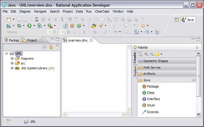
Chapter 7. Unified Modeling Language (UML) 29
Draft Document for Review December 9, 2008 2:44 pm 7672-arch-2-uml.fm
Alternatively, you can create a UML class diagram from existing source elements
within a project, including packages, classes, interfaces and EJBs. In the
Enterprise Explorer, right-click the desired source element or elements and
select Visualize → Add to New Diagram File → Class Diagram. In a similar
way it is also possible to add elements to an existing class diagram.
You can create as many class diagrams as you want to depict different aspects of
your application.
Figure 7-2 A new class diagram
Creating, editing, and viewing Java elements in UML class diagrams
When working with class diagrams developers can create, edit and delete Java
elements such as packages, classes, interfaces, and enum types to allow the
visual development of Java application code.
To draw a class diagram you simply select the desired elements from the palette
and drag them to the class diagram editor window. This launches the appropriate
wizard, such as the New Java Class wizard if you drag a Java class from the
palette, that guides you in the creation of the new element. Alternatively,
elements can be created directly in the Enterprise Explorer and placed on the
diagram later.
Figure 7-3, shows a class as it is seen when added to a class diagram. The class
is rendered as specified in the UML standard.

7672-arch-2-uml.fm Draft Document for Review December 9, 2008 2:44 pm
30 Rational Application Developer V7.5 Programming Guide
Figure 7-3 A Java class with action bar and modeling assistant arrows visible
In this case three compartments are visible:
The upper compartment or name compartment contains the class name and
if required a stereotype. A stereotype is a string, surrounded by guillemets
(angled brackets) that indicates the kind of element more precisely. In this
case we have a class, but more precisely its a Java class.
The middle compartment is the attribute compartment and contains the
attributes present in the class.
The lower compartment is the operation compartment and contains the
operations present in the class.
You can show or hide individual compartments so that only the compartments
you are interested in appear. To do this right-click on the class and select
Filters → Show/Hide Compartment. A submenu offers you the available
options.
Also, when you hover the mouse cursor over a class, the action bar and the
modeling assistant arrows are displayed:
The action bar is an icon-based context menu that provides quick access to
commands that allow you to edit a diagram element. In the case of a Java
class you can add fields and methods to the class. The actions, available on
the action bar, are also available through Add Java in the context menu
presented if you right-click on the class in the diagram.
The modeling assistant allow you to create and view relationships between
the selected element and other elements such as packages, classes or
interfaces. One modeling assistant arrow points towards the element and the
other points away. The arrow pointing towards the element is for incoming
relationships. Thus, when creating a relationship where the selected element
is the target, you would use the incoming arrow. Similarly, the arrow pointing
away from the element is for outgoing relationships and is used in a similar
way.
Action bar
Modeling assistant arrows

Chapter 7. Unified Modeling Language (UML) 31
Draft Document for Review December 9, 2008 2:44 pm 7672-arch-2-uml.fm
To create a relationship from one Java element to another element execute the
following steps:
Move the mouse cursor over the source element so that the modeling
assistant is available and click on the small box at the end of the outgoing
arrow.
Drag the connector that appears and drop it on the desired element or on an
empty space inside the diagram if you want to create a new element.
Select the required relationship type from the context menu that appears
when the connector is dropped (Figure 7-4).
You can create incoming relationships in the same way by using the incoming
arrow. Alternatively, you can select the desired relationship in the tool palette and
place it on the individual elements.
Figure 7-4 Using the Modeling Assistant to create a relationship
The modeling assistant also allows you to view related elements that are based
on a specific relationship. These are elements which exists in the model but that
are not currently shown on the class diagram. To do this double-click the small
box at the end of the outgoing or incoming arrow and select the desired
relationship from the resulting context menu as shown in Figure 7-5. This is
equivalent to selecting Filter → Show Related Elements from the element's
context menu.
Figure 7-5 Viewing related Java elements using the modeling assistant
The context menu for a class includes several additional editing options that
have not yet been discussed. Some of the additional options are as follows:
7672-arch-2-uml.fm Draft Document for Review December 9, 2008 2:44 pm
32 Rational Application Developer V7.5 Programming Guide
Delete from Diagram—This option removes the visual representation of the
selected element(s) from the diagram. It does not delete the element from the
project. Note that when you delete Java elements from a class diagram, the
underlying associations remain intact.
Format—This option changes the properties of the selected element that
govern its appearance and location in a diagram. Modifying these properties
only changes the appearance of this specific rendition of the element, it does
not affect how the element is rendered elsewhere on the diagram or in
another diagram. Some of the properties can be configured globally using the
modeling preferences dialog.
Filters—This option allows you to manage the visual representation of
elements in UML class diagrams but is concerned with what is visible on a
diagram when the element is rendered irrespective of what the element
contains. For example, UML allows a class to have operations but allows the
operations to be hidden, if required, when the class is drawn on a class
diagram. With the filters option you can show or hide attributes and
operations, determine if operation signatures are displayed or specify if the
fully qualified names of individual classes are shown.
Filters → Show Related Elements—This is a particular function of the
Filters option and requires its own explanation because it is so useful. Show
Related Elements helps developers to query for related elements in a
diagram. As shown in Figure 7-6, the Show Related Elements dialog allows
you to select from a set of predefined queries. By clicking on Details you can
view and change the actual relationships, along with other settings related to
the selected query.
Refactor and Source provide the same functionality to change and edit the
underlying Java code as they do when invoked on the class directly in the
Enterprise Explorer.
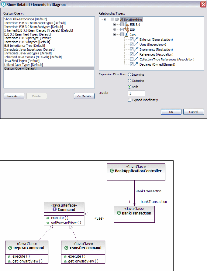
Chapter 7. Unified Modeling Language (UML) 33
Draft Document for Review December 9, 2008 2:44 pm 7672-arch-2-uml.fm
Figure 7-6 Show Related elements dialog
Figure 7-7 provides an example of a class diagram showing some elements and
the relationships between them.
Figure 7-7 Class diagram showing different UML elements
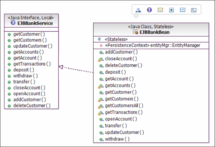
7672-arch-2-uml.fm Draft Document for Review December 9, 2008 2:44 pm
34 Rational Application Developer V7.5 Programming Guide
Creating, editing, and viewing EJBs in UML class diagrams
Class diagrams also allow developers to visually represent and develop
Enterprise JavaBeans (EJBs) in EJB applications. Developers can create class
diagrams and populate them with existing EJBs to allow the business tier
architecture to be documented and understood. Class diagrams can also be
used to develop new EJBs including EJB relationships such as inheritance and
association and to configure the security aspects of bean access such as
security roles and method permissions.
Rational Application Developer 7.5 now supports EJB 3.0, and class diagrams
can be drawn showing EJB 3.0 beans. The support for drawing class diagrams
showing EJB 2.1 and earlier beans is still supported, but will not be discussed
here.
To use the EJB class diagram capabilities a class diagram must be created within
the context of an EJB project. The palette can then be used to create and edit as
before but now with the addition of EJBs. Alternatively, you can create the EJBs
in the Enterprise Explorer and place them on a diagram later.
Figure 7-8 shows the graphical representation of an EJB 3.0 session bean.
Figure 7-8 Visualization of an EJB 3.0 Enterprise JavaBeans
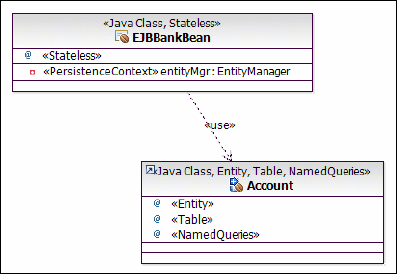
Chapter 7. Unified Modeling Language (UML) 35
Draft Document for Review December 9, 2008 2:44 pm 7672-arch-2-uml.fm
To visualize an EJB simply drag it from the Enterprise Explorer to the class
diagram editor. EJBs are rendered as a class which is stereotyped as <<Java
Class>> with appropriate stereotype for the type of bean. In this case the other
stereotype is <<Stateless>> because we have an EJB 3.0 stateless session
bean. An EJB exposes its functionality to clients through either a remote
interface, a local interface or less commonly both. The session bean shown in
Figure 7-8 provides only a local interface. The interface is shown on the class
diagram as a class stereotyped as <<Java Interface>> and <<Local>>.
EJBs in an EJB 3.0 project usually employ Java Persistence API (JPA) entities to
provide data persistence rather than EJB 2.1 entity beans. Figure 7-9 shows an
EJB 3.0 session bean and a JPA entity. Note that the JPA entity is shown in the
diagram as a class with appropriate stereotypes.
(
Figure 7-9 Class diagram showing an EJB 3.0 session bean and a JPA entity
Relationships between EJBs
You can use a class diagram to create relationships between EJBs. The palette
supports two kinds of relationship between beans:
EJB inheritance
EJB reference
EJB inheritance is a standard Java generalization relationship between two EJB
classes. An EJB reference relationship is shown on the class diagram as an
association and is implemented in the source code as an EJB 3.0 reference.
Figure 7-10 shows three EJB 3.0 session beans with relationships. An
inheritance relationship exists between TestSessionBean and
BaseTestSessionBean, this is drawn on the class diagram as a UML
generalization arrow. EJBBankBean holds an EJB 3.0 reference to
TestSessionBean and this is shown in the diagram as a directed UML association
between the two beans.
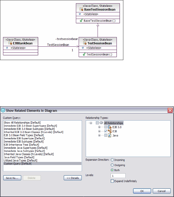
7672-arch-2-uml.fm Draft Document for Review December 9, 2008 2:44 pm
36 Rational Application Developer V7.5 Programming Guide
Figure 7-10 Class diagram showing three EJB 3.0 session beans with relationships.
Previously we looked at the Filters option, available when we right-click on a
class in a class diagram. This feature works for EJB 3.0 beans but an appropriate
set of predefined custom queries is shown for this type of element. Figure 7-11
shows the dialog for an EJB 3.0 session bean.
Figure 7-11 Show Related Elements dialog for EJB 3.0 session beans
By default, the details are collapsed and only the left pane in the dialog is visible.
By clicking Details the actual relationships along with other settings related to
the selected query can be viewed. You can select the different types of
relationship that should be included in the query along with the expansion
direction. If you select Incoming, all elements are shown that are related to the
selected element. On the other hand, if you want to see all elements that have a
relationship to the selected element, select Outgoing. Any changes made to the
queries can be saved for future use.
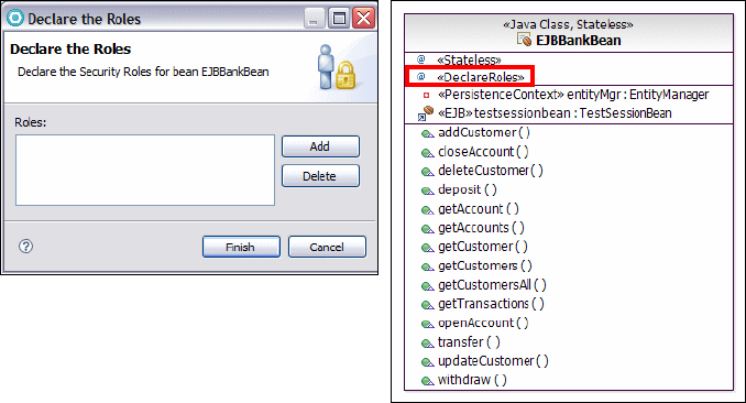
Chapter 7. Unified Modeling Language (UML) 37
Draft Document for Review December 9, 2008 2:44 pm 7672-arch-2-uml.fm
From the context menu there are several other options available to edit a
selected EJB or to change its appearance. Most of these features have been
described previously so the following discussion focuses only on topics that are
specific to EJBs. Some of these features are exposed as wizards.
Security roles and method permissions
You can use UML class diagrams to visually manage EJB security. This includes
creating security roles and configuring method permissions. Only the support for
for configuring security for EJB 3.0 beans using security annotations is discussed
here.
An EJB 3.0 security configuration involves the creation of required security roles
and the definition of the EJB method security permissions. Linking of security to
roles to roles defined in the container is not discussed here. This is typically done
using annotations.The following steps document how this is achieved:
To create a security role for a specific EJB right-click on the bean and select
Add EJB 3.0 → Security →Declare Roles. In the Declare the Roles dialog
(Figure 7-12, left), click the Add button and provide the name of a security
role, for example, Customer. Click Finish on the add dialog and then Finish
again in the Declare the Roles dialog to complete the process.
This adds the annotation @DeclareRoles(value="Customer") to the source
code for the EJB, and the EJB shown in the class diagram is updated with
<<DeclaredRoles>> to indicate that a security role is now present
(Figure 7-12, right).
Figure 7-12 Declare the roles dialog and diagram stereotype
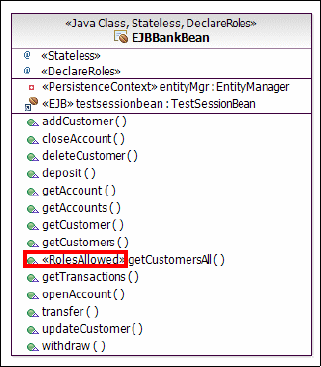
7672-arch-2-uml.fm Draft Document for Review December 9, 2008 2:44 pm
38 Rational Application Developer V7.5 Programming Guide
To define method permissions for an EJB 3.0 bean, select a bean method in
the class diagram, for example, getCustomersAll. To define method
permissions right-click on the selected method and select Add EJB 3.0 →
Security →Set Allowed Roles. The roles permitted to execute the method
can then be selected from the Set Allowed Roles dialog. This adds the
annotation @RolesAllowed(value="Customer") to the getCustomersAll
method in the source file for the bean and updates the method in the class
diagram with <<RolesAllowed>>. Figure 7-13 shows an EJB with method
permissions set for its getCustomerAll method.
Figure 7-13 EJB 3.0 bean with method permissions on getCustomersAll method
Creating, editing, and viewing WSDL elements in UML class diagrams
Rational Application Developer 7.5 enables developers to represent and create
Web Service Description Language (WSDL) Version 1.1 and XML Schema
(XSD) definition elements using UML class diagrams.
To use this feature, the Web Service Modeling capability must be enabled
beforehand. In the preferences dialog, accessed by selecting Window →
Preferences, expand the General node to access the Capabilities page. In the
Capabilities page click Advanced. In the dialog expand the Web Service
Developer node and select Web Service Development.
Figure 7-14 shows the graphical representation of a WSDL service. To visualize
a service, select its WSDL file from the Enterprise Explorer and drag it to a class
diagram. Alternatively, right-click a WSDL file and select Visualize → Add to
New Diagram File → Class Diagram.
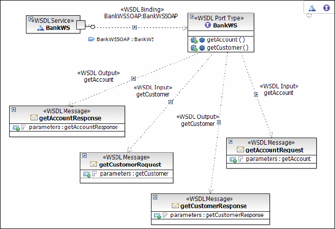
Chapter 7. Unified Modeling Language (UML) 39
Draft Document for Review December 9, 2008 2:44 pm 7672-arch-2-uml.fm
Figure 7-14 Graphical representation of a Web Service
Note that by default the external view of a service is shown. If you want to switch
to the compressed view, right-click the service and select the Filter submenu and
clear then Show External View.
Like Enterprise JavaBeans, WSDL services are displayed as UML classes on a
class diagram with appropriate stereotypes:
The individual ports of a service are depicted as small squares on the side of
the class. The class is stereotyped as <<WSDL Service>>. The functionality
provided by a port is exposed by a port type.
A port type is displayed as a UML interface that is modeled using the lollipop
notation. In Figure 7-14 you can see the port type explicitly displayed as an
interface being linked to its port. This link is realized as a dependency with
stereotype <<WSDL Binding>>. It describes the binding being used for this port
type. A port type references messages that describe that type of data being
communicated with clients.
A message itself consists of one or more parts that are linked to types. Types
are defined by XSD elements. Figure 7-14 shows that messages are
displayed as UML classes with the <<WSDL Message>> stereotype. XSD
elements are also displayed as UML classes although none are shown in
Figure 7-14.
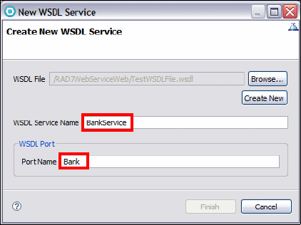
7672-arch-2-uml.fm Draft Document for Review December 9, 2008 2:44 pm
40 Rational Application Developer V7.5 Programming Guide
Creating a WSDL service
This section provides a sample scenario that describes how the UML class
diagram editor can be used to create a new Web service from scratch. We use
different tools provided by the tool palette to create the various elements of a
Web service, such as services, ports, port types, operations and messages.
Creation of the service involves the following steps:
Creating a WSDL service
Adding ports to a WSDL service
Creating WSDL port types and operations
Creating WSDL messages and parts
Editing parts and creating XSD types
Creating bindings between WSDL ports and port types
Each step is documented in detail in the following sections.
Creating a WSDL service
If you select the WSDL Service element in the tool palette and drop it on an
empty space inside a class diagram the New WSDL Service wizard starts to
create a new WSDL service along with a port as shown in Figure 7-15.
To begin with you must specify the WSDL file that will contain the service. You
can either click Browse to select an existing file or you can click Create New to
launch the New WSDL File wizard. If you create a new WSDL file, then on the
Options page clear Create WSDL Skeleton, because you will create these
elements later in the next tasks. Finally, provide a name for the service and port
and click Finish.
Figure 7-15 New WSDL Service wizard
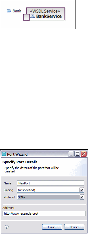
Chapter 7. Unified Modeling Language (UML) 41
Draft Document for Review December 9, 2008 2:44 pm 7672-arch-2-uml.fm
The result of this task is shown in Figure 7-16. Like an EJB, a WSDL service is
displayed as a UML class but with the stereotype WSDL Service. The port is
depicted as a small square on the side of the class. Note that the external view of
the component is shown. To switch to the compressed view, open the context
menu and clear Show External View from the Filter submenu. In this case the
port will not be visible.
Figure 7-16 Visualization of a WSDL service component
Adding ports to a WSDL service
A WSDL service consists of one or more individual ports. A port describes an
endpoint of a WSDL service that can be accessed by clients. It contains the
properties name, binding, and address. The name property provides a unique
name across all the ports defined within the enclosing WSDL file, the binding
property references a specific binding and the address property contains the
network address of the port.
To add a port to a WSDL service, right-click the service and select Add WSDL →
Port. This launches the Port wizard (Figure 7-17). Enter the name of the port
then click Finish. Optionally you can specify a binding and a protocol.
Note that this task is not required for our scenario because a port has already
been created and added to the service in the previous task.
Figure 7-17 Port wizard

7672-arch-2-uml.fm Draft Document for Review December 9, 2008 2:44 pm
42 Rational Application Developer V7.5 Programming Guide
After you have created a port, you can use the Properties view to review or
change any property of the port. Right-click the square representing the desired
port and select Show Properties View. Then select General on the left side of
the Properties view. On this page, you can enter a new name and address and
you can select a binding and protocol (Figure 7-18).
Figure 7-18 Port properties shown in the Properties view
Creating WSDL port types and operations
A port type describes the behavior of a port. It defines individual operations that
can be performed and the messages that are involved. An operation is an
abstract description of an action supported by a service. It provides a unique
name and the expected inputs and outputs. It might also contain a fault element
that describes any error data the operation might return.
You can create a new port type together with an operation with the help of the
New WSDL Port Type wizard (Figure 7-19). You can launch this wizard either by
dragging a WSDL Port Type from the palette to the class diagram or by
right-clicking in the diagram and selecting Add WSDL → Port Type.
First you must specify the WSDL file that should contain the port type. A port type
is not restricted to be in the same WSDL file as the enclosing WSDL service. As
described previously you can click Browse to select an existing WSDL file or
click Create New to create a new file. Next you must provide the port type name
and operation name and then finally click Finish.

Chapter 7. Unified Modeling Language (UML) 43
Draft Document for Review December 9, 2008 2:44 pm 7672-arch-2-uml.fm
Figure 7-19 New WSDL Port Type wizard
The result is shown in Figure 7-20. A port type is visualized in the diagram using
an interface with the stereotype <<WSDL Port Type>>. You can add further
operations by selecting Add WSDL → Operation from the context menu.
Note that we have not created a connection between this port type and the port.
We will do this in the last task.
Figure 7-20 Class diagram representation of a port type
Creating WSDL messages and parts
Messages are used by operations to describe the kind of data being
communicated with clients. An operation can have an input, output and a fault
message. A message is composed of one or several parts and each part is
linked to a type. The individual parts of a message can be compared to the
parameters of a method call in the Java language.
To create a new message along with a part, select the WSDL Message tool in the
tool palette and drag it to the diagram. This opens the dialog shown in
Figure 7-21.
First, you must specify the WSDL file that should contain the message. WSDL
services or port types and messages are top-level objects that can be defined in
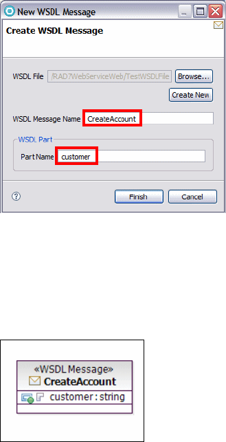
7672-arch-2-uml.fm Draft Document for Review December 9, 2008 2:44 pm
44 Rational Application Developer V7.5 Programming Guide
a separate WSDL file. As described previously you can either browse to select an
existing file or create a new one. Finally, enter the message name and part name
and click Finish.
Figure 7-21 New WSDL Message wizard
The result is shown in Figure 7-22. The newly created message is displayed
using UML class notation with stereotype WSDL Message. If you want to add any
further part to this massage, right-click the class and select Add WSDL → Add
Part.
Figure 7-22 Representation of a WSDL message in a class diagram
The CreateAccount message is associated with the input-element of the
createAccount operation in the next task. Before you proceed, create a second
message CreateAccountResponse along with a part named account. This
message will be associated with the output-element of this operation.
Editing parts and creating XSD types
WSDL recommends the use of XML Schema Definition (XSD) to define the type
of a part. You can use the class diagram to create and edit the required XSD
objects such as XSD elements, simple types, or complex types. If you right-click
in the class diagram and select Add WSDL you can select the required item from
the submenu. Alternatively, you can drag the item from the palette to the class

Chapter 7. Unified Modeling Language (UML) 45
Draft Document for Review December 9, 2008 2:44 pm 7672-arch-2-uml.fm
diagram. The wizards involved are similar to the ones described previously in
that you specify the WSDL file and enter a name for the XSD object to be
created.
If the XSD element added is a complex type you can add new elements to it. To
do this, right-click the complex type and select Add XSD → Add New Element.
This creates a new element within the selected complex type with type string.
You can further set or change the type of an existing XSD element. In the
diagram editor, right-click an XSD element or an element within a complex type
and select Add XSD → Set XSD Type. The dialog that opens provides a list of
available types that you can select.
Note that once you have created an XSD element, you can just as easily delete it
from the diagram. If you want to delete it permanently from the underlying WSDL
file, you must edit the file directly.
To review or change a type of a part of a WSDL message select the part to bring
up its properties in the Properties view, then select the General tab. As shown in
Figure 7-23, you can select the desired type in the drop-down combo box.
Figure 7-23 Properties view showing the properties of a part.
To proceed with this exercise, create two complex types, Account and Customer,
and add the attributes amount, name, and firstName as shown in Figure 7-24.
Figure 7-24 Complex types with attributes
Finally, link these types to the parts of the messages you have created as shown
in Figure 7-25.
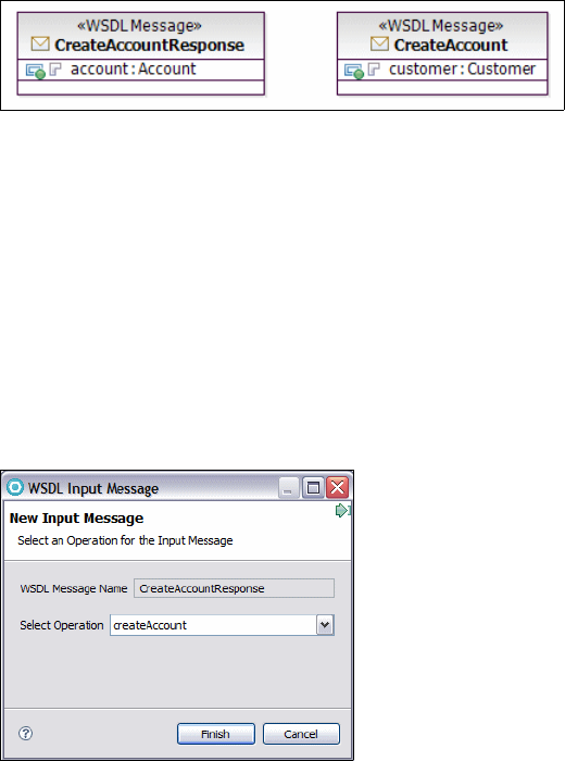
7672-arch-2-uml.fm Draft Document for Review December 9, 2008 2:44 pm
46 Rational Application Developer V7.5 Programming Guide
Figure 7-25 Using XSD complex types as the type for WSDL messages parts
Adding messages to WSDL operations
An operation can reference three different types of messages to describe the
data communicated with clients. These are input message, output message, and
fault message.
To add a message to an operation select either WSDL Input Message, WSDL
Output Message or WSDL Fault Message in the palette. Click the port type you
wish to add the message to and drag the cursor from the port type to the
message you want to add. In the dialog select the desired operation and click
Finish (Figure 7-26). Alternatively, you can use the modeling assistant to do this.
Figure 7-26 WSDL Input Message wizard
To proceed with the exercise, create a WSDL input message from the
createAccount operation to the CreateAccount message. Then create a WSDL
output message from the same operation to the CreateAccountResponse
message (Figure 7-27).
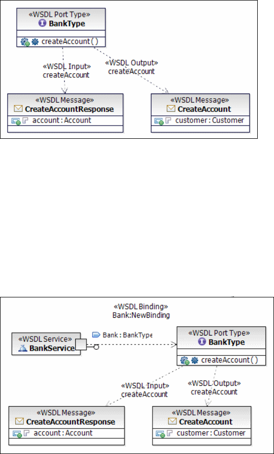
Chapter 7. Unified Modeling Language (UML) 47
Draft Document for Review December 9, 2008 2:44 pm 7672-arch-2-uml.fm
Figure 7-27 Class diagram showing a port type with messages
Create bindings between WSDL ports and port types
A binding is used to link a port type to a port. The class diagram editor offers you
several ways to do this. For example, you can use the WSDL Binding Creation
tool in the palette. To do this choose the tool in the palette and click on the port
(remember that a port is shown as a small square on the side of a service). Then
drag the cursor to the port type. A new binding is created between the port and
the port type. As shown in Figure 7-28, this binding is modeled as a dependency
with stereotype <<WSDL Binding>> between the two elements. The lollipop
notation is used to represent the interface provided by the port.
Figure 7-28 Class diagram showing a binding between a port and its port type
The last step is to generate the content for this binding. Select the dependency
representing the binding and open the Properties view. On the General page
click Generate Binding Content and complete the wizard (Figure 7-29).

7672-arch-2-uml.fm Draft Document for Review December 9, 2008 2:44 pm
48 Rational Application Developer V7.5 Programming Guide
Figure 7-29 Properties view showing binding properties
After you have created the entire Web service, you can directly create an
implementation of the Web Service within the diagram editor. Right-click a WSDL
service component and select Implement Web Service. This will start the Web
Service wizard that guides you through the process. You can also use the
diagram editor to create a Web Service client for a given Web Service. To do this
right-click a WSDL service component and select Consume Web Service.
Class diagram preferences
Rational Application Developer allows users to review and edit default settings or
preferences that affect the appearance and the behavior of UML class diagrams
and their content. These preferences are organized under the Modeling node
within the Preferences dialog (select Window → Preferences).
Before you create a new UML class diagram, you can set the default global
preferences for attributes and operations, such as visibility styles, showing or
hiding attributes and operations, showing or hiding operation signatures, and
showing or hiding parent names of classifiers. Most configuration settings are
present under the following Preferences dialog nodes:
UML diagrams—This node and the nodes beneath it such as Class and
Component allow users can specify several preferences regarding the style,
fonts and colors that are displayed in UML diagrams when they are created.
Users can change the default settings for showing or hiding attributes,
operations, operation signatures, or parent names of classifiers. They can
also specify which compartments are shown by default when a new UML
element is created.
Java—This node and the nodes beneath it allow users to specify settings that
deal with Java code when it is used in a UML model. One example is the
configuration of corresponding wizards that should be used when new fields
or methods are created within a class diagram.
Chapter 7. Unified Modeling Language (UML) 49
Draft Document for Review December 9, 2008 2:44 pm 7672-arch-2-uml.fm
– The settings for this are under Field and Method Creation. Its even
possible to specify the default values that should be applied to these
wizards.
–Show Related Elements Filters provides the option to filter out binary
Java types when the Show Related Elements action is executed. Binary
Java types are types that are not defined in the workspace, but instead are
available to the workspace through referenced JAR libraries.
EJB—The EJB preferences node allows users to specify if newly generated
or created EJBs are visualized in a selected class diagram. If this option is
selected and a diagram is not selected while creating or generating a new
bean, this bean is opened in a default class diagram.
Web Service—This node allows users to change the default settings for
visually representing existing WSDL elements. You can specify if the external
or compressed view of an existing WSDL element is shown. Furthermore you
can specify which WSDL components are visually represented in class
diagrams. To show or hide WSDL components, select or clear the
corresponding check boxes on this page.
Exploring relationships in applications
Rational Application Developer provides browse and topic diagrams that can be
used to explore and navigate through an application and to view the details of its
elements and relationships. They are designed to assist developers in
understanding and documenting existing code by quickly creating UML
representations of an existing application.
Browse diagrams
A browse diagram is a structural diagram which provides a view of a context
element such as a class, a package, or an EJB. It is a temporary and non
editable diagram that provides the capability to explore the given context
element. You can view the element details, including attributes, methods, and
relationships to other elements, and you are able to navigate to those elements.
Browse diagrams can be applied to various elements including Java classes and
Enterprise JavaBeans, but excluded are all elements related to Web services.
You can create a browse diagram from any source element or its representation
within a class diagram. To create a browse diagram, right-click the desired
element and select Visualize → Explore in Browse Diagram. A browse
diagram is created and shown in the corresponding diagram editor. The diagram
editor consists of a panel displaying the selected element along with its
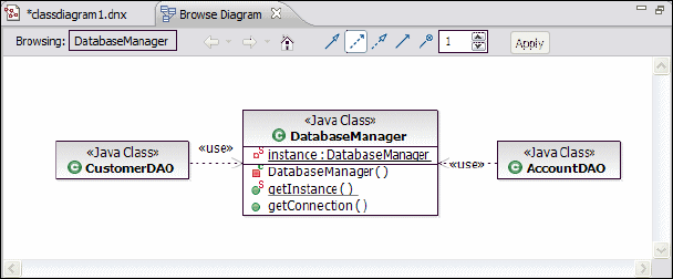
7672-arch-2-uml.fm Draft Document for Review December 9, 2008 2:44 pm
50 Rational Application Developer V7.5 Programming Guide
relationships and a tool bar. Because a browse diagram is not editable, the
palette and the modeling assistant are not available. Depending on the elements
shown, the diagram is displayed either using the radial or generalization tree
layout type. The radial layout type shows the selected element in the center of
the diagram, whereas the generalization tree layout type organizes the general
classes at the top of the diagram and the subclasses at the bottom.
The browse diagram acts like a Web browser for your code. It provides a history
and navigation, and you can customize the UML relationships you want to see.
The tool bar located at the top of the browse diagram displays the context
element you are currently browsing. At any one time, there is only one browse
diagram open. When you browse another element, it is displayed in the same
diagram replacing the previous element.
Figure 7-30 shows an example browse diagram with the Java class
DatabaseManager as the context element. You can see all the attributes and
methods declared by this class. In this case the dependency filter button is the
only one highlighted and so elements involved in a dependency relationship with
DatabaseManager are shown as well. You can see that AccountDAO and
CustomerDAO both depend on DatabaseManager.
Figure 7-30 Browse diagram example
The browse diagram retains the history of elements you have viewed so far. You
can use the two arrow buttons provided in the tool bar to navigate backward or
forward to browse previously viewed elements.
When you click the Home icon, the first element in the history is displayed.
Furthermore, the tool bar contains a list of filter icons that can be used to filter the
types of relationships that are shown along with the context element. Note that
there are different filters available depending on the type of element you are
currently browsing for example Java class or EJB. To enable or disable a filter,
click the appropriate icon and then click Apply. You can also change the number
Chapter 7. Unified Modeling Language (UML) 51
Draft Document for Review December 9, 2008 2:44 pm 7672-arch-2-uml.fm
of levels of relationships that are shown for the context element. The default
value is one. To change this value, specify a number and click Apply.
In Figure 7-30 the Home icon and the two arrow icons are disabled, so the
current element is the first element in the browse diagram history.
If you want to explore the details of a diagram element, double-click it. This
element becomes the new context element. When you right-click a diagram
element, the Navigate submenu provides several options such as opening the
Java source of a diagram element.
A browse diagram cannot be changed or saved, but Rational Application
Developer lets you save any browse diagram view as a diagram file that is fully
editable. Right-click an empty space inside a browse diagram and select File →
Save as Diagram File. If you want to use a browse diagram as part of
permanent documentation, you can save a browse diagram view as an image file
using File → Save as Image File.
Topic diagrams
Topic diagrams provide another way to create structural diagrams from the code
in your application. They are used to quickly create a query based view of
relationships between existing elements in your application. These queries are
called topics and represent commonly required views of your code, such as
showing the super type or sub types of a given class. Topic diagrams are
applicable to various elements, such as Java classes, EJBs or WSDL files. Like
browse diagrams these diagrams are not editable, but they can be saved as
editable UML diagrams and shared with other team members.
A new topic diagram of an application element is created by the Topic Diagram
wizard. To launch this wizard, right-click the desired element in the Enterprise
Explorer and select Visualize → Add to New Diagram File → Topic Diagram.
Once the wizard has started, on the Topic Diagram Location page, enter or select
the parent folder and provide a name for the file as shown in Figure 7-31. Then
click Next.
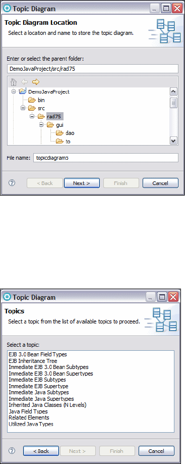
7672-arch-2-uml.fm Draft Document for Review December 9, 2008 2:44 pm
52 Rational Application Developer V7.5 Programming Guide
Figure 7-31 Topic Diagram wizard (1)
The Topics page shown in Figure 7-32 provides a list of standard topics Rational
Application Developer can create. Select a predefined query and click Finish.
This creates a new topic diagram based on default values associated with the
selected topic.
Figure 7-32 Topic Diagram wizard (2)
If you want to review or change these values click Next instead. The Related
Elements page shown in Figure 7-33 appears.
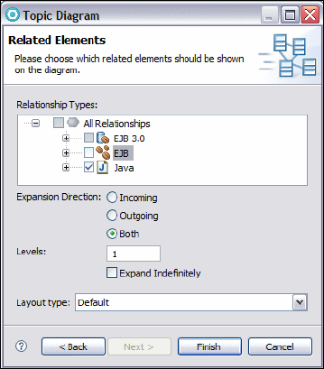
Chapter 7. Unified Modeling Language (UML) 53
Draft Document for Review December 9, 2008 2:44 pm 7672-arch-2-uml.fm
Figure 7-33 Topic Diagram wizard (3)
This page shows the details of the previous selected topic and allows you to
change these values. You can select different types of relationship that should be
included in the query along with the expansion direction:
If you select Incoming, all elements are shown that are related to the context
element.
On the other hand, if you want to see all elements that have a relationship to
the context element, select Outgoing.
You can further specify the number of levels of relationships to query and the
layout type for the diagram. The possible values are Default and Radial.
These values map to the generalization and radial tree layout type described
previously.
Once a topic diagram is created, you can review or change the underlying query.
To do this right-click on empty space inside the topic diagram and select
Customize Query.
Like browse diagrams, topic diagrams are not editable, so the tool palette and
the modeling assistant are not available. You can add more elements to the
diagram by right-clicking them in the Enterprise Explorer and selecting
Visualize → Add to Current Diagram.
7672-arch-2-uml.fm Draft Document for Review December 9, 2008 2:44 pm
54 Rational Application Developer V7.5 Programming Guide
It is also possible to save a topic diagram as an editable diagram or as an image
as we did previously with browse diagrams. To do this right-click on empty space
in a topic diagram and select either File → Save as Diagram File or File →
Save as Image File.
The query and the context element that you have specified are persisted in the
topic diagram. Every time you open a topic diagram the underlying elements are
queried and the diagram is automatically populated with the most current results.
If you make changes to the underlying elements when a topic diagram is already
open, the diagram might not represent the current status of the elements until
you refresh the diagram manually. To do this right-click on empty space in the
topic diagram and select Refresh.
Describing interactions with UML sequence diagrams
Rational Application Developer provides the capability to develop and manage
sequence diagrams. A sequence diagram is an interaction diagram that can be
used to describe the dynamic behavior of a system. It depicts the sequence of
messages which are sent between objects in a certain interaction or scenario.
Sequence diagrams can be used at different stages during the development
process:
Within the analysis phase, a sequence diagram can be used to describe the
realization of a use case that is a use case scenario.
Within the design phase, sequence diagrams can be more refined to show
how a system accomplishes an interaction and in this case shows objects of
actual design classes interacting.
A sequence diagram consists of a group of objects their associated lifelines and
the messages that these objects exchange over time during the interaction. In
this context, the term object does not necessarily refer to software objects
instantiated from a class. An object represents any structural thing defined by
UML.
Figure 7-34 provides an overview of a sample sequence diagram. It describes
the scenario where a customer wants to withdraw cash from an ATM. A
sequence diagram has a two-dimensional nature. The horizontal axis shows
each of the objects that are involved in an interaction, while the vertical axis
shows the lifelines, the messages exchanged and the sequence of creation and
destruction of the objects. Most objects that appear in a sequence diagram are in
existence for the duration of the entire interaction, so their lifelines are placed at
the top of the diagram. Objects can be created or destroyed during an
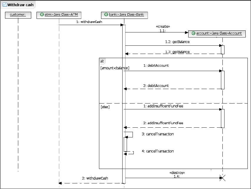
Chapter 7. Unified Modeling Language (UML) 55
Draft Document for Review December 9, 2008 2:44 pm 7672-arch-2-uml.fm
interaction. In this case their lifelines start or end respectively with the receipt of a
corresponding message to create or destroy them.
Figure 7-34 Overview of a sequence diagram
The main focus of Rational Application Developer when using sequence
diagrams is to document and visualize the dynamic behavior of a system rather
than to develop source code. The tool enables developers to create, edit, and
delete the various elements of a sequence diagram such as lifelines, messages
and combined fragments in a visual manner. In contrast to a class diagram, the
elements of a sequence diagram are not related to existing elements, such as
classes or interfaces. So changes made in a sequence diagram do not affect any
code.
Rational Application Developer has two different concepts of what a sequence
diagram is. The first kind of sequence diagram is created by a developer, within a
project, to document development work. In this case the developer adds lifelines,
7672-arch-2-uml.fm Draft Document for Review December 9, 2008 2:44 pm
56 Rational Application Developer V7.5 Programming Guide
messages and elements to the diagram to show specific object interactions. The
second kind of sequence diagram is referred to as Static Method Sequence
Diagram. This non-editable diagram is used to visualize the flow of messages
between existing Java objects in an executing application.
Creating sequence diagrams
To create a new sequence diagram, you must use the New Sequence Diagram
wizard that can be launched either directly from the top menu of Rational
Application Developer by selecting File → New → Other → Modeling →
Sequence Diagram or from within the Enterprise Explorer from the context
menu of any resource, such as projects or packages.
You can also create a new sequence diagram of an existing class or interface.
To do this in the Enterprise Explorer, right-click the desired source element and
select Visualize → Add to New Diagram File → Sequence Diagram. Once the
wizard has started you provide a name for the file that will be created to contain
the content of the diagram, and specify the parent folder where this file should be
stored. Clicking Finish completes the process and creates a new sequence
diagram. A sequence diagram has a corresponding diagram editor and palette
on the right side offers different tools which can be used to add new elements to
the diagram such as lifelines, messages or combined fragments. Also, there are
two items in the tool palette where a solid triangle is shown right next to the item.
When you click this triangle, a context menu is displayed that allows you to select
another tool from this category.
A sequence diagram is enclosed in a frame. A diagram frame provides a visual
border and enables the diagram to be easily reused in a different context. The
frame is depicted as a rectangle with a notched descriptor box in the top left
corner that provides a place for the diagram name. If you want to change the
name, select this box and enter the new name.
Creating lifelines
A lifeline represents the existence of an object involved in an interaction over a
period of time. A lifeline is depicted as a rectangle representing the object
involved in the interaction which contains the object's name, type and stereotype
with a vertical dashed line beneath indicating the progress of time. Figure 7-35
shows several examples of possible lifelines for objects of a class called
Customer. It is important to note that the terminology used with sequence
diagrams is different in UML 2.0 and later when compared with earlier versions of
UML. Also, text in a lifeline object box does not have to be underlined although it
can be rendered that way if required.

Chapter 7. Unified Modeling Language (UML) 57
Draft Document for Review December 9, 2008 2:44 pm 7672-arch-2-uml.fm
The first lifeline represents an instance of the Customer Java class and the
instance is named customer.
The second lifeline represents an anonymous instance of the Customer Java
class.
The last lifeline represents an object named customer whose type is not
shown.
Figure 7-35 Different representations of lifelines on a sequence diagram
To add a lifeline from an existing Java class or interface to a sequence diagram,
select the desired element in the Enterprise Explorer view and drag it on an
empty place in the diagram. This creates a new lifeline and places it at the top the
diagram aligned horizontally with the other lifelines. If you drag a different class
over the top of an existing lifeline on the sequence diagram then the class of the
lifeline is changed to the new class.
You can also use the tool palette to create a new lifeline. Select the Lifeline in
the palette and drop it on an empty space inside the diagram. Note, that this
creates a lifeline representing an object whose type is not specified but with a
default name. Once a lifeline is created, you can change the name and type of
the object it represents.
If you want to change the name, select the lifeline's shape and enter the new
name. If you want to change the type and a class or interface is available in the
Enterprise Explorer, select the desired class or interface in the Enterprise
Explorer and drag it on the lifeline's shape. You can also use the Properties view
to review or change any property of a given lifeline.
By default, a lifeline is shown as a rectangle containing the lifeline name, type,
and stereotype. If you right-click a lifeline, the Filters submenu provides several
options to change the lifeline's appearance.
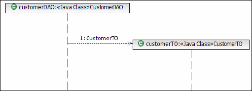
7672-arch-2-uml.fm Draft Document for Review December 9, 2008 2:44 pm
58 Rational Application Developer V7.5 Programming Guide
Creating messages
A message describes the kind of communication that occurs between two
lifelines. A message is sent from a source lifeline to a target lifeline to initiate
some kind of action or behavior such as invoking an operation on the target or
creation/destruction of a lifeline. The target lifeline often responds with a further
message to indicate that it has finished processing.
A message is visualized as a labeled arrow that originates from the source
lifeline and ends at the target lifeline. The message is sent by the source and
received by target and the arrow points from source to target. The label is used to
identify the message. It contains either a name or an operation signature if the
message is used to call an operation. The label also contains a sequence
number that indicates the ordering of the message within the sequence of
messages.
To create a message between two lifelines, hover the mouse pointer over the
source lifeline so that the modeling assistant is available. Then click on the
small box at the end of the outgoing arrow and drag the resulting connector
on the desired target lifeline. In the context menu that appears when you drop
the connector on the target, click the desired message type such as
synchronous or asynchronous and enter either a name or select an operation
from the drop-down combo box. Only if the target already has available
operations will you be able to select one.
You can also use the tool palette to create a message. Select the desired
message type by clicking the solid triangle right next to the Message category,
then click the source lifeline and drag the cursor to the target lifeline.
Selecting Create Message from the Palette allows the source lifeline to
create a new lifeline. The new lifeline starts when it receives this message.
The symbol at the head of this lifeline is shown at the same level as the
message that caused the creation (Figure 7-36). The message itself is
visualized as a dashed line with an open arrowhead. This type of message is
used to highlight that a new object is created during an interaction.
Figure 7-36 Sending a create message to create a new lifeline during an interaction

Chapter 7. Unified Modeling Language (UML) 59
Draft Document for Review December 9, 2008 2:44 pm 7672-arch-2-uml.fm
In contrast, a Destroy Message enables a lifeline to delete an existing lifeline.
The target lifeline is terminated at that point when it receives the message.
The end of the lifeline is denoted using the stop notation, a large X
(Figure 7-37). A destroy message is drawn in a similar way to a Create
Message. You can use this type of message to describe that an object is
destroyed during an interaction. Once a lifeline has been destroyed it is not
possible for it to be the target of any messages.
Figure 7-37 Destroying a lifeline during an interaction
A Synchronous Message enables the source lifeline to invoke an operation
provided by the target lifeline. The source lifeline continues and can send
more messages only after it receives a response from the target lifeline.
When you create a Synchronous Message, Application Developer places
three elements in the diagram (Figure 7-38):
– A line with a solid arrowhead representing a synchronous operation
invocation.
– A dashed line with a solid arrowhead representing the return message.
– A thin rectangle called an activation bar or execution occurrence
representing the behavior performed.
Figure 7-38 Synchronous message invocation
By default, only the operation's name is shown. If you want to see the full
operation signature, right-click the message arrow and select Filters → Show
Signature.
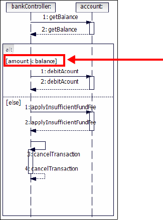
7672-arch-2-uml.fm Draft Document for Review December 9, 2008 2:44 pm
60 Rational Application Developer V7.5 Programming Guide
An Asynchronous Message allows the source lifeline to invoke an operation
provided by the target lifeline. The source lifeline can then continue and send
more messages without waiting. When an asynchronous message is sent the
source does not have to wait until the target processes it. An Asynchronous
Message is drawn similar as a synchronous message, but the line is drawn
with an open arrowhead, and the response is omitted. You can send another
kind of asynchronous message, the Asynchronous Signal Message. This is
a special form of a message that is not associated with a particular operation.
Creating combined fragments
UML 2.0 introduced the concept of combined fragments to support conditional
and looping constructs such as if-then-else statements or to enable parts of an
interaction to be reused.
Combined fragments are frames that encompass portions of a sequence
diagram or provide reference to other diagrams.
A combined fragment is represented by a rectangle that comprises one or more
lifelines. Its behavior is defined by an interaction operator that is drawn as a
notched descriptor box in the upper left corner of the combined fragment. For
example, the alternative interaction operator (alt) acts like an if-then-else
statement and is shown in Figure 7-39.
Figure 7-39 Sequence diagram with an alternative combined fragment
guard condition
Chapter 7. Unified Modeling Language (UML) 61
Draft Document for Review December 9, 2008 2:44 pm 7672-arch-2-uml.fm
UML 2.0 provides many other interaction operators for use with combined
fragments. Depending on its type, a combined fragment can have one or more
interaction operands. Each interaction operand represents a fragment of the
interaction with an optional guard condition. The interaction operand is executed
only if the guard condition is true at runtime. The absence of a guard condition
means that the combined fragment is always executed. The guard condition is
displayed as plain text enclosed within two square brackets. A combined
fragment separates the contained interaction operands with a dashed horizontal
line between each operand within the frame of the combined fragment. When the
combined fragment contains only one operand, the dashed line is unnecessary.
Figure 7-39 shows a fragment being used in a withdraw cash interaction. The
combined fragment is used to model an alternative flow in the interaction.
Because of the guard condition [amount<balance], if the account balance is
greater than the amount of money the customer wants to withdraw, the first
interaction operand is executed. This means the interaction debits the account.
Otherwise the [else] guard forces the second interaction operand to be
executed. An insufficient fund fee is added to the account and the transaction is
canceled.
To create a combined fragment, you must first select the desired fragment in the
palette. Click the solid triangle right next to the Combined Fragment category
and select the desired fragment from the available fragments. Then click the left
mouse button within an empty place in the diagram and drag the combined
fragment across the lifelines that you want to include in it. When you release the
mouse button, the Add Covered Lifelines dialog opens and this allows you to
select the individual lifelines to be covered by the combined fragment. Each
lifeline is represented by a check box, and each of them is selected by default.
When you click OK a new combined fragment along with one or two interaction
operands is created.
Figure 7-40 shows a newly created alternative combined fragment with two
empty interaction operands. If you want to specify a guard condition for an
interaction operand, select the corresponding brackets and enter the text. You
can create messages between the individual lifelines covered by the combined
fragment in the same way as described previously. Note how the sequence
numbers of the individual messages change within an interaction operand. You
can also nest other combined fragments within an existing combined fragment.
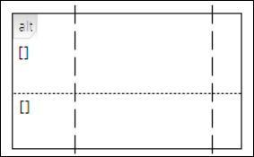
7672-arch-2-uml.fm Draft Document for Review December 9, 2008 2:44 pm
62 Rational Application Developer V7.5 Programming Guide
Figure 7-40 Empty combined fragment with two interaction operands
Once created, it is not possible to change the type of a combined fragment, or
more importantly its interaction operator. But if you right-click a combined
fragment the context menu allows you to add new interaction operands if you
select Add Interaction Operand or to add and remove lifelines from the
selected element if you select Covered Lifelines.
When you create an interaction operand, it appears in an expanded state. By
clicking the small triangle at the top of the interaction operand you can collapse it
to hide the entire operand and its associated messages. From the context menu
of an operand there are several options available to remove or reposition the
selected operand. Further, you are able to add a guard condition to the operand
or to add a new interaction operand if the enclosing combined fragment allows
multiple operands
Creating references to external diagrams
UML 2.1 provides the capability to reuse interactions that are defined in another
context. This provides you the ability to create complex sequence diagrams from
smaller and simpler interactions. A reference to another diagram is modeled
using the Interaction Use element. Like a combined fragment, an Interaction
Use element is represented by a frame. The operator ref is placed inside the
descriptor box in the upper left corner, and the name of the sequence diagram
being referenced is placed inside the frame's content area along with any
parameters for the sequence diagram.
An interaction use can encompass a single activation bar or several lifelines. To
create a reference to another sequence diagram:
Select Interaction Use in the palette and place the cursor on an empty space
inside the source sequence diagram.
When you drop the cursor, you are prompted to choose the current lifelines
that will be covered.
In the Add Covered Lifelines dialog that opens, select the lifelines that should
be encompassed by the interaction use element and click OK.

Chapter 7. Unified Modeling Language (UML) 63
Draft Document for Review December 9, 2008 2:44 pm 7672-arch-2-uml.fm
In Figure 7-41 the interaction use element references an interaction called
sequencediagram2, which provides further information on how the withdrawCash
operation is realized.
Figure 7-41 Creating a reference to another diagram
Exploring Java methods by using static method sequence diagrams
The static method sequence diagram feature provided by Rational Application
Developer enables developers to visualize a Java method. Existing Java code
can quickly be rendered in a sequence diagram in order to visually examine the
behavior of an application. A static sequence diagram from a Java method
provides the full view of the entire method call sequence.
To create a static method sequence diagram for a Java method:
Right-click the desired method in the Enterprise Explorer or Package Explorer
view and select Visualize → Add to New Diagram File → Static Method
Sequence Diagram.
The diagram is created and shown in the corresponding diagram editor.
A static method sequence diagram is a topic diagram, so the diagram content is
stored in a file with a .tpx extension. Like other topic diagrams, it is read only; the
tool palette, the tool bar, and the modeling assistant are not available.
When you right-click an empty space inside the diagram, the File submenu
provides you the options to either save the diagram as an image using Save as
Image File to convert this diagram to an editable UML sequence diagram using
Save as Diagram File, or to print the entire diagram using Print.
Note: At the time of writing it
was not possible to truly
reference another diagram.
Instead it was only possible to
provide a simple name.

7672-arch-2-uml.fm Draft Document for Review December 9, 2008 2:44 pm
64 Rational Application Developer V7.5 Programming Guide
Figure 7-42 shows a basic example of a static sequence diagram. It describes
the flow of control when the withdrawCash method provided by the ATM class is
called from the main method of this class. The synchronous message from the
diagram frame that invokes the method, in this case main, is called a found
message. The corresponding return message is referred to as a lost message.
Figure 7-42 static method sequence diagram example
A static sequence diagram for a Java method has to be created only once. Like
other topic diagrams, the query and context that have been specified when
creating the diagram are stored in the diagram itself. So each time a sequence
diagram is opened, Rational Application Developer queries the underlying
elements and populates the diagram with the latest updates. If you want to
refresh the contents of a static sequence diagram to reflect the latest changes in
the source code, right-click an empty space inside the diagram and select
Refresh.
Sequence diagram preferences
Using the Sequence and Communication node in the Preferences dialog, you
can change default values that affect the appearance of sequence diagrams
(Figure 7-43).
Note: At the time of writing, Application Developer failed to update the
contents of a static sequence diagram when the source code was changed. A
workaround is to restart Rational Application Developer with the -clean option.

Chapter 7. Unified Modeling Language (UML) 65
Draft Document for Review December 9, 2008 2:44 pm 7672-arch-2-uml.fm
For example, you can specify if return messages should be created automatically
or that message numbering is shown.
Figure 7-43 Sequence diagram preferences
7672-arch-2-uml.fm Draft Document for Review December 9, 2008 2:44 pm
66 Rational Application Developer V7.5 Programming Guide
More information on UML
For more information about UML, we recommend the following resources. These
Web sites provide information on modeling techniques, best practices, and UML
standards:
IBM developerWorks Rational: Provides guidance and information that can
help you implement and deepen your knowledge of Rational tools and best
practices. This network includes access to white papers, artifacts, source
code, discussions, training, and other documentation:
http://www.ibm.com/developerworks/rational/
In particular, we would like to highlight the following series of high quality
Rational Edge articles focusing on UML topics:
http://www.ibm.com/developerworks/rational/library/content/RationalEdge/arc
hives/uml.html
The IBM Rational Software UML Resource Center: This is a library of UML
information and resources that IBM continues to build upon and update. In
addition to current news and updates about the UML, you can find UML
documentation, white papers, and learning resources:
http://www.ibm.com/software/rational/uml/index.html
Object Management Group (OMG): These OMG Web sites provide formal
specifications on UML that have been adopted by the OMG and are available
in either published or downloadable form, and technical submissions on UML
that have not yet been adopted:
http://www.omg.org
http://www.uml.org
Craig Larmann’s home page: Provides articles and related links on topics
regarding to UML:
http://www.craiglarman.com/

© Copyright IBM Corp. 2008. All rights reserved. 67
Draft Document for Review December 9, 2008 2:44 pm 7672-base-0-p3.fm
Part 3 Basic Java and XML
development
In this part of the book, we describe the tooling and technologies provided by
Application Developer to develop applications using Java, aptterns, and XML.
Part 3
Note: The sample code for all the applications developed in this part is
available for download at:
ftp://www.redbooks.ibm.com/redbooks/SG247672
Refer to Appendix B, “Additional material” on page 1149 for instructions.
7672-base-0-p3.fm Draft Document for Review December 9, 2008 2:44 pm
68 Rational Application Developer V7.5 Programming Guide

© Copyright IBM Corp. 2008. All rights reserved. 69
Draft Document for Review December 9, 2008 2:44 pm 7672-base-1-java.fm
Chapter 8. Develop Java applications
This chapter introduces the Java development capabilities and tooling features of
Application Developer by developing the ITSO Bank application.
The chapter is organized into the following sections:
Java perspectives, views, and editor overview
Developing the ITSO Bank application
Understanding the sample code
Java editor and rapid application development
The sample code for this chapter is in 7672code\java.
8
Note: Application Developer V7.5 fully supports the Java SE 6.0 compliance.
However newer JRE versions can be downloaded, installed, and used in the
Application Developer by the customer themselves, as described in “Plugable
Java Runtime Environment (JRE)” on page 124.
Author Comment: Red text represent functionalities not found in the current version
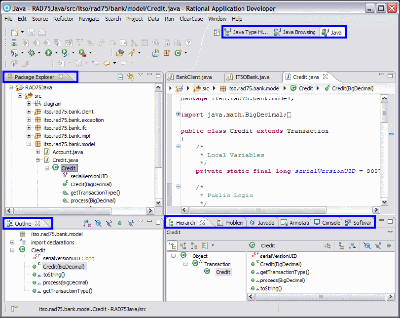
7672-base-1-java.fm Draft Document for Review December 9, 2008 2:44 pm
70 Rational Application Developer V7.5 Programming Guide
Java perspectives, views, and editor overview
Within Application Developer, there are three predefined perspectives containing
the views and editor that are most commonly used while developing Java SE
applications:
Java perspective
Java Browsing perspective
Java Type Hierarchy perspective
Those perspectives and their main views were briefly introduced in Chapter 4,
“Perspectives, views, and editors” on page 119. In this section we go deeper into
the details and describe some more useful views. The highlighted areas in
Figure 8-1 indicate all perspectives and views we discuss.
Figure 8-1 Views in the Java perspective [customized]
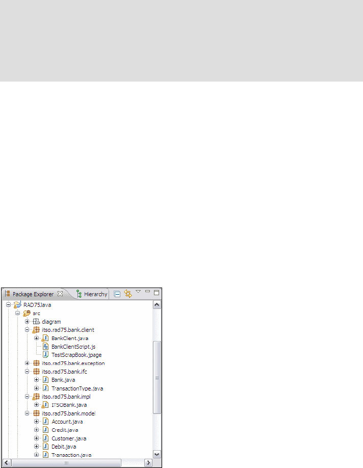
Chapter 8. Develop Java applications 71
Draft Document for Review December 9, 2008 2:44 pm 7672-base-1-java.fm
Java perspective
We use the Java perspective to develop Java SE applications or utility Java
projects (utility JAR files) containing code that is shared across multiple modules
within an enterprise application. Views can be added by selecting Window →
Show View.
Package Explorer view
The Package Explorer view displays all projects, packages, interfaces, classes,
member variables, and member methods contained in the workspace, as shown
in Figure 8-2. It allows us to easily navigate through the workspace.
Figure 8-2 Package Explorer view
Note: Figure 8-1 shows a customized Java perspective. It is the predefined
Java perspective with some more useful views added. We recommend that
you also customize the perspectives so that they fit your requirements. A
customized perspective can be saved: Window → Save Perspective As. A
modified perspective can be set back to a predefined or saved perspective:
Window → Reset Perspective.
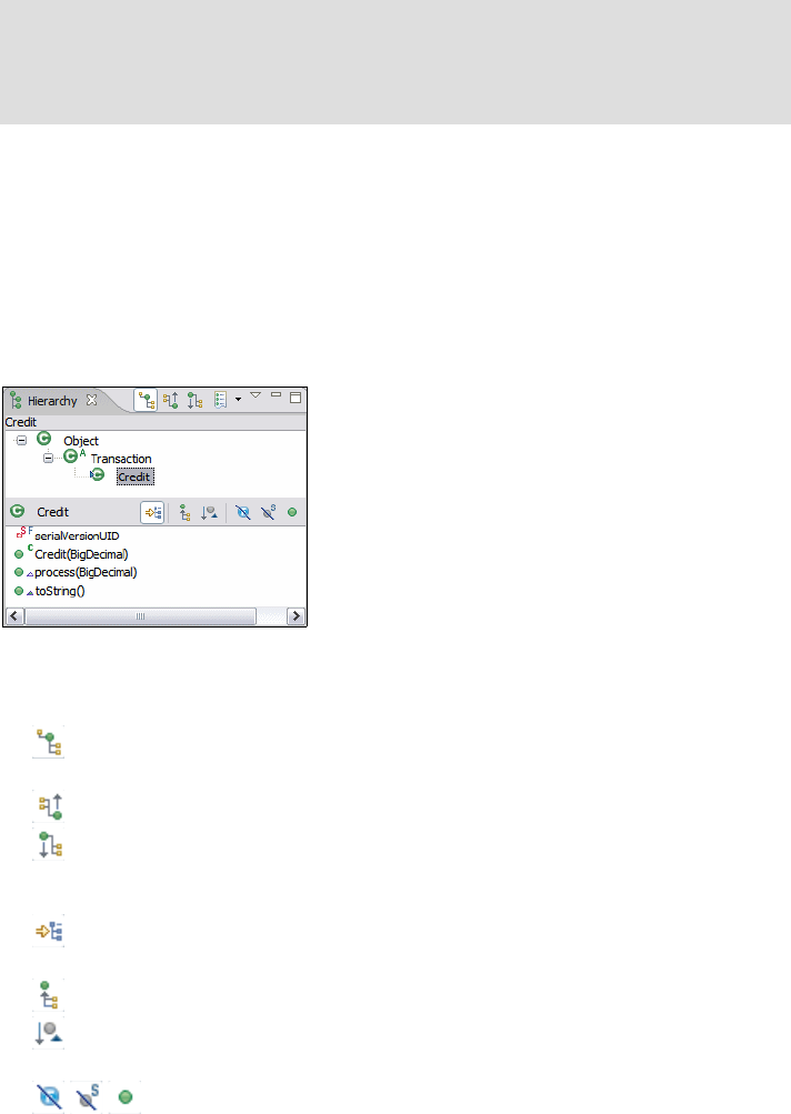
7672-base-1-java.fm Draft Document for Review December 9, 2008 2:44 pm
72 Rational Application Developer V7.5 Programming Guide
Hierarchy view
We use the Hierarchy view to display the type hierarchy of a selected type.
To view the hierarchy of a class type, select the class in the Package Explorer,
and press F4 or right-click the class and select Open Type Hierarchy. The
hierarchy of the selected class is displayed, as shown in Figure 8-3.
Figure 8-3 Hierarchy view for a selected class
The Hierarchy view provides three kinds of hierarchy layouts:
Type Hierarchy: All supertypes and subtypes of the selected type are
shown.
Supertype Hierarchy: Only all supertypes of the selected type are shown.
Subtype Hierarchy: Only all subtypes of the selected type are shown.
Other options in the Hierarchy view:
Locks the view and shows members in hierarchy. For example, use this
option if you are interested in all types implementing the toString() method.
Shows all inherited members.
Sorts members by theirs defining types. Defining type is displayed before
the member name.
Filters the displayed members.
Note: In this view, you cannot see the generated .class files. If you want to
see the folders and files as they are in the file system, open the Navigator view
by selecting Window → Show View → Navigator. Now you can see the
source code in the src directory and the byte code files in the bin directory.
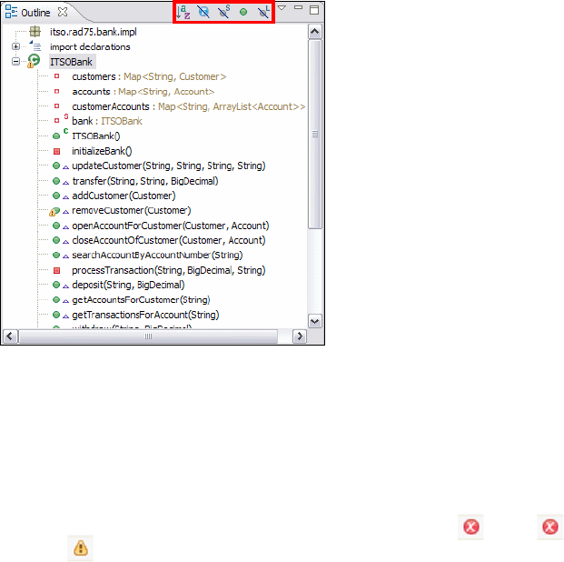
Chapter 8. Develop Java applications 73
Draft Document for Review December 9, 2008 2:44 pm 7672-base-1-java.fm
Outline view
The Outline view is very useful and is the recommended way to navigate through
a type that is currently opened in the Java editor. It lists all elements including
package, import declarations, type, fields, and methods. The developer can sort
and filter the elements that are displayed by using the icons highlighted in
Figure 8-4.
Figure 8-4 Outline view
Problems view
While editing resource files, various builders can automatically log problems,
errors, or warnings in the Problems view. For example, when you save a Java
source file that contains syntax errors, those will be logged as errors, as shown in
Figure 8-5. When you double-click the icon for a problem , error , or
warning , the editor for the associated resource automatically opens to the
relevant line of code.
Application Developer provides a quick fix for some problems. How to process a
quick fix is described in “Quick fix” on page 142.

7672-base-1-java.fm Draft Document for Review December 9, 2008 2:44 pm
74 Rational Application Developer V7.5 Programming Guide
Figure 8-5 Problems view with warnings notification
The Problems view allows you to filter the problems to show only specific types of
problems by clicking the View Menu icon , which opens a menu from which
you can sort the content or select the Configure Contents dialog (Figure 8-6).
Figure 8-6 Configure Contents of Problems view
Note: The Java builder is responsible for all Java resource files. However, in
an enterprise application project, other builders can be used. Builders can be
enabled and disabled for each project. Right-click the project in the Package
Explorer and select Properties and then Builders.
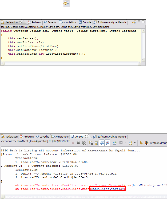
Chapter 8. Develop Java applications 75
Draft Document for Review December 9, 2008 2:44 pm 7672-base-1-java.fm
Declaration view
This view displays the declaration and definition of the currently selected type or
element, as shown in Figure 8-7. It is most useful to see the source code of a
referenced type within your code. For example, if you reference a customer within
your code and you want to see the implementation of the Customer class, just
select the referenced type Customer, and the source code of the Customer class is
displayed in this view. Clicking directly opens the source file of the selected
type in the Java editor.
Figure 8-7 Declaration view
Console view
The console is the view in which the Application Developer writes all outputs of a
process and allows you to provide keyboard inputs to the Java application while
running it. Uncaught exceptions are also displayed in the console.
The highlighted link in Figure 8-8 directs you to the line in the source code where
the exception has been thrown.
Figure 8-8 Console view with standard outputs and an exception
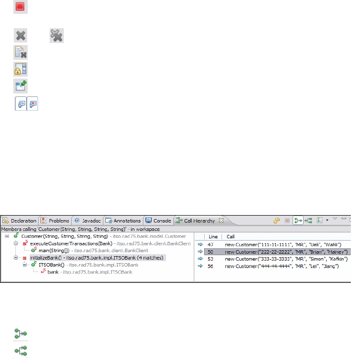
7672-base-1-java.fm Draft Document for Review December 9, 2008 2:44 pm
76 Rational Application Developer V7.5 Programming Guide
Other options in the Console view:
Terminates the currently running process. It is a useful button to terminate
a process running in an endless loop.
and Removes terminated launches from the console.
Clears the console.
Enables scroll lock in the console.
Pins the current console to remain on the top.
Shows the console when JVM logs are updated.
Call Hierarchy view
The Call Hierarchy view displays all callers and callees of a selected method, as
shown in Figure 8-9. To view the call hierarchy of a method, select it in the
Package Explorer or in the source code, and press Ctrl+Alt+H or right-click, and
select Open Call Hierarchy.
Figure 8-9 Call Hierarchy view [Callee Hierarchy]
Call Hierarchy view provides two kind of hierarchy layouts:
Caller Hierarchy: All the members calling the selected method are shown.
Callee Hierarchy: All members called by the selected method are shown.
Java Browsing perspective
The Java Browsing perspective is used to browse and manipulate your code. In
contrast to the Package Explorer view, which organizes all Java elements in a
tree, this perspective uses distinct views highlighted in Figure 8-10 to present the
same information.
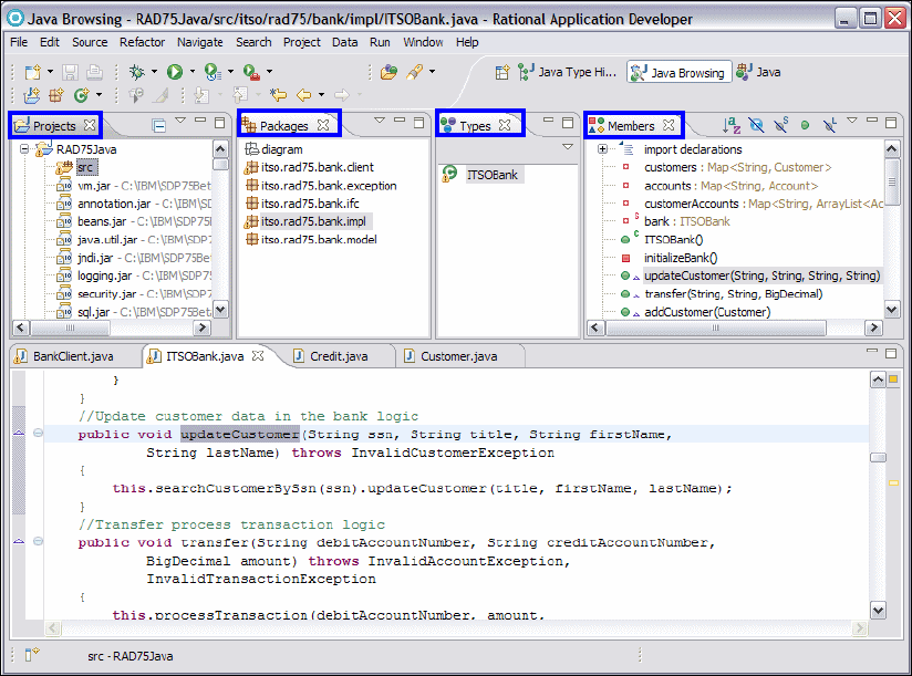
Chapter 8. Develop Java applications 77
Draft Document for Review December 9, 2008 2:44 pm 7672-base-1-java.fm
Figure 8-10 Views in the Java Browsing perspective
Java Type Hierarchy perspective
The Java Type Hierarchy perspective contains only the Hierarchy view, which
was described in “Hierarchy view” on page 72.

7672-base-1-java.fm Draft Document for Review December 9, 2008 2:44 pm
78 Rational Application Developer V7.5 Programming Guide
Developing the ITSO Bank application
In this section we demonstrate how Application Developer can be used to
develop a Java SE application. We create a Java project including several
packages, interfaces, classes, fields, and methods.
ITSO Bank application overview
The example application to work through in this section is called ITSO Bank. The
banking example is deliberately over-simplified, and the exception handling is
ignored to keep the example concise and relevant to our discussion.
Packaging structure
The ITSO Bank application contains several packages. Table 8-1 lists the
packages and describes their purpose.
Table 8-1 ITSO Bank application packages
Note: The sample code described in this chapter can be completed by
following along in the procedures documented. Alternatively, you can import
the sample Java code provided in:
c:\7672code\zInterchange\java\RAD75Java.zip
Refer to Appendix B, “Additional material” on page 1149 for instructions on
how to download the sample code.
Package Description
itso.rad75.bank.ifc Contains the interfaces of the application
itso.rad75.bank.impl Contains the bank implementation class
itso.rad75.bank.model Contains all business model classes of the application
itso.rad75.bank.exception Contains the exception classes of the application
itso.rad75.bank.client Contains the application client which we use to run the
application

Chapter 8. Develop Java applications 79
Draft Document for Review December 9, 2008 2:44 pm 7672-base-1-java.fm
Interfaces and classes overview
The application contains the following classes and interfaces:
Bank interface—This defines common operations a bank would perform, and
typically includes customer, account, and transaction related services.
TransactionType interface—This defines the kind of transactions the bank
allows.
ITSOBank class—This is an implementation of the Bank interface.
Account class—This is the representation of a bank account. It logs all
transactions performed on it for logging and querying purposes.
Customer class—This is the representation of a client of bank, an account
holder. A customer can have one or more accounts.
Transaction class—This is an abstract supertype of all transactions. A
transaction is a single operation that will be performed on an account. In the
example only two transaction types exist: Debit and Credit.
Debit class—This is one of the two existing concrete subtypes of the
Transaction class. This transaction results in an account being debited by the
amount indicated.
Credit class—This is the other concrete subtype of Transaction class. It
results in an account being credited by the amount indicated.
BankClient class—This is the executable class of the ITSO Bank application.
It creates instances of ITSOBank, Customer, Account classes, and performs
some transactions on the accounts.
All exception classes in the package itso.rad75.bank.exception—These are
the implemented exceptions that can occur in the ITSO Bank application.
ITSOBankException is the supertype of all ITSO Bank application exceptions.
Interfaces and classes structure
The ITSO Bank interfaces and classes structure are described in Table 8-2
(interfaces) and Table 8-3 (classes).
Table 8-2 ITSO Bank application interfaces
Interface name Package Modifiers
TransactionType itso.rad75.bank.ifc public
Bank itso.rad75.bank.ifc public

7672-base-1-java.fm Draft Document for Review December 9, 2008 2:44 pm
80 Rational Application Developer V7.5 Programming Guide
Table 8-3 ITSO Bank application classes
Interfaces and classes fields and getter & setters
The fields of the interfaces are described in Table 8-4 and the fields of the
classes are described in Table 8-5. The fields marked with *) are the
implementations of UML associations.
Table 8-4 Fields of the interfaces
Class name Package Superclass Modifiers Interfaces
ITSOBank itso.rad75.bank.impl java.lang.Object public itso.rad75.bank.ifc.
Bank
Account itso.rad75.bank.model java.lang.Object public java.io.Serializable
Customer itso.rad75.bank.model java.lang.Object public java.io.Serializable
Transaction itso.rad75.bank.model java.lang.Object public abstract java.io.Serializable
Credit itso.rad75.bank.model Transaction public
Debit itso.rad75.bank.model Transaction public
BankClient itso.rad75.bank.client java.lang.Object public
ITSOBankException itso.rad75.bank.exception java.lang.Exception public
AccountAlready
ExistException
itso.rad75.bank.exception ITSOBankException public
CustomerAlready
ExistException
itso.rad75.bank.exception ITSOBankException public
InvalidAccount
Exception
itso.rad75.bank.exception ITSOBankException public
InvalidAmount
Exception
itso.rad75.bank.exception ITSOBankException public
InvalidCustomer
Exception
itso.rad75.bank.exception ITSOBankException public
InvalidTransaction
Exception
itso.rad75.bank.exception ITSOBankException public
Interface Field Type Initial value Visibility, Modifiers
TransactionType CREDIT String "CREDIT" public static final
DEBIT String "DEBIT" public static final

Chapter 8. Develop Java applications 81
Draft Document for Review December 9, 2008 2:44 pm 7672-base-1-java.fm
Table 8-5 Fields and getter and setter methods of the classes
Class Field name Type Initial
value
Visibility,
Modifiers
Methods
ITSOBank accounts *)
customers *) Map<String,Account>
Map<String, Customer> mull private getter:
public,
setter:
private
customer
Accounts Map<String,
ArrayList<Account>>
bank ITSOBank new private
static getter:
public
static
Account accountNumber java.lang.String null private getter:
public,
setter:
private
balance java.math.BigDecimal
transactions *) ArrayList<Transaction>
Customer ssn
title
firstName
lastName
java.lang.String null private getter:
public,
setter:
private
accounts *) ArrayList<Account>
Transaction timeStamp Timestamp null private
amount java.math.BigDecimal
transactionId int 0
AccountAlready
ExistException accountNumber java.lang.String null private
CustomerAlready
ExistException ssn java.lang.String null private
InvalidAccount
Exception accountNumber java.lang.String null private
InvalidAmount
Exception amount java.lang.String null private
InvalidCustomer
Exception ssn java.lang.String null private
Invalid
Transaction
Exception
transactionType java.lang.String null private
amount java.math.BigDecimal
account Account
7672-base-1-java.fm Draft Document for Review December 9, 2008 2:44 pm
82 Rational Application Developer V7.5 Programming Guide
Interfaces and classes methods
The methods of the Bank interface are described in Table 8-6.
Table 8-6 Method declarations of the Bank interface
Class constructors and methods
The constructors and methods of the classes of the application are described in
Table 8-7.
Method name Return type Parameters Exceptions
addCustomer void Customer customer CustomerAlreadyExistException
closeAccountOfCustomer void Customer customer,
Account account
InvalidAccountException,
InvalidCustomerException
deposit void String accountNumber,
BigDecimal amount
InvalidAccountException,
InvalidTransactionException
getAccountsForCustomer ArrayList
<Account>
String customerSsn InvalidCustomerException
getCustomers Map<String,
Customer>
getTransactionsForAccount ArrayList
<Transaction>
String accountNumber InvalidAccountException
openAccountForCustomer void Customer customer,
Account account
InvalidCustomerException,
AccountAlreadyExistException
removeCustomer void Customer customer InvalidCustomerException
searchAccountByAccountNumber Account String accountNumber InvalidAccountException
searchCustomerBySsn Customer String ssn InvalidCustomerException
transfer void String
debitAccountNumber,
String
creditAccountNumber,
BigDecimal amount
InvalidAccountException,
InvalidTransactionException
updateCustomer void String ssn, String title,
String firstName, String
lastName
InvalidCustomerException
withdraw void String accountNumber,
BigDecimal amount
InvalidAccountException,
InvalidTransactionException
Chapter 8. Develop Java applications 83
Draft Document for Review December 9, 2008 2:44 pm 7672-base-1-java.fm
Table 8-7 Constructors and methods of the classes of the ITSO Bank application
Method name Modi-
fiers
Type Parameters Exceptions
ITSOBank
ITSOBank private constructor
addCustomer public void Customer customer CustomerAlreadyExistException
removeCustomer void Customer customer InvalidCustomerException
openAccountFor
Customer
void Customer customer,
Account account
InvalidCustomerException,
AccountAlreadyExistException
closeAccountOf
Customer
void Customer customer,
Account account
InvalidAccountException,
InvalidCustomerException
searchAccountBy
AccountNumber
Account String accountNumber InvalidAccountException
searchCustomerBySsn Customer String ssn InvalidCustomerException
processTransaction private void String accountNumber,
BigDecimal amount,
String transactionType
InvalidAccountException,
InvalidTransactionException
getAccountsFor
Customer
public ArrayList<A
ccount>
String customerSsn InvalidCustomerException
getTransactionsFor
Account
ArrayList<T
ransaction>
String accountNumber InvalidAccountException
updateCustomer void String ssn,
String title,
String firstName,
String lastName
InvalidCustomerException
deposit void String accountNumber,
BigDecimal amount
InvalidAccountException,
InvalidTransactionException
withdraw void String accountNumber,
BigDecimal amount
InvalidAccountException,
InvalidTransactionException
transfer void String
debitAccountNumber,
String
creditAccountNumber,
BigDecimal amount
InvalidAccountException,
InvalidTransactionException
initializeBank private void
Account
7672-base-1-java.fm Draft Document for Review December 9, 2008 2:44 pm
84 Rational Application Developer V7.5 Programming Guide
Account public constructor String accountNumber,
BigDecimal balance
processTransaction public void BigDecimal amount,
String transactionType
InvalidTransactionException
toString String
Customer
Customer public constructor String ssn,
String title,
String firstName,
String lastName
updateCustomer public void String title,
String firstName,
String lastName
addAccount void Account account AccountAlreadyExistException
removeAccount void Account account InvalidAccountException
toString String
Transaction
Transaction public constructor BigDecimal amount
getTransactionType public
abstract
String
process BigDecimal BigDecimal
accountBalance
InvalidTransactionException
Credit
Credit public constructor BigDecimal amount
getTransactionType public String
process BigDecimal BigDecimal
accountBalance
InvalidTransactionException
toString String
Debit
Debit public constructor BigDecimal amount
Method name Modi-
fiers
Type Parameters Exceptions
Chapter 8. Develop Java applications 85
Draft Document for Review December 9, 2008 2:44 pm 7672-base-1-java.fm
Class diagram
A UML class diagram helps to overview the interfaces and classes and their
relationships. In the class diagram in Figure 8-11, we added the packages as
well to get a complete picture of the ITSO Bank application.
We create this diagram by using Application Developer’s UML modeling tool in
“Creating a UML class diagram” on page 90.
getTransactionType public String
process BigDecimal BigDecimal
accountBalance
InvalidTransactionException
toString String
BankClient
main public
static
void String[] args
Method name Modi-
fiers
Type Parameters Exceptions

7672-base-1-java.fm Draft Document for Review December 9, 2008 2:44 pm
86 Rational Application Developer V7.5 Programming Guide
Figure 8-11 UML class diagram: ITSO Bank application
ITSO Bank application step-by-step development guide
The next sections provide a step by step guide to develop the ITSO Bank
application in Application Developer.
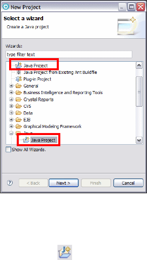
Chapter 8. Develop Java applications 87
Draft Document for Review December 9, 2008 2:44 pm 7672-base-1-java.fm
Creating a Java project
Java projects are not defined in the Java SE specification, they are used as the
lowest unit to organize the workspace and contains all resources needed for a
Java application as images, source, class and properties files.
With Application Developer started we recommend to switch to the Java
perspective as described in “Switching perspectives” on page 123.
We create a new Java project from the New Java Project wizard. Launch the New
Java Project wizard using the New Project dialog (Figure 8-12) selecting File →
New → Project in the workbench and then select Java Project or Java → Java
Project and click Next.
Figure 8-12 New Project dialog
Another way to launch the New Java Project wizard is directly from the
workbench by selecting File → New → Java Project or clicking the New Java
Project icon in the toolbar.
In the New Java Project - Create a Java Project dialog, enter the project name
and accept the default settings for each of the other fields (Figure 8-13, left):
– Project name: (type) RAD75Java
– Contents: Create new project in workspace. (Selected)
–JRE: Use default JRE (Currently ‘jdk’). (Selected)
– Project layout: Create separate source and output folders. (Selected)
– Click Next.

7672-base-1-java.fm Draft Document for Review December 9, 2008 2:44 pm
88 Rational Application Developer V7.5 Programming Guide
In the New Java Project - Java Settings dialog accept the default settings for
each of the tabs by just clicking Finish (Figure 8-13, right). This dialog allows
you to change the build path settings for a Java project. The build class path is
a list of paths visible to the compiler when building the project.
Click Finish.
Figure 8-13 New Java Project: Create a Java project and Java Settings
The New Java Project wizard dialogs options are described in Table 8-8 and
Table 8-9, explaining the dialogs capabilities.
Table 8-8 New Java Project - Create a Java Project options
Option Description
Project
name
Type a name for the new project

Chapter 8. Develop Java applications 89
Draft Document for Review December 9, 2008 2:44 pm 7672-base-1-java.fm
Table 8-9 New Java Project - Java Settings options
Contents Create new project in workspace: Create a new project with the
specified name in the workspace.
Create project from existing source: Retrieves an existing Java project,
setting up the build path automatically. Click Browse for a location of an
existing Java project.
JRE Use default JRE: Uses the workspace default JRE and compiler
compliance. Click Configure default to configure JREs.
Use project specific JRE: Specify the JRE to be used for the new Java
project and also set the matching JRE compiler compliance.
Use an execution environment JRE: Specify the execution environment
and compiler to be used for the new Java project.
Project
layout
Use project folder as root for sources and class files: The project folder
is used both as source folder and as output folder for class files.
Create separate folders for sources and class files: Creates a source
folder for Java source files and an output folder which holds the class files
of the project.
Working
sets
Add project to working sets: The new project will be added to the
working sets shown in Working Sets drop down field. The drop down field
shows a list of previous selected working sets. Click Select to select
working sets to which to add the new project.
Tab Description
Source Allows to add and remove source folders from the Java project. The
compiler translates all .java files found in the source folders to .class files
and stores them to the output folder. The output folder is defined per project
except if a source folder specifies an own output folder. Each source folder
can define an exclusion filter to specify which resources inside the folder
are not visible to the compiler.
Projects Allows to add another project within the workspace to the build path for this
new project (project dependencies).
Option Description

7672-base-1-java.fm Draft Document for Review December 9, 2008 2:44 pm
90 Rational Application Developer V7.5 Programming Guide
Creating a UML class diagram
Application Developer supports UML class diagrams. It allows the developer to
create a static visual representation of the packages, interfaces, classes, and
their relationships. Application Developer calls automatically the related wizard to
create the Java code while adding elements to the diagram.
Create a UML class diagram using the Class Diagram wizard
For our example we create an UML class diagram with the following steps:
Create a new folder for diagrams:
– Right-click the src folder in the RAD75Java project in the Package Explorer
and select New → Folder or New → Other → General → Folder.
– For Folder name, type diagram and click Finish to create the folder.
Libraries Allows to add libraries to the build path. There are five options:
Add JARs—Allows you to navigate the workspace hierarchy and select
JAR files to add to the build path.
Add External JARs—Allows you to navigate the file system (outside the
workspace) and select JAR files to add to the build path.
Add Variable—Allows you to add classpath variables to the build path.
Classpath variables are an indirection to JARs with the benefit of avoiding
local file system paths in a classpath. This is needed when projects are
shared in a team. Variables can be created and edited in the Classpath
Variable preference page. Select Window → Preferences → Java →
Build Path → Classpath Variables.
Add Library—Allows you to add predefined libraries like JUnit or Standard
Widget Toolkit (SWT).
Add Class Folder—Allows you to navigate the workspace hierarchy and
select a class folder for the build path.
Add External Class Folder—Allows you to navigate the file system
(outside the workspace) and select a class folder for the build path.
Migrate Jar—Migrate a jar on the build path to a newer version. If the
newer version contains refactoring scripts the refactoring stored in the
script will be executed.
Order
and
Export
This tab allows you to change the build path order. You specify the search
order of the items in the build path.
Select an entry in the list if you want to export it. Exported entries are
visible to other projects that require the new Java project being created.
Tab Description

Chapter 8. Develop Java applications 91
Draft Document for Review December 9, 2008 2:44 pm 7672-base-1-java.fm
Create an empty class diagram:
– Right-click the diagram folder in the Enterprise Explorer and select
New → Class Diagram or New → Other → Modeling → Class Diagram.
– Type ITSOBank-ClassDiagram as the field name and click Finish.
– Click OK to confirm enabling of Java Modeling.
The file ITSOBank-ClassDiagram.dnx appears in the diagram folder and opens
in the Visualizer Class Diagram editor.
Notice that the Java Drawer is open in the Palette (Figure 8-14). Application
Developer automatically opens the Java Drawer by default for a Java project.
Figure 8-14 Visualizer Class Diagram editor with Java Drawer in the Palette
Creating Java packages
Once the Java project has been created, Java packages can be added to the
project using the New Java Package wizard. Here are the options to launch the
New Java package wizard from the Visualizer Class Diagram editor.
Select in the Java Drawer, as shown in the Figure 8-14, and click
anywhere in class diagram editor.
Right-click the src folder in the Java project and select New → Package or
New → Other → Java → Package.
Or click in the toolbar.
Note: You can also add already existing elements to a class diagram. Drag the
element in the Package Explorer with the left mouse button and drop it in the
class diagram by releasing the button.

7672-base-1-java.fm Draft Document for Review December 9, 2008 2:44 pm
92 Rational Application Developer V7.5 Programming Guide
Create a Java package using the New Java Package wizard
For our example we create a Java package with the following steps:
Select the src folder in the RAD75Java project and click in the toolbar.
Type the package name (itso.rad75.bank.model) and click Finish to create
the package (Figure 8-15).
Figure 8-15 Create a Java package
ITSOBank example—Packages
Repeat the above mentioned steps to create the following Java packages, as
are described in “Packaging structure” on page 78:
–itso.rad75.bank.model
–itso.rad75.bank.ifc
–itso.rad75.bank.impl
–itso.rad75.bank.exception
–itso.rad75.bank.client
Creating Java interfaces
Once the Java packages has been created, Java interfaces can be added to the
packages using the New Java Interface wizard. You can launch the New Java
interface wizard from the Visualizer Class Diagram editor choosing one of the
following options.
Select in the Java Drawer and click anywhere in class diagram
editor field. The New Java Interface wizard opens.
Note: To add a package to the class diagram just drag and drop the
package to the class diagram editor, or right-click the package in the
Package Explorer and select Visualize → Add to Current Diagram.
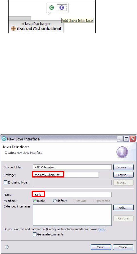
Chapter 8. Develop Java applications 93
Draft Document for Review December 9, 2008 2:44 pm 7672-base-1-java.fm
Right-click the desired package and select Add Java → Interface.
Or just mouse over a package and a action box will pop-up (Figure 8-16), then
click on the icon Add Java Interface.
Figure 8-16 Action box - add Java class and interface
Create a Java interface using the New Java Interface wizard
For our example we create java interfaces with the following steps:
Select or mouse over on the package itso.rad75.bank.ifc and click on the
icon Add Java Interface. The New Java Interface wizard opens.
In the New Java Interface dialog, enter the following data (Figure 8-17):
– Source folder: RAD75Java/src (default)
–Package: itso.rad75.bank.ifc (click Browse to select the package)
–Name: Bank
– Keep the default for all other settings.
– Click Finish to create the Java interface.
Figure 8-17 Create a Java interface

7672-base-1-java.fm Draft Document for Review December 9, 2008 2:44 pm
94 Rational Application Developer V7.5 Programming Guide
Notice that a line appears between the package and the Bank interface.
ITSOBank example—Interfaces
Repeat the above mentioned steps to create the following Java interfaces, as are
described in “Interfaces and classes overview” on page 79.
– Interface: Bank—Package: itso.rad75.bank.ifc
– Interface: TransactionType—Package: itso.rad75.bank.ifc
Creating Java classes
With Java packages and Java interfaces created now we add the Java classes to
the packages using the New Java class wizard. You can launch the New Java
class wizard from the Visualizer Class Diagram editor choosing one of the
following options.
Select in the Java Drawer and click anywhere in class diagram
editor. The New Java Class wizard opens.
Right-click on the appropriate package and select Add Java → Class
Mouse over on the package an action box apperas (Figure 8-16), and then
click on the icon Add Java Class.
Create a Java class using the New Java Class wizard
To create a Java class using the New Java Class wizard:
Select the itso.rad75.bank.model package and click on the Add Java Class
on the mentioned action box.
In the New Java Class dialog enter the following data and click Finish.
–Package: itso.rad75.bank.model (click Browse to select the package)
–Name: Transaction
– Modifiers: Select public (default) and abstract
– Superclass: java.lang.Object (default). You can change the superclass
by clicking Browse in the Superclass Selection dialog (Figure 8-18), in the
Choose a type field type the name of the superclass and click OK. All
matching types are listed while writing.
Note: To add an interface to the class diagram, you can just drag and drop the
interface to the class diagram editor, or select the interface in the Package
Explorer and Visualize → Add to Current Diagram.
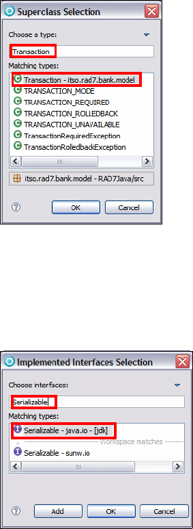
Chapter 8. Develop Java applications 95
Draft Document for Review December 9, 2008 2:44 pm 7672-base-1-java.fm
Figure 8-18 Superclass Selection dialog
– Interfaces: java.io.Serializable, click Add and type the interface name
in the Choose interfaces field. All matching types are listed. Select the
required interface and click Add. If you have added all required interfaces,
click OK to leave the dialog (Figure 8-19).
Figure 8-19 Implemented Interfaces Selection dialog
– Which method stubs would you like to create:
•public static void main(String[] args): clear (default)—Adds an
empty main method to the class and makes the class an executable
one. In the example, only the class BankClient must be executable.
• Constructors from superclass: clear (default)—Copies the constructors
from the superclass to the new class.
• Inherited abstract methods: clear—Adds to the new class stubs of any
abstract methods from superclasses or methods of interfaces that need
Note: The Superclass Selection
dialog is just illustrative and not part
of our example.

7672-base-1-java.fm Draft Document for Review December 9, 2008 2:44 pm
96 Rational Application Developer V7.5 Programming Guide
to be implemented. In the example, it is useful for the classes ITSOBank,
Credit, and Debit.
– Generate comments: clear (default)
– Click Finish to create the Java class (Figure 8-20).
Figure 8-20 New Java Class dialog
Notice that a line appears between the package and the Bank interface.
ITSOBank example—Classes
Repeat the above mentioned steps to create the following Java classes, that
are described in “Interfaces and classes structure” on page 79
–Transaction class into package itso.rad75.bank.model
–Customer class into package itso.rad75.bank.model
–Account class into package itso.rad75.bank.model
–ITSOBank into package itso.rad75.bank.impl
–ITSOBankException into package itso.rad75.bank.exception
–InvalidCustomerException into package itso.rad75.bank.exception
–InvalidAccountException into package itso.rad75.bank.exception
Note: You can add a class to the class diagram using drag and drop, or select
Visualize → Add to Current Diagram.

Chapter 8. Develop Java applications 97
Draft Document for Review December 9, 2008 2:44 pm 7672-base-1-java.fm
–InvalidTransactionException into package itso.rad75.bank.exception
Creating Java attributes (fields) and getter and setter methods
Once we have the needed Java classes and interfaces, we add Java attributes
(fields) to them using the Create Java Field wizard or writing directly the field
declaration into the interface or class body in the Java editor. The Create Java
Field wizard gets only called through the Visualizer Class Diagram editor,
choosing one of the following options.
Move the mouse pointer anywhere over the interface or class in the diagram
editor, and click Add Java Field in the pop-up action box that appears.
Or right-click the interface or class in the diagram editor and select Add
Java → Field. The Create Java Field wizard opens
Create a Java field using the Create Java field wizard
For our example we create java fields with the following steps:
Select the Transaction class and click the Add Java Field icon from the
action box.
In the Create Java Field dialog, enter the following data (Figure 8-21).
–Name: timeStamp
– Type: java.sql.Timestamp. To select this type click Browse, type in the
Pick a class or interface field, and click OK. Required import statements
are added to the source code automatically.
– Dimensions: 0 (default)—Changing the value of this field is for creating an
array of the selected type with the selected dimension.
– Contained by Java Collection: clear (default)

7672-base-1-java.fm Draft Document for Review December 9, 2008 2:44 pm
98 Rational Application Developer V7.5 Programming Guide
– Initial value: null
– Visibility: private (default)
– Modifiers: clear all (default)
– Click Finish to create the Java field.
Figure 8-21 Create Java Field dialog
Note: Select this field If the required attribute has a multiplicity higher
than 1. If selected, the wizard allows you to select the required Java
collection class. If you select any kind of Map class, you can select the
type of the key in the Java collection key type field. Finally, you can
create parameterized types by selecting the use generic collection
checkbox. More information about generic types can be found here:
http://java.sun.com/developer/technicalArticles/J2SE/generics/
The Preview field
shows the source
code that is created

Chapter 8. Develop Java applications 99
Draft Document for Review December 9, 2008 2:44 pm 7672-base-1-java.fm
Create getter and setter methods using refactor feature
This section describes how to generate getter and setter methods for Java
attributes by using the refactor feature of Application Developer.
To generate getter and setter methods for a Java attribute using the refactor
feature, do these steps:
Select in the class Transaction in the Package Explorer view, right-click the
timestamp attribute, and select Refactor → Encapsulate Field.
In the Encapsulate Field dialog, enter the following data (Figure 8-22):
– Getter name: getTimeStamp (default)
– Setter name: setTimeStamp (default)
– Insert new methods after: As first method (default)
– Access modifier: select public. You can later change the access modifier
of the setter method to private in the source code.
– Field access in declaring type: use getter and setter (default). It is good
programming style when you use the getter and setter method also
internally in the class to access member variables.
– Generate method comments: clear (default)
– Click OK to generate the getter and setter methods.
Note: There are two reasons why you might not see the attributes in the
class diagram:
Class diagram attribute compartment is collapsed—Select the interface
or class and click the little blue arrow in the compartment in the middle.
That expands the attribute compartment.
Class diagram attribute compartment is filtered out—Right-click the
interface or class and select Filters → Show/Hide Compartment →
Attribute Compartment.
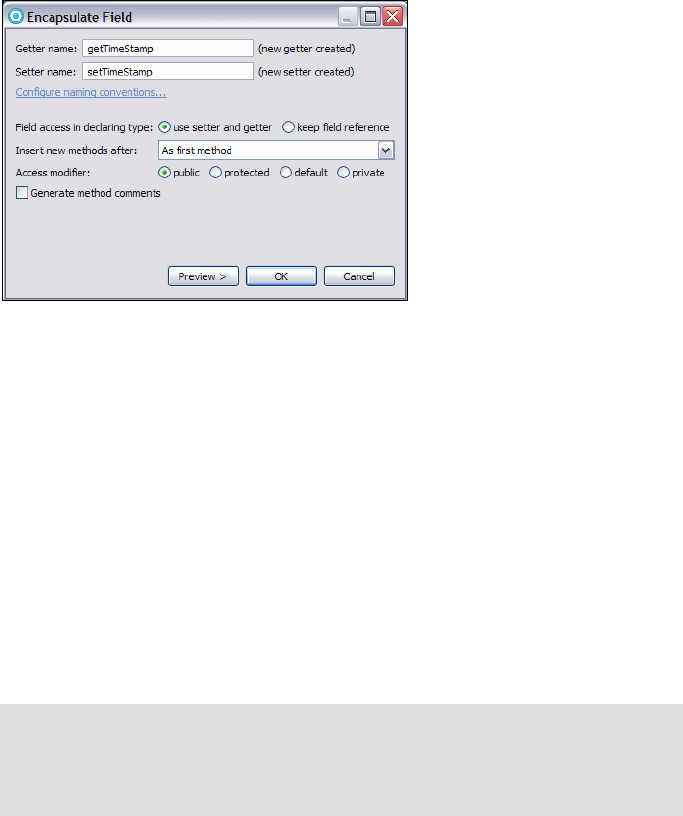
7672-base-1-java.fm Draft Document for Review December 9, 2008 2:44 pm
100 Rational Application Developer V7.5 Programming Guide
Figure 8-22 Encapsulate Field dialog
Create getters and setters methods using source feature
This section describes how to generate getter and setter methods for Java
attributes by using the source feature of Application Developer.
To generate getter and setter methods for a Java attribute using the source
feature, do these steps:
Create a field in the Transaction class:
–Name: transactionId
– Type: int
– Initial value: 0
Right-click the attribute in the diagram editor or in the Outline view and select
Source → Generate Getters and Setters.
In the Generate Getters and Setters dialog, enter the following data
(Figure 8-23):
– Select getters and setters to create:
getTransactionId and setTransactionId(int) (default)
– Insertion point: Last method (default)
– Sort by: First getters, then setters (default)
– Access modifier: public (default)
Note: If the source code is open in the Java editor, you can just right-click
somewhere in the Java editor and select Source → Generate Getters and
Setters, or you can select Source → Generate Getters and Setters in the
menu bar.
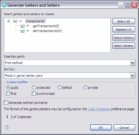
Chapter 8. Develop Java applications 101
Draft Document for Review December 9, 2008 2:44 pm 7672-base-1-java.fm
You can later change the access modifier of the setter method to private
in the source code.
– Generate method comments: clear (default)
– Click OK to generate the getter and setter methods.
Figure 8-23 Generate Getters and Setters dialog
ITSOBank example—Fields and getters & setters
Repeat the above mentioned steps to create the following fields to interfaces
and generate getters and setters for the ITSO Bank application classes.
Table 8-4 lists the fields of the interfaces, and Table 8-5 lists the fields and
getter/setter methods for the classes.
– Interface TransactionType—fields: CREDIT and DEBIT—java.lang.String
– Class Customer—fields: ssn, firstName and lastName—java.lang.String
– Generate getters (public) and setters (private) for the Customer class,
Adding method declarations to an interface
There are two ways to add a methods to a class or interface: We add a Java
method by using the Create Java Method wizard, or by writing directly the
method declaration into the interface or class body in the Java editor. The Create
Java Method wizard gets only called through the Visualizer Class Diagram editor:
7672-base-1-java.fm Draft Document for Review December 9, 2008 2:44 pm
102 Rational Application Developer V7.5 Programming Guide
Right-click the Bank interface in the diagram editor and select Add Java →
Method, or just move the mouse pointer anywhere over the interface in the
diagram editor, and click in the action bar above the class.
In the Create Java Method dialog, enter the following data (Figure 8-24).
–Name: searchCustomerBySsn
– Visibility: public (default)
– Modifiers: clear all (default)
– Type: void (default)
– Dimensions: 0 (default)
– Throws: itso.rad75.bank.exception.InvalidCustomerException. Add an
exception, by clicking Add and typing the exception class name in the
Pick one or more exception types to throw field. All matching types are
listed in the Matching types field. Select the required exceptions and click
OK.The class InvalidCustomerException must be created first under the
package itso.rad75.bank.exception in order to be selected from the
Browse Types list. Follow the instructions
– Parameters: java.lang.String ssn
– Click Finish to create the Java method.
Restriction: All methods of a Java interface are public abstract.
Modifier abstract can be omitted, as it is per default abstract.
Therefore, there is no choice by Visibility and Modifiers when you are
adding a method declaration to an interface. An interface has never a
constructor, so the constructor check box is never active.
Note: To add a parameter, click Add. Enter the name, select the type
and dimensions in the Create Parameter dialog, and click OK to add the
parameter. In the example, we do not pass any array parameters, and
dimensions are always 0 (default).

Chapter 8. Develop Java applications 103
Draft Document for Review December 9, 2008 2:44 pm 7672-base-1-java.fm
Figure 8-24 Create Java Method dialog
Note: There are two reasons why you might not see the methods in the
class diagram:
Class diagram method compartment is collapsed—Select the interface
or class and click the little blue arrow in the compartment in the bottom.
That expands the method compartment.
Class diagram method compartment is filtered out—Right-click the
interface or class and select Filters → Show/Hide Compartment →
Method Compartment.

7672-base-1-java.fm Draft Document for Review December 9, 2008 2:44 pm
104 Rational Application Developer V7.5 Programming Guide
ITSOBank example—Interface methods
Repeat the above mentioned steps to create the following method
declarations to the Bank interface of the ITSO Bank application. Table 8-6 lists
all method declarations that can be created:
–searchCustomerBySsn()—Type: itso.rad75.bank.model.Customer
–getCustomers()—Type: java.util.Map
–transfer()—Type: void
Adding constructors and Java methods to a class
The way to add constructors and methods to a class is the same as when you
add a method declaration to an interface, you can check the steps as explained
in “Adding method declarations to an interface” on page 101, except that there
are no restrictions as described for the interfaces.
ITSOBank example—Class methods
Repeat the above mentioned steps to create the following class methods for
the ITSO Bank application. Be aware that you have to select Constructor
when adding a constructor to a class. Table 8-7 lists all method declarations
that can be created:
– Class: ITSOBank —Method: updateCustomer() and transfer()
– Class: Customer —Method: Constructor
– Class: Transaction—Method: getTransactionType()
Notes:
Do not forget to set the right parameters and exceptions to the methods
that you create.
You can also import the final code later on “Implementing the classes
and methods” on page 108
Note: You can also import the final code later on “Implementing the
classes and methods” on page 108

Chapter 8. Develop Java applications 105
Draft Document for Review December 9, 2008 2:44 pm 7672-base-1-java.fm
Creating relationships between Java types
The classes in the ITSO Bank application have the following relationships:
ITSOBank remembers the customers and accounts.
A customer knows his or her accounts.
An account logs all the transactions for logging and querying purposes.
In Application Developer it is possible to model the relationships between Java
types in the Visualizer Class Diagram editor. This section includes the following
topics:
Extends relationship
Implements relationship
Association relationship
Tip: If you want to add a method to a class that implements or overrides an
existing method in an interface or a superclass, there is a much faster way to
add it than by using the Create Java Method wizard. Use the source feature
Override/Implement Methods:
Right-click the class in the diagram editor or in the Package Explorer and
select Source → Override/Implement Methods. In the
Override/Implement Methods dialog, all methods that can be implemented
or overridden by this class are listed. Select the methods you want to
override or implement and click OK to add the method stubs to the
selected class.
For example, you can implement the toString method in the Transaction
class.
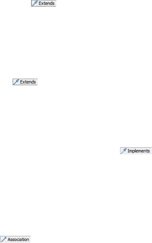
7672-base-1-java.fm Draft Document for Review December 9, 2008 2:44 pm
106 Rational Application Developer V7.5 Programming Guide
Extends relationship
Extend relationships are the used inside the Class diagram to represent
inheritance between Java classes. To create an extends relationship between
existing classes, select in the Java Drawer and drag the mouse with
the left mouse button down from any point on the child class to the parent class.
ITSOBank example—extends relationship
The only case of inheritance in our application is between the Transaction class
as a superclass of the Credit and Debit classes. Following the next steps you
will create those relationships:
Create the Credit class as mentioned in “Creating Java classes” on page 94.
Remember to select itso.rad75.bank.model.Transaction as superclass.
Create the Debit class as with the Credit class but this time leave the default
java.lang.Object as superclass.
Then select in the Java Drawer and drag the mouse with the left
mouse button down from any point on the Debit class to the Transaction
class.
A solid line with a triangular arrow is displayed from the Credit class and the
Debit class to the tso.rad75.bank.model.Transaction class indicating that
the extends relationships were created successfully.
Implements relationship
Implements relationships are the used inside the Class diagram to represent
usage of one or many Java interfaces by a Java class. To create an implements
relationship between an existing class and an interface select in
the Java Drawer and drag the mouse with the left mouse button down from any
point in the implementation class to the interface. The implements relationship is
displayed using a dashed line with a triangular arrow pointing to the interface.
ITSOBank example—implements relationship
There is already an implements relationship in the class diagram: The ITSOBank
class implements the Bank interface.
Association relationship
Association relationships are used inside the Class diagram to represent the
object level dependencies between Java classes. To create an association
relationship between to classes, do these steps:
Select in the Java drawer.
Drag the mouse with the left mouse button down from any point on the
Customer class to the Account class.
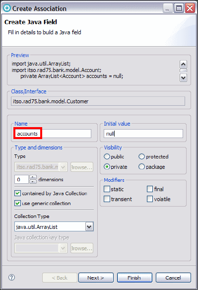
Chapter 8. Develop Java applications 107
Draft Document for Review December 9, 2008 2:44 pm 7672-base-1-java.fm
In the Create Association dialog, enter the following data (Figure 8-25).
–Name: accounts
– Type: - (not active)
– Dimensions: 0 (default)
– Contained by Java Collection: select
– Collection type: java.util.ArrayList
– Java Collection key type: - (not active)
– Use generic collection: select
– Initial value: null
– Visibility: private (default)
– Modifiers: clear all (default)
– Click Finish to create the association.
Figure 8-25 Create Association dialog

7672-base-1-java.fm Draft Document for Review December 9, 2008 2:44 pm
108 Rational Application Developer V7.5 Programming Guide
ITSOBank example—association relationship
Repeat the above mentioned steps to create the following association
relationships of the ITSO Bank application. The associations are listed in
Table 8-5 on page 81.
– Class: ITSOBank—field: accounts(Map <String, Account>)
– Class: ITSOBank—field: customers(Map <String, Customer>)
– Class: Account—field: transactions(ArrayList<Transaction>)
Implementing the classes and methods
In the previous sections of the ITSO Bank application example, we have included
step-by-step approaches with the objective of demonstrating the Application
Developer tooling and the logical process of developing a Java application. In this
section we import all the classes with the method code.
Import the classes
Right-click the src folder and select Import.
Select General File System, then click Browse and navigate to the folder
C:\76721code\java\import.
Select the import folder and click Finish (Figure 8-26).
Note: An association can be displayed as an arrow or an attribute:
Show as attribute—To display the association as an attribute,
right-click the association arrow and select Filters → Show As
Attribute.
Show as association arrow—To display the attribute as an
association, right-click the attribute and select Filters → Show As
Association.

Chapter 8. Develop Java applications 109
Draft Document for Review December 9, 2008 2:44 pm 7672-base-1-java.fm
Figure 8-26 Importing the classes
You can add all the classes to the diagram manually, or import the diagram
into the diagram folder from:
C:\7672code\java\diagram\ITSOBank-Diagram.dnx
To change the appearance of the diagram, right-click in the diagram and
select Filters → Show/Hide Connector Labels → All or No connector
Labels, or Filters → Show/Hide Relationships and select the relationships
to be displayed or hidden. For example, you can hide the many <<use>>
relationships.
Running the ITSO Bank application
Once you have completed the ITSO Bank application and resolved any
outstanding errors, you are ready to test the application. To launch the
application, we use a generic Java Application launch configuration that derives
most of the launch parameters from the Java project and the workbench
preferences. To run the ITSO Bank application, do these steps:
Right-click the BankClient class in the Package Explorer and select Run
As → Java Application or click the arrow of in the toolbar and select
Run As → Java Application.
Note: The selected class must be executable—containing a public static
void main(String[] args) method—otherwise, the application cannot run.
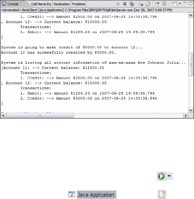
7672-base-1-java.fm Draft Document for Review December 9, 2008 2:44 pm
110 Rational Application Developer V7.5 Programming Guide
You can see the output in the Console view (Figure 8-27 shows part).
Figure 8-27 Console view with output of the ITSO Bank application
Creating a run configuration
In some cases, you might want to override the derived parameters or specify
additional arguments. To create a run configuration, do these steps:
Select Run → Run Configurations, or click the arrow of in the toolbar
and select Run Configurations.
In the Run dialog, select and then click to create a new
configuration (Figure 8-28). Notice that we already have a configuration from
running the BankClient application.

Chapter 8. Develop Java applications 111
Draft Document for Review December 9, 2008 2:44 pm 7672-base-1-java.fm
Figure 8-28 Run configuration dialog
The Main tab defines the class to be launched:
– Project: Select the project containing the class to launch.
– Main class: Click Search to get a list of all executable main classes in the
project. Select the main class to be launched.
– With the check boxes Include system libraries when searching for a
main class and Include inherited mains when searching for main
class, you can expand the area where Application Developer is searching
for an executable class.
–Stop in main: The program stops in the main method whenever it is
launched in debug mode.You do not have to specify a project, but doing so
allows a default classpath, source lookup path, and JRE to be chosen.
The Arguments tab defines the arguments to be passed to the application and
to the virtual machine. To add a program argument, do these steps:
– You can type a value directly into the field, or you can use a variable:
• Click Variables below the Program arguments field.
• Select one of the predefined variables or create your own variable by
clicking Edit Variables and then New.
• Enter the name and the value for the variable and click OK to add it.

7672-base-1-java.fm Draft Document for Review December 9, 2008 2:44 pm
112 Rational Application Developer V7.5 Programming Guide
• Click OK again to return to the Select a variable dialog. The new
variable is now available in the list. Select it and click OK to return to
the Arguments tab.
– In the same way, you can also add VM arguments.
– You can also specify the working directory to be used by the launched
application.
The JRE tab defines the JRE used to run or debug the application. You can
select a JRE from the already defined JREs, or define a new JRE.
The Classpath tab defines the location of class files used when running or
debugging an application. By default, the user and bootstrap class locations
are derived from the associated project's build path. You can override these
settings here.
The Source tab defines the location of source files used to display source
when debugging a Java application. By default, these settings are derived
from the associated project's build path. You can override these settings here.
The Environment tab defines the environment variable values to use when
running or debugging a Java application. By default, the environment is
inherited from the Eclipse runtime. You can override or append to the
inherited environment.
The Common tab defines general information about the launch configuration.
You can select to store the launch configuration in a specific file and specify
which perspectives become active when the launch configuration is launched.
Click Run to launch the class.
Understanding the sample code
In this section we explain the content of the sample code for the ITSO Bank
solution. You can later study all the sample code imported it into the project.
BankClient class
Is the starting class for the sample application, it basically creates an instance of
the ITSOBank class and uses the different Customer, Account and Transaction
methods to operate with the bank information. Example 8-1 shows some of the
relevant Java source code in simplified format of the BankClient class.
Example 8-1 BankClient class (abbreviated)
package itso.rad75.bank.client;
public class BankClient {
public static void main(String[] args) {
Bank iTSOBank = ITSOBank.getBank();

Chapter 8. Develop Java applications 113
Draft Document for Review December 9, 2008 2:44 pm 7672-base-1-java.fm
executeCustomerTransactions(iTSOBank);
}
private static void executeCustomerTransactions(Bank bank)
throws ITSOBankException {
......
customer1 = new Customer("xxx-xx-xxxx", "Mr", "Juan","Napoli");
bank.addCustomer(oCustomer);
(...)
}
}
ITSOBank class
This class implements the logic for the interface Bank and contains all the
business logic related to the manipulation of customers, accounts and
transactions in the ITSOBank application. Example 8-2 shows some of the
relevant Java source code in simplified format of the ITSOBank class.
Example 8-2 ITSOBank class
public class ITSOBank implements Bank {
public ITSOBank() {
this.setCustomers(new HashMap<String, Customer>());
this.setAccounts(new HashMap<String, Account>());
this.setCustomerAccounts(new HashMap<String, ArrayList<Account>>());
this.initializeBank();
}
private void initializeBank() {
Customer customer1 = new Customer("111-11-1111", "MR", "Ueli",
"Wahli");
this.addCustomer(customer1);
(...)
}
public void updateCustomer(String ssn, String title, String firstName,
String lastName) throws InvalidCustomerException {
this.searchCustomerBySsn(ssn).updateCustomer(title, firstName,
lastName);
}
public void withdraw(String accountNumber, BigDecimal amount)
throws InvalidAccountException, InvalidTransactionException {
this.processTransaction(accountNumber, amount,
itso.rad75.bank.ifc.TransactionType.DEBIT);
}
......
}

7672-base-1-java.fm Draft Document for Review December 9, 2008 2:44 pm
114 Rational Application Developer V7.5 Programming Guide
Customer class
This class handles the data and process the logic of the customer entity in the
ITSO Bank application, a customer can have many accounts therefore handles
the relationship with the Account class. Example 8-3 shows some of the relevant
Java source code in simplified format of the Customer class.
Example 8-3 Customer class
package itso.rad75.bank.model;
public class Customer {
public Customer(String ssn, String title, String firstName,
String lastName) {
this.setSsn(ssn);
this.setTitle(title);
this.setFirstName(firstName);
this.setLastName(lastName);
this.setAccounts(new ArrayList<Account>());
}
public void addAccount(Account account) throws AccountAlreadyExistException
{if (!this.getAccounts().contains(account)) {
this.getAccounts().add(account);
......
}
......
}
Account class
This class handles the data and process the logic of the account entity in the
ITSO Bank application, on an account many transactions can be held therefore
handles the relationship with the Transaction class. Example 8-4 shows some of
the relevant Java source code in simplified format of the Account class.
Example 8-4 Account class
package itso.rad75.bank.model;
public class Account implements Serializable {
public Account(String accountNumber, BigDecimal balance) {
this.setAccountNumber(accountNumber);
this.setBalance(balance);
this.setTransactions(new ArrayList<Transaction>());
}
public void processTransaction(BigDecimal amount, String transactionType)
throws InvalidTransactionException {
......
if (TransactionType.CREDIT.equals(transactionType)) {
transaction = new Credit(amount);
}

Chapter 8. Develop Java applications 115
Draft Document for Review December 9, 2008 2:44 pm 7672-base-1-java.fm
else if (TransactionType.DEBIT.equals(transactionType)) {
transaction = new Debit(amount);
......
}
......
}
Transaction class
This class handles the data and process the logic of a transaction in the ITSO
Bank application, a transaction can be either credit or debit type that is why
both inherits the transaction class structure. Example 8-5 shows some of the
relevant Java source code in simplified format of the Transaction class.
Example 8-5 Transaction class
package itso.rad75.bank.model;
public abstract class Transaction implements Serializable {
static int transactionCtr = 1; // to increment transactionId
public Transaction(BigDecimal amount) {
this.setTimeStamp(new Timestamp(System.currentTimeMillis()));
this.setAmount(amount);
this.setTransactionId(transactionCtr++);
}
public abstract String getTransactionType();
public abstract BigDecimal process(BigDecimal accountBalance)
throws InvalidTransactionException;
......
}
Credit class
This class handles the implementation code of a transaction class for credit
operations. Example 8-6 shows some of the relevant Java source code in
simplified format of the Credit class.
Example 8-6 Credit class
package itso.rad75.bank.model;
public class Credit extends Transaction {
public BigDecimal process(BigDecimal accountBalance)
throws InvalidTransactionException {
......
return accountBalance.add(this.getAmount());
......
}
(...)
}
7672-base-1-java.fm Draft Document for Review December 9, 2008 2:44 pm
116 Rational Application Developer V7.5 Programming Guide
Debit class
The Debit class is similar to the Credit class, but subtracts the amount from the
balance.
Additional features used for Java applications
The Java editor of the Application Developer provides a set of useful features to
develop the code. In this section we are highlighting some key features of
Application Developer when working on a Java project:
Using scripting inside the JRE
Analyzing source code
Debugging a Java application
Using the Java scrapbook
Plugable Java Runtime Environment (JRE)
Exporting Java applications to a JAR file
Running Java applications external to Application Developer
Importing Java resources from a JAR file into a project
Using scripting inside the JRE
Since Java Runtime environment JRE version 1.6, scripting code can be
executed inside the virtual machine environment with the usage of the classes in
the javax.script.* native Java package. The classes included in the JRE
release contains Java implementation logic for Mozilla open source Rhino and
ECMAScript Javascript language engines, but many others like Ruby or Phyton
can be included, as well as making your own scripting interpreter.
ITSOBank example—scripting invocation
In our application example, we created a scripting implementation, that you
already imported in “Import the classes” on page 108. The scripting module has
two components:
BankClientScript.js scripting file in the package itso.rad75.bank.client,
which contains a similar logic as implemented by the method
executeCustomerTransactions(Bank oBank) in the BankClient class.
executeCustomerTransactionsWithScript(Bank oBank) method in the class
BankClient, that invokes the script file and evaluates its logic.
To test the scripting functionality we have to modify two lines of code in the
method main(String[] args) of the class BankClient.
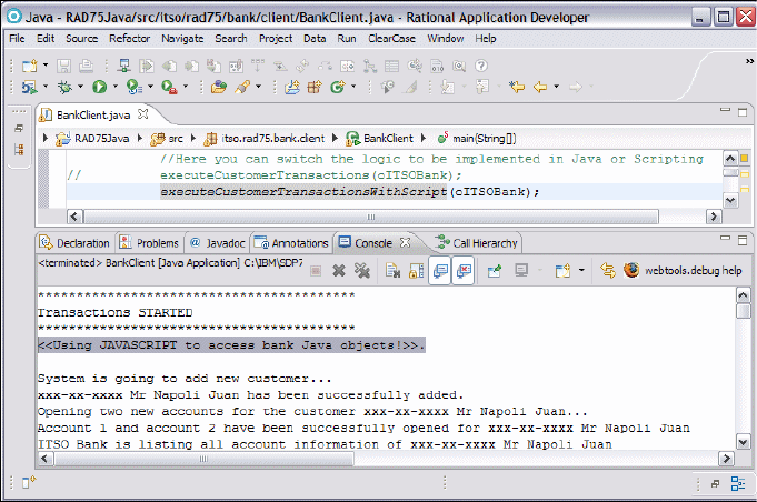
Chapter 8. Develop Java applications 117
Draft Document for Review December 9, 2008 2:44 pm 7672-base-1-java.fm
Look for the following code:
//Here you can switch the logic to be implemented in Java or Scripting
executeCustomerTransactions(oITSOBank);
//executeCustomerTransactionsWithScript(oITSOBank);
Comment the second line by selecting the line, then right-click, and select
Source → Toggle Comment.
Uncomment the third line, with the same steps.
Save the changes (Ctrl+S).
Run the ITSOBank Application as described in “Running the ITSO Bank
application” on page 109.
Verify that the output console has no errors and shows the message <<Using
JAVASCRIPT to access bank Java objects!>> (Figure 8-29).
Figure 8-29 Executing the BankClient with scripting
How does the scrpting example work?
Study the code of the executeCustomerTransactionsWithScript method:
private static void executeCustomerTransactionsWithScript(Bank oBank)
throws ScriptException {
//Lookup for the scripting engine
ScriptEngineManager engineMgr = new ScriptEngineManager();
ScriptEngine engine = engineMgr.getEngineByName("ECMAScript");
//Insert the bank object in the Bindings scope
7672-base-1-java.fm Draft Document for Review December 9, 2008 2:44 pm
118 Rational Application Developer V7.5 Programming Guide
engine.put("bank", oBank);
//Execute the script
try {
InputStream inputStream = Thread.currentThread()
.getContextClassLoader()
.getResourceAsStream("itso/rad75/bank/client/BankClientScript.js");
Reader reader = new InputStreamReader(inputStream);
engine.eval(reader);
} catch (ScriptException e) {
throw e;
}
}
The example uses the ECMAScript scrpting engine.
The bank object from the main method is inserted into the binding scope.
The script, BankClientScript.js, is loaded and then evaluated by the engine.
The script itself is very similar to the executeCustomerTransactions method.
Analyzing source code
The Rational Software Analyzer is a part of the Test and Performance Tools
Platform (TPTP) analysis framework. It lets you run a static analysis of the
resources that you are working with to detect violations of rules and rule
categories.
This section describes how to work with the Rational Software Analyzer:
Creating and editing a static analysis configuration
Running a static analysis
Creating and editing a static analysis configuration
For each resource, you can create an analysis configuration that specifies the
rules and rule categories that are used when analyzing the resource. A static
analysis code review, for example, detects violations of specific programming
rules and rule categories and generates a report in the Software Analyzer
Results view (Figure 8-30).
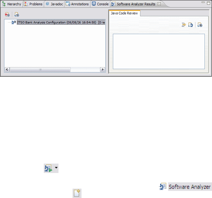
Chapter 8. Develop Java applications 119
Draft Document for Review December 9, 2008 2:44 pm 7672-base-1-java.fm
Figure 8-30 Software Analyzer Results for a Java project
To create an analysis configuration, you must be working in a perspective that
supports analysis capabilities. The Java and the Debug perspectives support
analysis capabilities by default. In all other perspectives, you can add it. Select
Window → Customize Perspective, select the Commands tab and Software
Analyzer.
To create an analysis configuration, do these steps:
Click Run → Analysis, or right-click a project in the Package Explorer and
select Software Analyzer → Software Analyzer Configurations, or click
the arrow of in the toolbar and select Software Analyzer
Configurations.
In the Software Analyzer Configurations dialog, select
and click the New icon to create a configuration (Figure 8-31):
–Type ITSO Bank Analysis Configuration as a name for the analysis
configuration
– Set the scope of the analysis:
• Analyze entire workspace: The rules that you select on the Rules tab
are applied to all the resources in your workspace.
• Analyze a resource working set: The rules that you select on the Rules
tab are applied to a specific set of projects, folders, or files in your
workspace.
• Analyze selected projects: The rules that you select on the Rules tab
are applied to the resources in the project you select.
–Select Analyze selected projects and select the RAD75Java project.
– Click Apply.
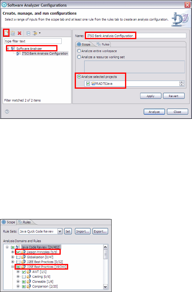
7672-base-1-java.fm Draft Document for Review December 9, 2008 2:44 pm
120 Rational Application Developer V7.5 Programming Guide
Figure 8-31 Analysis: Create, manage, and run configurations
Select the Rules tab to specify the rule categories, rules, or rule sets to apply
during the analysis:
– Rule Sets: Select a defined rule set, for example, Java Quick Code
Review, and click Set to configure the domains and rules.
– Analysis Domains and Rules: Expand the tree and select domains and
rules. For example, select Java Code review → Design Principles.
Note that setting a rule set selects a subset of domains and rules. In our
case, several J2SE Best Practices rules are preselected. Expand that
domain to see the selected rules (Figure 8-32).
Figure 8-32 Analysis: Domains and rules
– Click Apply.

Chapter 8. Develop Java applications 121
Draft Document for Review December 9, 2008 2:44 pm 7672-base-1-java.fm
Running a static analysis
You can analyze your source code using the analysis configurations that you
created. To run a static analysis, select an existing configuration or create a new
configuration, and click Analyze.
While the analysis runs, the Software Analyzer Results view opens and, if your
source code does not conform to the rules in the analysis configuration, the view
populates with results. The results are listed in chronological order and are
grouped into the same categories that you specified in the analysis configuration.
If you run the analysis for the RAD75Java project, no problems are reported.
If you run the analysis for the RAD75EJB project (from Chapter 14, “Develop EJB
applications” on page 387), one problem is reported (Figure 8-33).
Figure 8-33 Software Analyzer Results view
Static analysis results
A static analysis result is a concise explanation of a rule violation. The result is a
line item in the Software Analyzer Results view that shows that the resource
does not comply with the rules that you applied.
A result is not necessarily a problem, mistake, or bug, but you have to evaluate
each result in the list to determine what action, if any, you have to take. If the
result is a problem that has a trivial solution, the author of the rule might have
provided a quick fix that automatically corrects the resource.
To locate a problem, right-click an entry in the Software Analyzer Results view
and select View Result. This action opens the Java source file with the problem
code highlighted.
If a Quick Fix is provided, right-click an entry and select Quick Fix. The source
code is changed and the entry disappears from the list.

7672-base-1-java.fm Draft Document for Review December 9, 2008 2:44 pm
122 Rational Application Developer V7.5 Programming Guide
Debugging a Java application
For details debugging an application, refer to Chapter 24, “Debug local and
remote applications” on page 861.
Using the Java scrapbook
The scrapbook feature can be used to quickly run and test Java code without
having to create an executable testing class. Snippets of Java code can be
entered in a scrapbook page and evaluated by simply selecting the code and
running it.
A scrapbook page can be added to any project and package. The extension of a
scrapbook page is .jpage, to distinguish it from normal Java source file.
To create and run a scrapbook page, do these steps:
Right-click a package (itso.rad75.bank.client) in the Package Explorer and
select New → Other → Java → Java Run/Debug → Scrapbook Page.
Enter a file name (TestScrapBook) and click Finish. Note that we already
imported such a scrapbook.
The scrapbook page is opened in the Java editor and you can enter the
snippet Java code.
Example 8-7 contains two little snippets. The first one is related to the ITSO
Bank application and based on the BankClient class main method, and the
second one is a simple code snippet to produce a multiplication table.
Example 8-7 Java scrapbook examples
// ITSO Bank Snippet
itso.rad75.bank.ifc.Bank oITSOBank =
itso.rad75.bank.impl.ITSOBank.getBank();
System.out.println("\nITSO Bank is listing all customers status");
System.out.println(oITSOBank.getCustomers() + "\n");
for (itso.rad75.bank.model.Customer
customer:oITSOBank.getCustomers().values())
{System.out.println("Customer: "+ customer);
System.out.println(oITSOBank.getAccountsForCustomer(customer.getSsn()));
}
// Multiplication Table Snippet
String line;
int result;

Chapter 8. Develop Java applications 123
Draft Document for Review December 9, 2008 2:44 pm 7672-base-1-java.fm
for (int i = 1; i <= 10; i++) {
line ="row " + i + ": ";
// begin inner for-loop
for (int j = 1; j <= 10; j++) {
result = i*j;
line += result + " ";
} // end inner for-loop
System.out.println(line);
}
You can execute, display, or inspect a snippet:
– Select the code of the Multiplication Table Snippet, right-click, and
select Execute, or press Ctrl+U, or click in the toolbar. All output is
displayed in the Console view.
– Select the ITSO Bank Snippet, right-click, and select Display, or click
in the toolbar. Again, all output is displayed in the Console view.
– Select the ITSO Bank Snippet, right-click, and select Inspect, or press
Ctrl+Shift+I, or click in the toolbar. Again, all output is displayed in the
Console view. But in addition, an expression box opens, which allows you
to inspect the current variables. Pressing Ctrl+Shift+I again opens the
Expression view, which you can find in the Debug perspective, as
described in Chapter 24, “Debug local and remote applications” on
page 861.
Click in the Console view to end the scrapbook evaluation.
Important: All classes that are not from the java.lang package must be
fully qualified, or you have to set import statements:
Right-click anywhere in the scrapbook page editor and select Set
Imports.
For the example, add the following types and packages:
itso.rad75.bank.model.*
itso.rad75.bank.ifc.Bank
itso.rad75.bank.impl.ITSOBank
Note: You cannot execute, display, or inspect a snippet in the scrapbook
page, unless you have selected the code.
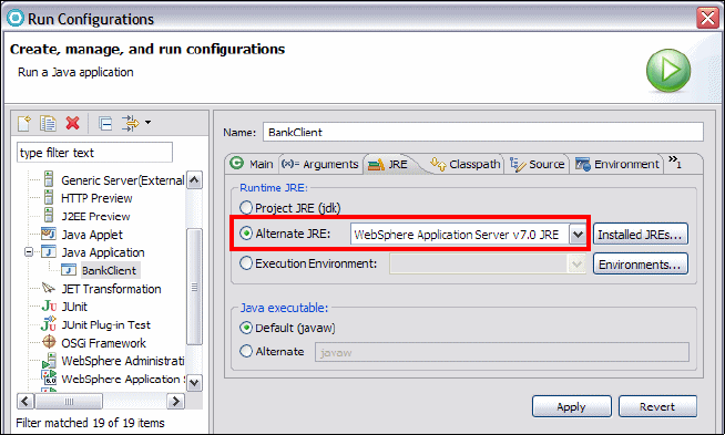
7672-base-1-java.fm Draft Document for Review December 9, 2008 2:44 pm
124 Rational Application Developer V7.5 Programming Guide
Plugable Java Runtime Environment (JRE)
Application Developer supports Java projects to run under different versions of
the Java Runtime Environment. New JREs can be added to the workspace, and
projects can be configured to use any of the JREs available. By default, the
Application Developer v7.5 uses and provides projects with support for IBM Java
Runtime Environment v6.0.
To add another JRE to the workspace, do these steps:
Select Window → Preferences and in the Preferences dialog, select Java →
Installed JREs.
Click Add to add a new JRE to the workspace.
Click Browse and select the home directory of the JRE you want to use.
Click OK. The new added JRE is now available in the list. By default, the
selected JRE is added to the build path of newly created Java projects.
The JRE that is used to run a program can also be chosen in the Run
Configurations dialog (Figure 8-34).
To change the JRE in a run configuration, do these steps:
Select Run → Run Configurations.
Select an existing Java application run configuration.
Select the JRE tab, select Alternate JRE, and change the JRE.
Figure 8-34 Run JRE configuration tab

Chapter 8. Develop Java applications 125
Draft Document for Review December 9, 2008 2:44 pm 7672-base-1-java.fm
Exporting Java applications to a JAR file
This section describes how to export a Java application to a JAR file that can be
run outside Application Developer using a JRE in a Windows Command Prompt.
We demonstrate how to export and run the ITSO Bank application.
To export the ITSO Bank application code to a JAR file, do these steps:
Right-click the RAD75Java project and select Export.
In the Export dialog, select Java → JAR file and click Next.
In the JAR Export dialog, enter the following data (Figure 8-35).
Figure 8-35 JAR Export
– Select the RAD75Java project.
–Select Export generated class files and resources (default).
–Select Export Java source files and resources.

7672-base-1-java.fm Draft Document for Review December 9, 2008 2:44 pm
126 Rational Application Developer V7.5 Programming Guide
– JAR file: C:\ITSOBankApplication.jar
–Select Compress the contents of the JAR file (default).
– Clear other check boxes.
In the JAR Packaging Options dialog accept the defaults and click Next.
In the JAR Manifest Specification dialog, click Browse for the Main class, and
select the BankClient class.
Click Finish to export the entire Java project as a JAR file.
click OK if the warning window appear.
Running Java applications external to Application Developer
Once you have exported the Java application as a JAR file you can run the Java
application on any installed JRE on your system (at least as long as there are no
version conflicts).
To run a Java application external to Application Developer on a Windows
system, do these steps:
Open a Command Prompt and navigate to the directory to which you have
exported the JAR file, for example C:\.
Enter the following command to run the ITSO Bank application:
java -jar ITSOBankApplication.jar
This results in the main method of BankClient being executed, and the results
are shown in Figure 8-36.
Note: We select to include the source to demonstrate later how to
import a JAR file into a project. It is not necessary or desirable to
include Java sources in a JAR file for execution.
Note: Ensure that the JRE is set in the Windows environment variable called
PATH. You can add the JRE to the path with the following command in the
Windows Command Prompt:
set path=%path%;{JREInstallDirectory}\bin
set path=%path%;C:\IBM\SDP75Beta\jdk\bin

Chapter 8. Develop Java applications 127
Draft Document for Review December 9, 2008 2:44 pm 7672-base-1-java.fm
Figure 8-36 Output from running ITSOBankApplication.jar in Command Prompt
Importing Java resources from a JAR file into a project
This section describes how to import Java resources from a JAR file into an
existing Java project in the workspace.
We use the ITSOBankApplication.jar file which we have created in “Exporting
Java applications to a JAR file” on page 125. Alternatively, you can use the
ITSOBankApplication.jar provided in the c:\7672code\java\jar directory
included with the Redbooks publication sample code.
Create a Java project called RAD75JavaImport with the default options.
Right-click the RAD75JavaImport project in the Package Explorer and select
Import.
In the Import dialog, select General → Archive File and click Next.
In the Import - Archive File dialog click Browse and locate the JAR file (for
example, c:\ITSOBankApplication.jar).
Clear the files .classpath and .project and the folder META-INF. These file
are created when required.
Select RAD75JavaImport/src as Into folder, and click Finish.
Test the imported Java project, select and run the BankClient class from the
Package Explorer.
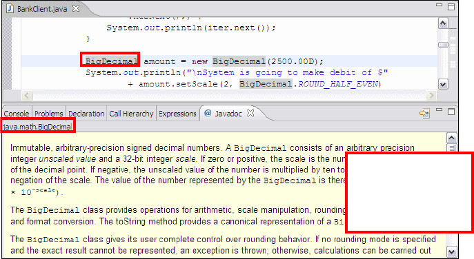
7672-base-1-java.fm Draft Document for Review December 9, 2008 2:44 pm
128 Rational Application Developer V7.5 Programming Guide
Javadoc tooling
Javadoc is a very useful tool in the Java Development Kit used to document Java
code. It generates a Web-based (HTML files) documentation of the packages,
interfaces, classes, methods, and fields.
Application Developer has a Javadoc view, which is implemented using a SWT
browser widget to display HTML. In the Java perspective, the Javadoc view is
context sensitive. It only displays the Javadoc associated with the Java element
where the cursor is currently located within the Java editor.
To demonstrate the use of Javadoc, we use the RAD75JavaImport project that we
imported.
Open the Javadoc view in the Java perspective if it is not already open.
Open the BankClient class in the Java editor.
You will notice that when the cursor selects a type, its Javadoc is shown in the
Javadoc view. Select the BigDecimal type, and the Javadoc view changes to
the documentation associated with BigDecimal (Figure 8-37).
Figure 8-37 Javadoc view: Context sensitive (BigDecimal)
Generating Javadoc
This section explains how to generate Javadoc from an existing Java project.
Application Developer supports the following types of Javadoc generation:
Generate Javadoc
UELI: I get an
exception when
selecting
BigDecimal

Chapter 8. Develop Java applications 129
Draft Document for Review December 9, 2008 2:44 pm 7672-base-1-java.fm
Generate Javadoc with diagrams from existing tags
Generate Javadoc with diagrams automatically
Generate Javadoc from an Ant script
Generate Javadoc
To generate Javadoc from an existing Java project, do these steps:
Right-click the RAD75JavaImport project in the Package Explorer and select
Export → Java → Javadoc, or select Project → Generate Javadoc.
In the Javadoc Generation dialog, enter the following data (Figure 8-38):
– The Javadoc command is predefined.
–Select Public for Create Javadoc for members with visibility (default).
–Select Use Standard Doclet. Alternatively, you can specify a custom
doclet with the name of the doclet and the classpath to the doclet
implementation.
– Destination: {workspaceDirectory}\RAD75Java\doc (default)
Generates Javadoc in the doc directory of current project.
Figure 8-38 Javadoc Generation dialog
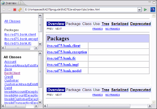
7672-base-1-java.fm Draft Document for Review December 9, 2008 2:44 pm
130 Rational Application Developer V7.5 Programming Guide
In the Configure Javadoc arguments for standard doclets dialog accept the
default settings and click Next.
In the Configure Javadoc arguments dialog, enter the following data:
–Select 1.6 for JRE source compatibility because we use generic types in
the project, which are only supported from JDK version 1.5 (5.0) or higher.
–Select Save the settings for this Javadoc export as an Ant script and
accept the destination: {workspace}\RAD75JavaImport\javadoc.xml
Click Finish to generate the Javadoc.
When prompted to update the Javadoc location, click Yes to all.
When prompted that the Ant file will be created, click OK.
Open the Javadoc in a browser by right-clicking index.html (in
RAD75JavaImport/doc) and selecting Open With → Web Browser
(Figure 8-39).
Figure 8-39 Javadoc output generated from the Javadoc wizard
Generate Javadoc from an Ant script
In “Generate Javadoc” on page 129, we selected Save Settings for this
Javadoc export as an Ant script. This generated the javadoc.xml ant script,
which can be used to invoke the Javadoc command.

Chapter 8. Develop Java applications 131
Draft Document for Review December 9, 2008 2:44 pm 7672-base-1-java.fm
To generate Javadoc from an Ant script, do these steps:
Right-click javadoc.xml in the Package Explorer and select Run As → Ant
Build.
The Javadoc generation process starts. If you cannot see the new generated
doc folder in the project, select the project and press F5 to refresh the view.
Generate Javadoc with diagrams from existing tags
Application Developer enables you to embed a @viz.diagram tag into Javadoc
on the class, interface, or package level. The @viz.diagram tag assumed that the
diagram being referenced is placed in the same folder as the Java file containing
the @viz.diagram tag, and the wizard then exports that diagram into a GIF, JPG,
or BMP, and embed it to the generated Javadoc.
Example 8-8 shows the use of the @viz.diagram tag in the BankClient class.
Example 8-8 BankClient class with a @viz.diagram tag
package itso.rad75.bank.client;
...
/**
* @viz.diagram ITSOBank-ClassDiagram.dnx
*/
public class BankClient {
public static void main(String[] args) {
try {
...
To generate Javadoc with diagrams from existing tags, do these steps:
Add the @viz.diagram tag to the source code, as shown in Example 8-8, and
copy the ITSOBank-Diagram.dnx file from the diagram folder to the
itso.rad75.bank.client package.
Restriction: For Web applications, this has the side effect of the class
diagrams being packaged into the WAR file with the compiled Java code.
We found two possible work-arounds:
Manually remove these diagrams from the WAR file after exporting.
Configure an exclusion filter for the EAR export feature. Refer to
“Filtering the content of an EAR” on page 955 for information on
techniques for filtering files (include and exclude) when exporting the
EAR.
7672-base-1-java.fm Draft Document for Review December 9, 2008 2:44 pm
132 Rational Application Developer V7.5 Programming Guide
Right-click the project in the Package Explorer and select Project →
Generate Javadoc with Diagrams → From Existing tags.
In the Javadoc Generation dialog, use the same options as in Figure 8-38 on
page 129.
Click Next in the next dialog panel.
In the Configure Javadoc arguments dialog, select 1.6 for JRE source
compatibility.
In the Choose diagram image generation options dialog, accept the default
settings and click Finish.
When prompted to update the Javadoc location, click Yes to all.
Open the Javadoc (RAD75JavaImport/doc/index.html) in a browser. Verify
that a diagram has been added to the generated Javadoc for the BankClient
class by selecting the BankClient class in the All Classes pane.
Generate Javadoc with diagrams automatically
If you do not have diagrams that you want to embed to the generated Javadoc,
you can let Application Developer to generate diagrams for you and embed them
to the Javadoc.
To generate Javadoc with diagrams automatically, do these steps:
Select the project in the Package Explorer, and select Project → Generate
Javadoc with Diagrams → Automatically.
In the Generate Javadoc with diagrams automatically dialog, enter the
following data (Figure 8-40):
– Javadoc command: path to javadoc.exe
{JDKInstallDirectory}\bin\javadoc.exe
– Keep the defaults for Diagrams.
– Optionally select Contribute diagrams and diagrams tags to source
if you want the @viz.diagram tags to be stored in the Java sources and the
generated diagrams to be stored in the packages of the Java sources.
– Click Finish to generate the Javadoc, then open the Javadoc and browse
the classes with the generated diagrams.
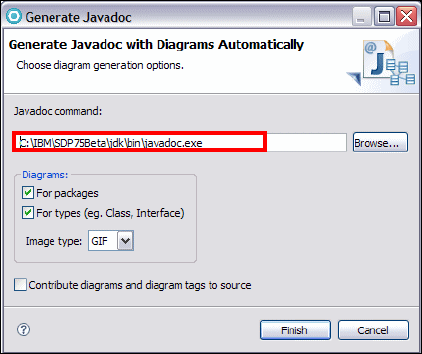
Chapter 8. Develop Java applications 133
Draft Document for Review December 9, 2008 2:44 pm 7672-base-1-java.fm
Figure 8-40 Generate Javadoc with Diagrams Automatically dialog
Java editor and rapid application development
Application Developer contains a number of features that ease and expedite the
code development process. These features are designed to make life easier for
both experienced and novice Java programmers by simplifying or automating
many common tasks.
This section is organized into the following topics:
Navigating through the code
Source folding
Type hierarchy
Smart insert
Marking occurrences
Smart compilation
Java and file search
Working sets
Quick fix
Quick assist
Content assist
Import generation
Adding constructors
Delegate method generator
Refactoring

7672-base-1-java.fm Draft Document for Review December 9, 2008 2:44 pm
134 Rational Application Developer V7.5 Programming Guide
Navigating through the code
This section highlights the use of the Outline view, Package Explorer, and
bookmarks to navigate through the code.
Using the Outline view to navigate the code
The Outline view displays an outline of a structured file that is currently open in
the editor area, and lists structural elements. The contents of the Outline view are
editor-specific.
For example, in a Java source file, the structural elements are package name,
import declarations, class, fields, and methods. We use the RAD75Java project to
demonstrate the use of the Outline view to navigate through the code:
Select and expand the RAD75Java → src → itso.rad75.bank.model from
the Package Explorer.
Double-click Account.java to open the file in the Java editor.
By selecting elements in the Outline view, you can navigate to the
corresponding point in your code. This allows you to easily find method and
field definitions without scrolling through the Java editor, as shown in
Figure 8-41.
Figure 8-41 Java editor - Outline view for navigation
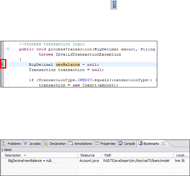
Chapter 8. Develop Java applications 135
Draft Document for Review December 9, 2008 2:44 pm 7672-base-1-java.fm
Using the Package Explorer to navigate the code
The Package Explorer, which is available by default in the Java perspective, can
also be used for navigation. The Package Explorer provides you with a
Java-specific view of the resources shown in the Enterprise Explorer view. The
element hierarchy is derived from the project's build paths.
Using bookmarks to navigate the code
Bookmarks are another simple way to navigate to resources that you frequently
use. The Bookmarks view displays all bookmarks in the workspace.
Set bookmark
To set a bookmark in the code, right-click in the gray sidebar to the left of the
code in the Java editor and select Add Bookmar, or select Edit → Add
Bookmark. In the Add Bookmark dialog, enter the name of the bookmark and
click OK.
View bookmark
Bookmarks are indicated by the symbol in the gray sidebar (Figure 8-42), and
are listed in the Bookmarks view (Figure 8-43). Double-clicking the bookmark
entry in the Bookmarks view opens the file and navigates to the line where the
bookmark has been set.
Figure 8-42 Java Editor with a bookmark
Show the Bookmarks view
To show the Bookmarks view, select Window → Show View → Other →
General → Bookmarks.
Figure 8-43 Bookmarks view

7672-base-1-java.fm Draft Document for Review December 9, 2008 2:44 pm
136 Rational Application Developer V7.5 Programming Guide
Delete bookmarks
A bookmark can be removed by right-clicking the bookmark symbol in the
gray sidebar and selecting Remove Bookmark, or right-click the bookmark in
the Bookmarks view and select Delete.
Source folding
Application Developer folds the source of import statements, comments, types,
and methods. Source folding can be configured through the Java editor
preferences.
To configure the folding feature, select Window → Preferences. In the
Preferences dialog, select Java → Editor → Folding.
Folded source is marked by a symbol, expanded source by a symbol on
the left side of the source code, as shown in Figure 8-44. Click the symbol to fold
or expand the source code.
Figure 8-44 Java Editor with source folding
Note: Bookmarks can also be given for a file they are not specific to Java
code. Select the file in the Enterprise Explorer and select Edit → Add
Bookmark. They can be used in any file to provide a quick way of navigating
to a specific location.

Chapter 8. Develop Java applications 137
Draft Document for Review December 9, 2008 2:44 pm 7672-base-1-java.fm
Type hierarchy
The Java editor allows the quick viewing of type hierarchy of a selected type.
Select a type with the cursor and press Ctrl+T to displays the hierarchy
(Figure 8-45).
Figure 8-45 Java Editor with quick type hierarchy view
Smart insert
To toggle the editor between smart insert and insert modes, press
Ctrl+Shift+Insert. When the editor is in smart insert mode, the editor provides
extra features specific to Java. For example, in smart insert mode when you cut
and paste code from a Java source to another Java source, all the needed
imports are automatically added to the target Java file.
To configure the smart insert mode, select Window → Preferences. In the
Preferences dialog, select Java → Editor → Typing, and study the different
options.
Note the small text at the bottom of the window as it changes from Smart Insert
to Insert when you press Crtl+Shift+Insert.
Marking occurrences
When enabled, the editor highlights all occurrences of types, methods,
constants, non-constant fields, local variables, expressions throwing a declared
exception, method exits, methods implementing an interface, and targets of
break and continue statements, depending on the current cursor position in the
source code (Figure 8-46). For better orientation in large files, all occurrences
are marked with a white line on the right side of the code.

7672-base-1-java.fm Draft Document for Review December 9, 2008 2:44 pm
138 Rational Application Developer V7.5 Programming Guide
The feature can be enabled and disabled by pressing Alt+Shift+O, or by clicking
in the toolbar. To configure mark occurrences, select Window →
Preferences. In the Preferences dialog, select Java → Editor → Mark
Occurrences.
Figure 8-46 Java Editor with mark occurrences (methods exits)
Smart compilation
The Java builder in the Application Developer workbench incrementally compiles
the Java code in the background as it is changed and displays any compilation
errors automatically, unless you disable the automatic build feature. Refer to
Chapter 4, “Perspectives, views, and editors” on page 119 for information on
enabling and disabling automatic builds and running workbench tasks in the
background.
Java and file search
Application Developer provides support for various searches. To display the
Search dialog click in the toolbar, or press Ctrl+H. The Search dialog can be
configured to display different searches by clicking Customize. In Figure 8-47
the search dialog has been customized to display only the Java and File Search
tabs.

Chapter 8. Develop Java applications 139
Draft Document for Review December 9, 2008 2:44 pm 7672-base-1-java.fm
Figure 8-47 Search dialog [customized]
In the Search dialog, you can perform the following searches:
Java searches operate on the structure of the code.
File searches operate on the files by name and/or text content.
Text searches allow you to find matches inside comments and strings.
Java searches are faster, because there is an underlying indexing structure for
the code.
Performing a Java search from the workbench (example)
To perform a Java search from the workbench, do these steps:
In the Java perspective click in the toolbar, or select Search → Java, or
press Ctrl+H.
– Select the Java Search tab and enter the following data (Figure 8-48).
– Search string: processTransaction
–Select Method.
–Select References.
–Select Workspace.
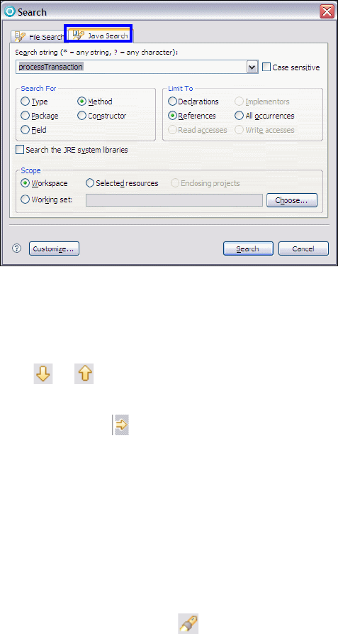
7672-base-1-java.fm Draft Document for Review December 9, 2008 2:44 pm
140 Rational Application Developer V7.5 Programming Guide
Figure 8-48 Java Search dialog
Click Search. While searching, you can click Cancel at any time to stop the
search. Partial results will be shown. The Search view shows the search
results.
Click or in the toolbar of the Search view to navigate to the next or
previous match. If the file in which the match was found is not currently open,
it is opened in the Java editor at the position of the match. Search matches
are tagged with a symbol on the left side of the source code line.
Searching from a Java view or editor
Java searches can also be performed from specific views, including the Outline
view, Hierarchy view, Package Explorer, or even the Search view, or from the
Java editor.
Right-click the resource you are looking for in the view or editor and select
References → Workspace, or press Ctrl+Shift+G.
Performing a file search (example)
In the Java perspective click in the toolbar, or select Search → File, or
press Ctrl+H.
– Select the File Search tab and enter the following data (Figure 8-49).
– Containing text: ROUND_HALF_EVEN
– File name patterns: *.java (default)
–Select Workspace.
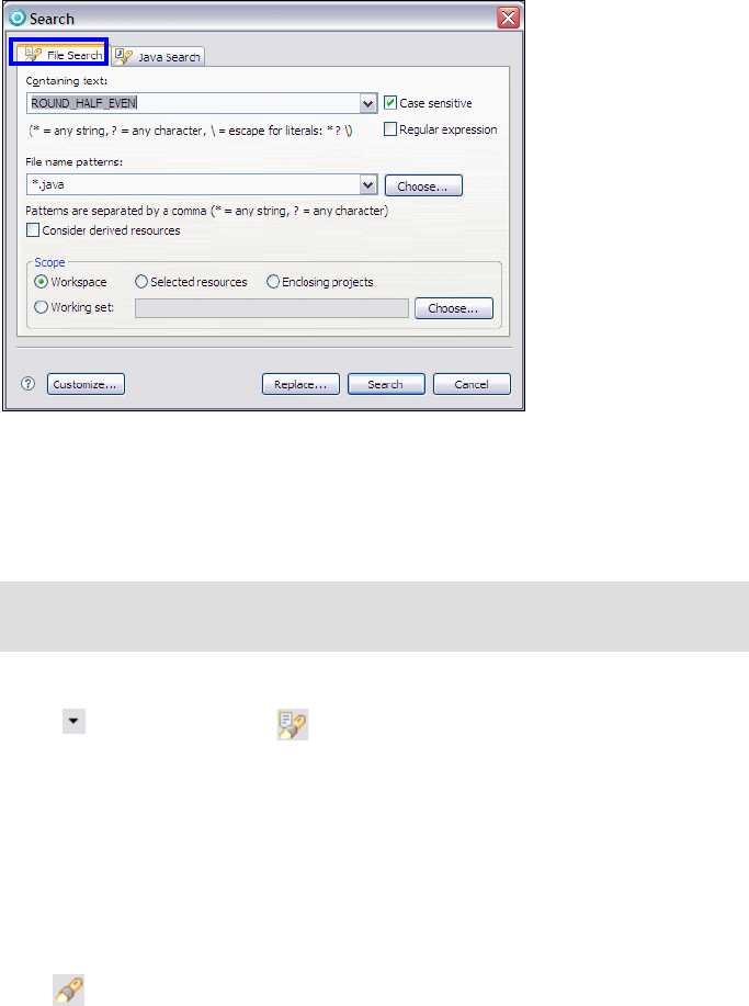
Chapter 8. Develop Java applications 141
Draft Document for Review December 9, 2008 2:44 pm 7672-base-1-java.fm
Figure 8-49 File Search dialog
Click Search. While searching, you can click Cancel at any time to stop the
search. Partial results will be shown. The Search view shows the search
results.
Viewing previous search results
Click first on the right side of in the Search view toolbar, and select one of
the previous searches. The list can be cleared by selecting Clear History.
Working sets
Working sets are used to filter resources by only including the specified
resources. They are selected and defined using the view's filter selection dialog.
We use an example to demonstrate the creation and use of a working set as
follows:
Click in the toolbar, or select Search → Java, or press Ctrl+H to open the
Java Search Dialog.
Enter itso.rad75.bank.model.Credit in the Search string field, select
Working set under Scope, and then click Choose.
In the Select Working Set dialog click New to create a new working set.
Note: To find all files of a given file name pattern, leave the Containing text
field empty.

7672-base-1-java.fm Draft Document for Review December 9, 2008 2:44 pm
142 Rational Application Developer V7.5 Programming Guide
In the New Working Set dialog, select Java to indicate that the working set
includes only Java resources and then click Next.
In the Java Working Set dialog, select only RAD75JavaImport → src →
itso.rad75.bank.model and click Add, then type EntityPackage in the
Working set name field, and click Finish (Figure 8-50).
Figure 8-50 New Java Working Set dialog
Select the new EntityPackage working set in the Select Working Sets dialog,
and click OK.
We have now created a working set named EntityPackage containing Java
resources comprised of all the Java files in the itso.rad75.bank.model
package.
Click Search to start the search process.
Quick fix
Application Developer offers a quick fix for some kind of problems, which were
detected during the code compilation or static code analysis. The developer can
process the quick fix to correct his code.

Chapter 8. Develop Java applications 143
Draft Document for Review December 9, 2008 2:44 pm 7672-base-1-java.fm
The following symbols show the developer that a quick fix is available:
Static code analysis:
– Quick fix for a result with a severity level of recommendation
– Quick fix for a result with a severity level of warning
– Quick fix for a result with a severity level of severe
Code compilation:
– Quick fix for a warning
– Quick fix for an error
To process the quick fix, click on the symbol. All suggestions to correct the
problem are displayed in an overlaid window. As soon a suggestion is selected, a
code preview is shown, so that the developer can see, what will be changed
(Figure 8-51). Double-click one of the suggestion to process the quick fix.
Figure 8-51 Java Editor with quick fix
Note: The problem symbol is grayed out but still visible. Save the source and
the problem symbol disappears.

7672-base-1-java.fm Draft Document for Review December 9, 2008 2:44 pm
144 Rational Application Developer V7.5 Programming Guide
Quick assist
Application Developer supports quick assists in the Java editor to provide
suggestions to complete tasks quickly. Quick assist depends on the current
curser position. When there is a suggestion and quick assist highlighting is
enabled, a green light bulb is displayed on the left side of the code line.
Enable quick assist highlighting
By default, the display of the quick assist light bulb is disabled. To enable it, do
these steps:
Select Window
→
Preferences.
In the Preferences dialog, select Java → Editor.
Select Light bulb for quick assists.
Invoking quick assist
To use the quick assist feature, double-click or press Ctrl+1 to provide a list of
intelligent suggestions. Select one to complete the task (Figure 8-52).
Figure 8-52 Java Editor with quick assist
Content assist
This feature displays possible code completions that are valid with the current
context.

Chapter 8. Develop Java applications 145
Draft Document for Review December 9, 2008 2:44 pm 7672-base-1-java.fm
Content assist preferences
To configure the Content Assist preferences, do these steps:
Select Window
→
Preferences.
In the Preferences dialog, select Java → Editor → Content Assist.
Modify the settings as desired and click Apply and OK.
Invoke content assist
Press Ctrl+Spacebar at any point in the Java editor, to invoke the content assist.
The content assist provides the all possible code completions that are valid for
the current context in a overlaid window (Figure 8-53). Double-click the desired
completion, or use the arrow keys to select it, and press Enter.
Figure 8-53 Java Editor with content assist
Import generation
The Java editor simplifies the task of finding the correct import statements to use
in the Java code.
Simply right-click the unknown type in the code and select Source → Add
Import, or select the type and press Ctrl+Shift+M. If the type is unambiguous,
the import statement is directly added. If the type exists in more than one
package, a window with all the types is displayed and you can select the correct
type for the import statement.
Tip: If there are still too many possible completions, just continue to write the
code yourself and the amount of suggestions becomes smaller.
Content assist can also be invoked to insert or to complete Javadoc tags.
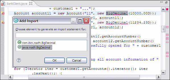
7672-base-1-java.fm Draft Document for Review December 9, 2008 2:44 pm
146 Rational Application Developer V7.5 Programming Guide
Figure 8-54 shows an example where the selected type (BigDecimal) exists in
several packages. Once you have determined that the java.math package is
what you want, double-click the entry in the list, or select it and click OK, and the
import statement is generated in the code.
Figure 8-54 Java Editor with import generation
You can also add the required import statements for the whole compilation unit.
Right-click a project, package, or Java type in the Package Explorer, and select
Source → Organize Imports, or select the project, package, or Java type and
press Ctrl+Shift+O. The code in the compilation unit is analyzed and the
appropriate import statements are added.
Adding constructors
This feature allows you to automatically add constructors to the open type. The
following constructors can be added:
Constructors from superclass
Constructor using fields
Constructors from superclass
Add any or all of the constructors defined in the superclass for the currently
opened type. Right-click anywhere in the Java editor and select Source → Add
Constructors from Superclass. Select the constructors which you want to add
to the current opened type, and click OK (Figure 8-55).
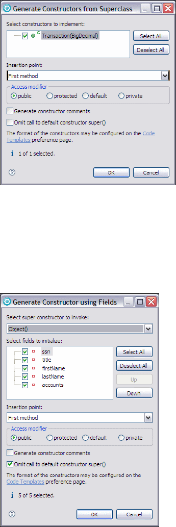
Chapter 8. Develop Java applications 147
Draft Document for Review December 9, 2008 2:44 pm 7672-base-1-java.fm
Figure 8-55 Generate Constructors from Superclass dialog
Constructor using fields
This option adds a constructor which initialized any or all of the defined fields of
the currently opened type. Right-click anywhere in the Java editor and select
Source → Add Constructors using Fields. Select the fields which you want to
initialize with the constructor and click OK (Figure 8-56).
Figure 8-56 Generate Constructor using Fields dialog
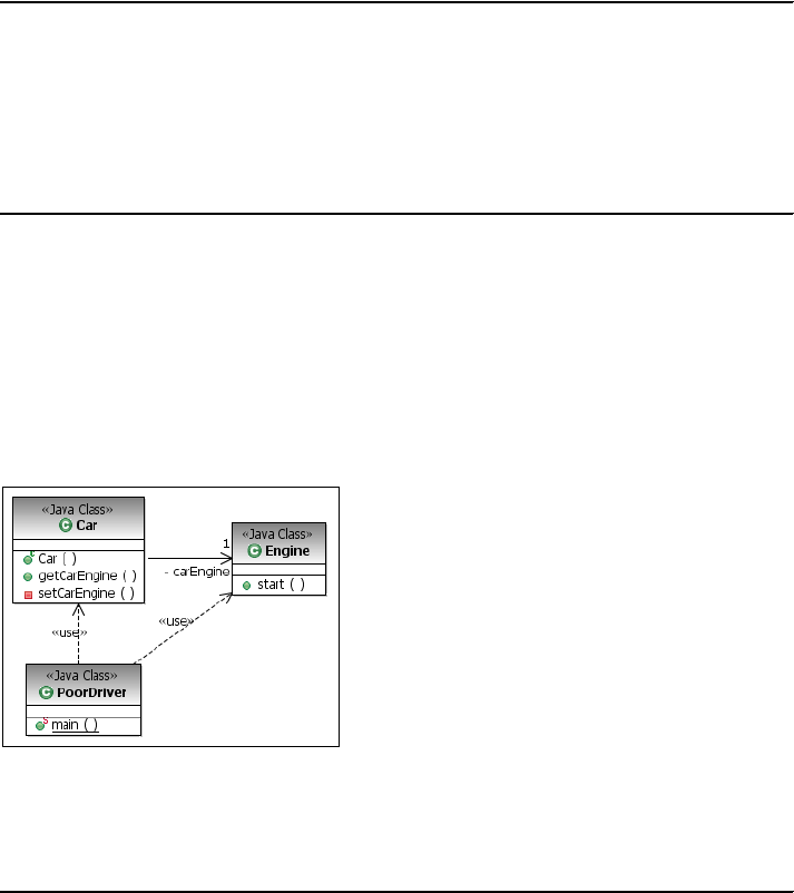
7672-base-1-java.fm Draft Document for Review December 9, 2008 2:44 pm
148 Rational Application Developer V7.5 Programming Guide
Example 8-9 shows the constructor code which would be generate with the
settings shown in Figure 8-56.
Example 8-9 Generated constructor code
public Customer(String ssn, String title, String firstName, String lastName,
ArrayList<Account> accounts) {
this.ssn = ssn;
this.title = title;
this.firstName = firstName;
this.lastName = lastName;
this.accounts = accounts;
}
Delegate method generator
The delegate method generator feature allows you to delegate methods from one
class to another for better encapsulation. We use a simple example to explain
this feature. A car has an engine, and a driver wants to start his car. Figure 8-57
shows that the engine is not encapsulated, the PoorDriver has to use the Car
and the Engine class to start his car.
Figure 8-57 Simple car example class diagram (before method delegation)
Example 8-10 shows how the poor driver has to start his car.
Example 8-10 Car, Engine, and PoorDriver classes (compressed)
// Car class
package itso.rad75.example;
import itso.rad75.example.Engine;
public class Car {
private Engine carEngine = null;
public Car(Engine carEgine) {
this.setCarEngine(carEngine);
}

Chapter 8. Develop Java applications 149
Draft Document for Review December 9, 2008 2:44 pm 7672-base-1-java.fm
public Engine getCarEngine() {
return carEngine;
}
private void setCarEngine(Engine carEngine) {
if (carEngine != null) {
this.carEngine = carEngine;
} else {
this.carEngine = new Engine();
}
}
}
// Engine class
package itso.rad75.example;
public class Engine {
public void start() {
// code to start the engine
}
}
// PoorDriver class
package itso.rad75.example;
import itso.rad75.example.Car;
public class PoorDriver {
public static void main(String[] args) {
Car myCar = new Car(null);
/* How can I start my car?
* Do I really have to touch the engine?
* - Yes, there is no other way at the moment.
*/
myCar.getCarEngine().start();
}
}
To make the driver happy, we delegate the start method from the Engine class to
the Car class. To delegate a method, do these steps:
Right-click the carEngine field in the Car class and select Source →
Generate Delegate Methods.
In the Generate Delegate Methods dialog, select only the start method and
click OK (Figure 8-58).
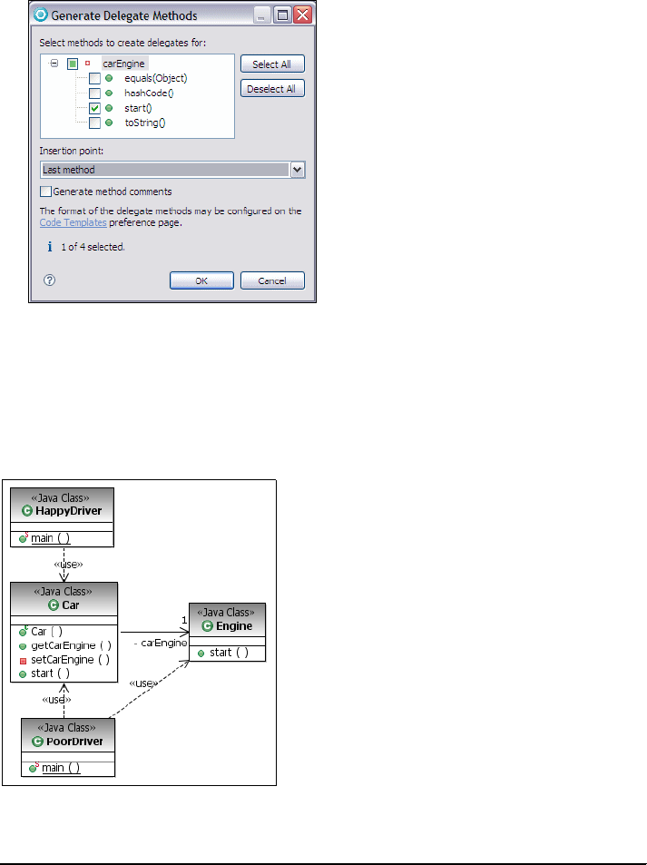
7672-base-1-java.fm Draft Document for Review December 9, 2008 2:44 pm
150 Rational Application Developer V7.5 Programming Guide
Figure 8-58 Generate Delegate Method dialog
This action adds the start method to the Car class, and code is added in the
body of the method to delegate the method call to the Engine class through
the carEngine attribute.
Figure 8-59 and Example 8-11 shows how the HappyDriver can start the car.
Figure 8-59 Simple car example class diagram (after method delegation
Example 8-11 Car and HappyDriver class
// Car class
package itso.rad75.example;
import itso.rad75.example.Engine;
public class Car {

Chapter 8. Develop Java applications 151
Draft Document for Review December 9, 2008 2:44 pm 7672-base-1-java.fm
private Engine carEngine = null;
public Car(Engine carEgine) {
this.setCarEngine(carEngine);
}
public Engine getCarEngine() {
return carEngine;
}
private void setCarEngine(Engine carEngine) {
if (carEngine != null) {
this.carEngine = carEngine;
} else {
this.carEngine = new Engine();
}
}
public void start() {
carEngine.start();
}
}
// HappyDriver class
package itso.rad75.example;
public class HappyDriver {
public static void main(String[] args) {
Car myAdvancedCar = new Car(null);
// Start the car - I don't care about technical details
myAdvancedCar.start();
}
}
Refactoring
During the development of a Java application, it might be necessary to perform
tasks, such as renaming classes, moving classes between packages, and
breaking out code into separate methods. Such tasks are both time consuming
and error prone, because it is up to the programmer to find and update each and
every reference throughout the project code. Application Developer provides a
list of refactor actions to automate the this process.
The Java development tools (JDT) of Application Developer provide assistance
for managing refactor. In the each refactor wizard you can select:
Refactor with preview: Click Next in the dialog to bring up a second dialog
panel where you are notified of potential problems and are given a detailed
preview of what the refactor action will do.

7672-base-1-java.fm Draft Document for Review December 9, 2008 2:44 pm
152 Rational Application Developer V7.5 Programming Guide
Refactor without preview: Click Finish in the dialog and have the refactor
performed. If a stop problem is detected, refactor cancels and a list of
problems is displayed.
Table 8-10 provides a summary of common refactor actions.
Table 8-10 Refactor actions
Name Function
Rename Starts the Rename Compilation Unit wizard. Renames the selected
element and (if enabled) corrects all references to the elements (also in
other files). It is available on methods, fields, local variables, method
parameters, types, compilation units, packages, source folders,
projects, and on a text selection resolving to one of these element
types.
Right-click the element and select Refactor → Rename, or select the
element and press Alt+Shift+R, or select Refactor → Rename from
the menu bar.
Move Starts the Move wizard. Moves the selected elements and (if enabled)
corrects all references to the elements (also in other files). Can be
applied on one or more static methods, static fields, types, compilation
units, packages, source folders and projects, and on a text selection
resolving to one of these element types.
Right-click the method signature and select Refactor → Move, or
select the method signature and press Alt+Shift+V, or select
Refactor → Move from the menu bar.
Change
Method
Signature
Starts the Change Method Signature wizard. You can change the
visibility of the method, change parameter names, parameter order,
parameter types, add parameters, and change return types. The wizard
updates all references to the changed method.
Right-click the element and select Refactor → Change Method
Signature, or select the element and press Alt+Shift+C, or select
Refactor → Change Method Signature from the menu bar.
Extract
Interface
Starts the Extract Interface wizard. You can create an interface from a
set of methods and make the selected class implements the newly
created interface.
Right-click the class and select Refactor → Extract Interface, or select
the element and select Refactor → Extract Interface from the menu
bar.
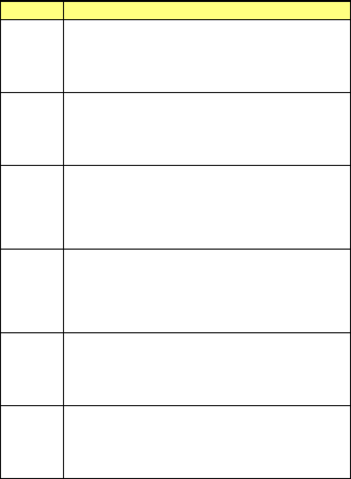
Chapter 8. Develop Java applications 153
Draft Document for Review December 9, 2008 2:44 pm 7672-base-1-java.fm
Push Down Starts the Push Down wizard. Moves a field or method to its
subclasses. Can be applied to one or more methods from the same
type or on a text selection resolving to a field or method.
Right-click the type and select Refactor → Push Down, or select the
element and select Refactor → Push Down from the menu bar.
Pull Up Starts the Pull Up wizard. Moves a field or method to its superclass.
Can be applied on one or more methods and fields from the same type
or on a text selection resolving to a field or method.
Right-click the type and select Refactor → Push Up, or select the
element and select Refactor → Push Up from the menu bar.
Extract
Method
Starts the Extract Method wizard. Creates a new method containing the
statements or expressions currently selected, and replaces the
selection with a reference to the new method.
Right-click the statement or expression and select Refactor → Extract
Method, or select it and press Alt+Shift+M, or select Refactor →
Extract Method from the menu bar.
Extract Local
Variable
Starts the Extract Local Variable wizard. Creates a new variable
assigned to the expression currently selected and replaces the
selection with a reference to the new variable.
Right-click the expression and select Refactor → Extract Local
Variable, or select it and press Alt+Shift+L, or select Refactor →
Extract Local Variable from the menu bar.
Extract
Constant
Starts the Extract Constant wizard. Creates a static final field from the
selected expression and substitutes a field reference, and optionally
replaces all other places where the same expression occurs.
Right-click the expression and select Refactor → Extract Constant, or
select Refactor → Extract Constant from the menu bar.
Inline Starts the Inline Method wizard. Inlines local variables, non abstract
methods, or static final fields.
Right-click the element and select Refactor → Inline, or select the
element and press Alt+Shift+I, or select Refactor → Inline from the
menu bar.
Name Function

7672-base-1-java.fm Draft Document for Review December 9, 2008 2:44 pm
154 Rational Application Developer V7.5 Programming Guide
Refactor example (rename a class)
The following example of a refactor operation assumes that you want to rename
the class Transaction to BankTransaction in the RAD7Java project.
To rename the Transaction class to BankTransaction, do these steps:
Right-click the Transaction class in the Package Explorer and select
Refactor → Rename.
In the Rename Compilation Unit wizard, enter the following data
(Figure 8-60):
– New name: BankTransition
–Select Update references (default).
– Clear other check boxes.
Figure 8-60 Refactor - Rename Compilation Unit wizard
Click Next to see the preview and potential problems.
Click Finish to process the rename task.
Encapsulate
Field
Starts the Encapsulate Field wizard. Replaces all references to a field
with getter and setter methods. Is applicable to a selected field or a text
selection resolving to a field.
Right-click the field, and select Refactor → Encapsulate Field..., or
select the element and select Refactor → Encapsulate Field... from
the menu bar.
Name Function

Chapter 8. Develop Java applications 155
Draft Document for Review December 9, 2008 2:44 pm 7672-base-1-java.fm
More information
We highly recommend the help feature provided by Application Developer. Click
Help → Help Contents → Developing Java applications. There is also a
Watch and Learn tutorial available, called Create a Hello World Java Application.
To start the tutorial click Help → Welcome → Tutorials → Create a Hello World
Java application.
The following URLs provide further information about Eclipse and Java
technology:
Sun™ Java™ SE Technology Home page—Contains links to specifications,
API Javadoc, and articles about Java SE:
http://java.sun.com/javase/index.jsp
IBM Developerworks Java Technology—Java news, downloads and CDs,
and learning resources:
http://www.ibm.com/developerworks/java/
Eclipse Open Source Community—Official home page of the eclipse open
source community:
http://www.eclipse.org/
Note: If there are any files with unsaved changes in the workspace and you
have not indicated in the preferences that the save has to be done
automatically, you are prompted to save these files before continuing the
refactor operation.
If there are problems or warnings, the wizard displays the Found Problems
window. If the problems are severe, the Continue button is disabled and the
refactor must be aborted until the problems have been corrected.
7672-base-1-java.fm Draft Document for Review December 9, 2008 2:44 pm
156 Rational Application Developer V7.5 Programming Guide

© Copyright IBM Corp. 2008. All rights reserved. 157
Draft Document for Review December 9, 2008 2:44 pm 7672-base-2-patterns.fm
Chapter 9. Accelerate development
using patterns
This chapter introduces the concept of pattern implementation, how it relates to
pattern specification, and the benefits that pattern implementation can bring to
software application development.
The focus of the chapter is to demonstrate by example how to use the Rational
Application Developer patterns tooling to develop and use patterns.
The chapter is organized into the following sections:
Introduction to pattern implementation
Creating a pattern implementation
Applying the pattern
9
7672-base-2-patterns.fm Draft Document for Review December 9, 2008 2:44 pm
158 Rational Application Developer V7.5 Programming Guide
Introduction to pattern implementation
As a developer, you are probably familiar with the concept of pattern as it relates
to software development, where a pattern is a proven solution to a common
problem within a given context. However, you might be less familiar with the
concept of pattern implementation and how it would help you accelerate your
development.
Pattern specification and pattern implementation
As do many developers, you probably read patterns-related books, where a
pattern is described along with its benefits, the problem it solves, and the context
it should be applied. This description is what is commonly referred as the pattern
specification, and its intent is to help you understand how and when to use the
pattern.
The idea of pattern implementation came from the desire to go further than just
using the pattern specification as a blueprint—to try to automate as much as
possible the application of the pattern. The result is to codify the pattern
specification into a pattern implementation, allowing you to automatically apply it
into a given environment.
The core idea behind pattern implementation is that as we have codified and
automated best practices, applying them is now faster than doing it manually, and
more consistent, because it involves less manual modifications.
Pattern implementation and Application Developer
In the context of Application Developer, the pattern implementation—rather than
being derived by a community design patterns—comes from your best practices
and existing successful implementations you would like to apply to other projects.
This approach is called exemplar authoring in Application Developer.
Exemplar authoring consists of using an exemplar to build the pattern
implementation. An exemplar is a representative output of the pattern and
contains an instance of each artifact you expect the pattern implementation to
generate. A good examplar should be built following the applicable best practices
and must allow you to define the points of variability of the pattern and the input
model. All the purpose of the exemplar authoring is to leverage your best
practices and existing assets to increase the development efficiency and
productivity. To do so, you codify the best practices to make their application
automatic.
Chapter 9. Accelerate development using patterns 159
Draft Document for Review December 9, 2008 2:44 pm 7672-base-2-patterns.fm
The exemplar authoring tool leverages the Eclipse’s Java Emitter Templates
(JET), which is part of the Eclipse Modeling Framework (EMF). JET is similar to
JavaServer Pages syntax and is powerful to generate Java, SQL, and any other
text based files.
JET allows you to customize the output artifacts into an XML input file and a set
of templates. The structure of this input file, as well as how it impacts the different
artifacts, is based on what you are doing when creating your transformation using
the Application Developer exemplar authoring tools. Because the tools produce
JET, exemplar authoring transformations are also sometimes referred to as JET
transformations.
Exemplar authoring is not only a set of tools, but more importantly, it is a process
to create pattern based into exemplars.
Exemplar authoring process
A key aspect to succeeding with creating patterns is that there is a proven
repeatable set of steps that you can follow in building your own patterns. This
approach to building patterns is known as exemplar analysis. In this process we
take steps to identify what artifacts have to be generated by the pattern and
determine which elements of the pattern are dynamic versus static. We use
those elements that are dynamic as the basis for the input model for the pattern.
Within the input model we have to identify the roles, their cardinality, and their
attributes.
At a high level, these are the steps we follow as part of exemplar analysis:
1. Identify artifact roles. When examining the exemplar, we often find that
there are multiple elements that are based on the same abstraction. For
instance, in the case of JavaBeans we often see that there is a pair of
elements: An interface and a class that adheres to the interface. Our
exemplar might contain multiple JavaBeans, but if the intent of our pattern is
to generate JavaBeans, we just have to pick out the most representative pair
and can ignore the other repeating cases. In this case, although the exemplar
contains multiple beans, we have just a single role for the class and one for
the interface. An important aspect of this identification is that a JET template
is associated with each role.
2. Create role groups. Using the exemplar authoring tooling, we then have to
group the roles based on their cardinality. One time roles appear at the
highest level, and then we create subgroups for roles that repeat. Many
subgroups can exist with all elements within a subgroup sharing the same
cardinality. For instance, an Eclipse project can contain a number of artifacts
such as a .project file and a .classpath file, which occur only once per
project. However, we might have multiple JavaBeans within a project. As such

7672-base-2-patterns.fm Draft Document for Review December 9, 2008 2:44 pm
160 Rational Application Developer V7.5 Programming Guide
we would place the .project and .classpath roles into a group at the top
level, and then place the JavaBeans role into subgroup.
At this point we have to keep in mind that each role will have a JET template
associated with it. When we run the pattern, the JET template is used to
generate instance of artifacts based on the role. Also, the input model, which
by default is an XML file, contains a set of elements based on the groups
defined. However, at this point, our elements do not provide any useful
information. Therefore, we now have to focus on the information that is
assigned to the element.
3. Identify attributes. At this point we know the type of dynamic information that
we have to pass into the pattern. However, we have to be more specific in
terms of the information required. For example, in the case of a JavaBean we
likely have to know what name to provide, a package name, and a directory
location. As such, we create a set of attributes that we assign to the role
groups, which in turn become attributes on the XML elements. As part of this
effort we have to perform a normalization step, whereby we review the
attributes to determine which attributes are atomic and which can be derived.
A derived attribute is one that can be calculated using information known
about the pattern and details provided by atomic attributes.
4. Customize templates. Once we have completed the previous steps, we have
to go through each of the JET templates and replace the static text with tags
that allow us to access and process the dynamic information provided by the
input model.
Prepare for the sample
We use the ITSO Bank sample application created in Chapter 8, “Develop Java
applications” on page 69, with some small changes as the examplar for our
pattern implementation.
Import the c:\7672code\patterns\RAD75Patterns.zip project interchange file
into Application Developer. Refer to “Importing sample code from a project
interchange file” on page 1152. Select both projects (RAD75Patterns and
RAD75PatternsClient).
After importing the projects, verify that the BankClient runs properly. For more
information refer to “Running the ITSO Bank application” on page 109.
Note: The BankClient is now in the RAD75PatternsClient project because
we split the initial RAD75Java project into 2 different projects:
RAD75Patterns: Model and implementation
RAD75PatternsClient: Client application and solution files (assets)

Chapter 9. Accelerate development using patterns 161
Draft Document for Review December 9, 2008 2:44 pm 7672-base-2-patterns.fm
Creating a pattern implementation
In this section we demonstrate how Application Developer examplar authoring
tools can be used to develop a pattern implementation. The pattern we decide to
implement allows us to easily create different test clients for our bank application.
We decide to use the BankClient application as our exemplar because it is our
best implementation of a test client for this bank application.
Here are the tasks we perform to develop our pattern implementation:
Create a new JET Transform project
Populating the transformation model
Adding and deriving attributes
Generate and edit templates
Create a new JET Transform project
A JET Transform project contains all the elements required for JET
transformations, including the transformation model. Table 9-1 provides an
overview of the specific files contained into this kind of projects.
Table 9-1 Files specific to a JET transform project
Note: The example we will be walking you through in the rest of the chapter is
probably not the best representation of a pattern implementation as its scope
of application is small (we will generate bank test clients). We selected this
example because it is providing enough variability to allow you to understand
how the exemplar authoring works, but not too much to not overwhelm you by
language and command details.
A more interesting example is described in “Facade pattern” on page 183.
File(s) Description
*.tma The transformation model
*.jet JET templates files, initially generated from the transformation
model.
input.ecore EMF input model generated from the transformation model
schema.xsd XML schema corresponding to the input model
sample.xml Sample of input file that would be used by the transformation
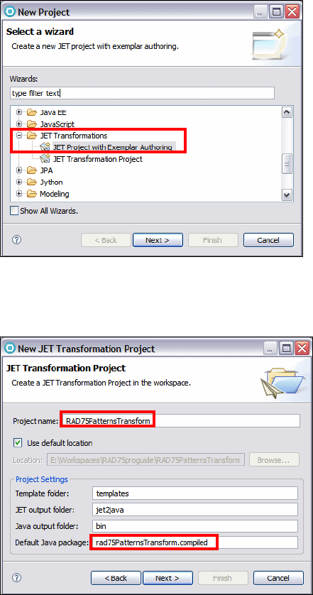
7672-base-2-patterns.fm Draft Document for Review December 9, 2008 2:44 pm
162 Rational Application Developer V7.5 Programming Guide
To create a new JET Transform project, do these steps:
In the Java perspective, select File → New → Project.
In the New Project dialog, select JET Transformations → JET Project with
Exemplar Authoring (Figure 9-1), and click Next.
Figure 9-1 Create a JET Transform project with exemplar authoring
In the New Jet Transformation Project dialog (Figure 9-2):
Figure 9-2 JET Transformation Project
–Type RAD75PatternsTransform as the project name.

Chapter 9. Accelerate development using patterns 163
Draft Document for Review December 9, 2008 2:44 pm 7672-base-2-patterns.fm
– Change the Default Java package text to make it start with a lowercase
letter (rad75PatternsTransform.compiled).
– Click Next.
Leave the default values as is in the JET Transformation Properties Dialog
and click Next.
In the Transformation Scope dialog, select the RAD75PatternsClient project,
leave the Import existing input schema model from ecore file cleared
(Figure 9-3).
Figure 9-3 Transformation Scope
Click Finish and the JET Transformation project is created. The Exemplar
Authoring editor now displays the RAD75JavaClient exemplar and an empty
model (Figure 9-4). The underlying file of this transformation is called
transform.tma (in case you have to reopen the transformation).
Note: At the time of writing this book, the Default Java package field is
filled automatically with the same letters entered in the Project Name field,
and the dialog displays an error message because the first character of the
package name is an uppercase letter. To activate the Next button, clear
Use default location and select it again.
Note: The Import existing input schema model from ecore file option
allows you to seed the transformation model from an existing ecore file,
allowing you to extend an existing transformation without reentering all the
information provided in the base transformation.
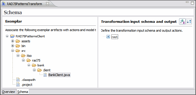
7672-base-2-patterns.fm Draft Document for Review December 9, 2008 2:44 pm
164 Rational Application Developer V7.5 Programming Guide
Figure 9-4 Exemplar Authoring Editor
Populating the transformation model
Now that the project is created, we can start populate the model with the different
elements we want the transformation to create.
The first thing to do is to create a new type to contain our transformation. To
do so, right-click on the root element and select New → Type. Type client for
the new type.
The analysis of the examplar lets us identify the files as the artifacts we want
the transform to generate:
– The Java project RAD75PatternsClient
– The project metadata files .classpath and .project
– The main class itso.rad75.bank.client.BankClient.java
We add these artifacts to the transformation model by dragging them from the
left pane (exemplar) to the right pane (model) onto the client type we just
created (Figure 9-5).
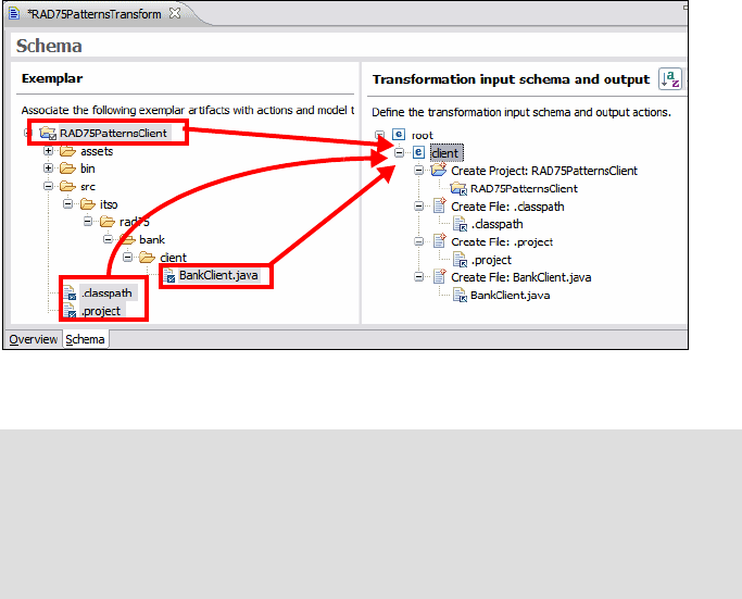
Chapter 9. Accelerate development using patterns 165
Draft Document for Review December 9, 2008 2:44 pm 7672-base-2-patterns.fm
Figure 9-5 Artifacts added to the transformation model under the client type
Each of the create actions will create the corresponding Eclipse resource.
Below are the names and paths of the associated exemplar artifacts:
– RAD75PatternsClient
– RAD75PatternsClient/.classpath
– RAD75PatternsClient/.project
– RAD75PatternsClient/src/itso/rad75/bank/client/BankClient.java
Some of the components of the names and paths that are likely to vary from
one test client to another:
–RAD75PatternsClient (project name)
–itso/rad75/bank/client (client directory corresponding to the client
package)
According to JET transformation best practices, these variable names have to
be stored in attributes and derived attributes.
Note: As you can see in Figure 9-5, each time you drag an artifact from the
exemplar to the model:
A create action (create project or create file) is created into the model.
The corresponding artifact into the exemplar is marked by a blue check
mark.
drag
1
2
3
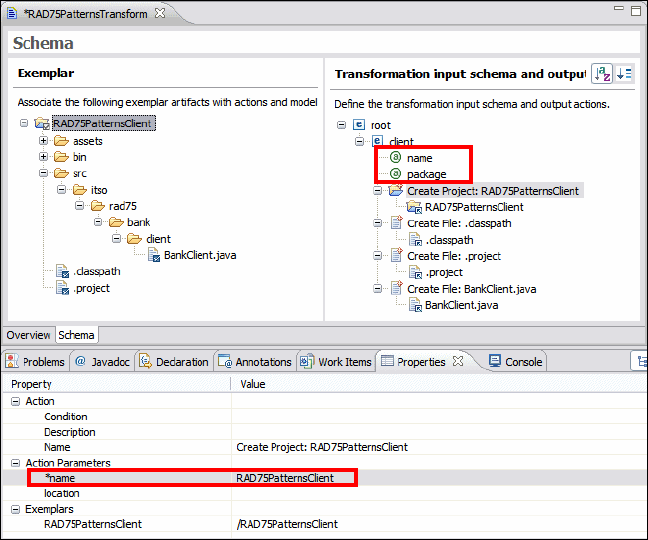
7672-base-2-patterns.fm Draft Document for Review December 9, 2008 2:44 pm
166 Rational Application Developer V7.5 Programming Guide
Adding and deriving attributes
In JET transformations, variable information is stored into attributes. The
exemplar authoring tool identifies two different types of attributes:
Attribute: Input attribute that has to be provided by the input model
Derived attribute: Attribute derived from an input attribute, usually used to
satisfy a naming convention (such as artifacts, Java variables)
Let us now add the necessary attributes and derived attributes:
Right-click the client type, and select New → Attribute. Call this new attribute
name.
Repeat the previous operation to add the package attribute.
Select the Create Project: RAD75PatternsClient action and view its
properties into the Properties view (Figure 9-6). The name action parameter
is used by the transformation to name the test client project when it is first
created. As we said above, this name must be variable and related to the
name attribute we just created. This is what we do in the next steps.
Figure 9-6 Create Project Properties
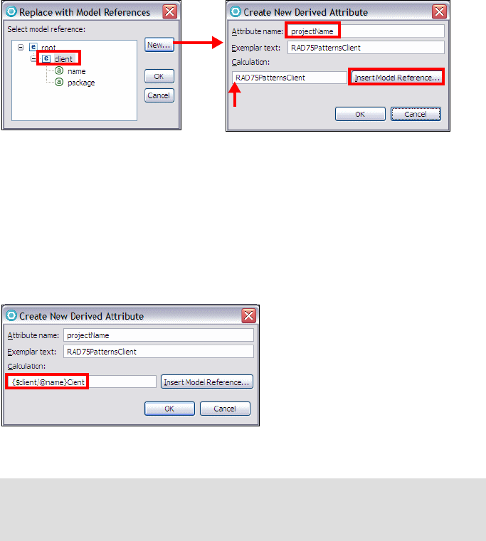
Chapter 9. Accelerate development using patterns 167
Draft Document for Review December 9, 2008 2:44 pm 7672-base-2-patterns.fm
Select the entire text of the action parameters name, right-click, and select
Replace with Model Reference.
In the Replace with Model References dialog, select the client type and click
New, because we want to add the Client string to the name attribute.
In the Create New Derived Attribute dialog, enter projectName as Attribute
Name. Point the cursor to the start of the Calculation field and click Insert
Model Reference (Figure 9-7).
Figure 9-7 Insert Model Reference
In the Select Model Reference dialog, select the name attribute of the client
type and click OK.
Note that a query expression for the name attribute as been inserted as
{$client/@name}RAD75PatternsClient. Change the expression to
{$client/@name}Client to define the calculation correctly (Figure 9-8). Click
OK to get back to Replace with Model References dialog.
Figure 9-8 Final definition of the projectName derived attribute
In the Replace with Model References dialog, select the projectName
attribute and click OK (Figure 9-9).
Note: The syntax used for the calculation is related to the fact that access
to the variable content is done by navigating an XML Domain Object Model
(DOM) using XPath.
cursor
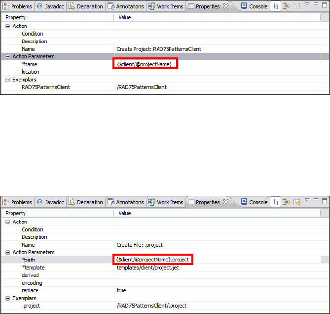
7672-base-2-patterns.fm Draft Document for Review December 9, 2008 2:44 pm
168 Rational Application Developer V7.5 Programming Guide
Figure 9-9 Final project name variable
Using the same approach to replace the path parameter of the .classpath
and .project elements. Select RAD75PatternsClient and replace the text
with a model reference to the projectName attribute (Figure 9-10):
{$client/$projectName}/.classpath
{$client/$projectName}/.project
Figure 9-10 Adding a reference to the .project path variable
Select the Create File: BankClient.java action, and in the Properties view
replace RAD75PatternsClient in the value of the path action parameter with
a model reference to the projectName attribute:
{$client/$projectName}/src/itso/rad75/bank/client/BankClient.java
We defined package as a variable, therefore we want to replace
itso/rad75/bank/client by a new derived attribute. Right-click client and
select New → Derived Attribute. Name the derived attribute clientDirectory
(Figure 9-11).
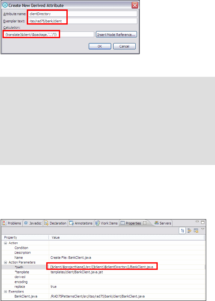
Chapter 9. Accelerate development using patterns 169
Draft Document for Review December 9, 2008 2:44 pm 7672-base-2-patterns.fm
Figure 9-11 Attribute deriving the directory path from the package attribute
Select the Create File: BankClient.java action and in the Properties view
replace the package directory with a reference to the clientDirectory
attribute (Figure 9-12):
old: {$client/@projectName}/src/itso/rad75/bank/client/BankClient.java
new: {$client/$projectName}/src/{$client/$clientDirectory}/BankClient.java
Figure 9-12 Final version of the BankClient.java path parameter
Save the transformation. The completed model is shown in Figure 9-13.
Note: Consider the expression on the Calculation box:
{translate($client/@package,'.','/')}
This translates the package attribute (in the form itso.rad75.bank.client)
into a directory path (in the form itso/rad75/bank/client).
The translate function is a standard XPath function. To learn more about
the standard XPath function go to http://www.w3.org/TR/xpath. To learn
more about the Rational Application Developer additional XPath functions
look into the help at Developing → Developing XML applications →
Creating XPath expressions.
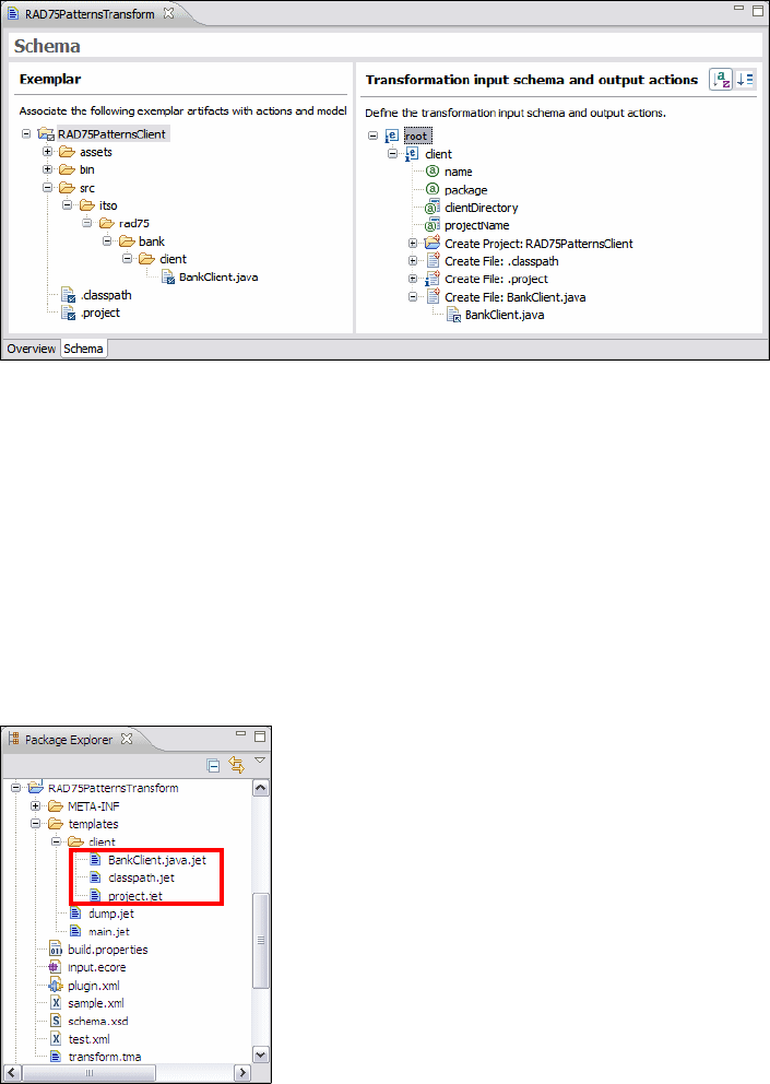
7672-base-2-patterns.fm Draft Document for Review December 9, 2008 2:44 pm
170 Rational Application Developer V7.5 Programming Guide
Figure 9-13 Final model for the JET transformation
Generate and edit templates
So far we have only made file names and paths variable; with templates we can
make the file content variable. Templates are the means used by JET to allow us
to modify the content of the files generated based on attributes (and derived
attributes) provided by the input model.
Let us generate the templates and insert variables into the content of these
templates. Right-click in the model transformation pane and select Update
Project. New Templates are generated into the project (Figure 9-14).
Figure 9-14 New generated templates
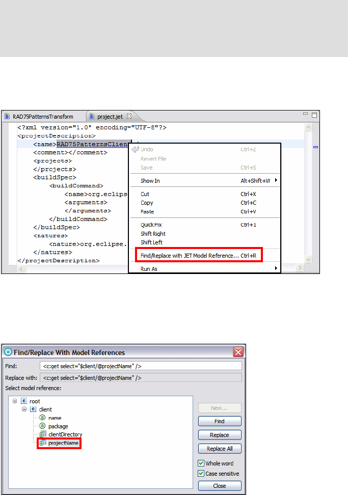
Chapter 9. Accelerate development using patterns 171
Draft Document for Review December 9, 2008 2:44 pm 7672-base-2-patterns.fm
Updating the project.jet file
Double-click project.jet to edit the template.
Select the underscored text, right-click, and select Find/Replace with JET
Model Reference (Figure 9-15).
Figure 9-15 Launching Find/Replace with JET Model Reference
In the Find/Replace with JET Model Reference dialog, select projectName,
click Replace, and then click Close (Figure 9-16).
Figure 9-16 Replacing the project name with the attribute
Note: There is a blue underscore under the name element, indicating that
the underscored string matches the exemplar strings of one of the
attributes. This indicates that the string should probably be replaced by a
variable expression referencing this attribute.

7672-base-2-patterns.fm Draft Document for Review December 9, 2008 2:44 pm
172 Rational Application Developer V7.5 Programming Guide
The name in the template has been replaced by the <c:get> tag:
<name><c:get select="$client/@projectName" /></name>
Save and close project.jet.
Updating the classpath.jet file
Open classpath.jet. The classpath contain a reference to the RAD75Patterns
project, that implements the bank application:
<?xml version="1.0" encoding="UTF-8"?>
<classpath>
<classpathentry kind="src" path="src"/>
<classpathentry kind="con"
path="org.eclipse.jdt.launching.JRE_CONTAINER"/>
<classpathentry combineaccessrules="false" kind="src"
path="/RAD75Patterns"/>
<classpathentry kind="output" path="bin"/>
</classpath>
It would be good to make the project name a variable in case we decide to
rename the project or decide to use a new project. However, we do not yet
have an attribute to store this value. We have to add it to the model.
Switch back to the RAD75PatternsTransform model and add a new attribute
called reference under client.
Switch back to classpath.jet and replace /RAD75Patterns (with the / at the
beginning) by the new created attribute called reference.
<classpathentry combineaccessrules="false" kind="src"
path="<c:get select="$client/@reference" />"/>
Save and close classpath.jet.
Updating the BankClient.java.jet file
We update the client program with many templates:
Open BankClient.java.jet and replace the package name with the package
attribute in the same manner:
package <c:get select="$client/@package" />;
import itso.rad75.bank.exception.ITSOBankException;
......
Note: You have to clear Whole word in the Find/Replace dialog to replace
the string with the slash.
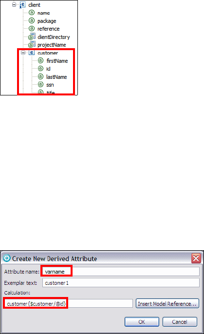
Chapter 9. Accelerate development using patterns 173
Draft Document for Review December 9, 2008 2:44 pm 7672-base-2-patterns.fm
Using a customer template
Analyzing the code of the BankClient, we can see that it creates one
customer (customer1), two accounts for this customer (account11 and
account12), and executes a deposit transaction on the first account and a
debit transaction on the second account. We make this variable, allowing us
to create as many customers and accounts as we like and perform all the
transactions we want.
A customer is defined by four parameters (SSN, title, first name, and last
name). We create it as a type and add the parameters as attributes. We also
have to add an id attribute to allow us to create multiple customers.
Switch back to the transformation model, select the client type, and select
New → Type. Name the new type customer. Add to the customer type four
attributes called ssn, title, firstName, lastName, and an extra attribute id.
When done, save all changes, right-click in the white space next to the model,
and select Update Project, to make the model modifications available for use
in the JET templates.
Switch back to BankClient.java.jet. Select customer1 in the Java code:
Customer customer1 = null;
Right-click, and select Find/Replace with JET Model Reference.
In the Find/Replace with JET Model Reference dialog, select customer and
click New to create a new derived attribute. Call the new derived attribute
varname and type customer{$customer/@id} into the Calculation box
(Figure 9-17). Click OK to go back to the previous dialog.
Figure 9-17 Creating the varName derived attribute
The ssn cannot be used an an ID
for customer variables. Therefore
an extra id attribute, which is
notpart of the customer data, is
created.
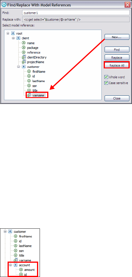
7672-base-2-patterns.fm Draft Document for Review December 9, 2008 2:44 pm
174 Rational Application Developer V7.5 Programming Guide
In the Find/Replace with JET Model Reference dialog, select varname,
click Replace All to replace all the instances of customer1, and then click
Close (Figure 9-18). All references to customer1 are replaced by the variable:
Customer <c:get select="$customer/@varname" /> = null;
Figure 9-18 Replace all occurrences of customer
When the customer is created (new Customer(.....), replace the parameters
by their corresponding model attribute (xxx-xx-xxxx by $customer/@ssn,
Mr by $customer/@title, Juan by $customer/@firstName, and Napoli by
$customer/@lastName). Add the Customer class name.
Customer <c:get select="$customer/@varname" /> = new Customer(
"<c:get select="$customer/@ssn" />",
"<c:get select="$customer/@title" />",
"<c:get select="$customer/@firstname" />",
"<c:get select="$customer/@lastname" />");
Using an account template
As we did for customer, we have to create a new type for account. Because
an account belongs to a given customer, we create this new type under
customer and we call it account. It contains two attributes, id and amount.

Chapter 9. Accelerate development using patterns 175
Draft Document for Review December 9, 2008 2:44 pm 7672-base-2-patterns.fm
Replace all occurrences of account11 by a new account derived attribute
called varname, with the calculation account{$account/@id}.
When the account is created (new Account(.....), replace the parameters by
their corresponding attributes (11 by $account/@id, 10000.00D by
$account/@amount). Add the Account class name.
Account <c:get select="$account/@varname" /> = new Account(
"<c:get select="$account/@id" />",
new BigDecimal(<c:get select="$account/@amount" />));
The account12 lines of code are similar to the account11 lines we just
replaced; they just create a second account. To reproduce that (and allow us
to create more than two accounts), we delete the account12 creation lines
and embed the account lines by a <c:iterate> tag, creating as many blocks of
lines as there are account elements declared in the input file:
<c:iterate select="$customer/account" var="account">
Account <c:get select="$account/@varname" /> = new Account
("<c:get select="$account/@id" />",
new BigDecimal(<c:get select="$account/@amount" />));
bank.openAccountForCustomer(<c:get select="$customer/@varname" />,
<c:get select="$account/@varname" />);
//Create and Add second account to the customer
System.out.println("Account "
+ <c:get select="$account/@varname" />.getAccountNumber()
+ " and account " + account12.getAccountNumber()
+ " has been successfully opened for "
+ <c:get select="$customer/@varname" /> + ".\n");
</c:iterate>
Using a transaction template
A transaction is always linked to only one account, so we create a new type
called transaction, under the account type. Because there can be debit and
credit transactions, we add a type attribute to the transaction type. We also
add an amount attribute to contain the amount the transaction applies to.
Note: Do not forget to select account before clicking New in the
Find/Replace With Model Reference dialog.
Note: We also updated the output line before </c:iterate> to replace it with
only one account reference.
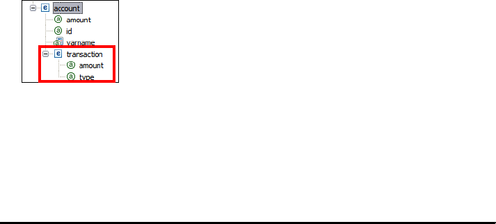
7672-base-2-patterns.fm Draft Document for Review December 9, 2008 2:44 pm
176 Rational Application Developer V7.5 Programming Guide
Replace the transaction amounts by the $transaction/@amount attribute.
Because we want to perform more than one transaction, we also have to add
a <c:iterate> tag on the transaction type. As there could be debit or credit
transactions, we need to perform a test on the type attribute to insert the
correct line of code. To do so, we use the <c:choose>, <c:when>, and
<c:otherwise> tags. Example 9-1 shows the resulting template.
Example 9-1 Template code containing the account and transaction parametrization
<c:iterate select="$customer/account" var="account">
Account <c:get select="$account/@varname" /> = new Account(
"<c:get select="$account/@id" />",
new BigDecimal(<c:get select="$account/@amount" />));
bank.openAccountForCustomer(<c:get select="$customer/@varname" />,
<c:get select="$account/@varname" />);
System.out.println("Account "
+ <c:get select="$account/@varname" />.getAccountNumber()
+ " has been successfully opened for "
+ <c:get select="$customer/@varname" /> + ".\n");
System.out.println("System is listing all account information of "
+ <c:get select="$customer/@varname" /> + "...");
System.out.println(bank.getAccountsForCustomer
(<c:get select="$customer/@varname" />.getSsn()));
<c:iterate select="$account/transaction" var="transaction">
amount = new BigDecimal(<c:get select="$transaction/@amount" />);
<c:choose select="$transaction/@type">
<c:when test="'Credit'">
System.out.println("\nSystem is going to make credit of $"
+ amount.setScale(2, BigDecimal.ROUND_HALF_EVEN)
+ " to account " + <c:get select="$account/@varname" />
.getAccountNumber() + "...");
bank.deposit(<c:get select="$account/@varname" />
.getAccountNumber(), amount);
System.out.println("Account "
+ <c:get select="$account/@varName" />.getAccountNumber()
+ " has sucessfully credited by $"
+ amount.setScale(2, BigDecimal.ROUND_HALF_EVEN) + ".\n");
</c:when>
<c:when test="'Debit'">
System.out.println("System is going to make debit of $"
+ amount.setScale(2, BigDecimal.ROUND_HALF_EVEN)
Chapter 9. Accelerate development using patterns 177
Draft Document for Review December 9, 2008 2:44 pm 7672-base-2-patterns.fm
+ " to account " + <c:get select="$account/@varname" /
.getAccountNumber() + "...");
bank.withdraw(<c:get select="$account/@varname" />
.getAccountNumber(), amount);
System.out.println("Account "
+ <c:get select="$account/@varName" />.getAccountNumber()
+ " has sucessfully debited by $"
+ amount.setScale(2, BigDecimal.ROUND_HALF_EVEN) + ".\n");
</c:when>
</c:choose>
</c:iterate> // transaction
</c:iterate> // account
We said previously that eventually we would like to create more than one
customer. To do so, we create a <c:iterate> tag before creating the customer.
Remove the declarations of the local variables, except BigDecimal amount.
Example 9-2 shows the final BankClient.java.jet with all the tags.
Example 9-2 Final version of BankClient.java.jet
/*
* File Name: BankClient.java
*/
package <c:get select="$client/@package" />;
import itso.rad75.bank.exception.ITSOBankException;
import itso.rad75.bank.ifc.Bank;
import itso.rad75.bank.impl.ITSOBank;
import itso.rad75.bank.model.Account;
import itso.rad75.bank.model.Customer;
Notes:
Because we iterate to create different amounts, the declaration of the
amount variable (BigDecimal amount;) must be before the first <c:iterate>
tag.
As the debit code is applied to account12, the easiest way to reuse the
lines of code is to replace account12 by $account/@varName, so it could
be applied to any account we create.
The account iteration closing tag (</c:iterate>) has been moved after the
transaction iteration closing tag because a transaction is a subtype of the
account type.
We also remove the remaining transactions and the account close
command, as we do not expect our clients program to close any accounts.
7672-base-2-patterns.fm Draft Document for Review December 9, 2008 2:44 pm
178 Rational Application Developer V7.5 Programming Guide
import java.math.BigDecimal;
public class BankClient {
public static void main(String[] args) {
// code unchanged
}
// Method to test the Bank application
private static void executeCustomerTransactions(Bank bank)
throws ITSOBankException {
try {
//Declare local variables
BigDecimal amount = null;
<c:iterate select="$client/customer" var="customer">
System.out.println("System is going to add new customer...");
Customer <c:get select="$customer/@varName" /> =
new Customer("<c:get select="$customer/@ssn" />",
"<c:get select="$customer/@title" />",
"<c:get select="$customer/@firstMame" />",
"<c:get select="$customer/@lastName" />");
bank.addCustomer(<c:get select="$customer/@varname" />);
System.out.println(<c:get select="$customer/@varname" />
+ " has been successfully added.\n");
System.out.println
("System is going to open new accounts for the customer "
+ <c:get select="$customer/@varName" /> + "...");
<c:iterate select="$customer/account" var="account">
Account <c:get select="$account/@varName" /> =
new Account("<c:get select="$account/@id" />",
new BigDecimal(<c:get select="$account/@amount" />));
bank.openAccountForCustomer(<c:get select="$customer/@varname" />,
<c:get select="$account/@varname" />);
System.out.println("Account "
+ <c:get select="$account/@varname" />.getAccountNumber()
+ " has been successfully opened for "
+ <c:get select="$customer/@varname" /> + ".\n");
System.out.println("System is listing all account information of "
+ <c:get select="$customer/@varname" /> + "...");
System.out.println(bank.getAccountsForCustomer
(<c:get select="$customer/@varname" />.getSsn()));
<c:iterate select="$account/transaction" var="transaction">
amount = new BigDecimal(<c:get select="$transaction/@amount" />);
<c:choose select="$transaction/@type">
<c:when test="'Credit'">
System.out.println("\nSystem is going to make credit of $"
+ amount.setScale(2, BigDecimal.ROUND_HALF_EVEN)
+ " to account " + <c:get select="$account/@varname" />
.getAccountNumber() + "...");
bank.deposit(<c:get select="$account/@varname" />
Chapter 9. Accelerate development using patterns 179
Draft Document for Review December 9, 2008 2:44 pm 7672-base-2-patterns.fm
.getAccountNumber(), amount);
System.out.println("Account "
+ <c:get select="$account/@varname" />.getAccountNumber()
+ " has sucessfully credited by $"
+ amount.setScale(2, BigDecimal.ROUND_HALF_EVEN) + ".\n");
</c:when>
<c:when test="'Debit'">
System.out.println("System is going to make debit of $"
+ amount.setScale(2, BigDecimal.ROUND_HALF_EVEN)
+ " to account " + <c:get select="$account/@varname" />
.getAccountNumber() + "...");
bank.withdraw(<c:get select="$account/@varname" />
.getAccountNumber(), amount);
System.out.println("Account "
+ <c:get select="$account/@varname" />.getAccountNumber()
+ " has sucessfully debited by $"
+ amount.setScale(2, BigDecimal.ROUND_HALF_EVEN) + ".\n");
</c:when>
</c:choose>
</c:iterate> // transaction
</c:iterate> // account
System.out.println("System is listing all account information of "
+ <c:get select="$customer/@varname" /> + "...");
System.out.println(bank.getAccountsForCustomer
(<c:get select="$customer/@varname" />.getSsn()));
</c:iterate> // customer
}//Catch exceptions and printout stack trace in console
catch (ITSOBankException e){throw e;}
}
}
Save all the files. Run Update Project before running the sample to make the
model modifications available for use in the JET templates.
Applying the pattern
To apply the pattern, we create an XML input file for the JET transformation:
Let us start by creating a sample.xml that creates the same test client we
used as exemplar. Open the sample.xml file that is contained in the
Note: The final BankClient.java.jet is available in the RAD75PatternsClient
project in the assets directory.
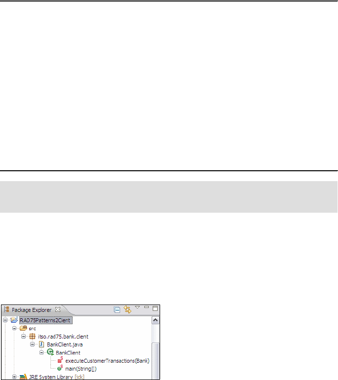
7672-base-2-patterns.fm Draft Document for Review December 9, 2008 2:44 pm
180 Rational Application Developer V7.5 Programming Guide
RAD75PatternsTransform project. Modify it to match what is in
(Example 9-3).
Example 9-3 Sample.xml to run the transformation
<root>
<client name="RAD75Patterns2" package="itso.rad75.bank.client"
reference="/RAD75Patterns">
<customer id="1" ssn="xxx-xx-xxxx" title="Mr" firstName="Ahmed"
lastName="Moharram">
<account id="11" amount="10000.00D">
<transaction type="Credit" amount="2500.00D"></transaction>
</account>
<account id="12" amount="11234.23D">
<transaction type="Debit" amount="1234.23D"></transaction>
<transaction type="Credit" amount="5000.00D"></transaction>
</account>
</customer>
</client>
</root>
Right-click sample.xml and select Run As → Input for Jet Transformation.
Explore the newly created RAD75Patterns2Client project (Figure 9-19):
– A package itso.rad75.bank.client is created.
– The client program BankClient.java is created.
– The classpath has been set so that there are no errors.
Figure 9-19 Client generated by transformation
Running the generated client
Open the generated client and study the source code.
Right-click BankClient.java → Run As → Java Application to verify that it
produces a similar output as the examplar.
Note: A version of sample.xml is available in the RAD75PatternsClient
project in the assets directory.

Chapter 9. Accelerate development using patterns 181
Draft Document for Review December 9, 2008 2:44 pm 7672-base-2-patterns.fm
Running another transformation
This time we are running a different XML file, sample2.xml, that is in the
RAD75PatternsClient project in the assets directory.
Open sample2.xml and explore the content. As you can see in Example 9-4,
we have two customers (Jane Doe and John Doe). Jane Doe has two
accounts and we perform a debit and a credit transactions on her first
account. John Doe has only one account and we do not perform any
transactions. We generate the client into the same RAD75Patterns2Client
project, but a new package (itso.rad75.bank2.client).
Example 9-4 Sample2.xml transformation
<root>
<client name="RAD75Patterns2" package="itso.rad75.bank2.client"
reference="/RAD75Patterns">
<customer id="1" ssn="999-99-9999" title="Mrs" firstName="Jane"
lastName="Doe">
<account id="11" amount="10000.00">
<transaction type="Debit" amount="2399.99"></transaction>
<transaction type="Credit" amount="2399.99"></transaction>
</account>
<account id="12" amount="11234.23">
</account>
</customer>
<customer id="2" ssn="888-88-8888" title="Mr" firstName="John"
lastName="Doe">
<account id="21" amount="10000.00"></account>
</customer>
</client>
</root>
To run the transform, right-click sample2.xml and select Run As → Input for
Jet Transformation. Because the containing project is not a JET
transformation project, the Edit launch configuration properties dialog is
displayed. In this dialog, select RAD75PatternsTransform as transformation
id from the drop-down list (Figure 9-20).
Note: You can verify that both accounts have been created, that all
transactions were performed, and that the balance is the same between the
generated project and the exemplar project.
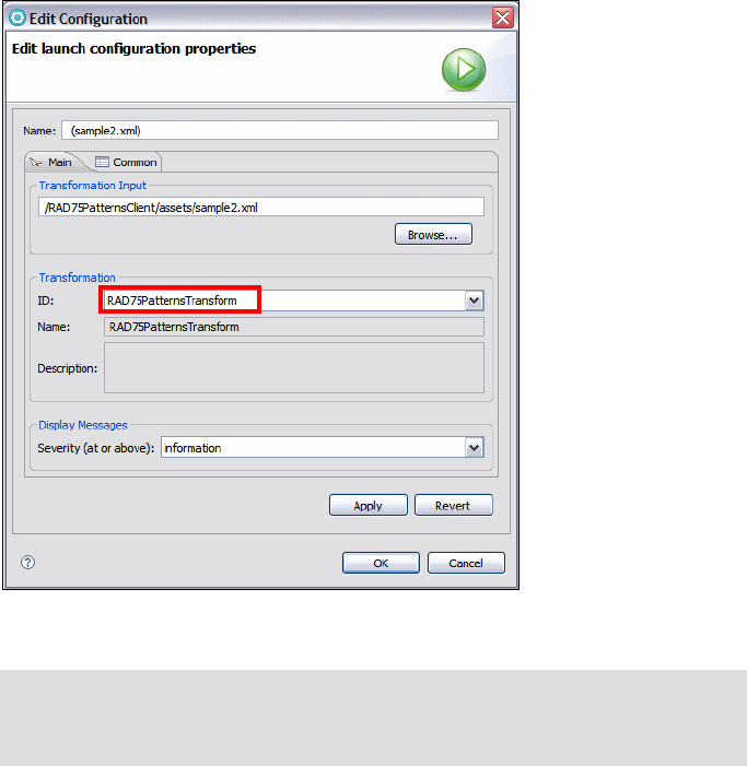
7672-base-2-patterns.fm Draft Document for Review December 9, 2008 2:44 pm
182 Rational Application Developer V7.5 Programming Guide
Figure 9-20 Creating the run configuration
Explore the newly created itso.rad75.bank2.client.BankClient.java and
study the generated source code. You can run the client to verify that it runs.
Note: After doing this initial configuration, the JET transformation can be
rerun just by right-clicking sample2.xml and selecting Run As → Input for
Jet Transformation.
Chapter 9. Accelerate development using patterns 183
Draft Document for Review December 9, 2008 2:44 pm 7672-base-2-patterns.fm
Facade pattern
In this section we introduce a second transformation example, which generates
the facade (interface and implementation) for the sample banking application.
Importing the facade example
Import the project interchange file for the facade example, by selecting File →
Import → Other → Project Interchange. Click Next. Locate the example in:
c:\7672code\patterns\RAD75PatternsFacade.zip
Select the RAD75PatternsFacade and RAD75PatternsFacadeTransform projects,
and click Finish. Note that RAD75PatternsFacade refers to RAD75Patterns as the
model. Study the two projects:
RAD75PatternsFacade is the examplar project. We will generate the interface,
itso.rad75.bank.ifc.Bank, and the implementation class,
itso.rad75.bank.impl.ITSOBank.
RAD75PatternsFacadeTransform is the JET Transformation project.
Facade transformation
Open the transform.tma file in RAD75PatternsFacadeTransform. The
transformation defines:
Attributes: name (of the interface), package (base package), systemProjName
(underlying project with the model)
Derived attributes: facadeDirectory (folders from package), facadeVarname
(variable for the interface), ifcPackage (package of interface), implClass
(implementation class name), implPackage (package of implementation), and
projectName (generated project)
Elements: entity (to define model objects), and operation (to define the
methods of the interface)
Creates: Project, .classpath, .project, Bank.java (interface), ITSOBank.java
(implementation)
The template files (templates\facade) include:
classpath.jet: .classpath template
project.jet: .project template
Bank.java.jet: interface template
ITSOBank.java.jet: implementation template
7672-base-2-patterns.fm Draft Document for Review December 9, 2008 2:44 pm
184 Rational Application Developer V7.5 Programming Guide
Running the transformation examples
We provide two XML files to run the transformation and generate an interface
and an implementation class:
BankSample.xml: This example generates a BankFacadeGenerated
project, with the Bank interface and the ITSOBank implementation class,
matching the original classes in the RAD75Patterns project.
LibrarySample.xml: This example generates a LibraryFacadeGenerated
project, with a Library interface and an ITSOLibrary implementation class.
This example demonstrates that the transformation can generate any
interface and a matching implementation class. The library example is based
on Book and Borrower model classes. Note that we do not provide the
underlying RAD75LibraryJava project with the model classes, and errors are
reported for the LibraryFacadeGenerated project..
More information
The following URLs provide further information for the topics covered in this
chapter:
You can find several articles on pattern transformations on the IBM
developerWorks Web site (search for JET pattern transformation):
http://www.ibm.com/developerworks
More information on using Exemplar Authoring and JET transformations can
be found at IBM developerWorks in the article Create powerful custom tools
quickly with Rational Software Architect Version 7.0:
http://www.ibm.com/developerworks/rational/library/07/0109_peterson/
For more information on patterns based development, visit the Patterns
Solution area at IBM developerWorks:
http://www.ibm.com/developerworks/rational/products/patternsolutions/index.
html?S_TACT=105AGX15&S_CMP=LP
More information on the XPath functions can be found at:
http://www.w3.org/TR/xpath

© Copyright IBM Corp. 2008. All rights reserved. 185
Draft Document for Review December 9, 2008 2:44 pm 7672-base-4-xml.fm
Chapter 10. Develop XML applications
This chapter provides an overview of current XML technologies and covers the
XML capabilities provided by Rational Application Developer 7.5.
The chapter is organized into the following sections:
XML overview and associated technologies
Rational Application Developer XML tools
Creating an XML schema
Generating HTML documentation from an XML schema file
Generating an XML file from an XML schema
Editing an XML file
Working with XSL transformation files
Transforming an XML file into an HTML file
XML mapping
Generating JavaBeans from an XML schema
Service Data Objects and XML
The sample code for this chapter is in 7672code\xml.
10
7672-base-4-xml.fm Draft Document for Review December 9, 2008 2:44 pm
186 Rational Application Developer V7.5 Programming Guide
XML overview and associated technologies
Extensible Markup Language (XML) is a subset of Standard Generalized Markup
Language (SGML). Both XML and SGML are meta languages, because they
allow the definition of a chosen set of elements and attributes to meet the
requirements of a specific application area. Markup languages are used to
annotate information so that it is easier to manipulate and understand. Markup is
also used to define how information should be presented for display. One
example of this is HTML. HTML is used to mark up document information so that
it can be displayed by a Web browser. The elements within an XML document
are organized hierarchically with a single root element at the top of the hierarchy.
XML is a key part of the software infrastructure. It provides a simple and flexible
means of defining, creating, and storing data. XML is used for a variety of
purposes such as systems configuration, messaging and data storage.
The set of rules which define what can be present in any specific XML document
are held in either a Document Type Definition (DTD) or an XML schema
Definition (XSD). If a DTD or XSD is available it is possible to check that an XML
document is valid. If an XML documents is to usable it must first be well-formed.
This means that it must adhere to all the XML syntax rules as defined in the XML
specification document. Only a well-formed XML document can be checked
using a DTD or XSD to see if it is valid. A valid XML document is guaranteed to
contain only what it should.
Detailed information on XML can be found at:
http://www.w3.org/XML/
XML processors
XML is tag-based; however there are no predefined XML tags. Tags are the
markup inserted in an XML document to define the elements from which it is
composed.
XML documents follow strict syntax rules. To create, read, and update XML
documents, you require an XML processor or parser. At the heart of an XML
application is an XML processor that parses an XML document allowing the
document elements to be retrieved and used as required. Parsers are also
responsibility for checking the syntax and structure of XML documents. The two
main XML parsers are the Simple API for XML (SAX) parser and the Document
Object Model (DOM) parser.
Chapter 10. Develop XML applications 187
Draft Document for Review December 9, 2008 2:44 pm 7672-base-4-xml.fm
Detailed information on SAX and DOM can be found at:
http://www.saxproject.org/
http://www.w3.org/DOM/
DTDs and XML schemas
DTDs and XML schemas are both used to describe XML document structure;
however, in recent years the acceptance of XML schemas has gained
momentum. Both DTDs and XML schemas define the building blocks for XML
documents, the elements, attributes and entities.
XML schemas are more powerful than DTDs. Here are some of the advantages
of XML schemas over DTDs:
They can define data types for elements and attributes, and their default and
fixed values. The data types can be of string, decimal, integer, boolean, date,
time, or duration.
They can apply restrictions to elements, by stating minimum and maximum
values, for example, an age element might be restricted to hold values from 1
to 90 or a string value may be restricted to only hold one value from a specific
list of values a defined allowed list such as Fixed, Savings or Loan.
Restrictions can also be applied to characters and patterns of characters, for
example, characters may be restricted to those from ‘a’ to ‘z’ and the length of
the character string may be restricted to only three letters. Another restriction
may be that the string may have a range of lengths, for example, a password
must be between 4 and 8 characters.
They can define complex element types. Complex types can contain simple
types or other complex types. Restrictions can be applied to the sequence
and frequency of the occurrence of each type. Complex types can be used in
the definition of other complex types.
XML schema documents, unlike DTDs, are actually XML documents. This
implies that XML schema documents can be automatically checked for validity
and authoring XML schema documents is simpler for those already familiar
with XML. Also, XML parsers do not have to be enhanced to provide support
for DTDs. Transformation of XML schema documents can be carried out
using Extensible Stylesheets Language Transformation (XSLT) documents
and they can be manipulated using the XML Document Object Model (DOM).
Detailed information on DTD and XML schema can be found at:
http://www.w3.org/TR/2006/REC-xml-20060816/
http://www.w3.org/XML/Schema
7672-base-4-xml.fm Draft Document for Review December 9, 2008 2:44 pm
188 Rational Application Developer V7.5 Programming Guide
XSL
Extensible Stylesheet Language (XSL) is a set of recommendations defined by
the W3C.
XSL is composed of the following three W3C recommendations:
XSL transformations (XSLT): This is an XML markup language which is used
for the transformation of XML documents
XML Path language (XPath): This is a language used to access or refer to
parts of an XML document
XSL-FO: This is a XML markup language which is used to format information
for the purpose of presentation in similar way to the way that HTML marks up
information fro presentation by a Web browser.
XML document transformations defined using XSLT are XML documents. The
elements present in the XSLT document are defined in the XSLT namespace.
Namespaces are discussed later in this chapter.
An XSLT transformation processor is required when transforming a document
using XSLT. The processor takes as input a source XML document and an XSLT
transformation document. The transformations defined in XSLT document are
used to transform the source file into the output file. XSLT uses pattern matching
and templates to define the required transformation. When a pattern defined in
the XSLT transformation document is found in the source document the
associated template, also defined in the XSLT transformation document, is
placed in the output file.
The output file produced is typically another XML document.
Detailed information on XSLT can be found at:
http://www.w3.org/TR/xslt.html
XML namespaces
Namespaces are used when there is a requirement for elements and attributes of
the same name to take on a different meaning depending on the context in which
they are used. For instance, an element called TITLE would have a different
meaning, depending on whether it was present within a PERSON element or within
a BOOK element. In the case of the PERSON element it would be something that is
placed in front of a persons name, such as Mr or Dr. In the case of BOOK element it
would be the title of the book, such as Programming Guide.
Chapter 10. Develop XML applications 189
Draft Document for Review December 9, 2008 2:44 pm 7672-base-4-xml.fm
If both elements, PERSON and BOOK, have to be defined in the same document, for
example, in a library entry that associates a book with its author, a mechanism is
required to distinguish between the two so that the correct semantics apply when
the TITLE element is used in the document.
Namespaces provide this mechanism by allowing a namespace and an
associated prefix to be defined. Elements that use a specific namespace prefix
are said to be present in that namespace and have the meaning defined for them
in the namespace. The prefix is separated from the element name by a colon
character. In our example TITLE would be defined in two different namespace.
One namespace would be concerned with elements relevant to holding
information on books and the other namespace would be concerned with
elements storing information on people. Example start tags for the elements
might be <book:TITLE> and <people:TITLE>.
Detailed information on XML namespaces can be found at:
http://www.w3.org/TR/REC-xml-names/
XPath
The XML path language (XPath) is used to address parts of an XML document.
The XML document is considered to be a tree of nodes and an XPath expression
selects a specific node or set of nodes within the tree. This is achieved by
defining the path to the node or nodes. An XPath expression in addition can
include instructions to manipulate values held at a specific node or set of nodes.
XPath is used with XSLT, discussed previously, as well as other XML
technologies.
Detailed information on XPath can be found at:
http://www.w3.org/TR/xpath
Rational Application Developer XML tools
Rational Application Developer provides a comprehensive visual XML
development environment. The tool set includes components for building DTDs,
XML schemas, XML Documents, and XSL files.
Rational Application Developer includes the following XML development tools:
DTD editor
XML editor
XML schema editor
XSL editor
XPath Expression wizard
7672-base-4-xml.fm Draft Document for Review December 9, 2008 2:44 pm
190 Rational Application Developer V7.5 Programming Guide
XML to XML Mapping editor
XSL debugger and XML transformer
XML schema to JavaBean generator
XML schema to HTML documentation generator
XML, DTD, and relational tables to XML schema generator
Creating an XML schema
In this section, we create an XML schema for use in storing bank account
information. The XML document structure defined in the schema is a collection of
accounts. Each account has an account ID, account type, account balance,
interest rate, and related customer information. The account ID is allowed to be
from 6 to 8 digits long and each digit must be in the range 0 to 9. The value of the
interest rate is allowed to be between 0 and 100. The phone number is in the
format (xxx) xxx-xxxx. The following steps create a project to hold our schema
document and create an empty schema document:
Open the Resource perspective and create a project named
RAD75XMLBank:
–Select File → New → Project → General → Project, then click Next.
– In the Project name field type RAD75XMLBank.
– Click Finish and the project is displayed in the Enterprise Explorer.
– Right-click the RAD75XMLBank project and select New → Folder. Enter
xml as folder name, and click Finish.
Create an XML schema:
– Right-click the xml folder and select New → Other → XML → XML
schema. Click Next.
– The parent folder is set to RAD75XMLBank/xml. In the File name field type
Accounts.xsd. Click Finish.
– Make sure that the Properties view is visible. If you cannot see the
Properties view, select Window → Show view → Properties.
Working with the Design view
The XML editor allows the XML source for the schema to be edited directly but
also features a Design view. The Design view presents the XML document in
such a way that it makes editing and navigation through the document easier.
The Design view can be used with any type of XML document but because we
are working with an XML schema, a format understood by the editor, the editor
can help with the creation of the schema document. We will create the schema in
the Design view.
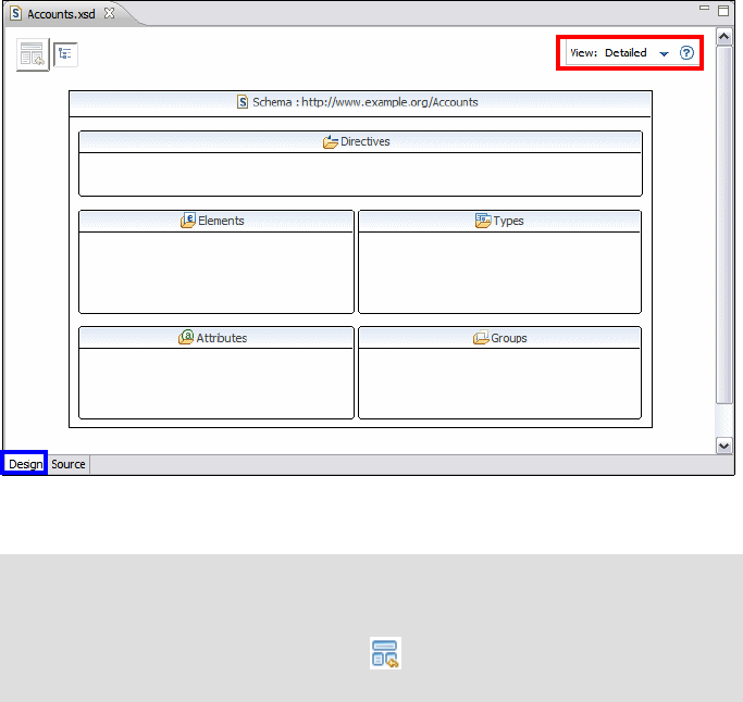
Chapter 10. Develop XML applications 191
Draft Document for Review December 9, 2008 2:44 pm 7672-base-4-xml.fm
Select the Design view. Notice that the top-right corner displays
View: Simplified.
–Simplified—The Simplified view hides many of the complicated XML
schema capabilities so that you can only create XML schemas that
conform to best practice authoring patterns.
–Detailed—The Detailed view exposes the full set of XML schema
capabilities so you can create XML data structures using any authoring
pattern. XML schema elements such as xsd:choice, xsd:sequence,
xsd:group, and element references are not displayed in the Simplified view
and actions in the editor that enable the creation of these elements are not
available.
We use the Detailed view for this exercise.
Select Detailed from the View: drop down list (Figure 10-1). Dismiss the
pop-up about switching view modes.
Figure 10-1 XML schema Editor: Design view, Detailed
Note: In the detailed view the top level view is called the schema index
view. We can navigate to this at any time while editing the schema by
clicking on the Show schema index view button in the top left of the
design view. The button has the icon . In Figure 10-1 this is currently
greyed out because we are already viewing the schema index.
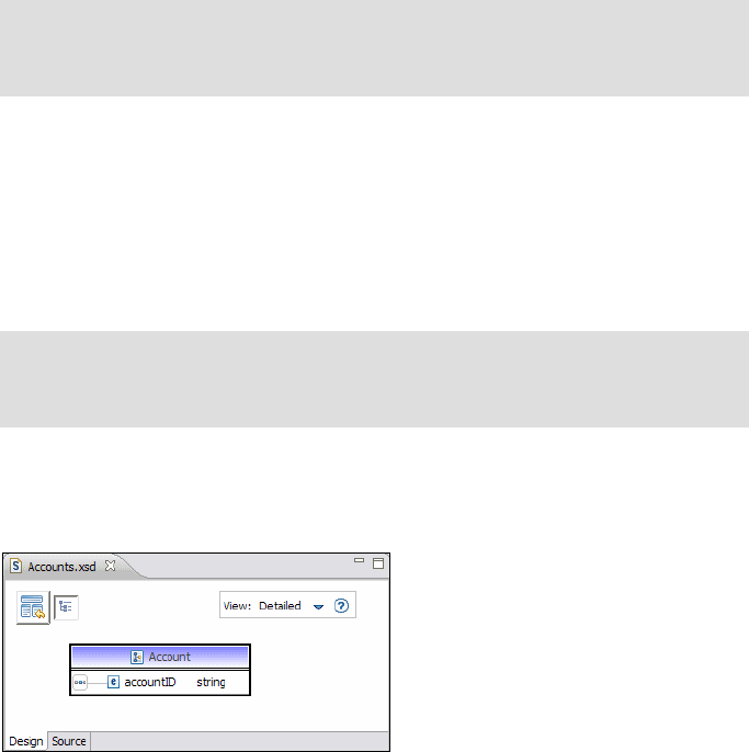
7672-base-4-xml.fm Draft Document for Review December 9, 2008 2:44 pm
192 Rational Application Developer V7.5 Programming Guide
Change the namespace prefix and target namespace:
– In the Properties view, select the General tab. You can see the current
namespace prefix and target namespace. The values are tns and
http://www.example.org/Accounts.
– Change the Prefix to itso.
– Change the Target namespace to http://itso.rad75.xml.com.
The Accounts.xsd file must contain a complex type element where we will
define the account information, including account id, account type, balance,
interest, and customer information:
– In the Design view, right-click the Types category and select Add
ComplexType. Overtype the name provided with the value Account.
Right-click the Account complex type, and select Add Sequence. The
design view switches from showing the schema index to only showing the
Account complex type:
– Clicking the Show schema index view icon returns to the schema index.
– Double-clicking on the Account complex type shows only this type in the
detailed view.
Right-click the Account complex type, and select Add Element.
Change the element name to accountID (Figure 10-2).
Figure 10-2 Account complex type
Tip: Alternatively, you can change the element name in the Properties
view, General tab, Name field. The Properties view provides many options
for modifying the properties of an XML schema.
Note: In simplified view you are not able to see the Add Sequence option
in the context menu, because the Simplified view hides many of the more
complicated XML elements.
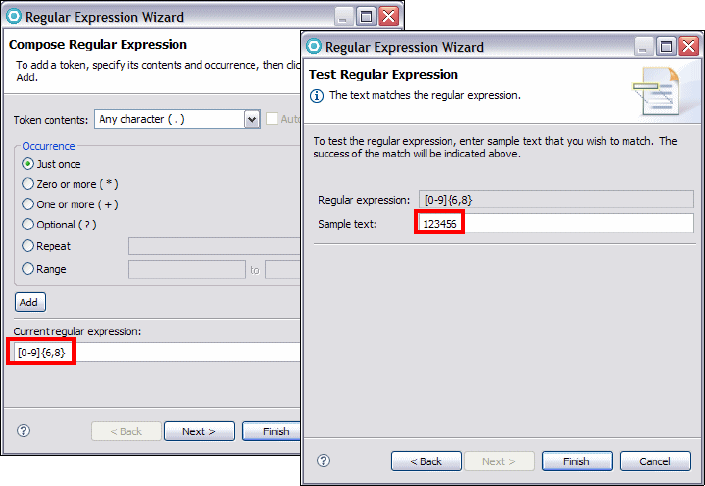
Chapter 10. Develop XML applications 193
Draft Document for Review December 9, 2008 2:44 pm 7672-base-4-xml.fm
In our bank, the account ID is 6 to 8 digits long and takes numerical values in
the range 0-9:
– Click the element accountID, and in the Properties view select the
Constraints tab.
– In the Specific constraint values section, select Patterns and Click Add.
The Regular Expression Wizard opens.
– In the Regular Expression Wizard (Figure 10-3):
• Type [0-9]{6,8} in the current regular expression field, and click Next.
• In the Sample text area, type 123456. Note that the warning at the top
of the dialog box disappears.
• Click Finish.
Figure 10-3 Regular Expression Wizard
– Note that the type for accountID changes from string to AccountIDType,
because we have constrained the string to create a new type.
– The Properties view with the constraint value is shown in Figure 10-4.
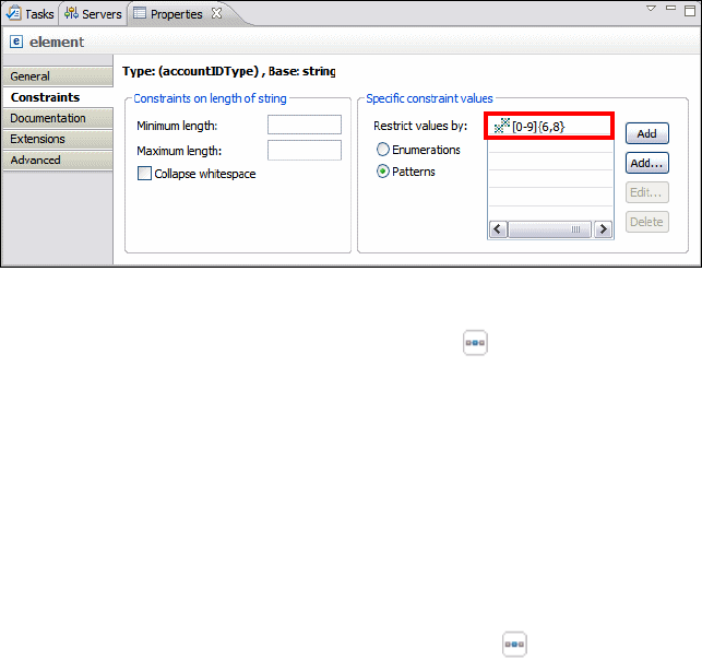
7672-base-4-xml.fm Draft Document for Review December 9, 2008 2:44 pm
194 Rational Application Developer V7.5 Programming Guide
Figure 10-4 Properties view with constraint
In the Design view, right-click the sequence icon and select Add Element.
Change its name to accountType. A bank account has three account types:
Savings, Loan, and Fixed:
– In the Properties view, select the Constraints tab. Under Specific
constraint values, select Enumerations.
– Click Add and enter Savings.
– Click Add and enter Loan.
– Click Add and enter Fixed.
Add the balance element:
– In the Design view, right-click the sequence icon and select Add
Element. Change its name to balance.
– In the Properties view, General tab, select the drop-down menu for Type.
–Select Browse from the drop-down menu, then select decimal.
Add the interest element:
– Add an element named interest and set the type to decimal as before.
– In the Properties view Constraints tab set the Minimum value to 0 and
Maximum value to 100.
Add the customerInfo element:
– Add an element named customerInfo.
– In the Properties view, General tab, select the drop-down menu for the
Type and select New.
– In the New Type dialog, select Complex Type and Create as local
anonymous type, then click OK (Figure 10-5).
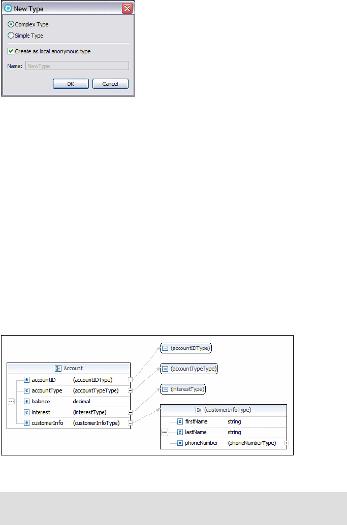
Chapter 10. Develop XML applications 195
Draft Document for Review December 9, 2008 2:44 pm 7672-base-4-xml.fm
Figure 10-5 new Type dialog
Click the plus sign to the right of customerInfo, and a (CustomerInfoType)
box appears to the right of the Account box.
Right-click (CustomerInfoType) and select Add Element. Change the name
to firstName.
Add another element named lastName.
Add another element named phoneNumber, which holds values with a
format such as (408) 456-7890:
– In the Properties view, Constraints tab, select Patterns.
– Click Add.... In the Current regular expression area, type
\([0-9]{3}\) [0-9]{3}-[0-9]{4}, and click Next. Note that there is a space
between the area code and the local phone number.
– Enter (408) 456-7890 as Sample text and click Finish.
The Design view is shown in Figure 10-6.
Figure 10-6 Account type complete
Tip: The Design view can be exported as an image for use elsewhereby
selecting XSD → Export Diagram as Image from the menu.
7672-base-4-xml.fm Draft Document for Review December 9, 2008 2:44 pm
196 Rational Application Developer V7.5 Programming Guide
If this XML schema is to define the structure of an XML document that can
actually be created, the XML schema must have a global element. All we
have at present is a complex type definition. We have to define at least one
element of this type. We can add a global element named accounts as
follows:
– Click the show schema index view icon at the top left corner.
– In the Design view of the schema, right-click the Elements category and
select Add Element.
– Change the name to accounts.
– In the Properties view, General tab, select the drop-down menu for Type
and select New. In the New Type dialog, select Complex Type and Create
as local anonymous type, and click OK.
– Double-click accounts and you are switched to the detailed view for the
accounts element. Right-click accountsType and select Add Element.
– Change the name to account.
– Right-click account and select Set Type → Browse → Account.
– In the Design view, make sure account is selected. In the Properties view,
General tab, set the Minimum Occurrence to 1 and Maximum Occurrence
to unbounded.
Source view
Finally we tidy up the XML source code that has been created. Select the Source
tab, right-click anywhere in the source code, and select Source → Format to
format the XSD file so that it has a tidy layout.
Save and close the file. The generated Accounts.xsd file is listed in
Example 10-1.
Example 10-1 Accounts.xsd file
<?xml version="1.0" encoding="UTF-8"?>
<schema targetNamespace="http://itso.rad75.xml.com"
elementFormDefault="qualified" xmlns="http://www.w3.org/2001/XMLSchema"
xmlns:itso="http://itso.rad75.xml.com">
<complexType name="Account">
<sequence>
<element name="accountID">
<simpleType>
<restriction base="string">
<pattern value="[0-9]{6,8}"></pattern>
</restriction>
</simpleType>
</element>

Chapter 10. Develop XML applications 197
Draft Document for Review December 9, 2008 2:44 pm 7672-base-4-xml.fm
<element name="accountType">
<simpleType>
<restriction base="string">
<enumeration value="Savings"></enumeration>
<enumeration value="Loan"></enumeration>
<enumeration value="Fixed"></enumeration>
</restriction>
</simpleType>
</element>
<element name="balance" type="decimal"></element>
<element name="interest">
<simpleType>
<restriction base="decimal">
<minExclusive value="0"></minExclusive>
<maxExclusive value="100"></maxExclusive>
</restriction>
</simpleType>
</element>
<element name="customerInfo">
<complexType>
<sequence>
<element name="firstName" type="string"></element>
<element name="lastName" type="string"></element>
<element name="phoneNumber">
<simpleType>
<restriction base="string">
<pattern value="\([0-9]{3}\) [0-9]{3}-[0-9]{4}">
</pattern>
</restriction>
</simpleType>
</element>
</sequence>
</complexType>
</element>
</sequence>
</complexType>
<element name="accounts">
<complexType>
<sequence>
<element name="account" type="itso:Account" minOccurs="1"
maxOccurs="unbounded"></element>
</sequence>
</complexType>
</element>
</schema>

7672-base-4-xml.fm Draft Document for Review December 9, 2008 2:44 pm
198 Rational Application Developer V7.5 Programming Guide
Validating an XML schema
In Application Developer v7.5, two validators are available, the Eclipse
XSD-based XML schema validator and the Xerces-based XML schema validator.
The Eclipse XSD-based XML validator is faster when validating large schemas
and is set as the default. You can verify the setting in Window → Preferences →
Validation → XML schema Validator (Figure 10-7):
Figure 10-7 XML schema Validator preferences
In some cases, when you build a large Java Enterprise Edition (Java EE) project,
the XSD validation process can take some time. You can disable the validator
either at the project level, or, at the global level:
To disable the validator at the project level, right-click the project and select
Properties → Validation, select Enable project specific settings, and clear
the XML Schema Validator check box in the Build column.
To disable the validator at the global level, use the Window → Preferences
dialog (Figure 10-7) and clear the XML Schema Validator check box in the
Build column.
Chapter 10. Develop XML applications 199
Draft Document for Review December 9, 2008 2:44 pm 7672-base-4-xml.fm
Run schema validation manually
The validation builder is not added to the simple projects, such as our project. To
validate your XML schema, complete the following steps:
Right-click Account.xsd in the Enterprise Explorer and select Validate.
If validation is successful, a Validation Results pop-up informas you of the
success. There are no errors in the Problems view.
If validation is not successful, validation errors are displayed in the Problems
view (you may have to open the view using Window → Show View). In
addition, a red X appears next to the file and in the Source view.
You should not receive any XML schema validation errors for Accounts.xsd,
because we created it in Design view and did not enter the XML manually.
If you want to make the document invalid so that you can see an error report,
change the type of one of the elements from decimal to deximal, and execute
validation again. After doing this and reading the error message, correct the error
and run validation again to remove the error message.
Generating HTML documentation from an XML schema file
HTML documentation generated from an XML schema contains information
about the schema such as its name, location, and namespace, as well as details
about the elements and types contained in the schema. This can be useful
because it provides a summary of the content of a schema in a form that is easily
readable.
The following steps generate HTML documentation based on an XML schema
file:
In the Enterprise Explorer, right-click Accounts.xsd and select Generate →
HTML. The XSD Documentation Generation Options dialog opens.
Select Generate XSD Documentation with frames. Selecting this option
generates schema documentation that uses HTML frames. If frame are not
required then select Generate XSD Documentation without frames
Click Next. Type docs as the folder name, and click Finish.
The HTML files are created in the location specified and the generated
index.html file is opened inside Application Developer. Explore the generated
documentation by selecting the Account type. You can see the diagram and
expand the underlying source code.
7672-base-4-xml.fm Draft Document for Review December 9, 2008 2:44 pm
200 Rational Application Developer V7.5 Programming Guide
Generating an XML file from an XML schema
Rational Application Developer is capable of generating an XML document from
an XML schema. This is useful since it allows a developer to gain familiarity with
XML documents that are valid against a specific schema. In practice a schema is
used to validate XML documents created elsewhere. Also, an XML document
generated from a schema is often called an XML instance document or simple an
instance document. To generate an XML file from our XML schema file, follow
these steps:
In the Enterprise Explorer, right-click Accounts.xsd and select Generate →
XML File.
Accept the default name Accounts.xml. Click Next.
The XML schema you created earlier does not have optional attributes or
elements. Accept the default values in the Select Root Element page (Create
first choice of required choice, Fill elements and attributes with data).
Click Finish.
The XML file opens in the editor.
Right-click the generated XML file Account.xml and select Validate. Notice
the validation errors against AccountID, interest, and phoneNumber. The
default values inserted by Rational Application Developer are not valid against
the schema.
– The XML schema specifies that the account id is 6 to 8 digits long. Change
the account id to 123456.
– Cchange the interest value to one which is valid (5.5).
– Change the phone number to a valid (xxx) xxx-xxxx format, for example,
(123) 456-7890.
– Optionally change the firstName and lastName to your name.
Right-click Account.xml and select Validate. You should have no validation
errors.
Editing an XML file
The XML editor enables you to directly edit XML files. There are several different
views you can use to edit an XML file (Figure 10-8):
Source view—You can manually insert, edit, and delete elements and
attributes in the Source view of the XML editor. To facilitate this effort, you can
use content assist (Ctrl-Space).
Design view—You can insert, delete, and edit elements, attributes,
comments, and processing instructions in this view. We used this view
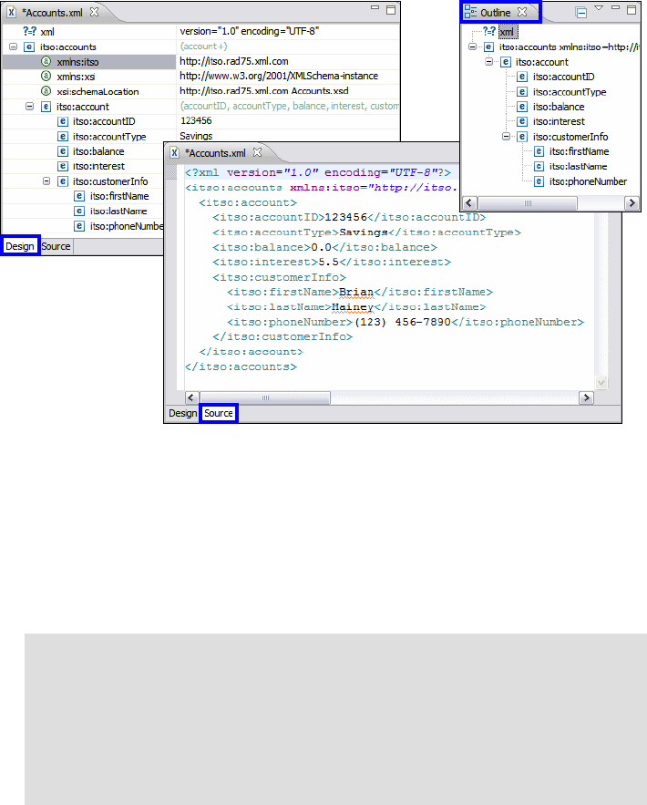
Chapter 10. Develop XML applications 201
Draft Document for Review December 9, 2008 2:44 pm 7672-base-4-xml.fm
previously when we created our XML schema. When editing an XML file
which is not a schema the Design view presents the document as a tree of
elements with attributes rather than the format we saw previously.
Outline view—You can insert and delete elements attributes, comments, and
processing instructions in this view.
Figure 10-8 Design view, Source view, and Outline view
Editing in the Source view
We continue to work on the XML file we generated in the last section:
In the Source view, place your cursor after the closing tag </itso:account>.
Press Ctrl+Space to activate code assist. A pop-up list of available choices,
which is based on the context, is displayed. Double-click <itso:account>.
Note: Content assist works because the document is associated with the
schema we created, and the editor can use the schema to determine what
is valid content for specific locations in the document. The start tag shows
how this is association is specified:
<itso:accounts xmlns:itso="http://itso.rad75.xml.com"
xmlns:xsi="http://www.w3.org/2001/XMLSchema-instance"
xsi:schemaLocation="http://itso.rad75.xml.com Accounts.xsd ">
7672-base-4-xml.fm Draft Document for Review December 9, 2008 2:44 pm
202 Rational Application Developer V7.5 Programming Guide
While the cursor is still between <itso:account> tags, press Ctrl+Space and
double-click <itso:accountID>.
Type a number for accountID between the start and end tags.
Repeat the same procedure to use the code assist feature to input the rest of
the information, such as accountType, balance, and so forth. Note that all
child tags are required.
After you finish typing, you can right-click in the XML source area and select
Format → Document.
Editing in the Design view
In the Design view, right-click itso:accounts and select Add Child →
account.
Expand the Account element you just created. All the child elements are
created with default values. You can now edit the values of the child elements.
In the Source view you have to add each child tag individually.
Editing in the Outline view
In the Outline view, right-click itso:accounts. You see a similar context menu
as in the Design view.
Save and close the file.
Working with XSL transformation files
An XSL transformation file is a style sheet that can be used to transform XML
documents into other document types and to format the output. In this section,
we create a simple XSL style sheet to format the XML file data into a table in an
HTML file.
Create a new XSL transformation file
To create a sample XSL transformation file, follow these steps:
Right-click the xml folder and select New → Other → XML → XSL, then click
Next.
In the File name field type Accounts.xsl and click Next.
In the Select XML file dialog, select the Accounts.xml file (expand
RAD75XMLBank/xml). This associates the Accounts.xml file with the
Accounts.xsl file.
Click Finish.
The generated XSL file is listed in Example 10-2.
Chapter 10. Develop XML applications 203
Draft Document for Review December 9, 2008 2:44 pm 7672-base-4-xml.fm
Example 10-2 Generated Accounts.xsl file
<?xml version="1.0" encoding="UTF-8"?>
<xsl:stylesheet xmlns:xsl="http://www.w3.org/1999/XSL/Transform"
version="1.0"
xmlns:xalan="http://xml.apache.org/xslt">
</xsl:stylesheet>
Creating the XSL transformation file
The XSL editor provides help with creating content in the style sheet through the
Snippets view. We use the Snippets view here to add an HTML header and an
table.
To add code snippets to the XSL file, do the following:
In the XSL editor position the cursor between the <xsl:stylesheet> tags,
right after xmlns:xalan="http://xml.apache.org/xslt">.
Select the Snippets view and select the XSL drawer (Figure 10-9).
Figure 10-9 Snippets view, XSL drawer
Double-click Default HTML header. This adds default HTML header
information to the XSL file.
Position the cursor after the end tag </xsl:template>.
In the XSL drawer double-click HTML table in XSL. The XSL Table Wizard
opens.
Note: If you cannot see the Snippets view, select Window → Show
View →Other → General → Snippets.
7672-base-4-xml.fm Draft Document for Review December 9, 2008 2:44 pm
204 Rational Application Developer V7.5 Programming Guide
If we did not associate the XSL file with an XML file, the first page of the
wizard allows us to do the association (Figure 10-10)
Figure 10-10 XSL Table Wizard, Select XML files
The next page of the wizard is where we add the table to the XSL file
(Figure 10-11):
–Select Wrap table in a template.
–Select Include header to indicate that you want to include a header row in
the table.
– Select and of the nodes on the left (for example, itso:account), and you
can see the generated code at the bottom.
– Click Next.
Tip: It is possible to view or change XML file associations at any time by
right-clicking the xsl file in Enterprise Explorer and selecting Properties.
Select Associations to view and edit the associations for the XSL file.
In our case this page
is skipped because
we already did the
association.
Chapter 10. Develop XML applications 205
Draft Document for Review December 9, 2008 2:44 pm 7672-base-4-xml.fm
Figure 10-11 XSL Table wizard, Add A Table To XSL file
The final wizard page allows properties for the table to be specified. Type 5 for
the Border field and 10 for the Cell spacing field. Select a background color
(light cyan), and a row color (white).
Click Finish, and the Accounts.xsl file is completed.
In the Source, make a few changes:
– Right-click and select Source → Format.
– Change the <title> to Accounts.
– Remove the itso: prefix from the values in the table header fields, for
example, <th>itso:AccountID</th>.
– Save and close the file.
Right-click Accounts.xsl and select Validate. You should not receive any
validation errors or warnings.
The generated Accounts.xsl file is listed in Example 10-3.

7672-base-4-xml.fm Draft Document for Review December 9, 2008 2:44 pm
206 Rational Application Developer V7.5 Programming Guide
Example 10-3 Accounts.xsl file
<?xml version="1.0" encoding="UTF-8"?>
<xsl:stylesheet xmlns:xsl="http://www.w3.org/1999/XSL/Transform"
version="1.0" xmlns:xalan="http://xml.apache.org/xslt"
xmlns:itso="http://itso.rad75.xml.com">
<xsl:output method="html" encoding="UTF-8" />
<xsl:template match="/">
<html>
<head>
<title>Accounts</title>
</head>
<body>
<xsl:apply-templates />
</body>
</html>
</xsl:template>
<xsl:template match="itso:accounts">
<table bgcolor="#80ffff" border="5" cellspacing="10">
<tr bgcolor="#ffffff">
<th>accountID</th>
<th>accountType</th>
<th>balance</th>
<th>interest</th>
<th>customerInfo</th>
</tr>
<xsl:for-each select="/itso:accounts/itso:account">
<tr bgcolor="#ffffff">
<td>
<xsl:value-of select="itso:accountID" />
</td>
<td>
<xsl:value-of select="itso:accountType" />
</td>
<td>
<xsl:value-of select="itso:balance" />
</td>
<td>
<xsl:value-of select="itso:interest" />
</td>
<td>
<xsl:value-of select="itso:customerInfo" />
</td>
</tr>
</xsl:for-each>
</table>
</xsl:template>
</xsl:stylesheet>
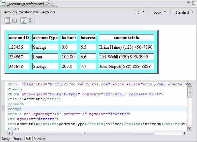
Chapter 10. Develop XML applications 207
Draft Document for Review December 9, 2008 2:44 pm 7672-base-4-xml.fm
Transforming an XML file into an HTML file
We can now use the XSL stylesheet file to generate an HTML file from the
sample XML file:
In the Enterprise Explorer, hold down the Ctrl key and select both the
Accounts.xml and Accounts.xsl files.
Right-click and select Run As → XSL Transformation.
The resulting file name is _Accounts_transform.html. The file is
automatically opened in the Page Designer.
Select the Split view (Figure 10-12).
Figure 10-12 XSL stylesheet transformation result
Notice the transformation messages in the Console view:
Processing:
XSL file name:
file:///E:\Workspaces\RAD75proguide\RAD75XMLBank\xml\Accounts.xsl.
XML input file name:
file:///E:\Workspaces\RAD75proguide\RAD75XMLBank\xml\Accounts.xml.
Result file name:
E:/Workspaces/RAD75proguide/RAD75XMLBank/xml/_Accounts_transform.html.
7672-base-4-xml.fm Draft Document for Review December 9, 2008 2:44 pm
208 Rational Application Developer V7.5 Programming Guide
XML mapping
The XML Mapping editor is a visual data mapping tool that is designed to
transform any combination of XML schema, DTD, or XML documents, and
produce a deployable transformation document. You can map XML-based
documents graphically by connecting elements from a source document to
elements from a target document. You can extend built-in transformation
functions using custom XPath expressions and XSLT templates. The mapping
tool automates XSL code generation and produces a transformation document
based on the mapping information you provide.
When mapping between a source XML file and target XML file many different
types of mapping transformation can be applied. The simplest is Move where the
values are simply transferred between source and target. Other mapping
transformations such as Concat perform more complex processing on the
values. The different types of mapping transformation that are available are
shown in Table 10-1.
Table 10-1 Available mapping transformations
Note: The Split view in the Page Designer is new to Rational Application
Developer 7.5. It is a combination of the Design view and the Source view
where both the Design and the Source can be viewed simultaneously. The
split between the two views can be either vertical or horizontal by clicking one
of the icons in the tool bar . Note that changing the source code
automatically changes the design.
Option Description
Move This type copies data from a source to a target.
Concat This type creates a string concatenation that allows you to retrieve data
from two or more entities to link them into a single result.
Inline map This type enables the map to call out to other maps, but other maps
cannot call it. It can only be used within the current map. If the inputs
and outputs are arrays, the inline map is implicitly iterated over the
inputs.
Submap This type references another map. It calls or invokes a map from this
or another map file. Choosing this transform type is most effective for
reuse purposes.
Chapter 10. Develop XML applications 209
Draft Document for Review December 9, 2008 2:44 pm 7672-base-4-xml.fm
In this section, we show an example involving the mapping of two XML schemas.
We use the mapping transformations Move, Concat, Inline map, Substring.
and Custom.
Preparation and import
To prepare for the XML mapping import the provided XSD files and XML file:
Accounts.xsd—This is the same file that we created previously and is the
source schema for the mapping.
AccountsList.xsd—This is an alternate representation of accounts and is our
target schema for the mapping.
Accounts.xml—This XML file contains sample data and is similar to the file
we created previously.
To import the files, do the following:
Create a new folder in the RAD75XMLBank project by right-clicking
RAD77XMLBank and selecting New → Folder. Type mapping as the folder
name and click Finish.
Right-click the mapping folder and select Import → General → File System
and click Next. Click Browse to navigate to the c:\7672code\xml folder. Click
OK. Select AccountList.xsd and click Finish.
Substring This type extracts information as required. For example, the substring
lastname, firstname with a "," delimiter and a substring index of 0
returns the value lastname. If the substring index was changed to 1
the output would now be firstname.
Group This type takes an array or collection of data and groups them into a
collection of a collection. Essentially, it is an array containing an array.
Grouping is done at the field level, meaning that it is done by selecting
a field of the input collection such as “department.”
Normalize This type normalizes the input string. For example, it can be used to
remove multiple occurrences of white space (such as space, tab, or
return).
Custom This type allows you to enter custom code or call reference code to be
used in the transform. You can extend built-in transformation functions
using custom XPath expressions and XSLT templates.
Assign Assign a constant value to an output element (right-click the output
element and select Create transform). Set the value in the Properties
view (use single quotes for strings).
Option Description
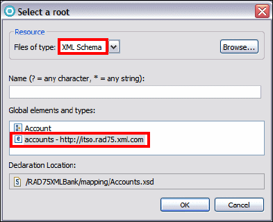
7672-base-4-xml.fm Draft Document for Review December 9, 2008 2:44 pm
210 Rational Application Developer V7.5 Programming Guide
Copy the Accounts.xml and Accounts.xsd files from the xml folder to the
mapping folder.
Launching the XML Mapping editor
The XML Mapping editor is used to create a mapping between the two XML
schemas:
To launch the XML Mapping editor, right-click the mapping folder and select
New → Other → XML → XML Mapping and click Next.
The parent folder is set to RAD75XMLBank/mapping.
In the File name field type Accounts.map, and click Next.
For Root inputs, click Add:
–Select XML schema from the Files of type drop-down list, and click
Browse. Expand RAD75XMLBank and select mapping → Accounts.xsd
and click OK.
– Select the accounts element from the Global elements and types list. Click
OK (Figure 10-13).
Figure 10-13 Selecting an input root for the mapping
For Root outputs, click Add, select the AccountsList.xsd file and the
accounts element (same as for the Root input).
Click Next.
To select a sample XML input file, click Add. Select Accounts.xml and click
OK (Figure 10-14).
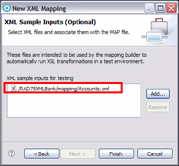
Chapter 10. Develop XML applications 211
Draft Document for Review December 9, 2008 2:44 pm 7672-base-4-xml.fm
Figure 10-14 XML sample input
Click Finish and the XML Mapping editor opens.
In the Enterprise Explorer, three new files are generated:
–Accounts.xsl: An XSL transformation file
–Accounts-out.xml: The transformation output XML file
–Accounts.map: The mapping file
Organizing the XML Mapping editor
Part of the beauty of this tool is that you can see the changes you making to the
resulting output xml file when you work on a mapping.
Before we start editing the mapping, we do the following:
Open Accounts-out.xml, then drag the editor panel down to the bottom part
of the mapping file (until a down arrow appears), so that it sits under
Accounts.map.
In the Workbench layout, the mapping file is at the top. The resulting xml file is
in the middle, and the Properties view is at the bottom (Figure 10-15).
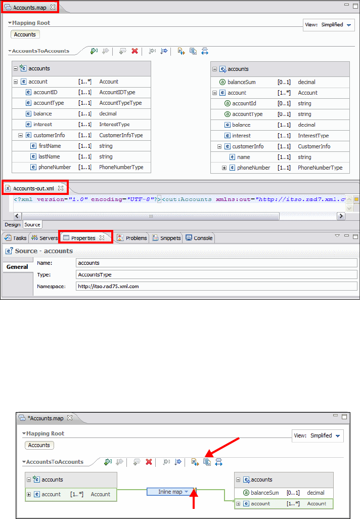
7672-base-4-xml.fm Draft Document for Review December 9, 2008 2:44 pm
212 Rational Application Developer V7.5 Programming Guide
Figure 10-15 Workbench layout for the XML Mapping editor
Editing the XML mapping
We now create the mapping between the two XML schemas:
In the XML Mapping editor, select the account element from Accounts.xsd on
the left hand side, and drag it to the account element from AccountList.xsd
on the right hand side (Figure 10-16).
Figure 10-16 Inline map
Generate XSLT script
Edit

Chapter 10. Develop XML applications 213
Draft Document for Review December 9, 2008 2:44 pm 7672-base-4-xml.fm
Click Generate XSLT script. See Figure 10-16 for help in finding this icon.
Check the Accounts-out.xml file and you will see that it has changed.
Inline mapping
Click Edit at the top right corner of the Inline map. See Figure 10-16 to find
the Edit icon.
In the Inline map details view, perform the following mapping transforms:
–Map the accountID, accountType, balance, and interest by dragging
the elements from the left to the corresponding elements on the right. Note
that we map the element accountID to the attribute accountId.
– Click Generate XSLT script and verify how the account information is
generated in the XML output.
–Map the customerInfo element from left to right. This creates an inline
map (Figure 10-17).
Figure 10-17 Account mapping
Click Generate XSLT script to see the change in the output XML file.
Concatenation mapping
The mapper allows us to define mappings where a set of input values are
concatenated to a single output value. Here we will concatenate firstName and
lastName in the source into one Name element in the target:
Click Edit at the top right corner of the customerInfo Inline map and add these
transformations:
– Select the firstName element and drag it to the name element on the right.
– Select the lastName element and drag it to the Move transform box
between the firstName and name. When you drag a second element to the
Note: Alternatively, you can simply save the mapping file and the changes are
automatically reflected in the resulting xml file.
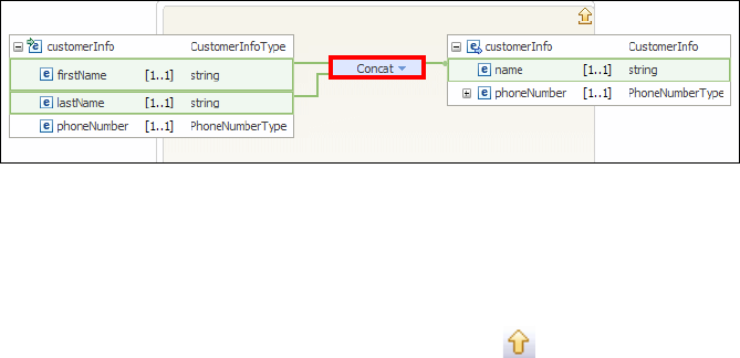
7672-base-4-xml.fm Draft Document for Review December 9, 2008 2:44 pm
214 Rational Application Developer V7.5 Programming Guide
transform type box, the transform type automatically changes to Concat
(Figure 10-18).
Figure 10-18 Concatenation mapping
We want to concatenate the name in the format lastName, firstName:
– Select the Concat transformation, and in the Properties view, select the
Order tab.
–Select lastName and click the Reorder Up icon .
– Select the General tab, select lastName, and put ‘, ’ in the Delimiter
column (with a space after the comma).
– Click Generate XSLT script icon. The changes are visible in
Accounts-out.xml file.
Substring mapping
The phone number is stored as a single data type in the source document and
we want to separate it into the sub-elements of area code and local number in
the target document.
The following steps perform the Substring mapping transformation :
– Select the phoneNumber element on the left and drag it to the areaCode
element on the right. You have to expand the phoneNumber element in the
target to see the areaCode element.
– Click the drop-down arrow in the transformation and select Substring
from the list.
– Right-click the transformation and select Show in Properties.
– In the Properties view, select the General tab. In the Delimiter field put a
space. Because the phone number format is (xxx) xxx-xxxx, the space
should be the delimiter between area code and local number.
– In the Substring index field, type 0.
– Select the phoneNumber element and drag it to the localNumber element.
– Change the transform type to Substring.
– In the Properties view, Delimiter field, type a space.
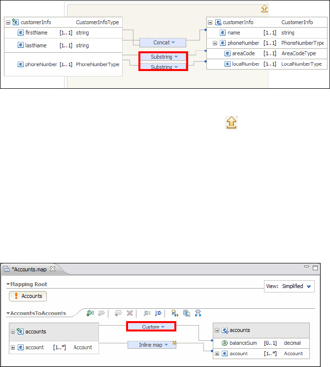
Chapter 10. Develop XML applications 215
Draft Document for Review December 9, 2008 2:44 pm 7672-base-4-xml.fm
– In the Substring index field, type 1. The current mapping is shown in
(Figure 10-19).
Figure 10-19 Substring mapping
To return to the main map, click the Up a level icon at the top right of the
inline map details page. Do it twice to return to the main map.
Calculation
We want to calculate the sum of the balance from all accounts and put it in the
balanceSum attribute of the output document. An XPath expression is used to
calculate this total.
Select the accounts element on the left and drag it to the balanceSum
attribute on the right.
Click the transform type box, and select Custom (Figure 10-20).
Figure 10-20 Custom mapping
Select the Custom mapping transformation. In the Properties view select the
General tab. Select XPath option for Code and type sum(./*/in:balance) as
the XPath expression (Figure 10-21).
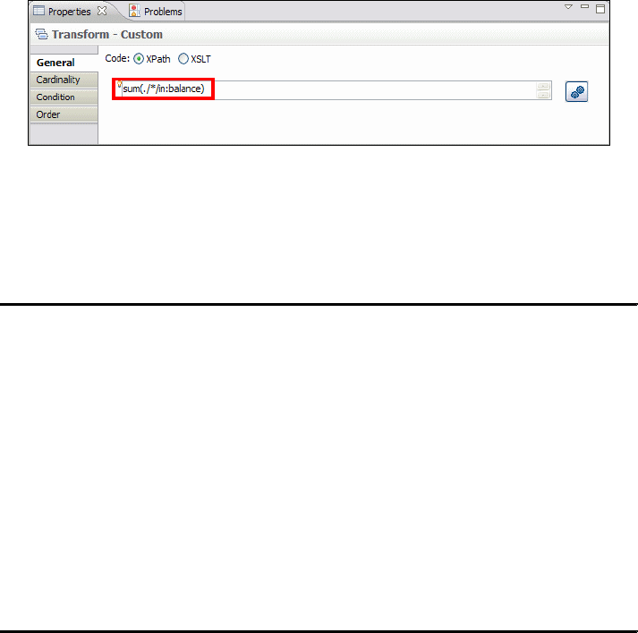
7672-base-4-xml.fm Draft Document for Review December 9, 2008 2:44 pm
216 Rational Application Developer V7.5 Programming Guide
Figure 10-21 Custom mapping using XPath
Save the mapping file and click Generate XSLT script to see the final output
XML file. Notice the balanceSum attribute of the accounts element, the
concatenated name, and the area code and local number (Example 10-4).
Example 10-4 Final output showing the balanceSum attribute
<?xml version="1.0" encoding="UTF-8"?>
<out:accounts xmlns:out="http://itso.rad75.xml.com"
xmlns:xsi="http://www.w3.org/2001/XMLSchema-instance" balanceSum="300">
<out:account accountId="123456" accountType="Savings">
<out:balance>0.0</out:balance>
<out:interest>5.5</out:interest>
<out:customerInfo>
<out:name>Hainey, Brian</out:name>
<out:phoneNumber>
<out:areaCode>(123)</out:areaCode>
<out:localNumber>456-7890</out:localNumber>
</out:phoneNumber>
</out:customerInfo>
</out:account>
......
<out:accounts>
Generating JavaBeans from an XML schema
To allow developers to quickly build an XML application, the XML schema editor
supports the generation of beans from an XML schema. Using these beans, you
can quickly create an instance document or load an instance document that
conforms to the XML schema.
To generate beans from an XML schema, do the following:
Create a Java project to contain the beans:
–Select File → New → Project → Java → Java Project and Click Next.
–Type RAD75XMLBankJava in the Project name field and click Finish.
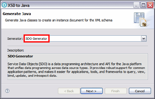
Chapter 10. Develop XML applications 217
Draft Document for Review December 9, 2008 2:44 pm 7672-base-4-xml.fm
– If you are prompted to switch to the Java perspective, click Yes.
Generate the JavaBeans:
– In the Enterprise Explorer, expand project RAD75XMLBank, right-click on
Accounts.xsd and select Generate → Java.
– When the Generate Java dialog is displayed (Figure 10-22), select the
SDO Generator and click Next.
Figure 10-22 XSD to Java Dialog
For the Container field, click Browse, select /RAD75XMLBankJava/src, and
click Finish.
Expand the RAD75XMLBankJava project and study the generated packages:
–com.xml.rad75.itso—interfaces
–com.xml.rad75.itso.impl—implementation classes
–com.xml.rad75.itso.util—utility classes
Use the generated JavaBeans
To test the generated beans, we create a test class named AccountsTest. This
class creates an instance of the Accounts object and serialize the instance into
XML format:
In the Enterprise Explorer, right-click RAD75XMLBankJava and select
New → Class.
Type com.xml.rad75.itso.sdo for the package name and AccountsTest for
the class name, and click Finish.
Complete the class with the sample code shown in Example 10-5. You can
find the AccountsTest.java file in the c:\7672code\xml folder.

7672-base-4-xml.fm Draft Document for Review December 9, 2008 2:44 pm
218 Rational Application Developer V7.5 Programming Guide
Study the main method first, then study the helper methods that are called
from the main method, marked in bold. The call to the save method on the
class ItsoResourceUtil serializes the SDO object tree and outputs the string
to the supplied file name or output stream class instance.
Example 10-5 AccountTest program
package com.xml.rad75.itso.sdo;
import java.math.BigDecimal;
import com.xml.rad75.itso.*;
import com.xml.rad75.itso.util.ItsoResourceUtil;
public class AccountsTest {
private DocumentRoot createDocumentRoot() {
DocumentRoot documentRoot = ItsoFactory.eINSTANCE.createDocumentRoot();
return documentRoot;
}
private AccountsType createAccountsType() {
AccountsType accountsType = ItsoFactory.eINSTANCE.createAccountsType();
return accountsType;
}
private Account createAccount(AccountTypeType accountType,
String accountId, BigDecimal balance, BigDecimal interest,
CustomerInfoType customerInfo) {
Account account = ItsoFactory.eINSTANCE.createAccount();
account.setAccountType(accountType);
account.setAccountID(accountId);
account.setBalance(balance);
account.setInterest(interest);
account.setCustomerInfo(customerInfo);
return account;
}
private CustomerInfoType createCustomerInfo(String firstName,
String lastName, String phoneNumber) {
CustomerInfoType customerInfo =
ItsoFactory.eINSTANCE.createCustomerInfoType();
customerInfo.setFirstName(firstName);
customerInfo.setLastName(lastName);
customerInfo.setPhoneNumber(phoneNumber);
return customerInfo;
}
public static void main(String args[]) throws Exception {
AccountsTest sample = new AccountsTest();
DocumentRoot documentRoot = sample.createDocumentRoot();

Chapter 10. Develop XML applications 219
Draft Document for Review December 9, 2008 2:44 pm 7672-base-4-xml.fm
AccountsType accountsType = sample.createAccountsType();
CustomerInfoType customerInfo;
customerInfo = sample.createCustomerInfo("Brian", "Hainey",
"(123) 456-7891");
Account account = sample.createAccount(AccountTypeType.SAVINGS_LITERAL,
"123456", new BigDecimal(20000.00),
new BigDecimal(3.5), customerInfo);
accountsType.getAccount().add(account);
customerInfo = sample.createCustomerInfo("Ueli", "Wahli",
"(408) 345-6780");
account = sample.createAccount(AccountTypeType.FIXED_LITERAL, "123457",
new BigDecimal(50000.00), new BigDecimal(6.0), customerInfo);
accountsType.getAccount().add(account);
customerInfo = sample.createCustomerInfo("Juan", "Napoli",
"(408) 345-6789");
account = sample.createAccount(AccountTypeType.LOAN_LITERAL, "123458",
new BigDecimal(60000.00), new BigDecimal(8.0), customerInfo);
accountsType.getAccount().add(account);
documentRoot.setAccounts(accountsType);
ItsoResourceUtil.getInstance().save(documentRoot, System.out);
ItsoResourceUtil.getInstance().save(documentRoot, "accounts.xml");
}
}
Run the sample
To execute the Java application, do the following:
Right-click on AccountTest.java and select Run As → Java Application.
The XML result is displayed in the Console view and stored in a file called
accounts.xml.
In the Package Explorer, right-click the RAD75XMLBankJava project and
select Refresh. The generated accounts.xml file is shown in Example 10-6.
Example 10-6 Generated accounts.xml file
<?xml version="1.0" encoding="UTF-8"?>
<itso:accounts xmlns:itso="http://itso.rad75.xml.com">
<itso:account>
<itso:accountID>123456</itso:accountID>
<itso:accountType>Savings</itso:accountType>
<itso:balance>20000</itso:balance>
<itso:interest>3.5</itso:interest>

7672-base-4-xml.fm Draft Document for Review December 9, 2008 2:44 pm
220 Rational Application Developer V7.5 Programming Guide
<itso:customerInfo>
<itso:firstName>Brian</itso:firstName>
<itso:lastName>Hainey</itso:lastName>
<itso:phoneNumber>(123) 456-7891</itso:phoneNumber>
</itso:customerInfo>
</itso:account>
<itso:account>
......
</itso:accounts>
Service Data Objects and XML
Service Data Objects (SDO) is a framework for data application development,
which includes an architecture and API. SDO simplifies the Java EE
programming model and abstracts data in a Service Oriented Architecture
(SOA). SDO unifies data application development and supports data held in XML
documents, incorporates Java EE patterns and best practices and provides
uniform access to a variety of data sources.
The core concepts in the SDO architecture are the data object and the data
graph:
A data object holds a set of named properties, each of which is either of
primitive Java type such as int or char or a reference to another data object.
The data object API provides functionality for the manipulation of these
properties.
A data graph provides an envelope for data objects, and is the normal unit of
transport of objects between components. Data graphs are also responsible
for tracking the changes made to the graph of data objects, including inserts,
deletes, and the modification of data object properties.
Data graphs are typically constructed from data sources, such as XML files,
EJBs, XML databases, relational databases, or from services, such as Web
services, JCA Resource Adapters and JMS messages. Components that
populate data graphs from data sources and commit changes to data graphs
back to the data source are called Data Mediator Services (DMS). The DMS
architecture and associated APIs are outside the scope of the SDO specification.
In this section, we describe how to use SDO to access XML documents.
Loading an SDO data graph from XML
In this example we load the accounts.xml file into a data graph and display the
content of the data graph on the console. To do this complete the following steps:
Create a new Java class:

Chapter 10. Develop XML applications 221
Draft Document for Review December 9, 2008 2:44 pm 7672-base-4-xml.fm
– In the Enterprise Explorer, right-click the com.xml.rad75.itso.sdo
package in and select New → Class.
–Type SDOSample as the class name., and select public static void
main(String[] args] so that a main method is generated.
– Click Finish.
In the Enterprise Explorer, right-click RAD75XMLBankJava and select
Properties. In the Properties dialog:
–Select Java Build Path → Libraries.
– Click Add External JARs, and add the
org.eclipse.emf.ecore.change_2.4.0.v200806091234.jar, which is
located in the installation folder <SDP7xShared>/plugins.
– Click OK to add the new Jar to the project.
Add the sample code to the main method including throws IOException
(Example 10-7).
Example 10-7 Code to load an XML document
public static void main(String[] args) throws IOException {
System.out.println("\n--- Printing XML document to System.out ---");
DocumentRoot documentRoot =
ItsoResourceUtil.getInstance().load("Accounts.xml");
ItsoResourceUtil.getInstance().save(documentRoot, System.out);
System.out.println("\n\n--- Done ---");
}
Select Source → Organize Imports to add import statements.
Right-click SDOSample and select Run As → Java Application. The
accounts.xml file is displayed in the Console.
Navigating the SDO data graph
XPath expressions are used to obtain data from the data objects present in the
data graph after the XML file is loaded.
Figure 10-23 shows the data graph for the accounts.xml file.
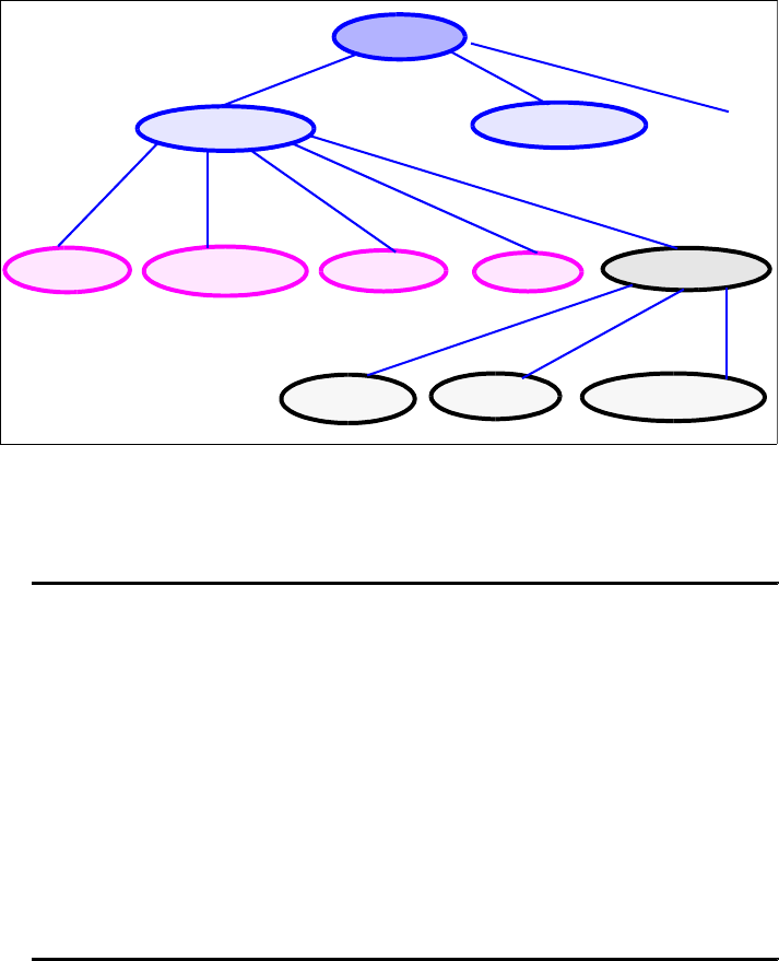
7672-base-4-xml.fm Draft Document for Review December 9, 2008 2:44 pm
222 Rational Application Developer V7.5 Programming Guide
Figure 10-23 Accounts data graph
Add the code shown in Example 10-8 to the main method.
Example 10-8 Java code for navigating the SDO data graph
// navigating the SDO data graph
AccountsType accountsType = documentRoot.getAccounts();
DataObject accountsTypeImpl = (AccountsTypeImpl) accountsType;
DataObject account1 = accountsTypeImpl.getDataObject("account.0");
System.out.println("\n\nThe first account is: " + account1 + "\n");
DataObject account2 = accountsTypeImpl.getDataObject
("account[accountID = '123457']");
System.out.println("The second account is: " + account2 + "\n");
DataObject account2CustomerInfo = accountsTypeImpl.getDataObject
("account[accountID = '123457']/customerInfo");
System.out.println("The second account customer information is: " +
account2CustomerInfo + "\n");
String account1CustomerName = account1.getString("customerInfo/firstName");
System.out.println("The first account customer first name is " +
account1CustomerName + "\n");
– The XPath dot notation is used to index data objects. The first object has
index 0, therefore account.0 returns the first account data object.
– The XPath expression account[accountID = '123457'] returns the
account data object whose account ID equals 123457.
–account[accountID = '123457']/customerInfo is an XPath expression
that returns a data object multiple levels below the root data object.
accounts
account.0 account.1
accountID accountType balance interest customerInfo
firstName lastName phoneNumber
...

Chapter 10. Develop XML applications 223
Draft Document for Review December 9, 2008 2:44 pm 7672-base-4-xml.fm
Right-click SDOSample and select Run As → Java Application. You can
also select Run → Run History → SDOSample.
The Console output from the SDO graph navigation code is shown here:
The first account is: com.xml.rad75.itso.impl.AccountImpl@d8d0d8d
(accountID: 123456, accountType: Savings, balance: 20000, interest: 3.5)
The second account is: com.xml.rad75.itso.impl.AccountImpl@64d764d7
(accountID: 123457, accountType: Fixed, balance: 50000, interest: 6)
The second account customer information is:
com.xml.rad75.itso.impl.CustomerInfoTypeImpl@65506550 (firstName: Ueli,
lastName: Wahli, phoneNumber: (408) 345-6780)
The first account customer first name is Brian
Updating the SDO data graph
An SDO data graph can be modified and the modifications reflected in the source
XML file which was loaded. In this example we update the interest rate of one
account, add an account, and finally delete an existing account (Example 10-9).
Example 10-9 Updating an SDO data graph
// updating the SDO data graph
account1.setString("interest", "10");
DataObject account3 = accountsTypeImpl.createDataObject("account");
account3.setString("accountID", "333333");
account3.set("accountType", AccountTypeType.LOAN_LITERAL);
account3.setString("balance", "999999");
account3.setString("interest", "2.5");
DataObject newCustomerInfo = account3.createDataObject("customerInfo");
newCustomerInfo.setString("firstName", "Mike");
newCustomerInfo.setString("lastName", "Smith");
newCustomerInfo.setString("phoneNumber", "(201) 654-8754");
account2.delete();
System.out.println("\n--- Printing updated XML document ---");
ItsoResourceUtil.getInstance().save(documentRoot, System.out);
The complete code listing of SDOSample.java can be found in the
c:\7672code\xml folder.
Select Run → Run History → SDOSample.
You can see that the interest rate for the first account (accountID = '123456')
has been updated, the second account (accountID = '123457') has been
removed, and a new account (accountId = '333333') has been added.
Note that the accounts.xml file is not updated because we only saved to the
Console.
7672-base-4-xml.fm Draft Document for Review December 9, 2008 2:44 pm
224 Rational Application Developer V7.5 Programming Guide
More information
For more information on XML schemas, refer to:
http://www.w3.org/XML/Schema
For more information on XML, refer to:
http://www.w3.org/XML/
For more information on XML parsers, refer to:
Xerces (XML parser - Apache):
http://xml.apache.org/xerces2-j
Xalan (XSLT processor - Apache):
http://xml.apache.org/xalan-j
JAXP (XML parser - Sun):
http://java.sun.com/xml/jaxp
SAX2 (XML API):
http://sax.sourceforge.net
For more information on SDO, refer to:
http://www-128.ibm.com/developerworks/java/library/j-sdo/
http://www.osoa.org/display/Main/SDO+Resources

© Copyright IBM Corp. 2008. All rights reserved. 225
Draft Document for Review December 9, 2008 2:44 pm 7672-pers-0-p4.fm
Part 4 Persistence
application
development
In this part of the book, we describe the tooling and technologies provided by
Application Developer to develop applications using databases and the Java
Persistence API (JPA).
Part 4
Note: The sample code for all the applications developed in this part is
available for download at:
ftp://www.redbooks.ibm.com/redbooks/SG247672
Refer to Appendix B, “Additional material” on page 1149 for instructions.
7672-pers-0-p4.fm Draft Document for Review December 9, 2008 2:44 pm
226 Rational Application Developer V7.5 Programming Guide

© Copyright IBM Corp. 2007. All rights reserved. 227
Draft Document for Review December 9, 2008 2:44 pm 7672-pers-1-database.fm
Chapter 11. Develop database
applications
In an enterprise environment, applications that use databases are very common.
In this chapter we explore technologies that are used in developing Java
database applications. Our focus is on highlighting the database tooling provided
with IBM Rational Application Developer v7.5.
This chapter is organized into the following sections:
Introduction
Connecting to the ITSOBANK database
Connecting to databases
Creating SQL statements
Developing a Java stored procedure
Developing SQLJ applications
Data modeling
11
7672-pers-1-database.fm Draft Document for Review December 9, 2008 2:44 pm
228 Rational Application Developer V7 Programming Guide
Introduction
Rational Application Developer provides rich features to make it easier to work
with tables, views, and filters; create and work with SQL statements; create and
work with database routines (such as stored procedures and user-defined
functions), and create and work with SQLJ files. You can also create, modify, and
generate data models. Depending on your goals, you might have to take certain
steps to set up your work environment.
Depending on your goals, this chapter is written for three types of users:
If you want to access databases and discover information about them, you
can use the database explorer to create a connection to those databases.
After you have set up connection information for a database, you can connect,
refresh a connection, and browse the objects that are contained in the
database.
If you want to develop database related activities such as SQL queries and
stored procedures, you have to create a data development project. The data
development project stores your routines and other data development objects.
Application developer also provides tooling to assist you to develop SQLJ
applications, and offers a DB beans package to access database information
without directly using the JDBC interface.
If you want to design your database model, you have to create a data design
project to store your objects. The modeling tool assists you to build a data
model, analyze the model, perform the impact analysis, and so forth.
All examples in this chapter are demonstrated against the open source
embedded Derby database server. The embedded version of Derby is bundled
inside Rational Application Developer, so its availability is guaranteed. These
examples can be easily applied to DB2 databases.
Connecting to the ITSOBANK database
We provide two implementations of the ITSOBANK database, Derby and DB2.
Follow the instructions in “Setting up the ITSOBANK database” on page 1154 to
set up the database.
The ITSOBANK database has four tables: CUSTOMER, ACCOUNT, ACCOUNT_CUSTOMER,
and TRANSACT. Note that the name TRANSACTION is reserved in the Derby
database, therefore we used TRANSACT.
Chapter 11. Develop database applications 229
Draft Document for Review December 9, 2008 2:44 pm 7672-pers-1-database.fm
An account can have multiple transactions and the ACCOUNT_ID becomes the
foreign key in the TRANSACT table and is related to the primary key of the ACCOUNT
table.
There is a many-to-many association between customers and accounts.
ACCOUNT_CUSTOMER is the junction table to turn this many-to-many relationship into
a one-to-many relationship between CUSTOMER and ACCOUNT_CUSTOMER and a
one-to-many relationship between ACCOUNT and ACCOUNT_CUSTOMER.
Connecting to databases
Application Developer enables you to create a connection to the following
databases:
Cloudscape
DB2 for Linux, UNIX, and Windows
DB2 i5/OS
DB2 for z/OS
Derby
HSQLDB
Informix
MaxDB
MySQL
Oracle
SQL Server
Sybase
Generic JDBC
Creating a connection to the ITSOBANK database
To connect to the Derby ITSOBANK database using the New Database Connection
wizard, do these steps:
Stop the WebSphere Application Server v7 if it is running and has accessed
the ITSOBANK database for other chapters, as Derby only allows one
connection.
Open the Data perspective by selecting Window → Open Perspective →
Other. In the Open Perspective dialog, select Data and click OK. The Data
perspective opens.
Locate the Data Source Explorer view, typically at the bottom left in the Data
perspective.
In the Data Source Explorer, right-click Databases and select New.
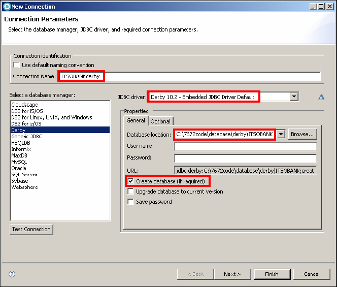
7672-pers-1-database.fm Draft Document for Review December 9, 2008 2:44 pm
230 Rational Application Developer V7 Programming Guide
In the New Connection wizard, do these steps (Figure 11-1):
– Clear Use default naming convention and type ITSOBANKderby as
Connection Name.
– For Select a database manager select Derby.
– For JDBC driver select Derby 10.2 - Embedded JDBC Driver Default.
– For Database location click Browse and locate
C:\7672code\database\derby\ITSOBANK.
– Leave the User name and Password fields empty, as derby database does
not require authentication.
–Select Create database (if required).
– Click Test Connection, and a pop-up displays Connection succeeded.
Click OK to close the pop-up.
– Click Next.
Figure 11-1 New Connection: Connection Parameters
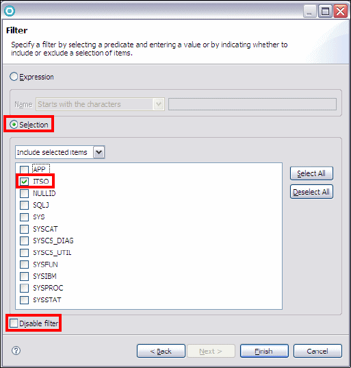
Chapter 11. Develop database applications 231
Draft Document for Review December 9, 2008 2:44 pm 7672-pers-1-database.fm
You can use filters to exclude data objects (such as tables, schemas, stored
procedures, and user-defined functions) from the view. Only the data objects
that match the filter condition are shown. We only want to see the objects in
schema ITSO (Figure 11-2):
– Clear Disable filter.
–Select Selection.
–Select Include selected items.
– From the schema list, select ITSO.
– Click Finish.
Figure 11-2 New Connection: Filter
The connection is displayed in the Data Source Explorer. Expand
ITSOBANKderby [Derby 10.3.1.4 ...] → ITSOBANK. The Schemas folder is
marked as [Filtered]. There is only one schema (ITSO) listed, the others are
filtered (Figure 11-3).
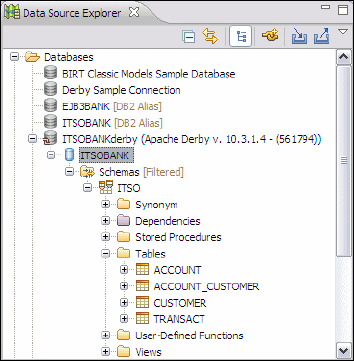
7672-pers-1-database.fm Draft Document for Review December 9, 2008 2:44 pm
232 Rational Application Developer V7 Programming Guide
Figure 11-3 Connection with schema and tables in Data Source Explorer
The filter framework allows you to filter out the tables at a more granular level.
Suppose we only want to see tables that start with the letter A. Expand the
schema ITSO, right-click Tables and select Filter. In the Filter dialog, do
these steps:
– Clear Disable filter.
–Select Expression.
– In the Name section, select Starts with the characters and enter A.
– Click OK.
Now you can only see two tables in the Database Explorer: ACCOUNT and
ACCOUNT_CUSTOMER.
We have to use the four tables in later sections. To disable the filter, right-click
Tables [Filtered] and select Filters, select Disable filter and click OK.
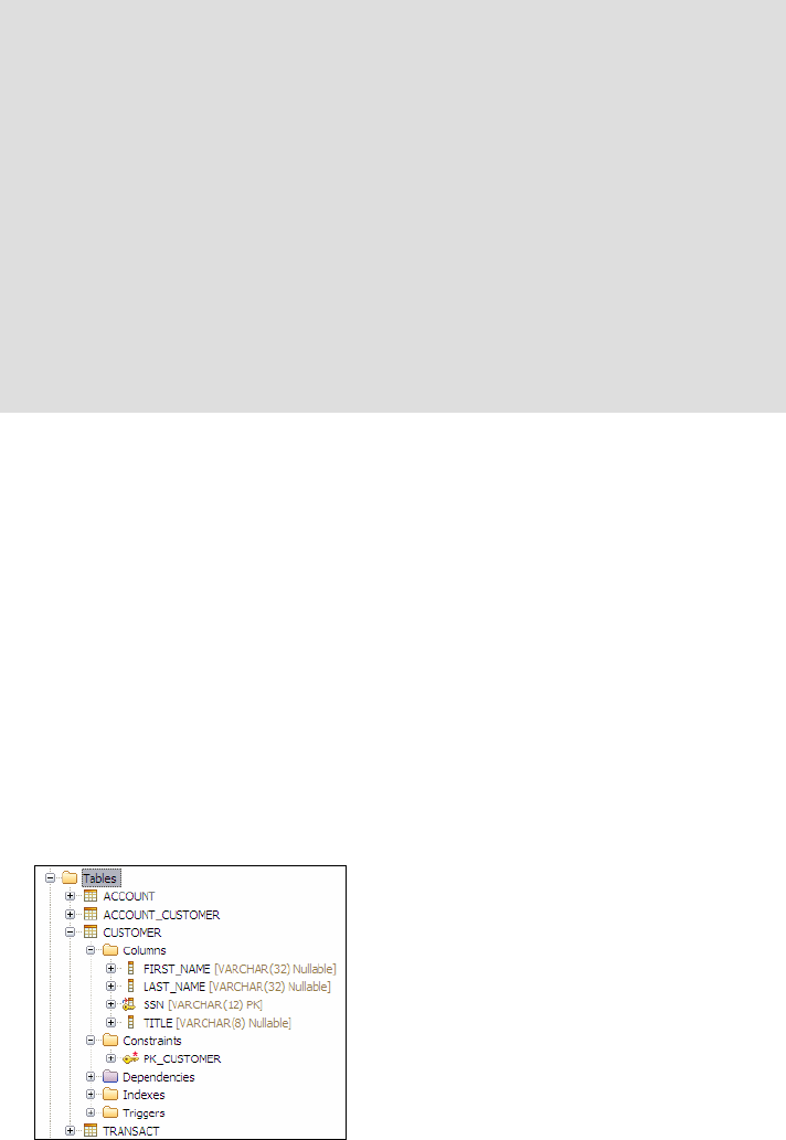
Chapter 11. Develop database applications 233
Draft Document for Review December 9, 2008 2:44 pm 7672-pers-1-database.fm
Browsing a database with the Data Source Explorer
The Data Source Explorer view operates much like any similar, graphical
directory browsing program. It provides a list of configured connection profiles.
Here you can create and manage database connections, browse data objects in
a connection, modify data objects and more.
Exploring the Derby database ITSOBANK:
Expand ITSOBANKderby (...) → ITSOBANK → Schemas → ITSO →
Tables → CUSTOMER (Figure 11-4).
– Expand Columns. All the columns in table CUSTOMER are listed. SSN is
marked as primary key.
– Expand Constraints. PK_CUSTOMER is listed as the primary key constraint.
Figure 11-4 Customer table with columns
Note: You may see the following error in the Problems view:
Problem with driver "Cloudscape - Cloudscape Embedded JDBC Driver
Default." (Error: Unable to locate JAR/zip in file system as specified by the
driver definition: db2j.jar.)
This file is not shipped with Application Developer. You can remove the driver
in the Preferences dialog:
Select Window → Preferences.
Select Data Management → Connectivity → Driver Definitions on the
left.
Select Cloudscape - Cloudscape Embedded JDBC Driver Default and
click Remove.
Click OK.
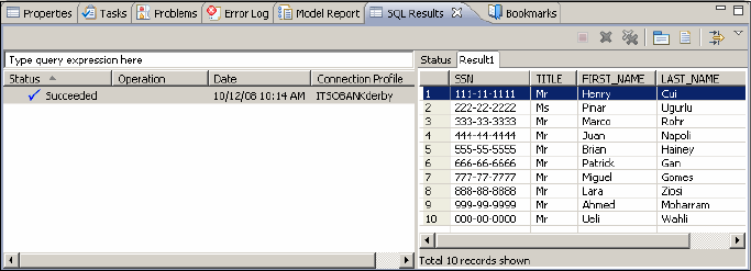
7672-pers-1-database.fm Draft Document for Review December 9, 2008 2:44 pm
234 Rational Application Developer V7 Programming Guide
In the Data Source Explorer view, right-click the Customer table and select
Data → Sample Contents. The action opens the SQL Results view, and the
running result is Succeeded. Highlight the Succeeded run and then select
the Results1 tab to see the list of customers (Figure 11-5).
Figure 11-5 Sample contents of Customer table
Edit, extract, and load
The context menu produced by a right-click on the Customer table has many
more options, such as:
Data → Edit allows you to directly affect the contents of the target table in a
spreadsheet like interface.
Data → Extract allows you to extract data into a file using a delimiter
(comma, semicolon, space, tab, vertical bar):
"111-11-1111","Mr","Henry","Cui"
"222-22-2222","Ms","Pinar","Ugurlu"
......
Data → Load allows you to load data from a file, such as produced by extract.
Data → Extract as XML allows you to generate an XML file from the
database table:
<?xml version="1.0" encoding="UTF-8"?>
<SQLResult>
<CUSTOMER>
<SSN>111-11-1111</SSN>
<TITLE>Mr</TITLE>
<FIRSTNAME>Henry</FIRSTNAME>
<LASTNAME>Cui</LASTNAME>
</CUSTOMER>
......
</SQLResult>
Data → Load from XML allows you to update a database table from an XML
file, such as produced by Extract as XML.
Chapter 11. Develop database applications 235
Draft Document for Review December 9, 2008 2:44 pm 7672-pers-1-database.fm
Creating SQL statements
You can create an SQL statement by using the SQL builder or the SQL editor in
the Data perspective.
The SQL editor supports any statements that can be run by the database to
which you are connected. You can create single or multiple SQL statements,
single or multiple XQuery statements, XQuery statements that are nested in SQL
statements, and SQL statements that are nested in XQuery statements. The
SQL editor provides features such as multiple statement support, syntax
highlighting, content assist, query parsing and validation etc.
The SQL builder provides a graphical interface for creating and running SQL
statements. Statements that are generated by the SQL builder are saved in a file
with the extension .sql. The SQL builder supports creating SELECT, INSERT,
UPDATE, DELETE, FULLSELECT, and WITH (DB2 only) statements.
In this section, we create and run an SQL query to retrieve a customer name
based on the social security number, and the total amount of money involved in
each transaction type (credit, debit). The SQL select statement includes table
aliases, table joins, a query condition, a column alias, a sort type, a database
function expression and a grouping clause.
Creating a data development project
Before you create routines or other database development objects, you must
create a data development project to store your objects. A data development
project is linked to one database connection in the Database Explorer.
A data development project is used to store routines and queries. You can store
and develop the following types of objects in a database development project:
SQL scripts
DB2 and Derby stored procedures
DB2 user-defined functions
You can also test, debug, export, and deploy these objects from a data
development project. The wizards that are available in a data development
project use the connection information that is specified for the project to help you
develop objects that are targeted for that specific database.
To create a data development project:
In the Data perspective, Data Project Explorer, select File → New → Data
Development Project (alternatively right-click in the Data Project Explorer
and select New → Data Development Project). Click Next.
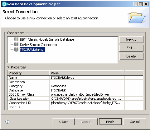
7672-pers-1-database.fm Draft Document for Review December 9, 2008 2:44 pm
236 Rational Application Developer V7 Programming Guide
In the New Data Development Project page of the wizard, type
RAD75DataDevelopment for the project name. Clear Omit current schema
in generated SQL Statements. Click Next.
In the Select Connection page, select ITSOBANKderby from the connections
list (Figure 11-6).
Figure 11-6 Data Development Project: Select Connection
Click Finish. The data development project is displayed in the Data Project
Explorer view.
Populating the transactions table
Before we build the SQL query, we want to populate the TRANSACT table with more
data (only one customer has transactions already). To load the records into this
table, do these steps:
In the Data Project Explorer right-click the project RAD7DataDevelopment
and select Import → General → File System, and click Next.
Click Browse and locate the C:\7672code\database\samples directory. Select
LoadTransaction.sql and click Finish.
The LoadTransaction.sql appears in the SQL Scripts folder. Right-click
LoadTransaction.sql and select Run SQL from the context menu.
The results are displayed in the SQL Results view. For the INSERT SQL
statements, the status should be Succeeded.
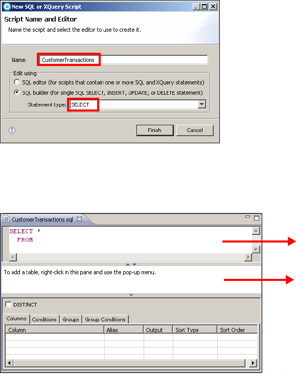
Chapter 11. Develop database applications 237
Draft Document for Review December 9, 2008 2:44 pm 7672-pers-1-database.fm
Creating a select statement
We want to retrieve a customer name and the total amount of money involved in
each transaction type (credit, debit).
To create the select statement:
In the Data Project Explorer view right-click the SQL Scripts folder in the
RAD75DataDevelopment project and select New → SQL or XQuery Script.
In the Script Name and Editor page, enter CustomerTransactions as the
name. Select SQL Builder as the editing tool and SELECT as the statement
type (Figure 11-7).
Figure 11-7 New SQL and Editor page
Click Finish and the SELECT statement template is created and opens in the
SQL builder (Figure 11-8).
Figure 11-8 SQL Builder
SQL
Source
Tables
7672-pers-1-database.fm Draft Document for Review December 9, 2008 2:44 pm
238 Rational Application Developer V7 Programming Guide
Using the SQL Builder
The SQL Builder has three main sections:
SQL source pane—The SQL Source pane contains the source code of the
SQL statement. You can type the SQL statement in this pane, or use the
features that are provided by the SQL builder to build the statement. Content
assist is available as you type and through the pop-up menu in the SQL
Source pane. This pane also provides content tips through the pop-up menu.
A content tip shows a simple example for the type of statement that you are
creating.
Tables pane—The Tables pane provides a graphical representation of the
table references that are used in the statement. In this pane, you can add or
remove a table, give a table an alias, and select or exclude columns from the
table. When you build a SELECT statement, you can also define joins
between tables in this pane.
Design pane—The options in the Design pane vary, depending on the type of
statement that you are creating. When more than one set of options is
available, the options appear as notebook pages. For example, for a SELECT
statement, some of the options include selecting columns, creating
conditions, creating groups, and creating group conditions.
Adding tables to the statement
We add four tables to the SELECT statement for the CustomerTransactions
query, because this query traverses from CUSTOMER through to ACCOUNT and
TRANSACT. We also create an alias for each of the tables in the SELECT
statement. An alias is an indirect method of referencing a table so that an SQL
statement can be independent of the qualified name of that table. If the table
name changes, only the alias definition must be changed.
The aliases for the ACCOUNT, CUSTOMER, TRANSACT, and ACCOUNT_CUSTOMER will be A,
C, T, and AC, respectively.
To add tables to the statement:
In the Data Source Explorer expand ITSOBANKderby → ITSOBANK →
Schemas → ITSO → Tables. You can see the four tables.
Right-click in the Tables pane, and then click Add Table on the pop-up menu.
In the Table name list, expand the ITSO schema and select CUSTOMER.
Enter C as the table alias, and then click OK (Figure 11-9). The CUSTOMER
table is shown in the Tables pane, and the source code in the SQL Source
pane shows the addition of the CUSTOMER table in the SELECT statement.
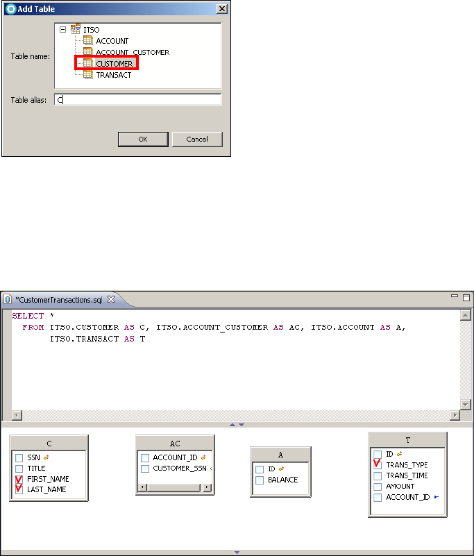
Chapter 11. Develop database applications 239
Draft Document for Review December 9, 2008 2:44 pm 7672-pers-1-database.fm
Figure 11-9 Add table
Follow the same procedure to add the ACCOUNT_CUSTOMER (alias AC), ACCOUNT
(alias A), and TRANSACT (alias T) tables to the Tables pane in the SQL builder.
Select a table and drag the sides to adjust the size of the displayed rectangle
(Figure 11-10).
Figure 11-10 Create select statement: Tables
Selecting columns for the result set
We add the following columns to the result set by selecting the columns in the
tables pane:
Select FIRSTNAME and LASTNAME columns in the C (CUSTOMER) table.
Select TRANS_TYPE column in the T (TRANSACT) table.
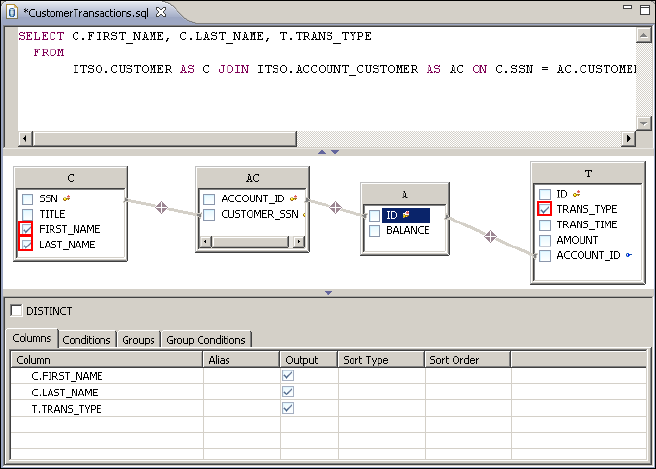
7672-pers-1-database.fm Draft Document for Review December 9, 2008 2:44 pm
240 Rational Application Developer V7 Programming Guide
Joining tables
A join operation lets you retrieve data from two or more tables based on matching
column values. Three joins are needed for this query:
Drag the cursor from column SSN column in the C (CUSTOMER) table to column
CUSTOMERS_SSN in AC (ACCOUNT_CUSTOMER) table.
Drag the cursor from ACCOUNT_ID in the AC (ACCOUNT_CUSTOMER) table to ID
in the A (ACCOUNT) table.
Drag the cursor from ID in the A (ACCOUNT) table to ACCOUNT_ID in the T
(TRANSACT) table.
Relationship lines are drawn between the selected columns (Figure 11-11).
Figure 11-11 Create select statement: Columns and table joins
Add a function expression to the result set
The fourth column for the query result set will be the result of a column
expression. We add together the total amount of each transaction type. This can
be calculated using the expression builder wizard:
In the Columns tab of the Design pane, click into the fourth cell in the Column
column (the first empty cell), select Build Expression from the drop-down
list, and press Enter.
The Expression Builder wizard opens (Figure 11-12).
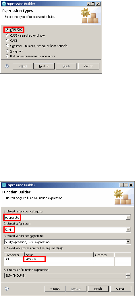
Chapter 11. Develop database applications 241
Draft Document for Review December 9, 2008 2:44 pm 7672-pers-1-database.fm
Figure 11-12 Create select statement: Expression Builder (1)
Select Function and click Next.
In the Function Builder page, select the following options (Figure 11-13):
– For Select a function category, select Aggregate.
– For Select a function, select SUM.
– For Select a function signature, select SUM(expression) → expression.
– In the Value column of the argument table, click the cell, and select
T.AMOUNT in the drop-down list.
– The preview of the function expression shows as SUM(AMOUNT).
– Click Finish.
Figure 11-13 Create select statement: Expression Builder (2)

7672-pers-1-database.fm Draft Document for Review December 9, 2008 2:44 pm
242 Rational Application Developer V7 Programming Guide
Adding a column alias and sort type
We add a column alias for the function column expression and sort the results:
Click the Columns tab in the Design pane.
Click the cell in the Alias column next to the SUM(T.AMOUNT) column
expression, type TotalAmount, and press Enter.
Click the cell in the Sort Type column next to the TotalAmount alias, select
Ascending, and press Enter.
The Columns page is seen in Figure 11-14.
Figure 11-14 Create select statement: Columns
Creating a query condition
The query needs a query condition so that the query extracts only result rows
with a given customer social security number. We add conditions to the query by
using the Conditions page in the Design pane.
To create a query condition:
In the Design pane, select the Conditions tab.
In the first row, click the cell in the Column column and select
C.LAST_NAME in the list.
In the same row, click the cell in the Operator column, and select the LIKE
operator.
In that row, click the cell in the Value column, and enter %u%.
A colon followed by a variable name is the SQL syntax for a host variable that
will be substituted with a value when you run the query.
The Conditions page is shown in Figure 11-15.
Figure 11-15 Create select statement: Conditions
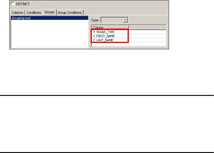
Chapter 11. Develop database applications 243
Draft Document for Review December 9, 2008 2:44 pm 7672-pers-1-database.fm
Adding a GROUP BY clause
We group the query by the transaction type so that we have one sum of the
amount for each type of transaction (credit, debit):
In the Design pane, select the Groups tab.
In the Column table, click the first row, select T.TRANS_TYPE in the list, and
then press Enter.
Repeat this for C.FIRST_NAME and C.LAST_NAME.
The Groups page is shown in Figure 11-16.
Figure 11-16 Create select statement: Groups
The query is now complete. Save the select statement. The SQL statement is
listed in Example 11-1.
Example 11-1 CustomerTransactions.sql
SELECT C.FIRST_NAME, C.LAST_NAME, T.TRANS_TYPE, SUM(T.AMOUNT) AS "TotalAmount"
FROM
ITSO.CUSTOMER AS C JOIN ITSO.ACCOUNT_CUSTOMER AS AC ON C.SSN =
AC.CUSTOMER_SSN JOIN ITSO.ACCOUNT AS A ON AC.ACCOUNT_ID = A.ID JOIN
ITSO.TRANSACT AS T ON A.ID = T.ACCOUNT_ID
WHERE C.LAST_NAME LIKE '%u%'"
GROUP BY T.TRANS_TYPE, C.FIRST_NAME, C.LAST_NAME
ORDER BY "TotalAmount" ASC
Running the SQL query
To run the select statement:
In the Data Project Explorer, right-click CustomerTransactions.sql and
select Run SQL.
Click Finish. The result is seen in Figure 11-17. You can see the total amount
of money for each transaction type is calculated and the results are ordered
by TotalAmount in ascending order.
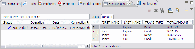
7672-pers-1-database.fm Draft Document for Review December 9, 2008 2:44 pm
244 Rational Application Developer V7 Programming Guide
Figure 11-17 Query results
Developing a Java stored procedure
A stored procedure is a block of procedural constructs and embedded SQL
statements that are stored in a database and can be called by name. Stored
procedures can help improve application performance and reduce database
access traffic. All database access must go across the network, which, in some
cases, can result in poor performance. For each SQL statement, a database
manager application must initiate a separate communication with database.
To improve application performance, you can create stored procedures that run
on a database server. A client application can then simply call the stored
procedures to obtain results of the SQL statements that are contained in the
procedure. Because the stored procedure runs the SQL statements on the
server for you, database performance is improved.
Stored procedures can be written as SQL procedures, or as C, COBOL, PL/I, or
Java programs. In this section, we develop a Java stored procedure against the
ITSOBANK Derby database to obtain the account information based on a partial
customer last name. While doing so, we will give also give $100 credit to every
account retrieved (this would be nice!).
Creating a Java stored procedure
To create a stored procedure using the Stored Procedure wizard, do these steps:
In the Data Project Explorer view, expand the RAD7DataDevelopment
project, right-click the Stored Procedures folder, and select New → Stored
Procedure. The New Stored Procedure wizard opens.
In the Name and Language page:
–RAD75DataDevelopment is preselected.
–Type AddCredit for the Name.
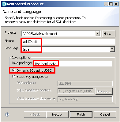
Chapter 11. Develop database applications 245
Draft Document for Review December 9, 2008 2:44 pm 7672-pers-1-database.fm
–Select Java as the language.
Because we are developing a stored procedure against Derby database,
Java is the only option for the Language. If you develop stored
procedures against a DB2 database, you will see two options: Java and
SQL.
–Type itso.bank.data as the package name.
–Select Dynamic SQL using JDBC (Figure 11-18).
– Click Next.
Figure 11-18 Create stored procedure: Name and Language
In the SQL Statements page, click Create SQL. This action launches the New
SQL Statement wizard that guides you through the creation of an SQL
statement.
In the first page of the New SQL Statement wizard, keep the defaults to create
a SELECT statement using the wizard, and click Next.
We go through several tabs to create the SQL statement:
– In the Tables tab, in the Available Tables list, expand the ITSO schema,
select ITSO.ACCOUNT, ITSO.ACCOUNT_CUSTOMER, and
ITSO.CUSTOMER, and click > to move the three tables to the Selected
Tables list.
– Select the Columns tab, expand the CUSTOMER table and select
FIRST_NAME and LAST_NAME. Expand the ACCOUNT table and select ID
and BALANCE. Click > to move the columns to the Selected Columns list.
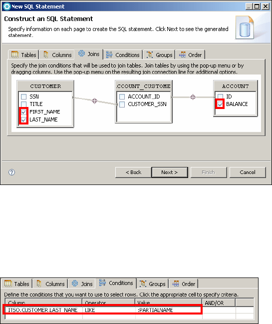
7672-pers-1-database.fm Draft Document for Review December 9, 2008 2:44 pm
246 Rational Application Developer V7 Programming Guide
– Select the Joins tab, drag the cursor from SSN (CUSTOMER) to CUSTOMER_SSN
(ACCOUNT_CUSTOMER), and from ID (ACCOUNT) to ACCOUNT_ID
(ACCOUNT_CUSTOMER) to create two joins (Figure 11-19).
Figure 11-19 Create stored procedure: Joins
– Select the Conditions tab. In the first row click the cell under Column and
select CUSTOMER.LASTNAME. In the same row select LIKE as the
Operator and type :PARTIALNAME as the Value (Figure 11-20). Click
Next.
Figure 11-20 Create stored procedure: Conditions
In the Change the SQL Statement page, review the generated SQL statement
and click Finish to close the New SQL Statement wizard.
Back in the New Stored Procedure wizard, select One for the Result set and
click Next.
In the Parameters page, leave the settings as default and click Next.
In the Deploy Options page of the wizard, clear Deploy on Finish. We will
deploy the stored procedure in later steps. Click Next.
In the Code Fragments page of the wizard, click Next.
Review the selections on the Summary page of the wizard and click Finish.

Chapter 11. Develop database applications 247
Draft Document for Review December 9, 2008 2:44 pm 7672-pers-1-database.fm
The stored procedure opens in the routine editor. Select the Configuration
tab in the routine editor. In the Java section, click ADDCRETID.java. The
generated file opens and is shown in Example 11-2.
Example 11-2 AddCredit.java
package itso.bank.data;
import java.sql.*; // JDBC classes
public class ADDCREDIT {
public static void aDDCREDIT(java.lang.String PARTIALNAME, ResultSet[] rs1)
throws SQLException, Exception {
// Get connection to the database
Connection con = DriverManager.getConnection("jdbc:default:connection");
PreparedStatement stmt = null;
boolean bFlag;
String sql;
sql = "SELECT ITSO.CUSTOMER.FIRST_NAME, ITSO.CUSTOMER.LAST_NAME,
ITSO.ACCOUNT.BALANCE"
+ " FROM"
+ " ITSO.ACCOUNT JOIN ITSO.CUSTOMER JOIN
ITSO.ACCOUNT_CUSTOMER ON ITSO.CUSTOMER.SSN =
ITSO.ACCOUNT_CUSTOMER.CUSTOMER_SSN ON ITSO.ACCOUNT.ID
= ITSO.ACCOUNT_CUSTOMER.ACCOUNT_ID"
+ " WHERE ITSO.CUSTOMER.LAST_NAME LIKE ?";
stmt = con.prepareStatement(sql);
stmt.setString(1, PARTIALNAME);
bFlag = stmt.execute();
rs1[0] = stmt.getResultSet();
}
}
We will give $100 credit to the selected accounts. Add the following code
under the rs1[0] = stmt.getResultSet() statement (Example 11-3):
Example 11-3 Snippet to give $100 credit to each account
String sql2 = "UPDATE ITSO.ACCOUNT SET BALANCE = (BALANCE + 100)"
+ " WHERE ID IN " +
"(SELECT ITSO.ACCOUNT.ID FROM ITSO.ACCOUNT"
+ " JOIN ITSO.ACCOUNT_CUSTOMER"
+ " ON ITSO.ACCOUNT.ID = ITSO.ACCOUNT_CUSTOMER.ACCOUNT_ID"
+ " JOIN ITSO.CUSTOMER ON ITSO.ACCOUNT_CUSTOMER.CUSTOMER_SSN ="
+ " ITSO.CUSTOMER.SSN"
+ " WHERE ITSO.CUSTOMER.LAST_NAME LIKE ?)";
stmt = con.prepareStatement(sql2);
stmt.setString( 1, PARTIALNAME );
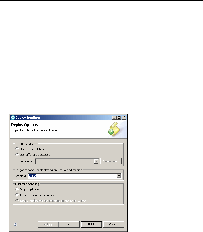
7672-pers-1-database.fm Draft Document for Review December 9, 2008 2:44 pm
248 Rational Application Developer V7 Programming Guide
stmt.executeUpdate();
The modified AddCredit.java can also be found in:
C:\7672code\database\samples
Deploying a Java stored procedure
A stored procedure must be deployed to the database where it is stored in the
catalog, ready for execution.
To deploy a Java stored procedure to a database:
In the Data Project Explorer, expand RAD75DataDevelopment → Stored
Procedures, right-click ADDCREDIT, and select Deploy.
The Deploy Routines wizard opens. Enter ITSO as the Schema name and
click Finish (Figure 11-21).
Figure 11-21 Deploy Routines
You can see a succeeded build status in the SQL Results view.
In the Data Source Explorer, expand ITSOBANK → Schemas→ ITSO →
right-click Stored Procedures, and select Refresh. You can see that
ADDCREDIT has been added to the Stored Procedures folder.
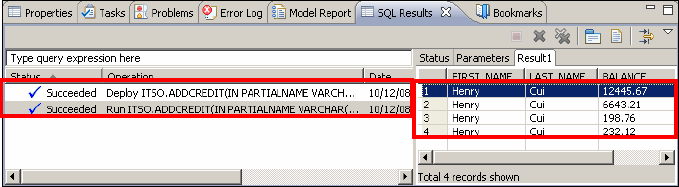
Chapter 11. Develop database applications 249
Draft Document for Review December 9, 2008 2:44 pm 7672-pers-1-database.fm
Running the stored procedure
Application Developer provides a test facility for testing the Java stored
procedures.
To run the stored procedure:
In the Data Project Explorer, right-click the stored procedure ADDCREDIT,
and select Run.
The Specify Parameter Values window opens. In the Value field type C% in
the cell and press Enter (PARTIALNAME LIKE 'C%' retrieves only the customer
with last name starts with C).
Click OK.
The result is shown in Figure 11-22. You can see $100 has been added to the
related accounts and the balances are updated.
Figure 11-22 Stored procedure results
Developing SQLJ applications
SQLJ enables you to embed SQL statements into Java programs. SQLJ is an
ANSI standard developed by a consortium of leading providers of database and
application server software.
The SQLJ translator translates an SQLJ source file into a standard Java source
file plus an SQLJ serialized profile that encapsulates information about static
SQL in the SQLJ source. The translator converts SQLJ clauses to standard Java
statements by replacing the embedded SQL statements with calls to the SQLJ
runtime library. An SQLJ customization script binds the SQLJ profile to the
database, producing one or more database packages. The Java file is compiled
and run (with the packages) on the database. The SQLJ runtime environment
consists of an SQLJ runtime library that is implemented in pure Java. The SQLJ
runtime library calls the JDBC driver for the target database.

7672-pers-1-database.fm Draft Document for Review December 9, 2008 2:44 pm
250 Rational Application Developer V7 Programming Guide
SQLJ provides better performance by using static SQL. SQLJ generally requires
fewer lines of code than JDBC to perform the same tasks. The SQLJ translator
checks the syntax of SQL statements during translation. SQLJ uses database
connections to type-check static SQL code. With SQLJ, you can embed Java
variables in SQL statements. SQLJ provides strong typing of query output and
return parameters and allows type-checking on calls. SQLJ provides static
package-level security with compile-time encapsulation of database
authorization.
Using the SQLJ wizard shipped with Application Developer, you can do the
following actions:
Name an SQLJ file and specify its package and source folder.
Specify advanced project properties, such as additional JAR files, to add to
the project classpath, translation options, and whether to use long package
names.
Select an existing SQL SELECT statement, or construct and test a new one.
Specify information for connecting to the database at run time.
In this section, we will create an SQLJ application to retrieve the customer and
the associated account information.
Creating SQLJ files
You can create SQLJ files by using the New SQLJ File wizard. The SQLJ support
is automatically added to the project when you use this wizard.
We create a Java project named RAD75SQLJ and then create the SQLJ file in
this project:
Open the Java perspective, select File → New → Java Project. Enter
RAD75SQLJ as the Project name and click Finish.
Select File → New → Other → Data → SQLJ Applications → SQLJ File
and click Next.
In the SQLJ File page, enter itso.bank.data.sqlj as the package name and
CustomerAccountInfo as the file name and click Next (Figure 11-23).
Work around: Right-click the ITSOBANKderby connection and select
Disconnect. The SQLJ wizard does not show the tables when the connection
is active.
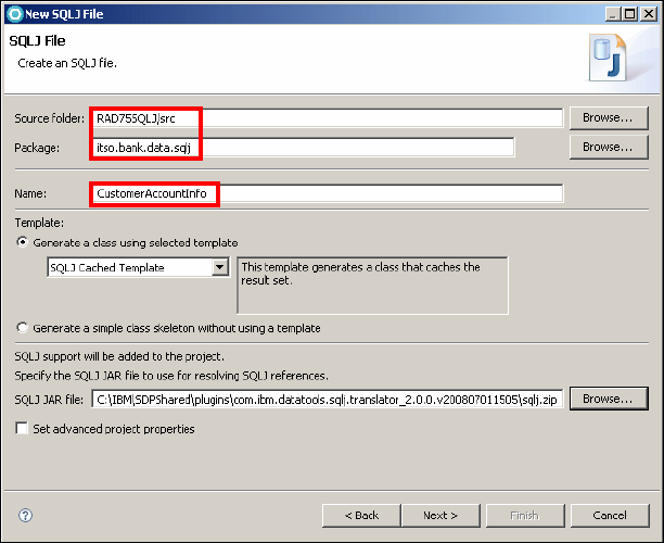
Chapter 11. Develop database applications 251
Draft Document for Review December 9, 2008 2:44 pm 7672-pers-1-database.fm
Figure 11-23 New SQLJ File
In the Select an Existing Statement Saved in Your Workspace page, click
Next. We create a new SQL statement.
In the Specify SQL Statement Information page, select Be guided through
creating an SQL statement, click Next.
In the Select Connection page, select the ITSOBANKderby connection that
you created in the previous section. Click Reconnect to reconnect to the
database if it is disconnected. Click Next.
In the Construct an SQL Statement page, we go through several pages:
– In the Tables tab, for Available Tables, expand the ITSO schema, select the
CUSTOMER, ACCOUNT, and ACCOUNT_CUSTOMER tables, and click
> to move these three tables to the Selected Tables list.
– Select the Columns tab. In the Available columns list, select TITLE,
FIRST_NAME and LAST_NAME under the CUSTOMER table, and ID and
BALANCE under the ACCOUNT table, and then click > to move these
columns to the selected Columns list (Figure 11-24).
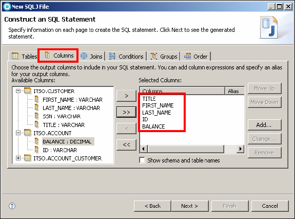
7672-pers-1-database.fm Draft Document for Review December 9, 2008 2:44 pm
252 Rational Application Developer V7 Programming Guide
Figure 11-24 Select the output columns
– Select the Joins tab. Drag the cursor from CUSTOMER.SSN to CUSTOMER_SSN
and from ACCOUNT.ID to ACCOUNT_ID (refer to Figure 11-19 on page 246).
– Select the Conditions tab. In the first row click the cell in the Column and
select ACCOUNT.BALANCE. In the same row select >= as the Operator
and type :BALANCE as the Value.
– Select the Order tab. Select BALANCE under ACCOUNT table and click >.
For Sort order select DESC. The results will be listed with the highest
balance first.
– Click Next.
In the Change the SQL Statement page, review the generated SQL statement
and click Next.
SELECT ITSO.CUSTOMER.TITLE, ITSO.CUSTOMER.FIRST_NAME,
ITSO.CUSTOMER.LAST_NAME, ITSO.ACCOUNT.ID, ITSO.ACCOUNT.BALANCE
FROM ITSO.CUSTOMER JOIN ITSO.ACCOUNT_CUSTOMER ON ITSO.CUSTOMER.SSN =
ITSO.ACCOUNT_CUSTOMER.CUSTOMER_SSN JOIN ITSO.ACCOUNT ON
ITSO.ACCOUNT_CUSTOMER.ACCOUNT_ID = ITSO.ACCOUNT.ID
WHERE ITSO.ACCOUNT.BALANCE >= :BALANCE
ORDER BY BALANCE DESC
In the Specify Runtime Database Connection Information page, select Use
DriverManager Connection (Figure 11-25). Derby does not use
authentication. Select Variables inside of method and leave the user ID as
itso and the password empty.
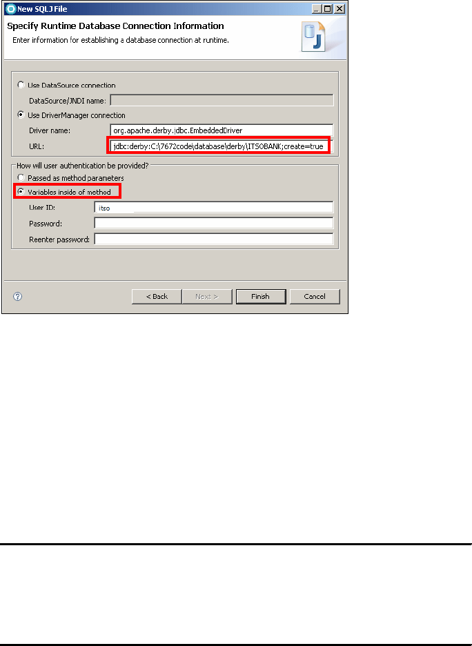
Chapter 11. Develop database applications 253
Draft Document for Review December 9, 2008 2:44 pm 7672-pers-1-database.fm
Figure 11-25 Specify Runtime Database Connection Information
Click Finish. The SQLJ file is generated.
Examining the generated SQLJ file
Before testing the SQLJ program, let us examine the generated SQLJ file:
The establishConnection method creates the database connection.
The execute method executes the SQL query and stores the result set in a
cache. The SQLJ statement is embedded in this method (Example 11-4):
Example 11-4 Embedded SQLJ
#sql [ctx] cursor1 = {SELECT ITSO.CUSTOMER.TITLE,
ITSO.CUSTOMER.FIRST_NAME, ITSO.CUSTOMER.LAST_NAME, ITSO.ACCOUNT.ID,
ITSO.ACCOUNT.BALANCE FROM ITSO.CUSTOMER JOIN ITSO.ACCOUNT_CUSTOMER
ON ITSO.CUSTOMER.SSN = ITSO.ACCOUNT_CUSTOMER.CUSTOMER_SSN JOIN
ITSO.ACCOUNT ON ITSO.ACCOUNT_CUSTOMER.ACCOUNT_ID = ITSO.ACCOUNT.ID
WHERE ITSO.ACCOUNT.BALANCE >= :BALANCE ORDER BY BALANCE DESC};
The next method moves to the next row of the result set if one exists.
The close method commits changes and closes the connection.

7672-pers-1-database.fm Draft Document for Review December 9, 2008 2:44 pm
254 Rational Application Developer V7 Programming Guide
The corresponding setter and getter methods for the table fields in the
database are also generated. You can use the getter methods to retrieve the
columns in a row.
Testing the SQLJ program
To create a test program to invoke the SQLJ program, do these steps:
In the Package Explorer right-click the package itso.bank.data.sqlj and
select New → Java Class.
Enter TestSQLJ as the class name. Select public static void main(String[]
args) and click Finish.
Copy/paste the following code to TestSQLJ (Example 11-5). The
TestSQLJ.java code can be found in C:\7672code\database\samples.
Example 11-5 TestSQLJ.java
package itso.bank.data.sqlj;
import java.math.BigDecimal;
public class TestSQLJ {
public static void main(String[] args) {
try {
CustomerAccountInfo info = new CustomerAccountInfo();
info.execute(new BigDecimal(10000)); // minimum balance displayed
while (info.next()) {
System.out.println("Customer name: " + info.getCUSTOMER_TITLE()
+ " " + info.getCUSTOMER_FIRST_NAME() + " "
+ info.getCUSTOMER_LAST_NAME());
System.out.println("Account ID: " + info.getACCOUNT_ID() +
" Balance: " + info.getACCOUNT_BALANCE());
System.out.println("---------------------------------------");
}
info.close();
} catch (Exception e) {
e.printStackTrace();
}
}
}
We have to add the Derby JDBC driver library to the project build path:
– Right-click project RAD75SQLJ and select Properties.

Chapter 11. Develop database applications 255
Draft Document for Review December 9, 2008 2:44 pm 7672-pers-1-database.fm
–In the Java Build Path, Libraries tab, click Add External JARs and
select derby.jar, which is in <RAD_HOME>\runtimes\base_v7\derby\lib.
Click OK.
Derby accepts only one database connection at a time. Switch to the Data
perspective. In the Database Explorer right-click the ITSOBANK connection
and select Disconnect.
In the Java perspective, right-click TestSQLJ.java → Run As → Java
Application.
The result is displayed in the console:
Retrieve some data from the database.
Customer name: Mr Brian Hainey
Account ID: 005-555002 Balance: 72213.41
---------------------------------------
Customer name: Mr Ueli Wahli
Account ID: 000-000001 Balance: 66666.66
---------------------------------------
Customer name: Ms Pinar Ugurlu
Account ID: 002-222001 Balance: 65484.23
---------------------------------------
Customer name: Mr Juan Napoli
Account ID: 004-444003 Balance: 23156.46
---------------------------------------
Customer name: Mr Henry Cui
Account ID: 001-111001 Balance: 12545.67
---------------------------------------
......
Data modeling
Application Developer provides tools to create, modify, and generate DDL for
data models. At any time when you are building a data model, you can analyze
the model to verify that it is compliant with the defined constraints. If you make
changes to the data model, Application Developer provides tooling to compare
the changed data model with the original data model.You can also perform an
impact analysis to determine how the changes might affect other objects.
Note: If you get the following exception:
Failed to start database 'C:/7672code/database/derby/ITSOBANK'
This means that the Derby database is locked by another connection. Check
the Database Explorer if the ITSOBANK connection is still active. Disconnect the
connection, or restart the workbench.
7672-pers-1-database.fm Draft Document for Review December 9, 2008 2:44 pm
256 Rational Application Developer V7 Programming Guide
A physical data model is a database-specific model that represents relational
data objects (for example, tables, columns, primary keys, and foreign keys) and
their relationships. A physical data model can be used to generate DDL
statements which can then be deployed to a database server.
In the Workbench, you can create and modify data models by using the Data
Project Explorer, the Properties view, or a diagram of the model. You can also
analyze models and generate DDL.
In this section, we will create the physical model from template, create tables
using the data diagram and deploy the physical model to the database. This
section includes the following tasks:
Creating a data design project
Creating a physical data model
Modeling with diagrams
Generating DDL from physical data model and deploy
Creating a data design project
Before you create data models or other data design objects, you must create a
data design project to store your objects.
A data design project is primarily used to store modeling objects. You can store
the following types of objects in a data design project:
Logical data models
Physical data models
Domain models
Glossary models
SQL scripts, including DDL scripts
To create a data design project:
In the Data perspective, select File → New → Data Design Project.
The New Data Design Project wizard opens.
In the Project Name field type RAD75DataDesign, then click Finish.
The data design project is displayed in the Data Project Explorer view
(Figure 11-26).
Chapter 11. Develop database applications 257
Draft Document for Review December 9, 2008 2:44 pm 7672-pers-1-database.fm
Figure 11-26 Data Project Explorer: Data Design project layout
Creating a physical data model
A physical data model is a database-specific model that represents relational
data objects (for example, tables, columns, primary and foreign keys) and their
relationships. A physical data model can be used to generate DDL statements
which can then be deployed to a database server.
Using the data tooling, you can create a physical data model in several ways:
Create a blank physical model by using a wizard.
Create a physical model from a template by using a wizard.
Reverse engineer a physical model from a database or a DDL file by using a
wizard or by dragging data objects from the Database Explorer.
Import a physical data model file from the file system.
In this section, we show you two ways to create the physical data model. First we
create a physical data model by reversing the model from an existing database
ITSOBANK. Then we create a new physical data model from a template and deploy
this new model to the database.
Creating a physical data model using reverse engineering
To create a physical data model by reverse engineering an existing database
schema, do these steps:
In the Data Source Explorer, right-click ITSOBANKDerby and select
Connect.
In the Data Project Explorer, right-click RAD75DataDesign and select
New → Physical Data Model. The New Physical Data Model wizard opens
(Figure 11-27). Enter the following:
– File name: ITSOBANK_Reverse
– Database and Version: Derby, and 10.2
–Select Create from reverse engineering.
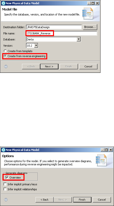
7672-pers-1-database.fm Draft Document for Review December 9, 2008 2:44 pm
258 Rational Application Developer V7 Programming Guide
Figure 11-27 New Physical Data Model: Create from reverse engineering
In the Select connection page, select ITSOBANKderby from the existing
connections list. Click Next.
In the Schema page, select ITSO and click Next.
In the Database Elements page, select Tables and click Next.
In the Options page, select Overview in the Generate diagrams section
(Figure 11-28).
Click Finish.
Figure 11-28 New Physical Data Model: Options
The physical model is created and added to the Data Models folder. The
overview diagram is added to the Data Diagrams folder (Figure 11-29).
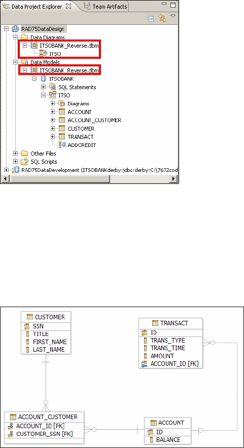
Chapter 11. Develop database applications 259
Draft Document for Review December 9, 2008 2:44 pm 7672-pers-1-database.fm
Figure 11-29 Data Design Project with physical model and diagram
The Physical Data Model editor is open on the ITSOBANK_Reverse model.
Descriptive information can be added. Do not close the physical model. It
must be open to open the diagram.
Open the ITSO overview diagram in the Data Diagrams folder. It contains all
the tables that are in the schema. You can move the tables to get a better
diagram (Figure 11-30).
Figure 11-30 Overview diagram
Select a table in the diagram, then look at the Properties view to see the
columns and relationships.
7672-pers-1-database.fm Draft Document for Review December 9, 2008 2:44 pm
260 Rational Application Developer V7 Programming Guide
Select a relationship (line) in the diagram and look at the Properties view to
see the cardinality (Details tab). The cardinality is also displayed visually in
the diagram.
Save and close the ITSO diagram and the ITSOBANK_Reverse.dbm model.
Creating a physical data model from a template
To create a physical data model from a template, do these steps:
Right-click RAD75DataDesign and select New → Physical Data Model. In
the New Physical Data Model wizard (refer to Figure 11-27 on page 258),
enter the following information:
File name: Bank_model
Database and Version: Derby, and 10.2
Select Create from template.
Click Finish.
The physical model is created and displayed in the Data Models folder. The data
diagram for the schema opens in the diagram editor.
Modeling with diagrams
You can use data diagrams to visualize and edit objects that are contained in
data projects. Data diagrams are a view representation of an underlying data
model. You can create diagrams that contain only a subset of model objects that
are of interest.
In this section, we create a schema named RAD75Bank in the physical data model.
Under this schema, we create two tables: ACCOUNT and TRANSACT. we add a
foreign key relationship between the ACCOUNT and TRANSACT tables.
In the Data Project Explorer select RAD75DataDesign → Data Models →
Bank_model.dbm → Database → Schema, and in the Properties view
change the schema name from Schema to RAD75Bank.
To add a table, do these steps:
– In the diagram editor, select the Data drawer in the palette and select
Table in the Data drawer.
– Click the empty area in the data diagram. A new table is added to the
diagram.
– Overtype the table name with ACCOUNT.
Hover the mouse over the ACCOUNT table in the diagram and you see four
icons appearing outside of the table (Figure 11-31). Click the Add Key icon.

Chapter 11. Develop database applications 261
Draft Document for Review December 9, 2008 2:44 pm 7672-pers-1-database.fm
Figure 11-31 Add key, column, index, and trigger
Overtype the name with ID (or change the name in the Properties view,
General tab).
Select the ID column, and in the Properties view, Type tab, change the Data
type to VARCHAR. Set the Length to 16 (Figure 11-32).
Figure 11-32 Edit the key
Hover the mouse over the ACCOUNT table and click the Add Column icon.
In the Properties view change the Name to BALANCE, the data type to
DECIMAL, enter 8 as the precision and 2 as the scale, and select Not Null.
Follow the same procedure to create the TRANSACT table:
–Key: ID VARCHAR(250) NOT NULL
– Columns:
TRANS_TYPE VARCHAR(32) NOT NULL
TRANS_TIME TIMESTAMP NOT NULL
AMOUNT DECIMAL(8,2) NOT NULL
ACCOUNT_ID VARCHAR(16)
Note: The key ID must be uppercase. If you use lowercase, you might get
the following error message when you run DDL on server in later section:
SQL Exception: 'ID' is not a column in table or VTI 'ACCOUNT'..
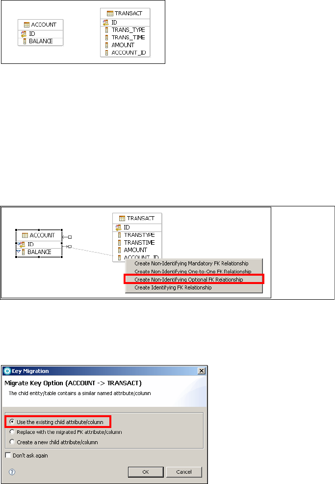
7672-pers-1-database.fm Draft Document for Review December 9, 2008 2:44 pm
262 Rational Application Developer V7 Programming Guide
The data diagram is shown in Figure 11-33.
Figure 11-33 Data diagram with two tables
Hover the mouse over the ACCOUNT table object in the diagram and you
should see two arrows appearing outside of the table, pointing in opposite
directions. Use the arrow that points away from the ACCOUNT table
(representing a relationship from parent to child) to create a relationship
between the ACCOUNT table and the TRANSACT table.
Drag the arrow that points away from the ACCOUNT table, and drop it on the
TRANSACT table. In the menu that opens select Create Non-Identifying
Optional FK Relationship (Figure 11-34)
Figure 11-34 Add relationship between tables
In the Migrate Key Option dialog, select Use the existing child
attribute/column, and click OK (Figure 11-35).
Figure 11-35 Key migration
We use an
existing column
(ACCOUNT_ID) as
foreign key
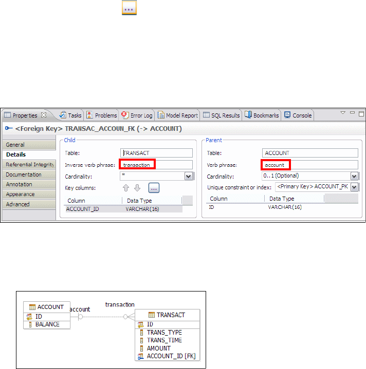
Chapter 11. Develop database applications 263
Draft Document for Review December 9, 2008 2:44 pm 7672-pers-1-database.fm
Select the foreign key relationship you just created. In the Properties view,
select the Details page.
Click the ellipsis button next to the Key Columns field. In the dialog, that
opens, select ACCOUNT_ID and clear ID (use the check boxes). Click OK.
Add information to the relationship properties to identify the roles of each
table in the relationship (Figure 11-36):
– In the Inverse Verb Phrase field, type transaction.
– In the Verb Phrase field, type account.
– Leave the cardinality as * and 0..1.
Figure 11-36 Relationship Details page
Save but do not close the diagram. Notice the relationship verbs in the
diagram (Figure 11-37).
Figure 11-37 Relationship with verbs
Generating DDL from physical data model and deploy
In this section, we generate the DDL and run the generated DDL into the Derby
database:
In the Data Project Explorer, right-click the schema (Data Models →
Bank_model.dbm → Database) RAD75Bank → Generate DDL.
In the Generate DDL dialog, select Fully qualified name and CREATE
statements (Figure 11-38), and click Next.
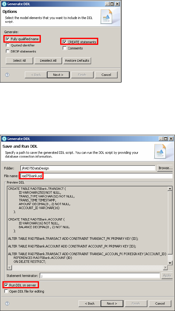
7672-pers-1-database.fm Draft Document for Review December 9, 2008 2:44 pm
264 Rational Application Developer V7 Programming Guide
Figure 11-38 Generate DDL
In the Objects page, leave everything selected and click Next.
In the Save and Run DDL page, change the file name to rad75bank.sql,
review the DDL, select Run DDL on server, and click Next (Figure 11-39).
Figure 11-39 Save and Run DDL
Quoted identifiers
are required if the
names contains
blanks.
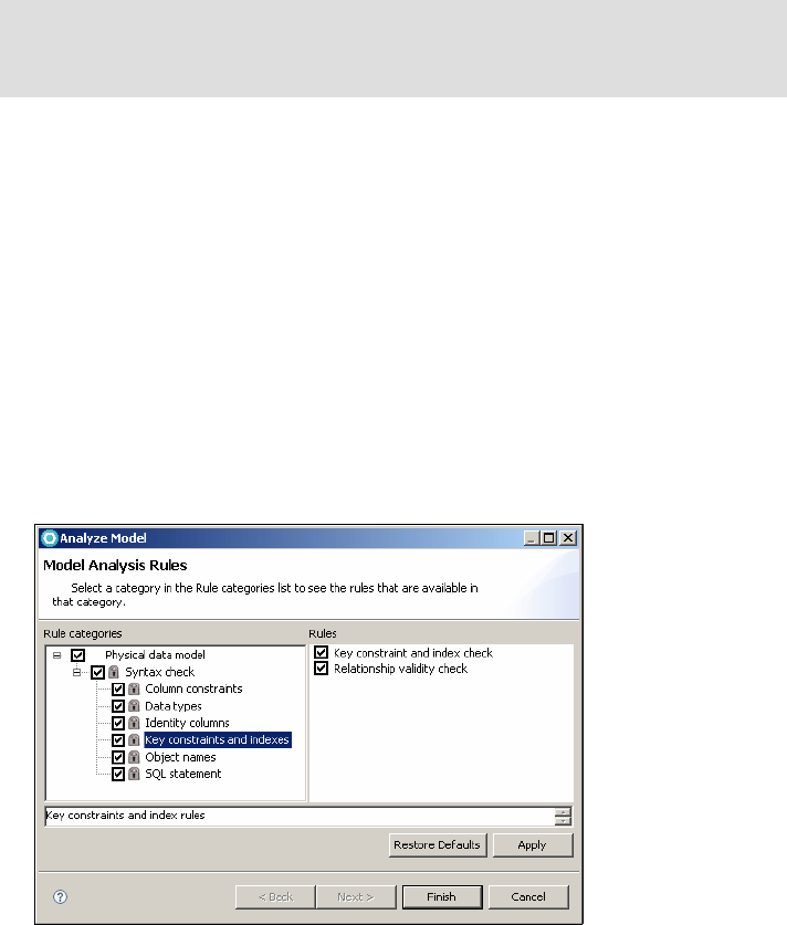
Chapter 11. Develop database applications 265
Draft Document for Review December 9, 2008 2:44 pm 7672-pers-1-database.fm
In the Select connection page, select ITSOBANKDerby, and click Next.
In the Summary page, click Finish.
The SQL script is created and stored in the SQL Scripts folder. Open
rad75bank.sql to review the DDL.
In the Database Explorer right-click the ITSOBank connection and select
Refresh. You can see RAD75BANK schema is displayed.
Analyzing the data model
The Analyze Model wizard analyzes a data model to ensure that it meets certain
specifications. Model analysis helps to ensure model integrity and helps to
improve model quality by providing design suggestions and best practices.
To analyze the RAD75Bank schema in the physical data model:
In the Data Project Explorer, right-click the schema RAD75Bank (in Data
Models → Bank_model.dbm → Database) and select Analyze Model.
The Analyze Model dialog opens (Figure 11-40). Select the different items in
the list to see the rules that are checked.
Click Apply if you made any changes, then click Finish.
Figure 11-40 Analyze Model
Tip: If you cannot see the RAD75BANK schema, you can right-click Schemas →
Properties and make sure both ITSO and RAD75BANK are selected. The
RAD75BANK schema with two tables is now visible.
7672-pers-1-database.fm Draft Document for Review December 9, 2008 2:44 pm
266 Rational Application Developer V7 Programming Guide
The result is displayed in the console:
Validation - 0 error(s), 0 warning(s), 0 informational message(s).
Close all the open files.
More information
More information on JDBC can be found at:
http://java.sun.com/j2se/1.4.2/docs/guide/jdbc/
http://java.sun.com/javase/technologies/database/
http://developers.sun.com/product/jdbc/drivers
More information on SQLJ can be found at:
http://www.javaworld.com/javaworld/jw-05-1999/jw-05-sqlj.html
http://www.onjava.com/pub/st/27

© Copyright IBM Corp. 2008. All rights reserved. 267
Draft Document for Review December 9, 2008 2:44 pm 7672-pers-2-jpa.fm
Chapter 12. Persistence using the Java
Persistence API (JPA)
In this chapter, we create the JPA entities that coordinate and mediate access
with the ITSOBANK database. We can use either the Derby or the DB2 database to
create the matching JPA entities (Customer, Account, and Transaction) in a
bottom-up scenario. Once we have the entities, we can connect the entity model
to any of the two databases by using a JNDI data source in the server.
To illustrate the JPA tooling we use the Derby database to create the entities.
Finally, we add inheritance to the entity model by introducing Credit and Debit
subclasses of the Transaction entity.
The sample code for this chapter is in 7672code\jpa.
12
7672-pers-2-jpa.fm Draft Document for Review December 9, 2008 2:44 pm
268 Rational Application Developer V7.5 Programming Guide
Introducing the Java Persistence API
This section is an extract from the IBM Redbooks publication WebSphere
Application Server Version 6.1 Feature Pack for EJB 3.0, SG24-7611, Chapter 2,
Introduction to JPA.
The persistence layer in a typical J2EE application that interacts with a relational
database has been implemented over the last years in several ways:
EJB 2.x entity beans
Data access object (DAO) pattern
Data mapper frameworks (such as IBatis)
Object-relational mapping (ORM) frameworks both commercial (such as
Oracle Toplink) or from the open-source world (such as Hibernate)
Data mapper and ORM frameworks gained a great approval among developers
communities, because they give a concrete answer to the demand of
simplification of the design of the persistence layer, and let developers
concentrate on the business related aspects of their solutions.
However, even if these frameworks overcome the limitations of EJB 2.x CMP
entity beans, one of the common concerns related to the adoption of such
frameworks was that they were not standardized.
One of the main innovative concepts introduced by EJB 3.0 is the provisioning of
a single persistence standard for the Java platform that can be used in both the
Java EE and Java SE environments, and that can be used to build the
persistence layer of a Java EE application. Furthermore, it defines a pluggable
service interface model, so that you can plug in different provider
implementations, without a significant changes to your application.
The Java Persistence API provides an object relational mapping facility to Java
developers for managing relational data in Java applications. Java persistence
consists of three areas:
Java Persistence API
Object-relational mapping metadata
Query language
Entities
In the EJB 3.0 specification entity beans have been substituted by the concept of
entities, which are sometimes called entity objects to clarify the distinction
between EJB 2.1 entity beans and JPA entities (entity objects).

Chapter 12. Persistence using the Java Persistence API (JPA) 269
Draft Document for Review December 9, 2008 2:44 pm 7672-pers-2-jpa.fm
A JPA entity is a Java object that must match the following rules:
It is a plain old Java object (POJO) that does not have to implement any
particular interface or extend a special class.
The class must not be declared final, and no methods or persistent instance
variables must be declared final.
The entity class must have a no-argument constructor that is public or
protected. The entity class may have other constructors as well.
The class must either be annotated with the @Entity annotation or specified
in the orm.xml JPA mapping file. We will use annotations is our examples.
The class must define an attribute that is used to identify in an unambiguous
way an instance of that class (it corresponds to the primary key in the mapped
relational table).
Both abstract and concrete classes can be entities, and entities may extend
non-entity classes (this is a significant limitation with EJB 2.x).
A simple entity example
Example 12-1 shows a simple Customer entity with a few fields.
Example 12-1 Simple entity class with annotations
package itso.bank.entities;
@Entity
public class Customer implements java.io.Serializable {
@Id
private String ssn;
private String title;
private String firstName;
private String lastName;
public String getSsn() { return this.ssn; }
public void setSsn(String ssn) { this.ssn = ssn; }
// more getter and setter methods
}
Note: Entities have overcome the traditional limitation that is present in EJB
2.x entity beans: They can be transferred on the wire (for example, they can
be serialized over RMI-IIOP). Of course, you must remember to implement the
java.io.Serializable interface in the entity.

7672-pers-2-jpa.fm Draft Document for Review December 9, 2008 2:44 pm
270 Rational Application Developer V7.5 Programming Guide
The @Entity annotation identifies a Java class as an entity.
The @Id annotation is used to identify the property that corresponds to the
primary key in the mapped table.
The class is conforming to the JavaBean specification.
Mapping the table and columns
To specify the mapping of the entity to a database table we use @Table and
@Column annotations (Example 12-2).
Example 12-2 Entity with mapping to a database table
@Entity
@Table (schema="ITSO", name="CUSTOMER")
public class Customer implements java.io.Serializable {
@Id
@Column (name="SSN")
private String ssn;
@Column (name="LAST_NAME")
private String lastName;
private String title;
private String firstNname;
......
The @Table annotation provides information related to which table and
schema the entity corresponds to.
The @Column annotation provides information related to which column is
mapped by an entity property. By default, properties are mapped to columns
with the same name, and the @Column annotation is used when the property
and column names differ.
Note: Entities support two types of persistence mechanisms:
Field-based persistence—The entity properties must be declared as public
or protected and instruct the JPA provider to ignore getter/setters.
Property-based persistence—You must provide getter/setter methods.
We recommend to use the property-based approach (as in Example 12-2),
because it is more adherent to the Java programming guidelines.
Chapter 12. Persistence using the Java Persistence API (JPA) 271
Draft Document for Review December 9, 2008 2:44 pm 7672-pers-2-jpa.fm
Relationships
Before starting our discussion of entity relationships, it is useful to refresh how
the concept of relationships is defined in object-oriented and in relational
database worlds (Table 12-1).
Table 12-1 Relationship concept in two different worlds
JPA defines the following relationships: one-to-one, many-to-one, one-to-many,
and many-to-many.
One-to-one relationship
In this type of relationship each entity instance is related to a single instance of
another entity. The @OneToOne annotation is used to define this single value
association, for example, a Customer is related to a CustomerRecord:
@Entity
public class Customer {
@OneToOne
@JoinColumn(
name="CUSTREC_ID", unique=true, nullable=false, updatable=false)
public CustomerRecord getCustomerRecord() {
return customerRecord;
}
....
}
Java/JPA RDBMS
A relationship is a reference from one
object to another. Relationships are defined
through object references (pointers) from a
source object to the target object.
Relationships are defined through
foreign keys.
If a relationship involves a collection of
other objects, a collection or array type is
used to hold the contents of the
relationship.
Collections are either defined by the
target objects have a foreign key back to
the source object's primary key, or by
having an intermediate join table to store
the relationships.
Relationships are always unidirectional, in
that if a source object references a target
object, it is not guaranteed that the target
object also has a relationship to the source
object.
Relationships are defined through
foreign keys and queries, such that the
inverse query always exists.
7672-pers-2-jpa.fm Draft Document for Review December 9, 2008 2:44 pm
272 Rational Application Developer V7.5 Programming Guide
In many situations the target entity of the one-to-one has a relationship back to
the source entity, but this is not required. In our example, CustomerRecord could
have a reference back to the Customer. When this is the case, we call it a
bidirectional one-to-one relationship.
There are two rules for bi-directional one-to-one associations:
The @JoinColumn annotation must be specified in the entity that is mapped
to the table containing the join column, or the owner of the relationship.
The mappedBy element should be specified in the @OneToOne annotation in
the entity that does not define a join column, that is, the inverse side of the
relationship.
Many-to-one and one-to-many relationships
Many-to-one mapping is used to represent simple pointer references between
two Java objects. In Java, a single pointer stored in an attribute represents the
mapping between the source and target objects. Relational database tables
implement these mappings using foreign keys.
On the other side, One-to-many mapping is used to represent the relationship
between a single source object and a collection of target objects. This
relationship is usually represented in Java with a collection of target objects, but
is more difficult to implement using relational databases (where you retrieve
related rows through a query).
For example, an Account entity object can be associated with many Transact
entity objects:
@Entity
@Table (schema="ITSO", name="ACCOUNT")
public class Account implements Serializable {
@Id
private String id;
private BigDecimal balance;
@OneToMany(mappedBy="account")
private Set<Transaciont> transactionCollection;
....
}
====================================================================
@Entity
@Table (schema="ITSO", name="TRANSACT")
public class Transaction implements Serializable {
@Id
private String id;
......

Chapter 12. Persistence using the Java Persistence API (JPA) 273
Draft Document for Review December 9, 2008 2:44 pm 7672-pers-2-jpa.fm
@ManyToOne
@JoinColumn(name="ACCOUNT_ID")
private Account account;
....
}
Using the @JoinColumn annotation
In the database, a relationship mapping means that one table has a reference to
another table. The database term for a column that refers to a key (usually the
primary key) in another table is a foreign key column.
In the Java Persistence API we call them join columns, and the @JoinColumn
annotation is used to configure these types of columns.
Many-to-many relationship
When an entity A references multiple B entities, and other As might reference
some of the same Bs, we say there is a many-to-many relation between A and B.
To implement a many to many relationship there must be a distinct join table that
maps the many-to-many relationship. This is called an association table.
For example, a Customer entity object can be associated with many Account
entity objects, and an Account entity object can be associated with many
Customer entity objects:
@Entity
public class Customer implements Serializable {
......
@ManyToMany(mappedBy="customerCollection")
private Set<Account> accountCollection;
......
}
Note: If you do not specify @JoinColumn, then a default column name is
assumed. The algorithm used to build the name is based on a combination of
both the source and target entities. It is the name of the relationship attribute
in the Transaction source entity (the account attribute), plus an underscore
character (_), plus the name of the primary key column of the target Account
entity (the id attribute).
Therefore a foreign key named ACCOUNT_ID is expected inside the TRANSACTION
table. If this is not applicable, you must use @JoinColumn to override this
automatic behavior.
The @JoinColumn annotation also applies to one-to-one relationships.

7672-pers-2-jpa.fm Draft Document for Review December 9, 2008 2:44 pm
274 Rational Application Developer V7.5 Programming Guide
==============================================================
@Entity
public class Account implements Serializable {
......
@ManyToMany
@JoinTable(name="ACCOUNT_CUSTOMER", schema="ITSO",
joinColumns=@JoinColumn(name="ACCOUNT_ID"),
inverseJoinColumns=@JoinColumn(name="CUSTOMER_SSN"))
private Set<Customer> customerCollection;
....
}
The @JoinTable annotation is used to specify the table and columns in the
database that associate customers with accounts. The entity that specifies the
@JoinTable is the owner of the relationship, so in this case the Account entity is
the owner of the relationship with the Customer entity.
The join column pointing to the owning side is described in the joinColumns
element, while the join column pointing to the inverse side is specified by the
inverseJoinColumns element.
Fetch modes
When an entity manager retrieves an entity from the underlying database, it can
use two types of strategies:
Eager mode: When you retrieve an entity from the entity manager or by using
a query, you are guaranteed that all of its fields (with relationships too) are
populated with data store data.
Lazy mode: This is a hint to the JPA runtime that you want to defer loading of
the field until you access it. Lazy loading is completely transparent, when you
attempt to read the field for the first time, the JPA runtime will load the value
from the data store and populate the field automatically.
@OneToMany(mappedBy="accounts", fetch=FetchType.LAZY)
private Set<Transaction> transactionCollection;
Lazy mode is the default for 1:m and m:m relationships, so the specicifaction
is optional in those cases.
Note: Neither the CUSTOMER nor the ACCOUNT table contains a foreign key. The
foreign keys are in the association table. Therefore, the Customer or the
Account entity can be defined as the owning entity.

Chapter 12. Persistence using the Java Persistence API (JPA) 275
Draft Document for Review December 9, 2008 2:44 pm 7672-pers-2-jpa.fm
Entity inheritance
For several years we hear the term impedance mismatch, which describes the
difficulties in bridging the object and relational worlds. In regard to inheritance,
unfortunately, there is no natural and efficient way to represent an inheritance
relationship in a relational database.
JPA introduces three strategies to support inheritance:
Single table—This strategy maps all classes in the hierarchy to the base
class table. This means that the table contains the superset of all the data
contained in the class hierarchy. For an example of single table inheritance,
refer to “Adding inheritance” on page 307.
Joined tables—With this strategy, the top level entry in the entity hierarchy is
mapped to a table that contains columns common to all the entities, while
each of the other entities down the hierarchy are mapped to a table that
contain only columns specific to that entity.
Table per class—With this strategy both the superclass and subclasses are
stored in their own table and no relationship exists between any of the tables.
Therefore, all the entity data are stored in their own tables.
Persistence units
A persistence unit defines a set of entity classes that are managed by one entity
manager (described hereafter) instance in an application. This set of entity
classes represents the data contained within a single data store.
Persistence units are defined by the persistence.xml configuration file. The JAR
file or directory whose META-INF directory contains persistence.xml is called the
root of the persistence unit. The scope of the persistence unit is determined by
the persistence unit’s root.
Example 12-3 shows an extract of the persistence.xml file.
Note: The use of eager mode can greatly impact the performance of your
application, especially if your entities have many and recursive relationships,
because all the entity will be loaded at once.
On the other hand, if the entity after that has been read by the entity manager,
is detached and sent over the network to another layer, you usually should
assure that all the entity attributes have been read from the underlying data
store, or that the receiver does not require related entities.

7672-pers-2-jpa.fm Draft Document for Review December 9, 2008 2:44 pm
276 Rational Application Developer V7.5 Programming Guide
Example 12-3 Extract of a persistence.xml file
<persistence version="1.0" ...........>
<persistence-unit name="ITSOBank" transaction-type="JTA">
<jta-data-source>jdbc/itsobank</jta-data-source>
<class>itso.bank.entities.Account</class>
<class>itso.bank.entities.Customer</class>
<class>itso.bank.entities.Transaction</class>
</persistence-unit>
</persistence>
Object-relational mapping through orm.xml
As we have seen in this chapter, the object relational (o/r) mapping of an entity
can be done through the use of annotations. As an alternative you can specify
the same information in an external file (called orm.xml) that must be packaged in
the META-INF directory of the persistence module, or in a separate file packaged
as a resource and defined in persistence.xml with the mapping-file element.
Example 12-4 shows an extract of an orm.xml file that defines the Account entity.
Example 12-4 Extract of an orm.xml file to define an entity mapping
<entity-mappings .........>
<entity class="itso.bank.entity.Account" metadata-complete="true"
name="Account">
<description>Account of ITSO Bank</description>
<table name="ACCOUNT" schema="ITSO"></table>
<attributes>
<id name="accountNumber">
<column name="id"/>
</id>
<basic name="balance"></basic>
<one-to-many name="transactionCollection"></one-to-many>
</attributes>
</entity>
......
</entity-mappings>
Persistence provider
Persistence providers are implementations of the Java Persistence API (JPA)
specification and can be deployed in the Java EE compliant application server
that supports JPA persistence.
Chapter 12. Persistence using the Java Persistence API (JPA) 277
Draft Document for Review December 9, 2008 2:44 pm 7672-pers-2-jpa.fm
There are two built-in JPA persistence providers for WebSphere Application
Server:
IBM WebSphere JPA persistence provider
Apache OpenJPA persistence provider
If an explicit provider element is not specified in the persistence unit definitions,
the application server will use the default persistence provider, which is the
WebSphere JPA persistence provider.
IBM WebSphere JPA persistence provider
While built from the Apache OpenJPA persistence provider, the WebSphere
Application Server JPA persistence provider contains enhancements, including
the following:
Statement batching support
Version ID generation
ObjectGrid cache plug-in support
WebSphere product-specific commands and scripts
Translated message files
Apache OpenJPA persistence provider
WebSphere Application Server provides the Apache OpenJPA persistence
provider to support the open source implementation of JPA, and allow for easy
migration of existing OpenJPA applications to the application server's solution for
JPA.
Entity manager
Entities cannot persist themselves on the relational database; annotations are
used only to declare a POJO as an entity or to define its mapping and
relationships with the corresponding tables on the relational database.
JPA has defined the EntityManager interface for this purpose to let applications
manage and search for entities in the relational database.
The EntityManager primary definition is:
An API that manages the life cycle of entity instances (extract):
–persist—Insert a new entity instance
–find—Find an instance by key
–remove—Delete an instance
–merge—Merge changes of an entity
–flush—Synchronize with database
–refresh—Reload from database

7672-pers-2-jpa.fm Draft Document for Review December 9, 2008 2:44 pm
278 Rational Application Developer V7.5 Programming Guide
–createNamedQuery—Create an instance of a predefined query
Each EntityManager instance is associated with a persistence context.
A persistence context defines the scope under which particular entity
instances are created, persisted, and removed through the APIs made
available by an EntityManager.
An object that manages a set of entities defined by a persistence unit.
The entity manager tracks all entity objects within a persistence context for
changes and updates made, and flushes these changes to the database. Once a
persistence context is closed, all managed entity object instances become
detached from the persistence context and its associated entity manager, and
are no longer managed.
JPA query language
The Java persistence query language (JPQL) is used to define searches against
persistent entities independent of the mechanism used to store those entities. As
such, JPQL is portable, and not constrained to any particular data store.
The Java persistence query language is an extension of the Enterprise
JavaBeans query language, EJB QL, and is designed to combine the syntax and
simple query semantics of SQL with the expressiveness of an object-oriented
expression language.
The application creates an instance of the javax.persistence.EntityManager
interface.
The EntityManager creates an instance of the javax.persistence.Query
interface, through its public methods, for example createNamedQuery.
The Query instance executes a query (to read or update entities).
Managed and unmanaged entities: An entity object instance is either man-
aged (attached) by an entity manager or unmanaged (detached):
When an entity is attached to an entity manager, the manager monitors
any changes to the entity and synchronizes them with the database when-
ever the entity manager decides to flush its state.
When an entity is detached, and therefore is no more associated with a
persistence context, it is unmanaged, and its state changes are not tracked
by the entity manager and synchronized with the database.
Chapter 12. Persistence using the Java Persistence API (JPA) 279
Draft Document for Review December 9, 2008 2:44 pm 7672-pers-2-jpa.fm
Query types
Query instances are created using the methods exposed by the EntityManager
interface (Table 12-2).
Table 12-2 How to create a Query instance
Query basic
A simple query that retrieves all the Customer entities from the database is shown
here:
EntityManager em = ...
Query q = em.createQuery("SELECT c FROM Customer c");
List<Customer> results = (List<Customer>)q.getResultList();
A JPQL query has an internal name space declared in the from clause of the
query. Arbitrary identifiers are assigned to entities so that they can be referenced
elsewhere in the query. In the query example above, the identifier c is assigned
to the Customer entity.
The where condition is used to express a logical condition:
EntityManager em = ...
Query q = em.createQuery("SELECT c FROM Customer c
where c.ssn='111-11-1111'");
List<Customer> results = (List<Customer>)q.getResultList();
Operators
JPQL several operators; the most important and used are:
Method name Description
createQuery(String qlString) Create an instance of Query for executing a Java
Persistence query language statement.
createNamedQuery
(String name)
Create an instance of Query for executing a named
query (in the Java Persistence query language or in
native SQL).
createNativeQuery
(String sqlString)
Create an instance of Query for executing a native
SQL statement, for example, for update or delete.
createNativeQuery
(String sqlString,
Class resultClass)
Create an instance of Query for executing a native
SQL query that retrieves a single entity type.
createNativeQuery
(String sqlString,
String resultSetMapping)
Create an instance of Query for executing a native
SQL query statement that retrieves a result set with
multiple entity instances.

7672-pers-2-jpa.fm Draft Document for Review December 9, 2008 2:44 pm
280 Rational Application Developer V7.5 Programming Guide
Logical operators: NOT, AND, OR
Relational operators: =, >, >=, <, <=, <>, [NOT] BETWEEN, [NOT] LIKE,
[NOT] IN, IS [NOT] NULL, IS [NOT] EMPTY, [NOT] MEMBER [OF]
Arithmetic operators: +, -, /, *
Named queries
JPQL defines two types of queries:
Dynamic queries: They are created on the fly.
Named queries: They are intended to be used in contexts where the same
query is invoked several times. Their main benefits include the improved
reusability of the code, a minor maintenance effort, and finally better
performance, because they are evaluated once.
;
Defining a named query
Named queries are defined using the @NamedQuery annotation:
@Entity
@Table (schema="ITSO", name="CUSTOMER")
@NamedQuery(name="getCustomerBySSN",
query="select c from Customer c where c.ssn = ?1")
public class Customer implements Serializable {
...
}
The name attribute is used to uniquely identify the named query, while the query
attribute defines the query. We can see how this syntax resembles the syntax
used in JDBC code with jdbc.sql.PreparedStatement statements.
Instead of a positional parameter (?1), the same named query can be expressed
using a named parameter:
@NamedQuery(name="getCustomerBySSN",
query="select c from Customer c where c.ssn = :ssn")
Completing a named query
Named queries must have all their parameters specified before being executed.
The javax.persistence.Query interface exposes two methods:
public void setParameter(int position, Object value)
Note: From this point of view, there is a strong similarity between
Dynamic/Named queries and JDBC Statement/PreparedStatements. How-
ever, named queries are stored in a global scope, which enable them to be
accessed by different EJB 3.0 components.
Chapter 12. Persistence using the Java Persistence API (JPA) 281
Draft Document for Review December 9, 2008 2:44 pm 7672-pers-2-jpa.fm
public void setParameter(String paramName, Object value)
A complete example that uses a named query is shown here:
EntityManager em = ...
Query q = em.createNamedQuery ("getCustomerBySSN");
q.setParameter(1, "111-11-1111");
//q.setParameter("ssn", "111-11-1111"); // for named parameter
List<Customer> results = (List<Customer>)q.getResultList();
Defining multiple named queries
If there are more than one named query for an entity, they are placed inside an
@NamedQueries annotation, which accepts an array of one or more
@NamedQuery annotations:
@NamedQueries({
@NamedQuery(name="getCustomers",
query="select c from Customer c"),
@NamedQuery(name="getCustomerBySSN",
query="select c from Customer c where c.ssn =?1"),
@NamedQuery(name="getAccountsBySSN",
query="select a from Customer c, in(c.accountCollection) a
where c.ssn =?1 order by a.accountNumber")
})
Relationship navigation
Relations between objects can be traversed using Java-like syntax:
SELECT t FROM Transaction t WHERE t.account.id = '001-111001'
There are other ways to use queries to traverse relationships. For example, if the
Account entity has a property called transacationCollection that is annotated
as a @OneToMany relationship, then this query retrieves all the Transaction
instances of one Account:
@NamedQuery(name="getTransactionsByID",
query="select t from Account a, in(a.transactionCollection) t
where a.id =?1 order by t.transTime")
Developing JPA entities
In this section we develop the JPA entities from an existing database.
7672-pers-2-jpa.fm Draft Document for Review December 9, 2008 2:44 pm
282 Rational Application Developer V7.5 Programming Guide
Setting up the ITSOBANK database
The JPA entities are based on the ITSOBank database. Therefore, we have to
define a database connection within Application Developer that the mapping
tools use to extract schema information from the database.
Refer to “Setting up the ITSOBANK database” on page 1154 for instructions on
how to create the ITSOBANK database. For the JPA entities we can either use the
DB2 or Derby database. For simplicity we use the built-in Derby database in this
chapter.
Setting up the database connection
For this section we assume that the ITSOBANKderby connection has been
defined as described in “Creating a connection to the ITSOBANK database” on
page 229.
Creating a JPA project
We generate the JPA entities from the ITSOBANK database into a JPA project. JPA
projects are basically utility projects that hold the Java classes, which represent
the JPA entities.
To create the JPA project, perform these steps:
In the Java EE perspective, Enterprise Explorer view, right-click and select
New → Project.
In the New Project wizard, select JPA → JPA Project, and click Next.
In the New JPA Project wizard, JPA Project page (Figure 12-1):
–Type RAD75JPA as Project name.
– For Target Runtime, select WebSphere Application Server v7.0.
– For Configuration, select Utility JPA project with Java 5.0.
– Clear Add project to an EAR.
– Click Next.
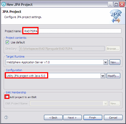
Chapter 12. Persistence using the Java Persistence API (JPA) 283
Draft Document for Review December 9, 2008 2:44 pm 7672-pers-2-jpa.fm
Figure 12-1 New JPA Project
In the New JPA Project wizard, JPA Facet page (Figure 12-2):
– For Platform select RAD JPA Platform.
– For Connection select ITSOBANKderby. If the connection is not active,
click Connect.
– Clear Override default schema from connection (ITSO is the schema).
– For JPA implementation, select Use implementation provided by the
server runtime.
– For persistent class management select Discover annotated classes
automatically.
–Select Create orm.xml.
– Click Finish.

7672-pers-2-jpa.fm Draft Document for Review December 9, 2008 2:44 pm
284 Rational Application Developer V7.5 Programming Guide
Figure 12-2 JPA Facet
When prompted to switch to the JPA perspective, click Yes.
The RAD75JPA project is created. Two files are created in the src/META-INF
folder:
– An empty orm.xml file that can be used for explicit mapping of entities to
database tables.
–A persistence.xml file that defines a persistence unit (RAD75JPA):
<?xml version="1.0" encoding="UTF-8"?>
<persistence version="1.0"
xmlns="http://java.sun.com/xml/ns/persistence"
xmlns:xsi="http://www.w3.org/2001/XMLSchema-instance"
xsi:schemaLocation="http://java.sun.com/xml/ns/persistence
http://java.sun.com/xml/ns/persistence/persistence_1_0.xsd">
<persistence-unit name="RAD75JPA">
</persistence-unit>
</persistence>
This file holds the persistent entity classes.

Chapter 12. Persistence using the Java Persistence API (JPA) 285
Draft Document for Review December 9, 2008 2:44 pm 7672-pers-2-jpa.fm
Generating JPA entities from database tables
Now we can generate the JPA entities from the ITSOBANK database into the JPA
project. Perform these steps.
In the Project Explorer, right-click the RAD75JPA project and select JPA
Tools → Generate Entities.
In the Generate Entities wizard, Database Connection page, the connection
(ITSOBANKderby) and schema (ITSO) are preselected. Click Next
(Figure 12-3).
Figure 12-3 Generate Entities: Database Connection
In the Generate Entities from Tables page (Figure 12-4):
– For Package type itso.bank.entities.
–Select Synchronize Classes in persistence.xml so that the generated
classes are added to the file.
– Click Select All to select the four tables.
– Overwrite the entity name for the TRANSACT table as Transaction.
– Click Finish.
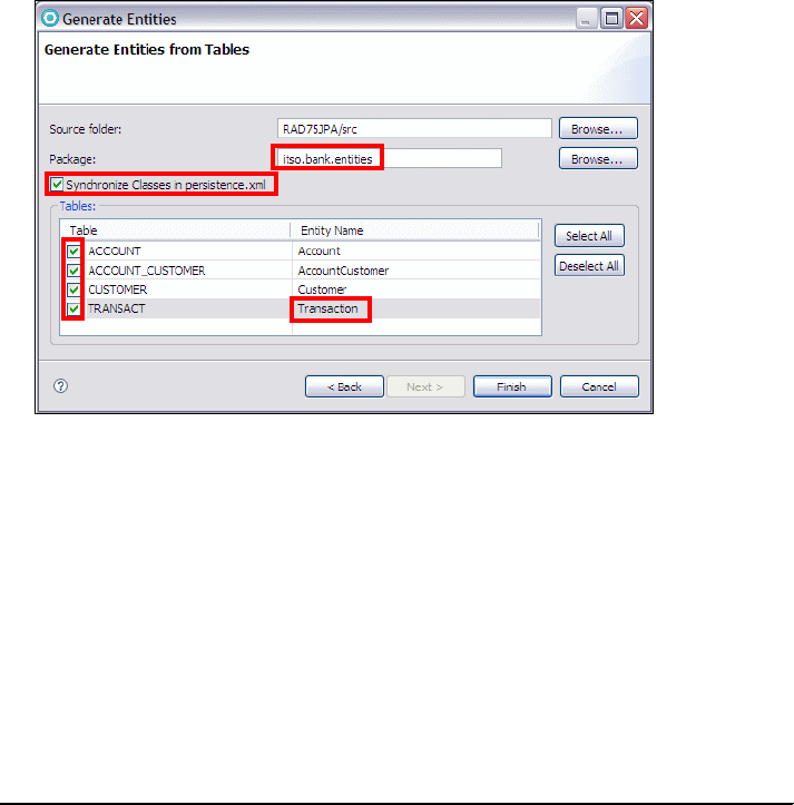
7672-pers-2-jpa.fm Draft Document for Review December 9, 2008 2:44 pm
286 Rational Application Developer V7.5 Programming Guide
Figure 12-4 Generate Entities: Tables
The itso.bank.entities package with three classes is generated, and the
three classes are added to the persistence.xml file.
Generated JPA entities
Let us study the generated entities.
Account entity
Example 12-5 shows an extract of the Account class.
Example 12-5 Account entity
package itso.bank.entities;
import java.io.Serializable;
import java.math.BigDecimal;
import java.util.Set;
import javax.persistence.Entity;
import javax.persistence.Id;
import javax.persistence.JoinColumn;
import javax.persistence.JoinTable;
import javax.persistence.ManyToMany;
import javax.persistence.OneToMany;
@Entity
public class Account implements Serializable {
@Id

Chapter 12. Persistence using the Java Persistence API (JPA) 287
Draft Document for Review December 9, 2008 2:44 pm 7672-pers-2-jpa.fm
private String id;
private BigDecimal balance;
@OneToMany(mappedBy="account")
private Set<Transaction> transactCollection;
@ManyToMany
@JoinTable(
joinColumns=@JoinColumn(name="ACCOUNT_ID"),
inverseJoinColumns=@JoinColumn(name="CUSTOMER_SSN"))
private Set<Customer> customerCollection;
......
// contructor, getter, setter methods
The @Entity annotation defined the class as an entity.
The @Id annotation defines id as the primary key.
The @OneToMany annotation defines the 1:m relationship with Transaction.
The mapping is defined in the Transaction entity. A Set<Tranasaction> field
holds the related instances.
The @ManyToMany and @JoinTables annotations define the m:m
relationship with Customer, including the two join columns. A Set<Customer>
field holds the related instances. We have to add the name of the relationship
table (ITSO.ACCOUNT_CUSTOMER).
Customer entity
Example 12-6 shows an extract of the Customer class.
Example 12-6 Customer entity
import ......;
@Entity
public class Customer implements Serializable {
@Id
private String ssn;
private String title;
@Column(name="FIRST_NAME")
private String firstName;
@Column(name="LAST_NAME")
private String lastName;

7672-pers-2-jpa.fm Draft Document for Review December 9, 2008 2:44 pm
288 Rational Application Developer V7.5 Programming Guide
@ManyToMany(mappedBy="customerCollection")
private Set<Account> accountCollection;
......
// constructor, getter, setter methods
The @Entity annotation defined the class as an entity.
The @Id annotation defines ssn as the primary key.
The @Column annotation maps the fields to a table column if the names do
not match. Note that by convention, columns names with underscores
(FIRST_NAME) create nice Java field names (firstName).
The @ManyToMany annotation defines the m:m relationship with Account.
The mapping is defined in the Account entity.
Transaction entity
Example 12-7 shows an extract of the Transaction class.
Example 12-7 Transaction entity
@Entity
@Table(name="TRANSACT")
public class Transaction implements Serializable {
@Id
private String id;
@Column(name="TRANS_TYPE")
private String transType;
@Column(name="TRANS_TIME")
private Timestamp transTime;
private BigDecimal amount;
@ManyToOne
private Account account;
......
// constructor, getter, setter methods
The @Entity annotation defined the class as an entity.
The @Table annotation defines the mapping to the TRANSACT table. Note that
the schema name (ITSO) is missing. The other two classes have no @Table
annotation because the entity name is identical to the table name.
The @Id annotation defines id as the primary key.
Chapter 12. Persistence using the Java Persistence API (JPA) 289
Draft Document for Review December 9, 2008 2:44 pm 7672-pers-2-jpa.fm
The @Column annotation maps the fields to a table column if the names do
not match.
The @ManyToOne annotation defines the m:1 relationship with Account. The
mapping defaults to account_id as the column name.
Completing the entity classes
The generated entities are missing the table mapping, such as ITSO.CUSTOMER.
Without explicit mapping, default table names are assumed, and such default
names have the current user ID as schema name.
For the Account entity we add the @Table annotation to the entity and the
relationship:
@Entity
@Table (schema="ITSO", name="ACCOUNT")
public class Account implements Serializable {
......
@ManyToMany
@JoinTable(name="ACCOUNT_CUSTOMER", schema="ITSO",
joinColumns=@JoinColumn(name="ACCOUNT_ID"),
inverseJoinColumns=@JoinColumn(name="CUSTOMER_SSN"))
private Set<Customer> customerCollection;
For the Customer entity we add the @Table annotation:
@Entity
@Table (schema="ITSO", name="CUSTOMER")
public class Customer implements Serializable {
For the Transaction entity we add the schema to the @Table annotation, and
the @ForeignKey annotation to the relationship with Account:
@Entity
@Table(schema="ITSO", name="TRANSACT")
public class Transaction implements Serializable {
......
@ManyToOne
@ForeignKey
private Account account;
Resolve the missing import statement by selecting Source → Organize
Imports or press Ctrl+Shift+O.
Verifying the persistence.xml file
Open the persistence.xml file and verify that the three class have been added:
<persistence version="1.0" ......>
<persistence-unit name="RAD75JPA">
<class>

7672-pers-2-jpa.fm Draft Document for Review December 9, 2008 2:44 pm
290 Rational Application Developer V7.5 Programming Guide
itso.bank.entities.Account</class>
<class>
itso.bank.entities.Customer</class>
<class>
itso.bank.entities.Transaction</class>
</persistence-unit>
</persistence>
Adding business logic
We want to add business logic, so that an account balance can only be changed
through a deposit or withdraw of funds. In addition, a deposit or withdraw must
create a transaction record.
Transaction class
To create transaction records, we define the possible values for transaction type
(credit and debit), and add a constructor with parameters,
Define two constants in the Transaction class:
public static final String DEBIT = "Debit";
public static final String CREDIT = "Credit";
Add a constructor that sets the id to a universally unique identifier (UUID),
and the transTime to the current time stamp.
public Transaction(String transType, BigDecimal amount) {
super();
setId(java.util.UUID.randomUUID().toString());
setTransType(transType);
setAmount(amount);
setTransTime( new Timestamp(System.currentTimeMillis()) );
}
Account class
First, we change the constructor to initialize the balance. Open the Account class
and change the code of the constructor:
public Account() {
super();
setBalance(new BigDecimal(0.00));
}
Note: Transaction objects must have a unique key, and the time stamp
(transTime field) is not unique on fast machines. Therefore, we create a
UUID using a Java utility class.

Chapter 12. Persistence using the Java Persistence API (JPA) 291
Draft Document for Review December 9, 2008 2:44 pm 7672-pers-2-jpa.fm
Next, we make the setBalance method private, so that is cannot be used by
clients:
private void setBalance(BigDecimal balance) {
this.balance = balance;
}
Finally, we add a processTransaction method that performs the credit or debit of
funds, and creates a transaction instance (Example 12-8).
Example 12-8 Processing credit and debit transactions
public Transaction processTransaction
(BigDecimal amount, String transactionType) throws Exception {
if (Transaction.CREDIT.equals(transactionType)) {
balance = balance.add(amount);
} else if (Transaction.DEBIT.equals(transactionType)) {
if (balance.compareTo(amount) < 0)
throw new Exception("Not enough funds for DEBIT of " + amount);
balance = balance.subtract(amount);
} else
throw new Exception("Invalid transaction type");
Transaction transaction = new Transaction(transactionType, amount);
transaction.setAccount(this);
return transaction;
}
Notice that the method verifies that enough funds are available for withdraw
(debit). After adjusting the balance, a transaction instance is created, and the
account is set into the new transaction.
Resolve the missing imports by selecting Source → Organize Imports, or press
Ctrl-Shift-O.
Adding named queries
Named queries can provide additional functionality, such as retrieving all the
instances of a class, or retrieving related instances by following a relationship
and sorting the results. When following the relationships through the generated
collection (Set), the related instances can be in any order.
Note that named queries are based on the entity attributes, and not on the
column names in the mapped table.
7672-pers-2-jpa.fm Draft Document for Review December 9, 2008 2:44 pm
292 Rational Application Developer V7.5 Programming Guide
Customer class
For the Customer class we want to be able to retrieve all customers, retrieve a
customer by partial last name, and we want to retrieve the list of accounts sorted
by the account ID.
Open the Customer class.
Add a @NamedQueries annotation that defines four named queries:
@Entity
@Table (schema="ITSO", name="CUSTOMER")
@NamedQueries({
@NamedQuery(name="getCustomers", query="select c from Customer c"),
@NamedQuery(name="getCustomerBySSN", query="select c from Customer c
where c.ssn =?1"),
@NamedQuery(name="getCustomersByPartialName", query="select c from
Customer c where c.lastName like ?1"),
@NamedQuery(name="getAccountsForSSN", query="select a from Customer
c, in(c.accountCollection) a where c.ssn =?1 order by a.id")
})
public class Customer implements Serializable {
The four queries enable these functions:
getCustomers Retrieve all customers
getCustomerBySSN Retrieve the customer for a given ssn, as an
alternative to the entity manager find method
getCustomerByPartialName Retrieve a list of customer by partial last name
getAccountsForSSN Retrieve the accounts of one customer
The last query illustrates how to follow a relationship (accountCollection)
from a customer to the related accounts, and sort them by their ID.
Alwayd organize imports (select Source → Organize Imports or press
Ctrl+Shift+O).
Account class
In the Account class we add two named queries to retrieve the accounts for a
customer, and to retrieve the transactions for an account. Both queries follow the
relationships defined in the Account class.
Open the Account class.
Add two named queries:
@Entity
@Table (schema="ITSO", name="ACCOUNT")
@NamedQueries({
@NamedQuery(name="getAccountsBySSN", query="select a from Account a,
in(a.customerCollection) c where c.ssn =?1 order by a.id"),
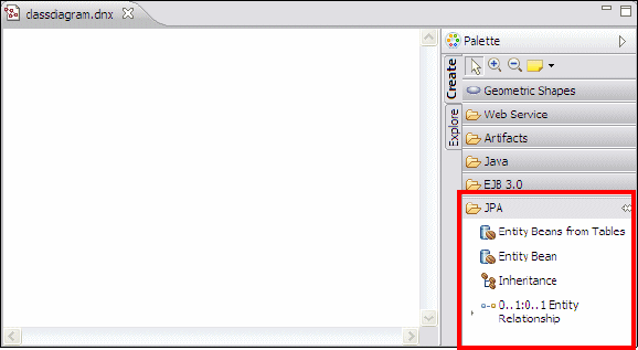
Chapter 12. Persistence using the Java Persistence API (JPA) 293
Draft Document for Review December 9, 2008 2:44 pm 7672-pers-2-jpa.fm
@NamedQuery(name="getTransactionsByID", query="select t from
Account a, in(a.transactCollection) t where a.id =?1
order by t.transTime")
})
public class Account implements Serializable {
Note that we use either the getAccountsForSSN query defined in the Customer
class, or the getAccountsBySSN query defined in the Account class, to retrieve
the accounts of a customer.
Visualizing the JPA entities
A UML diagram can vsualize JPA entities and their relationships. Entities can be
created from the diagram, or the UML diagram can be used to visualize existing
entities.
We create a UML class diagram from the generated JPA entities.
Right-click the RAD75JPA project and select New → Class Diagram.
Accept the default name (classdiagram), and click Finish.
When prompted to enable modeling capabilities, click OK.
The class diagram opens. Expand the Palette, JPA drawer (Figure 12-5).
Figure 12-5 Class diagram with JPA Palette
Drag the Customer class into the diagram (Figure 12-6).
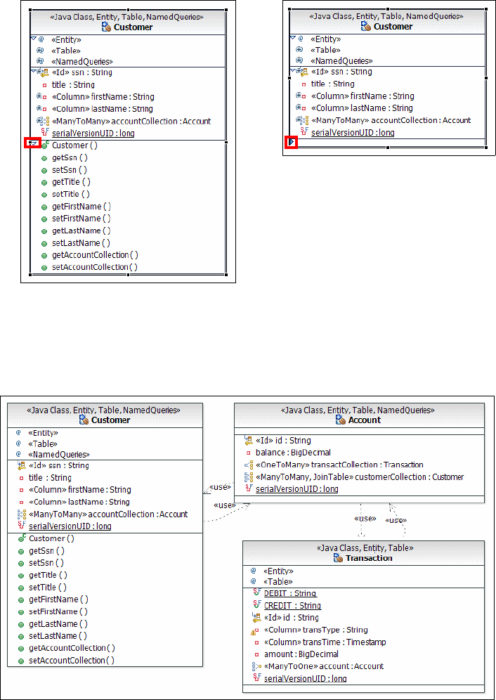
7672-pers-2-jpa.fm Draft Document for Review December 9, 2008 2:44 pm
294 Rational Application Developer V7.5 Programming Guide
Figure 12-6 Customer class visualized
Drag the Account and Transaction classes into the diagram. Close the
method compartments. Select and drag the <<use>> arrows to separate
them (Figure 12-7). Save and close the diagram.
Figure 12-7 JPA class diagram
Click the little down arrow to
compress a compartment
Chapter 12. Persistence using the Java Persistence API (JPA) 295
Draft Document for Review December 9, 2008 2:44 pm 7672-pers-2-jpa.fm
Testing JPA entities
One of the benefits of JPA entities over CMP beans is that they can be tested
outside of a WebSphere application server using a Java class with a main
method. JPA entities can also be tested using the JUnit framework. JUnit will be
covered in Chapter 23, “Test using JUnit” on page 819.
To test the entities we create an independent project (RAD75JPATest) that links
to the JPA project (RAD75JPA). To run JPA outside of the server, we have to use
the OpenJPA implementation, and not the JPA implementation of the server. This
requires modifications to the persistence.xml file.
Creating the Java project for entity testing
To test the JPA entities, we use a simple Java project.
In the Java perspective, right-click in the Package Explorer and select New →
Java Project.
In the Create a Java Project dialog, type RAD75JPATest as Project name,
accept all the defaults, and click Next.
In the Java Settings dialog, select the Projects tab, and click Add. Select the
RAD75JPA project—which we will be testing—and click OK.
Click Finish.
When prompted to switch to the Java perspective, click Yes.
Creating a Java class for entity testing
Let us create an EntityTester class with a main method.
Right-click the RAD75JPATest project and select New → Class.
In the Java Class dialog:
–Type itso.bank.entities.test as Package.
–Type EntityTester as Name.
– For Which method stubs would you like to create, select public static
void main(String[] args).
– Click Finish, and the EntityTester class opens in the editor.

7672-pers-2-jpa.fm Draft Document for Review December 9, 2008 2:44 pm
296 Rational Application Developer V7.5 Programming Guide
Setting up the build path for OpenJPA
Because this class runs outside of the server, we have to add the required JPA
and server libraries to the build path.
Right-click the RAD75JPATest project and select Properties.
In the Properties dialog, select Java Build Path (on the left) and the Source
tab. Change the output folder from RAD75JPATest/bin to RAD75JPATest/src
(Figure 12-8). Without this change, the persistence.xml file that we create
will not be found.
Figure 12-8 Java Build Path of Java project: Source
Select the Libraries page (Figure 12-9):
Figure 12-9 Java Build Path of Java project: Libraries

Chapter 12. Persistence using the Java Persistence API (JPA) 297
Draft Document for Review December 9, 2008 2:44 pm 7672-pers-2-jpa.fm
– Click Add Variable.
– In the New variable Classpath Entry dialog, select ECLIPSE_HOME, and
click Extend (Figure 12-10).
Figure 12-10 Extending a variable
– In the Variable Extension dialog, expand runtimes → base_v7 → lib,
select the j2ee.jar, and click OK (Figure 12-11).
Figure 12-11 Selecting a runtime JAR file
Note that relative
references
through variables
are more flexible
than references to
external JAR files.

7672-pers-2-jpa.fm Draft Document for Review December 9, 2008 2:44 pm
298 Rational Application Developer V7.5 Programming Guide
– Repeat this sequence by extending the ECLIPSE_HOME variable, and select
these JAR files:
runtimes/base_v7/derby/lib/derby.jar
runtimes/base_v7/plugins/com.ibm.ffdc.jar
runtimes/base_v7/plugins/com.ibm.ws.jpa.jar
runtimes/base_v7/plugins/com.ibm.ws.prereq.commons-collections.jar
– The Libraries tab shows now the extra JAR files (Figure 12-12).
Figure 12-12 Library tab with five extra JAR files
– Click OK to close the Properties dialog.
Setting up the persistence.xml file
The persistence.xml file is used to configure the OpenJPA implementation.
Because we want to use the RAD75JPA project later in the WebSphere server,
we do not want to change that file. We can create a similar file in the
RAD75JPATest project, so that it overwrites the file in the RAD75JPA project.
Right-click the src folder in the RAD75JPATest project and select New →
Folder. Enter META-INF as Folder name and click Finish.
Copy the persistence.xml file from the RAD75JPA project into the META-INF
folder of the RAD75JPATest project.
Open the persistence.xml file. In the editor (Example 12-9).
–Add transaction-type to the <persistence-unit> tag.
– Remove the <jta-data-source> tag.
–Add a <provider> tag.
– Add four properties to setup connection to the ITSOBANK database and for
logging.
Example 12-9 Persistence.xml file for OpenJPA
<?xml version="1.0" encoding="UTF-8"?>
<persistence ......>
<persistence-unit name="RAD75JPA" transaction-type="RESOURCE_LOCAL">
<provider>org.apache.openjpa.persistence.PersistenceProviderImpl

Chapter 12. Persistence using the Java Persistence API (JPA) 299
Draft Document for Review December 9, 2008 2:44 pm 7672-pers-2-jpa.fm
</provider>
<class>
itso.bank.entities.Account</class>
<class>
itso.bank.entities.Customer</class>
<class>
itso.bank.entities.Transaction</class>
<properties>
<property name="openjpa.ConnectionURL"
value="jdbc:derby:C:\7672code\database\derby\ITSOBANK" />
<property name="openjpa.ConnectionDriverName"
value="org.apache.derby.jdbc.EmbeddedDriver" />
<property name="openjpa.ConnectionUserName" value="itso" />
<property name="openjpa.Log" value="none" />
</properties>
</persistence-unit>
</persistence>
You can copy and paste the code from 7672code\jpa\test\persistence.xml.
Creating the test
To test the JPA entities we complete the main method in the EntityTester class
(Example 12-10).
Copy and paste the code from 7639code\jpa\test\EntityTester.java.
Select Source → Organize Imports, be sure to resolve:
java.math.BigDecimal
javax.persistence.Query
itso.bank.entities.Transaction
java.util.List
Note: If you want to use DB2 for the JPA entities, add these JAR files to the
Libraries page:
<SQLLIB-HOME>/java/db2jcc.jar
<SQLLIB-HOME>/java/db2jcc_license_cu.jarr
Change the JPA properties in the persistence.xml file to:
<property name="openjpa.ConnectionURL"
value="jdbc:db2://localhost:50000/ITSOBANK" />
<property name="openjpa.ConnectionDriverName"
value="com.ibm.db2.jcc.DB2Driver" />
<property name="openjpa.ConnectionUserName" value="db2admin" />
<property name="openjpa.ConnectionPassword" value="<password>"/>
<property name="openjpa.Log" value="none" />

7672-pers-2-jpa.fm Draft Document for Review December 9, 2008 2:44 pm
300 Rational Application Developer V7.5 Programming Guide
Example 12-10 Testing JPA entities using a Java program
public class EntityTester {
static EntityManager em;
public static void main(String[] args) {
String customerId = "111-11-1111";
if (args.length > 0) customerId = args[0];
System.out.println("Entity Testing");
System.out.println("\nCreating EntityManager");
em = Persistence.createEntityManagerFactory("RAD75JPA")
.createEntityManager();
System.out.println("RAD75JPA EntityManager successfully created\n");
em.getTransaction().begin();
System.out.println("\nAll customers: ");
Query query1 = em.createNamedQuery("getCustomers");
List<Customer> custList1 = query1.getResultList();
for (Customer cust : custList1) {
System.out.println(cust.getSsn() + " " + cust.getTitle() + " "
+ cust.getFirstName() + " " + cust.getLastName());
}
System.out.println("\nCustomers by partial name: a");
Query query2 = em.createNamedQuery("getCustomersByPartialName");
query2.setParameter(1, "%a%");
List<Customer> custList2 = query2.getResultList();
for (Customer cust : custList2) {
System.out.println(cust.getSsn() + " " + cust.getTitle() + " "
+ cust.getFirstName() + " " + cust.getLastName());
}
System.out.println("\nRetrieve one customer: " + customerId);
Customer cust = em.find(Customer.class, customerId);
System.out.println(cust.getSsn() + " " + cust.getTitle() + " "
+ cust.getFirstName() + " " + cust.getLastName());
Set<Account> acctSet = cust.getAccountCollection();
System.out.println("Customer has " + acctSet.size() + " accounts");
for (Account account : acctSet) {
System.out.println("Account: " + account.getId() + " balance "
+ account.getBalance());
}
System.out.println
("\nRetrieve customer accounts sorted using named query:");
Query query3 = em.createNamedQuery("getAccountsBySSN");
query3.setParameter(1, cust.getSsn());

Chapter 12. Persistence using the Java Persistence API (JPA) 301
Draft Document for Review December 9, 2008 2:44 pm 7672-pers-2-jpa.fm
List<Account> acctList = query3.getResultList();
for (Account account : acctList) {
System.out.println("Account: " + account.getId() + " balance "
+ account.getBalance());
}
System.out.println("\nPerform transactions on one account: " );
Account account = acctList.get(0);
System.out.println("Account: " + account.getId() + " balance "
+ account.getBalance());
Transaction tx = null;
try {
BigDecimal balance = account.getBalance();
tx = account.processTransaction(new BigDecimal(100.00), "Credit");
em.persist(tx); // make insert persistent
System.out.println("Tx created: " + tx.getAccount().getId() + " "
+ tx.getTransType() + " " + tx.getAmount() + " "
+ tx.getTransTime() + " id " + tx.getId());
tx = account.processTransaction(new BigDecimal(50.00), "Debit");
em.persist(tx);
System.out.println("Tx created: " + tx.getAccount().getId() + " "
+ tx.getTransType() + " " + tx.getAmount() + " "
+ tx.getTransTime() + " id " + tx.getId());
tx = account.processTransaction( balance.add(new BigDecimal(200.00)),
"Debit");
em.persist(tx);
} catch (Exception e) {
System.out.println("Transaction failed: " + e.getMessage());
}
em.flush(); // make inserts persistent in the DB
em.refresh(account); // retrieve account again to access transactions
System.out.println("\nAccount: " + account.getId() + " balance "
+ account.getBalance());
//List<Transaction> transList = (List<Transaction>)account
.getTransactCollection();
Query query4 = em.createNamedQuery("getTransactionsByID");
query4.setParameter(1, account.getId());
List<Transaction> transList = query4.getResultList();
System.out.println("Account has " + transList.size() + " transactions");
for (Transaction tran : transList) {
System.out.println("Transaction: " + tran.getTransType() + " "
+ tran.getAmount() + " " + tran.getTransTime() + " id " + tran.getId());
}
em.getTransaction().commit ();
}
}
7672-pers-2-jpa.fm Draft Document for Review December 9, 2008 2:44 pm
302 Rational Application Developer V7.5 Programming Guide
Understanding the entity testing code
Let us understand how to work with entities:
We require en entity manager for the RAD75JPA persistence unit.
static EntityManager em;
......
em = Persistence.createEntityManagerFactory("RAD75JPA")
.createEntityManager();
We start a transaction (this is not required for read-only access).
em.getTransaction().begin();
We retrieve all the customers with the getCustomers named query. A named
query with multiple results returns a list.
Query query1 = em.createNamedQuery("getCustomers");
List<Customer> custList1 = query1.getResultList();
We use the new Java 5 support for iterating though a list.
for (Customer cust : custList1) { .... }
We use the getCustomersByPartialName named query to retrieve customer
with the letter a in the last name. This query illustrates how to set a parameter
in the query.
Query query2 = em.createNamedQuery("getCustomersByPartialName");
uery2.setParameter(1, "%a%");
We use the accountCollection relationship in the Customer class to list the
related accounts. When we list the accounts they are in any order.
Set<Account> acctSet = cust.getAccountCollection();
We use the getAccountsBySSN named query to retrieve the related accounts
in sorted order.
Query query3 = em.createNamedQuery("getAccountsBySSN");
query3.setParameter(1, cust.getSsn());
List<Account> acctList = query3.getResultList();
We process transactions on one account. The last transaction fails because
the amount is larger than the balance.
tx = account.processTransaction(new BigDecimal(100.00), "Credit");
tx = account.processTransaction(new BigDecimal(50.00), "Debit");
tx = account.processTransaction( balance.add(new BigDecimal(200.00)),
"Debit");
We have to persist each new transaction.
em.persist(tx);

Chapter 12. Persistence using the Java Persistence API (JPA) 303
Draft Document for Review December 9, 2008 2:44 pm 7672-pers-2-jpa.fm
We want to retrieve the account and see all the transactions. The flush
method writes the updates to the database, and the refresh method
refreshes the account in memory.
em.flush(); // make inserts persistent in the DB
em.refresh(account); // retrieve account again to access transactions
We list the transactions of the account in time stamp sequence using the
getTransactionsByID named query. The transactCollection would return
the transactions in any sequence.
//List<Transaction> transList = (List<Transaction>)account
// .getTransactCollection();
Query query4 = em.createNamedQuery("getTransactionsByID");
query4.setParameter(1, account.getId());
List<Transaction> transList = query4.getResultList();
We commit all the changes.
em.getTransaction().commit();
Running the JPA entity test
Now we can run the test.
Make sure that the ITSOBANKderby connection is disconnected (with
Embedded Derby you can only have one active connection to a database).
You can verify this in the JPA perspective, Data Source Explorer. If the
connection is active, right-click the connection and select Disconnect.
Right-click the EntityTester class and select Run As → Java Application.
You receive error messages in the Console that the Customer class cannot be
found.
Select Run → Run Configurations. You can find the EntityTester
configuration under Java Application.
Select the Arguments tab.
For Program arguments, type 333-33-3333 (we want to work with that
employee).
For VM arguments, type (use the installation directory):
-javaagent:c:/IBM/SDP75/runtimes/base_v7/plugins/com.ibm.ws.jpa.jar
Note: OpenJPA includes a Java agent for automatically enhancing
persistent classes as they are loaded into the JVM. Java agents are
classes that are invoked prior to your application's main method.
OpenJPA's agent uses JVM hooks to intercept all class loading to enhance
classes that have persistence metadata before the JVM loads them.
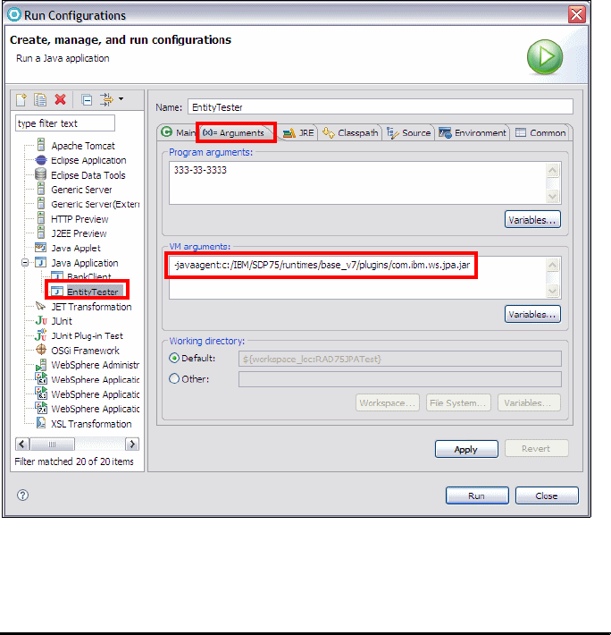
7672-pers-2-jpa.fm Draft Document for Review December 9, 2008 2:44 pm
304 Rational Application Developer V7.5 Programming Guide
Figure 12-13 shows the run configuration arguments.
Figure 12-13 Run configuration arguments
Click Apply, the click Run. The Console displays the output (Example 12-11).
Example 12-11 Sample output of entity tester
Entity Testing
Creating EntityManager
RAD75JPA EntityManager successfully created
All customers:
Aug 11, 2008 3:54:30 PM null null
SEVERE: javaAccessorNotSet
111-11-1111 Mr Henry Cui
222-22-2222 Ms Pinar Ugurlu
333-33-3333 Mr Marco Rohr
444-44-4444 Mr Xxxxx Yyyyyyy
555-55-5555 Mr Aaaa Bbbbb

Chapter 12. Persistence using the Java Persistence API (JPA) 305
Draft Document for Review December 9, 2008 2:44 pm 7672-pers-2-jpa.fm
666-66-6666 Mr Patrick Gan
777-77-7777 Mr Celso Gonzales
888-88-8888 Mr Cccccc Ddddddd
999-99-9999 Mr Eeeeeee Fffffffff
000-00-0000 Mr Ueli Wahli
Customers by partial name: a
666-66-6666 Mr Patrick Gan
777-77-7777 Mr Celso Gonzales
000-00-0000 Mr Ueli Wahli
Retrieve one customer: 333-33-3333
333-33-3333 Mr Marco Rohr
Customer has 3 accounts
Account: 003-999000777 balance 9926.52
Account: 003-999000999 balance 21.56
Account: 003-999000888 balance 568.79
Retrieve customer accounts sorted using named query:
Account: 003-999000777 balance 9876.52
Account: 003-999000888 balance 568.79
Account: 003-999000999 balance 21.56
Perform transactions on one account:
Account: 003-999000777 balance 9876.52
Tx created: 003-999000777 Credit 100 2008-08-11 16:01:46.14 id
5c6e691c-f107-4902-8be8-93e4230fcba6
Tx created: 003-999000777 Debit 50 2008-08-11 16:01:46.14 id
25a93a1a-7ef5-4a23-a925-6f7c638cddd3
Transaction failed: Not enough funds for DEBIT of 10076.52
Account: 003-999000777 balance 9926.52
Account has 2 transactions
Transaction: Credit 100 2008-08-11 16:01:46.14 id
5c6e691c-f107-4902-8be8-93e4230fcba6
Transaction: Debit 50 2008-08-11 16:01:46.14 id
25a93a1a-7ef5-4a23-a925-6f7c638cddd3
Repeat the test by selecting Run → Run History → Entity Tester. This time
four transactions are listed for the account.
7672-pers-2-jpa.fm Draft Document for Review December 9, 2008 2:44 pm
306 Rational Application Developer V7.5 Programming Guide
Displaying the SQL statements
We can configure the OpenJPA properties so that the SQL statements issued
against the database are displayed.
Open the persistence.xml file (in RAD75JPATest).
Change the openjpa.Log property to the value SQL=TRACE.
<property name="openjpa.Log" value="SQL=TRACE" />
Rerun the test (Run → Run History → Entity Tester) and you can see the
SQL statements.
– All customers:
SELECT t0.ssn, t0.FIRST_NAME, t0.LAST_NAME, t0.title FROM ITSO.CUSTOMER
t0
– Customers by partial last name:
SELECT t0.ssn, t0.FIRST_NAME, t0.LAST_NAME, t0.title FROM ITSO.CUSTOMER
t0 WHERE (t0.LAST_NAME LIKE ? ESCAPE '\') [params=(String) %a%]
– Accounts of a customer:
SELECT t1.id, t1.balance FROM ITSO.ACCOUNT_CUSTOMER t0 INNER JOIN
ITSO.ACCOUNT t1 ON t0.ACCOUNT_ID = t1.id WHERE t0.CUSTOMER_SSN = ?
[params=(String) 333-33-3333]
– Accounts of a customer sorted:
SELECT t0.id, t0.balance FROM ITSO.ACCOUNT t0 INNER JOIN
ITSO.ACCOUNT_CUSTOMER t1 ON t0.id = t1.ACCOUNT_ID INNER JOIN
ITSO.CUSTOMER t2 ON t1.CUSTOMER_SSN = t2.ssn WHERE (t1.CUSTOMER_SSN = ?)
ORDER BY t0.id ASC [params=(String) 333-33-3333]
– Perform a transaction:
INSERT INTO ITSO.TRANSACT (id, amount, TRANS_TIME, TRANS_TYPE,
ACCOUNT_ID) VALUES (?, ?, ?, ?, ?) [params=(String)
c77b2cb3-a4a6-4db3-bb27-22dec71b8bb2, (BigDecimal) 50, (Timestamp)
2008-08-11 16:12:49.406, (String) Debit, (String) 003-999000777]
– Update the account balance after the transactions:
UPDATE ITSO.ACCOUNT SET balance = ? WHERE id = ? [params=(BigDecimal)
10026.52, (String) 003-999000777]
– Transactions of an account:
SELECT t1.id, t1.ACCOUNT_ID, t1.amount, t1.TRANS_TIME, t1.TRANS_TYPE
FROM ITSO.ACCOUNT t0 INNER JOIN ITSO.TRANSACT t1 ON t0.id =
t1.ACCOUNT_ID WHERE (t0.id = ?) ORDER BY t1.TRANS_TIME ASC
[params=(String) 003-999000777]
Replace value "SQL=TRACE" by the value "none" to deactivate the trace.

Chapter 12. Persistence using the Java Persistence API (JPA) 307
Draft Document for Review December 9, 2008 2:44 pm 7672-pers-2-jpa.fm
Adding inheritance
We have two types of transactions, Credit and Debit. The two types are
distinguished in the database table by the TRANS_TYPE column, which became the
transType field in the Transaction class.
In this section we define two subclasses of Transaction, Credit and Debit. We
use single table inheritance, that is, we map all three classes to one table. The
TRANS_TYPE column becomes the discriminator column, and the transType field
goes away from the Transaction class.
Changing the Transaction class for inheritance
Inheritance is defined through three annotations:
@Inheritance—Defines that inheritance is present
@DiscriminatorColumn—Defines the discriminator column
@DiscriminatorValue—Defines the value for each class
To define inheritance in the Transaction class, perform these steps:
Open the Transaction class.
Add the annotations and make the class abstract (there are no Transaction
instances, only Credit and Debit):
@Entity
@Table(schema="ITSO", name="TRANSACT")
@Inheritance
@DiscriminatorColumn(name="TRANS_TYPE",
discriminatorType=DiscriminatorType.STRING, length=32)
public abstract class Transaction implements Serializable {
The transType field is not part of the instances, once the matching column is
used as the discriminator column. Remove or comment the transType field:
//@Column(name="TRANS_TYPE")
//private String transType;
Change the getTransType method to abstract (we still want to provide the
transType value to clients), and remove the setter:
public abstract String getTransType();
public void setTransType(String transType) { ...... }
Remove transType from the constructor:
public Transaction(String transType, BigDecimal amount) {
super();
setId(java.util.UUID.randomUUID().toString());
setTransType(transType);
setAmount(amount);
setTransTime( new Timestamp(System.currentTimeMillis()) );
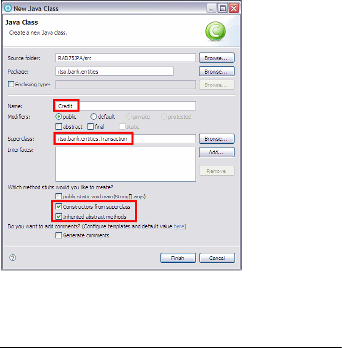
7672-pers-2-jpa.fm Draft Document for Review December 9, 2008 2:44 pm
308 Rational Application Developer V7.5 Programming Guide
}
Adding the Credit subclass
The Credit class is a subclass of the Transaction class, and is mapped to the
same ITSO.TRANSACT table.
Create a Credit class in the itso.bank.entities package as a subclass of
Transaction (Figure 12-14):
– Set the superclass to itso.bank.entities.Transaction.
–Select Constructor from superclass, and Inherited abstract methods.
– Click Finish.
Figure 12-14 Creating the Credit class
Complete the code with annotations and implement the getTransType method
(Example 12-12).
Example 12-12 Credit class
@Entity
@Table (schema="ITSO", name="TRANSACT")
Chapter 12. Persistence using the Java Persistence API (JPA) 309
Draft Document for Review December 9, 2008 2:44 pm 7672-pers-2-jpa.fm
@Inheritance
@DiscriminatorValue("Credit")
public class Credit extends Transaction {
public Credit() {
super(new BigDecimal(0.00));
}
public Credit(BigDecimal amount) {
super(amount);
}
@Override
public String getTransType() {
return Transaction.CREDIT;
}
}
To resolve the warning that the class does not implement a serialVersionID,
click the warning marker, and select Add default seriel version ID.
Adding the Debit subclass
Repeat the sequence and define the Debit subclass (Example 12-13).
Example 12-13 Debit class
@Entity
@Table (schema="ITSO", name="TRANSACT")
@Inheritance
@DiscriminatorValue("Debit")
public class Debit extends Transaction {
private static final long serialVersionUID = 1L; //generated
public Debit() {
super(new BigDecimal(0.00));
}
public Debit(BigDecimal amount) {
super(amount);
}
@Override
public String getTransType() {
return Transaction.DEBIT;
}
}
7672-pers-2-jpa.fm Draft Document for Review December 9, 2008 2:44 pm
310 Rational Application Developer V7.5 Programming Guide
Changing the Account class to process transactions
The processTransaction method in the Account class shows an error, because
we create a Transaction instance. We have to change the method to create
either a Credit or a Debit instance.
Open the Account class.
Change the processTransaction method (Example 12-14).
Example 12-14 Processing credit or debit transactions
public Transaction processTransaction(BigDecimal amount,
String transactionType) throws Exception {
Transaction transaction = null;
if (Transaction.CREDIT.equals(transactionType)) {
balance = balance.add(amount);
transaction = new Credit(amount);
} else if (Transaction.DEBIT.equals(transactionType)) {
if (balance.compareTo(amount) < 0)
throw new Exception("Not enough funds for DEBIT of " + amount);
balance = balance.subtract(amount);
transaction = new Debit(amount);
} else throw new Exception("Invalid transaction type");
Transaction transaction = new Transaction(transactionType, amount);
transaction.setAccount(this);
return transaction;
}
Adding toString methods for printing
To facilitate nice output when testing, especially with the Universal Test Client, we
add toString methods to the classes.
Open the Account class and add the toString method:
public String toString() {
return "Account: " + getId() + " balance " + getBalance();
}
Open the Customer class and add the toString method:
public String toString() {
return "Customer: " + getSsn() + " " + getTitle() + " "
+ getFirstName() + " " + getLastName();
}
Open the Transaction class and add the toString method:
public String toString() {
return getTransType() + ": " + getAmount() + " at "
+ getTransTime() + " (" + getAccount().getId() + ")";
}

Chapter 12. Persistence using the Java Persistence API (JPA) 311
Draft Document for Review December 9, 2008 2:44 pm 7672-pers-2-jpa.fm
Testing inheritance
The EntityTester class shows no errors, and we can run the test unchanged
(select Run → Run History → EntityTester). However, if you run the test, you
get an error message:
Transaction failed: No metadata was found for type "class
itso.bank.entities.Credit". The class does not appear in the list of
persistent types: [itso.bank.entities.Customer, itso.bank.entities.Account,
itso.bank.entities.Transaction].
We have to add the new types to the persistence.xml file:
<class>
itso.bank.entities.Account</class>
<class>
itso.bank.entities.Customer</class>
<class>
itso.bank.entities.Transaction</class>
<class>
itso.bank.entities.Credit</class>
<class>
itso.bank.entities.Debit</class>
Now you can rerun the test and it works.
Adding inheritance to the class diagram
We can add the two subclasses to the class diagram by dragging them into the
diagram. Then rearrange the diagram for better visibility (Figure 12-15).
Note: You have to update the persistence.xml files in both projects
(RAD75JPA and RAD75JPATest). For now, changing it in RAD75JPATest is
enough, but for later we need it in RAD75JPA as well.

7672-pers-2-jpa.fm Draft Document for Review December 9, 2008 2:44 pm
312 Rational Application Developer V7.5 Programming Guide
Figure 12-15 Complete class diagram of JPA entities
Preparing the entities for deployment in the server
In later chapters we access the JPA entities from EJB 3.0 session beans. For that
we have to configure the server with a data source for the ITSOBANK database,
and we have to configure the persistence.xml file to specify the JNDI name of
the data source.
The data source of the ITSOBANK database is defined in “Configuring the data
source in WebSphere Application Server” on page 1155:
– For user with DB2, we define data sources for both Derby and DB2. The
JNDI names are jdbc/itsobank and jdbc/itsobankdb2.
– We use jdbc/itsobank for the JPA entities. By changing the JNDI names
in the server, we can run with either database without changing the
application code.
To let JPA know what database to use at runtime, we have to add the JNDI
name of the data source to the persistence.xml file. This is only required in
the RAD75JPA project, and not in the RAD75JPATest project
(Example 12-15).

Chapter 12. Persistence using the Java Persistence API (JPA) 313
Draft Document for Review December 9, 2008 2:44 pm 7672-pers-2-jpa.fm
Example 12-15 Persistence.xml file with data source specification
<persistence ......>
<persistence-unit name="RAD75JPA">
<jta-data-source>jdbc/itsobank</jta-data-source>
<class>
......
Summary
The EJB 3.0 specification and the Java Persistence API (JPA) make development
of EJB applications much easier. There is no need for looking up EJB homes,
Web applications can access session EJBs through their business interface by
simple EJB injection. There is almost no need to develop data transfer objects
(DTO), the JPA entities can be used as DTOs.
More information
The Java Persistence API (JPA) is documented as part of the EJB 3.0
specification, and is available at:
http://jcp.org/aboutJava/communityprocess/final/jsr220/index.html
IBM developerWorks has many articles on JPA. Just type JPA into the search
field at the developerWorks Web site:
http://www.ibm.com/developerworks/
Alternative: For testing purposes, the data source can also be configured in
the WebSphere Enahnced EAR of an enterprise application. This technique is
described in “Creating a data source in the enhanced EAR” on page 802.
7672-pers-2-jpa.fm Draft Document for Review December 9, 2008 2:44 pm
314 Rational Application Developer V7.5 Programming Guide

© Copyright IBM Corp. 2008. All rights reserved. 315
Draft Document for Review December 9, 2008 2:44 pm 7672-dev-0-p5.fm
Part 5 Enterprise
application
development
In this part of the book, we describe the tooling and technologies provided by
Application Developer to develop enterprise applications using JSPs, servlets,
Enterprise JavaBeans (EJB), Struts, JavaServer Faces, Web services, Web 2.0
tools, Java Connector Architecture (JCA), and Portal Server.
Part 5
Note: The sample code for all the applications developed in this part is
available for download at:
ftp://www.redbooks.ibm.com/redbooks/SG247672
Refer to Appendix B, “Additional material” on page 1149 for instructions.
7672-dev-0-p5.fm Draft Document for Review December 9, 2008 2:44 pm
316 Rational Application Developer V7.5 Programming Guide

© Copyright IBM Corp. 2008. All rights reserved. 317
Draft Document for Review December 9, 2008 2:44 pm 7672-dev-1-web-jsp.fm
Chapter 13. Develop Web applications
using JSPs and servlets
This chapter focuses on developing Web applications using JavaServer Pages
(JSPs), Java EE servlet technology, and static HTML pages, which are
fundamental technologies for building Java EE Web applications. Through the
RedBank example, the chapter guides you through the features available in
Rational Application Developer V7.5 to work with these technologies.
In the first section, we describe the main tools available in Application Developer
to Web developers and introduce the new features provided with v7.5. Next we
present the design of the ITSO RedBank application, then we build and test the
application using the various tools available within Application Developer. In the
final section, we list sources of further information on Java EE Web components
and the Web tools within Application Developer.
The chapter is organized into the following sections:
Introduction to Java EE Web applications
Web development tooling
Summary of new features in v7.5
RedBank application design
Implementing the RedBank application
Testing the Web application
More information
13
7672-dev-1-web-jsp.fm Draft Document for Review December 9, 2008 2:44 pm
318 Rational Application Developer V7.5 Programming Guide
Introduction to Java EE Web applications
Java EE (Java Enterprise Edition) is an application development framework that
is the most popular standard for building and deploying Web applications in Java.
Two of the key underlying technologies for building the Web components of Java
EE applications are servets and JSPs. Servlets are Java classes that provide the
entry point to logic for handling a Web request and return a Java representation
of the Web response. JSPs are a mechanism to combine HTML with logic written
in Java. Once compiled and deployed, JSPs run as a servlet, where they also
take a Web request and return a Java object representing the response page.
Typically, in a large project, the JSPs and servlets are part of the presentation
layer of the application and include logic to invoke the higher level business
methods. The core business functions are usually separated out into a clearly
defined set of interfaces, so that these components can be used and changed
independently of the presentation layer (or layers, when there is more than one
interface).
Enterprise JavaBeans (EJBs) are also a key feature included in the Java EE
framework and are one popular option to implement the business logic of an
application. These are described in detail in Chapter 14, “Develop EJB
applications” on page 387. The separation of the presentation logic, business
logic, and the logic to combine them is referred to as the model-view-controller
pattern and is described later.
Technologies such as Struts, JavaServer Faces (JSF), various JSP tag libraries
and numerous others have been developed to extend the JSP and servlets
framework in different ways to improve aspects of Java EE Web development (for
example, JSF facilitates the construction of reusable UI components which can
be added to JSP pages). Some of these are described in detail in other chapters
of this book, however, it is important to note that the underlying technologies of
these tools are extensions to Java servlets and JSPs.
When planning a new project, the choice of technology depends on several
criteria (size or project, previous implementation patterns, maturity of technology,
skills of the team, and so on) and using JSPs with servlets and HTML is a
comparatively simple option for building Java EE Web applications. Figure 13-1
show the relationship between Java EE, Enterprise Application, Web
applications, EJBs, servlets, JSPs and additions such as Struts and JSF.
Chapter 13. Develop Web applications using JSPs and servlets 319
Draft Document for Review December 9, 2008 2:44 pm 7672-dev-1-web-jsp.fm
Figure 13-1 Java EE related technologies
Our focus in this chapter is on developing Web applications using JSPs, servlets,
and static pages using HTML with the tools included with Application Developer.
Once these concepts are mastered, it should be easier to understand the other
technologies available.
Java EE applications
At the highest level, the Java EE specification describes the construction of two
application types that can be deployed on any Java EE compliant application
server. These are Web applications represented by a Web Application Archive
(WAR) file or an enterprise application represented by an Enterprise Application
Archive (EAR) file. Both files are constructed in zip file format, with a defined
directory and file structure. Web applications generally contain the Web
components required to build the information presented to the end user and
some lower level logic, while the enterprise application contains an entire
application including the presentation logic and logic implementing its
interactions with an underlying database or other back-end system.
Also note that an EAR file can include one or more WAR files where the logic
within the Web applications (WARs) usually invokes the application logic in the
EAR.
Java EE Specification
Enterprise JavaBeans (EJB)
Specification
Java Servlet Specification
Web Components
JavaServer Pages (JSP)
Specification
JavaServer Faces
(JSF)
Struts
JSP Tag Libraries
Specification
Enterprise Application Components
EJB 2.1
EJB 3.0
JPA
7672-dev-1-web-jsp.fm Draft Document for Review December 9, 2008 2:44 pm
320 Rational Application Developer V7.5 Programming Guide
Enterprise applications
An enterprise application project contains the hierarchy of resources that are
required to deploy an enterprise (Java EE) application to WebSphere Application
Server. It can contain a combination of Web applications (WAR files), EJB
modules, Java libraries, and application client modules (all stored in JAR format).
They also must include a deployment descriptor (applicaton.xml within the
META-INF directory), which contains meta information to guide the installation and
execution of the application.
The JAR files within an enterprise application can be used by the other contained
modules. This allows sharing of code at the application level by multiple Web or
EJB modules.
On deployment, the EAR file is unwrapped by the application server and the
individual components (EJB modules, WAR files, and associated JAR files) are
deployed individually, however, some aspects are configured across the
enterprise application as a whole including, for example, shared JAR files.
The use of EJBs is not compulsory within an enterprise application. When
developing an enterprise application (or even a Web application) the developer
can write whatever Java is most appropriate for the situation. EJBs are the
defined standard within Java EE for implementing application logic, but many
factors can determine the decision for implementing this part of a solution. In the
RedBank sample application presented later in this chapter, the business logic is
implemented using standard Java classes that use HashMaps to store data.
Web applications
A Web application server publishes the contents of a WAR file under a defined
URL root (called a context root) and then directs Web requests to the right
resources and returns the appropriate Web response to the requestor. Some
requests can be simply mapped to a simple static resource (such as HTML files
and images) while others are mapped to a specific JSP or servlet class, which
are referred to as dynamic resources. It is through these requests that the Java
logic for a Web application is initiated and calls to the main business logic are
processed.
When a Web request is received, the application server looks at the context root
of the URL to identify which WAR the request is intended for, then the server
looks at the contents after the root to identify which resource to send the request
to. This might be a static resource (html file), the contents of which are simply
returned, or a dynamic resource (servlet or JSP), where the processing of the
request is handed over to JSP or servlet code.

Chapter 13. Develop Web applications using JSPs and servlets 321
Draft Document for Review December 9, 2008 2:44 pm 7672-dev-1-web-jsp.fm
In every WAR file there is descriptive meta information that describes this
information and guides the application server in its deployment and execution of
the servlets and JSPs within the Web application.
The structure of these elements within the WAR file is standardized and
compatible between different Web application servers. The Java EE specification
defines the hierarchical structure for the contents of a Web application that can
be used for deployment and packaging purposes. All Java EE compliant servlet
containers, including the test Web environment provided by Rational Application
Developer, support this structure.
The structure of a WAR file (and an EAR file) is shown in Figure 13-2.
Figure 13-2 Structure of EAR and WAR files
The web.xml file (also referred to as the deployment descriptor) is read on
deployment by the Web application server and guides the setting up and running
of the application. In particular, it has configuration information for starting up the
servlets and then ensuring that Web requests are mapped to the right servlet or
JSP. It also contains information on security (which user groups can access a
particular set of URLs), filters (a mechanism to call some Java code before a
request is processed), listeners (a mechanism to call some Java code on certain
events), and configuration parameters to be passed to servlets or the application
as a whole.
There are no requirements for the directory structure of a Web application
outside of the WEB-INF directory. All these resources are accessible to clients
(generally but not always Web browsers) directly from a URL given the context
root. Naturally, we recommend that you structure the Web resources in a logical
way for easy management (for example, an images folder to store graphics).
Enterprise Application Archive (EAR)
Includes following files:
/META-INF/application.xml - deployment descriptor
.jar - Utility Java libraries
.jar - Enterprise JavaBean (EJB) JARs
.war - Web Applications (WAR files).
Web Application Archive (WAR)
Includes following files:
/WEB-INF/web.xml - deployment descriptor
/WEB-INF/classes/* - Java classes used by application
/WEB-INF/lib/* - Java libraries used by application
/*.html, *.css, ... - HTML files, templates, style sheets
- all other files within WAR are accessible directly as Web
resources including html, jsps, jsp tag libraries, images,
sounds, etc.
may contain
one or more
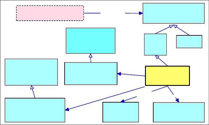
7672-dev-1-web-jsp.fm Draft Document for Review December 9, 2008 2:44 pm
322 Rational Application Developer V7.5 Programming Guide
Java EE Web APIs
The main classes used within the Java EE frame work and the interactions
between then are shown in Figure 13-3. The class ApplicationServlet is the
only class outside of the Java EE framework, and would contain the application
logic.
Figure 13-3 Java EE Web component classes
The main classes are as follows:
HttpServlet (extends Servlet)—The main entry point for handling a Web
request. The doGet, doPost (and others) methods invoke the logic for building
the response given the request and the underlying business data and logic.
HttpJspServlet (extends Servlet)—The Application Server will automatically
compile a JSP into a class that extends this type. It runs like a normal servlet
and its only entry point is the _jspService method.
HttpRequest (extends Request)—Provides an API for accessing all
pertinent information in a request.
HttpResponse (extends Response)—Provides an API for creating whatever
response is required given the request and the application state.
HttpSession—Stores any information required to be stored across a user
session with the application (as opposed to a single request).
RequestDispatcher—Within a Web application, it is often required to redirect
the processing of a request to another servlet. This class provides methods to
do this.
ServletRequest
String getParameter(String p)
void set Attribute(String s,
Object o)
Object getAttribute(String s)
ServletInputStream getInputStream()
...
HttpServletRequest
String getParameter(String p)
void setAttribute(String s, Object o)
Object getAttribute(String s)
...
Servlet
void init(..)
void service(ServletRequest, ServletResponse)
void destroy(..)
...
ServletResponse
String getParameter(String p)
void setAttribute(String s, Object o)
Object getAttribute(String s)
ServletInputStream getInputStream()
...
HttpServletResponse
String getParameter(String p)
void setAttribute(String s, Object o)
Object getAttribute(String s)
...
HttpServlet
doGet(..)
doPost(..)
doPut(..)
...
JSPServlet
_jspService(..)
RequestDispatcher
void forward(..)
void include(..)
...
HttpSession
void setAttribute(String s, Object o)
Object getAttribute(String s)
..
Application Servlet
Application Server calls service(..) for
each web request
get request
properties
build response Forward requests
to other pages
Store session
information

Chapter 13. Develop Web applications using JSPs and servlets 323
Draft Document for Review December 9, 2008 2:44 pm 7672-dev-1-web-jsp.fm
Note that there are other classes in the Java EE Web components framework,
and for a full description of the classes available refer, to “More information” on
page 385, which provides a link to the Java EE servlet specifications.
JSPs
It is possible to include any valid fragment of Java code in a JSP and mix it with
HTML. In the JSP code, the Java tags are marked by <% and %> and on
deployment (or sometimes the first page request, depending on configuration)
the JSP is compiled into a servlet class. This process combines the HTML and
the scriptlets in the JSP file in the _jspService method that populates the
HttpResponse variable. Combining a lot of complex Java code with HTML can
result in a very complicated JSP file, and except for very simple examples, this
practice should be avoided.
One way around this is to use custom JSP tag libraries, which are tags defined
by developers that initiate calls to a Java class. These classes implement the Tag,
BodyTag or IterationTag interfaces from the javax.servlet.jsp.tagext
package which is part of the Java EE framework. Each tag library is defined by a
.tld file which includes the location and content of the taglib class file. A
reference to this file has to be included in the deployment descriptor.
The most widely available tag library is the JavaServer Pages Standard Template
Library (JSTL), which provides some simple tags to handle simple operations
required in most JSP programming tasks, including looping, internationalization,
XML manipulation, and even processing of SQL result sets.
The RedBank application presented later uses JSTL tags to display tables and
add URLs to a page, and the final section of this chapter contains references on
what is possible with JSPs and tag libraries.
Model-view-controller (MVC) pattern
The model-view-controller (MVC) concept is a pattern used many times when
describing and building applications with a user interface component, including
Java EE applications.
Following the MVC concept, a software application or module should separate its
business logic (model) from its presentation logic (view). This is desirable
because it is likely that the view will change over time and it should not be
necessary to change the business logic each time. Also, many applications might
have different views of the same business model, and if the view is not
Note: JSP 2.0 introduces XML based tag files. Tag files no more requires .tld
file. Tags now can be developed using JSP or XML syntax.
7672-dev-1-web-jsp.fm Draft Document for Review December 9, 2008 2:44 pm
324 Rational Application Developer V7.5 Programming Guide
separated, then adding an additional view causes considerable disruptions and
increase the component's complexity.
This separation can be achieved through the layering of the component into a
model layer (responsible for implementing the business logic) and a view layer
(responsible for rendering the user interface to a specific client type). In addition
the controller layer sits between the two, intercepting the a requests from the
view (or presentation) layer and mapping them to calls on the business model
and then returning the response based on a response page selected by the
controller layer. The key advantage provided by the controller layer is that the
presentation can focus just on the presentation aspects of the application and
leave the flow control and mapping to controller layer.
There are several ways to achieve this separation in Java EE applications and
various technologies, such as JavaServer Faces (JSF) and Struts, focus on
different ways of applying the MVC pattern. The focus of this chapter is on JSPs
and servlets that fit into the view and controller layers of the MVC pattern. If only
servlets and JSPs are used in an application, then the details of how to
implement the controller layer is left to whatever mechanism the development
team decides is appropriate, and which they can create using Java classes.
In one example presented later in this chapter, a Command pattern (see Design
Patterns, Elements of Reusable Object-Oriented Software in the bibliography) is
applied to encompass the request to the business logic and interactions made
with the business logic through a facade class, while in the other interactions the
request is sent directly to a servlet that makes method calls through the facade.
Web development tooling
Application Developer includes many Web development tools for building static
and dynamic Web applications. Some of these are focused on technologies such
as struts, portals and JavaServer Faces which are described in other chapters. In
this section, we highlight the following tools and features, which focus on the
more fundamental aspects of Web development.
The tools described in this section include:
Web perspective and views
Web Site Navigation Designer
Web Diagram
Page Designer
Page templates
CSS Designer
Security Editor
File creation wizards
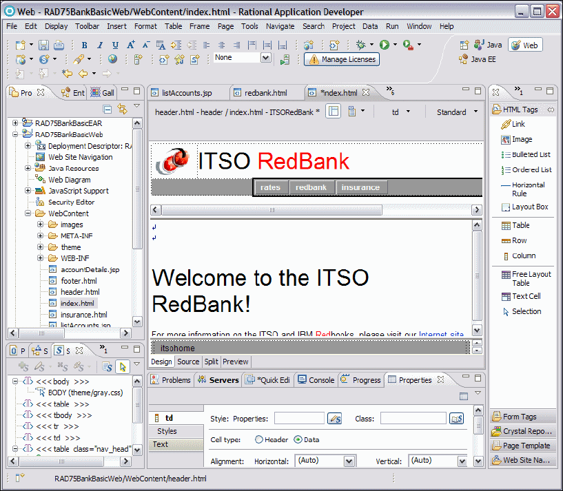
Chapter 13. Develop Web applications using JSPs and servlets 325
Draft Document for Review December 9, 2008 2:44 pm 7672-dev-1-web-jsp.fm
Some of these tools are illustrated further in the RedBank Web application
example built later in this chapter.
Web perspective and views
The Web perspective and its supporting views is designed to help Web
developers build and edit Web resources, such as servlets, JSPs, HTML pages,
style sheets, and images, as well as the deployment descriptor files.
The Web perspective can be opened by selecting Window → Open
Perspective → Web from the Workbench. Figure 13-4 displays the default layout
of the Web perspective with a simple index.html open in the editor.
Figure 13-4 Web perspective
7672-dev-1-web-jsp.fm Draft Document for Review December 9, 2008 2:44 pm
326 Rational Application Developer V7.5 Programming Guide
In the Web perspective, there are many views accessible (by selecting
Window → Show View), several of which are already open in the Web
perspective default setting.
By default, the views available in the Web perspective are as follows:
Colors view—When working with an HTML or JSP page in the Page
Designer view, the colors view gives the user the facility to manipulate colors
of cells, text, tables, and other HTML tags.
Console view—Shows output to SystemOut from any running processes.
Gallery view—Provides a large set of folders of predefined images, sounds,
and style sheets users can apply to their Web pages.
Links view—Given what is shown in the Page Designer view, the Links view
shows the links out from this file and elements in the Web project that link to it.
Navigator view—Provides a project and folder view of the workspace (similar
to Enterprise Explorer) but shows the files exactly as they exist in the file
system.
Outline view—Shows an outline of the file being viewed. For HTML and JSP
this shows a hierarchy of tags around the current cursor position. Selecting a
tag in this view will move the cursor in the main view to the selected element.
This is particularly useful for moving quickly around a large HTML file.
Page Data view—When editing JSP files, this gives a list of any page or
scripting variables available.
Page Designer—WYSIWYG editor for JSP and HTML. This consists of three
tabs, Design (where the user can drag and drop components onto the page),
Source (showing the HTML), and Preview (giving an indication of what the
final page looks like).
Palette view—When editing JSP or HTML files, this provides a list of HTML
items (arranged in drawers) which can be dragged and dropped onto pages.
Problems view—Shows any outstanding errors, warnings, or informational
messages for the current workspace.
Enterprise Explorer view—Shows a hierarchy view of all projects, folders
and files in the workspace. Note that in the Web perspective it structures the
information within Web projects in a way that makes navigation easier.
Properties view—Shows the properties for the item currently selected in the
main editor.
Quick Edit view—When editing HTML or JSP files, the Quick Edit view
provides a mechanism to quickly add Java Script to a given screen
component on certain events, for example onClick.

Chapter 13. Develop Web applications using JSPs and servlets 327
Draft Document for Review December 9, 2008 2:44 pm 7672-dev-1-web-jsp.fm
Servers view—Useful if the user wants to start or stop test servers while
debugging.
Snippets view—Allows editing of small bits of code, including adding and
editing actions assigned to tags. Items from the Snippets view can be drag
and dropped into the Quick Edit view.
Styles view—Allows the user to edit and apply both pre-built and
user-defined styles sheets to HTML elements and files.
Tasks view—Allows the user to maintain a list of things to be done within the
workspace. Note for Java code comment text tags can be configured which
will automatically add items to the Tasks list (see Window → Preferences
then Java → Compiler → Task Tags to edit these tags)
Thumbnails view—Given the selection of a particular folder in the Gallery
view, this view shows the contents of the folder.
Web Site Navigation Designer
The Web Site Navigation Designer is provided to simplify and speed up the
creation of the entire Web site navigation and can launch wizards to facilitate the
creation of HTML pages and JSPs. The tool provides features to view the Web
site in the Navigation tab, to add new pages, delete pages, and move pages
within in the site. This tool is especially useful for building pages in a Web
application that uses a page template.
The flow of an application can be visually laid out and then the elements (JSPs,
HTML pages) rearranged until it fits the requirements. Once the flow is arranged,
a developer can begin creating pages based on this design.
As a Web site design is built, the information is stored in the website-config.xml
file so that navigation links can be generated automatically. This can include a
page trail (showing the hierarchy of Web pages to get to the currently shown
page) or a set of page tabs to quickly navigate to other aspects of the application.
When the structure of a site changes, (for example when a new page is added)
the navigation links are automatically regenerated to reflect the new Web site
structure.
To launch the Web Site Designer, double-click Web Site Navigation found in the
root of the Web project folder.
Note: For more information on the Web perspective and views, refer to “Web
perspective” on page 155.

7672-dev-1-web-jsp.fm Draft Document for Review December 9, 2008 2:44 pm
328 Rational Application Developer V7.5 Programming Guide
Web Diagram
The Web Diagram (Figure 13-5) is another view of the Web application, which
shows the pages, the links between pages, and the page variables available on
each page. In addition, if Struts of JavaServer Faces technologies are being used
in the application, this view can include extra information to link the pages and
data together as appropriate for the selected technology.
Figure 13-5 Web Diagram
In the RedBank example, the Web Diagram is not used to build the application.
Instead, the Web Site Navigation Designer is the tool with which pages are built
and relationships between pages are shown. Chapter 16, “Develop Web
applications using JSF” on page 493 and Chapter 15, “Develop Web applications
using Struts” on page 445 both provide examples of how to apply the Web
Diagram.
Note: For a detailed example of using the Web Site Designer, refer to
“Launching the Web Site Designer” on page 346.
Chapter 13. Develop Web applications using JSPs and servlets 329
Draft Document for Review December 9, 2008 2:44 pm 7672-dev-1-web-jsp.fm
Page Designer
Page Designer is the primary editor within Application Developer for building
HTML, XHTML, JSPs, and JSF source code. It provides four representations of a
page: Design, Source, Split and Preview:
The Design tab provides a WYSIWYG environment to visually design the
contents of the page.
The Source tab provides access to the page source code showing the raw
HTML or JSP contents.
The Split tab (Figure 13-6) combines the Source tab and either the Design tab
or the Preview tab in a split screen view.
The Preview tab shows what the page would like if displayed in a Web
browser.
A good development technique is to work within the Design tab of Page Designer
and build up the HTML contents by clicking and dragging items from the Palette
view onto the page and arranging them with the mouse or editing properties
directly from the Properties view. Tags can be positioned absolutely instead of
relative. The Outline view is also very helpful to navigate quickly to another tag
that is related (for example, an ancestor) to the tag being edited. The Source tab
can be used to change details not immediately obvious in the Design tab, the
Split tab is very helpful to see design and source tab in one view, changes are
immediately reflected. The Preview tab can be used throughout the process to
verify the look of the final result.
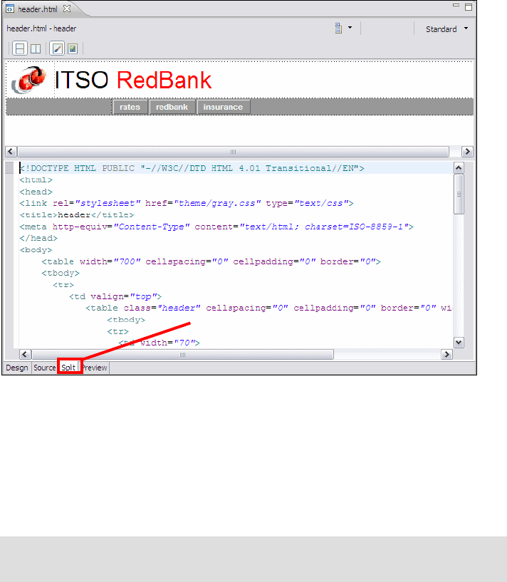
7672-dev-1-web-jsp.fm Draft Document for Review December 9, 2008 2:44 pm
330 Rational Application Developer V7.5 Programming Guide
Figure 13-6 Page Designer Split Tab
Often it is the case that HTML content is provided to a development team and
created from tools other than Application Developer. These files can be imported
simply using the context menu on the target directory and selecting File →
Import → General → File System and browsing to the new file and clicking
Import. When an imported file is opened in Page Designer, all the standard
editing features are available.
Page templates
A page template contains common areas that you want to appear on all pages,
and content areas which are intended to be unique on each page. They are used
to provide a common look and feel for a Web project.
The Page Template File creation wizard is used to create these files. Once
created the file can be modified in Page Designer. The page templates are stored
as *.htpl files for HTML pages and *.jtpl files for JSP pages. Changes to the
Note: For a detailed example of using the Page Designer, refer to “Developing
the static Web resources” on page 358 and “Working with JSPs” on page 369.
Split Tab

Chapter 13. Develop Web applications using JSPs and servlets 331
Draft Document for Review December 9, 2008 2:44 pm 7672-dev-1-web-jsp.fm
page template are reflected in pages that use that template. Templates can be
applied to individual pages, groups of pages, or applied to an entire Web project.
Areas can be marked as read-only meaning that Page Designer will not allow the
user to modify those areas.
When creating a new page template, the user is prompted if the template is to be
a dynamic page template or a design time template:
Dynamic page template use Struts-Tiles technology to generate pages on the
Web server.
Design time templates allow changes to be made and applied to the template
at design or build time, but once an application is deployed and running, the
page template cannot be changed. Design time templates do not rely on any
technologies other than the standard Java EE servlet libraries.
CSS Designer
Cascading style sheets (CSS) are a tool used with HTML pages to ensure that
an application has consistent colors, fonts, and sizes across all pages. It is
possible to create a default style sheet when creating a new project and there are
several samples included with Application Developer.
Usually, a good idea is to decide on the overall theme (color, fonts) for your Web
application in the beginning and create the style sheet at the start of the
development effort. Then, as you create the HTML and JSP files, you can select
that style sheet to ensure that the look of the Web pages are consistent. Style
sheets are commonly kept in the WebContent/theme folder.
The CSS Designer is used to modify cascading style sheet *.css files. It provides
two panels, the right hand side showing all the text types and their respective
fonts, sizes, and colors which are all editable. On the left hand side, a sample of
how the various settings will look. Any changes made are immediately applied to
the design in Page Designer if the HTML file is linked to the CSS file.
Security Editor
The Security Editor is a new enhancement with Application Developer V7.5. It
provides a wizard to specify security groups within a Web application and the
URLs that group has access to. The Java EE specification allows for security
groups and levels of access to defined sets of URLs to be defined in the
Note: An example of customizing style sheets used by a page template can
be found in “Customize a style sheet” on page 355.
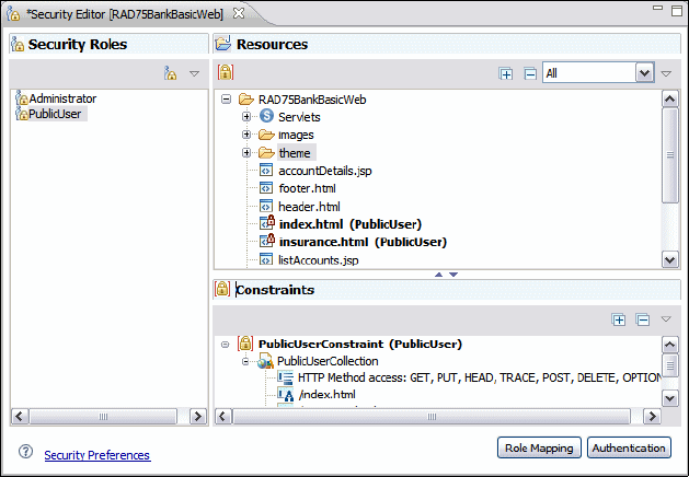
7672-dev-1-web-jsp.fm Draft Document for Review December 9, 2008 2:44 pm
332 Rational Application Developer V7.5 Programming Guide
deployment descriptor and the Security Editor provides a nice interface for this
information (Figure 13-7).
Figure 13-7 Security Editor example
Selecting an entry in the Security Roles pane shows the resources members of
that role in the Resources pane, and the Constraint rules that are applicable for
the role and resource (if one is selected). Each entry in the Constraints window
has a list of resource collections, which specify the resources available to it and
which HTTP methods can be used to access these resources. Using context
menus it is possible to create new roles, security constraints, and add resource
collections to these restraints.
Note that Java EE security specification defines the mechanism for declaring
groups and the URL sets that each group can access, but it is up to the Web
Container to map this information to an external security system. WebSphere’s
administrative console provides the mechanism to configure an external LDAP
directory. Refer to the IBM Redbooks publication, Experience J2EE! Using
WebSphere Application Server V6.1, SG24-7297.
File creation wizards
Application Developer provides many Web development file creation wizards by
selecting File → New → Other and then from Select a wizard expand the Web
folder and select the type of file required. These wizards prompt the user for the
key features of the new artifact and can help a user to quickly get a skeleton of
Chapter 13. Develop Web applications using JSPs and servlets 333
Draft Document for Review December 9, 2008 2:44 pm 7672-dev-1-web-jsp.fm
the component they require. The artifact created by the wizard can always be
manipulated directly if required.
The wizards available in the Web perspective are as follows:
CSS—The CSS file wizard is used to create a new cascading style sheet
(CSS) in a specified folder.
Dynamic Web Project—Steps the user through the creation of a new Web
project, including which features the project use and any page templates
present.
Filter—Constructs a skeleton Java class for a Java EE filter, which provides a
mechanism for performing processing on a Web request before it reaches a
servlet. The wizard also updates the web.xml file with the filter details.
Filter Mapping—Steps the user though the creation of a set of URLs to map
a Java EE filter with, The result of this wizard is stored in the deployment
descriptor.
HTML—Steps the user though the creation an HTML file in a specified folder,
with the option to use HTML Templates
JSP—Steps the user though the creation an JSP file in a specified folder, with
the option to use JSP Templates
Life-cycle Listener—The Java EE specification allows for classes to be
configured to receive pertinent events from the Web container. For example
the classes that implement the HttpSessionListener interface and are
declared in the deployment descriptor, receive notification every time a
HttpSession is created or destroyed. This wizard guides the user through the
creation of such a listener and adds a reference to the deployment descriptor.
Listener—A listener can be used to monitor and react to events in a servlet's
life-cycle by defining methods that get invoked when life-cycle events occur.
This wizard guides the user through the creation of such a listener and to
select the application lifecycle events to listen to.
Security Constraint—Used to populate the <security-constraint> in the
deployment descriptor that contains a set of URLs and a set of http methods,
which members of a particular security role are entitled to access.
Security Role—Adds a <security-role> element to the deployment
descriptor.
Servlet—Used to create a skeleton servlet class and add the servlet to the
deployment descriptor.
Servlet Mapping—Steps the user through the creation of new URL to servlet
mapping and adds it to the deployment descriptor.

7672-dev-1-web-jsp.fm Draft Document for Review December 9, 2008 2:44 pm
334 Rational Application Developer V7.5 Programming Guide
Static Web Project—Steps the user through building a new Web project
containing only static pages.
Tag—Steps the user through create a new Tag library file
Web Diagram—It is possible to create a Web Diagram for a Web project
which already has a large number of pages. This wizard creates an empty
Web Diagram onto which the user can place existing pages and show existing
page relationships.
Web Page—The Web Page wizard allows you to create an HTML or JSP file
in a specified folder, with the option to create from a large number of page
templates.
Web Page Template—The Page Template File wizard is used to create new
page template files in a specified folder, with the option to create from a page
template or create as a JSP fragment, and define the markup language
(HTML, HTML Frameset, Compact HTML, XHTML, XHTML Frameset, and
WML 1.3). You can select from one of the following models: Template
contains Faces Components, Template containing only HTML, Template
containing JSP.
Summary of new features in v7.5
Rational Application Developer V7.5 has a comprehensive supports for the Java
EE 5 specification, servlet 2.5, and JSP 2.1.
There have been significant changes in the tools available for creating artifacts
within a Web application.
The main changes are as follows:
Page Designer—The following enhancements are available:
– Split tab: Working in split view with design helps looking at the source and
also at the design page simultaneously
– New Layout Mode: Absolute Positioning provides a way to position tags
anywhere int the design page
JPA Web tooling—The Java Persistence API (JPA) Web tooling enables you
to create Web applications that access JPA entities, which map to relastional
tables. You can use exiting entities or create them while building the Web
Note: There are also a number of wizards specifically for Struts and JSF,
which are discussed in other chapters
Chapter 13. Develop Web applications using JSPs and servlets 335
Draft Document for Review December 9, 2008 2:44 pm 7672-dev-1-web-jsp.fm
application. The functionality of the entity manager is encapsulated into JPA
manager beans that provide methods to work with the JPA entities.
RedBank application design
In this section we describe the design for the ITSO RedBank Web application,
also known as RedBank. The intent is to outline the design of the RedBank
application and how it fits into the Java EE Web framework, particularly with
regard to JSPs and servlets.
Model
The model for the RedBank project is implemented using a simple Java project,
exposed to other components through a facade interface (called ITSOBank). The
main ITSOBank object is a singleton object, accessible by a single static public
method called getBank.
The ITSOBank object is composed of the other business objects which make up
the application, including Customer, Account, and Transaction. The facade into
the bank object includes methods such as getCustomer, getAccounts, and
withdraw, deport, and transfer. Figure 13-8 shows a simplified UML class
diagram of the model. The model is described in detail in Chapter 8, “Develop
Java applications” on page 69.

7672-dev-1-web-jsp.fm Draft Document for Review December 9, 2008 2:44 pm
336 Rational Application Developer V7.5 Programming Guide
Figure 13-8 Class diagram for RedBank model
The underlying technology to store data used by the ITSOBank application are
Java HashMaps. These are populated at startup in the constructor and obviously
the data is lost every time the application is restarted. In a real world example
this would be stored in a database, but for the purposes of this example
HashMaps are fine. In Chapter 14, “Develop EJB applications” on page 387 the
ITSOBank model is modified to run as EJBs and the application data is stored in a
database.
View layer
The view layer of the RedBank application is composed of four HTML files and
four JSP files. The application home page is the index.html containing a link to
four HTML pages (welcome.html, rates.html, insurance.html, and
redbank.html).
welcome.html, rates.html and insurance.html are simple static HTML pages
showing information, without forms or entry fields.
redbank.html contains a single form which allows a user to type in the
customer ID to access the customer services such as accessing balance, and
performing transactions. Note that although the account number is verified,
security issues (logon and password) are not covered in this example.
From redbank.html the user is shown the lisAccounts.jsp page, which
shows the customer’s details, a list of accounts, and a button to logout.
Bank (interface)
searchCustomerBySsn()
getAccountsForCustomer()
SearchAccountByAccountNumber()
getTransactionsForAccount()
addCustomer()
updateCustomer()
deposit()
withdraw()
transfer()
......
Customer
getSsn()
getFirstName()
getLastName()
getTitle()
Account
getBalance()
getAccountNumber()
getTransactions()
Transaction (abstract class)
get/setTimeStamp()
get/setAmount()
getTransactionId()
getTransactionType()
process()
DebitCredit
ITSOBank
static Bank getBank()
...
Stores HashMap of
Chapter 13. Develop Web applications using JSPs and servlets 337
Draft Document for Review December 9, 2008 2:44 pm 7672-dev-1-web-jsp.fm
Selecting an account brings up the accountDetails.jsp, which also shows
the balance for the selected account and a form through which a transaction
can be performed. This screen also shows the current account number and
balance, both dynamic values. A simple JavaScript code controls whether the
amount and destination account fields are available, depending on the option
selected. One of the transaction options on the accountDetails.jsp is List
Transactions, which invokes the listTransactions.jsp.
If anything goes wrong in the regular flow of events, the exception page
(showException.jsp) is shown to inform the user of the error.
These four JSP pages (listAccounts.jsp, accountDetails.jsp,
listTransactions.jsp, and showException.jsp) make up the dynamic pages
of the RedBank application.
Refer to Figure 13-17 on page 351 for a diagram showing the planned structure
of pages within the RedBank application. The diagram was created using the
Web Site Designer tool.
Controller layer
The controller layer was implemented using two different strategies: One
straightforward; and the other more complex, but more applicable to a real world
situation.
The application has a total of five servlets:
ListAccounts—Gets the list of accounts for one customer.
AccountDetails—Displays the account balance and the selection of
operations: List transactions, deposit, withdraw, and transfer.
Logout—Invalidates the session data.
PerformTransaction—Performs the selected operation by calling the
appropriate control action: ListTransactions, Deposit, Withdraw, or Transfer.
UpdateCustomer—Updates the customer information.
The first three servlets use a simple function call from the servlet to the model
classes to implement their controller logic and then use the RequestDispatcher
to forward control onto another JSP or HTML resource. The pattern used is
shown in the sequence diagram in Figure 13-9.
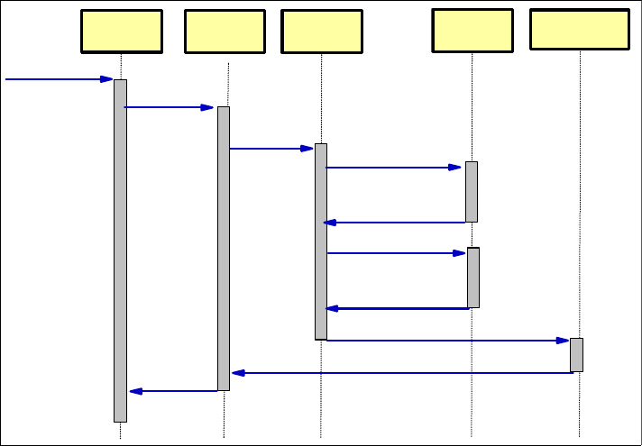
7672-dev-1-web-jsp.fm Draft Document for Review December 9, 2008 2:44 pm
338 Rational Application Developer V7.5 Programming Guide
Figure 13-9 ListAccounts sequence diagram
PerformTransaction uses a different implementation pattern. It acts as a front
controller, simply receiving the HTTP request and passing it to the appropriate
control action object. These objects are responsible for carrying out the control of
the application. Figure 13-10 shows a sequence diagram for the list transaction
operation from the account details page, including the function calls through
PerformTransaction, the ListTransactionsCommand class, onto the model
classes, and forwarding to the appropriate JSP.
User fills out SSN on
RedBank screen and
clicks Submit HttpPost to
ListAccounts
servlet.
calls doPost()
searchCustomerBySsn()
getAccountsForCustomer()
Returns page
showing list of
accounts
forwardRequest()
(through the RequestDispatcher)
User's
browser
Application
Server
List Accounts
Servlet ITSOBank listAccounts.jsp
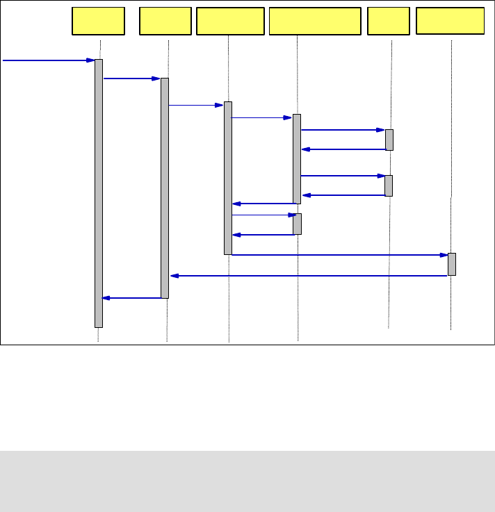
Chapter 13. Develop Web applications using JSPs and servlets 339
Draft Document for Review December 9, 2008 2:44 pm 7672-dev-1-web-jsp.fm
Figure 13-10 PerformTransaction sequence diagram
The Struts framework provides a much more detailed implementation of this
strategy and in a standardized way. Refer to Chapter 15, “Develop Web
applications using Struts” on page 445 for more details.
Implementing the RedBank application
Using an example, this section introduces you to the tools within Application
Developer’s that facilitate the development of Web applications. In the example,
we step through the creation of different Web artifacts (including page templates,
HTML, JSPs and servlets) and demonstrate how to use the tools available.
Note that the completed application has already been developed and is available
to explore if required by importing the project interchange file:
c:\7672code\zInterchange\webapp\RAD75BankBasicWeb.zip
Note: Action objects, or commands, are part of the command design pattern.
For more information, refer to Design Patterns: Elements of Reusable
Object-Oriented Software.
User's
browser
Web
Application
Server
PerformTransaction
Servlet ListTransactionsCommand ITSOBank
User selects List Transactions
from the account details screen
HttpPost to
ListAccounts
servlet.
calls doPost() with
transaction=list calls execute()
Returns page
showing list of
accounts
listTransactions.jsp
searchAccountByAccountNumber()
getTransactionsForAccount()
forwardRequest()
(through the RequestDispatcher)
getForwardView()

7672-dev-1-web-jsp.fm Draft Document for Review December 9, 2008 2:44 pm
340 Rational Application Developer V7.5 Programming Guide
The section is organized as follows:
Creating the Web project
Importing the Java RedBank model
Defining the Web site navigation and appearance
Developing the static Web resources
Developing the dynamic Web resources
Working with JSPs
At the end of this section, the RedBank application should be ready for testing.
Creating the Web project
The first step is to create a Web project in the workspace.
There are two types of Web projects available in Application Developer, namely,
static and dynamic. Static Web projects contain static HTML resources and no
Java code, and thus are comparatively simple. In order to demonstrate as many
features of Application Developer as possible, and because the RedBank
application contains both static and dynamic content, a Dynamic Web project is
used for this example.
In Application Developer, perform the following steps:
Open the Web perspective by selecting Window → Open Perspective →
Web.
To create a new Web Project, select File → New → Dynamic Web Project.
In the New Dynamic Web Project dialog, enter the following items
(Figure 13-11):
–Type RAD75BankBasicWeb in the name field.
– For Project contents, select Use Default (default). This specifies where
the project files should be placed on the file system. The default option of
leaving them in the workspace is usually fine.
– Target Runtime: Select WebSphere Application Server v7.0 (default).
This option will display the supported test environments that have been
installed. Use WebSphere Application Server V7.0 Test Environment.
– Dynamic Web Module version: Select 2.5.
Note: Before this, it might be a good idea to check that Web capabilities are
enabled. Select Windows → Preferences and expand General →
Capabilities make sure that Web Developer options (including basic, typical
and advanced) are selected.
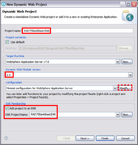
Chapter 13. Develop Web applications using JSPs and servlets 341
Draft Document for Review December 9, 2008 2:44 pm 7672-dev-1-web-jsp.fm
– Configuration: We define the configuration as the last item.
– EAR Membership: Select Add module to an EAR (default). Dynamic Web
Projects, such as the one we are creating, run exclusively within an
enterprise application. For this reason, you have to either create a new
EAR project or select an existing project.
– EAR Project Name: RAD75BankBasicEAR (overtype the default).
Because we selected Add module to an EAR project, the wizard will
create a new EAR project.
Figure 13-11 New Dynamic Web Project
For Configuration, click Modify to open the Project Facets dialog:
Select the additional features Default Style Sheet, JSTL, and Web Site
Navigation (Figure 13-12). Click OK and the configuration changes to
<custom>.
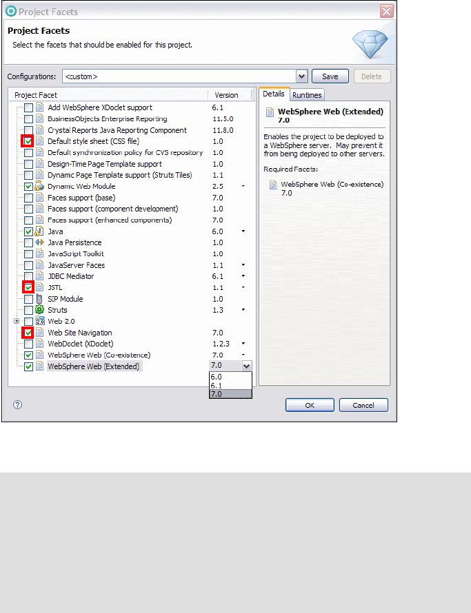
7672-dev-1-web-jsp.fm Draft Document for Review December 9, 2008 2:44 pm
342 Rational Application Developer V7.5 Programming Guide
Figure 13-12 Dynamic Web Project Facets
Click Next.
In the Web Module page, accept the default options (Figure 13-13).
Notes:
The options shown with a down arrow allow you to alter the underlying
version of this feature being selected. By default, the latest version
available is selected.
From this dialog, it is also possible to save the configuration for future
projects. To do this, click Save and enter a configuration name and a
description.
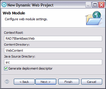
Chapter 13. Develop Web applications using JSPs and servlets 343
Draft Document for Review December 9, 2008 2:44 pm 7672-dev-1-web-jsp.fm
Figure 13-13 New Dynamic Web Project, Web Module settings
The settings here are as follows:
– Context Root: RAD75BankBasicWeb
The context root defines the base of the URL for the Web application.
The context root is the root part of the URI under which all the application
resources are going to be placed, and by which they will are referenced
later. It is also the top level directory for your Web application when it is
deployed to an application server.
– Content Directory: WebContent
This specifies the directory where the files intended for the WAR file are
created. All the contents of the WEB-INF directory, HTML, JSPs, images
and any other files that are deployed with the application are contained
under this directory. Usually the folder WebContent is sufficient.
– Java Source Directory: src
This specifies the directory where any Java source code used by the Web
application is stored. Again, the default value of src should be sufficient for
most cases.
Click Next to accept the default values.
In the Select a Page template for the Web Site dialog (Figure 13-14), leave
Use a default Page template for the Web Site cleared. This dialog allows
you to select from page templates supplied with Application Developer.

7672-dev-1-web-jsp.fm Draft Document for Review December 9, 2008 2:44 pm
344 Rational Application Developer V7.5 Programming Guide
Figure 13-14 New Dynamic Web Project, Page Templates
Click Finish and the Dynamic Web Project is created.
The Technology Quickstarts opens. You can browse features help topics. When
done, close the Technology Quickstart.
The Web project directory structure for the newly created RAD75BankBasicWeb
project and its associated RAD75BankBasicEAR project (enterprise application) is
displayed in Figure 13-15.
The main folders shown under the Web project are as follows:
Deployment Descriptor—This shows an abstracted view of the contents of
the projects web.xml. It includes sub folders for the main pieces which make
up a Web project configuration, including servlets and servlet mappings,
filters and filter mappings, listeners, security roles, and references.
Web Site Navigation—Clicking on this starts up the tool for editing the page
navigation structure.
Java Resources: src—This folder contains the Java source code for regular
classes, JavaBeans, and servlets. When resources are added to a Web
project, they are automatically compiled, and the generated class files are
added to the WebContent\WEB-INF\classes folder.
WebContent—This folder holds the contents of the WAR file that is deployed
to the server. It contains all the Web resources, including compiled Java
classes and servlets, HTML files, JSPs, and graphics needed for the
application.
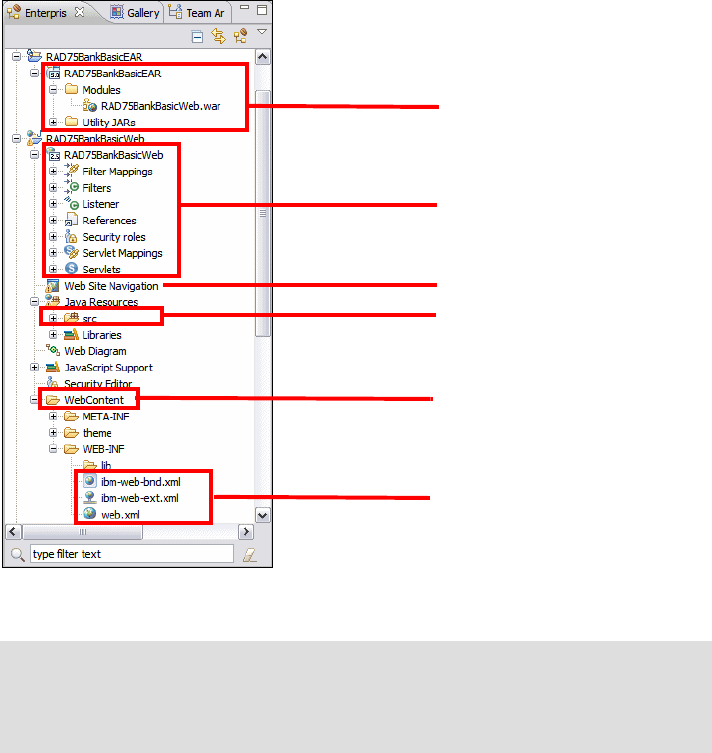
Chapter 13. Develop Web applications using JSPs and servlets 345
Draft Document for Review December 9, 2008 2:44 pm 7672-dev-1-web-jsp.fm
Figure 13-15 Web project directory structure
Importing the Java RedBank model
The ITSO Bank Web application requires the classes created in Chapter 8,
“Develop Java applications” on page 69. This section describes how to import the
project interchange file. You can skip this import if you already have the final
RAD75Java project in the workspace.
Select File → Import.
In the Import dialog, select Other → Project Interchange and click Next.
Important: Files that are not under WebContent are not deployed when the
Web project is published. Typically this would include Java source and SQL
files. Make sure that you place everything that should be published under the
WebContent folder.
Java source code
Web site navigation wizard
Structured view into EAR
deployment descriptor
Structured view into Web
deployment descriptor
WebContent folder that
is deployed to the
Application Server
Web deployment
descriptor files
7672-dev-1-web-jsp.fm Draft Document for Review December 9, 2008 2:44 pm
346 Rational Application Developer V7.5 Programming Guide
In the Import Projects dialog, click Browse to locate the interchange file
c:\7672code\zInterchange\java\RAD75Java.zip. Select the RAD75Java
project, and click Finish.
To verify that the model is running, it is possible to run the main method of the
class itso.rad75.bank.client.BankClient class. This will invoke the bank
facade classes directly, make some simple transactions directly and print out the
results to the console.
We will add the RAD75Java project to the RAD75BankBasicEAR enterprise
application in “Adding RAD75Java as a Web Library project” on page 362.
Defining the Web site navigation and appearance
This section demonstrates how to define the site pages and navigation using the
Web Site Designer. A frameset index page and style sheet are also created to
provide a common interface for the RedBank Web site navigation. The frameset
index page is used to define a standard user interface layout (header, navigation
menu, footer), and the style sheet is used by the Web pages to define standard
fonts, colors, table formatting, and other style factors. Then the empty pages are
created and the application is run to verify the basic navigation.
This section includes the following tasks:
Launching the Web Site Designer
Create the Web site navigation and related pages
Customize a style sheet.
Launching the Web Site Designer
To launch Web Site Designer from the Enterprise Explorer, double-click Web Site
Navigation (Figure 13-16).

Chapter 13. Develop Web applications using JSPs and servlets 347
Draft Document for Review December 9, 2008 2:44 pm 7672-dev-1-web-jsp.fm
Figure 13-16 Web Site Designer: Navigation view
Notice the following features:
Navigation and Detail tab—The Navigation tab (the default tab) allows a
user to visually design the layout of the site and the Detail tab is used to
define the fine details for each page including the ID, Navigation Label, File
Path, File Name /URL, Servlet URL, and Page Title.
Palette view—Selections from the Palette can be dragged to the Navigation
page. For example, the New Page icon can be dragged from the Palette to
create a new page, or the New Group icon can be dragged onto the page to
logically organize pages in a hierarchical grouping.
Site template—In the Properties view you can select a site template to define
the appearance of the site. This can be a sample page template included with
Application Developer, or a user-defined page template. New pages built from
the Web Site Designer will use this template by default.
Palette View for new
pages and groups
Navigation or
Detail tab of
Site Designer
Set the Web
Page
Template
7672-dev-1-web-jsp.fm Draft Document for Review December 9, 2008 2:44 pm
348 Rational Application Developer V7.5 Programming Guide
Create the Web site navigation and related pages
In this section, we use the Web Site Designer to construct the page navigation
and page skeletons for the RedBank Web site. At the end we will have a working
skeleton of the application, where we can navigate from page to page using the
tabs below the page header and the ancestor tabs. The pages will not have any
actual content, but this is added later.
We will create the navigation pages and corresponding HTML or JSP page for
each of the following pages (Table 13-1).
Table 13-1 Web pages of the RedBank application
Import Web resources for the RedBank application
Prior to the creation of the Web pages we have to import resources to provide the
correct look and feel for web pages used in our example, such as, images and
CSS files. Import those resources following the next steps:
Expand RAD75BankBasicWeb → WebContent and from the context menu
select Import.
Select General → File System and click Next.
In the From directory type c:\7672code\webapp, select the images and theme
folders, and click Finish.
The itso_logo.gif and c.gif images and the grey.css file are imported.
Create navigation HTML and JSP pages
To define the site navigation and create the HTML and JSP page skeletons,
perform the following steps in the Web Site Designer:
Launch the Web Site Designer from the Enterprise Explorer (if not open
already).
Navigation label HTML or JSP file
itsohome welcome.html
rates rates.html
insurance insurance.html
redbank redbank.html
listaccounts listAccounts.jsp
accountdetails accountDetails.jsp
listtransactions listTransactions.jsp
showexception showException.jsp
Chapter 13. Develop Web applications using JSPs and servlets 349
Draft Document for Review December 9, 2008 2:44 pm 7672-dev-1-web-jsp.fm
Create the root static navigation page (welcome.html):
–Select New Page from the Palette and click on the Navigation page to add
the first page.
– After the new page is added, the navigation label can be entered in the
Navigation page or in the Properties view under Navigation label. Type
itsohome. Save the Navigation page.
– Double-click the itsohome page to create the HTML file associated.
– In the New Web Page dialog, enter the following values:
• File name: welcome.html
• Folder: /RAD75BankBasicWeb/WebContent
• Template: Expand Basic Templates and select HTML/XHTML
• Launch the Document Markup dialog by clicking Options and verify the
following values, Markup Language=HTML, Document Type=HTML 4.01
Transitional.
•Select Style Sheets and add gray.css as style sheet, removing the
Master.css.
• Click Close and Finish to create the HTML page.
–The welcome.html page opens in the editor. Close this editor.
Define the navigation root.
In our example, itsohome (welcome.html) is the navigation root. By default,
when a page is created it is set as a navigation candidate, which is the
desired format for all other pages.
To make this change, select itsohome on the Web Site Navigation Diagram,
and from the context menu select Set Navigation → Set Navigation Root.
Add three static pages as children of itsohome. From the itsohome context
menu on Page Designer, select Add → New Page → As Child. Perform this
three times and type the navigation labels as rates, redbank, and insurance.
Double-click each page and type the file names as rates.html,
redbank.html, and insurance.html. Leave the template HTML/XHTML selected
(note that the gray.css style sheet is selected by default). Close the editor
that opens.
Create a new group named RedBank.
Page groups are used to logically build or organize pages into a movable
block of related pages. In the RedBank example the JSPs under
redbank.html are grouped together.
– Select the redbank page, right-click, and select Add → New Group → As
Child. A Group box appears below the redbank page.

7672-dev-1-web-jsp.fm Draft Document for Review December 9, 2008 2:44 pm
350 Rational Application Developer V7.5 Programming Guide
– Select the group and in the Properties view, Group tab, type RedBank as
the group name.
– Save the Navigation page.
Create the dynamic pages (JSPs) listaccounts, accountdetails,
listtransactions, and showexception.
– From the context menu of the RedBank group, select Add → New
Page → Into Group.
– After the New Page is added, notice you can type the navigation label in
the Navigation page or in the Properties view as Navigation label. For the
first page, type listaccounts.
– Double-click the listaccounts box to create the JSP file associated with
the navigation label.
– In the New Web Page dialog, enter the following items and then click Next:
• File name: listAccounts.jsp
• Template: Expand Basic Templates and select JSP.
• Click Options and verify the gray.css cascade style sheet.
– Click Finish to create the page. Close the editor that opens.
Repeat the steps to add the accountdetails (accountDetails.jsp),
listtransactions (listTransactions.jsp), and showexception
(showException.jsp) pages.
The showexception page only appears when there is a problem and is not
part of the standard navigation. Therefore, select the showexception page,
and clear Show in Navigation in the Properties view.
Change the Page Title column of each JSP through the Navigation view,
Detail tab, to: List Accounts, Account Details, List Transactions, and
Show Exception. This action changes the <title> tag in the source code of
each JSP.
Save and close the Navigation page.
The completed Web Site Navigation is shown in Figure 13-17.
Note: You can provide options to automatically generate servlet stubs
methods and to add extra fields to the web.xml file. For this example, the
default options are fine.
Important: The spelling and capitalization of the JSP file names must be
exact as shown.

Chapter 13. Develop Web applications using JSPs and servlets 351
Draft Document for Review December 9, 2008 2:44 pm 7672-dev-1-web-jsp.fm
Figure 13-17 Web Site Navigation after adding pages
Create frameset pages
The RedBank user interface (view) is made up of a combination of static HTML
pages and dynamic JSPs. In this section we describe how to create an HTML
frameset page (index.html) that will define the layout of the web pages created
in the section “Create navigation HTML and JSP pages” on page 348
Frameset pages provide an efficient method of creating a common layout for the
user interface of the Web application, because has the same structure as a table,
where the rows are defined in a tag element called <frameset> and the columns
are individually defined in a tag element called <frame>.
In our example we only have three rows or areas and no column separations:
Header area—With company logo and the navigation bar to other pages.
Workspace area—Where the rest of the operational pages are displayed.
Footer area—With the option to return to the main menu.
Note: By default, a Web server looks for index.html (or index.htm) when a
Web project is run. Although this behavior can be changed, we recommend
that you use index.html as the top level page name.

7672-dev-1-web-jsp.fm Draft Document for Review December 9, 2008 2:44 pm
352 Rational Application Developer V7.5 Programming Guide
Create an HTML frameset page
To create a new HTML frameset page (index.html) to be used for the RedBank
layout, perform the following steps:
Right-click WebContent and select New → Web Page from the context
menu.
In the New Web Page dialog, enter the following values as shown in
Figure 13-18:
– File name: index.html
– Template: Select Basic Templates → HTML/XHTML.
– Click Options, and for Markup Language select HTML Frameset and
click Close.
– Click Finish to create the index.html frameset.
Figure 13-18 Creating a frameset page
Create an HTML header for all Web pages
We create the static HTML web page for the header area that will show the logo
and heading information.
Right-click WebContent and select New → Web Page from the context menu.
Create a new web page New → Web Page from the context menu.
Chapter 13. Develop Web applications using JSPs and servlets 353
Draft Document for Review December 9, 2008 2:44 pm 7672-dev-1-web-jsp.fm
In the New Web Page dialog, enter the following values:
– File name: header.html
– Template: Select Basic Templates → HTML/XHTML.
– Click Options, and for Markup Language select HTML and click Close.
– Click Finish to create the static header.html.
Import the code for the logo, title, and action bar into the header.html file as
follows:
– Locate the file c:\7672code\webapp\html\SnippetForHeaderHTML.txt and
open it in a simple text editor (for example Notepad).
– Open header.html in Page Designer and select the Source tab.
– Paste the code from SnippetForHeaderHTML.txt between the <body> and
</body> tags.
– Save the header.html file and verify that the page has the ITSO RedBank
text and logo as desired by selecting the Preview tab.
Create an HTML footer for all Web pages
We create the Web page that holds the source of the footer area in the same way
as for the header page:
Create a new Web page named footer.html under WebContent.
Copy/paste the code from SnippetForFooterHTML.txt between the <body>
and </body> tags.
Save the footer.html file and switch to the Preview tab to see the newly
created link.
Customize frameset Web page areas
This section describes how to add frame references to the pages that are part of
the user interface frame areas. We describe how to customize the following
elements of the HTML page template (index.html, header.html and
footer.html) created in “Launching the Web Site Designer” on page 346.
Define the areas in the frameset
To create the mentioned areas/frames in the frameset and link the areas with the
previously created header.html and footer.html Web pages, do the following
steps:
In the Enterprise Explorer, expand RAD75BankBasicWeb → WebContent,
and open the index.html Web page.
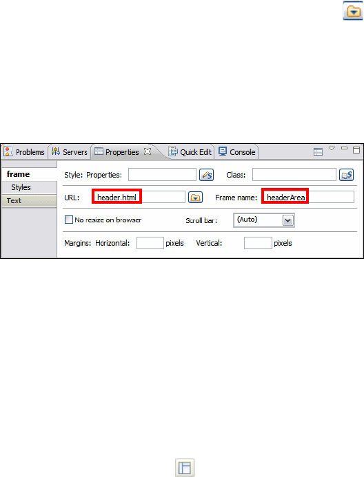
7672-dev-1-web-jsp.fm Draft Document for Review December 9, 2008 2:44 pm
354 Rational Application Developer V7.5 Programming Guide
In the Page Designer, select the Split tab to work simultaneously with the
source code and interface design.
To define the frameset areas, add a rows attribute to the frameset tag with the
following steps:
– In the Outline view right click the frameset tag and select Add Attribute →
New Attribute.
– In the New Attribute dialog type rows as name and 20%,70%,10% as value.
– Verify in the Source tag the value <frameset rows="20%,70%,10%">.
Link the header area with the header.html Web page, with the following
steps:
– In the Outline view expand html → frameset and select the frame node.
– In the Properties view (Figure 13-19), select the following attributes in the
frame tab:
• URL: Type header.html, or click the Browse icon and select File,
and in the File Selection dialog select header.html and click OK.
• Frame name: headerArea
• Leave the rest of the values by default and save the changes.
– Verify in the Split tab of the Page Designer that the <frame> code was
replaced by <frame .... src="header.html" name="headerArea">.
Figure 13-19 Properties of a frame
To link the workspace area, create a new frame and link it to the welcome.html
Web pag with the following steps:
– In the Outline view right click the frame tag and select Add After →
frame.
– In the Properties view, set the URL to welcome.html and the Frame name
to workspaceArea.
To link the footer area, create a new frame and link it to the footer.html Web
page and frame name footerArea.
Click the Show frames icon to see the frames disposition (Figure 13-20).
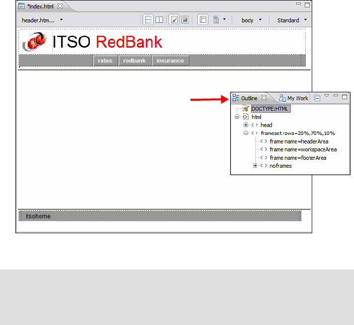
Chapter 13. Develop Web applications using JSPs and servlets 355
Draft Document for Review December 9, 2008 2:44 pm 7672-dev-1-web-jsp.fm
Figure 13-20 Frame design
Customize a style sheet
Style sheets can be created when a Web Project is created (by selecting the
Default style sheet (CSS File) option from the Project Facets dialog), when a
page template is created from a sample, or at any time by launching CSS File
creation wizard.
In the RedBank example a style sheet named gray.css was imported as part of
the process of “Import Web resources for the RedBank application” on page 348.
Both the HTML and the JSP Web pages we created reference the gray.css style
sheet to have a common appearance of fonts and colors.
In the following example, we customize the colors used on the navigation bar
links when you hover over a link. By default the link text in the navigation bar is
orange (cc6600) when hovering. We will customize this to be red (ff0000).
Note: The workspace area display the pages we created with the Web Site
Navigation in “Create the Web site navigation and related pages” on
page 348. It Initially displays the welcome.html web page, then the user can
navigate to other pages through the header area actions bar.
Outline view of
the index.html
page
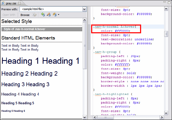
7672-dev-1-web-jsp.fm Draft Document for Review December 9, 2008 2:44 pm
356 Rational Application Developer V7.5 Programming Guide
To customize the gray.css style sheet, do these steps:
Open the theme/gray.css file in the CSS Designer (Figure 13-21).
Figure 13-21 CSS Designer: gray.css
By selecting the text style .nav-h-normal A:hover in the right-hand pane
(scroll down to locate the style, or find the style in the Styles view at the
bottom left), the text in the left-hand pane is displayed and highlighted. This
makes it easy to change the settings and see the change immediately.
Change the Hex HTML color code for .nav-h-normal A:hover from color:
#cc6600; (orange) to color: #ff0000; (red).
Customize the footer highlighted link text. Locate the .nav-f-normal A:hover
style and change the color from #ff6600 (orange) to #ff0000 (red).
Save the file.
Now when youhover over the links in the header and footer, the color changes to
red. Obviously any number of changes can be applied to the style sheets to
change the look, feel, and color of the application.

Chapter 13. Develop Web applications using JSPs and servlets 357
Draft Document for Review December 9, 2008 2:44 pm 7672-dev-1-web-jsp.fm
Verify the site navigation and page templates
At this stage although the pages have no content, we can verify that the page
templates look as expected and that the navigation links in the header and footer
navigation bars work as required, in order to do that we follow the next steps:
First add some text to identify each of the Web pages created in with the Web
Site Navigation.
– Open welcome.html in the Page Designer and go to the Source tab.
–Type Welcome Page between the tags <body></body>, the final code
should look as follows: <body>Welcome Page</body>.
– Repeat same steps indicating their names in the body page for:
rates.html, redbank.html and insurance.html.
Start the WebSphere Application Server V7.0 Test Environment in the
Servers view if it is not running.
In the Enterprise Explorer, right-click RAD75BankBasicWeb, and select
Run As → Run on Server.
In the Run Server dialog, select Choose an existing server and WebSphere
Application Server v7.0. Click Finish.
A browser pane starts at the index page and the user can click on the tabs for
rates, redbank, and insurance to move between these pages (Figure 13-22).
Figure 13-22 ITSO RedBank Web site
To remove the project from the test server, in the Servers view right-click
WebSphere Application Server v7.0, select Add Remove Projects, and
remove RAD75BankBasicEAR.
Alternatively, expand WebSphere Application Server v7.0, right-click the
RAD75BankBasicEAR project and select Remove.
Hover with the
mouse over a link
7672-dev-1-web-jsp.fm Draft Document for Review December 9, 2008 2:44 pm
358 Rational Application Developer V7.5 Programming Guide
Developing the static Web resources
In this section we create the content for the four static pages of our sample with
the objective of highlighting some of the features of Page Designer. Page
Designer facilitates the building of HTML pages by allowing the user to add
HTML elements from the Pallet view using drag and drop. HTML fragments can
also be imported directly into the source tab and this options is also
demonstrated.
The topics in this section are as follows:
Create the welcome.html page content (text, links)
Create the rates.html page content (tables)
Import the insurance.html page contents
Import the redbank.html page contents
Create the welcome.html page content (text, links)
The RedBank home page is index.html. The links to the child pages are
included as part of the header and footer of the our page template. In the
following example, we describe how to add static text to the page, and add a link
to the page to the IBM Redbooks Web site.
Open the welcome.html file in Page Designer.
Select the Design tab.
Insert the welcome message text.
– Delete the Welcome Page text.
– Insert two line breaks:
• In the Context Area right click and select Insert → Line Break, leave
Type: Normal (default).
• Repeat the steps for the second line break.
– In the Context Area, right click, and select Insert → Paragraph →
Heading 1.
– Enter the text Welcome to the ITSO RedBank! between the <h1> tags.
Insert a Link to the IBM Redbooks Web site.
– Add an empty line after the heading.
– From the menu bar, select Insert → Paragraph → Normal.
– Enter the text For more information on the ITSO and IBM Redbooks,
please visit our Internet site into the new area.
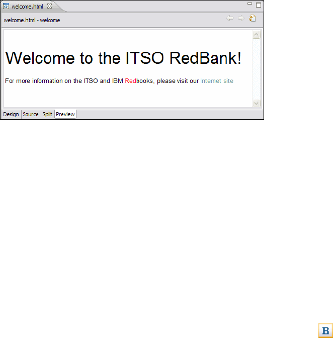
Chapter 13. Develop Web applications using JSPs and servlets 359
Draft Document for Review December 9, 2008 2:44 pm 7672-dev-1-web-jsp.fm
– Highlight the text Internet site, right-click and select Insert Link.
– In the Insert Link dialog, select HTTP, type http://www.ibm.com/redbooks
in the URL field, and click OK.
Customize the text font face, size, and color. This is done through the
Properties view.
– Select the word Red from Redbooks from the text created in the previous
step (use the keyboard Shift and arrow keys).
– In the Text tab in the Properties view select the color Red to make this
partial word stand out a little.
– The source changes to ...IBM <font color="red">Red</font>books, ...
Save the page.
Select the Preview tab and the page is displayed (Figure 13-23).
Figure 13-23 Preview of welcome.html
Create the rates.html page content (tables)
In this example we demonstrate how to add a static table containing interest
rates using the Page Designer.
Open the rates.html file in Page Designer and select the Design tab.
Delete the Rates Page text.
Expand HTML Tags in the Palette.
Select and drag a Table from the Palette to the content area.
In the Insert Table dialog, enter 5 for Rows and 5 for Columns and also 5 for
Padding inside cells, then click OK.
Resize the table as desired.
Enter the descriptions and rates (as seen in Figure 13-24) into the table.
Select each heading text, and in the Properties view click the Bold icon .
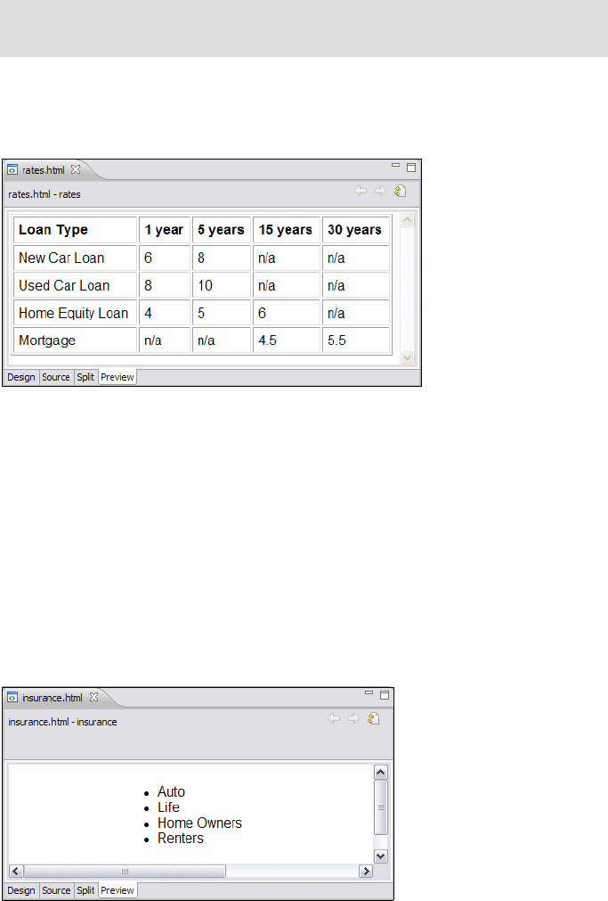
7672-dev-1-web-jsp.fm Draft Document for Review December 9, 2008 2:44 pm
360 Rational Application Developer V7.5 Programming Guide
Save the page.
Select the Preview tab and the page is displayed (Figure 13-24).
Figure 13-24 Preview the rates.html page
Import the insurance.html page contents
In this section, we import the body of the insurance.html file:
Locate the file c:\7672code\webapp\html\SnippetForInsuranceHTML.txt and
open it in a simple text editor (for example Notepad).
Open insurance.html in Page Designer and select the Source tab.
Select the text between the tags: <body></body>
Insert the text from the SnippetForInsuranceHTML.txt file.
Save the file and switch to the Preview tab (Figure 13-25).
Figure 13-25 Preview of Insurance.html
Note: Additional table rows and columns can be added and deleted with
the Table menu option.

Chapter 13. Develop Web applications using JSPs and servlets 361
Draft Document for Review December 9, 2008 2:44 pm 7672-dev-1-web-jsp.fm
Import the redbank.html page contents
Repeat the import of the body of the redbank.html file:
Locate the file c:\7672code\webapp\html\SnippetForBankHTML.txt.
Replace existing content area text with the text from the snippet.
Switch to the Preview tab (Figure 13-26).
Figure 13-26 Preview of redbank.html
The static HTML pages for the RedBank application are now complete. You can
navigate the site using the header action bar and the footer itsohome link.
Developing the dynamic Web resources
In addition to the tools created for building HTML content and designing the flow
and navigation in a Web application. Application Developer also provides several
wizards to help you quickly build JavaServer Pages (JSPs) and Java servlets,
even if you are not an expert programmer. The products of these wizards can be
used as-is, or modified to fit specific needs.
The wizards not only support the creation of servlets and JSPs, they also
compile the Java code and store the class files in the correct folders for
publishing to your application servers. Finally, as the wizards generate project
resources, the deployment descriptor file (web.xml) is updated automatically with
the appropriate configuration information for the servlets that are created.
In the previous section we described how to create each of the static Web pages.
In this section we demonstrate the process of creating and working with servlets.
The example servlets are first built using the wizards, then the code contents are
imported from the sample solution. In the next section “Working with JSPs” on
page 369, the JSP pages are created which invoke the logic in these servlets.
7672-dev-1-web-jsp.fm Draft Document for Review December 9, 2008 2:44 pm
362 Rational Application Developer V7.5 Programming Guide
Working with servlets
As described in the “Introduction to Java EE Web applications” on page 318,
servlets are flexible and scalable server-side Java components based on the Sun
Microsystems Java Servlet API, as defined in the Sun Microsystems Java Servlet
Specification. For Java EE Version 5, the supported API is Servlet 2.5, which is
used by Application Developer V7.5.
Servlets generate dynamic content by responding to Web client requests. When
an HTTP request is received by the application server, the Web Server
determines, based on the request URI, which servlet is responsible for answering
that request and forwards the request to that servlet. The servlet then performs
its logic and builds the response HTML that is returned back to the Web client, or
forwards the control to a JSP.
Application Developer provides the features to make servlets easy to develop
and integrate into your Web application. From the Workbench it is possible to
develop, debug, and deploy servlets. It is also possible to set breakpoints within
servlets, and step through the code in a debugger, and finally any changes made
are dynamically folded into the running Web application, without having to restart
the server each time.
In the sections that follow, we implement the ListAccounts, UpdateCustomer,
AccountDetails, and Logout servlets. Then the command or action pattern is
applied in Java to implement the PerformTransaction servlet.
Adding RAD75Java as a Web Library project
Before the implementation of the servlet classes can proceed, we must add a
reference from the RAD75BankBasicWeb project to the RAD75Java project,
because the servlets call the methods from classes in this project.
This uses a facility within Application Developer known as Web Library projects,
where a Java project can be associated with a Web project so that the Java
resources in the Web project can call those in the Java project. Also, when the
WAR file is built, a JAR file representing the Java project is automatically added
to the WEB-INF/lib directory.
To add RAD75Java as a Web Library project, perform the following steps:
Select the RAD75BankBasicWeb project, right-click, select Properties, and
select Java EE Module Dependencies.
Select the Web Libraries tab.
Select RAD75Java and click OK (Figure 13-27).

Chapter 13. Develop Web applications using JSPs and servlets 363
Draft Document for Review December 9, 2008 2:44 pm 7672-dev-1-web-jsp.fm
Figure 13-27 Java EE Module Dependencies dialog
The classes within RAD75Java can now be accessed by Java code in
RAD75BankBasicWeb.
Adding the ListAccounts servlet to the Web project
Application Developer provides a servlet wizard to assist you in adding servlets
to your Web application. Follow these steps:
Select File → New → Other → Web → Servlet and click Next.
The first page of the Create Servlet wizard opens.
Typ e itso.rad75.webapps.servlet as the package and ListAccounts as the
class name (Figure 13-28). Click Next.
Tip: The Create Servlet wizard can also be accessed by right-clicking the
project and selecting New → Servlet.
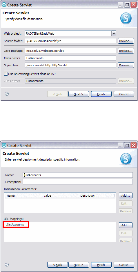

Chapter 13. Develop Web applications using JSPs and servlets 365
Draft Document for Review December 9, 2008 2:44 pm 7672-dev-1-web-jsp.fm
The page also allows the addition of servlet initialization parameters, which
are used to parameterize a servlet. Servlet initialization parameters can be
changed at runtime from within the WebSphere Application Server
administrative console.
The wizard will automatically generate the URL mapping /ListAccounts for
the new servlet. If a different, or additional URL mappings are required, these
can be added here.
In our sample, we do not require additional URL mappings or initialization
parameters. Click Next.
The third and final page (Figure 13-30) gives the option to have the wizard
create stubs methods for methods available from the HttpServlet interface.
The init method is called at start-up and destroy is called at shutdown. The
doPost, doGet, doPut, and doDelete methods are called when an HTTP
request is received for this servlet. All of the do methods have two
parameters, namely a HttpServletRequest and a HttpServletResponse. It is
the job of these methods is to extract the pertinent details from the request
and populate the response object.
Figure 13-30 New Servlet wizard page (3)
For the ListAccounts servlet, only doGet and doPost should be selected.
Usually, HTTP gets are used with direct links, when no information has to be
sent to the server. HTTP posts are typically used when information in a form
has to be sent to the server.
7672-dev-1-web-jsp.fm Draft Document for Review December 9, 2008 2:44 pm
366 Rational Application Developer V7.5 Programming Guide
There is no initialization required for our new servlet and so the init method
is not selected.
Click Finish.
The servlet is generated and added to the project. The source code can be found
in the Java Resources folder of the project, while the configuration for the servlet
is found in Servlets tab of the Web deployment descriptor.
Now expand the deployment descriptor for the RAD75BankBasicWeb
(immediately under the project in the Enterprise Explorer), and and you see that
the ListAccounts servlet is listed.
Implementing the ListAccounts servlet
A skeleton servlet now exists but does not perform any actions when it is
invoked. We now have to add code to the servlet in order to implement the
required behavior.
The ListAccounts.java code of the servlet is already opened.
Locate the file:
c:\7672code\webapp\servlet\ListAccounts.java
Replace the contents of the ListAccounts.java with the sample file. This
should compile successfully with no errors.
Look at the source code for the ListAccounts.java servlet. This class
implements the doPost and doGet methods, both of which call the
performTask method.
The performTask method does the following tasks:
– First the method deals with the HTTP request parameters supplied in the
request. This servlet expects to either receive a parameter called
customerNumber or none at all. If the parameter is passed, we store it in the
HTTP session for future use. If it is not passed, we look for it in the HTTP
session, because it might have been stored there earlier.
– Next the method implements the control logic. Access to the Bank facade
is obtained through the ITSOBank.getBank method and it is used to get the
customer object and the array of accounts for that customer.
– The third section adds the customer and account variables to the
HttpRequest object so that the presentation renderer (listAccounts.jsp)
gets the parameters it requires to perform its job. The control of processing
the request is then passed through to listAccounts.jsp using the
RequestDispatcher.forward method, which builds the response to be
shown on the browser.

Chapter 13. Develop Web applications using JSPs and servlets 367
Draft Document for Review December 9, 2008 2:44 pm 7672-dev-1-web-jsp.fm
– The final part of the method is the error handler. If an exception is thrown
in the previous code, the catch block will ensure that control is passed to
the showException.jsp page.
See Figure 13-9 on page 338 for a sequence diagram of the design of this
class.
The ListAccounts servlet is now complete. The changes should be saved
and the source editor closed.
Implementing the UpdateCustomer servlet
The UpdateCustomer servlet is used for updating the customer information and is
invoked from the ListAccounts JSP through a push button.
The servlet requires that the SSN of the customer that is to be updated is already
placed on the session (as should be done in the ListAccounts servlet). It extracts
the title, firstName, and lastName parameters from the HttpRequest object,
calls the bank.getCustomer(String customerNumber) method and then uses the
simple setters on the Customer class to update the details.
Follow the procedures described in “Adding the ListAccounts servlet to the Web
project” on page 363 and “Implementing the ListAccounts servlet” on page 366
for building the servlet, including the doGet and doPost methods.
The code to use for this class is in:
c:\7672code\webapp\servlet\UpdateCustomer.java
Implementing the AccountDetails servlet
The AccountDetails servlet retrieves the account details and forwards control to
the accountDetails.jsp page to show these details. The servlet expects the
parameter accountId in the request which specifies the account for which data
should be shown. The servlet then calls the bank.getAccount(..) method which
returns an Account object and adds it as a variable to the request. It then uses
the RequestDispatcher to forward the request onto the accountDetails.jsp.
Follow the procedures described in “Adding the ListAccounts servlet to the Web
project” on page 363 and “Implementing the ListAccounts servlet” on page 366
for building the servlet.
Note: A real-life implementation would perform security and authorization,
where the current user has the required access rights to the requested
account. This can be implemented using the Security Editor tool as described
in “Security Editor” on page 331.
7672-dev-1-web-jsp.fm Draft Document for Review December 9, 2008 2:44 pm
368 Rational Application Developer V7.5 Programming Guide
The code to use for this class is in:
c:\7672code\webapp\servlet\AccountDetails.java
Implementing the Logout servlet
The Logout servlet is used for logging the customer off from the RedBank
application. The servlet requires no parameters, and the only logic performed in
the servlet is to remove the SSN from the session, simulating a log off action.
This is done by calling the session.removeAttribute and session.invalidate
methods. Finally it uses the RequestDispatcher class to forward the browser to
the index.html page.
Follow the procedures described in “Adding the ListAccounts servlet to the Web
project” on page 363 and “Implementing the ListAccounts servlet” on page 366
for building the servlet.
The code to use for this class is in:
c:\7672code\webapp\servlet\Logout.java
Implementing the PerformTransaction command classes
In the PerformTransaction servlet, a command design pattern is used to
implement it as a front controller class that forwards control to one of the four
command objects namely Deposit, Withdraw, Transfer, and ListTransactions.
The design for this was presented in “Controller layer” on page 337, and this
implementation is based on the sequence diagram (Figure 13-10 on page 339).
Import the code for the commands package. The source is located in the folder:
C:\7672code\webapp\command
Create the package itso.rad75.webapps.command. In the Enterprise Explorer,
right-click the Java Resources: src folder and select New → Package.
Enter itso.rad75.webapps.command as the package name and click Finish.
From the context menu of the new package, select Import, then General →
File system. Click Next.
Click Browse and navigate to the folder C:\7672code\webapp\command. Click
OK.
Select the five Java files and click Finish:
Command.java
DepositCommand.java
ListTransactionsCommand.java
TransferCommand.java
WithdrawCommand.java

Chapter 13. Develop Web applications using JSPs and servlets 369
Draft Document for Review December 9, 2008 2:44 pm 7672-dev-1-web-jsp.fm
The command classes perform the operations on the RedBank model classes
(from the RAD75Java project) through the Bank facade. They also return the
file-name for the next screen to be shown after the command has been executed.
Implementing the PerformTransaction servlet
Now that all the commands for the PerformTransaction framework have been
realized, the PerformTransaction servlet can be created. The servlet uses the
value of the transaction request parameter to determine what command to
execute.
The Create Servlet wizard can be used to create a servlet named
PerformTransaction. The servlet class should be placed in the package
itso.rad75.webapps.servlet.
Follow the procedures described in “Implementing the ListAccounts servlet” on
page 366 for preparing the servlet, including the doGet and doPost methods.
The code to use for this class is in:
c:\7672code\webapp\servlet\PerformTransaction.java
PerformTransaction stores a HashMap of the action strings (deposit, withdraw,
transfer, and list) to instances of Command classes. Both the doGet and doPost
methods call performTask. In the performTask method the execute method is
called on the appropriate Command class that performs the transaction on the
Bank classes. After the execute is completed, the getForwardView method is
called on the Command class, which returns the next page to display, and
PerformTransaction uses the RequestDispatcher to forward the request to the
next page.
Working with JSPs
JSP files are edited in Page Designer, the same editor used to edit the HTML
page. When working with a JSP page in Page Designer, the Palette view has
additional elements (JSP tags) that can be used, such as JavaBean references,
Java Standard Template Language (JSTL) tags, and scriptlets containing Java
code.
Note about refactoring servlets: It is possible to rename an existing servlet
by selecting Refactor → Rename from the context menu. However, the
default options given on the renaming dialog do not update references to a
servlet in the web.xml file. When renaming a servlet, select Update fully
qualified names in non-Java text files option and enter *.xml in the File
name patterns field. This will then inform the user that web.xml is updated with
the renaming and give them the opportunity to cancel the operation.

7672-dev-1-web-jsp.fm Draft Document for Review December 9, 2008 2:44 pm
370 Rational Application Developer V7.5 Programming Guide
In this section, the implementation of listAccounts.jsp is described in detail and
the other JSPs (accountDetails.jsp, listTransactions.jsp, and
showException.jsp) are imported from the solution.
Implementing the List Accounts JSP
Customizing a JSP file by adding static content is done in the Page Designer tool
in the same way that an HTML file can be edited. It is also possible to add the
standard JSP declarations, scriptlets, expressions, and tags, or any other custom
tag developed or retrieved from the internet.
In this example, the listAccounts.jsp file is built up using page data variables
for customer and accounts (and array of Account classes for that customer).
These variables are added to the page by the ListAccounts servlet and are
accessible to the Java code and tags used in the JSP.
To complete the body of the listAccounts.jsp file, perform the following steps:
Open the listAccounts.jsp in Page Designer and select the Design tab.
Add the customer and accounts variables to the page data meta information
in the Page Data View (by default on the bottom left of the window). These
variables are added to the request object in the ListAccounts servlet, as
discussed in “Implementing the ListAccounts servlet” on page 366. Page
Designer needs to be aware of these variables:
– In the Page Data view expand Scripting Variables, right-click
requestScope, and select New → Request Scope Variable.
– In the Add Request Scope Variable dialog, enter the following information
and click OK:
• Variable name: customer
• Type: itso.rad75.bank.model.Customer
– Repeat this procedure to add the following request scope variable:
• Variable name: accounts
• Type: itso.rad75.bank.model.Account[]
Tip: You can use the browse-button (marked with an ellipsis) to find the
class using the class browser.
Important: Note the square brackets—the variable accounts is an array
of accounts.
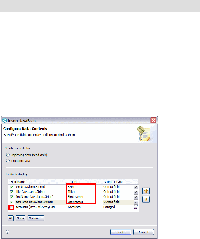
Chapter 13. Develop Web applications using JSPs and servlets 371
Draft Document for Review December 9, 2008 2:44 pm 7672-dev-1-web-jsp.fm
In the Palette view, select Form Tags → Form and click anywhere on the JSP
page in the content table. A dashed box appears on the JSP page,
representing the new form.
In the Properties view for the new Form element, enter the following items:
– Action: Type UpdateCustomer.
– Method: Select Post.
Add a table with customer information:
– In the Page Data view, expand and select Scripting Variables →
requestScope → customer (itso.rad75.java.model.Customer).
– Select and drag the customer object into the form that was previously
created.
– In the Insert JavaBean dialog (Figure 13-31), do these steps:
•Select Displaying data (read-only).
• Use the arrow up and down buttons to arrange the fields in the order
shown, and overtype the labels.
• Clear the accounts field (we do not display the accounts).
Figure 13-31 Inserting the Customer JavaBean
Note: You can use the Outline view to navigate to the form tag quickly.
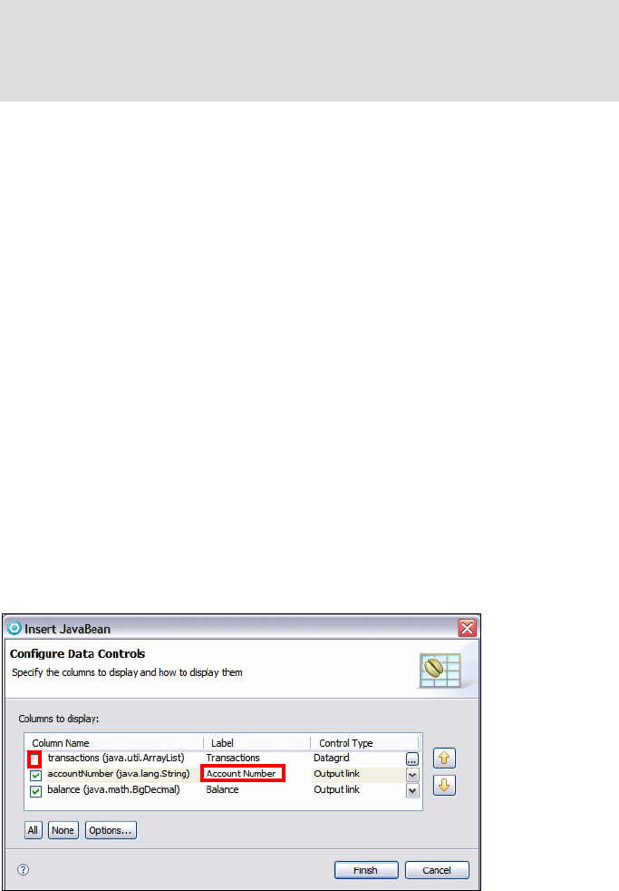
7672-dev-1-web-jsp.fm Draft Document for Review December 9, 2008 2:44 pm
372 Rational Application Developer V7.5 Programming Guide
Right-click the last row of the newly created table (select the LastName cell)
and select Table → Add Row Below.
In the Palette view select Form Tags → Submit Button and click in the
right-hand cell of the new row. Enter Update in the Label field and click OK.
The Name field can be left empty.
In the Palette view, select HTML Tags → Horizontal Rule and click in the
area immediately below the form.
In the Page Data view, expand and select Scripting Variables →
requestScope → accounts (itso.rad75.java.model.Account[]).
Select and drag the accounts object below of the Horizontal Rule created
In the Insert JavaBean wizard (Figure 13-32), do these steps:
– Clear transactions (we do not display the transactions).
– For both fields, select Output link in the Control Type column.
– In the Label field for the accountNumber field, enter Account Number.
– Ensure that the order of the fields is accountNumber and balance.
– Click Finish, and the accounts Bean is added to the page and is displayed
as a list.
Figure 13-32 Inserting the accounts JavaBean
Note: The newly created table with customer data is changed in a later
stage to use input fields for the title, first name, and last name fields. At the
time of writing, this was not possible to achieve through the use of the
available wizards.
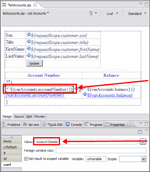
Chapter 13. Develop Web applications using JSPs and servlets 373
Draft Document for Review December 9, 2008 2:44 pm 7672-dev-1-web-jsp.fm
The wizard inserts a JSTL c:forEach tag and an HTML table with headings,
as entered in the Insert JavaBean window. Because we selected Output link
as the Control Type for each column, corresponding c:url tags have been
inserted. We now have to edit the URL for these links to make sure they are
identical and to pass the accountId variable as a URl parameter.
– Select the first <c:url> tag under the heading Account Number, which has
the text ${varAccounts.accountNumber}{}. In the Properties view, enter
AccountDetails in the Value field (Figure 13-33).
– The tag changes to AccountDetails{}.
Figure 13-33 Configuring the AccountDetails URL
– Select the second <c:url> tag under the heading Balance, which has the
text ${varAccounts.balance}{}. In the Properties view, enter
AccountDetails into the Value field. This specifies the target URL for the
link, which in this case maps to the AccountDetails servlet.
– Now we must add a parameter to this URL, so ensure the link goes to the
correct account. In the Palette view select JSP Tags → Parameter and
Click here
Change this value
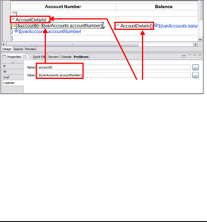
7672-dev-1-web-jsp.fm Draft Document for Review December 9, 2008 2:44 pm
374 Rational Application Developer V7.5 Programming Guide
click on the first <c:url> in the Account Number column. This has the text
AccountDetails{} (Figure 13-34).
– In the Properties view, for the c:param tab, enter accountId in the Name
field and ${varAccounts.accountNumber} in the Value field. This adds a
parameter to the account url with a name of accountId and the value of
the accountNumber request variable.
Figure 13-34 Adding parameters to c:url tags
– Repeat the two previous steps to add a parameter to the second <c:url>
tag in the Balance column, showing the text Account Number{}. Type
accountId as Name field and ${varAccounts.accountNumber} in the
Value field.
Click anywhere in the Balance column, and select the td tag in the Properties
view. Select Right in the Horizontal alignment list box. This makes the
contents of the Balance cells right-justified.
Select the Source tab and compare the code to display the accounts to
Example 13-1. This JSP code displays the accounts as a list, using the
<c:forEach> tag to loop through each account, and the <c:out> tag to
reference the current loop variable. The <c:url> tag builds a URL to
AccountDetails and the <c:param> tag adds the accountId parameter (with
account number value) to that URL.
Example 13-1 JSP code with JSTL tags to display accounts (formatted)
<c:forEach var="varAccounts" items="${requestScope.accounts}">
<tr>
<td>
<c:url value="AccountDetails" var="urlVariable">
<c:param name="accountId"
Click here to add parameters to the c:url tags

Chapter 13. Develop Web applications using JSPs and servlets 375
Draft Document for Review December 9, 2008 2:44 pm 7672-dev-1-web-jsp.fm
value="${varAccounts.accountNumber}"></c:param>
</c:url>
<a href="<c:out value='${urlVariable}' />">
<c:out value="${varAccounts.accountNumber}"></c:out>
</a>
</td>
<td align="right">
<c:url value="AccountDetails" var="urlVariable">
<c:param name="accountId"
value="${varAccounts.accountNumber}"></c:param>
</c:url>
<a href="<c:out value='${urlVariable}' />">
<c:out value="${varAccounts.balance}" />
</a>
</td>
</tr>
</c:forEach>
In the Palette view, select HTMLTags → Horizontal Rule and click in the area
below the account details table.
Add a logout form:
– In the Palette view, select Form Tags → Form and click below the new
horizontal rule. A dashed box will appear on the JSP page, representing
the new form.
– In the Properties view for the new form tag, enter the following items:
• Action: Type Logout.
• Method: Select Post.
– In the Palette view, select Form Tags → Submit Button and click into the
new form. When the Logout button is clicked, the doPost method is called
on the Logout servlet.
– In the Insert Submit Button dialog, enter Logout in the Label field and click
OK.
The remaining part is to change the title, first name and last name to be entry
fields, so that the user can update the customer details.
Do the following steps to convert the Title, First name, and Last name text
fields to allow text entry:
– Select the ${requestScope.customer.title} field.
– Select the Source tab and you can see the code:
<td><c:out value="${requestScope.customer.title}" /></td>
– Change the code to:
<td><input type="text" name="title"

7672-dev-1-web-jsp.fm Draft Document for Review December 9, 2008 2:44 pm
376 Rational Application Developer V7.5 Programming Guide
value="<c:out value='${requestScope.customer.title}' />" /></td>
– Repeat this for the first name and last name fields:
<td><input type="text" name="firstName"
value="<c:out value='${requestScope.customer.firstName}' />" /></td>
......
<td><input type="text" name="lastName"
value="<c:out value='${requestScope.customer.lastName}' />" /></td>
This changes the customer fields from display only fields to be editable, so
that the details can be changed.
You can change the length of the three input fields in the properties view, for
example, 6 columns and 3 maximum length for the title, and 32 columns for
the names.
The width of the content areas can be changed in the source code as well.
The account balance is a BigDecimal and must formatted, otherwise it
displays with many digits:
– Click on the balance field ${varAccounts.balance} in the Balance
column.
–Select JSP → Insert Custom.
– In the Insert Custom Tag dialog (Figure 13-35), click Add to add another
tag library.
– Locate and select the http://java.sun.com/jsp/jstl/fmt URI and click OK.
– Select the new tag library and select formatNumber as the custom tag.
Click Insert and Close.
Figure 13-35 Inserting a custom tag
– In the Source tab, select the <fmt:formatNumber> tag and in the
Properties view set maxFractionDigits and minFractionDigits to 2. For
the value type ${varAccounts.balance}.

Chapter 13. Develop Web applications using JSPs and servlets 377
Draft Document for Review December 9, 2008 2:44 pm 7672-dev-1-web-jsp.fm
– Remove the <c:cout value=.... > and </c:cout> tags:
<a href="<c:out value='${urlVariable}' />">
<c:out value="${varAccounts.balance}" />
<fmt:formatNumber maxFractionDigits="2" minFractionDigits="2"
value="${varAccounts.balance}"></fmt:formatNumber>
</c:cout>
</a>
Select any field in the accounts table, and in the Properties view select the
table tab. Set the width to 100 and select %.
Select the Account Number heading, and in the Properties view set the
horizontal aligment to Left. For the Balance heading set the horizontal
aligment to Right.
Save the file.
The JSP is shown in Figure 13-36.
Figure 13-36 listAccounts.jsp finished
Note: The jSP source code for the listAccounts.jsp is provided in
c:\7672code\webapp\jsp\listAccounts.jsp. You can import the code into the
WebContent folder, or copy/paste directly into Application Developer.
7672-dev-1-web-jsp.fm Draft Document for Review December 9, 2008 2:44 pm
378 Rational Application Developer V7.5 Programming Guide
Implementing the other JSPs
The other JPSs have already been created as part of the model solution. These
were built by a similar process of adding request beans to the JSPs and building
HTML and JSP elements around them.
To import the other JSP files, and to be able to view them in Page Designer,
perform the following steps:
Select the WebContent folder and Import, then select General → File
System. Click Next.
Click Browse and navigate to c:\7672code\webapps\jsp.
Select all the JSP files except listAccounts.jsp (which has already been
completed). Click Finish.
When prompted whether to override the existing files, click Yes to All.
Add the required variables to the appropriate Page Data view, following the next
steps for each of the mentioned JSPs in the table (Table 13-2):
Open each JSP file and in the Page Designer
And in the Page Data view, select Scripting Variables → New → Request
Scope Variable.
Table 13-2 Request scope variables for each JSP
Account Details JSP
The acountDetails.jsp shows the details for a particular customer account and
gives options to execute a transaction:
Note: Imported pages do not have the associated request beans showing in
the Page Data view because these are maintained in the .jspPersistence file
immediately under the Web project directory, you have to specifically add them
to the PageData View.
JSP File variable type
accountDetails.jsp account itso.rad75.bank.model.Account
listTransactions.jsp account itso.rad75.bank.model.Account
listTransactions.jsp transactions itso.rad75.bank.model.Transaction[]
showException.jsp message java.lang.String
showException.jsp forward java.lang.String

Chapter 13. Develop Web applications using JSPs and servlets 379
Draft Document for Review December 9, 2008 2:44 pm 7672-dev-1-web-jsp.fm
The JSP uses a single request variable called account to populate the top
portion of the body of the page, which shows the account number and
balance.
The middle section is a simple static form, which provides fields for the details
of a transaction (transaction type, amount, and destination account) and
posts the request to the PerformTransaction servlet for processing.
The Customer Details button navigates the user to the listAccounts.jsp
page.
The Page Designer view of this page is shown Figure 13-37.
Figure 13-37 Completed accountDetails.jsp in preview view
List Transactions JSP
The listTransactions.jsp shows a read only view of the account including the
account number and balance plus a list of all transactions:
The JSP uses two request variables called account and transactions. The
first section of the page uses the account request bean to populate a table
showing the account number and balance.
The middle section uses the transactions[] request bean to show a list of
transactions. This uses the JSTL tag library to iterate through the transaction
list and build up an HTML representation of the transaction history.
The Account Details button returns the browser to the accountDetails.jsp
page.
The Page Designer view of this page is shown Figure 13-38.
Form to
perform
transactions
Uses the
account
bean

7672-dev-1-web-jsp.fm Draft Document for Review December 9, 2008 2:44 pm
380 Rational Application Developer V7.5 Programming Guide
Figure 13-38 Completed listTransactions.jsp in preview view
Show Exception JSP
The showException.jsp is displayed when an exception occurs in the processing
of a request:
The JSP shows a simple error message and gives a link to another page
within the RedBank application to allow the user to continue.
There are two request beans used on this page; message stores the text to
display to the user, and forward stores a URL for the next page to continue.
The URL is hidden behind the text Click here to continue.
Figure 13-39 shows this page in the design view of Page Designer.
Figure 13-39 Completed showException.jsp in the preview view
The RedBank application is finished and ready to be tested.
Uses account bean to show number/balance
Uses transaction array bean to show the transaction history
Uses message page variable
Uses forward page variable
Chapter 13. Develop Web applications using JSPs and servlets 381
Draft Document for Review December 9, 2008 2:44 pm 7672-dev-1-web-jsp.fm
Testing the Web application
This section demonstrates how to run the sample RedBank application, built in
the previous sections.
Prerequisites to run the sample Web application
To run the RedBank application, you must do one of the following actions:
Complete the sample following the procedures described in “Implementing
the RedBank application” on page 339.
Import the completed project interchange file from:
c:\7672code\zInterchange\webapps\RAD75BankBasicWeb.zip
Refer to “Importing sample code from a project interchange file” on
page 1152 for details.
Running the sample Web application
To run the RedBank Web application in the test environment, do these steps:
Right-click RAD75BankBasicWeb in the Enterprise Explorer and select
Run As → Run on Server.
In the Server Selection dialog, select Choose an existing server, select
WebSphere Application Server v7.0, and click Finish.
The main page of the Web application should be displayed in a Web browser
inside Application Developer.
Verifying the RedBank Web application
Once you have launched the application by running it on the test server, there are
some basic steps that can be taken to verify the Web application is working
properly.
From the main page, select the redbank menu option.
In the RedBank page type a customer social security number, for example,
444-44-4444 (Figure 13-40).
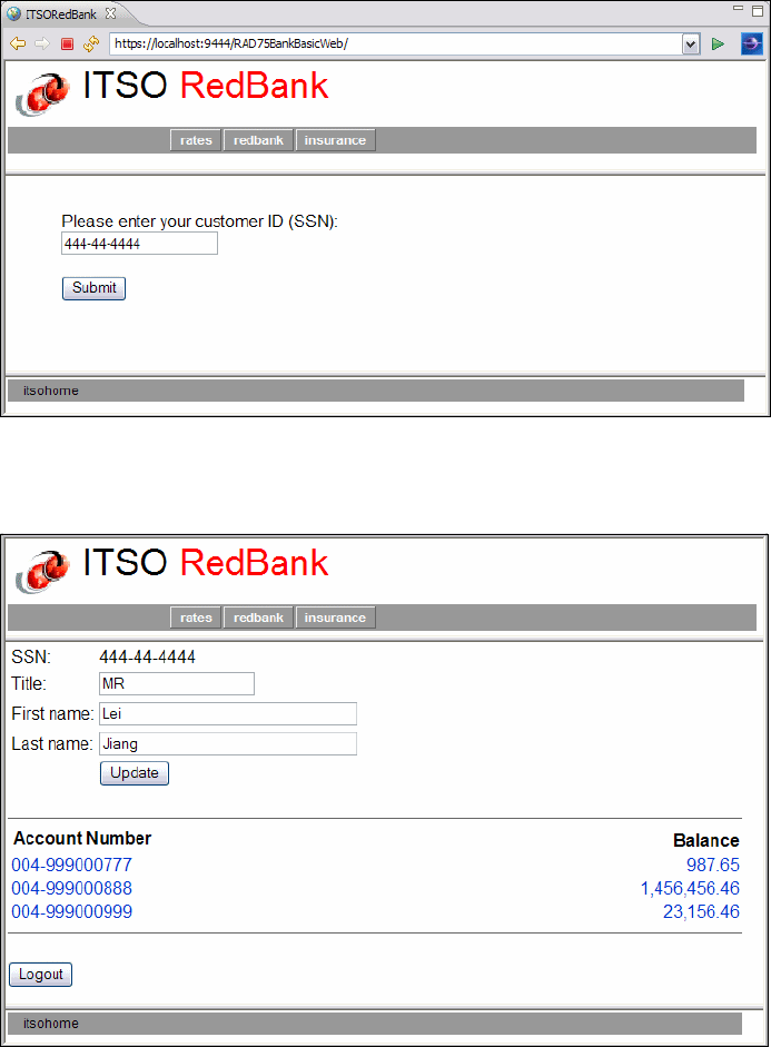
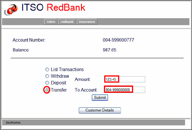
Chapter 13. Develop Web applications using JSPs and servlets 383
Draft Document for Review December 9, 2008 2:44 pm 7672-dev-1-web-jsp.fm
These actions are supported:
– Change the customer title or name fields and click Update. This performs
the doPost method of the UpdateCustomer servlet. For example, change
the title to Sir and then click Update.
– Clicking Logout performs a logout and returns to the Login page.
– Clicking on any account displays the account information (Figure 13-42).
Figure 13-42 Details for a selected account
These actions are supported:
–Select List Transactions and click Submit. There are no transactions yet.
–Select Deposit or Withdraw, enter an amount and click Submit to
execute a banking transaction. The page is redisplayed with the balance
updated.
–Select Transfer, enter an amount and a target account, and click Submit
The page is redisplayed with the balance updated.
– Click Customer Details to return to the account listing.
Run a few transactions (deposit, withdraw, transfer), then select List
Transactions and click Submit. The transaction listing is displayed
(Figure 13-43).

7672-dev-1-web-jsp.fm Draft Document for Review December 9, 2008 2:44 pm
384 Rational Application Developer V7.5 Programming Guide
Figure 13-43 List of transactions for an account
Try a withdraw of an amount greater than the balance. The Show Exception
JSP is displayed with an error message (Figure 13-44).
Figure 13-44 Withdraw over the limit error
Chapter 13. Develop Web applications using JSPs and servlets 385
Draft Document for Review December 9, 2008 2:44 pm 7672-dev-1-web-jsp.fm
RedBank Web application conclusion
We hope that all of the foregoing demonstrations worked successfully for you.
The example has demonstrated the following features, which are just a subset of
the tools available within Application Developer for Web development:
Basic servlets
Basic JSPs
Page Designer
Page templates
Web Site Navigation editor
CSS editor
JSP tags
New Servlet wizard
New Web Project wizard
Web Library projects
Navigation tabs
JSTL tag library
More information
There are many ways that the RedBank application can be improved, by adding
features or using other technologies. Some of these are covered in subsequent
chapters of this book, including these:
Using EJBs to store the model—Chapter 14, “Develop EJB applications” on
page 387
Using a database rather than HashMaps—Chapter 11, “Develop database
applications” on page 227
Using Struts to handle the requests—Chapter 15, “Develop Web applications
using Struts” on page 445
Using JSF components rather than JSTL—Chapter 16, “Develop Web
applications using JSF” on page 493
Debugging the application—Chapter 24, “Debug local and remote
applications” on page 861
The Help feature provided with Application Developer has a large section on
Developing Web sites and applications. It contains reference information for all
the features presented in this chapter and further information on topics only
covered briefly here, including JSP tag libraries, Security, and use of the Web
Diagram Editor.
7672-dev-1-web-jsp.fm Draft Document for Review December 9, 2008 2:44 pm
386 Rational Application Developer V7.5 Programming Guide
Finally, the following URLs provide further information for the topics covered in
this chapter:
Sun Java Servlet Technology Home page—Contains links to the
specification, API Javadoc, and articles on servlets.
http://java.sun.com/products/servlet/index.jsp
Sun JavaServer Pages Technology Home page—Home page for technical
information on JSPs:
http://java.sun.com/products/jsp/jstl/
Sun JavaServer Pages Standard Tag Library (JSTL)—Home page for
technical information on JSTL:
http://java.sun.com/products/jsp/jstl/
Online Color Scheme—Useful for figuring out the hex code for a particular
color:
http://www.colorschemer.com/online.html
JSP and Servlets best practices—This is an old article, but it articulates
clearly the different ways of applying an MVC pattern to JSPs and servlets:
http://java.sun.com/developer/technicalArticles/javaserverpages/servlets_js
p/
Experience J2EE! Using WebSphere Application Server V6.1, SG24-7297
This book has an excellent section on implementing J2EE security in
WebSphere Application Server:
http://www.redbooks.ibm.com/abstracts/sg247297.html

© Copyright IBM Corp. 2008. All rights reserved. 387
Draft Document for Review December 9, 2008 2:44 pm 7672-dev-7-ejb.fm
Chapter 14. Develop EJB applications
This chapter introduces Enterprise JavaBeans (EJB) and demonstrates by
example how to create, maintain, and test such components in the J2EE
platform.
We describe how to develop entity beans, and explain the relationships between
the entity beans and session beans. Then we integrate the EJBs with a front-end
Web application for the sample application. We include examples for creating,
developing, and testing the EJBs using Rational Application Developer.
The chapter is organized into the following sections:
Introduction to Enterprise JavaBeans
Sample application overview
Preparing for the sample
Developing an EJB application
You can play with the UTC to make sure all of the EJB methods work. When
you are done, close the UTC pane.
More information
14
Note: Document server-wide property for Was v7:
com.ibm.websphere.ejb.UseEJB61FEPScanPolicy=true
7672-dev-7-ejb.fm Draft Document for Review December 9, 2008 2:44 pm
388 Rational Application Developer V7.5 Programming Guide
Introduction to Enterprise JavaBeans
Enterprise JavaBeans (EJB) is an architecture for server-side component-based
distributed applications written in Java.
EJB 3.0 specification
In this section we learn about the EJB 3.0 specifications that describes session
EJBs and message-driven EJBs. This section is an extract from the IBM
Redbooks publication WebSphere Application Server Version 6.1 Feature Pack
for EJB 3.0, SG24-7611, Chapter 1, Introduction to EJB 3.0.
EJB 3.0 simplified model
There are many publications that discuss the complexities and differences
between the old EJB programming model and the new. For this reason, this book
will focus on diving right into the new programming model. To overcome the
limitations of the EJB 2.x, the new specification introduces a really new simplified
model, whose main features are:
Entity EJBs are now plain old java objects (POJO) that expose regular
business interfaces (POJI), and there is no requirement for home interfaces.
Removal of the requirement for specific interfaces and deployment
descriptors (deployment descriptor information can be replaced by
annotations).
A complete new persistency model (based on the JPA standard), that
supersedes EJB 2.x entity beans (see Chapter 12, “Persistence using the
Java Persistence API (JPA)” on page 267).
Interceptor facility to invoke user methods at the invocation of business
methods or at life cycle events.
Default values are used whenever possible (“configuration by exception”
approach).
Reduction of the requirements for usage of checked exception.
Figure 14-1 shows how the model of J2EE 1.4 has been completely reworked
with the introduction of the EJB 3.0 specification.
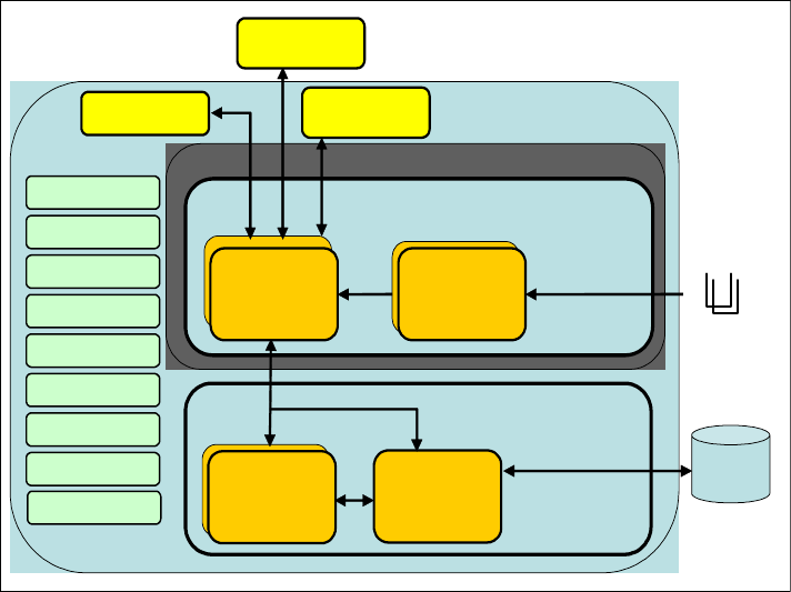
Chapter 14. Develop EJB applications 389
Draft Document for Review December 9, 2008 2:44 pm 7672-dev-7-ejb.fm
Figure 14-1 EJB 3.0 architecture
In this chapter we introduce these features.
Meta data annotations
EJB 3.0 uses meta data annotations, as part of Java SE 5.0.
Annotations are similar to XDoclet, a powerful open-source framework extensi-
ble, metadata-driven, attribute-oriented framework that is used to generate Java
code or XML deployment descriptors. However unlike XDoclet, that requires
pre-compilation, annotations are syntax checked by the Java compiler at com-
pile-time, and sometimes compiled into classes.
By specifying special annotations, developers can create POJO classes that are
EJB components.
In the sections that follow we illustrate the most popular use of annotations and
EJB 3.0 together.
SessionBean
BusinessLogic Tier
Session Beans Message
Driven Beans
Message
Driven Beans
Persistency Tier
Message
Driven Beans
JPA
Entities
Entity
Manager
EJB Container
JMS
JTA
JNDI
JDBC
RMI-IIOP
Threating
Pooling
Security
JMS
Provider
RDBMS
Remote
Client
Local
Client Application Server
Web Services
Remote
Client

7672-dev-7-ejb.fm Draft Document for Review December 9, 2008 2:44 pm
390 Rational Application Developer V7.5 Programming Guide
EJB types and their definition
In EJB 3.0 there are two types of EJB:
Session beans (stateless and stateful)
Message driven beans
Let us describe how annotations can be used to declare session beans and MDB
beans.
Stateless session EJB
Session stateless EJBs have always been used to model a task being performed
for a client code that invokes it. They implement business logic or rules of a
system, and provide coordination of those activities between beans, such as a
banking service, that allows for a transfer between accounts.
A session stateless bean, is generally used for business logic that spans a single
request and therefore cannot retain client-specific state among calls.
Because a stateless EJB does not maintain a conversational state, all the data
exchanged between the client and the EJB must be passed either as input
parameters, or as return value, declared on the EJB business method interface.
To better appreciate the simplification effort done by the EJB 3.0 specification, let
us have a comparison of the steps involved in the definition of an EJB according
to 2.x and 3.0.
Steps to define a stateless session bean in EJB 2.x
To define a stateless session EJB for EJB 2.x, you have to define the following
components:
EJB component interface: Used by an EJB client to gain access to the
capabilities of the bean. This is where the business methods are defined. The
component interface is called the EJB object. There are two types of
component interfaces (Figure 14-2):
– Remote component (EJBObject)—Used by a remote client to access the
EJB through the RMI-IIOP protocol.
– Local component (EJBLocalObject)—Used by a local client (that runs
inside the same JVM) to access the EJB.
Note: EJB2.x entity beans have been replaced by JPA entities, that are
discussed in Chapter 12, “Persistence using the Java Persistence API (JPA)”
on page 267.
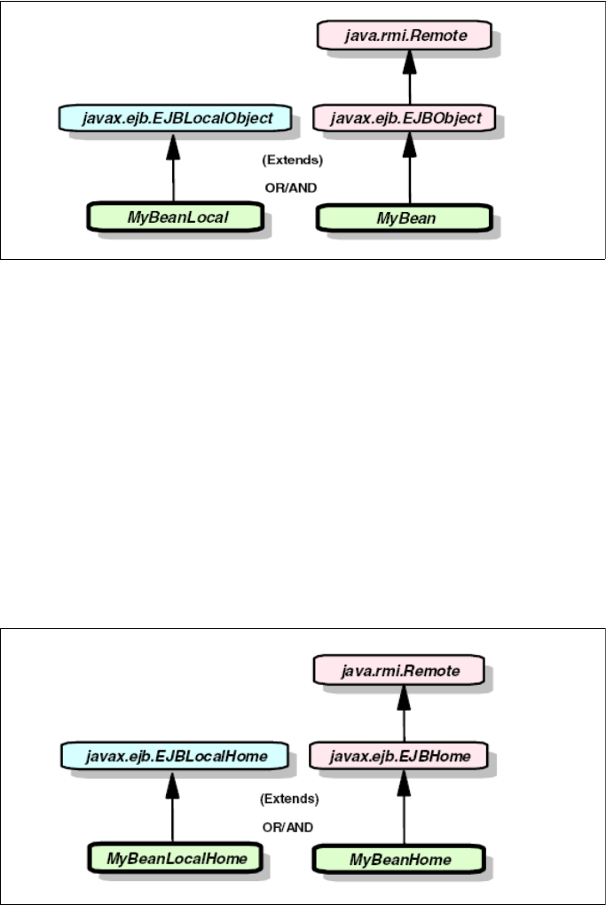
Chapter 14. Develop EJB applications 391
Draft Document for Review December 9, 2008 2:44 pm 7672-dev-7-ejb.fm
Figure 14-2 EJB 2.x component interfaces
EJB home interface: Used by an EJB client to gain access to the bean.
Contains the bean life cycle methods of create, find, or remove. The home
interface is called the EJB home. The EJBHome object is an object which
implements the home interface, and as in EJBObject, is generated from the
container tools during deployment, and includes container specific code. At
startup time the EJB container instantiates the EJBHome objects of the
deployed enterprise beans and registers the home in the naming service. An
EJB client accesses the EJBHome objects using the Java Naming and Directory
Interface (JNDI). There are two types of home interfaces (Figure 14-3):
– Remote interface (EJBHome)—Used by a remote client to access the EJB
through the RMI-IIOP protocol.
– Local interface (EJBLocalHome)—Used by a local client (that runs inside the
same JVM) to access the EJB.
Figure 14-3 EJB 2.x home interfaces

7672-dev-7-ejb.fm Draft Document for Review December 9, 2008 2:44 pm
392 Rational Application Developer V7.5 Programming Guide
EJB bean class: Contains all of the actual bean business logic. Is the class
that provides the business logic implementation. Methods in this bean class
associate to methods in the component and home interfaces.
Steps to define a stateless session bean in EJB 3.0
To declare a session stateless bean, according to EJB 3.0 specification, you can
simply define a POJO:
@Stateless
public class MyFirstSessionBean implements MyBusinessInterface {
// business methods according to MyBusinessInterface
.....
}
Let us have a look at the new, revolutionary aspects of this approach:
MyFirstSessionBean is a POJO that exposes a plain old Java interface (POJI),
in this case MyBusinessInterface. This interface will be available to clients to
invoke the EJB business methods.
The @Stateless annotation indicates to the container that the given bean is
stateless session bean so that the proper life cycle and runtime semantics
can be enforced.
By default, this session bean is accessed through a local interface.
This is all you need to set up a session EJB! There are no special classes to
extend and no interfaces to implement. The very simple model of EJB 3.0 is
shown in Figure 14-4.
Figure 14-4 EJB is a POJO exposing a POJI
On the other hand, if we want to expose the same bean on the remote interface,
we would use the @Remote annotation:
@Remote(MyRemoteBusinessInterface.class)
@Stateless
public class MyBean implements MyRemoteBusinessInterface {
MyFirstSessionBean
MyBusinessInterface
implements

Chapter 14. Develop EJB applications 393
Draft Document for Review December 9, 2008 2:44 pm 7672-dev-7-ejb.fm
// ejb methods
.....
}
Stateful session EJB
Stateful session EJBs are usually used to model a task or business process that
spans multiple client requests, therefore, a stateful session bean retains state on
behalf of an individual client. The client, on the other hand, has to store the
handle to the stateful EJB, so that it always accesses the same EJB instance.
Using the same approach we adopted before, to define a stateful session EJB is
to declare a POJO with the annotations:
@Stateful
public class MySecondSessionBean implements MyBusinessStatefulInterface {
// ejb methods
.....
}
The @Stateful annotation indicates to the container that the given bean is
stateful session bean so that the proper life cycle and runtime semantics can be
enforced.
Business interfaces
EJBs can expose different business interfaces, according to the fact that the EJB
could be accessed either from a local or remote client. We recommend that
common behaviors to both local and remote interfaces should be placed in a
super-interface, as shown in Figure 14-5.
Please take care of the following aspects:
A business interface cannot be both a local and a remote business interface
of the bean.
If a bean class implements a single interface, that interface is assumed to be
the business interface of the bean. This business interface will be a local
interface, unless the interface is designated as a remote business interface by
use of the @Remote annotation or by means of the deployment descriptor.
This give you a great flexibility during the design phase, because you can decide
which methods are visible to local and remote clients.
Tip: If the session bean implements only one interface, you can also just code
@Remote (without a class name).

7672-dev-7-ejb.fm Draft Document for Review December 9, 2008 2:44 pm
394 Rational Application Developer V7.5 Programming Guide
Figure 14-5 How to organize the EJB component interface
Using these guidelines, our first EJB is refactored as shown here:
@Stateless
public class MyFirstSessionBean
implements MyLocalBusinessInterface, MyRemoteBusinessInterface {
// implementation of methods declared in MyLocalBusinessInterface
....
....
// implementation of methods declared in MyRemoteBusinessInterface
....
....
}
The MyLocalBusinessInterface is declared as interfaces with a @Local or
@Remote annotation:
@Local
public interface MyLocalBusinessInterface
extends MyAbstractBusinessInterface {
// methods declared in MyLocalBusinessInterface
......
}\
@Remote
public interface MyRemoteBusinessInterface
extends MyAbstractBusinessInterface {
// methods declared in MyRemoteBusinessInterface
MyFirstSessionBean
MyLocalBusine ssInterface
im plemen ts
M yRe mote Bus iness In te rfa ce
My Abstrac tBusine ssI nterfac e
exte nd s
Chapter 14. Develop EJB applications 395
Draft Document for Review December 9, 2008 2:44 pm 7672-dev-7-ejb.fm
......
}
Another techniques to define the business interfaces exposed either as local or
remote is to specify @Local or @Remote annotations with the full class that
implements these interfaces:
@Stateless
@Local(MyLocalBusinessInterface.class)
@Remote(MyRemoteBusinessInterface.class)
public class MyFirstSessionBean implements MyLocalBusinessInterface,
MyRemoteBusinessInterface {
// implementation of methods declared in MyLocalBusinessInterface
....
....
// implementation of methods declared in MyRemoteBusinessInterface
....
....
}
You can declare arbitrary exceptions on the business interface, but take into
account the following rules:
Do not use RemoteException.
Any runtime exception thrown by the container is wrapped into an
EJBException.
Best practices for developing EJBs
An EJB 3.0 developer must be adherent to the following basic rules:
Each session bean must be a POJO, the class must be concrete (therefore
neither abstract or final), and must have a no-argument constructor (if not
present, the compiler will insert a default constructor).
The POJO must implement at least one POJI. We stress at least, because
you can have different interfaces for local and remote clients.
If the business interface is @Remote annotated, all the values passed
through the interface must implement java.io.Serializable. Typically the
declared parameters are defined serializable, but this is not required as long
as the actual values passed are serializable.
A session EJB can subclass a POJO, but cannot subclass another session
EJB.
7672-dev-7-ejb.fm Draft Document for Review December 9, 2008 2:44 pm
396 Rational Application Developer V7.5 Programming Guide
Message-driven bean
Message- driven beans are used for the processing of asynchronous JMS
messages within J2EE based applications. The are invoked by the container on
the arrival of a message.
In this way, they can be thought of as another interaction mechanism for invoking
EJBs, but unlike session beans, the container is responsible for invoking them
when a message is received, not a client (or another bean).
To define a message driven bean in EJB 3.0 you declare a POJO:
@MessageDriven(activationConfig = {
@ActivationConfigProperty(propertyName="destinationType",
propertyValue="javax.jms.Queue"),
@ActivationConfigProperty(propertyName="destination",
propertyValue="queue/myQueue")
})
public class MyMessageBean implements javax.jms.MessageListener {
public void onMessage(javax.msg.Message inMsg) {
// implement the onMessage method
// to handle the incoming message
....
}
}
The main relevant features of this example are:
In EJB 3.0, the MDB bean class is annotated with the @MessageDriven
annotation, which specifies a set of activation configuration parameters.
These parameters are unique to the particular kind of JCA 1.5 adapter that is
used to drive the MDB. Some adapters have configuration parameters that let
you specify the destination queue of the MDB. In the case where the adapter
does not support this, the destination name must be specified using a
<message-destination> entry in the XML binding file.
The bean class has to implement the MessageListener interface, which
defines only one method, onMessage. When a message arrives in the queue
monitored by this MDB, the container calls the onMessage method of the bean
class and passes the incoming message in as the parameter.
Furthermore, the activationConfig property of the @MessageDriven
annotation provides messaging system–specific configuration information.

Chapter 14. Develop EJB applications 397
Draft Document for Review December 9, 2008 2:44 pm 7672-dev-7-ejb.fm
Web services
Exposing EJB 3.0 beans as Web services using the @WebService annotation is
covered in Chapter 18, “Develop Web services applications” on page 563, where
we show how to implement a Web service from an EJB 3.0 session bean.
Life cycle events
Another very powerful use of annotations is to mark callback methods for session
bean life cycle events.
EJB 2.1 and prior releases required implementation of several life cycle methods,
such as ejbPassivate, ejbActivate, ejbLoad, and ejbStore, for every EJB even
if you do not need these methods.
Because we use POJOs in EJB 3.0, the implementation of these life cycle
methods have been made optional. Only if you implement any callback method in
the EJB, the container will invoke that specific method.
The life cycle of a session bean may be categorized into several phases or
events. The most obvious two events of a bean life cycle are creation and
destruction for stateless session beans.
After the container creates an instance of a session bean, the container performs
any dependency injection (described in the section that follows), and then
invokes the method annotated with @PostConstruct (if there is one).
The client obtains a reference to a session bean, and then invokes a business
method.
At the end of the life cycle, the EJB container calls the method annotated with
@PreDestroy, if there is one. The bean instance is then ready for garbage
collection.
A stateless session bean with the two callback methods is shown here:
@Stateless
public class MyStatelessBean implements MyBusinessLogic {
Note: The actual life cycle of a stateless session bean is independent of
when a client obtains a reference to it. For example, the container may hand
out a reference to the client, but not create the bean instance until some later
time, for example, when a method is actually invoked on the reference. Or, the
container may create a number of instances at startup time, and match them
up with references at a later time.

7672-dev-7-ejb.fm Draft Document for Review December 9, 2008 2:44 pm
398 Rational Application Developer V7.5 Programming Guide
// .. bean business method
@PostConstruct
public void initialize() {
// initialize the resources uses by the bean
}
@PreDestroy
public void cleanup() {
// deallocates the resources uses by the bean
}
}
All stateless and stateful EJBs go through these two phases.
In addition, stateful session beans go through the passivation/activation cycle.
Because an instance of a stateful bean is bound to a specific client (and
therefore it cannot be reused among different requests), and the EJB container
must manage the amount of physical available resources, the EJB container may
decide to deactivate, or passivate, the bean by moving it from memory to
secondary storage.
In correspondence with this more complex life cycle, we have further callback
methods, specific to stateful session beans:
The EJB container invokes the method annotated with @PrePassivate,
immediately before passivating it.
If a client invokes a business method on the bean while it is in the passive
stage, the EJB container activates the bean by calling the method annotated
with @PostActivate, if any, and then moves it to the ready stage.
At the end of the life cycle, the client explicitly invokes a method annotated
with @Remove, and the EJB container in turns calls the callback method
annotated @PreDestroy.
Note: Because a stateful bean is bound to a particular client, it is best practice
to correctly design session stateful beans to minimize their footprint inside the
EJB container, and to correctly un-allocate it at the end of its life cycle, by
invoking the method annotated with @Remove.
Stateful session beans have a time-out value. If the session stateful bean has
not been used in the time-out period, it is marked inactive and is eligible for
automatic deletion by the EJB container. Of course, it is still best practice for
applications to remove the bean when the client is through with it, rather than
relying on the time-out mechanism to do this.

Chapter 14. Develop EJB applications 399
Draft Document for Review December 9, 2008 2:44 pm 7672-dev-7-ejb.fm
Developers can explicitly invoke only the life cycle method annotated with
@Remove, the other methods are invoked automatically by the EJB container.
Interceptors
The EJB 3.0 specification defines the ability to apply custom made interceptors
to the business methods of both session and message driven beans.
Interceptors take the form of methods annotated with the @AroundInvoke
annotation (Example 14-1).
Example 14-1 Applying an interceptor
@Stateless
public class MySessionBean implements MyBusinessInterface {
@Interceptors(LoggerInterceptor.class)
public Customer getCustomer(String ssn) {
...
}
......
}
public class LoggerInterceptor {
@AroundInvoke
public Object logMethodEntry(InvocationContext invocationContext)
throws Exception {
System.out.println("Entering method: "
+ invocationContext.getMethod().getName());
Object result = invocationContext.proceed();
// could have more logic here
return result;
}
}
We have the following notes for this example:
The @Interceptors annotation is used to identify the session bean method
where the interceptor should be applied;
The LoggerInterceptor interceptor class defines a method (logMethodEntry)
annotated with @AroundInvoke.
The logMethodEntry method contains the advisor logic (in this case very
simply logs the invoked method name), and invokes the proceed method on
the InvocationContext interface to advice the container to proceed with the
execution of the business method.

7672-dev-7-ejb.fm Draft Document for Review December 9, 2008 2:44 pm
400 Rational Application Developer V7.5 Programming Guide
The implementation of interceptor in EJB 3.0 is a bit different from the analogous
implementation of this aspect-oriented programming (AOP) paradigm that you
can find in frameworks like Spring or AspectJ, because EJB 3.0 does not support
before or after advisors, but only around interceptors. However, around
interceptors may act as before or after interceptors, or both. Interceptor code
before the invocationContext.proceed call is run before the EJB method, and
interceptor code after that call is run after the EJB method.
A very common use of interceptors is to provide preliminary checks (validation,
security, and so forth) before the invocation of business logic tasks, and therefore
they can throw exceptions. Because the interceptor is called together with the
session bean code at run-time, these potential exceptions are sent directly to the
invoking client.
In this sample we have seen an interceptor applied on a specific method;
actually, the @Interceptors annotation may be applied at class level. In this case
the interceptor will be called for every method.
Furthermore, the @Interceptors annotation accepts a list of classes, so that
multiple interceptors can be applied to the same object.
To disable the invocation of a default interceptor or a class interceptor on a
specific method, you can use the @ExcludeDefaultInterceptors and
@ExcludeClassInterceptors annotations, respectively.
Dependency injection
The new specification introduces a powerful mechanism for obtaining Java EE
resources (JDBC data source, JMS factories and queues, EJB references) and
to inject them into EJBs, entities, or EJB clients.
In EJB 2.x the only way to obtain these resources was to use JNDI lookup using
resource references, with a piece of code that could become cumbersome and
Note: To give further flexibility, EJB 3.0 introduces the concept of a default
interceptor that can be applied on every session (or MDB) bean contained
inside the same EJB module. A default interceptor cannot be specified using
an annotation, instead you should define it inside the deployment descriptor of
the EJB module.
Note that the execution order in which interceptors are run is the following:
Default interceptor
Class interceptors
Method interceptors
Chapter 14. Develop EJB applications 401
Draft Document for Review December 9, 2008 2:44 pm 7672-dev-7-ejb.fm
vendor specific, because very often you had to specify properties related to the
specific J2EE container provider.
EJB 3.0 adopts a dependency injection (DI) pattern, which is one of best ways to
implement loosely coupled applications. It is much easier to use and more
elegant than older approaches, such as dependency lookup through JNDI or
container callbacks.
The implementation of dependency injection in the EJB 3.0 specification is based
on annotations or XML descriptor entries, which allow you to inject dependencies
on fields or setter methods.
Instead of complicated XML EJB references or resource references, you can use
the @EJB and @Resource annotations to set the value of a field or to call a
setter method within your beans with anything registered within JNDI. With these
annotations, you can inject EJB references and resource references such as
data sources and JMS factories.
In this section we show the most common usage of dependency injection in EJB
3.0.
@EJB annotation
The @EJB annotation is used for injecting session beans into a client. This
injection is only possible within managed environments, such as another EJB, or
a servlet. We cannot inject an EJB into a JSF managed bean or Struts action, for
example.
The parameters for the @EJB annotation are optional. The annotation
parameters are:
name—Specifies the JNDI name that is used to bind the injected EJB in the
environment naming context (java:comp/env).
beanInterface—Specifies the business interface to be used to access the
EJB. By default, the business interface to be used is taken from the Java type
of the field into which the EJB is injected. However, if the field is a supertype
of the business interface, or if method-based injection is used rather than
field-based injection, the beanInterface parameter is typically required,
because the specific interface type to be used might be ambiguous without
the additional information provided by this parameter.
beanName—Specifies a hint to the system of the ejb-name of the target EJB
that should be injected. It is analogous to the <ejb-link> stanza that can be
added to an <ejb-ref> or <ejb-local-ref> stanza in the XML descriptor.
To access a session bean from a Java servlet we use the code shown in
Example 14-2.

7672-dev-7-ejb.fm Draft Document for Review December 9, 2008 2:44 pm
402 Rational Application Developer V7.5 Programming Guide
Example 14-2 Injecting an EJB reference inside a servlet
import javax.ejb.EJB;
public class TestServlet extends javax.servlet.http.HttpServlet
implements javax.servlet.Servlet {
// inject the remote business interface
@EJB(beanInterface=MyRemoteBusinessInterface.class)
MyAbstractBusinessInterface serviceProvider;
protected void doGet(HttpServletRequest request,
HttpServletResponse response)
throws ServletException, IOException {
// call ejb method
serviceProvider.myBusinessMethod();
......
}
}
Here are some remarks on this example:
We have specified the beanInterface attribute, because the EJB exposes two
business interfaces (MyRemoteBusinessInterface and
MyLocalBusinessInterface).
If the EJB exposes only one interface, you are not required to specify this
attribute, however, it can be useful to make the client code more readable.
@Resource annotation
The @Resource annotation is the main annotation that can be used to inject
resources in a managed component. In the following we show the most common
usage scenarios of this annotation.
We show here how to inject a typical resource such as a data source inside a
session bean.
Field injection technique
Example 14-3 shows how to inject a data source inside a property that is used in
a business method:
Special notes for stateful EJB injection:
Because a servlet is a multi-thread object, you cannot use dependency
injection, but you must explicitly lookup the EJB through JNDI.
You can safely inject a stateful EJB inside another session EJB (stateless
or stateful), because a session EJB instance is guaranteed to be executed
by only a single thread at a time.

Chapter 14. Develop EJB applications 403
Draft Document for Review December 9, 2008 2:44 pm 7672-dev-7-ejb.fm
@Resource (name="jdbc/dataSource")
Example 14-3 Field injection technique for a data source
@Stateless
public class CustomerSessionBean implements CustomerServiceInterface {
@Resource (name="jdbc/dataSource")
private DataSource ds;
public void businessMethod1() {
java.sql.Connection c=null;
try {
c = ds.getConnection();
// .. use the connection
} catch (java.sql.SQLException e) {
// ... manage the exception
} finally {
// close the connection
if(c!=null) {
try { c.close(); } catch (SQLException e) { }
}
}
}
}
All parameters for the @Resource annotation are optional. The annotation
parameters are:
name—Specifies the component-specific internal name—resource reference
name—within the java:comp/env name space. It does not specify the global
JNDI name of the resource being injected. A binding of the reference
reference to a JNDI name is necessary to provide that linkage, just as it is in
J2EE 1.4.
type—Specifies the resource manager connection factory type.
authenticationType—Specifies whether the container or the bean is to
perform authentication.
shareable—Specifies whether resource connections are shareable or not.
mappedName—Specifies a product specific name that the resource should be
mapped to. WebSphere does not make any use of mappedName.
description—Description.

7672-dev-7-ejb.fm Draft Document for Review December 9, 2008 2:44 pm
404 Rational Application Developer V7.5 Programming Guide
Setter method injection
Another technique is to inject a setter method. The setter injection technique is
based on JavaBeans property naming conventions (Example 14-4).
Example 14-4 Setter injection technique for a data source
@Stateless
public class CustomerSessionBean implements CustomerServiceInterface {
private Datasource ds;
@Resource (name="jdbc/dataSource")
public void setDatasource(DataSource datasource) {
this.ds = datasource;
}
...
public void businessMethod1() {
...
}
}
Some remarks on these two examples:
In this example, we directly used the data source inside the session bean.
This is not good practice, because you should put JDBC code in specific
components, such as data access objects.
We recommend to use the setter injection technique, which gives more
flexibility:
– You can put initialization code inside the setter method.
– The session bean is setup to be easily tested as a stand-alone
component.
Other interesting usages of @Resource are:
To obtain a reference to the EJB session context:
@Stateless
public class CustomerSessionBean implements CustomerServiceInterface {
....
@Resource javax.ejb.SessionContext ctx;
}
To obtain the value of an environment variable, which is configured inside the
deployment descriptor with env-entry:
@Stateless
public class CustomerSessionBean implements CustomerServiceInterface {
....
Chapter 14. Develop EJB applications 405
Draft Document for Review December 9, 2008 2:44 pm 7672-dev-7-ejb.fm
@Resource String myEnvironmentVariable;
}
Injection of JMS resources, such as JMS factories or queues.
Using deployment descriptors
Up to now we have seen how to define an EJB, how to inject resources into it, or
how to specify its life cycle event with annotations. We can get the same result by
specifying a deployment descriptor (ejb-jar.xml) with the necessary information
in the EJB module.
EJB 3.0 application packaging
Session beans and MDBs can be packaged in Java standard JAR file.This can
be achieved by two strategies:
Using a Java project or Java Utility project
Using an EJB project
If you use the first approach you have to add the Java Project to the EAR project,
by editing the deployment descriptor (application.xml), and adding the lines:
<module>
<ejb>MyEJB3Module.jar</ejb>
</module>
When using the second approach, the IDE can automatically update the
application.xml file, and setup an ejb-jar.xml inside the EJB project. However,
in EJB 3.0 you are not required to define the EJBs and related resources in an
ejb-jar.xml file, because they are usually defined through the use of
annotations. The main usage of deployment descriptor files is to override or
complete behavior specified by annotations.
EJB features in Application Developer
The following features, supported by Application Developer, are for the EJB 3.0
specification and require a Java EE 5 compatible application server, such as
WebSphere Application Server v6.1 with the Feature Pack for EJB 3.0, or
WebSphere Application Server v7.0:
Ability to create session and message-driven enterprise beans
Ability to build data persistence using JPA entities.
Ability to generate deployment code automatically in the server

7672-dev-7-ejb.fm Draft Document for Review December 9, 2008 2:44 pm
406 Rational Application Developer V7.5 Programming Guide
Stateless session beans can implement a Web service endpoint.
Enterprise beans can utilize external Web services.
The container-managed timer service is provided.
Message-driven beans support more messaging types in addition to JMS.
The JPA query language allows to run SQL like statements against the JPA
entity model.
Sample application overview
In this chapter, we reuse the design of the application, described in Chapter 8,
“Develop Java applications” on page 69 with same small changes. However, the
content of this chapter does not depend on that chapter. You can complete the
sample in this chapter without knowledge of the sample developed in the Java
chapter.
The focus of this chapter is on implementing EJBs for the business model,
instead of regular JavaBeans. The rest of the application’s layers (control and
view) still apply as designed.
Figure 14-6 shows the sample application model layer design.
Figure 14-6 EJB module class diagram for the sample application
The EJBBank session bean acts as a facade for the EJB model. Our business
entities (Customer, Account, Transaction, Credit, and Debit) are implemented as
JPA
entities
Session bean
facade
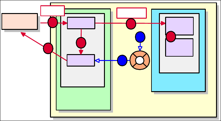
Chapter 14. Develop EJB applications 407
Draft Document for Review December 9, 2008 2:44 pm 7672-dev-7-ejb.fm
CMP entity beans with local interfaces, as opposed to regular JavaBeans. By
doing so, we automatically gain persistence, security, distribution, and
transaction management services. On the other hand, this also implies that the
control and view layers are not able to reference these entities directly, because
they can be placed in a different JVM. Only the session bean (EJBBank) can
access the business entities through their local interfaces.
You might be asking yourself, then, why we do not expose a remote interface for
the entity beans as well? The problem with doing that is two-fold. First, in such a
design, clients would probably make many remote calls to the model to resolve
each client request. This is not a recommended practice because remote calls
are more expensive than local ones. Finally, allowing clients to see into the model
breaks the layer’s encapsulation, promoting unwanted dependencies and
coupling.
Because the control layer is not able to reference the model objects directly, we
reuse the Customer, Account, Transaction, Credit, and Debit from the Java
application in Chapter 8, “Develop Java applications” on page 69as data transfer
objects, carrying data to the servlets and JSPs, but allowing no direct access to
the underlying model.
Figure 14-7 shows the application component model and the flow of events.
Figure 14-7 Application component model and workflow
The flow of events, as shown in Figure 14-7, is as follows:
1. The first event that occurs is the HTTP request issued by the Web client to the
server. This request is answered by a servlet in the control layer, also known
Application Server
Web Client
Web Container
EJB Container
EJB Module
Web Module
View
Control
JPA
Entities
1
5
DTOs
4
6
HTTP
7
injection
2Session
Facade
3

7672-dev-7-ejb.fm Draft Document for Review December 9, 2008 2:44 pm
408 Rational Application Developer V7.5 Programming Guide
as the front controller, which extracts the parameters from the request. The
servlet sends the request to the appropriate control JavaBean. This bean
verifies whether the request is valid in the current user and application states.
2. If so, the control layer sends the request through the @EJB injected interface
to the session EJB facade. This involves using JNDI to locate the session
bean’s interface and creating a new instance of the bean.
3. The session EJB executes the appropriate business logic related to the
request. This includes having to access JPA entities in the model layer.
4. The facade returns DTOs to the calling controller servlet with the response
data. The DTO returned can be a JPA entity, a collection of JPA entities, or
any Java object. In general, it is not necessary to create extra DTOs for entity
data.
5. The front controller servlet sets the response DTO as a request attribute and
forwards the request to the appropriate JSP in the view layer, responsible for
rendering the response back to the client.
6. The view JSP accesses the response DTO to build the user response.
7. The result view, possibly in HTML, is returned to the client.
Preparing for the sample
This section describes the steps to prepare for developing the sample EJB
application.
Required software
To complete the EJB development sample in this chapter, you must have the
following software installed:
IBM Rational Application Developer v7.5
Database software, either of these products:
– Derby v10.2 (installed by default with Application Developer)
– IBM DB2 Universal Database v8.2 or newer
Note: For more information on installing the software, refer to Appendix A,
“Product installation” on page 1121.

Chapter 14. Develop EJB applications 409
Draft Document for Review December 9, 2008 2:44 pm 7672-dev-7-ejb.fm
Enabling the EJB development capability
To develop EJBs, we have to enable the EJB development capability in Rational
Application Developer:
Select Window → Preferences.
Select General → Capabilities → Enterprise Java Developer and click OK
(the capability may already be enabled).
Creating and configuring the EJB projects
In Application Developer, we create and maintain Enterprise JavaBeans and
associated Java resources in EJB and utility projects. Within an EJB project,
these resources can be treated as a portable, cohesive unit.
With the EJB 3.0 specification, the entities are developed and managed by the
Java Persistence API (JPA), as described in Chapter 12, “Persistence using the
Java Persistence API (JPA)” on page 267. EJBs can be session beans or
message-driven beans.
An EJB module, with underlying JPA entities, typically contains components that
work together to perform some business logic. This logic can be self-contained,
or access external data and functions as needed. It should be comprised of a
facade (session bean) and the business entities. (JPA entities).The facade is
usually implemented using one or more session beans and message-driven
beans.
In this chapter we develop a session EJB as a facade for the JPA entities
(Customer, Account, Transaction), as shown in Figure 14-6 on page 406. The
RAD75JPA project must be available in the workspace (you can import the
project from c:\7672code\zInterchange\jpa).
Creating an EJB project
To develop the session EJB, we create an EJB project. It is also typical to create
an enterprise application (EAR) project that is the container for deploying the
EJB project.
To create a Java EE EJB project, do these steps:
Open the Java EE perspective.
Note: With EJB 3.0, we can also use a utility project to hold the EJB classes,
but it is more flexible to use an EJB project.

7672-dev-7-ejb.fm Draft Document for Review December 9, 2008 2:44 pm
410 Rational Application Developer V7.5 Programming Guide
In the Workbench, select File → New → Project.
In the New Project dialog, select EJB → EJB Project and click Next.
In the New EJB Project dialog (Figure 14-8):
– Enter RAD75EJB in the Name field.
– For Target Runtime, select WebSphere Application Server v7.0.
– For EJB Module version, select 3.0.
–Select Add project to an EAR (default) and enter RAD75EJBEAR for
EAR Project Name field. Default behavior is to create a new EAR project,
but you can also select an existing project from the drop-down combo box.
If you would like to create a new project and also configure its location,
click New. For our example, we use the given default value.
– For Configuration, select Default Configuration for WebSphere
Application Server v7.0. Optionally click Modify to see the project facets
(EJB Module 3.0, Java 6.0, WebSphere EJB (Extended) 7.0).
– Click Next.
Figure 14-8 Create an EJB project wizard (1)
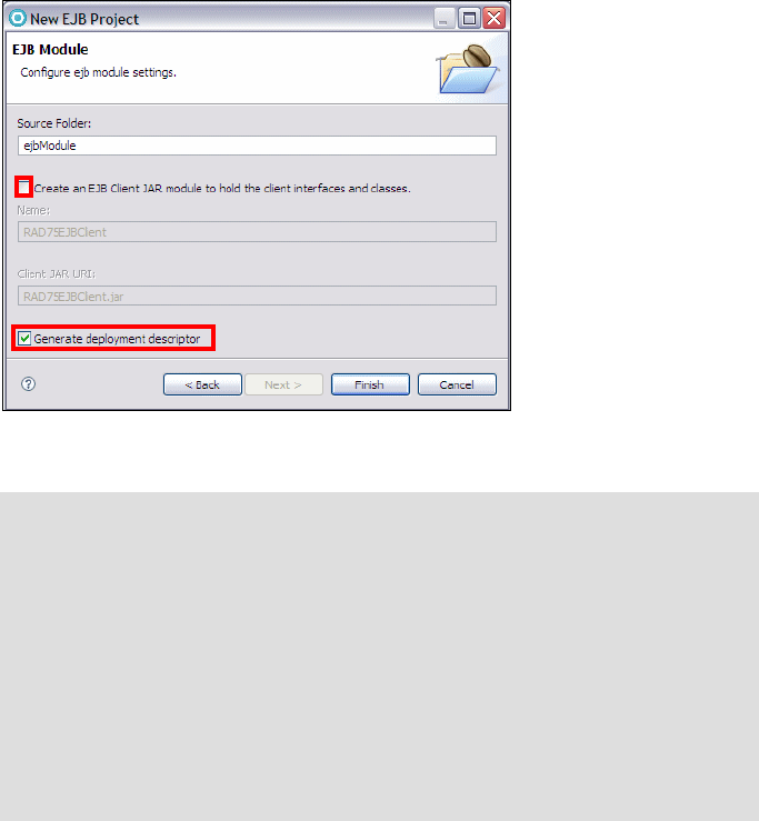
Chapter 14. Develop EJB applications 411
Draft Document for Review December 9, 2008 2:44 pm 7672-dev-7-ejb.fm
In the EJB Module dialog (Figure 14-9) enter the following items:
– Source folder: ejbModule (default)
– Clear Create an EJB Client JAR Project to hold client interfaces and
classes (default).
–Select Generate deployment descriptor.
– Click Finish.
Figure 14-9 Create an EJB project wizard (3)
If the current perspective is not the Java EE perspective when you create the
project, Application Developer prompts, asking if you want to switch to the
Java EE perspective. Click Yes.
Note: The EJB client JAR holds the interfaces of the enterprise beans, and
other classes that these interfaces depend on, such as their superclasses
and implemented interfaces, the classes and interfaces used as method
parameters, results, and exceptions.
The EJB client JAR can be deployed together with a client application that
accesses the EJBs. This results in a smaller client application as compared
to deploying the EJB project with the client application.
However, with EJB 3.0, EJBs are annotated Java classes that are
lightweight compared to EJB 2.1 EJBs, so the need for a client JAR is
minimal.

7672-dev-7-ejb.fm Draft Document for Review December 9, 2008 2:44 pm
412 Rational Application Developer V7.5 Programming Guide
The Technology Quickstarts view opens. You can click on a link to open the
Application Developer Help with a matching tutorial. Close the view.
The Enterprise Explorer contains the RAD75EJB project and the
RAD75EJBEAR enterprise application.
Make the JPA entities available to the EJB project
To make the JPA entities available to the EJBs, we add the RAD75JPA project to
the RAD75EJBEAR enterprise application and create a dependency.
Right-click the RAD75EJBEAR project and select Java EE → Generate
Deployment Descriptor Stub.
A META-INF folder with an application.xml file is created in the project.
Open the application.xml file.
In the editor, select the Design tab, and you can see the EJB module as part
of the EAR (Figure 14-10). Close the editor.
Figure 14-10 EAR deployment editor
Right-click the RAD75EJBEAR project and select Properties.

Chapter 14. Develop EJB applications 413
Draft Document for Review December 9, 2008 2:44 pm 7672-dev-7-ejb.fm
In the Properties dialog, select Java EE Module Dependencies, select the
RAD75JPA module, and click OK (Figure 14-11).
Figure 14-11 EAR module dependencies
Right-click the RAD75EJB project and select Properties. In the Properties
dialog, select Java EE Module Dependencies, select the RAD75JPA.jar,
and click OK (same as Figure 14-11).
Setting up the ITSOBANK database
The JPA entities are based on the ITSOBANK database. Therefore, we have to
define a database connection within Application Developer that the mapping
tools use to extract schema information from the database.
Refer to “Setting up the ITSOBANK database” on page 1154 for instructions on
how to create the ITSOBANK database. We can either use the DB2 or Derby
database. For simplicity we use the built-in Derby database in this chapter.
Configuring the data source for the ITSOBANK
There are a couple of methods that can be used to configure the data source,
including using the WebSphere Administrative Console or using the WebSphere
enhanced EAR, which stores the configuration in the deployment descriptor and
is deployed with the application.
There may be other projects

7672-dev-7-ejb.fm Draft Document for Review December 9, 2008 2:44 pm
414 Rational Application Developer V7.5 Programming Guide
The definition of the data source in the WebSphere Administrative Console is
covered in “Configuring the data source in WebSphere Application Server” on
page 1155.
This section describes how to configure the data source using the WebSphere
enhanced EAR capabilities. The enhanced EAR is configured in the Deployment
tab of the EAR Deployment Descriptor editor. If you select to import the complete
sample code, you only have to verify that the value of the databaseName property
in the deployment descriptor matches the location of the database.
Configure the data source using enhanced EAR
To configure a new data source using the enhanced EAR capability in the
deployment descriptor, do these steps:
Right-click the RAD75EJBEAR project and select Java EE → Open
WebSphere Application Server Deployment.
The WebSphere Deployment editor opens.
Select Derby JDBC Provider (XA) from the JDBC provider list. This JDBC
Provider is configured by default.
Click Add next to data source.
In the Create a Data Source dialog:
–Select Derby JDBC Provider (XA) under the JDBC provider and Version
5.0 data source, and click Next.
–Type ITSOBANKejb (as Name), jdbc/itsobank (as JNDI name), Data
Source for ITSOBANK EJBs (Description). Clear Use this data source
in container managed persistence (CMP). Click Next.
In the Create Resource Properties dialog, select databaseName and enter
the value C:\7672code\database\derby\ITSOBANK. Clear the description.
Click Finish.
Save and close the deployment descriptor (Figure 14-12).
Note: For more information on configuring data sources and general
deployment issues, refer to Chapter 26, “Deploy enterprise applications” on
page 933.

Chapter 14. Develop EJB applications 415
Draft Document for Review December 9, 2008 2:44 pm 7672-dev-7-ejb.fm
Figure 14-12 EAR enhanced deployment descriptor
Developing an EJB application
The EJB application consists of a Web module with a simple servlet, and an EJB
module with an EJB 3.0 session bean that uses the JPA entities to access the
database.
Implementing the session facade
The front-end application communicates with the JPA entity model through a
session facade. This design patterns makes the entities invisible to the EJB
client.
In this section we build the session facade, EJBBank, a stateless session bean.
Preparing an exception
The business logic of the session bean throws an exception when errors occur.
Let us create an application exception named ITSOBankException:
7672-dev-7-ejb.fm Draft Document for Review December 9, 2008 2:44 pm
416 Rational Application Developer V7.5 Programming Guide
Right-click the RAD75EJB project and select New → Class.
In the New Java Class dialog, type itso.bank.exception as package, and
ITSOBankException as Name. Set the superclass to java.lang.Exception.
Click Finish.
Complete the code in the editor:
public class ITSOBankException extends Exception {
private static final long serialVersionUID = 1L;
public ITSOBankException(String message) {
super(message);
}
}
Save and close the class.
Creating the EJBBank session bean
To create the session bean, do these steps:
Right-click the RAD75EJB project and select New → Session Bean.
In the Create EJB 3.0 Session Bean dialog (Figure 14-13):
– For Java package type itso.bank.session.
– For Class name type EJBBankBean.
– For State type select Stateless.
– For Create business interface, select Local, and set the name to
itso.bank.service.EJBBankService.
– Click Next.

Chapter 14. Develop EJB applications 417
Draft Document for Review December 9, 2008 2:44 pm 7672-dev-7-ejb.fm
Figure 14-13 Creating a session bean (1)
In the next dialog, accept the default of Container as transaction type, and
click Next (Figure 14-14).
Figure 14-14 Creating a session bean (2)
In the Select Class Diagram for Visualization dialog, select Add bean to
Class Diagram, and accept the default name of classdiagram.dnx.
Click Finish.

7672-dev-7-ejb.fm Draft Document for Review December 9, 2008 2:44 pm
418 Rational Application Developer V7.5 Programming Guide
When prompted for enablement of EJB 3.0 Modeling, click OK.
Save and close the class diagram.
The EJBBankBean is open in the editor. Notice the @Stateless annotation.
Before we can write the code, we have to complete the business interface.
Defining the business interface
In EJB 3.0, a session bean implements a business interface, which is the
interface clients use to access the session bean. The session bean can
implement multiple interfaces, for example a local interface and a remote
interface. We keep it simple with one local interface, EJBBankService.
The session bean wizard has created the EJBBankService interface. To complete
the code:
Open the EJBBankService interface. Notice the @Local annotation.
In the Java editor, add the methods to the interface (Example 14-5). The code
is available in c:\7672code\ejb\source\EJBBankService.txt.
Example 14-5 Business interface of the session bean
@Local
public interface EJBBankService {
public Customer getCustomer(String ssn) throws ITSOBankException;
public Customer[] getCustomersAll();
public Customer[] getCustomers(String partialName)
throws ITSOBankException;
public void updateCustomer(String ssn, String title, String firstName,
String lastName) throws ITSOBankException;
public Account[] getAccounts(String ssn) throws ITSOBankException;
public Account getAccount(String id) throws ITSOBankException;
public Transaction[] getTransactions(String accountID)
throws ITSOBankException;
public void deposit(String id, BigDecimal amount)
throws ITSOBankException;
public void withdraw(String id, BigDecimal amount)
throws ITSOBankException;
public void transfer(String idDebit, String idCredit, BigDecimal amount)
throws ITSOBankException;
public void closeAccount(String ssn, String id)
throws ITSOBankException;
public String openAccount(String ssn) throws ITSOBankException;
public void addCustomer(Customer customer) throws ITSOBankException;
public void deleteCustomer(String ssn) throws ITSOBankException;
}

Chapter 14. Develop EJB applications 419
Draft Document for Review December 9, 2008 2:44 pm 7672-dev-7-ejb.fm
Organize the imports (Ctrl+Shift+O). Select java.math.BigDecimal and
itso.bank.entities.Transaction when prompted. Save and close the
interface.
Completing the session bean
We now add the facade methods that are used by clients to perform banking
operations.
Generate skeleton methods
We can generate method skeletons for the methods of the business interface that
must be implemented:
Open the EJBBankBean (if you closed it).
Select Source → Override/Implement Methods.
In the Override/Implement Methods dialog, select all the methods of the
EJBBankService interface. For Insertion point select After 'EJBBankBean()'.
Click OK.
The method skeletons are generated. Delete the default constructor.
Create an entity manager
The session bean works with the JPA entities to access the ITSOBANK database.
We require an entity manager bound to the persistent context.
Add these definitions to the EJBBankBean class:
@PersistenceContext (unitName="RAD75JPA",
type=PersistenceContextType.TRANSACTION)
private EntityManager entityMgr;
The @PersistenceContext annotation defines the persistence context unit
with transactional behavior. The unit name matches the name in the
persistence.xml file in the RAD75JPA project:
<persistence-unit name="RAD75JPA">
The EntityManager instance is used to execute JPA methods to retrieve,
insert, update, delete, and query instances.
Organize imports (select the javax.persistence package).
Complete the methods
Tip: The Java code for this section can be copied from the file
c:\7672code\ejb\source\EJBBankBean.txt.

7672-dev-7-ejb.fm Draft Document for Review December 9, 2008 2:44 pm
420 Rational Application Developer V7.5 Programming Guide
We complete the methods of the session bean in a logical sequence, not in
alphabetical sequence of the generated skeletons.
getCustomer method
The getCustomer method retrieves one customer by ssn. Note that we use
entityMgr.find to retrieve one instance. Alternatively we could use the
getCustomerBySSN query (code in comments). If no instance is found, null is
returned (Example 14-6).
Example 14-6 Session bean getCustomer method
public Customer getCustomer(String ssn) throws ITSOBankException {
System.out.println("getCustomer: " + ssn);
//Query query = null;
try {
//query = entityMgr.createNamedQuery("getCustomerBySSN");
//query.setParameter(1, ssn);
//return (Customer)query.getSingleResult();
return entityMgr.find(Customer.class, ssn);
} catch (Exception e) {
System.out.println("Exception: " + e.getMessage());
throw new ITSOBankException(ssn);
}
}
getCustomers method
The getCustomers methods use a query to retrieve a collection of customers
(Example 14-7). The query is created and executed. The result list is converted
into an array an returned. Remember the query from the Customer entity:
select c from Customer c where c.lastName like ?1
This query looks like SQL but works on entity objects. In our case the entity name
and the table name are the same, but they do not have to be identical.
Example 14-7 Session bean getCustomers method
public Customer[] getCustomers(String partialName) throws ITSOBankException {
System.out.println("getCustomer: " + partialName);
Query query = null;
try {
query = entityMgr.createNamedQuery("getCustomersByPartialName");
query.setParameter(1, partialName);
List<Customer> beanlist = query.getResultList();
Customer[] array = new Customer[beanlist.size()];
return beanlist.toArray(array);
} catch (Exception e) {
throw new ITSOBankException(partialName);

Chapter 14. Develop EJB applications 421
Draft Document for Review December 9, 2008 2:44 pm 7672-dev-7-ejb.fm
}
}
updateCustomer method
The updateCustomer method is very simple (Example 14-8). Note that no call to
the entity manager is necessary. The table is updated automatically when the
method (transaction) ends.
Example 14-8 Session bean updateCustomer method
public void updateCustomer(String ssn, String title, String firstName,
String lastName) throws ITSOBankException {
System.out.println("updateCustomer: " + ssn);
Customer customer = getCustomer(ssn);
customer.setTitle(title);
customer.setLastName(lastName);
customer.setFirstName(firstName);
System.out.println("updateCustomer: " + customer.getTitle() + " "
+ customer.getFirstName() + " " + customer.getLastName());
}
getAccount method
The getAccount method retrieves one account by key, similar to the getCustomer
method.
getAccounts method
The getAccounts method uses a query to retrieve all the accounts of a customer
(Example 14-9). The query in the Account entity is:
select a from Account a, in(a.customerCollection) c where c.ssn =?1
order by a.id
This query looks for accounts that belong to a customer with a given ssn. An
alternate query in the Customer class could also be used:
select a from Customer c, in(c.accountCollection) a where c.ssn =?1
order by a.id
Example 14-9 Session bean getAccounts method
public Account[] getAccounts(String ssn) throws ITSOBankException {
System.out.println("getAccounts: " + ssn);
Query query = null;
try {
query = entityMgr.createNamedQuery("getAccountsBySSN");
query.setParameter(1, ssn);
List<Account>accountList = query.getResultList();
7672-dev-7-ejb.fm Draft Document for Review December 9, 2008 2:44 pm
422 Rational Application Developer V7.5 Programming Guide
Account[] array = new Account[accountList.size()];
return accountList.toArray(array);
} catch (Exception e) {
System.out.println("Exception: " + e.getMessage());
throw new ITSOBankException(ssn);
}
}
getTransactions method
The getTransactions method (Example 14-10) retrieves the transactions of an
account. It is similar to the getAccounts method.
Example 14-10 Session bean getTransactions method
public Transaction[] getTransactions(String accountID) throws ITSOBankException
{System.out.println("getTransactions: " + accountID);
Query query = null;
try {
query = entityMgr.createNamedQuery("getTransactionsByID");
query.setParameter(1, accountID);
List<Transaction> transactionsList = query.getResultList();
Transaction[] array = new Transaction[transactionsList.size()];
return transactionsList.toArray(array);
} catch (Exception e) {
System.out.println("Exception: " + e.getMessage());
throw new ITSOBankException(accountID);
}
}
deposit and withdraw methods
The deposit method adds money to an account by retrieving the account and
calling its processTransaction method with the Transaction.CREDIT code. The
new transaction instance is persisted (Example 14-11). The withdraw method is
similar.
Example 14-11 Session bean deposit method
public void deposit(String id, BigDecimal amount) throws ITSOBankException {
System.out.println("deposit: " + id + " amount " + amount);
Account account = getAccount(id);
try {
Transaction tx = account.processTransaction(amount, Transaction.CREDIT);
entityMgr.persist(tx);
} catch (Exception e) {
throw new ITSOBankException(e.getMessage());
};

Chapter 14. Develop EJB applications 423
Draft Document for Review December 9, 2008 2:44 pm 7672-dev-7-ejb.fm
}
transfer method
The transfer method calls withdraw and deposit on two accounts to move funds
from one account to the other (Example 14-12).
Example 14-12 Session bean transfer method
public void transfer(String idDebit, String idCredit, BigDecimal amount)
throws ITSOBankException {
System.out.println("transfer: " + idCredit + " " + idDebit + " amount "
+ amount);
withdraw(idDebit, amount);
deposit(idCredit, amount);
}
openAccount method
The openAccount method creates a new account instance with a randomly
constructed account number. The instance is persisted and the customer is
added to the customerCollection (Example 14-13).
Example 14-13 Session bean openAccount method
public String openAccount(String ssn) throws ITSOBankException {
System.out.println("openAccount: " + ssn);
Customer customer = getCustomer(ssn);
int acctNumber = (new java.util.Random()).nextInt(899999) + 100000;
String id = "00" + ssn.substring(0, 1) + "-" + acctNumber;
Account account = new Account();
account.setId(id);
entityMgr.persist(account);
//customer.getAccountCollection().add(account); // does not work
java.util.Set<Customer> custSet = new java.util.TreeSet<Customer>();
custSet.add(customer);
account.setCustomerCollection(custSet);
System.out.println("openAccount: " + id);
return id;
}
Note: The m:m relationship must be added from the owning side of the
relationship, in our case from the Account. The code to add the relationship
from the Customer side runs without error, but the relationship is not added.
7672-dev-7-ejb.fm Draft Document for Review December 9, 2008 2:44 pm
424 Rational Application Developer V7.5 Programming Guide
closeAccount method
The closeAccount method retrieves an account and all its transactions, then
deletes all instances using the entity manager remove method (Example 14-14).
Example 14-14 Session bean closeAccount method
public void closeAccount(String ssn, String id) throws ITSOBankException {
System.out.println("closeAccount: " + id + " of customer " + ssn);
Customer customer = getCustomer(ssn);
Account account = getAccount(id);
Transaction[] trans = getTransactions(id);
for (Transaction tx : trans) {
entityMgr.remove(tx);
}
entityMgr.remove(account);
System.out.println("closed account with " + trans.length
+ " transactions");
}
addCustomer method
The addCustomer method accepts a fully constructed Customer instance and
makes it persistent (Example 14-15).
Example 14-15 Session bean addCustomer method
public void addCustomer(Customer customer) throws ITSOBankException {
System.out.println("addCustomer: " + customer.getSsn());
entityMgr.persist(customer);
}
deleteCustomer method
The deleteCustomer method retrieves a customer and all its accounts, then
closes the accounts and deletes the customer (Example 14-16).
Example 14-16 Session bean deleteCustomer method
public void deleteCustomer(String ssn) throws ITSOBankException {
System.out.println("deleteCustomer: " + ssn);
Customer customer = getCustomer(ssn);
Account[] accounts = getAccounts(ssn);
for (Account acct : accounts) {
closeAccount(ssn, acct.getId());
}
entityMgr.remove(customer);
}
Organize the imports (select javax.persistence.Query, and java.util.List).

Chapter 14. Develop EJB applications 425
Draft Document for Review December 9, 2008 2:44 pm 7672-dev-7-ejb.fm
The EJBBankBean session bean is now complete. In the following sections we first
test the EJBs using a servlet, and then proceed to integrate the EJBs with a
sample Web application.
Testing the session EJB and the entities
To test the session EJB we can use the Universal Test Client, and we can
develop a simple servlet that executes all the functions.
Deploy the application to the server
To deploy the test application, perform these steps:
Start the WebSphere Application Server v7.0 in the Servers view.
Select the server and Add and Remove Projects. Add the RAD75EJBEAR
enterprise application and click Finish. Wait for the publishing to finish.
Notice the EJB binding messages in the Console:
[...] 00000010 ResourceMgrIm I WSVR0049I: Binding ITSOBANKejb as
jdbc/itsobank
[...] 00000015 EJBContainerI I CNTR0167I: The server is binding the
EJBBankService interface of the EJBBankBean enterprise bean in the
RAD75EJB.jar module of the RAD75EJBEAR application. The binding
location is: ejblocal:RAD75EJBEAR/RAD75EJB.jar/EJBBankBean#itso.bank
.service.EJBBankService
[...] 00000015 EJBContainerI I CNTR0167I: The server is binding the
EJBBankService interface of the EJBBankBean enterprise bean in the
RAD75EJB.jar module of the RAD75EJBEAR application. The binding
location is: ejblocal:itso.bank.service.EJBBankService
EJB 3.0 session beans are automatically bound to a long and a short JNDI
name.
Note: Make sure that the data source for the ITSOBANK database is
configured with a JNDI name of jdbc/itsobank. This can be done either in
the WebSphere Deployment editor (“Configuring the data source for the
ITSOBANK” on page 413) or in the administrative console of the server
(see “Configuring the data source in WebSphere Application Server” on
page 1155).
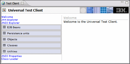
7672-dev-7-ejb.fm Draft Document for Review December 9, 2008 2:44 pm
426 Rational Application Developer V7.5 Programming Guide
Testing with the Universal Test Client
Before we integrate the EJB application with the Web application, we test the
session bean with the access to the JPA entities to see that it work as expected.
We use the enterprise application Universal Test Client (UTC), which is
contained in Application Developer.
In this section we describe some of the operations you can perform with the
Universal Test Client. We use the test client to retrieve a customer and its
accounts.
To test the session bean, do these steps:
In the Servers view, right-click the server and select Universal test client →
Run.
Accept the certificate, and login as admin/admin (the user ID setup when
installing Application Developer).
The Universal Test Client opens (Figure 14-15).
Figure 14-15 Universal Test Client home
Select JNDI Explorer. On the right side, expand [Local EJB Beans].
Select itso.bank.service.EJBBankService. The EJBBankService appears
under EJB Beans. Expand the interface (Figure 14-16).
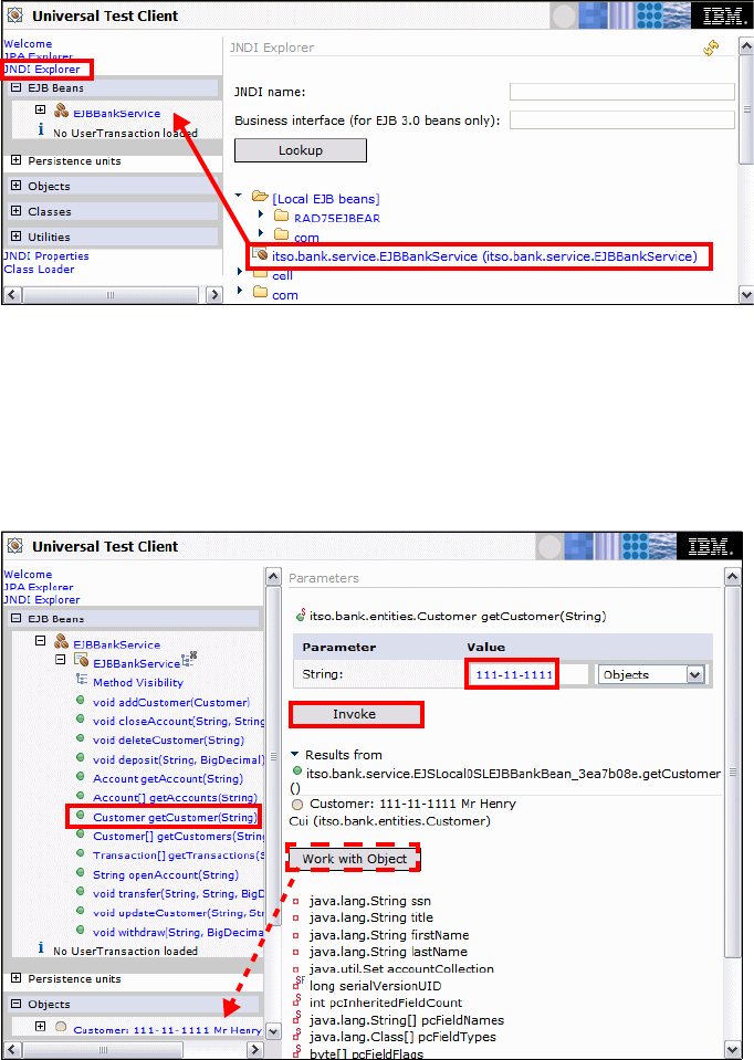
Chapter 14. Develop EJB applications 427
Draft Document for Review December 9, 2008 2:44 pm 7672-dev-7-ejb.fm
Figure 14-16 UTC JNDI Explorer
Expand EJBBankService (on the left) and select the getCustomer method .
The method with its parameter opens on the right.
Typ e 111-11-1111 as value on the right, and click Invoke.
A Customer instances is displayed as result (Figure 14-17).
Figure 14-17 UTC Retrieve a customer
7672-dev-7-ejb.fm Draft Document for Review December 9, 2008 2:44 pm
428 Rational Application Developer V7.5 Programming Guide
Click Work with Object. The customer instance appears under Objects. You
can expand the object, and invoke its methods (for example, getLastName) to
see the customer name.
Select the getAccounts method in the EJBBankService interface. Type
222-22-2222 as parameter value, and click Invoke. Three accounts are
displayed as result.
Select the getTransactions method. Type 002-222002 as parameter value,
and click Invoke. Several transaction records are displayed.
Select the OpenAccount method. Type 111-11-1111 as parameter value,
and click Invoke. A new account with a random ID (for example, 001-169749)
is created.
Select the deposit method. Type the new account number (001-xxxxxx) and
100.00 as parameter values, and click Invoke.
Select the getAccount method. Type the new account number (001-xxxxxx)
as parameter value, and click Invoke. Click Work with Object, expand the
account object, and invoke the getBalance method to verify the balance.
Select the closeAccount method. Type 111-11-1111 and the new account
number (001-xxxxxx) as parameter values, and click Invoke.
Verify in the Console that the account is closed:
closed account with 1 transactions
You can play with the UTC to make sure all of the EJB methods work. When you
are done, close the UTC pane.
Creating a test Web application
To test the EJB 3.0 session bean and entity model, we create a small Web
application with one servlet:
Select File → New Project → Web → Dynamic Web Project:
– Enter RAD75EJBTestWeb as name.
–Select 2.5 for Dynamic Web Module version.
– Add the project to the RAD75EJBEAR enterprise application.
– Click Finish and close the help that opens.
Right-click the RAD75EJBTestWeb project and Properties. In the Properties
dialog, Java EE Module Dependencies page, select the RAD75EJB.jar
module, and click OK.
Right-click the RAD75EJBTestWeb project and select New → Servlet.

Chapter 14. Develop EJB applications 429
Draft Document for Review December 9, 2008 2:44 pm 7672-dev-7-ejb.fm
Enter itso.test.servlet as package name and BankTest as class name. Click
Next twice, and select to generate doPost and doGet methods. Click Finish.
After the class definition, add an injector for the business interface:
@javax.ejb.EJB EJBBankService bank;
The injection of the business interface into the servlet resolves to the
automatic binding of the session EJB.
In the doGet method, enter the code:
doPost(request, response);
Complete the doPost method with the code of Example 14-17, which is
available in 7672code\ejb\source\BankTest.txt. This servlet executes the
methods of the session bean, after getting a reference to the business
interface.
Example 14-17 Servlet to test the EJB 3.0 module (abbreviated)
protected void doPost(HttpServletRequest request,
HttpServletResponse response) throws ServletException, IOException {
try {
PrintWriter out = response.getWriter();
String partialName = request.getParameter("partialName");
out.println("<html><body><h2>Customer Listing</h2>");
if (partialName == null) partialName = "%";
else partialName = "%" + partialName + "%";
out.println("<p>Customers by partial Name: " + partialName + "<br>");
Customer[] customers = bank.getCustomers(partialName);
for (Customer cust : customers) {
out.println("<br>" + cust);
}
Customer cust1 = bank.getCustomer("222-22-2222");
out.println("<p>" + cust1);
Account[] accts = bank.getAccounts(cust1.getSsn());
out.println("<br>Customer: " + cust1.getSsn() + " has "
+ accts.length + " accounts");
Account acct = bank.getAccount("002-222002");
out.println("<p>" + acct);
out.println("<p>Transactions of account: " + acct.getId());
Transaction[] trans = bank.getTransactions("002-222002");
out.println("<p><table border=1><tr><th>Type</th><th>Time</th>...");
for (Transaction t : trans) {
out.println("<tr><td>" + t.getTransType() + "</td><td>" + ...);
}
7672-dev-7-ejb.fm Draft Document for Review December 9, 2008 2:44 pm
430 Rational Application Developer V7.5 Programming Guide
out.println("</table>");
String newssn = "xxx-xx-xxxx";
bank.deleteCustomer(newssn); // for rerun
out.println("<p>Add a customer: " + newssn);
Customer custnew = new Customer();
custnew.setSsn(newssn);
custnew.setTitle("Mrs");
custnew.setFirstName("Julia");
custnew.setLastName("Roberts");
bank.addCustomer(custnew);
Customer cust2 = bank.getCustomer(newssn);
out.println("<br>" + cust2);
out.println("<p>Open two accounts for customer: " + newssn);
String id1 = bank.openAccount(newssn);
String id2 = bank.openAccount(newssn);
out.println("<br>New accounts: " + id1 + " " + id2);
Account[] acctnew = bank.getAccounts(newssn);
out.println("<br>Customer: " +newssn + " has " +acctnew.length ...);
Account acct1 = bank.getAccount(id1);
out.println("<br>" + acct1);
out.println("<p>Deposit and withdraw from account: " + id1);
bank.deposit(id1, new java.math.BigDecimal("777.77"));
bank.withdraw(id1, new java.math.BigDecimal("111.11"));
acct1 = bank.getAccount(id1);
out.println("<br>Account: " +id1+ " balance " + acct1.getBalance());
trans = bank.getTransactions(id1);
out.println("<p><table border=1><tr><th>Type</th><th>Time</th>...");
for (Transaction t : trans) {
out.println("<tr><td>" + t.getTransType() + ...");
}
out.println("</table>");
out.println("<p>Close the account: " + id1);
bank.closeAccount(newssn, id1);
out.println("<p>Update the customer: " + newssn);
bank.updateCustomer(newssn, "Mr", "Julius", "Roberto");
cust2 = bank.getCustomer(newssn);
out.println("<br>" + cust2);
out.println("<p>Delete the customer: " + newssn);
bank.deleteCustomer(newssn);
out.println("<p>Retrieve non existing customer: ");
Customer cust3 = bank.getCustomer("zzz-zz-zzzz");
out.println("<br>customer: " + cust3);

Chapter 14. Develop EJB applications 431
Draft Document for Review December 9, 2008 2:44 pm 7672-dev-7-ejb.fm
out.println("<p>End</body></html>");
} catch (Exception e) {
System.out.println("Exception: " + e.getMessage());
e.printStackTrace();
}
}
Testing the sample Web application
To test the Web application we run the servlet:
Expand the test Web project Deployment Descriptor → Servlets, select the
BankTest servlet, and Run As → Run on Server.
In the Run On Server dialog, select the WebSphere Application Server v7.0
server, select Always use this server when running this project, and click
Finish.
Accept the security certificate (if security is enabled).
A sample output of the servlet is shown in Example 14-18.
Example 14-18 Servlet output
Customer Listing
Customers by partial Name: %
Customer: 111-11-1111 Mr Henry Cui
Customer: 222-22-2222 Ms Pinar Ugurlu
Customer: 333-33-3333 Mr Marco Rohr
Customer: 444-44-4444 Mr Juan Napoli
Customer: 555-55-5555 Mr Brian Hainey
Customer: 666-66-6666 Mr Patrick Gan
Customer: 777-77-7777 Mr Miguel Gomes
Customer: 888-88-8888 Mr Lara Ziosi
Customer: 999-99-9999 Mr Ahmed Moharram
Customer: 000-00-0000 Mr Ueli Wahli
Customer: 222-22-2222 Ms Pinar Ugurlu
Customer: 222-22-2222 has 3 accounts
Account: 002-222002 balance 87.96
Transactions of account: 002-222002
Type Time Amount
Debit 2002-06-06 12:12:12.0 3.33
Credit 2003-07-07 14:14:14.0 6666.66
Credit 2004-01-08 23:03:20.0 700.77

7672-dev-7-ejb.fm Draft Document for Review December 9, 2008 2:44 pm
432 Rational Application Developer V7.5 Programming Guide
Add a customer: xxx-xx-xxxx
Customer: xxx-xx-xxxx Mrs Julia Roberts
Open two accounts for customer: xxx-xx-xxxx
New accounts: 00x-861080 00x-414074
Customer: xxx-xx-xxxx has 2 accounts
Account: 00x-861080 balance 0.00
Deposit and withdraw from account: 00x-861080
Account: 00x-861080 balance 666.66
Type Time Amount
Debit 2008-08-13 16:40:15.203 111.11
Credit 2008-08-13 16:40:15.203 777.77
Close the account: 00x-861080
Update the customer: xxx-xx-xxxx
Customer: xxx-xx-xxxx Mr Julius Roberto
Delete the customer: xxx-xx-xxxx
Retrieve non existing customer:
customer: null
End
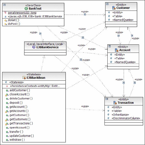
Chapter 14. Develop EJB applications 433
Draft Document for Review December 9, 2008 2:44 pm 7672-dev-7-ejb.fm
Visualizing the test application
We can improve the generated class diagram by adding the business interface,
the entities, and the servlet to the diagram (Figure 14-18).
Figure 14-18 Class diagram of the test Web application
Writing an EJB 3.0 Web application
The RAD75EJBWeb application is basically a copy of the RAD7BankBasicWeb
application from the previous redbook. However, it uses the JPA entities and
accesses the entities through the EJBBankBean session bean.

7672-dev-7-ejb.fm Draft Document for Review December 9, 2008 2:44 pm
434 Rational Application Developer V7.5 Programming Guide
Implementing the RAD75EJBWeb application
We change the original RAD57BankBasicWeb application to use EJB 3.0 APIs to
communicate with the EJBBankBean session bean.
You can import the finished application from the interchange file at:
c:\7672code\zInterchange\ejb\RAD75EJBWeb.zip
Note: If you already have RAD75EJB and RAD75JPA projects in the workspace,
only import RAD75EJBWeb and RAD75EJBWebEAR.
Web application navigation
The navigation between the Web pages is shown in Figure 14-19.
Figure 14-19 Web site navigation
From the home page (index.jsp), there are three static pages (rates.jsp,
insurance.jsp, and redbank.jsp).
The redbank.jsp is the login panel for customers.
After login, the customer details and the list of accounts is displayed
(listAccounts.jsp).
An account is selected in the list of accounts, and the details of the account
and a form for transaction list, deposit, withdraw, and transfer operations is
displayed (accountDetails.jsp).
From the account details form, banking transactions are executed:
– List transaction displays the list of previous debit and credit transactions
(listTransactions.jsp).
– Deposit, withdraw, and transfer operations are executed, and the updated
account information is displayed in the same page.
Chapter 14. Develop EJB applications 435
Draft Document for Review December 9, 2008 2:44 pm 7672-dev-7-ejb.fm
Additional functions are delete of an account, update customer information,
adding an account to a customer, and delete of the customer.
In case of errors, an error page is diplayed (showException.jsp).
The JSPs are based on the template that provides navigation bars through
headers and footers:
/theme/itso_jsp_template.jtpl, nav_head.jsp, footer.jsp
Servlets and commands
A number of servlets provide the processing and switching between the Web
pages:
ListAccounts—Perform the customer login, retrieve the customer and the
accounts, and forward to the accountDetails.jsp.
AccountDetails—Retieve one account and forward to the
accountDetails.jsp.
PerformTransaction—validate the form values and call one fo the commands
(ListTransactionsCommand, DepositCommand, WithdrawCommand, or
TransferCommand). The commands perform the requested banking transaction
and forward to the listTransactions.jsp or the accountDetails.jsp.
UpdateCustomer—Process updates of customer information, and also delete
of a customer.
DeleteAccount—Delete an account and forward to the listAccounts.jsp.
NewAccount—Create an account and forward to the listAccounts.jsp.
Logout—Logout and display the home page.
Java EE dependencies
The enterprise application (RAD75EJBWebEAR) includes the Web module
(RAD75EJBWeb), the EJB module (RAD75EJB), and the JPA utility project
(RAD75JPA).
The Web module (RAD75EJBWeb) has a dependency on the EJB module
(RAD75EJB), which has a dependency on the JPA project (RAD75JPA).
Accessing the session EJB
All database processing is done through the EJBBankBean session bean, using
the business interface (EJBBankService).
The servlets use EJB 3.0 injection to access the session bean:
@EJB EJBBankService bank;
7672-dev-7-ejb.fm Draft Document for Review December 9, 2008 2:44 pm
436 Rational Application Developer V7.5 Programming Guide
After this injection, all the methods of the session bean can be invoked, such as:
Customer customer = bank.getCustomer(customerNumber);
Account{} accounts = bank.getAccounts(customerNumber);
bank.deposit(accountId, amount);
Additional functionality
The original Web application does not execute some of the functions of the EJB
3.0 module. We improved the application and added these functions:
On the customer details panel (listAccounts.jsp) we add three buttons:
–New Customer—Enter data into the title, first name, and last name fields,
then click New Customer. A customer is created with a random social
security number.
–Add Account—This action adds an account to the customer, with a
random account number and zero balance.
–Delete Customer—Deletes the customer and all related accounts.
The logic for adding and deleting a customer is in the UpdateCustomer servlet.
The logic for a new account is in a new NewAccount servlet.
On the account details page (accountDetails.jsp) we add one button:
Delete Account—Deletes the account with all its transactions. The customer
with its remaining accounts are displayed next.
The logic for deleting an account is in a new DeleteAccount servlet.
For the Login panel we added logic (in the ListAccounts servlet) so that the
user can enter a last name instead of the social security number.
If the search by ssn fails, we retrieve all customers with that partial name. If
only one result is found, we accept it and display the customer. This allows
entry of partial names, such as Ro% to find the Rohr customer.
Running the Web application
Before running the Web application we must have the data source for the
ITSOBANK database configured. Refer to “Setting up the ITSOBANK database” on
page 413 for instructions. You can either configure the enhanced EAR in the
RAD75EJBWebEAR application, or define the data source in the server. We
suggest to define the data source in the server, as described in “Configuring the
data source in WebSphere Application Server” on page 1155.
To run the Web application perform these steps:
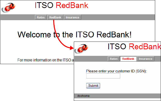
Chapter 14. Develop EJB applications 437
Draft Document for Review December 9, 2008 2:44 pm 7672-dev-7-ejb.fm
Select the server in the Servers view and Add and Remove Projects.
Remove the RAD75EJBEAR application, and add the RAD75EJBWebEAR
application, then click Finish.
Right-click the RAD75EJBWeb project and Run As → Run on Server.
Select the WebSphere Application Server v7.0 when prompted.
The home page is displayed. Click redbank to go to the login page
(Figure 14-20).
Figure 14-20 RedBank: Login
Enter a customer number (222-22-2222) and click Submit. The customer
details and the list of accounts are displayed (Figure 14-21).

7672-dev-7-ejb.fm Draft Document for Review December 9, 2008 2:44 pm
438 Rational Application Developer V7.5 Programming Guide
Figure 14-21 RedBank: Customer with accounts
Click on an account (002-222001) and the details and actions are displayed
(Figure 14-22).
Figure 14-22 RedBank: Account details
Select List Transactions and click Submit. The transactions are listed
(Figure 14-23).

Chapter 14. Develop EJB applications 439
Draft Document for Review December 9, 2008 2:44 pm 7672-dev-7-ejb.fm
Figure 14-23 RedBank: Transactions
Click Account Details to go back to the account.
Select Deposit, enter an amount (.33) and click Submit. The balance is
updated to 65,485.00.
Select Withdraw, enter an amount (485) and click Submit. The balance is
updated to 65,000.00.
Select Transfer, enter an amount (1000) and a target account (002-222002)
and click Submit. The balance is updated to 64,000.00.
Select List Transactions and click Submit. The transactions are listed and
there are three more entries (Figure 14-24).
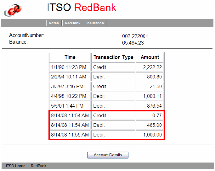
7672-dev-7-ejb.fm Draft Document for Review December 9, 2008 2:44 pm
440 Rational Application Developer V7.5 Programming Guide
Figure 14-24 RedBank: Transactions added
Click AccountDetails to go back to the account. Click Customer Details to
go back to the customer.
Click on the second account, then click Submit and you can see that the
second account has a transaction from the transfer operation.
Back in the customer details, change the last name and click Update. The
customer information is updated.
Overtype the names with Julia Roberts, and click New Customer.
Click Add Account and an account is added to the customer (Figure 14-25).

Chapter 14. Develop EJB applications 441
Draft Document for Review December 9, 2008 2:44 pm 7672-dev-7-ejb.fm
Figure 14-25 RedBank: New customer and new account
Perform some transactions on the new account.
Go back to customer details and click Delete Customer.
In the Login panel, enter Ro% and click Submit. The customer is found and
displayed.
In the Login panel, enter a bad value and click Submit. The customer details
panel is displayed with a NOT FOUND last name.
Click Logout.
Cleanup
Remove the RAD75EJBWebEAR application from the server.
Adding a remote interface
For testing using JUnit and for some Web applications, we also want to have a
remote interface for the EJBBankBean session bean.

7672-dev-7-ejb.fm Draft Document for Review December 9, 2008 2:44 pm
442 Rational Application Developer V7.5 Programming Guide
In the RAD75EJB project, itso.bank.service package, create an interface
named EJBBankRemote, that extends the business interface,
EJBBankService.
Add one method to the interface, getCustomersAll, to retrieve all the
customers.
Add a @Remote annotation.
Example 14-19 shows the remote interface.
Example 14-19 Remote interface of the session bean
package itso.bank.service;
import itso.bank.entities.Customer;
import javax.ejb.Remote;
@Remote
public interface EJBBankRemote extends EJBBankService {
public Customer[] getCustomersAll();
}
Open the EJBBankBean session bean:
– Add the EJBBankRemote interface to the implements list.
– Implement the getCustomersAll method similar to the getCustomers
method, using the getCustomers named query (without a parameter):
public class EJBBankBean implements EJBBankService, EJBBankRemote {
......
public Customer[] getCustomersAll() {
System.out.println("getCustomers: all");
Query query = null;
try {
query = entityMgr.createNamedQuery("getCustomers");
List<Customer> beanlist = query.getResultList();
Customer[] array = new Customer[beanlist.size()];
return beanlist.toArray(array);
} catch (Exception e) {
System.out.println("Exception: " + e.getMessage());
return null;
}
}
Complete EJB application interchange file
The completed enterprise applications are available in:
C:\7672code\zInterchange\ejb
Chapter 14. Develop EJB applications 443
Draft Document for Review December 9, 2008 2:44 pm 7672-dev-7-ejb.fm
More information
For more information on EJB, we recommend the following resources:
WebSphere Application Server Version 6.1 Feature pack for EJB 3.0,
SG24-7611, Redbooks publication, found at:
http://www.redbooks.ibm.com/abstracts/sg247611.html
EJB 2.0 Development with WebSphere Studio Application Developer,
SG24-6819, Redbooks publication, found at:
http://www.redbooks.ibm.com/abstracts/sg246819.html
Java EE Enterprise JavaBeans technology at:
http://java.sun.com/products/ejb/
Mastering Enterprise JavaBeans 3.0
http://www.theserverside.com/tt/books/wiley/masteringEJB3/index.tss
7672-dev-7-ejb.fm Draft Document for Review December 9, 2008 2:44 pm
444 Rational Application Developer V7.5 Programming Guide

© Copyright IBM Corp. 2007. All rights reserved. 445
Draft Document for Review December 9, 2008 2:44 pm 7672-dev-2-struts.fm
Chapter 15. Develop Web applications
using Struts
Apache Struts is an instance of a servlet/JSP model-view-controller (MVC)
framework. The goal of Apache Struts is to provide an open source framework
useful in building Web applications with Java servlet and JavaServer Pages
(JSP) technology. In addition, Struts encourages application architectures based
on the MVC design paradigm.
In this chapter, we explore the tooling support found in Rational Application
Developer Version 7.5 for Apache Struts.
The chapter is organized into the following sections:
Introduction to Struts
Preparing for the sample application
Developing a Web application using Struts
Running the Struts Bank Web application
Developing a Struts Web application using Tiles
15

7672-dev-2-struts.fm Draft Document for Review December 9, 2008 2:44 pm
446 Rational Application Developer V7 Programming Guide
Introduction to Struts
The Struts framework control layer uses technologies such as servlets,
JavaBeans, and XML. The view layer is implemented using JSPs and tag
libraries. The Struts architecture encourages the implementation of the concepts
of the model-view-controller (MVC) architecture pattern. By using Struts, you can
get a clean separation between the presentation (view) and business logic
(model) layers of your application.
Struts also speeds up Web application development by providing an extensive
JSP tag library, parsing and validation of user input, error handling, and
internationalization support.
The focus of this chapter is on the Application Developer tooling used to develop
Struts-based Web applications. Although we do introduce some basic concepts
of the Struts framework, we recommend that you refer to the following sites for
further in-depth information:
Apache Struts home page:
http://struts.apache.org/
Apache Struts User Guide:
http://struts.apache.org/userGuide/introduction.html
Note: Since the prior version of Application Developer (Version 6.x), Struts
has forked into three distinct frameworks:
Struts Classic (which is the original Struts framework)
Struts 2 (which is Struts + Webwork)
Struts Shale (which is a JSF version of Struts, now known as Shale)
Application Developer v7.5 includes support for only Struts Classic. The
versions supported by Application Developer are Struts 1.2 and 1.3. At the
time of writing this book, the latest version of the Struts Classic framework was
1.3.8 for general availability and 1.3.9 in beta.
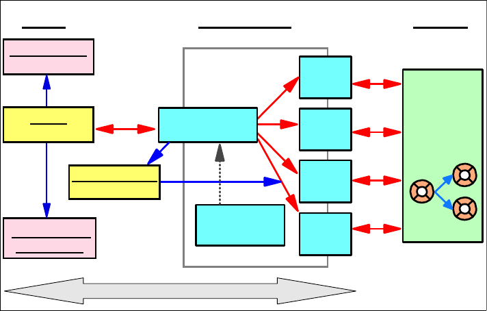
Chapter 15. Develop Web applications using Struts 447
Draft Document for Review December 9, 2008 2:44 pm 7672-dev-2-struts.fm
Model-view-controller (MVC) pattern with Struts
In “Model-view-controller (MVC) pattern” on page 323, we described the general
concepts and architecture of the MVC pattern. Figure 15-1 shows the Struts
components in relation to the MVC pattern:
Model: Struts does not provide model classes. Specifically, Struts does not
provide the separation between the controller and model layers. The
separation must be provided by the Web application developer as a facade,
service locator, EJB, or Java Bean.
View: Struts provides action forms (or form beans) in which data is
automatically or manually collected from HTTP requests with the purpose to
pass data between the view and controller layers. In addition, Struts provides
custom JSP tag libraries that assist developers in creating interactive
form-based applications using JSPs. Application resource files hold text
constants and error message, translated for each language, that are used in
JSPs.
Controller: Struts provides an ActionServlet (controller servlet) that
populates action forms from JSP input fields and then delegates work to an
action class where the application developer implements the logic to interface
with the model.
Figure 15-1 Struts components in the MVC architecture
: ActionForm
View Controller Model
Action
Action
Action
Action
configuration
file
Model
Application
Resources
ActionServlet
Tag libraries
: JSP
Struts Support
7672-dev-2-struts.fm Draft Document for Review December 9, 2008 2:44 pm
448 Rational Application Developer V7 Programming Guide
A typical Struts Web application is composed of the following components:
Action servlet—A single servlet (extending org.apache.struts.action.
ActionServlet) implements the primary function of mapping a request URI to
an action class. Before calling the action class, it populates the action form
associated to the action with the fields from the input JSP. If specified, the
action servlet also requests the action form to validate the data. It then calls
the action class to carry out the requested function. If action form validation
fails, control is returned to the input JSP so the user can correct the data. The
action servlet is configured in the Web deployment descriptor (web.xml). The
action servlet controls and manages the relationship between other Struts
components which is configured in the Struts configuration file
(struts-config.xml).
JSPs—Multiple JSPs that provide the end-user view. Struts includes an
extensive tag library to make JSP coding easier. The JSPs display the
information prepared by the action classes and requests new information from
the user.
Action classes—Multiple action classes (extending any one of the Struts
action classes like org.apache.struts.action.Action) that interface with the
model. When an action has performed its processing, it returns an action
forward object, which determines the view that should be called to display the
response (or alternatively forward to another action class). The action class
prepares the information required to display the response, usually as an
action form (although, it is not recommended), and makes it available to the
JSP. Usually the same action form that was used to pass information to the
action is used also for the response, but it is also common to have special
view beans tailored for displaying the data. An action forward has properties
for its name (logical mapping), path(URI), and a flag specifying if a forward or
a send redirect call should be made. The address to an action forward is
usually externalized in the Struts configuration file, but can also be generated
dynamically by the action class.
Action forms—Multiple action forms (extending one of the Struts action form
classes like org.apache.struts.action.ActionForm) to help facilitate transfer
form data from JSPs. The action forms are generic JavaBeans with getters
and setters for the input fields available on the JSPs. Usually there is one form
bean per Web page, but you can also use more coarse-grained form beans
holding the properties available on multiple Web pages (this fits very well for
wizard-style Web pages). If data validation is requested (a configurable
option) the form bean is not passed to the action until it has successfully
validated the data. Therefore the form beans can act as a sort of firewall
between the JSPs and the actions, only letting valid data into the system.
Resource files—One application resource file per language supported by the
application holds text constants and error messages and makes
internationalization easy.
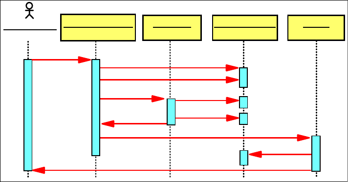
Chapter 15. Develop Web applications using Struts 449
Draft Document for Review December 9, 2008 2:44 pm 7672-dev-2-struts.fm
Figure 15-2 shows the basic flow of information for an interaction in a Struts Web
application.
Figure 15-2 Struts request sequence
A request from a Web browser is first received by the Struts action servlet.
If the action that handles the request has a form bean associated with it,
Struts creates the action form and (and if specified, automatically) populates it
with the data from the input form.
It then calls the validate method of the action form. If validation fails, the user
is returned to the input page to correct the input. If validation succeeds, Struts
calls the action’s execute method.
The action retrieves the data from the form bean and performs the
appropriate logic. The action often call session EJBs to perform the business
logic.
When done, the action either creates a new action form (or other appropriate
view bean) or reuses the existing one, populates it with new data, and stores
it in the request (or session) scope.
The action then returns a forward object to the action servlet, which forwards
to the appropriate output JSP (or alternatively forwards to another action).
The JSP uses the data in the action form to render the result.
: Web user
(Browser)
: ActionServlet : Action : ActionForm : JSP
HTTP setXxx()
validate()
execute()
forward()
getXxx()
getXxx()
setXxx()
"forward"

7672-dev-2-struts.fm Draft Document for Review December 9, 2008 2:44 pm
450 Rational Application Developer V7 Programming Guide
Application Developer support for Struts
Application Developer provides the following support for Struts-based Web
applications:
A Web project can be configured for Struts. This adds the Struts runtime
(and dependent JARs), tag libraries, and the action servlet to the project,
and creates skeleton Struts configuration and application resources files.
Application Developer support for Struts 1.2 or 1.3 can be selected when
setting up the project.
A set of Struts Component Wizards allows you to define action form classes,
action classes with action forwarding information, and JSP skeletons with the
tag libraries included.
The Struts Configuration Editor is provided to maintain the control
information for the action servlet.
The Web Diagram Editor provides a graphical design tool to edit a graphical
view of the Web application from which components (action forms, actions,
JSPs) can be created using the wizards. The Web Diagram Editor provides
top-down development (developing a Struts application from scratch),
bottom-up development (that is, you can easily diagram an existing Struts
application that you may have imported), and meet-in-the-middle
development (that is, enhancing or modifying an existing diagrammed Struts
application). The Web Diagram Editor is now written on top of the Graphical
Modeling Framework (GMF). Improved support allows direct/in-sync
manipulation of actual components/artifacts to reflect changes in the Web
Diagram Editor.
The Enterprise Explorer view provides a hierarchical (tree-like) view of the
application. This view shows the Struts artifacts (such as actions, action
forms, global forwards, global exceptions, and Web pages). You can expand
the artifacts to see their attributes. For example, an action can be expanded to
see the Action Forms, and forwards and local exceptions associated with the
selected Action. This is useful for understanding specific execution paths of
your application. The Enterpirse Explorer view is available in the Web
perspective.
Note: The Web Diagram in Application Developer, which supports the
creation of various Struts components, can also be applied in the creation
of Struts components when using the IBM Struts Portlet framework.
Specifically, when working with a Portlet project and the project has been
enabled to use the IBM Struts Portlet framework, the same palette options
of the Web Diagram are available to the Portlet project.

Chapter 15. Develop Web applications using Struts 451
Draft Document for Review December 9, 2008 2:44 pm 7672-dev-2-struts.fm
The JSP Page Designer provides support for rendering the Struts tags,
making it possible to properly view Web pages that use the Struts JSP tags.
This support is customizable using Application Developer’s Preferences
settings.
Validators to validate the Struts XML configuration file and the JSP tags used
in the JSP pages.
Preparing for the sample application
This section describes the tasks that have to be completed prior to developing
the Web application using Struts.
Setting up the sample database
The ITSOBANK database can be set up using either DB2 or Derby.
The instructions for creating the ITSOBANK database are given in “Setting up
the ITSOBANK database” on page 1154.
Configuring the data source in the WebSphere Server 7.0
The instructions for configuring the data source are given in “Configuring the data
source in WebSphere Application Server” on page 1155.
Activating Struts development capabilities
To activate the Struts development capabilities, such as the Struts Configuration
Editor, we must update the Application Developer preferences:
Select Window → Preferences → General → Capabilities.
Select Advanced.
Note: A completed version of the ITSO RedBank Web application built using
Struts can be found in the project interchange file:
C:\7672code\zInterchange\struts\RAD75Struts.zip
If you do not want to develop the sample yourself, but want to see it run, follow
the procedures described in “Importing the final sample application” on
page 491.
7672-dev-2-struts.fm Draft Document for Review December 9, 2008 2:44 pm
452 Rational Application Developer V7 Programming Guide
In the Advanced dialog, expand Web Developer (advanced) and select
Struts Development.
Click OK twice to close the dialogs.
ITSO Bank Struts Web application overview
We use the ITSO Bank as the theme of our sample Web application using Struts.
Similar samples were developed in the following chapters using other Web
application technologies:
Chapter 13, “Develop Web applications using JSPs and servlets” on
page 317
Chapter 16, “Develop Web applications using JSF” on page 493
The ITSO Bank sample application allows a customer to enter a customer ID
(social security number), select an account to view detailed transaction
information, or perform a deposit or withdrawal on the account. The model layer
of the application is implemented within the action classes using Java beans for
the sake of simplicity.
In the banking sample, we use the Struts framework for the controller and view
components of the Web application. To start, we implement the model using the
in-memory implementation provided by the RAD75Java project developed in
Chapter 8, “Develop Java applications” on page 69.
Figure 15-3 displays the Struts Web Diagram for the sample banking application.
The basic description and flow of the banking sample application are as follows:
The logon.jsp page is displayed as the initial page of the banking sample
application. The customer is allowed to enter her or his social security
number. In our case we use simple validation of the Struts framework to check
for an empty value. If the customer does not enter a valid value, the Struts
framework returns to the logon.jsp page and display the appropriate
message to the user.
The logon action logs in the user, and on successful logon retrieves the
customer and the account information and lists all the accounts associated
with the customer using the customerlisting.jsp Web page.
In the customerlisting.jsp, the customer can select to see details of an
account using the accountDetails action, or perform a transaction on an
account using the transact.jsp.
In the accountDetails.jsp, the details of the account are displayed, including
the transactions that have been performed on the account. The customer can
select to perform another transaction using the transact.jsp.
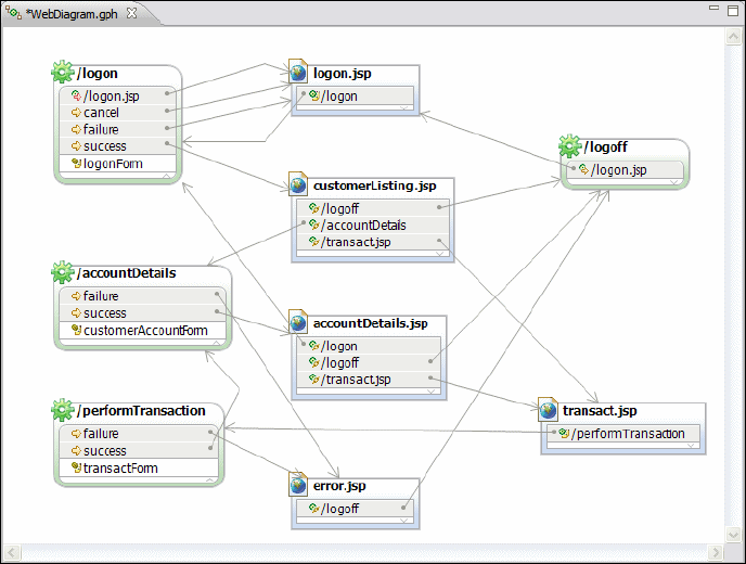
Chapter 15. Develop Web applications using Struts 453
Draft Document for Review December 9, 2008 2:44 pm 7672-dev-2-struts.fm
The transact.jsp invokes the performTransaction action. After a successful
transaction the accountDetails action is invoked to redisplay the
accountDetails.jsp.
The customer can log off using the logoff link, which invokes the logoff
action.
In case of errors, an error.jsp is displayed.
Figure 15-3 Struts Web Diagram: ITSO Bank sample
In this section we focus on creating the various Struts components, including the
Struts controller, actions, action forms, and Web pages, and relate these
components together. We implement the following steps to demonstrate the
capabilities of Application Developer:
Create a dynamic Web application with Struts support: In this section the
process of creating a dynamic Web application with Struts support and the
wizard generated support for Struts is be described.
Create Struts components: In this section we focus on creating Web pages,
actions, action forms, exceptions (local and global), and forwards using the
Web Diagram, and modify the properties of Struts components using the
Struts Configuration Editor.

7672-dev-2-struts.fm Draft Document for Review December 9, 2008 2:44 pm
454 Rational Application Developer V7 Programming Guide
Struts Configuration Editor: In this section we focus on creating Struts
components using the Struts Configuration Editor that provides a visual editor
to modify the Struts configuration file struts-config.xml.
Import the complete sample banking Web application: In the previous
sections we created various Struts components. Here we import the complete
banking sample implemented as shown in Figure 15-3 on page 453.
Run the sample banking application: In this section we verify the data source
configurations in the extended application descriptor of the imported sample
and then run and test the application in the WebSphere V7.0 Test
Environment.
Creating a dynamic Web project with Struts support
To create a dynamic Web project with Struts support, do these steps:
Open the Web perspective.
Select File → New → Dynamic Web Project and click Next.
In the New Dynamic Web Project dialog, enter the following values:
– Project Name: Type RAD75StrutsWeb.
– Dynamic Web Module version: Select 2.5.
Note: Because this chapter focuses on Application Developer’s Struts tools
and wizards (more than on the architecture and best practices of a Struts
application), we try to use the Struts tools and wizards as much as possible
when creating our application.
After having used the wizards to create some components (JSPs, form beans,
actions), you might find it faster to create new components by copying and
pasting from your existing components than by using all the wizards.
Important: Be sure to have installed the struts package during the installation
phase of Rational Application Developer, because it is not selected by default,
or you will not be able to use the Struts capabilities in your projects.
To verify and enable the Struts tool,s launch the Installation Manager from
Help → IBM Installation Manager, and enable the Struts support in the
Modify Packages dialog under IBM Rational Application Developer →
Web Development Tools → Struts Tools.
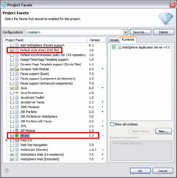
Chapter 15. Develop Web applications using Struts 455
Draft Document for Review December 9, 2008 2:44 pm 7672-dev-2-struts.fm
– Configuration: Click Modify to open the Project Facets dialog. IN the
Project Facets dialog, select Default Style sheet (CSS file), and Struts
(default version 1.3), then click OK (Figure 15-4).
– EAR Membership: Select Add project to an EAR and type
RAD75StrutsEAR as name.
Figure 15-4 Create a Struts-based dynamic Web project: Facets
Accept the defaults in the Web Module dialog for Context Root, Content
Directory and Java Source Director. Select Generate deployment
descriptor, and click Next.
Accept the defaults in the Struts Settings dialog for the resource bundle and
click Finish.
At this point, a new dynamic Web project with Struts support (RAD75StrutsWeb)
and an enterprise application project (RAD75StrutsEAR) have been created.
Close the Technology Quickstarts.
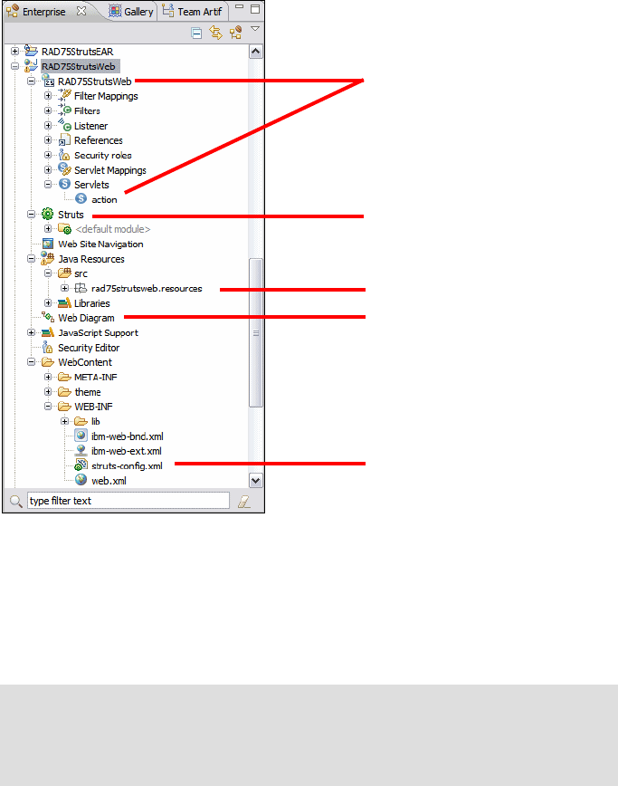
7672-dev-2-struts.fm Draft Document for Review December 9, 2008 2:44 pm
456 Rational Application Developer V7 Programming Guide
Struts artifacts
The following Struts-specific artifacts are created and Web application
configurations are modified by the wizard related to Struts when a new dynamic
Web application is created with Struts support (Figure 15-5).
Figure 15-5 Web project with Struts support
Struts configuration file struts-config.xml in WebContent/WEB-INF.
Web deployment descriptor (web.xml) with an action servlet that maps to the
Struts ActionServlet class, and has a mapping of *.do. (To see the servlet
mapping, open the Web deployment descriptor.)
Default Struts module with the name <default module> under which all the
Struts components are created.
Note: The Struts ActionServlet is configured (in web.xml) to intercept all
requests with a URL ending in .do. This is common for Struts applications,
but equally common is using a servlet mapping of /action/* to intercept all
URLs beginning with /action.
Deployment descriptor
with servlets
Struts artifacts
Web Diagram
Application Resources
Struts configuration file

Chapter 15. Develop Web applications using Struts 457
Draft Document for Review December 9, 2008 2:44 pm 7672-dev-2-struts.fm
ApplicationResources.properties in the package specified in the Struts
Settings dialog in the creation of a dynamic project. This is a property file
used in Struts to externalize messages and form field labels to accommodate
for a language and locale independent fashion (or internationalization - i18n).
Default Web Diagram (WebDiagram.gph) used by the Struts Web Diagram
Editor is used to create Struts components in a top-down design approach.
Adding the model classes to the application
We use the banking model developed in Chapter 8, “Develop Java applications”
on page 69.
If you do not have the RAD75Java project in the workspace, import the project
from C:\7672code\zInterchange\java\Rad75Java.zip. Select File →
Import → Other → Project Interchange, then locate the zip file, select the
RAD75Java project, and click Finish.
Right-click the RAD75StrutsEAR project and select Properties. Select Java
EE Module Dependencies, select RAD75Java, and click OK.
Right-click the RAD75StrutsWeb project and select Properties. Select Java
EE Module Dependencies, select RAD75Java.jar, and click OK.
Developing a Web application using Struts
This section describes how to develop a Web application using Struts with the
tooling provided by Application Developer.
The section is organized into the following tasks:
Creating the Struts components
Modify application resources
Using the Struts validation framework
Page Designer and the Struts tag library
Using the Struts Configuration Editor
Creating the Struts components
There are several ways to create Struts components:
Important: This section demonstrates how to develop a Web application
using Struts with the tooling included with Application Developer. We do not
cover the details for all of the sample code. A procedure to import and run the
completed Struts Bank Web application sample can be found in “Developing a
Struts Web application using Tiles” on page 485.
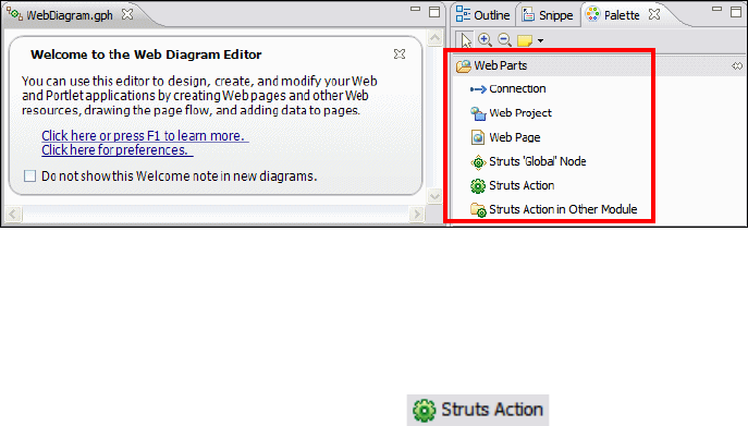
7672-dev-2-struts.fm Draft Document for Review December 9, 2008 2:44 pm
458 Rational Application Developer V7 Programming Guide
In the Enterprise Explorer, expand and right-click RAD75StrutsWeb →
Struts and select New to create a Struts Module, Action Mapping, Form
Bean, Global Forward, and Global Exception.
Using the Struts Configuration Editor: Application Developer provides a Struts
Configuration Editor, which is used to create Struts components and to modify
the Struts configuration file struts-config.xml. We describe how to use the
Struts Configuration Editor in detail in “Using the Struts Configuration Editor”
on page 473.
In the Struts Web Diagram Editor, use the Struts Palette to create Struts
components.
In this chapter, we take a top-down approach to design the Web application by
laying out all the components in the Web diagram using the Web Diagram Editor.
This section is organized into the following tasks:
Start the Web Diagram Editor
Create a Struts action
Create a Struts form bean
Create a Web page
Create a Struts Web connection
Start the Web Diagram Editor
Open the Web Diagram under the RAD75StrutsWeb project (Figure 15-6).
Figure 15-6 Web Diagram with the Struts drawer (Web Parts) open in the Palette
Create a Struts action
To create the Struts Action for logon, do these steps:
Close the Welcome
Drag and drop the Struts Action icon ( ) from the Palette.
Overtype the name of the action with /logon and press Enter (Figure 15-7).
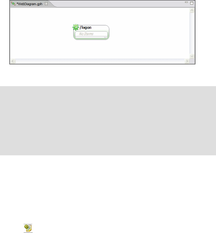
Chapter 15. Develop Web applications using Struts 459
Draft Document for Review December 9, 2008 2:44 pm 7672-dev-2-struts.fm
Figure 15-7 Struts Components - Create Struts action
Create a Struts form bean
In the previous section we created the logon action. The logon action is invoked
when the customer enters a customer ID (social security number). This
information is passed to the action as a Struts form bean.
To create and associate the logonForm form bean to the logon action, do these
steps:
Hover with the mouse over the /logon action, then click the Add Form Bean
icon ( ) from the selections presented.
In the Form Bean Selection dialog, do these steps:
– Click New.
– In the New Form Bean dialog (Figure 15-8), type LogonForm as the Form
Bean Name.
– Click the Form Bean Type link to launch the New ActionForm Class
dialog.
– In the New ActionForm Class dialog, accept the defaults for package,
modifiers, superclass, and method stubs. Accept the generated name
LogonForm for the ActionForm class name. Click Next.
Note: When initialially typing in the name, the logon component appears in
black and white. This is because the component has not yet been realized.
Once you are done with the typing in the name, the Struts action becomes
automatically realized and as a result, the action widget is displayed in color.
Notice that the Web Diagram Editor directly manipulates the underlying
artifacts (creation of action class and updating of the struts-config.xml) in this
case a LogonAction class is created in the rad75strutsweb.actions package,
and the Struts configuration file is updated.
7672-dev-2-struts.fm Draft Document for Review December 9, 2008 2:44 pm
460 Rational Application Developer V7 Programming Guide
– In the Create new fields for your ActionForm class dialog, click Add to
create a field named ssn of type String. Click Finish.
– At this time the Form Bean Type field contains the value
rad75strutsweb.forms.LogonForm. Accept the values for the New
Form-Bean dialog. Click Finish.
–The logonForm bean is added to the Form Bean Selection dialog. Click
OK.
A LogonForm class is created in the rad75strutsweb.forms package and the
Struts configuration file is updated.
Figure 15-8 shows the creation of the form bean and the result in the Web
Diagram.
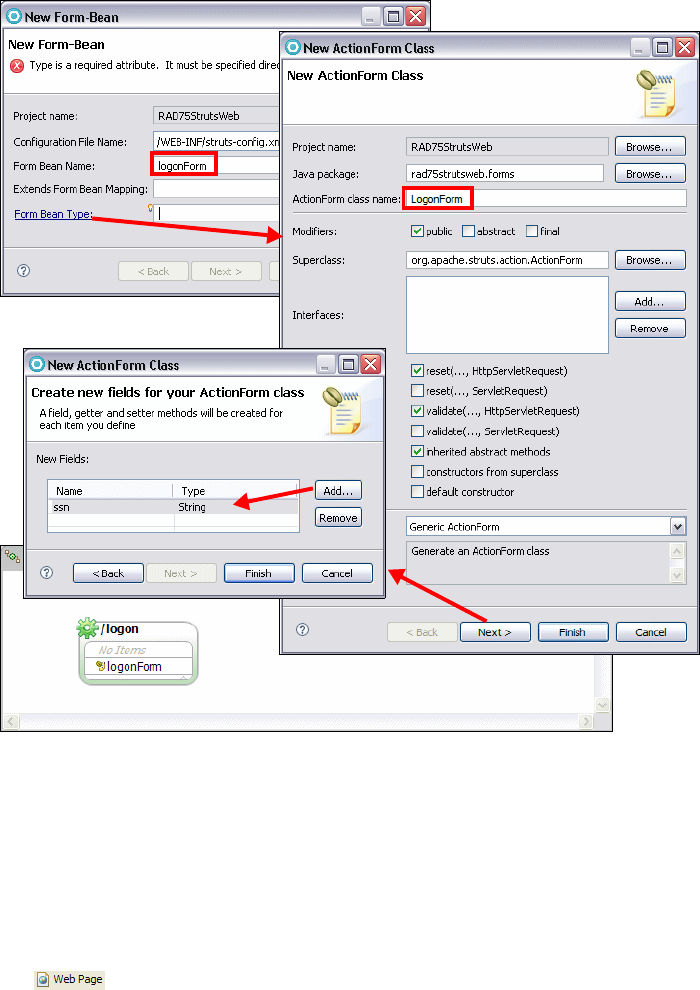
Chapter 15. Develop Web applications using Struts 461
Draft Document for Review December 9, 2008 2:44 pm 7672-dev-2-struts.fm
Figure 15-8 Struts components: Adding a Struts form bean
Create a Web page
Now that we have created the logon action and the logonForm action form, we
have to create the input and output pages for the logon action. The input page
(logon.jsp) lets the customer enter a customer ID (SSN) through the input form.
To create the logon.jsp and customerListing.jsp Web pages, do these steps:
From the Web Parts drawer of the Palette, drag and drop the Web Page icon
( ) into the Web diagram and type logon.jsp as the page name.
Repeat this to create the customerListing.jsp (Figure 15-9).
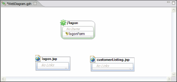
7672-dev-2-struts.fm Draft Document for Review December 9, 2008 2:44 pm
462 Rational Application Developer V7 Programming Guide
Figure 15-9 Struts components: Create Web pages
Two JSP files (with skeleton tags) are created under WebContent.
Create a Struts Web connection
A connection is typically used to connect two nodes in a Web diagram. In a Struts
context, when a connection is dragged from a Struts action, a pop-up connection
wizard is displayed, enabling the user to create the connection. When any of
these connections are realized, the corresponding Struts action mapping entry in
the Struts configuration file struts-config.xml is modified appropriately. As in
prior sections, once the connections are drag and defined on the palette, the
realization occurs automatically.
When you select Connection from the palette and drag it from a Struts action to
any other node, you are able to create the following:
Local Exception: When Local Exception is selected, the handler class that is
created is invoked when the Struts action throws the local exception.
Action Input: When the Struts validation framework is used, the action has to
forward the control back to the page that invoked the action in case of
validation failures. This is specified by specifying an action input mapping.
Include Action Mapping: The action in the action mapping entry is
configured as an include.
Forward Action Mapping: The action in the action mapping entry is
configured as a forward.
Global Forward: When Global Forward is selected, a global forward entry is
added in the configuration file.
Local Forward: When Local Forward is selected, a local forward entry is
added in the configuration file.
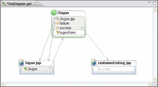
Chapter 15. Develop Web applications using Struts 463
Draft Document for Review December 9, 2008 2:44 pm 7672-dev-2-struts.fm
Global Exception: When Global Exception is selected, a global exception
entry is added in the configuration file.
In our sample, when a user enters an invalid customer ID (SSN), the logon action
fails and then forwards the user back to the logon page to enable the user to
re-enter this information. Likewise, if the logon action succeeds, the customer
has to be forwarded to the customerListing.jsp that displays the customer’s
account information.
To create the local forwards for success and failures for the logon action, do
these steps:
Select Connection in the Palette. Click on the logon.jsp and drag the cursor
to the /logon action. Select Struts Form when prompted.
Select Connection in the Palette. Click on the /logon action and drag the
cursor to the logon.jsp. Select Action Input when prompted.
Select Connection in the Palette. Click on the /logon action and drag the
cursor to the customerListing.jsp. Select Local Forward when prompted.
Accept the generated forward name of success.
Select Connection in the Palette. Click on the /logon action and drag the
cursor to the logon.jsp. Select Local Forward when prompted. Accept the
generated forward name of failure. Note that you can select the forward
name and overtype it.
The resulting Web Diagram is shown in Figure 15-10.
Figure 15-10 Struts components: Creating connections
Save the Web Diagram.
7672-dev-2-struts.fm Draft Document for Review December 9, 2008 2:44 pm
464 Rational Application Developer V7 Programming Guide
Realizing the Struts components
In Application Developer v7.5, the Web Diagram Editor automatically realizes the
components drawn onto the palette. In terms of Struts components, this
realization has differing consequences for each type of component. Table 15-1
describes the item generated and artifacts updated, given a realization of a
specific component.
Table 15-1 Struts components realization resultstt
Modify application resources
The wizard created an empty ApplicationResources.properties file in the
rad75strutsweb.resources package for us and we have to update it with the
texts and messages for our application.
While developing Struts applications, you usually find yourself having this file
open, because you typically add messages to it as you go along writing your
code. Again, this properties file is meant to externalize messages and more
importantly support i18n (internationalization) for Web site language support.
Example 15-1 shows a completed ApplicationResources.properties file.
Tip: You can select a component in the Web diagram and overtype the name
and the forward names.
To improve the layout of the application flow, you can drag components to
another spot. You can rearrange connections by dragging their middle point.
Object Resulting action when realized
Struts Form Beans Creating a new form bean from within an action creates a
new form bean class. In addition, it also updates the
struts-config.xml file with a form bean mapping and form
bean to action association.
Struts Actions Dragging a new action onto the palette creates a new
action class. In addition, it also updates the
struts-config.xml with an action mapping.
Local/Global Forwards,
Exceptions, Action Input
Connections
Dragging a connection onto the palette updates the
struts-config.xml file with the appropriate configuration.
JSP Dragging a Web page onto the palette creates a new Web
page JSP.

Chapter 15. Develop Web applications using Struts 465
Draft Document for Review December 9, 2008 2:44 pm 7672-dev-2-struts.fm
Example 15-1 ApplicationResources.properties snippet
# Optional header and footer for <errors/> tag.
#errors.header=<ul>
#errors.footer=</ul>
errors.prefix=<li>
errors.suffix=</li>
form.ssn=SSN
form.accountId=Account Id
form.balance=Balance
form.amount=Amount
form.accountDetails.transactionId=Transaction ID
form.accountDetails.transactionType=Transaction Type
form.accountDetails.transactionTime=Transaction Date-Time
form.accountDetails.transactionAmount=Transaction Amount
form.transaction.amount=Amount
errors.required={0} is a required Field
error.ssn=Verify that the customer ssn entered is correct.
error.amount=Verify that the amount entered is valid.
error.timeout=Your session has timed out. Please login again.
errors.systemError=The system is currently unavailable. Please try again later.
Initially this file only contains optional header and footer for errors. At this point
you can open the file and add two lines:
form.ssn=SSN
errors.required={0} is a required field.
We use this message to validate—using the Struts Validation Framework—the
logon form in logon.jsp to ensure that the user enters a value for the customer
(SSN).
Using the Struts validation framework
The Struts validation framework provides automatic validation of forms using
configuration files. The validation.xml and validator-rules.xml are the two
configuration files used by the Struts validation framework to validate forms.
Note: More information on the architecture and further documentation of
Struts validation framework can be found at:
http://struts.apache.org

7672-dev-2-struts.fm Draft Document for Review December 9, 2008 2:44 pm
466 Rational Application Developer V7 Programming Guide
To validate the logonForm using the Struts validation framework, do these steps:
We have provided a validation.xml and validation-rules.xml as part of
the sample code in C:\7672code\struts\validation. Import the two files into
RAD75StrutsWeb/WebContent/WEB-INF (you can also drag the files from
Windows Explorer into the WEB-INF folder in Application Developer).
Add the Struts validator plug-in and required property to the plug-in indicating
the location of the validation configuration files.
– Expand RAD75StrutsWeb → WebContent → WEB-INF.
– Open the struts-config.xml file in the Struts Configuration Editor.
– Select the Plug-ins tab in the Struts Configuration Editor.
– Click Add for Plug-ins, type ValidatorPlugIn, select the matching class
from the struts-core-1.3.8.jar, and click OK. The Struts validator
plug-in has now been added.
– Add the required parameter by clicking Add under the Plug-in Mapping
Extensions.
– Set the Property field to pathnames and the Value field to
/WEB-INF/validator-rules.xml,/WEB-INF/validation.xml.
Save and close the Struts configuration file.
The validation.xml file contains the following:
All the Struts form beans
The fields within the form bean that is validated,
The rule that is applied to validate the bean.
The snippet that validates the logonForm and makes the ssn field required is
shown in Example 15-2.
Example 15-2 validation.xml snippet - LogonForm
<form-validation>
<formset>
<form name="logonForm">
<field property="ssn" depends="required">
<arg0 key="form.ssn" />
</field>
</form>
</formset>
.......
.......
</form-validation>

Chapter 15. Develop Web applications using Struts 467
Draft Document for Review December 9, 2008 2:44 pm 7672-dev-2-struts.fm
The validator-rules.xml file contains the configuration for all the rules defined
in the validation.xml file.
The snippet for the required rule is shown in Example 15-3.
Example 15-3 validator-rules.xml snippet - Rule configuration for the required rule
<form-validation>
<global>
<validator name="required"
classname="org.apache.struts.validator.FieldChecks"
method="validateRequired"
methodParams="java.lang.Object,
org.apache.commons.validator.ValidatorAction,
org.apache.commons.validator.Field,
org.apache.struts.action.ActionErrors,
javax.servlet.http.HttpServletRequest"
msg="errors.required" />
</global>
</form-validation>
Page Designer and the Struts tag library
The Struts framework provides a tag library to help in the development of
Struts-based Web applications. The Page Designer is used to design and
develop HTML and dynamic Web pages within Application Developer. The
features of the Page Designer are explained in detail in Chapter 13, “Develop
Web applications using JSPs and servlets” on page 317.
Stuts tag library overview
In this section we explore the support for the Struts tag libraries within the Page
Designer. The Page Designer supports the Struts tag libraries by allowing
dropping of tags from the Page Designer Palette and into the design view of the
Page Designer.
Open the logon.jsp to see the Palette in Page Designer (Figure 15-11).
Struts HTML tags: Struts provides tags to render HTML content. Examples
of the Struts HTML tags are button, cancel, check box, form, and errors.
These tags can be dragged and dropped into a page in the page designer’s
design perspective. We drag and drop the errors tag to the logon.jsp and
display a message to the user if no ssn is entered later in this section.
Note: You must be editting a JSP in order to see the Struts tag libraries list.
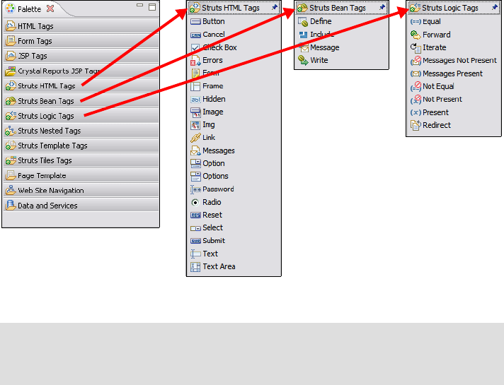
7672-dev-2-struts.fm Draft Document for Review December 9, 2008 2:44 pm
468 Rational Application Developer V7 Programming Guide
Struts Bean tags: The bean tag library provides tags to access bean
properties, request parameters, create page attributes, and so forth.
Struts Logic tags: The Logic tag library provides tags to implement
conditional, looping, and control related functionality.
Struts Nested tags: The Nested tag library provides tags to access complex
beans with nested structures.
Struts Template tags: The Template tag library provides tags for creation of
dynamic JSP templates.
Struts Tiles Tags: The Tiles tag library facilitates development of dynamic
Web applications in a tiled fashion where the tile can be reused throughout
the application.
Figure 15-11 Struts tag library support: Page Designer Struts tag drawers
Completing the logon JSP
We now add a simple HTML error tag to logon.jsp, which displays an HTML
error message that occurs due to the validation check by the Struts Validation
Framework. To add the HTML error tag to logon.jsp, do these steps:
Open the logon.jsp in Page Designer.
Tip: If you do not see all the Struts tag libraries in the palette, right-click the
palette and select Customize. From the Customize Palette dialog box, select
the drawers that you want to have available in the palette.

Chapter 15. Develop Web applications using Struts 469
Draft Document for Review December 9, 2008 2:44 pm 7672-dev-2-struts.fm
Select the Design tab. Note that there is some generated code with a Submit
Query button.
Select the Source tab and delete the complete <div> section that was
generted.
Select the Design tab or the Split tab.
Select the Errors icon from the Struts HTML Tags drawer and drop it at the
top of the page (Figure 15-12).
Figure 15-12 Struts tags: Struts errors tag rendered by Page Designer
Creating the input form
The logon.jsp page contains an input form with the customer SSN and a submit
button, similar to the form with the Submit Query button that was generated.
In the Page Data view on the left below corner select Struts Form Beans →
logonForm and drag it into the JSP form under the error list (Figure 15-13).
Figure 15-13 Page Data view with form bean
In the Configure Data Controls dialog (Figure 15-14):
–Select Updating an existing record and change the label of the ssn field
to Customer ID:. The HTM Form Action is prefilled with /logon (based on
the Web Diagram connection).
JSP
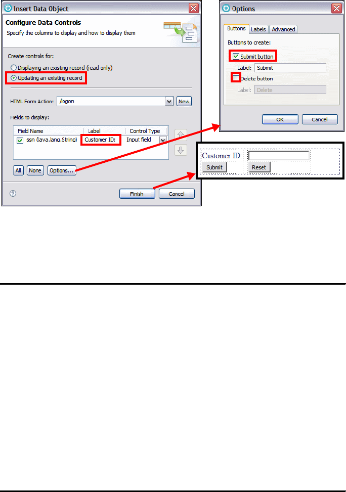
7672-dev-2-struts.fm Draft Document for Review December 9, 2008 2:44 pm
470 Rational Application Developer V7 Programming Guide
– Click Options and select Submit and clear Delete. Click OK.
– Click Finish and the form is generated.
Figure 15-14 Creating the logon JSP with a form
The source is shown in the Example 15-4. Notice the <html:errors /> and
the form that the wizard has added for rendering the action form.
Example 15-4 Struts tags:- Logon.jsp snippet of the tag in the source view
<html:errors />
<html:form action="/logon">
<TABLE>
<TBODY>
<TR>
<TD align="left">Customer ID:</TD>
<TD width="5"> </TD>
<TD><html:text property="ssn"></html:text></TD>
</TR>
<TR>
<TD align="left"><html:submit property="Submit"
value="Submit"></html:submit></TD>
<TD width="5"> </TD>
<TD><html:reset /></TD>
</TR>
</TBODY>
</TABLE>
</html:form>

Chapter 15. Develop Web applications using Struts 471
Draft Document for Review December 9, 2008 2:44 pm 7672-dev-2-struts.fm
Completing the logon action
The skeleton code for the LogonAction class was created from the Web Diagram
and is shown in Example 15-5.
Example 15-5 Skeleton action class (compressed)
package rad75strutsweb.actions;
import javax.servlet.http.HttpServletRequest;
import javax.servlet.http.HttpServletResponse;
import org.apache.struts.action.*;
public class LogonAction extends Action {
public ActionForward execute(ActionMapping mapping, ActionForm form,
HttpServletRequest request, HttpServletResponse response)
throws Exception {
ActionMessages errors = new ActionMessages();
ActionForward forward = new ActionForward(); // return value
try {
// do something here
} catch (Exception e) {
// Report the error using the appropriate name and ID.
errors.add("name", new ActionMessage("id"));
}
// If a message is required, save the specified key(s)
// into the request for use by the <struts:errors> tag.
if (!errors.isEmpty()) {
saveErrors(request, errors);
// Forward control to the appropriate 'failure' URI (....)
//forward = mapping.findForward(failure");
} else {
// Forward control to the appropriate 'success' URI (....)
forward = mapping.findForward("success");
}
// Finish with
return (forward);
}
}
We have to complete the execute method with our logic. The final code is shown
in Example 15-6. Select Source → Organize Imports or press Ctrl+Shift+O to
resolve the imports.
Example 15-6 Completed execute method of the logon action class
public class LogonAction extends Action {

7672-dev-2-struts.fm Draft Document for Review December 9, 2008 2:44 pm
472 Rational Application Developer V7 Programming Guide
public ActionForward execute(ActionMapping mapping, ActionForm form,
HttpServletRequest request, HttpServletResponse response)
throws Exception {
ActionMessages errors = new ActionMessages();
ActionForward forward = new ActionForward(); // return value
LogonForm logonForm = (LogonForm)form;
String ssn = logonForm.getSsn();
try {
// Create a bank object with pre-generated in-memory data
Bank bank = ITSOBank.getBank();
Customer customerBean = bank.searchCustomerBySsn(ssn);
// Add the customer to the request object for the JSP pages to use it
request.setAttribute("customer", customerBean);
// Add the bank and ssn objects to the session for further use
request.getSession().setAttribute("ssn", logonForm.getSsn());
request.getSession().setAttribute("ITSOBank", bank);
} catch (InvalidCustomerException e){
errors.add("ssn", new ActionError("error.ssn"));
} catch (Exception e) {
errors.add("error", new ActionError("errors.systemError"));
}
// If a message is required, save the specified key(s)
// into the request for use by the <struts:errors> tag.
if (!errors.isEmpty()) {
saveErrors(request, errors);
// Forward control to the appropriate 'failure' URI (........)
forward = mapping.findForward("failure");
} else {
// Forward control to the appropriate 'success' URI (.......)
forward = mapping.findForward("success");
}
// Finish with
return (forward);
}
}
Let us understand some of the action class coding:
The ActionForm parameter is cast to the correct LogonForm class and the ssn
value is extracted.
The customer and accounts are retrieved from the in-memory data
autogenerated on invocation to the ITSOBank.getBank() method.
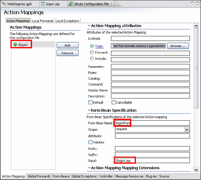
Chapter 15. Develop Web applications using Struts 473
Draft Document for Review December 9, 2008 2:44 pm 7672-dev-2-struts.fm
The ssn and bank objects are stored as session data and the customer
information is stored in the request block. The session data is available to all
actions and JSPs.
If exceptions are thrown by the data access, an ActionMessage is added to the
Struts errors list. The error text ("error.ssn" or "errors.systemError")
comes from the ApplicationResources file (see Example 15-1 on page 465).
An ActionForward of either "failure" or "success" is returned. Struts will find
the appropriate resulting action or JSP in the configuration file.
Using the Struts Configuration Editor
Application Developer provides an editor for the Struts struts-config.xml
configuration file. This editor is yet another way you can add new form beans and
actions and customize their attributes. You can also directly edit the XML source
file, should you prefer to do this manually instead of by using the wizards. The
Struts Configuration Editor is shown in Figure 15-15.
Figure 15-15 Struts Configuration Editor
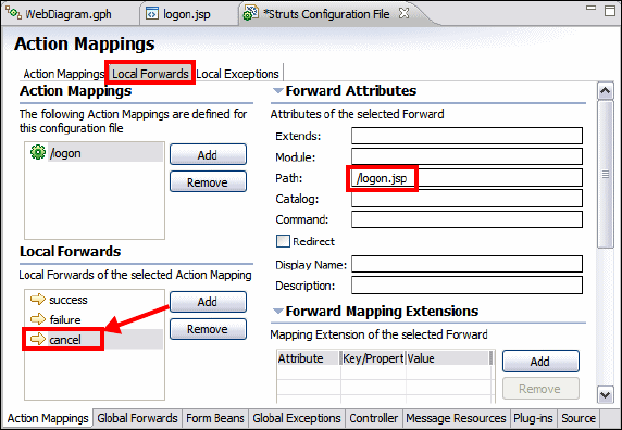
7672-dev-2-struts.fm Draft Document for Review December 9, 2008 2:44 pm
474 Rational Application Developer V7 Programming Guide
We use this editor to add a local forward called cancel to the logon action. This
forward can be used by the logon action’s execute method to forward the user to
the logon.jsp page, as we map this forward to the logon.jsp page.
We also specify the input attribute for all our actions. This attribute specifies
which page should be displayed if the validate method of a form bean or the
Struts validation framework fails to validate. Usually you want to display the input
page where the user entered the data so they can correct their entry.
Open the struts-config.xml file under RAD75StrutsWeb →
WebContent → WEB-INF.
The editor has tabs at the bottom of the screen to navigate between the
different Struts artifacts it supports.
– In the Action Mappings tab select the /logon action. You can see the
logonForm (Form Bean Name) and the logon.jsp (Input).
– Notice the Scope value of request; an alternative would be session.
Create a forward:
– Select the Local Forwards tab found at the top of the Action Mappings
page. Select the /logon action. We already have two forwards named
failure and success.
– Click Add in the local forwards section. A new forward with the name
forward1 is created.
– Overtype the name with cancel and enter /logon.jsp in the Path field in
the Forward Attributes (Figure 15-16).
Figure 15-16 Struts Configuration Editor: Creating new forward

Chapter 15. Develop Web applications using Struts 475
Draft Document for Review December 9, 2008 2:44 pm 7672-dev-2-struts.fm
Save the file.
Select the Source tab to look at the Struts configuration file. Example 15-7
shows parts of the struts-config.xml XML source.
Example 15-7 Struts configuration file: struts-config.xml
<?xml version="1.0"........>
<struts-config>
<!-- Data Sources -->
......
<!-- Form Beans -->
<form-beans>
<form-bean name="logonForm" type="rad75strutsweb.forms.LogonForm">
</form-bean>
</form-beans>
<!-- Global Exceptions -->
......
<!-- Global Forwards -->
......
<!-- Action Mappings -->
<action-mappings>
<action path="/logon" type="rad75strutsweb.actions.LogonAction"
name="logonForm" scope="request" input="/logon.jsp">
<forward name="success" path="/customerListing.jsp">
</forward>
<forward name="failure" path="/logon.jsp">
</forward>
<forward name="cancel" path="/logon.jsp">
</forward>
</action>
</action-mappings>
Note: The Redirect check box allows you to select if a redirect or forward
call should be made. A forward call keeps the same request with all
attributes it contains and just passes control over to the path specified. A
redirect (or send redirect) call tells the browser to make a new HTTP
request, which creates a new request object (and you lose any attributes
set in the original request).
A forward call does not change the URL in the browser’s address field, as it
is unaware that the server has passed control to another component. With
a redirect call, however, the browser updates the URL in its address field to
reflect the requested address.
You can also redirect or forward to other actions. It does not necessarily
have to be a JSP.

7672-dev-2-struts.fm Draft Document for Review December 9, 2008 2:44 pm
476 Rational Application Developer V7 Programming Guide
<message-resources
parameter="rad75strutsweb.resources.ApplicationResources"/>
<plug-in className="org.apache.struts.tiles.TilesPlugin">
<set-property property="definitions-config"
value="/WEB-INF/tiles-defs.xml"/>
<set-property property="definitions-parser-validate" value="true"/>
<set-property property="moduleAware" value="true"/>
</plug-in>
<plug-in className="org.apache.struts.validator.ValidatorPlugIn">
<set-property property="pathnames"
value="/WEB-INF/validator-rules.xml,/WEB-INF/validation.xml"/>
</plug-in>
</struts-config>
As you can see, the Struts tools have defined the logonForm bean in the
<form-beans> section and the logon action in the <action-mappings> section.
The JSPs, however, are not specified in the Struts configuration file. They are
completely separate form the Struts framework (only the forwarding
information is kept in the configuration file). At the end of the file is the name
of the application resources file where our texts and error messages are
stored.
The Struts Configuration Editor does round-trip editing, so if you edit
something in the XML view it is reflected in the other views.
The forwards we use are local to each action, meaning that only the action
associated with the forward can look it up. In the <global-forwards> section
you can also specify global forwards that are available for all actions in the
application. Normally you have a common error page to display any severe
error messages that may have occurred in your application and that prevents
it from continuing. Pages like these are good targets for global forwards, and
so are any other commonly used forward. Local forwards override global
forwards.
Close the configuration file editor.
Chapter 15. Develop Web applications using Struts 477
Draft Document for Review December 9, 2008 2:44 pm 7672-dev-2-struts.fm
Completing the application
Completing the application as shown in Figure 15-3 on page 453 would be quite
complex. Here are abbreviated instructions if you want to try this yourself.
Complete the Web Diagram
This is how we complete the Web Diagram:
Open the Web Diagram and rearrange the tree existing components to the
layout of Figure 15-3 on page 453.
Add three actions: logoff, accountDetails, and performTransaction.
Add three Web pages (JSPs): accountDetails.jsp, transact.jsp, and
error.jsp.
Create two action forms:
– In the accountDetails action create the customerAccountForm with two
attributes (String ssn and String accountId).
– In the performTransaction action create the transactForm with two
attributes (String accountId and String amount).
Create connections according to Table 15-2.
Table 15-2 Web Diagram connections
Notes: We recommend that all requests for JSPs go through an action class
so that you have control over the flow and can prepare the view beans (form
beans) necessary for the JSP to display properly. Struts provides simple
forwarding actions that you can use to accomplish this.
In our example we do not perform any customization on the Struts action
servlet (org.apache.struts.action.ActionServlet). If you have to do any
custom life cycle processing needed to be executed, you would want to create
your own action servlet, extending the ActionServlet class, and overriding the
appropriate ActionServlet methods. You would then also modify the
\WEB-INF\web.xml file and replace the name of the Struts ActionServlet with
the name of your action servlet class.
From To Type of connection
/logoff logon.jsp Static Forward
7672-dev-2-struts.fm Draft Document for Review December 9, 2008 2:44 pm
478 Rational Application Developer V7 Programming Guide
Completing the application resources
Complete the ApplicationResources.properties file according to Example 15-1
on page 465, or import the file from C:\7672code\struts\resource.
Complete the form beans
You can compare the generated form classes with the code provide in
C:\7672code\struts\form.
Complete the actions
The completed code is provided in C:\7672code\struts\action:
The LogonAction is already complete.
The LogoffAction has three lines in the execute method try clause:
//Destroy the objects in session.
request.getSession().setAttribute("ssn", null);
request.getSession().setAttribute("ITSOBank", null);
customerListing.jsp /logoff Struts Link
/accountDetails Struts Link
transact.jsp Struts Link
/accountDetails accountDetails.jsp Local Forward success
error.jsp Local Forward failure
accountDetails.jsp /logon Struts Link
/logoff Struts Link
transact.jsp Struts Link
transact.jsp /performTransaction Struts Form
/performTransaction /accountDetails (action) Local Forward success
error.jsp Local Forward failure
error.jsp /logoff Struts Link
/logon logon.jsp Local Forward cancel
From To Type of connection
Chapter 15. Develop Web applications using Struts 479
Draft Document for Review December 9, 2008 2:44 pm 7672-dev-2-struts.fm
Complete the AccountDetailsAction class execute method:
CustomerAccountForm customerAccountForm = (CustomerAccountForm) form;
String accountId = customerAccountForm.getAccountId();
try {
// Retrieve the account from the bank
Bank bank = (Bank)request.getSession().getAttribute("ITSOBank");
Account accountBean = bank.searchAccountByAccountNumber(accountId);
// Add the account info to request scope
request.setAttribute("account", accountBean);
} catch (Exception e) {
// Report the error using the appropriate name and ID.
errors.add("error", new ActionMessage("errors.systemError"));
}
......
forward = mapping.findForward("failure");
Complete the PerformTransactionAction class execute method:
TransactForm transactForm = (TransactForm) form;
String accountId = transactForm.getAccountId();
String amountf = transactForm.getAmount();
BigDecimal amount = null;
try {
// convert the amount and perform withdraw or deposit
Bank bank = (Bank)request.getSession().getAttribute("ITSOBank");
amount = new BigDecimal(amountf);
if ( amount.compareTo(new BigDecimal(0)) < 0 ){
bank.withdraw(accountId, amount.negate());
} else {
bank.deposit(accountId, amount);
}
} catch (NumberFormatException e) {
errors.add("amount", new ActionMessage("error.amount"));
} catch (InvalidTransactionException e) {
errors.add("amount", new ActionMessage("error.amount"));
}
......
forward = mapping.findForward("failure");
Import java.math.BigDecimal and
itso.rad75.bank.exception.InvalidTransactionException.
Complete the JSPs
The completed code is provided in C:\7672code\struts\jsp:
For a uniform look, import the rbhome.gif into WebContent/theme.
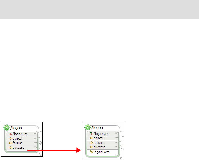
7672-dev-2-struts.fm Draft Document for Review December 9, 2008 2:44 pm
480 Rational Application Developer V7 Programming Guide
Complete the logon.jsp with a heading:
<body>
<IMG border="0" src="theme/rbhome.gif">
<font face="Arial" size="5"><b>ITSO Bank</B></font>
<HR>
<html:errors />
......
Replace the remaining generated JSPs with the provided code:
– accountDetails.jsp
– customerListing.jsp
– transact.jsp
– error.jsp
Complete the Web Diagram and Struts configuration file
The diagram and Struts configuratoin file should be complete. However, you can
optionally replace the Web Diagram (WebDiagram.gph) and Struts configuration
file (struts-config.xml):
Replace the struts-config.xml file from the config folder into the project
folder WebContent/WEB-INF.
Replace the WebDiagram.gph file from the diagram folder into the project root
directory. When you open the Web Diagram the action forms may not be
visible in the actions. Double-click in the small space at the bottom to display
the action form (Figure 15-17).
Figure 15-17 Web Diagram action with and without the action form
Study the sample code
Study the sample code, especially the actions and the JSPs:
The Java classes with the transfer beans and action forms are easy to
understand, they are standard Java beans.
Note: You can drag a source file from Windows Explorer into the
appropriate package in Application Developer

Chapter 15. Develop Web applications using Struts 481
Draft Document for Review December 9, 2008 2:44 pm 7672-dev-2-struts.fm
The AccountDetailsAction retrieves one customer account and the
transactions of that account and stores the data in the data transfer beans.
The PerfomTransactionAction adds or subtracts the transaction amount from
the balance, the logic for this is handled in the imported Java project on the
ITSOBank class in the package itso.rad75.bank.impl.
The customerListing.jsp displays the customer name and the list of
accounts, for that several Struts tags are used:
– Additional tag library:
<%@taglib uri="http://struts.apache.org/tags-logic"
prefix="logic"%>
–<bean:write>: display data from a JavaBean:
<bean:write name="customer" scope="request" property="firstName" />
–<html:link>: An HTML link to another Web page or action:
<html:link action="/logoff">logoff</html:link>
<html:link page="/transact.jsp" name="queryParms"> Deposit/Withdraw
</html:link>
Parameters for the link (accountId, balance) are stored in a HashMap.
–<logic:present>: Verify and retrieve session and request data:
<logic:notPresent name="ssn" scope="session">
<logic:redirect page="/logon.jsp" />
<logic:present name="ssn" scope="session">
<logic:present name="customer" property="accounts" scope="request">
–<logic:iterate>: Loop over a property:
<logic:iterate name="customer" property="accounts" scope="request"
id="account">
The accountDetails.jsp displays the account information and the list of
transactions of that account:
–<bean:message>: Retrieve a text from the application resource file:
<bean:message key="form.accountId" />
Note: For more information about the RAD75Java project logic please refer
to the Chapter 8, “Develop Java applications” on page 69.
Note: With Struts 1.3.8 the uri attribute in the JSP tags are changed,
from: http://jakarta.apache.org/struts/tags-*** to
http://struts.apache.org/tags-***.
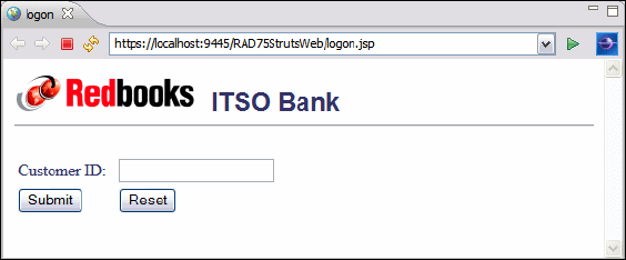
7672-dev-2-struts.fm Draft Document for Review December 9, 2008 2:44 pm
482 Rational Application Developer V7 Programming Guide
–<nested> tags: Nested loops
<nested:iterate name="account" property="transactions" id="transaction">
<nested:present name="account" property="transactions">
<bean:write name="transaction" property="timeStamp"/>
The transact.jsp displays the account information and a form to submit a
transaction amount for deposit oir withdraw.
The error.jsp displays the Struts errors.
Running the Struts Bank Web application
In this section we run the sample application and explore the functionality built
using Application Developer and its support for rapid development of
Struts-based Web applications.
To run the sample ITSO Bank application, do these steps:
Start the WebSphere Application Server v7.0 if it is not running.
Expand RAD75StrutsWeb → WebContent, right-click the logon.jsp and
select Run As → Run on Server.
In the Server Selection wizard select Choose and existing server, select the
WebSphere Application Server v7.0 server, select Always use tihs server
when running this project, and click Finish.
The home page logon.jsp is displayed (Figure 15-18).
Figure 15-18 Running the sample: Logon.jsp
If you click Submit without entering an ID, the Struts Validation Framework is
activated and displays the error message from the resources:
Verify that the customer ssn entered is correct
111-11-1111

Chapter 15. Develop Web applications using Struts 483
Draft Document for Review December 9, 2008 2:44 pm 7672-dev-2-struts.fm
Enter a sample ID of 111-11-1111 and click Submit. The customer and a list
of accounts is displayed (Figure 15-19). Here the logon action is responsible
for retrieving this information. In a real world application, the logon action talks
to the business tier to retrieve this information. The business tier architecture
is described in detail in Chapter 14, “Develop EJB applications” on page 387.
Figure 15-19 Running the sample: Account listing
To view details of a particular account, click the Account Number (for
example, 001-999000777) and the account information is listed. At this point
there may be no transactions (Figure 15-20).
Figure 15-20 Running the sample: Account details
To perform a transaction on the account, click Deposit/Withdraw. The link is
also available in the account listing (click back to get to the listing again).
The transaction page is displayed. Enter a positive number for a deposit and a
negative number for a withdrawal. We enter in 55.55 to indicate a deposit and
click Submit (Figure 15-21).

7672-dev-2-struts.fm Draft Document for Review December 9, 2008 2:44 pm
484 Rational Application Developer V7 Programming Guide
Figure 15-21 Running the sample: Performing transactions
The Account Details page is redisplayed with the updated balance and an
entry made for the last transaction (Figure 15-22).
Figure 15-22 Running the sample: Transaction listing
Run a few more transactions and the list of transaction grows (Figure 15-23).
55.55
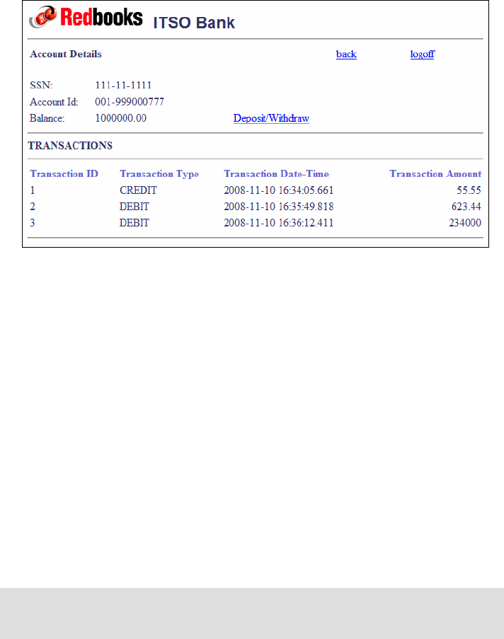
Chapter 15. Develop Web applications using Struts 485
Draft Document for Review December 9, 2008 2:44 pm 7672-dev-2-struts.fm
Figure 15-23 Running the sample: More transactions
Enter an invalid amount (for example, alphabetic) or a withdraw amount
greater than the balance, and you get the exception error:
Verify that the amount entered is valid.
Use the back and logoff links to go back to the logon panel.
Developing a Struts Web application using Tiles
Apache Tiles is a templating framework built to simplify the development of Web
application user interfaces. Apache Tiles allows application developers and page
authors to define page fragments (tiles) which are assembled into a complete
page at runtime. These tiles are a step up from jsp:include directives and can
be used to reduce the duplication of common page elements or embedded within
other tiles to develop a series of reusable templates. These templates streamline
the development of a consistent look and feel across an entire application.
Application Developer provides a minimal support for Tiles framework.
Nevertheless, we are going to show the extent of Tiles support.
Note: For more information on Tiles, please visit the following site:
http://tiles.apache.org/

7672-dev-2-struts.fm Draft Document for Review December 9, 2008 2:44 pm
486 Rational Application Developer V7 Programming Guide
Enable the Struts Tiles support
In our prior example when creating a Dynamic Web project, we did not enable
Struts Tiles in the Web project.
To enable the support, right-click the RAD75StrutsWeb project and select
Properties. In the Properties dialog, select Project Facets, select Dynamic Page
Template Support (Struts Tiles), and click OK. This action creates the Tiles
configuration and updates the Struts configuration to use Tiles. In addition a
TilesServlet is added to the Web deployment descriptor.
The Tiles configuration file (tiles-def.xml) is created under WebContent/WEB-INF,
and it has no definitions yet. In addition, the struts-config.xml file is updated
with a plug-in configuration (Example 15-8).
Example 15-8 Plug-in configuration for Tiles in struts-config.xml file
<plug-in className="org.apache.struts.tiles.TilesPlugin">
<set-property property="definitions-config"
value="/WEB-INF/tiles-defs.xml"/>
<set-property property="definitions-parser-validate" value="true"/>
<set-property property="moduleAware" value="true"/>
</plug-in>
There is also another piece of configuration that you have to put in manually. In
the struts-config.xml, after the <action-mappings> section, insert the line
shown in Example 15-9.
Example 15-9 Controller configuration for Tiles
<controller processorClass="org.apache.struts.tiles.TilesRequestProcessor" />
As a reference, these two entries in the struts-config.xml informs Struts that
Tiles is used in this Web application. Specifically, we can now use ActionForward
to forward control onto a Tiles configuration (among other things).
Note: Ignore the errors that are listed in the Probelms view. This is a known
defect that will be fixed in an upcoming FixPack. You can disable the Struts
validator in the project Properties, Validation tab, clear Struts Configuration
File Validator, and rebuild (clean) the project.
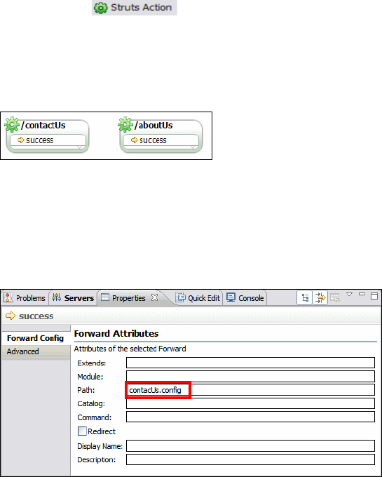
Chapter 15. Develop Web applications using Struts 487
Draft Document for Review December 9, 2008 2:44 pm 7672-dev-2-struts.fm
Building the Tiles application extension
In this section we create an example using Tiles. we only update the
customerListing.jsp with two links to Tiles pages.
Tile actions with local forward
We create two actions to display About Us and Contact Us pages.
Open the Web Diagram, as we have done in the prior sections, use the Struts
Action button ( )to create actions with names of /contactUs and
/aboutUs.
For each action, create a local forward by selecting the action and Add
Link → Local Forward (or use the arrow icon when hovering over the
action). Accept the default local forward name of success (Figure 15-24).
Figure 15-24 Actions for Tiles
Set the path value for both actions in the Properties view, Forward Config tab,
when selecting the success local forward (Figure 15-25). For /contactUs,
have the path of the success local forward point to contactUs.config, and for
/aboutUs to aboutUs.config.
Figure 15-25 Editing the Forward Config for local forwards
Add two connections from customerListing.jsp to the two actions, and select
Struts Link when prompted.
7672-dev-2-struts.fm Draft Document for Review December 9, 2008 2:44 pm
488 Rational Application Developer V7 Programming Guide
Tiles configuration file
We modify the Tiles configuration file to define Tiles areas actions and their
relationship with the Web pages. To do that open the Tiles configuration file
tiles-def.xml and add these definitions, or replace it with the following one
C:\7672code\struts\tiles\tiles-def.xml:
<!--Define each of your definitions here-->
<definition name="contactUs.config" path="/bankTemplate.jsp">
<put name="header" value="/bankHeaderTile.jsp"/>
<put name="body" value="/bankContactUsTile.jsp"/>
</definition>
<definition name="aboutUs.config" path="/bankTemplate.jsp"
extends="contactUs.config">
<put name="body" value="/bankAboutUsTile.jsp"/>
</definition>
Tiles Web pages
The web pages of our Tiles application have the following logic:
Tile Contact Us page is built using a template bankTemplate.jsp, a header
bankHeaderTile.jsp, and a body bankContactUsTile.jsp.
Tile About Us page extends the Contact Us page with another body.
Import the following Tiles Web pages from C:\7672code\struts\tiles into
WebContent:
bankAboutUsTile.jsp
bankContactUsTile.jsp
bankHeaderTile.jsp
bankTemplate.jsp
The template points to the header and body pages.
The header includes the image and ITSO Bank title.
The body pages contain descriptive text.
Add the links to the Struts Web page
The two Struts links have been added to the customerListing.jsp. Copy the two
links from the <div> section at the top to a place before the logoff link:
Generated code in <div>:
<html:link action="/contactUs">Struts Link Label</html:link><br>
<html:link action="/aboutUs">Struts Link Label</html:link><br>
Final code in HTML table:
<TD>Welcome <B>
<bean:write name="customer" scope="request" property="firstName" />
<bean:write name="customer" scope="request" property="lastName" /> ...

Chapter 15. Develop Web applications using Struts 489
Draft Document for Review December 9, 2008 2:44 pm 7672-dev-2-struts.fm
<TD width="128" align="right"><html:link action="/contactUs">
Contact Us</html:link></TD>
<TD width="128" align="right"><html:link action="/aboutUs">
About Us</html:link></TD>
<TD width="128" align="right"><html:link action="/logoff">
logoff</html:link></TD>
Delete the <div> section after copying the links into the HTML table.
Tiles recapitulation
We have created and/or imported the necessary components. In essence, we
have created two action classes which each (when executed successfully)
forwards to a Tiles configuration. The Tiles configuration contains information on
how the eventual page should render. The actual page is constructed at runtime.
The action entries in the struts-config.xml file have this format:
<action path="/contactUs" type="rad75strutsweb.actions.ContactUsAction">
<forward name="success" path="contactUs.config">
</forward>
</action>
<action path="/aboutUs" type="rad75strutsweb.actions.AboutUsAction">
<forward name="success" path="aboutUs.config">
</forward>
</action>
Tiles runtime behavior
When a /contactUs request arrives, Struts invokes the ContactUsAction class,
which forwards a success local forward. Struts forwards control to the
contactUs.config Tiles configuration. This configuration is based on the
bankTemplate.jsp, with a header bankHeaderTile.jsp and a body
bankContactUsTile.jsp. The assembly of the page displayed occurs at runtime.
The processing for an /aboutUs request is similar, however, the aboutUs
configuration extends the contactUs configuration and inherits the header.
Note: There is a mapping in the logical name between the path value of the
success local forward within the /contactUs action mapping entry in the
struts-config.xml and the contactUs.config entry in the tiles-def.xml.
The ContactUsAction and AboutUsAction classes were generated
automatically when we added the actions to the Web Diagram. No code
change is necessary.
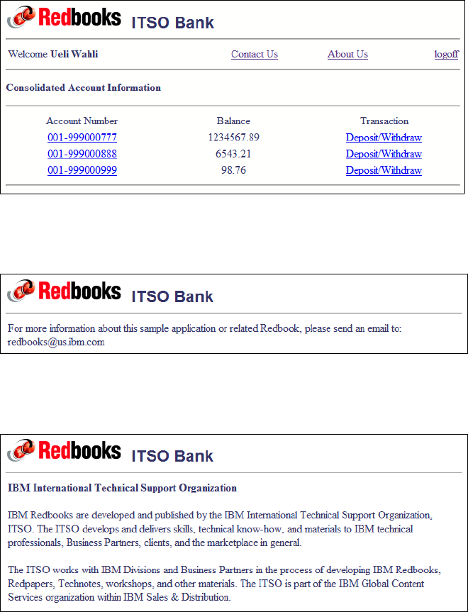
7672-dev-2-struts.fm Draft Document for Review December 9, 2008 2:44 pm
490 Rational Application Developer V7 Programming Guide
Running the Tiles application
To test the Tiles application, start with the logon.jsp → Run As → Run on
Server:
Logon as a customer and the accounts are displayed (Figure 15-26).
Figure 15-26 Customer with accounts and new links
Click Contact Us and the Tiles page is displayed (Figure 15-27).
Figure 15-27 Tiles page: Contact Us
Click About Us and the Tiles page is displayed (Figure 15-28).
Figure 15-28 Tiles page: About Us
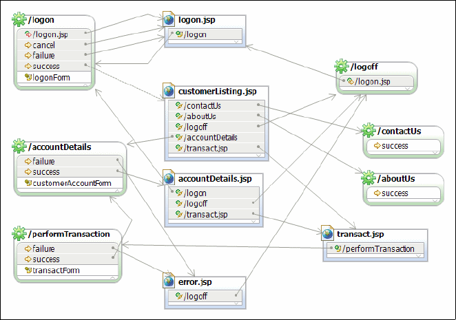
Chapter 15. Develop Web applications using Struts 491
Draft Document for Review December 9, 2008 2:44 pm 7672-dev-2-struts.fm
Importing the final sample application
In the previous sections we described how to build and run a Struts Web
application. If you did not manage to build the application, you can import the
project interchange file from:
C:\7672code\zInterchange\struts\RAD75Struts.zip
C:\7672code\zInterchange\struts\RAD75Struts-Tiles.zip
Select File → Import → Project Interchange and click Next.
In the Import wizard select Other → Project Interchange and click Next.
Click Browse to locate the interchange ZIP file and click Open.
Select both projects and click Finish.
The RAD75StrutsWeb and RAD75StrutsEAR projects are imported.
Open the Web Diagram in the RAD75StrutsWeb project (Figure 15-29). The
diagram looks like Figure 15-3 on page 453, with the two Tiles action added
and two more links from cusomerListing.jsp to the two Tiles actions.
Figure 15-29 Complete Web Diagram with Tiles actions
7672-dev-2-struts.fm Draft Document for Review December 9, 2008 2:44 pm
492 Rational Application Developer V7 Programming Guide
More information
For more information about Struts and Tiles, consult these Web sites:
Apache Struts home page:
http://struts.apache.org/
Apache Struts User Guide:
http://struts.apache.org/userGuide/introduction.html
Apache Tiles home page:
http://tiles.apache.org/
IBM developerWorks (search for Struts and Tiles):
http://www.ibm.com/developerworks/

© Copyright IBM Corp. 2008. All rights reserved. 493
Draft Document for Review December 9, 2008 2:44 pm 7672-dev-3-jsf.fm
Chapter 16. Develop Web applications
using JSF
JavaServer Faces (JSF) is a framework that simplifies building user interfaces for
Web applications. JPA is the Java Persistence API, described in Chapter 12,
“Persistence using the Java Persistence API (JPA)” on page 267.
This chapter introduces the features, benefits, and architecture of JSF. The focus
of the chapter is to demonstrate the Rational Application Developer support and
tooling for JSF. The chapter includes an example Web application using JSF, with
persistence implemented in JPA.
The chapter is organized into the following sections:
Introduction to JSF
Developing a Web application using JSF and JPA
The sample code for this chapter is in 7672code\jsf.
16

7672-dev-3-jsf.fm Draft Document for Review December 9, 2008 2:44 pm
494 Rational Application Developer V7.5 Programming Guide
Introduction to JSF
This section provides an introduction to JavaServer Faces (JSF).
JavaServer Faces (JSF) overview
JavaServer Faces is a framework that simplifies building user interfaces for Web
applications. The combination of the JSF technology and the tooling provided by
IBM Rational Application Developer allows developers of differing skill levels the
ability to achieve the promises of rapid Web application development.
This section provides an overview of the following aspects of JSF:
JSF features and benefits
JSF application architecture
JSF features in Application Developer 7.0
JSF features and benefits
The following list describes the key features and benefits of using JSF for Web
application design and development:
Standards-based Web application framework:
– JSF is a standards-based Web application framework. JavaServer Faces
technology is the result of the Java Community process JSR-127 and
evolved from Struts. JSF addresses more of the model-view-controller
pattern than Struts, in that it more strongly addresses the view or
presentation layer though UI components, and addresses the model
through managed beans. Although JSF is an emerging technology and is
likely become a dominant standard, Struts is still widely used.
– JSF is targeted at Web developers with little knowledge of Java and
eliminates much of the hand coding involved in integrating Web
applications with back-end systems.
Event driven architecture: JSF provides server-side rich UI components
that respond to client events.
User interface development:
– UI components are de-coupled from their rendering. This allows for other
technologies such as WML to be used (for example, mobile devices).
– JSF allows direct binding of user interface (UI) components to model data.
Note: Detailed information on the JSF specification can be found at:
http://java.sun.com/j2ee/javaserverfaces/download.html
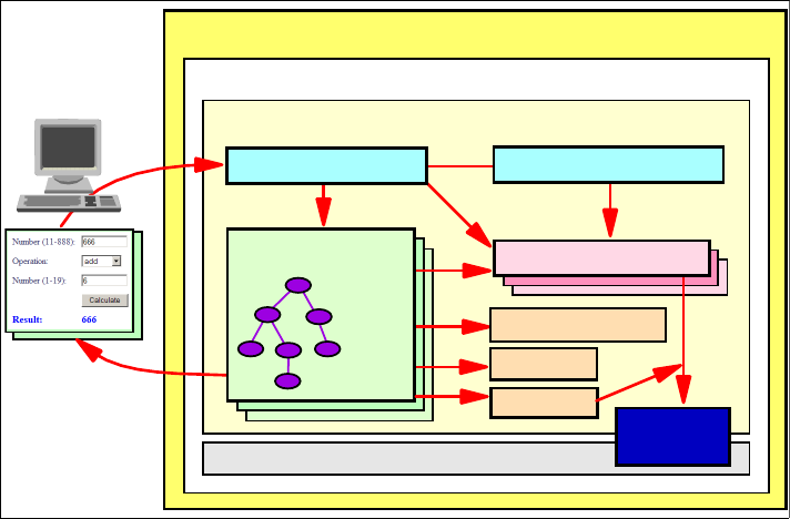
Chapter 16. Develop Web applications using JSF 495
Draft Document for Review December 9, 2008 2:44 pm 7672-dev-3-jsf.fm
– Developers can use extensive libraries of prebuilt UI components that
provide both basic and advanced Web functionality.
Session and object management: JSF manages designated model data
objects by handling their initialization, persistence over the request cycle, and
cleanup.
Validation and error feedback: JSF allows direct binding of reusable
validators to UI components. The framework also provides a queue
mechanism to simplify error and message feedback to the application user.
These messages can be associated with specific UI components.
Internationalization: JSF provides tools for internationalizing Web
applications, including supporting number, currency, time, and date
formatting, and externalization of UI strings.
JSF application architecture
The JSF application architecture can be easily extended in a variety of ways to
suit the requirements of your particular application. You can develop custom
components, renderers, validators, and other JSF objects and register them with
the JSF runtime.
The focus of this section is to highlight the JSF application architecture depicted
in Figure 16-1.
Figure 16-1 JSF application architecture
WebSphere Application Server
J2EE Enterprise Application
JSF Web Application
Other Modules (EJB)
Managed JavaBeans
JSF Libraries/Tags
Business
Logic
Faces Servlet XML Configuration File
Browser
JSPs with JSF UI
Component
Tree
Validators
Events
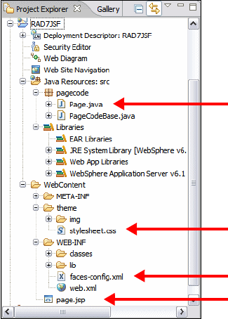
7672-dev-3-jsf.fm Draft Document for Review December 9, 2008 2:44 pm
496 Rational Application Developer V7.5 Programming Guide
Faces JSP pages are built from JSF components, where each component is
represented by a server-side class.
Faces servlet: One servlet (FacesServlet) controls the execution flow.
Configuration file: An XML file (faces-config.xml) that contains the
navigation rules between the JSPs, validators, and managed beans.
Tag libraries: The JSF components are implemented in tag libraries.
Validators: Java classes to validate the content of JSF components, for
example, to validate user input.
Managed beans: JavaBeans defined in the configuration file to hold the data
from JSF components. Managed beans represent the data model and are
passed between business logic and user interface. JSF moves the data
between managed beans and user interface components.
Events: Java code executed in the server for events (for example, a push
button). Event handling is used to pass managed beans to business logic.
Figure 16-2 represents the structure of a simple JSF application created in
Application Developer.
Figure 16-2 JSF application structure within Application Developer
JSF page server-side code
JSF stylesheet
Sample JSF Page
JSF configuration file
Chapter 16. Develop Web applications using JSF 497
Draft Document for Review December 9, 2008 2:44 pm 7672-dev-3-jsf.fm
JSF features in Application Developer 7.0
Application Developer includes a wide range of features for building highly
functional Web applications. Application Developer includes full support to make
drag-and-drop Web application development a reality.
Application Developer includes the following support and tooling for JSF Web
application development:
Visual page layout of JSF components using Page Designer
Web Diagram Editor for defining the flow of a JSF application
Built-in Component Property editor
Built-in tools to simplify and automate event handling
Page navigation defined declaratively
Automatic code generation for data validation, formatting, and CRUD
functions for data access
Multiple faces configuration file support for different purposes, such as
navigation and managed beans
Relational database support
EJB support
Web services support
Data abstraction objects for easy data connectivity using JPA
Data objects can be bound easily to user interface components
Support for runtime page templates with Tiles
Application Developer v7.0 has additional rich and powerful components for JSF.
These components include Menu Bar (displays a menu bar of buttons and/or
hyperlinks), Panel - Dialog (creates a block panel that behaves like a modal or
modeless dialog box), Panel - Form Box (creates a block panel that contains a
header area and one or more form label/field pairs), Panel - Section (creates a
block panel that has a header that can be used to expand/collapse the display of
the panel's content), Select - Color (displays a drop-down combo box from which
the user chooses a color), Select - Calendar (adds small calendar to the page),
Progress Bar (displays an animated progress bar), Link - Request (generates an
HTML link with a URL that can pass parameters and navigate to a page by
passing a string to JSF navigation rules), Data Iterator (iterates over rows of
model data allowing values from each row to be used in child components).
Application Developer v7.0 also provides additional improvements to existing
JSF components. Some of these improvements are as follows:
Command buttons can now have icons.
7672-dev-3-jsf.fm Draft Document for Review December 9, 2008 2:44 pm
498 Rational Application Developer V7.5 Programming Guide
A Data Table component can now have sortable columns.
Data Table component rows can now have single select mode using the radio
buttons.
A JSF panel content can now be updated using AJAX.
In addition to new and enriched JSF components, Application Developer v7.0
introduces new tools to provide much more development efficiency and minimize
development time. These new tools for JSF are:
VBL Expression Builder: Attributes of JSF components can be specified by
expressions created visually using the expression builder.
Pattern Builder: Some JSF components that have date and number formats
can use patterns created visually using the pattern builder.
Resource bundle editor: JSF applications support localization that requires
externalizing all the strings used in Faces JSP files into resource bundles.
The resource bundle editor visually works with these resource bundle files so
that the user can easily externalize all the strings.
Improved Quick Edit view: The Quick Edit view lets you add short scripts to
your HTML and JSP files. The view now supports a library of pre-defined
JavaScript functions on JSF components.
JSF features in Application Developer 7.5
Application Developer 7.5 provides additional features for JSF:
Dynamic Web project with JSF support
Improved Faces Configuration editor
Customizable property templates for data types (such as Date)
3rd party library integration with customizable palette
Custom component library building
Integration with JPA to easily create Web applicaitons with persistence
Preparing for the sample
This section describes the tasks that must be completed prior to developing the
JSF and JPA sample application.

Chapter 16. Develop Web applications using JSF 499
Draft Document for Review December 9, 2008 2:44 pm 7672-dev-3-jsf.fm
Setting up the sample database
To use JPA components, we require a relational database. This section provides
instructions for deploying the ITSOBANK sample database and populating the
database with sample data. For simplicity we use the built-in Derby database.
Follow the instructions in “Setting up the ITSOBANK database” on page 1154 to
create and load the sample ITSOBANK database.
Create a database connection
Follow the instructions in “Creating a connection to the ITSOBANK database” on
page 229 to create the ITSOBANKderby connection (if you do not have the
connection already defined).
Configuring the data source
There are a couple of methods that can be used to configure the data source,
including using the WebSphere Administrative Console or using the WebSphere
Enhanced EAR, which stores the configuration in the deployment descriptor and
is deployed with the application.
While developing JSF and JPA Web applications with Application Developer
v7.5, the data source is created automatically when you add JPA managed data
to a Faces JSP file. The data source configuration is added to the EAR
deployment descriptor.
However, if you already have defined the ITSOBANKderby data source in the
server (“Configuring the data source in WebSphere Application Server” on
page 1155), then you can run into problems because you can only have one
active connection to the database. Removing all applications form the server and
restarting the server clears the connection.
Note: A completed version of the Web application built using JSF and SDO
can be found in the c:\7672code\zInterchange\jsf\RAD75JSF.zip project
interchange file. If you do not want to create the sample yourself, but want to
see it run, follow the procedures described in “Running the JSF application” on
page 532.
7672-dev-3-jsf.fm Draft Document for Review December 9, 2008 2:44 pm
500 Rational Application Developer V7.5 Programming Guide
Developing a Web application using JSF and JPA
In this section we describe a Web application implemented with JavaServer
Faces (JSF).
We could use a similar technique as we used for the Struts application, and
implement a helper class to interact with the session bean. In JSF, for each JSP a
managed bean class is generated. For each action in the JSPs, a method in the
managed bean class is invoked. In those methods we could use the helper class
to interact with the session bean and retrieve the necessary data.
Application Developer 7.5 provides tooling to interact directly with the JPA entities
without using a session bean. A helper classed is created for each JPA entity,
with methods such as find, create, delete, update, and named query invocation.
We use this tooling support for our example.
Project setup
We use two projects for this application:
RAD75JSFEAR—Enterprise application with one Web module
RAD75JSFWeb—JSF Web application with facets for JSF and JPA
Creating the Web project
We create a dynamic Web project named RAD75JSFWeb with JSF and JPA
support:
Create the project (Figure 16-3):
– Type the Project name as RAD75JSFWeb.
– For Target Runtime, select WebSphere Application Server v7.0.
– For Dynamic Web Module version, select 2.5.
– For EAR Membership, Add project to an EAR, and type RAD75JSFEAR
as EAR Project Name.
– For Configuration, select JavaServer Faces v1.2 Project, then click
Modify.
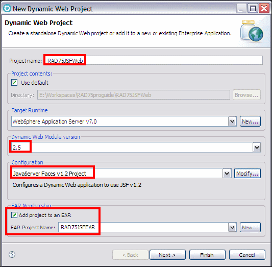
Chapter 16. Develop Web applications using JSF 501
Draft Document for Review December 9, 2008 2:44 pm 7672-dev-3-jsf.fm
Figure 16-3 Web project for JSF
In the Project Facets dialog (Figure 16-4):
–Select Faces support (base), Faces support (enhanced components),
Java Persistence, JavaServer Faces (preselected), JSTL, WebSphere
Web (Co-existence) and WebSphere Web (Extended).
– Click OK. The configuration changes to <custom>.
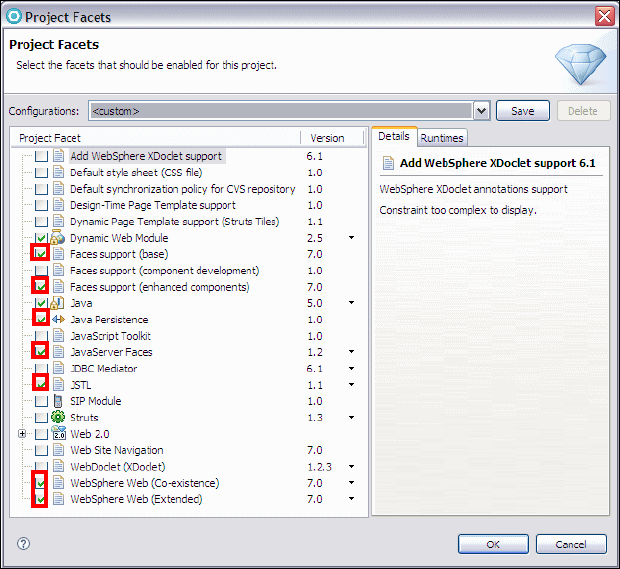
7672-dev-3-jsf.fm Draft Document for Review December 9, 2008 2:44 pm
502 Rational Application Developer V7.5 Programming Guide
Figure 16-4 Web project facets for JSF
Click Next, accept the context root, and select Generate deployment
descriptor.
For JPA Facet:
– Select the ITSOBANKderby connection that was defined for the JPA
sample application. Click Connect if the connection is not active.
–Select Use implementation provided by the server runtime, Discover
annotated classes automatically, and Create orm.xml.
– Click Next.
For JSF Capabilities, select Server Supplied JSF Implementation, and
accept the other defaults (such as /WEB-INF/faces-config.xml).
Click Finish and the project is created.
Switch to the Web perspective when prompted.
Close the Technology Quickstarts editor.

Chapter 16. Develop Web applications using JSF 503
Draft Document for Review December 9, 2008 2:44 pm 7672-dev-3-jsf.fm
Project facets
You can review and change the project facets in the Properties dialog of the
project by selecting Project Facets.
Structure of the JSF Web application
We can build the basic structure of the Web application using the Web Diagram.
The sample application consists of the following three pages:
Login page (logon): Validate the social security number (SSN). If it is valid it
then display the customer details for the customer.
Customer details page (customerDetails): Display the accounts of the
customer and allow you to select an account to view the transactions.
Account details page (accountDetails): Display the selected account details.
Create a Faces JSP page using the Web Diagram Editor
To create a Faces JSP page using the Web Diagram Editor, do these steps:
In the Enterprise Explorer, expand RAD75JSFWeb.
Open the Web Diagram.
Select Web Page from the Web Parts palette (the Palette view is
on the top right in the Web perspective) and drag it onto the page. The page
appears as an icon, with the name (page) selected and a button.
Click the button immediately to launch the page selection wizard. If you
react too late, delete the page.jsp that is created.
In the Web Page Selection dialog, click New Web Page to create a new
page.
In the New Web Page dialog, type logon.jsp as File Name. In the Template
section, select Basic Templates → JSP (preselected) and click Finish.
In the Web Page Selection dialog, select the logon.jsp and click OK.
A realized node is shown in the diagram.
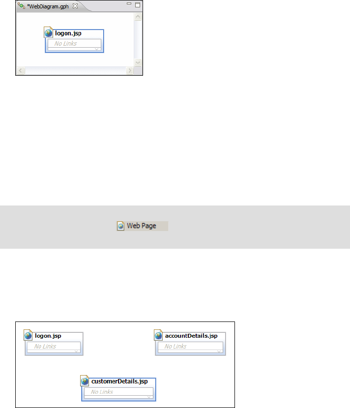
7672-dev-3-jsf.fm Draft Document for Review December 9, 2008 2:44 pm
504 Rational Application Developer V7.5 Programming Guide
A node in a Web Diagram is realized when its underlying resource exists.
Otherwise the node is unrealized. When you add a node to a Web Diagram, its
underlying resource (for example, a Web page) is normally created automatically.
In other words, you realize a node by default when you create it. Alternatively,
you can add a node to a diagram without creating its underlying resource.
In a Web Diagram, realized and unrealized nodes are shown differently. Realized
nodes have color and black title text. Unrealized nodes are gray and have gray
title text. In our sample, the logon page is realized.
Repeat the process to create Web pages for the other two JSF pages:
–customerDetails.jsp—Customer details and account overview
–accountDetails.jsp—Account details with transactions
Notice that all three pages are realized (black title). Save the Web Diagram.
Create connections between Faces JSP pages
Now that the pages have been created, we can create connections between the
pages using the Web Diagram Editor.
Tip: If you want to create the associated resource later, press Shift+Enter
after you drag Web Page onto the page, otherwise the underlying
resource is created automatically.
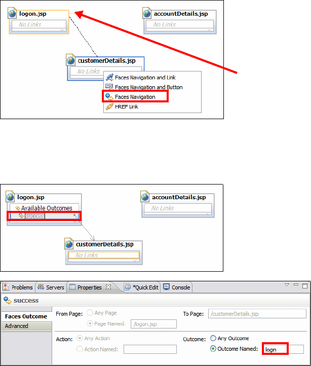
Chapter 16. Develop Web applications using JSF 505
Draft Document for Review December 9, 2008 2:44 pm 7672-dev-3-jsf.fm
To add connections between pages, do these steps:
Place the mouse over the logon.jsp. A connection handle is displayed near
the top right corner of the node. Drag the connection handle to the
customerDetails.jsp. When prompted, select Faces Navigation as
connection type.
Change the name of the success action under Available Outcomes. Select
the success action to highlight the text. Change the name in the Properties
view, Outcome Named field, from success to login.
Save the Web Diagram.
An arrow is drawn from logon to customerDetails. The line is solid because
the connection has been realized (added to the faces-config.xml).
We have a link from the logln.jsp to the customerDetails.jsp. This link is
activated when the outcome of an action on the logon page is login. To review
how this link is realized in the JSF configuration, do these steps:
Connection handle
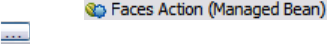
7672-dev-3-jsf.fm Draft Document for Review December 9, 2008 2:44 pm
506 Rational Application Developer V7.5 Programming Guide
– Expand RAD75JSFWeb → WebContent → WEB-INF and open the
faces-config.xml file.
– Verify that the navigation rule was added in the Source tab:
<navigation-rule>
<from-view-id>/logon.jsp</from-view-id>
<navigation-case>
<from-outcome>login</from-outcome>
<to-view-id>/customerDetails.jsp</to-view-id>
</navigation-case>
</navigation-rule>
– The navigation rule is also visible in the Navigation Rule tab.
– Close the faces-config.xml file.
Create a Faces action
The Web Diagram Editor provides the means to create faces actions and connect
Web pages to these actions.
To create a new Faces action, do these steps:
Create an empty class itso.jsf.action.Logout (select New → Class, and
type itso.jsf.action as package and Logout as class name).
In the Web Diagram, from the Web Parts palette select Faces Action
(Managed Bean) and drag it onto the page.
Click the button immediately to launch the Faces Action selection dialog.
Click New to create a new Faces action.
In the New Faces Action dialog:
–Type logout in the Managed bean name and logout in the Action method
field.
–Select request for Scope.
– Click Browse and locate an existing managed bean. Select the Logout
class.
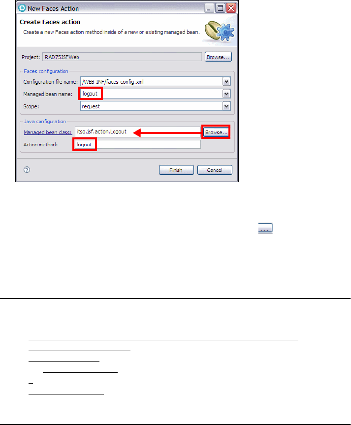
Chapter 16. Develop Web applications using JSF 507
Draft Document for Review December 9, 2008 2:44 pm 7672-dev-3-jsf.fm
Click Finish.
In the Faces Action Selection dialog, select logout → logout and click OK.
(You may have to close the dialog and reopen it with the button to see the
new action.)
A logout method is added to the Logout class (Example 16-1). Replace the
generated code with return "logout";
Example 16-1 Logout class
package itso.jsf.action;
public class Logout {
public String logout() {
//Put your logic here, returning appropriate outcome strings.
boolean condition=true;
if (condition) {
return "success";
}
return "failure";
return "logout";
}
The logout action is added to the Web Diagram.
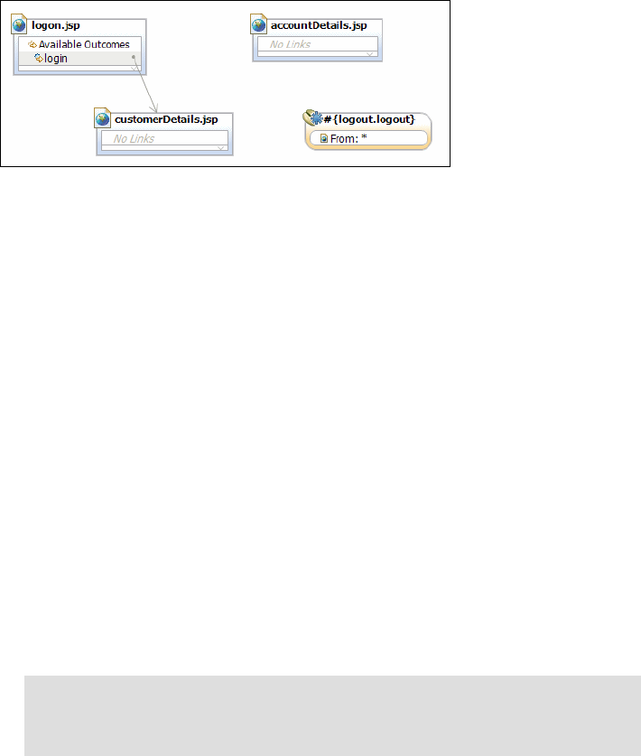
7672-dev-3-jsf.fm Draft Document for Review December 9, 2008 2:44 pm
508 Rational Application Developer V7.5 Programming Guide
Add a connection for the action
To add a connection from the Action to a page, do these steps:
Place the mouse over the logout action. A connection handle is displayed
near the top right corner of the node. Drag the connection handle to the
logon.jsp.
Change the name of the success action to logout (in the Properties view).
The new navigation rule is added to the faces-config.xml file.
Add remaining navigation rules
We now have an action bean that performs an action to return the user to the
logon screen. We have to define the remaining navigation rules in the Web
Diagram:
Create a connection from customerDetails to accountDetails (Faces
Navigation) and name the action accountDetails.
Create a connection from accountDetails to customerDetails and name the
action customerDetails.
After adding the connections and rearranging the pages and action,
rearrange and save the Web Diagram.
Tip: To change the shape of a connection, select the connection, point
somewhere on the line and drag the mouse away to reshape the line for
better visibility.
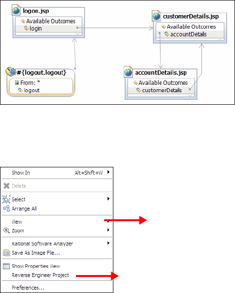
Chapter 16. Develop Web applications using JSF 509
Draft Document for Review December 9, 2008 2:44 pm 7672-dev-3-jsf.fm
Most functions in the Web Diagram Editor are available from the
context-menu. To access any of these functions, right-click in the diagram and
select an item from the menu.
Editing the Faces JSP pages
This section demonstrates the JSF editing features in Application Developer by
using the JSF pages created through the Web Diagram.
Editing the login page
We complete the login page in a few stages.
Add the UI components
To add the UI components to the logon.jsp page, do these steps:
Open the logon.jsp by double-clicking the file in the Web diagram or in the
WebContent folder. Select the Design or the Split tab.
Use the Enhanced Faces Components palette to drag and drop components.
Grid, Rulers
Populate diagram from existing Web pages
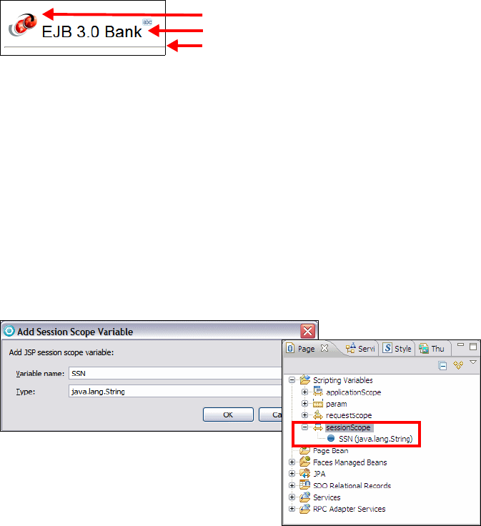
7672-dev-3-jsf.fm Draft Document for Review December 9, 2008 2:44 pm
510 Rational Application Developer V7.5 Programming Guide
Add the itso_logo.gif image to WebContent from the sample code
(7672code\jsf\jsp).
Drag an Image component from the Enhanced Faces Components into the
JSP.
Drag the itso_logo.gif image onto the component.
Add an Output component, and in the Properties view set the value to EJB
3.0 Bank, change the style to Arial size 18 (click the Style icon, select the
Arial font and click Add, set the size to 18).
Add a Horizontal Rule (from the HTML Tags palette).
Add a variable for the SSN
When a page has a field where text is entered, the input can be stored. This is
accomplished by creating a session scope variable to store the entered value
and bind it with an input field.
To create a variable, do these steps:
In the Page Data view, expand Scripting Variables.
Right-click sessionScope and select New → Session Scope Variable.
In the Add Session Scope Variable dialog, enter SSN for the Variable name,
and java.lang.String for Type, and click OK. The variable is added to the
Page Data view.
Image component
Output component
Horizontal rule
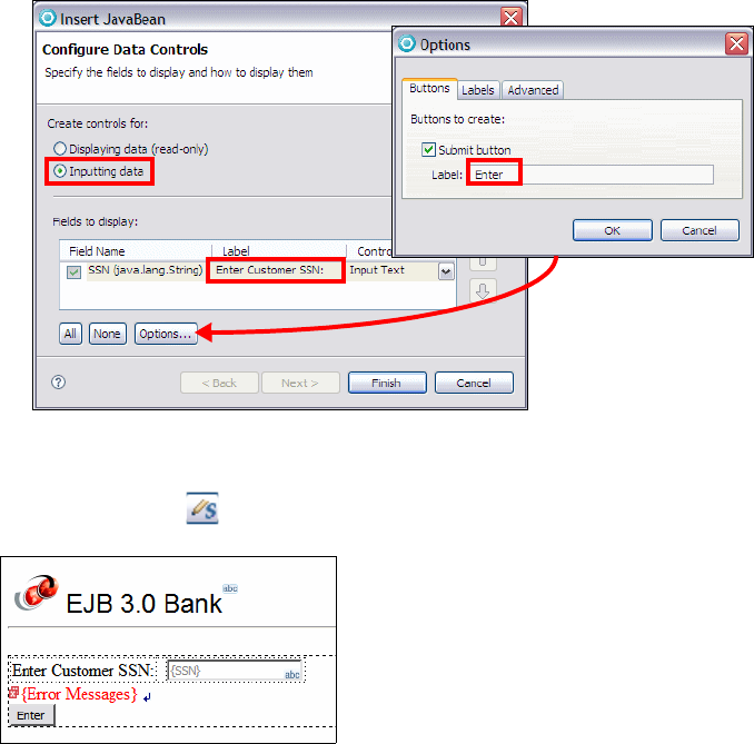
Chapter 16. Develop Web applications using JSF 511
Draft Document for Review December 9, 2008 2:44 pm 7672-dev-3-jsf.fm
Create a form for the SSN
A variable can be dropped into the page to create a form with an input field and a
push button:
In the Page Data view, expand and select Scripting Variables →
sessionScope → SSN. Drag SSN into the area under the horizontal line. A
tooltip pop-up says Drop here to insert new controls for “SSN”.
In the Insert JavaBean dialog:
–Select Inputting data.
– Overtype the generated Label with Enter Customer SSN:.
– Leave the control type as Input Text.
– Click Options, select Submit button, type Enter for the Label, and click
OK.
Click Finish. Select the {ErrorMessage} control and change the style color to
red in the Properties view. For Style: Props enter color: red. (You could also
click the Style icon and select the red color for the Color field.
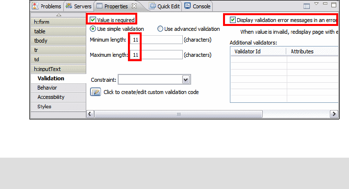
7672-dev-3-jsf.fm Draft Document for Review December 9, 2008 2:44 pm
512 Rational Application Developer V7.5 Programming Guide
Save the logon.jsp.
Select the {SSN} input field and verify in the Properties view that the value is
set to #{sessionScope.SSN}. This value indicates that the input field is
bound to the session variable SSN. The session variable value will be
displayed in the field and any change to the value is stored in the session
variable.
Add simple validation
JSF offers a framework for performing validation on input fields such as required
values, validation on the length of the input, and input check for all alphabetic or
digits. You can also define your custom validations.
To add simple validation to an input field, do these steps:
Select the Input component {SSN} in the Design tab.
In the Properties view for the input component. Enter the following items in
the Validation tab:
–Select Value is required.
–Select Display validation error message in an error message control.
When you select this check box an error message component is added
next to the Input box.
– Enter 11 in the Minimum and Maximum length fields.
Make the {Error Message for ssn1} component red.
Note: If we do not add an error message field for an input field, messages are
displayed automatically in the {Error Messages} field for the whole page.
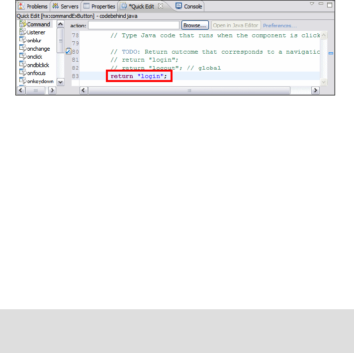
Chapter 16. Develop Web applications using JSF 513
Draft Document for Review December 9, 2008 2:44 pm 7672-dev-3-jsf.fm
Add static navigation to a page
Static navigation is called when the page is submitted. The string value returned
by the method is matched against the application’s navigation rules.
To add static navigation to the page, do these steps:
Select the Enter component (Command - Button).
Next to the Properties view, select the Quick Edit view. Click in the code
snippet field, and sample code is generated. Complete the return statement
as:
return "login";
Save the login.jsp. The action logic is stored as a doButton1Action method
in the pagecode.Logon.java file.
In the Source tab you can see the generated source code for the input field
and the Enter button:
<h:inputText styleClass="inputText" id="ssn1"
value="#{sessionScope.SSN}" required="true">
<f:validateLength minimum="11" maximum="11"></f:validateLength>
</h:inputText>
<h:message for="ssn1" style="color: red"></h:message>
......
<hx:commandExButton id="button1" styleClass="commandExButton"
type="submit" value="Enter" action="#{pc_Logon.doButton1Action}">
</hx:commandExButton>
We have to compare the customer SSN to the values in the database. We do so
by using a JPA entity to retrieve the records from the database.
Important: To retrieve records from the relational database, we require a
connection. We use the ITSOBANKderby connection that was created
in“Creating a connection to the ITSOBANK database” on page 229.
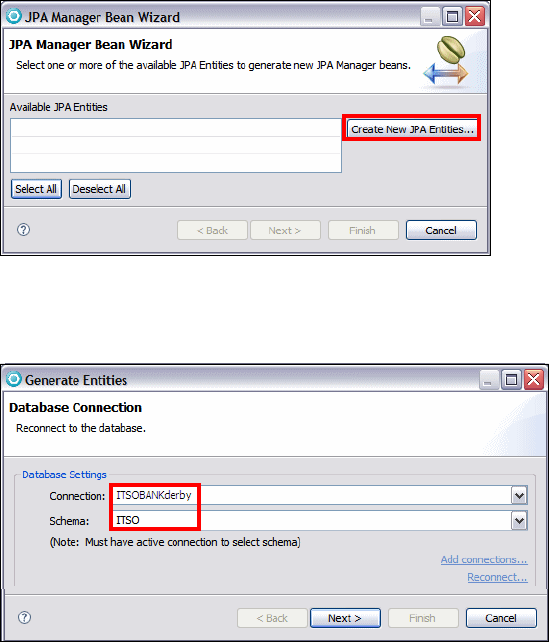
7672-dev-3-jsf.fm Draft Document for Review December 9, 2008 2:44 pm
514 Rational Application Developer V7.5 Programming Guide
Creating a JPA manager bean
In this section we create a JPA manager bean and JPA entities for the EJB3BANK
database. With the logon.jsp open in the editor, go to the Page Data view:
If the server is running and uses the connection to the database, stop the
server. Otherwise we cannot connect to the Derby database.
Expand JPA. Right-click JPA Manager Beans and select New → JPA
Manager Bean.
In the JPA Manager Bean Wizard click Create New JPA Entities.
For Connection, select the ITSOBANKderby connection. Click Reconnect if
not connected already. Select the ITSO schema. Click Next.
Typ e itso.bank.entity as package name. Select Synchronize Classes in
persistence.xml and select all the tables.
Overtype the Transact entity name with Transaction.
Click Finish.

Chapter 16. Develop Web applications using JSF 515
Draft Document for Review December 9, 2008 2:44 pm 7672-dev-3-jsf.fm
Select the Customer entity and click Next.
For the Customer entity go through the pages on the left-hand side:
– Primary key: Select ssn (preselected).
– Query Methods: Remove getCustomerByFirstname,
getCustomerByLastname, and getCustomerByTitle.
– Relationships: Account (preselected)
– Concurrency Control: No Concurrency Control (preselected)
– Other: Select all, except Use Resource Injection and Generate JSF
Converter for target entity. Click on What do these options mean? and
you get a description of all the options.

7672-dev-3-jsf.fm Draft Document for Review December 9, 2008 2:44 pm
516 Rational Application Developer V7.5 Programming Guide
Click Configure Project for JDBC Deployment to open the Set up
connections for deployment dialog. Select the ITSOBANKderby connection,
ITSO schema, clear Deploy JDBC Connection information to server, and
click OK.
Chapter 16. Develop Web applications using JSF 517
Draft Document for Review December 9, 2008 2:44 pm 7672-dev-3-jsf.fm
Click Finish.
Notice that the three generated JPA entities (Customer, Account, Transaction)
do not contain @Table annotations with the ITSO schema:
– Open the Customer entity (itso.bank.entity.Customer). Add the @Table
annotation after the @Entity annotation:
import javax.persistence.Table;
@Entity
@NamedQueries(....)
@Table (schema="ITSO", name="CUSTOMER")
– Open the Account entity, add the @Table annotation, and also add the
table and schema in the @JoinTable annotation:
@Entity
@Table (schema="ITSO", name="ACCOUNT")
......
@ManyToMany
@JoinTable(name="ACCOUNT_CUSTOMER",schema="ITSO",
joinColumns=@JoinColumn(name="ACCOUNT_ID"),
inverseJoinColumns=@JoinColumn(name="CUSTOMER_SSN"))
– Open the Transaction entity and add the schema to the @Table
annotation:
@Entity
@Table (schema="ITSO", name="TRANSACT")
–Select Source → Organize Imports to resolve the classes
Open the generated itso.bank.entity.controller.CustomerManager. Notice
the methods that have been generated for usage in JSF action code:
–createCustomer—Persist a new customer entity
–deleteCustomer—Delete a customer entity
–updateCustomer—Update a customer entity
–findCustomer—Find a customer entity by key
–getCustomer—Retrieve all customers using a named query
–getCustomerOrdered—Retrieve all customers sorted by ssn
–getCustomerSelectList—Retrieve a list of ssn for a combo box
The CustomerManager is added to the Page Data view of the logon.jsp.
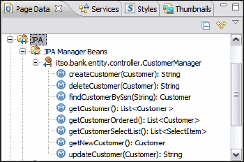
7672-dev-3-jsf.fm Draft Document for Review December 9, 2008 2:44 pm
518 Rational Application Developer V7.5 Programming Guide
Verify the connection information
The connection information to a data source has been added in several places:
The src/META-INF/persistence.xml file contains the <jta-data-source> tag
with java:comp/env/ITSOBANKderby.
<persistence ......>
<persistence-unit name="RAD75JSFWeb">
<jta-data-source>java:comp/env/ITSOBANKderby</jta-data-source>
<class>
itso.bank.entity.Account</class>
......
The WEB-INF/web.xml file contains a resource reference for the data source
with the name ITSOBANKderby.
The WEB-INF/ibm-web-bnd.xml file contains the JNDI name for the resource
reference, binding-name="jdbc/ITSOBANKderby".
The RAD75JSFEAR WebSphere deployment descriptor contains the
definition of the data source:
– Right-click RAD75JSFEAR and select Java EE → Open WebSphere
Application Server Deployment.
– Select the Generated Derby JDBC Provider and you can see the
ITSOBANKderby data source.
This JDBC provider and the data source are deployed to the server together
with the enterprise application.
Completing the action code for login
In the login action code we retrieve the customer and return login to pass control
to the customerDetails.jsp:
Open Logon.java in the pagecode package. You can also right-click in the
logon.jsp and select Edit Page Code.

Chapter 16. Develop Web applications using JSF 519
Draft Document for Review December 9, 2008 2:44 pm 7672-dev-3-jsf.fm
Complete the action code (refer to 7672code\jsf\doButton1Action.txt,
Example 16-2). Select Source → Organize Imports to resolve the classes.
Example 16-2 Logon action code
public String doButton1Action() {
try {
String ssn = (String)getSessionScope().get("SSN");
System.out.println("Logon " + ssn);
CustomerManager customerManager = (CustomerManager)
getManagedBean("customerManager");
Customer customer = customerManager.findCustomerBySsn(ssn);
if (customer == null) throw new Exception("Customer not found");
return "login";
} catch (Exception e) {
System.out.println("Login exception: " + e.getMessage());
getFacesContext().addMessage("ssn1",
new FacesMessage("Customer record not found.") );
return "failed";
}
}
We take the ssn and retrieve the customer. If no customer is found, we
construct a JSF error message and place it into the error field associated with
the ssn1 input field.
Testing the logon
At this point we can test if the logon process works:
Disconnect the ITSOBANKderby connection in the Data Source Explorer
view.
Start the WebSphere Application Server v7.0 server.
In the Servers view, select the WebSphere Application Server v7.0 server
and Add and Remove Projects, and add the RAD75JSFEAR application.
When the application is deployed and started, select the logon.jsp and
Run As → Run on Server. When prompted select the server and click
Finish.
Type an invalid ssn (less than 11 characters) and you get a validation error
message (actually it is displayed twice because we have two error message
fields).
Type a valid ssn (123-45-6789) that does not exist in the database and you get
the tailored error message (Customer Record not found).
Type a valid ssn (000-00-0000) and you are forwarded to the customer details
JSP, which for now is empty.
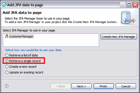
7672-dev-3-jsf.fm Draft Document for Review December 9, 2008 2:44 pm
520 Rational Application Developer V7.5 Programming Guide
Editing the customer details page
We complete the customerDetails.jsp in a few steps:
Open the customerDetails.jsp.
Add the header (image, EJB 3.0 Bank, and horizontal line). Note that you can
use copy/paste the components from the logon.jsp.
Add an output component with the text Customer (Arial font, size 14).
Create a JPA entity object for the customer
We create a JPA customer object to hold the data retrieved:
In the Page Data view, right-click JPA and select New → JPA Data
Consumption.
In the Add JPA data to page dialog, the CustomerManager is preselected.
Select Retrieve a single record and click Next.
On the next panel select Get record by primary key: findCustomerBySsn
(preselected), and click Next.
For Set filter values, change the Primary Key Value from #{param.ssn} to
#{sessionScope.SSN}. Click Finish.

Chapter 16. Develop Web applications using JSF 521
Draft Document for Review December 9, 2008 2:44 pm 7672-dev-3-jsf.fm
An entry customer (JPA Data) appears in the Page Data view under JPA →
JPA Page Data.
Add the customer object to the JSP
To display the customer data:
Drag the customer (JPA Data) into the JSP under the Customer text. A
Configure Data Controls dialog opens:
–Select Inputting data. All the fields are Input Text.
– Leave all fields selected.
– Verfiry that the sequence of the fields is ssn, title, firstName, lastName,
and accountCollection
– Change the labels to SSN:, First name:, Last name:, and Accounts:.
– Change the Control Type of ssn to Display Text. We cannot modify the
ssn.
– Click Options. In the Options dialog, select Submit button, and set the
Label to Update. Clear Delete button. Click OK.
– Click on the icon for the account collection.
• Select only id and balance, and change the id label to Number.
• Click Finish.
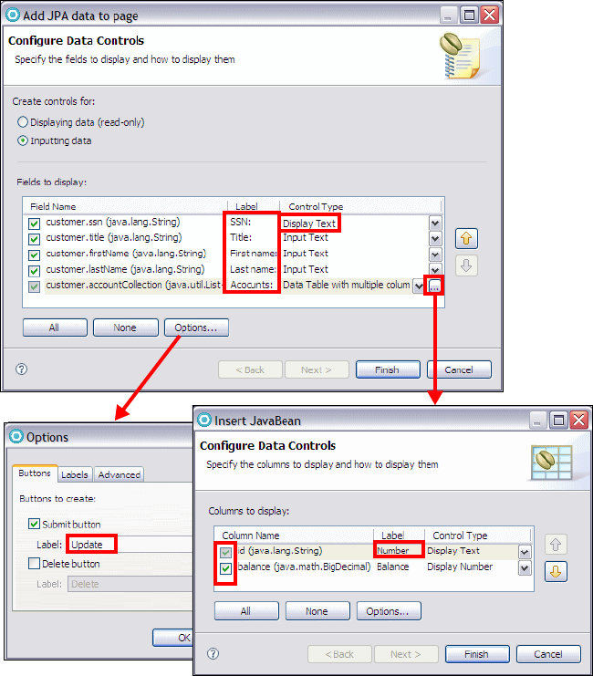
7672-dev-3-jsf.fm Draft Document for Review December 9, 2008 2:44 pm
522 Rational Application Developer V7.5 Programming Guide
– Click Finish. The table with customer information and accounts is added
to the JSP.
Select the Update button, and in the properties view change the id to update.
Add a Button - Command component at the bottom, next to the Update
button. In the Properties view, change the id to logoff, and set the label to
Logoff (under Display options).
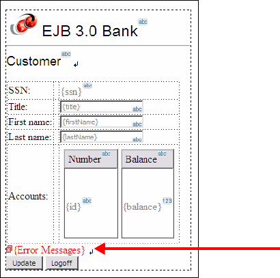
Chapter 16. Develop Web applications using JSF 523
Draft Document for Review December 9, 2008 2:44 pm 7672-dev-3-jsf.fm
Save the JSP. Open the page code (CustomerDetails.java, select Edit Page
Code) and you can see a getCustomer method that retrieves the customer:
@JPA(targetEntityManager =
itso.bank.entity.controller.CustomerManager.class,
targetAction = JPA.ACTION_TYPE.FIND)
@JPAFilter(name = "ssn", value = "#{sessionScope.SSN}")
public Customer getCustomer() {
if (customer == null) {
CustomerManager customerManager = (CustomerManager)
getManagedBean("customerManager");
String ssn = (String) resolveParam("customer_ssn",
"#{sessionScope.SSN}", "java.lang.String");
customer = customerManager.findCustomerBySsn(ssn);
}
return customer;
}
Republish the application to the server and run it. The customer is displayed
with the accounts.
To improve the look of the accounts table, select the table. In the Properties
view select hx:dataTableEx and set the border to 1. Select the balance
column (hx:columnEx) and set horizontal alignment to Right.
Make the error
message red

7672-dev-3-jsf.fm Draft Document for Review December 9, 2008 2:44 pm
524 Rational Application Developer V7.5 Programming Guide
Make the logoff action global
Select the Logoff button. In the Properties view, select the logout rule and click
Edit Rule. In the Edit Navigation Rule dialog, select All Pages, Any action, and
click OK.
Implementing customer update
The title, first name, and last name of the customer can be updated through the
generated input fields. We have to provide the logic for the Update button. The
CustomerManager contains the updateCustomer method that we can invoke.
In the customerDetails.jsp, select the Update button, and go to the Quick
Edit view.
Click into the action code and a doUpdateAction method is created.
Complete the code of the doUpdateAction method (refer to
C:\7672code\jsf\doUpdateAction.txt):
try {
CustomerManager customerManager =
(CustomerManager)getManagedBean("customerManager");
customerManager.updateCustomer(customer);
System.out.println("Customer updated: " + customer.getSsn());
} catch (Exception e) {
System.out.println("Customer update failed: " + customer.getSsn());
}
return "";
Publish and test the application. You can now change the title, first name, and
last name of a customer, and the update is persistent.
formatting
Chapter 16. Develop Web applications using JSF 525
Draft Document for Review December 9, 2008 2:44 pm 7672-dev-3-jsf.fm
Editing the account details page
We complete the accountDetails.jsp in a few steps:
Open the accountDetails.jsp.
Add the header (image, EJB 3.0 Bank, and horizontal line).
Add an output component with the text Account (Arial font, size 14).
Add a new session scope variable named accountID (String). We pass the ID
of a selected account from the customer page to the account page.
Add a JPA manager bean for the account
To display an account and its transactions, we build a JPA manager bean for the
account:
In the Page Data view, select JPA Manager Beans and New → JPA
Manager Bean.
Select Account and click Next. In the Tasks dialog:
–Primary Key: id
– Query Methods: Remove all
– Relationships: Leave both
– Concurrency Control: No Concurrency Control
– Other: Select Update Entity for use in JSF applications, clear others.
– Click Finish and the AccountManager class is generated.
Create a JPA entity object for the account
We create a JPA account object to hold the data retrieved:
In the Page Data view, right-click JPA and select New → JPA Data
Consumption.
In the Add JPA data to page dialog, select AccountManager and Retrieve a
single record. Click Next.
On the next panel select Get record by primary key: findAccountById
(preselected), and click Next.
a. For Set filter values, change the Primary Key Value from #{param.id} to
#{sessionScope.accountID}.
Click Finish.
Add the account to the page
To display the account data:
Drag the account (JPA Data) into the JSP. In the dialog:

7672-dev-3-jsf.fm Draft Document for Review December 9, 2008 2:44 pm
526 Rational Application Developer V7.5 Programming Guide
–Select Displaying data (read-only).
– Only select id and balance. Change the label from Id to Number.
– Click Finish.
Add a horizontal line under the account data.
Add an output component with the text Transactions (Arial font, size 14).
We want to display the transactions separately at the bottom in time sorted order.
We have to use a query for this purpose.
Add a JPA manager object for transactions
To display the transaction of an account, we build a JPA manager object for the
transaction list:
In the Page Data view, select JPA Manager Beans and New → JPA
Manager Bean.
Select Transaction and click Next. In the Tasks dialog:
–Primary Key: id
– Query Methods: remove all except getTransactionsByAccount.
•Select getTransactionsByAccount and click Edit.
• In the Order Results tab, select transTime and click .
• The query becomes:
SELECT t FROM Transaction t WHERE t.account.id = :account_id
ORDER BY t.transTime
• Click OK.
– Relationships: leave Account
– Concurrency Control: No Concurrency Control
– Other: Select Use Named Queries and Update Entity for use in JSF
applications, clear others.
– Click Finish and the TransactionsManager class is generated.
Create a JPA entity object for the transactions
We create a JPA transaction object to hold the data retrieved:
In the Page Data view, right-click JPA and select New → JPA Data
Consumption.
In the Add JPA data to page dialog, select TransactionsManager and
Retrieve a list of data. Click Next.
Chapter 16. Develop Web applications using JSF 527
Draft Document for Review December 9, 2008 2:44 pm 7672-dev-3-jsf.fm
On the next panel select get TransactionsByAccount (preselected), and
click Next.
For Set filter values, change the Filter variable from #{param.account_id} to
#{sessionScope.accountID}.
Click Finish.
Add the transaction list to the page
To display the transaction list:
In the Page Data view, expand the transactionList (JPA Data).
Drag the Contained Type:itso.bank.entity.Transaction into the JSP. In the
dialog:
–Select Data Table with multiple columns (preselected).
– Clear account (the account number is always the same).
– Arrange the fields: transtime, transtype, amount, id
– Change the labels to Timestamp, Type, Amount, and ID.
– Click Finish.
Set the table border to 1. Select the Amount column and set horizontal
alignment to Right. Select the {transTime} value and set the format
(Date/Time) type to Date and time.
Add a horizontal line under the transaction list.
Add two Button - Command components under the line. Set the ids to back
and logoff, and the labels to Back and Logoff. Add an Output component
between them for separation (value one blank).
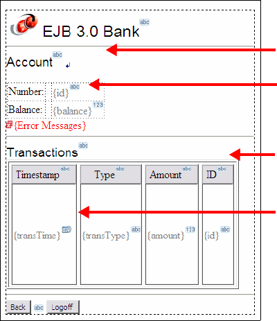
7672-dev-3-jsf.fm Draft Document for Review December 9, 2008 2:44 pm
528 Rational Application Developer V7.5 Programming Guide
Adding navigation between the pages
We already implemented the navigation from logon to customer details. Now we
implement the rest of the navigation:
In the accountDetails.jsp:
– In the Page Data view, expand Faces Managed Beans → logout (....) →
logout. Drag the logout action on top of the Logoff button. This creates
the binding #{logout.logout}.
– Select the Back button, and in the Quick Edit view, click in the empty code,
then complete the code as:
return "customerDetails";
In the customerDetails.jsp:
– In the Page Data view, expand Faces Managed Beans → logout (....) →
logout. Drag the logout action on top of the Logoff button. This creates
the binding.
Account selection
In the customerDetails.jsp, we want to select an account and invoke the
account details page:
Make the error
message red
account object
transaction list
object
command
buttons

Chapter 16. Develop Web applications using JSF 529
Draft Document for Review December 9, 2008 2:44 pm 7672-dev-3-jsf.fm
Select the data table of the account list (hx:dataTableEx in the Properties
view).
Select Row actions (under hx:dataTableEx).
Click Add for Add an action that’s performed when a row is clicked.
In the dialog, select Clicking the row submits the form to the server.
Parameters have to be set up manually. Click OK. A column with a link is
added to the data table.
Select the link and go to the Quick Edit view. Code is automatically generated.
Save the skeleton code.
Open the page code (select Edit Page Code), and locate the generated
doRowAction1Action method. Complete the code, which retrieves the
parameter (id), adds it into session scope (accountID), and forwards to the
account details page (Example 16-3). Refer to
7672code\jsf\doAction1Action.txt.
Example 16-3 Row action logic
public String doRowAction1Action() {
//......
int row = getRowAction1().getRowIndex();
String id = customer.getAccountCollection().get(row).getId();
System.out.println("Row action: " + row + " account " + id);
getSessionScope().put("accountID", id);
return "accountDetails";
}
Logoff
In the logoff code we have to clean the session scope:
Open the itso.jsf.action.Logout class and complete the code (refer to
7672code\jsf\Logout.java, Example 16-4).
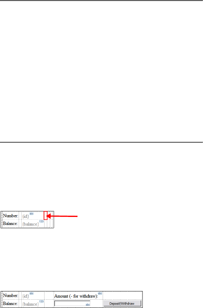
7672-dev-3-jsf.fm Draft Document for Review December 9, 2008 2:44 pm
530 Rational Application Developer V7.5 Programming Guide
Example 16-4 Logout action
package itso.jsf.action;
import java.util.Map;
import javax.faces.context.FacesContext;
public class Logout {
private static final String CUSTOMERSSN_KEY = "SSN";
private static final String ACCOUNTID_KEY = "accountID";
public String logout() {
FacesContext facesContext = FacesContext.getCurrentInstance();
Map<String, Object> sessionScope =
facesContext.getExternalContext().getSessionMap();
if (sessionScope.containsKey(CUSTOMERSSN_KEY))
sessionScope.remove(CUSTOMERSSN_KEY);
if (sessionScope.containsKey(ACCOUNTID_KEY))
sessionScope.remove(ACCOUNTID_KEY);
return "logout";
}
}
Implementing deposit and withdraw
We want to be able to deposit and withdraw funds into and from an account. We
implement these actions in the accountDetails.jsp:
Click in the account table and select Table → Add Column to Right. Add
three columns.
Select the third cell and set the width to 30 pixels in the Properties view.
Drag an Output component into cell four, with text Amount (- for withdraw):.
Drag an Input component into cell four/row two. Set the id to amountstring.
Drag a Button - Command component into cell five of row two. Set the id to
process, and the label to Deposit/Withdraw.
third cell

Chapter 16. Develop Web applications using JSF 531
Draft Document for Review December 9, 2008 2:44 pm 7672-dev-3-jsf.fm
In the Page Data view, create a request scope variable with the name
amount (String). Then drag the amount variable onto the input field to create
a binding of #{requestScope.amount}.
Select the Deposit/Withdraw button and go to the Quick Edit view to
generate an action method named doProcessAction.
Complete the doProcessAction method in the page code (refer to
7672code\jsf\doProcessAction.txt, Example 16-5).
Example 16-5 Deposit and withdraw action logic
public String doProcessAction() {
String amountstring = (String)getRequestScope().get("amount");
System.out.println("deposit/withdraw amount: " + amountstring);
try {
BigDecimal amount = new BigDecimal(amountstring);
if (amount.scale() > 2) throw
new Exception("Only 2 digits allowed for cents");
Account account = getAccount();
BigDecimal balance = account.getBalance();
if (amount.doubleValue() == 0) {
throw new Exception("Amount is zero");
} else if (amount.doubleValue() > 0) {
balance = balance.add(amount);
} else {
if (balance.compareTo(amount.abs()) < 0)
throw new Exception("Withdraw amount too big");
balance = balance.add(amount);
}
account.setBalance(balance);
AccountManager accountManager = (AccountManager)
getManagedBean("accountManager");
accountManager.updateAccount(account);
System.out.println("deposit/withdraw balance: " + balance);
// create transaction
TransactionManager transactionManager = (TransactionManager)
getManagedBean("transactionManager");
Transaction t = new Transaction();
t.setId( (new com.ibm.ejs.util.Uuid()).toString() );
t.setAmount(amount.abs());
t.setTransTime( new Timestamp(System.currentTimeMillis()) );
if (amount.doubleValue() > 0) t.setTransType("Credit");
else t.setTransType("Debit");
t.setAccount(account);
transactionManager.createTransaction(t);
transactionList = null;
getTransactionList();
getRequestScope().put("amount","");
} catch (NumberFormatException e) {
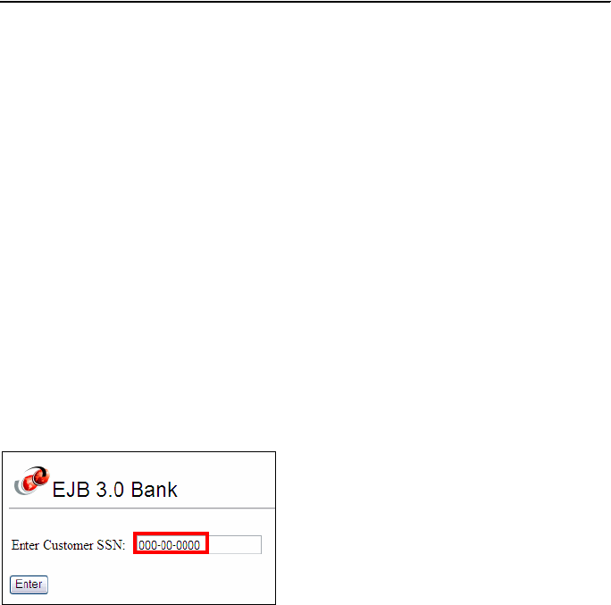
7672-dev-3-jsf.fm Draft Document for Review December 9, 2008 2:44 pm
532 Rational Application Developer V7.5 Programming Guide
getFacesContext().addMessage("amount",
new FacesMessage("Bad amount"));
} catch (Exception e) {
getFacesContext().addMessage("amount",
new FacesMessage("Deposit/withdraw failed: " + e.getMessage()));
}
return "";
}
Be sure that you import java.math.BigDecimal and java.sql.Timestamp.
This action logic performs the following steps:
– Retrieve the input amount.
– Verify that a withdraw amount does not exceed the balance.
– Change the balance and call the AccountManager to update the database.
– Build a transaction record and call the TransactionManager to insert the
record into the database.
– Retrieve the transaction records again to display the new record in the list.
– Issue JSF error messages for bad data.
Running the JSF application
When we run the finished application we can see the power of the combination of
JSF and JPA entities:
Logon:
The customer and accounts are displayed, click on an account:
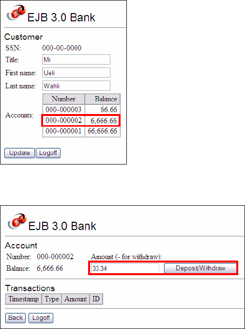
Chapter 16. Develop Web applications using JSF 533
Draft Document for Review December 9, 2008 2:44 pm 7672-dev-3-jsf.fm
The account is displayed without any transactions. Run a deposit:
The account balance is updated and the transaction is added. Try a big
withdraw and an error is displayed:
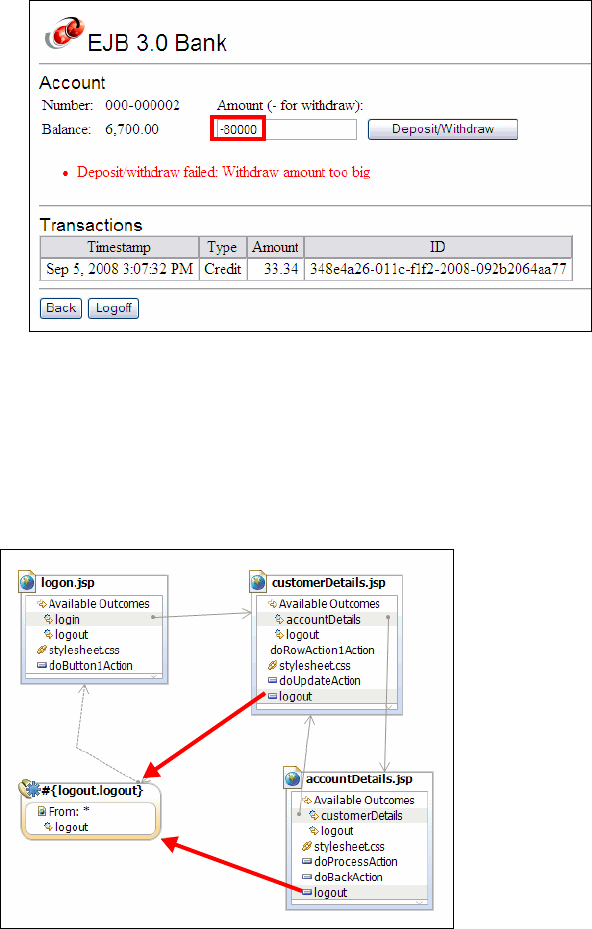
7672-dev-3-jsf.fm Draft Document for Review December 9, 2008 2:44 pm
534 Rational Application Developer V7.5 Programming Guide
Click Back or Logoff.
Web Diagram
Open the Web Diagram. We can complete the diagram by drawing connections
for the new actions that we defined (Figure 16-5).
Figure 16-5 JSF Web Diagram completed
The actions are also visible in the faces-config.xml file editor, Navigation Rule
tab (Figure 16-6).
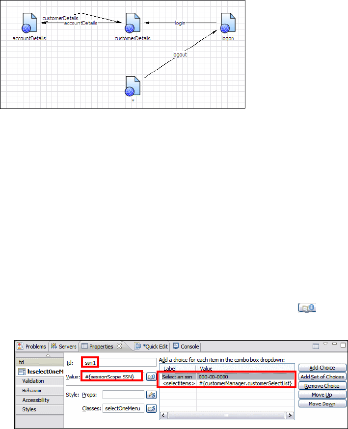
Chapter 16. Develop Web applications using JSF 535
Draft Document for Review December 9, 2008 2:44 pm 7672-dev-3-jsf.fm
Figure 16-6 Navigation rules in faces-config.xml
Drop-down menu for customer login
The CustomerManager class contains a getCustomerSelectList method that
retrieves the ssn of all the customers. This list can be used to populate a
drop-down menu for customer login:
Open the logon.jsp.
Replace the input field with a Combo Box component:
– Id: ssn1
– Value: #{sessionScope.SSN}
Add two choices for the list:
– Click Add Choice (Label: Select an ssn, Value: 000-00-0000)
– Click Add Set of Choices (Label: <selectitems>, Value: click and
locate #{customerManager.customerSelectList})
Validation: Select Value is required.
getCustomerSelectList method
This method retrieves customer objects and populates a list with these objects.
For our purpose we only need the ssn:
Open the CustomerManager at the getCustomerSelectList method.
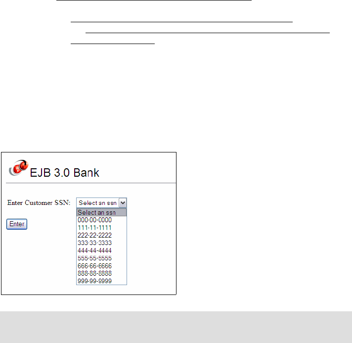
7672-dev-3-jsf.fm Draft Document for Review December 9, 2008 2:44 pm
536 Rational Application Developer V7.5 Programming Guide
Change the code so that the label and the value of the drop-down menu are
the same, namely the ssn:
public List<SelectItem> getCustomerSelectList() {
List<Customer> customerList = getCustomerOrdered();
List<SelectItem> selectList = new ArrayList<SelectItem>();
// MessageFormat mf = new MessageFormat("{0}");
for (Customer customer : customerList) {
// selectList.add(new SelectItem(customer, mf.format(
// new Object[] { customer.getSsn() }, new StringBuffer(),
// null).toString()));
selectList.add(new SelectItem(customer.getSsn(),
customer.getSsn()));
}
return selectList;
}
Redeploy the application, and the drop-down list is populated with the SSNs of all
the customers.
Adding a deluxe pager
JSP provides the Data Table component with many options, for example, paging.
We can add paging to the customer account list:
Open the customerDetails.jsp.
Select the account list table, and in the Properties view, expand
hxDataTableEx → Display options.
Note: This does not make sense for a real application, but it illustrates the
concept of populating a drop-down list with the results of a JPA query.

Chapter 16. Develop Web applications using JSF 537
Draft Document for Review December 9, 2008 2:44 pm 7672-dev-3-jsf.fm
Click Add a deluxe pager. The deluxe papers appears under the data table.
For Paging, set the Rows per table to 2 (Figure 16-7).
Figure 16-7 Adding a deluxe pager
Test the deluxe pager
With the deluxe pager, only two accounts are displayed for a customer, and the
pager has a forward button. You can test the paging by clicking the and the
buttons.
Figure 16-8 Display of customer accounts
Change the fields to update customer information. This verifies write access
to the database using JPA. For example, change the first name to Ulrich and
click Update.
Click one of the accounts (000-000002) to display the account information
with the transactions.

7672-dev-3-jsf.fm Draft Document for Review December 9, 2008 2:44 pm
538 Rational Application Developer V7.5 Programming Guide
Run some deposit and withdraw transactions and watch the list of
transactions grow (Figure 16-9).
Figure 16-9 Details for a selected account with transactions
Using the data source in the server
The application is configured to use the data source defined in the enterprise
application RAD75JSFEAR. For the final application we want to use the data
source configured in the server with the JNDI name jdbc/itsobank.
To configure the JSF application for the data soource in the server, perform these
steps:
Open the ibm-web-bnd.xml file (in RAD75JSFWeb/WebContent/WEB-INF).
Change the resource reference to:
<resource-ref name="ITSOBANKderby"
binding-name="jdbc/itsobank">
<authentication-alias name="ITSOBANKderby" />
</resource-ref>
Save and close the file.
Right-click RAD75JSFWeb and select JPA Tools → Configure Project for
JDBC Deployment:
– Click OK in the Cannot connect to connection profile ITSOBANK warning.
– Click Cancel in the Properties dialog.

Chapter 16. Develop Web applications using JSF 539
Draft Document for Review December 9, 2008 2:44 pm 7672-dev-3-jsf.fm
In the Set up connections for deployment dialog:
–Select ITSOBANKderby for the Connection.
– Clear Deploy JDBC Connection information to server (Figure 16-10).
Figure 16-10 Deployment of JDBC connection
– Click Configure project’s database connections.
– In the Properties for RADJSFWeb dialog, click Edit for Runtime
connection details (Figure 16-11).
Figure 16-11 Runtime connection details

7672-dev-3-jsf.fm Draft Document for Review December 9, 2008 2:44 pm
540 Rational Application Developer V7.5 Programming Guide
– In the Runtime Connection dialog, clear Deploy database and
connection properties when application is run on unit test server,
and click Finish (Figure 16-12).
Figure 16-12 Deployment of the runtime connection
The runtime connection is removed. Click OK in the Properties dialog.
Click OK in the Set up connections for deployment dialog.
Open the persistence.xml file (in WebContent/WEB-INF) and change the data
source JNDI name to jdbc/itsobank.
<persistence ......>
<persistence-unit name="RAD75JSFWeb">
<jta-data-source>jdbc/itsobank</jta-data-source>
Right-click RAD75JSFEAR and select Java EE → Open WebSphere
Application Server Deployment:
–Select Generated Derby JDBC Provider and verify that there is no data
source configured.
– Close the editor.

Chapter 16. Develop Web applications using JSF 541
Draft Document for Review December 9, 2008 2:44 pm 7672-dev-3-jsf.fm
Cleanup
Remove the RAD75JSFEAR application from the server.
Final code
To run the Web application you must have completed the sample JSF
application:
Either you completed the JSF pages as described in “Developing a Web
application using JSF and JPA” on page 500.
Or, you can import the interchange file of the application from:
c:\7672code\zInterchange\jsf\RAD75JSF.zip
Refer to “Importing sample code from a project interchange file” on
page 1152 for details.
You also must have set up the ITSOBANK database as described in “Setting up
the sample database” on page 499.
So far we have a JSF application with JPA access to a relational database. We
could certainly enhance the appearance of the pages and the error messages.
More information on JSF and AJAX
For more information on JSF and AJAX, we recommend the following resources.
Improve the usability of Web applications with type-ahead input fields using
JSF, AJAX, and Web services in Rational Application Developer V7, article
found at:
http://www.ibm.com/developerworks/rational/library/06/1205_kats_rad1/index.
html
Advanced usage of the Typeahead control in Rational Application Developer
V7.0, article found at:
http://www.ibm.com/developerworks/rational/library/07/0206_bermingham/index
.html
Note: Connection information is stored in the .wdo-connections file of the
RAD75JSFWeb project. You can only see that file by changing the filter in the
Enterprise Explorer (Down Arrow icon → Customize View, then clear
.*resources).
7672-dev-3-jsf.fm Draft Document for Review December 9, 2008 2:44 pm
542 Rational Application Developer V7.5 Programming Guide
JSF and Ajax: Web 2.0 application made easy with Rational Application
Developer V7, article found at:
http://www.ibm.com/developerworks/rational/library/06/1205_kats_rad2/index.
html
Creating a sorted JavaServer Faces Widget Library dataTable using Rational
Application Developer V7.0, article found at:
http://www.ibm.com/developerworks/rational/library/07/0220_gallagher/index.
html
New features of the JavaServer Faces Widget Library dataTable component
in IBM Rational Application Developer 7.0, article found at:
http://www.ibm.com/developerworks/rational/library/07/0213_gallagher/index.
html
Using the ProgressBar JSF Component in Rational Application Developer,
article found at:
http://www.ibm.com/developerworks/rational/library/07/0626_kats/
Improve the look and feel of your Web pages by using the Dynamic Page
Template, article found at:
http://www.ibm.com/developerworks/rational/library/07/0508_koinuma/index.ht
ml

© Copyright IBM Corp. 2008. All rights reserved. 543
Draft Document for Review December 9, 2008 2:44 pm 7672-dev-5-appclient.fm
Chapter 17. Develop Java EE application
clients
This chapter provides an introduction to Java EE application clients and the
facilities supplied by the Java EE application client container. In addition, we
highlight the features provided by Application Developer for developing and
testing Java EE application clients.
The chapter is organized into the following sections:
Introduction to Java EE application clients
Overview of the sample application
Preparing for the sample application
Developing the Java EE application client
Testing the Java EE application client
Packaging the Java EE application client
17

7672-dev-5-appclient.fm Draft Document for Review December 9, 2008 2:44 pm
544 Rational Application Developer V7.5 Programming Guide
Introduction to Java EE application clients
A Java EE application server is capable of making several different types of
resources available for remote access, such as:
Enterprise JavaBeans (EJBs)
JDBC data sources
Java Message Service (JMS) resources (queues and topics)
Java Naming and Directory Interface (JNDI) services
These resources are most often accessed from a component that is running
within the Java EE application server itself, such as an EJB, servlet, or JSP.
However, these resources can also be used from a stand-alone Java application
(known as a Java EE application client) running in its own Java Virtual Machine
(JVM), possibly on a different computer from the server. Figure 17-1 shows the
resource access scenarios described.
Figure 17-1 Java applications using Java EE server resources
Server JVM
JDBC
Data
Source
JMS
Queue
Java EE application
client container
JNDI service
EJB container
EJB EJB
Java EE application
client container
Java EE application
client container
Messaging
application
EJB
client
Database
application
JNDI lookup
Access resource
JPA

Chapter 17. Develop Java EE application clients 545
Draft Document for Review December 9, 2008 2:44 pm 7672-dev-5-appclient.fm
Because a regular JVM does not support accessing such application server
resources, additional setup for the runtime environment is required for a Java EE
application. There are two methods to achieve this:
Add the required packages to the Java Runtime Environment manually.
Package the application according to the Java EE application client
specification and execute the application in a Java EE application client
container.
In this chapter, we focus on the second of these options. In addition to providing
the correct runtime resources for Java applications accessing Java EE server
resources, the Java EE application client container provides additional features,
such as mapping references to JNDI names and integration with server security
features.
IBM WebSphere Application Server v7.0 includes a Java EE application client
container and a facility for launching Java EE application clients. The Java EE
application client container, known as Application Client for WebSphere
Application Server, can be installed separately from the WebSphere Application
Server installation CDs, or downloaded from developerWorks, and runs a
completely separate JVM on the client machine.
When the JVM starts, it loads the necessary runtime support classes to make it
possible to communicate with WebSphere Application Server and to support
Java EE application clients that will use server-side resources. Refer to the
WebSphere Application Server Information Center for more information about
installing and using the Application Client for WebSphere Application Server.
Note: The clients shown in Figure 17-1 might conceptually be running on the
same physical node, or even in the same JVM as the application server.
However, in this chapter the focus is on clients running in distributed
environments. Throughout this chapter, we develop an EJB client, invoking the
EJBs from Chapter 14, “Develop EJB applications” on page 387, to provide a
simple ITSO Bank client application.
Note: Although the Java EE specification describes the JAR format as the
packaging format for Java EE application clients, the Application Client for
WebSphere Application Server expects the application to be packaged as a
JAR inside an Enterprise Application Archive (EAR). The Application Client for
WebSphere Application Server does not support execution of a standalone
Java client JAR.

7672-dev-5-appclient.fm Draft Document for Review December 9, 2008 2:44 pm
546 Rational Application Developer V7.5 Programming Guide
Application Developer includes tooling to assist with developing and configuring
Java EE application clients, and a test facility that allows Java EE application
clients to be executed in an appropriate container. The focus of this chapter is on
the Application Developer tooling for Java EE application clients, so we will be
looking only at this facility.
Overview of the sample application
The sample application that we develop for this chapter is a simple Java EE
application client application. It invokes the services of the EJB application that
was developed in Chapter 14, “Develop EJB applications” on page 387, to look
up the customer information and account overview from a specified customer
SSN.
The application uses a graphical user interface, implemented with Swing
components, which displays the details for the customer with SSN 222-22-2222
(Figure 17-2).
Figure 17-2 Interface for the sample application client
Figure 17-3 shows a class diagram of the finished sample application:
The classes on the right-hand side of the class diagram are classes from the
EJB enterprise application, while the three left-hand classes are part of the
application client.
As the class diagram outlines, the application client controller class,
BankDesktopController, uses the EJBBankBean session EJB to retrieve
Customer and Account object instances, representing the customer and
associated account(s) that are retrieved from the ITSOBANK database.

Chapter 17. Develop Java EE application clients 547
Draft Document for Review December 9, 2008 2:44 pm 7672-dev-5-appclient.fm
Figure 17-3 Class diagram for the Bank Java EE application client
Preparing for the sample application
Prior to working on the sample for this chapter, we have to set up the database
for the sample application, import the EJB projects, and ensure that everything is
working.
Importing the base EJB enterprise application sample
To import the base enterprise application sample that we use as a starting point
for this chapter, do these steps:
From the workbench, select File → Import.
In the Import dialog, select Project Interchange and click Next.
In the Import Project Interchange Contents dialog, locate the file
c:\7672code\zInterchange\ejb\RAD75EJB.zip.
Select all projects (RAD75EJB, RAD75EJBEAR, RAD75EJBTestWeb and RAD75JPA.
Click Finish.
After the Import wizard has completed the import, four projects have been added
to the workspace:
7672-dev-5-appclient.fm Draft Document for Review December 9, 2008 2:44 pm
548 Rational Application Developer V7.5 Programming Guide
RAD75EJB: This project contains the EJBs, that makes up the business logic
of the ITSO Bank. The EJBBankBean session bean acts as a facade for the
EJB application. This project is packaged inside RAD75EJBEAR when exported
and deployed on an application server.
RAD75EJBEAR: This is the deployable enterprise application, which
functions as a container for the remaining projects. This enterprise application
must be executed on an application server.
RAD75EJBTestWeb: This is the sample Web application that is developed to
test the EJB 3.0 session bean and entity model. This project is packaged
inside RAD75EJBEAR when exported and deployed on an application server.
RAD75JPA: This Java project holds JPA entities that are passed between the
session facade and the client applications.
Setting up the sample database
The JPA entities are based on the ITSOBANK database. Therefore, we have to
define a database connection within Application Developer that the mapping
tools use to extract schema information from the database.
Refer to “Setting up the ITSOBANK database” on page 1154 for instructions on
how to create the ITSOBANK database. We can either use the DB2 or Derby
database. For simplicity we use the built-in Derby database in this chapter.
Configuring the data source
If the ITSOBANKderby data source has not been already configured for
RAD7EJBEAR, follow the instructions in “Configuring the data source for the
ITSOBANK” on page 413 or “Configuring the data source in WebSphere
Application Server” on page 1155.
Testing the imported code
Before continuing with the sample application, we suggest that you test the
imported code. Follow the instructions in “Testing the sample Web application” on
page 431.

Chapter 17. Develop Java EE application clients 549
Draft Document for Review December 9, 2008 2:44 pm 7672-dev-5-appclient.fm
Developing the Java EE application client
We now use Application Developer to create a project containing a Java EE
application client. This application client will be associated with its own enterprise
application.
To develop the Java EE application client sample, we complete the following
tasks:
Creating the Java EE application client projects
Configuring the Java EE application client projects
Importing the graphical user interface and control classes
Creating the BankDesktopController class
Completing the BankDesktopController class
Registering the BankDesktopController class as the main class
Creating the Java EE application client projects
To create a Java EE application client project, do these steps:
In the Java EE perspective, select File → New → Project. Expand the Java
EE folder, and select Application Client Project. (Alternatively, right-click in
the Enterprise Explorer and select New → Application Client Project.)
In the New Application Client Project dialog (Figure 17-4):
–Type RAD75AppClient as the Project name
–Type RAD75AppClientEAR as the EAR Project Name.
– Accept the defaults of WebSphere Application Server v7.0 for Target
Runtime and 5.0 for Application Client module version.
– Click Next.
Note: While it is possible to use the new client application with the existing
RAD75EJBEAR enterprise application, this is not the recommended approach.
The EJB project contains other server resources that should not be distributed
to the clients, such as passwords or proprietary business logic.

7672-dev-5-appclient.fm Draft Document for Review December 9, 2008 2:44 pm
550 Rational Application Developer V7.5 Programming Guide
Figure 17-4 New Application Client Project
In the Application Client module dialog, clear Create a default Main class,
select Generate deployment descriptor, and click Finish (Figure 17-5).
Figure 17-5 Application Client module
When the wizard is complete, the following two projects are created in your
workspace:
RAD75AppClientEAR: This is an enterprise application project that acts as a
container for the code to be deployed on the application client node.
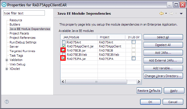
Chapter 17. Develop Java EE application clients 551
Draft Document for Review December 9, 2008 2:44 pm 7672-dev-5-appclient.fm
RAD75AppClient: This project contains the code for the application client. For
now, it is empty, except for the META-INF/application-client.xml file, which
is the application client deployment descriptor.
Configuring the Java EE application client projects
The application client project has to reference the RAD75EJB and RAD75JPA
projects. In this section, we configure this dependency by adding the
RAD7EJBClient as a dependency to both projects:
In the Enterprise Explorer, right-click RAD75AppClientEAR and select
Properties.
Select Java EE Module Dependencies, then select RAD75EJB and
RAD75JPA, and click OK (Figure 17-6).
Figure 17-6 Java EE Module Dependencies
Right-click RAD75AppClient, and select Properties. In the Properties dialog,
select Java EE Module Dependencies, then select RAD75EJB.jar, and click
OK.
Importing the graphical user interface and control classes
In this section, we complete the graphical user interface (GUI) for the Java EE
application client.
There maybe other projects

7672-dev-5-appclient.fm Draft Document for Review December 9, 2008 2:44 pm
552 Rational Application Developer V7.5 Programming Guide
Because this chapter focuses on the aspects relating to development of Java EE
application clients, we import the finished user interface and focus on
implementing the code for accessing the EJBs.
To import the framework classes for the Java EE application client, do these
steps:
In the Enterprise Explorer, right-click RAD75AppClient and select New →
Package. Type itso.rad75.client.ui as Name and click Finish.
Right-click itso.rad75.client.ui, and select Import.
In the Import dialog, expand General → File System and click Next.
In the Import file dialog, click Browse to locate c:\7672code\appclient.
Select AccountTableModel and BankDesktop, and click Finish
(Figure 17-7).
Figure 17-7 Import existing GUI class
Two classes have been imported to the RAD75AppClient project:
itso.rad75.client.ui.BankDesktop—This is a visual class, extending the
Swing JFrame, that contains the view for the Java EE application client.
itso.rad75.client.ui.AccountTableModel—This is an implementation of the
interface javax.swing.table.AbstractTableModel. The class provides the
relevant TableModel interface for a JTable, given an array of Account
instances.

Chapter 17. Develop Java EE application clients 553
Draft Document for Review December 9, 2008 2:44 pm 7672-dev-5-appclient.fm
Creating the BankDesktopController class
In this section, we create the controller class for the Java EE application client.
This class is also the main class for the application and contains the EJB lookup
code.
To create the BankDesktopController class, do these steps:
In the Enterprise Explorer, expand RAD75AppClient, right-click
appClientModule, and select New → Class.
In the New Java Class dialog (Figure 17-8), type itso.rad75.client.control in
the Package field, BankDesktopController in the Name field, select public
static void main(String[] args) and Constructors from superclass.
Click Add next to the Interface section. In the Implemented Interfaces
Selection dialog, type ActionListener in the Choose interfaces field, select
ActionListener - java.awt.event in the Matching types list, and click OK.
Figure 17-8 Create class BankDesktopController

7672-dev-5-appclient.fm Draft Document for Review December 9, 2008 2:44 pm
554 Rational Application Developer V7.5 Programming Guide
Completing the BankDesktopController class
In this section we add control logic to the BankDesktopController class, as well
as the code to look up customer and account information from the EJB
application.
To complete the BankDesktopController class, do these steps:
The BankDesktopController.java is open in the Java editor.
The client invokes methods of the EJBBankBean session bean through its
remote interface. Inject the remote interface of the session bean:
public class BankDesktopController implements ActionListener {
@EJB(name="ejb/bank",beanInterface=EJBBankRemote.class)
static EJBBankRemote bank;
After every step, select Source → Organize Imports (or press Ctrl+Shift+O)
to generate the required import statement.
Add two fields to the beginning of the class definition:
private BankDesktop desktop = null;
private AccountTableModel accountTableModel = null;
Locate the constructor and add the code (the new code is in bold):
public BankDesktopController() {
desktop = new BankDesktop();
accountTableModel = new AccountTableModel();
desktop.getTblAccounts().setModel(accountTableModel);
desktop.getBtnSearch().addActionListener(this);
desktop.setVisible(true);
}
Locate the main method, add the throws clause, and add three lines:
public static void main(String[] args) throws Exception {
BankDesktopController controller = new BankDesktopController();
// without the next line, app client fails in IDE, works outside
bank.getAccounts("xxx");
}
Note: The code found in this section can be copied from the complete
BankDesktopController class that is supplied in the sample code:
c:\7672code\appclient\BankDesktopController.java
We suggest that you copy the sections as noted in our procedure from the
completed BankDesktopController.java (step by step).

Chapter 17. Develop Java EE application clients 555
Draft Document for Review December 9, 2008 2:44 pm 7672-dev-5-appclient.fm
Locate the actionPerformed method stub and complete the method as
shown in Example 17-1.
Example 17-1 Complete actionPerformed method
public void actionPerformed(ActionEvent e) {
// we know that we are only listening to action events from
// the search button, so...
String ssn = desktop.getTfSSN().getText();
try {
// look up the customer
Customer customer = bank.getCustomer(ssn);
if (customer == null) throw new ITSOBankException
("Customer not found: " + ssn);
// look up the accounts
Account[] accounts = bank.getAccounts(ssn);
// update the user interface
desktop.getTfTitle().setText(customer.getTitle());
desktop.getTfFirstName().setText(customer.getFirstName());
desktop.getTfLastName().setText(customer.getLastName());
// store the accounts in the table model and set the model in the GUI
accountTableModel.setAccounts(accounts);
} catch (ITSOBankException x) {
// unknown customer. Report this using the output fields...
desktop.getTfTitle().setText("(not found)");
desktop.getTfFirstName().setText("(not found)");
desktop.getTfLastName().setText("(not found)");
accountTableModel.setAccounts(new Account[0]);
}
}
Save and close the BankDesktopController.
Creating an EJB reference and binding
An EJB 3.0 session bean has a short binding and a long binding that can be
used to inject the EJB reference. For the EJBBankBean session bean, the short
and long bindings for the remote interface are:
itso.bank.service.EJBBankRemote
ejb/RAD75EJBEAR/RAD75EJB.jar/EJBBankBean#itso.bank.service.EJBBankRemote
For this example, we use the long binding to invoke EJBBankRemote interface. We
have to define an EJB reference in deployment descriptor. Follow these steps to
add this EJB reference with the long binding.

7672-dev-5-appclient.fm Draft Document for Review December 9, 2008 2:44 pm
556 Rational Application Developer V7.5 Programming Guide
Expand RAD75AppClient and open (double-click) the RAD75AppClient
deployment descriptor. (Alternatively, right-click application-client.xml (in
appClientModule/META-INF) and select Open With → Application Client
Deployment Editor).
In the Design tab, click Add to add a new EJB reference. Select EJB
Reference and click OK. Type ejb/bank as EJB Reference Name, Session
as EJB Reference Type, and itso.bank.service.EJBBankRemote as
Remote Interface (Figure 17-9).
Figure 17-9 Create an EJB reference
The Source tab shows the XML source of the EJB reference:
<ejb-ref>
<ejb-ref-name>ejb/bank</ejb-ref-name>
<ejb-ref-type>Session</ejb-ref-type>
<remote>itso.bank.service.EJBBankRemote</remote>
</ejb-ref>
Save and close the application-client.xml file.
Right-click RAD75AppClient and select Java EE → Generate WebSphere
Bindings Deployment Descriptor to create a stub of
ibm-application-client-bnd.xml file.
In the Design tab, click Add to add a new EJB reference. Select EJB
Reference and click OK. Type ejb/bank as Name and ejb/RAD75EJBEAR
/RAD75EJB.jar/EJBBankBean#itso.bank.service.EJBBankRemote as
Binding Name (Figure 17-10).
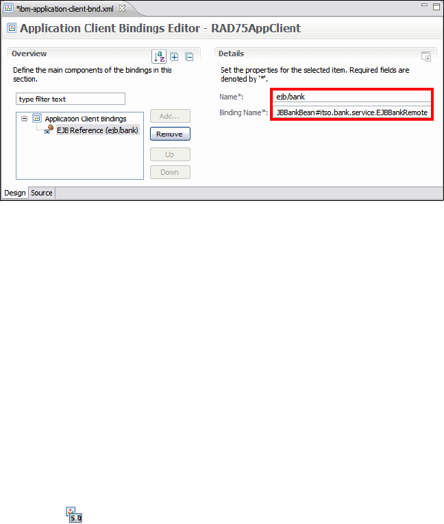
Chapter 17. Develop Java EE application clients 557
Draft Document for Review December 9, 2008 2:44 pm 7672-dev-5-appclient.fm
Figure 17-10 Create an EJB binding
The Source tab shows the XML source of the EJB binding:
<ejb-ref name="ejb/bank" binding-name="ejb/RAD75EJBEAR/RAD75EJB.jar
/EJBBankBean#itso.bank.service.EJBBankRemote" />
Save and close the ibm-application-client-bnd.xml file.
The code and configuration for the ITSO Bank Java EE application client is now
complete. Now we just need to register the BankDesktopController class as the
main class for the application client.
Registering the BankDesktopController class as the main class
The BankDesktopController class contains the logic for the Java EE application
client. We have to register that this is the main class for the application client,
such that Java EE application client containers know how to launch the
application:
Right-click RAD75AppClient and select Open With → JAR Dependency
Editor.
In the JAR Dependency editor, click Browse next to the Main-Class entry field
(at the bottom).
In the Type Selection dialog, start typing BankDesk... for the Select a class
using field, then select the BankDesktopController in the Matching types
list, and click OK.
Save and close the JAR Dependency editor.
7672-dev-5-appclient.fm Draft Document for Review December 9, 2008 2:44 pm
558 Rational Application Developer V7.5 Programming Guide
Testing the Java EE application client
Now that the code has been updated, we can test the Java EE application client
as follows:
Make sure that the WebSphere Application Server v7.0 is started.
Ensure that the RAD75EJBEAR enterprise application is deployed on the server:
– In the Servers view, right-click WebSphere Application Server v7.0 and
select Add and Remove Projects. Add the RAD75EJBEAR project if it is
not deployed to the server already.
– Do not add the RAD75AppClientEAR to the server. We run the application
client outside of the server.
In the Enterprise Explorer, right-click RAD75AppClient and select Run As →
Run Configurations.
In the Run Configurations dialog, double-click WebSphere v7.0 Application
Client in the left pane. A New_configuration is added and displayed in the
right pane (Figure 17-11):
–Type RAD75AppClient in the Name field.
–Select RAD75AppClientEAR as Enterprise application and
RAD75AppClient as Application Client module.
–Select Enable application client to connect to a server and accept
WebSphere Application Server v7.0 as the specific server.

Chapter 17. Develop Java EE application clients 559
Draft Document for Review December 9, 2008 2:44 pm 7672-dev-5-appclient.fm
Figure 17-11 Create a new run configuration for the application client
Click Apply, and then click Run.
If prompted with SSL Signer Exchange Prompt, click Yes.
If security is enabled in the Application Server, the Login at the Target Server
po-up appears. Enter admin/admin (the user ID configured for the server) and
click OK (Figure 17-12).
Figure 17-12 Login to the secure server
A number of messages are displayed in the Console:
IBM WebSphere Application Server, Release 7.0
Java EE Application Client Tool
Copyright IBM Corp., 1997-2008
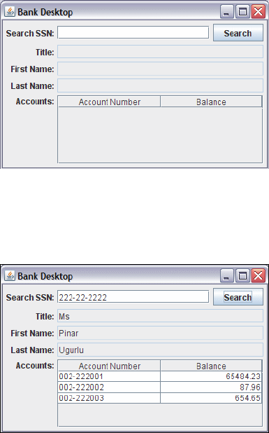
7672-dev-5-appclient.fm Draft Document for Review December 9, 2008 2:44 pm
560 Rational Application Developer V7.5 Programming Guide
WSCL0012I: Processing command line arguments.
......
WSCL0013I: Initializing the Java EE Application Client Environment.
......
WSCL0035I: Initialization of the Java EE Application Client Environment
has completed.
WSCL0014I: Invoking the Application Client class
itso.rad75.client.control.BankDesktopController
The Bank Desktop window opens (Figure 17-13).
Figure 17-13 Bank Desktop opens
Type a customer SSN and click Search. The customer and the accounts are
displayed (Figure 17-14).
Figure 17-14 Bank Desktop results
Type an invalid customer SSN and the name is displayed as (not found).
Close the client window.

Chapter 17. Develop Java EE application clients 561
Draft Document for Review December 9, 2008 2:44 pm 7672-dev-5-appclient.fm
Packaging the Java EE application client
To run the application client outside Application Developer, we have to package
the application.
To package the application client for deployment, do these steps:
In the Enterprise Explorer, right-click RAD75AppClientEAR and select
Export → EAR file.
In the EAR Export dialog, click Browse to select a destination (Figure 17-15),
for example, c:\7672code\deployment\RAD75AppClientEAR.ear. Click Finish
to generate the EAR.
Note: In the main method of the BankDesktopController we added the line:
bank.getAccounts("xxx");
Without this initial communication with the server to run the getAccounts
query, the application client fails when run inside Application Developer.
Exception in thread "AWT-EventQueue-0" java.rmi.MarshalException: CORBA
MARSHAL 0x4942f896 No; nested exception is:
org.omg.CORBA.MARSHAL: Unable to read value from underlying bridge :
null vmcid: IBM minor code: 896 completed: No
at com.ibm.CORBA.iiop.UtilDelegateImpl.mapSystemException
(UtilDelegateImpl.java:271)
at javax.rmi.CORBA.Util.mapSystemException(Util.java:84)
at itso.bank.service._EJBBankRemote_Stub.getAccounts
(_EJBBankRemote_Stub.java)
at itso.rad75.client.control.BankDesktopController.actionPerformed
(BankDesktopController.java:40)
Note: Although the Java EE specification names the JAR format as the
principle means for distributing Java EE application clients, the WebSphere
Application Server application client container expects an Enterprise
Application Archive (EAR) file.

7672-dev-5-appclient.fm Draft Document for Review December 9, 2008 2:44 pm
562 Rational Application Developer V7.5 Programming Guide
Figure 17-15 Application client export
The exported EAR file can now be deployed to a client node and executed using
the Application Client for WebSphere Application Server.
Running the deployed application client
You can use the launchClient command to run the application client outside of
Application Developer. You can find information on the command at:
http://publib.boulder.ibm.com/infocenter/wasinfo/v7r0/index.jsp?topi
c=/com.ibm.websphere.base.doc/info/aes/ae/rcli_javacmd.html
To execute the application client follow these steps:
Open a command window at <RAD_HOME>\runtimes\base_v7\bin.
Execute the launchclient command:
launchclient c:\7672code\deployment\RAD75AppClientEAR.ear
-CCBootstrapHost=localhost -CCBootstrapPort=28xx
The Bank Desktop window opens and you can run the application client (refer
to Figure 17-13 and Figure 17-14 on page 560).
Note: The -CCBootstrapHost parameter specifies the host machine where
the WebSphere Application Server v7.0 is running (default is localhost),
and the -CCBootstrapPort parameter specifies the RMI port (default 2809).
You can find the RMI port by opening the server configuration (double-click
the server in the Servers view) and look at server connection types.

© Copyright IBM Corp. 2007. All rights reserved. 563
Draft Document for Review December 9, 2008 2:44 pm 7672-dev-6-webservice.fm
Chapter 18. Develop Web services
applications
This chapter introduces the concepts of a service-oriented architecture (SOA)
and explains how such an architecture can be realized using the Java Enterprise
Edition (Java EE) Web services implementation.
We explore the features provided by Application Developer for Web services
development and look at two Web services development approaches: top-down
and bottom-up. We also demonstrate how Application Developer can help with
testing Web services and developing Web services client applications.
The chapter is organized into the following sections:
Introduction to Web services
JAX-WS programming model
Creating bottom-up Web services from a JavaBean
Creating a synchronous Web service JSP client
Creating a Web service JSF client
Creating a Web service thin client
Creating asynchronous Web service clients
Creating Web services from an EJB
Creating a top-down Web service from a WSDL and using an Ant task
Web services security
WS-Policy and WS-MetadataExchange (WS-MEX)
18
7672-dev-6-webservice.fm Draft Document for Review December 9, 2008 2:44 pm
564 Rational Application Developer V7 Programming Guide
Introduction to Web services
This section introduces architecture and concepts of the service-oriented
architecture (SOA) and Web services.
Service-oriented architecture (SOA)
In a service-oriented architecture, applications are made up from loosely coupled
software services, which interact to provide all the functionality needed by the
application. Each service is generally designed to be very self-contained and
stateless to simplify the communication that takes place between them.
There are three main roles involved in a service-oriented architecture:
Service provider
Service broker
Service requester
The interactions between these roles are shown in Figure 18-1.
Figure 18-1 Service-oriented architecture
Service provider
The service provider creates a service and can publish its interface and access
information to a service broker.
A service provider must decide which services to expose and how to expose
them. There is often a trade-off between security and interoperability; the service
provider must make technology decisions based on this trade-off. If the service
Service
Requester
Service
Broker
Service
Provider
look up
bind
register
Chapter 18. Develop Web services applications 565
Draft Document for Review December 9, 2008 2:44 pm 7672-dev-6-webservice.fm
provider is using a service broker, decisions must be made on how to categorize
the service, and the service must be registered with the service broker using
agreed-upon protocols.
Service broker
The service broker, also known as the service registry, is responsible for making
the service interface and implementation access information available to any
potential service requester.
The service broker will provide mechanisms for registering and finding services.
A particular broker might be public (for example, available on the Internet) or
private—only available to a limited audience (for example, on an intranet). The
type and format of the information stored by a broker and the access
mechanisms used will be implementation-dependent.
Service requester
The service requester, also know as a service client, discovers services and then
uses them as part of its operation.
A service requester uses services provided by service providers. Using an
agreed-upon protocol, the requester can find the required information about
services using a broker (or this information can be obtained in some other way).
Once the service requester has the necessary details of the service, it can bind
or connect to the service and invoke operations on it. The binding is usually
static, but the possibility of dynamically discovering the service details from a
service broker and configuring the client accordingly makes dynamic binding
possible.
Web services as an SOA implementation
Web services provides a technology foundation for implementing a
service-oriented architecture. A major focus during the development of this
technology is to make the functional building blocks accessible over standard
Internet protocols which are independent of platforms and programming
languages to ensure that very high levels of interoperability are possible.
Web services are self-contained software services that can be accessed using
simple protocols over a network. They can also be described using standard
mechanisms, and these descriptions can be published and located using
standard registries. Web services can perform a wide variety of tasks, ranging
from simple request-reply to full business process interactions.
Using tools like Application Developer, existing resources can be exposed as
Web services very easily.
7672-dev-6-webservice.fm Draft Document for Review December 9, 2008 2:44 pm
566 Rational Application Developer V7 Programming Guide
The following core technologies are used for Web services:
XML
SOAP
WSDL
XML
Extensible Markup Language (XML) is the markup language that underlies Web
services. XML is a generic language that can be used to describe any kind of
content in a structured way, separated from its presentation to a specific device.
All elements of Web services use XML extensively, including XML namespaces
and XML schemas.
The specification for XML is available at:
http://www.w3.org/XML/
SOAP
Simple Object Access Protocol (SOAP) is a network, transport, and
programming language neutral protocol that allows a client to call a remote
service. The message format is XML. SOAP is used for all communication
between the service requester and the service provider. The format of the
individual SOAP messages depends on the specific details of the service being
used.
The specification for SOAP is available at:
http://www.w3.org/TR/soap/
WSDL
Web Services Description Language (WSDL) is an XML-based interface and
implementation description language. The service provider uses a WSDL
document in order to specify:
The operations a Web service provides
The parameters and data types of these operations
The service access information
WSDL is one way to make service interface and implementation information
available in a service registry. A server can use a WSDL document to deploy a
Web Service. A service requester can use a WSDL document to work out how to
access a Web Service (or a tool can be used for this purpose).
The specification for WSDL is available at:
http://www.w3.org/TR/wsdl/
Chapter 18. Develop Web services applications 567
Draft Document for Review December 9, 2008 2:44 pm 7672-dev-6-webservice.fm
Related Web services standards
The basic technologies of XML, SOAP, and WSDL are fundamental to Web
services, but many other standards have been developed to help with developing
and using them.
An excellent resource for information on standards related to Web services can
be found at:
http://www.ibm.com/developerworks/views/webservices/standards.jsp
Web services in Java EE 5
Java EE 5 includes several API specifications. The main technologies in Java EE
5 that provide Web services support are as follows:
JAX-WS – JSR 224
Java API for XML Web Services (JAX-WS) is a new programming model that
simplifies application development through support of a standard,
annotation-based model to develop Web services applications and clients. The
JAX-WS 2.1 programming standard aligns itself with the document-centric
messaging model and replaces the remote procedure call programming model
defined by the Java API for XML-based RPC (JAX-RPC) specification.
JAXB – JSR-222
Java Architecture for XML Binding (JAXB), which is also known as JSR-222, is a
Java technology that provides an easy and convenient way to map Java classes
and XML schema for simplified development of Web services. JAXB leverages
the flexibility of platform-neutral XML data in Java applications to bind XML
schema to Java applications without requiring extensive knowledge of XML
programming.
JAXB is the default data binding technology that the Java API for XML Web
Services (JAX-WS) tooling uses and is the default implementation within this
product. You can develop JAXB objects for use within JAX-WS applications.
Implementing Enterprise Web services – JSR 109
Implementing Enterprise Web Services (JSR 109) defines the programming
model and run-time architecture to deploy and look up Web services in the Java
EE environment; more specifically, in the Web, EJB, and Client Application
containers. One of its main goals is to ensure vendors' implementations
interoperate.
7672-dev-6-webservice.fm Draft Document for Review December 9, 2008 2:44 pm
568 Rational Application Developer V7 Programming Guide
SAAJ – JSR 67
The SOAP with Attachments API for Java (SAAJ) interface is used for SOAP
messaging that provides a standard way to send XML documents over the
Internet from a Java programming model. SAAJ is used to manipulate the SOAP
message to the appropriate context as it traverses through the runtime
environment.
StAX – JSR 173
Streaming API for XML (StAX) is streaming Java-based, event-driven,
pull-parsing API for reading and writing XML documents. StAX enables you to
create bidirectional XML parsers that are fast, relatively easy to program, and
have a light memory footprint.
Web Services Metadata for the Java Platform – JSR 181
Web Services Metadata for the Java Platform defines an annotated Java format
that uses Java Language Metadata (JSR 175) to enable easy definition of Java
web services in a J2EE container.
The specifications for Web services support in Java EE 5 are available at:
http://java.sun.com/javaee/technologies/webservices/
Web services interoperability
In an effort to improve the interoperability of Web services, the Web Services
Interoperability Organization (known as WS-I) was formed. WS-I produces a
specification known as the WS-I Basic Profile, which describes the technology
choices that maximize interoperability between Web services and clients running
on different platforms, using different runtime systems, and written in different
languages.
The WS-I Basic Profile is available at:
http://ws-i.org/deliverables/workinggroup.aspx?wg=basicprofile
Web services security
The WS-Security specification describes extensions to SOAP that allow for
quality of protection of SOAP messages. This includes, but is not limited to,
message authentication, message integrity, and message confidentiality. The
specified mechanisms can be used to accommodate a wide variety of security
models and encryption technologies. It also provides a general-purpose
mechanism for associating security tokens with message content. For additional
information, refer to:
http://www.oasis-open.org/committees/tc_home.php?wg_abbrev=wss
Chapter 18. Develop Web services applications 569
Draft Document for Review December 9, 2008 2:44 pm 7672-dev-6-webservice.fm
JAX-WS programming model
Java API for XML-Based Web Services (JAX-WS), which is also known as
JSR-224, is the next generation Web services programming model that extends
the foundation provided by the Java API for XML-based RPC (JAX-RPC)
programming model. Using JAX-WS, developing Web services and clients is
simplified with greater platform independence for Java applications by the use of
dynamic proxies and Java annotations. The Web services tools included in
Application Developer support JAX-WS 2.0 and 2.1.
JAX-WS is a new programming model that simplifies application development
through support of a standard, annotation-based model to develop Web Service
applications and clients. The JAX-WS programming standard strategically aligns
itself with the current industry trend toward a more document-centric messaging
model and replaces the remote procedure call programming model as defined by
JAX-RPC. Although Application Developer still supports the JAX-RPC
programming model and applications, JAX-RPC has limitations and does not
support many current document-centric services. JAX-WS is the strategic
programming model for developing Web services and is a required part of the
Java EE 5 platform.
Implementing the JAX-WS programming standard provides the following
enhancements for developing Web services and clients:
Better platform independence for Java applications
Using JAX-WS APIs, developing Web services and clients is simplified with
better platform independence for Java applications. JAX-WS takes advantage of
dynamic proxies whereas JAX-RPC uses generated stubs. The dynamic proxy
client invokes a Web service based on a service endpoint interface (SEI) which is
generated or provided. The dynamic proxy client is similar to the stub client in the
JAX-RPC programming model. Although the JAX-WS dynamic proxy client and
the JAX-RPC stub client are both based on the SEI that is generated from a
WSDL file, there is a major difference. The dynamic proxy client is dynamically
generated at run time using the Java 5 dynamic proxy functionality, while the
JAX-RPC-based stub client is a non-portable Java file that is generated by
tooling. Unlike the JAX-RPC stub clients, the dynamic proxy client does not
require you to regenerate a stub prior to running the client on an application
server for a different vendor because the generated interface does not require
the specific vendor information.

7672-dev-6-webservice.fm Draft Document for Review December 9, 2008 2:44 pm
570 Rational Application Developer V7 Programming Guide
Annotations
JAX-WS introduces support for annotating Java classes with metadata to
indicate that the Java class is a Web service. JAX-WS supports the use of
annotations based on the Metadata Facility for the Java Programming Language
(JSR 175) specification, the Web Services Metadata for the Java Platform (JSR
181) specification and annotations that are defined by the JAX-WS 2.0/2.1
specification. Using annotations in the Java source and in the Java class
simplifies development of Web services by defining some of the additional
information that is typically obtained from deployment descriptor files, WSDL
files, or mapping metadata from XML and WSDL files into the source artifacts.
For example, you can embed a simple @WebService tag in the Java source to
expose the bean as a Web service (Example 18-1).
Example 18-1 JAX-WS annotation
@WebService
public class BankBean {
public String getCustomerFullName(String ssn) { ... }
}
The @WebService annotation tells the server runtime environment to expose all
public methods on that bean as a Web service. Additional levels of granularity
can be controlled by adding additional annotations on individual methods or
parameters. Using annotations makes it much easier to expose Java artifacts as
Web services. In addition, as artifacts are created from using some of the
top-down mapping tools starting from a WSDL file, annotations are included
within the source and Java classes as a way of capturing the metadata along
with the source files.
Invoking Web services asynchronously
With JAX-WS, Web services can be called both synchronously and
asynchronously. JAX-WS adds support for both a polling mechanism and
callback mechanism when calling Web services asynchronously. Using a polling
model, a client can issue a request, get a response object back, which is polled
to determine whether the server has responded. When the server responds, the
actual response is retrieved. Using the polling model, the client can continue to
process other work without waiting for a response to return. Using the callback
model, the client provides a callback handler to accept and process the inbound
response object. Both the polling and callback models enable the client to focus
on continuing to process work while providing for a more dynamic and efficient
model to invoke Web services.

Chapter 18. Develop Web services applications 571
Draft Document for Review December 9, 2008 2:44 pm 7672-dev-6-webservice.fm
For example, a Web service interface has methods for both synchronous and
asynchronous requests (Example 18-2). Asynchronous requests are identified in
bold.
Example 18-2 Asynchronous Methods in the Web service interface
@WebService
public interface CreditRatingService {
// sync operation
Score getCreditScore(Customer customer);
// async operation with polling
Response<Score> getCreditScoreAsync(Customer customer);
// async operation with callback
Future<?> getCreditScoreAsync(Customer customer,
AsyncHandler<Score> handler);
}
The asynchronous invocation that uses the callback mechanism requires an
additional input by the client programmer. The callback handler is an object that
contains the application code that is executed when an asynchronous response
is received. Example 18-3 shows an asynchronous callback handler.
Example 18-3 Asynchronous callback handler
CreditRatingService svc = ...;
Future<?> invocation = svc.getCreditScoreAsync(customerFred,
new AsyncHandler<Score>() {
public void handleResponse(Response<Score> response) {
Score score = response.get();
// do work here...
}
}
);
Example 18-4 shows an asynchronous polling client.
Example 18-4 Asynchronous polling
CreditRatingService svc = ...;
Response<Score> response = svc.getCreditScoreAsync(customerFred);
while (!response.isDone()) {
// do something while we wait
}
// no cast needed, thanks to generics
Score score = response.get();
7672-dev-6-webservice.fm Draft Document for Review December 9, 2008 2:44 pm
572 Rational Application Developer V7 Programming Guide
Data binding with JAXB 2.0 and 2.1
JAX-WS leverages the JAXB API and tools as the binding technology for
mappings between Java objects and XML documents. JAX-WS tooling relies on
JAXB tooling for default data binding for two-way mappings between Java objects
and XML documents. JAXB data binding replaces the data binding described by
the JAX-RPC specification.
WebSphere Application Server Version v7.0 supports the JAXB 2.1 specification.
JAX-WS 2.1 requires JAXB 2.1 for data binding. JAXB 2.1 provides
enhancements such as improved compilation support and support for the @XML
annotation, and full schema 1.0 support.
Dynamic and static clients
The dynamic client programming API for JAX-WS is called the dispatch client
(javax.xml.ws.Dispatch). The dispatch client is an XML messaging oriented
client. The data is sent in either PAYLOAD or MESSAGE mode:
PAYLOAD: When using the PAYLOAD mode, the dispatch client is only
responsible for providing the contents of the <soap:Body> element and
JAX-WS adds the <soap:Envelope> and <soap:Header> elements.
MESSAGE: When using the MESSAGE mode, the dispatch client is responsible for
providing the entire SOAP envelope including the <soap:Envelope>,
<soap:Header>, and <soap:Body> elements and JAX-WS does not add
anything additional to the message. The dispatch client supports
asynchronous invocations using a callback or polling mechanism.
The static client programming model for JAX-WS is the called the proxy client.
The proxy client invokes a Web service based on a service endpoint interface
(SEI) which is generated or provided.
MTOM support
Using JAX-WS, you can send binary attachments such as images or files along
with Web services requests. JAX-WS adds support for optimized transmission of
binary data as specified by Message Transmission Optimization Mechanism
(MTOM).
Chapter 18. Develop Web services applications 573
Draft Document for Review December 9, 2008 2:44 pm 7672-dev-6-webservice.fm
Multiple payload structures
JAX-WS exposes the following binding technologies to the user: XML Source,
SOAP Attachments API for Java (SAAJ) 1.3, and Java Architecture for XML
Binding (JAXB) 2.0.
XML Source enables a user to pass a javax.xml.transform.Source into the
runtime which represents the data in a source object to be passed to the runtime.
SAAJ 1.3 now has the ability to pass an entire SOAP document across the
interface, rather than just the payload itself. This is done by the client passing the
SAAJ SOAPMessage object across the interface. JAX-WS leverages the JAXB 2.0
support as the data binding technology of choice between Java and XML.
SOAP 1.2 support
Support for SOAP 1.2 was added to JAX-WS 2.0. JAX-WS supports both SOAP
1.1 and SOAP 1.2. SOAP 1.2 provides a more specific definition of the SOAP
processing model, which removes many of the ambiguities that sometimes led to
interoperability problems in the absence of the Web Services-Interoperability
(WS-I) profiles. SOAP 1.2 should reduce the chances of interoperability issues
with SOAP 1.2 implementations between different vendors. It is not interoperable
with earlier versions.
Web services development approaches
There are two general approaches to Web service development: top-down and
bottom-up:
In the top-down approach, a Web service is based on the Web service
interface and XML types, defined in Web Services Description Language
(WSDL) and XML Schema Definition (XSD) files. The developer first designs
the implementation of the Web service by creating a WSDL file using the
WSDL editor. The developer can then use the Web Service wizard to create
the Web service and skeleton Java classes to which the developer can add
the required code.The developer then modifies the skeleton implementation
to interface with the business logic.
The top-down approach allows for more control over the Web service
interface and the XML types used, and is the recommended approach for
developing new Web services.
In the bottom-up approach, a Web service is created based on the existing
business logic in Java beans or EJBs. A WSDL file is generated to describe
the resulting Web service interface.
7672-dev-6-webservice.fm Draft Document for Review December 9, 2008 2:44 pm
574 Rational Application Developer V7 Programming Guide
The bottom-up pattern is often used for exposing existing function as a Web
service. It might be faster, and no XSD or WSDL design skills are needed.
However, if complex objects (for example, Java collection types) are used,
then the resulting WSDL might be hard to understand and less interoperable.
Web services tools in Application Developer
Application Developer provides tools to create Web services from existing Java
and other resources or from WSDL files, as well as tools for Web services client
development and for testing Web services.
Creating a Web service from existing resources
Application Developer provides wizards for exposing a variety of resources as
Web services. The following resources can be used to build a Web Service:
JavaBean: The Web Service wizard assists you in creating a new Web
service from a simple Java class, configures it for deployment, and deploys
the Web service to a server. The server can be the WebSphere Application
Server v6.1 or v7.0 test environment included with Rational Application
Developer or another application server.
EJB: The Web Service wizard assists you in creating a new Web service from
a stateless session EJB, configures it for deployment, and deploys the Web
service to a server.
Creating a skeleton Web service
Application Developer provides the functionality to create Web services from a
description in a WSDL (or WSIL) file:
JavaBean from WSDL: The Web services tools assist you in creating a
skeleton JavaBean from an existing WSDL document. The skeleton bean
contains a set of methods that correspond to the operations described in the
WSDL document. When the bean is created, each method has a trivial
implementation that you replace by editing the bean.
Enterprise JavaBean from WSDL: The Web services tools support the
generation of a skeleton EJB from an existing WSDL file. Apart from the type
of component produced, the process is similar to that for Java beans.
Chapter 18. Develop Web services applications 575
Draft Document for Review December 9, 2008 2:44 pm 7672-dev-6-webservice.fm
Client development
To assist in development of Web service clients, Application Developer provides
these features:
Java client proxy from WSDL: The Web Service client wizard assists you in
generating a proxy JavaBean. This proxy can be used within a client
application to greatly simplify the client programming required to access a
Web service.
Sample Web application from WSDL: Rational Application Developer can
generate a sample Web application, which includes the proxy classes
described above, and sample JSPs that use the proxy classes.
Web Service Discovery Dialog: This dialog allows you to discover a Web
service that exists online or in your workspace, create a proxy for the Web
service, and then place the methods of the proxy into a Faces JSP file.
Testing tools for Web services
To allow developers to test Web services, Application Developer provides a
range of features:
WebSphere Application Server v7.0 and V6.x test environment. These
servers are included with Rational Application Developer as a test server and
can be used to host Web services. It provides a range of Web services
runtimes, including an implementation of the J2EE specification standards.
Sample JSP application: The Web application mentioned above can be
used to test Web services and the generated proxy it uses.
Web Services Explorer: This is a simple test environment that can be used
to test any Web Service, based only on the WSDL file for the service. The
service can be running on a local test server or anywhere else on the
network.
Universal Test Client: The Universal Test Client (UTC) is a very powerful and
flexible test application that is normally used for testing EJBs. Its flexibility
makes it possible to test ordinary Java classes, so it can be used to test the
generated proxy classes created to simplify client development.
TCP/IP Monitor: The TCP/IP Monitor works like a proxy server, passing
TCP/IP requests on to another server and directing the returned responses
back to the originating client. The TCP/IP messages that are exchanged are
displayed in a special view within Rational Application Developer.
7672-dev-6-webservice.fm Draft Document for Review December 9, 2008 2:44 pm
576 Rational Application Developer V7 Programming Guide
Preparing for the samples
To prepare for this sample, we import some sample code. This is a simple Web
application that includes Java classes and an Enterprise JavaBean.
Import the sample
This section describes the steps required for preparing the environment for the
Web services application samples:
In the Java EE perspective, select File → Import → Other → Project
Interchange.
In the Import Projects dialog, click Browse to navigate to and select the
RAD7WebServicesStart.zip in the c:\7672code\webservice folder, and click
Open.
Click Select All and click Finish.
After the build, there should be no warning or error messages in the workspace.
Sample projects
The sample application that we use for creating Web service consists of the
following projects:
RAD75WebServiceUtility project: Simple banking model with BankMemory,
Customer, and Account beans. This is a simplified version of the RAD75Java
project used in Chapter 8, “Develop Java applications” on page 69.
RAD75WebServiceWeb project: Contains the SimpleBankBean, a JavaBean
with a few methods that retrieve data from the MemoryBank, a search HTML
page, and a result JSP. We will use annotations to generate Web services for
this project.
RAD75WebServiceWeb2 project: Contains the same code as the
RAD75WebServiceWeb project. We will use the Web Service wizard to
generate Web services for this project.
RAD75WebServiceEJB project: Contains the SimpleBankFacade session
EJB with a few methods that retrieve data from the MemoryBank.
RAD75WebServiceEAR project: Enterprise application that contains the
other four projects.

Chapter 18. Develop Web services applications 577
Draft Document for Review December 9, 2008 2:44 pm 7672-dev-6-webservice.fm
Test the application
To start and test the basic application, do these steps:
In the Servers view, start the WebSphere Application Server v7.0.
Right-click the server and select Add and remove projects.
In the Add and Remove Projects dialog, select RAD75WebServiceEAR
under, click Add, then click Finish.
Expand RAD7WebServiceWeb → WebContent, right-click search.html,
and select Run As → Run on Server.
Select Choose an existing server and the V7.0 server to run the application
and then click Finish.
The search page opens in a Web browser. Enter an appropriate value in the
Social Security Number field, for example, 111-11-1111, and click Search. If
everything is working correctly, you can see the customer’s full name and first
account with the balance, which have been read from the memory data.
The stateless session EJB, SimpleBankFacade, can be tested using the
Universal Test Client (UTC). Refer to “Testing with the Universal Test Client”
on page 426 for more information on using the UTC. The methods are:
–getCustomerFullName(ssn)—Retrieves the full name (use 111-11-1111).
–getNumAccounts(ssn)—Retrieves the number of accounts.
–getAccountId(ssn, int)—Retrieves the account ID by index (0,1,2,...).
–getAccountBalance(accountId)—Retrieves the balance.
Stop the WebSphere Application Server v7.0.
We now have some resources in preparation for the Web services sample,
including a JavaBean in the RAD75WebServiceWeb project and a session EJB in
the RAD75WebServiceEJB project. We use these as a base for developing and
testing the Web services examples.
Creating bottom-up Web services from a JavaBean
In this section, we create a Web service from an existing Java class using the
bottom-up approach. The imported application contains a Java class called
SimpleBankBean, which has various methods to get customer and account
information from the bank. We can either use the Web Service wizard to
generate the Web service, or use the annotations directly. The Web Service
wizard will inject annotation to the delegate class derived from the JavaBean. So
these two approaches are essentially the same.
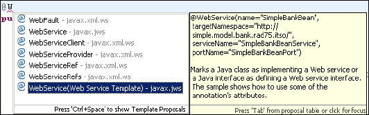
7672-dev-6-webservice.fm Draft Document for Review December 9, 2008 2:44 pm
578 Rational Application Developer V7 Programming Guide
Creating a Web service using annotations
The Java API for XML-Based Web Services (JAX-WS) programming standard
relies on the use of annotations to specify metadata that is associated with Web
service implementations. The standard also relies on annotations to simplify the
development of Web services. The JAX-WS standard supports the use of
annotations that are based on several Java Specification Requests (JSRs):
A Metadata Facility for the Java Programming Language (JSR 175)
Web Services Metadata for the Java Platform (JSR 181)
Java API for XML-Based Web Services (JAX-WS) 2.1 (JSR 224)
Common Annotations for the Java Platform (JSR 250)
Using annotations from the JSR 181 standard, we can annotate a service
implementation class or a service interface. Then we can generate a Web
service with a wizard or by publishing the application to a server. Using
annotations within both Java source code and Java classes simplifies Web
service development. Using annotations in this way defines additional
information that is typically obtained from deployment descriptor files, Web
Services Description Language (WSDL) files, or mapping metadata from XML
and WSDL into source artifacts.
In this section, we create a bottom-up Web service from a JavaBean using
annotations. The Web services are generated by publishing the application to a
server. No wizard is required in this example.
Annotate a JavaBean
We can annotate types, methods, fields, and parameters in the JavaBean to
specify a Web service. To annotate the JavaBean:
In the RAD75WebServiceWeb project, open the SimpleBankBean (in
itso.rad75.bank.model.simple).
Before the class declaration, type @W and press content assist (Ctrl+space),
scroll down to the bottom and select WebService(Web Service Template) -
javax.ws (Figure 18-2).
Figure 18-2 Content assist for Web service annotation
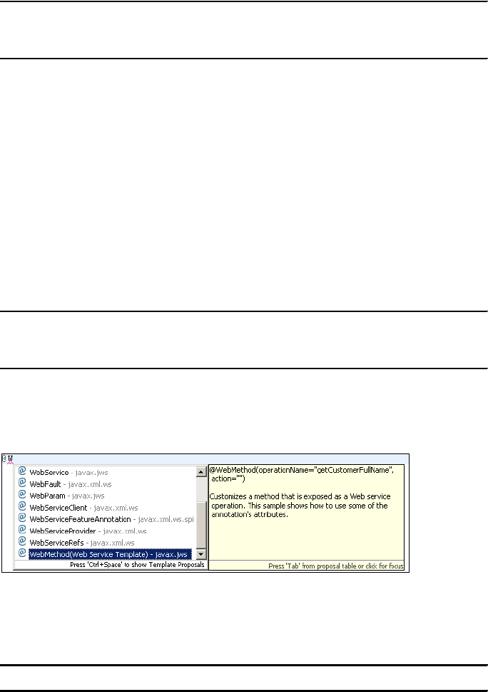
Chapter 18. Develop Web services applications 579
Draft Document for Review December 9, 2008 2:44 pm 7672-dev-6-webservice.fm
The annotation template is added to the Java class (Example 18-5).
Example 18-5 Web service annotation template
@WebService(name="SimpleBankBean",
targetNamespace="http://simple.model.bank.rad75.itso/",
serviceName="SimpleBankBeanService", portName="SimpleBankBeanPort")
The @WebService tag marks a Java class as implementing a Web service.
–The
name attribute is used as the name of the wsdl:portType when
mapped to WSDL 1.1.
–The targetNamespace attribute is the XML namespace used for the WSDL
and XML elements generated from this Web service.
–The serviceName attribute specifies the service name of the Web service:
wsdl:service.
–The portName attribute is the name of the endpoint port.
Change the Web service name, service name, and port name as listed in
Example 18-6.
Example 18-6 Annotate JavaBean Web service
@WebService(name="Bank",
targetNamespace="http://simple.model.bank.rad75.itso/",
serviceName="BankService", portName="BankPort")
Before the getCustomerFullName method, type @W and press content
assist (Ctrl+space), scroll down to the bottom and select WebMethod(Web
Service Template) - javax.ws (Figure 18-3).
Figure 18-3 Annotate method
The annotation template is added to the method (Example 18-7).
Example 18-7 WebMethod template
@WebMethod(operationName="getCustomerFullName", action="")
7672-dev-6-webservice.fm Draft Document for Review December 9, 2008 2:44 pm
580 Rational Application Developer V7 Programming Guide
The @WebMethod tag identifies the individual methods of the Java class that
are exposed externally as Web Service operations. In this example, we only
expose the getCustomerFullName method as a Web service operation.
–operationName is the name of the wsdl:operation matching this method.
–action determines the value of the soap action for this operation.
Change the operationName and action (Example 18-8).
Example 18-8 WebMethod annotation
@WebMethod(operationName="RetrieveCustomerName",
action="urn:getCustomerFullName")
Annotate the method input and output (Example 18-9).
Example 18-9 Annotate the method input and output
@WebMethod(operationName="RetrieveCustomerName",
action="urn:getCustomerFullName")
@WebResult(name="CustomerFullName")
public String getCustomerFullName(@WebParam(name="ssn")String ssn)
throws CustomerDoesNotExistException
The @WebParam and @WebResult tags customize the mapping of the
method parameters and results to message parts and XML elements.
Select Source → Organize Imports (or Ctrl+shift+O) to resolve the imports.
Validating Web services annotations
When developing Web services, you can benefit from two levels of validation.
The first level involves validating syntax and Java-based default values. This level
of validation is performed by the Eclipse Java Development Tools (JDT). The
second level of validation involves implicit default checking, as well as verification
of Web Services Description Language (WSDL) contracts. This second level is
performed by a JAX-WS annotations processor.
When you enable the annotation processor, warnings and errors for annotations
are displayed like Java errors. You can work with these warnings and errors in
various workbench locations, such as the Problems view.
Note: The annotation processing is enabled by default. If you want to disable
annotation processing, you can right-click the Web service project in the
Enterprise Explorer, select Properties → Java Compiler → Annotation
Processing, and clear Enable annotation processing.
Chapter 18. Develop Web services applications 581
Draft Document for Review December 9, 2008 2:44 pm 7672-dev-6-webservice.fm
By using the annotations processor to detect problems at build time, you can
prevent these problems from occurring at run time. For example, if you make the
changes of Example 18-10), you receive validation errors as shown in
Example 18-11.
Example 18-10 Validate Web services annotations
@WebService(name="!Bank", targetNamespace="simple.model.bank.rad75.itso/",
serviceName="BankService", portName="BankPort")
public class SimpleBankBean implements Serializable {
private static final long serialVersionUID = -637536840546155853L;
public SimpleBankBean() {
}
@WebMethod(operationName="!RetrieveCustomerName",
action="urn:getCustomerFullName")
@WebResult(name="CustomerFullName")
@Oneway
public String getCustomerFullName(@WebParam(name="ssn")String ssn)
throws CustomerDoesNotExistException {
Example 18-11 JAX-WS annotation processor validation results
JSR-181, 4.3.1: Oneway methods cannot return a value
JSR-181, 4.3.1: Oneway methods cannot throw checked exceptions
name must be a valid nmToken
operationName must be a valid nmToken
targetNamespace must be a valid URI
Creating a Web service from an annotated JavaBean by
publishing to the server
After annotating a Java bean, you can generate a Web service application by
publishing the application project of the bean directly to a server. When the Web
service is generated, no WSDL file is created in your project.
To create a Web service from an annotated JavaBean:
In the Servers view, start WebSphere Application Server v7.0 (if not
running).
Publish the Web service project on the server. Depending on the server
configuration this happens automatically, or manually (right-click the server
and select Publish).
Test the JAX-WS Web service using the Web Services Explorer
To test the Web service using the Web services explorer, do these steps:
Switch to the Services view that is below the Enterprise Explorer.
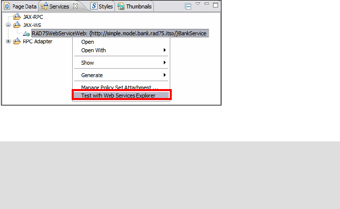
7672-dev-6-webservice.fm Draft Document for Review December 9, 2008 2:44 pm
582 Rational Application Developer V7 Programming Guide
Expand the JAX-WS folder, then right-click RAD75WebServiceWeb:
{http://simple.model.bank.rad75bank.itso/}BankService and select Test
with Web Services Explorer (Figure 18-4).
Figure 18-4 Test JAX-WS Web service using Web Services Explorer
The Web Services Explorer opens in the internal or external browser,
depending on the Window → Web Browser setting.
Select the RetrieveCustomerName operation.
Click Add and type 111-11-1111 in the ssn field.
Click Go and the result (Mr. Henry Cui) is displayed in the status pane
(Figure 18-5).
Behind the scenes: The Web Services Explorer is a JSP Web application
hosted on the Apache Tomcat servlet engine contained within Eclipse. The
Web Services Explorer uses the WSDL to render a SOAP request. It does
not involve data marshalling and unmarshalling. The return parameter is
stripped out and the values are displayed in a pre-defined format.

Chapter 18. Develop Web services applications 583
Draft Document for Review December 9, 2008 2:44 pm 7672-dev-6-webservice.fm
Figure 18-5 JAX-WS Web service test result with Web Services Explorer\
Double-click the Status pane bar to maximize it. Then click Source to view
the SOAP messages as raw XML:
– SOAP Request Envelope:
- <soapenv:Envelope
xmlns:soapenv="http://schemas.xmlsoap.org/soap/envelope/"
xmlns:q0="http://simple.model.bank.rad75.itso/"
xmlns:xsd="http://www.w3.org/2001/XMLSchema"
xmlns:xsi="http://www.w3.org/2001/XMLSchema-instance">
- <soapenv:Body>
- <q0:RetrieveCustomerName>
<ssn>111-11-1111</ssn>
</q0:RetrieveCustomerName>
</soapenv:Body>
</soapenv:Envelope>

7672-dev-6-webservice.fm Draft Document for Review December 9, 2008 2:44 pm
584 Rational Application Developer V7 Programming Guide
– SOAP Response Envelope:
- <soapenv:Envelope
xmlns:soapenv="http://schemas.xmlsoap.org/soap/envelope/">
- <soapenv:Body>
- <RetrieveCustomerNameResponse
xmlns:ns2="http://simple.model.bank.rad75.itso/">
<CustomerFullName>Mr. Henry Cui</CustomerFullName>
</RetrieveCustomerNameResponse>
</soapenv:Body>
</soapenv:Envelope>
View the dynamically generated WSDL
In JAX-WS Web services, the deployment descriptors are optional because it
uses annotations. The WSDL file can also be dynamically generated by the
runtime based on information it gathers from the annotations added to the Java
classes.
The URL for the dynamically generated WSDL is in this format:
http://<hostname>:<port>/<Web project context root>/<service name>?wsdl
To view the dynamically generated WSDL:
Enter the following URL in the browser (908x is the port number, most
probably 9080 or 9081):
http://localhost:908x/RAD75WebServiceWeb/BankService?wsdl
The dynamically generated WSDL file is displayed. We also notice that the
URL for the WSDL is changed to:
http://localhost:908x/RAD75WebServiceWeb/BankService/BankService.wsdl
Examine the generated WSDL. We can see that the generated WSDL
matches the Web services annotations that we added. An extract of the
generated WSDL snippet is listed in Example 18-12.
Example 18-12 Dynamically generated WSDL snippet
<?xml version="1.0" encoding="UTF-8" ?>
<definitions name="BankService"
targetNamespace="http://simple.model.bank.rad75.itso/"
xmlns="http://schemas.xmlsoap.org/wsdl/"
xmlns:xsd="http://www.w3.org/2001/XMLSchema"xmlns:tns=
"http://simple.model.bank.rad75.itso/"
xmlns:soap="http://schemas.xmlsoap.org/wsdl/soap/">
Note: You can find the URL using the Web Services Explorer. The URL is
shown in the navigator view.

Chapter 18. Develop Web services applications 585
Draft Document for Review December 9, 2008 2:44 pm 7672-dev-6-webservice.fm
<types> ......
<message> ......
......
<portType name="Bank">
<operation name="RetrieveCustomerName">
<input message="tns:RetrieveCustomerName" />
<output message="tns:RetrieveCustomerNameResponse" />
<fault name="CustomerDoesNotExistException"
message="tns:CustomerDoesNotExistException" />
</operation>
</portType>
<binding name="BankPortBinding" type="tns:bank">
<soap:binding style="document"
transport="http://schemas.xmlsoap.org/soap/http" />
<operation name="RetrieveCustomerName">
<soap:operation soapAction="urn:getCustomerFullName" />
<input>
<soap:body use="literal" />
</input>
<output>
<soap:body use="literal" />
</output>
<fault name="CustomerDoesNotExistException">
<soap:fault name="CustomerDoesNotExistException" use="literal"/>
</fault>
</operation>
</binding>
<service name="BankService">
<port name="BankPort" binding="tns:BankPortBinding">
<soap:address
location="http://localhost:9080/RAD75WebServiceWeb/BankService" />
</port>
</service>
</definitions>
To see the dynamically generated XML schema, use this URL:
http://localhost:908x/RAD75WebServiceWeb/BankService/BankService_schema1
.xsd
A simple test to verify that the Web service is running in the server can be
performed using this URL:
http://localhost:908x/RAD75WebServiceWeb/BankService
The result displayed in the browser is:
{http://simple.model.bank.rad75.itso/}BankService
Hello! This is an Axis2 Web Service!
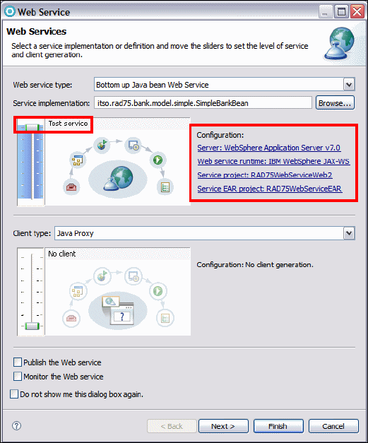
7672-dev-6-webservice.fm Draft Document for Review December 9, 2008 2:44 pm
586 Rational Application Developer V7 Programming Guide
Creating Web services using the Web Service wizard
The Web Service wizard assists you in creating a new Web service, configuring it
for deployment, and deploying the Web service to a server. To create a Web
service from a JavaBean, do these steps:
In the Java EE perspective, expand RAD75WebServiceWeb2 → Java
Resources: src → itso.rad75.bank.model.simple.
Right-click SimpleBankBean.java and select Web Services → Create Web
service. The Web Service wizard starts (Figure 18-6).
Figure 18-6 Web Service wizard: Web Services page

Chapter 18. Develop Web services applications 587
Draft Document for Review December 9, 2008 2:44 pm 7672-dev-6-webservice.fm
Select the Web Services options in the Web Services page:
–Select
Bottom up Java bean Web Service as your Web service type.
This should be selected by default.
– Move the slider for the service to the Test position (top). This provides
options for testing the service in subsequent pages of the wizard.
– Ensure that the following server-side configurations are selected:
• Server: WebSphere Application Server v7.0
• Web service runtime: IBM WebSphere JAX-WS
• Service project: RAD75WebServiceWeb2
• Service EAR project: RAD75WebServiceEAR
– If you click the hyperlink Server: WebSphere Application Server v7.0,
the Service Deployment Configuration dialog is displayed (Figure 18-7).
Behind the scenes:
The slider allows you to select the stages of Web services
development. It allows more granular division of Web services
development:
Develop: Develops the WSDL definition and implementation of the
Web service. This includes such tasks as creating the modules
which will contain the generated code, WSDL files, deployment
descriptors, and Java files when appropriate.
Assemble: Ensures that the project which will host the Web service
or client will get associated to an EAR when required by the target
application server.
Deploy: Creates the deployment code for the service.
Install: Installs and configures the Web module and EARs on the
target server. If any changes to the endpoints of the WSDL file are
required, they are made in this stage.
Start: Starts the Web service once the service has been installed on
the server.
Test: Provides various options for testing the service, such as using
the Web Service Explorer or sample JSPs.
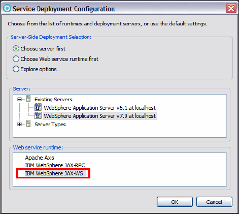
7672-dev-6-webservice.fm Draft Document for Review December 9, 2008 2:44 pm
588 Rational Application Developer V7 Programming Guide
Figure 18-7 Web Service wizard: Service Deployment Configuration
– This page allows you to select the server and runtime. We will leave this
page as default and click Cancel to exit this page.
–Clear
Publish the Web service (we do not publish to a UDDI registry) and
clear Monitor the Web service (we will do that later).
– Click Next in the Web Services page.
In the WebSphere JAX-WS Bottom Up Web Service Configuration dialog
(Figure 18-8):
– Leave the Delegate class name as default (SimpleBankBeanDelegate).
The delegate class is a wrapper that contains all the methods from the
Java bean as well as the JAX-WS annotation the runtime recognizes as a
Web service.
– Leave the Java to WSDL mapping style as default.
The style defines encoding style for messages sent to and from the Web
service. The recommended WSDL style is Document Wrapped.
–Select
Generate WSDL file into the project.
Because the annotations in the delegate class are used to tell the runtime
that the bean is a Web service, a static WSDL file is no longer generated
into your project automatically. The runtime can dynamically generate a
WSDL file from the information in the bean. Select this to generate a static
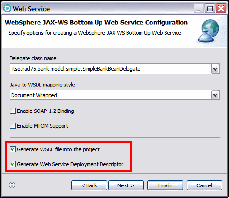
Chapter 18. Develop Web services applications 589
Draft Document for Review December 9, 2008 2:44 pm 7672-dev-6-webservice.fm
WSDL file for the Web service. This is a convenient option if you plan to
create the client at a later time or publish the WSDL for other users.
–Select
Generate Web service deployment descriptor.
For JAX-WS Web services deployment information is generated
dynamically by the runtime; static deployment descriptors are optional.
Selecting this check box will generate the deployment descriptors.
– Click Next.
Figure 18-8 Web Service wizard: Service Endpoint Interface Selection
In the WebSphere JAX-WS WSDL Configuration page (Figure 18-9):
–Select
WSDL Target Namespace, and enter http://bank.rad75.itso/ as
the WSDL Target Namespace.
–Select
Configure service name, and enter BankService as the WSDL
Service Name.
–Select
Configure WSDL Port Name, and enter BankPort as the WSDL
Port Name.
– Click Next.

7672-dev-6-webservice.fm Draft Document for Review December 9, 2008 2:44 pm
590 Rational Application Developer V7 Programming Guide
Figure 18-9 WebSphere JAX-WS WSDL Configuration page
The Web service is generated and deployed to the server.
The Test Web Services dialog (Figure 18-10) shows because we moved the
slider for the service to the Test position. Click Launch to launch the Web
Services Explorer.
Figure 18-10 Web Service wizard: Test Web Service
The Web Services Explorer opens in an external Web browser.
The Web services are available at two endpoints: one is the HTTP endpoint
and the other is the HTTPS endpoint. If your server is secured, the endpoint
of the Web service listed in the Web service explorer should be:
https://localhost:944x/RAD75WebServiceWeb2/BeanService
To test the HTTPS protected Web service with the Web Services Explorer,
you must configure the workbench JRE to work with a secured server. The
signer certificate from the WebSphere Application Server must be imported
Chapter 18. Develop Web services applications 591
Draft Document for Review December 9, 2008 2:44 pm 7672-dev-6-webservice.fm
into the Eclipse trust store. This involves complicated SSL configuration. To
make things easier, you can just send the SOAP request to the HTTP
endpoint.
– In the endpoints section, click Add and then enter the following endpoint:
http://localhost:908x/RAD75WebServiceWeb2/BankService
– Click Go.
– Select the getNumAccounts operation, then click Add.
– Enter a value for the customer ID, such as 111-11-1111, and click Go.
–The result 2 is displayed in the status pane.
– Optionally try other operations.
Close the Web Services Explorer.
Click Finish to exit the Web Service wizard.
You have successfully created Web services from a Java bean.
Resources generated by the Web Service wizard
After code generation, examine the generated code. You can see that the wizard
generates the following artifacts:
A delegate class named SimpleBankBeanDelegate. The delegate class is a
wrapper that contains all the methods from the Java bean as well as the
JAX-WS annotation the runtime recognizes as a Web service. The annotation
@javax.jws.WebService in the delegate class tells the server runtime
environment to expose all public methods on that bean as a Web service. The
targetNamespace, the serviceName, and the portName are what we specified in
the Web Service wizard.
@javax.jws.WebService (targetNamespace="http://bank.rad75.itso/",
serviceName="BankService", portName="BankPort",
wsdlLocation="WEB-INF/wsdl/BankService.wsdl")
A webservices.xml file in the WebContent/WEB-INF folder. This is the optional
Web services deployment descriptor. A deployment descriptor can be used to
override or enhance the information provided in the Service. For example, if
the <wsdl-service> element is provided in the deployment descriptor, then
the namespace used in this element overrides the targetNamespace member
attribute in the annotation.
A WSDL file (BankService.wsdl) and an XSD file (BankService_schema1.xsd)
in the WEB-INF/wsdl folder. If you plan to create the client at a later time or
publish the WSDL for other users, you can use this WSDL file.

7672-dev-6-webservice.fm Draft Document for Review December 9, 2008 2:44 pm
592 Rational Application Developer V7 Programming Guide
Creating a synchronous Web service JSP client
The Web Service Client wizard assists you in generating a Java bean proxy and
a sample application. The sample Web application demonstrates how to invoke
the Web services proxy. You can invoke the Web services using the JAX-WS
synchronous model, or the asynchronous model. In the section, we generate a
synchronous Web service client.
To generate a client and test the client proxy, do these steps:
Switch to the Services view, right-click the RAD75WebServiceWeb and
select Generate → Client (Figure 18-11).
Figure 18-11 Generate Web service client
In the Web Services Client dialog (Figure 18-12):
– Move the slider up to the Test position. This provides options for testing
the service using a JSP-based sample application.
–Select
Monitor the Web service.
We recommend that the Web service and Web service client are in separate
Web and EAR projects:
– Click Client project.... The Specify Client Project Settings dialog opens.
– Change the client project name to RAD75WebServiceClient.
–Accept
Dynamic Web project as the project type.
– Accept the client EAR project name as RAD75WebServiceClientEAR.
– Click OK. The wizard creates the Web and EAR projects.
– Click Next.

Chapter 18. Develop Web services applications 593
Draft Document for Review December 9, 2008 2:44 pm 7672-dev-6-webservice.fm
Figure 18-12 Generate Web service client
In the WebSphere JAX-WS Web Service Client Configuration dialog, select
Generate Web Service Deployment Descriptor (Figure 18-13). This will
generate the JSR 109 1.2 deployment descriptor. Click Next.
Figure 18-13 JAX-WS Web Service Client Configuration
The client code is generated into the new client project.
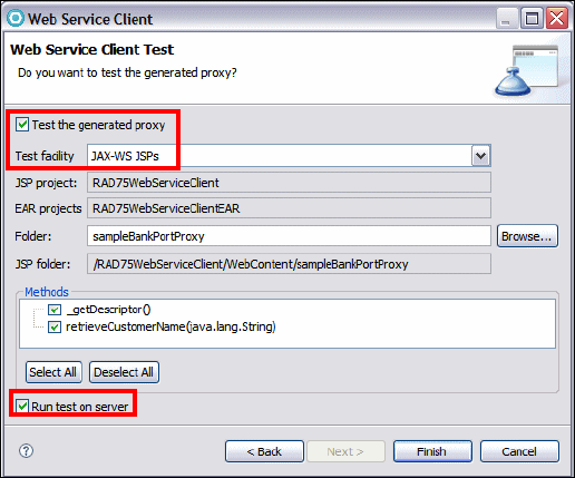
7672-dev-6-webservice.fm Draft Document for Review December 9, 2008 2:44 pm
594 Rational Application Developer V7 Programming Guide
In the Web Service Client Test dialog (Figure 18-14), use these settings:
–Select
Test the generated proxy.
– Test facility: Select JAX-WS JSPs (default).
– Folder: sampleSimpleBankBeanProxy (default). You can specify a
different folder for the generated application if you want.
– Methods: Leave all methods selected.
–Select
Run test on server.
Click Finish.
Figure 18-14 Web Service Client Test
The sample application is published to the server and the sample JSP is
displayed in a Web browser.
Select the retrieveCustomerName method, enter a valid value in the
customer ID field (such as 111-11-1111), and then click Invoke.
The results are displayed in the result pane (Figure 18-15).
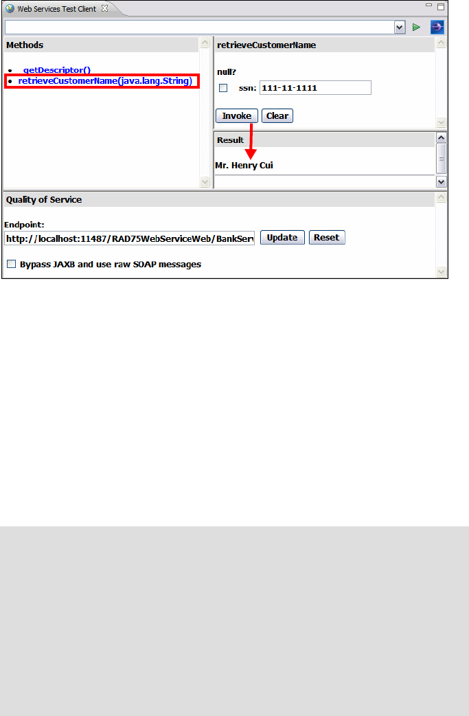
Chapter 18. Develop Web services applications 595
Draft Document for Review December 9, 2008 2:44 pm 7672-dev-6-webservice.fm
Figure 18-15 Sample JSP results
Notice the Endpoint in the Quality of Service pane:
http://localhost:11487/RAD75WebServiceWeb/BankService
You might see a port number other than above. It depends on what port
number the wizard generated for the TCP/IP Monitor.
The TCP/IP Monitor is also started. The TCP/IP Monitor lets you intercept and
examine the SOAP traffic coming in and out of a Web service.
If you select Window → Preferences → Run/Debug → TCP/IP Monitor, you
can see a new Monitor is there to listen to the same port number (11487). The
TCP/IP Monitor is started and ready to listen to the SOAP request and direct it
to the Web service provider (at port 908x).
Behind the scenes:
When you select Monitor the Web service in the Web Service wizard
page, the Web Service Client wizard dynamically creates the TCP/IP
Monitor for you. It uses certain algorithm to find an available listening
port for the Monitor, and the sample JSP client page uses the URL to
dynamically set the Web service endpoint to match the Monitor port.
Using the wizard to create the TCP/IP Monitor is very handy as the user
does not have to spend time to figure out how to redirect the SOAP
request to the TCP/IP Monitor, especially in the case of monitoring
remote Web services.
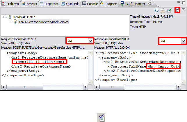
7672-dev-6-webservice.fm Draft Document for Review December 9, 2008 2:44 pm
596 Rational Application Developer V7 Programming Guide
All requests and responses are routed through the TCP/IP Monitor and
appear in the TCP/IP Monitor view.
The TCP/IP Monitor view probably appears in the top right pane. Move it to
the same pane as the Servers view.
The TCP/IP Monitor view shows all the intercepted requests in the top pane,
and when a request is selected, the messages passed in each direction are
shown in the bottom panes (request in the left pane, response in the right).
This can be a very useful tool in debugging Web services and clients.
Select the XML view to display the SOAP request and response in XML
format (Figure 18-16).
Figure 18-16 TCP/IP Monitor
To ensure that the Web service SOAP traffic is WS-I compliant, you can
generate a log file by clicking the icon at the top right corner. In the dialog
box that opens, select a name for the log file and specify where you want it to
be stored (for example in the client project).
The log file is validated for WS-I compliance. You will see a confirmation
dialog stating The WS-I Message Log file is valid. You can open the log file in
an XML editor to examine its contents.
Stop the TCP/IP Monitor by selecting Window → Preferences →
Run/Debug → TCP/IP Monitor and stop the TCP/IP Monitor from the list.
Resources generated by the Web Service client wizard
Figure 18-17 on page 597 shows the generated Web services client artifacts.
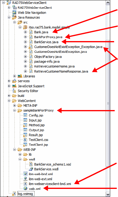
Chapter 18. Develop Web services applications 597
Draft Document for Review December 9, 2008 2:44 pm 7672-dev-6-webservice.fm
Figure 18-17 Web service client artifacts
Bank.java is the annotated service interface based on the WSDL to Java
mapping.
BankService.java is generated from the WSDL service. It is a factory class
that returns an instance that implements the service’s interface. In JAX-RPC,
this implementation class is called a stub. In JAX-WS, no stub class exists;
the stub is a class dynamically generated from WSDL.
BankPortProxy.java is an IBM-proprietary proxy class. JAX-WS does not
define this class. It is a convenience class which implements the Web
service’s interface and hides programming details such as the service factory
and binding provider calls.
The rest Java classes are the JAXB artifacts based on the schema types used
by the WSDL.
JAXB generated classes
Web service client DD
IBM proprietary Web service
binding file
Sample JSP files
IBM proprietary Web service
proxy
Factory class
Annotated interface
7672-dev-6-webservice.fm Draft Document for Review December 9, 2008 2:44 pm
598 Rational Application Developer V7 Programming Guide
The sampleBankPortProxy folder contains the generated sample JSPs,
which demonstrates how to invoke Web services proxy.
web.xml is the standard Web deployment descriptor, and it contains the JSR
109 1.2 Web service deployment information (<service-ref> tag).
Creating a Web service JSF client
The Web Service Discovery Dialog allows you to discover a Web service that
exists online or in the workspace, create a proxy to the Web service, and then
place the methods of the proxy on a Faces JSP file:
Remove the RAD75WebServiceClientEAR from the server using Add and
Remove Projects (we will add a project to the EAR and automatic publishing
gets into the way), or expand the server, right-click the project, and select
Remove.
Create a dynamic Web project In the Web perspective select File → New →
Dynamic Web Project.
– Enter RAD75WebServiceJSFClient as the project name.
– In the Configurations section, select JavaServer Faces v1.2 Project to
add the required JSF facets to the project facets list.
–Select
RAD75WebServiceClientEAR as the EAR project name.
– Click Finish (Figure 18-18). If you are prompted to open the Web
perspective, click Yes.
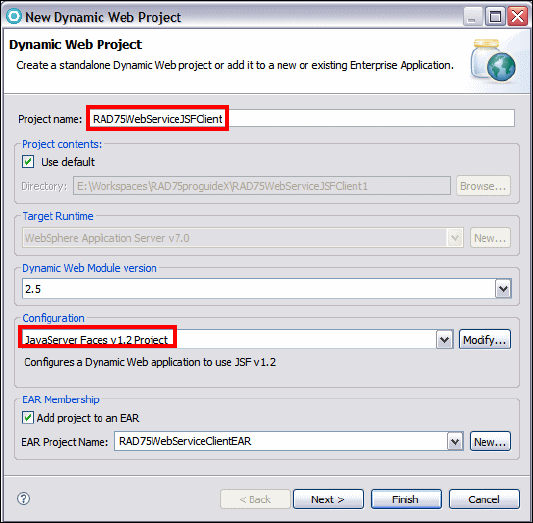
Chapter 18. Develop Web services applications 599
Draft Document for Review December 9, 2008 2:44 pm 7672-dev-6-webservice.fm
Figure 18-18 New Faces Project
In the RAD75WebServiceJSFClient project, right-click the WebContent and
select New → Web Page.
Enter WSJSFClient as the file name. Select JSP as the basic template and
click Finish.
The WSJSFClient.jsp opens in an editor. Select the Design or Split tab.
In the Palette, select the Data and Services category. Select Web Service
and click into the JSF page (Figure 18-19).

7672-dev-6-webservice.fm Draft Document for Review December 9, 2008 2:44 pm
600 Rational Application Developer V7 Programming Guide
Figure 18-19 Drag and drop Web Service to JSF design view
The Add Web Service dialog (Figure 18-20) comes up. Click Add. The Web
Services Discovery Dialog opens. Select Web services from your
workspace.
Figure 18-20 Add Web service
In the Web Services from your workspace page (Figure 18-21), click
BankService with the URL of the RAD75WebServiceWeb project (not the
RAD75WebServiceWeb2 project).
Drag and drop
to the JSF page

Chapter 18. Develop Web services applications 601
Draft Document for Review December 9, 2008 2:44 pm 7672-dev-6-webservice.fm
Figure 18-21 Web Services Discovery Dialog: Web Services from your workspace
The service is listed with its port. Select Port: BankPort and click Add to
Project (Figure 18-22).
Figure 18-22 Web Services Discovery Dialog: Add to Project
The Web service you selected is now listed in the list of Web services. Select
Bank as the service, retrieveCustomerName(String) as method, Create
input form and results display, and click Next (Figure 18-23).
Details launches the
Web Services Explorer

7672-dev-6-webservice.fm Draft Document for Review December 9, 2008 2:44 pm
602 Rational Application Developer V7 Programming Guide
Figure 18-23 Select Web service method
In the Input form page (Figure 18-24):
– Change the label to Enter Social Security Number:.
– Click Options and change the label from Submit to Get Full Name. Click
OK.
– Click Next.
Figure 18-24 Web service input form
In the Results form page, change the Label to Customer's full name is:.
Click Finish to generate the input and output parts into the JSF page
(Figure 18-25). Save the file.
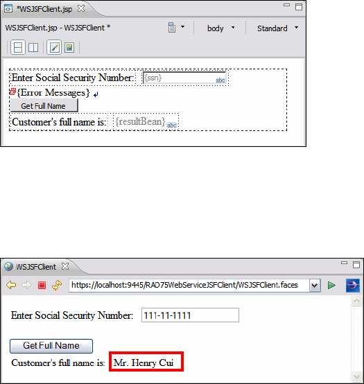
Chapter 18. Develop Web services applications 603
Draft Document for Review December 9, 2008 2:44 pm 7672-dev-6-webservice.fm
Figure 18-25 JSF page with Web service invocation
Right-click WSJSFClient.jsp and select Run As → Run on Server. The
client application is deployed to the server for testing. Type 111-11-1111, click
Get Full Name, and the result is displayed (Figure 18-26).
Figure 18-26 JSF client run
Creating a Web service thin client
WebSphere Application Server provides an unmanaged client implementation
that is based on the Java API for XML-based Web Services (JAX-WS) 2.1
specification. The thin client for JAX-WS with WebSphere Application Server is
an unmanaged and stand-alone Java client environment that enables running
JAX-WS Web services client applications to invoke Web services that are hosted
by WebSphere Application Server. A Web service thin client relies only on a JDK
that is compatible with IBM WebSphere Application Server v7 and a thin client jar
file that is available at:
<RAD_HOME>\runtimes\base_v7\runtimes\com.ibm.jaxws.thinclient_7.0.0.jar
Create the thin client project and generate the client code
To create the Web service thin client, do the following:
Create a Java project by selecting File → New → Project → Java Project.
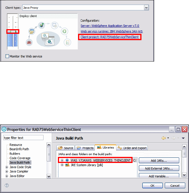
7672-dev-6-webservice.fm Draft Document for Review December 9, 2008 2:44 pm
604 Rational Application Developer V7 Programming Guide
Enter RAD75WebServiceThinClient as the project name and click Finish.
In the Java EE perspective, Services view, expand JAX-WS, then right-click
RAD75WebServiceWeb: {http://.../}BankService and select Generate →
Client.
Keep the slider at Deploy client level. Click the hyperlink Client project:...
In the Specify Client Project Settings dialog, select
RAD75WebServiceThinClient as the client project, and click OK
(Figure 18-27).
Figure 18-27 Generating a thin client
Click Finish to generate the helper classes and WSDL file into the client
project.
After the code generation, switch to the Enterprise Explorer view. Right-click
RAD75WebServiceThinClient and select Properties. Select Java Build
Path → Libraries (Figure 18-28).
Figure 18-28 Web service thin client build path
Notice that the thin client only requires the JRE and a thin client jar file. The
wizard adds a class path variable WAS_V7JAXWS_WEBSERVICES_THINCLIENT,
which points to the com.ibm.jaxws.thinclient_7.0.0.jar.

Chapter 18. Develop Web services applications 605
Draft Document for Review December 9, 2008 2:44 pm 7672-dev-6-webservice.fm
Create the client class to invoke the Web service
To invoke the Web service we create a simple Java class.
Right-click RAD75WebServiceThinClient and select New → Class.
Typ e itso.rad75.bank.test as the package name and WSThinClientTest as
the class name. Select public static void main(String[] args) and click
Finish.
Copy/paste the code from C:\7672code\webservice\thinclient
(Example 18-13).
Example 18-13 WSThinClientTest
package itso.rad75.bank.test;
import itso.rad75.bank.model.simple.BankPortProxy;
import itso.rad75.bank.model.simple
.CustomerDoesNotExistException_Exception;
import java.util.Scanner;
public class WSThinClientTest {
public static void main(String[] args) {
try {
Scanner scanner = new Scanner(System.in);
BankPortProxy proxy = new BankPortProxy();
System.out.println
("Please enter customer's social security number: ");
String ssn = scanner.next();
System.out.println("Customer's name is " +
proxy.retrieveCustomerName(ssn));
} catch (CustomerDoesNotExistException_Exception e) {
System.out.println("The customer does not exist!");
}
}
}
Notice how easy it is to invoke the Web service: Instantiate the proxy class
(BankPortProxy) and call the method (retrieveCustomerName) in the proxy.
Right-click WSThinClientTest.java and select Run As → Java Application.
When prompted in the Console, type 000-00-0000 as the customer's social
security number, and the customer’s names is displayed:
Retrieving document at '.../RAD75WebServiceThinClient/bin/META-INF/wsdl/'.
Retrieving schema at 'BankService_schema1.xsd', relative to ....
Please enter customer's social security number:
000-00-0000
Customer's name is Mr. Ueli Wahli
7672-dev-6-webservice.fm Draft Document for Review December 9, 2008 2:44 pm
606 Rational Application Developer V7 Programming Guide
Creating asynchronous Web service clients
An asynchronous invocation of a Web service sends a request to the service
endpoint and then immediately returns control to the client program without
waiting for the response to return from the service. JAX-WS asynchronous Web
service clients consume Web services using either the polling approach or the
callback approach:
Using a polling model, a client can issue a request and receive a response
object that is polled to determine if the server has responded. When the
server responds, the actual response is retrieved.
Using the callback model, the client provides a callback handler to accept
and process the inbound response object. The handleResponse method of the
handler is called when the result is available.
Both the polling and callback models enable the client to focus on continuing to
process work without waiting for a response to return, while providing for a more
dynamic and efficient model to invoke Web services.
Polling client
Using the polling model, a client can issue a request and receive a response
object that can subsequently be polled to determine if the server has responded.
When the server responds, the actual response can then be retrieved. The
response object returns the response content when the get method is called.
The client receives an object of type javax.xml.ws.Response from the
invokeAsync method. That Response object is used to monitor the status of the
request to the server, determine when the operation has completed, and to
retrieve the response results.
To create an asynchronous Web service client using the polling model, do the
following:
In the Java EE perspective, Services view, expand JAX-WS, then right-click
RAD75WebServiceWeb: {http://.../}BankService and select Generate →
Client.
Keep the slider at Deploy client level. Click the hyperlink Client project:. In
the Specify Client Project Settings dialog, select
RAD75WebServiceThinClient, and click OK. Click Next.
Select Enable asynchronous invocation for generated client
(Figure 18-29) and click Finish.
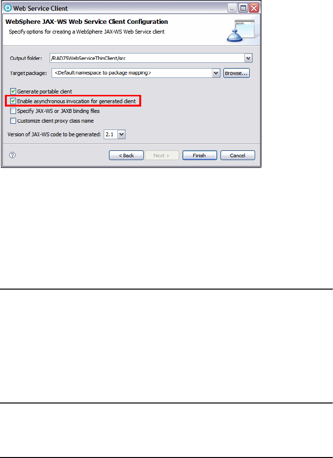
Chapter 18. Develop Web services applications 607
Draft Document for Review December 9, 2008 2:44 pm 7672-dev-6-webservice.fm
Figure 18-29 Enable asynchronous invocation for generated client
After the code generation, open BankPortProxy.java (Example 18-14). For
each method in the Web service, two additional methods are created. These
are polling and callback methods which allow the client to function
asynchronously. The retrieveCustomerNameAsync method that returns a
Response is used for polling, while the method that returns a Future is used for
callback.
Example 18-14 BankPortProxy asynchronous methods
public Response<RetrieveCustomerNameResponse>
retrieveCustomerNameAsync(String ssn) {
return _getDescriptor().getProxy().retrieveCustomerNameAsync(ssn);
}
public Future<?> retrieveCustomerNameAsync(String ssn,
AsyncHandler<RetrieveCustomerNameResponse> asyncHandler) {
return _getDescriptor().getProxy().retrieveCustomerNameAsync
(ssn,asyncHandler);
}
Create a new class called BankPollingClient in the itso.rad75.bank.test
package and copy/paste the code (Example 18-15).
Example 18-15 BankPollingClient
package itso.rad75.bank.test;
import itso.rad75.bank.model.simple.BankPortProxy;
import itso.rad75.bank.model.simple.RetrieveCustomerNameResponse;
import java.util.concurrent.ExecutionException;

7672-dev-6-webservice.fm Draft Document for Review December 9, 2008 2:44 pm
608 Rational Application Developer V7 Programming Guide
import javax.xml.ws.Response;
public class BankPollingClient {
public static void main(String[] args) {
try {
BankPortProxy proxy = new BankPortProxy();
Response<RetrieveCustomerNameResponse> resp =
proxy.retrieveCustomerNameAsync("111-11-1111");
// Poll for the response.
while (!resp.isDone()) {
// You can do some work that does not depend on the customer
name being available
// For this example, we just check if the result is available
every 0.2 seconds.
System.out.println
("retrieveCustomerName async still not complete.");
Thread.sleep(200);
}
RetrieveCustomerNameResponse rcnr = resp.get();
System.out.println
("retrieveCustomerName async invocation complete.");
System.out.println("Customer's name is " +
rcnr.getCustomerFullName());
} catch (InterruptedException e) {
System.out.println(e.getCause());
} catch (ExecutionException e) {
System.out.println(e.getCause());
}
}
}
Right-click BankPollingClient.java and select Run As → Java Application.
The output is written to the console:
retrieveCustomerName async still not complete.
retrieveCustomerName async still not complete.
retrieveCustomerName async invocation complete.
Customer's name is Mr. Henry Cui
Callback client
To implement an asynchronous invocation that uses the callback model, the
client provides an AsynchHandler callback handler to accept and process the
inbound response object. The client callback handler implements the
javax.xml.ws.AsynchHandler interface, which contains the application code that
is run when an asynchronous response is received from the server.

Chapter 18. Develop Web services applications 609
Draft Document for Review December 9, 2008 2:44 pm 7672-dev-6-webservice.fm
The AsynchHandler interface contains the handleResponse(Response) method
that is called after the run time has received and processed the asynchronous
response from the server. The response is delivered to the callback handler in
the form of a javax.xml.ws.Response object. The response object returns the
response content when the get method is called.
Additionally, if an error was received, then an exception is returned to the client
during that call. The response method is then invoked according to the threading
model used by the executor method, java.util.concurrent.Executor on the
client's java.xml.ws.Service instance that was used to create the dynamic proxy
or dispatch client instance. The executor is used to invoke any asynchronous
callbacks registered by the application. Use the setExecutor and getExecutor
methods to modify and retrieve the executor configured for the service.
To create an asynchronous Web service client using the callback model, do the
following:
Create the call back handler class RetrieveCustomerCallbackHandler in
the itso.rad75.bank.test package and copy/paste the code
(Example 18-16).
Example 18-16 RetrieveCustomerCallbackHandler
package itso.rad75.bank.test;
import itso.rad75.bank.model.simple.RetrieveCustomerNameResponse;
import java.util.concurrent.ExecutionException;
import javax.xml.ws.AsyncHandler;
import javax.xml.ws.Response;
public class RetrieveCustomerCallbackHandler implements
AsyncHandler<RetrieveCustomerNameResponse> {
private String customerFullName;
public void handleResponse(Response<RetrieveCustomerNameResponse> resp){
try {
RetrieveCustomerNameResponse rcnr = resp.get();
customerFullName = rcnr.getCustomerFullName();
} catch (ExecutionException e) {
System.out.println(e.getCause());
} catch (InterruptedException e) {
System.out.println(e.getCause());
}
}
public String getResponse() {
return customerFullName;
}
}

7672-dev-6-webservice.fm Draft Document for Review December 9, 2008 2:44 pm
610 Rational Application Developer V7 Programming Guide
Create the call back client class BankCallbackClient in the
itso.rad75.bank.test package and copy/paste the code (Example 18-17).
Example 18-17 BankCallbackClient
package itso.rad75.bank.test;
import itso.rad75.bank.model.simple.BankPortProxy;
import java.util.concurrent.Future;
public class BankCallbackClient {
public static void main(String[] args) throws Exception {
BankPortProxy proxy = new BankPortProxy();
// Set up the callback handler.
RetrieveCustomerCallbackHandler callbackHandler =
new RetrieveCustomerCallbackHandler();
// Make the Web service call.
Future<?> response = proxy.retrieveCustomerNameAsync
("111-11-1111", callbackHandler);
System.out.println("Wait 5 seconds.");
// Give the callback handler a chance to be called.
Thread.sleep(5000);
System.out.println("Customer's full name is "
+ callbackHandler.getResponse() + ".");
System.out.println("RetrieveCustomerName async end.");
}
}
Right-click BankCallbackClient.java and select Run As → Java
Application. The output is written to the console:
Wait 5 seconds.
Customer's full name is Mr. Henry Cui.
RetrieveCustomerName async end.
Asynchronous message exchange client
By default, asynchronous client invocations do not have asynchronous behavior
of the message exchange pattern on the wire. The programming model is
asynchronous; however, the exchange of request or response messages with the
server is not asynchronous. IBM has provided a feature that goes beyond the
JAX-WS specification to provide the asynchronous message exchange support.
In the asynchronous message exchange case, the client listens on a separate
HTTP channel to receive the response messages from a service-initiated HTTP
channel. The client uses WS-Addressing to provide the ReplyTo endpoint
reference (EPR) value to the service. The service initiates a connection to the

Chapter 18. Develop Web services applications 611
Draft Document for Review December 9, 2008 2:44 pm 7672-dev-6-webservice.fm
ReplyTo EPR to send a response.To use an asynchronous message exchange,
the com.ibm.websphere.webservices.use.async.mep property must be set on the
client request context with a boolean value of true. When this property is
enabled, the messages exchanged between the client and server are different
from messages exchanged synchronously.
To create an asynchronous message exchange client, do the following:
Create the BankCallbackMEPClient class in the itso.rad75.bank.test
package and copy/paste the code (Example 18-18).
Example 18-18 BankCallbackMEPClient
package itso.rad75.bank.test;
import itso.rad75.bank.model.simple.BankPortProxy;
import java.util.concurrent.Future;
import javax.xml.ws.BindingProvider;
public class BankCallbackMEPClient {
public static void main(String[] args) throws Exception {
BankPortProxy proxy = new BankPortProxy();
//proxy._getDescriptor().setEndpoint
("http://localhost:11487/RAD75WebServiceWeb/BankService");
// setup the property for asynchronous message exchange
BindingProvider bp = (BindingProvider)
proxy._getDescriptor().getProxy();
bp.getRequestContext().put
("com.ibm.websphere.webservices.use.async.mep", Boolean.TRUE);
// Set up the callback handler.
RetrieveCustomerCallbackHandler callbackHandler =
new RetrieveCustomerCallbackHandler();
// Make the Web service call.
Future<?> response = proxy.retrieveCustomerNameAsync
("111-11-1111", callbackHandler);
System.out.println("Wait 5 seconds.");
// Give the callback handler a chance to be called.
Thread.sleep(5000);
System.out.println("Customer's full name is "
+ callbackHandler.getResponse() + ".");
System.out.println("RetrieveCustomerName async end.");
}
}
Right-click BankCallbackMEPClient.java and select Run As → Java
Application. The output is written to the console:
[WAShttpAsyncResponseListener] listening on port 4070
Wait 5 seconds.

7672-dev-6-webservice.fm Draft Document for Review December 9, 2008 2:44 pm
612 Rational Application Developer V7 Programming Guide
Customer's full name is Mr. Henry Cui.
RetrieveCustomerName async end.
Note the new line in the WebSphere Application Server Console:
[...] 00000090 WSChannelFram A CHFW0019I: The Transport Channel
Service has started chain HttpOutboundChain:9.48.61.46:4070.
If you are interested to see the SOAP request message, you can activate the
comment line:
proxy._getDescriptor().setEndpoint
("http://localhost:11487/RAD75WebServiceWeb/BankService");
Note that the port 11487 must match the port of the TCP/IP Monitor.
Run the application again. The SOAP request is shown in Example 18-19.
Example 18-19 SOAP request for asynchronous message exchange
<soapenv:Header xmlns:wsa="http://www.w3.org/2005/08/addressing">
<wsa:To>http://localhost:11487/RAD75WebServiceWeb/BankService</wsa:To>
<wsa:ReplyTo>
<wsa:Address>http://9.48.61.46:4597/axis2/services/BankService.BankPort
</wsa:Address>
</wsa:ReplyTo>
<wsa:MessageID>urn:uuid:57A98210F9B1DA90111228429634645</wsa:MessageID>
<wsa:Action>urn:getCustomerFullName</wsa:Action>
</soapenv:Header>
<soapenv:Body>
<ns2:RetrieveCustomerName
xmlns:ns2="http://simple.model.bank.rad75.itso/">
<ssn>111-11-1111</ssn>
</ns2:RetrieveCustomerName>
</soapenv:Body>
</soapenv:Envelope>
Because the client listens on a separate HTTP channel to receive the
response messages from a service-initiated HTTP channel, the TCP/IP
Monitor is not able to capture the SOAP response.
Creating Web services from an EJB
You can generate EJB Web services using either the Web Service wizard, or the
annotations directly. In this section, we create a JAX-WS Web service from an
EJB session bean using the annotations directly:
Expand the EJB project RAD75WebServiceEJB and open the
SimpleBankFacadeBean (in ejbModule/itso.rad75.bank.ejb.facade).
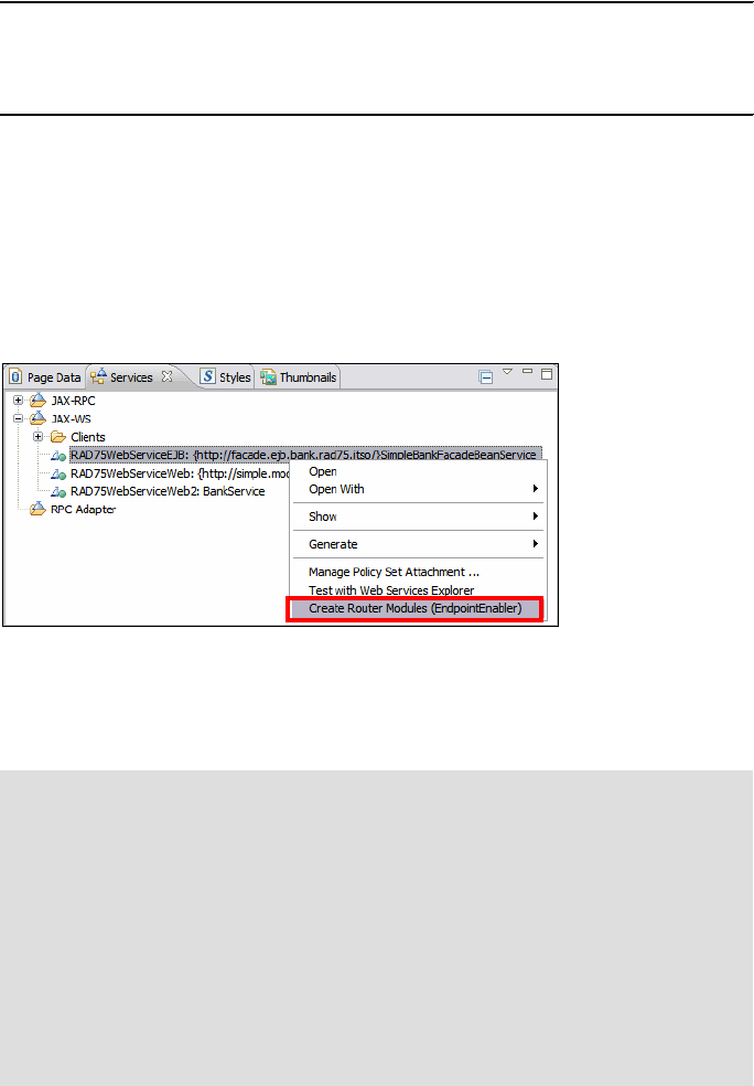
Chapter 18. Develop Web services applications 613
Draft Document for Review December 9, 2008 2:44 pm 7672-dev-6-webservice.fm
Add the @WebService annotation on the line above the @Stateless
annotation (Example 18-20). Press Ctrl+Shift+O to resolve the import.
Example 18-20 Annotate a stateless session EJB
@WebService
@Stateless
public class SimpleBankFacadeBean implements SimpleBankFacadeBeanLocal {
......
Wait for the RAD75WebServiceEAR application to publish on the server (or
force a manual publish). Notice that a new Web service named
RAD75WebServiceEJB is added in the Services views under JAX-WS.
An HTTP router module is needed to allow transport of SOAP messages over
the HTTP protocol. In the Services view, right-click the new
RAD75WebServiceEJB and select Create Router Modules
(EndpointEnabler) (Figure 18-30).
Figure 18-30 Create Router Module
In the Create Router Project dialog, two EJB bindings are listed: HTTP and
JMS. Note you can select both. This feature is called multiprotocol binding.
Behind the scenes:
The multiprotocol binding support for JAX-WS Web service is a new
feature of Application Developer v7.5. The multiprotocol support for
JAX-WS is an extension of the JAX-WS programming model, and
extends the existing JAX-WS capabilities to support binding types like
HTTP (SOAP over HTTP) and JMS (SOAP over JMS).
SOAP over HTTP is the most commonly used Web services binding
type. However, if you are looking for a more reliable, scalable, and
guaranteed messaging mechanism, consider using SOAP over JMS.
Only SOAP over HTTP is WS-I compliant.
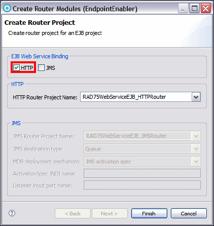
7672-dev-6-webservice.fm Draft Document for Review December 9, 2008 2:44 pm
614 Rational Application Developer V7 Programming Guide
For this example, we only use SOAP over HTTP. Accept HTTP as the default
EJB Web service binding (Figure 18-31) and click Finish.
Figure 18-31 Create Router Project
Open the deployment descriptor of the RAD75WebServiceEJB_HTTPRouter
project and you can see the generated servlet.
In the Services view, right-click RAD75WebServiceEJB and select Test with
Web Services Explorer.
Select the getAccountBalance operation, click Add and type
001-999000777 as the account number.
Click Go and you can see the result of the Web service call:
getAccountBalanceResponse
return (decimal): 12345.67
Creating a top-down Web service from a WSDL
When creating a Web service using a top-down approach, first you design the
implementation of the Web service by creating a WSDL file. You can do this
using the WSDL editor. You can then use the Web Service wizard to create the
Web service and skeleton Java classes to which you can add the required code.
The top-down approach is the recommended way of creating a Web service.

Chapter 18. Develop Web services applications 615
Draft Document for Review December 9, 2008 2:44 pm 7672-dev-6-webservice.fm
Designing the WSDL using the WSDL editor
In this section, we create a WSDL with two operations: getAccount (using an
account ID to retrieve an account) and getCustomer (using a customer ID to
retrieve a customer).
The WSDL editor allows you to easily and graphically create, modify, view, and
validate WSDL files. To create a WSDL, do these steps:
Create a Dynamic Web project to host the new Web service:
– Web project: RAD75TopDownBankWS
– EAR project: RAD75TopDownBankEAR
Create a WSDL file:
– Right-click WebContent (in RAD75TopDownBankWS) and select New →
Other → Web services → WSDL, and click Next.
– Change the File name to BankWS.wsdl and click Next.
– In the Options page, leave the default and click Finish (Figure 18-32).
Figure 18-32 New WSDL File wizard
The WSDL editor opens with the new WSDL file. Select the Design tab.
– In the WSDL editor, select Advanced from the View drop-down menu at
the top right corner.
– Select the Properties view. Now you are ready to edit the WSDL file
(Figure 18-33).

7672-dev-6-webservice.fm Draft Document for Review December 9, 2008 2:44 pm
616 Rational Application Developer V7 Programming Guide
Figure 18-33 WSDL editor
Editing the WSDL file
We define the operations and parameters of the WSDL.
Change the operation name by double-clicking NewOperation and
overtyping the name with getAccount. (You can also select the operation and
change the name in the Properties view.)
Add a new operation. In the Design view, right-click the port type BankWS,
select Add Operation, and name the operation getCustomer.
To change the input type of the WSDL operation getAccount, click the right
arrow to the right of the input operation to drill down into the schema.
The Inline Schema Editor opens. Select the Design tab and switch to the
Detailed view (Figure 18-34).
Figure 18-34 Schema editor: Start
BindingService Port Operation Port Type Part View
Arrows to drill down to schema
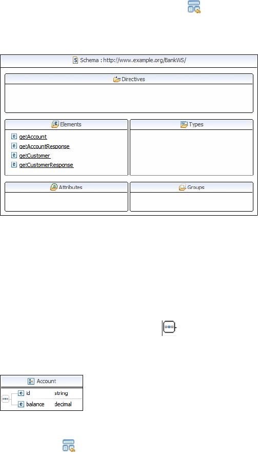
Chapter 18. Develop Web services applications 617
Draft Document for Review December 9, 2008 2:44 pm 7672-dev-6-webservice.fm
– Select the in element, and in the Properties view change the name to
accountId (leave the type as xsd:string).
– Click the Show schema index view icon at the top left to show all the
directives, elements, types, attributes, and groups in the WSDL
(Figure 18-35).
Figure 18-35 Schema editor: Index view
– In the Types category, right-click and select Add Complex Type. Change
the name to Account.
– Right-click Account and select Add Sequence.
– Right-click Account again, and select Add Element. Change the name to
id.
– Right-click the content model object and select Add Element. Change
the name to balance, and select the type as decimal using the Browse
option (Figure 18-36).
Figure 18-36 Schema editor: Account
– Click the icon at the top left corner. In the Types section, right-click and
select Add Complex Type. Change the name to Customer.
– Right-click Customer and select Add Sequence, then add four elements:
ssn, firstName, lastName, and title, all of type string (Figure 18-37).

7672-dev-6-webservice.fm Draft Document for Review December 9, 2008 2:44 pm
618 Rational Application Developer V7 Programming Guide
Figure 18-37 Schema editor: Customer
– Click the icon at the top left corner. We have to add global element for
the complex types.
• Right-click the Elements category and click Add Element. Change the
element name to Account. Right-click Account and select Set
Type → Browse → select Account.
• Add global element Customer, set type to Customer (Figure 18-38).
Figure 18-38 Schema editor: Global elements
In the WSDL editor, click the right arrow to the right of the element
getAccountResponse to drill down into the schema. Right-click element out
and select Set Type → Browse → select Account (Figure 18-39).
Figure 18-39 Schema editor: Output message
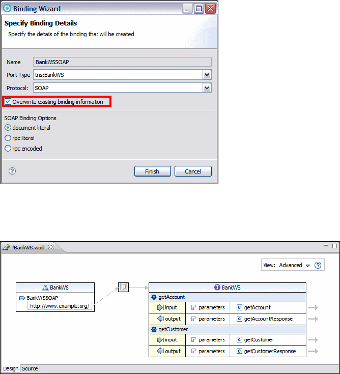
Chapter 18. Develop Web services applications 619
Draft Document for Review December 9, 2008 2:44 pm 7672-dev-6-webservice.fm
In the WSDL editor, click the right arrow to the right of the element
getCustomer to drill down into the schema. Change the element name from
in to customerId.
In the WSDL editor, click the right arrow to the right of the element
getCustomerResponse to drill down into the schema. Right-click element
out and select Set Type → Browse → select Customer.
In the WSDL editor, right-click the binding icon (as shown in Figure 18-33 on
page 616) and select Generate Binding Content.
In the Binding wizard, select Overwrite existing binding information and
click Finish (Figure 18-40).
Figure 18-40 Specify Binding Details wizard
Save the schema and WSDL file (Figure 18-41).
Figure 18-41 BankWS.wsdl

7672-dev-6-webservice.fm Draft Document for Review December 9, 2008 2:44 pm
620 Rational Application Developer V7 Programming Guide
In the Enterprise Explorer, right-click BankWS.wsdl and select Validate. A
dialog confirms that there are no errors or warnings. Click OK.
If you have a problem when creating the WSDL file, you can import the
BankWS.wsdl from C:\7672code\webservice\topdown.
Generating the skeleton JavaBean Web service
To generate a skeleton JavaBean Web service from a WSDL, do these steps:
Right-click BankWS.wsdl and select Web Services → Generate Java bean
skeleton.
Keep the slider at Start service level. Notice the code is generated into the
RAD75TopDownBankWS project.
Click Finish.
After the code generation, the skeleton class BankWSSOAPImpl.java opens
in the Java editor. Notice the annotation of the class:
@javax.jws.WebService (endpointInterface="org.example.bankws.BankWS",
targetNamespace="http://www.example.org/BankWS/", serviceName="BankWS",
portName="BankWSSOAP")
The RAD75TopDownBankEAR is deployed to the server, and the Web
service appears in the Services view.
Implement the generated JavaBean skeleton
We have to provide the business logic for the generated JavaBean skeleton. We
use the simple implementation shown in Example 18-21.
Example 18-21 Implementation of the Generated JavaBean skeleton
package org.example.bankws;
import java.math.BigDecimal;
@javax.jws.WebService (endpointInterface="org.example.bankws.BankWS",
targetNamespace="http://www.example.org/BankWS/", serviceName="BankWS",
portName="BankWSSOAP")
public class BankWSSOAPImpl{
public Account getAccount(String accountId) {
Account account = new Account();
account.setId(accountId);
account.setBalance(new BigDecimal(1000.00));
return account;
}

Chapter 18. Develop Web services applications 621
Draft Document for Review December 9, 2008 2:44 pm 7672-dev-6-webservice.fm
public Customer getCustomer(String customerId) {
Customer customer = new Customer();
customer.setSsn(customerId);
customer.setFirstName("Henry");
customer.setLastName("Cui");
customer.setTitle("Mr.");
return customer;
}
}
Test the generated Web service
To test the Web service we use the Web Services Explorer.
To test the Web service, expand JAX-WS in the Services view, right-click
RAD75TopDownBankWS and select Test with Web Services Explorer.
Test the getCustomer and getAccount operation. You should see that the
correct result is displayed in the Web Services Explorer.
Note: You cannot use the BankWS.wsdl in the WebContent folder to test the
Web service. The Web service endpoint is set to http://www.example.org/
when we created this WSDL. The dynamic WSDL loading from the Services
view will set the endpoint correctly.
Explore!
Once you have created a Web service, you might want to make changes to it:
For example, you might want to add a new WSDL operation
getBalanceByAccountId to the WSDL. Once the WSDL is changed, you
have to regenerate the Web service code and the existing business logic
may be wiped out.
To retain your changes while updating the Web service, you can use the
skeleton merge feature. This allows you to regenerate the Web service
while keeping your changes intact. Select Window → Preferences →
Web Services → Resource Management → Merge generated skeleton
file.

7672-dev-6-webservice.fm Draft Document for Review December 9, 2008 2:44 pm
622 Rational Application Developer V7 Programming Guide
Creating Web services with Ant tasks
If you prefer not to use the Web Service wizard, you can use Ant tasks to create
Web service using the IBM WebSphere JAX-WS runtime environment. The Ant
tasks support creating Web services using both top-down and bottom-up
approaches. Once you have created a Web service, you can then deploy it to a
server, test it, and publish it as a business entity or business service.
In this section, we will use Ant tasks to automate the top-down code generation
process that we did in the last section.
Create a Dynamic Web project to host the Web service generated by Ant
tasks: RAD75WebServiceAnt in RAD75WebServiceEAR.
Copy the BankWS.wsdl from RAD75TopDownBankWS/WebContent folder to the
RAD75WebServiceAnt folder (not under WebContent).
Right-click RAD75WebServiceAnt and select New → Other → Web
Services → Ant Files and click Next.
In the Create Ant Files dialog, select IBM WebSphere JAX-WS as the Web
service runtime and Top down Java bean Web Service as the Web service
type (Figure 18-42), click Finish.
Figure 18-42 Create Ant files
–A wsgenTemplates folder is created with two files:
was_jaxws_tdjava.xml and was_jaxws_tdjava.properties.
Open was_jaxws_tdjava.properties, and change InitialSelection= to:
InitialSelection=/RAD75WebServiceAnt/BankWS.wsdl
Change the Service.ServerId line to:
Service.ServerId=com.ibm.ws.ast.st.v7.server.base
Save and close the file.
Chapter 18. Develop Web services applications 623
Draft Document for Review December 9, 2008 2:44 pm 7672-dev-6-webservice.fm
Running the Web service Ant task
To run the Ant task, right-click was_jaxws_tdjava.xml and select Run As → 2
Ant Build:
In the Edit Configuration dialog, select the JRE tab and select Run in the
same JRE as the workspace.
Click Apply and then click Run.
The Web service is generated:
The Web service artifacts are generated into Java Resources folder.
You can implement the generated skeleton (BankWSSOAPImpl) and test the
Web service, as we did in the last section.
Sending binary data using MTOM
SOAP Message Transmission Optimization Mechanism (MTOM) is a standard
that is developed by the World Wide Web Consortium (W3C). MTOM describes a
mechanism for optimizing the transmission or wire format of a SOAP message by
selectively re-encoding portions of the message while still presenting an XML
Information Set (Infoset) to the SOAP application.
MTOM uses the XML-binary Optimized Packaging (XOP) in the context of SOAP
and MIME over HTTP. XOP defines a serialization mechanism for the XML
Infoset with binary content that is not only applicable to SOAP and MIME
packaging, but to any XML Infoset and any packaging mechanism. It is an
alternate serialization of XML that just happens to look like a MIME multipart or
related package, with XML documents as the root part.
That root part is very similar to the XML serialization of the document, except that
base64-encoded data is replaced by a reference to one of the MIME parts, which
is not base64 encoded. This reference enables you to avoid the bulk and
overhead in processing that is associated with encoding. Encoding is the only
way binary data can work directly with XML.
In this section we use the top-down approach to create a JAX-WS Web service to
send binary attachments along with SOAP request, and receive binary
attachments along with SOAP response using MTOM.

7672-dev-6-webservice.fm Draft Document for Review December 9, 2008 2:44 pm
624 Rational Application Developer V7 Programming Guide
The Web service client sends three types of document: Microsoft Word, image,
and PDF file. We describe several ways to send the documents:
The client uses byte[] to send the Word document.
The client uses java.awt.Image to send the image file.
The client uses javax.activation.DataHandler to send the PDF file.
Once the Web service receives the binary data from the client, it stores the
received document on the local hard disk and then passes the same document
back to the client. In a real world scenario, the provider or the consumer can just
send an acknowledgement message, once it receives the binary data from the
other side. For our example, we want to show how to enable the MTOM on both
the client and the server side in a compact example.
Create a Web service project and import the WSDL
To create a Web service project, do these steps:
Select File → New → Dynamic Web Project.
– Project Name: RAD75WSMTOM
– EAR Project Name: RAD75WSMTOMEAR
– Click Finish.
Import the c:\7672code\webservice\mtom\ProcessDocumentService.wsdl file
into the RAD75WSMTOM/WebContent folder.
Open the ProcessDocumentService.wsdl and take a look at the source. You
will see some interesting attributes, highlighted in Example 18-22.
Example 18-22 Extract of ProcessDocument.wsdl
<xs:schema xmlns:xs="http://www.w3.org/2001/XMLSchema"
xmlns:xmime="http://www.w3.org/2005/05/xmlmime"
xmlns:tns="http://mtom.rad7.ibm.com/"
targetNamespace="http://mtom.rad7.ibm.com/" version="1.0">
<xs:complexType name="sendPDFFile">
<xs:sequence>
<xs:element minOccurs="0" name="arg0" type="xs:base64Binary"
xmime:expectedContentTypes="*/*"/>
</xs:sequence>
</xs:complexType>
<xs:complexType name="sendWordFile">
<xs:sequence>
<xs:element minOccurs="0" name="arg0" type="xs:base64Binary"/>
</xs:sequence>
</xs:complexType>
<xs:complexType name="sendImage">
<xs:sequence>

Chapter 18. Develop Web services applications 625
Draft Document for Review December 9, 2008 2:44 pm 7672-dev-6-webservice.fm
<xs:element minOccurs="0" name="arg0" type="xs:base64Binary"
xmime:expectedContentTypes="image/jpeg"/>
</xs:sequence>
</xs:complexType>
Default mapping
The default mapping for xs:base64Binary is byte[] in Java. If you want to use a
different mapping, you can add the xmime:expectedContentTypes attribute to the
element containing the binary data. This attribute is defined in the
http://www.w3.org/2005/05/xmlmime namespace and specifies the MIME types
that the element is expected to contain. The setting of this attribute changes how
the code generators create the JAXB class for the data. Depending on the
expectedContentTypes value contained in the WSDL file, the JAXB artifacts
generated are in the Java type as described in Table 18-1.
Table 18-1 Mapping between MIME type and Java type
Based on this table we can predict that:
sendWordFile will be mapped to byte[] in Java.
sendPDFFile will be mapped to javax.activation.DataHandler.
sendImage will be mapped to java.awt.Image.
Generate the Web service and client
To create the Web service and client using the Web Service wizard, do these
steps:
Right-click ProcessDocumentService.wsdl and select Web Services →
Generate Java bean skeleton. The Web Service wizard starts with the Web
Services page.
MIME type Java type
image/gif java.awt.Image
image/jpeg java.awt.Image
text/plain java.lang.String
text/xml javax.xml.transform.Source
application/xml javax.xml.transform.Source
*/* javax.activation.DataHandler
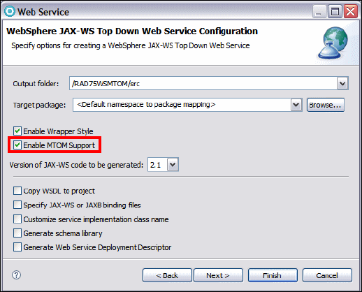
7672-dev-6-webservice.fm Draft Document for Review December 9, 2008 2:44 pm
626 Rational Application Developer V7 Programming Guide
Select the following options for the Web service:
–Server:
WebSphere Application Server v7.0
– Web service runtime: IBM WebSphere JAX-WS
– Service project: RAD75WSMTOM
– Service EAR project: RAD75WSMTOMEAR
Select the following options for the Web service client:
– Move the slider to Test client.
–Server:
WebSphere Application Server v7.0.
– Web service runtime: IBM WebSphere JAX-WS
– Client project: RAD75WSMTOMClient
– Client EAR project: RAD75WSMTOMClientEAR
Because the Web service client project is not yet in the workspace when we
run the Web Service wizard, the wizard creates the project for you.
Select Monitor the Web service and then click Next.
In the WebSphere JAX-WS Top Down Web Service Configuration page,
select Enable MTOM Support and click Next (Figure 18-43).
Figure 18-43 Enable MTOM support
A warning pops up. Click Details to view the complete message
(Figure 18-44.) Click Ignore to continue the code generation.

Chapter 18. Develop Web services applications 627
Draft Document for Review December 9, 2008 2:44 pm 7672-dev-6-webservice.fm
Figure 18-44 WS-I warning against MTOM
In the Test Web Service page click Next.
In the WebSphere JAX-WS Web Service Client Configuration page accept
the defaults, and click Next.
In the Web Service Client Test page, select JAX-WS JSPs as the Test
Facility, and click Finish. The generated JavaBean skeleton is opened, as
well as the sample JSP client.
Implement the JavaBean skeleton
Before we test the sample JSP client, we have to implement the generated Java
Bean skeleton. The Web services stores the received document on the local hard
drive and then passes the same document back to the client. Do these steps:
Examine the generated skeleton class ProcessDocumentPortBindingImpl. We
can see that sendWordFile is mapped to byte[], sendPDFFile is mapped to
javax.activation.DataHandler, and sendImage is mapped to
java.awt.Image, as we expected.
Copy/paste the code into ProcessDocumentPortImpl.java from
C:\7672code\webservice\mtom (Example 18-23).
Example 18-23 ProcessDocumentPortBindingImpl.java
package com.ibm.rad75.mtom;
import java.awt.Graphics2D;
import java.awt.Image;
import java.awt.image.BufferedImage;
import java.io.BufferedInputStream;
import java.io.File;
import java.io.FileOutputStream;
import javax.activation.DataHandler;
import javax.imageio.ImageIO;

7672-dev-6-webservice.fm Draft Document for Review December 9, 2008 2:44 pm
628 Rational Application Developer V7 Programming Guide
@javax.jws.WebService
(endpointInterface="com.ibm.rad75.mtom.ProcessDocumentDelegate",
targetNamespace="http://mtom.rad75.ibm.com/",
serviceName="ProcessDocumentService", portName="ProcessDocumentPort")
@javax.xml.ws.BindingType
(value=javax.xml.ws.soap.SOAPBinding.SOAP11HTTP_MTOM_BINDING)
public class ProcessDocumentPortBindingImpl{
public byte[] sendWordFile(byte[] arg0) {
try {
FileOutputStream fileOut = new FileOutputStream
(new File("C:/7672code/webservices/mtomresult/RAD-intro.doc"));
fileOut.write(arg0);
} catch (Exception e) {
e.printStackTrace();
}
return arg0;
}
public Image sendImage(Image arg0) {
try {
File file = new File
("C:/7672code/webservices/mntomresult/BlueHills.jpg");
BufferedImage bi = new BufferedImage(arg0.getWidth(null),
arg0.getHeight(null), BufferedImage.TYPE_INT_RGB);
Graphics2D g2d = bi.createGraphics();
g2d.drawImage(arg0, 0, 0, null);
ImageIO.write(bi, "jpeg", file);
} catch (Exception e) {
e.printStackTrace();
}
return arg0;
}
public DataHandler sendPDFFile(DataHandler arg0) {
try {
FileOutputStream fileOut = new FileOutputStream(new File(
"C:/7672code/webservices/mtoresult/JAX-WS.pdf"));
BufferedInputStream fileIn = new BufferedInputStream
(arg0.getInputStream());
while (fileIn.available() != 0) {
fileOut.write(fileIn.read());
}
} catch (Exception e) {
e.printStackTrace();
}
return arg0;
}
}
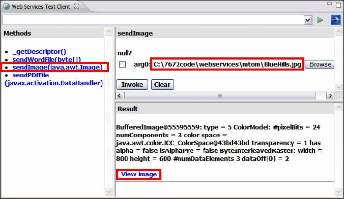
Chapter 18. Develop Web services applications 629
Draft Document for Review December 9, 2008 2:44 pm 7672-dev-6-webservice.fm
Examine the code listed in Example 18-23.
–The
sendWordFile method takes a byte[] as input and stores the binary
data as C:/7672code/webservices/mtomresult/RAD-intro.doc.
–The
sendImage method takes an image as input and stores the binary data
as C:/7672code/WebServices/mtomresult/BlueHills.jpg.
–The
sendPDFFile method takes a DataHandler as input and stores the data
in C:/7672code/WebServices/mtomresult/JAX-WS.pdf.
– All the three methods return the received data to the client after storing it
on the local drive.
Test and monitor the MTOM enabled Web service
Now it is the time to see if MTOM really optimizes the transmission of the data.
The output folder is C:\7672code\webservice\mtomresult. We use this folder
to store the document received by the Web service JavaBean.
In the sample JSP client, select the sendImage method.
Click Browse and navigate to C:\7672code\webservice\mtom. Select
BlueHills.jpg and click Open.
Click Invoke to invoke the sendImage method (Figure 18-45).
Figure 18-45 Invoking the MTOM Web service sendImage method
In the Result pane, click View image. The image is displayed in the Results
pane.
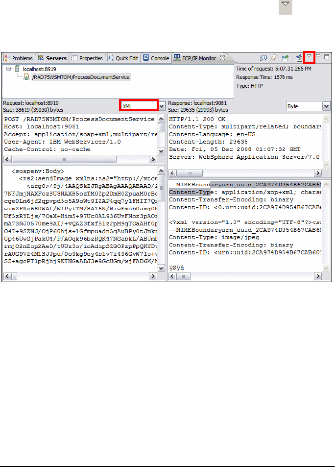
7672-dev-6-webservice.fm Draft Document for Review December 9, 2008 2:44 pm
630 Rational Application Developer V7 Programming Guide
Examine the C:\7672code\webservice\mtomresult folder. You can see that
BlueHills.jpg is stored in this folder. Note that the size is different from the
same file in the mtom folder (probably a different JPEG compression is used).
Select the TCP/IP Monitor tab to view the SOAP traffic. Click the icon and
then select Show Header. The HTTP header and the SOAP traffic are shown
in Figure 18-46.
Figure 18-46 SOAP traffic when MTOM is only enabled for the Web service
Take a look at the SOAP request and response:
– The Web service (provider) has MTOM enabled after the code generation.
Therefore, the SOAP response has a smaller payload! The Web service
sends the binary data as a MIME attachment outside the XML document
to realize the optimization.
– The SOAP request has a much larger payload because MTOM is not
enabled. The Web service client sends binary data as base64 encoded
data within the XML document.
The SOAP response and its HTTP header are shown in Example 18-24
(formatted by hand).
Example 18-24 SOAP response message and HTTP header with MTOM enabled
HTTP/1.1 200 OK
Content-Type: multipart/related;

Chapter 18. Develop Web services applications 631
Draft Document for Review December 9, 2008 2:44 pm 7672-dev-6-webservice.fm
boundary=MIMEBoundaryurn_uuid_2CA974D954B67CAB601228439267478;
type="application/xop+xml";
start="<0.urn:uuid:2CA974D954B67CAB601228439267479@apache.org>";
start-info="text/xml"
Content-Language: en-US
Content-Length: 29635
Date: Fri, 05 Dec 2008 01:07:32 GMT
Server: WebSphere Application Server/7.0
==========================================================================
--MIMEBoundaryurn_uuid_7EF64465327292D3521225396635214
Content-Type: application/xop+xml; charset=UTF-8; type="text/xml"
Content-Transfer-Encoding: binary
Content-ID: <0.urn:uuid:2CA974D954B67CAB601228439267479@apache.org>
<?xml version="1.0" encoding="UTF-8"?>
<soapenv:Envelope
xmlns:soapenv="http://schemas.xmlsoap.org/soap/envelope/">
<soapenv:Body>
<ns2:sendImageResponse xmlns:ns2="http://mtom.rad75.ibm.com/">
<return>
<xop:Include xmlns:xop="http://www.w3.org/2004/08/xop/include"
href="cid:urn:uuid:2CA974D.....@apache.org"/>
</return>
</ns2:sendImageResponse>
</soapenv:Body>
</soapenv:Envelope>
--MIMEBoundaryurn_uuid_2CA974D954B67CAB6012284392674784
Content-Type: image/jpeg
Content-Transfer-Encoding: binary
Content-ID: <urn:uuid:2CA974D954B67CAB601228439267605@apache.org>
ÿØÿà
The type and content-type attributes have the value application/xop+xml,
which indicates that the message was successfully optimized using XML-binary
Optimized packaging (XOP) when MTOM was enabled.
Enabling MTOM on the client
Now let us enable MTOM on the client side as well:
In the Enterprise Explorer expand RAD7MTOMClient → Java Resources →
src → com.ibm.rad75.mtom and open ProcessDocumentPortProxy.java.
Add one lines of code to each business method to invoke a new
enableMTOMClient method (Example 18-25). Refer to
C:\7672code\webservice\mtom\ProcessDocumentPortProxy.java.

7672-dev-6-webservice.fm Draft Document for Review December 9, 2008 2:44 pm
632 Rational Application Developer V7 Programming Guide
Example 18-25 Enable MTOM on the client
import javax.xml.ws.soap.SOAPBinding;
public class ProcessDocumentPortProxy{
......
public byte[] sendWordFile(byte[] arg0) {
enableMTOMClient();
return _getDescriptor().getProxy().sendWordFile(arg0);
}
public Image sendImage(Image arg0) {
enableMTOMClient();
return _getDescriptor().getProxy().sendImage(arg0);
}
public DataHandler sendPDFFile(DataHandler arg0) {
enableMTOMClient();
return _getDescriptor().getProxy().sendPDFFile(arg0);
}
private void enableMTOMClient(){
SOAPBinding binding = (SOAPBinding)
((BindingProvider)_getDescriptor().getProxy()).getBinding();
binding.setMTOMEnabled(true);
}
}
Run the sample JSP again using the sendImage method and the
...\mtom\BlueHills.jpg file. The SOAP request also has a small payload
after MTOM is enabled for the Web service client (Figure 18-47).
In the sample JSP client, invoke the sendWordFile method. Click Browse to
locate the word document ...\mtom\RAD-intro.doc, and click Invoke. Watch
the SOAP traffic in the TCP/IP Monitor.
Invoke the sendPDFFile method. Click Browse to locate the PDF document
...\mtom\JAX-WS.pdf, and click Invoke. Watch the SOAP traffic in the TCP/IP
Monitor.
Verify the C:\7672code\webservice\mtomresult folder. We can see that the
image file, word document, and PDF file are all stored successfully.

Chapter 18. Develop Web services applications 633
Draft Document for Review December 9, 2008 2:44 pm 7672-dev-6-webservice.fm
Figure 18-47 SOAP message with MTOM enabled for both client and server
Web services security
Web services security for WebSphere Application Server v7.0 is based on
standards included in the Organization for the Advancement of Structured
Information Standards (OASIS) Web services security (WSS) Version 1.0/1.1
specification, the Username Token Profile 1.0/1.1, and the X.509 Certificate
Token Profile 1.0/1.1.
WS-Security addressed three major issues involved in securing SOAP message
exchanges: authentication, message integrity, and message confidentiality.
Authentication
Authentication is used to ensure that parties within a business transaction are
really who they claim to be; thus proof of identity is required. This proof can be
claimed in various ways:
One simple way is by presenting a user identifier and a password. This is
referred to as a username token in WS-Security domain.
7672-dev-6-webservice.fm Draft Document for Review December 9, 2008 2:44 pm
634 Rational Application Developer V7 Programming Guide
A more complex way is to use an X.509 certificate issued by a trusted
certificate authority.
The certificate contains identity credentials and has a pair of private and public
keys associated with it. The proof of identity presented by a party includes the
certificate itself and a separate piece of information that is digitally signed using
the certificate's private key. By validating the signed information using the public
key associated with the party's certificate, the receiver can authenticate the
sender as being the owner of the certificate, thereby validating their identity.
Two WS-Security specifications, the Username Token Profile 1.0/1.1 and the
X.509 Certificate Token Profile 1.0/1.1, describe how to use these authentication
mechanisms with WS-Security.
Message integrity
To validate a message has not been tampered with or corrupted during its
transmission over the Internet, the message can be digitally signed using
security keys. The sender uses the private key of the their X.509 certificate to
digitally sign the SOAP request. The receiver uses the sender’s public key to
check the signature and identity of the signer. The receiver signs the response
with their private key, and the sender is able to validate the response has not
been tampered with or corrupted using the receiver’s public key to check the
signature and identity of the responder. The WS-Security: SOAP Message
Security 1.0/1.1 specification describes enhancements to SOAP messaging to
provide message integrity.
Message confidentiality
To keep the message safe from eavesdropping, encryption technology is used to
scramble the information in Web services requests and responses. The
encryption ensures that no-one accesses the data in transit, in memory, or after it
has been persisted, unless they have the private key of the recipient. The
WS-Security: SOAP Message Security 1.0/1.1 specification describes
enhancements to SOAP messaging to provide message confidentiality.
There are two options to configure WS-Security for JAX-WS Web services:
Policy set
Programming API for securing SOAP message with Web Service Security
(WSS API) and Service Programming Interfaces (SPI) for a service provider
We will use Policy set in our examples.
Chapter 18. Develop Web services applications 635
Draft Document for Review December 9, 2008 2:44 pm 7672-dev-6-webservice.fm
Policy set
You can use policy sets to simplify configuring the qualities of service for Web
services and clients. Policy sets are assertions about how Web services are
defined. Using policy sets, you can combine configurations for different policies.
You can use policy sets with JAX-WS applications, but not with JAX-RPC
applications.
A policy set is identified by a unique name. An instance of a policy set consists of
a collection of policy types. An empty policy set has no policy instance defined.
Policies are defined on the basis of a quality of service. Policy definitions are
typically based on WS-Policy standards language. For example, the WS-Security
policy is based on the current WS-SecurityPolicy language from the Organization
for the Advancement of Structured Information Standards (OASIS) standards.
Policy sets omit application or user-specific information, such as keys for signing,
key store information, or persistent store information. Instead, application and
user-specific information is defined in the bindings. Typically, bindings are
specific to the application or the user, and bindings are not normally shared. On
the server side, if you do not specify a binding for a policy set, a default binding
will be used for that policy set. On the client side, you must specify a binding for
each policy set.
A policy set attachment defines which policy set is attached to service resources,
and which bindings are used for the attachment. The bindings define how the
policy set is attached to the resources. An attachment is defined outside of the
policy set, as metadata associated with the application. To enable a policy set to
work with an application, a binding is required.
Apply WS-Security to Web service and client
In this section, we apply the Username WSSecurity default policy set to our Web
service and client. This policy set provides the following features:
Message integrity by digital signature (using RSA public-key cryptography) to
sign the body, timestamp, and WS-Addressing headers using the
WS-Security specifications.
Message confidentiality by encryption (using RSA public-key cryptography) to
encrypt the body, signature, and signature confirmation elements using the
WS-Security specifications.
A username token included in the request message to authenticate the client
to the service. The username token is encrypted in the request.
7672-dev-6-webservice.fm Draft Document for Review December 9, 2008 2:44 pm
636 Rational Application Developer V7 Programming Guide
Sample bindings for JAX-WS applications
WebSphere Application Server v7.0 includes provider and client sample bindings
for testing purposes. In the bindings, the product provides sample values for
supporting tokens for different token types, such as the X.509 token and the
username token. The bindings also include sample values for message
protection information for token types such as X.509. Both provider and client
sample bindings can be applied to the applications attached with a policy set.
In production environment, you must modify the bindings to meet your security
needs before using them in a production environment by making a copy of the
bindings and then modifying the copy. For example, you must change the key
and keystore settings to ensure security, and modify the binding settings to
match your environment.
Configure the username token
When using the Username WSSecurity default policy set, you must configure the
username and password for username token authentication separately from the
security settings defined in the bindings. The sample binding does not include a
username or password for token authentication, as it is specific to the target
deployed system. You must specify a valid username and password in your
environment using the WebSphere administrative console.
In the Servers view, right-click WebSphere Application Server v7.0 and
select Administration → Run administrative console.
Log in using user ID and password (admin).
Select Services → Policy sets → General client policy set bindings.
Click Client sample to edit the binding.
Click WS-Security.
Click Authentication and protection.
In the Authentication tokens list, select gen_signunametoken to edit the
username token settings.
Click Callback handler in the Additional Bindings section (bottom).
Enter the admin as the username and admin as the password and confirm
password. Click Apply.
Click Save and then Logout.
Attach the Username WSSecurity policy set to the Web service
To attach the Username WSSecurity default policy set to the Web service, do
these steps:
In the Java EE perspective, Services view, expand the JAX-WS node.
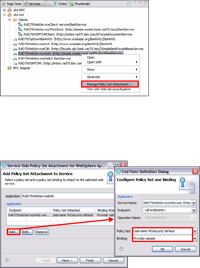
Chapter 18. Develop Web services applications 637
Draft Document for Review December 9, 2008 2:44 pm 7672-dev-6-webservice.fm
Right-click RAD75WebServiceWeb:{...}BankService and select Manage
Policy Set Attachment (Figure 18-48).
Figure 18-48 Manage Policy Set Attachment
Click Add.
From the Policy Set drop-down list, select Username WSSecurity default,
and for the Binding ensure Provider Sample is selected. This is a
service-side general binding packaged with WebSphere Application Server.
Click OK (Figure 18-49).
Figure 18-49 Configure Policy Set and Binding

7672-dev-6-webservice.fm Draft Document for Review December 9, 2008 2:44 pm
638 Rational Application Developer V7 Programming Guide
You can apply a policy set at the service, port, or operation level. Different
policy sets may be applied to various endpoints and operations within a single
Web service. However the service and client must have the same policy set
settings. For this example, we apply the policy set to the entire service, so the
Endpoint and Operation Name fields are left blank.
A warning window is displayed. Click Ignore. WS-Security was included in the
WS-I Basic Security Profile. The WS-I Basic Security Profile Version 1.0 was
in Final Material status.
Click Finish. Notice the service application is republished to the server.
Attach the policy set to the Web service client
To attach the Username WSSecurity default policy set to the Web service client,
do these steps:
In the Services view, expand the JAX-WS → Clients. Right-click
RAD75WebServiceClient: service/BankService and select Manage Policy
Set Attachment.
Click Next.
In the Application section, click Add to attach a policy set to the endpoint and
specify the bindings. Because the service is secured at the service level
rather than the endpoint or operation level, the client will be secured at this
level as well (Figure 18-50).
Figure 18-50 Client Side Policy Set Attachment
Chapter 18. Develop Web services applications 639
Draft Document for Review December 9, 2008 2:44 pm 7672-dev-6-webservice.fm
Accept the settings for Service Name (BankService), Endpoints (all), Policy
Set (Username WSSecurity default), Binding (Client sample). This is a
client-side general binding packaged with WebSphere Application Server.
Click OK and then click Ignore.
The policy types contained by the policy set you selected are listed in the
Bindings Configuration table. The configuration for these policy types are
already complete.
Click Finish to complete the wizard.
Test the secured Web service
To test the secured Web service, do these steps:
Select Window → Preferences → Run/Debug → TCP/IP Monitor. Make
sure the TCP/IP Monitor is started. Note the monitor port (xxxxx).
In the Enterprise Explorer, expand the RAD75WebServiceClient project,
right-click TestClient.jsp → Run As → Run on Server. Select the v7.0
server and click Finish.
In the sample JSP client, Quality of Service pane, change the endpoint to the
monitor port and click Update:
http://localhost:xxxxx/RAD75WebServiceWeb/BankService
Invoke the retrieveCustomerName with a customer number of 111-11-1111.
In the TCP/IP Monitor view, verify that the message is signed and encrypted,
and the Username token in the SOAP header is encrypted:
<soapenv:Envelope xmlns:soapenv="http://.../soap/envelope/">
<soapenv:Header xmlns:wsa="http://www.w3.org/2005/08/addressing">
<wsse:Security xmlns:wsse="http://docs.oasis-open.org/wss/2004/01
/oasis-200401-wss-wssecurity-secext-1.0.xsd" soapenv:mustUnderstand="1">
<wsu:Timestamp xmlns:wsu="http://docs.oasis-open.org/wss/2004/01
/oasis-200401-wss-wssecurity-utility-1.0.xsd"
wsu:Id="wssecurity_signature_id_24">
<wsu:Created>2008-12-05T17:05:35.953Z</wsu:Created>
</wsu:Timestamp>
<wsse:BinarySecurityToken xmlns:wsu="http://docs.oasis-open.org/wss/2004
/01/oasis-200401-wss-wssecurity-utility-1.0.xsd" wsu:Id="x509bst_26"
EncodingType="http://docs.oasis-open.org/wss/2004/01
/oasis-200401-wss-soap-message-security-1.0#Base64Binary"
ValueType="http://docs.oasis-open.org/wss/2004/01
/oasis-200401-wss-x509-token-profile-1.0#X509v3">
MIICQzCCAaygAwI.................................

7672-dev-6-webservice.fm Draft Document for Review December 9, 2008 2:44 pm
640 Rational Application Developer V7 Programming Guide
WS-I Reliable Secure Profile
Following on from the Reliable Asynchronous Messaging Profile (RAMP) Version
1.0 specification, the Web Services Interoperability organization (WS-I) Reliable
Secure Profile working group has developed Version 1.0 of an interoperability
profile dealing with secure, reliable messaging capabilities for Web services.
WS-I Reliable Secure Profile 1.0 provides secure reliable session-oriented Web
services interactions. WS-I Reliable Secure Profile 1.0 builds on WS-I Basic
Profile 1.2, WS-I Basic Profile 2.0, WS-I Basic Security Profile 1.0, and WS-I
Basic Security Profile 1.1, and adds support for WS-Reliable Messaging 1.1,
WS-Make Connection 1.0, and WS-Secure Conversation 1.3:
WS-Reliable Messaging 1.1 is a session-based protocol that provides
message level reliability for Web services interactions.
WS-Make Connection 1.0 was developed by the WS-Reliable Messaging
workgroup to address scenarios where a Web services endpoint is behind a
firewall or the endpoint has no visible endpoint reference. If a Web services
endpoint loses connectivity during a reliable session, WS-Make Connection
provides an efficient method to re-establish the reliable session.
WS-Secure Conversation 1.3 is a session-based security protocol that uses
an efficient symmetric key based encryption algorithm for message level
security.
The configuration steps to apply WS-I RSP Policy set are basically the same as
the steps for Username WSSecurity Policy set. Select WS-I RSP as the policy
set when adding a policy set attachment to the service (Figure 18-51). We leave
it as an exercise for the reader to explore this functionality.
Figure 18-51 Apply WS-I RSP profile

Chapter 18. Develop Web services applications 641
Draft Document for Review December 9, 2008 2:44 pm 7672-dev-6-webservice.fm
WS-Policy
WS-Policy is an interoperability standard that is used to describe and
communicate the policies of a Web service so that service providers can export
policy requirements in a standard format. Clients can combine the service
provider requirements with their own capabilities to establish the policies required
for a specific interaction.
WebSphere Application Server conforms to the Web services Policy Framework
(WS-Policy) specification. You can use the WS-Policy protocol to exchange
policies in standard format. A policy represents the capabilities and requirements
of a Web service, for example whether a message is secure and how to secure it,
and whether a message is delivered reliably and how this is achieved. You can
communicate the policy configuration to any other client, service registry, or
service that supports the WS-Policy specification, including non-WebSphere
Application Server products in a heterogeneous environment.
For a service provider, the policy configuration can be shared in a published
WSDL, that is obtained by a client using an HTTP get request, or by using the
Web Services Metadata Exchange (WS-MetadataExchange) protocol. The
WSDL is in the standard WS-PolicyAttachments format.
For a client, the client can obtain the policy of the service provider in the standard
WS-PolicyAttachments format and use this information to establish a
configuration that is acceptable to both the client and the service provider. In
other words, the client can be configured dynamically, based on the policies
supported by its service provider. The provider policy can be attached at the
application or service level.
Relationship to policy set
Policy sets are not inherently concerned with the WS-Policy specification, but
deal with the configuration of Web services and should be considered as a
front-end to WS-Policy. Policy sets provide a mechanism to specify a policy within
a Websphere environment. They do not provide a mechanism to communicate
this policy to non-Websphere partners in a heterogeneous environment. In
addition, policy set functionality does not provide a mechanism for the client to
Note: For more detailed information regarding Reliable Messaging, Secure
Conversation, Policy set and the RSP profile, refer to the Redbooks
publication, Web Services Feature Pack for WebSphere Application Server
V6.1, SG24-7618.
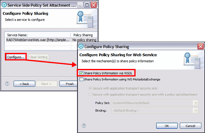
7672-dev-6-webservice.fm Draft Document for Review December 9, 2008 2:44 pm
642 Rational Application Developer V7 Programming Guide
calculate effective policy (that is, the policy acceptable to both client and
provider) based the intersection of a list of client and provider policies.
Configuring a service provider to share its policy configuration
In this section, we configuring a service provider to share its policy configuration:
In the Services view, right-click RAD75WebServiceWeb:{...}BankService
and select Manage Policy Set Attachment.
The Username WSSecurity default should be listed as the attached policy set
from the last section. Click Next.
In the Configure Policy Sharing dialog, select the service and click Configure.
Select Share Policy Information via WSDL and click OK (Figure 18-52).
Figure 18-52 Configure Policy Sharing
Click Ignore for the warning and then click Finish.
Once the server is published, open a browser and enter the following URL in
the browser (908x is the port number, most probably 9081):
http://localhost:908x/RAD75WebServiceWeb/BankService?wsdl
The WS-Policy information is embedded in the WSDL document
(Example 18-26).

Chapter 18. Develop Web services applications 643
Draft Document for Review December 9, 2008 2:44 pm 7672-dev-6-webservice.fm
Example 18-26 WS-Policy in WSDL
......
<service name="BankService">
<port name="BankPort" binding="tns:BankPortBinding">
<soap:address
location="http://localhost:9081/RAD75WebServiceWeb/BankService"/>
</port>
</service>
<wsp:Policy wsu:Id="8a877980db584a2bacf018d1d2dd8c8f">
<wsp:ExactlyOne>
<wsp:All>
<addressing:Addressing>
<wsp:Policy>
<wsp:ExactlyOne>
<wsp:All> </wsp:All>
</wsp:ExactlyOne>
</wsp:Policy>
</addressing:Addressing>
</wsp:All>
......
</wsp:Policy>
</definitions>
Configuring the client policy using a service provider policy
To configure the client policy using the service provider policy, do the following:
We have to remove the policy we applied in the last section, because we use
WS-Policy to request the service provider’s policy information.
– In the Services view, right-click RAD75WebServiceClient:
service/BankService and select Manage Policy Set Attachment.
– Click Next.
– Click Remove, and then click Finish.
Right-click RAD75WebServiceClient: service/BankService, select Manage
Policy Set Attachment.
Click Use Provider Policy.
In the Configure Policy acquisition for Web Service Client page, select HTTP
Get request targeted at <default WSDL URL>, and click OK (Figure 18-53).
The Policy Acquisition field for the service changes to Acquire Provider
Policy.
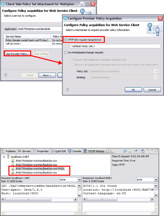
7672-dev-6-webservice.fm Draft Document for Review December 9, 2008 2:44 pm
644 Rational Application Developer V7 Programming Guide
Figure 18-53 Use Provider Policy
Click Ignore for the warning, and then click Finish.
Test the Web service again. In the TCP/IP Monitor, you can see the client first
acquires the WSDL through the HTTP GET (Figure 18-54). The client policy
calculations for a service is performed at the first invocation on that service.
Calculated policies are cached in the client for performance.
Figure 18-54 TCP/IP Monitor shows retrieve of WSDL

Chapter 18. Develop Web services applications 645
Draft Document for Review December 9, 2008 2:44 pm 7672-dev-6-webservice.fm
WS-MetadataExchange (WS-MEX)
In WebSphere Application Server Version v7.0, using JAX-WS, you can enable
the Web Services Metadata Exchange (WS-MetadataExchange) protocol so that
the policy configuration of the service provider is included in the WSDL and is
available to a WS-MetadataExchange GetMetadata request. A service provider
can use a WS-MetadataExchange request to share its policies, and a service
client can use a WS-MetadataExchange request to apply the policies of a
provider.
One advantage of using the WS-MetadataExhange protocol is that you can apply
transport-level or message-level security to WS-MetadataExchange GetMetadata
requests by using a suitable system policy set. Another advantage is that the
client does not have to match the provider configuration, or have a policy set
attached. The client only needs the binding information, and then the client can
operate based on the provider policy, or based on the intersection of the client
and provider policies.
To configuring a service provider to share its policy configuration using WS-MEX,
do the following:
In the Services view, right-click RAD75WebServiceWeb:{...}BankService
and select Manage Policy Set Attachment.
The Username WSSecurity default should be listed as the attached policy
set from the last section. Click Next.
In the Configure Policy Sharing dialog, select the service and then click
Configure.
Select Share Policy Information using WS-MetadataExchange and click
OK (Figure 18-55).
Figure 18-55 Share policy set using WS-MetadataExchange

7672-dev-6-webservice.fm Draft Document for Review December 9, 2008 2:44 pm
646 Rational Application Developer V7 Programming Guide
Click Ignore for the warning, and then click Finish.
To configuring the client policy configuration using WS-MEX, do the following:
Right-click RAD75WebServiceClient: service/BankService, select Manage
Policy Set Attachment. and then click Use Provider Policy
In the Configure Policy acquisition for Web Service Client page, select
WS-MetadataExchange and then click OK.
Click Ignore for the warning, and then click Finish.
Test the Web service again. In the TCP/IP Monitor, you can see the client first
issues a WS-MEX GetMetadata request to the actual Web service endpoint,
and the dialect of the request is WSDL (Example 18-27).
Example 18-27 WS-MEX request
<soapenv:Header xmlns:wsa="http://www.w3.org/2005/08/addressing">
<wsa:To>http://localhost:11487/RAD75WebServiceWeb/BankService</wsa:To>
<wsa:MessageID>urn:uuid:5F71ABE9421927F47C1228500226211</wsa:MessageID>
<wsa:Action>
http://schemas.xmlsoap.org/ws/2004/09/mex/GetMetadata/Request
</wsa:Action>
</soapenv:Header>
<soapenv:Body>
<mex:GetMetadata xmlns:mex="http://schemas.xmlsoap.org/ws/2004/09/mex">
<mex:Dialect>http://schemas.xmlsoap.org/wsdl/</mex:Dialect>
</mex:GetMetadata>
</soapenv:Body>
The GetMetadata response returns the WSDL with the policy information.
Chapter 18. Develop Web services applications 647
Draft Document for Review December 9, 2008 2:44 pm 7672-dev-6-webservice.fm
More information
For more information on Web services, refer to these resources:
If you want to learn more about JAX-WS, Reliable Messaging, Secure
Conversation, Policy set and RSP profile, see the Redbooks publication, Web
Services Feature Pack for WebSphere Application Server V6.1, SG24-7618.
For JAX-RPC Web services tools shipped with Application Developer v7.0,
see the Redbooks publications: Rational Application Developer V7
Programming Guide, SG24-7501, and Web Services Handbook for
WebSphere Application Server Version 6.1, SG24-6957.
IBM developerWorks has a whole section on SOA and Web services:
http://www.ibm.com/developerworks/webservices
An online list of current and emerging Web services standards can be found
on developerWorks under SOA and Web services → Standards:
http://www.ibm.com/developerworks/webservices/standards/
The JAX-WS specification is available at:
http://jcp.org/aboutJava/communityprocess/pfd/jsr224/index.html
The JAXB specification is available at:
http://jcp.org/en/jsr/detail?id=222
The MTOM specification is available at:
http://www.w3.org/TR/soap12-mtom/
Read about JAX-WS annotations at:
https://jax-ws.dev.java.net/jax-ws-ea3/docs/annotations.html
http://publib.boulder.ibm.com/infocenter/wasinfo/v6r1/index.jsp?topic=/com.
ibm.websphere.wsfep.multiplatform.doc/info/ae/ae/rwbs_jaxwsannotations.html
The WS-Policy specification is available at:
http://www.w3.org/Submission/WS-Policy/
The WS-MetadataExchange specification is available at:
http://www.ibm.com/developerworks/webservices/library/specification/ws-mex/
7672-dev-6-webservice.fm Draft Document for Review December 9, 2008 2:44 pm
648 Rational Application Developer V7 Programming Guide

© Copyright IBM Corp. 2008. All rights reserved. 649
Draft Document for Review December 9, 2008 2:44 pm 7672-dev-8-web20.fm
Chapter 19. Develop Web applications
using Web 2.0
Web 2.0 represents a paradigm shift in designing and developing Web
applications. JavaServer Faces (JSF) is a framework that simplifies building user
interfaces for Web applications, described in Chapter 16, “Develop Web
applications using JSF” on page 493. JPA is the Java Persistence API, described
in Chapter 12, “Persistence using the Java Persistence API (JPA)” on page 267.
This chapter introduces the features, benefits, and architecture of Web 2.0. The
focus of the chapter is to demonstrate the Rational Application Developer
support and tooling for Web 2.0, using Ajax Proxy, DOJO toolkit, and RPC
Adapter. The chapter includes an example Web application using Web 2.0, with a
front controller implemented with JSF and persistence implemented with JPA.
The chapter is organized into the following sections:
Introduction to Web 2.0
Developing a Web 2.0 using JSF, Ajax Proxy, and JPA
Developing a Web 2.0 application using Dojo and RPC
19
Note: The code snippets for this chapter are lcoated in C:\7672code\web20. Project
Interchanges for this chapter are lcoated in: C:\7672code\zInterchange\web20.
7672-dev-8-web20.fm Draft Document for Review December 9, 2008 2:44 pm
650 Rational Application Developer V7.5 Programming Guide
Introduction to Web 2.0
This section provides an introduction to Web 2.0.
Web 2.0 definition
Before we dive into the technical concepts, let us start by defining what exactly is
meant by the term Web 2.0. The term Web in Web 2.0 refers to the World Wide
Web technology which we have all grown to know and love. The 2.0 indicator in
Web 2.0 does not specify a new version release of a technical specification which
supports World Wide Web technology. Rather, it indicates a paradigm shift (or
evolution) in the way which Web applications and its components are designed
and developed and ultimately share information and collaborate within the
internet and with one another. In many ways, Web 2.0 also enables a paradigm
shift of the computing platform from the desktop to the Internet.
Web 2.0 application architecture
To fully under Web 2.0, we describe Web 2.0 in the following context:
Web 2.0 characteristics
Evolution from Web 1.0 to Web 2.0 applications
Comparing code on client browser and application server
Web 2.0 features and benefits
Effect on Web users
Web 2.0 characteristics
Web 2.0 applications usually involve the following characteristics.
The content of Web applications are delivered through a Web browser. Web
2.0 applications adhere to Web standards.
The usage of Web 2.0 applications feels less like classic Web applications,
but rather like desktop applications.
Web 2.0 applications often have user interface that fall in the Rich Internet
Application category. They often use pre-built/re-usable widgets that enables
a rich set of user interface features.
Evolution from Web 1.0 to Web 2.0 applications
Let us examine how Web applications have evolved from Web 1.0 to Web 2.0.
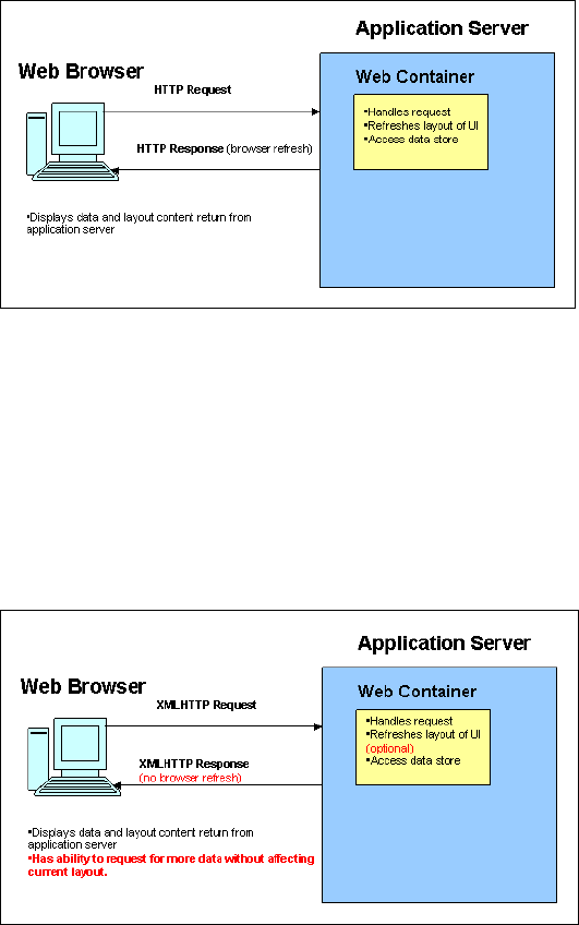
Chapter 19. Develop Web applications using Web 2.0 651
Draft Document for Review December 9, 2008 2:44 pm 7672-dev-8-web20.fm
In Web 1.0 applications, a request for more server side data retrieval and/or page
navigation typically requires an invocation of HTTP request/response pair. The
end result is that a Web page refresh is incurred. Web page refreshes are
typically viewed by end-users as a cumbersome delay in their workflow.
Figure 19-1 shows browser and server interaction in Web 1.0 applications.
Figure 19-1 Web 1.0 application architecture
In contrast, in Web 2.0, a request for more server side data retrieval and/or page
navigation typically still requires an invocation of HTTP request/response pair.
However, Web 2.0 applications leverage technologies which makes server-side
data retrieval and/or page navigation possible without incurring a Web page
refresh. In most cases, only the portions of the user interface is updated with the
changed data.
Figure 19-2 shows the different approach taken in Web 2.0 applications.
Figure 19-2 Web 2.0 application architecture
7672-dev-8-web20.fm Draft Document for Review December 9, 2008 2:44 pm
652 Rational Application Developer V7.5 Programming Guide
Comparing code on client browser and application server
In Web 1.0, for the most part, code on the application server (JSPs, tag libraries
and/or servlets) are responsible for delivering the user interface layout and data.
In this paradigm, the browser is primarily used as a medium for viewing the data
and the layout in which the data is displayed. Both data and layout is
tightly-coupled to one another, in that in order to refresh data, the layout must
also be refreshed.
In contrast, in Web 2.0 applications, the data is loosely coupled from the layout.
Under the Web 2.0 paradigm, it is possible for the application server to deliver the
layout content once and using client-side code (for example, JavaScript)
subsequent request for data can be initiated and completed independent of the
layout content.
Web 2.0 features and benefits
In this section we describe the features and benefits of Web 2.0.
Advantages of Web 2.0 architecture
As mentioned, the main benefits of the Web 2.0 architecture is that developers
can build applications that are responsive to the user and their actions. In
essence, the application behaves like a desktop program in that it appears that it
does not have wait for a server response each time an action is taken on the
page. Another benefit is for developers is that the popularity of this approach has
seen an increase in the number of tools available for creating Web 2.0
applications. There has an abundance of freely available components and
widgets which developers can leverage/re-use.
Disadvantages of Web 2.0 architecture
The Web 2.0 architecture does bring associated concerns. First, Web 2.0 is a
new approach using existing technologies. However, it does require to a
rethinking in the way to approach Web development. Furthermore, we are
pushing more code onto the client (as opposed to mainly server side). Therefore,
we must be cognizant of the impact (performance and security wise) that this
paradigm has on the client.
Effect on Web users
From the end user's perspective, incorporating Web 2.0 makes a Web-based
application often indistinguishable from a desktop program. Similar to a desktop
program, a Web 2.0 application would provide immediate feedback to the user
and support user-browser interaction without a browser refresh. The end result is
a Web 2.0 application is in a position to deliver a rich set of content and
functionality to the web user. Often, Web 2.0 enabled application are referred to
as Rich Internet Applications (or RIA).
Chapter 19. Develop Web applications using Web 2.0 653
Draft Document for Review December 9, 2008 2:44 pm 7672-dev-8-web20.fm
Supporting technologies
There are a handful of technologies which enables the paradigm shift of Web 2.0.
Some of the supporting technologies for Web 2.0 are:
Ajax
Asynchronous JavaScript and XML (Ajax) refers to a group of technologies that
are used to develop interactive Web applications. By combining these
technologies, Web pages appear more responsive since small amounts of data
are exchanged with the server and Web pages are not reloaded each time a user
makes an input change.
In classic Web applications users have to submit forms (HTTP requests) to
exchange data with the server. After some processing phase, the server returns
the whole page to the client.
Ajax moves this server-side logic to the client. Instead of loading the whole page,
the client can refresh the parts of page. The users’ HTTP requests turn simply
into JavaScript calls to the Ajax engine that is loaded by the browser.
Ajax is made up of the following technologies:
HTML and CSS for presenting information
JavaScript for dynamically interacting with the information presented
XML, XSLT, and HTMLHttpRequest object to manipulate data asynchronously
with the Web server
Ajax Proxy
Let us discuss the meaning of an Ajax Proxy and what purpose does it serve in
the Web 2.0 paradigm.
Ajax communication methods include XMLHttpRequest (XHR) and IFrame
requests. These methods allow the browser to send HTTP requests to a server
at any time with or without a user action. One limitation of an IFrame or XHR
request is the restriction to make a request to a different server other than the
one that served the original HTML page. This limitation is sometimes known as a
same domain limitation and exists as a security measure to prevent hacker from
injecting a malicious script by redirecting the page to an untrusted server.
However, an Ajax-based Web application may have to make a request to a server
that is different than the server that served the main HTML page. Client-side
methods exist to work around the same-domain limitation, but these methods
have limitations. The recommended solution to the same-domain limitation is to
use a proxy server to forward the request to a server on a different domain.
7672-dev-8-web20.fm Draft Document for Review December 9, 2008 2:44 pm
654 Rational Application Developer V7.5 Programming Guide
The need for a solution for the same-domain restriction is amplified when using
Ajax techniques. Ajax techniques can involve XHR or IFrame requests to
server-side services. An Ajax application that collects data from multiple sources
or services and combines them into one cohesive view is called a mashup. As an
Ajax-enabled application, or mashup, accesses more services to gather data and
as mashup usage increases, there is an increased chance that Ajax applications
must access a cross-domain service. The cross-domain service that needs to be
accessed might be a third-party service or an internal service running on a
different domain or port.
Choosing to proxy Ajax requests instead of using a client-side, browser-based
proxy alternative can be beneficial. A proxy server can be configured to only
support access to certain Web sites whereas a browser-based solution does not
have the ability to restrict cross-domain access on a per server basis. Another
proxy server benefit is content filtering from a third-party site. One form of
content filtering would be configuring a proxy server to only return content from a
third-party Web site if it matches a permissible content type. A final benefit is
using the proxy server to convert response data to a format a Web application
expects. A proxy server converting a Web service response from XML to
JavaScript Object Notation (JSON) for consumption by a browser is an example
of a proxy server converting data.
JSON
JavaScript Object Notation (JSON) is loosely based on a subset of the JavaScript
programming language. JSON was built to function as a data interchange format.
To make JSON re-usable across programming languages and platforms, JSON
is:
Language independent
Uses well-known/accepted programming concepts
JSON is built on two structures:
A collection of name/value pairs. In most programming languages, the
construct equivalent is either an object, record, structure, dictionary, hash
table, keyed list, or associative array.
An ordered list of values. In most programming languages, the construct
equivalent is either an array, vector, list, or sequence.
These are universal data structures. Virtually all modern programming languages
support them in one form or another. It makes sense that a data format that is
interchangeable with programming languages also be based on these structures.
In JSON, data structures have these forms:
Chapter 19. Develop Web applications using Web 2.0 655
Draft Document for Review December 9, 2008 2:44 pm 7672-dev-8-web20.fm
An object is an unordered set of name/value pairs. An object begins with { (left
brace) and ends with } (right brace). Each name is followed by : (colon) and
the name/value pairs are separated by , (comma).
An array is an ordered collection of values. An array begins with [ (left bracket)
and ends with ] (right bracket). Values are separated by , (comma).
The JSON4J library is an implementation of a set of JavaScript Object Notation
(JSON). With this library we can construct and manipulate data to be rendered
as the JSON implementation.
DOJO Toolkit
The Dojo Toolkit is an open source JavaScript library. It can be used to create
rich user interfaces and it is not tied to specific server-side technologies. It runs
natively in most of web browsers and provides an abstract layer for JavaScript
development. More details about Dojo Toolkit can be found at:
http://www.dojotoolkit.org
Dojo is divided in three modules:
Dojo Core: All the major functions needed to do Ajax developments and
others similar effect functions (fading, sliding, for example).
Dijit: A high quality set of interactions rich widgets and themes for use when
developing Ajax applications.
DojoX (Dojo Extensions): An area that contains a set of subprojects that
extend the Dojo Toolkit.
REST and RPC Adapter
Web-remoting is a pattern that provides support for JavaScript or client-side code
to directly invoke server side logic. This pattern provides the ability to invoke Java
methods from JavaScript. The invocation is by means of a JSON-RPC call. The
most common usage is asynchronous calls with XmlHttpRequest. Data is
transferred between the server and client in JSON format. Therefore, this pattern
is essentially a form of JSON Web services.
The IBM implementation for Web remoting is referred to as the RPC adapter for
IBM. The RPC adapter is designed to help developers create command-based
services quickly and easily in a manner that complements programming styles
for Ajax applications and other lightweight clients. Implemented as a generic
servlet, the RPC adapter provides an HTTP interface to registered JavaBeans.
The RPC adapter provides an HTTP interface to Registered JavaBeans. It will
deserialize the input and call the corresponding method in the JavaBean. It will
serialize the output from the JavaBean to JSON/XML format.
7672-dev-8-web20.fm Draft Document for Review December 9, 2008 2:44 pm
656 Rational Application Developer V7.5 Programming Guide
The RPC adapter currently supports two RPC protocols:
HTTP RPC, which encodes RPC invocations as URLs with query parameters,
for HTTP GET, or form parameters, for HTTP POST.
JSON-RPC, supports the SMD service descriptor employed by the Dojo
dojo.rpc.JsonService API.
HTTP RPC
In HTTP RPC, invocations are made using URLs with query parameters or form
parameters. The RPC adapter intercepts and deserializes the URL to get service
name, method name, and input parameters. Using these information RPC
adapter invokes the corresponding method of matching JavaBeans.
JSON-RPC
In JSON-RPC, method invocation is made using JSON objects. The response
generated is also a JSON object. The registered JavaBeans can be accessed
through the Dojo JSON-RPC API.
Web 2.0 features in Application Developer v7.5
Application Developer v7.5 provides the following Web 2.0 features:
Support for server-side Web 2.0 technologies
Visual Tools for RPC Adapter services
Visual Tools for Ajax Proxy
Visual Tools for Dojo development
Built in sample applications for each of the aforementioned Web 2.0
technologies. These sample applications are accessible through the Help
menu:
Select Help → Samples, then navigate to Samples → Application
samples → Web (Figure 19-3).

Chapter 19. Develop Web applications using Web 2.0 657
Draft Document for Review December 9, 2008 2:44 pm 7672-dev-8-web20.fm
Figure 19-3 Sample using Web 2.0 technologies
Preparing for the sample
This section describes the tasks that must be completed prior to developing the
Web 2.0 and JPA sample application. For the most part, steps taken to set up the
Ajax Proxy and DOJO/RPC Adapter are identical. We will refer to this project
setup section for both examples.
Setting up the sample database
For the most part, setting up the sample database for Web 2.0 development is no
different from the JSF development.
To use JPA components, we require a relational database. This section provides
instructions for deploying the ITSOBANK sample database and populating the
database with sample data. For simplicity we use the built-in Derby database.
Follow the instructions in “Setting up the ITSOBANK database” on page 1154 to
create and load the sample ITSOBANK database.
Create a database connection
Follow the instructions in “Creating a connection to the ITSOBANK database” on
page 229 to create the ITSOBANKderby connection (if you do not have the
connection already defined).
Note: A completed version of the Web applications built using Web 2.0 Ajax
Proxy and DOJO/RPC Adapter can be found in the project interchange files:
C:\7672code\zInterchange\web20\RAD75Web20AjaxProxy.zip
C:\7672code\zInterchange\web20\RAD75Web20Dojo.zip
7672-dev-8-web20.fm Draft Document for Review December 9, 2008 2:44 pm
658 Rational Application Developer V7.5 Programming Guide
Configuring the data source
For the most part, configuring the data source for Web 2.0 development is no
different from the JSF development.
There are a couple of methods that can be used to configure the data source,
including using the WebSphere Administrative Console or using the WebSphere
Enhanced EAR, which stores the configuration in the deployment descriptor and
is deployed with the application.
While developing Web 2.0and JPA Web applications with Application Developer
v7.5, the data source is created automatically when you add JPA managed data
to a Faces JSP file. The data source configuration is added to the EAR
deployment descriptor.
You can also use the data source configured in the server, as described in
“Configuring the data source in WebSphere Application Server” on page 1155.
Developing a Web 2.0 using JSF, Ajax Proxy, and JPA
In this section we describe a Web application implemented with Web 2.0.
We leverage the work done for the JSF chapter (Chapter 16, “Develop Web
applications using JSF” on page 493). The examples in this chapter will continue
to use JSF as the MVC framework. Ajax is then added on top of that work to add
and exemplify Web 2.0 features and functionality.
Project setup
We use two projects for this application:
RAD75Web20EAR—Enterprise application with one Web module
RAD75Web20—JSF based Web application with facets for JSF, Web 2.0 and
JPA
Creating the projects
Because we are going to re-use the JSF projects, we will not go through the
trouble of recreating the base JSF projects from scratch. Instead, we will walk
through the steps taken to ensure that the JSF projects are well-equipped for
Web 2.0 development.

Chapter 19. Develop Web applications using Web 2.0 659
Draft Document for Review December 9, 2008 2:44 pm 7672-dev-8-web20.fm
We provide an initial project interchange file to setup the Web and EAR projects
which are properly configured for development work of this chapter. Import the
start-up Web 2.0 project interchange file located in:
C:\7672code\web20\RAD75Web20-Ajax-Initial.zip
Select both projects:
RAD75Web20—Web project, basically a copy of RAD75JSFWeb that we
developed in Chapter 16, “Develop Web applications using JSF” on page 493.
We changed the table for the customer SSN input to a Panel - Group Box
component.
RAD75Web20EAR—Enterprise application, a copy of RAD85JSFEAR.
First we verify the configuration of the Web project:
Right-click on RAD75Web20 and select Properties.
In the Properties dialog, select Project Facets on the left, and verify that Web
2.0 is selected with Ajax Proxy, Dojo Toolkit, and Server-side technologies
under it (Figure 19-4).
Figure 19-4 Project Facets for Web 2.0
Click Cancel.
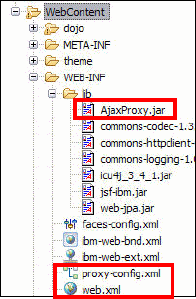
7672-dev-8-web20.fm Draft Document for Review December 9, 2008 2:44 pm
660 Rational Application Developer V7.5 Programming Guide
Structure of the Web 2.0 application
We leverage the existing JSF application in the Web 2.0 samples. The
application continues to consist of the following three pages:
Login page (logon): Validate the social security number (SSN). If it is valid it
then display the customer details for the customer. In the Web 2.0 exercise,
there will be two implementations of the login page which showcases two
different Ajax features.
Customer details page (customerDetails): Display the accounts of the
customer and allow you to select an account to view the transactions.
Account details page (accountDetails): Display the selected account details.
Ajax Proxy files
Earlier, we provided instructions on enabling Web 2.0 features within the We
project. Now, let us examine configuration details related to Ajax Proxy.
All of the relevant Ajax Proxy files are located in the WebContent/WEB-INF
directory (Figure 19-5).
Figure 19-5 Ajax Proxy related files
AjaxProxy.jar: contains all Ajax Proxy classes necessary for runtime and
compile time.
proxy-config.xml: contains proxy policy mapping information (such as URI to
HTTP method mapping, header mapping info, mime types, and cookies).
web.xml: The Web deployment descriptor is not a file specific to Ajax Proxy.
This file is part of the servlet specification. However, there are entries related
to Ajax Proxy which are registered into this file. There is a servlet mapping
entry for the controller servlet for Ajax Proxy (Example 19-1).
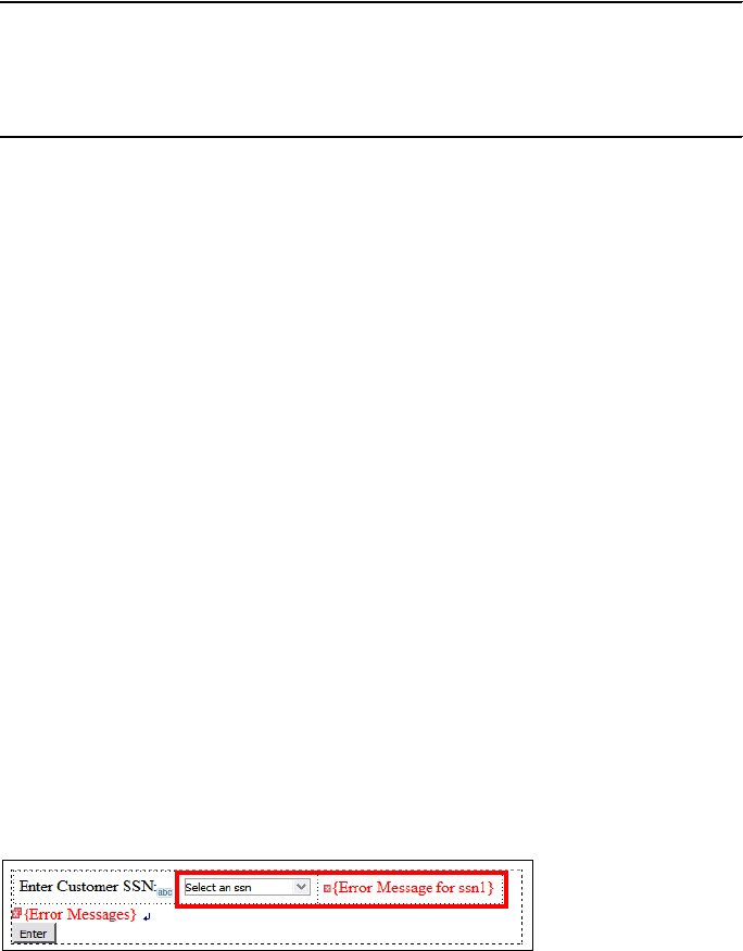
Chapter 19. Develop Web applications using Web 2.0 661
Draft Document for Review December 9, 2008 2:44 pm 7672-dev-8-web20.fm
Example 19-1 Ajax Proxy servlet
<servlet>
<servlet-name>ProxyServlet</servlet-name>
<servlet-class>
com.ibm.ws.ajaxproxy.servlet.ProxyServlet</servlet-class>
</servlet>
Adding type-ahead control to the login page
When a type-ahead control is attached to an input field, as a user types in the
field, a list of suggestions is constructed and displayed in a pop-up list box
attached to the field. Alternatively, as a user types, the field can be automatically
completed with a suggestion (and the user can keyboard to additional
suggestions. Type-ahead uses Ajax requests to communicate with the server
when building the list of suggestions. As a result, the page remains on display (it
is not submitted/redrawn) while the list is being build. The user interface remains
active while the list is being built.
In our sample, type-ahead control is used to generate suggestions for customer
SSN numbers. To keep the code simple, we generate static SSN numbers, but in
real applications, you would probably require complex generators.
Add type-ahead to the login page
To add type-ahead control to the login page, do these steps:
In the Web perspective, Enterprise Explorer, open the logon.jsp (in
RAD75Web20/WebContent).
We replace the drop-down box with a input text element to show the
type-ahead feature.
In the Design or Split tab, select the Select an ssn drop-down box and press
Delete. Then select the {Error Message for ssn1} and press Delete.
Drag an Input component from the Enhanced Faces Component palette into
the panel box, right after SSN:abc (make sure the generated source tag is
inside <hx:panelBox>).
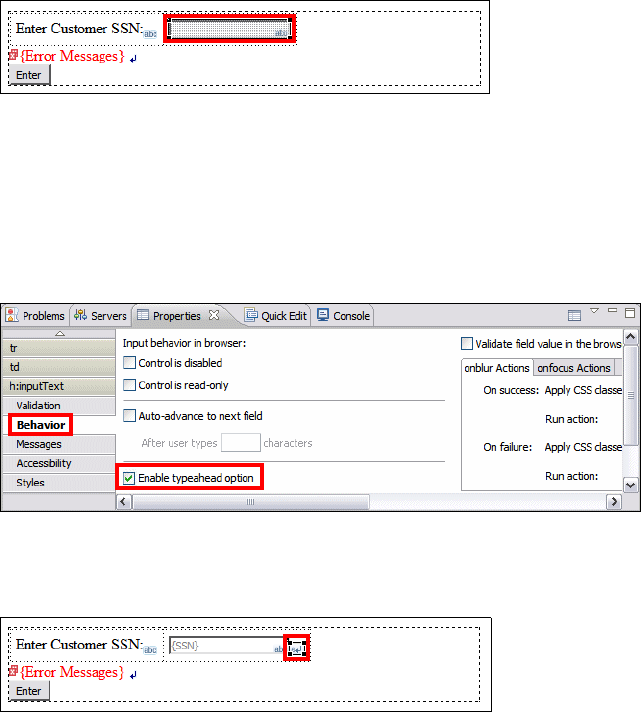
7672-dev-8-web20.fm Draft Document for Review December 9, 2008 2:44 pm
662 Rational Application Developer V7.5 Programming Guide
In the Page Data view, expand Scripting Variables → sessionScope and
drag the SSN on top of the input field to create the binding.
Select the {SSN} input text component and locate the Properties view. You
can see the value binding of #{sessionScope.SSN}.
In the Properties view, select Behavior under h:inputText, and select
Enable typeahead option.
An hx:inputHelperTypeahead tab is added to the Properties view. Notice that
the input field is now enabled for type-ahead support.
Generate a suggestion list
We have to generate a suggestion list for the type-ahead component. We can do
that by simply implementing a Java class that generates suggestions and returns
them in an ArrayList object. In our sample suggestions for the customer SSN
are generated in two ways:
A fixed list of SSNs (111-11-1111, 222-22-2222, ...)
A variable list of SSNs retrieved from the database using the CustomerManager
and JPA entities. This technique was used in the JSF application to populate
the drop-down list.
To create the suggestions class, do these steps:
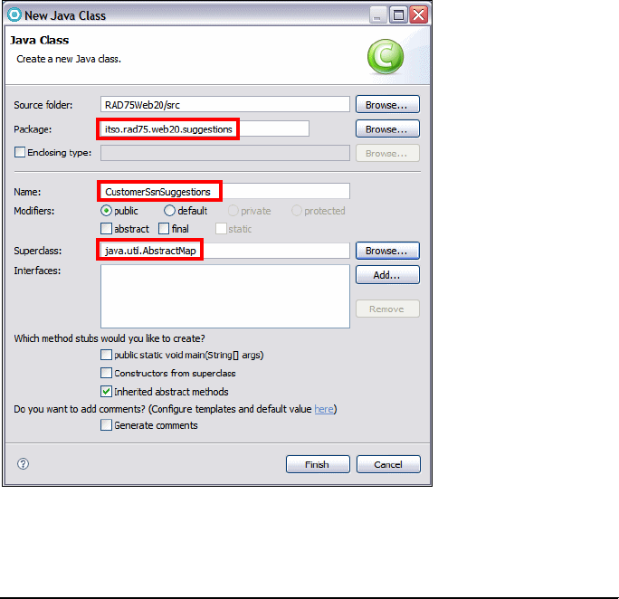
Chapter 19. Develop Web applications using Web 2.0 663
Draft Document for Review December 9, 2008 2:44 pm 7672-dev-8-web20.fm
In the Enterprise Explorer, right-click RAD75Web20 and select New →Class.
In the New Java Class dialog, enter these values:
–Package:
itso.rad75.web20.suggestions
–Name: CustomerSsnSuggestions
– Superclass: java.util.AbstractMap
– Click Finish.
The CustomerSsnSuggestions class opens in the editor. Replace the code
with c:\7672code\web20\CustomerSsnSuggestions.java (Example 19-2).
Example 19-2 Suggestions for customer keys
package itso.rad75.web20.suggestions;
import itso.bank.entity.controller.CustomerManager;
import java.util.AbstractMap;
import java.util.ArrayList;
import java.util.List;
import java.util.Set;
7672-dev-8-web20.fm Draft Document for Review December 9, 2008 2:44 pm
664 Rational Application Developer V7.5 Programming Guide
import javax.faces.model.SelectItem;
public class CustomerSsnSuggestions extends AbstractMap {
static ArrayList<String> ssnSuggestions = null;
int arrayLength = 10;
@Override
public Set entrySet() {
return null;
}
// generate fix set of SSNs
public Object get(Object key) {
if (ssnSuggestions == null) {
ssnSuggestions = new ArrayList<String>(arrayLength);
for (int i = 0; i < arrayLength; i++) {
String suggestion =
new String(i+""+i+""+i+"-"+i+""+i+"-"+i+""+i+""+i+""+i);
ssnSuggestions.add(suggestion);
}
}
return compareSuggestions(key);
}
// generate variable set of SSNs from the database
public Object get2(Object key) {
if (ssnSuggestions == null) {
CustomerManager customerManager = new CustomerManager();
List<SelectItem> list = customerManager.getCustomerSelectList();
ssnSuggestions = new ArrayList<String>(list.size());
for (SelectItem item: list) {
ssnSuggestions.add( (String)item.getValue() );
}
}
return compareSuggestions(key);
}
// compare user data with the list of SSNs
public Object compareSuggestions(Object key) {
String first = key.toString().substring(0,1);
System.out.println("SsnSuggestion input: " + key);
ArrayList<String> result = new ArrayList<String>(arrayLength);
for ( String entry: ssnSuggestions) {
if (first.equals( entry.substring(0,1) ))
result.add(entry);
}
// store result in session scope
FacesContext.getCurrentInstance().getExternalContext()
.getSessionMap().put("SSN", result.get(0));
return result;
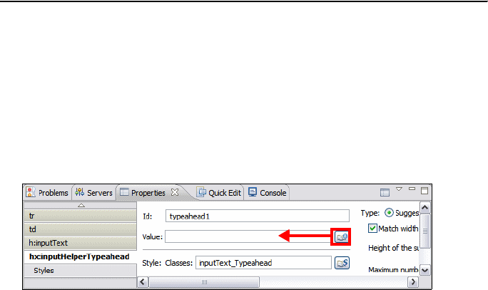
Chapter 19. Develop Web applications using Web 2.0 665
Draft Document for Review December 9, 2008 2:44 pm 7672-dev-8-web20.fm
}
}
We bind the CustomerSsnSuggestions class to type-ahead component.
–In
logon.jsp, Select the typeahead component (icon).
– In the Properties view, locate the hx:inputHelperTypeahead tab.
– Examine the other attributes of type-ahead component, such as maximum
number of suggestions displayed, delay time before a suggestion is made,
and match width of the suggestion area with the input field.
– click Browse for the Value field.
– In the Select Page Data Object dialog, click New Data Object.
– In the New Data Component dialog, select Faces Managed Beans →
Faces Managed Bean and click OK.
– In the Add JavaBean dialog, enter the following:
•Name:
ssnSuggestions
• Locate and select the CustomerSsnSuggestions class.
•Select
session scope.
•Select
Finish.
– In the Select Page Data Object dialog, select ssnSuggestions and click
OK. If the new bean is not visible, cancel the dialog, and open it again
from the Properties view, A value binding of #{ssnSuggestions} is
generated.
#{ssnSuggestions}

7672-dev-8-web20.fm Draft Document for Review December 9, 2008 2:44 pm
666 Rational Application Developer V7.5 Programming Guide
Test the logon page with type-ahead suggestions
To test the logon page with suggestions, execute the following steps:
In the Enterprise Explorer, expand RAD75Web20 → WebContent, right-click
logon.jsp, and select Run As → Run on Server.
Select the WebSphere Application Server v7.0 and click Finish to complete
publish onto the WebSphere Server.
In the login page, start typing 666 into the customer SSN field. As soon as
you stop typing, the suggestion list opens with customer SSN returned from
the suggestions bean (Figure 19-6).
Select the displayed SSN and click Submit to display the customer.
Figure 19-6 Testing the Ajax type-ahead feature
Notice that the type-ahead feature only displays SSNs from the list of all
SSNs that match the first character of the value entered.
Chapter 19. Develop Web applications using Web 2.0 667
Draft Document for Review December 9, 2008 2:44 pm 7672-dev-8-web20.fm
You can test the retrieve of SSNs from the database by renaming the
methods:
– get ==> get1 (fixed set of SSNs)
– get2 ==> get (variable set of SSNs from the database)
Adding Ajax refresh submit behavior
Ajax refresh submit behavior defines alternative content for the panel, which can
be asynchronously retrieved after the page has been loaded into the browser
without refreshing the whole page.
Whenever an action is triggered (for example, a button click), the client requests
the alternative content for the panel and it replaces the existing panel content
with new content. The page containing the panel is not replaced by the get,
instead, this tag allows part of the page to be replaced. The revised content is
retrieved from the same JSP from which the original content came.
Both the server life cycle copy of the page and the client-side page are kept in
sync. The new page content is retrieved using a post HTTP request operation.
The contents of the form containing the panel are posted as part of the request
so that the values in the form are available to the server code calculating the new
content to put in the panel.
In our example, we want to display a welcome message with the customer’s
name when an SSN is entered into the entry field.
Create an alternate logon page
We continue to leverage the resources in the existing JSF projects. In addition to
the existing JSP pages, we create an alternate logon JSP page. Refer to “Create
a Faces JSP page using the Web Diagram Editor” on page 503, and create a
JSP page called logon-ajax.jsp, or more simply:
In the Enterprise Explorer, right-click WebContent, and select New → Web
Page.
In the New Web Page dialog, type logon-ajax.jsp as name, select Basic
Template → JSP
, and click Finish:
Open both the logon-ajax.jsp and the existing logon.jsp, and in the Split tab
copy the content from logon.jsp to logon-ajax.jsp, starting with the tag:
<%@taglib uri="http://java.sun.com/jsf/core" prefix="f"%>
Do not copy the <%-- jsf:pagecode ....> tag. It must remain as:
<%-- jsf:pagecode language="java"
location="/src/pagecode/Logonajax.java" --%>

7672-dev-8-web20.fm Draft Document for Review December 9, 2008 2:44 pm
668 Rational Application Developer V7.5 Programming Guide
Select the Split tab, and save logon-ajax.jsp.
Copy the action code
We have to copy the action code for the Enter button to the new page.
Open Logonajax.java by right-clicking in the logon-ajax.jsp and selecting
Edit Page Code.
Open the Logon.java code in the same way.
Copy the doButton1Action method from Logon.java to Logonajax.java.
Close logon.jsp and Logon.java.
Select the editor of the logon-ajax.jsp, and in the Page Data view, expand
Page Bean and drag doButton1Action onto the Enter button in the JSP.
This creates the binding #{pc_Logonajax.doButton1Action}, and this method
is invoked when the Enter button is clicked,
Add an output field for the welcome message
To display the welcome message we use an output component.
Drag an Output component from the palette into the panel box, right after the
input field.
Add a getWelcome method to Logonajax.java (Example 19-3).
Example 19-3 Ajax getWelcome method
public String getWelcome() {
String welcome = "";
String ssn = (String)getSessionScope().get("SSN");
System.out.println("Ajax welcome: " + ssn);
try {
if (ssn != null) {
CustomerManager customerManager =
(CustomerManager)getManagedBean("customerManager");
Customer customer = customerManager.findCustomerBySsn(ssn);
welcome = "Welcome " + customer.getFirstName() + " " + customer
.getLastName() + "! Click Submit to logon ...";
}
} catch (Exception e) {
System.out.println("Ajax failed: " + e.getMessage());
welcome = "Ajax failed";
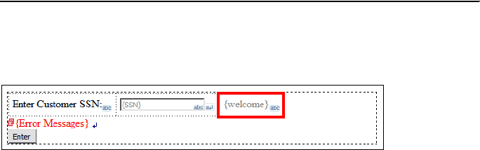
Chapter 19. Develop Web applications using Web 2.0 669
Draft Document for Review December 9, 2008 2:44 pm 7672-dev-8-web20.fm
}
return welcome;
}
From the Page Data view, drag the welcome property (under Page Bean)
onto the outputText field to create a binding of #{pc_Logonajax.welcome}. In
the source or Properties view, notice the id of the field, for example, text3.
This action retrieves the welcome message from the page code.
Add the navigation
When Enter is clicked, we want to display the customer details page.
In the Split tab, select the Enter button.
In the Properties view, click Add Rule (on the right side).
In the Add Navigation Rule dialog:
– For Page, select customerDetails.jsp.
–Select
The outcome named: and type login.
–Select
This page only (preselected).
– Click OK.

7672-dev-8-web20.fm Draft Document for Review December 9, 2008 2:44 pm
670 Rational Application Developer V7.5 Programming Guide
The navigation rule is added to the WEB-INF/faces-config.xml file.
Add Ajax refresh behavior
Finally we add the Ajax refresh behavior to the panel box and the input field.
In the logon-ajax.jsp select the panel box (<hx.panelBox> in the source).
In the Properties view, select Ajax under <hx.panelBox>.
Select Allow Ajax updates and Submit.
This action creates the tag:
<hx:ajaxRefreshSubmit target="box1" id="ajaxRefreshSubmit1"> </hx:ajax...>
Select the {SSN} input field.
Select the Quick Edit view (in the same pane as the Properties view):
–Select
onChange on the left.

Chapter 19. Develop Web applications using Web 2.0 671
Draft Document for Review December 9, 2008 2:44 pm 7672-dev-8-web20.fm
– Select Use pre-defined behavior.
– For Action, select Invoke Ajax behavior on the specified tag.
– For Target, select box1 (the id of the panel box).
Select ondblclick, and select the same behavior.
Notice the tags that are added under the input field:
<hx:behavior event="onchange" id="behavior1" behaviorAction="get"
targetAction="box1"></hx:behavior>
<hx:behavior event="ondblclick" id="behavior2" behaviorAction="get"
targetAction="box1"></hx:behavior>
Save the JSP, which also saves the Java code.
Test the logon page with Ajax refresh behavior
To test the Ajax refresh behavior, publish the application to the server.
Run the logon-ajax.jsp.
Start typing a customer SSN.
The type-ahead feature displays the matching SSN.
Select the SSN.
The onChange event does not seem to work.
Double-click in the input field and the welcome message appears.
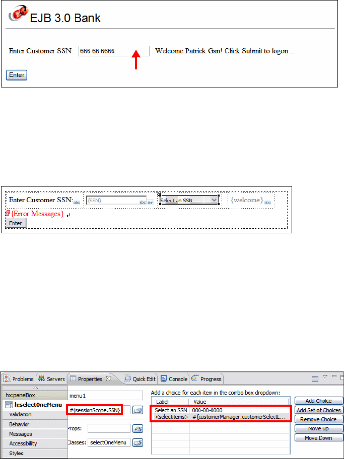
7672-dev-8-web20.fm Draft Document for Review December 9, 2008 2:44 pm
672 Rational Application Developer V7.5 Programming Guide
Click Enter to continue with the application.
Testing onChange behavior with a combo box
To test the refresh behavior without double-clicking we use a combo box.
Add a combo box next to the input field.
In the Properties view, click Add Choice and Add Set of Choices:
– For the first choice, set the label to Select an SSN, and the value to
000-00-0000.
– For the set of choices, accept the label as <selectitems>, and set the
value to #{customerManager.customerSelectList} (you can use the
Bind button).
Drop the session scope variable SSN onto the combo box to create a binding
of #{sessionScope.SSN}.
Testing the refresh
To test the Ajax refresh behavior, publish the application to the server.
Run the logon-ajax.jsp.
double-click
Chapter 19. Develop Web applications using Web 2.0 673
Draft Document for Review December 9, 2008 2:44 pm 7672-dev-8-web20.fm
Select an SSN from the drop-down list thast has been populated through the
CustomerManager.customerSelectList method.
The welcome message is displayed.
Cleanup
Remove the RAD75Web20EAR application from the server.
Developing a Web 2.0 application using Dojo and RPC
In this section we develop a Web application using the Web 2.0 technologies of
Dojo and RPC.
Project setup
We use two projects for this application:
RAD75Web20DojoEAR—Enterprise application with one Web module
RAD75Web20Dojo—Web application with facets for Web 2.0 and JPA, and
one Web page
Configuring the Web project
The focus of this sample is to show Dojo, RPC Adapter, and JPA working
together. For this reason, we will use an existing basic project with JPA properly
configured, and we enable it for Web 2.0.
Import the project interchange file from:

7672-dev-8-web20.fm Draft Document for Review December 9, 2008 2:44 pm
674 Rational Application Developer V7.5 Programming Guide
C:\7672code\web20\RAD75Web20-Dojo-Initial.zip
Select both projects (RAD75Web20Dojo and Rad75Web20DojoEAR). This
application is a copy of the JSF application developed in Chapter 16,
“Develop Web applications using JSF” on page 493.
Configure the Web project for Web 2.0 development:
– Right-click RAD75Web20Dojo and select Properties.
– In the Properties dialog, select Project Facets.
– In the Project Facets pane, select Web 2.0, which selects AJAX Proxy,
Dojo Toolkit, and Serverside technologies.
– Click OK.
Architecture of the Web 2.0 application
The sample application is based on JSF sample developed in Chapter 16,
“Develop Web applications using JSF” on page 493, with reduced functionality.
We will use the same JPA entities and rewrite the JSF pages to HTML with Dojo
Too lkit .
We will create three services (Figure 19-7):
CustomerServlet: Returns all SSN for the user selection.
CustomerService: Returns information and accounts for one SSN.
TransactionService: Returns information about a selected account.
Figure 19-7 Web 2.0 RPC dojo application structure
WebSphere Application Server v7.0
JPA
Entity
Entity
RPC Adapter
CustomerService
TransactionService
CustomerServlet
Using JSON4J
Client
Web
Page

Chapter 19. Develop Web applications using Web 2.0 675
Draft Document for Review December 9, 2008 2:44 pm 7672-dev-8-web20.fm
Exposing an RPC Adapter service
In this step we create the RPC Adapter service that returns a JSON response.
We require a service that returns the customer information by SSN.
To expose a service, do these steps:
In the Web perspective, select Window → Show View → Other →
General → Services.
In the Services view, right-click RPC Adapter and select Expose RPC
Adapter Service (Figure 19-8).
Figure 19-8 Exposing an RPC Adapter Service
In the Expose RPC Adapter Service dialog (Figure 19-9), enter the following
data:
– Web Project: RAD75Web20Dojo
– Class: itso.bank.entity.controller.CustomerManager
– Service Name: CustomerService
– Methods: Select findCustomerBySsn.
– Click Next.
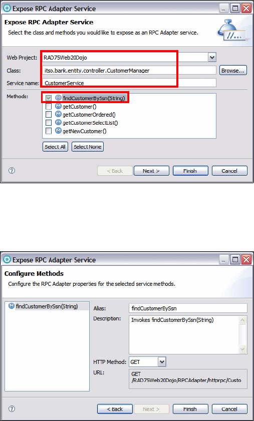
7672-dev-8-web20.fm Draft Document for Review December 9, 2008 2:44 pm
676 Rational Application Developer V7.5 Programming Guide
Figure 19-9 Exposing a service
In the Configure Methods dialog (Figure 19-10), accept the default options
and then click Finish.
Figure 19-10 Configure Methods
The service has been exposed. The RPC adapter is created in the Services
view and the findCustomerBySsn method is exposed (Figure 19-11).
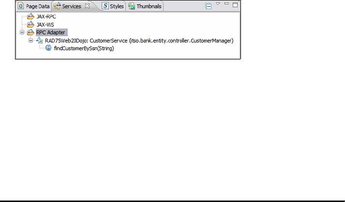
Chapter 19. Develop Web applications using Web 2.0 677
Draft Document for Review December 9, 2008 2:44 pm 7672-dev-8-web20.fm
Figure 19-11 RPC Adapter with an exposed service
When we create an RPV Adapter service, we are adding an abstract layer, no
matters which technology is used on the server to obtain the information
requested. The client side only needs to know the address (URL) and the format
of the data returned. Services provides encapsulation, reuse, and
loose-coupling.
The service is stored in the WebContent/WEB-INF/RpcAdapterConfig.xml file
(Example 19-4).
Example 19-4 RpcAdapterConfig.xml file (formatted)
<rpcAdapter ......>
<default-format>json</default-format>
<converters></converters>
<validators>
<validator id="default">
<validation-regex>([A-Za-z])+</validation-regex>
<validation-class>com.ibm.websphere.rpcadapter.DefaultValidator
</validation-class>
</validator>
</validators>
<services>
<pojo>
<name>CustomerService</name>
<implementation>itso.bank.entity.controller.CustomerManager</...>
<methods filter="whitelisting">
<method>
<name>findCustomerBySsn</name>
<alias>findCustomerBySsn</alias>
<description>Invokes findCustomerBySsn(String)</description>
<http-method>GET</http-method>
<parameters>
<parameter>
<name>ssn</name>
<type>java.lang.String</type>
<description></description>
</parameter>
</parameters>
</method>
</methods>
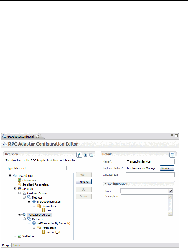
7672-dev-8-web20.fm Draft Document for Review December 9, 2008 2:44 pm
678 Rational Application Developer V7.5 Programming Guide
</pojo>
</services>
<serialized-params></serialized-params>
</rpcAdapter>
Adding the transaction service
Next, we define a service that returns the transactions of one account. Repeat
the same steps to expose this service.
In the Expose RPC Adapter Service dialog, enter the following items
Web Project: RAD75Web20Dojo
Class: itso.bank.entity.controller.TransactionManager
Service Name: TransactionService
Methods: select getTransactionByAccount
Click Finish.
RPC Adapter Configuration Editor
The configuration of the RPC Adapter in the RpcAdapterConfig.xml file can be
edited using the RPC Adapter Configuration Editor (Figure 19-12, which is
opened by double-clicking a service entry in the Services view, or double-clicking
the RpcAdapterConfig.xml file.
Figure 19-12 RPC Adapter Configuration Editor

Chapter 19. Develop Web applications using Web 2.0 679
Draft Document for Review December 9, 2008 2:44 pm 7672-dev-8-web20.fm
The RPC Adapter Configuration Editor makes it easy to configure the services.
This editor enables you to create, change, and remove services, add parameters,
create validators and other features about RPC adapter. The underlying XML
code can be viewed in the Source tab (Example 19-4 on page 677).
Creating an RPC Converter
Some type of classes require special handling by the RPC Adapter. For that
purpose we can create a converter.
For example, the getTransTime method of the Transaction entity class returns a
java.util.Date, but the JSON result is an OpenJPA subclass named
org.apache.openjpa.util.java$util$Date$proxy.
To create an RPC Converter, do these steps:
Open the RPC Adapter Configuration Editor.
Expand RPC Adapter →Converters, and click Add.
In the Add Item dialog, select Converter (the only choice), and click OK.
Select the new empty entry, and in the Details pane (Figure 19-13), enter:
– Bean: org.apache.openjpa.util.java$util$Date$proxy
– Converter: com.ibm.websphere.rpcadapter.converters.util.Date
Figure 19-13 RPC Adapter - Converter Details
Save and close the editor.
Creating a service using a servlet
We can create a service with a servlet, by writing the code to return a response
in JSON format.
Note: For this example, we use a servlet and the JSON4J library to
demonstrate a programmatic way to return information in JSON format.
7672-dev-8-web20.fm Draft Document for Review December 9, 2008 2:44 pm
680 Rational Application Developer V7.5 Programming Guide
To expose a servlet as a service, do these steps:
Right-click RAD75Web20Dojo and select New → Servlet.
In the Create Servlet dialog, enter the following items, and click Finish.
– Java Package: itso.bank.servlet
– Class Name: CustomerServlet
The CustomerServlet class opens in the editor. Use the code in
C:\7672code\web20\CustomerServlet.java to complete the code.
– Remove the constructor and the doPost method.
– Complete the doGet method (Example 19-5).
Example 19-5 Servlet doGet method
protected void doGet(......) throws ServletException, IOException {
response.setContentType("text/plain");
response.getWriter().write(getCustomers());
response.getWriter().flush();
response.getWriter().close();
}
– Add the getCustomers method (Example 19-6).
Example 19-6 Retrieving all customers and return a JSON object
private String getCustomers() {
JSONObject jSONObject = new JSONObject();
JSONArray jSONArray = new JSONArray();
try {
jSONObject.put("items", jSONArray);
CustomerManager customerManager = new CustomerManager();
List<Customer> customerList =
customerManager.getCustomerOrdered();
for (Customer customer : customerList) {
JSONObject obj = new JSONObject();
obj.put("ssn", customer.getSsn());
jSONArray.add(obj);
}
jSONObject.put("identifier", "ssn");
jSONObject.put("items", jSONArray);
} catch (Exception ex) {
ex.printStackTrace();
}
return jSONObject.toString();
}

Chapter 19. Develop Web applications using Web 2.0 681
Draft Document for Review December 9, 2008 2:44 pm 7672-dev-8-web20.fm
–Select Source → Organize Imports (or press Ctrl+Shift+O) to resolve
the classes (com.ibm.json.java.JSONObject, java.util.List).
The new getCustomers method returns a response in JSON format to
populate a combo box with a list of SSN.
Save and close the CustomerServlet.
Testing the services
Before writing any Web pages we can test the services that we created. Make
sure that the WebSphere Application Server v7.0 is started.
To test the services provided by the servlet, execute the following steps:
In the Enterprise Explorer, expand RAD75Web20Dojo, right-click the
CustomerServlet (either in the deployment descriptor or the Java class) and
select Run As → Run on Server.
The application is deployed to the server and the servlet is invoked. The result
of the servlet is displayed in Example 19-7.
Example 19-7 CustomerServlet execution result
{"items":[{"ssn":"000-00-0000"},{"ssn":"111-11-1111"},{"ssn":"222-22-2222"}
,{"ssn":"333-33-3333"},{"ssn":"444-44-4444"},{"ssn":"555-55-5555"},{"ssn":"
666-66-6666"},{"ssn":"777-77-7777"},{"ssn":"888-88-8888"},{"ssn":"999-99-99
99"}],"identifier":"ssn"}
To test the services provided by RPC Adapter, execute the following steps:
In the Services View, expand RPCAdapter → RAD75Web20Dojo:
CustomerService → findCustomerBySsn(String).
Right-click findCustomerBySsn(String) and select Run As → Run on
Server.
When prompted to save the file, click Cancel.
An information page is displayed, because the parameter is missing.
In the browser URL address, complete the request with a customer SSN:
https://localhost:944x/RAD75Web20Dojo/RPCAdapter/httprpc/CustomerService
/findCustomerBySsn?ssn=777-77-7777
Press Enter to send the request.
When prompted to save the file, click Save and navigate to a folder where you
can find the findCustomerBySsn file that is created.
Open the file in an editor (Example 19-8).
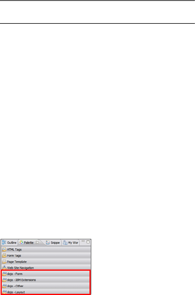
7672-dev-8-web20.fm Draft Document for Review December 9, 2008 2:44 pm
682 Rational Application Developer V7.5 Programming Guide
Example 19-8 JSON result of getCustomer request
{"result":{"lastName":"Gomes","title":"Mr","firstName":"Miguel","accountCol
lection":[{"transactCollection":null,"id":"007-777001","customerCollection"
:null,"balance":500.00}],"ssn":"777-77-7777"}}
Repeat the test for the getTransactionByAccount method of the
TransactionService. Use this URL:
https://localhost:944x/RAD75Web20Dojo/RPCAdapter/httprpc/TransactionServ
ice/getTransactionByAccount?account_id=002-222001
The result of this call is:
{"result":[{"transType":"Credit","transTime":"1990-01-01T23:23:23-0800","am
ount":2222.22,"id":"0000001","account":{"transactCollection":null,"id":"002
-222001","customerCollection":null,"balance":65484.23}},......]}
Creating the Web page
We want to display the results of the RPC calls on a Web page that contains:
A combo box populated with a list of SSN
A button to logon
A table with a list of accounts for the selected SSN
A table with a list of transactions for the selected account
To create the Web Page, following these steps:
In the Enterprise Explorer, expand RAD75Web20Dojo, right-click
WebContent, and select New → Web Page.
In the New Web Page dialog, enter the following values:
– File Name: Type index.html.
– Template: Select HTML/XHTML.
– Click Finish.
The HTML file opens in Page Designer. Because this is a Web 2.0 project, the
Palette has four additional drawers for dojo (Figure 19-14)
Figure 19-14 Dojo drawers in the Palette
Chapter 19. Develop Web applications using Web 2.0 683
Draft Document for Review December 9, 2008 2:44 pm 7672-dev-8-web20.fm
The index.html file has been added with some JavaScript and CSS code to
build Dojo applications (Example 19-9).
Example 19-9 HTML source with dojo imports
<script type="text/javascript" src="dojo/dojo/dojo.js"
djConfig="isDebug: true, parseOnLoad: true"></script>
<style type="text/css">
@import "dojo/dojo/resources/dojo.css";
@import "dojo/dijit/themes/tundra/tundra.css";
@import "dojo/dijit/themes/dijit.css";
Adding components to index.html
To design the HTML page, use the Source or Split tab in Page Designer. The
Design tab does not work well with Web 2.0 pages.
From the Palette, select dojo - Layout → BorderContainer and drag it onto
the page. This creates one line in the source:
<body class="tundra">
<div dojotype="dijit.layout.BorderContainer"></div>
</body>
Select the BorderContainer.
In the Properties view, set the style to height: 100%; width: 640px;. You can
use the Styles icon and set the values for Layout, or click the All
Attributes icon and set the style attribute there.
From the Palette, select dojo - Layout → ContentPane and drag it on top of
the BorderContainer.
Select ContentPane in the source, and in the Properties view enter the
following values:
– splitter=true
– region=top
–style=height: 150px; border: 1px solid black;
–id=logonPane
From the Palette, select HTML Tags → Table and drag it onto the page,
before the ending </div> tag of the ContentPane.
In the Table dialog, enter 2 for Rows and 3 for Columns, 0 for Border width,
and 10 for Spacing outside cells. Then click OK
In the first row (<tr>) and column (<td>) type Enter Customer SSN: .
In the third column add an id attribute with the value welcome and color
definitions:
table border="0" cellspacing="10">

7672-dev-8-web20.fm Draft Document for Review December 9, 2008 2:44 pm
684 Rational Application Developer V7.5 Programming Guide
<tbody>
<tr>
<td>Enter Customer SSN:</td>
<td></td>
<td id="welcome" style="color: blue;background-color: #eaeaea;"
align="center"></td>
</tr>
Add a heading <h2>Logon</h2> between the <div> tag and the <table>.
Create two more ContentPanel (without a table) after </table></div> tags:
<div preload="true" dojotype="dijit.layout.ContentPane" href=""></div>
<div preload="true" dojotype="dijit.layout.ContentPane" href=""></div>
Select the second ContentPane and in the Properties view enter the following
values:
– splitter=true
– region=center
–style=height: 100px; border: 1px solid black;
–id=accountPane
Select the third ContentPane and in the Properties view enter the following
values:
– splitter=true
– region=bottom
–style=height: 250px; border: 1px solid black;
–id=transactionPane
Basically, we divided the page in three regions: top, center, and bottom.
In the Palette, select dojo - Form → FilteringSelect and drag it onto page,
into the top reggion, first row and second column of the table.
Select FilteringSelect and in the Properties view enter the following values:
–store=
customStore
– searchAttr=ssn
–id=ssnCb
– invalidMessage=Enter a valid SSN
Edit the source of the FilteringSelect, and delete some of the attributes
(Example 19-10).
Example 19-10 Edit the FilteringSelect source
<select dojotype="dijit.form.FilteringSelect" name="select2"
Tip: Application Developer v7.5 provides content assist for dojo tags. Just
press Ctrl+Space inside a dojo tag.
Chapter 19. Develop Web applications using Web 2.0 685
Draft Document for Review December 9, 2008 2:44 pm 7672-dev-8-web20.fm
autocomplete="false" value="Val1" store="customStore"
searchattr="ssn" id="ssnCb" invalidmessage="Enter a valid SSN">
<option value="Val1" selected="selected">Value1</option>
<option value="Val2">Value2</option>
</select>
From the Palette, select dojo - Form → Button and drag it onto page, into
the second row and first column of the table.
Select Button and in the Properties view enter the following values:
–id=
logonBt
– label=Logon
In the Palette, select dojo - Others → Grid and drag it onto page, between
the <div> and </div> for the second ContentPane (accountPane). Change the
code to:
<div id="grid" dojotype="dojox.Grid" model="" structure="layout"
jsId="accountGrid" autoheight="true"></div>
Add a Grid to the third ContentPane (transactionPanel) and change the code
to:
<div id="grid0" dojotype="dojox.Grid" model="" structure="layout"
jsId="transactionGrid" autoheight="true"></div>
Add headings between the second and third ContentPane and the Grid:
<b>Accounts</b><p>
<b>Transactions</b><p>
Add the following code between <style type="text/css"> and </style>
tags, after the other imports:
@import "dojo/dojox/grid/_grid/tundraGrid.css";
In the Palette, select dojo - Others → ItemFileReadStore and drag it onto
page, after the <body class="tundra"> tag. Then change the code to:
<div dojotype="dojo.data.ItemFileReadStore" jsId="customStore"
url="/RAD75Web20Dojo/CustomerServlet"></div>
The index.html file is now complete (Example 19-11),
Example 19-11 Complete index.html file with dojo tags highlighted
<!DOCTYPE HTML PUBLIC "-//W3C//DTD HTML 4.01 Transitional//EN">
<html>
<head>
<script type="text/javascript" src="dojo/dojo/dojo.js"
Note: The jsId attribute was not in the Properties view. The jsId creates a
global JavaScript variable.
7672-dev-8-web20.fm Draft Document for Review December 9, 2008 2:44 pm
686 Rational Application Developer V7.5 Programming Guide
djConfig="isDebug: true, parseOnLoad: true"></script>
<script type="text/javascript">
dojo.require("dojo.parser");
dojo.require("dijit.layout.BorderContainer");
dojo.require("dijit.layout.ContentPane");
dojo.require("dijit.form.FilteringSelect");
dojo.require("dijit.form.Button");
dojo.require("dojox.grid.Grid");
dojo.require("dojo.data.ItemFileReadStore");
</script>
<script type="text/javascript" src="redBank.js" ></script> (added next)
<style type="text/css">
@import "dojo/dojo/resources/dojo.css";
@import "dojo/dijit/themes/tundra/tundra.css";
@import "dojo/dijit/themes/dijit.css";
@import "dojo/dojox/grid/_grid/tundraGrid.css";
</style>
<title>index</title>
<meta http-equiv="Content-Type" content="text/html; charset=ISO-8859-1">
</head>
<body class="tundra">
<div dojotype="dojo.data.ItemFileReadStore" jsId="customStore"
url="/RAD75Web20Dojo/CustomerServlet"></div>
<div dojotype="dijit.layout.BorderContainer"
style="height: 100%; width: 640px;">
<div preload="true" dojotype="dijit.layout.ContentPane" href=""
splitter="true" region="top"
style="height: 150px; border: 1px solid black;" id="logonPane">
<h2>Logon</h2>
<table border="0" cellspacing="10">
<tbody>
<tr>
<td>Enter Customer SSN:</td>
<td><select dojotype="dijit.form.FilteringSelect"
store="customStore" searchattr="ssn" id="ssnCb"
invalidmessage="Enter a valid SSN">
</select>
</td>
<td id="welcome" style="color: blue;background-color: #eaeaea;"
align="center"></td>
</tr>
<tr>
<td>
<div dojotype="dijit.form.Button" id="logonBt"
label="Logon"></div>
</td>
<td></td>
<td></td>
</tr>

Chapter 19. Develop Web applications using Web 2.0 687
Draft Document for Review December 9, 2008 2:44 pm 7672-dev-8-web20.fm
</tbody>
</table>
</div>
<div preload="true" dojotype="dijit.layout.ContentPane" href=""
splitter="true" region="center"
style="height: 100px; border: 1px solid black;" id="accountPane">
<b>Accounts</b><p>
<div id="grid" dojotype="dojox.Grid" model="" structure="layout"
jsId="accountGrid" autoheight="true">
</div>
</div>
<div preload="true" dojotype="dijit.layout.ContentPane" href=""
splitter="true" region="bottom"
style="height: 250px; border: 1px solid black;"
id="transactionPane">
<b>Transactions</b><p>
<div id="grid0" dojotype="dojox.Grid" model="" structure="layout"
jsId="transactionGrid" autoheight="true">
</div>
</div>
</div>
</body>
</html>
Creating the JavaScript file that drives the application
Most of the actions are driven by a JavaScript file (redBank.js):
Create a JavaScript source file:
–Select
File → New → Other → JavaScript → JavaScript Source File.
– In the New JavaScript file dialog, enter the following values:
• Parent Folder: /RAD75Web20Dojo/WebContent
• File Name: redBank.js
• Click Finish.
Complete the redBank.js with the code from C:\7672code\web20\redBank.js.
Add the following code into index.html between the <head> and </head>,
after the other <script> tags (before the <style> tag):
<script type="text/javascript" src="redBank.js" ></script>
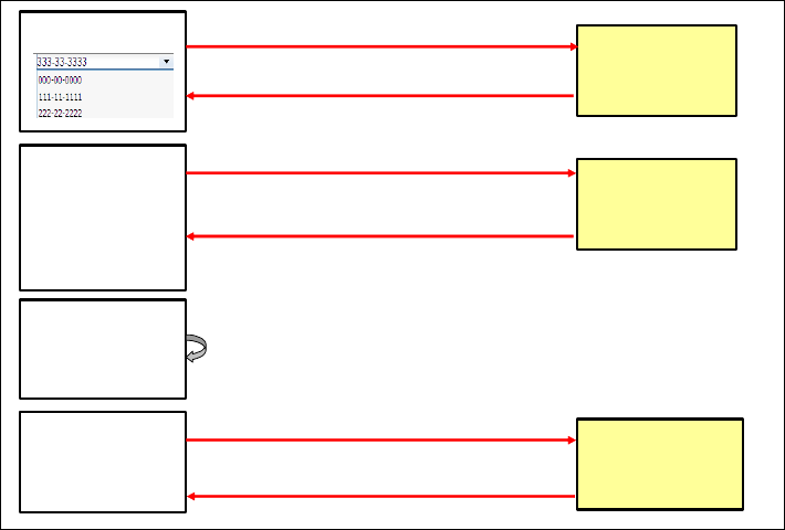
7672-dev-8-web20.fm Draft Document for Review December 9, 2008 2:44 pm
688 Rational Application Developer V7.5 Programming Guide
Examining the Dojo components
Let us explain some of the Dojo components that we added to the page:
dojo.data.ItemFileReadStore: Dojo provides a basic mechanism to store
information in JSON format. The url attribute is where the store looks for the
data, in our case by calling the CustomerServlet (which returns a list of SSN).
<div dojotype="dojo.data.ItemFileReadStore" jsId="customStore"
url="/RAD75Web20Dojo/CustomerServlet"></div>
dijit.form.FilteringSelect: This is an HTML select tag that can be
populated dynamically. The store attribute refers to the ItemFileReadStore,
and ssn is the search attribute.
<select dojotype="dijit.form.FilteringSelect" store="customStore"
searchattr="ssn" id="ssnCb" invalidmessage="Enter a valid SSN">
</select>
dojox.Grid: This is a basic grid, with a layout (rows and columns) and a
model (the contents).
Application flow
Figure 19-15 shows how the information is retrieved and displayed.
Figure 19-15 Dojo application flow
1. Page Loading...
CustomerServlet
1.2 {"items":[{"ssn":"000-00-0000"},{"ssn":"111-11-
1111"},{"ssn":"222-22-2222}
2.2{"result":{"lastName":"Gomes","title":"Mr","firstName":"Miguel","accountCollecti
on":[{"transactCollection":null,"id":"007-
777001","customerCollection":null,"balance":1200.00}],"ssn":"777-77-7777"}}
1.1 /CustomerServlet
2. Page was loaded
and an SSN is selected
2.3 The name of the
customer is displayed
and account
information is stored
into a variable
2.1 /Customer Service/findCustomerBySsn?ssn=777-77-7777
3. Logon button is
clicked
3.1 Account grid is
populated (with
previous variable)
CustomerService
TransactionService
4. Some cell of the
Account grid is clicked
4.3 Transaction grid is
populated
4.2{"result":[{"transType":"Credit","transTime":"2008-10-30T16:27:52-
0700","amount":1200.00,"id":"50159a85-011d-fc52-1764-
09080705aa77","account":{"transactCollection":null,"id":"007-777001“…
4.1 /TransactionService/getTransactionByAccount?account_id=007-777001
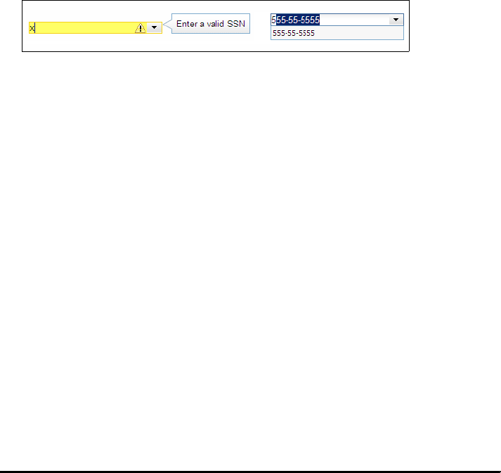
Chapter 19. Develop Web applications using Web 2.0 689
Draft Document for Review December 9, 2008 2:44 pm 7672-dev-8-web20.fm
Page loading
When the page is loading the dojo.data.ItemFileReadStore calls the
CustomerServlet to populate dijit.form.FilteringSelect. The
FilteringSelect provides facilities such as:
Input validation: If the user types a value that not exists in the list, a warning
message (customized message) is displayed (Figure 19-16).
Type-ahead: While the user is typing, the field is automatically completed with
a suggestion (Figure 19-16).
Figure 19-16 Input validation and type-ahead
Drop-down box: the user can select an item from the drop-down box that is
populated with the customer SSNs.
Initialization
The init method (in redBank.js) prepares the getInfo function for a combo box
selection (onChange), and the logon function for the Logon button (onClick).
function init() {
button = dijit.byId("logonBt");
combo = dijit.byId("ssnCb");
var getInfo = function(){
getCustomerInformation(combo.getValue());
};
dojo.connect(combo, "onChange", getInfo);
dojo.connect(button, "onClick", logon);
}
Calling a service to get the information
The getInfo function call the getCustomerInformation function. So, when the
user selects a valid SSN, the getCustomerInformation function calls a service ()
CustomerService) to get information about the SSN selected (Example 19-12).
Example 19-12 JavaScript getCustomerInformation function in redBank.js
var getCustomerInformation=function(ssn){
var serviceURL = "/RAD75Web20Dojo/RPCAdapter/httprpc/CustomerService
/findCustomerBySsn?ssn="+ssn;
dojo.xhrGet({
url: serviceURL,
load: getCustomerFields,
error: handleError,

7672-dev-8-web20.fm Draft Document for Review December 9, 2008 2:44 pm
690 Rational Application Developer V7.5 Programming Guide
handleAs: 'json'
});
};
The dojo.xhrGet returns the contents of a GET call on a URL. The data that is
arriving will be passed to the load: function, getCustomerFields, which displays
the welcome message in the field with the welcome id. The text appears with a
fade-in effect.
function getCustomerFields(data,ioArgs){
customer = data.result;
var out= dojo.fadeOut({ node: "welcome",duration: 500 });
dojo.connect(out,"onEnd",function(){
dojo.byId("welcome").innerHTML=" Welcome: " +
customer.firstName + " " + customer.lastName + " ! ";
dojo.fadeIn({ node:"welcome", duration:1000,delay:100 }).play();
});
out.play();
clearTables();
}
Application Developer provides a easy way to obtain the URL of a service
exposed by the RPC Adapter:
In the Services view, expand the RPCAdapter → RAD75Web20Dojo:
CustomerService.
Right-click findCustomerBySsn(String) and select Copy Service URL to
Clipboard.
Paste the clipboard content into the JavaScript code:
/RAD75Web20Dojo/RPCAdapter/httprpc/CustomerService/findCustomerBySsn
Logon
When the Logon button is clicked, the logon function displays the accounts of
the customer in the account grid through the fillAccountGrid function.
var logon=function(){
fillAccountGrid(customer.accountCollection);
};
Displaying the accounts
The fillAccountGrid function defines the headers of the account listing and fills
the grid with data. Note that the width of the columns can be set, a formatter
function is invoked for the balance, and the value is right aligned.
Chapter 19. Develop Web applications using Web 2.0 691
Draft Document for Review December 9, 2008 2:44 pm 7672-dev-8-web20.fm
function fillAccountGrid(account){
accountView = {
cells: [
[{name:'ID'},
{name:'Balance',width:'110px',formatter:formatterCurrency,
styles:'text-align: right;'}]
]
};
// a grid layout is an array of views.
accountLayout = [ accountView ];
accountData=[];
// Model for the Data Grid
accountModel = new dojox.grid.data.Table(null,accountData);
for(i=0;i<account.length;i++){
console.log(account[i]);
accountData.push([account[i].id,account[i].balance]);
}
accountModel.setData(accountData);
accountGrid.setModel(accountModel);
accountGrid.setStructure(accountLayout);
dojo.connect(accountGrid, "onCellClick", showDetails);
}
When the user clicks on an account (onCellClick), the showDetails function in
invoked.
Account selection
When an acocunt is selected (click), the showDetails function calls the
getTransactionInformation function to retrieve the transactions of the account:
function showDetails(e){
getTransactionInformation(accountModel.getDatum(e.rowIndex,0));
}
The getTransactionInformation function (same as the getCustomerInformation
function) calls a service (TransactionService) to retrieve the transactions.
var getTransactionInformation=function(id){
var serviceURL = "/RAD75Web20Dojo/RPCAdapter/httprpc/TransactionService
/getTransactionByAccount?account_id="+id;
dojo.xhrGet({
url: serviceURL,
load: fillTransactionGrid,
error: handleError,
handleAs: 'json'
});
};

7672-dev-8-web20.fm Draft Document for Review December 9, 2008 2:44 pm
692 Rational Application Developer V7.5 Programming Guide
The fillTransactionGrid function displays the transactions in the grid, similar to
the fillAccountGrid function.
transactionView = {
cells: [
[{name:'Timestamp',width:'180px'},{name:'Type'},
{name:'Amount',width:'75px',formatter:formatterCurrency,
styles:'text-align: right;'},
{name:'ID',width:'280px'}]
]
};
The formatterCurreny function adds the currency sign to the value.
function formatterCurrency(value){
dojo.require("dojo.currency");
return dojo.currency.format(value, {currency: "USD"});
}
Logging
Dojo provides a mechanism for logging in the application. To log certain events:
Include the isDebug configuration parameter (Example 19-13).
Example 19-13 JavaScript function dojo.js for logging
<script type="text/javascript" src="dojo/dojo/dojo.js"
djConfig="isDebug: true, parseOnLoad: true">
</script>
When the isDebug flag is true, we can log the application execution using the
console.log call (Example 19-14).
Example 19-14 JavaScript code for logging (in fillAccountGrid function)
for(i=0;i<account.length;i++){
console.log(account[i]);
accountData.push([account[i].id,account[i].balance]);
}
The result of a logging call appears in the browser at the bottom as
{002-222001}, and when clicked shows the details:
transactCollection : {}
id : 002-222001
customerCollection : {}
balance : 65484.23
To disable the log, just change isDebug: false.
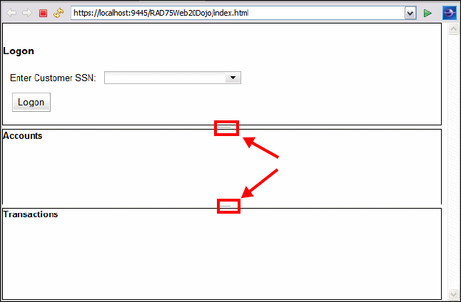
Chapter 19. Develop Web applications using Web 2.0 693
Draft Document for Review December 9, 2008 2:44 pm 7672-dev-8-web20.fm
Running the application
In the Enterprise Explorer, expand RAD75Web20Dojo → WebContent, then
right-click index.html, and select Run As → Run on Server.
On the subsequent dialog box, select Finish to complete publishing onto the
WebSphere Application Server.
When prompted with a security alert, click Yes.
The home page displays (Figure 19-17):
– You can drag the borders between the section to adjust their size.
– If the bottom part of the page does not display, you can maximize the
browser pane, or you can use an external browser (select Window →
Web Browser → Internet Explorer).
Figure 19-17 Web 20.0 dojo application run
You can use the drop-down menu to select an SSN, or you can start typing an
SSN and the type-ahead feature displays the matching number
(Figure 19-18).
drag lines to adjust size
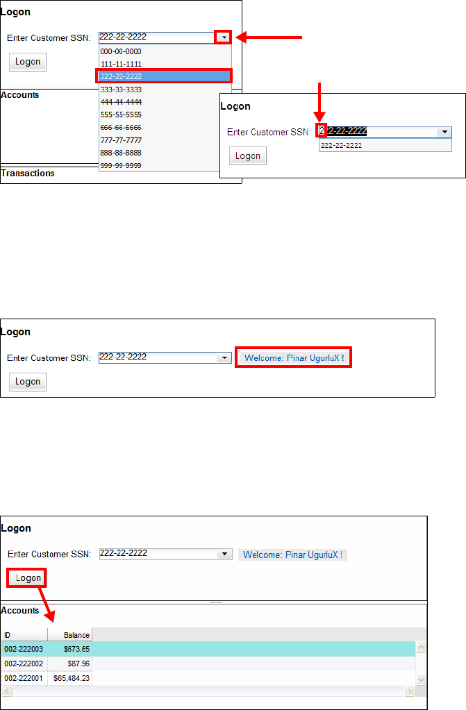
7672-dev-8-web20.fm Draft Document for Review December 9, 2008 2:44 pm
694 Rational Application Developer V7.5 Programming Guide
Figure 19-18 Selecting a customer using type-ahead or drop-down
Remember that the drop-down list was populated through the servlet that
retrieved the list of customer SSNs.
When a customer SSN is selected, the welcome message with the customer
name is displayed with a fade-in effect (Figure 19-19).
Figure 19-19 Welcome message
Remember that the customer with the accounts is retrieved by the RPC
service CustomerService, which invokes the findCustomerBySsn method.
Click Logon to populate the account list (Figure 19-20).
Figure 19-20 Customer with list of accounts
type-ahead
drop-down list

Chapter 19. Develop Web applications using Web 2.0 695
Draft Document for Review December 9, 2008 2:44 pm 7672-dev-8-web20.fm
Click on one account to display its transactions (Figure 19-21).
Figure 19-21 Account transactions
Remember that the transactions of an account are retrieved by the RPC
service TransactionService, which invokes the getTransactionByAccount
method.
Cleanup
Remove the RAD75Web20DojoEAR application from the server.
Final code
To run the Web application you must have completed the sample Web 2.0
application:
Either you completed the Web 2.0 application as described in “Developing a
Web 2.0 using JSF, Ajax Proxy, and JPA” on page 658, and “Developing a
Web 2.0 application using Dojo and RPC” on page 673.
Or, you can import the interchange file of the applications from:
c:\7672code\zInterchange\web20\RAD75Web20-Ajax.zip
c:\7672code\zInterchange\web20\RAD75Web20-Dojo.zip
Refer to “Importing sample code from a project interchange file” on
page 1152 for details.
You also must have set up the ITSOBANK database as described in “Setting up
the sample database” on page 657.
you can drag the lines to adjust the size
7672-dev-8-web20.fm Draft Document for Review December 9, 2008 2:44 pm
696 Rational Application Developer V7.5 Programming Guide
So far we have a Web 2.0 application with Ajax, Dojo, and JPA access to a
relational database. We could certainly enhance the appearance of the pages
and the error messages.
More information on Web 2.0 and JSF
For more information on JSF and Ajax, we recommend the following resources.
Dojo Toolkit
http://dojotoolkit.org/
JSON
http://www.json.org/
REST
http://en.wikipedia.org/wiki/Representational_State_Transfer

© Copyright IBM Corp. 2008. All rights reserved. 697
Draft Document for Review December 9, 2008 2:44 pm 7672-dev-9-jca.fm
Chapter 20. Develop applications to
connect to enterprise
information systems
Java EE Connector Architecture (JCA) plays a key role in the integration of
applications and data using open standards. This chapter introduces JCA, and
demonstrates by example how to access operations and data on enterprise
information systems (EIS) such as CICS, IMS™, SAP, Siebel®, PeopleSoft, JD
Edwards®, and Oracle within the Java EE platform.
We describe how to develop Java EE applications using Java EE Connector tools
within Application Developer v7.5.
The chapter is organized into the following sections:
Introduction to Java EE Connector Architecture
Application development for EIS
Sample application overview
More information
20
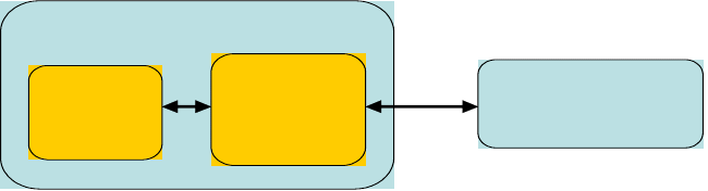
7672-dev-9-jca.fm Draft Document for Review December 9, 2008 2:44 pm
698 Rational Application Developer V7.5 Programming Guide
Introduction to Java EE Connector Architecture
Java EE Connector Architecture (JCA) is a standard architecture for connecting
enterprise information systems (EIS) such as CICS, IMS, Sap, Siebel,
Peoplesoft, JD Edwards, and Oracle. JCA standardizes the way Java EE
application components, Java EE compliant application servers and EIS
resources interact with each other. Resource adapters and application servers
implement the contract defined in the JCA specification. Resource adapters run
in the context of the application server and enable J2EE application components
to interact with the EIS using a common client interface. JCA compliant
application servers can support any JCA compliant resource
Figure 20-1 shows the Java EE component connected to an EIS through the JCA
resource adapter.
Figure 20-1 Java EE component connecting to EIS through JCA resource adapter
JCA was developed under the Java Community Process as JSR 16 (JCA 1.0)
and JSR 112 (JCA 1.5), which is the current version.
System contracts
In this section we learn about the basic components of the JCA architecture. JCA
defines a standard set of system-level contracts between the Java EE application
server and a resource adapter. The application server and the resource adapter
connect and interact with each other using the system contracts.
Seven types of system contracts are defined in the JCA specification:
Connection management contract: Allows the application server to create a
physical connection to the EIS. It also provides a mechanism for the
application sever to manage connection pooling.
Transaction management contract: Provides transactional support allowing
the EIS to participate in a transaction. Transactions can be managed by the
application server’s transaction manager with multiple EISs and other
resources as participants.
Application Server
Enterprise Inform ation
System
(EIS)
JCA Resource
Adapter
Java EE
component
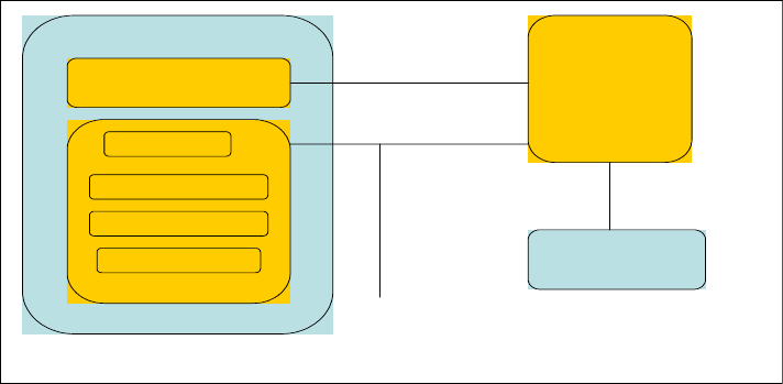
Chapter 20. Develop applications to connect to enterprise information systems 699
Draft Document for Review December 9, 2008 2:44 pm 7672-dev-9-jca.fm
Security contract: Allows application components in an application server to
access the EIS securely. The security contract is an extension of the
connection management contract implemented by adding Java Authentication
and Authorization Service (JAAS) into connection management interfaces.
Life cycle management contract: Allows the application server to manage
the life cycle of the resource adapter. It provides a mechanism for the
application server to start and shutdown an instance of the resource adapter.
Work management contract: Allows the resource adapter to submit work to
the application server for execution. The application server dispatches a
thread to handle the work. This contract is optional.
Transaction inflow contract: Allows the EIS to propagate a transaction
through the resource adapter to the application server.
Message inflow contract: Allows the resource adapter to pass synchronous
or asynchronous inbound messages to message endpoints on the application
server.
Figure 20-2 shows the integration between EIS, application server and
application component. These components are bound together using JCA
contracts.
Figure 20-2 System contract, application server, resource adapter integration
To find out more about JCA Specification, visit the JCA specification Web site at:
http://java.sun.com/j2ee/connector/download.html
Application Server
Enterprise Inform ation
System
(EIS)
JCA Resource
Adapter
Java EE component
Application Contract
System Contract
EIS Specific
Interface
Life Cycle Management, W ork Management
Connection Management, Transaction Management
Security Management, Transaction Inflow Management
Message Inflow Management
Work Manager
Connection Manager
Transaction Manager
Security Manager
7672-dev-9-jca.fm Draft Document for Review December 9, 2008 2:44 pm
700 Rational Application Developer V7.5 Programming Guide
Resource adapter
To achieve a standard system-level pluggability between application servers and
EISs, the JCA architecture defines a standard set of system-level contracts
between an application server and EIS as discussed in “System contracts” on
page 698. The JCA resource adapter implements the EIS-side of these
system-level contracts.
A JCA resource adapter is a system-level software driver used by an application
server or an application client to connect to an EIS. By plugging into an
application server, the resource adapter collaborates with the server to provide
the underlying mechanisms, the transactions, security, and connection pooling
mechanisms. A JCA resource adapter is used within the address space of the
application server.
The list of JCA Resource Adapters available to you in Application Developer v7.5
include:
CICS ECI adapter 5.1.0.3
CICS ECI adapter 6.0.2.x
CICS ECI adapter 7.1.0.x
CICS ECI XA adapter 7.1.0.x
IMS resource adapter 10.2.0
IMS resource adapter 9.1.0.2.5a (Support for English only)
IMS resource adapter 9.1.0.1.5b
JCA resource adapters support two-way communication between the Java EE
components and an EIS:
An outbound communication is initiated by a J2EE component, which acts
as a client to access an EIS.
An inbound communication is initiated by the EIS to notify a Java EE
component, which subscribed for events from that EIS. Inbound
communications are performed asynchronously using the messaging
infrastructure provided by the hosting application server as message
providers.
Java EE components that use the resource adapter may co-reside with the
adapter on the same application server or operate remotely.

Chapter 20. Develop applications to connect to enterprise information systems 701
Draft Document for Review December 9, 2008 2:44 pm 7672-dev-9-jca.fm
Common Client Interface
The Common Client Interface (CCI) is a standard API that allows application
components and Enterprise Application Integration (EAI) frameworks to interact
with the resource adapter. It provides a standard way for application components
to invoke functions on an EIS and get the returned results. The CCI is intended
for use by Enterprise Application Integration (EAI) and enterprise tools vendors.
So, WebSphere Adapters use CCI for outbound communication with an EIS.
WebSphere Adapters
WebSphere Adapter portfolio is a new generation of adapters based on the Java
EE Platform, Enterprise Edition standard. A WebSphere Adapter implements the
JCA specification 1.5. Also known as resource adapters or JCA adapters,
WebSphere Adapters enable managed, bidirectional connectivity and data
exchange between a number of EIS resources including PeopleSoft, SAP, Siebel,
JD Edwards, and Oracle.
The list of WebSphere Adapters available in Rational Application Developer v7.5
include:
WebSphere Adapter for JDBC
WebSphere Adapter for Sap Software
WebSphere Adapter for Sap Software with transaction support
WebSphere Adapter for Siebel Business Applications
WebSphere Adapter for PeopleSoft
WebSphere Adapter for JD Edwards EnterpriseOne
When developing a custom JCA compliant resource adapter, you can choose to
develop either the WebSphere type of resource adapter or the base JCA type of
resource adapter. WebSphere Adapters are fully compliant with the JCA 1.5
specification and contain IBM extensions. If you choose to develop an IBM
WebSphere type of resource adapter, you can leverage the services provided by
the adapter foundation classes. You can extend the generically implemented
system contract classes to fit the needs of your custom adapter. Your custom
adapter can also make use of the built-in utility APIs to handle common adapter
tasks. Using adapter foundation classes significantly reduces your development
time and effort to create a custom adapter.
Note: For more information on custom adapter development, refer to
WebSphere Adapter Development, SG24-6387, at:
http://www.redbooks.ibm.com/abstracts/sg246387.html
7672-dev-9-jca.fm Draft Document for Review December 9, 2008 2:44 pm
702 Rational Application Developer V7.5 Programming Guide
Application development for EIS
Rational Application Developer v7.5 simplifies application development for EIS by
providing wizard based tools and a list of adapters ready to use. This section
introduces these tools and their capabilities.
The Java EE Connector tools enable you to create Java EE applications running
on WebSphere Application Server to access operations and data on enterprise
information systems (EIS). J2C tools offer a number of qualities of service that
can be provided by an application server:
Security credential management
Connection pooling
Transaction management
These qualities of service are provided by means of system-level contracts
between a resource adapter provided by the connector (for example, CICS
Transaction Gateway or IMS Connect), and the application server.
Importers
IMS or CICS ECI transactions are often written in COBOL, C, or PL/I. For a Java
application to access these transactions through J2C resource adapters, the
data has to be imported and mapped to Java data structures. The importers are
tools that deliver this data mapping. Three importers are available for you to use
in your application: C Importer, COBOL Importer, and PL/I Importer. Once you
import a COBOL, C, or PL/I file into a project, you can work with this data as you
would with any data construct.
J2C wizards
Rational Application Developer v7.5 provides J2C wizards that enable you to
create J2C applications, either as standalone programs or as added function to
existing applications. The wizards
Dynamically import your selected resource adapter
Allow you to set the connection properties to connect to the EIS servers
Guide you through the file importing and data mapping steps
Facilitate the creation of Java classes and methods to access the transformed
source data
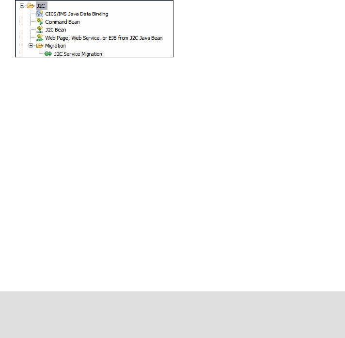
Chapter 20. Develop applications to connect to enterprise information systems 703
Draft Document for Review December 9, 2008 2:44 pm 7672-dev-9-jca.fm
A typical J2C application consists of a J2C JavaBean with one or more methods
that call EIS functions. For CICS and IMS, the input and outputs to these
functions are data binding classes that are created by the CICS/IMS Java Data
Binding Wizard. When you have created a J2C JavaBean, you then can create
Web pages, an EJB, or a Web service for the JavaBean.
To use the J2C wizard within Application Developer v7.5 follow these steps:
Switch to the Java EE perspective.
Select File → New → Other → J2C and select the J2C wizard that you want
to launch (Figure 20-3).
Figure 20-3 J2C wizards
CICS or IMS Java Data Binding: You can create the data binding classes on
their own. These classes are used in J2C methods that invoke CICS or IMS
functions.
Command Bean: You can use this wizard (optionally) to expose selected
methods as a command bean.
J2C Bean: You can use this wizard to create a JavaBean that communicates
with an EIS through JCA.
Web page, Web service, or EJB from J2C Java Bean: You can use this
wizard to create a Java EE resource that wraps the functionality provided by a
J2C JavaBean. For example, you can create a JSP to deploy the J2C bean on
WebSphere application server. The Java EE resource types available with this
wizard are: Simple JSP, Faces JSP, EJB, and Web service.
J2C Service Migration: You can use this wizard to migrate JCA applications
created in WebSphere Studio Application Developer Integration Edition
applications into Rational Application Developer projects.
Note: For more information on J2C wizard, refer to the Rational Application
Developer InfoCenter at:
http://publib.boulder.ibm.com/infocenter/radhelp/v7r5/index.jsp
7672-dev-9-jca.fm Draft Document for Review December 9, 2008 2:44 pm
704 Rational Application Developer V7.5 Programming Guide
What is new in Application Developer v7.5
This section describes the principal new features of J2C tools in Application
Developer 7.5, as well as changes in the behavior of features present in previous
versions. These include:
Tooling for WebSphere Adapters
Deployment of Websphere Adapters to WebSphere Application Server
J2C Java bean deployment: EJB 2.1 and 3.0 support
J2C Java bean deployment: Web services support
CICS container link support
MFS support for IMS
Tooling for WebSphere Adapters
This section describes how you can install the WebSphere Adapters and which
tooling support is available to generate and maintain J2C beans.
Distinct installation features
Installation Manager now offers the following individually selectable features:
Java EE Connectors (J2C) Tools
WebSphere Adapters
When you select to install WebSphere Adapters they are copied into:
<RAD_installation>\ResourceAdapters
Generation of J2C beans
You can generate a J2C bean for one of the WebSphere Adapters specifying
either outbound and inbound support. You can specify connection information to
browse the EIS metadata while stepping through the wizard. The output is based
on the selected objects and methods that are discovered, and it consists of Java
data binding beans (along with the XSD that they are created from), and a J2C
Java bean.
Code regeneration, refactoring, and clean up
The J2C Java data bindings life cycle is based on the generation of the following
artifacts from the discovered EIS metadata:
XSD → Java data binding → J2C Java bean
Chapter 20. Develop applications to connect to enterprise information systems 705
Draft Document for Review December 9, 2008 2:44 pm 7672-dev-9-jca.fm
The following scenarios are supported:
Editing of the data type schema and regeneration of J2C Java data binding:
– Use the XSD editor to modify one of the generated XSD files.
– Right-click on the XSD file and select: Source → Generate J2C Java
data bindings.
Note: even if you select a leaf schema all the records corresponding to the top
most schema will be regenerated.
Cleanup of unused J2C Java data bindings: After making multiple changes to
the XSD files and regenerating the Java data bindings it is possible that the
workspace contains Java data binding classes which are no longer
associated with any types in the XDS files. To clean up the workspace do the
following:
– Right-click on the XSD file and select: Source → Remove unused J2C
Java data bindings.
Refactoring of XSD type name and regeneration of corresponding J2C Java
data bindings:
– Right-click on a type in the XSD editor and select Refactor → Rename.
– The J2C Java beans and other Java types that depend on that J2C Java
data binding are refactored as well, to reference the J2C Java data binding
by its new name.
Deployment of Websphere Adapters to WebSphere Application
Server
By default, WebSphere Adapters are deployed to WebSphere Application Server
when you run the Web page, an EJB, or Web service to deploy your J2C Java
bean wizard. Many WebSphere Adapters require additional files provided by the
EIS vendors. For the resource adapter to function properly, these files have to be
added to the resource adapters class path. The class path of the installed
adapter is automatically updated on the server the next time publishing occurs,
based on the connection information provided when generating the J2C bean.
The end result of the automated deploy can be viewed from the administrative
console, looking at Resources→ Resource Adapters → Resource adapters.
If you have to use different versions of the adapter for different projects, you may
have to deploy the RAR file in the Enhanced EAR so that it is visible only to one
application EAR. To deploy the RAR in the Enhanced EAR, perform the following
steps:
Add the RAR module to the EAR project.
7672-dev-9-jca.fm Draft Document for Review December 9, 2008 2:44 pm
706 Rational Application Developer V7.5 Programming Guide
Open the Enhanced EAR editor and add a new shared library.
Specify the Shared library parameters (name, description, application
dependency files and native system dependency files) and click OK.
Deploy the EAR to the server.
This process is described in detail in the resource adapter documentation under
Developing → Developing Enterprise Applications → Connecting to Enterprise
Information Systems → Resource Adapters → WebSphere Adapters for
PeopleSoft, SAP, Siebel, JD. Edwards, and Oracle.
J2C Java bean deployment: EJB 2.1 and 3.0 support
The wizard File → New → Other → J2C Web Page, Web Service, or EJB from
J2C Java Bean allows you to deploy the J2C beans as Enterprise Java Beans
implementing the EJB specification 2.1 or 3.0.
Deployment of J2C beans as EJB 2.1
When deploying a J2C bean as an EJB 2.1, XDoclet EJB tags are used to define
the EJB. If the J2C Java bean is located in a Java project, the code is copied into
the EJB project before the XDoclet tags are added.
Deployment of J2C beans as EJB 3.0
When deploying a J2C bean as an EJB 3.0 to an Application Server v7.0 (or v6.1
with the Feature Pack for EJB 3.0), the @Stateless annotation is used to define
the stateless EJB. If the J2C bean is located in a Java project, the J2C tools will
turn the Java project into EJB 3.0 project by adding appropriate project facets. No
code will be copied and the @Stateless annotation is injected into the existing
J2C bean. Observe that no annotation is added to the J2C bean interface, where
you might want to add @Remote and/or @Local, depending on how you intend
to access the EJB from a client application.
J2C Java bean deployment: Web services support
The wizard File → New → Other → J2C Web Page, Web Service, or EJB from
J2C Java Bean provides you with a link to information about the generation of
Web services, but does not actually generate one (the Finish button is always
disabled). This differs from the behavior of version 7.0, where a Web service was
actually generated. The reason for the different behavior is that a top-down or a
meet-in-the-middle approach may be required in order to map Java types in the
J2C bean that are not supported by the chosen Web service specification
(JAX-RPC or JAX-WS).
Chapter 20. Develop applications to connect to enterprise information systems 707
Draft Document for Review December 9, 2008 2:44 pm 7672-dev-9-jca.fm
CICS container link support
Application Developer v7.5 has two new importers called COBOL CICS Channel
to Java and PL1 CICS Channel to Java, which can be used to create J2C Java
applications for COBOL/PL1 sources that contain CICS Container or Channel
commands. Containers and channels can be described as follows:
Containers Named blocks of data designed for passing information between
programs. You can think of them as named communication areas
(COMMAREA). The size of a container is limited only by the
amount of storage that you have available.
Channels Containers are grouped together in sets called channels. A
channel is analogous to a parameter list. There is no limit to the
number of containers that can be added to a channel.
The new CICS Channel support enhances how data is transferred between
programs, especially since COMMAREAs were limited in size to 32kb.
MFS support for IMS
Message Format Service (MFS) enables application programmers to specify
screen formats, application input and output fields, and various device
characteristics that define the end-user interface to an IMS transaction. While
MFS manages device-specific information, the application program defines the
application logic. For more information on this topic see the product help at
Developing → Developing Enterprise Applications → Connecting to Enterprise
Information Systems → Resource Adapters → IMS TM Resource Adapter →
IMS MFS SOA Support Resource Adapter.
Sample application overview
In this section we show three sample applications that connect to different types
of EIS (CICS and SAP) and illustrate outbound communication. The following
examples are provided:
CICS outbound scenario
CICS Channel outbound scenario
SAP outbound scenario
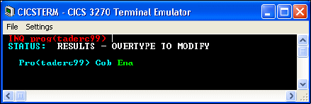
7672-dev-9-jca.fm Draft Document for Review December 9, 2008 2:44 pm
708 Rational Application Developer V7.5 Programming Guide
CICS outbound scenario
In this example we show how you can expose a COBOL program as a EJB 3.0
session bean that is invoked by a JavaServer Faces JSP. The product
documentation contains related samples and tutorials that are used as the
starting point for this scenario:
Tutorials → Watch and learn → Create a J2C application for a CICS
transaction with the same input and output
Samples → Technology Samples → Java → J2C Samples → CICS adapter
samples → Same input and outputs
Prerequisites
You must configure the CICS server and the CICS Transaction Gateway for this
example to work. This configuration is beyond the scope of this book. You should
obtain from your CICS administrator the parameters required to connect to the
CICS Transaction Gateway, which typically include:
URL
Server name
Port
User name
Password
The sample COBOL program, taderc9.cbl, is located in:
<RAD_Install-SDPShared>/plugins/com.ibm.j2c.cheatsheet.content_7.0.1.v20080
710-1450/Samples/CICS/taderc99
This program must be installed on the CICS server and you should be able to
query it from a CICS Terminal (Figure 20-4) using the command:
CEMT INQ PROG(taderc99)
Figure 20-4 CICS Terminal showing the installed COBOL program taderc99.cbl

Chapter 20. Develop applications to connect to enterprise information systems 709
Draft Document for Review December 9, 2008 2:44 pm 7672-dev-9-jca.fm
Creating the Java data binding class
The CICS/IMS Java Data Binding wizard enables you to create a class or set of
classes that map to COBOL, to C, or to PL/I data structures.
Select File → New → Other → J2C → CICS/IMS Java Data Binding, and
click Next.
In the Data Import dialog, for Choose mapping, select COBOL to Java, then
click Browse and locate the file taderc99.cbl in the directory:
<RAD_Install_SDPShared>\plugins\com.ibm.j2c.cheatsheet.content_7.0.1.v20080
710-1450\Samples\CICS\taderc99
The COBOL DFHCOMMAREA structure in taderc99 is shown in
Example 20-1.
Example 20-1 DFHCOMMAREA of COBOL program
01 DFHCOMMAREA.
02 CustomerNumber PIC X(5).
02 FirstName PIC A(15).
02 LastName PIC A(25).
02 Street PIC X(20).
02 City PIC A(20).
02 Country PIC A(10).
02 Phone PIC X(15).
02 PostalCode PIC X(7).
Click Next.
In the Importer dialog, you can set values for the platform, code page and
other properties. For Data Structures the default DFHCOMMAREA is
preselected. Click Next.
In the Saving Properties dialog, enter:
– Project Name: Taderc99 (click New and create a new Java project)
– Package Name: sample.cics.data
– ClassName: Change the default DFHCOMMAREA to CustomerInfo.
Click Finish.
Review the generated Java file CustomerInfo class. Notice that it implements
javax.resource.cci.Record and that it exposes getters and setters for all the
fields of DFHCOMMAREA (for example, getFirstName and setFirstName).

7672-dev-9-jca.fm Draft Document for Review December 9, 2008 2:44 pm
710 Rational Application Developer V7.5 Programming Guide
Creating the J2C bean
Next we create the J2C bean.
Select File → New → Other → J2C → J2C Bean, and click Next.
Select the resource adapter CICS → ECIResourceAdapter (IBM: 7.1.0.2),
and click Next (Figure 20-5).
Figure 20-5 Selection of the resource adapter
This action imports the file:
<RAD_Install>/ResourceAdapters/cics15/cicseci7102.rar
In the Connector Import dialog:
– Connector file: <RAD_HOME>\ResourceAdapters\cics15\cicseci7102.rar
– Connector project: cicseci7102
– Target Server: WebSphere Application Server 7.0
– Click Next.
In Connection Properties (Figure 20-6):
–Clear
Managed Connection.
–Select
Non-Managed Connection.
– Enter the connection details provided by your CICS administrator,
typically: Connection URL, Server name, Port number, User name,
Password
– Click Next.
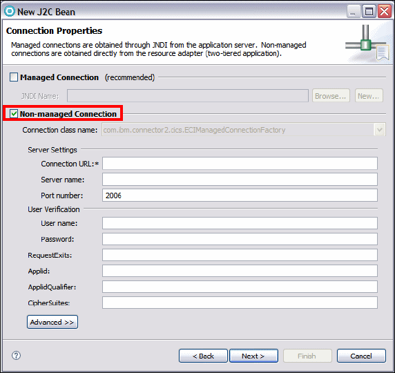
Chapter 20. Develop applications to connect to enterprise information systems 711
Draft Document for Review December 9, 2008 2:44 pm 7672-dev-9-jca.fm
Figure 20-6 Connection Properties
In the J2C Java Bean Output Properties dialog, enter:
– Project Name: Taderc99
– Package name: sample.cics
– Interface name: Customer
– Implementation Name: CustomerImpl (automatically filled)
– Click Next.
In the Java Methods dialog, click Add to open the Java Method dialog.
In the Java Method dialog (Figure 20-7):
–Name:
getCustomer
– Input type: Click Browse and type cust to locate the CustomerInfo class in
the sample.cics.data package. The value becomes:
/Taderc99/src/sample/cics/data/CustomerInfo.java
–Select Use the input type for output.
– Click Finish.
yourserver.yourcompany.com
yourserver
CICSuserID
CICSpassword
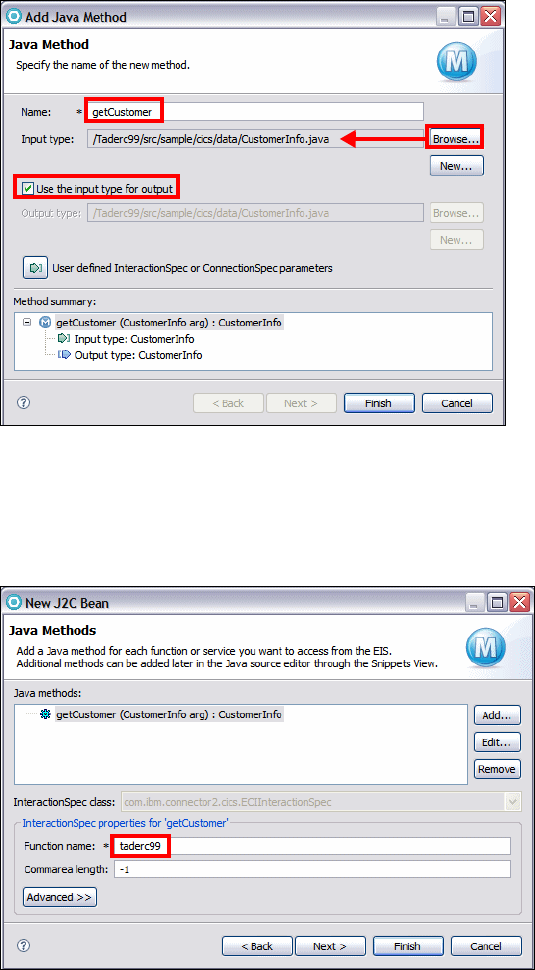
7672-dev-9-jca.fm Draft Document for Review December 9, 2008 2:44 pm
712 Rational Application Developer V7.5 Programming Guide
Figure 20-7 Adding a new Java Method to a J2C Java Bean
Back in the Java Methods dialog (Figure 20-8), you can see that the method
getCustomer is listed. In the InteractionSpec properties, specify the Function
name as taderc99 (this must match the name of the CICS program).
Figure 20-8 InteractionSpec properties
Click Next and Finish.
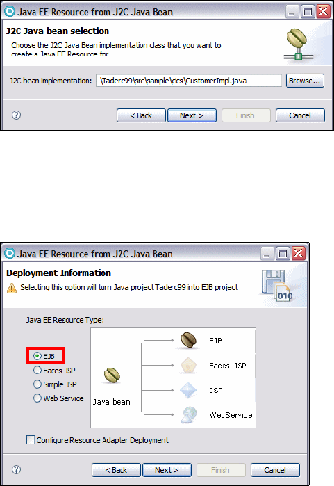
Chapter 20. Develop applications to connect to enterprise information systems 713
Draft Document for Review December 9, 2008 2:44 pm 7672-dev-9-jca.fm
This action generates a Customer interface and a CustomerImpl class into the
Taderc99 project. In addition the cicseci7102 project is created, containing a
plug-in (j2c_plugin.xml) and a CICS resource adapter XML file (ra.xml).
Deploying the J2C bean as an EJB 3.0 session bean
From the J2C bean we generate a session EJB.
Select File → New → Other → Web page, Web Service or EJB from J2C
Java bean, and click Next.
Click Browse, locate the CustomerImpl class, and click Next (Figure 20-9).
\Taderc99\src\sample\cics\CustomerImpl.java
Figure 20-9 Generate an EJB from a J2C bean (1)
In the Deployment Information dialog, select EJB (Figure 20-10). The target
project containing the J2C bean will be transformed into an EJB 3.0 project,
and the J2C bean class will be annotated as a session bean. Click Next.
Figure 20-10 Generate an EJB from a J2C bean (2)
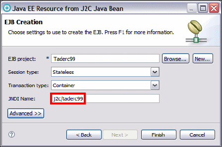
7672-dev-9-jca.fm Draft Document for Review December 9, 2008 2:44 pm
714 Rational Application Developer V7.5 Programming Guide
In the EJB Creation dialog (Figure 20-11), type j2c/taderc99 as JNDI name,
and accept the other values. Click Finish.
Figure 20-11 Generate an EJB from a J2C bean (3)
Open the CustomerImpl class and verify that the annotation was added:
@Stateless(mappedName="j2c/taderc99")
public class CustomerImpl implements sample.cics.Customer {
Optimally, open the Customer class and add the @Local annotation (this is
the default):
@Local
public interface Customer {
Generating a JSF client
We now generate a Java Server Faces client to test the EJB and the access to
the CICS system.
Create a Web project and enterprise application
Create a new Dynamic Web Project:
– Project name: Taderc99Web
– Target Runtime: WebSphere Application Server v7.0
– Dynamic Web Module version: 2.5
– Configuration: JavaServer Faces v1.2 Project
– EAR membership: Taderc99EAR
– Click Finish.

Chapter 20. Develop applications to connect to enterprise information systems 715
Draft Document for Review December 9, 2008 2:44 pm 7672-dev-9-jca.fm
Add the projects Taderc99 and cicseci7102 to the Java EE Module
dependencies list of the EAR project and of the Web project:
– Right-click Taderc99EAR and select Properties. Select Taderc99 and
cicseci7102 and click OK.
– Right-click Taderc99Web and select Properties. Select Taderc99.jar and
cicseci7102.rar and click OK.
Create a Web page
Add a new Web page called CustomerPage:
– Right-click WebContent (in Taderc99Web) and select New → Web Page.
–Type
CustomerPage, as name, select Basic Templates → JSP, and click
Finish.
Create a data component
Look at the Page Data view:
If you do not see a Services folder, click the Create a new data component
icon , select Services, and click OK (Figure 20-12).
Figure 20-12 New data component dialog
In the Page Data view, right-click Services and select New → EJB Session
bean.
In the Add Session Bean dialog:
– Click Add to open the Add EJB Reference dialog.
– In the EJB Reference dialog (Figure 20-13), select Taderc99EAR →
Taderc99 → CustomerImpl.
– The Name becomes ejb/CustomerImpl.
– For RefType, select Local.
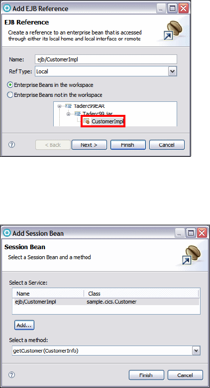
7672-dev-9-jca.fm Draft Document for Review December 9, 2008 2:44 pm
716 Rational Application Developer V7.5 Programming Guide
– Click Finish.
Figure 20-13 Creation of an EJB reference in the Web project
The ejb/CustomerImpl service is added to the Add Session Bean dialog. The
getCustomer method is selected (Figure 20-14). Click Finish.
Figure 20-14 Add Session Bean
In the Page Data view (Figure 20-15) you can see:
–A
customer_GetCustomer method with a input Param Bean and an output
Result Bean both of type sample.cics.data.CustomerInfo
– An action customer_GetCustomer.doAction
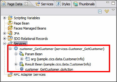
Chapter 20. Develop applications to connect to enterprise information systems 717
Draft Document for Review December 9, 2008 2:44 pm 7672-dev-9-jca.fm
Figure 20-15 Page data view with Service bean to expose EJB 3
Create the Web page content
Expand customer_GetCustomer → Param Bean → arg.
Select customerNumber and drag it into the editor of the Web page.
When prompted for Configuring Data Controls:
–Select
Inputting data.
– Change the label to Customer number.
– Click Options and verify that a Submit button is created.
– Click Finish.
– This adds an Input Control and a Button to the page
Drag and drop the action: customer_GetCustomer.doAction onto the Submit
button
Drag and drop the Result Bean below the Submit button.
When prompted for Configuring Data Controls
– Select the fields that were present in DFHCOMMAREA (starting with
customerNumber).
– Optionally tailor the labels and the sequence.
– Click Finish.
Save and close the Web page.
Running the JSF client
To run the JSF client, do these steps:
Make sure the WebSphere Application Server v7.0 is started.
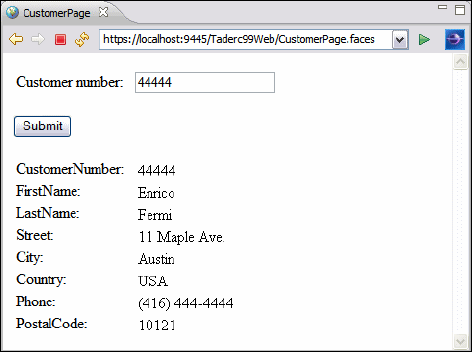
7672-dev-9-jca.fm Draft Document for Review December 9, 2008 2:44 pm
718 Rational Application Developer V7.5 Programming Guide
Add the Taderc99EAR enterprise application to the server.
Right-click CustomerPage.jsp and select: Run As → Run on Server. When
prompted select the Websphere Application Server v7.0
– Enter the customer number 44444 and click Submit.
– The EIS system is invoked and the customer information is returned
(Figure 20-16).
Figure 20-16 JSF Output from calling a CICS system
CICS Channel outbound scenario
In this example we show how you can create and execute the sample contained
in the product help under Samples → Technology Samples → Java → J2C
Samples → CICS adapter samples → Same input and outputs.
We recreate this sample so that it can be invoked by a JAX-WS Web service.
Creating the Java data binding for the channel and containers
To create the sample, proceed as follows:
Select New → Other → J2C → CICS/IMS Java Data Binding.
In the Data Import dialog (Figure 20-17):
– For Choose Mapping, select COBOL CICS Channel to Java
– You see a message: ’Containers’ cannot be empty.
– Near the Containers area, click New.
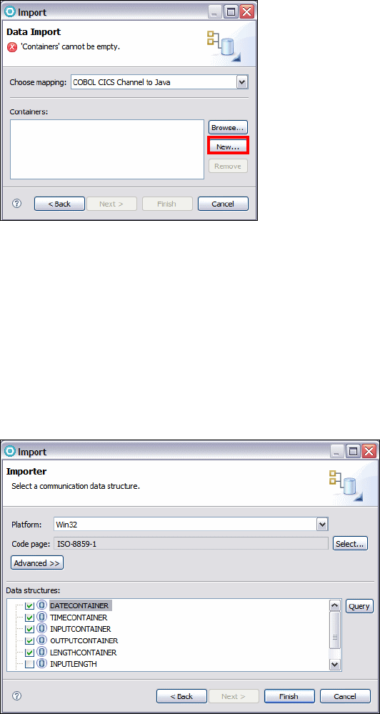
Chapter 20. Develop applications to connect to enterprise information systems 719
Draft Document for Review December 9, 2008 2:44 pm 7672-dev-9-jca.fm
Figure 20-17 Selection of Mapping COBOL CICS Channel to Java
In the new Data Import (Specify data import configuration properties) dialog:
– For Import File, browse to the sample COBOL file, and click Next.
<SDPShared_dir>\plugins\com.ibm.j2c.cheatsheet.content_7.0.1.v20080710-1
450\Samples\CICS32K\ec03.ccp
In the Importer (Select a communication data structure) dialog, select
DATECONTAINER, TIMECONTAINER, INPUTCONTAINER,
OUTPUTCONTAINER, and LENGTHCONTAINER, and click Finish
(Figure 20-18).
Figure 20-18 Discovery of the containers defined in the COBOL file

7672-dev-9-jca.fm Draft Document for Review December 9, 2008 2:44 pm
720 Rational Application Developer V7.5 Programming Guide
Note that there are other data structures listed in the dialog. We made the
selection to create Java beans for the five containers that are defined in the
COBOL file (Example 20-2):
Example 20-2 Definition of Containers in the COBOL file ec03.cpp
* Container names
01 DATECONTAINER PIC X(16) VALUE 'CurrentDate'.
01 TIMECONTAINER PIC X(16) VALUE 'CurrentTime'.
01 INPUTCONTAINER PIC X(16) VALUE 'InputData'.
01 OUTPUTCONTAINER PIC X(16) VALUE 'OutputMessage'.
01 LENGTHCONTAINER PIC X(16) VALUE 'InputDataLength'.
The Data Import dialog appears again, with the five containers listed. Click
Next.
In the Saving Properties dialog (Figure 20-19).
– For Project Name, click New. The New Source Project dialog opens:
•Select
Java project, and click Next.
•Type
CICSChannel as name, and click Finish.
– For Package Name, type sample.cics.data.
– For Class Name, type EC03ChannelRecord.
– For Channel Name, type InputRecord.
Figure 20-19 Definition of the CICS Channel name and related class name.
We can use an arbitrary channel name because the COBOL file expects to
receive the channel name as input (Example 20-3).

Chapter 20. Develop applications to connect to enterprise information systems 721
Draft Document for Review December 9, 2008 2:44 pm 7672-dev-9-jca.fm
Example 20-3 Channel name is expected in input in ec03.ccp
* Get name of channel
EXEC CICS ASSIGN CHANNEL(CHANNELNAME)
END-EXEC.
* If no channel passed in, terminate with abend code NOCH
IF CHANNELNAME = SPACES THEN
EXEC CICS ABEND ABCODE('NOCH') NODUMP
END-EXEC
END-IF.
Select the DATECONTAINER (Figure 20-20) and enter the following values:
– For Package Name, accept sample.cics.data.
– For Class Name, type DateContainer.
– For Container name, type CURRENTDATE.
– For Container type, select CHAR.
Figure 20-20 Definition of the DATECONTAINER
Repeat this step for all other containers using the following data:
– Class name: TimeContainer, InputContainer, OutputContainer,
LengthContainer
– Container name: CURRENTTIME, INPUTDATA, OUTPUTMESSAGE,
INPUTDATALENGTH
– Container type: CHAR
Note that the class names can be chosen arbitrarily, but the names of the
containers must match those defined in the COBOL file (Example 20-2 on
page 720).
The dialog shows no more errors. Click Finish.
At this point the CICSChannel connector project is generated with a
EC03ChannelRecord and five container classes in the sample.cics.data package.
Close the editor of the EC03ChannelRecord class.

7672-dev-9-jca.fm Draft Document for Review December 9, 2008 2:44 pm
722 Rational Application Developer V7.5 Programming Guide
Creating the J2C bean that accesses the channel
To create the J2C bean, follow these steps:
Select File → New → Other → J2C → J2C Bean, and click Next.
Select the resource adapter CICS → ECIResourceAdapter (IBM: 7.1.0.2) →
cicseci7102, and click Next.
In Connection Properties (same as in Figure 20-6 on page 711):
–Clear
Managed Connection.
–Select
Non-Managed Connection.
– Enter the connection details provided by your CICS administrator, typically
Connection URL, Server name, Port number, User name, and Password.
– Click Next.
In the dialog J2C Java Bean Output properties (Figure 20-21):
– For Project name, accept CICSChannel.
– For Package name, type sample.cics.
– For Interface name, type Ec03.
– This sets the implementation name to Ec03Impl.
Figure 20-21 J2C Java Bean Output Properties for CICSChannel
In the Java Methods dialog, click Add.
In the Java Method dialog (Figure 20-22):
– For Name, type invoke.
– For Input type, click Browse and select EC03ChannelRecord.
– Click Finish.
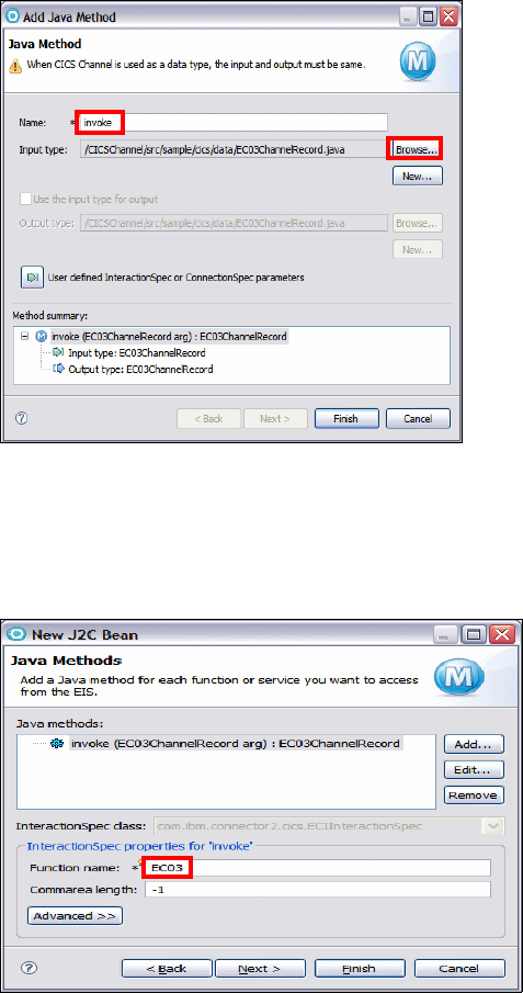
Chapter 20. Develop applications to connect to enterprise information systems 723
Draft Document for Review December 9, 2008 2:44 pm 7672-dev-9-jca.fm
Figure 20-22 Adding a Java method with channel record as input and output
In the Java Methods dialog (Figure 20-23), the invoke method is now listed. In
the InteractionSpec properties, specify the Function name as EC03 (this must
match the name of the CICS program). Click Next.
Figure 20-23 Specify the function name in the InteractionSpec (COBOL program)
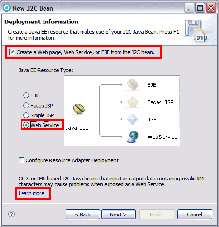
7672-dev-9-jca.fm Draft Document for Review December 9, 2008 2:44 pm
724 Rational Application Developer V7.5 Programming Guide
Develop a Web service to invoke the COBOL program
In the Deployment Information dialog (Figure 20-24):
Select Create a Web page, Web Service, or EJB from theJ2C bean, then
select Web Service.
Figure 20-24 Link to online help in the Web Service wizard.
Notice the Learn more link, which opens a product help page that states that
the code generated by the J2C bean tool does not allow for serialization.
Therefore, the bottom-up approach for Web Service creation is not readily
available.
Clear Create a Web page, Web Service, or EJB from theJ2C bean, and
click Finish. The Ec03 interface and the Ec03Impl class are generated into the
CICSChannel project.
Using an alternative approach
In this simple case it is easy to create a Java bean wrapper that encapsulates the
more complex types and let you run a bottom-up code generation.
In the CICSChannel project, add a Ec03Wrapper class with the code of
Example 20-4.

Chapter 20. Develop applications to connect to enterprise information systems 725
Draft Document for Review December 9, 2008 2:44 pm 7672-dev-9-jca.fm
Example 20-4 Ec03Wrapper.java
package sample.cics;
import javax.resource.ResourceException;
import sample.cics.data.EC03ChannelRecord;
import sample.cics.data.InputContainer;
public class Ec03Wrapper {
public String invoke(String in) throws ResourceException{
Ec03Impl test = new Ec03Impl();
InputContainer inputContainer = new InputContainer();
inputContainer.setInputContainer_inputcontainer(in);
EC03ChannelRecord inputRecord = new EC03ChannelRecord();
inputRecord.setInputContainer(inputContainer);
EC03ChannelRecord output = test.invoke(inputRecord);
return output.toString();
}
}
Create a new Dynamic Web Project called CICSChannelWeb associated to
EAR CICSChannelEAR (use the default module version 2.5 and the v7.0
target server).
In the Enterprise Explorer, Expand CICSChannelEAR, right-click on
Modules, and select Modify.
Select CICSChannel (it will be listed as an Utility JAR) and cicseci7102 (it
will be listed as Module), and click OK.
Start the WebSphere Application Server v7.0 (if not running).
Right-click Ec03Wrapper.java (in CICSChannel) and select Web
Services → Create Web service.
The Web Service wizard open (Figure 20-25). Accept all the defaults on the
first page, and click Next.
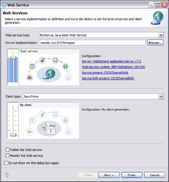
7672-dev-9-jca.fm Draft Document for Review December 9, 2008 2:44 pm
726 Rational Application Developer V7.5 Programming Guide
Figure 20-25 Web Service wizard
On the second page, select Generate WSDL file into the project (to see the
generated WSDL), and Generate Web Service Deployment Descriptor.
Accept all the default settings until the end of the wizard and click Finish.
In the Enterprise Explorer, CICSChannelWeb project (Figure 20-26), you can
see:
– The Services node with the Ec03WrapperService
– The WSDL file (Ec03WrapperService.wsdl) under WEB-INF/wsdl, with an
associated XML Schema (Ec03WrapperService_schema1.xsd)
– The Web service deployment descriptor (webservices.xml)

Chapter 20. Develop applications to connect to enterprise information systems 727
Draft Document for Review December 9, 2008 2:44 pm 7672-dev-9-jca.fm
Figure 20-26 Enterprise Explorer after generation of bottom-up Web service
The CICSChannelEAR enterprise application is deployed to the server.
Testing the Web service with CICS access
To test the generated code we use the Web Services Explorer.
Right-click Ec03WrapperService.wsdl and select Web Services → Test
with Web Services Explorer.
The Web Services Explorer opens (Figure 20-27):
– Click on the invoke operation.
– For the arg0 parameter, click Add
–Type Hello as value.
– Click Go.
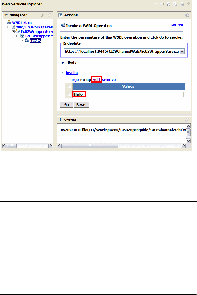
7672-dev-9-jca.fm Draft Document for Review December 9, 2008 2:44 pm
728 Rational Application Developer V7.5 Programming Guide
Figure 20-27 Web Services Explorer
The Web service is invoked and you should obtain a SOAP message result as
shown in Example 20-5. Click Source in the Status pane to see the SOAP
messages.
Example 20-5 Web service response (formatted for readability)
<soapenv:Envelope
xmlns:soapenv="http://schemas.xmlsoap.org/soap/envelope/">
<soapenv:Body>
<invokeResponse xmlns:ns2="http://cics.sample/">
<return>
sample.cics.data.EC03ChannelRecord@4f474f47
sample.cics.data.OutputContainer@5e905e90 Input data was: Hello
sample.cics.data.InputContainer@5f005f00 Hello
sample.cics.data.LengthContainer@5f255f25 Buffer Size: 4 bytes
00000010 00000000 00000000 00000000 |................|
</return>
</invokeResponse>
</soapenv:Body>
</soapenv:Envelope>
Chapter 20. Develop applications to connect to enterprise information systems 729
Draft Document for Review December 9, 2008 2:44 pm 7672-dev-9-jca.fm
SAP outbound scenario
This sample demonstrates the how to use the WebSphere SAP resource adapter
to create and retrieve information on an SAP system.
Required software and configuration
To complete the SAP adapter sample in this chapter, you must have the following
software installed:
IBM Rational Application Developer v7.5
J2EE Connector (J2C) tools. To install J2C tools, follow these steps:
– Open the Installation Manager. Click Modify, and click Next.
– In the Modify Packages page, select IBM Software Deliver Platform, and
click Next.
– In the Features list, select IBM Rational Application Developer for
WebSphere Software 7.5.0, and click Next.
– On the Install Packages page, select Java EE Connector (J2C) Tools →
Java EE Connector (J2C) Tools → WebSphere Adapters.
– Click Install.
You have to obtain these files from your SAP server administrator and add
them to the following directories:
–sapjco.jar: copy to <WAS_DIR>\lib
–librfr32.dll: copy to <WAS_DIR>>\bin and <WAS_DIR>\java\jre\bin
–sapjcorfc.dll: copy to<WAS_DIR>\bin and <WAS_DIR>\java\jre\bin
<WAS_DIR> = <RAD_HOME>\runtimes\base_v7
Creating a Connector Project and J2C bean
To create the SAP connector project and related J2C Beans for creating and
retrieving information to and from SAP system follow these steps:
Open the Java EE perspective.
In the Workbench, select File → New → Other → J2C → J2C Bean.
In the New J2C Bean dialog (Figure 20-28), select IBM WebSphere Adapter
for SAP Software (IBM: 6.1.0.3ifix001w) and click Next.
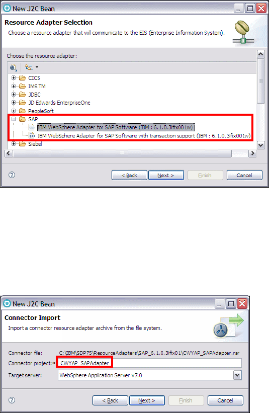
7672-dev-9-jca.fm Draft Document for Review December 9, 2008 2:44 pm
730 Rational Application Developer V7.5 Programming Guide
Figure 20-28 New J2C Bean - Resource Adapter Selection
In the Connector Import dialog (Figure 20-29):
–Type
CWYAP_SAPAdapter in the connector project name field.
– For Target server, select WebSphere Application Server 7.0.
– Click Next.
Figure 20-29 New J2C Bean - Connector Import
In the Connector Settings dialog (Figure 20-30), click Browse for each file
required to access to SAP server, navigate to the sapjco.jar, librfc32.dll, and
sapjcorfc.dll that we copied to the server folders. Click Next.
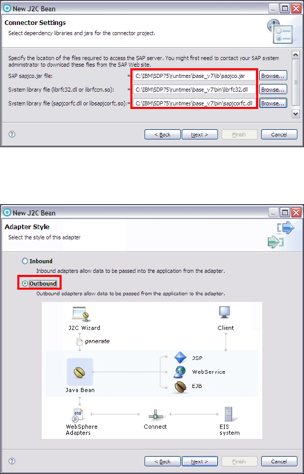
Chapter 20. Develop applications to connect to enterprise information systems 731
Draft Document for Review December 9, 2008 2:44 pm 7672-dev-9-jca.fm
Figure 20-30 New J2C Bean - Connector Setting
In the Adapter Style dialog (Figure 20-31), select Outbound and click Next.
Figure 20-31 New J2C Bean - Adapter Style
In the Discovery Configuration dialog (Figure 20-32), enter your SAP Server
connection information. For this sample, select BAPI® as SAP interface
name. Click Next. The wizard retrieve the objects discovered by the query.
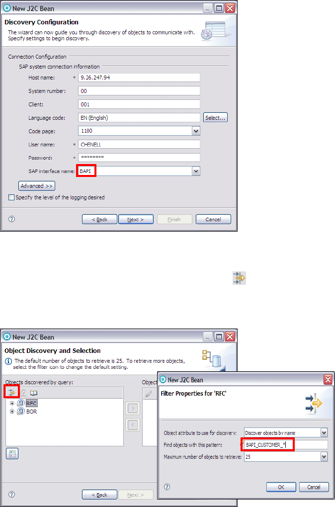
7672-dev-9-jca.fm Draft Document for Review December 9, 2008 2:44 pm
732 Rational Application Developer V7.5 Programming Guide
Figure 20-32 New J2C Bean - Discovery Configuration
In the Object Discovery and Selection dialog (Figure 20-33), select RFC from
the from Objects tree, then click Create or edit filter .
In the Filter Properties for ’RFC’ dialog enter BAPI_CUSTOMER_* for Find
objects with this pattern field, and click OK.
Figure 20-33 New J2C Bean - Object Discovery and Selection
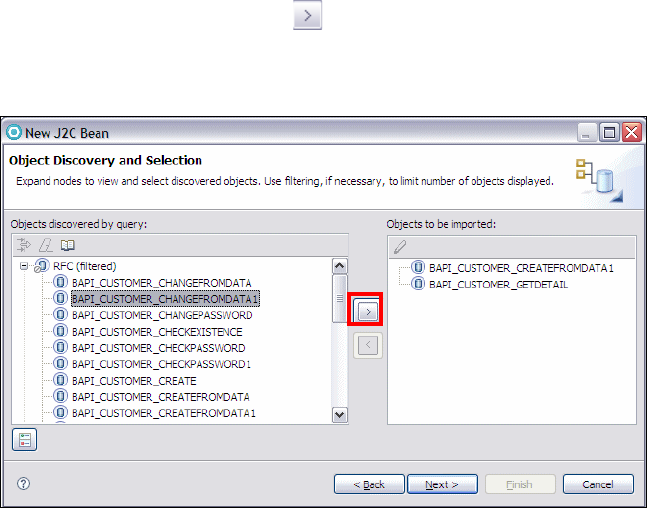
Chapter 20. Develop applications to connect to enterprise information systems 733
Draft Document for Review December 9, 2008 2:44 pm 7672-dev-9-jca.fm
In the Object Discovery and Selection dialog (Figure 20-34), expand RFC
(filtered), select BAPI_ CUSTOMER _CREATEFROMDATA1 and BAPI_
CUSTOMER _GETDETAIL, click to add them to Objects to be imported.
A Configuration Parameters dialog shows up, accept the defaults and click
OK. Click Next.
Figure 20-34 New J2C Bean - Object Discovery and Selection
In Configure Composite Properties dialog (Figure 20-35), enter RAD75BAPI
for Business objects name for service operations field.
Click Add, in the Add Value dialog, select Create and click OK. Select BAPI_
CUSTOMER _CREATEFROMDATA1 from RFC function for selected
operation list.
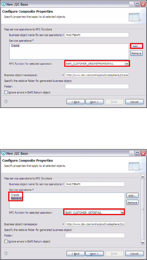
7672-dev-9-jca.fm Draft Document for Review December 9, 2008 2:44 pm
734 Rational Application Developer V7.5 Programming Guide
Figure 20-35 New J2C Bean - Configure Composite Properties
Repeat the previous step by selecting Retrieve, and BAPI_ CUSTOMER
_GETDETAIL for RFC function for selected operation list (Figure 20-36). Click
Next.
Figure 20-36 New J2C Bean - Configure Composite Properties
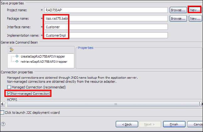
Chapter 20. Develop applications to connect to enterprise information systems 735
Draft Document for Review December 9, 2008 2:44 pm 7672-dev-9-jca.fm
In J2C Bean Creation and Deployment Configuration dialog, click New for
Project name field to create a new Java project that contain the generated
J2C beans.
In New Source Project Creation dialog, select Java project and click Next.
In the Create a Java project dialog, enter RAD75SAP for Project name,
accept the defaults, and click Finish.
In J2C Bean Creation and Deployment Configuration dialog (Figure 20-37):
– Enter itso.rad75.babi as Package Name.
– Enter Customer as Interface Name.
– Enter CustomerImpl as Implementation Name.
–Clear
Managed Connection, select Non-managed Connection.
– Click Finish.
Figure 20-37 J2C Bean Creation and Deployment Configuration dialog
After finishing with the J2C Wizard, you have the following two projects in your
workspace:
–CWYAP_SAPAdapter: SAP Adapter Project
–RAD75SAP: Java Project that holds generated J2C Beans
To test this generated J2C Beans, we now generate a simple Web Application
using J2C wizards.
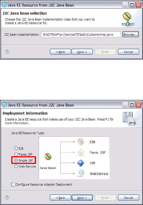
7672-dev-9-jca.fm Draft Document for Review December 9, 2008 2:44 pm
736 Rational Application Developer V7.5 Programming Guide
Generating the sample Web application
To generate the simple Web Application follow these steps:
In the Workbench, select File → New → Other → J2C → Web Page, Web
Service, or EJB from J2C Java Bean.
In the Java EE Resource from J2C Bean dialog (Figure 20-38) click Browse
for the J2C Bean implementation and select CustomerImpl. Click Next.
Figure 20-38 J2C Java bean selection
In the Deployment Information dialog (Figure 20-39), select Simple JSP and
click Next.
Figure 20-39 Deployment Information
In Simple JSP Creation dialog, click New for Web project field to create a new
Web project.
In the Dynamic Web Project dialog, enter RAD75SAPTestWeb as Project
name and RAD75SAPTestWebEAR as EAR Project Name. Ensure that
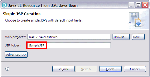
Chapter 20. Develop applications to connect to enterprise information systems 737
Draft Document for Review December 9, 2008 2:44 pm 7672-dev-9-jca.fm
WebSphere Application Server v7.0 is selected for Target Runtime. Click
Finish.
In Simple JSP Creation dialog (Figure 20-40), enter SampleJSP as JSP
Folder. Click Finish.
Figure 20-40 Simple JSP Creation
After finishing with the Simple JSP Creation Wizard, you have the following
two projects created in your workspace:
– RAD75SAPTestWeb
– RAD75SAPTestWebEAR
The RAD75SAPTestWebEAR project has to reference the
CWYAP_SAPAdapter project. We configure this dependency by adding the
CWYAP_SAPAdapter as a dependency to the EAR project:
– In the Enterprise Explorer, right-click RAD75SAPTestWebEAR and select
Properties. Select Java EE Module Dependencies and select
CWYAP_SAPAdapter, then click OK.
– Right-click RAD75SAPTestWeb and select Properties. Select Java EE
Module Dependencies and select CWYAP_SAPAdapter.rar, then click
OK.
Testing the Web application
To test the sample Web Application follow these steps:
Expand RAD75SAPTestWeb → WebContent → SampleJSP, right-click
TestClient.jsp and select Run As → Run on Server. Select the server
(WebSphere Application Server v7.0) and click Finish.
The application opens in a Web browser.
7672-dev-9-jca.fm Draft Document for Review December 9, 2008 2:44 pm
738 Rational Application Developer V7.5 Programming Guide
From the Methods Pane, click createSapRAD75BAPIWrapper. Scroll down
the page for Inputs, enter input values for
sapBapiCustomerCreatefromdata1Input and click Invoke.
The response from the SAP system is displayed in the Results pane.
From the Methods Pane, click retrieveSapRAD75BAPIWrapper. Scroll down
the page for sapBapiCustomerGetdetail, enter an input value for
customerToBeRequired and click Invoke.
The response from the SAP system is displayed in the Results pane.
More information
The product help contains the following relevant chapters:
Developing → Developing Data Access Applications → Connecting to
enterprise information systems
Tutorials → Watch and learn → Create a J2C application for a CICS
transaction with the same input and output
Tutorials → Do and learn → Create a J2C application for a CICS transaction
containing multiple possible outputs
Samples → Technology Samples → Java → J2C Samples
Cheat Sheets → J2C Java Bean
Other sources of information:
Generating a J2C bean using the J2C Tools in Rational Application Developer
V7.0
http://www.ibm.com/developerworks/rational/library/06/1212_nigul/
Create a J2C application for an Information Management System (IMS)
phone book transaction using IMS TM Resource Adapter
http://www.ibm.com/developerworks/rational/library/08/dw-r-j2cimsres
ource/
Working with J2C Ant Scripts in Rational Application Developer V7
http://www.ibm.com/developerworks/rational/library/06/1205_ho-benede
k/
Revealed! The Next Generation of Distributed CICS, SG24-7185

© Copyright IBM Corp. 2008. All rights reserved. 739
Draft Document for Review December 9, 2008 2:44 pm 7672-dev-10-portal.fm
Chapter 21. Develop portal applications
This chapter introduces important support of the portal development tools that is
included in IBM Rational Application Developer v7.5 with more focus on the new
features added to the current version. We also highlight how the portal tools in
Application Developer can be used to develop a portal and associated portlet
applications for WebSphere Portal v6.1. Finally, we have included a development
scenario to demonstrate how to use the new integrated portal tooling to develop
a portal, customize the portal, and develop two portlets.
The chapter is organized into the following sections:
Introduction to portal technology
Developing applications for WebSphere Portal
New Websphere portal and portlet development tools in Rational Application
Developer v7.5
Developing portal solutions using portal tools
For more detailed information on IBM WebSphere Portal v6.1, refer to “More
information” on page 774
21
7672-dev-10-portal.fm Draft Document for Review December 9, 2008 2:44 pm
740 Rational Application Developer V7.5 Programming Guide
Introduction to portal technology
As J2EE technology has evolved, much emphasis has been placed on the
challenges of building enterprise applications and bringing those applications to
the Web. At the core of the challenges currently being faced by Web developers
is the integration of disparate user content into a seamless Web application and
well-designed user interface. Portal technology provides a framework to build
such applications for the Web.
Because of the increasing popularity of portal technologies, the tooling and
frameworks used to support the building of new portals has evolved. The main
job of a portal is to aggregate content and functionality. Portal servers provide:
A server to aggregate content
A scalable infrastructure
A framework to build portal components and extensions
Additionally, many portals offer personalization and customization features.
Personalization enables the portal to deliver user-specific information targeting a
user based on their unique information. Customization allows the user to
organize the look and feel of the portal to suit their individual needs and
preferences.
Portals deliver e-business applications over the Web to many types of client
devices from PCs to PDAs. Portals provide site users with a single point of
access to multiple types of information and applications. Regardless of where the
information resides or what format it is in, a portal aggregates all of the
information in a way that is relevant to the user.
The goal of implementing an enterprise portal is to enable a working environment
that integrates people, their work, personal activities, and supporting processes
and technology.
Portal concepts and definitions
Before beginning development for portals, you should become familiar with some
common definitions and descriptions of portal-related terminology.
Portal page
A portal page is a single Web page that can be used to display content
aggregated from multiple sources. The content that appears on a portal page is
displayed by an arrangement of one or more portlets. For example, a World
Stock Market portal page might contain two portlets that display stock tickers for
popular stock exchanges and a third portlet that displays the current exchange
rates for world currencies.
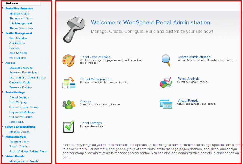
Chapter 21. Develop portal applications 741
Draft Document for Review December 9, 2008 2:44 pm 7672-dev-10-portal.fm
Portlet
A portlet is an individual application that displays content on a portal page. To a
user, a portlet is a single window or panel on the portal page that provides
information or Web application functionality. To a developer, portlets are
Java-based pluggable modules that can access content from a source such as
another Web site, an XML feed, or a database, and display this content to the
user as part of the portal page.
Figure 21-1 shows a portal welcome page and its contained portlets.
Figure 21-1 Portlets laid out on the Portal Welcome Page
Portlet application
A portlet application is a deployable unit that contains one or more portlets. It
encapsulates all the resources required by the portlets; such as Java classes,
JSP files, images, deployment descriptors, libraries and other resources.
7672-dev-10-portal.fm Draft Document for Review December 9, 2008 2:44 pm
742 Rational Application Developer V7.5 Programming Guide
Portlet states
Portlet states determine how individual portlets look when a user accesses them
on the portal page. These states are very similar to minimize, restore, and
maximize window states of applications run on any popular operating system just
in a Web-based environment.
The state of the portlet is stored in the PortletWindow.State object and can be
queried for changing the way a portlet looks or behaves based on its current
state. The IBM portlet API defines three possible states for a portlet:
Normal—The portlet is displayed in its initial state, as defined when it was
installed.
Minimized—Only the portlet title bar is visible on the portal page.
Maximized—The portlet fills the entire body of the portal page, hiding all
other portlets.
Portlet modes
Portlet modes allow the portlet to display a different face depending on how it is
being used. This allows different content to be displayed within the same portlet,
depending on its mode. Modes are most commonly used to allow users and
administrators to configure portlets or to offer help to the users. There are four
modes in the IBM Portlet API:
View—Initial face of the portlet when created. The portlet normally functions
in this mode.
Edit—This mode allows the user to configure the portlet for their personal use
(for example, specifying a city for a localized weather forecast).
Help—If the portlet supports the help mode, this mode displays a help page
to the user.
Configure—If provided, this mode displays a face that allows the portal
administrator to configure the portlet for a group of users or a single user.
Portlet events
Some portlets only display static content in independent windows. To allow users
to interact with portlets and to allow portlets to interact with each other, portlet
events are used. Portlet events contain information to which a portlet might need
to respond. For example, when a user clicks a link or button, this generates an
action event. To receive notification of a given event, the portlet must also have
the appropriate event listener implemented within the portlet class. There are
three commonly used types of portlet events:
Action—Generated when an HTTP request is received by the portlet that is
associated with an action, such as when a user clicks a link.
Chapter 21. Develop portal applications 743
Draft Document for Review December 9, 2008 2:44 pm 7672-dev-10-portal.fm
Message—Generated when one portlet within a portlet application sends a
message to another portlet.
Window—Generated when the user changes the state of the portlet window.
IBM WebSphere Portal
IBM WebSphere Portal provides an extensible framework that allows the end
user to interact with enterprise applications, people, content, and processes.
They can personalize and organize their own view of the portal, manage their
own profiles, and publish and share documents. WebSphere Portal provides
additional services such as single sign-on (SSO), security, credential vault,
directory services, document management, Web content management,
personalization, search, collaboration, search and taxonomy, support for mobile
devices, accessibility support, internationalization, e-learning, integration to
applications, and site analytics. Clients can further extend the portal solution to
provide host integration and e-commerce.
WebSphere Portal allows you to plug in new features or extensions using
portlets. In the same way that a servlet is an application within a Web server, a
portlet is an application within WebSphere Portal. Developing portlets is the most
important task when providing a portal that functions as the user’s interface to
information and tasks.
Portlets are an encapsulation of content and functionality. They are reusable
components that combine Web-based content, application functionality, and
access to resources. Portlets are assembled into portal pages that, in turn, make
up a portal implementation.
Portal solutions such as IBM WebSphere Portal are proven to shorten the
development time. Pre-built adapters and connectors are available so that
customers can leverage on the company's existing investment by integrating with
the existing legacy systems without re-inventing the wheel.
What’s new in WebSphere Portal v6.1?
WebSphere Portal v6.1 has some new features to help you develop more robust
enterprise solutions:
Improved installation, configuration, and security.
Support for new portlet standards: WebSphere Portal now supports the two
new portlet standards Java Portlet Specification 2.0 (JSR 286) and Web
Services for Remote Portlets (WSRP) Version 2.0.
7672-dev-10-portal.fm Draft Document for Review December 9, 2008 2:44 pm
744 Rational Application Developer V7.5 Programming Guide
Enriched search experience: The Search Center in all themes is more
responsive because it uses AJAX with a Dojo-based client-side Java Script
programming model.
New infrastructure supports Web 2.0 theme:
– More responsive user interfaces provide better context awareness for the
user through client-side aggregation of portal pages.
– Client-side mashups and interactive portal applications can be developed
using Ajax with a Dojo-based client-side JavaScript programming model.
– Portal models like navigation, page layout, and user information are
remotely accessible through REST services.
– Improved scalability results from enhanced caching capabilities. Page
fragments can be cached separately rather than caching entire pages.
– Dynamic behaviors such as context menus, annotations, highlighting, and
drag-and-drop interaction can be applied by an extensible set of semantic
tags.
– The new Feedreader portlet is based on Ajax.
Site management: The new Resource Manager portlet allows administrators
to create a page on a source server and publish it to a target server where
only a selected group of users can see and test the new page. After testing is
complete, you can promote the new page so that all users on the target server
with the appropriate access rights can view the new page.
Customization through themes and skins: The new Theme Customizer portlet
features a tabbed design and live preview that let you quickly and easily
customize key site elements including the banner, navigation, fonts, and
colors.
More information about WebSphere Portal v6.1 new features can be found at the
product information center at:
http://publib.boulder.ibm.com/infocenter/wpdoc/v6r1m0/index.jsp
Portal and portlet development features in Application Developer
Application Developer provides development tools for portal and portlet
applications destined to WebSphere Portal. Bundled with IBM Rational
Application Developer v7.5 are a number of portal tools that allow you to create,
test, debug, and deploy portal and portlet applications. Application Developer
supports portlet development using the Standard and IBM portlet APIs.
Chapter 21. Develop portal applications 745
Draft Document for Review December 9, 2008 2:44 pm 7672-dev-10-portal.fm
The following tools are provided to support development of your portlet
applications:
Portlet application samples
New Portlet Project wizard
WPAI mediator access
Portlet deployment descriptor editor
Portal server configuration
Portal server test, debug, and deploy
Import and export Web archive (WAR) file
Visual tooling to insert portlet objects into JSP files, using Page Designer.
Cooperative portlet wizards
Business process message access
Personalization wizard
Portal test environments
Application Developer v7.5 provides the following versions of integrated test
environments to run and test your portal and portlet projects from within the
Application Developer Workbench:
IBM WebSphere Portal Server 6.0.x
IBM WebSphere Portal Server 6.1
In this chapter we are using the Version 6.1 of WebSphere Portal.
Setting up Application Developer with the Portal test environment
Setting up of Portal test environment in Application Developer is now a much
easier and more streamlined task. We perform the following high-level activities
to complete the setup of Portal test environment in Application Developer,
documented under “Installing the WebSphere Portal v6.1 test environment” on
page 1131:
Installing WebSphere Portal v6.1
Adding WebSphere Portal v6.1 to Application Developer
Optimizing the Portal Server for development
Developing applications for WebSphere Portal
Application Developer includes many tools to help you quickly develop portals
and individual portlet applications. In this section, we cover some basic portlet
development strategies and provide an overview of the tools included Application
Developer to aid with development of WebSphere Portal.
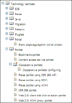
7672-dev-10-portal.fm Draft Document for Review December 9, 2008 2:44 pm
746 Rational Application Developer V7.5 Programming Guide
Portal samples and tutorials
Application Developer also comes with several samples and tutorials to aid you
with the development of WebSphere Portal. The Samples Gallery provides
sample portlet applications to illustrate portlet development.
To access portlet samples, click Help → Samples. Then expand Technology
samples and Portlet (Figure 21-2). Here you can select a Basic Portlet, Faces
Portlet, or Struts Portlet Framework to view sample portlet application projects
that you can then modify and build upon for your own purposes.
Figure 21-2 Portal and portlet development technology samples
The Tutorials Gallery provides detailed tutorials to illustrate portlet development.
These are accessible by selecting Help → Tutorials. Then expand Do and
Learn. You can select Create a portal application.
Development strategy
A portlet application consists of Java classes, JSP files, and other resources,
such as deployment descriptors and image files. Before beginning development,
several decisions must be made regarding the development strategy and
technologies that is used to develop a portlet application.
Choosing a portlet API: JSR 168, JSR 286, or IBM
Application Developer supports the development of portlets using the JSR 168
portlet API, the JSR 286 portlet API, and the IBM portlet API. All three types of
portlets can be deployed to WebSphere Portal.
Chapter 21. Develop portal applications 747
Draft Document for Review December 9, 2008 2:44 pm 7672-dev-10-portal.fm
This section provides you with information that can help you decide which API to
use when you develop portlets.
JSR 168 portlet API is a Java specification from the Java Community
Process that addresses the requirements of aggregation, personalization,
presentation, and security for portlets running in a portal environment.
Portlets that conform to the JSR 168 specification are more portable and
reusable, because they can be deployed to any JSR 168-compliant portal.
Rational tools supports portlet development based on the JSR 168
specification.
http://www.jcp.org/en/jsr/detail?id=168
Note: Click-to-Action cooperative behavior and portlet messaging are not
supported in JSR 168 Faces portlets.
JSR 286 portlet API is a Java specification from the Java Community
Process that has improved upon the JSR 186 portlet API by providing
additional capabilities, such as filters, events, and public render parameters.
These improvements have necessitated changes to the XSD for the Portlet
Deployment Descriptor (PDD) that adds new elements to it.
http://www.jcp.org/en/jsr/detail?id=286
IBM portlet API is IBM’s portlet API that was initially supported for
WebSphere Portal v4.x, and in subsequent versions of WebSphere Portal
v5.x and v6.x. Note that the IBM portlet API is deprecated in v6.x,m but is still
supported. No new functionality will be added and it is recommended you use
the Standard Portlet API.
Deciding which API to use
The IBM portlet API extends the servlet API and many of the main interfaces
(request, response, session). JSR 168 API does not extend the servlet API, but
shares many of the same characteristics. JSR 168 leverages much of the
functionality provided by the servlet specification, such as deployment, class
loading, Web applications, Web application life cycle management, session
management, and request dispatching.
For new portlets, consider using JSR 286 to take advantage of its additional
capabilities. If you cannot use JSR 286 for some reason, consider JSR 168 when
the functionality it provides is sufficient for the portlet's needs or when the portlet
is expected to be published as a Web Service for Remote Portlets (WSRP)
service. WSRP is another portal-based standard used to integrate the
presentation of remote portlets provided as Web services into the local portal
page. The concepts in JSR 168 and WSRP have been aligned to allow JSR 168
portlets to be published as Web services. Some of these concepts include portlet
modes and states, URL and name space encoding, and the handling of transient
and persistent information.
7672-dev-10-portal.fm Draft Document for Review December 9, 2008 2:44 pm
748 Rational Application Developer V7.5 Programming Guide
Choosing markup languages
WebSphere Portal supports multiple client types by generating pages in multiple
markup languages. Three are officially supported: HTML, WML, and cHTML.
Using Application Developer tools, you can develop portlet applications that
support these markup languages.
HTML is a markup language for desktop computers. All portlet applications
must support HTML, at a minimum.
WML is a markup language for WAP devices, which are typically mobile
phones.
cHTML is a markup language for mobile devices in the NTT DoCoMo i-mode
network.
To edit WML files and cHTML files, you can use Page Designer, as you do when
editing other Web content.
To run or debug a portlet application that supports WML or cHTML, you can use
a device emulator provided by a device vendor. To add a device emulator:
Select Window → Preferences.
In the Preferences dialog, select General → Web browser.
Click New to locate and define a Web browser type that is appropriate for the
device that you wish to test and debug.
More information about markup languages can be found under the Markup
guidelines topic in the WebSphere Portal Information Center.
Choosing other frameworks
JavaServer Faces (JSF) and Struts technology can be easily incorporated into a
portlet development strategy. Application Developer provides extensive tooling
support to help in the creation and code generation for creating a JSF portlet or
Struts portlet.
JavaServer Faces (JSF)
Faces-based application development can be applied to portlets, similar to the
way that Faces development is implemented in Web applications. Faces support
in Rational Application Developer simplifies the process of writing Faces portlet
applications and eliminates the need to manage many of the underlying
requirements of portlet applications.
Rational tools provide a set of wizards that help you create Faces portlet-related
artifacts. In many cases, these wizards are identical to the wizards used to create
standard Faces artifacts
Chapter 21. Develop portal applications 749
Draft Document for Review December 9, 2008 2:44 pm 7672-dev-10-portal.fm
Refer to the Application Developer Faces documentation in the InfoCenter for
usage details. Also refer to Chapter 16, “Develop Web applications using JSF” on
page 493 for more detailed information on application development using the
JSF framework.
Struts
Struts-based application development can also be applied to portlets, similar to
the way that Struts development is implemented in Web applications. The Struts
Portal Framework (SPF) was developed to merge these two technologies. SPF
support in Application Developer simplifies the process of writing Struts portlet
applications and eliminates the need to manage many of the underlying
requirements of portlet applications.
The Struts portlet tooling supports development of portlet applications based on
both the JSR 168 API and the IBM portlet API. There are differences in the
runtime code included with projects, tag libraries supported, Java class
references, and configuration architecture, but, unless otherwise noted, these
differences are managed by the product tooling.
In addition, multiple wizards are present to help you create Struts portlet-related
artifacts. These are the same wizards used in Struts development. Refer to the
Application Developer Struts documentation for usage details.
More information on Struts can be found at:
http://struts.apache.org/
Web development using Struts for non-portal applications is covered in
Chapter 15, “Develop Web applications using Struts” on page 445.
Portal tools for developing portals
A portal is essentially a J2EE Web application. It provides an aggregation
framework where developers can associate many portlets and portlet
applications via one or more portal pages.
Application Developer includes several new portal site creation tools that enable
you to visually customize portal page layout, themes, skins, and navigation.
Portal Import wizard
One way to create a new Portal project is to import an existing portal site from a
WebSphere Portal server into Application Developer. Importing is also useful for
updating the configuration of a project that already exists in Application
Developer.
7672-dev-10-portal.fm Draft Document for Review December 9, 2008 2:44 pm
750 Rational Application Developer V7.5 Programming Guide
The portal site configuration on WebSphere Portal server contains the following
resources: Global settings, resource definitions, portal content tree, and page
layout. Importing these resources from WebSphere Portal server to Application
Developer overwrites duplicate resources within the existing Portal project.
Non-duplicate resources from the server configuration are copied into the
existing Portal project. Likewise, resources that are unique to the Portal project
are not affected by the import.
Application Developer uses the XML configuration interface to import a server
configuration, and optionally retrieves files from installedApps/node/wps.ear of
the Application Server installation. These files include the JSP, CSS, and image
files for themes and skins. When creating a new Portal project, retrieving files is
mandatory. To retrieve files, Application Developer must have access to this
directory, as specified when you define a new server for this project.
Enabling the Portal development capability
By default, Application Developer portal development capability is not enabled.
To enable portal development capability, do these steps:
Select Window → Preferences.
In the Preferences dialog, expand General → Capabilities and click
Advanced.
In the Advanced dialog, expand Web Developer (advanced), select Portal
Development and click OK.
Click OK in the Preferences dialog and portal development is enabled.
Now you can access the Portal Import wizard by selecting File → Import and
expand Portal then selecting Portal. You have to specify the server and options
for importing the project into Application Developer.
Follow the instructions in the Help Topics on Developing Portal Applications to
ensure that the configuration in the development environment accurately reflects
that of the staging or runtime environment. If you do not do this, you might
experience compilation errors after the product is imported or encounter
unexpected portal behaviors.
Portal project wizard
The New Portal Project wizard guides you through the process of creating a
Portal project within Application Developer.
During this process, you are able to:
Specify a project name.
Select the version of the Portal server.
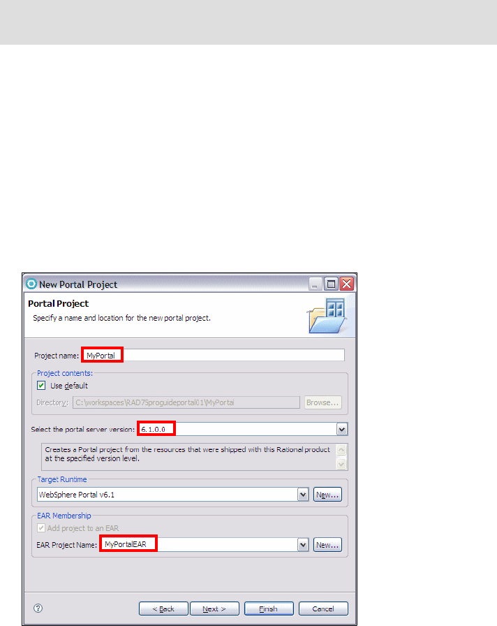
Chapter 21. Develop portal applications 751
Draft Document for Review December 9, 2008 2:44 pm 7672-dev-10-portal.fm
Select a default theme.
Select a default skin for the chosen theme.
The project that you create with this wizard does not have any portlet definitions,
labels, or pages. The themes and skins that are available in this wizard are the
same as if you had imported a portal site from a WebSphere Portal server. To
create a new Portal Project, do these steps:
Select File → New → Project → Portal.
Expand Portal and select Portal Project. Click Next.
In the New Portal Project dialog, type, for example, MyPortal in the Project
Name field. Use the default path, select the Portal Server v6.1 as your server,
select the WebSphere Portal v6.1 as the target runtime environment, type the
name of the EAR project (MyPortalEAR), and click Next (Figure 21-3).
Figure 21-3 New Portal Project wizard
In the Select Theme dialog, select the default theme (Portal) and click Next.
In the Select Skin dialog, select the default skin (IBM) and click Finish.
Important: You should not name your project wps or anything that resembles
this string, in order to avoid internal naming conflicts.
7672-dev-10-portal.fm Draft Document for Review December 9, 2008 2:44 pm
752 Rational Application Developer V7.5 Programming Guide
The Portal Designer editor is opened with the selected theme and skin.
Portal Designer
For portal site layout and appearance, you can think of Portal Designer as a
what-you-see-is-what-you-get (WYSIWYG) editor. It renders the graphic
interface of items such as themes, skins, page layouts, and basic portlets.
Portal Designer also displays the initial pages of JSF and Struts portlets within
your portal pages. Portal Designer will not display the content for WSRP remote
portlets. For more information on how to display basic portlets, refer to the
section Viewing portlets in Portal Designer in the Application Developer Help.
Use this editor to customize both the graphic design of your portal and the layout
of your portal pages. Use it as you would use any WYSIWYG Web editor.
Functions you can perform include:
Right-clicking a design element and selecting an Insert menu item
Clicking on a design element to edit its properties. Scroll down to read more
about working with properties
Using Page Designer to alter the graphic design of themes, skins and styles.
These editors are available in the Edit menu.
PortalConfiguration is the name of the layout source file that resides in the root
of the Portal project folder (Figure 21-4). To open Portal Designer, double-click
the ibm-portal-topology.xml file under the PortalConfiguration folder in the
Enterprise Explorer.
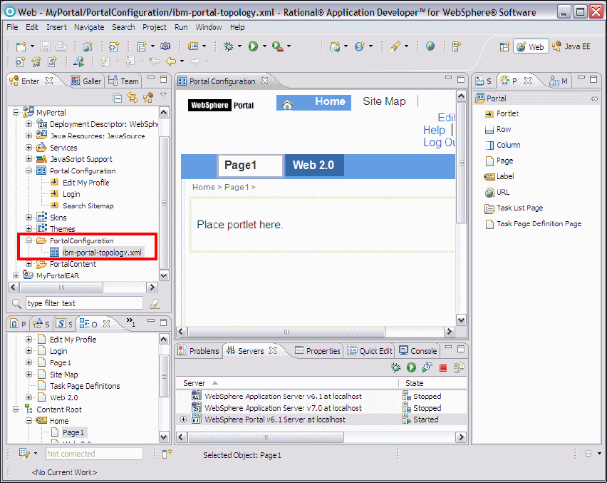
Chapter 21. Develop portal applications 753
Draft Document for Review December 9, 2008 2:44 pm 7672-dev-10-portal.fm
Figure 21-4 Portal Designer Workbench
Skin and theme design and editing
A skin is the border around each portlet within a portal page. Unlike themes,
which apply to the overall look and feel of the portal, skins are limited to the look
and feel of each portlet that you insert into your portal application.
Application Developer installation includes pre-built themes and skins to use with
portal projects. There are also wizards to create new themes and skins.
Changing themes and skins was previously done through portal administration.
In addition to these wizards for creating new skins and themes, there are tools
that can be used to change or edit these.
Once created, skins and themes are displayed in the Enterprise Explorer view.
Double-click a skin or theme to manually edit it.
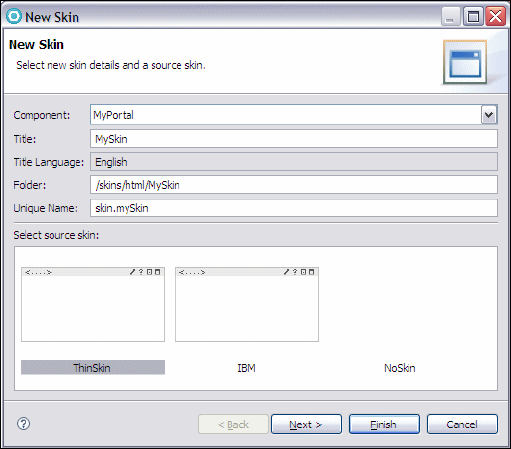
7672-dev-10-portal.fm Draft Document for Review December 9, 2008 2:44 pm
754 Rational Application Developer V7.5 Programming Guide
New Skin wizard
In addition to using the pre-made skins that came with the installation, you can
use the New Skin wizard to create customized skins for your project.
Right-click the Portal project in the Enterprise Explorer view and select
New → Skin. The New Skin page opens (Figure 21-5).
Figure 21-5 New Skin wizard
In the Select Themes page, select the themes that allow the skin you created,
then click Finish.
New Theme wizard
Themes provide the overall look and feel of your portal application. In addition to
using the pre-existing themes, you can use the New Theme wizard to create
customized themes for your project:
Right-click the Portal project in the Enterprise Explorer view and select
New → Theme. The New Them page opens (Figure 21-6).
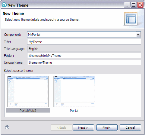
Chapter 21. Develop portal applications 755
Draft Document for Review December 9, 2008 2:44 pm 7672-dev-10-portal.fm
Figure 21-6 New Theme wizard
In the Select Skins page, select the allowed skins for the theme, then click
Finish.
New Websphere portal and portlet development tools in
Rational Application Developer v7.5
For those who are already familiar with portal and portlet development tools in
the previous version of the Application Developer, we briefly introduce the new
portal and portlet tooling in Application Developer v7.5.
Theme editing support
To edit a theme in the Portal Designer, select Edit Theme from the menu. The
Default.jsp file for the active theme opens in Page Designer. and gives you
WYSIWIG editor to work with. Also, one of the predefined themes has the Web
2.0 support so that users can make use of the Web 2.0 capabilities.
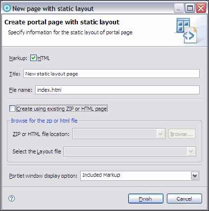
7672-dev-10-portal.fm Draft Document for Review December 9, 2008 2:44 pm
756 Rational Application Developer V7.5 Programming Guide
Creating portal pages using static page aggregation
Portal tools now supports the static page aggregation (SPA) feature in
WebSphere Portal Server v6.1. This feature helps you create generic HTML
pages as static Portal pages.
To create a portal page with static layout (Figure 21-7):
Right-click on a page or a label, and select Insert Static Page. or from the
main menu, click Insert → Static page.
In the new portal page of the static layout wizard, enter a file name.
Create a portal page, depending on your layout:
– To use a new layout file (index.html), click Finish.
– To use an existing layout, select Create using ZIP or HTML file, then use
Browse to navigate to the.zip or HTML file. Click Finish.
Figure 21-7 create a portal page with static layout
Creating user friendly URLs
Friendly URL is a new feature in WebSphere Portal v6.1 that allows portal
administrators to create constant user friendly URLs and map them to portal
pages. As administrators create the URLs, they can define human readable
names for them. These can be easily remembered and are therefore more user
friendly.
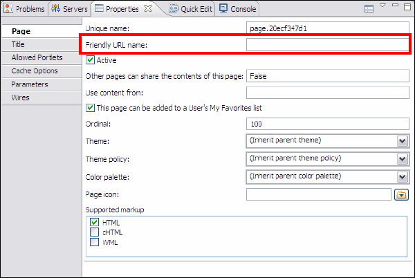
Chapter 21. Develop portal applications 757
Draft Document for Review December 9, 2008 2:44 pm 7672-dev-10-portal.fm
This feature enables you to manually:
Modify WebSphere Portal URLs (displayed in the browser address bar) to let
them navigate to another portal page.
Enter a complete portal URL into the browser address bar to navigate to a
particular page (omitting any rich navigational state).
To set a friendly URL to a portal label, page, or URL (Figure 21-8):
Select a label, page, or URL.
In the properties view, select the corresponding, Label, Page, or URL tab.
In the Friendly URL name field, specify a name. For example, support.
Save the settings.
Figure 21-8 Friendly URL feature
Client side click-to-action support
WebSphere Portal v6.1 provides client side programming model to reduce
roundtrips to the server and Application Developer v7.5 provides the necessary
client-side programming.
Client side click-to-action is one of the mechanism by which portlets can interact
and share information among each other. All components that contribute HTML
to a page can be a source or a target for exchanging information.
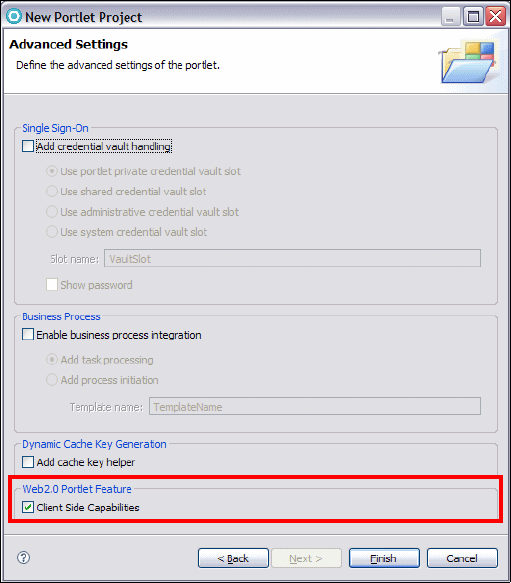
7672-dev-10-portal.fm Draft Document for Review December 9, 2008 2:44 pm
758 Rational Application Developer V7.5 Programming Guide
To add client side support when creating new Portlet projects, select Client
side Capabilities in the advanced settings of the New Portlet Project wizard
(Figure 21-9).
Figure 21-9 Enabling Client Side Capabilities in New Portlet Project
To enable the client side support in a new Web page of an existing Portlet
project, click Options in the New Web Page wizard, then select Portlet JSP
from the list on the left, and afterwards select the Client Side Capabilities
check box (Figure 21-10).

Chapter 21. Develop portal applications 759
Draft Document for Review December 9, 2008 2:44 pm 7672-dev-10-portal.fm
Figure 21-10 Enabling client side support in new Web Pages
Client-to-Action properties can be added to a Web page by dragging and
dropping them from the Palette into Page Designer (Figure 21-11)
Figure 21-11 Click-to-Action properties
Note: The new Click-to-Action feature is available only if the target server
is WebSphere Portal v6.1.
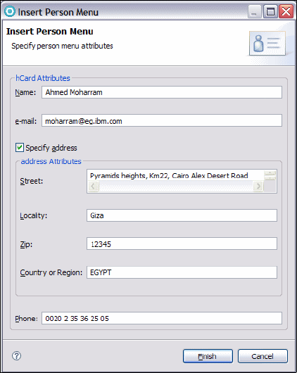
7672-dev-10-portal.fm Draft Document for Review December 9, 2008 2:44 pm
760 Rational Application Developer V7.5 Programming Guide
Person tagging support
Application Developer v7.5 provides new features called Person Menu and
Person Menu Extension, where Person Menu (Figure 21-12) displays a set of
contact information, and Person Menu Extension allows users to extend Person
Menu and enable JavaScript actions.
Figure 21-12 Insert Person menu
Application Developer 7.5 automatically generates JSP code corresponding to
the created Person Menu.
JSR 286 new PDD editor
Application Developer v7.5 has new tabs added to the Portlet Deployment
Descriptor to accommodate for the JSR 286 specification. The new tabs are for
events, render parameter, and filters (Figure 21-13).
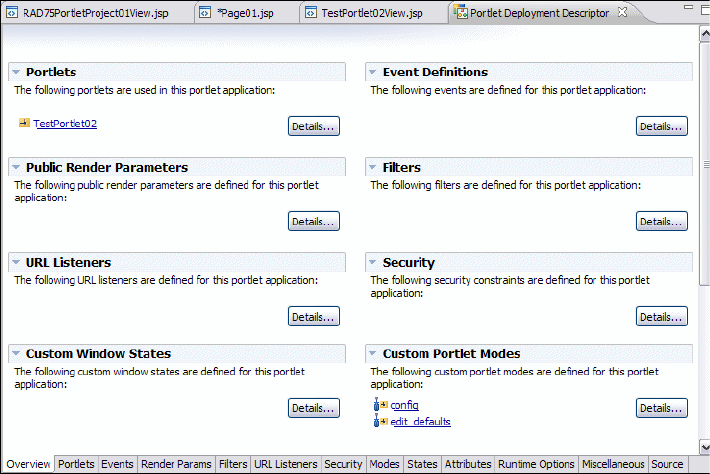
Chapter 21. Develop portal applications 761
Draft Document for Review December 9, 2008 2:44 pm 7672-dev-10-portal.fm
Figure 21-13 New tabs in the Portlet Deployment Descriptor
Ajax Proxy support
Ajax-based Web applications sometimes require sending Ajax requests to
servers different from the server that served by the HTML content. This can be
done using portlets with an Ajax proxy facet enabled in Application Developer
v7.5 (Figure 21-14).
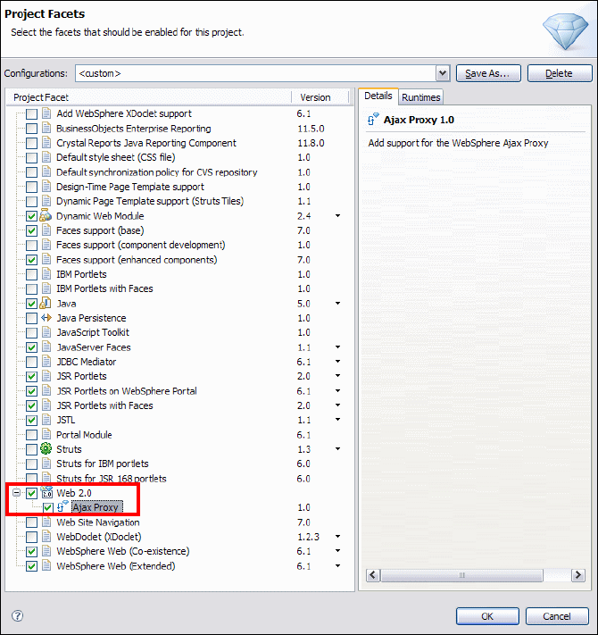
7672-dev-10-portal.fm Draft Document for Review December 9, 2008 2:44 pm
762 Rational Application Developer V7.5 Programming Guide
Figure 21-14 Ajax Proxy support
Developing portal solutions using portal tools
In this section, we provide an example to develop eventing portlets.
Developing eventing portlets
Events are a powerful and flexible mechanism for communication between JSR
286 portlets. Events can be used to exchange complex data between portlets
and to trigger portlet activity such as updates to back-end systems. In the portal,
Chapter 21. Develop portal applications 763
Draft Document for Review December 9, 2008 2:44 pm 7672-dev-10-portal.fm
they can also work with other communication mechanisms such as cooperative
portlets and click-to-action portlets.
Application Developer v7.5 provides wizards and user friendly editors to create
and configure events.
Wizards help portlets publish and receive events. You specify a unique name for
the event that has to be published or processed, using either the default name
space or a custom name space. In addition, the alias address in the name space
indicates that these events are compatible with any events of another portlet that
has the same alias and can therefore work with input or output values of the
provided address type.
Events subscribe to a server-side model or to a client-side model (IBM API and
JSR API portlets targeted on WebSphere Portal v6.1) for declaring, publishing,
and sharing information. Events can be distributed between local and remote
portlets.
Server-side model portlets communicate with each other using the WebSphere
Portal property broker. These portlets subscribe to the broker by publishing typed
data items, or properties, that they can share, either as a provider or as a
recipient.
Project setup
We use two projects for this application:
RAD75PortletEventEAR—Enterprise application
RAD75PortletEvent—Application with two portlets (based on JSR 286)
Import these projects from the interchange file located at:
C:\7672code\portal\RAD75PortletEventStart.zip
Structure of the sample application
The sample application consist of the following two portlets:
CityPortlet—Contains a list of cities for the user to select
CityInfoPortlet—Display detailed information about the city selected
Create an event to connect the portlets
We create an event to connect these two portlets:
In the Enterprise Explorer, expand RAD75PortletEvent.
Double-click in Portlet Deployment Descriptor
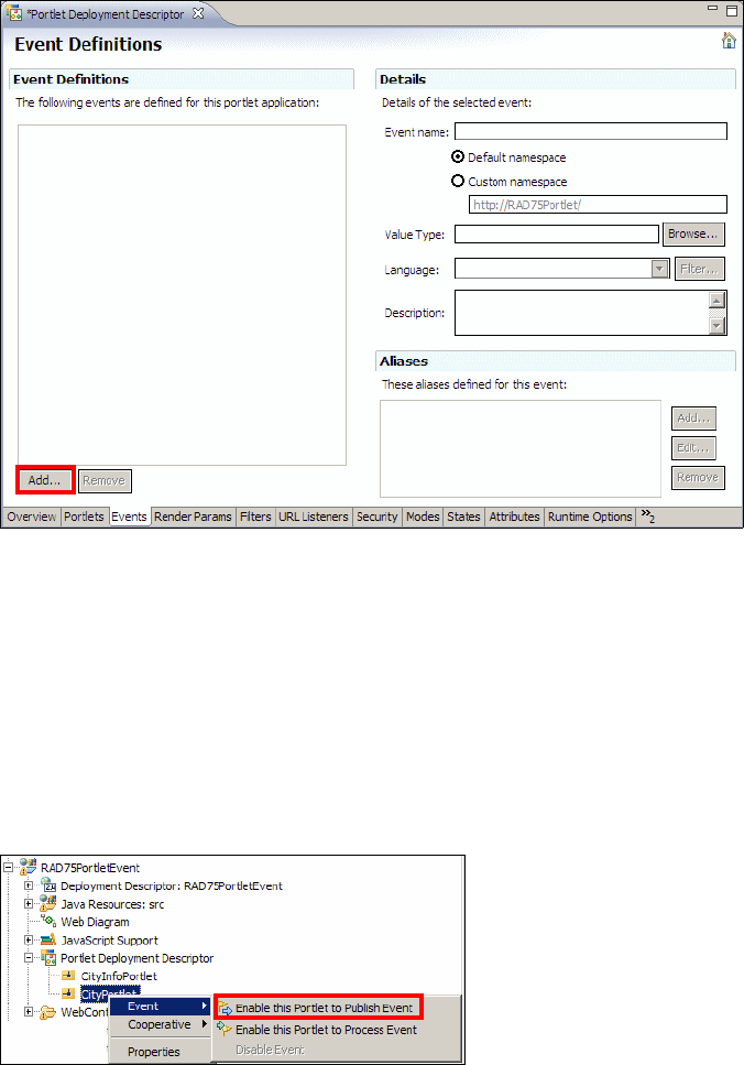
7672-dev-10-portal.fm Draft Document for Review December 9, 2008 2:44 pm
764 Rational Application Developer V7.5 Programming Guide
In the Portlet Deployment Descriptor editor, select the Events tab, where we
define the events for the portlet application (Figure 21-15). Click Add.
Figure 21-15 Portlet Deployment Descriptor: Events
In the Details pane (right side), type cityEvent for Event Name, and
java.lang.String for the Value Type. Save and close the editor.
To enabled a portlet to publish an event, do these steps:
In the Enterprise Explorer, expand RAD75PortletEvent → Portlet
Deployment Descriptor.
Right-click CityPortlet and select Events → Enable this portlet to publish
events (Figure 21-16).
Figure 21-16 Enabling a portlet to publish evens
cityEvent
java.lang.String

Chapter 21. Develop portal applications 765
Draft Document for Review December 9, 2008 2:44 pm 7672-dev-10-portal.fm
In the Event - Enable this Portlet to Publish events dialog, select cityEvent for
the Event name, and click Finish.
As a result, a processAction method is added to the CityPortlet class
(Example 21-1).
Example 21-1 CityPortlet class processAction method
public void processAction(ActionRequest request, ActionResponse response)
throws PortletException, java.io.IOException {
//Initialize the fields in the class as per your requirement
java.lang.String sampleObject = new java.lang.String();
response.setEvent("cityEvent", sampleObject);
}
To enable a portlet to process an event, do these steps:
In the Enterprise Explorer, expand RAD75PortletEvent → Portlet
Deployment Descriptor.
Right-click CityInfoPortlet and select Events → Enable this portlet to
process events.
In the Event - Enable this Portlet to Process events dialog, select cityEvent
for the Event name, and click Finish
As a result, a processEvent method is added to the CityInfoPortlet class
(Example 21-2).
Example 21-2 CityInfoPortlet processEvent method
public void processEvent(EventRequest request, EventResponse response)
throws PortletException, java.io.IOException {
Event sampleEvent = request.getEvent();
if(sampleEvent.getName().toString().equals("cityEvent")) {
Object sampleProcessObject = sampleEvent.getValue();
}
}
Adding the event logic to the two portlets
We have to put logic into the processAction method of the CityPortlet class
and the processEvent method of the CityInfoPortlet class.
When the user submits the CityPortlet, the processAction method is called.
We have to trigger an event with the value of the selected city to the
CityInfoPortlet to process this event.
7672-dev-10-portal.fm Draft Document for Review December 9, 2008 2:44 pm
766 Rational Application Developer V7.5 Programming Guide
Open the CityPortlet class and change the processAction method
(Example 21-3).
Example 21-3 CityPortlet class processAction method (updated)
public void processAction(ActionRequest request, ActionResponse response)
throws PortletException, java.io.IOException {
//Initialize the fields in the class as per your requirement
java.lang.String sampleObject = new java.lang.String();
response.setEvent("cityEvent", sampleObject);
String city = request.getParameter("cityCombo");
response.setEvent("cityEvent", city);
}
Open the CityInfoPortlet class and change the processEvent method to get
the value of the event received and delegate this value to the CityDB helper
class, which returns a CityInfoBean object with the information about the
selected city (Example 21-4).
Example 21-4 CityInfoPortlet class processEvent method (updated)
public void processEvent(EventRequest request, EventResponse response)
throws PortletException, IOException {
Event sampleEvent = request.getEvent();
if(sampleEvent.getName().toString().equals("cityEvent")) {
Object sampleProcessObject = sampleEvent.getValue();
String city = (String) sampleEvent.getValue();
cityInfoBean = CityDB.getCityInfo(city);
}
}
The doView method of the CityInfoPortlet class puts the cityInfoBean on
request scope and forwards processing to a JSP to display the result
(Example 21-5).
Example 21-5 CityInfoPortlet class doView method
public void doView(RenderRequest request, RenderResponse response)
throws PortletException, IOException {
// Set the MIME type for the render response
response.setContentType(request.getResponseContentType());
request.setAttribute("info",cityInfoBean);
// Invoke the JSP to render
PortletRequestDispatcher rd = getPortletContext().getRequestDispatcher
(getJspFilePath(request, VIEW_JSP));
rd.include(request,response);
}
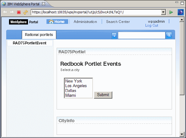
Chapter 21. Develop portal applications 767
Draft Document for Review December 9, 2008 2:44 pm 7672-dev-10-portal.fm
The CityInfoPortletView.jsp in the CityInfoPortlet retrieves the
cityInfoBean and displays the information about the selected city.
Deploying and running the event handling portlets
In the Enterprise Explorer, right click RAD75PortletEvent → Run As → Run on
Server.
In the subsequent dialog, select Finish to complete publishing to the WebSphere
Portal server. After the application has been deployed, Application Developer
opens a browser in the Workbench (Figure 21-17).
Figure 21-17 Browser with CityPortlet
Connecting the portlets
Now, we have to use wires to exchange information or actions between
portlets.To access the wiring tool, following these steps:
With the browser opened with the CityPortlet, pass the mouse over the
RAD75PortletEvent label.
An arrow appears on the right side, click the arrow to open a menu.
In the menu, select Edit Page Properties (Figure 21-18).
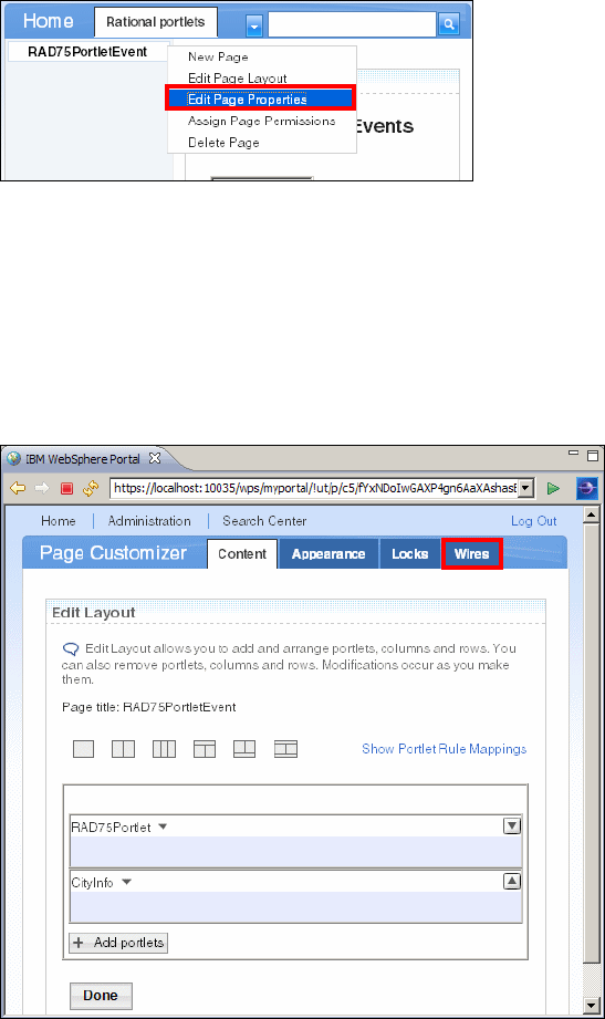
7672-dev-10-portal.fm Draft Document for Review December 9, 2008 2:44 pm
768 Rational Application Developer V7.5 Programming Guide
Figure 21-18 Edit Page Properties
In the Page Properties dialog, type rad75.portlet.page as Unique name, and
click OK.
Again, pass the mouse over the RAD75PortletEvent label.
In the menu, select Edit Page Layout.
In the Page Customizer dialog, select in the Wires tab (Figure 21-19).
Figure 21-19 Edit Page Layout
In the Portlet Wiring Tool, we connect the portlets (Figure 21-20):
– Source Portlet: Select RAD75Portlet.
– Sending: Select publish.{http://RAD75Portlet/}cityEvent.
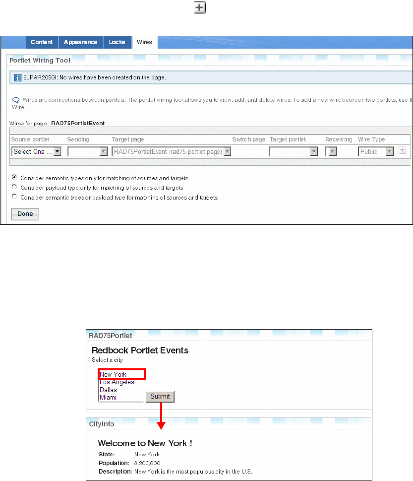
Chapter 21. Develop portal applications 769
Draft Document for Review December 9, 2008 2:44 pm 7672-dev-10-portal.fm
– Target Page: Select RAD75PortletEvent (rad75.portlet.page).
– Target portlet: Select CityInfo.
– Receiving: Select process.{http://RAD75Portlet/}cityEvent.
– Click in the plus icon to add the wire.
– Click Done, then click Home.
Figure 21-20 Portlet Wiring Tool (compressed)
Testing the application
To test the event link between the two portlets:
Select New York in the first portlet and click Submit.
The second portlet shows information about the selected city (Figure 21-21).
Figure 21-21 Application with event handling between portlets
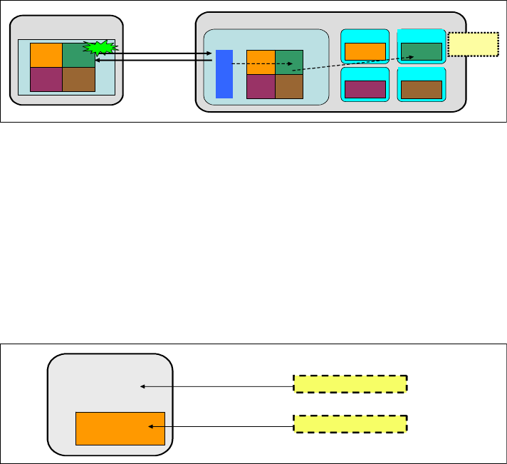
7672-dev-10-portal.fm Draft Document for Review December 9, 2008 2:44 pm
770 Rational Application Developer V7.5 Programming Guide
Creating Ajax and Web 2.0 portlets
The new JSR 286 contains improvements to develop AJAX portlets. One of the
new features is called resource serving.
Ajax using JSR 286 resource serving
Resource serving allows portlets to serve resource requests in resource URLs.
With WSRP 2.0, requests for resources such as PDF documents are addressed
within the WSRP protocol. Formerly an out-of-band connection was required for
such resources, for example HTTP. Resources are now portal context aware, as
the context information is passed directly over the WSRP protocol.
Resource serving allows Ajax support inside portlets, and the portlets have a
way to return XML, JSON, HTML fragments, or other content. Only the portlet
that made the requisition is updated, not the entire page (Figure 21-22).
Figure 21-22 Portlet with Ajax support
A resource request is a new callback interface triggered by so-called resource
URLs. To make a portlet be a resource serving portlet, we have to implement the
ResourceServingPortlet interface and implement the serveResource method.
The output for the serveResource method must have a separate content page.
Resource serving example
We adapt the previous portlet events example to add Ajax behavior. The
CityInfoPortlet will have a button to retrieve a list of hotels about the current
city (Figure 21-23).
Figure 21-23 Resource serving portlet to add city hotels
Browser
AB
CD
Portal Server
WAR
Portlet ‘A’
WAR
Portlet ‘B’
WAR
Portlet ‘C’
WAR
Portlet ‘D’
Portal W AR
Servlet
AB
CD
Click
XHR +
resource URL
HTML,JSON,XML etc
Server
resource
Portlet
Dynamic Content
doView()
serveResource()
hotels.jsp
CityInfoPortletView.jsp
Chapter 21. Develop portal applications 771
Draft Document for Review December 9, 2008 2:44 pm 7672-dev-10-portal.fm
Project setup
We have to projects:
RAD75PortletEventAjaxEAR—Enterprise application
RAD75PortletEventAjax—Application with two portlets (based on JSR 286)
Import these projects from the interchange file located at:
C:\7672code\portal\RAD75PortletEventAJaxStart.zip
First, we have to import some files before developing the others artifacts:
Select File → Import.
In the Import dialog, select General→ File System. Click Next.
In the File system dialog:
– For From directory, click Browse to locate C:\7672code\portal.
–Select
hotel.jsp in the right frame.
– For Into folder, click Browse and locate:
RAD75PortletEvent/WebContent/_CityInfo/jsp/html
– Click Finish.
Repeat the import to place HotelInfoBean.java into the
com.ibm.rad75portlet.bean package.
Repeat the import to place HotelDB.java into the com.ibm.rad75portlet.db
package.
Developing the Ajax code
Open the CityInfoPortlet class in the editor and perform these steps:
Add an implements clause to the class declaration (Example 21-6).
Example 21-6 Implementing ResourceServingPortlet
public class CityInfoPortlet extends GenericPortle
implements ResourceServingPortlet {
Select Source → Organize Imports (or Ctrl+Shift+O) to resolve the import.
Right-click in the editor window and select Source → Override/Implement
Methods. Select the serveResource method, After processEvent(...) for
Insertion point, and click OK.
Tip: You can also drag and drop a file from a Windows Explorer folder directly
into the appropriate folder or package in Application Developer.

7672-dev-10-portal.fm Draft Document for Review December 9, 2008 2:44 pm
772 Rational Application Developer V7.5 Programming Guide
When the serveResource method is called, we have to find the hotels of the
selected city and set a parameter with the hotel list to the JSP file. Add the
code below to the serveResource method (Example 21-7).
Example 21-7 CityInfoPortlet serveResource method
public void serveResource(ResourceRequest request,
ResourceResponse response) throws PortletException, IOException {
String cityId = request.getParameter("cityId");
request.setAttribute("hotels", HotelDB.getHotels(cityId));
PortletRequestDispatcher rd = getPortletContext()
.getRequestDispatcher(JSP_FOLDER + "/html/hotel.jsp");
rd.include(request, response);
}
Select Source → Organize Imports (or Ctrl+Shift+O) to resolve the import.
Add the code below (in bold) in the doView method to create the resource
URL and add it to the request (Example 21-8).
Example 21-8 CityInfoPortlet doView method
public void doView(RenderRequest request, RenderResponse response)
throws PortletException, IOException {
// Set the MIME type for the render response
response.setContentType(request.getResponseContentType());
request.setAttribute("info",cityInfoBean);
String resourceUrl = response.createResourceURL().toString();
request.setAttribute("resourceUrl", resourceUrl);
// Invoke the JSP to render
PortletRequestDispatcher rd = getPortletContext()
.getRequestDispatcher(getJspFilePath(request, VIEW_JSP));
rd.include(request,response);
}
Locate the JavaScript snippet file and copy its contents:
C:\7672code\portal\SnippetJavaScriptAjax.txt
Paste the code into the CityInfoPortletView.jsp after the tags
<portlet-client-model:init>......</<portlet-client-model:init>. This
code has JavaScript functions that call Ajax functions.
Next, we create a Hotels button with an event click that targets the resource
URL, and a <div> tag where the list of hotels will appear. Add the code below
into CityInfoPortletView.jsp after the </table> tag (Example 21-9).
Example 21-9 Hotels button and div tag
</table>
<br> <================== existing tag
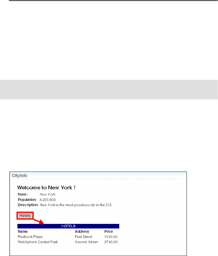
Chapter 21. Develop portal applications 773
Draft Document for Review December 9, 2008 2:44 pm 7672-dev-10-portal.fm
<form>
<input type="button"
onclick="<portlet:namespace/>getHotels('${requestScope.resourceUrl}',
'hotels','${requestScope.info.cityId}')" value="Hotels" >
</form>
</c:if> <================== existing tag
<div id="hotels"> </div>
Deploying and running the application
In the Enterprise Explorer, right-click RAD75PortletEvent → Run As → Run on
Server.
In the subsequent dialog, select Finish to publish the application to the
WebSphere Portal server. After the application has been deployed, Application
Developer opens a browser in the Workbench.
Testing the application
To test the Ajax functionality, perform these steps:
In the first portlet, select New York from the list box and click Submit.
The second portlet shows the information about New York city.
Click Hotels to call an Ajax function that retrieves a list of Hotels
(Figure 21-24).
Figure 21-24 Portlet application with Ajax
Note: After deploying the application, you have to connect the Portlets. Follow
the instructions in “Connecting the portlets” on page 767.
7672-dev-10-portal.fm Draft Document for Review December 9, 2008 2:44 pm
774 Rational Application Developer V7.5 Programming Guide
More information
For more information on portal technology, refer to these resources:
The following Redbooks publications cover the Portlet Application
Development for the older versions of WebSphere Portal:
–Building Composite Applications, SG24-7367
–IBM WebSphere Portal V5 A Guide for Portlet Application Development,
SG24-6076
–IBM WebSphere Portal V5.1 Portlet Application Development, SG24-6681
WebSphere Portal v6.0 refresh pack 1 and instructions (WP v6.0.1):
http://www-1.ibm.com/support/docview.wss?rs=688&uid=swg24015257
http://publib.boulder.ibm.com/infocenter/wpdoc/v6r0/index.jsp?topic=/com.ib
m.wp.ent.doc/wpf/pui_intro601.html
WebSphere Portal Update Installer:
http://www-1.ibm.com/support/docview.wss?rs=688&uid=swg24006942
WebSphere Application Server v6.0.2 Fix Pack 17 (WAS v6.0.2.17) for
Windows platforms:
http://www-1.ibm.com/support/docview.wss?rs=180&uid=swg24014309
Update Installer for WebSphere Application Server v6.0 releases:
http://www-1.ibm.com/support/docview.wss?rs=180&uid=swg24008401
Troubleshooting - Rational Application Developer v7.x cannot sense the
proper state of Portal Server v6.x:
http://www-1.ibm.com/support/docview.wss?rs=2042&context=SSRTLW&context=SSJ
M4G&context=SSCGQ7C&dc=DB520&uid=swg21258582&loc=en_US&cs=utf-8&lang=en
Installing and configuring WebSphere Portal v6.0 Servers for development
with Rational Application Developer v7.0 and Rational Software Architect
v7.0:
http://www.ibm.com/developerworks/rational/library/07/0327_riordan/index.ht
ml

© Copyright IBM Corp. 2008. All rights reserved. 775
Draft Document for Review December 9, 2008 2:44 pm 7672-test-0-p6.fm
Part 6 Test and debug
applications
In this part of the book, we describe the tooling and technologies provided by
Application Developer for testing and debugging.
Part 6
7672-test-0-p6.fm Draft Document for Review December 9, 2008 2:44 pm
776 Rational Application Developer V7.5 Programming Guide

© Copyright IBM Corp. 2008. All rights reserved. 777
Draft Document for Review December 9, 2008 2:44 pm 7672-test-2-servers.fm
Chapter 22. Servers and server
configuration
Application Developer provides support for testing, debugging, profiling, and
deploying Enterprise applications to local and remote test environments.
To run an enterprise application or Web application in Application Developer, the
application must be published (deployed) to the server. This is achieved by
deploying the EAR project, for the application, to an application server. With the
server started the application can be tested using a Web browser, or by using the
Universal Test Client (UTC) if it includes EJBs.
This chapter describes the features and concepts of server configuration, as well
as demonstrating how to configure a server to test applications.
The chapter is organized into the following sections:
Introduction to server configurations
Understanding WebSphere Application Server v7.0 profiles
WebSphere Application Server v7.0 installation
Using WebSphere Application Server v7.0 profiles
Adding and removing applications to and from a server
Configuring application and server resources
Configuring security
Developing automation scripts
22
7672-test-2-servers.fm Draft Document for Review December 9, 2008 2:44 pm
778 Rational Application Developer V7.5 Programming Guide
Introduction to server configurations
Application Developer includes integrated test environments for WebSphere
Application Server v6.1 and v7.0 and WebSphere Portal v5.1 and v6.0, as well
as support for many third-party servers obtained separately. The server
configuration is the same for WebSphere Application Server v7.0 (base),
Express, and Network Deployment Editions. One of the many great features of
the server tooling is the ability to simultaneously run multiple server
configurations and test environments on the same development node where
Application Developer is installed.
When using Application Developer, it is very common for a developer to have
multiple test environments or server configurations, which are made up of
workspaces, projects, preferences and supporting test environments
(local or remote).
Some of the key features of test environment configuration include:
Multiple workspaces with different projects, preferences, and other
configuration settings defined
Multiple Application Developer test environment servers configured
When using WebSphere Application Server v7.0 test environments, multiple
profiles, each potentially representing a different server configuration
For example, a developer might want to have a separate server configuration for
WebSphere Application Server v7.0 with a unique set of projects and
preferences in a workspace, and a server configuration pointing to a newly
created and customized WebSphere Application Server v7.0 profile. On the
same system, the developer might create a separate portal server configuration
with unique portal workspace projects and preferences, as well as a WebSphere
Portal v6.0 Test Environment. This chapter describes how to create, configure,
and run multiple WebSphere Application Server v7.0 instances on the same
development system.
Application servers supported by Rational Application Developer 7.5
The most commonly used application server with Application Developer is
WebSphere Application Server. WebSphere Application Server is tightly
integrated with Application Developer, which offers tooling to test, run, and debug
applications from the workbench, for example, by using the run-on-server
functionality. You can specify server-specific configurations such as extensions
and bindings for a WebSphere Application Server from the Workbench.
Chapter 22. Servers and server configuration 779
Draft Document for Review December 9, 2008 2:44 pm 7672-test-2-servers.fm
You can launch tooling for WebSphere Application Server from within the
Workbench, such as the WebSphere Administrative Console and the Profile
Management Tool. In addition, you can develop, run, and debug administrative
scripts against a WebSphere Application Server.
In Application Developer, the integration with WebSphere Application Server v7.0
for deployment, testing, and administration is the same as for the WebSphere
Application Server v7.0 test environment installed with Rational Application
Developer and also for the Network Deployment edition.
The following application servers are compatible with Rational Application
Developer v7.5:
IBM WebSphere Application Server versions 5.1, 6.0, 6.1 and 7.0
IBM WebSphere Application Server Express version 5.1
IBM WebSphere Portal version 5.1 and 6.0
J2EE Publishing Server (publish EAR to a server)
Static Web Publishing Server (HTTP server for static Web projects)
Application Developer server tools are based on the Eclipse Web Tools Platform
(WTP) project. WTP provides a facility for publishing an Enterprise Application
project and all of its modules to a runtime environment for testing purposes.
Server adapters are tools installed into the Workbench that support a particular
server. The server adapters on the following list are included, by default, in the
Web Tools Platform installed with Rational Application Developer:
Apache Tomcat versions 3.2, 4.0, 4.1, 5.0, 5.5 and 6.0
IBM Websphere Portal Server versions 6.0 and 6.1
IBM Websphere Application Server versions 6.0, 6.1 and 7.0
JBoss versions 3.2, 3, 4.0, 4.2 and 5.0
ObjectWeb Java Open Application Server (JOnAS) version 4
Oracle Containers for Java EE (OC4J) Standalone Server version 10.1.3 and
10.1.3.n
Additional servers adapters can be obtained by clicking on Download additional
server adapters in the New Server dialog as shown in Figure 22-1. To open the
New Server dialog right-click on the Servers window and select New → Server.
Some of the additional server adapters that could be obtained at the time of
writing were:
Apache Geromino Server versions 1.0, 1.1.x, 2.0 and 2.1
IBM Websphere Application Server Community Edition versions 1.1.x, 2.0
and 2.1
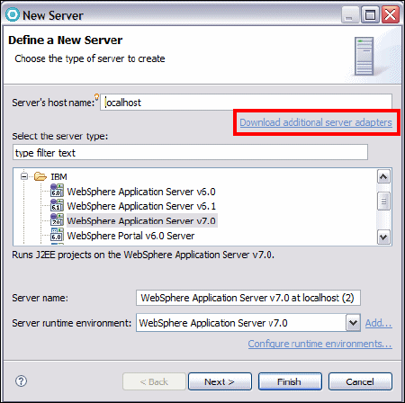
7672-test-2-servers.fm Draft Document for Review December 9, 2008 2:44 pm
780 Rational Application Developer V7.5 Programming Guide
Figure 22-1 Downloading additional server adapters
Local and remote test environments
When configuring a test environment, the server can be either a local integrated
server or a remote server. Once the server itself is installed and configured, the
server definition within Rational Application Developer is very similar for local and
remote servers.
In both the local and remote configurations Remote Method Invocation (RMI) or
SOAP connectors can be used by Rational Application Developer to control the
server using Java Management Extensions (JMX). The RMI (ORB bootstrap)
port is designed to improve performance and communication with the server. The
SOAP connector port is designed to be more firewall compatible and uses HTTP
as the base protocol. In the case of local configurations the Inter Process
Communication (IPC) connector is also available and is in fact the recommended
connector.

Chapter 22. Servers and server configuration 781
Draft Document for Review December 9, 2008 2:44 pm 7672-test-2-servers.fm
Understanding WebSphere Application Server v7.0
profiles
The concept of server profiles was introduced starting with WebSphere
Application Server v6.0. The WebSphere Application Server installation process
simply lays down a set of core product files required by the runtime processes.
After installation, you have to create one or more profiles that define the runtime
settings for a functional system. The core product files are shared between the
runtime components defined by these profiles.
With WebSphere Application Server Base and Express Editions, you can only
have standalone application servers (Figure 22-2). Each application server is
defined within a single cell and node. The administration console is hosted within
the application server and can only connect to that application server. No central
management of multiple application servers are possible. An application server
profile defines this environment.
Figure 22-2 System management topology: Standalone server (Base and Express)
You can also create standalone application servers with the Network Deployment
package, though you would most likely do so with the intent of federating that
server into a cell for central management at some point.
With the Network Deployment package, you have the option of defining multiple
application servers with central management capabilities. For more information
on profiles for the IBM WebSphere Application Server v7.0 Network Deployment
Edition, refer to WebSphere Application Server V6.1: Systems Management and
Configuration, SG24-7304.
Cell
Application
Server
"server1"
Node A
Admin
console
Application
Server profile

7672-test-2-servers.fm Draft Document for Review December 9, 2008 2:44 pm
782 Rational Application Developer V7.5 Programming Guide
Types of profiles
There are three types of profiles used when defining the runtime of an application
server:
Application server profile
Deployment manager profile
Custom profile
Application server profile
The application server profile defines a single standalone application server.
Using a profile will give you an application server that can run standalone
(unmanaged) with the following characteristics:
The profile consists of one cell, one node, and one server. The cell and node
are not relevant in terms of administration, but you will see them when you
administer the server through the administrative console.
The name of the application server is server1.
The WebSphere sample applications are automatically installed on the
server.
The server has a dedicated administrative console.
The primary use for this type of profile could be any of the following:
To build a server in a Base or Express installation, including a test
environment within Rational Application Developer.
To build a standalone server in a Network Deployment installation that is not
managed by the deployment manager, for example, to build a test machine.
To build a server in a distributed server environment to be federated and
managed by the deployment manager. If you are new to WebSphere
Application Server and want a quick way of getting an application server
complete with samples, this is a good option. When you federate this node,
the default cell becomes obsolete and the node is added to the deployment
manager cell. The server name remains as server1, and the administrative
console is removed from the application server.
Note: This is the application server profile used by Rational Application
Developer for the WebSphere Application Server v7.0 test environment.
Chapter 22. Servers and server configuration 783
Draft Document for Review December 9, 2008 2:44 pm 7672-test-2-servers.fm
Deployment manager profile
The deployment manager profile defines a deployment manager in a Network
Deployment installation. Although you could conceivably have the Network
Deployment package and run only standalone servers, this would bypass the
primary advantages of Network Deployment, which are workload management,
failover, and central administration.
In a Network Deployment environment, you should create one deployment
manager profile. This will give you:
A cell for the administrative domain
A node for the deployment manager
A deployment manager with an administrative console.
No application servers
Once you have the deployment manager, you can:
Federate nodes built either from existing application server profiles or custom
profiles.
Create new application servers and clusters on the nodes from the
administrative console.
Custom profile
A custom profile is an empty node, intended for federation to a deployment
manager. This type of profile is used when you are building a distributed server
environment. You would use this as follows:
Create a deployment manager profile.
Create one custom profile on each node on which you will run application
servers.
Federate each custom profile, either during the custom profile creation
process or later using the addNode command, of the deployment manager.
Create new application servers and clusters on the nodes from the
administrative console.
WebSphere Application Server v7.0 installation
The IBM WebSphere Application Server v7.0 integrated test environment is an
installation option available in IBM Installation Manager when Installing Rational
Application Developer.
7672-test-2-servers.fm Draft Document for Review December 9, 2008 2:44 pm
784 Rational Application Developer V7.5 Programming Guide
For details on how to install the WebSphere Application Server V7.0 Test
Environment, refer to “Installing IBM Rational Application Developer” on
page 1124 (Figure A-6 on page 1126).
Prior to the IBM WebSphere Application Server v7.0 test environment
installation, the runtimes directory looks as follows:
<rad_home>\runtimes\base_v7_stub
The stub folder contains minimal sets of compile-time libraries that allow you to
build applications for a server when it is not installed locally.
After the WebSphere Application Server v7.0 test environment is installed you
will see the directory:
<rad_home>\runtimes\base_v7
The base_v7 folder is the Application Server installation directory.
Using WebSphere Application Server v7.0 profiles
In “Understanding WebSphere Application Server v7.0 profiles” on page 781, we
reviewed WebSphere V7.0 profile concepts. The Profile Management tool is a
WebSphere Application Server tool that creates the profile for each runtime
environment. It is also a graphical user interface to the WebSphere Application
Server command-line tool, wasprofile. You can use the tools in Rational
Application Developer to start the WebSphere Application Server Profile
Management tool.
Creating a new profile using the WebSphere Profile wizard
To create a new WebSphere Application Server v7.0 profile using the
WebSphere Profile Management Tool, do the following from within the Rational
Application Developer environment:
In the workbench, select Window → Preferences.
In the Preferences window, expand Server → WebSphere Application
Server.
Under the WebSphere Application Server local server profile management
list, select WebSphere Application Server v7.0 (Figure 22-3).

Chapter 22. Servers and server configuration 785
Draft Document for Review December 9, 2008 2:44 pm 7672-test-2-servers.fm
Figure 22-3 Server Preferences page
Click Run Profile Management Tool next to the WebSphere profiles defined
in the runtime selected above list, which lists all the profiles defined for the
runtime environment selected in the previous step.
In the Profile Management Tool window, click Profile Management Tool.
The existing profile (was70profile1) is listed. Click Create (Figure 22-4).
Figure 22-4 Profile Management Tool window
In the Environment selection page, WebSphere Application Server is
preselected. Click Next.
In the Profile Creation Options page, select Typical profile creation and click
Next (Figure 22-5).
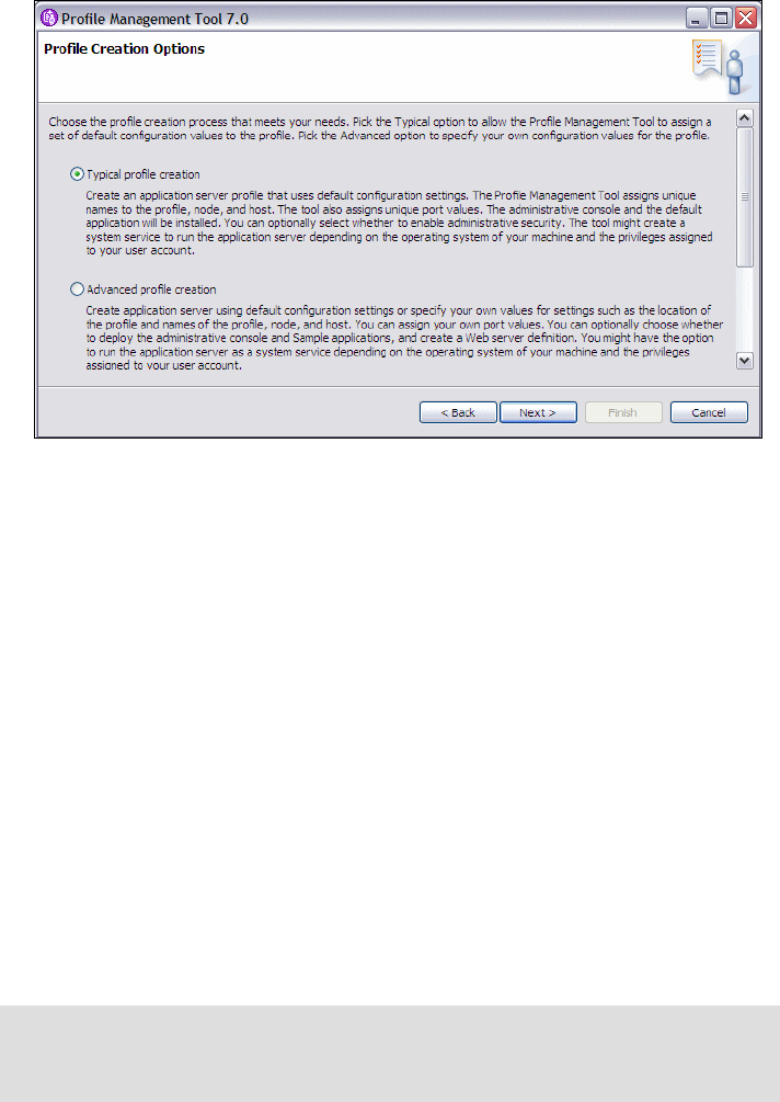
7672-test-2-servers.fm Draft Document for Review December 9, 2008 2:44 pm
786 Rational Application Developer V7.5 Programming Guide
Figure 22-5 Profile options
In the Administrative Security page, clear Enable administrative security
and click Next. Alternatively, select Enable administrative security and
enter a user name and password (for example, admin).
In the Profile Creation Summary page, review the profile settings. You can
see that the ports are incremented by 1 for the new profile you are creating so
that the new profile does not conflict with an existing profile. Click Create.
In the Profile Creation Complete page, clear Launch the First steps
console, and click Finish.
Notice that information that you can start the Profile Management Tool using
the pmt command in the <app_server_root>/bin/ProfileManagement
directory (<rad-home>/runtimes/base_v7/bin/ProfileManagement).
Back in the Profile Management Tool window, you can see the new profile is
present in the Profiles list with the name AppSrv01.
When you close the Profile Management tool window and return to the
Preferences window you can also see that the new profile is listed under the
WebSphere profiles defined in the runtime selected above list.
Note: The new server is installed as a Windows service that is started
automatically. You may want to edit the service in the Windows Services dialog
and set the Startup Type to Manual.

Chapter 22. Servers and server configuration 787
Draft Document for Review December 9, 2008 2:44 pm 7672-test-2-servers.fm
Verifying the new WebSphere profile
After creating the WebSphere profile, you can verify that it was created properly
and familiarize yourself with how to use it by doing the following:
View the directory structure and find the new profile:
<rad_home>/runtimes/base_v7/profiles/<profile_name>
<rad_home>/runtimes/base_v7/profiles/AppSrv01
This is where you will find, among other things, the config directory
containing the application server configuration files, the bin directory, for
commands, and the logs directory where log information is recorded.
Start the server by opening a command prompt, and issuing the startserver
commands:
cd <profile_home>\bin
startserver server1
Once the server has started the following message is displayed in the
command prompt but probably with a different process id:
ADMU3000I: Server server1 open for e-business; process id is xxxx
The server log files are in the <profile_home>/logs/server1 folder. Open the
following file to see the logging messages:
<profile_home>/logs/server1/SystemOut.log
Open the WebSphere Administrative Console by accessing its URL from a
Web browser. The format of the required URL and a specific example are:
http://<appserver_host>:<admin_console_port>/ibm/console
http://localhost:9062/ibm/console/
The administrative console port was listed in the Profile Creation Summary page
during profile creation. If the port used in your case is different from the example
given, you can determine the port from the SystemOut.log. Search for the string
bound to admin_host in the log file. The first number in the square brackets
following this string is the admin port being used. In this example the values are
[*:9062,*:9045].
Click Log in to access the admin console functionality. Security is not active
at this time so you do not have to enter a user name. If you choose to enter a
name, it can be any name. If you enter a name it will be used to track changes
you made to the configuration.
Note: For simplicity, we will now refer to the entire path for the profile as
<profile_home>.
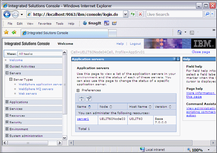
7672-test-2-servers.fm Draft Document for Review December 9, 2008 2:44 pm
788 Rational Application Developer V7.5 Programming Guide
In the admin console you can see Servers and Applications in the list
presented on the left hand side of the display. To investigate a portion of the
server configuration do the following:
–Select
Servers → Server Types → Websphere application servers,
and the server1 is listed (Figure 22-6). To see the configuration for this
server, click its name in the list.
Figure 22-6 Application servers list in the admin console
–Select Applications → Application Types → Websphere enterprise
applications. You can see a list of applications installed on server1.
– Click Logout and close the browser.
Stop the application server by executing the stopserver command in the
command window:
stopserver server1
The following message will be displayed in the console once the server has
stopped:
ADMU4000I: Server server1 stop completed.
Chapter 22. Servers and server configuration 789
Draft Document for Review December 9, 2008 2:44 pm 7672-test-2-servers.fm
Deleting a WebSphere profile
The steps required are provided here for future reference but do not perform the
steps now, because we want to retain the newly created profile:
From the menu bar of the workbench, select Window → Preferences →
Server → WebSphere Application Server.
Under the WebSphere Application Server local server profile management
list, select the installed runtime environment containing the profile to be
deleted.
Under the WebSphere profiles defined in the runtime selected list above,
select the profile to be deleted and click Delete. The registry and
configuration files associated with the profile selected for deletion, are
removed from the file system; however, any log files remain on the file system.
and can be removed manually.
Defining the new server in Application Developer
Once you have created a WebSphere profile, you can define the new server in
Rational Application Developer, to be used for the deployment of applications. A
server definition points to a server defined within the specific selected
WebSphere profile, such as the default profile created during installation, or a
profile created using the Profile Management Tool. There are a few things to
consider concerning the definition of a new server in Rational Application
Developer:
The profile was70profile1 is created when the WebSphere Application
Server v7.0 Integrated Test Environment feature is selected during the
installation of Rational Application Developer. Also, a WebSphere Application
Server v7.0 test environment server is defined and configured to use the
was70profile1 profile.
A Rational Application Developer server definition is essentially a pointer to a
WebSphere profile.
Create a server definition in Rational Application Developer
To create a server definition in Application Developer execute the following steps:
Select the Servers view, in the Java EE or Web perspective.
Right-click in the Servers view and select New → Server.
In the Define a New Server dialog shown in Figure 22-7, do the following:
–Leave the Server’s host name at its default value of localhost.
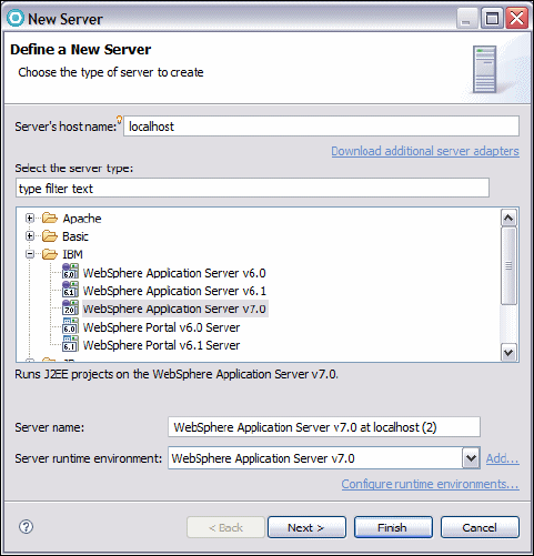
7672-test-2-servers.fm Draft Document for Review December 9, 2008 2:44 pm
790 Rational Application Developer V7.5 Programming Guide
– Select a Server runtime environment of WebSphere Application
Server v7.0.
– Click Next.
Figure 22-7 Define New Server dialog
In the New Server dialog, WebSphere Server Settings page (Figure 22-8), do
the following:
– Select the Websphere profile we created previously as the WebSphere
profile name. The profile to select is AppSrv01.
–Select
Automatically determine connection settings under Server
connection types and administrative ports.
–Select
Run server with resources within the workspace.
– Enter the value server1 for the Websphere server name.
– Click Next.
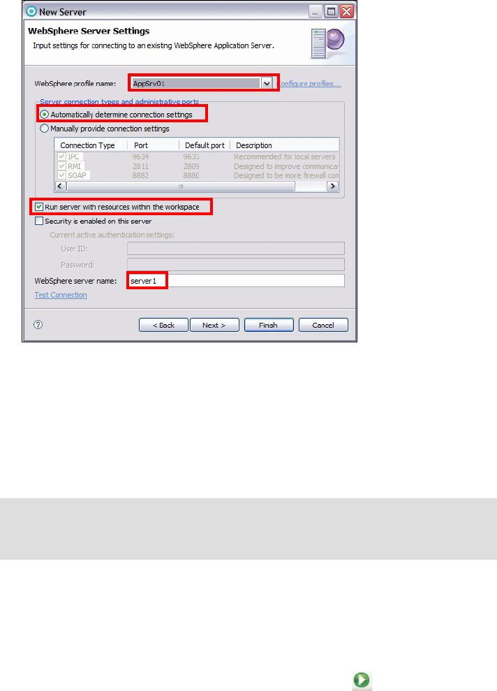
Chapter 22. Servers and server configuration 791
Draft Document for Review December 9, 2008 2:44 pm 7672-test-2-servers.fm
Figure 22-8 New Server dialog, WebSphere Server Settings page
In the Add and Remove Projects dialog, we do not select a project at this time
so click Finish.
The server definition is created and displayed in the Servers view. In our
example, the server definition WebSphere Application Server v7.0 at
localhost (2) is created.
Verify the server
After you have completed defining the server within Application Developer, we
recommend that you perform some basic verification steps to ensure that the
server is configured properly:
In the Servers view, right-click WebSphere Application Server v7.0 at
localhost (2), and select Start (or click the Start icon ).
Tip: Open the new server configuration by double-clicking on it. This allows
you to change the configuration settings, for example, you can change the
name of the server, but let us leave the name for now.
7672-test-2-servers.fm Draft Document for Review December 9, 2008 2:44 pm
792 Rational Application Developer V7.5 Programming Guide
Review the server startup output in the console. Also view the server logs
startServer.log and SystemOut.log for errors:
<profile_home>/logs/server1/startServer.log
<profile_home>/logs/server1/SystemOut.log
Right-click the server and select Administration → Run administrative
console.
After accessing several pages of the WebSphere Administrative Console to
verify it is working properly, click Logout and close the browser.
Verify that the server stops properly using the following steps:
– In the Servers view, right-click the server, and select Stop. The server
status should change to Stopped, after a while.
– Verify that the server has really stopped by entering the following
commands to verify the server status:
cd <profile_home>/bin
serverStatus -all
– The server status output should show that the server has stopped. If not,
stop the server by entering the following command:
stopServer server1
Customizing a server
Once the server has been defined in Rational Application Developer, it is very
easy to customize its settings. To do this, in the Servers view, double-click the
server you want to customize. The server overview window is shown in
Figure 22-9. This window allows the server configuration to be modified.

Chapter 22. Servers and server configuration 793
Draft Document for Review December 9, 2008 2:44 pm 7672-test-2-servers.fm
Figure 22-9 Server overview window
There are a several key settings that are worth covering in detail:
Server:
–WebSphere Profile name. This is where the desired WebSphere
application server profile is selected.
–Server connection type and administrative ports. The method used by
Rational Application developer to communicate with the server is selected
here. The radio buttons allow you to have the connection settings chosen
automatically or manually. If manual connection settings are chosen then
you can select whether to use IPC, RMI or SOAP as the communication
channel between the development environment and the server. By default,
the automatic setting radio button is active. When working with a local
server IPC is the recommended connection setting although all settings
will work. If you are working with a remote server, then SOAP or RMI can
be used.
7672-test-2-servers.fm Draft Document for Review December 9, 2008 2:44 pm
794 Rational Application Developer V7.5 Programming Guide
– Terminate server on workbench shutdown. If you want the server to be
terminated after the workbench is shutdown, you have to select this
option. Otherwise, the server continues to run after you shut down the
development environment. The next time you start the IDE, the server is
found again in its current state.
Publishing:
–Never publish automatically. Specifies that the workbench should not
automatically publish files to the server. A developer can still publish to the
server but must do this manually.
–Automatically publish when resources change. Specifies that a
change to the files running on the server should automatically be
published to the server. Publishing interval (in seconds) specifies how
often the publishing takes place. If you set the publishing interval to 0
seconds, a change to the files running on the server automatically causes
publishing to occur.
Publishing settings for Websphere Application Server:
– Run server with resources on Server. This option installs and copies the
full application and its server-specific configuration from the workbench
into the directories of the server. The advantage of selecting the Run
server with resources on Server setting is you are running your application
from the directories of your server and you can edit advanced
application-specific settings for your application using the WebSphere
Administrative Console. However, when you choose to add your
application to the server using the Add and Remove Projects wizard, this
option takes a longer time to complete than the Run server with resources
within the workspace option, as it involves more files being copied to the
server.
– Run server with resources within the workspace. This option requests
the server to run your application from the workspace. The Run server
with resources within the workspace setting is useful when developing and
testing your application. It is designed to operate faster than the Run
server with resources on Server option, as fewer files are involved when
copying over to the server.
– Minimize application files copied to the server. This option is designed
to optimize the publishing-time on the server by reducing the files copied
to the server. In addition to the application files not getting copied into the
installedApps directory of the server, the application also does not get
copied into your server configuration directory. As a result, when
configuring your application, you cannot use the WebSphere
Administrative Console to edit deployment descriptor information. You are
limited to editing the Java EE deployment descriptor files for your
Chapter 22. Servers and server configuration 795
Draft Document for Review December 9, 2008 2:44 pm 7672-test-2-servers.fm
application within the workbench. Clear this option if you have to use the
WebSphere Administrative Console to edit the deployment descriptor.
The Security settings are discussed in “Configuring security” on page 807.
Sharing a WebSphere profile between developers
The configuration of a server can be time consuming and error-prone. Once you
have configured the server resources, you might want to let other members of the
team use the same configuration from their local environment, without
duplicating the same effort.
To replicate server configurations across multiple profiles, you can use the
Server Configuration Backup wizard to create a backup of a WebSphere
Application Server v7.0 profile in a Configuration Archive (CAR) file. This
performs the same functionality as the wsadmin command:
wsadmin AdminTask exportWasprofile
You can also use the Server Configuration Restore wizard to restore a
WebSphere Application Server v7.0 profile from a configuration archive file. This
performs the same functionality as the wsadmin command:
wsadmin AdminTask importWasprofile
Server configuration backup
To backup the server configuration from WebSphere Application Server v7.0 at
localhost, do the following:
Configure the data source using WebSphere Application Server v7.0, as
described in “Configuring the data source in WebSphere Application Server”
on page 1155.
Create a new project to store the configuration archive file:
–Select
File → New → Project → General → Project and click Next.
– For the project name, enter WAS70Car and Click Finish.
In the Servers view right-click on WebSphere Application Server v7.0 at
localhost and select Server Configuration → Backup.
In the Server Configuration Backup dialog, specify /WAS70Car as the
Parent folder and WAS70AppSrv1 as the File name and click OK
(Figure 22-10).

7672-test-2-servers.fm Draft Document for Review December 9, 2008 2:44 pm
796 Rational Application Developer V7.5 Programming Guide
Figure 22-10 Server Configuration Backup dialog
After the server configuration backup process completes, you should see the
WAS70AppSrv1.car file under the WAS70Car project.
Server configuration restore
To restore the server configuration to a different server, in this case WebSphere
Application Server v7.0 at localhost (2) do the following:
Make sure that WebSphere Application Server v7.0 at localhost (2) is not
running and if it is stop it.
In the Servers view, right-click WebSphere Application Server v7.0 at
localhost (2) and select Server Configuration → Restore.
In the Server Configuration Restore dialog, specify /WAS70Car as the
Parent folder and WAS70AppSrv1.car as the file name and click OK
(Figure 22-11).
Figure 22-11 Server Configuration Restore dialog
After the server configuration restore process completes, start WebSphere
Application Server v7.0 at localhost (2).
Right-click WebSphere Application Server v7.0 at localhost (2) and select
Administration → Run administrative console. You should see the data
source you configured for WebSphere Application Server v7.0 at localhost
now also appears in the administrative console for WebSphere Application
Server v7.0 at localhost (2).
Chapter 22. Servers and server configuration 797
Draft Document for Review December 9, 2008 2:44 pm 7672-test-2-servers.fm
Defining a server for each workspace
If you want to switch workspaces and keep applications deployed on the server,
you can create a new WebSphere profile for each new Application Developer
workspace, as described in “Creating a new profile using the WebSphere Profile
wizard” on page 784. Then define only that server in the Servers view, as
described in “Create a server definition in Rational Application Developer” on
page 789.
This approach requires more disk space for each WebSphere profile and server
configuration, and requires additional memory if the servers run concurrently.
Adding and removing applications to and from a server
Once the server is configured, it can be further configured with server resources
and be used to run applications by adding applications to it.
This section describes how to add an enterprise application to a server. Note that
you cannot add Web or EJB projects to a server, only enterprise applications
EAR projects.
Adding an application to the server
To add an application to the server, do the following:
Verify that the server has started.
In the Servers view, right-click a server, and select Add and Remove
Projects.
In the Add and Remove Projects dialog (Figure 22-12), select one of the listed
EAR projects and click Add. After you click Add the project appears in the
Configured projects.
Click Finish.

7672-test-2-servers.fm Draft Document for Review December 9, 2008 2:44 pm
798 Rational Application Developer V7.5 Programming Guide
Figure 22-12 Add and Remove Projects
Once an application is added to the server you can run any of the HTML
pages or JSPs.
Removing an application from a server
An Application Developer server configuration is essentially a pointer to a server
defined in a WebSphere profile. In this section we describe two scenarios for
removing published projects from the server.
Remove an application using Application Developer
In most cases, you can remove the project from the test server within Rational
Application Developer as follows:
In the Servers view, right-click the server where the application is published,
and select Add and remove projects. In the Add and Remove Projects
dialog, select the project in the Configured projects list, click Remove, and
then click Finish.
Alternatively, expand the server in the servers view, right-click the EAR project
to be removed, and select Remove.
This operation uninstalls the application from the server.

Chapter 22. Servers and server configuration 799
Draft Document for Review December 9, 2008 2:44 pm 7672-test-2-servers.fm
Remove an application using the administrative console
In some cases you may decide to uninstall the application using the WebSphere
Administrative Console.
For example, if you have published a project in Rational Application Developer to
the test server, it is deployed to the server defined in the WebSphere profile. If
you then switch workspaces without first removing the project from the server,
you have a broken the association between the Rational Application Developer
server and the server defined in the WebSphere profile.
To address issues like the scenario described, uninstall the enterprise application
from the WebSphere Administrative Console as follows:
Make sure the server is started.
Start the WebSphere Administrative Console either by right-clicking the
server and selecting Administration → Run administrative console and
then if necessary clicking Log in.
Select Applications → Application Types → Websphere Enterprise
Applications.
Select the desired application to uninstall, and click Uninstall.
When prompted, click OK.
When uninstallation is complete, save the changes.
Configuring application and server resources
In WebSphere Application Server v7.0, application-related properties and data
sources can be defined within an Enhanced EAR file to simplify application
deployment as shown in Figure 22-13. The properties are used by the application
after it is deployed.
Note: After you uninstall the application using the WebSphere Administrative
Console, you can see that the project still appears in the Configured projects
section if you start the Add and Remove Projects wizard. You have to click
Remove to move the project to the Available projects section.

7672-test-2-servers.fm Draft Document for Review December 9, 2008 2:44 pm
800 Rational Application Developer V7.5 Programming Guide
Figure 22-13 Enhanced EAR
The enhanced EAR tooling is available in the WebSphere Application Server
Deployment Editor, as shown in Figure 22-14. Deployment information is saved
under the application /META-INF/ibmconfig directory.
Note: The Enhanced EAR editor is used to edit several WebSphere
Application Server v7.0 specific configurations, such as data sources, class
loader policies, substitution variables, shared libraries, virtual hosts, and
authentication settings. It lets you configure these settings with little effort and
allows them to be published every time you publish the application.
The benefit of this is that it makes the testing process simpler and easily
repeatable, because the configurations are saved to files that are usually
shared in the team repository. Thus, even though it will not let you configure all
the runtime settings, it is a good tool for development purposes because it
eases the process of configuring the most common settings.
The downside is that the configuration settings are stored in the EAR file, and
are not visible from administrative console. The console is only able to edit
settings that belong to the cluster, node, and server contexts. When you
change a configuration using the Enhanced EAR editor, this change is made
at the application context. Furthermore, in most cases these settings are
dependent on the node where the application server will be installed in
anyway, so it makes little sense to configure them at the application context for
deployment purposes.
Enhanced EAR
Enhanced EAR
J2EE App.
EAR
Properties
Resources
Enhanced EAR
Enhanced EAR
Java EE App.
EAR
Properties
Properties
Resources
Resources
Enhanced
Enhanced
EAR
EAR
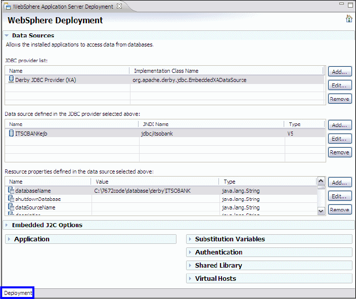
Chapter 22. Servers and server configuration 801
Draft Document for Review December 9, 2008 2:44 pm 7672-test-2-servers.fm
Figure 22-14 Enterprise application deployment descriptor: Enhanced EAR
The server configuration data that you specify in this editor gets embedded within
the application itself. This improves the administration process of publishing to
WebSphere Application Server v7.0 when installing a new application to an
existing local or remote WebSphere Server by preserving the existing server
configuration.
The following resource types can be added to the enhanced EAR:
JDBC resources (Data Sources section)
Resource adapters (Embedded J2C Options section)
Application class loader settings (Application section)
Substitution variables
JAAS Authentication entries
Shared Library
Virtual Hosts
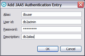
7672-test-2-servers.fm Draft Document for Review December 9, 2008 2:44 pm
802 Rational Application Developer V7.5 Programming Guide
Creating a data source in the enhanced EAR
The data sources that support EJB entity beans must be specified before the
application can be started. There are several ways to do it, but the easiest is to
use the Enhanced EAR editor.
For an example of configuring the enhanced EAR against the Derby database,
refer to “Configuring the data source for the ITSOBANK” on page 413. In this
section, we demonstrate how to create a data source for a DB2 database using
enhanced EAR settings:
In the Enterprise Explorer, right-click RAD7EJBEAR and select Java EE →
Open WebSphere Application Server Deployment.
Scroll down the page until you find the Authentication section. This allows
you to define a login configuration used by JAAS.
Click Add to create a new configuration (Figure 22-15).
Figure 22-15 JAAS Authentication Entry
Typ e dbuser as the Alias, and the appropriate user ID and password for your
configuration. Click OK to complete the creation of the configuration.
In the Enhanced EAR editor scroll back up to the Data Sources, JDBC
provider list section. By default, the Derby JDBC Provider (XA) is predefined.
Because we are using DB2 for this example, we have to add a DB2 JDBC
provider by clicking Add next to the provider list.
The Create JDBC Provider dialog opens (Figure 22-16):
–Select
IBM DB2 as the database type.
– Then select DB2 Universal JDBC Driver Provider (XA) as the provider
type.
– Click Next.
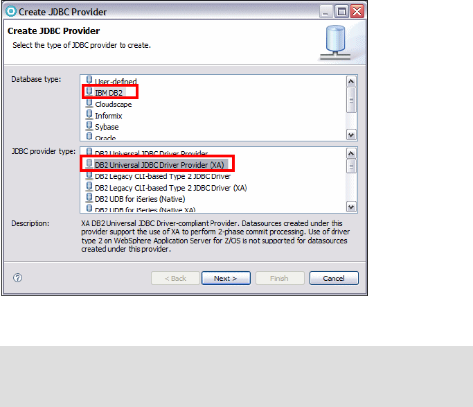
Chapter 22. Servers and server configuration 803
Draft Document for Review December 9, 2008 2:44 pm 7672-test-2-servers.fm
Figure 22-16 Creating a JDBC provider (page 1)
In the second page of the wizard (Figure 22-17):
–Type
DB2 XA JDBC Provider as the name.
– Notice the variables that are used to locate the JDBC driver:
${DB2UNIVERSAL_JDBC_DRIVER_PATH}
${UNIVERSAL_JDBC_DRIVER_PATH}
${DB2UNIVERSAL_JDBC_DRIVER_NATIVEPATH}
If these variables are not set globally for the WebSphere Application
Server, we can set them under Substitution Variables.
– Click Finish.
Note: Note that for our development purposes, the DB2 Universal JDBC
Driver Provider (non XA) would work fine, because we do not require XA
(two-phase commit) capabilities.
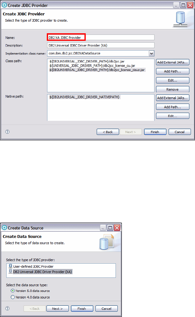
7672-test-2-servers.fm Draft Document for Review December 9, 2008 2:44 pm
804 Rational Application Developer V7.5 Programming Guide
Figure 22-17 Creating a JDBC provider (page 2)
With the new DB2 provider selected, click Add next to the defined data
sources list. In the Create Data Source dialog (Figure 22-18):
–Select
DB2 Universal JDBC Driver Provider (XA) from the JDBC
provider type list.
–Select
Version 5.0 data source.
– Click Next.
Figure 22-18 Create a data source (1)
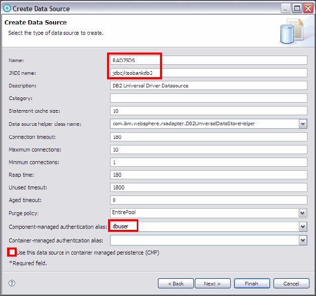
Chapter 22. Servers and server configuration 805
Draft Document for Review December 9, 2008 2:44 pm 7672-test-2-servers.fm
In the next page (Figure 22-19):
–Type
RAD75DS as the data source name and jdbc/itsobankdb2 as the
JNDI name.
– Select the dbuser alias for Component-managed authentication alias.
–Clear
Use this data source in container manager persistence (CMP).
We are using JPA entities and not EJB 2.1 entity beans.
– Click Next.
Figure 22-19 Create a data source (2)
In the last page of the wizard (Figure 22-20):
– Set the databaseName property value to ITSOBANK.
– Click Finish to conclude the wizard.
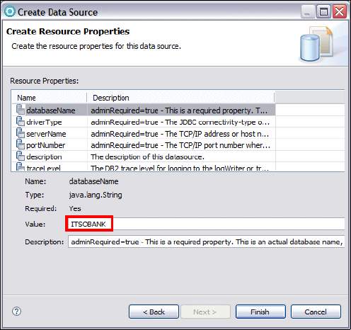
7672-test-2-servers.fm Draft Document for Review December 9, 2008 2:44 pm
806 Rational Application Developer V7.5 Programming Guide
Figure 22-20 Create a data source (3)
Save the deployment descriptor.
Setting substitution variable
If the variables to access the DB2 JDBC drivers are not set server wide (using
the administrative console), you can expand the Substitution Variable section and
define the variables:
Click Add.
In the Add Variable dialog, define the name of the variable (for example,
${DB2UNIVERSAL_JDBC_DRIVER_PATH), and set the value to the location where DB2
JDBC drivers are installed, for example, c:\SQLLIB\java.
Configuring server resources
Within Application Developer, the WebSphere administrative console is the
primary interface for configuring WebSphere Application Server v7.0 test
servers, both local and remote. Complicated resource configurations such as
messaging resources can only be configured using the WebSphere
administrative console.

Chapter 22. Servers and server configuration 807
Draft Document for Review December 9, 2008 2:44 pm 7672-test-2-servers.fm
There are a couple of methods for accessing the WebSphere administrative
console. In each case the WebSphere Application Server v7.0 test server must
be started.
Once the WebSphere Application Server v7.0 test server has started, you can
right-click the server and select Administration → Run administrative
console.
Configuring security
If the WebSphere Application Server v7.0 runtime environment has
administrative security enabled, you have to communicate the administrative
settings from your development environment to the runtime server. In Rational
Application Developer you have to specify that security is enabled in the runtime
environment, and provide the user ID and password in the server editor for the
secured server. If you are working with a secured WebSphere Application Server
Version v7.0 server, you have to establish a trust between the Rational
Application Developer development environment and the server.
In this section, we show you how to enable administrative security, using the local
operating system registry for authentication, by using the WebSphere
Administrative Console. We also show you how to pass the administrative
settings from the development environment to the runtime server.
Configuring security in the server
First, we configure the server so that it runs with security enabled:
Start the test server called WebSphere Application Server v7.0 at
localhost (2).
Right-click the server and select Administration → Run administrative
console.
Click Log in.
Expand Security → Global Security (Figure 22-21):
–Select
Enable administrative security and Enable application security.
–Clear
Use Java 2 security to restrict application access to local
resources.
Note: For more information on configuring WebSphere security, refer to IBM
WebSphere Application Server V6.1 Security Handbook, SG24-6316.
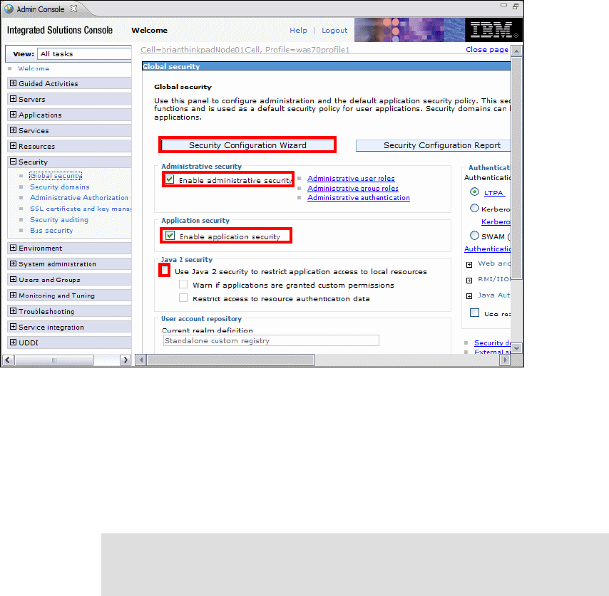
7672-test-2-servers.fm Draft Document for Review December 9, 2008 2:44 pm
808 Rational Application Developer V7.5 Programming Guide
Figure 22-21 Configuring security
Click Security Configuration wizard.
In the Specify extent of protection page, click Next.
In the Select user repository page, select Local operating system.
In the Configure user repository page, enter the primary administrative user
name, and click Next.
Click Finish, then click Save, then click Logout to log off from the
administrative console.
Stop the server.
Note: The specified user must have the required privileges in Windows, such
as the permission to log on as service. For more information see section 2.3 of
the IBM WebSphere Application Server V6.1 Security Handbook, SG24-6316.

Chapter 22. Servers and server configuration 809
Draft Document for Review December 9, 2008 2:44 pm 7672-test-2-servers.fm
Configuring security in the Workbench
We have to edit the server configuration to specify that security is enabled:
In the Servers view, double-click WebSphere Application Server v7.0 at
localhost (2). The server configuration editor opens (Figure 22-22).
– Expand the Security section.
–Select
Security is enabled on this server.
– The User ID and Password fields specify the administrator user of the
WebSphere administrative console. These values must be the same as
those entered in the Security Configuration wizard dialog, as described in
“Configuring security in the server” on page 807.
–Select
Automatically trust server certificate during SSL handshake is
selected
Figure 22-22 Security setting in server editor
Save and close the server configuration editor.
Start the server and run the administrative console.
You should see the secured administrative console (Figure 22-23). Enter the
user ID and password and click Log in.
Figure 22-23 Secured Administrative Console
7672-test-2-servers.fm Draft Document for Review December 9, 2008 2:44 pm
810 Rational Application Developer V7.5 Programming Guide
Developing automation scripts
Scripting is a non-graphical alternative that you can use to configure and manage
a WebSphere Application Server. The WebSphere administrative scripting tool,
wsadmin, is a non-graphical command interpreter environment that allows you to
run administrative operations on a server in a scripting language.
There are five wsadmin objects available when you use scripts:
AdminControl. This is used to run operational commands.
AdminConfig. This is used to run configuration commands to create or
modify WebSphere Application Server configuration elements.
AdminApp. This is used to administer applications.
AdminTask. This is used to run administrative commands.
Help. This is used to obtain general help.
The WebSphere administrative scripting program, wsadmin, supports two
scripting languages: Java Tcl (Jacl) and Java Python (Jython).
With the Version 6.1 release of WebSphere Application Server, IBM announced
the start of the deprecation process for the Jacl syntax associated with wsadmin.
In this chapter, we describe how to create a Jython project and Jython script, how
to edit the Jython script, and how to run it.
Creating a Jython project
To create a Jython project, follow these instructions:
Select File → New → Project → Jython → Jython Project and click Next.
For the Project name, type RAD75Jython and click Finish.
Creating Jython script files
To create a Jython script file, follow these instructions:
Select File → New → Other → Jython → Jython Script File and click Next.
Specify /RAD75Jython as the Parent folder and listJDBCProviders.py as
the File name.
Click Finish.

Chapter 22. Servers and server configuration 811
Draft Document for Review December 9, 2008 2:44 pm 7672-test-2-servers.fm
Editing Jython script files
The Jython editor is the tool for editing Jython scripts. The Jython editor has
many text editing features, such as content assist, syntax highlighting, unlimited
undo or redo, and automatic tab indentation.
Type the code shown in Example 22-1. It lists all defined JDBC providers in the
WebSphere Application Server. During typing, you can use content assist by
pressing Ctrl+Space. You can find the code in:
c:\7672code\Jython\listJDBCProviders.py
Example 22-1 List JDBC providers using a Jython script (listJDBCProviders.py)
def showJdbcProviders():
providerEntries = AdminConfig.list("JDBCProvider")
# split long line of entries into individual entries in list
providerEntryList = providerEntries.split(lf)
# print contents of list
for provider in providerEntryList:
print provider
AdminConfig.reset()
cell = AdminControl.getCell()
node = AdminControl.getNode()
lf = java.lang.System.getProperty("line.separator")
slash = java.lang.System.getProperty("file.separator")
print "System information: Cell=" + cell
print "System information: Node=" + node
showJdbcProviders()
Running administrative script files on WebSphere Application Server
You can run administrative scripts from within Application Developer, without
having to switch to the non-graphical wsadmin command. To run a Jython script,
follow these instructions:
Make sure the server has started.
Right-click the server WebSphere Application Server v7.0 at localhost and
select Administration → Run administrative script.
The Script page is the main page of the WebSphere Administrative Script
Launcher (Figure 22-24):
– In the Administrative Script field click Workspace.
– In the File Selection dialog, expand the RAD7Jython project and select
listJDBCProviders.py and click OK.

7672-test-2-servers.fm Draft Document for Review December 9, 2008 2:44 pm
812 Rational Application Developer V7.5 Programming Guide
– For Scripting runtime select WebSphere Application Server v7.0.
– For WebSphere profile, select AppSrv01 (or was70profile1), whatever
server is running.
– In the Security section, if the administrative security is still enabled with
local operating system registry, as you configured in “Configuring security”
on page 807, select Specify and enter the required User ID and
Password.
Figure 22-24 Running an administrative script
Click Apply to save the configuration.
Click Run to run the Jython script. You should see console output similar to
that listed below:
WASX7209I: Connected to process "server1" on node KLCHL2YNode01 using
SOAP connector; The type of process is: UnManagedProcess
System information: Cell=KLCHL2YNode01Cell
System information: Node=KLCHL2YNode01
"Derby JDBC Provider (XA)(cells/KLCHL2YNode01Cell/nodes/KLCHL2YNode01/
servers/server1|resources.xml#builtin_jdbcprovider)"
Chapter 22. Servers and server configuration 813
Draft Document for Review December 9, 2008 2:44 pm 7672-test-2-servers.fm
"Derby JDBC Provider (XA)(cells/KLCHL2YNode01Cell|resources.xml
#builtin_jdbcprovider)"
"Derby JDBC Provider(cells/KLCHL2YNode01Cell/nodes/KLCHL2YNode01/
servers/server1|resources.xml#JDBCProvider_1182202633563)"
Generating WebSphere admin commands for Jython scripts
You can use the WebSphere Administration Command assist tool to generate
WebSphere administrative, wsadmin, Jython scripting language commands as
you interact with the WebSphere Administrative Console. When you perform
server operations in the WebSphere Administrative Console, the WebSphere
Administration Command assist tool captures and displays the wsadmin
commands issued. You can transfer the output from the WebSphere
Administration Command view directly to a Jython editor, enabling you to develop
Jython scripts based on actual console actions.
To generate wsadmin commands as you interact with the WebSphere
Administrative Console, do the following:
Enable the command assistance notification option in the WebSphere
Administrative Console:
– Make sure the server has started.
– Right-click the server WebSphere Application Server v7.0 at localhost
(2) and select Administration → Run administrative console.
– Specify the User ID and the Password if the server is secured and click
Log in.
– On the left-pane, expand Applications → Application Types →
Websphere enterprise applications.
– Scroll to the right of the Enterprise Applications page and under the
Command Assistance section, click View administrative scripting
command for last action.
– Expand Preferences, select the Enable command assistance
notifications (Figure 22-25). Click Apply and close the window.

7672-test-2-servers.fm Draft Document for Review December 9, 2008 2:44 pm
814 Rational Application Developer V7.5 Programming Guide
Figure 22-25 Administrative Scripting Commands
In the Servers view, right-click the server and select Administration →
WebSphere administration command assist. The WebSphere
Administration Command window opens. The view might open on the
top-right, but you can move it to a better place, such as where the Servers
and Console views are.
In the Select Server to Monitor pull-down , select WebSphere
Application Server v7.0 at localhost (2), to ensure the server is selected.
In the WebSphere Administrative Console select Applications →
Application Types → Websphere enterprise applications in the left-pane.
You should see that the WebSphere Administration Command view is
populated with a wsadmin command for Jython.
In the WebSphere Administrative Console, left-pane, select Resources →
JDBC → JDBC Providers. Another command will appear in the WebSphere
Administration Command window (Figure 22-26).
Note: There might be a few seconds delay before you see the Jython
command in the WebSphere Administration Command view.

Chapter 22. Servers and server configuration 815
Draft Document for Review December 9, 2008 2:44 pm 7672-test-2-servers.fm
Figure 22-26 WebSphere Administration Command View
Create a Jython script file in the RAD75Jython project and name it
CommandAssist.py.
To transfer the wsadmin commands generated in the WebSphere
Administration Command view to the Jython script:
– Make sure the Jython editor for CommandAssist.py is open.
– In the Jython editor place the cursor at the bottom of the editor window.
– In the WebSphere Administration Command view use the Shift key and
the mouse to select both commands. Right-click the commands and select
Insert.
In the editor, two commands are added:
AdminApp.list()
AdminConfig.list(\
'JDBCProvider', AdminConfig.getid( \
'/Cell:KLCHL2YNode01Cell/'))
Add the print method in front of each of the two commands so that we have
the following:
print AdminApp.list()
print AdminConfig.list(\
'JDBCProvider', AdminConfig.getid( \
'/Cell:KLCHL2YNode01Cell/'))
Save the file.
Right-click CommandAssist.py and select Run As → Administrative
Script.
In the Script page of the WebSphere Administrative Script Launcher, select
the following items:
– For Scripting runtime, select WebSphere Application Server v7.0.
– For WebSphere profile, select AppSrv01 (or was70profile1).
– In the Security section, if administrative security is enabled, enter the
required User ID and Password.
7672-test-2-servers.fm Draft Document for Review December 9, 2008 2:44 pm
816 Rational Application Developer V7.5 Programming Guide
Click Apply and then click Run to execute the script. You should see console
output similar to that listed below:
WASX7209I: Connected to process "server1" on node KLCHL2YNode01 using
SOAP connector; The type of process is: UnManagedProcess
DefaultApplication
IBMUTC
ivtApp
query
"Derby JDBC Provider
(XA)(cells/KLCHL2YNode01Cell/nodes/KLCHL2YNode01/servers/
server1|resources.xml#builtin_jdbcprovider)"
"Derby JDBC Provider (XA)(cells/KLCHL2YNode01Cell|resources.xml#
builtin_jdbcprovider)"
"Derby JDBC
Provider(cells/KLCHL2YNode01Cell/nodes/KLCHL2YNode01/servers/
server1|resources.xml#JDBCProvider_1182202633563)"
The command assist feature is great when you are learning Jython and allows
you to easily create scripts for future use.
Debugging Jython scripts
The Jython debugger enables you to detect and diagnose errors in Jython scripts
that are run on a WebSphere Application Server.
For an example of debugging the sample listJDBCProviders script
(Example 22-1 on page 811), refer to “Jython debugger” on page 888.
Jython script for application deployment
For a complete Jython script that creates a JDBC provider and a data source,
and installs and starts an enterprise application, refer to “Automated deployment
using Jython based wsadmin scripting” on page 968.
Chapter 22. Servers and server configuration 817
Draft Document for Review December 9, 2008 2:44 pm 7672-test-2-servers.fm
More information
For more information, consult the following IBM Redbooks publications:
WebSphere Application Server V6.1: Systems Management and
Configuration, SG24-7304
IBM WebSphere Application Server V6.1 Security Handbook, SG24-6316
For more information on Jython please refer to the following documents:
Get to know Jython:
http://www.ibm.com/developerworks/java/library/j-alj07064/
WebSphere InfoCenter scripting:
http://publib.boulder.ibm.com/infocenter/wasinfo/v6r0/index.jsp?topic=/com.
ibm.websphere.express.doc/info/exp/ae/cxml_jython.html
7672-test-2-servers.fm Draft Document for Review December 9, 2008 2:44 pm
818 Rational Application Developer V7.5 Programming Guide

© Copyright IBM Corp. 2008. All rights reserved. 819
Draft Document for Review December 9, 2008 2:44 pm 7672-test-1-junit.fm
Chapter 23. Test using JUnit
The Application Developer test framework is built on the Eclipse Test &
Performance Tools Platform (TPTP), which extends the Eclipse Hyades Tool
Project. It contains monitoring, tracing, profiling, and testing tools. JUnit is one of
the testing tools and can be used for automated component testing. TPTP also
includes profiling capabilities for memory, performance, and other execution time
code analysis. We explore profiling in Chapter 27, “Profile applications” on
page 983.
In this chapter we introduce application testing concepts, and provide an
overview on TPTP and JUnit, as well as the features of Application Developer for
testing. In addition, we include working examples to demonstrate how to create,
and run component tests using JUnit, as well as demonstrate how to test Web
applications.
The chapter is organized into the following sections:
Introduction to application testing
JUnit testing [without using TPTP]
JUnit testing of JPA entities
JUnit testing using TPTP
Web application testing
The sample code is available in c:\7672code\junit.
23
7672-test-1-junit.fm Draft Document for Review December 9, 2008 2:44 pm
820 Rational Application Developer V7.5 Programming Guide
Introduction to application testing
Although the focus of this chapter is on component testing, we have included an
introduction to testing concepts, such as test phases and environments, to put
into context where component testing fits within the development cycle. Next, we
provide an overview on the TPTP and JUnit testing frameworks. The remainder
of the chapter provides a working example of using the features of TPTP and
JUnit within Application Developer.
Test concepts
Within a typical development project, there are various types of testing performed
during the different phases of the development cycle. Project requirements
based on size, complexity, risks, and costs determine the levels of testing to be
performed. The focus of this chapter is on component testing and unit testing.
Test phases
In this section we outline the key test phases and categorize them.
Unit test
Unit tests are informal tests that are generally executed by the developers of the
application code. They are often quite low-level in nature, and test the behavior of
individual software components, such as individual Java classes, servlets, or
EJBs.
Because unit tests are usually written and performed by the application
developer, they tend to be white-box in nature—that is, they are written using
knowledge about the implementation details and test-specific code paths. This is
not to say that all unit tests have to be written this way; one common practice is to
write the unit tests for a component based on the component specification,
before developing the component itself. Both approaches are valid, and you
might want to make use of both when defining your own unit testing policy.
Component test
Component tests are used to verify particular components of the code before
they are integrated into the production code base. Component tests can be
performed on the development environment. Within the context of Application
Developer, a developer configures a test environment and supporting testing
tools such as JUnit. Using the test environment, you can test customized code

Chapter 23. Test using JUnit 821
Draft Document for Review December 9, 2008 2:44 pm 7672-test-1-junit.fm
including JavaBeans, Enterprise JavaBeans, and JavaServer Pages without
having to deploy this code to a runtime system.
Build verification test (BVT)
Members of the development team check their source code into the source
control tool, and mark the components as part of a build level. The build team is
responsible for building the application in a controlled environment, based on the
source code available in the source control system repository. The build team
extracts the source code from the source control system, executes scripts to
compile the source code, packages the application, and tests the application
build.
The test run on the application of the build produced is called a build verification
test (BVT). BVT is a predefined and documented test procedure to ensure that
basic elements of the application are working properly, before accepting the build
and making it available to the test team for function verification test (FVT) and/or
system verification test (SVT).
Function verification test (FVT)
These tests are used to verify individual functions of an application. For example,
you can verify if the taxes are being calculated properly within a banking
application.
System verification test (SVT)
System verification tests are used to test a group of functions. A dedicated test
environment should be used with the same system and application software as
the target production environment. To get the best results from such tests, you
have to find the most similar environment and involve as many components as
possible, and verify that all functions are working properly in an integrated
environment.
Performance test
Performance tests simulate the volume of traffic that you expect to have for the
application(s) and ensure that the system will support this stress, and to
determine if the system performance is acceptable.
Note: Within the Rational product family, the IBM Rational Function Tester is
an ideal choice for this type of testing.
Note: Within the Rational product family, the IBM Rational Manual Tester is
an ideal choice for this type of testing.

7672-test-1-junit.fm Draft Document for Review December 9, 2008 2:44 pm
822 Rational Application Developer V7.5 Programming Guide
Customer acceptance test
This is a level of testing in which all aspects of an application or system are
thoroughly and systematically tested to demonstrate that it meets business and
non-functional requirements. The scope of a particular acceptance test is defined
in the acceptance test plan.
Test environments
When sizing a project, it is important to consider the system requirements for the
test environments. Here is a list of some common test environments that are
used.
Component test environment: This is often the development system and
the focus of this chapter. In larger projects, we recommend that development
teams have a dedicated test environment to be used as a sandbox to
integrate the components of the team members, before putting the code into
the application build.
Build verification test environment: This test environment is used to test
the application produced from a controlled build. For example, a controlled
build should have source control, build scripts, and packaging scripts for the
application. The build verification team runs a subset of tests, often known as
regression tests, to verify basic functionality of the system that is
representative to a wider scale of testing.
System test environment: This test environment is used for FVT and SVT to
verify the functionality of the application and integrate it with other
components. There can be many test environments with teams of people
focused on different aspects of the system.
Staging environment: The staging environment is critical for all sizes of
organizations. Prior to deploying the application to production, the staging
environment is used to simulate the production environment. This
environment can be used to perform customer acceptance tests.
Production environment: This is the live runtime environment that
customers will use to access the e-commerce Web site. In some cases,
customer acceptance testing might be performed on the production
environment. Ultimately, the customers test the application. You must have a
process to track customer problems and to implement fixes to the application
within this environment.
Note: Within the Rational product family, the IBM Rational Performance
Tester is an ideal choice for this type of testing.
Chapter 23. Test using JUnit 823
Draft Document for Review December 9, 2008 2:44 pm 7672-test-1-junit.fm
Calibration
By definition, calibration is a set of gradations that show positions or values.
When testing, it is important to establish a base line for such things as
performance and functionality for regression testing. For example, when
regression testing, you have to provide a set of tests that have been exercised on
previous builds of the application, before you test the new build. This is also very
important when setting entrance and exit criteria.
Test case execution and recording results
When trying to determine why a piece of functionality of a component within an
application has become broken, it is useful to know when the test case last
executed successfully. Recording the successes and failures of test cases for a
designated application build is essential to having an accountable test
organization and a quality application.
Benefits of unit and component testing
It might seem obvious as to why we want to test our code. Unfortunately, many
people do not understand the value of testing. Simply put, we test our code and
applications to find defects in the code, and to verify that changes we have made
to existing code do not break that code. In this section, we highlight the key
benefits of unit and component testing.
Perhaps it is more useful to look at the question from the opposite perspective,
that is, why developers do not perform unit tests. In general, the simple answer is
because it is too hard or because nobody forces them to. Writing an effective set
of unit tests for a component is not a trivial undertaking. Given the pressure to
deliver that many developers find themselves subjected to, the temptation to
postpone the creation and execution of unit tests in favor of delivering code fixes
or new functionality is often overwhelming.
In practice, this usually turns out to be a false economy, because developers very
rarely deliver bug-free code, and the discovery of code defects and the costs
associated with fixing them are simply pushed further out into the development
cycle, which is inefficient. The best time to fix a code defect is immediately after
the code has been written, while it is still fresh in the developer’s mind.
Furthermore, a defect discovered during a formal testing cycle must be written
up, prioritized, and tracked. All of these activities incur cost, and might mean that
a fix is deferred indefinitely, or at least until it becomes critical.
7672-test-1-junit.fm Draft Document for Review December 9, 2008 2:44 pm
824 Rational Application Developer V7.5 Programming Guide
Based on our experience, we believe that encouraging and supporting the
development and regular execution of unit test cases ultimately leads to
significant improvements in productivity and overall code quality. The creation of
unit test cases does not have to be a burden. If done properly, developers can
find the intellectual challenge quite stimulating and ultimately satisfying. The
thought process involved in creating a test can also highlight shortcomings in a
design, which might not otherwise have been identified when the main focus is
on implementation.
We recommend that you take the time to define a unit testing strategy for your
own development projects. A simple set of guidelines, and a framework that
makes it easy to develop and execute tests, pays for itself surprisingly quickly.
Once you have decided to implement a unit testing strategy for your project, the
first hurdles to overcome are the factors that dissuade developers from creating
and running unit tests in the first place. A testing framework can help by making it
easier to:
Write tests
Run tests
Rerun a test after a change
Tests are easier to write, because a lot of the infrastructure code that you require
to support every test is already available. A testing framework also provides a
facility that makes it easier to run and re-run tests, perhaps via a GUI. The more
often a developer runs tests, the sooner the problems can be located and fixed,
because the difference between the code that last passed a unit test, and the
code that fails the test, is smaller.
Benefits of testing frameworks
Testing frameworks also provide other benefits such as these:
Consistency: Every developer is using the same framework, all of your unit
tests work in the same way, can be managed in the same way, and report
results in the same format.
Maintenance: A framework has already been developed and is already in use
in a number of projects, and you spend less time maintaining your testing
code.
Ramp-up time: If you select a popular testing framework, you might find that
new developers coming into your team are already familiar with the tools and
concepts involved.
Automation: A framework can offer the ability to run tests unattended,
perhaps as part of a daily or nightly build.

Chapter 23. Test using JUnit 825
Draft Document for Review December 9, 2008 2:44 pm 7672-test-1-junit.fm
Test & Performance Tools Platform (TPTP)
TPTP provides an open platform supplying powerful frameworks and services
that allow software developers to build unique test and performance tools.
TPTP addresses the entire test and performance life cycle, from early testing to
production application monitoring, including test editing and execution,
monitoring, tracing and profiling, and log analysis capabilities.
Within the scope of Application Developer, it includes the following types of
testing:
JUnit testing
Manual testing
Performance testing of Web applications
Although each of these areas of testing has its own unique set of tasks and
concepts, two sets of topics are common to all three types:
Providing tests with variable data
Creating a test deployment
Further information about TPTP can be found here:
http://www.eclipse.org/tptp
JUnit testing [without using TPTP]
This section provides JUnit fundamentals as well as a working example of how to
create and run a JUnit test within Application Developer.
The JUnit home page is located at:
http://www.junit.org/
Note: A common practice in many development environments is the use of
daily builds. These automatic builds are usually initiated in the early hours of
the morning by a scheduling tool.

7672-test-1-junit.fm Draft Document for Review December 9, 2008 2:44 pm
826 Rational Application Developer V7.5 Programming Guide
JUnit fundamentals
A unit test is a collection of tests designed to verify the behavior of a single unit.
A unit is always the smallest testable part of an application. In object-oriented
programming, the smallest unit is always a class.
JUnit tests your class by scenario, and you have to create a testing scenario that
uses the following elements:
Instantiate an object
Invoke methods
Verify assertions
What is new in JUnit 4.x?
For the first time in its history, JUnit 4 has significant changes to previous
releases. It simplifies testing by using the annotation feature, which was
introduced in Java 5 (JDK 1.5). One helpful feature is that tests no longer rely on
sub classing, reflection, and naming conventions. JUnit 4 allows you to mark any
method in any class as an executable test case, just by adding the @Test
annotation in front of the method. Table 23-1 lists some important annotations.
Table 23-1 JUnit 4.x annotation overview
Note: An assertion is a statement that allows you to test the validity of any
assumptions made in your code.
Annotation name Description
@Test Marks that this method is a test method.
@Test(expected=
ExceptionClassName.class)
Tests if the method throws the named exception.
@Test(timeout=100) Fails if execution of method takes longer than 100
milliseconds.
@Ignore Ignores the test method.
@BeforeClass Marks the method that must be executed once before
the start of all the tests. For example to connect to the
database.
@AfterClass Marks the method that must be executed once after the
execution of all the tests. For example to disconnect
from the database.
Chapter 23. Test using JUnit 827
Draft Document for Review December 9, 2008 2:44 pm 7672-test-1-junit.fm
There is an Open Source project available called JUnit 4 Extensions. It provides
the @prerequisite(requires="methodName") annotation, which can be very
helpful. It allows you to call another method before entering the test. The test will
only be executed if this method returns true. An example is provided below.
More information about the JUnit 4 Extension project are here:
http://www.junitext.org/
Test case class
Example 23-1 shows a test case class using JUnit 4.x. The code is available in
c:\7672code\junit\examples\ITSOBankTestExample.java.
Example 23-1 Simple JUnit 4.x test case class
package itso.rad75.bank.test.junit.example;
import static org.junit.Assert.assertEquals;
// Imports for the annotations (other imports omitted)
import org.junit.After;
import org.junit.AfterClass;
import org.junit.Before;
import org.junit.BeforeClass;
import org.junit.Test;
import org.junitext.Prerequisite;
public class ITSOBankTestExample {
private Bank bank = null;
private static final String ACCOUNT_NUMBER = "001-999000777";
private static final String CUSTOMER_SSN = "111-11-1111";
@BeforeClass
public static void runBeforeClass() {}
@AfterClass
public static void runAfterClass() {}
@Before
public void runBeforeEveryTest() {
@Before Marks the method that must be executed before each
test (setUp).
@After Marks the method that must be executed after each test
(tearDown).
Annotation name Description
7672-test-1-junit.fm Draft Document for Review December 9, 2008 2:44 pm
828 Rational Application Developer V7.5 Programming Guide
if (this.bank == null) {
// Instantiate objects
this.bank = ITSOBank.getBank();
}
}
@After
public void runAfterEveryTest() {}
@Prerequisite(requires="isBankAvailable")
@Test
public final void testSearchAccountByAccountNumber() {
try {
// Invoke a method
Account bankAccount = this.bank
.searchAccountByAccountNumber(ITSOBankTestExample.ACCOUNT_NUMBER);
// Verify an assertion
assertEquals(bankAccount.getAccountNumber(),
ITSOBankTestExample.ACCOUNT_NUMBER);
} catch (InvalidAccountException e) {
e.printStackTrace();
}
}
@Test(expected=InvalidAccountException.class)
public final void testSearchAccountByInvalidAccountNumber()
throws InvalidAccountException {
Account bankAccount = this.bank
.searchAccountByAccountNumber("966-111000999");
}
@Test
public final void testSearchCustomerBySsn() {
// Invoke a method
try {
Customer bankCustomer = this.bank
.searchCustomerBySsn(ITSOBankTestExample.CUSTOMER_SSN);
// Verify an assertion
assertEquals(bankCustomer.getSsn(),
ITSOBankTestExample.CUSTOMER_SSN);
} catch (InvalidCustomerException e) {
e.printStackTrace();
}

Chapter 23. Test using JUnit 829
Draft Document for Review December 9, 2008 2:44 pm 7672-test-1-junit.fm
}
public boolean isBankAvailable() {
if (this.bank != null) {
return true;
} else {
return false;
}
}
}
In JUnit each test is implemented as a Java method that should be declared as
public void and should take no parameters. This method is then invoked from a
test runner. In previous JUnit releases, all the test method names had to begin
with test..., so the test runner could find them automatically and run them. In
JUnit 4.x, this is no longer required, because we mark the test methods with the
@Test annotation.
JUnit Assert class
JUnit provides a number of static methods in the org.junit.Assert class that
can be used to assert conditions and fail a test if the condition is not met.
Table 23-2 summarizes the provided static methods.
Table 23-2 JUnit Assert class: Static methods overview
Important: The package structure junit.framework used in JUnit 3.8.1 has
been changed to org.junit in JUnit 4.x.
Method name Description
assertEquals Asserts that two objects or primitives are equal. Compares objects
using equals method, and compares primitives using == operator.
assertFalse Asserts that a boolean condition is false.
assertNotNull Asserts that an object is not null.
assertNotSame Asserts that two objects do not refer the same object. Compares
objects using != operator.
assertNull Asserts that an object is null.
assertSame Asserts that two objects refer to the same object. Compares objects
using == operator.
assertTrue Asserts that a boolean condition is true.
fail Fails the test.

7672-test-1-junit.fm Draft Document for Review December 9, 2008 2:44 pm
830 Rational Application Developer V7.5 Programming Guide
All of these methods include an optional String parameter that allows the writer
of a test to provide a brief explanation of why the test failed. This message is
reported along with the failure when the test is executed. The full JUnit 4 API
documentation can be found here:
http://junit.org/junit/javadoc/4.5/
Test suite class
Test cases can be organized into test suites. In JUnit 4.x, the way to build test
suites has been completely replaced and no longer uses sub classing, reflection,
and naming conventions. Example 23-2 shows how to build a test suite class in
JUnit 4.x. The code is available in c:\7672code\junit\examples\Alltests.java.
Example 23-2 Simple JUnit 4.x test suite class
package itso.rad75.bank.test.junit;
import org.junit.runner.RunWith;
import org.junit.runners.Suite;
import org.junit.runners.Suite.SuiteClasses;
@RunWith(Suite.class)
@SuiteClasses({ITSOBankTest.class})
public class AllTests {}
The AllTests class is a simple placeholder for the @RunWith and @SuiteClasses
annotations, and does not require a static suite method. The @RunWith
annotation tells the JUnit 4 test runner to use the org.junit.runners.Suite class
for running the AllTests class. The @SuiteClasses annotation allows you to
define which test classes to include in this suite and in which order. If you add
more than one test class, the syntax is:
@SuiteClasses({TestClass1.class, TestClass2.class})
Prepare the JUnit sample
We use the ITSO Bank application created in “Developing the ITSO Bank
application” on page 78 for the JUnit test working example.
Important: Use a new workspace for the JUnit example. If you work in your
regular workspace, the Java builder will not function properly any more for
projects with non-Java files in src/META-INF, such as projects with JPA. Refer
to “Cleaning the workspace” on page 860 for a circumvention.

Chapter 23. Test using JUnit 831
Draft Document for Review December 9, 2008 2:44 pm 7672-test-1-junit.fm
The JUnit sample is based on the RAD75Java project. Import the RAD75Java
project into the new workspace from:
c:\7672code\zInterchange\java\RAD75Java.zip
Make a copy of RAD75Java with the name RAD75JUnit:
Right-click RAD75Java and select Copy.
Right-click in the Enterprise Explorer and select Paste. When prompted type
RAD75JUnit as the new name.
Verify that the project works by executing the BankClient class (right-click the
class and select Run As → Java Application).
The completed code for this section can also be imported from the
c:\7672code\zInterchange\junit\RAD75JUnit.zip project interchange file.
Creating a JUnit test case
Application Developer provides wizards to help you build JUnit test cases and
test suites. The following step-by-step guide leads you through the example, so
that you get familiar with the JUnit tooling within Application Developer:
Create a new package called itso.rad75.bank.test.junit in the RAD75JUnit
project (under src).
Add the JUnit library to the Java project so that the classes from the JUnit
framework can be resolved:
– Right-click the RAD75JUnit project and select Properties, or press
Alt+Enter.
–Select
Java Build Path and select the Libraries tab. Click Add Library.
– In the Add Library dialog, select JUnit and click Next.
–Select
JUnit 4 in the JUnit library version field and click Finish.
– Click OK to close the Properties dialog.
Create a JUnit test case
To create a test case for the transfer method of the ITSOBank class, do these
steps:
Right-click the itso.rad75.bank.impl.ITSOBank class and select New →
JUnit Test Case (only available in the Java perspective), or select New →
Other → Java → JUnit → JUnit Test Case, or click the arrow in the
icon in the toolbar and select .
In the JUnit Test Case dialog, enter the following data (Figure 23-1).

7672-test-1-junit.fm Draft Document for Review December 9, 2008 2:44 pm
832 Rational Application Developer V7.5 Programming Guide
Figure 23-1 JUnit Test Case Wizard
–Select New JUnit 4 test.
– For Package, click Browse and select itso.rad75.bank.test.junit.
– For Name, accept: ITSOBankTest
–Select setUp() and tearDown() methods.
– Clear Generate comments (default).
– Verify that the class under test is set to ITSOBank.
– Click Next.
In the Test Methods dialog, select the transfer method and Create final
method stubs (Figure 23-2) and then click Finish.
Note: A stub is a skeleton method so that you can add the body of the
method yourself.

Chapter 23. Test using JUnit 833
Draft Document for Review December 9, 2008 2:44 pm 7672-test-1-junit.fm
Figure 23-2 Select test methods
The wizard generates the ITSOBankTest class and opens the file in the editor.
Complete the test class
Typically, you run several tests in one test case. To make sure there are no side
effects between test runs, the JUnit framework provides the setUp and tearDown
methods. Every time the test case is run, setUp is called at the start and tearDown
is called at the end of the run.
Add three variables to ITSOBankTest class:
private Bank bank = null;
private static final String ACCOUNT_NUMBER_1 = "001-999000777";
private static final String ACCOUNT_NUMBER_2 = "002-999000777";
Remember that you can add missing imports by selecting Source →
Organize Imports, or by pressing Ctrl+Shift+O.
The bank variable is instantiated in the setUp method before starting each test
and is available for use in the test methods.
Add the code to the setUp method:
@Before
public void setUp() throws Exception {

7672-test-1-junit.fm Draft Document for Review December 9, 2008 2:44 pm
834 Rational Application Developer V7.5 Programming Guide
/* Instantiate objects
* The getBank method returns the initialized (containing Customers
* and Accounts) ITSOBank instance.
*/
if (this.bank == null) {
this.bank = ITSOBank.getBank();
}
}
Keep the generated code of the tearDown method unchanged.
Complete the test methods
When the ITSOBankTest is generated, the stub of the testTransfer method is
added. This section describes the steps to implement this test method and add a
second method.
Complete the testTransfer method (Example 23-3).
Example 23-3 ITSOBankTest class: testTransfer method
@Test
public final void testTransfer() {
try {
BigDecimal account1AmountBeforeTransfer = this.bank
.searchAccountByAccountNumber(
ITSOBankTest.ACCOUNT_NUMBER_1).getBalance();
BigDecimal account2AmountBeforeTransfer = this.bank
.searchAccountByAccountNumber(
ITSOBankTest.ACCOUNT_NUMBER_2).getBalance();
BigDecimal transferAmount = new BigDecimal(20.00D);
// Invoke a method
this.bank.transfer(ITSOBankTest.ACCOUNT_NUMBER_1,
ITSOBankTest.ACCOUNT_NUMBER_2, transferAmount);
Note: The JUnit framework calls the setUp method before each test method.
The ITSOBank class is implemented as a singleton (only one object of this
class exists). Therefore, you get always the same ITSOBank object, when you
call the static getBank method. When the setUp method gets called a second
time, you would get the same ITSOBank instance as in the first call.
For example, if you have removed all the customers in the first test method,
the ITSOBank object that you get in the second call of the setUp method would
be empty, because removing a customer from the bank closes automatically
all of his accounts. Therefore, it can be useful to call a kind of clean up service
in the tearDown method to reset the ITSOBank instance. In our example this is
not needed.
Chapter 23. Test using JUnit 835
Draft Document for Review December 9, 2008 2:44 pm 7672-test-1-junit.fm
// Verify assertions
Assert.assertEquals(this.bank.searchAccountByAccountNumber(
ITSOBankTest.ACCOUNT_NUMBER_1).getBalance().doubleValue(),
account1AmountBeforeTransfer.subtract(transferAmount)
.doubleValue(), 0.00D);
Assert.assertEquals(this.bank.searchAccountByAccountNumber(
ITSOBankTest.ACCOUNT_NUMBER_2).getBalance().doubleValue(),
account2AmountBeforeTransfer.add(transferAmount)
.doubleValue(), 0.00D);
} catch (ITSOBankException e) {
e.printStackTrace();
Assert.fail("Transfer failed: " + e.getMessage());
}
}
Note: Make sure you import java.math.BigDecimal and org.junit.Assert.
This test method transfers an amount from one account to another one. After
the credit and debit transactions have completed, the method verifies that the
balances of the two involved accounts have changed accordingly.
If you really want to test the method completely, you have to write a test
method for each possible outcome of that method. In our example we just add
another test method called testInvalidTransfer, as shown in Example 23-4.
This method also calls the transfer method, but this time we make a transfer
where the debit account does not have enough funds. The methods verifies
that you receive an InvalidTransactionException.
Example 23-4 ITSOBankTest class: testInvalidTransfer
@Test(expected = InvalidTransactionException.class)
public final void testInvalidTransfer() throws Exception {
BigDecimal transferAmount = this.bank.searchAccountByAccountNumber(
ITSOBankTest.ACCOUNT_NUMBER_1).getBalance().multiply(
new BigDecimal(2.00D));
// Invoke a method
this.bank.transfer(ITSOBankTest.ACCOUNT_NUMBER_1,
ITSOBankTest.ACCOUNT_NUMBER_2, transferAmount);
}
Creating a JUnit test suite
A JUnit test suite is used to run one or more test cases at once. Application
Developer contains a simple wizard to create a test suite for JUnit 3.8.1 test
cases.

7672-test-1-junit.fm Draft Document for Review December 9, 2008 2:44 pm
836 Rational Application Developer V7.5 Programming Guide
To create a JUnit 4.x test suite manually, do these steps:
Create a new class called AllTests in the same package. The class extends
the default super class java.lang.Object, and does not require any
interfaces or method stubs.
Add the import statements and annotations to the AllTests class, as shown
in Example 23-5. The structure of that class is described in “Test suite class”
on page 830.
Example 23-5 AllTests class: A JUnit 4.x test suite class
package itso.rad75.bank.test.junit;
import org.junit.runner.RunWith;
import org.junit.runners.Suite;
import org.junit.runners.Suite.SuiteClasses;
@RunWith(Suite.class)
@SuiteClasses({ITSOBankTest.class})
public class AllTests {}
In our example we only have added a single test class, and thus a test suite is
not required. However, as you add more and more test cases, a test suite
quickly becomes a more practical way to manage your unit testing.
To create a JUnit 3.8.1 test suite using the New JUnit Test Suite wizard, do these
steps:
Right-click the junit package and select New → Other → Java → JUnit →
JUnit Test Suite.
In the JUnit Test Suite dialog, enter the following data:
–Name:
AllTests
– Test classes to include in suite: select all test classes which you want to
include in this suite.
Important: We found that the New JUnit Test Suite wizard does not allow us
to select between JUnit 3.8.1 and JUnit 4.x test suites. The wizard can only be
used for JUnit 3.8.1 test suites and therefore, it only lets you add JUnit 3.8.1 or
lower JUnit version test cases. This is a known Eclipse bug:
http://bugs.eclipse.org/bugs/show_bug.cgi?id=155828
We had to create the JUnit test suite for the example manually. We provide
below a step-by-step guide to create a test suite for JUnit 3.8.1 test cases.
This guide is just given for completeness and cannot be used for the example.
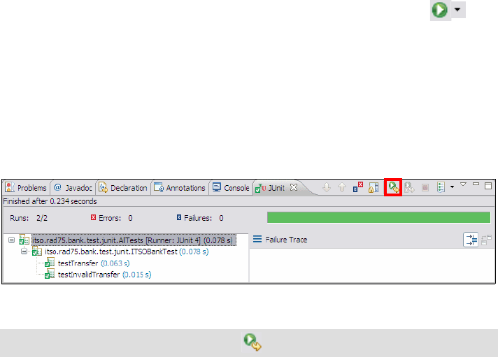
Chapter 23. Test using JUnit 837
Draft Document for Review December 9, 2008 2:44 pm 7672-test-1-junit.fm
– Click Finish.
Running the JUnit test case or JUnit test suite
To run a JUnit test case or JUnit test suite, do these steps:
Select the ITSOBankTest or AllTests class and click the arrow of in
the toolbar and select Run As → JUnit Test (or right-click the class and
select Run As → JUnit Test.
In our example, Application Developer runs the two test methods defined in
ITSOBankTest class.
The JUnit view opens. You might want to move the JUnit view on top of the
Console view.
Notice that the two test methods passed the asserts verification (Figure 23-3).
Figure 23-3 JUnit view: Both test methods passed the assert verifications
Modify and run the JUnit test case with assert failures
In our example we test only for success (even one method throws an exception,
but that was what we had expected). A test is considered to be successful, if the
test method returns normally. A test fails, if one of the methods could not pass all
assert verifications. An error indicates that an unexpected exception is raised by
any test, setUp, or tearDown method. The JUnit view is more interesting when an
error or failure occurs.
Modify the process method of the itso.rad75.bank.model.Credit class:
public BigDecimal process(BigDecimal accountBalance)
throws InvalidTransactionException {
if ((this.getAmount() != null)
&& (this.getAmount().compareTo(new BigDecimal(0.00D)) > 0)) {
return accountBalance.subtract(this.getAmount());
} else {
...... // rest unchanged
}
Tip: To run the same test again, click in the JUnit view toolbar.
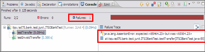
7672-test-1-junit.fm Draft Document for Review December 9, 2008 2:44 pm
838 Rational Application Developer V7.5 Programming Guide
We change add to subtract, which is obviously an error in the business logic.
Run the ITSOBankTest class again as a JUnit Test.
This time, a failure and its trace information is displayed for the testTransfer
method in the JUnit view (Figure 23-4).
Figure 23-4 JUnit view with failure
Double-clicking the entry in the Failure Trace list takes you to the specified line
in the specified Java source file. This is the line where to set a breakpoint and
start debugging the application. For details how to debug an application, refer
to Chapter 24, “Debug local and remote applications” on page 861.
Correct the process method of the Credit class, by undoing the change we
made before.
JUnit testing of JPA entities
According the Java Persistence API (JPA) specification, JPA entities are not
bound to any Java EE container. They can run in a Java SE environment and
therefore unit testing of JPA entities is easier than it was to test EJB 2.x entity
beans.
Prepare the JPA unit testing sample
We use the JPA project created in “Creating a JPA project” on page 282 for the
JPA unit test working example.
The JPA unit test sample is based on the RAD75JPA project. If you do not have that
project in the workspace, import the RAD75JPA project from:
c:\7672code\zInterchange\jpa\RAD75JPA.zip

Chapter 23. Test using JUnit 839
Draft Document for Review December 9, 2008 2:44 pm 7672-test-1-junit.fm
Setting up the ITSOBANK database
The JPA entities are based on the ITSOBank database. Therefore, we have to
define a database connection within Application Developer.
Refer to “Setting up the ITSOBANK database” on page 1154 for instructions on
how to create the ITSOBANK database. For the JPA entities we can either use the
DB2 or Derby database. For simplicity we use the built-in Derby database in this
chapter.
Configure the RAD75JUnit project
The RAD75JUnit project must be configured, so it can be used to run JPA entity
unit tests. Do the following steps, to configure the RAD75JUnit project properly:
In the Package Explorer, right-click the RAD75JUnit project and select
Properties.
Select Java Build Path in the tree and select the Libraries tab.
– Click Add Variable, select ECLIPSE_HOME and click Extend. Select
runtimes/base_v7/derbylib/derby.jar and click OK.
– Click Add Variable, select ECLIPSE_HOME and click Extend. Select
runtimes/base_v7/runtimes/com.ibm.ws.jpa.thinclient_7.0.0.jar and
click OK.
Select the Projects tab.
Click Add, select the RAD75JPA project and click OK.
Select the Source tab.
In the Default Output Folder field, type RAD75JUnit/src (overwriting
RAD75JUnit/bin).
Click OK. In the Setting Build Path dialog, click Yes to delete the
RAD75JUnit\bin folder.
The RAD75JUnit project is now properly configured for JPA unit testing.
Note: This change is necessary so that the persistence.xml file, which we
create later in the RAD75JUnit/src/META-INF folder, will be found while
executing the test case.
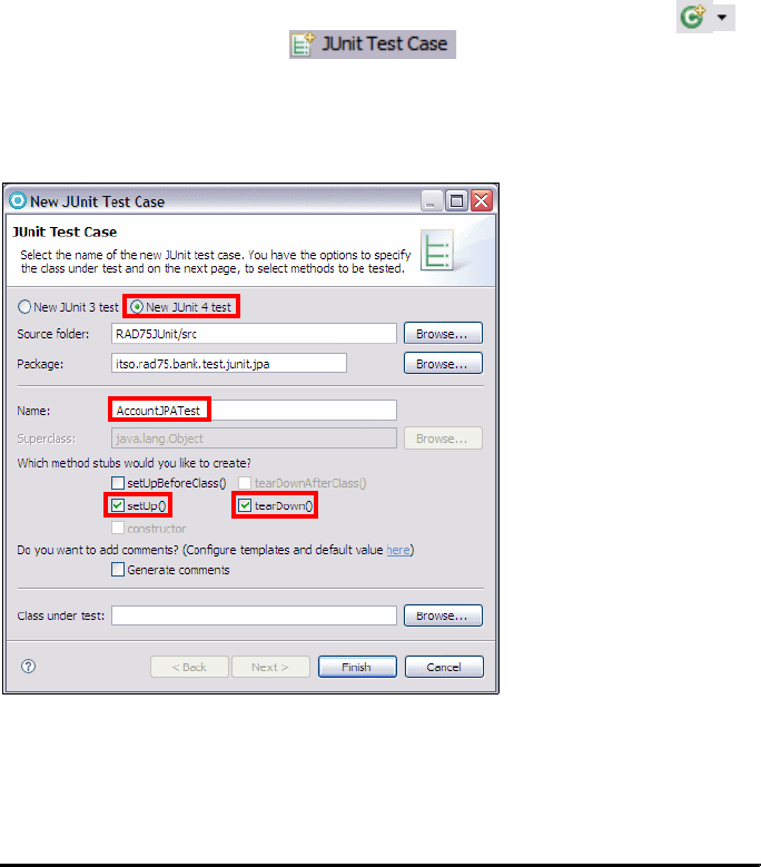
7672-test-1-junit.fm Draft Document for Review December 9, 2008 2:44 pm
840 Rational Application Developer V7.5 Programming Guide
Creating a JUnit test case for a JPA entity
To create a JUnit test case for a JPA entity, do the following steps:
Create a new package called itso.rad75.bank.test.junit.jpa under
RAD75JUnit/src.
Right-click the itso.rad75.bank.test.junit.jpa package and select New →
JUnit Test Case (only available in the Java perspective), or select New →
Other → Java → JUnit → JUnit Test Case, or click the arrow in the
icon in the toolbar and select .
In the New JUnit Test Case dialog, select New JUnit 4 test, type
AccountJPATest as Name, select setUp and tearDown methods, and click
Finish (Figure 23-5).
Figure 23-5 JUnit Test Case Wizard
Implement the AccountJPATest class as shown in Example 23-6. The code is
available in c:\7672code\junit\jpa\AccountJPATest.java.
Example 23-6 JUnit test case for JPA
package itso.rad75.bank.test.junit.jpa;
import ......
public class AccountJPATest {

Chapter 23. Test using JUnit 841
Draft Document for Review December 9, 2008 2:44 pm 7672-test-1-junit.fm
EntityManager em;
@Before
public void setUp() throws Exception {
if (em == null) {
em = Persistence
.createEntityManagerFactory("RAD75JPA")
.createEntityManager();
}
}
@After
public void tearDown() throws Exception {
if (em != null) {
em.close();
}
}
@Test
public void testLoadAccount() {
try {
Account ac = em.find(Account.class, "001-111001");
assertNotNull(ac);
} catch (Exception e) {
fail("Error: Account not found!");
e.printStackTrace();
}
}
}
Setting up the persistence.xml file
We have to modify the persistence.xml file because the JUnit test runs in Java
SE, not in the server. Instead of connecting to the database through a data
source, we connect directly through a JDBC driver. We could modify the
persistence.xml file in the RAD75JPA project, but it is better to leave that file
configured for the data source in the server, and place a new file into the
RAD75JUnit project, overwriting the file in the RAD75JPA project.
In the Package Explorer, right-click the RAD75JUnit → src folder and select
New → Folder. Type META-INF as folder name and click Finish.
Copy the file RAD75JPA/src/META-INF/persistence.xml to
RAD75JUnit/src/META-INF.
Open the persistence.xml file (in RAD75JUnit/src/META-INF), and change it
as shown in Example 23-7. The updated file is available in
c:\7672code\junit\jpa\persistence.xml.

7672-test-1-junit.fm Draft Document for Review December 9, 2008 2:44 pm
842 Rational Application Developer V7.5 Programming Guide
Example 23-7 JPA persistence.xml configured for Derby using OpenJPA
<?xml version="1.0" encoding="UTF-8"?>
<persistence .....>
<persistence-unit name="RAD75JPA" transaction-type="RESOURCE_LOCAL">
<jta-data-source>jdbc/itsobank</jta-data-source>
<provider>
org.apache.openjpa.persistence.PersistenceProviderImpl
</provider>
<class>itso.bank.entities.Account</class>
<class>itso.bank.entities.Customer</class>
<class>itso.bank.entities.Transaction</class>
<class>itso.bank.entities.Debit</class>
<class>itso.bank.entities.Credit</class>
<properties>
<property name="openjpa.ConnectionURL"
value="jdbc:derby:C:\7672code\database\derby\ITSOBANK" />
<property name="openjpa.ConnectionDriverName"
value="org.apache.derby.jdbc.EmbeddedDriver" />
<property name="openjpa.Log" value="none" />
</properties>
</persistence-unit>
</persistence>
To use the ITSOBANK database in DB2, the properties would be:
openjpa.ConnectionURL: jdbc:db2://localhost:50000/ITSOBANK
openjpa.ConnectionDriverName: com.ibm.db2.jcc.DB2Driver
openjpa.ConnectionUserName: db2admin (or similar)
openjpa.ConnectionPassword: <xxxxxxxx>
To see the SQL statements that are issued, set openjpa.Log to the value
SQL=TRACE.
Running the JPA unit test
Finally, the JPA JUnit test can be executed. To run the AccountJPATest, do the
following steps:
Make sure that the ITSOBANKderby connection is disconnected (with
Embedded Derby you can only have one active connection to a database).
You can verify this in the Data perspective, Data Source Explorer. If the
ITSOBANKderby connection is available and active, right-click the connection
and select Disconnect.
In the Package Explorer, right-click the AccountJPATest class and select
Run As → Run Configurations.
Double-click JUnit in the tree. A new JUnit Run Configuration for
AccountJPATest class is created.

Chapter 23. Test using JUnit 843
Draft Document for Review December 9, 2008 2:44 pm 7672-test-1-junit.fm
Select the Arguments tab (Figure 23-6), and in the VM arguments field, type:
-javaagent:c:/IBM/SDP75/runtimes/base_v7/plugins/com.ibm.ws.jpa.jar
Make sure to use the directory where Application Developer is installed.
Without this agent, the JPA entities are not found.
Figure 23-6 Run configuration arguments
Click Apply, then click Run.
The JUnit view opens showing that the AccountJPATest test case was
successful (Figure 23-7).
Figure 23-7 JUnit JPA test case was successful

7672-test-1-junit.fm Draft Document for Review December 9, 2008 2:44 pm
844 Rational Application Developer V7.5 Programming Guide
JUnit testing using TPTP
TPTP JUnit test generates an execution history from which a report can be
generated. In this section we discuss the following topics:
Creating the TPTP JUnit sample
Importing an existing JUnit test case
Running the TPTP JUnit test
Analyzing the test results
Generating test reports
Creating the TPTP JUnit sample
In this section we continue with the RAD75JUnit project that we created in “JUnit
testing [without using TPTP]” on page 825.
Note: If you imported the final RAD75JUnit project from the sample code and you
want to create this example on your own, delete the itso.rad75.bank.test.tptp
package.
Create new package
Add a new package called itso.rad75.bank.test.tptp to the RAD75JUnit project.
Create a TPTP JUnit test manually
To create a TPTP JUnit test manually, do these steps:
Right-click the itso.rad75.bank.test.tptp package and select New →
Other → Test → TPTP JUnit Test.
Select Show All Wizards (at the bottom) to see the Test category.
If the Confirm Enablement dialog appears, click OK to enable the Core
Testing Support capability of Application Developer.
In the New JUnit Test Definition dialog, enter the following data (Figure 23-8):
– Source folder: Click Browse and select RAD75JUnit/src. Click Yes when
prompted to allow Application Developer to add all the required libraries to
the classpath.
–Package:
itso.rad75.bank.test.tptp
–Name: ITSOBankTest
–Select In the test editor {default}.
Note: TPTP JUnit Tests are based on JUnit version 3.8.1.

Chapter 23. Test using JUnit 845
Draft Document for Review December 9, 2008 2:44 pm 7672-test-1-junit.fm
Figure 23-8 New JUnit Test source code dialog
In the JUnit Test Definition dialog, accept the parent folder
(AD75JUnit/src/itso/rad75/bank/test/tptp) and name (ITSOBankTest) and
click Finish.
The JUnit Test Suite editor opens and you can create and remove methods on
a JUnit test, and control how those methods are invoked. Three tabs are
visible: Overview, Test Methods, and Behavior.
In the Test Methods tab, click Add and enter testSearchCustomerBySsn in
the name field.
In the Behavior tab, click Add and select Loop. Select the Loop 1, click Add
again, select invocation, select the testSearchCustomerBySsn method
and click OK.
At this point the Behavior tab looks as shown in Figure 23-9.
Note: In the previous step we enter the name and location of the source
code, while in this step we enter the name and location of the TPTP Test
(the model). By default, they are identical.

7672-test-1-junit.fm Draft Document for Review December 9, 2008 2:44 pm
846 Rational Application Developer V7.5 Programming Guide
Figure 23-9 TPTP JUnit Test editor [Behavior tab]
Save the TPTP JUnit Test editor.
In the JUnit Code Update Preview Options dialog, select Never and Always
skip to the preview page. Click Finish.
Open the generated itso.rad75.bank.test.tptp.ITSOBankTest class in the
Java editor and add the highlighted code, as shown in Example 23-8.
Example 23-8 ITSOBankTest class
package itso.rad75.bank.test.tptp;
import itso.rad75.bank.exception.InvalidCustomerException;
import itso.rad75.bank.ifc.Bank;
import itso.rad75.bank.impl.ITSOBank;
import itso.rad75.bank.model.Customer;
// Keep other imports unchanged
Note: In the Overview tab:
If Implement Test Behavior as code is selected, the behavior is
purely code-based, that is, the test methods are executed exactly as
presented in the Test Methods view.
If Implement Test Behavior as code is cleared, then the Behavior tab
becomes available. The behavior feature should be used only for TPTP
JUnit tests that have been created manually.

Chapter 23. Test using JUnit 847
Draft Document for Review December 9, 2008 2:44 pm 7672-test-1-junit.fm
// All documentation is omitted
public class ITSOBankTest extends HyadesTestCase {
private Bank bank = null;
private static final String CUSTOMER_SSN = "111-11-1111";
public ITSOBankTest(String name) {
super(name);
}
public static Test suite() {
// Keep method body unchanged
}
protected void setUp() throws Exception {
if (this.bank == null) {
this.bank = ITSOBank.getBank();
}
}
protected void tearDown() throws Exception {
}
public void testSearchCustomerBySsn() throws Exception {
try {
Customer bankCustomer = this.bank
.searchCustomerBySsn(ITSOBankTest.CUSTOMER_SSN);
assertEquals(bankCustomer.getSsn(), ITSOBankTest.CUSTOMER_SSN);
} catch (InvalidCustomerException e) {
e.printStackTrace();
}
}
}
Importing an existing JUnit test case
To create a TPTP JUnit Test by importing an existing JUnit test case, do these
steps:
Import the ITSOBank381Test.java class into the itso.rad75.bank.test.tptp
package from C:\7672code\junit\examples.
Right-click somewhere in the Package Explorer, select Import → Test →
JUnit tests to TPTP
, and click Next.
In the Import JUnit tests to TPTP dialog, select RAD75JUnit →
itso.rad75.bank.test.tptp → ITSOBank381Test.java, and click Finish.

7672-test-1-junit.fm Draft Document for Review December 9, 2008 2:44 pm
848 Rational Application Developer V7.5 Programming Guide
The ITSOBank381Test.testsuite is created in the same package.
Open the ITSOBank381Test.testsuite in the TPTP JUnit Test editor. Verify in
the Test Methods tab that two test methods are invoked.
Save and close the editor.
Running the TPTP JUnit test
To run a TPTP JUnit test, do these steps:
Right-click ITSOBankTest.testsuite or ITSOBank381Test.testsuite and
Run As → Test. This creates the run configuration automatically and runs the
test.
You can verify the run configurations by selecting Run → Run
Configurations. The configurations show up under the Test category.
Analyzing the test results
When the test run is finished, the execution results are generated in the
RAD75JUnit project (Figure 23-10).
Figure 23-10 Package Explorer view containing test execution results
To analyze the test results, double-click the ITSOBankTest.execution result
(Figure 23-11).
Note: Notice that the Import JUnit tests to TPTP dialog does not allow us
to select test cases that are JUnit 4.x based because TPTP cannot handle
JUnit 4.x.

Chapter 23. Test using JUnit 849
Draft Document for Review December 9, 2008 2:44 pm 7672-test-1-junit.fm
Figure 23-11 TPTP JUnit test execution result
In Test Log Overview tab, you can see the test verdict (pass) and the starting
and stopping time of the test run.
The Test Log Events tab lists each single step of the test run with further
information about it.
Note: To view the graphic, you have to install the Scalable Vector Graphics
(SVG) browser plug-in. You can get this free viewer from the Adobe® Web
site:
http://www.adobe.com/svg/viewer/install/auto/
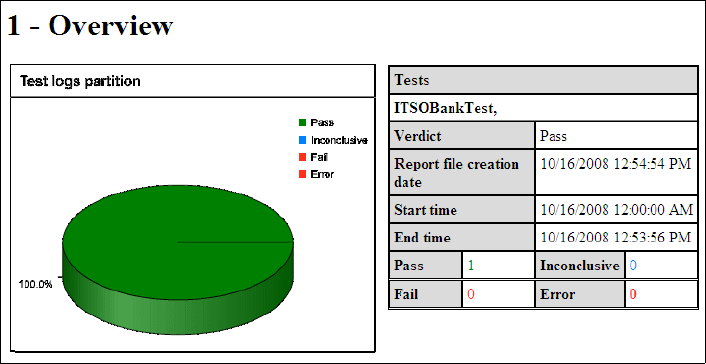
7672-test-1-junit.fm Draft Document for Review December 9, 2008 2:44 pm
850 Rational Application Developer V7.5 Programming Guide
Generating test reports
Based on a test execution results file, you can generate analysis reports:
Test Pass report: Summary of the latest test execution result with graphical
presentation of test success.
Time Frame Historic report: Summary of all test execution result within a
time frame with graphical presentation of the test success.
To generate a Test Pass Report, do these steps:
Open the Test perspective.
Expand RAD75JUnit → src → itso → rad75 → bank → test → tptp.
In the Test Navigator, right-click ITSOBankTest and select Report.
In the New Report dialog, select Test Pass Report and click Next.
In the Test Pass Report dialog, enter ITSOBankTest_TestPass as name (the
folder is preselected), and click Next.
In the Select a time frame dialog, enter the start and end date and time:
– The end time is set as the current time.
– For the start time, enter a time before you started testing (by default set to
the beginning of the day).
– Click Finish and a Test Pass report is generated.
Right-click ITSOBankTest_TestPass and select Open With → Web
Browser.
The Test Pass report opens in the Web Browser (Figure 23-12)
Figure 23-12 Test Pass report

Chapter 23. Test using JUnit 851
Draft Document for Review December 9, 2008 2:44 pm 7672-test-1-junit.fm
Web application testing
You can also create test cases that run against one of the Web projects,
RAD75BankBasicWeb or RAD75StrutsWeb or RAD75EJBWeb. However, when
testing anything that runs inside a servlet container, a testing framework like
Cactus could make the testing much easier.
In addition to providing a common framework for test tools and support for JUnit
test generation, TPTP includes features allowing you to test Web applications.
TPTP provides the following Web testing tasks:
Recording a test—The test creation wizard starts the Hyades proxy recorder,
which records your interactions with a browser-based application. When you
stop recording, the wizard starts a test generator, which creates a test from
the recorded session.
Editing a test—You can inspect and modify a test prior to compiling and
running it.
Generating an executable test—Follow this procedure to generate an
executable test. Before a test can be run, the Java source code of the test
must be generated and compiled. This process is called code generation.
Running a test—Run the generated test.
Analyzing test results—All the conclusion of a test run you see an execution
history, including a test verdict, and you can request two graphical reports
showing a page response time and a page hit analysis.
Preparing for the sample
As a prerequisite to the Web application testing sample, you must have the
WebSphere Application Server V7.0 test environment installed and running. We
use the RAD75BankBasicWeb application created in Chapter 13, “Develop Web
Note: Cactus is an open source sub-project in the Apache Software
Foundation's Jakarta Project. It is a simple framework for unit testing
server-side Java code, such as servlets, EJBs, tag libraries, and filters.
The objective of Cactus is to lower the cost of writing tests for server-side
code. Cactus supports so-called white box testing of server-side code. It
extends and uses JUnit.
More information here: http://jakarta.apache.org/cactus/

7672-test-1-junit.fm Draft Document for Review December 9, 2008 2:44 pm
852 Rational Application Developer V7.5 Programming Guide
applications using JSPs and servlets” on page 317, for the Web application
testing sample.
If you do not have the RAD75BankBasicWeb application in the workspace, import
the c:\7672code\zInterchange\webapp\RAD75BankBasicWeb.zip project
interchange file into the workspace (select all three projects).
The completed code for this section can also be imported from the
C:\7672code\zInterchange\junit\RAD75JUnitWebTest.zip project interchange
file.
To the verify that the Web application runs, do these steps:
Switch to the Web perspective.
Right-click the RAD75BankBasicWeb project in the Enterprise Explorer and
select Run As → Run on Server.
Verify that the Web browser starts and the welcome page of ITSO RedBank is
shown. Close the page.
Create a Java project
Create a new Java project called RAD75JUnitWebTest.
Recording a test
To create a simple HTTP test, do these steps:
Open the Test perspective.
Right-click RAD75JUnitWebTest in the Test Navigator view, select New →
Test Element → Test From Recording and click Next.
Select Create Test From New Recording and click Next.
In the Select Location for Test Suite dialog, select the RAD75JUnitWebTest
project, accept the test file name of RAD75JUnitWebTest.testsuite, and
click Finish.
A progress dialog box opens while your browser starts. Your browser settings
are updated and a local proxy is enabled. If you are using a browser other
than Microsoft Internet Explorer, see the online help for detailed instructions
on how to configure the proxy.
Note: To make sure your recording accurately captures HTTP traffic, clear the
browser cache.

Chapter 23. Test using JUnit 853
Draft Document for Review December 9, 2008 2:44 pm 7672-test-1-junit.fm
Recording has now started.
Start the selected Web application by entering the following URL in the
browser:
http://localhost:9080/RAD75BankBasicWeb/
Note that the port (9080) may be different in your installation.
We record a money transfer from a customer’s account to another one, and
verify that the required transactions have been created.
– Select the redbank link on the ITSO RedBank welcome page, type
333-33-3333 as customer ID (SSN), and click Submit.
– Click account number 003-999000777 and on the next page select
Transfer, enter 500 in the Amount field and 003-999000888 in the To
Account field, and click Submit.
– Verify that List transactions is selected and click Submit. One Debit
transaction is listed.
– Click Account Details and then click Customer Details.
– Click account number 003-999000888, verify that List transactions is
selected and click Submit. One Credit transaction is listed.
– Click Account Details, click Customer Details, and finally click Logout.
Close the browser to stop recording, or click Stop Recording in the toolbar of
the Recorder Control view (Figure 23-13).
Tip: The browser used for recording can be set in Window → Preferences →
Test → TPTP URL → URL Recorder.
Important: For Internet Explorer 7.0 you must use the IP-address to run
the Web application: http://<ip-address>:9080/RAD75BankBasicWeb/. No
recording is produced when using http://localhost:9080/...
For Firefox 2.0, you must first configure the network settings: Select
Tools → Options → Advanced → Network. Click Settings and select
Auto-detect proxy settings for the network.
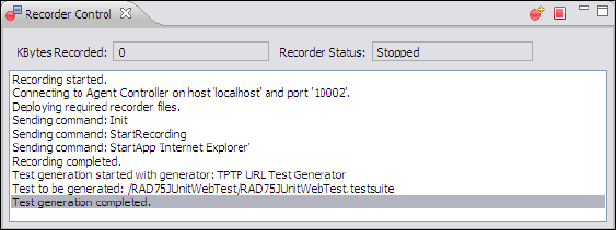
7672-test-1-junit.fm Draft Document for Review December 9, 2008 2:44 pm
854 Rational Application Developer V7.5 Programming Guide
Figure 23-13 Recorder Control view
When prompted to Confirm Open Editor, click Yes.
Notice the messages Recording completed and Test generation completed
in the Recorder Control view after closing the browser.
The wizard generates automatically a TPTP URL Test. The Recorder Control
view informs you with the message Test generation completed when the test
is successfully generated.
Editing the test
The TPTP URL Test appears under the RAD75JUnitWebTest project and is open
in the editor. We can inspect and modify it before compiling and running it. The
test is not Java code yet, but we can check the requests and modify them.
Enter the following data in the Overview tab (Figure 23-14):
– Source Folder: /RAD75JUnitWebTest/src
– Package Name: itso.rad75.bank.test
– Class Name: RAD75JUnitWebTest
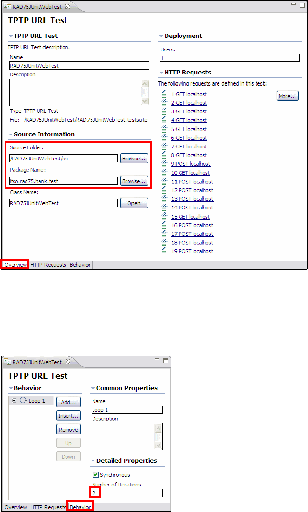
Chapter 23. Test using JUnit 855
Draft Document for Review December 9, 2008 2:44 pm 7672-test-1-junit.fm
Figure 23-14 TPTP URL Test dialog: Overview tab
Select the Behavior tab of the TPTP URL Test editor.
Change the behavior of the test. For example, we adjust the number of
iterations (Figure 23-15). Save and close the Test Editor.
Figure 23-15 TPTP URL Test dialog: Behavior tab

7672-test-1-junit.fm Draft Document for Review December 9, 2008 2:44 pm
856 Rational Application Developer V7.5 Programming Guide
Generating an executable test
Before a test can be run, the Java source code for the test must be generated
and compiled. This process is called code generation. The compiled code is
stored in the RAD75JUnitWebTest project.
To start the code generation of the RAD75JUnitWebTest, do these steps:
Right-click RAD75JUnitWebTest TPTP URL Test in the RAD75JUnitWebTest
project and select Generate.
In the TPTP URL Test Definition Code Generation dialog, accept the project
and source folder and click Finish to start the code generation.
To examine the generated Java code, switch to the Java or Web perspective,
and open the itso.rad75.bank.test.RAD75JUnitWebTest class.
Running the test
To run the RAD75JUnitWebTest, do these steps:
Switch to Test perspective.
Right-click RAD75JUnitWebTest TPTP URL Test in the RAD75JUnitWebTest
project and select Run As → Test.
The test executes and creates a result.
Analyzing the test results
When the test run is finished, the execution result appears in the Test
Navigator view. To analyze the test results, do these steps:
Double-click the execution result RAD75JUnitWebTest[<timestamp>]
file in the Test Navigator view. The Test Log Overview tab is displayed
(Figure 23-16).
The test log gives the test verdict and the starting and stopping time of the
test run. The verdict can be one of the following:
–fail: One or more requests returned a HTTP code of 400 or greater, or the
server could not be reached during playback.
–pass: No request returned a code of 400 or greater.
–inconclusive: The test did not run to completion.
–error: The test itself contains an error.

Chapter 23. Test using JUnit 857
Draft Document for Review December 9, 2008 2:44 pm 7672-test-1-junit.fm
Figure 23-16 Test Log Overview tab
Click the Events tab to get detailed information about each single HTTP
request (Figure 23-17).
Note: In applications that use session data you can run into errors
because the session ID is stored in the generated test case. When you
rerun such test cases, a new session ID is created by the server, and it
does not match the recorded session ID.
The problem is a known Eclipse issue and there are a few discussions in
the following two defects:
https://bugs.eclipse.org/bugs/show_bug.cgi?id=128613
https://bugs.eclipse.org/bugs/show_bug.cgi?id=139699

7672-test-1-junit.fm Draft Document for Review December 9, 2008 2:44 pm
858 Rational Application Developer V7.5 Programming Guide
Figure 23-17 Test Log Events tab
Generating test reports
Based on a test execution results file, you can generate different kinds of analysis
reports:
HTTP Page Response Time report: Bar graph showing the seconds
required to process each page in the test and the average response time for
all pages.
HTTP Page Hit Rate report: Bar graph showing the hits per second to each
page and the total hit rate for all pages.
You can also generate the Test Pass report in the same way as for the basic
JUnit tests.
Note: To view the reports, you have to install the Scalable Vector Graphics
(SVG) browser plug-in.

Chapter 23. Test using JUnit 859
Draft Document for Review December 9, 2008 2:44 pm 7672-test-1-junit.fm
HTTP Page Response Time report
To generate an HTTP Page Response Time report, do these steps:
Right-click the RAD75JUnitWebTest test suite in the Test Navigator view
and select Report.
In the New Report dialog, select HTTP Page Response Time and click Next.
In the New Report dialog, accept the parent folder (RAD75JUnitWebTest), enter
RAD75JUnitWebTest_HTTPPageResponseTime in the name field, and
click Finish.
If you have multiple test execution results, in the HTTP Report Generator
dialog, you have to select the test execution result for which the report is
generated and click Finish.
An HTTP Page Response Time report is generated and opens in the browser,
or select the generated file and Open With → Web Browser (Figure 23-18).
Figure 23-18 HTTP Page Response Time report
HTTP Page Hit Rate report
To generate a HTTP Page Hit Rate report, do these steps:
Right-click the RAD75JUnitWebTest test suite in the Test Navigator view
and select Report.
In the New Report dialog, select HTTP Page Hit Rate and click Next.
Click on one of the bars to display the numbers

7672-test-1-junit.fm Draft Document for Review December 9, 2008 2:44 pm
860 Rational Application Developer V7.5 Programming Guide
In the New Report dialog, accept the parent folder (RAD75JUnitWebTest), enter
RAD75JUnitWebTest_HTTPPageHitRate in the name field, and click
Finish.
If you have multiple test execution results, in the HTTP Report Generator
dialog, you have to select the test execution result for which the report is
generated and click Finish.
An HTTP Page Hit Rate report is generated and opens in the browser, or
select the generated file and Open With → Web Browser (Figure 23-19).
Figure 23-19 HTTP Page Hit Rate report
Cleaning the workspace
When enabling the Test perspective or Core Testing Support capability, the Java
builder is changed to ignore XML and HTML files. To fix the workspace, select
Window → Preferences → Java → Compiler → Building. Under Output folder,
Filtered resources, remove *.xml and *.html from the text:
*.launch,*.testsuite,*.deploy,*.location,*.execution,*.datapool,*.artifact,
*.testlog,*.xml,*.html,*.svg
Click on one of the bars to display the numbers

© Copyright IBM Corp. 2008. All rights reserved. 861
Draft Document for Review December 9, 2008 2:44 pm 7672-test-3-debug.fm
Chapter 24. Debug local and remote
applications
The debugging features included with IBM Rational Application Developer V7.5
can be used to debug a wide range of applications in several languages running
either on local test environments (including local Web applications) or on remote
servers such as WebSphere Application Server or WebSphere Portal.
In this chapter, the main debugging features are described and two examples of
how to use the debugger are provided. The new debug tooling features present
in Rational Application Developer v7.5 are introduced: these include the ability to
transfer Java-based debug sessions between Rational Team Concert team
members. Two examples of debug session transfer are described. Finally, a list of
potential sources for further information is supplied.
The chapter is organized into the following sections:
Summary of new features in v7.5
Overview of Application Developer debugging tools
Debugging a Web application on a local server
Debugging a Web application on a remote server
Jython debugger
Debug extension for Rational Team Concert Client (Team Debug)
More information
24
7672-test-3-debug.fm Draft Document for Review December 9, 2008 2:44 pm
862 Rational Application Developer V7.5 Programming Guide
Summary of new features in v7.5
The debugging facilities available with Rational Application Developer v7.5 are
very similar to those available in the previous version. The main new feature
introduced in v7.5 is collaborative debugging, available when using Rational
Team Concert Client. This feature is described in detail in the sections:
Collaborative debugging using Rational Team Concert Client
Debug extension for Rational Team Concert Client (Team Debug)
Overview of Application Developer debugging tools
This section provides an overview of the basic debug tooling features included in
Application Developer v7.5.
The topics covered here are:
Supported languages and environments
Basic Java debugging features
XSLT debugging
Remote debugging
Stored procedure debugging for DB2 V9
Collaborative debugging using Rational Team Concert Client
Supported languages and environments
Application Developer includes support for debugging many different languages
and environments. These are as follows:
Java
JavaScript
DB2 stored procedures (either in Java or SQL)
XSL transformations (XSLT)
SQLJ
Jython Scripts for WebSphere Application Server administration
Mixed language applications (for example XSLT called from Java)
WebSphere Application Server (servlets, JSPs, EJBs, Web services)
WebSphere Portal (portlets)
Applications in all these languages and environments can be debugged within
Application Developer using a similar process of setting breakpoints, running the
application in debug mode and within the Debug perspective stepping through
the code to track variables and logic and hopefully find and fix problems.
Chapter 24. Debug local and remote applications 863
Draft Document for Review December 9, 2008 2:44 pm 7672-test-3-debug.fm
Furthermore, the interface for debugging within the Debug perspective is
intended to be consistent across all these languages and environments.
Basic Java debugging features
The following section gives a brief description of the main debugging features
available within Application Developer for Java applications and explains how
they would typically be used. Although this description focuses mainly on the
tools available for Java, most of the features are available when debugging other
languages.
Views within the Debug perspective
When running an application in debug mode and a breakpoint is reached, the
user is prompted to see if they want to move to the Debug perspective. Note that
it is possible to do debugging in other perspectives, however the Debug
perspective provides the full set of views available for debugging.
By default, when debugging Java, the views shown in the Debug perspective are
as follows:
Source view—Shows the file of the source code that is being debugged,
highlighting the current line being executed.
Outline view—Contains a list of variables and methods for the code listing
shown in the display view.
Debug view—Shows a list of all active threads, and a stack trace of the
thread that is currently being debugged.
Servers view—Useful if the user wants to start or stop test servers while
debugging.
Variables view—Given the selected source code file shown in the Debug
view, the Variables view shows all the variables available to that class and
their values. The variables view is, by default, structured into columns. The
use of columns can be toggled from the Layout → Show Columns menu
option from the drop-down arrow menu in the Variables view. Also,
step-by-step debugging variables that change value are highlighted in a
different color.
Breakpoints view—Shows all breakpoints in the current workspace and
gives a facility to activate/de-activate them, remove them, change their
properties, and to import/export a set of them to other developers.
Display view—Allows the user to execute any Java command or evaluate an
expression in the context of the current stack frame.

7672-test-3-debug.fm Draft Document for Review December 9, 2008 2:44 pm
864 Rational Application Developer V7.5 Programming Guide
Expressions view—During debugging, the user has the option to inspect or
display the value of expressions from the code or even valuate new
expressions. The Expressions view contains a list of expressions and values
which the user has evaluated and then selected to track.
Console view—Shows the output to System.out.
Tasks view—Shows any outstanding source code errors, warnings or
informational messages for the current workspace.
Error Log—Shows all errors and warnings generated by plug-ins running in
the work space.
Figure 24-1 shows an application stopped at a breakpoint in the Debug
perspective.
Figure 24-1 Typical application running in the Debug perspective

Chapter 24. Debug local and remote applications 865
Draft Document for Review December 9, 2008 2:44 pm 7672-test-3-debug.fm
Debug functions
From the Debug view, you can use the functions available from the icon bar to
control the execution of the application. The following icons are available:
Resume (F8): Runs the application to the next breakpoint.
Suspend: Suspends a running thread.
Terminate: Terminates a process.
Disconnect: Disconnects from the target when debugging remotely.
Remove All Terminated Launches: Removes terminated executions
from the Debug view.
Step Into (F5): Steps into the highlighted statement.
Step Over (F6): Steps over the highlighted statement.
Step Return (F7): Steps out of the current method.
Drop to Frame: Provides the facility to reverse back to a higher method
call in the current stack frame.
Use Step Filters/Step Debug (Shift-F5): Enable/disable the filtering for
the step debug functions.
Step-By-Step Mode: Once the step-by-step debug feature is enabled in
the Run/Debug preferences, this icon can also be used to toggle the
feature.
Show Qualified Names (from drop-down menu): Toggle option to show
the full package name.
or Debug UI demon: Provides a drop-down list for controlling the
debugging of XSL transforms that are invoked by WebSphere
applications.
Show Running Threads filter
When debugging, there are often many extra threads shown in the Debug view
that are not useful for finding a fault in an application under development. This is
especially the case when debugging Web applications, where the Application
Server starts several threads that are very unlikely to be the cause of an
application problem. To show only threads that are suspended, bring up the
context menu of the thread being debugged in the Debug view and toggle the
Show Running Threads filter.
Using these buttons, menus and the information shown in the various views
available in the Debug perspective, it should be possible to debug most
problems.

7672-test-3-debug.fm Draft Document for Review December 9, 2008 2:44 pm
866 Rational Application Developer V7.5 Programming Guide
Enable/disable Step Filter/Step Debug in the Debug view
In the Debug view toolbar, there is a Use Step Filters icon. This feature allows
users to filter out Java classes that do not have to be stepped into while
debugging. For example, usually it is not necessary for programmers to step into
code from the classes within the Sun and IBM Java libraries when step-by-step
debugging, and by default these classes are in the step filter list. The facility is
provided to add any class or package to this list.
To add new Java package to the Step Filter/Step Debug feature in the Debug
view, do these steps:
Select Window → Preferences.
Expand Run/Debug → Java and Mixed Language Debug → Step Filters.
Click Add Filter.
Enter the new package or class you want to filter out and click OK.
The Step Filter/Step Debug feature can be toggled on and off by clicking Step
Filter ( ) in the Debug view.
Prior to Version 7.0, the java.* and javax.* packages were not visible from the
Step Filters preferences and were always filtered. Now these packages appear in
the step filer list and it is possible to de-select them and therefore, when
debugging, it is possible to step into classes from this package. The default
setting is to leave these classes remaining filtered.
Drop to Frame
The drop-to-frame feature allows the control of an application to be reversed
back to a previously executed line of code. This feature is available when
debugging Java applications and Web applications running on WebSphere
Application Server and is useful when you want to test a block of code using a
range of values.
For example, if a developer wants to test a method with the minimum and
maximum permitted values for a given parameter, a breakpoint can be added at
the end of the method, and the drop-to-frame feature can be used to back up the
control of the application to the start of the method, change the parameters, and
run it again.
When running an application in the Debug perspective, the stack frame can be
seen in the Debug view (Figure 24-2). Drop to frame allows you to back up your
application’s execution to previous points in the call stack by selecting the desired
method level from within the Debug view and then clicking Drop To Frame .
This moves the control of the application to the top of the method selected in the
Debug view.
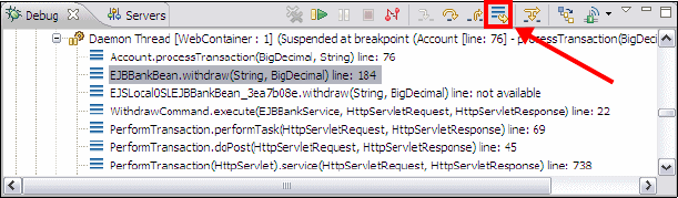
Chapter 24. Debug local and remote applications 867
Draft Document for Review December 9, 2008 2:44 pm 7672-test-3-debug.fm
Figure 24-2 Drop to Frame Button in the Debug view.
XSLT debugging
XSL (EXtensible Stylesheet Language) Transformations (XSLT) is a language for
transforming XML documents into XHTML or other XML documents. It is a
declarative language expressed in XML and provides mechanisms to match tags
from the source document to templates (similar to methods), store values in
variables, basic looping/code branching and invoke other templates in order to
build up the result document.
Also, XSLT files can use templates stored in other files and it is possible for XSLT
files to become complicated. Application Developer features a full-featured XSL
transformation debugger, and XSLT files can be debugged using a similar set of
tools to that available for Java.
To launch a debugging session for a XSLT file and its source XML file, simply
select both files on the Enterprise Explorer, right-click and select Debug As →
XSLT Transformation:
For example, If you have gone through Chapter 10, “Develop XML
applications” on page 185, select Accounts.xml and Accounts.xsl,
right-click, and select Debug As → XSLT Transformation.
This action steps into the first line of the XSL file, and from there, debugging
can continue. The debug launch configuration window (from the Context
Window use Debug As → Debug) allows the user to configure dependent
files (both XSLT and Java) and other settings to guide the XSLT debugging.
These configurations can then be saved to make launching the debugging
quicker in the future.
Figure 24-3 shows the Debug perspective when debugging XSLT. From the
Debug perspective, the user can step through the XSLT file and the source XML
and watch the result XML being built element by element.
Drop to Frame
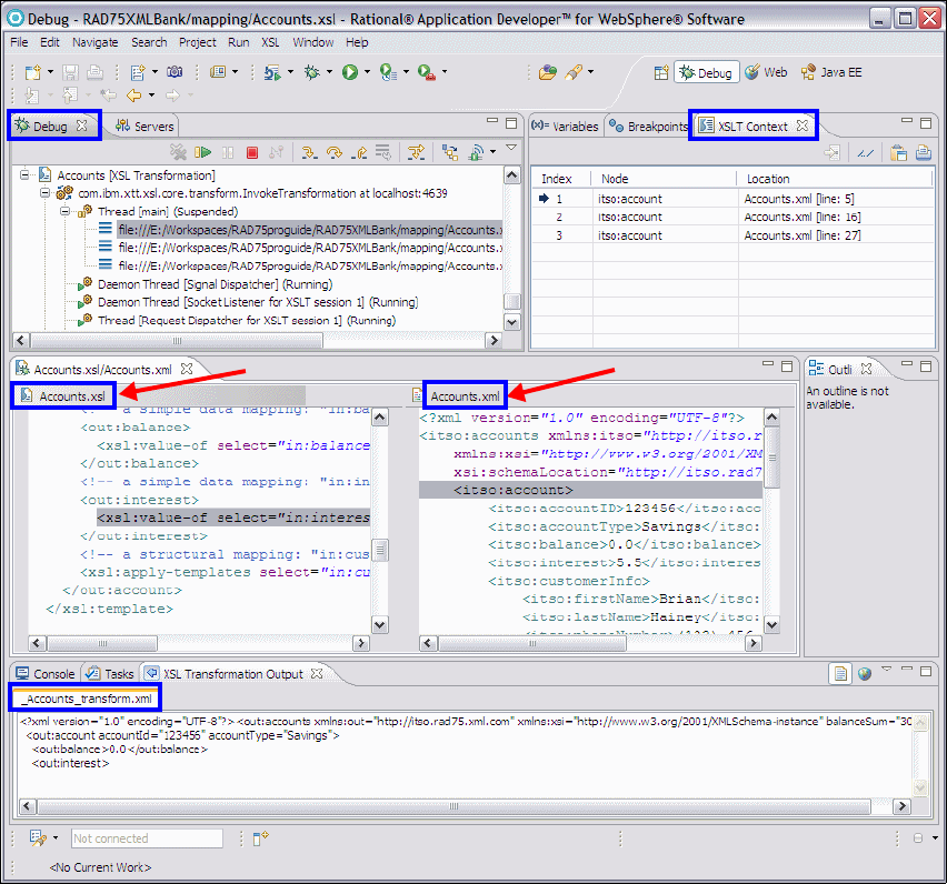
7672-test-3-debug.fm Draft Document for Review December 9, 2008 2:44 pm
868 Rational Application Developer V7.5 Programming Guide
Figure 24-3 Debugging XSLT
The following views are useful when debugging XSLT:
Debug view—Shows the XSL transformation running as an application with
the stack frame for the current execution point.
XSLT Context view—Shows the current context of the XML input for the
selected stack frame.
Expressions view—Can be used show the value of XSL expressions,
including XPath expressions in the current context.
Current
Source XML
Result HTML
Source XSL
Chapter 24. Debug local and remote applications 869
Draft Document for Review December 9, 2008 2:44 pm 7672-test-3-debug.fm
Variables view—Currently visible XSLT variables.
XSL Transformation Output view—Shows the serialized output of the
transformation as it is produced.
Display view—Shows the XSL file on the left side and the input XML file on
the right. The line being executed for each is highlighted.
Breakpoints view—Shows all breakpoints in the workspace, including those
placed in an XSLT file.In an XSL file there are several places where a
breakpoint has no effect, for example blank lines, <xsl:output> lines and
XML declarations. When the user attempts to add a breakpoint to an invalid
line they receive the message Cannot Add Breakpoint.
It is also possible to debug a XSLT transformation called from a Java application.
The easiest way to do this is to add a breakpoint in the Java code before the XSL
transformation is called (typically from the javax.com.transform.Transformer
transform method). Then use the Debug → Java And Mixed Language
Application option for the Java class from the context menu. When the debugger
stops at the breakpoint, use the Step Into icon, and the debugger moves to
debugging the XSL file and stops at the first line in the transformation.
Finally, it is also possible to debug Java code called from the XSL file. To do this
you must use the launch configuration window and make sure that the Class path
tab includes the projects that contain the Java code to be debugged. When
stepping through the XSLT debugger, it will be possible to Step Into the call to the
Java method.
Remote debugging
The debugger provided with Application Developer allows a programmer to
attach to a Java application running on a remote machine and control its
execution. This is particularly useful when debugging an application that cannot
be run on the development machine.
The application that is debugged remotely must be compiled with debug
information on (within Application Developer select Window → Preferences,
and look at Java → Compiler and the Classfile Generation attributes), and when
the application is launched, the appropriate JVM parameters must be supplied to
configure the IP address and port for the debugger machine. This setting varies
between different JVMs.
When starting the debug session, use Debug As → Debug (from the Enterprise
Explorer context menu) and create a new configuration for Remote Java
Application.
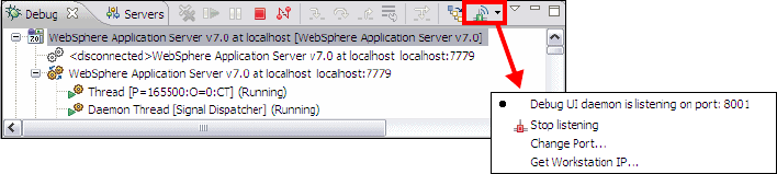
7672-test-3-debug.fm Draft Document for Review December 9, 2008 2:44 pm
870 Rational Application Developer V7.5 Programming Guide
Make sure the Host and Port are configured for the target machine and that the
source tab is filled out with the appropriate source code, then click Debug and
the remote debugging session will start.
The Debug UI daemon is a feature available from the toolbar of the Debug view
which allows developers to debug XSL transformations which are invoked by a
WebSphere application.
Figure 24-4 Setting Debug UI Daemon options
When enabled, the daemon listens on a port (which you can configure) and if
during the WebSphere debug session the application invokes an XSL
transformation, Application Developer will step into the XSLT file and debugging
continues. You can disable the feature by selecting the appropriate option from
the drop-down menu in the Debug view.
The debug daemon must also be started and ready to accept incoming debug
session for working with the Debug extension for Rational Team Concert Client
(Team Debug).
Stored procedure debugging for DB2 V9
This feature allows a user to debug Java and DB2 stored procedures running on
a local or remote DB2 server. The Debug Launch configuration editor provides
fields to specify a stored procedure on a DB2 database to debug, arguments to
pass to the procedure and the associated source code. If the database server is
configured correctly, the debugger will launch and allow debugging to continue.
Application Developer has a detailed help chapter on this feature.
Collaborative debugging using Rational Team Concert Client
Rational Application Developer provides:
Rational Team Concert Client
Debug Extension for Rational Team Concert Client
Team Debug Service Extension for Rational Team Concert server
Pull-down menu
with Debug UI
Daemon options
Chapter 24. Debug local and remote applications 871
Draft Document for Review December 9, 2008 2:44 pm 7672-test-3-debug.fm
This allows teams members to share debugging sessions including breakpoints
and session status. It is possible to send the session to a selected user or to park
it in a team repository for later retrieval. It is even possible to share the session by
dragging and dropping it onto a chat window provided that the messaging service
is enabled. For a detailed description see Debug extension for Rational Team
Concert Client (Team Debug)
Debugging a Web application on a local server
This section steps through a Web application scenario where a sample
application is run on the local Application Developer test server and the
debugging facilities are used to step through the code and watch the behavior of
the application.
The debug example includes the following tasks to demonstrate the debug
tooling:
Importing the sample application
Running the sample application in debug mode
Setting breakpoints in a Java class
Watching variables
Evaluating and watching expressions
Working with breakpoints
Set breakpoints in a JSP
Debugging a JSP
Importing the sample application
The following instructions show how to set up your workspace for the sample
application. We use the ITSO RedBank Web application sampled developed in
Chapter 14, “Develop EJB applications” on page 387 to demonstrate the debug
facilities.
If you have the necessary projects (RAD75EJBWebEAR, RAD75EJBWeb,
RAD75EJB, and RAD75JPA) in the workspace, you can skip this step.
To import the ITSO RedBank EJB Web application, follow these steps:
In the Web perspective select File → Import → Other → Project
Interchange and click Next.
In the Import Projects screen click Browse to locate the file:
C:\7672code\zInterchange\ejb\RAD75EJBWeb.zip
Select the projects that are not in the workspace, and click Finish.
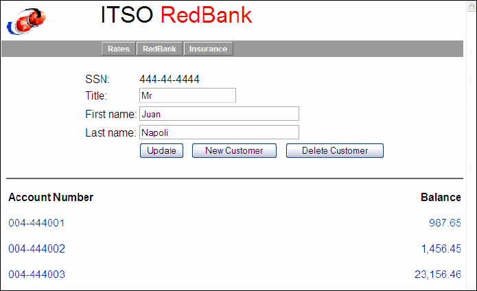
7672-test-3-debug.fm Draft Document for Review December 9, 2008 2:44 pm
872 Rational Application Developer V7.5 Programming Guide
To run this application you have to configure a database as described in “Setting
up the ITSOBANK database” on page 1154 and “Configuring the data source in
WebSphere Application Server” on page 1155.
Running the sample application in debug mode
To verify that the sample application was imported properly, run the sample Web
application on the WebSphere Application Server V7 test server in debug mode
as follows:
In the Enterprise Explorer, expand RAD75EJBWeb → WebContent.
Right-click index.jsp and select Debug As → Debug on Server.
If the Server Selection dialog opens, select Choose an existing server,
select WebSphere Application Server v7, and click Finish.This will start the
server, publish the application to the server, and bring up a browser showing
the Index page.
If the server is already running in normal (non-debug) mode, you are
prompted to switch mode. Click OK, and the server restarts in debug mode.
When the Index page is displayed, click RedBank, enter 444-44-4444 in the
Customer SSN field, and click Submit.
The list of accounts for that customer are displayed (Figure 24-5). If you can
see these results, then the application is working fine in debug mode.
Figure 24-5 Customer details for the RedBank application
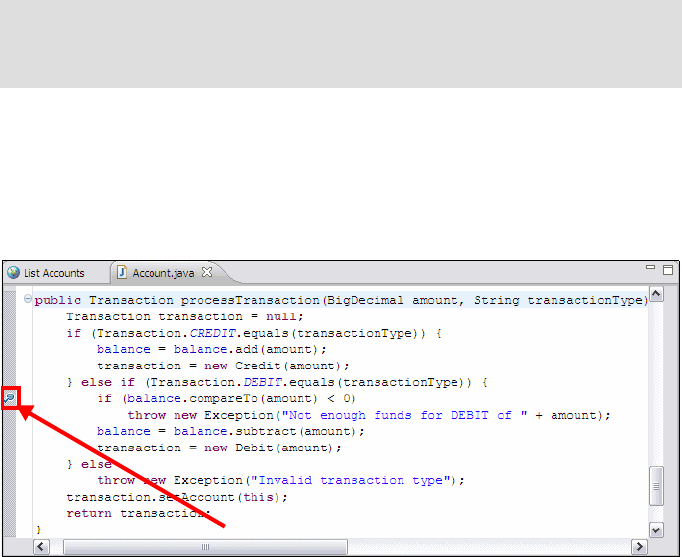
Chapter 24. Debug local and remote applications 873
Draft Document for Review December 9, 2008 2:44 pm 7672-test-3-debug.fm
Setting breakpoints in a Java class
Breakpoints are indicators to the debugger that it should stop execution at that
point in the code and let the user inspect the current state and step through
through the code. Breakpoints can be set to always trigger when the execution
point reaches it or when a certain condition has been met.
In the ITSO RedBank sample application, before the balance of an account is
updated after withdrawal of funds from an account, the new balance is compared
to see if it goes below zero. If there are adequate funds, the withdrawal will
complete. If there are not enough funds in the account, an Exception is thrown
from the Account class and the showException.jsp is displayed to the user
showing an appropriate message.
In this example, we set a breakpoint where the logic tests that the amount to
withdraw does not exceed the amount that exists in the account.
In the Enterprise Explorer select and expand RAD7JPA → src →
itso.bank.entities, and open Account.java in the Java editor.
Locate the processTransaction method.
Place the cursor in the gray bar (along the left edge of the editor area) on the
following line of code in the processTransaction method:
if (balance.compareTo(amount) < 0)
Double-click to set a breakpoint marker (Figure 24-6).
Figure 24-6 Setting a breakpoint in Java
Tip: You can use the Outline view or expand Account.java in the
Enterprise Explorer to find the processTransaction method quickly in the
source code.
Breakpoint
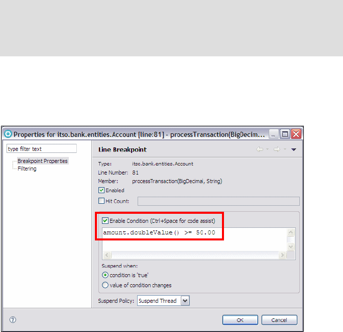
7672-test-3-debug.fm Draft Document for Review December 9, 2008 2:44 pm
874 Rational Application Developer V7.5 Programming Guide
Right-click the breakpoint and select Breakpoint Properties.
In the Breakpoint Properties window, you can change the details of the
breakpoint (Figure 24-7).
Figure 24-7 Breakpoint properties
–If the Hit Count property is set, it causes the breakpoint to be triggered
only when the line has been executed as many times as the hit count
specified. Once triggered, the breakpoint is disabled.
– Selecting Enable Condition allows breakpoints to trigger only when the
condition specified in the entry field evaluates to true. This condition is a
Java expression. Note that you can use code assist (Ctrl+Space) to see
the fields and methods that you can use in this expression. When this
condition is enabled, the breakpoint is marked with a question mark on the
breakpoint, which indicates that it is a conditional breakpoint.
For example, select Enable Condition, enter the expression
amount.doubleValue() >= 50.00, select condition is 'true'. Now the
breakpoint will only trigger on transactions over $50.00.
Click OK to close the breakpoint properties.
Note: Enabled breakpoints are indicated with a blue circle. Installed
breakpoints have an additional check mark overlay. A breakpoint can only
be installed when the class the breakpoint is located in has been loaded by
the VM.
Chapter 24. Debug local and remote applications 875
Draft Document for Review December 9, 2008 2:44 pm 7672-test-3-debug.fm
It should now be possible to run the application and trigger the breakpoint. Note
that it is not necessary to restart the Application Server for the new breakpoint to
work.
To trigger the breakpoint, perform the following steps:
In the home page, click on the RedBank tab, enter 444-44-4444 as the
customer number and click Submit.
In the List Accounts page, click on the first account (004-444001).
In the Account Details page, select Withdraw and enter 50 in the Amount
field.
Click Submit. The processTransaction method is executed and the new
breakpoint triggered.
Debug perspective
Depending on the preferences set in Windows → Preferences →
Run/Debug → Perspectives you may be prompted to open the Debug
perspective. In most cases the Debug perspective opens.
If the Debug perspective does not open automatically, select Window → Open
Perspective → (Other) → Debug.
The Debug perspective shows the source code where the execution stopped at
the breakpoint (refer to Figure 24-1 on page 864):
The Debug view shows the threads, currently stopped in
Account.processTransaction.
The source code of the Account class shows the current line (at the
breakpoint).
The Outline view shows the current method (processTransaction).
The Variables view shows the account (this), the amount (BigDecimal), the
transaction type (Debit), and the transaction (null).
The Breakpoints view shows the breakpoint (Account [line: 81]).
The Console view shows the server console. You may see time-out errors
because we stopped the execution in the middle of an EJB call.
In this perspective it is possible to step through the code, and to watch and edit
variables.

7672-test-3-debug.fm Draft Document for Review December 9, 2008 2:44 pm
876 Rational Application Developer V7.5 Programming Guide
Watching variables
The Variables view displays the current values of the variables in the selected
stack frame (Figure 24-6):
Expand this and verify the value of id. You can also expand the balance and
see the value (for example, 98765 with scale 2 = 987.65).
Expand amount. Although amount is of type BigDecimal, a string
representation of its value is shown in the bottom section of the window.
Figure 24-8 Displaying variables
The plus sign (+) next to a variable indicates that it is an object. By clicking on the
plus sign, it is possible to look into instance variables associated with the object.
Follow these steps to see how you can track the state of a variable, while
debugging the method:
Click Step Over in the Debug view (or press F6) to execute the current
statement.
Click Step Over again and the balance is updated. Note that the color of
balance changes in the Variables view.
It is possible to test the code with some other value for any of these instance
variables; a value can be changed by selecting Change Value from its context
menu. A dialog opens where the value can be changed. For objects such as
BigDecimal, you have to use a constructor to set the value.
For example, right-click balance and select Change Value. In the Change
Object Value dialog, type new java.math.BigDecimal(900.00), and click OK.

Chapter 24. Debug local and remote applications 877
Draft Document for Review December 9, 2008 2:44 pm 7672-test-3-debug.fm
Evaluating and watching expressions
When debugging, it is often useful to be evaluate an expression made up of
several variables within the current application context.
To view the value of an expression within the code:
Select the expression (for example, balance.compareTo(amount) in the
breakpoint line), right-click, and select Inspect. The result opens in a pop-up
window showing the value (Figure 24-9).
Figure 24-9 Inspect Pop-up window
To move the results to the Expressions view (Figure 24-10) so that the value
of the expression can continue to be monitored, press Ctrl+Shift+I.
To watch an expression, right-click in the Expressions view and select Add
Watch Expression. In the Add Watch Expression dialog, enter an
expression, such as, balance.doubleValue().
Figure 24-10 Inspecting a variable in Expressions view
Note: The Expressions view contains a list of watched expressions
(marked by a symbol) and a list of inspected expressions marked by a
a symbol (Figure 24-10). The difference between these is that the
value shown for watched expressions changes with the underlying value as
the user steps through the code, while an inspected expression will remain
showing the value it held when it was first inspected.
Watched expression
Inspected expression

7672-test-3-debug.fm Draft Document for Review December 9, 2008 2:44 pm
878 Rational Application Developer V7.5 Programming Guide
Using the Display view
To evaluate an expression in the context of the currently suspended thread which
does not come from the source code, use the Display view.
Set a new breakpoint on the line: transaction.setAccount(this);
Click Step Return until you reach that line.
From the Workbench, select Windows → Show View → Display.
Type the expression transaction.getTransTime() in the Display View, then
highlight the expression, right-click, and select Display (Figure 24-11).
Figure 24-11 Expression and evaluated result in display view
Each expression is executed, and the result is displayed as shown in
Figure 24-11. This is a useful way to evaluate Java expressions or even call
other methods during debugging, without having to make changes in your
code and recompile.
You can also highlight any expression in the source code, right-click, and
select Watch (or Inspect). The result is shown in the Expressions view.
Select Remove from the context menu to remove expressions or variables
from the Expressions views. In the Display view, just select the text and delete
it.
Working with breakpoints
To enable a breakpoint in the code, double-click in the grey area of the left frame
(or use the context menu on the left side of the frame) for the line of code the
breakpoint is required for. To remove double-click on it again, and to disable the
breakpoint, right-click and select Disable Breakpoint.
Tip: When entering an expression in the Display Panel, it is possible to use
code assist (Ctrl+Space).

Chapter 24. Debug local and remote applications 879
Draft Document for Review December 9, 2008 2:44 pm 7672-test-3-debug.fm
Alternatively, once they have been created, the breakpoints can be enabled and
disabled from the Breakpoints view (Figure 24-12). If the breakpoint is
un-selected in the Breakpoints view, it is skipped during execution.
To disable or enable all breakpoints, click the Skip All Breakpoints icon. If this
option is selected then all breakpoints are skipped during execution.
Figure 24-12 Enabling/Disabling Breakpoints
It is possible to export a set of breakpoints, including the conditions and hit count
properties so that they can be shared across a development team. To do this,
from the context menu of the Breakpoints view select Export Breakpoints and
the breakpoints are saved as a bkpt file to the selected location.
Before continuing with debugging of JSPs, do the following:
Remove the breakpoints by clicking the Remove All Breakpoints icon .
Click Resume to continue execution.
Note that you do not see the Web page automatically in the Debug perspective.
Click the view with the World icon (in the same pane as the source code) to see
the resulting Web page. Alternatively, switch to the Web perspective.
If you waited too long, the thread has been terminated in the server and you have
to restart the application from the index.jsp.
Set breakpoints in a JSP
You can also set breakpoints in JSPs. Within the source view of a JSP page, you
can set breakpoints inside JSP scriptlets, JSP directives, and lines which use
JSP tag libraries. You cannot set breakpoints in lines with only HTML code.
In the following example, we set a breakpoint in the listAccounts.jsp at the
point where the JSP displays a list of accounts for the customer.
Tip: Java exception breakpoints are a different kind of breakpoint that are
triggered when a particular exception is thrown. These breakpoints can be set
by selecting Run→ Add Java Exception Breakpoint.
Skip All Breakpoints
Box to activate/de-active breakpoint

7672-test-3-debug.fm Draft Document for Review December 9, 2008 2:44 pm
880 Rational Application Developer V7.5 Programming Guide
In the Web Perspective expand RAD75EJBWeb → WebContent and open
the listAccounts.jsp in the editor. Select the Source tab.
Set a breakpoint by double-clicking in the grey area next to the desired line of
code (Figure 24-13).
Note that the Breakpoint properties are also available for JSPs from the
context menu. These share the same features as Java breakpoints with the
exception that content assist is not available in the breakpoint condition field.
Figure 24-13 Adding a breakpoint to a JSP page
Debugging a JSP
When a new breakpoint is added, it is not necessary to redeploy the Web
application:
From the RedBank index page, select the RedBank tab.
On the redbank page, enter a Customer ID of 444-44-4444, and click Submit.
This executes the listAccounts.jsp file and hits the new breakpoint.
In the Confirm Perspective Switch dialog, click Yes to switch to the Debug
perspective.
Execution should stop at the breakpoint set in the listAccounts.jsp, because
clicking Submit in the application attempts to display the accounts by
executing this JSP. The thread is suspended in debug, but other threads might
still be running (Figure 24-14).

Chapter 24. Debug local and remote applications 881
Draft Document for Review December 9, 2008 2:44 pm 7672-test-3-debug.fm
Figure 24-14 Debugging a JSP
Once a breakpoint is hit, you can analyze variables and step through lines of
the JSP code. The same functions available for Java classes are available for
JSP debugging. The difference is that the debugger shows the JSP source
code and not the generated Java code.
The JSP variables are shown in the Variables view. Note that the JSP implicit
variables are also visible, and it is possible to look at things such as request
parameters or session data (Figure 24-15).
Note: If you have two JSPs with the same name in multiple Web applications,
the wrong JSP source might be displayed. Open the correct JSP to see its
source code.

7672-test-3-debug.fm Draft Document for Review December 9, 2008 2:44 pm
882 Rational Application Developer V7.5 Programming Guide
Figure 24-15 JSP Implicit variables in Variable view
Step over the lines within the JSP by pressing the F6 key (Step Over). Note
that the debugger will skip any lines with only HTML code.
Note the change in the variables view. Expand JSP Implicit Variables →
pageContext → page_attributes and select varAccounts, which is the
variable in the <c:forEach var="varAccounts"...> loop:
Account: 004-444001 balance 987.65
The customer and the accounts are visible under JSP Implicit Variables →
pageContext → request_attributes.
Click Resume ( ) allow the application to continue with the JSP page
generation.
Remove the breakpoint.
This concludes the section on debugging a local test environment.
Debugging a Web application on a remote server
It is possible to connect to and debug a Java Web application that has been
launched in debug mode on a remote application server. When debugging a
remote program the Debug perspective has the same features as when
debugging locally—the difference lies in the fact that the application is on a
remote JVM and the debugger must attach to the JVM through a configured
debug port. The debugging machine must also map the debug information to its
locally stored copy of the source code, so it is important that the source code on
the debugger machine matches what is deployed.

Chapter 24. Debug local and remote applications 883
Draft Document for Review December 9, 2008 2:44 pm 7672-test-3-debug.fm
This following example scenario includes a node where Application Developer
v7.5 is installed (Developer node), and a separate node where IBM WebSphere
Application Server v7 is installed (Application Server node). The developer node
attaches to the Application Server Node and controls it through a debugger.
Exporting the RedBank as an EAR file
This section describes how to export the RedBank to an Ear file so that it can be
deployed on a remote WebSphere Application Server.
In the Enterprise Explorer, right-click RAD75EJBWebEAR and select
Export → EAR file.
In the EAR Export dialog enter the following and then click Finish:
– EAR application: RAD75EJBWebEAR
– Destination: C:\temp\RAD75EJBWebEAR.ear
Deploying the RedBank application
The following steps show how to deploy the RedBank application to a remote
system where IBM WebSphere Application Server v7 has been installed:
Ensure that the target WebSphere Application Server - server1 application
server is started.
Start the WebSphere Application Server Administrative Console by entering
the following in a Web browser and logging on:
https://<hostname>:9043/ibm/console <=== port 9048 in our case
From the Administration Console, expand Applications and click New
Enterprise Application.
Select Local file system and click Browse and locate the generated EAR file
(C:\temp\RAD75EJBWebEAR.ear).
Select Fast Path and click Next.
Tip: If you defined a second server profile in (AppSRV02) in Chapter 22,
“Servers and server configuration” on page 777, then you can use this server
for debugging on a remote server.
Note: For the <hostname> it is sufficient to use the IP address of the
machine running WebSphere Application Server. Run the command
ipconfig from the command line to determine this. Note that the remote
server may run on a different set of ports.
7672-test-3-debug.fm Draft Document for Review December 9, 2008 2:44 pm
884 Rational Application Developer V7.5 Programming Guide
In Step 1, select Precompile JavaServer Pages files, and click Next.
In Step 2, click Next.
In Step 3 (Summary), accept the defaults and click Finish.
You should see a screen showing the progress of the installation. After a short
time, the following message will be displayed if the application is successfully
deployed:
Application RAD75EJBWebEAR installed successfully.
Click Save directly to the master configuration link URL.
Navigate to the Applications → Application → Types WebSphere
enterprise Application. Select RAD75EJBWebEAR and click Start.
Click Close Page and Logout.
Verify the application is working properly by opening a Browser and
navigating to the following URL of the target machine:
https://<hostname/address>:9443/RAD75EJBWeb/ <=== 9448 for us
Configuring debug on a remote WebSphere Application Server
The following steps explain how to configure WebSphere Application Server V6.1
to start in debug mode:
If it is not already running, start the application server.
<was_home>\bin\startServer.bat server1
Start the WebSphere Administrative Console by entering the following in a
Web browser and then logging in:
https://<hostname>:9043/ibm/console <=== port 9048 in our case
In the left-hand frame expand Servers → Server Types → WebSphere
Application Servers.
In the Application Servers page, click server1.
On the Configuration tab, select Debugging Service in the Additional
Properties section at the bottom right, to open the Debugging Service
configuration page.
In the General Properties section of the Configuration tab, select Enable
service at startup. This enables the debugging service when the server
starts.

Chapter 24. Debug local and remote applications 885
Draft Document for Review December 9, 2008 2:44 pm 7672-test-3-debug.fm
Click OK to make the changes to your local configuration.
Save the configuration changes.
Click Logout.
You must restart the application server before the changes that have been
made take effect.
Again, verify the application is working properly by navigating to the following
URL:
https://<hostname/IPaddress>:944x/RAD75EJBWeb/
Attaching to the remote server in Application Developer
Assuming that the target server is running in debug mode, complete the following
steps to attach to the remote WebSphere Application Server v7 from within
Application Developer v7.5. Note that the workspace used must contain the
RAD75EJBWeb project.
In the Enterprise Explorer, right-click RAD75EJBWeb, and select Debug
As → Debug Configurations.
Create a new remote Debug configuration for WebSphere Application Server
v7 server.
– On the Create, Manage, and run configurations page, double-click
WebSphere Application Server (or right-click and select New).
– Verify the name for this Debug configuration (RAD75EJBWeb).
– In the Connect tab, make sure the project is RAD75EJBWeb, select
WebSphere v7 Server for the IBM WebSphere Server type, enter the IP
address or target machine name for the Host name, and 7777 (7782 in our
case) as the JVM debug port.
– Click Apply (Figure 24-16).
Note: The value of the JVM debug port is required when connecting to the
application server with the debugger. The default value is 7777; in our case
the server used port 7782.

7672-test-3-debug.fm Draft Document for Review December 9, 2008 2:44 pm
886 Rational Application Developer V7.5 Programming Guide
Figure 24-16 Debug config for Remote debugging
– On the Source tab expand the Default folder. Note that about halfway
down is the RAD75EJBWeb project. This lets the debugger know where the
source code is.
– On the Common tab are standard options for debug configuration,
including where to save the configuration and where to output the
SystemOut file.
– Click Debug to attach the debugger to the remote server.
The Debug perspective now shows the Remote debugger running in the Debug
view, as shown in Figure 24-17. The debugger is waiting for a breakpoint to be
triggered. Note that clicking the Disconnect icon ( ) stops the debugging.
Figure 24-17 Debugging perspective while remote debugging
Typically 7777
local server
remote server
Chapter 24. Debug local and remote applications 887
Draft Document for Review December 9, 2008 2:44 pm 7672-test-3-debug.fm
Debugging a remote application
From a Web browser, navigate to the URL where hostname is the IP address or
name of the target machine:
https://<hostname/IPaddress>:944x/RAD75EJBWeb/
You can now debug the remotely running application in the same way as a locally
deployed application:
Set breakpoints (Java or JSP).
Step through the code.
Watch variables.
Execute expressions.
To terminate the debugging session, select the remote debugging instance and
click Disconnect .
Uninstalling the remote application
You might want to remove the RAD7BankBasicEAR application from the remote
server. In the administrative console under Applications → Application
Types → Websphere Enterprise Applications, select RAD7EJBWebEAR and
click Uninstall. Then save the configuration. Optionally, stop the remote server.
Note: When attaching to a local Application Developer’s WebSphere instance,
you must start the application server in debug mode, then open the Debug
perspective, and disconnect the debug instance started by Application
Developer automatically when the server was started in debug mode.
After that you can start a remote debug instance using localhost as the host
name and port 7777 (or the correct port, such as 7782). This will attach to the
test application server and allow the user to perform all the usual debugging
facilities.

7672-test-3-debug.fm Draft Document for Review December 9, 2008 2:44 pm
888 Rational Application Developer V7.5 Programming Guide
Jython debugger
The Jython debugger enables you to detect and diagnose errors in Jython script
(with extension .py or .jy) that is used for WebSphere Application Server
administration. With the debugger, you can control the execution of your code by
setting line breakpoints, suspending execution, stepping through your code, and
examining the contents of variables. (Note that variable values cannot be
changed in Jython.)
The Jython debugger only supports debugging of script that are running on
WebSphere Application Server Version v6.1 or v7.
You can debug a Jython script that has been developed or imported into a Jython
project. When you are debugging a Jython script, you can set line breakpoints.
When the workbench is running the script and encounters a breakpoint, the
script temporarily stops running. Execution suspends at the breakpoint before
the script is executed, at which point you can check the contents of variables. You
can then step over (execute) and see what effect the statement has on the script.
Using the Debug Launch configuration, you can launch a debugging session for a
given Jython script on either the local test server or a server running on a remote
machine. If the target environment is on a remote machine, then the host and
port numbers must be configured in the wsadmin arguments field. Refer to the
Application Developer online help for details on this feature.
Debugging a sample Jython script
In this section we debug the listJDBCProviders script that was described in
“Developing automation scripts” on page 810:
Open the listJDBCProviders.py Jython script file in the RAD75Jython
project.
Set a breakpoint in the showJdbcProviders function at the line:
for provider in providerEntryList
Select listJDBCProviders.py and Run → Debug As → Administrative
Script.
In the Debug Configurations dialog (Figure 24-18):
–Verify l
istJDBCProviders.py as Name.
Tip: To debug a Jython script, the server does not have to run in Debug mode.

Chapter 24. Debug local and remote applications 889
Draft Document for Review December 9, 2008 2:44 pm 7672-test-3-debug.fm
–Select WebSphere Application Server v7 as Scripting runtime and
was70profile1 as the WebSphere profile.
– Specify a User ID and password if security is enabled.
– Click Apply, then click Debug.
Figure 24-18 Jython debugging configuration
Execution of the script starts and when the breakpoint is encountered
execution is suspended.
When prompted, switch to the Debug perspective.
The Debug perspective opens and displays the familiar views (Figure 24-19):
– The Debug view shows the thread and is used to step through the code.
– The editor shows the source code and where we currently are.
– The Variables view shows the Jython variables, which cannot be changed.
– The Breakpoints view shows the breakpoints.
– The Outline view shows the outline of the script.
– The Console shows the output of the script.

7672-test-3-debug.fm Draft Document for Review December 9, 2008 2:44 pm
890 Rational Application Developer V7.5 Programming Guide
Figure 24-19 Debug perspective when debugging a Jython script
Step through the Jython code and watch the variables.
The Jython debugger is very useful when you encounter errors in your Jython
scripts. Run the script in debug mode, without having to restart the server.
Debug extension for Rational Team Concert Client
(Team Debug)
Application Developer v7 includes a debug extension for Rational Team Concert.

Chapter 24. Debug local and remote applications 891
Draft Document for Review December 9, 2008 2:44 pm 7672-test-3-debug.fm
Introduction
While debugging complex applications, any given team member may require the
expertise of a specialist to understand and correct a specific part of code.
However, recreating a debug session to reproduce a particular scenario can be
quite time consuming, so Application Developer offers the capability to share the
complete state of an existing debug session with another user, including any
breakpoints already set.
There are two main modes of operation:
If both users are logged on the Team Concert server at the same time, one
user can add a debug session to the team repository and then transfer the
debug session to the other user (Figure 24-20).
Alternatively, the debug session can be parked on the Team Concert server,
so that it can be retrieved later by any user. It is also possible to drag and drop
a link to a debug session onto a messaging system, if messaging has been
configured to integrate with Team Concert.
Figure 24-20 Workflow for transferring Java Debug session
Server
Team Concert Server
Team Debug Service
Client A
Application Developer
JVM to Debug
Debug UI Daemon
Client B
Application Developer
Debug UI Daemon
1: Login to Team Concert Server
2: Register user IP address
3: Add Debug session to Team Repository
4: Debug
5: Transfer to other user
6: Notify of transfer
8: Debug
7: Accept debug session
121
2
34,8
56
7
7672-test-3-debug.fm Draft Document for Review December 9, 2008 2:44 pm
892 Rational Application Developer V7.5 Programming Guide
Supported environments
Team Debug launchers only support Java 1.5 and higher as the target JRE. The
supported versions of Websphere Application Server are v6.0, v6.1, and v7.0.
The supported types of launch configurations are the following:
Debug on Server
Eclipse application
Java applet
JUnit
JUnit plug-in test
Remote Java application
Java application
While the Team Debug Client supports multiple languages, the Team Debug
Service is English only, so the user could receive error messages from the server
in English.
Prerequisites
The following prerequisites must be satisfied:
This feature leverages Team Concert and requires an installation of additional
features on the Team Concert Server as well as on Application Developer
(Team Concert Client). For installation instructions, “Installing IBM Rational
Team Concert” on page 1139.
Two Rational Application Developer users must be logged in to the same
Rational Team Concert server, either at the same time in case of a direct
transfer, or potentially at different times if the debug session is parked on the
server.
The two users should have imported the same versions of the project to be
debugged into the Application Developer workspace. Refer to Chapter 29,
“Rational Team Concert” on page 1077 for details on how to share a project in
Rational Team Concert.
In Application Developer, the Debug UI daemon (refer to “Remote
debugging” on page 869) must be active and listening for inbound
connections.
When the user logs onto the Team Concert server, the user’s IP address and
the debug daemon port are registered with the team debug service. This
information is needed to identify the users and send them notifications when
they are sent a debug session or they are requested to transfer their debug
session.
Chapter 24. Debug local and remote applications 893
Draft Document for Review December 9, 2008 2:44 pm 7672-test-3-debug.fm
If users do not receive notifications, check the user IP address and debug
daemon settings. The IP address of the client can be determined in the
Debug view by clicking on the Debug UI daemon icon and selecting
Workstation IP. After verifying the IP address, debug port, and status of the
daemon, try to logout and login again to Team Concert. This way the user is
registered again with the team debug service with the correct information. If
the problem persists, part the debug session and use the Team Debug view to
transfer the session.
If you test this functionality using two Application Developer instances running
on the same machine, remember to change the default value of the Debug UI
daemon port (8001) for at least one of the two instances.
Sharing a Java debug session by transferring it to another user
This example will show to share the debug session of a Java application. The
following scenario can be executed if you have completed the steps in “Source
control scenarios” on page 1099 (Chapter 29, “Rational Team Concert”). If you
are unsure whether the two users have the same versions of the projects
imported, you can revert back to a known baseline that contains the desired
sources.
To replace the contents of each user’s workspace with a known baseline, perform
these steps:
Right-click My Repository Workspaces in the Team Artifacts view.
Select the personal workspace of the user.
Right-click Java Prototype Component.
Select Replace With → Baseline.
Select the Baseline Imported prototype.
Look at the Pending Changes view.
Right-click on the Incoming Changes and select Accept.
To initiate the debug session and transfer it to another user, Lara performs the
following actions:
Open BankClient.java.
Place a breakpoint on the line executeCustomerTransactions(iTSOBank);.
Right-click BankClient.jav and select Debug As → Debug Configurations.
Create a new Java Application Configuration (Figure 24-21):
–Name:
RAD75 Team Debug Configuration
–Project: RAD75Java
– Main class: itso.rad75.bank.client.BankClient
– In the Team tab select Add debug session to team repository.

7672-test-3-debug.fm Draft Document for Review December 9, 2008 2:44 pm
894 Rational Application Developer V7.5 Programming Guide
– Select a team repository: hostname (rcsnl-cc.rcsnl.ams.nl.ibm.com)
– Ensure that at the bottom of the page you see Using Team Java Launcher.
Click Debug.
Figure 24-21 Debug configuration for a Java Application to be added to team repository
Note that the Team Java Launcher starts the JVM to debug with the following
parameters:
-agentlib:jdwp=transport=dt_socket,suspend=y,server=y,address=hostna
me:debugPort -Dfile.encoding=<codepage> -classpath <path>
<MainClass>
You cannot use the Eclipse JDT Launcher for this purpose because it starts the
JVM to debug without the server=y parameter.
Observe the Debug perspective (Figure 24-22). The Debug view should show
line referring to the virtual machine decorated with the following text:
[Team] VM [hostname:debugPort]

Chapter 24. Debug local and remote applications 895
Draft Document for Review December 9, 2008 2:44 pm 7672-test-3-debug.fm
Figure 24-22 Team Debugging
To transfer the debug session to Patrick, Lara performs these actions:
In the Debug perspective, right-click on the line:
[Team] VM [hostname:debugPort]
Select Transfer to User.
Enter the user name or a space followed by the last name to find Patrick.
A dialog shows the attempt to transfer the debug session.

7672-test-3-debug.fm Draft Document for Review December 9, 2008 2:44 pm
896 Rational Application Developer V7.5 Programming Guide
In his workspace, Patrick sees a dialog with the title Incoming Debug Session
(Figure 24-23):
Select Import Breakpoints.
Click Yes.
Figure 24-23 Invitation to accept an incoming debug session from another user
Note: The presence of firewalls between the Team Concert server and
Application Developer may prevent this functionality from working. A symptom
of such situation would be a message stating:
Unable to add debug session to repository
Reason: Cannot connect to IP_address:debugPort
The IP address and port in the error message are those of the JVM to be
debugged (typically on the Team Concert client). The port is randomly chosen
by the Team Launcher, which means that you cannot easily open this port on
the firewall. One way of fixing the value of the debug port is to start the Java
program in debug server mode instead of using the Team Launcher. Note
however that it is currently not possible to fix the value of the port used by the
Team Debug Service on the Team Concert Server. This is considered an
enhancement for a future release.
To launch the Java program in debug server mode:
Create a new Java launch configuration, and add this in the VM argument:
-agentlib:jdwp=transport=dt_socket,suspend=y,server=y,address=hos
tname:debugPort
Note that the hostname used must be recognizable by the Jazz server (do
not specify localhost, use the full hostname or IP address).
Launch this session in Run mode.
Create a Remote Java Application debug configuration and connect to this
running JVM for debug.
Once connected, add the debug session to the Jazz server.
Chapter 24. Debug local and remote applications 897
Draft Document for Review December 9, 2008 2:44 pm 7672-test-3-debug.fm
Lara’s debug session is suspended at the same line where she left it and Patrick
can step into the application from the point where Lara transferred it.
If Patrick has imported the breakpoints, they will be grouped in a Working Set
named after Lara’s user on the Team Concert Server. The debug output and
input streams will be directed to the console of the user that receives the debug
session.
Patrick can decide to transfer the session back to Lara at some later stage in the
execution. Alternatively, Lara can also request the session back by doing the
following:
In the Team Artifacts view, expand the Debug node under the Project Area.
Expand Search Team Debug Session → Started by Me.
Identify the session started by Lara and currently being debugged by Patrick.
Right-click the session, and select Debug.
Patrick receives a notification that the debug session is requested by Lara.
When Patrick accepts, Lara will be asked if she wants to import Patrick
breakpoints.
A new debug session appears in Lara’s Debug view.
Sharing a WebSphere Application Server Debug session by parking it
on the server
This example shows how a developer can share a WebSphere Application
Server v7 debug session with another user by first parking the session in
Rational Team Concert. A parked debug session has no owner and can be
retrieved by another use at a later time.
In this example, Patrick has loaded into his repository workspace the contents on
the Web Development Component. Patrick performs these actions:
Start the WebSphere Application Server in debug mode.
Add the project RAD75EJBWebEAR to the server.
Set a breakpoint in Account.java on the line:
if (balance.compareTo(amount) < 0)
In the Debug view, right-click WebSphere Application Server v7.0 at
localhost localhost:7777, and select Add to Team Repository.
Note that the Team decoration is added and you should now see:
[Team] VM [hostname:7777]
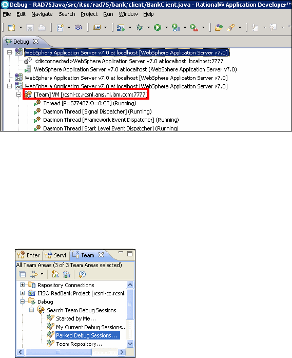
7672-test-3-debug.fm Draft Document for Review December 9, 2008 2:44 pm
898 Rational Application Developer V7.5 Programming Guide
Patrick can now proceed to debug the application. He will follow the steps listed
in “Running the sample application in debug mode” on page 872, and attempt to
withdraw a large amount until he hits the breakpoint. At this point Patrick decides
to park the debug session by doing the following:
Right-click [Team] VM [Team-Concert-server-hostname:7777], and select
Park Debug Session.
Parked debug sessions are stored on the Team Concert Server and nobody
owns them. Anyone can retrieve them and regain control.
Figure 24-24 Appearance of a debug session added to a Team Repository
Possibly at a later time, Lara decides to continue Patrick’s debug session. She
performs these actions:
In the Team Artifacts view, expand the node Debug under the Project Area.
In the node Search Team Debug Sessions, select Parked Debug Sessions
(Figure 24-25)
Figure 24-25 Search for parked debug sessions
In the Team Debug view, identify the session started by Patrick, right-click on
the session, and select: Debug (Figure 24-26).
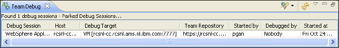
Chapter 24. Debug local and remote applications 899
Draft Document for Review December 9, 2008 2:44 pm 7672-test-3-debug.fm
Figure 24-26 Team Debug view showing a parked debug session
A dialog prompts whether you want to import breakpoints. Click Yes.
At this point Lara will see in the Debug perspective the code that contains the
breakpoint. The variables view shows the contents as determined by the
workflow previously followed by Patrick. Lara will also see a copy of the standard
output and standard error streamed to the console (the same keep being
streamed to the console of Patrick’s instance of Application Developer). While
Lara steps through the code, Patrick will see the results in the Web browser
opened on his machine. Lara can then decide to transfer the session back to
Patrick, or to park it again on the server.
More information
The online help provided with Application Developer has a large section on
debugging applications and is a good starting point. It has information on the
following topics:
Java development tools (JDT) debugger.
Java and mixed language debugger
J2EE/Web application debugging
Jython debugger
XSLT debugger
Debug extensions for Rational Team Concert Client
DB2 stored procedure debugger
SQLJ debugger
Installing Rational Debug extensions for Rational Team Concert Client
http://publib.boulder.ibm.com/infocenter/radhelp/v7r5/topic/com.ibm.
debug.team.client.ui.doc/topics/cbtovrvw.html
Installing Rational Debug Extension for Rational Team Concert Server
http://publib.boulder.ibm.com/infocenter/radhelp/v7r5/index.jsp?topi
c=/com.ibm.rad.install.doc/topics/t_install_teamdebug.html
7672-test-3-debug.fm Draft Document for Review December 9, 2008 2:44 pm
900 Rational Application Developer V7.5 Programming Guide
Rational Team Concert InfoCenter
http://publib.boulder.ibm.com/infocenter/rtc/v1r0m0/index.jsp
Finally, IBM developerWorks has a number of tutorials and articles to explain
debugging for various situations, including the following topics:
Debugging and Testing Java Applications:
http://www.ibm.com/developerworks/edu/i-dw-r-radcert2556.html
Getting Started with the New Rational Application Developer XSLT Debugger:
http://www-128.ibm.com/developerworks/rational/library/05/614_debug/

© Copyright IBM Corp. 2008. All rights reserved. 901
Draft Document for Review December 9, 2008 2:44 pm 7672-deploy-0-p7.fm
Part 7 Deploy and profile
applications
In this part of the book, we describe the tooling and technologies provided by
Application Developer for automatic builds, deployment, and profiling.
Part 7
7672-deploy-0-p7.fm Draft Document for Review December 9, 2008 2:44 pm
902 Rational Application Developer V7.5 Programming Guide

© Copyright IBM Corp. 2008. All rights reserved. 903
Draft Document for Review December 9, 2008 2:44 pm 7672-deploy-1-ant.fm
Chapter 25. Build applications with Ant
Traditionally, application builds are performed by using UNIX/Linux shell scripts
or Windows batch files in combination with tools such as make. While these
approaches are still valid, new challenges exist when developing Java
applications, especially in a heterogeneous environment. Traditional tools are
limited in that they are closely coupled to a particular operating system. With Ant,
you can overcome these limitations and perform the build process in a
standardized fashion regardless of the platform.
This chapter provides an introduction to the concepts and features of Ant within
IBM Rational Application Developer v7.5. The focus of the chapter is to
demonstrate how to use the Ant tooling included in Rational Application
Developer to build applications.
The chapter is organized into the following sections:
Introduction to Ant
Ant features in Application Developer
Building a simple Java application
Building a Java EE application
Running Ant outside of Application Developer
Using the Rational Application Developer Build Utility
25
7672-deploy-1-ant.fm Draft Document for Review December 9, 2008 2:44 pm
904 Rational Application Developer V7.5 Programming Guide
Introduction to Ant
Ant is a Java-based, platform-independent, open source build tool. It was
formerly a sub-project in the Apache Jakarta project, but in November 2002 it
was migrated to an Apache top-level project. Ant’s function is similar to the make
tool. Since it is Java-based and does not make use of any operating
system-specific functions, it is platform independent, thus allowing you to build
your projects using the same build script on any Java-enabled platform.
The Ant build operations are controlled by the contents of the XML-based script
file. This file not only defines what operations to perform, but also defines the
order in which they should be performed, and any dependencies between them.
Ant comes with a large number of built-in tasks sufficient to perform many
common build operations. However, if the tasks included are not sufficient, you
also have the ability to extend Ant’s functionality by using Java to develop your
own specialized tasks. These tasks can then be plugged into Ant.
Not only can Ant be used to build your applications, it can also be used for many
other operations such as retrieving source files from a version control system,
storing the result back in the version control system, transferring the build output
to other machines, deploying the applications, generating Javadoc, and sending
messages when a build is finished.
Ant build files
Ant uses XML build files to define what operations must be performed to build a
project. Here is a list of the main components of a build file:
Project: A build file contains build information for a single project. It can
contain one or more targets.
Target: A target describes the tasks that must be performed to satisfy a goal.
For example, compiling source code into class files might be one target, and
packaging the class files into a JAR file might be another target.
Targets can depend upon other targets. For example, the class files must be
up-to-date before you can create the JAR file. Ant can resolve these
dependencies.
Task: A task is a single step that must be performed to satisfy a target.
Tasks are implemented as Java classes that are invoked by Ant, passing
parameters defined as attributes in the XML. Ant provides a set of standard
tasks (core tasks), a set of optional tasks, and an API, which allows you to
write your own tasks.

Chapter 25. Build applications with Ant 905
Draft Document for Review December 9, 2008 2:44 pm 7672-deploy-1-ant.fm
Property: A property has a name and a value pair. Properties are essentially
variables that can be passed to tasks through task attributes. Property values
can be set inside a build file, or obtained externally from a properties file or
from the command line. A property is referenced by enclosing the property
name inside ${}, for example ${basedir}.
Path: A path is a set of directories or files. Paths can be defined once and
referred to multiple times, easing the development and maintenance of build
files. For example, a Java compilation task can use a path reference to
determine the classpath to use.
Ant tasks
A comprehensive set of built-in tasks is supplied with the Ant distribution. The
tasks that we use in our example are as follows:
delete: Deletes files and directories
echo: Outputs messages
jar: Creates Java archive files
javac: Compiles Java source
mkdir: Creates directories
tstamp: Sets properties containing date and time information
To find out more about Ant, visit the Ant Web site at:
http://ant.apache.org/
This chapter provides a basic outline of the features and capabilities of Ant. For
complete information, you should consult the Ant documentation included in the
Ant distribution or available on the Internet at:
http://ant.apache.org/manual/index.html
Ant features in Application Developer
Application Developer includes the following features to aid in the development
and use of Ant scripts:
It provides the ability to create and run Ant buildfiles in the Workbench and
run the build process in a background task like other tasks within Application
Developer.
The Ant editor also offers content assist (including Ant specific templates)
with the ability to insert snippets and syntax highlighting.
Note: Application Developer v7.5 includes Ant v1.7.
7672-deploy-1-ant.fm Draft Document for Review December 9, 2008 2:44 pm
906 Rational Application Developer V7.5 Programming Guide
The Ant editor has a format function that allow you to format your Ant files
base on your preferences.
The Ant editor also offers annotations support.
It provides the ability to add new Ant task and types that will be available for
build files.
A Problems view is available in the Ant editor to highlight syntax errors in your
Ant files.
In this section, we highlight the following Ant-related features in Application
Developer:
Content assist
Code snippets
Formatting an Ant script
Defining the format of an Ant script
Problems view
Preparing for the sample
To demonstrate the basic concepts of Ant, we provide a very simple Java
application named HelloAnt, which prints a message to the console.
We use a simple Java project (RAD75Ant) and class (HelloAnt) for this example.
To create a new Java project, do these steps:
In the Workbench, select File → New → Project.
In the New Project dialog, select Java → Java Project and click Next.
When prompted for the project name, enter RAD75Ant for the project name
field, and click Finish.
If the current perspective is not the Java perspective when you create the
project, Application Developer prompts you to switch to the Java perspective.
Click Yes.
To import the HelloAnt class into the RAD75Ant Java project, do these steps:
Right-click the RAD75Ant project and select New → Package.
In the New Package dialog, type itso.rad75.ant.hello for the Name, and
click Finish.
Right-click itso.rad75.ant.hello and select Import.
In the Import dialog, select General → File System, and click Next.

Chapter 25. Build applications with Ant 907
Draft Document for Review December 9, 2008 2:44 pm 7672-deploy-1-ant.fm
In the File System dialog, click Browse and select c:\7672code\ant\ as
directory, select HelloAnt.java, and click Finish (Figure 25-1).
Figure 25-1 Import a Java class
Creating a build file
To create the simple build file, do these steps:
Right-click the RAD75Ant project. and select New → File.
In the New File dialog, type build.xml as the file name, and click Finish
(Figure 25-2).
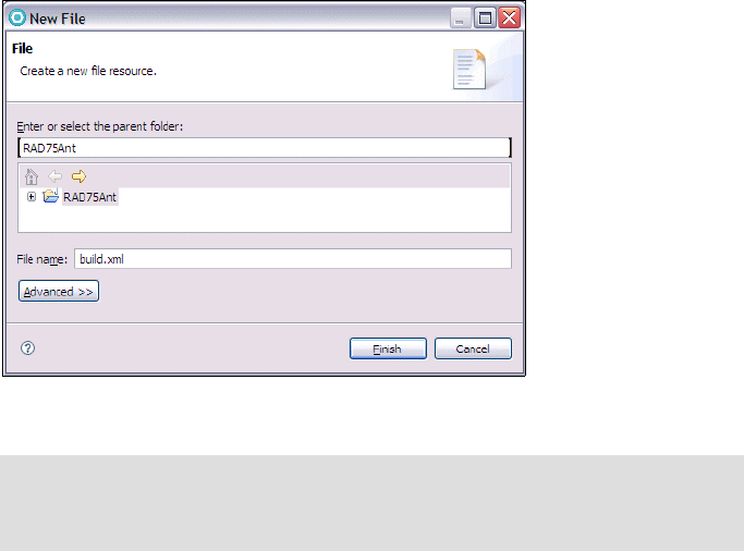
7672-deploy-1-ant.fm Draft Document for Review December 9, 2008 2:44 pm
908 Rational Application Developer V7.5 Programming Guide
Figure 25-2 Create the build.xml file
Double-click the build.xml file to open it in the Ant editor. Copy and paste the
text in c:\7672code\ant\build.txt into the build.xml file.
We now walk you through the various sections of this file, and provide an
explanation for each section.
Project definition
The <project> tag in the build.xml file defines the project name and the default
target. The project name is an arbitrary name; it is not related to any project
name in your Application Developer workspace.
<project name="HelloAnt" default="dist" basedir=".">
The project tag also sets the working directory for the Ant script. All references to
directories throughout the script file are based on this directory. A dot (.) means
to use the current directory, which, in Application Developer, is the directory
where the build.xml file resides.
Note: Application Developer has the ability to link to external files on the
file system. The Advanced button on the New File dialog allows you to
specify the location on the file system that the new file is linked to.
Chapter 25. Build applications with Ant 909
Draft Document for Review December 9, 2008 2:44 pm 7672-deploy-1-ant.fm
Global properties
Properties that will be referenced throughout the whole script file can be placed
at the beginning of the Ant script. Here we define the property build.compiler
that tells the javac command what compiler to use. We tell it to use the Eclipse
compiler.
We also define the names for the source directory, the build directory, and the
distribute directory. The source directory is where the Java source files reside.
The build directory is where the class files end up, and the distribute directory is
where the resulting JAR file is placed:
We define the source property as ".", which means that it is the same
directory as the base directory specified in the project definition above.
The build and distribute directories will be created as c:\temp\build and
c:\temp\RAD75Ant directories.
Properties can be set as shown below, but Ant can also read properties from
standard Java properties files or use parameters passed as arguments on the
command line:
<!-- set global properties for this build -->
<property name="build.compiler"
value="org.eclipse.jdt.core.JDTCompilerAdapter"/>
<property name="source" value="."/>
<property name="build" value="c:\temp\build"/>
<property name="distribute" value="c:\temp\RAD75Ant"/>
<property name="outFile" value="helloant"/>
Build targets
The build file contains four build targets:
init
compile
dist
clean
Initialization target (init)
The first target we describe is the init target. All other targets (except clean) in
the build file depend upon this target. In the init target, we execute the tstamp
task to set up properties that include timestamp information. These properties
are then available throughout the whole build. We also create a build directory
defined by the build property.
7672-deploy-1-ant.fm Draft Document for Review December 9, 2008 2:44 pm
910 Rational Application Developer V7.5 Programming Guide
<target name="init">
<!-- Create the time stamp -->
<tstamp/>
<!-- Create the build directory structure used by compile -->
<mkdir dir="${build}"/>
</target>
Compilation target (compile)
The compile target compiles the Java source files in the source directory and
places the resulting class files in the build directory.
<target name="compile" depends="init">
<!-- Compile the java code from ${source} into ${build} -->
<javac srcdir="${source}" destdir="${build}"/>
</target>
With these parameters, if the compiled code in the build directory is up-to-date
(each class file has a timestamp later than the corresponding Java file in the
source directory), the source will not be recompiled.
Distribution target (dist)
The dist target creates a JAR file that contains the compiled class files from the
build directory and places it in the lib directory under the dist directory. Because
the distribution target depends on the compile target, the compile target must
have executed successfully before the distribution target is run.
<target name="dist" depends="compile">
<!-- Create the distribution directory -->
<mkdir dir="${distribute}/lib"/>
<!-- Put everything in ${build} into the output JAR file -->
<!-- We add a time stamp to the filename as well -->
<jar jarfile="${distribute}/lib/${outFile}-${DSTAMP}.jar"
basedir="${build}">
<manifest>
<attribute name="Main-Class"
value="itso.rad75.ant.hello.HelloAnt"/>
</manifest>
</jar>
</target>
Cleanup target (clean)
The last of our standard targets is the clean target. This target removes the build
and distribute directories, which means that a full recompile is always performed
if this target has been executed.
<target name="clean">
<!-- Delete the ${build} and ${distribute} directory trees -->

Chapter 25. Build applications with Ant 911
Draft Document for Review December 9, 2008 2:44 pm 7672-deploy-1-ant.fm
<delete dir="${build}"/>
<delete dir="${distribute}"/>
</target>
Note that the build.xml file does not call for this target to be executed. It has to
be explicitly specified when running Ant.
Content assist
To access the content assist feature in the Ant editor, do these steps:
Open the build.xml in an editor (if not already open).
Place the cursor in the file and enter <pro, and then press Ctrl+Spacebar.
The content assist dialog is presented (Figure 25-3). You can then use the up
and down arrow keys to select the tag that you want.
Figure 25-3 Content assist in Ant editor
Code snippets
Application Developer v7.5 provides the ability to create code snippets that
contain commonly used code to be inserted into files rather than typing the code
in every time.
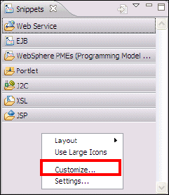
7672-deploy-1-ant.fm Draft Document for Review December 9, 2008 2:44 pm
912 Rational Application Developer V7.5 Programming Guide
To create code snippets, do these steps:
Open the Snippets view by selecting Window → Show View → Other, and in
the Show View dialog expand the General folder, select the Snippets view,
and click OK.
Right-click the Snippets view and select Customize (Figure 25-4).
Figure 25-4 Customizing snippets
In the Customize Palette dialog, select New → New Category.
In the New Customize Palette dialog (Figure 25-5), do these steps:
–Name:
Ant
– Description: Ant Snippets
–Select Custom.
– Click Browse next to Custom, select Ant Buildfiles for Content Type
Selection, and click OK to return to the Customize Palette dialog.
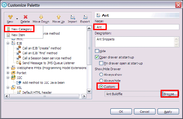
Chapter 25. Build applications with Ant 913
Draft Document for Review December 9, 2008 2:44 pm 7672-deploy-1-ant.fm
Figure 25-5 New Customize Palette dialog
In the Customize Palette dialog, select New → New Item.
In the Unnamed Template dialog, enter the following items:
–Name:
Comment Tag
– Click New in the variables section
–Variable Name: comment
– Template Pattern: <!-- ${comment} -->
Click OK in the Customize Palette dialog.
The Ant category with the Comment Tag entry is added to the Snippets view.
Using the code snippet
Now that you have created a code snippet, you can use it in any Ant build file. To
use a code snippet, do these steps:
Open the build.xml file.
Add an empty line under the <project> tag, place the cursor there,
double-click the Comment Tag in the Snippets view, and the Insert Template
dialog is displayed (Figure 25-6 on page 914).
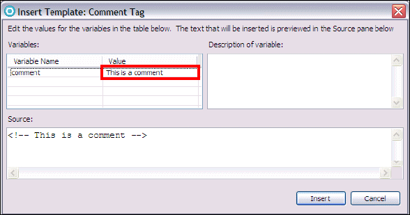
7672-deploy-1-ant.fm Draft Document for Review December 9, 2008 2:44 pm
914 Rational Application Developer V7.5 Programming Guide
Figure 25-6 Insert Template dialog
In the variables table, type This is a comment in the comment variable.
Click Insert.
The comment line is inserted. Save the file.
<project name="HelloAnt" default="dist" basedir=".">
<!-- This is a comment -->
<!-- set global properties for this build -->
Formatting an Ant script
Application Developer offers you the ability to format Ant scripts in the Ant editor.
To format the Ant script, do these steps:
Open the build.xml file.
Right-click the editor and select Format, or press Ctrl+Shift+F.
Defining the format of an Ant script
To define the format of an Ant script, do these steps:
Select Window → Preferences.
In the Preferences dialog, select and expand Ant.
In the Ant preferences dialog, you can specify the console colors
(Figure 25-7).

Chapter 25. Build applications with Ant 915
Draft Document for Review December 9, 2008 2:44 pm 7672-deploy-1-ant.fm
Figure 25-7 Ant preferences
Expand the Ant folder and select Editor.
– In the Appearance tab, you can change the layout preferences of your Ant
file.
– In the Syntax tab, you can change the syntax highlighting preferences with
a preview of the results, and on the Problems tab you can define how
certain problems should be handled.
– In the Problems tab, you can change the severity levels for the buildfile
problems.
– In the Folding tab, you can enable folding when opening a new editor and
specify which region types should be folded.
Expand Editor.
– In the Content Assist window, you can define the content assist
preferences.
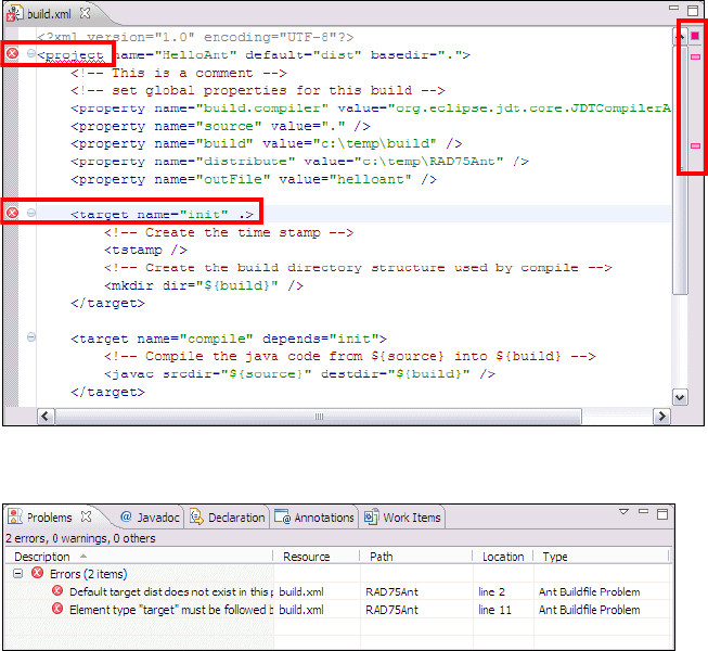
7672-deploy-1-ant.fm Draft Document for Review December 9, 2008 2:44 pm
916 Rational Application Developer V7.5 Programming Guide
– In the Formatter window, you can define the preferences for the formatting
tool for the Ant files.
– In the Templates window, you can create, edit, delete, import and export
templates for Ant files.
Select Runtime.
In this dialog, you can define your preferences such as classpath, tasks,
types, and properties.
Problems view
Application Developer offers you the Problems view for the Ant file. The editor
presents an error in the view by placing a red X on the left of the line with the
problem as well as a line marker in the file on the right of the window
(Figure 25-8). The Problems view lists the problems as seen in Figure 25-9.
Figure 25-8 Problems in the Ant editor
Figure 25-9 Problems view displaying Ant problems
Chapter 25. Build applications with Ant 917
Draft Document for Review December 9, 2008 2:44 pm 7672-deploy-1-ant.fm
Building a simple Java application
We created a simple build file that compiles the Java source for our HelloAnt
application and generates a JAR file with the result. The build file is called
build.xml, which is the default name assumed by Ant if no build file name is
supplied.
The example simple build file has the following targets:
init: Performs build initialization tasks. All other targets depend upon this
target.
compile: Compiles Java source into class files.
dist: Creates the deliverable JAR for the module, and depends upon the
compile target.
clean: Removes all generated files. Used to force a full build.
Each Ant build file can have a default target. This target is executed if Ant is
invoked on a build file and no target is supplied as a parameter. In our example,
the default target is dist, as specified in the <project> tag. The dependencies
between the targets are illustrated in Figure 25-10.
Figure 25-10 Ant example dependencies
Running Ant
Ant is a built-in function to Application Developer. You can launch it from the
context menu of any XML file, although it will run successfully only on valid Ant
XML build script files. When launching an Ant script, you are given the option to
select which targets to run.
dist clean
compile
init
depends on
7672-deploy-1-ant.fm Draft Document for Review December 9, 2008 2:44 pm
918 Rational Application Developer V7.5 Programming Guide
To run the build script:
Open the Java perspective.
Expand the RAD75Ant project.
Right-click build.xml and select Run As → 3 Ant Build... .
In the Edit Configuration dialog (Figure 25-11), select the desired attributes:
–In the Targets tab you can see that the dist target is executed by default.
If you select multiple targets, the execution order is shown under Target
execution order, and the order can be changed by clicking Order. For now,
only select the dist target.
– In the JRE tab, select Run in the same JRE as the workspace.
– Click Apply if you make any changes.
Figure 25-11 Selecting Ant targets to run
Note: Because the dist target depends on compile, even if you only
select dist, the compile target is executed as well.

Chapter 25. Build applications with Ant 919
Draft Document for Review December 9, 2008 2:44 pm 7672-deploy-1-ant.fm
The Run Ant wizard gives you several tabs to configure or run the Ant
process. The tabs allow you to do the following operations:
–Main: This tab allows you to select the build file, base directory, and
arguments to pass to the Ant process.
–Refresh: This tab allows you to set some refresh options when the Ant
process has finished running.
–Build: This tab allows you to set some build options before the Ant
process is run.
–Targets: This tab allows you to select the targets and the sequences the
targets are to run.
–Classpath: This tab allows you to customize the classpath for the Ant
process.
–Properties: This tab allows you to add, edit, or remove properties to be
used by the Ant process.
–JRE: This tab allows you to select the Java Runtime Environment to use to
run the Ant process.
–Environment: This tab allows you to define environmental variables to be
used by the Ant process. This tab is only relevant when running in an
external JRE.
–Common: This tab allows you to define the launch configuration for the
Ant process.
Click Run to execute the Ant build.
The output is in the Console (Figure 25-12).
Figure 25-12 Ant output in the Console

7672-deploy-1-ant.fm Draft Document for Review December 9, 2008 2:44 pm
920 Rational Application Developer V7.5 Programming Guide
Ant console
The Console view opens automatically when running Ant, but if you want to open
it manually, select Window → Show view → Console.
The Console shows that Ant has created the c:\temp\build directory, compiled
the source files, created the c:\temp\RAD75Ant\lib directory, and generated a
JAR file (helloant-20081008.jar).
Rerun Ant
If you launch Ant again with the same target selected, Ant skips creating the
directories, but the class and JAR files are created.
Forced build
To generate a complete build, select the clean target as the first and the dist
target as the second target to run. You have to clear dist, select clean, and then
select dist again to get the execution order right (Figure 25-13). Alternatively
you can click Order to change the execution order. Click Apply and Run.
Figure 25-13 Launching Ant to generate complete build
Chapter 25. Build applications with Ant 921
Draft Document for Review December 9, 2008 2:44 pm 7672-deploy-1-ant.fm
Classpath problem
The classpath specified in the Java build path for the project is not available to
the Ant process. If you are building a project that references another project, the
classpath for the javac compiler must be set up in the following way:
<javac srcdir="${source}" destdir="${build}" includes="**/*.java">
<classpath>
<pathelement location="../MyOtherProject"/>
<pathelement location="../MyThirdProject"/>
</classpath>
</javac>
Running the sample application to verify the Ant build
Now that you have completed the Ant build, we recommend that you verify the
build by running the sample application as follows:
Open a Windows command window.
Navigate to the output directory of the Ant build (for example,
c:\temp\RAD75Ant\lib).
Set the Java path by entering the following command:
Enter the location of the installation directory (for example, our installation
directory is found in c:\IBM\SDP75).
set PATH=c:\IBM\SDP75\jdk\bin;%PATH%
Run the following command:
java -jar helloant-20081008.jar
Note that the timestamp in the JAR filename is dependent on when it is built.
You should see the following output:
Hello from Turkey!
Building a Java EE application
As we have just demonstrated in the previous section, building a simple Java
application using Ant is quite easy. In this section we demonstrate how to build a
Java EE application from existing Java EE related projects.
This section is organized as follows:
Java EE application deployment packaging
Preparing for the sample
7672-deploy-1-ant.fm Draft Document for Review December 9, 2008 2:44 pm
922 Rational Application Developer V7.5 Programming Guide
Creating the build script
Running the Ant Java EE application build
Java EE application deployment packaging
EAR, WAR, and EJB JAR files contain a number of deployment descriptors that
control how the artifacts of the application are to be deployed onto an application
server. These deployment descriptors are mostly XML files and are standardized
within the Java EE specification.
While working in Application Developer, some of the information in the
deployment descriptor is stored in XML files. The deployment descriptor files also
contain information in a format convenient for interactive testing and debugging.
This is one of the reasons that it is so quick and easy to test Java EE applications
in the integrated WebSphere Application Server V7 Test Environment included
with Application Developer.
The actual EAR being tested, and its supporting WAR, EJB, and client
application JARs, are not actually created as a standalone file. Instead, a special
EAR is used that simply points to the build contents of the various Java EE
projects. Since these individual projects can be anywhere on the development
machine, absolute path references are used.
When an enterprise application project is exported, a true standalone EAR is
created, including all the module WARs, EJB JARs, JPAs and Java utility JARs it
contains. Therefore, during the export operation, all absolute paths are changed
into self-contained relative references within that EAR, and the internally
optimized deployment descriptor information is merged and changed into a
standard format. To create a Java EE-compliant WAR or EAR, we therefore have
to use Application Developer’s export function.
Preparing for the sample
For the purposes of demonstrating how to build a J2EE application using Ant, we
use the Java EE applications developed in Chapter 14, “Develop EJB
applications” on page 387.
To import the RAD75EJB.zip project interchange file containing the sample code
into Rational Application Developer, do these steps:
Open the Java EE perspective Enterprise Explorer view.
Select File → Import.
Expand the Other folder and select Project Interchange and then click Next.

Chapter 25. Build applications with Ant 923
Draft Document for Review December 9, 2008 2:44 pm 7672-deploy-1-ant.fm
In the Import Projects dialog, click Browse next to the zip file, navigate to and
select the RAD75EJB.zip from the c:\7672code\zInterchange\ejb folder,
and click Open.
Click Select All to select all projects and then click Finish.
After importing the two project interchange files, you have the following
projects:
– RAD75EJB
– RAD75EJBEAR
– RAD75EJBTestWeb
–RAD75JPA
Creating the build script
To build the RAD75EJBEAR enterprise application, we created an Ant build script
(build.xml) that utilizes the Java EE Ant tasks provided by Application
Developer.
To add the Ant build script to the project, do these steps:
Open the Java EE perspective Enterprise Explorer view.
Expand RAD75EJBEAR, and select META-INF.
Select File → New → Other.
In the New File dialog, select General → File, and click Next.
Typ e build.xml in the File name field, and click Finish.
Double-click the build.xml file to open it in the editor. Copy and paste the text
in c:\7672code\ant\j2ee\build.txt into the build.xml file.
Modify the value for the work.dir property to match your desired working
directory (for example, c:/temp/RAD7AntEE), as highlighted in Example 25-1.
Example 25-1 J2EE Ant build.xml script
<?xml version="1.0" encoding="UTF-8"?>
<project name="ITSO RAD Pro Guide Ant" default="Total" basedir=".">
<!-- Set global properties -->
<property name="work.dir" value="c:/temp/RAD75AntEE" />
<property name="dist" value="${work.dir}/dist" />
<property name="project.ear" value="RAD75EJBEAR" />
Note: For information on downloading the sample code, refer to
Appendix B, “Additional material” on page 1149.

7672-deploy-1-ant.fm Draft Document for Review December 9, 2008 2:44 pm
924 Rational Application Developer V7.5 Programming Guide
<property name="project.ejb" value="RAD75EJB" />
<property name="project.war" value="RAD75EJBTestWeb" />
<property name="type" value="incremental" />
<property name="debug" value="true" />
<property name="source" value="true" />
<property name="meta" value="false" />
<property name="noValidate" value="false" />
The build.xml script includes the following Ant targets, which correspond to
common Java EE application build:
deployEjb: This generates the deploy code for all EJBs in the project.
buildEjb: This builds the EJB project (compiles resources within the project).
buildWar: This builds the Web project (compiles resources within the
project).
buildEar: This builds the Enterprise Application project (compiles resources
within the project).
exportEjb: This exports the EJB project to a JAR file.
exportWar: This exports the Web project to a WAR file.
exportEar: This exports the Enterprise Application project to an EAR file.
buildAll: This invokes the buildEjb, buildWar, and buildEar targets.
exportAll: This invokes the exportEjb, exportWar, and exportEar targets to
create the RAD7EJBEAR.ear used for deployment.
The additional targets are:
init: Initialize and create a directory.
info: Print out the properties.
Total: Invokes buildAll and exportAll.
clean: Delete the output files.
EJB specification level
If you have enterprise beans at 1.1, 2.0, or 2.1 specification-level, you have to
generate deployment code for the enterprise beans. The ejbDeploy tool executed
under the deployEjb target generates deployment code for these artifacts.
When you install the WebSphere Application Server V6.1 with Feature Pack for
EJB 3.0 or WebSphere Application Server v7.0, you can utilize the EJB 3.0
specification at runtime. For EJB 3.0 specification-level, you no longer have to
generate the EJB deployment code. So, the ejbdeploy command does not
generate deployment code for artifacts at Java EE 5 specification-level.

Chapter 25. Build applications with Ant 925
Draft Document for Review December 9, 2008 2:44 pm 7672-deploy-1-ant.fm
The following lists the general behavior of the ejbdeploy command when issued
with the presence of Java EE 5 artifacts:
Tolerates EAR 5.0 files and EJB 3.0 JAR files.
Tolerates EAR files with Java 2 Platform Enterprise Edition (J2EE) 1.4
deployment descriptors that contain EJB 3.0 JAR files. Deployment code is
generated only for EJB at 1.1, 2.0, or 2.1 specification-level. However,
deployment code is not generated for EJB beans at 3.0 specification-level.
If the -complianceLevel option for the ejbdeploy command is not specified, in
any of the following cases the default -complianceLevel setting is Java
developer kit V5.0, "5.0":
– An EAR or JAR file that contains Java EE 5 or EJB 3.0 deployment
descriptor files
– An EAR file without any deployment descriptor files
All other cases, the -complianceLevel setting defaults to Java developer kit
V1.4, "1.4".
If you are generating deployment code for J2EE 1.4 EAR or JAR files that contain
source code files which make use of the new language features in Java
developer kit 5.0, you must specify the following parameter when running the
ejbdeploy command: -complianceLevel "5.0".
In the global properties for this build script, we define a number of useful
variables, such as the project names and the target directory. We also define a
number of properties that we pass on to the Application Developer Ant tasks.
These properties allow us to control whether the build process should perform a
full or incremental build, whether debug statements should be included in the
generated class files, and whether Application Developer’s metadata information
should be included when exporting the project.
When launching this Ant script, we can also override these properties by
specifying other values in the arguments field, allowing us to perform different
kinds of builds with the same script.
Running the Ant Java EE application build
When launching the build.xml script, you can select which targets to run and the
execution order.
To run the Ant build.xml to build the Java EE application, do these steps:
Right-click build.xml (in RAD75EJBEAR/META-INF), and select Run As → 3
Ant Build....
7672-deploy-1-ant.fm Draft Document for Review December 9, 2008 2:44 pm
926 Rational Application Developer V7.5 Programming Guide
The Edit configuration and launch dialog opens (Figure 25-14).
Figure 25-14 Launch Ant to build and export a J2EE project (EAR)
Note: From the content menu for the Ant build script, the following two build
options exist:
2 Ant Build: This invokes the default target for the Ant build. In our
example, this is the Total target, which in turn invokes buildAll and
exportAll targets.
3 Ant Build: This will launch a dialog where you can select the targets
and order, and provide parameters, as seen in Figure 25-14.
Chapter 25. Build applications with Ant 927
Draft Document for Review December 9, 2008 2:44 pm 7672-deploy-1-ant.fm
Select the Main tab:
– To build the Java EE EAR file with debug, source files, and metadata,
enter the following values in the Arguments text area:
-DDebug=true -Dsource=true -Dmeta=true
– To build the Java EE EAR for production deployment (without debug
support, source code, and meta data), enter the following value in the
Arguments text area:
-Dtype=full
Select the Targets tab. Ensure that Total is selected (default).
Select the JRE tab. Select Run in the same JRE as the workspace.
Click Apply and then click Run.
Verify in the c:\temp\RAD75AntEE\dist output directory that the
RAD7EJBEAR.ear, RAD75EJB.jar, and RAD75EJBTestWeb.war files were created.
The Console view displays the operations performed and their results.
Running Ant outside of Application Developer
To automate the build process even further, you might want to run Ant outside of
Application Developer by running Ant in headless mode.
Preparing for the headless build
Application Developer includes a runAnt.bat file that can be used to invoke Ant
in headless mode and passes the parameters that you specify. This have to be
customized for your environment.
The runAnt.bat file included with Application Developer is located in the
following directory (for example, our <rad_home> directory is found in c:\IBM\SDP75):
<rad_home>\bin
To create a headless Ant build script for J2EE project, do these steps:
Copy the runAnt.bat file to a new file called itsoRunAnt.bat.
Modify the WORKSPACE value in the itsoRunAnt.bat so that it points to your
current workspace (Example 25-2):
set WORKSPACE=C:\workspaces\RAD75proguide

7672-deploy-1-ant.fm Draft Document for Review December 9, 2008 2:44 pm
928 Rational Application Developer V7.5 Programming Guide
Example 25-2 Snippet of the itsoRunAnt.bat (modified runAnt.bat)
......
set JAVAEXE="C:\IBM\SDP75\jdk\jre\bin\java.exe"
......
set INSTALL_DIRECTORY="C:\IBM\SDP75"
......
set LAUNCHER_JAR="C:\IBM\SDP75Shared\plugins\org.eclipse.equinox.launcher_1.0
.100.v20080509-1800.jar"
REM #######################################################
REM ##### you must edit the "WORKSPACE" setting below #####
REM #######################################################
REM *********** The location of your workspace ************
set WORKSPACE=C:\workspaces\RAD75proguide
:workspace
if not $%WORKSPACE%$==$$ goto check
......
Running the headless Ant build script
To run the itsoRunAnt.bat command file, do these steps:
Ensure that you have closed Application Developer.
Open a Windows command prompt.
Navigate to the location of the itsoRunAnt.bat file.
Run the command file by entering the following command:
itsoRunAnt -buildfile
c:\workspaces\RAD75proguide\RAD75EJBEAR\META-INF\build.xml clean Total
-DDebug=true -Dsource=true -Dmeta=true
The -buildfile parameter specifies the fully qualified path of the build.xml
script file. We can pass the targets to run as parameters to itsoRunAnt and
we can also pass Java environment variables by using the -D switch.
In this example, we run the clean and Total targets, and we include the
debug, Java source, and metadata files in the resulting EAR file.
There are several build output files, which can be found in the
c:\temp\RAD75AntEE\dist directory: RAD75EJB.jar, RAD75EJBEAR.ear, and
RAD75EJBTestWeb.war.
Attention: Prior to running Ant in headless mode, Application Developer must
be closed. If you do not close Application Developer, you will get build errors
when attempting to run Ant build in headless mode.

Chapter 25. Build applications with Ant 929
Draft Document for Review December 9, 2008 2:44 pm 7672-deploy-1-ant.fm
Using the Rational Application Developer Build Utility
Application Developer v7.5 introduces a new feature, called build utility, that can
be installed standalone on a build server running on Windows, Linux, or z/OS.
The build utility has a smaller footprint that Application Developer itself, as it does
not contain any user interface code. The inputs to the build utility are the projects
developed in Application Developer and the outputs are JAR, WAR, and EAR
files.
In the following we assume that the build utility was installed on Windows in the
folder C:\IBM\BuildUtility.
The build utility includes a runAnt.bat file that can be used to invoke Ant in
headless mode the same way as Application Developer does.
The runAnt.bat file included with the build utility is located in the directory
C:\IBM\BuildUtility\eclipse\bin.
When you invoke a build on a build server, typically you use Ant to create a
workspace containing the projects before you build them. In the following
example, we modify the Ant build script so that it first imports the projects into a
new workspace and then builds them.
Example of using the build utility
We use the RAD75EJBWebEAR enterprise application for the build utility
example. This application is similar to the RAD75EJBEAR application that we
used for the Ant headless build.
Extract the project interchange file into a directory on the source server:
C:\7672code\zInterchange\ejb\RAD75EJBWeb.zip ==> C:\sources
Note: We have included itsoRunAnt.bat and output.txt files in the
c:\7672code\ant\j2ee directory. The output.txt file contains the output from
the headless Ant script for review purposes.
Verify that the installation directory (see Example 25-2 on page 928, bold)
points to the correct directory on your system.
Note: For information on installing the build utility, refer to “Installing Rational
Application Developer Build Utility” on page 1148.

7672-deploy-1-ant.fm Draft Document for Review December 9, 2008 2:44 pm
930 Rational Application Developer V7.5 Programming Guide
Create the build file (BUbuild.xml)
To create the build file, we copy the build file from the headless Ant example and
modify it for the RAD75EJBWebEAR enterprise application.
Copy the RAD75EJBEAR\META-INF\build.xml file to C:\sources\BUbuild.xml.
Modify the BUBuild.xml as highlighted in Example 25-3. The changes to the
original build.xml file are:
– Project names are different
– Import the projects into the workspace before the build
– Full build instead of incremental build
Example 25-3 BUbuild.xml for the build utility”
<?xml version="1.0" encoding="UTF-8"?>
<project name="ITSO RAD Pro Guide Ant Build Utility" default="Total"
basedir=".">
<!-- Set global properties -->
<property name="work.dir" value="c:/temp/RAD75BU" />
<property name="dist" value="${work.dir}/dist" />
<property name="project.ear" value="RAD75EJBWebEAR" />
<property name="project.ejb" value="RAD75EJB" />
<property name="project.war" value="RAD75EJBWeb" />
<property name="project.jpa" value="RAD75JPA" />
<property name="type" value="full" />
<property name="debug" value="true" />
<property name="source" value="true" />
<property name="meta" value="false" />
<property name="noValidate" value="false" />
<target name="init">...
<target name="info">
<!-- Displays the properties for this run -->
<echo message="debug=${debug}" />
<echo message="type=${type}" />
<echo message="source=${source}" />
<echo message="meta=${meta}" />
<echo message="noValidate=${noValidate}" />
<echo message="Output directory=${dist}" />
<echo message="project.ear=${project.ear}" />
<echo message="project.ejb=${project.ejb}" />
<echo message="project.war=${project.war}" />
<echo message="project.jpa=${project.jpa}" />
</target>
<target name="importJPA">
<projectImport projectname="${project.jpa}" />

Chapter 25. Build applications with Ant 931
Draft Document for Review December 9, 2008 2:44 pm 7672-deploy-1-ant.fm
<eclipse.refreshLocal resource="${project.jpa}" />
</target>
<target name="importEJB">
<projectImport projectname="${project.ejb}" />
<eclipse.refreshLocal resource="${project.ejb}" />
</target>
<target name="importWAR">
<projectImport projectname="${project.war}" />
<eclipse.refreshLocal resource="${project.war}" />
</target>
<target name="importEAR">
<projectImport projectname="${project.ear}" />
<eclipse.refreshLocal resource="${project.ear}" />
</target>
<target name="importAll"
depends="importJPA,importEJB,importWAR,importEAR">
<!-- Import all projects and exports all files -->
<echo message="Import All projects" />
</target>
<target name="deployEjb">...
<target name="buildEjb" depends="deployEjb">...
<target name="buildJPA">
<!-- Builds the JPA project -->
<projectBuild ProjectName="${project.jpa}" BuildType="${type}"
DebugCompilation="${debug}" />
</target>
<target name="buildWar">...
<target name="buildEar">...
<target name="exportEjb" depends="init">...
<target name="exportWar" depends="init">...
<target name="exportEar" depends="init">...
<target name="buildAll" depends="buildJPA,buildEjb,buildWar,buildEar">
<!-- Builds all projects -->
<echo message="Built all projects" />
</target>
<target name="exportAll" depends="exportEjb,exportWar,exportEar">...
<target name="Total" depends="importAll,buildAll,exportAll">...
<target name="clean">...
</project>
The projects are imported into the Eclipse workspace from the workspace
directory itself, using targets such as:
<target name="importEJB">
<projectImport projectname="${project.ejb}"/>
<eclipse.refreshLocal resource="${project.ejb}" />
</target>
7672-deploy-1-ant.fm Draft Document for Review December 9, 2008 2:44 pm
932 Rational Application Developer V7.5 Programming Guide
Because we do not specify the attribute projectLocation for the
projectImport task, it is assumed that the projects to import are in the
workspace directory. Note that projectImport does not make a physical copy
of the projects, it just imports a reference to the projects.
Create the command file for execution
To run the buildi utility, we create a batch command file.
Create a command file as C:\sources\itsoBUBuild.bat with the following
content (Example 25-4):
Example 25-4 Contents of ITSOBUBuild.bat
@echo on
setlocal
set WORKSPACE=C:\sources
C:\IBM\BuildUtility\eclipse\bin\runant.bat
-buildfile C:\sources\BUbuild.xml clean Total
Execute the build using the commands:
cd C:\sources
itsoBUbuild.bat >BUoutput.txt
Review the BUoutput.txt file. You should see these lines towards the end:
[ejbExport] EJBExport completed to c:/temp/RAD75BU/dist/RAD75EJB.jar
[warExport] WARExport completed to c:/temp/RAD75BU/dist/RAD75EJBWeb.war
[earExport] EARExport completed to c:/temp/RAD75BU/dist/RAD75EJBWebEAR.ear
Verify the files created in the folder c:/temp/RAD75BU/dist.
More information on Ant
For more information on Ant, we recommend the following resources:
Automatically generate project builds using Ant, white paper found at:
http://www.ibm.com/developerworks/library/ar-auototask/
Note: We have included the files BUbuild.xml, itsoBUBuild.bat, and
BUoutput.txt in C:\7672code\ant\buildutility.

© Copyright IBM Corp. 2008. All rights reserved. 933
Draft Document for Review December 9, 2008 2:44 pm 7672-deploy-2-ear.fm
Chapter 26. Deploy enterprise
applications
The term deployment can have many different meanings depending on the
context. In this chapter we start out by defining the concepts of application
deployment. The remainder of the chapter provides a working example for
packaging and deploying the ITSO Bank enterprise application to a standalone
IBM WebSphere Application Server v7.0.
The application deployment concepts and procedures described in this chapter
apply to Application Server v7.0 (Base, Express, and Network Deployment
editions). In Application Developer v7.5, the configuration of the integrated
Application Server v7.0 for deployment, testing, and administration is the same
for the separately installed Application Server v7.0.
The chapter is organized into the following sections:
Introduction to application deployment
Preparing for the deployment of the EJB application
Packaging the application for deployment
Manual deployment of enterprise applications
Automated deployment using Jython based wsadmin scripting
26

7672-deploy-2-ear.fm Draft Document for Review December 9, 2008 2:44 pm
934 Rational Application Developer V7.5 Programming Guide
Introduction to application deployment
Deployment is a critical part of the Java EE application development cycle.
Having a solid understanding of the deployment components, architecture, and
process is essential for the successful deployment of the application.
In this section we review the following concepts of the Java EE and WebSphere
deployment architecture:
Common deployment considerations
Java EE application components and deployment modules
Preparing for the deployment of the EJB application
WebSphere deployment architecture
Java and WebSphere class loader
Common deployment considerations
Some of the most common factors that impact the deployment of a Java EE
application are as follows:
Deployment architecture: How can you create, assemble, and deploy an
application properly if you do not understand the deployment architecture?
Infrastructure: What are the hardware and software constraints for the
application?
Security: What security will be imposed on the application and what is the
current security architecture?
Application requirements: Do they imply a distributed architecture?
Performance: How many users are using the system (frequency, duration,
and concurrency)?
Note: Further information on the IBM Application Server deployment can be
found in the following sources:
WebSphere Application Server V6.1: Planning and Design, SG24-7305
WebSphere Application Server V6.1: Systems Management and
Configuration, SG24-7304
WebSphere Application Server V6: Scalability and Performance,
SG24-6392
IBM WebSphere Application Server v7.0 InfoCenter, found at:
http://publib.boulder.ibm.com/infocenter/wasinfo/v7r0/index.jsp
Chapter 26. Deploy enterprise applications 935
Draft Document for Review December 9, 2008 2:44 pm 7672-deploy-2-ear.fm
Java EE application components and deployment modules
Within the Java EE application development life cycle, the application
components are created, assembled, and then deployed. In this section, we
explore the application component types, deployment modules, and packaging
formats to gain a better understanding of what is being packaged (assembled)
for deployment.
Application component types
In Java EE 5, there are four application component types supported by the
runtime environment:
Application clients: Run in the Application client container.
Applets: Run in a browser (or a stand-alone applet container).
Web applications (servlets, JSPs, HTML pages): Run in the Web container.
EJBs: Run in the EJB container.
Deployment modules
The Java EE deployment components are packaged for deployment as modules:
Web module
EJB module
Resource adapter module
Application client module
Packaging formats
Each module is packaged on a specific jar file format:
Web modules in Web Application Archive (WAR)
EJB and Application client modules in JAR files
Resource adapter modules in Resource Application Archive (RAR)
Enterprise Application Archive (EAR) can be used to package EJB modules,
resource adapter modules, application client modules, and Web modules.
Deployment descriptors
In J2EE 1.4 and earlier, information describing a J2EE application and how to
deploy it into a J2EE container was stored in XML files called deployment
descriptors. An EAR file normally contained multiple deployment descriptors,
depending on the modules it contains. Figure 26-1 shows a schematic overview
of a J2EE EAR file. In this figure the various deployment descriptors are
designated with DD after their name.
7672-deploy-2-ear.fm Draft Document for Review December 9, 2008 2:44 pm
936 Rational Application Developer V7.5 Programming Guide
Figure 26-1 J2EE EAR file structure
The deployment descriptor of the EAR file itself is stored in the META-INF
directory in the root of the EAR and is called application.xml. It contains
information about the modules making up the application.
The deployment descriptors for each module are stored in the META-INF directory
of the module and are called web.xml (for Web modules, actually in WEB-INF),
ejb-jar.xml (for EJB modules), ra.xml (for resource adapter modules), and
application-client.xml (for Application client modules). These files describe
the contents of a module and allow the Java EE container to configure servlet
mappings, JNDI names, and so forth.
Classpath information, specifying which other modules and utility JARs are
needed for a particular module to run, is stored in the manifest.mf file, also in the
META-INF directory of the modules.
Deployment descriptors in Java EE 5
However, with Java EE 5, deployment descriptors become optional and an
Enterprise Application can be deployed using annotations to replace the
information previously contained into deployment descriptors.
Web
DD
EJB
Module
JAR file
EJB
Module
JAR file
Web
Module
WAR file
Web
Module
WAR file
Client
Module
JAR file
Client
Module
JAR file
J2EE
Application
EAR file
Installed
RARs
Installed
RARs
IBM Bind
Schema
Map
Schema
Attributes
Table
Creation
was.policy
(Java2 Sec)
IBM
Bind /Ext
HTML,
GIFs,
etc.
HTML,
GIFs,
etc.
Servlet
JSP
Servlet
JSP
Application
DD
Web
Services
DD
Client
Classes
Client
Classes
EJBsEJBs
IBM
Bind/Ext
IBM
Bind/Ext
EJB
DD
WS IBM
Bind/Ext
Web
Servic es
DD
Client
DD
WS Client
IB M Bind/Ext
WSDL <- > Java
Mapping Files
WSDL <-> Java
Mapping Files
WS Client IBM
Bind/Ext
WS IBM
Bind/Ext
WS Client IBM
Bind/Ext
WSDL <-> Java
Mapping Files
Chapter 26. Deploy enterprise applications 937
Draft Document for Review December 9, 2008 2:44 pm 7672-deploy-2-ear.fm
To generate the standard deployment descriptor for a Java EE module, either
select Generate deployment descriptor in the Create Project dialog, or
right-click an existing project and select Java EE → Generate Deployment
Descriptor Stub.
Wether you use standard Java EE deployment descriptors or not, Application
Developer can also generate additional WebSphere-specific information used
when deploying applications to WebSphere environments. This supplemental
information is stored in XMI files, also in the META-INF (or WEB-INF) directory of
the respective modules. Examples of information in the IBM-specific files are IBM
extensions, such as servlet reloading and EJB access intents. To use these
extension file you need first to generate them.
To do so :
Right-click on the project you want to add the WebSphere-specific
deployment descriptor.
Select Java EE → Generate WebSphere XXX Deployment Descriptor,
depending on the kind of descriptor you want to generate. The available kinds
of deployment descriptor (XXX) are:
– Bindings—Creates ibm-web-bnd.xml or ibm-ejb-jar-bnd.xml or similar
– Extensions—Creates ibm-web-ext.xml or ibm-ejb-jar-ext.xml or similar
– Programming Model Extensions—Creates ibm-web-ext-pme.xml or
ibm-ejb-jar-ext-pme.xml or similar
Deployment Descriptor editors
Application Developer have easy-to-use editors for working with the deployment
descriptors. The information that goes into the different files is accessible from
one page in the IDE, eliminating the need to be concerned about what
information is put into what file. However, if you are interested, you can click the
Source tab of the Deployment Descriptor editor to see the text version of what is
actually stored in that descriptor.
For example, if you open the EJB deployment descriptor, you have access to
settings that are stored across multiple deployment descriptors for the EJB
module, including:
EJB deployment descriptor, ejb-jar.xml
Bindings file, ibm-ejb-jar-bnd.xml
Extensions deployment descriptor, ibm-ejb-jar-ext.xml
The deployment descriptors can be modified in Application Developer by
double-clicking the file to open the Deployment Descriptor Editor (Figure 26-2).
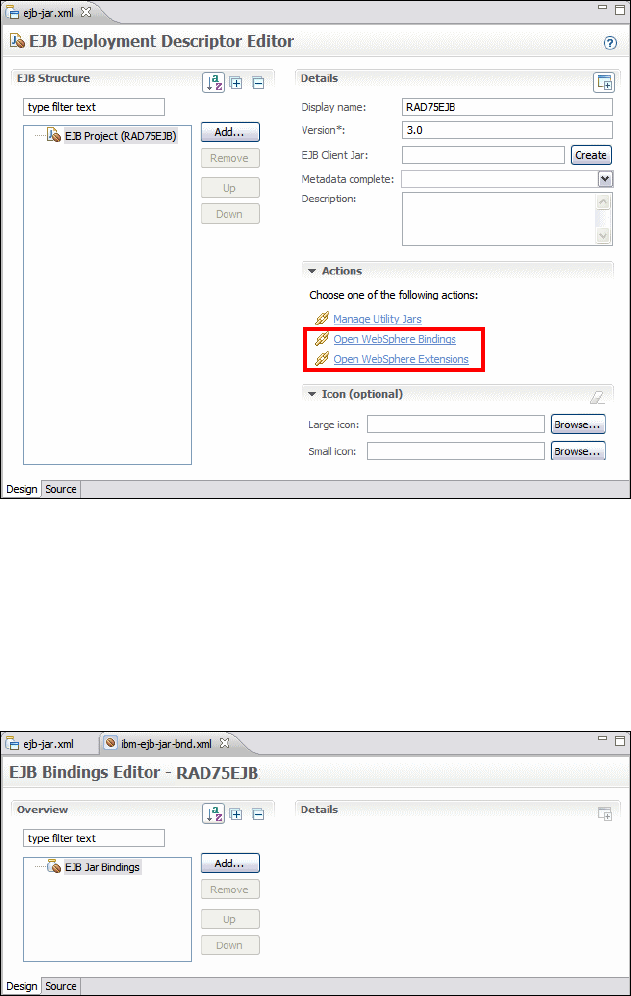
7672-deploy-2-ear.fm Draft Document for Review December 9, 2008 2:44 pm
938 Rational Application Developer V7.5 Programming Guide
Figure 26-2 Deployment Descriptor editor for an EJB project
While the editor allows you to modify the content of the ejb-jar.xml, the links
under Actions allow you to open the IBM bindings and extensions stored in the
WebSphere-specific deployment descriptor files (Figure 26-3). The descriptor
files are kept in the META-INF directory of the module you are editing. Clicking the
Source tab allows you to access and modify the XML source of the deployment
descriptor.
Figure 26-3 Deployment Descriptor editor for Bindings
Chapter 26. Deploy enterprise applications 939
Draft Document for Review December 9, 2008 2:44 pm 7672-deploy-2-ear.fm
WebSphere deployment architecture
This section provides an overview of the IBM WebSphere Application Server v7.0
deployment architecture.
Application Developer v7.5 includes an integrated Application Server v7.0.
Administration of the server and applications is performed by using the
WebSphere Administrative Console for such configuration tasks as:
J2C authentication aliases
Data sources
Service buses
JMS queues and connection factories
Due to the loose coupling between Application Developer and Application
Server, applications can deploy in the following ways:
Deploy from an Application Developer project to the integrated Application
Server v7.0.
Deploy from an Application Developer project to a separate Application
Server runtime environment.
Deploy through an EAR to an integrated Application Server v7.0.
Deploy through an EAR to a separate Application Server runtime
environment.
Administration of the application server is performed through the WebSphere
Administrative Console that runs in a Web browser.
In addition, the Application Server v7.0 can obtain an EAR from external tools
and be loaded into Application Developer v7.5 or Application Developer
Assembly and Deployment (RAD-AD). Application Developer or RAD-AD
optimize the EAR and a new EAR is saved to deploy to the application server.
The RAD Assembly and Deploy function replaces the former Application Server
Toolkit (AST) v6.1 function. Assembly and Deploy is licensed as part of the
WebSphere Application Server v7.0. It includes a superset of the older AST
functionality and is fully integrated within the Application Developer v7.5 tooling.
The remaining Application Developer v7.5 functions are included on a trial basis
and can be easily purchased through a downloadable license key.
A diagram of the deployment architecture and the various mechanisms to deploy
out an application are provided in Figure 26-4.
Details on how to configure the servers in Application Developer v7.5 are
documented in Chapter 22, “Servers and server configuration” on page 777.

7672-deploy-2-ear.fm Draft Document for Review December 9, 2008 2:44 pm
940 Rational Application Developer V7.5 Programming Guide
Figure 26-4 Deployment architecture
WebSphere profiles
Application Server v6.0 introduced the concept of WebSphere profiles. It has
been split into two separate components:
A set of shared product files—Runtime files
A set of configuration files known as WebSphere profiles—Configurable files
A WebSphere profile includes Application Server configuration, applications, and
properties files that constitute a new application server. Having multiple profiles
equates to having multiple Application Server instances for use with a number of
applications.
In Application Developer v7.5, this allows a developer to configure multiple
application servers for various applications that they might be working with.
Separate WebSphere profiles can then be set up as test environments in
Rational Application Developer (see Chapter 22, “Servers and server
configuration” on page 777).
Rational
Application
Developer v7.5
WebSphere Application
WebSphere Application
Server v7.0
Server v7.0
WebSphere Application
WebSphere Application
Server v7.0
Server v7.0
Test Environment
Test Environment
Deploy
Deploy EAR
Application
Application
Application
Configure
Application
Server
Developer Production
Externally
Packaged
EAR
RAD
Assembly and
Deployment
Deploy EAR
Configure
Application
Server
Chapter 26. Deploy enterprise applications 941
Draft Document for Review December 9, 2008 2:44 pm 7672-deploy-2-ear.fm
WebSphere enhanced EAR
WebSphere Application Server v6 also introduced the enhanced EAR feature.
The enhanced EAR information, which includes settings for the resources
required by the application, is stored in an ibmconfig subdirectory of the
enterprise application (EAR file) META-INF directory.
The enhanced EAR feature provides an extension of the Java EE EAR with
additional configuration information for resources typically required by Java EE
applications. This information is not mandatory to be supplied at packaging time,
but it can simplify the deployment of applications to Application Server for
selected scenarios.
The Enhanced EAR editor can be used to edit several WebSphere Application
Server specific configurations, such as JDBC providers, data sources, class
loader policies, substitution variables, shared libraries, virtual hosts, and
authentication settings. The configuration settings can be made simply within the
editor and published with the EAR at the time of deployment.
The upside of the tool is that it makes the testing process simpler and repeatable,
since the configurations can be saved to files and then shared within a team’s
repository. Even though it does not let you configure every possible runtime
setting, it is a good tool for development purposes because it eases the process
of configuring the most common ones.
The downside is that the configurations are attached to the EAR, and are not
available server- or system-wide. In the WebSphere Administrative Console you
can navigate to the enhanced EAR deployment information (select
Applications → WebSphere enterprise applications, select the application,
then click the Application scoped resources link), but you cannot modify the
settings. You can only edit settings that belong to the cluster, node, and server
contexts.
When you change a configuration using the Enhanced EAR editor, these
changes are made within the application context. The deployer can still make
changes to the EAR file using the RAD Assembly and Deployment (RAD-AD),
but it still requires a separate tool. Furthermore, in most cases these settings are
dependent on the node the application server is installed in anyway, so it might
not make sense to configure them at the application context for production
deployment purposes.
Table 26-1 lists the supported resources that the enhanced EAR provides and
the scope in which they are created.

7672-deploy-2-ear.fm Draft Document for Review December 9, 2008 2:44 pm
942 Rational Application Developer V7.5 Programming Guide
Table 26-1 Enhanced EAR resources supported and their scope
To open the Enhanced EAR, right-click an enterprise application and select Java
EE → Open WebSphere Application Server Deployment (Figure 26-5).
Figure 26-5 Enhanced EAR Deployment Descriptor Editor
Figure 26-5 displays the JDBC provider (Derby JDBC Provider (XA)), a
configured data source (ITSOBANKejb) with properties (databaseName). Select a
JDBC provider to see the list of data sources. This example of defining a data
source using the Enhanced EAR editor was created in “Creating a data source in
the enhanced EAR” on page 802.
Scope Resources
Application JDBC providers. data sources, substitution variables, class loader
policies
Server Shared libraries
Cell JAAS authentication aliases, virtual hosts
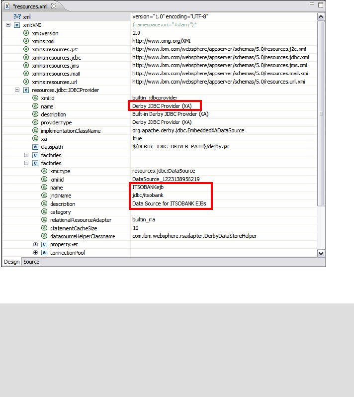
Chapter 26. Deploy enterprise applications 943
Draft Document for Review December 9, 2008 2:44 pm 7672-deploy-2-ear.fm
Figure 26-6 displays the contents of the resources.xml file that is part of the
enhanced EAR information stored in:
ibmconfig/cells/defaultCell/applications/defaultApp/deployments/defaultApp
Notice that in the ibmconfig directory are the well-known directories for a
WebSphere cell configuration. The XML editor of Application Developer displays
the configuration contents for the Derby JDBC Provider (XA) and the data
source.
Figure 26-6 Enhanced EAR: resources.xml
Note: For more detailed information and an example of using the WebSphere
enhanced EAR, refer to these sources:
Packaging applications chapter in the WebSphere Application Server V6.1:
Systems Management and Configuration, SG24-7304
IBM WebSphere Application Server v7.0 Info Center, found at:
http://publib.boulder.ibm.com/infocenter/wasinfo/v7r0/index.jsp
7672-deploy-2-ear.fm Draft Document for Review December 9, 2008 2:44 pm
944 Rational Application Developer V7.5 Programming Guide
WebSphere Rapid Deployment
WebSphere Rapid Deployment is a collection of tools and technologies
introduced in IBM WebSphere Application Server v6.1 to make application
development and deployment easier than ever before.
WebSphere Rapid Deployment consists of the following elements:
Rapid deployment tools
Fine-grained application updates
Rapid deployment tools
Using the rapid deployment tools part of WebSphere Rapid Deployment, you can
accomplish the following tasks:
Create a new Java EE application quickly without the overhead of using an
integrated development environment (IDE).
Package Java EE artifacts quickly into an EAR file.
Deploy and test Java EE modules and full applications quickly on a server.
For example, you can place full Java EE applications (EAR files), application
modules (WAR files, EJB JAR files), or application artifacts (Java source files,
Java class files, images, and JSPs) into a configurable location on your file
system, referred to as the monitored, or project, directory. The rapid deployment
tools then automatically detect added or changed parts of these Java EE artifacts
and perform the steps necessary to produce a running application on an
application server.
There are two ways to configure the monitored directory, each performing
separate and distinct tasks (as shown in Figure 26-7):
Free-form project
Automatic application installation project

Chapter 26. Deploy enterprise applications 945
Draft Document for Review December 9, 2008 2:44 pm 7672-deploy-2-ear.fm
Figure 26-7 WebSphere Rapid Deployment modes
With the free-form project approach, you can place in a single project directory
the individual parts of your application, such as Java source files that represent
servlets or enterprise beans, static resources, XML files, and other supported
application artifacts. The rapid deployment tools then use your artifacts to
automatically place them in the appropriate Java EE project structure, generate
any additional required artifacts to construct a Java EE-compliant application,
and deploy that application on a target server.
The advantage of using a free-form project is that you do not have to know how
to package your application artifacts into a Java EE application. The free-form
project takes care of the packaging part for you. The free-form project is suitable
when you just want to test something quickly, perhaps write a servlet that
performs a task.
The automatic application installation project allows you to quickly and easily
install, update, and uninstall Java EE applications on a server. If you place EAR
files in the project directory, they are automatically deployed to the server. If you
delete EAR files from the project directory, the application is uninstalled from the
server. If you place a new copy of the same EAR file in the project directory, the
and/or
J2EE
Apps
(EARs)
J2EE
Apps
(EARs)
J2EE
Apps
(EARs)
J2EE
Apps
(EARs)
J2EE
Apps
(EARs)
Client
JARs
J2EE
Apps
(EARs)
J2EE
Apps
(EARs)
WAR
J2EE
Apps
(EARs)
J2EE
Apps
(EARs)
EJB
JARs
Module Archives
Add J2EE
Applications or
Module archives
to WRD
workspace WRD
Change
Detection /
Trigger
process
Application - Installed,
Restarted, Reinstalled
or Uninstalled
V6
Application
Server
Static
File
(Image,
HTML)
Servlet,
JSP,
etc.
Java
Source Add J2EE Artifacts to
WRD workspace -
J2EE project
structure not
required WRD
Change
Detection /
Trigger
process
User creates individual
J2EE artifacts (Java
Source, Web resources,
etc.) WRD generates
J2EE artifacts
and package
Application - Installed,
Restarted, Reinstalled
or Uninstalled
Automated Application Install
Free-Form Project

7672-deploy-2-ear.fm Draft Document for Review December 9, 2008 2:44 pm
946 Rational Application Developer V7.5 Programming Guide
application is reinstalled. If you place WAR or EJB JAR files in the automatic
application installation project, the rapid deployment tool generates the
necessary EAR wrapper and then publishes that EAR file on the server. For RAR
files, a wrapper is not created. The standalone RAR files are published to the
server.
An automatic application installation project simplifies management of
applications and relieves you of the burden of going through the installation
panels in the WebSphere Administrative Console or developing wsadmin scripts
to automate your application deployment.
The rapid deployment tools can be configured to deploy applications either onto
a local or remote WebSphere Application Server.
Java and WebSphere class loader
Class loaders are responsible for loading classes, which can be used by an
application. Understanding how Java and WebSphere class loaders work is an
important element of Application Server configuration needed for the application
to work properly after deployment. Failure to set up the class loaders properly will
often result in class loading exceptions such as ClassNotFoundException when
trying to start the application.
Java class loader
Java class loaders enable the Java virtual machine (JVM) to load classes. Given
the name of a class, the class loader should locate the definition of this class.
Each Java class must be loaded by a class loader.
When the JVM is started, three class loaders are used:
Bootstrap class loader: The bootstrap class loader is responsible for loading
the core Java libraries (that is, core.jar, server.jar) in the <JAVA_HOME>/lib
directory. This class loader, which is part of the core JVM, is written in native
code.
Note: For more detailed information on WebSphere Rapid Deployment, refer
to these sources:
WebSphere Application Server V6.1: Planning and Design, SG24-7305
WebSphere Application Server V6.1: Systems Management and
Configuration, SG24-7304
IBM WebSphere Application Server v7.0 InfoCenter, found at:
http://publib.boulder.ibm.com/infocenter/wasinfo/v7r0/index.jsp
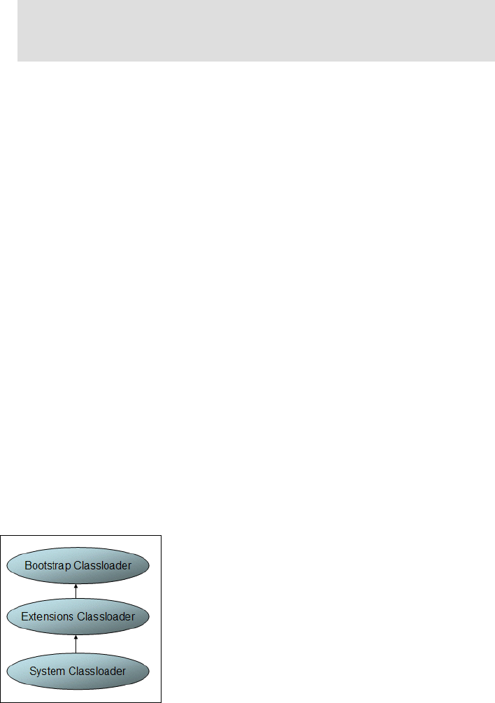
Chapter 26. Deploy enterprise applications 947
Draft Document for Review December 9, 2008 2:44 pm 7672-deploy-2-ear.fm
Extensions class loader: The extensions class loader is responsible for
loading the code in the extensions directories (<JAVA_HOME>/lib/ext or any
other directory specified by the java.ext.dirs system property). This class
loader is implemented by the sun.misc.Launcher$ExtClassLoader class.
System class loader: The system class loader is responsible for loading the
code that is found on java.class.path, which ultimately maps to the system
CLASSPATH variable. This class loader is implemented by the
sun.misc.Launcher$AppClassLoader class.
Delegation is a key concept to understand when dealing with class loaders. It
states that a custom class loader (a class loader other than the bootstrap,
extension, or system class loaders) delegates class loading to its parent before
trying to load the class itself. The parent class loader can either be another
custom class loader or the bootstrap class loader. Another way to look at this is
that a class loaded by a specific class loader can only reference classes that this
class loader or its parents can load, but not its children.
The Extensions class loader is the parent for the System class loader. The
Bootstrap class loader is the parent for the Extensions class loader. The class
loaders hierarchy is shown in Figure 26-8.
If the System class loader has to load a class, it first delegates to the Extensions
class loader, which in turn delegates to the Bootstrap class loader. If the parent
class loader cannot load the class, the child class loader tries to find the class in
its own repository. In this manner, a class loader is only responsible for loading
classes that its ancestors cannot load.
Figure 26-8 Java class loaders hierarchy
Note: Beginning with JDK 1.4, the core Java libraries in the IBM JDK are
no longer packaged in rt.jar as was previously the case (and is the case
for the Sun JDKs), but instead split into multiple JAR files.
7672-deploy-2-ear.fm Draft Document for Review December 9, 2008 2:44 pm
948 Rational Application Developer V7.5 Programming Guide
WebSphere class loader
It is important to keep in mind when reading the following material on
WebSphere class loaders, that each Java Virtual Machine (JVM) has its own
setup of class loaders. This means that in a WebSphere environment hosting
multiple application servers (JVMs), such as a Network Deployment
configuration, the class loaders for the JVMs are completely separated even if
they are running on the same physical machine.
WebSphere provides several custom delegated class loaders, as shown in
Figure 26-9. The top box represents the Java (Bootstrap, Extension, and
System) class loaders. WebSphere does not load much here, just enough to get
itself bootstrapped and initialize the WebSphere extension class loader.
Figure 26-9 WebSphere class loaders hierarchy
The WebSphere extensions class loader is where WebSphere itself is loaded. It
uses the following directories to load the required WebSphere classes:
<JAVA_HOME>\lib
<WAS_HOME>\classes (Runtime Class Patches directory, or RCP)
<WAS_HOME>\lib (Runtime class path directory, or RP)
<WAS_HOME>\lib\ext (Runtime Extensions directory, or RE)
<WAS_HOME>\installedChannels
Java class loaders
WebSphere Extension class loader
(Runtime, Library JARs)
Application class loader
(EJBs, RARs, Utility JARs) Application class loader
(EJBs, RARs, Utility JARs)
WAR
class loader
WAR
class loader
WAR
class loader
WAR
class loader
Chapter 26. Deploy enterprise applications 949
Draft Document for Review December 9, 2008 2:44 pm 7672-deploy-2-ear.fm
The WebSphere runtime is loaded by the WebSphere extensions class loader
based on the ws.ext.dirs system property, which is initially derived from the
WS_EXT_DIRS environment variable set in the setupCmdLine.bat file. The default
value of ws.ext.dirs is as follows:
SET WAS_EXT_DIRS=%JAVA_HOME%\lib;%WAS_HOME%\classes;%WAS_HOME%\lib;
%WAS_HOME%\installedChannels;%WAS_HOME%\lib\ext;%WAS_HOME%\web\help;
%ITP_LOC%\plugins\com.ibm.etools.ejbdeploy\runtime
The RCP directory is intended to be used for fixes and other APARs that are
applied to the application server runtime. These patches override any copies of
the same files lower in the RP and RE directories. The RP directory contains the
core application server runtime files. The bootstrap class loader first finds
classes in the RCP directory, then in the RP directory. The RE directory is used for
extensions to the core application server runtime.
Each directory listed in the ws.ext.dirs environment variable is added to the
WebSphere extensions class loaders class path. In addition, every JAR file
and/or ZIP file in the directory is added to the class path.
You can extend the list of directories and files loaded by the WebSphere
extensions class loaders by setting a ws.ext.dirs custom property to the Java
virtual machine settings of an application server.
Application and Web module class loaders
Java EE applications consist of five primary elements: Web modules, EJB
modules, application client modules, resource adapters (RAR files), and utility
JARs. Utility JARs contain code used by both EJBs and/or servlets. Utility
frameworks (such as log4j) are a good example of a utility JAR.
EJB modules, utility JARs, resource adapters files, and shared libraries
associated with an application are always grouped together into the same class
loader. This class loader is called the application class loader. Depending on the
application class loader policy, this application class loader can be shared by
multiple applications (EAR) or be unique for each application (the default).
By default, Web modules receive their own class loader (a WAR class loader) to
load the contents of the WEB-INF/classes and WEB-INF/lib directories. The
default behavior can be modified by changing the application's WAR class loader
policy (the default being Module). If the WAR class loader policy is set to
Application, the Web module contents are loaded by the application class
loader (in addition to the EJBs, RARs, utility JARs, and shared libraries). The
application class loader is the parent of the WAR class loader.
7672-deploy-2-ear.fm Draft Document for Review December 9, 2008 2:44 pm
950 Rational Application Developer V7.5 Programming Guide
The application and the Web module class loaders are reloadable class loaders.
They monitor changes in the application code to automatically reload modified
classes. This behavior can be altered at deployment time.
Handling JNI code
Due to a JVM limitation, code that has to access native code through a Java
Native Interface (JNI) must not be placed on a reloadable class path, but on a
static class path. This includes shared libraries for which you can define a native
class path, or the application server class path. So if you have a class loading
native code through JNI, this class must not be placed on the WAR or application
class loaders, but rather on the WebSphere extensions class loader.
It might make sense to break out just the lines of code that actually load the
native library into a class of its own and place this class on a static class loader.
This way you can have all the other code on a reloadable class loader.
Preparing for the deployment of the EJB application
This section describes the steps required to prepare the environment for the
deployment sample. We will use the ITSO Bank enterprise application developed
in Chapter 14, “Develop EJB applications” on page 387, to demonstrate the
deployment process.
This section includes the following tasks:
Reviewing the deployment scenarios
Installing the prerequisite software
Importing the sample application project interchange files
Sample database
Reviewing the deployment scenarios
Now that the Application Developer integration with Application Server is
managed the same as a standalone Application Server, the procedure to deploy
the ITSO Bank sample application is nearly identical to that of a standalone
Application Server.
There are several possible configurations in which our sample can be installed,
but in this chapter we will deploy the ITSO Bank application to a separate
production IBM Application Server v7.0. This scenario uses two nodes
(developer node, application server node).

Chapter 26. Deploy enterprise applications 951
Draft Document for Review December 9, 2008 2:44 pm 7672-deploy-2-ear.fm
Installing the prerequisite software
The application deployment sample requires that you have the software
mentioned in this section installed. Within the example, you can choose between
DB2 Universal Database or Derby as your database server. We used Derby for
this chapter and our deployment exercises.
The sample for the working example environment consists of two nodes (see
Table 26-2 for product mapping):
Developer node—This node will be used by the developer to import the
sample code and package the application in preparation for deployment.
Application server node—This node will be used as the target server where
the enterprise application will be deployed.
Table 26-2 Product mapping for deployment
Software Version
Developer node
Microsoft Windows XP + Service Pack 2 + Critical fixes
and security patches.
IBM Application Developer
* Integrated IBM Application Server V7.0
v7.5
Derby (installed by default) v10.2
Application server node
Microsoft Windows XP + Service Pack 2 + Critical fixes
and security patches.
IBM Application Server (Base stand-alone) v7.0
Derby (installed by default) v10.2
Note: For detailed information on installing the required software for the
sample, refer to Appendix A, “Product installation” on page 1121.
Tip: DB2 Universal Database or Derby
You can use DB2 or Derby as database server. Because Derby is installed by
default as part of the Application Server (integrated and stand-alone), we used
Derby as the database for this chapter and the deployment exercises.
7672-deploy-2-ear.fm Draft Document for Review December 9, 2008 2:44 pm
952 Rational Application Developer V7.5 Programming Guide
Importing the sample application project interchange files
This section describes how to import the project interchange files into Application
Developer. The RAD75EJB.zip contains the following projects for the ITSO Bank
enterprise application developed in Chapter 14, “Develop EJB applications” on
page 387:
RAD75JPA—This is the Java project that contains persistence JPA classes.
RAD75EJB—This is the EJB project with session beans.
RAD75TestWeb—This is the web project that is used to test the EJB beans.
RAD75EJBEAR—This is the EAR project for the enterprise application; it
includes the above modules.
A second project interchange file, RAD75EJBWeb.zip, contains the Web
application that uses the EJBs:
RAD75EJBWeb—This is a Web project (JSP and servlets) for the front-end
application.
RAD75EJBWebEAR—This is the EAR project for the Web application. Note
that this EAR also references the RAD75EJB and RAD75JPA projects.
To import the RAD75EJB.zip project interchange file, do these steps:
In the Java EE (or Web) perspective, Enterprise Explorer, select File →
Import.
Select Other → Project Interchange from the list of import sources and then
click Next.
In the Import Projects dialog, click Browse for the zip file, navigate to and
select the RAD75EJB.zip from the C:\7672code\zInterchangeFiles\ejb
folder, and click Open.
Click Select All to select all projects and then click Finish.
Repeat this sequence for the RAD75EJBWeb.zip file, and select the
RAD75EJBWeb and RAD75EJBWebEAR projects.
Sample database
The ITSO Bank application are based on the ITSOBANK database. Refer to
“Setting up the ITSOBANK database” on page 1154 for instructions on how to
create the ITSOBANK database. You can either use the DB2 or Derby database.
For simplicity we chose to use the built-in Derby database in this chapter.
Chapter 26. Deploy enterprise applications 953
Draft Document for Review December 9, 2008 2:44 pm 7672-deploy-2-ear.fm
To make it even simpler, we have placed the Derby database as part of the file
you have downloaded for this chapter. The ITSOBANK folder under the
C:\7672code\Database\Derby folder constitutes the Derby database. Therefore,
the complete path or location of the database is:
C:\7672code\Database\Derby\ITSOBANK
This value has to be configured for the databaseName resource property for the
data source we will define in the server (see “Configuring the data source in the
application server” on page 956). Therefore, if you configure this location in the
data source, you do not have to set up a sample Derby database, as it has
already been done for you. Make sure that you test the data source connection.
Packaging the application for deployment
This section describes the steps in preparation for packaging, as well as how to
export the enterprise application from Application Developer to an EAR file,
which is used to deploy on the application server.
This section includes the following procedures:
Removing the enhanced EAR data source
Generating the deploy code
Exporting the EAR files
Removing the enhanced EAR data source
As explained earlier, the application deployment descriptor contains enhanced
EAR information for the JDBC Provider and data source configuration. These
settings are useful when running the application within Application Developer.
As we are deploying the application to a remote application server system and
because the enhanced EAR data source configuration overrides the
administrative console configuration, the enhanced EAR data source settings
must be removed.
To remove the enhanced EAR data source settings, do these steps:
Right-click the RAD75EJBEAR project and select Java EE → Open
WebSphere Application Server Deployment.
The WebSphere Deployment editor opens.
Select Derby JDBC Provider (XA) from the JDBC provider list and click
Remove.
Save the deployment descriptor.
7672-deploy-2-ear.fm Draft Document for Review December 9, 2008 2:44 pm
954 Rational Application Developer V7.5 Programming Guide
Generating the deploy code
Previously to Java EE 5, deployment code had to be generated to be able to
deploy the EJBs to an application server. This is no more necessary for Java EE
5 application. So if you EAR contains only Java EE 5 applications you do not
have to generate deployment code. However, if you have a mix of EJB 2.x and
EJB 3.0 in your EAR then deployment code would need to be generated for the
EJB 2.x projects.
Generating the deploy code is as follows:
Make sure that you have selected the correct backend folder in the
deployment descriptor of the EJB 2.x projects, either Derby or DB2.
Deployment code is generated for the selected mapping (backend folder).
Deployment is required for EJBs 2.x. This can be performed in the IDE now,
or when installing the application on the server.
In the Enterprise Explorer, right-click the EAR project and select Prepare for
Deployment. For a Java EE 5 EAR project deployment code is only
generated for the EJB 2.x modules it contains.
You can also directly right-click the EJB 2.x projects and select Prepare for
Deployment (the Web modules do not require deployment).
Exporting the EAR files
We have two enterprise applications for the EJB sample in the workspace:
RAD75EJBEAR and RAD75EJBWebEAR. We have to export both of these enterprise
projects as EAR files.
To export the enterprise applications from Application Developer to EAR files, do
these steps:
In the Enterprise Explorer, right-click RAD75EJBEAR and select Export →
EAR file.
In the EAR Export dialog, enter the destination path (for example,
C:\7672code\deployment\RAD75EJB.ear) and click Finish (Figure 26-10). As
we are deploying the application to IBM WebSphere Application Server v7.0,
select Optimize for a specific server runtime and set to was.base v7.

Chapter 26. Deploy enterprise applications 955
Draft Document for Review December 9, 2008 2:44 pm 7672-deploy-2-ear.fm
Figure 26-10 Choices for exporting an EAR file
Repeat the export for the project RAD75EJBWebEAR.
Filtering the content of an EAR
It is possible to exclude certain files from the exported EAR, for example,
diagrams and Javadoc.
To filter (exclude) files from an EAR, do these steps:
Right-click a Java, Web, or EJB project and select Properties.
On the Source tab, expand the source folder (typically src), select Excluded
and click Edit.
In the Inclusion and Exclusion Patterns dialog, click Add to exclude files of a
given extension (for example, **/*.dnx to exclude diagrams).
Click Finish and then OK.
Manual deployment of enterprise applications
Both enterprise applications have been packaged as an EAR file and can be
deployed to the application server. This section describes the steps required to
configure the target Application Server and install the two enterprise applications.
Note: You can either use the EAR files exported in the previous section for
deployment to the target Application server, or alternatively use the solution
EAR files from the C:\7672code\jython directory of the sample code.
7672-deploy-2-ear.fm Draft Document for Review December 9, 2008 2:44 pm
956 Rational Application Developer V7.5 Programming Guide
Configuring the data source in the application server
The data source for the application server can be created in several ways,
including these:
Enhanced EAR—This is the ideal option for deploying the application to the
Integrated Application Server in Application Developer, but because we are
deploying to the stand-alone server, we are not using the enhanced EAR
functionality.
Scripting using wsadmin command line interface—For details, refer to the
Application Server v7.0 InfoCenter. This is also covered in the second part of
this chapter, which is about the automated deployment using Jython-based
wsadmin scripting.
WebSphere Administrative Console—For our example, we create and
configure the data source for the ITSO Bank application using the
administrative console of the target stand-alone Application Server v7.0.
The high-level configuration steps to configure the data source within Application
Server for the ITSO Bank application sample are as follows:
Start the application server.
If you configured the stand-alone application server as a Windows service,
you can start the server by starting its service.
Configure the JDBC provider.
Create the data source.
Start the application server
Ensure that the application server where you want to deploy the applications is
started. You can use any WebSphere Application Server, stand-alone or
configured as a profile in Application Developer.
If the server is not running, start the server in any of these ways:
Use the Windows start menu. For example, select Start → Programs → IBM
WebSphere → Application Server V7 → Profiles → default → Start
server.
If you followed the instructions in Chapter 22, “Servers and server
configuration” on page 777 and installed a second WebSphere profile, you
can start that server from the Servers view of Application Developer.
An application server can also be started using the startServer server1
command in the bin folder where the server profile is installed, for example:
C:\Program Files\IBM\WebSphere\AppServer\profiles\default\bin
<RAD_HOME>\runtimes\base_v7\profiles\was70profile1\bin

Chapter 26. Deploy enterprise applications 957
Draft Document for Review December 9, 2008 2:44 pm 7672-deploy-2-ear.fm
If you configured the stand-alone application server as a Windows service,
you can start the server by starting its service.
Start the administrative console
We use the WebSphere Administrative Console to define the data source and
install the applications. When using a server from Application Developer, you can
start the administrative console by right-clicking the server and selecting
Administration → Run administrative console. However, we recommend to
perform the configuration in an external browser to simulate a real deployment
environment.
To start the administrative console, open a Web browser (Internet Explorer,
Firefox) and use this URL:
http://<hostname>:<port>/ibm/console
http://localhost:9060/ibm/console test environment
http://localhost:9062>/ibm/console alternate profile
For a stand-alone server, you can also select Start → Programs → IBM
WebSphere → Application Server V6 → Profiles → default → Start
administrative console.
Click Login (without security, no user ID is required).
Figure 26-11 shows the Welcome page.
Tip: You can also use the WebSphere Application Server v7.0 test
environment to go through the enterprise application installation dialogs.
However, make sure that the RAD75EJBEAR and RAD75EJBWebEAR applications
are removed from the server (right-click the server and select Add and
Remove Projects).
Note: To verify that the server has started properly, you can look for the
message Server server1 open for e-business in the SystemOut.log found in
the <was_profile_root>\logs\server1 directory.

7672-deploy-2-ear.fm Draft Document for Review December 9, 2008 2:44 pm
958 Rational Application Developer V7.5 Programming Guide
Figure 26-11 Welcome page of the administrative console
Create the JDBC driver variable
If you are using Derby, verify that the WebSphere variable for the Derby JDBC
driver (DERBY_JDBC_DRIVER_PATH) is defined.
Select Environment → WebSphere Variables. Verify that
DERBY_JDBC_DRIVER_PATH is defined (Figure 26-12).
Figure 26-12 WebSphere Variable: DERBY_JDBC_DRIVER _PATH \
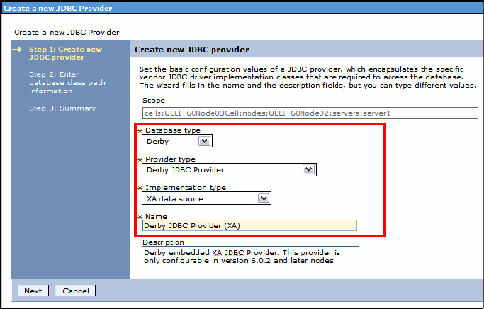
Chapter 26. Deploy enterprise applications 959
Draft Document for Review December 9, 2008 2:44 pm 7672-deploy-2-ear.fm
Configure the JDBC provider
This section describes how to configure the JDBC provider for the selected
database type. The following procedure demonstrates how to configure the
JDBC Provider for Derby:
Select Resources → JDBC → JDBC providers.
Select the server scope: Node=<hostname>Node<xx>, Server=server1
Click New.
In the Create new JDBC Providers page (Figure 26-13), do these steps:
– For Database type, select Derby.
– For JDBC Provider, select Derby JDBC Provider.
– For Implementation type, select XA data source.
– Accept the default name of Derby JDBC Provider (XA).
– Click Next.
Figure 26-13 Create a JDBC provider
For Derby, Step 2 is skipped (the class path is set correctly), and in Step 3:
Summary page, click Finish.
Click Save to the master configuration.

7672-deploy-2-ear.fm Draft Document for Review December 9, 2008 2:44 pm
960 Rational Application Developer V7.5 Programming Guide
Create the data source
We create the data source for the ITSOBANK database for the selected JDBC
provider:
Select Derby JDBC Provider (XA) for Derby or DB2 Universal JDBC Driver
Provider (XA) for DB2.
Under Additional Properties (right-hand side of page), click Data sources.
In the Data source page, click New.
Enter the basic configuration for the new Data source (Figure 26-14).
Figure 26-14 Basic configuration for the data source
–Name: RAD75DS for ITSOBANK (this can be anything).
– JNDI name: jdbc/itsobank (this must match the JNDI name that was
given in the EAR enhanced deployment descriptor (refer to Figure 26-5 on
page 942).
If you already configured a data source with the JNDI name
jdbc/itsobank, use another name, such as jdbc/itsobank1.
In the next page (Figure 26-15), enter the database name.
– Make sure that you enter the complete path of the database file. For
example, in our case this value is:
C:\7672code\database\derby\ITSOBANK
–Clear Use this data source in container managed persistence (CMP).
This is for EJB 2.x only.
– Click Next.
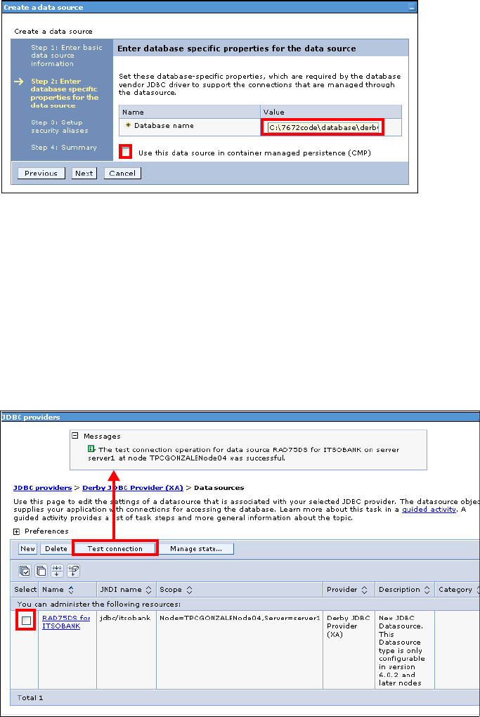
Chapter 26. Deploy enterprise applications 961
Draft Document for Review December 9, 2008 2:44 pm 7672-deploy-2-ear.fm
Figure 26-15 Enter the database path or name
Leave the next page blank (no authentication aliases are required for Derby)
and click Next.
In the summary page, verify the configuration information you entered for the
data source and click Finish.
Click Save to the master configuration.
Verify the database connection for the new data source (Figure 26-16):
– Select the data source (check box)
– Click Test connection and a message indicates success or failure.
Figure 26-16 Test connection of the data source
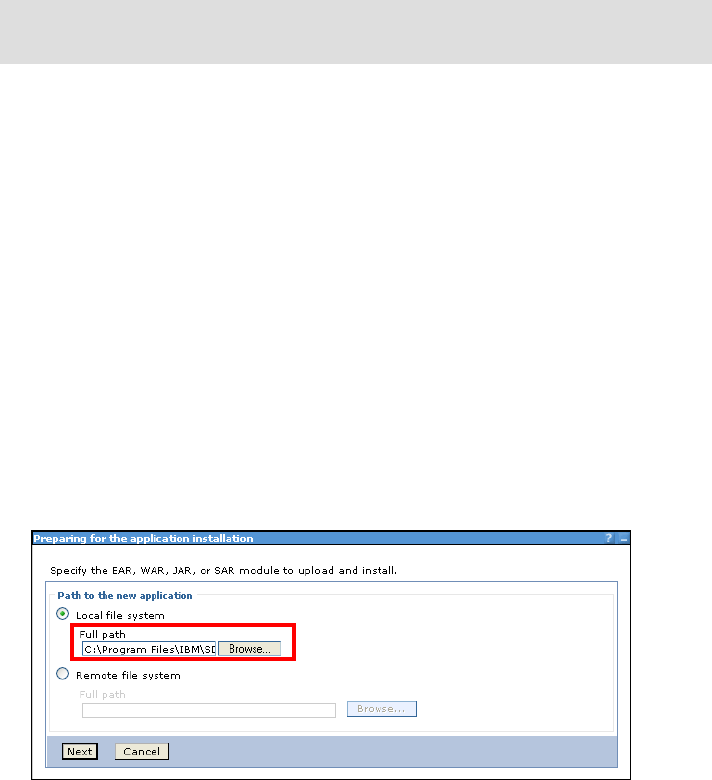
7672-deploy-2-ear.fm Draft Document for Review December 9, 2008 2:44 pm
962 Rational Application Developer V7.5 Programming Guide
Installing the enterprise applications
To install the two enterprise applications to the target application server, do these
steps:
Copy the RAD75EJBEAR.ear and RAD75EJBWebEAR.ear files from the developer
node (where you exported the files from Application Developer) to the
application server node, typically into the installableApps directory:
<AppServer_HOME>/installableApps
<RAD_HOME>/runtimes/base_v7/profiles/<profile>/installableApps
In the WebSphere Administrative Console select Applications → New
Application.
Click New Enterprise Application.
Enter the following items (Figure 26-17):
–Select
Local file system.
– Specify path: C:\.......\installableApps\RAD75EJBEAR.ear
Figure 26-17 Enterprise application installation: Specify the path to the EAR file
Click Next
Ensure that Fast Path is checked and click Next. This starts the installation
wizard.
In the Select installation options page, accept the default values and click
Next (Figure 26-18). Optionally select Precompile JavaServer Pages files
for applications with a Web module with JSPs.
Tip: If the connection fails, make sure that no connection is active from
Application Developer (in the Data perspective disconnect from ITSOBANK).

Chapter 26. Deploy enterprise applications 963
Draft Document for Review December 9, 2008 2:44 pm 7672-deploy-2-ear.fm
Figure 26-18 Enterprise application installation: Installation options
In the Map modules to servers page, accept the default values and click Next
(Figure 26-19).
Figure 26-19 Enterprise application installation: Map modules to servers
In the summary page, verify the configuration information for the new
enterprise application and click Finish to confirm (Figure 26-20).
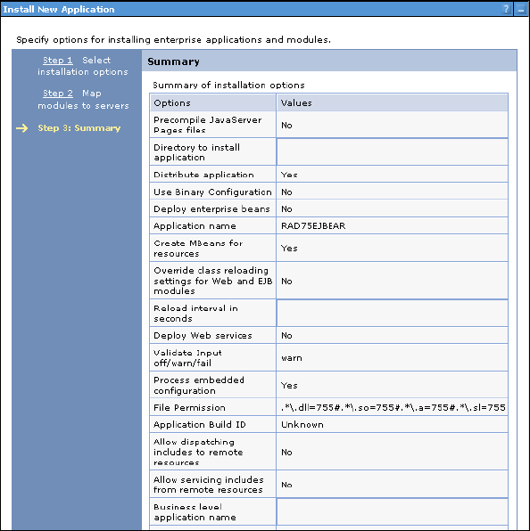
7672-deploy-2-ear.fm Draft Document for Review December 9, 2008 2:44 pm
964 Rational Application Developer V7.5 Programming Guide
Figure 26-20 Summary page for the Install Application wizard
You will see a number of messages, concluded by successful installation:
Installing...
If there are enterprise beans in the application, the EJB deployment
process can take several minutes. Do not save the configuration until the
process completes.
Check the SystemOut.log on the deployment manager or server where the
application is deployed for specific information about the EJB deployment
process as it occurs.
ADMA5016I: Installation of RAD75EJBEAR started.
......
ADMA5005I: The application RAD75EJBEAR is configured in the WebSphere
Application Server repository.
......
Application RAD75EJBEAR installed successfully.
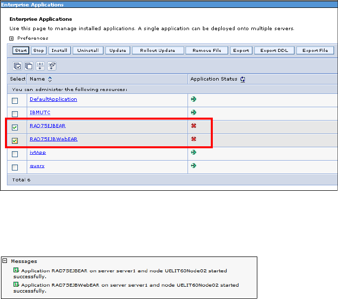
Chapter 26. Deploy enterprise applications 965
Draft Document for Review December 9, 2008 2:44 pm 7672-deploy-2-ear.fm
Click Save directly to the master configuration.
Repeat the installation steps to install the RAD75EJBWebEAR.ear enterprise
application:
– In the installation options page, select Precompile JavaServer Pages
files.
– The rest of the steps are the same.
Starting the enterprise applications
To start the enterprise applications, do these steps:
In the administrative console, select Applications → Application Types →
WebSphere enterprise applications.
Select the RAD75EJBEAR and RAD75EJBWebEAR applications and click
Start (Figure 26-21).
Figure 26-21 Start the newly deployed Enterprise application
The status for the applications changes to a green arrow, and two messages
about the successful start are displayed at the top.
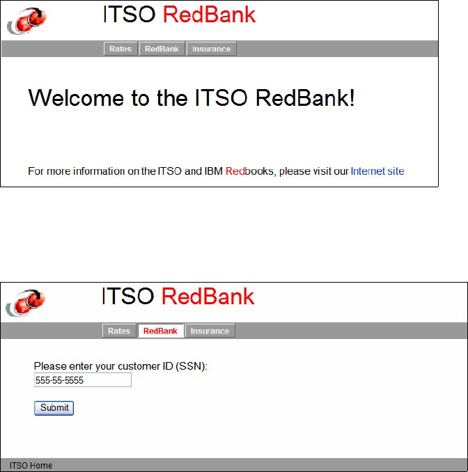
7672-deploy-2-ear.fm Draft Document for Review December 9, 2008 2:44 pm
966 Rational Application Developer V7.5 Programming Guide
Verifying the application after manual installation
To verify that the ITSO Bank sample is deployed and working properly, do these
steps:
Enter the following URL in a browser to access the ITSO Bank application:
http://<hostname>:9080/RAD75EJBWeb/ stand-alone server
http://localhost:9081/RAD75EJBWeb/ WebSphere profile
The ITSO RedBank home page is displayed (Figure 26-22).
Figure 26-22 ITSO RedBank: Home page
Click redbank and the login page is displayed. Enter a customer ID, for
example, 555-55-5555, and click Submit (Figure 26-23).
Figure 26-23 ITSO RedBank: Login page
The accounts page lists the accounts of the customer with their balance.
(Figure 26-24).
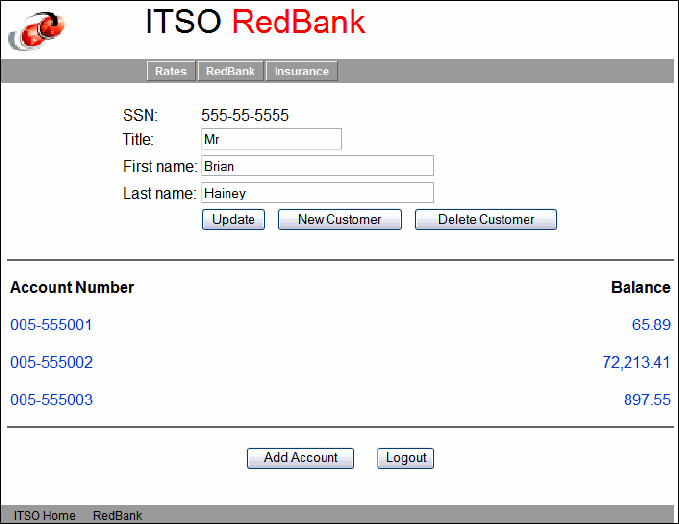
Chapter 26. Deploy enterprise applications 967
Draft Document for Review December 9, 2008 2:44 pm 7672-deploy-2-ear.fm
Figure 26-24 ITSO RedBank: Accounts page
This concludes our testing, though you can further experiment with the
application:
– Update the customer name or title.
– Click on one of the account numbers to get the account maintenance
page.
– Submit banking transactions, such as deposit, withdraw, and transfer.
– List the transactions.
– Logout.
Uninstalling the application
We also want to show deployment using automation scripts, so after testing we
uninstall the applications. This is necessary if you want to use the same server
for the automation scripts.
In the WebSphere Administrative Console, select Applications →
Application Types → WebSphere enterprise applications.
Select the two RAD75EJBxxx applications and click Stop.
7672-deploy-2-ear.fm Draft Document for Review December 9, 2008 2:44 pm
968 Rational Application Developer V7.5 Programming Guide
Select the two RAD75EJBxxx applications and click Uninstall. Click OK
when prompted to remove the applications.
Wait for the uninstall successful messages, then click Save.
Automated deployment using Jython based wsadmin
scripting
In this section we will introduce you to the WebSphere scripting client called
wsadmin, and the new scripting language used in the client, called Jython.
WebSphere Application Server’s administration model is based on the Java
Management Extensions (JMX) framework. JMX enables you to wrap hardware
and software resources in Java and expose them in a distributed environment.
WebSphere’s administrative services provides functions that use the JMX
interfaces to manipulate the application server configuration, which is stored in a
XML based repository in the server’s file system. Application Server provides the
following tools that aid in administration of its configuration:
WebSphere Administrative Console—A Web application.
Command-line commands—These executable commands can be found in
the <was_install_root>/bin folder and also in the <was_profile_root>/bin
folder.
wsadmin scripting client—A command-line interface. Scripts can be used to
automate the administration of multiple application servers and nodes.
Thin client—A lightweight runtime package that enables you to run the
wsadmin tool or a standalone administrative Java program remotely.
Overview of wsadmin
The wsadmin tool is a scripting client that has a command-line interface. It is
targeted towards advanced administrators. It provides extra flexibility that is
available through the Web based administrative console and helps make the
administration much quicker. It is primarily used to automate administrative
activities that can consist of several administrative commands and need to be
executed repetitively.
The wsadmin client uses the Bean Scripting Framework (BSF). The BSF allows
using a variety of scripting languages. Prior to WebSphere Application Server
V6, only one scripting language was supported, Java Command Language
(Jacl). Application Server now supports two languages: Jacl and Jython (or
jpython).

Chapter 26. Deploy enterprise applications 969
Draft Document for Review December 9, 2008 2:44 pm 7672-deploy-2-ear.fm
Jython is the strategic direction. New tools in WebSphere Application Server
v7.0, RAD Assembly and Deployment (RAD-AD), and Rational Application
Developer v7.5 are available to help create scripts using Jython. A Jacl-to-Jython
migration tool is included with the Application Server.
There are five wsadmin objects that are available to use in the scripts:
AdminControl— This object is used to run operational commands.
AdminConfig—This object is used to create or modify Application Server
configurational elements.
AdminApp—This object is used to administer applications.
AdminTask—This object is used to run administrative commands.
Help—This object is used to obtain general help.
Overview of Jython
Jython is an implementation of the Python language. The wsadmin tool uses
Jython V2.1. The J in Jython represents its Java-like syntax. But Jython is also
quite different than Java or C++ syntax. Though like Java, Jython is a typed,
case-sensitive, and object-oriented language, but unlike Java it is an indentation
based language, which means that it does not have any mandatory statement
termination characters (like a semi-colon in Java), and code blocks are specified
by indentation. To begin a code block, you have to indent in, and to end a block,
indent out. Statements that expect an indentation level end in a colon (:).
Functions are declared with the def keyword, and comments start with a pound
sign (#). Example 26-1 shows a Jython code snippet.
Example 26-1 Jython snippet
def listAllApps # This function lists all application
apps = AdminApp.list()
if len(apps) == 0:
print "Inside if block - No enterprise applications"
else:
print "Inside the else block"
appsList = apps.split(lSep)
for app in appsList:
print app
# This is a comment - Main section starts here
lSep = java.lang.System.getProperty('line.separator')
listAllApps # call the listAllApps function defined above

7672-deploy-2-ear.fm Draft Document for Review December 9, 2008 2:44 pm
970 Rational Application Developer V7.5 Programming Guide
Structure of a Jython script
A Jython script usually consists of method definitions and a main section. The
outline view of the Application Developer lists the methods of the script file for
easy code navigation. The main section is at the end of the Jython script and
consists of declaration of global variables, which can be used across all the
methods. The main section then calls functions (Figure 26-25).
Figure 26-25 Structure of a Jython script
Developing a Jython script to deploy the ITSO Bank
In this section we follow a step by step process and complete a Jython script that
deploys the RAD75EJBWebEAR and RAD75EJBEAR files as enterprise applications to a
target v7.0 application server. Here are the steps that have to be executed:
Create a JDBC provider.
Create and configure a data source.
Install the ITSO Bank Web application.
Install the ITSO Bank EJB application.
Start both applications.
Function
Function
Main Section
Note: We also have a section on Jython in Chapter 22, “Servers and server
configuration” in “Developing automation scripts” on page 810.
Chapter 26. Deploy enterprise applications 971
Draft Document for Review December 9, 2008 2:44 pm 7672-deploy-2-ear.fm
Preparation
In this section we create a Jython project and a Jython script in Application
Developer:
The RAD75EJBEAR.ear and RAD75EJBWebEAR.ear files are available in the
C:\7672code\deployment folder (where you exported the files), or you can use
the solution files from C:\7672code\jython.
Create a Jython project in Application Developer. If you followed the
instructions in Chapter 22, “Servers and server configuration” on page 777,
you already have this project, otherwise you can create it as follows:
– Click File → New → Project and the New Project wizard opens. Select
Jython → Jython Project and click Next.
– For the Project name, type RAD75Jython and click Finish.
Create a Jython script to deploy the ITSO Bank application:
–Select
File → New → Other → Jython → Jython Script File and click
Next.
– In the Parent folder field, specify /RAD75Python, and for the File name, type
deployITSOBankApp.py.
– Click Finish to create the Jython script file.
In the Servers view, decide which server to use for testing. You can use the
test environment or the server profile you defined in Chapter 22, “Servers and
server configuration” on page 777.
Main section of the script
Let us define our global variables first.
Open the Jython script (if you closed it).
Add the following four global variables:
global AdminConfig
global AdminControl
global AdminApp
global AdminTask
Define a global variable for the deployment server node name and the
deployment server:
nodeName = AdminControl.getNode()
srvrInfo=AdminConfig.list('Server')
srvr=AdminConfig.showAttribute(srvrInfo, 'name')
Define a global variable for the name of the new JDBC provider, the data
source, and the database:
jdbcProv = "ITSO Derby JDBC Provider (XA)"
7672-deploy-2-ear.fm Draft Document for Review December 9, 2008 2:44 pm
972 Rational Application Developer V7.5 Programming Guide
dataSourceName = "RAD75JythonDS"
jndiDS = "jdbc/itsobank2"
dbasename="C:/7672code/database/derby/ITSOBANK"
Define a global variable to store the name of the new connection factory
(used for EJB container-managed persistence):
cfname = "RAD75JythonDS_CF"
Define global variables to store the path of the EAR files and the enterprise
application names:
webappEAR = "C:/7672code/jython/RAD75EJBWebEAR.ear"
ejbappEAR = "C:/7672code/jython/RAD75EJBEAR.ear"
webappEARName = "RAD75EJBWebEAR" # display name of the enterprise App
ejbappEARName = "RAD75EJBEAR" # display name of the enterprise App
Create function calls for the six deployment steps:
createProvider() # Step 1 - Create the JDBC provider
createDS() # Step 2 - Create the data source
installApp(webappEAR, webappEARName) # Step 3 - Install ITSO Bank Web App
installApp(ejbappEAR,ejbappEARName) # Step 4 - Install ITSO Bank EJB App
startApp(ejbappEARName) # Step 5 - Start ITSO Bank EJB
startApp(webappEARName) # Step 6 - Start ITSO Bank Web App
Next we define the six functions. Note that the function code goes before the
main section.
Creating a JDBC provider
We create a function named createProvider for this purpose:
This statement defines the function createProvider, which will encapsulate
the code for creating a new JDBC provider:
def createProvider():
This code snippet checks if the JDBC provider we want to create already
exists, and if it does, then we simply return. Make sure that rest of the code
for this method is indented:
prov = AdminControl.completeObjectName("name=" + jdbcProv +
",type=JDBCProvider,Server="+srvr + ",node="+nodeName + ",*")
if len(prov) > 0:
return
#endif
Define local variables for attributes required to create a new JDBC provider:
provName=['name',jdbcProv]
impClass=['implementationClassName',
'org.apache.derby.jdbc.EmbeddedXADataSource']
jdbcAttrs=[]
jdbcAttrs.append(provName)

Chapter 26. Deploy enterprise applications 973
Draft Document for Review December 9, 2008 2:44 pm 7672-deploy-2-ear.fm
jdbcAttrs.append(impClass)
We are using a template to create the JDBC provider:
tmplName = 'Derby JDBC Provider (XA)'
templates =
AdminConfig.listTemplates("JDBCProvider",tmplName).split(lineSeparator)
tmpl = templates[0]
serverId = AdminConfig.getid("/Node:" + nodeName + "/Server:" + srvr + "/")
Create the JDBC provider using the template, save the configuration, and
end:
AdminConfig.createUsingTemplate("JDBCProvider",serverId,jdbcAttrs,tmpl)
AdminConfig.save()
#enddef
The complete code for this function is shown in Example 26-2.
Example 26-2 Create a JDBC provider using the template for Derby JDBC Provider (XA)
def createProvider():
prov = AdminControl.completeObjectName("name="+jdbcProv + ",
type=JDBCProvider,Server="+srvr + ",node="+nodeName + ",*")
if len(prov) > 0:
return
#endif
provName=['name',jdbcProv]
impClass=['implementationClassName',
'org.apache.derby.jdbc.EmbeddedXADataSource']
jdbcAttrs=[]
jdbcAttrs.append(provName)
jdbcAttrs.append(impClass)
tmplName = 'Derby JDBC Provider (XA)'
templates = AdminConfig.listTemplates("JDBCProvider", tmplName)
.split(lineSeparator)
tmpl = templates[0]
serverId = AdminConfig.getid("/Node:" + nodeName + "/Server:" + srvr + "/")
AdminConfig.createUsingTemplate("JDBCProvider",serverId,jdbcAttrs,tmpl)
AdminConfig.save()
#enddef
Creating a data source
We create a function named createDS for this purpose:
def createDS():
The following code snippet checks if the data source we want to create
already exists, and if it does, then we simply return. Once again, make sure
that rest of the code for this method is indented:

7672-deploy-2-ear.fm Draft Document for Review December 9, 2008 2:44 pm
974 Rational Application Developer V7.5 Programming Guide
dsId = AdminConfig.getid("/JDBCProvider:"+jdbcProv + "/DataSource:"+
dataSourceName + "/")
if len(dsId) > 0:
return
#endif
Define local variables for attributes required to create a data source:
dsname=['name',dataSourceName]
jndiName=['jndiName',jndiDS]
description=['description','ITSOBank Data Source']
dsHelperClassname=['datasourceHelperClassname',
'com.ibm.websphere.rsadapter.DerbyDataStoreHelper']
dsAttrs=[]
dsAttrs.append(dsname)
dsAttrs.append(jndiName)
dsAttrs.append(description)
dsAttrs.append(dsHelperClassname)
provId = AdminConfig.getid("/Node:"+nodeName + "/Server:"+srvr +
"/JDBCProvider:"+jdbcProv + "/")
Create the data source and save the configuration:
AdminConfig.create('DataSource',provId,dsAttrs)
AdminConfig.save()
We have to configure the data source and add resource property set
attributes, such as database name, password, description, and login timeout.
Because this piece of code is more than a few lines, we put the code into a
separate function. Let us define a function call:
modifyDS()
The last step is to enable the use of this data source in container-managed
persistence. We use a separate method as well:
useDSinCMP()
The code for this function is shown in Example 26-3.
Example 26-3 Create a data source
def createDS():
dsId = AdminConfig.getid("/JDBCProvider:"+jdbcProv + "/DataSource:"+
dataSourceName + "/")
if len(dsId) > 0:
return
#endif
dsname=['name',dataSourceName]
jndiName=['jndiName',jndiDS]
description=['description','ITSOBank Data Source']
dsHelperClassname=['datasourceHelperClassname',
'com.ibm.websphere.rsadapter.DerbyDataStoreHelper']
Chapter 26. Deploy enterprise applications 975
Draft Document for Review December 9, 2008 2:44 pm 7672-deploy-2-ear.fm
dsAttrs=[]
dsAttrs.append(dsname)
dsAttrs.append(jndiName)
dsAttrs.append(description)
dsAttrs.append(dsHelperClassname)
provId = AdminConfig.getid("/Node:"+nodeName + "/Server:"+srvr +
"/JDBCProvider:"+jdbcProv + "/")
AdminConfig.create('DataSource',provId,dsAttrs)
AdminConfig.save()
modifyDS() # modify DS to add the poperties (databaseName)
useDSinCMP() # enable this DS in Container Managed Persistence (CMP)
#enddef
Modify the data source with properties
Even though we have already written the code to create the data source, we still
have to add a resource property set with attributes such as the database name,
password, description, and login time out. The code in Example 26-4 is the
complete code for the modifyDS function.
Example 26-4 Add resource property set to the data source
def modifyDS():
dsId = AdminConfig.getid("/JDBCProvider:"+jdbcProv + "/DataSource:"+
dataSourceName + "/")
dbnameAttrs = [["name", "databaseName"], ["value", dbasename], ["type",
"java.lang.String"], ["description", "This is a required property"]]
descrAttrs = [["name", "description"], ["value", ""], ["type",
"java.lang.String"]]
passwordAttrs = [["name", "password"], ["value", ""], ["type",
"java.lang.String"]]
loginTimeOutAttrs = [["name", "loginTimeout"], ["value", 0], ["type",
"java.lang.Integer"]]
propset = []
propset.append(dbnameAttrs)
propset.append(descrAttrs)
propset.append(passwordAttrs)
propset.append(loginTimeOutAttrs)
pSet = ["propertySet", [["resourceProperties", propset]]]
attrs = [pSet]
AdminConfig.modify(dsId, attrs)
AdminConfig.save()
#enddef

7672-deploy-2-ear.fm Draft Document for Review December 9, 2008 2:44 pm
976 Rational Application Developer V7.5 Programming Guide
Use the data source in container-managed persistence (CMP)
We have to configure this data source for use in container-managed persistence
of entity EJBs. This is quite a simple and easy thing to do when using the
administration console (Figure 26-26), but when using a script, this is a multiple
step process. Note that for EJB 3.0 and JPA we do not have to do this.
Figure 26-26 Enabling a data source to be used in CMP
The code in Example 26-5 is the complete code for the useDSinCMP function.
Example 26-5 Enable the data source for container-managed persistence
def useDSinCMP():
dsId = AdminConfig.getid("/JDBCProvider:"+jdbcProv +
"/DataSource:"+dataSourceName + "/")
rra = AdminConfig.getid("/Node:"+nodeName+"/Server:"+srvr
+"/J2CResourceAdapter:WebSphere Relational Resource Adapter/")
nameAttr = ["name", cfname]
authmechAttr = ["authMechanismPreference", "BASIC_PASSWORD"]
cmpdsAttr = ["cmpDatasource", dsId]
attrs = []
attrs.append(nameAttr)
attrs.append(authmechAttr)
attrs.append(cmpdsAttr)
newcf = AdminConfig.create("CMPConnectorFactory", rra, attrs)
AdminConfig.save()
# Modify the CMPConnectionFactory to add the Mapping attributes
mapAuthAttr = ["authDataAlias", ""]
mapConfigaliasAttr = ["mappingConfigAlias", ""]
mapAttrs = []
mapAttrs.append(mapAuthAttr)
mapAttrs.append(mapConfigaliasAttr)
mappingAttr = ["mapping", mapAttrs]
attrs2 = []
attrs2.append(mappingAttr)

Chapter 26. Deploy enterprise applications 977
Draft Document for Review December 9, 2008 2:44 pm 7672-deploy-2-ear.fm
cfId = AdminConfig.getid("/CMPConnectorFactory:"+cfname+"/")
AdminConfig.modify(cfId, attrs2)
AdminConfig.save()
AdminConfig.modify(dsId, attrs2)
AdminConfig.save()
#enddef
Install the enterprise applications
We are at the point where we have written the code required to create a JDBC
provider and a data source for the ITSO Bank applications. Therefore, we are
ready to start installing the EAR files. The best practice is to create a generic
method that encapsulates the code to install any EAR file when provided with the
location of the EAR file and the display name of the application.
The code in Example 26-6 is the complete code for the installApp function.
Example 26-6 Install or update an enterprise application
def installApp(appEAR, appName):
try:
app = AdminApp.view(appName)
except:
options = "-appname " + appName
AdminApp.install(appEAR, options)
AdminConfig.save()
else:
if app > 1:
options = "-operation update -contents " + appEAR
contentType = 'app'
AdminApp.update(appName, contentType, options)
AdminConfig.save()
#enddef
In the main section we had already defined variables that contain the complete
path of the EAR files and also their display names. Therefore, we can use these
variables as parameters and use the installApp function to install the
RAD75EJBEAR and RAD75EJBWebEAR applications:
installApp(webappEAR, webappEARName)
installApp(ejbappEAR, ejbappEARName)
Start the enterprise applications
After installing the applications, we have to start both enterprise applications.
Again, it makes sense to create a generic function that can start any enterprise
application when provided with the display name of that application.
7672-deploy-2-ear.fm Draft Document for Review December 9, 2008 2:44 pm
978 Rational Application Developer V7.5 Programming Guide
The code in Example 26-7 is the complete code for the startApp function.
Example 26-7 Start an enterprise application
def startApp(appName):
app = AdminControl.completeObjectName
("type=Application,name="+appName+",*")
if len(app) > 1:
return
appMgr = AdminControl.queryNames
("node="+nodeName+",type=ApplicationManager,process="+srvr+",*")
AdminControl.invoke(appMgr,'startApplication',appName)
#enddef
Once again, we can use the global variables that contain the display name of
both applications and pass them as parameters to the startApp function:
startApp(ejbappEARName)
startApp(webappEARName)
Executing the Jython script
We plan to execute the Jython script against the application server that is already
configured in Application Developer.
Note that we used a JNDI name of jdbc/itsobank2 for the new data source, so
that we do not have a conflict with an existing data source in the server.
To execute the Jython script, do these steps:
Make sure that the target server is started.
Right-click deployITSOBankApp.py and select Run As → Administrative
Script.
Tip: The complete code of the deployITSOBankApp.py Jython script is
available in the sample code:
C:\7672code\jython\deployITSOBankApp.py
Import this file into the RAD75Jython project (or copy/paste from Windows
Explorer into Application Developer. In addition to the logic discussed above,
the script has many comments and produces test output to the console (print
statements) so that the execution can be followed.
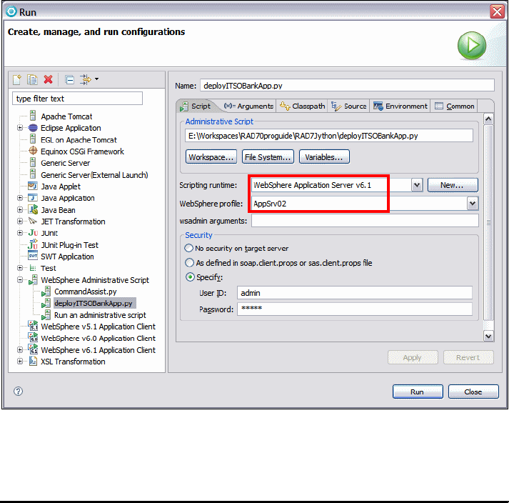
Chapter 26. Deploy enterprise applications 979
Draft Document for Review December 9, 2008 2:44 pm 7672-deploy-2-ear.fm
In the Modify attributes and launch dialog:
–Select
WebSphere Application Server V7.0 for the Scripting runtime.
– Select the WebSphere profile (was70profile1, or AppSrv01).
– Specify user ID and password if the server runs with security enabled.
– Click Run to execute the Jython script (Figure 26-27).
Figure 26-27 Select the runtime and the WebSphere profile
The console view shows the result of the execution (Example 26-8).
Example 26-8 Output of the Jython script
WASX7209I: Connected to process "server1" on node UELIT60Node02 using SOAP
connector; The type of process is: UnManagedProcess
***** STEP 1 completed - The ITSO Derby JDBC Provider (XA) has been created
Done creating the DS. Config saved ..
Done modifying the DS. Config Saved ..
***** STEP 2 completed - Done creating the DS. Config saved ..

7672-deploy-2-ear.fm Draft Document for Review December 9, 2008 2:44 pm
980 Rational Application Developer V7.5 Programming Guide
***** App not found: RAD75EJBWebEAR. Installing it now
ADMA5016I: Installation of RAD75EJBWebEAR started.
ADMA5058I: Application and module versions are validated with versions of
deployment targets.
ADMA5005I: The application RAD75EJBWebEAR is configured in the WebSphere
Application Server repository.
ADMA5053I: The library references for the installed optional package are
created.
ADMA5005I: The application RAD75EJBWebEAR is configured in the WebSphere....
ADMA5001I: The application binaries are saved in C:\<WAS_HOME>\profiles
\AppSrv02\wstemp\Script1144d386b1d\workspace\cells\<cell>
\applications\RAD75EJBWebEAR.ear\RAD75EJBWebEAR.ear
ADMA5005I: The application RAD75EJBWebEAR is configured in the WebSphere ...
SECJ0400I: Successfuly updated the application RAD75EJBWebEAR with the
appContextIDForSecurity information.
ADMA5011I: The cleanup of the temp directory for application RAD75EJBWebEAR is
complete.
ADMA5013I: Application RAD75EJBWebEAR installed successfully.
***** Done installing App: RAD75EJBWebEAR. Config saved ..
***** App not found: RAD75EJBEAR. Installing it now
ADMA5016I: Installation of RAD75EJBEAR started.
......
ADMA5013I: Application RAD75EJBEAR installed successfully.
***** Done installing App: RAD75EJBEAR. Config saved ..
***** The startApplication operation for RAD75EJBEAR completed.
***** The startApplication operation for RAD75EJBWebEAR completed.
Verifying the application after automatic installation
You can find the ITSO Derby JDBC Provider (XA) and the RAD75Jython data
source using the Administrative Console.
To verify that the ITSO Bank sample is deployed and working properly, follow the
instructions in “Verifying the application after manual installation” on page 966.
The verification concludes this chapter, as we have successfully deployed our
enterprise applications, both manually by using the WebSphere Administrative
Console, and also by using the Jython scripting with the Jython tooling provided
by Application Developer v7.5.
Chapter 26. Deploy enterprise applications 981
Draft Document for Review December 9, 2008 2:44 pm 7672-deploy-2-ear.fm
Generation Jython source code for wsadmin commands
WebSphere Application Server provides a WebSphere Administration Command
assist tool that can be used to generate the Jython source code for administrative
activities. For further information and an example of using this tool, refer to
“Generating WebSphere admin commands for Jython scripts” on page 813.
More information
For more information on application deployment, refer to these resources:
WebSphere Application Server v7.0 Information Center:
http://publib.boulder.ibm.com/infocenter/wasinfo/v6r1/index.jsp?topic=/com.
ibm.websphere.base.doc/info/welcome_base.html
Understand WebSphere Extended Deployment:
http://www.ibm.com/developerworks/autonomic/library/ac-webxd/
Learn how to publish an enterprise application with WebSphere Application
Server and Application Server Toolkit, v6.1:
http://www.ibm.com/developerworks/edu/wes-dw-wes-hellowas.html
7672-deploy-2-ear.fm Draft Document for Review December 9, 2008 2:44 pm
982 Rational Application Developer V7.5 Programming Guide

© Copyright IBM Corp. 2008. All rights reserved. 983
Draft Document for Review December 9, 2008 2:44 pm 7672-deploy-3-profile.fm
Chapter 27. Profile applications
Profiling is a technique used by developers to collect runtime data and detect
application problems such as memory leaks, performance bottlenecks, excessive
object creation, and exceeding system resource limits during the development
phase.
This chapter introduces the features, architecture, and process for profiling
applications using the profiling features of IBM Rational Application Developer
v7.5. We have included an example for basic memory analysis, execution time
analysis, and method code coverage analysis.
The chapter is organized into the following sections:
Introduction to profiling
Preparing for the profiling sample
Profiling a Java application
Profiling a Web application running on the server
27
7672-deploy-3-profile.fm Draft Document for Review December 9, 2008 2:44 pm
984 Rational Application Developer V7.5 Programming Guide
Introduction to profiling
Traditionally, performance analysis is performed once an application is getting
close to deployment or after it has already been deployed. The profiling tools
included with Application Developer allow the developer to move the
performance analysis to a much earlier phase in the development cycle, thus
providing more time for changes to the application that might effect the
architecture of the application before they become critical production
environment issues.
The types of problems that Application Developer profiling tooling can assist in
detecting include:
Memory usage problems
Performance bottlenecks
Excessive object creation
System resource limits
The profiling tools can be used to gather data on applications that are running:
Inside an application server, such as WebSphere Application Server
As a standalone Java application
On the same system as Application Developer
On a remote WebSphere Application Server with the IBM Rational Agent
Controller installed
In multiple JVMs
Profiling features
Within Application Developer, there are several analysis types. Each analysis
type includes associated views that provides the user with the ability to
concentrate on particular types of analysis such as memory leaks, performance
bottlenecks, and excessive object creation while profiling an application.
The following analysis types and their associated views are described in this
section:
Basic memory analysis
Execution time analysis
Method code coverage analysis
Probekit analysis

Chapter 27. Profile applications 985
Draft Document for Review December 9, 2008 2:44 pm 7672-deploy-3-profile.fm
Basic memory analysis
Basic memory analysis displays statistics about the application heap. It is used to
detect memory management problems. Memory analysis can help developers
identify memory leaks as well as excessive object allocation that might cause
performance problems. Basic memory analysis has been enhanced with the
views described in Table 27-1.
Table 27-1 Basic memory analysis views
Execution time analysis
Execution time analysis is used to detect performance problems by highlighting
the most time intensive areas in the code. This type of analysis helps developers
identify and remove unused or inefficient coding algorithms. Execution time
analysis has been enhanced with the views described in Table 27-2.
Table 27-2 Execution time analysis views
View name Description
Memory statistics Displays statistics about the application heap. It provides
detailed information such as the number of classes loaded, the
number of instances that are alive, and the memory size
allocated by every class.
Object references Displays references by a set of objects. This is useful to study
data structures, to find memory leaks, and to find unexpected
references.
View name Description
Execution statistics Displays statistics about the application execution time.
Call tree Displays information about method calls during the
profiling session in a form that lets easily identify a hot
spot. It consists of two parts , the execution flow call tree
and call stack view.
Method invocation Displays a graphical representation of the entire course of
a program's execution and also provides the ability to
navigate through the methods that invoked the selected
method.
Method invocation details Displays statistical data on a selected method.
Object references Displays references by a set of objects. This is useful to
study data structures, to find memory leaks, and to find
unexpected references.
UML2 trace interactions Displays execution flow of an application according to the
notation defined by UML.
7672-deploy-3-profile.fm Draft Document for Review December 9, 2008 2:44 pm
986 Rational Application Developer V7.5 Programming Guide
Method code coverage analysis
Method code coverage analysis is used to detect areas of code that have not
been executed in a particular scenario that is tested. This capability is a useful
analysis tool to integrate with component test scenarios and can be used to
assist in identifying test cases that might be missing from a particular test suite or
code that is redundant. Method code coverage analysis has been enhanced with
the view described in Table 27-3.
Table 27-3 Method code coverage view
Probekit analysis
Probes are reusable Java code fragments that you write to collect detailed
runtime data about a program's objects, instance variables, arguments, and
exceptions. Probekit provides a framework on the Eclipse platform to help you
create and use probes. One common use of Probekit is to create lightweight
profilers that collect only the data developers are interested in.
A probekit file can contain one or more probes, with each containing one or more
probe fragments. These probes can be specified when to be executed or on
which program they will be used. The probe fragments are a set of Java methods
that are merged with standard boilerplate code with a new Java class generated
and compiled. The functions generated from the probe fragments appear as
static methods of the generated probe class.
The probekit engine—also called the byte-code instrumentation (BCI) engine—is
used to apply probe fragments by inserting the calls into the target programs.
The insertion process of the call statements into the target methods is referred to
as instrumentation. The data items requested by a probe fragment are passed
as arguments (for example, method name and arguments). The benefit of this
approach is that the probe can be inserted into a large number of methods with
small overhead.
Probe fragments can be executed at the following points:
At method entry or exit time
At exception handler time
Before the original code in the class static initializer
Before every executable code when source code is available
When specific methods are called, not inside the called method
View name Description
Coverage statistics Displays usage statistics for a selected type of object.
Chapter 27. Profile applications 987
Draft Document for Review December 9, 2008 2:44 pm 7672-deploy-3-profile.fm
Each of the probe fragments can access the following data:
Package, class, and method name
Method signature
this object
Arguments
Return value
There are two major types of probes available to the user (Table 27-4).
Table 27-4 Types of probes available with Probekit
Profiling architecture
The profiling architecture that exists in Application Developer is based on the
Eclipse Test & Performance Tools Platform (TPTP) project. More detailed
information on the Eclipse TPTP project can be found at:
http://www.eclipse.org/tptp/
In the past TPTP workbench users required the services of the standalone Agent
Controller before they could use the function in the Profiling and Logging
perspective and in the Test perspective. Even when the user tried to profile a
Java application locally or to run TPTP tests locally, the Agent Controller would
have to be installed on the local machine.
The Integrated Agent Controller is a new feature in the TPTP workbench, which
allows users to profile a Java application locally and to run a TPTP test locally
without requiring the standalone Agent Controller on the local machine. Profiling
on a remote machine or running a TPTP test on a remote machine still requires
the Agent Controller on that remote machine.
This feature is packaged in the TPTP runtime install image and therefore no
separate install step is required. The Integrated Agent Controller does not require
any configuration at all. Unlike the Agent Controller, which requires the user to
enter information, such as the path for the Java executable, the Integrated Agent
Controller determines the required information from the Eclipse workbench
during startup.
Type of probe Description
Method probe Probe can be inserted anywhere within the body of a method with the
class or jar files containing the target methods instrumented by the
BCI engine.
Callsite probe Probe is inserted into the body of the method that calls the target
method. The class or jar files that call the target instrumented by the
BCI engine.
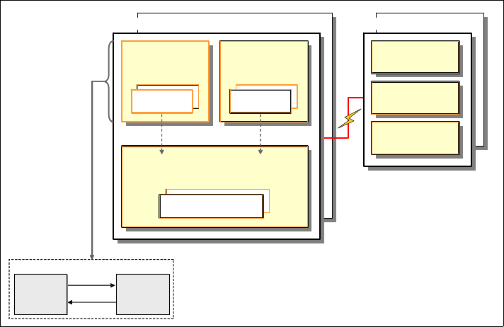
7672-deploy-3-profile.fm Draft Document for Review December 9, 2008 2:44 pm
988 Rational Application Developer V7.5 Programming Guide
TPTP provides the Agent Controller daemon with a process for enabling client
applications to launch host processes and interact with agents that exist within
host processes. Figure 27-1 shows the profiling architecture.
Figure 27-1 Profiling architecture of IBM Rational Application Developer V7.0
The definitions for the profiling architecture are as follows:
Application process: The process that is executing the application
consisting of the Java Virtual Machine (JVM) and the profiling agent.
Agent: The profiling component installed with the application that provides
services to the host process, and more importantly, provides a portal by which
application data can be forwarded to attached clients.
Test Client: A local or remote application that is the destination of host
process data that is externalized by an agent. A single client can be attached
to many agents at once, but does not always have to be attached to an agent.
Agent Controller: A daemon process that resides on each deployment host
providing the mechanism by which client applications can either launch new
host processes, or attach to agents coexisting within existing host processes.
The Agent Controller can only interact with host processes on the same node.
Application Developer comes with an integrated agent controller, therefore, a
separate install of the agent controller is not required.
Deployment hosts: The host that an application has been deployed to and is
being monitored for the capture of profiling agent.
Development Hosts
JVMPI
Events
Controls
Eclipse Plug-ins-
Test Client
JDK
IBM Agent Controller
Service
Service
Service
Service
Deployment Hosts
Application
Process
Agent
Agent
Application
Process
Agent
Agent
Profiler
Agent
Java
Virtual
Machine

Chapter 27. Profile applications 989
Draft Document for Review December 9, 2008 2:44 pm 7672-deploy-3-profile.fm
Development hosts: The host that runs an Eclipse-compatible architecture
such as Application Developer to receive profiling information and data for
analysis.
Each application process shown in Figure 27-1 represents a JVM that is
executing a Java application that is being profiled. A profile agent will be attached
to each application to collect the appropriate runtime data for a particular type of
profiling analysis. This profiling agent is based on the Java Virtual Machine
Profiler Interface (JVMPI) architecture. More details on the JVMPI specification
can be found at:
http://java.sun.com/j2se/1.4.2/docs/guide/jvmpi
The data collected by the agent is then sent to the Agent Controller, which then
forwards this information to Application Developer for analysis and visualization.
There are two types of profiling agents available in Application Developer:
Java Profiling Agent: This agent is based on the JVMPI architecture and is
shown in Figure 27-1. This agent is used for the collection of both standalone
Java applications as well as applications running on an application server.
J2EE Request Profiling Agent: This agent resides in an application server
process and collects runtime data for J2EE applications by intercepting
requests to the EJB or Web containers.
Profiling and Logging perspective
The Profiling and Logging perspective can be accessed by selecting Window →
Open Perspective → Other → Profiling and Logging and then clicking OK. If it
is not listed, click Show all.
If Profiling and Logging is not enabled in the workspace, you are prompted to
enable this capability. Click OK.
There are many supporting views for the Profiling and Logging perspective. To
see the supporting views select Window → Show View → Other under Profiling
and Logging (Figure 27-2):
Note: There is only one instance of the J2EE Request Profiling agent that
is active in a process that hosts WebSphere Application Server.

7672-deploy-3-profile.fm Draft Document for Review December 9, 2008 2:44 pm
990 Rational Application Developer V7.5 Programming Guide
Figure 27-2 Profiling and Logging views
Preparing for the profiling sample
This section describes the tasks that have to be completed prior to profiling the
sample Web application. We use the Web application developed in Chapter 14,
“Develop EJB applications” on page 387, as our sample application for profiling.
Complete the following tasks in preparation for the profiling sample:
Prerequisite software installation
Enabling the Profiling and Logging capability
Prerequisite software installation
The working example requires the following software be installed:
IBM Rational Application Developer v7.5
Integrated Agent Controller
This feature is packaged in the Application Developer install image and
therefore no separate install step is required.
Enabling the Profiling and Logging capability
To enable the Profiling and Logging capability in the preferences, do these steps:
Select Window → Preferences.
In the Preferences dialog expand General → Capabilities and click
Advanced (Figure 27-3).

Chapter 27. Profile applications 991
Draft Document for Review December 9, 2008 2:44 pm 7672-deploy-3-profile.fm
Figure 27-3 Enable Profiling and Logging capability (1)
In the Advanced dialog expand Tester, and select Profiling and Logging
(Figure 27-4) and click OK.
Note: If you want to use the Probekit, you have to enable this capability by
selecting Probekit (Figure 27-4).

7672-deploy-3-profile.fm Draft Document for Review December 9, 2008 2:44 pm
992 Rational Application Developer V7.5 Programming Guide
Figure 27-4 Enable Profiling and Logging capability (2)
Profiling a Java application
In this section we profile a Java application. We import the sample code and run
the application in profiling mode.
Importing the sample project interchange file
To import the JPA application project interchange file, do these steps:
Open the Java EE perspective.
Select File → Import.
In the Import dialog, select Project Interchange and click Next.
In the Import Projects dialog, click Browse and locate the file:
c:\7672code\zInterchange\jpa\RAD75JPA.zip
Select the RAD75JPA and RAD75JPATest projects, and click Finish.
Alternatively you can run the Java application (BankClient) in the RAD75Java
project in profiling mode.
Tip: If you have the sample JPA application (RAD75JPA and RAD75JPATest
projects) already in the workspace, skip this step.

Chapter 27. Profile applications 993
Draft Document for Review December 9, 2008 2:44 pm 7672-deploy-3-profile.fm
Creating a profiling configuration
We use the EntityTester class (in RAD75JPATest itso.bank.entities.test) as
sample application. Refer to “Testing JPA entities” on page 295 for a description
of the EntityTester class.
Right-click EntityTester and select Profile As → Profile Configurations.
In the Profile Configurations dialog, double-click Java Application, and an
entry named EntityTester is added and opened.
In the Arguments tab, type 333-33-3333 as Program arguments, and
-javaagent:<RAD_HOME>/runtimes/base_v7/plugins/com.ibm.ws.jpa.jar
as VM arguments (Figure 27-5).
Figure 27-5 Profile Configuration: Arguments
In the Monitor tab, select Execution Time Analysis (Figure 27-6). Note that
you can only select one of the four options.
Important: If you do not already configured the data source settings for the
ITSOBANK database, follow the steps in “Configuring the data source for the
ITSOBANK” on page 413 before publishing and running the sample
application.
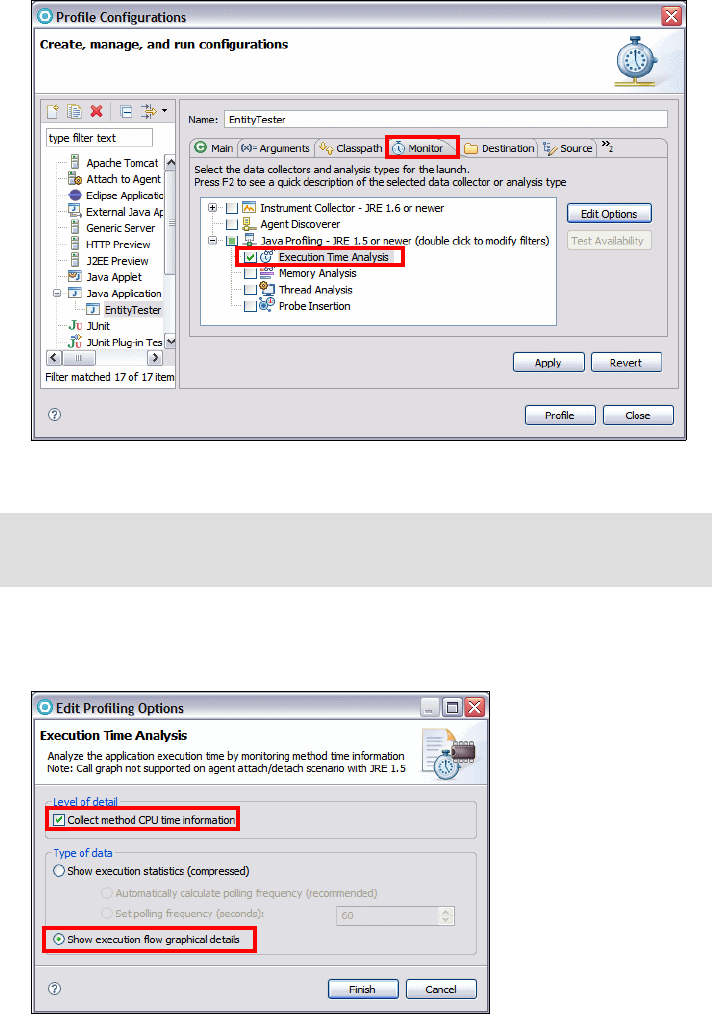
7672-deploy-3-profile.fm Draft Document for Review December 9, 2008 2:44 pm
994 Rational Application Developer V7.5 Programming Guide
Figure 27-6 Profile Configuration: Monitor
Click Edit Options, and in the Edit Profiling Options dialog, select Collect
method CPU time information, and click Finish (Figure 27-7).
Figure 27-7 Profiling options for execution time analysis
Note: You can only select one analysis type. Refer to the technote:
http://www-01.ibm.com/support/docview.wss?uid=swg21328379

Chapter 27. Profile applications 995
Draft Document for Review December 9, 2008 2:44 pm 7672-deploy-3-profile.fm
Click Apply to save the configuration.
Running the EntityTester application
To run the application, click Profile.
When prompted, click Yes to switch to the Profiling and Logging perspective.
In the Profiling Monitor view you can see that Execution Time is being
measured.
In the Console view you can see that program running through its parts and
displaying the output (Figure 27-8).
Figure 27-8 EntityTester run in profiling mode
Analyzing profiling data
We have now run the sample application that we want to collect data for. In this
section, we analyze the collected data for execution statistics.
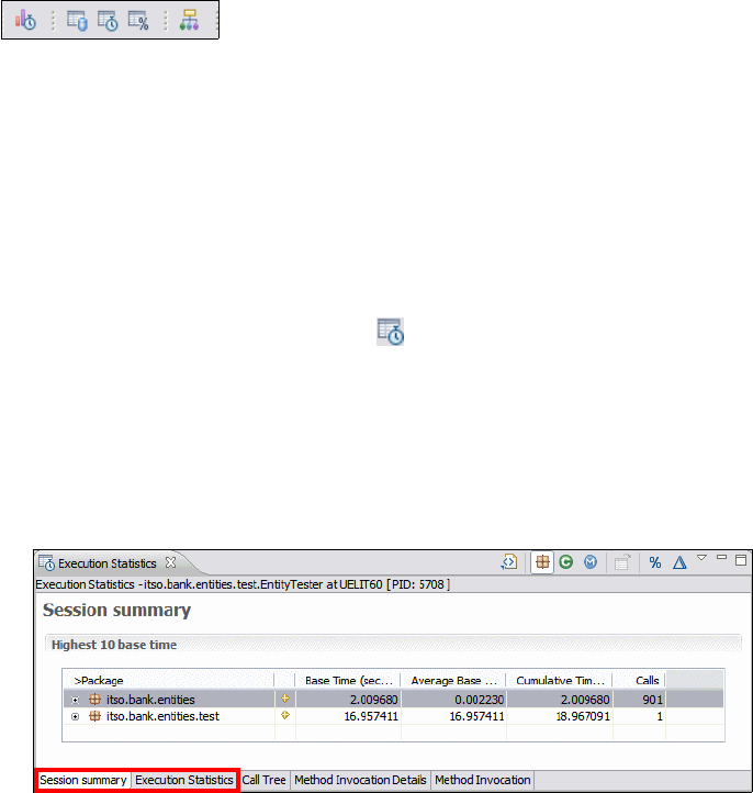
7672-deploy-3-profile.fm Draft Document for Review December 9, 2008 2:44 pm
996 Rational Application Developer V7.5 Programming Guide
To display the collected data, we use the toolbar icons (Figure 27-9).
Alternatively, you can right-click the process and select Open With → statistic:
Open Execution Flow
Open Memory Statistics
Open Execution Statistics
Open Coverage Statistics
Open Object References
Figure 27-9 Profiling statistics icons
Execution statistics
The Execution Statistics view displays statistics about the application execution
time. It provides data such as the number of methods called, and the amount of
time taken to execute every method. Execution statistics are available at the
package, class, method and instance level.
To analyze the execution statistics, in the Profiling Monitor view, double-click
Execution Time Analysis, or click the icon, or right-click the entry and select
Open With → Execution Statistics.
The Session summary and the Execution Statistics tab show the same
data, using different filters. On the Execution Statistics tab you can set the
filter, for example, No filter (our selection), Highest 10 base time (which is
the filter for the Session summary), Highest 10 cumulative time, and so
forth (Figure 27-10).
Figure 27-10 Execution time Statistics: Summary
Expand the packages and classes to see the accumulated values per class or
per method (Figure 27-11).
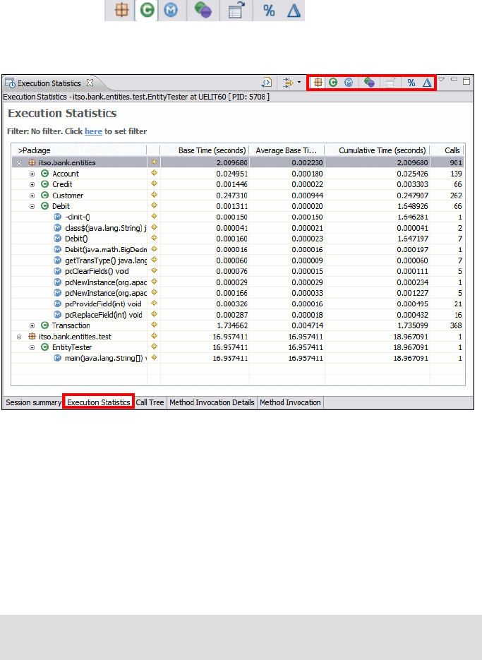
Chapter 27. Profile applications 997
Draft Document for Review December 9, 2008 2:44 pm 7672-deploy-3-profile.fm
Notice the icons to switch to package, class,
method, and instance views, to open the source, to display data as
percentages, and to add delta columns.
Figure 27-11 Execution Time Statistics: Expanded
For each object type, the following statistics are displayed:
–Base Time: The time taken to execute the invocation (excluding time
spent in called methods).
–Average Base Time: The base time divided by the number of calls.
–Cumulative Time: The time taken to execute the invocation (including
time spent in called method).
–Calls: The number of calls made to the package, class, or method.
Call Tree
Select the Call Tree tab. Expand main → main → processTransaction →
Credit to analyze the call tree and the percent of time spent in each method of
the tree (Figure 27-12).
Note: The JPA entity classes include a number of generated methods with
the pc prefix that are generated for database access.

7672-deploy-3-profile.fm Draft Document for Review December 9, 2008 2:44 pm
998 Rational Application Developer V7.5 Programming Guide
Figure 27-12 Execution Time Analysis: Call Tree
Method invocation details
Expand Account to see the methods of the Account class. Select
processTransaction and select Method Invocation Details (Figure 27-13).
The Method Invocation Details view provides statistical data on a selected
method. The following data is displayed for the selected method:
Selected method (Account.processTransaction): Shows details including
the number of times the selected method is called, the class and package
information, and the time taken by this method.
Selected method invoked by: Shows details of each method that calls the
selected method, including the number of calls to the selected method, and
the number of times the selected method is invoked by the caller. In our case,
the main method invokes the processTransaction method.
Selected method invokes: Shows details of each method invoked by the
selected method, for example, Credit and Debit constructors, setAccount of
the Transaction class, and internal JPA methods.

Chapter 27. Profile applications 999
Draft Document for Review December 9, 2008 2:44 pm 7672-deploy-3-profile.fm
Figure 27-13 Execution Time Analysis: Method Invocation Details
Select the Method Invocation tab to see a graphical representation of the
calls (Figure 27-14).
Figure 27-14 Execution Time Analysis: Method invocation

7672-deploy-3-profile.fm Draft Document for Review December 9, 2008 2:44 pm
1000 Rational Application Developer V7.5 Programming Guide
Execution flow
The Execution Flow view and table both show a representation of the entire
program execution. In this view, the threads of the program fit horizontally, and
time is scaled so that the entire execution fits vertically. In the table, the threads
are grouped in the first column and time is recorded in successive rows.
In the Profiling Monitor view, click the Open Execution Flow icon , or select
Open With → Execution Flow (Figure 27-29).
The bottom pane displays the action sequence. Expand main and select the
first main method.
The top pane shows the execution stripes (Figure 27-15).
Figure 27-15 Execution Flow
Select the Zoom In icon and click into the column to see more details.

Chapter 27. Profile applications 1001
Draft Document for Review December 9, 2008 2:44 pm 7672-deploy-3-profile.fm
UML sequence diagrams
You can also analyze the graphical details of the execution flow using the data
collected with Execution Time Analysis. These graphical details are displayed
using the UML sequence diagram notation. The representation of time in these
diagrams helps in determining bottlenecks in application performance as well as
network communication. The following types of diagrams are available:
UML2 Class Interactions: Shows interactions of classes that participate in
the execution of an application.
UML2 Object Interactions: Shows interactions of objects that participate in
the execution of an application.
UML2 Thread Interactions: Shows interactions of methods that execute in
different threads, which participate in the execution of an application.
To display UML2 interaction diagrams, do these steps:
In the Profiling Monitor view, right-click the entry and select Open With →
UML2 Class interactions (Figure 27-16). You have to scroll to find suitable
interactions.
Figure 27-16 UML2 Interaction
The other two UML diagrams are very similar: UML2 Object Interactions and
UML2 Thread Interactions.
The appearance can be
configured through
Window → Preferences
→ Profiling and Logging
→ Appearance → UML2
Sequence Diagram
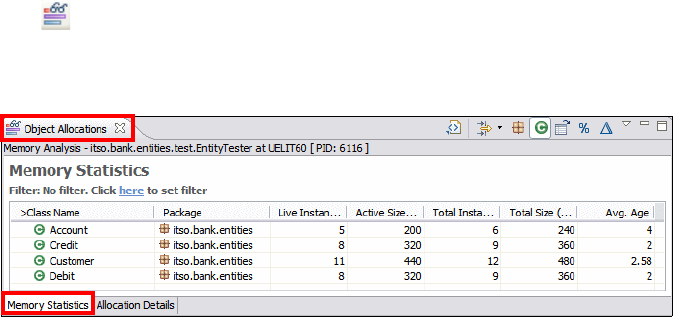
7672-deploy-3-profile.fm Draft Document for Review December 9, 2008 2:44 pm
1002 Rational Application Developer V7.5 Programming Guide
You can drill down into a lifeline that allows you to view all the trace interactions
within a particular lifeline (right-click the class and select Drill down into
selected lifeline). This feature helps to trace the root cause of a problem from a
host, to a process, to a thread, and eventually to a class or an object.
You can highlight a call stack to view all the methods invocations in a call stack by
right-clicking a method and selecting Highlight call stack.
Memory statistics
The Memory Statistics view displays statistics about the application heap. It
provides detailed information such as the number of classes loaded, the number
of instances that are alive, and the memory size allocated by every class.
Memory statistics are available at the package, class, and instance level.
To analyze the memory consumption, we have to rerun the application with
another profiling option.
Select Run → Profile Configurations. In the Profile Configurations dialog,
select the EntityTester (preselected).
In the Monitor tab, select Memory Analysis.
Click Edit Options and select Track object allocation sites. Click Finish.
Click Apply, then click Profile.
A new entry opens in the Profiling Monitor view. The Console view shows the
application output while it runs to completion.
Double-click Memory Analysis, or click the Open Object Allocations view
icon .
The Object Allocations view displays live and total instances, active and total
size, and average age (Figure 27-17).
Figure 27-17 Object Allocations
Select a class (Credit) and select the Allocation Details tab (Figure 27-18).
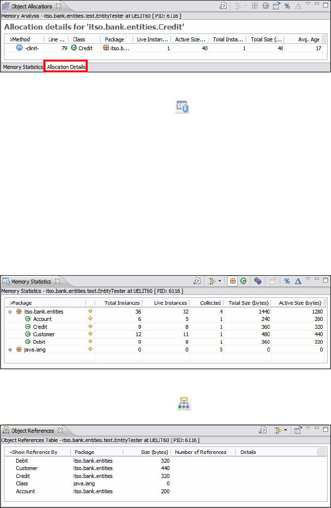
Chapter 27. Profile applications 1003
Draft Document for Review December 9, 2008 2:44 pm 7672-deploy-3-profile.fm
Figure 27-18 Object Allocation Details
Click the Open Memory Statistics icon .
The Memory Statistics (Figure 27-19) displays:
–Total Instances: Shows the total number of instances that had been
created of the selected package, class, or method.
–Live Instances: Shows the number of instances of the selected package,
class, or method, where no garbage collection has taken place.
–Collected: Shows the number of instances of the selected package, class,
or method, that were removed during garbage collection.
–Total Size: Shows the total size in bytes of the selected package, class, or
method, of all instances that were created for it.
–Active Size: Shows the total number of size of all live instances.
Figure 27-19 Memory Statistics
Click the Open Object References icon (Figure 27-20).
Figure 27-20 Object References
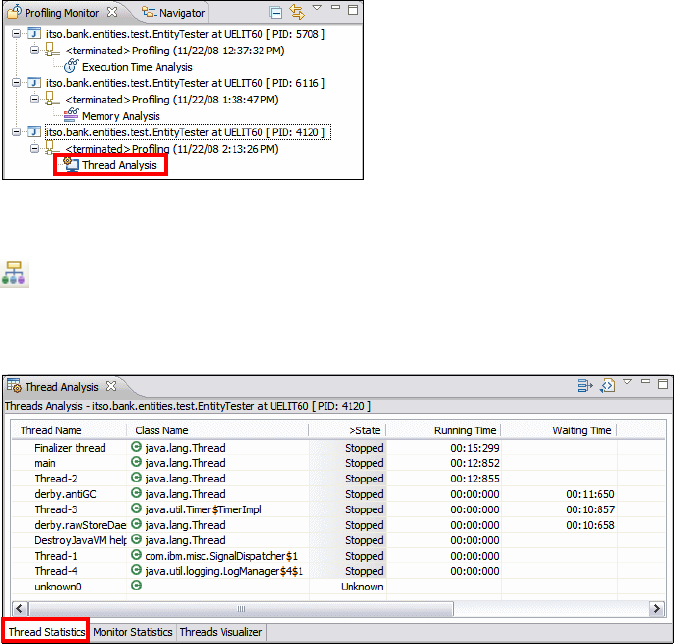
7672-deploy-3-profile.fm Draft Document for Review December 9, 2008 2:44 pm
1004 Rational Application Developer V7.5 Programming Guide
Thread analysis
To analyze the threads, we have to rerun the application with another profiling
option.
Select Run → Profile Configurations.
For the EntityTester class, in the Monitor tab, select Thread Analysis.
Click Edit Options and select Contention analysis. Click Finish.
Click Apply, then click Profile.
A new entry opens in the Profiling Monitor view (Figure 27-21).
Figure 27-21 profiling Monitor with three runs
Double-click Thread Analysis, or click the Open Thread Analysis view icon
.
The Thread Statistics tab shows the state, running and waiting time of the
threads (Figure 27-22).
Figure 27-22 Thread Analysis: Thread Statistics
The Monitor Statistics tab shows the details of a selected thread, including
the Java classes involved.
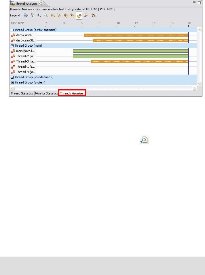
Chapter 27. Profile applications 1005
Draft Document for Review December 9, 2008 2:44 pm 7672-deploy-3-profile.fm
The Thread Visualizer tab shows the threads that were active, and the time
when they were active (Figure 27-23). we can see two threads for the Derby
database and 5 threads for the application code.
Figure 27-23 Thread Analysis: Visualizer
Reports
For several statistics you can create a report in comma-separated-values (CSV),
HTML, or XML format by clicking the New Report icon .
Clean up
You can remove measurements by right-clicking an entry in the Profiling Monitor
view and selecting Delete.
Profiling a Web application running on the server
In this section we run a Web application in the WebSphere Application Server
v7.0 in profiling mode.
Importing the sample project interchange file
Tip: If you have the ITSO RedBank Web application (RAD75EJBEAR and
dependent projects) already in the workspace, skip this step.

7672-deploy-3-profile.fm Draft Document for Review December 9, 2008 2:44 pm
1006 Rational Application Developer V7.5 Programming Guide
To import the ITSO RedBank Web application project interchange file, do these
steps:
Open the Java EE perspective.
Select File → Import.
In the Import dialog, select Project Interchange and click Next.
In the Import Projects dialog, click Browse and locate the file:
c:\7672code\zInterchange\ejb\RAD75EJB.zip
Select the RAD75JPA and RAD75EJB projects, and click Finish.
Repeat the import for the interchange file:
c:\7672code\zInterchange\ejb\RAD75EJBWeb.zip
Select the RAD75EJBWeb and RAD75EJBWebEAR projects, and click
Finish.
Publishing and running sample application
The sample application has to be published to the WebSphere Application
Server, prior to running the application server in profile mode.
To publish and run the sample application on the WebSphere Application Server
v7 test server, do these steps:
In the Web perspective, Enterprise Explorer, expand RAD75EJBWeb →
WebContent.
Right-click index.jsp and select Run As → Run on Server.
In the Run on Server dialog, select Choose an existing server, select
WebSphere Application Server v7 at localhost, and click Finish.
This operation will start the server and publish the application to the server. The
index.jsp page is displayed in a Web browser.
Important: If you do not already configured the data source settings for the
ITSOBANK database, follow the steps in “Configuring the data source for the
ITSOBANK” on page 413 before publishing and running the sample
application.

Chapter 27. Profile applications 1007
Draft Document for Review December 9, 2008 2:44 pm 7672-deploy-3-profile.fm
Starting the server in profiling mode
To start the WebSphere Application Server v7 in profiling mode, you would click
the Profile Restart icon in the Servers view:
However, the server start fails after a short time with this message in the Console
view:
ADMU3011E: Server launched but failed initialization
In addition, the native_stderr.log file (in <RAD_HOME>\runtimes\base_v7\
profiles\was70profile1\logs\server1), displays the following error message:
JVMJ9TI001E Agent library JPIBootLoader could not be opened (The specified
module could not be found. )
JVMJ9VM015W Initialization error for library j9jvmti24(-3): JVMJ9VM009E
J9VMDllMain failed
Could not create the Java virtual machine.
If you get this error, it means environment variables do not contain the required
libraries for profiling on the server.
Setting up profiling environment variables
To setup the required environment variables, do these steps:
Locate the installation directories for Application Developer and the shared
SDP:
<SDP75> = C:\IBM\SDP75 or similar
<SDPShared> = C:\IBM\SDP75Shared or similar
Create a command file in <SDP75>, for example, profiling.bat:
SET JAVA_PROFILER_HOME=C:\IBM\SDP70Shared\plugins\org.eclipse.tptp.
platform.jvmti.runtime_4.4.200.v200809231141\agent_files\win_ia32
SET PROBEKIT_HOME=C:\IBM\SDP70Shared\plugins\org.eclipse.hyades.
probekit_4.2.400.v200809150100
SET TPTP_AC_HOME=C:\IBM\SDP70Shared\plugins\org.eclipse.tptp.platform.
ac.win_ia32_4.4.1.v200808290100\agent_controller
SET PATH=%JAVA_PROFILER_HOME%;%TPTP_AC_HOME%\bin;%TPTP_AC_HOME%\lib;
%PROBEKIT_HOME%;%PATH%
start eclipse.exe -product com.ibm.rational.rad.product.v75.ide
Stop the server in Application Developer, then close Application Developer.
Start Application Developer using the profiling.bat command fie.

7672-deploy-3-profile.fm Draft Document for Review December 9, 2008 2:44 pm
1008 Rational Application Developer V7.5 Programming Guide
Profile on server: Execution Time Analysis
Once Application Developer is started, start the server in profiling mode.
Right-click the server and select Profile.
After a while, the Profile on Server dialog opens (Figure 27-24). Select
Execution Time Analysis.
Figure 27-24 Profile on server
Click Edit Options. In the Edit profiling options dialog, select Collect method
CPU time information and Show execution flow graphical details. Click
Finish (refer to Figure 27-7 on page 994).
When prompted, switch to the Profiling and Logging perspective.
When the server is started, the Profiling Monitor shows the active monitor
(Figure 27-25).
Note: This issue is addressed in the following technote:
http://www-01.ibm.com/support/docview.wss?rs=0&uid=swg21319688
If you are using WebSphere Application Server v6.1 for profiling, see:
http://www-01.ibm.com/support/docview.wss?uid=swg21288832
Note that you
can only select
one analysis.
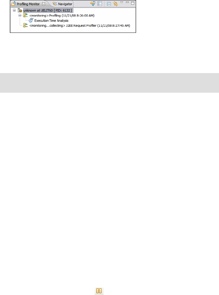
Chapter 27. Profile applications 1009
Draft Document for Review December 9, 2008 2:44 pm 7672-deploy-3-profile.fm
Figure 27-25 Profiling Monitor
Run the sample application to collect profiling data
To collect data, we display the accounts of one customer, run a debit and a credit
transaction, list the transactions, and update the customer name:
In the Java EE perspective, right-click RAD75EJBWeb and select Profile
As → Profile on Server. Click Finish to publish the application.
In the RedBank home page, click RedBank. If the heading and footing do not
display, right-click the redbank.jsp and Profile on Server.
In the Login page, enter 222-22-2222 in the customer SSN field and click
Submit.
Select the last account.
In the Account Details page, select Withdraw and withdraw an amount of
$25.
In the Account Details page, select Deposit and deposit $33.
In the Account Details page, select List Transactions.
In the List Transactions page, click Account Details.
In the Account Details page, click Customer Details.
In the Customer page, change the last name, and click Update.
In the Customer page, click Logout.
Pause monitoring
In the profiling Monitor view, pause monitoring by selecting both processes and
clicking the Pause Monitoring icon (or right-click and select Pause
Monitoring.
You can also keep the profiling running while you analyze the accumulated data.
Note: This step requires that you have published the project to the server as
described in “Publishing and running sample application” on page 1006.
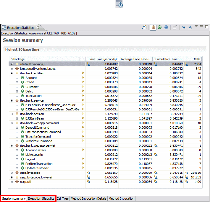
7672-deploy-3-profile.fm Draft Document for Review December 9, 2008 2:44 pm
1010 Rational Application Developer V7.5 Programming Guide
Statistic views
The statistic views are the same as for profiling the Java application and are not
described in detail in this section.
Execution statistics
To analyze the execution statistics, in the Profiling Monitor view, select the
<attached> Profiling process and click the icon, or select Open With →
Execution Statistics (Figure 27-26).
Figure 27-26 Execution Statistics
You can expand a class to see the statistics for each method (Figure 27-27).
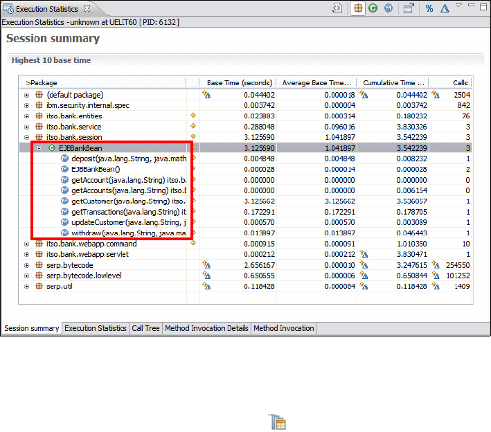
Chapter 27. Profile applications 1011
Draft Document for Review December 9, 2008 2:44 pm 7672-deploy-3-profile.fm
Figure 27-27 Execution Statistics by methods of a class
Method invocation details
Expand itso.bank.entities → Account to see the methods of the Account class.
Right-click processTransaction and select Show Method Invocation
Details (Figure 27-28).
The Method Invocation Details view provides statistical data on a selected
method. The following data is displayed for the selected method:
Selected method (Account.processTransaction): Shows details including
the number of times the selected method is called, the class and package
information, and the time taken by this method.
Selected method invoked by: Shows details of each method that calls the
selected method, including the number of calls to the selected method, and
the number of times the selected method is invoked by the caller. In our case,
the deposit and withdraw methods of the EJBBankBean class invoke the
selected method.
Selected method invokes: Shows details of each method invoked by the
selected method, for example, Credit and Debit constructors, setAccount of
Transaction class, and internal JPA methods.

7672-deploy-3-profile.fm Draft Document for Review December 9, 2008 2:44 pm
1012 Rational Application Developer V7.5 Programming Guide
Figure 27-28 Method Invocation Details
Execution flow
The Execution Flow view and table both show a representation of the entire
program execution. In this view, the threads of the program fit horizontally, and
time is scaled so that the entire execution fits vertically. In the table, the threads
are grouped in the first column and time is recorded in successive rows.
In the Profiling Monitor view, select the <attached> J2EE Request Profile
process and click the icon, or select Open With → Execution Flow
(Figure 27-29).
The bottom pane displays the action sequence. Expand the Web Container
and select the first doPost method.
The top pane shows the execution stripes. Select the Zoom In icon and
click into the Web Container column, near the start time of the method, until
you see the graphic diagram appear.
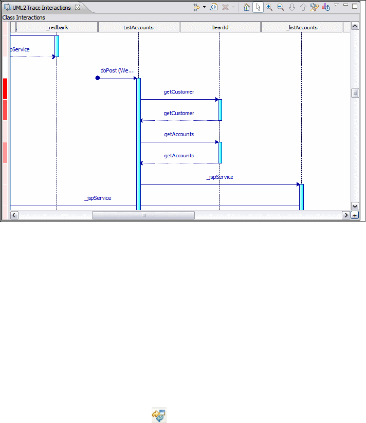
7672-deploy-3-profile.fm Draft Document for Review December 9, 2008 2:44 pm
1014 Rational Application Developer V7.5 Programming Guide
UML sequence diagrams
To display an UML2 interaction diagram, do these steps:
In the Profiling Monitor view, right-click the <attached> J2EE Request
Profiler process and select Open With → UML2 Class interactions
(Figure 27-31). You have to scroll to find suitable interactions.
Figure 27-31 UML2 Class Interactions
You can drill down into a lifeline that allows you to view all the trace interactions
within a particular lifeline (right-click the class and select Drill down into
selected lifeline). This feature helps to trace the root cause of a problem from a
host, to a process, to a thread, and eventually to a class or an object.
You can highlight a call stack to view all the methods invocations in a call stack by
right-clicking a method and select Highlight call stack.
Refreshing the views and resetting data
You can keep the profiling running while you analyze the views. Now and then
you might want to refresh the views with the latest data, or reset the data:
Click the Refresh Views icon to refresh the views.
Right-click the profiling process and select Reset Data to start a new
collection of data and subsequent analysis.

Chapter 27. Profile applications 1015
Draft Document for Review December 9, 2008 2:44 pm 7672-deploy-3-profile.fm
Ending the profiling session
To end the profiling session, click the Terminate icon . To remove the profiling
agent, right-click the agent and select Delete. You are prompted if you want to
delete the data in the file system. The connection to the server is removed.
Profile on server: Memory and thread analysis
To profile the application on the server for memory or thread analysis, you have
to stop the server, change the profiling options, and restart the server:
Stop the server.
Start the server in profiling mode, and wait for the Profile on Server dialog.
–Select
Memory Analysis (Figure 27-24 on page 1008) and click Edit
Options.
–Or select Thread Analysis and click Edit Options.
– In the Profile on server dialog, click Finish.
Click Yes in the Confirm Perspective switch dialog.
The Profiling and Logging perspective opens and the agent is displayed in the
Profiling Monitor view.
Run the sample application
In the Java EE perspective, right-click redbank.jsp and select Profile As →
Profile on Server. You do not have to republish the application.
Run the sample sequence of operations as described in “Run the sample
application to collect profiling data” on page 1009.
Display memory and thread analysis
Open the appropriate views from the Profiling Monitor view to perform the
analysis.
More information
In the Application Developer Online Help, select Developing → Monitoring,
profiling, and analyzing applications.
7672-deploy-3-profile.fm Draft Document for Review December 9, 2008 2:44 pm
1016 Rational Application Developer V7.5 Programming Guide

© Copyright IBM Corp. 2008. All rights reserved. 1017
Draft Document for Review December 9, 2008 2:44 pm 7672-team-0-p8.fm
Part 8 Management and
team development
In this part of the book, we describe the tooling and technologies provided by
Application Developer for managing and developing applications in a team
environment, using Concurrent Versions System (CVS), and Rational Team
Concert.
Part 8
7672-team-0-p8.fm Draft Document for Review December 9, 2008 2:44 pm
1018 Rational Application Developer V7.5 Programming Guide

© Copyright IBM Corp. 2008. All rights reserved. 1019
Draft Document for Review December 9, 2008 2:44 pm 7672-team-2-cvs.fm
Chapter 28. CVS integration
This chapter provides an introduction to the widely adopted open source version
control system known as Concurrent Versions System (CVS) and the tools within
Application Developer V7.5 to integrate with it. Through an example installation
and implementation of CVS followed by usage scenarios, including two
developers working on a simulated project, we demonstrate the main features of
using CVS within Application Developer.
The chapter is organized into the following sections:
Introduction to CVS
CVSNT Server installation and implementation
CVS client configuration for Application Developer
Configuring CVS in Application Developer
Development scenario
CVS resource history
Comparisons in CVS
Annotations in CVS
Branches in CVS
Working with patches
Disconnecting a project
Team Synchronizing perspective
More information
28
7672-team-2-cvs.fm Draft Document for Review December 9, 2008 2:44 pm
1020 Rational Application Developer V7.5 Programming Guide
Introduction to CVS
Concurrent Versions System (CVS) is a popular open source Software
Configuration Management (SCM) system for source code version control. It can
be used by individual developers or very large teams and can be configured to
run across the Web or any configuration where the users have TCP/IP access to
a CVS server. CVS allows users to work on the same file simultaneously without
locking and provides a facility to merge changes and resolve conflicts when they
arise. For these main reasons and the fact that it is free and relatively easy to
install and configure, CVS has become very popular both for open source and
commercial projects.
The Mircosoft Windows version of CVS—known as CVSNT—while still retaining
the original functionality has split off from the original UNIX version and has been
enhanced even further, to the extent that enhancements in CVSNT have been
ported back to the UNIX version. It can be run on any Windows NT® or later
system and allows clients to connect to the CVS server from many different
environments.
Finally, it is important to note that CVS only implements version control and does
not handle other aspects of SCM, such as requirements management, defect
tracking, and build management. There are other open source projects for
performing these functions, and also, the IBM Rational suite of products has a
large set of tools that perform the same functions in an integrated way.
CVS features
Some of the main features of CVS are as follows:
Multiple client-server protocols over TCP/IP, a feature that allows developers
access to the latest code from a wide variety of clients located anywhere with
access to the CVS server.
All the versions of a file are stored in a single repository file using
forward-delta versioning, which stores only the differences between
sequential versions.
Developers are insulated from each other. Every developer works in their own
directory, and CVS merges the work in the repository when they are ready to
commit. Conflicts can be resolved as development progresses (using
synchronize) and must be resolved before any piece of work is committed to
the repository.

Chapter 28. CVS integration 1021
Draft Document for Review December 9, 2008 2:44 pm 7672-team-2-cvs.fm
CVS uses an unreserved checkout approach to version control that helps
avoid artificial conflicts common when using an exclusive checkout model.
CVS keeps shared project data in repositories. Each repository has a root
directory on the file system.
CVS maintains a history of the source code revisions. Each change is
stamped with the time it was made and the user name of the person who
made it. We recommend that developers also provide a description of the
change. Given this information, CVS can help developers find answers to
questions such as: Who made the change, when was it made, the reasons
why, and what specifically was changed.
CVS support within Application Developer
Application Developer provides a fully integrated CVS client, the main features of
which are demonstrated throughout this chapter. At the highest level, there are
two perspectives in Application Developer that are important when working with
CVS:
CVS Repository Exploring perspective—Provides an interface for creating
new links to a repository, browsing the content of the repository, and checking
out content (files, folders, projects) to the workspace.
Team Synchronizing perspective—Provides an interface for synchronizing
code on the workspace with code in a repository. The perspective is also used
by other version control systems, including IBM Rational ClearCase.
In addition to these two perspectives, there are numerous menu options, context
menu options, and other features throughout Application Developer to help users
work with a CVS repository.
Important: CVS and Application Developer have a slightly different
interpretation of what the term conflict means:
In CVS, a conflict means that two changes have been made to the
same line or set of lines in the same source code file. In these cases an
automatic merge is not possible and some manual merging is required.
For Application Developer, a conflict means only that there exists a
locally modified version of a resource for which a more recent revision is
available in the branch in the repository. In these cases an automatic
merge might resolve the issue, or if there are changes to the same set
of lines then (as is the case for resolving CVS conflicts), manual
merging is required.
7672-team-2-cvs.fm Draft Document for Review December 9, 2008 2:44 pm
1022 Rational Application Developer V7.5 Programming Guide
Application Developer v7.5 supports four authentication protocols when
establishing a connection to a CVS server:
pserver (password server)—This is the simplest but least secure
communication method. Using this mechanism the user name and password
is passed to the CVS server using a defined protocol. The downside is that
the password is transmitted in clear text over the network, making it
vulnerable to network sniffing tools.
ext (external)—This method allows the user to specify an external program to
connect to the repository. On the preferences page Window →
Preferences → Team → CVS → Ext Connection Method, a user can
specify the local application to run, to send commands to the CVS server and
the parameters to pass to it. Each CVS operation performed is then done
through this executable, and passwords are encrypted using whatever
mechanism the executable uses. Generally this mechanism requires shell
accounts on the server machine so that the clients can make use the remote
shell applications.
extssh (external program using secure shell)—This method is similar to
the ext method from above, but uses a built-in SSH client supplied with
Application Developer to perform encryption. The preferences page
Window → Preferences → General → Network Connections → SSH2
provides a set of options for configuring the ssh security including the ssh
application path and some private keys.
pserverssh2 (password server using secure shell)—This method uses the
pserver mechanism of storing the users and passwords within the CVS
server as above, but uses ssh encryption (as configured in the SSH2
connection method preferences page) to communicate the user and
password information to the server.
For more information on these configurations, refer to the CVS home page and
Application Developer help. The option pserver is the easiest to configure and is
used in the example in this chapter.
CVSNT Server installation and implementation
The following CVSNT Server installation and implementation section is
organized as follows:
Installing the CVS server
Configuring the CVS server repository
Creating the Windows users and groups used by CVS
Verifying the CVSNT installation
Creating CVS users

Chapter 28. CVS integration 1023
Draft Document for Review December 9, 2008 2:44 pm 7672-team-2-cvs.fm
Installing the CVS server
The CVS server distribution for Linux, UNIX, and Windows platforms is available
at the CVS project site, as is installation and usage documentation:
http://www.march-hare.com/cvspro/
At the time of writing, the CVSNT branch 2.5.x branch was the most stable
version.
To install CVS on the Windows platform, do these steps:
Before installing CVSNT, refer to these useful installation tips:
http://www.cvsnt.org/wiki/InstallationTips
Download the CVSNT Server V2.5.03 (cvsnt-2.5.03.2382.msi) from the
above URL to a temporary directory (for example, c:\temp).
Execute the CVSNT installer by double-clicking the downloaded
cvsnt-2.5.03.2382.msi file from the temporary directory.
In the Welcome dialog, click Next.
In the License Agreement dialog, review the terms, select I accept the terms
in the Licence Agreement, and click Next.
In the Choose Setup Type dialog, click Typical.
Note: Application Developer does not directly support CVSNT (version
2.5.03), and therefore CVSNT has to be configured to act like a standard CVS
server by setting the Compatibility options. This is done in the sample under
the step titled “Configuring the CVS server repository” on page 1024.
We used CVSNT V2.5.03.2382 for the sample because all of our sample
applications where developed on the Windows platform, and the CVS home
page stated that this was the most stable recent version. We found CVSNT
easy to use and did not experience any significant problems using CVSNT,
however, the correct configuration was required.
For information on CVS compatibility with Eclipse versions, refer to the
following URL:
http://wiki.eclipse.org/index.php/CVS_FAQ
Important: The CVSNT software requires a user performing the
installation has local system privileges to install and configure a service in
Windows.

7672-team-2-cvs.fm Draft Document for Review December 9, 2008 2:44 pm
1024 Rational Application Developer V7.5 Programming Guide
In the Ready to Install dialog, click Install.
In the Completing the CVSNT 2.5.03.2382 Setup Wizard dialog, click Finish.
When the installation is complete, the installation program prompts to see if you
want to perform a restart. We recommend that you restart your system. This step
guarantees that the environment variables are set up properly and the CVSNT
Windows services are started.
Configuring the CVS server repository
After you have installed the CVS server and restarted the system, do the
following steps to create and configure the CVS server repository:
Manually create the common root directory. For example, the directory
c:\rep7672 can be created using Windows Explorer.
Select Start → Programs → CVSNT → Service control panel to start the
CVSNT control application.
The CVS services must be stopped to create a new repository. In the CVSNT
control panel window, click Stop under CVSNT Service and CVSNT Lock
Service (Figure 28-1).
Figure 28-1 Stop the CVSNT services
Select the Repository configuration tab, and click Add.
In the Server Settings dialog, enter the following values (Figure 28-2):
– Location: c:/rep7672 (we created this directory manually)
–Name:
/rep7672 (default)
– Description: RAD 7.5 Redbook CVS repository

Chapter 28. CVS integration 1025
Draft Document for Review December 9, 2008 2:44 pm 7672-team-2-cvs.fm
– Leave the other selections with their defaults.
– Click OK.
Figure 28-2 Add repository
When prompted with the message c:/rep7672 exists, but is not a valid CVS
repository. Do you want to initialize it?, click Yes and then Apply.
Select the Compatibility Options tab (Figure 28-3). For both type of clients:
–Select
Respond as cvs 1.11.2 to version request.
–Select
Emulate ‘-n checkout’ bug.
–Select
Hide extended log/status information.
–Clear
Ignore client-side force -k options
– For Clients allowed to connect, select Any CVS/CVSNT (default).
Figure 28-3 Compatibility options
These settings ensure that CVSNT is compatible with clients such as
Application Developer and other CVS clients.
Click Apply and then OK to close the CVS control panel.
7672-team-2-cvs.fm Draft Document for Review December 9, 2008 2:44 pm
1026 Rational Application Developer V7.5 Programming Guide
Creating the Windows users and groups used by CVS
The following instructions configure the user account for CVSNT and associate
the CVSNT application with that user.
Add a Windows user (cvsadmin)
To add a Windows CVS administrator user, do these steps:
In the Windows desktop, right-click My Computer (or whatever the label of
the computer is on the desktop), and select Manage.
In the Computer Management dialog, select Local Users and Groups →
Users.
Select Action → New User.
In the New User dialog, enter the following values:
– User name: cvsadmin
– Password: <password>. Remember this password for later!
– Leave full name blank.
– Description: User account for the CVSNT application.
–Clear
User must change password at next logon.
–Clear
User cannot change password.
–Clear
Password never expires.
–Clear
Account is disabled.
– Click Create and click Close.
Do not exit the Computer Management tool.
Add Windows user (cvsadmin) to the Administrators group
To add the Windows user to a group that has the sufficient permissions, do these
steps:
In the Computer Management application, select Groups and double-click
Administrators.
Click Add.
Typ e cvsadmin in the Enter the object names to select field, and click Check
Names. The user name is verified and prefixed by the local machine name.
Click OK to add cvsadmin to the Administrators group.
Click Apply and then OK to exit the Administrators Properties window.
Close the Computer Management dialog.
We created a new administrative user for the CVS server machine to start and
stop the CVS administration processes.
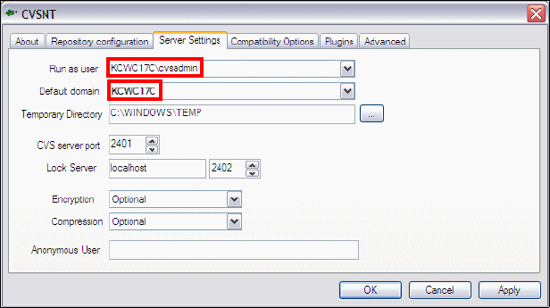
Chapter 28. CVS integration 1027
Draft Document for Review December 9, 2008 2:44 pm 7672-team-2-cvs.fm
Configure the CVS administration user
The CVS services have to be associated with the cvsadmin user to complete the
configuration. Do these steps:
Restart the CVSNT Control Panel application, Start → Programs →
CVSNT → CVSNT Control Panel.
Select the Server Settings tag and select cvsadmin (prefixed by the CVS
server machine name) for Run as user, and the local machine name for
Default domain (Figure 28-4).
Figure 28-4 CVSNT Server Settings
Click Apply and OK.
Verifying the CVSNT installation
To verify that the CVSNT installation is running as required, do these steps:
Restart the system, which ensures that the environment variables are loaded
and the CVSNT services are started.
After the system has been restarted, verify that the following CVSNT
Windows services have started, by starting the CVSNT Control Panel,
viewing the About tab and checking the status of the following services:
– CVSNT
– CVSNT Lock Service
Both of these services should show as running.

7672-team-2-cvs.fm Draft Document for Review December 9, 2008 2:44 pm
1028 Rational Application Developer V7.5 Programming Guide
Creating CVS users
To create CVS users to access the files in the repository, do these steps:
Open a Windows command prompt.
Set the cvsroot environment variable with the following command:
set cvsroot=:pserver:cvsadmin@KCWC17C.itsosj.sanjose.ibm.com:/rep7672
Where KCWC17C.itsosj.sanjose.ibm.com is the host name of the CVS server
and /rep7672 is the directory the repository is located on the host machine.
Log on to the CVS repository machine to manage the users, using the
following command:
cvs login cvsadmin
You are prompted to enter the CVS password.
Enter the password for the cvsadmin user created in “Creating the Windows
users and groups used by CVS” on page 1026.
Enter the following CVS commands to add users:
cvs passwd -a -r cvsadmin <cvs-user-id>
–cvs passwd -a is the command to add a new user and password, or
change a password if that user already exists.
–-r cvsadmin indicates the alias or native user name that the user will run
under when connecting to the repository (we set this to be cvsadmin for
the user created in “Creating the Windows users and groups used by
CVS” on page 1026).
–<cvs-user-id> is the user ID to be added.
For example, to add user cvsuser1, enter the following command:
cvs passwd -a -r cvsadmin cvsuser1
Note: The full host name must be specified, localhost does not work. To
find the host name of a machine, right-click the My Computer icon on the
Windows desktop, select Properties, and select the Computer Name tab.
The full computer name is shown on this page.
Note: The first occurrence of a user being added creates the file passwd in
the directory, c:\rep7672\CVSROOT. The new user is appended to this file.
We recommend that this file not be edited directly by a text editor. It also
must not be placed under CVS control.
Chapter 28. CVS integration 1029
Draft Document for Review December 9, 2008 2:44 pm 7672-team-2-cvs.fm
A prompt opens to enter the password:
Adding user cvsuser1@KCWC17C.itsosj.sanjose.ibm.com
New password: ********
Verify password: ********
Note that the user ID and password created is completely specific to the CVS
repository and is unrelated to the windows password.
Repeat the previous step for an additional CVS user: cvsuser2. We need two
users for the example.
Provide the development team members their CVS account information, host
name, and connection type to the CVS server, so that they can establish a
connection from Application Developer. For example:
– Account info: Developer CVS user ID (for example, cvsuser1)
– CVS server host name: (for example, KCWC17C.itsosj.sanjose.ibm.com)
– Connection type: pserver
– Password: <password>
– Repository path: /rep7672
Any subsequent changes to the users or passwords must be done by the
administrator using the same commands.
CVS client configuration for Application Developer
This section describes how to create a client connection within Application
Developer to a CVS server. Typically these activities are done in Application
Developer from a new workspace.
Configuring the CVS team capability
Verify that team capabilities CVS support is enabled by doing these steps:
Select Windows → Preferences.
Select and expand the General and select Capabilities.
Select the Team capability.
Click Advanced.
Expand the Team and verify that CVS Support is selected (Figure 28-5).
Click OK.
Click Apply and OK to close the Preferences dialog.
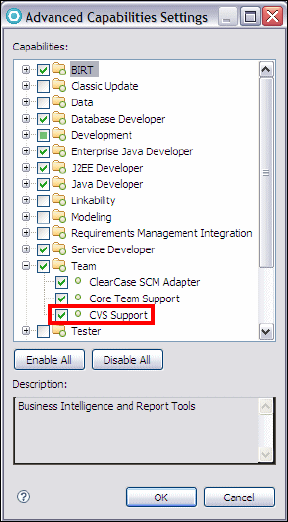
7672-team-2-cvs.fm Draft Document for Review December 9, 2008 2:44 pm
1030 Rational Application Developer V7.5 Programming Guide
Figure 28-5 Verify Team capability CVS Support is enabled
Accessing the CVS repository
To access a repository that has been configured on a server for users to perform
their version management, do these steps:
Select Windows → Open Perspective → Other → CVS Repository
Exploring. Click OK.
In the CVS Repositories view, right-click, and select New → Repository
Location.
Add the parameters for the repository location as shown in Figure 28-6,
where Host and Repository path should reflect where the CVS repository is,
and User and Password are the name of the user of the workspace. Select
pserver as the connection type.
Select Validate Connection Finish and Save Password, and then click
Finish.
Click No in the Secure Storage dialog (unless you want to establish the
password recovery feature).
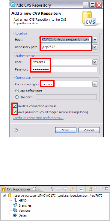
Chapter 28. CVS integration 1031
Draft Document for Review December 9, 2008 2:44 pm 7672-team-2-cvs.fm
Figure 28-6 Add the CVS repository to the workspace
If everything worked correctly, you can to see a repository location in the CVS
Repositories view. The entry can be expanded to show HEAD, Branches,
Versions, and Dates (Figure 28-7).
Figure 28-7 CVS Repositories view
Configuring CVS in Application Developer
Within Application Developer, it is possible to set the following CVS related
settings to guide the integration of CVS:
Label decorations
File content
Ignored resources
CVS-specific settings
CVS keyword substitution
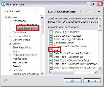
7672-team-2-cvs.fm Draft Document for Review December 9, 2008 2:44 pm
1032 Rational Application Developer V7.5 Programming Guide
Label decorations
Label decorations are set to be on for CVS by default. This means that the CVS
properties of a particular file are shown on its label or icon. For example, if a file
has changed from the version in the repository, it will have a > symbol next to its
file name.
To view or change the label decorations, select Windows → Preferences and
expand General → Appearance and select Label Decorations. By default, the
CVS labels are selected (Figure 28-8).
Figure 28-8 CVS Label Decoration preferences
File content
The file content of resources can be configured to be stored as either ASCII or
binary. When working with a file extension that is not defined in the file content
list stored in Application Developer, files of this type are saved into the repository
as binary by default. When a resource is stored as a binary, CVS cannot show
line-by-line comparisons between versions. However, files that have binary
content cannot be stored as ASCII CVS files. Once a file is created as one type,
it cannot be changed. Therefore, it is important to make sure that each file
content type is configured correctly in Application Developer before adding a new
project to the repository.
To verify that a resource in the workspace is stored in the repository correctly,
select Windows → Preferences and expand Team → File Content
(Figure 28-9). Verify that the file extensions that you are using are present and
stored in the repository as desired.
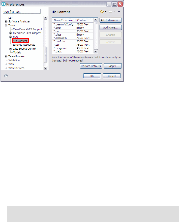
Chapter 28. CVS integration 1033
Draft Document for Review December 9, 2008 2:44 pm 7672-team-2-cvs.fm
Figure 28-9 Team File Content preferences
If a particular file extension is not in the list, then this extension has to be added,
unless the resource is stored in the default binary format. Application Developer
prompts the user for the resource type when performing the first check-in (see
Figure 28-16 on page 1043) if it encounters a new type, or the new type can be
added manually in the Preferences page.
A common file that is often supplied with a source code distribution is a
Makefile.mak file, which is usually an ASCII file.
To demonstrate adding this file type extension (that is not present in this list),
do these steps:
Select Windows → Preferences and expand Team → File Content.
Click Add Extension.
Enter the extension name mak and click OK.
Find the extension in the list, and in the Content column, and select ASCII
Text from the drop-down.
Click Apply and then OK.
Tip: The content can also be changed by highlighting the extension and
clicking Change. This toggles the setting between ASCII Text and Binary.
7672-team-2-cvs.fm Draft Document for Review December 9, 2008 2:44 pm
1034 Rational Application Developer V7.5 Programming Guide
Ignored resources
Resources that are created or changed dynamically through mechanisms such
as compilation or builds are not recommended to be saved in the repository. This
can include class files, executables, and Enterprise JavaBean stubs and
implementation codes.
Application Developer stores a list of these resources that are ignored when
performing CVS operations. This is accessed by selecting Windows →
Preferences and expanding Team → Ignored Resources.
Resources can be added to this list by specifying the pattern that will be ignored.
The two wild card characters are an asterisk (*)—which indicates a match of zero
or many characters—and a question mark (?)—which indicates a match of one
character. For example, a pattern of _EJS*.java would match any file that begins
with _EJS and had zero to many characters and ends in .java.
The following example shows the addition of the filename pattern *.tmp to the
ignored resources list:
Select Windows → Preferences and expand Team → Ignored Resources.
Click Add Pattern.
Enter the pattern *.tmp and click OK.
Ensure that the resource (*.tmp) is selected and added to the Ignored
Resources list (Figure 28-10). *.tmp resources are now ignored by CVS in
Application Developer.

Chapter 28. CVS integration 1035
Draft Document for Review December 9, 2008 2:44 pm 7672-team-2-cvs.fm
Figure 28-10 Resources that will be ignored when saving to the repository
To remove a pattern from the ignore list, select it and click Remove. To
temporarily disable ignoring a file pattern clear its check box in the list.
Additionally, there are two further facilities that can be used to exclude a file from
version control:
Resources marked as derived are automatically not checked into the CVS
repository by Application Developer. This field is set by builders in the Eclipse
framework, such as the Java builder. To determine if a resource is derived or
not, right-click the resource and select Properties, or look in the Properties
view. The Derived field is shown under Info. It is also possible to change the
Derived field value in the properties dialog.
Use of a .cvsignore file. This file contains a list of files or directories that
should not be placed into the repository. CVS checks this file and does not
add to CVS any files which are in this list.
A file can be added to the list by right-clicking the file in the Enterprise
Explorer and selecting Team → Add to .cvsignore.
Further details on the syntax of .cvsignore can be found at:
http://www.cvsnt.org/manual/html/cvsignore.html

7672-team-2-cvs.fm Draft Document for Review December 9, 2008 2:44 pm
1036 Rational Application Developer V7.5 Programming Guide
CVS-specific settings
The CVS settings in Application Developer are extensive and cannot be covered
in full here. Some of the more important settings are highlighted in Table 28-1
with short descriptions. A complete description of the remaining settings can be
obtained from the Application Developer help system.
Table 28-1 Category of CVS settings available
Category Window Preferences Description
General CVS
Settings
Team → CVS Settings for the behavior in communicating
with CVS, handling the files and projects
received from CVS and when to prompt the
user for certain activities.
Annotate Team → CVS →
Annotate
Switch on or of annotating of binary files.
Comment
Templ ates
Team → CVS →
Comment Templates
Let you create, edit or remove comment
templates which can be used while
checking in a file.
Console Team → CVS →
Console
Various settings for the CVS console view
including a flag to for whether to display
CVS commands to the console.
Ext
Connection
Method
Team → CVS →
Ext Connection
Method
Settings to identify the ssh external
program and associated parameters when
using the ext protocol to communicate with
the CVS server.
Label
Decorations
Team → CVS →
Label Decorations
Settings for how to display the CVS state of
resources in Application Developer.
Password
Management
Team → CVS →
Password
Management
Manages which repositories have
passwords saved within Application
Developer.
Synchronize/
Compare
Team → CVS →
Synchronize/Compare
Various settings for comparison
Update/
Merge
Team → CVS →
Update/Merge
Settings for guiding the Application
Developer process when merging is
required during synchronization.
Watch/Edit Team → CVS →
Watch/Edit
Settings for the CVS watch and edit
functionality which allows users to be
informed (via e-mail) when a file has been
edited or committed by another user.
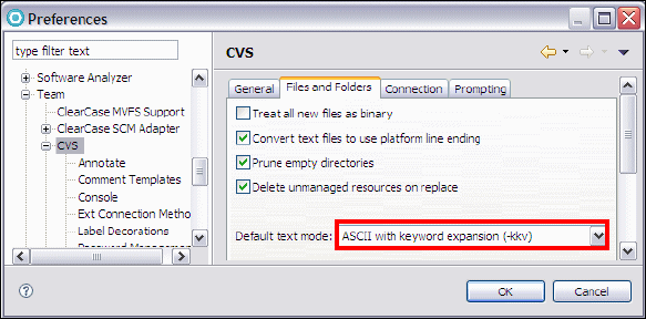
Chapter 28. CVS integration 1037
Draft Document for Review December 9, 2008 2:44 pm 7672-team-2-cvs.fm
CVS keyword substitution
In addition to storing the history of changes to a given source code file in the
CVS repository, it is also possible to store meta-information (such as author,
date/time, revision and change comments) in the contents of the file. Typically a
standard header template is configured in Application Developer, which is then
applied to each file when CVS operations (usually check-in and checkout) are
performed. The template can include a set of CVS keywords inside a heading,
which are expanded out when a file is checked in or out. This is known as
keyword expansion.
Keyword expansion is an effective mechanism for developers to quickly identify
what version a resource is in the repository versus what a user has checked out
locally on their workspace.
Application Developer, by default, has the keyword substitution set to ASCII with
keyword expansion (-kkv) under the selection Windows → Preferences →
Team → CVS and the File and Folders tab (Figure 28-11). This setting expands
out keyword substitution based on the interpretation by CVS, and is performed
wherever the keywords are located in the file.
Figure 28-11 CVS Keyword expansion setting

7672-team-2-cvs.fm Draft Document for Review December 9, 2008 2:44 pm
1038 Rational Application Developer V7.5 Programming Guide
Some of the available keywords (case sensitive) are listed in Table 28-2.
Table 28-2 CVS keywords
To ensure consistency between multiple users working on a team, it is
recommended that a standard header is defined for all Java source files. A
simple example is shown in Example 28-1.
Example 28-1 Example of CVS keywords used in Java
/**
* Class comment goes here.
*
* <pre>
* Date $Date
* Id $Id
* </pre>
* @author $Author
* @version $Revision
*/
To ensure consistency across all files created, each user would have to cut and
paste this into their document. Fortunately, Application Developer offers a means
to ensure this consistency.
Keyword Description
$Author$ Expands to the name of the author of the change in the file, for example:
$Author: itsodev $
$Date$ Expands to the date and time of the change in UTC, for example:
$Date: 2008/10/14 18:21:32 $
$Header$ Contains the CVS file in repository, revision, date (in UTC), author, state
and locker, for example:
$Header: /rep7672/XMLExample/.project,v 1.1 2008/10/14 18:21:32
itsodev Exp itso $
$Id$ Like $Header$ except without the full path of the CVS file, for example:
$Id: .project,v 1.1 2008/10/14 18:21:32 itsodev Exp itso $
$Log$ The log message of this revision. This does not get replaced but gets
appended to existing log messages.
$Name$ Expands to the name of the sticky tag, which is a file retrieved by date or
revision tags, for example: $Name: version_1_3 $
$Revision$ Expands to the revision number of the file, for example: $Revision: 1.1 $
$Source$ Expands to the full path of the RCS file in the repository, for example:
$Source: /rep7672/XMLExample/.project,v $

Chapter 28. CVS integration 1039
Draft Document for Review December 9, 2008 2:44 pm 7672-team-2-cvs.fm
To set up a standard template, do these steps:
Select Windows → Preferences → Java → Code Style → Code
Templates.
Expand Comments → Files and click Edit.
Cut and paste or type what comment header you require (Figure 28-12).
Figure 28-12 Setup of a common code template for Java files
Click OK to complete the editing, then click Apply followed by OK.
This sets up a standard CVS template. The next time a new class is created,
checked in, and then checked out, the header is displayed (Example 28-2).
Example 28-2 Contents of Java file after check in and check out from CVS
/**
* class comment goes here.
*
* <pre>
* Date $Date: 2004/10/29 18:21:32 $
* Id $Id: $Id: Example.java,v 1.1 2004/10/29 18:21:32 itsodev Exp itso $
* </pre>
* @author $Author: itsodev $
* @version $Revision: 1.1 $
*/
Note: The double dollar sign ($$) is required because Application Developer
treats a single dollar ($) as one of its own variables. $$ is used as a means of
escaping the single dollar so that it can be post processed by CVS.
7672-team-2-cvs.fm Draft Document for Review December 9, 2008 2:44 pm
1040 Rational Application Developer V7.5 Programming Guide
Development scenario
To show you how to work with CVS in Application Developer, we follow a simple
but typical development scenario, shown in Table 28-3.
Two developers, cvsuser1 and cvsuser2, work together to create a servlet
ServletA and a view bean View1.
Table 28-3 Sample development scenario
Note: The example in this chapter calls for two simulated developer systems.
For demonstration purposes, this can be accomplished by having two
workspaces on the same machine. Refer to “Workbench basics” on page 76
for detailed instructions on setting up multiple workspaces.
Step Developer 1 (cvsuser1) Developer 2 (cvsuser2)
1Creates a new Dynamic Web Project
RAD75CVSGuide and a servlet ServletA
in it and adds it to the version control
and the repository.
2
2b: Updates the servlet ServletA.
2a: Imports the RAD75CVSGuide CVS
module as a Workbench project.
Creates a view bean View1, adds it to
the version control, and synchronizes
the project with the repository.
33a: Synchronizes the project with the
repository to commit the changes to
repository (servlet) and receives
changes from the repository (view
bean).
3b: Synchronize the project with the
workspace to receive the servlet.
44a: Continues changing and updating
the servlet. Synchronizes the project
with the repository to commit his
changes to repository and merges
changes.
4c: Synchronize with the repository to
pick up the merged servlet.
4a: Begins changes to servlet in
parallel with developer 1.
4b: Synchronizes the project after
cvsuser1 has committed and has to
merge code from the workspace and
the CVS repository.
5Assigns version number the project.

Chapter 28. CVS integration 1041
Draft Document for Review December 9, 2008 2:44 pm 7672-team-2-cvs.fm
Steps 1 through 3 are serial development with no parallel work on the same file
being done. During steps 4 and 5 both developers work in parallel, resulting in
conflicts. These conflicts are resolved using the CVS tools in Application
Developer.
In the sections that follow, we perform each of the steps and explain the team
actions in detail.
Create and share the project (step 1 - cvsuser1)
Application Developer offers a perspective specifically designed for viewing the
contents of CVS servers: The CVS Repository Exploring perspective.
Add a CVS repository
For this section, ensure that you have completed, “CVSNT Server installation
and implementation” on page 1022 and “Accessing the CVS repository” on
page 1030.
The CVS Repositories view now contains the repository location
(Figure 28-13).
Figure 28-13 CVS Repositories view
Expanding a location in the CVS Repositories view reveals branches and
versions. A special branch, called HEAD, is shown outside the main branches
folder because of its importance. It is the main integration branch, holding the
project’s current development state.
The CVS Repositories view can be used to check out repository resources as
projects on the Workbench. You can also configure branches and versions, view
resource histories, and compare resource versions and revisions.
First, a project must be created and shared before full use can be made of the
repository.
Important: Always work in the workspace of the correct user (cvsuserX).

7672-team-2-cvs.fm Draft Document for Review December 9, 2008 2:44 pm
1042 Rational Application Developer V7.5 Programming Guide
Create a project and servlet
To create a project and a servlet, do these steps:
Switch to the Web perspective and create a new Dynamic Web Project by
selecting File → New → Dynamic Web Project.
Typ e RAD75CVSGuide as the name of the project, keep the defaults for all
the other options, and click Finish.
In the Enterprise Explorer, right-click RAD75CVSGuide and select New →
Servlet.
In the Create Servlet dialog (Figure 28-14):
–Type
itso.rad75.teamcvs.servlet for the Java package.
–Type
ServletA for the Class name.
– Click Finish.
Figure 28-14 Create Servlet wizard
Add the project to the repository
To add the Web project source code to the repository, do these steps:
In the Enterprise Explorer, right-click RAD75CVSGuide and select Team →
Share Project.
In the Share Project dialog, select CVS, and click Next.
In the Share Project with CVS Repository dialog, select Use existing
repository location, select the repository, and click Next.
In the Enter Module Name dialog, select Use project name as module
name (default), and click Next. A status window might appear as the
resources are added to the repository.

Chapter 28. CVS integration 1043
Draft Document for Review December 9, 2008 2:44 pm 7672-team-2-cvs.fm
The Share Project Resources dialog (Figure 28-15) opens, listing the
resources to be added. Click Finish.
Figure 28-15 Verification of resources add under CVS revision control
A dialog opens, informing you that new file types are being added, which are
not configured as types in the Application Developer preferences. Those files
are meta informations of the project and must be ASCII Text (Figure 28-16).
Set these file types to ASCII Text, and click Next.
Figure 28-16 Adding new file types on check-in
7672-team-2-cvs.fm Draft Document for Review December 9, 2008 2:44 pm
1044 Rational Application Developer V7.5 Programming Guide
In the commit files dialog, type Initial version in the comment field and click
Finish.
A status window opens, showing the progress as the initial versions of a new
project are checked into the repository. Because RAD75CVSGuide is a
relatively small project, this process should only take a few seconds. For
larger projects where the initial check-in might take some time, the Run
Background button allows the user to continue working in their workspace
while the CVS check-in process completes.
After this has been completed, the RAD75CVSGuide project is checked into the
repository and available for other developers to use.
Adding a shared project to the workspace (step 2a - cvsuser2)
The purpose of any source code repository is to allow multiple developers to
work as a team on the same project. The RAD75CVSGuide project has been
created in one developer’s workspace and shared using CVS.
Now we want to add the same project to a second developer’s workspace.
The second developer must add the CVS repository location to their
workspace using the CVS Repositories view in the CVS Repository Exploring
perspective, as described in “Add a CVS repository” on page 1041.
Right-click the RAD75CVSGuide module, and select Check Out. The current
project in the HEAD branch is checked out to the workspace.
Develop the view bean
Now that both developers have exactly the same synchronized HEAD branch of
the RAD75CVSGuide project on their workspaces, it is time for the second
developer to create the view bean View1.
Open the Web perspective.
In the Enterprise Explorer, right-click RAD75CVSGuide and select New →
Class.
The difference is that the HEAD
branch in the repository contains
the RAD75CVSGuide project.
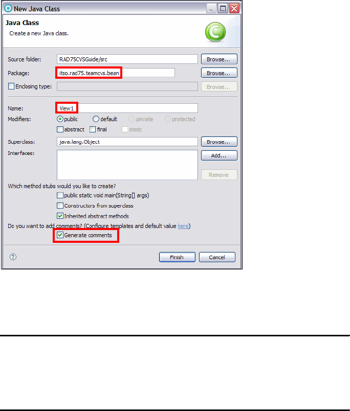
Chapter 28. CVS integration 1045
Draft Document for Review December 9, 2008 2:44 pm 7672-team-2-cvs.fm
In the New Class dialog (Figure 28-17):
–Type
itso.rad75.teamcvs.bean for the Package.
–Type
View1 for the Name.
–Select
Generate comments.
– Click Finish.
Figure 28-17 Creating the View1 view bean
Add the highlighted two private attributes in the View1 class (Example 28-3).
Example 28-3 Add two private attributes to the View1 class
package itso.rad75.teamcvs.bean;
public class View1 {
private int count;
private String message;
}
In the Java Editor, right-click and select Source → Generate Getters and
Setters, select Select All, and verify that the Access modifier is set public
(Figure 28-18). Click OK.
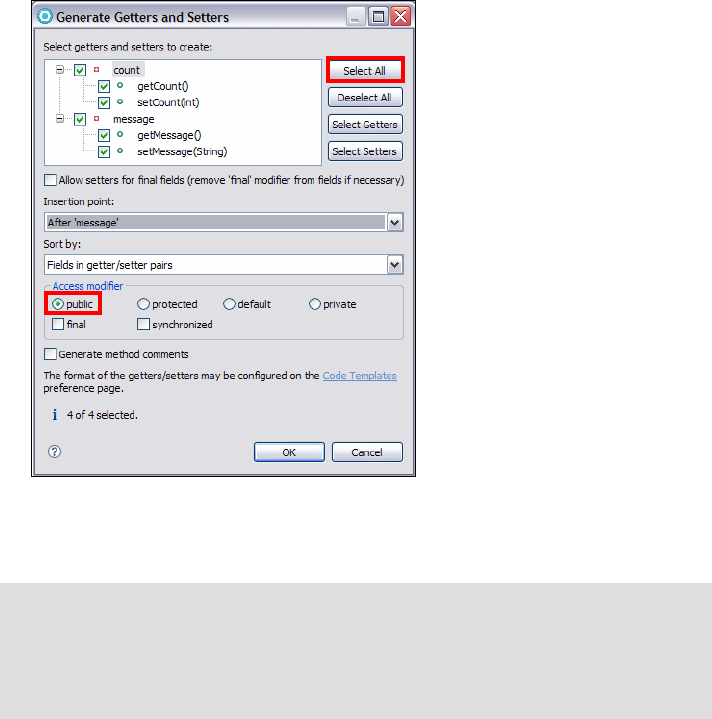
7672-team-2-cvs.fm Draft Document for Review December 9, 2008 2:44 pm
1046 Rational Application Developer V7.5 Programming Guide
Figure 28-18 Creating setters and getters for class View1
Save and close the View1 class.
Synchronizing with the repository
To update the repository with these changes, do these steps:
Right-click RAD75CVSGuide and select Team → Synchronize with
Repository.
A dialog prompts you to change to the Team Synchronizing perspective.
Select Remember my decision and click Yes. The project is compared with
the repository, and the differences are displayed in the Synchronize view
(Figure 28-19).
Tip: In the Enterprise Explorer view, the greater than sign (>) in front of a
resource name means that the particular resource is not synchronized with
the repository. The question mark symbol (?) indicates that the file is not in the
repository. These visual cues can be used to determine when a project
requires synchronization.
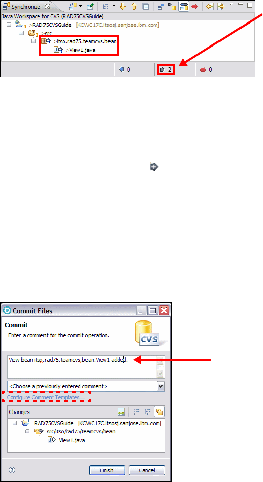
Chapter 28. CVS integration 1047
Draft Document for Review December 9, 2008 2:44 pm 7672-team-2-cvs.fm
Figure 28-19 Synchronizing RAD75CVSGuide after creating the viewbean View1
This view allows you to update resources in the Workbench with newer
content from the repository (incoming), commit resources from the
Workbench to the repository (outgoing), and resolve conflicts that might occur
in the process.
The arrow icons with a plus sign indicate that the files do not exist in the
repository. Because the package itso.rad75.teamcvs.bean and the class
View1.java are new and not yet checked in, they show the plus sign.
To add these new resources to version control, right-click RAD75CVSGuide
in the Synchronize view, and select Commit.
In the Commit Files dialog, type View bean itso.rad75.teamcvs.bean.View1
added for the commit comment and check the files displayed on bottom half
of the window to make sure the changes are as expected (Figure 28-20).
Click Finish and the changes are committed to the repository.
Figure 28-20 Verifying committing of resources into repository
This number
indicates that
there are two
outgoing changes
pending.
New feature:
Comments get spell
checked.

7672-team-2-cvs.fm Draft Document for Review December 9, 2008 2:44 pm
1048 Rational Application Developer V7.5 Programming Guide
Modifying the servlet (step 2b - cvsuser1)
While activities in “Adding a shared project to the workspace (step 2a -
cvsuser2)” occur, our original user, cvsuser1, is working on developing the
servlet further.
In the first workspace created for cvsuser1, do these steps:
In the Enterprise Explorer, open ServletA.java (in RAD75CVSGuide/Java
Resources/src/itso.rad75.teamcvs.servlet).
Create a static attribute called totalCount of type int and initialized to zero
as highlighted in Example 28-4. Save and close the servlet.
Example 28-4 ServeltA gets a static attribute
package itso.rad75.teamcvs.servlet;
.....
public class ServletA extends HttpServlet {
private static final long serialVersionUID = 1L;
private static int totalCount = 0;
public ServletA() {
super();
}
.....
}
Synchronizing with the repository (step 3a - cvsuser1)
User cvsuser1 now synchronizes with the repository and receives the changes of
cvsuser2 (adding the View1 bean) and provides the opportunity to check-in the
changes made to ServletA. Do these steps:
In the Enterprise Explorer, right-click the RAD75CVSGuide project and select
Team → Synchronize with Repository.
Select Remember my decision and click Yes to switch to the Synchronize
view.
Note: The user can specify some common text within commit comments,
and re-use the same format for all commits. To create such comments,
click Configure Comment Template to create a comment, then select it
from the drop-down list in this dialog.
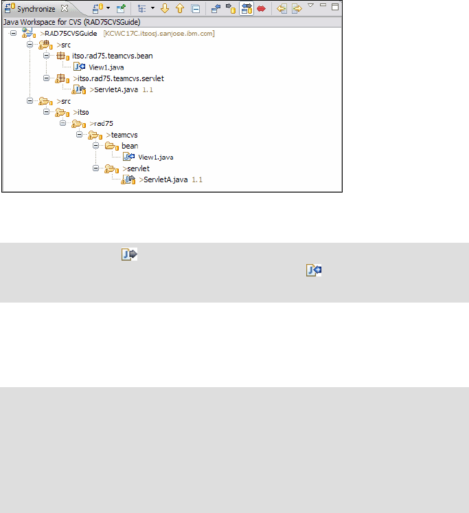
Chapter 28. CVS integration 1049
Draft Document for Review December 9, 2008 2:44 pm 7672-team-2-cvs.fm
Expand the RAD75CVSGuide → src trees to view the changes
(Figure 28-21).
Figure 28-21 User cvsuser1 merging with CVS repository
To obtain updated resources from the CVS repository, right-click the
RAD75CVSGuide project and select Update. This brings a copy of the
View1.java file into this workspace.
Verify that the changes do not cause problems with existing resources in the
local workspace, by checking the Problems View. In this case, there are none.
Right-click the RAD75CVSGuide project and select Commit.
In the Commit dialog, add the comment Static variable totalCount added to
ServletA and click Finish (Figure 28-22). This checks the changes made to
ServletA into the repository.
Note: The symbol in the diagram indicates that an existing resource
differs from what is in the repository. The symbol indicates that a new
resource is in the repository that does not exist on the local workspace.
Note: When using Application Developer v7.5, sometimes a Java file that
has been changed appears twice in the Synchronize view. It might appear
under the representation of the Java package and also under a folder
representation of the packages. Figure 28-21 shows an example of this
with both View1.java and ServletA.java showing twice. While this looks
untidy, if either of the representations of the file are updated, then both
disappear from the Synchronize view as expected.
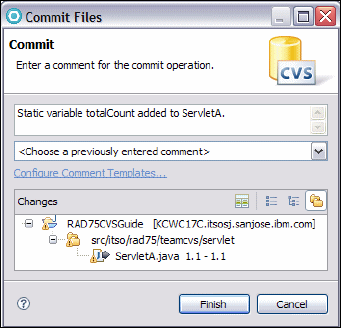
7672-team-2-cvs.fm Draft Document for Review December 9, 2008 2:44 pm
1050 Rational Application Developer V7.5 Programming Guide
Figure 28-22 Adding comment for changes to ServletA
The repository now has the latest changes to the code from both developers. The
user cvsuser1 is in sync with the repository; however, cvsuser2 has not yet
received the changes to the ServletA.
Synchronizing with the repository (step 3b - cvsuser2)
The second workspace used by cvsuser2 should also synchronize (update) with
the repository and receive the changes of cvsuser1.
This brings the changes made to ServletA into the workspace and makes sure
that both workspaces are completely up to date.
Parallel development (step 4 - cvsuser1 and cvsuser2)
The previous steps have highlighted development and repository synchronization
with two people working on two parts of a project. It highlights the need to
synchronize between each phase in the development before further work is
performed.
The following scenario demonstrates two developers working simultaneously on
the same file, starting from the same revision. Each user’s sequence of events is
described in the sections below; and a summary is shown in the time-line in
Figure 28-23.

Chapter 28. CVS integration 1051
Draft Document for Review December 9, 2008 2:44 pm 7672-team-2-cvs.fm
Figure 28-23 Parallel concurrent development of same resource by multiple developers
User cvsuser1 updates and commits changes
In this scenario, user cvsuser1 modifies the doPost method to log information for
an attribute. The following procedure demonstrates how to synchronize the
source code and commit the changes to CVS.
In the Enterprise Explorer, open ServletA (in RAD75CVSGuide/Java
Resources/src/itso.rad75.teamcvs.servlet).
Generate Getter- and Setter-method for static variable totalCount.
Navigate to the doPost method by scrolling down the file and adding the code
to count the number of post requests received:
protected void doPost(HttpServletRequest request,
HttpServletResponse response) throws ServletException, IOException {
ServletA.setTotalCount(ServletA.getTotalCount() + 1);
System.out.println("The total number of requests is: " +
ServletA.getTotalCount());
}
Save and close the file.
Synchronize the project with the repository by right-clicking and selecting
Team → Synchronize with Repository.
Fully expand out the tree in the Synchronize view. The servlet should be the
only change.
Right-click the project and select Commit, add the comment doPost method
implemented by cvsuser1, and click Finish to commit.
CVS Repository
cvsuser1
cvsuser2
servletA v1.2
servletA v1.2
Time
servletA v1.3
check out
check out
check in
servletA v1.4
check in &
merge

7672-team-2-cvs.fm Draft Document for Review December 9, 2008 2:44 pm
1052 Rational Application Developer V7.5 Programming Guide
The developer cvsuser1 has now completed the task of adding code into the
servlet. Changes can now be picked up by other developers in the team.
User cvsuser2 updates and commits changes
To complete the scenario, the second developer also makes changes to doPost
method of ServletA. This is done in the workspace of cvsuser2 and assumes
that the workspace was synchronized before this scenario was started.
To make the changes, do these steps:
In the Enterprise Explorer, open ServletA.
Generate Getter- and Setter-method for static variable totalCount.
Add the highlighted code of Example 28-5 to the ServletA. An instance
variable for the view bean is added and the doPost method gets implemented.
Save and close the file.
Example 28-5 cvsuser2 completes the ServletA as well
package itso.rad75.teamcvs.servlet;
.....
public class ServletA extends HttpServlet {
private static final long serialVersionUID = 1L;
private static int totalCount = 0;
private View1 myViewBean;
.....
protected void doPost(HttpServletRequest request,
HttpServletResponse response) throws ServletException, IOException {
this.myViewBean = new View1();
this.myViewBean.setCount(ServletA.getTotalCount());
switch (ServletA.getTotalCount()) {
case (0):
System.out.println("No hits on page");
break;
case (1):
System.out.println("One hit on page");
break;
default:
System.out.println("Hits are greater than one");
}
}
.....
}
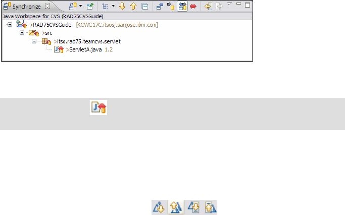
Chapter 28. CVS integration 1053
Draft Document for Review December 9, 2008 2:44 pm 7672-team-2-cvs.fm
Synchronize with the repository by right- clicking the RAD75CVSGuide
project and selecting Team → Synchronize with Repository.
Expand the tree in the Synchronize view to see the changes (Figure 28-24).
Figure 28-24 Synchronize view with conflicting changes
Double-click ServletA.java to see the changes (Figure 28-25):
– On the left side are the changes made by the current user cvsuser2 and
on the right side is the code in the repository (checked in by user
cvsuser1).
– Use the arrow icons at the top to move from change to
change.
– Black lines between the panes indicate identical blocks.
– Red lines indicate changes (inserts or conflicts).
– Red bars on the right indicate conflicts.
Merging in this case requires consolidation between the two developers as to
the best solution. In our example, we assume that the changes in the
repository (right side) have to be placed sequentially before changes
performed by cvsuser2 (left side).
Note: The symbol indicates that the file has conflicting changes that
requires merging.
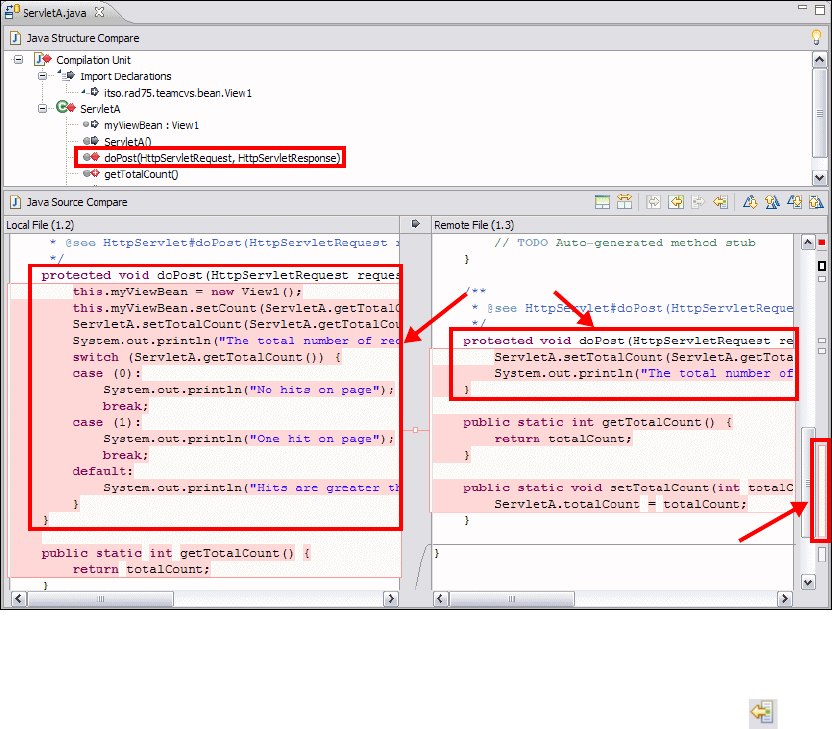
7672-team-2-cvs.fm Draft Document for Review December 9, 2008 2:44 pm
1054 Rational Application Developer V7.5 Programming Guide
Figure 28-25 The changes between the local and remote repository
Double-click the doPost method in the Java Structure Compare view.
Step 1: Click the Copy Current Change from Right to Left icon .
This places the change of the conflicting section on the right-hand panel to
the bottom of the section in the left-hand panel (Figure 28-26).
Step 2: In the left pane, highlight the two lines of code which were added and
move them to the correct location in the method.
These changes cause a conflict
Red portions indicate
conflicting changes.
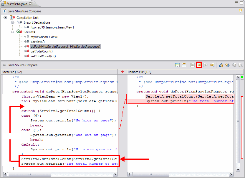
Chapter 28. CVS integration 1055
Draft Document for Review December 9, 2008 2:44 pm 7672-team-2-cvs.fm
Figure 28-26 Merging changes from right to left
Verify that the code is exactly as agreed by the developers, and save the new
merged change by selecting File → Save.
Re-synchronize the file using Team → Synchronize With Repository.
In the Synchronize view, verify that the changes are correct, right-click
ServletA.java and select Mark as Merged, then right-click again and select
Commit.
In the Commit dialog, enter the comment ServletA changed and doPost
method merged with cvsuser1.
This operation creates a revision of the file, revision 1.4, which contains the
merged changes from users cvsuser1 and cvsuser2. This is the case even
though both developers originally checked out revision 1.2.
Step 1: Code copied from
right to left
Move it to this position
Step 1
Step 2
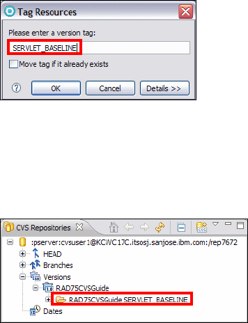
7672-team-2-cvs.fm Draft Document for Review December 9, 2008 2:44 pm
1056 Rational Application Developer V7.5 Programming Guide
User cvsuser1 synchronizes
The workspace for cvsuser1 should also be synchronized with the repository at
this stage to pick up the merged code of the ServletA.
Creating a version (step 5 - cvsuser1)
Now that the changes for both users are committed and cvsuser1 has
synchronized with the repository, we want to create a version to milestone our
work. Perform the following in the workspace of cvsuser1:
Right-click RAD75CVSGuide and select Team → Tag as Version. The Tag
Resources dialog opens (Figure 28-27).
Figure 28-27 Tagging the project as a version
Typ e SERVLET_BASELINE as the version tag and click OK.
Verify that the tag has been performed by switching to the CVS Repository
Exploring perspective and expand Versions (Figure 28-28).
Figure 28-28 Repository view showing new project revision
CVS resource history
Within Application Developer, a developer can view the resource history of any
file in a shared project. This is done in the CVS resource History view, which
shows a list of all the revisions of a resource in the repository. From this view you
can also compare two revisions, revert the existing workspace file to a previous
revision, or open an editor to show the contents of a revision.

Chapter 28. CVS integration 1057
Draft Document for Review December 9, 2008 2:44 pm 7672-team-2-cvs.fm
To demonstrate this feature, do these steps:
In the Enterprise Explorer, right-click ServletA.java and select Team →
Show History, and the History view opens (Figure 28-29).
Figure 28-29 CVS History view for ServletA.java
The CVS resource history displays the columns described in Table 28-4.
Table 28-4 CVS resource history terminology
The following icons are available at the top of the History view:
Refresh—Refreshes the history shown for the currently shown resource.
Link Editor with Selection—A toggle switch which automatically shows
the history of the resource currently being shown in the main editor.
Pin the History View—Locks the history view into showing just the
currently selected resource’s history. When this is toggled on then the Link
Editor with Selection is automatically switched off.
Column Description
Revision The revision number of each version of the file in the repository. An
asterisk (*) indicates that this is the current version in the workspace.
Tags Any tags which have been associated with the revision.
Revision Time The date and time when the revision was created in the repository.
Author The name of the used that created and checked in the revision into
the repository.
Comments The comment (if any) supplied for this revision at the time it was
committed.
7672-team-2-cvs.fm Draft Document for Review December 9, 2008 2:44 pm
1058 Rational Application Developer V7.5 Programming Guide
Group Revisions by date—This changes the view to show the revisions
ordered by date rather than by logical revision number. It is also possible to
order the items in the History View by clicking on the column headers.
Local Revisions, Local and Remote Revisions, Local
Revisions—These boxes provide three options, which type of revisions to
show for the selected resource.
Compare Mode—If this toggle is on then double-clicking on a line in the
history view shows a comparison between the selected repository file and the
file in the workspace. If this is switched off then double- clicking displays the
contents of that file revision.
Filters—This feature is available from the drop-down menu in the History
view. It allows a user to filter the History view by author, date, or text within the
check-in comments.
Comparisons in CVS
Often developers have to view what changes have been made to a file and in
which revision. Application Developer provides a mechanism to graphically
display two revisions of a file and their differences. Two types of comparison are
possible, users can compare the version in their workspace with any version in
the CVS repository, or any two files in the CVS repository can be compared with
each other.
The Resource History view provides these mechanisms and the following
scenario has an example of how to do this.
Comparing a workspace file with the repository
The user cvsuser1 has Version 1.4 of the ServletA file in the workspace and
wants to compare the differences between the current version and Version 1.1.
To do this, do these steps:
In the Enterprise Explorer, right-click ServletA.java and select Compare
with → History, and the History view opens.
Double-click revision 1.1 and the Comparison Editor opens (Figure 28-30):
– In the top half the outline view of the changes are shown. This includes
attribute changes and which methods that have been changed.
– In the bottom two panes the actual code differences are highlighted. The
left pane has the revision in the workspace and the right pane has the
revision 1.1 from the repository.

Chapter 28. CVS integration 1059
Draft Document for Review December 9, 2008 2:44 pm 7672-team-2-cvs.fm
Figure 28-30 Comparison between current ServletA.java and revision 1.1
Comparing two revisions in repository
In this case, the developer wants to compare the differences between revision
1.1 and 1.3 in the repository of the ServletA file, but version 1.4 is in the
workspace and the developer does not want to remove it.
The procedure to compare these two files is as follows:
Open the CVS Resource History using the procedure in “CVS resource
history” on page 1056, which displays the view shown in Figure 28-31.
Note: The bars in the bottom pane on the right-hand side indicate the parts of
the file which are different. By clicking a bar, Application Developer positions
the panes to highlight the changes. This can assist in quickly moving around
large files with many changes.
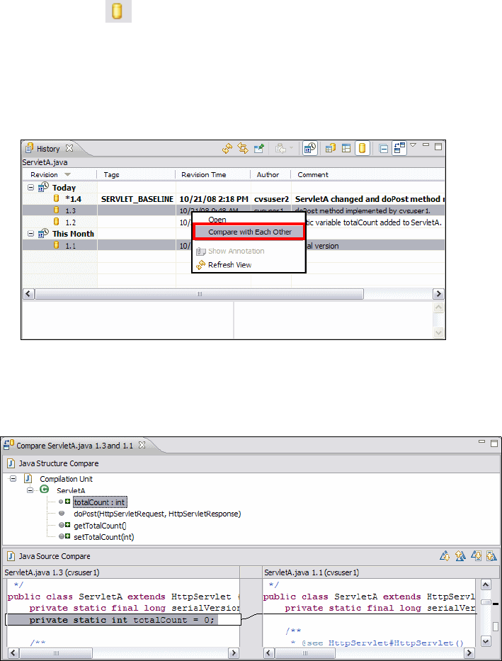
7672-team-2-cvs.fm Draft Document for Review December 9, 2008 2:44 pm
1060 Rational Application Developer V7.5 Programming Guide
First click the icon to only show remote revisions.
Select the row of the first revision to compare, for example revision 1.1, and
then, while pressing the Ctrl key, select the row of the second version, which
is 1.3.
Right-click, ensuring that the two revisions remain highlighted, and select
Compare With Each Other (Figure 28-31).
Figure 28-31 Highlight the two versions to compare
The result appears as in Figure 28-32. The higher version always appears in
the left-hand pane and the lower version to the right.
Figure 28-32 Comparisons of two revisions from the repository

Chapter 28. CVS integration 1061
Draft Document for Review December 9, 2008 2:44 pm 7672-team-2-cvs.fm
Annotations in CVS
The Annotation view allows a user to view all the changes that have been
performed on a particular file in a single combination of workspace views. It
displays what lines were changed in particular revisions, the author responsible
for the change, when the file was changed and the change description entered at
the time. By showing this information across all revisions of a file and in the same
set of connected views, developers can quickly determine the origin of changes
and the explanation behind them.
To demonstrate annotations, we can go back to our example of looking at
ServletA and see what the information the Annotations feature provides:
In the Enterprise Explorer, right-click ServletA.java and select Team →
Show Annotation. If the Changing Quick Diff Reference dialog appears,
select OK.
Application Developer opens the ServletA in a Java Editor, where a colored
line is displayed on the left bar of the source code. When you hover the
mouse over the colored line, a pop-up displays which CVS revision was last
responsible for changing that line (Figure 28-33). In the History view the
revision associated with the line of source code selected, is highlighted.
Figure 28-33 CVS Annotation view

7672-team-2-cvs.fm Draft Document for Review December 9, 2008 2:44 pm
1062 Rational Application Developer V7.5 Programming Guide
Branches in CVS
Branches are a source control technique to allow development on more than one
baseline in the repository.
In CVS, the HEAD branch always refers to the latest or current work that is being
performed in a team environment. This is only sufficient for a development team
that works on one release, which contains all the latest developments, including
major enhancements and bug fixes. The real-world situation is usually that at
least two streams are required. One main stream to manage the development,
and a maintenance stream for the version that is in currently production. This
allows new versions of the production build to be created without fear of being
affected by the changes made to the main development stream. This scenario is
when branches can be useful and where CVS baselines and parallel streams of
work should be created.
At some point the development and maintenance streams have to be merged
together to provide a new baseline to be a production version. This process
ensures that any fixes or enhancements made in the maintenance stream make
it into the development stream. This is known as a merge, and the CVS tools
within Application Developer provide features to facilitate this process. A
representation of this is shown in Figure 28-34.
Figure 28-34 Branching with two streams
Branching
Creating a branch is useful when you want to maintain multiple streams of the
software being developed or supported and when they are in different stages of
delivery (usually development and production support).
Maintenance Stream
Development Stream
Merge two branches
Time
Release of software

Chapter 28. CVS integration 1063
Draft Document for Review December 9, 2008 2:44 pm 7672-team-2-cvs.fm
The scenario demonstrated here is that a particular release has been deployed
to the production environment, and a new project has started to enhance the
application. In addition to this, the existing production release has to be
maintained so that problems identified are fixed quickly. Branching provides the
mechanism to achieve this and the following example outlines how this might be
done.
Perform the following steps for the first workspace for cvsuser1:
In the Enterprise Explorer of the Web perspective, right-click
RAD75CVSGuide and select Team → Tag as Version. Type
BRANCH_ROOT in the tag version field, and click OK.
Right-click RAD75CVSGuide again, and select Team → Branch.
In the Create a new CVS Branch dialog (Figure 28-35), enter Maintenance
as the branch name and BRANCH_ROOT for the version name. Verify that
Start working on the branch is selected so that the workspace automatically
sets itself up for development on the new branch. Click OK.
Figure 28-35 Creating a new CVS Branch
Right-click RAD75CVSGuide, select Properties, and select the CVS tab. A
view is displayed with the tag name displayed as Maintenance (Branch). This
indicates that the project is now associated with the CVS Maintenance branch
and any changes checked in go to that branch (Figure 28-36).
Attention: Remember the version name entered here, as it is important. It
identifies the point at which the branch was created and is required later
when the branches are merged.

7672-team-2-cvs.fm Draft Document for Review December 9, 2008 2:44 pm
1064 Rational Application Developer V7.5 Programming Guide
Figure 28-36 Branch information for a project in the local workspace
Open the CVS Repository Explorer window by clicking Window → Open
Perspective → Other → CVS Repository Explorer.
Right-click the repository and click Refresh View.
Expand the tree to verify that the branch has been created in the repository
(Figure 28-37).
Figure 28-37 List of branches
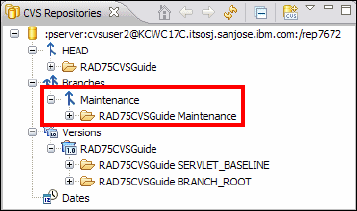
Chapter 28. CVS integration 1065
Draft Document for Review December 9, 2008 2:44 pm 7672-team-2-cvs.fm
Refreshing branching information
The CVS Repositories view does not automatically receive a list of all branches
from the server. If a branch has been created on the CVS server, the user of a
workspace must perform a refresh to receive the name of the new branch. In our
sample case, cvsuser2 should perform a refresh to receive information about the
new maintenance branch.
From the cvsuser2 workspace, do these steps:
To refresh the branches in a repository, open the CVS Repository Exploring
perspective.
Select the repository and expand the tree.Select and right-click the Branches
node, and select Refresh Branches.
In the Refresh Branches dialog, click Select All followed by Finish.
The Maintenance branch is now shown under the Branches folder
(Figure 28-38).
Figure 28-38 Refreshed Branch list
Updating branch code
Assume now that there are changes required to be made to ServletA and a new
view bean (View2) must to be created. This scenario demonstrates the merge
process with the changes being made in the maintenance branch and then
moved into the main branch.
In the workspace of cvsuser1, do these steps:
From the Enterprise Explorer open ServletA.java.
Navigate to the doPost method and at the top add the statement:
System.out.println("Added in some code to demonstrate branching");
Save and close the file.
Right-click the itso.rad75.teamcvs.beans package and select New →
Class.

7672-team-2-cvs.fm Draft Document for Review December 9, 2008 2:44 pm
1066 Rational Application Developer V7.5 Programming Guide
Typ e View2 for the name of the class and click Finish.
Right-click RAD75CVSGuide and select Team → Synchronize With
Repository.
In the Synchronize view, right-click RAD75CVSGuide and select Commit.
In the Commit dialog, type Branching example as the revision comments,
and click Finish.
In the CVS Repository Explorer perspective, expand the tree below the
Maintenance branch (Figure 28-39).
Figure 28-39 Code checked into the branch
The changes have now been committed into the Maintenance branch, which now
has different content than the main branch. These changes are not seen by
developers working on the HEAD branch, which is the development stream in our
scenario.
Note: Note that the logical revision for View2.java is 1.1.2.1 and for
ServletA.java is 1.4.2.1. The extra two numbers in the logical revision are
added by CVS when a branch is created. The first two numbers indicate
the logical revision where the branch was created, the third indicates which
branch the change from that logical revision (currently the second one if we
count the HEAD branch) and the final number is the logical revision within
this branch. In this case both files are the first revision in the Maintenance
branch, and so the last digit is the number one.
Chapter 28. CVS integration 1067
Draft Document for Review December 9, 2008 2:44 pm 7672-team-2-cvs.fm
Merging
Merging of branches occurs when it is decided that code from one branch should
be incorporated into another branch. This might be required for several reasons,
such as if a major integration release is about to be released for testing, or if bug
fixes are required from the maintenance branch to resolve certain issues.
The scenario here is that development on the main CVS branch has completed
and any production fixes made to the Maintenance branch are required in the
main branch as a new production build is planned.
To merge the two branches, the following information is required:
The name of the branch or version that contains your changes.
The version from which the branch was created. This is the version name that
you supplied when branching.
In our case, the branch is called Maintenance, and the version from which we
created the branch was called BRANCH_ROOT.
Merging requires that the target or destination branch be loaded into the
workspace before merging in a branch. Because in our scenario the changes are
merged to HEAD, the HEAD branch must be loaded in the workspace.
Perform the following on the cvsuser1 workspace:
In the Web perspective right-click RAD75CVSGuide and select Replace
With → Another Branch or Version.
In the dialog, select HEAD and click OK to load the latest (HEAD) version of
the RAD75CVSGuide project into the workspace.
Right-click RAD75CVSGuide and select Team → Merge. This displays the
dialog shown in Figure 28-40, which prompts the user for the start and end
points of the merge.

7672-team-2-cvs.fm Draft Document for Review December 9, 2008 2:44 pm
1068 Rational Application Developer V7.5 Programming Guide
Figure 28-40 Selection of the merge start point
Click Browse for the Common base version (start tag) field, expand Versions,
select BRANCH_ROOT and click OK.
Click Browse for the Branch or version to be merged (end tag) field, expand
Branches, select Maintenance and click OK.
The Select the Merge Points dialog (Figure 28-40) now shows the start and
end tags of the merge, which will be applied to the version in the workspace.
The options to Preview Merge in the synchronize view and Perform the
merge into the local workspace provide the facility to select where to
perform the merge:
– Previewing it in the Synchronize view allows the user to review and make
changes to each file as required.
– Performing the merge into the local workspace applies the changes
immediately into the workspace based on preferences selected in the
workspace preferences.
For the example, select Preview Merge in the synchronize view and clear
Merge non-conflicting changes and only preview conflicts.
Click Finish to start the merging.
Expand the tree in the Synchronize view to display changes. Verify that there
are no conflicts. If there are, then the developer has to resolve these conflicts.
In our case, the merge is simple and there are no conflicts (Figure 28-41).
Select a start and end branch
or revision in these two boxes

Chapter 28. CVS integration 1069
Draft Document for Review December 9, 2008 2:44 pm 7672-team-2-cvs.fm
Figure 28-41 Files required to be merged
Right-click RAD75CVSGuide and select Merge.
This attempts to bring the changes from the branch into the main stream, and
because there are no conflicts it completes successfully.
Right-click RAD75CVSGuide and select Team → Synchronize with
Repository.
Expand the Synchronize view to display the changed files ServletA.java and
View2.java (Figure 28-42).
Figure 28-42 CVS updates to HEAD from the merge
This view shows that the file View2.java is a new file to be added to the
repository and that the file ServletA.java has been changed. This is
consistent with the changes that were made in the Maintenance branch and
now have to be added to the main branch.
Right-click the project and select Commit. In the Commit dialog, add the
comment Merged changes from Maintenance branch, and click OK.
The changes from the branch have now been merged into the main development
branch.
This scenario, although a simple one, highlights the technique required by users
to work with branches. In a real scenario there would be conflicts, and this would
require resolution between developers. Be aware that branching and concurrent
development is a complex process and requires communication and planning
between the two teams.
File to be added as
part of the merge
File to be changed as
part of the merge
7672-team-2-cvs.fm Draft Document for Review December 9, 2008 2:44 pm
1070 Rational Application Developer V7.5 Programming Guide
Application Developer provides the tools to assist developers when merging;
however, equally important are procedures for handling situations such as
branching and merging of code, which should be established among the team
early in a project life cycle.
Working with patches
Application Developer provides the facility for developers to be able to share work
when they only have read access to a CVS repository. In this circumstance the
developer that does not have full access to the repository can create a patch and
forward it to another developer with write access, and the patch can be applied to
the project and the changes committed.
Such a configuration is useful when access to the source code repository has to
be restricted to a small number of users to prevent uncoordinated changes
corrupting the quality of the code. Any number of users can then contribute
changes and fixes to the repository using patches, but only through designated
code minders who can commit the work and who have the opportunity to review
changes before applying them to the repository.
This is done through the Team → Create Patch and Team → Apply patch
options available from a project context menu. A patch can contain a single file, a
project or any other combination of resources on the workspace. The Application
Developer online help has a complete description of how to work with CVS
patches.
Disconnecting a project
For many reasons (for example, to disassociate a project from one repository to
allow it to be added to another repository) a developer might want to disconnect a
project from the current CVS repository. To perform this task, complete the
following steps:
In the Web perspective, right-click RAD75CVSGuide and select Team →
Disconnect.
A prompt opens, asking to confirm the disconnect from CVS and if the CVS
control information should be deleted (Figure 28-43).
Select Do not delete the CVS meta information and click OK.

Chapter 28. CVS integration 1071
Draft Document for Review December 9, 2008 2:44 pm 7672-team-2-cvs.fm
Figure 28-43 Disconnect confirmation
By not deleting the CVS meta information, we can reconnect the project with the
CVS repository later more easily. If the meta information is removed, CVS cannot
determine which revision in the repository a particular file is associated with.
Reconnect
You can reconnect a project to the repository by selecting Team → Share
Project. Reconnecting is easier if the CVS meta information was not deleted:
If the meta information was deleted, the user is prompted to synchronize the
code with the an existing revision in the repository.
If the meta information is still available, select Team → Share Project, select
CVS in Share Project dialog and click Next. The original CVS repository
information is shown (Figure 28-44). Click Finish to re-connect.
Figure 28-44 Reconnect to repository with original CVS meta information

7672-team-2-cvs.fm Draft Document for Review December 9, 2008 2:44 pm
1072 Rational Application Developer V7.5 Programming Guide
Team Synchronizing perspective
The Team Synchronizing perspective in Application Developer has been used in
the examples in this chapter but has not yet described in detail. The purpose of
this perspective is to provide to the user with a tool to identify changes repository
compared with what is on the local workspace, and assist in synchronizing the
two together.
Features provided with the Team Synchronize perspective include:
Provide a comparison of changes in the workspace (as described in
“Comparisons in CVS” on page 1058).
Committing the changes made to the repository (as described in the previous
scenarios).
Create custom synchronization of a subset of resources in the workspace.
Schedule checkout synchronization.
Custom configuration of resource synchronization
The Synchronize view provides the ability to create custom synchronization sets
for the purpose of synchronizing only identified resources that a developer might
be working on. This allows the developer to focus on changes that are part of
their scope of work and ensure they are aware of the changes that occur without
worrying about changes to other areas.
The developer can make changes to the other areas or someone else might
check-in changes to these parts, but only the resources in the defined set are
synchronized.
This is handy if the changes being worked on are localized and other areas of the
code are changing in ways not important for the work at hand. On the other hand,
problems can occur with this mode of operation as well. Developers have to be
careful that important changes to the non-synchronized parts are not ignored for
long periods of time.
Important: Custom synchronization is most effective when an application is
designed with defined interfaces, where the partitioning of work is clear.
However, even in this scenario, it should be used with caution because it can
introduce additional work in the development cycle for final product integration.
Procedures have to be documented and enforced to ensure that integration is
incorporated as part of the work pattern for this scenario.

Chapter 28. CVS integration 1073
Draft Document for Review December 9, 2008 2:44 pm 7672-team-2-cvs.fm
The example scenario (again using the RAD75CVSGuide project) demonstrates
custom synchronization, through two procedures:
Full synchronization of the project RAD75CVSGuide
Partial synchronization of the ServletA.java
To perform the example, complete the following for the cvsuser1 workspace:
Open the Team Synchronizing perspective.
Click the Synchronize button at the top the Synchronize view and click
Synchronize to add a new synchronization definition.
In the Synchronize dialog, select CVS and click Next.
Expand the Workspace tree to view the contents and note that all resources
in the workspace are selected. Accept the defaults for the Synchronize CVS
dialog, and click Finish.
If there are no changes, then a dialog box opens, saying Synchronizing: No
changes found, and in the Synchronize view a message of No changes in
'CVS (Workspace)'. Click OK in the dialog box.
To preserve this synchronization, click Pin Current Synchronization .
Add a new synchronization by clicking the Synchronize icon at the top of
the Synchronize view.
In the Synchronize dialog, select CVS and click Next.
Expand the project tree under JavaSource to view the contents, click
Deselect All to deselect all the resources, and select only ServletA.java.
The Synchronize CVS dialog appears as shown in Figure 28-45.
Note: When using Application Developer v7.5, the list of resources shows
a Workspace and a Java Workspace folder. If a customized resource set
is required, it can be selected from either folder with the same final result.
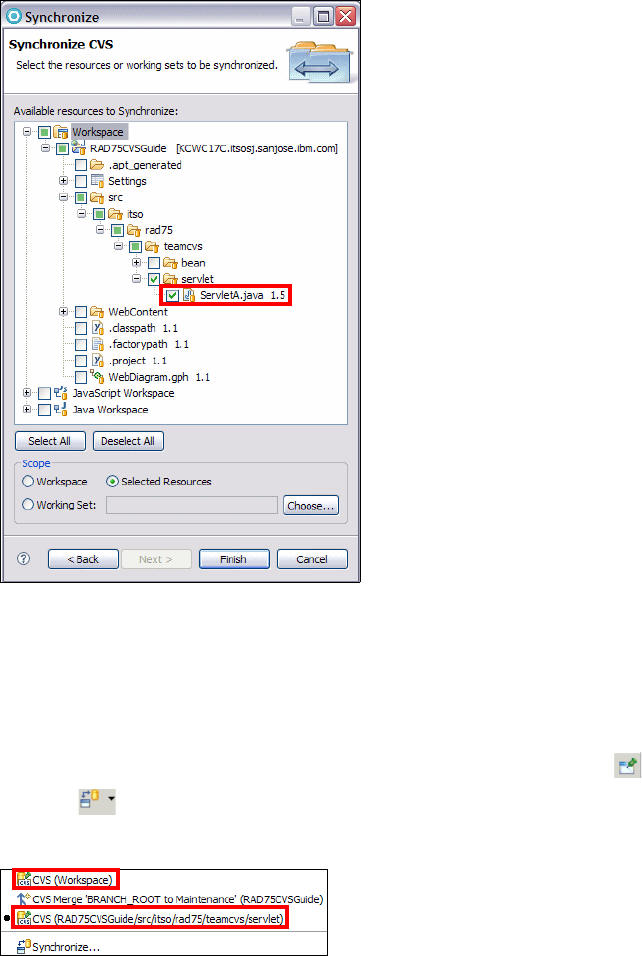
7672-team-2-cvs.fm Draft Document for Review December 9, 2008 2:44 pm
1074 Rational Application Developer V7.5 Programming Guide
Figure 28-45 Selecting ServletA.java for synchronization
Click Finish.
If there are no changes, then a dialog box opens, saying Synchronizing: No
changes found, and in the Synchronize view a message of No changes in
'CVS (Workspace)'. Click OK in the dialog box.
To preserve this synchronization, click Pin Current Synchronization .
Click the icon at the top of the Synchronize view. There are now two CVS
Synchronizations in the list (Figure 28-46).
Figure 28-46 List of synchronizations created
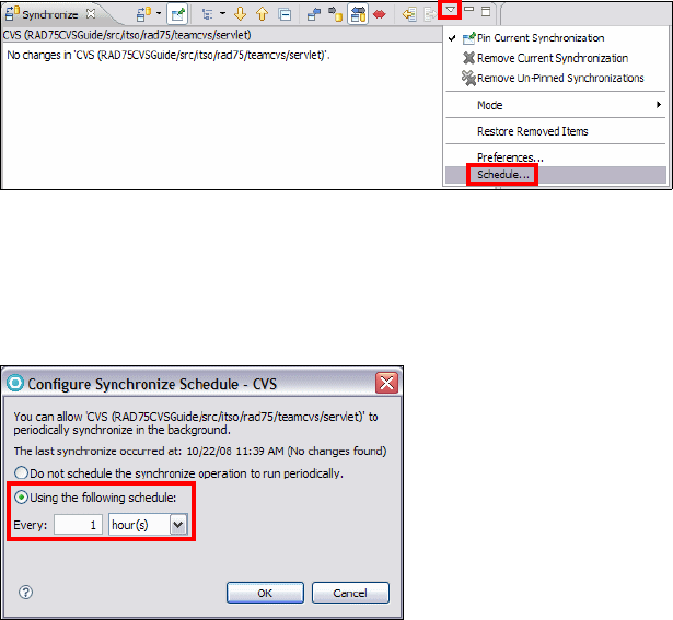
Chapter 28. CVS integration 1075
Draft Document for Review December 9, 2008 2:44 pm 7672-team-2-cvs.fm
Schedule synchronization
Application Developer allows the scheduling synchronization of the workspace.
This feature follows on from “Custom configuration of resource synchronization”
on page 1072, in which a user would like to schedule the synchronization that
has been defined. Scheduling a synchronization can only be performed for
synchronizations that have been pinned.
To demonstrate this feature, assume that the RAD75CVSGuide project is loaded
in the workspace and a synchronization has been defined for this project and
pinned. Scheduling of this project for synchronization is then performed using the
following steps:
In the Synchronize view select Schedule from the drop-down list
(Figure 28-47).
Figure 28-47 Drop-down selection for scheduling synchronization
In the Configure Synchronize Schedule dialog, select Using the following
schedule: and the time period that you want to synchronize (Figure 28-48).
Click OK.
Figure 28-48 Setting synchronization schedule
The user might be prompted to pin the current CVS synchronization, if it is not
already pinned. Click Yes.
7672-team-2-cvs.fm Draft Document for Review December 9, 2008 2:44 pm
1076 Rational Application Developer V7.5 Programming Guide
Assuming that one hour is chosen, the RAD75CVSGuide project is synchronized
every hour to ensure that the latest updates are available. This action performs
the synchronize operation and shows any changes available in the synchronize
view, where the user can accept or postpone integrating the changes as
appropriate.
More information
The help feature provided with Application Developer has a large section on
using the Team Synchronizing and the CVS Repository Exploring perspective
and describes all the features covered in this chapter.
In addition, the following URLs provide further information for the topics covered
in this book:
CVS home page—The main source of information for CVS:
http://www.nongnu.org/cvs/
CVSNT home page—This is the main source of information for CVSNT,
which is the CVS server implementation for Windows machines and the CVS
server software used in this chapter. See the following URL:
http://cvsnt.org/wiki
Eclipse CVS information—The CVS features available in Application
Developer V7.5 come from Eclipse 3.4. The following link is the main
information page for this project. It contains documentation, downloads, and
even the source code:
http://wiki.eclipse.org/CVS
Tortoise CVS home page—This is another CVS client that lets users
perform CVS operations from Windows Explorer. It provides most of the
features of Application Developer and is available under the GNU public
license. This can come in handy when CVS operations are required outside
Application Developer. See the following URL:
http://www.tortoisecvs.org
CVS command line reference—Some operations on the CVS server (for
example changing the password of a user) is best done from the command
line. The following URL provides a quick reference for the CVS command line
interface:
http://refcards.com/docs/forda/cvs/cvs-refcard-a4.pdf

© Copyright IBM Corp. 2008. All rights reserved. 1077
Draft Document for Review December 9, 2008 2:44 pm 7672-team-3-concert.fm
Chapter 29. Rational Team Concert
This chapter describes the capabilities of the Rational Team Concert Client
included with Rational Application Developer. The main goal of the chapter is to
show how a team of Application Developer users can get started using Team
Concert by defining the team composition and the project iterations, choosing a
development process among various proven best practices, sharing existing
projects, managing code and conflicts, tracking defects, tasks and other work
items and generating reports. We show how you can run automated builds and
debug collaboratively using additional features provided by Application
Developer.
This chapter is organized into the following sections:
Introduction to IBM Rational Team Concert
Getting started: Setup a project area
Source control scenarios
Building with Team Concert and the Application Developer Build Utility
Running reports (Standard edition only)
Collaborative Debugging
More information
29

7672-team-3-concert.fm Draft Document for Review December 9, 2008 2:44 pm
1078 Rational Application Developer V7.5 Programming Guide
Introduction to IBM Rational Team Concert
Team Concert is a scalable platform for collaborative development based on the
the Jazz Open Source platform (http://jazz.net). The major features of Team
Concert include:
Customizable processes
Agile planning
Work item tracking
Source code management
Build management
From an architectural standpoint, Team Concert is built upon an application
server, which could be Tomcat or IBM WebSphere Application Server and a
relational database, which could be Derby, IBM DB2, or Oracle.
Editions
Team Concert is provided in three different editions. Smaller teams can get
started using the Express-C edition which supports up to 10 users and provides
access for the first three users free of charge.
Larger teams may want to use or upgrade to the Express or Standard editions,
which support up to 50 and 250 users. All editions provide integration with
Subversion and LDAP authentication, while the Standard edition provides
connectors for IBM Rational ClearCase and IBM Rational ClearQuest. Team
Concert also integrates with IBM Lotus® Sametime® and Jabber for instant
messaging. Refer to http://jazz.net for information about additional planned
integrations. For a full description of the features offered by each edition, see
Table 29-1 on page 1079.
Note: Refer to “Installing IBM Rational Team Concert” on page 1139 for
instructions on how to install Team Concert Express-C edition and the Team
Concert Client, which is an optional component of Application Developer.
Note: The scenarios described in this chapter have been tested with Team
Concert Standard Edition, Tomcat and DB2. Features that are specific to the
Standard Edition have been highlighted and most scenarios are applicable to
the Express-C edition. The source code management and item tracking
features described in this chapter are those of Team Concert itself, so no
installation of ClearCase, Subversion or ClearQuest is required to follow the
proposed scenarios.
Chapter 29. Rational Team Concert 1079
Draft Document for Review December 9, 2008 2:44 pm 7672-team-3-concert.fm
Table 29-1 Feature Comparison of the three editions of Rational Team Concert
Edition Express-c Express Standard
Maximum users 10 50 250
Database included
(optional)
Derby only IBM DB2 Express
(DB2, Oracle)
IBM DB2 Express
(DB2, Oracle)
Application server
included (optional)
Apache Tomcat
only
Tom ca t
(IBM WebSphere)
Tomca t
(IBM WebSphere)
Source code
management
Yes Yes Yes
Work item tracking Yes Yes Yes
Build management Yes Yes Yes
Agile planning Yes Yes Yes
Subversion integration Yes Yes Yes
Server-level permissions Yes Yes Yes
LDAP authentication Yes Yes Yes
Customizable process Yes Yes Yes
Customizable work item
attributes and workflow
No No Yes
Reports No No Yes
Dashboard No No Yes
Role-based process
permissions
No No Yes
Rational ClearCase
connector
No No Yes
Rational ClearQuest
connector
No No Yes
LDAP import No No Yes

7672-team-3-concert.fm Draft Document for Review December 9, 2008 2:44 pm
1080 Rational Application Developer V7.5 Programming Guide
Architecture
The architecture of the Team Concert server comprises kernel and optional
components, described in (Figure 29-1):
Figure 29-1 Kernel and Optional components
Kernel components
The kernel components are the repository and the team process.
Repository
The repository contains items that can be identified by universally unique
identifiers (UUID). Item states and values also have such unique identifiers.
There are auditable item types, which maintain an audit trail consisting of the
past states of the item, the user who saved the item, and the time of the change.
The repository component provides a server-side CRUD API for the items in
the repository. The repository is supported by a relational database. The
top-level items stored in the repository are project areas, which typically
correspond to software development projects and contain references to
artifacts (deliverables), team members, process, and schedule.
A project area may contain multiple development lines, for example one for
new development and one for maintenance.
Each development line has its own deliverables, members, process and
schedule, which may be structured in multiple iterations.
Agile
Planning
Work
Items
Source
Control
Team
Build
Team
Reports
Repository Team
Process
Kernel
Optional Components
Chapter 29. Rational Team Concert 1081
Draft Document for Review December 9, 2008 2:44 pm 7672-team-3-concert.fm
Within a project area, members can be organized into Team Areas, which
define the users, their roles, the development line they work on, and any
process customizations that applies to that specific group.
Team process
Team Concert is process-aware but does not impose a particular process. The
selected process can actively modify the behavior of the tool by defining user
roles, permissions, preconditions for client and server-side operations,
predefined reports and queries.
The process is hierarchical: It can be defined at the project area level and then
customized for each team area belonging to the project. When creating a new
project area, you can select among the following process templates (Table 29-2)
that are shipped with the product and can be further customized:
Agile
The Eclipse Way
OpenUp
Cloudburst
Scrum
SimpleTeam
Out of these process templates, OpenUp, developed by the Eclipse Process
Framework (http://www.eclipse.org/epf/) includes typical characteristics of
the Rational Unified Process.
Table 29-2 Main features of Team Concert process templates
Process Development
Lines
Iteration
types
Roles Work Item
categories
Agile Main
development
Development
Stabilization
Project lead
Team member
Defect
Retrospective
Story
Task
The
Eclipse
Way
Main
development
Development
Stabilization
Contributor
Team lead
Defect
Enhancement
Plan Item
Retrospective
Story
Task
Track Build Item

7672-team-3-concert.fm Draft Document for Review December 9, 2008 2:44 pm
1082 Rational Application Developer V7.5 Programming Guide
Optional components
The optional components are listed below.
Work items
Each process defines categories of work items that can be assigned to team
member, worked on and queried. Each work item type has a state transition
model that defines the available states and the actions that users can take to
move a work item from one state to another.
Some types of work items, such as Defect or Enhancement are suitable for being
associated to source code change sets. Other types of work items such as
Retrospective (in the Eclipse way and Agile processes), are used to record what
went well and what did not go well in the recently completed iteration, and so
forth.
Agile planning
The Agile planning component allows team leads and members to create
iteration plans and to distribute work items to them according to the chosen
process.
OpenUp Main
development
Inception
Elaboration
Construction
Transition
Analyst
Architect
Developer
Project manager
Stakeholder
Tester
Defect
Enhancement
Risk
Task
Use Case
Cloudburst Development
Maintenance
Development
End game
Maintenance
Ready to ship
Project lead
Team member
Defect
Enhancement
Task
Scrum Main
development
Sprint1
Sprint2
Product owner
Scrum master
Team member
Stakeholder
Defect
Impediment
Retrospective
Story
Task
Simple
Team
Development Team member Defect
Enhancement
Task
Process Development
Lines
Iteration
types
Roles Work Item
categories
Chapter 29. Rational Team Concert 1083
Draft Document for Review December 9, 2008 2:44 pm 7672-team-3-concert.fm
Source control
The source control component is based on repository workspaces, and streams.
Team Concert bases source control on change sets, not on files. Change sets
contain the before and after states of versionable items, an optional comment,
and can be linked to a work item.
In Application Developer (and in Eclipse) there is a local workspace, contained in
the Eclipse workspace, which mirrors the repository workspace of that particular
user. A repository workspace is similar to an Application Developer or Eclipse
workspace because it contains the artifacts developed by one particular user, but
it is very different because it is stored in the repository, on the Team Concert
server.
Change sets are pushed from the local workspace onto the repository
workspace by the check in operation. Conversely, files can be imported into a
local workspace from the repository workspace by using the load operation.
The fact of having a repository workspace allows each user to make a backup
of their work on the server. Once a particular user is satisfied with the
changes, the user can make them available to the team by using the deliver
operation.
Change sets are delivered from the repository workspace (which belongs to
one user) to the stream (which belongs to a team).
A stream holds a common shared copy of the files, and it is also stored on the
server.
A user can accept changes made by other team members and available in the
stream change history. Each workspace or stream keeps a change history
that permits to creation of the current version of the items from the
accumulated changes.
In complex projects, streams and workspaces can be partitioned into
components that have their own change history, change sets and configuration
(Figure 29-2).
To initialize streams and workspaces, it is possible to create a baseline, which is
an immutable copy of a component in a given workspace or stream. A snapshot
is an immutable collection of one baseline for each workspace component, which
can be used to recreate the entire workspace configuration (typically for
reproducing a build).

7672-team-3-concert.fm Draft Document for Review December 9, 2008 2:44 pm
1084 Rational Application Developer V7.5 Programming Guide
Figure 29-2 Local and Workspace Repository and their relationship to a Stream
Team build
Team Concert includes the Jazz Build Engine and an Ant build toolkit that can
publish build information to the Jazz repository. The repository contains:
Build definition items, representing a particular build, such as a weekly
project-wide integration build;
Build engine items, representing a particular build system running on a build
server;
Build request items, representing a particular request to run a build;
Build result items, representing the outputs from a particular run.
The installation of Team Concert provides two components: Jazz Build Engine
and Build Toolkit.
The Jazz Build Engine can be used to run continuous builds or to request
builds at a particular point in time. While the build items described above are
optimized for use with the Jazz Build Engine, they can also be used with other
build engines such IBM Rational BuildForge or CruiseControl.
Team Concert Server
Repository
Stream
Repository Workspace User B
Repository Workspace User A
Accept
Deliver
Application Developer
Eclipse Workspace
Local Workspace User A
Load Check in
Component 1
Component 1Component 1
Component 1
Folders, Files
Chapter 29. Rational Team Concert 1085
Draft Document for Review December 9, 2008 2:44 pm 7672-team-3-concert.fm
The Build Toolkit is a set of Ant Tasks that can be used to perform the
following tasks:
– Publishing build results and contributions
– Enabling progress monitoring
– Working with Jazz source control
– Controlling the build life cycle
There are four types of available build templates that can be selected when
creating a new build definition:
Ant - Jazz Build Engine A build using Ant and the Jazz Build
Engine
Command Line - Jazz Build Engine A build that invokes a command line
using the Jazz Build Engine
Generic A generic build
Maven - Jazz Build Engine A build using Maven 2 and the Jazz
Build Engine
Team reports
The reports component applies only to the Standard edition and it consists of the
data warehouse and the reports engine. The data warehouse stores read-only
snapshots of the repository data in a non-normalized form that is optimized for
efficient queries and quick response times. The report engine is based on the
Eclipse BIRT (Business Intelligence and Reporting Tools) project.
Getting started: Setup a project area
This section is a practical introduction to the Team Concert Client shipped with
Application Developer. We will work primarily in two Perspectives:
Work Items
Jazz Administration
The section is organized in the following topics:
Creating a repository connection and project area
Predefined work items: Define team members
Predefined work items: Define iterations and iteration plans
Process configuration: Define preconditions
New work item: Create components
Creating a repository workspace
Setting up team areas

7672-team-3-concert.fm Draft Document for Review December 9, 2008 2:44 pm
1086 Rational Application Developer V7.5 Programming Guide
Creating a repository connection and project area
You can perform the setup of a new Project Area from Application Developer
following these steps:
Select Windows → Open Perspective → Work Items (Figure 29-3).
Figure 29-3 Work Items perspective
Select Create a Repository Connection (Figure 29-4):
Figure 29-4 Create a Jazz repository connection
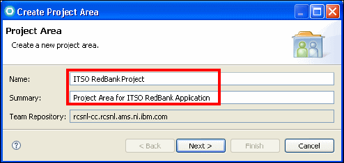
Chapter 29. Rational Team Concert 1087
Draft Document for Review December 9, 2008 2:44 pm 7672-team-3-concert.fm
– Enter the URI that you defined when you installed the server:
https://hostname:port/jazz/
– Enter the Connection Name: hostname
– Enter the user ID and password of a user that has been defined on the
server at installation time
If Team Concert is installed on the same machine as Application Developer,
you will see the URI corresponding to localhost in the URI drop down list
Right-click on the Repository Connection in the Team View.
Select New → Project Area (Figure 29-5)
– Enter the name: ITSO RedBank Project
– Enter the Description: Project Area for ITSO Redbank Application
– Click Next.
Figure 29-5 Create RedBank project area
Select the Process Template that you want to apply to this Team process
Area, in this case we select OpenUp Process (Figure 29-6).

7672-team-3-concert.fm Draft Document for Review December 9, 2008 2:44 pm
1088 Rational Application Developer V7.5 Programming Guide
Figure 29-6 Select the OpenUp process for the project area
The Project Area editor opens. Here you can define the team members, their
roles, the iterations of the project, process customizations, work item types,
and releases.
Predefined work items: Define team members
In the Work Items view you find some predefined work items that guide you to get
started (Figure 29-7). You will assign a few of them to yourself to prepare the
project.
Figure 29-7 View of work items initially created

Chapter 29. Rational Team Concert 1089
Draft Document for Review December 9, 2008 2:44 pm 7672-team-3-concert.fm
Select the Define team members work item. This opens the Work Item
Editor, where you can find a description of what you have to do to complete
this task (Figure 29-8). Select some appropriate values:
– Change status from New to Start Working.
–Severity:
Major
– Owned by: yourself
– Planned for: Inception
– Due: today’s date
Save (note that the status changes from Start Working to In progress).
Figure 29-8 Work Item view
As described in the work item, open the Project Area editor:
– Locate the Members section.
–Select
Create.
–Select
Create a new User.
– Fill in the user information.
– Assign to a Repository group (JazzUsers)
– Assign a Rational Concert - Developer license.
– Click Finish.
– Assign some of the available process roles to the members (Figure 29-9).
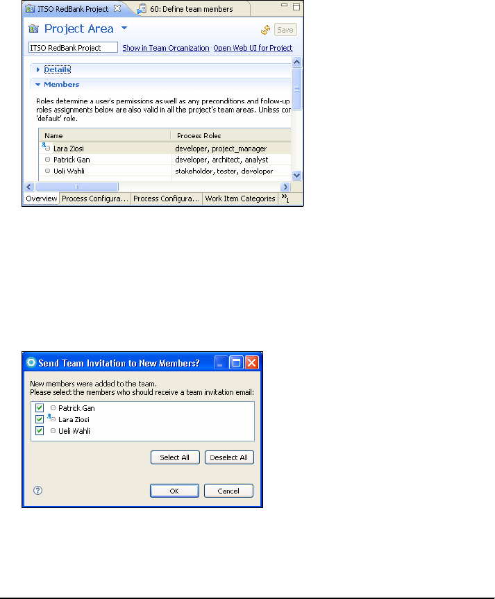
7672-team-3-concert.fm Draft Document for Review December 9, 2008 2:44 pm
1090 Rational Application Developer V7.5 Programming Guide
Figure 29-9 Assign members to the project and process roles to the members
When you are done adding the members and save the project area editor, you
are prompted for sending an invitation e-mail the new members, assuming
that the e-mail service has been configured on the server (Figure 29-10). If
the Mail service is not configured, you will see an exception that you can
ignore.
Figure 29-10 Send Team Invitation to new members of a project area
The new team members receive an e-mail (Example 29-1).
Example 29-1 E-mail generated by Team Concert to invite new team member
You have been invited to join the Jazz team ITSO RedBank Project.
You can explore the related project area via the web UI at
https://rcsnl-cc.rcsnl.ams.nl.ibm.com:9443/jazz/web/projects/ITSO%20RedBank%20P
roject.
Use File>Accept Team Invitation within the Rational Team Concert client to open
the Accept Team Invitation dialog.

Chapter 29. Rational Team Concert 1091
Draft Document for Review December 9, 2008 2:44 pm 7672-team-3-concert.fm
Copy the invitation below and paste into the Accept Invitation text field.
teamRepository=https://rcsnl-cc.rcsnl.ams.nl.ibm.com:9443/jazz/
userId=lziosi
userName=Lara Ziosi
projectAreaName=ITSO RedBank Project
The other team members can accept the invitation as described in the e-mail.
If e-mail notification was not configured on the server, then you will see an
exception that can be ignored.
However, you will have to provide the above connection details to the users in
some way. With that information the users will do the following:
– Open the Work Items Perspective and select Connect to the Repository.
– Right-click on the repository connection in the Team Artifacts view and
select Connect to Project Areas.
– In the dialog that opens, select the project area name to connect to.
In the Work Item editor for Define Team Members, select Resolve and Fixed.
Predefined work items: Define iterations and iteration plans
To define the iterations and iteration plans, to the following:
Open the work item Define Iterations and select Start Working. Save it.
– In the Project Area editor, Overview tab, look at the Process Iterations:
– Set dates for the iterations defined in the four phases: Inception,
Elaboration, Construction, Transition by selecting Edit Properties
(Figure 29-11).
– Here you could create additional development lines (for example, one for
maintenance) and remove or add iterations.
In the Work Item editor for Define Iterations select Resolve, and Fixed.
Open the work item Define an iteration plan and select Start Working.
Following the description, perform these steps:
– Select the Plans node under the Project Area in the Team Artifacts view.
– Right-click Inception Iteration I1.
–Select
New → Iteration Plan.
– Name the iteration plan InceptionIterationPlan.
– In the editor that opens, in the Planned Items tab, you can see the folders
Top Items and Defects and Enhancements.
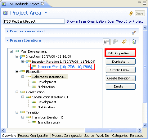
7672-team-3-concert.fm Draft Document for Review December 9, 2008 2:44 pm
1092 Rational Application Developer V7.5 Programming Guide
– Drag and drop all the predefined work items from the Work Item View onto
the Top Items folder. This assigns the work items to the current iteration.
In the Work Item editor for Define an Iteration plan, select Resolved and
Fixed.
Figure 29-11 Define development lines, iterations, dates for the phases of the project
Open the view called My Work.
Select the project area ITSO RedBank Project.
You should see the work you have already completed and the planned work
(Figure 29-12).
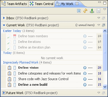
Chapter 29. Rational Team Concert 1093
Draft Document for Review December 9, 2008 2:44 pm 7672-team-3-concert.fm
Figure 29-12 My Work View after completing a few work items
Process configuration: Define preconditions
Team Concert allows you to associate preconditions to certain actions, in order
to enforce desirable behavior. You can specify different preconditions for different
phases of a project. By default the Open Up process template specifies rules on
the delivery operation during the Stabilization phase of the Elaboration Iteration.
We will add the rule that every delivery must be associated with a Work Item:
In the Project Area editor, select the Process Configuration tab.
Under Configuration → Team Configuration, select Operation Behavior.
For the user: Everyone (default) select the operation: Source Control →
Deliver (client).
Note that Preconditions and follow-up actions are configured for this
operation is selected.
The following preconditions are already selected:
– Clean Workspace
– Descriptive Change Sets
Remove Descriptive Change Sets (we will replace it with a more restrictive
condition).
Click Add in the Preconditions (7 available) group (Figure 29-13).
Multiple select (use the Ctlr key) the following preconditions: Prohibit
Unused, Java imports, and Require Work items and Comments.
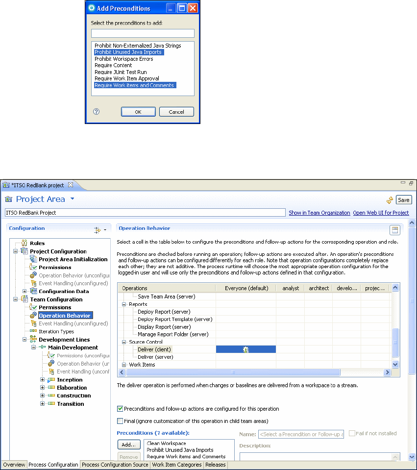
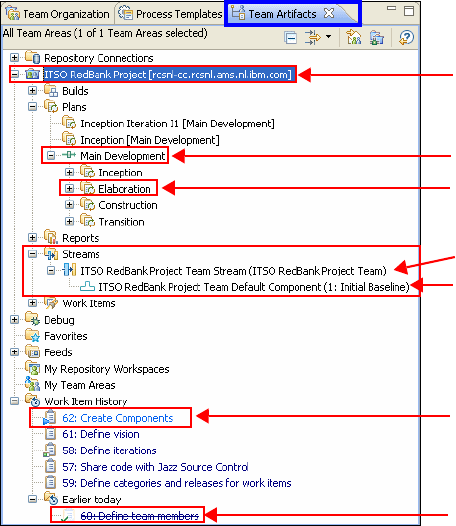
Chapter 29. Rational Team Concert 1095
Draft Document for Review December 9, 2008 2:44 pm 7672-team-3-concert.fm
New work item: Create components
We want to be able to manage different parts of the project in different
components owned by different teams. We first create a work item to track this
task. Note that you can also create work items from the iteration plan.
Select File → New → Work Item.
Project Area: ITSO RedBank project
Work Item Type: Task
Enter the following information:
–Summary:
Create Components
– Filed against: ITSO RedBank Project
– Owned by: yourself
– Planned for: Inception
– Due: today’s date
Save the Work Item. Select In progress. Save again.
Open the Team Artifacts View (Figure 29-15).
Figure 29-15 Team Artifacts view showing stream, component and work item history
New work item
Stream
Component
Fixed work item
Development line
Project area
Iteration

7672-team-3-concert.fm Draft Document for Review December 9, 2008 2:44 pm
1096 Rational Application Developer V7.5 Programming Guide
Expand the Project Area node ITSO RedBank Project. Inside the node
streams there is the stream called ITSO RedBank Project Team Stream,
which contains the component ITSO RedBank Project Team Default
Component.
Right-click on the Stream and select Open.
In the Components list select New. Enter the following names:
Java prototype Component
Web Application Component
When you select Save, the component initial baselines are created
(Figure 29-16).
Figure 29-16 Creation of additional components
In the Work Item editor for Create Components, select Resolve and Fixed.
Associate this work item with the inceptioniterationplan (drag and drop it on
the Top Items folder).
Creating a repository workspace
Create a repository workspace for the current user:
Select the Team Artifacts view.
Right-click on My Repository Workspaces → New Repository Workspace.
The New Repository Workspace dialog opens (Figure 29-17).
Select Flow with a stream (select the only available stream).
Type the name ITSO Redbank Lara’s Workspace.
In Components to Add:
– Select all the components.
–Select
Load Repository Workspace after creation to copy the selected
components from the repository workspace to the local workspace after
the repository workspace has been created.
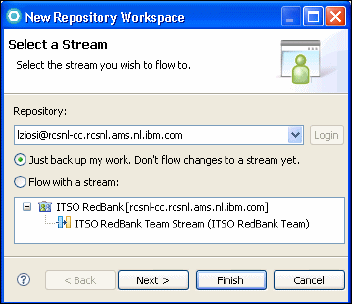
Chapter 29. Rational Team Concert 1097
Draft Document for Review December 9, 2008 2:44 pm 7672-team-3-concert.fm
Click Finish.
Figure 29-17 Create a repository workspace for the current user
In the Load Repository Workspace dialog:
–Select:
Browse the components to select the folders to be loaded.
– Select all three components.
Setting up team areas
We want to create two team areas to distinguish development of a Java
application prototype from the main development of the RedBank application.
Open the Team Organization view (in the Jazz Administration perspective).
Right-click on the default Team Area (ITSO RedBank ProjectTeam) and select
New → Team Area.
Type the Name Java Prototype Team and an optional Summary
(Figure 29-18).

7672-team-3-concert.fm Draft Document for Review December 9, 2008 2:44 pm
1098 Rational Application Developer V7.5 Programming Guide
Figure 29-18 Creation of new Team Are for the Java Team
Repeat the same steps to create the team area Web Development Team.
Distribute members among the two teams (Figure 29-19).
Assign the ownership of the Java Prototype component to the Java Prototype
Tea m:
– Open the Team Area editor for Java Prototype Team.
–Select
Artifacts → Stream.
– Right-click and select Search Components.
– Find the Java Prototype component.
– Change owner to the Java Prototype Team.
Assign the ownership of the Web Application Component to the Web
Development Team.
Figure 29-19 Team Organization view with team areas and team members

Chapter 29. Rational Team Concert 1099
Draft Document for Review December 9, 2008 2:44 pm 7672-team-3-concert.fm
Source control scenarios
In this section we describe some common development scenarios using various
source control features.
Sharing existing projects
Connecting to the repository and loading projects
Managing conflicts
Sharing existing projects
In this section we share a Java project and a Web project.
Sharing the Java project
To seed the project area we want to import a Java prototype of the RedBank
application. We also want to store it in a dedicated component. Only the Java
Team will be concerned with this project.
Select Start working on the work item Share code with Jazz Source Control.
Open the Java Perspective.
Select File → Import → Project Interchange and locate the
C:\7672code\zInterchange\java\RAD75Java.zip file.
Right-click the RAD75Java project in the Package Explorer, and select
Team → Share Project → Jazz source Control.
In the Share Project dialog click Next (Figure 29-20).
Figure 29-20 Share an existing project with Jazz Source Control
In the Share Project in Jazz dialog (Figure 29-21):
– Select: Select a component in an existing repository workspace.
–Select
ITSO RedBank Lara’s Workspace.
–Select
Java Prototype Component.

7672-team-3-concert.fm Draft Document for Review December 9, 2008 2:44 pm
1100 Rational Application Developer V7.5 Programming Guide
– Click Next.
Figure 29-21 Select a component from a repository workspace to share a project
In the Review Ignored Resources page, you can see that .class files and the
bin folder are not added to source control. Click Finish.
Expand the project in the Package Explorer. Notice that files and packages
are decorated by black arrows oriented left to right, indicating outgoing
changes (Figure 29-22).
Figure 29-22 Package Explorer after sharing a project
Expand the contents of the Pending Changes view. This view shows the
incoming/outgoing changes between the workspace (ITSO Redbank Lara’s
Workspace) and the stream (ITSO RedBank Project Team Stream). The
component Java Prototype Component has one outgoing change set called
Share projects, which contains all files and folders to be added to source
control.
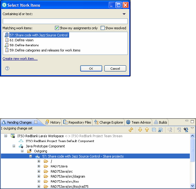
Chapter 29. Rational Team Concert 1101
Draft Document for Review December 9, 2008 2:44 pm 7672-team-3-concert.fm
Right-click on the Share projects change set and select Associate Work
Item.
Select the work item Share Code with Jazz Source Control (Figure 29-23).
Figure 29-23 Associate a work item to a change set
Notice that the change set is now called Share Code with Jazz Source
Control - Share projects (Figure 29-24).
Figure 29-24 Pending changes view after sharing a project
Right-click on the change set and select Deliver. This places the project in the
team repository and removes all the outgoing changes from the Pending
Changes view.
If you right-click on the Java Prototype Component in the Pending Changes
view you can select Show Repository Files.
The Repository Files view opens and you can verify that all the project files
and folders are stored in the repository.
In the Team Artifacts view, locate the stream ITSO RedBank Project Team
Stream.

7672-team-3-concert.fm Draft Document for Review December 9, 2008 2:44 pm
1102 Rational Application Developer V7.5 Programming Guide
Right-click on the stream and select Show Repository Files. This action
shows that the deliver operation has made the projects available in the
Stream where the team can access them.
Since this is the initial state of the project and we want to be able to go back to
it if required, we create a new baseline for the Java Prototype Component.
Note that the existing baseline (Initial Baseline) was created as soon as the
component was created, and it is not associated to any source files.
Right-click Java Prototype Component in the Pending Changes view and
select New → Baseline. Name the baseline Imported prototype.
Right-click on the outgoing change and select Deliver.
To verify, right-click Java Prototype Component in the Pending Changes
view and select Show Baselines. The History View opens and you can
right-click on each baseline and select Show Repository Files
(Figure 29-25).
Figure 29-25 History view shows the baselines of the component
Sharing a Web application
We now repeat the above steps for the Web application.
Select File → Import → Project Interchange and locate the
C:\7672code\zInterchange\ejb\RAD75EJBWeb.zip file.
Right-click the RAD75EJBWeb project in the Package Explorer and select
Team → Share Project → Jazz source Control.
– Select all four available projects.
– Share them into the component ITSO RedBank Lara’s Workspace →
Web Application Component.
In the Pending Changes View:
– Right-click on the Change Set and select Associate Work Item.
– Select the work item Share Code with Jazz Source Control.
– Right-click on the change set and select Deliver.
In the Team Artifacts view, Work Item history node:
– Select the work item Share Code with Jazz Source Control.
–Mark it as Resolved and Fixed.

Chapter 29. Rational Team Concert 1103
Draft Document for Review December 9, 2008 2:44 pm 7672-team-3-concert.fm
Connecting to the repository and loading projects
Now that the project has been delivered to the Team Repository it can be
accessed by another user. The following steps are performed in an empty
Application Developer workspace. Perform these actions to start working on the
Java project as user Patrick:
Create a repository connection.
Connect to the project area ITSO RedBank Project.
Create a new repository workspace:
– Load all components from the stream.
– In the Load Repository Workspace dialog (Figure 29-26), select Find and
Load Eclipse projects.
Figure 29-26 Methods to load existing projects from a repository workspace
– The RAD75Java Project appears under Java Prototype Component
(Figure 29-27).
Figure 29-27 Loading specific projects into the local Eclipse workspace

7672-team-3-concert.fm Draft Document for Review December 9, 2008 2:44 pm
1104 Rational Application Developer V7.5 Programming Guide
Patrick finds that there are warnings (Figure 29-28) and corrects them by
removing two unused methods from BankClient.java. Patrick saves the file.
– Open the Pending Changes view.
– Select the file BankClient.java.
– Right-click and select Check-in → New Change set.
Note that the Check-in operation is only going to store the changes in
Patrick’s own repository workspace. The other team members have no
access to the changed file until Patrick actually delivers the change set to the
team repository.
Figure 29-28 Check-in operation from Pending Changes view
– The change set appears under the Outgoing header with the label: <Enter
a Comment>.
– Click once on the label and type Resolve Warnings (Figure 29-29).
Figure 29-29 Pending Changes view after check-in and change set creation
Standard
Edition only?
See PMR
05183,211,788
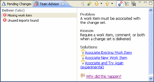
Chapter 29. Rational Team Concert 1105
Draft Document for Review December 9, 2008 2:44 pm 7672-team-3-concert.fm
Finally Patrick decides that it is best to make the changes available to the
whole team right away. Right-click on the change set and select Deliver.
The Team Advisor View appears and informs Patrick that he cannot deliver
the changes (Figure 29-30). Due to the preconditions set in the project
process, Patrick will not be able to deliver a change set that is not associated
to a work item and that introduces unused imports. The latter issue is due to
the fact that after deleting the two methods, some existing imports have
become unused.
Figure 29-30 Team Advisor with reasons why a deliver operation is not completed
To resolve the first problem Patrick can click select Associate New Work
Item, naming the work item a [space].
To resolve the second problem, it is enough to select Source → Organize
Imports (or press CTRL+SHIFT+O) with the BankClient.java open in the
Java source editor.
Now it is possible for Patrick to deliver the change to the team repository.
After opening the work item Clean Java Prototype, the Links folder should
contain a link to the change set Resolve Warnings.
Managing conflicts
For the purpose of demonstrating how conflicts can be managed in Team
Concert, we describe what happens if Lara—unaware of the changes made by
Patrick—decides to change the implementation of the Java prototype, switching
to the use of JavaScript (refer to “Using scripting inside the JRE” on page 116).
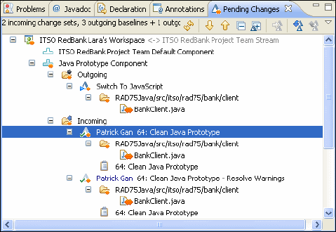
7672-team-3-concert.fm Draft Document for Review December 9, 2008 2:44 pm
1106 Rational Application Developer V7.5 Programming Guide
While logged on as Lara, perform the following:
In the Java Perspective, Package Explorer view, expand the package
itso.rad75.bank.client. Note that BankClient.java is decorated with an
arrow from right to left indicating an incoming change.
Open BankClient.java.
Change the lines:
//Here you can switch the logic to be implemented in Java or Scripting
executeCustomerTransactions(oITSOBank);
//executeCustomerTransactionsWithScript(oITSOBank);
to use Java Script instead of Java:
//Here you can switch the logic to be implemented in Java or Scripting
//executeCustomerTransactions(oITSOBank);
executeCustomerTransactionsWithScript(oITSOBank);
Save the file.
Right-click on the file in Package Explorer and select Team → Check in.
Remember that this action pushes the change set onto Lara’s private
workspace repository.
Open the Pending Changes view if it is not visible.
You will see an outgoing change set with the label Enter a Comment.
Click on the label and type Switch To Java Script.
You will see orange double headed arrows indicating conflicts (Figure 29-31).
Figure 29-31 Conflicts in the pending Changes view
Lara tries to Deliver.
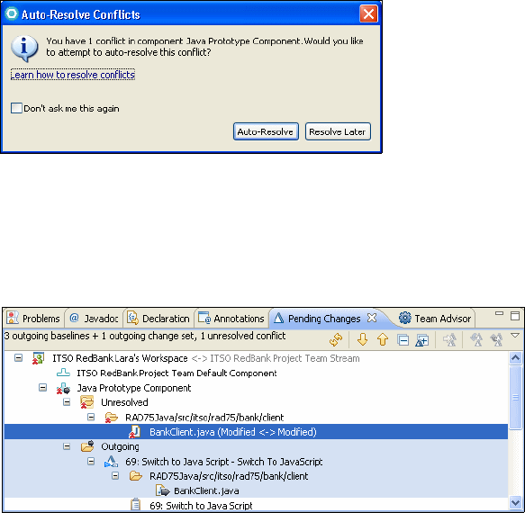
Chapter 29. Rational Team Concert 1107
Draft Document for Review December 9, 2008 2:44 pm 7672-team-3-concert.fm
(Standard edition only) Lara is prompted to associate a work item with the
change set.
Lara creates the new work item called Switch to JavaScript.
When Lara tries to Deliver again, the Team Advisor reports:
Problem
An error occurred during "Deliver".
Cannot deliver changes since they would create conflicts for
"/RAD75Java/src/itso/rad75/bank/client/BankClient.java". Try accepting all
incoming changes, resolve the conflicts, then deliver again.
As a result Lara right-clicks on the incoming changes and selects Accept.
When Lara tries to Deliver the change set Switch to JavaScript, the following
dialog box appears (Figure 29-32).
Figure 29-32 Auto-Resolve Conflicts dialog
Click Resolve Later to explore all possibilities for conflict resolution.
Because the conflict was left unresolved, it appears in the Pending Changes
view in the Unresolved section for the component (Figure 29-33).
Figure 29-33 Unresolved conflict in Pending Changes view
By right-clicking on BankClient.java in the Unresolved category, options for
resolving the conflict are displayed (Figure 29-34).
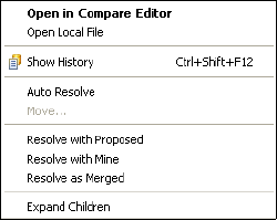
7672-team-3-concert.fm Draft Document for Review December 9, 2008 2:44 pm
1108 Rational Application Developer V7.5 Programming Guide
Figure 29-34 Possible options for resolving conflicts
Auto Resolve Works by merging nonconflicting changes such as
simple additions or removals (but not intra-line
differences).
Resolve with proposed Replaces the file in your workspace with the one
that contains the conflicting changes.
Resolve with Mine Replaces the file that contains the conflicting
changes with the file that is currently in your
workspace.
Resolve as Merged Indicates that you have finished merging.
Before deciding which option to use, Lara selects Open in Compare Editor.
In Java Structure Compare (Figure 29-35) you can see that the change made
by Lara to the main function is seen as outgoing. The changes made by
Patrick (deletion of import statements and of two methods) are seen as
incoming, and they cannot be overruled using this editor.
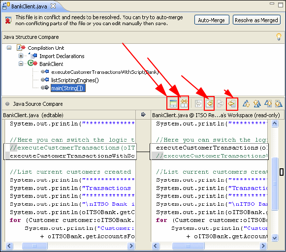
Chapter 29. Rational Team Concert 1109
Draft Document for Review December 9, 2008 2:44 pm 7672-team-3-concert.fm
Figure 29-35 Compare Editor
Lara decides that she wants to preserve her changes, so she right-clicks on
BankClient.java in the Unresolved category in the pending Changes view
and selects Resolve with Mine.
The Pending Changes view shows the conflict as resolved.
Lara selects Deliver and Resolve Work Item.
When Patrick refreshes the Pending Changes view, he will see the incoming
change associated to the work item Switch to Java Script.
After review of the work item description Patrick accepts the incoming
change.
Patrick then opens the work item Clean Java prototype and selects
Resolve, Won’t Fix, because in this case the warnings about unused
methods had to be preserved to allow a different choice of implementation in
this Java prototype.
Show ancestor pane
Two-way compare (ignore ancestor)
Copy all non-conflicting changes R to L
Copy current change R to L

7672-team-3-concert.fm Draft Document for Review December 9, 2008 2:44 pm
1110 Rational Application Developer V7.5 Programming Guide
Building with Team Concert and the Application
Developer Build Utility
In this section we show how you can request builds on the Team Concert Build
engine invoking the Application Developer Build Utility introduced in “Using the
Rational Application Developer Build Utility” on page 929. This section is
organized in the following parts:
Creating a build user
Creating a repository workspace owned by the build user
Starting the Jazz build engine
Preparing the Ant build file
Creating a build engine and a build definition
Requesting a build
Creating a build user
In order to run builds in Team Concert, you need a dedicated user added to the
team area. This user must be assigned a special license type and must own the
repository workspace used for the build.
Create a work item called Create Build User and select Start Working.
Right-click on the project area in the Team Artifacts view and select Create
from the Members section.
Set the userId and the userName as build.
Note that by default the password of this user is set to be equal to its user ID.
You will need the user ID and password of this user to start the build engine.
Assign a Build System license to the build user (Figure 29-36).
Note: Before you can run the steps in this section you should have installed
the Rational Team Concert Build System and the Rational Application
Developer Build Utility on the computer that runs the Rational Team Concert
server, as described in Appendix A, “Product installation” on page 1121.
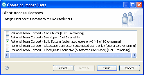
Chapter 29. Rational Team Concert 1111
Draft Document for Review December 9, 2008 2:44 pm 7672-team-3-concert.fm
Figure 29-36 Assign a Build System license to the build user
Creating a repository workspace owned by the build user
Perform the following steps in the Team Artifacts view to create a new repository
workspace:
Select My Workspaces → New Repository Workspace.
Select Flow with a stream → ITSO RedBank Project Team Stream.
Type the Name as ITSO RedBank Project Build Workspace.
Accept to load the four projects from the Web Application Component.
Change the owner of the new workspace to be the build user:
Right-click ITSO RedBank Project Build Workspace and select Open.
Select Browse on the Owned By field and type build to select the build user.
Notice that the new workspace disappears from the node My Workspaces.
Starting the Jazz build engine
On the Team Concert server you must start the Jazz build engine before you can
request any builds. The build engine is an executable at:
<RTC_Build_installation>\buildsystem\buildengine\eclipse\jbe
The required arguments for the Jazz build engine are:
repository <repository address> (address of a Jazz repository)
userId <user id> (user id of a user defined in the Jazz
repository)

7672-team-3-concert.fm Draft Document for Review December 9, 2008 2:44 pm
1112 Rational Application Developer V7.5 Programming Guide
You can launch jbe without any arguments to see the full list of optional
arguments. Note that in order to launch the build engine, a JDK version 1.5 or
higher must be on the system path. If that is not the case, you can supply the
location of a suitable JDK as a command line argument introduced by -vm.
The following batch file (Example 29-2) illustrates how you could start the build
engine on a Team Concert server and a build engine installed in:
C:\Program Files\ibm\JazzTeamServer
C:\Program Files\ibm\TeamConcertBuild\buildsystem
Example 29-2 Sample batch file to start the Team Concert Build Engine
@echo on
setlocal
set RTC_SERVER_HOME="C:\Program Files\ibm\JazzTeamServer"
set JAVA_HOME=%RTC_SERVER_HOME%\server\win32\ibm-java2-i386-50\jre\bin
set RTC_BUILD_HOME="C:\Program Files\ibm\TeamConcertBuild"
cd %RTC_BUILD_HOME%\buildsystem\buildengine\eclipse
jbe -repository https://rcsnl-cc.rcsnl.ams.nl.ibm.com:9443/jazz -userId build
-pass build -sleepTime 3 -verbose -vm %JAVA_HOME%\java.exe
Note that the password of the build user is passed as an optional command line
argument introduced by -pass. An alternative to providing the password on the
command line is to launch jbe once with the optional argument
-createPasswordFile. If you execute:
<RTC_Build_installation>\buildsystem\buildengine\eclipse\jbe
-createPasswordFile passwordFile.txt
you will be prompted to enter the password for the build user, which will be stored
encrypted in the file provided on the command line. It is recommended that you
protect the file itself with appropriate operating system permissions.
Preparing the Ant build file
A suitable Ant build file has been developed in “Create the build file
(BUbuild.xml)” on page 930. To share this Ant file, perform these steps:
Create a project using File → New → Project → General → Project, and set
the project name as AntScripts.
Import the Ant build file using File → Import → File System, and import the
file C:\7672code\ant\j2ee\BuildUtility\BUbuild.xml.
Share this project directly in the ITSO RedBank Project Team Workspace.
Deliver the Change set.
Chapter 29. Rational Team Concert 1113
Draft Document for Review December 9, 2008 2:44 pm 7672-team-3-concert.fm
Review the Pending Changes view and accept the incoming change sets into
the build workspace and Lara’s workspace.
Creating a build engine and a build definition
In this section we describe how to configure the build engine in Application
Developer. Subsequently we create a new build definition and associate it to this
build engine.
In the Team Artifacts view, expand the Project Area node.
Right-click on Builds → Build Engines.
Select New Build Engine.
In the Build Engine editor set the following values:
–ID:
default (if you change this value, you need to pass an optional
argument engineID when you start jbe)
– Team Area: ITSO RedBank Project Team
– Save the Build Engine editor.
If the build engine is not currently running you will see a warning in the editor.
We are now ready to create a new build definition of type Command Line - Jazz
Build Engine.
Expand the Project Area in the Team Artifacts view.
Right-click on the Builds node, select New Build definition, and enter the
following values (Figure 29-37):
– Team Area: ITSO RedBank Project Team
–Select Create a new build.
– Among the available build templates, select Command Line - Jazz Build
Engine.
– Click Next.

7672-team-3-concert.fm Draft Document for Review December 9, 2008 2:44 pm
1114 Rational Application Developer V7.5 Programming Guide
Figure 29-37 New build definition of type Command Line - Jazz Build Engine
–Select Jazz Source Control. You do this when you want to load files from
a repository workspace before the build starts.
– Click Finish.
Now we need to provide a command based on the contents of the script:
C:\IBM\BuildUtility\eclipse\bin\runAnt.bat
The above script uses some operating system environment variables, such as
WORKSPACE. In the Build Definition editor you cannot access operating system
environment variables, but you can set up properties. Property values can be
defined in the Properties tab of the editor and can be referenced from any tabs
using the syntax ${propertyName}. For clarity, because the term workspace is
overloaded in this context, we will replace the WORKSPACE environment variable
used in runAnt.bat with the BU_WORKSPACE property in the Build Definition editor.
To get started, try and save the Build Definition editor. You will see that there are
three errors detected:
A command must be specified
A load directory must be specified
A repository workspace must be specified
If you click on any of the errors you are taken to the field of the editor that misses
a required value.
Workspace: ITSO Redbank Project Build Workspace (this is the repository
workspace owned by the build user with the latest sources to build)
Load directory: ${BU_WORKSPACE}
Chapter 29. Rational Team Concert 1115
Draft Document for Review December 9, 2008 2:44 pm 7672-team-3-concert.fm
Command:
${JAVA_HOME}\java.exe -Dwtp.autotest.noninteractive=true
-Dwas.runtime=${BASE_DIR}..\..\runtimes -cp ${BASE_DIR}\startup.jar
org.eclipse.core.launcher.Main -application com.ibm.etools.j2ee.ant.RunAnt
Remain in the Command Line tab of the Build Definition editor and enter
Arguments as:
-data ${BU_WORKSPACE} -buildfile ${BU_WORKSPACE}\AntScripts\BUBuild.xml
Switch to the Properties tab of the Build Definition editor and enter the following
Property Name and Value pairs:
BASE_DIR: C:\IBM\BuildUtility\eclipse
Note that BASE_DIR is defined as the eclipse subfolder of the installation
directory of the Application Developer Build Utility. You might have to change
this value to match your installation of the build utility.
JAVA_HOME: ${BASE_DIR}\jdk\bin
BU_WORKSPACE: C:\builds
${BU_WORKSPACE} is used as value of the Team Concert load directory and as
value of the Eclipse workspace used by the build utility.
The load directory is a temporary storage on the build server where the
contents of the repository workspace owned by the build user will be copied
when the build starts.
Because we pass the value of this variable as the -data argument to the build
utility, the build utility will create an empty Eclipse workspace in that same
directory. It will be the responsibility of the Ant build script to actually import the
projects into the empty workspace. This is done by using the Ant task
projectImport without any specified projectLocation as we have already seen
in “Create the build file (BUbuild.xml)” on page 930.
Because we have previously shared the Ant script, it will be copied to the load
directory, and we can therefore provide its location using -buildfile.
Requesting a build
In the Team Artifacts view, do the following:
Expand the Project Area node.
Expand the Builds node.
Right-click on the build definition Itso Redbank Project Team.
Select Request Build.
Select Submit.

7672-team-3-concert.fm Draft Document for Review December 9, 2008 2:44 pm
1116 Rational Application Developer V7.5 Programming Guide
This queues the build request and you can monitor its status from the Builds view
(Figure 29-38).
Figure 29-38 Builds view after completion of some builds
At any time you can right-click on the Build Description and select Open Latest
Build Details. From the Build Details editor you can access the build log,
associate the build with an existing work item, create a new work item, or create
a release associated to the build (Figure 29-39).
Figure 29-39 Build Details editor
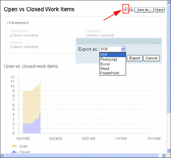
Chapter 29. Rational Team Concert 1117
Draft Document for Review December 9, 2008 2:44 pm 7672-team-3-concert.fm
Running reports (Standard edition only)
If you are using Standard edition, the Team Artifacts view shows a node called
Reports under the Project Area. To see how you can create a report, do the
following:
Expand Reports → Report templates.
Right click on Open vs Closed Work Items.
Select Create Report.
Select the destination folder as My Reports.
A new report based on the selected template is created under My Reports. To
run the report, do the following:
Double click on Open vs Closed Work Items under My Reports.
Expand the Parameters section. Select appropriate parameters values.
Click Run.
Save the report.
You can also export the report as PDF, Postscript, Excel®, Word,
PowerPoint®.
As soon as you select the export format, the corresponding tool opens.
Figure 29-40 Report based on the open vs closed work items template
Export
7672-team-3-concert.fm Draft Document for Review December 9, 2008 2:44 pm
1118 Rational Application Developer V7.5 Programming Guide
Collaborative debugging
Collaborative debugging is a feature provided by Application Developer that
allows users logged onto the same Team Concert repository to share a debug
session including all status information and breakpoints. This feature is
described in Chapter 24, “Debug local and remote applications” on page 861.
More information
For more information on Team Concert and its integration with Application
Developer, refer to these resources:
Rational Team Concert enablement roadmap (login to http://jazz.net):
http://www.ibm.com/developerworks/rational/roadmaps/rtcroadmap/?S_TACT=105A
GX63&S_CMP=JAZZ&ca=ddc-
Jazz platform technical overview (login to http://jazz.net):
https://jazz.net/learn/LearnItem.jsp?href=content/docs/platform-overview/in
dex.html
How to use the Scrum project management method with IBM Rational Team
Concert and the Jazz platform:
http://www.ibm.com/developerworks/rational/library/08/0701_ellingsworth/
Collaborative Application Lifecycle Management with Rational Products,
SG24-7622
Application Developer: select Help → Help Contents, under:
– Product overview → Introduction to Rational Team Concert
– Installing and upgrading → Installing Rational Team Concert
–Migrating
→ Migrating the Jazz Team Server
– Collaborating
–Developing
→ Debugging Applications → Debug extension for Rational
Team Concert Client
– Administering → Managing the Jazz Team Server through the Web
interface
– Managing change and releases
– Tutorials → Do and Learn → Tutorial: Get started with Rational Team
Concert
– Troubleshooting and support → Rational Team Concert troubleshooting
and support
Application Developer: select Help → Cheat Sheets, then select
Team/Jazz → Setup a new Jazz Project Area and Team Area

Draft Document for Review December 9, 2008 2:44 pm 7672-app-p9.fm
© Copyright IBM Corp. 2008. All rights reserved. 1119
Part 9 Appendixes
Part 9
7672-app-p9.fm Draft Document for Review December 9, 2008 2:44 pm
1120 Rational Application Developer V7.5 Programming Guide

Draft Document for Review December 30, 2008 9:46 am 7672-app-installconfig.fm
© Copyright IBM Corp. 2008. All rights reserved. 1121
Appendix A. Product installation
The objective of this appendix is to highlight the key installation considerations
and options, identify components installed while writing this book, and provide a
general awareness regarding the use of IBM Installation Manager to install IBM
Rational Application Developer v7.5.
The appendix is organized into the following sections:
IBM Installation Manager
Installing IBM Rational Application Developer
Installing the WebSphere Portal v6.1 test environment
Installing IBM Rational Team Concert
Installing Rational Application Developer Build Utility
A

7672-app-installconfig.fm Draft Document for Review December 30, 2008 9:46 am
1122 Rational Application Developer V7.5 Programming Guide
Launchpad
There are a number of scenarios that you can follow when installing Rational
Application Developer:
Installing from the CDs
Installing from a downloaded electronic image on your workstation
Installing from an electronic image on a shared drive
Installing from a repository on an HTTP or HTTPS server
While writing this Redbooks publication, we installed IBM Rational Application
Developer v7.5 from a downloaded electronic image on the workstation. The
steps are listed as follows:
After you download all the components of Application Developer v7.5, unzip the
files into an installation folder. From there start the Launchpad by executing
RAD_SETUP\launchpad.exe:
On the first panel, select the language, for example, English, and click OK.
The Launchpad opens (Figure A-1)
Figure A-1 Launchpad
Click Install UBM Rational Application Developer for WebSphere Software.

Appendix A. Product installation 1123
Draft Document for Review December 30, 2008 9:46 am 7672-app-installconfig.fm
IBM Installation Manager
IBM Installation Manager is used to install Rational Application Developer. IBM
Installation Manager is a program that helps you install the Rational desktop
product packages on your workstation. It also helps you update, modify, and
uninstall this and other packages that you install. A package can be a product, a
group of components, or a single component that is designed to be installed by
Installation Manager.
The first step is to install Version 1.2 of Installation Manager:
Select IBM Installation Manager Version 1.2.
Accept the license agreement.
Select the installation directory: C:\IBM\Installation Manager\eclipse.
Click Install, wait for the installation to finish, and click Restart Installation
Manager.
There are six wizards in the Installation Manager that make it easy to maintain
your package through its lifecycle (Figure A-2).
Figure A-2 Installation Manager
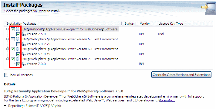
7672-app-installconfig.fm Draft Document for Review December 30, 2008 9:46 am
1124 Rational Application Developer V7.5 Programming Guide
These are the six wizards:
The Install wizard walks you through the installation process.
The Update wizard searches for available updates to packages you have
installed.
With the Modify wizard, you can modify certain elements of a package you
have already installed.
The Manage Licenses wizard helps you set up the licenses for your
packages.
Using the Roll Back wizard, you can revert back to a previous version of a
package.
The Uninstall wizard removes a package from your computer.
Installing IBM Rational Application Developer
From the Installation Manager, click Install to install Application Developer:
In the Install Packages dialog, select Application Developer and the
webSphere servers that you want to install. Select WebSphere Application
Server v7.0 and optionally WebSphere Application Server v6.1
(Figure A-3). Click Next.
Figure A-3 Install Packages
Click Check for Other Versions or Extension to see if newer versions are
available.
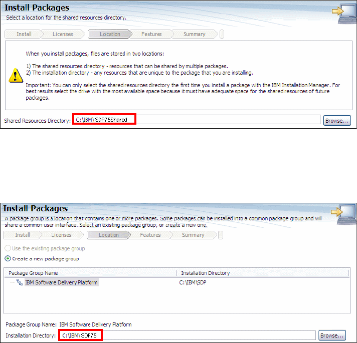
Appendix A. Product installation 1125
Draft Document for Review December 30, 2008 9:46 am 7672-app-installconfig.fm
Select I accept the terms in the license agreements and then click Next.
In the Select a location for the shared resources directory page, change the
Shared Resource Directory from C:\Program Files\IBM\SDPShared to
C:\IBM\SDP75Shared (Figure A-4). Click Next.
Figure A-4 Shared Resource Directory
In the Package Group page, select Create a new package group, and set
the installation directory for the package group to C:\IBM\SDP75 (Figure A-5),
and click Next.
Figure A-5 Installation location for package group
In the Extend an existing Eclipse page, we do not want to extend an existing
Eclipse. Leave this page as default and click Next.
In the Select the languages you want to install page, select your language and
click Next.
In the Select the features you want to install page, select the package features
that you want to install. If you want to complete all the chapters for this
Redbooks publication, you have to select the features shown in Figure A-6.
Click Next.

7672-app-installconfig.fm Draft Document for Review December 30, 2008 9:46 am
1126 Rational Application Developer V7.5 Programming Guide
Figure A-6 Select the features you want to install
Note: You only need the WebSphere Adapters for the JCA examples
accessing CICS and SAP.
In the configurations page (Figure A-7):
– Select how to access the Help system (Web, download for local access, or
intranet server).
– Select the name of the WebSphere Application Server profile, and the
user ID and password for administrative security.
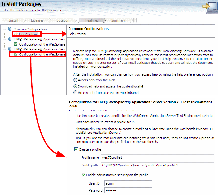
Appendix A. Product installation 1127
Draft Document for Review December 30, 2008 9:46 am 7672-app-installconfig.fm
Figure A-7 Configuration options
In the Summary page, review your choices, and click Install.
The installation proceeds with install Application Developer and the selected
server runtimes.
When the installation process is completed, a message confirms the success
of the process. Click View log file to open the installation log file for the
current session in a new window. Close the Installation Log window to
continue.
In the Install Package wizard, do not start IBM Rational Application Developer
when you exit. Click Finish to close the Install Package wizard, and you are
returned to the Start page of Installation Manager.

7672-app-installconfig.fm Draft Document for Review December 30, 2008 9:46 am
1128 Rational Application Developer V7.5 Programming Guide
Installing the license for Rational Application Developer
You have two options on how to enable licensing for Rational Application
Developer:
Importing a product activation kit
Enabling Rational Common Licensing to obtain access to floating license
keys
In this section, we show you how to import a product activation kit:
Start IBM Installation Manager.
On the main page, click Manage Licenses.
The Manage Licenses dialog opens. Select Application Developer Version
7.5 and Import product Activation Kit. Click Next.
In the Import Activation Kit page, browse to the path of the download location
for the kit, then select the appropriate Java archive (JAR) file and click Open.
Click Next.
Figure A-8 Import Activation Kit
In the Licenses page, select I accept the terms in the license agreements.
Click Next.
In the summary page, click Finish.
The product activation kit with its permanent license key is imported to
Application Developer. The Manage Licenses wizard indicates whether the
import is successful.

Appendix A. Product installation 1129
Draft Document for Review December 30, 2008 9:46 am 7672-app-installconfig.fm
Updating Rational Application Developer
Once Application Developer has been installed, the Installation Manager
provides an interface to update the product.
In the Installation Manager overview, select Update Packages (see Figure A-2
on page 1123).
Selecting Update Packages takes you to the dialogue shown in Figure A-9.
You can select Update all to update all products installed, or you can be explicit
about a particular product. Clicking Next searches for the updates to the
products selected.
Figure A-9 Update Packages
Uninstalling Rational Application Developer
Application Developer V7.0 can be uninstalled interactively through the IBM
Installation Manager.
Before uninstallation of any products, ensure to terminate the programs that you
installed using Installation Manager.
In the Installation Manager overview select Uninstall Packages (see Figure A-2
on page 1123).
In the Uninstall Packages page, select the Rational Application Developer
product package that you want to uninstall (Figure A-10). Click Next.
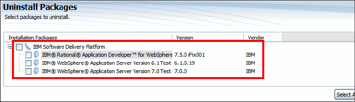
7672-app-installconfig.fm Draft Document for Review December 30, 2008 9:46 am
1130 Rational Application Developer V7.5 Programming Guide
Figure A-10 Uninstall Application Developer
In the Summary page review the list of packages that will be uninstalled and then
click Uninstall. The Complete page is displayed after the uninstallation finishes.
Click Finish to exit the wizard.
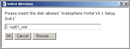
Appendix A. Product installation 1131
Draft Document for Review December 30, 2008 9:46 am 7672-app-installconfig.fm
Installing the WebSphere Portal v6.1 test environment
In this section we describe how to install WebSphere Portal v6.1, add it to
Application Developer v7.5, and configure the portal test environment for
performance.
Installing WebSphere Portal v6.1
If you have already installed Portal Server v6.1 on the same machine where you
are about to install Rational Application Developer, the installation wizard of
Application Developer automatically integrates the installed Portal Server as a
target runtime.
Most of you are installing the Portal test environment after you have installed
Application Developer. The best way to do this is to use the Launchpad for
Rational Application Developer v7.5 (Figure A-1 on page 1122).
In the Launchpad dialog, click WebSphere Portal V6.1 test environment.
A dialog prompts the user to insert the Disk 1, which is the setup disk for
WebSphere Portal v6.1. You can either do this or extract all the downloaded
zip files for Application Developer v7.5 into a temporary directory and specify
the path of that folder in this dialog (Figure A-11).
Figure A-11 Location of the install image of WebSphere Portal Setup Disk 1
Click Next on the Welcome Page.
Click Next on the Software license agreement (if you agree).
In the next page, select Administration as the Installation type and click Next
(Figure A-12).

7672-app-installconfig.fm Draft Document for Review December 30, 2008 9:46 am
1132 Rational Application Developer V7.5 Programming Guide
Figure A-12 Installing the WebSphere Portal v6.1 test environment
In the next page, specify the WebSphere Portal installation directory. Accept
the default (C:\IBM\WebSphere), and click Next.
In the next page, you have to select if you want to install a new instance of
WebSphere Application Server or use an existing instance. We use an
existing server installed with Application Developer v7.5.
Select Install on top of an existing instance and click Next.
In the next page, select the location of the existing WebSphere Application
Server (for example, C:\IBM\SDP75\runtimes\base_v61), and click Next.
In the next page, specify the node name and the fully qualified hostname of
the machine). Accept the defaults, and click Next.
In the next page, enter the user ID and password for the Portal Server
administrator user. Type the values that were used for the servers installed
with Application Developer v7.5 (admin/admin), and click Next.
In the next page, optionally select to start the server as a Windows Services.
We suggest to clear the option. Click Next.
In the next page (Figure A-13), the wizard displays the summary screen.
Read and verify, and if everything is as desired, and click Next to start the
install process. This can take a long time (up to 2 hours), depending on the
machine resources.
When the wizard has completed installing the product, it displays the final
summary dialog. Click Finish.

Appendix A. Product installation 1133
Draft Document for Review December 30, 2008 9:46 am 7672-app-installconfig.fm
Figure A-13 WebSphere Portal v6.1 summary
Adding WebSphere Portal v6.1 to Application Developer
To execute the portal and portlet applications, we have to create a new server in
Application Developer for the installed Portal Server as the target runtime.
Start Application Developer.
In the Servers view, right- click and select New → Server to start the New
Server dialog (Figure A-14).

7672-app-installconfig.fm Draft Document for Review December 30, 2008 9:46 am
1134 Rational Application Developer V7.5 Programming Guide
Figure A-14 Define a Portal Server
In the New Server dialog, select WebSphere Portal v6.1 Server as the
server type and click Configure runtime environments to verify if the install
wizard has configured the newly installed Portal Server correctly.
The dialog displays the list of installed server runtime environments
(Figure A-15). You should see an entry for WebSphere Portal v6.1. You can
also bring up this dialog by selecting Window → Preferences, and select
Server → Installed Runtimes.
Figure A-15 List of Installed Server Runtime Environments
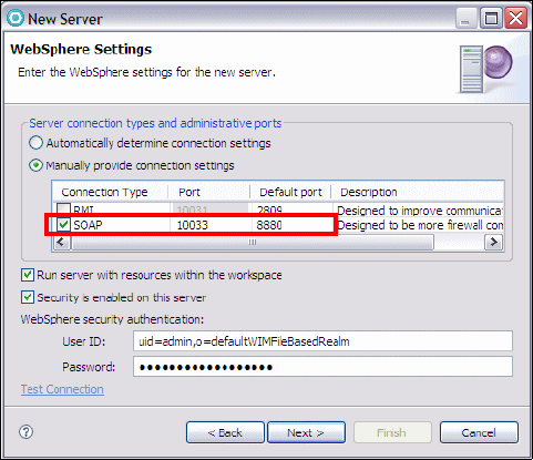
Appendix A. Product installation 1135
Draft Document for Review December 30, 2008 9:46 am 7672-app-installconfig.fm
Select WebSphere Portal v6.1 and click Edit, if the Edit button is enabled. If
the Edit button is disabled, Application Developer recognized automatically
the new Portal Server.
In the Edit Server Runtime dialog, verify that the install path locations of Portal
and Application Servers are correct. Click Finish to close this dialog
Close the Installed Server Runtime Environments dialog.
In the New Server dialog, click Next.
In the WebSphere Settings dialog (Figure A-16), select SOAP as the server
connection type, and click Next.
Figure A-16 WebSphere Settings
In the WebSphere Portal Settings dialog (Figure A-17), verify the portal
settings, such as context root, default, and personalized home, and the install
location of Portal Server.
In the same dialog, enter the user ID and password for the Portal Server
administrator, for example admin/admin (overtype the values that are here).
Decide if you want to enable the automatic login of a particular user when the
Portal test environment starts. Click Next.
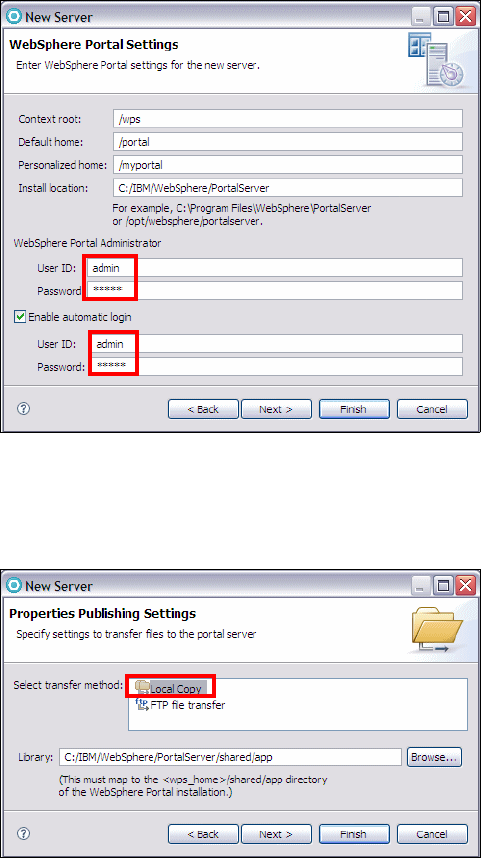
7672-app-installconfig.fm Draft Document for Review December 30, 2008 9:46 am
1136 Rational Application Developer V7.5 Programming Guide
Figure A-17 WebSphere Portal Settings
In the Properties Publishing Properties dialog, select the default value of
Local Copy for the transfer method. Click Next. (Figure A-18)
Figure A-18 Publishing Settings
In the Add and Remove Projects dialog, click Next (you do not have any
portal or portlet projects to add to this server).
In the Tasks dialog, click Finish. This should install a new test server. You can
verify this in the Servers view that displays a new entry for WebSphere Portal
v6.1 Server (Figure A-19).

Appendix A. Product installation 1137
Draft Document for Review December 30, 2008 9:46 am 7672-app-installconfig.fm
Figure A-19 Portal Server added to Application Developer
Do not start the server yet, we have to optimize the server first.
Optimizing the Portal Server for development
To optimize the WebSphere Portal for development and to improve s the start up
performance, run the task described in the InfoCenter at:
http://publib.boulder.ibm.com/infocenter/wpdoc/v6r1m0/index.jsp?topic=/com.
ibm.wp.ent.doc/install/inst_opt.html
Run the ConfigEngine command in <Portal_Profile-HOME>/ConfigEngine:
ConfigEngine.bat enable-develop-mode-startup-performance
The task should end with a 0 return code. If some problems occur during the
execution of the task, you can find a problem resolution at:
http://www-01.ibm.com/support/docview.wss?uid=swg21316233
Verify development mode
In Application Developer, do these steps:
Right-click the Portal Server and select Start (or click the Start icon) which
starts the server, and change its status to Started and its state to
Synchronized. Note that it takes a while to start the Portal Server.
Right-click on the portal server entry in the Servers view, and select
Administration → Run administrative console. This opens a browser
session with administrative console of the Portal Server.
Enter user ID and password (admin).
Navigate to Server → Application Servers → WebSphere_Portal and verify
that Run in development mode is selected (Figure ).
If you make changes, click Apply, and then click Save to apply changes to the
master configuration.
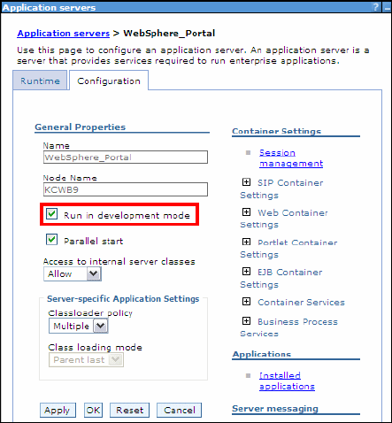
7672-app-installconfig.fm Draft Document for Review December 30, 2008 9:46 am
1138 Rational Application Developer V7.5 Programming Guide
Enable debugging service
If you are using a remote Portal Server without using the Rational tools, and you
intend to use this Portal Server for debugging purposes, then you might want to
enable the debugging service for this server during its startup process.
Select Server → Application Servers → WebSphere_Portal → Debugging
Service (under Additional properties):
Select Enable service at server startup.
Click Apply, and click Save to apply changes to the master configuration.
Stop the server
We are done with installation and configuration. Stop the server.
Besides these basic changes, there are more tips that you can implement to
increase the performance of the Portal Server during the development mode or
to reduce its startup time. Refer to “More information” on page 774.
Appendix A. Product installation 1139
Draft Document for Review December 30, 2008 9:46 am 7672-app-installconfig.fm
Installing IBM Rational Team Concert
The complete instructions for installing any of the three editions of Rational Team
Concert can be found in the product help under Installing and upgrading →
Installing Rational Team Concert.
Installing Rational Team Concert Express-c server
In this section we show how you can get started with the installation of Rational
Team Concert Express-C edition on Windows. For other editions and platforms
refer to product help. You can obtain IBM Rational Team Concert Express-c
edition for free from http://jazz.net.
The server license is free and you are provided with three free Developer
licenses. Note that you are required to register to access the download page.
After you download the file, extract the archive to a directory on your file
system with a short path, such as:
C:\IBM
As a result, you should have the directories:
C:\IBM\jazz\buildsystem
C:\IBM\jazz\client
C:\IBM\jazz\repotools
C:\IBM\jazz\scmtools
C:\IBM\jazz\server
At this point you can start the provided Apache Tomcat server. For
instructions on how to change the default server ports and the default launch
directory refer to the product help.
– Open a command window.
– Change directory to the server directory:
cd C:\IBM\jazz\server
– Run the command to start the server:
server.startup.bat
Running the setup wizard
To configure the team server, perform these steps:
Open a Web browser with the URL:
https://localhost:9443/jazz/setup
Provide the default Username and Password of ADMIN/ADMIN (Figure A-20).
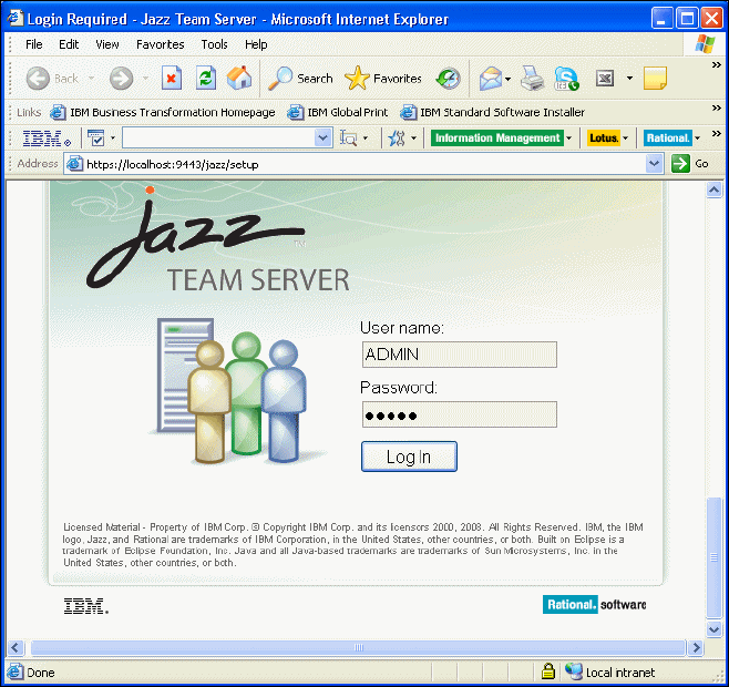
7672-app-installconfig.fm Draft Document for Review December 30, 2008 9:46 am
1140 Rational Application Developer V7.5 Programming Guide
Figure A-20 Running the setup after starting Tomcat
To select a setup path click Fast Path Setup, which skips the configuration of
the mail server for e-mail notification and uses the built-in Derby database
(Figure A-21). Refer to the product help for information on using the Custom
Setup option.
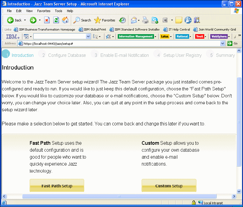
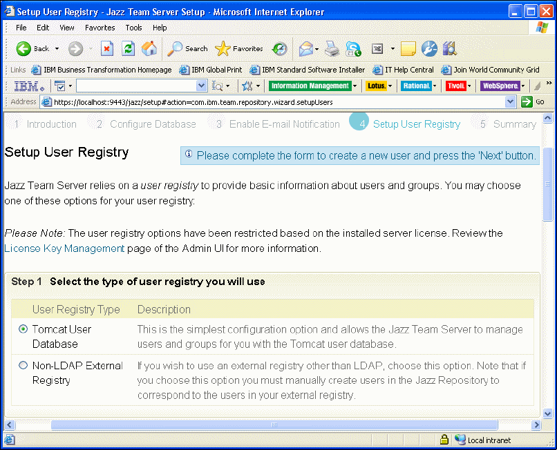
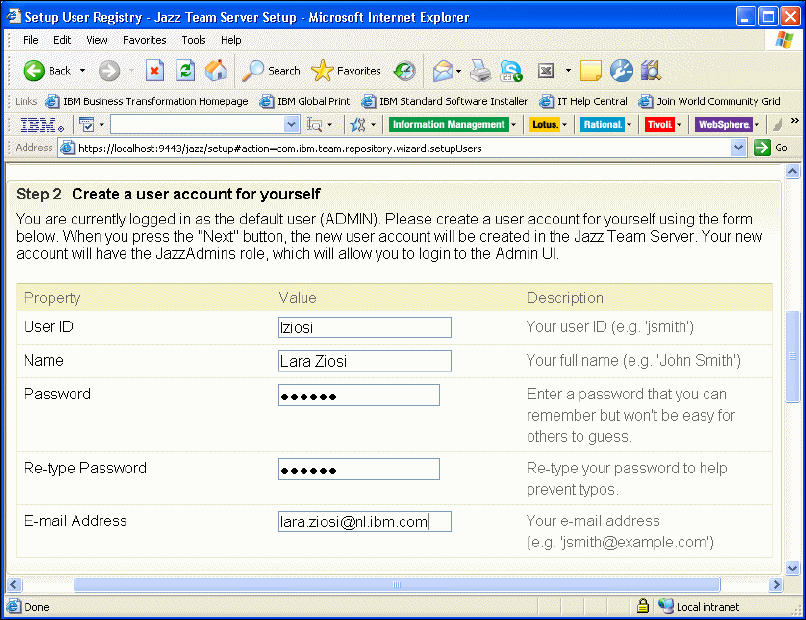
Appendix A. Product installation 1143
Draft Document for Review December 30, 2008 9:46 am 7672-app-installconfig.fm
Figure A-23 Creating the first user account
In the Setup User Registry page (Step 3), you can disable the ADMIN user
used to log on to the setup wizard (Figure A-24).
In the Setup User Registry page (Step 4), you can see three available
Developer licenses. Assign one license to the user you just created.


Appendix A. Product installation 1145
Draft Document for Review December 30, 2008 9:46 am 7672-app-installconfig.fm
Figure A-25 Summary
Verify that the setup is correct by launching the Team Server Admin Web UI
opening the following URL:
https://localhost:9443/jazz/admin
If you do not want to have passwords in clear in any files on the file system,
inspect the contents and then remove the backup property files contained in:
C:\IBM\jazz\server\teamserver-<digits>backup.properties
You are now ready to connect to the server with the Rational Team Concert
client or a Web browser.
You can stop the server from a command window by running the command:
C:\IBM\jazz\server.shutdown.bat
7672-app-installconfig.fm Draft Document for Review December 30, 2008 9:46 am
1146 Rational Application Developer V7.5 Programming Guide
The server was started as an application. You can make it become a service
so that it starts automatically at boot time. Refer to the following Jazz technote
for instructions:
https://jazz.net/learn/LearnItem.jsp?href=content/tech-notes/jazz-team-serv
er-0_6-running-jazz-team-server-in-tomcat-as-a-windows-service/index.html
Installing Rational Team Concert Build Engine and Build Toolkit
Installing the Build Engine and Build Toolkit from the Express-C.zip file consists
of simply uncompressing the archive and verifying that the following directories
were extracted:
C:\IBM\jazz\buildsystem
C:\IBM\jazz\buildsystem\buildengine
C:\IBM\jazz\buildsystem\buildtoolkit
Installing the client and the debug extensions
There are three required components besides the Rational Team Concert server:
Rational Team Concert Client
Debug Extension for Rational Team Concert Client
Team Debug Service Extension for Rational Team Concert Server
Rational Team Concert Client and debug extensions
The first two components are optional features of Rational Application Developer
that can be installed using IBM Installation Manager. They are contained in the
Rational Application Developer core disks. An existing installation can be
modified to include these features as follows:
Stop Rational Application Developer if it is running.
Launch IBM Installation Manager.
Click Modify.
Select the Package group that contains Rational Application Developer.
Click Next on the page that shows the languages.
In the Features page, select:
–Rational lifecycle integrations → Rational Team Concert - Client
–Rational lifecycle integrations → Rational Team Concert - Client →
Debug Extensions for Rational Team Concert Client
Click Next and Finish.

Appendix A. Product installation 1147
Draft Document for Review December 30, 2008 9:46 am 7672-app-installconfig.fm
For more information see the product Help under: Developing → Debugging
Applications → Debug Extensions for Rational Team Concert Client →
Overview.
Rational Team Concert server debug extensions
The Rational Team Concert Server has to be configured with the Team Debug
Service Extension, which is found in the Rational Application Developer optional
disk C1N1GML: IBM Rational Debug Extension for IBM Rational Team Concert
Server.
The installation of the Debug Extension is described in the product Help under:
Installing and Upgrading → Installing Rational Application Developer →
Installing Supporting Software → Installing Rational Debug Extension for
Rational Team Concert Server.
To verify that the installation is correct, connect to the Rational Team Concert
server with a Web browser and verify that the following service is active
(Figure A-26):
com.ibm.debug.team.common.service.ITeamDebugService
Figure A-26 Verify that the debug extension is active on the Team Concert Server
7672-app-installconfig.fm Draft Document for Review December 30, 2008 9:46 am
1148 Rational Application Developer V7.5 Programming Guide
Installing Rational Application Developer Build Utility
The build utility can be used to execute builds on a build server without having
Application Developer, WebSphere Application Server or Portal Server installed.
It does not contain any user interface code, and it allows you to create ANT
scripts for running the available Ant Tasks in headless mode.
The build utility maintains three sets of two archives, for the operating systems:
Windows, Linux, or z/OS.
Here we show only how to install on Windows the core files and the WebSphere
Application Server v7 stub files. The corresponding sources can be found in the
download image: C1LY0ML (IBM Rational Application Developer for WebSphere
Build Utility V7.5 Multilingual Multiplatform Part 2). For a complete description of
the other platforms and supported application servers, see the product Help
under: Installing and Upgrading → Installing Supporting Software →
Installing Rational Application Developer for WebSphere Software build
utility.
From the electronic image #2 or CD #2, extract the following files to a
temporary directory:
RAD-75_BuildUtility_v70Stub_windows-<yyyymmdd_tttt>.zip
RAD-75_BuildUtility_windows-<yyyymmdd_tttt>.zip
Unzip the files to a root directory of your choice. We recommended that you
select a root directory with a short path without any spaces (such as, C:\IBM),
otherwise the sample in BuildUtility\eclipse\samples\AutoBuild will fail.
The archives create the following directory structure:
<root>/BuildUtility/eclipse (core installation files)
<root>/BuildUtility/runtimes (WebSphere Application Server v7.0 stub files)

Draft Document for Review December 9, 2008 4:10 pm 7672addm.fm
© Copyright IBM Corp. 2008. All rights reserved. 1149
Appendix B. Additional material
The additional material is a Web download of the sample code for this book. This
appendix describes how to download, unpack, describe the contents, and import
the project interchange file. In some cases the chapters also require database
setup; however, if needed, the instructions will be provided in the chapter in
which they are needed.
The appendix is organized into the following sections:
Locating the Web material
Unpacking the sample code
Description of the sample code
Setting up the ITSOBANK database
Configuring the data source in WebSphere Application Server
Importing sample code from a project interchange file
B
7672addm.fm Draft Document for Review December 9, 2008 4:10 pm
1150 Rational Application Developer V7.5 Programming Guide
Locating the Web material
The Web material associated with this book is available in softcopy on the
Internet from the IBM Redbooks Web server. Enter the following URL in a Web
browser, and then download the two ZIP files from:
ftp://www.redbooks.ibm.com/redbooks/SG247672
Alternatively, you can go to the IBM Redbooks Web site at:
http://www.ibm.com/redbooks
Select the Additional materials and open the directory that corresponds with
the Redbooks publication form number, SG24-7672.
The additional Web material that accompanies this Redbooks publication
includes the following files:
File name Description
7672code.zip Zip file containing sample code
7672codesolution.zip Zip file containing solution interchange files
System requirements for downloading the Web material
The following system configuration is recommended:
Hard disk space: 20 GB minimum
Operating System: Windows or Linux
Processor:2 GHz
Memory:2 GB
Using the sample code
In this section we provide a description of the sample code and how to use it.
Unpacking the sample code
After you have downloaded the two ZIP files, unpack the files to your local file
system using WinZip, PKZip, or similar software. For example, we unpacked the
7672code.zip and 7672codesolution.zip files to the C:\ drive, which creates
C:\7672code. Throughout the samples, we reference the sample code as if you
have unpacked the files to the C drive.
Appendix B. Additional material 1151
Draft Document for Review December 9, 2008 4:10 pm 7672addm.fm
Description of the sample code
Table B-1 describes the contents of the sample code after unpacking. The
7672code folder has two major sections:
Code sample to follow the instructions in a chapter
Interchange files with the solution of each chapter
Table B-1 Sample code description
Directory Sample code for which chapter
c:\7672code Root directory after unpacking the sample code
..\java Chapter 8, “Develop Java applications” on page 69
..\patterns Chapter 9, “Accelerate development using patterns” on page 157
..\xml Chapter 10, “Develop XML applications” on page 185
..\database Chapter 11, “Develop database applications” on page 227
Also includes the code to setup the ITSOBANK database in either Derby or DB2
..\jpa Chapter 12, “Persistence using the Java Persistence API (JPA)” on page 267
..\webapp Chapter 13, “Develop Web applications using JSPs and servlets” on page 317
..\ejb Chapter 14, “Develop EJB applications” on page 387
..\struts Chapter 15, “Develop Web applications using Struts” on page 445
..\jsf Chapter 16, “Develop Web applications using JSF” on page 493
..\appclient Chapter 17, “Develop Java EE application clients” on page 543
..\webservice Chapter 18, “Develop Web services applications” on page 563
..\web20 Chapter 19, “Develop Web applications using Web 2.0” on page 649
..\jca Chapter 20, “Develop applications to connect to enterprise information systems” on
page 697
..\portal Chapter 21, “Develop portal applications” on page 739
..\junit Chapter 23, “Test using JUnit” on page 819
..\ant Chapter 25, “Build applications with Ant” on page 903
..\jython Chapter 26, “Deploy enterprise applications” on page 933
..\zInterchange Directory with an interchange file for most chapters containing the final code

7672addm.fm Draft Document for Review December 9, 2008 4:10 pm
1152 Rational Application Developer V7.5 Programming Guide
Interchange files with final code
The directory C:\7672code\zInterchange contains the final applications for most
chapters:
..\java\RAD75Java.zip
..\patterns\RAD75Patterns.zip
..\xml\RAD75XML.zip
..\database\RAD75Database.zip
..\jpa\RAD75JPA.zip
..\webapp\RAD75BankBasicWeb.zip
..\ejb\RAD75EJB.zip RAD75EJBWeb.zip
..\struts\RAD75Struts.zip RAD75Struts-Tiles.zip
..\jsf\RAD75JSF.zip
..\appclient\RAD75AppClient.zip
..\webservice\RAD75WebService.zip
..\web20\RAD75Web20-Ajax.zip RAD75Web20-Dojo.zip
..\jca\RAD75JCACICS.zip RAD75JCACICSChannle.zip RAD75JCASAP.zip
..\portal\RAD75PortalEvent.zip RAD75PortalEventAjax.zip
..\junit\RAD75JUnit.zip RAD75JUnitWebTest.zip
..\ant\RAD75Ant.zip
..\jython\RAD75Jython.zip
Importing sample code from a project interchange file
This section describes how to import the Redbooks publication sample code
project interchange zip files into Application Developer. This section applies for
each of the chapters containing sample code that have been packaged as a
project interchange zip file.
To import a project interchange file, do these steps:
From the Workbench, select File → Import.
From the Import dialog, select Other → Project Interchange, and then click
Next (Figure B-1).
Tip: After importing an interchange file for the RAD7EJB project, you have to
deploy the code again. Right-click the RAD7EJB project and select Prepare
for Deployment.

Appendix B. Additional material 1153
Draft Document for Review December 9, 2008 4:10 pm 7672addm.fm
Figure B-1 Import a project interchange file
When prompted for the path and file name, enter the following:
– From zip file: Click Browse and locate the path and the zip file (for
example, C:\7672code\zInterchange\java\RAD7Java.zip).
– Project location root: Leave the default workspace location.
After locating the zip file, the projects contained in the interchange file are
listed. Select the project(s) that you want to import, and click Finish.
For example, we select RAD7Java and clicked Finish (Figure B-2).
Figure B-2 Import projects from an interchange file
7672addm.fm Draft Document for Review December 9, 2008 4:10 pm
1154 Rational Application Developer V7.5 Programming Guide
Setting up the ITSOBANK database
We provide two implementations of the ITSOBANK database, Derby and DB2. You
can choose to implement either or both databases and then set up the enterprise
applications to use one of the databases. The Derby database system is shipped
with the WebSphere Application Server. We tested the application on DB2
Version 8.2, but it should work on DB2 v9.1 as well.
Derby
Command files to define and load the ITSOBANK database in Derby are provided
in the C:\7672code\database\derby folder:
DerbyCreate.bat, DerbyLoad.bat and DerbyList.bat files assume that you
installed Application Developer in C:\IBM\SDP75\ folder. You have to edit
these files to point to your Application Developer installation directory if you
installed the product in a different folder.
In the C:\7672code\database\derby directory:
– Execute the DerbyCreate.bat file to create the database and table.
– Execute the DerbyLoad.bat file to delete the existing data and add
records.
– Execute the DerbyList.bat file to list the contents of the database.
These command files use the SQL statements and helper files provided in:
itsobank.ddl—Database and table definition
itsobank.sql—SQL statements to load sample data
itsobanklist.sql—SQL statement to list the sample data
tables.bat—Command file to execute itsobank.ddl statements
load.bat—Command file to execute itsobank.sql statements
list.bat—Command file to execute itsobanklist.sql statements
The Derby ITSOBANK database is created under:
C:\7672code\database\derby\ITSOBANK
Appendix B. Additional material 1155
Draft Document for Review December 9, 2008 4:10 pm 7672addm.fm
DB2
DB2 command files to define and load the ITSOBANK database are provided in
C:\7672code\database\db2 folder:
Execute the createbank.bat file to define the database and table.
Execute the loadbank.bat file to delete the existing data and add records.
Execute the listbank.bat file to list the contents of the database.
These command files use the SQL statements provided in:
itsobank.ddl—Database and table definition
itsobank.sql—SQL statements to load sample data
itsobanklist.sql—SQL statement to list the sample data
Configuring the data source in WebSphere Application
Server
This section shows how to configure the data source in the WebSphere
administrative console. We configure the data source against the WebSphere
Application Server v7.0 test environment shipped with Application Developer.
Here are the high-level configuration steps to configure the data source within
WebSphere Application Server for the ITSOBANK database:
Starting the WebSphere Application Server
Configuring the environment variables
Configuring J2C authentication data
Configuring the JDBC provider
Creating the data source
Starting the WebSphere Application Server
If you are using a stand-alone WebSphere Application Server v7.0, enter the
following commands in a command window:
cd \IBM\WebSphere\AppServer\profiles\AppSrv01\bin
startServer.bat server1
If you are using the WebSphere Application Server v7.0 test environment
shipped with Application Developer, in the Servers view, right-click WebSphere
Application Server v7.0 at localhost and select Start.
7672addm.fm Draft Document for Review December 9, 2008 4:10 pm
1156 Rational Application Developer V7.5 Programming Guide
Configuring the environment variables
Prior to configuring the data source, ensure that the environment variables are
defined for the desired database server type. This step does not apply to Derby
because we are using the embedded Derby, which already has the variables
defined. For example, if you choose to use DB2 Universal Database, you must
verify the path of the driver for DB2 Universal Database.
Launch the WebSphere administrative console:
– If you are using the WebSphere Application Server v7.0 test environment
shipped with Application Developer, you can simply right-click WebSphere
Application Server v7.0 and select Administration → Run
administrative console.
– For a stand-alone server, type the following URL in a Web browser:
http://localhost:9062/ibm/console
You may use a different port other than 9062. The administrative console
port number was chosen during the installation of the server profile.
Click Log in. If you installed WebSphere with administrative security enabled,
use the user ID and password chose at installation time (for example,
admin/admin).
Expand Environment → WebSphere Variables.
Scroll down the page and click the desired variable and update the path
accordingly for your installation.
For Derby:
–DERBY_JDBC_DRIVER_PATH—By default this variable is already configured
because Derby is installed with WebSphere Application Server:
${WAS_INSTALL_ROOT}/derby/lib
For DB2:
– DB2UNIVERSAL_JDBC_DRIVER_PATH
Edit the value and provide the DB2 installation directory, for example,
C:\IBM\SQLLIB\java, or C:\SQLLIB\java.
Click Save (at the top).
Configuring J2C authentication data
This section describes how to configure the J2C authentication data (database
login and password) for WebSphere Application Server from the WebSphere
administrative console. This step is required for DB2 UDB and optional for Derby.
Appendix B. Additional material 1157
Draft Document for Review December 9, 2008 4:10 pm 7672addm.fm
If using DB2 UDB, configure the J2C authentication data (database login and
password) for WebSphere Application Server from the Administrative Console:
Select Security → Global security.
Under the Authentication properties, expand Java Authentication and
Authorization Service and select J2C Authentication data.
Click New.
Enter the Alias, User ID, and Password in the JAAS J2C Authentication data
page. For example, create an alias called db2user with the user ID and
password used when installing DB2.
Click Save.
Configuring the JDBC provider
This section describes how to configure the JDBC provider for the selected
database type. The following procedure demonstrates how to configure the
JDBC provider for Derby, with notes on how to do the equivalent for DB2 UDB.
To configure the JDBC provider from the WebSphere administrative console, do
these steps:
Select Resources → JDBC → JDBC Providers.
Select the scope settings.
– Select the server scope from the drop-down menu. In our case, we select
Node=<machine>NodeXX, Server=server1.
Click New.
From the New JDBC Providers page, do these steps and then click Next:
– Select the Database Type: Select Derby.
Note: For DB2 UDB, select DB2.
– Select the JDBC Provider: Select Derby JDBC Provider.
Note: For DB2 UDB, select DB2 Universal JDBC Driver Provider.
– Select the Implementation type: Select XA data source.
Note: For DB2 UDB, select XA data source.
Click Next.
Click Finish.

7672addm.fm Draft Document for Review December 9, 2008 4:10 pm
1158 Rational Application Developer V7.5 Programming Guide
Creating the data source
To create the data source for Derby, do these steps:
Select the Derby JDBC Provider (XA).
Under Additional Properties, select Data sources.
Click New.
Typ e ITSOBANKderby as Data source name, and jdbc/itsobank as JNDI
name. Click Next.
Typ e C:\7672code\database\derby\ITSOBANK as the Database name.
Clear Use this data source in container managed persistence (CMP),
because JPA does not use CMP. Click Next.
Skip the Setup security aliases page. Click Next.
Click Finish and then click Save.
Verify the connection by selecting ITSOBANKderby (the check box) and then
click Test connection. You should get the message:
The test connection operation for data source ITSOBANKderby on server
server1 at node xxxxxNodexx was successful with 1 warning(s).
If you are using DB2, create a data source for JDBC Providers → DB2
Universal JDBC Provider Driver (XA):
Select Data sources, then click New.
Typ e ITSOBANKdb2 as Data source name, and jdbc/itsobankdb2 as JNDI
name.
Typ e ITSOBANK as Database name and localhost as Server name. Leave 4
as Driver type and 50000 as Port number. Clear Use this data source in
container managed persistence (CMP).
Select the db2user alias for Authentication alias for XA recovery and for
Component-managed authentication alias.
Click Next, then Finish and then Save.
Verify the connection by selecting ITSOBANKdb2 (the check box) and then
click Test connection. You should get the successful message.
Note: If you always want to use DB2 for the ITSOBANK database, set the JNDI
name for the DB2 data source to jdbc/itsobank and for Derby to
jdbc/itsobankderby. The sample application uses jdbc/itsobank to access
the database, and it can be Derby or DB2.
© Copyright IBM Corp. 2008. All rights reserved. 1159
Draft Document for Review December 9, 2008 2:44 pm 7672abrv.fm
Ajax Asynchronous JavaScript and
XML
AOP aspect-oriented programming
API Application Programming
Interface
AST Application Server Toolkit
ATM automatic teller machine
AWT Abstract Window Toolkit
BCI byte-code instrumentation
BIRT Business Intelligence and
Reporting Tools
BMP bean-managed persistence
BPEL Business Process Execution
Language
BSF Bean Scripting Framework
BVT build verification test
CBE Common Base Event
CCI Common Client Interface
CDT C/C++ Development Tooling
CMP container managed
persistence
CMR container managed
relationship
CORBA Common Object Request
Broker Architecture
CRUD create, retrieve, update and
delete
CSS cascading style sheet
CSV comma separated values
CVS Concurrent Versions System
DADX document access definition
extension
DAO data access object
DB database
Abbreviations and acronyms
DDL data definition language
DMS database management
system; data mediator
services
DOM domain object model
DTD document type definition
DTO data transfer object
EAI enterprise application
integration
EAR Enterprise Application
Archive
EGL Enterprise Generation
Language
EJB Enterprise JavaBean
EJS Enterprise Java Server
EL expression language
EMF Eclipse Modeling Framework
FK foreign key
FTP File Transfer Protocol
FVT function verification test
GEF Graphical Editing Framework
GIF Graphic Interchange File
GMF Graphical Modeling
Framework
GUI graphical user interface
HTML HyperText Markup Language
HTTP Hypertext Transfer Protocol
IBM International Business
Machines
IDE integrated development
environment
ITSO International Technical
Support Organization
J2C Java EE Connector
7672abrv.fm Draft Document for Review December 9, 2008 2:44 pm
1160 Rational Application Developer V7.5 Programming Guide
J2EE Java 2 Platform Enterprise
Edition
J2SE™ Java 2 Platform Standard
Edition
JAAS Java Authentication and
Authorization Service
JAF Java Activation Framework
JAR Java archive
JAXB Java API for XML Binding
JAX-RPC Java API for XML RPC
JAX-WS Java API for XML Based Web
Services
JAXP Java API for XML Processing
JAXR Java API for XML Registries
JCA J2EE Connector Architecture
JCP Java Community Process
JDBC Java DataBase Connectivity
JDK Java Development Kit
JDT Java development tools
JET Java Emitter Templates
JMS Java Message Service
JMX Java Management Extensions
JNDI Java Naming and Directory
Interface
JNI Java Native Interface
JOnAS Java Open Application Server
JPA Java Persistence API
JPQL Java persistence query
language
JRE Java Runtime Environment
JSF JavaServer Faces
JSON JavaScript Object Notation
JSP JavaServer Pages
JSR Java Specification Request
JSTL JSP Standard Tag Library
JTA Java Transaction API
JVM Java Virtual Machine
JVMPI Java Virtual Machine Profiler
Interface
JWL JSF Widget Library
LDAP Lightweight Directory Access
Protocol
MDB message-driven bean
MFS Message Format Service
MIME Multipurpose Internet Mail
Extensions
MTOM Message Transmission
Optimization Mechanism
MVC model-view-controller
OASIS Organization for the
Advancement of Structured
Information Standards
ODBC Open DataBase Connectivity
OMG Object Management Group
OO object-oriented
ORB Object Request Broker
PDA personal digital assistant
PDE Plug-in Development
Environment
POJI plain old Java interface
POJO plain old Java object
PTP point-to-point
QL query language
RA resource adapter
RAD rapid application development
RAMP Reliable Asynchronous
Messaging Profile
RAR resource adapter archive
RDB relational database
RMI remote method invocation
RUP Rational Unified Process
SAX Simple API for XML
SCM software configuration
management
SDK Software Developer Kit
Abbreviations and acronyms 1161
Draft Document for Review December 9, 2008 2:44 pm 7672abrv.fm
SDO Service Data Objects
SDP Software Delivery Platform
SEI service endpoint interface
SGML Standard Generalized Markup
Language
SIP Session Initiation Protocol
SLED SUSE Linux Enterprise
Desktop
SLES SUSE Linux Enterprise
Server
SOA service oriented architecture
SOAP Simple Object Access
Protocol
SPF Struts Portal Framework
SPI Service Programming
Interfaces
SQL Structured Query Language
SQLJ Structured Query Language
for Java
SSI server side include
SSL secure socket layer
SSN social security number
SSO single sign-on
SVG scalable vector graphics
SVT system verification test
SWT Standard Widget Toolkit
TLA term license agreement
TLD tag library descriptor
TPTP Test & Performance Tools
Platform
UCM Unified Change Management
UDB Universal Database
UDDI Universal Description,
Discovery, and Integration
UI user interface
UML Unified Modeling Language
URI Uniform Resource Identifier
URL Uniform Resource Locator
UTC Universal Test Client
UUID universally unique identifier
VM virtual machine
VOB versioned object base
VOIP voice over IP
W3C World Wide Web Consortium
WAR Web Application Archive
WML Wireless Markup Language
WS-I Web Services Interoperability
Organization
WSDL Web Service Description
Language
WSRP Web Services for Remote
Portlet
WSS Web services security
WTP Web Tools Platform
WYSIWYG what-you-see-is-what-you-get
XML eXtensible Markup Language
XOP XML-binary Optimized
Packaging
XSD XML Schema Definition
XSL eXtensible Stylesheet
Language
XSLT XSL transformations
7672abrv.fm Draft Document for Review December 9, 2008 2:44 pm
1162 Rational Application Developer V7.5 Programming Guide
Draft Document for Review December 9, 2008 2:44 pm 7672bibl.fm
© Copyright IBM Corp. 2008. All rights reserved. 1163
Related publications
The publications listed in this section are considered particularly suitable for a
more detailed discussion of the topics covered in this book.
IBM Redbooks
For information about ordering these publications, see “How to get Redbooks” on
page 1164. Note that some of the documents referenced here may be available
in softcopy only.
WebSphere Application Server V7.0: Technical Overview, REDP-4482
Experience Java EE! Using WebSphere Application Server Community
Edition 2.1, SG24-7639
Rational Application Developer V7 Programming Guide, SG24-7501
WebSphere Application Server Version 6.1 Feature Pack for EJB 3.0,
SG24-7611
Web Services Feature Pack for WebSphere Application Server V6.1,
SG24-7618
Building Dynamic Ajax Applications Using WebSphere Feature Pack for Web
2.0, SG24-7635
Topics on Version 7 of Rational Developer for System z and WebSphere
Developer for System z, SG24-7482
Using Rational Performance Tester Version 7, SG24-7391
Web Services Handbook for WebSphere Application Server 6.1, SG24-7257
Building SOA Solutions Using the Rational SDP, SG24-7356
Patterns: Extended Enterprise SOA and Web Services, SG24-7135
Online resources
These Web sites are also relevant as further information sources:
WebSphere and Rational software
http://www.ibm.com/software/websphere
http://www.ibm.com/software/rational
7672bibl.fm Draft Document for Review December 9, 2008 2:44 pm
1164 Rational Application Developer V7.5 Programming Guide
WebSphere Information Center
http://publib.boulder.ibm.com/infocenter/wasinfo/v7r0/index.jsp
IBM Education Assistant
http://www.ibm.com/software/info/education/assistant
developerWorks
http://www.ibm.com/developerworks
alphaWorks
http://www.ibm.com/alphaworks
Eclipse
http://www.eclipse.org
Sun Java
http://java.sun.com
Java Community Process
http://www.jcp.org
Apache Derby database
http://db.apache.org/derby
OASIS
http://www.oasis-open.org
Jython
http://www.jython.org
Web Services Interoperability Organization
http://www.ws-i.org
How to get Redbooks
You can search for, view, or download Redbooks, Redpapers, Technotes, draft
publications and Additional materials, as well as order hardcopy Redbooks, at
this Web site:
ibm.com/redbooks
7672bibl.fm Draft Document for Review December 9, 2008 2:44 pm
1166 Rational Application Developer V7.5 Programming Guide

© Copyright IBM Corp. 2008. All rights reserved. 1167
Draft Document for Review December 9, 2008 2:44 pm 7672IX.fm
Index
Symbols
.jspPersistence 378
.metadata directory 85
@PersistenceContext 419
@viz.diagram 131
A
Abstract Window Toolkit 31
acceptance test 822
access CVS repository 1030
Account class 114
account template 174
AccountDetails 337
action
bar 30
class 448
servlet 448
action code 518
ActionForm 47
ActionServlet 47
add a project to a server 797
addCustomer method 424
additional material 1149
AJAX 51
Analyze Model wizard 265
Annotation view 1061
Ant 903
build
files 904
path 905
project 904
property 905
target 904
task 904
build J2EE application 921
create build script 923
deployment packaging 922
run Ant build 925
build simple Java application 917
The index has not been updated yet
build targets 909
classpath problem 921
clean 910
compile 910
forced build 920
global properties 909
init 909
project definition 908
rerun Ant 920
run Ant 917
content assist 911
documentation 905
example 906
headless build 927
introduction 904
build files 904
new features 905
tasks 905
J2EE
applications 921
build script 923
Javadoc 130
new features
code assist 911
code snippets 911
define format of an Ant script 914
format an Ant script 914
Problems view 916
run 917
Run Ant wizard 919
run headless build 928
run outside Application Developer 927
runAnt.bat 927
script 130, 908
tasks 904–905
delete 905
echo 905
jar 905
javac 905
mkdir 905
tstamp 905
Web service 622
Web site 905
Apache
7672IX.fm Draft Document for Review December 9, 2008 2:44 pm
1168 Rational Application Developer V7.5 Programming Guide
OpenJPA
persistence provider 277
Apache Geronimo 779
Apache Jakarta 851
Ant 904
Apache Tiles 485
Apache Tomcat 779
appearance
of Java elements 100
preferences 100
applet 32
application
classloader 949
client module 320, 935
deployment 934
flow 407
installation wizard 962
logging 182
profiling 983
resources 464
samples 180
Application Client for WebSphere Application Server
545
Application Client project 177
Application Developer
Ant support 903
CVS support 1021
database tools 228
debug 862
Log and Trace Analyzer 84
portal development 744
portal test environment 745
Struts support 450
Tiles framework 485
Application Server
installation directory 784
Application Server profile 782
Application Server Toolkit 969
application-client.xml 936
ApplicationResources.properties 457, 464
ApplicationServlet 322
Assert class 829
association relationship 106
Asynchronous JavaScript 51
attribute
derived 166
autoboxing 27
automatic
build 87
automatic build 87
automation scripts 810
AWT
See Abstract Window Toolkit
B
BankClient class 112
BankClient.java.jet 179
BankFacadeJava 184
BEA WebLogic Server 779
Bean Scripting Framework 968
bookmarks 134–135
Bookmarks view 135
bootstrap 946
breakpoint
conditional 874
JSP 879
marker 873
properties 874
set 873
Breakpoints view 137, 863
browse diagram 23, 49
build 87, 903
Ant build file 904
applications 903
compiler 909
targets 909
verification test 821
build.xml 907, 917
J2EE application 923
C
C 26
C++ 26
Cactus 851
calibration 823
Call Hierarchy view 76
capabilities 88
cascading style sheets 38, 331
change
variable value 876
class diagram
EJB 34
J2EE client 546
class loader 946
WebSphere 948
classloaders 949–950
WebSphere classloaders
Index 1169
Draft Document for Review December 9, 2008 2:44 pm 7672IX.fm
RCP directory 948
RE directory 948
RP directory 948
classpath
Ant classpath 921
variables 98
CLASSPATH variable 947
classpath.jet 172
clean build 88
closeAccount method 424
Cloudscape 229
code assist 111, 113
code coverage analysis 986
code formatter 105
blank lines 108
braces 107
comments 109
control statements 109
indentations 107
line wrapping 109
new lines 108
preferences 101–102
white space 107
code snippet
Ant 912
code style 102
and formatting 102
code visualization 22
coding conventions 103
Colors view 326
column alias 242
combined fragments 60
command
design pattern 339
Common Annotations for the Java Platform 578
Common Object Request Broker Architecture 29
CommonBaseEvents.xml 85
Compare view 1058
compare with 95
compare with local history 94
compilation target 910
compiler options 114
preferences 114
component
test 820
concatenation mapping 213
Concurrent Versions System 1019
condition
breakpoint 874
conflict 1021
connection
database 229
server 793
Connector project 176, 178
Console view 133
constructor 104
container-managed relationships 60
content assist 111, 145
Ant 911
context root 320, 343
cookies 36
CORBA
See Common Object Request Broker Architec-
ture
Core Java APIs 27
Craig Larmann 66
create
static Web resources 358
test case 833
Web Project 340
Create Servlet wizard 369
Credit class 115
Crystal Reports perspective 130
Crystal Reports Web project 177
CSS
See Cascading Style Sheets
CSS Designer 331
CSS File wizard 333
custom
profile 782
Customer class 114
CustomerManager 517
CVS 1019
administrator 1026
annotations 1061
branch 1062
merging 1067
client configuration 1029
access CVS repository 1030
enable CVS Team capability 1029
comparison 1058
conflict 1021
development scenario 1040
features 1020
introduction 1020
keyword substitution 1037
merge 1053
parallel development 1050
7672IX.fm Draft Document for Review December 9, 2008 2:44 pm
1170 Rational Application Developer V7.5 Programming Guide
patches 1070
preferences
CVS specific settings 1036
file content 1032
ignored resources 1034
label decorations 1032
Repositories view 1041
repository 1024
add 1041
synchronization 1050
scenario 1040
shared project 1044
Synchronize 1046
team capability 1029
version 1056
Web site 1023
CVS Annotation view 132
CVS Repositories view 131, 1065
CVS Repository Exploring perspective 130, 1021
CVS Resource History view 132
CVSNT 1020
control panel 1024
create CVS users 1028
Server 1022
server implementation 1023
server installation 1023
server repository configuration 1024
verify installation 1027
D
data 960
Data Definition project 177
Data Design project 177, 256
Data Development project 177, 235
Data Diagram Editor 134
data diagrams 260
data graph 49, 222
data mediator 50
data modeling 255
data object 49
Data Output view 133
Data perspective 132, 134–135
Data Project Explorer view 132
data source
container-managed persistence 976
enhanced EAR 802
ITSOBANK 960
SDO 499, 658
database
connection 229
Database Explorer view 132
DB2 stored procedure debugging 899
DB2 Universal JDBC Driver Provider (XA) 802
DDL generation 263
Debit class 116
debug 862
expressions 877
features
breakpoints 878
drop to frame 866
JSP 880
Jython 888
port 885
remote 869
Web application on local server
debug functions 865
set breakpoint in JSP 879
set breakpoint in servlet 873
watch variables 876
Web application on remote server
attach to remote server 885
configure debug in server 884
export project to WAR file 883
Debug perspective 136, 862–863
debug tooling
supported environments
WebSphere Application Server 862
WebSphere Portal 862
supported languages
EGL 862
Java 862
mixed language 862
SQL stored procedures 862
SQLJ 862
XSLT 862
Debug UI daemon 870
Debug view 137, 863
debugging
icons 865
Declaration view 75
default
workspace 83
delegate method generator 148
deleteCustomer method 424
delta versioning 1020
dependency relationship 26
deployITSOBankApp.py 971
Index 1171
Draft Document for Review December 9, 2008 2:44 pm 7672IX.fm
deployment 933
architecture 934
common considerations 934
deploy the enterprise application
configure data source in the server 956
descriptor 937
descriptors 935
J2EE application components
applets 935
application clients 935
EJBs 935
Web applications 935
J2EE deployment modules
application client module 935
EJB module 935
resource adapter module 935
Java and WebSphere class loader 946
package an application 953
prepare for sample
deployment scenario 950
import sample code 952
install prerequisite software 951
scenario 950
WebSphere deployment architecture 939
WebSphere Rapid Deployment 944
Deployment Manager
profile 782
deposit
method 422
Derby 228
ITSOBANK database 229
JDBC Provider (XA) 802
stored procedure 235
derived
attribute 166
design time template 331
Design view 190
desktop applications 26
developerWorks
Rational 66
samples 181
diagrams
external 62
disconnected data graphs 49
Display view 863, 878
doGet 365
doPost 365
drop to frame 865–866
DTD 187
DTD editor 189
dynamic behavior diagrams 28
dynamic page template 331
Dynamic Web project 179
dynamic Web project 175, 178
Struts support 454
Dynamic Web Project wizard 333
dynamic Web resources 361
E
EAR 922
filtering 955
EAR file 319
Eclipse
CVS information 1076
Java Development Tools 580
Test and Performance Tools Platform 819
Web Tools Platform 779
Editing JSP 370
editors 121
EJB 387
application 407
capability 409
class diagram 34
deployed code 954
inheritance 35
JAR 165
JARs 922
local and remote interfaces 61
module 320, 935
new features 405
overview 388
project 176–177, 409
create 410
query language 60
relationships 35
security roles 37
session facade 415
Timer Service 61
Universal Test Client 426
visualize 35
EJB 3.0
Web application 433
EJB application
prepare for development 408, 729
configure data source 413
create EJB project 409
testing with UTC 426
7672IX.fm Draft Document for Review December 9, 2008 2:44 pm
1172 Rational Application Developer V7.5 Programming Guide
ejb-jar.xml 937
embedded SQL 253
enabling transcoding for development 748
encapsulation 407
enhanced EAR 414, 800, 941
data source 802, 953
Enhanced EAR Editor 941
Enhanced Faces Components palette 509
enterprise application 320
Enterprise Application project 175, 178
Enterprise JavaBeans 56, 387
see EJB
types
message-driven 59
entityMgr.createNamedQuery 420
entityMgr.find 420
entityMgr.remove 424
environment 822
Error Log view 148
evaluate an expression 878
example projects 182
exception breakpoints 879
executable test 856
Execution Flow view 1000, 1012
Execution Statistics view 996
execution time analysis 985
views 985
exemplar analysis 159
exemplar authoring 158
export
EAR 954
Java application 125
expression
debugging 877
evaluation 877
language 44
Expression Builder wizard 240
Expressions view 864
extends relationship 106
Extensible Markup Language 33
Extensible Style Language 188
extensions classloader 949
external diagrams 62
F
facade 184
pattern 183
transformation 183
Faces Action 506
faces-config.xml 496, 506
FacesServlet 496
facets 169
fast view 126
file associations 92
File Creation wizard 332
Filter Mapping wizard 333
Filter wizard 333
filters 44
folding 112
framework
JUnit 834
function
expression 240
verification test 821
G
Gallery view 157, 326
getAccount method 421
getAccounts method 421
getCustomer method 420
getCustomers method 420
getTransactions method 422
Graphical Modeling Framework 450
graphical user interfaces 30
Abstract Window Toolkit 31
Java components 32
Standard Widget Toolkit 31
Swing 31
H
HEAD branch 1044
headless
Ant build 927
headless build 927
Hierarchy view 72
history 93
History view 1056
hit count 874
HTML 37
HTTP 35, 38
recording 852
See Hypertext Transfer Protocol
status codes 36
test 852
HTTP Page Hit Rate report 858–859
HTTP Page Response Time report 858
Index 1173
Draft Document for Review December 9, 2008 2:44 pm 7672IX.fm
HttpJspServlet 322
HttpRequest 322
HttpResponse 322
HttpServlet 322
HttpSession 322
HyperText Markup Language 35, 37
Hypertext Transfer Protocol 35
see HTTP
I
IBM Installation Manager 1123
IBM WebSphere Portal 54, 743
ibm-portal-topology.xml 752
icons for debugging 865
IDE
See integrated development environment
ignored resources 1034
implements relationship 106
import
JAR file 127
import generation 145
indentation 107
Informix 229
initialization target 909
injector
business interface 429
inline mapping 213
installation
CVS for NT 1023
WebSphere Portal 1131
WebSphere Portal V5.0 Test Environment
1131
Installation Manager 1123
Installed JREs
preferences 115
integrated
development environment 120
Integrated Agent Controller 987
interaction
operators 61
use element 62
Interface Definition Language 29
internal 34
Internet
preferences 97
Internet preferences 97
proxy settings 97
Web Browser settings 96
InvalidateSession 337
ITSO Bank
export 125
Struts 452
ITSO Bank application
Bank interface 104, 108
export 125
methods 83
overview 78
packages 78–79
step-by-step development 86
UML class diagram 85
ITSOBank class 113
ITSOBANK database 228
setup 1154
ITSOCVSGuide 1042
J
J2EE
perspective 140
Request Profiling Agent 989
specification 319
Web APIs 322
J2EE Application Client 62, 544
JAAS
authentication 802
Jacl 810
Jakarta 851
Java
application
debug 122
export 125
build path 172
class loader 946
classpath variables 98
debugging features 863
development
preferences 98
development preferences
appearance of Java elements 100
code style and formatting 102
Java classpath variables 98
development settings 48
Editor
preferences 109
language 26
packages 92, 94, 96
project 178
7672IX.fm Draft Document for Review December 9, 2008 2:44 pm
1174 Rational Application Developer V7.5 Programming Guide
Runtime Environment 115
scrapbook 122
search 139
servlet 317
source folder 344
stored procedure 244
utility JAR 922
Java 2 Platform Enterprise Edition 162
Java API for XML Processing 34
Java Browsing perspective 139, 70, 76
Java class loader
extensions class loader 947
hierarchy 947
system class loader 947
Java Editor settings 109
Java EE
Module Dependencies 172
Java Emitter Templates 159
Java Management Extensions 968
Java Message Service 71, 544
Java Naming and Directory Interface 29, 63, 544
Java Native Interface 31
Java perspective 138, 70
Java Portlet specification 55
Java Profiling Agent 989
Java Python 810
Java Remote Method Invocation 29
Java Runtime Environment 124
Java Tcl 810
Java Type Hierarchy perspective 142, 70, 77
Java Virtual Machine 28
JavaBean
annotation 578
Javadoc 128
Ant 130
Ant script 131
diagrams 131–132
generate 128
tooling 128
view 128
JavaServer Faces 48
overview 494, 650
see also JSF
JavaServer Pages 41, 317
JavaServer Pages Standard Template Library 323
JAXP 34
JBoss 779
JDBC 29
driver
variable 958
provider
Jython 816
jdbc/itsobankdb2 805
jdbc/itsobankejb 960
JDT 580
JET 159
JET Transform project 161
JMS 71
JMX 968
JNDI
See Java Naming and Directory Interface
JNI 950
See Java Native Interface
join 240
JPA
manager bean 514
JPA Manager Bean wizard 514
JRE 115
JSF
action 506
add connection for action 508
add navigation rules 508
add simple validation 512
add static navigation to page 513
add UI components 509
add variables 510
application architecture 495
Application Developer 497
benefits 494
components 497
configuration file 496
create connection between JSF pages 504
create Faces Action 506
expression builder 498
features 494
form 511
JPA entity object 520
managed bean 500
overview> 494
Quick Edit view 498
resource bundles 498
servlet 496
specification 494
validators 496
variable 511
Web application 503, 660
JSF and SDO Web application
configure data source via enhanced EAR 499,
Index 1175
Draft Document for Review December 9, 2008 2:44 pm 7672IX.fm
658
JSP 41
breakpoint 879
debugging 880
include 485
Tag libraries 43
tag libraries 323
variables 881
JSP Page Designer 451
JSP Standard Tag Library 44
JSR 168 746
JSR 175 578
JSR 181 578
JSR 224 578
JSR 235 49
JSR 250 578
JSTL 44, 323
JUnit
Assert class 829
framework 834
introduction 819
library 831
methods 835
run 837
sample 830
test
case 831
test suite 835
testing 825
view 837
JVM
debug port 885
See Java Virtual Machine
Jython 810
create data source 973
create JDBC provider 972
debugger 888
execute 978
generate 981
install enterprise application 977
overview 969
project 178, 810, 971
script 970
deploy ITSO Bank 970
file 810
start enterprise application 977
K
keyword
substitution 1037
L
label decorations 1032
launchClient command 64
LibraryFacadeJava 184
life cycle
events 44
Life-cycle Listener wizard 333
lifeline 56
links 358
Links view 326
Linux 903
ListAccounts 337
listeners 44
local
history 93
local history 93
compare with 95
replace with 95
restore from 95
Log Console view 920
log files 84
M
make 903–904
mapping
concatenate 213
inline 213
substring 214
mark occurrences 112, 138
MDB 59
See Message Driven Bean
Members view 139
Memory Statistics view 149, 1002
memory usage problems 984
merging 1067
from a stream 1067
Message Transmission Optimization Mechanism
623
message-driven EJBs 59, 71
Method Invocation Details view 998, 1011
migration
considerations 24
MIME 623
modeling assistant 30
7672IX.fm Draft Document for Review December 9, 2008 2:44 pm
1176 Rational Application Developer V7.5 Programming Guide
model-view-controller 46, 323
Struts Web application 447
MTOM 623
multiprotocol binding 613
Multipurpose Internet Mail Extensions 43
MVC
See model-view-controller
Struts 447
MySQL 229
N
navigate Java code 134
navigation
candidate 349
root 349
rule 506
static 513
navigation rules 508
Navigator view 132
Network Deployment 781
O
OASIS 633
Object Management Group 66
Object References view 149
ObjectWeb Java Open Application Server 779
online help 127
openAccount method 423
OpenJPA
persistence provider 277
Oracle 229, 779
Organization for the Advancement of Structured In-
formation Standards 633
Outline view 137, 73, 326, 863
owned element association 27
P
Package Explorer view 71
Page Data view 157, 326, 469
Page Designer 326, 329
page template 330, 351
create static 352
customize 353
Palette
view 326
parallel development 1050
patches 1070
pattern
apply 179
command 339
facade 183
implementation 157
specification 158
performance
bottlenecks 984
test 821
PerformTransaction 337
persistence
provider 276
personal digital assistant 54
perspectives 120
available 129
Crystal Reports 130
customizing 124
CVS Repository Exploring 130
CVS Repository Exploring perspective 130
Data 132, 134–135
Debug 136
J2EE 140
Java Browsing 139, 76
Java perspective 138
Java Type Hierarchy 142, 77
layout 122
Plug-in Development 147
preferences 95
Profiling and Logging 149
Report Design 150
Resource 152
specify default 124
switching 123
Team Synchronizing 153
Test 154
Web 155
physical data model 256–257
Physical Data Model editor 259
Plug-in Development perspective 147
Plug-ins view 143, 145, 147–148, 151, 159
portal
applications 54
development strategy
JavaServer Faces 748
introduction 740
samples and tutorials 746
tools
Portal Import wizard 749
Portal Project wizard 750
Index 1177
Draft Document for Review December 9, 2008 2:44 pm 7672IX.fm
skin and theme design 753
concepts and definitions
portal page 740
portlet 741
portlet application 741
portlet events 742
portlet modes 742
portlet states 742
development 744
page 740
preferences 750
samples and tutorials 746
skin 753
technology 740
test environments
WebSphere Portal V5.0 745
theme 754
Portal Designer 752
Portal Import Wizard 749
Portal Project wizard 750–751
portlet 741
API 746
applications 739
development 744
events
action events 742
message events 743
Window events 743
JSF 748
modes
configure 742
edit 742
help 742
states 742
maximized 742
minimized 742
normal 742
portlet modes 742
Struts 749
Pramati Server 779
preferences 86
appearance 100
braces 107
capabilities 88
classpath variables 99
code style 102
compiler 115
file associations 92
folding 112
formatter 105
indentation 107
installed JREs 116
Internet 97
Java Editor 110
local history 94
mark occurrences 112
perspectives 95
Process 10
startup and shutdown 83
templates 113
Web browser 96
white space 108
probekit analysis 986
Problems view 137, 916
Process Advisor 7
Process Browser 7
Process Preferences 10
product
activation kit 1128
profile
application server 782
WebSphere Application Server 940
Profile Management Tool 779, 784
profiling
agent types
J2EE Request Profiling Agent 989
Java Profiling Agent 989
analyze data 995
architecture 987
agent 988
Agent Controller 988
application process 988
deployment hosts 988
development hosts 989
test client 988
example 990
features
code coverage 986
execution time analysis 985
memory analysis 985
introduction 984
prepare for profiling sample
enable Profiling and Logging capability 990
publish and run sample application 1006
profile the sample application
start server in profile mode 1007
profiling sets 984
Profiling and Logging capability 91
7672IX.fm Draft Document for Review December 9, 2008 2:44 pm
1178 Rational Application Developer V7.5 Programming Guide
Profiling and Logging perspective 149, 989
Profiling Monitor view 149
programming technologies 25
desktop applications 26
dynamic Web applications 38
Enterprise JavaBeans 56
J2EE Application Clients 62
messaging systems 70
static Web sites 35
Web Services 65
project
close 173
directory structure 344
disconnect from CVS 1070
EJB 409
facets 169
interchange file 173, 1152
properties 171–172
version 1056
Properties view 511
Proxy Settings 97
Python 969
Q
query condition 242
quick assist 144
Quick Edit view 326, 513
quick fix 73, 142
R
RAD7Ant 906
RAD7BankBasicEAR 341
RAD7BankBasicWeb 340
RAD7DataDesign 256
RAD7DataDevelopment 236
RAD7Java 87, 362
RAD7JavaImport 127
RAD7JUnitWebTest 852
RAD7Jython 810, 971
RAD7Patterns 160
RAD7PatternsClient 160
RAD7PatternsFacade 183
RAD7PatternsFacadeTransform 183
RAD7SQLJ 250
RAD7StrutsWeb 454
RAD7WebServiceAnt 622
RAD7WebServiceJSFClient 598
RAD7XMLBank 190
RAD7XMLBankJava 216
rapid application development 133
Rational Application Developer
configure CVS 1031
editors 121
folders 172
installation 1121, 1124
JavaServer Faces support 497
license 1128
local vs remote test environment 780
log files 84
new EJB features 405
new server 789
online help 127
perspectives 120
preferences 86
projects 166
Connector project 176
Dynamic Web project 175
EJB project 176
Enterprise Application project 175
Java project 176
Rational Unified Process 7
samples 179
server configuration 777
startup parameters 82
Struts 450
Struts support
Struts Component wizard 450
Struts Configuration Editor 450
Web Project Struts enabled 450
supported test servers 779
test server introduction 778
UML visual editing 22
uninstall 1129
views 121
Web services tools 574
XML tools 189
Rational Edge 66
Rational Function Tester 821
Rational Manual Tester 821
Rational Performance Tester 822
Rational Software UML Resource Center 66
RCP directory 948
RE directory 948
realized node 503
RedBank
application design 335
application test 381
Index 1179
Draft Document for Review December 9, 2008 2:44 pm 7672IX.fm
class diagram 336
controller layer 337
home page 358
html pages 352
implementation 339
model 345
site navigation 348
user interface 351
view layer 336
Web Diagram 328
Redbooks Web site 1164
Contact us lx
refactor 99, 151
actions 152
refactoring servlets 369
Regular Expression wizard 193
related elements 32
remote
debugging 869
remove project from a server
via Rational Application Developer 798
Report Design perspective 150–151
Report project 177
request sequence 449
RequestDispatcher 322
resource
synchronization 1072
resource adapter 949
module 935
Resource perspective 152
result set 240
reverse engineering 257
RMI
See Remote Method Invocation
row action 529
RP directory 948
rule
violation 121
Rule Builder perspective 153
Run Ant wizard 919
run configuration 110
runAnt.bat 927, 929
RUP
life cycle 6
S
sample code 1149
description by chapter 1151
locate 1150
project interchange files 1152
Scalable Vector Graphics 849
schema validation 199
scrapbook 122
SDO
access XML 220
search dialog 138
security
Workbench 809
Security Configuration wizard 808
Security Constraint wizard 333
Security Role wizard 333
select statement 237
sequence diagrams 54
preferences 64
server
add project 797
configuration
export 796
connection type 793
customization 792
remove project 798
resources 799, 806
Servers view 137, 327, 425
service
client 565
provider 564
requester 565
service broker 564–565
Service Data Objects 49
XML 220
service provider 564
service requester 564
service-oriented architecture 563–564
service
requester 565
service broker 565
service provider 564
servlet 39, 362
add to Web Project 362–363
container 321
create 363
Servlet Application Programming Interface 40
Servlet Mapping wizard 333–334
Servlet wizard 333
ServletContext 44
servlets 362
session
7672IX.fm Draft Document for Review December 9, 2008 2:44 pm
1180 Rational Application Developer V7.5 Programming Guide
scope variable 510
session bean 415
business methods 419
create 416
session facade 415
set breakpoint 873
showcase samples 180
Simple API for XML Parsing 34
Simple Object Access Protocol 566
SIP project 178
site
appearance 346
navigation 340, 346
template 347
smart compile 138
smart insert 137
Snippets view 327
SOA 563
SOAP
over JMS 613
Software Configuration Management 1020
source code analysis 118
Source Code Comparison editor 154
source folding 136
Source view 863
SQL
query 243
statement 235
SQL Builder 134
SQL Server 229
SQLJ 228
applications 249
file 253
serialized profile 249
test 254
translator 249
wizard 250
staging environment 822
Standard Widget Toolkit 31
start server in profile mode 1007
startup parameters 82
stateful session EJB 59
stateless 415
stateless session EJB 58
static analysis 121
configuration 118
result 121
static method sequence diagram 23, 63
static navigation 513
static pages
create a list 360
create tables 359
links 358
text 358
Static Web project 176, 179
Static Web Project wizard 334
static Web sites 35
step
filter 866
into 865
over 865, 876
step over 865
step-by-step mode 865
stored procedure 244
deployment 248
run 249
Stored Procedure wizard 244
structural diagrams 27
Struts 445
action classes 448
action form 448
architecture 446
Component wizards 450
Configuration Editor 450
configuration file 448
configuration file editor 473
controller 447
create action 458
create components 457
Struts Action 458
Struts Form Bean 459
Struts Web Connection 462
create form bean 459
create Web connection 462
create Web page 461
development 457
development capabilities 451
errors tag 469
introduction 446
ITSO Bank 452
model 447
model-view-controller 447
MVC 447
Portlet framework 450
portlets 749
resource files 448
tag libraries 468
tag library 467
Index 1181
Draft Document for Review December 9, 2008 2:44 pm 7672IX.fm
validation framework 462, 465
validators 451
view 447
Web application 448
prepare for sample 452
run sample
run sample application 482
Struts enabled project 454
Web application using Tiles 485
Web Diagram editor 450
Struts-bean tags 468
struts-config.xml 47, 448
Struts-html tags 467
Struts-logic tags 468
Struts-nested tags 468
Struts-template tags 468
Struts-tiles tags 468
style sheets
customize 355
Styles view 327
substring mapping 214
suspend 865
Swing 31
SWT
See Standard Widget Toolkit
Sybase 229
synchronization
schedule 1075
Synchronize view 153, 1072
system verification test 821
T
tables 359
tag libraries 43
tag library descriptor 43
Tasks view 132, 327
TCP/IP Monitor 575, 595
TCP/IP Monitor view 596
team capability 89
Team Synchronizing perspective 153, 1021, 1072
technology samples 180
templates 113
patterns 170
terminate 865
test 822
benefits 823
case 823
concepts 820
framework 824
phases 820
results 848
strategy 824
suite
class 830
Test & Performance Tools Platform 819, 825, 987
test environment
configuration 778
local and remote 780
Test Log view 154
Test Navigator 154
Test Pass report 850
Test perspective 154
text 358
Thumbnails view 327
Tiles 485
configuration file 488
run application 490
runtime behavior 489
Web pages 488
tiles-def.xml 486
Time Frame Historic report 850
topic diagrams 23, 51
TPTP 819
JUnit run 848
JUnit test 844
JUnit Test editor 846
test results 849
URL Test 854
transaction
class 115
template 175
transfer method 423
transformation 184
facade 183
model 164
templates 170
TSO Bank application
run 109
type hierarchy 137
Types view 139
U
UDDI registry 566
UML
class diagram 23, 28
diagram settings 48
7672IX.fm Draft Document for Review December 9, 2008 2:44 pm
1182 Rational Application Developer V7.5 Programming Guide
lifelines 56
more information 66
relationships 26
sequence diagram 54
topic diagrams 23
visual editing 22
WSDL 38
WSDL message 43
WSDL operations 46
UML2 Class Interactions view 1001
UML2 Object Interactions view 1001
UML2 Thread Interactions view 1001
uninstall 1129
unit test 820
Universal Description, Discovery, and Integration
67
Universal Test Client 426
EJB 426
Web services testing 575
UNIX 903
UpdateCustomer 337
updateCustomer method 421
URL mapping 365
User Function Library 177
UTC 426
Utility project 178
V
validation 512
variable
change value 876
variables
debugging 876
JSP 881
Variables view 137, 863
version
project 1056
versioning 1056
view
add and remove 125
Page Data 510
Properties 511
Quick Edit 513
views 121
Annotation 1061
Bookmarks 135
Breakpoints 137, 863
Call Hierarchy 76
Colors 326
Compare 1058
Console 133
CVS Annotation 132
CVS Repositories 131, 1041, 1065
CVS Resource History view 132
Data Definition view 132
Data Project Explorer 132
Debug 137, 863
Declaration 75
Design 190
Display 863, 878
Error Log 148
Execution Flow 1000, 1012
Execution Statistics 996
Expressions 864
Gallery 157, 326
Hierarchy 72
History 1056
Javadoc 128
JUnit 837
Links 326
Members 139
Memory Statistics 149, 1002
Method Invocation Details 998, 1011
Navigator 132
Object References 149
Outline 137, 326, 863
Page Data 157, 326
Page Designer 326
Palette 326
Plug-ins 143, 145, 147–148, 151, 159
Problems 137
Profiling Monitor 149
Quick Edit 326
Servers 137, 327
Snippets 327
Source 863
Styles 327
Synchronize 153, 1072
Tasks 132, 327
TCP/IP Monitor 596
Test Log 154
Thumbnails 327
Types 139
Variables 137, 863
XSLT Context 868
XSLT Transformation Output 869
VoiceXML 43
Index 1183
Draft Document for Review December 9, 2008 2:44 pm 7672IX.fm
W
WAR 922, 935
classloader 949
watch variables 876
Web
content folder 344
Web application
debug on local server 871
debug on remote server 882
module 935
testing
example 854
using JSF and SDO 493, 649
Web applications 38
Web archive
See WAR
Web development tooling 324
CSS Designer 331
file creation wizard 332
Page Designer 329
page templates 330
Web Site Designer 327
Web Diagram 328
actions 534
Editor 503
create JSF page 503
toolbar 509
Tiles actions 491
Web Diagram Editor 450
Web Diagram wizard 334
Web module 320
Web Page Template wizard 334
Web Page wizard 334
Web perspective 155, 325
Web project
directory structure 340
Web Service Discovery Dialog 575, 598
Web Service wizard 574, 586
Web services 65, 563
client development 575
create with Ant tasks 622
development 573
EJB from WSDL 574
interoperability 568
introduction
related standards 567
service-oriented architecture 564
SOA implementation 565
Java client proxy from WSDL 575
JavaBean from WSDL 574
JSF client 598
prepare for development 576
runtime 587
Sample Web application from WSDL 575
security 568, 633
test tools 575
TCP/IP Monitor 575
test environment 575
Universal Test Client 575
Web Services Explorer 575
tools 574
top-down from WSDL 614
UML 40
using annotations 578
Web Services Description Language 67, 566
Web Services Explorer 575, 590
Web Services Interoperability Organization 69, 568
Web Services Metadata for the Java Platform 578
Web Site Designer 327, 346
Web Tools Platform 779
web.xml 321, 936
WEB-INF directory 321
WebLogic Server 779
WebSphere
admin commands 813
administrative console 787
administrative scripting tool 810
class loader 948
JPA persistence provider 277
Network Deployment 781
profile
sharing 795
test 787
Profiles
application server profile 782
custom profile 783
deployment manager profile 783
profiles 781, 940
sample applications 782
scripting client 968
WebSphere Administration Command assist tool
813
WebSphere Application Server 778
Base Edition 933
deployment architecture 939
enable debug 884
Express Edition 933
installation 783
7672IX.fm Draft Document for Review December 9, 2008 2:44 pm
1184 Rational Application Developer V7.5 Programming Guide
Network Deployment Edition 933
profile creation 784
Profiles 781
profiles 940
WebSphere class loader
application class loader 949
extensions to class loader 948
handling JNI code 950
hierarchy 948
Web module class loader 949
WebSphere enhanced EAR 941
WebSphere Portal 743
installation 1131
V5.0 test environment 1131
WebSphere Profile wizard 784
WebSphere Rapid Deployment
modes 945
tools 944
Welcome page 76
preferences 78
Wireless Markup Language 43
withdraw method 422
wizard
JPA Manager Bean 514
Workbench
basics 76, 79
preferences 86
working set 141
workspace 79
World Wide Web Consortium 623
ws.ext.dirs 949
wsadmin 810, 968
WSDL 566
dynamic 584
editor 615
messages
UML 43
UML class diagrams 38
WS-I 69
Basic Profile 568
compliance 596
WTP 779
WYSIWYG 329
X
XML 33, 186
and relational data 190
binary Optimized Packaging 623
constraints 193
editor 189, 200
mapping editor 190, 208
namespaces 188
overview 186
path language 188
processor 186
schema
editor 189
generate JavaBeans 216
generate XML file 200
Service Data Objects 220
tools
DTD editor 189
XML editor 189
XML Schema editor 189
XPath Expression wizard 189
XSL editor 189
transform 207
validator 198
XOP 623
XPath 188–189
expression 208, 215
expression wizard 189
XSL 188
debugging and transformation 190
editor 189
file 202
transformation 207
XSL Transformation Output view 869
XSL Transformations 34, 188
XSL-FO 188
XSLT 188
Context view 868
debugger 867
templates 208
transformation 867

®
SG24-7672-00 ISBN
Draft Document for Review December 30, 2008 1:05 pm
INTERNATIONAL
TECHNICAL
SUPPORT
ORGANIZATION
BUILDING TECHNICAL
INFORMATION BASED ON
PRACTICAL EXPERIENCE
IBM Redbooks are developed by
the IBM International Technical
Support Organization. Experts
from IBM, Customers and
Partners from around the world
create timely technical
information based on realistic
scenarios. Specific
recommendations are provided
to help you implement IT
solutions more effectively in
your environment.
For more information:
ibm.com/redbooks
®
Rational Application
Developer V7.5
Programming Guide
Develop application
using Java EE 5
Test, debug, and
profile with local and
remote servers
Deploy applications
to WebSphere
servers
IBM Rational Application Developer for WebSphere Software v7.5
(for short, Application Developer) is the full function Eclipse 3.4
based development platform for developing Java Standard Edition
Version 6 (Java SE 6) and Java Enterprise Edition Version 5 (Java EE
5) applications with a focus on applications to be deployed to IBM
WebSphere Application Server and IBM WebSphere Portal. Rational
Application Developer provides integrated development tools for all
development roles, including Web developers, Java developers,
business analysts, architects, and enterprise programmers.
Rational Application Developer is part of the IBM Rational Software
Delivery Platform (SDP), which contains products in four life cycle
categories:
Architecture management, which includes integrated
development environments
Change and release management
Process and portfolio management
Quality management
This publication is a programming guide that highlights the features
and tooling included with Rational Application Developer v7.5. Many
of the chapters provide working examples that demonstrate how to
use the tooling to develop applications, as well as achieve the
benefits of visual and rapid application development. This
publication is an update of Rational Application Developer V7
Programming Guide, SG24-7501.
Back cover
