CPE 233 MCU RAT Assembler Manual 5 01
User Manual:
Open the PDF directly: View PDF ![]() .
.
Page Count: 56
- Acknowledgements
- The RAT MCU was the brainchild of Kianoosh Salami and Bryan Mealy. Good ideas a quite common in academia; what’s not so common is the basic footwork required to bring good ideas to fruition. Jeff Gerfen made this idea work with the first offering of C...
- The RAT Assembler
- The RAT Instruction Set

- 1 -
The RAT
Assembler
Manual
Version: 5.01 ©2019 bryan mealy

- 2 -
Table of Contents
Table of Contents ............................................................................................................ - 2 -
The RAT Assembler ....................................................................................................... - 4 -
RAT Assembler Overview .......................................................................................... - 5 -
RAT Assembler Memory Issues ................................................................................. - 5 -
Memory Segmentation ............................................................................................ - 5 -
Start-up Code .......................................................................................................... - 5 -
RATASM File Generation .......................................................................................... - 6 -
xxx.asl ..................................................................................................................... - 6 -
xxx.err ..................................................................................................................... - 6 -
prog_rom.vhd .......................................................................................................... - 6 -
xxx.dbg.................................................................................................................... - 6 -
xxx.mem.................................................................................................................. - 6 -
RAT Assembly Language Overview .......................................................................... - 7 -
RAT Assembler Comments .................................................................................... - 7 -
RAT Assembler Labels ........................................................................................... - 7 -
RAT Assembler Directives ......................................................................................... - 7 -
Directive: .ORG ..................................................................................................... - 8 -
Segment Directives: .CSEG and .DSEG................................................................ - 8 -
Directive: .CSEG ................................................................................................... - 8 -
Directive: .DSEG ................................................................................................... - 9 -
Directive: .DB ........................................................................................................ - 9 -
Directive: .BYTE ................................................................................................... - 9 -
Directive: .EQU ................................................................................................... - 10 -
Directive: .DEF .................................................................................................... - 10 -
The RAT Instruction Set ............................................................................................... - 12 -
RAT Assembly Instructions by Type ....................................................................... - 12 -
Instruction Type: Reg/Reg .................................................................................... - 13 -
Instruction Type: Reg/Imm ................................................................................... - 14 -
Instruction Type: Imm .......................................................................................... - 15 -
Instruction Type: Reg ........................................................................................... - 16 -
Instruction Type: None ......................................................................................... - 17 -
RAT Assembly Instructions Type Listing ................................................................ - 18 -
Detailed RAT Assembly Instruction Description ..................................................... - 18 -
Notes on Instruction Formats .................................................................................... - 18 -
ADD ...................................................................................................................... - 19 -
ADDC ................................................................................................................... - 20 -
AND ...................................................................................................................... - 21 -
ASR ....................................................................................................................... - 22 -
BRCC .................................................................................................................... - 23 -
BRCS .................................................................................................................... - 24 -
BREQ .................................................................................................................... - 25 -
BRN ...................................................................................................................... - 26 -

- 3 -
BRNE .................................................................................................................... - 27 -
CALL .................................................................................................................... - 28 -
CLC ....................................................................................................................... - 29 -
CLI ........................................................................................................................ - 30 -
CMP ...................................................................................................................... - 31 -
EXOR .................................................................................................................... - 32 -
IN .......................................................................................................................... - 33 -
LD ......................................................................................................................... - 34 -
LSL ....................................................................................................................... - 35 -
LSR ....................................................................................................................... - 36 -
MOV ..................................................................................................................... - 37 -
NOP....................................................................................................................... - 38 -
OR ......................................................................................................................... - 39 -
OUT ...................................................................................................................... - 40 -
POP ....................................................................................................................... - 41 -
PUSH .................................................................................................................... - 42 -
RET ....................................................................................................................... - 43 -
RETID ................................................................................................................... - 44 -
RETIE ................................................................................................................... - 45 -
ROL....................................................................................................................... - 46 -
ROR ...................................................................................................................... - 47 -
RSP ....................................................................................................................... - 48 -
SEC ....................................................................................................................... - 49 -
SEI......................................................................................................................... - 50 -
ST .......................................................................................................................... - 51 -
SUB ....................................................................................................................... - 52 -
SUBC .................................................................................................................... - 53 -
TEST ..................................................................................................................... - 54 -
WSP ...................................................................................................................... - 55 -
RAT Sample Style File ............................................................................................. - 56 -

RAT Assembler Manual
The RAT Assembler
- 4 -
Acknowledgements
The RAT MCU was the brainchild of Kianoosh Salami and Bryan Mealy. Good ideas a quite
common in academia; what’s not so common is the basic footwork required to bring good ideas to
fruition. Jeff Gerfen made this idea work with the first offering of CPE 233 with the RAT MCU in
Winter 2010. Later changes (improvements) to the RAT MCU and supporting documentation
were made by many of the instructors teaching the course using the RAT MCU; these instructors
include Paul Hummel and Bridget Benson.

RAT Assembler Manual
The RAT Assembler
- 5 -
The RAT Assembler
RAT Assembler Overview
The RAT assembler is responsible for generating machine code for the RAT instruction set.
Kianoosh Salami and Bryan Mealy initially defined the RAT instruction set architecture in an
attempt to generate a meaningful academic experience for CPE 233 students.
The RAT assembler, ratasm, was written in a CYGWIN environment and is based on standard
scanning (FLEX) and parsing (YACC) tools. The ratasm assembler is a two-pass assembler; the
first pass primarily locates various labels and assigns them appropriate values; the second pass
assigns assembly instruction bits and inserts startup code as required.
RAT Assembler Memory Issues
The RAT architecture comprises of the many modules including various memories, a program
counter, I/O, interrupts, and a control unit. The RAT assembler has direct involvement with two
types of memory in the RAT architecture: the program memory and the scratch RAM. The
assembler generates and assigns machine code to the program memory; the assembly also
generates startup code for cases where scratch RAM requires initialization.
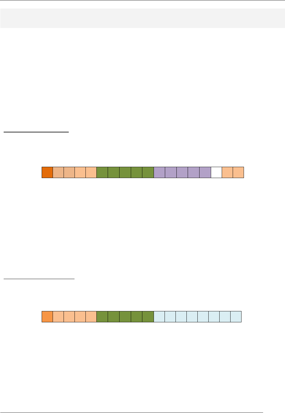
Memory Segmentation
Computer hardware is generally comprised of different memory modules, each serving a distinct
purpose. Software items such as assemblers generally have options to configure these memories
prior to actual program execution. The RAT assembler contains commands referred as
“directives” that allow programmers to configure these memories with a modest set of controls.
The programmer’s view of the RAT microcontroller models the two memory types as program
memory and scratch memory. The RAT assembler allows the programmer several configuration
options for these memories. The RAT assembler models the RAT MCU memory resources into
two segments: the code segment and the data segment. The code segment refers to instruction
memory while the data segment refers to scratch memory. As a result, the programmer must
explicitly specify which segment a particular instruction or directive belongs to using assembler
directives. The .DSEG and .CSEG assembler directives specify the data segment and code
segment, respectively.
Start-up Code
The .DB assembler directive allows programmers to name and initialize references to memory
locations in scratch RAM. Use of the .DB directive requires programmers to provide initial values
for the specified memory; these initial values must be written to scratch RAM using RAT MCU
assembly instructions.
As a feature of the RAT assembler, the RAT MCU assembler automatically generates the code
that initializes the scratch RAM using “start-up” code. Using the .DB directive requires that the
programmer arrange program memory such that the program code starts at a location in program
memory that leaves adequate space for the assembler to insert the start-up code. Each byte of
memory initialized by the start-up code requires two instructions: MOV & ST. The MOV instruction
places a value into a register; the ST instruction places the contents of that register into scratch
RAM.

RAT Assembler Manual
The RAT Assembler
- 6 -
RATASM File Generation
We specifically designed the RAT assembler, ratasm, for the beginning assembly language
programmer in mind. As a result, ratasm includes in-depth error checking and report generating.
Running ratasm generates several files, which aids in program understanding and/or debugging.
This section lists the files generated by ratasm. For all the assembler generated files, ratasm
replaces the “xxx” prefix with the filename (not including the .asm extension) of the program that
ratasm attempted to assemble. All RAT assembly programs must include an “.asm” extension in
order for ratasm to assemble the file.
xxx.asl
This is the output listing file associated with the assembly language program that ratasm
attempted to assemble. This assembler automatically generates this file when the assembler
attempts to assemble the program; the assembler generates this file whether the program
assembles successfully or not. In the case where the program has errors, the xxx.asl files lists
those errors including a helpful comment in most cases.
The output listing file likewise provides all associated instruction opcodes, assembler directives,
data memory information, symbol table listing, and other useful information. If your program
contains errors, this file lists those errors; the error file provides a more direct listing of these
errors. If there is any information missing from the output listing file, you probably don’t need it.
xxx.err
If the program you are attempting to compile contains errors, the xxx.err file provides a list of
those errors and associated error messages. There are basically two types of errors in the ratasm
assembler: 1) errors that the assembler can pinpoint, and 2) errors that the assembler knows are
errors but cannot specify what the exact error is. In the first case, ratasm prints a relatively helpful
error message to help the programmer find and fix the error. In the second case, however, ratasm
provides little or no information about the error other than the line in the program where ratasm
assumes the error occurred.
prog_rom.vhd
This file is a VHDL model of a ROM object containing the machine code for the successfully
assembled program. The RAT assembler only generates this file when the program successfully
assembles. If the program does not successfully assemble, ratasm deletes any existing
prog_rom.vhd file in the directory where ratasm executes.
xxx.dbg
This is a specially formatted file containing information used by the debugger/simulator. If you’re
not the debugger, then you won’t be needing the information contained in this file.
xxx.mem
This file contains the opcodes for the program. The file lists the opcodes in hexadecimal format
and includes an entry for each location in program memory. This file fills program memory
addresses that do not contain valid instructions with “00000”.

RAT Assembler Manual
Assembly Language Overview
- 7 -
RAT Assembly Language Overview
Assembly language programs have four distinct parts: 1) comments, 2) labels, 3) assembler
directives, and 4) assembly language instructions. Later sections address RAT assembler
directives and instructions.
RAT Assembler Comments
The RAT assembler uses the semi-colon character (;) to indicate a comment. The comment
character can appear in any column of source code text. The RAT assembly considers all text
following the comment character on any source code line to be a comment.
RAT Assembler Labels
The ratasm assembler uses labels to mark locations in both the code and data segments. Various
instructions can use these labels as part of the instruction syntax. Labels are specified by a string
followed immediately (without white space) by a colon. Label definitions in the code segment can
appear as the first field in any valid instruction or can appear on lines by themselves. Label
definitions in the data segment can appear without associated assembler directives. Label
definitions can appear on associated lines with some directives, but not all of them (see the
section on assembler directives). Multiple label definitions cannot appear on the same line in the
source code.
RAT Assembler Directives
The ratasm assembler has several directives in order to provide the programmer with more
versatility in overall program design. The directives enforce a clear and concise style of
programming and generate errors and warnings upon misuse. Table 1 shows the list of ratasm
directives; an explanation of these directives follows the table.
Directive Short Description
.CSEG Indicates following information is associated with code segment
.DSEG Indicates following information is associated with data segment
.ORG Allows to adjust information placement in code and data segments
.EQU Allows numeric values to be associated with strings
.DEF Allows register file register to be associate with string
.BYTE Allows user to reserve uninitialized memory
.DB Allows user to reserve and initialize memory
Table 1: A list of ratasm assembler directives.

RAT Assembler Manual
Assembly Language Overview
- 8 -
Directive: .ORG
The .ORG directive is shorthand for “origin”. The directive is used to placed data and instructions
at known locations in either the data or the code segments, respectively. The .ORG directive
takes one argument, which sets the location counter in the given segment. Both the code and
data sections maintain their own counters, which increment according to the data declarations
(the data segment) or listed instructions (the code segment). The .ORG directive effectively sets
these respective counters to the value associated with the argument provided with the .ORG
directive. The .ORG directive must appear in the first column of the source listing and thus cannot
have a label on the same line. Figure 1 shows an example of the .ORG directive.
;-------------------------------------------------------------------------
-
;-- .ORG used in code segment
;-------------------------------------------------------------------------
-
.CSEG
.ORG 0x34 ; sets the code segment counter to 0x34
LSL R5 ; instruction at address 0x34
LSR R6 ; instruction at address 0x35
;-------------------------------------------------------------------------
-
;-- .ORG used in data segment
;-------------------------------------------------------------------------
-
.DSEG
.ORG 0x5A ; set the data segment counter to 0x5A
var_name1 .BYTE 0 ; associated var_name1 with memory address 0x5A
var_name2 .BYTE 0 ; associated var_name2 with memory address 0x5A
Figure 1: Example usage of the .ORG directives in both code and data segments.
Segment Directives: .CSEG and .DSEG
The MCU memory space is divided into a code segment and a data segment. The .CSEG and
.DSEG directives provide a means to differentiate between code and data segments. Program
memory holds the opcodes all program instructions and thus forms the code segment. All
declared data is associated with data memory and thus forms the data segment. Executable
instructions must appear in the code segment while memory-type directives must appear in the
data segment. Further details appear in the following sections.
Directive: .CSEG
The .CSEG directive indicates that all the labels after the .CSEG directive are defined in terms
program memory (as opposed to data memory). Instructions can only appear in the code
segment while data declarations can only appear in the data segment. Attempts to declare
memory in the code segment will result in an assembler error.
The .CSEG directive has no argument. When you use the .CSEG directive, the code memory
address reverts to the either the code memory position one location after the previously issued
instruction or reverts back to the previously issued .ORG value that was issued in the code
segment. The .CSEG directive must appear in the first column of the source listing and thus
cannot have a label on the same line. Figure 1 shows an example of .CSEG usage.

RAT Assembler Manual
Assembly Language Overview
- 9 -
Directive: .DSEG
The .DSEG directive indicates that all the labels after the .DSEG directive are defined in terms
data memory (as opposed to program memory). Instructions can only appear in the code
segment while data can only be declared in the data segment. Attempts to declare instructions in
the data segment will result in an assembler error.
The .DSEG directive has no argument. When the .DSEG directive is used, the data memory
address reverts back to the either the data memory position one location after the previously
declared memory or revert back to the previously issued .ORG value that was issued in the data
segment. The .DSEG directive must appear in the first column of the source listing and thus
cannot have a label on the same line. Figure 1 shows an example of .DSEG usage.
Directive: .DB
Programmers use the .DB directive to reserve and initialize a given number of bytes in scratch
memory starting at the current data memory address. You can use this directive either with or
without a label on the same line. When the .DB directive appears with a label on the same line,
the assembler assigns the label the value of the current data memory counter and can thus you
can use this value in some RAT instructions. When you use the .DB directive without a label, the
assembler initializes memory at the current address in data memory. The .DB directive initializes
one byte for each decimal or hex number following the .DB directive. The internal counter used
the data segment automatically tracks the proper location in data memory as the program
specifies more memory locations. The .DB directive can only appear in the data segment and will
generate an assembler error if it appears in the code segment7.
;-------------------------------------------------------------------------
-
;-- .DB Directive usage
;-------------------------------------------------------------------------
-
.DSEG ; we’re in the data segment
.ORG 0x20 ; set the data segment counter to 0x20
; define ascii equivalent for numerals 0 to 9
; 0x30 = ‘0’, 0x31 = ‘1’, etc.
;
ascii_digits: .DB 0x30, 0x31, 0x32, 0x33, 0x34
.DB 0x35, 0x36, 0x37, 0x38, 0x39
Figure 2: Example of the .DB directive.
Directive: .BYTE
Programmers use the .BYTE directive to reserve a given number of uninitialized memory
locations starting at the current data memory address. You can use this directive both with and
without a label on the same line. When the .BYTE directive appears with a label, the assembler
assigns the value to the label associated with the current data memory counter. The one
argument to the .BYTE directive specifies the number of bytes to reserve in memory
(uninitialized) starting at the current data memory location. The internal counter of the data
segment automatically tracks the proper location in data memory as the programmer specifies
more memory locations. The .BYTE directive can only appear in the data segment. Figure 2
shows the two forms of the .BYTE assembler directive.

RAT Assembler Manual
Assembly Language Overview
- 10 -
;-------------------------------------------------------------------------
-
;-- .BYTE Directive usage
;-------------------------------------------------------------------------
-
.DSEG ; we’re in the data segment
.ORG 0x30 ; set the data segment counter to 0x30
btn_cnt1 .BYTE 6 ; declare 6 bytes of data starting at data
; memory address 0x30; the label can be
; used for accessing the specified data
.BYTE 3 ; declare 3 bytes of data starting at data
; memory address 0x36
Figure 3: Example of the .BTYE directive.
Directive: .EQU
The .EQU directive associates a label with an 8-bit value. Programmers can specify values using
either decimal or hexadecimal. This directive allows for the replacement of specialized values
such as masks with more descriptive alpha-type names. The .EQU directive can appear in either
the code or data segments. It is customary assembly language programming practice to place all
.EQU assembler directives somewhere near the beginning of the assembly source code file and
before any assembly language instruction.
The .EQU directive requires a label value field and a numeric value field. Figure 10 shows
examples of the .EQU directive.
;--------------------------------------------------------------------
;- Port Constants
;--------------------------------------------------------------------
.EQU ADC_PORT = 0x02 ; port for ADC
.EQU ENG_PORT = 0x0C ; port for English converter
.EQU RAT_CLR_PORT = 34 ; port for clear all regs port
;--------------------------------------------------------------------
;--------------------------------------------------------------------
;- Bit Mask Constants
;--------------------------------------------------------------------
.EQU BTTN1_MASK = 0x08 ; mask all but BTN5
.EQU BTTN2_MASK = 0x02 ; mask all but BTN5
;--------------------------------------------------------------------
Figure 3: Examples of the .EQU assembler directive.
Directive: .DEF
The .DEF directive stands for “define” and associates a label with a register. This directive allows
for the replacement of basic register specifiers, such as “r0”, “r1”, etc., with labels. The main
purpose of this directive is to make reading and understanding RAT assembly language
programs easier for the human reader. This directive is a message from the programmer to the
assembler to interpret labels as registers. This being the case, programmers should strive to use
this directive in a self-commenting manner only with a special designated prefix, such as “r_”.
Having the ability to specify labels in place of registers allows programmers to use more
descriptive alpha-type names, which supports the notion of self-commenting labels. The .DEF
directive can appear in either the code or data segments, though it is customary assembly
language programming practice to place all .DEF assembler directives somewhere near the
beginning of the assembly source code file and before any assembly language instruction. The
.EQU directive requires a label value field and a register name separated by an equals sign, thus

RAT Assembler Manual
Assembly Language Overview
- 11 -
the programmer must place an equals sign must between these two fields. Figure 4 shows a few
examples of the .DEF directive. We often refer to the labels that represent registers from the
.DEF directive as “aliases”.
;---------------------------------------------------------------------
;- Register Aliases
;---------------------------------------------------------------------
.DEF R_COUNT = r30 ; register used for iteration
.DEF R_OUT_VAL = r10 ; register used to store output value
;----------------------------------------------------------------------
Figure 4: Examples of the .DEF assembler directive
RAT Assembler Manual
Detailed Instruction Description
- 12 -
The RAT Instruction Set
RAT Assembly Instructions by Type
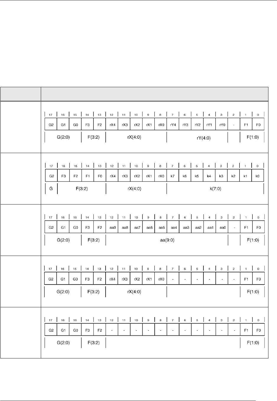
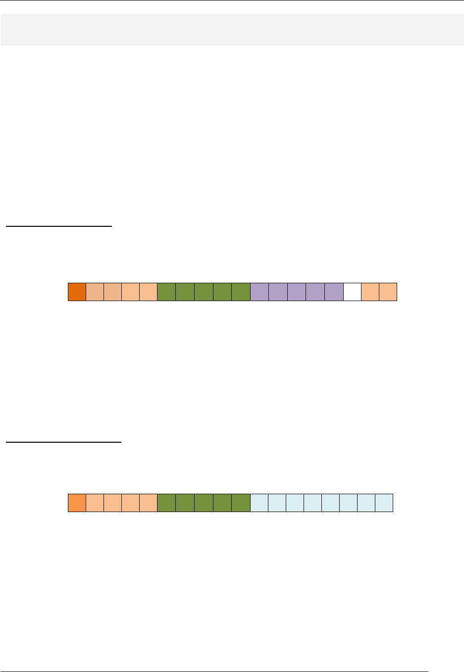
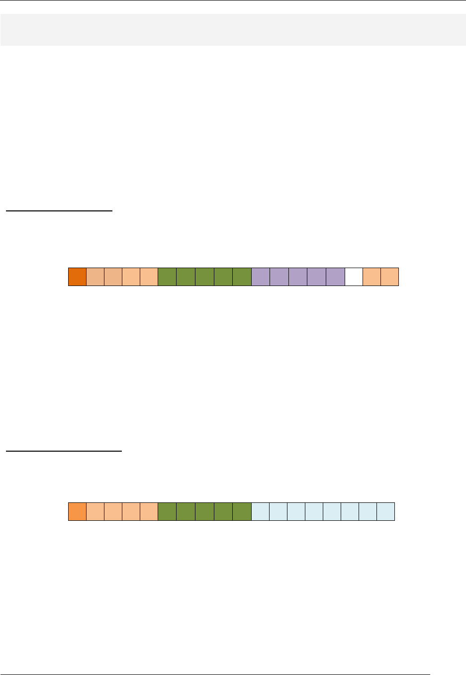
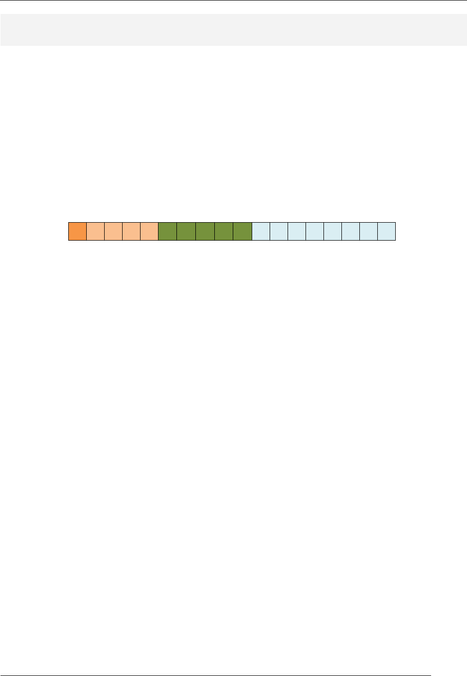
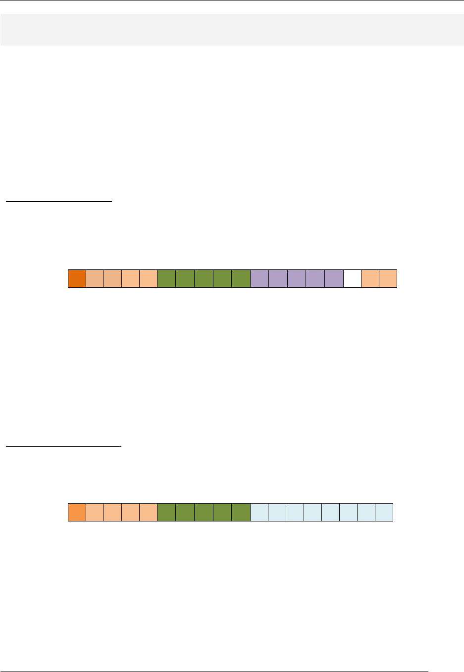
The RAT instruction set has five types of instructions; the number and type of operands determines the
instruction type. Each of these instruction types has their own distinct format. Table 2 provides an
overview of the five types of instruction formats.
Instr
Type
Instruction Format
reg/reg
reg/imm
imm
reg
none
Table 2: Instruction types and associated instruction formats.
RAT Assembler Manual
Detailed Instruction Description
- 13 -
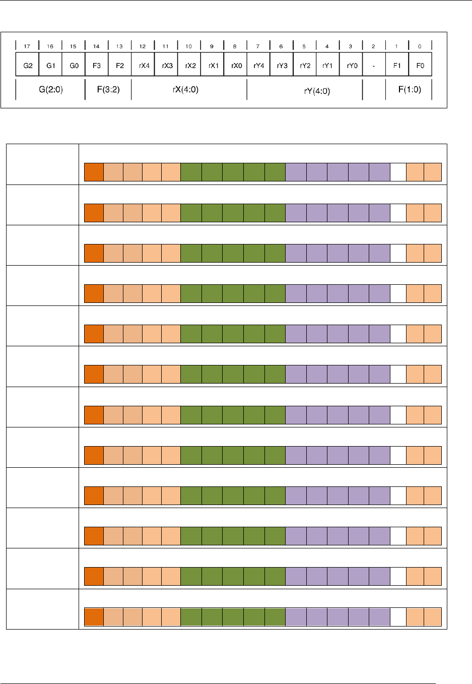
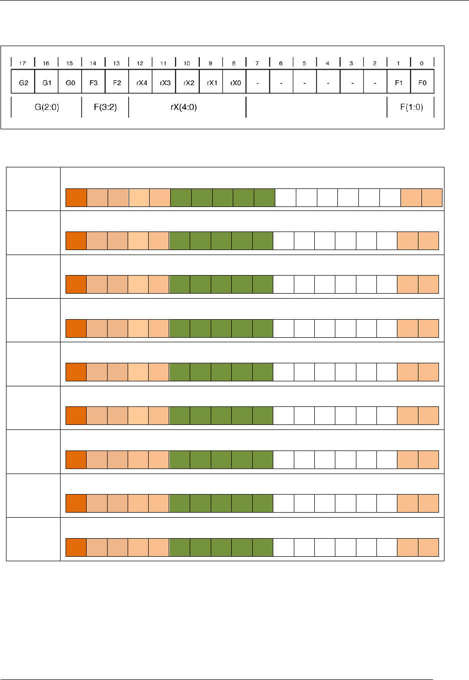
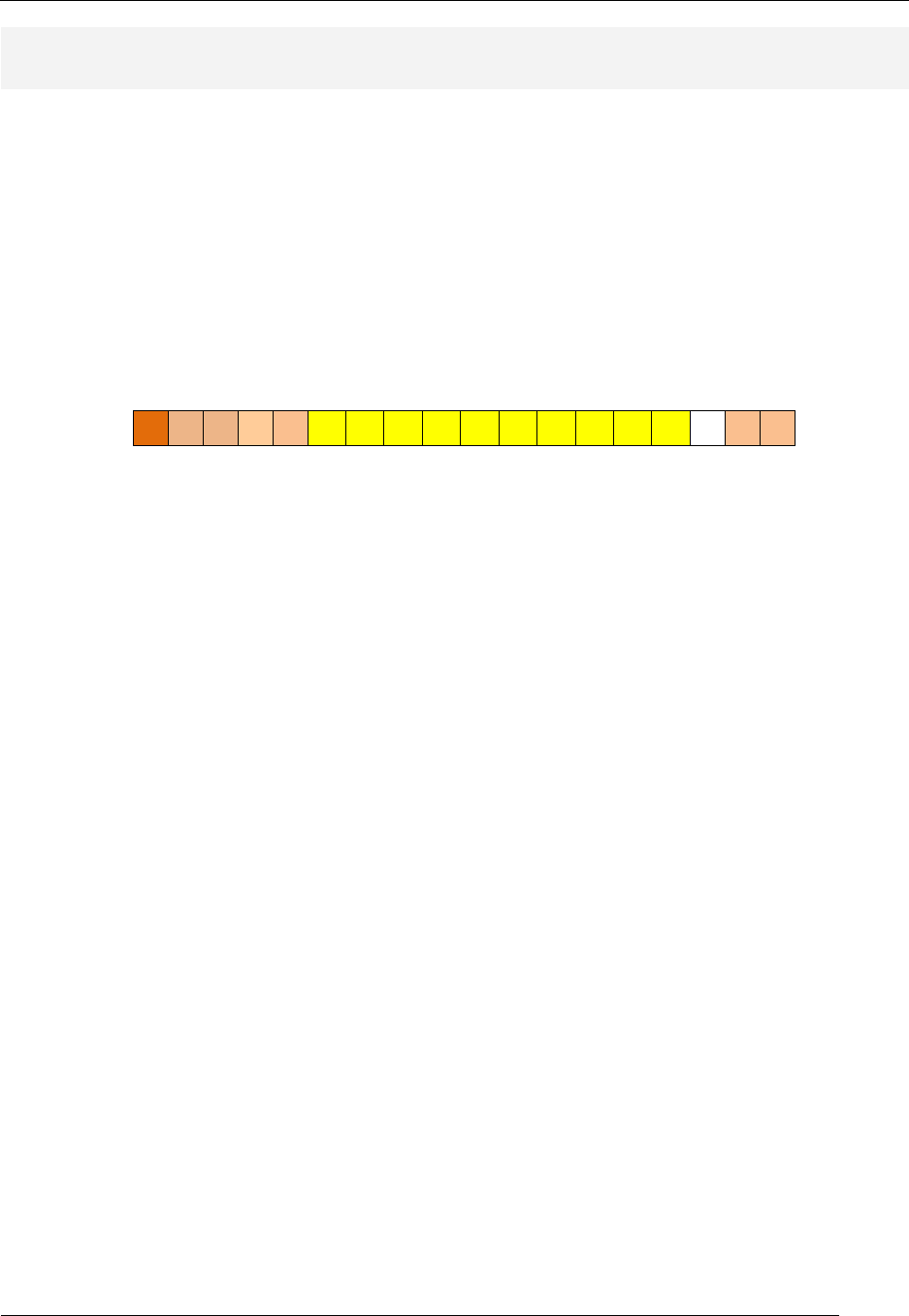
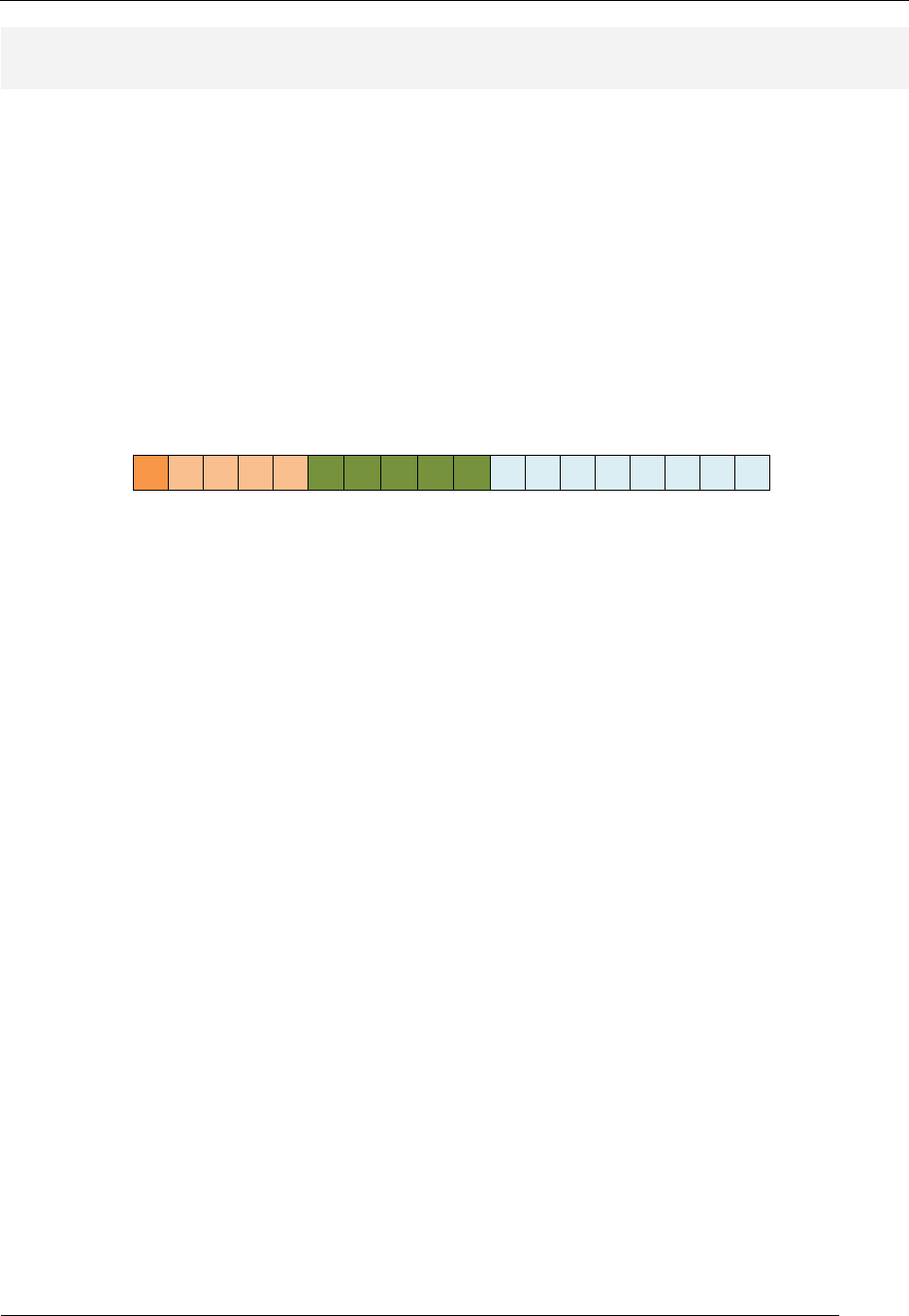
Instruction Type: Reg/Reg
Figure 5: Reg/Reg-type instruction format.
AND
AND rx,ry
17 16 15 14 13 12 11 10 9 8 7 6 5 4 3 2 1 0
0 0 0 0 0 rX rX rX rX rX rY rY rY rY rY 0 0
OR
OR rx,ry
17 16 15 14 13 12 11 10 9 8 7 6 5 4 3 2 1 0
0 0 0 0 0 rX rX rX rX rX rY rY rY rY rY 0 1
EXOR
EXOR rx,ry
17 16 15 14 13 12 11 10 9 8 7 6 5 4 3 2 1 0
0 0 0 0 0 rX rX rX rX rX rY rY rY rY rY 1 0
TEST
TEST rx,ry
17 16 15 14 13 12 11 10 9 8 7 6 5 4 3 2 1 0
0 0 0 0 0 rX rX rX rX rX rY rY rY rY rY 1 1
ADD
ADD rx,ry
17 16 15 14 13 12 11 10 9 8 7 6 5 4 3 2 1 0
0 0 0 0 1 rX rX rX rX rX rY rY rY rY rY 0 0
ADDC
ADDC rx,ry
17 16 15 14 13 12 11 10 9 8 7 6 5 4 3 2 1 0
0 0 0 0 1 rX rX rX rX rX rY rY rY rY rY 0 1
SUB
SUB rx,ry
17 16 15 14 13 12 11 10 9 8 7 6 5 4 3 2 1 0
0 0 0 0 1 rX rX rX rX rX rY rY rY rY rY 1 0
SUBC
SUBC rx,ry
17 16 15 14 13 12 11 10 9 8 7 6 5 4 3 2 1 0
0 0 0 0 1 rX rX rX rX rX rY rY rY rY rY 1 1
CMP
CMP rx,ry
17 16 15 14 13 12 11 10 9 8 7 6 5 4 3 2 1 0
0 0 0 1 0 rX rX rX rX rX rY rY rY rY rY 0 0
MOV
MOV rx,ry
17 16 15 14 13 12 11 10 9 8 7 6 5 4 3 2 1 0
0 0 0 1 0 rX rX rX rX rX rY rY rY rY rY 0 1
LD
LD rx,(ry)
17 16 15 14 13 12 11 10 9 8 7 6 5 4 3 2 1 0
0 0 0 1 0 rX rX rX rX rX rY rY rY rY rY 1 0
ST
ST rx,(ry)
17 16 15 14 13 12 11 10 9 8 7 6 5 4 3 2 1 0
0 0 0 1 0 rX rX rX rX rX rY rY rY rY rY 1 1
Table 3: Reg/Reg-type instructions with opcodes.
RAT Assembler Manual
Detailed Instruction Description
- 14 -
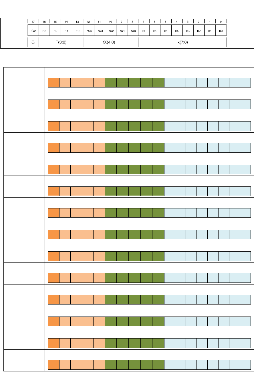
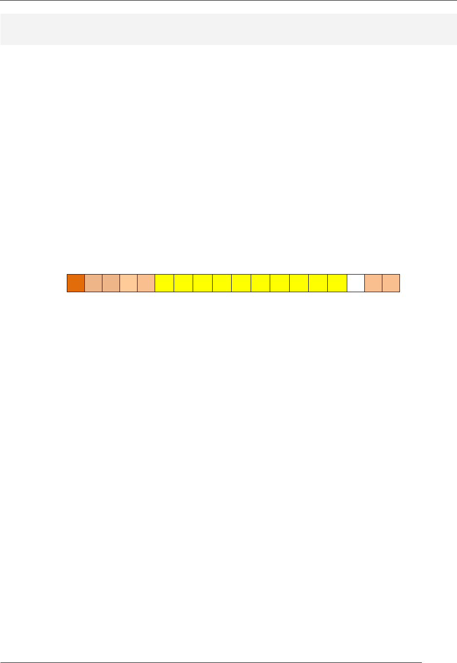
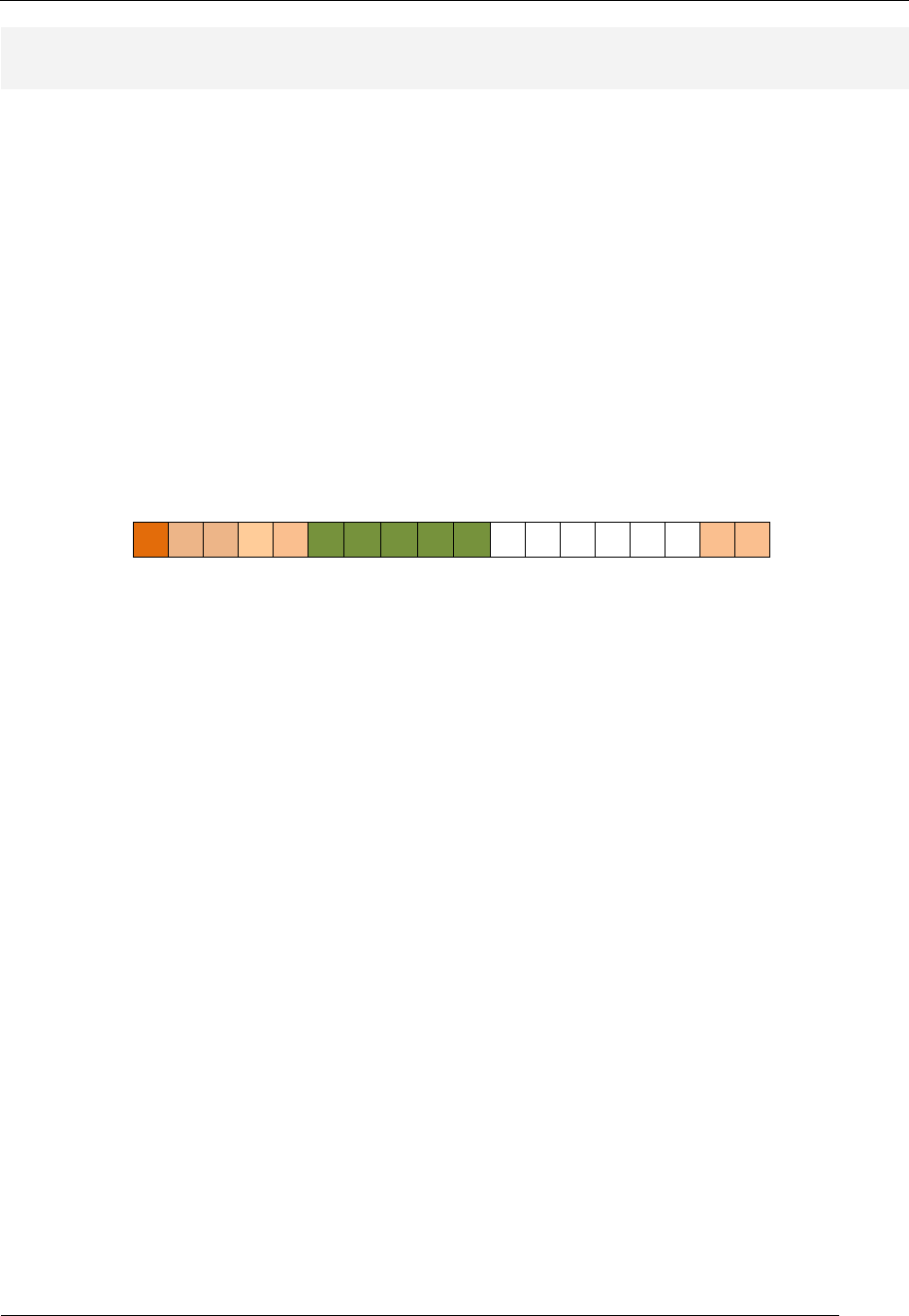
Instruction Type: Reg/Imm
Figure 6: Reg/Imm-type instruction format.
AND
AND rx,imm
17 16 15 14 13 12 11 10 9 8 7 6 5 4 3 2 1 0
1 0 0 0 0 rX rX rX rX rX k k k k k k k k
OR
OR rx,imm
17 16 15 14 13 12 11 10 9 8 7 6 5 4 3 2 1 0
1 0 0 0 1 rX rX rX rX rX k k k k k k k k
EXOR
EXOR rx,imm
17 16 15 14 13 12 11 10 9 8 7 6 5 4 3 2 1 0
1 0 0 1 0 rX rX rX rX rX k k k k k k k k
TEST
TEST rx,imm
17 16 15 14 13 12 11 10 9 8 7 6 5 4 3 2 1 0
1 0 0 1 1 rX rX rX rX rX k k k k k k k k
ADD
ADD rx,imm
17 16 15 14 13 12 11 10 9 8 7 6 5 4 3 2 1 0
1 0 1 0 0 rX rX rX rX rX k k k k k k k k
ADDC
ACCD rx,imm
17 16 15 14 13 12 11 10 9 8 7 6 5 4 3 2 1 0
1 0 1 0 1 rX rX rX rX rX k k k k k k k k
SUB
SUB rx,imm
17 16 15 14 13 12 11 10 9 8 7 6 5 4 3 2 1 0
1 0 1 1 0 rX rX rX rX rX k k k k k k k k
SUBC
SUBC rx,imm
17 16 15 14 13 12 11 10 9 8 7 6 5 4 3 2 1 0
1 0 1 1 1 rX rX rX rX rX k k k k k k k k
CMP
CMP rx,imm
17 16 15 14 13 12 11 10 9 8 7 6 5 4 3 2 1 0
1 1 0 0 0 rX rX rX rX rX k k k k k k k k
IN
IN rx,imm
17 16 15 14 13 12 11 10 9 8 7 6 5 4 3 2 1 0
1 1 0 0 1 rX rX rX rX rX k k k k k k k k
OUT
OUT rx,imm
17 16 15 14 13 12 11 10 9 8 7 6 5 4 3 2 1 0
1 1 0 1 0 rX rX rX rX rX k k k k k k k k
MOV
MOV rx,imm
17 16 15 14 13 12 11 10 9 8 7 6 5 4 3 2 1 0
1 1 0 1 1 rX rX rX rX rX k k k k k k k k
LD
LD rx,imm
17 16 15 14 13 12 11 10 9 8 7 6 5 4 3 2 1 0
1 1 1 0 0 rX rX rX rX rX k k k k k k k k
ST
ST rx,imm
17 16 15 14 13 12 11 10 9 8 7 6 5 4 3 2 1 0
1 1 1 0 1 rX rX rX rX rX k k k k k k k k
Table 4: Reg/Imm-type instructions with opcodes.
RAT Assembler Manual
Detailed Instruction Description
- 15 -
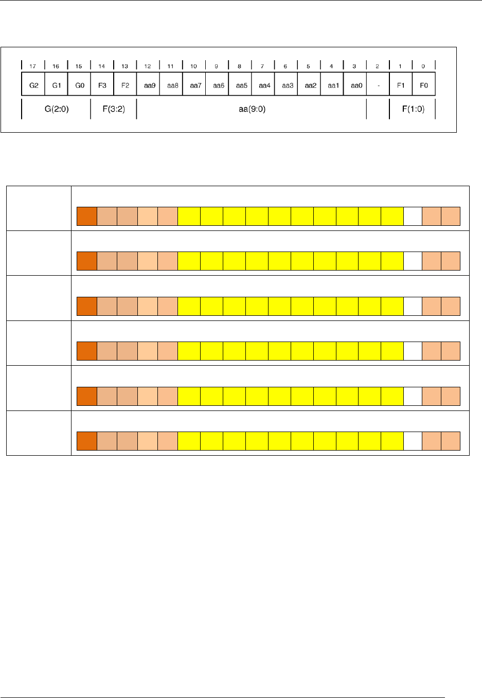
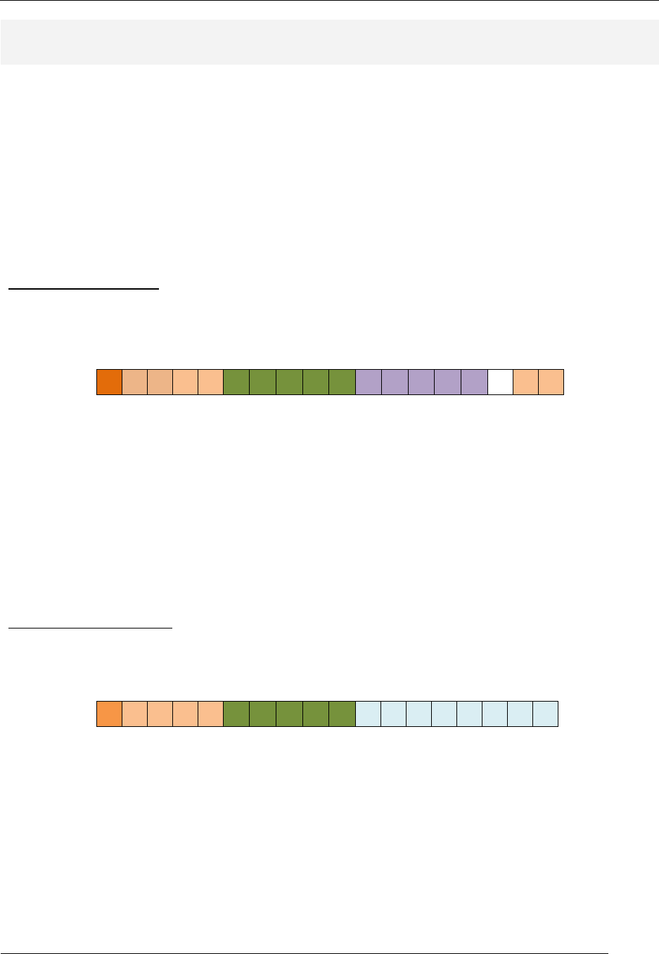
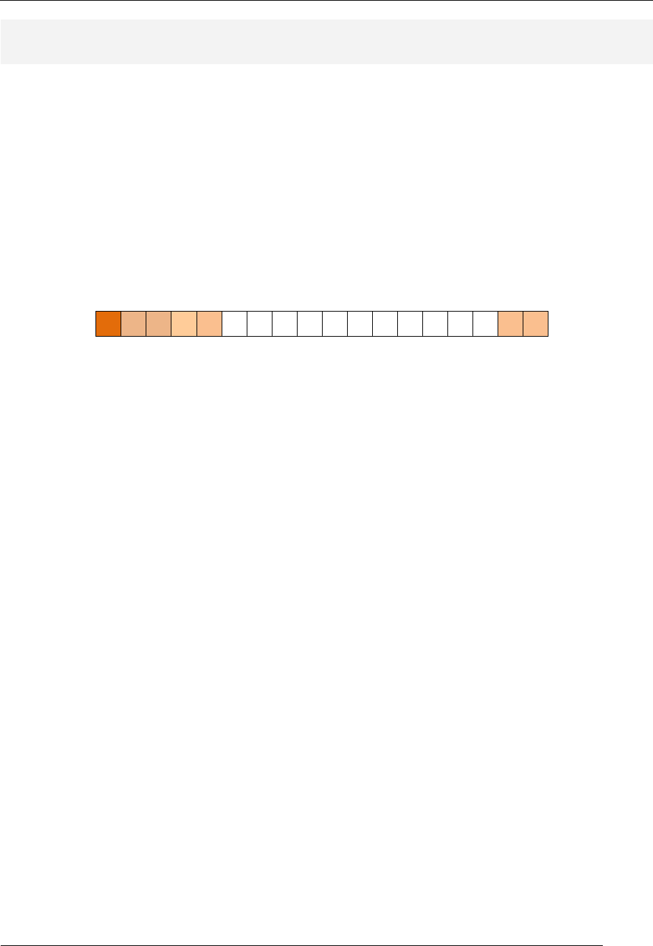
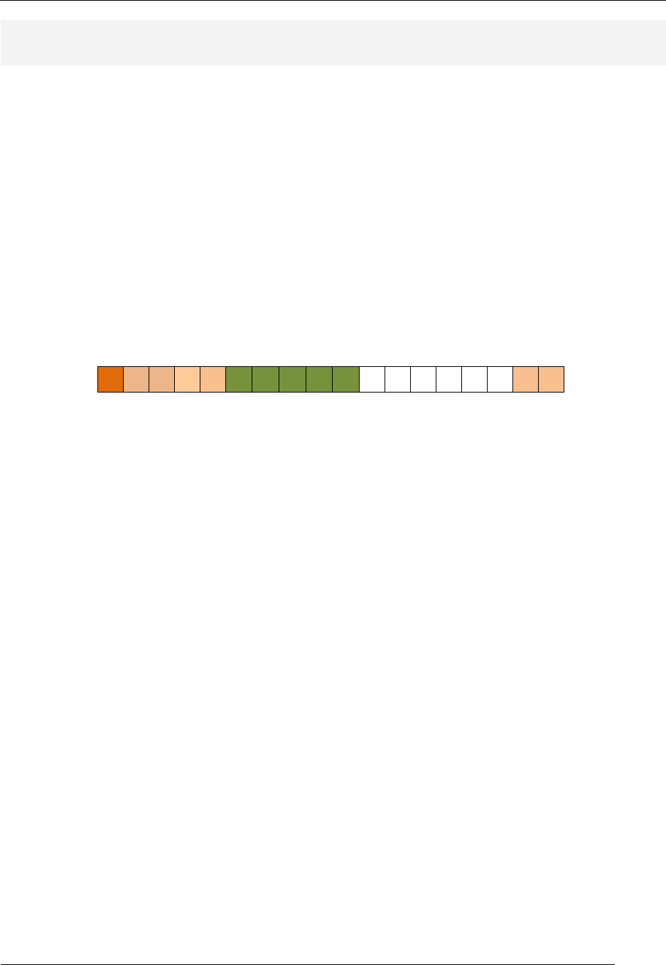
Instruction Type: Imm
Figure 7: Imm-type instruction format.
BRN
BRN label
17 16 15 14 13 12 11 10 9 8 7 6 5 4 3 2 1 0
0 0 1 0 0 aa aa aa aa aa aa aa aa aa aa - 0 0
CALL
CALL label
17 16 15 14 13 12 11 10 9 8 7 6 5 4 3 2 1 0
0 0 1 0 0 aa aa aa aa aa aa aa aa aa aa - 0 1
BREQ
BREQ label
17 16 15 14 13 12 11 10 9 8 7 6 5 4 3 2 1 0
0 0 1 0 0 aa aa aa aa aa aa aa aa aa aa - 1 0
BRNE
BRNE label
17 16 15 14 13 12 11 10 9 8 7 6 5 4 3 2 1 0
0 0 1 0 0 aa aa aa aa aa aa aa aa aa aa - 1 1
BRCS
BRCS label
17 16 15 14 13 12 11 10 9 8 7 6 5 4 3 2 1 0
0 0 1 0 1 aa aa aa aa aa aa aa aa aa aa - 0 0
BRCC
BRCC label
17 16 15 14 13 12 11 10 9 8 7 6 5 4 3 2 1 0
0 0 1 0 1 aa aa aa aa aa aa aa aa aa aa - 0 1
Table 5: Imm-type instructions with opcodes.
RAT Assembler Manual
Detailed Instruction Description
- 16 -
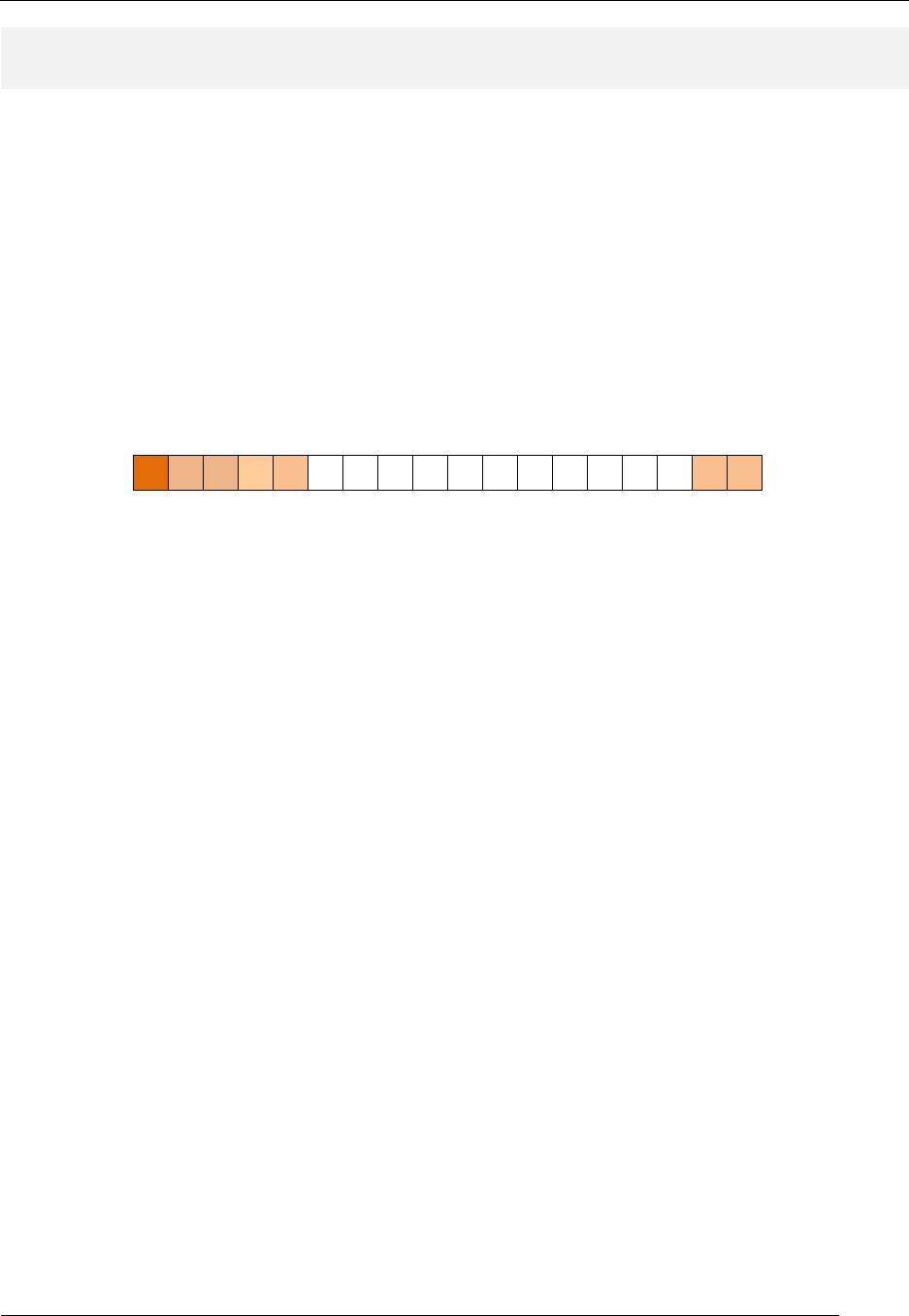
Instruction Type: Reg
Figure 8: Reg-type instruction format.
LSL
LSL rx
17 16 15 14 13 12 11 10 9 8 7 6 5 4 3 2 1 0
0 1 0 0 0 rX rX rX rX rX - - - - - - 0 0
LSR
LSR rx
17 16 15 14 13 12 11 10 9 8 7 6 5 4 3 2 1 0
0 1 0 0 0 rX rX rX rX rX - - - - - - 0 1
ROL
ROL rx
17 16 15 14 13 12 11 10 9 8 7 6 5 4 3 2 1 0
0 1 0 0 0 rX rX rX rX rX - - - - - - 1 0
ROR
ROR rx
17 16 15 14 13 12 11 10 9 8 7 6 5 4 3 2 1 0
0 1 0 0 0 rX rX rX rX rX - - - - - - 1 1
ASR
ASR rx
17 16 15 14 13 12 11 10 9 8 7 6 5 4 3 2 1 0
0 1 0 0 1 rX rX rX rX rX - - - - - - 0 0
PUSH
PUSH rx
17 16 15 14 13 12 11 10 9 8 7 6 5 4 3 2 1 0
0 1 0 0 1 rX rX rX rX rX - - - - - - 0 1
POP
POP rx
17 16 15 14 13 12 11 10 9 8 7 6 5 4 3 2 1 0
0 1 0 0 1 rX rX rX rX rX - - - - - - 1 0
WSP
WSP rx
17 16 15 14 13 12 11 10 9 8 7 6 5 4 3 2 1 0
0 1 0 1 0 rX rX rX rX rX - - - - - - 0 0
RSP
WSP rx
17 16 15 14 13 12 11 10 9 8 7 6 5 4 3 2 1 0
0 1 0 1 0 rX rX rX rX rX - - - - - - 0 1
Table 6: Reg-type instructions with opcodes.
RAT Assembler Manual
Detailed Instruction Description
- 17 -
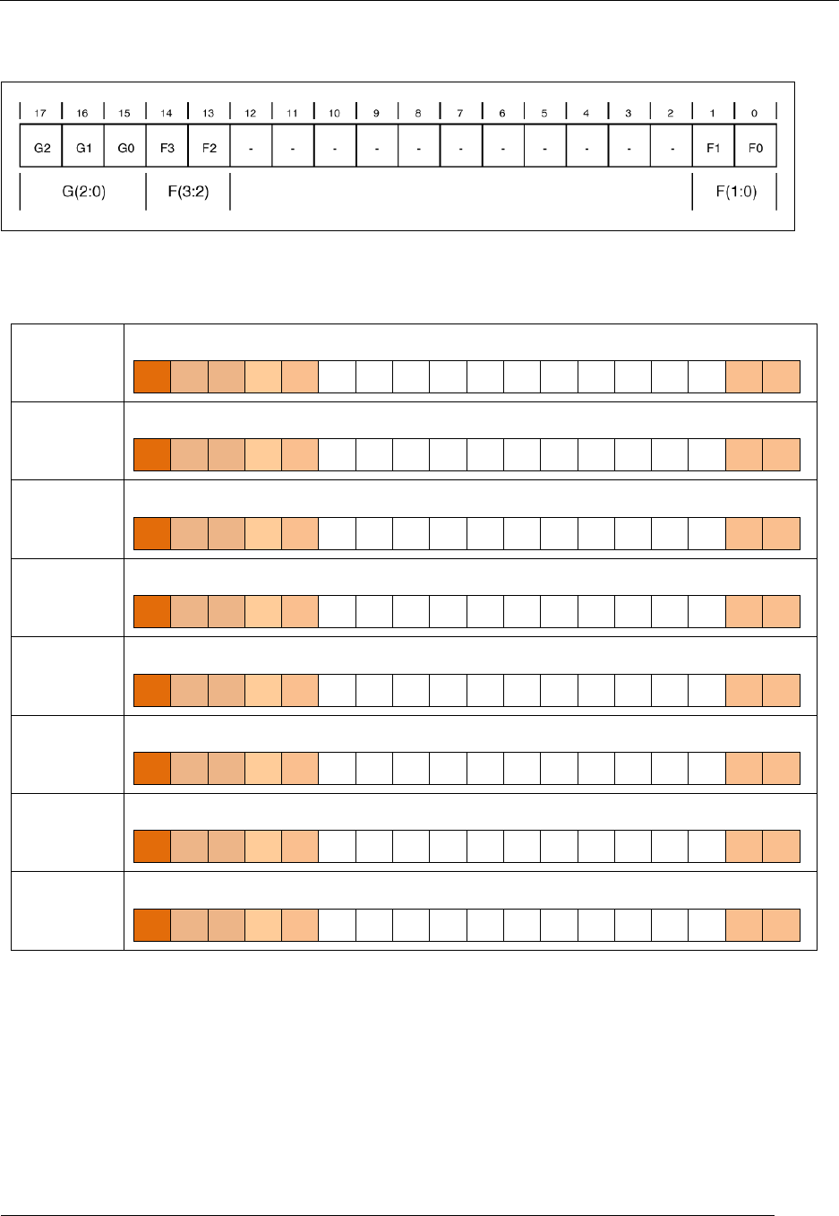
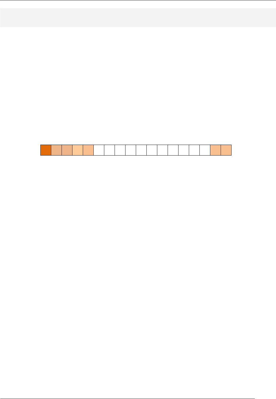
Instruction Type: None
Figure 9: None-type instruction format.
CLC
CLC
17 16 15 14 13 12 11 10 9 8 7 6 5 4 3 2 1 0
0 1 1 0 0 0 0
SEC
SEC
17 16 15 14 13 12 11 10 9 8 7 6 5 4 3 2 1 0
0 1 1 0 0 0 1
RET
RET
17 16 15 14 13 12 11 10 9 8 7 6 5 4 3 2 1 0
0 1 1 0 0 1 0
NOP
RET
17 16 15 14 13 12 11 10 9 8 7 6 5 4 3 2 1 0
0 1 1 0 0 1 1
SEI
SEI
17 16 15 14 13 12 11 10 9 8 7 6 5 4 3 2 1 0
0 1 1 0 1 0 0
CLI
CLI
17 16 15 14 13 12 11 10 9 8 7 6 5 4 3 2 1 0
0 1 1 0 1 0 1
RETID
RETID
17 16 15 14 13 12 11 10 9 8 7 6 5 4 3 2 1 0
0 1 1 0 1 1 0
RETIE
RETIE
17 16 15 14 13 12 11 10 9 8 7 6 5 4 3 2 1 0
0 1 1 0 1 1 1
Table 7: None-type instructions with opcodes.
RAT Assembler Manual
Detailed Instruction Description
- 18 -
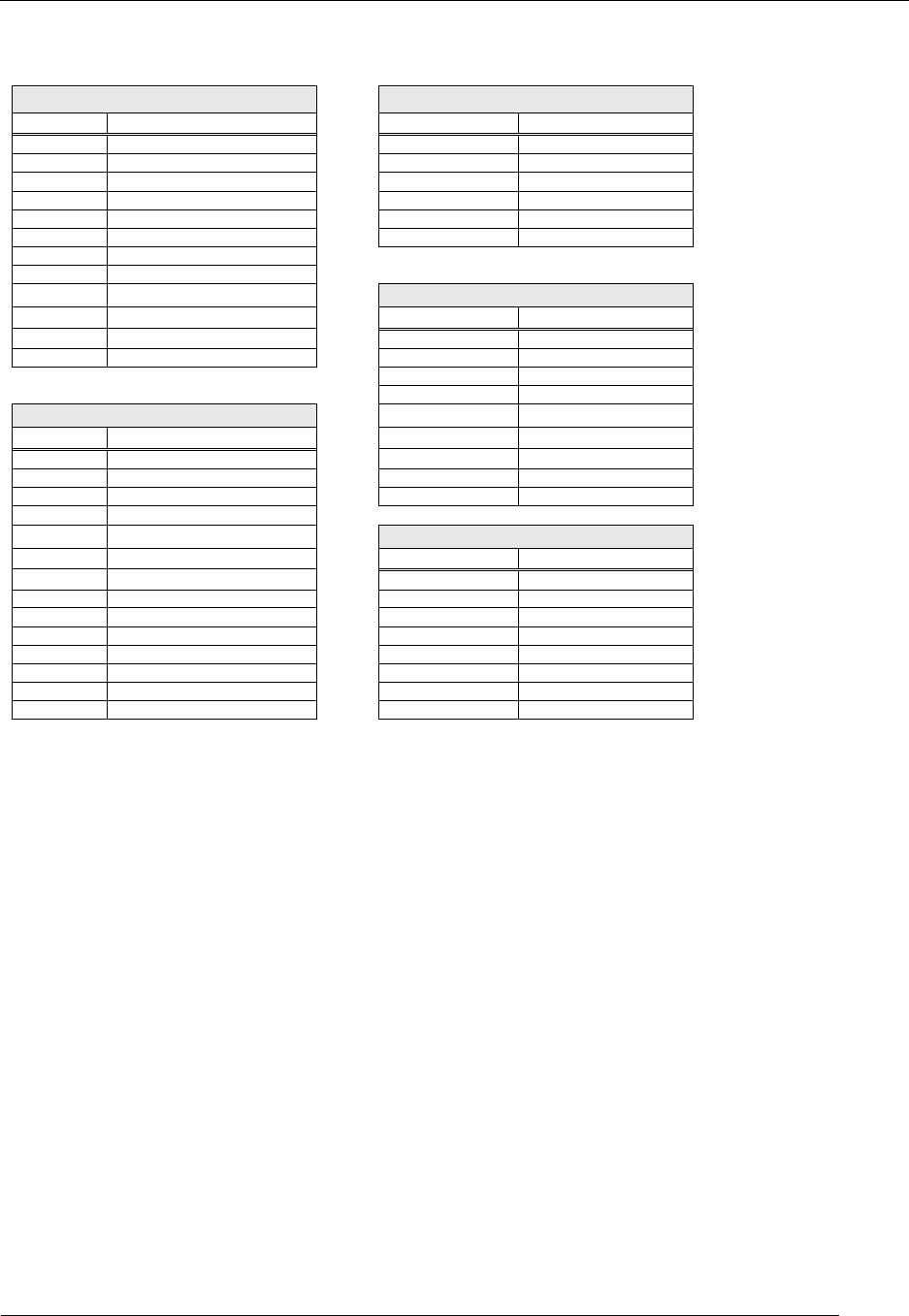
RAT Assembly Instructions Type Listing
Reg/Reg Type
Imm Type
INSTR
Form
INSTR
Form
AND
AND rx,ry
BRN
BRN label
OR
OR rx,ry
CALL
CALL label
EXOR
EXOR rx,ry
BREQ
BREQ label
TEST
TEST rx,ry
BRNE
BRNE label
ADD
ADD rx,ry
BRCS
BRCS label
ADDC
ADDC rx,ry
BRCC
BRCC label
SUB
SUB rx,ry
SUBC
SUBC rx,ry
CMP
CMP rx,ry
Reg Type
MOV
MOV rx,ry
INSTR
Form
LD
LD rx,(ry)
LSL
LSL rx
ST
ST rx,(ry)
LSR
LSR rx
ROL
ROL rx
ROR
ROR rx
Reg/Imm Type
ASR
ASR rx
INSTR
Form
PUSH
PUSH rx
AND
AND rx,imm
POP
POP rx
OR
OR rx,imm
WSP
WSP rx
EXOR
EXOR rx,imm
RSP
RSP rx
TEST
TEST rx,imm
ADD
ADD rx,imm
None Type
ADDC
ACCD rx,imm
INSTR
Form
SUB
SUB rx,imm
CLC
CLC
SUBC
SUBC rx,imm
SEC
SEC
CMP
CMP rx,imm
RET
RET
MOV
MOV rx,imm
RETID
RETID
LD
LD rx,imm
RETIE
RETIE
ST
ST rx,imm
SEI
SEI
IN
IN rx,imm
CLI
CLI
OUT
OUT rx,imm
NOP
NOP
Detailed RAT Assembly Instruction Description
The following section lists each of the RAT instruction in a detailed format. The instruction details include
the following:
• Instruction mnemonic
• Short Instruction description
• Associated RTL statements
• Condition flag affects
• Extended instruction description
• Detailed instruction format
• Instruction usage example
Notes on Instruction Formats
Instructions format include two, one, or no operands. We generally attempt to clarify the actions of each
instruction by declaring operands to be either source or destination operands. While this classification is
convenient and usually helpful, it becomes confusing in its application. The two main issues are that
some instruction formats do not have operands (none-types) while others have only one operand, which
makes it tough to specify whether the one operand is a source or destination operand. The guiding factor
is that we arbitrarily states that no instruction changes the source operand.
RAT Assembler Manual
Detailed Instruction Description
- 19 -
ADD (addition)
RTL: Rd ← Rd + Rs (reg – reg form)
RTL: Rd ← Rd + immed (reg – imm form) Forms: ADD Rd,Rs
ADD Rd,imm_val
Carry Flag: set if the addition operation results in a
carry out of the MSB position; cleared otherwise. Zero Flag: set if all bits in Rd are zero after operation is
complete; cleared otherwise.
Description: The ADD instruction performs an addition operation on the two operands and stores the
result in the destination register Rd. The result of this operation overwrites the value in the destination
register. The ADD instruction has two distinct forms, which are differentiated by the source operand.
Register-Register Form: A register specifies the source operand; the source operand is the value in
that register. Instruction execution does not affect the value in the source register.
Instruction
Format:
17 16 15 14 13 12 11 10 9 8 7 6 5 4 3 2 1 0
0 0 0 0 1 rX rX rX rX rX rY rY rY rY rY - 0 0
rX: destination register; rY: source register
Usage:
ADD r1,r4 ; addition of values in registers r1 & r4;
; result is placed in r1; value in r4 is not
; affected.
; r1 = 0xA4 r4 = 0xC7 (before exec)
; r1 = 0x6B r4 = 0xC7 Z=0 C=1 (after exec)
Register-Immediate Form: An immediate value (any 8-bit value) specifies the source operand.
Instruction
Format:
17 16 15 14 13 12 11 10 9 8 7 6 5 4 3 2 1 0
1 0 1 0 0 rX rX rX rX rX k k k k k k k k
rX: destination register; k: source immediate value
Usage:
ADD r1,0xDC ; addition of values in register r1 & 0xDC;
; result is placed in r1
; r1 = 0x24 (before execution)
; r1 = 0x00 Z=1 C=1 (after execution)
RAT Assembler Manual
Detailed Instruction Description
- 20 -
ADDC (addition including Carry flag)
RTL: Rd ← Rd + Rs + C (reg – reg form)
RTL: Rd ← Rd + immed + C (reg – imm form) Forms: ADDC Rd,Rs
ADDC Rd,imm_val
Carry Flag: set if the addition operation results in a
carry out of the MSB position; cleared otherwise. Zero Flag: set if all bits in Rd are zero after operation is
complete; cleared otherwise.
Description: The ADDC instruction performs an addition operation on the two operands and the
Carry flag and stores the result in the destination register Rd. The result of this operation overwrites the
value in the destination register. The ADDC instruction has two distinct forms, which are differentiated
by the form of the source operand.
Register-Register Form: The source operand is specified by a register; the source operand is the value
in that register. Instruction execution does not affect the value in the source register.
Instruction
Format:
17 16 15 14 13 12 11 10 9 8 7 6 5 4 3 2 1 0
0 0 0 0 1 rX rX rX rX rX rY rY rY rY rY - 0 1
rX: destination register; rY: source register
Usage:
ADDC r1,r4 ; addition of values in registers r1 & r4;
; result is placed in r1; value in r4 is not
; affected.
; r1 = 0xA4 r4 = 0xC7 C =1 (before exec)
; r1 = 0x6C r4 = 0xC7 Z=0 C=1 (after exec)
Register-Immediate Form: An immediate value (any 8-bit value) specifies the source operand.
Instruction
Format:
17 16 15 14 13 12 11 10 9 8 7 6 5 4 3 2 1 0
1 0 1 0 1 rX rX rX rX rX k k k k k k k k
rX: destination register; k: source immediate value
Usage:
ADDC r1,0xDC ; addition of values in register r1 & 0xDC & C flag;
; result is placed in r1
; r1 = 0x24 C=1 (before execution)
; r1 = 0x01 Z=0 C=1
(after execution)

RAT Assembler Manual
Detailed Instruction Description
- 21 -
AND (logical bitwise AND)
RTL: Rd ← Rd · Rs (reg – reg form)
RTL:
Rd ← Rd · immed (reg – imm form) Forms:
AND Rd,Rs
AND Rd,imm_val
Carry Flag: cleared after operation.
Zero Flag: set if all bits in Rd are zero after operation is
complete; cleared otherwise.
Description: The AND instruction performs a bit-wise logical AND operation between the source and
destination operands and places the result in the register specified by the destination operand. The
AND instruction has two distinct forms which are differentiated by the source operand. The result of the
AND operation overwrites the value in the destination register.
Register-Register Form: The source operand is specified by a register; the source operand is the value
in that register. Instruction execution does not affect the value in the source register.
Instruction
Format:
17 16 15 14 13 12 11 10 9 8 7 6 5 4 3 2 1 0
0 0 0 0 0 rX rX rX rX rX rY rY rY rY rY - 0 0
rX: destination register; rY: source register
Usage:
AND r1,r4 ; bitwise and of values in register r1 & r4;
; result is placed in r1; value in r4 is not
; affected.
; r1 = 0xA4 r4 = 0xC7 (before execution)
; r1 = 0x84 r4 = 0xC7 (after execution)
Register-Immediate Form: An immediate value (any 8-bit value) specifies the source operand.
Instruction
Format:
17 16 15 14 13 12 11 10 9 8 7 6 5 4 3 2 1 0
1 0 0 0 0 rX rX rX rX rX k k k k k k k k
rX: destination register; k: source immediate value
Usage:
AND r1,0x3C ; bitwise AND of values in register r1 & 0x4A;
; result is placed in r1
; r1 = 0xA4 (before execution)
; r1 = 0x24 (after execution)
RAT Assembler Manual
Detailed Instruction Description
- 22 -
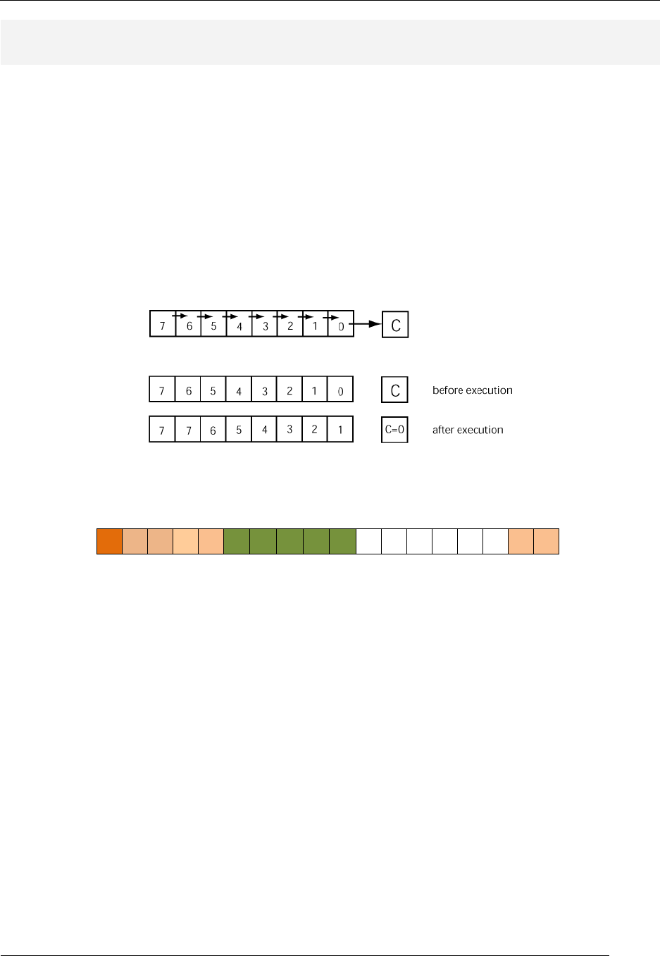
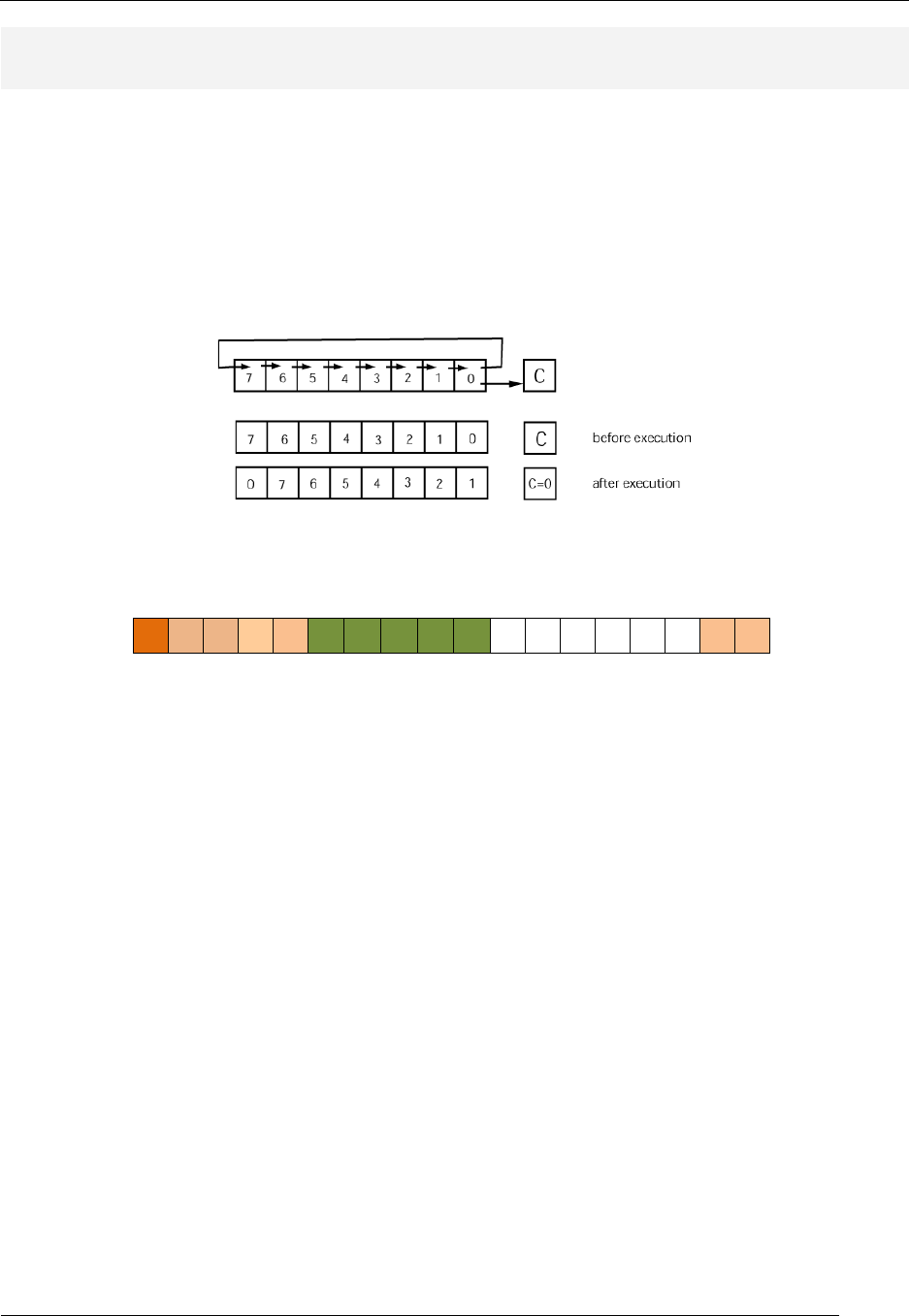
ASR (arithmetic shift right)
RTL: Rd ← Rd(7) & Rd(7) & Rd(6:1), C ← Rd(0) Forms: ASR Rd
Carry Flag: takes value of LSB of destination register Zero Flag: set if all bits in Rd are zero after operation is
complete; cleared otherwise.
Description: The ASR instruction performs a shift right operation on the destination register. The
current value of the destination register MSB remains unchanged. This instruction treats the MSB as
the sign bit and thus right shifts the sign-bit into the bit-6 location of the destination. The LSB of the
destination register before the shift operation shifts into the Carry flag; the diagram below shows this
result by placing the “C=0” into the Carry flag. To be clear, the LSB is shifted into the Carry flag, the
“C=0” in the diagram below indicates the bit position before the shift and not the value of the bit written
to the Carry flag after the operation. This instruction has a reg-type instruction format.
Instruction
Format:
17 16 15 14 13 12 11 10 9 8 7 6 5 4 3 2 1 0
0 1 0 0 1 rX rX rX rX rX - - - - - - 0 0
rX: destination register
Usage:
ASR r1 ; arithmetic shift right of register r1;
; result is placed in r1;
; r1 = 0xE7 (before execution)
; r1 = 0xF3 C=1 Z=0 (after execution)
See Also: LSR

RAT Assembler Manual
Detailed Instruction Description
- 23 -
BRCC (branch if carry cleared)
RTL: if (C==0) then PC ← imm_val, else nop Forms:
BRCC label
BRCC imm_val
Carry Flag: not affected Zero Flag: not affected
Description: The BRCC is a program flow instruction branches to an address value when the Carry
flag is cleared (C=0). If the Carry flag is presently set, program flow drops through to the instruction
following the BRCC instruction, effectively making the BRCC instruction a NOP. A program label or a
constant value designates the immediate value associated with the BRCC instruction. This instruction
is an imm-type instruction.
Instruction
Format:
17 16 15 14 13 12 11 10 9 8 7 6 5 4 3 2 1 0
0 0 1 0 1 aa aa aa aa aa aa aa aa aa aa - 0 1
aa: program memory address
Usage:
DOGBONE:
ADD r1,r2 ; add register r2 to register r1
; Carry flag is affected by this operation.
;
BRCC DOGBONE ; if C=0, program flow will jump to instruction
; after the label argument of this instruction.
; If C=1, program execution drops to the
; instruction following BRCC
See Also: BRCS
RAT Assembler Manual
Detailed Instruction Description
- 24 -
BRCS (branch if carry set)
RTL: if (C==1) then PC ← imm_val, else nop Forms:
BRCS label
BRCS imm_val
Carry Flag: not affected Zero Flag: not affected
Description: The BRCS is a program flow instruction branches to an address value when the carry
flag is set. If the carry flag is cleared, program flow drops through to the instruction following the BRCS
instruction, effectively making the BRCS instruction a NOP. A program label or a constant value
designates the immediate value associated with the BRCS instruction. This instruction is an imm-type
instruction.
Instruction
Format:
17 16 15 14 13 12 11 10 9 8 7 6 5 4 3 2 1 0
0 0 1 0 1 aa aa aa aa aa aa aa aa aa aa - 0 0
aa: program memory address
Usage:
WHISKER:
ADD r1,r2 ; add register r2 to register r1
; Carry flag is affected by this operation.
;
BRCS WHISKER ; if C=1, program flow will jump to instruction
; after the label argument of this instruction.
; If C=0, program execution drops to the
; instruction following BRCC
See Also: BRCC
RAT Assembler Manual
Detailed Instruction Description
- 25 -
BREQ (branch if equal)
RTL: if (Z==1) then PC ← imm_val, else nop Forms:
BREQ label
BREQ imm_val
Carry Flag: not affected Zero Flag: not affected
Description: The BREQ is a program flow instruction branches to an address value in the case that
the zero flag is set. If the zero flag is presently cleared, program flow drops through to the instruction
following the BREQ instruction, which effectively makes the BREQ instruction a NOP. A program label
or a constant value specifies the immediate value associated with this instruction. The mnemonic for
this instruction is somewhat confusing. The “equal” part of the instruction is associated with the fact if
two equivalent values are subtracted from each other and the result is zero; in this case, the result sets
the zero flag. This instruction is an imm-type instruction.
Instruction
Format:
17 16 15 14 13 12 11 10 9 8 7 6 5 4 3 2 1 0
0 0 1 0 0 aa aa aa aa aa aa aa aa aa aa - 1 0
aa: program memory address
Usage:
WHISKER:
ADD r1,r2 ; add register r2 to register r1
; Zero flag is affected by this operation.
;
BREQ WHISKER ; if Z=1, program flow will jump to instruction
; after the label argument of this instruction.
; If Z=0, program execution drops to the
; instruction following BREQ
See Also: BRNE
RAT Assembler Manual
Detailed Instruction Description
- 26 -
BRN (unconditional branch)
RTL: PC ← imm_val Forms: BRN immed_val
Carry Flag: not affected Zero Flag: not affected
Description: The BRN is a program flow instruction causes an unconditional branch to the immediate
address associated with the instruction. A program label or constant value specifies the immediate.
This instruction is an imm-type instruction.
Instruction
Format:
17 16 15 14 13 12 11 10 9 8 7 6 5 4 3 2 1 0
0 0 1 0 0 aa aa aa aa aa aa aa aa aa aa - 0 0
aa: program memory address
Usage:
NOODLE: ; typical program label
ROL R1 ; rotate register r1 left
BRN NOODLE ; unconditional branch back to ROL instruction
See Also: BRNE, BREQ, BRCC, BRCS

RAT Assembler Manual
Detailed Instruction Description
- 27 -
BRNE (branch if not equal)
RTL: if (Z==0) then PC ← imm_val, else nop Forms:
BRNE label
BRNE imm_val
Carry Flag: not affected Zero Flag: not affected
Description: The BRNE instruction branches to an address value in the case that the zero flag is
cleared. If the zero flag is presently set, program flow drops through to the instruction following the
BRNE instruction. A program label or a constant value designates the immediate value associated with
the branch. The mnemonic for this instruction is somewhat confusing. The “not equal” portion part of
the instruction is associated with the fact if two non-equal values are subtracted from each other and
the result is non-zero; in this case , the result clears the zero flag. This instruction is an imm-type
instruction.
Instruction
Format:
17 16 15 14 13 12 11 10 9 8 7 6 5 4 3 2 1 0
0 0 1 0 0 aa aa aa aa aa aa aa aa aa aa - 1 1
aa: program memory address
Usage:
WHISKER:
ADD r1,r2 ; add register r2 to register r1
; Zero flag is affected by this operation.
;
BRNE WHISKER ; if Z=0, program flow will jump to instruction
; after the label argument of this instruction.
; If Z=1, program execution drops to the
; instruction following BRNE
See Also: BREQ
RAT Assembler Manual
Detailed Instruction Description
- 28 -
CALL (branch to subroutine)
RTL: PC ← imm_val, (SP-1) ← PC, SP←SP - 1 Forms: CALL imm_val
Carry Flag: not affected Zero Flag: not affected
Description: The CALL is a program flow instruction directs program flow to a set of instructions that
are generally designated to be a subroutine. The address associated with the CALL instruction is the
address of the next executed instruction following the CALL instruction. The CALL instruction pushes
the current value of the PC onto the stack at the same time as the CALL instruction immediate address
is loaded in the PC. The “current” value of the PC contains the address of the instruction after the CALL
instruction and is the first instruction scheduled for execution after the subroutine completes execution.
Each CALL instruction generally has an accompanying RET instruction in order to avoid stack
underflow/overflow problems. This instruction is an imm-type instruction.
Instruction
Format:
17 16 15 14 13 12 11 10 9 8 7 6 5 4 3 2 1 0
0 0 1 0 0 aa aa aa aa aa aa aa aa aa aa - 0 1
aa: program memory address
Usage:
;---------------------------------------------------------------
;- ADD_VALS subroutine: add some registers
;---------------------------------------------------------------
ADD_VALS:
ADD r1,r2
ADD r1,r3
ADD r1,r4
RET
;----------------------------------------------------------------
CALL ADD_VALS ; branches to ADD_VALS subroutine
See Also: RET
RAT Assembler Manual
Detailed Instruction Description
- 29 -
CLC (clear Carry flag)
RTL: C ← 0 Forms: CLC
Carry Flag: cleared (C=0) Zero Flag: not affected
Description: The CLC instruction clears the carry flag. This instruction requires no arguments and
thus has a none-type instruction format.
Instruction
Format:
17 16 15 4 13 12 11 10 9 8 7 6 5 4 3 2 1 0
0 1 1 0 0 - - - - - - - - - - - 0 0
Usage:
CLC ; clear the Carry flag
; C=1 (before execution)
; C=0 (after execution)
See Also: SEC
RAT Assembler Manual
Detailed Instruction Description
- 30 -
CLI (clear interrupt flag)
RTL: IF ← 0 [masks] Forms: CLI
Carry Flag: not affected Zero Flag: not affected
Description: The CLI instruction disables the MCU from acting on received interrupts. The IF bit
(interrupt flag) must be set (unmasked) in order to allow the MCU to process interrupts. The CLI
instruction clears (masks) the IF bit. The RAT MCU does not act on interrupts that appear when the
interrupts are disabled. This instruction requires no arguments and thus has a none-type instruction
format.
Instruction
Format:
17 16 15 14 13 12 11 10 9 8 7 6 5 4 3 2 1 0
0 1 1 0 1 - - - - - - - - - - - 0 1
Usage:
CLI ; clear interrupt flag to allow interrupts
; IF=1 (before execution)
; IF=0 (after execution)
See Also: SEI
RAT Assembler Manual
Detailed Instruction Description
- 31 -
CMP (compare two values)
RTL: Rd - Rs (reg – reg form)
RTL: Rd - immed (reg – imm form) Forms: CMP Rd,Rs
CMP Rd,imm_val
Carry Flag: set if the operation results in a borrow
(underflow) into the MSB position; cleared otherwise Zero Flag: set if all bits in the result are zero after
operation is complete; cleared otherwise.
Description: The CMP instruction performs a subtraction operation on the two operands; the result is
not written back to the destination register but the Z and C flags are altered according to the result of
the subtraction operation. Specifically, the value in the source operand is subtracted from the value in
the destination register. The Carry flag is set by this operation and indicate the instruction execution
resulted in an underflow. The instruction does not modify the source or destination register.
Register-Register Form: The source operand is specified by a register; the source operand is the value
in that register. Instruction execution does not affect the value in the source register.
Instruction
Format:
17 16 15 14 13 12 11 10 9 8 7 6 5 4 3 2 1 0
0 0 0 1 0 rX rX rX rX rX rY rY rY rY rY - 0 0
rX: destination register; rY: source register
Usage:
CMP r1,r4 ; value in register r4 is subtracted from value in
; register r1; C and Z flags are affected but
; values in registers do not change
; r1 = 0xD4 r4 = 0xC7 (before exec)
; r1 = 0xD4 r4 = 0xC7 Z=0 C=0 (after exec)
Register-Immediate Form: An immediate value (any 8-bit value) specifies the source operand.
Instruction
Format:
17 16 15 14 13 12 11 10 9 8 7 6 5 4 3 2 1 0
1 1 0 0 0 rX rX rX rX rX k k k k k k k k
rX: destination register; k: source immediate value
Usage:
CMP r1,0xC8 ; value 0xC8 is subtracted from value in
; register r1; C and Z flags are affected but
; values in registers do not change
; r1 = 0x88 (before execution)
; r1 = 0x88 Z=0 C=1 (after execution)
RAT Assembler Manual
Detailed Instruction Description
- 32 -
EXOR (logical bitwise exclusive OR)
RTL: Rd ← Rd xor Rs (reg – reg form)
RTL:
Rd ← Rd xor immed (reg – imm form) Forms:
EXOR Rd,Rs
EXOR Rd,imm_val
Carry Flag: cleared after operation.
Zero Flag: set if all bits in Rd are zero after operation is
complete; cleared otherwise.
Description: The EXOR instruction performs a bit-wise logical exclusive OR operation between the
source and destination operands and places the result into the register specified by the destination
operand. The EXOR instruction has two distinct forms, which are differentiated by the source operand.
The EXOR instruction overwrites the value in the destination register. .
Register-Register Form: The source operand is specified by a register; the source operand is the value
in that register. Instruction execution does not affect the value in the source register.
Instruction
Format:
17 16 15 14 13 12 11 10 9 8 7 6 5 4 3 2 1 0
0 0 0 0 0 rX rX rX rX rX rY rY rY rY rY - 1 0
rX: destination register; rY: source register
Usage:
EXOR r1,r4 ; bitwise exclusive OR of values in register r1 & r4;
; result is placed in r1; value in r4 is not
; affected.
; r1 = 0xA4 r4 = 0xC7 (before execution)
; r1 = 0x63 r4 = 0xC7 Z=0 (after execution)
Register-Immediate Form: An immediate value (any 8-bit value) specifies the source operand.
Instruction
Format:
17 16 15 14 13 12 11 10 9 8 7 6 5 4 3 2 1 0
1 0 0 1 0 rX rX rX rX rX k k k k k k k k
rX: destination register; k: source immediate value
Usage:
EXOR r1,0x7C ; bitwise exclusive OR of values in register
; r1 & 0x1C; result is placed in r1
; r1 = 0xF0 (before execution)
; r1 = 0x8C Z=0 (after execution)
RAT Assembler Manual
Detailed Instruction Description
- 33 -
IN (input data from input port)
RTL: Rd ← in_port(imm_val) Forms: IN Rd,imm_val
Carry Flag: not affected Zero Flag: not affected
Description: The IN instruction inputs the data on the input port specified by the source operand into
the register specified by the destination operand. Data read in from the input port overwrites the value
in the destination register. The immediate value for the source operand can be any 8-bit value. This
instruction is a reg-imm instruction format.
Instruction
Format:
17 16 15 14 13 12 11 10 9 8 7 6 5 4 3 2 1 0
1 1 0 0 1 rX rX rX rX rX k k k k k k k k
rX: destination register; k: source immediate value
Usage:
IN r1,0x23 ; input value on input port number 0x23 and
; place in register r1;
; r1=0xD4 in port 0x23 val=0xC8 (before exec)
; r1=0xC8 (after exec)
See Also: OUT
RAT Assembler Manual
Detailed Instruction Description
- 34 -
LD (load value from data memory into register)
RTL: Rd ← (Rs) (reg – reg form)
RTL:
Rd ← (immed) (reg – imm form) Forms:
LD Rd,(Rs)
LD Rd,imm_val
Carry Flag: not affected Zero Flag: not affected
Description: The LD instruction copies data from the data memory address specified by the source
operand into the destination register. This instruction has two distinct forms, which are differentiated by
the source operand. The reg-immed form uses the immed value as the data memory address while the
reg-reg form specifies a register contains the data memory address. The execution of this instruction
leaves the source operand unchanged but does changes the destination operand.
Register-Register Form: An indirect register reference specifies the source operand; the instruction
uses the contents of the source register as the address of the data in data memory to copy to the
destination register. Instruction execution does not affect the value of the specified data memory
location.
Instruction
Format:
17 16 15 14 13 12 11 10 9 8 7 6 5 4 3 2 1 0
0 0 0 1 0 rX rX rX rX rX rY rY rY rY rY - 1 0
rX: destination register; rY: source register
Usage:
LD r1,(r4) ; value of data addressed by the value in
; register r4 is placed into register r1;
; the value in register r4 is not affected.
; r1=0xD4 r4=0xC7 mem loc 0xC7=34 (before exec)
; r1=0x34 r4=0xC7 mem loc 0xC7=34 (after exec)
Register-Immediate Form: The source operand specifies a value that holds the address of the data in
data memory to copy to the destination register.
Instruction
Format:
17 16 15 14 13 12 11 10 9 8 7 6 5 4 3 2 1 0
1 1 1 0 0 rX rX rX rX rX k k k k k k k k
rX: destination register; k: source immediate value
Usage:
LD r1,0x45 ; value of data in memory address 0x45 is
; placed into register r1;
; r1=0xD4 mem loc 0x45=CD (before exec)
; r1=0xCD mem loc 0x45=CD (after exec)
RAT Assembler Manual
Detailed Instruction Description
- 35 -
LSL (logical shift left)
RTL: Rd ← Rd(6:0) & C, C ← Rd(7) Forms: LSL Rd
Carry Flag: takes value of MSB of destination register
before shift operation Zero Flag: set if all bits in Rd are zero after operation is
complete; cleared otherwise.
Description: The LSL instruction performs a left shift operation on the destination register. The MSB
of the original destination register, Rd(7), is shifted into the carry flag. The previous value of the carry
flag becomes the LSB of the new value in the destination register. This instruction has a reg-type
instruction format.
Instruction
Format:
17 16 15 14 13 12 11 10 9 8 7 6 5 4 3 2 1 0
0 1 0 0 0 rX rX rX rX rX - - - - - - 0 0
rX: destination register
Usage:
LSL r1 ; logical shift left of register r1;
; result is placed in r1;
; r1 = 0x54 C=1 (before execution)
; r1 = 0xA9 C=0 (after execution)
See Also: LSR
RAT Assembler Manual
Detailed Instruction Description
- 36 -
LSR (logical shift right)
RTL: Rd ← C & Rd(7:1), C ← Rd(0) Forms: LSR Rd
Carry Flag: takes value of LSB of destination register
before shift operation Zero Flag: set if all bits in Rd are zero after operation is
complete; cleared otherwise.
Description: The LSR instruction performs a right shift operation on the destination register. The LSB
of the original destination register is shifted into the carry flag. The previous value of the carry flag
becomes the MSB of the new value in the destination register. This instruction has a reg-type
instruction format.
Instruction
Format:
17 16 15 14 13 12 11 10 9 8 7 6 5 4 3 2 1 0
0 1 0 0 0 rX rX rX rX rX - - - - - - 0 1
rX: destination register
Usage:
LSR r1 ; logical shift right of register r1;
; result is placed in r1;
; r1 = 0x54 C=1 (before execution)
; r1 = 0xAA C=0 (after execution)
See Also: LSL
RAT Assembler Manual
Detailed Instruction Description
- 37 -
MOV (move value into register)
RTL: Rd ← Rs (reg – reg form)
RTL: Rd ← immed (reg – imm form) Forms: MOV Rd,Rs
MOV Rd,imm_val
Carry Flag: not affected Zero Flag: not affected
Description: The MOV instruction copies the data from the source operand into the register specified
by the destination operand.
Register-Register Form: The source operand is specified as a register; the source operand is the value
in that register. Instruction execution does not affect the value in the source register.
Instruction
Format:
17 16 15 14 13 12 11 10 9 8 7 6 5 4 3 2 1 0
0 0 0 1 0 rX rX rX rX rX rY rY rY rY rY - 0 1
rX: destination register; rY: source register
Usage:
MOV r1,r4 ; value in register r4 is place in register r1;
; value in register r4 does not change
; r1 = 0xD4 r4 = 0xC7 (before execution)
; r1 = 0xC7 r4 = 0xC7 (after execution)
Register-Immediate Form: An immediate value (any 8-bit value) specifies the source operand.
Instruction
Format:
17 16 15 14 13 12 11 10 9 8 7 6 5 4 3 2 1 0
1 1 0 1 1 rX rX rX rX rX k k k k k k k k
rX: destination register; k: source immediate value

RAT Assembler Manual
Detailed Instruction Description
- 38 -
NOP (no operation)
RTL: − Forms: NOP
Carry Flag: not affected
Zero Flag: not affected
Description: The NOP instruction does not directly change the state of any register or memory
location in the processor. Because the NOP is a valid instruction, it executes like other instructions but
it has no effect on the state of the processor. Programmers typically use this instruction to insert delays
into their programs. This instruction has a none-type instruction format.
Instruction
Format:
17 16 15 14 13 12 11 10 9 8 7 6 5 4 3 2 1 0
0 1 1 0 0 - - - - - - - - - - - 1 1
rX: destination register; rY: source register
Usage: NOP ; do nothing (insert delay)
RAT Assembler Manual
Detailed Instruction Description
- 39 -
OR (logical bitwise OR)
RTL: Rd ← Rd + Rs (reg – reg form)
RTL:
Rd ← Rd + immed (reg – imm form) Forms:
OR Rd,Rs
OR Rd,imm_val
Carry Flag: cleared after operation.
Zero Flag: set if all bits in Rd are zero after operation is
complete; cleared otherwise.
Description: The OR instruction performs a bit-wise logical OR operation between the source and
destination operands and places the result in the register specified by the destination operand. The OR
instruction has two distinct forms which are differentiated by the source operand. The value in the
destination register is overwritten with the result of the OR operation.
Register-Register Form: The source operand is specified by a register; the source operand is the value
in that register. Instruction execution does not affect the value in the source register.
Instruction
Format:
17 16 15 14 13 12 11 10 9 8 7 6 5 4 3 2 1 0
0 0 0 0 0 rX rX rX rX rX rY rY rY rY rY - 0 1
rX: destination register; rY: source register
Usage:
OR r1,r4 ; bitwise OR of values in register r1 & r4;
; result is placed in r1; value in r4 is not
; affected.
; r1 = 0xA4 r4 = 0xC7 (before execution)
; r1 = 0xE7 r4 = 0xC7 Z=0 (after execution)
Register-Immediate Form: An immediate value (any 8-bit value) specifies the source operand.
Instruction
Format:
17 16 15 14 13 12 11 10 9 8 7 6 5 4 3 2 1 0
1 0 0 0 1 rX rX rX rX rX k k k k k k k k
rX: destination register; k: source immediate value
Usage:
OR r1,0x1C ; bitwise OR of values in register r1 & 0x1C;
; result is placed in r1
; r1 = 0x24 (before execution)
; r1 = 0x3C Z=0 (after execution)
RAT Assembler Manual
Detailed Instruction Description
- 40 -
OUT (output data from register to output port)
RTL: out_port(imm_val) ← Rd Forms: OUT Rd,imm_val
Carry Flag: not affected Zero Flag: not affected
Description: The OUT instruction outputs data in the destination register to the output port specified
by the source operand. The OUT instruction execution does not affect the value in the destination
register. The immediate value can be any 8-bit value. This instruction has a reg-imm-type instruction
format.
Instruction
Format:
17 16 15 14 13 12 11 10 9 8 7 6 5 4 3 2 1 0
1 1 0 1 0 rX rX rX rX rX k k k k k k k k
rX: source register; k: destination immediate value
Usage:
OUT r1,0x37 ; output value in register r1 to output port
; designated by 0x37
; r1=0xD4 (before exec)
; r1=0xD4 out port 0x37 = 0xD4
(after exec)
See Also: IN
RAT Assembler Manual
Detailed Instruction Description
- 41 -
POP (copy data from stack into register)
RTL: Rd ← (SP), SP ← SP +1 Forms: POP R1
Carry Flag: not affected Zero Flag: not affected
Description: The POP instruction is one of two ways to copy data from the scratch RAM into the
register file. The POP instruction copies data from the top of the stack into the destination register and
increments the stack pointer. The POP instruction overwrites data in the destination register. The POP
operation is normally used in conjunction with the PUSH operation to ensure the integrity of the stack.
This instruction has a reg-type instruction format.
Instruction
Format:
17 16 15 14 13 12 11 10 9 8 7 6 5 4 3 2 1 0
0 1 0 0 1 rX rX rX rX rX - - - - - - 1 0
rX: destination register
Usage:
POP r1 ; copy the value from the top of stack into
; register r1
; r1 = 0x?? (before execution)
; r1 = 0xBF (after execution)
; (sp) = 0xBF (before execution)
; (sp+1) = 0x?? (after execution)
See Also: PUSH
RAT Assembler Manual
Detailed Instruction Description
- 42 -
PUSH (store data from register onto stack)
RTL: (SP-1) ← Rs, SP ← SP - 1 Forms: PUSH Rs
Carry Flag: not affected Zero Flag: not affected
Description: The PUSH instruction is one of two ways to transfer data from the register file to data
memory. The PUSH operation copies data from the source register onto the stack and decrements the
stack pointer (SP). The PUSH instruction does not alter the contents of the destination register. The
PUSH operation is typically used in conjunction with the POP operation to ensure stack integrity. This
instruction has a reg-type instruction format.
Instruction
Format:
17 16 15 14 13 12 11 10 9 8 7 6 5 4 3 2 1 0
0 1 0 0 1 rX rX rX rX rX - - - - - - 0 1
rX: source register
Usage:
PUSH r1 ; copy the value register r1 to the stack
; (one less than the top of stack);
; r1 = 0x71 (before execution)
; r1 = 0x71 (after execution)
; (sp)= ?? (before execution)
; (sp) = ?? (after execution)
; (sp-1) = ?? (before execution)
; (sp-1) = 0x71 (after execution)
See Also: POP
RAT Assembler Manual
Detailed Instruction Description
- 43 -
RET (return from subroutine)
RTL: PC ← (SP), SP ← SP + 1 Forms: RET
Carry Flag: not affected Zero Flag: not affected
Description: The RET instruction is typically issued on the exit from a subroutine. The RET
instruction pops the top of stack into the PC and increments the stack pointer. The return instruction is
typically used in conjunction with the CALL instruction in order to prevent stack overflow/underflow
issues. This instruction has a none-type instruction format.
Instruction
Format:
17 16 15 14 13 12 11 10 9 8 7 6 5 4 3 2 1 0
0 1 1 0 0 - - - - - - - - - - - 1 0
Usage:
RET ; return from subroutine; stack is popped into
; program counter (PC)
See Also: CALL

RAT Assembler Manual
Detailed Instruction Description
- 44 -
RETID (return from interrupt handler with interrupts disabled)
RTL: PC ← (SP),
SP ← SP+1,
Z← shadZ, C← shadC,
IF ← 0 [masked]
Forms: RETID
Carry Flag: The shadow Carry flag overwrites the
Carry flag. Zero Flag: The shadow Zero flag overwrites the Zero
flag.
Description: The RETID instruction is issued on the exit from an interrupt service routine. The RETID
instruction pops the top of the stack into the PC and restores the C and Z flags from their respective
shadow registers. The RETID instruction also disables future interrupts by masking the IF (interrupt flag).
This instruction has a none-type instruction format.
Instruction
Format:
17 16 15 14 13 12 11 10 9 8 7 6 5 4 3 2 1 0
0 1 1 0 1 - - - - - - - - - - - 1 0
Usage:
RETID ; return from interrupt handler; stack is popped into
; program counter (PC); shadow C & Z flags
; overwrite the real C & Z flags
; C=0 Z=1 shadC=1 shadZ=0 IF=1 (before execution)
; C=1 Z=0 shadC=1 shadZ=0 IF=0(after execution)
See Also: RETIE
RAT Assembler Manual
Detailed Instruction Description
- 45 -
RETIE (return from interrupt handler with interrupts enabled)
RTL: PC ← (SP),
SP ← SP+1,
Z← shadZ, C← shadC,
IF ← 1 [unmasked]
Forms: RETIE
Carry Flag: The shadow Carry flag overwrites the
Carry flag. Zero Flag: The shadow Zero flag overwrites the Zero
flag.
Description: The RETIE instruction is issued on the exit from an interrupt service routine. The RETIE
instruction pops the top of stack into the PC and restores the C and Z flags from their respective shadow
registers. The RETIE instruction also enables future interrupts by unmasking the IF (interrupt flag). This
instruction has a none-type instruction format.
Instruction
Format:
17 16 15 14 13 12 11 10 9 8 7 6 5 4 3 2 1 0
0 1 1 0 1 - - - - - - - - - - - 1 1
Usage:
RETIE ; return from interrupt handler; stack is popped into
; program counter (PC); shadow C & Z flags
; overwrite the real C & Z flags
; C=0 Z=1 shadC=1 shadZ=0 IF=1 (before execution)
; C=1 Z=0 shadC=1 shadZ=0 IF=1(after execution)
See Also: RETID

RAT Assembler Manual
Detailed Instruction Description
- 46 -
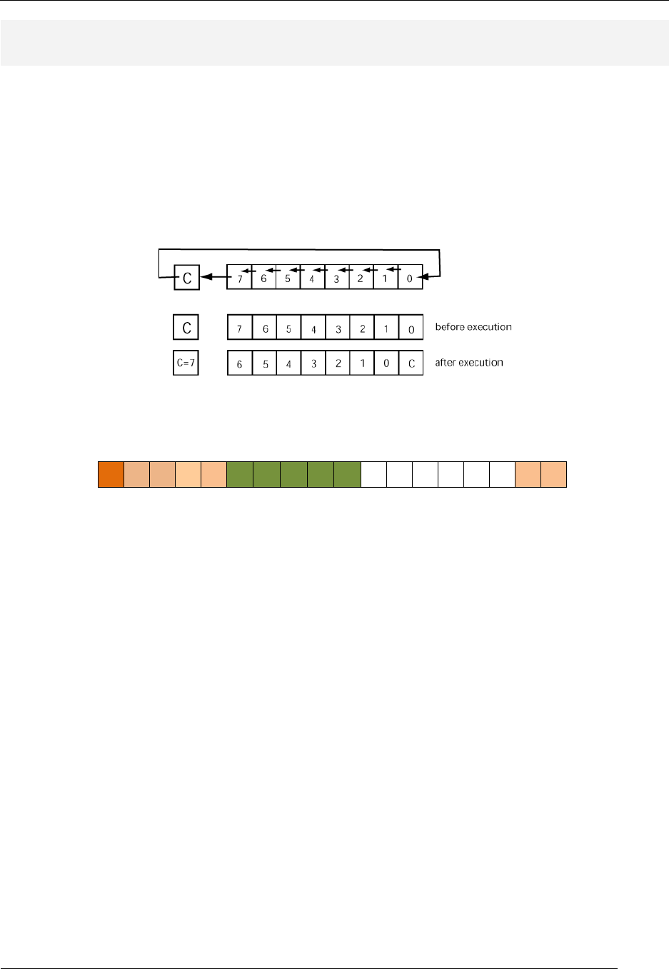
ROL (rotate left)
RTL: Rd ← Rd(6:0) & Rd(7), C ← Rd(7) Forms: ROL Rd
Carry Flag: takes value of MSB of destination register
before shift operation Zero Flag: set if all bits in Rd are zero after operation is
complete; cleared otherwise.
Description: The ROL instruction performs a shift left operation on the destination register. In the
rotate left operation, the MSB of the destination register before the shift becomes the LSB of the
destination register after the shift. The carry flag is loaded with the value of the MSB before the shift left
operation. This instruction has a reg-type instruction format.
Instruction
Format:
17 16 15 14 13 12 11 10 9 8 7 6 5 4 3 2 1 0
0 1 0 0 0 rX rX rX rX rX - - - - - - 1 0
rX: destination register
Usage:
ROL r1 ; logical shift right of register r1;
; result is placed in r1;
; r1 = 0x71 (before execution)
; r1 = 0xE2 C=0 Z=0 (after execution)
See Also: ROR
RAT Assembler Manual
Detailed Instruction Description
- 47 -
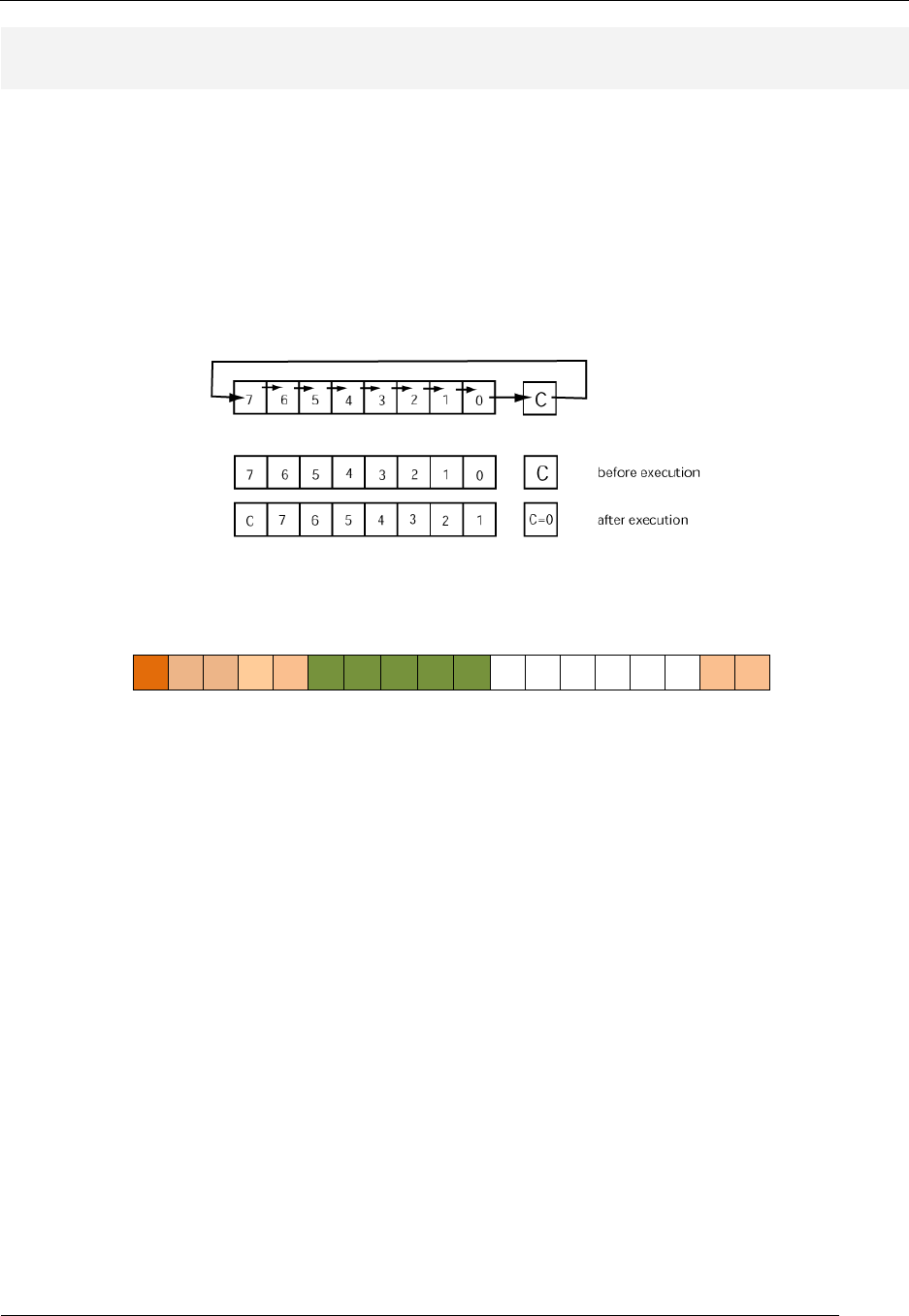
ROR (rotate right)
RTL: Rd ← Rd(0) & Rd(7:1), C ← Rd(0) Forms: ROR Rd
Carry Flag: takes value of lsb of destination register
before shift operation Zero Flag: set if all bits in Rd are zero after operation is
complete; cleared otherwise.
Description: The ROR instruction performs a shift right operation on the destination register. In the
rotate right operation, the LSB of the destination register before the shift becomes the MSB of the
destination register after the shift. The carry flag is loaded with the value of the LSB before the shift left
operation. This instruction has a reg-type instruction format.
Instruction
Format:
17 16 15 14 13 12 11 10 9 8 7 6 5 4 3 2 1 0
0 1 0 0 0 rX rX rX rX rX - - - - - - 1 1
rX: destination register
Usage:
ROR r1 ; logical shift right of register r1;
; result is placed in r1;
; r1 = 0x8B (before execution)
; r1 = 0xC5 C=1 (after execution)
See Also: ROL

RAT Assembler Manual
Detailed Instruction Description
- 48 -
RSP (read stack pointer)
RTL: Rd ← SP Forms: RSP Rd
Carry Flag: not affected Zero Flag: not affected
Description: The RSP instruction reads the value of the stack pointer (SP) and writes it to the
destination register. The RSP instruction does not affect the value of the stack pointer. This instruction
has a reg-type instruction format.
Instruction
Format:
17 16 15 14 13 12 11 10 9 8 7 6 5 4 3 2 1 0
0 1 0 1 0 rX rX rX rX rX - - - - - - 0 1
rX: destination register
Usage:
RSP r1 ; write the current stack pointer (SP) to register r1
; r1 = 0x1D SP=0x30 (before execution)
; r1 = 0x30 SP=0x30 (after execution)
See Also: CALL, RET, PUSH, POP, WSP

RAT Assembler Manual
Detailed Instruction Description
- 49 -
SEC (set Carry flag)
RTL: C ← 1 Forms: SEC
Carry Flag: set (C=1) Zero Flag: not affected
Description: The SEC instruction sets the carry flag. The instruction requires no arguments and thus
has a none-type format.
Instruction
Format:
17 16 15 14 13 12 11 10 9 8 7 6 5 4 3 2 1 0
0 1 1 0 0 - - - - - - - - - - - 0 1
Usage:
SEC ; set the Carry flag
; C=0 (before execution)
; C=1 (after execution)
See Also: CLC

RAT Assembler Manual
Detailed Instruction Description
- 50 -
SEI (set interrupt flag)
RTL: IF ← 1 [unmasks] Forms: SEI
Carry Flag: not affected Zero Flag: not affected
Description: The SEI instruction enables the MCU to process received interrupts. The IF (interrupt
flag) must be set (unmasked) in order for the MCU to process interrupts. The SEI instruction sets the IF
bit. If there is an interrupt pending when the IF bit is set under program control, an interrupt cycle is
entered on the end of the next instruction cycle following the SEI instruction. Entry into an interrupt
cycle automatically disables any future interrupts until the program unmasks interrupts via a RETIE or
SEI instruction. The instruction requires no arguments and thus has a none-type format.
Instruction
Format:
17 16 15 14 13 12 11 10 9 8 7 6 5 4 3 2 1 0
0 1 1 0 1 - - - - - - - - - - - 0 0
Usage:
SEI ; set interrupt flag to allow interrupts
; IF=0 (before execution)
; IF=1 (after execution)
See Also: CLI
RAT Assembler Manual
Detailed Instruction Description
- 51 -
ST (store value from register into data (scratchpad) memory)
RTL: (Rd) ← Rs (reg – reg form)
RTL: (immed) ← Rs (reg – imm form) Forms: ST Rs,(Rd)
ST Rs,imm_val
Carry Flag: not affected Zero Flag: not affected
Description: The ST instruction copies data from the source register into data memory at the
location specified by the destination operand. The ST instruction has two forms; both forms use the
source operand to provide an address into data memory. The reg-immed form uses the immed value
as the data memory address while the reg-reg form specifies which register contains the data memory
address. The ST instruction changes the value in data memory but does not change either operand.
Register-Register Form: The destination operand specifies the address in data memory to store the
data indirectly by providing a register location that holds the address. The source operand specifies the
register location of the data that the instruction copies to data memory. Instruction execution overwrites
the data at the specified memory location.
Instruction
Format:
17 16 15 14 13 12 11 10 9 8 7 6 5 4 3 2 1 0
0 0 0 1 0 rX rX rX rX rX rY rY rY rY rY - 1 1
rX: source register; rY: destination register
Usage:
ST r1,(r4) ; value of data in register r1 is placed in
; data memory location addressed by the value in
; register r4; value in register r4 is not affected.
; r1=0xD4 r4=0xC7 mem loc 0xC7=34 (before exec)
; r1=0xD4 r4=0xC7 mem loc 0xC7=D4 (after exec)
Register-Immediate Form: The destination operand specifies the direct address in data memory to
store the value specified by the source register. Instruction execution overwrites the data at the
specified memory location.
Instruction
Format:
17 16 15 14 13 12 11 10 9 8 7 6 5 4 3 2 1 0
1 1 1 0 1 rX rX rX rX rX k k k k k k k k
rX: source register; k: destination immediate value
Usage:
ST r1,0x5D ; value of data in register r1 is placed in
; data memory location 0x5D;
; r1=0x1F mem loc 0x5D=34 (before exec)
; r1=0x1F
mem loc 0x5D=1F (after exec)
RAT Assembler Manual
Detailed Instruction Description
- 52 -
SUB (subtraction)
RTL: Rd ← Rd - Rs (reg – reg form)
RTL: Rd ← Rd - immed (reg – imm form) Forms: SUB Rd,Rs
SUB Rd,imm_val
Carry Flag: set if the subtraction operation results in a
borrow (underflow) into the MSB position. Zero Flag: set if all bits in Rd are zero after operation is
complete; cleared otherwise.
Description: The SUB instruction performs a subtraction operation on the two operands and stores
the result in the destination register. Specifically, this instruction subtracts the value in the source
register from the value in the destination register. This instruction indicates an underflow by setting the
Carry flag. The SUBC instruction has two distinct forms, which are differentiated by the source
operand. This instruction overwrites the value in the destination register Rd.
Register-Register Form: The source operand is specified by a register; the source operand is the value
in that register. Instruction execution does not affect the value in the source register.
Instruction
Format:
17 16 15 14 13 12 11 10 9 8 7 6 5 4 3 2 1 0
0 0 0 0 1 rX rX rX rX rX rY rY rY rY rY - 1 0
rX: destination register; rY: source register
Usage:
SUB r1,r4 ; subtraction of values in registers r1 & r4;
; result is placed in r1; value in r4 is not
; affected.
; r1 = 0xD4 r4 = 0xC7 (before exec)
; r1 = 0x0D r4 = 0xC7 Z=0 C=0 (after exec)
Register-Immediate Form: An immediate value (any 8-bit value) specifies the source operand.
Instruction
Format:
17 16 15 14 13 12 11 10 9 8 7 6 5 4 3 2 1 0
1 0 1 1 0 rX rX rX rX rX k k k k k k k k
rX: destination register; k: source immediate value
Usage:
SUB r1,0xC8 ; subtraction of immediate value of 0xC8 from value in
r1; ;
; result is placed in r1
; r1 = 0x88 (before execution)
; r1 = 0xC0 Z=0 C=1 (after execution)
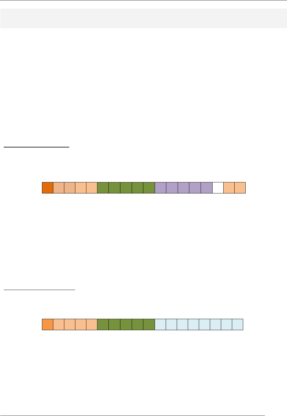
RAT Assembler Manual
Detailed Instruction Description
- 53 -
SUBC (subtraction including Carry flag)
RTL: Rd ← Rd - Rs - C (reg – reg form)
RTL: Rd ← Rd - immed - C (reg – imm form) Forms: SUBC Rd,Rs
SUBC Rd,imm_val
Carry Flag: set if the subtraction operation results in a
borrow (underflow) into the MSB position. Zero Flag: set if all bits in Rd are zero after operation is
complete; cleared otherwise.
Description: The SUB instruction performs a subtraction operation on the two operands and the
Carry flag and stores the result in the destination register. Specifically, this instruction subtracts the
value in the source register and the Carry flag from the value in the destination register. This instruction
indicates an underflow by setting the Carry flag. The SUBC instruction has two distinct forms which are
differentiated by the source operand. This instruction overwrites the value in the destination register
Rd.
Register-Register Form: The source operand is specified by a register; the source operand is the value
in that register. Instruction execution does not affect the value in the source register
Instruction
Format:
17 16 15 14 13 12 11 10 9 8 7 6 5 4 3 2 1 0
0 0 0 0 1 rX rX rX rX rX rY rY rY rY rY - 1 1
rX: destination register; rY: source register
Usage:
SUBC r1,r4 ; addition of values in registers r1 & r4;
; result is placed in r1; value in r4 is not
; affected.
; r1 = 0xD4 r4 = 0xC7 C=1 (before exec)
; r1 = 0x0C r4 = 0xC7 Z=0 C=0 (after exec)
Register-Immediate Form: An immediate value (any 8-bit value) specifies the source operand.
Instruction
Format:
17 16 15 14 13 12 11 10 9 8 7 6 5 4 3 2 1 0
1 0 1 1 1 rX rX rX rX rX k k k k k k k k
rX: destination register; k: source immediate value
Usage:
SUBC r1,0xC8 ; addition of values in register r1 & 0xDC & C flag;
; result is placed in r1
; r1 = 0x89 C=1 (before execution)
; r1 = 0xC0 Z=0 C=1 (after execution)
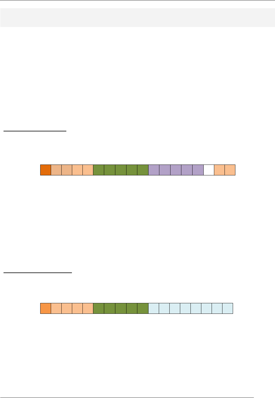
RAT Assembler Manual
Detailed Instruction Description
- 54 -
TEST (logical bitwise AND; registers do not change)
RTL: Rd · Rs (reg – reg form)
RTL:
Rd · immed (reg – imm form) Forms:
TEST Rd,Rs
TEST Rd,imm_val
Carry Flag: cleared after operation.
Zero Flag: set if all bits in Rd are zero after operation is
complete; cleared otherwise.
Description: The TEST instruction performs a bit-wise logical AND operation between the source and
destination operands. The instruction does not write the result back to the destination operand but it
does alter the Z flag to reflect the result of the AND operation. This instruction also clears the C flag.
The TEST instruction has two distinct forms, which are differentiated by the source operand. This
instruction does not affect the contents of either the source or the destination register.
Register-Register Form: The source operand is specified by a register; the source operand is the value
in that register. Instruction execution does not affect the value in the source register.
Instruction
Format:
17 16 15 14 13 12 11 10 9 8 7 6 5 4 3 2 1 0
0 0 0 0 0 rX rX rX rX rX rY rY rY rY rY - 1 1
rX: destination register; rY: source register
Usage:
TEST r1,r4 ; bitwise AND of values in register r1 & r4;
; Z flag is modified; values in r1 & r4 are not
; affected.
; r1 = 0xA4 r4 = 0xC7 (before execution)
; r1 = 0xA4 r4 = 0xC7 Z=0 (after execution)
Register-Immediate Form: An immediate value (any 8-bit value) specifies the source operand.
Instruction
Format:
17 16 15 14 13 12 11 10 9 8 7 6 5 4 3 2 1 0
1 0 0 1 1 rX rX rX rX rX K k k k k k k k
rX: destination register; k: source immediate value
Usage:
TEST r1,0x3C ; bitwise AND of values in register r1 & 0x4A;
; Z flag is modified; value in r1 is not affected
; r1 = 0xA4 (before execution)
; r1 = 0xA4 Z=0 (after execution)

RAT Assembler Manual
Detailed Instruction Description
- 55 -
WSP (write stack pointer)
RTL: SP ← Rs Forms: WSP Rs
Carry Flag: not affected Zero Flag: not affected
Description: The WSP instruction writes a value from the source register into the stack pointer (SP).
This instruction effectively initializes the stack pointer. The WSP instruction does not affect the value of
the source register. The instruction has a reg-type format.
Instruction
Format:
17 16 15 14 13 12 11 10 9 8 7 6 5 4 3 2 1 0
0 1 0 1 0 rX rX rX rX rX - - - - - - 0 0
rX: source register
Usage:
MOV r1,0x1D ; place value in r1
WSP r1 ; write r1 to the stack pointer (SP)
; r1 = 0x1D SP=0x30 (before execution)
; r1 = 0x1D SP=0x1D (after execution)
See Also: CALL, RET, PUSH, POP, RSP

RAT Assembler Manual
Detailed Instruction Description
- 56 -
RAT Sample Style File
Figure 10 shows an example assembly language program highlighting respectable RAT assembly
language source code appearance.
;- Programmer: Pat Wankaholic
;- Date: 09-29-10
;-
;- This program does something really cool. Here's the description...
;--------------------------------------------------------------------
;--------------------------------------------------------------------
;- Constants
;--------------------------------------------------------------------
.EQU SWITCH_PORT = 0x30 ; port for switches ----- INPUT
.EQU LED_PORT = 0x0C ; port for LED output --- OUTOUT
.EQU BTN_PORT = 0x10 ; port for button input - INPUT
;--------------------------------------------------------------------
;--------------------------------------------------------------------
;- Misc Constants
;--------------------------------------------------------------------
.EQU BTN2_MASK = 0x08 ; mask all but BTN5
.EQU B0_MASK = 0x01 ; mask all but bit0
;--------------------------------------------------------------------
;--------------------------------------------------------------------
;- Memory Designation Constants
;--------------------------------------------------------------------
.DSEG
.ORG 0x00
COW: .DB 9,7,6,5
;--------------------------------------------------------------------
.CSEG
.ORG 0x10
init: SEI ; enable interrupts
main_loop: IN R0, BTN_PORT ; input status of buttons
AND R0, BTN2_MASK ; clear all but BTN2
BRN bit_wank ; jumps when BTN2 is pressed
;-----------------------------------------------------------------
;- nibble wank portion of code
;-----------------------------------------------------------------
wank: ROL R1 ; rotate 2 times - msb-->lsb
bit3: BRN fin_out ; jump unconditionally to led output
;------------------------------------------------------------------
;------------------------------------------------------------------
; bit-wank algo: do something Blah, blah, blah ...
;-------------------------------------------------------------------
bit_wank: LD R0,0x00 ; clear s0 for use as working register
OR R0, B1_MASK ; set bit1
bit2: LSR R1 ; shift msb into carry bit
BRCS bit3 ; jump if carry not set
;------------------------------------------------------------------
CALL My_sub ; subroutine call
fin_out: OUT R0,LED_PORT ; output data to LEDs
BRN main_loop ; endless loop
;------------------------------------------------------------------
;------------------------------------------------------------------
; My_sub: This routines does something useful. It expects to find
; some special data in registers s0, s1, and s2. It changes the
; contents of registers blah, blah, blah...
;-------------------------------------------------------------------
My_sub: LSR R1 ; shift msb into carry bit
BRCS bit3 ; jump if carry not set
RET
Figure 10: Example RAT code with preferred RAT coding style.
