RDR VX525 RDRVX525
User Manual: RDRVX525
Open the PDF directly: View PDF ![]() .
.
Page Count: 136 [warning: Documents this large are best viewed by clicking the View PDF Link!]
SERVICE MANUAL
VIDEO CASSETTE RECORDER/
DVD RECORDER
SPECIFICATIONS
RMT-D240A
Refer to the SERVICE MANUAL of VHS MECHANI-
CAL ADJUSTMENT MANUAL VII for MECHANICAL
ADJUSTMENTS. (9-921-790-11)
— Continued on next page —
RDR-VX525
US Model
DX-13A MECHANISM
System
[DVD recorder section]
Laser
Semiconductor laser
Audio recording format
Dolby Digital
Video recording format
MPEG Video
[VCR section]
Format
VHS NTSC standard
Video recording system
Rotary head helical scanning FM
system
Video heads
Double azimuth four heads
Video signal
NTSC color, EIA standards
Tape speed
SP: 33.35 mm/s (1
3
/
8
inches/s)
EP: 11.12 mm/s (
7
/
16
inches/s)
LP: 16.67 mm/s (
11
/
16
inches/s),
playback only
Maximum recording/playback time
8 hrs. in EP mode (with T-160 tape)
Rewind time
Approx. 2 min (with T-120 tape)
[Timer section]
Clock
Quartz locked
Timer indication
12-hour cycle
Timer setting
12 programs in total (max.)
Inputs and outputs
LINE 1 IN and LINE 2 IN
VIDEO IN, phono jack (1 each)
Input signal: 1 Vp-p, 75 ohms,
unbalanced, sync negative
AUDIO IN, phono jacks (2 each)
Input level: 327 mVrms
Input impedance: more than
47 kilohms
LINE 2 IN
S VIDEO, 4-pin, mini-DIN jack
Y: 1.0 Vp-p, unbalanced, sync negative
C: 0.286 Vp-p, load impedance 75 ohms
DV IN, 4-pin jack, i.LINK S100
LINE OUT
VIDEO OUT, phono jack (1)
Output signal: 1 Vp-p, 75 ohms,
unbalanced, sync negative
AUDIO OUT, phono jacks (2)
Standard output: 327 mVrms
Load impedance: 47 kilohms
Output impedance: less than 10 kilohms
DIGITAL AUDIO OUT
OPTICAL, Optical output jack
−18 dBm (wave length: 660 nm)
COAXIAL, phono jack
Output signal: 0.5 Vp-p, 75 ohms
COMPONENT VIDEO OUT (Y, P
B
, P
R
)
Phono jack
Y: 1.0 Vp-p/PB, PR: 0.7 Vp-p, 75 ohms
— 2 —
General
Power requirements
120 V AC, 60 Hz
Power consumption
31 W
Power back-up
Back-up duration: 30 min
Operating temperature
5°C to 35°C (41°F to 95°F)
Storage temperature
−20°C to 60°C (−4°F to 140°F)
Operating humidity
25% to 80%
Dimensions including projecting parts
and controls (w/h/d)
Approx. 430 × 82 × 332 mm
(Approx. 17 × 3 1/
4
× 131/
8
inches)
Mass
Approx. 4.7 kg (Approx. 10.4 lbs)
Supplied accessories
Remote commander (remote) (1)
Size AA (R6) batteries (2)
Audio/video cord (1)
Set top box controller (1)
HDMI cord (1)
Design and specifications are subject to change
without notice.
S VIDEO OUT
4-pin, mini-DIN jack
Y: 1.0 Vp-p, unbalanced, sync negative
C: 0.286 Vp-p, load impedance 75 ohms
SET TOP BOX CONTROL
Mini jack
HDMI
HDMI 19 pin-Standard Connector
— 3 —
WARNING!!
WHEN SERVICING, DO NOT APPROACH THE LASER
EXIT WITH THE EYE TOO CLOSELY. IN CASE IT IS
NECESSARY TO CONFIRM LASER BEAM EMISSION,
BE SURE TO OBSERVE FROM A DISTANCE OF MORE
THAN 25 cm FROM THE SURFACE OF THE
OBJECTIVE LENS ON THE OPTICAL PICK-UP BLOCK.
CAUTION
Use of controls or adjustments or performance of procedures
other than those specified herein may result in hazardous
radiation exposure.
SAFETY-RELATED COMPONENT WARNING!!
COMPONENTS IDENTIFIED BY MARK 0 OR DOTTED
LINE WITH MARK 0 ON THE SCHEMATIC DIAGRAMS
AND IN THE PARTS LIST ARE CRITICAL TO SAFE
OPERATION. REPLACE THESE COMPONENTS WITH
SONY PARTS WHOSE PART NUMBERS APPEAR AS
SHOWN IN THIS MANUAL OR IN SUPPLEMENTS
PUBLISHED BY SONY.
CAUTION:
The use of optical instrument with this product will increase eye
hazard.
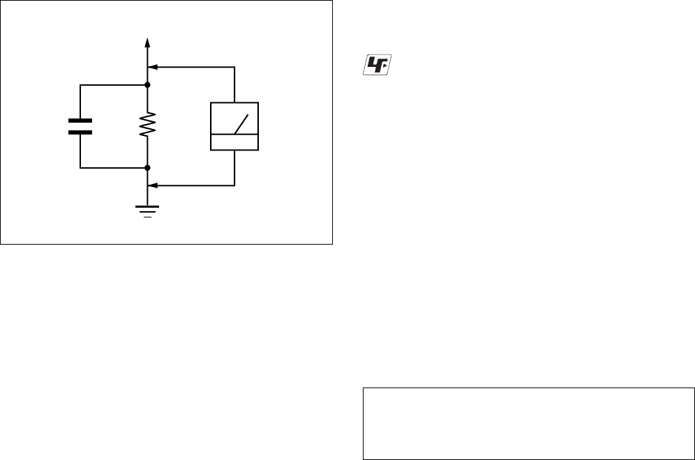
Fig. A. Using an AC voltmeter to check AC leakage.
1.5 k
Ω
0.15 µFAC
voltmeter
(0.75 V)
To Exposed Metal
Parts on Set
Earth Ground
LEAKAGE TEST
The AC leakage from any exposed metal part to earth ground
and from all exposed metal parts to any exposed metal part having
a return to chassis, must not exceed 0.5 mA (500 microamperes).
Leakage current can be measured by any one of three methods.
1. A commercial leakage tester, such as the Simpson 229 or RCA
WT-540A. Follow the manufacturers' instructions to use these
instruments.
2. A battery-operated AC milliammeter. The Data Precision 245
digital multimeter is suitable for this job.
3. Measuring the voltage drop across a resistor by means of a VOM
or battery-operated AC voltmeter. The “limit” indication is
0.75V, so analog meters must have an accurate low-voltage scale.
The Simpson 250 and Sanwa SH-63Trd are examples of a
passive VOM that is suitable. Nearly all battery operated digital
multimeters that have a 2V AC range are suitable. (See Fig. A)
1. Check the area of your repair for unsoldered or poorly-soldered
connections. Check the entire board surface for solder splashes
and bridges.
2. Check the interboard wiring to ensure that no wires are
“pinched” or contact high-wattage resistors.
3. Look for unauthorized replacement parts, particularly transistors,
that were installed during a previous repair. Point them out to
the customer and recommend their replacement.
4. Look for parts which, though functioning, show obvious signs
of deterioration. Point them out to the customer and recommend
their replacement.
5. Check the line cord for cracks and abrasion. Recommend the
replacement of any such line cord to the customer.
6. Check the B+ voltage to see it is at the values specified.
7. Check the antenna terminals, metal trim, “metallized” knobs,
screws, and all other exposed metal parts for AC leakage. Check
leakage as described below.
SAFETY CHECK-OUT
After correcting the original service problem, perform the following
safety checks before releasing the set to the customer:
Unleaded solder
Boards requiring use of unleaded solder are printed with the lead-
free mark (LF) indicating the solder contains no lead.
(Caution: Some printed circuit boards may not come printed with
the lead free mark due to their particular size.)
: LEAD FREE MARK
Unleaded solder has the following characteristics.
•Unleaded solder melts at a temperature about 40°C higher than
ordinary solder.
Ordinary soldering irons can be used but the iron tip has to be
applied to the solder joint for a slightly longer time.
Soldering irons using a temperature regulator should be set to
about 350°C.
Caution: The printed pattern (copper foil) may peel away if the
heated tip is applied for too long, so be careful!
•Strong viscosity
Unleaded solder is more viscous (sticky, less prone to flow) than
ordinary solder so use caution not to let solder bridges occur such
as on IC pins, etc.
•Usable with ordinary solder
It is best to use only unleaded solder but unleaded solder may
also be added to ordinary solder.
— 4 —
TABLE OF CONTENTS
Precautions
1Safety Precautions ······························································ 5
2Servicing Precautions ························································ 7
3ESD Precautions ································································· 8
4Handling the Optical Pick-up ············································· 9
5Reset operation after IC104 was replaced ························ 10
1. General
Hookups and Settings ······················································1-2
Quick Guide to Disc Types··············································1-6
DVD Playback ·································································1-8
DVD Recording ·····························································1-10
DVD Editing ··································································1-13
VCR Playback ·······························································1-16
VCR Recording ·····························································1-18
Dubbing (TAPE y DVD) ···········································1-20
DV/D8 Dubbing (DV/D8 t DVD) ······························1-21
Settings and Adjustments ··············································1-22
Additional Information ··················································1-25
2. Disassembly and Reassembly
2-1 Cabinet and PCB ····························································2-1
2-1-1 Cabinet Top Removal ·····················································2-1
2-1-2 Botton Cover Removal ···················································2-1
2-1-3 Ass’y Front Panel Removal············································2-1
2-1-4 Function PCB Removal ··················································2-1
2-1-5 Chassis Removal ····························································2-2
2-1-6 VCR Main PCB Removal ··············································2-2
2-2 Circuit Board Locations ·················································2-3
2-3 VCR Deck Parts Locations ············································2-4
2-3-1 Top View ········································································2-4
2-3-2 Bottom View···································································2-6
2-4 VCR DECK····································································2-7
2-4-1 Ass’y Holder Cassette Removal ·····································2-7
2-4-2 Ass’y Lever Arm Removal ·············································2-7
2-4-3 Lever FL Door Removal ················································2-8
2-4-4 Slider FL Drive, Gear FL Cam Removal ·······················2-8
2-4-5 Gear Worm Wheel Removal···········································2-9
2-4-6 Cable Flat Removal ························································2-9
2-4-7 Ass’y Motor Loading Removal ····································2-10
2-4-8 Bracket Gear, Gear Joint 2, 1 Removal ························2-10
2-4-9 Gear Loading Drive, Slider Cam,
Ass’y Lever Load S, T Removal ··································2-11
2-4-10 Gear Loading Drive, Slider Cam,
Ass’y Lever Load S, T Assembly ·································2-11
2-4-11 Lever Pinch Drive, Lever Tension Drive Removal·······2-12
2-4-12 Ass’y Lever Tension, Ass’y Band Brake Removal ······2-12
2-4-13 Ass’y Lever Brake S, T Removal ·································2-13
2-4-14 Ass’y Gear Idle Removal ·············································2-13
2-4-15 Disk S, T Reel Removal ···············································2-14
2-4-16 Ass’y Holder Clutch Removal ·····································2-14
2-4-17 Ass’y Lever Up Down, Ass’y Gear Center Removal ···2-15
2-4-18 Guide Cassette Door Removal ·····································2-15
2-4-19 Ass’y Lever Unit Pinch, Plate Joint,
Spring Pinch Drive Removal ········································2-16
2-4-20 Ass’y Lever #9 Guide Removal ···································2-16
2-4-21 FE Head Removal ························································2-17
2-4-22 Ass’y ACE Head Removal ···········································2-17
2-4-23 Ass’y Slider S, T Removal ···········································2-18
2-4-24 Plate Ground Deck, Ass’y Cylinder Removal ··············2-18
2-4-25 Hook Capstan, Belt Pulley Removal ····························2-19
2-4-26 Ass’y Motor Capstan Removal ····································2-19
2-4-27 Ass’y Post #8 Guide Removal ·····································2-20
2-4-28 Ass’y Level Head Cleaner Removal ····························2-20
2-4-29 How to Eject the Cassette Tape ····································2-20
2-5 The Table of Cleaning, Lubrication and
Replacement Time about Principal Parts ·····················2-21
3. Block Diagram ..........................................................3-1
4. PCB Diagrams
4-1 DVD Main PCB ······························································4-3
4-2 VCR Main PCB ······························································· 4-7
4-3 Function PCB ································································4-11
4-4 Front Jack PCB······························································4-13
4-5 DV Jack PCB ·································································4-15
5. Schematic Diagrams
5-1 S.M.P.S (VCR Main PCB) ··············································5-3
5-2 Power (VCR Main PCB) ·················································5-5
5-3 Logic (VCR Main PCB) ··················································5-7
5-4 A/V (VCR Main PCB) ····················································5-9
5-5 Hi-Fi (VCR Main PCB) ················································5-11
5-6 MPEG Decoder (DVD Main PCB) ·······························5-13
5-7 A/V Decoder (DVD Main PCB) ···································5-15
5-8 In Out (DVD Main PCB) ··············································5-17
5-9 DV & HDMI (DVD Main PCB) ···································5-19
5-10 Front Timer (Front Jack PCB) ·······································5-21
5-11 Function (Function PCB) ··············································5-23
6. Alignment and Adjustments
6-1 VCR Adjustment ·····························································6-1
6-1-1 Reference ·········································································6-1
6-1-2 Head Switching Point Adjustment ··································6-3
6-2 VCR Mechanical Adjustment ··········································6-4
6-2-1 Tape Transport System and Adjustment Locations ·········6-4
6-2-2 Tape Transport System Adjustment ·································6-5
6-2-3 Reel Torque ···································································6-10
7. Troubleshooting ·················································7-1
8. Repair Parts List
8-1 Exploded Views ·······························································8-2
8-1-1 Cabinet Assembly ····························································8-2
8-1-2 VCR Deck Section (Top Side) ········································8-3
8-1-3 VCR Deck Section (Bottom Side)···································8-4
8-2 Electrical Parts List ·························································8-5
— 5 —
PRECAUTIONS
1 SAFETY PRECAUTIONS
1) Before returning an instrument to the customer, always make a
safety check of the entire instrument, including, but not limited
to, the following items:
(1) Be sure that no built-in protective devices are defective or have
been defeated during servicing.
(1)Protective shields are provided to protect both the technician
and the customer. Correctly replace all missing protective
shields, including any removed for servicing convenience.
(2)When reinstalling the chassis and/or other assembly in the
cabinet, be sure to put back in place all protective devices,
including, but not limited to, nonmetallic control knobs,
insulating fish papers, adjustment and compartment covers/
shields, and isolation resistor/capacitor networks. Do not operate
this instrument or permit it to be operated without all protective
devices correctly installed and functioning.
(2) Be sure that there are no cabinet openings through which adults
or children might be able to insert their fingers and contact a
hazardous voltage. Such openings include, but are not limited
to, excessively wide cabinet ventilation slots, and an improperly
fitted and/or incorrectly secured cabinet back cover.
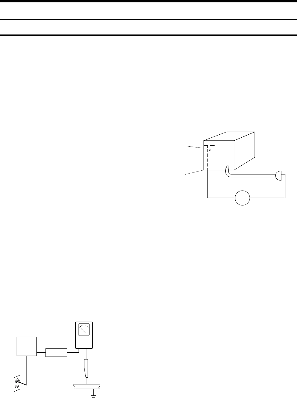
(3) Leakage Current Hot Check-With the instrument completely
reassembled, plug the AC line cord directly into a 120V AC
outlet. (Do not use an isolation transformer during this test.)
Use a leakage current tester or a metering system that complies
with American National Standards institute (ANSI) C101.1
Leakage Current for Appliances and Underwriters Laboratories
(UL) 1270 (40.7). With the instrument’s AC switch first in the
ON position and then in the OFF position, measure from a known
earth ground (metal water pipe, conduit, etc.) to all exposed
metal parts of the instrument (antennas, handle brackets, metal
cabinets, screwheads, metallic overlays, control shafts, etc.),
especially any exposed metal parts that offer an electrical return
path to the chassis.
Any current measured must not exceed 0.5mA. Reverse the
instrument power cord plug in the outlet and repeat the test. See
Fig. 1.
Any measurements not within the limits specified herein indicate
a potential shock hazard that must be eliminated before returning
the instrument to the customer.
(4) Insulation Resistance Test Cold Check-(1) Unplug the power
supply cord and connect a jumper wire between the two prongs
of the plug. (2) Turn on the power switch of the instrument. (3)
Measure the resistance with an ohmmeter between the jumpered
AC plug and all exposed metallic cabinet parts on the instrument,
such as screwheads, antenna, control shafts, handle brackets,
etc. When an exposed metallic part has a return path to the
chassis, the reading should be between 1 and 5.2 megohm. When
there is no return path to the chassis, the reading must be infinite.
If the reading is not within the limits specified, there is the
possibility of a shock hazard, and the instrument must be repared
and rechecked before it is returned to the customer. See Fig. 2.
DEVICE
UNDER
TEST
(READING SHOULD
NOT BE ABOVE
0.5mA)
LEAKAGE
CURRENT
TESTER
EARTH
GROUND
TEST ALL
EXPOSED METER
SURFACES
ALSO TEST WITH
PLUG REVERSED
(USING AC ADAPTER
PLUG AS REQUIRED)
2-WIRE CORD
Fig. 1 AC Leakage Test
Fig. 2 Insulation Resistance Test
2) Read and comply with all caution and safety related notes on or
inside the cabinet, or on the chassis.
3) Design Alteration Warning-Do not alter or add to the mechanical
or electrical design of this instrument. Design alterations and
additions, including but not limited to, circuit modifications and
the addition of items such as auxiliary audio output connections,
might alter the safety characteristics of this instrument and create
a hazard to the user. Any design alterations or additions will
make you, the servicer, responsible for personal injury or
property damage resulting therefrom.
4) Observe original lead dress. Take extra care to assure correct
lead dress in the following areas:
(1) near sharp edges, (2) near thermally hot parts (be sure that
leads and components do not touch thermally hot parts), (3) the
AC supply, (4) high voltage, and (5) antenna wiring. Always
inspect in all areas for pinched, out-of-place, or frayed wiring,
Do not change spacing between a component and the printed-
circuit board. Check the AC power cord for damage.
5) Components, parts, and/or wiring that appear to have overheated
or that are otherwise damaged should be replaced with
components, parts and/ or wiring that meet original
specifications.
Additionally, determine the cause of overheating and/or damage
and, if necessary, take corrective action to remove any potential
safety hazard.
Antenna
Terminal
Exposed
Metal Part
ohm ohmmeter

— 6 —
6) Product Safety Notice-Some electrical and mechanical parts
have special safety-related characteristics which are often not
evident from visual inspection, nor can the protection they give
necessarily be obtained by replacing them with components rated
for higher voltage, wattage, etc. Parts that have special safety
characteristics are identified by shading, an ( ) or a ( ) on
schematics and parts lists. Use of a substitute replacement that
does not have the same safety characteristics as the
recommended replacement part might create shock, fire and/or
other hazards. Product safety is under review continuously and
new instructions are issued whenever appropriate.

— 7 —
2 SERVICING PRECAUTIONS
CAUTION: Before servicing units covered by this service manual
and its supplements, read and follow the Safety Precautions section
of this manual.
Note: If unforseen circumstances create conflict between the
following servicing precautions and any of the safety precautions,
always follow the safety precautions. Remember: Safety First.
2-1 General Servicing Precautions
(1) a. Always unplug the instrument’s AC power cord from the AC
power source before (1) re-moving or reinstalling any
component, circuit board, module or any other instrument
assembly, (2) disconnecting any instrument electrical plug or
other electrical connection, (3) connecting a test substitute in
parallel with an electrolytic capacitor in the instrument.
b. Do not defeat any plug/socket B+ voltage interlocks with
which instruments covered by this service manual might be
equipped.
c. Do not apply AC power to this instrument and/or any of its
electrical assemblies unless all solid-state device heat sinks
are correctly installed.
d. Always connect a test instrument’s ground lead to the
instrument chassis ground before connecting the test
instrument positive lead. Always remove the test instrument
ground lead last.
Note: Refer to the Safety Precautions section ground lead last.
(2) The service precautions are indicated or printed on the cabinet,
chassis or components. When servicing, follow the printed or
indicated service precautions and service materials.
(3) The components used in the unit have a specified flame
resistance and dielectric strength.
When replacing components, use components which have the
same ratings. Components identified by shading, by ( ) or by
() in the circuit diagram are important for safety or for the
characteristics of the unit. Always replace them with the exact
replacement components.
(4) An insulation tube or tape is sometimes used and some
components are raised above the printed wiring board for safety.
The internal wiring is sometimes clamped to prevent contact
with heating components. Install such elements as they were.
(5) After servicing, always check that the removed screws,
components, and wiring have been installed correctly and that
the portion around the serviced part has not been damaged and
so on. Further, check the insulation between the blades of the
attachment plug and accessible conductive parts.
2-2 Insulation Checking Procedure
Disconnect the attachment plug from the AC outlet and turn the
power ON. Connect the insulation resistance meter (500V) to the
blades of the attachment plug. The insulation resistance between
each blade of the attachment plug and accessible conductive parts
(see note) should be more than 1 Megohm.
Note: Accessible conductive parts include metal panels, input
terminals, earphone jacks, etc.

— 8 —
3 ESD PRECAUTIONS
Electrostatically Sensitive Devices (ESD)
Some semiconductor (solid state) devices can be damaged easily
by static electricity.
Such components commonly are called Electrostatically Sensitive
Devices (ESD). Examples of typical ESD devices are integrated
circuits and some field-effect transistors and semiconductor chip
components. The following techniques should be used to help reduce
the incidence of component damage caused by static electricity.
(1) Immediately before handling any semiconductor component or
semiconductor-equipped assembly, drain off any electrostatic
charge on your body by touching a known earth ground.
Alternatively, obtain and wear a commercially available
discharging wrist strap device, which should be removed for
potential shock reasons prior to applying power to the unit under
test.
(2) After removing an electrical assembly equipped with ESD
devices, place the assembly on a conductive surface such as
aluminum foil, to prevent electrostatic charge buildup or
exposure of the assembly.
(3) Use only a grounded-tip soldering iron to solder or unsolder
ESD devices.
(4) Use only an anti-static solder removal devices. Some solder
removal devices not classified as “anti-static” can generate
electrical charges sufficient to damage ESD devices.
(5) Do not use freon-propelled chemicals. These can generate
electrical charges sufficient to damage ESD devices.
(6) Do not remove a replacement ESD device from its protective
package until immediately before your are ready to install it.
(Most replacement ESD devices are packaged with leads
electrically shorted together by conductive foam, aluminum foil
or comparable conductive materials).
(7) Immediately before removing the protective materials from the
leads of a replacement ESD device, touch the protective material
to the chassis or circuit assembly into which the device will be
installed.
CAUTION: Be sure no power is applied to the chassis or circuit,
and observe all other safety precautions.
(8) Minimize bodily motions when handling unpackaged
replacement ESD devices. (Otherwise harmless motion such as
the brushing together of your clothes fabric or the lifting of
your foot from a carpeted floor can generate static electricity
sufficient to damage an ESD device).
— 9 —
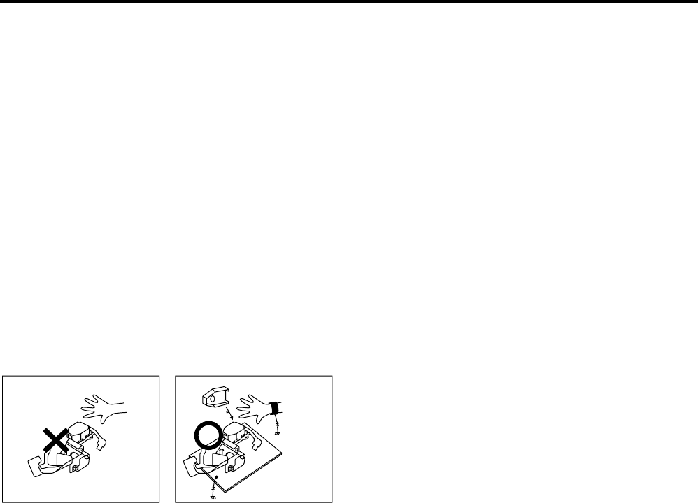
4 HANDLING THE OPTICAL PICK-UP
The laser diode in the optical pick up may suffer electrostatic
breakdown because of potential static electricity from clothing and
your body.
The following method is recommended.
(1) Place a conductive sheet on the work bench (The black sheet
used for wrapping repair parts.)
(2) Place the set on the conductive sheet so that the chassis is
grounded to the sheet.
(3) Place your hands on the conductive sheet (This gives them the
same ground as the sheet.)
(4) Remove the optical pick up block
(5) Perform work on top of the conductive sheet. Be careful not to
let your clothes or any other static sources to touch the unit.
◆Be sure to put on a wrist strap grounded to the sheet.
◆Be sure to lay a conductive sheet made of copper etc. Which is
grounded to the table.
Fig.3
(6) Short the short terminal on the PCB, which is inside the Pick-
Up ASS’Y, before replacing the Pick-Up. (The short terminal is
shorted when the Pick-Up Ass’y is being lifted or moved.)
(7) After replacing the Pick-up, open the short terminal on the PCB.
THE UNIT
WRIST-STRAP
FOR GROUNDING
1M
1M CONDUCTIVE SHEET

— 10 —
5 Reset operation after IC104 was replaced
Be sure to perform the reset by the method described below, if the
IC104 (FLASH MEMORY) used on the DVD Main board was
replaced.
Resetting method
1. Enter the Adjustment mode, and press two times the “1” button
on the remote commander.
(For an entering method of Adjustment mode, see 6-1. VCR
Adjustment.)
The tray will automatically open and the version information
will be displayed on the TV screen.
2. Turn the power off.
1-1
1. GENERAL This section is extracted from instruction manual.
(3-096-487-11)
RDR-VX525
4
About this manual
•Instructions in this manual describe the controls on the
remote. You can also use the controls on the recorder if
they have the same or similar names as those on the
remote.
•The on-screen display illustrations used in this manual
may not match the graphics displayed on your TV
screen.
•The explanations regarding discs in this manual refer to
discs created on this recorder. The explanations do not
apply to discs that are created on other recorders and
played back on this recorder.
*MP3 (MPEG1 Audio Layer 3) is a standard format
defined by ISO/MPEG which compresses audio data.
Icon Meaning
Functions available for DVD+RWs
Functions available for DVD-RWs
in VR (Video Recording) mode
Functions available for DVD-RWs
in video mode
Functions available for DVD+Rs
Functions available for DVD-Rs in
VR (Video Recording) mode
Functions available for DVD-Rs in
video mode
Functions available for DVD
VIDEOs
Functions available for DVD-RAMs
Functions available for VIDEO CDs
or CD-Rs/CD-RWs in video CD
format
Functions available for music CDs
or CD-Rs/CD-RWs in music CD
format
Functions available for DATA CDs
(CD-ROMs/CD-Rs/CD-RWs
containing MP3* audio tracks or
JPEG image files)
Functions available for DATA
DVDs (DVD-ROMs/DVD+RWs/
DVD-RWs/DVD+Rs/DVD-Rs
containing MP3* audio tracks or
JPEG image files)
Functions available for VHS
VIDEOs
+RW
-
RWVR
-
RWVideo
+R
-
RVR
-
RVideo
DVD
RAM
VCD
CD
DATA CD
DATA DVD
9
Quick access to recorded titles -
Title List
Display the Title List to view all titles on a disc
and select a title for playback or editing.
Creating your own program - Playlist
Record a program on a DVD-RW (VR mode) or
DVD-R (VR mode), then erase, move or add
scenes as you like without changing the original
contents.
One Touch Dubbing - DV/D8 Dubbing
Connect your digital video camera to the DV IN
jack and press the ONE-TOUCH DUBBING
button to dub a DV/D8 format tape over to a disc.
Operation restrictions
*1 When pressing DVD, VCR playback stops.
*2 When pressing VIDEO, DVD playback stops.
*3 Only for timer recording. You can also record from LINE1 and LINE2 at the same time.
10:10 AM
>
>
>
>
LINE 1
08:00 PM
May/02/2007
T
No.1/4
01
02
03
04
Title Length Edit
LINE 1 01:29:03
LINE 1 00:31:23
LINE 1 01:59:00
LINE 1 00:58:56
Title List (Original)
Original
Playlist
ONE-TOUCH
DUBBING
Control
Dubbing
Current Operation
Possible Simultaneous Operations
VCR
Playback VCR
Recording DVD
Playback DVD
Recording
Playing a VHS tape*1 —No No Yes
Recording on a VHS tape No — Yes Yes*3
Playing a DVD*2 No Yes — No
Recording on a DVD Yes Yes*3 No —
10
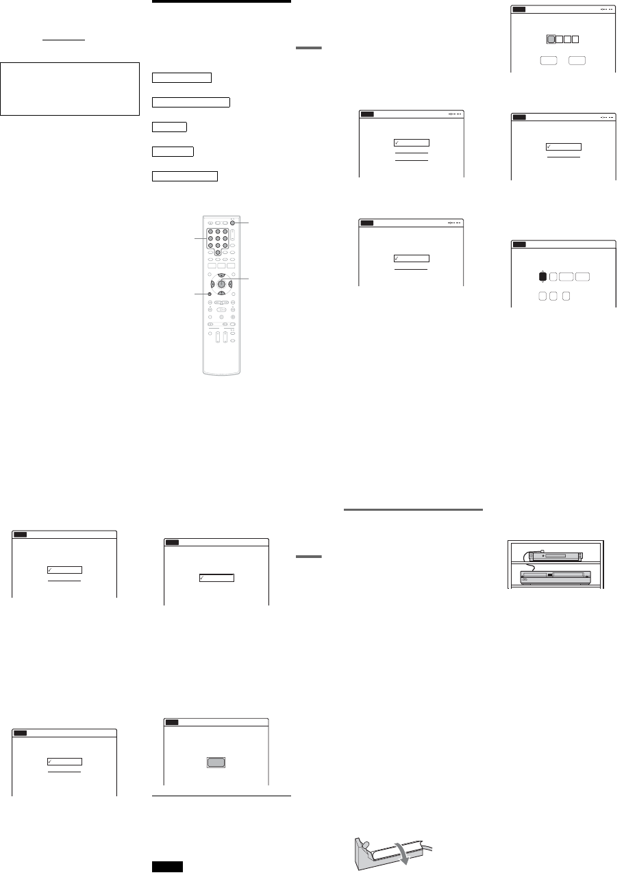
How to Use the On-Screen
Menus
The following three displays are mainly used to
operate this recorder. Once you become familiar
with the basic operations, you will find the
recorder easy to use.
System Menu
The System Menu appears when you press
SYSTEM MENU, and provides entries to all of
the recorder’s main functions, such as timer
recording and setup.
Select an option by pressing M/m and ENTER.
A “Title List”
Displays the list of the disc contents,
including the recording information and
movie thumbnail image, which allows you to
select a title to play or edit.
B “Timer”
Used to set a new timer recording for a disc or
VHS tape, as well as change or cancel the
timer recordings you set.
C “Edit”
Used to create or edit a Playlist (unfinalized
DVD-RWs (VR mode)/DVD-Rs (VR mode)
only).
D “Dubbing”
Used to dub from a disc to a VHS tape and
vice versa, and also dub from a DV/D8 format
tape to a disc.
E “Disc Setting”
Used to rename, protect, format, or finalize a
disc, or erase all titles on the disc. Also,
displays the disc information.
F “Setup”
Displays the “Setup” display for setting up the
recorder to suit your preferences.
M/m/</,,
ENTER
SYSTEM
MENU
OPTIONSORETURN
112233
445566
7788
00
99
Title List (Original) 10:10 AM
Press ENTER :
Title Menu for DVD Title List.
Setup
Disc Setting
Edit
Title List
Timer
Dubbing
6
10:10 AM
01 LINE 1 >01:29:03
02 LINE 1 >00:31:23
03 LINE 1 >01:59:00
04 LINE 1 >00:58:56
LINE
1
08:00 PM
May/02/2007
T
No. Title Length Edit
Title List (Original)
1/4
8
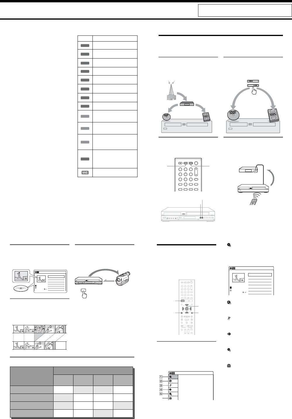
What is a Video Cassette Recorder/DVD Recorder?
This is a DVD recorder with built-in VHS video deck, and allows recording/playback of DVD discs and
VHS tapes. DVD editing is also possible.
Recording and timer recording
Record TV programs on a DVD or VHS tape,
either manually or using the timer. You need to
connect a tuner such as a cable box to this
recorder.
Easy selection between DVD and
VCR
Simply press the DVD or VIDEO button to select
the media format you want to use.
One Touch Dubbing - DVD y VHS
Dub in either direction between a DVD disc and
VHS tape with the simple press of a button.
Note that copy-protected signals will not be
recorded.
Control your cable box or satellite
receiver - Set top box control
Connect the supplied set top box controller to have
the recorder change the channel of your cable box
or satellite receiver (page 12).
112233
445566
7788
00
99
DVD VIDEO
DVD
VIDEO
VIDEO
DVD
103
CH 103!
1-2
11
Sub-menu
The sub-menu appears when you select an item
from a list menu (e.g., a title from the Title List
menu), and press ENTER. The sub-menu displays
options applicable only to the selected item. The
displayed options differ depending on the
situation and disc type.
Select an option by pressing M/m and ENTER.
Example: The Title List menu
OPTIONS
The OPTIONS menu appears when you press
OPTIONS. You can search for a title/chapter/
track, check the playing and remaining time, or
change settings for audio/angle/subtitle. The
displayed options differ depending on the media
type.
Press M/m to select an option, press </, to
select the desired item, and press ENTER.
Example: When you press OPTIONS while a
DVD VIDEO is playing.
Selectable options
Selectable options on the System Menu differ
depending on the media type, disc condition, and
operating status.
Example: When a disc or a VHS tape is stopped.
*1 Unfinalized disc only
*2 With a disc inserted
To return to the previous display
Press ORETURN.
Notes
•The OPTIONS menu may not appear during DVD
recording.
•The System Menu does not appear when recording on
a DVD, or dubbing from VHS tape to a DVD.
•You cannot use the DVD or VIDEO buttons with the
System Menu turned on.
Title List (Original) 10:10 AM
No. Title Length Edit
01 LINE 1 >01:29:03
02 LINE 1 >00:31:23
03 LINE 1 >01:59:00
04 LINE 1 >00:58:56
LINE 1
May/02/2007
08:00 PM
T
1/4
Play
Title Erase
Chapter Erase
Protect
Title Name
A·B Erase
Divide Title
Options for the selected item
1/4
1/1
00:00:25
T
C
Title
Chapter
Time
Remain
Audio
Angle
00:01:30
Subtitle
2/2 ENG
1/1
ENG Dolby D2ch (1/1)
DVD
VIDEO
Type Selectable option
+RW
-
RWVR *1
-
RWVideo
*1
+R*1 *1
-
RVR *1 *1
-
RVideo
*1 *1
DVD
RAM
VCD
CD
DATA CD
DATA DVD
*2
12
Hookups and Settings
Hooking Up the Recorder
Follow steps 1 to 7 to hook up and adjust the
settings of the recorder.
Notes
•Plug cords securely to prevent unwanted noise.
•See the instructions supplied with the components to be
connected.
•You cannot connect this recorder to a TV that does not
have a video input jack.
•Be sure to disconnect the power cord of each
component before connecting. Do not connect the
power cord until you reach “Connecting the Power
Cord” on page 20.
Step 1: Unpacking
Check that you have the following items:
•Audio/video cord
(phono plug u 3 y phono plug u 3) (1)
•Remote commander (remote) (1)
•Set top box controller (1)
•Size AA (R6) batteries (2)
•HDMI cord (1)
Step 2: Connecting the
Cable Box/Satellite
Receiver (Tuner)
This recorder does not include a TV tuner.
To record TV programs on this recorder, you need
to connect the recorder to a tuner that has audio/
video output jacks.
If you have been using your VCR connected to an
antenna, connect this recorder to your VCR using
an audio/video cord. In this way, you will be able
to record TV programs.
You cannot record on this recorder if you have:
–a cable box or satellite receiver without audio/
video outputs.
–cable with no cable box.
–antenna only (no cable TV).
In the cases above, contact your cable service or
satellite service company to see if they can
provide you with a compatible cable box or
satellite receiver.
Using the cable box/satellite
receiver control function
This function allows the recorder to control a
cable box or satellite receiver via the supplied set
top box controller. You can also use the recorder’s
remote control to change channels on the cable
box/satellite receiver whenever the cable box/
satellite receiver and the recorder are turned on.
To use the cable box/satellite receiver control
function, you need to:
–Check the brand code of your cable box/satellite
receiver. See “Cable Box/Satellite Receiver
Brand Code” (page 121).
–Connect the set top box controller (page 13).
–Set the brand code number and the recorder’s
input that is connected to the cable box/satellite
receiver (page 23).
After setting up the cable box/satellite receiver
control, check that the recorder can correctly
control the cable box or satellite receiver
(page 26).
13
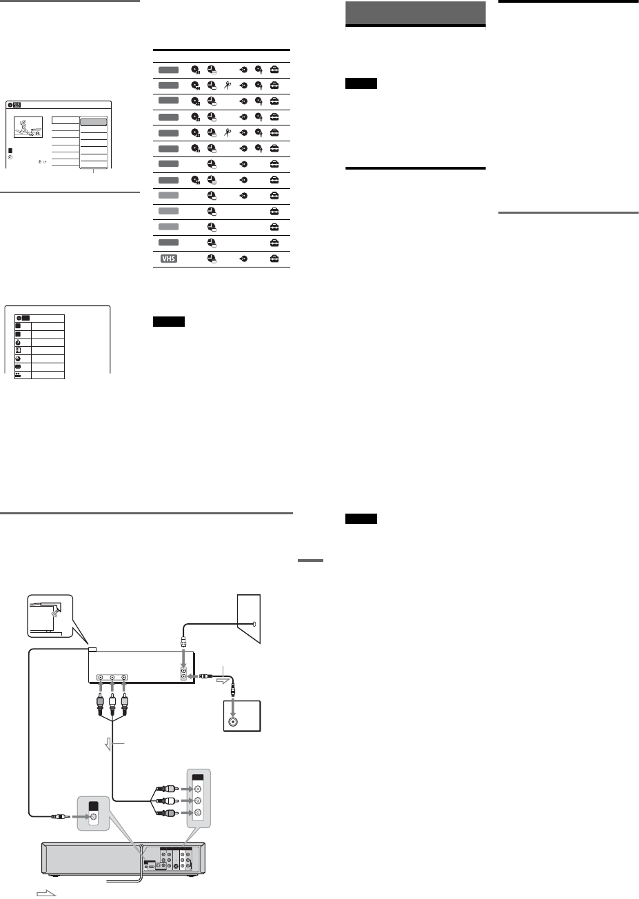
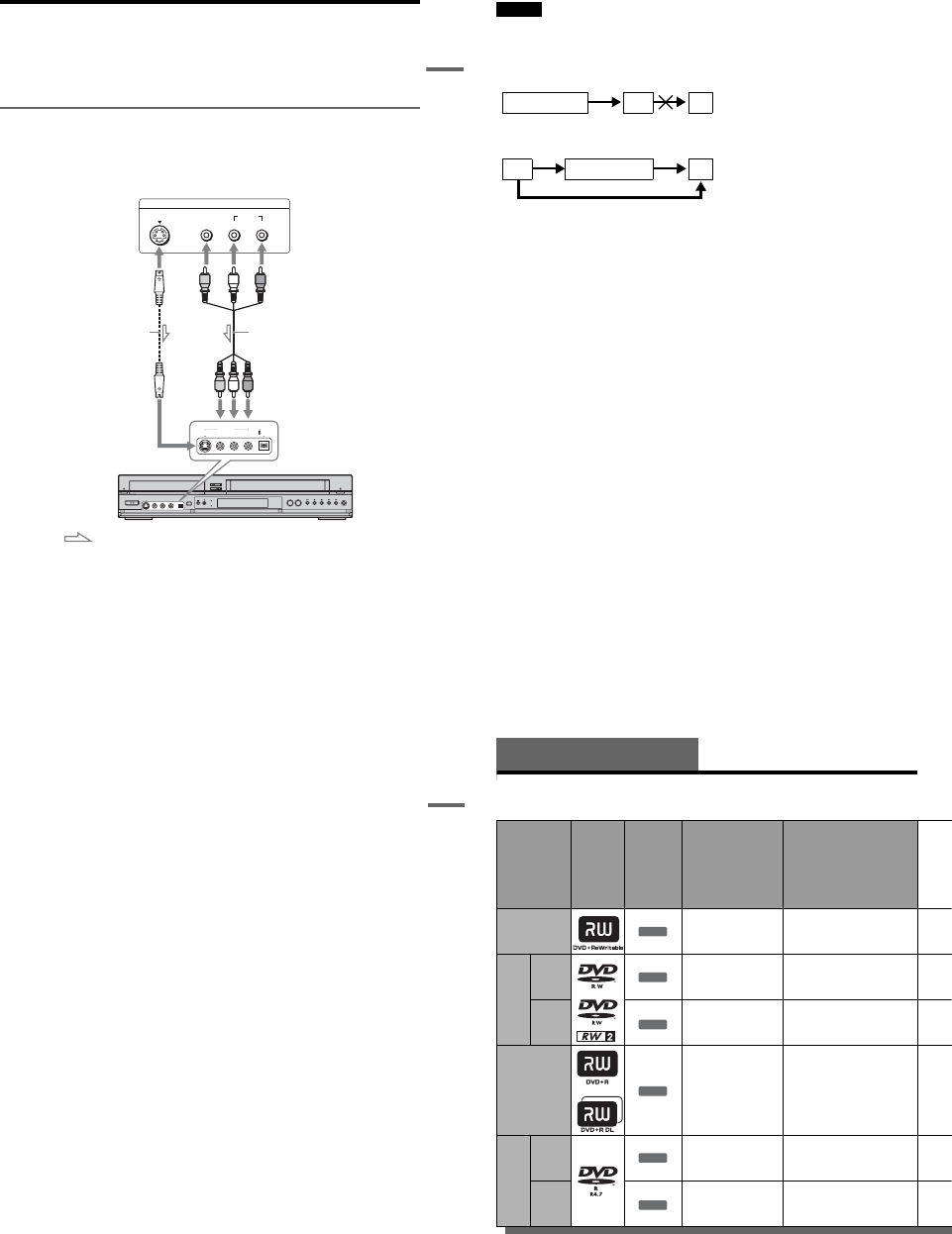
Hookups and Settings
Connecting a cable box/satellite receiver and set top box controller
Connect the LINE IN jacks using an audio/video cord.
With this hookup, you can record any channel on the cable box or satellite receiver. Be sure that the cable
box or satellite receiver is turned on. This connection is necessary to use the Synchro-Rec function
(pages 51 and 80).
To watch cable or satellite programs, you need to match the input source on the recorder (L1) to the input
jack connected to the cable box or satellite receiver (LINE 1 IN).
Place the set top box controller near the remote sensor on the cable box/satellite receiver.
About AV path through
This recorder automatically sends the input signal from the LINE 1 IN jacks to the LINE OUT VIDEO/
AUDIO jacks without turning itself on.
When you connect a cable box or satellite receiver to the LINE 1 IN jacks and your TV to the LINE OUT
(VIDEO/AUDIO L/R) jacks (page 15), you can watch programs from a cable box or satellite receiver on
the TV even when the recorder is turned off.
L
R
VIDEO
AUDIO
LINE OUT
VIDEO
YL
P
B
R
P
R
AUDIO
LINE 1 IN
AUDIO OUT S VIDEO OUT
COMPONENT
VIDEO OUT
DIGITAL AUDIO OUT
OPTICAL COAXIAL
HDMI OUT
SETTOP
BOX
CONTROL
ANT IN
RL
AUDIO
OUT VIDEO
OUT
TO TV
VIDEO
LINE 1 IN
AUDIO
SETTOP
BOX
CONTROL
Set top box
controller
(supplied) Cable box/
satellite receiver
Antenna cable
(not supplied)
Wall
to antenna input
TV
Audio/video cord
(not supplied)
to SET TOP BOX
CONTROL
to LINE 1 IN
VCR-DVD recorder
: Signal flow
,continued 14
Notes
•Synchro-Recording does not work with some tuners. For details, see the tuner’s operating instructions.
•AV path through function does not work for:
–Input signals from the LINE 2 IN jacks.
–Output signals to S VIDEO OUT, COMPONENT VIDEO OUT, or HDMI OUT jacks.
1-3
15
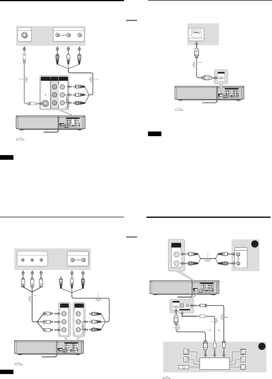
Hookups and Settings
Step 3: Connecting to Your TV
Connect the supplied audio/video cord to the LINE OUT (VIDEO/AUDIO L/R) jacks of the recorder.
To enjoy higher quality images, connect an S video cord (not supplied) instead of the yellow (video) plug.
When using this connection, be sure to connect the audio cord to the LINE OUT (AUDIO L/R) jacks.
When playing “wide screen” images
Some recorded images may not fit your TV screen. To change the picture size, see page 96.
Notes
•Do not connect to the S VIDEO OUT and yellow LINE OUT (VIDEO) jacks at the same time.
•During DVD recording, you cannot watch VHS pictures by pressing VIDEO, as the S VIDEO OUT jack will output
DVD video signals only.
•Do not connect your TV’s audio output jacks to the LINE IN (AUDIO L/R) jacks at the same time. This will cause
unwanted noise to come from your TV’s speakers.
L
R
VIDEO
AUDIO
LINE OUT
VIDEO
YL
P
B
R
P
R
AUDIO
LINE 1 IN
AUDIO OUT S VIDEO OUT
COMPONENT
VIDEO OUT
DIGITAL AUDIO OUT
OPTICAL COAXIAL
HDMI OUT
SETTOP
BOX
CONTROL
L
R
VIDEO
AUDIO
LINE OUT
VIDEO
AUDIO
LINE 1 IN
S VIDEO OUT
AUDIO
INPUT
RLVIDEO
INPUT
S VIDEO
: Signal flow
S video cord
(not supplied)
TV or projector
(red) (white) (yellow)
Audio/video cord
(supplied)
(red)
(white)
(yellow)
to S VIDEO OUT
VCR-DVD recorder
to LINE OUT
(VIDEO/AUDIO L/R)
,continued 16
If your TV has an HDMI input jack
Connect the HDMI* OUT jack using a certified HDMI cord (supplied). You will enjoy high quality
picture and sound. The HDMI indicator lights up on the front panel when the recorder outputs signals
through the HDMI OUT jack.
Be sure to turn off the recorder before connecting an HDMI cord.
*This DVD recorder incorporates High-Definition Multimedia Interface (HDMI™) technology.
HDMI, the HDMI logo and High-Definition Multimedia Interface are trademarks or registered trademarks of HDMI
Licensing LLC.
Notes
•You cannot connect the HDMI OUT jack to DVI jacks that are not HDCP compliant (e.g., DVI jacks on PC displays).
•During DVD recording, you cannot watch VHS pictures by pressing VIDEO, as the HDMI OUT jack will output
DVD video signals only.
L
R
VIDEO
AUDIO
LINE OUT
VIDEO
YL
P
B
R
P
R
AUDIO
LINE 1 IN
AUDIO OUT S VIDEO OUT
COMPONENT
VIDEO OUT
DIGITAL AUDIO OUT
OPTICAL COAXIAL
HDMI OUT
SETTOP
BOX
CONTROL
HDMI IN
HDMI OUT
TV or
projector
HDMI cord (supplied)
to HDMI OUT
: Signal flow
VCR-DVD recorder
to HDMI input
17
Hookups and Settings
If your TV has component video input jacks
Connect the COMPONENT VIDEO OUT jacks using a component video cord (not supplied) or three
video cords (not supplied) of the same kind and length. You will enjoy accurate color reproduction and
high quality images.
If your TV accepts progressive 480p format signals, you must use this connection and then set
“Progressive” of “Video” to “On” in the “Setup” display (page 97).
When using this connection, be sure to connect the audio cord to the LINE OUT (AUDIO L/R) jacks.
Note
During DVD recording, you cannot watch VHS pictures by pressing VIDEO, as the COMPONENT VIDEO OUT jacks
will output DVD video signals only.
L
R
VIDEO
AUDIO
LINE OUT
VIDEO
YL
P
B
R
P
R
AUDIO
LINE 1 IN
AUDIO OUT S VIDEO OUT
COMPONENT
VIDEO OUT
DIGITAL AUDIO OUT
OPTICAL COAXIAL
HDMI OUT
SETTOP
BOX
CONTROL
Y
P
B
P
R
COMPONENT
VIDEO OUT
COMPONENT VIDEO IN
P
B
P
R
Y
AUDIO
LR
INPUT
L
R
VIDEO
AUDIO
LINE OUT
: Signal flow
TV or projector
(red) (white) (green)
Component video cord
(not supplied)
(red)(blue)
(red)
(green)
(blue)
to COMPONENT
VIDEO OUT
Audio/video cord
(supplied)
(white)
(red)
to LINE OUT
(AUDIO L/R)
VCR-DVD recorder
18
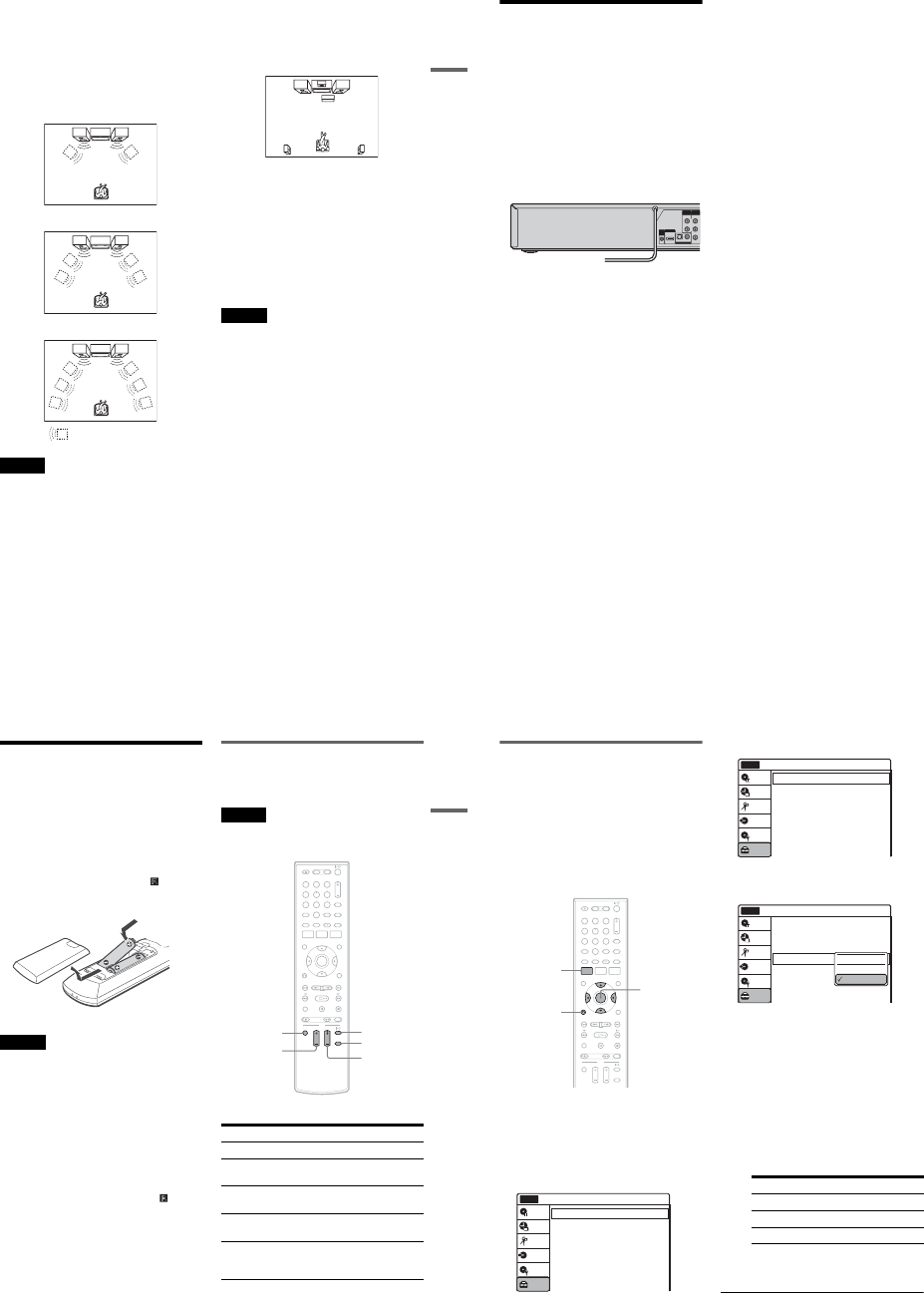
Step 4: Connecting to Your AV Amplifier (Receiver)
Select one of the following patterns A or B, according to the input jack on your AV amplifier (receiver).
This will enable you to listen to DVD audio tracks through your AV amplifier (receiver).
L
R
VIDEO
AUDIO
LINE OUT
VIDEO
YL
P
B
R
P
R
AUDIO
LINE 1 IN
AUDIO OUT S VIDEO OUT
COMPONENT
VIDEO OUT
DIGITAL AUDIO OUT
OPTICAL COAXIAL
HDMI OUT
SETTOP
BOX
CONTROL
AUDIO
INPUT
L
R
L
R
AUDIO OUT
B
A
DIGITAL AUDIO OUT
OPTICAL COAXIAL
HDMI OUT
: Signal flow
AV amplifier (receiver)
(red)
(white) Audio cord
(not supplied) (white)
(red)
VCR-DVD recorder to AUDIO OUT (L/R)
to DIGITAL AUDIO OUT
(COAXIAL or OPTICAL)
Optical digital cord
(not supplied)
Coaxial digital cord
(not supplied)
[Speakers]
Rear (L)
Front (L)
Center
to coaxial or
optical digital
input
[Speakers]
Rear (R)
Front (R)
Subwoofer
or
AV amplifier (receiver)
with a decoder
HDMI cord
(supplied) or
to HDMI OUT
to HDMI input
1-4
19
Hookups and Settings
A Connecting to audio L/R jacks
This connection uses a stereo amplifier’s
(receiver’s) two front speakers for sound.
You can enjoy the surround function that creates
virtual speakers from two stereo speakers. Select
“Surround1,” “Surround2,” or “Surround3” in
“Surround” of “Audio” setup (page 99).
Surround 1
Surround 2
Surround 3
Note
Make sure that your listening position is between and at
an equal distance from your speakers, and that the
speakers are located in similar surroundings.
B Connecting to a digital audio input jack
Use this connection if your AV amplifier
(receiver) has a Dolby*1 Digital or DTS*2 decoder
and a digital input jack. You can enjoy the
surround effect of Dolby Digital (5.1ch) or DTS
(5.1ch).
*1 Manufactured under license from Dolby Laboratories.
“Dolby” and the double-D symbol are trademarks of
Dolby Laboratories.
*2 “DTS” and “DTS Digital Out” are trademarks of DTS,
Inc.
zHints
•For correct speaker location, see the operating
instructions supplied with the connected components.
•During VHS playback, the DIGITAL AUDIO OUT
jacks can also output digital audio signals.
Notes
•During DVD recording, the DIGITAL AUDIO OUT
jacks or HDMI OUT jack output DVD audio signals
only. You cannot hear VHS sound by pressing VIDEO.
•After you have completed the connection, make the
appropriate settings under “Audio Connection Setup”
in Easy Setup (page 23). Otherwise, no sound or a loud
noise will come from your speakers.
•With a coaxial or optical digital connection, you cannot
use the virtual surround effects of this recorder.
•When outputting from the DIGITAL AUDIO OUT
jacks, you cannot switch the bilingual sounds on a
DVD-RW (VR mode) or DVD-R (VR mode) by
pressing AUDIO.
•When you connect the recorder to an AV amplifier
(receiver) using an HDMI cord, you will need to do one
of the following:
–Connect the AV amplifier (receiver) to the TV with
an HDMI cord.
–Connect the recorder to the TV with a video cord
other than HDMI cord (component video cord,
SVIDEO cord, or audio/video cord).
Virtual speaker
20
Step 5: Connecting the
Power Cord
Plug the recorder and TV power cords into an AC
outlet. After you connect the power cord, you
must wait for a short while before
operating the recorder. You can operate the
recorder only after the front panel display lights up
and the recorder enters standby mode.
If you connect additional equipment to this
recorder (page 27), be sure to connect the power
cord only after all connections are complete.
YL
P
B
R
P
R
AUDIO OUT
COMPONENT
VIDEO OUT
DIGITAL AUDIO OUT
OPTICAL COAXIAL
HDMI OUT
SETTOP
BOX
CONTROL
to AC outlet <
21
Hookups and Settings
Step 6: Preparing the
Remote
You can control the recorder using the supplied
remote.
Insert two size AA (R6) batteries by matching the
3 and # ends on the batteries to the markings
inside the battery compartment. Be sure to close
the battery cover properly. When using the
remote, point it at the remote sensor on the
recorder.
Notes
•If the supplied remote interferes your other Sony DVD
recorder or player, change the command mode number
for this recorder (page 22).
•Use the batteries correctly to avoid possible leakage
and corrosion. Do not touch the liquid with bare hands
should leakage occur. Observe the following:
–Do not use a new battery with an old battery, or
batteries of different manufacturers.
–Do not attempt to recharge the batteries.
–If you do not intend to use the remote for an extended
period of time, remove the batteries.
–If battery leakage occurs, wipe out any liquid inside
the battery compartment, and insert new batteries.
•Do not expose the remote sensor (marked on the
front panel) to strong light, such as direct sunlight or
lighting apparatus. The recorder may not respond to the
remote.
•With normal use, the batteries should last about three to
six months.
•Do not leave the remote in an extremely hot or humid
place.
•Do not drop any foreign object into the remote casing,
particularly when replacing the batteries.
Controlling a Sony TV with the
remote
You can use this remote to operate your Sony TV.
Note
Depending on the TV, some or all of the buttons below
may not work for the TV.
The remote performs the following:
Press To
TV "/1 Turn your TV on or off
TV VOL +/– Adjust the volume of your
TV
TV CH +/– Select the channel on your
TV
TV INPUT Switch your TV’s input
source
TV DIGITAL/
ANALOG Select the broadcast on
your TV that can switch
between digital and analog
112233
445566
7788
00
99
TV "/1
TV VOL +/– TV INPUT
TV CH +/–
TV DIGITAL/
ANALOG
,continued 22
If you have a Sony DVD player or
more than one Sony DVD recorder
If the supplied remote interferes with your other
Sony DVD recorder or player, set the command
mode number for this recorder and the supplied
remote to one that differs from the other Sony
DVD recorder or player, after you have completed
“Step 7: Easy Setup.”
The default command mode setting for this
recorder and the supplied remote is DVD 3.
1Check that Easy Setup (page 23) has been
finished. If Easy Setup has not been
finished, first perform Easy Setup.
2Press SYSTEM MENU.
The System Menu appears.
3Select “Setup,” and press ENTER.
4Select “Options,” and press ENTER.
5Select “Command Mode,” and press
ENTER.
6Select a command mode (“DVD 1,” “DVD
2,” or “DVD 3”), and press ENTER.
7Set the command mode for the remote so it
matches the command mode for the
recorder you set above.
Follow the steps below to set the command
mode on the remote.
AHold down ENTER.
BWhile holding down ENTER, enter the
command mode code number using the
number buttons.
CHold down both the number buttons and
ENTER at the same time for more than
three seconds.
112233
445566
7788
00
99
SYSTEM
MENU
M/m/</,,
ENTER
ORETURN
10:10 AM
Clock Set
Video
Audio
Features
Options
Easy Setup
Setup
Disc Setting
Edit
Title List
Timer
Dubbing
Setup
No Disc
Command Mode Code number
DVD1 number button 1
DVD2 number button 2
DVD3 number button 3
Options
Language
Parental
Front Display
Command Mode
Factory Setting
: Auto
: DVD 3
10:10 AM
Setup
Disc Setting
Edit
Title List
Timer
Dubbing
No Disc
Options
Language
Parental
Front Display
Command Mode
Factory Setting
: Auto
: DVD1 No
10:10 AM
Setup
Disc Setting
Edit
Title List
Timer
Dubbing
No Disc
DVD 1
DVD 2
DVD 3
1-5
23
Hookups and Settings
To return to the previous display
Press ORETURN.
To check the command mode for the recorder
Press x(stop) on the recorder when the recorder
is turned off. The command mode for the recorder
appears in the front panel display.
Step 7: Easy Setup
Follow the steps below to make the minimum
number of basic adjustments for using the
recorder. If you do not complete Easy Setup, it
will appear each time you turn on your recorder.
Settings are made in the following order.
m
m
m
m
m
1Turn on the TV.
2Press "/1.
The recorder turns on.
If the command mode for the recorder has not
been changed, set the command mode for the
remote to the default setting of DVD3. If the
command mode for the remote is changed to
DVD1 or DVD2, you will be unable to operate
this recorder.
OSD Language Setup
Cable Box/Sat. Control Setup
Clock Setup
TV Type Setup
Audio Connection Setup
Finished!
112233
445566
7788
00
99
M/m/</,,
ENTER
ORETURN
"/1
Number
buttons
,continued 24
3Switch the input selector on your TV so that
the signal from the recorder appears on
your TV screen.
“Initial setting necessary to operate the DVD
recorder will be made. You can change them
later using setup.” appears.
•If this message does not appear, select “Easy
Setup” in the “Setup” display to run Easy
Setup (page 104).
4Press ENTER.
The setup display for selecting the language
used in the on-screen display appears.
5Select a language, and press ENTER.
The setup display for cable box/satellite
receiver control appears.
6Select whether or not you use the cable
box/satellite receiver control, and press
ENTER.
If you want to use the cable box/satellite
receiver control (page 12), select “Yes.”
If not, select “No,” then go to step 10.
7Press the number buttons to enter the
brand code of your cable box/satellite
receiver.
See “Cable Box/Satellite Receiver Brand
Code” (page 121).
•To re-enter the code number, select
“Cancel” and return to step 6.
8Select “OK,” and press ENTER.
9
Select the recorder’s audio/video input
(“Line1” or “Line2”) that is connected to
the cable box/satellite receiver, and press
ENTER.
The setup display for clock setting appears.
10Press M/m to set the month and press ,.
Set the day, year, hour, minutes, and AM/PM
in the same way, then press ENTER. The day
of the week is set automatically.
The setup display for selecting the picture size
of the connected TV appears.
English
Français
Español
Easy Setup
Select the screen language.
No Disc
Do you want to control
your set top box with this recorder?
(Changes to the current setting will
erase all timer settings.)
Yes
No
Easy Setup
No Disc
Easy Setup
No Disc
OK Cancel
Enter the brand code of
your set top box.
Select the input line that you
connected the set top box to.
Line1
Line2
Easy Setup
No Disc
Hour Min
AM/PM
Month
Set the time and date manually.
Day Year
00 AM12 :
01 01 2007 Mon
No Disc Easy Setup
12:00 AM
01
25
Hookups and Settings
11
Select the setting that matches your TV
type.
“16:9”: For wide-screen TVs or standard TVs
with a wide screen mode.
“4:3 Letter Box”: For standard TVs.
Displays “wide screen” pictures with bands
on the upper and lower sections of the screen.
“4:3 Pan Scan”: For standard TVs.
Automatically displays “wide screen”
pictures on the entire screen and cuts off the
sections that do not fit.
For details, see “Video Settings (Video)” on
page 96.
12
Press ENTER.
The setup display for selecting the type of
Dolby Digital signal appears.
13
Select the type of Dolby Digital signal you
want to send to your amplifier (receiver).
If your AV amplifier (receiver) has a Dolby
Digital decoder, select “Dolby Digital.”
Otherwise, select “D-PCM.”
14
Press ENTER.
The setup display for selecting the type of
DTS signal appears.
15
Select whether or not you want to send a
DTS signal to your amplifier (receiver),
and press ENTER.
If your AV amplifier (receiver) has a DTS
decoder, select “On.” Otherwise, select “Off.”
16
Press ENTER when “Finish” appears.
Easy Setup is finished. All connections and
setup operations are complete.
If you use the cable box/satellite receiver
control, check that the control works correctly
(page 26).
To return to the previous display
Press ORETURN.
zHint
If you want to run Easy Setup again, select “Easy Setup”
in the “Setup” display (page 104).
Note
To record TV programs using the timer, you must set the
clock accurately.
16 : 9
4 : 3 Letter Box
4 : 3 Pan Scan
Easy Setup
Select your TV screen type.
10:10 AM
No Disc
D-PCM
Dolby Digital
Easy Setup
Dolby Digital
10:10 AM
No Disc
On
Off
Easy Setup
DTS
10:10 AM
No Disc
Finish
Easy Setup
Easy Setup is finished.
10:10 AM
No Disc
,continued 26
Checking the cable box/satellite
receiver control setting
1Turn on the recorder and the cable box/
satellite receiver.
2Point the recorder’s remote at the recorder
(not at the cable box/satellite receiver).
3Press CH +/– and check that the channel
changes on the cable box/satellite receiver
window.
4Press the number buttons and check that
the channel changes on the cable box/
satellite receiver window.
If you cannot get the recorder to control your
cable box/satellite receiver
Check the settings at “Set Top Box Control” in
“Features” setup (page 101).
Check the connection and place the set top box
controller near the cable box/satellite receiver
(page 12).
If your cable box or satellite receiver still does not
operate with this recorder, contact your cable or
satellite company to see if they can provide you
with a compatible cable box or satellite receiver.
To fix the set top box controller to your cable
box/satellite receiver
Once you have confirmed that the set top box
controller controls your cable box or satellite
receiver, affix it in place.
1Attach the supplied double-sided tape to the
set top box controller.
Remove the backings on the double-sided
tape.
2Affix it so that the set top box controller is
near the remote control sensor on your cable
box/satellite receiver.
1-6
27
Hookups and Settings
Connecting Another VCR or Similar Device
After disconnecting the recorder’s power cord from an AC outlet, connect the other VCR or similar
recording device to the LINE IN jacks of this recorder. See also the instruction manual supplied with the
connected equipment.
If you connect equipment that has a timer function, you can use the Synchro Rec function (pages 51 and
80). In this case, connect the equipment to the LINE 1 IN jacks (page 13).
Connecting to the LINE 2 IN jacks on the front panel
Connect other VCR or similar device to the LINE 2 IN jacks of this recorder. If the equipment has an
Svideo jack, you can use an S video cord (not supplied) instead of the yellow (video) plug of the audio/
video cord. Do not connect to the S VIDEO and yellow VIDEO jacks at the same time.
You can connect a second DVD player and record DVDs.
zHints
•When the connected equipment outputs only monaural sound, connect an audio cord to the white LINE IN AUDIO L
(mono) jack.
•To record from connected equipment, select an input source (LINE1 or LINE2) to match the jack you connected to
(pages 54 and 83).
S VIDEO AUDIO
LR
VIDEO
(MONO)
DV IN
S VIDEO
VIDEO
LINE 2 IN
L AUDIO R
OUTPUT
Other VCR, etc.
S video cord
(not supplied) Audio/video cord
(not supplied)
VCR-DVD recorder
to LINE 2 IN
: Signal flow
,continued
28
Notes
•Do not connect more than one type of video cord between the recorder and your TV at the same time.
•Pictures containing copy protection signals that prohibit any copying cannot be recorded. You cannot dub from DVD
VIDEOs to this recorder.
•Do not connect the output jack of this recorder to another equipment’s input jack with the other equipment’s output
jack connected to the input jack of this recorder. Noise (feedback) may result.
•If you pass the recorder signals via the VCR, you may not receive a clear image on your TV screen.
Be sure to connect your VCR to the VCR-DVD recorder and your TV in the order shown below. To watch video tapes,
watch the tapes through a second line input on your TV.
VCRVCR-DVD recorder TV
VCR VCR-DVD recorder TV
Line input 1
Line input 2
29
Hookups and Settings
30
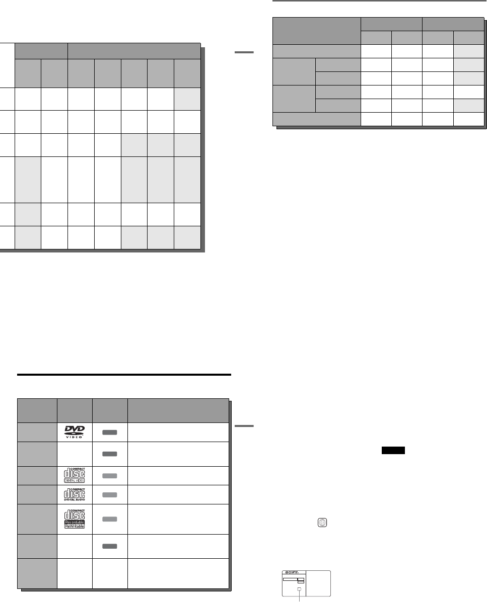
Quick Guide to Disc Types
Recordable and Playable Discs
Usable disc versions (as of December 2006)
•8×-speed or slower DVD+RWs
•6×-speed or slower DVD-RWs (Ver.1.1, Ver.1.2
with CPRM*1)
•16×-speed or slower DVD+Rs
•16×-speed or slower DVD-Rs (Ver.2.0, Ver.2.1
with CPRM)
•8×-speed or slower DVD+R DL (Double Layer)
discs*6
“DVD+RW,” “DVD-RW,” “DVD+R,” “DVD+R DL,”
and “DVD-R” logos are trademarks.
Disc Type Disc
Logo
Icon used
in this
manual
Formatting
(new discs) Compatibility with other
DVD players (finalizing)
DVD+RW Automatically
formatted
Playable on DVD+RW
compatible players
(automatically finalized)
DVD-
RW
VR
mode Format in VR mode*2
(page 47)
Playable only on VR mode
compatible players (finalization
unnecessary) (page 88)
Video
mode Format in Video
mode*2 (page 47)
Playable on most DVD players
(finalization necessary)
(page 88)
DVD+R
Automatically
formatted
Playable on DVD+R compatible
players (finalization necessary)
(page 88)
DVD+R DL
DVD-
R
VR
mode
Format in VR mode
using the “Disc Setting”
display (page 67)
Playable only on DVD-R VR
mode compatible players
(finalization necessary)
(page 88)
Video
mode
Automatically
formatted in Video
mode
Playable on most DVD players
(finalization necessary)
(page 88)
+RW
-
RWVR
-
RWVideo
+R
-
RVR
-
RVideo
1-7
31
Quick Guide to Disc Types
*1 CPRM (Content Protection for Recordable Media) is
a coding technology that protects copyrights for
images.
*2 Unused DVD-RWs are automatically formatted
according to the setting of “Format DVD-RW” in
“Features” setup (page 101).
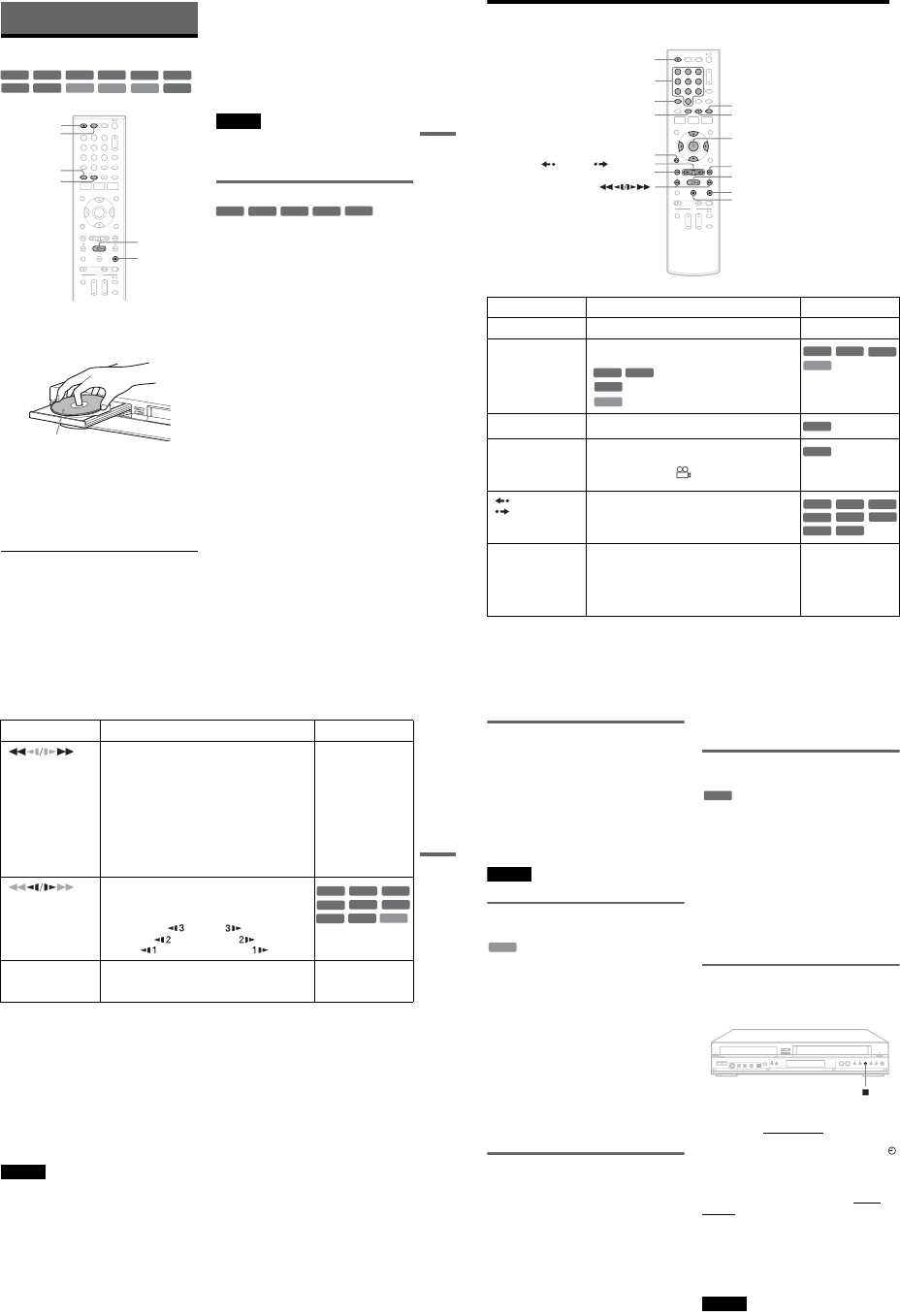
*3 Erasing titles only frees up disc space if you erase the
last title.
*4 Erasing titles or chapters frees up disc space.
*5 Erasing titles or chapters does not free up disc space.
*6 When using DVD+R DL (Double Layer) discs, see
the instructions supplied with the discs.
Recording Features Editing Features
Rewrite
(page 67)
Auto
Chapter
(page 49)
Change
Title
Name
(page 60)
Erase
Title/
Chapter
(page 57)
A-B
Erase
(page 58)
Divide
Title
(page 59)
Playlist
(page 61)
Yes Yes YesYes/No
*3 Yes Yes No
Yes Yes YesYes/Yes
*4 Yes Yes Yes
Yes Yes YesYes/No
*3 No No No
No Yes Yes Yes/No*5 No No No
No Yes Yes Yes/Yes*5 Yes Yes Yes
No Yes Yes Yes/No*5 No No No
,continued 32
12 cm/8 cm discs
Discs that cannot be recorded on
•8 cm discs
•DVD-RAMs
Disc Type
12 cm 8 cm
Playback Recording Playback Recording
DVD+RW Yes Yes Yes No
DVD-RW
VR mode Yes Yes Yes No
Video mode Yes Yes Yes No
DVD-R
VR mode Yes Yes — —
Video mode Yes Yes Yes No
DVD+R Yes Yes — —
33
Quick Guide to Disc Types
Playable Discs
“DVD VIDEO” and “CD” logos are trademarks.
*A logical format of files and folders on DATA-CDs,
defined by ISO (International Organization for
Standardization).
Discs that cannot be played
•CD-ROMs/CD-Rs/CD-RWs that are not
recorded in music CD or Video CD format, or do
not contain MP3 audio tracks or JPEG image
files.
•Data part of CD-Extras
•DVD-ROMs that are not recorded in DVD
Video format, or do not contain MP3 audio
tracks or JPEG image files.
•DVD Audio discs
•HD layer on Super Audio CDs
•DVD VIDEOs with a different region code
(see page 34)
•A disc recorded in a color system other than
NTSC, such as PAL or SECAM
Disc Type Disc Logo Icon Used
in This
Manual Characteristics
DVD VIDEO Discs such as movies that can be purchased or
rented
DVD-RAM —DVD-RAMs recorded by another recording
device. 12 cm discs without cartridges, or
removable from their cartridges can be played.
VIDEO CD VIDEO CDs or CD-Rs/CD-RWs in VIDEO CD
format (with PBC function)
CD Music CDs or CD-Rs/CD-RWs in music CD
format that can be purchased
DATA CD
CD-ROMs/CD-Rs/CD-RWs created on a PC or
similar device in music format, or MP3 or JPEG
format that conforms to ISO9660* Level 1/
Level 2
DATA DVD —DVD-ROMs/DVD+RWs/DVD-RWs/DVD+Rs/
DVD-Rs in MP3 or JPEG format conforming to
Universal Disk Format (UDF)
8 cm DVD+RW/
DVD-RW/DVD-R
——
8 cm DVD+RWs, DVD-RWs, and DVD-Rs
recorded with a DVD video camera (Still images
recorded with a DVD video camera cannot be
played.)
DVD
RAM
VCD
CD
DATA CD
DATA DVD
,continued 34
Note on playback operations of DVD VIDEOs/
VIDEO CDs
Some playback operations of DVD VIDEOs/
VIDEO CDs may be intentionally set by software
producers. Since this recorder plays DVD
VIDEOs/VIDEO CDs according to the disc
contents the software producers designed, some
playback features may not be available. Also, see
the instructions supplied with the DVD VIDEOs/
VIDEO CDs.
Note on DualDiscs
A DualDisc is a two sided disc product which
mates DVD recorded material on one side with
digital audio material on the other side.
However, since the audio material side does not
conform to the Compact Disc (CD) standard,
playback on this product is not guaranteed.
Region code (DVD VIDEO only)
Your recorder has a region code printed on the rear
of the unit and will only play DVD VIDEOs
(playback only) labeled with identical region
codes. This system is used to protect copyrights.
DVD VIDEOs labeled will also play on this
recorder.
If you try to play any other DVD VIDEO, a
message will appear on the TV screen to indicate
that the disc is not playable. Depending on the
DVD VIDEO, no region code indication may be
labeled even though playing the DVD VIDEO is
prohibited by area restrictions.
Music discs encoded with copyright protection
technologies
This product is designed to playback discs that
conform to the Compact Disc (CD) standard.
Recently, various music discs encoded with
copyright protection technologies are being
marketed by some record companies. Please be
aware that among those discs, there are some that
do not conform to the CD standard and may not be
playable by this product.
Note on DVD+RWs/DVD+Rs, DVD-RWs/DVD-
Rs, or CD-RWs/CD-Rs recorded on other
equipment
Some DVD+RWs/DVD+Rs, DVD-RWs/DVD-
Rs, or CD-RWs/CD-Rs cannot be played on this
recorder due to the recording quality or physical
condition of the disc, or the characteristics of the
recording device and authoring software. The disc
will not play if it has not been correctly finalized.
For more information, see the operating
instructions for the recording device.
Notes
•You cannot mix VR mode and Video mode on the same
DVD-RW or DVD-R. To change the DVD-RW’s
format, reformat the disc (page 67). Note that a disc’s
contents will be erased after reformatting.
•You cannot shorten the time required for recording
even with high-speed discs. Also, you cannot record on
the disc if the disc is not 1x speed compatible.
•It is recommended that you use discs with “For Video”
printed on their packaging.
•You cannot add new recordings to DVD-RWs (Video
mode), DVD+Rs, or DVD-Rs (Video mode) recorded
on other equipment.
•You may not be able to further record on a DVD+RW
recorded on other equipment. Note that recording on
such discs may cause the recorder to rewrite the DVD
menu.
•If the disc contains PC data unrecognizable by this
recorder, the data may be erased.
ALL
NO.
RDR-VX525
X
Region code
1-8
35
DVD Playback
DVD Playback
Playing Discs
1Press DVD to operate the DVD recorder.
2Press ZOPEN/CLOSE, and place a disc on
the disc tray.
3Press ZOPEN/CLOSE to close the disc
tray.
Wait until “LOAD” disappears from the front
panel display.
4Press H PLAY.
Playback starts.
To stop playback
Press xSTOP.
zHints
•You can play DATA CDs or DATA DVDs with MP3
audio tracks or JPEG image files (pages 41 or 42).
•If you insert a DVD VIDEO, VIDEO CD, or CD,
playback starts automatically depending on the disc.
•When playing a DVD+RW, DVD-RW, DVD+R,
DVD-R, and DVD-RAM, you can select the title from
the Title List menu (page 39).
•When using a DVD-RAM with a cartridge, remove the
disc from the cartridge.
Notes
•To play a disc recorded with other equipment on this
recorder, finalize the disc on the recording equipment
first.
•For simultaneous VHS and DVD operation, see page 9.
Using the DVD’s Menu
When you play a DVD VIDEO, or a finalized
DVD+RW, DVD-RW (Video mode), DVD+R, or
DVD-R (Video mode), you can display the disc’s
menu by pressing TOP MENU or MENU.
+RW +R
DVD
VCD CD
-
RWVR
-
RWVideo
DATA DVD
DATA CD
-
RVR
-
RVideo
RAM
112233
445566
7788
00
99
xSTOP
ZOPEN/
CLOSE
MENU
HPLAY
DVD
TOP MENU
Playback side facing down
+RW +R
DVD
-
RWVideo
+R
-
RVideo
36
Playback Options
Button Operation Disc
ZOPEN/CLOSE Stops playing and opens the disc tray. All discs
AUDIO Selects one of the audio tracks recorded on the disc
when pressed repeatedly.
: Selects the main or sub sound.
: Selects the audio source.
: Selects stereo or monaural audio tracks.
SUBTITLE Selects a subtitle language when pressed repeatedly. .
ANGLE Selects an angle when pressed repeatedly.
If various angles (multi-angles) for a scene are
recorded on the disc, “ ” appears in the front panel
display.
REPLAY/
ADVANCE •Replays or briefly fast forwards a scene when
pressed during playback.
•Goes to the previous or next frame when pressed
during pause mode.
.PREV/
NEXT >•Goes to the beginning of the current or next title/
chapter/scene/track and starts playback when
pressed during playback.
•Goes to the beginning of the previous title/chapter/
scene/track when .PREV is pressed within three
seconds after starting a title/chapter/scene/track.
All discs
112233
445566
7788
00
99
ZOPEN/CLOSE
XPAUSE
AUDIO
.PREV
REPLAY/ ADVANCE
xSTOP
SUBTITLE
MENU
HPLAY
M/m/</,,
ENTER
Number buttons
O RETURN
> NEXT
ANGLE
-
RWVR
-
RVR
DVD
VCD
DVD
VCD
-
RWVR
-
RVR
DVD
DVD
+RW
-
RWVR
-
RWVideo
+R
DVD
-
RVR
-
RVideo
RAM
37
DVD Playback
To resume normal playback after playing at various speeds, press HPLAY.
zHints
•You can change playback options, such as subtitle,
audio track, angle, etc., using the OPTIONS menu
(page 11).
•During playback or pause mode, the recorder’s m/
M buttons and the remote’s .PREV/>NEXT
buttons work the same way (page 36). Hold the buttons
down during playback to fast forward or fast reverse. In
pause mode, you can play in slow motion. Three speeds
are available, depending on the duration of the press.
•See “DVD Audio/Subtitle Language” on page 120 for
the meaning of the language abbreviation.
Notes
•If you pause playback of a CD, or DATA CD/DATA
DVD containing MP3 audio tracks, playback will not
start until you press H PLAY or X PAUSE.
•Sound will be interrupted during Scan Audio
(page 38).
Notes on playing DTS soundtracks on a CD
When playing DTS-encoded CDs, excessive noise
will be heard from the analog stereo jacks. To
avoid possible damage to the audio system, the
consumer should take proper precautions when
the analog stereo jacks of the recorder are
connected to an amplification system. To enjoy
DTS Digital Surround™ playback, an external
5.1-channel decoder system must be connected to
the digital jack of the recorder.
Notes on playing DVDs with a DTS soundtrack
DTS audio signals are output only through the
DIGITAL AUDIO OUT (COAXIAL or
OPTICAL)/HDMI OUT jack.
When you play a DVD with DTS soundtracks, set
“Digital Out” – “DTS” to “On” of “Audio” in the
“Setup” display (page 98).
If you connect the recorder to audio equipment
without a DTS decoder, do not set “DTS” to “On”
in “Audio” setup. A loud noise (or no sound) may
come out from the speakers, which might disturb
your ears or cause damage to the speakers.
(fast reverse/fast
forward)
Fast reverses or fast forwards the disc when pressed
during playback.
Search speed changes with each press:
fast reverse fast forward
FR1 Tt FF1*1
FR2*2 TT tt FF2*2
FR3*3 TTT ttt FF3*3
All discs
*1 FF1 with sound
(Scan Audio) is
available for DVDs
with Dolby Digital
soundtracks.
*2 FR2 and FF2 are not
available for MP3.
*3 FR3 and FF3 are only
available for DVDs
and VIDEO CDs.
(slow) Plays in slow motion when pressed in pause mode.
Playback speed changes with each press:
reverse slow motion forward slow motion
Tt
TT tt
TTT ttt
*Playback direction
only
XPAUSE Pauses playback.
If you pause playback for more than five minutes,
playback starts automatically.
All discs
Button Operation Disc
VCD
+RW
+R
-
RWVR
-
RWVideo
DVD
-
RVR
-
RVideo
RAM
*
,continued 38
Playing quickly with sound (Scan
Audio) (DVDs with Dolby Digital soundtracks
only)
You can play quickly with dialog or sound during
FF1 fast-forward of a DVD with Dolby Digital
soundtracks. Simply press M during playback.
zHint
To turn off the Scan Audio function, set “Scan Audio” of
“Audio” to “Off” in the “Setup” display (page 99).
Note
Sound will be interrupted during Scan Audio.
Playing VIDEO CDs with PBC
functions
PBC (Playback Control) allows you to play
VIDEO CDs interactively using a menu on your
TV screen.
When you start playing a VIDEO CD with PBC
functions, a menu appears.
Select an item using the number buttons and press
ENTER. Then follow the instructions in the menu
(press HPLAY when “Press SELECT”
appears).
Operations differ depending on the disc. See the
instructions supplied with the disc.
To cancel PBC Playback
Press MENU to display “Menu: Off.” To use the
PBC functions, press MENU again to display
“Menu:On.”
Resuming playback from the point
where you stopped the disc (Resume
Play)
Press HPLAY again after stopping a disc to
resume playback from the same point.
To start from the beginning, press xSTOP twice,
and press HPLAY.
The point where you stopped playing is cleared
when:
–you open the disc tray.
–you play another title.
–you switch the Title List menu to original or
Playlist (DVD-RW (VR mode)/DVD-R (VR
mode)/DVD-RAM only).
–you edit the title after stopping playback.
–you make a recording.
Playing restricted DVDs (Parental
Control)
If you play a restricted DVD, a message appears
asking whether you want to override the
restriction.
1Select “OK” and press ENTER.
The display for entering your password
appears.
2Enter your four digit password using the
number buttons.
The recorder starts playback.
To register or change the password, see “Parental
(DVD VIDEOs only)” on page 103.
Locking the recorder (Child Lock)
You can lock all of the buttons on the recorder so
that the settings are not canceled by mistake.
With the recorder turned on and stopped, hold
down x (stop) on the recorder for more than ten
seconds. The recorder turns off and “CHILD
LOCK” appears in the front panel display. The
indicator remains lit if there is a timer setting. The
recorder will not work except for timer recordings.
To unlock the recorder, hold down x on the
recorder until “CHILD LOCK” disappears from
the front panel display. The recorder is unlocked
and turns on.
To stop timer recording while the recorder is
locked, press x twice. The recording stops and the
recorder is unlocked.
Note
The recorder will be unlocked when:
–you stop timer recording by pressing x.
–you insert a tape.
VCD
DVD
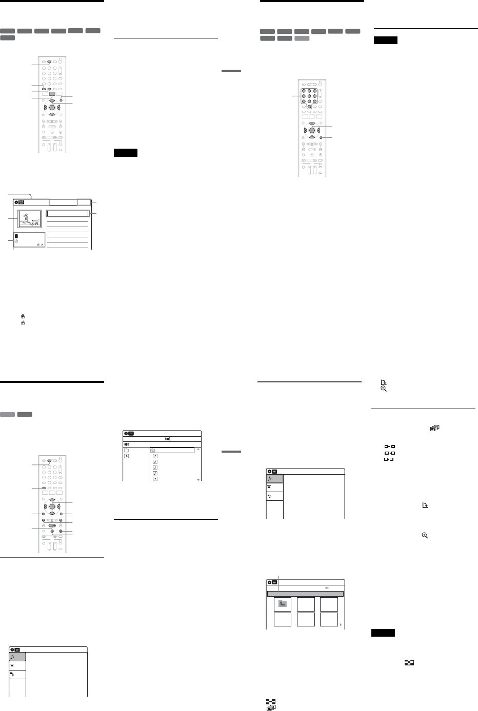
1-9
39
DVD Playback
Playing a Title From the
Title List
The Title List menu displays the program titles on
the disc.
1Press DVD to operate the DVD recorder.
2Place a disc on the disc tray.
3Press TITLE LIST.
Example: DVD-RW (VR mode)
ADisc type:
Displays a disc type.
Also displays the title type (original or
Playlist) for DVD-RWs (VR mode),
DVD-Rs (VR mode), and DVD-RAMs.
BMovie thumbnail image
CTitle information:
Displays the title number, title name,
recording date, and recording mode.
“” indicates a protected title, while
“” indicates unprotected.
DClock
4Select the title, and press ENTER.
The sub-menu appears.
5Select “Play,” and press ENTER.
Playback starts from the selected title on the
disc.
About the Title List for DVD-RWs (VR mode)
and DVD-Rs (VR mode)
You can switch the Title List to show an original
or Playlist.
While the Title List menu is turned on, press
ORIGINAL/PLAYLIST repeatedly to select
either “Title List (Original)” or “Playlist.”
For details, see “Edit options for DVD-RWs (VR
mode)/DVD-Rs (VR mode)” on page 56.
To turn off the Title List
Press TITLE LIST.
zHint
You can also switch the Title List of DVD-RAMs to
show an original or Playlist.
Notes
•The Title List does not appear for DVD-RWs (Video
mode), DVD+Rs, or DVD-Rs (Video mode) that have
been finalized. To view a title, press TOP MENU or
MENU (page 35).
•The Title List may not appear for discs created on other
DVD recorders.
•Letters that cannot be displayed are replaced with “*.”
+RW +R
-
RWVR
-
RWVideo
RAM
-
RVR
-
RVideo
112233
445566
7788
00
99
TITLE LIST
MENU
TOP MENU
ORIGINAL/
PLAYLIST
DVD
M/m/</,,
ENTER
10:10 AM
01 LINE 1 >01:29:03
02 LINE 1 >00:31:23
03 LINE 1 >01:59:00
04 LINE 1 >00:58:56
LINE
1
08:00 PM
May/02/2007
T
No. Title Length Edit
Title List (Original)
1/4
1
2
3
4
3
40
Searching for a Title/
Chapter/Track, etc.
You can search a DVD by title or chapter, and
VIDEO CD by track or scene. As titles and tracks
are assigned individual numbers on the disc, select
the title or track by entering its number. You can
also search for a scene using the time code.
1Press OPTIONS during playback.
The OPTIONS menu appears.
2Select a search method.
“Title” (for DVDs)
“Chapter” (for DVDs)
“Track” (for VIDEO CDs with PBC function
off)
“Time” (for DVDs/VIDEO CDs with PBC
function off): Searches for a starting point
using the time code.
3
Press
M
/
m
/
<
/
,
to select the number of
the title, chapter, track, etc., you want, or
press the number buttons to enter the time
code.
For example: “Time”
To find a scene at 2 hours, 5 minutes, and 20
seconds, enter “20520.”
If you make a mistake, wait a moment until
the display returns to the elapsed playing time
display, then select another number.
4Press ENTER.
The recorder starts playback from the selected
point.
To turn off the display, press OPTIONS.
Notes
•Depending on the disc, you may not be able to use the
OPTIONS menu to search for a title/chapter/track, or
enter the time code for a playback point.
•When playing a Playlist title, you may not be able to
search for a scene using the time code.
+RW +R
VCD
-
RWVR
-
RWVideo
RAMDVD
-
RVR
-
RVideo
112233
445566
7788
00
99
OPTIONS
M/m/</,,
ENTER
Number
buttons
41
DVD Playback
Playing MP3 Audio Tracks
and JPEG Image Files
You can play DATA CDs (CD-ROMs/CD-Rs/
CD-RWs)/DATA DVDs (DVD-ROMs/
DVD+RWs/DVD-RWs/DVD+Rs/DVD-Rs) that
contain MP3 audio tracks or JPEG image files.
Playing MP3 audio tracks
You can play MP3 audio tracks on DATA CDs or
DATA DVDs.
1Press DVD to operate the DVD recorder.
2Place a DATA CD/DATA DVD on the disc
tray.
When you insert a DATA CD/DATA DVD
containing MP3 audio tracks and JPEG image
files, the display for selecting a media type
appears. When you select “Mix,” you can
enjoy a slide show with sound (page 43).
If you insert a DATA CD/DATA DVD
containing only MP3 audio tracks, the
“Music” display appears. Go to step 4.
3Select “Music,” and press ENTER.
The “Music” display appears.
4Select an album, and press ENTER.
5Select a track, and press ENTER.
Playback starts from the selected track.
When a track or album is being played, the
title is shown in a box.
To stop playback
Press xSTOP.
To pause playback
Press X PAUSE.
To restart playback, press H PLAY or X
PAUSE.
To return to the previous display
Press ORETURN.
To switch between MP3 audio tracks and JPEG
image files
Press xSTOP, and press TOP MENU.
zHint
When playback of all the MP3 audio tracks within the
album finishes, the recorder stops.
DATA CD
DATA DVD
112233
445566
7788
00
99
HPLAY
ORETURN
M/m/</,,
ENTER
./>
DVD
TOP MENU
xSTOP
OPTIONS
X PAUSE
10:10 AM
Photo
Music
Mix
Press ENTER :
Music menu for this disc.
Stop 00:00:00
Prev Directory
01-Track1.mp3
02-Track2.mp3
03-Track3.mp3
04-Track4.mp3
05-Track5.mp3
MP3_001
0/9
10:10 AM
Music
Surround:Off
,continued 42
Playing JPEG image files
You can play JPEG image files on DATA CDs or
DATA DVDs.
1Press DVD to operate the DVD recorder.
2Place a DATA CD/DATA DVD on the disc
tray.
When you insert a DATA CD/DATA DVD
containing MP3 audio tracks and JPEG image
files, the display for selecting a media type
appears. When you select “Mix,” you can
enjoy a slide show with sound (page 43).
If you insert a DATA CD/DATA DVD
containing only JPEG image files, the
“Photo” display appears. Go to step 4.
3Select “Photo,” and press ENTER.
The “Photo” display appears.
4Select a folder, and press ENTER.
To display the previous or next page, press
./>.
5Select an image file, and press ENTER.
The selected image is displayed over the
entire screen.
To display the previous or next image, press
./>.
The following menu icons appear in the upper
part of the screen.
: Returns to the “Photo” display.
: Starts the slide show (page 42).
: Rotates the image (page 42).
: Zooms the image (page 42).
Press OPTIONS to turn on/off the menu
icons.
To play the slide show
1Press </, to select “,” and press
ENTER.
The “Slideshow Speed” menu appears.
“”: Slow
“”: Normal
“”: Fast
2Press </, to select the desired play speed,
and press ENTER.
The slide show starts from the selected image.
To stop playing, press x STOP.
To rotate the selected image
Press </, to select “ ,” and press ENTER.
Each time you press ENTER, the image turns
clockwise by 90°.
To zoom in an image
Press </, to select “ ,” and press ENTER.
Each time you press ENTER, the magnification
changes as follows:
2ut 4ut 2ut normal
To return to the previous display
Press ORETURN.
To switch between MP3 audio tracks and JPEG
image files
Press xSTOP, and press TOP MENU.
zHint
You can also start the slide show by pressing H PLAY
in step 5 above.
Notes
•You cannot use M/m/</, to move the image within
the screen while zooming.
•Slide show can play in only one direction.
•You cannot rotate or zoom during slide show.
•If you select “ ” in the rotated image display,
the images in the “Photo” display will not be
rotated.
10:10 AM
Photo
Music
Press ENTER :
Mix
Music menu for this disc.
Slideshow
\\abc\defg
Page 1 / 2
10:10 AM
Photo
Directory information
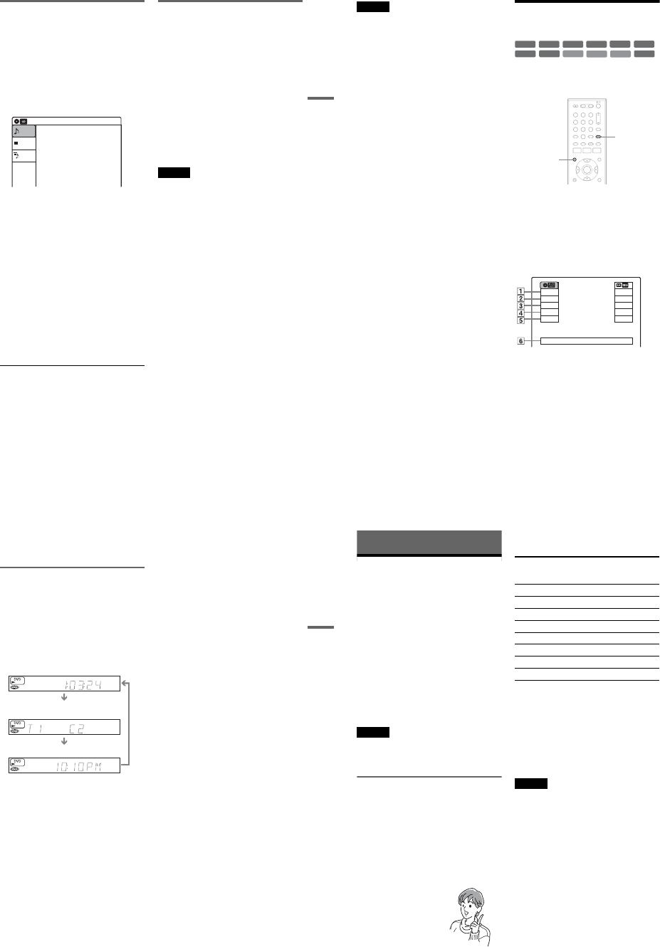
1-10
43
DVD Playback
Enjoying a slide show with sound
When a disc contains both MP3 audio tracks and
JPEG image files, you can enjoy a slide show with
sound.
1Press DVD to operate the DVD recorder.
2Insert a DATA CD/DATA DVD containing
both the MP3 audio tracks and JPEG image
files.
The display for selecting a media type
appears.
3Select “Mix,” and press ENTER.
The “Music” display appears.
4Select an album, and press ENTER.
5Select a track, and press ENTER.
Playback starts from the selected track, and
the display asks for confirmation.
6Select “Yes,” and press ENTER.
The “Photo” display appears.
7Select the folder you want to view, and
press ENTER.
8Press H PLAY to start the slide show.
The “Slideshow Speed” menu appears.
9Press </, to select the slide show
speed, and press ENTER.
The slide show starts with sound.
To stop the slide show
Press x STOP.
zHints
•When playing JPEG images, you can also use the on-
screen menu. For details, see “Playing JPEG image
files” (page 42).
•The slide show is played repeatedly until MP3
playback stops.
About MP3 audio tracks and JPEG
image files
MP3 is audio compression technology that
satisfies the ISO/IEC MPEG regulations.
JPEG is image compression technology.
You can play back DATA CDs (CD-ROMs/CD-
Rs/CD-RWs) or DATA DVDs (DVD-ROMs/
DVD+RWs/DVD-RWs/DVD+Rs/DVD-Rs)
recorded in MP3 (MPEG1 Audio Layer 3) and
JPEG format.
However, this recorder only plays DATA CDs
whose logical format is ISO9660 Level 1/Level 2
or Joliet, and DATA DVDs of Universal Disk
Format (UDF).
See the instructions supplied with the disc drives
and the recording software (not supplied) for
details on the recording format.
Note
The recorder may not be able to play some DATA CDs
or DATA DVDs created in the Packet Write format.
MP3 audio tracks or JPEG image files that the
recorder can play
The recorder can play the following tracks and
files:
–MP3 (MPEG1 Audio Layer 3) audio tracks.
–MP3 audio tracks with the extension “.MP3.”
–JPEG image files with the extension “.JPEG” or
“.JPG.”
zHints
•If you add numbers (01, 02, 03, etc.) to the front of the
file names, the files will be played in that order.
•Since a disc with many trees takes longer to start
playback, it is recommended that you create albums
with no more than two trees.
10:10 AM
Photo
Music
Press ENTER :
Mix
Music menu for this disc.
,continued 44
Notes
•Some DATA CDs or DATA DVDs cannot be played
on this recorder depending on file format.
•Only one session of a multi-session DATA DVD can
be played back.
•Only alphabet and numbers can be used for album or
track names. Anything else is displayed as an asterisk.
•The recorder will play any data with the extension
“.MP3,” even if they are not in MP3 format. Playing
such data may generate a loud noise which could
damage your speaker system.
•The recorder does not conform to audio tracks in
MP3PRO format.
•The recorder can recognize up to 499 MP3 audio tracks
within a single album. The recorder may not recognize
some discs depending on the recording device used for
recording or the disc condition.
•The recorder can play MP3 audio tracks recorded in the
following sampling frequencies: 32 kHz, 44.1 kHz,
48 kHz.
•ID3 tags cannot be displayed.
•If you add the extension “.JPG” or “.JPEG” to data not
in JPEG format, a message appears indicating that the
format is not supported.
•Depending on the disc or the size of image files,
playback may take some time to start.
•The recorder can recognize up to 999 JPEG image files
within a single folder. The recorder may not recognize
some discs depending on the recording device used for
recording or the disc condition.
•Progressive and lossless compression JPEG image files
are not supported.
•The image size that the recorder can display is limited
to width 32 - 7680 pixels by height 32 - 8192 pixels.
•JPEG image files that conform to the DCF* image file
format are not supported.
*“Design rule for Camera File system”: Image standards
for digital cameras regulated by JEITA (Japan
Electronics and Information Technology Industries
Association).
Displaying the Playing Time
and Play Information
You can check disc information, such as playing
time, recording mode, and remaining disc space.
Press DISPLAY.
The information display appears.
Each time you press the button, the display
changes as follows:
Disc and tape information/date and time
m
Disc information only
m
No display
◆DVD
APlaying status
BPlaying time
CRecording mode
DRemaining disc space (in stop mode)
Remaining time of the current title (during
playback*1)
EInput source*2
FDate and time
+R
DVD
VCD CD
-
RWVR
-
RWVideo
+RW
DATA CD
DATA DVD
RAM
-
RVR
-
RVideo
112233
445566
7788
00
99
TIME/TEXT
DISPLAY
Stop
0:30:00
SP
Rem 01:30
Line1
Wed May 02. 2007 10:10 AM
Play
0:05:30
HQ
Rem 00:25
Original
45
DVD Playback
*1 Also appears in stop mode with Resume Play
activated (page 38).
*2 Title type (original or Playlist) for DVD-RWs (VR
mode)/DVD-Rs (VR mode)/DVD-RAMs.
Viewing information on the front
panel display
You can view the information on the front panel
display.
Press TIME/TEXT repeatedly.
The displays differ depending on the disc type or
playing status.
Example: When playing a DVD
Example: When a DVD is stopped
Example: When playing a CD
Playing time of the current title
Current title number and current chapter
number
Clock
Clock
m
Current title and chapter number
m
Remaining disc space
m
Input source
Playing time of the current track
m
Current track number
m
Clock
46
DVD Recording
Before Recording
Before you start recording…
•This recorder can record on various disc types.
Select the disc type according to your needs
(page 30).
•Check that the disc has enough available space
for the recording (page 44). For DVD+RWs or
DVD-RWs, you can free up disc space by
erasing titles (page 57).
•Check that the recorder is connected to a tuner
such as a cable box or satellite receiver
(page 12). See also the tuner’s instruction
manual.
zHint
To play a disc recorded with this recorder on other
equipment, finalize the disc (page 88).
Notes
•Timer recordings will start with or without the recorder
turned on. The recorder automatically turns off after a
recording has finished.
•This recorder records at ×1 speed.
Recording mode
Like the SP or EP recording mode of VCRs, this
recorder has eight different recording modes.
Select a recording mode according to the time and
picture quality you need. For example, if picture
quality is your top priority, select “HQ” (high
quality). If recording time is your priority, “SLP”
can be a possible choice.
Press REC MODE repeatedly to switch the
recording modes.
Recording mode and recording time
The following table is an approximate guide for
the recording time on a single DVD (4.7 GB).
zHint
The approximate recording time for DVD+R DL
(Double Layer) discs is as follows:
HQ: 1 hour 48 minutes
HSP: 2 hours 42 minutes
SP: 3 hours 37 minutes
LSP: 4 hours 31 minutes
ESP: 5 hours 25 minutes
LP: 7 hours 14 minutes
EP: 10 hours 51 minutes
SLP: 14 hours 28 minutes
Notes
•When in a recording mode other than HQ, the recorder
compresses the audio/video data before recording.
Since the compression rate needs to decrease for fast-
moving images or if picture noise is present, recorded
data size increases, and available recording time
becomes shorter. When recording such pictures, a
recording mode offering longer recording time is
recommended.
•Situations below may cause inaccuracies with the
recording time.
–Recording fast-moving or images containing picture
noise.
–Recording a program with poor reception, or a
program or video source of low picture quality
–Recording on a disc that has already been edited
–Recording only a still picture or just sound
•Since the recording mode for recorded titles is
calculated after sampling the recorded data during
playback, it may be displayed differently from the
mode you selected when recording. However, the
actual recording itself is correctly made in the selected
mode.
I want to record with the
best possible picture
quality, so I’ll select HQ.
Recording mode Approximate
recording time
(minute)
HQ (High quality) 60
HSP R90
SP (Standard mode) 120
LSP r150
ESP r180
LP r240
EP r360
SLP (Long duration) 480
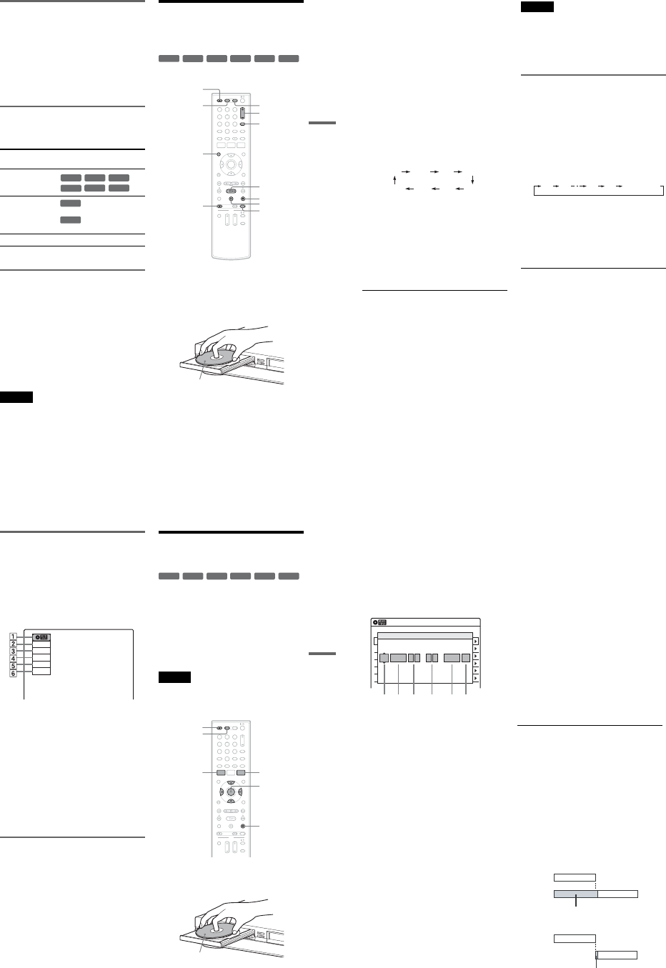
1-11
47
DVD Recording
Recording main and sub sounds
You can record the different soundtracks on a
DVD-RW (VR mode) or DVD-R (VR mode) from
equipment connected to the LINE 1 IN or LINE 2
IN jacks. When playing the disc, you can select
main or sub sound by pressing the AUDIO button.
Set “Line Audio Input” in “Audio” setup to
“Main/Sub” in the Setup Display (page 100).
When recording on other discs, select either sound
track with the connected equipment before
recording.
Unrecordable pictures
Pictures with copy protection cannot be recorded
on this recorder. Recording stops when a copy
guard signal is detected.
*The recorded disc can be played only on CPRM
compatible equipment (page 30).
Formatting a new disc
New, unformatted discs are automatically
formatted when first inserted in the recorder.
For DVD-RWs/DVD-Rs, you can select a
recording format (VR mode or Video mode)
according to your needs (page 30).
•Unused DVD-RWs are automatically formatted
according to the setting of “Format DVD-RW”
in “Features” setup (page 101).
•Unused DVD-Rs are automatically formatted in
Video mode. To format in VR mode, change the
recording format using the “Disc Setting”
display (page 67).
Notes
•You cannot mix VR mode and Video mode on the same
DVD-RW or DVD-R.
•You can change the recording format on DVD-RWs by
reformatting (page 67).
•You cannot change the recording format on used DVD-
Rs.
•The recorder records on new DVD-Rs in Video mode
unless you first format the discs in VR mode.
DVD Recording From
Connected Equipment
Without the Timer
You can record TV programs on the recorder
through the connected cable box/satellite receiver.
1Turn on the recorder and the connected
cable box/satellite receiver.
2Press DVD to operate the DVD recorder.
3Press ZOPEN/CLOSE, and place a
recordable disc on the disc tray.
4Press ZOPEN/CLOSE to close the disc
tray.
Wait until “LOAD” disappears from the front
panel display.
Unused discs are automatically formatted. For
the DVD-RW/DVD-R’s recording format
(VR mode or Video mode), see “Formatting a
new disc” on page 47.
Copy control
signals Recordable discs
Copy-Free
Copy-Once
Ver.1.1, Ver.1.2 with CPRM*
Ver.2.0, Ver.2.1 with CPRM*
Copy-Never None
+RW
-
RWVR
-
RWVideo
+R
-
RVR
-
RVideo
-
RWVR
-
RVR
+RW +R
-
RWVR
-
RWVideo
-
RVR
-
RVideo
112233
445566
7788
00
99
REC MODE
XPAUSE
xSTOP
CH +/–
zREC
ZOPEN/
CLOSE
HPLAY
VIDEO
DVD
DISPLAY
INPUT
Recording side facing down
,continued 48
5Press CH +/– or INPUT repeatedly to select
the channel or input source you want to
record.
•When using the cable box/satellite receiver
control, select the channel by pressing
CH +/– on this recorder’s remote. The
recorder’s input is switched to the connected
input (LINE1 or LINE2). You can also use
the number buttons.
•When not using the cable box/satellite
receiver control, select the connected input
(LINE1 or LINE2) by pressing INPUT, and
then select the channel on the cable box/
satellite receiver’s side.
6Press REC MODE repeatedly to select the
recording mode.
The display changes on the TV screen as
follows:
For details about the recording mode, see
page 46.
7Press zREC.
Recording starts.
Recording continues until you stop the
recording or the disc is full.
Leave the cable box/satellite receiver turned
on and do not change the channel you are
recording.
To stop recording
Press xSTOP.
Note that it may take a few seconds for the
recorder to stop recording.
To pause recording
Press XPAUSE.
To restart recording, press XPAUSE again.
To watch a VHS tape while recording
Press VIDEO to operate the VCR, insert a tape,
then press HPLAY.
zHints
•To play a disc recorded with this recorder on other
equipment, finalize the disc (page 88).
•You can turn off the TV during recording.
Notes
•Recording may not start immediately after zREC is
pressed.
•You cannot change the recording mode during
recording or recording pause.
•If there is a power failure, the program you are
recording may be erased.
•You cannot change the input source during recording.
Recording using the Quick Timer
(One-touch Timer Recording)
You can set the recorder to record in 30-minute
increments.
1Press DVD to operate the DVD recorder.
2Press zREC repeatedly to set the
duration.
Each press increases the time by 30 minutes,
up to eight hours*.
“c” and “OTR” light up, and the remaining
recording time appears in the front panel
display.
When the time counter reaches “0:00,” the
recorder stops recording and turns off.
*14 hours 30 minutes for DVD+R DL (Double Layer)
discs.
To cancel the Quick Timer
Press zREC repeatedly until the counter appears
in the front panel display. The recorder returns to
normal recording mode.
To stop recording
Press xSTOP twice.
Note that it may take a few seconds for the
recorder to stop recording.
HQ SPHSP LSP
SLP LPEP ESP
0:30 1:00 7:30 8:00
(Normal
recording)
49
DVD Recording
Checking the disc status while
recording
You can check the recording information such as
recording time or disc type.
Press DISPLAY during recording.
The information display appears.
Press the button repeatedly to change the display
(page 44).
ADisc type
BRecording status
CRecording time
DRecording mode
ERemaining disc space
FInput source
zHint
You can view the information also in the front panel
display. Press TIME/TEXT repeatedly to change the
display. Note that TIME/TEXT does not work during
One-touch Timer Recording.
Creating chapters in a title
The recorder will automatically divide a recording
(a title) into chapters by inserting chapter marks at
5 or 15-minute intervals during recording. Select
the interval, “5 Min” (default) or “15 Min” in
“DVD Auto Chapter” of “Features” in the “Setup”
display (page 100).
If you do not want to divide titles, select “Off.”
DVD Timer Recording From
Connected Equipment
You can set the timer for a total of 12 programs
together with DVD and VCR timer recording, up
to one month in advance.
Note that the maximum continuous recording time
for a single title is 12 hours. Contents beyond this
time will not be recorded.
If you record from connected equipment that has a
timer function, you can use the Synchro Rec
function (page 51).
Note
Do not operate your cable box or satellite receiver just
before or during a timer recording. This may prevent the
accurate recording of a program.
1Press DVD to operate the DVD recorder.
2Press ZOPEN/CLOSE, and place a
recordable disc on the disc tray.
Record
0:00:03
HQ
Rem 00:59
Line1
+RW +R
-
RWVR
-
RWVideo
-
RVR
-
RVideo
112233
445566
7788
00
99
M/m/</,,
ENTER
ZOPEN/
CLOSE
xSTOP
SYSTEM
MENU
DVD
TIMER
Recording side facing down
,continued 50
3Press ZOPEN/CLOSE to close the disc
tray.
Wait until “LOAD” disappears from the front
panel display.
Unused discs are automatically formatted. For
the DVD-RW/DVD-R’s recording format
(VR mode or Video mode), see “Formatting a
new disc” on page 47.
4Press TIMER.
5Select an item using </, and adjust
using M/m.
A“Media”: Select “DVD.”
B“Date”: Sets the date using M.
To record the same program every day or
the same day every week, press m.
The item changes as follows:
Today y Sun-Sat (Sunday to Saturday)
y Mon-Sat (Monday to Saturday) y
Mon-Fri (Monday to Friday) y Sun
(every Sunday) y Mon (every Monday)
y … y Sat (every Saturday) y
1month later y … y Today
C“Start”: Sets the start time.
D“End”: Sets the stop time.
E“Ch”: Selects the channel or input
source.
•When using the cable box/satellite
receiver control, select the channel.
•When not using the cable box/satellite
receiver control, select the input, LINE1
or LINE2. Select the channel on the
connected cable box/satellite receiver’s
side before the timer recording starts.
F“Mode”: Selects the recording mode
(page 46).
To use the Rec Mode Adjust function
(page 51), select “AUTO.”
If you make a mistake, select the item and
change the setting.
6Press ENTER.
The Timer List menu (page 53) appears.
The c indicator lights up in the front panel
display, and the recorder is ready to start
recording.
•If the c indicator flashes in the front panel
display, check that a recordable disc is
inserted and that there is enough disc space
for the recording.
•If timer settings overlap, a message appears.
To change or cancel a timer recording, select
“Edit” from the Timer List (page 53).
7Press SYSTEM MENU to turn off the menu.
There is no need to turn off the recorder before
the timer recording starts.
Leave the cable box/satellite receiver turned
on and do not change the channel selected on
the cable box/satellite receiver until the
recorder finishes the timer recording.
To stop recording
Press xSTOP twice.
Note that it may take a few seconds for the
recorder to stop recording.
If timer settings overlap
The program that starts first has priority and the
second program starts recording only after the first
program has finished. If the programs start at the
same time, the program listed first in the menu has
priority. If the end time of one setting and the start
time of another timer setting is the same, the
beginning of the program that starts later will be
cut.
01 DVD 04/15 09:00PM 10:00PM CH8
--- --/-- --:-- --:-- ---- ---04
--- --/-- --:-- --:-- ---- ---05
--- --/-- --:-- --:-- ---- ---06
03 --- --/-- --:-- --:-- ---- ---
02 DVD 04/30 09:15PM 09:45PM CH11
10:10 AM
No Rec To Date Start End Source Mode Edit
Timer – Standard
No.01
:PM
DVD
PM
:
Today 09 00 10 00 Line1 SP
12 3 4 56
Media Date Start End Ch Mode
7:00 8:00 9:00 10:00
7:00 8:00 9:00 10:00
Program 1
Program 2
will be cut off
Program 1
Program 2
will be cut off
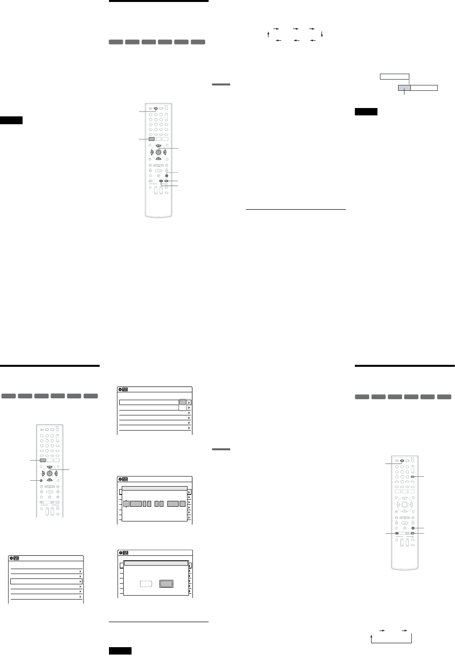
1-12
51
DVD Recording
To change or cancel timer recording
See “Changing or Canceling DVD Timer Settings
(Timer List)” on page 53.
To use the Rec Mode Adjust function
If the remaining disc space is not enough for the
current recording, the recorder automatically
adjusts the recording mode. Select “AUTO” for
“Mode” when setting the timer.
zHints
•You can play the recorded program by selecting the
program title in the Title List menu.
•When the start time and the channel or input source to
be recorded are the same but the “Media” setting
differs, the program is recorded to both the DVD disc
and the VHS tape.
•You can also turn on the timer programming menu
from the System Menu. Press SYSTEM MENU to
select “Timer,” and select “Timer-Standard.”
Notes
•Even when correctly set, the program may not be
recorded if another recording is underway, or other
prioritized timer setting overlaps.
•Before the timer recording starts, “TIMER REC”
flashes in the front panel display.
•The recorder automatically turns off when a timer
recording finishes, even if the recording started with
the recorder turned on.
•The recorder does not record programs with Copy-
Never signals. Such recordings stop after a few
seconds.
Recording From Connected
Equipment With a Timer
(Synchro Rec)
You can set the recorder to automatically record
programs from connected equipment that has a
timer function (such as a satellite tuner). Connect
the equipment to the LINE 1 IN jacks on the rear
of the recorder (page 13).
When the connected equipment turns on, the
recorder starts recording a program from the LINE
1 IN jacks.
1Press DVD to operate the DVD recorder.
2Insert a recordable disc.
3Select the line input audio.
Set “Line Audio Input” of “Audio” setup to
“Stereo” or “Main/Sub” in the “Setup”
display (page 100).
+RW +R
-
RWVR
-
RWVideo
-
RVR
-
RVideo
112233
445566
7788
00
99
M/m/</,,
ENTER
SYNCHRO
REC
xSTOP
REC MODE
SYSTEM
MENU
DVD
,continued 52
4Press REC MODE repeatedly to select the
recording mode.
The display changes on the TV screen as
follows:
For details about the recording mode, see
page 46.
5Press SYSTEM MENU while the recorder is
in stop mode.
6Select “Setup,” and press ENTER.
7Select “Features,” and press ENTER.
The “Features” setup appears.
8Select “Synchro Recording,” and press
ENTER.
9Select “to DVD,” and press ENTER.
10
Press SYSTEM MENU to turn off the menu.
11
Set the timer on the connected equipment
to the time you want to record, and turn it
off.
12
Press SYNCHRO REC.
The SYNCHRO REC indicator lights up on
the front panel and the recorder stands by for
Synchro-Rec.
The recorder starts recording when a signal is
received from the connected equipment.
When the connected equipment turns off, the
recording stops and the recorder turns off.
To stop recording
Press xSTOP twice.
To cancel a Synchro-Rec function
Press SYNCHRO REC before recording starts.
The SYNCHRO REC indicator on the recorder
turns off.
If you press SYNCHRO REC during Synchro-
Rec, the recording stops, the SYNCHRO REC
indicator turns off, and the recorder turns off.
If the timer settings of a Synchro-Recording
and another timer recording overlap
Regardless of whether or not the program is a
Synchro-Rec program, the program that starts first
has priority. The recorder starts recording the
second program about ten seconds after the first
program has finished. If the end time of one
setting and the start time of another timer setting is
the same, the beginning of the program that starts
later will be cut.
Notes
•The recorder starts recording only after detecting the
video signal from the connected equipment. The
beginning of the program may not be recorded
regardless of whether or not the recorder’s power is on
or off.
•To use the connected equipment during Synchro-Rec
standby, cancel the standby mode by pressing
SYNCHRO REC. To return to standby mode again, be
sure to turn off the equipment and press SYNCHRO
REC, before Synchro-Rec starts.
•The Synchro-Rec function does not work with some
tuners. For details, see the tuner’s operating
instructions.
•After a recording has finished, the recorder enters the
Synchro-Rec standby mode until the SYNCHRO REC
indicator turns off.
•If Synchro-Rec starts with the recorder turned on, the
recorder will turn off when the recording ends.
•The recorder does not record programs with Copy-
Never signals. Such recordings stop after a few
seconds.
HQ SPHSP LSP
SLP LPEP ESP
7:00 8:00 9:00 10:00
Program 1
Program 2
will be cut off
53
DVD Recording
Changing or Canceling DVD
Timer Settings (Timer List)
You can change or cancel timer settings using the
Timer List menu.
1Press SYSTEM MENU.
The System Menu appears.
2Select “Timer,” and press ENTER.
3Select “Timer List,” and press ENTER.
Timer information displays the recording
date, time, recording mode, etc.
If there are more than six timer settings, press
m to display the next page.
4Select the timer setting you want to change
or cancel, and press ENTER.
The sub-menu appears.
5Select one of the options, and press
ENTER.
“Edit”: Changes the timer setting.
Select an item using </, and adjust using
M/m. Press ENTER.
“Erase”: Erases the timer setting.
Select “OK” and press ENTER when asked
for confirmation.
6Press SYSTEM MENU to turn off the Timer
List.
To return to the previous display
Press ORETURN.
Notes
•Even when correctly set, the program may not be
recorded if another recording is underway, or other
prioritized timer setting overlaps. For priority, see
page 50.
+RW +R
-
RWVR
-
RWVideo
-
RVR
-
RVideo
112233
445566
7788
00
99
SYSTEM
MENU M/m/</,,
ENTER
ORETURN
01 DVD 04/15 09:00PM 10:00PM Line1
--- --/-- --:-- --:-- ---- ---04
--- --/-- --:-- --:-- ---- ---05
--- --/-- --:-- --:-- ---- ---06
03 --- --/-- --:-- --:-- ---- ---
02 DVD 04/30 09:15PM 09:45PM Line1
10:10 AM
SP
SP
Timer List
No. Media Date Start End Ch Mode Edit
01 DVD 04/15 09:00PM 10:00PM Line1
--- --/-- --:-- --:-- ---- ---04
--- --/-- --:-- --:-- ---- ---05
--- --/-- --:-- --:-- ---- ---06
03 --- --/-- --:-- --:-- ---- ---
02 DVD 04/30 09:15PM 09:45PM Line1
10:10 AM
Timer List
No. Media Date Start End Ch Mode Edit
Edit
E
rase
01 DVD 04/15 09:00PM 10:00PM CH8
--- --/-- --:-- --:-- ---- ---04
--- --/-- --:-- --:-- ---- ---05
--- --/-- --:-- --:-- ---- ---06
03 --- --/-- --:-- --:-- ---- ---
02 DVD 04/30 09:15PM 09:45PM CH11
10:10 AM
No Rec To Date Start End Source Mode Edit
Timer – Standard
No.01
:PM
DVD
PM
:
04/15 09 00 10 00 Line1 SP
Media Date Start End Ch Mode
01 DVD 04/15 09:00PM 10:00PM CH8
--- --/-- --:-- --:-- ---- ---04
--- --/-- --:-- --:-- ---- ---05
--- --/-- --:-- --:-- ---- ---06
03 --- --/-- --:-- --:-- ---- ---
02 DVD 04/30 09:15PM 09:45PM CH11
10:10 AM
No Media Date Start End Source Mode Edit
Timer List
Do you want to erase ‘‘No.01’’?
OK Cancel
,continued 54
•You cannot change the timer settings for a recording
currently underway.
•The Timer List displays both the DVD recorder and
VCR timer settings.
Recording From Another
VCR or Similar Device
You can record from a connected VCR or similar
device. For connection details, see “Connecting
Another VCR or Similar Device” on page 27.
Use the DV IN jack on the front panel if the
equipment has a DV/D8 output jack (i.LINK
jack). To record from a digital video camera
connected to the DV IN jack, see page 90.
1Press DVD to operate the DVD recorder.
2Insert a recordable disc.
3Press INPUT repeatedly to select an input
source according to the connection you
made.
The front panel display changes as follows:
+RW +R
-
RWVR
-
RWVideo
-
RVR
-
RVideo
112233
445566
7788
00
99 INPUT
xSTOP
REC MODE
DVD
zREC
LINE2 DVLINE1
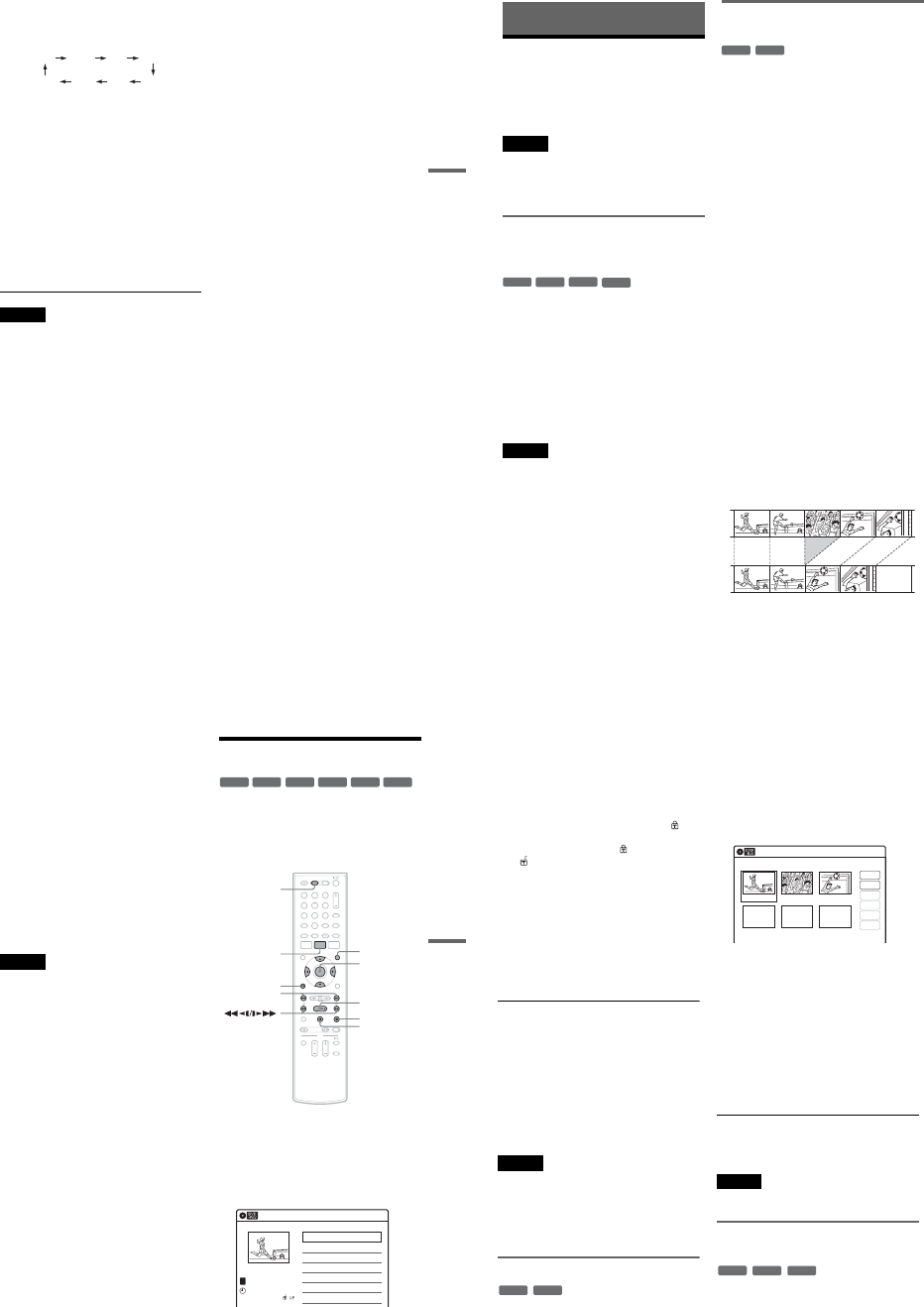
1-13
55
DVD Recording
4Press REC MODE repeatedly to select the
recording mode.
The display changes on the TV screen as
follows:
For details about the recording mode, see
page 46.
5Select the line input audio.
Set “Line Audio Input” of “Audio” setup to
“Stereo” or “Main/Sub” in the “Setup”
display (page 100).
6Insert the source tape into the connected
equipment and set to playback pause.
7Press zREC on this recorder and the
pause or play button on the connected
equipment at the same time.
Recording starts.
To stop recording, press xSTOP on this
recorder.
Notes
•A video game image may not be recorded clearly.
•The recorder does not record programs with Copy-
Never signals. Such recordings stop after a few
seconds.
•During recording or recording pause, you cannot
change the recording mode.
•You cannot change the input source during recording.
HQ SPHSP LSP
SLP LPEP ESP
56
DVD Editing
Before Editing
This recorder offers various edit options for
various disc types. Before you edit, check the disc
type in the front panel display, and select the
option available for your disc (page 30).
Notes
•You may lose the edited contents if you remove the disc
or a timer recording starts while editing.
•You cannot edit recordings on DVD-RWs (Video
mode), DVD+Rs, or DVD-Rs (Video mode) recorded
on other DVD equipment.
Edit options for DVD+RWs/DVD-RWs
(Video mode)/DVD+Rs/DVD-Rs
(Video mode)
You can perform simple edits. Since Video mode
titles are actual recordings on the disc, you cannot
undo any edits you make. The edit functions
available for Video mode titles are:
–Renaming a title (page 60).
–Erasing a title (page 57).
–Setting protection against erasure (DVD+RWs
only) (page 57).
–Erasing a section of a title (A-B Erase)
(DVD+RWs only) (page 58).
–Dividing a title (DVD+RWs only) (page 59).
Notes
•Once the disc is finalized, you cannot edit or record on
the disc (except for DVD+RWs).
•If a message appears and indicates that the disc’s
control information is full, erase unnecessary titles.
Edit options for DVD-RWs (VR mode)/
DVD-Rs (VR mode)
You can enjoy advanced edit functions. First you
have two options for a DVD-RW (VR mode) and
DVD-R (VR mode): editing either the original
recording (called the “original”), or the playback
information created from the original (called a
“Playlist”). Since each is different in nature and
offers different merits, read the following and
select the one that better suits your needs.
To edit original titles
Edits made to the original titles are final. If you
plan to retain an unaltered original recording,
create and edit a Playlist (see below). The edit
functions available for original titles are:
–Renaming a title (page 60).
–Erasing a title (page 57).
–Erasing a chapter (page 58).
–Setting protection against erasure (page 57).
–Erasing a section of a title (A-B Erase) (page 58).
–Dividing a title (page 59).
To create and edit Playlist titles
A Playlist is a group of Playlist titles created from
the original title for editing purposes. When you
create a Playlist, only the control information
necessary for playback, such as the playback
order, is stored on the disc. Since the original titles
are left unaltered, Playlist titles can be re-edited.
If you erase an original title used in a Playlist, that
Playlist is also erased.
Example: You have recorded the final few
matches of a soccer tournament on a DVD-RW
(VR mode). You want to create a digest with the
goal scenes and other highlights, but you also want
to keep the original recording.
-
RWVideo
+RW
+R
-
RVideo
-
RWVR
-
RVR
57
DVD Editing
In this case, you can compile highlight scenes as a
Playlist title. You can even rearrange the scene
order within the Playlist title. See “Editing a
Playlist” on page 63.
The advanced edit functions available for Playlist
titles are:
–Renaming a title (page 60).
–Erasing a title (page 57).
–Erasing a chapter (page 58).
–Erasing a section of a title (A-B Erase) (page 58).
–Editing a Playlist scene (page 63).
–Dividing a title (page 59).
–Combining titles (page 64).
zHint
You can switch the Title List to show original or Playlist.
While the Title List menu is turned on, press ORIGINAL/
PLAYLIST repeatedly.
Notes
•You cannot protect Playlist titles.
•If a message appears and indicates that the disc’s
control information is full, erase unnecessary titles.
•You cannot create or edit Playlist titles on a finalized
disc. When you want to edit or record on the DVD-RW
(VR mode) again, unfinalize the disc (page 88).
Editing a Title
This section explains the basic edit functions. Note
that editing is irreversible. To edit a DVD-RW
(VR mode) or DVD-R (VR mode) without
changing the original recordings, create a Playlist
title (page 61).
1Press DVD to operate the DVD recorder.
2Press TITLE LIST.
When editing a DVD-RW (VR mode) or
DVD-R (VR mode), press ORIGINAL/
PLAYLIST to switch to the “Title List
(Original),” if necessary.
3Select a title, and press ENTER.
The sub-menu appears.
-
RWVR
-
RWVideo
+RW +R
-
RVideo
-
RVR
112233
445566
7788
00
99
M/m/</,,
ENTER
TITLE LIST
HPLAY
xSTOP
XPAUSE
DVD
ORIGINAL/
PLAYLIST
./>
ORETURN
Title List (Original) 10:10 AM
>
>
LINE
1
08:00 PM
May/02/2007
T
No. Title Length Edit
01 LINE 1 01:29:03
02 LINE 1 00:31:23
03 LINE 1 >01:59:00
04 LINE 1 >00:58:56
1/4
,continued 58
4Select an option, and press ENTER.
You can select from the following:
“Title Erase”: Erases the selected title. Select
“OK” when asked for confirmation.
“Chapter Erase”*1: Allows you to select a
chapter in the title and erase it (see below).
“Protect”*2: Protects the title. Select “On”
when the Protection display appears. “ ”
appears for the protected title. To cancel the
protection, select “Off.” “ ” changes to
“.”
“Title Name”: Allows you to rename the title
(page 60).
“A-B Erase”*2: Erases a section of the title
(see below).
“Divide Title”*2: Divides a title into two
(page 59).
*1 DVD-RWs (VR mode) and DVD-Rs (VR mode)
only
*2 DVD+RWs, DVD-RWs (VR mode), and DVD-R
(VR mode) only
About freeing up disc space
Erasing titles, chapters, or scenes:
–frees up disc space on a DVD-RW (VR mode).
–frees up disc space on a DVD+RW/DVD-RW
(Video mode) only when you erase the last title
or chapter.
–cannot free up disc space on a DVD+R/DVD+R
DL/DVD-R.
zHint
You can also rename a disc (page 67).
Notes
•When editing a DVD-RW (Video mode), DVD+R, or
DVD-R, finish all editing before finalizing the disc.
You cannot edit a finalized disc.
•You cannot erase protected titles or erase chapters from
a protected title.
•If you erase an original title used in a Playlist, that
Playlist is also erased.
Erasing a chapter (Chapter Erase)
You can select a chapter within a title and erase it.
Note that erasing chapters from original titles
cannot be undone.
1Press TITLE LIST.
Press ORIGINAL/PLAYLIST to switch to the
“Title List (Original),” if necessary.
2Select a title, and press ENTER.
The sub-menu appears.
3Select “Chapter Erase,” and press ENTER.
The display for erasing chapters appears.
4Select the chapter you want to erase, and
press ENTER.
“Check” is selected. To preview the chapter,
press ENTER. When playback finishes or
when you press O RETURN, the display
returns to “Chapter Erase (Original).”
5Select “Erase,” and press ENTER.
The display asks for confirmation.
6Select “OK,” and press ENTER.
The selected chapter is erased from the title.
To erase other chapters, repeat from step 4.
zHint
You can also erase chapters from a Playlist title
(page 63).
Note
If you erase an original title used in a Playlist, that Playlist
is also erased.
Erasing a section of a title
(A-B Erase)
You can select a section (scene) within a title and
erase it. Note that erasing scenes from original
titles cannot be undone.
-
RWVR
-
RVR
Chapter Erase (Original) 10:10 AM
Chapter No. 1 / 3 Title No.01
03 00:04:2002 00:00:1001 00:00:34
Check
Erase
Modify
Move
Add
Copy
-
RWVR
-
RVR
+RW
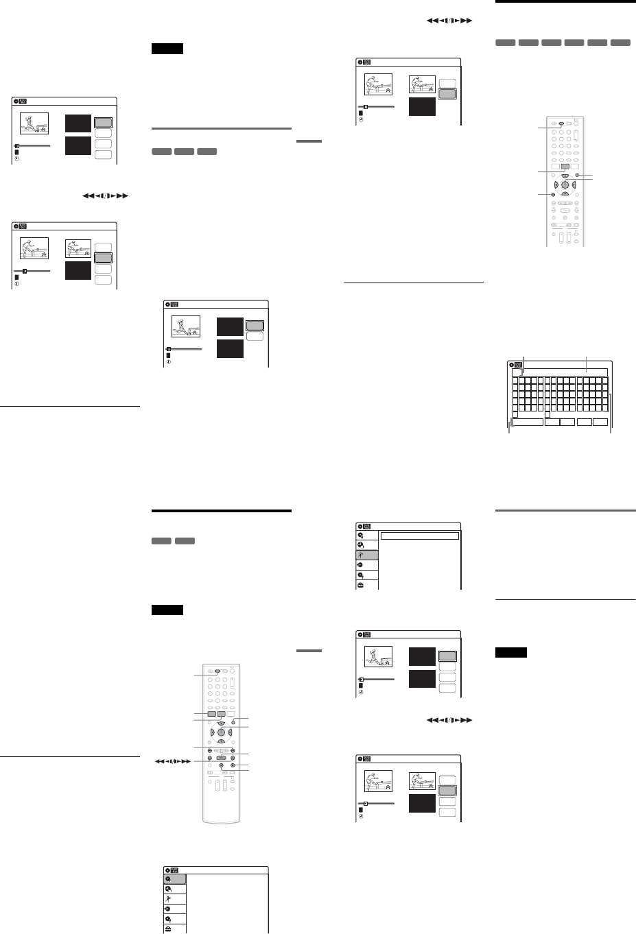
1-14
59
DVD Editing
1Press TITLE LIST.
When editing a DVD-RW (VR mode) or
DVD-R (VR mode), press ORIGINAL/
PLAYLIST to switch to the “Title List
(Original),” if necessary.
2Select a title, and press ENTER.
The sub-menu appears.
3Select “A-B Erase,” and press ENTER.
The display for setting point A and B appears.
“Start” is selected.
4Press ENTER at the start point of the
section to be erased (point A).
You can use HPLAY, ,
./>,xSTOP, and XPAUSE to find
the point. “End” is selected.
5Press ENTER at the end point of the section
(point B).
“Erase” is selected.
To reset the start or end point, select “Start” or
“End” and repeat from step 4 or 5.
6Press ENTER.
The display asks for confirmation.
7Select “OK,” and press ENTER.
The scene is erased.
To continue, repeat from step 4.
To finish, select “Finish,” and press ENTER.
zHints
•A chapter mark is inserted after the scene was erased.
The chapter mark divides the title into separate chapters
on either side of the mark.
•You can also erase a section of a Playlist title (page 63).
Notes
•Images or sound may be momentarily interrupted at the
point where you erase a section of a title.
•Sections shorter than five seconds may not be erased.
•The start and end points of a title may be different from
what you have set.
•The total playing time of the title does not change even
if a scene was erased.
•If you erase an original title used in a Playlist, that
Playlist is also erased.
Dividing a title into two (Divide Title)
You can divide a title into two. Note that dividing
original titles cannot be undone.
1Press TITLE LIST.
When editing a DVD-RW (VR mode) or
DVD-R (VR mode), press ORIGINAL/
PLAYLIST to switch to the “Title List
(Original),” if necessary.
2Select a title, and press ENTER.
The sub-menu appears.
3Select “Divide Title,” and press ENTER.
The display for setting the dividing point
appears.
“Point” is selected.
A-B Erase 10:10 AM
Title No.01
End 00:00:00
Start 00:00:00
Start
End
Erase
Finish
00:00:07
T
Title No.01
May/02/2007 08:00 PM
A-B Erase 10:10 AM
Title No.01
End 00:00:00
Start 00:00:10
Start
End
Erase
Finish
00:00:10
T
Title No.01
May/02/2007 08:00 PM
-
RWVR
+RW
-
RVR
Divide Title (Original) 10:10 AM
Title No.01
T
Point
Divide
00:00:07
Title No. 01
Start 00:00:00
End 00:00:00
May/02/2007 08:00 PM
,continued 60
4Press ENTER at the point where you want to
divide the title.
You can use HPLAY, ,
./>,xSTOP, and XPAUSE to find
the point.
“Divide” is selected.
5Press ENTER.
The display asks for confirmation.
To reset the dividing point, select “No” and
press ENTER, then repeat from step 4.
6Select “Yes,” and press ENTER.
The display asks whether to rename the title.
To use the same name as before, select “No”
and press ENTER to finish.
7Select “Yes,” and press ENTER.
The “Title Name” display appears.
8Follow steps 5 to 7 of “Changing the Name
of a Title” (page 60) to complete
renaming.
The divided title appears in the Title List with
the new name.
zHints
•You can also divide a Playlist title (page 63).
•If the dividing point is set too close to the beginning of
the title, the title cannot be divided.
Changing the Name of a
Title
You can enter a title name of up to 32 characters.
Since the displayed number of characters is
limited, their appearance in menus such as Title
List may be different. When the display for
entering characters appears, follow the steps
below.
1Press DVD to operate the DVD recorder.
2Press TITLE LIST.
When editing a DVD-RW (VR mode) or
DVD-R (VR mode), press ORIGINAL/
PLAYLIST to switch to the “Title List
(Original),” if necessary.
3Select a title, and press ENTER.
The sub-menu appears.
4Select “Title Name,” and press ENTER.
The “Title Name” display appears.
10:10 AM
Title No.01
T
00:00:10
Divide Title (Original)
Title No. 01 End 00:00:10
Start 00:00:00
Point
Divide
May/02/2007 08:00 PM
+R
-
RWVR
-
RWVideo
+RW
-
RVR
-
RVideo
112233
445566
7788
00
99
M/m/</,,
ENTER
ORETURN
TITLE LIST
DVD
ORIGINAL/
PLAYLIST
Title Name
K_
A B C D E
F G H I J
K L M N O
P Q R S T
U V W X Y
Z
a b c d e
f g h i j
k l m n o
p q r s t
u v w x y
z
12345
67890
- _ + = .
~!@ # $
%^& ( )
Backspace Space Delete Clear Finish
10:10 AM
Input row
Character paletteSetting buttons
Cursor
61
DVD Editing
5Select the character you want to enter
using M/m/</,, and press ENTER.
The selected character appears in the input
row.
You can only enter characters and symbols
that are displayed.
•To change the cursor position, select the
input row using M, and press </,.
•To erase a character, select either of the
following setting buttons and press ENTER.
“Backspace”: Erases the character to the left
of the cursor.
“Delete”: Erases the character at the cursor
position.
“Clear”: Erases all the characters in the input
row.
•To insert a space, move the cursor to the
desired position, select “Space,” and press
ENTER.
•To insert a character, move the cursor to the
desired position, select the character, and
press ENTER.
6Repeat step 5 to enter the remaining
characters.
To return to the Title List without renaming
the title, press ORETURN.
7Select “Finish,” and press ENTER.
zHint
You can also rename a disc (page 67). Follow steps 5 to
7 above when the “Disc Name” display appears.
Creating a Playlist
Playlist titles allow you to edit without changing
the original recordings (see “Edit options for
DVD-RWs (VR mode)/DVD-Rs (VR mode)” on
page 56). You can create a Playlist title by
combining up to 99 sections (scenes) from original
titles.
Notes
•If you erase an original title used in a Playlist, that
Playlist is also erased.
•You cannot create or edit Playlist titles on a finalized
disc. When you want to edit or record on the DVD-RW
(VR mode) again, unfinalize the disc (page 88).
1Press DVD to operate the DVD recorder.
2Press SYSTEM MENU while the recorder is
in stop mode.
-
RWVR
-
RVR
112233
445566
7788
00
99
M/m/</,,
ENTER
SYSTEM
MENU
HPLAY
TITLE LIST
xSTOP
XPAUSE
DVD
ORIGINAL/
PLAYLIST
./>
Press ENTER :
Title Menu for DVD Title List.
10:10 AM
Title List (Original)
Setup
Disc Setting
Edit
Title List
Timer
Dubbing
,continued 62
3Select “Edit,” and press ENTER.
4Select “Create Playlist,” and press ENTER.
The display for creating a Playlist appears.
“Start” is selected.
5Press ENTER at the start point.
You can use HPLAY, ,
./>,xSTOP, and XPAUSE to find
the point.
“End” is selected.
6Press ENTER at the end point.
“Make” is selected.
To reset the start or end point, select “Start” or
“End” and repeat step 5 or 6.
7Press ENTER.
The selected section is captured as a scene. To
continue, repeat from step 5.
8When you finish capturing scenes, select
“Finish” and press ENTER.
Playing a Playlist title
1Press TITLE LIST.
2Press ORIGINAL/PLAYLIST to switch to the
“Playlist” Title List.
3Select a Playlist title, and press ENTER.
The sub-menu appears.
4Select “Play,” and press ENTER.
zHint
When a Playlist title is created, the start and end points
will become chapter marks, and each scene will become
a chapter.
Notes
•The picture may pause when an edited scene is played.
•The start and end points in a title may be different from
what you have set.
10:10 AM
Create Playlist
Edit Playlist
Edit
Setup
Disc Setting
Edit
Title List
Timer
Dubbing
Create Playlist 10:10 AM
Scene No.01
End 00:00:00
Start 00:00:00
T
Start
End
Make
Finish
00:00:07
---/--/---- --:--
Playlist No. 01
10:10 AM
Scene No.01
T
Finish
00:00:10
Create Playlist
Playlist No. 01 End 00:00:00
Start 00:00:10
Start
End
Make
---/--/---- --:--
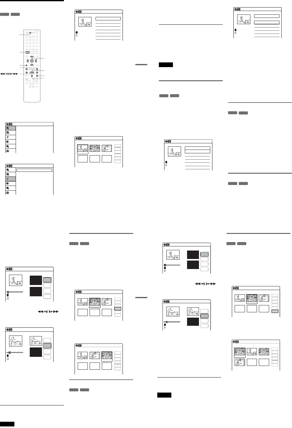
1-15
63
DVD Editing
Editing a Playlist
You can edit Playlist titles or scenes within them,
without changing the actual recordings.
1Press DVD to operate the DVD recorder.
2Press SYSTEM MENU while the recorder is
in stop mode.
3Select “Edit,” and press ENTER.
4Select “Edit Playlist,” and press ENTER.
The “Playlist” Title List appears.
5Select a Playlist title, and press ENTER.
The sub-menu appears.
6Select an option, and press ENTER.
Select from the following options. For details,
see the pages in parentheses.
“Title Erase”: Erases the title. Select “OK”
when asked for confirmation.
“Chapter Erase”: Allows you to select
chapters in the Playlist title to erase (page 58).
“Title Name”: Allows you to rename the title
(page 60).
“A-B Erase”: Allows you to select sections in
the title to erase (page 58).
“Edit Scene”: Allows you to re-edit scenes in
the Playlist title. Go to step 7.
“Divide Title”: Divides the title in two at a
desired point (page 59).
“Combine Titles”: Allows you to combine
two titles into one (page 64).
7Select “Edit Scene,” and press ENTER.
The display for editing scenes appears.
“Check”: Allows you to preview a scene.
Starts playback of the selected scene when
you press ENTER. The display returns to the
“Edit Scene” display when the playback
finishes or when you press O RETURN.
“Erase”: Erases a scene (page 64).
“Modify”: Allows you to change the start and
end point of a scene (page 64).
-
RWVR
-
RVR
112233
445566
7788
00
99
SYSTEM
MENU
DVD
M/m/</,,
ENTER
HPLAY
xSTOP
XPAUSE
ORETURN
./>
Press ENTER :
Title Menu for DVD Title List.
10:10 AM
Title List (Original)
Setup
Disc Setting
Edit
Title List
Timer
Dubbing
10:10 AM
Create Playlist
Edit Playlist
Edit
Setup
Disc Setting
Edit
Title List
Timer
Dubbing
Playlist 10:10 AM
01 LINE 1 >00:05:04
02 LINE 1 >00:00:51
03:25 PM
May/02/2007
T
No. Title Length Edit1/2
LINE
1
Edit Scene 10:10 AM
Scene No.01 / 03 Playlist No.01
03 00:04:2002 00:00:1001 00:00:34
Check
Erase
Modify
Move
Add
Copy
,continued 64
“Move”: Allows you to change scene order
(page 65).
“Add”: Allows you to add other scenes before
a selected scene (page 65).
“Copy”: Allows you to copy a scene
(page 66).
To return to the previous display
Press O RETURN.
To turn off the display
Press SYSTEM MENU.
zHint
The Resume Play function will work for scene playback.
Note
You cannot create or edit Playlist titles on a finalized
disc. When you want to edit or record on the DVD-RW
(VR mode) again, unfinalize the disc (page 88).
Combining two titles into one
(Combine Titles)
You can select a Playlist title and combine it with
another Playlist title.
1Follow steps 1 to 5 of “Editing a Playlist”
(page 63) to select a Playlist title.
The sub-menu appears.
2Select “Combine Titles,” and press
ENTER.
The next title below is also selected.
3Select a Playlist title to be combined.
4Press ENTER.
The display asks for confirmation.
5Select “Yes,” and press ENTER.
The display asks whether to rename the title.
To use the same name as before, select “No”
and press ENTER to finish.
6Select “Yes,” and press ENTER.
The “Title Name” display appears.
7Follow steps 5 to 7 of “Changing the Name
of a Title” (page 60) to complete
renaming.
The two Playlist titles become one Playlist
title with the new name.
Erasing a scene (Erase)
You can erase a selected scene.
1Follow steps 1 to 7 of “Editing a Playlist”
(page 63).
The “Edit Scene” display appears.
2Select the scene you want to erase, and
press ENTER.
3Select “Erase,” and press ENTER.
The display asks for confirmation.
4Select “OK,” and press ENTER.
The selected scene is erased.
To erase other scenes, repeat from step 2.
Modifying a scene (Modify)
You can change the start and end point of the
selected scene.
-
RWVR
-
RVR
Playlist 10:10 AM
>
>
LINE
1
03:25 PM
May/02/2007
T
No. Title Length Edit
01 LINE 1 00:05:04
02 LINE 1 00:00:51
03 LINE 1 >01:59:00
04 LINE 1 >00:58:56
1/4
Playlist 10:10 AM
>
>
11:30 PM
May/15/2007
T
No. Title Length Edit
01 LINE 1 00:05:04
02 LINE 1 00:00:51
03 LINE 1 >01:59:00
04 LINE 1 >00:58:56
3/4
LINE
1
-
RWVR
-
RVR
-
RWVR
-
RVR
65
DVD Editing
1Follow steps 1 to 7 of “Editing a Playlist”
(page 63).
The “Edit Scene” display appears.
2Select the scene you want to modify, and
press ENTER.
3Select “Modify,” and press ENTER.
“Start” is selected.
4Press ENTER at the start point.
You can use HPLAY, ,
./>,xSTOP, and XPAUSE to find
the point.
“End” is selected.
5Press ENTER at the end point.
“Change” is selected.
To reset the start or end point, select “Start” or
“End” and repeat step 4 or 5.
6Press ENTER.
The display returns to the “Edit Scene”
display.
The re-selected section is captured as a scene.
To modify other scenes, repeat from step 2.
To cancel modifying
Select “Cancel,” and press ENTER.
Note
The start and end point of a scene may be different from
what you have set.
Moving a scene (Move)
You can change the scene order within the Playlist
title.
1Follow steps 1 to 7 of “Editing a Playlist”
(page 63).
The “Edit Scene” display appears.
2Select the scene you want to move, and
press ENTER.
3Select “Move,” and press ENTER.
4Select a new location using </,, and
press ENTER.
The selected scene moves to the new location.
To move other scenes, repeat from step 2.
Adding a scene (Add)
You can add a scene before the selected scene.
1Follow steps 1 to 7 of “Editing a Playlist”
(page 63).
The “Edit Scene” display appears.
2Select the location where you want to add,
and press ENTER.
A new scene will be added before the selected
scene.
Modify 10:10 AM
T
Change
Cancel
00:00:07
Playlist No. 01
Scene No.01
End 00:00:00
Start 00:00:00
Start
End
May/02/2007 03:25 PM
Modify 10:10 AM
Scene No.01
T
00:00:10
May/02/2007 03:25 PM
Playlist No. 01
Change
Cancel
End 00:00:00
Start 00:00:10
Start
End
-
RWVR
-
RVR
Edit Scene 10:10 AM
Scene No.02 / 03
03 00:04:2002 00:00:1001 00:00:34
Playlist No.01
Check
Erase
Modify
Move
Add
Copy
Edit Scene 10:10 AM
Scene No.03 / 03
02 00:04:20 03 00:00:1001 00:00:34
Playlist No.01
Check
Erase
Modify
Move
Add
Copy
-
RWVR
-
RVR
,continued 66
3Select “Add,” and press ENTER.
“Start” is selected.
4Press ENTER at the start point.
You can use HPLAY, ,
./>,xSTOP, and XPAUSE to find
the point.
“End” is selected.
5Press ENTER at the end point.
“Add” is selected.
To reset the start or end point, select “Start” or
“End” and repeat step 4 or 5.
6Press ENTER.
The display returns to the “Edit Scene”
display.
The selected section is added before the scene
selected in step 2.
To add other scenes, repeat from step 2.
To cancel adding
Select “Cancel,” and press ENTER.
Note
The start and end point of a scene may be different from
what you have set.
Copying a scene (Copy)
You can copy and add a selected scene.
1Follow steps 1 to 7 of “Editing a Playlist”
(page 63).
The “Edit Scene” display appears.
2Select the scene you want to copy, and
press ENTER.
3Select “Copy,” and press ENTER.
4Select a location to copy to using </,
and press ENTER.
The scene is copied to the selected location.
To copy other scenes, repeat from step 2.
Add 10:10 AM
T
00:00:07
Playlist No. 01
Scene No.01
Add
Cancel
End 00:00:00
Start 00:00:00
Start
End
May/02/2007 03:25 PM
Add 10:10 AM
Scene No.01
T
00:00:10
Playlist No. 01
Add
Cancel
End 00:00:00
Start 00:00:10
Start
End
May/02/2007 03:25 PM
-
RWVR
-
RVR
Edit Scene 10:10 AM
Scene No.02 / 03
03 00:04:2002 00:00:1001 00:00:34
Check
Erase
Modify
Move
Add
Copy
Playlist No.01
Edit Scene 10:10 AM
Scene No.01 / 04
04 00:04:20
03 00:00:1002 00:00:3401 00:00:10
Playlist No.01
Check
Erase
Modify
Move
Add
Copy
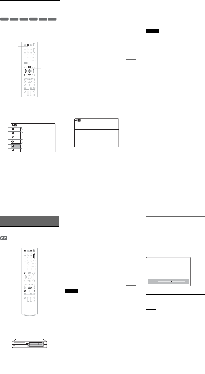
1-16
67
DVD Editing
Formatting/Renaming/
Protecting a Disc
The “Disc Setting” display allows you to check the
disc information or change the disc name.
Depending on the disc type, you can also format or
set protection.
1Press DVD to operate the DVD recorder.
2Press SYSTEM MENU while the recorder is
in stop mode.
3Select “Disc Setting,” and press ENTER.
The “Disc Setting” display appears.
4Select an option, and press ENTER.
A“Disc Name”: Allows you to rename a
disc.
For details on how to enter characters,
see page 60.
B“Disc Protect” (DVD+RWs/DVD-RWs
(VR mode)/DVD-Rs (VR mode) only):
Protects all titles on the disc when
“Protected” is selected. To cancel the
protection, select “Not Protected.”
C“Disc Format” (DVD+RWs/DVD-
RWs/DVD-Rs only): Erases all
contents of the disc, including protected
titles, and makes a blank disc (except
DVD-Rs).
For DVD-RWs, select a recording
format (“VR Mode” or “Video Mode”)
according to your needs.
To format unused DVD-Rs in VR
mode, select “VR Mode” and then
“OK.”
D“Disc Finalize”: Finalizes a disc. See
page 88 for details.
E“Disc Information”: Displays the
following information.
•Disc name
•Disc type (and recording format for a
DVD-RW (VR mode)/DVD-R (VR
mode))
•Total number of titles
•Protect setting
•The oldest and most recent recording
date
•The total available recording time in
each recording mode
F“Erase All Titles” (DVD+RWs/DVD-
RWs/DVD-Rs (VR mode) only):
Erases all titles on the disc (except
protected titles). Select “OK” when
asked for confirmation.
For DVD-RWs (VR mode)/DVD-Rs
(VR mode), Playlist titles created with
protected titles are also erased.
+RW
-
RWVR
-
RWVideo
+R
-
RVR
-
RVideo
112233
445566
7788
00
99
SYSTEM
MENU
DVD
M/m/</,,
ENTER
ORETURN
Disc Setting 10:10 AM
Disc Name :
Disc Protect : Not Protected
Disc Format : VR Mode
Disc Finalize : Unfinalized
Disc Information
Erase All Titles
Setup
Disc Setting
Edit
Title List
Timer
Dubbing
2
3
4
5
1
6
10:10 AM
Disc Information
Disc Name
Media
Title No.
Protected
Date
Remainder
Disc 1
DVD-RW VR ModeFormat
Original 6 / Playlist 1
Not Protected
4/05/2007 ~ 4/30/2007
HQ : 0H 57M
LSP : 2H 23M
EP : 5H 46M
HSP : 1H 26M
ESP : 2H 52M
SLP : 7H 40M
SP : 1H 55M
LP : 3H 50M
4.4/4.7GB
,continued 68
To return to the previous display
Press ORETURN.
zHints
•You can set protection for individual titles (page 57).
•By reformatting, you can change the recording format
on DVD-RWs, or record again on DVD-RWs (Video
mode) that have been finalized.
Notes
•You can label a disc using up to 32 characters;
however, the name may not display on other DVD
equipment.
•You cannot label an unused DVD-R (Video mode)
disc. Label the disc after you first record on it.
•You cannot mix VR mode and Video mode on the same
DVD-RW or DVD-R.
•You cannot change the recording format on used DVD-
Rs.
•The recorder records on new DVD-Rs in Video mode
unless you first format the discs in VR mode (page 47).
69
VCR Playback
VCR Playback
Playing a VHS Tape
1Press VIDEO to operate the VCR.
2Insert a tape.
Playback starts automatically if you insert a
tape with its safety tab removed.
3Press HPLAY.
The front panel display shows the playing
time.
When the tape reaches the end, it will rewind
automatically.
To stop playback
Press xSTOP.
To eject the tape
Press ZOPEN/CLOSE.
To turn off the power while rewinding (Rewind
Shut Off)
Press "/1 while the tape is rewinding. The power
will turn off but the tape will keep rewinding until
it reaches the end.
To use the time counter
Press CLEAR at the point where you want to find
later. The counter in the front panel display resets
to “0:00:00.”
To search for the 0:00:00 point automatically, see
page 72.
To display the counter on the TV screen, press
DISPLAY.
Notes
•During playback, the VCR automatically detects the
recording system (S-VHS/VHS) and the recording
mode (SP or EP) from the tape. LP mode recordings
made on other equipment will play, but picture quality
is not guaranteed.
•The counter resets to “0:00:00” whenever a tape is
reinserted.
•The counter stops counting when it comes to a portion
with no recording.
•The counter resets to “0:00:00” after ten hours, and
starts recounting.
•When playback does not start even if you insert a tape
with its safety tab removed, set “VCR Function” –
“Auto Play” of “Features” to “On” in the “Setup”
display (page 101).
•If you switch to the VCR while playing a disc, DVD
playback stops.
•The VCR does not record in S-VHS format, but will
play S-VHS tapes by automatically detecting the
format, but picture quality will be lower than usual S-
VHS. Image may be unclear if playback options such
as slow-motion, etc., are used.
•Playback of S-VHS tapes recorded in EP (3x) mode is
not guaranteed.
•The VCR is not compatible with the PAL or SECAM
color system. Only NTSC tapes can be played.
•For simultaneous VHS and DVD operation, see page 9.
112233
445566
7788
00
99
xSTOP
"/1
DISPLAY
CLEAR
HPLAY
ZOPEN/
CLOSE VIDEO
TRACKING +/–
,continued 70
Adjusting the picture (tracking)
You can manually adjust tracking if the recording
quality is too poor to be remedied by the VCR’s
automatic tracking (a tracking meter appears
during the automatic tracking).
Press TRACKING +/–.
The tracking meter appears.
Press TRACKING +/– repeatedly until the
distortion disappears.
To resume automatic tracking
Press TRACKING + and TRACKING – on the
recorder at the same time for more than ten
seconds. Or, eject the tape and reinsert it.
Tracking
Tracking meter
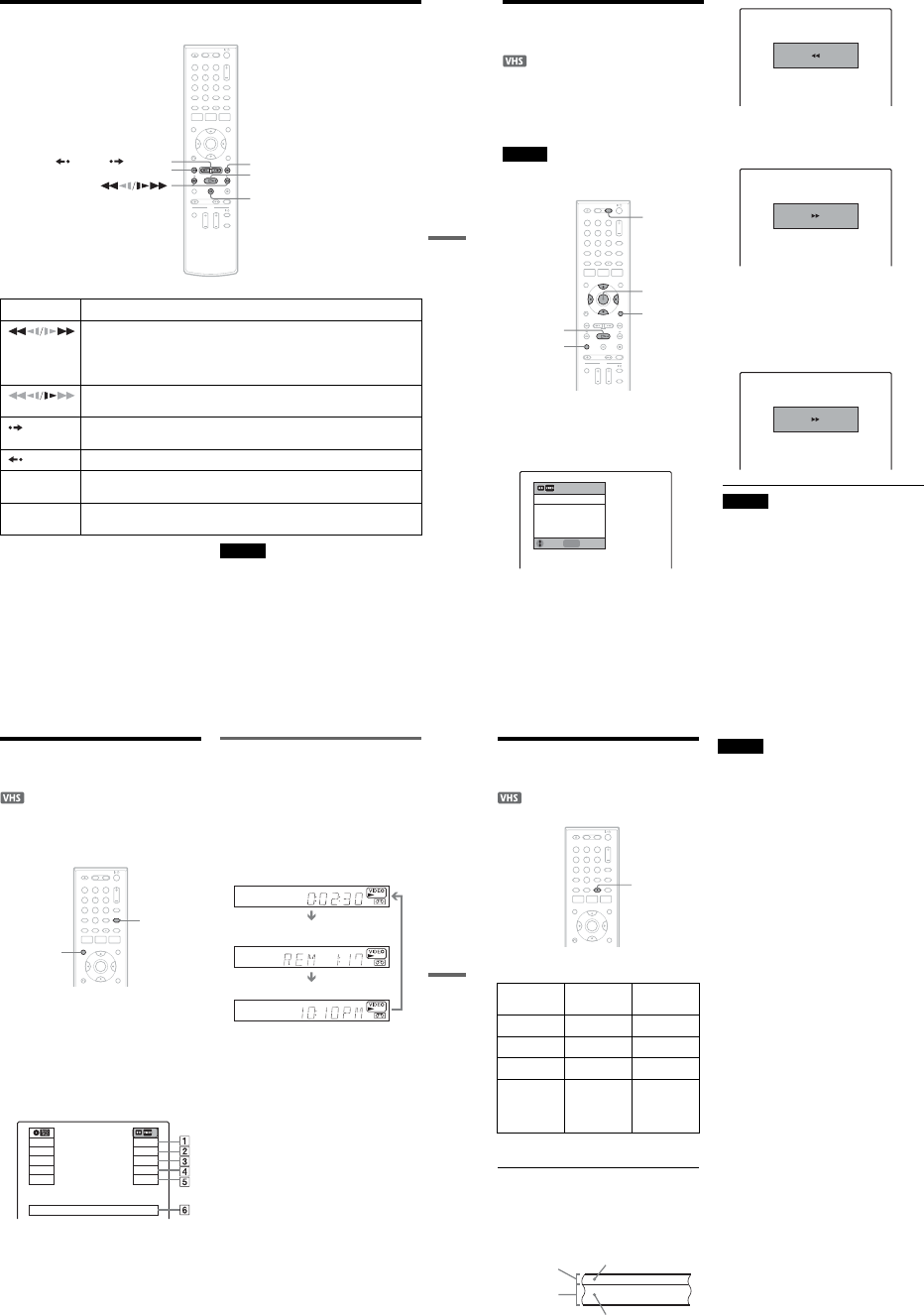
1-17
71
VCR Playback
Playback Options
*1 Can be pressed up to four times to forward about
two minutes.
*2 For 10 seconds in SP or LP mode/for 15 seconds in EP
mode.
To resume normal playback, press HPLAY.
Notes
•The sound is muted during playback at various speeds.
•The picture may show noise during high-speed reverse
play.
Button Operation
(fast reverse/fast
forward)
•Fast reverses or fast forwards when pressed during stop mode.
When you hold down during fast reverse or fast forward, you can view the picture.
•Plays at high speed when briefly pressed during playback.
When you hold down the button during playback, the high-speed play continues until
you release the button.
(slow) Plays in slow motion when pressed in pause mode.
ADVANCE • Advances one frame for each press in pause mode.
•Fast forwards the current scene for 30 seconds when pressed during playback.*1
REPLAY Replays the previous scene when pressed during playback.*2
.PREV/
NEXT >Press during playback. Playback speed changes with each press:
–×7
y
–×5
y
–×3
y
PAUSE
y
SLOW
yPLAY y
×2
y
×3
y
×5
y
×7
XPAUSE Pauses playback.
If you pause playback for more than five minutes, playback starts automatically.
112233
445566
7788
00
99
XPAUSE
>NEXT
REPLAY/ ADVANCE
.PREV HPLAY
72
Searching Using Various
Functions
The VCR automatically marks the tape with an
index signal at the point where each recording
begins.
You can easily find a specific point using various
search functions.
Note
During DVD recording, you cannot use VCR search
functions.
1Press VIDEO to operate the VCR.
2Press OPTIONS.
3Select a search method from the OPTIONS
menu, and press ENTER.
“Go To Zero”: Searches for the 0:00:00 point
on the tape counter.
To reset the counter to 0:00:00, press CLEAR.
“End Search”: Searches for the beginning of a
blank space. If no blank space is found, the
tape will reach the end.
“Forward Intro Scan”/“Reverse Intro Scan”:
Searches for an index mark and plays back for
about five seconds at that point.
Press H PLAY to view that program. If you
do not press H PLAY, the VCR
automatically searches for the next index
mark, or until it reaches the end of the tape.
Notes
•The VCR may not recognize the end of a blank space
depending on its length.
•No index signal is marked if you pause a recording and
then keep recording the same program. To mark an
index, press x STOP or change the input source once
during recording pause.
112233
445566
7788
00
99
M/m/</,,
ENTER
HPLAY
VIDEO
OPTIONS
CLEAR
ENTER Enter
Go To Zero
End Search
Forward Intro Scan
Reverse Intro Scan
Move
0:00:00
Go to Zero
0:00:13
End search
–0:00:01
Scan and play
73
VCR Playback
Displaying the Playing Time
and Play Information
You can check playback information, such as
elapsed or remaining time, recording mode, etc.,
on the TV screen.
Press DISPLAY during playback.
The information display appears.
Each time you press the button, the display
changes as follows:
Tape and disc information/date and time
m
Tape information only
m
No display
APlaying status
BTime counter (elapsed time)
CRecording mode
DRemaining tape length
EInput source
FDate and time
Viewing information on the front
panel display
You can view the information on the front panel
display.
Press TIME/TEXT repeatedly.
The displays differ depending on the status.
Example: When playing a tape
Example: When a tape is in stop mode
Clock
m
Elapsed time
m
Remaining tape length
m
Input source
112233
445566
7788
00
99
DISPLAY
TIME/TEXT
Play
0:30:00
SP
Rem 01:30
Line1
Wed May 02. 2007 10:10 AM
Stop
0:05:30
HQ
Rem 00:25
Line1
Elapsed time
Remaining tape length
Clock
74
Selecting the Sound During
Playback
Press AUDIO repeatedly during playback.
*No indicator appears in the front panel display when
you play a tape without Hi-fi recording.
How sound is recorded on a video tape
The VCR records sound onto two separate tracks.
Hi-fi audio is recorded onto the main track along
with the picture. Monaural sound is recorded onto
the normal audio track along the edge of the tape.
Notes
•To play a tape in stereo, you must use the A/V
connections.
•When you play a tape recorded in monaural, the sound
is heard in monaural regardless of the AUDIO setting.
To listen to On-screen
display Front panel
display
Stereo Hi-Fi STEREO
Left channel Left STEREO
Right channel Right STEREO
Monaural
sound on the
normal audio
track
Mono STEREO*
112233
445566
7788
00
99
AUDIO
Normal audio track
Hi-fi audio track
(main track)
Monaural sound
Stereo sound
(left/right channels)
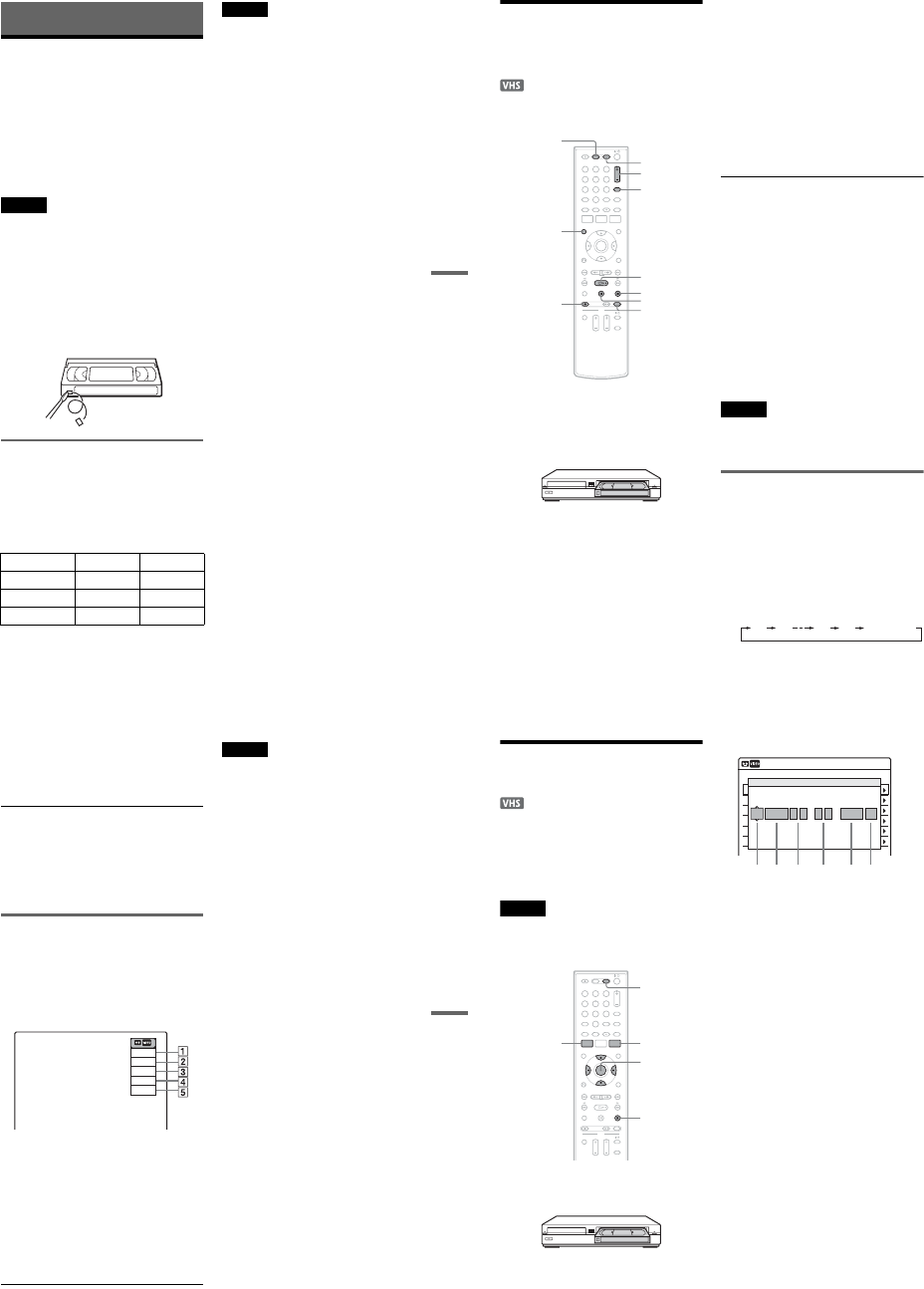
1-18
75
VCR Recording
VCR Recording
Before Recording
Before you start recording…
•This VCR records in VHS format, not S-VHS
format.
•Check that the tape is longer than the recording
time (page 73).
•Check that the recorder is connected to a tuner
such as a cable box or satellite receiver
(page 12). See also the tuner’s instruction
manual.
Notes
•Timer recordings will start with or without the recorder
turned on. Once started, the recorder cannot be turned
off. The recorder automatically turns off after a
recording has finished.
•This recorder has the copy guard function. Programs
that contain a Copy-Never copy guard signal cannot be
correctly recorded on the VCR.
To save a recording
To prevent accidental erasure, break off the safety
tab as illustrated. To record on the tape again,
cover the tab hole with adhesive tape.
Recording mode
“EP” (Extended Play) and “SP” (Standard Play) is
available for recording mode (tape speed). “EP”
provides recording time three times as long as
“SP.” However, “SP” produces better picture and
audio quality.
Maximum recording time
Notes
•Tapes recorded in EP (×3) mode by this VCR cannot be
played back on VHS video decks with SP mode only.
•Noise may appear in the image when tapes recorded in
EP (×3) mode by this VCR are played back on other
VHS video decks with EP mode.
Tape Length SP EP
T-120 2 hrs 6 hrs
T-160 2 hrs 40 mins 8 hrs
T-180 3 hrs 9 hrs
Safety tab
76
VCR Recording From
Connected Equipment
Without the Timer
You can record TV programs on the recorder
through the connected cable box/satellite receiver.
1Turn on the recorder and the connected
cable box/satellite receiver.
2Press VIDEO to operate the VCR.
3Insert a tape with its safety tab in place.
4Press CH +/– or INPUT repeatedly to select
the channel or input source you want to
record.
•When using the cable box/satellite receiver
control, select the channel by pressing
CH +/– on this recorder’s remote. The
recorder’s input is switched to the connected
input (LINE1 or LINE2). You can also use
the number buttons.
•When not using the cable box/satellite
receiver control, select the connected input
(LINE1 or LINE2) by pressing INPUT, and
then select the channel on the cable box/
satellite receiver’s side.
5Press REC MODE repeatedly to select the
recording mode, “SP” or “EP.”
For details about the recording mode, see
page 75.
6Press zREC.
“REC” appears in the front panel display, and
recording starts.
Leave the cable box/satellite receiver turned
on and do not change the channel you are
recording.
To stop recording
Press xSTOP.
To pause recording
Press XPAUSE.
To restart recording, press XPAUSE again.
If you pause recording for more than five minutes,
recording stops automatically.
To watch a DVD while recording
Press DVD to operate the DVD recorder, insert a
disc, and press HPLAY.
zHints
•Tape information displayed on the TV screen will not
be recorded on the tape.
•You can turn off the TV during recording.
Notes
•You cannot change the recording mode or input source
while recording.
•If you insert a tape with its safety tab removed, the tape
is ejected when you press zREC.
Recording using the Quick Timer
(One-touch Timer Recording)
You can set the recorder to record in 30-minute
increments.
1Press VIDEO to operate the VCR.
2Press zREC repeatedly to set the
duration.
Each press increases the time by 30 minutes,
up to six hours.
112233
445566
7788
00
99
REC MODE
HPLAY
XPAUSE
xSTOP
zREC
VIDEO
CH +/–
DVD
INPUT
DISPLAY
0:30 1:00 5:30 6:00
(Normal
recording)
77
VCR Recording
“c” and “OTR” light up, and the remaining
recording time appears in the front panel
display.
When the time counter reaches “0:00,” the
recorder stops recording and turns off.
To cancel the Quick Timer
Press zREC repeatedly until the counter appears
in the front panel display. The recorder returns to
normal recording mode.
To stop recording
Press xSTOP twice.
Checking the remaining tape length
You can check recording information, such as
remaining tape length or recording mode, etc.
Press DISPLAY while recording.
The information display appears.
Press the button repeatedly to change the display
(page 73).
ARecording status
BTime counter
CRecording mode
DRemaining tape length
EInput source
To check the remaining tape length, set “VCR
Function” – “Tape Length” of “Features” in the
“Setup” display correctly (page 101).
zHint
You can view the information also in the front panel
display. Press TIME/TEXT repeatedly to change the
display. Note that TIME/TEXT does not work during
One-touch Timer Recording.
Notes
•The remaining tape length may not be indicated
accurately for short tapes such as T-20 or T-30, or tapes
recorded in LP mode.
•After DISPLAY is pressed, it may take one minute for
the remaining tape length to appear.
Record
0:30:00
SP
Rem 01:30
Line1
78
VCR Timer Recording From
Connected Equipment
You can set the timer for a total of 12 programs
together with DVD and VCR timer recording, up
to one month in advance.
If you record from connected equipment that has a
timer function, you can use the Synchro Rec
function (page 80).
Note
Do not operate your cable box or satellite receiver just
before or during a timer recording. This may prevent the
accurate recording of a program.
1Press VIDEO to operate the VCR.
2Insert a tape with its safety tab in place.
3Press TIMER.
4Select an item using </, and adjust
using M/m.
A“Media”: Select “VCR.”
B“Date”: Sets the date using M.
To record the same program every day or
the same day every week, press m.
The item changes as follows:
Today y Sun-Sat (Sunday to Saturday)
y Mon-Sat (Monday to Saturday) y
Mon-Fri (Monday to Friday) y Sun
(every Sunday) y Mon (every Monday)
y … y Sat (every Saturday) y
1month later y … y Today
C“Start”: Sets the start time.
D“End”: Sets the stop time.
E“Ch”: Selects the channel or input
source.
•When using the cable box/satellite
receiver control, select the channel.
•When not using the cable box/satellite
receiver control, select the input, LINE1
or LINE2. Select the channel on the
connected cable box/satellite receiver’s
side before the timer recording starts.
F“Mode”: Selects the recording mode;
“SP” or “EP.” To use the Rec Mode
Adjust function (page 79), select
“AUTO.”
If you make a mistake, select the item and
change the setting.
5Press ENTER.
The Timer List menu (page 81) appears. The
c indicator lights up in the front panel
display, and the recorder is ready to start
recording.
112233
445566
7788
00
99
M/m/</,,
ENTER
SYSTEM
MENU TIMER
xSTOP
VIDEO
01 VHS 4/15 09:00PM 10:00PM CH8
--- --/-- --:-- --:-- ---- ---04
--- --/-- --:-- --:-- ---- ---05
--- --/-- --:-- --:-- ---- ---06
03 --- --/-- --:-- --:-- ---- ---
02 VHS 4/30 09:15PM 09:45PM CH11
10:10 AM
No Rec To Date Start End Source Mode Edit
No.01
:PM
VCR
PM
:
Today 09 00 10 00 Line1 SP
12 3 4 56
Timer – Standard
Media Date Start End Ch Mode
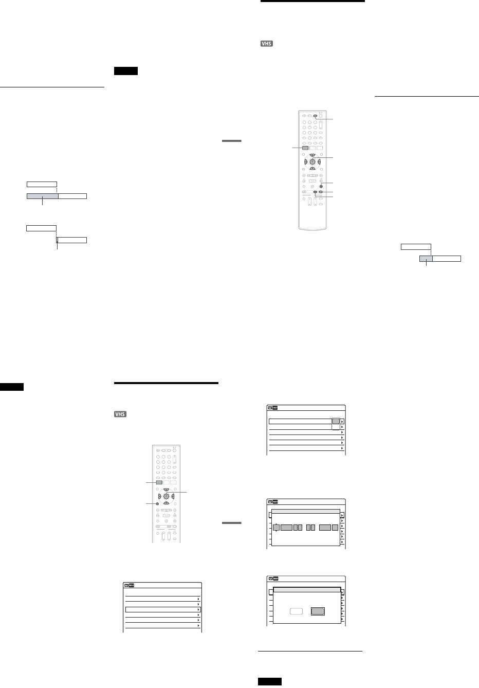
1-19
79
VCR Recording
•If the c indicator flashes in the front panel
display, check that a tape with its safety tab
in place is inserted.
•If timer settings overlap, a message appears.
To change or cancel a timer recording, select
“Edit” from the Timer List (page 81).
6Press SYSTEM MENU to turn off the menu.
There is no need to turn off the recorder before
the timer recording starts.
Leave the cable box/satellite receiver turned
on and do not change the channel selected on
the cable box/satellite receiver until the
recorder finishes the timer recording.
To stop recording
Press xSTOP twice.
If timer settings overlap
The program that starts first has priority and the
second program starts recording only after the first
program has finished. If the programs start at the
same time, the program listed first in the menu has
priority. If the end time of one setting and the start
time of another timer setting is the same, the
beginning of the program that starts later will be
cut.
To change or cancel timer recording
See “Changing or Canceling VCR Timer Settings
(Timer List)” on page 81.
To use the Rec Mode Adjust function
If the remaining tape length is too short for the
current recording, the VCR automatically changes
the recording mode from SP to EP.
When setting the timer, select “AUTO” in
“Mode,” and check that the “Tape Length” setting
is correct for the inserted tape (“VCR Function” -
“Tape Length” of “Features” in the “Setup”
display (page 101)).
zHints
•When the start time and the channel or input source to
be recorded are the same but the “Media” setting
differs, the program is recorded to both the DVD disc
and the VHS tape.
•You can also turn on the Timer programming menu
from the System Menu. Press SYSTEM MENU to
select “Timer,” and select “Timer-Standard.”
Notes
•Even when correctly set, the program may not be
recorded if another recording is underway, or other
prioritized timer setting overlaps.
•You cannot record on a tape with its safety tab
removed.
•Before the timer recording starts, “TIMER REC”
flashes in the front panel display.
•The recorder automatically turns off when a timer
recording finishes, even if the recording started with
the recorder turned on.
7:00 8:00 9:00 10:00
7:00 8:00 9:00 10:00
Program 1
Program 2
Program 1
will be cut off
will be cut off
Program 2
80
Recording From Connected
Equipment With a Timer
(Synchro Rec)
You can set the recorder to automatically record
programs from connected equipment that has a
timer function (such as a satellite tuner). Connect
the equipment to the LINE 1 IN jacks on the rear
of the recorder (page 13).
When the connected equipment turns on, the
recorder starts recording a program from the LINE
1 IN jacks.
1Press VIDEO to operate the VCR.
2Insert a tape with its safety tab in place.
3Press REC MODE repeatedly to select the
recording mode, “SP” or “EP.”
4Press SYSTEM MENU while the recorder is
in stop mode.
5Select “Setup,” and press ENTER.
6Select “Features,” and press ENTER.
The “Features” setup appears.
7Select “Synchro Recording,” and press
ENTER.
8Select “to VIDEO,” and press ENTER.
9Press SYSTEM MENU to turn off the menu.
10
Set the timer on the connected equipment
to the time of the program you want to
record, and turn it off.
11
Press SYNCHRO REC.
The SYNCHRO REC indicator lights up on
the front panel and the recorder stands by for
Synchro-Rec.
The recorder starts recording when a signal is
received from the connected equipment.
When the connected equipment turns off, the
recording stops and the recorder turns off.
To stop recording
Press xSTOP twice.
To cancel Synchro-Rec function
Press SYNCHRO REC before recording starts.
The SYNCHRO REC indicator on the recorder
turns off.
If you press SYNCHRO REC during Synchro-
Rec, the recording stops, the SYNCHRO REC
indicator turns off, and the recorder turns off.
If the timer settings of a Synchro-Recording
and another timer recording overlap
Regardless of whether or not the program is a
Synchro-Rec program, the program that starts first
has priority and the second program starts
recording only after the first program has finished.
If the end time of one setting and the start time of
another timer setting is the same, the beginning of
the program that starts later will be cut.
SYNCHRO
REC
xSTOP
REC MODE
SYSTEM
MENU M/m/</,,
ENTER
112233
445566
7788
00
99
VIDEO
7:00 8:00 9:00 10:00
Program 1
Program 2
will be cut off
81
VCR Recording
Notes
•The recorder starts recording only after detecting the
video signal from the connected equipment. The
beginning of the program may not be recorded
regardless of whether or not the recorder’s power is on
or off.
•To use the connected equipment during Synchro-Rec
standby, cancel the standby mode by pressing
SYNCHRO REC. To return to standby mode again, be
sure to turn off the equipment and press SYNCHRO
REC, before Synchro-Rec starts.
•The Synchro-Rec function does not work with some
tuners. For details, see the tuner’s operating
instructions.
•After a recording has finished, the recorder enters the
Synchro-Rec standby mode until the SYNCHRO REC
indicator turns off.
•You cannot record on a tape with its safety tab
removed.
•If Synchro-Rec starts with the recorder turned on, the
recorder will turn off when the recording ends.
Changing or Canceling VCR
Timer Settings (Timer List)
You can change or cancel timer settings using the
Timer List menu.
1Press SYSTEM MENU.
The System Menu appears.
2Select “Timer,” and press ENTER.
3Select “Timer List,” and press ENTER.
Timer information displays the recording
date, time, recording mode, etc.
If there are more than six timer settings, press
m to display the next page.
112233
445566
7788
00
99
SYSTEM
MENU M/m/</,,
ENTER
ORETURN
01 VCR 04/15 09:00PM 10:00PM Line1
--- --/-- --:-- --:-- ---- ---04
--- --/-- --:-- --:-- ---- ---05
--- --/-- --:-- --:-- ---- ---06
03 --- --/-- --:-- --:-- ---- ---
02 VCR 04/30 09:15PM 09:45PM Line1
10:10 AM
SP
SP
Timer List
No. Media Date Start End Ch Mode Edit
,continued 82
4Select the timer setting you want to change
or cancel, and press ENTER.
The sub-menu appears.
5Select one of the options, and press
ENTER.
“Edit”: Changes the timer setting.
Select an item using </, and adjust using
M/m. Press ENTER.
“Erase”: Erases the timer setting.
Select “OK” and press ENTER when asked
for confirmation.
6Press SYSTEM MENU to turn off the Timer
List.
To return to the previous display
Press ORETURN.
Notes
•Even when correctly set, the program may not be
recorded if another recording is underway, or other
prioritized timer setting overlaps. For priority, see
page 79.
•You cannot change the timer settings for a recording
currently underway.
•The Timer List displays both the DVD recorder and
VCR timer settings.
01 VCR 04/15 09:00PM 10:00PM Line1
--- --/-- --:-- --:-- ---- ---04
--- --/-- --:-- --:-- ---- ---05
--- --/-- --:-- --:-- ---- ---06
03 --- --/-- --:-- --:-- ---- ---
02 VCR 04/30 09:15PM 09:45PM Line1
10:10 AM
Timer List
No. Media Date Start End Ch Mode Edit
E
rase
Edit
01 DVD 04/15 09:00PM 10:00PM CH8
--- --/-- --:-- --:-- ---- ---04
--- --/-- --:-- --:-- ---- ---05
--- --/-- --:-- --:-- ---- ---06
03 --- --/-- --:-- --:-- ---- ---
02 DVD 04/30 09:15PM 09:45PM CH11
10:10 AM
Timer – Standard
No Rec To Date Start End Source Mode Edit
No.01
:PM
VCR
PM
:
04/15 09 00 10 00 Line1 SP
Media Date Start End Ch Mode
01 VHS 4/15 09:00PM 10:00PM CH8
--- --/-- --:-- --:-- ---- ---04
--- --/-- --:-- --:-- ---- ---05
--- --/-- --:-- --:-- ---- ---06
03 --- --/-- --:-- --:-- ---- ---
02 VHS 4/30 09:15PM 09:45PM CH11
10:10 AM
Timer List
No Rec To Date Start End Source Mode Edit
Do you want to erase “No.01”?
OK Cancel
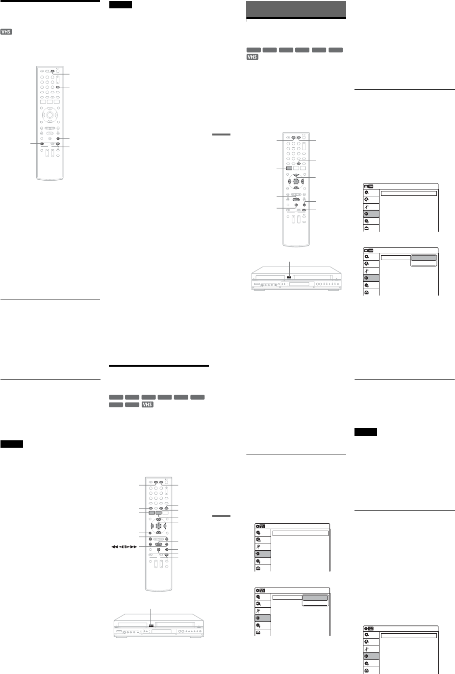
1-20
83
VCR Recording
Recording From Another
VCR or Similar Device
You can record from a connected VCR or similar
device. For connection details, see “Connecting
Another VCR or Similar Device” on page 27.
1Press VIDEO to operate the VCR.
2Insert a tape with its safety tab in place.
3Press INPUT repeatedly to select the input
source (LINE1 or LINE2) according to the
connection you made.
4Press REC MODE repeatedly to select the
recording mode, “SP” or “EP.”
5Insert the source tape into the connected
equipment and set to playback pause.
6Press zREC on this recorder and the
pause or play button on the connected
equipment at the same time.
Recording starts.
To stop recording, press xSTOP on this
recorder.
Notes
•A video game image may not be recorded clearly.
•You cannot record on a tape with its safety tab
removed.
•During recording or recording pause, you cannot
change the recording mode.
•You cannot change the input source during recording.
112233
445566
7788
00
99INPUT
VIDEO
zREC
xSTOP
REC MODE
84
Dubbing (TAPE y DVD)
Dubbing From a VHS Tape to
a DVD
You can easily record (dub) a VHS tape to a disc.
Before dubbing, make the necessary audio settings
on the VCR.
◆How titles and chapters are created
The recorder takes each recording on the VHS tape
and automatically divides them into titles as they
are dubbed to a disc. These titles are then further
divided into chapters at either 5 or 15-minute
intervals, according to the “DVD Auto Chapter”
setting of “Features” in the “Setup” display.
1Press DVD and insert a recordable disc.
To select the recording mode, press REC
MODE repeatedly (see page 46).
2Insert a source VHS tape.
3Press VIDEO to operate the VCR.
4Start playing the VHS tape, and then press
x STOP or X PAUSE at the point where
you want to start dubbing.
To select VCR sound, press AUDIO during
playback (see page 74).
5Press T VIDEO on the recorder.
Dubbing starts.
To stop dubbing
Press xSTOP.
Note that it may take a few seconds for the
recorder to stop dubbing.
To play discs recorded with this recorder on
other DVD equipment
Finalize the disc (see page 88).
To dub using the on-screen menu
1After step 4 above, press SYSTEM MENU.
2Select “Dubbing” from the System Menu, and
press ENTER.
3Select “Simple Dubbing,” and press ENTER.
4Select “VIDEO t DVD,” and press ENTER.
The display asks for confirmation.
-
RWVR
-
RWVideo
+RW +R
-
RVR
-
RVideo
112233
445566
7788
00
99
M/m/</,,
ENTER
REC MODE
xSTOP
SYSTEM
MENU
DVD VIDEO
XPAUSE
HPLAY
AUDIO
TVIDEO
Dubbing 10:10 AM
Simple Dubbing
Program Dubbing
DV/D8 Dubbing
Setup
Disc Setting
Edit
Title List
Timer
Dubbing
Dubbing 10:10 AM
Simple Dubbing
Program Dubbing
DV/D8 Dubbing
Setup
Disc Setting
Edit
Title List
Timer
Dubbing
VIDEO --> DVD
DVD --> VIDEO
85
Dubbing (TAPE y DVD)
5Select “Yes,” and press ENTER.
Dubbing starts.
zHints
•A black (no signal) screen at the end of the dubbed disc
is not a malfunction. This screen is recorded if a time
discrepancy exists between the disc and tape when the
recording is stopped.
•When dubbing a VHS tape to a DVD, the VHS tape
counter value may differ slightly from the DVD
recording time.
•VCR playback sound is output during dubbing.
Notes
•Dubbing cannot be made when:
–using a non-recordable DVD.
–using VHS software with copy guard functions.
•Dubbing stops when:
–the VHS tape reaches the end and stops.
–the VHS video deck or the DVD deck is stopped.
–the disc remaining time runs out.
•The System Menu, OPTIONS menu, and information
display are not displayed during dubbing.
•Copyrights
–Recordings made from VHS tapes and other
copyrighted material are solely for individual
enjoyment, and other unauthorized use is prohibited
under copyright law.
–Unauthorized editing of copyrighted material is
prohibited under copyright law.
Dubbing From a DVD to a
VHS Tape
You can record (dub) a DVD title to a VHS tape.
Note that when you record copy-protected
software to a tape, picture may appear disrupted
when you play back the tape.
You can also select titles or scenes and dub them
all at once. See “Dubbing selected titles and scenes
(Program Dubbing)” on page 86.
Before dubbing, make the necessary audio settings
on the DVD recorder.
1Press VIDEO and insert a VHS tape with its
safety tab in place.
To select the recording mode, SP or EP, press
REC MODE repeatedly (see page 75).
-
RWVR
-
RWVideo
+RW +R
DVD
-
RVR
-
RVideo
RAM
112233
445566
7788
00
99
M/m/</,,
ENTER
xSTOP
REC MODE
SYSTEM
MENU
VIDEO
AUDIO
SUBTITLE
TOP MENU
DVD
TITLE LIST
HPLAY
XPAUSE
./>
ORETURN
DVDt
,continued 86
2Insert a source disc.
3Press DVD to operate the DVD recorder.
4Press TOP MENU or TITLE LIST to select a
title.
5Start playing the DVD, and then press x
STOP or X PAUSE at the point where you
want to start dubbing.
To select DVD sound, language, or subtitle,
press AUDIO or SUBTITLE during playback
(see page 36).
6Press DVD t on the recorder.
Dubbing starts.
To stop dubbing
Press xSTOP.
Note that it may take a few seconds for the
recorder to stop dubbing.
To dub using the on-screen menu
1After step 5 above, press SYSTEM MENU.
2Select “Dubbing” from the System Menu, and
press ENTER.
3Select “Simple Dubbing,” and press ENTER.
4Select “DVD t VIDEO,” and press ENTER.
The display asks for confirmation.
5Select “Yes,” and press ENTER.
Dubbing starts.
If the disc’s menu appears when DVD
playback finishes, press xSTOP to stop
dubbing. Otherwise the disc’s menu is
recorded until the tape reaches its end.
zHints
•The brightness of the playback picture may differ from
normal DVD playback picture.
•The DVD playback time may differ slightly from the
VHS tape counter value.
•The sound being played back (main, sub, etc.) is the
dubbed sound.
Notes
•Dubbing stops when:
–the DVD is played back to the end and stops.
–the DVD deck or the VHS video deck is stopped.
–the tape remaining time runs out.
•The System Menu, OPTIONS menu, and information
display are not displayed during dubbing.
•Copyrights
–Recordings made from discs and other copyrighted
material are solely for individual enjoyment, and
other unauthorized use is prohibited under copyright
law.
–Unauthorized editing of copyrighted material is
prohibited under copyright law.
Dubbing selected titles and scenes
(Program Dubbing)
You can select titles or scenes from a DVD, and
dub the contents to a VHS tape all at once.
1Press VIDEO and insert a VHS tape with its
safety tab in place.
To select the recording mode, SP or EP, press
REC MODE repeatedly (see page 75).
2Press DVD and insert a source disc.
To select DVD sound, language, or subtitle,
press AUDIO or SUBTITLE during playback
(see page 36).
3Press SYSTEM MENU.
The System Menu appears.
4Select “Dubbing,” and press ENTER.
Dubbing 10:10 AM
Simple Dubbing
Program Dubbing
DV/D8 Dubbing
Setup
Disc Setting
Edit
Title List
Timer
Dubbing
Dubbing 10:10 AM
Simple Dubbing
Program Dubbing
DV/D8 Dubbing
Setup
Disc Setting
Edit
Title List
Timer
Dubbing
VIDEO --> DVD
DVD --> VIDEO
Dubbing 10:10 AM
Simple Dubbing
Program Dubbing
DV/D8 Dubbing
Setup
Disc Setting
Edit
Title List
Timer
Dubbing
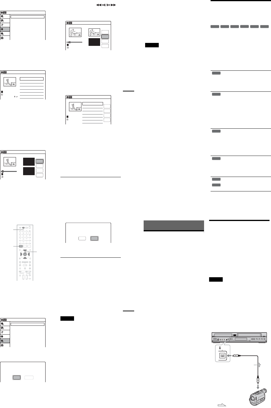
1-21
87
Dubbing (TAPE y DVD)
5Select “Program Dubbing,” and press
ENTER.
6Select “Create Dubbing List,” and press
ENTER.
If you have performed Program Dubbing
before, the display asks for confirmation. To
continue, select “Yes” and press ENTER.
The display for selecting titles appears.
7Select the title you want to dub, and press
ENTER.
The sub-menu appears.
To dub the entire title, select “Title Dubbing”
and press ENTER. The Program Dubbing List
appears with the selected title. Go to step 13.
To select a scene to dub, go to step 8.
8Select “Scene Dubbing,” and press
ENTER.
The display for setting a scene appears.
“Start” is selected.
9Press ENTER at the start point.
You can use HPLAY, ,
./>,xSTOP, and XPAUSE to find
the point.
“End” is selected.
10
Press ENTER at the end point.
“Make” is selected.
To reset the start or end point, select “Start” or
“End” and repeat from step 9 or 10.
11
Press ENTER.
To continue, repeat from step 9.
12
Select “Finish,” and press ENTER.
The Program Dubbing List appears with the
selected scene.
13
Select an option and press ENTER, if
necessary.
To add other titles or scenes, select “Addition”
and press ENTER, and repeat from step 7.
To cancel the selected title or scene, select
“Erase” and press ENTER. When asked for
confirmation, select “OK” and press ENTER.
To view the selected title or scene, select
“Check” and press ENTER.
To cancel dubbing, press O RETURN.
14
Select “Dubbing,” and press ENTER.
Dubbing starts.
Program Dubbing 10:10 AM
Create Dubbing List
Program Dubbing List
Setup
Disc Setting
Edit
Title List
Timer
Dubbing
Create Dubbing List 10:10 AM
>
>
T
No. Title Length Edit
01 LINE 1 00:05:04
02 LINE 1 00:00:51
May/02/2007
03:25 PM
1/2
LINE
1
Scene Dubbing 10:10 AM
Scene No.01
T
---/--/---- --:--
Dubbing List No. 01
Make
Finish
Start
End
Start 00:00:00
End 00:00:00
00:00:07
10:10 AM
Scene No.01
T
00:00:10
---/--/---- --:--
Dubbing List No. 01
Make
Finish
Start
End
Scene Dubbing
Start 00:00:10
End 00:00:00
Program Dubbing List 10:10 AM
>
T
No. Title Length Edit
01 LINE 1 00:05:04
May/02/2007
03:25 PM
Addition
Check
Dubbing
Erase
LINE
1
,continued 88
To stop dubbing
Press x STOP.
Note that it may take a few seconds for the
recorder to stop dubbing.
zHints
•The brightness of the playback picture may differ from
normal DVD playback picture.
•The DVD playback time may differ slightly from the
VHS tape counter value.
•The sound being played back (main, sub, etc.) is the
dubbed sound.
Notes
•Dubbing stops when:
–the DVD is played back to the end and stops.
–the DVD deck or the VHS video deck is stopped.
–the tape remaining time runs out.
•The System Menu, OPTIONS menu, and information
display are not displayed during dubbing.
•Copyrights
–Recordings made from discs and other copyrighted
material are solely for individual enjoyment, and
other unauthorized use is prohibited under copyright
law.
–Unauthorized editing of copyrighted material is
prohibited under copyright law.
•Once you eject the disc, the Program Dubbing List is
erased.
Finalizing a Disc (Preparing
a Disc for Playback on
Other Equipment)
Finalizing is necessary in order to play discs
recorded with this recorder on other DVD
equipment.
When you finalize a DVD+RW/DVD-RW (Video
mode)/DVD+R/DVD-R (Video mode), a DVD
menu will be automatically created, which can be
displayed on other DVD equipment.
Before finalizing, check the differences between
the disc types in the table below.
Differences between the disc types
Discs are automatically finalized when
removed from the recorder. If you want
to record on it again, reformat the disc
(page 67). Note however, that
reformatting a disc erases all its
contents.
Finalizing is unnecessary when playing a
disc on VR format compatible equipment.
Even if your other DVD equipment is
VR format compatible, you may need to
finalize the disc, especially if the
recording time is short. After finalizing,
you cannot edit or record on the disc. If
you want to edit or record on it again,
unfinalize or reformat the disc (page 67).
Note however, that reformatting a disc
erases all its contents.
Finalizing is necessary in order to play
on equipment other than this recorder.
After finalizing, you cannot edit or
record on the disc. If you want to edit or
record on it again, unfinalize or reformat
the disc (page 67). Note however, that
reformatting a disc erases all its
contents.
Finalizing is necessary in order to play
on equipment other than this recorder.
The finalized discs can be played on
other VR mode compatible players.
After finalizing, you cannot further edit
or record on the disc.
Finalizing is necessary in order to play
on equipment other than this recorder.
After finalizing, you cannot further edit
or record on the disc.
-
RWVR
-
RWVideo
+RW +R
-
RVR
-
RVideo
+RW
-
RWVR
-
RWVideo
-
RVR
+R
-
RVideo
89
Dubbing (TAPE y DVD)
1Press DVD to operate the DVD recorder.
2Insert a disc.
3Press SYSTEM MENU while the recorder is
in stop mode.
The System Menu appears.
4Select “Disc Setting,” and press ENTER.
The “Disc Setting” display appears.
5Select “Disc Finalize,” and press ENTER.
The display asks for confirmation.
6Select “Finalize,” and press ENTER.
The display asks for confirmation again.
7Select “OK,” and press ENTER.
The recorder starts finalizing the disc.
To turn off the display
Press SYSTEM MENU.
To unfinalize a DVD-RW (VR mode)
If you cannot record or edit on a DVD-RW (VR
mode) that has been finalized, unfinalize the disc
by selecting “Unfinalize” in step 6 above.
zHints
•You can check whether the disc has been finalized or
not. If you cannot select “Finalize” in step 6 above, the
disc has already been finalized.
•To check the disc information, select “Disc
Information” in the “Disc Setting” display and press
ENTER. See page 67 for details.
Notes
•Depending on the condition of the disc, the recording,
or the DVD equipment, discs may not play even if the
discs are finalized.
•The recorder may not be able to finalize a disc if it was
recorded on another recorder.
112233
445566
7788
00
99
SYSTEM
MENU
DVD
M/m/</,,
ENTER
Disc Setting 10:10 AM
Disc Name :
Disc Protect : Not Protected
Disc Format : VR Mode
Disc Finalize : Unfinalized
Disc Information
Erase All Titles
Setup
Disc Setting
Edit
Title List
Timer
Dubbing
Do you want to finalize this disc ?
UnfinalizeFinalize
Disc will be finalized.
Do you want to continue ?
CancelOK
90
DV/D8 Dubbing (DV/D8 t DVD)
Before DV/D8 Dubbing
This section explains dubbing with a digital video
camera via the DV IN jack on the front panel. If
you want to dub by way of the LINE IN jacks, see
“Recording From Another VCR or Similar
Device” on page 54.
To record from the DV IN jack
The DV IN jack on this recorder conforms to the
i.LINK standard. You can connect any other
equipment that has an i.LINK (DV) jack, and
record digital signals.
Follow the instructions in “Connecting a Digital
Video Camera to the DV IN Jack,” and then move
on to the section on dubbing. For more
information about i.LINK, see “About i.LINK” on
page 113.
zHint
If you plan to do additional editing on a disc after the
initial dub, use the DV IN jack and record on a DVD-RW
(VR mode) or DVD-R (VR mode). Note that erasing
unwanted scenes does not free up disc space for DVD-Rs
(VR mode).
Connecting a Digital Video
Camera to the DV IN Jack
You can connect a digital video camera to the DV
IN jack on the recorder to record or edit from a
DV/D8 format tape. Operation is straightforward
because the DVD recorder will fast forward and
rewind the tape for you – you do not need to
operate your digital video camera. Do the
following to start using the “DV/D8 Edit”
functions of this recorder.
See the instruction manual supplied with the
digital video camera as well before connecting.
Notes
•The DV IN jack is for input only. It will not output
signals.
•You cannot use the DV IN jack when:
–your digital video camera does not work with this
recorder. Connect the camera to the LINE IN jack and
follow the instructions of “Recording From Another
VCR or Similar Device” on page 54.
–the input signal is not in DVC-SD format. Do not
connect a MICROMV format digital video camera
even if it has an i.LINK jack.
–the images on the tape contain copy protection
signals, which limit recording.
Hookups
DV IN
VCR-DVD recorder
to DV IN
: Signal flow
i.LINK cable
(not supplied)
to DV output
Digital video camera
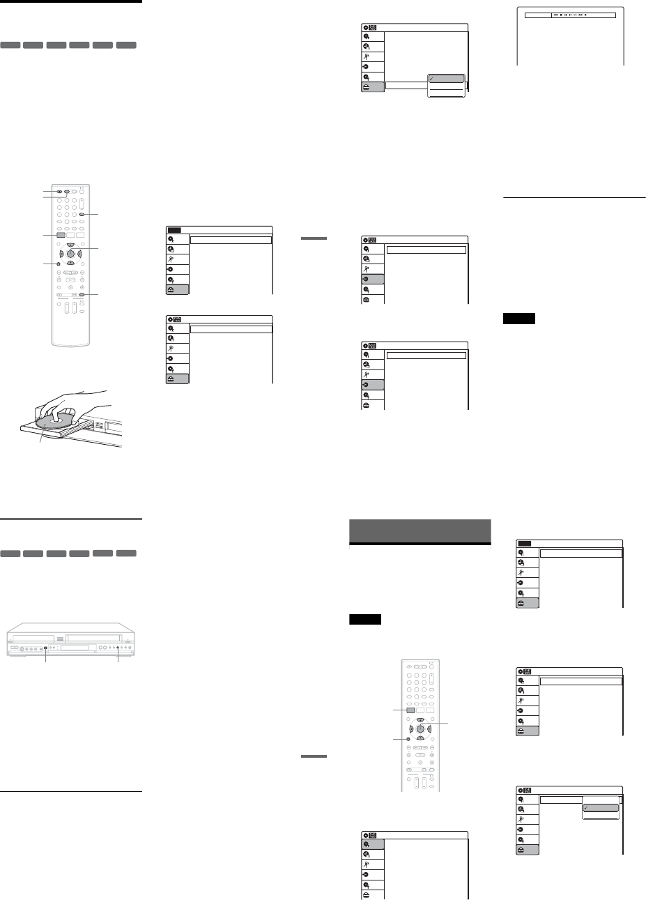
1-22
91
DV/D8 Dubbing (DV/D8 t DVD)
Dubbing From a DV/D8
Format Tape to a DVD
You can record a DV/D8 format tape onto a disc.
The recorder controls the digital video camera.
You can fast forward, rewind, play in slow motion,
and stop the tape to select the scenes using the on-
screen menu.
To simply dub the entire contents of a DV/D8
format tape (One Touch Dubbing), see page 93.
◆How titles and chapters are created
The dubbed contents on the disc become one title,
and the title is then divided into chapters at either
5 or 15-minute intervals, according to the “DVD
Auto Chapter” setting of “Features” in the “Setup”
display.
1Press DVD to operate the DVD recorder.
2Press ZOPEN/CLOSE, and place a
recordable disc on the disc tray.
3Press ZOPEN/CLOSE to close the disc
tray.
Wait until “LOAD” disappears from the front
panel display.
Unused discs are automatically formatted. For
the DVD-RW/DVD-R’s recording format
(VR mode or Video mode), see “Formatting a
new disc” on page 47.
4Insert the source DV/D8 format tape into
your digital video camera.
For the recorder to record or edit, your digital
video camera must be set to video playback
mode.
5Press INPUT repeatedly to select “DV.”
6Press REC MODE repeatedly to select the
recording mode.
For details about the recording mode, see
page 46.
7Press SYSTEM MENU while the recorder is
in stop mode.
The System Menu appears.
8Select “Setup,” and press ENTER.
9Select “Audio,” and press ENTER.
-
RWVR
-
RWVideo
+RW +R
-
RVR
-
RVideo
112233
445566
7788
00
99
REC MODE
INPUT
ZOPEN/
CLOSE
SYSTEM
MENU M/m/</,,
ENTER
ORETURN
DVD
Recording side facing down
10:10 AM
Clock Set
Video
Audio
Features
Options
Easy Setup
Setup
Disc Setting
Edit
Title List
Timer
Dubbing
Setup
No Disc
Audio 10:10 AM
Digital Out
Downmix
Audio DRC
Audio (HDMI)
Scan Audio
Surround
DV/D8 Audio Input
Line Audio Input
: Dolby Surround
: Standard
: Auto
: On
: Off
: Stereo 1
: Stereo
Setup
Disc Setting
Edit
Title List
Timer
Dubbing
,continued 92
10
Select “DV/D8 Audio Input,” and press
ENTER.
“Stereo 1”: Records original sound only.
Normally select this when dubbing a DV
format tape.
“Stereo 2”: Records additional audio only.
“Mix”: Records original and additional
sounds.
Select “Stereo 2” or “Mix” if you have added
a second audio channel when recording with
your digital video camera. For the details, see
page 100.
11
Select an option, and press ENTER.
12
Press ORETURN twice.
13
Select “Dubbing,” and press ENTER.
14
Select “DV/D8 Dubbing,” and press
ENTER.
15
Select “DV/D8 Simple Dubbing,” and
press ENTER.
The following display appears.
If “DV” or “DV Camera Mode” is displayed
instead of “DV Tape Mode,” check that the
digital video camera is correctly connected
and its power turned on, and that its mode is
set for dubbing.
16
Find the dubbing start point on the tape,
and stop or pause playback.
Press </, to select m,x,X,y,H, or
M on the TV screen and press ENTER to
find the point, and stop or pause with x or X.
17
Press , to select z on the TV screen, and
press ENTER.
Dubbing starts.
To stop recording
Select x on the TV screen, and press ENTER.
Note that it may take a few seconds for the
recorder to stop recording.
To turn off the display for DV/D8 dubbing
Press INPUT.
zHint
If “DV Camera Mode” appears on the screen, you can use
z on the TV screen to record the camera image directly
on the recorder.
Notes
•If you want to play the disc on other DVD equipment,
finalize the disc (page 88).
•You cannot connect more than one piece of digital
video equipment to the recorder.
•You cannot record the date, time, or contents of a DV/
D8 format tape onto the disc.
•If you record from a DV/D8 format tape with a
soundtrack that is recorded in multiple sampling
frequencies (48 kHz, 44.1 kHz, or 32 kHz), no sound,
or an unnatural sound will be output when playing back
the sampling frequency switch point on the disc.
•The recorded picture may be momentarily affected if
the picture size of the source image changes, or if there
is nothing recorded on the tape.
•Noise may occur when you switch the audio sampling
mode (48 kHz/16 bits t 32 kHz/12 bits).
Audio 10:10 AM
Digital Out
Downmix
Audio DRC
Audio (HDMI)
Scan Audio
Surround
DV/D8 Audio Input
Line Audio Input
: Dolby Surround
: Standard
: Auto
: On
: Off
: Stereo 1
: Stereo
Setup
Disc Setting
Edit
Title List
Timer
Dubbing
Stereo 1
Stereo 2
Mix
Dubbing 10:10 AM
Simple Dubbing
Program Dubbing
DV/D8 Dubbing
Setup
Disc Setting
Edit
Title List
Timer
Dubbing
DV/D8 Dubbing 10:10 AM
DV/D8 Simple Dubbing
DV/D8 One Touch Dubbing
Setup
Disc Setting
Edit
Title List
Timer
Dubbing
DV Tape Mode
93
DV/D8 Dubbing (DV/D8 t DVD)
Dubbing an entire DV/D8 format tape
to a DVD (One Touch Dubbing)
You can record the entire contents of a DV/D8
format tape onto a disc with a single press of the
ONE-TOUCH DUBBING button. The recorder
controls the digital video camera for the whole
process, and completes the recording.
1Follow steps 1 to 11 of “Dubbing From a
DV/D8 Format Tape to a DVD” (page 91),
and press SYSTEM MENU to turn off the
display.
2Press ONE-TOUCH DUBBING on the
recorder.
The recorder rewinds the tape in the digital
video camera and then starts recording the
tape contents from the beginning.
When playback of the tape stops, One Touch
Dubbing ends automatically.
To stop recording
Press x (stop).
Note that it may take a few seconds for the
recorder to stop recording.
zHint
You can also perform One Touch Dubbing when you
select “DV/D8 One Touch Dubbing” and press ENTER
in step 15 of “Dubbing From a DV/D8 Format Tape to a
DVD” on page 91. Follow the instructions appearing on
the TV screen.
-
RWVR
-
RWVideo
+RW +R
-
RVR
-
RVideo
ONE-TOUCH DUBBING x
94
Settings and Adjustments
Using the Setup Displays
By using the setup displays, you can make various
adjustments to items such as picture and sound, as
well as select a language for the subtitles.
The setup displays are used in the following way.
Note
Playback settings stored on the disc take priority over the
setup display settings, and not all of the functions
described may work.
1Press SYSTEM MENU while the recorder is
in stop mode.
The System Menu appears.
2Select “Setup,” and press ENTER.
The “Setup” display appears.
3Select “Clock Set,” “Video,” “Audio,”
“Features,” “Options,” or “Easy Setup,”
and press ENTER.
The selected setup display appears.
Example: “Video” setup
4Select the item you want to set up, and
press ENTER.
Available options for the item appear.
Example: “TV Type”
M/m/</,,
ENTER
112233
445566
7788
00
99
SYSTEM
MENU
ORETURN
10:10 AM
Title List (Original)
Press ENTER :
Title Menu for DVD Title List.
Setup
Disc Setting
Edit
Title List
Timer
Dubbing
10:10 AM
Clock Set
Video
Audio
Features
Options
Easy Setup
Setup
Disc Setting
Edit
Title List
Timer
Dubbing
Setup
No Disc
Video 10:10 AM
TV Type
HDMI Resolution
Video (HDMI)
Black Level
Picture Control
Progressive
: 4:3 Letter Box
: Auto
: Y Cb Cr
: On
: Standard
: Off
Setup
Disc Setting
Edit
Title List
Timer
Dubbing
Video 10:10 AM
TV Type
HDMI Resolution
Video (HDMI)
Black Level
Picture Control
Progressive
: 4:3 Letter Box
: Auto
: Y Cb Cr
: On
: Standard
: Off
Setup
Disc Setting
Edit
Title List
Timer
Dubbing
16:9
4:3 Letter Box
4:3 Pan Scan
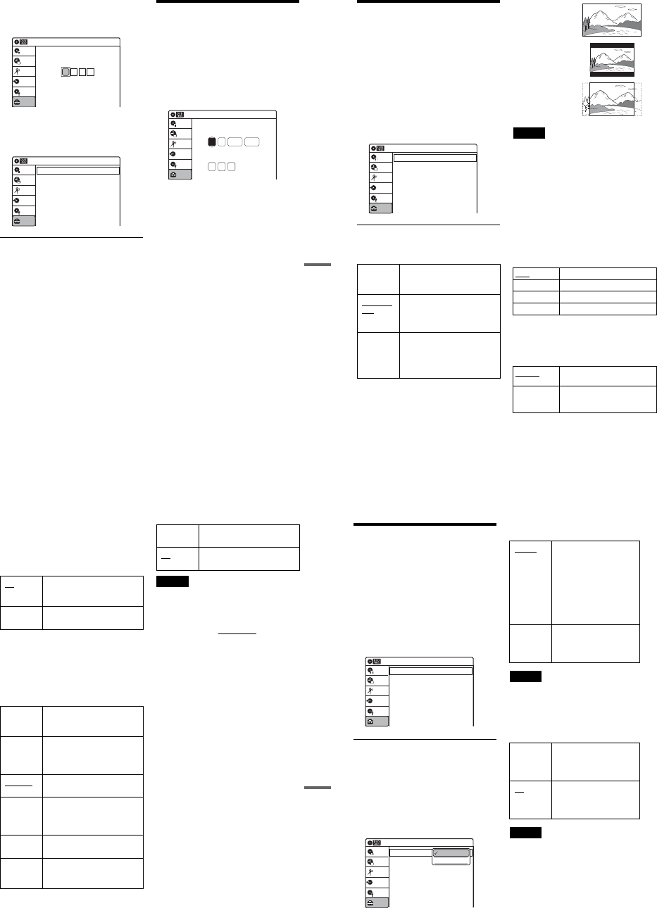
1-23
95
Settings and Adjustments
Some items display a dialog box that requires
additional settings.
Example: When “Parental” in “Options”
setup is selected.
5Select an option, and press ENTER.
The currently selected option is displayed
next to the setup item.
Example: When “16:9” is set.
To return to the previous display
Press O RETURN.
To turn off the display
Press SYSTEM MENU.
Clock Setting (Clock Set)
The “Clock Set” setup allows you to make clock
settings for the recorder.
1Press SYSTEM MENU while the recorder is
in stop mode.
2Select “Setup,” and press ENTER.
3Select “Clock Set,” and press ENTER.
The clock setting display appears.
4Press M/m to set the month, and press ,.
Set the day, year, hour, minutes, and AM/PM
in sequence. Press </, to select the item to
be set, then press M/m to set the item. The day
of the week is set automatically.
5Press ENTER to start the clock.
10:10 AM
Create the password.
Create the password
Setup
Disc Setting
Edit
Title List
Timer
Dubbing
Video 10:10 AM
TV Type
HDMI Resolution
Video (HDMI)
Black Level
Picture Control
Progressive
: 16:9
: Auto
: Y Cb Cr
: On
: Standard
: Off
Setup
Disc Setting
Edit
Title List
Timer
Dubbing
2007 Mon01 01
10 : 10 AM
10:10 AM
Clock Set
Set the time and date manually.
Hour Min
AM/PM
Month Day Year
Setup
Disc Setting
Edit
Title List
Timer
Dubbing
96
Video Settings (Video)
The “Video” setup allows you to adjust items
related to the image, such as size and color.
Choose the settings according to the type of TV,
tuner, or decoder connected to the recorder.
1Press SYSTEM MENU while the recorder is
in stop mode.
2Select “Setup,” and press ENTER.
3Select “Video,” and press ENTER.
The “Video” setup appears with the following
options. The default settings are underlined.
TV Type
Selects the aspect ratio of the connected TV (4:3
standard or wide).
Note
Depending on the disc, “4:3 Letter Box” may be selected
automatically instead of “4:3 Pan Scan” or vice versa.
HDMI Resolution
Selects the type of video signals output from the
HDMI OUT jack. When you select “Auto”
(default), the recorder outputs video signals of the
highest resolution acceptable for your TV. If the
picture is not clear, unnatural or not to your
satisfaction, try another option that suits the disc
and your TV/projector, etc. For details, refer also
to the instruction manual supplied with the TV/
projector, etc.
The setting is effective only when you connect a
HDMI equipped TV to the HDMI OUT jack.
Video (HDMI)
Selects the type of output from the HDMI OUT
jack.
The setting is effective only when you connect a
HDMI equipped TV to the HDMI OUT jack.
16:9 Select this when connecting to a
wide-screen TV or TV with a
wide mode function.
4:3 Letter
Box Select this when connecting to a
4:3 screen TV. Displays a wide
picture with bands on the upper
and lower portions of the screen.
4:3 Pan
Scan Select this when connecting to a
4:3 screen TV. Automatically
displays a wide picture on the
entire screen and cuts off the
portions that do not fit.
Video 10:10 AM
TV Type
HDMI Resolution
Video (HDMI)
Black Level
Picture Control
Progressive
: 4:3 Letter Box
: Auto
: Y Cb Cr
: On
: Standard
: Off
Setup
Disc Setting
Edit
Title List
Timer
Dubbing
Auto Normally, select this.
1920×1080i Sends 1920×1080i video signals.
1280×720P Sends 1280×720p video signals.
720×480P Sends 720×480p video signals.
Y Cb Cr Normally, select this when
connecting to an HDMI device.
RGB Gives brighter colors and deeper
black. Select this if colors are
weak.
16:9
4:3 Letter Box
4:3 Pan Scan
97
Settings and Adjustments
Black Level
Selects the black level (setup level) for the video
signals output from the LINE OUT jacks
(page 15).
This setting is not effective when the recorder
outputs progressive signals.
Picture Control
Selects the picture control for the video signals
output from the LINE OUT jacks (page 15).
You can adjust the video signal of DVD or
VIDEO CD (with PBC function off) from the
recorder to obtain the picture quality you want.
Select the setting that best suits the program you
are watching.
zHint
When you watch a movie, “Cinema 1” or “Cinema 2” is
recommended.
Progressive
If your TV accepts progressive (480p) format
signals, you will enjoy accurate color reproduction
and high quality image.
Connect your TV to the COMPONENT VIDEO
OUT jacks (page 17).
Notes
•If you select progressive signals when you connect the
recorder to a TV that cannot accept the signal in
progressive format, the image quality will deteriorate.
In this case, set “Progressive” to “Off.” Or, press DVD
in stop mode to operate the DVD recorder, and then
hold down XPAUSE on the recorder for five seconds
or more.
•When you connect your TV using an HDMI cable, the
“Progressive” setting is set to “On.”
On Raises the standard black level.
Select this when the picture
appears too dark.
Off Sets the black level of the output
signal to the standard level.
Dynamic 1 Produces a bold dynamic picture
by increasing the picture contrast
and the color.
Dynamic 2 Produces a more dynamic picture
than “Dynamic 1” by further
increasing the picture contrast
and the color.
Standard Displays a standard picture
(function turned off).
Cinema 1 White colors become brighter
and black colors become richer,
and the color contrast is
increased.
Cinema 2 Enhances details in dark areas by
increasing the black level.
Personal Adjusts “Contrast,” “Brightness,”
“Color,” and “Hue” using M/m/
</,.
On Sets the recorder to output
progressive signals.
Off Outputs video signals in interlace
format.
98
Audio Settings (Audio)
The “Audio” setup allows you to adjust the sound
according to the playback and connection
conditions.
1Press SYSTEM MENU while the recorder is
in stop mode.
2Select “Setup,” and press ENTER.
3Select “Audio,” and press ENTER.
The “Audio” setup appears with the following
options. The default settings are underlined.
Digital Out
The following setup items switch the method of
outputting audio signals when you connect a
component such as an amplifier (receiver) to the
DIGITAL AUDIO OUT (OPTICAL or
COAXIAL)/HDMI OUT jack.
For connection details, see “Connecting to Your
AV Amplifier (Receiver)” on page 18.
Press ENTER, and select “Dolby Digital” or
“DTS.”
If you connect a component that does not accept
the selected audio signal, a loud noise (or no
sound) will come out from the speakers, and may
affect your ears or cause speaker damage.
◆ Dolby Digital (DVDs only)
Selects the type of Dolby Digital signal.
Note
If the HDMI OUT jack is connected to equipment not
compatible with Dolby Digital signals, D-PCM signals
will be automatically output, even when “Dolby Digital”
is selected.
◆ DTS (DVD VIDEOs only)
Selects whether or not to output DTS signals.
Note
If the HDMI OUT jack is connected to equipment not
compatible with DTS signals, no signal will be output,
regardless of the “DTS” setting.
Audio 10:10 AM
Digital Out
Downmix
Audio DRC
Audio (HDMI)
Scan Audio
Surround
DV/D8 Audio Input
Line Audio Input
: Dolby Surround
: Standard
: Auto
: On
: Off
: Stereo 1
: Stereo
Setup
Disc Setting
Edit
Title List
Timer
Dubbing
10:10 AM
Dolby Digital
DTS
Digital Out
: 4:3 Letter Box
On
Setup
Disc Setting
Edit
Title List
Timer
Dubbing
D-PCM
Dolby Digital
D-PCM Select this when the recorder
is connected to an audio
component lacking a built-in
Dolby Digital decoder. You
can select whether the
signals conform to Dolby
Surround or not by making
adjustments to the
“Downmix” item in “Audio”
setup (page 99).
Dolby
Digital Select this when the recorder
is connected to an audio
component with a built-in
Dolby Digital decoder.
On Select this when the recorder
is connected to an audio
component with a built-in
DTS decoder.
Off Select this when the recorder
is connected to an audio
component without a built-in
DTS decoder.
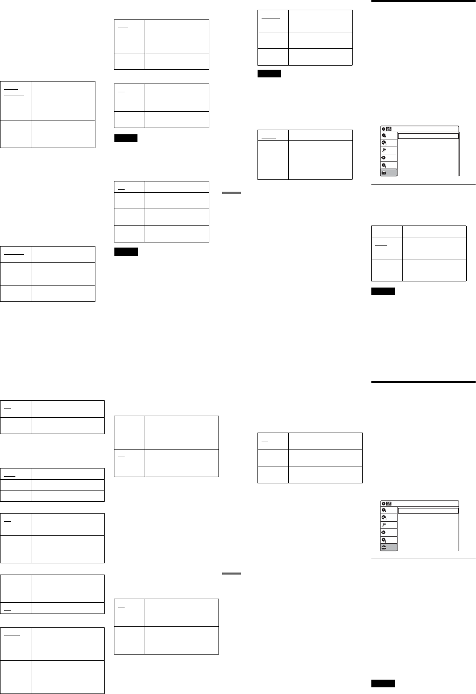
1-24
99
Settings and Adjustments
Downmix (DVDs only)
Switches the method for mixing down to two
channels when you play a DVD which has rear
sound elements (channels) or is recorded in Dolby
Digital format. For details on the rear signal
components, see “A Connecting to audio L/R
jacks” on page 19. This function affects the output
of the following jacks:
–LINE OUT (AUDIO L/R) jacks
–AUDIO OUT L/R jacks
–DIGITAL AUDIO OUT (OPTICAL or
COAXIAL)/HDMI OUT jack when “Dolby
Digital” is set to “D-PCM” (page 98).
To enjoy the surround effect of Dolby Digital, turn
off the surround settings of this recorder
(page 99).
Audio DRC (Dynamic Range Control) (DVDs
only)
Makes the sound clear when the volume is turned
down when playing a DVD that conforms to
“Audio DRC.” This affects the output from the
following jacks:
–LINE OUT (AUDIO L/R) jacks
–AUDIO OUT L/R jacks
–DIGITAL AUDIO OUT (OPTICAL or
COAXIAL)/HDMI OUT jack only when
“Dolby Digital” is set to “D-PCM” (page 98).
Audio (HDMI) (DVD VIDEOs only)
Selects the output method from the HDMI OUT
jack.
Scan Audio (DVDs only)
Note
Sound will be interrupted during Scan Audio.
Surround
Turns on the surround function to create virtual
rear speakers from a stereo TV or two separate
front speakers (page 19).
Notes
•When the playback signal does not contain a signal for
the surround speakers, the surround effects will be
difficult to hear.
•When you select one of the surround modes, turn off
the surround settings of the connected TV or amplifier
(receiver).
Dolby
Surround Normally select this
position.
Multi-channel audio signals
are output to two channels
for enjoying surround
sounds.
Normal Multi-channel audio signals
are downmixed to two
channels for use with your
stereo.
Standard Normally select this
position.
TV Mode Makes low sounds clear
even if you turn the volume
down.
Wide
Range Gives you the feeling of
being at a live performance.
Auto Normally, select this.
Outputs audio signals
according to the “Dolby
Digital” or “DTS” settings
(page 98).
PCM Converts Dolby Digital or
DTS to PCM.
On Outputs audio signals during
FF1 fast-forward of a DVD
disc with Dolby Digital
soundtracks.
Off No sound is output during
FF1 fast-forward.
Off No surround effect
Surround1 Creates one set of virtual
surround speakers
Surround2 Creates two sets of virtual
surround speakers
Surround3 Creates three sets of virtual
surround speakers
,continued 100
DV/D8 Audio Input
Note
Select “Stereo 2” or “Mix” if you have added a second
audio channel when recording with your digital video
camera.
Line Audio Input
When recording from equipment connected to the
LINE 1 IN or LINE 2 IN jacks to a DVD disc in
this recorder, select line input audio.
zHint
When recording on a disc other than DVD-RWs (VR
mode)/DVD-Rs (VR mode), select either sound track
with the connected equipment before recording.
Recording, Set Top Box
Control, and VCR Settings
(Features)
The “Features” setup allows you to make various
settings for recording, playback, and the set top
box control function.
1Press SYSTEM MENU while the recorder is
in stop mode.
2Select “Setup,” and press ENTER.
3Select “Features,” and press ENTER.
The “Features” setup appears with the
following options. The default settings are
underlined.
DVD Auto Chapter
Automatically divides a recording (a title) into
chapters by inserting chapter markings at
specified intervals. The markings are inserted
while the recording is being made.
Note
Actual intervals may differ depending on the size of the
recording. The selected setting should be regarded as an
approximate chapter interval.
Stereo 1 Records original sound only.
Normally select this when
dubbing a DV format tape.
Stereo 2 Records additional audio
only.
Mix Records both original and
additional sounds.
Stereo Records stereo sound only.
Main/Sub Records the two different
soundtracks on DVD-RWs
(VR mode)/DVD-Rs (VR
mode). You can select either
soundtrack when playing
back the disc.
Off No chapter mark is inserted.
5 Min Inserts chapter marks at
approximately 5 minute
intervals.
15 Min Inserts chapter marks at
approximately 15 minute
intervals.
Setup
Disc Setting
Edit
Title List
Timer
Dubbing
10:10 AM
DVD Auto Chapter
Format DVD-RW
VCR Function
Synchro Recording
Set Top Box Control
Features
: 5 Min
: VR
: to DVD
101
Settings and Adjustments
Format DVD-RW (DVD-RWs only)
Selects the recording format for an unused DVD-
RW, when first inserted.
VCR Function
Press ENTER and select “Tape Length,” “Auto
Play,” or “Auto Repeat.”
◆ Tape Length
◆ Auto Play
◆ Auto Repeat
Synchro Recording
Set Top Box Control
You can control your cable box/satellite receiver
using the supplied set top box controller. See
“Step 7: Easy Setup” for details. Press ENTER,
and select “On” or “Off.”
When “Set Top Box Control” is set to “On,” you
can make the following settings. Note that when
you change “Set Top Box Control” to “On” or
“Off,” all timer recording settings will be
canceled.
◆ Brand Code
See “Cable Box/Satellite Receiver Brand Code”
(page 121) for the brand code for your cable box
or satellite receiver, and enter the code using the
number buttons and ENTER.
◆ Connections
Selects the connection you used for your cable box
or satellite receiver. Select the connection from
“Line1” or “Line2.”
◆ Ch. Digit lock
Allows you to select whether to fix the digits for
your cable box or satellite receiver.
VR Automatically formats the disc in
VR mode.
Video Automatically formats the disc in
Video mode.
T120 For T-120 or shorter length tapes.
T160 For T-160 length tapes.
T180 For T-180 or longer length tapes.
On Starts playback automatically,
when you insert a tape with its
safety tab removed.
Off Turns off the function. You need
to press HPLAY to start
playback, even if you insert a tape
with its safety tab removed.
On Plays back a tape repeatedly. The
VCR rewinds the tape to the
beginning and restarts playback
automatically.
Off Turns off the function.
to DVD Sets the recorder to record
programs from connected
equipment that has a timer
function (such as a satellite tuner)
to a DVD disc.
to VIDEO Sets the recorder to record
programs from connected
equipment that has a timer
function (such as a satellite tuner)
to a VHS tape.
On Turns on the cable box/satellite
receiver control function. See
“Using the cable box/satellite
receiver control function”
(page 12).
Off Turns off the cable box/satellite
receiver control function. Select
this if you do not want to use the
supplied set top box controller.
Off Select this when your cable box or
satellite receiver only accepts a
three or more digit channel
number. Normally select this.
Lock to
2 digits Select this only when your cable
box or satellite receiver only
accepts a two digit channel
number.
,continued 102
◆ Mode for SET button
Select “Mode 1” or “Mode 2” if your cable box or
satellite receiver requires pressing an ENTER
button or a SET button etc., after entering the
channel number. If “Mode 1” does not work, try
“Mode 2.” If your cable box or satellite receiver
does not respond to either setting, contact the
manufacturer of the cable box or satellite receiver.
Language, Parental Control
Settings/Factory Settings
(Options)
The “Options” setup allows you to set up other
operational settings.
1Press SYSTEM MENU while the recorder is
in stop mode.
2Select “Setup,” and press ENTER.
3Select “Options,” and press ENTER.
The “Options” setup appears with the
following options. The default settings are
underlined.
Language
◆ OSD (On-Screen Display)
Switches the display language on the screen.
◆ Disc Menu (DVD VIDEOs only)
Switches the language for the DVD menu.
◆ Audio (DVD VIDEOs only)
Switches the language of the soundtrack.
When you select “Original,” the language given
priority in the disc is selected.
◆ Subtitle (DVD VIDEOs only)
Switches the language of the subtitles recorded on
the disc.
When you select “Auto,” the subtitle language
changes according to the language you selected
for the soundtrack. See page 120 for an
explanation of the language abbreviations.
Note
If you select a language in “Disc Menu,” “Subtitle,” or
“Audio” that is not recorded on the DVD VIDEO, one of
the recorded languages will be automatically selected.
Off No code is sent when SET is
pressed. Normally select this.
Mode 1 Sends the channel number you
entered.
Mode 2 Sends the channel number you
entered.
Language
Parental
Front Display
Command Mode
Factory Setting
: Auto
: DVD 3
10:10 AM
Options
Setup
Disc Setting
Edit
Title List
Timer
Dubbing
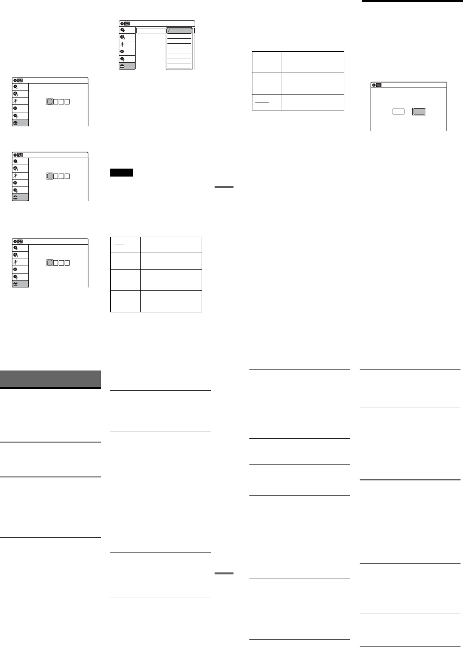
1-25
103
Settings and Adjustments
Parental (DVD VIDEOs only)
Playback of some DVD VIDEOs can be limited
according to a predetermined level, such as the age
of the users. Scenes may be blocked or replaced
with different scenes.
1After step 3 above, select “Parental,” and
press ENTER.
•If you have not entered a password, the
display for registering a new password
appears.
Enter a 4-digit password using the number
buttons.
The display for confirming the password
appears.
Re-enter the password.
•When you have already registered a
password, the display for entering the
password appears.
Enter a 4-digit password using the number
buttons.
2Select “Rating Level,” and press ENTER.
The selection items for “Rating Level” are
displayed.
The lower the value, the stricter the limitation.
3Select the level, and press ENTER.
The Parental setting is complete.
•To cancel the Parental setting for the disc, set
“Rating Level” to “Off” in step 3.
•To change the password, select “Change
Password” in step 2, and press ENTER. When
the display for registering a password appears,
enter a new four-digit password using the
number buttons.
zHint
If you enter a wrong number, press < or CLEAR and re-
enter.
Notes
•If you forget your password, select “Factory Setting” of
“Options” in the “Setup” display.
•Playback of discs without the Parental Control function
cannot be limited on this recorder.
•Depending on the disc, you may be asked to change the
Parental Control level while playing the disc. In this
case, enter your password, then change the level.
Front Display
Adjusts the lighting of the front panel display.
10:10 AM
Create the password.
Create the password
Setup
Disc Setting
Edit
Title List
Timer
Dubbing
10:10 AM
Confirm the password.
Create the password
Setup
Disc Setting
Edit
Title List
Timer
Dubbing
10:10 AM
Enter your password.
Enter your password
Setup
Disc Setting
Edit
Title List
Timer
Dubbing
Auto Adjusts to low lighting when
power is off.
Bright Maintains bright lighting
when power is off.
Dimmer Maintains low lighting
regardless of whether power
is on or off.
Off Turns off the lighting when
power is off. Maintains the
lighting when power is on.
Rating Level
Change Password
: On: Level 8 (Adults)
10:10 AM
Parental
Setup
Disc Setting
Edit
Title List
Timer
Dubbing
Off
Level 8 (Adults)
Level 7
Level 6
Level 5
Level 4
Level 3
Level 2
,continued 104
Command Mode
Changes the command mode of this recorder if
other DVD equipment is assigned the same
command mode. Be sure to match the command
mode of the supplied remote to the setting made
here. For details, see “If you have a Sony DVD
player or more than one Sony DVD recorder” on
page 22.
Factory Setting
Allows you to return the setup settings to their
default settings. Note that all of your previous
settings will be lost.
1After step 3 on page 102, select “Factory
Setting,” and press ENTER.
2Select “Start,” and press ENTER.
The setup settings return to their default
settings.
3Press ENTER when “Finish” appears.
The power automatically turns off and then on
again, and the recorder is reset to the factory
settings.
When the “Easy Setup” display appears,
follow the instructions for Easy Setup
(page 23) from step 4.
Easy Setup
(Resetting the Recorder)
Select this to run the Easy Setup program.
1Press SYSTEM MENU while the recorder is
in stop mode.
2Select “Setup,” and press ENTER.
3Select “Easy Setup,” and press ENTER.
4Select “Start,” and press ENTER.
5Follow the instructions for Easy Setup
(page 23) from step 5.
DVD 1 Select this if the default
command mode conflicts
with other DVD equipment.
DVD 2 Select this if the default
command mode conflicts
with other DVD equipment.
DVD 3 The default command mode
of the recorder.
10:10 AM
Easy Setup
Follow the guide to make initial settings.
Before you start,
Check that you have made all necessary connections.
Start Cancel
105
Additional Information
Additional Information
Troubleshooting
If you experience any of the following difficulties
while using the recorder, use this troubleshooting
guide to help remedy the problem before
requesting repairs. Should any problem persist,
consult your nearest Sony dealer.
Power
The power does not turn on.
,Check that the AC power cord is connected
securely.
Picture
There is no picture.
,Re-connect all connecting cords securely.
,The connecting cords are damaged.
,Check the connection to your TV (page 12).
,Switch the input selector on your TV (such as to
“VIDEO”) so that the signal from the recorder
appears on the TV screen.
Picture noise appears.
,Check the connection to your TV (page 12) and
switch the input selector on your TV so that the
signal from the recorder appears on the TV
screen.
,If the picture output signal from your recorder
passes through your VCR to get to your TV, or if
you are connected to a combination TV/VIDEO
player, the copy-protection signal applied to
some DVD programs could affect picture
quality. If you still experience this problem even
when you connect your recorder directly to your
TV, try connecting your recorder to your TV’s
S VIDEO input.
,You have set the recorder to progressive format
even though your TV cannot accept the
progressive signal. In this case, set “Progressive”
to “Off” in “Video” setup (page 97), or press
DVD in stop mode to operate the DVD recorder
and then hold down X PAUSE on the recorder
for five seconds or more.
,Even if your TV is compatible with progressive
format (480p) signals, the image may be affected
when you set the recorder to progressive format.
In this case, set “Progressive” to “Off” in
“Video” setup (page 97), or press DVD in stop
mode to operate the DVD recorder and then hold
down X PAUSE on the recorder for five seconds
or more.
There is no picture or the picture noise appears
when connected to the DV IN jack.
,Try the following: 1Turn the recorder off and
on again. 2Turn the connected equipment off
and on again. 3Disconnect and then connect the
i.LINK cable again.
There is no picture or the picture noise appears
when connected to the HDMI OUT jack.
,Try the following: 1Turn the recorder off and
on again. 2Turn the connected equipment off
and on again. 3Disconnect and then connect the
HDMI cord again.
,If the HDMI OUT jack is used for video output,
changing the “HDMI Resolution” setting in the
“Video” setup may solve the problem (page 96).
Connect the TV and the recorder using a video
jack other than the HDMI OUT, and switch the
TV’s input to the connected video input so that
you can see the on-screen displays. Change the
“HDMI Resolution” setting in the “Video” setup,
and switch the TV’s input back to HDMI. If the
picture still does not appear, repeat the steps and
try other options.
,The recorder is connected to an input device that
is not HDCP compliant (page 16).
The channel on the cable box/satellite receiver
has been changed.
,The set top box controller is connected and “Set
Top Box Control” is set to “On.” Check the “Set
Top Box Control” settings in “Features” setup
(page 101).
The picture from equipment connected to the
recorder’s input jack does not appear on the
screen.
,If the equipment is connected to the LINE 1 IN
jack, select “LINE1” in the front panel display by
pressing INPUT.
If the equipment is connected to the LINE 2 IN
jacks, select “LINE2” in the front panel display
by pressing INPUT.
,continued 106
The playback picture or TV program from the
equipment connected through the recorder is
distorted.
,If the playback picture output from a DVD
player, VCR, or tuner goes through your recorder
before reaching your TV, the copy-protection
signal applied to some programs could affect
picture quality. Disconnect the playback
equipment in question and connect it directly to
your TV.
The picture does not fill the screen.
,Set “TV Type” in “Video” setup to fit the aspect
ratio of your TV (page 96).
The picture does not fill the screen, even
though the aspect ratio is set in “TV Type” in
“Video” setup.
,The aspect ratio of the disc is fixed on your DVD.
Sound
There is no sound.
,Re-connect all connections securely.
,The connecting cord is damaged.
,The input source setting on the amplifier or the
connection to the amplifier is incorrect.
,The recorder is in reverse play, fast-forward,
slow motion, or pause mode.
,If the audio signal does not come through the
DIGITAL AUDIO OUT (OPTICAL or
COAXIAL) jack, check the “Audio” setup
settings (page 98).
No sound is output from the HDMI OUT jack.
,Try the following: 1Turn the recorder off and
on again. 2Turn the connected equipment off
and on again. 3Disconnect and then connect the
HDMI cord again.
,The HDMI OUT jack is connected to a DVI
device (DVI jacks do not accept audio signals).
,The equipment connected to the HDMI OUT
jack does not conform to the audio signal format.
Sound is noisy.
,When playing a CD with DTS soundtracks, noise
will come from the LINE OUT (AUDIO L/R) or
AUDIO OUT L/R jacks (page 37).
The sound volume is low.
,The sound volume is low on some DVDs.
The sound volume may improve if you set
“Audio DRC” in “Audio” setup to “Wide
Range” (page 99).
An alternate audio track cannot be recorded or
played.
,If you have connected an AV amplifier to the
DIGITAL AUDIO OUT (OPTICAL or
COAXIAL) jack and want to change the audio
track for a DVD-RW (VR mode)/DVD-R (VR
mode) during playback, set “Dolby Digital” in
“Audio” setup to “D-PCM” (page 98).
,When recording to a disc other than DVD-RWs
(VR mode)/DVD-Rs (VR mode), set “Line
Audio Input” in “Audio” setup to “Stereo.”
DVD Playback
The disc does not play.
,The disc is upside down. Insert the disc with the
labeled side facing up.
,The disc is not correctly inserted.
,Moisture has condensed inside the recorder.
Remove the disc and leave the recorder turned on
for about half an hour until the moisture
evaporates.
,If the disc was recorded on another recorder, the
recorder cannot play the disc if it was not
finalized (page 88).
The disc does not start playback from the
beginning.
,Resume play was activated (page 38).
,You have inserted a disc whose Title menu or
DVD menu automatically appears on the TV
screen when it is first inserted. Use the menu to
start playback.
The recorder starts playing the disc
automatically.
,The DVD VIDEO features an auto playback
function.
Playback stops automatically.
,If the disc has an auto pause signal, the recorder
stops playback at the auto pause signal.

1-26
107
Additional Information
Some functions such as Stop, Search, or Slow-
motion Play cannot be performed.
,Depending on the disc, you may not be able to do
some of the operations above. See the instruction
manual supplied with the disc.
,While the recorder is reading disc information,
playback operations will not work.
The language for the soundtrack cannot be
changed.
,Multilingual tracks are not recorded on the disc
being played.
,The DVD VIDEO prohibits the changing of the
language for the soundtrack.
,Try changing the language using the DVD
VIDEO’s menu.
The subtitle language cannot be changed or
turned off.
,Multilingual subtitles are not recorded on the
DVD VIDEO.
,The DVD VIDEO prohibits changing of the
subtitles.
,Try changing the subtitle using the DVD
VIDEO’s menu.
,The subtitles cannot be changed for the titles
recorded on this recorder.
The angles cannot be changed.
,Multi-angles are not recorded on the DVD
VIDEO being played.
,You are trying to change the angles when “ ”
does not appear in the front panel display
(page 36).
,The DVD VIDEO prohibits changing angles.
,Try changing the angle using the DVD VIDEO’s
menu.
,The angles cannot be changed for the titles
recorded on this recorder.
The MP3 audio track cannot be played.
,The DATA CD is not recorded in the MP3
format that conforms to ISO9660 Level 1/
Level 2.
,The MP3 audio track does not have the extension
“.MP3.”
,The data is not formatted in MP3 even though it
has the extension “.MP3.”
,The data is not MPEG1 Audio Layer 3 data.
,The recorder cannot play audio tracks in
MP3PRO format.
,When playing a disc containing JPEG image
files, “Photo” is selected (page 41).
The JPEG image file cannot be played.
,The DATA CD is not recorded in a JPEG format
that conforms to ISO9660 Level 1/Level 2.
,The JPEG image file does not have the extension
“.JPG” or “.JPEG.”
,The data is not formatted in JPEG even though it
has the extension “.JPG” or “JPEG.”
,The length or width of the image is more than
4,720 dots.
,When playing a disc containing MP3 audio
tracks, “Music” is selected (page 42).
The title of the MP3 audio album/ track or JPEG
image folder/file is not correctly displayed.
,The recorder can only display numbers and
alphabet. Other characters are displayed as
asterisks.
DVD Recording/Timer recording/
Editing
The channel cannot be changed from the
channel you are recording.
,Set the TV’s input source to “TV.”
Recording does not start immediately after
zREC is pressed.
,Operate the recorder only after “LOAD,”
“FORMAT,” or “INF WRITE” disappears from
the front panel display.
Nothing was recorded even though the timer
setting is set correctly.
,There was a power failure during recording.
,Disconnect the AC power cord from the AC
outlet, and connect it again.
,The program contains copy protection signals
that restrict copying.
,The program that starts first has priority and the
second program starts recording only after the
first program has finished. If the programs start
at the same time, the program listed first in the
menu has priority (page 50).
,There is no DVD inserted in the recorder.
,There is not enough disc space for the recording.
,The connected cable box/satellite receiver was
turned off.
,The set top box controller was incorrectly
connected (page 12).
,continued 108
,The settings in “Set Top Box Control” in
“Features” setup have been changed (page 101).
Recording does not stop immediately after
xSTOP is pressed.
,It will take a few seconds for the recorder to input
disc data before recording can stop.
Timer recording is not complete or did not start
from the beginning.
,There was a power failure during recording.
,The recorder’s internal clock stopped due to a
power failure that lasted for more than 30
minutes. Reset the clock (page 95).
,The channel or input changed from the one you
are recording.
,The program that starts first has priority and the
second program starts recording only after the
first program has finished. If the programs start
at the same time, the program listed first in the
menu has priority (page 50).
,There is not enough disc space for the recording.
The c indicator flashes after timer recording is
set.
,Insert a recordable disc (page 30).
,The disc does not have any space for recording.
,The disc has 99 or more titles, which prevents
further recording.
,The disc is protected (page 67).
The SYNCHRO REC indicator flashes after
Synchro-Recording is set.
,Insert a recordable disc (page 30).
,Insert a disc with enough space for the recording.
,The disc has 99 or more titles, which prevents
further recording.
,The disc is protected (page 67).
Contents previously recorded were erased.
,Data that has been recorded on a DVD with a PC
will be erased from the disc when the disc is
inserted.
VCR Playback
The playback picture does not appear on the TV
screen.
,
Make sure the TV is set to the channel for the VCR.
If a monitor is used, set it to video input.
The picture is not clear.
,Adjust the tracking by the TRACKING +/–
button.
,The video heads are dirty (see page 111). Clean
the video heads using a Sony video head cleaning
cassette. If a Sony cleaning cassette is not
available in your area, have the heads cleaned at
your nearest Sony dealer (a standard service fee
will be charged). Do not use a commercially
available liquid type cleaning cassette, as it may
damage the video heads.
,The video heads may have to be replaced.
Consult your local Sony dealer for more
information.
,The tape is defective.
The picture rolls vertically during picture
search.
,Adjust the vertical hold control on the TV or
monitor.
The picture has no sound.
,The tape is defective.
,Check the audio cord connection.
A tape cannot be inserted.
,Check that a tape is not already in the tape
compartment.
VCR Recording
The channel cannot be changed from the one
you are recording.
,Set the TV’s input source to “TV.”
No TV program appears on the TV screen.
,
Make sure the TV is set to the channel for the VCR.
If a monitor is used, set it to video input.
The tape starts playing as soon as it is
inserted.
,The safety tab has been removed. To record on
this tape, cover the tab hole.
109
Additional Information
The tape is ejected when zREC is pressed.
,Check that the safety tab has not been removed.
Nothing happens when zREC is pressed.
,Make sure the tape is not at its end.
VCR Timer recording
The timer does not operate.
,Check that the clock is correctly set.
,Make sure a tape has been inserted.
,Check that the safety tab has not been removed.
,Make sure the tape is not at its end.
,Make sure a program has been set for timer
recording.
,Make sure the timer settings are set for a future
time.
,Check that the cable box is turned on.
,“- -:- -” appears in the front panel display if the
recorder is disconnected from the wall outlet for
more than 30 minutes. Reset the clock and timer.
,Turn the power off and unplug the AC power
cord.
,The program that starts first has priority and the
second program starts recording only after the
first program has finished. If the programs start
at the same time, the program listed first in the
menu has priority (page 79).
The c indicator flashes after timer recording is
set.
,Check that the safety tab has not been removed.
The SYNCHRO REC indicator flashes after
Synchro-Recording is set.
,Check that the safety tab has not been removed.
Display
Menus or displays do not appear on the
screen.
,While the recorder is reading disc information,
the System Menu, OPTIONS menu, or
information display will not appear.
“- -:- -” appears in the front panel display.
,Set the clock again (page 95).
The c indicator is flashing.
,The disc does not have any space for recording.
,Insert a recordable disc or a tape with its safety
tab in place inside the recorder.
The recording mode indication is incorrect.
,Since the recording mode for recorded titles is
calculated after sampling the recorded data
during playback, it may be displayed differently
from the mode you selected when recording.
However, the actual recording itself is correctly
made in the selected mode.
Remote control
The remote does not function.
,Batteries are weak.
,The remote is too far from the recorder.
,Turn on the recorder.
,The remote is not pointed at the remote sensor on
the recorder.
,Different command modes are set for the
recorder and remote. Set the same command
mode (page 22).
Other Sony equipment responds to the remote.
,The same command mode is set for both the
Sony DVD equipment. Set a different command
mode for the recorder (page 22).
Others
The recorder does not operate properly.
,Restart the recorder. Press down "/1 on the
recorder for more than ten seconds until “SONY
DVD” appears in the front panel display.
,When static electricity, etc., causes the recorder
to operate abnormally, turn off the recorder and
wait until the clock appears in the front panel
display. Then, unplug the recorder and after
leaving it off for a while, plug it in again.
The disc tray does not open after you press
ZOPEN/CLOSE.
,It may take a few seconds for the disc tray to
open after you have recorded or edited a disc.
This is because the recorder is adding disc data to
the disc.
,continued 110
“Cannot record because of high temperature.”
appears on the TV screen.
,Check that the vent on the rear of the recorder is
not blocked. Then, turn off the recorder, wait
until the clock appears in the front panel display,
and disconnect the AC power cord. Leave the
recorder off for a while, then re-connect the
power cord, and press "/1 on the recorder.
“CHILD LOCK” appears in the front panel
display.
,The recorder is locked. Cancel the Child Lock
(page 38).
Control by AV mouse is not possible.
,Some satellite receivers may not support AV
mouse.
The Set Top Box Control function does not
work.
,Turn on the recorder.
Notes About This Recorder
On adjusting volume
Do not turn up the volume while listening to a
section with very low level inputs or no audio
signals. If you do, the speakers may be damaged
when a peak level section is played.
On cleaning
Clean the cabinet, panel, and controls with a soft
cloth slightly moistened with a mild detergent
solution. Do not use any type of abrasive pad,
scouring powder or solvent such as alcohol or
benzine.
On cleaning discs, disc/lens cleaners
Do not use cleaning discs or disc/lens cleaners
(including wet or spray types). These may
cause the apparatus to malfunction.
On replacement of parts
In the event that this unit is repaired, repaired parts
may be collected for reuse or recycling purposes.
Notes about the discs
•To keep the disc clean, handle the disc by its
edge. Do not touch the surface. Dust,
fingerprints, or scratches on the disc may cause
it to malfunction.
•Do not expose the disc to direct sunlight or heat
sources such as hot air ducts, or leave it in a car
parked in direct sunlight as the temperature may
rise considerably inside the car.
•After playing, store the disc in its case.
•Clean the disc with a cleaning cloth. Wipe the
disc from the center out.
•Do not use solvents such as benzine, thinner,
commercially available disc/lens cleaners, or
anti-static spray intended for vinyl LPs.
•Do not use the following discs.
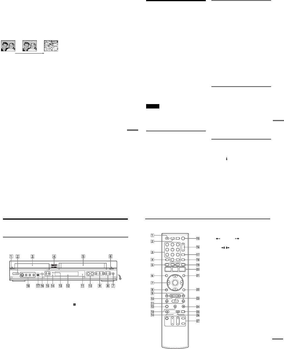
1-27
111
Additional Information
–A disc that has a non-standard shape (e.g.,
card, heart).
–A disc with a label or sticker on it.
–A disc that has cellophane tape or sticker
adhesive on it.
Symptoms caused by contaminated video
heads
When the video heads are dirty, the picture is
distorted or the tape cannot be played.
Clean the video heads using a Sony video head
cleaning cassette. If a Sony cleaning cassette is not
available in your area, have the heads cleaned at
your nearest Sony dealer (a standard service fee
will be charged). Do not use a commercially
available liquid type cleaning cassette, as it may
damage the video heads.
Specifications
System
[DVD recorder section]
Laser
Semiconductor laser
Audio recording format
Dolby Digital
Video recording format
MPEG Video
[VCR section]
Format
VHS NTSC standard
Video recording system
Rotary head helical scanning FM system
Video heads
Double azimuth four heads
Video signal
NTSC color, EIA standards
Tape speed
SP: 33.35 mm/s (13/8inches/s)
EP: 11.12 mm/s (7/16 inches/s)
LP: 16.67 mm/s (11/16 inches/s),
playback only
Maximum recording/playback time
8 hrs. in EP mode (with T-160 tape)
Rewind time
Approx. 2 min (with T-120 tape)
[Timer section]
Clock
Quartz locked
Timer indication
12-hour cycle
Timer setting
12 programs in total (max.)
initial
contamination terminal
,continued
113
Additional Information
About i.LINK
The DV IN jack on this recorder is an i.LINK-
compliant DV IN jack. This section describes the
i.LINK standard and its features.
What is i.LINK?
i.LINK is a digital serial interface for handling
digital video, digital audio and other data in two
directions between equipment having the i.LINK
jack, and for controlling other equipment.
i.LINK-compatible pieces of equipment can be
connected by a single i.LINK cable. Possible
applications are operations and data transactions
with various digital AV equipment. When two or
more i.LINK-compatible equipment are
connected to this recorder in a daisy chain,
operations and data transactions are possible with
not only the equipment that this recorder is
connected to but also with other devices via the
directly connected equipment.
Note, however, that the method of operation
sometimes varies according to the characteristics
and specifications of the equipment to be
connected, and that operations and data
transactions are sometimes not possible on some
connected equipment.
Note
Normally, only one piece of equipment can be connected
to this recorder by the i.LINK cable (DV connecting
cable). When connecting this recorder to i.LINK-
compatible equipment having two or more i.LINK jacks
(DV jacks), see the instruction manual of the equipment
to be connected.
About the name “i.LINK”
i.LINK is a more familiar term for IEEE 1394 data
transport bus proposed by SONY, and is a
trademark approved by many corporations.
IEEE 1394 is an international standard
standardized by the Institute of Electrical and
Electronics Engineers.
i.LINK baud rate
i.LINK’s maximum baud rate varies according to
the equipment. Three maximum baud rates are
defined:
S100 (approx. 100 Mbps*)
S200 (approx. 200 Mbps)
S400 (approx. 400 Mbps)
The baud rate is listed under “Specifications” in
the instruction manual of each equipment. It is
also indicated near the i.LINK jack on some
equipment.
The maximum baud rate of equipment on which it
is not indicated such as this unit is “S100.”
When units are connected to equipment having a
different maximum baud rate, the baud rate
sometimes differs from the indicated baud rate.
*What is Mbps?
Mbps stands for megabits per second, or the amount of
data that can be sent or received in one second. For
example, a baud rate of 100 Mbps means that 100
megabits of data can be sent in one second.
i.LINK functions on this recorder
For details on how to dub when this recorder is
connected to other video equipment having DV
jacks, see page 90.
The DV jack on this recorder can only input DVC-
SD signals. It cannot output signals. The DV jack
will not accept MICROMV signals from
equipment such as a MICROMV digital video
camera with an i.LINK jack.
For further precautions, see the notes on page 90.
For details on precautions when connecting this
recorder, also see the instruction manuals for the
equipment to be connected.
Required i.LINK cable
Use the Sony i.LINK 4-pin-to-4-pin cable (during
DV/D8 dubbing).
i.LINK and are trademarks.
114
Guide to Parts and Controls
For more information, see the pages in parentheses.
Front panel
Buttons on the recorder have the same function as the buttons on the remote if they have the same or
similar names.
AA (open/close) button (35, 47, 91)
B"/1 (on/standby) switch (23)
CDisc tray (35, 47, 91)
DDVD t button (85)
TVIDEO button (84)
ETape compartment (69, 76)
FA (eject) button (69)
GzREC (record) button (47, 76)
Hm/M (rewind/fast-forward) buttons
(37)
IH (play) button (35, 69)
X (pause) button (36, 47, 71, 76)
x (stop) button (35, 47, 69, 76)
JSELECT DVD/VIDEO buttons (35, 47, 69,
76)
K (remote sensor) (21)
LFront panel display (45, 73)
MHDMI indicator (16)
NSYNCHRO REC indicator (51, 80)
OCHANNEL/TRACKING +/– buttons*1*2
(47, 70, 76)
PONE-TOUCH DUBBING button (93)
QDV IN jack (90)
RLINE 2 IN (S VIDEO/VIDEO/AUDIO L
(MONO)/R) jacks (27)
*1 The CHANNEL/TRACKING + button has a tactile
dot. Use the tactile dot as a reference.
*2 The CHANNEL +/– buttons are used for channel
selection when the set top box control is turned on
(page 12).
Open the
cover
115
Additional Information
Remote
For DVD functions
AZOPEN/CLOSE button (35, 47, 91)
BDVD button (35, 47)
CNumber buttons*1 (36)
SET button (102)
DANGLE button (36)
ETOP MENU button (35)
MENU button (35)
FDISPLAY button (44)
GM/m/</,/ENTER button (23)
HORETURN button (23)
I.PREV (previous)/> NEXT
buttons (36)
J REPLAY/ ADVANCE buttons
(36)
Km/M (search) buttons (36)
LCLEAR button (103)
MXPAUSE button (47)
NzREC (record) button (47)
O?/1 (on/standby) switch (23)
PCH (channel) +/– button*1*2 (12, 47)
QINPUT button (47, 54, 91)
RTIME/TEXT button (45)
SAUDIO button*1 (36)
SUBTITLE button (36)
TSYSTEM MENU button (10)
TITLE LIST button (39, 57)
TIMER button (49)
UORIGINAL/PLAYLIST button (39, 57)
VOPTIONS button (40)
WHPLAY button*1 (35)
XxSTOP button (35, 47)
YREC MODE button (47, 91)
ZSYNCHRO REC button (51)
wj TV buttons
•?/1 (on/standby) switch (21)
•INPUT button (21)
•CH (channel) +/– button*1 (21)
•VOL (volume) +/– button (21)
•DIGITAL/ANALOG button (21)
*1 Number 5, AUDIO, CH +, and HPLAY buttons
have a tactile dot. Use the tactile dot as a reference.
*2 The CH +/– button are used for channel selection
when the set top box control is turned on (page 12).
112233
445566
7788
00
99
,continued
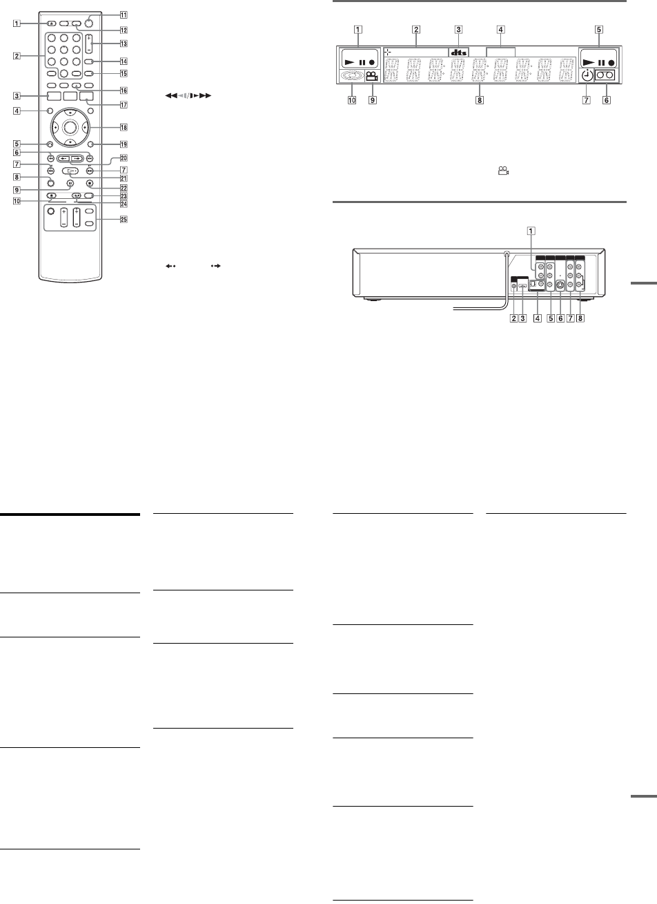
1-28
116
For VCR functions AZOPEN/CLOSE (eject) button (69)
BNumber buttons*1 (76)
SET button (102)
CSYSTEM MENU button (10)
DDISPLAY button (73)
EORETURN button (23)
F.PREV (previous)/> NEXT
buttons (71)
G (search) buttons (71)
HCLEAR button (69)
IXPAUSE button (71, 76)
JzREC (record) button (76)
K?/1 (on/standby) switch (23)
LVIDEO button (69, 76)
MCH (channel)/TRACKING +/– button*1*2
(12, 70, 76)
NINPUT button (76)
OTIME/TEXT button (73)
PAUDIO button*1 (74)
QTIMER button (78)
RM/m/</,/ENTER button (23)
SOPTIONS button (72)
T REPLAY/ ADVANCE buttons
(71)
UHPLAY button*1 (69)
VxSTOP button (69, 76)
WREC MODE button (76)
XSYNCHRO REC button (80)
YTV buttons
•?/1 (on/standby) switch (21)
•INPUT button (21)
•CH (channel) +/– button*1 (21)
•VOL (volume) +/– button (21)
•DIGITAL/ANALOG button (21)
*1 Number 5, AUDIO, CH +, and HPLAY buttons
have a tactile dot. Use the tactile dot as a reference.
*2 The CH +/– button are used for channel selection
when the set top box control is turned on (page 12).
112233
445566
7788
00
99
117
Additional Information
Front panel display
ADVD playing/recording status
BDisc type/recording format
CAudio signal indicators
DSTEREO indicator (74)
EVIDEO playing/recording status
FTape indicator
GTimer indicator
HDisplays the following (45, 73):
•Playing time/remaining time
•Current title/chapter/track/index number
•Recording time/recording mode
•Clock
•Channel
I (angle) indicator (36)
JDisc indicator
Rear panel
AAUDIO OUT L/R jacks (18)
BSET TOP BOX CONTROL jack (13)
CHDMI OUT jack (16)
DDIGITAL AUDIO OUT (COAXIAL/
OPTICAL) jacks (18)
ECOMPONENT VIDEO OUT (Y, PB, PR)
jacks (17)
FS VIDEO OUT jack (15)
GLINE 1 IN (VIDEO/AUDIO L/R) jacks
(13)
HLINE OUT (VIDEO/AUDIO L/R) jacks
(15, 17)
DVD RW VR VCD VIDEO
STEREO
L
R
VIDEO
AUDIO
LINE OUT
VIDEO
YL
P
B
R
P
R
AUDIO
LINE 1 IN
AUDIO OUT S VIDEO OUT
COMPONENT
VIDEO OUT
DIGITAL AUDIO OUT
OPTICAL COAXIAL
HDMI OUT
SETTOP
BOX
CONTROL
118
Glossary
Chapter (page 40)
Sections of a picture or a music feature that are
smaller than titles. A title is composed of several
chapters. Depending on the disc, no chapters may
be recorded.
Copy protection signals (page 47)
Copy restriction set by copyright owners, etc.
These signals are included in some software or TV
programs and restrict recording on this recorder.
Dolby Digital (page 98)
Digital audio compression technology developed
by Dolby Laboratories. This technology conforms
to multi-channel surround sound. The rear channel
is stereo and there is a discrete subwoofer channel
in this format. Dolby Digital provides the same
discrete channels of high quality digital audio
found in “Dolby Digital” theater surround sound
systems. Good channel separation is realized
because all of the channel data is recorded
discretely, and little deterioration occurs because
all channel data processing is digital.
DTS (page 98)
Digital audio compression technology by DTS,
Inc. This technology conforms to multi-channel
surround sound. The rear channel is stereo and
there is a discrete subwoofer channel in this
format. DTS provides the same discrete channels
of high quality digital audio.
Good channel separation is realized because all of
the channel data is recorded discretely, and little
deterioration occurs because all channel data
processing is digital.
DVD+RW (page 30)
A DVD+RW (read “plus RW”) is a recordable and
rewritable disc. DVD+RWs use a recording
format that is comparable to the DVD VIDEO
format.
DVD-RW (page 30)
A DVD-RW is a recordable and rewritable disc
that is the same size as a DVD VIDEO. The DVD-
RW has two different modes: VR mode and Video
mode. DVDs created in Video mode have the
same format as a DVD VIDEO, while discs
created in VR (Video Recording) mode allow the
contents to be programmed or edited.
DVD+R (page 30)
A DVD+R (read “plus R”) is a recordable disc that
is the same size as a DVD VIDEO. Contents can
be recorded only once to a DVD+R, and will have
the same format as a DVD VIDEO.
DVD-R (page 30)
A DVD-R is a recordable disc that is the same size
as a DVD VIDEO. Contents can be recorded only
once to a DVD-R. The DVD-R has two different
modes: VR mode and Video mode. DVDs created
in Video mode have the same format as a DVD
VIDEO, while discs created in VR (Video
Recording) mode allow the contents to be
programmed or edited.
DVD VIDEO (page 33)
A disc that contains up to eight hours of moving
pictures on a disc the same diameter as a CD.
The data capacity of a single-layer and single-
sided DVD is 4.7 GB (Giga Byte), which is 7
times that of a CD. The data capacity of a double-
layer and single-sided DVD is 8.5 GB, a single-
layer and double-sided DVD is 9.4 GB, and
double-layer and double-sided DVD is 17 GB.
The picture data uses the MPEG 2 format, which
is a worldwide standard of digital compression
technology. The picture data is compressed to
about 1/40 (average) of its original size. The DVD
also uses a variable rate coding technology that
changes the data to be allocated according to the
status of the picture. Audio information is
recorded in a multi-channel format, such as Dolby
Digital, allowing you to enjoy a more real audio
presence.
Furthermore, various advanced functions such as
the multi-angle, multilingual, and Parental
Control functions are provided on the DVD.
119
Additional Information
HDMI (High-Definition Multimedia Interface)
(page 16)
HDMI is an interface that supports both video and
audio on a single digital connection. The HDMI
connection carries standard to high definition
video signals and multi-channel audio signals to
AV components such as HDMI equipped TVs, in
digital form without degradation.
The HDMI specification supports HDCP (High-
bandwidth Digital Contents Protection), a copy
protection technology that incorporates coding
technology for digital video signals.
Interlace format
Interlace format shows every other line of an
image as a single “field” and is the standard
method for displaying images on television. The
even number field shows the even numbered lines
of an image, and the odd numbered field shows the
odd numbered lines of an image.
Original (page 56)
Titles actually recorded on a DVD-RW (VR
mode) or DVD-R (VR mode). Erasing original
titles frees up disc space on DVD-RWs.
Playlist (page 56)
Playback information created from the actual
recordings on a DVD-RW (VR mode) or DVD-R
(VR mode). A Playlist leaves the original titles as
they are, and contains only the information needed
to control playback. A Playlist title takes up very
little disc space.
Progressive format (page 97)
Compared to the Interlace format that alternately
shows every other line of an image (field) to create
one frame, the Progressive format shows the entire
image at once as a single frame. This means that
while the Interlace format can show 30 frames/60
fields in one second, the Progressive format can
show 60 frames in one second. The overall picture
quality increases and still images, text, and
horizontal lines appear sharper.
Title (page 40)
The longest section of a picture or music feature
on a DVD, movie, etc., in video software, or the
entire album in audio software.
Track (page 40)
Sections of a music feature on a CD (the length of
a song).

1-29
120
DVD Audio/Subtitle
Language
When you play a DVD VIDEO, the language of
the selected audio track or subtitle is abbreviated
as follows. See page 102 to change the audio track
or subtitle.
Abbreviation Language
ARA Arabic
BUL Bulgarian
CHI Chinese
CRO Croatian
CZE Czech
DAN Danish
DEU German
ENG English
ESP Spanish
FIN Finish
FRA French
GRE Greek
HUN Hungarian
IDN Indonesian
IND Hindi
ISL Icelandic
ITA Italian
IWR Hebrew
JPN Japanese
KOR Korean
MAL Malay
NLD Dutch
NOR Norwegian
POL Polish
POR Portuguese
RUS Russian
SVE Swedish
THA Thai
TUR Turkish
VIE Vietnamese
ZAF Afrikaans
Abbreviation Language
121
Additional Information
Cable Box/Satellite
Receiver Brand Code
When you want to use the set top box control
function, find the brand code number of your cable
box/satellite receiver from the list and enter it in
step 7 of Easy Setup (page 23).
If more than one code number is listed, try
entering them one at a time until you find the one
that works with your cable box/satellite receiver.
Cable box brand Code number
3M 0033
ABC 0003, 0007, 0011, 0017,
0008, 0014, 0001, 0013,
0206, 0047, 0237, 0033
Accuphase 0003, 0007, 0013, 0047,
0001, 0011, 0017, 0014,
0206
Acorn 1102, 0237
Action 0237
Active 0237, 1102
Aim 0015
Allegro 0315, 0153
Amark 0008, 0277, 0144, 0056
American 0060
Americast 0899
Antronix 0207, 0022
Anvision 0211, 0111
Apache 0770
Arbatron 0014, 0011, 0003, 0476
Archer 0153, 0022, 0207, 0039,
0797, 0237, 0260
ASE 1080
Auna 1269
BBT 0267
BCC 0276
Belcor 0056, 0022
Bell & Howell 0014
Bell Atlantic 0641
Bell South 0899
Bestlink 0303
Betavue 0022
British Telecom 0003
BVS 0641
Cable Healthcare 0769, 0058
Cable Star 0056
Cabletenna 0022, 0039
Cableview 0022
Century 0153, 0618, 0008, 0315
Citation 0017
Citizen 0153, 0315, 0078, 0242
Clearmaster 0883
ClearMax 0883, 1247
Colour Voice 0031, 0025
Comband 0233, 0232
Comtec 0274
Comtronics 0060, 0040
Comtronics Eagle 0040, 0060
Contec 0019
Coolmax 0883
Curtis Mathes 0015, 0242
Dae Ryung Eagle 0008
Daeryung 0008, 0877, 0477, 0277,
1877
Diamond 0035
Digeo 1476
Digi 0637
Director 0476
Dumont 0637
Eagle Comtronics 0060, 0028
Eastern 0002, 0274, 0418
Electricord 0078
Emerson 0797, 0303, 0015, 0014
Everquest 0040, 0015
Focus 0400
Fosgate 0276
Fujitsu 0246
Funai 0248, 0019
FutureVision 0649
Cable box brand Code number
,continued
122
Garrard 0153
Gateway 0764
GC Electronics0207, 0056, 0330, 0016,
0040, 0077, 0030
GE 0232, 0233, 0144, 0021
Gemini 0015, 0070, 0057, 0242,
0014, 0797, 0013, 0400
General Instrument 0476, 0011, 0014, 0098,
0810, 0024, 0003, 0015,
0276
GHZ 0078
Gibraltar 0003
Global 1327
GMI 0069, 0057, 0015, 0797
GoldStar 0144, 0040
Goodmind 0770, 0797
Gradiente1136
Hamlin 0020, 0009, 0034, 0259,
0015, 0273, 0206
Healthway Interactive 0058, 1020, 1015, 0769
Hitachi 0011, 0154, 0009, 0008,
0003, 0033, 0014, 0255
Houston Tracker 0011
Hwalin 0303
Hytek 0007
IBM 0670
IEEC 1018
Interbuy 0274
IPC Guest Services 0893
Jasco 0315, 0153, 0015
Jebsee 0014, 0400
Jerrold 0003, 0014, 0276, 0011,
0012, 0020, 0024, 0015,
0047, 0098, 0476, 0031,
0029, 0111, 0032, 0054,
0810, 0028
Kuang Yu 0024
Leon 0069, 0015
LG 0040, 0144
Linsay 0440
Macom 0033
Cable box brand Code number
Maestro 0812
Magnavox 0797, 0027, 0032, 0334,
0069
Millennium 0618, 0153
Memorex 0000
Mitsubishi 0003
Motorola 0476, 0276, 1476, 0810,
1376, 1254, 0400, 1106
Movie Time 0156, 0078, 0063, 0203
MS 0069, 0015, 1018, 0303
MultiVision 0012
Myrio 1117
NET 0274
Next Level 0764, 1316, 1315, 1314
Nexus 0770
Northcoast 0671, 0314
Nova Vision 0277, 0008
Novabeam 0277
Novaplex 0618, 0277, 0017, 0008
NSC 0156, 0070, 0203, 0063,
0400, 0012, 0618, 0022,
0637, 0010, 0044
Oak 0007, 0019, 0303, 0248,
0017
Omega 0015
Omniview 0371
Optimus 0021
Pace 0237
Pacific Bell 0843
Panasonic 0107, 0021, 0144, 0008,
0124, 0307, 0000, 0040
Panther 0637
Paragon 0000, 0525, 0008
Penney 0637, 0000
Philips 0025, 0031, 0290, 0027,
0030, 0153, 0060, 0242,
0028, 0334, 0211, 0029,
0259, 0307, 0652, 0013,
0069, 0649, 0255, 0305,
0032, 0111, 0317
Pioneer 0144, 0023, 0533, 1877,
0877, 0260
Cable box brand Code number
123
Additional Information
Popular Mechanics 0400
Prelude 0770
Prism 0012, 0013, 0059
Protelcon 0786
Pulsar 0000, 0040
Quasar 0000
Quest 0144, 0020
R Line 0040
RadioShack 0883, 0015, 0315, 0303,
0797
Rampage 0255
Ranger 1247
RCA 0021, 0060, 0797, 0047,
1256, 0843
Realistic 0207, 0153
Recoton 0153, 0400
Regal 0259, 0020, 0273, 0279,
0276
Regency 0002, 0020, 0682
Rembrandt 0070, 0153, 0040, 0022,
0011
RK 0304, 0306, 0479
Runco 0000
Samsung 0040, 0144, 0023, 0003,
0070, 0000
Sasktel 1737
Scientific Atlanta 0008, 0277, 0017, 0006,
0237, 0025, 0477, 0207,
0877, 0003, 0012, 0000,
0021, 1877
Seam 0510
Sears 0510
Sejin 1265
Siemens 0246
Sigma 0019
Signal 0040, 0015, 0011, 0035
Signature 0011
SkyCable 0112
Skygiant 1091
SL Marx 0040
Cable box brand Code number
Sony 1006
Spectradyne 0769, 0058
Spectravision 0058
Sprucer 0021, 0307, 0010, 0144
Standard Components 0203, 0096, 0155
Starcom 0003, 0015, 0047, 0014,
0098, 0305
Stargate 0015, 0040, 0770, 0865,
0797, 0305, 0014
Starquest 0015
StarSight 0542, 0422
Stealth 0274
Stellar One 0807
Storm 1018, 0637
Suena Madritel 1230
Supercable 0276
Supermax 0883
Sylvania 0001
Tandy 0258
Tatung 0097
Teac 1018
Technics 0029
Teknika 0146
Teleavia 0040
TeleCaption 0221
Teleview 0063, 0040
Texscan 0001, 0096, 0010
TFC 0310
Thomson 1256
Timeless 0418, 0274, 0040
Tocom 0012, 0013, 0029, 0019,
0059, 0017
Torx 0003
Toshiba 0000
Trans PX 0303, 0276, 0153, 0315
Trinity 1248
Tristar 0883
TS 0255, 0024, 1018, 0003,
0303
Cable box brand Code number
,continued

1-30E
124
Tusa 0015
TV COMM 0035, 0019
TV Guide 1476
TV86 0063, 0040
Uniden 0022, 0225
Unika 0207, 0153, 0022
United Artists 0007
United Cable0003, 0014, 0011, 0276
Universal 0191, 0078, 0207, 0056,
0022, 0039, 0153, 0077,
0322, 0315
US Electronics 0276, 0008, 0003, 0017
V2 0883
Verizon 0246
Videoway 0250, 0000
VideoWorks 0124
Vidtech 0244
Viewmaster 0883, 0770
Viewstar 0258, 0289, 0060, 0063,
0211, 0027, 0111, 0030,
0121
Vision 0883
Visionetics 1264
Vortex View 0883
WaveMaster 0565
Wiso 0078
Zenith 0000, 0525, 0054, 0017,
0039, 0153, 0060, 0315,
0191, 0899
Zentek 0400
Cable box brand Code number Satellite receiver
brand Code number
AlphaStar 0772
Atlantic Telephone 1333
Bell ExpressVu 0775
Century 0856
Chaparral 0216
Crossdigital 1109
DirecTV 0749, 0566, 0392, 1749,
0099, 1109, 1076, 1442,
1856, 0247, 1142, 1639,
0724, 0639, 0819
Dish Network System 0775, 1005, 1170
Dishpro 0775, 1005
Echostar 0775, 1170, 1005
Expressvu 0775
Galaxis 0863
GE 0566
General Instrument 0361, 0869, 0627
GOI 0775
Gradiente 0856
Hitachi 0819, 0749
Houston Tracker 0775
HTS 0775
Hughes Network Systems 0749, 1749, 1442, 1142
Humax 1176, 1359, 1048, 0863,
0283
Innova 0099
Jerrold 0361, 0036, 0627
JVC 0775, 1170
Magnavox 0722, 0724
McIntosh 0869
Memorex 0724
Mitsubishi 0749
Motorola 0869
NEC 1270, 0496, 0499, 0507,
0508
Netsat 0099
Next Level 0869
Optimus 0724
Panasonic 0247, 0701
125
Additional Information
Paysat 0724
Philips 1076, 0099, 1142, 0724,
0722, 0749, 1442, 1749,
0856, 0775
Primestar 0361, 0627, 0869
Proscan 0392, 0566
QNS 1367
RadioShack 0869
RCA 0566, 0392, 0143, 0855
Samsung 1109, 1276
Sky 0856, 0099, 1856
Sony 0639, 1639
Star Choice 0869
Star Trak 0869, 0772
Thomson 0566, 0392
Tivo 1142, 1442
Toshiba 0790, 0749, 1749, 1285
UEC 1333, 1358
Uniden 0724, 0722
Video Cipher II Plus 0361
Zenith 0856, 1856
Satellite receiver
brand Code number
126
Index
Words in quotations appear in
the on-screen displays.
Numerics
16:9 25,96
4:3 Letter Box 25,96
4:3 Pan Scan 25,96
A
“A-B Erase” 58
“Add” 64,65
ADVANCE 36,71
ANGLE 36
AUDIO 36,74
“Audio” 102
“Audio (HDMI)” 99
Audio cords 18
“Audio DRC” 99
Audio settings 98
“Auto Play” 101
“Auto Repeat” 101
B
Batteries 21
“Black Level” 97
“Brand Code” 101
C
Cable box 13
Cable box brand 121
Cable box brand code 121
“Ch. Digit lock” 101
Changing or canceling timer
settings (Timer List) 53,81
Chapter 118
“Chapter Erase” 58
“Check” 63
Child Lock 38
Cleaning discs 110
Cleaning the video heads 111
CLEAR 69
Clock Set settings 95
“Combine Titles” 64
“Command Mode” 22,104
COMPONENT VIDEO OUT
17
Connecting
the cable box/satellite
receiver 12
to your AV/amplifier
(receiver) 18
to your TV 15
“Connections” 101
Controlling a Sony TV with
the remote 21
“Copy” 66
Copy protection 47,118
Copy-Free 47
Copy-Never 47
Copy-Once 47
Counter 69
CPRM 30
“Create Dubbing List” 87
“Create Playlist” 62
Creating chapters 49
D
“Digital Out” 98
“Disc Finalize” 67,89
“Disc Format” 67
“Disc Information” 67
“Disc Menu” 102
“Disc Name” 67
“Disc Protect” 67
“Disc Setting” 67,89
Disc types 30
Display
front panel display 117
Setup Display 94
“Divide Title” 59,63
Dolby Digital 25,98,118
“Downmix” 99
DTS 25,37,98,118
“Dubbing” 84,86
“DV/D8 Audio Input” 92,
100
“DV/D8 Dubbing” 92
“DV/D8 One Touch
Dubbing” 93
“DV/D8 Simple Dubbing” 92
“DVD Auto Chapter” 100
DVD Editing 56
DVD VIDEO 33,118
DVD+R 30,118
DVD+R DL 30
DVD+RW 30,118
DVD-R 30,118
DVD-RAM 33
DVD-RW 30,118
E
Easy Setup 104
“Edit” 53,82
“Edit Playlist” 63
“Edit Scene” 63
Enter characters 60
EP mode 76
“Erase” 53,58,82
“Erase All Titles” 67
F
“Factory Setting” 104
Fast forward 37,71
Fast reverse 37,71
Feature settings 100
Finalizing 88
“Format DVD-RW” 101
Formatting 47,67
“Front Display” 103
Front panel 114
Front panel display 117
H
Handling discs 110
HDMI 16,119
“HDMI Resolution” 96
I
i.LINK 90,113
INPUT 48,76,91
Interlace format 119
J
JPEG image files 42
L
“Language” 102
Language abbreviation 120
LINE 1 IN 13
LINE 2 IN 27
127
“Line Audio Input” 51,55,
100
M
MENU 35
Menu
Top menu 35
“Mode for SET button” 102
“Modify” 64
“Move” 65
MP3 audio tracks 41
N
NEXT 36,71
Number buttons 40
O
One Touch Dubbing 93
On-screen display
OPTIONS menu 11
Setup Display 94
Sub-menu 11
System Menu 10
OPTIONS 11
Options settings 102
Original 39,119
ORIGINAL/PLAYLIST 39,
57
“OSD” language 24,102
P
“Parental” 103
Parental Control 38
Parts and controls 114
PAUSE 37,48,71,76
PBC 38
“Picture Control” 97
PLAY 35,69
Playable discs 33
Playback 35,69
JPEG image files 42
MP3 audio tracks 41
Resume Play 38
Slow-motion play 37,71
Playlist 39,61,119
Power cord 20
PREV 36,71
Program Dubbing 86
“Progressive” 97
Progressive format 119
“Protect” 58
Q
Quick Timer 48,76
R
Rear panel 117
REC 48,76
REC MODE 48,76
Recording 46,75
recordable discs 30
recording format 30
recording mode 46
tape speed 75
Recording mode 46,75
Recording time 46,49
Region code 34
Remaining time 44,77
Remote 21,115
REPLAY 36,71
Resetting 104
Resume Play 38
Rotate 42
S
Safety tab 75
Satellite receiver 13
Satellite receiver brand code
124
“Scan Audio” 38,99
“Scene Dubbing” 87
Searching
for “Chapter” 40
for “Title” 40
for “Track” 40
Time Search 40
Set top box control 12,24,
101
Set top box controller 12,26
Settings 94
Setup Display 94
“Simple Dubbing” 86
Slide show 42,43
SP mode 76
STOP 35,48,69,76
Sub-menu 11
SUBTITLE 36
“Subtitle” 102
“Surround” 99
SYNCHRO REC 52,80
“Synchro Recording” 52,80,
101
System Menu 10
T
“Tape Length” 101
Tape speed 75
TIME/TEXT 45,73
TIMER 50,78
Timer List 53,81
Timer recording 49,78
change or cancel 53,81
Title 119
“Title Dubbing” 87
“Title Erase” 58,63
TITLE LIST 39,57
Title List 39
“Title Name” 58,63
TOP MENU 35
Track 119
TRACKING 70
Tracking adjustment 70
Troubleshooting 105
“TV Type” 96
U
“Unfinalize” 89
Unrecordable pictures 47
V
“VCR Function” 101
“Video (HDMI)” 96
VIDEO CD 33
Video mode 30
Video settings 96
VR mode 30
Z
Zoom 42
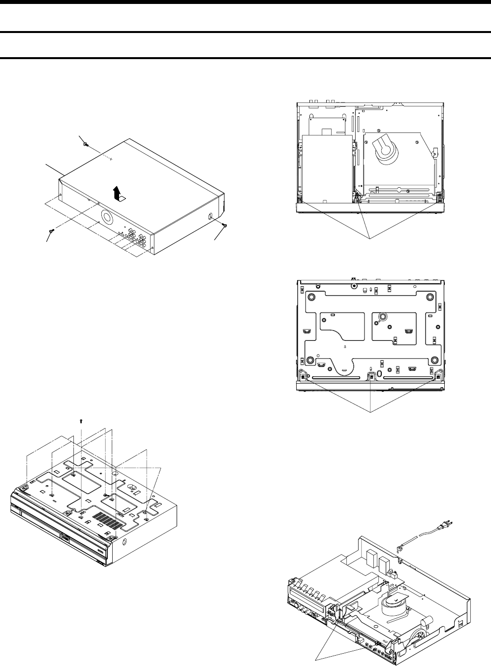
2-1
RDR-VX525
2. DISASSEMBLY AND REASSEMBLY
2-1 CABINET AND PCB
Fig. 2-1 Cabinet Top Removal
Fig. 2-2 Bottom Cover Removal
2-1-1 Cabinet Top Removal
2-1-2 Bottom Cover Removal
2-1-3 Ass’y Front Panel Removal
Fig. 2-3 Ass’y Front Panel Removal
2-1-4 Function PCB Removal
Fig. 2-4 Function PCB Removal
(Bottom View)
1REMOVE 8 SCREWS
2RELEASE 2 HOOKS
2 RELEASE 3 HOOKS
(Bottom View)
1 RELEASE 2 HOOKS
1REMOVE 1 SCREW
3Lift up the Cabinet Top
in the direction of arrow
2REMOVE
8 SCREWS
1REMOVE
1 SCREW
1 RELEASE 3 HOOKS
(Top View)
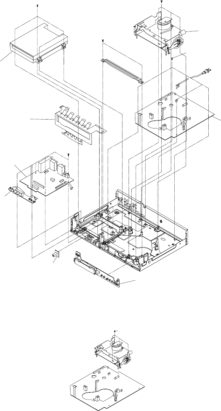
2-2
Fig. 2-5 Chassis Removal
2-1-5 Chassis Removal
2-1-6 VCR Main PCB Removal
Fig. 2-6 VCR Main PCB Removal
2REMOVE 4 SCREWS
5REMOVE 5 SCREWS
4REMOVE 6
SCREWS
1REMOVE 2 SCREWS
3REMOVE 4 SCREWS
DVD DECK
DVD MAIN PCB
VCR DECK
VCR MAIN PCB
FRONT JACK PCB
DV JACK PCB
FUNCTION PCB
SHIELD LOADER
1 REMOVE 4 SCREWS
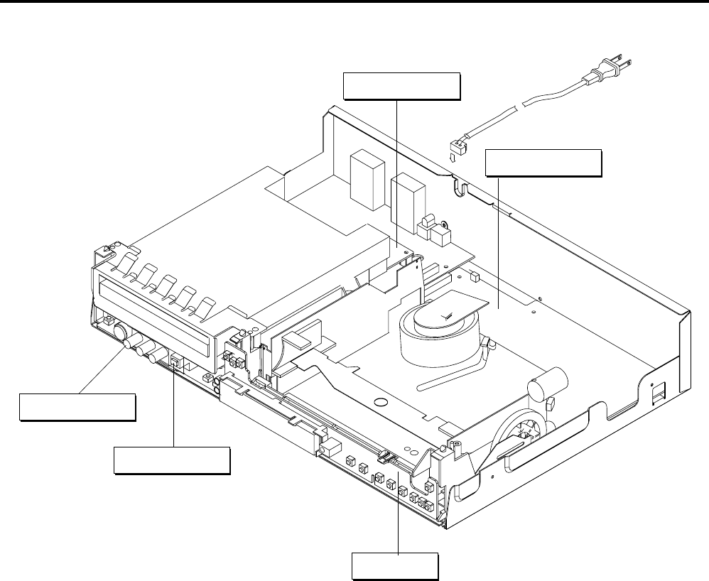
2-3
Fig. 2-7 Circuit Board Locations
2-2 CIRCUIT BOARD LOCATIONS
VCR MAIN PCB
FUNCTION PCB
DVD MAIN PCB
DV JACK PCB
FRONT JACK PCB
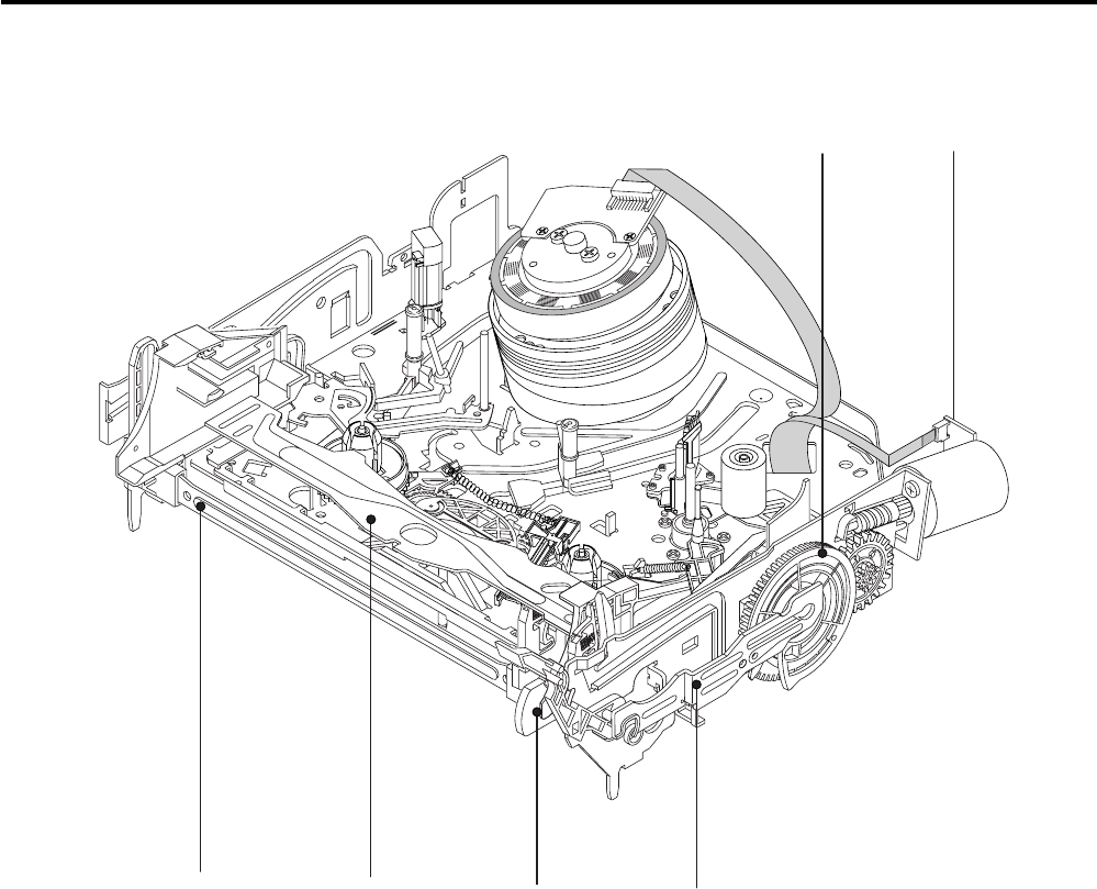
2-4
2-3 VCR DECK PARTS LOCATIONS
2-3-1 Top View
Fig. 2-8 Top parts Location-1
1GEAR FL CAM
2ASS’Y MOTOR LOADING
3ASS’Y LEVER ARM
4ASS’Y HOLDER CASSETTE
5LEVER FL DOOR
6SLIDER FL DRIVE
2
3456
1
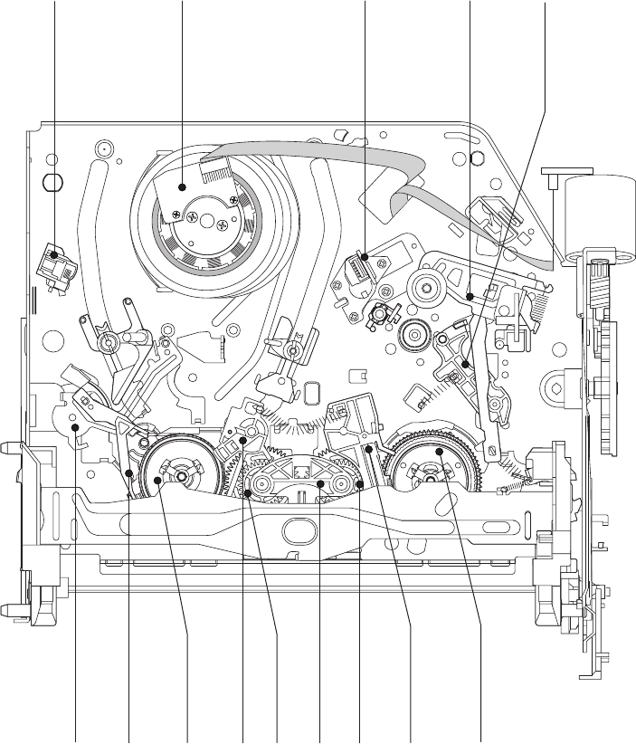
2-5
Fig. 2-9 Top Parts Location-2
1FE HEAD
2ASS’Y CYLINDER
3ASS’Y ACE HEAD
4ASS’Y LEVER UNIT PINCH
5ASS’Y LEVER #9 GUIDE
6ASS’Y LEVER TENSION
7ASS’Y BAND BRAKE
8DISK S REEL
9ASS’Y LEVER S BRAKE
0GEAR IDLE
qa LEVER IDLE
qs ASS’Y LEVER T BRAKE
qd DISK T REEL
12
6789 qa0qs qd
0
34
5
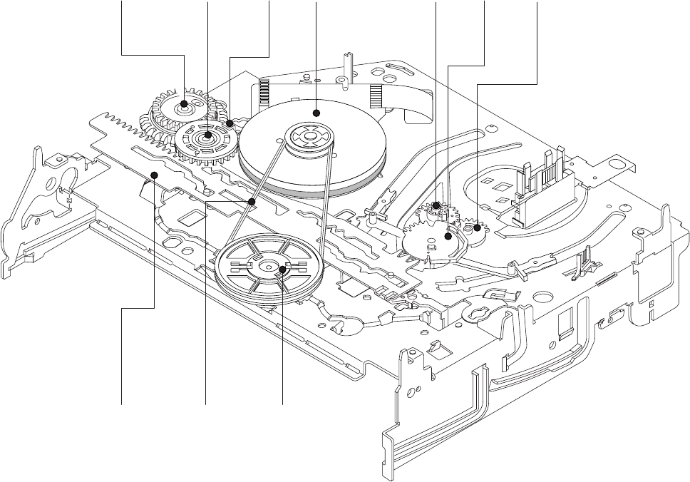
2-6
2-3-2 Bottom View
Fig. 2-10 Bottom Parts Location
1GEAR JOINT 1
2GEAR JOINT 2
3BRAKET GEAR
4ASS’Y MOTOR CAPSTAN
5ASS’Y LEVER T LOAD
6GEAR LOADING DRIVE
7ASS’Y LEVER S LOAD
8ASS’Y CLUTCH
9BELT PULLEY
0SLIDER CAM
123
4567
8
9
0
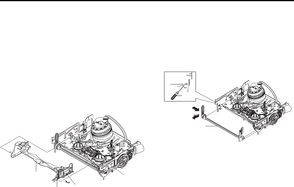
2-7
2-4 VCR DECK
2-4-1 Ass’y Holder Cassette Removal
1) Pull the Ass’y Holder Cassette 1 to the eject position.
2) Pull the Ass’y Holder Cassette 1 as grasping the Ass’y Holder
Cassette 1 and Lever Lock2 in the same time to release hooking
from Main Base until the Boss [A] of Ass’y Holder Cassette 1
is taken out from the Rail [B].
3) Lift the Ass’y Holder Cassette 1, in this time, you have to grasp
the Lever Lock 2 Continuously until the Ass’y Holder Cassette
1 is taken out completely.
Note: Be sure to insert Lever Lock 2 in the direction of “A” to
prevent separation and breakage of the Lever Lock 2 at
disassembling and reassembling.
Fig. 2-11 Ass’y Holder Cassette Removal
2-4-2 Ass’y Lever Arm Removal
1) Push the hole “A” in the direction of arrow “B” use the pin.(about
Dia. 2.5)
2) Pull out the Ass’y Lever Arm 1 from the Boss of Main Base.
3) Remove the Ass’y Lever Arm 1 in the direction of arrow “C”.
Fig. 2-12 Ass’y Lever Arm Removal
"A"
1 ASS'Y HOLDER
CASSETTEE
BOSS [A]
2 LEVER LOCK
RAIL [B]
PIN
HOLE "A"
1 ASS'Y LEVER ARM
"C"
"B"
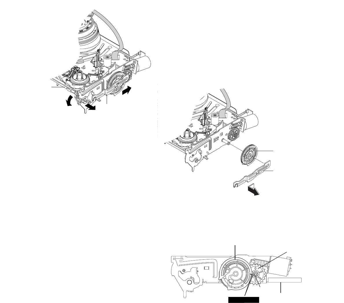
2-8
2-4-4 Slider FL Drive, Gear FL Cam Removal
1) Pull the Slider FL Drive 1 to the front direction.
2) Remove the Slider FL Drive 1 in the direction of arrow. (Refer
to Fig. 2-14)
3) Remove the Gear FL cam 2.
Note: When reinstalling be sure to reassemble Slider FL drive 1
after you insert the Boss of Lever ARM-R in Groove of Slider FL
drive 1.
Assembly: Align the Gear FL Cam 2 with the Gear worm wheel
Post as shown drawing.
(Refer to Timing point)
Fig. 2-14 Slider FL Drive Removal
Fig. 2-15 Gear FL Cam, Gear Worm
2-4-3 Lever FL Door Removal
1) Release the Lever FL Door 2 and Remove the Slider FL Drive
1 in the direction of arrow “A”.
Fig. 2-13 Lever FL Door Removal
"B" "C"
"A"
2LEVER FL DOOR
1SLIDER FL DRIVE
1 SLIDER FL DRIVE
2 GEAR FL CAM
2GEAR FL CAM
GEAR WORM WHEEL
POST
TIMING POINT
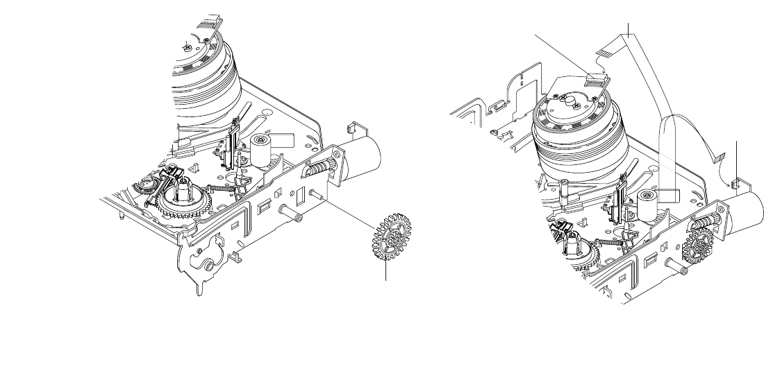
2-9
3CONNECTOR
W AFER
1 CABLE FLAT
2CONNECTOR W AFER
2-4-5 Gear Worm Wheel Removal
1) Remove the Gear Worm Wheel 1.
Fig. 2-16 Gear Worm Wheel Removal
2-4-6 Cable Flat Removal
1) Remove the Drum connecting part of Cable Flat 1 from
Connector Wafer 2, 3.
Fig. 2-17 Cable Flat Removal
1GEAR WORM WHEEL
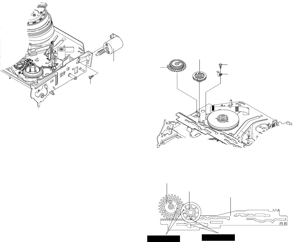
2-10
4 GEAR
JOINT 1
3 GEAR JOINT 2
1 SCREW
2
BRACKET GEAR
2-4-7 Ass’y Motor Loading Removal
1) Remove the Screw 1.
2) Remove the Ass’y Motor Loading 2.
Fig.2-18 Ass’y Motor Loading Removal
2-4-8 Bracket Gear, Gear Joint 2, 1 Removal
1) Remove the Screw 1.
2) Remove the Bracket Gear 2.
3) Remove the Gear Joint 2 3.
4) Remove the Gear Joint 1 4.
Assembly:
1) Be sure to align dot mark of Gear Joint 1 1 with dot mark of
Gear Joint 2 2 as shown Fig 2-20.
(Refer to Timing point 1)
2) Confirm the Timing Point 2 of the Gear Joint 2 2 and Slider
Cam 3.
Fig. 2-19 Bracket Gear, Gear Joint 1, 2 Removal
Fig. 2-20 Gear Joint 1, 2 Assembly
2 ASS'Y MOTOR
LOADING
1 SCREW
TIMING POINT 1 TIMING POINT 2
1 GEAR JOINT 1
2 GEAR JOINT 2
3 SLIDER CAM
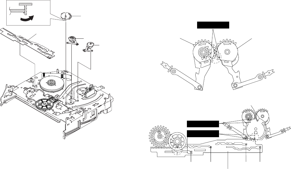
2-11
2-4-9 Gear Loading Drive, Slider Cam,
Ass’y Lever Load S, T Removal
1) Remove the Belt Pulley. (Refer to Fig. 2-38)
2) Remove the Gear Loading Drive 1 after releasing Hook [A] in
the direction arrow as shown in detail drawing.
3) Remove the Slider Cam 2.
4) Remove the Ass’y Lever Load S 3 & Ass’y Lever Load T 4.
Fig. 2-21 Gear Loading Drive, Slider Cam,
Ass’y Lever T, S Load Removal
2-4-10 Gear Loading Drive, Slider Cam,
Ass’y Lever Load S, T Assembly
1) When reinstalling, be sure to align dot of Ass’y Lever Load T
1 with dot of Ass’y Lever Load S 2 as shown in drawing,
(Refer to Timing Point 1).
2) Insert the Pin A, B, C, D into the Slider Cam 3 hole,
3) Be sure to align dot of Ass’y Lever Load T 1 and dot of Gear
Loading Drive 4, (Refer to Timing Point 2).
4) Aline dot of Gear Loading drive 4 with mark of Slider Cam 3
as shown in drawing (Refer to Timing Point 3).
Fig. 2-22 Gear Loading Drive, Slider Cam,
Ass’y Lever Load S, T Assembly
2LEVER LOAD S
1LEVER LOAD T
PIN A PIN C PIN B
PIN D
3SLIDER CAM
TIMING POINT 2
TIMING POINT 1
TIMING POINT 3
4GEAR LOADING DRIVE
HOOK(A)
1 GEAR LOADING DRIVE
2 SLIDE CAM
4 ASS'Y LEVER LOAD T
3 ASS'Y LEVER
LOAD S
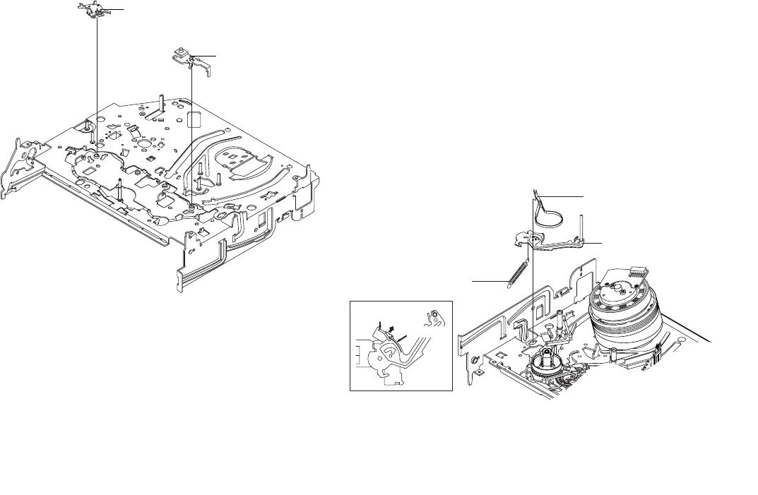
2-12
STOPPER"A"
3 ASS'Y BAND
BRAKE
2 ASS'Y LEVER
TENTION
1 SPRING TENTION
LEVER
MARK[B]
2-4-11 Lever Pinch Drive,
Lever Tension Drive Removal
1) Remove the Lever Pinch Drive 1, Lever Tension Drive 2.
Fig. 2-23 Lever Pinch Drive,
Lever Tension Drive Removal
2-4-12 Ass’y Lever Tension,
Ass’y Band Brake Removal
1) Remove the Ass’y Lever Brake S (Refer to Fig 2-25).
2) Remove the Spring Tension Lever 1.
3) Rotate stopper of Main Base in the direction of arrow “A”.
4) Lift the Ass’y Lever Tension 2 & Ass’y Band brake 3.
Note:
1) When replacing the Ass’y Lever Tension 2, be sure to apply
Grease on the post,
2) Take care not to touch stain on the felt side, and not to be folder
and broken Ass’y Band brake
3) After Ass’y Lever Tension seated, Rotate stopper of Main Base
to the Mark[B].
Fig. 2-24 Ass’y Lever Tension,
Ass’y Band Brake Removal
1 LEVER PINCH DRIVE
2 LEVER TENSION
DRIVE
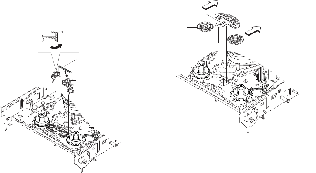
2-13
2-4-13 Ass’y Lever Brake S, T Removal
1) Release the Hook [A] and the Hook [B], [C] in the direction of
arrow as shown in Fig 2-25.
2) Lift the Ass’y Lever S, T Brake 1, 2 with spring brake 3.
Assembly:
1) Assembly the Ass’y Lever S Brake 1 on the Main Base.
2) Assembly the Ass’y Lever T Brake 2 with spring brake 3.
Note: Take extreme care not to be folded and
transformed Spring Brake at removing or reinstalling.
Fig. 2-25 Ass’y Lever Brake S, T Removal
2-4-14 Ass’y Gear Idle Removal
1) Push the Lever Idle 1 in the direction of arrow “A”, “B”.
2) Lift the Lever Idle 1.
Assembly:
1) Apply oil in two Bosses of Lever Idle 1.
2) Assemble the Gear Idle 2 with the Lever Idle 1.
Note: When replacing the Gear Idle 2, be sure to add oil in the
boss of Lever Idle 1.
Fig. 2-26 Ass’y Gear Idle Removal
HOOK(A)
1 ASS'Y
LEVER S BRAKE
3 SPRING BRAKE
2 ASS'Y LEVER T
BRAKE
HOOK(B)
HOOK(C)
"A"
1 LEVER IDLE
2 GEAR IDLE
HOOK "C"
2 GEAR IDLE
"B"
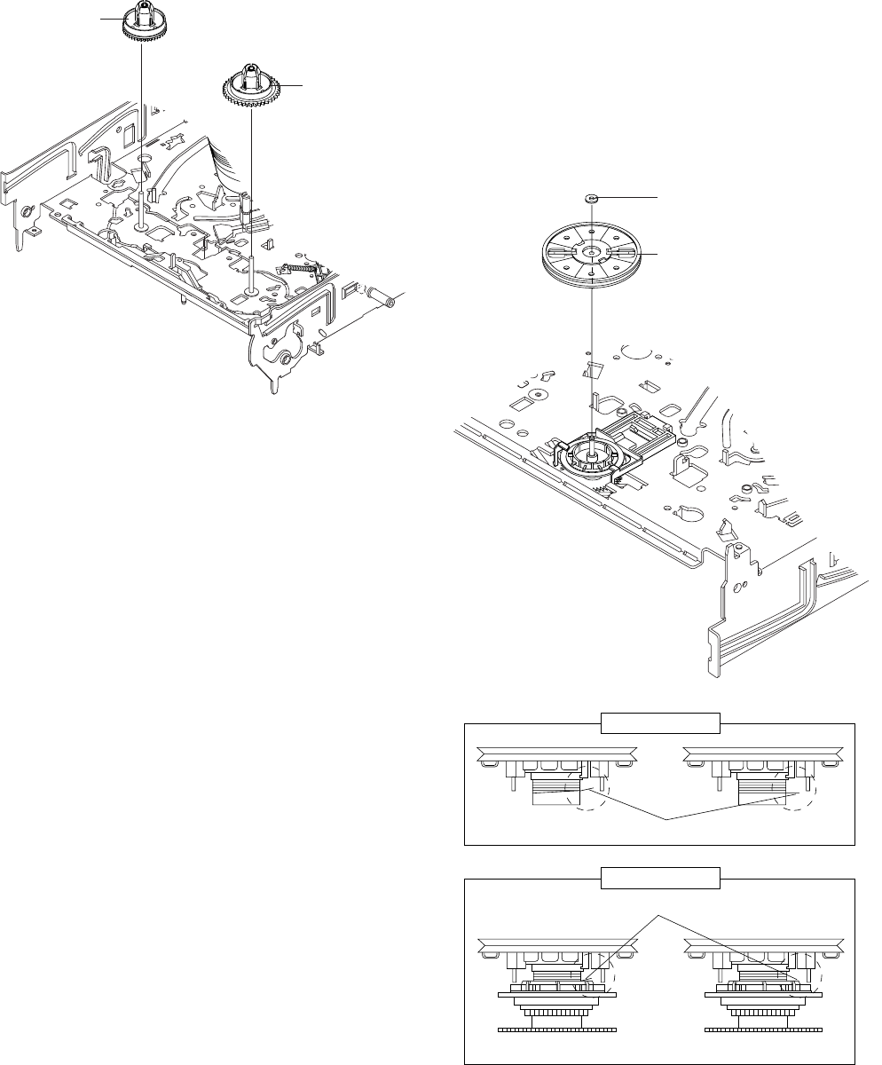
2-14
2-4-15 Disk S, T Reel Removal
1) Lift the Disk S, T Reel 1, 2.
Fig. 2-27 Disk S, T Reel Removal
2-4-16 Ass’y Holder Clutch Removal
1) Remove the Washer Slit 1.
2) Lift the Ass’y Holder Clutch 2.
Note: When you reinstall Ass’y Holder Clutch.
1) Check the condition of spring as shown in detail A.
2) Don't push Ass’y Holder Clutch down with excessive force Just
insert Holder Clutch Ass’y into post center with dead force and
Rotate it smoothly.
Be sure to confirm that spring is in the slit of Ass’y Gear Center
as shown in detail B.
Fig. 2-28 Ass’y Holder Clutch Removal
1WASHER SLIT
2ASS
'
Y HOLDER CLUTCH
DETAIL A
<BAD> SPRING <GOOD>
<BAD>
SPRING
<GOOD>
DETAIL B
1 REEL S
2 REEL T
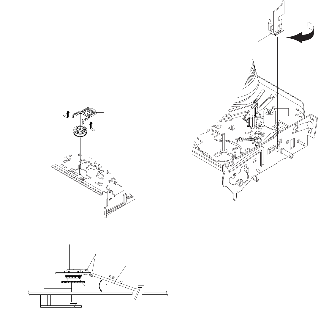
2-15
1 GUIDE CASSETTE DOOR
HOOK [A]
2-4-17 Ass’y Lever Up Down, Ass’y Gear
Center Removal
1) Remove the 2 hooks in the direction of arrow as shown Fig. 2-
29 and lift the Ass’y Lever Up Down 1.
2) Lift the Ass’y Gear Center 2.
Assembly:
1) Insert the Ass’y Lever Up Down 1 in the rectangular holes on
Main Base as shown in Fig 2-30.
2) Lift the Ass’y Lever Up Down 1 about 35°.
(Refer to Fig 2-30)
3) Insert Ring of the Ass’y Gear Center 2 in the Guide of the
Ass’y Lever Up Down 1.
4) Insert the Ass’y Gear Center 2 in the post on Main Base.
5) Push down the Ass’y Lever Up Down 1 for locking of the Hook.
Note:
1) Take care not to separate and sentence does not mark sense.
2) Be sure to confirm that Ring of the Ass’y Gear Center 2 is in
the Guide of the Ass’y Lever Up Down 1 after finishing
assembly of Ass’y Lever Up Down 1 and Ass’y Gear Center
2.
Fig. 2-29 Ass’y Lever Up Down Removal
Fig. 2-30 Ass’y Lever Up Down Removal
2-4-18 Guide Cassette Door Removal
1) Lift the Hook [A].
2) Rotate the Guide Cassette Door 1 in the direction of arrow.
Note: After reinstalling the Guide Cassette Door 1 sure the Hook
[A].
Fig. 2-31 Guide Cassette Door Removal
1 ASS'Y LEVER UP DOWN
2 ASS'Y GEAR CENTER
MAIN BASE
ASS'Y LEVER UP DOWN
GUIDE
ASS'Y GEAR CENTER
RING
GEAR
POST
HOOK
35
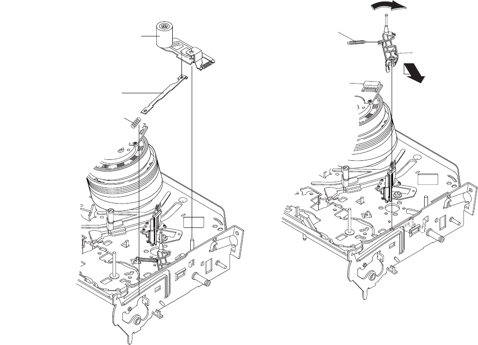
2-16
"A"
"B"
2 ASS'Y LEVER #9 GUIDE
1 SPRING #9 GUIDE
2-4-19 Ass’y Lever Unit Pinch, Plate Joint,
Spring Pinch Drive Removal
1) Lift the Ass’y Lever Unit Pinch 1.
2) Remove the Plate Joint 2 from Lever Pinch Drive.
3) Remove the Spring Pinch Drive 3.
Note:
1) Take extreme care not to touch the grease on the Roller Pinch.
2) When reinstalling, be sure to apply grease on the post pinch
roller.
Fig. 2-32 Ass’y Lever Unit Pinch, Plate Joint,
Spring Pinch Drive Removal
2-4-20 Ass’y Lever #9 Guide Removal
1) Remove the Spring #9 Guide 1.
2) Lift the Ass’y Lever #9 Guide 2 in the direction of arrow “A”.
Note:
1) Take extreme care not to get grease on the tape Guide Post.
2) After reinstalling, check the bottom side of the Post #9 Guide to
the top side of Main Base.
Fig. 2-33 Ass’y Lever #9 Guide Removal
1 ASS'Y LEVER
UNIT PINCH
2 PLATE JOINT
3 SPRING PINCH
DRIVE
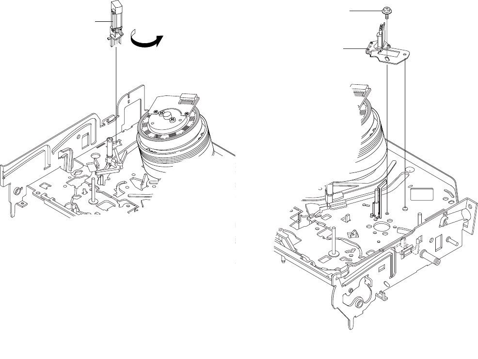
2-17
1 SCREW
2ASS'Y HEAD ACE
1 FE HEAD
2-4-21 FE Head Removal
1) Remove the FE Head 1 in the direction of arrow to lift up.
Fig. 2-34 FE Head Removal
2-4-22 Ass’y ACE Head Removal
1) Pull out the FPC from connector of Ass’y ACE Head 2.
2) Remove the screw 1.
3) Lift the Ass’y ACE Head 2.
Fig. 2-35 Ass’y ACE Head Removal
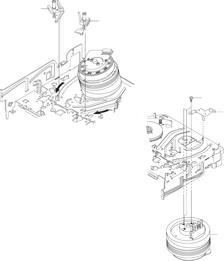
2-18
1 3 SCREWS
2
PLATE GROUND
DECK
3 ASS'Y CYLINDER
1 ASS'Y
SLIDER S
2 ASS'Y
SLIDER T
2-4-23 Ass’y Slider S, T Removal
1) Move the Ass’y Slider S, T 1, 2 to slot, and then lift it to
remove. (Refer to arrow)
Fig. 2-36 Ass’y Slider S, T Removal
2-4-24 Plate Ground Deck, Ass’y Cylinder Re-
moval
1) Remove the 3 Screws 1.
2) Lift the Plate Ground Deck 2.
3) Lift the Ass’y Cylinder 3.
Assembly:
1) Match the 3 holes in the bottom of Ass’y Cylinder 3 to the 3
holes of Main Base as attending not to drop or knock the Ass’y
Cylinder 3.
2) Tighten the 1 Screw 1.
3) Match the Plate Ground Deck 2 to the Hole of Base Main.
4) Tighten the other 2 Screws 1.
Note:
1) Take care not to touch the Ass’y Cylinder 3 and the tape guide
post at reinstalling.
2) When reinstalling, Don't push down too much on Screw Driver.
Fig. 2-37 Plate Ground Deck, Ass’y Cylinder Removal
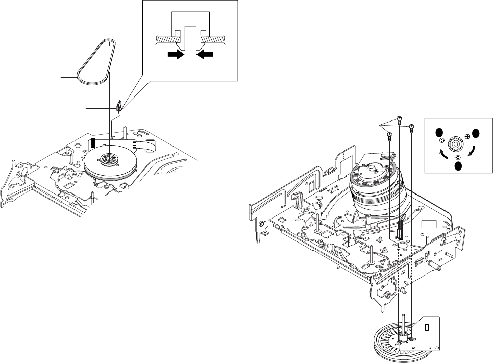
2-19
2 BELT PULLEY
1 HOOK CAPSTAN
HOOK
2-4-25 Hook Capstan, Belt Pulley Removal
1) Remove the Hook Capstan 1 after realeasing Hook in the
direction arrow as shown in detail drawing.
2) Remove the Belt Pulley 2.
Note: Take extreme care not to get grease on Belt Pulley 2 at
assembling or reassembling.
Fig. 2-38 Belt Pulley Removal
2-4-26 Ass’y Motor Capstan Removal
1) Remove the 3 Screws 1.
2) Remove the Ass’y Motor Capstan 2.
Assembly:
1) Match the 3 holes of Ass’y Motor Capstan 2 to the 3 holes of
Main Base. Be careful not to drop or knock the Ass’y Motor
Capstan 2.
2) Tighten the 3 Screws 1 in the direction of arrow as shown detail
drawing.
Note: After tightening screws, check if there is gap between the
head of screws and the top side of Main Base. There should have no
gap between the head of screws and the top side of Main Base.
After reinstalling, adjusting the tape transport system again.
Fig. 2-39 Ass’y Motor Capstan Removal
2 ASS'Y MOTOR
CAPSTAN
1 3 SCREWS
A
B
C
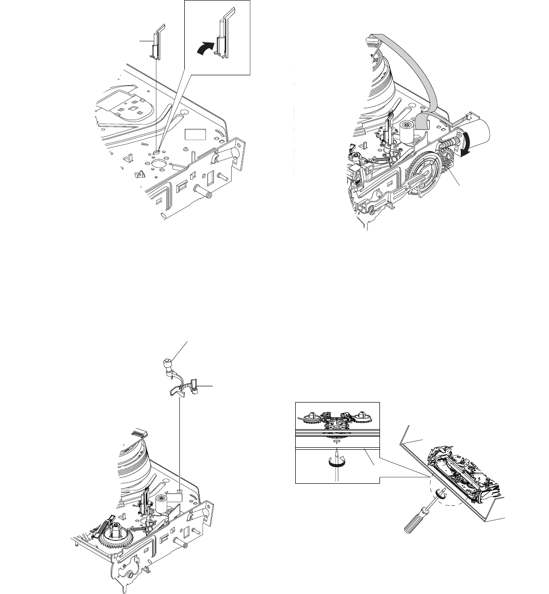
2-20
1 ASS'Y POST #8 GUIDE
Fig. 2-40 Ass’y Post #8 Guide Removal
2-4-27 Ass’y Post #8 Guide Removal
1) Rotate the Ass’y Post #8 Guide 1 in the direction of arrow to
lift up.
2-4-28 Ass’y Level Head Cleaner Removal
1) Release the Hook 1.
2) Lift the Ass’y Lever Head Cleaner 2.
Fig. 2-41 Ass’y Lever Head Cleaner Removal
2-4-29 How to Eject the Cassette Tape
(If the tape is stuck in the unit)
1) Turn the Gear worm 1 clockwise with screw driver.(Refer to
arrow)
(Other method: Remove the Screw of Ass’y Motor Load,
Separate the Ass’y Motor Load)
Fig. 2-42
2) When Slider S,T are approched in the position of unloading,
rotate holder Clutch counterclockwise after inserting screw driver
in the hole of frame's bottom in order to wind the unwinded
tape.
(Refer to Fig.2-43)
(If you rotate Gear Worm 1 continuously when tape is in state
of unwinding, you may cause a tape contamination by grease
and tape damage.
Be sure to wind the unwinded tape in the state of set horizently.)
3) Rotate Gear Worm 1 clockwise using screw driver again up to
the state of eject mode and then pick out the tape.(Refer to Fig.2-
42)
Fig. 2-43
FRAME
1HOOK
2ASS'Y LEVER HEAD CLEANER
1 GEAR WORM
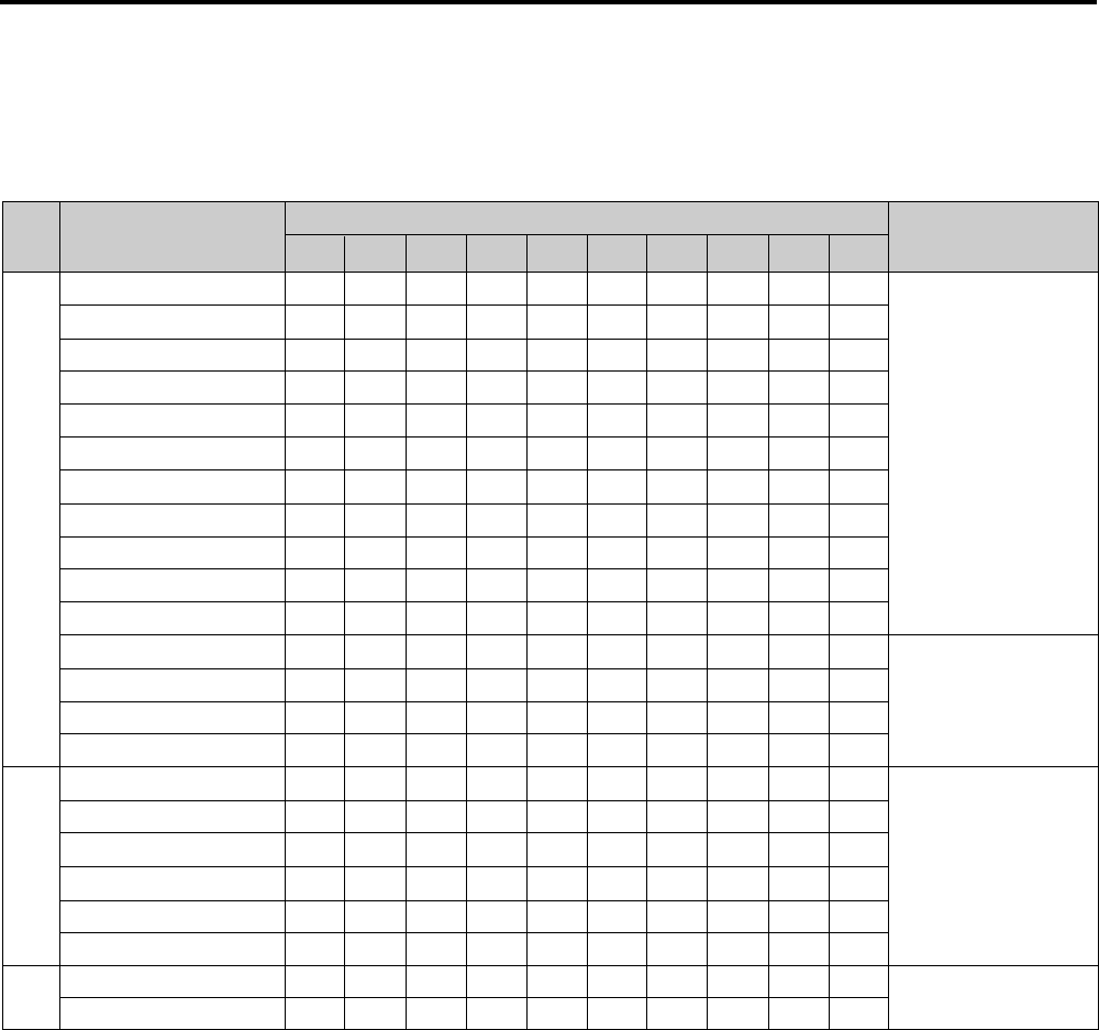
2-21
1) The replacement time of parts is not life of parts.
2) The table 2-1 is that the VCR Set is in normal condition (normal temperature, normal humidity).
The checking period may be changed owing to the condition of use, runtime and environmental conditions.
3) Life of the Cylinder Ass’y is depend on the condition of use.
4) See exploded view for location of each parts.
<Table 2-1>
∆ : Cleaning O : Check and replacement in necessary ◆ : Add Oil
T
A
P
E
P
A
T
H
S
Y
S
T
E
M
D
R
I
V
I
N
G
*Parts Name Checking Period Remark
500 1000 1500 2000 2500 3000 3500 4000 4500 5000
POST TENSION ∆∆∆∆∆∆∆∆∆∆
SLANT POST S, T ∆∆∆∆∆∆∆∆∆∆
#8 GUIDE SHAFT ∆∆∆∆∆∆∆∆∆∆
CAPSTAN SHAFT ∆∆∆∆∆∆∆∆∆∆
#9 GUIDE POST ∆∆∆∆∆∆∆∆∆∆
#3 GUIDE POST ∆∆∆∆∆∆∆∆∆∆
GUIDE ROLLER S, T ∆∆∆ OOOOOOO
CYLINDER ASS’Y ∆OOOOOOOOO
FE HEAD ∆∆∆ OOOOOOO
ACE HEAD ∆OOOOOOOOO
PINCH ROLLER ∆OOOOOOOOO
POST REEL S, T ◆◆◆◆◆
SLEEVE TENSION ◆◆◆◆◆
POST CENTER ◆◆◆◆◆
LEVER IDLE BOSS (2Point)
◆◆◆◆◆
CAPSTAN MOTOR PULLEY
∆∆∆∆∆OOOOO
BELT PULLEY O O O O O O O
HOLDER CLUTCH ASS’Y
∆OOOOOOOOO
GEAR CENTER ASS’Y O O O O O O O O O
GEAR IDLE (2Point) O O O O O O O O O
LOADING MOTOR O O O O O O O O O
BAND BRAKE ASS’Y O O O O O O O O O
BRAKE T ASS’Y O O O O O O O O O
S
Y
S
T
E
M
-Periodic time of applying oil
(Apply oil after cleaning)
- The excessive applying oil may
be the cause of malfunction.
-To clean the parts, use patch and
alcohol (solvent).
-After cleaning, use the video tape
after alcohol is gone away
completely.
-We recommend to use oil [EP-50]
or solvent.
-One or two drops of oil should be
applied after cleaning with
alcohol.
B
R
A
K
E
S
Y
S
T
E
M
2-5 THE TABLE OF CLEANING, LUBRICATION AND REPLACEMENT TIME ABOUT PRINCIPAL
PARTS

2-222-22E
MEMO
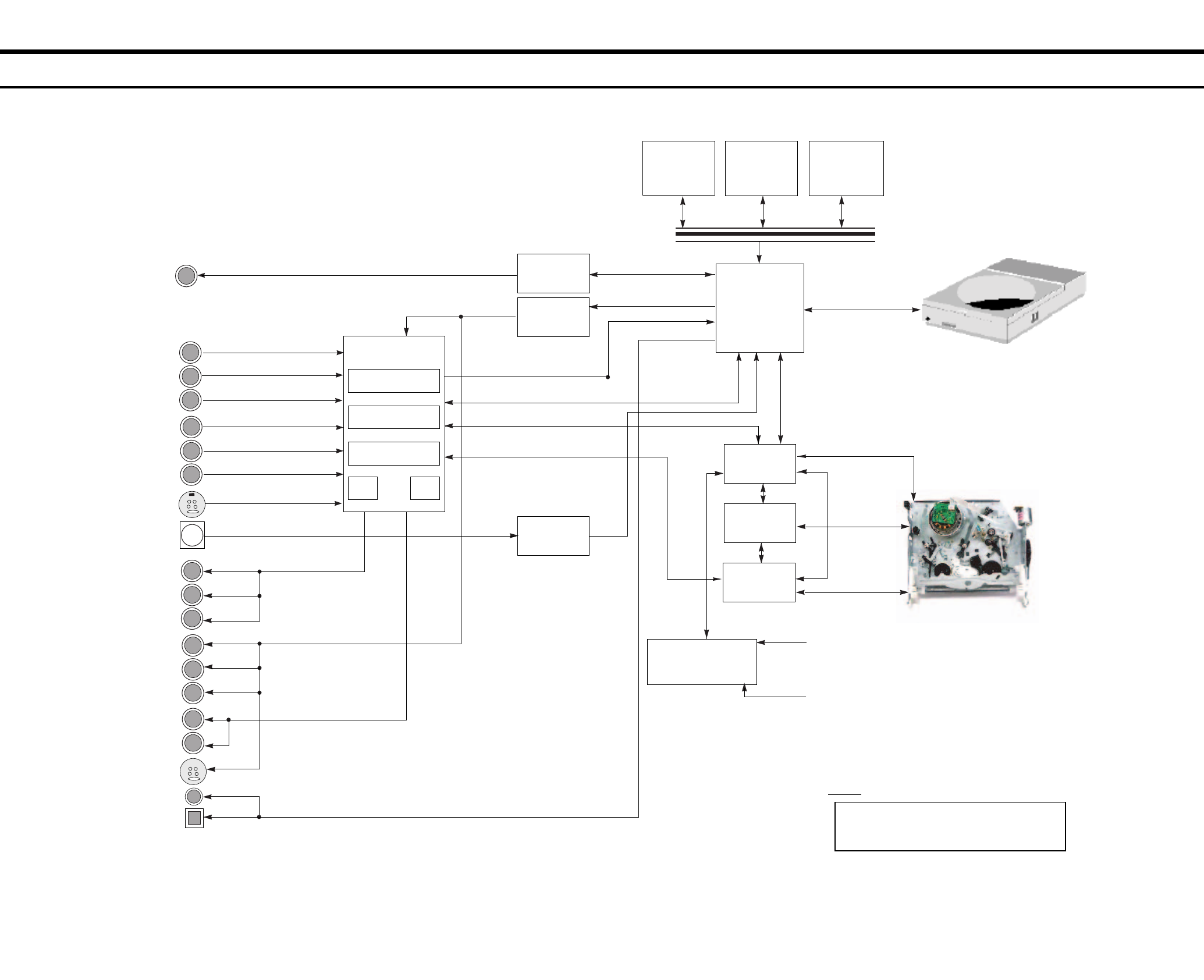
RDR-VX525
3. Block Diagram
3-23-1
IC104
4MB FLASH
K8D3216UBM
(8bit)
16M DDR
(16bit)
DVD-Rewritable Drive
TS-P632A
VCR DECK
(DX-13A New Slim)
SUPER IN
LINE1 IN(REAR)
LINE2 IN(FRONT)
DV IN
IC103
EEPROM
24LC32
(I
2
C)
SAA7138
MTS
(BTSC)
DVD CODEC
MS9301
IC101
6CH AMP
LA73054
IEEE1394PHY
TSB41AB1
VCR MICOM
MN 101D10F
AV I-CHIP
LA71207
HI-FI
LA72670
Front Panel
VFD DRIVE, KEY CONTROL
PT6315
Key Input
Remocon
COAXIAL
OPTICAL
SUPER OUT
DIGITAL AUDIO OUT
DVD V IN
VIDEO DIGITAL DATA (TIU656)
AUDIO DIGITAL DATA (I
2
C)
VCR VIDEO
VCR AUDIO
Y
Pb
Pr
VIDEO
L
R
L
R
IEC958
VIDEO
DECORDER
MUX
Audio
ADC Audio
DAC
RF IC2
S3C80F9B
I
2
C DATA CLK
STB OUT
Notes:
Special key has been written in the IC103 (CPRM
key), and therefore the IC103 cannot be replaced.
If this IC is faulty, replace the board entirely.

3-4E
MEMO

4. PCB Diagrams
4-24-1
4-1 DVD Main PCB - - - - - - - - - - - - - - - - - - - - - - - - - - - - - - - - - - - - - - - - 4-3
4-2 VCR Main PCB - - - - - - - - - - - - - - - - - - - - - - - - - - - - - - - - - - - - - - - - 4-7
4-3 Function PCB - - - - - - - - - - - - - - - - - - - - - - - - - - - - - - - - - - - - - - - - - 4-11
4-4 Front Jack PCB - - - - - - - - - - - - - - - - - - - - - - - - - - - - - - - - - - - - - - - - 4-13
4-5 DV Jack PCB - - - - - - - - - - - - - - - - - - - - - - - - - - - - - - - - - - - - - - - - - - 4-15
RDR-VX525
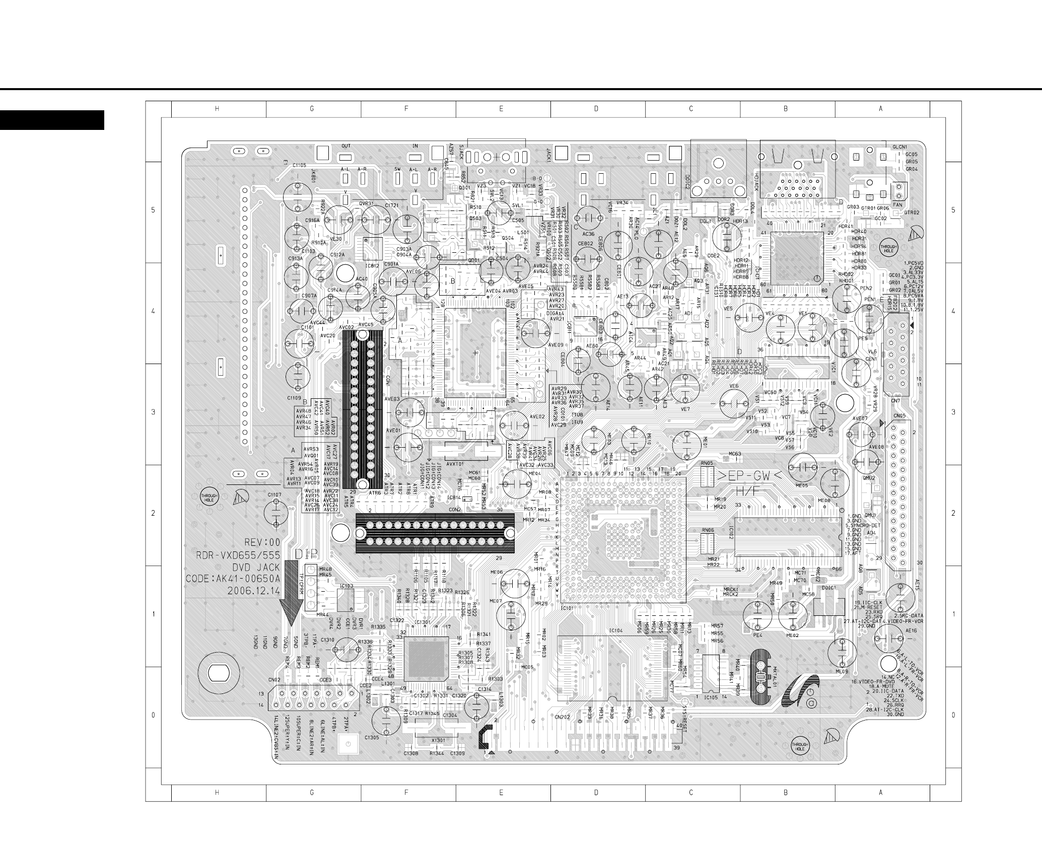
4-1 DVD Main PCB
4-44-3
COMPONENT SIDE
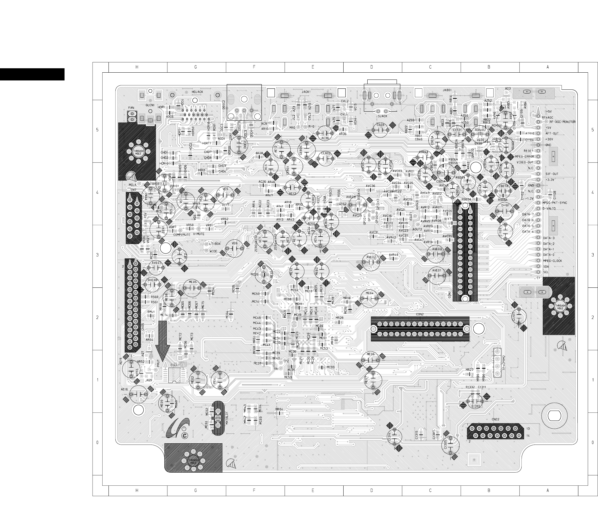
4-64-5
CONDUCTOR SIDE
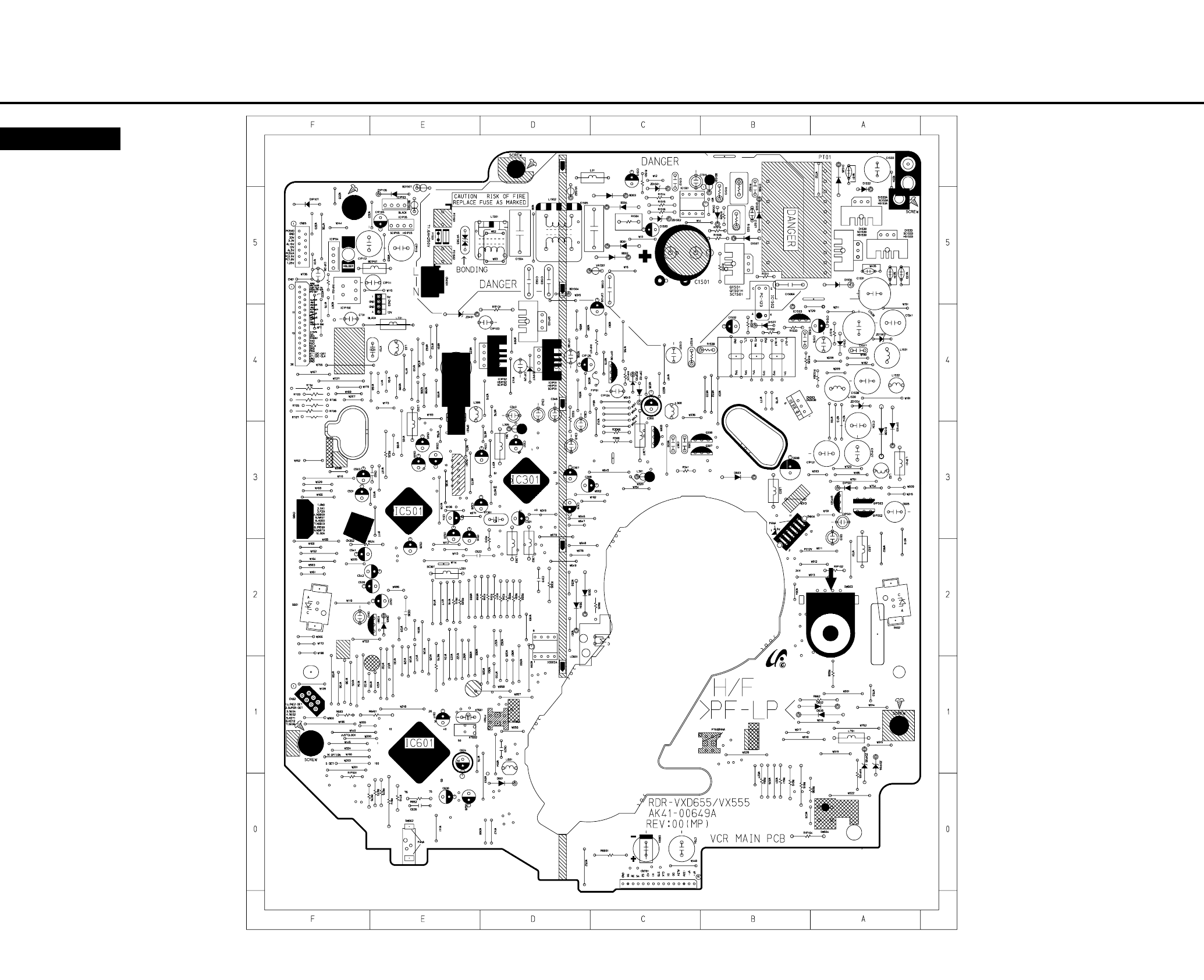
4-84-7
4-2 VCR Main PCB
COMPONENT SIDE
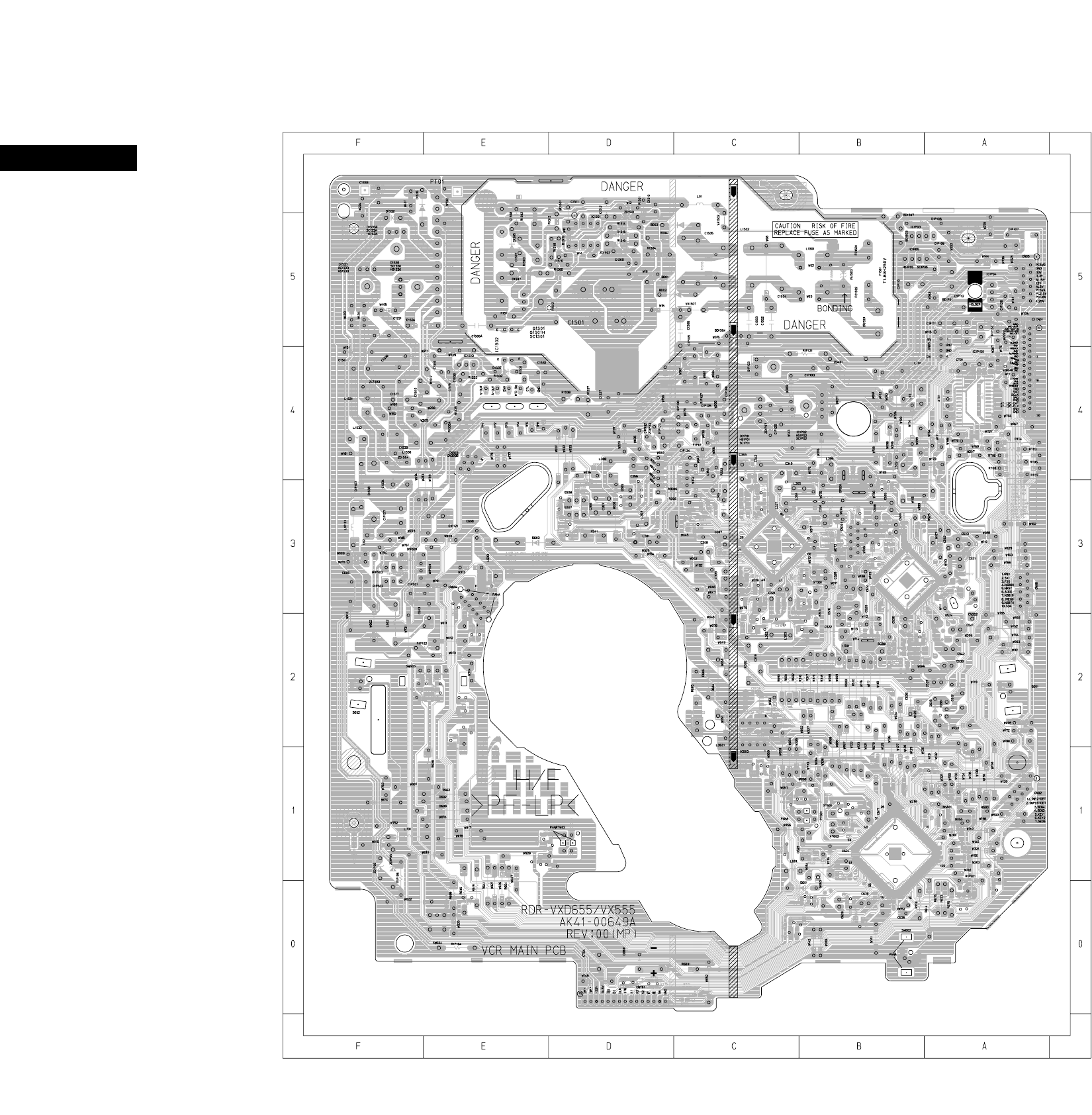
4-104-9
CONDUCTOR SIDE
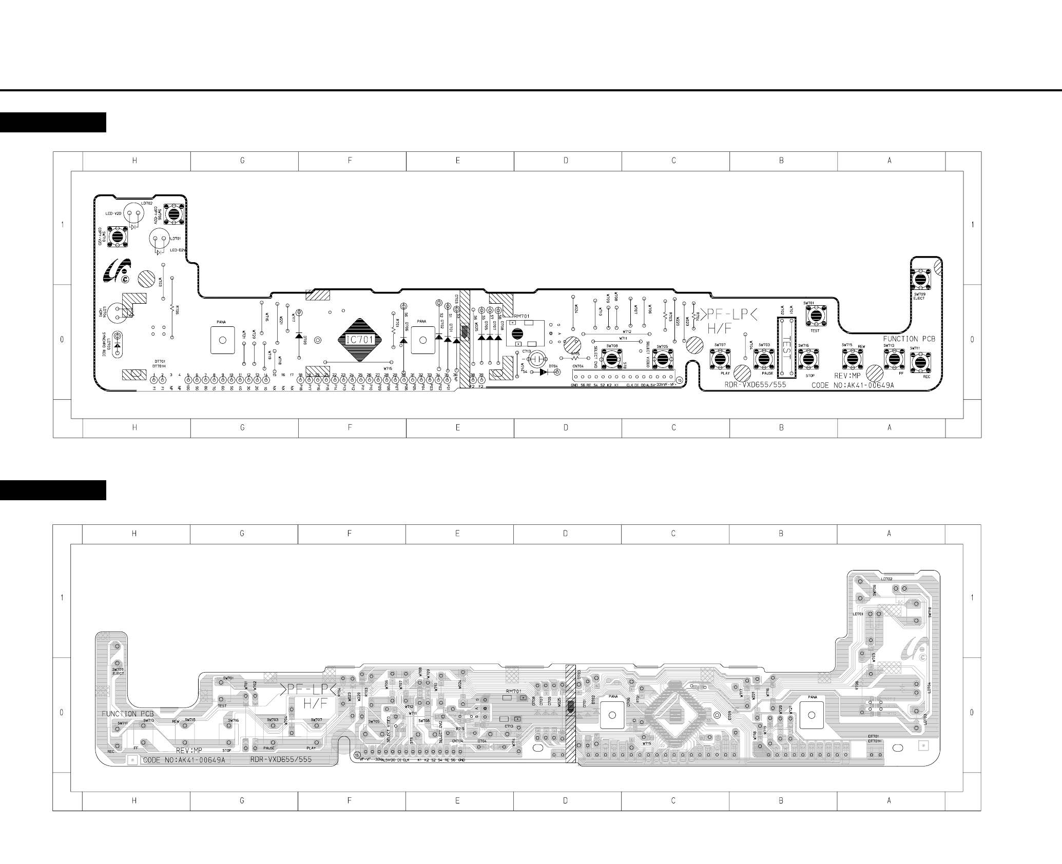
4-124-11
4-3 Function PCB
COMPONENT SIDE
COMPONENT SIDE
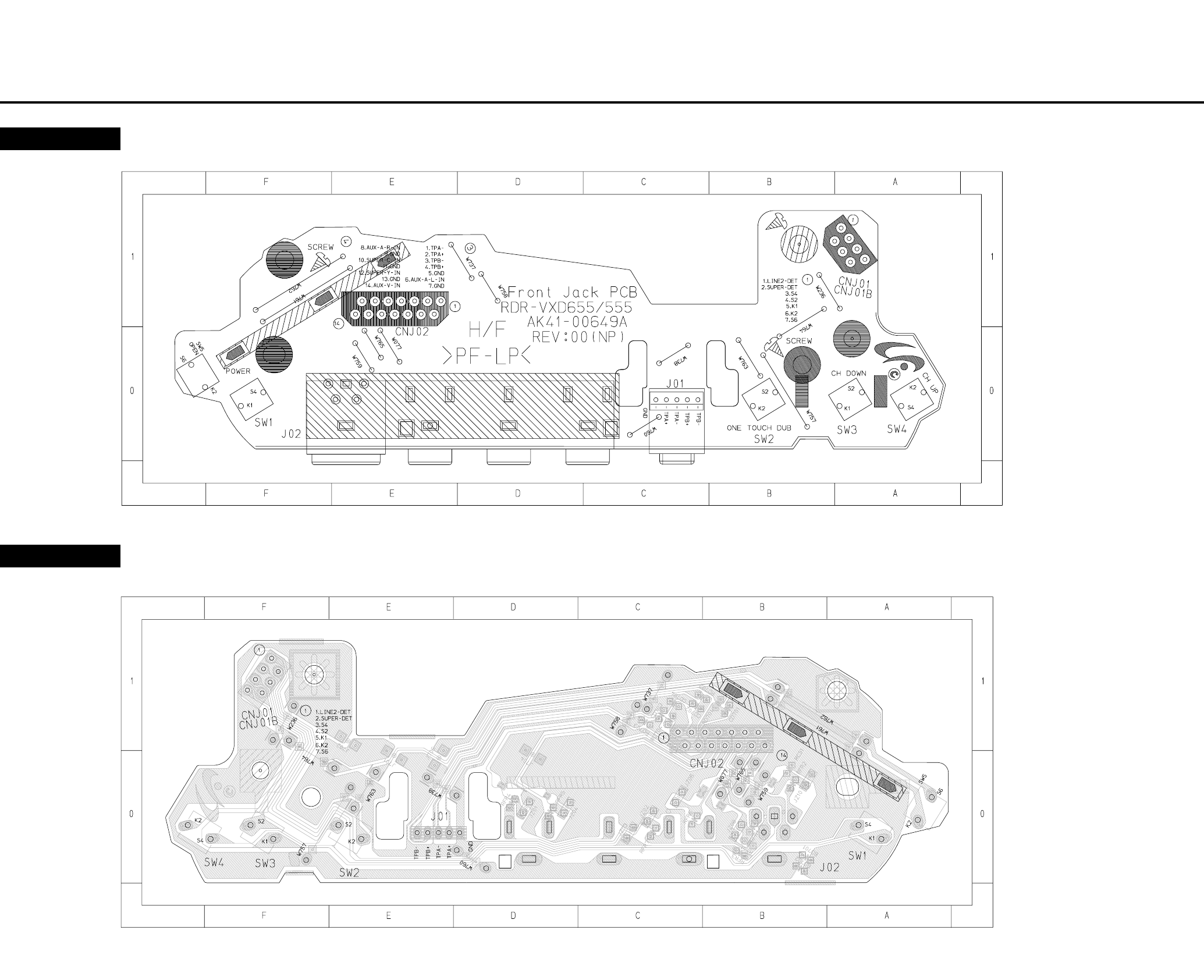
4-144-13
4-4 Front Jack PCB
COMPONENT SIDE
CONDUCTOR SIDE
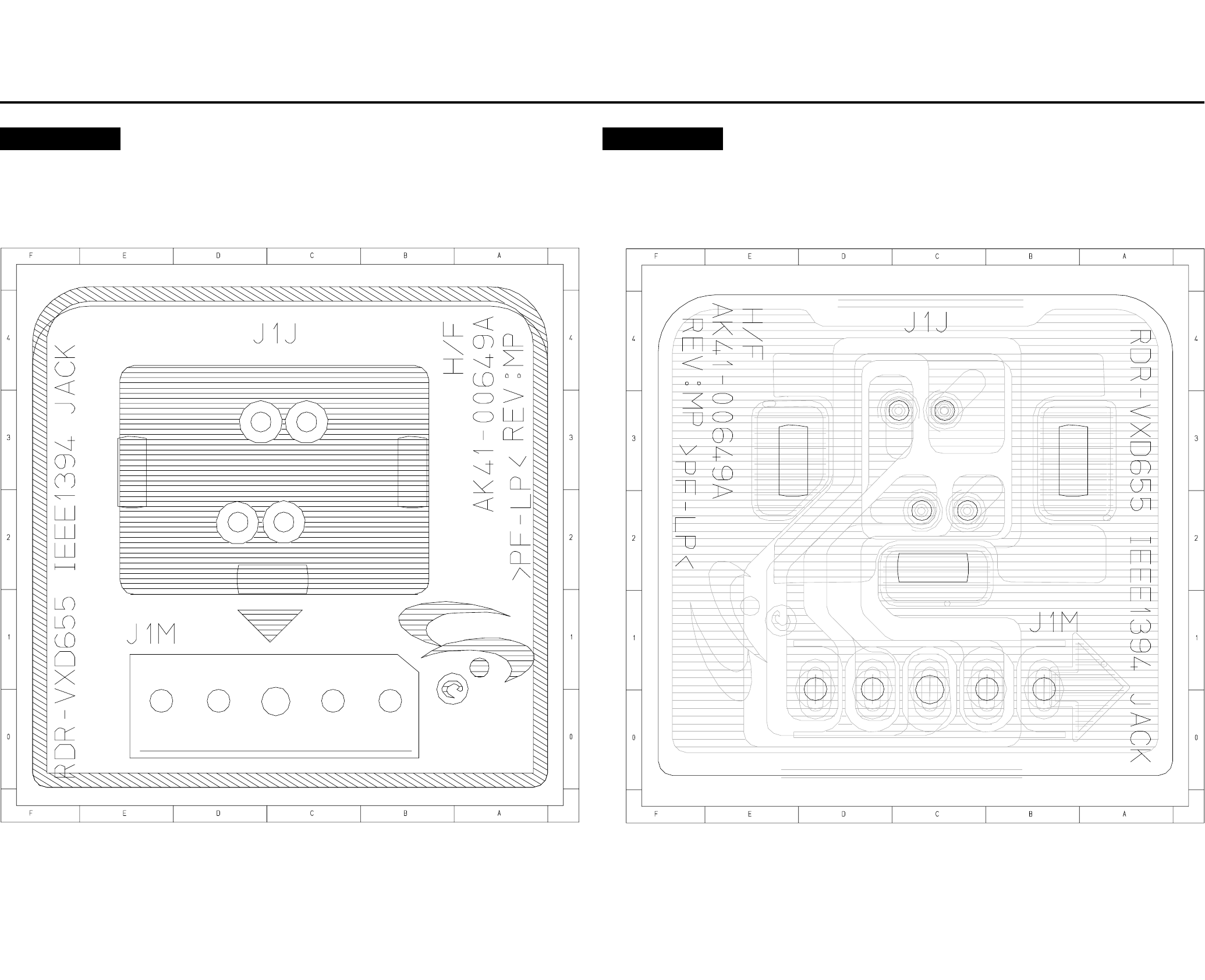
4-16E4-15
4-5 DV Jack PCB
COMPONENT SIDE COMPONENT SIDE
5. Schematic Diagrams
5-25-1
5-1 S.M.P.S (VCR Main PCB) - - - - - - - - - - - - - - - - - - - - - - - - - - - - - - - - - 5-3
5-2 Power (VCR Main PCB) - - - - - - - - - - - - - - - - - - - - - - - - - - - - - - - - - - 5-5
5-3 Logic (VCR Main PCB) - - - - - - - - - - - - - - - - - - - - - - - - - - - - - - - - - - - 5-7
5-4 A/V (VCR Main PCB) - - - - - - - - - - - - - - - - - - - - - - - - - - - - - - - - - - - - 5-9
5-5 Hi-Fi (VCR Main PCB) - - - - - - - - - - - - - - - - - - - - - - - - - - - - - - - - - - - 5-11
5-6 MPEG Decoder (DVD Main PCB) - - - - - - - - - - - - - - - - - - - - - - - - - - - - 5-13
5-7 A/V Decoder (DVD Main PCB) - - - - - - - - - - - - - - - - - - - - - - - - - - - - - - 5-15
5-8 In Out (DVD Main PCB) - - - - - - - - - - - - - - - - - - - - - - - - - - - - - - - - - - 5-17
5-9 DV & HDMI (DVD Main PCB) - - - - - - - - - - - - - - - - - - - - - - - - - - - - - - - 5-19
5-10 Front Timer (Front Jack PCB)/DV Jack (DV Jack PCB) - - - - - - - - - - - - - - 5-21
5-11 Function (Function PCB) - - - - - - - - - - - - - - - - - - - - - - - - - - - - - - - - - - 5-23
RDR-VX525
Note
For schematic Diagram
- Resistors are in ohms, 1/8W unless otherwise noted.
Special note :
Most semiconductor devices are electrostatically sensitive and therefore require the special handling techniques described under the
“electrostatically sensitive (ES) devices” section of this service manual.
Important safety notices :
Components identified with the mark 0 have the special characteristics for safety. When replacing any of these components.
Use only the same type.
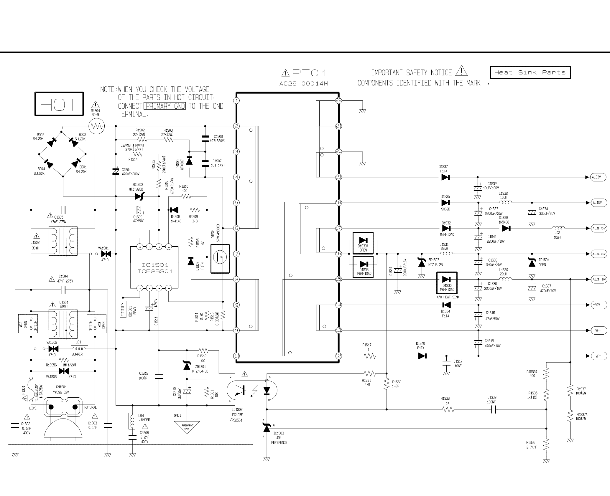
5-45-3
5-1 S.M.P.S. (VCR Main PCB)
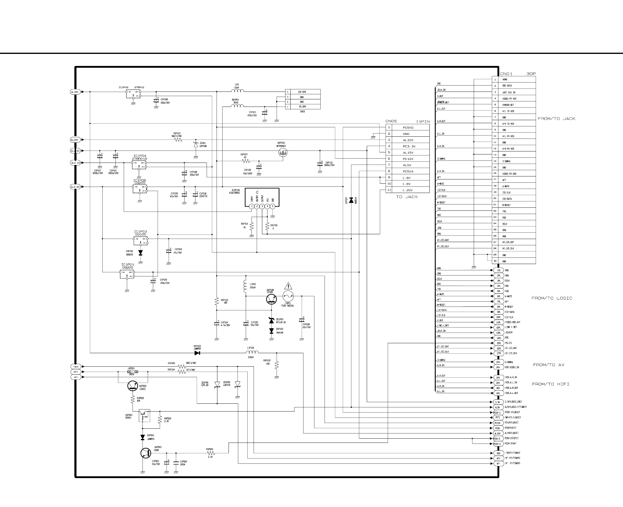
5-65-5
5-2 Power (VCR Main PCB)
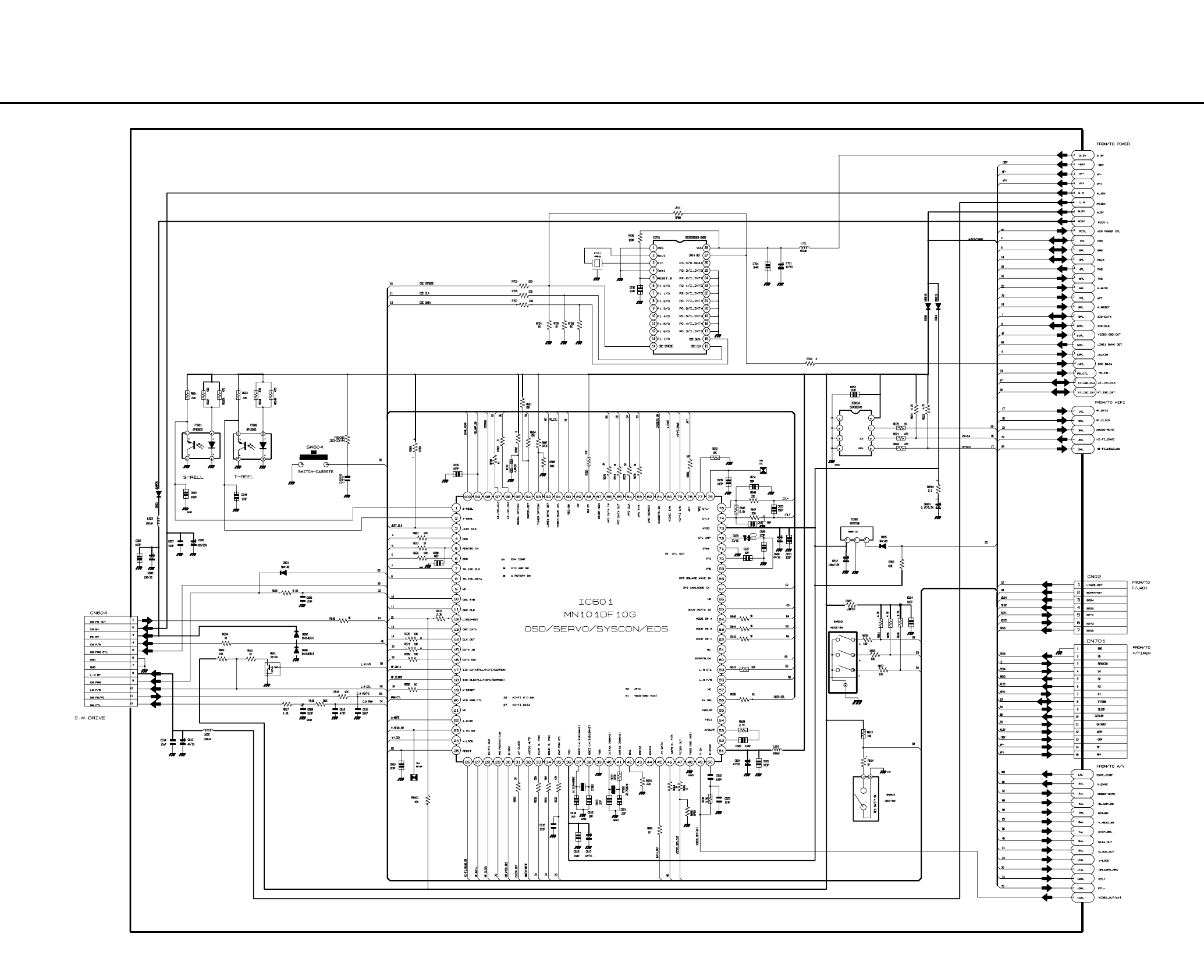
5-85-7
5-3 Logic (VCR Main PCB)
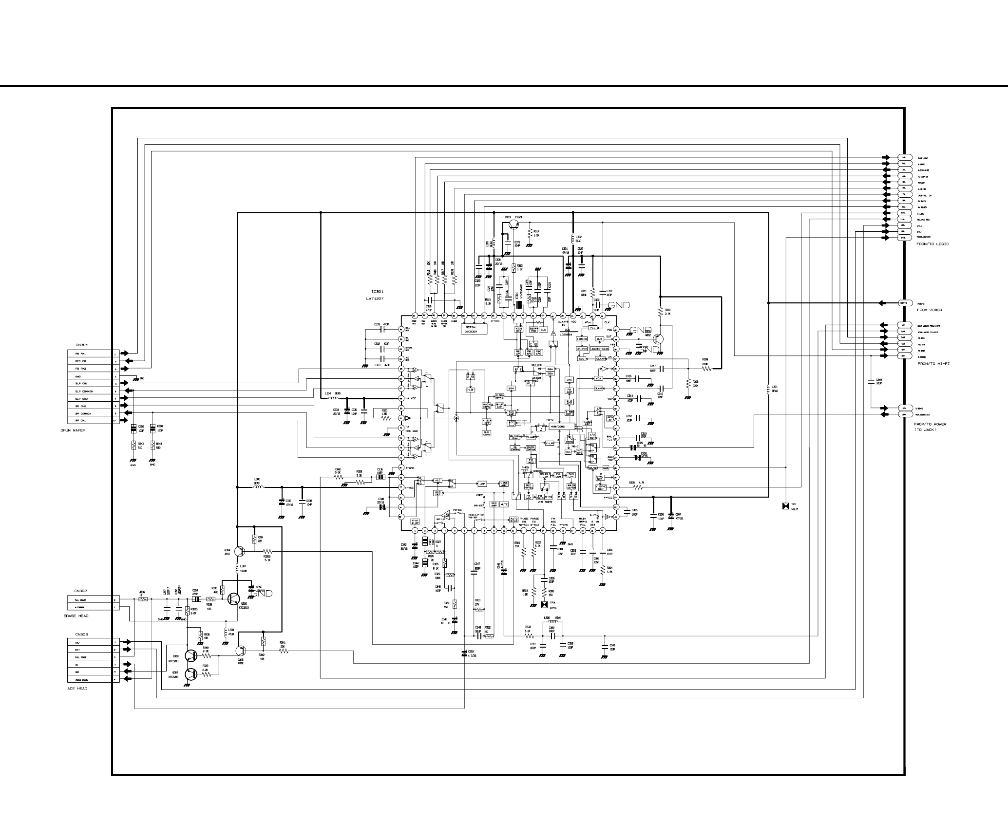
5-105-9
5-4 A/V (VCR Main PCB)
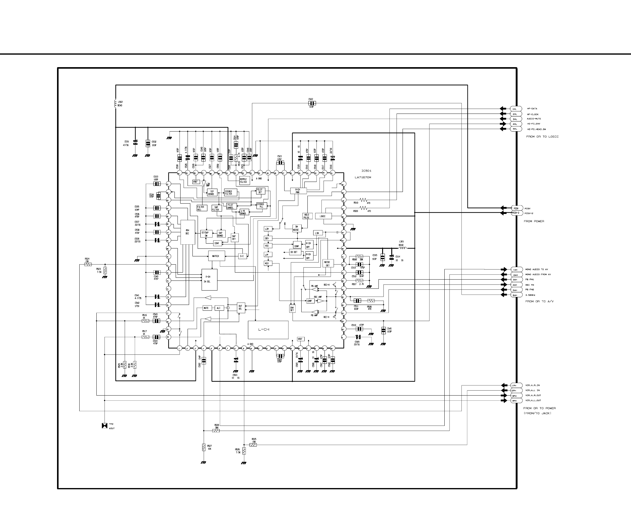
5-125-11
5-5 Hi-Fi (VCR Main PCB)
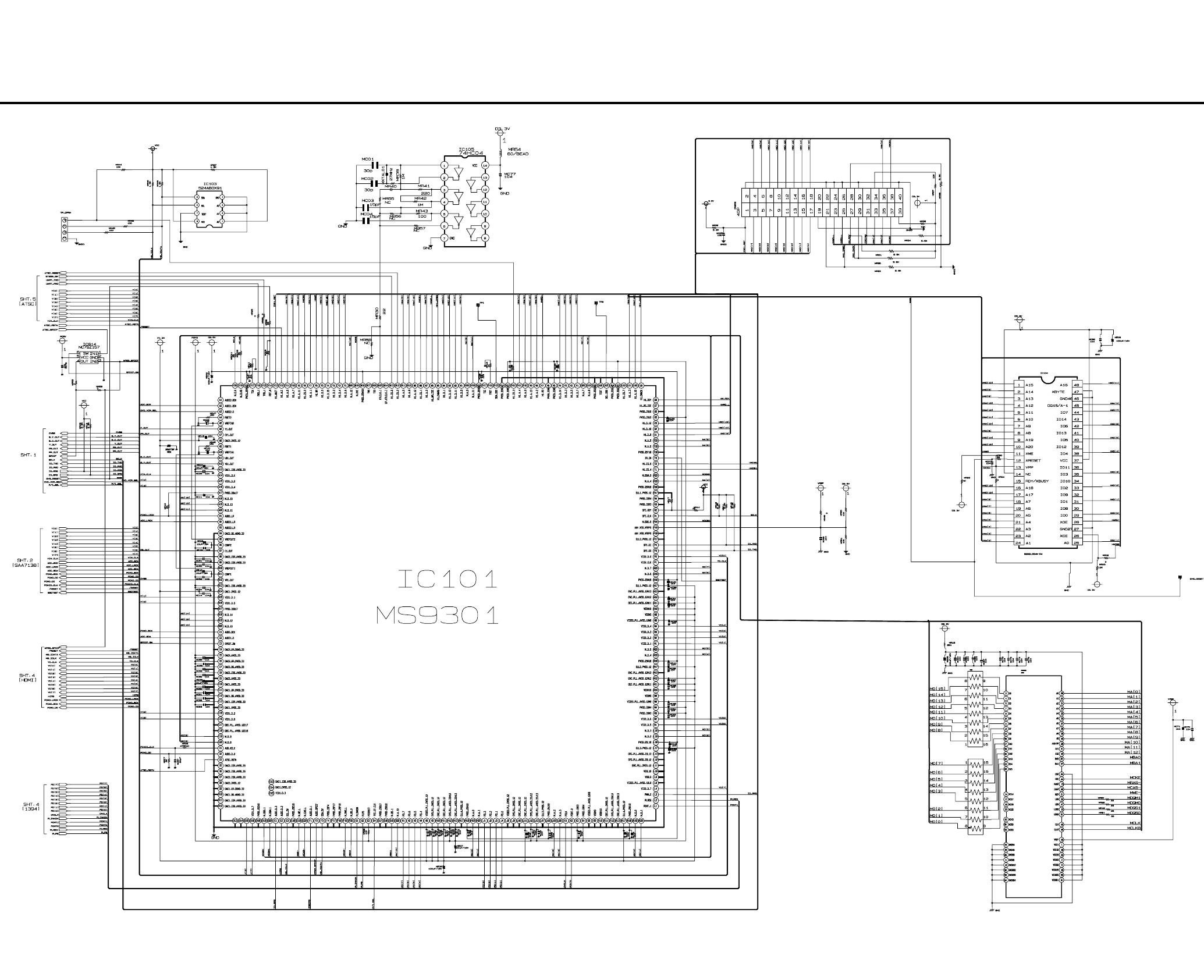
5-145-13
5-6 MPEG Decoder (DVD Main PCB)
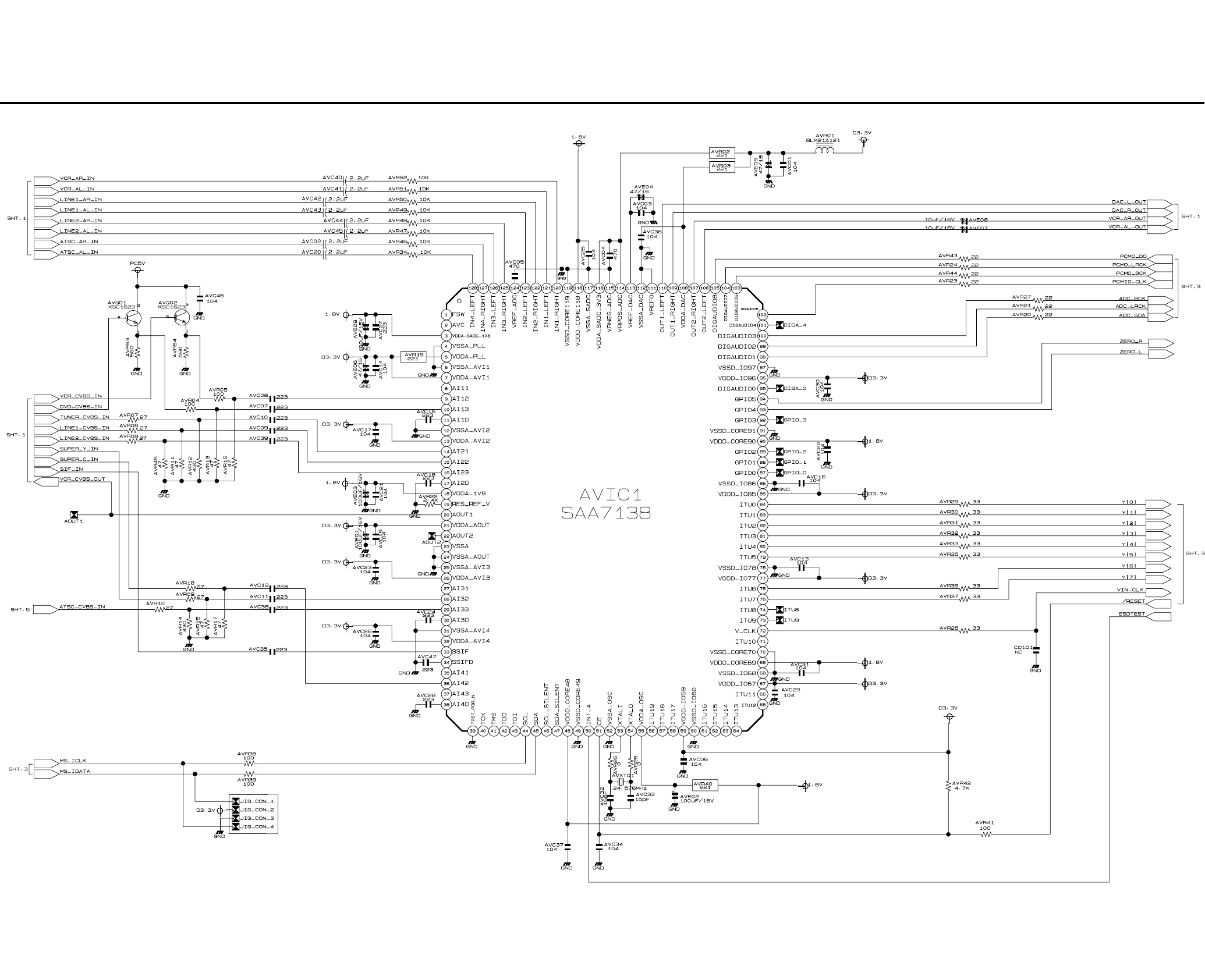
5-165-15
5-7 A/V Decoder (DVD Main PCB)
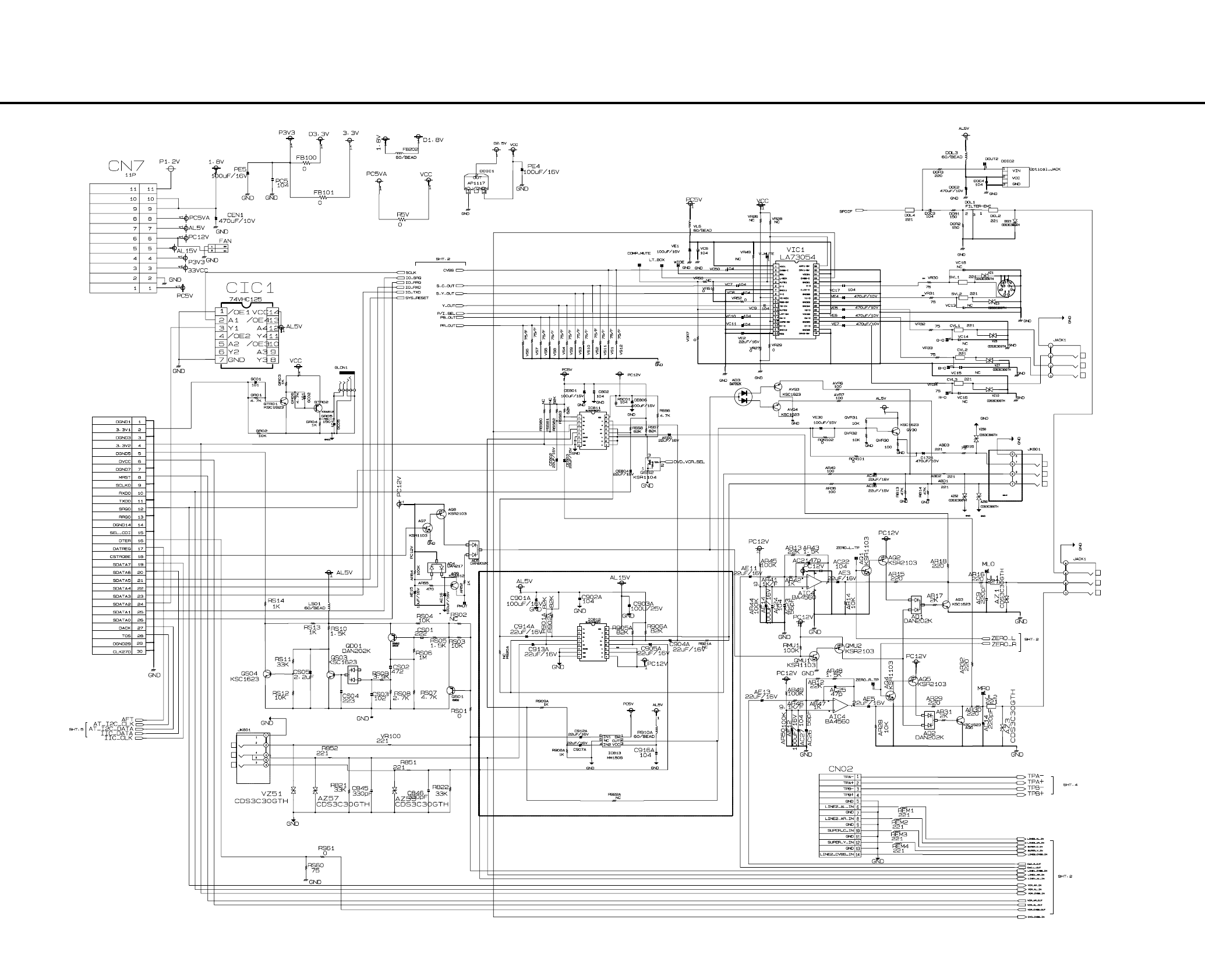
5-185-17
5-8 In Out (DVD Main PCB)
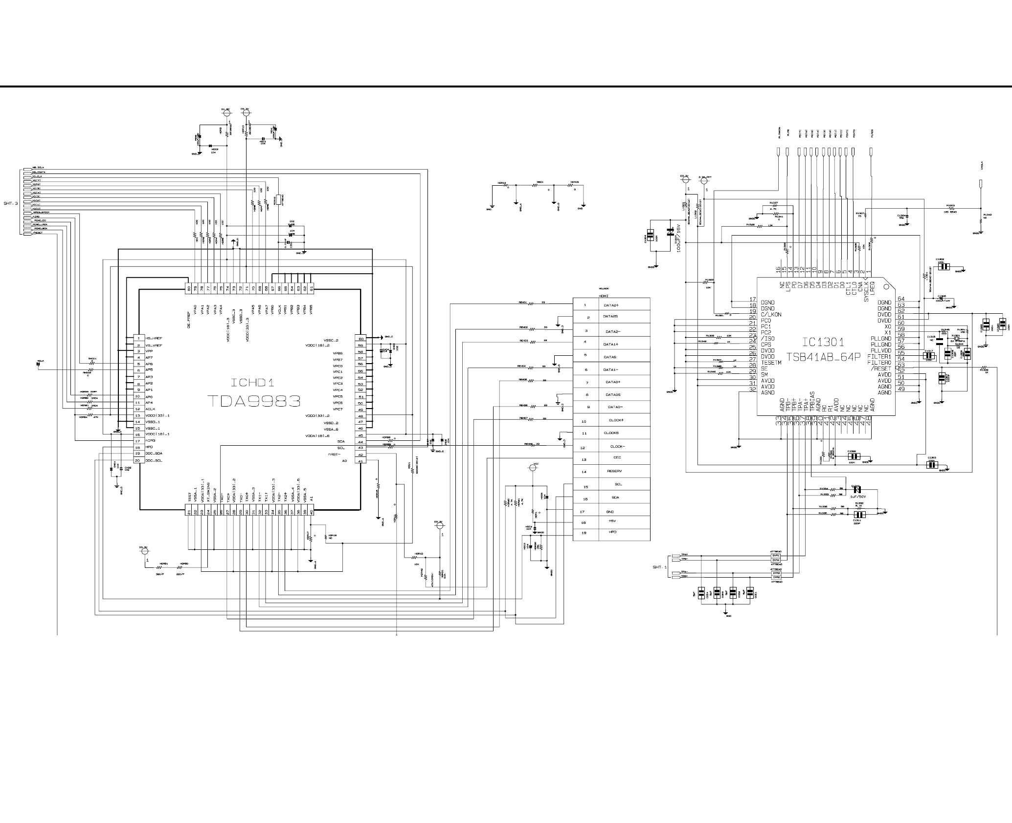
5-205-19
5-9 DV & HDMI (DVD Main PCB)
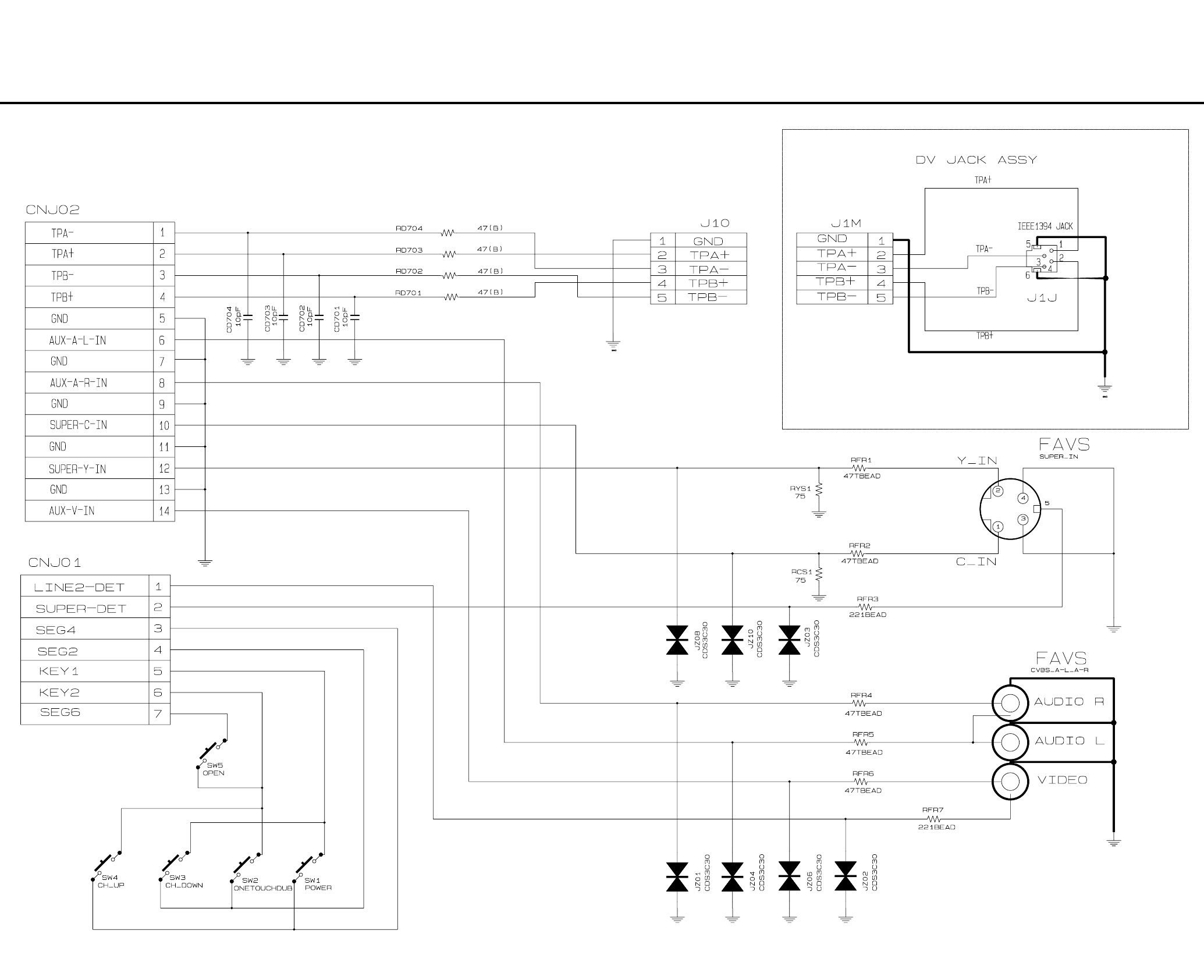
5-225-21
5-10 Front Timer (Front Jack PCB)/DV Jack (DV Jack PCB)
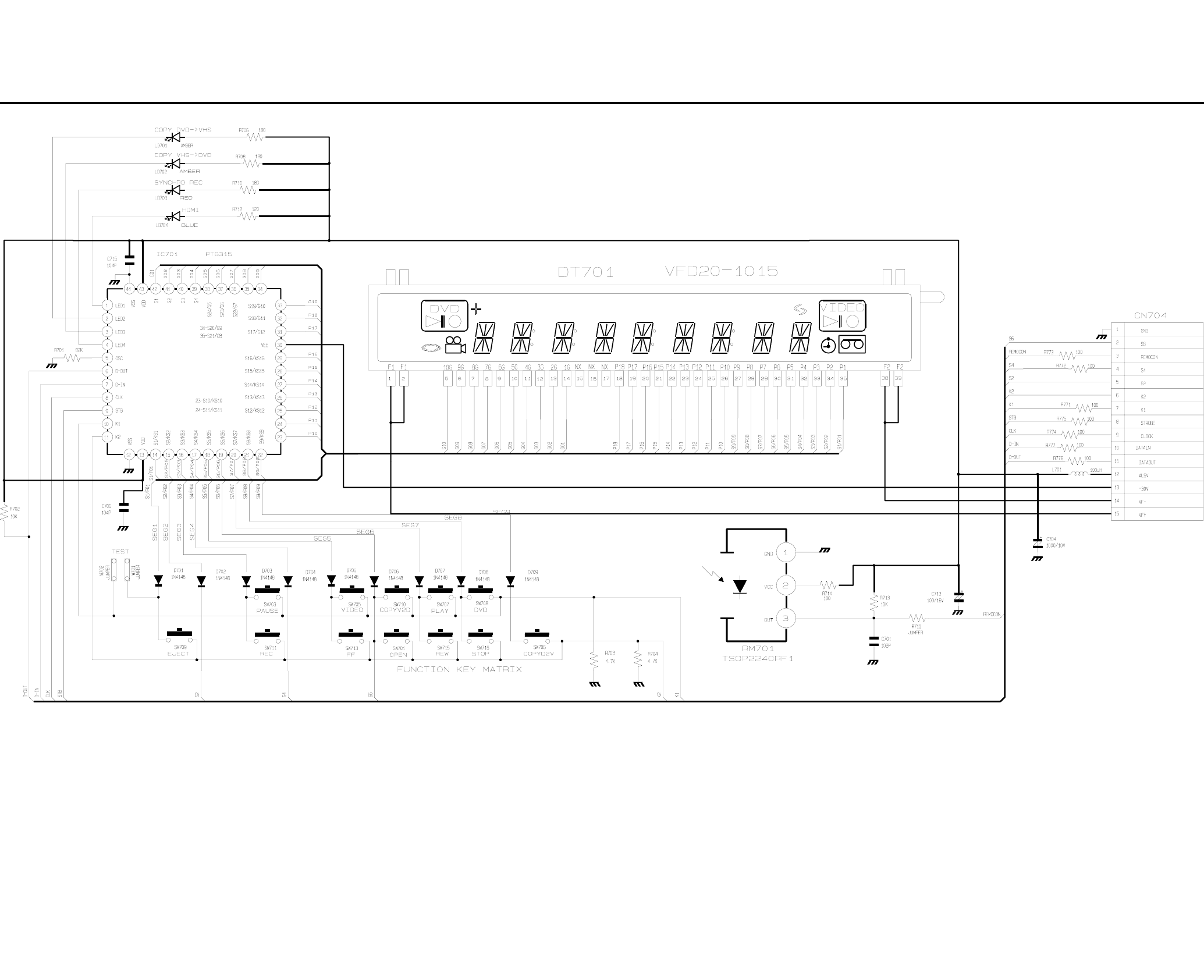
5-24E5-23
5-11 Function (Function PCB)
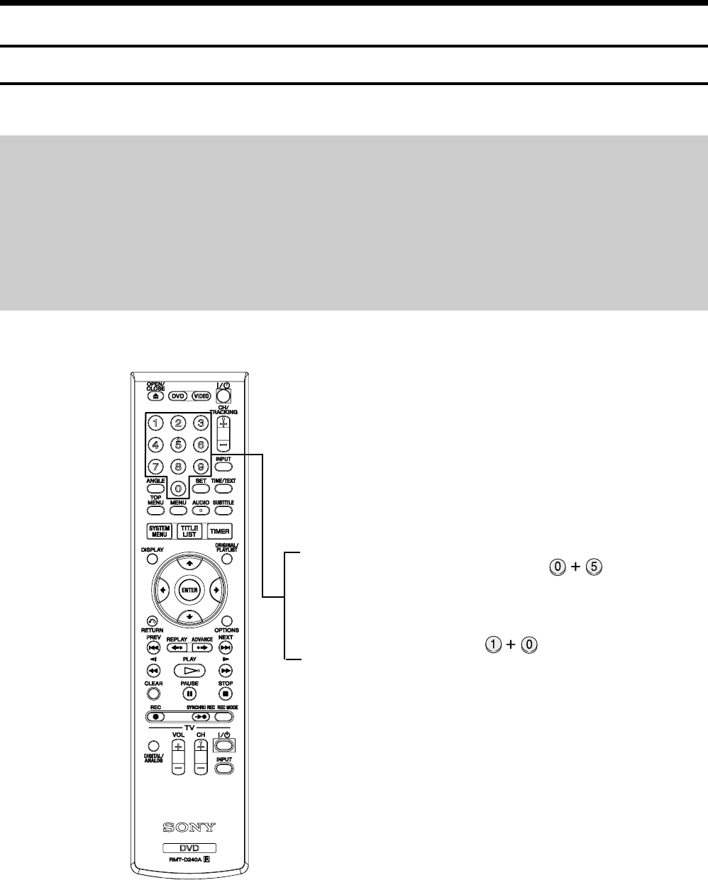
6-1
RDR-VX525
6. ALIGNMENT AND ADJUSTMENTS
6-1 VCR ADJUSTMENT
6-1-1 Reference
1) X-Point (Tracking center) adjustment, “Head switching adjustment” can be adjusted with remote control.
2) When replacing the VCR Main PCB Micom (IC601) and NVRAM (IC603A: EEPROM) be sure to adjust the “Head switching adjustment”.
3) When replacing the cylinder ass’y, be sure to adjust the “X-Point” and “Head switching adjustment”.
4) How to adjust.
- Intermittently short-circuit the Test Point on Function PCB with pincers to the adjustment mode.
- If the corresponding adjustment button is pressed, the adjustment is performed automatically.
- When the adjustment is completed, be sure to turn the power off.
6-1-1(a) Location of adjustment button of remote control
Fig. 6-1
X-Point (Tracking Center) Adjustment ;
Head Switching Adjustment ;
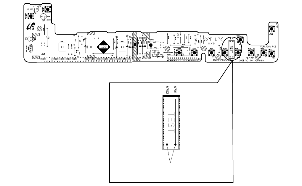
6-2
6-1-1(b) TEST location for adjustment mode setting
Fig. 6-2 Function PCB (Top View)
Short-Circuit for few seconds and release.
(Just one time)
6-3
6-1-2 Head Switching Point Adjustment
1) Playback the alignment tape.
2) Intermittently short-circuit the two Test Points on Function PCB while setting the adjustment mode. (See Fig. 6-2)
3) Press the “1, 0” buttons ; remote control adjustment operates automatically. (See Fig. 6-1)
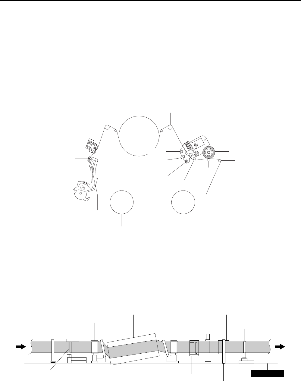
6-4
6-2 VCR MECHANICAL ADJUSTMENT
6-2-1 Tape Transport System and Adjustment Locations
The tape transport system has been adjusted precisely in the factory. Alignment is not necessary except for the
following :
1) Noise observed on the screen.
2) Tape damage.
3) Parts replacement in the tape transport system.
Lower flange height of tape guide is used as the reference for the transport adjustment.
To maintain the height of the tape guide and prevent damage, do not apply excessive force onto the main base.
Fig. 6-4 Tape Travel Diagram
POST TENSION
MAIN BASE
FE HEAD CYLINDER ASS'Y PINCH ROLLER
GUIDE ROLLER "S" GUIDE ROLLER "T"
#8 GUIDE POST #9 GUIDE POST
CAPSTAN SHAFT
ACE HEAD
#3 GUIDE POST
Fig. 6-3 Location of Tape Transport Adjustment
TENSION POST
#3 GUIDE POST
GUIDE ROLLER "S"
SUPPLY REEL DISK
FULL ERASE HEAD
TI LT SCREW
AZIMUTH SCREW
X-POSITION
ADJUS T SLIT
TAKE UP REEL DISK
CYLINDER ASS' Y
GUIDE ROLLER "T"
#8 GUIDE POST
#9 GUIDE POST
PINCH ROLLER
HIGH T SCREW
CAPSTAN
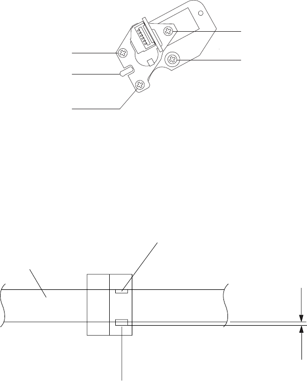
6-5
6-2-2 Tape Transport System Adjustment
When parts are replaced, perform the required adjustments by referring to procedures for the tape transport
system. If there are any changes to the tape path, first run a T-120 tape and make sure excessive tape wrinkle does not occur at the tape guides.
◆ If tape wrinkle is observed at the guide roller S, T, turn the guide roller S, T until wrinkle disappears.
◆ If the tape wrinkle is still observed at the tape guide, perform the tilt adjustment of the ACE head.
(1) ACE Head Assembly Adjustment
a. ACE HEAD HEIGHT ADJUSTMENT
1) Run the alignment tape (Color bar) in the playback mode.
2) Observe surface of the audio head using a dental mirror.
3) Turn screw (C) clockwise or counterclockwise until the gap of lower tape edge and the lower edge of the control head is about 0.25mm.
(Refer to Fig. 6-5 and 6-6)
Fig. 6-5 Location of ACE Head Adjustment Screw
0 ~ 0 .25 mm
AUDIO HEAD
VIDEO HEAD
CONTROL HEAD
Fig. 6-6 ACE Head Height Adjustment
TI LT SCREW
SCREW (A)
SCREW (B)
SCREW (C)
SCREW (D)
AZIMUTH ADJUS T
X-POSITION
ADJUST SLIT
HIGHT SCREW
X-POSITION LOCKING
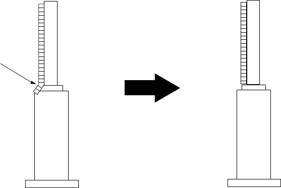
6-6
b. ACE HEAD TILT ADJUSTMENT
1) Playback a blank tape and observe the position of the tape at the lower flange of tape guide.
2) Confirm that there is no curl or wrinkle at the lower flange of tape guide as shown in Fig. 6-7 (B).
3) If a curl or wrinkle of the tape occurs, slightly turn the screw (A) tilt adjust on the ACE head ass’y.
4) Reconfirm the ACE head height.
(A) (B)
(BAD)
WRINKLE
(GOOD)
Fig. 6-7 Tape Guide Check
c. AUDIO AZIMUTH ADJUSTMENT
1) Load alignment tape (Mono scope) and playback the 7KHz signal.
2) Connect channel-1 scope probe to audio output.
3) Adjust screw (B) to achieve maximum audio level. (See Fig. 6-5)
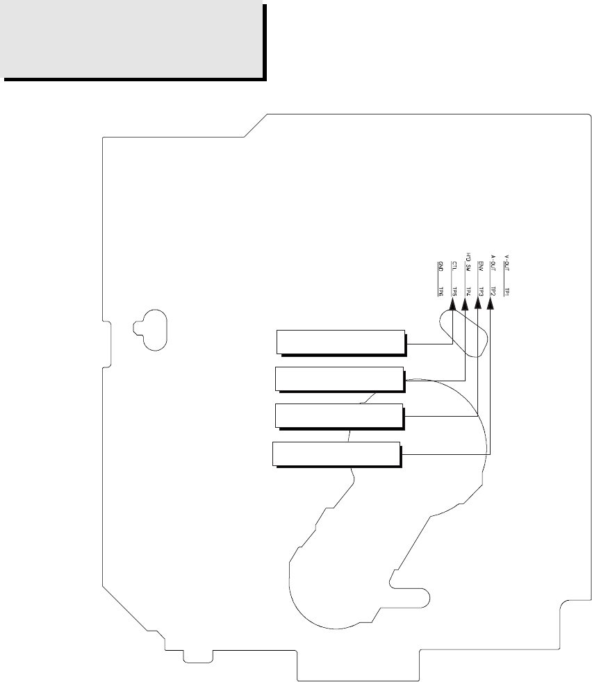
6-7
d. ACE HEAD POSITION (X-POINT) ADJUSTMENT
1) Playback the alignment tape (Color bar)
2) Intermittently short-circuit the two Test Points on Function Timer PCB. (See Fig. 6-2)
3) Press the “0, 5” remote control buttons, then adjustment is operates automatically. (See Fig. 6-1)
4) Connect the CH-1 probe to “Envelope” the CH-2 probe to “H’D switching pulse” and then trigger to CH-1.
5) Insert the (-) driver into the X-Point adjustment hole and adjust it so that envelope waveform is maximum.
Test point:TP2 (Audio Output)
TP3 (Envelope)
TP4 (H’D S/W -Trigger)
TP5 (Control Pulse)
Fig. 6-8 Location of Test point (VCR Main PCB-Top View)
iew)
AUDIO OUTPUT
CONTROL PULSE
HEAD SWITCHING
ENVELOPE
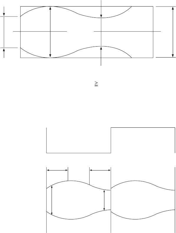
6-8
(2) Linearity adjustment (Guide roller S, T adjustment)
1) Playback the Mono Scope alignment tape (SP mode).
2) Observe the video envelope signal on an oscilloscope (triggered by the video switching pulse).
3) Make sure the video envelope waveform (at its minimum) meets the specification shown in Fig. 6-9.
If it does not, adjust as follows :
Note:
a=Maximum output of the video RF envelope.
b=Minimum output of the video RF envelope at the entrance side.
c=Minimum output of the video RF envelope at the center point.
d=Maximum output of the video RF envelope at the exit side.
4) If the section A in Fig. 6-10 does not meet the specification, adjust the guide roller S up or down.
5) If the section B in Fig. 6-10 does not meet the specification, adjust the guide roller T up or down.
a
a b c d
c,b,d/a 63%
bcd
Fig. 6-9 Envelope Waveform Adjustment
AB
A B
H'D SWITCHING PULSE
ENVELOPE
Fig. 6-10 Adjustment Points
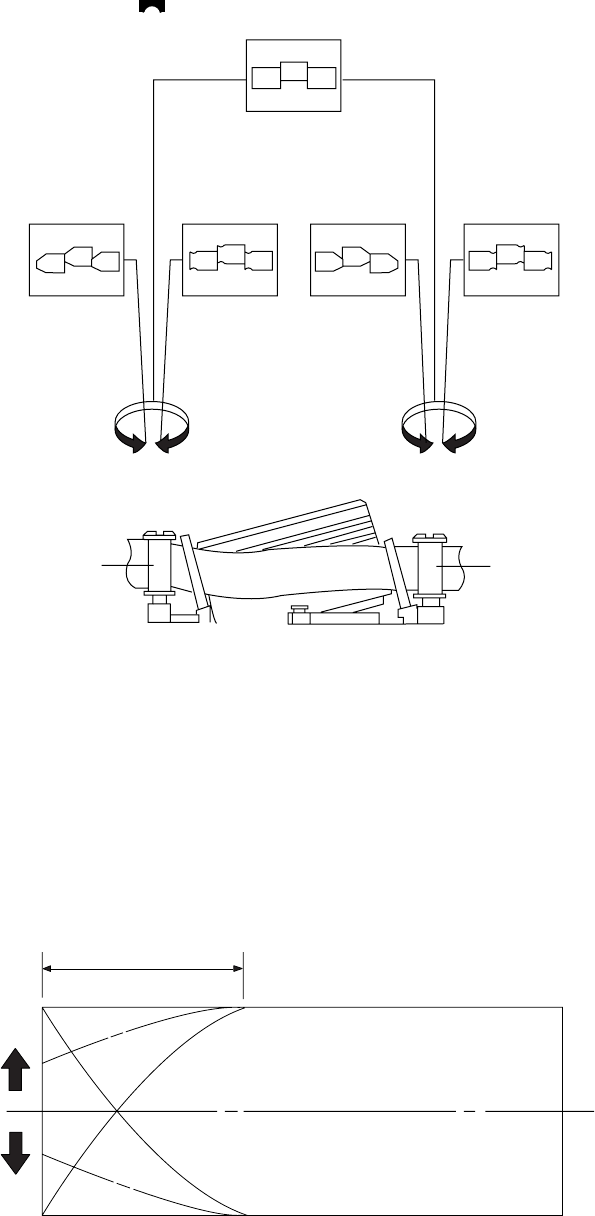
6-9
6) Play back the Mono Scope alignment tape (SP mode).
7) Connect an oscilloscope CH-1 to the “Envelope” and CH-2 to the “H’D SW Pulse” for triggering.
8) Turn the guide roller heads with a flat head ( ) driver to obtain a flat video RF envelope as shown in Fig. 6-11.
Fig. 6-11 Guide Roller S, T Height Adjustment
IDEAL ENVELOPE
S HEIGHT TOO HIGH S HEIGHT TOO LOW T HEIGHT TOO HIGH T HEIGHT TOO LOW
GUIDE ROLLER S GUIDE ROLLER T
Fig. 6-12 Video Envelope Rising when Operation mode Changes from RPS to Play Mode
ENTRANCE SIDE ENVELOPE
(3) Check Transitional Operation from RPS to Play
Check transition from RPS mode to play mode : Using a pre-recorded SP tape, make sure the entry side of envelope comes to an appropriate
steady state within 3 seconds (as shown in Fig. 6-12).
If the envelope waveform does not reach specified peak-to peak amplitude within 3 seconds, adjust as follows :
1) Make sure there is no gap between the supply roller lower flange and the tape.
If there is a gap, adjust the supply guide roller again.
2) Change operation mode from the RPS to the play mode (again) and make sure the entry side of envelope rises within 3 second.
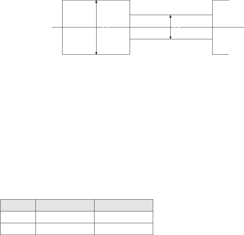
6-10E
(4) Envelope Check
1) Make recordings on T-120 (E-120) and T-160 (E-180) tape.
Make sure the playback output envelope meets the specification as shown in Fig. 6-13.
2) Play back a self recorded tape (recording made on the unit using with T-120 (E-120).
The video envelope should meet the specification as shown in Fig. 6-13.
In SP mode, (A) should equal (B).
If the head gap is wide, upper cylinder should be checked.
Fig. 6-13 Envelope Input and Output Level
(5) Tape Wrinkle Check
1) Run the T-160 (E-180) tape in the playback, FPS, RPS and Pause modes and observe tape wrinkle at each guide.
2) If excessive tape wrinkle is observed, perform the following adjustments in Playback mode :
◆Tape wrinkle at the guide roller S, T section : Linearity adjustment.
◆Tape wrinkle at tape guide flange : ACE head assembly coarse adjustment.
6-2-3 Reel Torque
1) The rotation of the capstan motor causes the holder clutch ass’y to rotate through the belt pulley.
2) The spring wrap PLAY/REV of holder clutch ass’y drives the disk reel S, T through gear idler by rotation of gear center ass’y.
3) Brake is operated by slider cam at FF/REW mode.
4) Transportation of accurate driving force is done by gears. (Gear Center Ass’y)
Note: If the spec. does not meet the followings specifications, replace the holder clutch ass’y and then recheck.
< Table 6-1 >
MODE TORQUE g/cm GAUGE
PB 42 ± 11 Cassette Torquemeter
RPS 145 ± 30 Cassette Torquemeter
A B
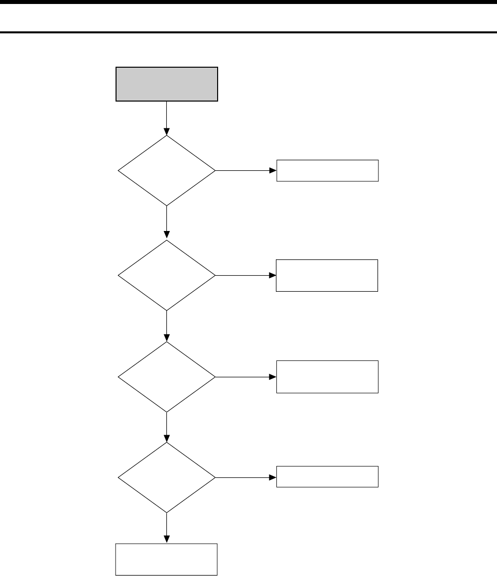
7-1
RDR-VX525
7. TROUBLESHOOTING
No Power Detected
F1S01
BD01~04, ZD1S01~2
SHORT and OPEN
Check feedback IC1S01
Change short or opened parts
Change fuse
Check the voltage f RIS02,
RIS03, and DIS05
Replace Q1S01
NO
NO
Voltage at
Collector of
Q1S01
NO
YES
YES
YES
Operation of
Q1S01
NO
YES

7-2
Key Operation or
Remote Control Error
Voltage on the Function Display Ass’y?
Check RM701 (Remocon module)
and IC601 (Pin 5)
Check power of front connector
(CN704 Pin 12)
Check the circuit around the clock
Check the circuit around
IC601 reset
End
NO
Key operation such
as STOP,PLAY,OPEN
Check the circuit around the swith.
check the condition of commmunication
with Main Micom
(IC601 83~86, VFD STB, CLOCK
DATA-IN,DATA-OUT)
NO
YES
Check the circuit
around IC601 reset?
NO
YES
XT601 14.318MHz
oscillation
NO
Change IC701
NO
YES
YES
STOP,PLAY,OPEN
Key operation are
normal?
YES
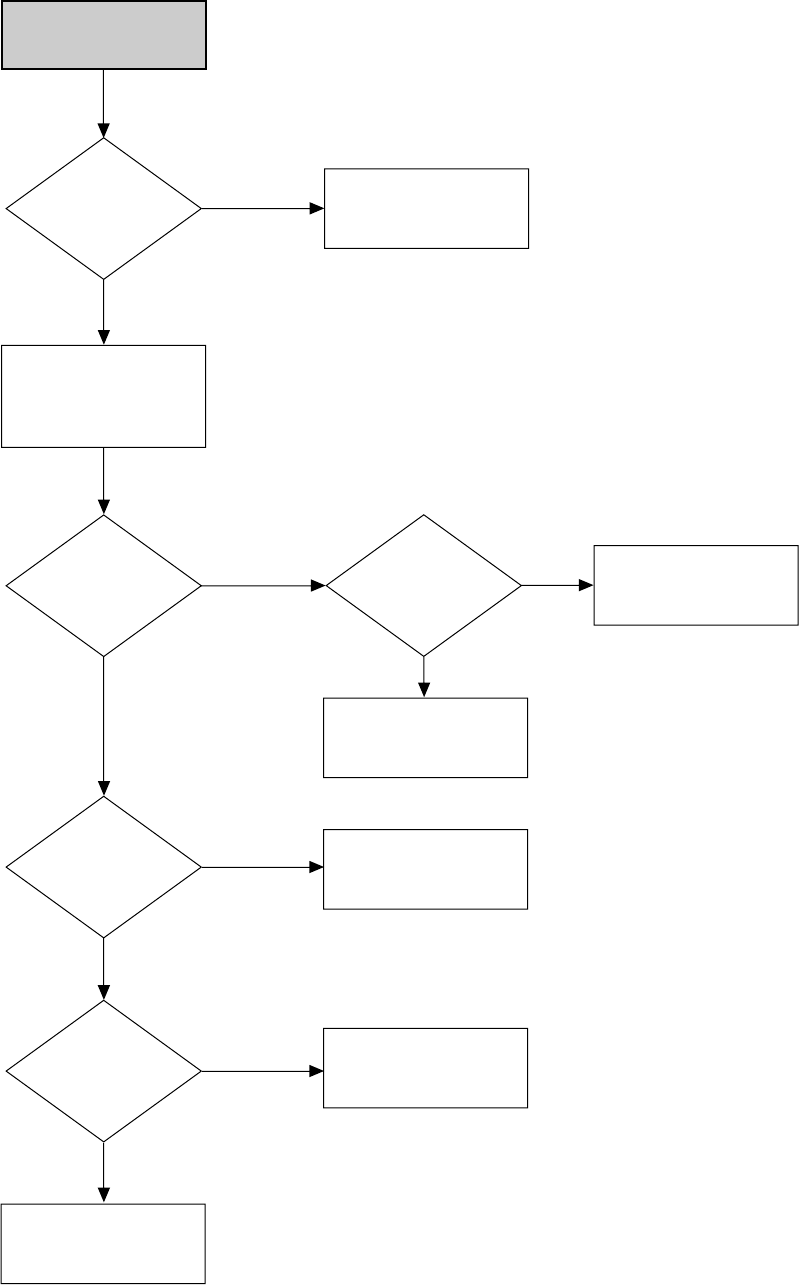
7-3
PLAY MODE
INOPERATIVE
EE-VIDEO
INSERT THE CASETTE
TAPE RECORDED BY
ANOTHER VCR AND
PRESS PLAY BUTTON
PLAY
INDICATOR
IN THE DISPLAY
PRESS PLAY KEY
IN REMOTE
CONTROL
MECHANISM
OPERATION
SEE (PB VIDEO) AUDIO MISSING
IN PLAY MODE
SEE
(MECHANISM DOES NOT
OPERATE IN PLAY MODE)
CHECK PLAY Button
and Pattern
CHECK
IC601, XT601
SEE
(VIDEO MISSING IN EE MODE)
NO
NO NO
YES
NO
PB-VIDEO
SEE
VIDEO MISSING
IN PLAY MODE
NO
YES
YES
YES
DOES NOT OPERATE
OR OPERATES
BUT STOP SOON
YES
(VCR Section)

7-4
LOAD A TAPE AND
PRESS PLAY BUTTON
TURN VCR POWER ON
MECHANISM DOESN'T
OPERATE IN PLAY MODE
TAPE LOADING
OPERATION
(LOAD)
IC601-59:HIGH
IC601-58:LOW
CYLINDER
ROTATION
SW 30Hz
IC601-23
CYL FG.PG
IC601-65
CHECK CYLINDER
CHECK
IC601
NO NO
NO
NO
YES
YES
YES
YES
CHECK CN604
8pin 12V
(VCR Section)
A
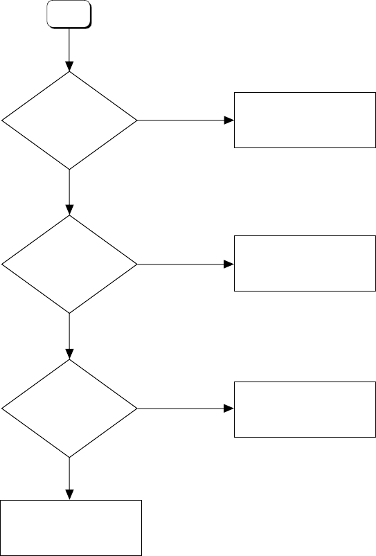
7-5
CAPSTAN
ROTATION
(S.T REEL)
IC601-1.2
PROG.SW STATE
IC601-62, 63, 64
CHANGE IC601
CHECK
LOADING MOTOR
MECHANISM OR SW603
TAKE UP REEL SENSOR
SUPPLY REEL SENSOR
(PT601.PT602)
SEE
(CAPSTAN DOES NOT
ROTATE)
NO
DC
STOP MODE
YES
PULSE
YES
A

7-6
RECORD MODE
DOESN'T OPERATE
PLAY
OPERATION
LOAD VCR WITH A
BLANK TAPE AND
PRESS RECORD BUTTON
REC MODE SAFETY TAB
D-REC A (H)
IC601-30
SEE
(AUDIO MISSING IN
RECORD MODE)
CHANGE SW602
CHECK IC601
CHANGE TAPE
SEE
(PLAY MODE
DOESN'T OPERATE)
EJECT NO
NO
YES
NO
REC-VIDEO
SEE
(VIDEO MISSING IN
RECORD MODE)
NO
YES
YES
YES
YES
(VCR Section)

7-7
TURN THE VCR
POWER ON AND
INSERT A TAPE
PRESS EJECT BUTTON
CASSETTE LOADING
MECHANISM
DOES NOT OPERATE
TAPE DETECTED
CST IN MODE
IC601-87:HIGH(5V)
CHANGE IC601
CHECK
IC601
CHECK
DM B+ LINE
CHANGE IC610
NO NO
NO
YES
IC601-59:LOW(0V)
IC601-58:HIGH(5V)
IC601-59:HIGH(5V)
IC601-58:LOW(0V)
CHECK
CASSETT LOADING
MECHANISM
YES
YES
NO
CN604 8pin 12V?
YES
YES
NO
(VCR Section)
7-8
PLACE VCR IN STOP MODE
CHANGE IC301
LINE 2 INPUT
VIDEO MISSING IN
EE MODE
IC301-26
VIDEO OUT
NO
NO
NO
IC601-49, 50
VIDEO IN
YES
YES
AVQ02-E
VIDEO OUT
YES
CHECK
IC601
NO
IC301-53,54
VIDEO DATA/
CLOCK
YES
CHECK OSD PICTURE
CHECK AVIC1, AVQ02
CHECK LINE OUT and
C1721, AB03, R816
CHECK
R638, C623,
C622
NO
IC601-50
SYNC IN
YES
(VCR Section)
7-9
VIDEO MISSING IN
RECORD MODE
IC301-21pin
VIDEO signal out?
NO DEFECT RECORD MODE
E-E mode and IC301-26pin
CHECK VIDEO signal out
NO
YES
IC301-22pin
VIDEO signal out? CHECK C305
NO
YES
IC301-14pin
CHECK REC FM signal? CHECK IC301-23pin Power
5Vp-p
NO
YES
IC301-70pin
REC FM signal in? CHECK IC301-68pin Power
5Vp-p and R320
NO
YES
IC301-73pin (SP)
IC301-66pin (SLP)
CHECK REC FM signal?
CHECK drum wafen and
VIDEO head
NO
YES
(VCR Section)

7-10
VIDEO MISSING IN
PLAY MODE
VIDEO EE MODE
OPERATION
PLACE THE VCR PLAY MODE
CHANGE IC301 CHECK IC601
CHECK
VIDEO HEAD
CHECK
C305
CHECK
IC601-23
CHECK VIDEO
OUT LINE
SEE PAGE 7-8
(VIDEO MISSING IN EE MODE)
NO
YES
YES
NO
YESYES
VIDEO FM
IC301-14
VIDEO
IC301-22
VIDEO
IC301-26
VIDEO
IC601-49, 47
VIDEO
AVIC1-9
NO H'D SW
IC301-57
NO
YES
YES
NO NO NO
CHECK AVIC1
(VCR Section)

7-11
COLOR MISSING IN
RECORD MODE
(VIDEO IN)
RECORD MODE
(VCR Section)
NOTE: XT301 - Always (3.579545MHz)
COLOR signal
IC301-46
COLOR KILLER
IC301 "60"(2V)
CHANGE
IC301
CHECK THE REC LINE
SEE PAGE 7-9
(VIDEO MISSING IN RECORD
MODE)
NO
NO
NO
YES
YES
YES
CHECK XT301 CHANGE XT301
NO
YES
CHANGE IC301

7-12
COLOR MISSING IN
PLAY MODE
FM-ENV
IC301-14
COLOR-MONITOR
IC301-46
COLOR-KILLER
IC301-"6"(2V)
SW 30HZ
IC301-57
CHANGE
IC301
CHECK IC301-48, 51
XT301
CHECK IC601
SEE PAGE 7-10
(VIDEO MISSING IN PLAY MODE)
NO
NO
NO
NO
YES
YES
YES
YES
YES
NOTE: XT301 - Always (3.579545MHz)
(VCR Section)
CHECK
IC301-26
7-13
OSD PICTURE
MISSING
CHECK IC601-37, 38pin
14.318MHz signal out
CHECK IC601-52,53pin
AFC signal out
CHANGE IC601
CHECK C618,C619
CHECK C626, R639
YES
NO
YES
NO
(VCR Section)
7-14
SELECT LINE MODE
WITHOUT INPUT SIGNAL
BLUE MISSING IN
STOP MODE
CHANGE IC601
CHECK IC601-37, 38pin
14.318MHz out
CHECK IC601-52, 53pin
AFC signal
CHECK C626, R639
CHECK C618, C619
NO
NO
YES
YES
CHECK IC601-50pin
SYNK signal
CHECK C622, R638
NO
YES
(VCR Section)
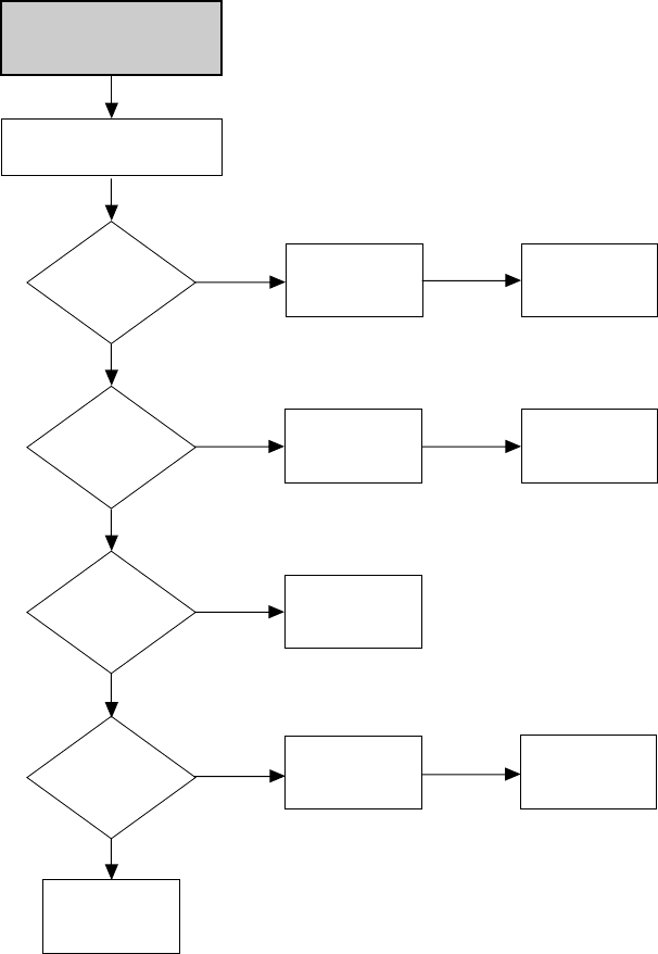
7-15
(VCR Section)
VCR STOP MODE
AUDIO MISSING IN
L1/L2 MODE
CHECK
AVC42, 43, 44,
45&AVR47, 48, 49, 50
CHECK SIGNAL INPUT
AVIC1-122, 123,
125, 126 pin
CHECK
AVE07, AVE08
NO
NO NO
YES
YES
YES
YES
CHECK SIGNAL OUTPUT
OF IC501-1, 77 pin
CHECK
HIFI IC501
CHECK SIGNAL INPUT
OF IC501-9, 71 pin
CHECK SIGNAL OUTPUT
AVIC1-106, 107 pin
NO
CHECK
AVIC1
CHECK
AVIC1
NO
NO
CHECK IC501-R523,
R524, R525, R526
CHECK IC501-R516,
R537, C543, C544
CHECK AVIC1-109,
110, 120, 121 pin
NO
(VCR Section)
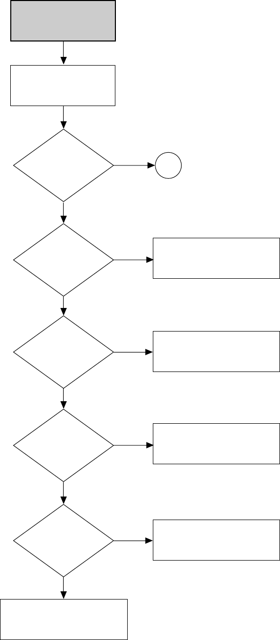
7-16
MISSING AUDIO
IC501-78, 80
AUDIO SIGNAL
IC501-26
AUDIO FM
CHECK CYLINDER
CHANGE
IC501
CHECK
C511, R506 CHANGE IC501
CHECK
AUDIO MISSING
IN L1/L2 MODE
AUDIO MISSING IN
REC MODE
MONO
HIFI
MONO
NO
NO
YES
YES
IC501-9, 71
AUDIO SIGNAL
IC501-37, 38
CLK, DATA
CHECK
R523, R524, R525, R511
CHECK
R509, R510
NO
NO
YES
YES
(VCR Section)
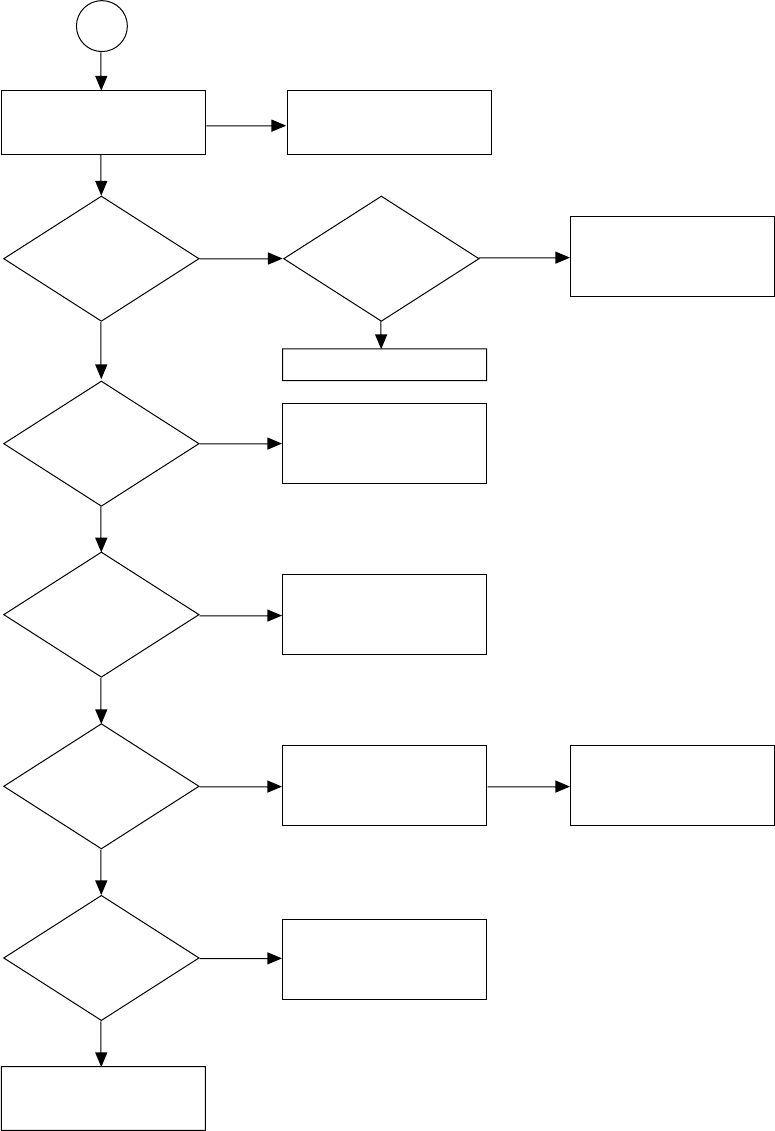
7-17
CHECK
Q304, Q305, C354
CHECK
R331, C353
CHANGE
IC301
IC301-76
AUDIO SIGNAL
IC501-4
AUDIO SIGNAL
NO
NO
NO
IC301-53, 54, 55
CHECK (CLOCK, DATA)
CHECK
C336, R322, R348
YES
NO
NO
NO
YES
YES
YES
YES
YES
YES
CHECK
IC301-58 AND CHANGE IC301
CHANGE IC501
IC301-10
AUDIO SIGNAL
IC301-9
AUDIO FM SIGNAL
IC301-7
MIX SIGNAL
(AUDIO+70KHz)
Q305
OSCILLATION
NO
CHECK AUDIO MISSING
IN PB MODE
CHECK
PB MODE
CHECK
A/CE HEAD
MONO
NO
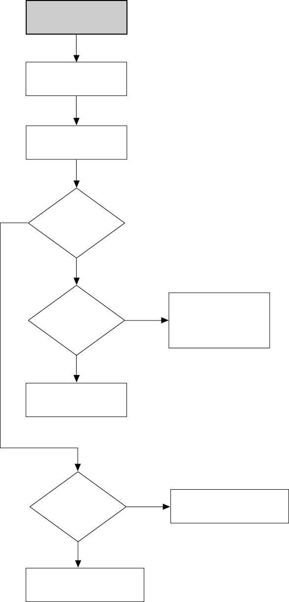
7-18
CHECK "AUDIO
MISSING IN L1/L2 MODE"
PLACE THE VCR IN PB MODE
CHANGE
IC501
AUDIO MISSING
IN PB MODE
CHECK C349, R333 or
CHANGE IC301
CHECK ACE HEAD
C353, C348, R332
AND CHANGE IC301
AUDIO SELECT
IC501-24, 27
AUDIO FM(MIXED)
CHECK
IC501-29(A.H D SW)
CHANGE CYLINDER OR
IC501
NO
HIFI
MONO
YES
IC301-3
AUDIO SIGNAL
NO
YES
(VCR Section)
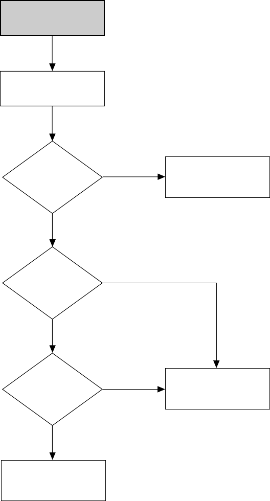
7-19
PLAY
NO SERVO LOCK
IC601-68
C-FG
IC601-76
CTL PULSE
CHECK
CTL PULSE AC
LEVEL (SP. SLP:
OVER 1Vp-p)
CHANGE
IC601
CHECK
A/CE HEAD
CHECK
CN604-1
NO
NO
NO
YES
YES
YES
(VCR Section)

7-20
CAPSTAN DOES
NOT ROTATE
PLACE THE VCR
IN PLAY MODE
CN604-2
15V
CN604-3
AL 5V
CN604-9
3.2V
CN604-5
2.6V
CN601-33
OUTPUT(PWM)
IC601-35
OUTPUT(PWM)
CHECK
CAPSTAN MOTOR
CHECK
R615, C606, R671
CHECK R607
CHANGE
IC601
CHECK
IC601
CHECK
B+ IN THE POWER BLOCK
CHECK
5V AT AL5V LINE
IN THE POWER BLOCK
NO
NO NO
NO
YES
NO
YES
NO
YES
YES
YES YES
(VCR Section)

7-21
DRUM DOES
NOT ROTATE
CN604-6
12V
CN604-3
5V
CN604-12
2.5V
CHECK
CYLINDER MOTOR
CN601-34 PWM OUT
CHECK 5V LINE
CHECK
12V AT PC12V LINE
IN THE POWER BLOCK
NO
NO
NO
YES
YES
YES YES
CHANGE IC601
NO
CHECK
R631, R617, R618, C609, C610
(VCR Section)
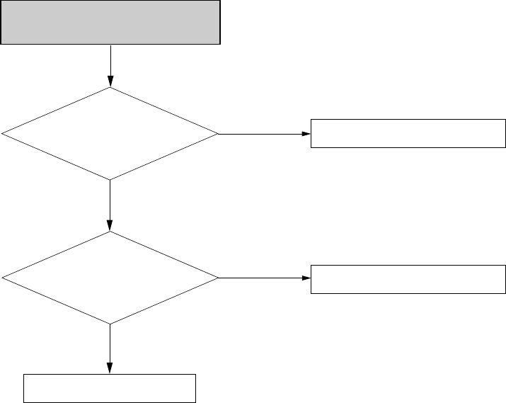
7-22
Power cable
(Pin #1: 5V, Pin #4 :12V)
CN03
Is the FFC cable
(between DVD main & Loader)
inserted correctly?
Change the main board
Check the power
No
No
Reinsert FFC cable correctly
Yes
Yes
Disc loading error
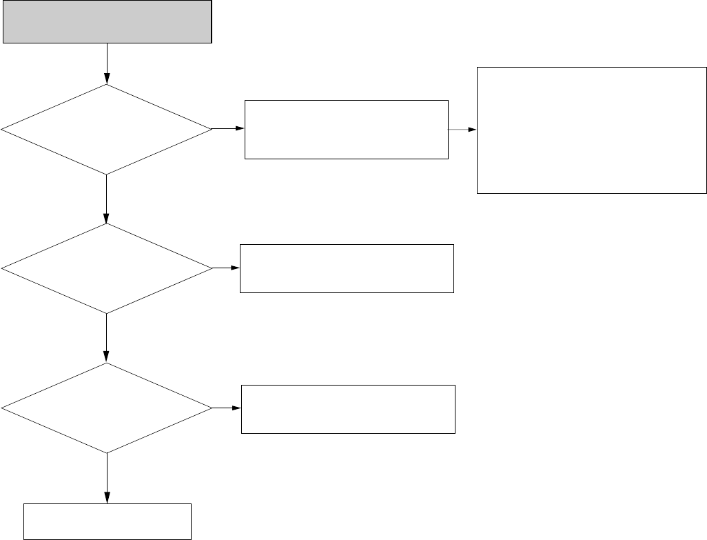
7-23
Check AVIC1
(Pin #109, 110)
Check AIC4 (Pin #1, 7)
Check peripheral parts of JK801
Check VCC of AVIC1 and peripheral
parts of Clock oscillation
(IC105 Pin # 1, 2, 14)
No
No
Check VCC and peripheral parts of AIC4.
Check applicatin of JACK 1
Check IC812 (Pin #3, 13) No
Yes
Yes
Yes
No Analog Audio Output
Check Audio input signal
1) Line 1 Audio input : AVIC1 Pin #122, 123
2) Line 2 Audio input :AVIC1 Pin #125, 126
3) VHS Play Audio input : AVIC1 Pin #120,
121, IC812 Pin #2,12
Check VCC and peripheral parts of IC812
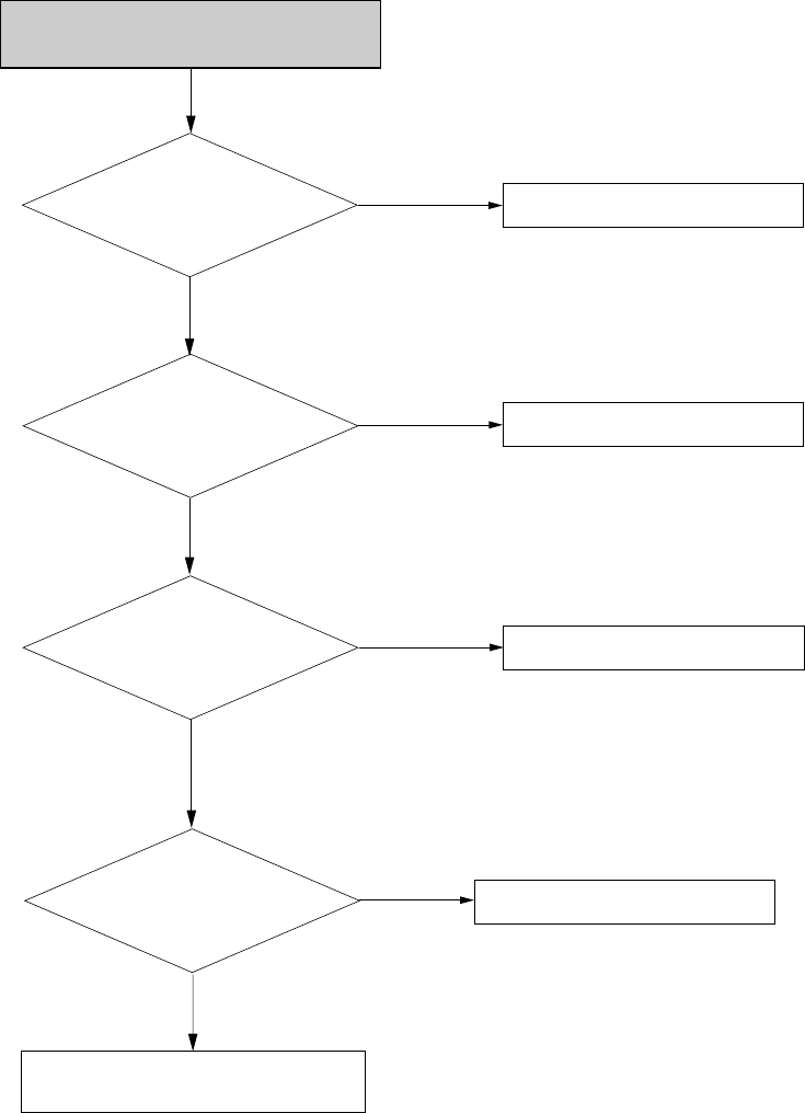
7-24
Check the digital audio
setting
Proper vcc of DOL3
Check peripheral parts of optical
and coaxial output terminal
Refer to user manual
No
Checking
Check Vcc Line
Proper signal input on DOL4 No
No
Proper signal on DOL2 Replace DOL2
Yes
Yes
Yes
Skip setting check (hardware problem)
No digital audio out
Check MR53

7-25
Check audio
input signal
1) Line 1 Audio input: AVIC1 Pin #122, 123
2) Line 2 Audio input: AVIC1 Pin #125, 126
3) VHS PLAY Aduio input: AVIC1 Pin #120,121
& IC812 Pin #2, 12
Check VCC (3.3V, 1.8V) of
IC101A
Change DVD JACK Board
1. Check peripheral parts of
Clock oscillation
1) IC105 Pin #1, 2, 14
2. Check peripheral parts of AVIC1
1) Pin #98,#99,#100
2) Pin #102~#105
Check peripheral parts of
JACK1, JK801 and TUNER.
No
No
Check VCC line
No Check VCC line of AVIC1
and IC105
Yes
Yes
Yes
No audio on line input mode or
recorded disc playback

7-26
Check VC50 No Check VCC of IC101 and peripheral
parts of Clock oscillation
(IC105 Pin #1, 2, 14)
No
No
Yes
Yes
Yes
CVBS output error
Check VCC and peripheral
parts of VIC 1
Check VIC 1 (Pin #2, 33)
Check IC811 (Pin #3, 4) Check peripheral parts of
IC811, AVIC1 (Pin #10) and AVQ01
Check peripheral parts of
and QV30
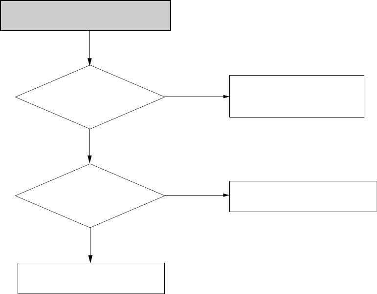
7-27
Check VC7, VC8 No Check VCC of IC101 and peripheral
parts of Clock oscillation
(IC105 Pin #1, 2,14)
No
Yes
Yes
S-Video output error
Check VC1
(Pin # 6, 8, 28, 31)
Check VCC and peripheral parts of
VIC 1
Check peripheral parts of SJACK

7-28
Component output error
Check VC9. V10, V11 No Check VCC of IC101 and peripheral
parts of Clock oscillation
(IC105 Pin #1, 2,14)
No
Yes
Yes
Check VIC 1
(Pin # 11, 14, 16, 21, 23, 25) Check VCC and peripheral parts of
VIC 1
Check peripheral parts of JACK1

7-29
Line1 CVBS Video Input Error
Check JK801
(Video input signal)
No
Check VCC of AVIC1 and peripheral
parts of Clock oscillation
(Pin #53, 54) of AVIC1
No
Yes
Yes
Check AVIC1
(Pin # 15)
Check VCC and peripheral parts of
AVIC1
No
Yes
Check AVIC1
(Pin #75, 76, 79 ~ 84)
Check peripheral parts of JK801
1. Check VCC of IC101 and peripheral
parts of Clock oscillation
(IC105 Pin #1, 2, 14)
2. Refer to the “ CVBS output error”

7-30
Line2 CVBS Video Input Error
Check Front
JACK (Video input signal)
and CN02 (Pin #14)
No
Check VCC of AVIC1 and peripheral
parts of Clock oscillation
(Pin #53, 54) of AVIC1
No
Yes
Yes
Check AVIC1
(Pin # 16)
Check VCC and peripheral parts of
AVIC1
No
Yes
Check AVIC1
(Pin #75, 76, 79~84)
Check peripheral parts of Front Jack
and cable and connector of CN02
1. Check VCC of IC101 and peripheral
parts of Clock oscillation
(IC105 Pin #1, 2, 14)
2. Refer to the “ CVBS output error”
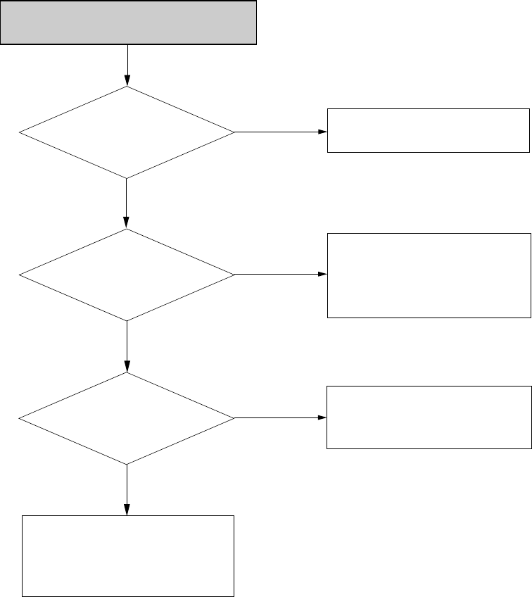
7-31
Line2 S-Video Video Input Error
Check Front
JACK (SVideo input signal)
and CN02 (Pin #10,12)
No
1. Check VCC of AVIC1 and peripheral
parts of Clock oscillation
(Pin #53, 54) of AVIC1
No
Yes
Yes
Check AVIC1
(Pin # 28, 36)
Check VCC and peripheral parts of
AVIC1
No
Yes
Check AVIC1
(Pin #75, 76, 79 ~84)
Check peripheral parts of Front Jack
and cable and connector of CN02
1. Check VCC of IC101 and peripheral
parts of Clock oscillation
(IC105 Pin #1, 2, 14)
2. Refer to the “ CVBS output error”

7-32E
DV (Digital Video) Input Error
Check DV JACK
(J1J, J1M, J10) and CN02
(Pin #1, 2, 3, 4)
No
Check VCC and Clcok oscillation
(Pin #59, 60) of IC1301
No
Yes
Yes
Check IC1301
(Pin #34~37)
Check peripheral parts of CN02 and
IC1301
No
Yes
Check IC1301
(Pin #4 ~13)
Check peripheral parts of DV JACK
and cable and connector of CN02
1. Check Pin #19 of IC1301
2. Check Pin #6~13 of IC1301
3. Check peripheral parts of Clock
oscillation (IC105 Pin #1, 2, 14)
4. Check VCC of IC101
5. Refer to the “CVBS output errror”

8-1
RDR-VX525
8. REPAIR PARTS LIST
8-1 Exploded Views ----------------------------------------------------------------------8-2
8-1-1 Cabinet Assembly ---------------------------------------------------------------------------------- 8-2
8-1-2 VCR Deck Section (Top Side) -------------------------------------------------------------------- 8-3
8-1-3 VCR Deck Section (Bottom Side) ---------------------------------------------------------------- 8-4
8-2 Electrical Parts List ------------------------------------------------------------------8-5
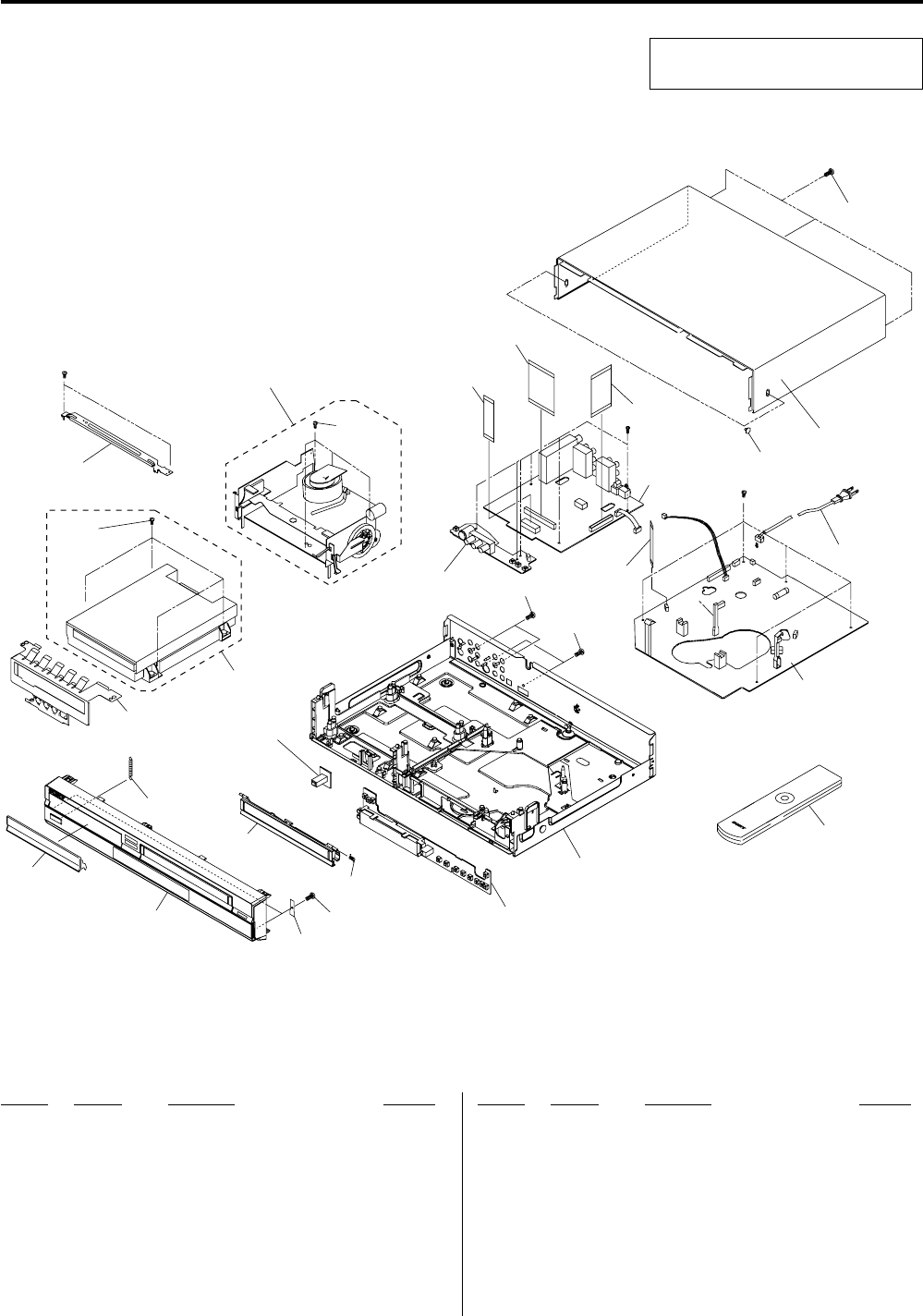
8-2
8-1-1 Cabinet Assembly
8-1 EXPLODED VIEWS
NOTE:
•-XX, -X mean standardized parts, so they may
have some differences from the original one.
•Items marked “*” are not stocked since they
are seldom required for routine service. Some
delay should be anticipated when ordering these
items.
•The mechanical parts with no reference number
in the exploded views are not supplied.
Ref. No. Part No. Description Remarks Ref. No. Part No. Description Remarks
19-885-113-50 ASSY CABINET FRONT
29-885-101-19 ASSY DECK
39-885-111-30 DOOR TRAY
79-885-069-88 SCREW-TAPTITE ZPC (WHT)
89-885-069-84 SCREW-TAPTITE BLK SWCH101
99-885-102-43 CABLE-FLAT;30V, 80C, 360MM, 40P
12 9-885-084-32 SCREW-TAPTITE
A001 9-885-112-11 REMOCON ASSY; RDR-VX555
C003 9-885-111-29 DOOR CASSETTE
C015 9-885-111-27 CABINET TOP
CN01B 9-885-112-93 CABLE-FLAT; 80MM, 30P, 1MM
CNJ02B 9-885-112-94 CABLE-FLAT; 200MM, 14P, 1.25MM
H001 9-885-111-31 ASSY LOADER; TS-P632A
P022 9-885-111-36 ASSY PWB MAIN DVD
0P025 1-824-674-11 POWER CORD EP2 SPT-2
W001 9-885-079-18 SCREW-TAPTITE
W202 9-885-069-85 SCREW-TAPTITE ZPC (YEL) SWR
W252 3-075-262-01 SCREW BH 4X12
C015
not supplied
not supplied
not supplied
not supplied
not supplied
not supplied
not supplied
not supplied
not supplied
not supplied
not supplied
not supplied
W202
C003
W001
W001
CNJ02B
CN01B
P025
A001
P022
W252
W202
H001
not
supplied
9
8
3
1
7
12
2
( )
Except for Assy Cylinder,
H/Cleaner lever Assy
The components identified by mark 0 or
dotted line with mark 0 are critical for safety.
Replace only with part number specified.
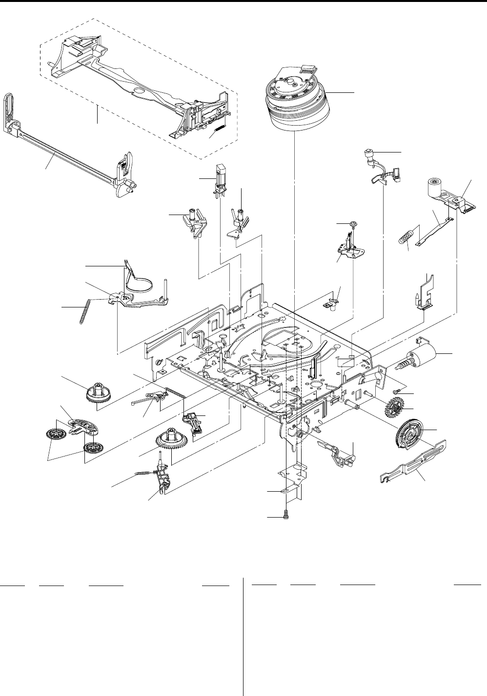
8-3
8-1-2 VCR Deck Section (Top Side)
Ref. No. Part No. Description Remarks Ref. No. Part No. Description Remarks
T001 9-885-101-30 ASSY CYLINDER 6HD
T003 1-796-434-11 LOADING ASSY, MOTOR
T010 9-885-101-27 ASSY ACE HEAD
T015 9-885-101-25 ASSY UNIT PINCH
T019 9-885-101-23 REEL S
T020 9-885-101-22 REEL T
T021 9-885-112-31 LEVER IDLE
T023 9-885-101-21 ASSY LEVER TENSION
T024 3-067-782-01 SPRING-TENSION LEVER
T025 9-885-101-20 ASSY BAND BRAKE
T028
T020
T027
T019 T028
T024
T023
T025
T001
W016
T01
5
T077
T071
T003
W201
W015
T010
not supplied
not supplied
not supplied
not supplied
not supplied
not supplied
not supplied
not supplied
not supplied
not supplied
not supplied
not supplied
not supplied
not supplied
not supplied
T026
not supplied
T021
*T026 9-885-108-18 ASSY LEVER BRAKE S
T027 9-885-101-24 ASSY LEVER BRAKE T
T028 3-067-786-01 SPRING-BRAKE
T071 9-885-101-28 GUIDE CASSETTE DOOR
T077 9-885-101-18 ASSY HEAD CLEANER
W015 9-885-069-89 SCREW-MACHINE ZPC (YEL)
W016 9-885-069-90 SCREW-TAPTITE ZPC (YEL)
W201 9-885-069-81 SCREW-MACHINE ZPC (YEL)
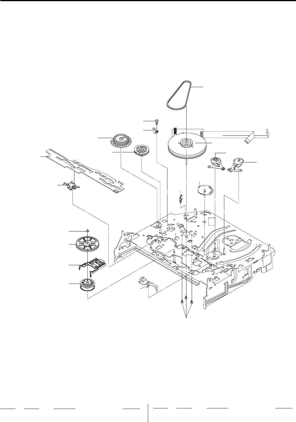
8-4
8-1-3 VCR Deck Section (Bottom Side)
T046
T044
W019
W018
not supplied
not supplied
not supplied
not supplied
not supplied
not supplied
not supplied
not supplied
not supplied not supplied
not
supplied
not supplied
not supplied
not supplie
d
T044 9-885-101-26 MOTOR CAPSTAN
T046 3-067-790-01 BELT-PULLEY
Ref. No. Part No. Description Remarks Ref. No. Part No. Description Remarks
W018 9-885-069-87 SCREW-TAPTITE PH ZPC (YEL)
W019 9-885-069-82 SCREW-TAPTITE ZPC (YEL) SW

8-5
< DIODE >
AD1 9-885-070-27 DIODE DAN202K
AD2 9-885-070-27 DIODE DAN202K
*AZ1 9-885-102-51 DIODE CDS3C30GTH
*AZ3 9-885-102-51 DIODE CDS3C30GTH
*AZ50 9-885-102-51 DIODE CDS3C30GTH
*AZ52 9-885-102-51 DIODE CDS3C30GTH
*AZ55 9-885-102-51 DIODE CDS3C30GTH
*AZ57 9-885-102-51 DIODE CDS3C30GTH
*DOZ1 9-885-102-51 DIODE CDS3C30GTH
QD01 9-885-070-27 DIODE DAN202K
*VZ1 9-885-102-51 DIODE CDS3C30GTH
*VZ3 9-885-102-51 DIODE CDS3C30GTH
*VZ5 9-885-102-51 DIODE CDS3C30GTH
*VZ7 9-885-102-51 DIODE CDS3C30GTH
*VZ10 9-885-102-51 DIODE CDS3C30GTH
*VZ50 9-885-102-51 DIODE CDS3C30GTH
*VZ51 9-885-102-51 DIODE CDS3C30GTH
< IC >
AIC4 9-885-070-53 IC 4560 (OP AMP)
AVIC1 9-885-111-37 IC SAA7138HL (VIDEO DECODER)
CIC1 9-885-079-21 IC 74VHC125 (CMOS LOGIC)
IC102 9-885-111-38 IC K4H561638 (DRAM)
IC103 IC (CPRM key) (Refer to Note 1)
Note 1: Special key has been written in the IC103 (CPRM key), and
therefore the IC103 cannot be replaced.
If this IC is faulty, replace the board entirely.
Note 2: Perform the reset whenever the IC104 was replaced (See page
10).
IC104 9-885-111-39 IC ASSY-MEMORY (FLASH) (Refer to Note 2)
IC105 1-805-039-11 IC M74HCU04 (CMOS LOGIC)
IC811 9-885-036-96 IC BU4053BCFV (CMOS LOGIC)
IC812 9-885-036-96 IC BU4053BCFV (CMOS LOGIC)
IC813 9-885-106-72 IC (AUDIO PROCESSOR)
IC1301 9-885-070-64 IC TSB41AB1-PAP (DATA COMM/GEN)
9ICHD1 IC TDA9983 (VIDEO PROCESS)
VIC1 9-885-037-03 IC LA73054 (VIDEO)
NOTE:
•Due to standardization, replacements in the
parts list may be different from the parts
specified in the diagrams or the components
used on the set.
•-XX, and -X mean standardized parts, so they
may have some difference from the original one.
•RESISTORS
All resistors are in ohms.
METAL: metal-film resistor
METAL OXIDE: Metal Oxide-film resistor
F: nonflammable
•Not all of the parts are listed.
•Items marked “*” are not stocked since they are
seldom required for routine service. Some delay
should be anticipated when ordering these items.
•SEMICONDUCTORS
In each case, u: µ, for example:
uA...: µA... , uPA... , µPA... ,
uPB... , µPB... , uPC... , µPC... ,
uPD..., µPD...
•CAPACITORS:
uF: µF
•COILS
uH: µH
8-2 ELECTRICAL PARTS LIST
Ref. No. Part No. Description Remarks Ref. No. Part No. Description Remarks
When indicating parts by reference number,
please include the board name.
DV JACK
The components identified by mark 0 or
dotted line with mark 0 are critical for safety.
Replace only with part number specified.
DV JACK BOARD
*************
(This DV JACK BOARD is included in VCR
MAIN BOARD.)
< JACK >
J1J 9-885-084-29 JACK-IEEE1394 4P/1C (DV IN)
< CONNECTOR >
*J1M 9-885-108-67 JACK-IEEE1394 5P
DVD MAIN BOARD
***************
9-885-111-36 ASSY PWB MAIN DVD
< BEAD/CORE >
ABD1 1-400-316-11 CORE-FERRITE BEAD 220ohm
ABD2 1-400-316-11 CORE-FERRITE BEAD 220ohm
ABD3 1-400-316-11 CORE-FERRITE BEAD 220ohm
AVR02 1-400-316-11 CORE-FERRITE BEAD 220ohm
AVR03 1-400-316-11 CORE-FERRITE BEAD 220ohm
AVR19 1-400-316-11 CORE-FERRITE BEAD 220ohm
AVR40 1-400-316-11 CORE-FERRITE BEAD 220ohm
DVR1 9-885-083-84 BEAD-SMD 47ohm
DVR2 9-885-083-84 BEAD-SMD 47ohm
DVR3 9-885-083-84 BEAD-SMD 47ohm
DVR4 9-885-083-84 BEAD-SMD 47ohm
HDR9 1-400-316-11 CORE-FERRITE BEAD 220ohm
HDR10 1-400-316-11 CORE-FERRITE BEAD 220ohm
MR08 9-885-083-84 BEAD-SMD 47ohm
MR18 1-400-316-11 CORE-FERRITE BEAD 220ohm
R851 1-400-316-11 CORE-FERRITE BEAD 220ohm
R852 1-400-316-11 CORE-FERRITE BEAD 220ohm
REM1 1-400-316-11 CORE-FERRITE BEAD 220ohm
REM2 1-400-316-11 CORE-FERRITE BEAD 220ohm
REM3 1-400-316-11 CORE-FERRITE BEAD 220ohm
REM4 1-400-316-11 CORE-FERRITE BEAD 220ohm
RIS10 9-885-083-84 BEAD-SMD 47ohm
VR100 1-400-316-11 CORE-FERRITE BEAD 220ohm
< CONNECTOR >
*HDJACK 9-885-108-17 CONNECTOR-HDMI (HDMI OUT)
DVD MAIN
The components identified by mark 9 contain
confidential information.
Strictly follow the instructions whenever the
components are repaired and/or replaced.

8-6
Ref. No. Part No. Description Remarks Ref. No. Part No. Description Remarks
DVD MAIN
< TRANSISTOR >
AQ1 9-885-070-34 TRANSISTOR
AQ2 9-885-070-37 TRANSISTOR KSR2103
AQ3 9-885-070-30 TRANSISTOR KSC1623-L
AQ4 9-885-070-34 TRANSISTOR
AQ5 9-885-070-37 TRANSISTOR KSR2103
AQ6 9-885-070-30 TRANSISTOR KSC1623-L
AVQ01 9-885-070-30 TRANSISTOR KSC1623-L
AVQ02 9-885-070-30 TRANSISTOR KSC1623-L
GTR01 9-885-070-30 TRANSISTOR KSC1623-L
GTR02 9-885-070-30 TRANSISTOR KSC1623-L
QMU1 9-885-070-34 TRANSISTOR
QMU2 9-885-070-37 TRANSISTOR KSR2103
QS01 9-885-070-29 TRANSISTOR KSA812
QS02 9-885-070-29 TRANSISTOR KSA812
QS03 9-885-070-30 TRANSISTOR KSC1623-L
QS04 9-885-070-30 TRANSISTOR KSC1623-L
QSS2 9-885-043-26 TRANSISTOR KSR1104
< FILTER >
DOL1 9-885-069-75 FILTER-EMI SMD
< VIBRATOR >
AVXT01 9-885-070-70 CRYSTAL-SMD (24.576MHz)
MXTAL019-885-067-37 CRYSTAL (27MHz)
X1301 9-885-070-70 CRYSTAL-SMD (24.576MHz)
FRONT JACK BOARD
*****************
(This FRONT JACK BOARD is included in VCR
MAIN BOARD.)
< CONNECTOR >
CNJ01 1-815-689-11 CONNECTOR FPC 7P
< DIODE >
*JZ01 9-885-102-51 DIODE CDS3C30GTH
*JZ02 9-885-102-51 DIODE CDS3C30GTH
*JZ03 9-885-102-51 DIODE CDS3C30GTH
*JZ04 9-885-102-51 DIODE CDS3C30GTH
*JZ06 9-885-102-51 DIODE CDS3C30GTH
*JZ08 9-885-102-51 DIODE CDS3C30GTH
< COIL/FERRITE BEAD >
RD701 9-885-083-84 BEAD-SMD 47ohm
RD702 9-885-083-84 BEAD-SMD 47ohm
RD703 9-885-083-84 BEAD-SMD 47ohm
RD704 9-885-083-84 BEAD-SMD 47ohm
RFR1 9-885-083-84 BEAD-SMD 47ohm
RFR2 9-885-083-84 BEAD-SMD 47ohm
RFR3 1-400-316-11 CORE-FERRITE BEAD 220ohm
RFR4 9-885-083-84 BEAD-SMD 47ohm
RFR5 9-885-083-84 BEAD-SMD 47ohm
RFR6 9-885-083-84 BEAD-SMD 47ohm
RFR7 1-400-316-11 CORE-FERRITE BEAD 220ohm
< SWITCH >
SW1 9-885-069-77 SWITCH-TACT (POWER)
SW2 9-885-069-77 SWITCH-TACT (ONETOUCH DUB)
SW3 9-885-069-77 SWITCH-TACT (CH DOWN)
SW4 9-885-069-77 SWITCH-TACT (CH UP)
SW5 9-885-069-77 SWITCH-TACT (OPEN)
FUNCTION BOARD
***************
(This FUNCTION BOARD is included in VCR
MAIN BOARD.)
< DIODE >
D701 9-885-111-32 DIODE 1N4148
D702 9-885-111-32 DIODE 1N4148
D703 9-885-111-32 DIODE 1N4148
D704 9-885-111-32 DIODE 1N4148
D705 9-885-111-32 DIODE 1N4148
D706 9-885-111-32 DIODE 1N4148
D707 9-885-111-32 DIODE 1N4148
D708 9-885-111-32 DIODE 1N4148
D709 9-885-111-32 DIODE 1N4148
< COIL >
L701 1-400-074-11 INDUCTOR 100uH
< VFD DISPLAY >
DT701 9-885-070-01 VFD DISPLAY HNV-10SM40
< IC >
IC701 9-885-070-48 IC PT6315 (VFD)
< LED >
LD701 1-805-289-11 LED (COPY DVD -> VHS)
LD702 1-805-289-11 LED (COPY VHS -> DVD)
LD703 9-885-076-83 LED (SYNCHRO REC)
LD704 9-885-079-26 LED (HDMI)
< REMOCON MODULE >
RM701 9-885-069-95 MODULE REMOCON TSOP2240RF1
< SWITCH >
SW703 9-885-069-77 SWITCH-TACT (PAUSE)
SW705 9-885-069-77 SWITCH-TACT (VIDEO)
SW706 9-885-069-77 SWITCH-TACT (COPY DVD -> VHS)
SW707 9-885-069-77 SWITCH-TACT (PLAY)
SW708 9-885-069-77 SWITCH-TACT (DVD)
SW709 9-885-069-77 SWITCH-TACT (EJECT)
SW710 9-885-069-77 SWITCH-TACT (COPY VHS -> DVD)
SW711 9-885-069-77 SWITCH-TACT (REC)
SW713 9-885-069-77 SWITCH-TACT (FF)
SW715 9-885-069-77 SWITCH-TACT (REW)
SW716 9-885-069-77 SWITCH-TACT (STOP)
FRONT JACK FUNCTION

8-7
Ref. No. Part No. Description Remarks Ref. No. Part No. Description Remarks
VCR MAIN
VCR MAIN BOARD
***************
(DV JACK BOARD, FRONT JACK BOARD and
FUNCTION BOARD are included in this VCR MAIN BOARD.)
SC1S01 9-885-069-86 SCREW-TAPTITE ZPC (YEL) SWRC
SC1S33 9-885-069-86 SCREW-TAPTITE ZPC (YEL) SWRC
< CAPACITOR >
C319 1-100-020-11 CONDENSER 10000PF
C502 1-165-563-11 CONDENSER 0.1uF
C522 1-100-020-11 CONDENSER 10000PF
C635 1-100-020-11 CONDENSER 10000PF
C636 1-100-020-11 CONDENSER 10000PF
0C1S02 1-100-358-11 CONDENSER CERAMIC DISC 100PF
0C1S03 1-100-358-11 CONDENSER CERAMIC DISC 100PF
0C1S04 9-885-079-30 CONDENSER FILM 47nF
0C1S05 9-885-079-30 CONDENSER FILM 47nF
C1S07 1-165-990-11 CONDENSER 100PF
C1S08 1-165-574-11 CONDENSER FILM 10000PF
C1S12 1-165-574-11 CONDENSER FILM 10000PF
C1S39 1-165-999-11 CONDENSER FILM 0.1uF
< CONNECTOR >
CN02 1-815-689-11 CONNECTOR FPC 7P
CN301 1-815-685-11 CONNECTOR FPC 10P
CN303 1-815-688-11 CONNECTOR FPC 6PSN
< FLAT CABLE >
CN303B 9-885-069-80 CABLE-FLAT
< DIODE >
*BD01 9-885-103-76 DIODE SHL20K
*BD02 9-885-103-76 DIODE SHL20K
*BD03 9-885-103-76 DIODE SHL20K
*BD04 9-885-103-76 DIODE SHL20K
D601 9-885-111-32 DIODE 1N4148
*D604 9-885-103-77 DIODE 1N5819
D605 9-885-111-32 DIODE 1N4148
*D606 9-885-103-77 DIODE 1N5819
D1P102 9-885-111-32 DIODE 1N4148
*D1P106 9-885-103-77 DIODE 1N5819
*D1P107 9-885-103-77 DIODE 1N5819
D1S05 9-885-070-13 DIODE UF4007
D1S06 9-885-111-32 DIODE 1N4148
D1S07 9-885-070-16 DIODE F1T4
D1S30 9-885-076-80 DIODE MBRF10A0
D1S32 9-885-076-80 DIODE MBRF10A0
D1S33 9-885-076-80 DIODE MBRF10A0
D1S34 9-885-070-16 DIODE F1T4
D1S35 9-885-070-15 DIODE SHG2D
*D1S38 9-885-102-60 DIODE 1N5408
D1S40 9-885-070-16 DIODE F1T4
ZD1P03 9-885-070-21 DIODE MTZJ9
ZD1P05 9-885-070-18 DIODE UZP27B
ZD1P06 9-885-070-17 DIODE UZ5.6BM
ZD1S01 9-885-070-25 DIODE MTZJ4
ZD1S02 9-885-036-94 DIODE MTZJ20B
ZD1S03 8-719-109-93 DIODE RD6.2ESB2
< COIL/FERRITE BEAD >
BD1P01 1-400-086-11 FERRITE CORE
BD1S01 1-400-085-11 INDUCTOR 70uH
BD1S03 1-400-085-11 INDUCTOR 70uH
BD1S04 1-400-085-11 INDUCTOR 70uH
L02 1-424-828-11 COIL CHOKE 10uH
L03 1-424-828-11 COIL CHOKE 10uH
L301 1-400-085-11 INDUCTOR 70uH
L302 1-400-086-11 FERRITE CORE
L303 1-400-086-11 FERRITE CORE
L304 1-400-086-11 FERRITE CORE
L305 1-400-085-11 INDUCTOR 70uH
L306 9-885-070-66 INDUCTOR-RADIAL
L307 1-400-074-11 INDUCTOR 100uH
L501 1-400-086-11 FERRITE CORE
L502 1-400-086-11 FERRITE CORE
L601 1-400-082-11 INDUCTOR RA 100uH
L602 1-400-074-11 INDUCTOR 100uH
L603 1-400-074-11 INDUCTOR 100uH
L1P101 1-400-074-11 INDUCTOR 100uH
L1S30 9-885-070-00 COIL CHOKE DR CHOKE (8*6)
L1S31 9-885-070-00 COIL CHOKE DR CHOKE (8*6)
L1S32 1-424-828-11 COIL CHOKE 10uH
LT01 1-400-074-11 INDUCTOR 100uH
< FUSE >
0F1P01 1-576-729-11 FUSE-RADIAL LEAD (1A/50V)
0F1S01 1-576-526-11 FUSE (1.6A/250V)
< FUSE CLIP >
FC1S01 1-576-527-11 FUSE CLIP
FC1S02 1-576-527-11 FUSE CLIP
< IC/PHOTO COUPLER >
IC301 9-885-070-58 IC LA71207 (VIDEO PROCESS)
IC501 9-885-070-60 IC LA72670M (SIGNAL PROCESSOR)
IC601 9-885-111-33 IC MN101D10G-CH (MICOM)
IC1P01 9-885-070-56 IC G9105 (POSI. FIXED REG)
IC1P02 9-885-084-28 IC (SWITCH VOL. REG)
IC1P03 9-885-070-56 IC G9105 (POSI. FIXED REG)
IC1P04 9-885-102-61 IC KIA278R018PI (POSI. FIXED REG)
IC1P05 9-885-070-57 IC G9205 (POSI. FIXED REG)
*IC1P150 9-885-108-63 IC KIA278R000P5 (POSI. FIXED REG)
IC1S01 9-885-037-01 IC (PWM CONTROLLER)
0IC1S02 9-885-070-43 PHOTO-COUPLER
IC1S03 1-804-445-11 IC KA4318
IC603A 9-885-111-34 IC AT24C04N-10SU-2.7 (EEPROM)
IC6B1 1-804-773-11 IC (RESET)
ICT01 9-885-111-35 IC S3C80G9B21-SN99 (CBC)
< LINE FILTER >
0L1S01 1-424-831-11 LINE FILTER 20mH
0L1S02 1-424-830-11 LINE FILTER 30mH
< TRANSFORMER >
0PT01 9-885-102-62 TRANS SWITCHING EER3534
The components identified by mark 0 or dotted line with
mark 0 are critical for safety.
Replace only with part number specified.

8-8
Ref. No. Part No. Description Remarks Ref. No. Part No. Description Remarks
< PHOTO INTERRUPTER >
PT601 9-885-106-66 PHOTO-INTERRUPTER (S-REEL)
PT602 9-885-106-66 PHOTO-INTERRUPTER (T-REEL)
< TRANSISTOR >
Q302 9-885-070-29 TRANSISTOR KSA812
Q303 9-885-070-30 TRANSISTOR KSC1623-L
Q304 9-885-070-29 TRANSISTOR KSA812
Q305 9-885-070-33 TRANSISTOR KTC3203-Y
Q306 9-885-070-29 TRANSISTOR KSA812
Q307 9-885-070-33 TRANSISTOR KTC3203-Y
Q308 9-885-070-33 TRANSISTOR KTC3203-Y
Q601 9-885-043-26 TRANSISTOR KSR1104
Q1P103 9-885-070-38 FET FQP33N10
Q1P108 9-885-070-31 TRANSISTOR KSC2328A-Y
Q1PS01 9-885-070-32 TRANSISTOR KSC945
Q1PS02 9-885-070-33 TRANSISTOR KTC3203-Y
Q1PS03 9-885-070-36 TRANSISTOR KSR2001
Q1S01 9-885-036-95 FET
< REGISTOR >
R1S13 1-245-575-11 R-METAL OXIDE
< THERMISTOR >
0R1S04 9-885-101-36 THERMISTOR-NTC
< SWITCH >
SW602 9-885-101-37 SWITCH REC (REC SAFETY SW)
SW603 9-885-061-06 SWITCH MODE (MODE SW)
*SW604 9-885-104-29 SWITCH DETECTOR (SWITCH CASSETTE)
< VARISTOR >
VA1S01 9-885-070-65 VARISTOR
VA1S02 9-885-070-65 VARISTOR
*VA1S03 9-885-108-15 VARISTOR
< VIBRATOR >
XT01 1-795-604-11 RESONATOR CERAMIC (4.0MHz)
XT301 1-795-603-11 VIBRATOR CRYSTAL (3.6MHz)
XT601 9-885-070-67 CRYSTAL-UNIT (14.31818MHz)
XT602 1-795-332-11 VIBRATOR CRYSTAL (32.768kHz)
MISCELLANEOUS
***************
99-885-102-43 CABLE-FLAT;30V, 80C, 360MM, 40P
0P025 1-824-674-11 POWER CORD EP2 SPT-2
ACCESSORIES
************
3-096-487-11 MANUAL, INSTRUCTION (ENGLISH)
9-885-102-44 CBF CABLE-MONO PLUG TO LED
9-885-113-51 CBF SIGNAL
VCR MAIN
8-8E
The components identified by mark 0 or dotted line with
mark 0 are critical for safety.
Replace only with part number specified.
— 158 —
RDR-VX525
Sony Corporation
Home Electronics Network Company
9-883-955-11
2007D0500-1
© 2007.4
Published by Quality Assurance Dept.

REVISION HISTORY
Clicking the version allows you to jump to the revised page.
Also, clicking the version at the upper right on the revised page allows you to jump to the next revised
page.
Ver. Date Description of Revision
1.0 2007.04 New
RDR-VX525
