RHF76 052 User Manual Lo Ra WAN Module
User Manual:
Open the PDF directly: View PDF ![]() .
.
Page Count: 44
- Introduction of RHF76-052
- Electrical Characteristics
- Hardware Design Reference
- Package Information
- Application in LoRaWAN
- Introduction of AT Command
- Essential informations before using AT command
- AT Commands description

V2.5 2016-01-11
www.risinghf.com
LoRaWAN Module RHF76-052 User Manual
RisingHF
Document information
Info
Content
Keywords
LoRaWAN, RHF76-052, AT Command, UART, USB
Abstract
This document shows how to use RisingHF LoRaWAN
module RHF76-052 set up a LoRa/LoRaWAN node, and
defines AT command format used by the module
UM01509
LoRaWAN Module RHF76-052 User Manual
V2.6

V2.5 2016-01-11
www.risinghf.com
LoRaWAN Module RHF76-052 User Manual
RisingHF
Content
Content...................................................................................................................................................................... 2
Tables........................................................................................................................................................................ 5
FIgures.......................................................................................................................................................................5
Part I-RHF76-052 Hardware description..............................................................................................................1
1 Introduction of RHF76-052..................................................................................................................................1
2 Electrical Characteristics..................................................................................................................................... 1
2.1 Absolute Maximum Ratings......................................................................................................................... 1
2.2 Operating Range........................................................................................................................................... 1
2.3 Module Specifications...................................................................................................................................1
2.4 GPIO Definition..............................................................................................................................................2
3 Hardware Design Reference...............................................................................................................................4
4 Package Information............................................................................................................................................ 6
4.1 Package Information..................................................................................................................................... 6
5 Application in LoRaWAN..................................................................................................................................... 7
2.1 LoRaWAN/LoRaMAC...........................................................................................................................7
2.2 RHF76-052 with LoRaWAN................................................................................................................ 8
Part II-AT Command Specifications....................................................................................................................10
6 Introduction of AT Command............................................................................................................................10
6.1 Feature..........................................................................................................................................................10
6.2 Related Products.........................................................................................................................................10
7 Essential informations before using AT command........................................................................................11
7.1 Conventions................................................................................................................................................. 11
7.2 Symbols........................................................................................................................................................ 11
7.3 Format...........................................................................................................................................................11
7.3.1 Query..................................................................................................................................................... 11
7.3.2 Configure / Control...............................................................................................................................11
7.3.3 Return.................................................................................................................................................... 11
7.4 Error...............................................................................................................................................................12
7.5 EEPROM...................................................................................................................................................... 12
7.6 Payload Length Limitation......................................................................................................................... 13
8 AT Commands description................................................................................................................................14
8.1 AT.................................................................................................................................................................. 15

V2.5 2016-01-11
www.risinghf.com
LoRaWAN Module RHF76-052 User Manual
RisingHF
8.2 ID................................................................................................................................................................... 15
8.3 RESET.......................................................................................................................................................... 16
8.4 MSG.............................................................................................................................................................. 16
8.5 CMSG........................................................................................................................................................... 16
8.6 MSGHEX...................................................................................................................................................... 17
8.7 CMSGHEX................................................................................................................................................... 17
8.8 PORT............................................................................................................................................................ 18
8.9 ADR............................................................................................................................................................... 18
8.10 DR............................................................................................................................................................... 18
8.10.1 Datarate Scheme...............................................................................................................................18
8.10.2 Customized Data Rate Scheme......................................................................................................21
8.11 CH............................................................................................................................................................... 22
8.12 POWER...................................................................................................................................................... 23
8.13 REPT...........................................................................................................................................................23
8.14 RXWIN2......................................................................................................................................................24
8.15 RXWIN1......................................................................................................................................................24
8.16 VER............................................................................................................................................................. 25
8.17 KEY............................................................................................................................................................. 25
8.18 FDEFAULT.................................................................................................................................................25
8.19 DFU............................................................................................................................................................. 26
8.20 HELP...........................................................................................................................................................27
8.21 MODE......................................................................................................................................................... 28
8.22 JOIN............................................................................................................................................................ 28
8.23 CLASS........................................................................................................................................................ 29
8.24 LOWPOWER............................................................................................................................................. 29
8.25 TEST........................................................................................................................................................... 30
8.25.1 Print Help Information....................................................................................................................... 30
8.25.2 Enter TEST mode..............................................................................................................................30
8.25.3 Query RF configuration.....................................................................................................................30
8.25.4 Set RF Configuration.........................................................................................................................31
8.25.5 TX LoRa Packet.................................................................................................................................32
8.25.6 RX LoRa Packet................................................................................................................................ 32
8.25.7 TX Continuous Wave........................................................................................................................ 33

V2.5 2016-01-11
www.risinghf.com
LoRaWAN Module RHF76-052 User Manual
RisingHF
8.25.8 TX Continuous LoRa.........................................................................................................................33
8.25.9 RSSI.....................................................................................................................................................33
8.25.10 LWDL.................................................................................................................................................33
8.26 UART.......................................................................................................................................................... 33
8.26.1 TIMEOUT............................................................................................................................................33
8.27 DELAY........................................................................................................................................................ 34
Revision...................................................................................................................................................................35

V2.5 2016-01-11
www.risinghf.com
LoRaWAN Module RHF76-052 User Manual
RisingHF
Tables
Table 2- 1 Absolute Maximum Ratings......................................................................................................... 1
Table 2- 2 Operating Range........................................................................................................................... 1
Table 2- 3 Module Specifications...................................................................................................................1
Table 2- 4 GPIO description........................................................................................................................... 2
Table 4- 1 Related products list................................................................................................................... 10
Table 5- 1 Error code list...............................................................................................................................12
Table 5- 2 Memorized configuration............................................................................................................12
Table 5- 3 Payload length limitation............................................................................ 错误!未定义书签。
Table 6- 1 Command List..............................................................................................................................14
Table 6- 2 LoRaWAN EU868 Data Rate Scheme.................................................................................... 20
Table 6- 3 LoRaWAN US915 Data Rate Scheme.................................................................................... 20
Table 6- 4 Factory default configuration..................................................................................................... 26
Table 6- 5 TEST mode sub-command list..................................................................................................30
Table 6- 6 MAX output power of HF and LF band.................................................................................... 31
Table 6- 7 LoRaWAN Delay Items.............................................................................................................. 34
FIgures
Figure 3- 1 RHF76-052 AM Reference Design (FW upgrade with UART)............................................. 4
Figure 3- 2 RHF76-052 AN Reference Design (FW upgrade with USB).................................................5
Figure 4- 1 package outline drawing............................................................................................................. 6
Figure 4- 2 Recommended land pattern....................................................................................................... 7
Figure 5- 1 Energy profile of RHF76-052 application in LoRaWAN......................................................... 8
Figure 5- 2 Energy profile of RHF76-052 application in LoRaWAN......................................................... 9
V2.6 2015-12-03
www.risinghf.com
LoRaWAN Module RHF76-052 User Manual
RisingHF
1
Part I-RHF76-052 Hardware description
1 Introduction of RHF76-052
RisingHF™ LoRaWAN™ module RHF76-052 is embedded with LoRaWAN stack. Customer could use
a host MCU to control this modem with simple AT command. The advanced and simple command
interface offers rapid time to market.
This part is targeted to help customer to set their hardware platform quickly with RHF76-052 modem.
2 Electrical Characteristics
2.1 Absolute Maximum Ratings
Stresses above the values listed below may cause permanent device failure. Exposure to absolute
maximum ratings for extended periods may affect device reliability.
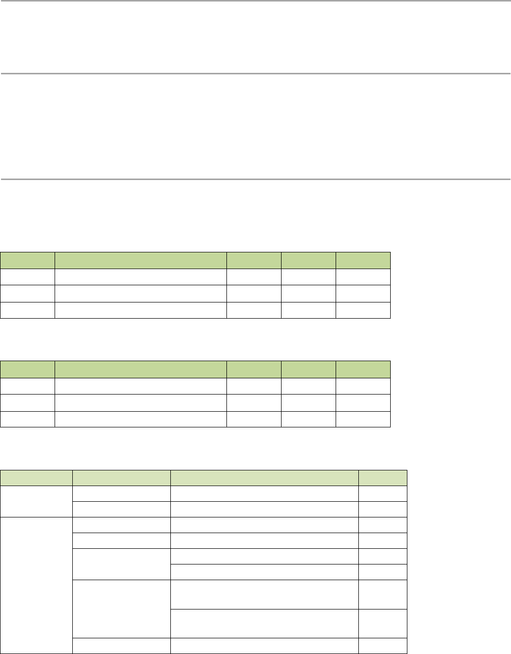
Table 2- 1 Absolute Maximum Ratings
Item
Description
min
max
unit
VCCmr
Supply voltage
-0.3
+3.9
V
Tmr
Temperature
-55
+115
℃
Pmr
RF input level
-
+10
dBm
2.2 Operating Range
Table 2- 2 Operating Range
Item
Description
min
max
unit
VCCop
Supply voltage
+1.8
+3.6
V
Top
Temperature
-40
+85
℃
Pop
RF input level
-
+10
dBm
2.3 Module Specifications
Table 2- 3 Module Specifications
ITEMs
Parameter
Specifications
Unit
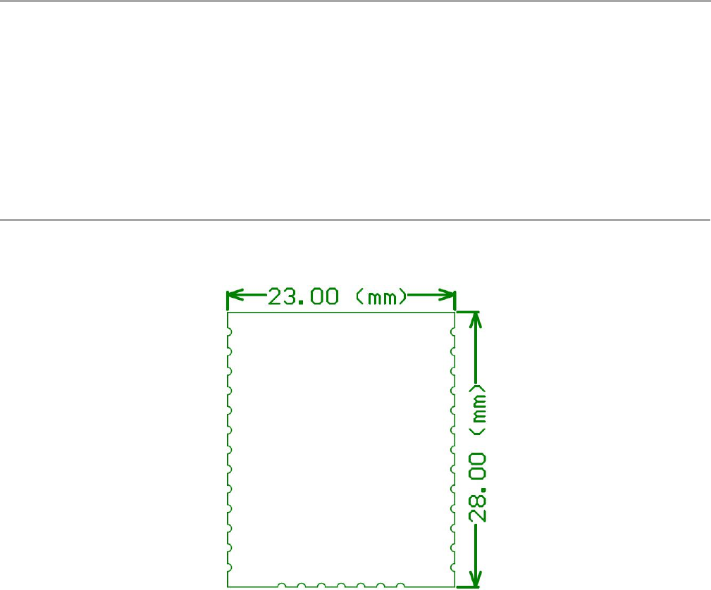
Structure
Size
23(W) X 28(L) X 2.6(H)
mm
Package
33 pins, SMT
Electrical
Characteristics
power supply
3.3V type
V
Sleep current
1.45uA
uA
Operation current
(Transmitter+MCU)
120mA @20dBm in 434MHz/470MHz type
mA
45mA @14dBm in 868MHz/915MHz type
mA
Operation current
(Receiver+MCU)
16mA @BW125kHz, 434MHz/470MHz
type
mA
15.5mA @BW125kHz, 868MHz/915MHz
type
mA
Output power
20dBm max @434MHz/470MHz
dBm

V2.6 2015-12-03
www.risinghf.com
LoRaWAN Module RHF76-052 User Manual
RisingHF
2
14dBm max @868MHz/915MHz
dBm
Sensitivity
-139dBm @SF12, BW125kHz,
434MHz/470MHz
dBm
-137dBm @SF12, BW125kHz,
868MHz/915MHz
dBm
Harmonics (LF)
<-42dBm below 1GHz
dBm
<-35dBm above 1GHz
dBm
Harmonics (HF)
<-40dBm above 1GHz
dBm
Interface
RFIO_LF
RF port for Low Band (434MHz/470MHz)
RFIO_HF
RF port for High Band (868MHz/915MHz)
SPI
1 group of SPI, include 4 pins
USART
1 group of USART, include 2pins
USB
1 group of USB, include 2 pins
I2C
1 group of I2C, include 2 pins
ADC
2 ADC Input, include 2 pins
GPIOs
8 GPIOs more except the interface above
NRST
Manual reset pin input
2.4 GPIO Definition
Table 2- 4 GPIO description
Number
Name
Type
Description and application
1
VCC
-
Supply voltage for the module
2
GND
-
Ground
3
PA8
I/O
GPIO_PA8(2)
4
PA9
I/O
GPIO_PA9;
UART1_TX of Modem for Firmware upgrade(RHF76-
052AM)
5
PA10
I/O
GPIO_PA10;
UART1_RX of Modem for Firmware upgrade(RHF76-
052AM)
6
NSS
I/O
GPIO_PB12
7
SCK
I/O
GPIO_PB13
8
MISO
I/O
GPIO_PB14
9
MOSI
I/O
GPIO_PB15
10
USART1_CTS
I/O
USART1_CTS(1) from MCU; GPIO_PA11;
USB_DM for Firmware upgrade(RHF76-052AN)
11
USART1_RTS
I/O
USART1_RTS(1) from MCU; GPIO_PA12;
USB_DP for Firmware upgrade(RHF76-052AN)
12
SWDIO
I/O
SWDIO of SWIM for program download;

V2.6 2015-12-03
www.risinghf.com
LoRaWAN Module RHF76-052 User Manual
RisingHF
3
Number
Name
Type
Description and application
13
SWCLK
I/O
SWCLK of SWIM for program download;
14
PA15
I/O
Boot_EN (GPIO_PA15), Connect to a toggle switch to
enable DFU mode for FW upgrade.
15
PB3
I/O
GPIO_PB3
16
PB4
I/O
Status LED (GPIO_PB4) trigger, connect to an
external LED to show status of LoRaWAN processing
17
NC
-
Connected to Ground
18
NC
-
Connected to Ground
19
NC
-
Connected to Ground
20
PA3/ADC3
I/O
GPIO_PA3
21
PB5
I/O
Status LED (GPIO_PB5) trigger, connect to an
external LED, Reserved
22
USART1_TX
I/O
USART1_TX of Modem, connect to RXD of Host MCU
23
USART1_RX
I/O
USART1_RX of Modem, connect to TXD of Host MCU
24
I2C_SCL
I/O
GPIO_PB8
25
I2C_SDA
I/O
GPIO_PB9
26
PC13/Wkup2
I/O
GPIO_PC13
27
NRST
I
Reset trigger input of Modem
28
PA0/AD0
I/O
GPIO_PA0
29
GND
-
Ground
30
RFIO_HF
-
RF input/output in high band, i.e. 868MHz/915MHz
31
GND
-
Ground
32
RFIO_LF
-
RF input/output in low band, i.e. 434MHz/470MHz
33
GND
-
Ground
Note: (1) Optional handshake lines are supported in future firmware releases.
(2) GPIO couldn’t be controlled by Host MCU by UART in current version.
V2.6 2015-12-03
www.risinghf.com
LoRaWAN Module RHF76-052 User Manual
RisingHF
4
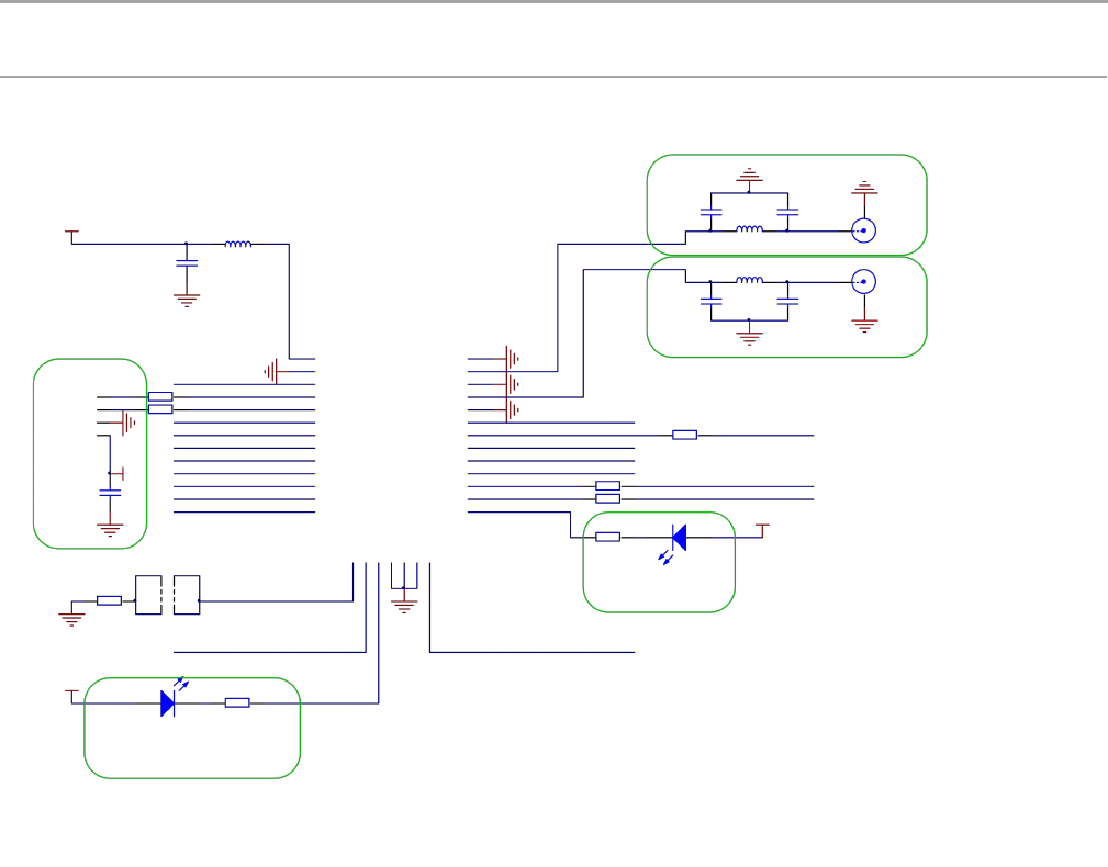
3 Hardware Design Reference
Figure 3- 1 RHF76-052 AM Reference Design (FW upgrade with UART)
V2.6 2015-12-03
www.risinghf.com
LoRaWAN Module RHF76-052 User Manual
RisingHF
5
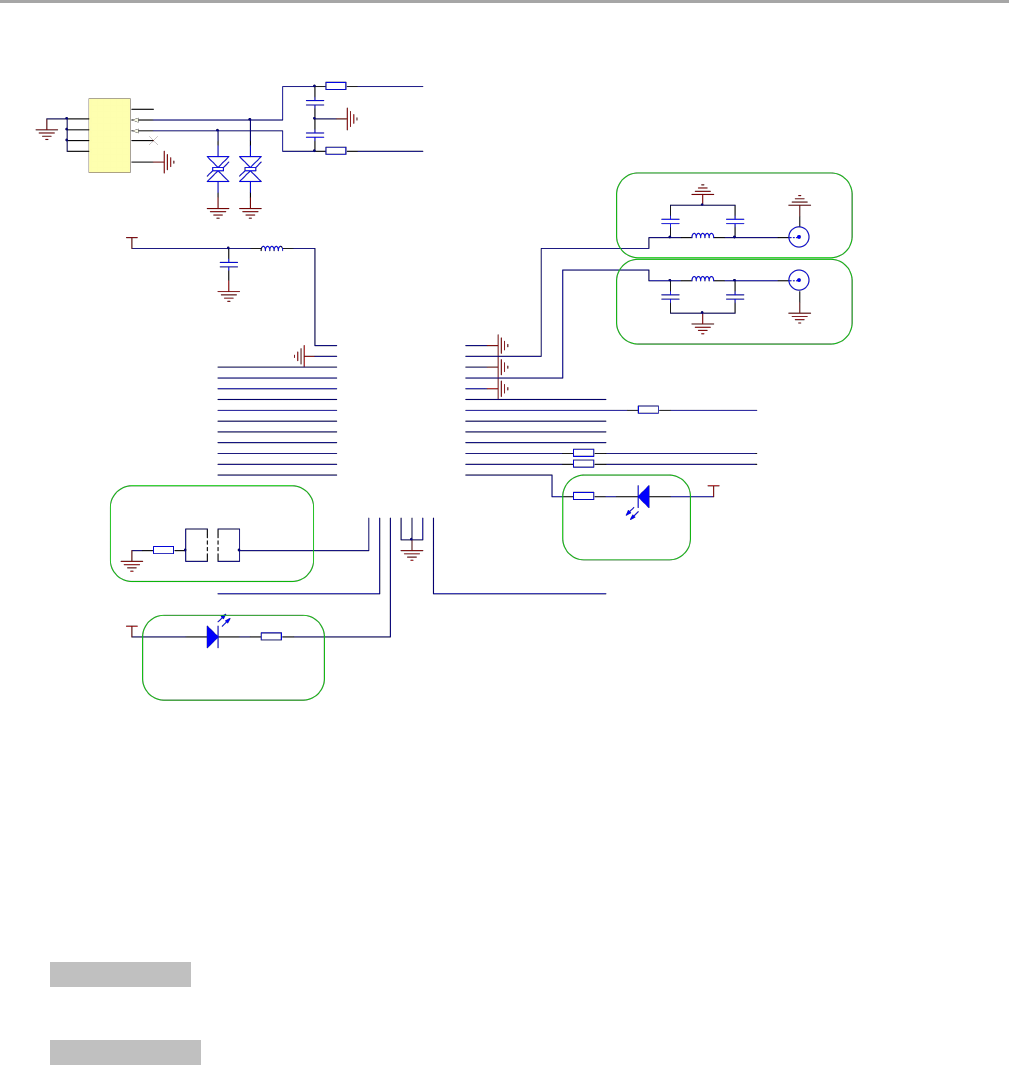
Figure 3- 2 RHF76-052 AN Reference Design (FW upgrade with USB)
Hardware design description:
1) VCC operation range: +1.8V to +3.6V
2) Pin22 and Pin 23 of the Modem would be used as UART port, please connect to Host MCU. Pin22
should be connected to RXD of Host MCU, and Pin23 should be connected to TXD of Host MCU.
3) For RHF76-52 AM: Pin4 and Pin5 of the Modem would be used as FW upgrade port based on UART
connection. Pin4 should be connected to RXD of Host, and Pin5 should be connected to TXD of Host.
For RHF76-052 AN: Pin10 and Pin11 of the Modem would be used as FW upgrade port based on
USB CDC connection. Pin10 should be connected to USB_DM, and Pin11 should be connected to
USB_DP.
4) Pin14 (GPIO_PA15) would be used to enable the DFU mode for FW upgrade. Please connect it to a
toggle switch to achieve DFU enable function via a hardware way.
Note: Customer could also use a SW way with AT command to access into DFU mode.
5) Pin16 would be used to show LoRaWAN processing status. Please connect this pin to a LED if need.
This LED would blink when transmit or receive a message in LoRaWAN mode.
V2.6 2015-12-03
www.risinghf.com
LoRaWAN Module RHF76-052 User Manual
RisingHF
6
6) Pin21 would be used to be reserved for LED connection.
RHF76-052AM/AN UART modem support both low band (434MHz/470MHz) and high band
(868MHz/915MHz). When use an internal antenna with mismatch impedance, a πtopology for
antenna matching is strongly suggested.
7) Antenna selection
Please use a 0dBi omnidirectional antenna in the design.
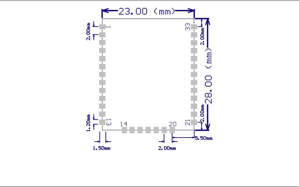
4 Package Information
4.1 Package Information
The RHF76-052 is available in a 33-lead SMD package as shown in Figure 4- 1below:
Figure 4- 1 package outline drawing
Figure 4- 2 show the recommended land pattern for layout.
V2.6 2015-12-03
www.risinghf.com
LoRaWAN Module RHF76-052 User Manual
RisingHF
7
Figure 4- 2 Recommended land pattern
5 Application in LoRaWAN
2.1 LoRaWAN/LoRaMAC
LoRaWAN networks typically are laid out in a star-of-stars topology in which gateways relay messages
between end-devices and a central network server at the backend. Gateways are connected to the
network server via standard IP connections while end devices use single-hop LoRa™ or FSK
communication to one or many gateways. All communication is generally bi-directional, although uplink
communication from an end device to the network server is expected to be the predominant traffic.
Communication between end-devices and gateways is spread out on different frequency channels and
data rates. The selection of the data rate is a trade-off between communication range and message
duration, communications with different data rates do not interfere with each other. LoRa data rates
range from 0.3 kbps to 50 kbps, with different Band Width and Spreading Factor. To maximize both
battery life of the end-devices and overall network capacity, the LoRa network infrastructure can
manage the data rate and RF output for each end-device individually by means of an adaptive data rate
(ADR) scheme.
End-devices may transmit on any channel available at any time, using any available data rate, as long
as the following rules are respected:
1) The end-device changes channel in a pseudo-random fashion for every transmission. The
resulting frequency diversity makes the system more robust to interferences.
2) The end-device respects the maximum transmit duty cycle relative to the sub-band used and local
regulations.
V2.6 2015-12-03
www.risinghf.com
LoRaWAN Module RHF76-052 User Manual
RisingHF
8
3) The end-device respects the maximum transmit duration (or dwell time) relative to the sub-band
used and local regulations.
The RHF76-052 Module incorporates Semtech’s LoRa Chip SX1276 and ST’s ultra-low power MCU.
With only 1.45uA sleep current in WOR mode, the module is really very suitable for LoRaWAN
application.
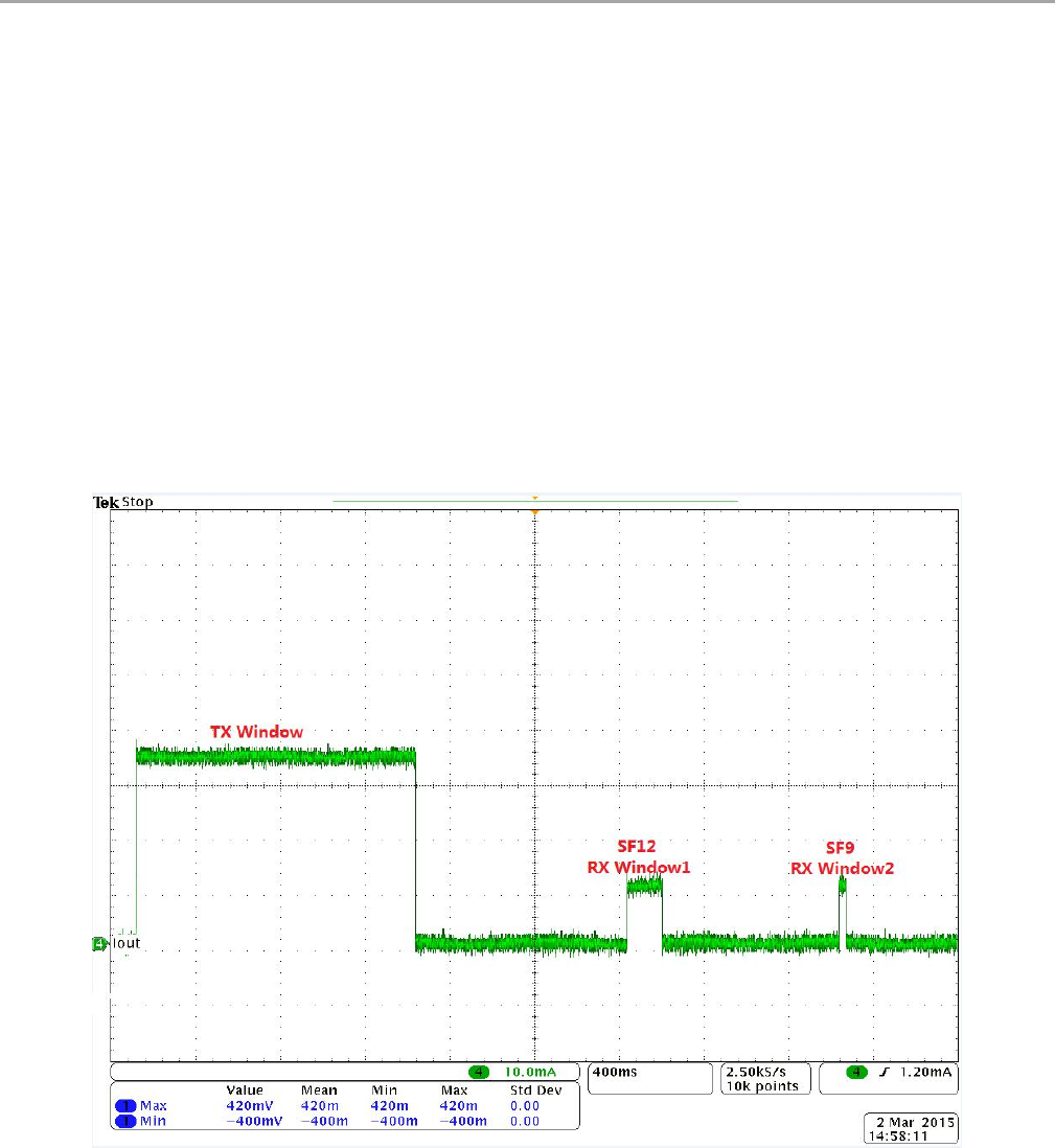
2.2 RHF76-052 with LoRaWAN
The Figure 5- 1 and Figure 5- 2 below show the power consumption of the RHF76-052 module. The
code is organized so that the MCU and all peripherals are in sleep mode most of the time.
In Figure 16, two RX windows will follow the TX window which is in accordance with LoRaWAN protocol.
In the RX window1, the SF of the receiver would set to SF12 for example (should be same as the SF
when transmit before).When there is no packet received in the RX window1, the RX window2 would
occur. In the RX window2, the SF of the receiver would set to SF9.
Figure 5- 1 Energy profile of RHF76-052 application in LoRaWAN
(No packet received from Server)
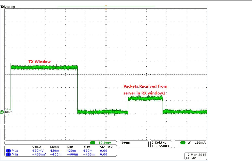
In Figure 5- 2, the node receive the packet from server in the RX window1.
V2.6 2015-12-03
www.risinghf.com
LoRaWAN Module RHF76-052 User Manual
RisingHF
9
Figure 5- 2 Energy profile of RHF76-052 application in LoRaWAN
(A packet received from Server in RX window1)

V2.6 2015-12-03
www.risinghf.com
LoRaWAN Module RHF76-052 User Manual
RisingHF
10
Part II-AT Command Specifications
6 Introduction of AT Command
RisingHF™ LoRaWAN™ modem is LoRaWAN compatible device, which supports flexible LoRaWAN
communication. This document is intended to describe a command interface implementation of
LoRaWAN Class A/C protocol. LoRaWAN protocol is available from LoRa Alliance, it is recommended
to review LoRaWAN specification before using LoRaWAN modem.
6.1 Feature
Maximum 255 bytes frame
User configuration nonvolatile
Support all LoRaWAN R1.0 data rate schemes(EU868/US915/EU868-like)
Customized data rate scheme
LoRaWAN Class A/C
Numerous test commands (LoRa P2P, Class C downlink, Continuous Wave etc.)
Flexible hexadecimal string parser
Ultra-low power (1.4uA@3.3V)
1
Case insensitive commands
Flexible RXWIN2 configuration interface
Configurable RXWIN1 channel frequency
Possibility to enable full-duplex LoRaWAN system
6.2 Related Products
Part Number
Bootloader
Interface
RHF3M076
USB
USB
RHF76-052
AM
UART
UART
RHF76-052
AN
USB
UART
Table 4- 1 Related products list
Note: RHF76-052 AM and RHF76-052 AN is based on the same hardware, which is that only the
firmware upgrade is different
1UART interface modem only

V2.6 2015-12-03
www.risinghf.com
LoRaWAN Module RHF76-052 User Manual
RisingHF
11
7 Essential informations before using AT command
7.1 Conventions
Command is case insensitive;
All commands have response;
Command length never exceeds total 528 characters;
One valid AT Command must end with '\n', "\r\n" is also valid;
If command timeout feature is enabled, end '\n' will not be mandatory;
<LF> means the newline character. <CR> means carriage return;
UART
2
configuration "9600, 8, n 1" (8 bits data, no parity, 1 stop bit);
7.2 Symbols
= --> Set value for command
? --> Query
: --> Start a list input parameter
+ --> Prefix of command
, --> Separator of parameters
Space --> Empty character, could be used to format command
NOTE: You could use quote sign < "> to force input parameter with space, such as <AT+MSGHEX="AA BB CC DD EE">, then "AA BB CC
DD EE" is treated as one parameter. But if you input command <AT+MSGHEX=AA BB CC DD EE>, "AA BB CC DD EE" will treated as 5
parameters, AT+MSGHEX returns error.
7.3 Format
All commands in this document are end with <CR><LF>. In order to facilitate the description, all
<CR><LF> is intentionally omitted in this document.
7.3.1 Query
Use query command to check LoRaWAN modem configuration, such as channel configuration, ADR
status, TX power, etc.
AT+COMMAND
AT+COMMAND?
AT+COMMAND=?
NOTE: Query format is available with every LoRaWAN supported command
7.3.2 Configure / Control
Uses configure/control command to set new configuration or control transaction.
AT+COMMAND=DATA
7.3.3 Return
Return data is in format like "+CMD: RETURN DATA"
+COMMAND: “RETURN DATA”
2RHF76-052AM supports UART interface
RHF3M076 supports USB CDC interface of which UART configuration is unconcerned

V2.6 2015-12-03
www.risinghf.com
LoRaWAN Module RHF76-052 User Manual
RisingHF
12
7.4 Error
Code
Comment
-1
The number of parameters is invalid
-2
The content of the parameter is invalid
-3
API function returns error when user parameter is passed to it
-4
LoRaWAN modem can't save parameter to EEPROM
-5
The command is disabled currently
-6
Unknown error occurs
-7
There is not enough HEAP to execute user operation
-10
Command unknown
-11
Command is in wrong format
-12
Command is unavailable in current mode (Check with "AT+MODE")
-20
Too many parameters. LoRaWAN modem support max 15 parameters
-21
Length of command is too long (exceed 528 bytes)
-22
Receive end symbol timeout, command must end with <LF>
-23
Invalid character received
Table 5- 1 Error code list
This error code list applies to all LoRaWAN supported command. User could refer to this list to know
what is happening to LoRaWAN modem, when gets errors.
7.5 EEPROM
Items below will be synchronized to EEPROM of LoRaWAN modem once changed successfully, this
makes LoRaWAN mode memorized, user doesn't need to reconfigure parameter after repower,
LoRaWAN modem helps to keep it. If user wants to go back factory default configuration, refer to 3.18
FDEFAULT.
Item
Channel frequency, datarate range
(up to 16 channels)
Datarate
TX power
ADR
RX Window2 frequency/datarate
RX Window1 frequency
Keys(NwkSkey, AppSkey, AppKey)
ID(DevAddr, DevEUI, AppEui)
PORT
Unconfirmed message repetition
Mode3
LWABP/LWOTAA
Customize data rate scheme
Delay(RX1, RX2, JRX1, JRX2)
Table 5- 2 Memorized configuration
3Test mode is not stored; a reset during test mode makes modem switch back to previous mode.

V2.6 2015-12-03
www.risinghf.com
LoRaWAN Module RHF76-052 User Manual
RisingHF
13
7.6 Payload Length Limitation
Payload length depends on the current using spread factor and band width. Table below shows the
relationship of “Spread Factor”, “Band Width”, “PHYPayload” and “MacPayload”.
Spread Factor
Band Width
PHYPayload
MacPayload
FRMPayload

V2.6 2015-12-03
www.risinghf.com
LoRaWAN Module RHF76-052 User Manual
RisingHF
14
8 AT Commands description
Command
Description
AT
Test command
HELP
Print command list
FDEFAULT
Factory data reset
RESET
Software reset
DFU
Force bootloader to enter dfu mode
LOWPOWER
Enter sleep mode
VER
Version[Major.Minor.Patch]
MSG
LoRaWAN unconfirmed data
MSGHEX
LoRaWAN unconfirmed data in hex
CMSG
LoRaWAN confirmed data
CMSGHEX
LoRaWAN confirmed data in hex
CH
LoRaWAN channel frequency
DR
LoRaWAN datarate
ADR
LoRaWAN ADR control
REPT
Unconfirmed message repetition
POWER
LoRaWAN TX power
RXWIN2
LoRaWAN RX window2
RXWIN1
Customized RXWIN1 frequency
PORT
LoRaWAN communication port
MODE
LWABP, LWOTAA, TEST
ID
LoRaWAN DevAddr/DevEui/AppEui
KEY
Set NWKSKEY/APPSKEY/APPKEY
CLASS
Choose LoRaWAN modem class(A/B/C)
JOIN
LoRaWAN OTAA JOIN
TEST
Send test serious command
UART
UART configure
DELAY
RX window delay
Table 6- 1 Command List

V2.6 2015-12-03
www.risinghf.com
LoRaWAN Module RHF76-052 User Manual
RisingHF
15
8.1 AT
Use to test if connection of module is OK. This is a dummy command just like other common "AT
modules"
Format:
AT
AT?
Return:
+AT: OK
8.2 ID
Use to check the ID of the LoRaWAN module, or change the ID.
Read ID Format:
AT+ID // Read all, DevAddr(ABP), DevEui(OTAA), AppEui(OTAA)
AT+ID? // Read all
AT+ID=? // Read all
AT+ID=DevAddr // Read DevAddr
AT+ID=DevEui // Read DevEui
AT+ID=AppEui // Read AppEui
AT+ID=DevAddr, "new devaddr" // Set new DevAddr
AT+ID=DevEui, "new deveui" // Set new DevEui
AT+ID=AppEui, "new appeui" // Set new AppEui
Return:
+ID: DevAddr, xx:xx:xx:xx
+ID: DevEui4, xx:xx:xx:xx:xx:xx:xx:xx
+ID: AppEui5, xx:xx:xx:xx:xx:xx:xx:xx
Change end device address (DEVADDR)
AT+ID=DevAddr, “4 bytes length hex identifier”
eg: AT+ID=DevAddr, "01234567"
eg: AT+ID=DEVADDR, "01 23 45 67"
Return:
+ID: DevAddr, 01:23:45:67
Change device extended unique identifier (DEVEUI)
AT+ID= DevEui, “8 bytes length hex identifier (64bit)”
eg: AT+ID=DevEui, "0123456789ABCDEF"
eg: AT+ID=DEVEUI, "01 23 45 67 89 AB CD EF"
Return:
+ID: DevEui, 01:23:45:67:89:AB:CD:EF
Change device extended unique identifier (APPEUI)
4DevEui which is supplied by RisingHF are derived from STM32's UUID, these EUIs are RisingHF unique is not standard
IEEE EUI-64, , it is recommended to apply and use IEEE-EUI64.
5Default AppEui is 52:69:73:69:6E:67:48:46

V2.6 2015-12-03
www.risinghf.com
LoRaWAN Module RHF76-052 User Manual
RisingHF
16
AT+ID= AppEui, “8 bytes length hex identifier (64bit)”
eg: AT+ID=AppEui, "0123456789ABCDEF"
eg: AT+ID=APPEUI, "01 23 45 67 89 AB CD EF"
Return:
+ID: AppEui, 01:23:45:67:89:AB:CD:EF
8.3 RESET
Use to reset the module. If module returns error, then reset function is invalid.
Format:
AT+RESET
Return:
+RESET: OK
+RESET: ERROR(-5) // USB interface device returns error
Note: This command is unavailable if the LoRaWAN modem is USB interface device
8.4 MSG
Use to send string format frame which is no need to be confirmed by the server.
Format:
AT+MSG="Data to send"
Return:
+MSG: Start LoRaWAN transaction
+MSG: TX "xxxxxx"
+MSG: Done
Example: (Normal)
+MSG: Start LoRaWAN transaction
+MSG: TX "RisingHF"
+MSG: Done
Example: (Downlink message, RX payload is in hex format)
+MSG: Start LoRaWAN transaction
+MSG: TX "RisingHF"
+MSG: PORT: 8; RX: "12 34 56 78"
+MSG: RXWIN26, RSSI -106, SNR 4
+MSG: Done
Example: (MAC command received)
+MSG: Start LoRaWAN transaction
+MSG: TX "RisingHF"
+MSG: LoRaWAN command received
+MSG: RXWIN2, RSSI -88, SNR 13.75
+MSG: Done
8.5 CMSG
Use to send string format frame which must be confirmed by the server.
Format:
6RXWIN2: Message is received during RX Window2; RXWIN1: RX Window1; RXWIN0: Class C Extra RXWIN2.

V2.6 2015-12-03
www.risinghf.com
LoRaWAN Module RHF76-052 User Manual
RisingHF
17
AT+CMSG="Data to send"
Return: (NACK)
+CMSG: Start LoRaWAN transaction
+CMSG: TX "RisingHF"
+CMSG: Wait ACK
+CMSG: Done
Return: (ACK Received)
+CMSG: Start LoRaWAN transaction
+CMSG: TX "RisingHF"
+CMSG: Wait ACK
+CMSG: ACK Received
+CMSG: RXWIN2, RSSI -88, SNR 13.75
+CMSG: Done
Return: (ACK with Payload received)
+CMSG: Start LoRaWAN transaction
+CMSG: Wait ACK
+CMSG: ACK Received
+CMSG: PORT: 5; RX: "14 54 54"
+CMSG: RXWIN2, RSSI -88, SNR 13.5
+CMSG: Done
8.6 MSGHEX
Use to send hex format frame which is no need to be confirmed by the server.
Format:
AT+MSGHEX="xx xx xx xx"
eg: AT+MSGHEX="11 22 33 AA BB FF"
Return:
+MSGHEX: Start LoRaWAN transaction
+MSGHEX: TX "xxxxxx"
+MSGHEX: Done
For detailed examples, please refer to MSG. MSG and MSGHEX are the same command except
payload format.
8.7 CMSGHEX
Use to send hex format frame which must be confirmed by the server.
Format:
AT+CMSGHEX="Data to send"
eg: AT+CMSGHEX="11 22 33 AA BB FF"
Return:
+CMSGHEX: Start LoRaWAN transaction
+CMSGHEX: TX "xxxxxx"
+CMSGHEX: Wait ACK
+CMSGHEX: Done
For detailed examples, please refer to CMSG. CMSG and CMSGHEX are the same command except
payload format.

V2.6 2015-12-03
www.risinghf.com
LoRaWAN Module RHF76-052 User Manual
RisingHF
18
8.8 PORT
Set PORT number which will be used by MSG/CMSG/MSGHEX/CMSGHEX command to send
message, port number should range from 1 to 255. User should refer to LoRaWAN specification to
choose port.
Format:
AT+PORT="port" // "port" should be 1~255
eg: AT+PORT=8 // Set port to 8
eg: AT+PORT=? // Check current port
Return:
+PORT: 8 // PORT query/set return
8.9 ADR
Set ADR function of LoRaWAN module.
Format:
AT+ADR="New state"
eg: AT+ADR=ON // Enable ADR function
AT+ADR=OFF // Disable ADR function
AT+ADR=? // Check current ADR configuration
Return:
+ADR: ON // ADR query/set return
8.10 DR
Use LoRaWAN defined DRx to set datarate of LoRaWAN AT modem. Refer to Table 3- 2 LoRaWAN
EU868 Data Rate Scheme and Table 3- 3 LoRaWAN US915 Data Rate Scheme about the detailed
definition of LoRaWAN data rate.
Format:
AT+DR="DRx" // "DRx" should range 0~15
eg: AT+DR=0
eg: AT+DR=5
eg: AT+DR=DR0
eg: AT+DR=DR5
eg: AT+DR=? // Check current selected DataRate
Return:
+DR: DR0
+DR: US915 DR0 SF10 BW125K
Return: (ADR is functional)
+DR: DR0 (ADR DR3)
+DR: US915 DR3 SF7 BW125K
+DR: US915 DR0 SF10 BW125K
8.10.1 Datarate Scheme
LoRaWAN R1.0 defines 2 kinds of datarate scheme: EU868 (or EU868-like) and US915. RisingHF
LoRaWAN modem supports both this 2 kinds of datarate.

V2.6 2015-12-03
www.risinghf.com
LoRaWAN Module RHF76-052 User Manual
RisingHF
19
Check data rate scheme:
AT+DR=SCHEME // Check current band
Return: (US915)
+DR: US915
+DR: US915 DR0 SF10 BW125K
+DR: US915 DR1 SF9 BW125K
+DR: US915 DR2 SF8 BW125K
+DR: US915 DR3 SF7 BW125K
+DR: US915 DR4 SF8 BW500K
+DR: US915 DR5 RFU
+DR: US915 DR6 RFU
+DR: US915 DR7 RFU
+DR: US915 DR8 SF12 BW500K
+DR: US915 DR9 SF11 BW500K
+DR: US915 DR10 SF10 BW500K
+DR: US915 DR11 SF9 BW500K
+DR: US915 DR12 SF8 BW500K
+DR: US915 DR13 SF7 BW500K
+DR: US915 DR14 RFU
+DR: US915 DR15 RFU
Return: (EU868)
+DR: EU868
+DR: EU868 DR0 SF12 BW125K
+DR: EU868 DR1 SF11 BW125K
+DR: EU868 DR2 SF10 BW125K
+DR: EU868 DR3 SF9 BW125K
+DR: EU868 DR4 SF8 BW125K
+DR: EU868 DR5 SF7 BW125K
+DR: EU868 DR6 SF7 BW250K
+DR: EU868 DR7 FSK 50kbps
+DR: EU868 DR8 RFU
+DR: EU868 DR9 RFU
+DR: EU868 DR10 RFU
+DR: EU868 DR11 RFU
+DR: EU868 DR12 RFU
+DR: EU868 DR13 RFU
+DR: EU868 DR14 RFU
+DR: EU868 DR15 RFU
Return: (CUSTOM)
+DR: CUSTOM
+DR: CUSTOM DR0 RFU
+DR: CUSTOM DR1 RFU
+DR: CUSTOM DR2 RFU
+DR: CUSTOM DR3 RFU

V2.6 2015-12-03
www.risinghf.com
LoRaWAN Module RHF76-052 User Manual
RisingHF
20
+DR: CUSTOM DR4 RFU
+DR: CUSTOM DR5 RFU
+DR: CUSTOM DR6 RFU
+DR: CUSTOM DR7 RFU
+DR: CUSTOM DR8 RFU
+DR: CUSTOM DR9 RFU
+DR: CUSTOM DR10 RFU
+DR: CUSTOM DR11 RFU
+DR: CUSTOM DR12 RFU
+DR: CUSTOM DR13 RFU
+DR: CUSTOM DR14 RFU
+DR: CUSTOM DR15 RFU
Choose data rate scheme
AT+DR=EU868 // LoRaWAN EU868 data rate scheme
AT+DR=US915 // LoRaWAN US915 data rate scheme
AT+DR=CUSTOM // Customized data rate scheme
LoRaWAN Data Rate
Configuration
Indicative physical
bit rate [bit/s]
DR0
LoRa SF12/125KHz
250
DR1
LoRa SF11/125KHz
440
DR2
LoRa SF10/125KHz
980
DR3
LoRa SF9/125KHz
1760
DR4
LoRa SF8/125KHz
3125
DR5
LoRa SF7/125KHz
5470
DR6
LoRa SF7/250KHz
11000
DR7
FSK:50kbps
50000
DR8-DR15
RFU
RFU
Table 6- 2 LoRaWAN EU868 Data Rate Scheme
LoRaWAN Data Rate
Configuration
Indicative physical
bit rate [bit/s]
DR0
LoRa SF10/125KHz
980
DR1
LoRa SF9/125KHz
1760
DR2
LoRa SF8/125KHz
3125
DR3
LoRa SF7/125KHz
5470
DR4
LoRa SF8/500KHz
12500
DR5-DR7
RFU
RFU
DR8
LoRa SF12/500KHz
980
DR9
LoRa SF11/500KHz
1760
DR10
LoRa SF10/500KHz
3900
DR11
LoRa SF9/500KHz
7000
DR12
LoRa SF8/500KHz
12500
DR13
LoRa SF7/500KHz
21900
DR14-DR15
RFU
RFU
Table 6- 3 LoRaWAN US915 Data Rate Scheme

V2.6 2015-12-03
www.risinghf.com
LoRaWAN Module RHF76-052 User Manual
RisingHF
21
8.10.2 Customized Data Rate Scheme
In order to provide maximum flexibility to define data rate, this customized data rate scheme feature is
added from firmware v1.8.0.
Define a new data rate:
AT+DR=CUSTOM, DRx, SFx, BW, [DRx (RXWin1)]
Note: [DRx (RXWin1)] is optional parameter, which could be used to specify an RXWin1 data rate for a
predefined data rate. For example, “AT+DR=CUSTOM, DR0, SF10, 500, DR4” will map DR0 and DR4, this
means when sending a message use DR0, RXWIN1 will set DR11 to receive downlink. This feature is
useful when downlink output power is higher than uplink, in this situation, it is reasonable to use higher
data rate and still keep uplink budget and downlink budget balance, and make whole network high
efficient. If absent, RXWIN1 data rate will be set to the same as uplink data rate in default.
Set data rate to RFU (Reserve For Use)
AT+DR=CUSTOM, DRx, RFU
Example:
// Set DR0 to SF7 and BW125KHz
AT+DR=CUSTOM, DR0, SF7, 125
Return:
+DR: CUSTOM DR0 SF7 BW125K //By default downlink DR is the same as uplink DR
Example:
// Set DR0 to SF9 and BW500KHz, and map DR0 (uplink) with DR11 (downlink).
AT+DR=CUSTOM, DR3, SF10, 500, DR4
Return:
+DR: CUSTOM DR3 SF10 BW500K DLDR4
Example:
// Set DR0 to FSK 50kpbs
AT+DR=CUSTOM,DR0,FSK
Return:
+DR: CUSTOM DR0 FSK 50kbps
Example:
// Set DR0 to FSK 50kpbs, and map DR0 with DR5,
// Note: [BW] parameter should be set to 0 or any other integer.
AT+DR=CUSTOM,DR0,FSK,0,DR5
Return:
+DR: CUSTOM DR0 FSK 50kbps
Example:
// Set DR0 to RFU
AT+DR=CUSTOM, DR0, RFU

V2.6 2015-12-03
www.risinghf.com
LoRaWAN Module RHF76-052 User Manual
RisingHF
22
Return:
+DR: CUSTOM DR0 RFU
Example:
// Check custom data rate scheme
AT+DR=CUSTOM
AT+DR=SCHEME
Return:
+DR: CUSTOM
+DR: CUSTOM DR0 SF7 BW125K
+DR: CUSTOM DR1 RFU
+DR: CUSTOM DR2 RFU
+DR: CUSTOM DR3 SF10 BW500K DLDR4
+DR: CUSTOM DR4 RFU
+DR: CUSTOM DR5 RFU
+DR: CUSTOM DR6 RFU
+DR: CUSTOM DR7 RFU
+DR: CUSTOM DR8 RFU
+DR: CUSTOM DR9 RFU
+DR: CUSTOM DR10 RFU
+DR: CUSTOM DR11 RFU
+DR: CUSTOM DR12 RFU
+DR: CUSTOM DR13 RFU
+DR: CUSTOM DR14 RFU
+DR: CUSTOM DR15 RFU
Note: After changing the data rate scheme, user should run commands below to check if the data rate
settings are valid, and make sure no RFU data rate is used.
AT+CH
AT+RXWIN2
AT+DR
8.11 CH
Set channel parameter of LoRaWAN modem, Set frequecy zero to disable one channel.
Format:
AT+CH="LCn", ["Freq"], ["DR_MIN"], ["DR_MAX"]
// Change the LCn channel frequency to "Freq"
// "Freq" is in MHz.
// Available DR_MIN/DR_MAX range DR0 ~ DR15
1. Change channel LC0 frequency to 433.3MHz, datarate DR0~DR5
eg: AT+CH=0, 433.3, DR0, DR5
2. Change channel LC1 frequency to 433.5MHz, datarate DR0~DR2
eg: AT+CH=1, 433.5, DR0, DR2

V2.6 2015-12-03
www.risinghf.com
LoRaWAN Module RHF76-052 User Manual
RisingHF
23
3. Disable channel LC2
eg: AT+CH=2, 0
4. Change channel LC3 frequency to 433.7MHz, with default datarate DR0~DR5
eg: AT+CH=?
eg: AT+CH=3, 433.7
// It is not recommended to use this command
5. Change channel LC0 frequency to 433.3MHz,DR7
eg: AT+CH=0, 433.3, DR7
6. Change channel LC3 frequency to 433.7MHz, datarate DR0~DR5
eg: AT+CH=3, 433.7, 0, 5
7. Change channel LC3 frequency to 433.7MHz, datarate DR7
eg: AT+CH=3, 433.7, DR7
Return:
+CH: 3,433700000,DR0:DR5
+CH: 3,433700000,DR1
Query Return Format:
+CH: TOTAL_CHANNEL_NUMBER; LCn,FREQn,DR_MINn,DR_MAXn; LCy,FREQy,DR_MINy,DR_MAXy; ...
LCz,FREQz,DR_MINz,DR_MAXz;
eg: +CH: 8; 0,433300000,DR0,DR5; 1,433500000,DR0,DR5; 2,433700000,DR0,DR5;
3,433900000,DR0,DR5; 4,434100000,DR0,DR5; 5,434300000,DR0,DR5; 6,434500000,DR0,DR5;
7,434700000,DR0,DR5;
8.12 POWER
Set TX power of LoRaWAN AT Module, valid power value 20, 14, 11, 8, 5, 2.
Format:
AT+POWER="Power value" // Change LoRaWAN Tx Power
eg: AT+POWER=14 // Change LoRaWAN AT module TX power to 14dBm
Return:
+POWER: 14
8.13 REPT
Unconfirmed message repeats times.
Format:
AT+REPT="Repeat Times" //Repeat times" should range 1~15
eg: AT+REPT=2 //Repeat 2 times
Return:
+REPT: 2

V2.6 2015-12-03
www.risinghf.com
LoRaWAN Module RHF76-052 User Manual
RisingHF
24
8.14 RXWIN2
Set second RX window frequency and Data Rate. This command will change RXWIN2 configuration,
which may cause downlink lost, if configuration is wrong.
Format:
AT+RXWIN2=Frequency,DRx // Set frequency and datarate
AT+RXWIN2=Frequency,SFx,BW // Set RXWIN2 through SF and BW
AT+ RXWIN2=? // Query RX Window2 configuration
AT+ RXWIN2? // Query RX Window2 configuration
AT+ RXWIN2 // Query RX Window2 configuration
eg: AT+RXWIN2=433.3,DR3 // Set RXWIN2 433.3MHz/DR3
eg: AT+RXWIN2=433.3,SF7,500 // Set RXWIN2 433.3MHz/SF7/BW500KHz
Return:
// General data rate
+RXWIN2: 433300000,DR5
// Customized RX Window2 data rate with spread factor and band width
+RXWIN2: 433000000,SF7,BW125K
From firmware 1.8.0, RXWIN2 command could support more flexible configuration. Both LoRaWAN
defined data rate (combination of spread faction and band width) and LoRa defined spread factor and
band width format are supported. User could set his RXWIN2 to any possible SF and BW scheme,
which is a very useful function for LoRaWAN proof of concept.
8.15 RXWIN1
RXWIN1 command could be used to set customized RXWIN channel, each RXWIN channel maps to
an uplink channel. When RXWIN1 is enabled, user need make sure every uplink channel has its own
mapped RXWIN1 channel, or the modem may perform unexpected.
With this special RXWIN1 command, a function of frequency shift between uplink and downlink
is possible, then full-duplex is easy to achieve for the system if gateway support.
a) Enable RXWIN1
AT+RXWIN1=ON
b) Disable RXWIN1
AT+RXWIN1=OFF
c) Set RXWIN1
AT+RXWIN1=CH,FREQ
CH is the channel number 0~16. FREQ is in MHz
eg: AT+RXWIN1=0,868.9
d) Check RXWIN1
AT+RXWIN1 // return normal or special case
// RXWIN1 is disabled
+RXWIN1: OFF
// RXWIN1 is enabled
+RXWIN1: ON; 8; 0, 923300000; 1, 923900000; 2, 924500000; 3, 925100000;
4, 925700000; 5, 926300000; 6, 926900000; 7, 927500000;

V2.6 2015-12-03
www.risinghf.com
LoRaWAN Module RHF76-052 User Manual
RisingHF
25
8.16 VER
Check firmware version. Versioning rule refers to Semantic Versioning 2.0.0.
Format:
AT+VER=?
AT+VER?
AT+VER
Return:
+VER: $MAJOR.$MINOR.$PATCH
+VER: 1.8.0
8.17 KEY
Change LoRaWAN related AES-128 KEY. If wrong key is used, your LoRaWAN modem will be rejected
by LoRaWAN server. Contact server administrator to know what key should use. All KEYs are
unreadable for security, the one who forgets his KEY need rewrite with a new key.
Format:
Change network session key (NWKSKEY)
AT+KEY=NWKSKEY, “16 bytes length key”
eg: AT+KEY=NWKSKEY, "2B7E151628AED2A6ABF7158809CF4F3C"
eg: AT+KEY=NWKSKEY, "2B 7E 15 16 28 AE D2 A6 AB F7 15 88 09 CF 4F 3C"
Return:
+KEY: NWKSKEY 2B 7E 15 16 28 AE D2 A6 AB F7 15 88 09 CF 4F 3C
Change application session key (APPSKEY)
AT+KEY=APPSKEY, “16 bytes length key”
eg: AT+KEY=APPSKEY, "2B7E151628AED2A6ABF7158809CF4F3C"
eg: AT+KEY= APPSKEY, "2B 7E 15 16 28 AE D2 A6 AB F7 15 88 09 CF 4F 3C"
Return:
+KEY: APPSKEY 2B 7E 15 16 28 AE D2 A6 AB F7 15 88 09 CF 4F 3C
Change application session key (APPKEY)
AT+KEY=APPKEY, “16 bytes length key”
eg: AT+KEY=APPKEY, "2B7E151628AED2A6ABF7158809CF4F3C"
AT+KEY= APPKEY, "2B 7E 15 16 28 AE D2 A6 AB F7 15 88 09 CF 4F 3C"
Return:
+KEY: APPKEY 2B 7E 15 16 28 AE D2 A6 AB F7 15 88 09 CF 4F 3C
8.18 FDEFAULT
Reset LoRaWAN AT modem to factory default configuration. Command “AT+FDEFAULT=RISINGHF”
should be used to do the factory reset. Company name "RISINGHF" (case insensitive) is kept on
purpose to avoid command to be triggered unexpectedly. After reset user could use “Query” format
command to know which configuration is used.
Format:

V2.6 2015-12-03
www.risinghf.com
LoRaWAN Module RHF76-052 User Manual
RisingHF
26
AT+FDEFAULT=RISINGHF
Return:
+FDEFAULT: OK
Item
Value
Channel
3 channels
CH0: 868.1MHz
CH1: 868.3MHz
CH2: 868.5MHz
Datarate Range
DR0 : DR5
Unconfirmed Message Repetition
1
Confirmed Message Retry7
3
Port
8
Datarate
DR0
ADR
ON
Power
14dBm
RXWIN2
869.525MHz, DR3
RXWIN1 Delay
1s
RXWIN2 Delay
2s
JOIN ACCEPT RXWIN1 Delay
5s
JOIN ACCEPT RXWIN2 Delay
6s
Table 6- 4 Factory default configuration
NOTE: Customized modem may be precompiled to use a different factory default configuration. If any user has request, please contact
RisingHF support@risinghf.com.
8.19 DFU
Use to enter DFU mode. If user need to enter DFU mode to update LoRaWAN modem firmware, then
user should first send "AT+DFU=ON" command to enable firmware upgrade. Once DFU mode is on,
user should repower LoRaWAN modem (unplug and plug back), after repowered LoRaWAN will enter
DFU mode, user could use DfuSe tool to update the firmware. If user want to exit DFU mode without
upgrade, user just need to repower again, LoRaWAN modem will exit DFU mode automatically.
For UART bootloader, "AT+DFU=ON" command will make device enter bootloader mode automatically.
Format:
AT+DFU="New state"
eg: AT+DFU=ON // Enable DFU function
eg: AT+DFU=OFF // Disable DFU function
AT+DFU=? // Check if DFU is enabled configuration
Return:
+DFU: ON
+DFU: OFF
Example: (RHF76-052AM/RHF76-052AN)
+DFU: ON
Enter bootloader mode after reboot
7Confirmed message retry number of time is fixed value, which can’t be change through AT command.

V2.6 2015-12-03
www.risinghf.com
LoRaWAN Module RHF76-052 User Manual
RisingHF
27
Reboot in 5s...
Example: (RHF3M076)
+DFU: ON // Need manually repower RHF3M076 device
Note: DFU mode is risky. Before updating, user must make sure the firmware is supplied by RisingHF, a wrong firmware may brick LoRaWAN
modem.
8.20 HELP
Return brief help information. Refer to Table 3- 1 Command List.
Format:
AT+HELP=?
AT+HELP?
AT+HELP
Return:
+HELP: OK
AT -- AT Ping
HELP -- Print command list
FDEFAULT -- Factory data reset
RESET -- Software reset
DFU -- Bootloader mode
LOWPOWER -- Enter sleep mode
VER -- Version
MSG -- Unconfirmed
MSGHEX -- Unconfirmed (HEX)
CMSG -- Confirmed
CMSGHEX -- Confirmed (HEX)
CH -- Set channel
ADR -- ADR ON/OFF
DR -- Set datarate
REPT -- MSG/MSGHEX repetition
POWER -- TX power
RXWIN1 -- RX window1
RXWIN2 -- RX window2
PORT -- TX port
MODE -- LWABP/LWOTAA/TEST
ID -- DevAddr/DevEui/AppEui
KEY -- NWKSKEY/APPSKEY/APPKEY
CLASS -- Class(A/B/C)
JOIN -- OTAA Join request
TEST -- Test commands
UART -- UART configure
DELAY -- RX window delay

V2.6 2015-12-03
www.risinghf.com
LoRaWAN Module RHF76-052 User Manual
RisingHF
28
8.21 MODE
Use to select work mode. LWABP8, LWOTAA9, TEST are supported. LoRaWAN modem can only work
with one mode at a time. By default, LWABP is enabled, all test commands are unavailable, LoRaWAN
will return error(-12) if it receives test command in non-test mode.
"AT+MODE" command will reset LoRaWAN stack when first enter LWABP/LWOTTA mode and reset
LoRa chip when first enter test mode.
LWABP/LWOTAA mode status is remembered by LoRaWAN modem, each time LoRaWAN modem
starts, it will enter previous working mode before reset or repower.
Format:
AT+MODE="New mode"
eg: AT+MODE=TEST // Enter TEST mode
eg: AT+MODE=LWOTAA // Enter TEST mode
eg: AT+MODE=LWABP // Enter LWABP mode
Return
+MODE: LWABP // Enter LWABP mode successfully
+MODE: LWOTAA // Enter LWABP mode successfully
+MODE: TEST // Enter TEST mode successfully
8.22 JOIN
When OTAA mode is enabled, JOIN command could use to join a known network.
Format:
AT+JOIN=["Times"], ["DELAY"], ["DELAY RANDOM OFFSET"]
AT+JOIN=REJOIN
1. Query
eg: AT+JOIN=? // Query JOIN status
eg: AT+JOIN? // Query JOIN status
2. Join
eg: AT+JOIN // Send JOIN request
3. Disconnect with current network, force send one JOIN request
eg: AT+JOIN=FORCE
4. Stop JOIN
eg: AT+JOIN=STOP
5. Auto send JOIN request 10 times with (20 +/- 4)s delay, set times to 0 join forever.
eg: AT+JOIN=10, 20, 4
eg: AT+JOIN=0 // JOIN forever with default delay(10 +/- 2)s
8LWABP is short for LoRaWAN Activation ByPersonalization. Check < LoRaWAN™ Specification> for details
9LWOTAA is short for LoRaWAN Over-The-Air-Activation.

V2.6 2015-12-03
www.risinghf.com
LoRaWAN Module RHF76-052 User Manual
RisingHF
29
6. Returns
a) Join successfully
+JOIN: Starting
+JOIN: NORMAL, count 1, 0s, 0s
AT+DR=CUSTOM,DR0,FSK
+JOIN: NetID 000024 DevAddr 48:00:00:01
+JOIN: Done
b) Join failed
+JOIN: Join failed
8.23 CLASS
This command could enable LoRaWAN modem to work at different mode (Class A/B10/C). LoRaWAN
modem works at class A mode when power on, user need manually switch mode to class B/C as
needed.
Format:
eg: AT+CLASS=A // Enable Class A mode
eg: AT+CLASS=C // Enable Class C mode
Return
+CLASS: A // Enter LWABP mode successfully
8.24 LOWPOWER
11
Sleep command could be used to make modem enter sleep mode with ultra-low power consumption,
check device datasheet to know detailed parameters. After device enters in sleep mode, host device
could send any character to wakeup it, after wakeup host should wait at least 5ms to send next
commands, a C code example is attached to show how to handle LOWPOWER mode.
During the LOWPOWER mode, level of UART RX pin must keep unchanged, any signal on UART RX
pin will make modem exit LOWPOWER mode. When LOWPOWER mode is triggered, there are extra
30ms before modem really enter sleep mode, host device should use this time to de-initial its UART if it
is needed.
Format:
eg: AT+LOWPOWER // Sleep command supports only this format
// Query symbol is not available
Return
+ LOWPOWER: SLEEP // Enter SLEEP mode successfully
+ LOWPOWER: WAKEUP // Modem is woke up.
C example:
printf("AT+LOWPOWER\r\n");// Set low-power mode
// ...
// HOST do other operation.
// ...
printf("A"); // Send any character to wake-up the modem
DelayMs(5); // Wait modem ready
printf("AT+ID\r\n"); // New operation
10 Class B is unavailable in current version
11 RHF76-052AM (UART enabled) supports this feature, RHF3M076 (USB enabled) doesn't support sleep mode.

V2.6 2015-12-03
www.risinghf.com
LoRaWAN Module RHF76-052 User Manual
RisingHF
30
8.25 TEST
TEST command is not like other command, it is a serious command, includes several sub-commands,
refer to table below. With test mode, user could do RF performance test quickly without any knowledge
of LoRa chip. Commands which are related to RF configuration is disabled in test mode.
Sub-Command
Comment
HELP
Print test command help information, make LoRa transceiver to standby mode
STOP
Set LoRaWAN Modem to TEST stop mode
TXCW
Transmit continuous wave
TXCLORA
Transmit continuous LoRa signal
RFCFG
Set RF configuration in TEST mode
RXLRPKT
Continuous receive pure LoRa packet, print once there is new packet received
TXLRPKT
Send one HEX format packet out
TXLRSTR
Send one string format packet
RSSI
Get RSSI value of specified channel
LWDL
Send LoRaWAN downlink packet, useful tool to test CLASS C device
Table 6- 5 TEST mode sub-command list
8.25.1 Print Help Information
Format:
AT+TSET=HELP
Return:
+TEST: HELP
STOP -- AT+TEST=STOP
HELP -- AT+TSET=HELP
TXCW -- AT+TEST=TXCW
TXCLORA -- AT+TEST=TXCLORA
RFCFG -- AT+TEST=RFCFG,[F],[SF],[BW],[TXPR],[RXPR],[POW]
RXLRPKT -- AT+TEST=RXLRPKT
TXLRPKT -- AT+TEST=TXLRPKT,"HEX"
TXLRSTR -- AT+TEST=TXLRSTR,"TEXT"
RSSI -- AT+TEST=RSSI,F,[CNT]
LWDL -- AT+TEST=LWDL,TYPE,DevAddr,"HEX",[FCNT],[FPORT],[FCTRL]
"[ ]" means the parameter is omissible together with parameters behind it
8.25.2 Enter TEST mode
Before use any TEST command, LoRaWAN should work in test mode, or error code -12 will be
reported.
Command:
AT+MODE=TEST
Return:
+MODE: TEST // LoRaWAN modem enter TEST mode successfully
8.25.3 Query RF configuration
First thing after enter TEST mode should be check RF configuration.
Command:

V2.6 2015-12-03
www.risinghf.com
LoRaWAN Module RHF76-052 User Manual
RisingHF
31
AT+TEST=? // Query test mode and RF configuration
Return Error:
+TEST: ERROR(-12)
When come with ERROR(-12), user could try "AT+MODE=?" to check if LoRaWAN modem is in TEST mode, if not user should enter test
mode first.
Return STOP:
+TEST: STOP
+TEST: RFCFG F:433300000, SF12, BW125K, TXPR:8, RXPR:8, POW:14dBm
Return TXLRPKT:
+TEST: TXLRPKT
+TEST: RFCFG F:433300000, SF12, BW125K, TXPR:8, RXPR:8, POW:14dBm
Return RXLRPKT:
+TEST: RXLRPKT
+TEST: RFCFG F:433300000, SF12, BW125K, TXPR:8, RXPR:8, POW:14dBm
Return TXCW:
+TEST: TXCW
+TEST: RFCFG F:433300000, SF12, BW125K, TXPR:8, RXPR:8, POW:14dBm
8.25.4 Set RF Configuration
RFCFG supports set frequency, SF, band width, TX preamble, RX preamble and TX power settings.
TX and RX shares all configuration except "preamble length", user could choose different preamble
length. For LoRa communication, it is strongly recommended to set RX preamble length longer than
TX's. Bandwidth only supports 125KHz / 250KHz / 500KHz.
Depend on Semtech SX1276 (PA_BOOST/RFO) and design solution of RisingHF module, MAX output
power of different band LoRaWAN modem could be different. Check below table about the details.
Device
Bootloader
Interface
LF Band12
HF Band13
RHF3M076
USB
USB
20dBm
14dBm
RHF76-052AM
UART
UART
20dBm
14dBm
RHF76-052AN
USB
UART
20dBm
14dBm
Table 6- 6 MAX output power of HF and LF band
RHF3M076 is part number of RisingHF LoRaWAN modem.
Format:
"[ ]" means the parameter is omissible together with parameters after it
12 LF Band: Frequency is less than 525MHz
13 HF Band: Frequency is larger than 525MHz

V2.6 2015-12-03
www.risinghf.com
LoRaWAN Module RHF76-052 User Manual
RisingHF
32
AT+TEST=RFCFG,[FREQUENCY],[SF],[BANDWIDTH],[TX PR],[RX PR],[TX POWER]
// TX Configuration/868MHz/SF9/BW125KHz/TXPREAMBEL 12/RXPREAMBEL 15/14dBm
eg: AT+TEST=RFCFG,866,SF12,125,12,15,14
Return:
+TEST: RFCFG F:866000000,SF12,BW125K,TXPR:12,RXPR:15,POW:14dBm
8.25.5 TX LoRa Packet
After enter test mode, user could send LoRa packet through "AT+TEST=TXLRPKT" sub-command.
The command format is like below:
AT+TEST=TXLRPKT, "HEX STRING"
Command sequence to send LoRa packet:
// Set test mode
AT+MODE=TEST
// Query test mode, check RF configuration
AT+TEST=?
// Set RF Configuration
AT+TEST=RFCFG,[FREQUENCY],[SF],[BANDWIDTH],[TX PR],[RX PR],[TX POWER]
// Send HEX format packet
AT+TEST=TXLRPKT, "HEX String"
eg:AT+TEST=TXLRPKT, "00 AA 11 BB 22 CC"
// Send TEXT format packet
AT+TEST=TXLRSTR, "TEXT"
eg:AT+TEST=TXLRSTR, "LoRaWAN Modem"
Return:
+TEST: TXLRPKT “00 11 22 33 44”
+TEST: TXLRSTR "LoRaWAN Modem"
+TEST: TX DONE
8.25.6 RX LoRa Packet
After enter test mode, user could enter LoRa packet continuous RX mode through RXLRPKT sub-
command. Like below:
AT+TEST=RXLRPKT
Command sequence to receive LoRa packet:
// Set test mode
AT+MODE=TEST
// Query test mode, check RF configuration
AT+TEST=?
// Set RF Configuration
AT+TEST=RFCFG,[FREQUENCY],[SF],[BANDWIDTH],[TX PR],[RX PR],[TX POWER]
// Enter RX continuous mode
AT+TEST=RXLRPKT

V2.6 2015-12-03
www.risinghf.com
LoRaWAN Module RHF76-052 User Manual
RisingHF
33
Return:
+TEST: LEN:250, RSSI:-106, SNR:10
+TEST: RX 00 11 22 33 44
8.25.7 TX Continuous Wave
Before enable TXCW function, right frequency and TX power should be set. Format:
AT+TEST=TXCW
Return:
+TEST: TXCW
8.25.8 TX Continuous LoRa
Before enable TXCLORA function, right frequency and TX power should be set. Format:
AT+TEST= TXCLORA
Return:
+TEST: TXCLORA
8.25.9 RSSI
Read RSSI from a specified channel. Format:
AT+TEST = RSSI, frequency(MHz), [times]
Return:
+TEST: RSSI, frequency
+TEST: RSSI 0, RSSI0; 1, RSSI1; ... n, RSSIn;
...
+TEST: RSSI n+1, RSSI0; n+2, RSSI1; ..., ...
...
+TEST: RSSI, AVG average, MAX maximum, MIN minimum
8.25.10 LWDL
LWDL command is designed to test LoRaWAN modem CLASS C function. Use this command, user
can easily send data to a working LoRaWAN Class C device.
AT+TEST = LWDL, TYPE, "DevAddr", "HEX STRING", [FCNT], [FPORT], [FCTRL]
Return:
AT+TEST=LWDL,MSG,"009291ad","14 54 54 88 08 93 122 35", 1, 5, 00
+TEST: LWDL "A0 AD 91 92 00 00 01 00 05 13 4D 37 EA 53 E3 02 3A 9F 01 25 D2 34"
+TEST: LORAWAN DOWNLINK TX DONE
8.26 UART
8.26.1 TIMEOUT
LoRaWAN AT modem supports UART receive timeout feature, AT parser inside the modem start
counts from first "AT" character is received, when counter overflows, a "Input timeout" event will be
triggered. One message like below will be showed. Maximum timeout value is 300ms.
+INFO: Input timeout, start parse

V2.6 2015-12-03
www.risinghf.com
LoRaWAN Module RHF76-052 User Manual
RisingHF
34
AT+UART=TIMEOUT, 0 // Disable timeout feature
AT+UART=TIMEOUT, 1000 // Set timeout 1s feature
AT+UART=TIMEOUT // Get timeout value
8.27 DELAY
RX window delay configuration command. Supports configure RECEIVE_DELAY1, RECEIVE_DELAY2,
JOIN_ACCEPT_DELAY1, JOIN_ACCEPT_DELAY2.
Command
Item
Comments
AT+DELAY=RX1, ms
RECEIVE_DELAY1
RX window 1 delay time
AT+DELAY=RX2, ms
RECEIVE_DELAY2
RX window 1 delay time
AT+DELAY=JRX1, ms
JOIN_ACCEPT_DELAY1
Join accept RX window 1 delay time
AT+DELAY=JRX2, ms
JOIN_ACCEPT_DELAY2
Join accept RX window 2 delay time
Table 6- 7 LoRaWAN Delay Items
Format:
// Query delay settings
AT+DELAY
AT+DELAY?
AT+DELAY=?
// Set delay
AT+DELAY=RX1, 1000 // Unit: ms
AT+DELAY=RX2, 2000
AT+DELAY=JRX1, 5000
AT+DELAY=JRX2, 6000
Return:
+DELAY RX1, 1000
+DELAY RX2, 2000
+DELAY JRX1, 5000
+DELAY JRX2, 6000

V2.6 2015-12-03
www.risinghf.com
LoRaWAN Module RHF76-052 User Manual
RisingHF
35
Revision
V2.5 2016-01-11
+ Combine the AT command descriptions with HW informations
V2.4 2015-12-03
+ Sync to FW v1.9.1
V2.3 2015-11-26
+ Maximum payload size 255 bytes
+ Add AT+DELAY command
+ AT+DR=CUSTOM command FSK support
V2.1 2015-11-24
+ Fix typo
+ Remove all tedious <CR><LF>
V2.0 2015-11-18
+ Add RXWIN1 command
+ Add RXWIN2 SF and BW format command
+ Add AT+TEST=RFCFG command
+ Update DR, supports customized data rate scheme
+ Update doc for LoRaWAN mode firmware V1.8.0
V1.6 2015-09-11
+ AT+DR=BAND, AT+TEST=RSSI
+ Update doc for LoRaWAN mode firmware V1.6.8
V1.5 2015-09-04
+ Add "LOWPOWER" command to enable LowPower Mode
+ Add commands CH, PORT, JOIN, UART
+ Update ID, DR, TEST,
+ Update doc for LoRaWAN mode firmware V1.6.0
V1.2 2015-06-04
+ Add "CLASS" command to enable LoRaWAN Class C
+ Update doc for LoRaWAN mode firmware V1.2.6
V1.1 2015-05-14
+ Update "2.4 Error"
+ Fix typo
+ Add content about LoRaWAN output power
+ Update doc for LoRaWAN mode firmware V1.2.4

V2.6 2015-12-03
www.risinghf.com
LoRaWAN Module RHF76-052 User Manual
RisingHF
36
V1.0 2015-05-09
+ Use new template
+ Doc is for LoRaWAN mode firmware V1.1.0

V2.6 2015-12-03
www.risinghf.com
LoRaWAN Module RHF76-052 User Manual
RisingHF
37
Please Read Carefully:
Information in this document is provided solely in connection with RisingHF products. RisingHF reserve the right to make changes, corrections,
modifications or improvements, to this document, and the products and services described herein at any time, without notice.
All RisingHF products are sold pursuant to RisingHF’s terms and conditions of sale.
Purchasers are solely responsible for the choice, selection and use of the RisingHF products and services described herein, and RisingHF
assumes no liability whatsoever relating to the choice, selection or use of the RisingHF products and services described herein.
No license, express or implied, by estoppel or otherwise, to any intellectual property rights is granted under this document. If any part of this
document refers to any third party products or services it shall not be deemed a license grant by RisingHF for the use of such third party
products or services, or any intellectual property contained therein or considered as a warranty covering the use in any manner whatsoever of
such third party products or services or any intellectual property contained therein.
UNLESS OTHERWISE SET FORTH IN RISINGHF’S TERMS AND CONDITIONS OF SALE RisingHF DISCLAIMS ANY EXPRESS OR
IMPLIEDWARRANTY WITH RESPECT TO THE USE AND/OR SALE OF RisingHF PRODUCTS INCLUDING WITHOUT LIMITATION
IMPLIEDWARRANTIES OF MERCHANTABILITY, FITNESS FOR A PARTICULAR PURPOSE (AND THEIR EQUIVALENTS UNDER THE
LAWSOF ANY JURISDICTION), OR INFRINGEMENT OF ANY PATENT, COPYRIGHT OR OTHER INTELLECTUAL PROPERTY RIGHT.
RISINGHF PRODUCTS ARE NOT DESIGNED OR AUTHORIZED FOR USE IN: (A) SAFETY CRITICAL APPLICATIONS SUCH AS LIFE
SUPPORTING, ACTIVE IMPLANTED DEVICES OR SYSTEMS WITH PRODUCT FUNCTIONAL SAFETY REQUIREMENTS; (B)
AERONAUTIC APPLICATIONS; (C) AUTOMOTIVE APPLICATIONS OR ENVIRONMENTS, AND/OR (D) AEROSPACE APPLICATIONS OR
ENVIRONMENTS. WHERE RISINGHF PRODUCTS ARE NOT DESIGNED FOR SUCH USE, THE PURCHASER SHALL USE PRODUCTS
AT PURCHASER’S SOLE RISK, EVEN IF RISINGHF HAS BEEN INFORMED IN WRITING OF SUCH USAGE, UNLESS A PRODUCT IS
EXPRESSLY DESIGNATED BY RISINGHF AS BEING INTENDED FOR “AUTOMOTIVE, AUTOMOTIVE SAFETY OR MEDICAL” INDUSTRY
DOMAINS ACCORDING TO RISINGHF PRODUCT DESIGN SPECIFICATIONS. PRODUCTS FORMALLY ESCC, QML OR JAN QUALIFIED
ARE DEEMED SUITABLE FOR USE IN AEROSPACE BY THE CORRESPONDING GOVERNMENTAL AGENCY.
Resale of RisingHF products with provisions different from the statements and/or technical features set forth in this document shall
immediately void any warranty granted by RisingHF for the RisingHF product or service described herein and shall not create or extend in any
manner whatsoever, any liability of RisingHF.
RisingHF and the RisingHF logo are trademarks or registered trademarks of RisingHF in various countries.
Information in this document supersedes and replaces all information previously supplied.
The RisingHF logo is a registered trademark of RisingHF. All other names are the property of their respective owners.
© 2016 RISINGHF - All rights reserved
http://www.risinghf.com
FEDERALCOMMUNICATIONSCOMMISSION(FCC)STATEMENTS
Thelora GatewayMo dulecomplieswithPart15oftheUnitedStatesofAmericaFCCrulesandregulations.TheOriginal
EquipmentManufacturer(OEM)mustcomplywiththeFCCcertificationrequirements.
15.21Anychangesormodificationsmadetothemodulewithoutthemanufacturer’sapprovalcouldvoidtheuser’s
authoritytooperatethemodule.
15.105(b)ThisequipmenthasbeentestedandfoundtocomplywiththelimitsforaClassBdigitaldevice,pursuantto
part15oftheFCCrules.Theselimitsaredesignedtoprovidereasonableprotectionagainstharmfulinterferenceina
residentialinstallation.Thisequipmentgenerates,usesandcanradiateradiofrequencyenergyand,ifnotinstalledand
usedinaccordancewiththeinstructions,maycauseharmfulinterferencetoradiocommunications.However,thereis
noguaranteethatinterferencewillnotoccurinaparticularinstallation.Ifthisequipmentdoescauseharmful
interferencetoradioortelevisionreception,whichcanbedeterminedbyturningtheequipmentoffandon,theuseris
encouragedtotrytocorrecttheinterferencebyoneormoreofthefollowingmeasures:
Reorientorrelocatethereceivingantenna.
Increasetheseparationbetweentheequipmentandreceiver.
Connecttheequipmentintoanoutletonacircuitdifferentfromthattowhichthereceiverisconnected.
Consultthedealeroranexperiencedradio/TVtechnicianforhelp.
PLEASENOTETHEMODULEOPERATIONISSUBJECTTOTHEFOLLOWINGTWOCONDITIONS:
1. Thisdevicemaynotcauseharmfulinterferences.
2. Thisdevicemustacceptanyinterferencereceived,includinginterferencethatmaycauseundesiredoperation.
RADIATIONEXPOSURESTATEMENT
ThisequipmentcomplieswithFCCradiationexposurelimitssetforthforanuncontrolledenvironment.Endusersmust
followthespecificoperatinginstructionsforsatisfyingRFexposurecompliance.Thistransmittermustnotbeco‐located
oroperatinginconjunctionwithanyotherantennaortransmitter,andtheendproductmusthaveaseparationdistance
ofatleast20cmfromall persons.WiththedocumentedmaxoutputpowerthemodulemeetstheFCCSARExemptionto
complywithanyapplicableRFexposurerequirementsinitsfinalconfiguration.
ORIGINALEQUIPMENTMANUFACTURER(OEM)NOTES
TheOEMmustcertifythefinalendproducttocomplywithunintentionalradiators(FCCSections15.107and
15.109)beforedeclaringcomplianceofthefinalproducttoPart15oftheFCCrulesandregulations.Integration
intodevicesthataredirectlyorindirectlyconnectedtoAClinesmustaddwithClassIIPermissiveChange.
TheOEMmustcomplywiththeFCClabelingrequirements.Ifthemodule’slabelisnotvisiblewheninstalled,
thenanadditionalpermanentlabelmustbeappliedontheoutsideofthefinishedproductwhichstates:
“ContainstransmittermoduleFCCID:2AJUZ76052”.Additionally, the followingstatementshould be included
onthelabelandinthefinalproduct’susermanual:“ThisdevicecomplieswithPart15oftheFCCRules.
Operationissubjecttothefollowingtwoconditions:(1)Thisdevicemaynotcauseharmfulinterferences,and
(2)thisdevicemustacceptanyinterferencereceived,includinginterferencethatmaycauseundesired
operation.”
Themoduleislimitedtoinstallationinmobileorfixedapplications.Separateapprovalisrequiredforallother
operatingconfigurations,includingportableconfigurationwithrespecttoPart2.1093anddifferentantenna
configurations.
Amoduleormodulescanonlybeusedwithoutadditionalauthorizationsiftheyhavebeentestedandgranted
underthesameintendedend‐useoperationalconditions,includingsimultaneoustransmissionoperations.
Whentheyhavenotbeentestedandgrantedinthismanner,additionaltestingand/orFCCapplicationfiling
mayberequired.Themoststraightforwardapproachtoaddressadditionaltestingconditionsistohavethe
granteeresponsibleforthecertificationofatleastoneofthemodulessubmitapermissivechangeapplication.
Whenhavingamodulegranteefileapermissivechangeisnotpracticalorfeasible,thefollowingguidance
providessomeadditionaloptionsforhostmanufacturers.Integrationsusingmoduleswhereadditionaltesting
and/orFCCapplicationfiling(s)mayberequiredare:(A)amoduleusedindevicesrequiringadditionalRF
exposurecomplianceinformation(e.g.,MPEevaluationorSARtesting);(B)limitedand/orsplitmodulesnot
meetingallofthemodulerequirements;and(C)simultaneoustransmissionsforindependentcollocated
transmittersnotpreviouslygrantedtogether.
This Module is Limited modular approval, it is limited to OEM installation ONLY.
Change another host devices or Integration into different devices must add with Class II Permissive Change.
Additional measurements (15B) and/or equipment authorizations (e.g Verification) may need to be addressed
depending on co-location or simultaneous transmission issues if applicable.
(OEM) Integrator is reminded to assure that these installation instructions will not be made available to the end user
of the final host device.
