RMS PM100 Software User Manual (V3 3)
User Manual:
Open the PDF directly: View PDF ![]() .
.
Page Count: 75


7929 SW Burns Way Phone: 503-344-5085
Suite B Fax: 503-682-9014
Wilsonville, OR 97070 sales@rinehartmotion.com
1/5/2016 RMS PM100 Software User Manual 2 of 75
Document Organization
This document has been organized such that a new user can follow sections in this document in
a step-by-step manner after receiving the inverter.
Step 1
Step 2
Step 3
Step 4
Step 5
Calibration Processes
Resolver
Current Offsets
VDC
RTD
SIN/COS Encoder Calibration
Hall Sensor Encoder Calibration
Firmware
Firmware
Download & store the
software release
package (SWRP)
Re-flashing the inverter
RS232 Data
Acquisition
Data Formats
(GUI + this document)
RMS GUI
EEPROM Parameter
Configuration Monitoring Parameters
Programming & saving
EEPROM parameters
Vehicle State Machine

7929 SW Burns Way Phone: 503-344-5085
Suite B Fax: 503-682-9014
Wilsonville, OR 97070 sales@rinehartmotion.com
1/5/2016 RMS PM100 Software User Manual 3 of 75
Table of Contents
TABLE OF CONTENTS ..................................................................................... 3
1. FIRMWARE ...................................................................................... 6
1.1 Firmware Release Package ............................................................................ 7
1.1.1 Firmware .................................................................................................................................... 7
1.1.2 Tools .......................................................................................................................................... 7
1.1.3 Documentation .......................................................................................................................... 9
1.2 Saving Firmware Release Package .............................................................. 10
2. C2PROG – FIRMWARE PROGRAMMING GUIDE .................................. 12
2.1 Required Hardware ....................................................................................... 12
2.2 Required Software ........................................................................................ 12
2.3 Programming Steps ...................................................................................... 12
3. RMS DATA ACQUISITION GUIDE ...................................................... 16
3.1 Required Hardware ....................................................................................... 16
3.2 Required Software ........................................................................................ 16
3.2.1 Data Records ........................................................................................................................... 16
3.2.2 Update Rate............................................................................................................................. 16
3.3 Data Acquisition Parameters ......................................................................... 17
3.3.1 Data Capture Tools ................................................................................................................. 17
3.3.2 Utilizing the Captured Data: ..................................................................................................... 17
4. DATA FORMATS ............................................................................. 18
5. RMS GUI – EEPROM PARAMETERS GUIDE ................................... 20
5.1 Required Hardware ....................................................................................... 20
5.2 Required Software ........................................................................................ 20
5.3 Programming Steps ...................................................................................... 20
5.4 Saving EEPROM values ............................................................................... 21
5.5 Uploading EEPROM values .......................................................................... 21
5.6 Switching back to SCI mode ......................................................................... 22
6. EEPROM PARAMETER SETUP (VIA GUI EEPROM VIEW) ................ 23
7. MONITORED PARAMETERS VIEW (VIA GUI MEMORY VIEW) ................ 24
8. CALIBRATION PROCESSES .............................................................. 26
9. VEHICLE STATE MACHINE ............................................................... 28
9.1 Start State (VSM_state = 0): ......................................................................... 28
9.1.1 12V Power-up: ......................................................................................................................... 28
9.1.2 Load from EEPROM: ............................................................................................................... 28
9.1.3 Power on Self-Test (POST): .................................................................................................... 28
9.2 Pre-charge Sequence: .................................................................................. 31

7929 SW Burns Way Phone: 503-344-5085
Suite B Fax: 503-682-9014
Wilsonville, OR 97070 sales@rinehartmotion.com
1/5/2016 RMS PM100 Software User Manual 4 of 75
9.2.1 Pre-charge Initialization (VSM_State = 1) ............................................................................... 31
9.2.2 Pre-charge Active (VSM_State = 2) ........................................................................................ 31
9.2.3 Pre-charge Complete (VSM_State = 3) ................................................................................... 31
9.3 Wait State (VSM_state = 4): .......................................................................... 32
9.3.1 Key Switch Mode 0 .................................................................................................................. 32
9.3.2 Key Switch Mode 1 .................................................................................................................. 32
9.4 Ready State (VSM_State = 5): ...................................................................... 33
9.5 Motor Running State (VSM_State = 6): ......................................................... 33
9.6 Fault State (VSM_State = 7): ........................................................................ 33
9.6.1 Fault Priority:............................................................................................................................ 35
9.6.2 Clear Faults Command: ........................................................................................................... 35
9.7 Shutdown in Process State (VSM_State = 14): ............................................. 35
9.8 Recycle Power State (VSM_State = 15): ...................................................... 35
APPENDIX A MOTOR CONFIGURATION PARAMETERS .................................. 36
APPENDIX B SYSTEM CONFIGURATION PARAMETERS ................................. 37
APPENDIX C CAN CONFIGURATION PARAMETERS ..................................... 43
APPENDIX D CURRENT PARAMETERS ........................................................ 44
APPENDIX E VOLTAGE & FLUX PARAMETERS ............................................ 45
APPENDIX F TEMPERATURE PARAMETERS ................................................ 46
APPENDIX G ACCELERATOR & TORQUE PARAMETERS ................................ 48
APPENDIX H SPEED PARAMETERS ............................................................ 54
APPENDIX I PID REGULATOR PARAMETERS ............................................. 57
APPENDIX J SHUDDER COMPENSATION PARAMETERS ................................ 59
APPENDIX K BRAKE PARAMETERS ........................................................... 62
APPENDIX L GUI DISPLAY PARAMETERS .................................................. 66
APPENDIX M POST FAULTS ..................................................................... 69
APPENDIX N RUN FAULTS ........................................................................ 71
REVISION HISTORY ...................................................................................... 74


7929 SW Burns Way Phone: 503-344-5085
Suite B Fax: 503-682-9014
Wilsonville, OR 97070 sales@rinehartmotion.com
1/5/2016 RMS PM100 Software User Manual 6 of 75
1. Firmware
RMS firmware is a single file in hexadecimal format that can be downloaded and programmed
into the RMS controller over the serial port. The title of the firmware file follows the date
versioning scheme. This scheme uses the year followed by the month and then date. The
format is ‘RMS_yyyymmdd_nnnn_option.hex’.
In addition to the date code, the RMS firmware version number also contains a software release
number (nnnn).
The “option” refers to specific features. As noted below the main firmware is labelled as
Group_1 or Group_2.
An example of a released firmware file would be RMS_20150724_1953_Group_1.hex
Where,
‘20150724’ is the date code, July 24, 2015
‘19’ is the major release number
‘53’ is the minor release number
Important: Starting with firmware 1900+, users will be provided with two (2) executable files.
The hex file with the tag “Group_1” in the filename should be used for motor types between 0
and 59. The hex file with the tag “Group_2” in the filename should be used for motor types
starting from 60 and onward.
RMS Firmware is released on a continuous basis. The time to release firmware depends on the
new feature requests, change requests, and bug reports discovered internally at RMS or by the
external customers.
Each firmware release has an accompanying ‘Firmware Release Notes’ document that provides
the following information:
(a) Important notices regarding the new firmware
(b) New features and/or change requests
(c) Bug fixes

7929 SW Burns Way Phone: 503-344-5085
Suite B Fax: 503-682-9014
Wilsonville, OR 97070 sales@rinehartmotion.com
1/5/2016 RMS PM100 Software User Manual 7 of 75
1.1 Firmware Release Package
In addition to the document, Firmware Release Notes, the firmware release package contains
the following directories/folders:
(a) Firmware
(b) Tools
(c) Documentation
The complete RMS firmware package is uploaded to an online repository. To access the
repository navigate to the RMS web site, www.rinehartmotion.com Go to the Support page.
If customers need to access a previous release, many previous releases are available online at
the same repository, or contact RMS.
1.1.1 Firmware
This folder contains the firmware file. The firmware file can be downloaded to the PM unit over
the serial port (RS-232). The program C2Prog is used to download the firmware to the
controller. Please see section, ‘C2Prog - Firmware Programming Guide’ for more details.
The SCI (serial communication interface) is used for three purposes. It is used for firmware
download, graphical user interface (GUI) communication, and for SCI data acquisition.
The default communication method is SCI at power up. SCI data is transmitted in hexadecimal
format. This data can be captured on a PC by using any standard communications software
such as Hyper-terminal or Real-term. The data can also be captured on any type of device that
has a standard serial port. The data can be used to plot specific graphs to understand vehicle
performance.
The GUI is used to reprogram EEPROM parameters and also to monitor data using MS
Windows platform. In order to activate GUI, disconnect the SCI communication device and hook
up the PC to PM unit. Start GUI application. GUI then tries to establish communication with PM
unit. This may take a few seconds. Once the communication is established, GUI will show all
parameters that can be monitored and reprogrammed. Refer to the section, ‘RMS GUI –
EEPROM Parameter Programming Guide’ for details on programming EEPROM parameters
into the PM unit.
1.1.2 Tools
This folder contains several tools to program the firmware, monitor and program several
parameters, and capture data stream for a more in-depth analysis.
1.1.2.1 RMS GUI
The sub-folder ‘GUI Files’ contains the GUI application and all the needed files to install and run
this application properly. The GUI program allows the user to monitor various variables and to

7929 SW Burns Way Phone: 503-344-5085
Suite B Fax: 503-682-9014
Wilsonville, OR 97070 sales@rinehartmotion.com
1/5/2016 RMS PM100 Software User Manual 8 of 75
reprogram EEPROM parameters. EEPROM parameters must be programmed before the
controller is operated. Refer to the section, ‘RMS GUI –EEPROM Parameter Programming
Guide’ for more information.
Following file can be located in the sub-folder GUI Files:
• RMS GUI.exe: This provides the main application to monitor data and also to reprogram
EEPROM parameters. There is not setup file. Simply copy this application to an appropriate
location.
• defsyms_yyyymmdd.txt: This is the default symbols file that includes the parameters to be
monitored and reprogrammed. This is a firmware-specific file which means that each
firmware has its own default symbols file. The two files can be matched through the date
code in yyyymmdd format. The default symbols file is also located under the ‘Firmware’
folder.
• gtk+-2.8.9-setup-1.exe: This is a one-time installed library file. The computer needs to be
rebooted after the installation.
• gui_config.txt: This file is no longer required for RMS GUI version 1.3.0 or above. This file
is used to set the correct serial port to communicate between GUI and controller box.
However, the new GUI application automatically detects and stores the COM port
information. This file can be opened with any text editor, such as Notepad.exe.
1.1.2.2 C2Prog
C2Prog is a flash programming tool for TI C2000™ MCUs. Rather than using JTAG as the
communication interface between the programming tool and the MCU, C2Prog utilizes RS-232,
RS-485 and CAN (Controller Area Network). The programmer is, therefore, well suited for
deployment in the field where the JTAG port is typically not accessible.
C2Prog Flash Programmer uses the boot-loader feature of the MCU for rapid Flash
programming over the serial line. Please download a version from the RMS’ online repository.
The link has been provided in the above section, ‘Firmware Release Package’.
For the latest version of the application and more details, please visit http://www.codeskin.com
1.1.2.3 Realterm
Realterm is a terminal program specially designed for capturing, controlling and debugging
binary and other data streams. It has more features for debugging communication ports than a
Hyper-terminal. However, it has no support for dialing modems.
RMS uses this application to develop SCI features and collect the streaming data during bench
testing. However, most of the on-vehicle testing has been done using PDA Palm-V. Palm-V is
much smaller in size than any laptop computer and can be easily carried in RMS’ electric
vehicle during test drives.

7929 SW Burns Way Phone: 503-344-5085
Suite B Fax: 503-682-9014
Wilsonville, OR 97070 sales@rinehartmotion.com
1/5/2016 RMS PM100 Software User Manual 9 of 75
Some of the features of this application include command line control, ability to capture to file,
arbitrary baud rates, etc. For more details, please refer to http://realterm.sourceforge.net/
1.1.3 Documentation
There are a number of documents that are useful for setting up and operating the RMS
products.
• RMS Getting Started Guide
• RMS PM Hardware User Manual, description of hardware features of RMS inverters.
• RMS PM Software User Manual (this manual)
• Resolver Calibration Manual, all PM motors must have the resolver calibrated.
• Download Diagnostic Data, a manual covering high speed data download from the inverter.
• Inverter Discharge Process
• PM100 HV Connection Manual
• And others, see www.rinehartmotion.com/support for more
This RMS Software Manual includes details on:
o PM Programming using C2Prog (in this document, section ‘C2Prog – Firmware
Programming Guide’)
o Programming EEPROM Parameters using GUI (in this document, section ‘RMS GUI –
EEPROM Parameter Programming Guide’)
o RMS SCI Data Acquisition (previously known as SCI Data Stream Parameters)
o Shudder Compensation Manual (now a sub-section in this document)
7929 SW Burns Way Phone: 503-344-5085
Suite B Fax: 503-682-9014
Wilsonville, OR 97070 sales@rinehartmotion.com
1/5/2016 RMS PM100 Software User Manual 10 of 75
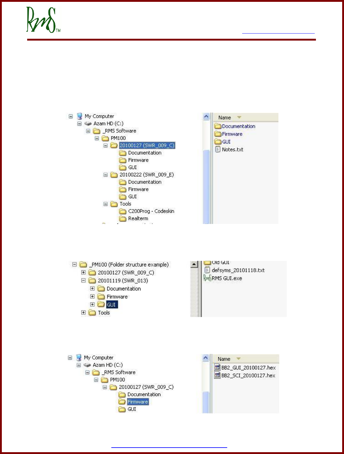
1.2 Saving Firmware Release Package
It is highly recommended that each firmware release package is downloaded and kept separate
from each other. This allows a better referencing during debugging. Also, save files directly
under the C:\ drive instead of ‘Desktop\My Documents’.
Following is a suggested folder structure to keep track of RMS firmware versions:
High level view of RMS folder structure
Files under subfolder ‘GUI’
Files under subfolder ‘Firmware’

7929 SW Burns Way Phone: 503-344-5085
Suite B Fax: 503-682-9014
Wilsonville, OR 97070 sales@rinehartmotion.com
1/5/2016 RMS PM100 Software User Manual 12 of 75
2. C2Prog – Firmware Programming Guide
2.1 Required Hardware
RS232 cable or RS232-USB Adapter (based on PC’s port availability)
2.2 Required Software
(a) New firmware for the PM unit will be provided by Rinehart Motion Systems.
(b) The reprogramming requires the use of the C2Prog software.
• Home page: http://www.codeskin.com/
• C2Prog page: http://www.codeskin.com/c2prog-download
2.3 Programming Steps
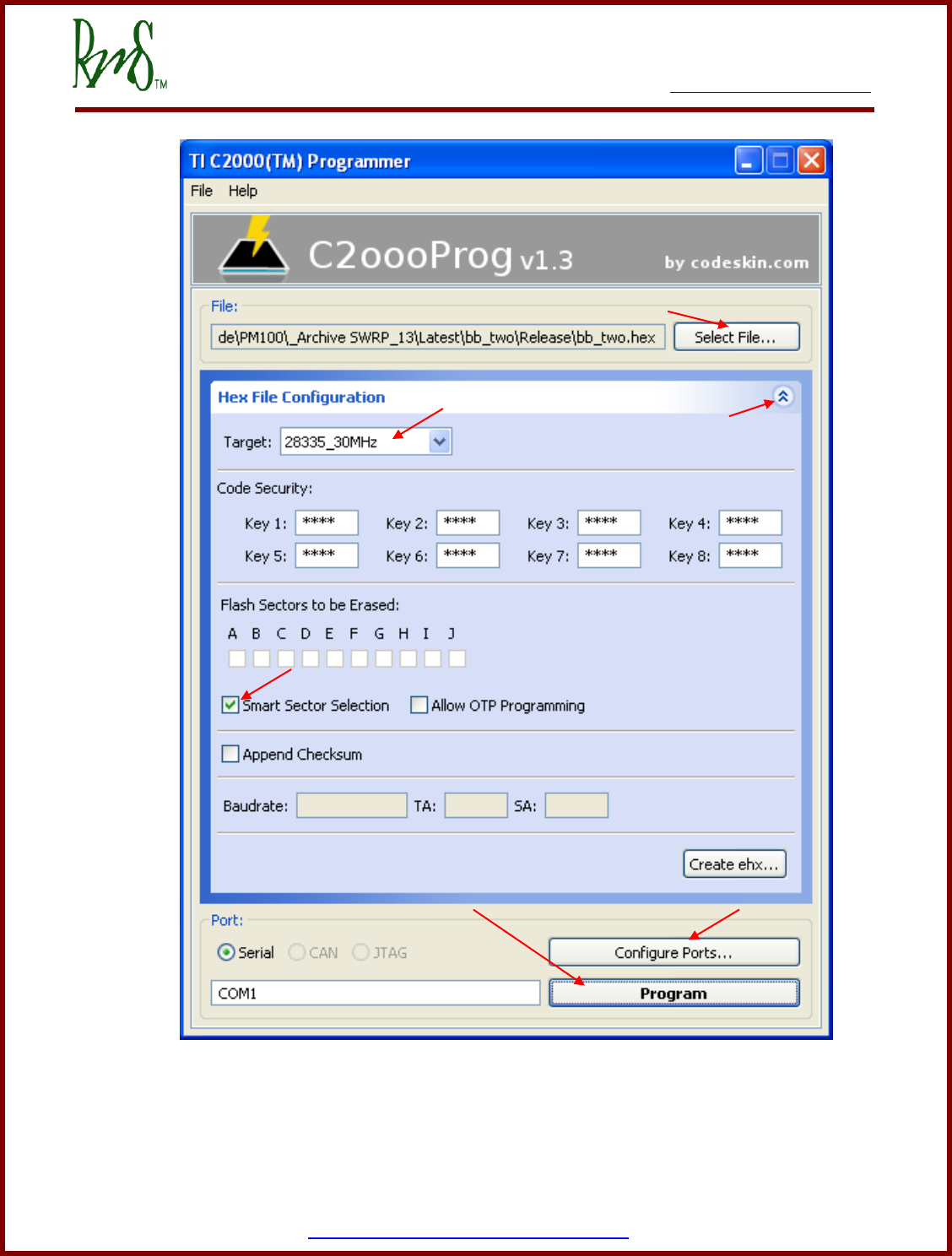
(a) After starting the software make sure that the screen looks similar to the one below. If
necessary press the expansion button next to “Hex File Configuration”.
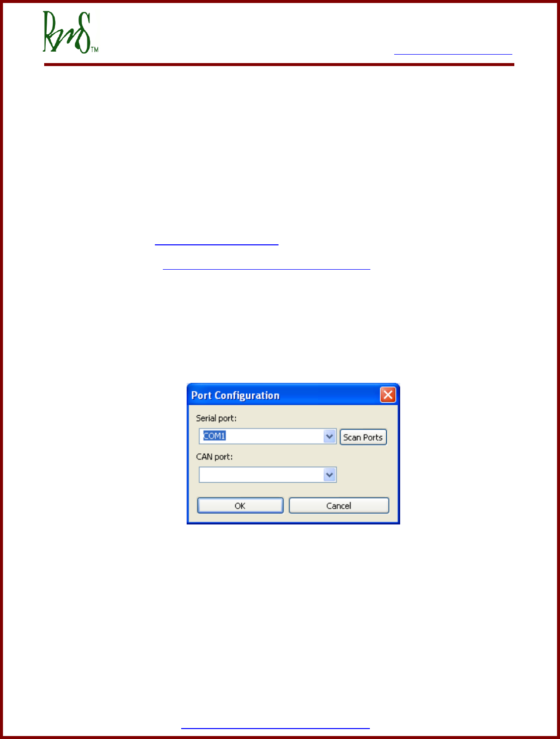
(b) Make sure the proper COM selected. First click “Configure Ports” and then “Scan Ports”
to see the available COM ports. Then select the proper port from the pull-down.
(c) Using the “Target:” pull-down menu select the correct target from the list. RMS firmware
requires one of the two options:
• 28335_30MHz (only used with rare units that contain floating point support)
• 28234_30MHz (this is the most common)
7929 SW Burns Way Phone: 503-344-5085
Suite B Fax: 503-682-9014
Wilsonville, OR 97070 sales@rinehartmotion.com
1/5/2016 RMS PM100 Software User Manual 14 of 75
(d) Make sure that the “Smart Selector Selection” box is checked.
(e) Click the “Select File…” button on the top right hand corner and browse to the correct
firmware file provided by RMS. The file will have a .hex extension.
(f) Now click the “Program” button near the bottom.
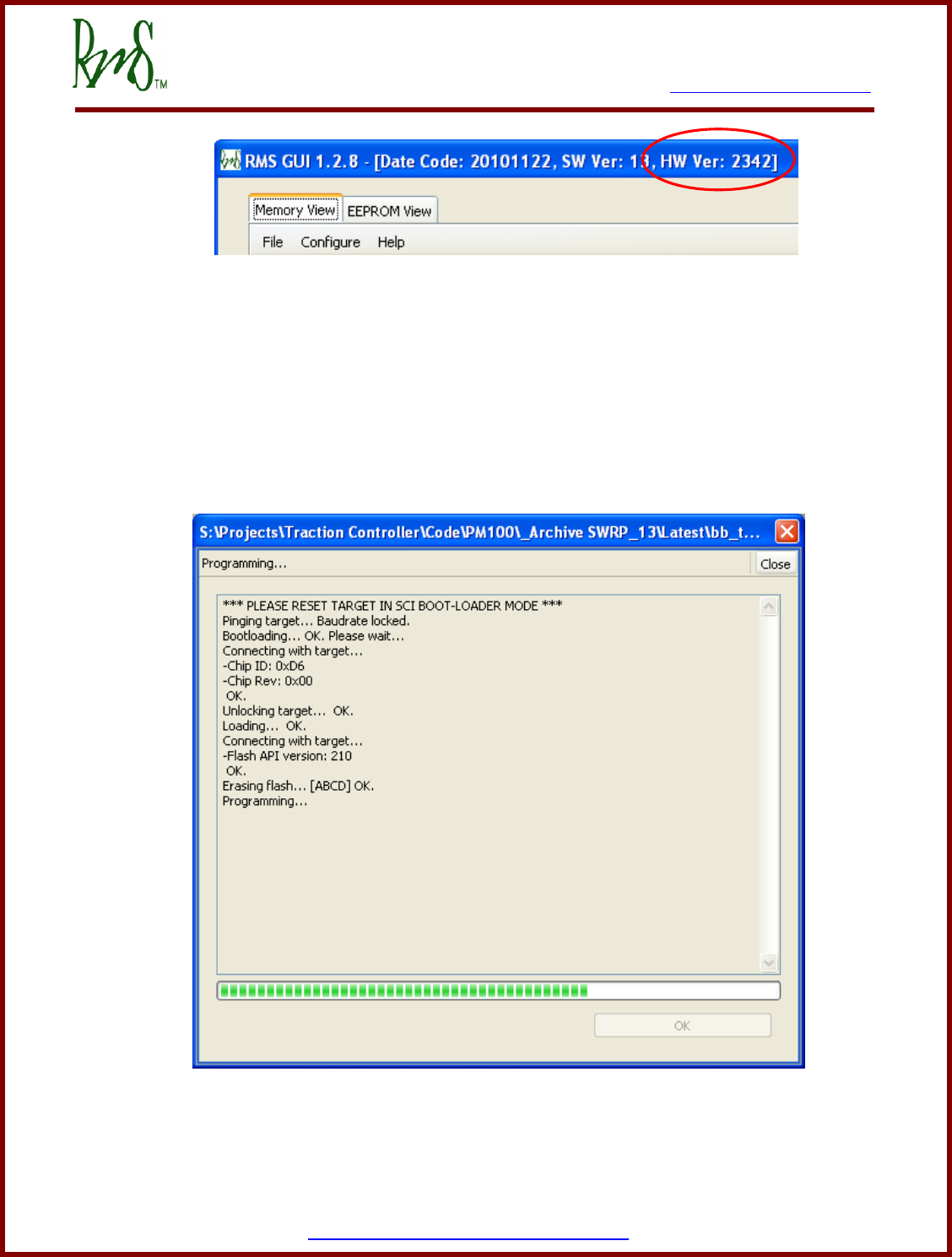
(g) Make sure that Program Enable switch in the inverter harness is closed. Then power-on
the inverter. Programming will then begin. The C2Prog software will show the status of
the programming.
(h) When the programming is completed, click OK to close the Status screen. If going to step
‘b’ above.

7929 SW Burns Way Phone: 503-344-5085
Suite B Fax: 503-682-9014
Wilsonville, OR 97070 sales@rinehartmotion.com
1/5/2016 RMS PM100 Software User Manual 16 of 75
3. RMS Data Acquisition Guide
3.1 Required Hardware
RS232 cable or RS232-USB Adapter (based on PC’s port availability)
3.2 Required Software
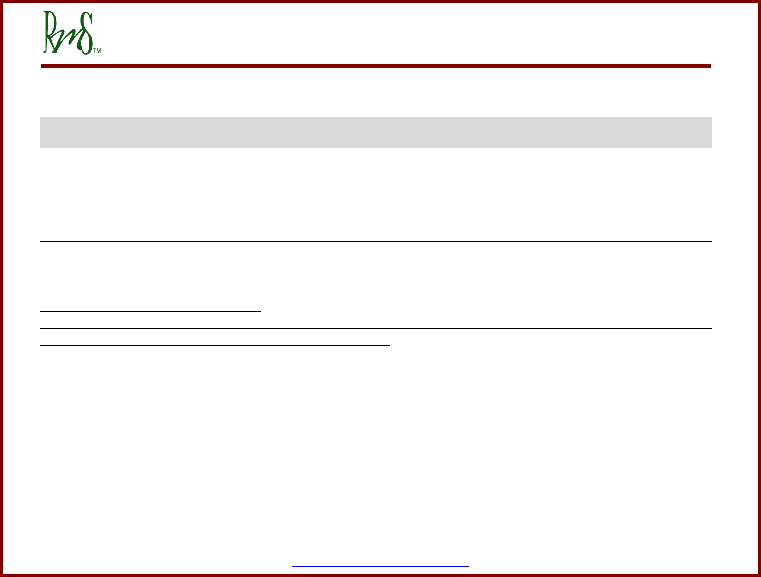
This section defines parameters that are transmitted by the PM unit using SCI over RS232
serial cable. In order to receive the data, RS232 port should be configured as follows:
Baud Rate
57600
Parity
None
Data Bits
8
Stop Bits
1
Hardware Flow Control
None
3.2.1 Data Records
Each parameter is 16-bits long and each nibble (4-bits) in a parameter is sent as an ASCII
character. A ‘record’ consists of total five characters, that is, the four nibbles in a parameter and
a space character. After sending all records, two additional characters, a carriage return and a
linefeed, are sent.
0
0
6
8
<space>
Figure 5.1 – Data Record
Data
Record
1
Data
Record
2
Data
Record
3
Data
Record
N
<carriage
return>
<linefeed>
Figure 5.2 – A complete set of data records
3.2.2 Update Rate
The update rate of one complete set of data records depends on the total number of records in
each set:
For example, if there are 21 data records in one set:
Time to send 5 characters (1 data record) = 3 msec
Time to send 21 records = 21 records x 3 msec = 63 msec
Plus last two characters = 63 + 3 = 66 msec

7929 SW Burns Way Phone: 503-344-5085
Suite B Fax: 503-682-9014
Wilsonville, OR 97070 sales@rinehartmotion.com
1/5/2016 RMS PM100 Software User Manual 17 of 75
3.3 Data Acquisition Parameters
The following data records are transmitted over the serial bus:
Count
Parameter
1
Slow Interrupt Counter
2
Filtered Accel-pot
3
Blended Torque
4
Vehicle Torque Command
5
DC Voltage
6
DC Current
7
Omega Tach
8
Flux Weakening Regulator Output
9
FB Voltage Magnitude
10
IQ Command
11
IQ Feedback
12
ID Command
13
ID Feedback
14
Modulation
15
Module A Temperature
16
Motor Temperature
17
Run Fault Low Word
18
Run Fault High Word
19
Torque Shudder
20
Filtered Brake pot
3.3.1 Data Capture Tools
In order to save the data on the serial bus, a terminal program such as Realterm
(HUhttp://realterm.sourceforge.net/UH) can be used. Most of the data capture at RMS has been done
using a Palm or a similar device.
3.3.2 Utilizing the Captured Data:
Once the data is captures in a text file, it should be imported into a Microsoft Excel spreadsheet
as space delimited data. After importing all data, it can be copied into SCI Template.xls
spreadsheet which provides conversion formulae for each data record and allows the user to
plot graphs to analyze the vehicle performance in more detail.

7929 SW Burns Way Phone: 503-344-5085
Suite B Fax: 503-682-9014
Wilsonville, OR 97070 sales@rinehartmotion.com
1/5/2016 RMS PM100 Software User Manual 18 of 75
4. Data Formats
Throughout this document, all parameters will adhere to the data formats mentioned in this
section, unless specified otherwise.
The column, Variable Type follows the standard computer programming data types. These data
types are defined as follows:
• Byte (char): an 8-bit value ranging from 0 – 255 for unsigned and -128 – 127 for signed
characters.
• Integer (int): a 16-bit value ranging from 0 – 65535 for unsigned and -32768 – 32767 for
signed integers.
• Long Integer (long): a 32-bit value ranging from –(231+1) to 231.
All EEPROM data is broadcast with a multiplication factor. In order to get the actual value,
divide it by the value in the column ‘Multiplier’ (may also be referred to as ‘Prescalar’).
Format
Variable Type
Range
Unit
Multiplier
Temperature
Signed Integer
± 3000.0
°C
10
Low Voltage
Signed Integer
± 300.00
Volts
100
High Voltage
Signed Integer
± 3000.0
Volts
10
Torque
Signed Integer
± 3000.0
N.m.
10
Current
Signed Integer
± 3000.0
Amps
10
Angle
Signed Integer
0 to ±359.9
Degrees
10
Angular Velocity
Signed Integer
± 30000
RPM
N.A.
Boolean
Unsigned Byte
0 OR 1
Binary
N.A.
Frequency
Signed Integer
± 3000.0
Hz
10
Power
Signed Integer
± 3000.0
kW
10
Flux
Signed Integer
0 to 30.000
Webers
1000
Proportional Gain
Unsigned Integer
0 - 655.00
OR
0 - 6.5535
N.A.
100
OR
10000
Integral Gain
Unsigned Integer
0 - 6.5535
N.A.
10000
Derivative Gain
Unsigned Integer
0 - 655.35
N.A.
100
Low-pass Filter
Gain
Unsigned Integer
0 - 6.5535
N.A.
10000
Time
Unsigned Long
Integer
OR
Unsigned Integer
See Parameter
Description
See Parameter
Description
See Parameter
Description
Per-unit Value
See Parameter
Description
See Parameter
Description
See Parameter
Description
See Parameter
Description


7929 SW Burns Way Phone: 503-344-5085
Suite B Fax: 503-682-9014
Wilsonville, OR 97070 sales@rinehartmotion.com
1/5/2016 RMS PM100 Software User Manual 20 of 75
5. RMS GUI – EEPROM Parameters Guide
RMS GUI is a Windows application developed by RMS. This application communicates over a
RS232 port. The primary purpose of this application is to be able to monitor a specific set of
parameters in real time. However, the application also provides the ability to program certain
EEPROM parameters. The set of EEPROM parameters need to be modified based on each
motor and other system set up by the customer. EEPROM parameters must be programmed
correctly before the PM controller is operated.
This section provides the user with a process of updating EEPROM parameters for the PM1 unit
using the GUI application.
5.1 Required Hardware
RS232 cable or RS232-USB Adapter (based on PC’s port availability)
5.2 Required Software
Following software applications/files are needed to program EEPROM parameters:
RMS GUI Application: This application is part of the RMS Firmware Release Package and
can be downloaded using the link provided in the above section, ‘Firmware Release
Package’.
Default symbols file (defsyms_yyyymmdd.txt): Each released firmware requires a specific
default symbols file. Please refer to section 1.1.2.1 ‘RMS GUI’ for more details.
Firmware file: Please refer to section 1.1.1 ‘Firmware’ for more details.
5.3 Programming Steps
(a) Start the GUI. Make sure it is version 1.2.7 or above. Confirm the GUI version number,
Firmware date code and firmware version on the title of the GUI window. The latest RMS
GUI application also displays the COM port information.
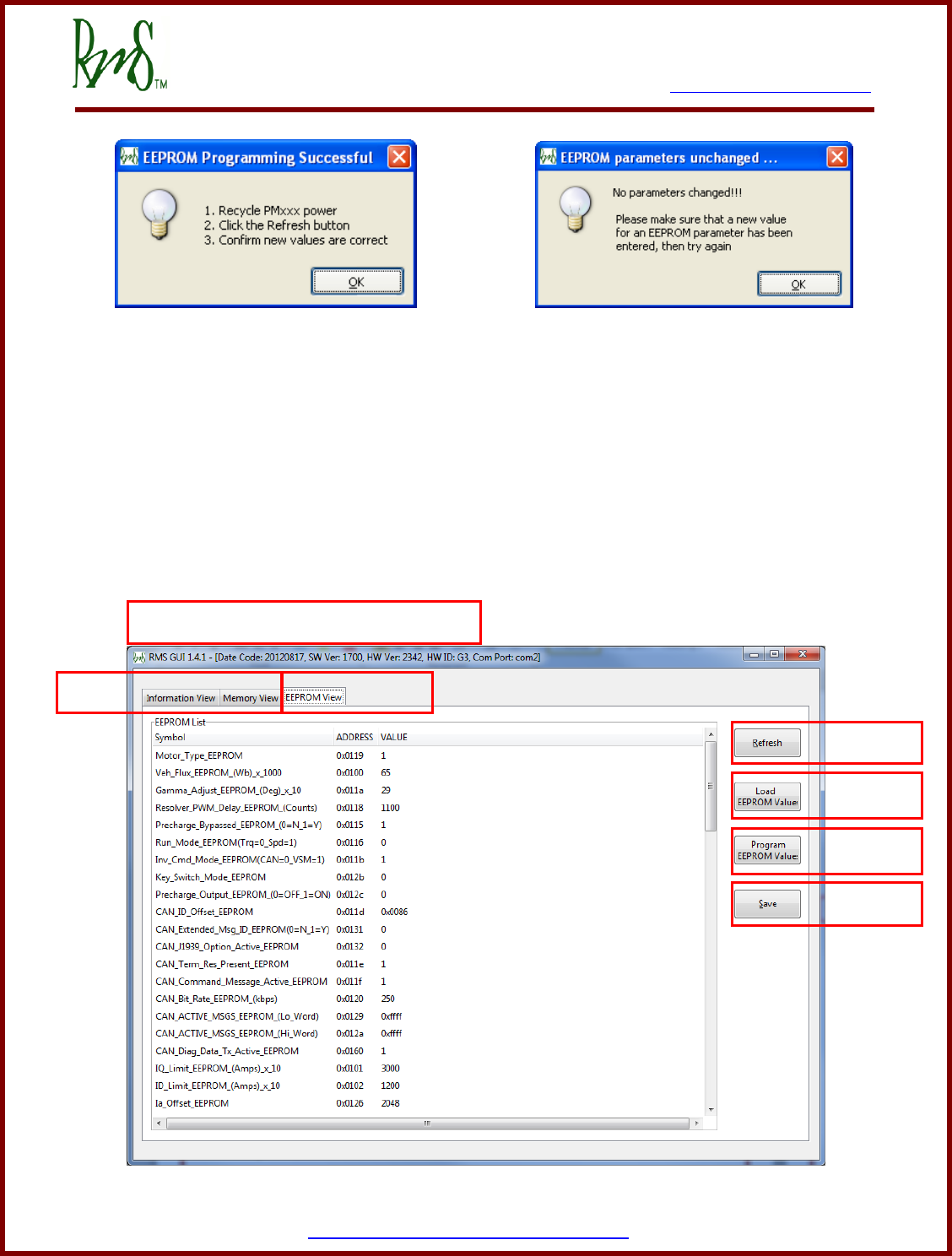
(b) Click on the EEPROM View tab (labeled ‘Tab 2’ in figure 5.2). This will display all EEPROM
parameters that can be programmed by the user.
(c) In order to change any value, click on the value under the VALUE column. Enter a new
value and then click ENTER key on your keyboard.
(d) When all values are changed, click on the Program EEPROM button (labeled ‘Button 3’ in
figure 5.2).
(e) A status message will confirm whether the programming was successful or not. Follow the
on-screen instructions.
7929 SW Burns Way Phone: 503-344-5085
Suite B Fax: 503-682-9014
Wilsonville, OR 97070 sales@rinehartmotion.com
1/5/2016 RMS PM100 Software User Manual 21 of 75
Figure 5.1
5.4 Saving EEPROM values
EEPROM values can be saved by using the Save button (labeled ‘Button 4’ in figure 5.2). You
will be prompted for a filename to save the data to. After selecting the file you will be prompted
to press “OK” to start the download.
5.5 Uploading EEPROM values
You can also load a predefined set of values by using the Load EEPROM Values button
(labeled ‘Button 2’ in figure 5.2).
Figure 5.2
Button 1
Button 2
Button 3
Button 4
Tab 2
Tab 1
GUI version, Firmware Date-code & Version
7929 SW Burns Way Phone: 503-344-5085
Suite B Fax: 503-682-9014
Wilsonville, OR 97070 sales@rinehartmotion.com
1/5/2016 RMS PM100 Software User Manual 22 of 75
5.6 Switching back to SCI mode
Once in the GUI mode, the user has the option to switch back to the SCI data acquisition mode.
However, it requires the RMS GUI application to be completely shut down. In other words, the
GUI application must release the serial port.
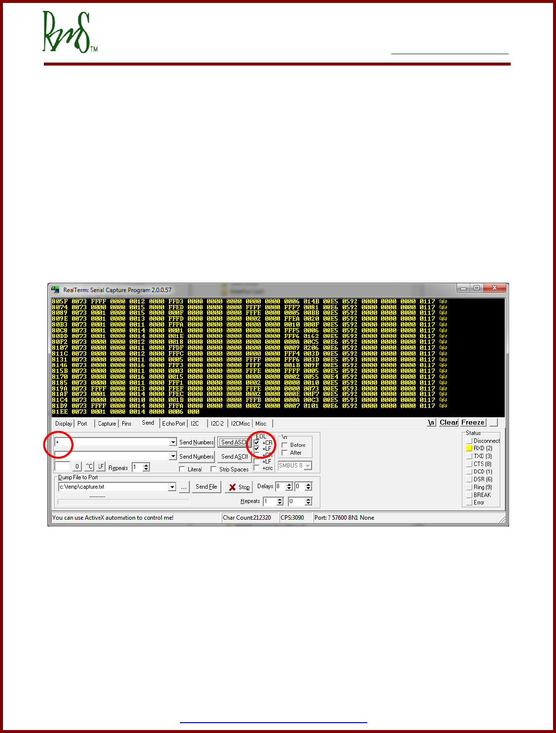
Once the serial port is released, another terminal application such as Realterm can be started.
Open the serial port and click anywhere in the window where the serial data appears. Press ‘+’
and then <Enter>. The SCI broadcast data should start to appear again.
Realterm, in particular, also has an option to send out the ASCII characters as shown below.
You can enter ‘+’ in the first box and check the +CR and +LF options for carriage return and
linefeed respectively. Then press the “Send ASCII” button. The SCI broadcast data should start
to appear again.

7929 SW Burns Way Phone: 503-344-5085
Suite B Fax: 503-682-9014
Wilsonville, OR 97070 sales@rinehartmotion.com
1/5/2016 RMS PM100 Software User Manual 23 of 75
6. EEPROM Parameter Setup (via GUI EEPROM View)
There are a number of internal parameters (may be considered as “calibrations”) that must be
set in the controller before it is ready to operate a vehicle. All of these values must be adjusted
to suit the vehicle and motor you are using. These adjustments are part of personalizing the
drivability and vehicle dynamics to suit the final application of the vehicle.
Parameter setup is accomplished using custom software provided by RMS. Refer to section 8,
“RMS GUI – EEPROM Parameters Guide” for more information on how to update and program
these parameters in non-volatile memory.
Refer to the following appendices for different categories of EEPROM parameters (each
appendix is hyper-linked, press CTRL-CLICK to go to a specific table):
Appendix A: Motor Configuration Parameters
Appendix B: System Configuration Parameters
Appendix C: CAN Configuration Parameters
Appendix D: Current Parameters
Appendix E: Voltage & Flux Parameters
Appendix F: Temperature Parameters
Appendix G: Accelerator & Torque Parameters
Appendix H: Speed Parameters
Appendix I: PID Regulator Parameters
Appendix J: Shudder Compensation Parameters
Appendix K: Brake Parameters
7929 SW Burns Way Phone: 503-344-5085
Suite B Fax: 503-682-9014
Wilsonville, OR 97070 sales@rinehartmotion.com
1/5/2016 RMS PM100 Software User Manual 24 of 75
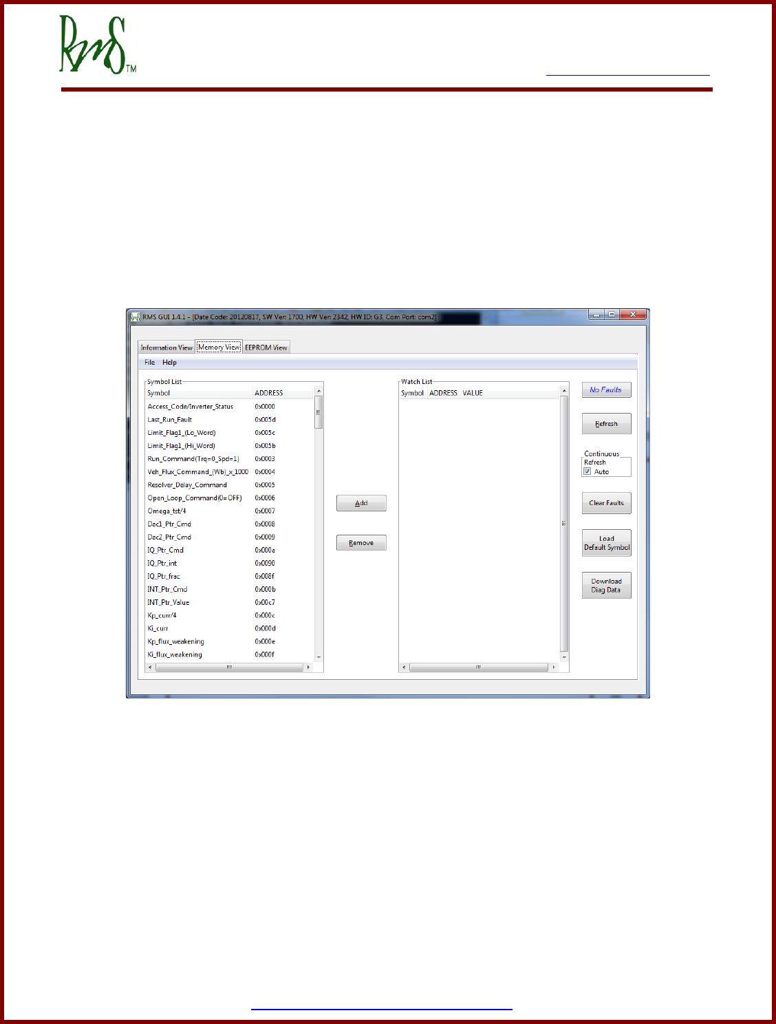
7. Monitored Parameters View (via GUI Memory View)
The GUI provides the ability to monitor several operation parameters of the controller. It is also
helpful for checking connections to the controller. Items can be added or removed from the
Memory Window to the Watch window to view the parameter.
Refer to the following appendix for a complete list of parameters that can be monitored through
RMS GUI (each appendix is hyper-linked, press CTRL-CLICK to go to a specific table):
Appendix L: GUI Display Parameters
No Faults/Check Faults button: This button allows the user to check the fault status when the
‘Auto’ box is check for ‘Continuous Refresh’ or by clicking on this button. ‘No Faults; status in
blue indicates that there are no faults currently present. ‘Check Faults’ status indicates the
presence of one or more faults. To check which faults are present, click on this button.
Clear Faults button: This button allows the user to clear all faults with the exception of a few
mentioned in Appendix N (table of Run Faults).
Download Diagnostic Data button: This button allows the user to download SCI Diagnostic
Data. Please refer to the user manual ‘Download Diagnostic Data’ for details.
Load Default Symbols button: This button allows the user to load the default symbols file for
the firmware in the PM unit.


7929 SW Burns Way Phone: 503-344-5085
Suite B Fax: 503-682-9014
Wilsonville, OR 97070 sales@rinehartmotion.com
1/5/2016 RMS PM100 Software User Manual 26 of 75
8. Calibration Processes
Before the RMS inverter can be used successfully, it is very important to make sure that it is
calibrated properly. There are several calibrations that are performed before each unit is
shipped to the customer. However, some of these calibrations depend on the specific
environment in which the unit is used.
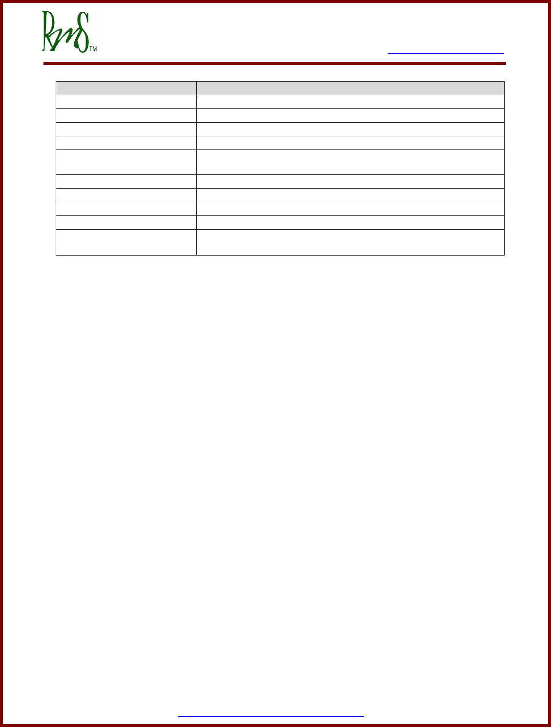
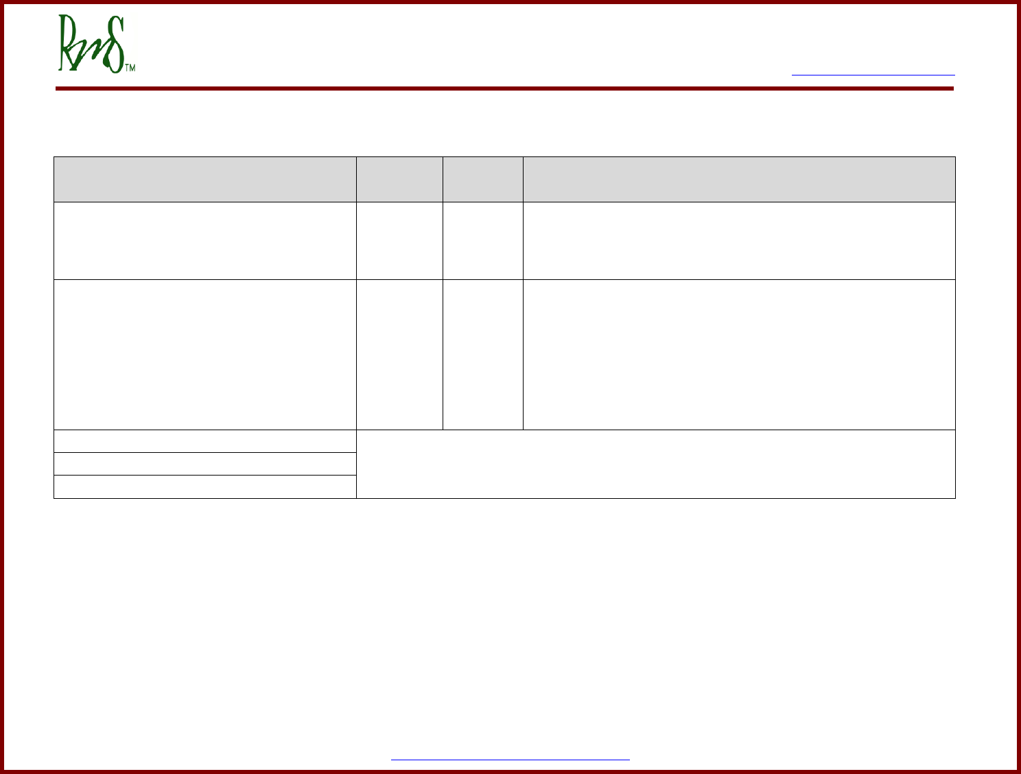
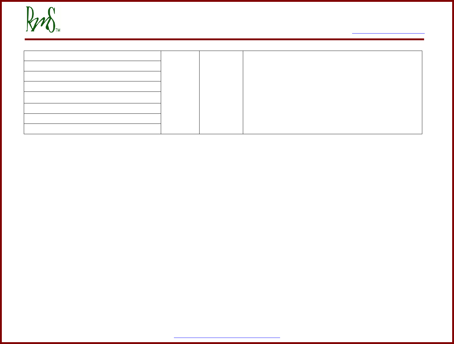
User Manuals for following calibration processes are provided to customers. The calibrations
can be performed as many times as needed.
Calibration Process
User Manual (PDF format)
Factory
Calibrated?
Current Offset
Current Offset Calculation
(only used with certain units, not common)
No
DC Voltage
RMS DC Voltage Calibration Process
(factory calibrated thus not normally needed)
Yes
Hall Sensor Encoder
Encoder Hall Sensor Calibration
(not normally needed)
No
SIN/COS Encoder
RMS Encoder Calibration for SIN_COS Encoder
(only necessary with certain motors that have a
sin/cos encoder)
No
Resolver
RMS Resolver Calibration Process
(this process is necessary for all motors that use
a resolver)
No
RTD
RMS RTD Calibration Process
(factory calibrated thus not normally needed)
Yes


7929 SW Burns Way Phone: 503-344-5085
Suite B Fax: 503-682-9014
Wilsonville, OR 97070 sales@rinehartmotion.com
1/5/2016 RMS PM100 Software User Manual 28 of 75
9. Vehicle State Machine
The drive has an internal state machine that steps through a series of actions at startup, at
shutdown, and generally whenever operation “transitions” from one mode or state to another.
The particular state that the drive is in can be tracked via the RMS GUI software. The state is
monitored via the VSM_State symbol. This symbol will take on the following values:
VSM_State
Name
0
Start State
1
Pre-charge sequence initial state – Turn on the pre-charge relay
2
Pre-charge sequence active state – Waiting for capacitor to finish charging.
3
Pre-charge sequence finish state – Completes the final checks before
proceeding to Wait State.
4
Wait State – waiting for activation of forward or reverse.
5
Ready State – Activates the inverter state machine to begin energizing the
motor.
6
Motor Running State – Normal motor running
7
Fault State – The controller has faulted
14
Shutdown in Process – In key switch mode 1, user has turned key switch to
off position.
15
Recycle Power State – This indicates that the power to the controller needs
to be recycled after EEPROM Programming is complete.
9.1 Start State (VSM_state = 0):
9.1.1 12V Power-up:
When the vehicle is powered up, this is the default state. If the program enable input is held low
at power up it will not execute the RMS software and will not proceed into the Vehicle State
Machine.
Default Initialization:
This is the processor setup and initialization process, including setting all I/O pins to the correct
state (in/out, pull-up or –down, weak or strong, etc). At this point, the initialization process sets
up a default list of parameters with pre-assigned default values.
9.1.2 Load from EEPROM:
This state will load the application parameters to configure the unit for the actual application.
This also loads FACTORY CALIBRATIONS from memory, as these are just a class of EEPROM
parameters.
9.1.3 Power on Self-Test (POST):
A number of tests are to be performed in this state. Each test will have an associated fault flag.
Following is a list of parameters checked:
7929 SW Burns Way Phone: 503-344-5085
Suite B Fax: 503-682-9014
Wilsonville, OR 97070 sales@rinehartmotion.com
1/5/2016 RMS PM100 Software User Manual 29 of 75
Test Area
Description
Current sensors
Check current sensors reading to be within a valid range
Accelerator input
Check accelerator input data is within a valid range
PCB Temperature Sensor
Check PC temperature is in valid range
GDB Temperature Sensor
Check gate drive board temperatures in range
Module Temperature Sensors
Check substrate temperatures for module A, module B, and module
C in range
5V power
Check internal 5V and external transducer power in range
12V power
Check 12V power in range
2.5V power
Check internal 2.5V reference voltage in range
1.5V power
Check internal 1.5V reference voltage in range
HW Faults
(Saturation and over current)
If exist, attempt to clear faults and then report
If a power-on self-test fault occurs it will blink the fault indicator followed by two quick blinks to
differentiate POST faults from RUN faults. The number of blinks gives a general indication of the
particular fault.
A particular fault code can be found by clicking on the “Check Faults” button on the “Memory
View” page of RMS GUI. Parameters, “post_fault_hi and post_fault_lo have been removed from
the parameter list and are not available anymore.
The list on the next page shows all POST faults:

7929 SW Burns Way Phone: 503-344-5085
Suite B Fax: 503-682-9014
Wilsonville, OR 97070 sales@rinehartmotion.com
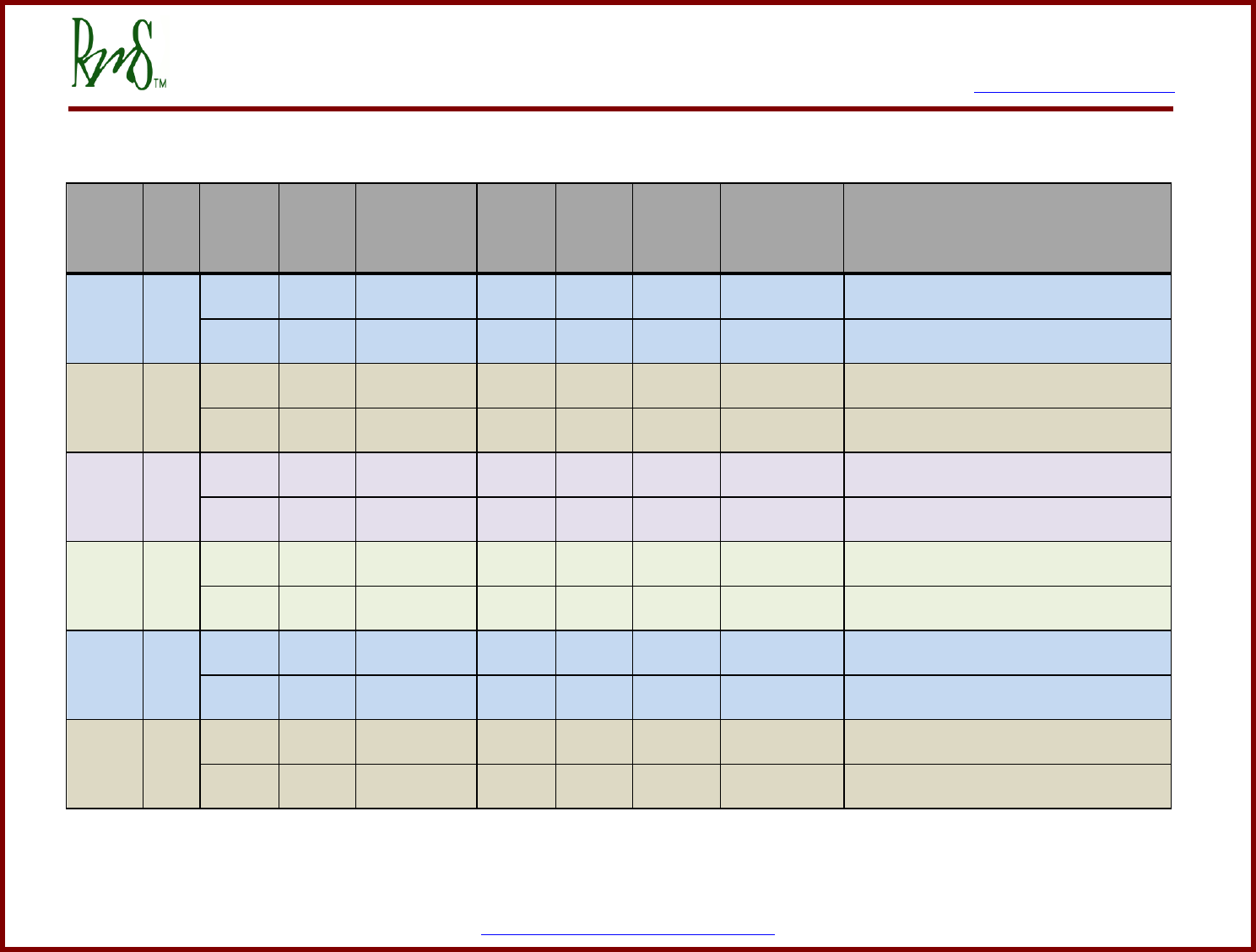
1/5/2016 RMS PM100 Software User Manual 30 of 75
CAN Byte
CAN Bit
POST Fault
CAN Byte
Value
Fault Word
Byte 0
0
Hardware Gate/Desaturation Fault
1
00000001
1
HW Over-current Fault
2
00000002
2
Accelerator Shorted
4
00000004
3
Accelerator Open
8
00000008
4
Current Sensor Low
16
00000010
5
Current Sensor High
32
00000020
6
Module Temperature Low
64
00000040
7
Module Temperature High
128
00000080
Byte 1
8
Control PCB Temperature Low
1
00000100
9
Control PCB Temperature High
2
00000200
10
Gate Drive PCB Temperature Low
4
00000400
11
Gate Drive PCB Temperature High
8
00000800
12
5V Sense Voltage Low
16
00001000
13
5V Sense Voltage High
32
00002000
14
12V Sense Voltage Low
64
00004000
15
12V Sense Voltage High
128
00008000
Byte 2
16
2.5V Sense Voltage Low
1
00010000
17
2.5V Sense Voltage High
2
00020000
18
1.5V Sense Voltage Low
4
00040000
19
1.5V Sense Voltage High
8
00080000
20
DC Bus Voltage High
16
00100000
21
DC Bus Voltage Low
32
00200000
22
Pre-charge Timeout
64
00400000
23
Pre-charge Voltage Failure
128
00800000
Byte 3
24
EEPROM Checksum Invalid
1
01000000
25
EEPROM Data Out of Range
2
02000000
26
EEPROM Update Required (warning)
4
04000000
27
Reserved
8
08000000
28
Reserved
16
10000000
29
Reserved
32
20000000
30
Brake Shorted
64
40000000
31
Brake Open
128
80000000
Please refer to Appendix M for description of power-on self-test faults.

7929 SW Burns Way Phone: 503-344-5085
Suite B Fax: 503-682-9014
Wilsonville, OR 97070 sales@rinehartmotion.com
1/5/2016 RMS PM100 Software User Manual 31 of 75
9.2 Pre-charge Sequence:
9.2.1 Pre-charge Initialization (VSM_State = 1)
This state declared VDC Out-of-range high fault if DC voltage is above the software over-
voltage threshold. The value of software over-voltage threshold is hard-coded and can only be
changed through RMS firmware release process.
If DC voltage is below the software over-voltage threshold, Pre-charge output is activated. State
machine goes to Pre-charge Active State.
9.2.2 Pre-charge Active (VSM_State = 2)
This state controls the charging of the capacitors internal to the controllers. If the rate of charge
stays within range, Main output is activated and Pre-charge output is deactivated. During the
pre-charge process:
If DC voltage exceeds software over-voltage threshold, VDC Out-of-range high fault is declared.
After 3 seconds that is, the maximum pre-charge time,
- If DC voltage is less than the value of EEPROM parameter, DC Under-voltage
threshold VDC Out-of-range low fault is declared.
- If DC voltage is still charging, pre-charge timeout fault is declared.
9.2.3 Pre-charge Complete (VSM_State = 3)
This state checks if the capacitor charge is stable, that is, it is not over-charged or under-
charged, or there is no quick change in voltage since the pre-charge output was deactivated. If
any of the conditions is true, a relevant fault is declared.

7929 SW Burns Way Phone: 503-344-5085
Suite B Fax: 503-682-9014
Wilsonville, OR 97070 sales@rinehartmotion.com
1/5/2016 RMS PM100 Software User Manual 32 of 75
9.3 Wait State (VSM_state = 4):
This state checks for the Key Switch Mode. Based on that value, the inverter can be powered to
run the motor as follows:
9.3.1 Key Switch Mode 0
This mode allows for a simple on/off ignition switch functionality. To power up the PM unit, turn
the ignition to ON position. This state then checks to see that the brake switch is active and only
one of /FORWARD and /REVERSE switches is active. If both switches, /FORWARD and
/REVERSE, are active, the state shall declare a FWD_RVS_INVALID_STATE_FAULT. If a
correct direction and the brake are active then the motor will be enabled.
9.3.2 Key Switch Mode 1
This mode allows for traditional ignition switch functionality. To power up the PM unit, turn the
ignition to ON position. This state then checks to see that the brake switch has been active and
start signal pulse has been received. While keeping the brakes on, only one of /FORWARD and
/REVERSE switches needs to be activated. If both switches, /FORWARD and /REVERSE, are
active, the state shall declare a FWD_RVS_INVALID_STATE_FAULT.

7929 SW Burns Way Phone: 503-344-5085
Suite B Fax: 503-682-9014
Wilsonville, OR 97070 sales@rinehartmotion.com
1/5/2016 RMS PM100 Software User Manual 33 of 75
9.4 Ready State (VSM_State = 5):
The READY state shall send out the Enable Inverter Command and wait for Inverter Ready Flag
to be set. The Inverter Ready Flag will be set if the inverter successfully performs a series of
actions necessary to stat the motor. If inverter does not enable the motor within a specific
amount of time, the state shall declare an inverter state timeout fault.
This state automatically transitions to the next state if there are not faults.
The following table lists several inverter states:
Inverter States
(inv_mode)
Description
0
Precharge, power-up state
1
Stop - Inverter is not running and is in “STOP” state.
2
Open Loop State - for testing purposes
3
Closed Loop state – normal state
4
Start Time Delay – small delay before starting the inverter
5
Current Sensor Test – flux ramp and flux regulators enabled
6
Closed Loop Torque – iorque regulator is enabled
7
Torque Ramp – start torque ramp
8
Idle Run – inverter running normally
9
Idle Stop – inverter is stopped
10
Ramp Off Torque – ramps down the torque command
11
Ramp Off Flux – ramps down the flux command
12
All Ramps Off – shutoff inverter
15
Default – Stop state
9.5 Motor Running State (VSM_State = 6):
This is the normal motor running operation of the vehicle state machine. While running the drive
can be switched from torque command to speed command mode, and may be exercised within
the full operating envelope of the machine / drive combination.
9.6 Fault State (VSM_State = 7):
If a fault occurs either during power-On self-test, or while the drive is running, the drive will go to
the fault state.
If the drive has a fault during the running state a fault code will be set and the fault indicator will
begin blinking. At any given time, the fault indicator will blink only one fault.
A particular fault code can be found by clicking on the “Check Faults” button on the “Memory
View” page of RMS GUI. Parameters, “run_fault_hi and run_fault_lo have been removed from
the parameter list and are not available anymore.

7929 SW Burns Way Phone: 503-344-5085
Suite B Fax: 503-682-9014
Wilsonville, OR 97070 sales@rinehartmotion.com
1/5/2016 RMS PM100 Software User Manual 34 of 75
CAN Byte
CAN Bit
RUN Fault
CAN Byte
Value
Fault Word
Byte 4
32
Motor Over-speed Fault
1
00000001
33
Over-current Fault
2
00000002
34
Over-voltage Fault
4
00000004
35
Inverter Over-temperature Fault
8
00000008
36
Accelerator Input Shorted Fault
16
00000010
37
Accelerator Input Open Fault
32
00000020
38
Direction Command Fault
64
00000040
39
Inverter Response Time-out Fault
128
00000080
Byte 5
40
Hardware Gate/Desaturation Fault
1
00000100
41
Hardware Over-current Fault
2
00000200
42
Under-voltage Fault
4
00000400
43
CAN Command Message Lost Fault
8
00000800
44
Motor Over-temperature Fault
16
00001000
45
Reserved
32
00002000
46
Reserved
64
00004000
47
Reserved
128
00008000
Byte 6
48
Brake Input Shorted Fault
1
00010000
49
Brake Input Open Fault
2
00020000
50
Module A Over-temperature Fault1
4
00040000
51
Module B Over-temperature Fault7
8
00080000
52
Module C Over-temperature Fault7
16
00100000
53
PCB Over-temperature Fault7
32
00200000
54
Gate Drive Board 1 Over-temperature Fault
64
00400000
55
Gate Drive Board 2 Over-temperature Fault7
128
00800000
Byte 7
56
Gate Drive Board 3 Over-temperature Fault7
1
01000000
57
Current Sensor Fault
2
02000000
58
Reserved
4
04000000
59
Reserved
8
08000000
60
Reserved
16
10000000
61
Reserved
32
20000000
62
Resolver Not Connected
64
40000000
63
Inverter Discharge Active (warning)
128
80000000
Please refer to Appendix N for the table of run faults.
1
This is a new fault used only for Gen-3 board which is used in all PM150 units.

7929 SW Burns Way Phone: 503-344-5085
Suite B Fax: 503-682-9014
Wilsonville, OR 97070 sales@rinehartmotion.com
1/5/2016 RMS PM100 Software User Manual 35 of 75
9.6.1 Fault Priority:
Fault indicator will blink faults in the following priority:
POST Faults (Higher priority)
RUN Faults (Lower priority)
POST faults are followed by two quick blinks to distinguish from RUN faults. For each type of
fault (POST or RUN), the highest priority of a fault is based on the number of blinks. The fault
with 1 blink is the highest priority and the fault with the highest number of blinks is the lowest
priority fault. The fault blinking will occur such that if the highest priority fault goes away, the
lower priority fault will start blinking and this pattern will continue till all faults are removed.
9.6.2 Clear Faults Command:
Once a fault is acknowledged, it can be cleared using the Clear Faults Command from the GUI.
In order to clear a fault, set the Clear Faults Command to 0.
This command clears all active faults including POST Faults. The only exception is the POST
Fault, EEPROM Update Required (refer to section 10.1.4 above). This fault is set after
programming a new firmware in the PM controller. The purpose of this fault is to have the user
accept all previous EEPROM parameters and update the new ones. If there are no EEPROM
parameters to update, user should still enter the Access Code and Program EEPROM
Command to accept all EEPROM parameters. Please refer to “RMS GUI – EEPROM
Parameters Guide” for more details on how to program EEPROM parameters.
In CAN mode, before sending out the Clear Faults Command, make sure that the
inverter is disabled. If inverter is enabled and the command is sent out, the motor may
start running based on the mode and commanded Torque/Speed.
9.7 Shutdown in Process State (VSM_State = 14):
This state indicates that the inverter “Shutdown in Process”. In key switch mode 1, user has turned key
switch to off position by holding the ignition input low.
9.8 Recycle Power State (VSM_State = 15):
This state indicates that the EEPROM Programming has been successfully completed. For new
EEPROM values to take effect, the controller must be re-powered.
7929 SW Burns Way Phone: 503-344-5085
Suite B Fax: 503-682-9014
Wilsonville, OR 97070 sales@rinehartmotion.com
1/5/2016 RMS PM100 Software User Manual 36 of 75
Appendix A Motor Configuration Parameters
RMS GUI
Parameter
GUI
ADDRESS
Value
Range
Description
Motor_Type_EEPROM
0x0119
0 - 255
This parameter is used to select the motor that will be connected to
the inverter. If you do not know the motor type number for your
motor please contact RMS.
Resolver_PWM_Delay_EEPROM_(Counts)
0x0118
0 - 6250
This parameter adjusts a delay that is used to synchronize the
resolver feedback to the PWM cycle. It is only used with motors that
use resolvers. See RMS Resolver Calibration Process for more
information on resolver calibration.
Gamma_Adjust_EEPROM_(Deg)_x_10
0x011A
0 - ±3599
This is a calibration parameter used in the alignment of the magnetic
field of the motor with the resolver. This parameter is only used with
PM type motors. See RMS Resolver Calibration Process for more
information on resolver calibration.
Sin_Offset_EEPROM_(Voltsx100)
Please refer to the manual, “RMS Encoder Calibration for SIN_COS Encoder”.
Cos_Offset_EEPROM_(Voltsx100)
Sin_Offset_EEPROM_(ADC_Counts)
0x0163
0 – 4096
This feature is dependent on the hardware version of the PM unit. In
some cases, the resolver sine and cosine outputs may require
adjustments for improved signals. These offsets are added as ADC
counts to calibrate the sin and cosine signals directly.
Cos_Offset_EEPROM_(ADC_Counts)
0x0164
0 – 4096

7929 SW Burns Way Phone: 503-344-5085
Suite B Fax: 503-682-9014
Wilsonville, OR 97070 sales@rinehartmotion.com
1/5/2016 RMS PM100 Software User Manual 37 of 75
Appendix B System Configuration Parameters
RMS GUI
Parameter
GUI
ADDRESS
Value
Range
Description
Serial_Number_EEPROM
0x0113
0 to 65535
Used for storage of the unit serial number.
Precharge_Bypassed_EEPROM
0x0115
0 or 1
Set to 1: Setting this to a 1 will bypass the pre-charge sequence.
When the drive is powered it will go directly to state “Wait State”.
Set to 0: Setting this to a 0 will enable the pre-charge sequence as
described above.
Default is 0.
Run_Mode_EEPROM
0x0116
0 or 1
Set to 1: Setting this to a 1 will force the drive into speed control
mode. This mode is only recommended for demonstration purposes
when the motor is not connected to a high inertia load such as a
vehicle. The Accelerator input will command a speed. Contact the
factory for more information. For speed mode to operate correctly
the Regen Torque Limit must be greater than 0. It should be set to at
least 10% of the Motor Torque Limit.
Set to 0: Setting this to a 0 will place the drive into torque mode. This
is the normal operating mode for the drive.
Default is 0.
Inv_Cmd_Mode_EEPROM(CAN = 0_VSM=1)
0x011B
0 or 1
This parameter sets the operating mode of the inverter.
Set to 0: Operate under control of the CAN bus. The CAN bus is
responsible for enabling and disabling the motor. The brake,
forward, and reverse switches are not used.
Set to 1: Operate under control of accelerator input and switches
(VSM Mode).

7929 SW Burns Way Phone: 503-344-5085
Suite B Fax: 503-682-9014
Wilsonville, OR 97070 sales@rinehartmotion.com
1/5/2016 RMS PM100 Software User Manual 38 of 75
Key_Switch_Mode_EEPROM
0x012B
0 or 1
This parameter provides alternate key switch modes. This allows
different types of ignition for vehicles.
0 = Allows a simple on/off switch for powering up the inverter.
1 = Provides the functionality of a more traditional ignition switch
with momentary START signal that powers up the inverter and
keeps it powered until the ignition switch is turned off. This
configuration must use the IGNITION and START inputs.
Key Switch Mode is only effective in VSM Mode. CAN mode
remains unaffected. However, the parameter can be updated
through both GUI and CAN.
Discharge_Enable_EEPROM
0x016D
0,1,2
Controls the Active Discharge process. Can be used to
discharge the internal high voltage capacitors quicker than the
passive discharge. See the RMS Inverter Discharge Process
Manual for more information.
0 = discharge disabled
1 = discharge is enabled without any faults
2 = discharge is enabled with faults
Relay_Output_State_EEPROM
0x012C
0 - 255
This parameter controls all relays. To keep the compatibility with
previous versions (prior to firmware version 1909), this parameter
should be set to 0x000C which will maintain the functionality of
OK and fault outputs.
Bit 0: Relay 1 - (Precharge output)
Bit 1: Relay 2 - (Main Output)
Bit 2: Relay 3 - (OK Output)
Bit 3: Relay 4 - (Fault Output)
Bit 4: Relay 5
Bit 5: Relay 6
Bit 6: Relay 7
Bit 7: Relay 8
Please see the table below for detailed behavior of each relay.


7929 SW Burns Way Phone: 503-344-5085
Suite B Fax: 503-682-9014
Wilsonville, OR 97070 sales@rinehartmotion.com
1/5/2016 RMS PM100 Software User Manual 40 of 75
Precharge Output Options
Relay #
Command
Mode
0: CAN
1: VSM
Precharge
Bypass
0: No
1: Yes
Output Relay
Config
0: CAN Control
1: Normal Mode
CAN
Command
0: Turn off
1: Turn on
Precharge
States
Active?
Output
State Final
0: Off
1: ON
Function Description
0 0 0 0 Y 0 CAN Control
Output will toggle during prechrage.
Afterwards, goes to CAN control
0 0 0 1 Y 1 CAN Control
Output will toggle during prechrage.
Afterwards, goes to CAN control
0 0 1 0 Y 1 Normal Function
Output will toggle during prechrage.
Afterwards, goes to output configuration
0 0 1 1 Y 1 Normal Function
Output will toggle during prechrage.
Afterwards, goes to output configuration
0 1 0 0 N 0 CAN Control Output directly goes to CAN control
0 1 0 1 N 1 CAN Control Output directly goes to CAN control
0 1 1 0 N 1 Normal Function Output directly goes to output configuration
0 1 1 1 N 1 Normal Function Output directly goes to output configuration
1 0 0 x Y 0 Normal Function
Output will toggle during prechrage.
Afterwards, goes to output configuration
1 0 0 x Y 0 Normal Function
Output will toggle during prechrage.
Afterwards, goes to output configuration
1 0 1 x Y 0 Normal Function
Output will toggle during prechrage.
Afterwards, goes to output configuration
1 0 1 x Y 0 Normal Function
Output will toggle during prechrage.
Afterwards, goes to output configuration
1 1 0 x N 0 Normal Function Output directly goes to output configuration
1 1 0 x N 0 Normal Function Output directly goes to output configuration
1 1 1 x N 1 Normal Function Output directly goes to output configuration
1 1 1 x N 1 Normal Function Output directly goes to output configuration
1
Precharge

7929 SW Burns Way Phone: 503-344-5085
Suite B Fax: 503-682-9014
Wilsonville, OR 97070 sales@rinehartmotion.com
1/5/2016 RMS PM100 Software User Manual 41 of 75
Main Output Options
Relay #
Command
Mode
0: CAN
1: VSM
Precharge
Bypass
0: No
1: Yes
Output Relay
Config
0: CAN Control
1: Normal Mode
CAN
Command
0: Turn off
1: Turn on
Precharge
States
Active?
Output
State Final
0: Off
1: ON
Function Description
0 0 0 0 Y 1 Normal Function
Ouptut under precharge control.
ON at the end of pecharge.
0 0 0 1 Y 1 Normal Function
Ouptut under precharge control.
ON at the end of pecharge.
0 0 1 0 Y 1 Normal Function
Ouptut under precharge control.
ON at the end of pecharge.
0 0 1 1 Y 1 Normal Function
Ouptut under precharge control.
ON at the end of pecharge.
0 1 0 0 N 0 CAN Control Output directly goes to CAN control.
0 1 0 1 N 1 CAN Control Output directly goes to CAN control.
0 1 1 x N 0 Normal Function Output is ON. No precharge function.
0 1 1 x N 1 Normal Function Output is ON. No precharge function.
1 0 0 x Y 1 Normal Function
Ouptut under precharge control.
ON at the end of pecharge.
1 0 0 x Y 1 Normal Function
Ouptut under precharge control.
ON at the end of pecharge.
1 0 1 x Y 1 Normal Function
Ouptut under precharge control.
ON at the end of pecharge.
1 0 1 x Y 1 Normal Function
Ouptut under precharge control.
ON at the end of pecharge.
1 1 0 x N 0 Normal Function Output directly goes to output configuration
1 1 0 x N 0 Normal Function Output directly goes to output configuration
1 1 1 x N 1 Normal Function Output directly goes to output configuration
1 1 1 x N 1 Normal Function Output directly goes to output configuration
Main
2
7929 SW Burns Way Phone: 503-344-5085
Suite B Fax: 503-682-9014
Wilsonville, OR 97070 sales@rinehartmotion.com
1/5/2016 RMS PM100 Software User Manual 42 of 75
Other outputs
Relay #
Command
Mode
0: CAN
1: VSM
Precharge
Bypass
0: No
1: Yes
Output Relay
Config
0: CAN Control
1: Normal Mode
CAN
Command
0: Turn off
1: Turn on
Precharge
States
Active?
Output
State Final
0: Off
1: ON
Function Description
0 x 0 0 / 1 x 0 / 1 CAN Control
This output can be toggled by CAN Parameter
command
1 x 1 x x 1 Normal Function
This output will toggle a fault code of a fault
exists
0 x 0 0 / 1 x 0 / 1 CAN Control
This output can be controlled by CAN
Parameter command
1 x 1 x x 1 Normal Function
This output will be ON to indiciate 12-V on the
inverter
0 x 0 0 / 1 x 0 / 1 CAN Control
This output can be controlled by CAN
Parameter command
1 x 1 x x 1 Normal Function
This output will be ON to indiciate 12-V on the
inverter
0 x 0 0 / 1 x 0 / 1 CAN Control
This output can be controlled by CAN
Parameter command
1 x 1 x x 1 Normal Function
This output will be ON to indiciate 12-V on the
inverter
0 x 0 0 / 1 x 0 / 1 CAN Control
This output can be controlled by CAN
Parameter command
1 x 1 x x 1 Normal Function
This output will be ON to indiciate 12-V on the
inverter
0 x 0 0 / 1 x 0 / 1 CAN Control
This output can be controlled by CAN
Parameter command
1 x 1 x x 1 Normal Function
This output will be ON to indiciate 12-V on the
inverter
Fault
3
4
OK
Unused
8
Unused
5
Unused
6
Unused
7
7929 SW Burns Way Phone: 503-344-5085
Suite B Fax: 503-682-9014
Wilsonville, OR 97070 sales@rinehartmotion.com
1/5/2016 RMS PM100 Software User Manual 43 of 75
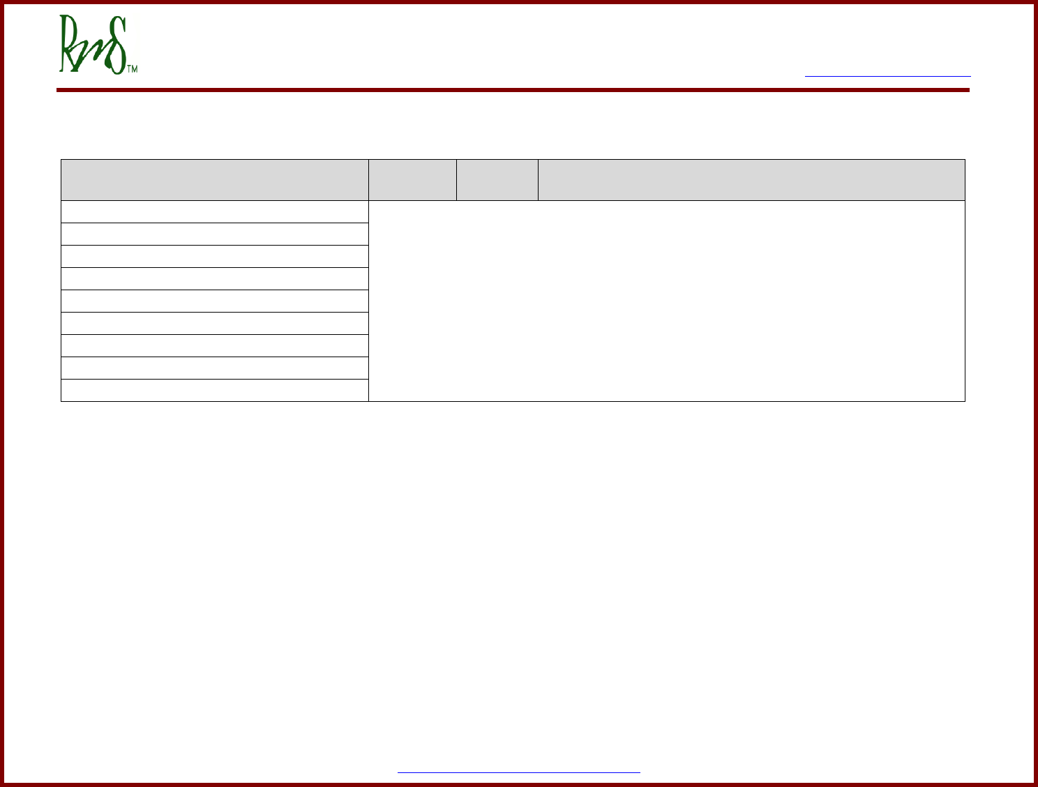
Appendix C CAN Configuration Parameters
RMS GUI
Parameter
GUI
ADDRESS
Value
Range
Description
CAN_ID_Offset_EEPROM
Please refer to the document, RMS CAN Protocol for a detailed description of all
CAN parameters.
CAN_Extended_Msg_ID_EEPROM(0=N_1=Y)
CAN_J1939_Option_Active_EEPROM
CAN_Term_Res_Present_EEPROM
CAN_Command_Message_Active_EEPROM
CAN_Bit_Rate_EEPROM_(kbps)
CAN_ACTIVE_MSGS_EEPROM_(Lo_Word)
CAN_ACTIVE_MSGS_EEPROM_(Hi_Word)
CAN_Diag_Data_Tx_Active_EEPROM
7929 SW Burns Way Phone: 503-344-5085
Suite B Fax: 503-682-9014
Wilsonville, OR 97070 sales@rinehartmotion.com
1/5/2016 RMS PM100 Software User Manual 44 of 75
Appendix D Current Parameters
RMS GUI
Parameter
GUI
ADDRESS
Value
Range
Description
IQ_Limit_EEPROM_(Amps)_x_10
0x0101
See motor
setup
manual
This parameter sets the Q-axis current limit. The Q-axis current is an
industry term for the torque producing portion of the motor current.
The current level is set in terms of peak amps. For example, to set a
level of 400 amps peak use a parameter setting of 4000.
ID_Limit_EEPROM_(Amps)_x_10
0x0102
See motor
setup
manual
This parameter sets the D-axis current limit. The D-axis current is an
industry term for the flux producing portion of the motor current. For
induction motors it is necessary to provide flux current to the motor.
For PM motors the flux is provided by the magnets. However, at high
speeds it is necessary to weaken the flux. D-axis current will be
used with PM motors to reduce the magnet flux. The current level is
set in terms of peak amps. For example, to set a level of 400 amps
peak use a parameter setting of 4000.
Ia_Offset_EEPROM
Please refer to the document, Current Offset Calibration for a detailed description on
these parameters. It is not normally necessary to make any change to these
parameters.
Ib_Offset_EEPROM
Ic_Offset_EEPROM
The total motor current is the vector determined by the Q-axis current and the D-axis current. So the total current is the square root of IQ^2 +
ID^2.

7929 SW Burns Way Phone: 503-344-5085
Suite B Fax: 503-682-9014
Wilsonville, OR 97070 sales@rinehartmotion.com
1/5/2016 RMS PM100 Software User Manual 45 of 75
Appendix E Voltage & Flux Parameters
RMS GUI
Parameter
GUI
ADDRESS
Value
Range
Description
DC_Volt_Limit_EEPROM_(V)_x_10
0x0104
0 - 10000
This parameter is used to implement a DC Bus voltage limiting
feature. The parameter should be set higher than the maximum
battery voltage.
DC_Volt_Hyst_EEPROM_(V)_x_10
0x0105
300
Used with the above parameter.
DC_UnderVolt_Thresh_EEPROM_(V)_x_10
0x0117
0 - 10000
This is the under-voltage fault threshold voltage. If it is desired that
the drive does not detect under-voltage faults the value can be set
to 0.
Veh_Flux_EEPROM_(Wb)_x_1000
0x0100
0 - 30000
This parameter sets the back EMF (flux) constant for the motor. It
will automatically default to the correct value when the motor type
is changed. Most of the time, the default value is sufficient and this
value seldom needs to be changed. The flux value is set in units of
Webers. For example to set a value of 0.1 Webers set the
parameter to 100.

7929 SW Burns Way Phone: 503-344-5085
Suite B Fax: 503-682-9014
Wilsonville, OR 97070 sales@rinehartmotion.com
1/5/2016 RMS PM100 Software User Manual 46 of 75
Appendix F Temperature Parameters
RMS GUI
Parameter
GUI
ADDRESS
Value
Range
Description
Inv_OverTemp_Limit_EEPROM_(C)_x_10
0x0106
-40 – 125 C
This parameter sets the Inverter temperature limit. The
temperature is measured from three sensors that are mounted
inside the power module. Generally the module temperature will
be about 0 – 20°C higher than the water temperature. The
temperature is set is degrees Celsius times 10 (85°C is set as
850). If the temperature exceeds this value then the inverter will
turn off and declare a fault.
Mtr_OverTemp_Limit_EEPROM_(C)_x_10
0x0121
-40 – 250 C
This parameter sets the Motor temperature limit (if the motor
has a temperature sensor). The temperature is set is degrees
Celsius times 10 (150°C is set as 1500). If the temperature
exceeds this value then the inverter will turn off and declare a
fault.
Full_Torque_Temp_EEPROM_(C)_x_10
-
-
Please refer to the table in Appendix G.
Zero_Torque_Temp_EEPROM_(C)_x_10
RTD_Selection_EEPROM_(BITS_1_0)2
-
-
Please refer to the manual, “RMS PM User Manual - Gen3
Features”.
2
This is a new feature used only for Gen-3 board which is used in all PM150 units. Please refer to the manual, “RMS PM User Manual - Gen3 Features”.
7929 SW Burns Way Phone: 503-344-5085
Suite B Fax: 503-682-9014
Wilsonville, OR 97070 sales@rinehartmotion.com
1/5/2016 RMS PM100 Software User Manual 47 of 75
G3_RTD1_100_Ohm_Gain_EEPROM_x_10000
-
-
Please refer to the manual, “RMS RTD Calibration Process”.
It is not normally necessary to make any changes to these
parameters.
G3_RTD1_100_Ohm_Offset_EEPROM_x_100
G3_RTD2_100_Ohm_Gain_EEPROM_x_10000
G3_RTD2_100_Ohm_Offset_EEPROM_x_100
G3_RTD1_1K_Ohm_Gain_EEPROM_x_10000
G3_RTD1_1K_Ohm_Offset_EEPROM_x_100
G3_RTD2_1K_Ohm_Gain_EEPROM_x_10000
G3_RTD2_1K_Ohm_Offset_EEPROM_x_100
7929 SW Burns Way Phone: 503-344-5085
Suite B Fax: 503-682-9014
Wilsonville, OR 97070 sales@rinehartmotion.com
1/5/2016 RMS PM100 Software User Manual 48 of 75
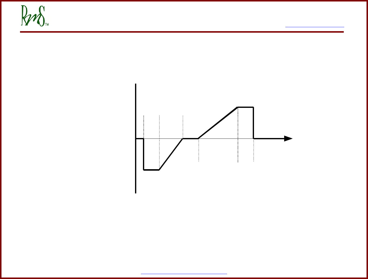
Appendix G Accelerator & Torque Parameters
The accelerator pedal input provides a torque command to the motor. The graph below details the relationship between the accelerator
input voltage and the torque command:
Below is a list of the parameters that effect how the accelerator input works. The accelerator input has a range of 0 to 500. This
corresponds to a physical range of 0 to 5.00 volts on the input. The parameters are designed for a pedal that provides a low input
voltage when the pedal is released and a higher voltage as the pedal is pressed. If the vehicle has a pedal that operates in the
opposite direction use the ACCEL PEDAL FLIPPED parameter as described below.
0
ACCEL_MIN
COAST_LO
COAST_HI
PEDAL_HI
X
X
MOTOR TORQUE LIMIT
REGEN TORQUE LIMIT
ACCEL Input
PEDAL_LO
ACCEL_MAXACCEL_MAX
TORQUE_CMD

7929 SW Burns Way Phone: 503-344-5085
Suite B Fax: 503-682-9014
Wilsonville, OR 97070 sales@rinehartmotion.com
1/5/2016 RMS PM100 Software User Manual 49 of 75
For initial setup and calibration, the accel pedal voltage can either be monitored by a volt meter, or it can be monitored by the GUI
software over the serial port.
RMS GUI
Parameter
GUI
ADDRESS
Value
Range
Description
Accel_Pedal_Flipped_EEPROM_(0=N_1=Y)
0x0114
0 or 1
If the pedal increases in voltage as it is pressed use a value of 0
(not flipped). If the pedal decreases in voltage as it is pressed use a
value of 1 (flipped). When this parameter is 1, the pedal voltage will
first be processed by the equation new_pedal_voltage = 5.00 –
old_pedal_voltage. Thus will make the pedal act the same as a
pedal that normally increases in voltage.
Pedal_Lo_EEPROM_(V)_x_100
0x0107
1 – 500
For accelerator inputs less than this value the torque command is
zero. This value should be set to a value that is lower than the
lowest possible accelerator position, but higher than zero. If the
accelerator input were to be shorted to ground the desired torque
command is zero.
Accel_Min_EEPROM_(V)_x_100
0x0108
1 – 500
For accelerator inputs between PEDAL_LO and ACCEL_MIN the
torque command is set to a constant value of REGEN TORQUE
LIMIT. Depending on the desired characteristics of the vehicle this
range could be very small.
Coast_Lo_EEPROM_(V)_x_100
0x0109
1 – 500
For accelerator inputs between ACCEL_MIN and COAST_LO the
torque command is linearly from REGEN TORQUE LIMIT to zero. If
desired this range allows the operator to control the amount of
regen torque.
Coast_Hi_EEPROM_(V)_x_100
0x010A
1 – 500
For the range between COAST_LO and COAST_HI the torque
command is zero. Normally this range would be fairly small.
Accel_Max_EEPROM_(V)_x_100
0x010B
1 – 500
For the range between COAST_HI and ACCEL_MAX the torque is
linearly increased from zero to the MOTOR TORQUE LIMIT. This
would be the normal driving range.

7929 SW Burns Way Phone: 503-344-5085
Suite B Fax: 503-682-9014
Wilsonville, OR 97070 sales@rinehartmotion.com
1/5/2016 RMS PM100 Software User Manual 50 of 75
Pedal_Hi_EEPROM_(V)_x_100
0x010C
1 – 500
For the range between ACCEL_MAX and PEDAL_HI the torque
command is held constant at MOTOR TORQUE LIMIT. PEDAL_HI
should be set above the normal range of pedal motion, but below
500.
Motor_Torque_Limit_EEPROM_(Nm)_x_10
0x0110
See Motor
Manual
This parameter sets the maximum torque that can be commanded
by the controller in motoring mode. It is active in both VSM mode
and CAN mode. However, if the current limit of the drive is reached
before the torque command has been achieved the controller will
limit on the current first. If this happens the operator will feel an
additional amount of unused pedal range at the top end. The motor
torque limit should always be set at a torque that would be lower
than or equal to the current limit. Torque value is set in Nm times
10. For example to set 300 Nm use a value of 3000.
Regen_Torque_Limit_EEPROM_(Nm)_x_10
0x0111
See Motor
Manual
This parameter sets the maximum regen torque that can be
commanded by the controller. It is active in both VSM mode and
CAN mode. In VSM mode this parameter is the maximum regen
torque that is commanded when the pedal is fully released. Torque
value is set in Nm times 10. For example to set 300 Nm use a value
of 3000.
Braking_Torque_Limit_EEPROM_(Nm)_x_10
0x0112
This parameter sets the amount of the torque applied when the
brake is active. Torque value is set in Nm times 10. For example to
set 300 Nm use a value of 3000.
Torque_Rate_Limit_EEPROM_(Nm)_x_10
0x014B
0.1 – 25.0
Nm
This parameter adjusts how quickly the torque command is allowed
to change. The parameter is set in terms of torque increment every
3 milliseconds. Torque value is set in Nm times 10.

7929 SW Burns Way Phone: 503-344-5085
Suite B Fax: 503-682-9014
Wilsonville, OR 97070 sales@rinehartmotion.com
1/5/2016 RMS PM100 Software User Manual 51 of 75
Full_Torque_Temp_EEPROM_(C)_x_10
0x015D
-40 – 250 ⁰C
Below this temperature threshold where the full torque is available.
As the motor temperature is increased from
Full_Torque_Temp_EEPROM_(C)_x_10 to
Zero_Torque_Temp_EEPROM_(C)_x_10, the allowed torque
capability is linearly decreased. This parameters should be less
than Zero_Torque_Temp_EEPROM_(C)_x_10 which should be
less than Mtr_OverTemp_Limit_EEPROM_(C)_x_10.
Zero_Torque_Temp_EEPROM_(C)_x_10
0x015E
-40 – 250 ⁰C
Temperature threshold where the torque is zeo. This value should
be less than Mtr_OverTemp_Limit_EEPROM_(C)_x_10.
The Motor_Torque_Limit_EEPROM_(Nm)_x_10 and Regen_Torque_Limit_EEPROM_(Nm)_x_10 parameters set the maximum value
of commanded torque. They will be modified internally based on motor speed as the motor cannot put out full torque over the entire
speed range.
The accelerator should be designed so that in its normal range of operation it is greater than 0 volts and less than 5 volts. The
parameters Pedal_Lo_EEPROM and Pedal_Hi_EEPROM should be set so that if the input goes to 0 or 5 the torque command goes to
zero.
These parameters allow the controller to be setup to command a pedal off amount of regen torque. This regen torque would mimic the
engine compression feel that vehicles often have.
Example Setup:
As an example let’s assume that assume that the accelerator input comes from a potentiometer. That is, the one end of the pot is
connected to AGND. The other end is connected to XDCR_PWR (+5V), and the wiper is connected to AIN1. This setup is shown in the
example application schematic.
First we need to determine the range of travel of this potentiometer. With the controller 12V turned on measure the voltage on the
wiper of the pot (AIN1). Note how the voltage changes as the pedal is pushed and released. If the voltage increases as the pedal is
pressed then the ACCEL_PEDAL_FLIPPED_EEPROM parameter needs to be set to 0. If the voltage decreases then the
ACCEL_PEDAL_FLIPPED_EEPROM parameter needs to be set to 1. Whenever the parameter is set to 1 all of the other parameter

7929 SW Burns Way Phone: 503-344-5085
Suite B Fax: 503-682-9014
Wilsonville, OR 97070 sales@rinehartmotion.com
1/5/2016 RMS PM100 Software User Manual 52 of 75
settings must be calculated as follows (parameter = 500 – actual voltage*100). For example if you desire a parameter to be set to 1.20
volts then the actual parameter setting will be 500 – 1.20*100 = 380.
For this example we will assume that the voltage increases as the pedal is pressed. So Accel_Pedal_Flipped_EEPROM will be set to
0.
First measure the wiper voltage (AIN1) when the pedal is in the fully off position. For this example let’s assume the measured value is
0.83 volts.
The Pedal_Lo_EEPROM parameter should be set to a value that is lower than this measured value. In this example let’s set it to 0.40
volts (this corresponds to Pedal_Lo_EEPROM = 40). We want to set the parameter Accel_Min_EEPROM to be equal to this measured
value (Accel_Min_EEPROM = 83). This will cause the torque to start increasing as soon as the pedal begins to be pressed.
Now measure the value of the wiper voltage (AIN1) when the pedal is fully pressed. For this example let’s assume that measured value
is 4.75 volts.
When the pedal is fully pressed we want to be commanding full torque so set the Accel_Max_EEPROM parameter to this measured
value (Accel_Max_EEPROM = 475).
The Pedal_Hi_EEPROM parameter should be set to a value that is above this measured value but less than 5.00 volts. In this example
let’s set the value to 4.90 volts (Pedal_Hi_EEPROM = 490).
The Coast_Lo_EEPROM and Coast_Hi_EEPROM parameters define a range of pedal position where the torque command will be
zero. For this example we’ll define this range to be fairly narrow and with the pedal only slightly depressed. So we will set
Coast_Lo_EEPROM to 1.10 volts (110) and Coast_Hi_EEPROM to 1.20 volts (120).
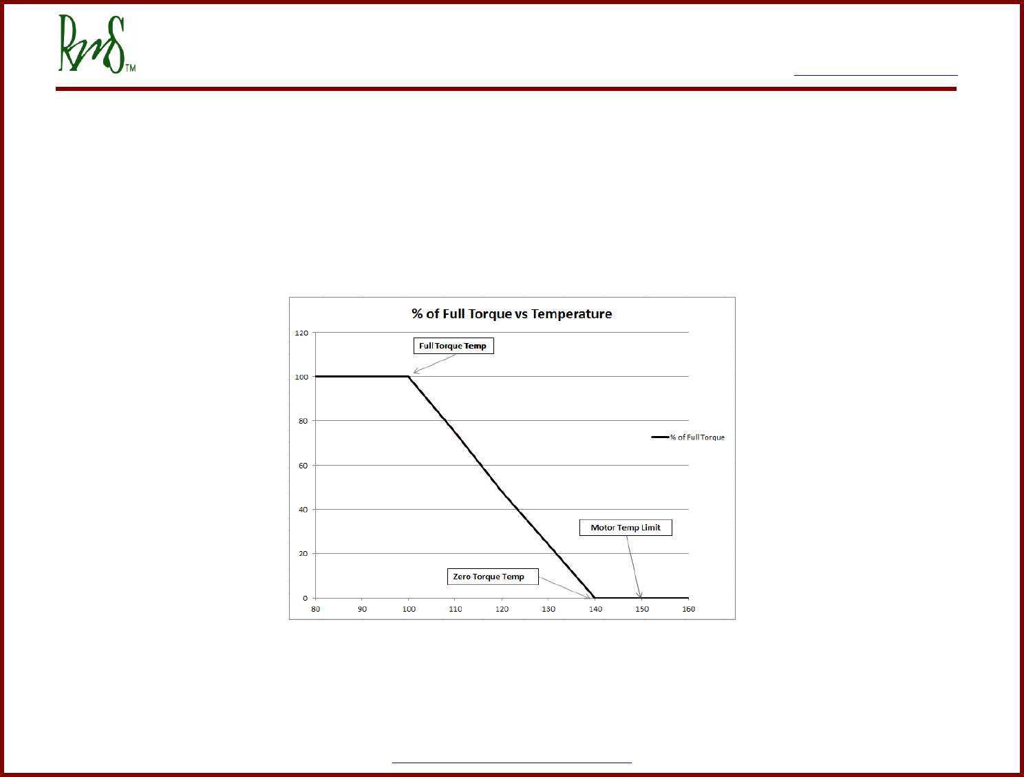
7929 SW Burns Way Phone: 503-344-5085
Suite B Fax: 503-682-9014
Wilsonville, OR 97070 sales@rinehartmotion.com
1/5/2016 RMS PM100 Software User Manual 53 of 75
Motor Over-temperature Torque Reduction
This feature allows the Torque Capability to take motor temperature into consideration. Figure G-2 shows the relationship between
Torque Capability and Motor Speed. Based on the calculation of the slope and offset of the line from
Full_Torque_Temp_EEPROM_(C)_x_10 to Zero_Torque_Temp_EEPROM_(C)_x_10, the new torque capability is reduced by a factor
of (slope * Motor Temperature + offset). Zero_Torque_Temp_EEPROM_(C)_x_10 should be less than
Zero_Torque_Temp_EEPROM_(C)_x_10, which should be less than Mtr_OverTemp_Limit_EEPROM_(C)_x_10.
Figure G-2
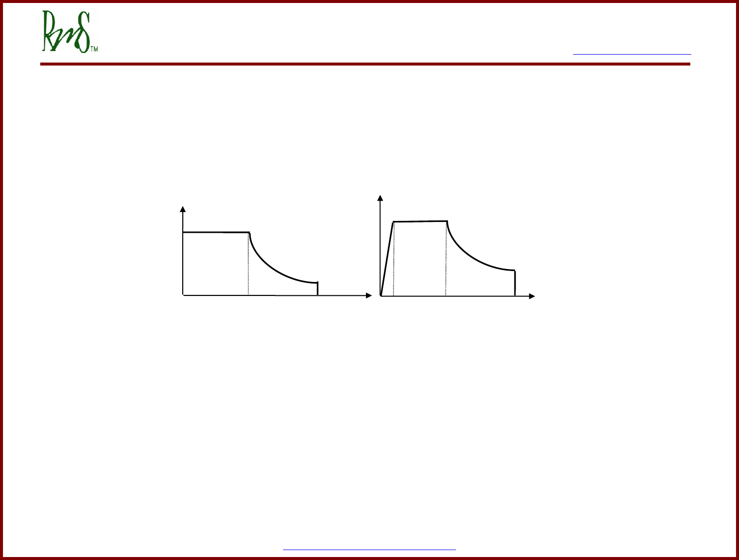
7929 SW Burns Way Phone: 503-344-5085
Suite B Fax: 503-682-9014
Wilsonville, OR 97070 sales@rinehartmotion.com
1/5/2016 RMS PM100 Software User Manual 54 of 75
Appendix H Speed Parameters
Torque Capability Curve is a function of Motor Speed, a feedback parameter from the Motor Control. Figure H-1 shows the relationship
between Torque Capability and Motor Speed:
There are two types of Torque Capability curves, Motor Torque Capability and REGEN Torque Capability. The two quantities
MOTOR_TRQ_LMT and REGEN_TRQ_LMT (see previous section) define the maximum values for these curves.
When motors exceed a certain speed the amount of torque that they can produce will drop. The BREAK_SPEED parameter defines a
curve that represents this drop in torque. The curve is defined BREAK_SPEED divided by actual speed time the torque limit.
The purpose of this curve is to reduce the torque limit so that the accel input does not try and command torque that the motor cannot
deliver. If CAN mode is used or other torque limit means the BREAK_SPEED parameter can be set equal to MAX_SPEED to eliminate
this effect.
Figure H-1 – Torque Capability vs. Motor Speed
Motor Speed
REGEN_TRQ_LM
T
REGEN Torque
MAX_SPEED
BREAK_SPEED
FADE_SPEED
Motor Torque
MOTOR_TRQ_LM
T
MAX_SPEED
BREAK_SPEED
7929 SW Burns Way Phone: 503-344-5085
Suite B Fax: 503-682-9014
Wilsonville, OR 97070 sales@rinehartmotion.com
1/5/2016 RMS PM100 Software User Manual 55 of 75
The following table lists the calibration parameters that pertain to the above graphs. The values of these parameters come from the
EEPROM and are set via the DSPGui software.
RMS GUI
Parameter
GUI
ADDRESS
Value
Range
Description
Max_Speed_EEPROM
0x010F
1 - 30000
RPM
This parameter sets the maximum allowable speed. If the speed is
above this value the torque command will be reduced to zero.
(Default value: 10,000 RPM)
Regen_Fade_Speed_EEPROM
0x010D
1 - 30000
RPM
This parameter sets at which the amount of regen torque available
is reduced. (Default value: 200 RPM)
Break_Speed_EEPROM
0x010E
1 - 30000
RPM
This parameter sets the speed at which the maximum torque
command is reduced to compensate for a reduction of available
torque due to field weakening. (Default value: 3000 RPM)
Speed_Rate_Limit_EEPROM_(RPM/sec)
0x014E
100 – 5100
RPM/sec
This parameter adjusts how quickly the speed command is allowed
to change. The parameter is set in terms of speed increment every
second. Default value is set to 100 RPM/sec. This parameter has
no effect on torque mode operation.
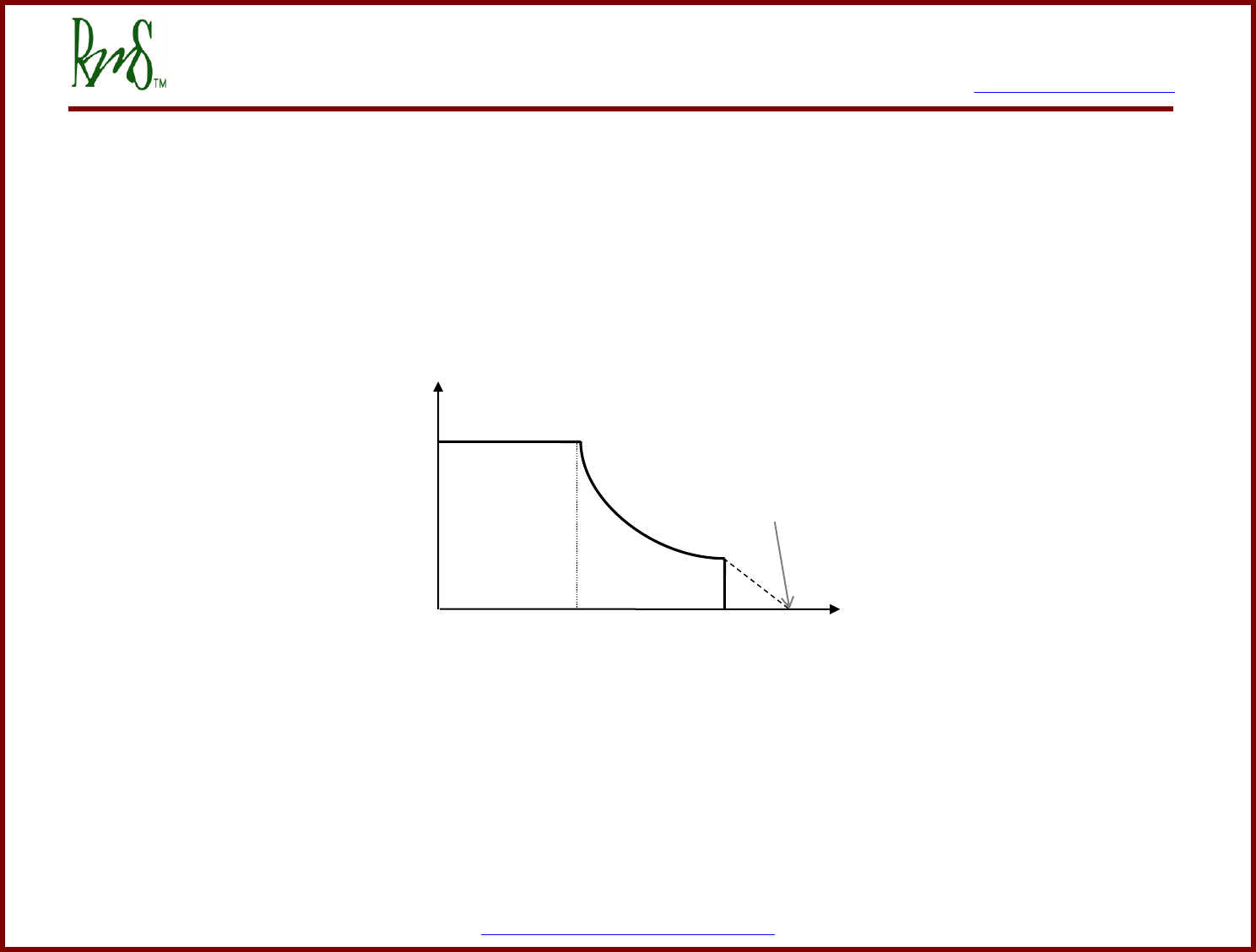
7929 SW Burns Way Phone: 503-344-5085
Suite B Fax: 503-682-9014
Wilsonville, OR 97070 sales@rinehartmotion.com
1/5/2016 RMS PM100 Software User Manual 56 of 75
Max Speed Torque Reduction
This feature allows the Torque Capability to take maximum speed into consideration. Figure H-2 shows the relationship between
Torque Capability and Motor Speed. When the speed goes above the Max Speed, it begins a linear reduction in the torque towards
zero. The slope of the reduction is such that at (Max Speed * 1.02) the torque is zero. The torque slope would be calculated based on
the available torque at max speed. This reduction of torque is applied to motoring as well as regen.
Figure H-2
Motor Torque Capability
MOTOR_TRQ_LMT
MAX_SPEED
BREAK_SPEED
1.02 x MAX_SPEED
7929 SW Burns Way Phone: 503-344-5085
Suite B Fax: 503-682-9014
Wilsonville, OR 97070 sales@rinehartmotion.com
1/5/2016 RMS PM100 Software User Manual 57 of 75
Appendix I PID Regulator Parameters
The motor controller is some instances use a torque regulator and a speed regulator. For non IPM type motors the torque regulator is
used all of the time. The speed regulator is only used if the controller is in Speed Mode (see Run Mode parameter). The regulators are
both based on the classic PID architecture. Each of these regulators has 4 gain values associated with them. They are:
Kp – Proportional Gain
Ki – Integral Gain
Kd – Derivative Gain
Klp – Low Pas filter gain
Generally it is not necessary to adjust these gains. In some instances if the torque regulator seems unstable it may be necessary to
adjust the value. Please contact RMS if this situation arises.
RMS GUI
Parameter
GUI
ADDRESS
Value
Range
Description
Kp_Torque_EEPROM_x_10000
0x12D
0 – 6.5535
Torque Regulator proportional gain. This is a times 10000 value.
Multiply the value within the valid range by 10000 before
programming it using RMS GUI application.
Ki_Torque_EEPROM_x_10000
0x012E
0 – 6.5535
Torque Regulator integral gain. This is a times 10000 value.
Multiply the value within the valid range by 10000 before
programming it using RMS GUI application.
Kd_Torque_EEPROM_x_100
0x012F
0 – 655.35
Torque regulator derivative gain. This is a times 100 value. Multiply
the value within the valid range by 100 before programming it using
RMS GUI application.
Klp_Torque_EEPROM_x_10000
0x0130
0 – 6.5535
Torque regulator low pass filter gain. This is a times 10000 value.
Multiply the value within the valid range by 10000 before
programming it using RMS GUI application.
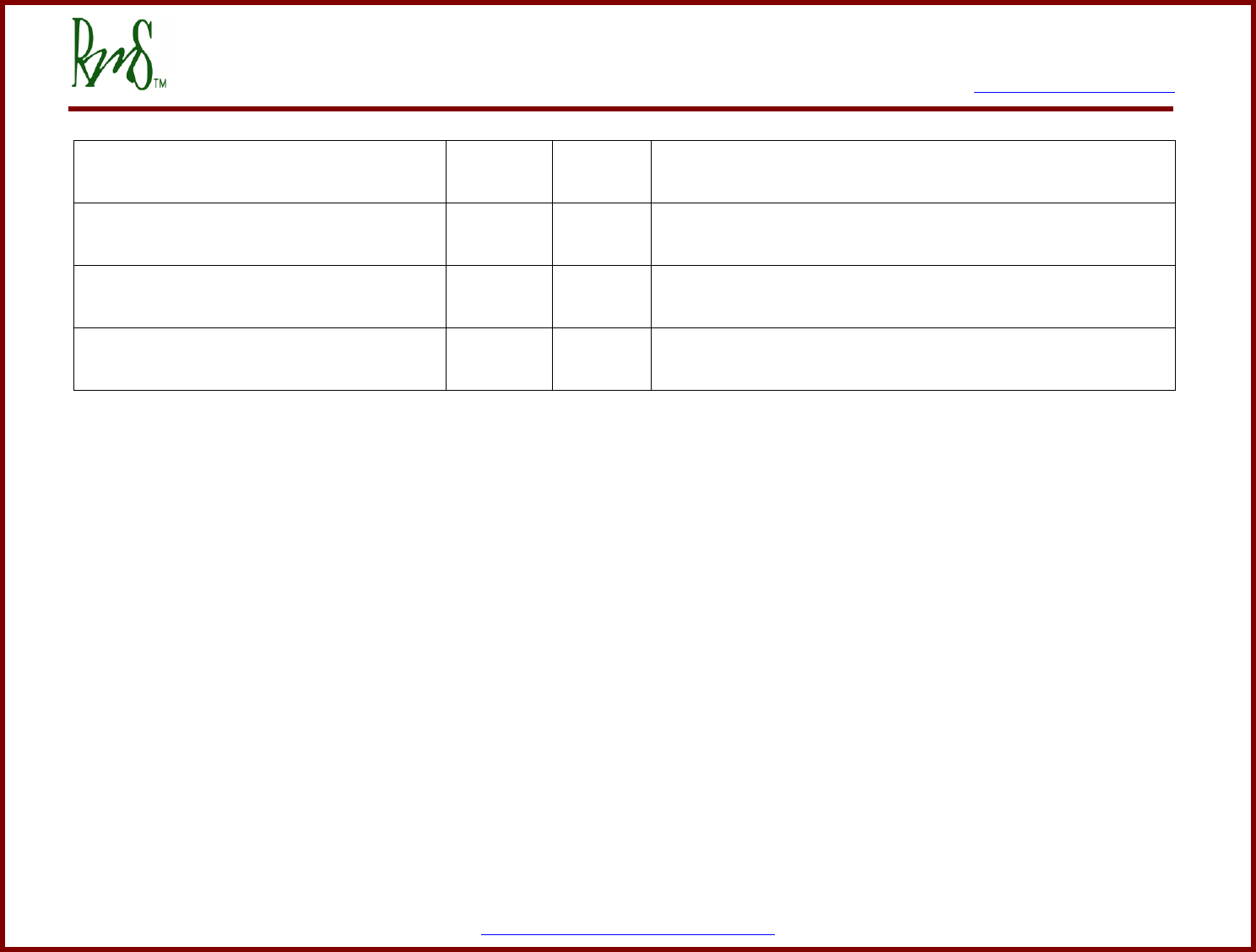
7929 SW Burns Way Phone: 503-344-5085
Suite B Fax: 503-682-9014
Wilsonville, OR 97070 sales@rinehartmotion.com
1/5/2016 RMS PM100 Software User Manual 58 of 75
Kp_Speed_EEPROM_x_100
0x122
0 – 655.35
Speed regulator proportional gain. This is a times 100 value.
Multiply the value within the valid range by 100 before programming
it using RMS GUI application.
Ki_Speed_EEPROM_x_10000
0x0123
0 – 6.5535
Speed regulator integral gain. This is a times 10000 value. Multiply
the value within the valid range by 10000 before programming it
using RMS GUI application.
Kd_Speed_EEPROM_x_100
0x0124
0 – 655.35
Speed regulator derivative gain. This is a times 100 value. Multiply
the value within the valid range by 100 before programming it using
RMS GUI application.
Klp_Speed_EEPROM_x_10000
0x0125
0 – 6.5535
Speed regulator low pass gain. This is a times 10000 value.
Multiply the value within the valid range by 10000 before
programming it using RMS GUI application.
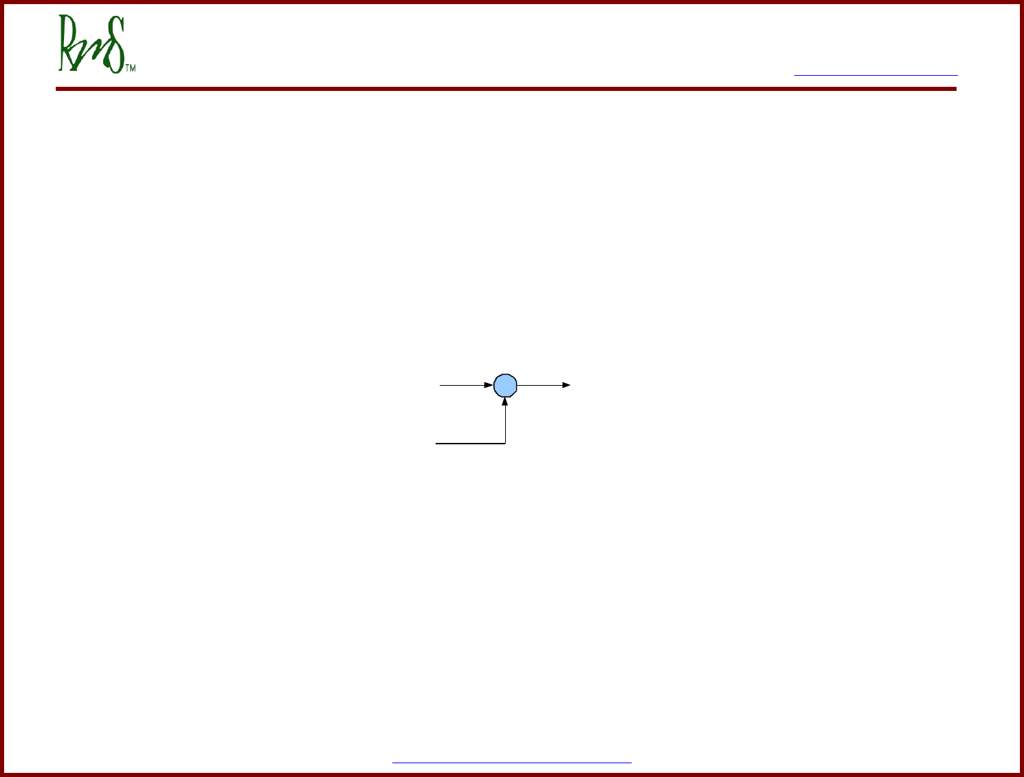
7929 SW Burns Way Phone: 503-344-5085
Suite B Fax: 503-682-9014
Wilsonville, OR 97070 sales@rinehartmotion.com
1/5/2016 RMS PM100 Software User Manual 59 of 75
Appendix J Shudder Compensation Parameters
Using an electric motor in a vehicle can expose driveline resonances (shudder) that might not normally be noticed in an ICE vehicle.
Typically these resonances occur at very low speeds and moderate torque levels.
The shudder compensation system implemented on the PMxxx family converters provides a mechanism for the user to try and
counteract the resonance.
The basic idea is to provide a compensating torque that tries to drive any AC components of the speed to zero. That is if the speed is
found to be varying (oscillating) and additional torque is added to the command that attempts to remove the oscillation.
Figure 1: Shudder Torque Implementation
Figure 1 shows the mechanism for including the shudder compensation torque into the torque command. If shudder compensation is
enabled the shudder torque value will be added to the normal torque command that comes from the VSM (vehicle state machine) or
from a CAN command.
The mechanism for calculating the correct value of shudder torque compensation is shown in Figure 2. The compensation algorithm
compares the electrical speed of the motor to a filtered version of the speed. The output of the comparison is then clamped to a value
between +TCLAMP and –TCLAMP. This value is then phased out based on two speed parameters, Shudder Speed Lo and Shudder
Speed Hi.
+
+
Torque Command
From VSM or CAN
Shudder
Torque in
per unit
Torque Command
to Main Control
Loop
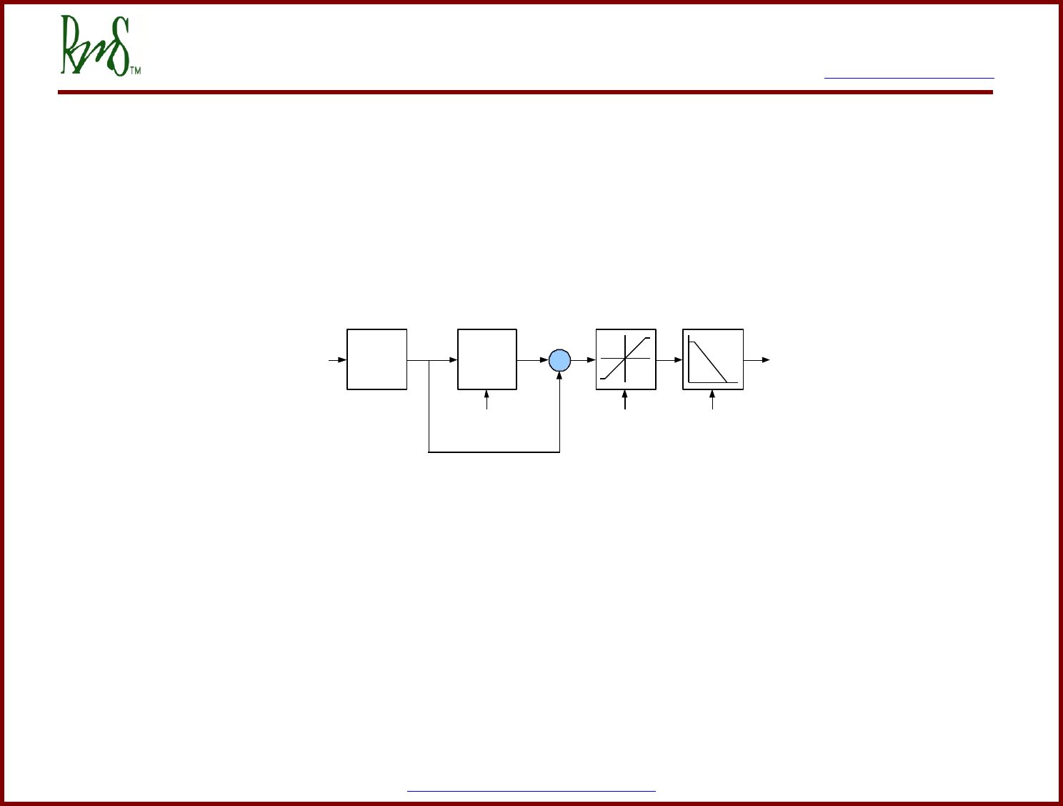
7929 SW Burns Way Phone: 503-344-5085
Suite B Fax: 503-682-9014
Wilsonville, OR 97070 sales@rinehartmotion.com
1/5/2016 RMS PM100 Software User Manual 60 of 75
Figure 2: Shudder Compensation Algorithm
Kp_
shudder
- Electrical speed
in per unit
Low-Pass
Filter
Shudder Filter
Frequency
-
+
TCLAMP Shudder Speed Lo
& Shudder Speed Hi
Shudder
Torque in
per unit

7929 SW Burns Way Phone: 503-344-5085
Suite B Fax: 503-682-9014
Wilsonville, OR 97070 sales@rinehartmotion.com
1/5/2016 RMS PM100 Software User Manual 61 of 75
RMS GUI
Parameter
GUI
ADDRESS
Value
Range
Description
Shudder_Compensation_Enable_EEPROM
0x0134
0, 1
This parameter is used to enable or disable the shudder compensation
system. The default value is 0 for disabled. To enable the system change
the value to a 1.
Kp_Shudder_EEPROM_x_100
0x0135
0.1 – 50
This parameter defines the gain of the shudder compensation controller.
This parameter has a scaling factor of 100. Thus a setting of 100 gives a
gain of 1.00. The default value of the gain is 20 (or a parameter setting of
2000). Testing of the vehicle system will be necessary to determine the best
gain setting.
TCLAMP_Shudder_EEPROM_(Nm)_x_10
0x0136
0 – 100 Nm
This parameter defines the maximum amount of compensation torque that
will be added to the commanded torque. The parameter has a scaling factor
of 10. Thus a setting of 10 gives a torque of 1.0 Nm. The default value is
19.9 Nm.
Shudder_Filter_Freq_EEPROM_(Hz)_x_10
0x0137
0.1 – 20 Hz
This parameter determines the frequency of the low-pass filter used in the
shudder compensation algorithm (See Figure 2). The parameter has a
scaling factor of 10. Thus a setting of 10 gives a frequency of 1.0 Hz. The
default value of the parameter is 3.0 Hz (setting of 30). The filter frequency
should be lower than the frequency of resonance of the drive-line. Again it
may be necessary to perform testing on the vehicle to determine the correct
value.
Shudder_Speed_Fade_EEPROM_(RPM)
0x0140
0 – 32000
RPM
This parameters is used to define the linear phase in of the shudder torque
compensation at lower speeds starting from 0 RPM. Between this value and
Shudder_Speed_Lo, full value of shudder torque is used. This value must be
lower than Shudder_Speed_Lo value.
Shudder_Speed_Lo_EEPROM_(RPM)
0x0138
These two parameters are used to define the phase out of the shudder
torque compensation at higher speeds. Both parameters are in RPM. Below
Shudder_Speed_Lo the full value of the shudder torque is used. Between
Shudder_Speed_Lo and Shudder_Speed_Hi the shudder torque is linearly
decreased. Above Shudder_Speed_Hi the shudder torque value is 0. At
higher speeds drive-line compensation may not be necessary. These two
parameters allow the system to be phased out at higher speeds. The default
values are 300 rpm for Shudder_Speed_Lo and 400 rpm for
Shudder_Speed_Hi. Shudder_Speed_Lo must be less than
Shudder_Speed_Hi.
Shudder_Speed_Hi_EEPROM_(RPM)
0x0139

7929 SW Burns Way Phone: 503-344-5085
Suite B Fax: 503-682-9014
Wilsonville, OR 97070 sales@rinehartmotion.com
1/5/2016 RMS PM100 Software User Manual 62 of 75
Appendix K Brake Parameters
The Brake input works in two modes. These modes include Switch mode and Brake Pot mode. The switch mode allows for only a
single value of braking torque (regen). The Brake Pot mode allows for a variable amount of braking torque. Normally, the Brake Pot
would be connected to the brake pedal of a vehicle and would change in voltage relative to the amount of brake pedal applied.
Brake Switch Mode:
In this mode, the digital input DIN3 is used. When entering braking mode, the controller ramps the torque according to the
regen_ramp_rate parameter. The graph below explains the relationship between time and REGEN torque when the brake input is
pressed:
Where T0 is the start time (in seconds) which is always 0 in this case, T1 is the ramp period indicated by the equivalent EEPROM
parameter in seconds, Torque0 is value of torque that is currently produced, and Torque1 is the VSM Braking Torque Limit
In order to use the brake in switch mode, following parameters need to be set as follows:
T0 = 0
T1
Torque0
Torque1
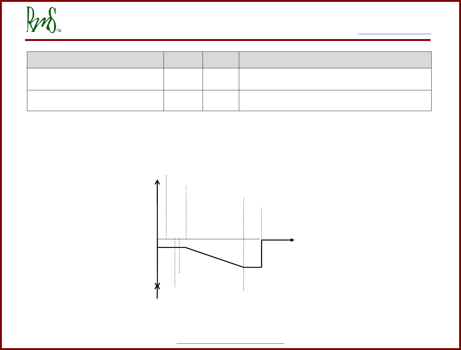
7929 SW Burns Way Phone: 503-344-5085
Suite B Fax: 503-682-9014
Wilsonville, OR 97070 sales@rinehartmotion.com
1/5/2016 RMS PM100 Software User Manual 63 of 75
RMS GUI
Parameter
GUI
ADDRESS
Value
Range
Description
Brake_Mode_EEPROM_(0=SWITCH_1=POT)
0x013A
0 or 1
This parameter selects the mode for the brake input.
0: Brake Switch Mode
1: Brake Pot Mode
Regen_Ramp_Rate_EEPROM_(Sec)_x_1000
0x0133
3 - 20000
This value of time is entered in milliseconds. This is the time in which
REGEN torque value ramps down to the braking torque limit. This time can
also be represented as |T1 – T0|.
Brake Pot Mode:
The graph below details the relationship between the brake input voltage and the REGEN torque command:
BRAKE_THRESH_LO
BRAKE_THRESH_HI
BRAKE_LO
BRAKE_MIN
BRAKE_MAX
BRAKE_HI
BRAKE Input
0
Braking Torque
Limit
TORQUE_CMD
Regen Torque
Limit

7929 SW Burns Way Phone: 503-344-5085
Suite B Fax: 503-682-9014
Wilsonville, OR 97070 sales@rinehartmotion.com
1/5/2016 RMS PM100 Software User Manual 64 of 75
The brake input has a range of 0 to 500. This corresponds to a physical range of 0 to 5.00 volts on the input. The parameters are designed
for a pedal that provides a low input voltage when the pedal is released and a higher voltage as the pedal is pressed. If the vehicle has a
pedal that operates in the opposite direction use the BRAKE PEDAL FLIPPED parameter as described below.
For initial setup and calibration, the brake pedal voltage can either be monitored by a volt meter, or it can be monitored by the GUI
software over the serial port.
Below is a list of the parameters that effect how the brake input works.
RMS GUI
Parameter
GUI
ADDRESS
Value
Range
Description
Brake_Mode_EEPROM_(0=SWITCH_1=POT)
0x013A
0 or 1
This parameter selects the mode for the brake input.
0: Brake Switch Mode
1: Brake Pot Mode
Brake_Switch_Bypassed_EEPROM
0x15F
0 – 2
This parameter decides if the brake input should be ignored or not in
VSM mode:
0: Do not ignore brake input (process as usual)
1: Ignore brake input for starting the vehicle and for regen
2: Ignore brake input only for starting the vehicle
Brake_Pedal_Flipped_EEPROM
0x013F
0 or 1
If the pedal increases in voltage as it is pressed use a value of 0 (not
flipped). If the pedal decreases in voltage as it is pressed use a
value of 1 (flipped). When this parameter is 1, the pedal voltage will
first be processed by the equation new_pedal_voltage = 5.00 –
old_pedal_voltage. Thus will make the pedal act the same as a
pedal that normally increases in voltage.
Brake_Lo_EEPROM_(V)_x_100
0x013B
1 – 500
For brake inputs less than this value the torque command is zero.
This value should be set to a value that is lower than the lowest
possible brake position, but higher than zero. If the brake input were
to be shorted to ground the desired torque command is zero. Below
this value, Brake Input Short Fault is set.

7929 SW Burns Way Phone: 503-344-5085
Suite B Fax: 503-682-9014
Wilsonville, OR 97070 sales@rinehartmotion.com
1/5/2016 RMS PM100 Software User Manual 65 of 75
Brake_Min_EEPROM_(V)_x_100
0x013C
1 – 500
For brake inputs less than this value, the torque command is held at
0.
Brake_Max_EEPROM_(V)_x_100
0x013D
1 – 500
For brake inputs between BRAKE_MIN and BRAKE_MAX, the
torque command is linearly decreased from 0 to Braking Torque
Limit.
Brake_Hi_EEPROM_(V)_x_100
0x013E
1 – 500
For the range between BRAKE_MAX and BRAKE_HI the torque
command is held constant at Braking Torque Limit. BRAKE_HI
should be set above the normal range of pedal motion, but below
500. Above this value, Brake Input Open Fault is set.
Brake_Thresh_Lo_EEPROM_(V)_x_100
0x0161
1 – 500
This value is supposed to be between
Brake_Lo_EEPROM_(V)_x_100 and
Brake_Min_EEPROM_(V)_x_100. Below this threshold, brake is
considered inactive (OFF).
Brake_Thresh_Hi_EEPROM_(V)_x_100
0x0162
1 – 500
This value is supposed to be between
Brake_Lo_EEPROM_(V)_x_100 and
Brake_Min_EEPROM_(V)_x_100. This value should be greater than
Brake_Thresh_Lo_EEPROM_(V)_x_100 to provide some hysteresis
for turning the brake switch on and off. Above this threshold, brake is
considered active (ON).
7929 SW Burns Way Phone: 503-344-5085
Suite B Fax: 503-682-9014
Wilsonville, OR 97070 sales@rinehartmotion.com
1/5/2016 RMS PM100 Software User Manual 66 of 75
Appendix L GUI Display Parameters
The GUI provides the ability to monitor several operation parameters of the controller. It is also helpful for checking connections to the
controller. Items can be added from the Item list to the Watch window to view the parameter.
RMS GUI Parameter
Description
Run_Command(Trq=0_Spd=1)
Displays the current command mode (Torque control or Speed control).
Commanded_Speed_(RPM)
Shows the Commanded speed if the controller is in Speed mode.
Feedback_Speed_(RPM)
Shows the motor speed as calculated from particular motor position feedback sensor used for the motor
type (e.g. encoder/resolver).
Commanded_Torque_(Nm)_x_10
The commanded torque is displayed if the controller is in torque control mode
Feedback_Torque_(Nm)_x_10
This is the motor torque as calculated by the controller. The torque is calculated based on motor
currents and the parameters of the motor. If the motor is running in reverse the Feedback Torque will
have the opposite sign to the Commanded Torque.
Voltage_Feedback_Speed_(RPM)
This parameter shows the motor speed as calculated from measuring the back EMF of a PM motor. This
parameter will only be valid if there is sufficient back EMF to generate a measurable voltage and the
motor is not enabled. It is useful to ensure that motor phasing matches the resolver feedback (same
direction/speed).
Torque_Shudder_(Nm)_x_10
Amount of torque compensation that is being applied when using the Shudder compensation feature.
V_DC_Filtered_(Volts)_x_10
DC Bus Voltage measurement.
V_MAG_Filtered_(Volts)_x_10
The magnitude of the output voltage being applied to the motor. This is represented in line to neutral
peak volts.
SW_Over_Voltage_(Volts)_x_10
A hard-coded value for over-voltage threshold this is used during pre-charge process and during normal
operation for over-voltage detection.
I_DC_Filtered_(Amps)_x_10
The DC Bus current. The controller can only calculate this value as it does not actually measure the DC
bus current. The calculation is based on an estimate of the motor power and the DC Bus voltage.
I_MAG_Filtered_(Amps)_x_10
The motor phase current magnitude. This is the peak value of the current (not RMS).
SW_Over_Current_(Amps)_x_10
A hard-coded value for over-current threshold this is used during normal operation for over-current
detection.

7929 SW Burns Way Phone: 503-344-5085
Suite B Fax: 503-682-9014
Wilsonville, OR 97070 sales@rinehartmotion.com
1/5/2016 RMS PM100 Software User Manual 67 of 75
Motor_Temp_(C)_x_10
Shows the motor temperature if available. The sensor used is selected automatically via the motor type.
Some motors do not have a sensor selected and this will display 0 then.
Mod_A_Temp_(C)_x_10
The temperature of the sensor embedded in Phase A of the power module.
Mod_B_Temp_(C)_x_10
Phase B
Mod_C_Temp_(C)_x_10
Phase C
PCB_Temp_(C)_x_10
Temperature of the control board PCB.
GDB_Temp_(C)_x_10
Temperature of the gate driver board PCB (Gen-2 boards only).
GDB_1_Temp_(C)_x_10
Temperature of the gate driver board PCB 1 (Gen-3 boards only).
GDB_2_Temp_(C)_x_10
Temperature of the gate driver board PCB 2 (Gen-3 boards only).
GDB_3_Temp_(C)_x_10
Temperature of the gate driver board PCB 3 (Gen-3 boards only).
RTD1_Temp_(C)_x_10
Temperature of the sensor hooked to the RTD1 input.
RTD2_Temp_(C)_x_10
Temperature of the sensor hooked to the RTD2 input.
RTD3_Temp_(C)_x_10
Temperature of the sensor hooked to the RTD3 input (Gen-2 board only).
RTD4_Temp_(C)_x_10
Temperature of the sensor hooked to the RTD4 input (Gen-2 board only).
RTD5_Temp_(C)_x_10
Temperature of the sensor hooked to the RTD5 input (Gen-2 board only).
ID_Bits
3 =Gen-2 board
2 =Gen-3 board
Inverter_Mode
The Inverter State, see description in section 11.4
VSM_State
The VSM State, see description in section 11
Inverter_Enable
Displays a 1 when the inverter is enable, 0 if disabled.
Vehicle_Direction
Shows the commanded vehicle direction, 1 = Forward, 0 = Not commanded, -1 = Reverse
Ignition_Input
Shows the state of DIN5, 1 = asserted, 0 = deasserted.
Start_Input
Shows the state of DIN6, 1 = asserted, 0 = deasserted.
Brake_Switch
Shows the state of DIN3, 1 = asserted, 0 = deasserted.
Forward_Switch
Shows the state of DIN1, 1 = asserted, 0 = deasserted.
Reverse_Switch
Shows the state of DIN2, 1 = asserted, 0 = deasserted.
Regen_Disable_Switch
Shows the state of DIN4, 1 = asserted, 0 = deasserted.

7929 SW Burns Way Phone: 503-344-5085
Suite B Fax: 503-682-9014
Wilsonville, OR 97070 sales@rinehartmotion.com
1/5/2016 RMS PM100 Software User Manual 68 of 75
OK_Output_Status
Shows the state of RLY3, 1 = asserted, 0 = deasserted.
Precharge_Output_Status
Shows the state of RLY1, 1 = asserted, 0 = deasserted.
Main_Output_Status
Shows the state of RLY2, 1 = asserted, 0 = deasserted.
Fault_Output_Status
Shows the state of RLY4, 1 = asserted, 0 = deasserted.
Hall_Input_1_Status
Shows the status of Hall Input 1
Hall_Input_2_Status
Shows the status of Hall Input 2
Hall_Input_3_Status
Shows the status of Hall Input 3
Encoder_Input_A_Status
Shows the status of Encoder Input A
Encoder_Input_B_Status
Shows the status of Encoder Input B
Encoder_Input_Z_Status
Shows the status of Encoder Input Z
SAT_Fault_Output_Status
Shows the status of HW Desaturation fault, 0=asserted, 1=deaaserted
OC_Fault_Output_Status
Shows the status of HW Over-current fault, 0=asserted, 1=deaaserted
VSM_Accel_Filtered
Shows the voltage applied to AIN1, 0 = 0 volts, 500 = 5.0 volts
VSM_Brake_Filtered
Shows the voltage applied to AIN3, 0 = 0 volts, 500 = 5.0 volts
Power_on_Timer_3ms_(Hi_byte)
The controller keeps a count of how many 3ms intervals have occurred since power was applied. It is
represented as a 32 bit number.
Power_on_Timer_3ms_(Lo_byte)
See above.
Sin_corr_(V)_x_100
If used, the reading of the resolver SIN input. Display shows the peak value of the input.
Cos_corr_(V)_x_100
If used, the reading of the resolver COS input. Display shows the peak value of the input.
Motor_Angle_(DEG)_x_10
Shows the rotational position of the motor shaft. Can be used to verify encoder or resolver operation.
Delta_Resolver_In_Fil_(DEG)_x_10
This parameter is used for calibration of the resolver offset. It shows the offset between the back EMF
angle and the resolver angle. Only valid if the motor is not enabled.
Gamma_Adjust_(Deg)_x_10
This is a command parameter. The value can be adjusted by typing the new data in the GUI. This
parameter is used with the resolver calibration procedure. This parameter is an offset angle added to the
resolver feedback angle. The parameter will reset to the EEPROM whenever the power is cycled to the
controller.
Go back to the section (CTRL + Click), “Monitored Parameters View (via GUI Memory View)”

7929 SW Burns Way Phone: 503-344-5085
Suite B Fax: 503-682-9014
Wilsonville, OR 97070 sales@rinehartmotion.com
1/5/2016 RMS PM100 Software User Manual 69 of 75
Appendix M POST Faults
POST Fault
Fault Indicator
Number of Blinks
Fault Description
Hardware Gate/Desaturation Fault
5
A hardware de-saturation fault occurs for any of the following conditions:
The current exceeds normal level and causes short-circuit in an IGBT
An IGBT circuit is bad
An over-voltage condition occurs on DC bus
Currently, this fault cannot be cleared using the ‘Clear Fault Command’. In
order to clear this fault, inverter power must be recycled.
HW Over-current Fault
5
This fault occurs when any of the current sensors detect an over-current condition
which could be positive or negative. All six over-current faults are ORed together
to cause the HW over-current fault.
Accelerator Shorted
4
Accelerator input voltage is less than the value in EEPROM parameter,
Pedal_Lo_EEPROM_(V)_x_100.
Accelerator Open
4
Accelerator input voltage is more than the value in EEPROM parameter,
Pedal_Hi_EEPROM_(V)_x_100.
Current Sensor Low
3
Current sensor reading is lower than the hard-coded value (-22.5 Amps) set for
this fault.
Current Sensor High
3
Current sensor reading is higher than the hard-coded value (22.5 Amps) set for
this fault.
Module Temperature Low
1
This fault is currently not active.
Module Temperature High
1
One or more of the three module temperatures are above 125 C.
Control PCB Temperature Low
1
PCB temperature is below -24 C.
Control PCB Temperature High
1
PCB temperature has exceeded 125 C.
Gate Drive PCB Temperature Low
1
GDB temperature is below -24 C.
Gate Drive PCB Temperature High
1
GDB temperature has exceeded 125 C.
5V Sense Voltage Low
2
5V Sense reading is too low
5V Sense Voltage High
2
5V Sense reading is too high

7929 SW Burns Way Phone: 503-344-5085
Suite B Fax: 503-682-9014
Wilsonville, OR 97070 sales@rinehartmotion.com
1/5/2016 RMS PM100 Software User Manual 70 of 75
12V Sense Voltage Low
2
12V Sense reading is too low
12V Sense Voltage High
2
12V Sense reading is too high
2.5V Sense Voltage Low
2
2.5V Sense reading is too low
2.5V Sense Voltage High
2
2.5V Sense reading is too high
1.5V Sense Voltage Low
2
1.5V Sense reading is too low
1.5V Sense Voltage High
2
1.5V Sense reading is too high
DC Bus Voltage High
6
During pre-charge, DC voltage is above the hard-coded SW over-voltage limit.
SW over-voltage limit can be checked from the monitored parameter list by
adding SW_Over_Voltage_(Volts)_x_10 to the watch list.
DC Bus Voltage Low
6
DC bus voltage is below 100-V.
Pre-charge Timeout
6
DC bus voltage is not charging at the rate of 2.7 V/50 msec and 3 seconds have
elapsed.
Pre-charge Voltage Failure
6
After pre-charge is complete, DC voltage has changed by more than 10-V within
15 msec.
EEPROM Checksum Invalid
7
EEPROM checksum is not valid.
EEPROM Data Out of Range
7
This fault is currently not active.
EEPROM Update Required
7
The number of EEPROM parameters has changed (most of the time increased),
check the new parameters and set appropriate values.
Brake Shorted
8
Brake input voltage is less than the value in EEPROM parameter,
Brake_Lo_EEPROM_(V)_x_100.
Brake Open
8
Brake input voltage is more than the value in EEPROM parameter,
Brake_Hi_EEPROM_(V)_x_100.
Go back to the section (CTRL + Click), “Power on Self-Test (POST):”

7929 SW Burns Way Phone: 503-344-5085
Suite B Fax: 503-682-9014
Wilsonville, OR 97070 sales@rinehartmotion.com
1/5/2016 RMS PM100 Software User Manual 71 of 75
Appendix N Run Faults
RUN Fault
Fault Indicator
Number of Blinks
Fault Description
Motor Over-speed Fault
6
Motor speed is above the value in EEPROM parameter,
Motor_Overspeed_EEPROM_(RPM)
Over-current Fault
3
One or more of the three phase currents is above the hard-coded SW over-
current limit. SW over-current limit can be checked from the monitored parameter
list by adding SW_Over_Current_(Amps)_x_10 to the watch list.
Over-voltage Fault
2
Filtered value of DC voltage is above the hard-coded SW over-voltage limit. SW
over-voltage limit can be checked from the monitored parameter list by adding
SW_Over_Voltage_(Volts)_x_10 to the watch list.
Inverter Over-temperature Fault
1
One or more of the three module temperatures are above the value in EEPROM
parameter, Inv_OverTemp_Limit_EEPROM_(C)_x_10.
Accelerator Input Shorted Fault
4
Accelerator input is below the value in EEPROM parameter,
Pedal_Lo_EEPROM_(V)_x_100.
Accelerator Input Open Fault
4
Accelerator input is above the value in EEPROM parameter,
Pedal_Hi_EEPROM_(V)_x_100.
Direction Command Fault
7
Both directions forward and reverse are active at the same time.
This fault has been de-activated.
Inverter Response Time-out Fault
8
Inverter has not been enabled within 2 minutes of receiving the inverter enable
command either through VSM or CAN.
Hardware Gate/Desaturation Fault
5
A hardware de-saturation fault occurs for any of the following conditions:
The current exceeds normal level and causes short-circuit in an IGBT
An IGBT circuit is bad
An over-voltage condition occurs on DC bus
Currently, this fault cannot be cleared using the ‘Clear Fault Command’. In
order to clear this fault, inverter power must be recycled.
Hardware Over-current Fault
5
This fault occurs when any of the current sensors detect an over-current condition
which could be positive or negative. All six over-current faults are ORed together
to cause the HW over-current fault.

7929 SW Burns Way Phone: 503-344-5085
Suite B Fax: 503-682-9014
Wilsonville, OR 97070 sales@rinehartmotion.com
1/5/2016 RMS PM100 Software User Manual 72 of 75
Under-voltage Fault
2
DC bus voltage is below the value in EEPROM parameter,
DC_UnderVolt_Thresh_EEPROM_(V)_x_10.
CAN Command Message Lost Fault
9
The inverter is not able to see the heartbeat command message when in CAN
mode.
Motor Over-temperature Fault
1
The motor temperature value exceeds the value in the EEPOM parameter,
Mtr_OverTemp_Limit_EEPROM_(C)_x_10.
Brake Input Shorted Fault
10
Brake input is below the value in EEPROM parameter,
Brake_Lo_EEPROM_(V)_x_100.
Brake Input Open Fault
10
Brake input is above the value in EEPROM parameter,
Brake_Hi_EEPROM_(V)_x_100.
Module A Over-temperature Fault3
1
Module A temperature has exceeded the value in the EEPROM parameter,
Inv_OverTemp_Limit_EEPROM_(C)_x_10.
This is a new fault for Gen-3 boards only.
Module B Over-temperature Fault3
1
Module B temperature has exceeded the value in the EEPROM parameter,
Inv_OverTemp_Limit_EEPROM_(C)_x_10.
This is a new fault for Gen-3 boards only.
Module C Over-temperature Fault3
1
Module C temperature has exceeded the value in the EEPROM parameter,
Inv_OverTemp_Limit_EEPROM_(C)_x_10.
This is a new fault for Gen-3 boards only.
PCB Over-temperature Fault3
1
PCB temperature has exceeded the value in the EEPROM parameter,
Inv_OverTemp_Limit_EEPROM_(C)_x_10.
This is a new fault for Gen-3 boards only.
Gate Drive Board 1 Over-temperature
Fault
1
GDB 1 temperature has exceeded the value in the EEPROM parameter,
Inv_OverTemp_Limit_EEPROM_(C)_x_10.
3
This is a new fault used only for Gen-3 boards (all RMS products are currently at Gen-3).

7929 SW Burns Way Phone: 503-344-5085
Suite B Fax: 503-682-9014
Wilsonville, OR 97070 sales@rinehartmotion.com
1/5/2016 RMS PM100 Software User Manual 73 of 75
Gate Drive Board 2 Over-temperature
Fault4
1
GDB 2 temperature has exceeded the value in the EEPROM parameter,
Inv_OverTemp_Limit_EEPROM_(C)_x_10.
This is a new fault for Gen-3 boards only.
Gate Drive Board 3 Over-temperature
Fault4
1
GDB 3 temperature has exceeded the value in the EEPROM parameter,
Inv_OverTemp_Limit_EEPROM_(C)_x_10.
This is a new fault for Gen-3 boards only.
Current Sensor Fault
3
If current readings are not within a certain range, current sensor is assumed to be
mal-functioning.
Resolver Not Connected Fault
11
The resolver is not connected.
Inverter Discharge Active
11
Inverter discharge is in process.
Go back to the section (CTRL + Click), “Fault State (VSM_State = 7):”
4
This is a new fault used only for Gen-3 board which is used in all PM150 units.

7929 SW Burns Way Phone: 503-344-5085
Suite B Fax: 503-682-9014
Wilsonville, OR 97070 sales@rinehartmotion.com
1/5/2016 RMS PM100 Software User Manual 74 of 75
Revision History
Version
Description of Versions/ Changes
Updated by
Date
2.0
This version has following manuals combined:
. SW Release Package Description
. PM Programming using Codeskin
. RMS SCI Data Acquisition
. Programming EEPROM using GUI
. PM User Manual (Sections 9, 10, 11, 12, 13)
Also, updated several sections based on document,
“Firmware 1700 Release Notes”.
Azam Khan
9/5/12
2.1
Added “Shudder Compensation” manual to appendix.
Azam Khan
9/10/12
2.2
Peer Reviewed
Chris Brune
9/12/12
2.3
In Appendix D, provided reference of “Current Offset
Calibration” manul for current offset parameters,
Ia_Offset_EEPROM, Ib_Offset_EEPROM, and
Ic_Offset_EEPROM.
Azam Khan
9/13/12
2.4
In section 3.3,
Removed unnecessary column from the table
that lists SCI broadcast parameters.
From the same table, removed parameters
number 17 and 18, Run Fault High Word and
Limit Flag Low Word, and replaced the two
with Run Fault Low Word and Run Fault High
Word.
Azam Khan
10/25/12
2.5
Updated Appendix K: Brake Parameters
Brake Input Bypassed EEPROM parameter can also
be set to a value of 2 in addition to 0 and 1. If this
parameter is set to 2, brake input will be ignored only
for starting the vehicle. However, the user can
continue to use it for regen.
Azam Khan
11/20/2012
2.6
SWRP 1805:
Added new faults, “Resolver Not Connected” and
“Inverter Discharge Active”.
Sections updated:
Section 9.6
Appendix N
Azam Khan
12/13/2012

7929 SW Burns Way Phone: 503-344-5085
Suite B Fax: 503-682-9014
Wilsonville, OR 97070 sales@rinehartmotion.com
1/5/2016 RMS PM100 Software User Manual 75 of 75
Version
Description of Versions/ Changes
Updated by
Date
2.7
SWRP 1818:
Added a new feature “Max Speed Torque Reduction”
Sections updated:
Appendix H
Azam Khan
4/23/2013
2.8
Changed all references to the term “C2ooo” to just
“C2” in accordance with the application name
update.
Corrected the CAN byte numbers for Run Faults to be 4,
5, 6, and 7 and adjusted bit numbers accordingly.
Azam Khan
4/15/2014
2.9
Updated the description for
Relay_Output_State_EEPROM_(0=OFF_1=ON) in
Appendix B System Configuration Parameters
Azam Khan
6/18/2014
3.0
In Appendix B, added detailed tables for each relay
output describing it behavior based on other
configuration parameters.
Azam Khan
7/17/2014
3.1
Added a new section 5.6,’Switching back to SCI mode’, that
describes how to switch between GUI and SCI modes.
In Appendix B, updated tables for the relay outputs. Also
updated the description for Relay_Output_State_EEPROM.
Azam Khan
8/12/2014
3.2
Updated Firmware naming description.
Removed broken manual links, updated manual
descriptions.
Chris Brune
8/26/2015
3.3
Added Inverter Discharge EEPROM parameter to the list of
parameters.
Clarified list of calibrations.
Chris Brune
1/05/2016
