RNode Manual
User Manual:
Open the PDF directly: View PDF ![]() .
.
Page Count: 8
RNode User Manual
Thank you very much for buying this product! If you have any questions,
suggestions, criticisms or good ideas, I’d love to hear from you! This guide
provides a few pointers on getting started with RNode, how to connect to
the board, and how configure it.!
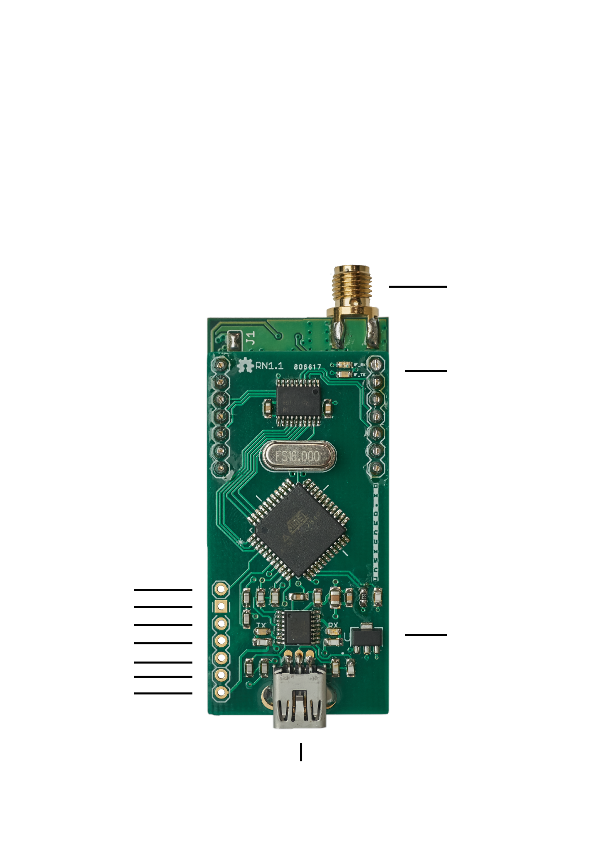
Device Overview
Please have a look at the following chart and familiarise yourself with the
different ports, connectors and indicators on you RNode.#
External Reset
Serial RX
Serial TX
Digital GPIO 1
Digital GPIO 2
GND
5V
USB Connector$
(Mini-B)
SMA Antenna
Connector
Multi-purpose
LEDs
USB activity$
LEDs

Cautions
•Never operate the device without a connected antenna!$
Doing so can damage the radio.!
•Always ensure a regulated 5V DC supply of correct polarity is used to
power the device. Supplying the device with incorrect voltage or polarity
will damage the device.!
•Always observe your local laws and regulations regarding RF emissions.
This device is capable of operating in a wide range of frequency bands
and emission modes, some of which may be illegal in your jurisdiction. It is
your responsibility to ensure you are operating this device in a lawful way.!
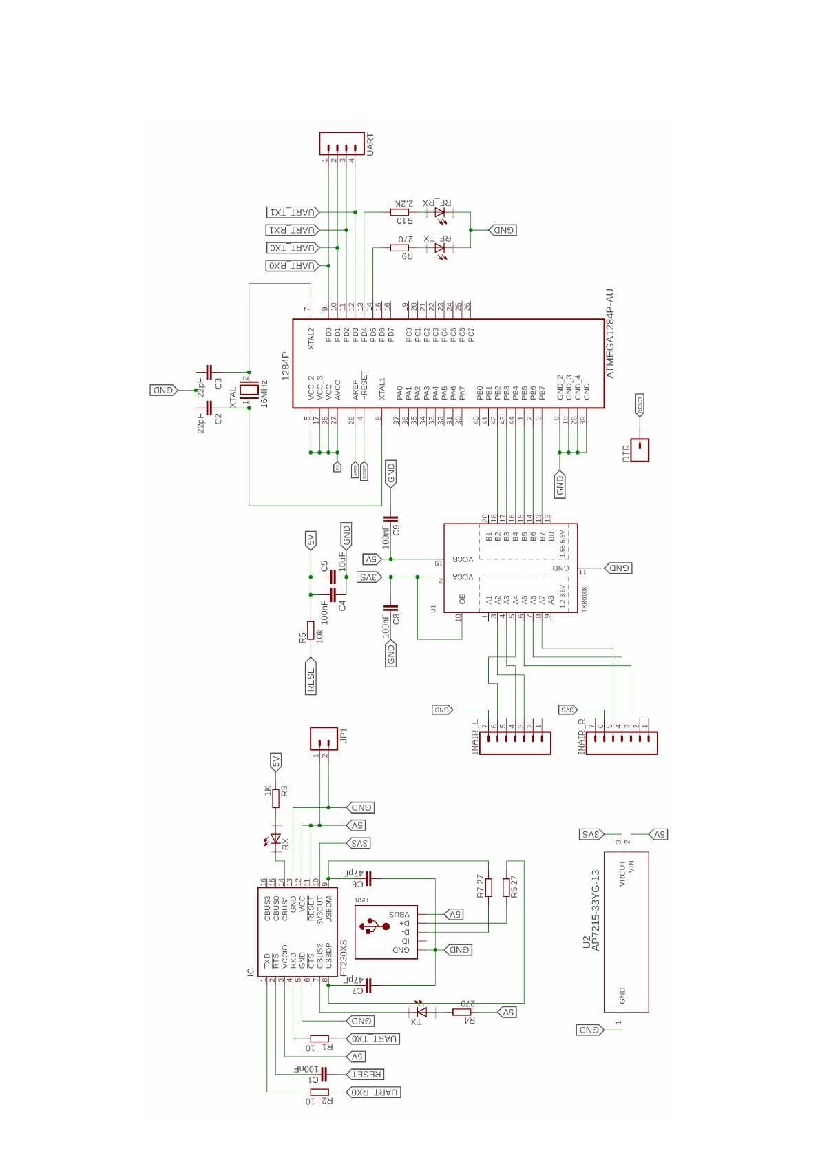
Specifications
•High-quality LoRa module with genuine Semtech SX1276 chip!
•Powered by an ATmega1284p MCU clocked at 16 MHz!
•128 kilobytes of flash!
•16 kilobytes of RAM!
•Large payloads with a packet MTU of 500 bytes!
•Max 17 dBm continuous TX output in the 820-1020 MHz band!
•Max 14 dBm continuous TX output in the 410-525 MHz band!
•Sensitivity down to -139 dBm!
•Data rates ranging from 11 bps to 37.5 kbps!
•Mini-USB connector!
•SMA antenna connector!
•Fully programmable!
•Arduino compatible!
•Open source firmware and config util!
•Two general purpose digital IO ports available!
•Operating temperature range: -20°C to 60°C (non-condensing)!
•23.3 mA idle power consumption!
Connecting RNode to Host Equipment
RNode can be connected to any host supporting USB or serial UART
connections. The board uses an FTDI USB-to-serial converter, so drivers
should already be included in most operating systems. You can use either
the USB port, or connect directly to the Serial RX and Serial TX ports.!
The default firmware uses 115200 baud, 8N1. No UART flow control is used.
RTS line is connected to External Reset.!
If you wish to prevent the USB host from being able to reset the board,
connect an 80Ω resistor between the pins 5V and External Reset.#

Operating Modes
RNode can operate in two modes, host-controlled (default) and TNC mode:!
•When RNode is in host-controlled mode, it will stay in standby when
powered on, until the host specifies frequency, bandwidth, transmit power
and other required parameters. In host-controlled mode, promiscuous
mode can be activated to sniff any LoRa frames.!
•When RNode is in TNC mode, it will configure itself on power-up and
enable the radio immediately. This mode can be enabled by using the
configuration utility.!
Configuring RNode
The device is useable out of the box, but can be further configured to your
needs by using the RNode Configuration Utility. Please visit the RNode page
at https://unsigned.io/rnode for the latest version of the config utility.!
Multi-purpose LEDs
RNode is equipped with two multi-purpose LEDs close to the antenna port.
The LEDs are used to signify a variety of device states and events.!
Pattern
Description
After powering the device:!
Blue LED is pulsing slowly
RNode is in standby and all health checks and
device verification succeeded.
After powering the device:!
Orange LED is pulsing slowly
Device verification failed, and operation was
halted. Possible radio or EEPROM damage.
When radio is on:
Blue LED is on
Device is receiving data, or a data carrier was
detected on the channel
When radio is on:
Orange LED is on
Device is transmitting data
Blue and orange LEDs alternatingly
blinks for 3 seconds
Hardware error. Possibly invalid radio
parameters were supplied.
Blue and orange LEDs alternatingly
blinks for more than 3 seconds
EEPROM is about to be formatted. Power
down device within 7 seconds to cancel.
Blue LED emits 3 short blinks
Radio powered on and ready
Orange LED emits 3 short blinks
Warning indicator. Check error codes sent.
When radio is on:
Blue LED is on
Device is receiving data, or a data carrier was
detected on the channel
When radio is on:
Orange LED is on
Device is transmitting data

Updating the Firmware
You can easily update the device firmware to the latest version by using the
RNode Config Utility. Alternatively, you can manually download specific
firmware versions from https://github.com/markqvist/RNode_Firmware and
flash it manually with avrdude or similar programs.!
Programming
The easiest way to program RNode is probably from within the Arduino IDE.
Even the entire default RNode firmware can be edited and compiled directly
from the Arduino environment. For adding RNode to your Arduino IDE,
please see https://unsigned.io/board-support-in-arduino-ide/. It is also
possible to work with any other toolchain that supports the ATmega1284p
that powers RNode, like avr-gcc or similar.!
If you want to make your own firmware for RNode, it can be a good idea to
use the default firmware as a starting point, since a lot of the setup required
to use RNode, such as initialising the LoRa transceiver, is already done for
you. The source code for the firmware is available under an MIT license, and
can be found here: https://github.com/markqvist/RNode_Firmware. !
The GPIO pins correspond to Arduino pins 10 and 11 (PD2 and PD3).!
A Few Notes on the EEPROM
As a completely open device, RNode does not block you from modifying the
EEPROM contents, which specifies things like radio parameters, serial
number, manufacture date and similar. But please be aware that doing so
might render the device inoperable or burn out the radio.!
Before making any modifications, please make sure to create a backup of
the EEPROM. RNode includes a cryptographic signature of the EEPROM
contents, which validates all the information stored within it. You will not be
able to re-create a valid signature if you erase it! Without this signature, the
board will still function, but warranty will be void.!
If you upload your own programs or alternative firmwares to RNode, you
should make sure that they don’t write to the last 200 bytes of EEPROM. You
can back up your EEPROM with the config utility.!
Interfacing with RNode
You can interface directly with the device using the protocol specified later in
this manual, or to get started easily, use one of the available libraries. To
download libraries and examples, please have a look at: https://github.com/
markqvist/RNode_Firmware/tree/master/Libraries.#

USB and Serial Protocol
Communications to and from the device uses KISS framing with a custom
command set. RNode also does not use HDLC ports in the command byte,
and as such uses the full 8 bits of the command byte is available for the
actual command. Please see table below for supported commands.!
Command
Byte
Description
Data frame
0x00
A data frame to or from the device
Frequency
0x01
Sets or queries the frequency
Bandwidth
0x02
Sets or queries the bandwidth
TX Power
0x03
Sets or queries the TX power
Spreading Factor
0x04
Sets or queries the spreading factor
Coding Rate
0x05
Sets or queries the coding rate
Radio State
0x06
Sets or queries radio state
Radio Lock
0x07
Sets or queries the radio lock
Device Detect
0x08
Probe command for device detection
Promiscuous
0x0E
Sets or queries promiscuous mode
Ready
0x0F
Flow control command indicating ready for TX
RX Stats
0x21
Queries received bytes
TX Stats
0x22
Queries transmitted bytes
Last RSSI
0x23
Indicates RSSI of last packet received
Blink
0x30
Blinks LEDs
Random
0x40
Queries for a random number
Firmware Version
0x50
Queries for installed firmware version
ROM Read
0x51
Read EEPROM byte
ROM Write
0x52
Write EEPROM byte
TNC Mode
0x53
Enables TNC mode
Normal Mode
0x54
Enables host-controlled mode
ROM Erase
0x59
Completely erases EEPROM
Error
0x90
Indicates an error

Error Codes
If an error occurs on the device, it will be signalled to the host using the error
command, which will include an error code as command payload. As an
example, if the radio could not be initialised, the device will send
0xc09001c0 to the host. The error codes are defined as follows.!
Flow Control and Packet Buffer
When sending data frames for transmission to the device, RNode employs a
simple mechanism of flow control to ensure no packets are dropped due to
congestion. When a data frame is is received from the host, the device will
put the frame into a queue. By default, the queue can hold up to 24 frames
(12 kilobytes of data). If the channel is free, the frame will be transmitted
immediately. If there is already activity on the channel, the device will wait
until the channel is free, and then send all frames in it’s queue. RNode can
receive and queue frames from the host while it is waiting for the channel to
become free.!
Every time a frame is received from the host, RNode will send a Ready
command back to the host (0xc00F01c0), if it is ready for more data. If the
queue is full, a Ready command will not be sent. As soon as more space is
available in the queue, a Ready command will be sent to the host. If the host
sends a data frame when the queue is full, the frame will be dropped, and
RNode will send an Error - Queue Full command to the host (0xc09004c0).!
Receiving Packets and RSSI
When the device is powered up and configured by a host, or operating in
TNC mode, it will be listening for packets on the specified frequency. Once a
packet has been demodulated, it will be sent as a data frame to the host.!
Just before sending the data frame, the device will signal the average RSSI
of the packet by sending an RSSI command. Subtract 292 from the received
command payload to obtain the RSSI in dBm. As an example, lets assume
the command 0xC023C6C0 is received from the device. The command
payload is C6, which is equal to 198. We obtain the RSSI by subtracting the
offset: 198 - 292 = -94dBm.#
Command
Byte
Description
Radio Init
0x01
Radio module could not be started
Transmission Failure
0x02
Transmission failed due to a hardware error
EEPROM Locked
0x03
EEPROM write failed due to EEPROM lock
Queue Full
0x04
Data frame dropped because the queue is full

Packet Format and MTU
RNode allows large packets with a max payload of 500 bytes. Standard
LoRa packets can only carry a payload of 255 bytes, so RNode achieves the
larger MTU by directly stringing together two standard LoRa packets.!
At the physical layer, a one-byte header is employed, which includes a
random sequence number in the most-significant 4 bits, and a split packet
flag in the least significant bit. Bits 3, 2 and 1 are reserved for future uses.
This physical layer format is transparent to the host, and 500 byte packets
are sent and delivered in exactly the same way as a small packet would.!
If you do not need large packet support, but want compatibility with
standard LoRa networks, this feature can be turned off, see the next section.!
Promiscuous Mode
RNode can be put into promiscuous mode to perform packet capture and
packet injection on standard LoRa networks. In promiscuous mode, all
demodulated LoRa frames will be dumped raw to the host. Raw LoRa
frames can also be injected by sending data frames to the device. Standard
255 byte LoRa MTU applies in promiscuous mode.!
For a ready-to-use LoRa packet sniffer program, have a look at LoRaMon
here: https://github.com/markqvist/LoRaMon.!
Getting Help
If you have any questions regarding RNode, please do not hesitate to send
me an email at mark@unsigned.io. You can also register for the forums at
unsigned.io where other users might offer pointers and advice.#