ROT 4500
User Manual: ROT-4500
Open the PDF directly: View PDF ![]() .
.
Page Count: 2
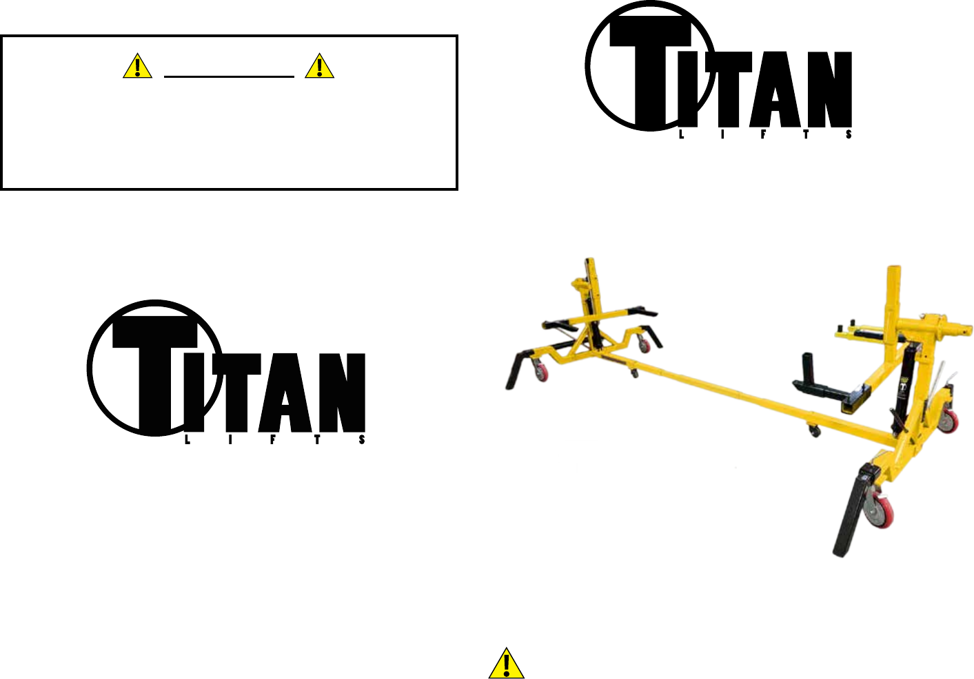
AUTOMOTIVE ROTISSERIE
MANUAL
MODEL: ROT-4500
4,500 LB ROTISSERIE
®
FOLLOW THIS MANUAL CAREFULLY TO ENSURE THE EQUIPMENT WILL
FUNCTION CORRECTLY AND PROVIDE MANY YEARS OF DEPENDABLE
SERVICE. FAILURE TO FOLLOW THESE INSTRUCTIONS AND SAFETY
WARNINGS MAY RESULT IN PERSONAL INJURY OR PROPERTY DAMAGE.
KEEP THIS MANUAL IN A SAFE DRY PLACE FOR FUTURE REFERENCE.
WARNING
The warnings, precautions and instructions in this manual cannot
cover all possible conditions and situations that may occur. The
operator must understand that the operator must supply common
sense and examine caution factors when using this product to
determine safety in all circumstances being used.
®
PO Box 7069 Greenwood, IN 46142
1.888.908.4826 FAX (317) 215.2770
www.titanlifts.com
TITAN MARKETING, LLC
Copyright © 2017 by Titan Marketing, LLC. All rights reserved. No portion of
this manual or any artwork contained herein may be reproduced in any shape
or form without the express consent of Titan Marketing, LLC. Diagrams within
this manual may not be drawn proportionally. Due to continuing improvements,
actual product may differ slightly from the product described herein. Tools
required for assembly and service may not be included.
Patent No.: US 8,104,588 B2
CA 2,729,670
DESCRIPTION
SAFETY
SPECIFICATIONS
This product should be used for repairing and maintaining
automobiles. The vehicle can be lifted 49” and rotated 360°.
1. DO NOT exceed the rated capacity of the equipment
2. Stay clear of the equipment when lifting or lowering
3. Keep the area around the equipment clear of obstacles
4. ALWAYS use the safety lock on the equipment
Max Height: 49”
Min Height: 21”
Max Length: 260”
Min Length: 121”
Width: 81”
Max Length Between Support Arms: 238”
Min Length Between Support Arms: 99”
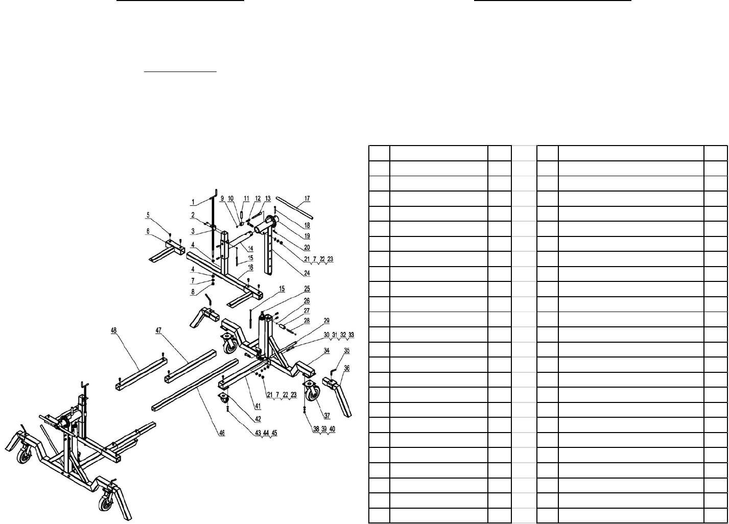
N0. Description QTY N0. Description QTY
1Adjust Screw Rod
225 Hydraulic Cylinder 2
2Screw M8*12 426 Circlip 4
3Screw Rod Stand 227 Guide Sleeve 2
4Bearing 428 Guide Spindle 2
5Screw M10*25 22 29 Operation Handle 2
6Movable Stand 430 Bolt M14*100 4
7Flat Washer Φ16 631 Flat Washer Φ14 4
8Lock Nut M16 232 Lock Washer Φ14 4
9Lock Nut M10 233 Lock Nut M14 4
10 Wedge Handle Seat 234 Main Stand 2
11 Handle 235 Set Screw 4
12 Spring 236 Steel Feet 4
13 Locking Pin 237 8” Caster 4
14 Rotating Stand 238 Bolt M10*20 16
15 Chain Pin 439 Lock Washer Φ10 16
16 Stand 240 Flat Washer Φ10 16
17 Turning Handle 241 Main Connecting Rod 2
18 Connecting Pin 242 3” Caster 2
19 Locking Plate 243 Bolt M8*16 8
20 R-pin 244 Lock Washer Φ8 8
21 Bolt M16*70 445 Flat Washer Φ8 8
22 Lock Washer Φ16 446 Extending Rod 2
23 Nut M16 447 Connecting Rod 2
24 Lifting Stand 248 Intermediate Connecting Rod 1
