R&S/R&S AMIQ Series Operation R&S
User Manual: R&S/R&S AMIQ Series Operation
Open the PDF directly: View PDF ![]() .
.
Page Count: 212 [warning: Documents this large are best viewed by clicking the View PDF Link!]
- Contents
- Putting into Operation
- Getting Started
- Operation
- Functional Description
- Remote Control – Commands and Data Formats
- Notation
- Common Commands
- BERT – Bit Error Rate Tests
- CALibration – Adjustment and Calibration
- DIAGnostic – Hardware Diagnosis
- MARKer – Marker Management
- MEMory/MMEMory – Waveform Management
- OUTPut – Hardware Settings
- PROGram – Program Sequence Control
- SOURce – Hardware Settings
- STATus – Status Reporting
- SYSTem – Various Settings
- ARM/TRIGger/ABORt – Triggering, Sequence Control
- Waveform File Format
- List of Commands
- Examples
- Index

1110.3339.12-08- 1
Test and Measurement
Division
Operating Manual
I/Q Modulation Generator
AMIQ
1110.2003.02/03/04
valid as of firmware version 4.00
Printed in the Federal
Republic of Germany

AMIQ Tabbed Divider Overview
1110.3339.12 RE E-1
Tabbed Divider Overview
Contents
Data Sheet
Safety Instructions
Certificate of Quality
EU Certificate of Conformity
List of R&S Representatives
Contents of Manuals for I/Q Modulation Generator AMIQ
Tabbed Divider
1 Chapter 1: Putting into Operation
2 Chapter 2: Getting Started
3 Chapter 3: Operation
4 Chapter 4: Functional Description
5 Chapter 5: Remote Control – Basics
6 Chapter 6: Remote Control – Commands
7 Chapter 7: Examples
8 Chapter 8: Maintenance
9 Chapter 9: Error Messages
10 Index

AMIQ Contents
1110.3339.12 3 E-7
Contents
1 Putting into Operation......................................................................................... 1.1
Introduction...................................................................................................................................... 1.1
Front and Rear View ........................................................................................................................ 1.2
Putting into Operation..................................................................................................................... 1.2
Unpacking................................................................................................................................ 1.2
Setting Up................................................................................................................................ 1.3
Rackmounting.......................................................................................................................... 1.3
Connection to AC Supply.........................................................................................................1.4
Power Fuses............................................................................................................................ 1.4
Power Up / Switch-on Test ...................................................................................................... 1.4
Instrument Switch-off............................................................................................................... 1.6
EMC Shielding Measures ........................................................................................................ 1.6
Connection to Test Setup ............................................................................................................... 1.7
Connecting the Controller........................................................................................................ 1.7
Software for AMIQ Control ...................................................................................................... 1.8
Signal Inputs and Outputs .......................................................................................................1.8
Connecting BER Test Signals ................................................................................................. 1.9
Connecting other Facilities .................................................................................................... 1.10
Installation of Options................................................................................................................... 1.11
Option AMIQ-B1, BER Test................................................................................................... 1.11
Option AMIQ-B2, Differential I/Q Outputs.............................................................................. 1.11
Option AMIQ-B3, Digital I/Q Output .............................................................................................1.12
Option AMIQB19, I/Q Rear-Panel Connection ...................................................................... 1.12
Option AMIQK11, IS-95 CDMA ............................................................................................. 1.12
Option AMIQK12, CDMA 2000.............................................................................................. 1.12
Option AMIQK13, Digital Standard W-CDMA TTD Mode (3GPP) ........................................ 1.12
Option AMIQK14, Digital Standard TD-SCDMA.................................................................... 1.12
Option AMIQK15, OFDM Signal Generation ......................................................................... 1.12
Option AMIQK16, Digital Standard 802.11b Wireless LAN................................................... 1.13
Initial Installation or Update of AMIQ Software........................................................................... 1.13
2 Getting Started..................................................................................................... 2.1
Control via Serial Interface ...................................................................................................... 2.1
Control via IEC/IEEE-Bus Interface......................................................................................... 2.2
Control via Floppy.................................................................................................................... 2.3
Switchover between Remote-Control Interfaces ..................................................................... 2.3
3 Operation ............................................................................................................. 3.1
Control Elements ..................................................................................................................... 3.1
Indicating Elements (LEDs) ..................................................................................................... 3.1
Calculation of I/Q Modulation Signals...................................................................................... 3.2
Control via WinIQSIM.................................................................................................... 3.2
Control via Vector Signal Generator SMIQ ................................................................... 3.2

Contents AMIQ
1110.3339.12 4 E-6
4 Functional Description........................................................................................ 4.1
Uses ................................................................................................................................................. 4.1
Stress Signals for I/Q Signals..................................................................................................4.1
Special Characteristics for Use of AMIQ as I/Q Modulation Source ...................................... 4.2
Basic Operating Modes................................................................................................................... 4.3
Signal Outputs ................................................................................................................................. 4.4
Marker Outputs........................................................................................................................ 4.4
Clock Output and Input.................................................................................................. 4.5
Triggering ......................................................................................................................................... 4.5
I/Q Signal Adjustments.................................................................................................................... 4.7
Adjusting the Level .................................................................................................................. 4.7
Adjusting the Offset ................................................................................................................. 4.7
Adjusting the Delay.................................................................................................................. 4.7
AMIQ – Block Diagram ............................................................................................................4.8
Measurement of Bit Error Rate....................................................................................................... 4.9
Connector ................................................................................................................................ 4.9
Signal Path and Waveform.................................................................................................... 4.10
Test Method........................................................................................................................... 4.11
PRBS Polynomials................................................................................................................. 4.13
Measurement Result, Accuracy, Measurement Time ........................................................... 4.13
Possible Problems with BER Measurement and Related Solutions...................................... 4.14
Further Hints and Tricks ........................................................................................................4.15
Installation of Option AMIQ-B1, BER Measurement.............................................................. 4.16
Avoid Reflections in the BER Measurement.......................................................................... 4.17
Application Example for Option Differential Outputs ................................................................ 4.18
AMIQ Model 03 / 04 ........................................................................................................................ 4.20
Digital I/Q Output Option AMIQ-B3 ..............................................................................................4.21
Operation of Digital I/Q Output Option (AMIQ-B3) using WinIQSIM ..................................... 4.22
Pin Allocation of Digital I/Q Outputs....................................................................................... 4.23
Brief Specifications ................................................................................................................ 4.23
Technical Details ................................................................................................................... 4.24
IEEE 488 Commands ............................................................................................................ 4.25
External Clock................................................................................................................................ 4.26
Brief Description .................................................................................................................... 4.26
Operation............................................................................................................................... 4.27
IEC/IEEE-bus command........................................................................................................ 4.27
Multisegment Waveform ............................................................................................................... 4.28
Application and structure .......................................................................................................4.28
IEC/IEEE bus commands...................................................................................................... 4.29

AMIQ Contents
1110.3339.12 5 E-7
5 Remote Control - Basics..................................................................................... 5.1
Short Introduction............................................................................................................................ 5.1
Messages.......................................................................................................................................... 5.1
Interface Messages ................................................................................................................. 5.2
Device Messages (Commands and Device Responses) ........................................................ 5.2
Structure and Syntax of the Device Messages............................................................................. 5.3
SCPI Introduction..................................................................................................................... 5.3
Structure of a Command ......................................................................................................... 5.3
Structure of a Command Line.................................................................................................. 5.5
Responses to Queries............................................................................................................. 5.6
Parameters .............................................................................................................................. 5.6
Overview of Syntax Elements.................................................................................................. 5.8
Instrument Model and Command Processing .............................................................................. 5.9
Input Unit ................................................................................................................................. 5.9
Command Recognition .......................................................................................................... 5.10
Data Set and Instrument Hardware....................................................................................... 5.10
Status Reporting System....................................................................................................... 5.10
Output Unit............................................................................................................................. 5.11
Command Sequence and Command Synchronization.......................................................... 5.11
Status Reporting System .............................................................................................................. 5.12
Structure of an SCPI Status Register.................................................................................... 5.12
Overview of Status Registers ................................................................................................ 5.14
Description of the Status Registers ....................................................................................... 5.15
Status Byte (STB) and Service Request Enable Register (SRE)................................ 5.15
IST Flag and Parallel Poll Enable Register (PPE)....................................................... 5.16
Event Status Register (ESR) and Event Status Enable Register (ESE) ..................... 5.16
STATus:OPERation Register...................................................................................... 5.17
STATus:QUEStionable Register ................................................................................. 5.17
Application of the Status Reporting System .......................................................................... 5.18
Service Request, Making Use of the Hierarchy Structure........................................... 5.18
Serial Poll .................................................................................................................... 5.19
Parallel Poll.................................................................................................................. 5.19
Query by Means of Commands................................................................................... 5.19
Error Queue Query...................................................................................................... 5.19
Reset Values of the Status Reporting Systems..................................................................... 5.20
Hardware Interfaces....................................................................................................................... 5.21
IEC/IEEE Bus Interface......................................................................................................... 5.21
Characteristics of the Interface.............................................................................................. 5.21
Bus Lines............................................................................................................................... 5.21
Interface Functions................................................................................................................ 5.22
Interface Messages ............................................................................................................... 5.23
RS-232-C Interface......................................................................................................................... 5.24
Interface characteristics......................................................................................................... 5.24
Signal lines ............................................................................................................................ 5.24
Transmission parameters...................................................................................................... 5.25
Interface functions ................................................................................................................. 5.25
Handshake ............................................................................................................................ 5.26

Contents AMIQ
1110.3339.12 6 E-6
6 Remote Control – Commands and Data Formats............................................. 6.1
Notation ................................................................................................................................... 6.1
Common Commands .............................................................................................................. 6.3
BERT – Bit Error Rate Tests ................................................................................................... 6.8
CALibration – Adjustment and Calibration............................................................................. 6.13
DIAGnostic – Hardware Diagnosis ........................................................................................ 6.17
MARKer – Marker Management............................................................................................ 6.20
MEMory/MMEMory – Waveform Management ..................................................................... 6.22
OUTPut – Hardware Settings ................................................................................................ 6.35
PROGram – Program Sequence Control.............................................................................. 6.41
SOURce – Hardware Settings............................................................................................... 6.42
STATus – Status Reporting................................................................................................... 6.47
SYSTem – Various Settings .................................................................................................. 6.50
ARM/TRIGger/ABORt – Triggering, Sequence Control......................................................... 6.54
Waveform File Format........................................................................................................... 6.57
Creating a Waveform File „Manually“.......................................................................... 6.64
Converting a Waveform File with the Application Software AMIQ-K2......................... 6.66
Example of combining waveform files:........................................................................ 6.68
List of Commands.................................................................................................................. 6.70
Remote-control commands......................................................................................... 6.70
Tags for Determining the Waveform File Formats...................................................... 6.73
7 Examples.............................................................................................................. 7.1
Program examples for Remote Control......................................................................................... 7.1
Including IEC/IEEE-Bus Library for QuickBasic ...................................................................... 7.1
Initialization and Default Status ...............................................................................................7.2
Initializing the Controller ................................................................................................ 7.2
Functions for Receiving and Sending Data and Commands ........................................ 7.2
Initializing the Instrument............................................................................................... 7.2
Sending Device Setting Commands........................................................................................ 7.3
Switchover to Manual Control.................................................................................................. 7.3
Executing Batch Programs...................................................................................................... 7.4
Reading out Device Settings ................................................................................................... 7.4
Command Synchronization...................................................................................................... 7.5
Service Request ...................................................................................................................... 7.6
Selftest with Progress Indication.............................................................................................. 7.7
Waveform Descriptions................................................................................................................. 7.10
GSM Signals (GMSK)............................................................................................................ 7.10
GSM continuous, PRBS 9 data ................................................................................... 7.10
GSM Normal Burst ...................................................................................................... 7.10
GSM Normal Burst, BERT PRBS 9 data..................................................................... 7.11
EDGE Signals (8PSK) ........................................................................................................... 7.12
EDGE Normal Burst .................................................................................................... 7.12
EDGE Normal Burst, BERT PRBS 9 data................................................................... 7.12
GSM/EDGE (GMSK/8PSK) alternating Bursts............................................................ 7.13
NADC Signals........................................................................................................................ 7.14
NADC continuous, PRBS 9 data ................................................................................. 7.14
NADC Downlink Burst ................................................................................................. 7.14
NADC Downlink Burst, BERT PRBS 9 data................................................................ 7.15

AMIQ Contents
1110.3339.12 7 E-7
DECT Signals ........................................................................................................................ 7.16
DECT continuous, PRBS 9 data ................................................................................. 7.16
Bluetooth Signals................................................................................................................... 7.17
Bluetooth continuous, PRBS 9 data ............................................................................ 7.17
Bluetooth continuous, PRBS 15 data .......................................................................... 7.17
3GPP (FDD) W-CDMA Signals ............................................................................................. 7.18
Testmodel 1, 16 Channels .......................................................................................... 7.18
Testmodel 1, 32 Channels .......................................................................................... 7.18
Testmodel 1, 64 Channels .......................................................................................... 7.19
Testmodel 2................................................................................................................. 7.19
Testmodel 3, 16 Channels .......................................................................................... 7.20
Testmodel 3, 32 Channels .......................................................................................... 7.20
Testmodel 4................................................................................................................. 7.21
Uplink DPCH Mode, 1 DPCH (60 ksps) ...................................................................... 7.21
Uplink DPCH Mode, 1 DPCH (960 ksps) .................................................................... 7.22
Uplink DPCH Mode, 6 DPCH (960 ksps) .................................................................... 7.22
Uplink PRACH only Mode ........................................................................................... 7.23
Uplink PCPCH only Mode ........................................................................................... 7.23
IS95 CDMA Signals...............................................................................................................7.24
Pilot Signal................................................................................................................... 7.24
Pilot Signal (with ACPR filter)...................................................................................... 7.24
9 Channels .................................................................................................................. 7.25
9 Channels (with ACPR filter)...................................................................................... 7.25
9 Channels, worst case Crest ..................................................................................... 7.26
9 Channels, worst case Crest (with ACPR filter)......................................................... 7.26
64 Channels ................................................................................................................ 7.27
Uplink Signal (1 Access, 1 Traffic Channel)................................................................ 7.27
Multicarrier Signals ................................................................................................................ 7.28
15 CW Carriers, maximum Crest................................................................................ 7.28
15 CW Carriers, minimum Crest................................................................................. 7.28
8 GSM carriers ............................................................................................................ 7.29
8 EDGE carriers .......................................................................................................... 7.29
5 NADC carriers .......................................................................................................... 7.29
Multicarrier Mixed Signals......................................................................................................7.30
3 WCDMA 3GPP carriers, 5 MHz spacing.................................................................. 7.30
3 WCDMA 3GPP carriers, 10 MHz spacing................................................................ 7.30
1 WCDMA 3GPP carrier + 1 EDGE carrier................................................................. 7.31
1 CDMA IS95 carrier + 1 NADC carrier....................................................................... 7.31
8 Maintenance......................................................................................................... 8.1
Mechanical and Electrical Maintenance .................................................................................. 8.1
Storing and Packing................................................................................................................. 8.1
9 Error Messages ................................................................................................... 9.1
Troubleshooting .............................................................................................................................. 9.1
List of Error Messages .................................................................................................................... 9.2
SCPI Standard Messages ....................................................................................................... 9.2
No error ......................................................................................................................... 9.2
Operation complete....................................................................................................... 9.2
Query error - error upon data request ........................................................................... 9.3
Device-specific error...................................................................................................... 9.3
Execution error .............................................................................................................. 9.4
Command error ............................................................................................................. 9.5
AMIQ-Specific Messages ........................................................................................................ 9.7

ContentsFigures AMIQ
1110.3339.12 8 E-7
Figures
Fig. 1-1 AMIQ used in a test setup .................................................................................................. 1.1
Fig. 1-2 AMIQ Front view................................................................................................................. 1.2
Fig. 1-3 AMIQ rear view................................................................................................................... 1.3
Fig. 4-1 Simplified block diagram of AMIQ ...................................................................................... 4.8
Fig. 4-2 PRBS Polynomials............................................................................................................ 4.13
Fig. 4-3 Avoid reflections in the BER measurement...................................................................... 4.17
Fig. 4-4 Application block diagram of option AMIQ-B2.................................................................. 4.18
Fig. 4-5 Pin allocation of digital I/Q outputs ...................................................................................4.23
Fig. 4-6 Technical implementation of digital I/Q outputs................................................................ 4.24
Fig. 4-7 Integration of the AMIQ into a system with system clock ................................................. 4.26
Fig. 4-8 Feeding a DUT with a spectrally pure external clock ....................................................... 4.26
Fig. 4-9 Generation of an MWV from partial traces....................................................................... 4.29
Fig. 5-1 Example for the tree structure of the SCPI command systems: The SYSTem system...... 5.4
Fig. 5-2 Instrument model in the case of remote control by means of the IEC bus......................... 5.9
Fig. 5-3 The status register model................................................................................................. 5.12
Fig. 5-4 The Status registers ......................................................................................................... 5.14
Fig. 5-5 Pin Assigment of the IEC-bus interface............................................................................ 5.21
Fig. 5-6 Pin assigment of the RS-232-C interface ......................................................................... 5.24
Fig. 5-7 Null-modem connection scheme...................................................................................... 5.26
Tables
Table 4-1 Specifications of option AMIQ-B3 .................................................................................. 4.23
Table 4-2 IEEE 488 commands for option AMIQ-B3 ..................................................................... 4.25
Table 5-1 Synchronization with *OPC, *OPC? and *WAI .............................................................. 5.11
Table 5-2 Meaning of the bits used in the status byte.................................................................... 5.15
Table 5-3 Meaning of the bits used in the event status register..................................................... 5.16
Table 5-4 Meaning of the bits used in the STATus:OPERation register........................................ 5.17
Table 5-5 Meaning of the bits used in the STATus:QUEStionable register ................................... 5.17
Table5-6 Resetting instrument functions ...................................................................................... 5.20
Table 5-7 Interface functions.......................................................................................................... 5.22
Table 5-8 Universal Commands .................................................................................................... 5.23
Table 5-9 Addressed Commands .................................................................................................. 5.23
Table 5-10 Control strings or control characters of the RS-232-C interface.................................... 5.25
Table 6-1 Common commands ....................................................................................................... 6.3
Table 6-2 BERT – Bit error rate tests............................................................................................... 6.9
Table 6-3 CALibration – Adjustment and calibration...................................................................... 6.13
Table 6-4 DIAGnostic – Hardware diagnosis................................................................................. 6.17
Table 6-5 MARKer – Marker management.................................................................................... 6.20
Table 6-6 MEMory – Waveform management............................................................................... 6.22
Table 6-7 MMEMory – Waveform management............................................................................ 6.23
Table 6-8 OUTPut – Hardware settings......................................................................................... 6.35
Table 6-9 PROGram – Program sequence.................................................................................... 6.41
Table 6-10 SOURce – Hardware settings........................................................................................ 6.42
Table 6-11 Status reporting.............................................................................................................. 6.47
Table 6-12 System settings.............................................................................................................. 6.50
Table 6-13 ARM/TRIGger/ABORt – Triggering, sequence control................................................. 6.54
Table 6-14 List of all remote-control commands.............................................................................. 6.70
Table 9-1 Error symptoms................................................................................................................ 9.1

Safety Instructions
095.1000 Sheet 17
This unit has been designed and tested in accordance with the EC Certificate of Conformity and has left the
manufacturer’s plant in a condition fully complying with safety standards.
To maintain this condition and to ensure safe operation, the user must observe all instructions and warnings
given in this operating manual.
Safety-related symbols used on equipment and documentation from R&S:
Observe
operating
instructions
Weight
indication for
units >18 kg
PE terminal Ground
terminal Danger!
Shock hazard
Warning!
Hot surfaces Ground Attention!
Electrostatic
sensitive devi-
ces require
special care
1. The unit may be used only in the operating con-
ditions and positions specified by the manufac-
turer. Unless otherwise agreed, the following
applies to R&S products:
IP degree of protection 2X, Pollution severity 2,
overvoltage category 2, altitude max. 2000 m.
The unit may be operated only from supply net-
works fused with max. 16 A.
2. For measurements in circuits with voltages Vrms
> 30 V, suitable measures should be taken to
avoid any hazards.
(using, for example, appropriate measuring
equipment, fusing, current limiting, electrical
separation, insulation).
3. If the unit is to be permanently wired, the PE
terminal of the unit must first be connected to
the PE conductor on site before any other con-
nections are made. Installation and cabling of
the unit to be performed only by qualified techni-
cal personnel.
4. For permanently installed units without built-in
fuses, circuit breakers or similar protective de-
vices, the supply circuit must be fused such as
to provide suitable protection for the users and
equipment.
5. Prior to switching on the unit, it must be ensured
that the nominal voltage set on the unit matches
the nominal voltage of the AC supply network.
If a different voltage is to be set, the power fuse
of the unit may have to be changed accordingly.
6. Units of protection class I with disconnectible
AC supply cable and appliance connector may
be operated only from a power socket with
earthing contact and with the PE conductor con-
nected.
7. It is not permissible to interrupt the PE conduc-
tor intentionally, neither in the incoming cable
nor on the unit itself as this may cause the unit
to become electrically hazardous.
Any extension lines or multiple socket outlets
used must be checked for compliance with rele-
vant safety standards at regular intervals.
8. If the unit has no power switch for disconnection
from the AC supply, the plug of the connecting
cable is regarded as the disconnecting device.
In such cases it must be ensured that the power
plug is easily reachable and accessible at all
times (length of connecting cable approx. 2 m).
Functional or electronic switches are not suit-
able for providing disconnection from the AC
supply.
If units without power switches are integrated in
racks or systems, a disconnecting device must
be provided at system level.
9. Applicable local or national safety regulations
and rules for the prevention of accidents must
be observed in all work performed.
Prior to performing any work on the unit or
opening the unit, the latter must be discon-
nected from the supply network.
Any adjustments, replacements of parts, main-
tenance or repair may be carried out only by
authorized R&S technical personnel.
Only original parts may be used for replacing
parts relevant to safety (eg power switches,
power transformers, fuses). A safety test must
be performed after each replacement of parts
relevant to safety.
(visual inspection, PE conductor test, insulation-
resistance, leakage-current measurement, func-
tional test).
continued overleaf

Safety Instructions
095.1000 Sheet 18
10. Ensure that the connections with information
technology equipment comply with IEC950 /
EN60950.
11. Lithium batteries must not be exposed to high
temperatures or fire.
Keep batteries away from children.
If the battery is replaced improperly, there is
danger of explosion. Only replace the battery by
R&S type (see spare part list).
Lithium batteries are suitable for environmental-
ly-friendly disposal or specialized recycling.
Dispose them into appropriate containers, only.
Do not short-circuit the battery.
12. Equipment returned or sent in for repair must be
packed in the original packing or in packing with
electrostatic and mechanical protection.
13. Electrostatics via the connectors may dama-
ge the equipment. For the safe handling and
operation of the equipment, appropriate mea-
sures against electrostatics should be imple-
mented.
14. The outside of the instrument is suitably clea-
ned using a soft, line-free dustcloth. Never
use solvents such as thinners, acetone and
similar things, as they may damage the front
panel labeling or plastic parts.
15. Any additional safety instructions given in this
manual are also to be observed.

1110.2003.02 CE E-1
EC Certificate of Conformity
Certificate No.: 98034
This is to certify that:
Equipment type Order No. Designation
AMIQ 1110.2003.02/.03/.04 I/Q Modulation Generator
AMIQ-B2 1110.3700.02/.03 Differential I/Q Outputs
AMIQ-B3 1122.2103.02 Digital I/Q Output
AMIQB19 1110.3400.02 I/Q Rear Panel Connection
complies with the provisions of the Directive of the Council of the European Union on the
approximation of the laws of the Member States
- relating to electrical equipment for use within defined voltage limits
(73/23/EEC revised by 93/68/EEC)
- relating to electromagnetic compatibility
(89/336/EEC revised by 91/263/EEC, 92/31/EEC, 93/68/EEC)
Conformity is proven by compliance with the following standards:
EN61010-1 : 1993 + A2 : 1995
EN50081-1 : 1992
EN50082-2 : 1995
Affixing the EC conformity mark as from 1998
ROHDE & SCHWARZ GmbH & Co. KG
Mühldorfstr. 15, D-81671 München
Munich, 1999-09-17 Central Quality Management FS-QZ / Becker

AMIQ Manuals
1110.3339.12 0.1 E-2
Contents of Manuals for
I/Q Modulation Generator AMIQ
Operating Manual
The operating manual consisting of a data sheet and 10 chapters contains comprehensive informa-
tion on characteristics, putting into operation, operation and remote control of AMIQ:
The data sheet informs about guaranteed specifications and characteristics.
Chapter 1 describes the operating principle of AMIQ, control elements and connectors on
the front and rear panel as well as all procedures required for putting the instru-
ment into operation and integration into a test system.
Chapter 2 details instrument control via the remote interfaces with the aid of program ex-
amples.
Chapter 3 presents control and display elements.
Chapter 4 describes key operating modes and special characteristics of AMIQ with refer-
ence to possible applications.
Chapter 5 describes programming of AMIQ, command processing, status reporting system
and characteristics of hardware interfaces.
Chapter 6 describes the remote-control commands defined for the instrument. At the end of
the chapter an alphabetical list of commands is given.
Chapter 7 contains program examples for a number of typical applications of AMIQ.
Chapter 8 describes preventive maintenance.
Chapter 9 gives hints on troubleshooting and contains a list of error messages.
Chapter 10 contains an index for the operating manual.
Service Manual
The service manual informs on how to check compliance with rated specifications, on instrument
function, repair, troubleshooting and fault elimination. It contains all information required for the
maintenance of AMIQ by exchanging modules.
The service manual also contains the circuit documentation for the module "IQ Analog/Digital Unit".
AMIQ Introduction
1110.3339.12 1.1 E-6
1 Putting into Operation
Introduction
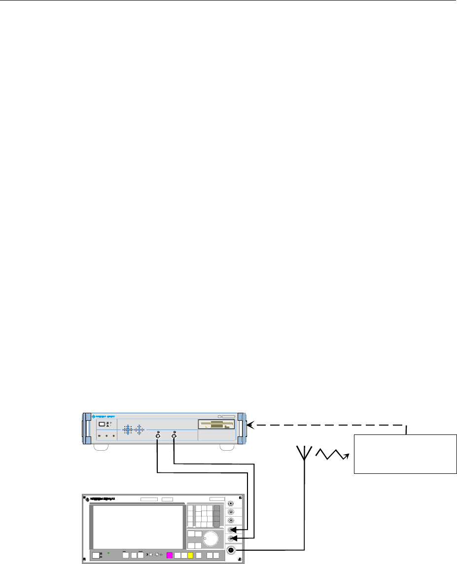
Task AMIQ is a modulation source for complex baseband signals of state-of-the-art
telecommunication networks. Two synchronous outputs, which are matched to each
other, and a large memory together with wide analog bandwidth make AMIQ suitable
for universal use.
AMIQ has been designed to generate I and Q signals in the baseband for present and
future types of modulation. "I" stands for the in-phase component, "Q" for the
quadrature component.
Operating
principle The data to be output by AMIQ are normally calculated by an external workstation (eg
PC). To control this calculation, Rohde & Schwarz offers two programs: WINIQSIM
and AMIQ Control, a software for R&S vector signal generator SMIQ (see Section
"Software for AMIQ Control on page 1.8"). The desired information data stream (eg a
piece of speech) is generated and a modulation mode selected. Then various
interference and distortions (so-called impairments) are superimposed to this (ideal)
baseband signal. Thus a long sequence of sample values is obtained, which are
loaded into AMIQ (via floppy, IEC/IEEE bus or RS-232 interface). The sequence in
the AMIQ memory is then output as analog I and Q signals with the aid of fast and
accurate D/A converters. The outputs are (normally) connected to the modulation
inputs of an I/Q modulator (eg SMIQ), which modulates the baseband signal onto the
desired RF (Fig. 1-1).
Transmission
error The RF signal is transmitted via the antenna to the receiver where it is converted
back into information data. On the transmission link, errors may be caused in the
information data stream by coding, impairments and decoding. These errors can be
detected with the aid of option AMIQ-B1 (BER measurement) and evaluated.
SMIQ
ïð
SMIQ
MADE IN GE RMANY
CONTROLON
I/Q MODULATION GENERATOR AMIQ
.1110 .2003. 02
RUNNING
I Q
AMIQ
Device under test (DUT)
Bit error rate test (optional)
RF
Fig. 1-1 AMIQ used in a test setup
Test setup The four additional marker outputs and a trigger input simplify integration in a test
setup. The user-selectable positions of the marker switch points permit external,
variable amplifiers (eg for power ramping) or signalling facilities to be controlled.
Front and Rear View AMIQ
1110.3339.12 1.2 E-6
Front and Rear View
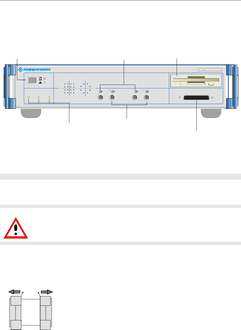
Fig. 1-2 AMIQ Front view
Putting into Operation
Caution!
The following instructions should be strictly observed, in particular when putting the
instrument into operation for the first time, to avoid damage to the instrument and
hazards to persons.
Unpacking
After unpacking the instrument, check for completeness according to the delivery note and the
accessory lists for the individual items.
Remove protective covers
Remove the two protective covers from the front and rear of
the AMIQ and carefully check the instrument for any damage.
In case of any damage you should immediately inform the
responsible transport agent and keep all packing material not
to forfeit your claims.
The original packing should also be used for any later transport or shipment of AMIQ. You should keep
at least the two protective covers for the front and rear of the instrument.
Power switch
preset in as long
as Instrument is on
3 LEDs indicating the instrument status
ON AMIQ ready for operation
CONTROL Remote control active
RUNNING Waveform in output memory in triggered
3,5''-disk drive
Refer to "Installation of Options"
in chapter 1 when exchanging
data and instrument software
I In-phase component
Q Quadrature component
Chapter 1 "Introduction"
.
MADE IN GERMANY
CONTROLON
I/Q MODULATION GENERATOR AMIQ
.1110.2003. 03
RUNNING I QI Q DIGITAL OUTPUT
Chapter 1
"Power up / Switch-onTest"
.
Option Digital I/Q Output AMIQ-B3
Additional outputs T and Q with option
Differential I/Q Outputs installed
AMIQ Putting into Operation
1110.3339.12 1.3 E-6
SCPI
625 IEEE 488
REF REF CLK Q Q I I TRIG BER
FILT 1234 FILTMARK
X 10
MARK
AU TO POWE R SELE CTIO N
50...60 Hz 150 VA
10 0... 120 / 200...240 V
F 1 / F 2 :
IEC 127 - T 2.5 H / 250 V
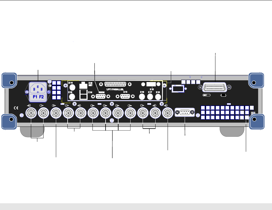
Power connector
with 2 fuses (F)
"Connection to AC
Supply" in chapter 1
RS-232 interface
"Connecting the
Controller" in chapter 1
Connector for servicing
and extensions
"Connecting other
Facilities" in chapter 1
IEC/IEEE-bus interface
"Connection the Controller"
in chapter 1
4marker outputs
With option "Rear IQ outputs (AMIQ-B19)
installed, MARK 3 willl become Q and MARK 4 I.
Q filter, input
and output
Clock input/output
Reference frequency
Input / Output
"Signal Inputs and Outputs" in chapter 1
Air vents
Trigger input
BER input
"Connecting BER
Test Signals" in chapter 1
I filter, input
and output
Fig. 1-3 AMIQ rear view
Setting Up
Permissible setup positions for AMIQ:
•Flat.
•Upright standing on its rear. In this case an angular AC supply connector should be used.
Note: To ensure problem-free operation of the instrument the following should be observed:
•
Do not obstruct air vents at the rear and sides.
•
Observe the permissible ambient temperature specified in the data sheet.
•
Avoid condensation. Allow instrument with condensation to dry before switching on.
Rackmounting
Adapter ZZA-211 (Order No. 1096.3260.00) allows the AMIQ to be mounted in 19" racks. Rackmounting
is described in the installation instructions of the rack adapter.
For rackmounting it is recommended to fit the option AMIQB19 (I/Q Rear-Panel Connection) (Order No.
1110.3400.02), which changes I and Q connectors from the front to the rear.
Note: To ensure problem-free operation of the instrument the following should be observed:
•
Provide for sufficient air flow in the rack.
•
Make sure that there is sufficient space between air vents and rack.
Putting into Operation AMIQ
1110.3339.12 1.4 E-6
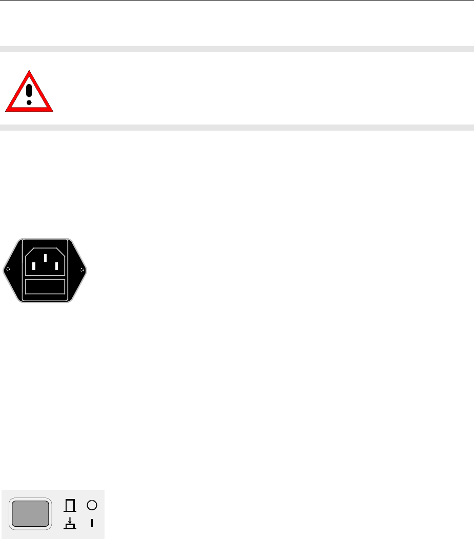
Connection to AC Supply
Caution!
Allow instrument with condensation to dry before switching on.
Observe permissible ambient temperatures -10°C to +45°C.
Do not cover up air vents.
AMIQ may be connected to a single-phase AC supply with a rated voltage from 100 V to 240 V and
rated frequency from 50 Hz to 60 Hz.
Note: AMIQ automatically sets itself to the local AC supply voltage. There is no need for
external switchover or exchanging fuses.
← AC supply connector
← Power fuses
Use the power cord supplied with the AMIQ for
connection to the AC supply. Since the AMIQ is
designed in line with protection class I requirements
to EN61010 it may only be connected to an earthing-
contact type connector. As soon as the connection
has been established, AMIQ outputs a beep and the
ON LED lights with slightly reduced brightness. After
the start-up is completed, the ON LED is fully on.
Power Fuses
AMIQ is fully fused by two fuses IEC127-T4.0H/250 V. The fuses are accommodated in the pull-out
fuse holder below the power connector. Before replacing the fuses, disconnect the power cord from the
AMIQ. Use a screwdriver to lift the fuse holder below the power connector and pull it out. Use only fuses
of the above type.
Power Up / Switch-on Test
Ø Press switch-on key on the AMIQ front panel.
Note: No floppy should be in the drive when AMIQ is switched on. If
this happens nonetheless, one of the actions stored on the
floppy may be executed (see sections "New installation of
AMIQ software" and "Changing the IEC/IEEE-bus address in
this chapter).
Start-up procedure After power-up the system is started, the controller short test is performed
and the operating system DOS and the remote-control software are loaded
from the integrated hard disk. During this time the ON LED lights with
reduced intensity.
Test of controller
hardware First the switch-on test for the integrated controller is performed. Since at
this stage the LEDs are not driven, no information can be obtained on the
device status. If a fault occurs, AMIQ outputs a sequence of beeps, the
meaning of which can be seen in the enclosed main board manual. If a fault
occurs, the switch-on procedure is normally aborted.

AMIQ Putting into Operation
1110.3339.12 1.5 E-6
Short test of functional
hardware The AMIQ hardware is then set to operating state and tested. Any error is
signalled by two short successive beeps provided the built-in loudspeaker
was not switched off with the IEC/IEEE-bus command :SYST:BEEP:STAT
OFF. At the end of the selftest a single beep is output. After this the
instrument is ready for operation.
Further information on error can be obtained by a repeated readout of the
error queue using IEC/IEEE-bus queries :SYST:ERR?.
Even if an error occurs, the switch-on procedure is in most cases continued
so that the error queue can be read out. The instrument may not be fully
functional however.
LEDs after the short test If an error is detected in the short test, the ON LED flashes.
With the short test completed successfully, the last active setup is
automatically loaded from the hard disk and the instrument is set to the
operating status before switch-off. The currently selected waveform is
loaded together with this complete setup. For a curve with 4.000.000
samples and with AMIQ 03, this may take up approx. 20 seconds. With
AMIQ 04 and its quadrupled memory capacity, the loading time increases to
approx. 80 s.
If no further errors occurred, the ON and the CONTROL LEDs briefly light.
Afterwards, the ON and RUN LEDs come fully on.
Error messages If an error is detected the error message is entered in plain text into the
error queue of AMIQ and ON LED flashes. This is why after restart the
AMIQ control program in the host computer should read out the error queue
by means of the command SYST:ERR? until it is empty, i.e., until the entry
0,"No Error" is read. Depending on the error detected, AMIQ will
usually respond to commands transmitted via IEEE-bus or RS-232 interface
but may not be fully functioning. The ON LED lights steadily at full
brightness.
Note If ON LED flash fast, it is only a hint that AMIQ does not generate any curve
at the moment. It appears whenever a curve was stored directly to the
AMIQ’s SDRAM to save time before switching off AMIQ by means of the
MEM:DATA RAM, <binary block data> command (e.g. with
WinIQSIM via the settings Transmission, Force internal, Destination
AMIQ-RAM). This can be suppressed by loading curves via a waveform file
using the command MMEM:LOAD RAM, 'filename.WV'; such a curve is
available immediately after switching on the instrument.
Ø If AMIQ does not start as described above, check the AC supply
connection and, if required, replace the two power fuses (see section
"Power fuses" in this chapter).
Ø A complete selftest of AMIQ’s hardware components can be started with
the common command *TST?. Furthermore, the command
DIAG:SELF:SDRAM? can be used to test the whole SDRAM of AMIQ in
detail, see Sections „Common Commands“ and „DIAGnostic – Hardware
Diagnosis“ in Chapter 6.

Putting into Operation AMIQ
1110.3339.12 1.6 E-6
Instrument Switch-off
Ø Wait until the hard disk or the floppy disk drive are no longer accessed
Ø Remove floppy from the disk drive
Ø Press power switch on the front panel. All instrument settings are
retained.
EMC Shielding Measures
To avoid electromagnetic interference, the instrument must always be closed when in operation. Use
only appropriate, shielded signalling lines and control cables. Particularly the line connected to the clock
output should be double-shielded and terminated.

AMIQ Connection to Test Setup
1110.3339.12 1.7 E-6
Connection to Test Setup
Connecting the Controller
AMIQ has no user interface of its own. An external controller is therefore required for operating AMIQ
which can be performed in two ways:
Connection via IEC/IEEE
bus AMIQ is simply connected to the IEC/IEEE bus. Upon delivery the bus
address is 6. If the bus address has been changed, e.g. by a previous
control command, or if the bus address has to be changed, proceed as
described in section "Changing the IEC/IEEE-bus address" on page 1.7.
Connection via the serial
interface AMIQ is connected to the serial interface of a PC by means of a null
modem cable. Connect the cable to the 9-contact sub-D connector of the
AMIQ labeled RS232. Use the COM1 or COM2 connector of the PC
which may be a 25-contact or 9-contact connector. Suitable adapters
may have to be used.
Serial interface The serial interface is configured for 9600 Baud, 8 data bits, no parity.
When the WinIQSIM software is used, which is recommended by R&S,
the interface of the PC is automatically configured with the AMIQ
settings. However, the interface used has to be set in the menu first.
Pin assignment and wiring of the null modem cable are described in
section "Handshake" of chapter 5.
Changing the IEC/IEEE-bus Address
Upon delivery the instrument is set to address 6. If for any reason this address is not available, the
setting can be changed as follows:
ØGenerate a file on a PC, which contains only the following line:
:SYST:COMM:GPIB:ADDR x
with x being the desired address. Add an empty line.
ØCopy this file under the name AUTOEXEC.IEC into the main memory of a 3.5" floppy.
ØInsert the floppy in the AMIQ, switch AMIQ off and on again.
Connection to Test Setup AMIQ
1110.3339.12 1.8 E-6
Software for AMIQ Control
AMIQ can only be remote-controlled. To simplify operation, Rohde & Schwarz offers two different
software programs for the control of AMIQ:
• WinIQSIM: This software permits calculation of complex I/Q signals, controls the transfer of these
signals to the AMIQ via IEEE-bus or RS-232 interface and determines how the signals are output.
• AMIQ control software menu for SMIQ: In this case AMIQ is controlled from SMIQ. Control is similar
to that of the SMIQ options but I/Q signals cannot be generated. It is possible, however, to load I/Q
signals that have been generated on an external PC.
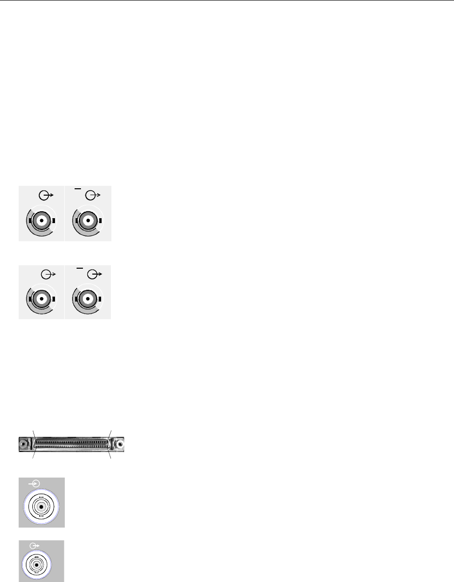
Signal Inputs and Outputs
I
I
QQ
Pin 68
Pin 35
Pin 34
Pin 1
Digital Output
Analog I/Q output:
The loaded waveforms are output at two BNC connectors I and Q on
the front panel (four BNC connectors I and I, Q andQ if option
Differential Outputs (AMIQ-B2) is fitted). The output is determined by
the trigger conditions and depends on the applied trigger signals (see
section "Triggering" in chapter 4). If the trace output is not active, an
idle-channel signal is output (see section "ARM/TRIGger/ABORt -
Triggering, Sequence control" in chapter 6).
If option AMIQ-B2 is not fitted the I/Q outputs on the front panel can be
taken to the rear with option I/Q Rear-Panel Connection (AMIQB19).
This simplifies wiring particularly when the AMIQ is rack-mounted.
Note: When the I/Q outputs are taken to the rear, marker outputs 3
and 4 (BNC connectors) are used. This means that marker
outputs 3 and 4 are no longer available.
Upon delivery and after an *RST, the I and Q outputs are
switched off. Use commands OUTPUT:I FIX and OUTPUT:Q
FIX to reactivate the channels.
Digital I/Q output:
Option AMIQ-B3, Digital I/Q Output, provides the 16 bit wide data bus for
both I and Q channels via a 68-pole SCSI socket at the front panel of the
AMIQ. See section "Option "Digital I/Q Output AMIQ-B3" below.
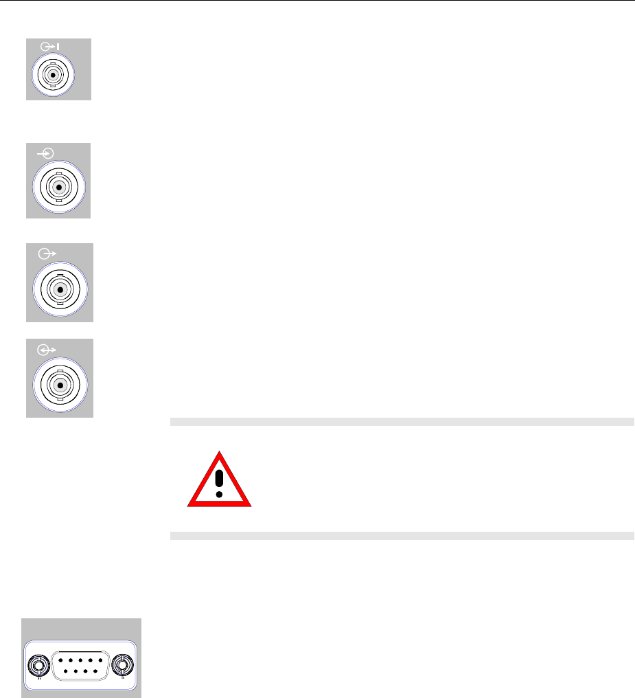
TRIG
Trigger input (TRIG):
Rear BNC connector (female). The output of the stored waveform can be started
or enabled with a TTL signal applied to this connector. Trigger condition and
polarity are user-selectable.
1MARK Marker outputs (MARK):
Four BNC connectors (female) at the rear. These outputs (TTL level, can be
terminated with 50 Ω) are used for the control of further instruments, e.g. an
oscilloscope or variable amplifiers (power ramping). (See "Marker outputs" in
chapter 4).
AMIQ Connection to Test Setup
1110.3339.12 1.9 E-6
FILT
I/Q filter (input and output):
Here an external passband filter (e.g. for anti-aliasing) can be looped in for the I
and Q path instead of the internal filters. The outputs have a nominal impedance
of 50 Ω and yield a peak voltage of 0.5 V into 50 Ω when driven at full scale. The
filter attenuation in the passband range should be 0 dB.
REF
Reference clock input (REF):
Input for an external 10 MHz reference clock; Vrms = 0.1 V to 2 V, input
impedance 50 Ω.
REF
Reference clock output (REF):
Output of 10 MHz reference clock; Vrms = 0.5 V, output impedance 50 Ω.
CLK Clock input/output (CLK):
Output with the actual clock rate; Vrms = 0.5 V, output impedance 50 Ω.
Input for external clock (TTL signal).
Caution!
Because of the high clock rates at the clock output, a
double-screened cable should be used to keep within
permissible EMI limits. The line should in all cases be
terminated with 50
Ω
.
Connecting BER Test Signals
BER
AMIQ comprises a programmable facility for bit error rate (BER)
measurements. The required signals have to be applied to the AMIQ via the
BER input with TTL level. The signals to be applied depend on the test
method used and are described in the manual for option AMIQ-B1 (see
section "BER measurement" in chapter 4).

Connection to Test Setup AMIQ
1110.3339.12 1.10 E-6
Connecting other Facilities
The connectors labeled LPT/PARALLEL, X10, X11, X12 and X13 are used
for servicing or for extensions.
Note: In normal operation these connectors must be open.

AMIQ Installation of Options
1110.3339.12 1.11 E-6
Installation of Options
The following options are available for AMIQ:
BER Measurement AMIQ-B1 1110.3500.02
Differential I/Q Outputs AMIQ-B2 1110.3700.02
Digital I/Q Output AMIQ-B3 1122.2103.02
Rear I/Q Outputs AMIQB19 1110.3400.02
IS-95 CDMA AMIQK11 1122.2003.02
CDMA 2000 AMIQK12 1122.2503.02
Digital Standard W-CDMA TTD Mode (3GPP) AMIQK13 1122.2603.02
TD-SCDMA AMIQK14 1122.2703.02
OFDM Signal Generation AMIQK15 1122.2803.02
Option Digital Standard 802.11b Wireless LAN AMIQK16 1122.2903.02
AMIQ is supplied with the options already fitted. For a subsequent installation of options refer to the
fitting instructions supplied with the options or refer to chapter 4 of the Service Manual.
Software options AMIQ-B1, AMIQK11, AMIQK12, AMIQK13, AMIQK14, AMIQK15 and AMIQK16
can be activated by the customer. No extra test equipment is needed for the installation. Since
the option is activated by means of an enable code, the unit need not be opened. Proceed
according to the instructions supplied with the option.
Installation of a software option is described at the end of chapter 4 using AMIQ-B1 as an example. The
IEC/IEEE bus command to enable a software option is:SYSTem:OPTion <name>, <key>, see
chapter 6.
In order to fit one of the hardware options AMIQ-B2, AMIQ-B3 or AMIQB19 the casing of the
instrument must be opened. This will break the calibration seal so that the calibration is no
longer valid. Therefore, these options should be installed by an R&S service representative.
Important: The components used in the instrument are sensitive to electrostatic charges
and should therefore be handled according to ESD regulations.
Option AMIQ-B1, BER Test
AMIQ-B1 is a software option which can be installed without opening the instrument. For the installation
proceed as described in the instructions supplied with the option.
For a description of the BER test refer to chapter 4.
Option AMIQ-B2, Differential I/Q Outputs
To fit this hardware option the instrument must be opened. Therefore, it must be retrofitted by an
authorized service representative. Control of the differential outputs of AMIQ by means of WinIQSIM is
supplied starting with version 2.10.
For an application example for option Differential Outputs refer to chapter 4.

Option AMIQ-B3, Digital I/Q Output AMIQ
1110.3339.12 1.12 E-6
Option AMIQ-B3, Digital I/Q Output
Retrofitting the hardware option AMIQ-B3 requires the instrument to be opened. Therefore, it must be
done by an authorized service representative. The Digital I/Q Output can be controlled by WinIQSIM
version 3.10 and higher.
An application example for option Digital I/Q Output is given in chapter 4.
Option AMIQB19, I/Q Rear-Panel Connection
This option can be fitted only if option Differential Outputs (AMIQ-B2) is not installed. Retrofitting the
option requires the instrument to be opened. Therefore, this must be done by an authorized service
representative. With option AMIQB19 fitted, marker outputs 3 and 4 are no longer available as these
connectors are used as Q and I signal outputs (i.e. the I output is connected to marker output 4, the Q
output is connected to marker output 3).
Option AMIQK11, IS-95 CDMA
Software option for interpreting a waveform file generated according to IS95 by WinIQSIM, version 2.10
or higher. These CDMA signals comply with the IS-95A and J-STD-008 mobile radio standards.
Option AMIQK12, CDMA 2000
Software option for interpreting a waveform file generated in WinIQSIM vers. 3.20 according to CDMA
2000. These CDMA signals comply with the IS-2000 mobile radio standard. The 1X and the 3X modes
(multi carrier and direct spread) can be simulated at the physical layer.
Option AMIQK13, Digital Standard W-CDMA TTD Mode (3GPP)
Software option to interpret a waveform file generated in WinIQSIM as of version 3.60.
3GPP TDD (3rd Generation Partnership Project Time Division Duplex) refers to a mobile radio
transmission method defined by 3GPP (http://www.3GPP.org).
Option AMIQK14, Digital Standard TD-SCDMA
Software option to interpret a waveform file generated in WinIQSIM as of version 3.50.
TD-SCDMA (time-division synchronous CDMA) designates a mobile-radio transmission method
developed by the China Wireless Telecommunication Standard Group (CWTS, http://www.cwts.org).
This standard is similar to the 3GPP TDD proposal, but with greater emphasis placed on GSM
compatibility and with a chip rate limited to 1.28 Mcps.
Option AMIQK15, OFDM Signal Generation
Software option for interpreting a waveform file generated in WinIQOFDM with the aid of WinIQSIM
Vers. 3.40. Special emphasis is placed on the generation of signals conforming to HIPERLAN/2 or IEEE
802.11a (WinIQOFDM is a PC software that generates OFDM-modulated signals from binary data
streams, these signals are then read by WinIQSIM via the DDE interface for further processing).

AMIQ Initial Installation or Update of AMIQ Software
1110.3339.12 1.13 E-6
Option AMIQK16, Digital Standard 802.11b Wireless LAN
Software option to interpret a waveform file generated in WinIQSIM as of version 3.80.
The 802.11b wireless LAN standard is a packet-oriented method for data transmission. The data
packets are transmitted and received on the same frequency in time division duplex (TDD), but without
a fixed timeslot raster.
Initial Installation or Update of AMIQ Software
For initial installation of the AMIQ software, a program disk (3.5") is needed. The disk is available from
your local sales engineer. It usually contains two files: AMIQxxx.DAT and README.TXT. "xxx" stands
for the firmware version number; AMIQ304.DAT means firmware version 3.04, for example.
In AMIQxxx.DAT, over 40 files required for the firmware update are packed in compressed form.
Insert the disk into the AMIQ floppy disk drive. Then switch the unit off and on again. On switch-on, the
unit automatically checks whether an update disk is inserted in the drive. If this is the case, the complete
new firmware is loaded from the disk. The download takes approx. 4 minutes and is indicated by a
green LED on the floppy disk drive. When the LED goes out, AMIQ is ready for operation.
In the event that the firmware is not loaded, a fault may be in the controller which can only be eliminated
with the aid of a graphics card (ISA or PCI bus) when the instrument is open and a keyboard is
connected (see Service Manual).

AMIQ Getting Started
1110.3339.12 2.1 E-4
2 Getting Started
AMIQ can only be remote-controlled. For this purpose a serial interface RS-232, an IEC/IEEE-bus
interface and the disk drive are available. This chapter gives a brief introduction to instrument operation
via these interfaces. Typical applications, characteristics and operating modes of AMIQ will be described
in chapter 4.
Control via Serial Interface
AMIQ can be connected to the serial interface of a PC via the rear, 9-contact sub-D connector labeled
RS 232.
Setting example:
With the following steps, a 100 kHz sinusoidal signal is obtained at the outputs of AMIQ.
½ Connect instrument and controller by means of the null modem cable (see section "Connecting the
Controller" in chapter 1, for pin assignment of null modem cable see "Handshake" in chapter 5).
½ Set the serial interface at the controller to 9600 Baud, no parity, 8 bit, 1 stop bit.
Example: To configure the controller interface enter the following command under DOS:
mode com<x>: 9600, n, 8, 1 <x> = 1 or 2 depending on connector used.
½ Create the following ASCII file at the controller:
(empty line) Sets instrument to remote control
*RST;*CLS;*WAI Resets the instrument
*RCL ’SINUS’ Outputs stored trace
(empty line)
½ Transfer this ASCII file to the instrument via the RS-232 interface. Enter the following command at
the controller:
copy <file name> com<x>:
A frequency of 100 kHz is now available at the outputs of the instrument, as this setting is stored under
SINUS.
Note: Upon delivery and after an *RST the I and Q output are switched off. Use commands
OUTPUT:I FIX and OUTPUT:Q FIX to activate the outputs.
DOS commands are used for all settings via the serial interface. The use of a terminal
emulation program considerably simplifies handling of the serial interface. Since these
programs greatly differ, no instructions are given here for their use.
Simple terminal programs are for instance available on the Internet, e.g. under
http://www.leo.org/archiv/msdos/ or
ftp://garbo.uwasa.fi/pc

Getting Started AMIQ
1110.3339.12 2.2 E-4
Changing the transmission rate:
The instrument is set in the factory to a baud rate of 9600 bps and hardware handshake via RTS and
CTS lines. The handshake procedure cannot be changed. When the baud rate is changed or if another
rate is required, the rate can be modified as follows:
½ Create a file with the name AUTOEXEC.IEC in the main directory of a 3.5" floppy. Write the following
lines into this file:
:SYST:COMM:SER:BAUD 9600
and replace 9600 by the baud rate desired (for permissible values see description of command
:SYST:COMM:SER:BAUD).
½ Switch off AMIQ, insert the file and start AMIQ.
Upon the start the created file is read and the baud-rate setting command executed.
Control via IEC/IEEE-Bus Interface
The AMIQ can be connected to the IEC/IEEE bus via the rear IEEE 488 connector (see section
"Connecting the Controller" in chapter 1).
Setting example:
With the following control steps a 100 kHz sinusoidal signal is obtained at the outputs of AMIQ.
½ Connect instrument and controller by means of an IEC/IEEE-bus cable.
Note: The instrument is set in the factory to the IEC/IEEE-bus address 6. If this address has been
changed or is not available (e.g. because it is used by another instrument), the address can
be changed as described in section "Changing the IEC/IEEE-bus Address" in chapter 1.
½ Create and start the following program at the controller:
CALL IBFIND("DEV1", amiq%) Opens channel to the instrument
CALL IBPAD(amiq%, 6) Specifies device address at the controller
CALL IBWRT(amiq%, "*RST;*CLS;*WAI") Resets instrument
CALL IBWRT(amiq%, "*RCL ’SINUS’") Outputs trace
(stored in the instrument upon delivery)
A 100 kHz sinewave signal is now available at the outputs of AMIQ.

AMIQ Getting Started
1110.3339.12 2.3 E-4
Control via Floppy
Purpose In addition to the control capabilities described above, AMIQ can also be
controlled via a file in the disk drive. This control function is however not
intended for continuous operation but for executing functions (e.g. setting the
baud rate or IEC/IEEE-bus address) that are not accessible during normal
operation. (see "Control via Serial Interface").
Function On power-up a check is made whether a floppy is in the disk drive and whether
this file contains an AUTOEXEC.IEC file. If this is the case the remote-control
commands in this file are executed one after the other. The syntax is identical
to that used on the IEC/IEEE bus or at the serial interface.
Execution of
program files The execution of program files can be triggered any time with command
PROG:EXEC ’name’ (which has to be transferred via one of the other remote-
control sources). The called program file is searched for first on the floppy,
then on the hard disk.
Switchover between Remote-Control Interfaces
After power up all remote-control sources (serial interface, IEC/IEEE bus) are active. When the
instrument receives a command on one of the two interfaces, the REMOTE LED is switched on and the
other interface is deactivated. To be able to use the other interface different procedures can be chosen:
• Switch the instrument off and on again
• Send command *GTL via the serial interface if the latter is active.
• Send the message IBLOC(amiq%) via the IEC/IEEE bus if the latter is active.
After the commands in a batch file have been executed, the instrument returns to the previous remote
control mode.

AMIQ Operation
1110.3339.12 3.1 E-4
3 Operation
Control Elements
AMIQ has no manual control elements except for the power on/off key. The I and Q signal outputs, the
3.5" disk drive and 3 LEDs are available on the front panel.
AMIQ is remote-controlled (see chapter 6).
I/Q signals can be simply and flexibly generated via the WinIQSIM program. AMIQ can also be
controlled from Vector Signal Generator SMIQ (see section "Calculation of I/Q Modulation Signals"
below).
Indicating Elements (LEDs)
Three LEDs are provided on the AMIQ front panel with the following functions:
ON Is dimmed during the short test and lights fully during normal operation. The ON-LED
flashes slowly while a data set is loaded into the AMIQ; it flashes quickly if an error
occurred during the short test on power-up. Further information on the error can be
obtained with :SYST:ERR?.
CONTROL Lights when the host controller has switched the AMIQ to remote control. Flashes
during long data transmissions. The remote-control source can only be changed (e.g.
from IEC/IEEE bus to RS-232) when this LED is off. See also command *GTL.
RUNNING Lights as soon as and as long as AMIQ reads data from the output memory and
outputs them at the I and Q output sockets.

Operation AMIQ
1110.3339.12 3.2 E-4
Calculation of I/Q Modulation Signals
Control via WinIQSIM
WinIQSIM The simplest and most flexible way to generate I/Q signals is to use the WinIQSIM
program from Rohde & Schwarz. This program can be installed on a PC. The user
interface permits convenient generation of the desired modulation waveforms and
the corresponding control of AMIQ.
IEC/IEEE bus /
RS-232 • AMIQ can be controlled from the PC with WinIQSIM in two different ways:
• Via a state-of-the-art IEEE-488 interface which can be controlled via an
installed WINDOWS® operating system (GPIB.DLL required).
• Via the RS-232 interface. However, the data transmission rate here is lower
than with control via the IEC/IEEE bus.
Control via Vector Signal Generator SMIQ
SMIQ If SMIQ is the RF source for vector-modulated signals, AMIQ can be controlled
from SMIQ. An additional controller is not required in this case.
Settings All main settings of AMIQ can be made in the AMIQ CTRL menu. The individual
menu items are described in the SMIQ manual.

AMIQ Uses
1110.3339.12 4.1 E-6
4 Functional Description
Uses
Application AMIQ is mainly used for generating modulation signals for the I and Q inputs of a
vector-modulated RF generator. Another application is testing modules or
components with an I/Q interface. The control of I/Q interfaces is particularly
simplified by fine tuning the delay, level and offset of the I/Q outputs. With this
adjustment non-ideal characteristics of the circuits to be driven can be
compensated for.
Apart from the use as an I/Q signal source AMIQ allows all kinds of signals of
programmable waveform to be generated at the I/Q outputs and at the four digital
marker outputs of the instrument.
Design AMIQ basically consists of a two-channel D/A converter and an output SDRAM for
4,000,000 samples (AMIQ model 03) or 16,000,000 samples (AMIQ model 04).
The D/A converter clock can be adjusted in the wide range 10 Hz to 105 MHz. The
technical data, however, are valid up to 100 MHz only. For operation at clock rates
higher than 100 MHz note the restrictions described in the data sheet.
Operation AMIQ has no local control elements and is remote-controlled via the serial
interface or the IEC/IEEE bus. The output memory is also loaded via these
interfaces. In addition, loaded waveforms can be temporarily stored on an internal
hard disk and called up for the next output. Waveforms can also be loaded into
AMIQ via the built-in disk drive.
Stress Signals for I/Q Signals
The error vector of vector-modulated RF signals mainly depends on the characteristics of the I/Q
modulator and modulation generator. The following characteristics are essential for a small error vector:
Amplitude
imbalance Differences in amplitude between the I and Q channels lead to an offset in the
constellation diagram and thus to a narrower eye width for the modulation. This
can be illustrated by an I/Q vector diagram:
I
Q
Ideal modulation vector
Resulting
modulation vector Error vector

Uses AMIQ
1110.3339.12 4.2 E-6
Phase
coincidence Phase differences and delay differences between I and Q also yield an error
vector depending on the coding content.
DC content DC offsets produce residual carriers in the generated RF signal.
Each of the above stress factors in amplitude or phase leads to an inaccurate display of the desired
vector component and thus to an error vector.
Special Characteristics
for Use of AMIQ as I/Q Modulation Source
Symmetrical
design In the development of AMIQ particular care was taken to keep the error vector as
low as possible. The I and Q signal paths in the AMIQ are of identical design and
the clock signals for the D/A converters for the two channels come from the same
source. The programmed I and Q values for the D/A converter are always read
together from the memory.
Internal
alignments The two AMIQ channels can be aligned for optimum balance with the aid of the
built-in amplitude and phase meter without any external equipment being required.
Internal fine
tuning To compensate for possible amplitude and offset errors of the connected RF
generator, amplitude and offset of the two channels can be fine tuned.
Delay correction Small delay errors between the channels, as may be caused for instance by not
completely identical cables between AMIQ and I/Q generator, can be
compensated for in the AMIQ in a range from -1 ns to +1 ns with a resolution of
10 ps.
External triggering The output can be started and stopped with an external trigger signal.
Marker outputs Four user-programmable and sample-accurately set marker outputs can be used,
for instance, to drive external power ramping components.

AMIQ Basic Operating Modes
1110.3339.12 4.3 E-6
Basic Operating Modes
AMIQ has two different clock rate modes and two amplitude modes which should be selected as
required for the desired clock rate and waveform:
Clock rate mode 1
SLOW This mode is automatically set if a clock rate below 2 MHz is selected on AMIQ.
The advantage offered by this mode is in the variation of the stored waveform
length. In the case of AMIQ model 03, the waveform length can be varied from 24
to 4,000,000, in the case of AMIQ model 04 from 24 to 16,000,000 in steps of 1.
For clock rates between 2 MHz and 4 MHz, both the SLOW and the FAST mode
can be selected. The SLOW clock rate mode can be selected with the command
CLOCK <frequency>,SLOW
Clock rate mode 2
FAST This mode is automatically set if a clock rate above 4 MHz is selected on AMIQ.
Please note that with this mode the waveform length can be varied only in steps
of 4, i.e. in AMIQ model 03 from 24 to 4,000,000 and in AMIQ model 04 from 24
to 16,000,000. This means that the number of samples must be divisible by 4.
For clock rates between 2 MHz and 4 MHz, both the SLOW and the FAST mode
can be selected. The FAST clock rate mode can be selected with the command
CLOCK <frequency>,FAST
Amplitude mode
Fix This mode is characterized by a maximum performance of the output signal and
should preferably be used for generating vector-modulated signals.
In the Fix mode, the level cannot be varied after D/A conversion, the amplitude of
the output signal is determined only by the programming of the waveform D/A
converter. When fully driven, the D/A converter yields an output amplitude of 0.5 V
at the 50 Ω termination and thus corresponds to the maximum vector amplitude of
the I/Q inputs of standard RF generators.
For accurate matching to the modulation inputs of the connected RF generator,
the amplitudes of the I and Q outputs of AMIQ can be separately adjusted for full-
scale operation. The zero offset of the outputs can also be optimally adapted to
the RF synthesizer by slight variations.
Amplitude mode
VAR This mode is intended for all applications for which the I/Q inputs of the RF
generator or the module to be tested require I/Q input levels which cannot be set
with the amplitude mode Fix.
In the VAR mode the amplitude of the I/Q outputs can be set without the need to
reprogram the respective waveform in the memory. The amplitude setting range is
in this case twice as wide as in the Fix mode. In this mode also an analog
inversion of the I and Q channels is possible. Because of the wide dynamic range
for variable level tuning (20 dB), a poorer S/N ratio of the output signals may have
to be accepted in this mode.

Signal Outputs AMIQ
1110.3339.12 4.4 E-6
Signal Outputs
Marker Outputs
Control AMIQ is provided with four rear marker outputs, two for the I channel and two for
the Q channel (see "Rear View" in chapter 1). These outputs are controlled by the
waveform memory with a 16-bit word width for I and Q.
In this case the two least-significant bits (LSBs) in the waveform memory are set
for the I and Q channels. Bit assignment for the four marker outputs:
Marker 1 LSB (bit 0) of I channel
Marker 2 Bit 1 of I channel
Marker 3 LSB (bit 0) of Q channel
Marker 4 Bit 1 of Q channel
When a waveform is loaded the markers are automatically programmed (see also
"MARKer - Marker Management" in chapter 6).
Uses
Power ramping
Trigger generator
Marker outputs are typically used for controlling the power ramping of I/Q
modulators to increase the switch-off dynamic range.
With power ramping the pulse modulator input of the RF generator is used to
switch off the RF signal synchronously with an I/Q symbol. Because of the delay
difference between the I/Q inputs and the pulse modulator input of the RF
generator, the marker signal in the I/Q data stream applied to the pulse modulator
input has to be shifted.
To ensure symbol-accurate power ramping, the marker outputs of AMIQ can be
shifted with the remote-control command :MARKer<n>[:LIST] irrespective of
the programmed waveform (see "MARKer – Marker Management" in chapter 6).
The changed marker settings can then be stored together with the waveform.
The marker outputs may of course also be used separately, eg to use AMIQ as a
universal trigger generator .
Connector To obtain clear pulse shapes at the outputs, terminated lines should be connected
to the marker outputs (50 Ω). The typical pulse amplitude at the termination is 2 V.
This allows TTL inputs to be directly driven.
Change of I/Q
outputs to the
rear
Changing the I/Q outputs is possible only if option Differential Outputs (AMIQ-B2)
is not fitted.
If the I and Q inputs of AMIQ are changed to the rear for rackmounting
(AMIQB19), only the marker outputs 1 and 2 are available for markers. Marker
outputs 3 and 4 are then used as Q and I outputs.

AMIQ Triggering
1110.3339.12 4.5 E-6
Clock Output and Input
Use of
clock output
Connection of
clock output
At the AMIQ clock output, a squarewave signal is present whose frequency
corresponds to the clock rate selected on AMIQ. By means of this output, AMIQ
can be used as a clock generator for synchronization.
The frequency can be set with high resolution (typ. 32 bits) between 10 Hz and
105 MHz. The frequency of 10 Hz, too, can be set with this resolution.
Note: To be able to activate this output, AMIQ must not be in the STOP
state.
The clock output should be terminated with 50
Ω. For the level, the same
conditions apply as for the marker outputs. A double shielded cable has to be
used because of the steep edges and the high harmonics content of the clock
signal.
Use of
clock input External clock input is meaningful for AMIQ models 03 and 04 when operated in
conjunction with option AMIQ-B3 (Digital I/Q Output).
It enables two operating modes:
• Integration of AMIQ into a system with a system clock
• Feeding a DUT (e.g. D/A converter) with a spectrally pure external clock signal
while maintaining clock/data synchronism
For detailed information on external clock input see "External Clock" section in this
chapter.
Triggering
The output of a waveform on AMIQ can be started either by remote control (see chapter 6,
"ARM/TRIGger/ABORt – Triggering, Sequence Control") or by an external trigger signal. The trigger
input is a TTL input and its edge or active level can be selected. There are the following modes:
CONTinuous After the trigger is received, waveform output starts with the first point of the
waveform and is repeated continuously. At the end of the waveform, output is
continued immediately with the first point.
SINGle After the trigger is received, waveform output starts with the first point of the
waveform and ends with the last point. Then the I/Q outputs go to idle state.
GATed After the trigger is received, waveform output starts with the first point of the
waveform and is repeated continuously. After the end of the trigger event,
waveform output is stopped and the I/Q outputs go to idle state. On the next
trigger, waveform output starts with the first point of the waveform.
OFF No triggering; no data are output. Any ongoing waveform output is stopped and
the I/Q outputs go to idle state.

Triggering AMIQ
1110.3339.12 4.6 E-6
The following applies to all trigger modes:
• Before triggering and after the end of a trigger event, the I/Q outputs go to idle state (see chapter 6
"Waveform File Format" IDLE SIGNAL tag).
• The time between the reception of a trigger signal and the start of waveform output is as follows:
• Clock rate mode 1 (SLOW) • Mode 1: 220 ns +(1 sample + 20 ns) jitter
• Clock rate mode 2 (FAST) • Mode 2: 11 samples + 1 sample jitter
• The required pulse width for a reliable identification of the trigger signal is:
• Clock rate mode 1 (SLOW) • min. 200 ns + 1 sample
• Clock rate mode 2 (FAST) • min. 11 samples
• 1 sample is the time elapsed between two subsequent output values.
!For detailed information on the various trigger modes and examples of application see chapter 6,
command :TRIGger:MODE OFF | GATed | SINGle | CONTinuous

AMIQ I/Q Signal Adjustments
1110.3339.12 4.7 E-6
I/Q Signal Adjustments
In the AMIQ, level, offset and delay difference of I/Q outputs can be adjusted. The respective
commands are contained in the :CORR (command) subsystem (see "SOURce – Hardware Settings " in
chapter 6). These adjustments affect the positions marked in the block diagram below (Fig.4-1).
Adjusting the Level
In the Fix amplitude mode, the output level can be adjusted by approx. +/-10% with the aid of the
following commands. Possible external gain differences can thus be compensated for.
Command (example): :CORR:GAIN:I:FIX -0.1
:CORR:GAIN:Q:FIX 0.1
Permissible range: –1.0 to +1.0
• The automatic internal adjustment of the AMIQ is performed via the :CAL:AMPL? query.
• In the FIX mode, the range –1 to +1 corresponds to an offset variation of approx. ±30 mV into 50 Ω.
• In the VAR mode, the range –1 to +1 corresponds to an offset variation of approx. ±75 mV into 50 Ω.
Adjusting the Offset
The DC offset of the output levels can be fine-tuned in a range of approx. 30 mV using the following
commands. The voltage is specified in V (terminated into 50 Ω).
Command (example): :CORR:OFFS:I:FIX 0.3
:CORR:OFFS:Q:FIX -0.2
or :CORR:OFFS:Q:VAR -0.2
Permissible range: –1.0 to +1.0
• The automatic internal adjustment in the AMIQ is performed via the :CAL:OFFS? query.
Adjusting the Delay
For compensating slight differences in signal delay (caused eg by not completely identical cables or
amplifiers), the I and Q output signals can be shifted against each other. The shift range is approx.
±1 ns at 10 ps resolution. The entry of positive values delays the I signal as against the Q signal.
Command (example): :CORR:SKEW: -0.1
Permissible range: –1.0 to +1.0
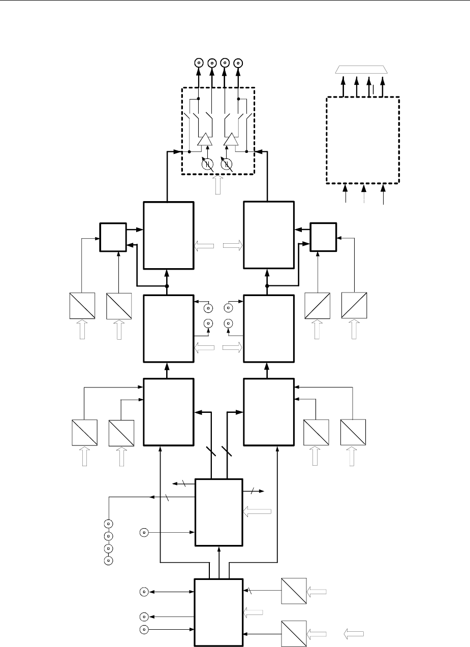
I/Q Signal Adjustments AMIQ
1110.3339.12 4.8 E-6
AMIQ – Block Diagram
Waveform
Memory -
,Data Control
CLK
DATA IN Digital/Analog
Converter
Digital/Analog
Converter
Filter
Filter OUTPUT
Amplifier,
Attenuator
Synthesizer,
Clock-
Distribution
OUTPUT I
OUTPUT Q
A
D
10 MHz REF
IN/OUT TRIGGER
INPUT
Data
Data
off, 25MHz,
2,5MHz, Extern
D
D
A
D
A
I-Offset
var Adj
D
A
I-Gain
var
Multi-
plier
D
A
I-Ampl
fix Adj
D
A
D
A
D
A
Q-Offset
fix Adj
CLOCK
IN/OUT
4
A
D
MARKER 1234
FILT EXT
14
14
OUTPUT
Amplifier,
Attenuator
fix
var
Mode
fix, var
fix
var
Q-Offset
var Adj
Q-Gain
var
I-Offset
fix Adj
Q-Ampl
fix Adj
Skew Adj
10MHz
Ref Adj
I-CLK
Q-CLK
:CORR:OFFS:I:VAR
:CORR:GAIN:I:FIX
:CORR:OFFS:I:FIX
:CORR:OFFS:Q:FIX
:CORR:GAIN:Q:FIX
:CORR:OFFS:Q:VAR
:CORR:SKEW
:OUTP:Q:AMPL
:OUTP:I:AMPL
off, 25MHz,
2,5MHz, Extern
:OUTP:I:FILT
:OUTP:Q:FILT
:CAL:ROSC
:OUTP:I
:OUTP:Q
Controller Input
Multi-
plier
Option
AMIQ-B2
Q
I
I
Q
I
I
U
Bias(I)
U
Bias(Q)
AMIQ-B2 -
CONTROL
(Q I if AMIQ-B19)
A
Option
AMIQ-B3
16
16
I-Data
Q-Data
I-Data
Q-Data
Clock
I
Q
Clk
Clk
Fig. 4-1 Simplified block diagram of AMIQ

AMIQ Measurement of Bit Error Rate
1110.3339.12 4.9 E-6
Measurement of Bit Error Rate
Option AMIQ-B1 allows the signal decoded by the DUT to be assessed. To do so the waveform memory
is filled with a PRBS-modulated (pseudo random binary sequence) data sequence. The data are
decoded by the DUT and forwarded to the AMIQ as clock and data signals. AMIQ synchronizes to the
known PRBS sequence and counts the bit errors.
The BER measurement can also be performed separately (with data from another source).
Connector
The clock and data signals supplied by the DUT must have TTL level and are applied to the bit error rate
input, a 9-contact SUB-D connector at the instrument rear labelled BER. The pin assignment is as
follows:
SUB-D connector Adapter cord
Part number 1110.3551.00
1,2,3,4,5 Ground Shield
6 Bit clock input "CLOCK"
7 Data input “DATA”
8 DAT ENABle input “DAT ENAB”
9 Restart “RES”
The polarity of the clock and data signals, the PRBS polynomial and the integration time can be set with
the respective remote-control commands. The input signals are not terminated in the AMIQ but applied
to ICs type 74LVT14 via a 220 Ω resistor.

Measurement of Bit Error Rate AMIQ
1110.3339.12 4.10 E-6
Signal Path and Waveform
Test setup The desired signal is calculated with the aid of WinIQSIM and loaded into AMIQ. It
is applied to an RF modulator via the I/Q outputs and forwarded to the DUT
(device under test). The latter demodulates the received source bits and returns
them to AMIQ together with a transfer clock. In the AMIQ, the data bits are
checked for errors. The total of the transmitted bits and the faulty bits are counted.
The quotient of error bits/total bits is the BER.
PRBS data To be able to detect faulty bits in a BER measurement, the algorithm used for data
generation must be known. Data are calculated with the aid of so-called pseudo-
random binary sequences (PRBS). These are quasi-random bit sequences which
are repeated according to the selected polynomial.
An advantage of the PRBS data is that the bit error detector has only to know the
calculation algorithm but not the total sequence. Furthermore, the analysis can be
started anywhere in the bit stream, ie the bit-stream source and the analyzer need
not be synchronized.
To get familiar with the BER measurement and to check the BER measurement function in
a simple way, a waveform file named PRBS9_E.WV is stored in the AMIQ waveform
directory. This file contains a PRBS sequence with an error bit, which should produce an
error indication of about 0.19% in WinIQSIM. The COMMENT tag of this waveform includes
a short description allowing a fast check of the BER measurement function.
{COMMENT: This is a waveform for checking the BER measurement. The waveform is applied to
two marker outputs on the rear panel (no signal at I/Q output). To check the BER measurement,
connect the adapter cord (Order No. 1110.3551.00) to the rear BER connector and the DATA
cable to MARK1 and the CLOCK cable to MARK2. The signal at MARK1 (DATA) is a PRBS
sequence with one error bit. To check the BER measurement with WinIQSIM, select 'Remote
Control and Bert', 'Load HD File' and PRBS9_E, tick on Marker Ch.1 and Ch.2, select 'BERT' and
start the BER measurement with 'Cont'. A bit error rate of approximately 0.19% should appear.}
Transfer clock If the DUT does not provide a transfer clock, a marker channel can be
programmed instead as a clock output.
This is explained in the operating manual for WinIQSIM, chapter "Data Editor",
and in the application manual "Software WinIQSIM for Calculating I/Q Signals for
Modulation Generator AMIQ", chapter 5 "BER measurement with WinIQSIM and
AMIQ", order no. 1027.3007.30.

AMIQ Measurement of Bit Error Rate
1110.3339.12 4.11 E-6
Test Method
Generation of
PRBS data PRBS data are generated with the aid of a feedback shift register. The feedback
points are determined by the calculation algorithm. An initial state selected at
random yields exactly one subsequent state. The initial state and therefore the
subsequent state occur only once in the whole data sequence.
Feedback of data
stream If the feedback shift register is filled with a data sequence at the beginning of a
measurement and the register is then switched from "filling" to "feedback", the
register will generate a data sequence which is exactly identical to the one it
should receive from the DUT. Faulty bits can thus be identified and counted by
comparing the received data to the results obtained from the shift register.
This method has the advantage that the analysis can be separated from signal
generation (logically and with respect to time). Consequently, delays caused by the
DUT, the use of other PRBS sources and transmission over long distances with
spatially separated transmitter and receiver, do not cause any problems.
Faulty bits in
output status If a bit error is already present in the output state (faulty bits are not detected
during “filling“), the shift register starts from an incorrect position in the whole data
string. As a result all subsequent states will be faulty. Since, statistically, every
second bit is faulty, the BER will be about 50%. In this case a new measurement is
started automatically so that the error goes unnoticed by the user.
BER
measurement
with
uninterrupted
repetition of the
random
sequence
The non-integrating BER measurement operates with random sequences which
are stored in the AMIQ memory cyclically. The length of the random sequence is
obtained from 2 to the degree of the polynomial less 1, ie PRBS9 has a length of
511 (29 is 512, less 1).
The BER measurement can be set with the command BERT:SETup:RESTart
INTernal and output on the CLOCK and DATA line.
The analysis data
are interrupted
by other data
The data bits carry "extraneous" data such as sync, preambles, other channels etc
in addition to the PRBS data. To identify the data to be evaluated, the BER
measurement must be provided with a validity signal (DAT ENABle input) apart
from the actual data. This DAT ENABle signal is generated either by the DUT or
provided by the AMIQ as a marker channel.
The DAT ENABle signal can be defined in the data editor when the data are
generated in the WinIQSIM. It may be necessary to match the timing of the
marker signal to the data of the DUT (see below).
The BER measurement using the AMIQ should be set to the use of a validity
signal (DAT ENABle); for this the polarity in menu AMIQ -> Remote Control
and BERT is set. The setting DAT ENABle = high signifies that data from the DUT
are counted and subjected to a BER measurement only if the DAT ENABle input is
at 1.

Measurement of Bit Error Rate AMIQ
1110.3339.12 4.12 E-6
BER
measurement
with interrupted
random
sequence –
integrating BER
measurement
Depending on the type of data, oversampling and the finite memory length of
AMIQ, it may happen that the generated random sequence is not cyclically
repeated at the memory wrap-around but that a break occurs at this point. In an
ordinary BER measurement which relies exclusively on the CLOCK and DATA
signals, this break would cause a loss of synchronization and thus about 50% of
faulty bits.
A random sequence with a discontinuity can be handled with the integrating BER
measurement and is switched on by means of the
BERT:SETup:RESTart EXTern command. The BER measurement must be
halted in time and re-started at the beginning of the data sequence. Halt and start
is effected using a signal at the RES input (pin 9 of D-sub connector): A logic 1 at
this input resets the BER measurement, a 0 starts the measurement. It is useful to
link this input with a marker channel of the AMIQ in which a single 1 (about 2 bits
long) is coded at the beginning of the data sequence. The marker channel then
starts the BER measurement anew for each memory cycle (of the discontinuity).
If the data signals are interrupted from other data (eg preambles), the latter can
result in bit errors. The BER measurement can be interrupted for such data with
the aid of the DAT ENABle input on a different marker channel.
In the integrating BER measurement the individual measurements are added up
under the control of a signal at the RES INPUT until the predefined total number
of data or errors bits are attained or exceeded.
Complex measurement and signal sequences of this type cannot be easily
generated manually so with the use of the Windows software WinIQSIM from R&S
it is possible generate data sequences for the BER measurement. It can thus be
ensured that the DAT ENAB and RES signals are timed correctly for the data
signals and discontinuity.
See also chapter titled "Data Editor" in the WinQSIM manual as well as application
manual "Software WinIQSIM for Calculating I/Q Signals for Modulation Generator
AMIQ", chapter 5 "BER measurement with WinIQSIM and AMIQ" Order No.
1027.3007.30.
Note: The flexible programming of the test hardware permits other BER measurement
methods to be used, eg comparison with output pattern, masking certain time and
data ranges. Contact your local R&S sales office for further information.
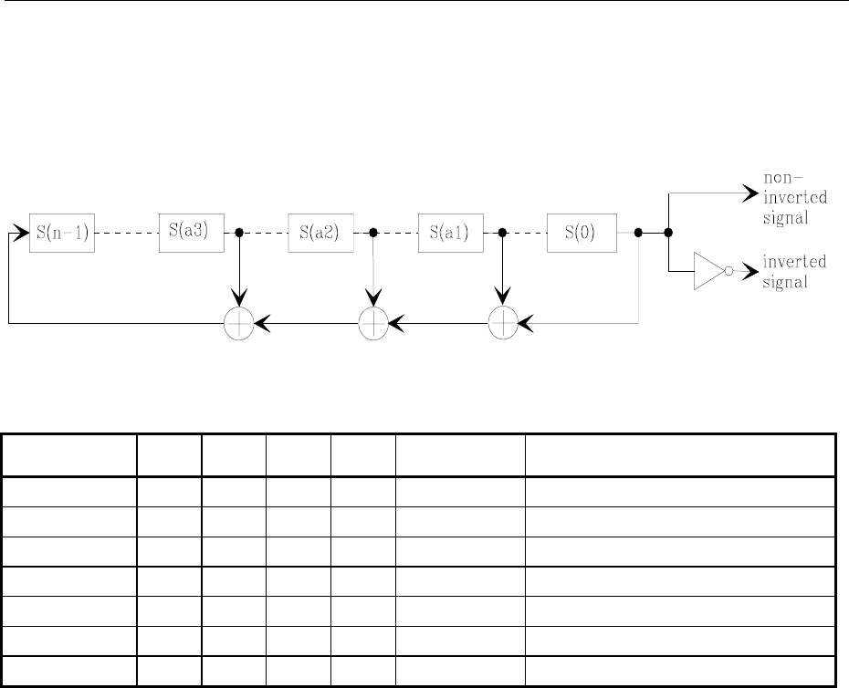
AMIQ Measurement of Bit Error Rate
1110.3339.12 4.13 E-6
PRBS Polynomials
A feedback shift register is used for generating and checking the PRBS. The feedback is switched
depending on the polynomial used. The sequence length of a generator is 2n - 1, n being the degree of
the polynomial.
EXOR EXOR EXOR
Fig. 4-2 PRBS Polynomials
PN generator n a1 a2 a3 Output Applicable standard
PN9 9 4 - - non-inverted ITU-T Rec. O.153 Fascicle IV.4
PN11 11 2 - - non-inverted ITU-T Rec. O.152 Fascicle IV.4
PN15 15 1 - - inverted ITU-T Rec. O.151 Fascicle IV.4
PN16 16 5 3 2 non-inverted --
PN20 20 3 - - non-inverted ITU-T Rec. O.153 Fascicle IV.4
PN21 21 2 - - non-inverted --
PN23 23 5 - - inverted ITU-T Rec. O.151 Fascicle IV.4
Measurement Result, Accuracy, Measurement Time
Value range: The measured BER (ie ratio of faulty bits to total bits) is normally between 10-
2
and
10-
9
. This means that a great number of bits may have to be checked before a
faulty bit is detected. Because of the great number of bits involved the
measurement time is usually very long.
Since 32-bit-wide counters are used for the total bits and the error bits, the
maximum measurement time is 4.29⋅109 bits.
Statistics The BER measurement measures statistical bit errors, ie errors which do not
occur at regular intervals but at random. Although a single measurement
determines the exact number of errors in the measured range, a reliable BER rate
can only be obtained when a sufficient number of errors occurs in the observed
range with the result that the single BER measurement result approaches the true
error rate with high probability .
End criteria To keep the measurement time short with low and high bit error rates, two end
criteria have been defined in AMIQ for the BER measurement.
• Criterion 1: Total number of bits
The measurement is terminated when the total of the specified bits is reached.
Due to this criterion the BER measurement is reliably stopped after the
specified number of bits even if no error or only a few errors were detected and

Measurement of Bit Error Rate AMIQ
1110.3339.12 4.14 E-6
the measurement result is not very accurate (few bit errors).
• Criterion 2: Number of faulty bits
The measurement is terminated when the specified number of bit errors is
detected. With this criterion, the measurement is rapidly terminated when high
bit error rates occur. Since a great number of errors is counted, the
measurement is relatively accurate.
The two criteria are used together. The criterion which finally yields a valid result is
indicated by AMIQ after a result query.
Interruption of
measurement At the end of a measurement, the restart of a new one is delayed until the first
measurement result has been queried with BERT:RES?. The resulting brief
measurement interruption is irrelevant because the subsequent measurement will
be synchronized within 24 data bits.
Possible Problems with BER Measurement and Related Solutions
Fault Possible cause Fault description/remedy
BER
measurement
does not
synchronize
No signals from DUT received
or the signal level is not
correct.
Ø Read the activity of the inputs used for the BER measurement on the
WinIQSIM or SMIQ display.
A green lamp (on the screen) next to the name (clock, data) indicates
that the respective line is active.
BER measurement using
PRBS sequences was not
activated in AMIQ.
Ø Activate the BER measurement using PRBS sequences once before
the measurement is started. This is done with command
BERT:SEL "PRBS".
This command ensures that the measurement hardware is loaded with
the correct configuration file. Then switch AMIQ off and on again to load
the configuration file to the measurement hardware.
The selected PRBS is not
correct. Normally, the PRBS of the data is transmitted together with the waveform
file and used as a default setting. If the PRBS is changed, the BER
measurement cannot synchronize to the data (because the calculation
polynomial is not correct).
A wrong clock edge is used for
triggering violating setup or
hold times.
Ø Check the bit clock signal, the data signal and the DAT ENABle
signal, if any, on an oscilloscope.
The fault may also be caused by reflections on the clock line, which
switch the data signal twice into the BER measurement; see section
Avoid Reflections in the BER Measurement on page 4.17.
Incorrect polarity of data signal
(or DAT ENABle signal). In this case the PRBS cannot synchronize either. Note that an inversion
of the output signal specified for some cases by the PRBS standard is
performed automatically upon PRBS selection. Manual inversion of the
data signal is thus not required.
A bit error occurs during
synchronization (eg the
synchronization time is nine
data bits with PRBS9)
The BER measurement is started at a wrong position so that about 50%
of the subsequent data bits are identified as faulty. This "incorrect" result
is rejected by the AMIQ software and the measurement is automatically
repeated (upon the next query by WinIQSIM or SMIQ).

AMIQ Measurement of Bit Error Rate
1110.3339.12 4.15 E-6
Fault Possible cause Fault description/remedy
No clock
received from
DUT
When testing RF components,
the clock recovery may no be
available. An external clock is
however required for clocking
the data during the BER
measurement
An AMIQ marker channel can be used instead of the clock from the clock
recovery circuit. To do so proceed as follows:
Ø Connect the marker channel (eg marker 1) to the clock input (pin 7) of
the BER measurement.
Ø Program a 0-1 transition in this marker channel for each data bit to be
evaluated.
This method cannot be used with modulations using a value >1 (eg
QPSK) as several bits are coded per symbol. It may be possible to select
a bit pattern in the marker channel which permits a clock edge to be
generated for each bit in the symbol. In this case a sufficiently high
oversampling value must be selected.
BERT is selected by WinIQSIM in the data editor for the generation of a
suitable marker signal. For details refer to the WinIQSIM manual.
Measured BER
too high The data are switched with the
wrong clock edge and/or the
eye pattern of the data is not
optimally met.
Ø Check the clock/data relationship by means of an oscilloscope and
set optimum timing.
ØIf the clock is derived from an AMIQ marker channel, shift the channel
by a few sampling points (see OUTPUT:MARKER<n>:DELAY).
BER measurement [FW1]does
not synchronize . If data that are not cyclically repeated (ie when an interruption occurs at
the memory wrap-around), the measurement will identify about 50% of
the bits as faulty after the wrap-around.
ØMake sure that the measurement is optimally started at the beginning
of the sequence via the signal on the REStart line (see "BER
measurement with interrupted random sequence – integrating BER
measurement" in section "Test Method" on page 4.11).
Further Hints and Tricks
Correction of
DUT delay • If all signals come from the DUT, the delay of the DUT will not cause any problems.
In this case the BER measurement is performed completely independent of the
AMIQ signal output. After the start of the measurement, the BER is automatically
synchronized to the applied data.
• If the clock, DAT ENABle or restart signals are not supplied by the DUT but
generated on the AMIQ marker outputs and the signals are used together with the
clock or data from the DUT, delays may occur which have to be corrected.
The DUT will normally require a certain time to return the data bits to AMIQ. This delay
may be less than one bit. The signal on the marker channel is directly applied from the
output socket to the input for the BER measurement and is therefore not delayed. The
signals on the marker channels (eg the clock signal) must therefore be shifted with
reference to the I/Q output data so that they are optimally time-synchronized.
This can be done in two ways:
Ø Shift the marker of a loaded trace by a specified number of samples using the
function OUTPUT:MARKER<n>:DELAY <samples>.
Ø A pattern is used for generating the clock signals, which defines the sequence of
010 transitions in the marker channel. Modify this clock pattern to shift the active
clock edge (referred to the I/Q output).
Then:
Ø Check the timing of the BER signals on an oscilloscope.
Ø Connect the marker channel containing a clock signal to the clock input (pin 7) of
the BER IC.

Measurement of Bit Error Rate AMIQ
1110.3339.12 4.16 E-6
Installation of Option AMIQ-B1, BER Measurement
If the instrument is ordered with option AMIQ-B1, the option comes as active and ready for operation. If
the option is subsequently ordered, proceed according to the instructions supplied with the option. If
these instructions are not available, follow the instructions given below:
Ø Connect AMIQ to a controller.
Ø Activate option AMIQ-B1 in the AMIQ. To do so send command SYST:OPT AMIQB1,xxxxxxxx to
AMIQ, xxxxxxxx being the key number.
The key number is supplied together with the option. The option needs not be reactivated after a
firmware update.
The activation command can be sent to AMIQ under Remote Control and BERT -> Test and Adjustment
-> Send Command to AMIQ in the AMIQ menu of WinIQSIM.
Ø To activate the BER measurement using PRBS sequences, activate this measurement mode with
command BERT:SEL “PRBS“.
This prepares the loading of the measurement hardware with the correct configuration file. AMIQ has to
be switched off and on again to load the configuration file to the measurement hardware when the
measurement is started. This selection command has to be sent only once. Once the configuration has
been set, it is preserved even after a firmware update.
Activation is checked when a BER measurement is called in WinIQSIM and carried out automatically if
not done before.
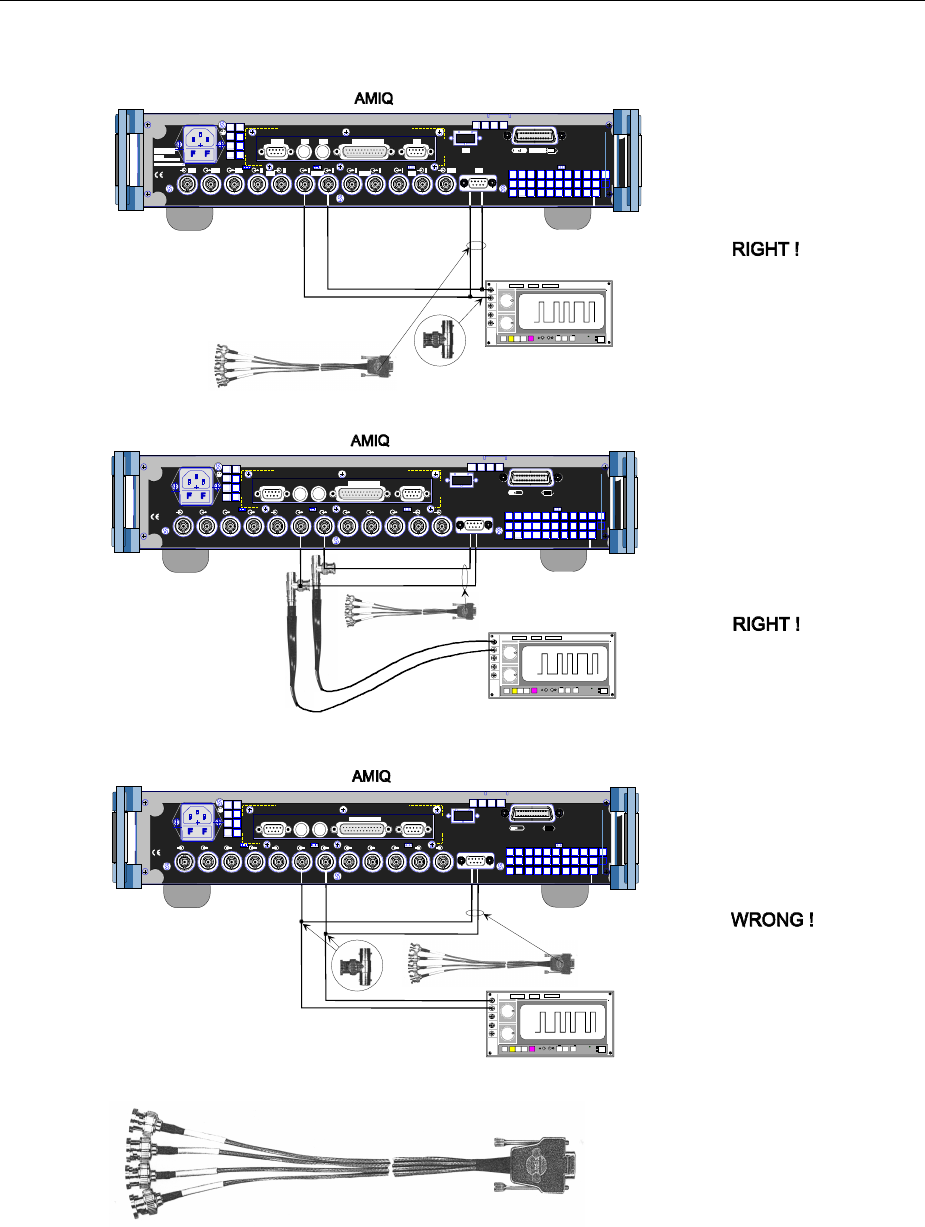
AMIQ Measurement of Bit Error Rate
1110.3339.12 4.17 E-6
Avoid Reflections in the BER Measurement
Clock
Clock Data
Data
Oscilloscope
SCPI
625 IEEE 488
REF REF CLK Q Q I I TRIG BER
FILT 1234 FILTMARK
X 10
MARK
AUTO POWER SELECTION
50...60 Hz 150 VA
100...120 / 200...240 V
F 1 / F 2 :
IEC 127 - T 4.0 H / 250 V
RS 232 X 11 X 12 X 13
LPT
LPT / PARALLEL
SCPI
625 IEEE 488
REF REF CLK Q Q I I TR IG BER
FILT 1 2 3 4 FILTMARK
X 10
MARK
AUTO P OWER S EL ECTI ON
50...60 Hz 150 VA
100...120 / 200...240 V
F 1 / F 2 :
IEC 127 - T 4.0 H / 250 V
RS 232 X 11 X 12 X 13
LPT
LPT / PARALLE L
If the oscilloscope is connected
by means of BNC cables as
shown in this figure, the result
of the BER measurement might
be impaired because of
reflections (spurious signals)
caused by the long branch lines
to the oscilloscope.
With this test setup using BNC
cables, no probes are needed.
There are no reflections
if the BNC cables are directly
connected to the oscilloscope
by means of T connectors.
50 Ohm BNC cable
50 Ohm BNC cable
Clock Data
SCPI
625 IEEE 488
REF REF CLK Q Q I I TRIG BER
FILT 1234 FILTMARK
X 10
MARK
AUTO P OWER S EL ECTI ON
50...60 Hz 150 VA
100...120 / 200...240 V
F 1 / F 2 :
IEC 127 - T 4.0 H / 250 V
RS 232 X 11 X 12 X 13
LPT
LPT / PARALLEL
No reflection problems if
the signals are tapped off
with probes.
Oscilloscope
Oscilloscope
CLOCK
DATA
MASK
RES
CLOCK
DATA
MAS
K
RES
CLOCK
DAT A
MASK
RES
BER test cable
BER test cable
BER test cable
CLOCK
DATA
MASK
RES
The BER test cable is part of the
option AMIQ-B1. It can be ordered
as a replacement part with the stock
no. 1110.3551.00. The pin assignment
is described in section "Connector" in
this chapter.
New BER test cable are labelled
DAT ENAB instead of MASK
Fig. 4-3 Avoid reflections in the BER measurement
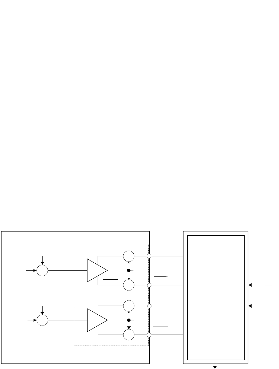
Application Example for Option Differential Outputs AMIQ
1110.3339.12 4.18 E-6
Application Example for Option Differential Outputs
(AMIQ-B2)
Option Differential Outputs (AMIQ-B2, stock no. 1110.3700.02) is a hardware option ready for operation
immediately after being fitted by an R&S service technician. Essentially, a PC board must be installed
and the front panel of AMIQ must be replaced by another one containing 4 output connectors.
Control of the differential outputs by WinIQSIM is supported starting with version 2.10 of both products.
Advantages of
differential outputs
compared to
asymmetric outputs
Manufacturers equip IQ modulator components with differential inputs mainly
to obtain improved technical data concerning port insulation, spurious
responses and harmonics.
Option AMIQ-B2, Differential Outputs, allows to feed these components
correctly with symmetric signals in order to make full use of the technical
specifications of the modulator ICs.
An operating voltage of +5 V, recently also +3,3 V, referred to ground is used.
As a consequence of this asymmetric power supply, the DC level (= operating
point of the corresponding input) must be set to the center of the operating
voltage range by means of an external electric network. The additional
expense to install the external electric network is saved by option AMIQ-B2.
This option allows to superimpose a DC voltage ranging from –2.5 V to + 2.5
V (called bias voltage in the following) upon the symmetric I or Q signal (high-
impedance input).
Example The following application example shows the function of the option combined
with the AMIQ basic unit.
+
+
UBias(I)
+
II + Corr
Offset I User Correction
CORR:OFFS:I:FIX|VAR -1 ... +1
+
+
UBias(Q)
+
QQ + Corr
Offset Q User Correction
CORR:OFFS:Q:FIX|VAR -1 ... +1
AMIQ
AMIQ-B2
DUT
I
I
I
I + Corr
Q
Q
Q + Corr
I/Q modulator
component
RF carrier
I + Corr I+Corr+UBias
I+Corr+UBias
Q + Corr Q+Corr+UBias
Q+Corr+UBias
I
OUTP:Q:BIAS -2.5 ... 2.5V
OUTP:I:BIAS -2.5 ... 2.5V
I/Q modulated RF carrier
Fig. 4-4 Application block diagram of option AMIQ-B2

AMIQ Application Example for Option Differential Outputs
1110.3339.12 4.19 E-6
Functions of the structure shown above:
• AMIQ provides the modulation signals I and Q (asymmetric).
• Option AMIQ-B2 outputs these signals together with the inverted signals I and Q. The signals
control the modulator chip.
• To set the operating point of the modulator component (DUT) a DC voltage UBias that can be
adjusted individually for I (I) and Q (Q) is superimposed upon the modulation signals.
• To optimize the RF carrier suppression an additional correction voltage (Corr), again individually
adjustable for both channels I and Q, can be superimposed upon the initial signals. Inclusion of
option AMIQ-B2 causes the correction voltages to be set in positive direction at the non-inverting
outputs, in negative direction at the inverting outputs. This doubles the absolute value of the
correction between I and I or between Q and Q. Should it be necessary, a difference between the
best operating points for I and Q of the modulator chip can be balanced.
The bias voltage of the option represents basically a „common mode“ voltage for the four signal outputs
while the offset voltage selected via „user correction“ in the AMIQ basic unit represents a balance
setting between the inverting and the non-inverting output.
Once the operating point of the DUT is set via Ubias it can be simply preserved by selecting an output
impedance of 50 Ω for the OFF state even if the signal level is switched off. If „High Impedance“ is
selected, the bias voltage will be set to zero whenever the output is switched off.

AMIQ Model 03 / 04 AMIQ
1110.3339.12 4.20 E-6
AMIQ Model 03 / 04
AMIQ models 03 and 04 can be fitted with the option AMIQ-B3 (digital I/Q output) and supplied with an
external clock, see also "Option AMIQ-B3 (digital I/Q output)" and "External Clock" in this chapter.
AMIQ model 04 is provided with a much larger memory and can thus store traces up to 16 000 000 I/Q
values. Compared with model 03 (4 000 000 I/Q values) model 04 has four times greater memory
capacity. Apart from that there is no difference between the two models.

AMIQ Digital I/Q Output Option AMIQ-B3
1110.3339.12 4.21 E-6
Digital I/Q Output Option AMIQ-B3
The digital I/Q output option is available for models 03 and 04 and supplies the 16-bit data bus for both
channels I and Q at a 68-pin front-panel connector on the AMIQ basic unit. Of the 16 bits the two least
significant bits (d0 and d1) are used as marker signals and the remaining 14 bits for signal generation.
This data bus also drives the two internal 14-bit main DACs. The associated bit clock is supplied in
addition.
Using version 3.10 and higher of the program WinIQSIM the digital output can be activated (ON) or
deactivated (OFF) as long as pin 66 at the connector is high (see pin allocation). If this pin is low, then
the outputs are permanently of high-impedance. This avoids latch-up effects of the following circuit in
the absence of supply voltage.
Traces calculated with versions < 3.10 of WinIQSIM had previously a width of 14 bits, ie d0 and d1 were
fixed at 0 and d2 was rounded by means of d1. Data bits d0 and d1 could be used as marker bits.
Each trace generated by WinIQSIM version 3.10 and higher has a resolution of 14 or 16 bits, depending
on the selected output resolution (see "Operation"):
• For an output resolution of 8 to 14 bits WinIQSIM generates traces with a generation resolution of
14 bits.
• For an output resolution of 15 or 16 bits WinIQSIM generates traces with a generation resolution of
16 bits.
Example:
A 12 bit output resolution is set in WinIQSIM. WinIQSIM calculates and transfers the IQ data with a
resolution of 14 bits (so the marker signals remain accessible). In the {RESOLUTION: x,y} tag, the trace
contains the generation resolution (14 bits) as well as the output resolution (12 bits). When this trace is
loaded into the output RAM of the AMIQ, it is automatically quantized to 12 bits. Still it is possible to
increase the output resolution of the trace to a maximum of 14 bits later without calculating the trace
again.
Each trace generated by WinIQSIN version 3.10 or higher has a resolution of 14 or 16 bits. From this
version up each trace contains the new {RESOLUTION: x,y} tag with
• 'x' = generation resolution (bit width of trace generated by WinIQSIM) and
• 'y' = output resolution (bit width of trace output by AMIQ).
Traces with a generation resolution of 14 bits allow the use of markers without any restriction. However
no markers are available with traces of 16-bit generation resolution because data bits d0 and d1
represent the least significant bits of the I/Q values.
When markers are active and a trace with a generation resolution of 16 bits is loaded, the markers are
switched off and marker commands are rejected. Decreasing the output resolution with the command
OUTPut:RESolution 8...16 does not allow the use of markers since the reduction of the resolution
is achieved mathematically with a rounding logarithm by setting data bits d0 and d1 to 0 which means
that there can be no valid markers. Although loading marker list is theoretically possible after the
reduction of the output resolution to ≤ 14 bits, no use was made of this for the sake of clarity of operation
– the decisive factor for the execution of marker commands is solely the resolution of generation.
A generation resolution of 16 bits has no relevance for the I/Q outputs; in analog operation same as
before d2 ... d15 go to the 14-bit converter. The higher resolution can be fully exploited only together
with the digital I/Q option (AMIQ-B3) and permits a 12-dB higher resolution than at the analog output.
The output resolution of a trace can subsequently be modified with the IEEE 488 command
OUTPut:RESolution 8...16 and must always be ≤ the generation resolution.
The command OUTPut:RESolution 8...16 can be used independently of the digital I/Q output
option (AMIQ-B3) and can be quite useful to reduce the output resolution of the analog outputs to
observe the DUT's response.

Digital I/Q Output Option AMIQ-B3 AMIQ
1110.3339.12 4.22 E-6
Reducing the output resolution has the effect of setting unused bits to 0 and rounding the value. The
value is always output MSB-justified at the digital I/Q output and at the 14-bit D/A converter.
To synchronize the digital data output via the digital I/Q output option (AMIQ-B3) with a system clock,
AMIQ is to be driven with an external clock. To do this, the clock connector on the rear of the AMIQ
basic unit is to be set from output to input in the WinIQSIM program (see section "External Clock" on
page 4.26, "Operation").
To be able to work with a bit clock greater than 25 MHz to 30 MHz, it is recommended to plug the DUT
directly to the 68-pin connector or, if possible, to use short connecting cables to avoid interfering
reflections. In such cases, data and clock lines should be terminated with resistances of 120 Ω to 150 Ω.
Operation of Digital I/Q Output Option (AMIQ-B3) using WinIQSIM
Modulation Generator AMIQ is operated via the WinIQSIM program (versions required:
WinIQSIM = 3.10).
The analog and digital outputs can be activated independently from one another. The AMIQ can be set
in the following way:
• Click the REM button in the top bar or open the menu item ”AMIQ” and ”Remote Control and
BERT...”. The AMIQ operator window now appears.
• The digital I/Q output can be activated or deactivated following the selection of the ”Hardware-
Setting” submenu under "Digital Output".

AMIQ Digital I/Q Output Option AMIQ-B3
1110.3339.12 4.23 E-6
Pin Allocation of Digital I/Q Outputs
Pin 68
Pin 35
Pin 34
Pin 1
Digital Output
Fig. 4-5 Pin allocation of digital I/Q outputs
The output pins of the option has the following features:
Pin 66: the wiring of this pin (PWR_SENSE) enables or disables the outputs:
Low (<0.8 V) = outputs disabled, of high impedance
High (>2.4 V) = outputs enabled
Pin 67: a supply voltage (+3.3 V or +5 V) is provided for an external circuit. The magnitude of
VCC depends on the wiring at Pin 68.
Pin 68: the wiring of this pin determines the supply voltage level at pin 67.
Low (<0.8 V) = +5 V
High (>2.4 V) = +3.3 V
The high level of data, marker and clock signals adapts to the selected supply voltage level.
Further allocation of pins:
Pins 1 to 16: data I0 to I15 (I0 ≡ marker 1, I1 ≡ marker 2)
Pins 17 to 32: data Q0 to Q15 (Q0 ≡ marker 3, Q1 ≡ marker 4)
Pin 33: bit clock
Pin 34: inverted bit clock
Pins 35 to 65: ground
Brief Specifications
Table 4-1 Specifications of option AMIQ-B3
Output 68-contact connector (mini D-sub, half pitch)
Number of channels 2 (one each for I and Q)
Resolution 8 to 16 bits (selectable), no marker output for wordwidth 15 or 16
Max. clock frequency 100 MHz (at clock frequencies greater than 40 MHz, the 20 to 25 ns AMIQ delay between
the input clock and the output data must be taken into account)
Output impedance Approx. 30 to 50 Ω
Data output level +3.3 or +4.0 V to +4.5 V (LVT or ABT high level)
VCC level +3.3 V or +5 V/0.3 A (selectable)
Clock output Normal and inverted polarity
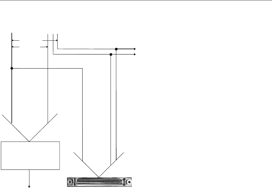
Digital I/Q Output Option AMIQ-B3 AMIQ
1110.3339.12 4.24 E-6
Technical Details
14-bit D/A converter
d15 ... d2
d15 ... d0
Digital I/Q output
Analog I/Q output
Data bus
Marker outputs
d0d1d2d15
Channel I: d0 ≡ marker 1, d1 ≡ marker 2
Channel Q: d0 ≡ marker 3, d1 ≡ marker 4
Fig. 4-6 Technical implementation of digital I/Q outputs

AMIQ Digital I/Q Output Option AMIQ-B3
1110.3339.12 4.25 E-6
IEEE 488 Commands
The following IEEE 488 commands apply to option AMIQ-B3:
Table 4-2 IEEE 488 commands for option AMIQ-B3
Section (see chapter 6) IEEE 488 commands
OUTPut – hardware settings OUTPut:DIGital ON|OFF
OUTPut:RESolution 8 ... 16
OUTPut:MARKer<n> ON|OFF
OUTPut:MARKer<n>:DELay <samples>
Common commands *IDN?
*OPT?
SYSTEM – different settings SYSTem:OPTion?
DIAGnostic – hardware diagnosis DIAG:ABO:ID?
Marker management MARKer<n>[:LIST] <marker list>
Trace file format Tag {RESOLUTION: x,y}
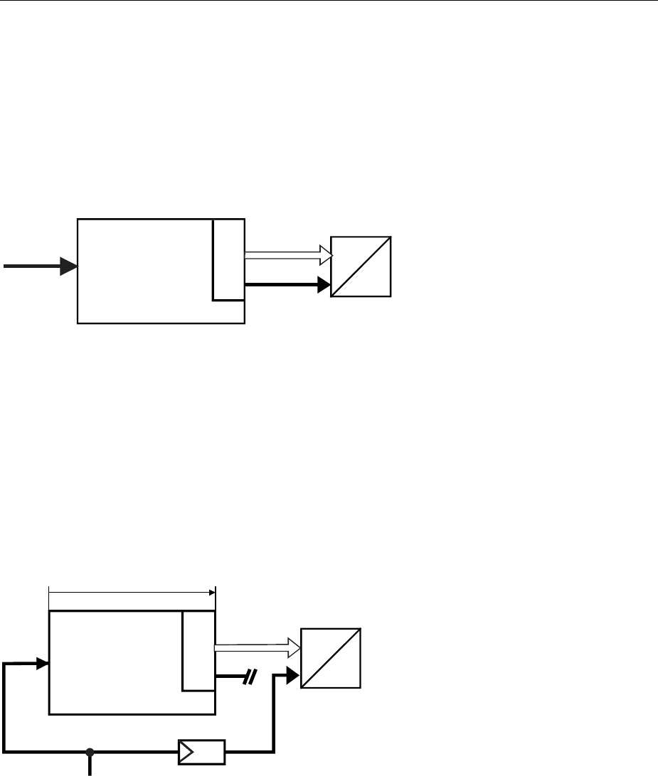
External Clock AMIQ
1110.3339.12 4.26 E-6
External Clock
Brief Description
AMIQ 03 and 04 can be fed with an external clock at the rear-panel connector CLK. The AMIQ can thus
be operated synchronously by means of an external clock. Using an external clock together with option
AMIQ-B3 (digital I/Q output) enables the following operating modes, for example:
Integrating an AMIQ into a system with system clock
DA
AMIQ
Internal
AMIQ clock
Data DUT
System clock
AMIQ B3
Fig. 4-7 Integration of the AMIQ into a system with system clock
Advantage clock frequencies of up to 100 MHz, clock and data synchronous with external clock
Disadvant
age clock may become noise through coupling in AMIQ
Feeding a DUT (eg D/A converter) with a spectrally clean external clock whilst
retaining clock/data synchronization
DA
AMIQ
Si
gna
l
d
e
l
ay
20
to
2
5 ns
Delay equalization required from 40 MH
z
System clock
Data DUT
AMIQ clock
unused
System clock
AMIQ B3
Fig. 4-8 Feeding a DUT with a spectrally pure external clock
Advantage clean clock for DUT
Disadvantage clock frequencies of only up to 40 MHz possible
clock frequencies of 40 to 100 MHz require delay equalization of the clock line to the
DUT

AMIQ External Clock
1110.3339.12 4.27 E-6
Operation
Modulation Generator AMIQ is operated via the WinIQSIM program (versions required:
WinIQSIM = 3.01BETA, AMIQ-FW = 3.0BETA).
• Click the REM button in the top bar or open menu item ”AMIQ” and ”Remote Control and BERT...”.
The AMIQ operator window now appears.
• The "Clock Mode" can be selected under "Source, Trigger ..." following the selection of the
”Hardware Setting” submenu.
IEC/IEEE-bus command
For IEC/IEEE-bus command and frequency ranges see chapter 6: SCLock INTernal|EXTSlow|EXTFast.

Multisegment Waveform AMIQ
1110.3339.12 4.28 E-6
Multisegment Waveform
Application and structure
In particular when the AMIQ is used in automatic test equipment (ATE), the components to be tested
must be operated by a wide variety of test signals. To minimize the test time, the change between the
individual test signals must be as rapid as possible. Loading the new signals from the AMIQ hard disk
should be avoided, if possible. The multisegment waveform (MWV)), which is implemented in the
AMIQ as of firmware version 4.00, meets this requirement.
Superficially, an MWV is similar to a standard waveform in the AMIQ. Its maximum length depends on
the AMIQ model (4 Msamples with AMIQ03, 16 Msamples with AMIQ04). What makes the MWV special
is the fact that it can consist of up to 30 partial traces, the segments.
Each segment can be considered an independent waveform (with its own marker assignment and clock
rate). The complete waveform is loaded into the output RAM of the AMIQ, where a segment can be
selected and output. It is possible to change between the segments (partial signals) without reloading
the output RAM by simply specifying a new segment index. A rapid change between the partial signals,
and, consequently, an acceleration of the test procedure is thus possible.
The structue of the AMIQ output RAM requires the multisegment waveforms to comply with the following
conditions :
• Maximally 30 segments.
• The minimum length of each segment must be 128 ksamples (= 131.072 samples).
• The segment length in samples must be a multiple of 4.
• For a fast segment change, it is recommended that all segments be generated with the same clock
rate. The clock rate can easily be changed in each new segment.
Note: Use the WinIQSIM operator program as of version 3.80 for easy generation of a
multisegment waveform from various partial traces.
The AMIQ ensures compliance with these conditions. The user only needs to specify which standard
waveforms in the AMIQ he or she would like to combine to form a multisegment waveform. The AMIQ
automatically meets the conditions placed on length by repeating the basic waveform of a segment.
Once a multiwaveform has been generated, it can be loaded and output like any other waveform.
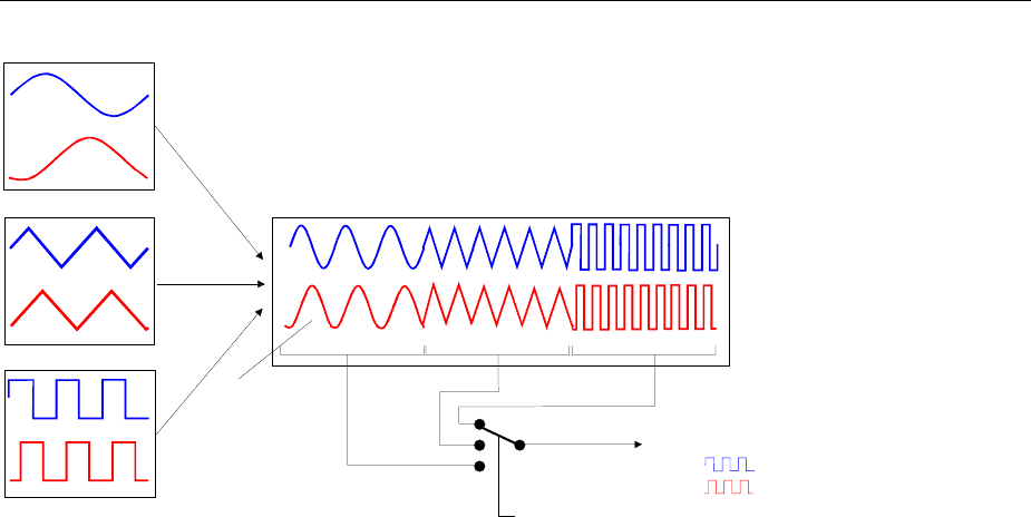
AMIQ Multisegment Waveform
1110.3339.12 4.29 E-6
Partial trace 1
Resulting MWV in output RAM
Partial trace 2
Partial trace 3 Segment 1 Segment 2 Segment 3
MMEMory:MWV:FIRStsegment <Partial trace>,<MWV>,<Comment>
MMEMory:MWV:APPend <Partial trace>,<MWV>,<Comment>
MMEMory:LOAD RAM, <MWV>
ARM
TRIG
g
er:MWVSe
g
ment 3
Output signal
Automatic
repetition
of partial trace
Fig. 4-9 Generation of an MWV from partial traces
IEC/IEEE bus commands
For a detailed description of the IEC/IEEE bus commands, refer to chapter 6.
• Generating an MWV
MMEMory:MWV:FIRStsegment 'Source waveform file to start','Destination
multi segment waveform file','Comment'
MMEMory:MWV:APPend 'Source waveform file to append','Destination multi
segment waveform file','Comment'
• Deleting segments of a multisegment waveform
MMEMory:MWV:DELete 'Multi Segment Waveform file',<Segment to delete>.
• Output of multisegment waveform segments
MMEMory:LOAD RAM 'Multi Segment Waveform file'
ARM und TRIG
TRIGger:MWVS <Segment Index>
• Restrictions during the MWV output
The following minor restrictions apply during an MWV output:
• The GATED trigger operating mode (TRIGger:MODe GATed) is not available.
• Marker lists (OUTPut:MARKer<1..4>:LIST '0-100:1;200-400:0') cannot be subsequently taken into
account.
• Shifting the marker signals (OUTPut:MARKer<1..4>:DELete <shift in samples>) is not possible.
• The output resolution (OUTPut:RESolution <resolution in bit>) of the I/Q signal cannot be
subsequently modified.
• The clock frequency (SOURce:CLOck <clockfrequenz>) cannot be subsequently modified.
These restrictions are referred to in chapter 6, in the commands concerned.

AMIQ Short Introduction
1110.3339.12 5.1 E-5
5 Remote Control - Basics
The instrument is equipped with an IEC bus interface according to standard IEC 625.1/IEEE 488.1 and
a RS-232 interface. The connectors are located at the rear of the instrument and permit to connect a
controller for remote control. The instrument supports the SCPI version 1996.0 (Standard Commands
for Programmable Instruments). The SCPI standard is based on standard IEEE 488.2 and aims at the
standardization of device-specific commands, error handling and the status registers (see section "SCPI
Introduction").
This section assumes basic knowledge of IEC bus programming and operation of the controller. A de-
scription of the interface commands can be obtained from the relevant manuals.
The requirements of the SCPI standard placed on command syntax, error handling and configuration of
the status registers are explained in detail in the respective sections. Tables provide a fast overview of
the commands implemented in the instrument and the bit assignment in the status registers. The tables
are supplemented by a comprehensive description of every command and the status registers. Detailed
programming examples of the essential functions can be found in chapter 7, "Programming Examples".
The examples for IEC bus programming are all written in QuickBASIC.
Note: In contrast to instruments with manual control, which are designed for maximum possible oper-
ating convenience, the priority of remote control is the "predictability" of the device status. This
means that when incompatible settings are attempted, the command is ignored and the device
status remains unchanged, i.e. other settings are not automatically adapted. Therefore,
IEC/IEEE-bus control programs should always define an initial device status (e.g. with the
command *RST) and then implement the required settings.
Short Introduction
Chapter 2, "Getting Started", outlines a short introduction to remote control of the AMIQ. The chapter
also describes how the transfer parameters for RS-232 and the IEC bus can be set without using re-
mote control commands.
Messages
The messages transferred via the data lines of the IEC bus and the serial interface (see section
"Hardware Interfaces" in this chapter) can be divided into two groups:
-interface messages
-device messages

Messages AMIQ
1110.3339.12 5.2 E-5
Interface Messages
Interface messages are transferred on the data lines of the IEC bus, the ATN control line being active.
They are used for communication between controller and instrument and can only be sent by a com-
puter which has the function of an IEC bus controller.
Interface commands can be further subdivided into
-universal commands
-addressed commands
Universal commands act on all devices connected to the IEC bus without previous addressing, ad-
dressed commands only act on devices previously addressed as listeners. The interface messages
relevant to the instrument are listed in section "Hardware Interfaces" in this chapter, subsection
"Interface Messages".
There are no interface message for the RS-232 interface. Only the "Device Clear" is emulated by the
BREAK-signal of the serial interface (see section "Interface functions" on page 5.25). Other interface
messages are replaced by device messages (e.g. "*GTL").
Device Messages (Commands and Device Responses)
Device messages are transferred via the data lines of the IEC bus (the "ATN" control line not being ac-
tive) or via the serial interface. The ASCII code is used. The device messages are largely identical for
the two interfaces. A distinction is made according to the direction in which device messages are trans-
ferred:
– Commands are messages the controller sends to the instrument. They operate the device
functions and request information. The commands are subdivided according to
two criteria:
1. According to the effect they have on the instrument:
Setting commands cause instrument settings such as reset of the instru-
ment or setting the output level to 1 Volt.
Queries cause data to be provided for output on the IEC bus,
e.g. for identification of the device.
2. According to their definition in standard IEEE 488.2:
Common commands are exactly defined as to their function and notation in
standard IEEE 488.2. They refer to functions such as
management of the standardized status registers, re-
set and selftest.
Device-spec. commands refer to functions depending on the features of the
instrument such as frequency setting. A majority of
these commands has also been standardized by the
SCPI committee (cf. section "SCPI Introduction").
– Device responses are messages the instrument sends to the controller after a query. They can
contain measurement results, instrument settings and information on the in-
strument status (cf. section "Responses to Queries").
Structure and syntax of the device messages are described below. The commands are listed and ex-
plained in detail in chapter 6.

AMIQ Structure and Syntax of the Device Messages
1110.3339.12 5.3 E-5
Structure and Syntax of the Device Messages
SCPI Introduction
SCPI (Standard Commands for Programmable Instruments) describes a standard command set for
programming instruments, irrespective of the type of instrument or manufacturer. The goal of the SCPI
consortium is to standardize the device-specific commands to a large extent. For this purpose, a model
was developed which defines the same functions inside a device or for different devices. Command
systems were generated which are assigned to these functions. Thus it is possible to address the same
functions with identical commands. The command systems are of a hierarchical structure. Fig. 5-1 illus-
trates this tree structure using a section of command system SYSTem, which allows to define various
device settings. Most of the other examples concerning syntax and structure of the commands are
taken from this command system.
SCPI is based on standard IEEE 488.2, i.e. it uses the same syntactic basic elements as well as the
common commands defined in this standard. Part of the syntax of the device responses is defined with
greater restrictions than in standard IEEE 488.2 (see section "Responses to Queries").
Structure of a Command
The commands consist of a so-called header and, in most cases, one or more parameters. Header and
parameter are separated by a "white space" (ASCII code 0 to 9, 11 to 32 decimal, e.g. blank). The
headers may consist of several key words. Queries are formed by directly appending a question mark to
the header.
Note: The commands used in the following examples may not in every case be implemented in the
instrument.
Common Commands
Common (=device-independent) commands consist of a header preceded by an
asterisk "*" and eventually one or several parameters.
Examples:
*RST RESET, resets the instrument.
*ESE 253 EVENT STATUS ENABLE, sets the bits of the event status enable
registers.
*ESR? EVENT STATUS QUERY, queries the contents of the event status
register.
Device-specific commands
Hierarchy Device-specific commands are of hierarchical structure (see Fig. 5-1). The different
levels are represented by combined headers. Headers of the highest level (root
level) have only one key word. This key word denotes a complete command sys-
tem.

Structure and Syntax of the Device Messages AMIQ
1110.3339.12 5.4 E-5
Example:
:SYSTem This key word denotes the command system :SYSTem.
For commands of lower levels, the complete path has to be specified, starting on
the left with the highest level, the individual key words being separated by a colon
":".
Example:
:SYSTem:BEEPer:STATe ON
This command is located on the third level of the SYSTem system. It switches on
the beeper (acoustic signal).
SYSTem
BEEPER STATe
CATalog DELete
LENGth?
...
... COMMunicate
GPIB SERial
ADDRess BAUD
Fig. 5-1 Example for the tree structure of the SCPI command systems:
The SYSTem system
Some key words occur on several levels within one command system. Their effect
depends on the structure of the command, i. e. on the position in the command
header they are inserted in.
Example: :MMEMory:DATA:LENGth?
This command contains the key word LENGth? in the third command level. The
command returns the number of waveform files in the current directory.
:MMEMory:DCATalog:LENGth?
This command contains the key word LENGth? in the third command level. It re-
turns the number of waveform directories below the virtual root directory.
Optional key
words Some command systems permit certain key words to be optionally inserted into the
command header or omitted. These key words are marked by square brackets in
this manual. The full command length must be recognized by the instrument for
reasons of compatibility with the SCPI standard. Some commands are considerably
shortened by omitting optional key words.
Example: :MARKer<n>[:LIST] <marker_list>
This command transfers a list of markers to the AMIQ. The following command has
the same effect:
:MARK<n> <marker_list>
Note: An optional key word must not be omitted if its effect is specified
more precisely by a numeric suffix.

AMIQ Structure and Syntax of the Device Messages
1110.3339.12 5.5 E-5
Long and
short form The key words feature a long form and a short form. Either the short form or the
long form can be entered, other abbreviations are not permissible.
Example: :STATus:QUEStionable:ENABle 1
:STAT:QUES:ENAB 1
Note: The short form is marked by upper-case letters, the long form cor-
responds to the complete word. Upper-case and lower-case nota-
tion only serves to distinguish the two forms in the manual, the
instrument itself does not distinguish upper-case and lower-case
letters.
Parameters Parameters must be separated from the header by a "white space". If several pa-
rameters are specified in a command, they are separated by a comma ",". A few
queries permit the parameters MINimum, MAXimum and DEFault. For a description
of the types of parameter, refer to section, "Parameters".
Example: [:SOURce]:CLOCk frequency[,mode]
This command defines the clock rate (frequency) for reading samples from the
output memory in various modes.
Numeric suffix If a device features several functions or features of the same kind, e.g. outputs, the
desired function can be selected by a suffix added to the command. Entries without
suffix are interpreted like entries with the suffix 1.
Example: :OUTPut:MARKer<2> ON
This command activates marker output no. 2.
Structure of a Command Line
A command line may consist of one or several commands. It is terminated by a <New Line>, a <New
Line> with EOI or an EOI together with the last data byte. Quick BASIC automatically produces an EOI
together with the last data byte.
Several commands in a command line must be separated by a semicolon ";". If the next command be-
longs to a different command system, the semicolon is followed by a colon.
Example: CALL IECOUT("MMEM:LOAD RAM,’SINE’;:OUTP:I FIX")
This command line contains two commands. The first command belongs to the MMEMory
system and loads the SINE.WV waveform. The second command belongs to the OUTPut
system and sets the I channel to FIX (Vpp = 1 V into 50 Ω).
If the successive commands belong to the same system, having one or several levels in common, the
command line can be abbreviated. To this end, the second command after the semicolon starts with the
level that lies below the common levels (see also Fig. 5-1). The colon following the semicolon must be
omitted in this case.
Example: CALL IECOUT("MMEM:MSIS ’C:’;:MMEM:LOAD RAM,’SINE’")
This command line, which is shown in its full length, contains two commands separated by
a semicolon and a colon. Both commands belong to the MMEMory system, i.e. they have a
level in common, so the command line can be abbreviated.
In the abbreviated form, the second command starts at the level below MMEM:, i.e. with
LOAD. The colon after the semicolon is omitted.
The abbreviated command line reads as follows:

Structure and Syntax of the Device Messages AMIQ
1110.3339.12 5.6 E-5
CALL IECOUT("MMEM:MSIS ’C:’;LOAD RAM,’SINE’")
Each new command line must start with the complete path, however.
Example: CALL IECOUT("MMEM:MSIS ’C:’")
CALL IECOUT("MMEM:LOAD RAM, ’SINE")
Responses to Queries
A query is defined for each setting command unless explicitly specified otherwise. It is formed by adding
a question mark to the associated setting command. According to SCPI, the responses to queries are
partly subject to stricter rules than in standard IEEE 488.2.
1. The requested parameter is transmitted without header.
Example: :OUTPut:I[:STATe]? Response: OFF
2. Maximum values, minimum values and all further quantities, which are requested via a special text
parameter are returned as numerical values.(not used in AMIQ)
3. Numerical values are output without a unit. Physical quantities are referred to the basic units or to the
units set using the Unit command.
Example: :OUTPut:I:AMPlitude? Response: 1 for 1 V
4. Boolean values are returned as 0 (for OFF) and 1 (for ON).
Example: :SYSTem:BEEPer:STATe? Response: 1
5. Text (character data) is returned in short form (see also section "Parameters").
Example: OUTPut:FILTer? Response: EXT
Parameters
Most commands require a parameter to be specified. The parameters must be separated from the
header by a "white space". Permissible parameters are numerical values, Boolean parameters, text,
character strings and block data. The type of parameter required for the respective command and the
permissible range of values are specified in the command description.
Numerical values Numerical values can be entered in any form, i.e. with sign, decimal point and
exponent. Values exceeding the resolution of the instrument are rounded up or
down. The mantissa may comprise up to 255 characters, the exponent must lie
inside the value range -32000 to 32000. The exponent is introduced by an "E"
or "e". Entry of the exponent alone is not permissible. In the case of physical
quantities, the unit can be entered. Permissible unit prefixes are G (giga), MA
(mega), MOHM and MHZ are also permissible), K (kilo), M (milli), U (micro)
and N (nano). It the unit is missing, the basic unit is used.
Example: :OUTPut:I:AMPlitude 0.01 V is equivalent to
:OUTPut:I:AMPlitude 1E-4

AMIQ Structure and Syntax of the Device Messages
1110.3339.12 5.7 E-5
Special numerical The texts MINimum, MAXimum, DEFault, UP and DOWN are interpreted as
values special numerical values (not used in the AMIQ).
In the case of a query, the associated numerical value is provided.
Example: Setting command: :SENSE2:POWer:REFerence MAXimum
Query: :SENSE2:POWer:REFerence?
Response: 100MW
MIN/MAX MINimum and MAXimum denote the minimum and maximum value.
DEF DEFault denotes a preset value. This value conforms to the default setting, as
it is called by the *RST command.
UP/DOWN UP, DOWN increases or reduces the numerical value by one step. The step
width can be specified via an allocated step command (see chapter 6, "List of
Commands") for each parameter which can be set via UP, DOWN.
INF/NINF INFinity, Negative INFinity (NINF) represent the numerical values -9.9E37 or
9.9E37, respectively. INF and NINF are only sent as device responses.
NAN Not a Number (NAN) represents the value 9.91E37. NAN is only sent as device
response. This value is not defined. Possible causes are division of zero by
zero, subtraction of infinite from infinite and the representation of missing val-
ues.
Boolean Parameters Boolean parameters represent two states. The ON state (logically true) is rep-
resented by ON or a numerical value unequal to 0. The OFF state (logically
untrue) is represented by OFF or the numerical value 0. 0 or 1 is provided in a
query.
Example: Setting command: :OUTPut:CLOCk ON
Query: :OUTPut:CLOCk? Response: 1
Text Text parameters observe the syntactic rules for key words, i.e. they can be en-
tered using a short or long form. Like any parameter, they have to be separated
from the header by a white space. In the case of a query, the short form of the
text is provided.
Example: Setting command::OUTPut:FILTer EXTernal
Query: :OUTPut:FILTer? Response: EXT
Strings Strings must always be entered within quotation marks (’ or ").
Example: :MMEMory:DELete "winiqsim\foobar" or
:MMEMory:DELete ’winiqsim\foobar’

Structure and Syntax of the Device Messages AMIQ
1110.3339.12 5.8 E-5
Block data Block data is a transmission format which is suitable for the transmission of
large amounts of data. A command using a block data parameter has the fol-
lowing structure:
Example: :HEADer:HEADer #45168xxxxxxxx
The double dagger (ASCII character #) introduces the data block. The next
number indicates how many of the following digits describe the length of the
data block. In the example the 4 following digits indicate the length to be 5168
bytes. The data bytes follow. During the transmission of these data bytes all de-
limiters or other control characters are ignored until all bytes are transmitted.
Overview of Syntax Elements
The following survey offers an overview of the syntax elements.
:
;
,
?
*
"
#
The colon separates the key words of a command.
In a command line the separating semicolon marks the uppermost
command level.
The semicolon separates two commands of a command line.
It does not alter the path.
The comma separates several parameters of a command.
The question mark forms a query.
The asterisk marks a common command.
Quotation marks introduce a string and terminate it.
The double dagger (ASCI character #) introduces block data.
A "white space" (ASCII-Code 0 to 9, 11 to 32 decimal, e.g. blank) separates
header and parameter.
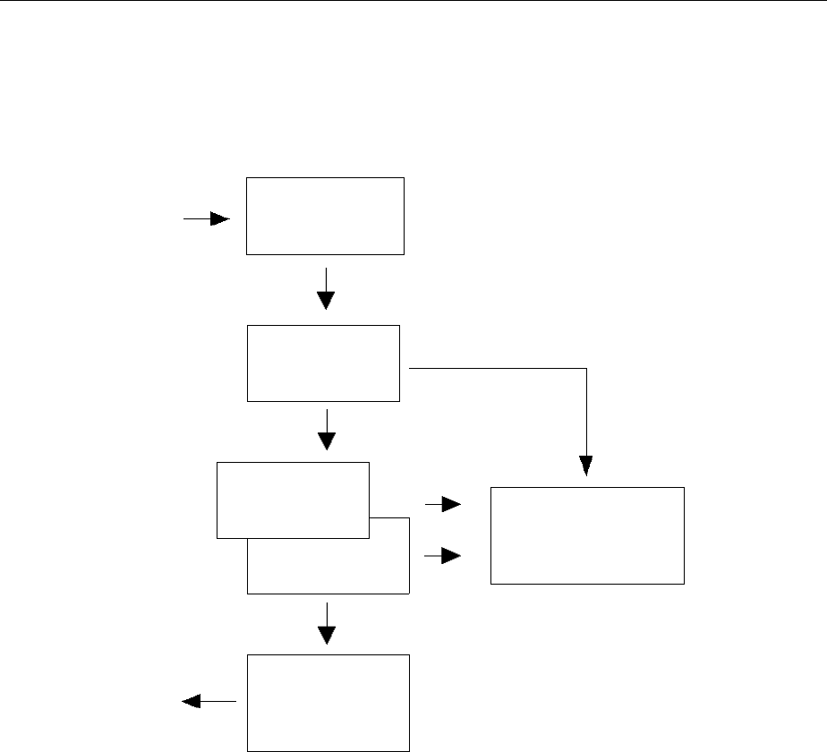
AMIQ Instrument Model and Command Processing
1110.3339.12 5.9 E-5
Instrument Model and Command Processing
The instrument model shown in Fig. 5-2 has been made viewed from the standpoint of the servicing of
IEC bus commands. The individual components work independently of each other and simultaneously.
They communicate by means of so-called "messages".
IEC bus
Input unit with
input buffer
Command
recognition
Data set
Instrument
hardware
IEC bus
Output unit with
output buffer
Status reporting
system
Fig. 5-2 Instrument model in the case of remote control by means of the IEC bus
Input Unit
The input unit receives commands character by character from the IEC bus and collects them in the
input buffer. The input unit sends a message to the command recognition as soon as the input buffer is
full or as soon as it receives a delimiter, <PROGRAM MESSAGE TERMINATOR>, as defined in IEEE
488.2, or the interface message DCL.
If the input buffer is full, the IEC bus traffic is stopped and the data received up to then are processed.
Subsequently the IEC bus traffic is continued. If, however, the buffer is not yet full when receiving the
delimiter, the input unit can already receive the next command during command recognition and execu-
tion. The receipt of a DCL clears the input buffer and immediately initiates a message to the command
recognition.

Instrument Model and Command Processing AMIQ
1110.3339.12 5.10 E-5
Command Recognition
The command recognition analyses the data received from the input unit. It proceeds in the order in
which it receives the data. Only a DCL is serviced with priority, a GET (Group Execute Trigger), e.g., is
only executed after the commands received before. Each recognized command is immediately trans-
mitted to the data set but not executed immediately.
Syntactical errors in the command are recognized here and transferred to the status reporting system.
The rest of a command line after a syntax error is analyzed further as far as possible and serviced.
If the command recognition recognizes a delimiter or a DCL, it requests the data set to set the com-
mands in the instrument hardware as well. Subsequently it is immediately prepared to process com-
mands again. This means for the command servicing that further commands can already be serviced
while the hardware is still being set ("overlapping execution").
Data Set and Instrument Hardware
The expression "instrument hardware" denotes the part of the instrument fulfilling the actual instrument
function - signal generation, measurement etc. The controller is not included.
The data set is a detailed software reproduction of the instrument hardware.
IEC bus setting commands lead to an alteration in the data set. The data set management enters the
new values (e.g. frequency) into the data set, however, only passes them on to the hardware when re-
quested by the command recognition. As this is always only effected at the end of a command line, the
order of the setting commands in the command line is not relevant.
The data are only checked for their compatibility among each other and with the instrument hardware
immediately before they are transmitted to the instrument hardware. If the detection is made that execu-
tion is not possible, an "execution error" is signaled to the status reporting system. All alterations of the
data set are canceled, the instrument hardware is not reset. Due to the delayed checking and hardware
setting, however, impermissible instrument states can be set for a short period of time within one com-
mand line without this leading to an error message (example: simultaneous activation of FM and PM). At
the end of the command line, however, a permissible instrument state must have been reached again.
Before passing on the data to the hardware, the settling bit in the STATus:OPERation register is set (cf.
section STATus:OPERation Register). The hardware executes the settings and resets the bit again as
soon as the new state has settled. This fact can be used to synchronize command servicing.
IEC bus queries induce the data set management to send the desired data to the output unit.
Status Reporting System
The status reporting system collects information on the instrument state and makes it available to the
output unit on request. The exact structure and function are described in section "Status Reporting
System" below.

AMIQ Instrument Model and Command Processing
1110.3339.12 5.11 E-5
Output Unit
The output unit collects the information requested by the controller, which it receives from the data set
management. It processes it according to the SCPI rules and makes it available in the output buffer. If
the information requested is longer, it is made available "in portions" without this being recognized by the
controller.
If the instrument is addressed as a talker without the output buffer containing data or awaiting data from
the data set management, the output unit sends error message "Query UNTERMINATED" to the status
reporting system. No data are sent on the IEC bus, the controller waits until it has reached its time limit.
This behavior is specified by SCPI.
Command Sequence and Command Synchronization
What was said above makes clear that overlapping execution is possible in principle for all commands.
Equally, setting commands within one command line are not absolutely serviced in the order in which
they have been received.
In order to make sure that commands are actually carried out in a certain order, each command must
be sent in a separate command line, that is to say, with a separate IBWRT()-call.
In order to prevent an overlapping execution of commands, one of commands *OPC, *OPC? or *WAI
must be used. All three commands cause a certain action only to be carried out after the hardware has
been set and has settled. By a suitable programming, the controller can be forced to wait for the respec-
tive action to occur (cf. Table 5-1).
Table 5-1 Synchronization with *OPC, *OPC? and *WAI
Com-
mand Action after the hardware has settled Programming the controller
*OPC Setting the operation-complete bit in the ESR - Setting bit 0 in the ESE
- Setting bit 5 in the SRE
- Waiting for service request (SRQ)
*OPC? Writing a "1" into the output buffer Addressing the instrument as a talker
*WAI Executing the next command
Note: The IEC bus handshake is not stopped Sending the next command
An example for command synchronization can be found in chapter 7, "Programming Examples".

Status Reporting System AMIQ
1110.3339.12 5.12 E-5
Status Reporting System
The status reporting system (cf.Fig. 5-4) stores all information on the present operating state of the in-
strument, e.g. that the instrument presently carries out an AUTORANGE and on errors which have oc-
curred. This information is stored in the status registers and in the error queue. The status registers and
the error queue can be queried via IEC bus.
The information is of a hierarchical structure. The register status byte (STB) defined in IEEE 488.2 and
its associated mask register service request enable (SRE) form the uppermost level. The STB receives
its information from the standard event status register (ESR) which is also defined in IEEE 488.2 with
the associated mask register standard event status enable (ESE) and registers STATus:OPERation and
STATus:QUEStionable which are defined by SCPI and contain detailed information on the instrument.
The IST flag ("Individual STatus") and the parallel poll enable register (PPE) allocated to it are also part
of the status reporting system. The IST flag, like the SRQ, combines the entire instrument status in a
single bit. The PPE fulfills an analog function for the IST flag as the SRE for the service request.
The output buffer contains the messages the instrument returns to the controller. It is not part of the
status reporting system but determines the value of the MAV bit in the STB and thus is represented in
Fig. 5-4.
Structure of an SCPI Status Register
Each SCPI register consists of 5 parts which each have a width of 16 bits and have different functions
(cf. Fig. 5-3). The individual bits are independent of each other, i.e. each hardware status is assigned a
bit number which is valid for all five parts. For example, bit 3 of the STATus:OPERation register is as-
signed to the hardware status "wait for trigger" in all five parts. Bit 15 (the most significant bit) is set to
zero for all parts. Thus the contents of the register parts can be processed by the controller as positive
integer.
15 14 13 12 PTRansition part 3 2 1 0
15 14 13 12 EVENt part 3 2 1 0
15 14 13 12 ENABle part 3 2 1 0
& & & & & & & & & & & & & & & &
to higher-order register
Sum bit
& = logical AND
= logical OR
of all bits
+
+
15 14 13 12 NTRansition part 3 2 1 0
15 14 13 12 CONDition part 3 2 1 0
Fig. 5-3 The status register model

AMIQ Status Reporting System
1110.3339.12 5.13 E-5
CONDition part The CONDition part is directly written into by the hardware or the sum bit of
the next lower register. Its contents reflects the current instrument status. This
register part can only be read, but not written into or cleared. Its contents is
not affected by reading.
PTRansition part The Positive-TRansition part acts as an edge detector. When a bit of the
CONDition part is changed from 0 to 1, the associated PTR bit decides
whether the EVENt bit is set to 1.
PTR bit =1: the EVENt bit is set.
PTR bit =0: the EVENt bit is not set.
This part can be written into and read at will. Its contents is not affected by
reading.
NTRansition part The Negative-TRansition part also acts as an edge detector. When a bit of the
CONDition part is changed from 1 to 0, the associated NTR bit decides
whether the EVENt bit is set to 1.
NTR bit =1: the EVENt bit is set.
NTR bit =0: the EVENt bit is not set.
This part can be written into and read at will. Its contents is not affected by
reading.
With these two edge register parts the user can define which state transition of
the condition part (none, 0 to 1, 1 to 0 or both) is stored in the EVENt part.
EVENt part The EVENt part indicates whether an event has occurred since the last read-
ing, it is the "memory" of the condition part. It only indicates events passed on
by the edge filters. It is permanently updated by the instrument. This part can
only be read by the user. Upon reading, its contents is set to zero. In colloquial
language, this part is often equated with the entire register.
ENABle part The ENABle part determines whether the associated EVENt bit contributes to
the sum bit (cf. below). Each bit of the EVENt part is ANDed with the associ-
ated ENABle bit (symbol ’&’). The results of all logical operations of this part
are passed on to the sum bit via an OR function (symbol ’+’).
ENAB bit =0: the associated EVENt bit does not contribute to the sum bit
ENAB bit =1: if the associated EVENT bit is "1", the sum bit is set to "1" as
well.
This part can be written into and read by the user at will. Its contents is not
affected by reading.
Sum bit As indicated above, the sum bit is obtained from the EVENt and ENABle part
for each register. The result is then entered into a bit of the CONDition part of
the higher-order register.
The instrument automatically generates the sum bit for each register. Thus an
event, e.g. a PLL that has not locked, can lead to a service request throughout
all levels of the hierarchy.
Note: The service request enable register SRE defined in IEEE 488.2 can be taken
as ENABle part of the STB if the STB is structured according to SCPI. By
analogy, the ESE can be taken as the ENABle part of the ESR.
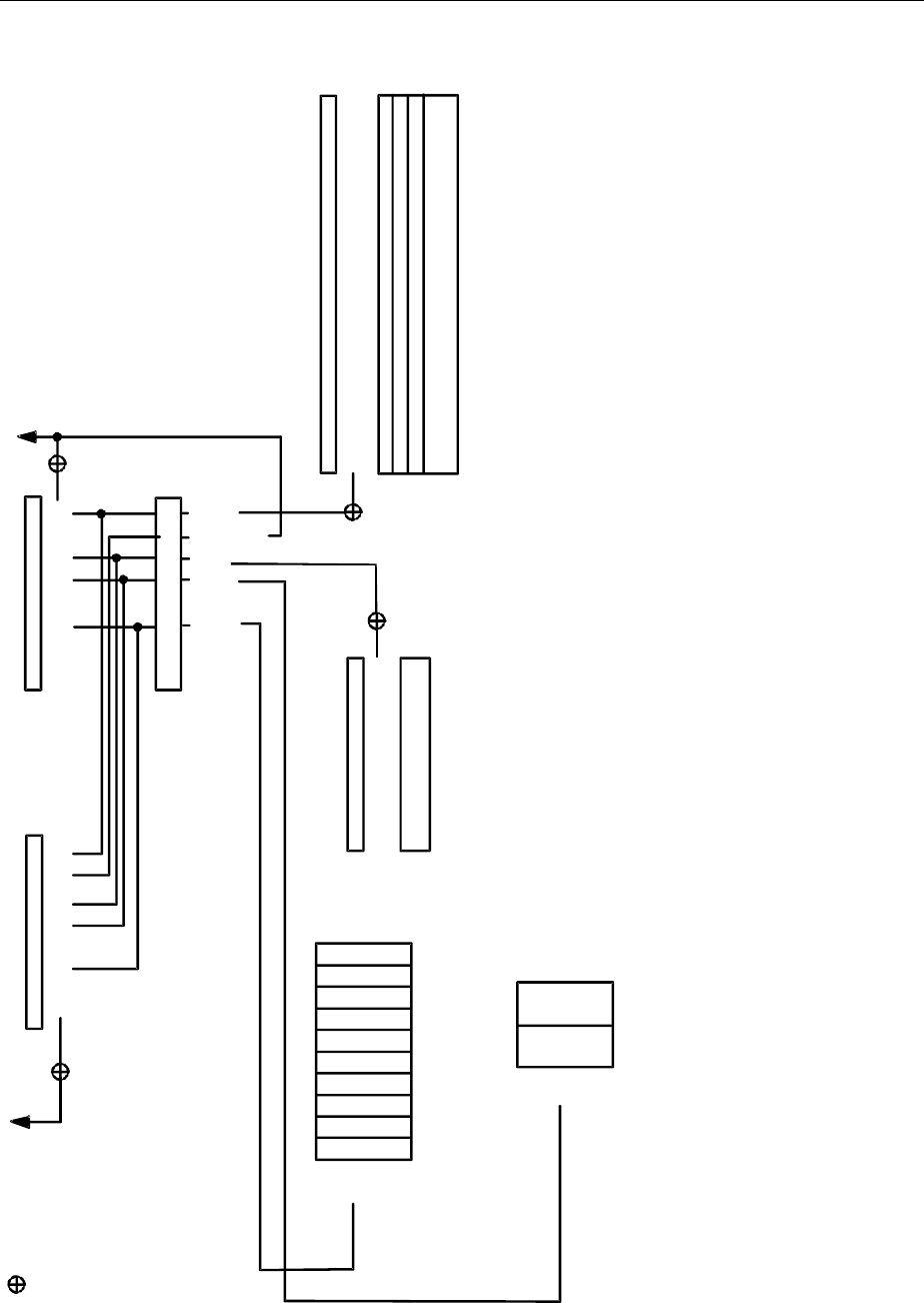
Status Reporting System AMIQ
1110.3339.12 5.14 E-5
Overview of Status Registers
SRE STB
STATus:OPERation register
PPE
IST flag
(response to parallel poll)
& = logical AND
= logical OR
of all bits
ESE ESR
SRQ
RQS/MSS
ESB
Power on
Command error
Execution error
Device dependent error
Query error
Operation complete
15
14
13
12
11
10
9
8
7
6
5
4
3
2
1
0
-&-
-&-
-&-
-&-
-&-
-&-
-&-
-&-
-&-
-&-
-&-
-&-
-&-
-&-
-&-
-&-
-&-
-&-
-&-
-&-
-&-
-&-
-&-
-&-
-&-
-&-
-&-
-&-
-&-
-&-
-&-
-&-
-&-
7
6
5
4
3
2
1
0
Alwais 0
Not used
SELFtest
Waiting for trigger
SETTling
CALibrating
7
6
5
4
3
2
1
0
OPER
Error queue
MAV
ERRQ
STATus:EVENt register
Responses
to queries
Error
messages
Message AVailable
7
6
5
4
3
2
1
0
7
6
5
4
3
2
1
0
Not used
Not used
Not used
Not used
Not used
Not used
Not used
Not used
Not used
Not used
Not used
Not used
Fig. 5-4 The Status registers

AMIQ Status Reporting System
1110.3339.12 5.15 E-5
Description of the Status Registers
Status Byte (STB) and Service Request Enable Register (SRE)
The STB is already defined in IEEE 488.2. It provides a rough overview of the instrument status by col-
lecting the pieces of information of the lower registers. It can thus be compared with the CONDition part
of an SCPI register and assumes the highest level within the SCPI hierarchy. A special feature is that bit
6 acts as the sum bit of the remaining bits of the status byte.
The STATUS BYTE is read out using the command "*STB?" or a serial poll.
The STB is linked to the SRE. The latter corresponds to the ENABle part of the SCPI registers in its
function. Each bit of the STB is assigned a bit in the SRE. Bit 6 of the SRE is ignored. If a bit is set in the
SRE and the associated bit in the STB changes from 0 to 1, a Service Request (SRQ) is generated on
the IEC bus, which triggers an interrupt in the controller if this is appropriately configured and can be
further processed there.
The SRE can be set using command "*SRE" and read using "*SRE?".
Table 5-2 Meaning of the bits used in the status byte
Bit no. Meaning
2Error Queue not empty
The bit is set when an entry is made in the error queue.
If this bit is enabled by the SRE, each entry of the error queue generates a Service Request. Thus an error can
be recognized and specified in greater detail by polling the error queue. The poll provides an informative error
message. This procedure is to be recommended since it considerably reduces the problems involved with IEC
bus control.
3 vacant
4MAV-Bit (Message AVailable)
The bit is set if a message is available in the output buffer which can be read.
This bit can be used to enable data to be automatically read from the instrument to the controller (cf. chapter 7,
"Programming Examples").
5ESB bit
Sum bit of the event status register. It is set if one of the bits in the event status register is set and enabled in
the event status enable register.
Setting of this bit indicates a serious error which can be specified in more detail by polling the event status reg-
ister.
6MSS-Bit (Master Status Summary bit)
The bit is set if the instrument triggers a service request. This is the case if one of the other bits of this register is
set together with its mask bit in the service request enable register SRE.
7OPERation status register sum bit
The bit is set if an EVENt bit is set in the OPERation status register and the associated ENABle bit is set to 1.
A set bit indicates that the instrument is just performing an action. The type of action can be queried by polling
the OPERation status register.

Status Reporting System AMIQ
1110.3339.12 5.16 E-5
IST Flag and Parallel Poll Enable Register (PPE)
By analogy with the SRQ, the IST flag combines the entire status information in a single bit. It can be
queried by means of a parallel poll (cf. section "Parallel Poll") or using the command "*IST?".
The parallel poll enable register (PPE) determines which bits of the STB contribute to the IST flag. The
bits of the STB are ANDed with the corresponding bits of the PPE, with bit 6 being used as well in con-
trast to the SRE. The IST flag results from the ORing of all results. The PPE can be set using com-
mands "*PRE" and read using command "*PRE?".
Event Status Register (ESR) and Event Status Enable Register (ESE)
The ESR is already defined in IEEE 488.2. It can be compared with the EVENt part of an SCPI register.
The event status register can be read out using command "*ESR?".
The ESE is the associated ENABle part. It can be set using the command "*ESE" and read using the
command "*ESE?".
Table 5-3 Meaning of the bits used in the event status register
Bit No.Meaning
0Operation Complete
This bit is set on receipt of the command *OPC exactly when all previous commands have been executed.
1Request Control
This bit is not used in the AMIQ.
2Query Error
This bit is set if either the controller wants to read data from the instrument without having sent a query, or if it
does not fetch requested data and sends new instructions to the instrument instead. The cause is often a query
which is faulty and hence cannot be executed.
3Device-dependent Error
This bit is set if a device-dependent error occurs. An error message with a number between -300 and -399 or a
positive error number, which denotes the error in greater detail, is entered into the error queue (cf. chapter 9,
"Error Messages").
4Execution Error
This bit is set if a received command is syntactically correct but cannot be performed for other reasons. An error
message with a number between -200 and -300, which denotes the error in greater detail, is entered into the
error queue (cf. chapter 9, "Error Messages").
5Command Error
This bit is set if a command which is undefined or syntactically incorrect is received. An error message with a
number between -100 and -200, which denotes the error in greater detail, is entered into the error queue (cf.
chapter 9, "Error Messages").
6User Request
This bit is not used in the AMIQ.
7Power On (supply voltage on)
This bit is set on switching on the instrument.

AMIQ Status Reporting System
1110.3339.12 5.17 E-5
STATus:OPERation Register
In the CONDition part, this register contains information on which actions the instrument is being exe-
cuting or, in the EVENt part, information on which actions the instrument has executed since the last
reading. It can be read using one of the commands "STATus:OPERation:CONDition?" or
"STATus:OPERation [:EVENt]?"..
Table 5-4 Meaning of the bits used in the STATus:OPERation register
Bit-No. Meaning
0CALibrating
This bit is set as long as an internal adjustment routine is executed.
1SETTing
This bit is set as long as a new hardware status is settling after a setting command.
5Waiting for TRIGGER
This bit is set as long as the instrument is waiting for a trigger event.
9Selftest
This bit is set while the instrument executes the command *TST? or one of the commands DIAG:SELF:xxx?
STATus:QUEStionable Register
This register contains information on questionable instrument states. They can occur, e.g. if the instru-
ment is operated outside its specified range. It can be queried using one of the commands ":STATus
:QUEStionable:CONDition?" or ":STATus:QUEStionable[:EVENt]?".
Table 5-5 Meaning of the bits used in the STATus:QUEStionable register
Bit-No. Meaning
At present, no bits of this register are used in the AMIQ.

Status Reporting System AMIQ
1110.3339.12 5.18 E-5
Application of the Status Reporting System
In order to effectively use the status reporting system, the information contained there must be trans-
mitted to the controller to be further processed. There are several methods which are outlined in the
following. For detailed program examples, see chapter 7, "Programming Examples".
Service Request, Making Use of the Hierarchy Structure
Under certain circumstances, the instrument can send a service request (SRQ) to the controller. Usually
this service request initiates an interrupt at the controller, to which the control program can react appro-
priately. As evident from Fig. 5-4, an SRQ is always initiated if one or several of bits 2, 3, 4, 5 or 7 of the
status byte are set and enabled in the SRE. Each of these bits combines the information of a further
register, the error queue or the output buffer. The corresponding setting of the ENABle parts of the
status registers can achieve that arbitrary bits in an arbitrary status register initiate an SRQ. In order use
the possibilities of the service request effectively, all bits should be set to "1" in the enable registers SRE
and ESE.
Examples (cf.Fig. 5-3, section Overview of Status Registers and chapter 7, "Programming examples"):
Use command "*OPC" to generate an SRQ:
½Set bit 0 in the ESE (Operation Complete)
½Set bit 5 in the SRE (ESB)
After its settings have been completed, the instrument generates an SRQ.
Indication of the end of a measurement by means of an SRQ with the controller:
½Set bit 7 in the SRE (sum bit of the STATus:OPERation register)
½Set bit 4 (measuring) in the STATus:OPERation:ENABle.
½Set bit 4 in the STATus:OPERation:NTRansition so as to make sure that the transition of
measuring bit 4 from 1 to 0 (end of measurement) is recorded in the EVENt part.
After a sweep has been completed, the instrument generates an SRQ.
The SRQ is the only possibility for the instrument to become active on its own. Each controller program
should set the instrument such that a service request is initiated in the case of malfunction. The program
should react appropriately to the service request. A detailed example for a service request routine can
be found in chapter 7, "Programming examples".

AMIQ Status Reporting System
1110.3339.12 5.19 E-5
Serial Poll
In a serial poll, just as upon the command "*STB", the status byte of an instrument is queried. However,
the query is made via interface messages and is thus clearly faster. The serial-poll method has already
been defined in IEEE 488.1 and used to be the only standard possibility for different instruments to poll
the status byte. The method also works for instruments which do not adhere to SCPI or IEEE 488.2.
The quick-BASIC command for executing a serial poll is "IBRSP()". The serial poll is mainly used to
obtain a fast overview of the state of several instruments connected to the IEC bus.
Parallel Poll
In a parallel poll, up to eight instruments are simultaneously requested by the controller by means of a
single command to transmit 1 bit of information each on the data lines, i.e., to set the data line allocated
to each instrument to a logic "0" or "1". By analogy to the SRE register which determines under which
conditions an SRQ is generated, there is a parallel poll enable register (PPE) which is ANDed with the
STB bit by bit, considering bit 6 – AND as well. The results are ORed, the result is then sent (possibly
inverted) as a response to the parallel poll of the controller. The result can also be queried without par-
allel poll by means of the command "*IST".
The instrument first has to be set for the parallel poll using the quick-BASIC command "IBPPC()". This
command allocates a data line to the instrument and determines whether the response is to be inverted.
The parallel poll itself is executed using "IBRPP()".
The parallel-poll method is mainly used in order to quickly find out after an SRQ which instrument has
sent the service request if there are many instruments connected to the IEC bus. To this effect, SRE
and PPE must be set to the same value. A detailed example for a parallel poll can be found in chapter 7,
"Programming Examples".
Query by Means of Commands
Each part of any status register can be read by means of queries. The individual commands are listed in
the detailed description of the registers in section Overview of Status Registers. What is returned is
always a number which represents the bit pattern of the register queried. Evaluating this number is ef-
fected by the controller program.
Queries are usually used after an SRQ in order to obtain more detailed information on the cause of the
SRQ.
Error Queue Query
Each error state in the instrument leads to an entry in the error queue. The entries of the error queue
are detailed plain-text error messages which can be looked at in the ERROR menu via manual control
or queried via the IEC bus using command "SYSTem:ERRor?". Each call of "SYSTem:ERRor?" pro-
vides one entry from the error queue. If no error messages are stored there any more, the instrument
responds with 0, "No error"
The error queue should be queried after every SRQ in the controller program as the entries describe the
cause of an error more precisely than the status registers. Especially in the test phase of a controller
program the error queue should be queried regularly since faulty commands from the controller to the
instrument are recorded there as well.

Status Reporting System AMIQ
1110.3339.12 5.20 E-5
Reset Values of the Status Reporting Systems
Table5-6 summarizes the different commands and events causing the status reporting system to be
reset. None of the commands, except *RST and SYSTem:PRESet influences the functional instrument
settings. In particular, DCL does not change the instrument settings.
Table5-6 Resetting instrument functions
Event Switching on
supply voltage DCL,SDC
Power-On-Status-
Clear
(Device Clear,
Selected Device
Clear)
*RST or SYS-
Tem:PRESet STATus:PRESet *CLS
Effect 0 1
Clear STB,ESR
yes
yes
Clear SRE,ESE
yes
Clear PPE
yes
Clear EVENt parts of the
registers
yes
yes
Clear ENABle parts of all
OPERation-and QUES-
Tionable registers,
Fill ENABle parts of all
other registers with "1".
yes
yes
Fill PTRansition parts with
„1"
Clear NTRansition parts
yes
yes
Clear error queue yes yes
yes
Clear output buffer yes yes yes 1) 1) 1)
Clear command process-
ing and input buffer yes yes yes
1) Every command being the first in a command line, i.e. immediately following a <PROGRAM MESSAGE TERMINATOR>
clears the output buffer.

AMIQ Hardware Interfaces
1110.3339.12 5.21 E-5
Hardware Interfaces
IEC/IEEE Bus Interface
The standard instrument is equipped with an IEC/IEEE-bus connection. The IEEE 488 interface con-
nector is located on the rear panel of the instrument. A controller for remote control can be connected
via the IEEE 488 interface using a shielded cable.
Characteristics of the Interface
é8-bit parallel data transfer,
ébidirectional data transfer,
éthree line handshake,
éhigh data transfer rate of max. 350 kByte/s,
éup to 15 devices can be connected,
émaximal length of the connecting cables 15 m (single connection 2 m),
éwired OR if several instruments are connected in parallel.
12 1
13
24
shield SRQ NDAC DAV DIO4 DIO2
logic GND GND(10) GND(8) GND(6) REN DIO7
GND(11) GND(9) GND(7) DIO8 DIO6 DIO5
ATN IFC NRFD EOI DIO3 DIO1
Fig. 5-5 Pin Assigment of the IEC-bus interface
Bus Lines
1. Data bus with 8 lines DIO 1 to DIO 8.
The transmission is bit-parallel and byte-serial in the ASCII/ISO code. DIO1 is the least significant
bit, DIO8 the most significant bit.

Hardware Interfaces AMIQ
1110.3339.12 5.22 E-5
2. Control bus with 5 lines
IFC (Interface Clear),
active LOW resets the interfaces of the instruments connected to the default setting.
ATN (Attention),
active LOW signals the transmission of interface messages
inactive HIGH signals the transmission of device messages.
SRQ (Service Request),
active LOW enables the connected device to send a service request to the controller.
REN (Remote Enable),
active LOW permits switchover to remote control.
EOI (End or Identify),
has two functions in connection with ATN:
ATN=HIGH active LOW marks the end of data transmission.
ATN=LOW active LOW triggers a parallel poll.
3. Handshake bus with three lines
DAV (Data Valid),
active LOW signals a valid data byte on the data bus.
NRFD (Not Ready For Data),
active LOW signals that one of the connected devices is not ready for data transfer.
NDAC (Not Data Accepted),
active LOW signals that the instrument connected is accepting the data on the data bus.
Interface Functions
Instruments which can be controlled via IEC bus can be equipped with different interface functions.
Table 5-7 Interface functions
Control character Interface function
SH1 Handshake source function (source handshake)
AH1 Handshake drain function (acceptor handshake)
L4 Listener function
T6 Talker function, ability to respond to serial poll
SR1 Service request function
PP1 Parallel poll function
RL1 Remote/Local switchover function
DC1 Reset function (Device Clear)
DT1 Trigger function (Device Trigger)

AMIQ Hardware Interfaces
1110.3339.12 5.23 E-5
Interface Messages
Interface messages are transmitted to the instrument on the data lines, with the attention line being ac-
tive (LOW). They serve to communicate between controller and instrument.
Universal Commands
Universal commands are encoded in the range 10 through 1F hex. They are effective for all instruments
connected to the bus without pervious addressing.
Table 5-8 Universal Commands
Command QuickBASIC command Effect on the instrument
DCL (Device Clear) IBCMD (controller%, CHR$(20)) Aborts processing of the commands just received
and sets the command processing software to a
defined initial state. Does not change the instrument
setting.
IFC (Interface Clear) IBSIC (controller%) Resets the interfaces to the default setting.
LLO (Local Lockout) IBCMD (controller%, CHR$(17)) The LOC/IEC ADDR key is disabled.
SPE (Serial Poll Enable) IBCMD (controller%, CHR$(24)) Ready for serial poll.
SPD (Serial Poll Disable) IBCMD (controller%, CHR$(25)) End of serial poll.
PPU (Parallel Poll
Unconfigure) IBCMD (controller%, CHR$(21)) End of the parallel-poll state.
Addressed Commands
Addressed commands are encoded in the range 00 through 0F hex. They are only effective for instru-
ments addressed as listeners.
Table 5-9 Addressed Commands
Command QuickBASIC command Effect on the instrument
SDC (Selected Device
Clear) IBCLR (device%) Aborts processing of the commands just received
and sets the command processing software to a
defined initial state. Does not change the instrument
setting.
GET (Group Execute
Trigger) IBTRG (device%) Triggers a previously active device function. The
effect of the command is the same as with that of a
pulse at the external trigger signal input.
GTL (Go to Local) IBLOC (device%) Transition to the "Local" state (manual control).
PPC (Parallel Poll
Configure) IBPPC (device%, data%) Configure instrument for parallel poll. The Quick-
BASIC command additionally executes PPE / PPD.

RS-232-C Interface AMIQ
1110.3339.12 5.24 E-5
RS-232-C Interface
The standard instrument is equipped with an RS-232-C interface. The 9-pin connector is located on the
rear panel. A controller can be connected via this interface for remote control.
Interface characteristics
éSerial data transmission in asynchronous mode,
éBidirectional data transmission via two separate lines,
éTransmission rate selectable from 300 to 115200 baud,
éLogic 0 signal from +3 V to +15 V,
éLogic 1 signal from -15 V to -3 V,
éAn external instrument (controller) can be connected,
éHardware handshake RTS/CTS set.
RxD DTR
1
6
5
9
TxD
DSR CTS
RTS
Fig. 5-6 Pin assigment of the RS-232-C interface
Signal lines
RxD (Receive Data),
Input; data line for transmitting from remote station to local terminal.
TxD (Transmit Data),
Output; data line for transmitting from local terminal to remote station.
DTR (Data Terminal Ready),
Output (log. ’0’ = active); with DTR, the instrument indicates that it is ready to receive data.
GND (Ground),
Interface ground, connected to instrument ground.
DSR (Data set ready),
Input (log. ’0’ = active); DSR indicates to the instrument that the remote station is ready to re-
ceive data.
RTS (Request to send),
Output (log. ’0’ = active); with RTS, the instrument indicates that it is ready to receive data. The
RTS line controls whether the instrument is ready to receive data or not.
CTS (Clear to send),
Input (log. ’0’ = active); CTS tells the instrument that the remote station is ready to receive data.

AMIQ RS-232-C Interface
1110.3339.12 5.25 E-5
Transmission parameters
In order to ensure error-free and correct data transmission, the parameters of the instrument and the
controller must be set identically.
Transmission rate Baud rates ranging from 1200 to 115200 can be set in the instru-
(baud rate) ment: see chapter 6, :SYSTem:COMMunicate:SERial:Baud.
Data bits Data transmission is in 8-bit ASCII code. The first bit transmitted
is the LSB (Least Significant Bit).
Start bit Each data byte begins with a start bit. The falling edge of the start
bit indicates the beginning of the data byte.
Parity bit No parity bit is used.
Stop bit The transmission of a data byte is terminated by a stop bit.
Example:
Transmission of character A (41 hex) in the 8-bit ASCII code.
01 02 03 04 05 06 07 08 09 10
Bit 01 = Start bit Bit 02...09 = Data bits Bit 10 = Stop bit
Bitduration= 1/baud rate
Interface functions
For interface control, some control characters from the ASCII code range of 0 to 20 hex are predefined
and can be transmitted via the interface (see Table A-4).
Table 5-10 Control strings or control characters of the RS-232-C interface
Control Character Function
Break (at least 1 character only log 0) Reset of instrument
Waiting time until output of new command: 100 ms
0Dhex, 0Ahex Terminator of commands <CR>, <LF>
Switchover between local and remote
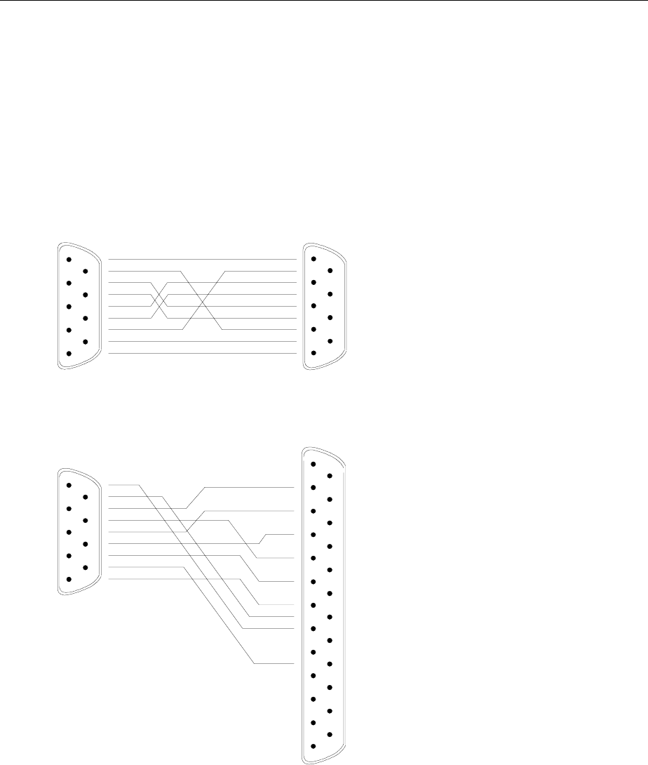
RS-232-C Interface AMIQ
1110.3339.12 5.26 E-5
Handshake
Hardware handshake
In case of a hardware handshake, the instrument signals that it is ready for reception via line DTR and
RTS. A logic ’0’ means "ready" and a ’1’ means "not ready".
The CTS or DSR lines (see signal lines) tell the instrument whether the controller is ready for reception
or not. The transmitter of the instrument is switched on by a ’0’ and switched off by a ’1’. The RTS line
remains active as long as the serial interface is active. The DTR line controls whether the instrument is
ready for reception or not.
1
2
3
4
5
6
7
8
9
DSUB connector, 9 poles / female
1
2
3
4
5
6
7
8
9
DSR
RxD
RTS
TxD
CTS
DTR
GND
AMIQ Controller / PC
DSR
RxD
RTS
TxD
CTS
DTR
GND
AMIQ Controller / PC
1
2
3
4
5
6
7
8
9
DSR
RxD
RTS
TxD
CTS
DTR
GND
1
2
3
4
5
14
15
16
17
6
7
8
9
18
19
20
21
10
11
12
22
23
24
13 25
TxD
RxD
RTS
CTS
DSR
GND
DTR
DSUB connector, 9 poles / female
DSUB connector, 9 poles / female
DSUB connector, 25 poles / female
Connection between instrument
and controller (Null-modem cable)
The connection of the instrument to a
controller is made with a so-called null-
modem cable. Here, the data, control
and signalling lines must be crossed.
The wiring diagram on the left applies
to a controller with a 9-pin or 25-pin
configuration.
Fig. 5-7 Null-modem connection scheme

AMIQ Notation
1110.3339.12 6.1 E-7
6 Remote Control – Commands and Data Formats
In the following sections, all remote control commands of the AMIQ are first listed in tables and then
described in detail, separated according to the command systems. The notation largely corresponds to
the one of the SCPI standards.
All commands can be used for control via IEC/IEEE bus, the serial interface and via the batch files on
floppies and the hard disk (see :PROGram subsystem).
In the detailed description always the shortest possible command line is given as an example for all
commands, except common commands. The value specified for each command is the value set after
an *RST. No values are required for queries and commands triggering an action (eg *CLS).
Notation
Table of commands
Command: The command column provides an overview of the commands and their
hierarchical arrangement.
Parameters: The parameters column indicates the requested parameters together with
their specified range.
Remark: In the remark column, all commands are indicated
− which do not have a query form,
− which have only one query form ,
− which are implemented only in conjunction with a certain option of the
instrument.
Upper/lower case
characters Upper/lower case characters serve to mark the long or short form of the
keywords of a command. The shortform consists of upper case characters, the
long form comprises upper/lower case characters. Only these two forms are
permissible. The instrument itself does not distinguish between upper and
lower case characters.
Special characters | A selection of keywords with identical effect exists for several commands.
These keywords are indicated in the same line, they are separated by a vertical
stroke. Only one of these keywords has to be specified in the header of the
command. The effect of the command is independent of which of the keywords
is specified.
:MMEMory first level
:CD | CDIRectory second level
A vertical stroke between the parameters marks alternative options in the
sense of "or". The effect of the command is different, depending on which
parameter is entered.
Example: Selection of the parameters for the command
:TRIGger:SLOPe RISing | HIGH

Notation AMIQ
1110.3339.12 6.2 E-7
[ ] Key words in square brackets can be omitted when composing the header (see
78chapter 5, section "Structure of a Command" – Optional Keywords). The full
command length must be accepted by the instrument for reasons of
compatibility with the SCPI standards.
Parameters in square brackets are optional and can be omitted.
<n> This sign marks the numeric suffix, which identifies marker outputs, for
instance.
<name> Angle brackets mark a character data parameter that has to be specified within
quotation marks (""). For instance, *RCL <name> may become *RCL "sine".

AMIQ Common Commands
1110.3339.12 6.3 E-7
Common Commands
The common commands are taken from the IEEE 488.2 (IEC 625.2) standard (except for those marked
"not IEEE 488.2" which are device-specific extensions). They have the same effect on all devices. The
headers of these commands consist of an asterisk * followed by three letters. Many common
commands refer to the status reporting system which is described in detail in chapter 5, under "Status
Reporting System".
Table 6-1 Common commands
Command Parameters Remark
*CLS No query
*DCL Not IEEE 488.2
*ESE 0 to 255
*ESR? Query only
*GTL Not IEEE 488.2
*IDN? Query only
*IST? Query only
*OPC
*OPT? Query only
*RCL <name>
*RST
*SAV <name>
*SRE 0 to 255
*STB? Query only
*TRG
*TST? Query only
*WAI
*CLS
CLEAR STATUS sets the status byte (STB), the Standard Event Register (ESR) and the
EVENt-part of the QUEStionable and the OPERation register to zero. The command does not alter
the mask and transition parts of the status registers. It clears the output buffer.
Example: *CLS

Common Commands AMIQ
1110.3339.12 6.4 E-7
*DCL
DEVICE CLEAR resets the remote control logic of the device to a defined default state. The
command is equivalent to the line message Device Clear but can also be used via the serial
interface. Device settings (loaded waveforms, output level, etc) are not changed.
Example: *DCL
*ESE 0 to 255
EVENT STATUS ENABLE sets the Event Status Enable register to the value indicated. The query
*ESE? returns the contents of the event status enable register in decimal representation.
Example: *ESE 255 *RST value: 0
*ESR?
EVENT STATUS REGISTER returns the contents of the Event Status Register in decimal
representation and then sets the register to zero.
Example: *ESR?
*GTL
GO TO LOCAL pseudo command. The GTL line message via the IEC/IEEE bus has the same
function. After this command all remote control channels are active. The channel on which the next
command arrives will be used.
This command is mainly intended for the serial interface. The interface message "gtl" should be
used instead on the IEC/IEEE bus because, when the command *GTL is sent, the IEC/IEEE-bus
talker function of the host will not notice that the device has changed to the local mode and requires
to be newly addressed.
Example: *GTL
*IDN?
IDENTIFICATION QUERY – The response of AMIQ is Rohde & Schwarz, AMIQ, ssssss/sss, x.yy,
where ssssss/sss is the serial number and x.yy the software version.
Example: *IDN?
Response eg: "Rohde&Schwarz,AMIQ,123456/789,3.0" for AMIQ model 02
"Rohde&Schwarz,AMIQ02,123456/789,3.0" for AMIQ model 02 with 03 board
"Rohde&Schwarz,AMIQ03,123456/789,3.0" for AMIQ model 03
"Rohde&Schwarz,AMIQ04,123456/789,3.0" for AMIQ model 04
*IST?
INDIVIDUAL STATUS QUERY returns the contents of the IST flag in decimal form (0 or 1). The IST
flag can also be queried by means of a Parallel Poll.
Example: *IST?

AMIQ Common Commands
1110.3339.12 6.5 E-7
*OPC or *OPC?
OPERATION COMPLETE sets bit 0 in the Event Status Register when all preceding commands
have been executed. This bit can be used to initiate a Service Request, if bit 5 in the Status Enable
Register is set. Advantage of *OPC over *OPC?: The program can perform other tasks while
waiting for an SRQ after an "operation complete" bit has been set in the Event Status Register.
The query OPC? returns a "1" as soon as all preceding commands have been executed. Thus
the controller and the device can easily be synchronized. The "1" is insignificant however –
the procedure is so that, for example, the "ibrd" instruction (function from National
Instruments for reading data from the IEC/IEEE bus) stops program execution until a "1" is
placed in the output buffer. Sending an *OPC? query is therefore not a suitable procedure for
waiting for a "1" in a program loop. This can be done with *OPC.
Example: *OPC?
*OPT?
OPTION IDENTIFICATION QUERY returns a list of installed options separated by commas. A zero
in the list indicates that an option is not installed. The following options are available at present:
− AMIQ-B1: BER Measurement
− AMIQB19: Rear I/Q Outputs
− AMIQ-B2: Differential I/Q Outputs
− AMIQK11: IS-95 CDMA
− AMIQ-B3: Digital I/Q Output
− AMIQK12: CDMA 2000 (from WinIQSIM Version 3.20)
− AMIQK13: not assigned
− AMIQK14: Digital Standard TD-SCDMA (from WinIQSIM Version 3.50)
− AMIQK15: OFDM Signal Generation (from WinIQSIM Version 3.40)
− AMIQK16: Digital Standard 802.11b Wireless LAN
The query *OPT? returns the designations of all options installed in the order given above. Options
not installed are designated "0". In the example below, the zeros indicate that options AMIQB19,
AMIQK13, AMIQK14 and AMIQK16 are not installed.
Example: *OPT? Response: AMIQB1,0,AMIQB2,AMIQK11,AMIQB3,AMIQK12,0,0,AMIQK15,0
*RCL <name>
RECALL recalls the device status file (files with extension .CFG) from drive C: and sets the device
status saved with *SAV under <name>. The extension .CFG may be omitted. It is not allowed to
specify any drive names and paths; the default drive set via MMEM:MSIS <drive> is ignored. If
<name> does not exist, an error message is generated. No distinction is made between upper and
lower case letters for the parameter <name>.
A device status can be loaded from or saved to floppy disk and thus transferred to another device.
See SYSTem:STATe:COPY <source>,<dest> command in the SYSTEM section (p. 6.50 ff).
Example: *RCL "sinus"

Common Commands AMIQ
1110.3339.12 6.6 E-7
*RST
RESET sets the device to a defined default state. If the *RST command is contained in a batch file,
the file is not aborted. Some settings are not affected by *RST. This includes the IEC/IEEE-bus
address, the transmission speed of the serial interface and the status registers.
Example: *RST
*RST default settings:
BERT:SET:CLOC RIS
BERT:SET:MCO 10000
BERT:SET:DATA NORM
BERT:SET:MERR 100
BERT:SET:MASK OFF
BERT:SET:REST INT
BERT:SET:TYPE PRBS9
MARK1:LIST '0-0:0'
MARK2:LIST '0-0:0'
MARK3:LIST '0-0:0'
MARK4:LIST '0-0:0'
MMEM:CDIR '\'
MMEM:MSIS 'C:'
MMEM:LOAD RAM NONE
OUTP:CLOC ON
OUTP:DIG OFF
OUTP:I:AMPL 0.5
OUTP:I:AMPL:BAL 0.5
OUTP:I:FILT 25MHZ
OUTP:I:STAT OFF
OUTP:MARK1:DEL 0
OUTP:MARK1:STAT OFF
OUTP:MARK2:DEL 0
OUTP:MARK2:STAT OFF
OUTP:MARK3:DEL 0
OUTP:MARK3:STAT OFF
OUTP:MARK4:DEL 0
OUTP:MARK4:STAT OFF
OUTP:OIMP R50
OUTP:Q:AMPL 0.5
OUTP:Q:AMPL:BAL 0.5
OUTP:Q:FILT 25MHZ
OUTP:Q:STAT OFF
OUTP:RES 14
OUTP:TYPE UNB
OUTP:I:BIAS 0
OUTP:Q:BIAS 0
SOUR:CLOC 3000000
SOUR:CLOC:MODE SLOW
SOUR:SCLO INTERNAL
SOUR:CORR:GAIN:I:FIX 0.0
SOUR:CORR:GAIN:Q:FIX 0.0
SOUR:CORR:OFFS:I:FIX 0.0
SOUR:CORR:OFFS:I:VAR 0.0
SOUR:CORR:OFFS:Q:FIX 0.0
SOUR:CORR:OFFS:Q:VAR 0.0
SOUR:CORR:SKEW 0.0
SOUR:ROSC:SOUR INT
SYST:BEEP:STAT ON
TRIG:MODE CONT
TRIG:SLOP POS
TRIG:SOUR BUS
IDLE SIGNAL I = 32768 = 0V
IDLE SIGNAL Q = 32768 = 0V
*SAV <name>
SAVE saves the current device status as a device status file (files with the extension .CFG) with the
specified name in drive C:. The extension .CFG may be omitted. It is not allowed to specify any drive
names and paths; the default drive set via MMEM:MSIS <drive> is ignored. This status also
comprises the name of the waveform file currently in the output buffer. The words current and preset
are reserved and must not be used. If a device status with the specified name already exists, it is
overwritten. Names may contain up to eight alphanumeric characters; no difference is made
between upper and lower case characters. Up to 100 device states can be stored, then an error
message is output and the command is not executed. In this case, entries in the memory must be
cleared before a new *SAV command is sent. The save/recall memory is administered under
:SYSTem:STATe.
A device status can be loaded from or saved to floppy disk and thus transferred to another device.
See MMEMory:COPY command in this chapter!
Example: *SAV "cdma"
*SRE 0 to 255
SERVICE REQUEST ENABLE sets the Service Request Enable Register to the defined value. Bit 6
(MSS mask bit) remains 0. This command determines under which conditions a service request is
triggered. Query *SRE? outputs the contents of the Service Request Enable Register in decimal
form. Bit 6 is always 0.
Example: *SRE 191 *RST value: 0
*STB?
STATUS BYTE QUERY reads out the contents of the status byte in decimal form.
Example: *STB?

AMIQ Common Commands
1110.3339.12 6.7 E-7
*TRG
TRIGGER starts the data output from the output buffer. Data output in progress is stopped and
restarted.
Example: *TRG*TST?
*TST?
TEST triggers a complete selftest of AMIQ. This includes approx. 50 internal tests and
measurements yielding the ASCII result „0“ if no error is detected. In case of an error, „1“ is returned
and a short beep sounds.
The selftest for AMIQ’s SDRAM is not included in *TST? because of its long execution time of
approx. 30 seconds for an AMIQ 03 (4.000.000 samples) and approx. 2 minutes for an AMIQ 04
(16.000.000 samples). It can be performed separately by the DIAG:SELF:SDRam? query (see
DIAGnostic – Hardware Diagnosis on page 6.17).
Before the complete selftest is started the device status is automatically saved. It is restored after
the selftest is completed. This implies that the time required for the selftest is extended by the time
needed to restore the previous device status depending on the length of the loaded curve. To keep
this time as short as possible it is recommended to load a short curve (e.g. SINE.WV) before calling
up the selftest. With SINE.WV a complete selftest takes approx. 12 seconds.
The complete selftest *TST? consists of 10 different test routines for the individual hardware
components, see "DIAGnostic:SELFtest ..."
In case of errors during the selftest, each error message is entered in plain text into the error queue.
The error queue may be read out via the SYST:ERR? command.
During the selftest bit 9 in the STATus:OPERation register is set.
Example: *TST?
*WAI
WAIT TO CONTINUE stops the remote control channel until all previous commands are executed.
Thus controller and device can be easily synchronized. See also *OPC.
Example: *WAI

BERT – Bit Error Rate Tests AMIQ
1110.3339.12 6.8 E-7
BERT – Bit Error Rate Tests
AMIQ is able to carry out BER tests with a clock rate of approx. 100 Hz to 20 MHz. All pertaining
functions are controlled in this subsystem.
The BER test is performed by means of option AMIQ-B1. This option is simply installed by entering a
key code (see command SYST:OPT AMIQB1,xxxxxx). For the measurement principle and further
detailed information on the BER test refer to chapter 4.
To perform a BER test, a data signal and a corresponding clock signal is provided by the DUT. The
polarity of both signals can be arbitrarily programmed in the AMIQ (commands
:BERT:SETup:CLOCk[:POLarity], :BERT:SETup:DATA[:POLarity]).
The signal provided by the DUT should correspond to a known (and adjustable) PRBS sequence
(pseudo random bit sequence). The AMIQ compares this signal to the sequence generated by the
internal PRBS generator. The type of PRBS generator to be used must be selected with the command
:BERT:SETup:TYPE before the test is started.
The PRBS generator is then initialized with the data provided by the DUT. The AMIQ uses the first 24
bits after the beginning of the test and then activates the comparator and bit counter. All data received
and all bit errors that occurred are counted. At the end of the test the ratio between the bit errors and
the total number of data is calculated. This ratio is read out as the BER result.
Note: If an error occurs during the first 24 bits, the internal PRBS generator will not be
synchronized in the following and therefore detect a large number of bit errors. In this
case, value no. 7 of BERT:RESult? is set to 0 indicating that the BER measurement is
not synchronized and will be automatically repeated. Possible reasons for an excessive bit
error rate are discussed in chapter 4, section "Possible Problems with BER Measurement
and Related Solutions".
The BER test is terminated if one of the following conditions is met:
• A given number of data is reached. This condition guarantees that the test is terminated after this
number of data, however, if only few errors occurred, the BER result might still be inaccurate.
• A given number of bit errors is reached. This condition gives a quick result if the bit error rate is high.
For a low bit error rate, the test takes longer but still has about the same accuracy.
If the bit error rate is extremely small or zero, the test is terminated by the total number of data and
not by the number of bit errors.
• The test is terminated by a remote control command.
Note: None of the following commands is defined by the SCPI standard. The "Not SCPI" note in
the command table was therefore omitted.
For fast instrument setup for BER measurements see chapter 4, Signal Path and Waveform, PRBS data

AMIQ BERT – Bit Error Rate Tests
1110.3339.12 6.9 E-7
Table 6-2 BERT – Bit error rate tests
Command Parameter Notes
:BERT:COPY <name> No query
:BERT:DELete <name> No query
:BERT:RESult? Query only
:BERT:SELect <name>
:BERT:SETup:TYPE PRBS9 | PRBS11 | PRBS15 |
PRBS16 | PRBS20 | PRBS21 |
PRBS23
:BERT:SETup:CLOCk[:POLarity] RISing | FALLing
:BERT:SETup:DATA[:POLarity] NORM | INVerted
:BERT:SETup:MASK alias
:BERT:SETup:DENable OFF | HIGH | LOW
:BERT:SETup:MCOunt <n> Range: 1 ... 4294967294
:BERT:SETup:MERRor <n> Range: 1 ... 4294967294
:BERT:SETup:RESTart INTernal | EXTernal
:BERT:STARt
:BERT:STOP
:BERT:COPY <name>
copies the specified BERT file from the floppy to drive C: of the AMIQ. It is not allowed to specify any
drive names and paths; the default drive set via MMEM:MSIS <drive> is ignored. The BERT file is
a file containing the configuration information for the (reprogrammable) hardware. If a file with the
same name already exists, error message –282, "Illegal program name" is generated to avoid an
inadvertent overwriting (if required, delete before with BERT:DEL). If the file does not exist on the
floppy, error message –256, "Filename not found" is generated. A query does not exist.
Example: :BERT:COPY "NEW_BER"
Note: This function is not needed for usual operation, it is used only for retrofitting further
BER options and for service purposes.
:BERT:DELete <name>
clears the specified BERT file from drive C: of the AMIQ. It is not allowed to specify any drive names
and paths; the default drive set via MMEM:MSIS <drive> is ignored. If the file does not exist on the
floppy, error message –256, "Filename not found" is generated. A query does not exist.
Example: :BERT:DEL "OLD_BER"
Note: This function is not needed for usual operation, it is used only for retrofitting further
BER options and for service purposes.
:BERT:RESult?
transfers the result of the last BER measurement to the host. The response to the query comprises
7 numeric values separated by commas.
Example: :BERT:RES?
Response: "10000,5,5E-4,1,1,1,1"
Value No.: "1 ,2,3 ,4,5,6,7"

BERT – Bit Error Rate Tests AMIQ
1110.3339.12 6.10 E-7
Value No. 1 Number of data bits in the current query.
Value No. 2 Number of error bits in the current query.
Value No. 3 Bit error rate; if none of the stop conditions was reached since the start of the BER measurement, this
value corresponds to the current ratio between "number of error bits" and "number of data bits". If at
least one end result was obtained during the current (and still ongoing) measurement, the value
corresponds to the last end result obtained. This keeps the BER indication more steady (over the time).
Value No. 4 1 The BER measurement was terminated, i.e., the number of data bits or error bits specified by
means of the commands "BERT:SET MCOunt <n>" or "BERT:SET MERRor <n>" was
reached, or the BER measurement was stopped with the command "BERT:STOP".
0: The BER measurement is not yet terminated.
Value No. 5 1: After the start of a BER measurement (by means of the command "BERT:STARt") an edge
was detected on the clock line.
0: The clock line is not active
Value No. 6 1: After the start of a BER measurement (by means of the command "BERT:STARt") a data
change was detected on the data line. This data change relates to clocked data only; without a
clock, no data changes are detected.
0: The data line is not active.
Value No. 7 1: The BER measurement is synchronized, i.e., clock and data line are active and the ratio
between "number of error bits" and "number of data bits" is better than 0.1 so that the
measurement result obtained can be considered to be reasonable.
0: The BER measurement is not synchronized. For reasons refer to chapter 4, section "Possible
Problems with BER Measurement and Related Solutions".
:BERT:SELect <name>
notes down the BERT file for programming the BERT-FPGA copied to drive C: via BERT:COPY
<name>. It is not allowed to specify any drive names and paths; the default drive set via MMEM:MSIS
<drive> is ignored. Programming is performed only when the device is switched on the next time.
After changing the BERT file the instrument must be switched off and on again.
At present, the following BERT files exist:
NONE Contains no BER measurement, is used for service purposes and if the option is not
installed.
PRBS Contains BER measurement using the PRBS method. The following commands can
only be used if PRBS measurement is selected.
Example: :BERT:SEL "PRBS" *RST value: NONE
:BERT:SETup:...
Depending on the loaded BERT file (see :BERT:SELect) further settings can be made with the aid
of the following commands:
:BERT:SETup:TYPE PRBS9 | PRBS11 | PRBS15 | PRBS16 | PRBS20 | PRBS21 | PRBS23
Various lengths of the pseudo random number sequence can be set for the BERT file "PRBS". The
values "PRBS9" to "PRBS23" are only useful for this file. This command can be extended by other
parameter values for the other BERT files. The PRBS polynomials corresponding to the parameters
selected here are explained in chapter 4.
Example: :BERT:SET:TYPE PRBS15 *RST value: PRBS9

AMIQ BERT – Bit Error Rate Tests
1110.3339.12 6.11 E-7
:BERT:SETup:CLOCk[:POLarity] RISing | FALLing
determines the active edge of the externally applied clock signal. The clock signal is supplied to pin
6 of the BER-connector.
Example: :BERT:SET:CLOC RIS *RST value: RIS
:BERT:SETup:DATA[:POLarity] NORM | INVerted
determines the polarity of the external data signal. The data signal is supplied to pin 7 of the BER-
connector.
NORM: High level corresponds to logic 1, low level to logic 0.
INV: Low level corresponds to logic 1, high level to logic 0.
Example: :BERT:SET:DATA INV *RST value: NORM
:BERT:SETup:DENable OFF|HIGH|LOW alias
:BERT:SETup:MASK OFF|HIGH|LOW
AMIQ is provided with an input (Data Enable) which permits the BER measurement to be
temporarily disabled so that data bursts or data interrupted by other data can be processed. This
command configures this input. The data enable signal is supplied to pin 8 of the BER connector.
OFF: A signal applied to input 8 is ignored, all data are used for BER measurement
HIGH: While input 8 is high, the data bits supplied are counted, bit errors are detected and
counted as well. If the input is low, the measurement is interrupted.
LOW: While input 8 is low, the data bits supplied are counted, bit errors are detected and
counted as well. If the input is high, the measurement is interrupted.
Example: :BERT:SET:MASK HIGH *RST value: OFF
Note: The requirements for the data enable input concerning setup and hold times are the
same as for the data input.
:BERT:SETup:MCOunt <n>
This command sets the total number of data bits to be measured (data masked by the command
BERT:SETup:MASK are not counted). As soon as the internal counter has reached this number (or
exceeded this number, in case of the integrating BER test), the BER measurement is terminated. If
the query "BERT:RES?" is sent to the AMIQ, the 4th value of the response indicates that the BER
measurement has been terminated. This 4th value is set to 1.
Possible range: 1 ... 4294967294 (232-1)
Example: :BERT:SET:MCO 10000 *RST value: 10000

BERT – Bit Error Rate Tests AMIQ
1110.3339.12 6.12 E-7
:BERT:SETup:MERRor <n>
This command sets the number of error bits to be measured. As soon as the internal bit error
counter has reached this number (or exceeded this number, in case of the integrating BER test), the
BER measurement is terminated. If the query "BERT:RES?" is sent to the AMIQ, the 4th value of
the response indicates that the BER measurement has been terminated. This 4th value is set to 1.
Possible range: 1 ... 4294967295 (232-1)
Example: :BERT:SET:MERR 10 *RST value: 100
:BERT:SETup:RESTart INTernal|EXTernal
INT: The reset signal for the BER measurement is internally generated by the program. This
setting is suitable for random sequences which cyclically fit into the memory of the AMIQ so
that an uninterrupted repetition of the sequence is guaranteed.
EXT: If the random sequence during the memory cycle cannot be continued without interruption,
the BER measurement must be stopped in time and re-started at the beginning of the data
sequence. The halt and start is effected by means of a 0-1-0 transition at the input RES (pin 9
of D-sub connector). The BER results are added up until the predefined total number of data
or error bits are attained or exceeded (integrating BER measurement).
For details on the two BER measurement methods see chapter 4, sections
"Measurement of Bit Error Rate"
"Test Method", in particular the paragraphs:
"BER measurement with uninterrupted repetition of the random sequence"
"BER measurement with interrupted random sequence- integrating BER measurement"
The restart signal for the BER test is generated internally by the program (INT) or by a 0-1-0 edge at
pin 9 (RESTART) of the BER connector (EXT).
Example: :BERT:SET:REST EXT *RST value: INT
Attention: If the restart signal is applied in time intervals shorter than the measurement time set,
the measurement can not be terminated because it is restarted over and over again.
Thus, no valid result can be obtained.
:BERT:STARt
This command starts a BER measurement and sets the result to NAN (not a number).
Example: :BERT:STAR
:BERT:STOP
This command stops a running BER measurement. The command has no effect if there is no
measurement.
Example: :BERT:STOP

AMIQ CALibration – Adjustment and Calibration
1110.3339.12 6.13 E-7
CALibration – Adjustment and Calibration
This command set contains functions for automatic adjustment (which can be performed without any
external facilities being required) and adjustment settings. All determined or set values are stored in the
AMIQ-internal EEPROM or on the hard disk and transferred back to the hardware each time the
instrument is switched on.
All functions return 0 after a successful execution, otherwise an error code unequal 0. Each
unsuccessful calibration generates an entry in the error queue which can be queried
with:SYSTem:ERRor?.
Note: All offset and amplitude calibrations as well as :CAL:ALL? determine separate values for
the filter settings OFF, 2.5 MHz, 25 MHz and EXT, irrespective of the value set for
:OUTP:I | Q:FILT. If an external filter is not connected, the routines cannot determine
calibration values for them. A respective warning is output in this case and a result unequal
0 is returned via remote control. The values for the other filter settings are correctly
determined and stored. To avoid a warning being output, external filters have to be
connected, in the simplest case a cable which connects the filter output to the pertaining
filter input.
While adjustment functions are executed, the I and Q outputs are switched off and various settings
changed. After the execution is terminated, the previous device status is restored. This implies that the
time required for the automatic adjustment is extended by the time needed to restore the previous
device status depending on the length of the loaded curve. To keep this time as short as possible it is
recommended to load a short curve (e.g. SINE.WV) before calling up the automatic adjustment.
Except for :CALibration:ALL? none of the commands is specified by the SCPI standards. "Not
SCPI" was therefore omitted in the command table.
*RST is not effective for this command set. Since the instrument was adjusted in the factory, default
settings cannot be specified.
Table 6-3 CALibration – Adjustment and calibration
Command Parameter Notes
:CALibration:ALL? Query only
:CALibration:AMPLitude? Query only
:CALibration:AMPLitude:VALue? Query only
:CALibration:AMPLitude:I? Query only
:CALibration:AMPLitude:I:VALue? Query only
:CALibration:AMPLitude:Q? Query only
:CALibration:AMPLitude:Q:VALue? Query only
:CALibration:DIAGnose 0.9000 to 1.1000
:CALibration:OFFSet? Query only
:CALibration:OFFSet:VALue? Query only
:CALibration:OFFSet:I? Query only
:CALibration:OFFSet:I:VALue? Query only
:CALibration:OFFSet:Q? Query only
:CALibration:OFFSet:Q:VALue? Query only
:CALibration:ROSCillator 0 to 4095

CALibration – Adjustment and Calibration AMIQ
1110.3339.12 6.14 E-7
:CALibration:ALL?
executes all automatic adjustments described below. If all of the operations are executed without an
error, 0 is returned. A value unequal 0 is returned if at least one of the operations failed.
Example: :CAL:ALL?
:CALibration:AMPLitude?
adjusts the signal generation hardware for the operating modes :OUTP:I | Q VAR and FIX. For full-
scale of the waveform D/A converter, the hardware is adjusted so that the amplitude at the I and Q
output is exactly 1 V (EMF).
Example: :CAL:AMPL?
:CALibration:AMPLitude:VALue?
returns a list of the amplitude calibration values stored in the EEPROM in ASCII format, separated
by commas. 18 values are returned:
I_Ampl_Adj[0...3], I_Ampl_Var_p2V, I_Ampl_Var_p90mV, I_Ampl_Var_0V, I_Ampl_Var_m90mV, I_Ampl_Var_m2V,
Q_Ampl_Adj[0...3], Q_Ampl_Var_p2V, Q_Ampl_Var_p90mV, Q_Ampl_Var_0V, Q_Ampl_Var_m90mV, Q_Ampl_Var_m2V
Example: :CAL:AMPL:VAL?
:CALibration:AMPLitude:I?
adjusts the signal generation hardware for the operating modes :OUTP:I VAR and FIX. For a full-
scale of the waveform D/A converter, the hardware is adjusted so that the amplitude at the I output
is exactly 1 V (EMF).
Example: :CAL:AMPL:I?
:CALibration:AMPLitude:I:VALue?
returns a list of the amplitude calibration values stored in the EEPROM for channel I in ASCII format,
separated by commas. 9 values are returned:
I_Ampl_Adj[0...3], I_Ampl_Var_p2V, I_Ampl_Var_p90mV, I_Ampl_Var_0V, I_Ampl_Var_m90mV, I_Ampl_Var_m2V
Example: :CAL:AMPL:I:VAL?
:CALibration:AMPLitude:Q?
adjusts the signal generation hardware for the operating modes :OUTP:Q VAR and FIX. For a full-
scale of the waveform D/A converter, the hardware is adjusted so that the amplitude at the Q output
is exactly 1 V (EMF).
Example: :CAL:AMPL:Q?
:CALibration:AMPLitude:Q:VALue?
returns a list of the amplitude calibration values stored in the EEPROM for channel Q in ASCII
format, separated by commas. 9 values are returned:
Q_Ampl_Adj[0...3], Q_Ampl_Var_p2V, Q_Ampl_Var_p90mV, Q_Ampl_Var_0V, Q_Ampl_Var_m90mV, Q_Ampl_Var_m2V
Example: :CAL:AMPL:Q:VAL?

AMIQ CALibration – Adjustment and Calibration
1110.3339.12 6.15 E-7
:CALibration:DIAGnose 0.9000 to 1.1000
specifies a calibration factor for the diagnostic A/D converter with the aid of which measurement
errors of the converter can be compensated for. Each measured value is multiplied by this
calibration factor before it is output. An external DC voltmeter is required for exact determination of
this value. The procedure is described in the Service Manual.
Example: :CAL:DIAG 1.04
:CALibration:OFFSet?
adjusts the residual DC offset and the offset setting error at the I/ Q outputs to a minimum. Separate
values are determined and stored for each filter setting value (see also the note at the beginning of
this section).
Example: :CAL:OFFS?
:CALibration:OFFSet:VALue?
returns a list of the offset calibration values stored in the EEPROM in ASCII format, separated by
commas. 58 values are returned:
I_Offset1_Adj_FIX[0 ... 3], I_Offset1_Adj_VAR[0 ... 3], I_Offset2_Adj[0 ... 20],
Q_Offset1_Adj_FIX[0 ... 3], Q_Offset1_Adj_VAR[0 ... 3], Q_Offset2_Adj[0 ... 20]
Example: :CAL:OFFS:VAL?
:CALibration:OFFSet:I?
adjusts the residual DC offset and the offset setting error at the I output to a minimum. Separate
values are determined and stored for each filter setting value (see also the note at the beginning of
this section).
Example: :CAL:OFFS:I?
:CALibration:OFFSet:I:VALue?
returns a list of the offset calibration values stored in the EEPROM for channel one in ASCII format,
separated by commas. 29 values are returned:
I_Offset1_Adj_FIX[0 ... 3], I_Offset1_Adj_VAR[0 ... 3], I_Offset2_Adj[0 ... 20]
Example: :CAL:OFFS:I:VAL?
:CALibration:OFFSet:Q?
adjusts the residual DC offset and the offset setting error at the Q output to a minimum. Separate
values are determined and stored for each filter setting value (see also note at the beginning of this
section).
Q_Offset1_Adj_FIX[0 ... 3], Q_Offset1_Adj_VAR[0 ... 3], Q_Offset2_Adj[0 ... 20]
Example: :CAL:OFFS:Q?
:CALibration:OFFSet:Q:VALue?
returns a list of offset calibration values stored in the EEPROM for the Q channel in ASCII format,
separated by commas. 29 values are returned.
Example: :CAL:OFFS:Q:VAL?

CALibration – Adjustment and Calibration AMIQ
1110.3339.12 6.16 E-7
:CALibration:ROSCillator 0 to 4095
enters the tuning voltage for the internal 10 MHz reference oscillator. With the aid of an external
frequency counter, the internal reference oscillator can thus be accurately adjusted to 10 MHz. This
value is stored in the EEPROM. The query returns the value stored in the EEPROM.
Example: :CAL:ROSC 2102
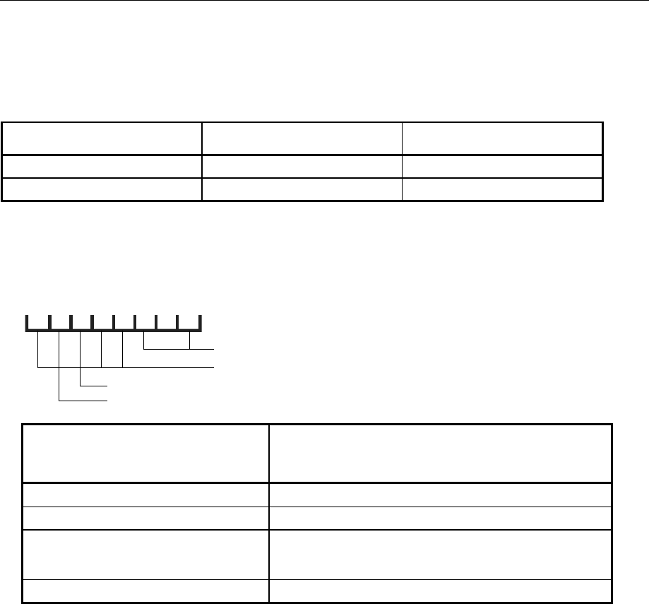
AMIQ DIAGnostic – Hardware Diagnosis
1110.3339.12 6.17 E-7
DIAGnostic – Hardware Diagnosis
The commands of the diagnostic system inform on the internal device status.
Table 6-4 DIAGnostic – Hardware diagnosis
Command Parameter Notes
:DIAGnostic:ABOard:ID? Query only; not SCPI
:DIAGnostic:TPOint<n>? Query only; not SCPI
:DIAGnostic:ABOard:ID?
returns the ID of the built-in analog board.
d7 d6 d5 d4 d3 d2 d1 d0
1: Option AMIQ-B2 (Differential Outputs) fitted
1: Option AMIQ-B3 (Digital I/Q Output) fitted
AMIQ Board ID
Variant
Layout
AMIQ Board ID
if no hardware option is fitted, i.e. if bits d5
and d6 are not set
AMIQ Model, Response string upon *IDN?
145 (0x91) 02 "Rohde&Schwarz,AMIQ,..."
137 (0x89) 02 "Rohde&Schwarz,AMIQ,..."
153 (0x99) 02 "Rohde&Schwarz,AMIQ02,..."
or
03 "Rohde&Schwarz,AMIQ03,..."
155 (0x9B) 04 "Rohde&Schwarz,AMIQ04,..."
Example: :DIAG:ABO:ID?
:DIAGnostic:TPOint<n>?
returns the voltage of the test point identified by <numeric_suffix> (permissible values: 0 to 15). The
voltage is measured by means of the diagnostic A/D converter. To do so the desired test point is set,
the converter started and after a waiting time of 60 ms (maximum duration of a conversion
procedure) the result is returned. The test points are described in the service manual.
Example: :DIAG:TPO7?

DIAGnostic – Hardware Diagnosis AMIQ
1110.3339.12 6.18 E-7
:DIAGnostic:SELFtest:...?
A total of 11 selftest commands are available for testing individual components or programming a
progress bar. The syntax and function of these command is listed in the following table.
Important note:
Before any of the selftest commands for individual components (DIAG:SELF:BAS ...
SDRam) is executed it is absolutely necessary to save the current device status (*SAV
'filename') and recall it after execution (*RCL 'filename) so that correct operation of
AMIQ is guaranteed after the selftest. The device status for each of the components is not
automatically restored in order to avoid the setup loading time which might be quite long
depending on the length of the loaded curve. As in the case of a complete selftest, it is
recommended to load a short curve before executing the *SAV command. This will keep the
time for restoring the previous device state short.
Attention:
The execution time for the SDRAM test is approx. 30 seconds for AMIQ 03 (4,000,000
samples) and approx. 2 minutes for AMIQ 04 (16,000,000 samples). Please provide sufficient
timeout in the controller.
On calling up the individual selftest components all errors are entered in the error queue.
The individual selftest components yield the ASCII result „0“ if no error is detected, „1“ in case of an
error.

AMIQ DIAGnostic – Hardware Diagnosis
1110.3339.12 6.19 E-7
IEEE-Bus Command Description
*TST? The complete selftest consists of the 10 individual
components described in the following:
DIAGnostic:SELFtest:BAS?
DIAGnostic:SELFtest:DSYStem?
DIAGnostic:SELFtest:DACReference?
DIAGnostic:SELFtest:OADJust?
DIAGnostic:SELFtest:OFFSet?
DIAGnostic:SELFtest:REFFrequency?
DIAGnostic:SELFtest:VCO?
DIAGnostic:SELFtest:LEVels?
DIAGnostic:SELFtest:ATTenuators?
DIAGnostic:SELFtest:LPASs?
They are executed without interruption.
DIAGnostic:SELFtest:SDRam?
The selftest for the AMIQ’s SDRAM is not included in
*TST? because its execution time amounts to approx.
30 seconds for AMIQ 03 (4,000,000 samples) and approx.
2 min for AMIQ 04 (16,000,000 samples).
The selftest yields the ASCII result „0“ if no error is detected
in any of the components, „1“ in case of an error.
DIAGnostic:SELFtest:BASics?
DIAGnostic:SELFtest1? Sequencer FPGA file
BER-FPGA file
Stock number of analog board
EEPROM data
DIAGnostic:SELFtest:DSYStem?
DIAGnostic:SELFtest2? Zero point of the system
Reference level of diagnostic AD-converter
DIAGnostic:SELFtest:DACReference?
DIAGnostic:SELFtest3? Reference level of all setting DACs
DIAGnostic:SELFtest:OADJust?
DIAGnostic:SELFtest4? Offset settings
DIAGnostic:SELFtest:OFFSet?
DIAGnostic:SELFtest5? Offsets in the signal path
DIAGnostic:SELFtest:REFFrequency?
DIAGnostic:SELFtest6? Clock frequency sources
DIAGnostic:SELFtest:VCO?
DIAGnostic:SELFtest7? VCO control voltage
DIAGnostic:SELFtest:LEVels?
DIAGnostic:SELFtest8? Operating level
DIAGnostic:SELFtest:ATTenuators?
DIAGnostic:SELFtest9? Attenuator test in the I and Q channel
DIAGnostic:SELFtest:LPASs?
DIAGnostic:SELFtest10? Identical filters in I and Q channels
DIAGnostic:SELFtest:SDRam?
DIAGnostic:SELFtest11? Test of SDRAM of AMIQ by means of a random binary
sequence.
Note: The execution time for this command is
approx 30 seconds for AMIQ 03 (4,000,000
samples) and approx. 2 minutes for AMIQ 04
(16,000,000 samples). Provide sufficient
timeout in the controller.
Example: *SAV 'TEMP'
:DIAG:SELF:ATT?
*RCL 'TEMP'
Program example:
Selftest with progress indication
in the programming language C combined with the IEEE-bus driver GPIB.COM by National
Instruments, see chapter 7!

MARKer – Marker Management AMIQ
1110.3339.12 6.20 E-7
MARKer – Marker Management
Two binary marker outputs are available for each channel. The status of the outputs is stored in the two
least-significant bits of each waveform sample with the following assignment:
Marker output Channel Bit
Marker 1 I Least-significant bit
Marker 2 I Second bit
Marker 3 Q Least-significant bit
Marker 4 Q Second bit
A 1 in one of these bits generates high level at the associated marker output, 0 the corresponding low
level.
The marker outputs can be programmed in three different ways:
• When the waveform file is generated with the host computer, the respective bits of each sample are
set to the desired values.
• The markers are specified within the waveform file with the aid of the MARKER LIST tag.
• The markers are specified with the remote control command :MARK:LIST <marker list>
independent of the waveform file.
In the case of a conflict between the marker values from a waveform loaded via the commands
MMEM:LOAD RAM,<filename> or MEM:DATA RAM,<Binärblock> (and included in the data bits d0
and d1), and the marker values from a marker list loaded afterwards via the command
MARK<n>[:LIST] <marker list>, the markers from the list have the priority.
If the marker values of a marker list do not correspond (eg MARK1 '100-101:0;100-101:1'), the
last setting is valid.
When a waveform is loaded via the commands MMEM:LOAD RAM, 'filename> or MEM:DATA
RAM;<Binärblock>, the existing marker lists are deleted (an empty marker list "0-0:0" is generated)
so that the marker bits included in the waveform can become effective.
Note: The :MARKer subsystem is available four times (:MARKer1 to :MARKer4) for the four
marker channels. Markers 1 and 2 belong to the I channel, markers 3 and 4 to the
Q channel.
If the "Rear I/Q Outputs" option (AMIQ-B19) is installed, marker outputs 3 and 4 on the
rear are not available because they are used for the I and Q output signals, i.e. the I output
is assigned to marker output 4 and the Q output to marker output 3.!
If "Digital I/Q Output" option (AMIQ-B3) is not installed, any commands relating to these
marker outputs are ineffective, but no error message is output.
If the option is installed, marker outputs 3 and 4 are available on data lines Q0 and Q1
(see chapter 4, "Digital I/Q Output" option AMIQ-B3).
Table 6-5 MARKer – Marker management
Command Parameter Notes
:MARKer<n>[:LIST] <marker list> Not SCPI

AMIQ MARKer – Marker Management
1110.3339.12 6.21 E-7
3:MARKer<n>[:LIST] <marker list>
transfers a marker list to AMIQ. The markers are immediately stored in the RAM (an ongoing output
is interrupted and has to be restarted). The markers of the waveform currently in the RAM are
changed. The waveform file on the hard disk is not affected, but can be changed with the aid of an
update waveform file (see section "Waveform File Format" {TYPE:WV-ADD}).
Since marker lists are saved in the AMIQ's setup same as any other command, they must not be
greater than 450 character long in order not to overburden the setup files. This has the benefit that
marker lists up to this length are immediately set following the power-off/on of the AMIQ or after
loading a setup with *RCL <name>.
Longer marker lists should be split and transferred by means of several commands. After power-
off/on of AMIQ or loading a setup only the last part of the marker list is available. This means that
longer marker lists should be transferred directly to the required trace using the
WinIQSIM software.
The query MARK<n>? returns the marker list of the waveform currently in the RAM. The list contains
any number of entries separated by colons, which may have one of the following forms:
start-end:value or start:value
with start: start index
end: end index; exclusive, ie the markers of samples with this index are
not changed
value: 0 or 1
start-end:value: Specification of marker ranges
‚value‘ applies in the range between the specified start index and end index. The
markers in ranges not specified remain unchanged.
start:value: Specification of marker changes
‚value‘ applies in the range between the specified start index and the next
specified start index or up to the end of the waveform. The markers in all ranges
are changed.
The list may contain any number of marker changes or ranges. Start must of course be lower than
the length of the loaded waveform. Start and value are ASCII coded, not in binary form.
AMIQ has a delay line (in the form of software) for each marker channel, which can be set in the
:OUTPut subsystem.
Example: MARK1 “0-100:1;200-400:0“ *RST value: 0-0:0 empty list
After the output has been started, high level is present at the marker 1 output during the
output of samples 0 to 100. From sample 101 to 199, the level depends on the value of the
least-significant bits of the samples (because no entries have been made for this in the
marker list). From sample 200 to 400 the output is at high level. From sample 401 till the
end of the waveform the level again depends on the values in the samples.
If a trace with a generation resolution of 16 bits is loaded (see trace file format {RESOLUTION 16,x}
in this chapter), the marker list command is ineffective. However there will be no error message
because the dependence between the generation resolution of a trace and the marker outputs is
already taken into account in WinIQSIM.
The marker lists can be called up again after loading a trace with a generation resolution of 14 bits.
Restrictions for the multisegment waveform
The :MARKer<n>[:LIST] <marker list> command is not available for the multisegment waveform
(see chapter 4). Marker lists cannot be subsequently taken into account.
If an MWV is loaded, and this command is followed by a query, the identification of an empty list is
returned.
Example: MARK1:LIST? Response: '0-0:0'

MEMory/MMEMory – Waveform Management AMIQ
1110.3339.12 6.22 E-7
MEMory/MMEMory – Waveform Management
AMIQ is able to store waveform files on its internal hard disk from where they are loaded in the output
buffer. The commands of the two systems allow waveform files to be transferred between controller
and AMIQ and the management (copying, shifting, renaming, clearing) of waveform files and directories
on the AMIQ hard disk.
The command for a direct transfer of waveform data from the IEC/IEEE bus to the RAM is part of the
MEMory subsystem. According to SCPI, all commands for accessing the hard disk and the floppy are
contained in the MMEMory system. Because of the similarity of the functions, the two systems are dealt
with in one section.
The MMEMory subsystem manages only waveform files. Executable batch files are managed in the
:PROGram subsystem.
Note: Although the functions (copying, clearing, changing directory, etc) are similar to those of
DOS, SCPI keywords and parameters are often different from the familiar DOS
conventions. For reasons of SCPI compatibility, AMIQ uses SCPI forms as far as possible.
A few alternative commands (eg CD for CDIRectory, MD for MDIRectory, and RD for
RDIRectory) were introduced for the sake of compatibility with DOS conventions.
AMIQ provides a virtual file system on its hard disk with the drives C:, D:, E:, and F: (D:, E:, and F: are
logical partitions on the hard disk). The drives can be defined as default drives via the command
MMEMory:MSIS <drive>.
Note: The AMIQ has at least the two drives C: and D: with a storage capacity of 2000 Mbyte on
drive C: and the rest on drive D:, depending on the installed disk drive. It may also have
other drives.
Which and how many drives AMIQ actually has depends on the supply of disk drives at the
time and can be found out by means of commands MMEMory:SCATalog? and
MMEMory:SCATalog:LENGth?
Each drive has only one directory level. All path names for the drives are relative to a fictitious root
directory to be addressed with \. The specified names are not the DOS file names. There are no
restrictions for file operations on the floppies.
With all data transfer commands, the data for the two channels are transferred simultaneously.
Table 6-6 MEMory – Waveform management
Command Parameter Notes
:MEMory:DATA RAM, <binary block data>
:MEMory:NAME? Query only; not SCPI

AMIQ MEMory/MMEMory – Waveform Management
1110.3339.12 6.23 E-7
Table 6-7 MMEMory – Waveform management
Command Parameter Notes
:MMEMory:CATalog | DIRectory? Query only
:MMEMory:CATalog:LENGth? Query only; not SCPI
:MMEMory:CDIRectory | CD <directory>
:MMEMory:COPY <filename> [, <dest>]
:MMEMory:DATA <filename>, <bin. block data> *No query
:MMEMory.DATA? <filename>[,<tag>] *
:MMEMory:DATA:LENGth? <filename> [,<tag>] *Not SCPI
:MMEMory:DCATalog | DDIRectory? Query only; not SCPI
:MMEMory:DCATalog | DDIRectory:LENGth? Query only; not SCPI
:MMEMory:DELete <filename> *
:MMEMory:LOAD RAM, <filename> *
:MMEMory:MDIRectory | MD <directory> Not SCPI
:MMEMory:MSIS <drive>
:MMEMory:RDIRectory | RD <directory> Not SCPI
:MMEMory:SCATalog? Not SCPI
:MMEMory:SCATalog:LENGth? Not SCPI
Commands for multisegment waveforms
:MMEMory:MWV:FIRStsegment <Source waveform file to start>, *
<Destination MWV file>, *
<Comment>
No query
Not SCPI
:MMEMory:MWV:APPend <Source waveform file to append>, *
<Destination MWV file>, *
<Comment>
No query
Not SCPI
:MMEMory:MWV:DELete <MWV file>,<Segment to delete> * No query
Not SCPI
:MMEMory:LOAD RAM, <MWV file> *
* compose <filename>
Trace file names can be given in different ways for commands marked with *:
• If only the trace file name is given in <filename> (neither drive not path), then <filename> refers
to the default drive selected with MMEM:MSIS <drive> and the default directory set with MMEM:CD
<directory>.
Example:
:MMEM:MSIS 'D:'
:MMEM:CD 'MYDIR'
:MMEM:LOAD RAM, 'MYWAV'
accesses D:\MYDIR\MYWAV.WV'.
• If a path with a trace file name is given in <filename>, then <filename> refers to the default drive
selected with MMEM:MSIS <drive>.
Example:
:MMEM:MSIS 'D:'
:MMEM:LOAD RAM, '\MYDIR\MYWAV'
accesses D:\MYDIR\MYWAV.WV'

MEMory/MMEMory – Waveform Management AMIQ
1110.3339.12 6.24 E-7
• If drive and trace file name is given <filename>, then the specified drive is linked with the default
directory set by means of MMEM:CD <directory>.
Example:
:MMEM:CD 'MYDIR'
:MMEM:LOAD RAM,'D:MYWAV'
accesses D:\MYDIR\MYWAV.WV'
• If drive, path and file name but no path is given in <filename>, then access is made irrespective of
the default drive and default path.
Example:
:MMEM:LOAD RAM, 'D:\MYDIR\MYWAV'
accesses D:\MYDIR\MYWAV.WV'
:MEMory ...
This command system contains the command for the transfer of trace data from the IEC/IEEE bus into
the RAM of AMIQ.
:MEMory:DATA RAM, <binary block data>
The command takes the waveform file (in binary block data format) from the IEC/IEEE bus and
directly stores it in the RAM. Note that RAM is not specified in inverted commas. Any curve in the
RAM is overwritten.
Attention: A curve loaded directly into AMIQ’s SDRAM by means of this command (e.g. using
WinIQSIM and the settings Transmission, Force internal, Destination AMIQ-RAM) is
no longer available after AMIQ is switched off and on again. The ON LED blinks.
The lowest two bits of each sample set the marker outputs (see comments in the description of the
:MARKer system) but do not influence the analog value at the I/Q outputs. A :MARKer:LIST-
command overwrites these bits.
This command clears all existing marker lists (generating empty marker lists "0-0:0") so that any
marker bits included in the waveform can become effective.
Example:
Transferring a waveform file as a binary block from the process controller to the AMIQ output RAM
via the IEC/IEEE bus:
MMEMory:DATA RAM, #3767 <binary data>
Length in ASCII of binary data record bytes
Number of digits of subsequent length information in ASCII
# The ASCII Character # initiates binary block transfer
767 bytes of curve form
<Binary data> designates a data block structured like the contents of a waveform file,
i.e. comprising at least the {TYPE} tag and the {WAVEFORM} tag, e.g.
{TYPE: WV, 0}{WAVEFORM-403: 0,#IIQQIIQQIIQQ.......IIQQ}

AMIQ MEMory/MMEMory – Waveform Management
1110.3339.12 6.25 E-7
:MEMory:DATA? RAM[,<tag>]
The query form of the MEMory:DATA command transmits the following of the waveform in the RAM
• the whole contents of the waveform if no tag name is given, (eg MEM:DATA?)
• the contents of the tag if a tag name is indicated (eg MEM:DATA? RAM,'COMMENT')
in the binary block format from AMIQ to the controller.
If the trace is encoded (generated with WinIQSIM) re-reading of the waveform data is refused with
error message "261, Waveform protected".
For a definition of tags see section "Waveform File" on page 6.57 ff. For handling of file names see
section "*compose <filename>" on page 6.23.
Example:
The COMMENT tag of the trace in the RAM is
{COMMENT: I = cosine, Q = sine, 100 points, 100 kHz at clock 10 MHz; Marker 1 set for 10
samples (=1µs)}
With the command
MMEMory:DATA? RAM,'COMMENT'
the content of the tag of the trace in the RAM is returned.
Reply: #293 I = cosine, Q = sine, 100 points, 100 kHz at clock 10 MHz;
Marker 1 set for 10 samples (=1µs)
:MEMory:NAME?
returns the name of the waveform file in the output buffer.
Example: :MEM:NAME?
Response (example): "C:\DUALTONE.WV"
"RAM" if the curve was directly loaded into the RAM via MEM:DATA RAM, <binary block data>
:MMEMory ...
This command system contains all the commands for accessing the hard disk and diskette.
:MMEMory:CATalog | DIRectory?
returns a list of the waveform files in the default drive (MMEM:MSIS <drive>) and default directory
(MMEM:CD <directory>). The list is in the following format (without the line breaks):
<used_bytes_in_this_directory>,<free_bytes_on_this_disk>,
”name1,TRAC,<filesize_in_bytes>”,
”name2,TRAC,<filesize_in_bytes>”,
”name3,TRAC,<filesize_in_bytes>”, …
Example: :MMEM:MSIS 'D:' Set default drive D:
:MMEM:CD 'MYDIR' Set default drive MYDIR
:MMEM:CAT? Call waveform file
If drive A: is specified with a directory or path by means of MMEM:CD <directory>, then the
drive set with MMEM:MSIS <drive> is ignored and all trace files on the diskette under the given
directory is listed.
Example: :MMEM:CD 'A:\ADIR1'
:MMEM:CAT?
:MMEM:CD 'A:\ADIR1\ADIR2'
:MMEM:CAT?

MEMory/MMEMory – Waveform Management AMIQ
1110.3339.12 6.26 E-7
:MMEMory:CATalog:LENGth?
returns the number of waveform files in the default drive (MMEM:MSIS <drive>) and default
directory (MMEM:CD <directory>). This is equal to the number of entries in the list generated by
MMEMory:CATalog?
Example: :MMEM:CAT:LENG?
:MMEMory:CDIRectory | CD <directory>
changes the default directory. <directory> is the path relative to the waveform root directory of one of
the AMIQ drives or the path on the floppy. The command MMEMory:MSIS <drive> defines the
default directory (C:, D:, E:, or F:). A directory on one of the drives must not contain any
subdirectories (ie no backslashes). For a directory on floppy, drive and path can be specified. The
waveform root directory can be addressed with \ and used like any other waveform directory.
Note: The effect of this command slightly differs from the corresponding DOS command. The set
default directory is only used when a file name is entered without a path for a command that
contains a file name as a parameter. If a file name is entered with a path, the path parameter
refers to the virtual root directory and not to the default directory.
In response to :MMEM:CDIR? the name of the currently used directory is returned.
Example: :MMEM:CDIR "winiqsim" *RST value: "\"
Create the directory SUBDIR in drive D: and turn it into the default directory:
:MMEM:MSIS 'D:'
:MMEM:MDIR 'SUBDIR'
:MMEM:CDIR 'SUBDIR'
Change into a waveform directory on the floppy disk:
:MMEM:CDIR "A:" or "A:\"
:MMEM:CDIR "A:\DIR" or "A:\DIR\"
:MMEM:CDIR "A:\DIR\SUBDIR" or "A:\DIR\SUBDIR\" etc.
:MMEMory:COPY <filename> [, <destination>]
copies waveform files (characterized by the extension *.wv) from <filename> to <dest> on the AMIQ
hard disk.
If no extension is specified, the specified file is interpreted as a waveform file. If no drive and no
directory structure are specified, the file designated by <filename> is searched on the default drive
(MMEM:MSIS <drive>) and in the default directory (MMEM:CD <directory>).
Examples:
:MMEM:MSIS 'D:' Default settings for the ...
:MMEM:CD '\' ... following three commands
:MMEM:COPY 'SWAVE.WV','DWAVE.WV'
Copy file in the default drive D: and within the waveform root directory with another name
:MMEM:COPY 'SWAVE','DWAVE'
Copy file in the default drive D: and within the waveform root directory with another name
:MMEM:COPY 'SWAVE','\SUBDIR\DWAVE'
Copy file in the default drive D: from the waveform root directory to a waveform subdirectory in the default drive D:
with another name

AMIQ MEMory/MMEMory – Waveform Management
1110.3339.12 6.27 E-7
If <dest> is not specified <filename> is copied to the default drive or to the default directory. Files on
the hard disk having the same file name <dest> are overwritten without a warning.
Example:
:MMEM:MSIS 'D:'
:MMEM:CD 'MYDIR'
:MMEM:COPY '\DIR\WAVE.WV'
Copy on the default drive D: from the trace subdirectory DIR to the default directory MYDIR of the same name
WAVE.WV
There are two ways of copying between drives:
1. Specifying drive, path and filename:
Example:
:MMEM:COPY 'C:\SUBDIR1\MY.WV','D:\SUBDIR1\MY.WV' or
:MMEM:COPY 'C:\SUBDIR1\MY.WV','D:\SUBDIR1'.
Copy drive C: to D: with specified path
:MMEM:MSIS 'D:'
:MMEM:CD 'MYDIR'
:MMEM:COPY 'A:SWAVE','DWAVE'
Copy from the root directory of the diskette to the default drive D: and the trace subdirectory MYDIR under another
name
:MMEM:MSIS 'D:'
:MMEM:CD 'MYDIR'
:MMEM:COPY 'A:\SUBDIR\SWAVE','DWAVE'
Copy from the trace subdirectory of the diskette to the default drive D: and its trace subdirectory under another name
:MMEM:COPY 'A:\SUBDIR\SWAVE','C:\SUBDIR\DWAVE'
Copy from the trace subdirectory of the diskette to a trace subdirectory on drive C: under another name
:MMEM:COPY 'C:\SWAVE.WV','A:'
Copy from the root directory of drive C: to the root directory of the diskette provided the trace was not generated by
WinIQSIM and is thus disguised.
2. Specifying drive and filenames only:
If copying should be made for example from directory MYDIR on drive C: to drive D: in a directory of
the same name (therefore the same directory for both drives) the path MYDIR can be chosen as the
default directory. The path then need not be given in <filename> ('\' not used).
Example:
MMEM:CD 'MYDIR'
MMEM:COPY 'C:MYWAV_C','D:MAWAV_D'
The copy of C:\MYDIR\MYWAV_C.WV → D:\MYDIR\MYWAV_D.WV runs analogously:
The MMEM:COPY command does not have a query form
:MMEMory:DATA <filename>, <binary block data>
This command transfers a waveform as a binary block from the process controller to AMIQ via the
IEC/IEEE bus and stores it under <filename> in the selected directory on the AMIQ hard disk. Up to
500 waveform files can be stored in one directory - if this limit is exceeded, an error message is
generated and the command is not executed. The query MMEM:DATA? <filename> transfers the
waveform back to the PC if the curve was not created with WinIQSIM, and is scrambled therefore.
See section "*compose <filename>" on page 6.23 ff.

MEMory/MMEMory – Waveform Management AMIQ
1110.3339.12 6.28 E-7
Example:
Transferring a waveform file as a binary block from the process controller to AMIQ via the IEC/IEEE
bus and storing it as a waveform file in AMIQ:
MMEMory:DATA 'MYCURVE.WV', #3767 <binary data>
Length in ASCII of binary data record bytes
Number of digits of subsequent length information in ASCII
# The ASCII Character # initiates binary block transfer
767 bytes of curve form
<Binary data> designates a data block structured like the contents of a waveform file,
i.e. comprising at least the {TYPE} tag and the {WAVEFORM} tag, e.g.
{TYPE: WV, 0}{WAVEFORM-403: 0,#IIQQIIQQIIQQ.......IIQQ}
Use the query form of the command to transfer a waveform file as a binary block from the AMIQ to
the controller via IEC/IEEE bus interface.
MMEMory:DATA? 'MYCURVE.WV'
Response: #3767<767 bytes of curve>

AMIQ MEMory/MMEMory – Waveform Management
1110.3339.12 6.29 E-7
:MMEMory:DATA? <filename>[, <tag>]
The query form of the MMEMory:DATA command transmits the following of the waveform file
indicated with <filename>
• the whole contents of the waveform if no tag name is given
• the contents of the tag if a tag name is indicated
in binary format from AMIQ to the controller.
If the waveform file indicated with <filename> is encoded (generated with WinIQSIM) re-reading
of waveform data is refused with error message "261, Waveform protected" .
For a definition of the tags refer to section Waveform File Format on page 6.57. The handling of file
names is explained in section "*compose <filename>" on page 6.23.
Example:
The COMMENT tag in the waveform file SINE.WV reads:
{COMMENT: I = cosine, Q = sine, 100 points, 100 kHz at clock 10 MHz; Marker 1 set for 10
samples (=1µs)}
With the command
MMEMory:DATA? 'SINE.WV','COMMENT'
the contents of the tag are returned:
Response: #293 I = cosine, Q = sine, 100 points, 100 kHz at clock 10 MHz;
Marker 1 set for 10 samples (=1µs)
:MMEMory:DATA:LENGth? <filename> [,<tag>]
This query returns the length in byte of the waveform file <filename>. This does not include the SCPI
block data header added at the beginning of the actual waveform file by the :MMEM:DATA?
<filename> query. The file length returned is thus equal to the actual file length that would be
returned, e.g., by the MS-DOS command DIR.
If the name of a tag is specified as a second parameter, the query returns the length of this tag
including the tag header and the curved brackets. If the tag doesn't exist, 0 is returned. The handling
of file names is explained in section "*compose <filename>" on page 6.23.
Example:
Length of waveform file SINE.WV:
:MMEM:DATA:LENG? "sine.wv"
Response: 767 (File length of the waveform file SINE.WV)
Length of "WAVEFORM" tag (= count of waveform data) in waveform file SINW.WV:
:MMEM:DATA:LENG? "sine.wv", "WAVEFORM"
Response: 419 (Length of tag, including curved brackets)
{WAVEFORM-403: 0,#<400 I/Q values in binary data format>}
└────────────────── 419 ───────────────────┘
Length of "COMMENT" tag in waveform file DUALTONE.WV:
:MMEM:DATA:LENG? "DUALTONE", "COMMENT"
Response: 68 (Length of tag, including curved brackets)
{COMMENT: Dual tone, 128 points, 0.9 MHz, 1.1 MHz at clock 12.8 MHz}
└─────────────────────────────── 68 ────────────────────────────────┘

MEMory/MMEMory – Waveform Management AMIQ
1110.3339.12 6.30 E-7
:MMEMory:DCATalog | DDIRectory?
returns a list of waveform file directories of the default directory (MMEM:MSIS <drive>) separated
by commas. This includes the backslash \ as the virtual root directory of the waveform file
management.
It is not possible to generate a directory list of a floppy disk because the disk may contain a directory
tree with an arbitrary number of sub-levels. The setting MMEM:CD 'A:\' is ignored – instead, the
directory list of the drive preset via MMEM:MSIS <drive> is returned.
Example: :MMEM:MSIS 'C:'
:MMEM:DCAT?
Response (for example): "\","MYDIR","WINIQSIM"
:MMEMory:DCATalog | DDIRectory:LENGth?
returns the number of waveform directories of the default drive Laufwerkes (MMEM:MSIS <drive>)
below the virtual root directory. The number corresponds to the number of entries in the list
generated by MMEMory:DCATalog?.
Example: :MMEM:DCAT:LENG?
:MMEMory:DELete <filename>
clears a file from the current directory. Drive and path can be specified. The file extension is always
.wv. The handling of file names is explained in section "*compose <filename>" on page 6.23.
Example: :MMEM:DEL "mywave.wv"
:MMEM:DEL "winiqsim\mywave.wv"
:MMEM:DEL "\winiqsim\mywave"
:MMEM:DEL "A:\mywave.wv"
:MMEM:DEL "A:\mydir\mywave"
:MMEMory:LOAD RAM, <filename>
loads a file into the RAM. The keyword RAM must always be specified.
RAM and NONE are not allowed as file names !
The handling of file names is explained in section "*compose <filename>" on page 6.23.
This command clears all existing marker lists (generates empty marker lists "0-0:0") so that all
marker bits included in the waveform that may exist can become effective.
Examples: :MMEM:LOAD RAM, "mywave.wv"
:MMEM:LOAD RAM, "\winiqsim\mywave.wv"
:MMEM:LOAD RAM, "C:\mywave.wv"
:MMEM:LOAD RAM, "D:\mywave.wv"
:MMEM:LOAD RAM, "D:\winiqsim\mywave.wv"
Important note: The AMIQ is delivered with a library of example waveforms preinstalled on the
AMIQ hard disk. The waveform library contains of about 200 MBytes of examples
covering the fields of multi carrier CW signals (directory \CW), GSM (directory
\GSM), NADC (directory \NADC), W-CDMA (directory \WCDMA) and IS-95 CDMA
(directory \CDMA). The directory \APPL_MAN contains the example waveforms
described in the WinIQSIM Application Manual.
If the trigger system is set to continuous data output (TRIG:MODE CONT), the output signal will
appear at the I/Q outputs immediately after a curve has been loaded.

AMIQ MEMory/MMEMory – Waveform Management
1110.3339.12 6.31 E-7
The :MMEM:LOAD? query returns the name of the file currently stored in the RAM; the response is
identical with the response to the :MEMory:NAME? query.
Query: :MMEM:LOAD? or :MEMory:NAME?
Reply eg: C:\winiqsim\mywave.wv or
RAM if a waveform was directly loaded into the AMIQ output RAM with the
command MEM:DATA RAM,<binaryblock>
:MMEMory:MDIRectory | MD <directory>
generates a new directory in the default directory (MMEM:MSIS <drive>). <directory> is the path
relative to the waveform root directory on drives C:, D:, E:, or F: or the path on the floppy. A drive
name included in <directory> (e.g. C:\MYDIR) is not allowed and will be ignored. The directory (e.g.
C:\MYDIR) is created in the default drive. A directory on one of the four default drives must not
contain any further directory levels (ie no backslashes). Only one directory level is permissible under
the waveform root directory. Up to 100 directories can be stored - above this number an error
message is generated and the command is not executed.
For a directory on floppy, the drive name A: and a path can be specified. Creating directories on the
disk corresponds largely to the function of the DOS command MD.
Example: :MMEM:MSIS 'C:'
:MMEM:MD "winiqsim" or :MMEM:MD "\winiqsim"
:MMEM:MD "winiqsim\subdir" not allowed!
Create a waveform directory on floppy disk:
:MMEM:MD "A:\MYDIR" Observe order: Before MYSUBDIR can be created,
:MMEM:MD "A:\MYDIR\MYSUBDIR" MYDIR must be created.
:MMEMory:MSIS <drive>
MSIS = Mass Storage Identification String.
This command selects the default hard disk drive with <drive> = 'C:', 'D:', 'E:' or 'F:' ('c:', 'd:', 'e:' or 'f:'
are also permissible) and acts like the command C:, D:, E: or F: under DOS.
AMIQ offers at least drives C: and D: with a memory capacity of 2000 Mbyte in C: and the rest in D:,
depending on the built-in hard disk drive; there may be more drives installed.
The type and number of hard disk drives installed in AMIQ depends on the current delivery situation
for such drives. To check the drives installed, use commands MMEMory:SCATalog? and
MMEMory:SCATalog:LENGth?.
If neither drives nor directories are specified in the trace file command (eg MMEM:LOAD
RAM,'mywave.wv'), the trace file is searched for in the default drive and in the default directory set
with MMEM:CD <directory>. The specified directory names (eg MMEM:MD 'mydir') always
refer to the default drive.
The default drive refers to the handling command of trace files and their directories but not to the
command systems BERT, PROGram and SYStem including *SAV and *RCL. Hard-disk access is
solely for drive C: irrespective of the set default drive. The query (MMEM:MSIS?) returns the set
default drive in plain text, eg D:.
Example: :MMEM:MSIS 'D:' or :MMEM:MSIS 'd:' *RST value: C:

MEMory/MMEMory – Waveform Management AMIQ
1110.3339.12 6.32 E-7
:MMEMory:RDIRectory | RD <directory>
The command deletes the specified directory on the default drive (MMEM:MSIS <drive>). Naming
a drive in <directory> (eg C:\MYDIR) is not permitted and will be ignored. Yet directory (eg
C:\MYDIR) is used and deleted on the default drive. The default directory and root directory “\“
cannot be deleted.
The directory to be deleted for the diskette may contain the drive designation and path information
and corresponds largely to the function of the DOS command RD.
Example: :MMEM:MSIS 'C:'
:MMEM:RD "winiqsim"
To delete a trace directory on the diskette
:MMEM:RD 'A:\ADIR1\ADIR2' deletes only ADIR2
:MMEM:RD 'A:\ADIR1 deletes ADIR1
Note sequence: prior to being able to delete ADIR1, ADIR2 must be deleted.
:MMEMory:SCATalog?
(S of SCATalog stands for Storage and refers to the S of MSIS)
The command returns a list of drives available in AMIQ separated by commas.
Example: :MMEM:SCAT?
Reply eg: "C:","D:"
:MMEMory:SCATalog:LENGth?
The command returns the number of drives available in AMIQ.
Example: :MMEM:SCAT:LENG?
Reply eg 2

AMIQ MEMory/MMEMory – Waveform Management
1110.3339.12 6.33 E-7
:MMEMory :MWV ...
This command system contains all the commands for hard-disk access which are required for handling
the multisegment waveforms (MWV), see chapter 4, Multisegment Waveforms.
:MMEMory:MWV:FIRStsegment <Source waveform file to start>,<Destination MWV file>,
<Comment>
If this command is transmitted to the AMIQ, a new MWV is generated on the AMIQ hard disk. This
MWV consists only of the segment selected in the Source waveform file parameter. An existing
MWV of the same name will be overwritten.
Before an MWV can be generated, the partial trace with which an MWV is started must be present
on the AMIQ hard disk. If this is the case, the new MWV is started with this command.
When an MWV is generated, three parameters must be specified:
1. Source waveform file to start: The standard waveform (and, if necessary, its file path on the
AMIQ hard disk) which is to be copied as the first segment into the multisegment waveform to
be generated.
2. Destination multi segment waveform file: The multisegment waveform to be generated.
3. Comment: A comment on the entire MWV, which can later be read from the MWV, and which
facilitates file management and selection.
Example: :MMEM:MWV:FIRS 'SEG1.WV','MYMWV.WV','COMMENT'
No query form
:MMEMory:MWV:APPend <Source waveform file to append>,<Destination MWV
file>,<Comment>
This command appends the segment selected from the Source waveform file parameter to the
MWV selected.
To be appended to an existing MWV, a partial trace must be present on the AMIQ hard disk.
When appending an MWV, three parameters must be specified:
1. Source waveform file to start: The standard waveform (and, if necessary, its file path on the
AMIQ hard disk) which is to be appended as the next segment to the current multisegment
waveform.
2. Destination multi segment waveform file: The multisegment waveform to be extended.
3. Comment: A comment on the entire MWV, which can later be read from the MWV, and which
facilitates file management and selection.
Example: :MMEM:MWV:APP 'SEG2.WV','MYMWV.WV','COMMENT'
:MMEM:MWV:APP 'SEG3.WV','MYMWV.WV','COMMENT'
:MMEM:MWV:APP 'SEG4.WV','MYMWV.WV','COMMENT'
No query form
The most important error messages in the AMIQ error queue when generating an MWV
• Selected waveform is a multi segment waveform but has to be a standard waveform: It is not
possible to append segments which are multisegment waveforms themselves. Please select a
standard waveform to be appended.
• Selected waveform is a standard waveform but has to be a multi segment waveform: Please
select an existing (or new) MWV as destination for Append or Set first.
• Maximum number of segments (30) in destination waveform file exceeded: The maximum
number of 30 segments of an MWV in the AMIQ cannot be exceeded.

MEMory/MMEMory – Waveform Management AMIQ
1110.3339.12 6.34 E-7
• Resulting waveform length in destination MWV exceeds maximum length: The maximum total
length of an MWV (4 Msamples or 16 Msamples, depending on the AMIQ model) is exceeded.
The new segment can no longer be appended.
For further error messages, refer to the AMIQ error queue (SYST:ERR?) in plain text.
To output partial segments of an MWV at the AMIQ output connectors, first load the MWV from the
hard disk into the AMIQ output RAM, using the same commands as for a standard waveform
(:MMEMory:LOAD RAM 'Multi Segment Waveform file'.
The signal output can then be started with ARM and TRIG or TRIGger:MWVS <Segment Index>,
see chapter 6, ARM/TRIGger/ABOrt – Triggering, Sequence Control.
:MMEMory:MWV:DELete <Multi Segment Waveform file>,<Segment to delete>.
If a segment of a multisegment waveform is no longer required, or if the maximum segment number
in an MWV has already been reached and a segment is to be replaced, the Delete Segment function
can be used. Generating a completely new MWV is thus not necessary. The segment which is no
longer required can simply be deleted from the trace and a new segment appended to the trace.
The segment indices of all segments behind the deleted segment are reduced by 1.
Select the MWV from the Multi Segment Waveform parameter from which a segment is to be
deleted. The index of the segment to be deleted must be specified under Segment to delete. If the
MWV consists of one segment only, and if it is deleted, the entire MWV file is removed from the
AMIQ hard disk.
Example: :MMEM:MWV:APP 'MYMWV.WV',2
No query form

AMIQ OUTPut – Hardware Settings
1110.3339.12 6.35 E-7
OUTPut – Hardware Settings
The commands of this system determine characteristics of the various output sockets.
Table 6-8 OUTPut – Hardware settings
Command Parameter Notes
:OUTPut:BIAS -2.5 V ... 2.5 V For option AMIQ-B2
(Differential Outputs)
Not SCPI
:OUTPut:CLOCk ON | OFF Not SCPI
:OUTPut:DIGital ON | OFF For Option AMIQ-B3
(Digital I/Q Output). This
option is available for AMIQ
model 03 and 04.
Not SCPI
:OUTPut:FILTer OFF | 2.5 MHz | 25 MHz | EXTernal
:OUTPut:I:AMPLitude:BALanced 0 V...4 V For option AMIQ-B2
(Differential Outputs)
Not SCPI
:OUTPut:I:AMPLitude[:UNBalanced] 0 V to 1 V Not SCPI
:OUTPut:I:FILTer OFF | 2.5 MHz | 25 MHz | EXTernal Not SCPI
:OUTPut:I[:STATe] OFF | FIXed | VARiable | INVerted
:OUTPut:Q:AMPLitude:BALanced 0 V...4V For option AMIQ-B2
(Differential Outputs)
Not SCPI
:OUTPut:Q:AMPLitude[:UNBalanced] 0 V to 1 V Not SCPI
:OUTPut:Q:FILTer OFF | 2.5 MHz | 25 MHz | EXTernal Not SCPI
:OUTPut:Q[:STATe] OFF | FIXed | VARiable | INVerted
:OUTPut:MARKer<n>[:STATe] ON | OFF
:OUTPut:MARKer<n>:DELay <samples>
:OUTPut:OIMPedance R50 | HIGH Not SCPI
:OUTPut:RESolution 8 ... 16 Not SCPI
:OUTPut:TYPE BALanced | UNBalanced BALanced only for option
AMIQ-B2 (Differential
Outputs)
:OUTPut:CLOCk ON | OFF
through-connects (ON) the sampling clock of the waveform D/A converter to the clock output or
switches it off (OFF).
Example: :OUTP:CLOC ON *RST value: ON
:OUTPut:DIGital ON | OFF
The command ON switches on the 16-bit wide digital I/Q outputs if pin 66 of the 68-contact SCSI
connector is at HIGH. For details see chapter 4, section "Option Digital I/Q Output AMIQ-B3". For the
ON setting to be effective, the digital I/Q output option (AMIQ-B3) must have been installed. The option
is available for models 03 and 04 of AMIQ.
Example: :OUTP:DIG ON *RST value: OFF

OUTPut – Hardware Settings AMIQ
1110.3339.12 6.36 E-7
:OUTPut:FILTer OFF | 2.5MHz | 25MHz | EXTernal
determines the reconstruction filters to be cut into the signal path. AMIQ comprises two internal
lowpass filters of 2.5 MHz and 25 MHz and allows an external filter to be cut in or not to use any filter
at all. The filters for the two channels can be switched separately or together in one command. The
command affects both channels, with :OUTP:I:FILT or :OUTP:Q:FILT the channels can be
separately switched and queried.
The query returns two values separated by a comma. The first value is for the I channel, the second
for the Q channel.
Example: :OUTP:FILT EXT *RST value: OFF
:OUTPut:I:AMPLitude[:UNBalanced] 0V to 1V
sets the output level Vp for the asymmetric outputs. It is only effective when OUTP:I VARiable or
INVerted is set. The parameter denotes the peak amplitude if the output is terminated in 50
If AMIQ is in the BALanced mode (option AMIQ-B2, Differential Outputs) this command acts as a
preset command, i.e. the level is set on switching over to the UNBalanced mode.
I | Q
Vp
Example: :OUTP:I:AMPL 0.45V *RST value: 1V
:OUTPut:I:FILTer OFF | 2.5MHz | 25MHz | EXTernal
determines the reconstruction filter to be cut into the signal path of the I channel. AMIQ is provided
with two internal lowpass filters with limit frequencies of 2.5 MHz and 25 MHz, allows an external
filter to be cut in or not to use any filter at all. The filters of the two channels can be switched
separately or together in one command. This command is only effective for the I channel. With
:OUTP:FILT both channels can be switched and queried.
Example: :OUTP:FILT:I 25MHz *RST value: OFF
:OUTPut:I[:STATe] OFF | FIXed | VARiable | INVerted
switches the I and Q outputs between fixed level (FIX, Vpp = 1 V into 50 Ohm), variable level (VAR),
inverted variable level (INV) and off (OFF). In the OFF state, the OUTP:OIMP R50 | HIGH command
determines the impedance of the outputs that are switched off. The level set for INV is identical to
the level for VAR, however, the phase of the curve is shifted by 180 deg.
Example: :OUTP:I VAR *RST value: OFF
:OUTPut:Q:AMPLitude[:UNBalanced] 0V to 1V
sets the output level Vp for the asymmetric outputs. It is only effective when OUTP:Q VARiable or
INVerted is set. The parameter denotes the peak amplitude if the output is terminated in 50
If AMIQ is in the BALanced mode (option AMIQ-B2, Differential Outputs) this command acts as a
preset command, i.e. the level is set on switching over to the UNBalanced mode.
Example: :OUTP:Q:AMPL 0.12V *RST value: 1V

AMIQ OUTPut – Hardware Settings
1110.3339.12 6.37 E-7
:OUTPut:Q:FILTer OFF | 2.5MHz | 25MHz | EXTernal
determines which reconstruction filter is cut into the signal path of the Q channel. AMIQ is provided
with two internal lowpass filters with limit frequencies of 2.5 MHz and 25 MHz and allows an external
filter to be cut in or not to use any filter at all. The filters can be switched separately or together in
one command. This command is only effective for the Q channel. With :OUTP:FILT the channels
can be switched and queried together.
Example: :OUTP:Q:FILT 2.5MHz *RST value: OFF
The OUTP:FILT? query simultaneously returns the filter in the I channel and in the Q channel.
Query: :OUTP:FILT?
Reply eg: 2.5MHZ, 25MHZ
:OUTPut:Q[:STATe] OFF | FIXed | VARiable | INVerted
switches the Q output between fixed level (FIX, Vpp = 1 V an 50 Ohm), variable level (VAR), inverted
variable level (INV) and off (OFF, high-impedance). The level set for INV is identical to the level for
VAR, however, the phase of the curve is shifted by 180 deg.
Example: :OUTP:Q INV *RST value: OFF
:OUTPut:MARKer<n>[:STATe] ON | OFF
For what markers this command is active depends on the options installed in AMIQ.
If neither the "Rear I/Q Outputs" option (AMIQ-B19) nor the "Digital I/Q Output" option (AMIQ-B3) is
installed, the rear-panel marker output designated by <n> (n = 1 to 4) is switched on or off by this
command.
In the ON position, the output is either 0 V or +5 V depending on the marker data of the loaded
waveform. In the OFF position, the output is high impedance.
If the "Rear I/Q Outputs" option (AMIQ-B19) is installed, marker outputs 3 and 4 are not available
because these connectors are used for the Q and I output signals. The command has therefore no
effect for marker outputs 3 and 4.
If both the "Rear I/Q Outputs" option (AMIQ-B19) and the "Digital I/Q Output" option (AMIQ-B3) are
installed, marker 3 is available on data line Q0 and marker 4 on data line Q1 (see chapter 4, "Digital
I/Q Output" option AMIQ-B3), but data lines Q0 and Q1 of AMIQ-B3 cannot be switched to high
impedance with this command because AMIQ-B3 does not provide for this.
If the marker outputs are already switched on and a trace with a generation resolution of 16 bits
{RESOLUTION 16,x} is loaded (see section „Waveform File Format on page 6.57 ff.), they then
become switched off. If a trace with a generation resolution of 16 bits is already loaded, the marker
outputs cannot be switched on.
In the two cases, no error message is issued because the tie-up between generation resolution and
marker outputs is already taken into account in WinIQSIM.
The marker outputs can become switched on again when a trace with a generation resolution of 14
or 12 bits is loaded. The markers cannot be switched on either following the reduction of the output
resolution with the command OUTP:RES because a rounding algorithm is employed that cannot
generate valid marker bits.
Example: :OUTP:MARK3 OFF *RST value: OFF

OUTPut – Hardware Settings AMIQ
1110.3339.12 6.38 E-7
:OUTPut:MARKer<n>:DELay <samples>
shifts all markers of marker channel <n> (n = 1 to 4) by <samples>. If <samples> is less than 0, the
markers are shifted towards the front (ie earlier in time), otherwise towards the end. This function
has a "wrap around" which means that markers shifted out of the trace are coming in again at the
opposite end. The marker data of a waveform file on the hard disk are not changed.
If the "Rear I/Q Outputs" option (AMIQ-B19) is installed, marker outputs 3 and 4 are not available
because these connectors are used for the Q and I output signals. The command has therefore no
effect for marker outputs 3 and 4, but no error message is output.
If both the "Rear I/Q Outputs" option (AMIQ-B19) and the "Digital I/Q Output" option (AMIQ-B3) are
installed, marker 3 is available on data line Q0 and marker 4 on data line Q1 (see chapter 4, "Digital
I/Q Output" option AMIQ-B3).
If a trace with a generation resolution of 16 bits {RESOLUTION 16,x} is already loaded (see section
„Waveform File Format“ on page 6.57 ff.), this command will not be carried out. No error message is
issued because the tie-up between the generation resolution of a trace and marker commands is
already taken into account in WinIQSIM.
Example: :OUTP:MARK2:DEL 100 *RST value: 0
Restrictions for multisegment waveform
The :OUTPut:MARKer<n>:DELay <samples> command is not available for the multisegment
waveform (see chapter 4). A subsequent shifting of the marker signals is not possible.
If an MWV is loaded, and this command is followed by a query, the value 0 is returned.
Example: OUPT:MARK:DEL? Response: 0
:OUTPut:OIMPedance R50 | HIGH
determines the impedance of the AMIQ outputs switched off via the OUTP:I|Q[:STATe] OFF
command. The commands is effective with and without option AMIQ-B2 (differential outputs). The
output impedance is valid for both channels. The setting R50 corresponds to OUTP:I|Q VAR and
OUTP:I|Q 0V, while the setting HIGH implies that the output connectors are disconnected by
means of a cutoff relay so that they become high-impedance connectors.
If the command is sent while the AMIQ outputs are switched on (OUTP:I|Q FIX|VAR|INV) it will
define a preset value effective as soon as the outputs are switched off via OUTP:I|Q OFF.
Example :OUTP:OIMP R50 *RST value: R50

AMIQ OUTPut – Hardware Settings
1110.3339.12 6.39 E-7
:OUTPut:TYPE UNBalanced | BALanced
switches over between the outputs I and Q referred to ground (UNBalanced) and the differential
outputs I and I, Q and Q (BALanced).
The setting BAL requires option AMIQ-B2 (Differential Outputs) to be fitted.
UNBalanced: The level of 0 V to 1 V defined via OUTP:I|Q:AMPL[:UNB] <numeric_value>
is equal to the amplitude Vp of the inner conductors of the BNC sockets I and Q
referred to ground, measured at a terminating impedance of 50 Ω.
BALanced: The level of V to 4 V defined via OUTP:I|Q:AMPL:BAL <numeric_value>
is equal to the amplitude Vpp of the inner conductors of the BNC sockets I and I, Q
and Q for a high-impedance termination.
Example :OUTP:TYPE BAL *RST value: UNB
:OUTPut:I:AMPLitude:BALanced 0V to 4V
(requires option AMIQ-B2 (Differential Outputs) to be fitted)
The command sets the peak amplitude Vp between the two inner conductors of the BNC sockets I
andI for a non-loaded output. It is effective only for OUTP:I VARiable or INVerted.
I | Q I | Q
V
p
If AMIQ is set to the UNBalanced mode, this command will define a preset level effective as soon as
the instrument is switched over to the BALanced mode.
Example :OUTP:I:AMPL:BAL 1V *RST value: 0.5 V
OUTPut:Q:AMPLitude:BALanced 0V to 4V
(requires option AMIQ-B2 (Differential Outputs) to be fitted)
The command defines the peak-to-peak amplitude between the inner conductors of the BNC
sockets Q and Q for a high-impedance termination. It is effective only if OUTP:Q VARiable or
INVerted is set.
If AMIQ is set to the UNBalanced mode, this command will define a preset level effective as soon as
the instrument is switched over to the BALanced mode.
Example :OUTP:Q:AMPL:BAL 1V *RST value: 0.5 V
:OUTPut:I:BIAS -2.5 to 2.5 V
(requires option AMIQ-B2 (Differential Outputs) to be fitted)
The command defines the DC offset (bias voltage) for the I channel and in the BALanced mode.
The specified level remains effective if the I output is switched off (OUTP:I OFF), provided that the
output impedance was set to 50 Ω by means of the command OUTP:OIMP R50.
If the output impedance was set to HIGH while the I output was switched off the output socket is cut
off by a relay so that the BIAS setting is not effective.
Example :OUTP:I:BIAS -0.2V *RST value: 0 V

OUTPut – Hardware Settings AMIQ
1110.3339.12 6.40 E-7
:OUTPut:Q:BIAS -2.5 to 2.5 V
(requires option AMIQ-B2 (Differential Outputs) to be fitted)
The command defines the DC offset (bias voltage) for the Q channel and in the BALanced mode.
The specified level remains effective if the Q output is switched off (OUTP:Q OFF), provided that the
output impedance was set to 50 Ω by means of the command OUTP:OIMP R50.
If the output impedance was set to HIGH while the Q output was switched off the output socket is
cut off by a relay so that the BIAS setting is not effective.
Example :OUTP:Q:BIAS -0.2V *RST value: 0 V
:OUTPut:RESolution 8 to 16
Traces from version 3.10 and higher of WinIQSIM are generated with a resolution of 14 or 16 bits.
Each trace receives the tag {RESOLUTION: x,y} where 'x' = generation resolution (bit width of trace
generation in WinIQSIM) and 'y' = output resolution (bit width of trace to be output in AMIQ). The
output generation can be modified after loading the trace and must always be ≤ the generation
resolution. This command can be used independently of the option AMIQ-B3 (digital outputs). It can
prove to be useful to reduce the resolution of the analog outputs for the purpose of investigating the
response of a DUT. Reducing the output resolution has the effect of setting unused bits to 0,
rounding the value and providing MSB-justified outputs at the digital I/Q output and at the 14-bit D/A
converter.
Example: :OUTP:RES 8 *RST value: 14
Restrictions for multisegment waveform
The :OUTPut:RESolution command is not available for the multisegment waveform (see
chapter 4). The output resolution of the I/Q signal cannot be subsequently changed.
If an MWV is loaded, and this command is followed by a query, the value set for the currently
selected segment in the MWV is returned.
Example: OUPT:RES? Response: 14

AMIQ PROGram – Program Sequence Control
1110.3339.12 6.41 E-7
PROGram – Program Sequence Control
AMIQ is able to execute a sequence of IEC/IEEE-bus commands from a file. The file must contain a
valid IEC/IEEE-bus command in each line. Empty lines and comment lines (beginning with a double
cross) are ignored.
The batch files can be copied from a floppy to the internal hard disk of AMIQ from where they are
executed. Contrary to the waveform files, no directories can be specified.
In most of the commands the parameter is a file name (<name>). Valid DOS names with up to 8
characters may be used, however without information on drive and path or extension (the extension .iec
is automatically added). A directory must not be specified.
Note: After power up of AMIQ, the autoexec.iec batch file, if any, is automatically executed from
the floppy in the drive.
Table 6-9 PROGram – Program sequence
Command Parameter Notes
:PROGram:COPY <name> Not SCPI, no query
:PROGram:DELete <name>
:PROGram:RUN | EXECute <name>
:PROGram:COPY <name>
copies the specified batch file from the floppy to drive C: of the AMIQ. It is not allowed to specify any
drive names, paths, and file extensions; the default drive set via mit MMEM:MSIS <drive> is
ignored. If a file with the same name already exists, the error message -288 <Illegal program name>
is output.
Example: :PROG:COPY "myprog"
:PROGram:DELete <name>
searches first the floppy, then drive C: for the specified batch file and clears the file. It is not allowed
to specify any drive names, paths, and file extensions; the default drive set via mit MMEM:MSIS
<drive> is ignored.
Example: :PROG:DEL "myprog"
:PROGram:RUN | EXECute <name>
executes the batch file specified with <name>. <name> is first searched for on the floppy and then
on the hard disk. It is not allowed to specify any drive names, paths, and file extensions; the default
drive set via mit MMEM:MSIS <drive> is ignored.
:EXECute and :RUN have the same function.
Example: :PROG:RUN "myprog"

SOURce – Hardware Settings AMIQ
1110.3339.12 6.42 E-7
SOURce – Hardware Settings
The commands of this system modify the output signals.
The CORRection subsystem within the [:SOURce] system is a supplement to :CALibration.
The commands serve for a fine adjustment of level offset and gain for :OUTP:MODE FIX (the settings
are not effective for OUTP:MODE VAR and INV) and of the delay difference between the I and Q
channels. This adjustment can be used to compensate for inaccuracies of external instruments and
therefore for an overall system adjustment (see section "IQ Signal Adjustments" in chapter 4).
Note: The keyword SOURce is optional in all subsequent commands and can be omitted as
shown in the examples for the individual commands.
Table 6-10 SOURce – Hardware settings
Command Parameter Notes
[:SOURce]:CLOCk <frequency>[, mode] Not SCPI
[:SOURce]:SCLock EXTSlow | EXTFast | INTernal nicht SCPI
[:SOURce]:CORRection:GAIN:I:FIXed <value> -1.0 ... 1.0
[:SOURce]:CORRection:GAIN:Q:FIXed <value> -1.0 ... 1.0
[:SOURce]:CORRection:OFFSet:I:FIXed <value> -1.0 ... 1.0
[:SOURce]:CORRection:OFFSet:I:VARiable <value> -1.0 ... 1.0
[:SOURce]:CORRection:OFFSet:Q:FIXed <value> -1.0 ... 1.0
[:SOURce]:CORRection:OFFSet:Q:VARiable <value> -1.0 ... 1.0
[:SOURce]:CORRection:SKEW <value> -1.0 ... 1.0 Not SCPI
[:SOURce]:ROSCillator:SOURce INTernal | EXTernal
[:SOURce]:CLOCk <frequency>[, mode]
This command defines the clock frequency at which samples are read from the output buffer and
applied to the output sockets via the D/A converters. Valid frequency values are from 10 Hz to
105 MHz. Valid mode values are SLOW and FAST. For frequencies below 2 MHz and above 4 MHz,
the mode definition is ignored and can therefore be omitted.
For clock frequencies between 2 MHz and 4 MHz, the user can switch AMIQ to the desired clock
frequency mode.
Clock frequency mode SLOW
This mode is automatically set if a clock frequency below 2 MHz is selected.
The advantage offered by this mode is in the small stepwidth for varying the stored waveform
length. In the case of AMIQ model 03 the waveform length can be varied from 24 to 4,000,000,
in the case of AMIQ model 04 from 24 to 16,000,000 in steps of 1.
For clock frequencies between 2 MHz and 4 MHz, both the SLOW and the FAST mode can be
selected. The SLOW mode can be set with the command
CLOCK <frequency>,SLOW
Clock frequency mode FAST
This mode is automatically set if a clock frequency above 4 MHz is selected.

AMIQ SOURce – Hardware Settings
1110.3339.12 6.43 E-7
Please note that with this mode the waveform length can be varied only in steps of 4, i.e. in
AMIQ model 03 from 24 to 4,000,000 and in AMIQ model 04 from 24 to 16,000,000. This
means that the number of samples must be divisible by 4.
For clock frequencies between 2 MHz and 4 MHz, both the SLOW and the FAST mode can be
selected. The FAST mode can be set with the command
CLOCK <frequency>,FAST
If waveforms are loaded that do not match the selected clock frequency mode in terms of minimum
number of samples or steps, corresponding error messages are placed in the error queue.
If no mode is specified for a clock frequency between 2 MHz and 4 MHz, the previous mode is
maintained.
This command causes switchover of the CLK connector on the rear panel so that it operates as an
output, i.e. switchover is made from the external clock input mode (selected with SCLock EXTSlow
| EXTFast) to internal clock. The command has the same effect as the command SCLock
INTernal. In this way, control programs for older AMIQ models can also be run on AMIQ models
03 and 04, if these models are set to SCLock EXTSlow | EXTFast.
Example: :CLOC 2.5MHZ, SLOW *RST value: 3MHz, SLOW
Note: Operation in the 'frequency' range above 100 MHz requires a reduced ambient
temperature. Proper functioning of the instrument is guaranteed up to 100 MHz.
Restrictions for multisegment waveform
The[:SOURce]:CLOCk frequency[, mode] command is not available for the multisegment
waveform (see chapter 4). The clock frequency of an MWV cannot be subsequently changed.
If an MWV is loaded, and this command is followed by a query, the value set for the currently
selected segment in the MWV is returned.
Example: CLOCk? Response: 100000
[:SOURce]:SCLock INTernal | EXTSlow | EXTFast l
The command SCLock EXTSlow | EXTFast switches the rear-panel BNC connector CLK as an input
for an external clock. External clocking for the AMIQ models 03 and 04 is useful in conjunction with
option AMIQ-B3 (digital I/Q output) and enables two operating modes:
1, integration of AMIQ in a system with system clock.
2, feeding the DUT (eg D/A converter) with a spectrally pure external clock while retaining the
clock/data synchronization.
For details on external clocking, see chapter 4, section "External Clock". The command SCLock
INTernal switches back to the internal clock (also the command CLOCk frequency[, mode]),
and the rear-panel BNC connector CLK becomes a clock output (default setting).
AMIQ always starts with the internal clock setting SCLock INT. This setting is also effective
after loading a setup.
This is necessary because it is not always the case that the external clock is present on the power-
up of AMIQ. The external clock mode must therefore be switched on first.

SOURce – Hardware Settings AMIQ
1110.3339.12 6.44 E-7
The trigger command *TRG starts the data output at the clock mode set with SCLock INTernal |
EXTSlow | EXTFast (see also chapter 4, Basic Modes of AMIQ):
SCLock INTernal: Clock mode SLOW or FAST using the frequency set with CLOck xxxMHz.
SCLock EXTSlow:Clock mode SLOW (suitable for clocks ≤ 4 MHz).
Clocks > 4 MHz can cause impairment of the trace. The external clock
frequency is not monitored.
SCLock EXTFast:Clock mode FAST (suitable for clocks ≥ 2 MHz).
External clock frequency monitor: if the external clock frequency falls below
2 MHz, the SDRAM will be halted, warning 1270 "Waveform output
stopped; external clock too low!" is saved in the error queue and
the RUNNING LED goes off. Status bit 8 (SOURCE) of the operation
register reflects the status of the RUNNING LED.
• RUNNING LED off (trace output stopped) status bit 8 = 0,
• RUNNING LED on (trace being output) status bit 8 = 1
The output of a trace is started again with TRIGger. It is not necessary to
load the trace again!
If the external clock frequency is changed while a trace is being output, the
clock frequency must be valid and stable 10 ms at the latest. Otherwise the
trace output is stopped.
Example: :SCL EXTF *RST value: INT
[:SOURce]:CORRection:GAIN:I:FIXed <value>
determines the gain factor for the I channel. It is only effective with :OUTP:I[:STATe] FIX set.
<value> is specified without a unit. The permissible value range is -1.0 to 1.0, with 0.0 corresponding
to a gain of 1.0. Simple conversion of setting values into gain factors is only possible for 0.0.
Example: CORR:GAIN:I -0.1 *RST value: 0.0
[:SOURce]:CORRection:GAIN:Q:FIXed <value>
determines the gain factor for the Q channel. It is only effective when :OUTP:Q[:STATe] FIX is
set. <value> is specified without a unit. The permissible value range is -1.0 to 1.0, with 0.0
corresponding to a gain of 1.0. Simple conversion of setting values into gain factors is only possible
for 0.0.
Example: CORR:GAIN:Q:FIX -0.1 *RST value: 0.0
[:SOURce]:CORRection:OFFSet:I:FIXed <value>
determines the offset for the I channel when the output mode FIXed (command
OUTPut:I[:STATe] FIXed)is selected. <value> is specified without a unit. The permissible value
range is -1.0 to 1.0, with 0.0 corresponding to the minimum offset. Limit values of the valid range are
–30 mV and 30 mV (into 50 Ohm) with a step width of 30 µV.
Example: CORR:OFFS:I:FIX –0.1 *RST value: 0.0

AMIQ SOURce – Hardware Settings
1110.3339.12 6.45 E-7
[:SOURce]:CORRection:OFFSet:I:VARiable <value>
determines the offset for the I channel when output mode VARiable (command
OUTPut:I[:STATe] VARiable) or INVerted is selected. <value> is specified without a unit. The
permissible value range is –1.0 to 1.0, with 0.0 corresponding to the minimum offset. The limits of
the valid range depend on the setting of the mechanical attenuator set. When the level is changed
that switches the attenuator, the offset of the output signals is changed as well. The following
assignment applies:
Attenuator Voltage (into 50 Ω) for setting -1 Voltage (into 50 Ω) for setting 1
0 dB –70 mV 70 mV
20 dB –7.0 mV 7.0 mV
40 dB –0.70 mV 0.70 mV
The attenuator is set with command OUTPut:I:AMPLitude; it cannot be set or queried separately.
Example: CORR:OFFS:I:VAR -0.1 *RST value: 0.0
[:SOURce]:CORRection:OFFSet:Q:FIXed <value>
determines the offset for the Q channel when the output mode FIXed (command
OUTPut:Q[:STATe] FIXed). <value> is specified without a unit. The applicable value range is –
1.0 to 1.0, with 0.0 corresponding to the minimum offset. The key values of the range are –30 mV
and 30 mV (into 50 Ohm) with a step width of 30 µV.
Example: CORR:OFFS:Q:FIX –0.1 *RST value: 0.0
[:SOURce]:CORRection:OFFSet:Q:VARiable <value>
determines the offset for the Q channel when the output mode VARiable (command
OUTPut:Q[:STATe] VARiable) or INVerted is selected. <value> is specified without a unit. The
applicable value range is –1.0 to 1.0, with 0.0 corresponding to the minimum offset. The assignment
of limit values for the valid range depends on the position of the mechanical attenuator set. When
the level is changed that switches the mechanical attenuator, the offset of the output signal is
changed as well. The following assignment applies:
Attenuator Voltage (into 50 Ω) for setting - 1 Voltage (into 50 Ω) for setting 1
0 dB –70 mV 70 mV
20 dB –7.0 mV 7.0 mV
40 dB –0.70 mV 0.70 mV
The attenuator is set with command OUTPut:Q:AMPLitude; it cannot be set or queried separately.
Example: CORR:OFFS:Q:VAR -0.1 *RST value: 0.0
[:SOURce]:CORRection:SKEW <value>
determines the delay between I and Q channel. Positive values delay the I channel compared to the
Q channel. <value> is specified without a unit. The applicable value range is -1.0 to 1.0, with 0.0
corresponding to the minimum delay. The limits of the valid range are approx. –1 ns to 1 ns.
Example: CORR:SKEW -0.5 *RST value: 0.0

SOURce – Hardware Settings AMIQ
1110.3339.12 6.46 E-7
[:SOURce]:ROSCillator:SOURce INTernal | EXTernal
switches the 10 MHz reference oscillator to internal or external 10 MHz synchronization. At the
reference output always the signal generated by the internal reference oscillator is present.
Example: :ROSC:SOUR EXT *RST value: INT

AMIQ STATus – Status Reporting
1110.3339.12 6.47 E-7
STATus – Status Reporting
This path permits readout of information on operating states and errors occurred in the instrument. It
can also be determined which status bits are set under which conditions (so that a Service Request is
triggered, for instance). The meaning of the two registers and their individual bits and the elements of
the register (CONDition, EVENt, ENABle, PTRansition, NTRansition) are described in the section
"Status Reporting System" in chapter 5.
Note: Resetting the instrument (*RST) does not clear these registers. For this reason no *RST
values are specified. The registers can be reset with :STATus:PRESet.
Table 6-11 Status reporting
Command Parameter Notes
:STATus:OPERation:[EVENt]? Query only
:STATus:OPERation:CONDition? Query only
:STATus:OPERation:ENABle 0 to 32767
:STATus:OPERation:PTRansition 0 to 32767
:STATus:OPERation:NTRansition 0 to 32767
:STATus:QUEStionable[:EVENt]? Query only
:STATus:QUEStionable:CONDition? Query only
:STATus:QUEStionable:ENABle 0 to 32767
:STATus:QUEStionable:PTRansition 0 to 32767
:STATus:QUEStionable:NTRansition 0 to 32767
:STATus:PRESet
:STATus:OPERation[:EVENt]?
queries the EVENt register of the STATus:OPERation register. Reading clears this register.
Example: :STAT:OPER?
:STATus:OPERation:CONDition?
queries the CONDition register of the STATus:OPERation register. Since this register directly
reflects the hardware, it is not cleared by reading.
Example: :STAT:OPER:COND?
:STATus:OPERation:ENABle 0 to 32767
enters a figure which is interpreted as a bit pattern in the ENABle register of the STATus:OPERation
register. Setting a bit causes the event to be taken over into the sum bit in the status byte. The most-
significant bit is not used.
Example: :STAT:OPER:ENAB 32767

STATus – Status Reporting AMIQ
1110.3339.12 6.48 E-7
:STATus:OPERation:PTRansition 0 to 32767
enters a number which is interpreted as a bit pattern in the PTRansition register of the
STATus:OPERation register. Setting a bit causes a transition from 0 to 1 in the CONDition register
(ie the occurrence of the corresponding event in the hardware) to be transferred into the EVENt
register. The most-significant bit is not used.
Example: :STAT:OPER:PTR 32767
:STATus:OPERation:NTRansition 0 to 32767
enters a number which is interpreted as a bit pattern in the NTRansition register of the
STATus:OPERation register. Setting a bit causes a transition from 1 to 0 in the CONDition register
(ie the disappearance of the corresponding event in the hardware) to be transferred into the EVENt
register. The most-significant bit is not used.
Example: :STAT:OPER:NTR 0
:STATus:QUEStionable[:EVENt]?
queries the EVENt register of the STATus:QUEStionable register. Reading clears this register.
Example: :STAT:QUES?
:STATus:QUEStionable:CONDition?
queries the CONDition register of the STATus:QUEStionable register. Since this register directly
reflects the corresponding hardware it is not cleared by reading.
Example: :STAT:QUES:COND?
:STATus:QUEStionable:ENABle 0 to 32767
enters a number which is interpreted as a bit pattern in the ENABle register of the
STATus:QUEStionable register. Setting a bit causes the event to be transferred into the sum bit in
the status byte.
Example: :STAT:QUES:ENAB?
:STATus:QUEStionable:PTRansition 0 to 32767
enters a number which is interpreted as a bit pattern in the PTRansition section of the
STATus:QUEStionable register. Setting a bit causes a transition from 0 to 1 in the CONDition
register (ie the occurrence of the corresponding event in the hardware) to be transferred to the
EVENt register. The most-significant bit is not used.
Example: :STAT:QUES:PTR 32767
:STATus:QUEStionable:NTRansition 0 to 32767
enters a number which is interpreted as a bit pattern in the NTRansition register of the
STATus:QUEStionable register. Setting a bit causes a transition from 1 to 0 in the CONDition
register (ie the disappearance of the corresponding event in the hardware) to be transferred to the
EVENt register. The most-significant bit is not used.
Example: :STAT:QUES:NTR 0

AMIQ STATus – Status Reporting
1110.3339.12 6.49 E-7
:STATus:PRESet
sets the edge detectors (PTRansition and NTRansition) and the ENABle registers of the two status
registers OPERational and QUESTionable to defined values:
PTRansition is set to 32767 (0x7FFF), ie all hardware events are detected and transferred to the
EVENt register.
NTRansition is set to 0, ie the disappearance of a hardware event does not cause any change in the
EVENt register.
The ENABle registers are also set to 0, events are not transferred into the status byte (*STB?).
Example: :STAT:PRES

SYSTem – Various Settings AMIQ
1110.3339.12 6.50 E-7
SYSTem – Various Settings
The commands of this chapter are configuration commands which do not directly affect signal
generation.
Table 6-12 System settings
Command Parameter Notes
:SYSTem:BEEPer
:SYSTem:BEEPer:STATe ON | OFF
:SYSTem:COMMunicate:GPIB:ADDRess 1 to 30
:SYSTem:COMMunicate:GTL Not SCPI
:SYSTem:COMMunicate:SERial:BAUD 1200 | 2400 | 4800 | 9600 | 19200
| 38400 | 57600 | 115200
:SYSTem:ERRor? Query only
:SYSTem:LANGuage FAST | SLOW
:SYSTem:OPTion <name>, <key>
for AMIQ-B19:
<name>,ON|INST|1 (installation)
<name>,OFF|NA|-1 (deinstall.)
Not SCPI
:SYSTem:PRESet
:SYSTem:STATe:CATalog? Not SCPI, query only
:SYSTem:STATe:CATalog:LENGth? Not SCPI, query only
:SYSTem:STATe:DELete <name> Not SCPI
:SYSTem:VERSion? Query only
:SYSTem:BEEPer
triggers a single beep.
Example: :SYST:BEEP
:SYSTem:BEEPer:STATe ON | OFF
switches the beeper on or off. When the instrument is switched on a beep comes from the controller
board which cannot be controlled by the AMIQ software.
Example: :SYST:BEEP OFF *RST value: ON
:SYSTem:COMMunicate:GPIB:ADDRess 1 to 30
sets the IEC/IEEE bus address of AMIQ. Upon delivery the address is set to 6. *RST does not
overwrite this value.
Note: the IEC/IEEE-bus address can also be changed via a floppy disk if neither IEC/IEEE-bus nor
serial interface is available. See also chapter 2.
Example: :SYST:COMM:GPIB:ADDR 12
:SYSTem:COMMunicate:GTL
Alias command to *GTL. The GTL line message via the IEC/IEEE bus has the same function.
Following this command, all remote-control channels are again active; the channel on which the next
command is triggered is then used.

AMIQ SYSTem – Various Settings
1110.3339.12 6.51 E-7
This command is primarily intended for the serial interface. Instead of this command, the "gtl"
interface message should be used on the IEC/IEEE bus; otherwise, when the SYST:COMM:GTL
command is sent, the IEC/IEEE bus talker function of the host does not notice that the device has
changed to local and must be newly addressed.
Example: SYST:COMM:GTL
:SYSTem:COMMunicate:SERial...
The following commands contain settings for the serial interface. Only the transmission speed can
be set. The following values are preset: RTS/CTS handshake, no XON/XOFF, 8 data bits, no parity,
1 stop bit.
:SYSTem:COMMunicate:SERial:BAUD | 1200 | 2400 | 4800 | 9600 | 19200 | 38400 | 57600 | 115200
sets the transmission speed of the serial interface. This setting applies to both directions. The R&S
software WinIQSIM determines the transmission speed set in the AMIQ by itself.
Example: :SYST:COMM:SER:BAUD 115200 *RST value: 9600
:SYSTem:ERRor?
reads an error message from the error queue of the instrument and returns it to the controller. The
read entry is cleared from the queue. The error queue is described in more detail in the section
"Status Reporting System" in chapter 5.
Example: :SYST:ERR?
:SYSTem:LANGuage FAST | SLOW
switches into the high-speed transfer mode of the IEC/IEEE bus. Here the normal command parser
is inactive. All incoming data bytes are directly forwarded to the program section which writes the
waveform data into the output buffer. This means that I and Q samples must be sent directly after
the switching command (raw data, no waveform data, no binary block data header). A transfer of
commands is not possible in this mode. All settings made prior to switchover (eg also trigger source)
remain valid. When at least one of the following event occurs, this mode is quit and the normal
mode switched on again:
- the controller has set the EOI line
- the controller sets the device to local
- a device clear (DCL) is received.
As long as this mode is active, bit 1 of the status byte (STB) is set. Also in this mode the STB can be
queried by a serial poll. If an error occurs in this mode, a respective error message is generated
(which can be queried with SYSTem:ERR? after a return in the SCPI mode) and the command error
bit in the SESR is set.
Example: :SYST:LANG FAST *RST value: SCPI

SYSTem – Various Settings AMIQ
1110.3339.12 6.52 E-7
:SYSTem:OPTion <name>, <key>
permits the installation of software options. <name> is the name of the software option to be
installed (AMIQB1, AMIQB19, AMIQK11, AMIQK12, AMIQK13, AMIQK14, AMIQK15, or AMIQK16).
<key> is a key number supplied together with the option. The name must be entered without a
possible minus sign.
Exception: Installation of option AMIQB19 (I/Q Rear-Panel Connection):
AMIQB19 is a hardware option, however, AMIQ is not able to detect it by means of a hardware
query. To inform the AMIQ’s administration of options whether option AMIQB19 is fitted or not, the
key code INST|ON|1 must be entered when the option is fitted, otherwise NA|OFF|-1. No ordinary
key number is used.
For an installed option, the key number can be re-read with the query form of the command:
SYST:OPT? <name>
A list of installed options can be queried with :SYS:OPT? or *OPT?. A list of currently available
options for AMIQ is given in the description of *OPT?
Example: Installation of an option:
:SYST:OPT AMIQB1, 12345678
:SYST:OPT AMIQB19,INST
Re-reading the key number of an installed option:
:SYST:OPT? AMIQB1 Response eg 123456789
:SYSTem:PRESet
resets AMIQ to the factory-set state. The IEC/IEEE-bus address and the baud rate of the serial
interface are not affected. The waveform file, batch files and device states stored with *SAV remain
unchanged. The command is identical with *RST. A query does not exist.
Example: :SYST:PRES
:SYSTem:STATe
With these commands the device status memory (as created by *SAV and used by *RCL) is
managed. A maximum of 100 memories are available.
:SYSTem:STATe:CATalog?
returns a list of device status memories available in the instrument, separated by commas. If no
memories are available, a single blank is returned.
Example: :SYST:STAT:CAT?
:SYSTem:STATe:CATalog:LENGth?
returns the number of device status memories. This corresponds to the entries in the list generated
by :SYSTem:STATe:CATalog?.
Example: :SYST:STAT:CAT:LENG?

AMIQ SYSTem – Various Settings
1110.3339.12 6.53 E-7
:SYSTem:STATe:COPY <source>,<dest>
copies files recording the device status (characterized by the extension .CFG) on drive C: from
<source> to <dest>. The default drive set via MMEM:MSIS <drive> is ignored.
The extension *.CFG may be omitted. Device status files are always stored in the AMIQ’s default
directory which is why no paths must be specified. Device status files copied from or to a floppy disk
may have a specified path.
The command has no query form!
Examples: :SYST:STAT:COPY 'SETUP','A:'
copy from AMIQ’s setup directory to the root directory of the floppy disk with the
same file name
:SYST:STAT:COPY 'SETUP.CFG','A:\'
copy from AMIQ’s setup directory to the root directory of the floppy disk with the
same file name
:SYST:STAT:COPY 'SETUP','A:\SUBDIR\'
copy from AMIQ’s setup directory to a subdirectory of the floppy disk with the
same file name
:SYST:STAT:COPY 'SETUP','A:\SUBDIR\MEMSET'
copy from AMIQ’s setup directory to a subdirectory of the floppy disk with
another file name
:SYST:STAT:COPY 'A:\SUBDIR\MEMSET','SETUP'
copy from a subdirectory of the floppy disk to AMIQ’s setup directory with
another file name
:SYST:STAT:COPY 'A:\SETUP','C:'
copy from the floppy disk to AMIQ’s setup directory with the same file name
:SYST:STAT:COPY 'A:\SETUP','C:MEMSET'
copy from the root directory of the floppy disk to AMIQ’s setup directory with
another name
:SYST:STAT:COPY 'C:SETUP','C:MEMSET'
copy within AMIQ’s setup directory
:SYST:STAT:COPY 'A:SETUP','A:MEMSET'
copy within the root directory of the floppy disk
:SYSTem:STATe:DELete <name>
clears a device status memory on drive C:. The default drive set via MMEM:MSIS <drive> is
ignored, drive and path information are not permitted. The reserved memories PRESET and
CURRENT cannot be cleared. If the name does not exist, the commands does not have any effect.
Example: :SYST:STAT:DEL "mystat"
:SYSTem:VERSion?
returns the SCPI version number valid for the instrument. Presently this is 1996.0. The software
version number can be read with *IDN?.
Example: :SYST:VERS?

ARM/TRIGger/ABORt – Triggering, Sequence Control AMIQ
1110.3339.12 6.54 E-7
ARM/TRIGger/ABORt – Triggering, Sequence Control
The trigger system has been simplified compared to the SCPI model but was made compatible as far
as possible: The INITiate step was omitted, the instrument behaves as if :INITiate:CONTinuous
ON were permanently set.
Table 6-13 ARM/TRIGger/ABORt – Triggering, sequence control
Command Parameter Notes
:ABORt
:ARM
:TRIGger[:IMMediate]
:TRIGger:SLOPe POSitive | HIGH | RISing |
NEGative | LOW | FALLing
:TRIGger:MODE OFF | GATed | SINGle |
CONTinuous Not SCPI
:TRIG:SOURce MANual | BUS | EXTernal
Command for multisegment waveforms
:TRIGger:MWVSegment <Segment index> 1... 30 Not SCPI
:ABORt
interrupts the current output. The device does not output signals until the next :TRIG command is
given. Until this command is received, the idle signal defined by the IDLE SIGNAL tag in the loaded
waveform is output (see "Waveform File Format" section below). If the loaded waveform contains no
IDLE SIGNAL tag, the idle value of the last waveform containing an IDLE SIGNAL tag is set.
Example: :ABOR
:ARM
The command
• stops the waveform output,
• activates the output buffer so that the waveform output is started from the beginning upon the
next trigger event,
• waits for a trigger event.
Until the trigger event, the idle signal defined by the IDLE SIGNAL tag in the loaded waveform is
output (see "Waveform File Format" section below). If the loaded waveform contains no
IDLE SIGNAL tag, the idle value of the last waveform containing an IDLE SIGNAL tag is set.
When the trigger event occurs, waveform output is started from the beginning.
This command is mandatory for the TRIG:MODE GATed mode of the trigger system (see
corresponding description). For all other modes the TRIG command as a rule suffices to start
waveform output.
Example: :ARM
:TRIGger[:IMMediate]
displays the trigger event. If the output buffer is active (with ARM), AMIQ starts to output signals after
having received this command irrespective of the trigger source - ie also with :TRIG:SOUR EXT.

AMIQ ARM/TRIGger/ABORt – Triggering, Sequence Control
1110.3339.12 6.55 E-7
This command has the same effect as *TRG or the interface message Group Execute Trigger
(GET), with the exception that GET does not have any effect when :TRIG:SOUR is set to EXT.
Example: :TRIG
:TRIGger:SLOPe POSitive | HIGH | RISing | NEGative | LOW | FALLing
determines the edge or level at the external trigger connector as trigger event. In the :TRIG:MODE
GATed mode AMIQ uses level triggering, ie the signal is output as long as the set level is present at
the trigger connector. In all other operating modes, AMIQ uses edge triggering, ie the signal output
is started when the level changes in the specified direction.
Example: :TRIG:SLOP FALL *RST value: POS
:TRIGger:MODE OFF | GATed | SINGle | CONTinuous
determines the operating mode of the trigger system.
OFF: No triggering, no data are output. Waveform output is stopped, see "Idle signal
during stopped waveform output".
GATed: For the GATed mode to be activated, it is necessary to switch to external
triggering with the TRIG:SOUR EXT command and to set the level at the external
trigger connector with the TRIG:SLOP command,which enables waveform
output. The GATed mode is enabled with the ARM command. If the level set with
TRIG:SLOP is present at the external trigger connector, waveform output is
started with the first point of the waveform and is repeated continuously. If the level
is changed, waveform output is stopped, see "Idle signal during stopped
waveform output". If the level at the external trigger connector is changed again
(minimum waiting time 100 µs), waveform output is restarted with the first point of
the loaded waveform.
To enable waveform output in the GATed mode with a level of 0 V at the external
trigger connector, the following command sequence has to be output:
TRIG:SOUR EXT
TRIG:MODE GAT
TRIG:SLOP LOW
ARM
A simple test can be made by connecting the inner conductor
with the outer conductor of the external trigger connector by
actuating a key. When the key is pressed, the waveform is
output, when the key is released, the idle signal is output.
Restriction for multisegment waveform
The GATed operating mode is not available for the multisegment waveform (see
chapter 4).
SINGle: The complete waveform is output once (starting with the first point and ending with
the last point of the waveform), then the output is stopped, see "Idle signal during
stopped waveform output". The next trigger event will restart waveform output
from the beginning. Retriggering during a waveform output is not possible.
Waveform output can be triggered internally by means of a TRIG command and
by an edge at the external trigger connector:
Single shot with internal trigger:
TRIG:SOUR BUS
TRIG:MODE SING
TRIG Each TRIG command triggers a single-shot waveform output.

ARM/TRIGger/ABORt – Triggering, Sequence Control AMIQ
1110.3339.12 6.56 E-7
Single shot with external trigger:
TRIG:SOUR EXT
TRIG:SLOP FALL
TRIG:MODE SING
A simple test can be made by connecting the inner conductor
with the outer conductor of the external trigger connector by
actuating a key. When the key is pressed, a single-shot
waveform output is triggered by a falling edge.
CONTinuous: Waveform output is started with the first point of the waveform and repeated
continuously. At the end of the waveform, the output is continued immediately with
the first point. Any trigger events as well as the trigger source (TRIG:SOUR) and
edge settings (TRIG:SLOP) are ignored. The output signal is present at the I/Q
outputs immediately upon a waveform is loaded with the MMEM:LOAD
RAM,’filename’ command.
Idle signal during stopped waveform output
The idle signal defined by the IDLE SIGNAL tag in the loaded waveform (see "Waveform File
Format" section below) is present at the output connectors when waveform output is stopped with
TIRG:MODE OFF or during the time AMIQ waits for a trigger signal (TRIG:MODE GATed or SINGle
mode). If the loaded waveform contains no IDLE SIGNAL tag, the idle value of the last waveform
containing an IDLE SIGNAL tag is set.
Example: :TRIG:MODE CONT *RST value: CONT
:TRIG:SOURce MANual | BUS | EXTernal
This command determines the trigger source:
MANual or BUS: GET or *TRG or :TRIGger[:IMMediate] via the IEC/IEEE bus or the RS-232
interface.
EXTernal: external triggering via connector
Example: :TRIG:SOUR EXT *RST value: MAN
Command for multisegment waveforms
:TRIGger:MWVSegment <Segment Index> 1 to 30
To output partial segments of an MWV, first load the MWV from the hard disk into the AMIQ output
RAM, using the same commands as for a standard waveform (:MMEMory:LOAD RAM ’Multi
Segment Waveform file’).
If the signal output (e.g. with ARM and TRIG) is triggered, the first segment of the MWV is
automatically output. The TRIGger:MWVS <Segment Index> command selects a specific
segment from the MWV. The segment selected is then output automatically.

AMIQ Waveform File Format
1110.3339.12 6.57 E-7
Waveform File Format
File format Waveforms are stored as DOS files on the device-internal hard disk and on
floppies. The same format is used in the two cases and also for transmission via
the IEC/IEEE bus and the serial interface, in the latter case packed in a binary
block command. The file name extension is always .WV.
Tags A tag-oriented format is used. Tags are self-contained information units. They
have the general format
{Name: Data} or {Name-length: Data}
The colon separates the name and data sections. For the sake of clarity the
colon is always followed by a blank.
Name identifies the day. It is always specified in upper-case characters.
Data are tag-specific but in most cases plain text in ASCII format.
Length indicates the number of bytes of the WAVEFORM tag and consists of:
number of digits of the Start-value (1 to 7)
+ length of ",#" (2 bytes)
+ number of I/Q pairs * 4 (2 bytes for each I- and Q-value).
Several tags in one
file Tags may be interleaved. Normally the order of the tags within a file is irrelevant,
but there may be exceptions. All tags can but need not be contained in a
waveform file. Exceptions are described with the individual tags.
Unknown tags are not evaluated by AMIQ but are stored unchanged and without
an error message and can be read again.
The following tags are defined:
{TYPE: magic, xxxxxxxx} <
<<
<indispensable>
>>
>
The TYPE tag identifies this file as a valid AMIQ file. The tag must be the first tag in the file.
xxxxxxxx is an ASCII-coded checksum over the data range of the WAVEFORM tag in this
waveform. If the waveform contains several WAVEFORM tags, the checksum refers to the first one.
The AMIQ uses the checksum to detect transmission errors. If the TYPE tag contains 0 or a non-
numerical value for the checksum, the AMIQ ignores the checksum.
Data byte configuration in the waveform tag:
{WAVEFORM-403: 0,# .................. }
403 Bytes
IQ
LHHLIQ
LHHLIQ
LHHLIQ
LH HL
The following C function calculates the checksum on computers according to Intel conventions (big
endian), with 'start' being a pointer to the first byte following the # character in the WAVEFORM tag,
and 'length' the number of bytes between 'start' and the closing brace (which is not included in the
calculation; 'length' must be divisible by 4 without a remainder).

Waveform File Format AMIQ
1110.3339.12 6.58 E-7
UINT32 checksum(void *start, UINT32 length)
{
UINT32 i, result = 0xA50F74FF;
for(i=0; i < length/4; i++)
result = result ^ ((UINT32 *)start)[i];
return(result);
}
If computers are used which are fitted with processors other than Intel, a switching of the I/Q values
and their low and high bytes may occur. In this case, it is advisable to individually link the bytes of
the I/Q data as follows:
res1=A5
res2=0F
res3=74
res4=FF
For i=1 to IQPoints
res1= res1 XOR QH(i)
res2= res2 XOR QL(i)
res3= res3 XOR IH(i)
res4= res4 XOR IL(i)
Next i
Checksum = HexToNumber(res1) * 2^24 + HexToNumber(res2) * 2^16 + HexToNumber(res3) * 2^8
+ HexToNumber(res4)
QH() Most significant byte of Q value
QL() Least significant byte of Q value
IH() Most significant byte of I value
IL() Least significant byte of I value
IQPoints Number of I/Q values
res1 bis res4 Temporary variables
'magic' identifies the type of the waveform file and can assume the following three values:
WV The file is a complete, selfcontained waveform file. When already available on
the target medium, the previous version is overwritten.
WV-ADD This file is an additional update of an existing file the name of which is obtained
from the TARGET tag. The copyright tag of an update file must have the same
contents as the target file. The MARKER LIST and WAVEFORM tags are
combined with their counterparts in the target. The tag DATE is not permissible
and causes an error message. Combining overlapping marker lists is not
allowed! For a detailed description of the combination of curves refer to section
Example of combining waveform files: on page 6.68.
Note: Because of the flexible, tag-based form of the waveform files, a version number
is not required.

AMIQ Waveform File Format
1110.3339.12 6.59 E-7
{TARGET: name} (mandatory for TYPE = WV-ADD)
This tag specifies the target waveform file for which this update should be used. This is only useful
for the WV-ADD and WV-REPLACE types, and for these types it is prescribed. When an update file
does not include this tag, the whole update file is aborted and an error message generated. See
Example of combining waveform files: on page 6.68.
{CLOCK: frequency[,SLOW | FAST]} (optional)
This tag specifies the clock frequency with which the waveform should be output. The effect of the
tag and the syntax of the number and SLOW | FAST parameters correspond to the remote-
control command [:SOURce]:CLOCk and over from external to internal clock.
If one intends to load a waveform file containing the CLOCK tag and to supply the output signal with
an external clock, the command SCLock EXTxxx must be executed after the waveform is loaded.
Beispiel: MMEM:LOAD RAM,'SINE'
SCLock EXTFast
A query of SOURce:CLOCk? after loading the waveform returns the values set by means of the
{CLOCK:...} tag.
{COMMENT: string} (optional)
The tag contains a plain-text ASCII string of any length. The string is not evaluated in the AMIQ, it
serves for the output of keywords on the PC and for describing the waveform. The string may
contain all printable ASCII characters except the closing brace.
{COPYRIGHT: string} (important for TYPE = WV-ADD)
This tag contains the name under which WinIQSIM (or other programs for waveform generation) are
registered. The string may contain all printable ASCII characters except the closing brace. To put
curves together with TYPE:WV-ADD, the COPYRIGHT strings of the curves must correspond.
{DATE: yyyy-mm-dd;hh:mm:ss} (optional)
This tag contains date and time at which the waveform file was generated. The year should be
specified with four digits. AMIQ does not evaluate this tag.

Waveform File Format AMIQ
1110.3339.12 6.60 E-7
{FILTER: value} (optional)
Specifies which output filter should the looped into the output filter. The tag is valid simultaneously
for the two channels; it duplicates the function of the remote-control command :OUTP:FILT.
Permissible values are OFF, 2.5 MHz, 25 MHz and EXT.
{MARKER LIST x: start-end:value;…} Specification of marker ranges (optional)
{MARKER LIST x: start:value;…} Specification of marker changes
This tag contains the marker list for channel x. The format is described in detail in the :MARKer
subsystem; numbering is identical with the numeric suffix of the :MARKer subsystem. Markers can
also be directly set in the IQ data (in the two least-significant bits of each I and Q sample).
The marker list is not loaded if a RESOLUTION tag with an output resolution of 16 is specified
before the marker tag.
In the case of a conflict between the marker values from a waveform loaded via the commands
MMEM:LOAD RAM,<filename> or MEM:DATA RAM,<Binärblock> (and included in the data bits
d0 and d1), and the marker values from a marker list loaded afterwards via the tag {MARKER
LIST}, the markers from the list have the priority.
If the marker values of a marker list (eg {MARKER LIST 1: '100-101:0;100-101:1'}) do not
correspond, the last setting is valid.
Example: Two equivalent marker configurations,
set by specifying the marker ranges:
{MARKER LIST 1: 0-9:0;10-19:1;20-29:0;30-39:1}
set by specifying the marker changes:
{MARKER LIST 1: 0:0;10:1;20:0;30:1}
{WAVEFORM-length: start,#xxxxxxxxxxxx…} <
<<
<indispensable>
>>
>
This tag contains the actual waveform data.
The quantity length indicates the number of bytes of the WAVEFORM tag and consists of:
number of digits of the start-value (1 to 7)
+ length of ",#" (2 bytes)
+ number of I/Q pairs * 4 (2 bytes for each I- and Q-value).
Example:
{WAVEFORM-403: 0,# ......... }
IQIQIQIQIQ
403 Bytes
start specifies the address from which onwards the subsequent samples should be stored in the
output buffer. Thus a waveform can be transferred to the AMIQ little by little. xxxxxxx… are binary(!)
data, that alternately contain I and Q samples, the first sample being a I sample. Each sample
consists of two bytes, the least-significant one (LSByte) is the first. The lowest two bits of each
sample contain marker data (refer to chapter 4 as for the assignment of bits to marker data). The
WAVEFORM tag must be contained in the waveform file. The two may be present at the same time.
Several WAVEFORM tags are also permissible. In this case the union set of the data will be used. In
the case of overlapping tags, the data of the last tag are valid.
The two bytes of a sample cover the value range 0x300 ... 0xFD00 (0x768 ... 64768). This value is
transferred to the D/A converter unchanged.
Depending on the setting of OUTP:I|Q FIX|VAR|INV different output levels are applied to the
output connectors of AMIQ:

AMIQ Waveform File Format
1110.3339.12 6.61 E-7
Binary value of the sample
identical with the value of
the waveform D/A converter
Asymmetric
outputs
amplitude Vp at 50 Ω between
inner and outer conductor of I
and Q output
I
Vp
Valid as Q output also!
Symmetric outputs of option
AMIQ-B2
(Differential Outputs)
amplitude Vp between the inner
conductors of the non-loaded output
sockets I and I, Q and Q.
V
p
= I - I
V
pI
I
I
V
p= 2V-(-2V) = 4V
Level between inner
and outer conductor
of BNC connector
max. level
Valid as Q output also!
OUTP:I FIX
OUTP:Q FIX
0x300 (768)
0x8000 (32768)
0xFD00 (64768)
-0.5 V
0 V
0.5 V
-2 V
0 V
2 V
OUTP:I VAR
OUTP:Q VAR
OUTP:I INV
OUTP:Q INV
Level same as VAR,
phase shifted by 180°
0x300 (768)
0x8000 (32768)
0xFD00 (64768)
-1 V
0 V
1 V
-4 V
0 V
4 V
{IDLE SIGNAL: I, Q} (optional)
This tag defines the idle signal , i.e. the two ASCII-coded 16 bit values output while the waveform is
already in the output buffer but not yet being output because AMQ is waiting for a trigger event, for
example in the TRIGger:MODE GATed or SINGle mode, or because waveform output has been
stopped, for example in the TRIGger:MODE OFF mode.
If the loaded waveform contains no IDLE SIGNAL tag, the idle value of the last waveform containing
an IDLE SIGNAL tag is set.

Waveform File Format AMIQ
1110.3339.12 6.62 E-7
Level values at the I and Q outputs (50 Ω
ΩΩ
Ω between inner and outer conductor)
for various characteristic 16-bit values:
With OUTP:I FIX and OUTP:Q FIX setting:
{IDLE SIGNAL: 65535, 65535} 0.512 V
{IDLE SIGNAL: 64768, 64768} 0.5 V
{IDLE SIGNAL: 32768, 32768} 0 V
{IDLE SIGNAL: 768, 768} -0.5 V
{IDLE SIGNAL: 0,0} -0.512 V
With OUTP:I VAR and OUTP:Q VAR setting and output level of 1 V:
{IDLE SIGNAL: 65535, 65535} 1.024 V
{IDLE SIGNAL: 64768, 64768} 1.000 V
{IDLE SIGNAL: 32768, 32768} 0 V
{IDLE SIGNAL: 768, 768} -1.000 V
{IDLE SIGNAL: 0,0} -1.024 V
For open-circuited outputs, the output levels are twice as high.
Following the *RST value command, the idle signal of the AMIQ is set to 32768 and thus to the
value of 0 V at the outputs. Loading a trace with the IDLE SIGNAL tag modifies the value of the idle
signal according to the entry in the IDEL SIGNAL tag.{RESOLUTION: x,y} (can be selected)
Traces from version 3.10 and higher of WinIQSIM are generated with a resolution of 14 or 16 bits.
Each trace receives the new tag {RESOLUTION: x,y} where
'x' = generation resolution (bit width of trace generation in WinIQSIM) and
'y' = output generation (bit width of trace to be output in AMIQ).
Markers can be used without any restriction for traces generated with a resolution of 12 or 14 bits.
With traces of 16-bit generation resolution, however, the markers cannot be used because data bits
d0 and d1 are allocated as the LSB bits of the I/Q values.
The RESOLUTION tag must be placed always in front of the MARKER LIST tag because the
generation resolution of the trace must be known at the time of marker list processing. Traces with
16-bit generation resolution must not have a marker list. If they do, the list will be ignored, active
markers get switched off and any marker commands rejected.
A generation resolution of 16 bits has no relevance for the analog I/Q outputs; in analog operation
same as before d2 ... d15 go to the 14-bit D/A converter. The higher resolution can be fully exploited
only together with the digital I/Q option (AMIQ-B3) and permits a 12-dB higher resolution than at the
analog output.
The output resolution (y) specified with {RESOLUTION: x,y} can subsequently be modified in AMIQ
using the IEEE 488 command OUTPut:RESolution 8...16 and must always be ≤ the
generation resolution.
The command OUTPut:RESolution 8...16 can be used independently of the digital I/Q output
option (AMIQ-B3) and can be quite useful to reduce the output resolution of the analog outputs to
observe the DUT's response.
Reducing the output resolution has the effect of setting unused bits to 0 and rounding the value. The
value is always output MSB-justified at the digital I/Q output and at the 14-bit D/A converter.

AMIQ Waveform File Format
1110.3339.12 6.63 E-7
Tags for multisegment waveforms
When a multisegment waveform is generated from different partial traces using the
MMEMory:MWV:FIRStsegment and MMEMory:MWV:APPend commands, tags are automatically
generated in the MWV, which contain information on the individual partial segments and start with
MWV_SEGMENT... . The tag contents can be read via the following commands:
MEMory:DATA? RAM,'Tag' or
MMEMory:DATA? 'MWV_file.wv','Tag'
The tag content (i.e. the entry following ':' to the closing brace) is returned as binary string; see
command description in this chapter.
{MWV_SEGMENT_COUNT: <Segment count>}
Number of segments the MWV is generated from
{MWV_SEGMENT_CLOCK: <Clockfreq. Seg. 1>, <Clockfreq. Seg. 2>, <Clockfreq. Seg. 3> }
Clock frequencies of the individual segments
{MWV_SEGMENT_START: <Start Seg. 1>,<Start Seg. 2>,<Start Seg. 3>}
Start values of the individual segments in samples (a sample is an I/Q pair, consisiting of 2 x 2 bytes
= 4 bytes)
{MWV_SEGMENT_LENGTH: <Length Seg. 1>,<Length Seg. 2>,<Length Seg. 3>,}
Lengths of the individual segments in samples
{MWV_SEGMENT_COMMENT <Segment Index>: Comment}
Comment referring to segment
{MWV_SEGMENT_RESOLUTION: <GSeg. 1>,<OSeg. 1>,<GSeg. 2>,<OSeg. 2>,<GSeg. 3>,<OSeg. 3>}
Generation resolution of the individual segments (GSeg)
Output resolution of the individual segments (OSeg.)
Example:
Reading clock frequencies of the individual segments from the MWV-file.wv file:
MMEMory:DATA? 'MWV_file.wv','MWV_SEGMENT_CLOCK'
Response as binary string:
Number of following bytes
Number of characters of the following length information
: # introduces a binary data block
20 Bytes
#220100000,1000000,60000
Clock frequency
1. Seg.
100000 Hz 2. Seg.
1000000 Hz 3. Seg.
60000 Hz

Waveform File Format AMIQ
1110.3339.12 6.64 E-7
Creating a Waveform File „Manually“
We will use to example of a sine function in the I channel and a cosine function in the Q channel, each
with 20 points, to explain how a waveform file SICO.WV is generated.
The sine and cosine values are calculated by a short program written in the programming language C
(see annex to this section on page 6.67). They are stored in the file SICO.TXT as follows:
Contents of SICO.TXT:
Sine (I) Cosine (Q)
0.000000 1.000000
0.309017 0.951057
0.587785 0.809017
0.809017 0.587785
0.951057 0.309017
1.000000 -0.000000
0.951056 -0.309017
0.809017 -0.587785
0.587785 -0.809017
0.309017 -0.951056
-0.000000 -1.000000
-0.309017 -0.951057
-0.587785 -0.809017
-0.809017 -0.587785
-0.951056 -0.309017
-1.000000 0.000000
-0.951056 0.309017
-0.809017 0.587785
-0.587785 0.809017
-0.309017 0.951057
The decimal values in SICO.TXT should be normalized such
that they are in the between –1.0 and +1.0.
The AMIQ waveform file SICO.WV will be based on the
contents of this file.
To be read by AMIQ these waveform data must be coded binary and packed into an appropriate
WAVEFORM information unit.
AMIQ recognizes a great variety of information units called tags. A tag consists of a name and a data
set and is enclosed in curved brackets. The tag is a kind of label carrying the information what AMIQ
should do with the data set (see also section „Waveform File Format“ on page 6.57 and step 3 of the
following instructions).
The following steps outline how to create the waveform file SICO.WV:
Step 1 The values from the file SICO.TXT must be converted into binary format
consisting of integer numbers without a sign a with 16-bit width. The numeric
range between –1.0 and +1.0 corresponds to the modulation range of the
waveform D/A converter of 64000.
+1.0 →64768 ü
0.0 →32768 ý 64000
-1.0 →768 þ
A further C-program is suitable for creating the binary data set from the ASCII
values stored in SICO.TXT file (see annex to this section on page 6.67). This
program stores the binary data set to a file called SICO.WV.
The contents of the file SICO.WV reads as follows:
IQIQIQIQIQIQIQI ... IQ
Explanation: There is no readable representation for binary values in this document. This is
why we use the sequence IQIQIQ to characterize the binary code in the present
example.

AMIQ Waveform File Format
1110.3339.12 6.65 E-7
Step 2 The file SICO.WV contains now the binary data set corresponding to the 20 I/Q
pairs. Before this binary data set can be further processed in step 3, the TYPE tag
{TYPE: WV, xxxxxxx} must be placed in front.
The TYPE tag must be the first entry in a WAVEFORM file. The TYPE tag
identifies the file as a valid AMIQ file.
WV denotes that the file contains a curve which is closed upon
itself.
xxxxxxx is the checksum of the waveform file. To simplify our example
0 is used, i.e., AMIQ does not evaluate a checksum.
To enter the TYPE tag in the SICO.WV file, an ASCII editor is to be used which
can handle binary data too, e.g. Microsoft Windows editor WORDPAD.EXE. The
Microsoft Windows editor NOTEPAD.EXE is not recommended, since it changes
the binary data!
Now the contents of the SICO.WV file read:
{TYPE: WV, 0}
IQIQIQIQIQIQIQIQIQI ... IQ
Step 3 The binary data must now be packed into a WAVEFORM tag with the following
structure:
{WAVEFORM-Length:└┘Start,#IQIQIQIQIQIQIQIQIQI ... IQ}
The WAVEFORM tag consists of the following characters and data:
{Opens each tag.
WAVEFORM Name of the tag for waveform files.
-Separates the name from the length indication.
Length Length of the data set
Length indicates the number of bytes of the data set and
consists of:
number of digits of the Start-value (1 to 7, in our example 1)
+ length of ",#" (2 bytes)
+ number of I/Q pairs * 4 (2 bytes for each I- and Q-value).
In our example containing a sine and a cosine with 20 pairs for
each wave and with the start address 0 in the AMIQ’s output
memory, the resulting length is 83.
:└┘ Separates the name and length from the remainder of the data
set. The blank └┘ can be omitted.
Start Address in the output memory of AMIQ used to store the
following samples. In our example and most applications, this
will be '0'.
,# Indicates the beginning of the binary data.
IQIQIQ Binary data set.
The binary data contain the I and Q values in alternate order,
the first value is an I value. Each value consists of 2 Bytes,
starting with the least significant bit.
}Terminates each tag.
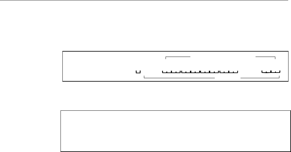
Waveform File Format AMIQ
1110.3339.12 6.66 E-7
The editor mentioned above which can handle binary data is now used to place
the string "{WAVEFORM-83:└┘0,#" in front and '}' at the end of the data set.
The contents of the waveform file SICO.WV for 20 I/Q pairs and start address 0 in
the AMIQ’s RAM is now ready for operation and reads.
{WAVEFORM-83: 0,# ... }
IQIQIQIQIQ
83 bytes
{TYPE: WV, 0} 20 I/Q pairs = 80 bytes
The tags TYPE and WAVEFORM are mandatory for each waveform file. All other
tags described in section „Waveform File Format“ on page 6.57 are optional and
can be inserted after the TYPE tag in arbitrary order, e.g.
{TYPE: WV,0}
{COMMENT: I/Q=sine/cosine, 20 points, clock 10 MHz}
{CLOCK: 10e6}
{FILTER: 2,5MHz}
{WAVEFORM-83:└┘0,#IQIQIQIQIQIQ ... IQ}
Converting a Waveform File with the Application Software AMIQ-K2
The application software AMIQ-K2 from R&S is distributed free of charge and allows to convert a large
variety of I/Q data sets to AMIQ waveform files. Moreover, AMIQ-K2 can be used to remote-control
some important AMIQ functions, to load and to store curves.
This application software is available in the internet (http://www.rsd.de) under the path:
Products →
Test and Measurement →
Signal Generation →
IQ modulation generator AMIQ →
or
IQ simulation software WinIQSIM →
or from each R&S representative.
The control sequence
Select Source Files(s)
Type Mathcad (mixed)
Source File SICO.TXT
Transmit
Destination
WV formatted SICO.WV
allows to quickly generate a waveform file that is ready to operate from the file SICO.TXT containing the
I/Q pairs in alternate order.

AMIQ Waveform File Format
1110.3339.12 6.67 E-7
Annex:
C-program for creating the file SICO.TXT containing 20 sine and cosine pairs:
#include <stdlib.h>
#include <stdio.h>
#include <math.h>
void main (void)
{
#define SAMPLES 20
int i;
float grad,rad;
FILE *logging_fp;
logging_fp = fopen("SICO.TXT", "w");
for (i = 0; i < SAMPLES; i++)
{grad = (360.0 / (float)(SAMPLES)) * (float)i;
rad = grad * (3.141592654/180.0);
fprintf (logging_fp,"%f %f\n",sin(rad),cos(rad));
}
fclose(logging_fp);
}
Contents of the file
SICO.TXT:
Sinus (I) Cosinus (Q)
0.000000 1.000000
0.309017 0.951057
0.587785 0.809017
0.809017 0.587785
0.951057 0.309017
1.000000 -0.000000
0.951056 -0.309017
0.809017 -0.587785
0.587785 -0.809017
0.309017 -0.951056
-0.000000 -1.000000
-0.309017 -0.951057
-0.587785 -0.809017
-0.809017 -0.587785
-0.951056 -0.309017
-1.000000 0.000000
-0.951056 0.309017
-0.809017 0.587785
-0.587785 0.809017
-0.309017 0.951057
Extract from a C-program generating a binary data set from the I/Q pairs in the file SICO.TXT
and storing the result to file SICO.WV:
:
FILE *fp_sour_i,*fp_sour_q,*fp_dest;
unsigned int i_uint, q_uint;
:
fp_sour = fopen("SICO.TXT", "rt" );
fp_dest = fopen("SICO.WV", "wb" );
:
while (1)
{//Read I/Q pair from ASCII file
if (fscanf (fp_sour,"%f %f",&i_float, &q_float) == EOF)
break;
//Convert I/Q pair to unsigned integer
i_uint = (unsigned int)(32768.0 + (i_float*32000.0)+0.5);
i_uint &= 0xFFFC; //Mask marker bits
q_uint = (unsigned int)(32768.0 + (q_float*32000.0)+0.5);
q_uint &= 0xFFFC; //Mask marker bits
//Write converted I/Q pair to waveform file
fwrite (&i_uint,1,2,fp_dest);
fwrite (&q_uint,1,2,fp_dest);
}:

Waveform File Format AMIQ
1110.3339.12 6.68 E-7
Example of combining waveform files:
The curves DUAL_S0.WV and DUALTONE.WV are to be combined and stored in the AMIQ under the
name DECTDUAL.WV.
The two curves are already on the AMIQ.
DUAL_S0.WV can be kept there whereas DUALTONE.WV is required in the controller. The file is
copied onto a disk by means of the command
MMEM:COPY 'DUALTONE.WV','A:DUALTONE.WV' (copying works because DUALTONE.WV is not
coded).
On the controller, the file DUALTONE.WV is converted to a batch file named DUALADD.IEC with a
binary editor, and the file has the following structure:
DUALADD.IEC
MMEM:DATA 'DECTDUAL.WV',#3862
{TYPE: WV-ADD,0}
{TARGET: DECT_S0.WV}
{COMMENT: Dual tone, 128 points, 0.9 MHz, 1.1 MHz at clock 12.8 MHz}
{COPYRIGHT: 1998 Rohde&Schwarz (WINIQSIM)}
{CLOCK: 12.8e6}
{IDLE SIGNAL: 32768, 32768}
{WAVEFORM-520: 184320,#<binary data set>}
MMEM:DATA:
The command takes over a waveform file in the binary block format and stores it under
DECTDUAL.WV. Since the waveform file is a curve of the type WV-ADD, the latter is combined
with the curve indicated under TARGET and then stored under DECTDUAL.WV.
DECTDUAL.WV:
Name of the curve containing the two curves to be combined.
#3862:
#3862: 3: number of digits of the following length indication.
#3862: 862: length of the following binary data set in bytes. To determine this length indication
easily the data set should be stored in a file as from {TYPE:WV_ADD; the exact length of this
file can be determined with the DOS command DIR.
TYPE: WV-ADD:
Denotes the curve from batch file DUALADD.IEC as a curve which is to be added to the curve
indicated under TARGET.
TARGET: DECT_S0.WV:
Specifies the waveform file to which the curve from batch file DUALADD:IEC is to be added.
COPYRIGHT: 1998 Rohde&Schwarz (WINIQSIM):
The COPYRIGHT string of target waveform file DECT_SO.WV and the curve DUALTONE.WV to
be added should match.
WAVEFORM-520: 184320,# <binary data set>:
In DUALTONE.WV the waveform tag is indicated with a length of 515 (WAVEFORM-515:
0,#<binary data set>). The value preceding ",#" (184320) indicates the start address of target
waveform file DECT_SO.WV to which curve DUALTONE.WV is to be added. It is important to
know how many samples a curve is made of. There are 184320 samples in the case of
DECT_S0.WV. This value is generally known even if curves generated by the user are used.
New WinIQSIM files contain the tag SAMPLES from which the number of samples of a curve can
be immediately obtained.
If the value is unknown, it should be determined from the length indication behind the tag
WAVEFORM of curve DECT_S0.WV.
Number of samples = length indication after WAVEFORM (737283) – number of digits of start
value 0 (1) – 2) / 4!
Number of samples = (737283 – 1 – 2) / 4
Number of samples = 184320
The value 184320 is to be indicated after WAVEFORM as start value for the curve to be added.
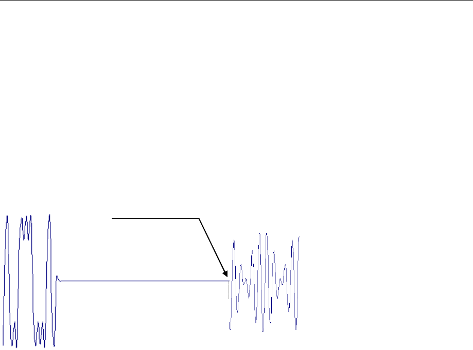
AMIQ Waveform File Format
1110.3339.12 6.69 E-7
The original curve DUALTONE.WV has indicated 0 as start value and a length of 515 bytes.
Since the start value has increased by 5 digits from 0 to 184320, the waveform length should
also be increased by 5 from 515 to 520.
Store this data set on disk under DUALADD.IEC and insert the disk into the AMIQ.
Enter the command PROG:EXEC 'A:DUALADD.IEC' on the controller. The curves DUAL_S0.WV and
DUALTONE.WV are combined and stored in the AMIQ under the name DECTDUAL.WV.
The sequence of commands
MMEM:LOAD RAM,'DECTDUAL.WV'
ARM
TRIG
loads the curve DECTDUAL.WV and the following signal appears at the output of the AMIQ:
DECT_S0.WV
l
ast samp
l
e
184320
of DECT_S0.WV DUALTONE.W
V
Manually combined waveforms

List of Commands AMIQ
1110.3339.12 6.70 E-7
List of Commands
The list contains all AMIQ remote-control commands in alphabetical order. A list of tags for determining
the waveform file formats follows at the end of this table.
Remote-control commands
Table 6-14 List of all remote-control commands
Command Parameter Page
:ABORt 6.54
:ARM 6.54
:BERT:COPY <name> 6.9
:BERT:DELete <name> 6.9
:BERT:RESult? 6.9
:BERT:SELect <name> 6.10
:BERT:SETup:CLOCk[:POLarity] RISING|FALLING 6.10
:BERT:SETup:DATA[:POLarity] NORM|INVerted 6.11
:BERT:SETup:DENable OFF|HIGH|LOW 6.11
:BERT:SETup:MASK OFF|HIGH|LOW 6.11
:BERT:SETup:MCOunt 1 ... 232-1 6.11
:BERT:SETup:MERRor 1 ... 232-1 6.12
:BERT:SETup:RESTart INTernal|EXTernal 6.12
:BERT:SETup:TYPE PRBS9|PRBS11|PRBS15|PRBS16|PRBS20|PRBS21|PRBS23 6.10
:BERT:STARt 6.12
:BERT:STOP 6.12
:CALibration:ALL? 6.14
:CALibration:AMPLitude:I:VALue? 6.14
:CALibration:AMPLitude:I? 6.14
:CALibration:AMPLitude:Q:VALue? 6.14
:CALibration:AMPLitude:Q? 6.14
:CALibration:AMPLitude:VALue? 6.14
:CALibration:AMPLitude? 6.14
:CALibration:DIAGnose 0.9000...1.1000 6.15
:CALibration:OFFSet:I:VALue? 6.15
:CALibration:OFFSet:I? 6.15
:CALibration:OFFSet:Q:VALue? 6.15
:CALibration:OFFSet:Q? 6.15
:CALibration:OFFSet:VALue? 6.15
:CALibration:OFFSet? 6.15
:CALibration:ROSCillator 0...4095 6.16
:DIAGnostic:ABOard:ID? 6.17
:DIAGnostic:SELFtest 6.18
:DIAGnostic:TPOint<n>? 6.17
:MARKer<n>[:LIST] <marker list> 6.20
:MEMory:DATA RAM,<binary block data> 6.24
:MEMory:DATA? RAM[<tag>], 6.25
:MEMory:NAME? 6.25
:MMEMory:CATalog:LENGth? 6.26
:MMEMory:CATalog|DIRectory? 6.25
:MMEMory:CDIRectory|CD <directory> 6.26
:MMEMory:COPY <filename>[,<destination>] 6.26
:MMEMory:DATA <filename>, <binary block data> 6.28

AMIQ List of Commands
1110.3339.12 6.71 E-7
:MMEMory:DATA:LENGth? <filename>[,<tag>] 6.29
:MMEMory:DATA? <filename>[,<tag>] 6.29
:MMEMory:DCATalog|DDIRectory:LENGth? 6.30
:MMEMory:DCATalog|DDIRectory? 6.30
:MMEMory:DELete <filename> 6.30
:MMEMory:LOAD RAM,<filename> 6.30
:MMEMory:MDIRectory|MD <directory> 6.31
:MMEMory:MSIS <drive> 6.31
:MMEMory:MWV:APPEend <Source waveform file to append>,<Destination MWV
file>,<Comment> 6.33
:MMEMory:MWV:DELete <Multi Segmnet Waveform file>, <Segment to delete> 6.34
:MMEMory:MWV:FIRStsegment <Source waveform file to start>,<Destination MWV file>,
<Comment> 6.33
:MMEMory:RDIRectory|RD <directory> 6.32
:MMEMory:SCATalog:LENGth? 6.32
:MMEMory:SCATalog? 6.32
:OUTPut: DIGital ON|OFF 6.35
:OUTPut:CLOCk ON|OFF 6.35
:OUTPut:FILTer OFF|2.5MHz|25MHz|EXTernal 6.36
:OUTPut:I:AMPLitude:BALanced 0...4V 6.39
:OUTPut:I:AMPLitude[:UNBalanced] 0V...1V 6.36
:OUTPut:I:BIAS -2.5 ... 2.5 V 6.39
:OUTPut:I:FILTer OFF|2.5MHz|25MHz|EXTernal 6.36
:OUTPut:I[:STATe] OFF|FIXed|VARiable|INVerted 6.36
:OUTPut:MARKer<n>:DELay <samples> 6.38
:OUTPut:MARKer<n>[:STATe] ON|OFF 6.37
:OUTPut:OIMPedance R50|HIGH 6.38
:OUTPut:Q:AMPLitude:BALanced 0...4V 6.39
:OUTPut:Q:AMPLitude[:UNBalanced] 0V...1V 6.36
:OUTPut:Q:BIAS -2.5 ... 2.5 V 6.40
:OUTPut:Q:FILTer OFF|2.5MHz|25MHz|EXTernal 6.37
:OUTPut:Q[:STATe] OFF|FIXed|VARiable|INVerted 6.37
:OUTPut:RESolution 8...16 6.40
:OUTPut:TYPE UNBalanced|BALanced 6.39
:PROGram:COPY <name> 6.41
:PROGram:DELete <name> 6.41
:PROGram:RUN|EXECute <name> 6.41
:STATus:OPERation:[EVENt]? 6.47
:STATus:OPERation:CONDition? 6.47
:STATus:OPERation:ENABle 0...32767 6.47
:STATus:OPERation:NTRansition 0...32767 6.48
:STATus:OPERation:PTRansition 0...32767 6.47
:STATus:PRESet 6.49
:STATus:QUEStionable:CONDition? 6.48
:STATus:QUEStionable:ENABle 0...32767 6.48
:STATus:QUEStionable:NTRansition 0...32767 6.48
:STATus:QUEStionable:PTRansition 0...32767 6.48
:STATus:QUEStionable[:EVENt]? 6.48
:SYSTem:BEEPer 6.50
:SYSTem:BEEPer:STATe ON|OFF 6.50
:SYSTem:COMMunicate:GPIB:ADDRess 1...30 6.50
:SYSTem:COMMunicate:GTL 6.50
:SYSTem:COMMunicate:SERial:BAUD 1200|2400|4800|9600|19200|38400|57600|115200 6.51
:SYSTem:ERRor? 6.51
:SYSTem:LANGuage FAST|SLOW 6.51
:SYSTem:OPTion <name>,<key> 6.52
:SYSTem:PRESet 6.52

List of Commands AMIQ
1110.3339.12 6.72 E-7
:SYSTem:STATe:CATalog:LENGth? 6.52
:SYSTem:STATe:CATalog? 6.52
:SYSTem:STATe:COPY <source> 6.53
:SYSTem:STATe:DELete <name> 6.53
:SYSTem:VERSion? 6.53
:TRIGger:MODE OFF|GATed|SINGle|CONTinuous 6.55
:TRIGger:MWVSegment <Segment Index> 1 ... 30 6.56
:TRIGger:SLOPe POSitive|HIGH|RISing|NEGative|LOW|FALLing 6.55
:TRIGger:SOURce MANual|BUS|EXTernal 6.56
:TRIGger[:IMMediate] 6.54
[:SOURce]:CLOCk frequency[,mode] 6.42
[:SOURce]:CORR:SKEW <value> 6.45
[:SOURce]:CORRection:GAIN:I:FIXed <value> 6.44
[:SOURce]:CORRection:GAIN:Q:FIXed <value> 6.44
[:SOURce]:CORRection:OFFSet:I:FIXed <value> 6.44
[:SOURce]:CORRection:OFFSet:I:VARiable <value> 6.45
[:SOURce]:CORRection:OFFSet:Q:FIXed <value> 6.45
[:SOURce]:CORRection:OFFSet:Q:VARiable <value> 6.45
[:SOURce]:ROSCillator:SOURce INTernal|EXTernal 6.46
[:SOURce]:SCLock INTernal|EXTSlow|EXTFast 6.43

AMIQ List of Commands
1110.3339.12 6.73 E-7
Tags for Determining the Waveform File Formats
Tags have the general format: {Name: Data} or {Name-length: Data}
Name / Name-length Data Page
CLOCK: frequency[,SLOW|FAST] 6.59
COMMENT: string 6.59
COPYRIGHT: string 6.59
DATE: yyyy-mm-dd;hh:mm:ss 6.59
FILTER: value 6.60
IDLESIGNAL: I,Q 6.62
MWV_SEGMENT_CLOCK: <Clockfreq. Seg. 1>, <Clockfreq. Seg. 2>, <Clockfreq. Seg. 3> 6.63
MWV_SEGMENT_COMMENT <Segment Index>: Comment 6.63
MWV_SEGMENT_COUNT: <Segment count> 6.63
MWV_SEGMENT_LENGTH: <Length Seg. 1>,<Length Seg. 2>,<Length Seg. 3> 6.63
MWV_SEGMENT_RESOLUTION: <GSeg. 1>,<OSeg. 1>,<GSeg. 2>,<OSeg. 2>,<GSeg. 3>,<OSeg. 3> 6.63
MWV_SEGMENT_START: <Start Seg. 1>,<Start Seg. 2>,<Start Seg. 3> 6.63
RESOLUTION: x,y 6.62
TARGET: name 6.59
TYPE: magic,xxxxxxxx 6.57
WAVEFORM-Länge: start,#xxxxxxxxxxxx… 6.61

AMIQ Including IEC/IEEE-Bus Library for QuickBasic
1110.3339.12 7.1 E-4
7 Examples
Program examples for Remote Control
The following examples explain how to program the instrument and can serve as a basis to solve more
complex programming tasks. In the examples, remote control via IEC/IEEE bus and the programming
language QuickBASIC are used.
Remote-control commands should be used without the QuickBASIC function names for the serial
interface (same as IECIN(), IECOUT() etc). A terminal emulation program may be employed for
transmission. If this program has a so-called chat mode (often switched on with the key combination
Ctrl-C), commands can be directly entered in a window. The responses are automatically displayed in
another window. Without a terminal program, commands can be sent with
echo kommando > COM1
from the DOS command line. Depending on the interface used, COM1 has to be replaced by COM2.
Answers from the instrument cannot always be read in. Furthermore, all characters interpreted by DOS
as special characters, cannot be transmitted in this way.
Another possibility to be used on the serial interface is to write the desired commands in a file and to
send this file to the instrument with
copy -b datei.ext COM1
Depending on the interface used, COM1 should be replaced by COM2. In this case answers cannot be
read in either but all characters can be transmitted.
Including IEC/IEEE-Bus Library for QuickBasic
REM -------------------------- General Declarations ----------------------
COMMON SHARED amiq%
DECLARE SUB IECOUT (out$)
DECLARE SUB IECIN (read$)
REM -------------------------- Include IEC/IEEE-bus library for QuickBasic
'$INCLUDE: 'c:\testtool\qbasic\qbdecl.bas'
REM***********************************************************************

Initialization and Default Status AMIQ
1110.3339.12 7.2 E-4
Initialization and Default Status
The IEC/IEEE bus as well as the settings of the instrument are brought into a defined default state at the
beginning of each program. Subroutines "InitController" and "InitDevice" are used to this
effect.
Initializing the Controller
REM -------------------------- Initialize Controller ----------------------
REM InitController
iecaddress% = 6 'IEC-bus address of device,
CALL IBFIND("DEV1", amiq%) 'Open port to the instrument.
CALL IBONL(amiq%, 1)
CALL IBPAD(amiq%, iecaddress%) 'Inform controller about instrument
'address,
CALL IBCLR(amiq%) 'Reset IEC/IEEE-bus operation of the
instrument,
CALL IBEOS(amiq%, 0) 'Reception terminated with EOI,
CALL IBEOT(amiq%, 1) 'EOI is set with last character
'to be sent,
CALL IBTMO(amiq%, T10s) 'Set response time to 10 s.
REM***********************************************************************
Functions for Receiving and Sending Data and Commands
REM ------------------ Functions for receiving and sending ---------------
REM ------------------ data and commands ---------------------------------
REM ------------------ Read data from IEC/IEEE bus -----------------------
SUB IECIN (read$)
temp$ = SPACE$(100) 'Delete domain,
CALL IBRD(amiq%, temp$) 'Read data from IEC bus.
read$ = LEFT$(temp$, IBCNT%) 'and discard the rest.
END SUB
REM ------------------ Output on IEC/IEEE bus ------------------------------
---
SUB IECOUT (out$)
wrt$ = out$ + CHR$(&HD) + CHR$(&HA)
CALL IBWRT(amiq%, wrt$)
REM***********************************************************************
END SUB
REM***********************************************************************
Initializing the Instrument
The IEC/IEEE-bus status registers and instrument settings of the AMIQ are brought into the default
state.
REM ------------------ Initialize the instrument -------------------------
REM InitDevice
CALL IECOUT("*CLS") 'Reset status registers,
CALL IECOUT("*RST;*WAI") 'Reset the instrument.
REM***********************************************************************

AMIQ Sending Device Setting Commands
1110.3339.12 7.3 E-4
Sending Device Setting Commands
In this example a waveform file is copied from the floppy to the AMIQ hard disk (so that it will be
available later on) and then loaded into the output buffer. Subsequently the marker output 1 is
programmed so that it is at high level for the first 100 samples and then low level (the end is specified as
a very large number, larger than the waveform). Thus a start marker is obtained. The output sockets are
switched to a constant level. The trigger system is set to continuous output and then the waveform
output is started.
Since QuickBASIC would interprete double inverted commas in a command line as end of the
command, simple quotation marks are used instead. AMIQ handles them like double inverted commas.
Generally, no name extension is specified for file names. AMIQ uses fixed name extensions for the
various file types. For waveform files the extension is .wv.
REM ----------------- Device setting commands ----------------------------
CALL IECOUT("MMEM:COPY 'a:\gsm', 'gsm'") 'Copy file "gsm.wv"
CALL IECOUT("MMEM:LOAD RAM, 'gsm'") 'Load file into the output
buffer
CALL IECOUT("MARK1 '0-100:1;101-999999:0'") 'Marker output 1 high for the
'first 100 samples
CALL IECOUT("OUTP:I FIX; Q FIX") 'Sets both outputs to a fixed
'max. level of 1 V
CALL IECOUT("TRIG:MODE CONT") 'Continuous signal generation
CALL IECOUT("ARM;:TRIG") 'Starts signal generation
REM**********************************************************************
Switchover to Manual Control
This may be necessary when several remote-control sources should be used successively.
REM ------------------ Switch instrument to manual control ---------------
CALL IBLOC(amiq%) 'Sets instruments to local state.
REM***********************************************************************
The following alternative is possible but not recommended. It should only be used for the serial
interface.
REM ------------------ Switch instrument to manual control ---------------
CALL IECOUT("*GTL") 'Sets instruments to local state.
REM**********************************************************************

Executing Batch Programs AMIQ
1110.3339.12 7.4 E-4
Executing Batch Programs
AMIQ is able to execute a list of IEC/IEEE-bus commands from a file. In this file all IEC/IEEE-bus
commands can be used. All outputs are written into a file of the same name in the same directory as the
batch file, but with the extension .log.
REM ------------------ Readout of device settings ---------------------
CALL IECOUT("PROG:RUN 'sequence'") 'Starts batch file "sequence.iec"
'from the floppy; if it is not found
on the floppy from the hard disk.
Reading out Device Settings
A number of device settings are read out here. The short form of the commands is used.
REM ------------------- Read out device settings --------------------------
CALL IECOUT("MMEM:LOAD?") 'Requests name of currently
'loaded waveform file,
CALL IECIN(WaveformName$) 'Input value.
CALL IECOUT("MMEM:DATA? ' + Waveformname$ + ', 'copyright'")
'Requests copywrite comment of the
'loaded waveform file.
CALL IECIN(Copyright$) 'Input value.
CALL IECOUT("OUTP:MARK1:DEL?") 'Requests delay of marker 1 output
'(in samples),
CALL IECIN(Delay$) 'Input value.
REM ------------------- Display of values on screen ------------------------
PRINT "Waveform file loaded:"; Waveformname$
PRINT "Copyright by "; Copyright$
PRINT "Marker 1 Delay:"; Delay$
REM***********************************************************************

AMIQ Command Synchronization
1110.3339.12 7.5 E-4
Command Synchronization
Execution of commands in the AMIQ is consecutive, never overlapping. For this reason an explicit
synchronization of commands is not required. However, it is often desirable to inform the host computer
about the end of a longer action (eg copying a file from a floppy).
REM ------------ Examples for synchronization with the host: -----------
REM ------------Because repeated access has to be made to the hard disk
REM ------------command MMEM:COPY has a relatively long execution time.-
REM ------------It has to be ensured that the host continues the--------
REM ------------program only after the waveform file has been completely
REM-------------copied. ----------------------------------------
CALL IECOUT("MMEM:COPY 'a:\gsm', 'gsm'") Copies "gsm.wv" file
REM ------------First option: Use of *OPC? -----------------------------
CALL IECOUT("*OPC?")
REM ------------Here the controller can serve other devices-------------
CALL IECIN(OpcOk$) 'Waiting for the 1 of *OPC?'
'ie the waveform is completely copied
REM ------------Second option: Use of *OPC -----------------------------
REM ------------In order to use the service request function with the---
REM-------------National Instruments GPIB driver, the "Disable Auto ----
REM-------------Serial Poll" setting must be changed to "yes" by -------
REM-------------means of IBCONF!
CALL IECOUT("*SRE 32") 'Enable service request for ESR,
CALL IECOUT("*ESE 1") 'Set event enable bit for
'operation complete bit.
ON PEN GOSUB OpcReady 'Initialize service
'request routine.
PEN ON
CALL IECOUT("*OPC")
REM ------------Continue main program here -----------------------------
STOP 'End of program.
OpcReady:
REM ------------This subroutine is executed when ------------------
REM ------------copying is completed. -----------------------------
REM ------------Program reaction suitable for the OPC service ----------
REM ------------request, eg
PRINT "Please remove disk from the AMIQ floppy disk drive"
RETURN
REM*********************************************************************

Service Request AMIQ
1110.3339.12 7.6 E-4
Service Request
The service request routine requires an extended initialization of the instrument in the course of which
the respective bits of the transition and enable registers are set.
In order to use the service request function in conjunction with a National Instruments GPIB driver, the
"Disable Auto Serial Poll" setting must be changed to "yes" by means of IBCONF.
REM --------- Example of initialization of the SRQ in the case of errors --
CALL IECOUT("*CLS") 'Resets status reporting system.
CALL IECOUT("*SRE 168") 'Enables service request for the
'STAT:OPER,STAT:QUES and ESR
'registers,
CALL IECOUT("*ESE 61") 'Sets event enable bit for
'command execution, device-
'dependent and query errors,
CALL IECOUT("STAT:OPER:ENAB 32767") 'Sets OPERation enable bit
'for all events,
CALL IECOUT("STAT:OPER:PTR 32767") 'Sets associated OPERation
'PTRansition bits,
CALL IECOUT("STAT:QUES:ENAB 32767") 'Sets questionable enable bits
'for all events,
CALL IECOUT("STAT:QUES:PTR 32767") 'Sets associated questionable
'PTRansition bits,
ON PEN GOSUB Srq 'Initializes service
'request routine.
PEN ON
REM ------------------- Main program continued here -----------------------
STOP 'End of program
REM***********************************************************************
Srq:
REM ------------------- Service Request Routine --------------------------
DO SRQFOUND% = 0
FOR I% = UserN% TO UserM% 'Polls all bus users.
ON ERROR GOTO noUser 'No user existing.
CALL IBRSP(I%, STB%) 'Serial poll, read status byte.
IF STB% > 0 THEN 'This instrument has bits set
'in the STB.
SRQFOUND% = 1
IF (STB% AND 16) > 0 THEN GOSUB Outputqueue
IF (STB% AND 4) > 0 THEN GOSUB Failure
IF (STB% AND 8) > 0 THEN GOSUB Questionablestatus
IF (STB% AND 128) > 0 THEN GOSUB Operationstatus
IF (STB% AND 32) > 0 THEN GOSUB Esrread
END IF
noUser:
NEXT I%
LOOP UNTIL SRQFOUND% = 0
ON ERROR GOTO Errorhandling
ON PEN GOSUB Srq: RETURN 'Re-enables SRQ routine;
'End of SRQ routine.
REM**********************************************************************

AMIQ Selftest with Progress Indication
1110.3339.12 7.7 E-4
REM ------------ ------ Subroutines for the individual STB bits ---------
Outputqueue: ' Reads output queue.
CALL IECIN(Nachricht$)
PRINT "Message in output queue:"; Message$
RETURN
Failure: 'Reads error queue.
CALL IECOUT("SYSTEM:ERROR?")
CALL IECIN(ERROR$)
PRINT "Fehlertext :"; ERROR$
RETURN
Questionablestatus: 'Reads questionable status register.
CALL IECOUT("STATus:QUEStionable:EVENt?")
CALL IECIN(Ques$)
RETURN
Operationstatus: 'Reads operation status register.
CALL IECOUT("STATus:OPERation:EVENt?")
CALL IECIN(Oper$)
IF (VAL(Oper$) AND 2) > 0 THEN PRINT "Adjustment running"
IF (VAL(Oper$) AND 2) > 0 THEN PRINT "Hardware settling"
IF (VAL(Oper$) AND 32) > 0 THEN PRINT "Waiting for trigger"
RETURN
Esrread: 'Reads event status register,
CALL IECOUT("*ESR?") 'reads ESR.
CALL IECIN(Esr$)
IF (VAL(Esr$) AND 1) > 0 THEN PRINT "Action terminated"
IF (VAL(Esr$) AND 4) > 0 THEN GOTO Failure
IF (VAL(Esr$) AND 8) > 0 THEN PRINT "Internal error"
IF (VAL(Esr$) AND 16) > 0 THEN GOTO Failure
IF (VAL(Esr$) AND 32) > 0 THEN GOTO Failure
IF (VAL(Esr$) AND 128) > 0 THEN PRINT "'Power on"
RETURN
REM **********************************************************
REM ------------------ Error routine -----------------------------------
Errorhandling:
PRINT "ERROR" 'Output error message,
STOP 'Aborts program.
REM*********************************************************************
REM*********************************************************************
Selftest with Progress Indication
In the following example a selftest with progress indication is implemented. The programming language
used is C combined with the IEC/IEEE-bus driver GPIB.COM by National Instruments.
#include <stdio.h>
#include <string.h>
#include <stdlib.h>
#include <conio.h>
#include <bios.h>
#include "C:\NI-GPIB\C\DECL.H"
void report_error(int fd, char *errmsg)
{

Selftest with Progress Indication AMIQ
1110.3339.12 7.8 E-4
fprintf(stderr, "Error %d: %s\n", iberr, errmsg);
if (fd != -1) {
printf("Cleanup: taking board off-line\n");
ibonl(fd,0);
}
exit(1); // Abort program
}
void cmnd_out (int amiq, char *befstr)
{ibwrt(amiq, befstr,(long)strlen(befstr));
if (ibsta & ERR)
report_error (amiq, "Could not initialize AMIQ");
}
void query_in (int amiq, char* reading)
{ibeos (amiq,0x140A);
ibrd(amiq, reading, 100);
if (ibsta & ERR)
report_error (amiq, "Could not read data from AMIQ");
reading[ibcnt-1] = '\0'; // overwrite LF with string terminator
}
void check_errorqueue (int amiq)
{char reading[101];
while (1)
{cmnd_out (amiq,"SYST:ERR?"); // read out error queue
query_in (amiq,reading);
if (reading[0] == '0') // no error output for "0,No Error"
return;
printf ("%s\n",reading);
}
}
void main()
{int amiq; /* File descriptor für AMIQ */
int i;
char iec_befehl [80];
char reading [101];
char *st_comp[] =
{"BASics? ",
"DSYStem? ",
"DACReference?",
"OADJust? ",
"OFFSet? ",
"REFFrequency?",
"VCO? ",
"LEVels? ",
"ATTenuators? ",
"LPASs? "
};
if ((amiq = ibdev(0, 6, 0, T30s, 1, 0)) < 0)
report_error (amiq, "Could not initialize AMIQ");
/* Selftest with progress indication */
cmnd_out (amiq,"*SAV 'TEMP'"); // Save current setup
for (i = 0; i < 10; i++)

AMIQ Selftest with Progress Indication
1110.3339.12 7.9 E-4
{sprintf (iec_befehl,"DIAG:SELF:%s",st_comp[i]); // Selftest command
printf ("%s ",st_comp[i]); // put together
cmnd_out (amiq,iec_befehl);
query_in (amiq,reading); // Response to query '0' (o.k.) or '1' (Error)
if (reading[0] == '0')
printf ("passed!\n"); // no error
else
check_errorqueue (amiq); // read out error queue
}
cmnd_out (amiq,"*RCL 'TEMP'"); // fetch setup before selftest
ibonl(amiq, 0); /* Take amiq off-line */
}

GSM Signals (GMSK) AMIQ
1110.3339.12 7.10 E-4
Waveform Descriptions
The following example waveforms are pre-installed on the AMIQ hard disk.
GSM Signals (GMSK)
GSM continuous, PRBS 9 data
WinIQSim setting file: GSM\GSM continuous, PRBS9, 2044 symb.iqs
Waveform file: GSM\GSM_CONT.wv
Used payload data: PRBS 9
Slot/Framestructure: None
Syncword: None
Sequence length (symbols): 2044
Samplerate: 1.354 MHz (8.1771 MHz for AMIQ version after resampling)
Samples: 10220 (61716 for AMIQ version after resampling)
Prepared for AMIQ filter: 2.5 MHz
Programmed markers: None
Remarks:
GSM Normal Burst
WinIQSim setting file: GSM\GSM Normal Burst, PRBS9, Slot 1, 1 Frame.iqs
Waveform file: GSM\GSM_BRST.wv
Used payload data: PRBS 9
Slot/Framestructure: Normal GSM Burst, Slot 1 active, 1 Frame long
Syncword: TSC_1
Sequence length (symbols): 1250
Samplerate: 1.354 MHz (8.1771 MHz for AMIQ version after resampling)
Samples: 6250 (37740 for AMIQ version after resampling)
Prepared for AMIQ filter: 2.5 MHz
Programmed markers: Marker 1 for additional power ramping (AMIQ)
Remarks:

AMIQ GSM Signals (GMSK)
1110.3339.12 7.11 E-4
GSM Normal Burst, BERT PRBS 9 data
WinIQSim setting file: GSM\GSM Normal Burst, PRBS9, Slot 1, continuous data, 511 frames,
Markers.iqs
Waveform file: GSM\GSM_BERT.wv
Used payload data: Continuous BERT PRBS 9 data
Slot/Framestructure: Normal GSM Burst, Slot 1 active, 511 Frames long
Syncword: TSC_1
Sequence length (symbols): 638750
Samplerate: 6.771 MHz
Samples: 15968750
Prepared for AMIQ filter: 2.5 MHz
Programmed markers: Marker 1: Data Signal
Marker 2: Data Enable
Marker 3: Bit Clock
Marker 4: Restart
Remarks: Only applicable for AMIQ04, not available for SMIQ-B60

EDGE Signals (8PSK) AMIQ
1110.3339.12 7.12 E-4
EDGE Signals (8PSK)
EDGE Normal Burst
WinIQSim setting file: EDGE\EDGE Normal Burst, PRBS9, Slot 1, 1 Frame.iqs
Waveform file: EDGE\EDGEBRST.wv
Used payload data: PRBS 9
Slot/Framestructure: Normal EDGE Burst, Slot 1 active, 1 Frame long
Syncword: TSC_0
Sequence length (symbols): 1250
Samplerate: 2.167 MHz (8.5833 MHz for AMIQ version after resampling)
Samples: 10000 (39616 for AMIQ version after resampling)
Prepared for AMIQ filter: 2.5 MHz
Programmed markers: Marker 1 for additional power ramping (AMIQ)
Remarks:
EDGE Normal Burst, BERT PRBS 9 data
WinIQSim setting file: EDGE\EDGE Normal Burst, PRBS9, Slot 1, continuous data, 511
frames, Markers.iqs
Waveform file: EDGE\EDGEBERT.wv
Used payload data: Continuous BERT PRBS 9 data
Slot/Framestructure: Normal EDGE Burst, Slot 1 active, 511 Frames long
Syncword: TSC_0
Sequence length (symbols): 638750
Samplerate: 6.771 MHz
Samples: 15968750
Prepared for AMIQ filter: 2.5 MHz
Programmed markers: Marker 1: Data Signal
Marker 2: Data Enable
Marker 3: Bit Clock
Marker 4: Restart
Remarks: Only applicable for AMIQ04, not available for SMIQ-B60

AMIQ EDGE Signals (8PSK)
1110.3339.12 7.13 E-4
GSM/EDGE (GMSK/8PSK) alternating Bursts
WinIQSim setting file: EDGE\GSM_EDGE alternating\GSM_EDGE alternating Bursts, 1
Frame.iqs
Waveform file: EDGE\GSM_EDGE\GSM_EDGE.wv
Used payload data: PRBS 9
Slot/Framestructure: Alternating GSM (GMSK) / EDGE (8PSK) Bursts, 1 Frame long.
GSM Bursts on even and EDGE Bursts on odd slot numbers.
Syncword: TSC_1 for GSM Bursts, TSC_0 for EDGE Bursts
Sequence length (symbols): 1250
Samplerate: 2.167 MHz (8.5833 MHz for AMIQ version after resampling)
Samples: 10000 (39616 for AMIQ version after resampling)
Prepared for AMIQ filter: 2.5 MHz
Programmed markers: None
Remarks:

NADC Signals AMIQ
1110.3339.12 7.14 E-4
NADC Signals
NADC continuous, PRBS 9 data
WinIQSim setting file: NADC\NADC continuous, PRBS9, 4088 symb.iqs
Waveform file: NADC\NADCCONT.wv
Used payload data: PRBS 9
Slot/Framestructure: None
Syncword: None
Sequence length (symbols): 4088
Samplerate: 388.8 kHz (7.6944 MHz for AMIQ version after resampling)
Samples: 65408 (1294432 for AMIQ version after resampling)
Prepared for AMIQ filter: 2.5 MHz
Programmed markers: None
Remarks:
NADC Downlink Burst
WinIQSim setting file: NADC\NADC Downlink Burst, PRBS9, Slot 1, 1 Frame.iqs
Waveform file: NADC\NADCBRST.wv
Used payload data: PRBS 9
Slot/Framestructure: Downlink Burst, Slot 1 active, 1 Frame long
Syncword: A91DE4A (hex)
Sequence length (symbols): 972
Samplerate: 388.8 kHz (7.6944 MHz for AMIQ version after resampling)
Samples: 15552 (307776 for AMIQ version after resampling)
Prepared for AMIQ filter: 2.5 MHz
Programmed markers: None
Remarks:

AMIQ NADC Signals
1110.3339.12 7.15 E-4
NADC Downlink Burst, BERT PRBS 9 data
WinIQSim setting file: NADC\NADC Downlink Burst, PRBS9, Slot 1, continuous data, 511
frames, Markers.iqs
Waveform file: NADC\NADCBERT.wv
Used payload data: Continuous BERT PRBS 9 data
Slot/Framestructure: Downlink Burst, Slot 1 active, 511 Frames long
Syncword: A91DE4A (hex)
Sequence length (symbols): 496692
Samplerate: 777.600 kHz
Samples: 15894144
Prepared for AMIQ filter: No preparation possible due to sequence length. An external Filter with a
cut-off frequency of approx. 400 kHz can be used.
Programmed markers: Marker 1: Data Signal
Marker 2: Data Enable
Marker 3: Bit Clock
Marker 4: Restart
Remarks: Only applicable for AMIQ04, not available for SMIQ-B60

DECT Signals AMIQ
1110.3339.12 7.16 E-4
DECT Signals
DECT continuous, PRBS 9 data
WinIQSim setting file: DECT\DECT continuous, PRBS9, 2044 sym.iqs
Waveform file: DECT\DECTCONT.wv
Used payload data: PRBS 9
Slot/Framestructure: None
Syncword: None
Sequence length (symbols): 2044
Samplerate: 18.432 MHz
Samples: 32704
Prepared for AMIQ filter: 2.5 MHz
Programmed markers: None
Remarks:

AMIQ Bluetooth Signals
1110.3339.12 7.17 E-4
Bluetooth Signals
Bluetooth continuous, PRBS 9 data
WinIQSim setting file: Bluetooth\Bluetooth continuous, PRBS9, 12775 sym.iqs
Waveform file: BLUE\BLUEPN9.wv
Used payload data: PRBS 9
Slot/Framestructure: None
Syncword: None
Sequence length (symbols): 12775
Samplerate: 5.0 MHz (10.0 MHz for AMIQ version after resampling)
Samples: 63875 (127752 for AMIQ version after resampling)
Prepared for AMIQ filter: 2.5 MHz
Programmed markers: None
Remarks:
Bluetooth continuous, PRBS 15 data
WinIQSim setting file: Bluetooth\Bluetooth continuous, PRBS15, 819175 sym.iqs
Waveform file: BLUE\BLUEPN15.wv
Used payload data: PRBS 15
Slot/Framestructure: None
Syncword: None
Sequence length (symbols): 819175
Samplerate: 10.0 MHz (after resampling)
Samples: 8191752 (after resampling)
Prepared for AMIQ filter: 2.5 MHz
Programmed markers: None
Remarks: Only applicable for AMIQ04, not available for SMIQ-B60

3GPP (FDD) W-CDMA Signals AMIQ
1110.3339.12 7.18 E-4
3GPP (FDD) W-CDMA Signals
Testmodel 1, 16 Channels
WinIQSim setting file: 3GPP\Testmodel 1, 16 Ch.iqs
Waveform file: 3GPP\DLTM116C.wv
Link direction: Downlink
Scrambling code: 0
Used payload data: PRBS 9
Used channels: P-CPICH, P-SCH, S-SCH, P-CCPCH, PICH and 16 DPCHs with 30 ksps
according to Testmodel 1
Sequence length (slots): 15
Samplerate: 30.720 MHz
Samples: 307200
Prepared for AMIQ filter: 2.5 MHz
Crest factor: 10.81 dB
Programmed markers: None
Remarks:
Testmodel 1, 32 Channels
WinIQSim setting file: 3GPP\Testmodel 1, 32 Ch.iqs
Waveform file: 3GPP\DLTM132C.wv
Link direction: Downlink
Scrambling code: 0
Used payload data: PRBS 9
Used channels: P-CPICH, P-SCH, S-SCH, P-CCPCH, PICH and 32 DPCHs with 30 ksps
according to Testmodel 1
Sequence length (slots): 15
Samplerate: 30.720 MHz
Samples: 307200
Prepared for AMIQ filter: 2.5 MHz
Crest factor: 11.5 dB
Programmed markers: None
Remarks:

AMIQ 3GPP (FDD) W-CDMA Signals
1110.3339.12 7.19 E-4
Testmodel 1, 64 Channels
WinIQSim setting file: 3GPP\Testmodel 1, 64 Ch.iqs
Waveform file: 3GPP\DLTM164C.wv
Link direction: Downlink
Scrambling code: 0
Used payload data: PRBS 9
Used channels: P-CPICH, P-SCH, S-SCH, P-CCPCH, PICH and 64 DPCHs with 30 ksps
according to Testmodel 1
Sequence length (slots): 15
Samplerate: 30.720 MHz
Samples: 307200
Prepared for AMIQ filter: 2.5 MHz
Crest factor: 10.47 dB
Programmed markers: None
Remarks:
Testmodel 2
WinIQSim setting file: 3GPP\Testmodel 2.iqs
Waveform file: 3GPP\DLTM2.wv
Link direction: Downlink
Scrambling code: 0
Used payload data: PRBS 9
Used channels: P-CPICH, P-SCH, S-SCH, P-CCPCH, PICH and 3 DPCHs with 30 ksps
according to Testmodel 2
Sequence length (slots): 15
Samplerate: 30.720 MHz
Samples: 307200
Prepared for AMIQ filter: 2.5 MHz
Crest factor: 9.11 dB
Programmed markers: None
Remarks:

3GPP (FDD) W-CDMA Signals AMIQ
1110.3339.12 7.20 E-4
Testmodel 3, 16 Channels
WinIQSim setting file: 3GPP\Testmodel 3, 16 Ch.iqs
Waveform file: 3GPP\DLTM316C.wv
Link direction: Downlink
Scrambling code: 0
Used payload data: PRBS 9
Used channels: P-CPICH, P-SCH, S-SCH, P-CCPCH, PICH and 16 DPCHs with 15 ksps
according to Testmodel 3
Sequence length (slots): 15
Samplerate: 30.720 MHz
Samples: 307200
Prepared for AMIQ filter: 2.5 MHz
Crest factor: 11.51 dB
Programmed markers: None
Remarks:
Testmodel 3, 32 Channels
WinIQSim setting file: 3GPP\Testmodel 3, 32 Ch.iqs
Waveform file: 3GPP\DLTM332C.wv
Link direction: Downlink
Scrambling code: 0
Used payload data: PRBS 9
Used channels: P-CPICH, P-SCH, S-SCH, P-CCPCH, PICH and 32 DPCHs with 15 ksps
according to Testmodel 3
Sequence length (slots): 15
Samplerate: 30.720 MHz
Samples: 307200
Prepared for AMIQ filter: 2.5 MHz
Crest factor: 13.16 dB
Programmed markers: None
Remarks:

AMIQ 3GPP (FDD) W-CDMA Signals
1110.3339.12 7.21 E-4
Testmodel 4
WinIQSim setting file: 3GPP\Testmodel 4.iqs
Waveform file: 3GPP\DLTM4.wv
Link direction: Downlink
Scrambling code: 0
Used payload data: PRBS 9
Used channels: P-SCH, S-SCH, P-CCPCH
Sequence length (slots): 15
Samplerate: 30.720 MHz
Samples: 307200
Prepared for AMIQ filter: 2.5 MHz
Crest factor: 5.47 dB
Programmed markers: None
Remarks:
Uplink DPCH Mode, 1 DPCH (60 ksps)
WinIQSim setting file: 3GPP\Uplink DPCH, 60k.iqs
Waveform file: 3GPP\UL1DP60.wv
Link direction: Uplink
Scrambling code: 0 (Long Code)
Used payload data: PRBS 9
Used channels: DPCCH + 1 DPDCH with 60 ksps
Sequence length (slots): 15
Samplerate: 30.720 MHz
Samples: 307200
Prepared for AMIQ filter: 2.5 MHz
Crest factor: 3.54 dB
Programmed markers: None
Remarks:

3GPP (FDD) W-CDMA Signals AMIQ
1110.3339.12 7.22 E-4
Uplink DPCH Mode, 1 DPCH (960 ksps)
WinIQSim setting file: 3GPP\Uplink DPCH, 960k.iqs
Waveform file: 3GPP\UL1DP960.wv
Link direction: Uplink
Scrambling code: 0 (Long Code)
Used payload data: PRBS 9
Used channels: DPCCH + 1 DPDCH with 960 ksps
Sequence length (slots): 15
Samplerate: 30.720 MHz
Samples: 307200
Prepared for AMIQ filter: 2.5 MHz
Crest factor: 3.54 dB
Programmed markers: None
Remarks:
Uplink DPCH Mode, 6 DPCH (960 ksps)
WinIQSim setting file: 3GPP\Uplink DPCH, 6x960k.iqs
Waveform file: 3GPP\UL6DP960.wv
Link direction: Uplink
Scrambling code: 0 (Long Code)
Used payload data: PRBS 9
Used channels: DPCCH + 6 DPDCH with 960 ksps
Sequence length (slots): 15
Samplerate: 30.720 MHz
Samples: 307200
Prepared for AMIQ filter: 2.5 MHz
Crest factor: 7.72 dB
Programmed markers: None
Remarks:

AMIQ 3GPP (FDD) W-CDMA Signals
1110.3339.12 7.23 E-4
Uplink PRACH only Mode
WinIQSim setting file: 3GPP\Uplink PRACH.iqs
Waveform file: 3GPP\UL_PRACH.wv
Link direction: Uplink
Scrambling code: 0 (Long Code)
Used payload data: PRBS 9, 2 RACH Preambles, Message length 10 ms
Used channels: PRACH with 30 ksps
Sequence length (slots): 30
Samplerate: 30.720 MHz (23.040 MHz for SMIQ-B60 version)
Samples: 614400 (460800 for SMIQ-B60 version)
Prepared for AMIQ filter: 2.5 MHz
Crest factor: 5.94 dB
Programmed markers: None
Remarks:
Uplink PCPCH only Mode
WinIQSim setting file: 3GPP\Uplink PCPCH.iqs
Waveform file: 3GPP\UL_PCPCH.wv
Link direction: Uplink
Scrambling code: 0 (Long Code)
Used payload data: PRBS 9, 2 CPCH Preambles, Power Control Preamble 8 slots, Message
length 1 frame
Used channels: PCPCH with 30 ksps
Sequence length (slots): 45
Samplerate: 30.720 MHz (15.360 MHz for SMIQ-B60 version)
Samples: 921600 (460800 for SMIQ-B60 version)
Prepared for AMIQ filter: 2.5 MHz
Crest factor: 6.8 dB
Programmed markers: None
Remarks:

IS95 CDMA Signals AMIQ
1110.3339.12 7.24 E-4
IS95 CDMA Signals
Pilot Signal
WinIQSim setting file: CDMA\pilot.iqs
Waveform file: CDMA\pilot.wv
Link direction: Downlink
Used payload data: PRBS 11
Used Walsh codes: 0 (Pilot)
Sequence length (symbols): 1536
Samplerate: 9.830 MHz (6.144 MHz for SMIQ-B60 version)
Samples: 786432 (491520 for SMIQ-B60 version)
Baseband filter: cdma_bs.ifl (similar to filter used in SMIQ B42, prov. best ACPR & EVM)
Prepared for AMIQ filter: 2.5 MHz
Crest factor: 6.9 dB
Programmed markers: None
Remarks:
Pilot Signal (with ACPR filter)
WinIQSim setting file: CDMA\pilotL.iqs
Waveform file: CDMA\pilotL.wv
Link direction: Downlink
Used payload data: PRBS 11
Used Walsh codes: 0 (Pilot)
Sequence length (symbols): 1536
Samplerate: 9.830 MHz (6.144 MHz for SMIQ-B60 version)
Samples: 786432 (491520 for SMIQ-B60 version)
Baseband filter: cdma_705.ifl (optimized for ACPR measurement margin at 705 kHz)
Prepared for AMIQ filter: 2.5 MHz
Crest factor: 6.9 dB
Programmed markers: None
Remarks:

AMIQ IS95 CDMA Signals
1110.3339.12 7.25 E-4
9 Channels
WinIQSim setting file: CDMA\9CH_smiq.iqs
Waveform file: CDMA\9CH_smiq.wv
Link direction: Downlink
Used payload data: PRBS 9
Used Walsh codes: 0 (Pilot), 1 (Paging), 9, 10, 11, 15, 17, 25, 32 (Sync)
Sequence length (symbols): 1536
Samplerate: 9.830 MHz (6.144 MHz for SMIQ-B60 version)
Samples: 786432 (491520 for SMIQ-B60 version)
Baseband filter: cdma_bs.ifl (similar to filter used in SMIQ B42, prov. best ACPR & EVM)
Prepared for AMIQ filter: 2.5 MHz
Crest factor: 10.92 dB
Programmed markers: None
Remarks:
9 Channels (with ACPR filter)
WinIQSim setting file: CDMA\9CHsmiqL.iqs
Waveform file: CDMA\9CHsmiqL.wv
Link direction: Downlink
Used payload data: PRBS 9
Used Walsh codes: 0 (Pilot), 1 (Paging), 9, 10, 11, 15, 17, 25, 32 (Sync)
Sequence length (symbols): 1536
Samplerate: 9.830 MHz (6.144 MHz for SMIQ-B60 version)
Samples: 786432 (491520 for SMIQ-B60 version)
Baseband filter: cdma_705.ifl (optimized for ACPR measurement margin at 705 kHz)
Prepared for AMIQ filter: 2.5 MHz
Crest factor: 10.90 dB
Programmed markers: None
Remarks:

IS95 CDMA Signals AMIQ
1110.3339.12 7.26 E-4
9 Channels, worst case Crest
WinIQSim setting file: CDMA\9CHBad.iqs
Waveform file: CDMA\9CHBad.wv
Link direction: Downlink
Used payload data: PRBS 9
Used Walsh codes: 0 (Pilot), 4 (Paging), 8, 16, 24, 32 (Sync), 40, 48, 56
Sequence length (symbols): 1536
Samplerate: 9.830 MHz (6.144 MHz for SMIQ-B60 version)
Samples: 786432 (491520 for SMIQ-B60 version)
Baseband filter: cdma_bs.ifl (similar to filter used in SMIQ B42, prov. best ACPR & EVM)
Prepared for AMIQ filter: 2.5 MHz
Crest factor: 15.36 dB
Programmed markers: None
Remarks:
9 Channels, worst case Crest (with ACPR filter)
WinIQSim setting file: CDMA\9CHBadL.iqs
Waveform file: CDMA\9CHBadL.wv
Link direction: Downlink
Used payload data: PRBS 9
Used Walsh codes: 0 (Pilot), 4 (Paging), 8, 16, 24, 32 (Sync), 40, 48, 56
Sequence length (symbols): 1536
Samplerate: 9.830 MHz (6.144 MHz for SMIQ-B60 version)
Samples: 786432 (491520 for SMIQ-B60 version)
Baseband filter: cdma_705.ifl (optimized for ACPR measurement margin at 705 kHz)
Prepared for AMIQ filter: 2.5 MHz
Crest factor: 15.14 dB
Programmed markers: None
Remarks:

AMIQ IS95 CDMA Signals
1110.3339.12 7.27 E-4
64 Channels
WinIQSim setting file: CDMA\64CHSMIQ
Waveform file: CDMA\64CHSMIQ.wv
Link direction: Downlink
Used payload data: PRBS 9
Used Walsh codes: all 64
Sequence length (symbols): 1536
Samplerate: 9.830 MHz (6.144 MHz for SMIQ-B60 version)
Samples: 786432 (491520 for SMIQ-B60 version)
Baseband filter: cdma_bs.ifl (similar to filter used in SMIQ B42, prov. best ACPR & EVM)
Prepared for AMIQ filter: 2.5 MHz
Crest factor: 17.66 dB
Programmed markers: None
Remarks:
Uplink Signal (1 Access, 1 Traffic Channel)
WinIQSim setting file: CDMA\Uplink.iqs
Waveform file: CDMA\Uplink.wv
Link direction: Uplink
Used payload data: PRBS 11
Used Channels: 0 (Access), 1 (Traffic)
Sequence length (symbols): 1536
Samplerate: 9.830 MHz (8.602 MHz for SMIQ-B60 version)
Samples: 524288 (458752 for SMIQ-B60 version)
Baseband filter: cdma_ms.ifl
Prepared for AMIQ filter: 2.5 MHz
Crest factor: 7.82 dB
Programmed markers: None
Remarks:

Multicarrier Signals AMIQ
1110.3339.12 7.28 E-4
Multicarrier Signals
15 CW Carriers, maximum Crest
WinIQSim setting file: Multicarrier\15 CW Carriers, maximum Crest.iqs
Waveform file: Multicr\15CWMAX.wv
Used modulation data: none
Sequence length (symbols):
Carrier spacing: 1.0 MHz
Samplerate: 16.500 MHz (83.25 MHz for AMIQ version after resampling)
Samples: 132 (668 for AMIQ version after resampling)
Prepared for AMIQ filter: 25 MHz
Crest factor: 11.76 dB
Programmed markers: None
Remarks: Same starting phase for maximum Crest factor
15 CW Carriers, minimum Crest
WinIQSim setting file: Multicarrier\15 CW Carriers, minimum Crest.iqs
Waveform file: Multicr\15CWMIN.wv
Used modulation data: none
Sequence length (symbols):
Carrier spacing: 1.0 MHz
Samplerate: 16.500 MHz (83.25 MHz for AMIQ version after resampling)
Samples: 132 (668 for AMIQ version after resampling)
Prepared for AMIQ filter: 25 MHz
Crest factor: 4.16 dB
Programmed markers: None
Remarks: Optimized starting phase for minimum Crest factor

AMIQ Multicarrier Signals
1110.3339.12 7.29 E-4
8 GSM carriers
WinIQSim setting file: Multicarrier\8 GSM Carriers, 600 kHz Carrier Spacing.iqs
Waveform file: Multicr\8GSM600.wv
Used modulation data: PRBS 9 (no Slot/Framestructure)
Sequence length (symbols): 2044
Carrier spacing: 599.9674 kHz
Samplerate: 10.971 MHz
Samples: 82796
Prepared for AMIQ filter: 2.5 MHz
Crest factor: 6.7 dB
Programmed markers: None
Remarks:
8 EDGE carriers
WinIQSim setting file: Multicarrier\8 EDGE Carriers, 600 kHz Carrier Spacing.iqs
Waveform file: Multicr\8EDGE600.wv
Used modulation data: PRBS 9 (no Slot/Framestructure)
Sequence length (symbols): 8176
Carrier spacing: 599.9674 kHz
Samplerate: 10.971 MHz
Samples: 331184
Prepared for AMIQ filter: 2.5 MHz
Crest factor: 8.1 dB
Programmed markers: None
Remarks:
5 NADC carriers
WinIQSim setting file: Multicarrier\5 NADC Carriers, 120 kHz Carrier Spacing.iqs
Waveform file: Multicr\5NADC120.wv
Used modulation data: PRBS 9 (no Slot/Framestructure)
Sequence length (symbols): 4088
Carrier spacing: 119.9902 kHz
Samplerate: 674.361 kHz (7.8372 MHz for AMIQ version after resampling)
Samples: 113448 (1318452 for AMIQ version after resampling)
Prepared for AMIQ filter: 2.5 MHz
Crest factor: 8.18 dB
Programmed markers: None
Remarks:

Multicarrier Mixed Signals AMIQ
1110.3339.12 7.30 E-4
Multicarrier Mixed Signals
3 WCDMA 3GPP carriers, 5 MHz spacing
WinIQSim setting file: Mixed Signal\3 WCDMA 3GPP carriers, 5 MHz spacing\3 WCDMA
3GPP carriers, 5 MHz spacing.iqs
Waveform file: MixedSig\3WCDMA5.wv
Used modulation data: Carrier 1: Testmodel 1, 64 Code Channels, PRBS 9 data
Carrier 2: Testmodel 1, 64 Code Channels, PRBS 11 data
Carrier 3: Testmodel 1, 64 Code Channels, PRBS 15 data
Sequence length (slots): 15
Carrier spacing: 5.0 MHz
Samplerate: 81.440 MHz (36.880 MHz for SMIQ-B60 version)
Samples: 814400 (368800 for SMIQ-B60 version)
Prepared for AMIQ filter: 25 MHz
Crest factor: 12.82 dB
Programmed markers: None
Remarks:
3 WCDMA 3GPP carriers, 10 MHz spacing
WinIQSim setting file: Mixed Signal\3 WCDMA 3GPP carriers, 10 MHz spacing\3 WCDMA
3GPP carriers, 10 MHz spacing.iqs
Waveform file: MixedSig\3WCDMA10.wv
Used modulation data: Carrier 1: Testmodel 1, 64 Code Channels, PRBS 9 data
Carrier 2: Testmodel 1, 64 Code Channels, PRBS 11 data
Carrier 3: Testmodel 1, 64 Code Channels, PRBS 15 data
Sequence length (slots): 15
Carrier spacing: 10.0 MHz
Samplerate: 101.440 MHz (39.200 for SMIQ-B60 version)
Samples: 1014400 (392000 for SMIQ-B60 version)
Prepared for AMIQ filter: 25 MHz
Crest factor: 12.99 dB
Programmed markers: None
Remarks:

AMIQ Multicarrier Mixed Signals
1110.3339.12 7.31 E-4
1 WCDMA 3GPP carrier + 1 EDGE carrier
WinIQSim setting file: Mixed Signal\WCDMA 3GPP + EDGE\WCDMA 3GPP + EDGE.iqs
Waveform file: MixedSig\3GPPEDGE.wv
Used modulation data: Carrier 1: 3GPP Testmodel 1, 64 Code Channels, PRBS 9 data
Carrier 2: continuous EDGE, PRBS 9 data
Sequence length: 60 WCDMA slots / 10832 EDGE symbols
Carrier spacing: 5.0 MHz
Samplerate: 71.440 MHz
Samples: 2857600
Prepared for AMIQ filter: 25 MHz
Crest factor: 12.22
Programmed markers: None
Remarks: Not available for SMIQ-B60
1 CDMA IS95 carrier + 1 NADC carrier
WinIQSim setting file: Mixed Signal\CDMA IS95 + NADC\CDMA IS95 + NADC.iqs
Waveform file: MixedSig\IS95NADC.wv
Used modulation data: Carrier 1: CDMA IS95 with 9 channels (see 9CH_smiq.iqs)
Carrier 2: continuous NADC, PRBS 9 data
Sequence length (symbols): 12288 CDMA symbols / 243 NADC symbols
Carrier spacing: 1.25 MHz
Samplerate: 22.161 MHz
Samples: 14182912
Prepared for AMIQ filter: 2.5 MHz
Crest factor: 11.07
Programmed markers: None
Remarks: Only applicable for AMIQ04, not available for SMIQ-B60

AMIQ Maintenance
1110.3339.12 8.1 E-2
8 Maintenance
The following chapter contains information on the maintenance of AMIQ.
Please follow the instructions in the service manual when exchanging modules or ordering spares. The
Order Nos. for spare parts can be found in the service manual.
The address of our support center and a list of all Rohde & Schwarz service centers can be found at the
beginning of this manual.
The service manual includes further information particularly on troubleshooting, repair, exchange of
modules and calibration.
Mechanical and Electrical Maintenance
AMIQ does not require any special maintenance. Remove any contamination on the instrument by
means of a soft cloth. Make sure that the air vents are not obstructed.
Storing and Packing
AMIQ can be stored at a temperature of –40°C to +70°C. When stored for an extended period of time
the instrument should be protected against dust.
The original packing should be used, particularly the protective covers at the front and rear, when the
instrument is to be transported or dispatched. If the original packing is no longer available, use a sturdy
cardboard box of suitable size and carefully wrap the instrument to protect it against mechanical
damage.

AMIQ Troubleshooting
1110.3339.12 9.1 E-3
9 Error Messages
This chapter permits simple faults to be localized and contains a list of all error messages generated by
AMIQ. Detailed information on troubleshooting and repair is given in the service manual.
Troubleshooting
When an error occurs in the AMIQ, two cases have to be distinguished:
1. The instrument starts "normally" but detects an error. This is signalled by a fast flash of the ON LED.
In this case the device software functions properly and the error can be read out via IEC/IEEE bus or
RS-232 interface. The error message can be queried with :SYS:ERR? (see "List of error messages"
in this chapter).
The error message provides further information on the error and where the error occurred. With the
aid of special service commands (see service manual) the hardware can be set and checked.
If ON LED flash fast but SYS:ERR? doesn’t indicate an error, it is only a hint that AMIQ doesn’t
generate any curve at the moment. It appears whenever a curve was stored directly to the AMIQ’s
SDRAM to save time before switching off AMIQ by means of the MEM:DATA RAM, <binary
block data> command (e.g. via WinIQSIM and the settings Transmission, Force internal,
Destination AMIQ-RAM). This can be avoided by loading curves via a waveform file and the
command MMEM:LOAD RAM, ’filename.WV’. Such a curve will be available immediately after
power-up of AMIQ.
2. The instrument does not start. This may have several reasons:
Table 9-1 Error symptoms
Symptoms shown by AMIQ Possible reasons
Error elimination
The ON LED does not light immediately after power up. Check fuses in the power connector (see "Power
Fuses" in chapter 1).
The ON-LED lights, then the CONTROL LED lights briefly.
The ON-LED alone continues lighting steadily but the
instrument does not accept any commands.
A setting may lead to a long start-up time. Since AMIQ is
started with the status set before switching off, also the
previous waveform is loaded. If this is a curve with a great
number of points (up to 16 million points for AMIQ04),
loading may take up to more than 2 minutes.
The three LEDs do not light briefly. The built-in PC does not
start. A fault has occurred in the setting of the internal PC. This
fault may be caused by a flat lithium battery.
Replace battery and reset the BIOS of the PC (see
service manual).
Note: Loading may take up to a minute if the setting contains a very lagre output curve. Thus the
timeout of the controller may be reached before a curve is completely loaded. This is why it
is recommendable to set the timeout to a relatively large value for AMIQ operation.

List of Error Messages AMIQ
1110.3339.12 9.2 E-3
List of Error Messages
AMIQ is able to generate information, warning and error messages. If an event occurs which has to be
signalled, the AMIQ software enters the respective message in an error queue. Up to 10 messages can
be entered in the queue. These error messages can be read successively by a repeated use of the
:SYST:ERR? command. If there are no more messages in the queue, 0 (no error) is returned.
Note: Even if the condition causing an entry in the queue disappears again, the entry remains in
the queue unit it is read by means of :SYST:ERR?.
Reading the error queue clears the entries.
SCPI Standard Messages
SCPI error messages are the same in all SCPI instruments. The errors are assigned negative numbers.
The standard text of the error message is often supplemented by a comment from AMIQ which provides
more detailed information (device-dependent information), eg -250, "Mass storage error; directory in
use". Since this part depends on the individual situation, it often contains more relevant information than
the standard text.
No error
Error code Explanation
0No error
This message is output when there are no entries in the error queue.
Operation complete
Error code Explanation
-800 Operation Complete
This message is entered in the error queue after an *OPC on the conclusion of all operations.

AMIQ List of Error Messages
1110.3339.12 9.3 E-3
Query error - error upon data request
When the following error codes are output, bit 2 is set in the ESR register.
Error code Explanation
-420 Query UNTERMINATED
An incomplete query was received.
Example: the device is addressed to talk although the received query was incomplete.
-410 Query INTERRUPTED
The query was interrupted.
Example: a query is followed by new data before a response was completely sent.
Device-specific error
The following errors cause bit 3 in the ESR register to be set.
Error code Explanation
-360 Communication error
An error was detected at the lowest data transmission level.
Example: the status transition of an IEC/IEEE-bus handshake line was not correct.
-350 Queue overflow
Error code entered in the queue in lieu of the code when the queue is full. It indicates that an error occurred
but was not recorded in the queue. The original error message is lost.
-340 Calibration failed
The internal calibration was not successful.
-330 Self-test failed
An error occurred during the internal selftest.
-315 Configuration memory lost
Nonvolatile configuration data saved by the device have been lost.
-313 Calibration memory lost
Nonvolatile calibration data used by the CAL system have been lost.
-310 System error
An unspecified system error has occurred.

List of Error Messages AMIQ
1110.3339.12 9.4 E-3
Execution error
The following errors cause bit 4 in the ESR register to be set.
Error code Explanation
-257 File name error
The specified file name cannot be used, eg because the file does not exist (reading, clearing) or already
exists (writing, generation)
-256 File name not found
A file with the specified name does not exist.
-255 Directory full
The specified directory is full - no more files can be written.
-250 Mass storage error
A mass storage error occurred, eg an attempt was made to change to a non-existing directory or to clear
the current directory.
-240 Hardware failed
A hardware component (eg the EEPROM in which calibration data are stored) could not be accessed.
-232 Invalid format
Format or structure of a waveform file is inappropriate, eg a necessary tag is missing.
-225 Out of memory
The AMIQ software has insufficient memory to perform the requested operation.
-223 Too much data
More data were sent by the host than the AMIQ can handle.
-222 Data out of range
A value of the transmitted command was outside the legal range.
-221 Settings conflict
A setting contradicts another setting. The last attempted setting was not executed.

AMIQ List of Error Messages
1110.3339.12 9.5 E-3
Command error
The following errors cause bit 5 in the ESR register to be set.
Error code Explanation
-168 Block data not allowed
The command contains legal block data which are not allowed at this point.
-161 Invalid block data
The command contains illegal block data, eg no numeric data element is sent after the introductory #.
-158 String data not allowed
The command contains a legal string data element which is not allowed at this point.
-148 Character data not allowed
The character data is prohibited for this command or at this point of the command.
-144 Character data too long
The character data element contains more than 12 characters.
-141 Invalid character data
The character data element contains an invalid character or the element is not valid for this command.
-138 Suffix not allowed
A suffix is not allowed for this command or at this point of the command.
-134 Suffix too long
The suffix contains more than 12 characters.
-131 Invalid suffix
The suffix is not appropriate for this command.
-128 Numeric data not allowed
The command contains a numeric data element the device does not accept in this position.
-124 Too many digits
The decimal numeric data element contains too many digits.
-123 Exponent too large
The magnitude of the exponent is too large.
-114 Header suffix out of range
The command contains an illegal numeric suffix.
-113 Undefined header
The sent command header has not been defined.
-112 Program mnemonic too long
The header contains more than 12 characters.
-109 Missing parameter

List of Error Messages AMIQ
1110.3339.12 9.6 E-3
Error code Explanation
The command does not contain the required parameters.
-108 Parameter not allowed
The command contains parameters at a position where they are not accepted.
-105 GET not allowed
A GET was received within a program message.
-104 Data type error
The recognized data element is of the wrong type (eg character data instead of numeric data)
-103 Invalid separator
The semicolon was omitted after a program message unit.
-102 Syntax error
The data type received is not accepted at this position.
-101 Invalid character
The command contains a character which is invalid for that type.
-100 Command error
Generic error message that cannot detect a more specific error.

AMIQ List of Error Messages
1110.3339.12 9.7 E-3
AMIQ-Specific Messages
AMIQ-specific messages are used for errors for which SCPI does not provide a specific error message.
The numbers of AMIQ-specific messages are positive.
Error code Explanation
251 Bad file format
The file (waveform, setup, batch, etc) has an illegal format, eg it belongs to a previous program version, is
incomplete or damaged.
312 Old EEPROM version found and upgraded
The nonvolatile EEPROM for storing calibration data and important information was programmed with a
previous program version. This message is not an error but an information. The EEPROM is automatically
updated. Missing values are appropriately preset.
313 EEPROM checksum error; using default value
The contents of the EEPROM and the backup are damaged. AMIQ uses appropriate preset values instead
of the values stored. It is recommended to call again the internal calibration routines.
314 EEPROM corrupt; restored from backup
The contents of the EEPROMs is damaged and is replaced by a backup copy stored on the internal hard
disk. No data are lost.
315 Old setup file, using some defaults
A device status activated on power-up or by *RCL was generated by a previous program version and
does not contain the required values for all settings. The file is automatically updated; appropriate
presettings are used for the missing values.
330 Initialisation failed
Initialization of a hardware or software component failed after power-up.
340 Calibration failed for external filter
This is not an error and for information only. Most of the calibration routines determine calibration values
for each filter setting, ie also for external filters. If no external filter is connected, the calibration routine
does not converge and is not able to obtain a value. The previous value remains unchanged.
To avoid this message being output, external filters (consisting of a cable in the simplest case) should be
connected for the two channels between the filter input and output before the calibration routine is called
up.

AMIQ Index
1110.3339.12 I.1 E-7
Index
A
Address
IEC/IEEE bus ...........................................................1.7
Addressed commands ..................................................5.23
Alignment (internal).........................................................4.2
AMIQ
I/Q adjustment..........................................................4.7
Operating modes......................................................4.3
Operation .................................................................3.1
Special characteristics..............................................4.2
Triggering.................................................................4.5
Uses.........................................................................4.1
AMIQ control ..................................................................1.8
AMIQ Model 03.............................................................4.20
AMIQ Model 04.............................................................4.20
AMIQ-B1
Installation..............................................................4.16
AMIQ-B1 (option)............................................................4.9
AMIQ-B1 (Option).........................................................1.11
AMIQB19 (Option)........................................................1.11
AMIQ-B2
Application..............................................................4.18
AMIQ-B2 (Option).........................................................1.11
AMIQ-B3
Digital I/Q output............................................4.21, 6.35
AMIQ-B3 (Option).........................................................1.11
AMIQK11 (Option)........................................................1.11
AMIQK12 (Option)........................................................1.11
AMIQK14 (Option)........................................................1.11
AMIQK15 (Option)........................................................1.11
AMIQK16 (Option)........................................................1.11
Amplitude imbalance ......................................................4.1
Amplitude mode..............................................................4.3
Asterisk ..........................................................................5.8
Asymmetric signals.......................................................4.18
AUTOEXEC.IEC.............................................................2.2
B
Batch programs ..............................................................7.4
Battery replacement........................................................9.1
Baud rate (RS-232-C)...................................................5.25
BER measurement
Cyclic random sequences.......................................6.12
Cyclical random sequences....................................4.11
getting familiar........................................................4.10
Integrated...............................................................6.12
integrating ..............................................................4.12
Interrupted random sequences...............................4.12
Interruption of data .................................................4.11
BER Test (option).........................................................1.11
BERT
Installation..............................................................4.16
Memory wrap-around..............................................4.12
Synchronization......................................................4.14
Value range............................................................4.13
WinIQSIM...............................................................4.10
Bias voltage..................................................................4.19
Binary format ................................................................6.64
BIOS
Resetting..................................................................9.1
Bit error rate
Measurement ....................................................1.9, 4.9
Bit error rate tests (remote control) .................................6.8
Block data.......................................................................5.8
Boolean parameters .......................................................5.7
Boolean values...............................................................5.6
C
Calibration (remote control).......................................... 6.13
CDMA (Option) ............................................................ 1.12
CDMA 2000 (Option).................................................... 1.12
Changing the transmission rate...................................... 2.2
Character data ............................................................... 5.6
Clock frequency mode FAST ....................................... 6.42
Clock frequency mode SLOW...................................... 6.42
Clock generator.............................................................. 4.5
Clock input/output (CLK)................................................ 1.9
Clock output and input ................................................... 4.5
Clock rate....................................................................... 4.3
Clock rate mode............................................................. 4.3
Clock recovery ............................................................. 4.15
Colon (separator) ........................................................... 5.8
combining waveform files............................6.58, 6.59, 6.68
Comma (separator)........................................................ 5.8
Command
addressed.............................................................. 5.23
recognition............................................................. 5.10
sequence............................................................... 5.11
synchronization...................................................... 5.11
syntax elements....................................................... 5.8
universal ................................................................ 5.23
Command (remote control)
device-specific ......................................................... 5.3
parameters............................................................... 5.6
responses to queries................................................ 5.6
structure................................................................... 5.3
Command line................................................................ 5.5
Command Processing.................................................... 5.9
Command synchronization ............................................. 7.5
Commands
List......................................................................... 6.70
Notation ................................................................... 6.1
Common commands ...................................................... 6.3
Condition register......................................................... 5.13
Connection
Controller ................................................................. 1.7
IEC/IEEE bus........................................................... 1.7
Connection to AC supply................................................ 1.4
Connector
RS-232 .................................................................... 1.7
Control
via RF generator...................................................... 3.2
via WinIQSIM........................................................... 3.2
Control elements............................................................ 3.1
Control lines (IEC-Bus) ................................................ 5.22
Control software...................................................... 1.1, 1.8
Controller
Connection............................................................... 1.7
D
D/A converter (use of AMIQ).......................................... 4.1
Data
lines (IEC/IEEE-bus).............................................. 5.21
Data bit (RS-232-C) ..................................................... 5.25
Data set (IEC bus) ....................................................... 5.10
DC offsets...................................................................... 4.2
DCL................................................................................ 5.9
Decimal point ................................................................. 5.6
Default drive
select..................................................................... 6.31
Delay
of DUT ................................................................... 4.15
Delay adjustment ........................................................... 4.7

Index AMIQ
1110.3339.12 I.2 E-7
Delay differences............................................................4.2
Delimiter .........................................................................5.9
Device messages ...........................................................5.2
syntax.......................................................................5.3
Device settings
Readout....................................................................7.4
sending.....................................................................7.3
Device-specific error messages......................................9.7
Differential Outputs
Application..............................................................4.18
Differential Outputs (option)..........................................1.11
Digital I/Q Output (option).............................................1.12
Digital I/Q output AMIQ-B3 ...........................................4.21
Digital I/Q Output AMIQ-B3 ..........................................6.35
Digital Standard 802.11b Wireless LAN Option.............1.13
Digital Standard TD-SCDMA (Option)...........................1.12
Double dagger (
#
)...........................................................5.8
DUT
Delay......................................................................4.15
E
EMC shielding measures................................................1.6
Enable register .............................................................5.13
EOI (command line)........................................................5.5
Error
Elimination................................................................9.1
Messages (List)........................................................9.2
Search......................................................................9.1
Error message................................................................1.5
Error queue...................................................................5.19
Event status enable register (ESE)...............................5.16
Event status register (ESE) ..........................................5.16
Exponent ........................................................................5.6
Ext. Clock
Spectral in ..............................................................4.26
External clock ...............................................................4.26
External clock input ........................................................4.5
F
Fine tuning......................................................................4.2
Floppy
Control......................................................................2.3
Front view.......................................................................1.2
Functional description.....................................................4.1
Fuses .............................................................................1.4
G
Generation resolution ...................................................4.21
GET (Group Execute Trigger).......................................5.10
H
Handshake (RS-232-C) ................................................5.26
Hardware
Selftest.....................................................................1.5
Settings (remote control) ........................................6.35
Hardware diagnosis (remote control) ............................6.17
Hardware Settings (remote control) ..............................6.42
Header (commands) .......................................................5.3
I
I/Q filter (input and output)..............................................1.9
I/Q output........................................................................1.8
I/Q Rear-Panel Connection (option)..............................1.12
I/Q signals
Adjustment ...............................................................4.7
Interface ...................................................................4.1
Source (use of AMIQ).............................................. 4.1
Stress signals .......................................................... 4.1
Idle signal..................................................................... 6.62
Idle signal during stopped waveform output ........ 6.56, 6.61
IDLE SIGNAL tag......................................................... 6.61
IEC/IEEE bus
Changing the address.............................................. 1.7
IEC/IEEE Bus
Control..................................................................... 2.2
IEC/IEEE-bus
interface................................................................. 5.21
Indicating elements (LEDs) ............................................ 3.1
Initialization
Controller ................................................................. 7.2
Instrument................................................................ 7.2
Input buffer..................................................................... 5.9
Installation
AMIQ-B1................................................................ 4.16
Instrument Hardware.................................................... 5.10
Instrument Model ........................................................... 5.9
Integrated BER measurement...................................... 6.12
Integrating BER measurement ..................................... 4.12
Interface
functions (IEC/IEEE-bus)....................................... 5.22
functions (RS-232-C) ............................................. 5.25
IEC/IEEE-bus ........................................................ 5.21
messages (IEC bus) ................................................ 5.2
messages (IEC/IEEE-bus)..................................... 5.23
RS-232-C............................................................... 5.24
Serial ....................................................................... 1.7
Setting ..................................................................... 2.1
Switchover............................................................... 2.3
Interrupt ....................................................................... 5.15
IS-95 CDMA (option).................................................... 1.12
IST-Flag....................................................................... 5.16
K
Key words (commands).................................................. 5.3
L
LED................................................................................ 3.1
LEDs.............................................................................. 1.5
Level .............................................................................. 4.3
Level adjustment............................................................ 4.7
List of commands......................................................... 6.70
Long form (commands) .................................................. 5.5
Lower-case (commands)................................................ 5.5
M
Main board..................................................................... 1.4
Mantissa ........................................................................ 5.6
Manual control
Switchover............................................................... 7.3
Marker management (remote control) .......................... 6.20
Marker outputs........................................................ 1.8, 4.4
Marker range................................................................ 6.21
Maximum value (commands) ......................................... 5.7
Memory size................................................................... 4.1
Minimum value (commands) .......................................... 5.6
Multisegment waveform (MWV) .......................... 4.28, 6.33
Conditions.............................................................. 4.28
Delete segments........................................... 4.29, 6.34
Generation.................................................... 4.29, 6.33
Output segment ..................................................... 6.56
Output segments ................................................... 4.29
Partial segment...................................................... 6.34
Partial signals ............................................... 4.28, 6.34
Partial traces.......................................................... 4.28

AMIQ Index
1110.3339.12 I.3 E-7
Partial traces ..........................................................6.33
Restrictions ............... 4.29, 6.21, 6.38, 6.40, 6.43, 6.55
Segment change ...........................................4.28, 6.56
Segment index ..............................................4.28, 6.56
Segments...............................................................4.28
N
NAN................................................................................5.7
New Line (command line) ...............................................5.5
NINF...............................................................................5.7
NTRansition register.....................................................5.13
Null modem ....................................................................1.7
Numeric suffix..........................................................5.4, 6.2
Numerical values ............................................................5.6
O
OFDM Signal Generation (Option)................................1.12
Offset adjustment ...........................................................4.7
Offset voltage ...............................................................4.19
Operating modes............................................................4.3
Operating principle..........................................................1.1
Option
AMIQ-B1 .........................................................1.11, 4.9
AMIQB19................................................................1.11
AMIQ-B2 ................................................................1.11
AMIQ-B3 ................................................................1.11
AMIQK11................................................................1.11
AMIQK12.......................................................1.11, 1.12
AMIQK16................................................................1.11
BER Test................................................................1.11
CDMA 2000............................................................1.12
Digital I/Q Output....................................................1.12
Digital Standard 802.11b Wireless LAN..................1.13
Digital Standard TD-SCDMA ..................................1.12
I/Q Rear Panel Connection.....................................1.12
Installation..............................................................1.11
IS-95 CDMA ...........................................................1.12
List .........................................................................1.11
OFDM Signal Generation .......................................1.12
Options
List ...........................................................................6.5
Query .......................................................................6.5
Output buffer.................................................................5.11
Output resolution ..........................................................4.21
Overlapping execution..................................................5.10
Overview
syntax elements .......................................................5.8
P
Parallel poll...................................................................5.19
Parallel poll enable register (PPE) ................................5.16
Parity bit (RS-232-C) ....................................................5.25
Partial segment.............................................................6.34
Partial signals ......................................................4.28, 6.34
Partial traces .......................................................4.28, 6.33
Path (commands) ...........................................................5.4
Phase differences...........................................................4.2
Physical quantities..........................................................5.6
Power fuses....................................................................1.4
Power ramping ...............................................................4.4
PRBS
Test sequence with error........................................4.10
PRBS data
Generation..............................................................4.11
PRBS modulation ...........................................................4.9
PRBS polynomials........................................................4.13
Preparation for Use.........................................................1.1
Program examples..........................................................7.1
Program sequence control (remote control) ................. 6.41
PTRansition register..................................................... 5.13
Putting into operation ..................................................... 1.2
Connection to AC supply ......................................... 1.4
EMC shielding measures ......................................... 1.6
Setting up ................................................................ 1.3
Switching off ............................................................ 1.6
Switching on ............................................................ 1.4
Unpacking................................................................ 1.2
Putting into Operation
Rackmounting.......................................................... 1.3
Q
Queries .......................................................................... 5.2
Question mark................................................................ 5.8
Quotation marks............................................................. 5.8
R
Rackmounting................................................................ 1.3
Rapid change between test signals.............................. 4.28
Rear view....................................................................... 1.2
Reference clock input (REF) .......................................... 1.9
Reference clock output (REF)........................................ 1.9
Remote control
Commands .............................................................. 6.1
Program examples................................................... 7.1
Setting ..................................................................... 2.1
Remote Control
Basics...................................................................... 5.1
Reset
status reporting system.......................................... 5.20
RS-232-C
interface................................................................. 5.24
S
Sample clock........................................................... 4.1, 4.3
Sample Clock............................................................... 6.43
SCPI
Error messages ....................................................... 9.2
standard................................................................... 5.1
Segment change................................................. 4.28, 6.56
Segment index.................................................... 4.28, 6.56
Segments..................................................................... 4.28
Selftest.................................................................... 1.4, 1.5
with progress indication ........................................... 7.7
Semicolon (separator).................................................... 5.8
Serial interface
Operation................................................................. 2.1
Serial poll..................................................................... 5.19
Service request (SRQ).......................................... 5.18, 6.6
Service Request (SRQ).................................................. 7.6
Setting commands ......................................................... 5.2
Setting the bus address ................................................. 1.7
Setting up....................................................................... 1.3
Shift register................................................................. 4.11
Short form (commands).................................................. 5.5
SICO.WV ..................................................................... 6.64
Sign ............................................................................... 5.6
Signal outputs ................................................................ 4.4
Skew.............................................................................. 4.2
SMIQ ...................................................................... 1.1, 3.2
Software
Initial installation, update........................................ 1.13
Special characters ......................................................... 6.1
Square brackets...................................................... 5.4, 6.2
SRE (service request enable register).......................... 5.15
SRQ (service request)........................................... 5.18, 6.6
Start bit (RS-232-C) ..................................................... 5.25

Index AMIQ
1110.3339.12 I.4 E-7
Start-up time...................................................................9.1
STATus
OPERation register.................................................5.17
QUEStionable register............................................5.17
Status byte (STB) .........................................................5.15
Status register
ENABle part ...........................................................5.13
EVENt part .............................................................5.13
Status registers
overview.................................................................5.14
Status reporting (remote control) ..................................6.47
Status reporting system................................................5.12
Stop bit (RS-232-C) ......................................................5.25
String..............................................................................5.7
Sum bit .........................................................................5.13
Switching off ...................................................................1.6
Switching on ...................................................................1.4
Symmetric signals ........................................................4.18
System settings (remote control) ..................................6.50
T
TagIDLE SIGNAL.........................................................6.61
Tags (remote control) ...................................................6.57
Taktrate ........................................................................6.43
Test setup.......................................................................1.1
Text parameters .............................................................5.7
Transfer clock...............................................................4.10
Transmission error..........................................................1.1
Trigger
CONTinuous...........................................................6.56
GATed....................................................................6.55
Input (TRIG) .............................................................1.8
OFF........................................................................6.55
SINGle................................................................... 6.55
Triggering....................................................................... 4.5
CONTinuous............................................................ 4.5
GATed ..................................................................... 4.5
Generator................................................................. 4.4
OFF ......................................................................... 4.5
SINGle..................................................................... 4.5
Triggering (remote control)........................................... 6.54
U
Unit ................................................................................ 5.6
Universal commands.................................................... 5.23
Unpacking...................................................................... 1.2
Update
Software ................................................................ 1.13
Upper case/lower case (commands).............................. 6.1
Uses .............................................................................. 4.1
V
Vertical stroke................................................................ 6.1
View of AMIQ................................................................. 1.2
W
Waveform (remote control)........................................... 6.57
Waveform file
Create.................................................................... 6.64
Waveform management (remote control) ..................... 6.22
White space................................................................... 5.8
WinIQSIM ............................................................... 1.8, 3.2
BERT..................................................................... 4.10
