R&S/R&S FSEA20 FSEB20 Operation R&S
User Manual: R&S/R&S FSEA20 FSEB20 Operation
Open the PDF directly: View PDF ![]() .
.
Page Count: 431 [warning: Documents this large are best viewed by clicking the View PDF Link!]
- Operating Manual
- Preparing for Operation
- Description of Front and Rear Panel Views
- Start-Up - Instruments with Windows NT Controller
- Unpacking the Instrument
- Setting up the Instrument
- EMI Protection Measures
- Connecting to AC Supply
- AC Power Line Fuses
- Switching the Instrument on/off
- Battery Backed-up Memory
- Function Test
- Controller Function - Windows NT
- Connecting a Mouse
- Connecting an External Keyboard
- Connecting an External Monitor
- Connecting a Printer
- Connecting a CD-ROM Drive
- Firmware Update
- Installing Windows NT Software
- Options
- Start-Up - Instruments with MS DOS Controller or without Controller
- Getting Started
- Manual Operation
- The Screen
- Changing the Menu
- Setting the Parameters
- Disabling the Control Elements - HOLD Key
- Setting the Stepsize - STEP Key
- Mouse and External Keyboard Control
- Menu Overview
- Instrument Functions
- General Configuration – SYSTEM and CONFIGURATION Key Groups
- Mode Selection – MODE Key
- Preliminary Setup and Interface Configuration – SETUP Key
- Enabling Firmware Options
- External Reference Oscillator
- Service Functions
- Setting the Interface Configuration and Time - with Windows NT Controller
- IEC/IEEE-Bus Address Selection - with Windows NT Controller
- User Port Configuration - with Windows NT Controller
- Serial Interface Configuration - with Windows NT Controller
- Setting the Date and Time - with Windows NT Controller
- Connecting the External Monitor - with Windows NT Controller
- Switching the Beeper ON/OFF - with Windows NT Controller
- Setting the Interface Configuration and Time - without Controller Option or with MS DOS Controller
- IEC Bus Address Selection
- Switching the Beeper ON/OFF
- User Port Configuration - without Controller Option or with MS DOS Controller
- Serial Interface Configuration - without Controller Option or with MS DOS Controller
- Setting Date and Time - without Controller Option or with MS DOS Controller
- Mouse Configuration - without Controller Option or with MS DOS Controller
- External Keyboard Configuration - without Controller Option or with MS DOS Controller
- Firmware Update
- Using Transducers
- Status Display-Remote/Manual Control – STATUS Key Group
- Measurement Documentation – HARDCOPY Key Group
- Saving and Recalling Data Sets – MEMORY Key Group
- Macros – USER Key
- Analyzer Mode
- Frequency and Span Selection – FREQUENCY Key Group
- Start Frequency – START Key
- The FREQ AXIS LIN/LOG softkey switches between linear and logarithmic scales on the frequency axis.
- Stop Frequency – STOP Key
- Center Frequency – CENTER Key
- Center Frequency Step Size
- Frequency Span – SPAN Key
- The FREQ AXIS LIN/LOG softkey switches between linear and logarithmic scales on the frequency axis (see START key).
- Level Display and RF Input Configuration – LEVEL Key Group
- Marker Functions – MARKER Key Group
- Setup of Display and Limit Lines – LINES Key Field
- Trace Selection and Setup –TRACE Key Group
- Sweep Control – SWEEP Key Group
- Tracking Generator Option
- Option FSE-B3 (TV Demodulator
- Frequency and Span Selection – FREQUENCY Key Group
- Index

1065.6016.12-14- I 10/01
Test and
Measurement Division
Operating Manual
SPECTRUM ANALYZER
FSEA20/30
1065.6000.20/.25/35
FSEB20/30
1066.3010.20/.25/35
FSEM20/30
1080.1505.20/.21/.25
1079.8500.30/.31/.35
FSEK20/30
1088.1491.20/.21/.25
1088.3494.30/.31/.35
Volume 1
Operating manual consists of 2 volumes
Printed in the Federal
Republic of Germany

FSE Tabbed Divider Overview
1065.6016.12 RE E-2
Tabbed Divider Overview
Volume 1
Data Sheet
Safety Instructions
Certificate of quality
EC Certificate of Conformity
Support Center
List of R & S Representatives
Manuals for Signal Analyzer FSE
Tabbed Divider
1 Chapter 1: Putting into Operation
2 Chapter 2: Getting Started
3 Chapter 3: Operation
4 Chapter 4: Functional Description
10 Index
Volume 2
Safety Instructions
Manuals for Signal Analyzer FSE
Tabbed Divider
5 Chapter 5: Remote Control – Basics
6 Chapter 6: Remote Control – Commands
7 Chapter 7: Remote Control – Program Examples
8 Chapter 8: Maintenance and Hardware Interfaces
9 Chapter 9: Error Messages
10 Index
1171.0000.42-02.00 Sheet 1
Before putting the product into operation for
the first time, make sure to read the following
Safety Instructions
Rohde & Schwarz makes every effort to keep the safety standard of its products up to date and to offer
its customers the highest possible degree of safety. Our products and the auxiliary equipment required
for them are designed and tested in accordance with the relevant safety standards. Compliance with
these standards is continuously monitored by our quality assurance system. This product has been
designed and tested in accordance with the EC Certificate of Conformity and has left the manufacturer’s
plant in a condition fully complying with safety standards. To maintain this condition and to ensure safe
operation, observe all instructions and warnings provided in this manual. If you have any questions
regarding these safety instructions, Rohde & Schwarz will be happy to answer them.
Furthermore, it is your responsibility to use the product in an appropriate manner. This product is
designed for use solely in industrial and laboratory environments or in the field and must not be used in
any way that may cause personal injury or property damage. You are responsible if the product is used
for an intention other than its designated purpose or in disregard of the manufacturer's instructions. The
manufacturer shall assume no responsibility for such use of the product.
The product is used for its designated purpose if it is used in accordance with its operating manual and
within its performance limits (see data sheet, documentation, the following safety instructions). Using
the products requires technical skills and knowledge of English. It is therefore essential that the
products be used exclusively by skilled and specialized staff or thoroughly trained personnel with the
required skills. If personal safety gear is required for using Rohde & Schwarz products, this will be
indicated at the appropriate place in the product documentation.
Symbols and safety labels
Observe
operating
instructions
Weight
indication for
units >18 kg
Danger of
electric
shock
Warning!
Hot
surface
PE terminal Ground Ground
terminal
Attention!
Electrostatic
sensitive
devices
Supply
voltage
ON/OFF
Standby
indication
Direct
current
(DC)
Alternating
current (AC)
Direct/alternating
current (DC/AC)
Device fully
protected by
double/reinforced
insulation
Safety Instructions
1171.0000.42-02.00 Sheet 2
Observing the safety instructions will help prevent personal injury or damage of any kind caused by
dangerous situations. Therefore, carefully read through and adhere to the following safety instructions
before putting the product into operation. It is also absolutely essential to observe the additional safety
instructions on personal safety that appear in other parts of the documentation. In these safety
instructions, the word "product" refers to all merchandise sold and distributed by Rohde & Schwarz,
including instruments, systems and all accessories.
Tags and their meaning
DANGER This tag indicates a safety hazard with a high potential of risk for the
user that can result in death or serious injuries.
WARNING This tag indicates a safety hazard with a medium potential of risk for the
user that can result in death or serious injuries.
CAUTION This tag indicates a safety hazard with a low potential of risk for the user
that can result in slight or minor injuries.
ATTENTION This tag indicates the possibility of incorrect use that can cause damage
to the product.
NOTE This tag indicates a situation where the user should pay special attention
to operating the product but which does not lead to damage.
These tags are in accordance with the standard definition for civil applications in the European
Economic Area. Definitions that deviate from the standard definition may also exist. It is therefore
essential to make sure that the tags described here are always used only in connection with the
associated documentation and the associated product. The use of tags in connection with unassociated
products or unassociated documentation can result in misinterpretations and thus contribute to personal
injury or material damage.
Basic safety instructions
1. The product may be operated only under
the operating conditions and in the
positions specified by the manufacturer. Its
ventilation must not be obstructed during
operation. Unless otherwise specified, the
following requirements apply to
Rohde & Schwarz products:
prescribed operating position is always with
the housing floor facing down, IP protection
2X, pollution severity 2, overvoltage
category 2, use only in enclosed spaces,
max. operation altitude max. 2000 m.
Unless specified otherwise in the data
sheet, a tolerance of ±10% shall apply to
the nominal voltage and of ±5% to the
nominal frequency.
2. Applicable local or national safety
regulations and rules for the prevention of
accidents must be observed in all work
performed. The product may be opened
only by authorized, specially trained
personnel. Prior to performing any work on
the product or opening the product, the
product must be disconnected from the
supply network. Any adjustments,
replacements of parts, maintenance or
repair must be carried out only by technical
personnel authorized by Rohde & Schwarz.
Only original parts may be used for
replacing parts relevant to safety (e.g.
power switches, power transformers,
fuses). A safety test must always be
performed after parts relevant to safety
have been replaced (visual inspection, PE
conductor test, insulation resistance
measurement, leakage current
measurement, functional test).
3. As with all industrially manufactured goods,
the use of substances that induce an
allergic reaction (allergens, e.g. nickel)
such as aluminum cannot be generally
excluded. If you develop an allergic
reaction (such as a skin rash, frequent
sneezing, red eyes or respiratory
difficulties), consult a physician immediately
to determine the cause.
Safety Instructions
1171.0000.42-02.00 Sheet 3
4. If products/components are mechanically
and/or thermically processed in a manner
that goes beyond their intended use,
hazardous substances (heavy-metal dust
such as lead, beryllium, nickel) may be
released. For this reason, the product may
only be disassembled, e.g. for disposal
purposes, by specially trained personnel.
Improper disassembly may be hazardous to
your health. National waste disposal
regulations must be observed.
5. If handling the product yields hazardous
substances or fuels that must be disposed
of in a special way, e.g. coolants or engine
oils that must be replenished regularly, the
safety instructions of the manufacturer of
the hazardous substances or fuels and the
applicable regional waste disposal
regulations must be observed. Also
observe the relevant safety instructions in
the product documentation.
6. Depending on the function, certain products
such as RF radio equipment can produce
an elevated level of electromagnetic
radiation. Considering that unborn life
requires increased protection, pregnant
women should be protected by appropriate
measures. Persons with pacemakers may
also be endangered by electromagnetic
radiation. The employer is required to
assess workplaces where there is a special
risk of exposure to radiation and, if
necessary, take measures to avert the
danger.
7. Operating the products requires special
training and intense concentration. Make
certain that persons who use the products
are physically, mentally and emotionally fit
enough to handle operating the products;
otherwise injuries or material damage may
occur. It is the responsibility of the
employer to select suitable personnel for
operating the products.
8. Prior to switching on the product, it must be
ensured that the nominal voltage setting on
the product matches the nominal voltage of
the AC supply network. If a different voltage
is to be set, the power fuse of the product
may have to be changed accordingly.
9. In the case of products of safety class I with
movable power cord and connector,
operation is permitted only on sockets with
earthing contact and protective earth
connection.
10. Intentionally breaking the protective earth
connection either in the feed line or in the
product itself is not permitted. Doing so can
result in the danger of an electric shock
from the product. If extension cords or
connector strips are implemented, they
must be checked on a regular basis to
ensure that they are safe to use.
11. If the product has no power switch for
disconnection from the AC supply, the plug
of the connecting cable is regarded as the
disconnecting device. In such cases, it
must be ensured that the power plug is
easily reachable and accessible at all times
(length of connecting cable approx. 2 m).
Functional or electronic switches are not
suitable for providing disconnection from
the AC supply. If products without power
switches are integrated in racks or systems,
a disconnecting device must be provided at
the system level.
12. Never use the product if the power cable is
damaged. By taking appropriate safety
measures and carefully laying the power
cable, ensure that the cable cannot be
damaged and that no one can be hurt by
e.g. tripping over the cable or suffering an
electric shock.
13. The product may be operated only from
TN/TT supply networks fused with max.
16 A.
14. Do not insert the plug into sockets that are
dusty or dirty. Insert the plug firmly and all
the way into the socket. Otherwise this can
result in sparks, fire and/or injuries.
15. Do not overload any sockets, extension
cords or connector strips; doing so can
cause fire or electric shocks.
16. For measurements in circuits with voltages
Vrms > 30 V, suitable measures (e.g.
appropriate measuring equipment, fusing,
current limiting, electrical separation,
insulation) should be taken to avoid any
hazards.
17. Ensure that the connections with
information technology equipment comply
with IEC 950/EN 60950.
18. Never remove the cover or part of the
housing while you are operating the
product. This will expose circuits and
components and can lead to injuries, fire or
damage to the product.
Safety Instructions
1171.0000.42-02.00 Sheet 4
19. If a product is to be permanently installed,
the connection between the PE terminal on
site and the product's PE conductor must
be made first before any other connection
is made. The product may be installed and
connected only by a skilled electrician.
20. For permanently installed equipment
without built-in fuses, circuit breakers or
similar protective devices, the supply circuit
must be fused in such a way that suitable
protection is provided for users and
products.
21. Do not insert any objects into the openings
in the housing that are not designed for this
purpose. Never pour any liquids onto or into
the housing. This can cause short circuits
inside the product and/or electric shocks,
fire or injuries.
22. Use suitable overvoltage protection to
ensure that no overvoltage (such as that
caused by a thunderstorm) can reach the
product. Otherwise the operating personnel
will be endangered by electric shocks.
23. Rohde & Schwarz products are not
protected against penetration of water,
unless otherwise specified (see also safety
instruction 1.). If this is not taken into
account, there exists the danger of electric
shock or damage to the product, which can
also lead to personal injury.
24. Never use the product under conditions in
which condensation has formed or can form
in or on the product, e.g. if the product was
moved from a cold to a warm environment.
25. Do not close any slots or openings on the
product, since they are necessary for
ventilation and prevent the product from
overheating. Do not place the product on
soft surfaces such as sofas or rugs or
inside a closed housing, unless this is well
ventilated.
26. Do not place the product on heat-
generating devices such as radiators or fan
heaters. The temperature of the
environment must not exceed the maximum
temperature specified in the data sheet.
27. Batteries and storage batteries must not be
exposed to high temperatures or fire. Keep
batteries and storage batteries away from
children. If batteries or storage batteries are
improperly replaced, this can cause an
explosion (warning: lithium cells). Replace
the battery or storage battery only with the
matching Rohde & Schwarz type (see
spare parts list). Batteries and storage
batteries are hazardous waste. Dispose of
them only in specially marked containers.
Observe local regulations regarding waste
disposal. Do not short-circuit batteries or
storage batteries.
28. Please be aware that in the event of a fire,
toxic substances (gases, liquids etc.) that
may be hazardous to your health may
escape from the product.
29. Please be aware of the weight of the
product. Be careful when moving it;
otherwise you may injure your back or other
parts of your body.
30. Do not place the product on surfaces,
vehicles, cabinets or tables that for reasons
of weight or stability are unsuitable for this
purpose. Always follow the manufacturer's
installation instructions when installing the
product and fastening it to objects or
structures (e.g. walls and shelves).
31. Handles on the products are designed
exclusively for personnel to hold or carry
the product. It is therefore not permissible
to use handles for fastening the product to
or on means of transport such as cranes,
fork lifts, wagons, etc. The user is
responsible for securely fastening the
products to or on the means of transport
and for observing the safety regulations of
the manufacturer of the means of transport.
Noncompliance can result in personal injury
or material damage.
32. If you use the product in a vehicle, it is the
sole responsibility of the driver to drive the
vehicle safely. Adequately secure the
product in the vehicle to prevent injuries or
other damage in the event of an accident.
Never use the product in a moving vehicle if
doing so could distract the driver of the
vehicle. The driver is always responsible for
the safety of the vehicle; the manufacturer
assumes no responsibility for accidents or
collisions.
33. If a laser product (e.g. a CD/DVD drive) is
integrated in a Rohde & Schwarz product,
do not use any other settings or functions
than those described in the documentation.
Otherwise this may be hazardous to your
health, since the laser beam can cause
irreversible damage to your eyes. Never try
to take such products apart, and never look
into the laser beam.
1171.0000.42-02.00 página 1
Por favor lea imprescindiblemente antes de
la primera puesta en funcionamiento las
siguientes informaciones de seguridad
Informaciones de seguridad
Es el principio de Rohde & Schwarz de tener a sus productos siempre al día con los estandards de
seguridad y de ofrecer a sus clientes el máximo grado de seguridad. Nuestros productos y todos los
equipos adicionales son siempre fabricados y examinados según las normas de seguridad vigentes.
Nuestra sección de gestión de la seguridad de calidad controla constantemente que sean cumplidas
estas normas. Este producto ha sido fabricado y examinado según el comprobante de conformidad
adjunto según las normas de la CE y ha salido de nuestra planta en estado impecable según los
estandards técnicos de seguridad. Para poder preservar este estado y garantizar un funcionamiento
libre de peligros, deberá el usuario atenerse a todas las informaciones, informaciones de seguridad y
notas de alerta. Rohde&Schwarz está siempre a su disposición en caso de que tengan preguntas
referentes a estas informaciones de seguridad.
Además queda en la responsabilidad del usuario utilizar el producto en la forma debida. Este producto
solamente fue elaborado para ser utilizado en la indústria y el laboratorio o para fines de campo y de
ninguna manera deberá ser utilizado de modo que alguna persona/cosa pueda ser dañada. El uso del
producto fuera de sus fines definidos o despreciando las informaciones de seguridad del fabricante
queda en la responsabilidad del usuario. El fabricante no se hace en ninguna forma responsable de
consecuencias a causa del maluso del producto.
Se parte del uso correcto del producto para los fines definidos si el producto es utilizado dentro de las
instrucciones del correspondiente manual del uso y dentro del margen de rendimiento definido (ver
hoja de datos, documentación, informaciones de seguridad que siguen). El uso de los productos hace
necesarios conocimientos profundos y el conocimiento del idioma inglés. Por eso se deberá tener en
cuenta de exclusivamente autorizar para el uso de los productos a personas péritas o debidamente
minuciosamente instruidas con los conocimientos citados. Si fuera necesaria indumentaria de
seguridad para el uso de productos de R&S, encontrará la información debida en la documentación del
producto en el capítulo correspondiente.
Símbolos y definiciones de seguridad
Ver manual
de
instrucciones
del uso
Informaciones
para
maquinaria
con uns peso
de > 18kg
Peligro de
golpe de
corriente
¡Advertencia!
Superficie
caliente
Conexión a
conductor
protector
Conexión
a tierra
Conexión
a masa
conductora
¡Cuidado!
Elementos de
construción
con peligro de
carga
electroestática
potencia EN
MARCHA/PARADA
Indicación
Stand-by
Corriente
continua
DC
Corriente
alterna AC
Corriente
continua/alterna
DC/AC
El aparato está
protegido en su
totalidad por un
aislamiento de
doble refuerzo
Informaciones de seguridad
1171.0000.42-02.00 página 2
Tener en cuenta las informaciones de seguridad sirve para tratar de evitar daños y peligros de toda
clase. Es necesario de que se lean las siguientes informaciones de seguridad concienzudamente y se
tengan en cuenta debidamente antes de la puesta en funcionamiento del producto. También deberán
ser tenidas en cuenta las informaciones para la protección de personas que encontrarán en otro
capítulo de esta documentación y que también son obligatorias de seguir. En las informaciones de
seguridad actuales hemos juntado todos los objetos vendidos por Rohde&Schwarz bajo la
denominación de „producto“, entre ellos también aparatos, instalaciones así como toda clase de
accesorios.
Palabras de señal y su significado
PELIGRO Indica un punto de peligro con gran potencial de riesgo para el
ususario.Punto de peligro que puede llevar hasta la muerte o graves
heridas.
ADVERTENCIA Indica un punto de peligro con un protencial de riesgo mediano para el
usuario. Punto de peligro que puede llevar hasta la muerte o graves
heridas .
ATENCIÓN Indica un punto de peligro con un protencial de riesgo pequeño para el
usuario. Punto de peligro que puede llevar hasta heridas leves o
pequeñas
CUIDADO Indica la posibilidad de utilizar mal el producto y a consecuencia
dañarlo.
INFORMACIÓN Indica una situación en la que deberían seguirse las instrucciones en el
uso del producto, pero que no consecuentemente deben de llevar a un
daño del mismo.
Las palabras de señal corresponden a la definición habitual para aplicaciones civiles en el ámbito de la
comunidad económica europea. Pueden existir definiciones diferentes a esta definición. Por eso se
debera tener en cuenta que las palabras de señal aquí descritas sean utilizadas siempre solamente en
combinación con la correspondiente documentación y solamente en combinación con el producto
correspondiente. La utilización de las palabras de señal en combinación con productos o
documentaciones que no les correspondan puede llevar a malinterpretaciones y tener por
consecuencia daños en personas u objetos.
Informaciones de seguridad elementales
1. El producto solamente debe ser utilizado
según lo indicado por el fabricante referente
a la situación y posición de funcionamiento
sin que se obstruya la ventilación. Si no se
convino de otra manera, es para los
productos R&S válido lo que sigue:
como posición de funcionamiento se define
principialmente la posición con el suelo de la
caja para abajo , modo de protección IP 2X,
grado de suciedad 2, categoría de
sobrecarga eléctrica 2, utilizar solamente en
estancias interiores, utilización hasta 2000 m
sobre el nivel del mar.
A menos que se especifique otra cosa en la
hoja de datos, se aplicará una tolerancia de
±10% sobre el voltaje nominal y de ±5%
sobre la frecuencia nominal.
2. En todos los trabajos deberán ser tenidas en
cuenta las normas locales de seguridad de
trabajo y de prevención de accidentes. El
producto solamente debe de ser abierto por
personal périto autorizado. Antes de efectuar
trabajos en el producto o abrirlo deberá este
ser desconectado de la corriente. El ajuste,
el cambio de partes, la manutención y la
reparación deberán ser solamente
efectuadas por electricistas autorizados por
R&S. Si se reponen partes con importancia
para los aspectos de seguridad (por ejemplo
el enchufe, los transformadores o los
fusibles), solamente podrán ser sustituidos
por partes originales. Despues de cada
recambio de partes elementales para la
seguridad deberá ser efectuado un control de
Informaciones de seguridad
1171.0000.42-02.00 página 3
seguridad (control a primera vista, control de
conductor protector, medición de resistencia
de aislamiento, medición de medición de la
corriente conductora, control de
funcionamiento).
3. Como en todo producto de fabricación
industrial no puede ser excluido en general
de que se produzcan al usarlo elementos
que puedan generar alergias, los llamados
elementos alergénicos (por ejemplo el
níquel). Si se producieran en el trato con
productos R&S reacciones alérgicas, como
por ejemplo urticaria, estornudos frecuentes,
irritación de la conjuntiva o dificultades al
respirar, se deberá consultar inmediatamente
a un médico para averigurar los motivos de
estas reacciones.
4. Si productos / elementos de construcción son
tratados fuera del funcionamiento definido de
forma mecánica o térmica, pueden generarse
elementos peligrosos (polvos de sustancia
de metales pesados como por ejemplo
plomo, berilio, níquel). La partición elemental
del producto, como por ejemplo sucede en el
tratamiento de materias residuales, debe de
ser efectuada solamente por personal
especializado para estos tratamientos. La
partición elemental efectuada
inadecuadamente puede generar daños para
la salud. Se deben tener en cuenta las
directivas nacionales referentes al
tratamiento de materias residuales.
5. En el caso de que se produjeran agentes de
peligro o combustibles en la aplicación del
producto que debieran de ser transferidos a
un tratamiento de materias residuales, como
por ejemplo agentes refrigerantes que deben
ser repuestos en periodos definidos, o
aceites para motores, deberan ser tenidas en
cuenta las prescripciones de seguridad del
fabricante de estos agentes de peligro o
combustibles y las regulaciones regionales
para el tratamiento de materias residuales.
Cuiden también de tener en cuenta en caso
dado las prescripciones de seguridad
especiales en la descripción del producto.
6. Ciertos productos, como por ejemplo las
instalaciones de radiación HF, pueden a
causa de su función natural, emitir una
radiación electromagnética aumentada. En
vista a la protección de la vida en desarrollo
deberían ser protegidas personas
embarazadas debidamente. También las
personas con un bypass pueden correr
peligro a causa de la radiación
electromagnética. El empresario está
comprometido a valorar y señalar areas de
trabajo en las que se corra un riesgo de
exposición a radiaciones aumentadas de
riesgo aumentado para evitar riesgos.
7. La utilización de los productos requiere
instrucciones especiales y una alta
concentración en el manejo. Debe de
ponerse por seguro de que las personas que
manejen los productos estén a la altura de
los requerimientos necesarios referente a
sus aptitudes físicas, psíquicas y
emocionales, ya que de otra manera no se
pueden excluir lesiones o daños de objetos.
El empresario lleva la responsabilidad de
seleccionar el personal usuario apto para el
manejo de los productos.
8. Antes de la puesta en marcha del producto
se deberá tener por seguro de que la tensión
preseleccionada en el producto equivalga a
la del la red de distribución. Si es necesario
cambiar la preselección de la tensión
también se deberán en caso dabo cambiar
los fusibles correspondientes del prodcuto.
9. Productos de la clase de seguridad I con
alimentación móvil y enchufe individual de
producto solamente deberán ser conectados
para el funcionamiento a tomas de corriente
de contacto de seguridad y con conductor
protector conectado.
10. Queda prohibida toda clase de interrupción
intencionada del conductor protector, tanto
en la toma de corriente como en el mismo
producto ya que puede tener como
consecuencia el peligro de golpe de corriente
por el producto. Si se utilizaran cables o
enchufes de extensión se deberá poner al
seguro, que es controlado su estado técnico
de seguridad.
11. Si el producto no está equipado con un
interruptor para desconectarlo de la red, se
deberá considerar el enchufe del cable de
distribución como interruptor. En estos casos
deberá asegurar de que el enchufe sea de
fácil acceso y nabejo (medida del cable de
distribución aproximadamente 2 m). Los
interruptores de función o electrónicos no
son aptos para el corte de la red eléctrica. Si
los productos sin interruptor están integrados
en construciones o instalaciones, se deberá
instalar el interruptor al nivel de la
instalación.
Informaciones de seguridad
1171.0000.42-02.00 página 4
12. No utilice nunca el producto si está dañado el
cable eléctrico. Asegure a través de las
medidas de protección y de instalación
adecuadas de que el cable de eléctrico no
pueda ser dañado o de que nadie pueda ser
dañado por él, por ejemplo al tropezar o por
un golpe de corriente.
13. Solamente está permitido el funcionamiento
en redes de distribución TN/TT aseguradas
con fusibles de como máximo 16 A.
14. Nunca conecte el enchufe en tomas de
corriente sucias o llenas de polvo. Introduzca
el enchufe por completo y fuertemente en la
toma de corriente. Si no tiene en
consideración estas indicaciones se arriesga
a que se originen chispas, fuego y/o heridas.
15. No sobrecargue las tomas de corriente, los
cables de extensión o los enchufes de
extensión ya que esto pudiera causar fuego
o golpes de corriente.
16. En las mediciones en circuitos de corriente
con una tensión de entrada de Ueff > 30 V se
deberá tomar las precauciones debidas para
impedir cualquier peligro (por ejemplo
medios de medición adecuados, seguros,
limitación de tensión, corte protector,
aislamiento etc.).
17. En caso de conexión con aparatos de la
técnica informática se deberá tener en
cuenta que estos cumplan los requisitos de
la EC950/EN60950.
18. Nunca abra la tapa o parte de ella si el
producto está en funcionamiento. Esto pone
a descubierto los cables y componentes
eléctricos y puede causar heridas, fuego o
daños en el producto.
19. Si un producto es instalado fijamente en un
lugar, se deberá primero conectar el
conductor protector fijo con el conductor
protector del aparato antes de hacer
cualquier otra conexión. La instalación y la
conexión deberán ser efecutadas por un
electricista especializado.
20. En caso de que los productos que son
instalados fijamente en un lugar sean sin
protector implementado, autointerruptor o
similares objetos de protección, deberá la
toma de corriente estar protegida de manera
que los productos o los usuarios estén
suficientemente protegidos.
21. Por favor, no introduzca ningún objeto que
no esté destinado a ello en los orificios de la
caja del aparato. No vierta nunca ninguna
clase de líquidos sobre o en la caja. Esto
puede producir corto circuitos en el producto
y/o puede causar golpes de corriente, fuego
o heridas.
22. Asegúrese con la protección adecuada de
que no pueda originarse en el producto una
sobrecarga por ejemplo a causa de una
tormenta. Si no se verá el personal que lo
utilice expuesto al peligro de un golpe de
corriente.
23. Los productos R&S no están protegidos
contra el agua si no es que exista otra
indicación, ver también punto 1. Si no se
tiene en cuenta esto se arriesga el peligro de
golpe de corriente o de daños en el producto
lo cual también puede llevar al peligro de
personas.
24. No utilice el producto bajo condiciones en las
que pueda producirse y se hayan producido
líquidos de condensación en o dentro del
producto como por ejemplo cuando se
desplaza el producto de un lugar frío a un
lugar caliente.
25. Por favor no cierre ninguna ranura u orificio
del producto, ya que estas son necesarias
para la ventilación e impiden que el producto
se caliente demasiado. No pongan el
producto encima de materiales blandos como
por ejemplo sofás o alfombras o dentro de
una caja cerrada, si esta no está
suficientemente ventilada.
26. No ponga el producto sobre aparatos que
produzcan calor, como por ejemplo
radiadores o calentadores. La temperatura
ambiental no debe superar la temperatura
máxima especificada en la hoja de datos.
Informaciones de seguridad
1171.0000.42-02.00 página 5
27. Baterías y acumuladores no deben de ser
expuestos a temperaturas altas o al fuego.
Guardar baterías y acumuladores fuera del
alcance de los niños. Si las baterías o los
acumuladores no son cambiados con la
debida atención existirá peligro de explosión
(atención celulas de Litio). Cambiar las
baterías o los acumuladores solamente por
los del tipo R&S correspondiente (ver lista de
piezas de recambio). Baterías y
acumuladores son deshechos problemáticos.
Por favor tirenlos en los recipientes
especiales para este fín. Por favor tengan en
cuenta las prescripciones nacionales de cada
país referente al tratamiento de deshechos.
Nunca sometan las baterías o acumuladores
a un corto circuito.
28. Tengan en consideración de que en caso de
un incendio pueden escaparse gases tóxicos
del producto, que pueden causar daños a la
salud.
29. Por favor tengan en cuenta que en caso de
un incendio pueden desprenderse del
producto agentes venenosos (gases, líquidos
etc.) que pueden generar daños a la salud.
30. No sitúe el producto encima de superficies,
vehículos, estantes o mesas, que por sus
características de peso o de estabilidad no
sean aptas para él. Siga siempre las
instrucciones de instalación del fabricante
cuando instale y asegure el producto en
objetos o estructuras (por ejemplo paredes y
estantes).
31. Las asas instaladas en los productos sirven
solamente de ayuda para el manejo que
solamente está previsto para personas. Por
eso no está permitido utilizar las asas para la
sujecion en o sobre medios de transporte
como por ejemplo grúas, carretillas
elevadoras de horquilla, carros etc. El
usuario es responsable de que los productos
sean sujetados de forma segura a los medios
de transporte y de que las prescripciones de
seguridad del fabricante de los medios de
transporte sean tenidas en cuenta. En caso
de que no se tengan en cuenta pueden
causarse daños en personas y objetos.
32. Si llega a utilizar el producto dentro de un
vehículo, queda en la responsabilidad
absoluta del conductor que conducir el
vehículo de manera segura. Asegure el
producto dentro del vehículo debidamente
para evitar en caso de un accidente las
lesiones u otra clase de daños. No utilice
nunca el producto dentro de un vehículo en
movimiento si esto pudiera distraer al
conductor. Siempre queda en la
responsabilidad absoluta del conductor la
seguridad del vehículo y el fabricante no
asumirá ninguna clase de responsabilidad
por accidentes o colisiones.
33. Dado el caso de que esté integrado un
producto de laser en un producto R&S (por
ejemplo CD/DVD-ROM) no utilice otras
instalaciones o funciones que las descritas
en la documentación. De otra manera pondrá
en peligro su salud, ya que el rayo laser
puede dañar irreversiblemente sus ojos.
Nunca trate de descomponer estos
productos. Nunca mire dentro del rayo laser.

DIN EN ISO 9001 : 2000
DIN EN 9100 : 2003
DIN EN ISO 14001 : 1996
DQS REG. NO 001954 QM/ST UM
Certified Quality System
Sehr geehrter Kunde,
Sie haben sich für den Kauf eines
Rohde & Schwarz-Produktes entschie-
den. Hiermit erhalten Sie ein nach
modernsten Fertigungsmethoden
hergestelltes Produkt. Es wurde nach
den Regeln unseres Management-
systems entwickelt, gefertigt und
geprüft.
Das Rohde & Schwarz Management-
system ist zertifiziert nach:
DIN EN ISO 9001:2000
DIN EN 9100:2003
DIN EN ISO 14001:1996
Dear Customer,
you have decided to buy a Rohde &
Schwarz product. You are thus as-
sured of receiving a product that is
manufactured using the most modern
methods available. This product was
developed, manufactured and tested
in compliance with our quality manage-
ment system standards.
The Rohde & Schwarz quality manage-
ment system is certified according to:
DIN EN ISO 9001:2000
DIN EN 9100:2003
DIN EN ISO 14001:1996
Cher Client,
vous avez choisi d‘acheter un produit
Rohde & Schwarz. Vous disposez
donc d‘un produit fabriqué d‘après
les méthodes les plus avancées. Le
développement, la fabrication et les
tests respectent nos normes de ges-
tion qualité.
Le système de gestion qualité de
Rohde & Schwarz a été homologué
conformément aux normes:
DIN EN ISO 9001:2000
DIN EN 9100:2003
DIN EN ISO 14001:1996
QUALITÄTSZERTIFIKAT CERTIFICATE OF QUALITY CERTIFICAT DE QUALITÉ

1065.6000.20 CE E-7
EC Certificate of Conformity
Certificate No.: 9502002
This is to certify that:
Equipment type Order No. Designation
FSEA20/30 1065.6000.20/.25/.30/.35 Spectrum Analyzer
FSEB20/30 1066.3010.20/.25/.30/.35
FSEK20/21 1088.1491.20/.21/.25
FSEK30/31 1088.3494.30/.31/.35
FSEM20/21 1080.1505.20/.21/.25
FSEM30/31 1079.8500.30/.31/.35
complies with the provisions of the Directive of the Council of the European Union on the
approximation of the laws of the Member States
- relating to electrical equipment for use within defined voltage limits
(73/23/EEC revised by 93/68/EEC)
- relating to electromagnetic compatibility
(89/336/EEC revised by 91/263/EEC, 92/31/EEC, 93/68/EEC)
Conformity is proven by compliance with the following standards:
EN61010-1 : 1991
EN55011 : 1998 + A1 : 1999, Klasse B
EN61000-3-2 : 1995 + A1 : 1998 + A2 : 1998 + A14 : 2000
EN61000-3-3 : 1995
EN50082-1 : 1992
Affixing the EC conformity mark as from 1995
ROHDE & SCHWARZ GmbH & Co. KG
Mühldorfstr. 15, D-81671 München
Munich, 2001-01-11 Central Quality Management FS-QZ / Becker

1073.4990.02 CE E-11
EC Certificate of Conformity
Certificate No.: 9502052
This is to certify that:
Equipment type Stock No. Designation
FSE-B1 1073.4990.02 Color Display
FSE-B10 1066.4769.02 Tracking Generator
FSE-B11 1066.4917.02 Tracking Generator
FSE-B12 1066.5065.02 Output Attenuator
FSE-B13 1119.6499.02 1 dB Input Attenuator
FSE-B15 1073.5696.02/.03 Computer Function
FSE-B16 1073.5973.02/.03/.04 Ethernet Interface
FSE-B17 1066.4017.02 2nd IEC BUS Interface
FSE-B18 1088.6993.02 Removeable Harddrive
FSE-B19 1088.7248.xx Second Harddisk
FSE-B2 1073.5044.02 7 GHz Frequency Extension
FSE-B21 1084.7243.02 External Mixer Output
FSE-B23 1088.7348.02 741,4 MHz Broadband Output
FSE-B24 1106.3680.02 44 GHz Frequency Extension
FSE-B3 1073.5244.02 TV Demodulator
FSE-B4 1073.5396.02 OCXO 10 MHz and Low Phase Noise
FSE-B7 1066.4317.02 Signal Vectoranalysis
FSE-B77 1102.8493.02 Signal Vectoranalysis
FSE-B8 1066.4469.02 Tracking Generator
FSE-B9 1066.4617.02 Tracking Generator
FSE-Z2 1084.7043.02 PS/2 Mouse
complies with the provisions of the Directive of the Council of the European Union on the approximation
of the laws of the Member States
- relating to electromagnetic compatibility
(89/336/EEC revised by 91/263/EEC, 92/31/EEC, 93/68/EEC)
Conformity is proven by compliance with the following standards:
EN55011 : 1998 + A1 : 1999, Klasse B
EN61000-3-2 : 1995 + A1 : 1998 + A2 : 1998 + A14 : 2000
EN61000-3-3 : 1995
EN50082-1 : 1992
Affixing the EC conformity mark as from 1995
ROHDE & SCHWARZ GmbH & Co. KG
Mühldorfstr. 15, D-81671 München
Munich, 2001-01-11 Central Quality Management FS-QZ / Becker

1007.8684.14-04.00
Customer Support
Technical support – where and when you need it
For quick, expert help with any Rohde & Schwarz equipment, contact one of our
Customer Support Centers. A team of highly qualified engineers provides telephone
support and will work with you to find a solution to your query on any aspect of the
operation, programming or applications of Rohde & Schwarz equipment.
Up-to-date information and upgrades
To keep your Rohde & Schwarz equipment always up-to-date,
please subscribe to our electronic newsletter at
http://www.rohde-schwarz.com/www/response.nsf/newsletterpreselection
or request the desired information and upgrades via email from your Customer Support
Center (addresses see below).
Feedback
We want to know if we are meeting your support needs. If you have any comments
please email us and let us know CustomerSupport.Feedback@rohde-schwarz.com.
USA & Canada Monday to Friday (except US public holidays)
8:00 AM – 8:00 PM Eastern Standard Time (EST)
Tel. from USA 888-test-rsa (888-837-8772) (opt 2)
From outside USA +1 410 910 7800 (opt 2)
Fax +1 410 910 7801
E-mail Customer.Support@rsa.rohde-schwarz.com
East Asia Monday to Friday (except Singaporean public holidays)
8:30 AM – 6:00 PM Singapore Time (SGT)
Tel. +65 6 513 0488
Fax +65 6 846 1090
E-mail Customersupport.asia@rohde-schwarz.com
Rest of the World Monday to Friday (except German public holidays)
08:00 – 17:00 Central European Time (CET)
Tel. from Europe +49 (0) 180 512 42 42
From outside Europe +49 89 4129 13776
Fax +49 (0) 89 41 29 637 78
E-mail CustomerSupport@rohde-schwarz.com

Adressen/Addresses
FIRMENSITZ/HEADQUARTERS (Tel) Phone
(Fax) Fax
E-mail
Rohde & Schwarz GmbH & Co. KG
Mühldorfstraße 15 · D-81671 München
Postfach 80 14 69 · D-81614 München
(Tel) +49 (89) 41 29-0
(Fax) +49 89 4129-121 64
info@rohde-schwarz.com
WERKE/PLANTS
Rohde & Schwarz Messgerätebau GmbH
Riedbachstraße 58 · D-87700 Memmingen
Postfach 1652 · D-87686 Memmingen
(Tel) +49 (8331) 108-0
(Fax) +49 (8331) 108-11 24
info.rsdmb@rohde-schwarz.com
Rohde & Schwarz GmbH & Co. KG
Werk Teisnach
Kaikenrieder Straße 27 · D-94244 Teisnach
Postfach 1149 · D-94240 Teisnach
(Tel) +49 (9923) 857-0
(Fax) +49 (9923) 857-11 74
info.rsdts@rohde-schwarz.com
Rohde & Schwarz GmbH & Co. KG
Dienstleistungszentrum Köln
Graf-Zeppelin-Straße 18 · D-51147 Köln
Postfach 98 02 60 · D-51130 Köln
(Tel) +49 (2203) 49-0
(Fax) +49 (2203) 49 51-229
info.rsdc@rohde-
schwarz.com·service.rsdc@rohde-
schwarz.com
TOCHTERUNTERNEHMEN/SUBSIDIARIES
Rohde & Schwarz Vertriebs-GmbH
Mühldorfstraße 15 · D-81671 München
Postfach 80 14 69 · D-81614 München
(Tel) +49 (89) 41 29-137 74
(Fax) +49 (89) 41 29-137 77
customersupport@rohde-
schwarz.com
Rohde & Schwarz International GmbH
Mühldorfstraße 15 · D-81671 München
Postfach 80 14 60 · D-81614 München
(Tel) +49 (89) 41 29-129 84
(Fax) +49 (89) 41 29-120 50
info.rusis@rohde-schwarz.com
Rohde & Schwarz Engineering and Sales
GmbH
Mühldorfstraße 15 · D-81671 München
Postfach 80 14 29 · D-81614 München
(Tel) +49 (89) 41 29-137 11
(Fax) +49 (89) 41 29-137 23
info.rse@rohde-schwarz.com
R&S BICK Mobilfunk GmbH
Fritz-Hahne-Str. 7 · D-31848 Bad Münder
Postfach 2062 · D-31844 Bad Münder
(Tel) +49 (5042) 998-0
(Fax) +49 (5042) 998-105
info.rsbick@rohde-schwarz.com
Rohde & Schwarz FTK GmbH
Wendenschlossstraße 168, Haus 28
D-12557 Berlin
(Tel) +49 (30) 658 91-122
(Fax) +49 (30) 655 50-221
info.ftk@rohde-schwarz.com
Rohde & Schwarz SIT GmbH
Agastraße 3
D-12489 Berlin
(Tel) +49 (30) 658 84-0
(Fax) +49 (30) 658 84-183
info.sit@rohde-schwarz.com
R&S Systems GmbH
Graf-Zeppelin-Straße 18 D-51147 Köln
Postfach 98 02 60 D-51130 Köln
(Tel) +49 (2203) 49-5 23 25
(Fax) +49 (2203) 49-5 23 36
info.rssys@rohde-schwarz.com
ADRESSEN WELTWEIT/ADDRESSES WORLDWIDE
Rohde & Schwarz
Bureau d'Alger
5B Place de Laperrine
16035 Hydra-Alger
(Tel) +213 (21) 48 20 18
(Fax) +213 (21) 69 46 08
Algeria
siehe / see MexicoAntilles (Neth.)
Precision Electronica S.R.L.
Av. Pde Julio A. Roca 710 - 6° Piso
1067 Buenos Aires
(Tel) +541 (14) 331 10 67
(Fax) +541 (14) 334 51 11
alberto.lombardi@prec-elec.com.ar
Argentina
Rohde & Schwarz (Australia) Pty. Ltd.
Sales Support
Unit 6
2-8 South Street
Rydalmere, N.S.W. 2116
(Tel) +61 (2) 88 45 41 00
(Fax) +61 (2) 96 38 39 88
sales@rsaus.rohde-schwarz.com
Australia
Rohde & Schwarz-Österreich Ges.m.b.H.
Am Europlatz 3
Gebäude B
1120 Wien
(Tel) +43 (1) 602 61 41-0
(Fax) +43 (1) 602 61 41-14
rs-austria@rsoe.rohde-schwarz.com
Austria
Rohde & Schwarz Azerbaijan
Liaison Office Baku
ISR Plaza, 5th floor
340 Nizami Str.
370000 Baku
(Tel) +994 (12) 93 31 38
(Fax) +994 (12) 93 03 14
rs-azerbaijan@rsd.rohde-
schwarz.com
Azerbaijan
BIL Consortium Ltd.
Corporate Office
House-33, Road-4, Block-F
Banani, Dhaka-1213
(Tel) +880 (2) 881 06 53
(Fax) +880 (2) 882 82 91
Bangladesh
siehe / see MexicoBarbados
siehe/see UkraineBelarus
Rohde & Schwarz Belgium N.V.
Excelsiorlaan 31 Bus 1
1930 Zaventem
(Tel) +32 (2) 721 50 02
(Fax) +32 (2) 725 09 36
info@rsb.rohde-schwarz.com
Belgium
siehe / see MexicoBelize
siehe/see MexicoBermuda
siehe/see SloveniaBosnia-
Herzegovina
Rohde & Schwarz Do Brasil Ltda.
Av. Alfredo Egidio de Souza Aranha n° 177,
1° andar - Santo Amaro
04726-170 Sao Paulo - SP
(Tel) +55 (11) 56 44 86 11
(general)·+55 (11) 56 44 86 25 (sales)
(Fax) +55 (11) 56 44 86 36
sales-brazil@rsdb.rohde-
schwarz.com
Brazil
George Keen Lee Equipment Pte Ltd.
#11-01 BP Tower
396 Alexandra Road
Singapore 119954
(Tel) +656 276 06 26
(Fax) +656 276 06 29
gkleqpt@singnet.com.sg
Brunei
Rohde & Schwarz
Representation Office Bulgaria
39, Fridtjof Nansen Blvd.
1000 Sofia
(Tel) +359 (2) 96 343 34
(Fax) +359 (2) 963 21 97
rs-bulgaria@rsbg.rohde-schwarz
Bulgaria
Rohde & Schwarz Canada Inc.
555 March Rd.
Kanata, Ontario K2K 2M5
(Tel) +1 (613) 592 80 00
(Fax) +1 (613) 592 80 09
sales@rscanada.ca
Canada
Dymeq Ltda.
Av. Larrain 6666
Santiago
(Tel) +56 (2) 339 20 00
(Fax) +56 (2) 339 20 10
dymeq@dymeq.com
Chile
Rohde & Schwarz China Ltd.
Representative Office Beijing
6F, Parkview Center
2 Jiangtai Road
Chao Yang District
Beijing 100016
(Tel) +86 (10) 64 31 28 28
(Fax) +86 (10) 64 37 98 88
info.rschina@rsbp.rohde-
schwarz.com
China
Rohde & Schwarz China Ltd.
Representative Office Shanghai
Room 807-809, Central Plaza
227 Huangpi North Road
Shanghai 200003
(Tel) +86 (21) 63 75 00 18
(Fax) +86 (21) 63 75 91 70
May.Zhu@rsbp.rohde-schwarz.com
Rohde & Schwarz China Ltd.
Representative Office Guangzhou
Room 2903, Metro Plaza
183 Tian He North Road
Guangzhou 510075
(Tel) +86 (20) 87 55 47 58
(Fax) +86 (20) 87 55 47 59
Winnie.Lin@rsbp.rohde-
schwarz.com
siehe/see AustriaAlbania

Adressen/Addresses
Rohde & Schwarz China Ltd.
Representative Office Chengdu
Unit G, 28/F, First City Plaza
308 Shuncheng Avenue
Chengdu 610017
(Tel) +86 (28) 86 52 76 06
(Fax) +86 (28) 86 52 76 10
sophia.chen@rsbp.rohde-
schwarz.com
China
Rohde & Schwarz China Ltd.
Representative Office Xian
Room 603, Jin Xin International
No. 99 Heping Road
Xian 710001
(Tel) +86 (29) 87 41 53 77
(Fax) +86 (29) 87 20 65 00
sherry.yu@rsbp.rohde-schwarz.com
Rohde & Schwarz China Ltd.
Representative Office Shenzhen
Room 1901, Central Business Building
No. 88 Fuhua Yilu
Futian District
Shenzhen 518026
(Tel) +86 (755) 82 03 11 98
(Fax) +86 (755) 82 03 30 70
jessica.lia@rsbp.rohde-schwarz.com
siehe / see MexicoCosta Rica
siehe/see SloveniaCroatia
siehe / see MexicoCuba
Hinis Telecast Ltd.
Agiou Thoma 18
Kiti
Larnaca 7550
(Tel) +357 (24) 42 51 78
(Fax) +357 (24) 42 46 21
hinis@logos.cy.net
Cyprus
Rohde & Schwarz Praha, s.r.o.
Hadovka Office Park
Evropská 2590/33c
16000 Praha 6
(Tel) +420 (2) 24 31 12 32
(Fax) +420 (2) 24 31 70 43
office@rscz.rohde-schwarz.com
Czech Republic
Rohde & Schwarz Danmark A/S
Ejby Industrivej 40
2600 Glostrup
(Tel) +45 (43) 43 66 99
(Fax) +45 (43) 43 77 44
rsdk@rsdk.rohde-schwarz.com
Denmark
U.A.S. Universal Advanced Systems
31 Manshiet El-Bakry Street
Heliopolis
11341 Cairo
(Tel) +20 (2) 455 67 44
(Fax) +20 (2) 256 17 40
an_uas@link.net
Egypt
siehe/see MexicoEl Salvador
Rohde & Schwarz Danmark A/S
Estonian Branch Office
Narva mnt. 13
10151 Tallinn
(Tel) +372 (6) 14 31 23
(Fax) +372 (6) 14 31 21
estonia@rsdk.rohde-schwarz.com
Estonia
Rohde & Schwarz Finland Oy
Taivaltie 5
01610 Vantaa
(Tel) +358 (207) 60 04 00
(Fax) +358 (207) 60 04 17
info@rsfin.rohde-schwarz.com
Finland
Rohde & Schwarz France
Immeuble "Le Newton"
9-11, rue Jeanne Braconnier
92366 Meudon La Forêt Cédex
(Tel) +33 (0) 141 36 10 00
(Fax) +33 (0) 141 36 11 11
contact@rsf.rohde-schwarz.com
France
Niederlassung/Subsidiary Rennes
37 Rue du Bignon
Bâtiment A
35510 Cesson Sévigné
(Tel) +33 (2) 99 51 97 00
(Fax) +33 (2) 99 51 98 77
Zweigniederlassungen der Rohde &
Schwarz Vertriebs-GmbH/Branch offices of
Rohde & Schwarz Vertriebs-GmbH
Germany
Zweigniederlassung Nord, Geschäftsstelle
Berlin
Ernst-Reuter-Platz 10 · D-10587 Berlin
Postfach 100620 · D-10566 Berlin
(Tel) +49 (30) 34 79 48-0
(Fax) +49 (30) 34 79 48 48
info.rsv@rohde-schwarz.com
Zweigniederlassung Büro Bonn
Josef-Wirmer-Straße 1-3 · D-53123 Bonn
Postfach 140264 · D-53057 Bonn
(Tel) +49 (228) 918 90-0
(Fax) +49 (228) 25 50 87
info.rsv@rohde-schwarz.com
Germany
Zweigniederlassung Nord, Geschäftsstelle
Hamburg
Vierenkamp 6 D-22423 Hamburg
(Tel) +49 (40) 38 61 83 - 00
(Fax) +49 (40) 38 61 83 - 20
info.rsv@rohde-schwarz.com
Zweigniederlassung Mitte, Geschäftsstelle
Köln
Niederkasseler Straße 33 · D-51147 Köln
Postfach 900 149 · D-51111 Köln
(Tel) +49 (2203) 807-0
(Fax) +49 (2203) 807-650
info.rsv@rohde-schwarz.com
Zweigniederlassung Süd, Geschäftsstelle
München
Mühldorfstraße 15 · D-81671 München
Postfach 80 14 69 · D-81614 München
(Tel) +49 (89) 41 86 95-0
(Fax) +49 (89) 40 47 64
info.rsv@rohde-schwarz.com
Zweigniederlassung Süd, Geschäftsstelle
Nürnberg
Donaustraße 36
D-90451 Nürnberg
(Tel) +49 (911) 642 03-0
(Fax) +49 (911) 642 03-33
info.rsv@rohde-schwarz.com
Zweigniederlassung Mitte, Geschäftsstelle
Neu-Isenburg
Siemensstraße 20 D-63263 Neu-Isenburg
Postfach 16 51 D-63236 Neu-Isenburg
(Tel) +49 (6102) 20 07-0
(Fax) +49 (6102) 20 07 12
info.rsv@rohde-schwarz.com
Kop Engineering Ltd.
P.O. Box 11012
3rd Floor Akai House, Osu
Accra North
(Tel) +233 (21) 77 89 13
(Fax) +233 (21) 701 06 20
joblink@ghana.com
Ghana
Mercury S.A.
6, Loukianou Str.
10675 Athens
(Tel) +302 (10) 722 92 13
(Fax) +302 (10) 721 51 98
mercury@hol.gr
Greece
siehe/see Mexico Guatemala
siehe / see MexicoGuiana
siehe / see MexicoHaiti
siehe/see Mexico Honduras
Electronic Scientific Engineering
9/F North Somerset House
Taikoo Place
979 King's Road, Quarry Bay
Hong Kong
(Tel) +852 (25) 07 03 33
(Fax) +852 (25) 07 09 25
stephenchau@ese.com.hk
Hong Kong
Rohde & Schwarz
Budapesti Iroda
Váci út 169
1138 Budapest
(Tel) +36 (1) 412 44 60
(Fax) +36 (1) 412 44 61
rs-hungary@rshu.rohde-
schwarz.com
Hungary
siehe/see DenmarkIceland
Rohde & Schwarz India Pvt. Ltd.
244, Okhla Industrial Estate
Phase - III
New Delhi 110 020
(Tel) +91 (11) 26 32 63 81
(Fax) +91 (11) 26 32 63 73
sales@rsindia.rohde-schwarz.com
India
Rohde & Schwarz India Pvt. Ltd.
Bangalore Office
No. 24, Service Road, Domlur
2nd Stage Extension
Bangalore - 560 071
(Tel) +91 (80) 535 23 62
(Fax) +91 (80) 535 03 61
rsindiab@rsnl.net
Rohde & Schwarz India Pvt. Ltd.
Hyderabad Office
302 & 303, Millennium Centre
6-3-1099/1100, Somajiguda
Hyderabad - 500 016
(Tel) +91 (40) 23 32 24 16
(Fax) +91 (40) 23 32 27 32
rsindiah@nd2.dot.net.in

Adressen/Addresses
Rohde & Schwarz India Pvt. Ltd.
Mumbai Office
B-603, Remi Bizcourt, Shah Industrial
Estate, Off Veera Desai Road
Andheri West
Mumbai - 400 058
(Tel) +91 (22) 26 30 18 10
(Fax) +91 (22) 26 73 20 81
rsindiam@rsnl.net
India
PT Rohde & Schwarz Indonesia
Graha Paramita 5th Floor
Jln. Denpasar Raya Blok D-2
Jakarta 12940
(Tel) +62 (21) 252 36 08
(Fax) +62 (21) 252 36 07
sales@rsbj.rohde-
schwarz.com·services@rsbj.rohde-
schwarz.com
Indonesia
Rohde & Schwarz Iran
Liaison Office Tehran
Groundfloor No. 1, 14th Street
Khaled Eslamboli (Vozara) Ave.
15117 Tehran
(Tel) +98 (21) 872 42 96
(Fax) +98 (21) 871 90 12
alfred.korff@rsd.rohde-schwarz.com
Iran
siehe/see United KingdomIreland
Eastronics Ltd.
Measurement Products
11 Rozanis St.
P.O.Box 39300
Tel Aviv 61392
(Tel) +972 (3) 645 87 77
(Fax) +972 (3) 645 86 66
david_hasky@easx.co.il
Israel
J.M. Moss (Engineering) Ltd.
Communications Products
9 Oded Street
P.O.Box 967
52109 Ramat Gan
(Tel) +972 (3) 631 20 57
(Fax) +972 (3) 631 40 58
jmmoss@zahav.net.il
Rohde & Schwarz Italia S.p.a.
Centro Direzionale Lombardo
Via Roma 108
20060 Cassina de Pecchi (MI)
(Tel) +39 (02) 95 70 41
(Fax) +39 (02) 95 30 27 72
rsi.info@rsi.rohde-schwarz.com
Italy
Rohde & Schwarz Italia S.p.a.
Via Tiburtina 1182
00156 Roma
(Tel) +39 (06) 41 59 81
(Fax) +39 (06) 41 59 82 70
rsi.info@rsi.rohde-schwarz.com
siehe / see MexicoJamaica
Rohde & Schwarz Japan K.K.
Tokyo Office
711 Bldg., Room 501 (5th floor)
7-11-18 Nishi-Shinjuku
Shinjuku-ku
Tokyo 160-00023
(Tel) +81 (3) 59 25 12 88
(Fax) +81 (3) 59 25 12 90
scj.support@rsjp.rohde-schwarz.com
Japan
Rohde & Schwarz Japan K.K.
Shin-Yokohama Office
KM Daiichi Bldg., 8F
2-13-13 Kouhoku-ku
Yokohama-shi
Kanagawa 222-0033
(Tel) +81 (4) 54 77 35 70
Rohde & Schwarz Japan K.K.
Osaka Office
TEK Dai 2 Bldg., 8F
1-13-20 Esaka-shi
Suita-shi
Osaka-fu 564-0063
(Tel) +81 (6) 63 10 96 51
Jordan Crown Engineering & Trading Co.
Jabal Amman, Second Circle
Youssef Ezzideen Street
P.O.Box 830414
Amman, 11183
(Tel) +962 (6) 462 17 29
(Fax) +962 (6) 465 96 72
jocrown@go.com.jo
Jordan
Rohde & Schwarz Kazakhstan
Representative Office Almaty
Pl. Respubliki 15
480013 Almaty
(Tel) +7 (32) 72 67 23 54
(Fax) +7 (32) 72 67 23 46
rs-kazakhstan@rsd-rohde-
schwarz.com
Kazakhstan
Excel Enterprises Ltd
Dunga Road
P.O.Box 42 788
Nairobi
(Tel) +254 (2) 55 80 88
(Fax) +254 (2) 54 46 79
Kenya
Rohde & Schwarz Korea Ltd.
83-29 Nonhyun-Dong, Kangnam-Ku
Seoul 135-010
(Tel) +82 (2) 34 85 19 00
(Fax) +82 (2) 547 43 00
sales@rskor.rohde-
schwarz.com·service@rskor.rohde-
schwarz.com
Korea
Group Five Trading & Contracting Co.
Mezzanine Floor
Al-Bana Towers
Ahmad Al Jaber Street
Sharq
(Tel) +965 (244) 91 72/73/74
(Fax) +965 (244) 95 28
jk_agarwal@yahoo.com
Kuwait
Rohde & Schwarz Danmark A/S
Latvian Branch Office
Merkela iela 21-301
1050 Riga
(Tel) +371 (7) 50 23 55
(Fax) +371 (7) 50 23 60
latvia@rsdk.rohde-schwarz.com
Latvia
Rohde & Schwarz
Liaison Office Riyadh
P.O.Box 361
Riyadh 11411
(Tel) +966 (1) 465 64 28 Ext. 303
(Fax) +966 (1) 465 64 28 Ext. 229
chris.porzky@rsd.rohde-schwarz.com
Lebanon
Netcom
P.O.Box 55199
Op. Ex-Presidential Palace
Horch Tabet
Beirut
(Tel) +961 (1) 48 69 99
(Fax) +961 (1) 49 05 11
tohme.sayar@netcomm.tv
siehe/see SwitzerlandLiechtenstein
Rohde & Schwarz Danmark A/S
Lithuanian Branch Office
Lukiskiu 5-228
2600 Vilnius
(Tel) +370 (5) 239 50 10
(Fax) +370 (5) 239 50 11
lithuania@rsdk.rohde-schwarz.com
Lithuania
siehe/see BelgiumLuxembourg
NETRA
Sarski odred 7
1000 Skopje
(Tel) +389 (2) 329 82 30
(Fax) +389 (2) 317 74 88
netra@netra.com.sk
Macedonia
Rohde & Schwarz Malaysia Sdn Bhd
Suite 10.04, Level 10, Wisma E&C
No. 2 Lorong Dungun Kiri
Damansara Heights
50490 Kuala-Lumpur
(Tel) +60 (3) 20 94 00 33
(Fax) +60 (3) 20 94 24 33
sales.malaysia@rohde-schwarz.com
Malaysia
Tektraco International Technology Ltd.
121, B'Kara Road
San Gwann SGN 08
(Tel) +356 (21) 37 43 00 or 37 80 88
(Fax) +356 (21) 37 66 67
sales@tektraco.com
Malta
Rohde & Schwarz de Mexico
S. de R.L. de C.V.
German Centre Oficina 4-2-2
Av. Santa Fé 170
Col. Lomas de Santa Fé
01210 Mexico D.F.
(Tel) +52 (55) 85 03 99 13
(Fax) +52 (55) 85 03 99 16
latinoamerica@rsd.rohde-
schwarz.com
Mexico
siehe/see AustriaMoldava
ICTC Pvt. Ltd.
Hattisar, Post Box No. 660
Kathmandu
(Tel) +977 (1) 443 48 95
(Fax) +977 (1) 443 49 37
ictc@mos.com.np
Nepal

Adressen/Addresses
Rohde & Schwarz Nederland B.V.
Perkinsbaan 1
3439 ND Nieuwegein
(Tel) +31 (30) 600 17 00
(Fax) +31 (30) 600 17 99
info@rsn.rohde-schwarz.com
Netherlands
Nichecom
1 Lincoln Ave.
Tawa, Wellington
(Tel) +64 (4) 232 32 33
(Fax) +64 (4) 232 32 30
rob@nichecom.co.nz
New Zealand
siehe/see MexicoNicaragua
Ferrostaal Abuja
Plot 3323, Barada Close
P.O.Box 8513, Wuse
Off Amazon Street
Maitama, Abuja
(Tel) +234 (9) 413 52 51
(Fax) +234 (9) 413 52 50
fsabuja@rosecom.net
Nigeria
Rohde & Schwarz Norge AS
Enebakkveien 302 B
1188 Oslo
(Tel) +47 (23) 38 66 00
(Fax) +47 (23) 38 66 01
firmapost@rsnor.rohde-schwarz.com
Norway
Mustafa Sultan Science & Industry Co.LLC.
Test & Measurement Products
Way No. 3503
Building No. 241
Postal Code 112
Al Khuwair, Muscat
(Tel) +968 63 60 00
(Fax) +968 60 70 66
m-aziz@mustafasultan.com
Oman
Siemens Pakistan
23, West Jinnah Avenue
Islamabad
(Tel) +92 (51) 227 22 00
(Fax) +92 (51) 227 54 98
reza.bokhary@siemens.com.pk
Pakistan
siehe/see Mexico Panama
siehe/see AustraliaPapua New
Guinea
siehe/see ArgentinaParaguay
Rohde & Schwarz (Philippines) Inc.
Unit 2301, PBCom Tower
6795, Ayala Ave. cor. Herrera St.
Makati City
(Tel) +63 (2) 753 14 44
(Fax) +63 (2) 753 14 56
Philippines
Rohde & Schwarz SP.z o.o.
Przedstawicielstwo w Polsce
ul. Stawki 2, Pietro 28
00-193 Warszawa
(Tel) +48 (22) 860 64 94
(Fax) +48 (22) 860 64 99
rs-poland@rspl.rohde-schwarz.com
Poland
Rohde & Schwarz Portugal, Lda.
Alameda Antonio Sergio
7-R/C - Sala A
2795-023 Linda-a-Velha
(Tel) +351 (21) 415 57 00
(Fax) +351 (21) 415 57 10
info@rspt.rohde-schwarz.com
Portugal
siehe/see MexicoRepublic
Dominican
Rohde & Schwarz
Representation Office Bucharest
89 Eroii Sanitari Bldv., sector 5
050472 Bucuresti
(Tel) +40 (21) 411 20 13
(Fax) +40 (21) 410 68 46
rs-romania@rsro.rohde-schwarz.com
Romania
Rohde & Schwarz International GmbH
119180, Yakimanskaya nab., 2
Moscow
(Tel) +7 (095) 745 88 50 to 53
(Fax) +7 (095) 745 88 54
rs-russia@rsru.rohde-schwarz.com
Russian
Federation
Rohde & Schwarz International GmbH -
Liaison Office Riyadh
c/o Haji Abdullah Alireza Co. Ltd.
P.O.Box 361
Riyadh 11411
(Tel) +966 (1) 293 2035
(Fax) +966 (1) 466 1657
chris.porzky@rsd.rohde-schwarz.com
Saudi Arabia
Gentec
Haji Abdullah Alireza & Co. Ltd.
P.O.Box 43054
Riyadh
(Tel) +966 (1) 293 20 35
(Fax) +966 (1) 466 16 57
akanbar@gentec.com.sa
Saudi Arabia
Rohde & Schwarz
Representative Office Belgrade
Tose Jovanovica 7
11030 Beograd
(Tel) +381 (11) 305 50 25
(Fax) +381 (11) 305 50 24
rs-scg@rscs.rohde-schwarz.com
Serbia-
Montenegro
Rohde & Schwarz Regional Headquarters
Singapore Pte. Ltd.
1 Kaki Bukit View
#05-01/02 Techview
Singapore 415 941
(Tel) +65 68 46 18 72
(Fax) +65 68 46 12 52
Singapore
Rohde & Schwarz Systems &
Communications Asia Pte Ltd
Service
1 Kaki Bukit View
#04-01/07 Techview
Singapore 415 941
(Tel) +65 68 46 37 10
(Fax) +65 68 46 00 29
info@rssg.rohde-schwarz.com
Specialne systemy a software, a.s.
Svrcia ul. 3
841 04 Bratislava 4
(Tel) +421 (2) 65 42 24 88
(Fax) +421 (2) 65 42 07 68
3s@special.sk
Slovak
Republic
Rohde & Schwarz
Representative Office Ljubljana
Tbilisijska 89
1000 Ljubljana
(Tel) +386 (1) 423 46 51
(Fax) +386 (1) 423 46 11
rs-slovenia@rssi.rohde-schwarz.com
Slovenia
Protea Data Systems (Pty.) Ltd.
Communications and Measurement Division
Private Bag X19
Bramley 2018
(Tel) +27 (11) 719 57 00
(Fax) +27 (11) 786 58 91
unicm@protea.co.za
South Africa
Protea Data Systems (Pty.) Ltd.
Cape Town Branch
Unit G9, Centurion Business Park
Bosmandam Road
Milnerton
Cape Town, 7441
(Tel) +27 (21) 555 36 32
(Fax) +27 (21) 555 42 67
unicm@protea.co.za
Rohde & Schwarz Espana S.A.
Salcedo, 11
28034 Madrid
(Tel) +34 (91) 334 10 70
(Fax) +34 (91) 729 05 06
rses@rses.rohde-schwarz.com
Spain
Rohde & Schwarz Espana S.A.
Av. Princep d'Astúries, 66
08012 Barcelona
(Tel) +34 (93) 415 15 68
(Fax) +34 (93) 237 49 95
bcn@rses.rohde-schwarz.com
Dynatel Communications (PTE) Ltd.
451/A Kandy Road
Kelaniya
(Tel) +94 (112) 90 80 01
(Fax) +94 (112) 91 04 69 69
dynatel@dynanet.lk
Sri Lanka
SolarMan Co. Ltd.
P.O.Box 11 545
North of Fraouq Cementry 6/7/9 Bldg. 16
Karthoum
(Tel) +249 (183) 47 31 08
(Fax) +249 (183) 47 31 38
solarman29@hotmail.com
Sudan
Rohde & Schwarz Sverige AB
Flygfältsgatan 15
128 30 Skarpnäck
(Tel) +46 (8) 605 19 00
(Fax) +46 (8) 605 19 80
info@rss.rohde-schwarz.com
Sweden
Roschi Rohde & Schwarz AG
Mühlestr. 7
3063 Ittigen
(Tel) +41 (31) 922 15 22
(Fax) +41 (31) 921 81 01
support@roschi.rohde-schwarz.com
Switzerland
Electro Scientific Office
Baghdad Street
Dawara Clinical Lab. Bldg
P.O.Box 8162
Damascus
(Tel) +963 (11) 231 59 74
(Fax) +963 (11) 231 88 75
memo@hamshointl.com
Syria

Adressen/Addresses
Rohde & Schwarz Taiwan (Pvt.) Ltd.
Floor 14, No. 13, Sec. 2, Pei-Tou Road
Taipei 112
(Tel) +886 (2) 28 93 10 88
(Fax) +886 (2) 28 91 72 60
celine.tu@rstw.rohde-schwarz.com
Taiwan
SSTL Group
P.O. Box 7512
Dunga Street Plot 343/345
Dar Es Salaam
(Tel) +255 (22) 276 00 37
(Fax) +255 (22) 276 02 93
sstl@ud.co.tz
Tanzania
Rohde & Schwarz International Thailand
2nd floor Gems Tower
Bangrak, Suriyawong
Bangkok 10600
(Tel) +66 (2) 200 07 29
(Fax) +66 (2) 267 00 79
Thailand
Schmidt Electronics (Thailand) Ltd.
Messtechnik
202 Le Concorede Tower, 23rd Fl.
Ratchadaphisek Rd.
Huay kwang
Bangkok 10320
(Tel) +66 (2) 69 41 47 05
(Fax) +66 (2) 69 41 476
salestm@schmidtelectronics.com
TPP Operation Co. Ltd.
Kommunikationstechnik
41/5 Mooban Tarinee
Boromrajchonnee Road
Talingchan
Bangkok 10170
(Tel) +66 (2) 880 93 47
(Fax) +66 (2) 880 93 47
siehe/see Mexico (Tel)
(Fax)
Trinidad
&Tobago
Teletek
71, Rue Alain Savary
Residence Alain Savary (C64)
Cité el Khadra
1003 Tunis
(Tel) +216 (71) 77 33 88
(Fax) +216 (71) 77 05 53
teletek@gnet.tn
Tunisia
Rohde & Schwarz International GmbH
Liaison Office Istanbul
Bagdat Cad. 191/3, Arda Apt. B-Blok
81030 Selamicesme-Istanbul
(Tel) +90 (216) 385 19 17
(Fax) +90 (216) 385 19 18
nadir.guerelman@rsd.rohde-
schwarz.com
Turkey
Rohde & Schwarz
Representative Office Kiev
4, Patris Loumoumba ul.
01042 Kiev
(Tel) +38 (044) 268 60 55
(Fax) +38 (044) 268 83 64
rsbkiev@public.ua.net
Ukraine
Rohde & Schwarz International GmbH
Liaison Office Middle East
Vertrieb
P.O. Box 31156
Abu Dhabi
(Tel) +971 (2) 6335 670
(Fax) +971 (2) 6335 671
Dario Barisoni@rsd.rohde-
schwarz.com
United Arab
Emirates
Rohde & Schwarz Bick Mobile
Communication
P.O.Box 17466
JAFZ, PPU ZG-07
Dubai
(Tel) +971 (4) 883 71 35
(Fax) +971 (4) 883 71 36
Rohde & Schwarz Emirates L.L.C.
ESNAAD Premisses at Mussafah, P.O.Box
31156
Abu Dhabi
(Tel) +971 (2) 55 49 411
(Fax) +971 (2) 55 49 433
rsuaeam@emirates.net.ae
Rohde & Schwarz UK Ltd.
Ancells Business Park
Fleet
Hampshire GU51 2UZ
(Tel) +44 (1252) 81 88 88 (sales)·+44
(1252) 81 88 18 (service)
(Fax) +44 (1252) 81 14 47
sales@rsuk.rohde-schwarz.com
United
Kingdom
Rohde & Schwarz UK Ltd.
3000 Manchester Business Park
Aviator Way
Manchester M22 5TG
(Tel) +44 (870) 735 16 42
(Fax) +44 (1252) 81 14 77
sales@rsuk.rohde-schwarz.com
United
Kingdom
Aeromarine S.A.
Cerro Largo 1497
11200 Montevideo
(Tel) +598 (2) 400 39 62
(Fax) +598 (2) 401 85 97
cs@aeromarine.com.uy
Uruguay
Rohde & Schwarz, Inc.
Eastern Regional Office (US Headquarters)
8661A Robert Fulton Drive
Columbia, MD 21046-2265
(Tel) +1 (410) 910 78 00
(Fax) +1 (410) 910 78 01
info@rsa.rohde-schwarz.com
USA
Rohde & Schwarz, Inc.
Central Regional Office / Systems & EMI
Products
8080 Tristar Drive
Suite 120
Irving, TX 75063
(Tel) +1 (469) 713 53 00
(Fax) +1 (469) 713 53 01
info@rsa.rohde-schwarz.com
Rohde & Schwarz, Inc.
R&D and Application Support
8905 SW Nimbus Ave
Suite 240
Beaverton, OR 97008
(Tel) +1 (503) 403 47 00
(Fax) +1 (503) 403 47 01
info@rsa.rohde-schwarz.com
Rohde & Schwarz, Inc.
Western Regional Office
7700 Irvine Center Drive
Suite 100
Irvine, CA 92618
(Tel) +1 (949) 885 70 00
(Fax) +1 (949) 885 70 01
info@rsa.rohde-schwarz.com
Rohde & Schwarz, Inc.
Service & Calibration Center
8661A Robert Fulton Drive
Columbia, MD 21046-2265
(Tel) +1 (410) 910 50 02
(Fax) +1 (410) 910 79 31
service.rsa@rsa.rohde-schwarz.com
Rohde & Schwarz Representative Office
Vietnam
Unit 807, 8/F, Schmidt Tower
239 Xuan Thuy Road
Cau Giay District
Hanoi
(Tel) +84 (4) 834 20 46Vietnam
siehe/see MexicoWest Indies

FSE Manuals
1065.6016.12 0.1 E-1
Contents of Manuals for Spectrum Analyzer FSE
Operating Manual FSE
The operating manual describes the following models and options:
• FSEA20/30 9kHz/20 Hz to 3,5 GHz
• FSEB20/30 9kHz/20 Hz to 7 GHz
• FSEM20/30 9kHz/20 Hz to 26,5 GHz
• FSEK20/30 9kHz/20 Hz to 40 GHz
• Option FSE-B3 TV Demodulator
• Option FSE-B5 FFT Filter
• Option FSE-B8/9/10/11 Tracking Generator
• Option FSE-B13 1 dB Attenuator
• Option FSE-B15 DOS Controller (Id.-Nr: 1073.5696.02/.03)
• Option FSE-B15 Windows NT Controller (Id.-Nr.: 1073.5696.06)
• Option FSE-B16 Ethernet Adapter
• Option FSE-B17 Second IEC/IEEE Bus Interface
Options FSE-B7, Vector Signal Analysis, and FSE-B21, External Mixer Output, are described in se-
parate manuals.
The present operating manual contains comprehensive information about the technical data of the
instrument, the setup and putting into operation of the instrument, the operating concept and controls
as well as the operation of the FSE via the menus and via remote control. Typical measurement
tasks for the FSE are explained using the functions offered by the menus and a selection of program
examples.
In addition the operating manual gives information about maintenance of the instrument and about
error detection listing the error messages which may be output by the instrument. It is subdivided into
2 volumes containing the data sheet plus 9 chapters:
Volume 1
The data sheet informs about guaranteed specifications and characteristics of the instrument.
Chapter 1 describes the control elements and connectors on the front and rear panel as
well as all procedures required for putting the FSE into operation and integra-
tion into a test system.
Chapter 2 gives an introduction to typical measurement tasks of the FSE which are ex-
plained step by step.
Chapter 3 describes the operating principles, the structure of the graphical interface and
offers a menu overview.
Chapter 4 forms a reference for manual control of the FSE and contains a detailed de-
scription of all instrument functions and their application.
Chapter 10 contains an index for the operating manual.
Volume 2
Chapter 5 describes the basics for programming the FSE, command processing and the
status reporting system.
Chapter 6 lists all the remote-control commands defined for the instrument. At the end of
the chapter a alphabetical list of commands and a table of softkeys with com-
mand assignment is given.
Chapter 7 contains program examples for a number of typical applications of the FSE.
Chapter 8 describes preventive maintenance and the characteristics of the instrument’s
interfaces.
Chapter 8 gives a list of error messages that the FSE may generate.
Chapter 9 contains a list of error messages.
Chapter 10 contains an index for the operating manual.

Manuals FSE
1065.6016.12 0.2 E-1
Service Manual - Instrument
The service manual - instrument informs on how to check compliance with rated specifications (per-
formance test) and on the self tests.
Service Manual
The service manual is not delivered with the instrument but may be obtained from your R&S service
department using the order number 1065.6016.94.
The service manualinforms on instrument function, repair, troubleshooting and fault elimination. It
contains all information required for the maintenance of FSE by exchanging modules.It contains in-
formation about the individual modules of FSE. This comprises the test and adjustment of the mod-
ules, fault detection within the modules and the interface description.

FSE Contents – Preparing for Operation
1065.6016.12 I-1.1 E-8
Contents - Chapter 1 " Preparing for Operation "
1 Preparing for Operation...................................................................................... 1.1
Description of Front and Rear Panel Views .................................................................................. 1.1
Front View................................................................................................................................ 1.1
Rear View .............................................................................................................................. 1.13
Start-Up - Instruments with Windows NTController................................................................. 1.18
Unpacking the Instrument...................................................................................................... 1.18
Setting up the Instrument ...................................................................................................... 1.18
Stand-alone Operation ................................................................................................ 1.18
19" Rack Installation.................................................................................................... 1.19
EMI Protection Measures ...................................................................................................... 1.19
Connecting to AC Supply....................................................................................................... 1.19
AC Power Line Fuses............................................................................................................ 1.19
Switching the Instrument on/off ............................................................................................. 1.20
Switching on the Instrument........................................................................................ 1.20
Startup Menu and Booting........................................................................................... 1.21
Switching off the Instrument........................................................................................ 1.21
Energy Saving Mode ................................................................................................... 1.21
Battery Backed-up Memory ................................................................................................... 1.21
Function Test ................................................................................................................................. 1.22
Controller Function - Windows NT .............................................................................................. 1.23
Connecting a Mouse...................................................................................................................... 1.24
Connecting an External Keyboard ............................................................................................... 1.25
Connecting an External Monitor ..................................................................................................1.26
Connecting a Printer...................................................................................................................... 1.28
Installation of a Network Printer (with option FSE-B16 only) ................................................. 1.34
Connecting a CD-ROM Drive ........................................................................................................ 1.36
Firmware Update............................................................................................................................ 1.38
Installing Windows NT Software..................................................................................................1.39
Options ........................................................................................................................................... 1.40
Option FSE-B17 – Second IEC/IEEE Interface ..................................................................... 1.40
Installing the software.................................................................................................. 1.40
Operation..................................................................................................................... 1.42
Option FSE-B5 - FFT Filter.................................................................................................... 1.43
Option FSE-B16 – Ethernet Adapter ..................................................................................... 1.44
Hardware Installation................................................................................................... 1.44
Software Installation .................................................................................................... 1.45
Operation..................................................................................................................... 1.49

Contents – Preparing for Operation FSE
1065.6016.12 I-1.2 E-8
Start-Up - Instruments with MS DOS Controller or without Controller .................................. 1.56
Unpacking the Instrument...................................................................................................... 1.56
Instrument Setup ................................................................................................................... 1.56
19" Rack Installation.................................................................................................... 1.56
EMI Protection Measures ...................................................................................................... 1.57
Connecting to AC Power ....................................................................................................... 1.57
AC Power Line Fuses............................................................................................................ 1.57
Instrument On/Off.................................................................................................................. 1.57
Battery-Powered Memory...................................................................................................... 1.58
Functional Test .............................................................................................................................. 1.58
Connecting a Mouse...................................................................................................................... 1.58
Connecting an External Keyboard ............................................................................................... 1.62
Connecting an Output Device ...................................................................................................... 1.66
Firmware Update............................................................................................................................ 1.70
Options ........................................................................................................................................... 1.71
Option FSE-B17 – Second IEC/IEEE Interface ..................................................................... 1.71
Installing the software.................................................................................................. 1.71
Operation..................................................................................................................... 1.71
Option FSE-B5 - FFT Filter.................................................................................................... 1.72
Prerequisites ............................................................................................................... 1.72
Enabling the option...................................................................................................... 1.72
Option FSE-B16 – Ethernet Adapter ..................................................................................... 1.73
Hardware Installation................................................................................................... 1.73
BNC (Thin Ethernet, CheaperNet; FSE-B16 Var. 03) .................................... 1.73
AUI (Thick Ethernet; FSE B16 Var. 02).......................................................... 1.74
RJ45 (UTP, 10BaseT, Western Connector)................................................... 1.74
Software Installation .................................................................................................... 1.75
Installation of Network Drivers........................................................................ 1.75
Installation of Network Operating System ...................................................... 1.78
Operation..................................................................................................................... 1.81

FSE Front View
1065.6016.12 1.1 E-8
1 Preparing for Operation
Chapter 1 describes the controls and connectors of the Spectrum Analyzer FSE by means of the front
and rear view. Then follows all the information that is necessary to put the instrument into operation and
connect it to the AC supply and to external devices. The description is separated for FSE equipped with
Windows NT controller (page 1.18) and FSE without controller or equipped with DOS controller (page
1.58).
A more detailed description of the hardware connectors and interfaces can be found in chapter 8.
Chapter 2 provides an introduction into the operation of the FSE by means of typical examples of
configuration and measurement; for the description of the concept for manual operation and an
overview of menus refer to chapter 3. For a systematic explanation of all menus, functions and
parameters and background information refer to the reference part in chapter 4. For remote control of
the FSE refer to the general description of the SCPI commands, the instrument model, the status
reporting system, and command description in chapter 5 and 6.
Description of Front and Rear Panel Views
Front View
1
Display Screen see Chap. 3 and 4
2
Softkeys see Chap. 3 and 4
3 USER
USER
Writing Macros see Chap. 4
4 MARKER
MARKER
NORMAL SEARCH
DELTA MKR
Select and set marker
NORMAL Select and set the marker
SEARCH Set and start the peak/min search
DELTA Select and set the delta markers
MKR ⇒Set the active marker
see Chap. 4
5 FREQUENCY
FREQUENCY
START STOP
CENTER SPAN
Define frequency axis in the active window
CENTER Set center frequency
SPAN Set sweep width
START Set start frequency
STOP Set stop frequency
see Chap. 4
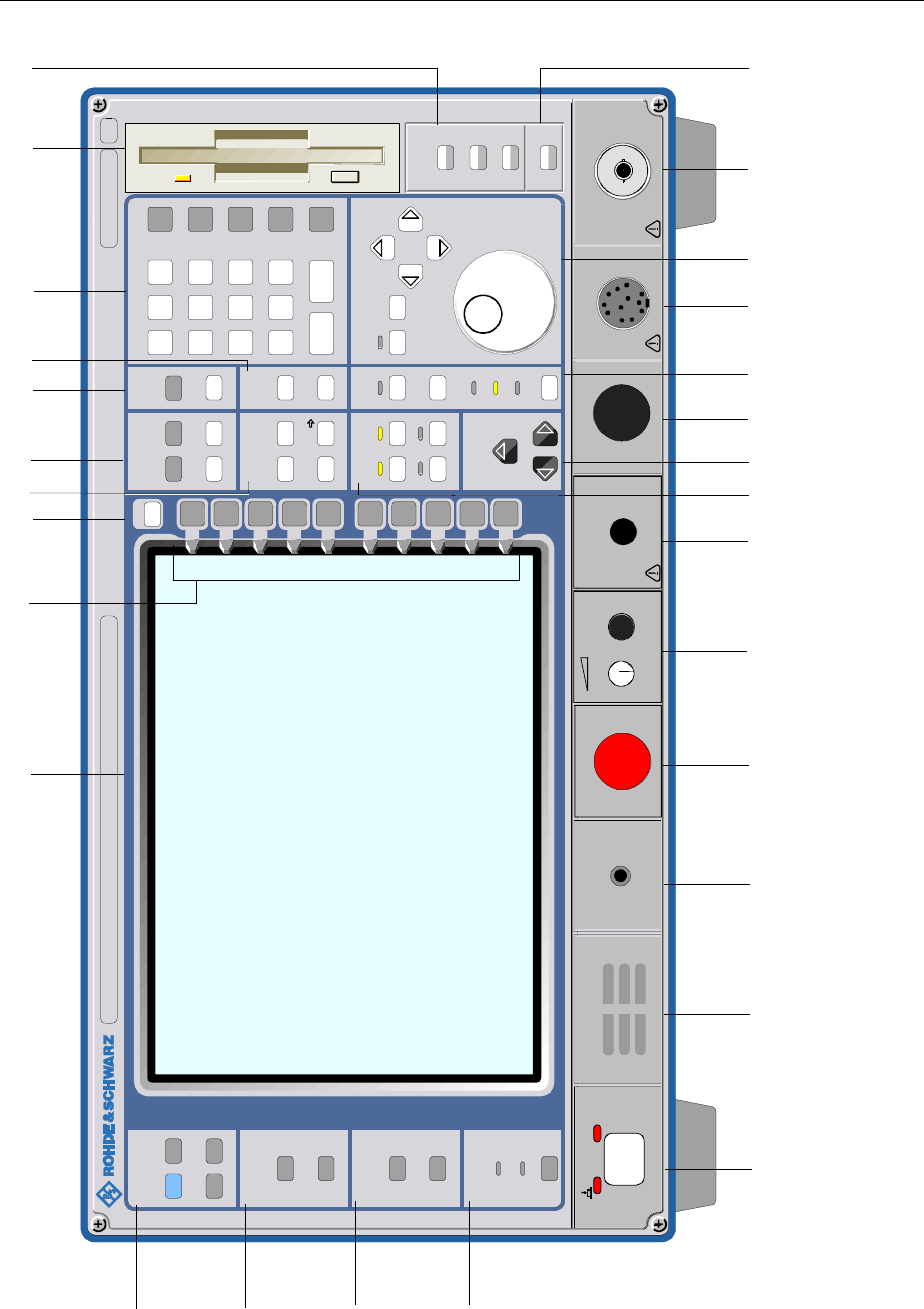
Front View FSE
1065.6016.12 1.2 E-8
0
123
456
789
.-
CLR BACK
GHz
MHz
kHz
Hz
EXP
-dBm
V
s
dBm
mV
ms
dB
µV
µs
dB..
nV
ns
HOLD STEP
SYSTEM
CONFIGURATION
PRESET CAL
DISPLAY INFO
MODE
SETUP
SETTING
START
HARDCOPY
STATUS
SRQ
REMOTE
LOCAL
FREQUENCY LEVEL DATA ENTRY
REF
START STOP RANGE
MARKER LINES
NORMAL SEARCH D LINES
DELTA LIMITSMKR
TRACE SWEEP DATA VARIATION
TRIGGER
12
34
RBW
VBW
SWT
MENU
MEMORY
CONFIG
SAVE
RECALL
CENTER SPAN
SWEEP
COUPLING
1119.5005.SPECTRUM ANALYZER 1 kHz - 10 MHz FSEA20
... 25
USER
INPUT
ON STANDBY AF OUTPUT PROBE POWER PROBE/CODE RF INPUT
5 0
Ω
MAX
MADE IN GERMANY
30 dBm
+DC
MAX 0V
1234567 8910
24 23 18 17 16 15 14 13 12 11
22 21 20 19
25
26
27
28
Fig. 1-1 Front View
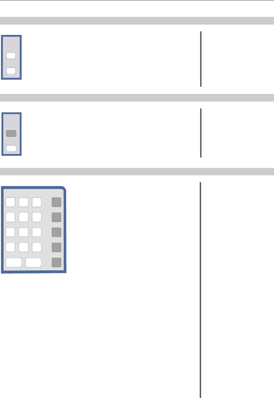
FSE Front View
1065.6016.12 1.3 E-8
6LINES
LINES
D LINES
LIMITS
Setup evaluation lines and tolerance limits
D LINES Setup evaluation lines (display lines)
LIMITS Definition and recall of tolerance limits
see Chap. 4
7 LEVEL
LEVE L
REF
RANGE
Define reference levels and display range in the active
measurement window.
REF Set reference level
(= max. display level)
RANGE Set range
see Chap. 4
8 DATA ENTRY
0
123
456
789
.-
CLR BACK
GHz
MHz
kHz
Hz
EXP
-dBm
V
s
dBm
mV
ms
dB
µV
µs
dB..
nV
ns
DATA ENTRY Keypad for data input
0...9 input numbers
.input decimal point
–change sign
CLR –close input field (for
uncompleted or already closed
inputs, the original entry is
kept)
–erase the current entry in input
field (beginning of an input)
–close message window
(status, error and warning
messages)
BACK erase last character input
GHz s The units keys close the data
V -dBm input and define the multipli-
cation factor for each basic unit.
MHz ms For dimension-less or
mV dBm alphanumeric inputs, the units
keys have weight 1.
kHz µs They behave, in this case, like
µV dB.. the ENTER key.
Hz ns
nV dB
EXP Append an exponent
see Chap. 3

Front View FSE
1065.6016.12 1.4 E-8
0
123
456
789
.-
CLR BACK
GHz
MHz
kHz
Hz
EXP
-dBm
V
s
dBm
mV
ms
dB
µV
µs
dB..
nV
ns
HOLD STEP
SYSTEM
CONFIGURATION
PRESET CAL
DISPLAY INFO
MODE
SETUP
SETTING
START
HARDCOPY
STATUS
SRQ
REMOTE
LOCAL
FREQUENCY LEVEL DATA ENTRY
REF
START STOP RANGE
MARKER LINES
NORMAL SEARCH D LINES
DELTA LIMITSMKR
TRACE SWEEP DATA VARIATION
TRIGGER
12
34
RBW
VBW
SWT
MENU
MEMORY
CONFIG
SAVE
RECALL
CENTER SPAN
SWEEP
COUPLING
1119.5005.SPECTRUM ANALYZER 1 kHz - 10 MHz FSEA20
... 25
USER
INPUT
ON STANDBY AF OUTPUT PROBE POWER PROBE/CODE RF INPUT
5 0
Ω
MAX
MADE IN GERMANY
30 dBm
+DC
MAX 0V
1234567 8910
24 23 18 17 16 15 14 13 12 11
22 21 20 19
25
26
27
28
Figure 1-1 Front View
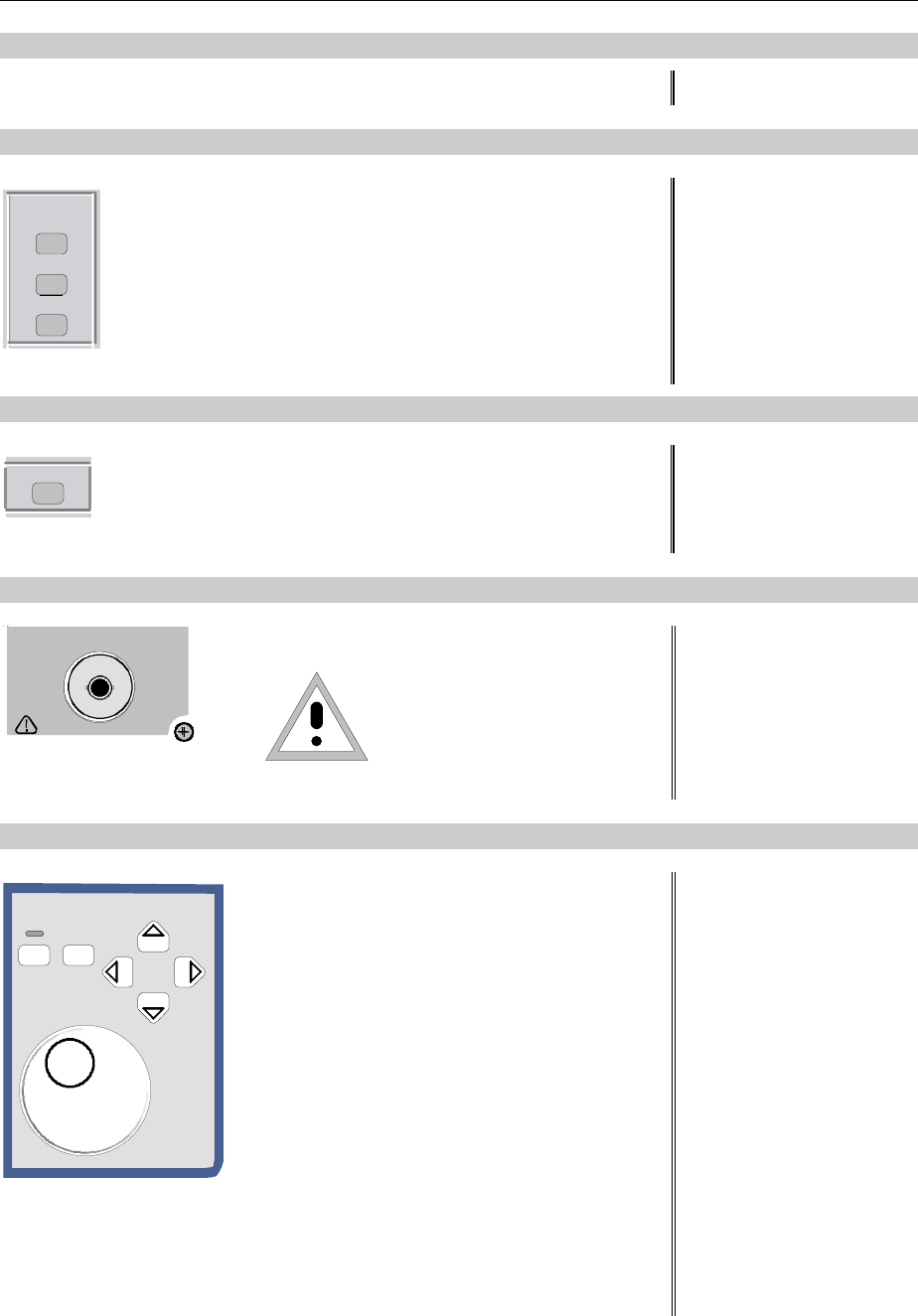
FSE Front View
1065.6016.12 1.5 E-8
9
3 1/2" diskette drive; 1.44 MByte
10 MEMORY
MEMORY
CONFIG
SAVE
RECALL
Memory media and file management
SAVE Save instrument data
RECALL Recall instrument data
CONFIG Configuration of memory media and data
see Chap. 4
11 INPUT
INPUT Set impedance and attenuation at the RF input. see Chap. 4
12 RF INPUT
RF INPUT 50Ω
MAX
MADE IN GERMANY
30 dBm
+DC
MAX 0V
RF-Input Caution:
The maximum DC voltage is
0 V, the maximum power is
1 W (=
^ 30 dBm at
≥
10 dB
attenuation)
see Chap. 8
13 DATA VARIATION
HOLD STEP
DATA VARIATION Key group for entering data and for cursor
movement
HOLD Disable control elements /
overall control. The LED
indicates the hold condition.
STEP Set step size for cursor keys and
roll-key.
Cursor keys – Move the cursor within the
input fields and tables.
– Vary the input value.
– Define the direction of
movement for the roll-key.
Roll-key – Vary input values.
– Move markers and limits.
– Select letters in the help line
editor.
– Move cursor in the tables
see Chap. 3
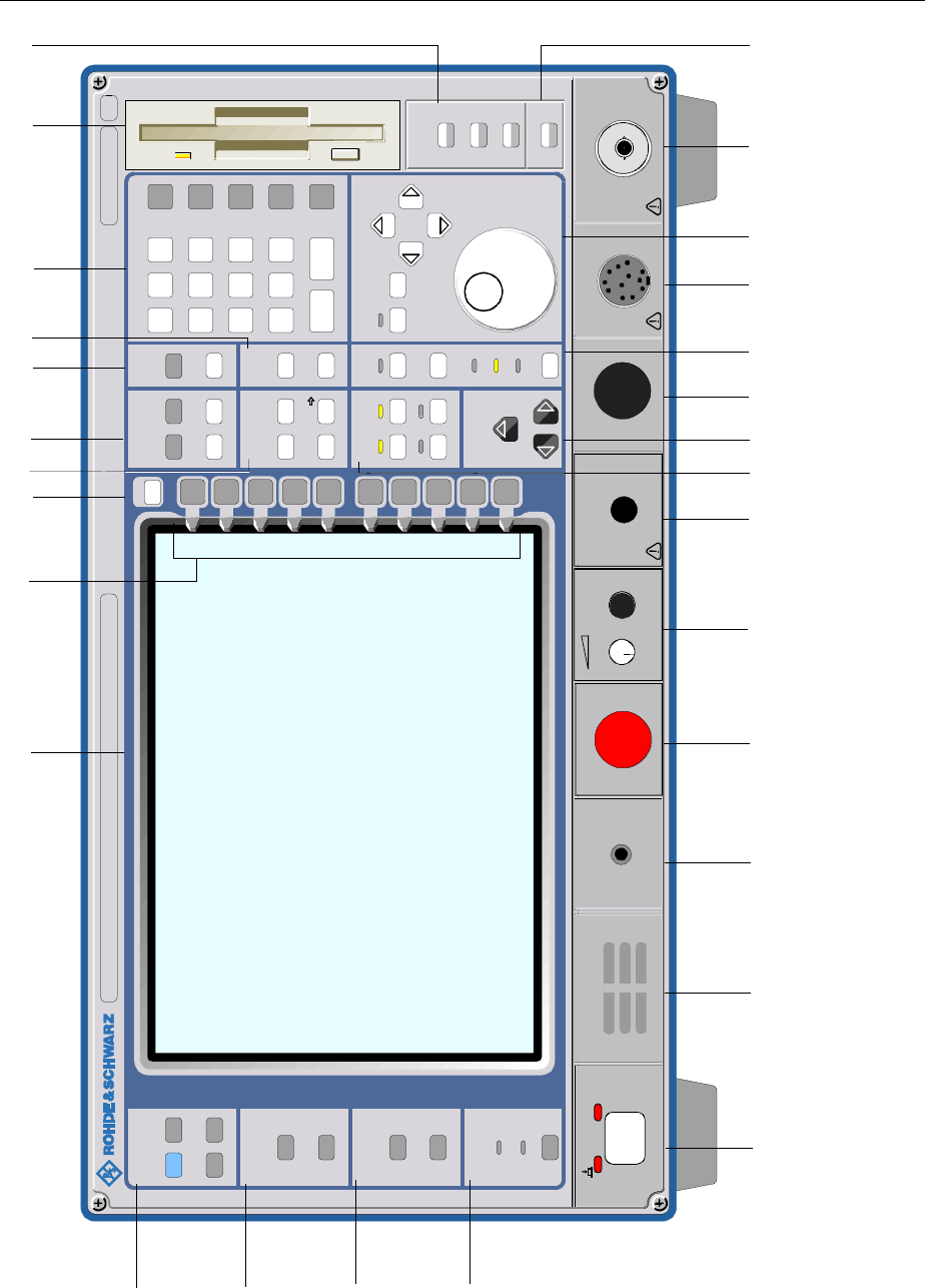
Front View FSE
1065.6016.12 1.6 E-8
0
123
456
789
.-
CLR BACK
GHz
MHz
kHz
Hz
EXP
-dBm
V
s
dBm
mV
ms
dB
µV
µs
dB..
nV
ns
HOLD STEP
SYSTEM
CONFIGURATION
PRESET CAL
DISPLAY INFO
MODE
SETUP
SETTING
START
HARDCOPY
STATUS
SRQ
REMOTE
LOCAL
FREQUENCY LEVEL DATA ENTRY
REF
START STOP RANGE
MARKER LINES
NORMAL SEARCH D LINES
DELTA LIMITSMKR
TRACE SWEEP DATA VARIATION
TRIGGER
12
34
RBW
VBW
SWT
MENU
MEMORY
CONFIG
SAVE
RECALL
CENTER SPAN
SWEEP
COUPLING
1119.5005.SPECTRUM ANALYZER 1 kHz - 10 MHz FSEA20
... 25
USER
INPUT
ON STANDBY AF OUTPUT PROBE POWER PROBE/CODE RF INPUT
5 0
Ω
MAX
MADE IN GERMANY
30 dBm
+DC
MAX 0V
1234567 8910
24 23 18 17 16 15 14 13 12 11
22 21 20 19
25
26
27
28
Figure 1-1 Front View
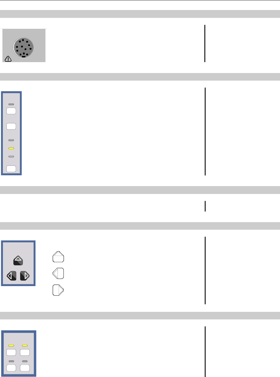
FSE Front View
1065.6016.12 1.7 E-8
14 PROBE/CODE
PROBE/CODE Power supply and coded socket for R&S
accessories.(12-pin Tuchel) see Chap. 8
15 SWEEP
SWEEP
TRIGGER
RBW
VBW
SWT
SWEEP
COUPLING
Input sweep parameters
TRIGGER Set trigger source. The LED illuminates on
valid trigger.
SWEEP Set type of sweep.
COUPLING Set coupled parameters. Resolution
BandWidth (RBW), Video BandWidth
(VBW) and SWeep Time (SWT).
The LEDs light indicating coupled
parameters which are manually cancelled.
see Chap. 4
16
Reserved for options
17 MENU
MENU Menu-change keys
Call main menu
Change to left menu
Change to right menu
see Chap. 3
18 TRACE
TRACE
12
34
Select and activate measurement traces (Trace 1...4).
The LEDs indicate traces turned on.
see Chap. 4

Front View FSE
1065.6016.12 1.8 E-8
0
123
456
789
.-
CLR BACK
GHz
MHz
kHz
Hz
EXP
-dBm
V
s
dBm
mV
ms
dB
µV
µs
dB..
nV
ns
HOLD STEP
SYSTEM
CONFIGURATION
PRESET CAL
DISPLAY INFO
MODE
SETUP
SETTING
START
HARDCOPY
STATUS
SRQ
REMOTE
LOCAL
FREQUENCY LEVEL DATA ENTRY
REF
START STOP RANGE
MARKER LINES
NORMAL SEARCH D LINES
DELTA LIMITSMKR
TRACE SWEEP DATA VARIATION
TRIGGER
12
34
RBW
VBW
SWT
MENU
MEMORY
CONFIG
SAVE
RECALL
CENTER SPAN
SWEEP
COUPLING
1119.5005.SPECTRUM ANALYZER 1 kHz - 10 MHz FSEA20
... 25
USER
INPUT
ON STANDBY AF OUTPUT PROBE POWER PROBE/CODE RF INPUT
5 0
Ω
MAX
MADE IN GERMANY
30 dBm
+DC
MAX 0V
1234567 8910
24 23 18 17 16 15 14 13 12 11
22 21 20 19
25
26
27
28
Figure 1-1 Front View
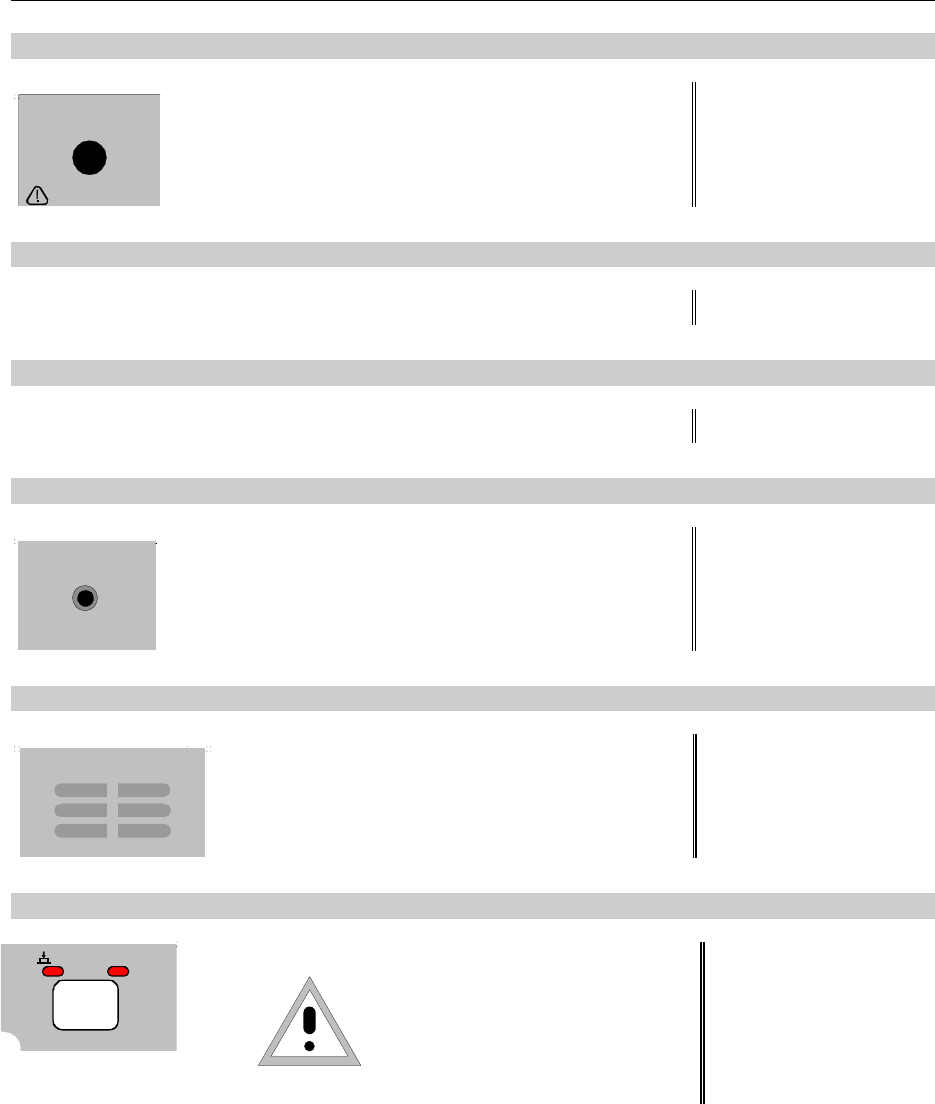
FSE Front View
1065.6016.12 1.9 E-8
19 PROBE POWER
PROBE POWER Power supply connector (+15V / - 12.6V) for
measurement accessories (probes) see Chap. 8
20
Reserved for options
21
Reserved for options
22 AF OUTPUT
AF OUTPUT AF output connector (head phones) (miniature
phone jack) see Chap. 8
23
Internal loudspeaker
The loudspeaker is disabled when the phone jack
is inserted in the AF output.
see Chap. 8
24
ON STANDBY ON/STANDBY
Caution:
In standby mode, the AC line
voltage is still present within the
instrument.
see Chap. 1
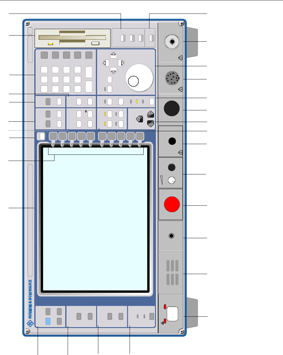
Front View FSE
1065.6016.12 1.10 E-8
0
123
456
789
.-
CLR BACK
GHz
MHz
kHz
Hz
EXP
-dBm
V
s
dBm
mV
ms
dB
µV
µs
dB..
nV
ns
HOLD STEP
SYSTEM
CONFIGURATION
PRESET CAL
DISPLAY INFO
MODE
SETUP
SETTING
START
HARDCOPY
STATUS
SRQ
REMOTE
LOCAL
FREQUENCY LEVEL DATA ENTRY
REF
START STOP RANGE
MARKER LINES
NORMAL SEARCH D LINES
DELTA LIMITSMKR
TRACE SWEEP DATA VARIATION
TRIGGER
12
34
RBW
VBW
SWT
MENU
MEMORY
CONFIG
SAVE
RECALL
CENTER SPAN
SWEEP
COUPLING
1119.5005.SPECTRUM ANALYZER 1 kHz - 10 MHz FSEA20
... 25
USER
INPUT
ON STANDBY AF OUTPUT PROBE POWER PROBE/CODE RF INPUT
50
Ω
MAX
MADE IN GERMANY
30 dBm
+DC
MAX 0V
1234567 8910
24 23 18 17 16 15 14 13 12 11
22 21 20 19
25
26
27
28
Fig.1-1 Front View

FSE Front View
1065.6016.12 1.11 E-8
25 STATUS
STATUS
SRQ
REMOTE
LOCAL
Indicators for remote control and switch for manual
control.
LOCAL Switch from remote to manual control.
The LED SRQ indicates that a service
request from the instrument is active on the
IEC Bus.
The LED REMOTE indicates that the
instrument is under remote control.
see Chap. 4
26 HARDCOPY
SETTING
START
HARDCOPY Printer control
START Start a print job with the setup defined in
the SETTING menu.
SETTING Configure the diagram, parameter list and
measurement protocol outputs on the
various output media.
see Chap. 4
27 CONFIGURATION
CONFIGURATION
MODE
SETUP
Select operational modes and define default settings
MODE Select mode
SETUP Define configurationss
see Chap. 4
28 SYSTEM
SYSTEM
PRESET CAL
DISPLAY INFO
General instrument default settings
PRESET Recall instrument default settings
DISPLAY Configure the display screen format
CAL Calibrate the analyzer
INFO –Information concerning instrument state
and measurement parameters
–Call help functions
see Chap. 4
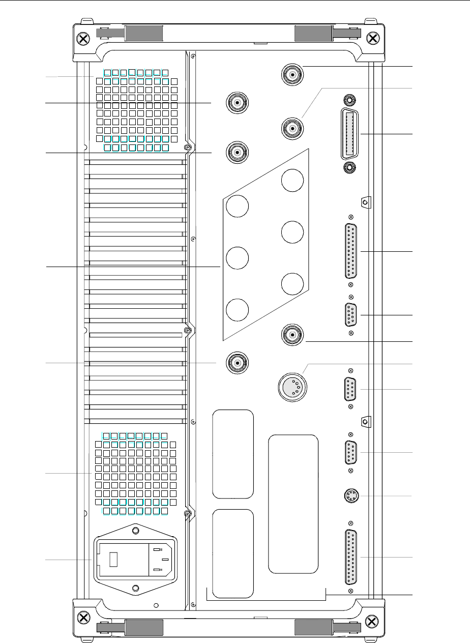
Rear View FSE
1065.6016.12 1.12 E-8
LPT
KEYBOARD
COM1 COM2
MONITOR USER
MOUSE
EXT REF
IN/OUT NOICE SOURCE
SWEEP
I
0
EXT TRIG/GATE OUT
IF 21.4 MHz
29 30 31 32 33 30
34
3536
3738394041
4344
45 42
46
VIDEO
OUT
<SCP
I
>
I
EC
625
Fig. 1-2 Rear View
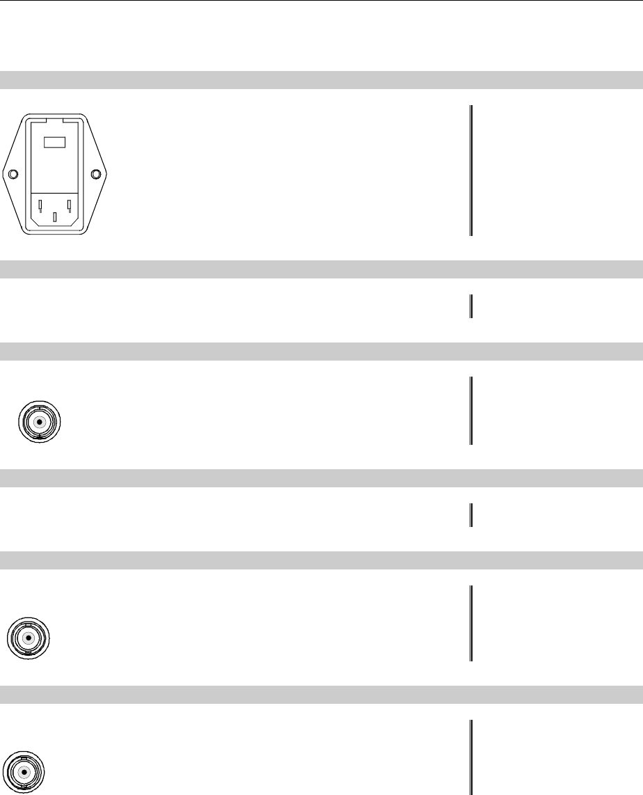
FSE Rear View
1065.6016.12 1.13 E-8
Rear View
29
Power switch
Fuse holder
AC power connector
see Chap. 1
30
Power supply fans
31 EXT TRIG/GATE
EXT TRIG/GATE
Input connector for an external trigger or an external
gate signal see Chap. 4 and 8
32
Reserved for options
33 IF 21.4 MHZ OUT
IF 21.4 MHz
OUT
Output connector for 21.4 MHz IF see Chap. 8
34 VIDEO OUT
VIDEO
OUT
Output connector for video signal see Chap. 8

Rear View FSE
1065.6016.12 1.14 E-8
LPT
KEYBOARD
COM1 COM2
MONITOR USER
MOUSE
EXT REF
IN/OUT NOICE SOURCE
SWEEP
I
0
EXT TRIG/GATE OUT
IF 21.4 MHz
29 30 31 32 33 30
34
3536
3738394041
4344
45 42
46
VIDEO
OUT
<SCP
I
>
I
EC
625
Figure 1-2 Rear View
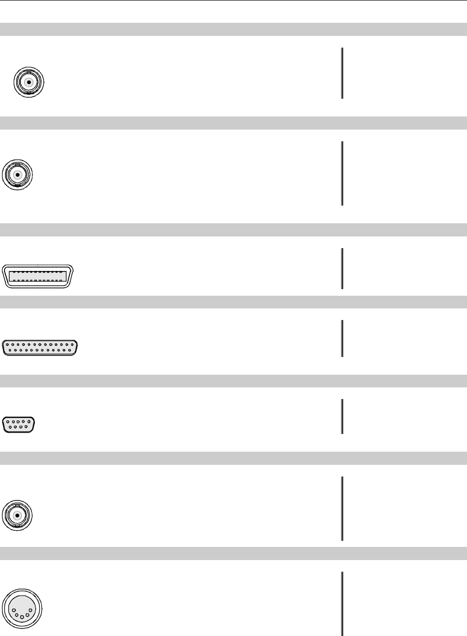
FSE Rear View
1065.6016.12 1.15 E-8
35 NOISE SOURCE
NOICE SOUR
Output connector for a switchable noise source see Chap. 8
36 SWEEP
SWEEP
Output connector
During a sweep, a sawtooth voltage is output which is
proportional to frequency.
see Chap. 8
37 <SCPI> IEC625
<SCPI> IEC625
IEC\IEEE-bus-connector see Chap. 8
38 USER
USER
User interface connector with configurable inputs and
outputs (USER-PORT A and USER-PORT B) see Chap. 8
39 MONITOR
MONITOR
Connector for an external VGA monitor see Chap. 8
40 EXT REF IN/OUT
EXT REF
IN/OUT
Input connector for an external reference (1 to 16 MHz),
switchable to 10 MHz output see Chap. 4 and 8
41 KEYBOARD
KEYBOARD
Connector for an external keyboard
(5-pin DIN socket) see Chap. 1 and 8
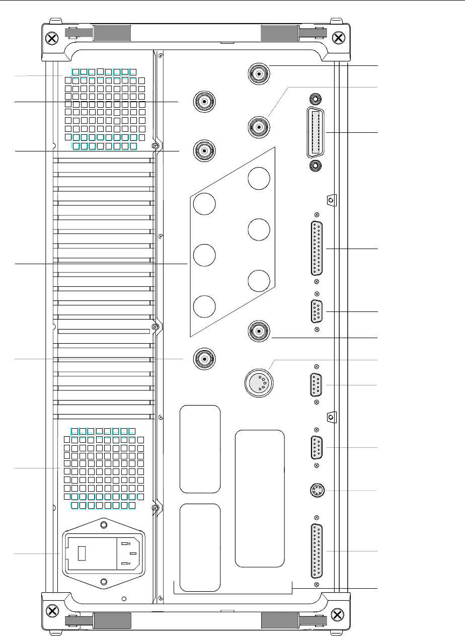
Rear View FSE
1065.6016.12 1.16 E-8
LPT
KEYBOARD
COM1 COM2
MONITOR USER
MOUSE
EXT REF
IN/OUT NOICE SOURCE
SWEEP
I
0
EXT TRIG/GATE OUT
IF 21.4 MHz
29 30 31 32 33 30
34
3536
3738394041
4344
45 42
46
VIDEO
OUT
<SCP
I
>
I
EC
625
Figure 1-2 Rear View

FSE Rear View
1065.6016.12 1.17 E-8
42 COM2
COM2
Connector for serial interface 2
(9-pin socket; COM2) see Chap. 1 and 8
43 COM1
COM1
Connector for serial interface 1
(9-pin socket; COM1) see Chap. 1 and 8
44 MOUSE
MOUSE
Connector for a PS/2 mouse see Chap. 1 and 8
45 LPT
LPT
Parallel interface connector
(printer connector, Centronics compatible) see Chap. 1 and 8
46
Inputs / Outputs for options
(cover plates for digital interface expansion)
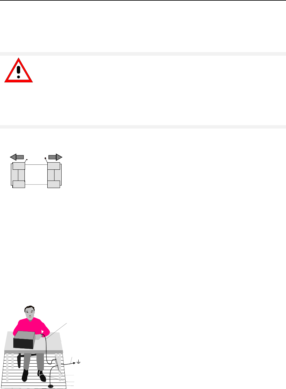
Start-Up - Instruments with Windows NT Controller FSE
1065.6016.12 1.18 E-8
Start-Up - Instruments with Windows NT Controller
The following section describes how to put the instrument into service and how to connect external
devices like eg printer and monitor.
Important Note:
Before turning the instrument on, check the following:
•instrument covers are in place and screwed down,
•fan openings are free from obstructions,
•signal levels at the input connectors are all within specified limits,
•signal outputs are connected correctly and not overloaded.
The instrument may be damaged if the above conditions are not observed.
Unpacking the Instrument
remove protective caps
½ Take the instrument out of its transport container and check
whether the items listed in the packing list and in the lists of
accessories are all there.
½ Remove the two protective covers from the front and rear of the
FSE and carefully check the instrument for damage.
½ Should the instrument be damaged, immediately notify the carrier
which shipped the instrument to you and keep the container and
packing material.
½ For further transport or shipment of the FSE the original packing
should also be used. It is recommended to keep at least the two
protective covers for the front and rear to prevent damage to the
controls and connectors.
Setting up the Instrument
Stand-alone Operation
The instrument is designed for use under general laboratory conditions. The ambient conditions must be
as follows:
Wrist strap with cord
Building ground
Floor mat
Ground connection
of operational site
Heel strap
• The ambient temperature must be in the range
recommended in the data sheet.
• All fan openings must be unobstructed and the air flow at
the rear panel and at the side-panel perforations must not
be obstructed. The distance from the wall should be at
least 10 cm.
• The FSE should be placed on a level surface.
• In order to avoid damage of electronic components of the
instrument or of the device under test due to electrostatic
discharge on manual touch, protection of the operational
site against electrostatic discharge is recommended.
For applications in the laboratory or on a work bench, it is recommended that the support feet on the
bottom of the instrument be extended. For the LCD display, this provides the optimum viewing angle
which typically ranges from perpendicular to the display front to approximately 30° below.

FSE Start-Up - Instruments with Windows NT Controller
1065.6016.12 1.19 E-8
19" Rack Installation
Important Note:
When the instrument is rack-mounted, ensure that the air flow through the side-
panel holes and the air outlet in the rear panel are not obstructed.
The instrument may be mounted in a 19" rack by using the rack adapter kit ZZA-95 (order number: see
data sheet). The installation instructions are included in the adapter kit.
EMI Protection Measures
In order to prevent electromagnetic interference (EMI), the instrument may be operated only when all
covers are correctly in place. Only adequately shielded signal and control cables may be used (see
recommended accessories).
Connecting to AC Supply
The FSE features automatic AC-line voltage selection (range: see power supply name-plate). The AC
power connector is located on the rear panel (see below).
½Connect the instrument to the AC power source using the AC power cable delivered with the
instrument.
AC Power Line Fuses
The FSE is protected by two fuses as specified on the power supply name-plate. The fuses are located
in a removable fuse holder which is located between the AC power switch and the AC power connector
(see below).
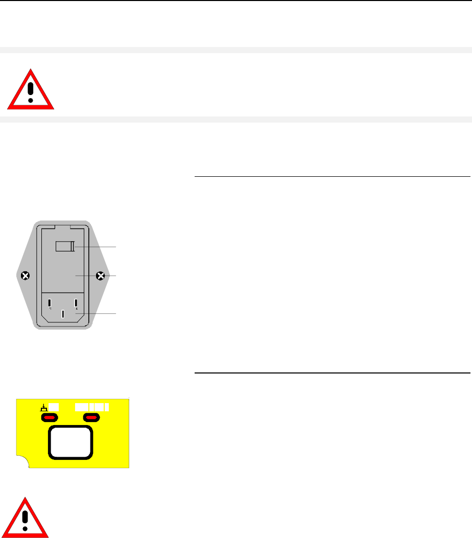
Start-Up - Instruments with Windows NT Controller FSE
1065.6016.12 1.20 E-8
Switching the Instrument on/off
Caution:
Do not power down during booting. This may corrupt harddisk files.
Note: On power-up, the drive should contain no disk, since otherwise the instrument will try to boot from
the disk.
AC power switch on the rear panel
I
0
ON
OFF
Ac power switch
Fuse holder
AC power connector
Power switch
After turn-on (position ON), the instrument is in the ready
state (STANDBY) or in operation dependent upon the
position of the ON/STANDBY switch located on the
instrument front panel (see below).
Note:The AC power switch can be left ON all the time..
Switching to OFF is only required when the instrument
has to be completely disconnected from the AC power
source.
Switching to OFF (position OFF) disconnects the FSE
completely from the AC power source.
ON/STANDBY switch on the front panel
ON STANDBY
.
Standby
½ON/STANDBY switch is not depressed.
The yellow LED (STANDBY) is on. Only the FSE‘s
internal power is connected to the AC line. The crystal
oven is maintained at the normal operating temperature.
Operation
Caution:
In standby mode, the FSE is
still live.
½ON/STANDBY is depressed.
The green LED (ON) is on. The instrument is ready for
operation. All modules within the instrument are supplied
with power.
Switching on the Instrument
½To switch on the FSE, set the power switch on the rear panel to position I.
½Pressing the ON/STANDBY key on the front panel. The green LED ahould come on.

FSE Start-Up - Instruments with Windows NT Controller
1065.6016.12 1.21 E-8
Startup Menu and Booting
When the instrument is switched on, a message indicating the installed BIOS version (eg Analyzer BIOS
Rev. 1.2) appears on the screen for a few seconds.
Windows NT is booted first and then the instrument firmware. As soon as boot up is over, the instrument
will start measuring. The settings used will be the one that was active when the instrument was
previously switched off, provided no other device configuration than FACTORY had been selected with
AUTO RECALL in the MEMORY menu.
Switching off the Instrument
½Remove the disk, if any, from the drive before switching off.
½Press the ON/STANDBY key on the front panel. The yellow LED should come on.
Only when completely disconnecting the FSE from the AC power source:
½Set the power switch on the rear panel to position 0.
Energy Saving Mode
The FSE offers an energy saving mode for the screen display. The screen goes blank if no entries have
been made from the front panel (key, softkey or hotkey and rollkey) for a selectable period of time.
To switch on the energy saving mode:
1. Call the SYSTEM DISPLAY - CONFIG DISPLAY submenu to configure the screen display:
½Press the DISPLAY key
½Press the CONFIG DISPLAY softkey
2. Activate the save mode
½Press the SCR. SAVER ON softkey.
The softkey is highlighted, indicating that the energy saving mode is on. At the
same time the data entry for the shutdown time opens.
3. Enter the shutdown time
½Press the SCR. SAVER TIME softkey.
½Enter the shutdown time in minutes and confirm the entry using the ENTER key.
The screen will go blank when the shut down time elapsed.
Battery Backed-up Memory
The FSE has a battery-powered read/write memory (CMOS-RAM) for backing up instrument settings on
power-off. After each power-on, the FSE is reloaded with the operational parameters which were active
just prior to the last power-off (STANDBY or AC power OFF) or were set with AUTO RECALL (see
Chapter 4 "Saving and Recalling Data Sets").
A lithium battery powers the CMOS-RAM. When the battery goes flat (after approx. 5 years), any data
stored in the CMOS-RAM will be lost. If this happens, the factory setup is loaded on power up. As the
FSE has to be opened to replace the battery, please contact the representative of our company
responsible for you for changing batteries.

Functional Test - Instruments with Windows NT Controller FSE
1065.6016.12 1.22 E-8
Function Test
On power up, the FSE displays the following message on the screen:
Analyzer BIOS
Rev.x.y
Copyright
Rohde & Schwarz
Munich
Booting
A self-test of the digital hardware is then performed. If the self-test finds no faults, Windows NT is
booted up and the instrument starts measuring.
Any errors which occur in self-test are transferred as ASCII text to the printer interface (LPT). Therefore,
an error diagnosis can be carried out, even for serious failures.
A check of the data contents of the instrument is performed in system error correction (CAL, CAL
TOTAL key) The individual results of the correction (PASSED / FAILED) can be displayed in the
calibration menu.
With the aid of the built-in self-test functions (INFO key, SELFTEST soft key), the functional integrity of
the instrument can be verified and/or defective modules can be localized.

FSE Windows NT Controller Function
1065.6016.12 1.23 E-8
Controller Function - Windows NT
Caution:
The drivers used in the integrated controller function are specially configured for the
instrument. To prevent functions crashing, only the settings described below should
be used. Only the update software released by Rohde&Schwarz should be used to
update the drivers. Only programs authorized by Rohde&Schwarz for use on the
instrument may be run on the instrument.
Do not power down during booting. This may corrupt the harddisk files.
The instrument has an integrated Windows-NT controller. The user can switch between the
measurement screen and the controller screen. When an external monitor is connected, the
measurement function and the controller function can be displayed simultaneously (see section
"Connecting an External Monitor"). The controller function is automatically booted on power-up.
Windows NT operation is described in the supplied manual or in the online help of Windows NT.
Login
The user has to login to Windows NT by entering his name and password. As a factory default, the
instrument is configured for Auto Login, i.e. the login is performed automatically and in the background.
The user name used is then "instrument" and the password is also "instrument" (lower case).
To login under another name, call up the logout window in the task bar with START - SHUT DOWN.
Mark the item "Close all programs and log on as a different user?" in the window and click YES while
holding the SHIFT key down until the login window is displayed to enter the user identification. The
password should be entered in the correct syntax including lower-case and upper-case characters.
Administrator identification
Some of the installations (eg CD-ROM drive) described below require the administrator login. This is
indicated in the relevant window.
The administrator is an identification which in particular allows system settings which are disabled for
the standard user.
The password for the administrator is 894129 for the instrument.
After an installation under the administrator identification, the "Service Pack" of Windows NT has to be
re-installed, see section "Installation of Windows NT Software".
On power-up following an installation under the administrator identification, the NT login window is
displayed (no autologin). The user name "Administrator" is indicated in the window. This entry is to be
replaced by "instrument" and then "instrument" as password entered. An autologin is then possible.
Changeover between measurement screen and controller screen
To call up the controller screen use key combination <ALT><SYSREQ> (US keyboard).
To return to the measurement screen, activate the window "R&S Analyzer Interface" on the controller.
Logout
The instrument can be switched off (standby mode). Logging out of Windows NT is not necessary.

Connecting a Mouse - with Windows NT Controller FSE
1065.6016.12 1.24 E-8
Connecting a Mouse
Caution:
The keyboard may only be connected when the instrument is switched off
(STANDBY). Otherwise, correct operation of the keyboard cannot be guaranteed.
A mouse can be connected to the PS/2 (MOUSE) connector on the rear panel of the instrument to make
it easier to use.
MOUSE
During measurements, softkeys, tables and data input fields may also be controlled by mouse. For
computer function, the mouse has the usual functions.
The control functions for the mouse during measurement operation are described in Chapter 3 in the
section "Mouse Control of Further Display Elements". This section contains a list in which the screen
display elements for mouse control of the corresponding softkeys and push buttons of the instrument
are described. Chapter 8 describes the connector interface.
After connection of the mouse and subsequent power-on, the mouse will be automatically recognized.
Special settings such as mouse cursor speed etc., can be made in the Windows NT menu START -
SETTINGS - CONTROL PANEL - MOUSE.

FSE Connecting an External Keyboard - with Windows NT Controller
1065.6016.12 1.25 E-8
Connecting an External Keyboard
Caution:
The mouse may only be connected when the instrument is switched off
(STANDBY). Otherwise, correct operation of the mouse and instrument cannot be
guaranteed.
The instrument is fitted with a rear-panel 5-contact DIN connector (KEYBOARD) for the connection of
an external PC keyboard.
KEYBOARD x
During measurements, the keyboard makes it easier to enter comments, filenames, etc. For computer
function, the keyboard has the usual functions.
Chapter 3, in section "External Keyboard Control", contains a list which describes the assignment of the
instrument front-panel key functions to the key codes of the external keyboard as well as special key
combinations used for quick operations. Chapter 8 describes the interface for the connector.
After connection of the keyboard and subsequent power-on, the keyboard will be automatically
recognized. The default setting is for the US keyboard. Special settings such as repetitional rate etc. can
be performed in Windows NT menu START - SETTINGS - CONTROL PANEL - KEYBOARD.

Connecting an External Monitor - with Windows NT Controller FSE
1065.6016.12 1.26 E-8
Connecting an External Monitor
Caution:
The monitor may only be connected when the instrument is switched off (STANDBY).
Otherwise, the monitor may be damaged.
Do not modify the screen driver (display type) as this would cause a malfunction.
Notes: - When connecting the monitor to the PC MONITOR connector, the display of controller
function can be adapted to the external screen (eg higher resolution) in the NT menu
START-SETTING - CONTROL PANEL - DISPLAY PROPERTIES.
- CHIPS (setting = both) should not be modified since otherwise switching between the
external monitor and the instrument screen is not possible.
The instrument is fitted with a rear-panel connector PC MONITOR or ANALYZER MONITOR for an
external monitor.
PC MONITOR
ANALYZER MONITOR
Chapter 8 describes the connector interface.
With an external monitor it is possible to have an enlarged display of the measurement screen
(ANALYZER MONITOR connector) or of the controller screen (PC MONITOR connector). The
measuring instrument and the Windows NT controller can be operated in parallel. The mouse and the
keyboard are allocated to only one mode.
Display of the measurement screen - Connection to ANALYZER MONITOR connector
Connection
After connecting the external monitor the measurement screen is displayed on both the external monitor
and the instrument. Further settings are not necessary.
Operation
The instrument is operated as usual via its softkeys, the mouse and keyboard, etc..
Toggle between measurement screen and controller screen
Key combination <ALT><SYSREQ> is used to call up the controller. After call up, the mouse and
keyboard are allocated to the controller function.
By activating the window "R&S Analyzer Interface" the user returns to the measurement screen and the
mouse and keyboard are allocated to this screen.
Display of the controller screen - Connection to PC MONITOR connector
Connection
After connecting the monitor external monitor operation should be selected.
Setting is performed in the SETUP-GENERAL SETUP menu (key group: CONFIGURATION, see in
Chapter 4, the section "Presettings and Interface Configuration"):
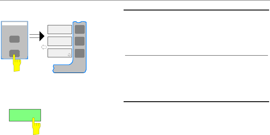
FSE Connecting an External Monitor - with Windows NT Controller
1065.6016.12 1.27 E-8
CONFIGURATION
MODE
SETUP
EXTERNAL
REFERENCE
GENERAL
SETUP
Call SETUP-GENERAL SETUP menu
½Press the SETUP key in the CONFIGURATION
field.
The SETUP menu is opened.
½Press the GENERAL SETUP softkey.
The GENERAL SETUP submenu is opened and the
current settings of the instrument parameters are
displayed on the screen in the form of tables.
MONITOR
CONNECTED
Selecting the external monitor mode
½Press the MONITOR CONNECTED softkey.
The softkey is in color to indicate that the external
monitor mode is activated. The external monitor
displays the controller screen.
Operation
The controller function is operated as usual with the mouse and keyboard. The measuring instrument
(displayed on the instrument screen) can be operated with both the softkeys and keys of the instrument.
Toggle between screens
By activating (clicking) the window "R&S Analyzer Interface" at the controller the mouse and keyboard
are allocated to the measurement screen. The mouse and keyboard are allocated to the controller when
the window is deactivated.
Connecting a Printer - with Windows NT Controller FSE
1065.6016.12 1.28 E-8
Connecting a Printer
Caution:
The printer may be connected only when the instrument is switched off (STANDBY)
Notes: - The installation of some printer drivers is possible only under the administrator identification
(see section "Controller Function").
- After the installation, the "Service Pack" of Windows NT is to be re-installed, see "New
Installation of Windows NT Software".
- To ensure that the instrument performs an autologin, the user identification is to be reset to
"instrument" after the next power-up, see section "Controller Function".
- If bad printouts are produced after installing the printer driver, it is recommended to obtain
the latest drivers from the printer manufacturer (eg via Internet). Experience has shown that
printer problems are thus solved in most cases.
The instrument provides an option for connecting up to three different printers to provide screen
hardcopy.
The interfaces can also be used for printing in the controller mode. The output formats "WMF"
(Windows Metafile) and "Clipboard" are preset. A large number of output devices can be connected
under Windows NT after installing suitable printer drivers.
The output devices supported by the instrument can be found in the selection box DEVICE/LANGUAGE
in the HARDCOPY –SETTINGS DEVICE1/2 menu (see in Chapter 4, the section "Documentation of
Measurement Results"). To print out via the COM interface, the latter must be assigned the controller
function in the SETUP - GENERAL SETUP menu (owner = OS).
Chapter 8 describes the connector interfaces.
The interface connectors are located on the rear panel:
LPT
COM1 COM2
After the printer has been connected to the appropriate interface connector, the interface needs to be
configured, the printer driver has to be installed and assigned to an interface.
1. Connecting the keyboard and mouse
Ti install and configure of printer drivers on the FSE, it is necessary to connect a keyboard to the front
panel and a PS/2 mouse to the rear panel (see sections "Connecting a Mouse" and "Connecting a
Keyboard").
2. Configuring of the interface
LPT1 The LPT1 needs no configuration.
Note: An external CM-ROM drive can be connected to this interface. If this is
the case, one of the serial interfaces can be used for the printout.
COM1/COM2 The COM interfaces have to be assigned to the controller function (OWNER = OS)
in the SETUP - GENERAL SETUP menu. The configuration of serial interfaces
COM1 and COM2 can then be performed in the Windows NT menu START -
SETTINGS - CONTROL PANEL - PORTS. The parameters COM PORTS
BAUDRATE, BITS, PARITY, STOPBITS, HW/SW-HANDSHAKE must be those
specified for the printer in question (see the operating manual for the output
device).

FSE Connecting a Printer - with Windows NT Controller
1065.6016.12 1.29 E-8
Note: The serial interfaces can be used for remote control when the analyzer
is made the owner (Owner = Instrument). The settings made for the
serial interface in the menu SETUP - GENERAL SETUP overwrite the
settings in the NT menu..
However, settings in the Windows NT menu do not overwrite those of
the SETUP menu. This means that the settings are only valid as long as
the interface is assigned to the operating system.
3. Selection and installation of the printer driver
The selection and installation of the printer driver, the assignment to the interface and the setting of
most of the printer-specific parameters (eg paper size) is performed under Windows NT in the
START - SETTINGS - PRINTER menu.
4. Configuration of the connected output device
The printer connected to the instrument is configured in the HARDCOPY DEVICE–SETTINGS
DEVICE1/2 menu (key group: HARDCOPY, see Chapter 4, Section "Selection and Configuration of
the Output Device "). The configuration of one or two output devices (DEVICE1 and DEVICE2) can
be entered, at least one of which must be activated for printing.
•The parameter DEVICE/LANGUAGE determines which printer is used.
•The parameter PRINT TO FILE determines if the output is written to a file.
•The parameter ORIENTATION sets the page format to horizontal or vertical (landscape or
portrait).
Selecting the printer type automatically sets the parameters PRINT TO FILE and ORIENTATION to
values which correspond to the standard mode for this printer. Other printer-dependent parameters
such as FORMFEED, PAPERFEED etc., can be modified under Windows NT in the printer
properties window (START/SETTINGS/PRINTERS/SETTINGS/....).
Table 1-1 shows the standard factory settings for the two output devices.
The factory settings of DEVICE 1 correspond to the "WMF" (Windows Metafile) output format, with
printout to a file. WMF is a common format which is used to import of hardcopies (eg of
measurement windows) to other Windows applications that support this format (eg WinWord).
The factory setting of DEVICE 2 is "Clipboard". In this setting, the printout is copied to the Windows
NT clipboard. Most Windows applications support the clipboard. The clipboard contents can be
directly inserted into a document with EDIT - PASTE.
Table 1-1 Factory settings for DEVICE 1 and DEVICE 2 in the HARDCOPY-DEVICE SETTINGS menu.
Parameter Parameter name DEVICE 1 settings DEVICE 2 settings
Output device DEVICE WINDOWS METAFILE CLIPBOARD
Output PRINT TO FILE YES ---
Paper orientation ORIENTATION --- ---
In the following example, an HP DeskJet 660C printer is connected to interface LPT1 and configured as
DEVICE2 for hardcopies of the screen.
Switch off FSE.
Connect printer to the LPT1 interface .
Switch on both the FSE and the printer.
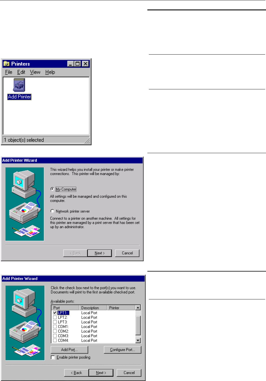
Connecting a Printer - with Windows NT Controller FSE
1065.6016.12 1.30 E-8
Select printer driver under Windows NT
½Press key combination <ALT> <SYSREQ>
The Windows NT screen is displayed.
½In the Start menu click on "Settings" and
then "Printers".
The printer window is opened.
½Double-click "Add Printer".
The "Add Printer Wizard" window is
opened. This window leads through the
following printer driver installation.
½Click first "My computer" and then "Next".
The available ports are displayed.
½Select LPT1 port.
The selection is indicated by a tick.
½"Click "Next".
The available printer drivers are displayed.
The left-hand selection table indicates the
manufacturers and the right-hand one the
available printer drivers.
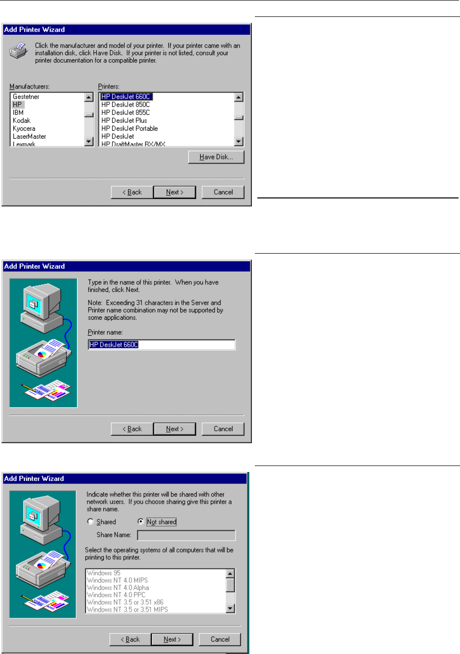
FSE Connecting a Printer - with Windows NT Controller
1065.6016.12 1.31 E-8
½Mark "HP" in the "Manufacturers" selection
table and "HP DeskJet 660C" in the
"Printers" selection table .
Note: If the required printer type is not in the
list, the driver has not yet been
installed. In this case click "HAVE
DISK". A message box requesting to
insert a disk with the printer driver will
be displayed. Insert the disk, press OK
and select the printer driver. After
installation, Service Pack must be
reinstalled (see section "Installing
Windows NT Software").
½Click "Next".
The entry field for the printer name is
displayed.
½The printer name can be modified in the
entry field "Printer name" (max. 60
characters).
If one or more printers have already been
installed, a query is displayed in this
window to ask if the printer last installed as
the default printer should be selected for
the Windows NT applications (Do you
want your Windows-based programs to
use this printer as default printer?) "No" is
preset.
½Click "Next".
A query is displayed whether the printer is
to be shared with other network users..
This query is irrelevant when installing a
local printer. The answer "Not shared" is
preset.
½Click "Next".
The window for printing a test page is
displayed. The test page is for checking if
the installation was successful.
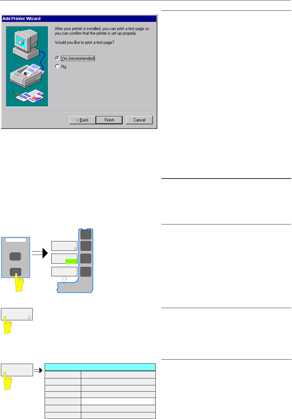
Connecting a Printer - with Windows NT Controller FSE
1065.6016.12 1.32 E-8
½Switch on printer.
½Click Yes (recommended)".
½Click "Finish".
A test page is printed out if the installation
was successful.
If the test page is not printed out or not
completely, the Windows NT online help
offers troubleshooting instructions under
the entry "Printer Trouble Shooting".
Note:
If a request for the printer driver path
appears after clicking "Finish", this printer
installation should be performed under the
administrator identification (see section
"Controller Function".
Now, the instrument needs to be configured
so that hardcopies of the measurement
screen can be printed out on this printer.
Configuring HP DeskJet 660C.
½Click the "R&S Analyzer Interface" button.
The measurement screen is displayed.
START
HARDCOPY
DEVICE
HARDCOPY
TRC COLOR
AUTO INC
COLOR
ON OFF
SETTING
½Press the SETTINGS key in the
HARDCOPY field.
The SETTING menu is opened.
HARDCOPY
DEVICE ½Press the HARDCOPY DEVICE softkey.
The HARDCOPY DEVICE submenu is
opened and the current settings of the two
possible output devices are displayed in
HARDCOPY DEVICE SETTINGS-table.
SETTINGS
DEVICE2
HARDCOPY DEVICE SETTINGS
Device1 WINDOWS METAFILE
Print to File YES
Orientation ---
Device2 CLIPBOARD
Print to File ---
Orientation ---
½Press the SETTING DEVICE2 softkey.
Line DEVICE2 is marked with the
selection bar.
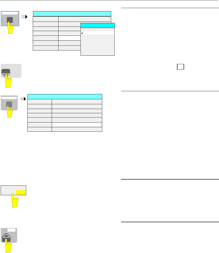
FSE Connecting a Printer - with Windows NT Controller
1065.6016.12 1.33 E-8
s
V
-dBm
DATA ENTRY
GHz
HARDCOPY DEVICE SETTINGS
Device1 WINDOWS METAFILE
Print to File YES
Orientation ---
Device2 CLIPBOARD
Print to File ---
Orientation ---
DEVICE
CLIPBOARD
WINDOWS METAFILE
ENHANCED METAFILE
BITMAP FILE
HP DeskJet 660C
½Press one of the unit keys.
The DEVICE selection box is displayed on
the screen. The current selection is
marked by a tick and highlighted by the
selection bar.
DATA VARIATION ½Press the cursor key à until the entry
HP DeskJet 600C is highlighted by the
selection bar.
s
V
-dBm
DATA ENTRY
GHz
HARDCOPY DEVICE SETTINGS
Device1 WINDOWS METAFILE
Print to File YES
Orientation ---
Device2 HP Deskjet 660C
Print to File NO
Orientation PORTRAIT
½Press one of the unit keys.
The DEVICE selection box is closed and
HP DeskJet 660C is entered in the
DEVICE2 row.
Note:
Selecting the printertype automatically sets
the parameters PRINT TO FILE and
ORIENTATION to standard mode values for
this printer. Other printer-dependent
parameters such as PAPERSIZE, can be
modified under Windows NT in the printer
properties window
(START/SETTINGS/PRINTER/SETTINGS)..
ENABLE
DEV1 DEV2
Start printing.
½Press the ENABLE softkey until DEV2 is
marked on the second softkey line.
Printing can then be started with the
START key in the HARDCOPY menu.
MENU Return to main menu
½Press the menu key several times.
Note: After the installation, the "Service
Pack" of Windows NT is to be re-
installed, see "New Installation of
Windows NT Software".
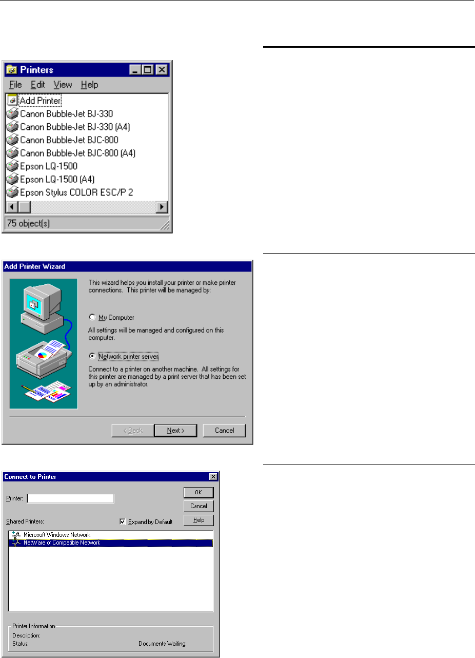
Connecting a Printer - with Windows NT Controller FSE
1065.6016.12 1.34 E-8
Installation of a Network Printer (with option FSE-B16 only)
After opening the "Printers" dialog window
proceed with the installation as follows:
½Double-click the "Add Printer" line.
The "Add Printer Wizard" window is
opened. This window guides the user
through the printer driver installation.
½Click "Network printer server" and then
"Next".
A window to set the path to the printer
server is displayed.
½Set the path to the desired printer server,
mark it and select it with OK.
½Confirm the following request for the
installation of a suitable printer driver with
OK.
The list of printer drivers is displayed.
The manufacturers are listed in the
window at the left, the available printer
drivers at the right.
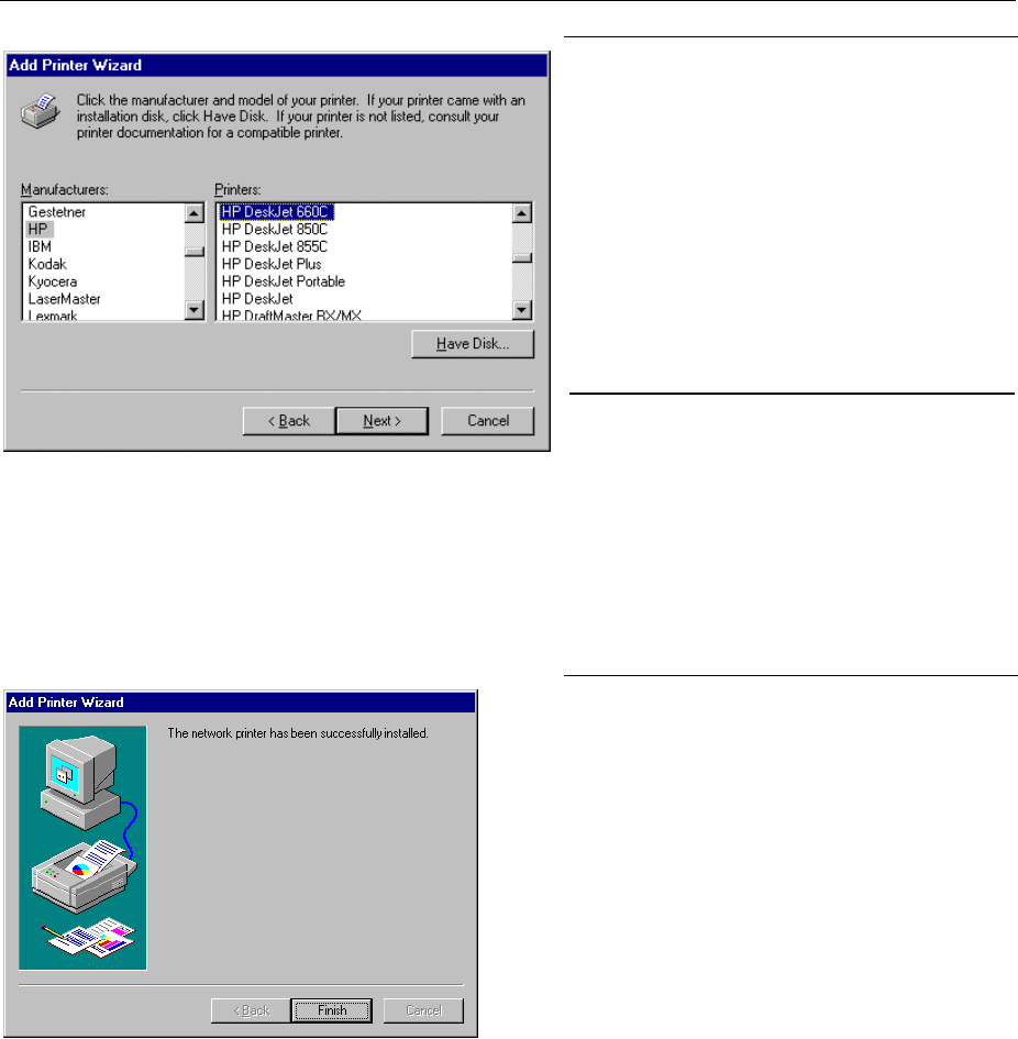
FSE Connecting a Printer - with Windows NT Controller
1065.6016.12 1.35 E-8
½Select the manufacturer in the
"Manufacturers" window and then the
printer driver in the "Printers" window.
Note:
If the required type of output device is not
included in the list, the driver has not yet
been installed. In this case click on button
"HAVE DISK". A message box requesting
to insert a disk with the corresponding
printer driver will be displayed. Insert the
disk, press OK and select the required
printer driver.
½ Click "Next"
If one or more printers are already
installed, a prompt is displayed in this
window to ask if the printer last installed as
default printer should be selected for the
Windows NT applications ("Do you want
your Windows-based programs to use this
printer as default printer?"). The default
selection is "No".
½Start the printer driver installation with
"Finish".
Note:
If a prompt for the printer driver path
appears after pressing "Finish", the
Service Pack must be re-installed after this
printer installation (see Chapter 1, section
"Installing Windows NT Software").
After installation, the instrument has to be configured for printout with this printer in the HCOPY -
SETTINGS menu.
Finally, Service Pack x must be re-installed (see section "Installing Windows NT Software").
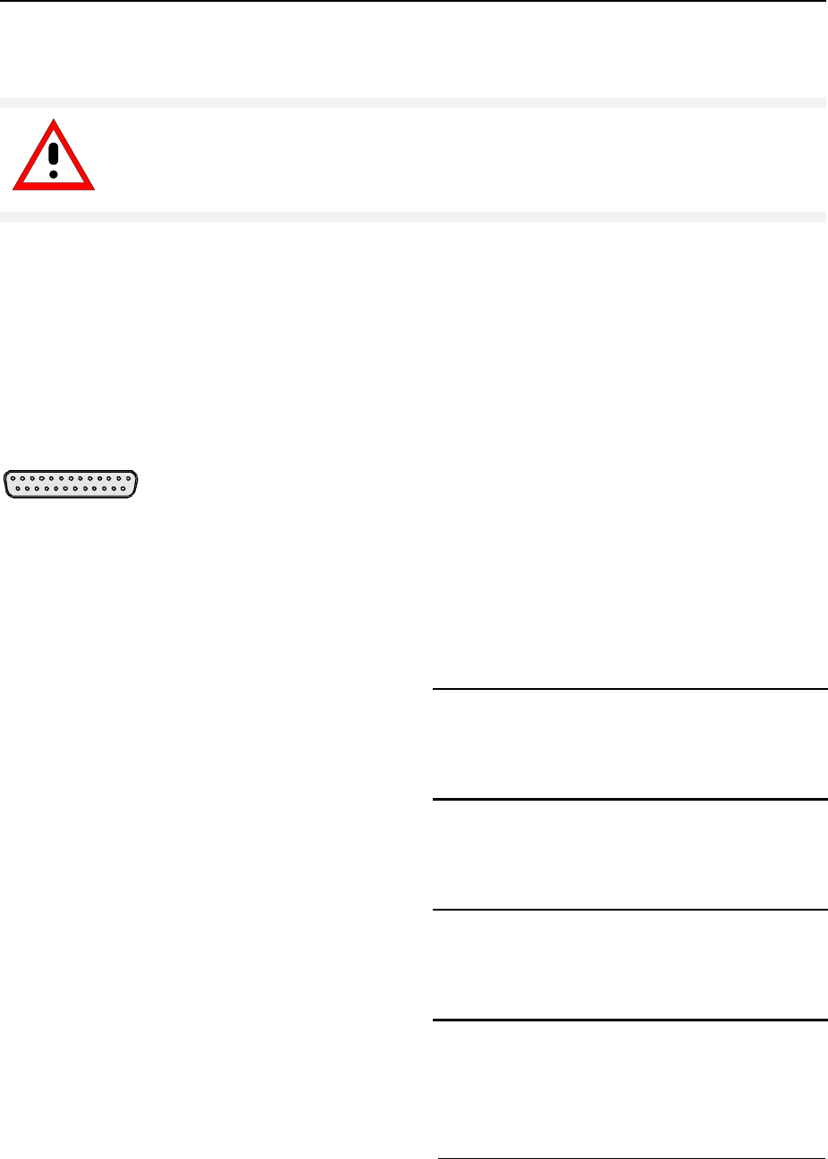
Connecting a CD ROM Drive - with Windows NT Controller FSE
1065.6016.12 1.36 E-8
Connecting a CD-ROM Drive
Caution:
The CD-ROM may only be connected when the instrument is switched off (STANDBY).
If this is not observed correct operation of the CD-ROM and the instrument cannot be
guaranteed.
Notes: - The installation of a CD-ROM is possible only under the administrator identification (see
section "Controller Function").
- After the installation, the "Service Pack" of Windows NT is to be re-installed, see "New
Installation of Windows NT Software".
- To ensure that the instrument performs an autologin, the user identification is to be reset to
"instrument" after the next power-up, see section "Controller Function",
The instrument is fitted with a rear-panel interface LPT1 for the connection of a CD-ROM drive.
LPT
The following CD-ROM drives are supported:
− MICROSOLUTIONS BACKPACK External CD-ROM.
− FREECOM IQ DRIVE
− ADAPTEC Parallel SCSI Adapter + SCSI CD-ROM
After connection, the CD-ROM drive is to be installed under Windows NT.
Switch off FSE.
Connect CD-ROM drive to interface LPT1 of the
instrument and to AC power source.
Switch on FSE.
Administrator identification
½Press key combination <ALT> <SYSREQ>
The Windows NT screen is displayed.
½Call the logout window with "Shut Down" in
the "Start" menu.

FSE Connecting a CD ROM Drive - with Windows NT Controller
1065.6016.12 1.37 E-8
½Mark entry "Shut down and log on as a
different user".
½Press the "Shift" key and click button "Yes" at
the same time.
The login window is displayed.
½Enter "administrator" under "name" and
"894129" under "password", confirm entry
with "OK".
Select driver under Windows NT
½In the Start menu press first "Setting" and
then "Control Panel".
The system control window is opened.
½Double-click "SCSI Adapters".
The "SCSI Adapters" window is opened.
½Click the "Driver" index card and then button
"Add".
The list of installed drivers is displayed.
½Click "Have Disk".
This window leads through the following
installation.
Note: After the installation, the "Service Pack"
of Windows NT is to be re-installed,
see "New Installation of Windows NT
Software.
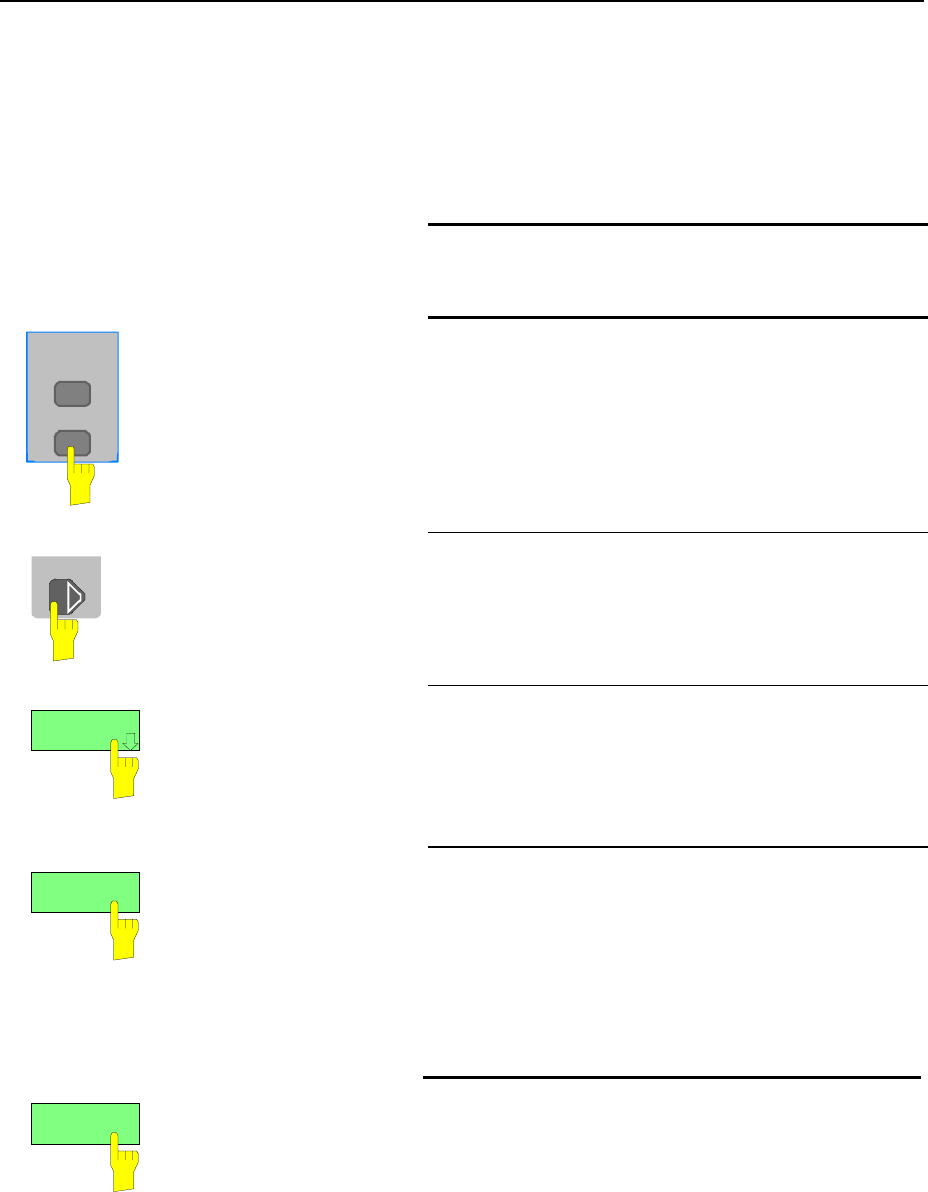
Firmware Update - with Windows NT Controller FSE
1065.6016.12 1.38 E-8
Firmware Update
The installation of a new firmware version can be performed using the built-in diskette drive and does
not require opening the analyzer. The firmware update kit contains several diskettes.
The installation program is called up in the CONFIGURATION - SETUP menu.
Insert diskette 1 into the drive.
CONFIGURATION
MODE
SETUP
Call SETUP-GENERAL SETUP menu
½Press the SETUP key in the CONFIGURATION
field.
The SETUP menu is opened.
MENU ½Change to the right-hand menu using the menu key.
FIRMWARE
UPDATE
½Press the FIRMWARE UPDATE softkey.
The submenu is opened.
UPDATE ½Press the UPDATE softkey.
The installation program starts and leads the user
through the remaining steps of the update.
The installation can be cancelled.
RESTORE
½Press the RESTORE softkey.
The previous firmware version is restored.

FSE Installing Windows NT Software
1065.6016.12 1.39 E-8
Installing Windows NT Software
The driver software and the Windows NT system settings are exactly adapted to the measurement
functions of the instrument. Correct operation of the instrument can, therefore, be guaranteed only if the
software and hardware used is released or provided by Rohde & Schwarz.
The use of other software or hardware may cause the FSE to malfunction.
The latest list of software authorized for use on the FSE can be obtained from your nearest
Rohde&Schwarz agency (see list of addresses).
After each software installation requiring the administrator identification, "Service Pack" of Windows NT
must be re-installed (also with administrator identification; see section "Controller Function"):
Re-installing Service Pack
½In the Start menu click "Run".
The entry window opens.
Service Pack 5:
½Enter "C:\SP5\I386\UPDATE\UPDATE" into the
command line and start installation with "OK".
The following window leads through the installation.
Service Pack 3:
½Enter "C:\SP3\I386\UPDATE" into the command line
and start installation with "OK".
The following window leads through the installation.

Options - with Windows NT Controller FSE
1065.6016.12 1.40 E-8
Options
This section describes options FSE-B17, Second IEC/IEE Interface, FSE-B16, Ethernet Interface.
Note: - Option FSE-B13, 1 dB Attenuator, is described in Chapter 4, Section ’Level Display/RF Input’
- Options FSE-B8 to B12, Tracking Generator, and FSE-B3, TV Demodulator, are described in
Chapter 4, Sections ’Tracking Generator’ and ’TV Demodulator’
- For a description of options FSE-B7, Vector Signal Analysis, and FSE-B21, External Mixer
Output, see manuals of options.
Option FSE-B17 – Second IEC/IEEE Interface
Notes: - The installation of option FSE-B17 is possible only under the administrator identification
(see section "Controller Function").
- After the installation, the "Service Pack" of Windows NT is to be re-installed, see "New
Installation of Windows NT Software".
- To ensure that the instrument performs an autologin, the user identification is to be reset to
"instrument" after the next power-up, see section "Controller Function".
- Interface "COM2" is no longer available after installation of option FSE-B17.
Besides the instrument external devices can also be controlled via the IEC/IEEE bus using the optional
2nd bus interface FSE-B17 and the computer function for instrument. The interface software permits
IEC/IEEE-bus commands to be included in user programs. The installation instructions are enclosed
with the option.
Installing the software
The operating software is already installed and need not be loaded from the driver diskettes which serve
as backup diskettes.
The driver must be loaded on the start-up of Windows NT. To do this, enter the type of board, configure
the board and enter the parameters for the connected equipment. If the option is factory fitted, all this
has been done in the factory.
The following parameters may not be changed after selection on configuration of the board:
Board Type ...................AT-GPIB/TNT
Base I/O Address .............02C0h
Interrupt Level ..............3
DMA Channel ..................5
Enable Auto Serial Polling ...No
For further parameters, refer to manual for the board.
Selecting the board type
½Click "Start" in the task bar.
½Click consecutively "Settings", "Control
Panel" and "GPIB" in this sequence.
The "GPIB Configuration" menu for
selecting the board type and configuring
the board is opened.
½Click button "Board Type".
The "Board Type" menu for selecting the
board type is opened.
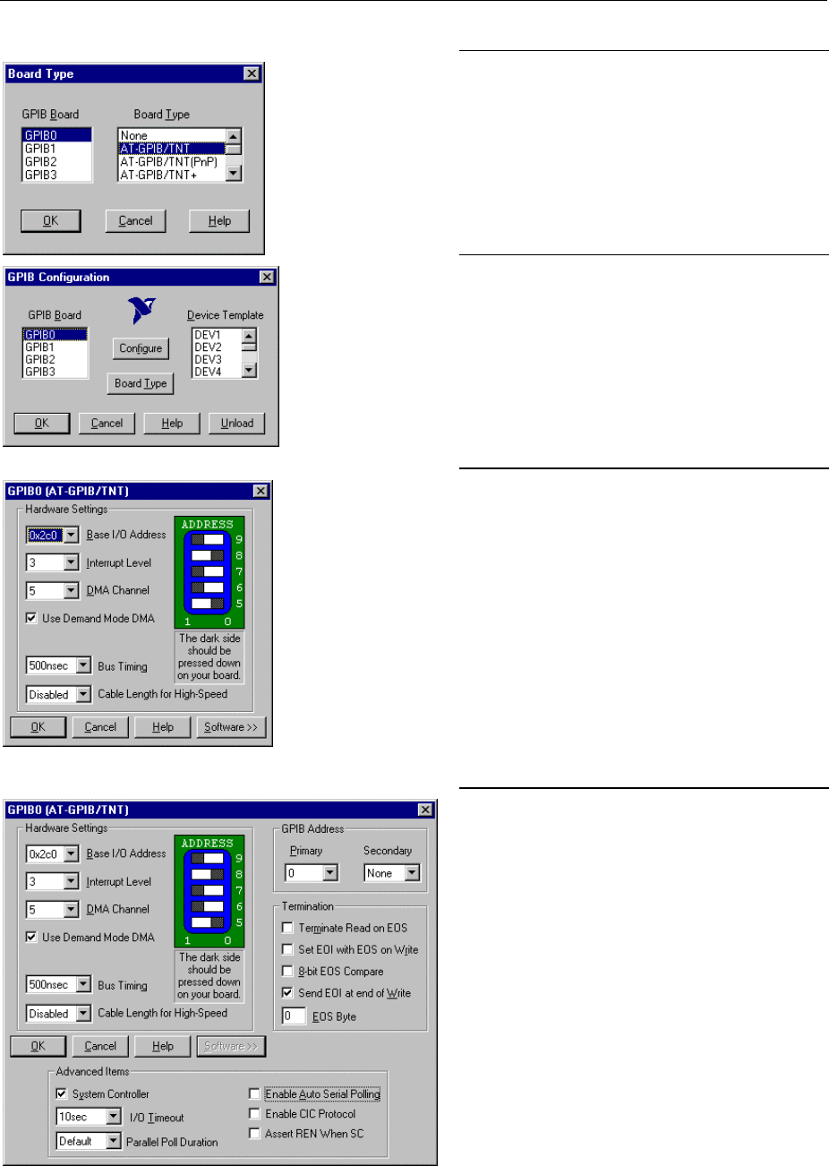
FSE Options - with Windows NT Controller
1065.6016.12 1.41 E-8
½Mark "GPIB0" in the "GPIB Board" list.
½Mark "AT-GPIB/TNT" in the "Board Type"
list.
½Confirm the selection with "OK".
The "GPIB Configuration" menu is
displayed again.
½Click button "Configure".
The "GPIB0 (AT-GPIB/TNT)" menu for
configuring the board is opened.
Configuring the board
½Set "3" in the "Interrupt Level" list.
½Click button "Software".
The menu is extended.
½Deactivate (= no tick) "Enable Auto Serial
Polling" in the "Advanced Items" field.
½Quit the menu with "OK".
The "GPIB Configuration" menu is displayed
again.
Note:
The settings of the following parameters
should not be no longer modified.
Board Type ......... AT-GPIB/TNT
Base I/O Address ......... 02C0h
Interrupt Level .............. 3
DMA Channel .................. 5
Enable Auto Serial Polling .. No
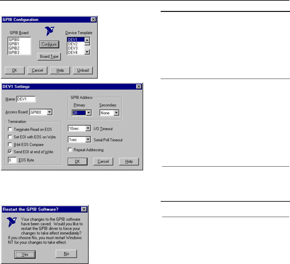
Options - with Windows NT Controller FSE
1065.6016.12 1.42 E-8
Setting the parameters for the connected
equipment
½Mark the instrument in the "Device
Template" list and confirm selection with
"OK".
The "DEV.. Settings" menu is opened.
½Perform the settings for the selected unit
in the "DEV.. Settings" menu.
The logic name for the instrument is preset
with DEV1 and address 20. See board
manual for further units.
Note: When assigning logic names to
connected equipment note that
these names do not correspond to
the directory names under DOS.
½Terminate setting with "OK".
The query asking if the GPIB software
should be re-started is displayed.
½Select "No".
½Re-start controller with Start-Restart in the
task bar.
After the controller has been re-started,
the settings for the GPIB interface are
effective.
Note: After the installation, the "Service
Pack" of Windows NT is to be re-
installed, see "New Installation of
Windows NT Software".
Use of DOS Programs
When using DOS programs, driver GPIB-NT.COM should be loaded. For this to take place, the line
device=C:\PROGRA~1\NATION~1\GPIB\NI488\DosWin16\Gpib-nt.com has to be activated in
the file C:\WINNT\SYSTEM32\CONFIG.NT. If the option is factory fitted, this line will have been
entered in the factory.
Operation
The second IEC/IEEE-bus interface corresponds physically to that of the instrument (see Chapter 8).
If the instrument is to be controlled via the IEC/IEEE bus, a bus cable must be plugged to both bus
connectors. The interface can be driven under DOS/WINDOWS3.1/95/NT by R&S software (FS-K3,
Order No. 1057.3028.02, etc.) or by user-written software. The handling of IEC/IEEE-bus commands in
user programs is described in the manual for the card.
The files are in directory C:\Program Files\National Instrument\GPIB\NI488.
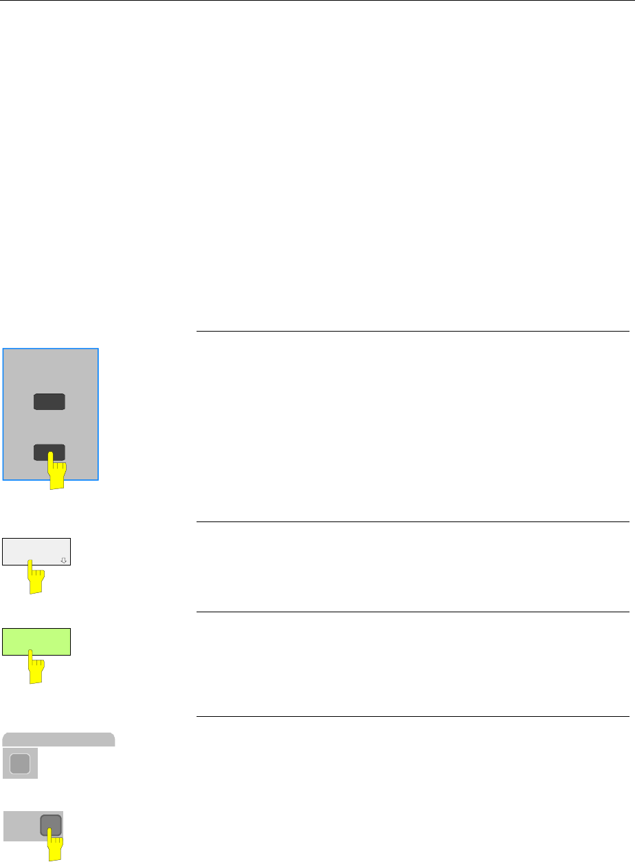
FSE Options - with Windows NT Controller
1065.6016.12 1.43 E-8
Option FSE-B5 - FFT Filter
Option FFT Filter FSE-B5 is a firmware option. It has to be enabled by a keyword.
Prerequisites
1. Keywords
The keyword is printed on a label which is part of the equipment supplied and has to be stuck to the
rear of FSE.
2. Hardware
The modification state of module DIGITAL IF has to be either MODIF INDEX > 5 or
MODIF INDEX = 5 and HW CODE ≥ 6. The modification state can be checked in the module list
INSTALLED COMPONENTS in menu INFO HARDWARE+OPTIONS.
3. Firmware
The modification state of the firmware has to ≥ 1.62. The modification state can be checked in table
FIRMWARE VERSION in menu INFO FIRMWARE VERSIONS.
Enabling the option
SETUP
MODE
CONFIGURATION ½Call up menu SETUP by pressing the SETUP key.
OPTIONS ½Call up submenu OPTIONS by pressing the OPTIONS softkey.
Table FIRMWARE OPTIONS is displayed, listing the installed
options.
ENABLE NEW
OPTION ½Activate the entry field by pressing the ENABLE NEW OPTION
soft key.
1
.
.
.
MHz
dBm
mV
ms
DATA ENTRY ½Enter the 10-digit keyword via the numeric keypad and terminate
the entry by pressing one of the unit keys.
Now option FFT filter is listed in table FIRMWARE OPTIONS.
Note: Message ’option key invalid’ indicates an invalid entry.
Options - with Windows NT Controller FSE
1065.6016.12 1.44 E-8
Option FSE-B16 – Ethernet Adapter
With the option Ethernet Adapter FSE-B16, the device can be connected to an Ethernet-LAN (local area
network). It is possible to transmit data via the network and to use the network printer. The adapter
operates with a 10 MHz Ethernet in line with standards IEEE 802.3 10Base2 (Thin Ethernet,
CheaperNet, BNC-Net) (B16 model 03) or 10Base5 (Thick Ethernet) (B16 model 02).
Hardware Installation
Caution:
Prior to installation contact the network administrator, especially in case of complex
LAN installations since mistakes in cabling might have influence the whole network.
If the adapter is installed at the factory, it is preconfigured. In case of retrofitting, refer to the installation
instructions. The hardware settings must not be modified since the functions of the device could
otherwise be impaired.
The following parameters are factory-set:
I/O Addr. 300, IRQ 5, MEM D0000
The connection with the network depends on the connectors used in the network.
BNC (Thin Ethernet, CheaperNet; FSE-B16 Var. 03)
Connection The device is looped into the LAN segment via rear-panel 2 BNC
connectors.
If a cable is not connected to one of the BNC connectors, this BNC
connector has to be terminated with 50 Ohm. BNC T connectors
must not be used.
Network traffic Note that the network traffic is disturbed if a segment is interrupted.
Requirements Thin Ethernet segment requirements have to be complied with:
- maximum segment length of 185 m
- minimum distance between the connectors of 0.5 m
- maximum of 30 connectors per segment.
If components that comply with enhanced requirements are
exclusively used (Ethernet Adapter FSE-B16 complies with the
enhanced requirements):
- maximum length of segment of 300 m
- maximum number of connectors of 100
With repeaters used:
- maximum total length of the network of 900 m containing a
- maximum of 3 segments
- maximum of two repeaters between two connectors

FSE Options - with Windows NT Controller
1065.6016.12 1.45 E-8
AUI (Thick Ethernet; FSE B16 Var. 02)
Connection The device is connected to the LAN segment using a transceiver
cable (DB-15 AUI connector, not part of the equipment supplied)
which is connected to the rear panel and to the transceiver.
Network traffic The connection does not conflict with the network traffic. The device
can also be disconnected from the network without any problems
but make sure that data are not being transmitted.
Requirements The Thick Ethernet segment requirements have to be taken into
account.
- The maximum segment length should be 500 m and the
- distance between the connectors should at least be 2.5 m.
- A maximum of 100 connectors may be used in a segment.
With repeaters used,
- the total length of the network must not be more than 2500 m
containing
- a maximum of 3 segments.
- There should be no more than two repeaters between two
connectors.
If other network components are used, these conditions may vary.
RJ45 (UTP, 10BaseT, Western Connector)
Connection The device is connected to the LAN segment using a RJ45 cable
(not part of the equipment supplied) which is connected to the rear
panel and to the network hub of the LAN segment.
Network traffic This connection does not conflict with the network traffic. The
device can also be disconnected from the network without any
problems but make sure that data are not being transmitted.
Requirements Since RJ45 is not a bus but a star topology no special requirements
have to be taken into account for the connection.
The LAN requirements should be considered in the installation.
Software Installation
Data transmission within the network is by means of data blocks, the so-called packets. Besides user
data other information, the so-called protocol data (transmitter, receiver, type of data, order) are
transmitted. The drivers corresponding to the protocol have to be installed to process protocol
information. A network operating system is required for network services (data transmission, directory
services, printing in the network) and thus has to be installed.
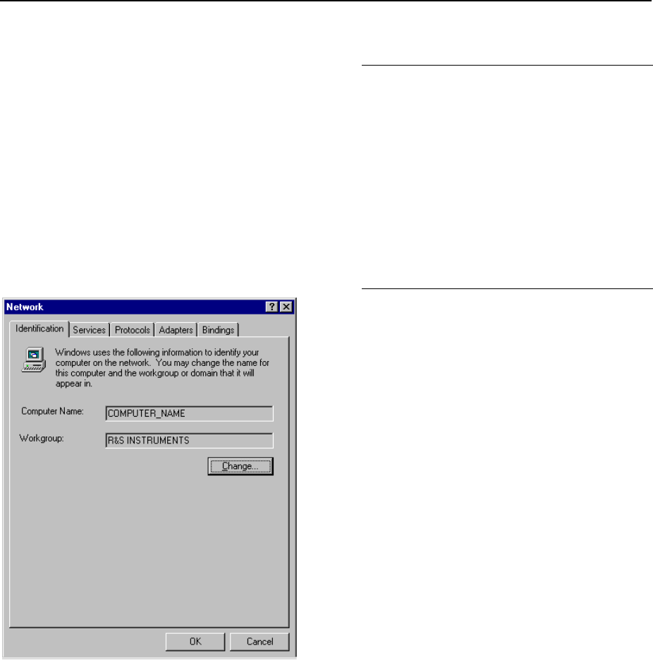
Options - with Windows NT Controller FSE
1065.6016.12 1.46 E-8
Calling up Configuration Menu for Network Settings
½Click "Start" in the task bar.
½Click consecutively "Settings", "Control
Panel" and "Network".
The "Network" configuration menu for
network settings is opened.
Registering the Identification
Note: It is important for the computer name to be unique in the network..
½Select "Identification".
½Confirm computer and workgroup names
with "OK" or enter new names in submenu
"Change".
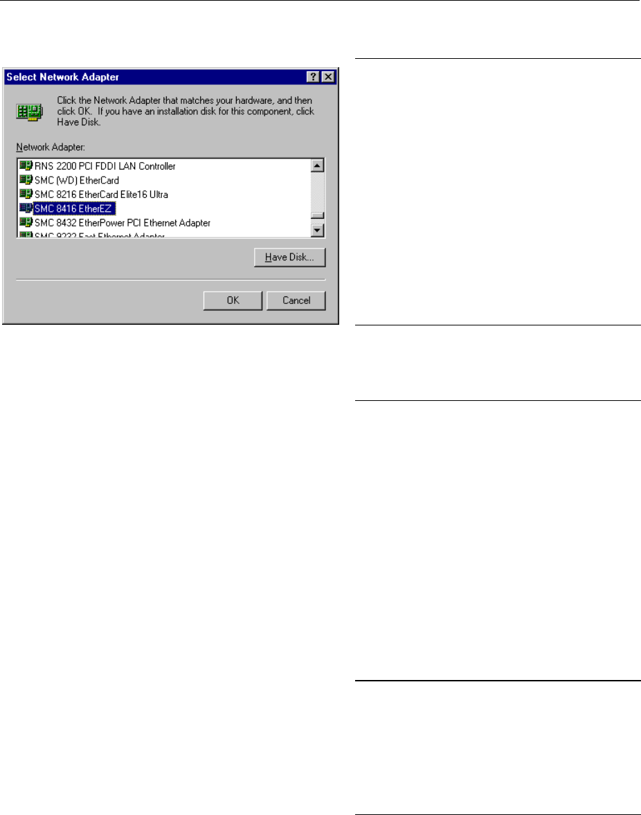
FSE Options - with Windows NT Controller
1065.6016.12 1.47 E-8
Installation and Configuration of the Driver for the Network Adapter
½Select "Adapter".
½Click "Add" and mark network driver "SMC
8416 EtherEZ" and select with "OK".
The query "Files.." is displayed.
½Answer it by clicking "Continue".
The "SMCEthernet Card Setup" window is
displayed.
½Close the window with "OK".
Some files are copied and the network
adapter is displayed under "Network
Adapters".
The entry "MS Loopback Adapter" refers
to a driver which ensures instrument
control and should not be modified.
Note: The network adapter settings must
not be modified since this may cause
problems to the instrument.
Installation of Network Protocols
Note: The network administrator knows which protocols are to be used..
½Select "Protocol".
½Click "Add", mark the desired protocol and
select with "OK".
This operation has to be performed
several times when several protocols are
selected.
½Execute the installation by clicking
"Continue".
Note: If a protocol requires further settings,
they can be performed with "Proper-
ties" after marking the corresponding
entry. If further settings are not
possible, this field is gray.
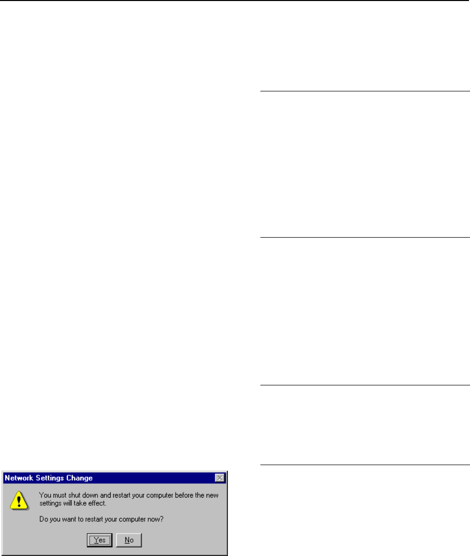
Options - with Windows NT Controller FSE
1065.6016.12 1.48 E-8
Installation of Network Services
To utilize the resources of the network it is necessary to install the corresponding services.
Note: The network administrator knows which services are to be used.
½Select "Services".
½Click "Add", mark the desired service and
select with "OK".
This operation has to be performed
several times when several services are
selected.
Some services are pre-installed and can
be cleared with "Remove" if they are not
needed.
½Execute the installation by clicking
"Continue".
Note: If a service requires further settings,
they can be performed with
"Properties" after marking the corres-
ponding entry. If further settings are
not possible, this field is gray.
Terminating the Installation
½Quit the "Network" configuration menu for
network settings with "OK".
The settings are checked and processed.
Missing information is queried.
½Answer the query "You must shutdown..."
with "Yes".
The settings are valid after computer re-
start.
Note: After the installation, the "Service
Pack" of Windows NT is to be re-
installed, see "New Installation of
Windows NT Software".

FSE Options - with Windows NT Controller
1065.6016.12 1.49 E-8
Examples of Configurations
Network Protocols Services Notes
NOVELL Netware NWLink IPX/SPX
Compatible
Transport
Client Service for
NetWare The "Frame Type" used under "Protocols -
Properties" should be set.
IP networks
(FTP, TELNET, WWW,
GOPHER, etc.)
TCP/IP Protocol Simple TCP/IP
Services An "IP Address" unambiguous in the network
should be set under "Protocols - Properties".
MICROSOFT network NetBEUI Protocol
or
TCP/IP Protocol
Workstation
Server A name unambiguous in the network should be
registered under "Identification - Computer
Name".
Operation
After installing the network operating system it is possible to transfer data between the device and other
computers and to use printers in the network. A precondition for network operation is the authorization to
use network resources. Resources may be access to the file directories of other computers or the use of
a central printer. The network or server administrator will grant the authorizations. The network name of
the resource and the corresponding authorization are required. Passwords protect the resources
against improper use. A user name is normally assigned to every authorized user. The user also has a
password. Resources may then be assigned to the user. The type of access, i.e. whether data are only
read or also written as well as a shared access to data has to be defined. Other types are possible
depending on the network operating system.
NOVELL
Operating system NETWARE from NOVELL is as server-supported system. Data transfer between the
individual workstations is not possible. Data transfer is between workstation computers and a central
computer, the server. This server provides storage capacity and the connection to the network printers.
Like under DOS, the data on a server are organized in directories and are offered to the workstation as
virtual drives. A virtual drive on a workstation is like a hard disk and data can be processed accordingly.
This is called drive mapping. Also network printers can be addressed as normal printers.
Network operating system NOVELL is available in two forms: NETWARE 3 and NETWARE 4 NDS. In
the previous version NETWARE 3, each server manages its own resources itself and is independent. A
user has to be managed separately on each server. For NOVELL 4 NDS, all resources are managed in
the NDS (NOVELL DIRECTORY SERVICE). The user only has to log in once and gains access to the
resources released for him. The individual resources and the user are managed as objects in a
hierarchical tree (NDS TREE). The position of the object in the tree is called CONTEXT for NETWARE
and must be known in order to access the resources.
MICROSOFT
For MICROSOFT, data can be transferred between workstations (peer-to-peer) but also between
workstations and servers. The servers can provide access to individual files as well as the connection to
network printers. Like under DOS, the data on a server are organized in directories and are offered to
the workstation as virtual drives. A virtual drive on a workstation is like a hard disk and data can be
processed accordingly. This is called drive mapping. Also network printers can be addressed as normal
printers. A connection to DOS, WINDOWS FOR WORKGROUPS, WINDOWS95, WINDOWS NT is
possible.
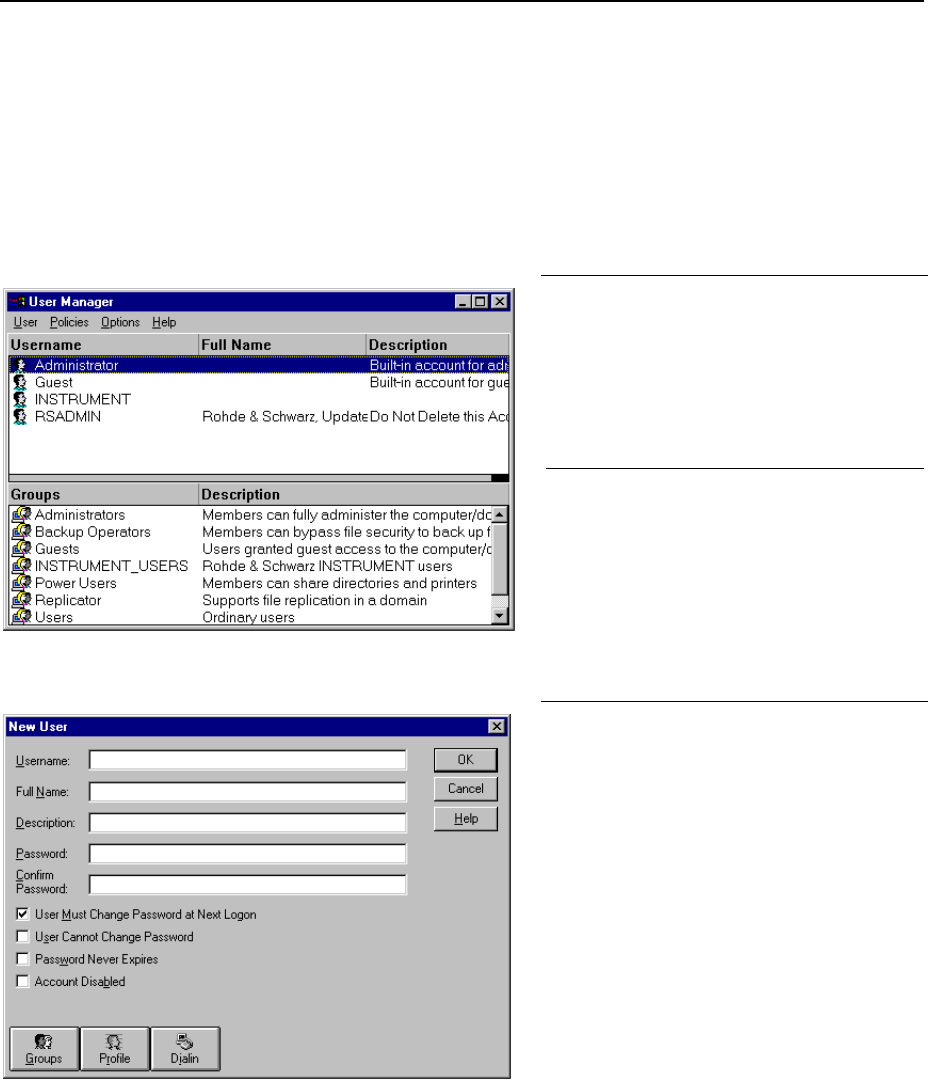
Options - with Windows NT Controller FSE
1065.6016.12 1.50 E-8
Installing a user
After the network software has been installed, the instrument logs with an error message during the next
start-up since there is no user "Instrument" (= user identification for NT autologin) in the network. It is
therefore necessary to install a user which should be the same for Windows NT and for the network.
The network administrator is responsible for the installation of new users in the network.
Note: The installation of new users is possible only under the administrator identification (see
section "Controller Function").
½Click "Start" in the task bar.
½Click consecutively "Programs"
"Administrative Tools (Common)" and
"User Manager" .
The "User Manager" menu is opened.
½Click "User" and select "New User".
The menu "New User" for entering user
data is opened.
½Fill in the lines "Username", "Password"
and "Confirm Password" and confirm
the entry with OK.
The user data should correspond to the
network settings.
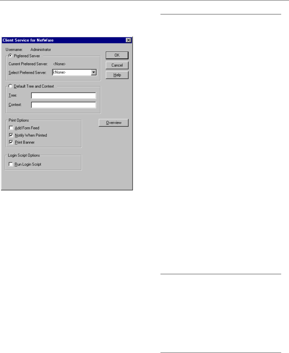
FSE Options - with Windows NT Controller
1065.6016.12 1.51 E-8
Only NOVELL network:
Configure NOVELL Client ½Click "Start" in the task bar.
½ Click consecutively "Settings",
"Control Panel", "CSNW".
NOVELL 3.x
½Click "Preferred Server".
½ Under "Select Preferred Server"
select the NOVELL server for which
the user has been installed.
NOVELL 4.x
½Click "Default Tree and Context" .
½Enter the NDS Tree under "Tree" and,
under "Context", the hierarchical path
for which the user has been installed.
Note: These specifications can be
obtained from the network
administrator.
Login in the Network
Network login is automatically performed with the operating system login. A prerequisite is that the user
name and the password are the same under Windows NT and in the network.
Use of Network Drives
½Click "Start" in the task bar.
½Click consecutively "Programs" and
"Windows NT Explorer".
½Click "Network" line in the "All
Directories" list.
A list of available network drives is
displayed.
½Click "Tools" and "Map Network Drive".
In the list "Shared Directories:" the
network paths available in the network
are displayed.
½Mark the desired network path.
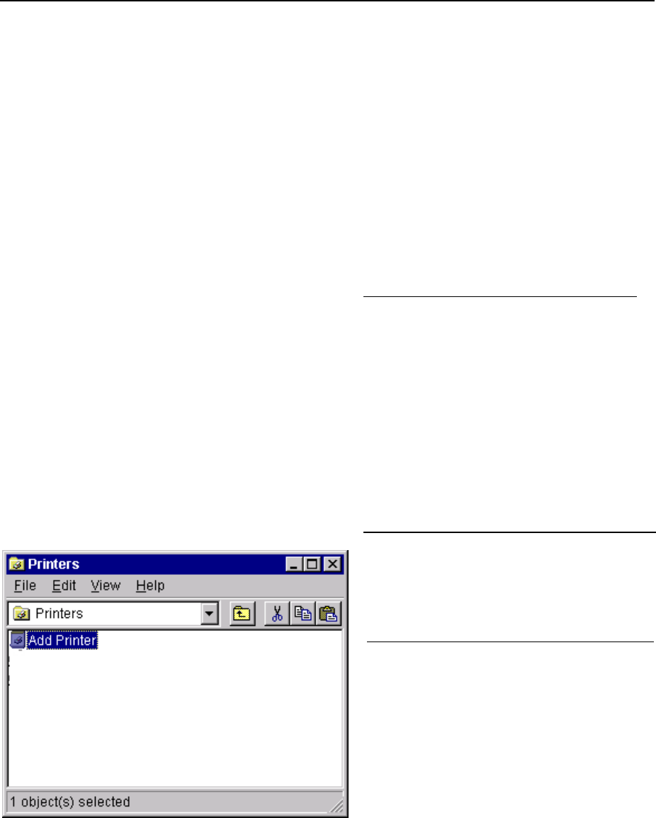
Options - with Windows NT Controller FSE
1065.6016.12 1.52 E-8
½Select the drive under "Drive:"
½Activate "Reconnect at Logon:" if the
link is to be automatically established at
each unit start.
½Connect the network path to the
selected drive with "OK".
The user name and the password are
queried. The drive is then displayed in
the "All Directories" list of Explorer.
Note: Only drives for which an
authorization is available may
be connected.
Disconnect link:
½Click "Tools" and "Disconnect Network
Drive" in Explorer.
½Select under "Drive:" the drive whose
connection is to be removed.
½Disconnect link with "OK". The query
should be answered with "Yes".
Printing on a Network Printer
Select printer driver under Windows NT
½Press key combination <ALT> <SYSREQ>
The Windows NT screen is displayed.
½In the Start menu press first "Setting" and
then "Printers".
The printer window is opened.
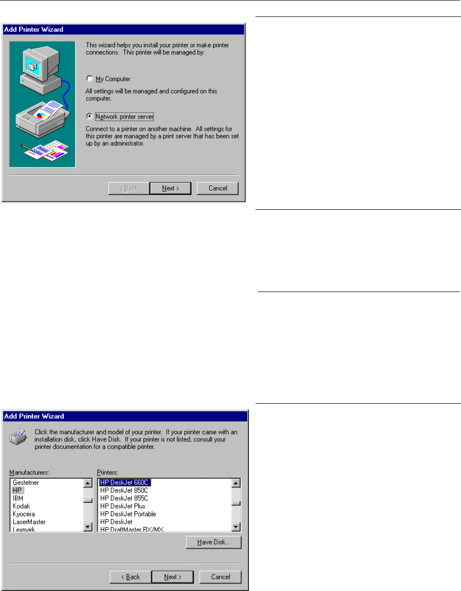
FSE Options - with Windows NT Controller
1065.6016.12 1.53 E-8
½Double-click line "Add Printer".
The "Add Printer Wizard" window is
opened. This window leads through the
following printer driver installation.
½Click first "Network Printer Source" and
then "Next".
The list of available network printers is
displayed.
½Mark the printer and select with "OK".
The available printer drivers are displayed.
The left-hand selection table indicates the
manufacturers and the right-hand one the
available printer drivers.
½Mark the manufacturer in selection table
"Manufacturers" and then the printer driver
in selection table "Printers".
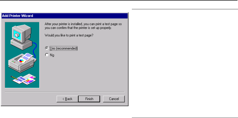
Options - with Windows NT Controller FSE
1065.6016.12 1.54 E-8
½Click "Next".
The window for starting a test page is
displayed. The test print is for checking if
the installation was successful.
½Switch on printer.
½Click Yes (recommended)".
½Click "Finish".
A test page is printed out if the installation
was successful.
If the test page is not printed out or not
completely, the Windows NT online help
offers troubleshooting instructions under
the entry "Printer Trouble Shooting".
The instrument has to be configured with
this printer for the printout of the
measurement screen. This configuration is
described in this chapter in the section
"Connecting an Output Device".
Server Function
With the server function data can be provided on the instrument for use in other computers. This is
possible only in the MICROSOFT network. The server function is released after network installation as
standard. If this is not required, it should be deactivated, see "Installation of Network Services".
The availability of instrument data in the network is controlled by releases. The release is a property of
a file or of a directory. To grant a release, the object is to be marked in "Windows NT Explorer" and
pressed by the right-hand mouse key. The release is performed under Properties -> Sharing by
selecting "Shared As". Other computers can then access these objects with the names allocated under
"Share Name". The online help gives further information on the network operation.
TCP/IP
The TCP/IP protocol allows files to be transmitted between different computer systems. A program
running on both computers is required to control the data transfer. The same operating or file system
need not be used by the two partners. A file transfer is possible between DOS/WINDOWS and UNIX,
for example. One partner has to be configured as host the other as client or vice versa. The system
performing several processes at the same time (UNIX) will normally be the host. The usual file transfer
program used for TCP/IP is FTP (File Transfer Protocol). An FTP host is installed as standard on most
of the UNIX systems.
After installing the TCP/IP services, a terminal link can be established with "Start" - "Programs" -
"Accessories" - "Telnet" or a data transmission with FTP using "Start" - "Run" "ftp" - "OK". Thus, all
controller systems can be accessed which support these universal protocols (UNIX, VMS, ...).
Further information is given in the NT online help which can be called up with "Help".

FSE Options - with Windows NT Controller
1065.6016.12 1.55 E-8
FTP
For a complete description of the functions and commands see the FTP documentation.
Establishing a connection ½Click "Start" and then "Run" in the task bar.
The program is started with the DOS command
FTP
The following command sets up the connection:
OPEN <xx.xx.xx.xx>
xx.xx.xx.xx = IP address, e.g. 89.0.0.13
File transmission To transmit a file to the target system, the following command is
used:
PUT <file name>
file name = name of file e.g. DATA.TXT.
To call a file from the target system, the following command is
used:
GET<file name>
file name = name of file e.g. SETTING.DAT.
TYPE B
allows the transmission of files in the BINARY format, no
conversion is performed.
TYPE A
allows the transmission of files in the ASCII format. Thus, control
characters are converted so that the text files can be read on the
target system, too.
Examples:
PUT C:\AUTOEXEC.BAT
sends the AUTOEXEC.BAT file to the target system.
LCD DATA
changes to subdirectory DATA in the computer function.
CD SETTING
changes to the subdirectory SETTING on the target system.
Changing directories The command
LCD <path>
changes the directory as the corresponding DOS command.
LDIR
lists the directory.
These commands refer to the computer function of the
instrument. If the ’L’ preceding the commands is omitted, they
apply to the target system.

Start-Up FSE
1065.6016.12 1.56 E-8
Start-Up - Instruments with MS DOS Controller or without
Controller
Important Note:
Before turning the instrument on, it must be observed that the following conditions
are fulfilled:
•instrument covers are in place and all fasteners are tightened,
•fan openings are free from obstructions,
•signal levels at the input connectors are all within specified maximums,
•signal outputs are correctly connected.and not overloaded.
Non-observance may cause damage to the instrument .
Unpacking the Instrument
After the instrument has been removed from its packaging, insure that all deliverable items are present
as follows:
•FSE spectrum analyzer
•AC power cable
•operating manual
Now check the instrumentfor visible mechanical damage. If damage is present, promptly inform the
delivery firm that delivered the instrument. In case damage is found, retain the carton and the packing
materials.
Instrument Setup
The instrument is designed for use under general laboratory conditions. The ambient conditions required
at the operational site are as follows:
•The ambient temperature must be in the range of + 5 to + 45 °C.
•All fan openings must be unobstructed and the air exhaust at the rear panel and at the side-panel
perforations must not be covered. The distance to the wall should be at least 10 cm.
•The mounting surface should be flat.
19" Rack Installation
Important Note:
For rack installation, insure that the air flow at the side-panel perforations and the
air exhaust at the rear panel are not obstructed.
The instrument may be mounted in a 19" rack by using the rack adapter kit ZZA-95 (order number:
396.4911.00). The installation instructions are included in the adapter kit.
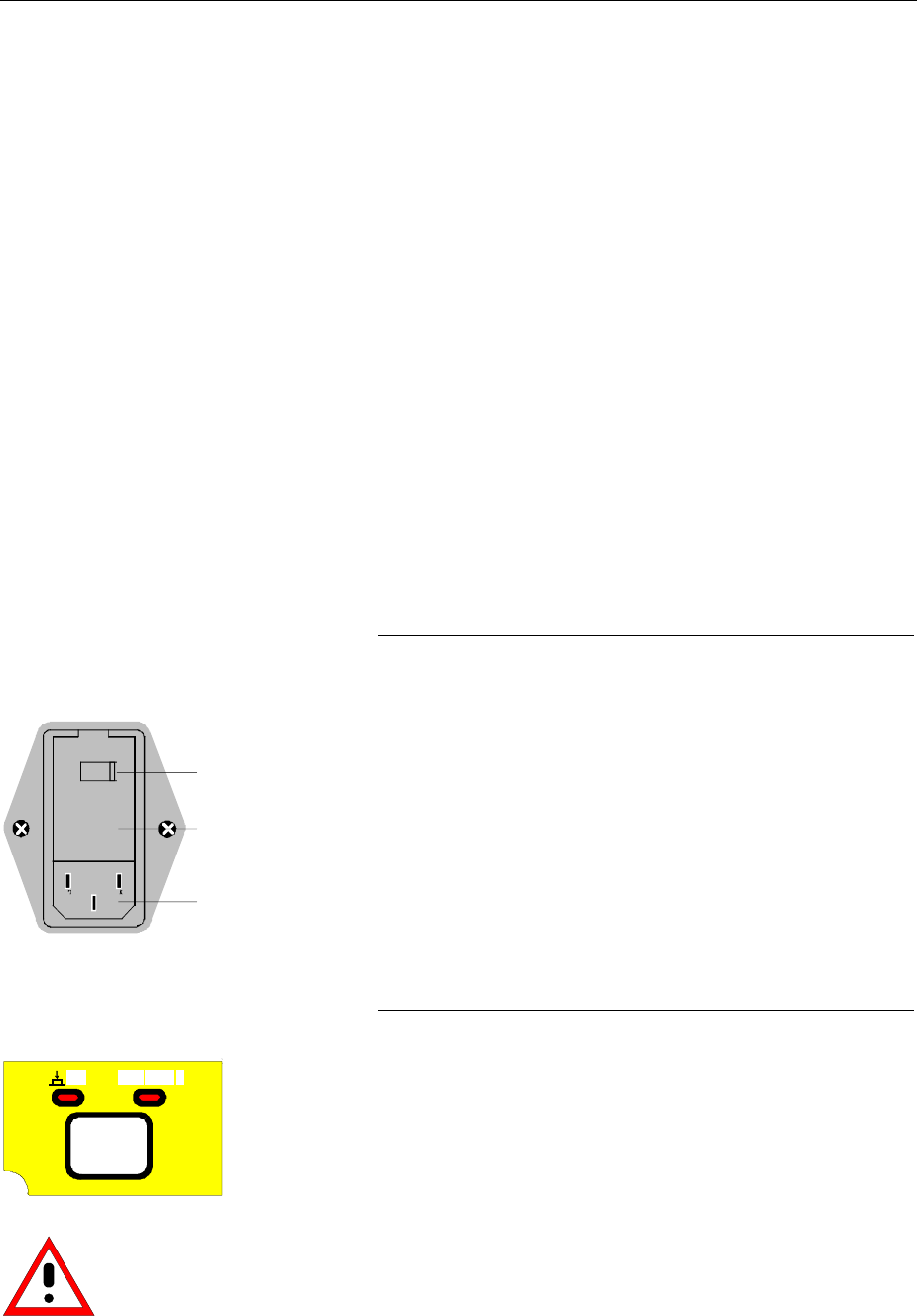
FSE Start-Up
1065.6016.12 1.57 E-8
EMI Protection Measures
In order to prevent electromagnetic interference (EMI), the instrument may be operated only when all
covers are correctly in place. Only adequately shielded signal and control cables may be used (see
recommended accessories).
Connecting to AC Power
The FSE is equipped with an AC voltage selection feature and will automatically set itself according to
the applied AC voltage (range: 90 to 132 VAC and 180 to 265 VAC, 47 to 440 Hz). The AC power
connector is located on the rear panel (see below).
½Connect the instrument to the AC power source using the AC power cable delivered with the
instrument.
AC Power Line Fuses
The FSE is protected by two fuses as specified on the power supply name-plate. The fuses are located
in a removable fuse holder which is located between the AC power switch and the AC power connector
(see below).
Instrument On/Off
AC power switch on the rear panel
I
0
ON
OFF
Ac power switch
Fuse holder
AC power connector
Power On/Off
½Depress the AC Power Switch to the desired position
ON/OFF.
After turn-on (position ON), the instrument is in the ready
state (STANDBY) or in operation dependent upon the
position of the ON/STANDBY switch located on the
instrument front panel (see below).
Note:The AC power switch may remain ON continuously.
Switching to OFF is only required when the instrument
must be completely removed from the AC power source.
Switching to OFF (position OFF) removes all instrument
circuitry from the AC power source.
ON/STANDBY switch on the front panel
ON STANDBY
.
Standby
½ON/STANDBY switch is not depressed.
The yellow LED (STANDBY) is illuminated. The DC power
supply is supplied with power and the quartz oven is
maintained at normal operating temperature.
Operation
Caution:
In standby mode, the AC
power voltage is present
within the instrument.
½ON/STANDBY is depressed.
The green LED (ON) is illuminated. The instrument is
ready for operation. All modules within the instrument are
supplied with power.
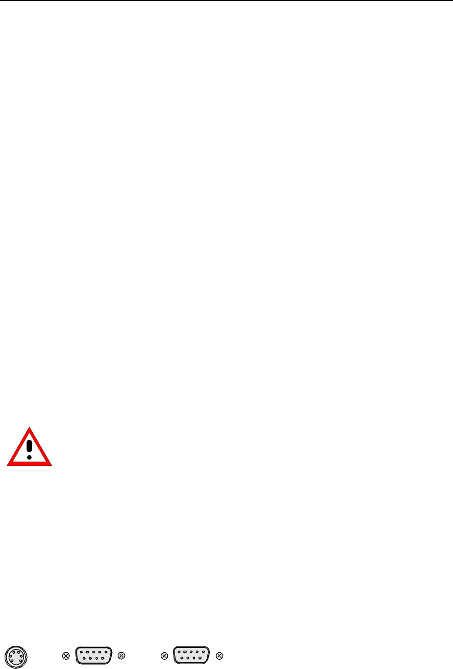
Connecting a Mouse FSE
1065.6016.12 1.58 E-8
Battery-Powered Memory
The FSE is equipped with a battery-powered read/write memory (CMOS-RAM) where instrument
settings are saved at power-off. After each power-on, the FSE is reloaded with the operational
parameters which were active just prior to the last power-off (STANDBY or AC power OFF).
A lithium battery is used to supply power to the CMOS-RAM. When the battery is depleted (expected life
is approx. 5 years), any data stored in CMOS-RAM will be lost. In this case, the factory standard setup is
loaded at turn-on. For changing batteries please contact the representative of our company responsible
for you.
Functional Test
After turning on the AC power, the FSE returns the following message to the display screen:
Analyzer BIOS
Rev.x.y
Copyright
Rohde & Schwarz
Munich
Booting
After appearance of the above message, a self-test of the digital hardware is performed. Any errors
which occur in self-test are transferred as ASCII text to the printer interface (LPT). Thus, an error
diagnosis can be carried out, even for serious failures. A check of the data contents of the spectrum
analyzer is performed in self calibration (CAL, CAL TOTAL key) The individual results of the calibration
(PASSED / FAILED) can be displayed in the calibration menu.
With the aid of the built-in self-test functions (INFO key, SELFTEST softkey), the functional integrity of
the analyzer can be verified and/or defective modules can be localized.
Connecting a Mouse
Caution:
The mouse may only be connected when the instrument is switched off
(STANDBY). Otherwise, correct operation of the mouse and instrument cannot be
guaranteed.
In order to ease manual operations, the FSE provides an option for connecting a mouse to a PS/2
mouse (MOUSE) or a serial interface (COM1 or COM2) connector.
During measurement operation, softkeys, tables and data input fields may also be controlled via the
mouse. With the installed option FSE-B15, the mouse can be selectively assigned to measurement
instrument operation, computer operation or both modes of operation. If the option FSE-B15 is not
installed, then the mouse can only be assigned to measurement instrument operation.
The control functions for the mouse are described in Chapter 3 in the section "Mouse Operations". This
section also contains a list in which the screen display elements for mouse control of the corresponding
softkeys and push buttons of the instrument are described. Chapter 8 contains the interface description.
The Microsoft mouse is the supported mouse type and is available under option PS-B1 (order number
1006.6359.02). The mouse connectors are located on the rear panel.
COM1 COM2MOUSE
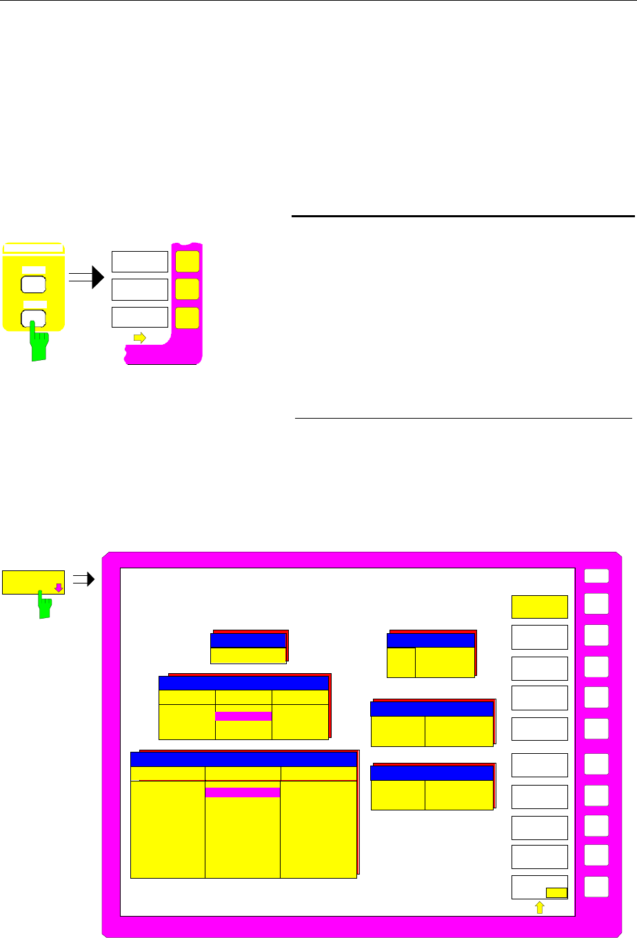
FSE Connecting a Mouse
1065.6016.12 1.59 E-8
After connection of the mouse, the selected interface must be configured and the mouse assigned to
either single or dual mode of operation.
The configuration is performed according to menu SETUP-GENERAL SETUP (key group:
CONFIGURATION, see in Chapter 4, the section "Preliminary Setup and Interface Configuration").
•The parameter MOUSE INTERFACE configures the selected interface.
•The parameter MOUSE OWNER assigns the mouse to either single or dual mode of operation.
In the following illustrative example, the mouse is connected to the PS/2 interface and is assigned to the
dual mode of operation.
CONFIGURATION
MODE
SETUP
EXTERNAL
REFERE NCE
GENERAL
SETUP
Select SETUP-GENERAL SETUP menu
½Press the SETUP key in the CONFIGURATION key
group.
The SETUP menu is opened.
½Press the GENERAL SETUP softkey.
The GENERAL SETUP sub-menu is opened and
the current settings of the general instrument
parameters are displayed in tabular form on the
display screen.
U
SE
R
Ba
u
d
B
i
ts
Par
i
t
y
S
t
o
p
b
i
t
s
HW-Ha
n
d
sha
k
e
SW-H
an
d
s
h
a
k
e
O
w
n
e
r
Pr
o
t
o
co
l
CO
M
2
C
O
M
1
96
0
0
8
N
o
n
e
1
N
o
n
e
X
ON/
X
OFF
In
str
u
me
n
t
R
e
mote
1
2
00
8
No
n
e
1
No
n
e
No
n
e
I
n
s
t
r
u
me
n
t
Mou
s
e
GPIB
ADDRESS
GENERAL
SETUP
COM
PORT 1
TIME
DATE
EXTERNAL
KEYBOARD
MOUSE
USER
PORT A
COM
PORT 2
USER
PORT B
GPIB ADRESS
19
PORT A PORT B
Direction
Value Input
10101010 Output
00010001
USER PORTS
COM PORTS
TIME AND DATE
MOUSE
EXT KEYBOARD
Connection
Language
not connected
US American
Interface
Owner PS/2
Instrument
Time
Date 21:59
01 Oct 1994
GENERAL
SETUP
KEY CLICK
ON OFF
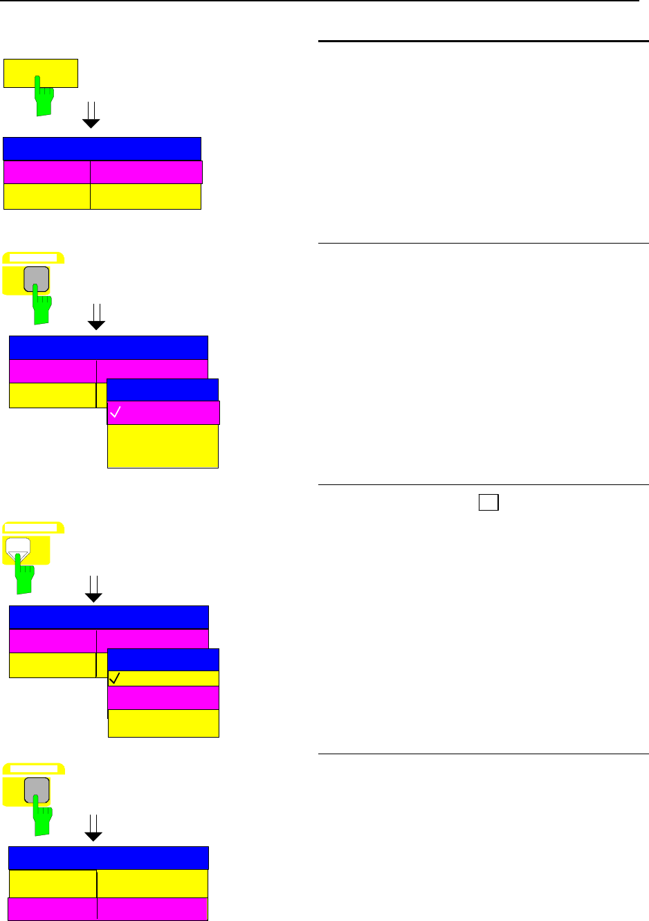
Connecting a Mouse FSE
1065.6016.12 1.60 E-8
MOUSE
Interface NOT CONNECTED
Owner INSTRUMENT
MOUSE
Select interface
½Press the MOUSE softkey.
The INTERFACE parameter in the MOUSE table
is marked by the selection bar.
Interface NOT CONNECTED
Owner
GHz s
V -dBm
DATA ENTRY
NOT CONNECTED
INTERFACE
PS/2
COM PORT1
COM PORT2
MOUSE
½Press one of the units keys.
The INTERFACE selection box appears on the
display screen. The current state (NOT
CONNECTED) is indicated by a check mark and
the selection bar is in the background.
Interface NOT CONNECTED
Owner
NOT CONNECTED
INTERFACE
PS/2
COM PORT1
COM PORT2
DATA VARIATION
MOUSE
½Press the cursor key à until the entry PS/2 is
indicated by the selection bar.
Interface PS/2
Owner INSTRUMENT
GHz s
V -dBm
DATA ENTRY
MOUSE
½Press one of the units keys.
The INTERFACE selection box is closed, the
setting PS/2 is entered in the MOUSE table and
the selection bar is automatically set to the
OWNER parameter.
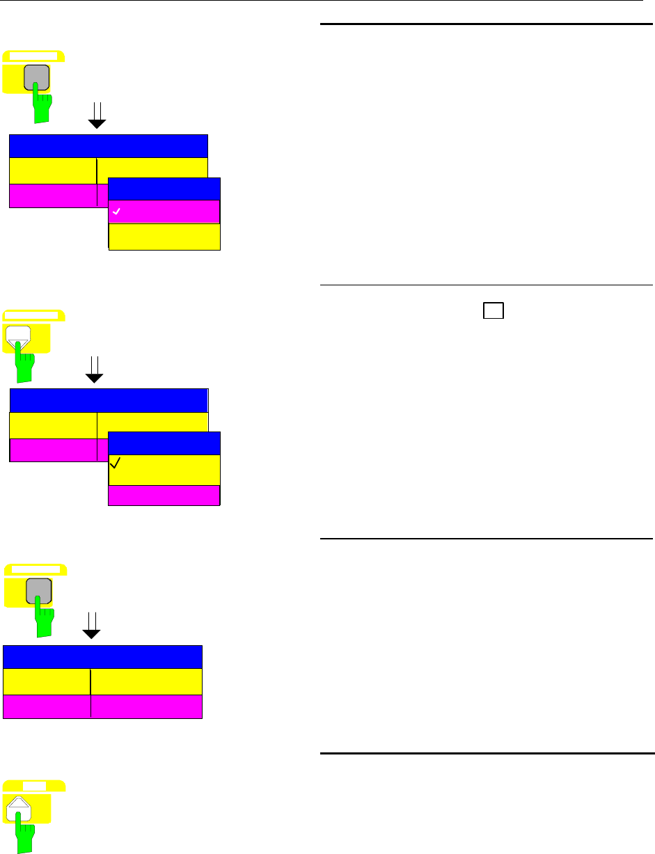
FSE Connecting a Mouse
1065.6016.12 1.61 E-8
Interface PS/2
Owner
GHz s
V -dBm
DATA ENTRY
INSTRUMENT
DOS
INSTR AND DOS
OWNER
MOUSE
Assign mouse mode
½Press one of the units keys.
The OWNER selection box appears on the
display screen. The current state (INSTRUMENT)
is indicated by a check mark and the selection bar
is in the background.
Interface PS/2
Owner
INSTRUMENT
DOS
INSTR AND DOS
OWNER
MOUSE
DATA VARIATION ½Press the cursor key à until the entry INSTR
AND DOS is indicated by the selection bar.
Interface PS/2
Owner INSTR AND DOS
MOUSE
GHz s
V -dBm
DATA ENTRY
½Press one of the units keys.
The OWNER selection box is closed and the
setting INSTR AND DOS is entered in the
MOUSE table.
The mouse is now installed and is available in
both the measurement instrument and DOS
modes.
MENU
Return to main menu
½Press the menu-change key several times.

Connecting an External Keyboard FSE
1065.6016.12 1.62 E-8
Connecting an External Keyboard
Caution:
The keyboard may only be connected when the instrument is switched off
(STANDBY). Otherwise, correct operation of the keyboard cannot be guaranteed.
The FSE provides an option for connecting an external PC keyboard to the 5-pin DIN connector at the
rear panel.
During measurement operations, the keyboard simplifies the input of commentary text, filenames, etc. If
the option FSE-B15 (computer function) is installed, the keyboard has the usual DOS-mode functions.
Note: Using the key combination <ALT><S-Abf> (German keyboard) or <ALT><SYSREQ> (US-
keyboard), the representation on the display screen can be rapidly toggled between the
measurement instrument and the DOS display formats.
Chapter 3 contains a list which describes the assignment of the FSE front-panel key functions to the key
codes of the external keyboard as well as special key combinations used for quick operations. Chapter 8
contains the interface dscription.
The keyboard connection (KEYBOARD) is located on the rear panel.
KEYBOARD x
After connecting the keyboard, the connection must be entered into the instrument and the key
assignments for measurement instrument operations must be determined.
The configuration takes place in the menu SETUP-GENERAL SETUP (key group: CONFIGURATION,
see in Chapter 4, the section "Preliminary Setup and Interface Configuration").
•The parameter EXT KEYBOARD CONNECTION informs the instrument that an external keyboard is
connected.
•The parameter EXT KEYBOARD LANGUAGE sets the keyboard language definition for
measurement instrument operation (US-AMERICAN or GERMAN).
Note: During measurement instrument operation, the key combination <ALT> <F1> can be used to
toggle the language definition.
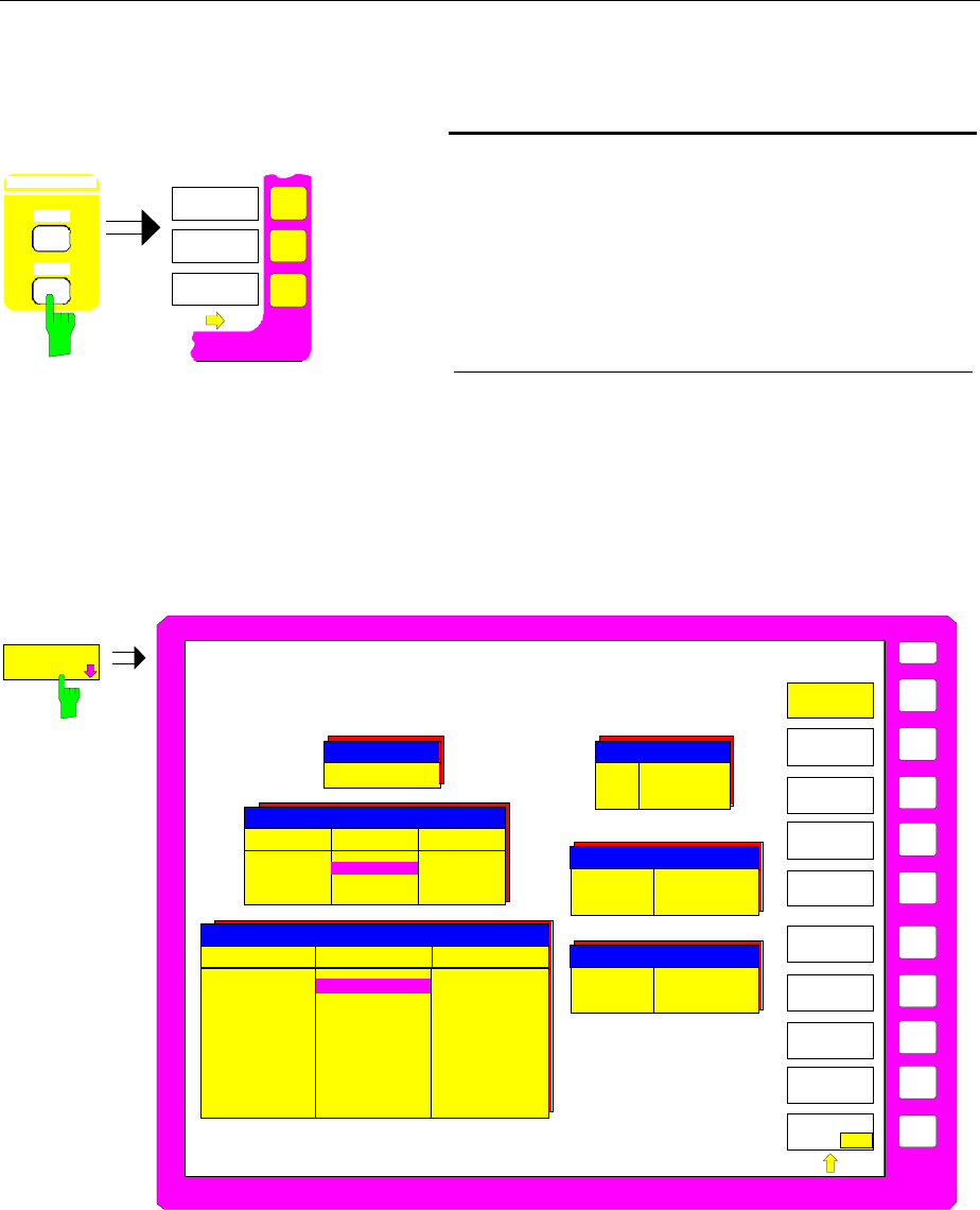
FSE Connecting an External Keyboard
1065.6016.12 1.63 E-8
In the following illustrative example, the instrument is informed that a keyboard has been connected.
The GERMAN keyboard definition is selected.
CONFIGURATION
MODE
SETUP
EXTERNAL
REFERE NCE
GENERAL
SETUP
Call SETUP-GENERAL SETUP menu
½Press the SETUP key of the CONFIGURATION
key group.
The SETUP menu is opened.
½Press the GENERAL SETUP softkey.
The GENERAL SETUP sub-menu is opened and
the current settings of the general instrument
parameters are shown in tabular form on the display
screen.
U
SE
R
Ba
u
d
B
i
ts
Par
i
t
y
S
t
o
p
b
i
t
s
HW-Ha
n
d
sha
k
e
SW-H
an
d
s
h
a
k
e
O
w
n
e
r
Pr
o
t
o
co
l
CO
M
2
C
O
M
1
96
0
0
8
N
o
n
e
1
N
o
n
e
X
ON/
X
OFF
In
str
u
me
n
t
R
e
mote
1
2
00
8
No
n
e
1
No
n
e
No
n
e
I
n
s
t
r
u
me
n
t
Mou
s
e
GPIB
ADDRESS
GENERAL
SETUP
COM
PORT 1
TIME
DATE
EXTERNAL
KEYBOARD
MOUSE
USER
PORT A
COM
PORT 2
USER
PORT B
GPIB ADRESS
19
PORT A PORT B
Direction
Value Input
10101010 Output
00010001
USER PORTS
COM PORTS
TIME AND DATE
MOUSE
EXT KEYBOARD
Connection
Language
not connected
US American
Interface
Owner PS/2
Instrument
Time
Date 21:59
01 Oct 1994
GENERAL
SETUP
KEY CLICK
ON OFF
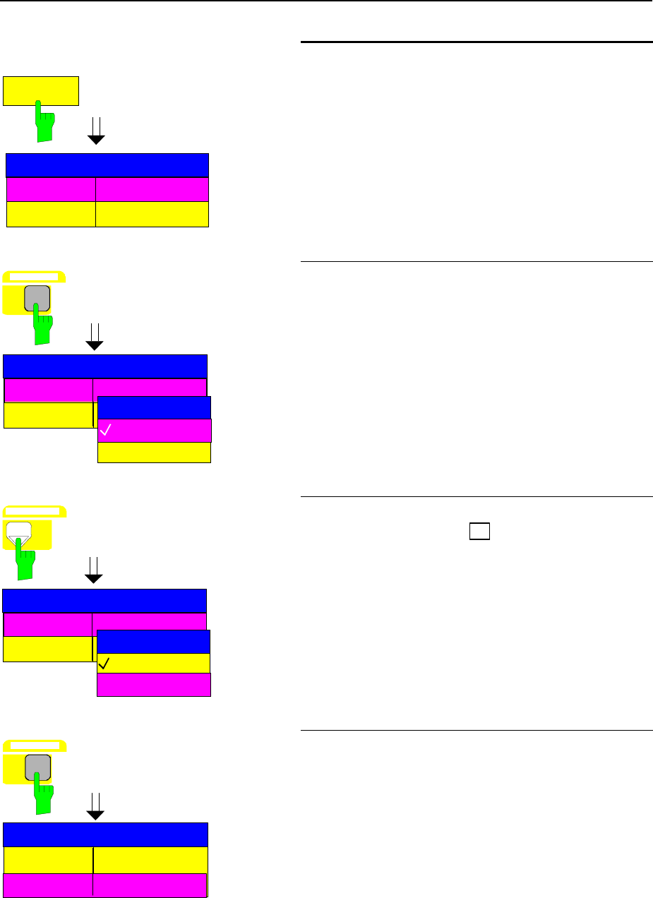
Connecting an External Keyboard FSE
1065.6016.12 1.64 E-8
EXTERNAL
KEYBOARD
Connection NOT CONNECTED
Language US-AMERICAN
EXT KEYBOARD
Setup keyboard connection
½Press the EXTERNAL KEYBOARD softkey.
The CONNECTION parameter in the EXT
KEYBOARD table is marked by the selection bar.
GHz s
V -dBm
DATA ENTRY
Connection NOT CONNECTED
Language US-AMERICAN
EXT KEYBOARD
NOT CONNECTED
CONNECTION
CONNECTED
½Press one of the units keys.
The CONNECTION selection box appears on the
display screen. The current state (NOT
CONNECTED) is indicated by a check mark and the
selection bar is in the background.
Connection NOT CONNECTED
Language US-AMERICAN
EXT KEYBOARD
NOT CONNECTED
CONNECTION
CONNECTED
DATA VARIATION
½Press the cursor key à until the CONNECTED
entry is indicated by the selection bar.
Language US-AMERICAN
EXT KEYBOARD
Connection CONNECTED
GHz s
V -dBm
DATA ENTRY
½Press one of the units keys.
The CONNECTION selection box is closed, the
setup CONNECTED is entered in the table, EXT
KEYBOARD is entered and the selection bar is
automatically set to the LANGUAGE parameter.
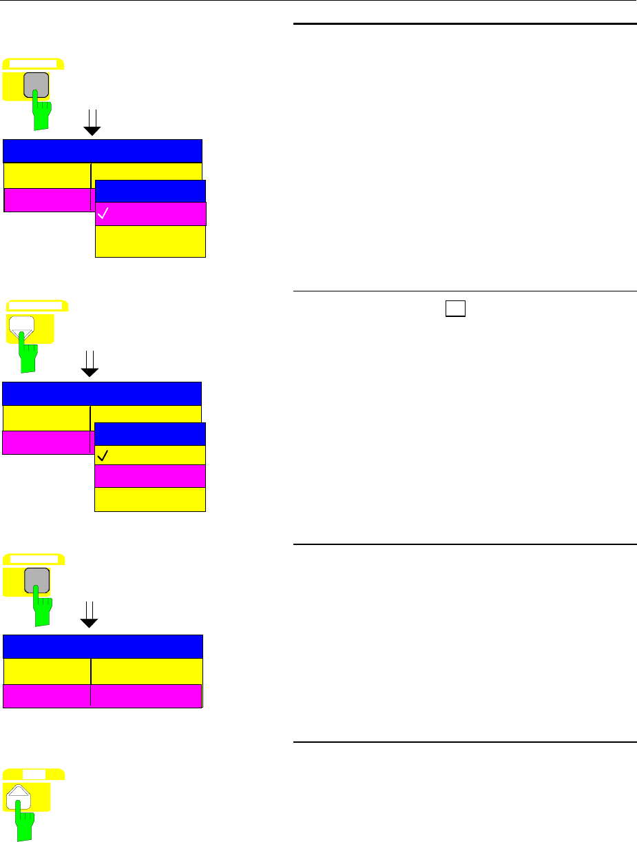
FSE Connecting an External Keyboard
1065.6016.12 1.65 E-8
Connection NOT CONNECTED
Language US-AMERICAN
EXT KEYBOARD
GHz s
V -dBm
DATA ENTRY
US-AMERICAN
LANGUAGE
GERMAN
FRENCH
Select German keyboard
½Press one of the units keys.
The LANGUAGE selection box appears on the
display screen. The current state is indicated by a
check mark and the selection bar is in the
background.
Connection
Language US-AMERICAN
EXT KEYBOARD
US-AMERICAN
LANGUAGE
GERMAN
DATA VARIATION
FRENCH
NOT CONNECTED
½Press the cursor key à until the GERMAN entry is
indicated by the selection bar.
Language
EXT KEYBOARD
Connection CONNECTED
GERMAN
GHz s
V -dBm
DATA ENTRY
½Press one of the units keys.
The LANGUAGE selection box is closed and the
GERMAN setting is entered in the EXT KEYBOARD
table.
Note: This setting is valid only for the measurement
instrument mode. The keyboard assignment in
DOS mode is independently set by using the
corresponding MS-DOS command.
MENU
Return to MAIN MENU
½Press the menu-change key several times.
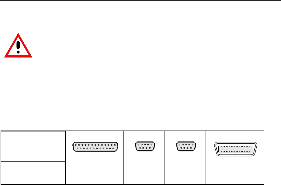
Connecting an Output Device FSE
1065.6016.12 1.66 E-8
Connecting an Output Device
Caution:
The output device may be connected only when the instrument is switched off
(STANDBY)
The FSE provides an option for connecting up to four different output devices to allow printing a hard
copy of the display screen. The output devices supported by the FSE can be found in the selection box
DEVICE/LANGUAGE in the HARDCOPY –SETTINGS DEVICE1/2 menu (see in Chapter 4, the section
"Documentation of Measurement Results").
Chapter 8 contains the interfeace description of the connectors.
The interface connectors are located on the rear panel (see Table 1-2).
Table 1-2 Interface Connectors for Output Devices
Rear panel interface
connectors
LPT
COM1 COM2
<SCPI> IEC625
Name in instrument
control
LPT1 COM1 COM2 GPIB1
After connection of the output device to the appropriate interface connector, the configuration of the
interface as well as the output device must be entered and the output device must be assigned to the
interface.
The configuration of the selected interface (COM1, COM2 or GPIB1) is performed according to the
SETUP-GENERAL SETUP menu (key group: CONFIGURATION, see in Chapter 4, the section
"Preliminary Setup and Interface Configuration").
Note: Interface LPT1 cannot be configured. If the option FSE-B15, computer function, is installed,
LPT1 can be used for printing in both the measurement instrument mode and the computer
mode. However, it can only be used for one mode at a time.
Interfaces COM1 and COM2
•The parameters COM PORTS BAUDRATE, BITS, PARITY, STOPBITS, HW/SW-HANDSHAKE
determine the transmission parameters of the interface.
Note: The transmission parameters must agree with the specifications of the output device (see the
operating manual for the output device).
•The parameter COM PORTS PROTOCOL informs the instrument that an output device is
connected to an interface (REMOTE setting).
•The parameter COM PORTS OWNER assigns the interface to one or both operational modes.
Note: If printing is required in the measurement instrument mode, then this parameter must be set
to INSTRUMENT or INSTRUMENT AND DOS. If, on the other hand, printing is required in
computer mode (Option FSE-B15, computer function), then the parameter must be set to
DOS or INSTRUMENT AND DOS.

FSE Connecting an Output Device
1065.6016.12 1.67 E-8
Interface GPIB1
•The parameter GPIB ADDRESS passes the IEC Bus address of the output device to the
instrument.
Note: If the output device is operated in "listen only" mode, this setup may be omitted.
The configuration of the connected output device and the assignment to the interface takes place in the
HARDCOPY DEVICE–SETTINGS DEVICE1/2 menu (key group:HARDCOPY, see in Chapter 4, the
section "Selection and Configuration of the Output Device "). The configuration of up to two output
devices (DEVICE1 and DEVICE2) may be entered, of which, at least one must be activated for printing.
•The parameter DEVICE/LANGUAGE determines which output device is to be used.
Note: During the selection of the printer type, it must be observed that the selected printer type and
the connected output device are compatible. In case of doubt, consult the operating manual for
the output device.
•The parameter CONNECTION sets the interface which is to be used.
The number of additional parameters which need to be entered depends upon the selected interface
and the output device used.
•The parameter ORIENTATION sets the page format to horizontal or vertical (portrait).
•The parameter DEVICE RESET determines if the output device is to be reset before each print job.
•The parameter FORMFEED determines if a formfeed should follow each print job.
•The parameter PAPER FEED specifies the paper feeder (single sheet or endless paper).
Table 1-3 shows the standard factory settings for the two output devices.
The standard factory settings for DEVICE 1 correspond to an output device controlled by the command
language HPGL, typically, a plotter connected to the IEC-Bus interface.
The standard factory settings for DEVICE 2 correspond to a Epson printer (and compatible) connected
to the parallel interface LPT.
Table 1-3 Factory settings for DEVICE 1 and DEVICE 2 in the HARDCOPY-DEVICE SETTINGS
menu.
Parameter Parameter Name DEVICE 1 Settings DEVICE 2 Settings
Output Device/Descriptive Language DEVICE/LANGUAGE HPGL EPSON 24
Output Channel CONNECTION GPIB 1 LPT
IEC Bus Address GPIB ADDRESS 4 ---
Paper Format ORIENTATION PORTRAIT PORTRAIT
Output Device Reset DEVICE RESET OFF OFF
Formfeed FORMFEED OFF ON
Paperfeed PAPERFEED MANUAL MANUAL
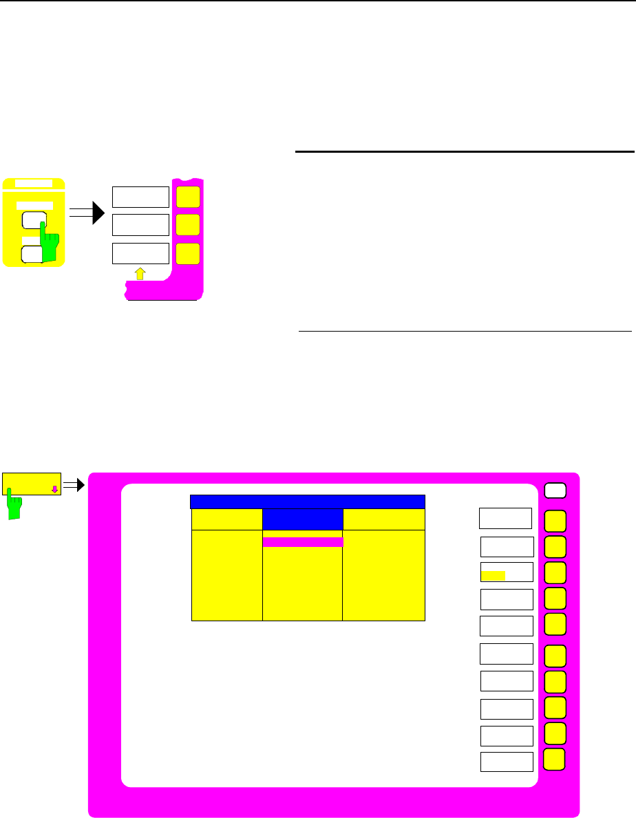
Connecting an Output Device FSE
1065.6016.12 1.68 E-8
In the following illustrative examples, a Postscript printer is connected to the LPT interface.
Note: Interface LPT cannot be configured. The configuration of the other interfaces (COM1, COM2 or
GPIB1) is performed according to the SETUP-GENERAL SETUP menu (key group:
CONFIGURATION, see in Chapter 4, the section "Preliminary Setup and Interface
Configuration").
START
HARDCOPY
DEVICE
HARDCOPY
SETTINGS
Configure printer and connect to interface
½Press the SETTINGS key of the HARDCOPY key
group.
The SETTINGS menu is opened.
½Press the HARDCOPY DEVICE softkey
The HARDCOPY DEVICE sub-menu is opened
and the current settings for the two possible output
devices are displayed in tabular form on the display
screen.
SETTINGS
DEVICE1
HARDCOPY
DEVICE
USER
Device/Language
Connection
GPIB Address
Orientation
Device Reset
Formfeed
Paperfeed
SETTINGS DEVICE 1 SETTINGS DEVICE 2
HPGL
GPIB 1
4
PORTRAIT
OFF
EPSON 24
LPT
PORTRAIT
OFF
ON
MANUALFEED
ITEM
HARDCOPY
DEVICE
SETTINGS
DEVICE2
ENABLE
DEV1 DEV2
DEVICE SETTINGS
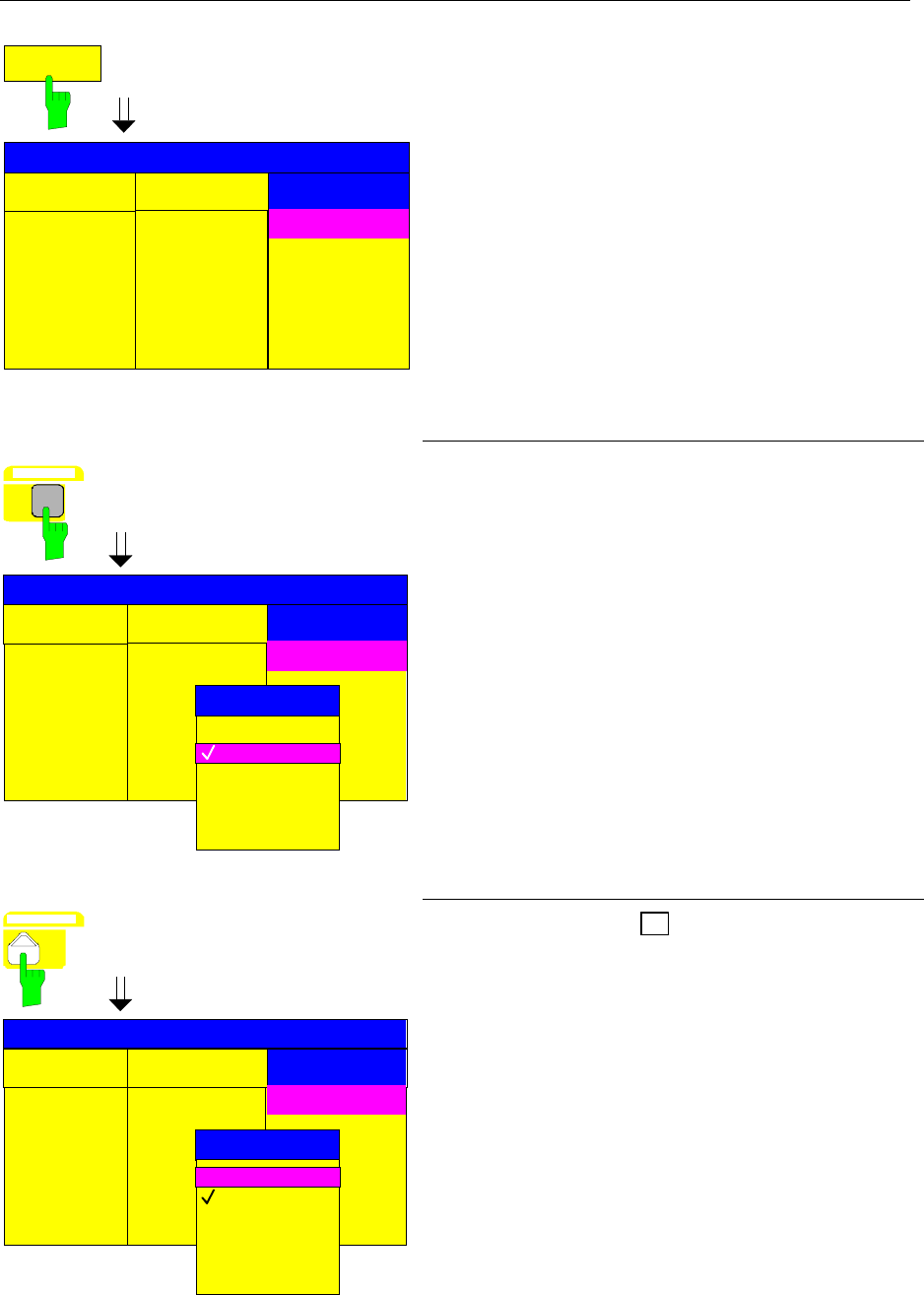
FSE Connecting an Output Device
1065.6016.12 1.69 E-8
SETTINGS
DEVICE2
SETTINGS DEVICE 2
HPGL
GPIB 1
4
PORTRAIT
OFF
EPSON 24
LPT
PORTRAIT
OFF
ON
MANUALFEED
ITEM
Device/Language
Connection
GPIB Address
Orientation
Device Reset
Formfeed
Paperfeed
SETTINGS DEVICE 1
DEVICE SETTINGS
½Press the SETTINGS DEVICE2 softkey.
The current selection in the first line of the table
column SETTINGS DEVICE2 is marked by the
selection bar.
SETTINGS DEVICE 2
HPGL
GPIB 1
4
PORTRAIT
OFF
EPSON 24
LPT
ITEM
Device/Language
Connection
GPIB Address
Orientation
Device Reset
Formfeed
Paperfeed
SETTINGS DEVICE 1
GHz s
V -dBm
DATA ENTRY
SELECT DEVICE
POSTSCR
EPSON 24
HPPCL 4
HPPCL 5
HPGL
PCX
WMF
DEVICE SETTINGS
½Press one of the units keys.
The SELECT DEVICE selection box appears on the
display screen. The current selection is indicated by a
check mark and the selection bar is in the
background.
SETTINGS DEVICE 2
HPGL
GPIB 1
4
PORTRAIT
OFF
EPSON 24
LPT
ITEM
Device/Language
Connection
GPIB Address
Orientation
Device Reset
Formfeed
Paperfeed
SETTINGS DEVICE 1
SELECT DEVICE
POSTSCR
EPSON 24
HPPCL 4
HPPCL 5
HPGL
PCX
WMF
DEVICE SETTINGS
DATA VARIATION ½Press the cursor key à until the POSTSCR entry is
indicated by the selection bar.
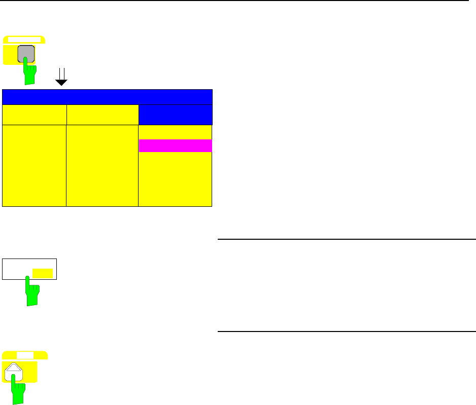
Firmware Update FSE
1065.6016.12 1.70 E-8
GHz s
V -dBm
DATA ENTRY
SETTINGS DEVICE 2
HPGL
GPIB 1
4
PORTRAIT
OFF
POSTSCR
LPT
PORTRAIT
OFF
ON
MANUALFEED
ITEM
Device/Language
Connection
GPIB Address
Orientation
Device Reset
Formfeed
Paperfeede
SETTINGS DEVICE 1
DEVICE SETTINGS
½Press one of the units keys.
The SELECT DEVICE selection box is closed and
the POSTSCR setting is entered in the table column
SETTINGS DEVICE2. The selection bar now
indicates the current entry in the next row of the table.
Note: The CONNECTION parameter is set to LPT
at the factory and, therefore, must not be
changed. The selection of the printer type
automatically sets the parameters
ORIENTATION, DEVICE RESET, FORM
FEED and PAPER LENGTH to values which
correspond to a standard mode of operation
with this output device.
ENABLE
DEV1 DEV2
Activate printer
½Press the ENABLE softkey until DEV2 in the second
softkey line is selected.
MENU
Return to main menu
½Press the menu-change key several times.
Firmware Update
The installation of a new firmware version can be performed using the built-in diskette drive and does
not require opening the spectrum analyzer. The deliverable items contained in the Firmware Update Kit
and the installation program call procedure may be found in the documentation accompanying the kit.
The installation program then leads the user through the remaining steps of an update.

FSE Options
1065.6016.12 1.71 E-8
Options
Option FSE-B17 – Second IEC/IEEE Interface
Besides the FSE external devices can also be controlled via the IEC/IEEE bus using the optional 2nd
bus interface FSE-B17 and the computer function for FSE (option FSE-B15). The interface software
permits IEC/IEEE-bus commands to be included in user programs.
Installing the software
1. The operating software is already installed and need not be loaded from the driver diskettes which
serve as backup diskettes.
2. The driver GPIB.COM must be loaded on the start-up of DOS. For this to take place, the line
DEVICE = C:\AT-GPIB\GPIB.COM has to be entered in the file C:\CONFIG.SYS. If the option is
factory fitted, this line will have been entered in the factory.
3. The configuration of the card can be modified with the program C:\AT-GPIB\IBCONF.EXE. The
following parameters may not be changed:
Bios version < 3.0: Bios version ≥ 3.0:
Enable Auto Serial Polling .. No Enable Auto Serial Polling .. No
Base I/O Address ............ 02C0h Base I/O Address ............ 02C0h
Interrupt Level ............. NONE Interrupt Level ............. NONE
DMA Channel ................. 5 DMA Channel ..................... NONE
For further parameters, refer to manual for the card.
4. The parameters of units connected are also set with the program IBCONF.EXE. The logic
designation for FSE is preset to DEV1 and the address to 20. For further equipment refer to manual
for the card.
Note: Ensure that the names assigned to the connected units are not the same as the directory
names under DOS.
Operation
The second IEC/IEEE-bus interface corresponds physically to that of FSE (see chapter 8).
If the FSE is to be controlled via the IEC/IEEE bus, a bus cable must be plugged to both bus
connectors.
The interface can be driven under DOS/WINDOWS by R&S software (FSE-K3, Order No.
1057.2996.02, etc.) or by user-written software. The handling of IEC/IEEE-bus commands in user
programs is described in the manual for the card.
The files for DOS in the computer function are in directory C:\AT-GPIB, those for WINDOWS in
directory C:\AT-GPIBW .
Note: The program IBIC.EXE (see manual for the card) may not be used for controlling the FSE
(measuring unit section); however external units can be controlled via the bus.

Options FSE
1065.6016.12 1.72 E-8
Option FSE-B5 - FFT Filter
Option FFT Filter FSE-B5 is a firmware option. It has to be enabled by a keyword.
Prerequisites
1. Keywords
The keyword is printed on a label which is part of the equipment supplied and has to be stuck to the
rear of FSE.
2. Hardware
The modification state of module DIGITAL IF has to be either MODIF INDEX > 5 or
MODIF INDEX = 5 and HW CODE ≥ 6. The modification state can be checked in the module list
INSTALLED COMPONENTS in menu INFO HARDWARE+OPTIONS.
3. Firmware
The modification state of the firmware has to ≥ 1.62. The modification state can be checked in table
FIRMWARE VERSION in menu INFO FIRMWARE VERSIONS.
Enabling the option
SETUP
MODE
CONFIGURATION
½Call up menu SETUP by pressing the SETUP key.
OPTIONS
½Call up submenu OPTIONS by pressing the OPTIONS softkey.
Table FIRMWARE OPTIONS is displayed, listing the installed
options.
ENABLE NEW
OPTION
½Activate the entry field by pressing the ENABLE NEW OPTION
softkey.
DATA ENTRY
MHz
mV dBm
1
.
.
.
½Enter the 10-digit keyword via the numeric keypad and terminate
the entry by pressing one of the unit keys.
Now option FFT filter is listed in table FIRMWARE OPTIONS.
Note: Message ’option key invalid’ indicates an invalid entry.
FSE Options
1065.6016.12 1.73 E-8
Option FSE-B16 – Ethernet Adapter
With the option Ethernet Adapter FSE-B16, the device can be connected to an Ethernet-LAN (local area
network). Together with the option Computer Function FSE-B15 it is possible to transmit data via the
network and to use the network printer. The adapter operates with a 10 MHz Ethernet in line with
standards IEEE 802.3 10Base2 (Thin Ethernet, CheaperNet, BNC-Net) (B16 model 03) or 10Base5
(Thick Ethernet) (B16 model 02). Operation without the option Computer Function FSE-B15 is not
possible.
Hardware Installation
Caution:
Prior to installation contact the network administrator, especially in case of complex
LAN installations since mistakes in cabling might have influence the whole network.
If the adapter is installed at the factory, it is preconfigured. In case of retrofitting, refer to the installation
instructions. The hardware settings must not be modified since the functions of the device could
otherwise be impaired.
The following parameters are factory-set:
I/O Addr. 300, IRQ 5, MEM CA000
The connection with the network depends on the connectors used in the network.
BNC (Thin Ethernet, CheaperNet; FSE-B16 Var. 03)
Connection The device is looped into the LAN segment via rear-panel 2 BNC
connectors.
If a cable is not connected to one of the BNC connectors, this BNC
connector has to be terminated with 50 Ohm. BNC T connectors
must not be used.
Network traffic Note that the network traffic is disturbed if a segment is interrupted.
Requirements Thin Ethernet segment requirements have to be complied with:
- maximum segment length of 185 m
- minimum distance between the connectors of 0.5 m
- maximum of 30 connectors per segment.
If components that comply with enhanced requirements are
exclusively used (Ethernet Adapter FSE-B16 complies with the
enhanced requirements):
- maximum length of segment of 300 m
- maximum number of connectors of 100
With repeaters used:
- maximum total length of the network of 900 m containing a
- maximum of 3 segments
- maximum of two repeaters between two connectors

Options FSE
1065.6016.12 1.74 E-8
AUI (Thick Ethernet; FSE B16 Var. 02)
Connection The device is connected to the LAN segment using a transceiver
cable (DB-15 AUI connector, not part of the equipment supplied)
which is connected to the rear panel and to the transceiver.
Network traffic The connection does not conflict with the network traffic. The device
can also be disconnected from the network without any problems
but make sure that data are not being transmitted.
Requirements The Thick Ethernet segment requirements have to be taken into
account.
- The maximum segment length should be 500 m and the
- distance between the connectors should at least be 2.5 m.
- A maximum of 100 connectors may be used in a segment.
With repeaters used,
- the total length of the network must not be more than 2500 m
containing
- a maximum of 3 segments.
- There should be no more than two repeaters between two
connectors.
If other network components are used, these conditions may vary.
RJ45 (UTP, 10BaseT, Western Connector)
Connection A direct connection to a RJ45 star topology is not possible. With a
MINI transceiver (AUI → RJ45) used, connection can be made via
the AUI port at the rear of the device.
Network traffic This connection does not conflict with the network traffic. The
device can also be disconnected from the network without any
problems but make sure that data are not being transmitted.
Requirements Since RJ45 is not a bus but a star topology no special requirements
have to be taken into account for the connection.
The LAN requirements should be considered in the installation.

FSE Options
1065.6016.12 1.75 E-8
Software Installation
Data transmission within the network is by means of data blocks, the so-called packets. Besides user
data other information, the so-called protocol data (transmitter, receiver, type of data, order) are
transmitted. The drivers corresponding to the protocol have to be installed to process protocol
information. A network operating system is required for network services (data transmission, directory
services, printing in the network) and thus has to be installed.
Installation of Network Drivers
a) ODI
ODI drivers have been developed by NOVELL for the network operating system NETWARE. It is an
open standard so that other systems can be based on it, too. The driver system is of modular design
and can thus be easily adapted to the hardware.
Files required
for installation:
LSL.COM (ODI drivers)
SMC8000.EXE (hardware drivers for the adapter)
NET.CFG (configuration file)
The NET.CFG file comprises information required for the installation
of the network drivers. It is a text file that can be generated by any
editor e.g. EDIT.
At least the following information has to be contained in the NET.CFG
file:
Link Support
Max Stacks 8
Buffer 12 1586
MemPool 8192
Link Driver SMC8000
Port 300
Mem CA000
Int 5
Frame ETHERNET_II
Parameter Frame ... depends on the type of packets used in the
network. The network administrator can provide information about the
frame type used. With a wrong type used, problems will not occur in
the network but a connection to other systems cannot be set up.
Loading the drivers The drivers have to be loaded under DOS in the following order:
LSL
SMC8000
To allow for an automatic start, the drivers can be entered into the
C:\NETWORK.BAT file. This batch file will be executed automatically
when the device is started. The drivers can be unloaded if the
programs are called up with the parameter /U. Unloading has to be in
the reverse order.

Options FSE
1065.6016.12 1.76 E-8
b) NDIS
NDIS drivers are mainly used by network operating systems from MICROSOFT (DOS MS-
NET,WINDOWS FOR WORKGROUPS, WINDOWS 95, WINDOWS NT). It is an open system so that
other systems can be based on it, too. The driver system is of modular design and can thus be easily
adapted to the hardware.
Files required
for installation: PROTMAN.DOS
PROTMAN.EXE
NET.EXE
NET.MSG
IFSHLP.SYS
PROTOCOL.INI
NDISHLP.SYS
NETH.MSG
WFWSYS.CFG
SMC8000.DOS (Hardware drivers for the adapter)
SYSTEM.INI
Files PROTOCOL.INI and SYSTEM.INI contain information required for
installing the network drivers. They are text files that can be created or
modified by any editor, e.g. EDIT.
At least the following information has to be contained in the
PROTOCOL.INI file:
[network.setup]
version=0x3110
netcard=ms$w8003e,1,MS$W8003E,3
transport=ms$nwlinknb,NWLINK
transport=ms$ndishlp,MS$NDISHLP
transport=ms$netbeui,NETBEUI
lana0=ms$w8003e,1,ms$nwlinknb
lana1=ms$w8003e,1,ms$ndishlp
lana2=ms$w8003e,1,ms$netbeui
[protman]
DriverName=PROTMAN$
PRIORITY=MS$NDISHLP
[NWLINK]
BINDINGS=MS$W8003E
[MS$NDISHLP]
DriverName=ndishlp$
BINDINGS=MS$W8003E
[NETBEUI]
DriverName=netbeui$
SESSIONS=10
NCBS=12
BINDINGS=MS$W8003E
LANABASE=1
[MS$W8003E]
DriverName=SMC8000$
irq=5
iobase=0x300
ramaddress=0xca00
[SMC8000W]
Adapters=MS$W8003E

FSE Options
1065.6016.12 1.77 E-8
At least the following information has to be contained in the
SYSTEM.INI file:
[Network]
winnet=wfwnet/00025100
multinet=nonet
FileSharing=Yes
PrintSharing=Yes
LogonDisconnected=yes
EnableSharing=Yes
UserName=FSE
Workgroup=WORKGROUP
ComputerName=FSE
Comment=FSE
[network drivers]
netcard=smcmac.dos
transport=ndishlp.sys,*netbeui
devdir=C:\NDIS
LoadRMDrivers=No
[NWNBLINK]
LANABASE=0
Parameter "UserName= ..." comprises the user name for the network.
Parameter "Workgroup= ..." comprises the user name for the network.
Parameter "ComputerName= ..." determines the name of the device in the network.
This name has to be unique in the network.
All drivers should be copied into a directory, e.g. C:\NDIS.
Requirements in the
CONFIG.SYS file The C:\CONFIG.SYS file has to be extended by the following line:
DRIVER = C:\NDIS\IFSHLP.SYS
To do this, the read-only attribute of the file has to be removed by the
following DOS command:
ATTRIB C:\CONFIG.SYS -R
Loading the drivers On startup of the device, the network drivers will be loaded
automatically.

Options FSE
1065.6016.12 1.78 E-8
c) Packet Drivers
The "Packet" network driver system has been developed by universities and can be used free of charge.
Many free-of-charge network operating systems (KERMIT) are based on this driver system. Although
the drivers for these network cards used to be made at universities, manufacturers have now started to
supply their own drivers.
File required
for installation: PKT8000.COM
Loading the drivers The driver should be copied into a directory, e.g. C:\PACKET.
The DOS command
C:\PACKET\PKT8000 -i 0x7e 5 0x300 0xca00
starts the driver.
To allow for an automatic start, the driver can be entered into the
C:\NETWORK.BAT file. This batch file will be executed automatically
on the startup of the device.
Installation of Network Operating System
a) NOVELL NETWARE
ODI drivers are the precondition for NOVELL NETWARE. The access software is available in three
models: NETWARE SHELL, NETWARE REQUESTER and NETWARE CLIENT 32. NETWARE SHELL
allows access to NETWARE 3 servers only. The NETWARE REQUESTER allows access to NETWARE
3 as well as NETWARE 4 (NDS). NETWARE CLIENT 32 cannot run on the device.
NETWARE SHELL
Files required
for installation:
IPXODI.COM
NETX.EXE
The files should be copied into the directory comprising the network
drivers.
If a connection to a certain network server is requested, the name of
the server can be entered into the NET.CFG file by means of the
following line:
PREFERRED SERVER = FSESERVER
(FSESERVER has to be replaced by the server name in the network).

FSE Options
1065.6016.12 1.79 E-8
Loading the drivers The drivers are loaded under DOS in the following order:
IPXODI
NETX
To allow for an automatic start, the drivers can be entered into the
C:\NETWORK.BAT file in addition to the network drivers. This batch
file will be executed automatically on the startup of the device. The
drivers can be unloaded if the programs are called up with the
parameter /U . Unloading has to be in the reverse order.
NETWARE REQUESTER
Files required
for installation: IPXODI.COM
AUTO.VLM
BIND.VLM
CONN.VLM
FIO.VLM
GENERAL.VLM
IPXNCP.VLM
NDS.VLM
NETX.VLM
NMR.VLM
NWP.VLM
PNW.VLM
PRINT.VLM
REDIR.VLM
RSA.VLM
SECURITY.VLM
TRAN.VLM
VLM.EXE
The files should be copied into the directory comprising the network
drivers.
Changes in the
CONFIG.SYS file In the C:\CONFIG.SYS file line
LASTDRIVE = V: has to be replaced by line
LASTDRIVE = Z:
To do this, the read-only attribute of the file has to be removed with
the DOS command
ATTRIB C:\CONFIG.SYS -R
Changes in the
NET.CFG file The NET.CFG file is extended by the following lines:
Netware Dos Requester
NETWARE PROTOCOL = NDS BIND
FIRST NETWORK DRIVE = W
SHOW DOTS = ON
SPX CONNECTIONS = 99
IPX PACKET SIZE LIMIT = 1514
hold= off

Options FSE
1065.6016.12 1.80 E-8
If a connection to a certain network server is requested, the name of
the server can be entered into the NET.CFG file by means of line
PREFERRED SERVER = FSESERVER
(FSESERVER has to be replaced by the server name in the network).
Loading the drivers The drivers are loaded under DOS in the following order:
IPXODI
VLM
To allow for an automatic start, the drivers can be entered into the
C:\NETWORK.BAT file in addition to the network drivers. This batch
file will be executed automatically on the startup of the device. The
drivers can be unloaded if the programs are called up with the
parameter /U . Unloading has to be in the reverse order.
b) MICROSOFT NET
Drivers required The NDIS drivers are the precondition for the MICROSOFT NET.
Other drivers are not required.
Loading the drivers The start is via the following DOS command:
C:\NDIS\NET START
To allow for an automatic start, the command can be entered into the
C:\NETWORK.BAT file. This batch will be executed automatically on
the startup of the device.
c) TCP/IP
TCP/IP (Transmission Control Protocol / Internet Protocol) is not a network operating system but a
standard. This standard allows to transmit data between computers using different operating systems.
The services are managed by utility programs such as FTP, TELNET, KERMIT, HTTP, RSH. TCP/IP
only provides services for the transport and network addressing.
Drivers required TCP/IP can be based on the ODI or PACKET drivers. Normally,
another driver providing the TCP/IP support is required. See
corresponding product about the use of the drivers.

FSE Options
1065.6016.12 1.81 E-8
d) KERMIT
Drivers required The data transmission program KERMIT is based on the PACKET
drivers. To install KERMIT it is required to copy all the files into a
directory, e.g. C:\KERMIT. The precondition for this is that an IP
address is assigned to the device by the network administrator and
that the Sub Net Mask for the network is known. Both addresses are
in the form of four digits from 0 to 255 separated by a dot. An IP
address in the network has to be unique as problems might otherwise
occur. The Sub Net Mask is the same in the whole network.
Examples of IP address: 89.0.0.14
Example of Sub Net Mask: 255.255.0.0
Operation
After installing the network operating system it is possible to transfer data between the device and other
computers and to use printers in the network. A precondition for network operation is the authorization to
use network resources. Resources may be access to the file directories of other computers or the use of
a central printer. The network or server administrator will grant the authorizations. The network name of
the resource and the corresponding authorization are required. Passwords protect the resources
against improper use. A user name is normally assigned to every authorized user. The user also has a
password. Resources may then be assigned to the user. The type of access, i.e. whether data are only
read or also written as well as a shared access to data has to be defined. Other types are possible
depending on the network operating system.
NOVELL
Operating system NETWARE from NOVELL is as server-supported system. Data transfer between the
individual workstations is not possible. Data transfer is between workstation computers and a central
computer, the server. This server provides storage capacity and the connection to the network printers.
Like under DOS, the data on a server are organized in directories and are offered to the workstation as
virtual drives. A virtual drive on a workstation is like a hard disk and data can be processed accordingly.
This is called drive mapping. Also network printers can be addressed as normal printers. Network
operating system NOVELL is available in two forms: NETWARE 3 and NETWARE 4 NDS. In the
previous version NETWARE 3, each server manages its own resources itself and is independent. A
user has to be managed separately on each server. For NOVELL 4 NDS, all resources are managed in
the NDS (NOVELL DIRECTORY SERVICE). The user only has to log in once and gains access to the
resources released for him. The individual resources and the user are managed as objects in a
hierarchical tree (NDS TREE). The position of the object in the tree is called CONTEXT for NETWARE
and must be known in order to access the resources.

Options FSE
1065.6016.12 1.82 E-8
Logging into network After all network drivers have been loaded and the device has
established a connection with the server, a new drive W: is
generated. After a change to this drive, the log in can be started
with the
LOGIN
command. The user name and the password are queried.
For NOVELL 4 NDS it is necessary to set the CONTEXT
beforehand using the
CX <context>
command.
Virtual drives To generate a virtual drive on the computer function of a device,
the following command is used
MAP [ROOT]<dr>:=<server>/,<volume>:<directory>
where:
dr drive indicator under which the virtual drive is addressed
(E to P, R to V)
server name of the NOVELL server on which the directory is located.
volume name of the data medium on which the directory is
located.
directory name of the directory which is to be accessed.
If parameter ROOT is specified, the higher directories can no
longer be addressed.
Example:
MAP P:=VENUS/SYS:MESURE\FSE
causes that the directory \MESURE\FSE on hard disk SYS of
server VENUS appears on the device as drive P . In drive P it is
also possible to see the directory structure of MESURE. If the
command is called up with the parameter ROOT, it would only be
possible to access directory structures below FSE.
The
MAP DEL <lw>:
command allows drive mapping to be canceled.
Storage of device data
on a server Instead of storing device data on hard disks, they can be stored
on virtual drives. To do this, it is first required to generate a virtual
drive E: in the computer function. The LOADINFO file in directory
d:\ has to comprise line
ATTACHDEVICE E_DOS AS :C: EDOS
to enable the device to recognize the drive. Access to E: is
according to normal device functions.

FSE Options
1065.6016.12 1.83 E-8
Printing on a network
printer To be able to use a printer in the computer function, this printer
has to be connected first with the computer function by means of
the following command
CAPTURE L=<lpt> Q=<printer_queue>
where:
lpt printer port (1=LPT1, 2=LPT2, 3=LPT3)
printer_queue name of printer queue.
Example:
CAPTURE L=1 Q=PRINTER_FSE
causes printer data which are normally sent to printer port LPT1 to
be routed to the network printer called PRINTER_FSE.
Hardcopy from device
to a network printer It is not possible to directly route a hardcopy from the device to a
network printer. It has to be printed first into a file on the hard disk
(Print to File). This file is then copied to the printer in the computer
function.
This procedure is automated by the following DOS batch file:
START:
IF NOT EXIST C:\USER\OUTPUT.PRN GOTO START
COPY C:\USER\OUTPUT.PRN LPT1 /B
DEL C:\USER\OUTPUT.PRN
GOTO START
If this batch program is called up, the computer function waits until
the device has generated a print file called OUTPUT.PRN, prints
this file and deletes it again.
MICROSOFT
For MICROSOFT, data can be transferred between workstations (peer-to-peer) but also between
workstations and servers. The servers can provide access to individual files as well as the connection to
network printers. Like under DOS, the data on a server are organized in directories and are offered to
the workstation as virtual drives. A virtual drive on a workstation is like a hard disk and data can be
processed accordingly. This is called drive mapping. Also network printers can be addressed as normal
printers. A connection to DOS, WINDOWS FOR WORKGROUPS, WINDOWS95, WINDOWS NT is
possible.
Logging into network After all network drivers are loaded and the device has
established a connection with the server, a new drive W: is
generated. After a change to this drive, the log in can be started
with the
NET LOGON
command. The user name and the password are queried.

Options FSE
1065.6016.12 1.84 E-8
Virtual Drives To generate a virtual drive on the computer function of a device,
the following command is used
NET USE <dr>: \\<server>\<directory>
where:
dr drive indicator under which the virtual drive is
addressed (E to P, R to V)
server name of the server on which the directory is located.
directory name of the directory which is to be accessed.
Example:
NET USE P: VENUS\MESSUNG\FSE
causes the directory \MESURE\FSE of server VENUS to appear
as drive P on the device.
Drive mapping is canceled by means of
NET USE <lw>: \\<server>\<directory> /DELETE
Storage of device data on a
server Instead of storing device data on hard disks, they can be stored
on virtual drives. To do this, it is first required to generate a virtual
drive E: in the computer function. The LOADINFO file in directory
d:\ has to comprise line
ATTACHDEVICE E_DOS AS :C: EDOS
to enable the device to recognize the drive. Access to E: is
according to normal device functions.
Printing on a network printer To be able to use a printer in the computer function, this printer
has to be connected first with the computer function by means of
the following command
NET USE <port>: \\<server>\<printerqueue>
port printer port (LPT1, LPT2, LPT3)
server name of server on which the directory is located
printerqueue name of printer queue of printer
Example:
NET USE LPT1: \\VENUS\PRINTER_FSE
uses printer data which are normally sent to printer port LPT1 to
be routed to the network printer called PRINTER_FSE.
Hardcopy from device to a
network printer It is not possible to directly route a hardcopy from the device to a
network printer. It has to be printed first into a file on the hard disk
(Print to File). This file is then copied to the printer in the computer
function.
This procedure is automated by the following DOS batch file:
START:
IF NOT EXIST C:\USER\OUTPUT.PRN GOTO START
COPY C:\USER\OUTPUT.PRN LPT1 /B
DEL C:\USER\OUTPUT.PRN
GOTO START
If this batch program is called up, the computer function waits until
the device has generated a print file called OUTPUT.PRN, prints
this file and deletes it again.

FSE Options
1065.6016.12 1.85 E-8
TCP/IP
The TCP/IP protocol allows files to be transmitted between different computer systems. A program
running on both computers is required to control the data transfer. The same operating or file system
need not be used by the two partners. A file transfer is possible between DOS/WINDOWS and UNIX,
for example. One partner has to be configured as host the other as client or vice versa. The system
performing several processes at the same time (UNIX) will normally be the host. The usual file transfer
program used for TCP/IP is FTP (File Transfer Protocol). An FTP host is installed as standard on most
of the UNIX systems.
Columbia University provides the KERMIT program which not only allows file transfer via networks but
also via modem. KERMIT can be used free of charge. The two procedures provide safe data
transmission, i.e. errors normally do not occur.
FTP
For a complete description of the functions and commands see the FTP documentation.
Establishing a connection The program is started with the DOS command
FTP
The following command sets up the connection:
OPEN <xx.xx.xx.xx>
xx.xx.xx.xx = IP address, e.g. 89.0.0.13
File transmission To transmit a file to the target system, the following command is
used:
PUT <file name>
file name = name of file e.g. DATA.TXT.
To call a file from the target system, the following command is
used:
GET<file name>
file name = name of file e.g. SETTING.DAT.
TYPE B
allows the transmission of files in the BINARY format, no
conversion is performed.
TYPE A
allows the transmission of files in the ASCII format. Thus, control
characters are converted so that the text files can be read on the
target system, too.
Examples:
PUT C:\AUTOEXEC.BAT
sends the AUTOEXEC.BAT file to the target system.
LCD DATA
changes to subdirectory DATA in the computer function.
CD SETTING
changes to the subdirectory SETTING on the target system.

Options FSE
1065.6016.12 1.86 E-8
Changing directories The command
LCD <path>
changes the directory as the corresponding DOS command.
LDIR
lists the directory.
These commands refer to the computer function of the
instrument. If the ’L’ preceding the commands is omitted, they
apply to the target system.
KERMIT
KERMIT comprises a large number of functions described in detail in the help file KERMIT.HLP.
Establishing a connection The program is started by means of the DOS command
KERMIT
The
SET TCP/IP ADDRESS <xx.xx.xx.xx>
xx.xx.xx.xx = IP address e.g. 89.0.0.13
command allows to set the individual IP address.
The Sub Net Mask is set by means of
SET TCP/IP SUBNETMASK <xx.xx.xx.xx>
xx.xx.xx.xx= Sub Net Mask e.g. 255.0.0.0.
These commands can also be entered into the MSCUSTOM.INI
file and will be executed automatically when KERMIT is started.
The computer to which data are to be transferred is set by means
of
SET PORT TCP/IP <xx.xx.xx.xx>
xx.xx.xx.xx=IP address of target computer.
A prerequisite is that the KERMIT program on the target computer
is running in the host mode.
KERMIT can be ordered via Internet in WWW (URL:
http://WWW.COLUMBIA.EDU) from COLUMBIA UNIVERSITY for
almost all operating systems.
The
CONNECT
command sets up the connection.
The
HANGUP
command allows to stop the connection and the
QUIT
command to leave the program.

FSE Options
1065.6016.12 1.87 E-8
Data transmission To transmit a file to the target system, the
SEND <file name>
file name = name of file e.g. DATA.TXT
command is used. To transmit a file from the target system, the
GET<file name>
file name = name of file e.g. SETTING.DAT
command is used.
Changing directories Like with DOS, the directory is changed by means of the
CD <path>
command and the contents of the directory is indicated by means
of the
DIRECTORY
command.
These commands concern the computer function of the device. If
REMOTE.. is used in front of the commands, they apply to the
target system.
Examples:
SEND C:\AUTOEXEC.BAT
sends the AUTOEXEC.BAT file to the target system.
CD DATA
changes to the subdirectory DATA in the computer function.
REMOTE CD SETTING
changes to the subdirectory SETTING on the target system.

FSE Contents - Getting Started
1065.6016.12 I-2.1 E-1
Contents - Chapter 2 "Getting Started"
2 Getting Started..................................................................................................... 2.1
Level and Frequency Measurements............................................................................................. 2.1
Measurement Task.................................................................................................................. 2.1
Important Spectrum Analyzer Functions ................................................................................. 2.2
Sweep, Level and Frequency Measurements – Example 1 .................................................. 2.2
Sweep, Level and Frequency Measurements – Example 2 .................................................. 2.6
Level Measurement Accuracy ................................................................................................. 2.8
Measurement of Harmonic Separation.......................................................................................... 2.9
Measurement Task.................................................................................................................. 2.9
Important Spectrum Analyzer Functions ............................................................................... 2.10
Measurement Procedure - Harmonic Separation – Example 1........................................... 2.11
Measurement Procedure - Harmonic Separation – Example 2............................................. 2.16
Measurement Procedure - Harmonic Separation – Example 3........................................... 2.20
Measurement of Intermodulation Distortions............................................................................. 2.24
Measuring Task ..................................................................................................................... 2.24
Important Spectrum-Analyzer Functions ............................................................................... 2.25
Measurement......................................................................................................................... 2.26
Time-domain Measurements with Pulsed Signals ..................................................................... 2.31
Measuring Task ..................................................................................................................... 2.31
Important Spectrum Analyzer Functions ............................................................................... 2.31
Measurement......................................................................................................................... 2.32

Contents - Getting Started FSE
1065.6016.12 I-2.2 E-1

FSE Level and Frequency Measurements
1065.6016.12 2.1 E-10
2 Getting Started
Chapter 2 presents basic measurements performed by a spectrum analyzer to provide fast and easy
access to the operation of the instrument.
Before starting any measurement with the FSE, please note the instructions given in chapter 1 for
putting the instrument into operation. In chapters 3 you will find detailed information on customizing the
instrument and the display.
For a systematic explanation of all menus, functions and parameters and background information refer
to the reference part in chapter 4.
In the following description, each step is explained in detail using the FSE so that the instrument can be
immediately used without the need for learning all of the available functions. The described
measurement applications are:
•Measurement of the level and frequency of a sine wave signal.
•Measurement of harmonics.
•Measurement of third order intermodulation and determination of the intercept point.
•Zero span measurement of a pulsed signal.
All of the following examples assume the standard settings for the analyzer. These are set with the
PRESET key in the SYSTEM key field. The most important standard settings are shown in Table 2-1. A
complete listing of standard settings can be found in chapter 4.
Table 2-1 Important PRESET settings
Parameter Parameter name Setting
FSEA FSEB FSEM FSEK
Mode Mode analyzer analyzer analyzer analyzer
Center frequency Center Frequency 1,75 GHz 3,5 GHz 13,25 GHz 20 GHz
Active Freq. Meas. Range Span 3,5 GHz 7 GHz 26,5 GHz 40 GHz
Reference Level Ref Level – 20 dBm – 20 dBm – 20 dBm – 20 dBm
RF Attenuation RF ATT 10 dB 10 dB 10 dB 10 dB
Level Display Range Level Range 100 dB 100 dB 100 dB 100 dB
Resolution Bandwidth Res Bw 3 MHz 3 MHz 3 MHz 3 MHz
Video Bandwidth Video Bw 3 MHz 3 MHz 3 MHz 3 MHz
Sweep Time Sweep Time 5 ms 5 ms 150 ms 225 ms
Trigger Trigger free run free run free run free run
Level and Frequency Measurements
Measurement Task
The determination of the level and frequency of a signal is one of the most frequently encountered
measurement tasks typically performed by a spectrum analyzer. Usually, for the measurement of an
unknown signal, the PRESET settings are initially selected. If levels above +30 dBm are expected or
possible, then a power attenuator must be inserted ahead of the analyzer input. Without attenuation,
these signal levels might damage or destroy the input attenuator or the input mixer.
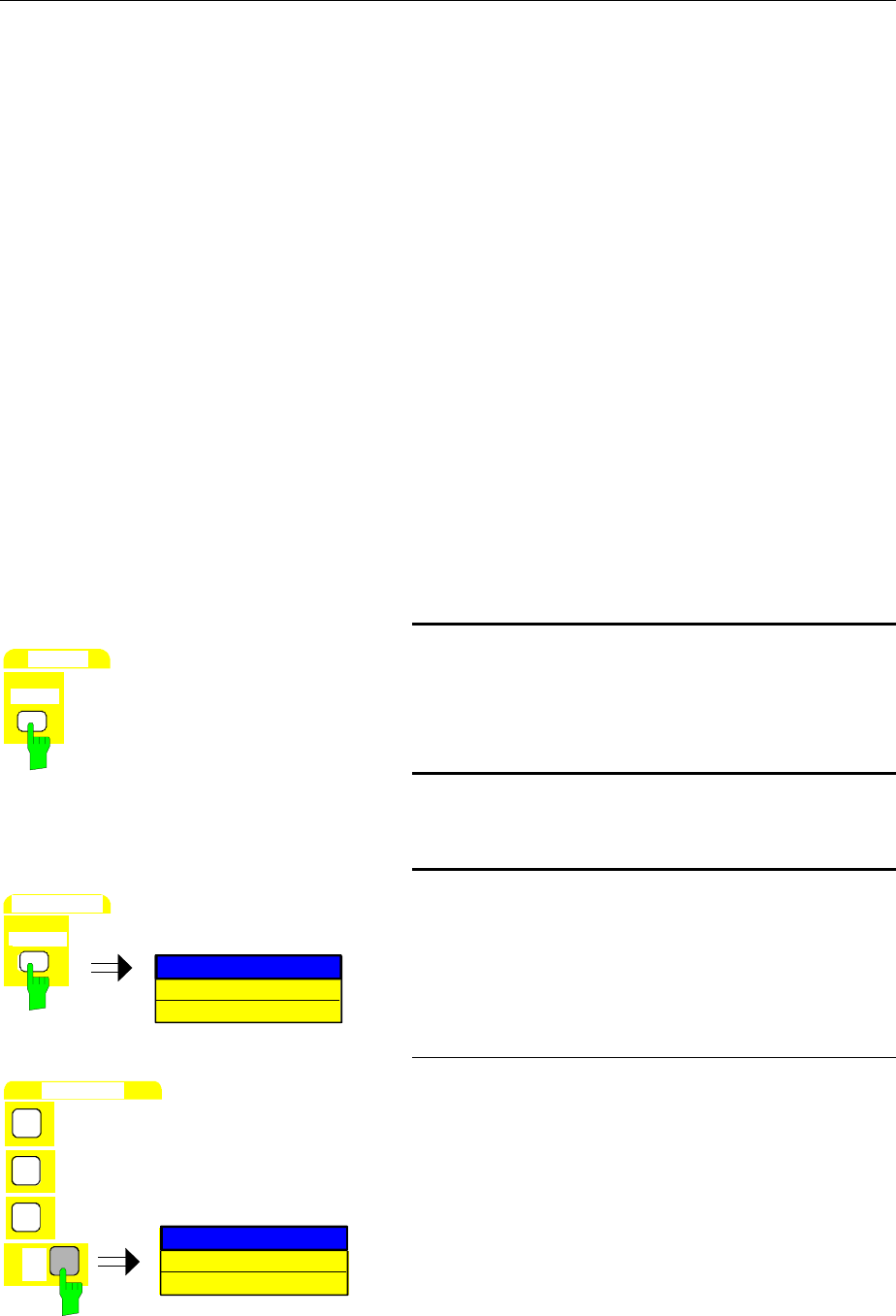
Level and Frequency Measurements FSE
1065.6016.12 2.2 E-10
Important Spectrum Analyzer Functions
Important parameters for level and frequency measurements are the settings for the CENTER
FREQUENCY, the selection of the active measurement frequency range (SPAN) and the MARKER
functions.
Sweep, Level and Frequency Measurements – Example 1
In this example, a signal with a frequency of 200 MHz and a level of -10 dBm are applied to the RF
INPUT of the analyzer. The selection of the center frequency and the active frequency range takes place
manually.
The necessary setup functions are performed almost without exception by the fixed-function keys. The
menus which appear with a key can, for the most part, be ignored. In this manner, fast, key-oriented
operation is possible.
The following setup steps are performed:
1. Reset the instrument.
2. Apply the test signal.
3. Set the center frequency to 200 MHz.
4. Reduce the active measurement frequency range (SPAN) to 1 MHz.
5. Measure the level and frequency using the marker.
6. Optimize the measurement dynamic range and reduce the level measurement error.
7. Measure the frequency with the internal frequency counter
SYSTEM
PRESET
1. Reset the instrument.
½Press the PRESET key.
2. Connect the test signal to the RF INPUT located
on the instrument front panel.
CENTER FREQUENCY
CENTER
FREQUENCY
1.75 GHz
3. Set the center frequency to 200 MHz.
½Press the CENTER key in the FREQUENCY key
field.
The input field for center frequency appears on the
display screen.
D
A
T
A
E
N
T
R
Y
2
0
CENTER FREQUENCY
dBm
0
200 MHz
MHz
ms
mV
½Enter 200 via the numeric keypad and terminate
with the MHz key.
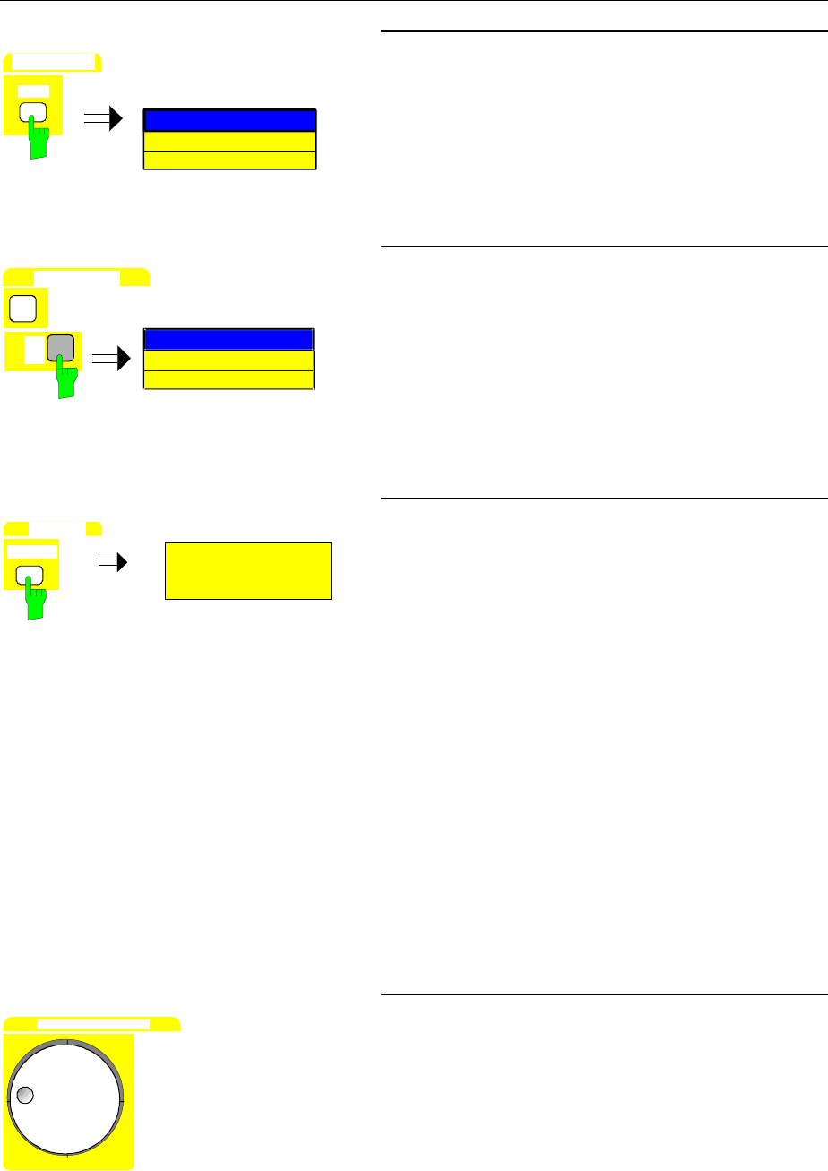
FSE Level and Frequency Measurements
1065.6016.12 2.3 E-10
SPAN
FREQUENCY
SPA
N
SPAN
400 MHz
4. Reduce the measurement frequency range
(SPAN) to 1 MHz.
½Press the SPAN key in the FREQUENCY key field.
DATA ENTRY
1
dBm MHz
ms
mV SPAN
SPAN
MHz1
½Enter 1 via the numeric keypad and terminate with
the MHz key.
Note: In conjunction with the change in measure-
ment frequency range (SPAN), the resolution
bandwidth (RES BW), video bandwidth
(VIDEO BW) and sweep time (SWEEP TIME)
are set to new values since they are defined
as coupled functions in the standard PRESET
settings.
MARKER
NORMAL
MARKER
200.00000000 MHz
-10.5 dBm
[T1]
1
5. Measure level and frequency using the marker
and read the resulting values on the display
screen.
½Press the NORMAL key in the MARKER key field.
The marker jumps to the largest signal peak shown
on the display screen.
Note: When the marker is switched on for the
first time, it automatically performs the
PEAK SEARCH function as demonstrated
in this example.
If a marker was already active, the
SEARCH key in the MARKER key field
must be pressed in order to set the
currently active marker to the displayed
signal maximum.
The level and frequency measured by the marker
can be read in the marker field at the upper edge of
the display screen. (see Fig. 2-1).
DATA VARIATION
½Using the roll-key, the marker can be moved along
the measured curve.
The corresponding level and frequency values
appear in the marker field.
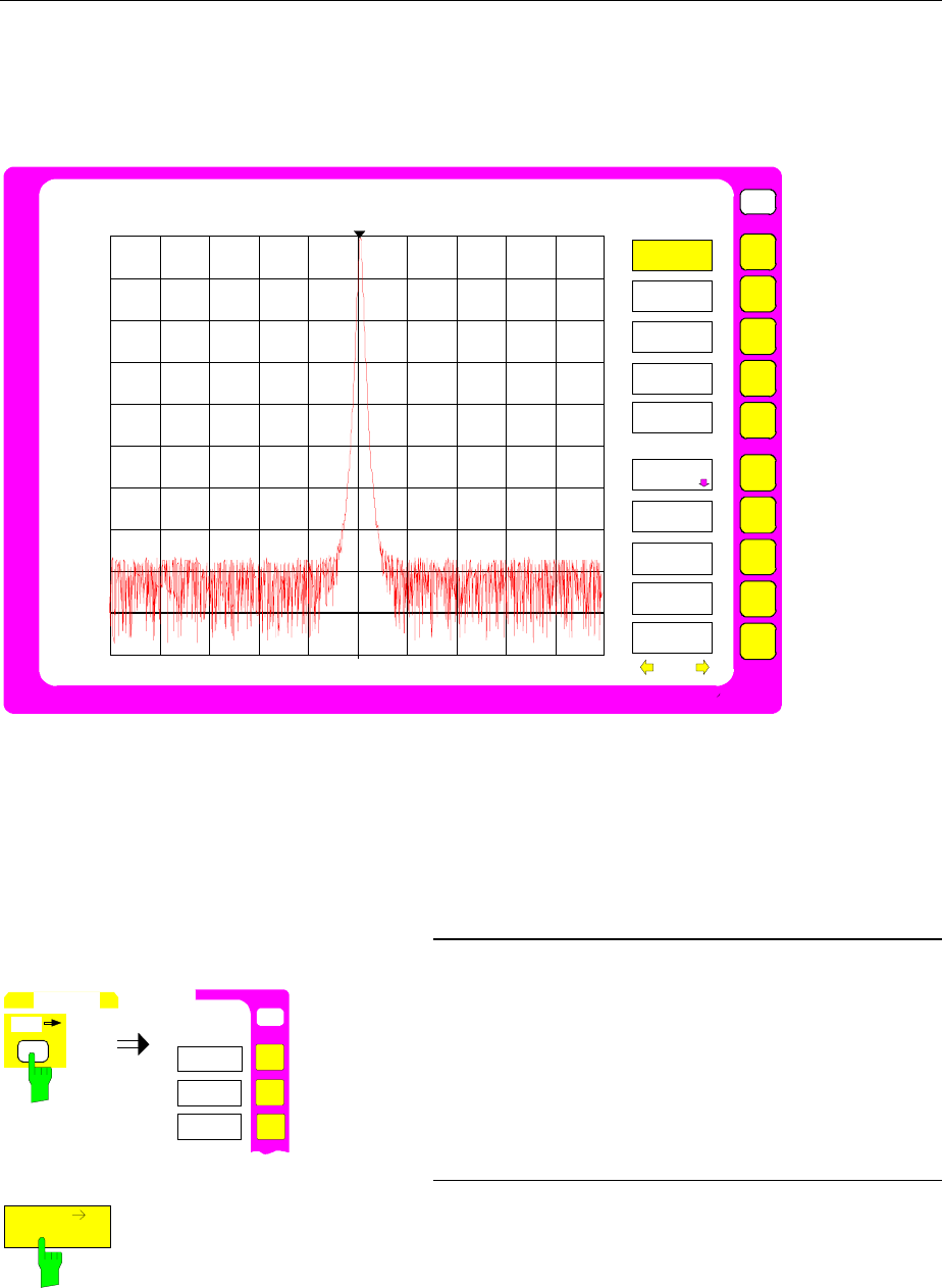
Level and Frequency Measurements FSE
1065.6016.12 2.4 E-10
Fig. 2-1 shows the measured curve on the display screen over a 1 MHz range as well as the marker
level and frequency values.
Markerfield
|
USER
Ref Lvl
-20 dBm
RBW 20 kHz
VBW 20 kHz
SWT 7.5 ms
Marker 1[T1]
-10.8 dBm
200.0052 MHz
Span 1 MHz
100 kHz/
1
Center 200 MHz
RF ATT 10 dB
Unit dBm
MARKER
NORMAL
MARKER 2
MARKER 3
SIGNAL
COUNT
MARKER
DEMOD
MARKER 1
MARKER 4
ALL MARKER
OFF
MARKER
INFO
MARKER
ZOOM
-20
-40
-60
-80
-100
-120
-30
-50
-70
-90
-110
Fig. 2-1 200-MHz signal. The measured values are displayed in the marker field.
At low signal-to-noise ratios, the level measurement accuracy can be improved by an optimum selection
of the FSE parameters. The accuracy of the frequency display can also be enhanced by applying the
internal frequency counter.
MKR
USER
MA
RKER
MKR->
CENTER
MKR->
REF LEVEL
PEAK
MARKER ->
6. Optimize the dynamic range and reduce the
level measurement error.
½Press the MKR→ key in the MARKER key field.
The MARKER-MKR→ menu is opened.
REF LEVEL
MKR
½Press MKR → REF LEVEL softkey.
The reference level (REF LEVEL) is reduced to the
signal level.
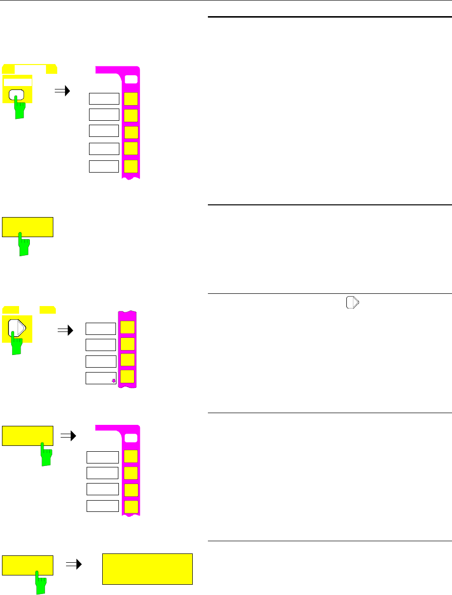
FSE Level and Frequency Measurements
1065.6016.12 2.5 E-10
MARKER
NORMAL
O
N
USER
NORMAL
MARKER1
MARKER2
MARKER3
MARKER
N
SIGNAL
COUNT
MARKER4
7: Determine the exact frequency with the internal
frequency counter.
Note: The frequency counter measures the frequency
of the marked signal with the selected counter
resolution and at the accuracy of the internal
frequency reference. A frequency measurement
made using the marker is, however, limited by
the number of horizontal display points and the
applicable resolution bandwidth.
½Press the NORMAL key in the MARKER key field.
The MARKER NORMAL menu is opened.
COUNT
SIGNAL
½Press the SIGNAL COUNT softkey.
The internal frequency counter is now active and
measures the signal frequency with the PRESET re-
solution. The resolution is to be increased to
10 Hz.
MENU
N
N
COUNTER
RESOL
½Press the menu change key .
The supplementary menu is opened.
COUNTER
RESOL
N
10 kHz
100 Hz
USER
COUNTER
RESOLUTION
1 kHz
10 Hz
½ Press the COUNTER RESOL softkey.
The COUNTER RESOLUTION sub-menu is
opened.
10 Hz
MARKER 1 [T1 CNT]
-10.5 dBm
200.00001 MHz
½Press the 10 Hz softkey.
The desired frequency resolution (10 Hz) is now
selected.
In the marker field, the item [CNT] indicates that the
counter is active (see Fig. 2-2).
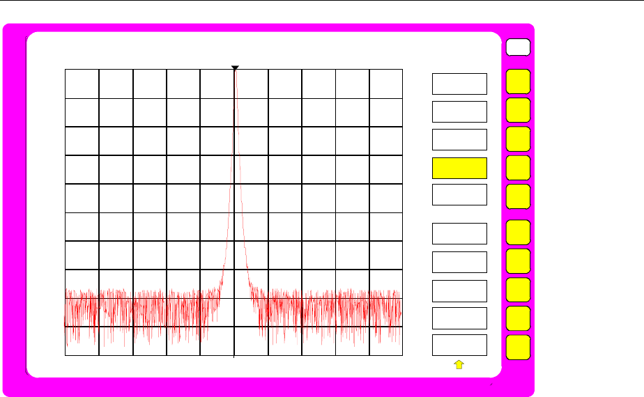
Level and Frequency Measurements FSE
1065.6016.12 2.6 E-10
USER
COUNTER
RESOLUTION
10 kHz
1 kHz
100 Hz
10 Hz
1 Hz
0.1 Hz
Ref Lvl
-20 dBm
RBW 20 kHz
VBW 20 kHz
SWT 7.5 ms
Marker 1[T1 CNT]
-10.8 dBm
200.00513 MHz
Span 1 MHz
100 kHz/
1
Center 200 MHz
RF ATT 10 dB
Unit dBm
-20
-40
-60
-80
-100
-120
-30
-50
-70
-90
-110
Fig. 2-2 Frequency measurement using the internal frequency counter.
Sweep, Level and Frequency Measurements – Example 2
The zoom function (MARKER ZOOM) operates much faster than the manual input of center frequency
and measurement frequency range, and permits the measurement frequency range displayed on the
screen to be as narrow as desired.
As in Example 1, a signal with a frequency of 200 MHz and a level of -10 dBm is applied to the analyzer
RF INPUT.
The following setup steps are performed:
1. Reset the instrument.
2. Apply the signal.
3. Zoom in on the signal.
4. Measure the level and frequency with the marker.
5. Optimize the dynamic range and reduce the level measurement error.
6. Measure the frequency with the internal frequency counter.
Steps 1 to 2 and 4 to 6 correspond to steps 1 to 2 and 5 to 7, respectively, of Example 1. Step 3
replaces the manual input of center frequency and measurement frequency range. (steps 3 and 4).
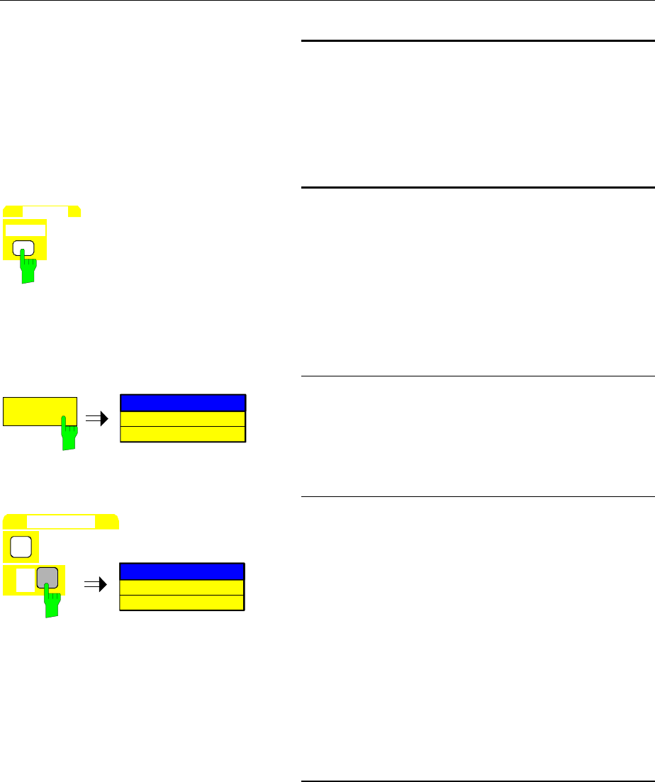
FSE Level and Frequency Measurements
1065.6016.12 2.7 E-10
See steps 1 and 2 of example 1
1. Reset the instrument to standard settings.
2. Connect the test signal to the analyzer RF
INPUT.
MARKER
NORMAL
3. Zoom in on the signal.
½Press the NORMAL key in the MARKER key field .
The marker moves to the largest signal displayed on
the screen. In this example, it is the signal at 200
MHz. (PEAK SEARCH function, see step 5 in
Example 1).
MARKER
ZOOM
MARKER ZOOM
3.5 GHz
½Press the MARKER ZOOM softkey.
The input field for the measurement frequency
range appears on the display screen.
DATA ENTRY
1
dBm
MHz
ms
mV
MARKER ZOOM
1 MHz
½Enter 1 via the numeric keypad and terminate with
the MHz key.
After entry of the measurement frequency range,
the marked signal is counted and then used as the
new center frequency. At the same time, the
entered measurement frequency range is set.
Note: In conjunction with the active measurement
frequency range (SPAN) change, the
resolution bandwidth (RES BW), video
bandwidth (VIDEO BW) and sweep time
(SWEEP TIME) are also set to new values
since they are defined as coupled functions
in the standard PRESET settings.
See steps 5 to 7 of example 1:
4. Read the values for level and frequency as
measured by the marker.
5. Optimize the dynamic range and reduce the
level measurement error.
6. Determine the frequency with the internal
frequency counter.
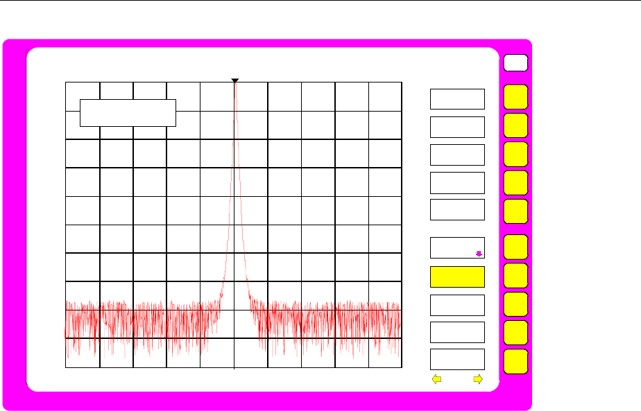
Level and Frequency Measurements FSE
1065.6016.12 2.8 E-10
USER
MARKER
NORMAL
MARKER 2
MARKER 3
SIGNAL
COUNT
MARKER
DEMOD
MARKER 1
MARKER 4
ALL MARKER
OFF
MARKER
INFO
MARKER
ZOOM
Ref Lvl
-20 dBm
RBW 20 kHz
VBW 20 kHz
SWT 7.5 ms
Marker 1[T1]
-10.8 dBm
200.0052 MHz
Span 1 MHz
100 kHz/
1
Center 200 MHz
RF ATT 10 dB
Unit dBm
-20
-40
-60
-80
-100
-120
-30
-50
-70
-90
-110
MARKER ZOOM
1 MHz
Fig. 2-3 The MARKER ZOOM function requires the entry of the measurement frequency range (span)
Level Measurement Accuracy
The level measurement accuracy of an analyzer is influenced by the following parameters:
•RF attenuator (RF-ATT)
•IF amplification
•Resolution bandwidth (RES BW)
•Display range (LEVEL RANGE)
•Display linearity (SCALE FIDELITY)
The error in a level measurement for the FSE is < 1 dB for frequencies up to 1 GHz and < 1.5 dB for
frequencies from 1 GHz to 3.5 GHz. This specification includes all of the above mentioned influential
factors. The frequency characteristics of the pertinent modules (RF divider, front end) are stored
individually in memory on each module. The FSE initializing routines read out the corresponding values
during execution immediately after the analyzer is turned on and corrects the frequency characteristics
during the sweep. Any errors in the attenuation settings, the filter bandwidth or the video rectifier are
corrected after calling the built-in calibration routines. For calibration purposes, the FSE has an internal
120 MHz calibration source which is switched internally to the RF INPUT.
The measurement accuracy is guaranteed only after running the calibration routines. It should be noted,
however, that the individual parameters are so stable that a calibration need only be performed, after
approximately 15 minutes warm-up time, for larger temperature variations. Normally, a weekly
calibration is more than adequate.
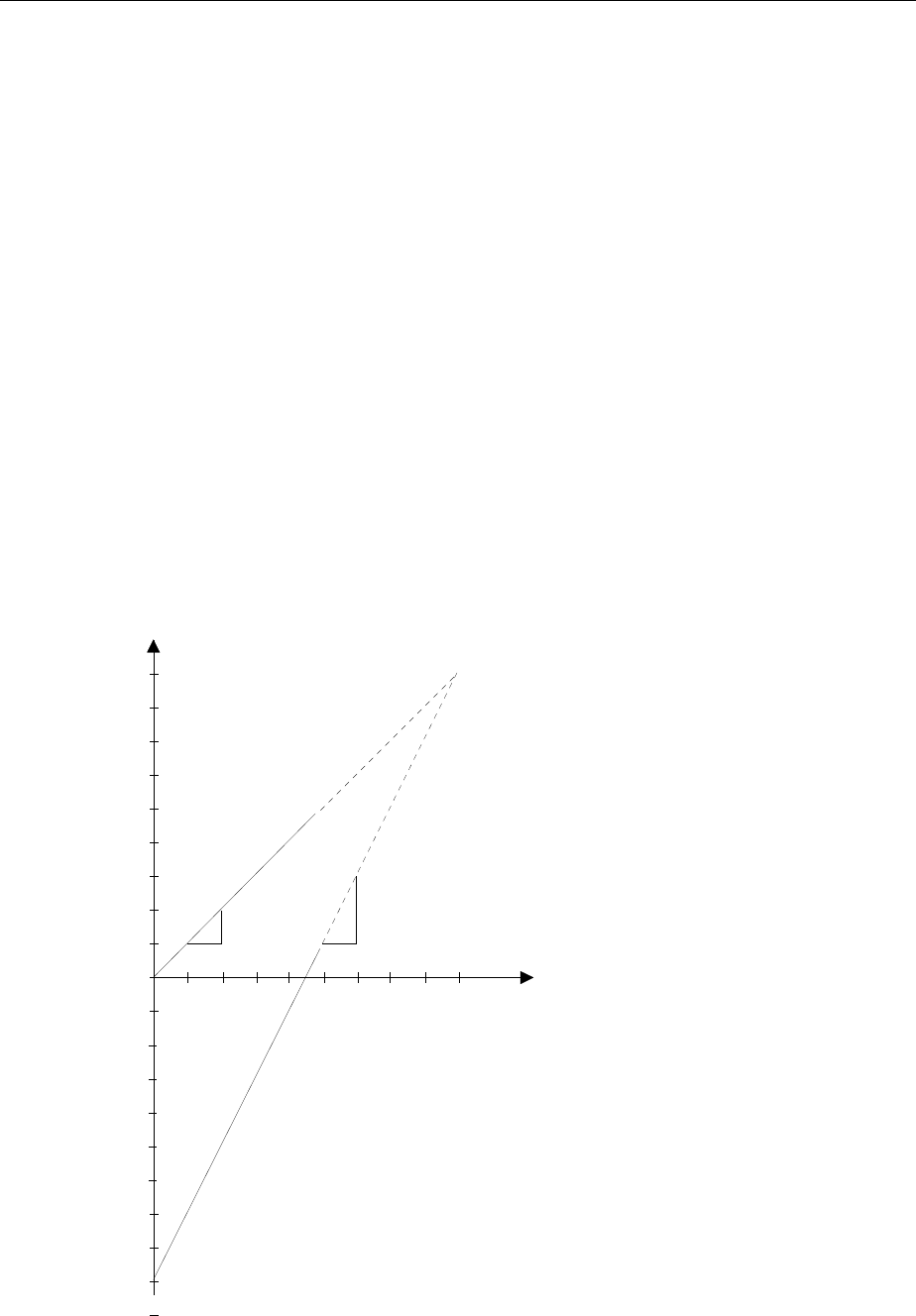
FSE Measurement of Harmonic Separation
1065.6016.12 2.9 E-10
Measurement of Harmonic Separation
Measurement Task
The measurement of signal harmonics is a frequently occurring task which can be optimally performed
by a spectrum analyzer. In general, all signals will contain harmonics to some degree. Harmonics are
especially critical in high-power transmitters, e.g., in radio transmitters, where a significant radiated
harmonic component may interfere with the reception of other radio services. Generally, non-linear
device characteristics create harmonics which are often selectively reduced through the use of low-pass
filters. Since the spectrum analyzer also has non-linear characteristics, e.g., at the first mixer, it is
necessary to exercise caution during a measurement to insure that the spurious harmonics generated
by the analyzer do not influence the measurement results. If necessary, the fundamental frequency
must be selectively attenuated with respect to the harmonics by insertion of an appropriate high-pass
filter.
For harmonic-content measurements, the achievable measurement dynamic range is dependent upon
the k2 intercept of the spectrum analyzer. The k2 intercept point is defined as the fictitious first-mixer
input level where the levels of the first harmonic and of the fundamental frequency are equal. In practice,
this level cannot be applied to the mixer since, to do so, would cause its destruction. However, using the
k2 intercept point concept, the achievable measurement dynamic range for the harmonics of a Unit
Under Test (UUT) can be calculated with relative simplicity.
As can be seen in Fig.2-4, the harmonic level is reduced by 20 dB when the level at the fundamental
frequency is reduced by 10 dB.
Fig.2-4 Theoretical display curve of fundamental and first harmonic with a k2 intercept of 50 dBm.
0
10
20
30
40
50
-10
-20
-30
-40
-50
-60
-70
-80
-90
-100
-30 -20 -10 0 10 20 30 40 50
Display
Level
[dBm]
RF Level
[dBm]
k2 Intercept
[dBm]
Funda-
mental First
Harmonic
-110
-120
-130
1
1
1
2

Measurement of Harmonic Separation FSE
1065.6016.12 2.10 E-10
From the linear equations and the given intercept point, the following formula can be derived for the
achievable harmonic separation ak2 in dB:
aIPP
ke22=−
’(1) ak2 = harmonic separation
Pe= mixer level/dBm
IP2 = k2 intercept point
The formula for the internally produced level P1 at the first harmonic in dBm is:
PPIP
e122=• − (2)
The lower harmonic measurement limit is dictated by the noise figure of the spectrum analyzer. Through
adequate averaging with the video filter, the UUT harmonic level which is to be measured should be at
least 4 dB over the noise figure so that the measurement error caused by the input noise is less than 1
dB.
From the above, the following rules for the measurement of large harmonic separations can be derived:
•Select an IF bandwidth as narrow as possible in order to reduce the noise figure.
•Select the RF attenuation as high as required so that the necessary harmonic separation can still be
measured.
Note: The mixer amplitude is the applied RF level reduced by the selected RF attenuation. The low
distortion (LOW DISTORTION function) mode of the analyzer automatically sets the optimum
RF attenuation for the best harmonic separation.
The maximum harmonic separation is achieved when the harmonics level is equal to the inherent noise
level of the receiver. The corresponding level at the mixer according to (2) is:
[]
PdBm PdBmIP
enoise
=+/2
2
For a 30 Hz resolution bandwidth, (noise level < -140 dB, IP2 = 50 dBm), this level is -45 dBm.
Therefore, according to (1) , the maximum measurable harmonic separation is 95 dB less 4 dB
minimum signal-to-noise ratio.
Important Spectrum Analyzer Functions
In addition to frequency and level settings, the harmonic separation measurement requires, above all,
the delta markers. Also, the MRK→ CF STEP SIZE function (marker frequency = center frequency step-
width) is used in order to quickly measure the individual harmonics with the cursor keys.
There are several methods to measure harmonic content:
éThe measurement of fundamental and harmonic signals in one measurement frequency range.
éThe individual measurement of the harmonic separation in a narrow measurement frequency range.
This method is preferred when high harmonic separation is to be measured (requires large dynamic
range and, thus, narrow resolution bandwidth) or the frequency of the fundamental is very high, i.e., a
very wide measurement frequency range is necessary.
éThe measurement of fundamental and harmonics in two independent windows on the display screen
(SPLIT SCREEN mode).
Example 1 describes the measurement of fundamental and harmonics in one measurement frequency range.
Example 2 describes the measurement of harmonic separation in separate measurement frequency ranges.
Example 3 shows the measurement of fundamental and harmonics in two independent windows on the
display screen.
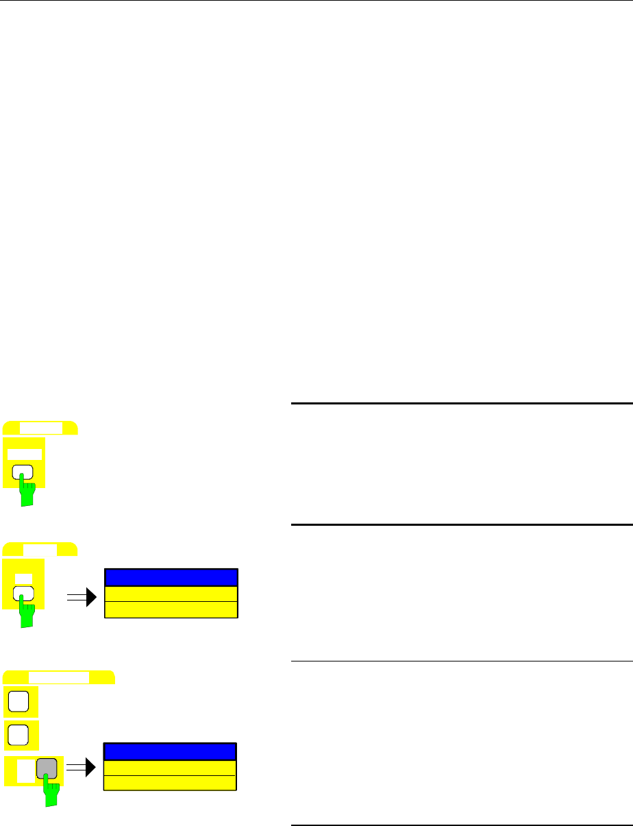
FSE Measurement of Harmonic Separation
1065.6016.12 2.11 E-10
Measurement Procedure - Harmonic Separation – Example 1
The analyzer 10 MHz reference signal is used at the input signal. The connector EXT REF IN/OUT on
the rear panel is connected to the analyzer front-panel RF INPUT. Since the output level is 7 dBm, the
reference level must be set to 10 dBm.
The following setup steps are performed:
1. Reset the instrument.
2. Set the reference level to 10 dBm.
3. Connect the rear-panel 10 MHz reference signal to the analyzer input RF INPUT.
4. Set the start frequency to 5 MHz.
5. Set the stop frequency to 55 MHz.
6. Smooth the displayed noise with the video bandwidth.
7. Measure the fundamental signal with the marker.
8. Measure the harmonic separation with the delta marker.
9. Measure the separation of remaining harmonics.
SYSTEM
PRESET
1. Reset the analyzer.
½Press the PRESET key.
LEVEL
REF
REFERENCE LEVEL
-20 dBm
2. Set the reference level to 10 dBm.
½Press REF key in the LEVEL key field.
The entry field for the reference level appears on the
display screen.
DATA ENTRY
1
0
10 dBm
REFERENCE LEVEL
dBm
MHz
ms
mV
½Enter 10 via the numeric keypad and terminate with
the dBm key.
3. Connect the 10 MHz-reference signal (output
EXT REF IN/OUT) to the analyzer RF INPUT.
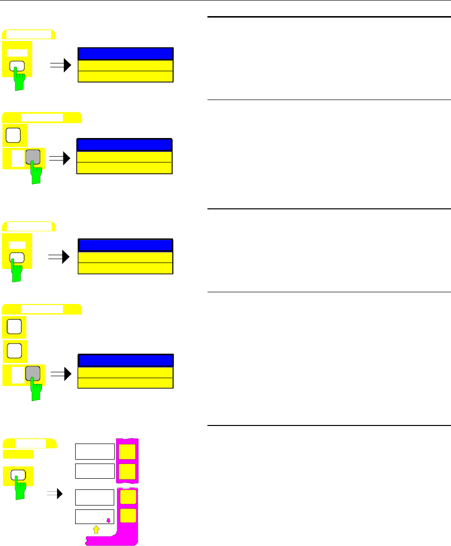
Measurement of Harmonic Separation FSE
1065.6016.12 2.12 E-10
FREQUENCY
START
START FREQUENCY
0 Hz
4. Set the start frequency to 5 MHz
½Press the START key in the FREQUENCY key field.
The entry window for the start frequency appears on
the display screen.
DA
T
A
ENTR
Y
5
5 MHz
START FREQUENCY
dBm
MHz
ms
mV
½Enter 5 via the numeric keypad and terminate with
the MHz key.
FREQUENCY
STOP
STOP FREQUENCY
3.5 GHz
5. Set the stop frequency to 55 MHz
½Press the STOP key in the FREQUENCY key field.
The entry window for the stop frequency appears on
the display screen.
DA
T
A
EN
T
R
Y
5
55 MHz
5
STOP FREQUENCY
dBm
MHz
ms
mV
½Enter 55 via the numeric keypad and terminate with
the MHz key.
SWEEP
COUPLING
VIDEO BW
MANUAL
COUPLING
RATIO
COUPLING
DEFAULT
VIDEO BW
AUTO
6. Smooth the displayed noise with the video
bandwidth
½Press the COUPLING key in the SWEEP key field.
The SWEEP-COUPLING menu is opened.
The video bandwidth can now be either
automatically coupled to the resolution bandwidth or
manually entered.
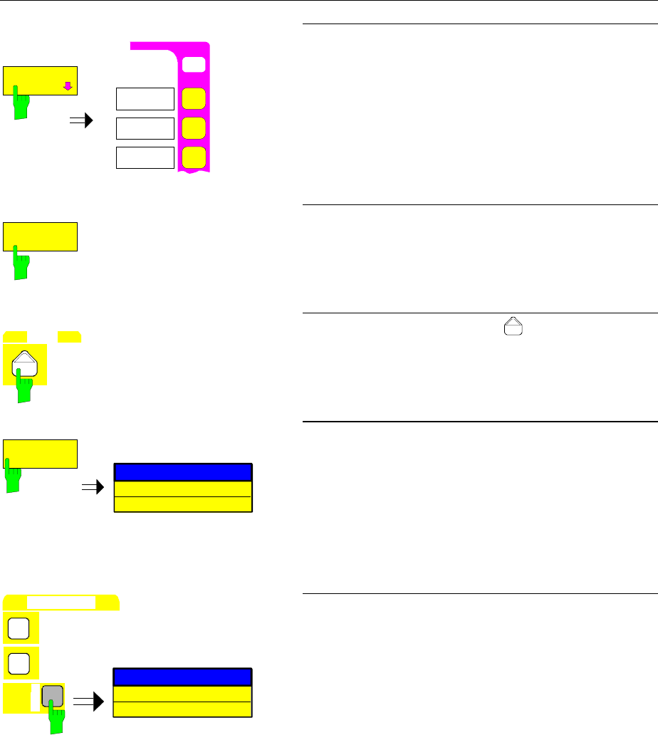
FSE Measurement of Harmonic Separation
1065.6016.12 2.13 E-10
USER
COUPLING
RATIO
RBW / VBW
SINE [1]
COUPLING
RATIO
RBW / VBW
PULSE [.1]
RBW / VBW
NOISE [10]
either:
Automatic coupling of the video bandwidth to the
measurement frequency range
½Press the COUPLING RATIO softkey.
The sub-menu for setting the automatic coupling of
bandwidths to the measurement frequency range is
opened.
RBW / VBW
NOISE[10]
½Press the RBW / VBW NOISE softkey [10].
The video bandwidth is set to a factor of 10 less
than the resolution bandwidth. This smoothes the
displayed noise.
MENU
½Press the menu change key .
The COUPLING RATIO submenu is closed.
VIDEO BW
MANUAL
VIDEO BANDWIDTH
3 MHz
or:
Manual input of the video bandwidth
½Press the VIDEO BW MANUAL softkey.
The entry field for the video bandwidth appears on
the display screen.
VIDEO BANDWIDTH
DATA ENTRY
1
0
10 kHz
µ
s
µ
V
dB
kHz
½Enter 10 via the numeric keypad and terminate with
the kHz key.
The analyzer displays the fundamental as well as
the first to third harmonics (see Fig.2-5).
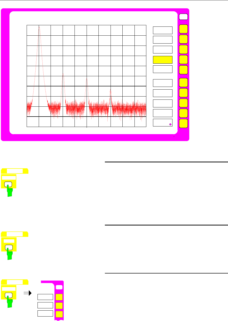
Measurement of Harmonic Separation FSE
1065.6016.12 2.14 E-10
USER
Ref Lvl
10 dBm
RBW 500 kHz
VBW 10 kHz
SWT 100 ms
Stop 55 MHz
0
-20
-40
-60
-80
-100
5 MHz/
-10
-30
-50
-70
-90
Start 5 MHz
RF ATT 40 dB
Mixer -30 dBm
Unit dBm
COUPLED
FUNCTIONS
RES BW
MANUAL
COUPLING
RATIO
RES BW
AUTO
VIDEO BW
MANUAL
VIDEO BW
AUTO
SWEEP TIME
MANUAL
SWEEP TIME
AUTO
COUPLING
DEFAULT
Fig.2-5 The fundamental and harmonics to 55 MHz
MARKER
NORMAL
7. Measure the fundamental with the marker.
½Press the NORMAL key in MARKER key field.
The marker appears at the fundamental peak (see
also level and frequency measurement step 5 of the
PEAK SEARCH function).
The measured values can be read at the upper left
of the display screen.
MARKER
DELTA
8: Activate the delta marker and measure the
harmonic separation
½Press the DELTA key in the MARKER key field
The delta marker is active and appears on the
fundamental.
MARKER
SEARCH
O
N
USER
SEARCH
PEAK
NEXT PEAK
NEXT PEAK
RIGHT
MARKER
½Press the SEARCH key in the MARKER key group .
The SEARCH-MARKER menu is opened.
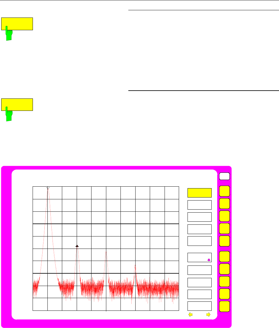
FSE Measurement of Harmonic Separation
1065.6016.12 2.15 E-10
NEXT PEAK
RIGHT
½Press the NEXT PEAK RIGHT softkey.
The delta marker jumps to the first harmonic and
measures the difference between the harmonic and
the fundamental. The measured values can be read
at the upper left of the display screen. In this
example, the harmonic separation is approx. 40 dB
(see Fig.2-6).
NEXT PEAK
RIGHT
9. Measure the separation of additional harmonics
½Press the NEXT PEAK RIGHT softkey.
The delta marker jumps to the next highest
harmonic. The measured value can be read as
before.
USER
Ref Lvl
10 dBm
RBW 500 kHz
VBW 10 kHz
SWT 100 ms
Delta [T1]
-44.8 dB
10.0000 MHz
Stop 55 MHz
0
-20
-40
-60
-80
-100
5 MHz/
-10
-30
-50
-70
-90
1
Start 5 MHz
RF ATT 40 dB
Mixer -30 dBm
Unit dBm
1
MARKER
NORMAL
MARKER 2
MARKER 3
SIGNAL
COUNT
MARKER
DEMOD
MARKER 1
MARKER 4
ALL MARKER
OFF
MARKER
INFO
MARKER
ZOOM
Fig.2-6 First harmonic separation: approx. 40 dB referred to the fundamental
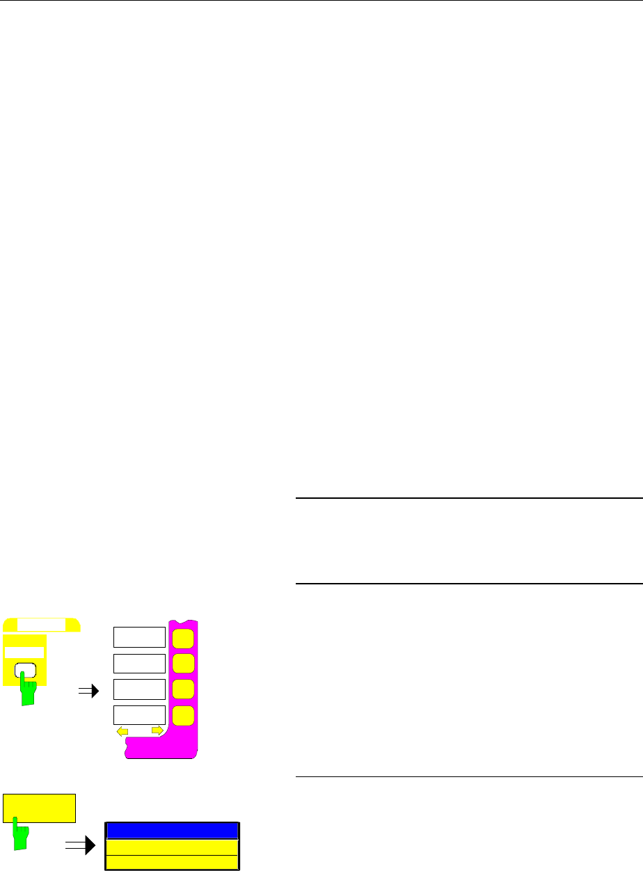
Measurement of Harmonic Separation FSE
1065.6016.12 2.16 E-10
Measurement Procedure - Harmonic Separation – Example 2
In example 2, the fundamental frequency of the test signal and the separation of the individual
harmonics are measured. The reference to the fundamental is established with the REFERENCE
FIXED marker, and the movement from harmonic to harmonic is performed with the MKR→ CF STEP
SIZE and step keys. This method is recommended when the highest dynamic range is to be achieved.
The following measurement steps are carried out:
1. Reset the instrument.
2. Set the reference level to 10 dBm.
3. Connect the rear-panel 10 MHz reference signal (connector EXT REF IN/OUT) to the analyzer
input RF INPUT.
4. Set the start frequency to 5 MHz.
5. Set the stop frequency to 55 MHz.
6. Smooth the displayed noise with the video bandwidth.
7. Measure the fundamental signal with the marker.
8. Reduce the measurement frequency range (ZOOM function):
9. Set the frequency step size to the fundamental frequency.
10. Save the reference value (REFERENCE FIXED)
11. Measure the separation to the first harmonic.
12. Measure the separations to the remaining harmonics.
Set the analyzer according to Example 1 up to and
including "Measure the fundamental with the
marker" (steps 1 to 7).
MARKER
NORMAL
ALL MARKERS
OFF
MARKER
INFO
MARKER
ZOOM
8. Reduce the measurement frequency range.
½Press the NORMAL key in the MARKER key field .
The MARKER-NORMAL menu is opened.
MARKER
ZOOM
SPAN
MARKER ZOOM
3.5 GHz
½Press the MARKER ZOOM softkey.
The entry field for the measurement frequency
range appears on the display screen.
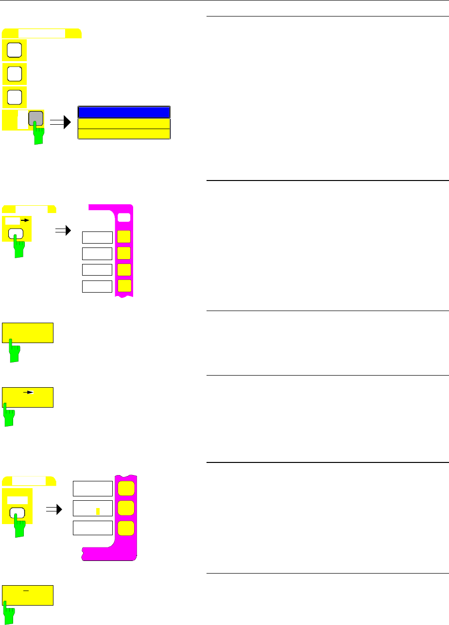
FSE Measurement of Harmonic Separation
1065.6016.12 2.17 E-10
DATA ENTRY
µ
s
µ
V
dBm
1
0
0
SPA
N
MARKER ZOOM
100 kHz
kHz
½Enter 100 via the numeric keypad and terminate with
the kHz key.
MKR
USER
MA
RK
E
R
PEAK
MKR->
CENTER
MKR->
REF LEVEL
MARKER->
9. Set the frequency step size to the fundamental
frequency
½Press the MKR → key in the MARKER key field
The MARKER-MKR → menu is opened.
PEAK
½Press the PEAK softkey.
The marker appears at peak of the fundamental
signal.
MKR CF
STEPSIZE
.
½Press the MKR
→
CF STEP SIZE softkey.
The step size used when setting the center
frequency with the cursor keys is set equal to the
marker frequency.
MARKER
DELTA
ALL DELTA
OFF
DELTA MRK
ABS REL
REFERENCE
FIXED
10. Fix reference value
½Press the DELTA key in the MARKER key field.
The DELTA-MARKER menu is opened.
REFERENCE
FIXED
½ Press the REFERENCE FIXED softkey.
The position of the marker is now a curve-
independent reference for the delta measurement,
even when the actual reference point is not visible
on the display screen.
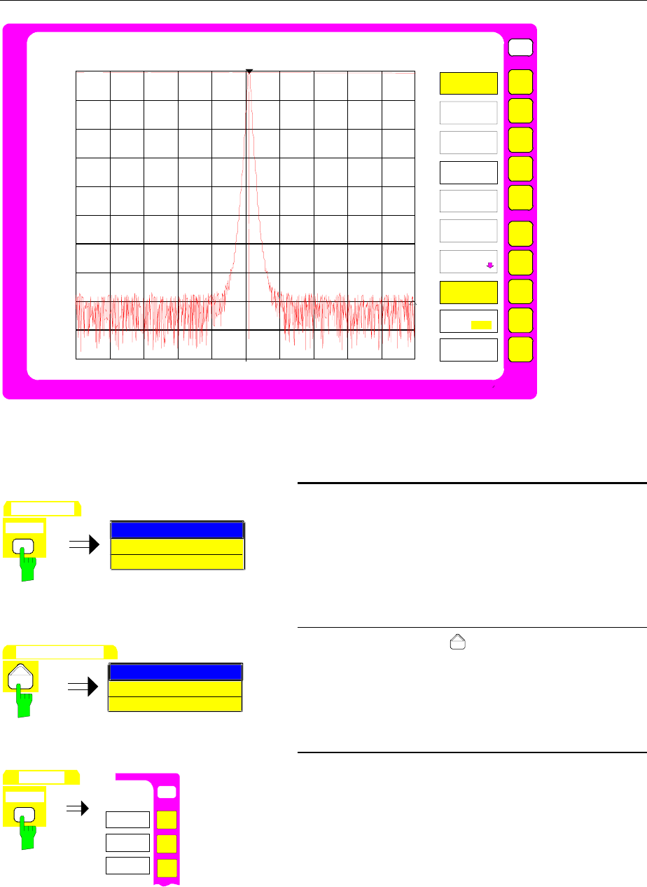
Measurement of Harmonic Separation FSE
1065.6016.12 2.18 E-10
USER
Ref Lvl
10 dBm
RBW 2 kHz
VBW 2 kHz
SWT 100 ms
DELTA1 [T1 FXD]
-80.8 dB
48.0 kHz
Span 100 kHz
10.0
-10
-30
-50
-70
-90
10 kHz/
0
-20
-40
-60
-80
1
Center 10.000002 MHz
RF ATT 40 dB
Mixer -30 dBm
Unit dBm
FXD
FXD
DELTA
MARKER
DELTA 2
DELTA 3
PHASE
NOISE
DELTA 1
REFERENCE
FIXED
DELTA 4
ALL DELTA
OFF
REFERENCE
POINT
DELTA MKR
ABS REL
Fig. 2-7 Fundamental with REFERENCE FIXED marker
FREQUENCY
CENTER
SPAN
CENTER FREQUENCY
10 MHz
11. Measure the harmonic
½Press the CENTER key in the FREQUENCY key
field.
The entry field for the center frequency appears on
the display screen.
DATA VARIATION
SPAN
CENTER FREQUENCY
20 MHz
½Press the cursor key in the DATA VARIATION
key field.
The center frequency is increased by one step
(= fundamental frequency).
MARKER
SEARCH
O
N
USER
SEARCH
PEAK
NEXT PEAK
NEXT PEAK
RIGHT
MARKER
½Press the SEARCH key in the MARKER key field.
The SEARCH-MARKER menu is opened.
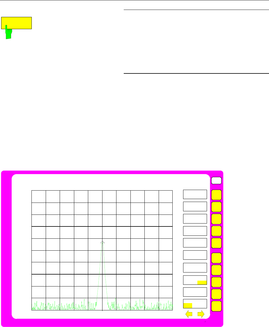
FSE Measurement of Harmonic Separation
1065.6016.12 2.19 E-10
PEAK
½Press the PEAK softkey.
The delta marker appears at the first harmonic and
measures the separation from harmonic to
fundamental. The measured value is displayed in
the marker field at the upper left of the display
screen (see Fig. 2-8).
12. Measure the separation of additional
harmonics
½Repeat all of step 11.
The center frequency is once again increased by the
frequency of the fundamental. The delta marker
thus appears at the next harmonic.
Fig. 2-8 Measurement of the first harmonic
Note: The spurious harmonics generated internal to the analyzer can be easily recognised by switching
in additional RF attenuation. When an additional 10 dB attenuation is inserted, the displayed level
of harmonics generated by the analyzer will be reduced by 10 dB, however, harmonics from the
UUT will remain unchanged. This assumes that the receiver noise is substantially below the
displayed level.
USER
Ref Lvl
10 dBm
RBW 2 kHz
VBW 2 kHz
SWT 100 ms
DELTA1 [T1 FXD]
-42.3 dB
10.001 MHz
Span 100 kHz
10.0
-10
-30
-50
-70
-90
10 kHz/
0
-20
-40
-60
-80
1
Center 20.002118 MHz
RF ATT 40 dB
Mixer -30 dBm
Unit dBm
MARKER
SEARCH
NEXT PEAK
NEXT PEAK
RIGHT
NEXT PEAK
LEFT
SEARCH LIM
ON OFF
SELECT
MARKER
PEAK
ACTIVE
MKR DELTA
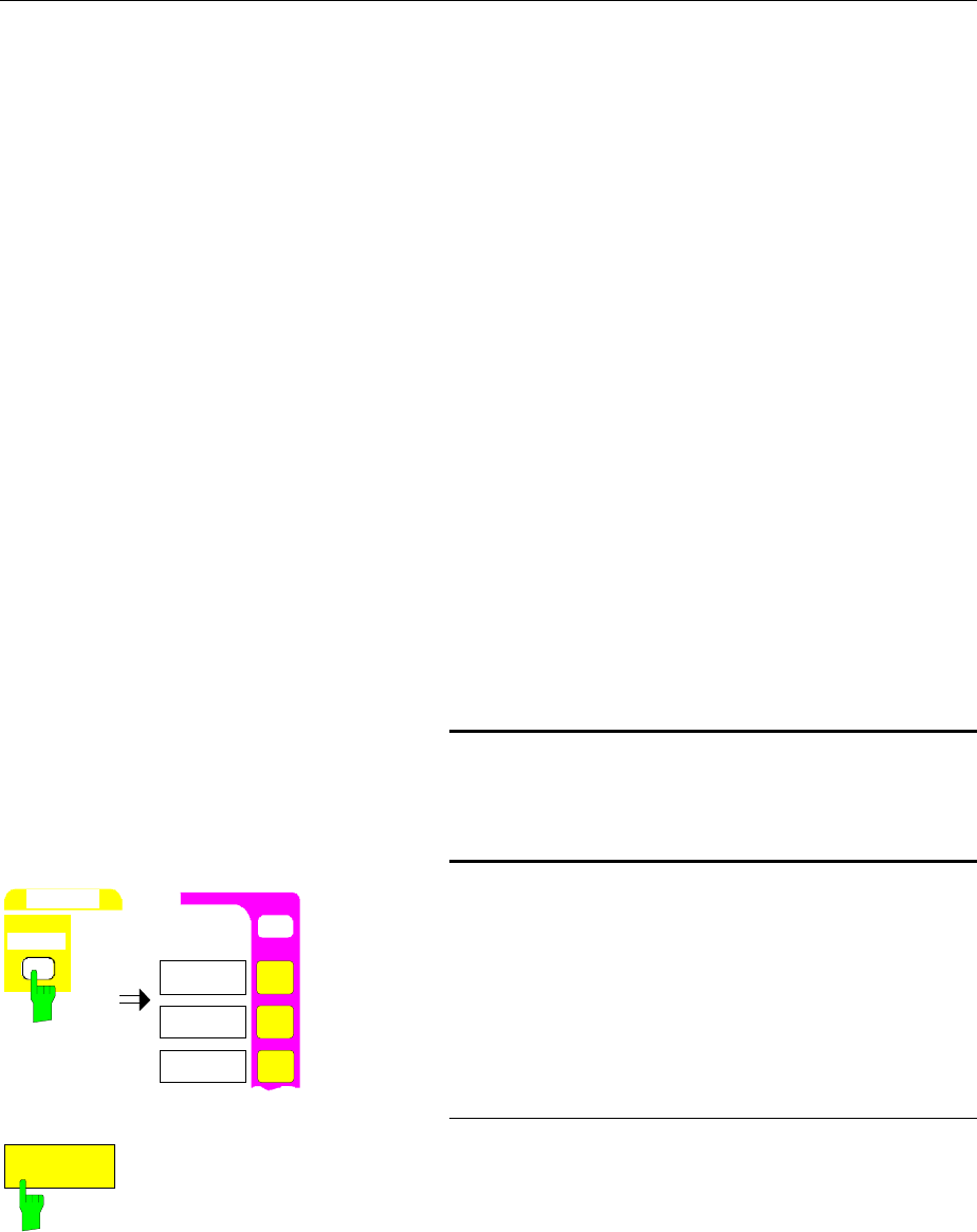
Measurement of Harmonic Separation FSE
1065.6016.12 2.20 E-10
Measurement Procedure - Harmonic Separation – Example 3
The measurement of fundamental and harmonics can also be performed in two independent windows
on the display screen (SPLIT-SCREEN mode). This mode permits the simultaneous presentation of the
fundamental and harmonics with higher resolution and dynamic range.
The following measurement steps are carried out:
1. Reset the instrument.
2. Set the reference level to 10 dBm.
3. Connect the rear-panel 10 MHz reference signal (connector EXT REF IN/OUT) to the analyzer
input RF INPUT.
4. Set the start frequency to 5 MHz.
5. Set the stop frequency to 55 MHz.
6. Smooth the displayed noise with the video bandwidth.
7. Measure the fundamental signal with the marker.
8. Reduce the measurement frequency range (ZOOM function):
9. Set the frequency step size to the fundamental frequency.
10. Set the display to two measurement windows.
11. Uncouple the window settings.
12. Measure the harmonic separation.
Set the analyzer according to Example 2 up to and
including " Set the frequency step size to the
fundamental frequency" (steps 1 to 9).
DISPLAY
SYSTEM
USER
DISPLAY
FULL
SCREEN
SPLIT
SCREEN
10. Set the display to two uncoupled
measurement windows.
½Press the DISPLAY key in the SYSTEM key field.
The SYSTEM DISPLAY menu is opened.
SPLIT
SCREEN
½Press the SPLIT SCREEN softkey.
Two windows are displayed simultaneously on the
display screen (see Fig.2-9). The upper measure-
ment window is called Screen A and the lower is
called Screen B. At the initial turn-on, both
measurement windows are coupled, i.e., changes in
settings such as frequency or levels take place in
both windows.
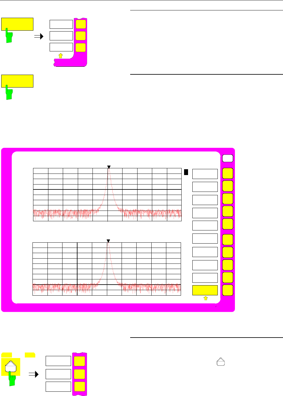
FSE Measurement of Harmonic Separation
1065.6016.12 2.21 E-10
SCREEN
COUPLING
SCREEN
UNCOUPLED
11. Uncouple the window settings
½Press the SCREEN COUPLING softkey.
The SCREEN COUPLING sub-menu is opened.
SCREEN
UNCOUPLED
½Press the SCREEN UNCOUPLED softkey .
The settings for each measurement window can
now be selected independently. The entry is
assigned to either ACTIVE SCREEN A or ACTIVE
SCREEN B as selected by the softkey in the main
menu window.
USER
Ref Lvl
10 dBm
RBW 1 kHz
VBW 1 kHz
SWT 100 ms
MKR1 [T1]
+9.8 dBm
10.010000 MHz
Span 100 kHz
10.0
-10
-30
-50
-70
-90
10 kHz/
-0
-20
-40
-60
-80
Center 10.000002 MHz
RF ATT 40 dB
Mixer -30 dBm
Unit dBm
SCREEN
COUPLING
MODE
COUPLED
SCREENS
UNCOUPLED
Ref Lvl
10 dBm
RBW 1 kHz
VBW 1 kHz
SWT 100 ms
RF ATT 40 dB
Mixer -30 dBm
Unit dBm
Span 100 kHz
10 kHz/
Center 10.000002 MHz
10.0
-10
-30
-50
-70
-90
-0
-20
-40
-60
-80
1
MKR1 [T2]
+9.8 dBm
10.010000 MHz
B
A
HORIZONTAL
SCALING
VERTICAL
SCALING
1
COUPLING
CONTROL
Fig.2-9 SPLIT-SCREEN Mode
MENU
ACTIVE
SCREEN A
ACTIVE
SCREEN B
12. Measure the harmonic in the lower
measurement window SCREEN B.
½Press the menu change key .
The main menu is opened.
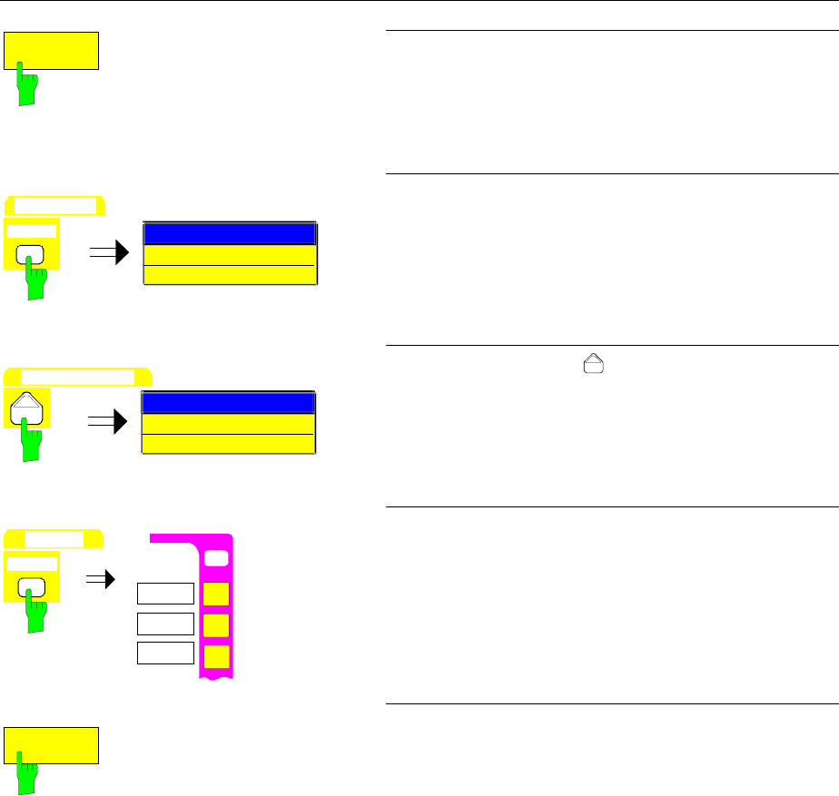
Measurement of Harmonic Separation FSE
1065.6016.12 2.22 E-10
ACTIVE
SCREEN B
½Press the ACTIVE SCREEN B softkey.
The following entries are now valid for the lower
window which is used to measure the harmonic
separation.
FREQUENCY
CENTER
SPAN
CENTER FREQUENCY
10 MHz
½Press the CENTER key in the FREQUENCY key
field.
The entry field for the center frequency appears on
the display screen.
DATA VARIATION
SPAN
CENTER FREQUENCY
20 MHz
½Press the cursor key in the DATA VARIATION
key field.
The center frequency is increased by one step.
(= fundamental frequency).
MARKER
SEARCH
O
N
USER
SEARCH
PEAK
NEXT PEAK
NEXT PEAK
RIGHT
MARKER
½Press the SEARCH key in the MARKER key field.
The SEARCH-MARKER menu is opened.
PEAK
½Press the PEAK softkey.
A marker appears at the first harmonic and meas-
ures the level of the harmonic. The measured value
is displayed in the marker field at the upper left of
the second measurement window (see Fig.2-10).
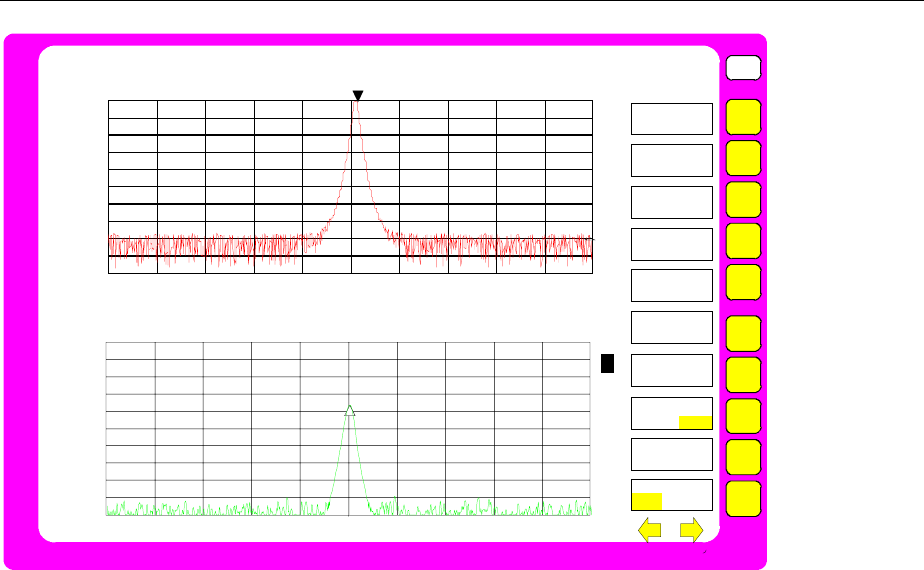
FSE Measurement of Harmonic Separation
1065.6016.12 2.23 E-10
USER
Ref Lvl
10 dBm
RBW 1 kHz
VBW 1 kHz
SWT 100 ms
MKR1 [T1]
+9.8 dBm
10.010000 MHz
Span 100 kHz
10.0
-10
-30
-50
-70
-90
10 kHz/
-0
-20
-40
-60
-80
Center 20.000004 MHz
RF ATT 40 dB
Mixer -30 dBm
Unit dBm
Ref Lvl
10 dBm
RBW 1 kHz
VBW 1 kHz
SWT 100 ms
RF ATT 40 dB
Mixer -30 dBm
Unit dBm
Span 100 kHz
10 kHz/
Center 10.000002 MHz
10.0
-10
-30
-50
-70
-90
-0
-20
-40
-60
-80
1
DELTA [T2]
-36.8 dBm
10.000010 MHz
A
B
1
MARKER
SEARCH
NEXT PEAK
NEXT PEAK
RIGHT
NEXT PEAK
LEFT
SEARCH LIM
ON OFF
SELECT
MARKER
PEAK
ACTIVE
MKR DELTA
Fig.2-10 Alternate representation of fundamental and first harmonic
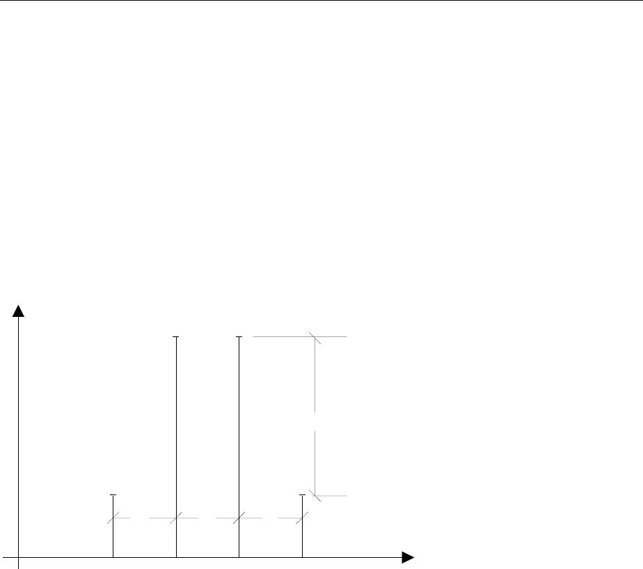
Intermodulation Distortions FSE
1065.6016.12 2.24 E-10
Measurement of Intermodulation Distortions
Measuring Task
If several signals are applied to a transmission quadripole with a non-linear characteristic,
intermodulation products occur at its output due to addition and subtraction of the signals. The non-
linear characteristic causes harmonics of the information signals to occur, which are mixed up at the
characteristic. The low-order mixture products are particularly significant since they have the highest
levels and are close to the information signals. The third-order intermodulation product causes the most
significant distortions. In case of two-tone modulation it is the mixture product of the first information
signal and the first harmonic of the second information signal.
The frequencies of the spurious signals occur with an offset of the information signals above and below
the information signals. Fig. 2-11 shows the intermodulation products PS1 and PS2, which are obtained
from the two information signals PN1 and PN2.
f
N1
f
N2
f
S2
f
S1
f
∆
f
∆
f
∆
ad3
P
N1
P
N2
P
S1 P
S2
Frequency
Level
Fig. 2-11 Intermodulation products PS1 and PS2
The intermodulation product at fS2 is obtained by mixture of the first harmonic of the information signal
PN2 with the signal PN1, the intermodulation product at fS1 by mixture of the first harmonic of the
information signal PN1 with the signal PN2 .
fs1 = 2 x fn1 - fn2 (1)
fs2 = 2 x fn2 - fn1 (2)
The level of the spurious products depends on the level of the information signals. If both information
signals are increased by 1 dB, the level of the spurious responses increases by 3 dB. I.e., the offset ad3
of the spurious responses decreases by 2 dB. This is illustrated by Fig.2-12.
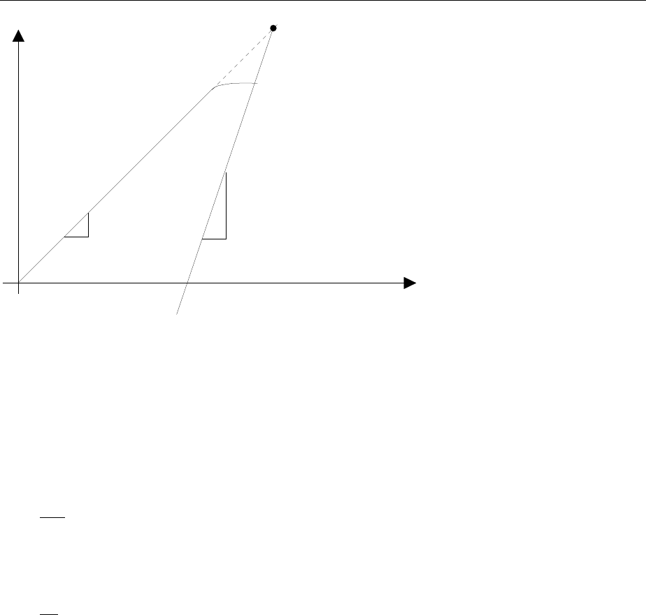
FSE Intermodulation Distortions
1065.6016.12 2.25 E-10
Output
level
Intercept point
Intermodulation
product
Information
signal
Input level
Compression
1
11
3
Fig.2-12 Dependance of the spurious product level from the level of the information signals
The information signals at the output of a four-terminal network increase as the input level increases as
long as the input level is in the linear range. If the level changes by 1 dB at the input, it also changes by
1 dB at the output. At a specified input level the quadripole compresses and the output level does not
increase any more. The third-order intermodulation products increase three times as fast as the
information signals. The intercept point is the fictitious level where both lines intersect. It cannot be
measured directly since the wanted level is limited by the maximum output power of the quadripole.
It can however be calculated from the known gradients of the lines and the measured intermodulation
offset aD3 with a given level using the following formula:
IP aP
DN
32
3
=+ (3)
If, e.g., the intermodulation offset is 60 dB and the input level PN is -20 dBm, the third-order intercept IP3
is calculated as follows:
IP dBm dBm360
220 10=+− =() .(4)
Important Spectrum-Analyzer Functions
Correct setting of the RF attenuation is particularly important for intermodulation measurements. In the
FSE, the attenuation can be set automatically according to the reference level. There are three coupling
methods:
– RF ATTEN AUTO
– ATTEN AUTO LOW DIST
– ATTEN AUTO LOW NOISE
The coupling mode ATTEN AUTO LOW DIST is recommended to be used for measurement of
intermodulation distortions since the intrinsic spurious products are minimized.
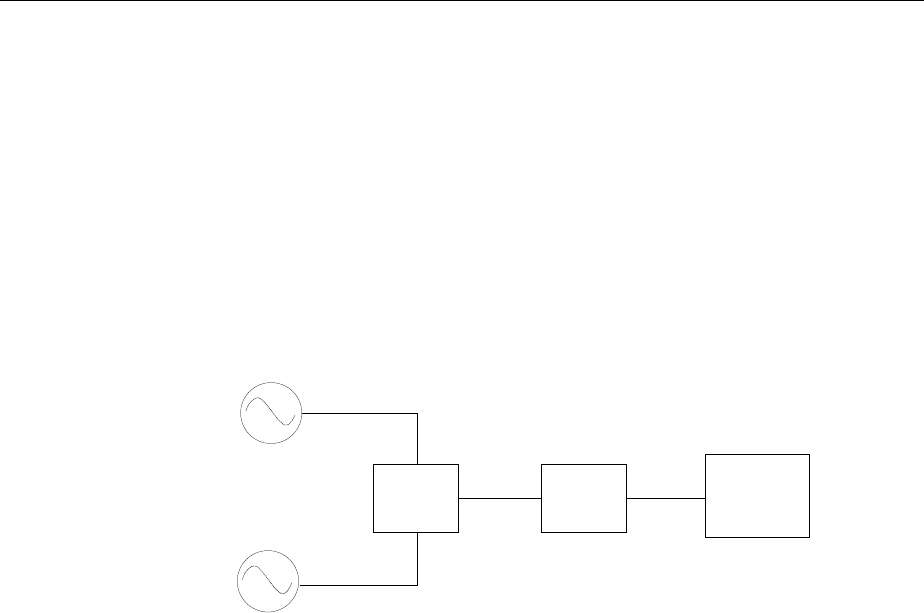
Intermodulation Distortions FSE
1065.6016.12 2.26 E-10
Measurement
In the following, measurement of the third-order intercept of an amplifier is described, by way of
example.
Two signal generators with the frequencies f1 and f2 supply signals to the amplifier via a power divider.
The output of the device under test is connected to the RF input of the FSE. The level of the two signal
generators is the same and is selected such that the DUT is not overloaded.
f1 = 99.5 MHz
f2 = 100.5 MHz
Level at amplifier input = -20 dBm with f1 and f21
Test setup:
Analyzer
Power-
splitter DUT
f1
f2 10-dB
amplifier
The following measurement steps are carried out:
1. Reset the FSE.
2. Set the center frequency to 100 MHz.
3. Set the frequency-display range to 5 MHz (SPAN function).
4. Set the reference level to -10 dBm.
5. Set the resolution bandwidth to 10 kHz.
6. Set the RF attenuation for low-distortion mode.
7. Measure the intercept point using the markers.
8. Calculate IP3 from the measured offset and the signal level according to (4)
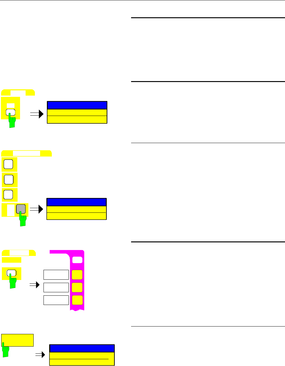
FSE Intermodulation Distortions
1065.6016.12 2.27 E-10
Cf. measurement example Level and Frequency
Measurements (steps 1 to 3)
1. Reset the instrument.
2. Set the center frequency to 100 MHz.
3. Set the frequency-display range to 5 MHz.
LEVEL
REF
REFERENCE LEVEL
-20 dBm
4. Set the reference level to -10 dBm
½Press the REF key in the LEVEL key field.
The entry window for the reference level is
displayed.
DATA ENTRY
1
0
dBm
mV
ms
-10 dBm
REFERENCE LEVEL
-
MHz
½Enter -10 via the numeric keypad in the entry field
and terminate the entry by pressing the dBm key.
SWEEP
COUPLING
USER
COUPLED
FUNCTIONS
RES BW
MANUAL
RES BW
AUTO
5. Set the resolution bandwidth to 10 kHz
½Press the COUPLING key in the SWEEP key field.
The SWEEP-COUPLING menu is opened.
RES BW
MANUAL
RESOLUTION BANDWIDTH
3 MHz
½Press the RES BW MANUAL softkey.
The entry field for the resolution bandwidth is
displayed.
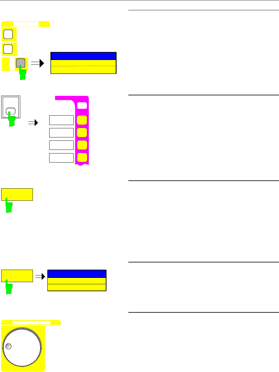
Intermodulation Distortions FSE
1065.6016.12 2.28 E-10
D
A
T
A
E
N
T
R
Y
1
0
RESOLUTION BANDWIDTH
dB
µ
V
µ
s
10 kHz
kHz
½Enter 10 in the entry field via the numeric keypad
and terminate the entry by pressing the kHz key.
USER
INPUT
RF ATTEN
MANUAL
ATTEN AUTO
NORMAL
ATTEN AUTO
LOW NOISE
INPUT
ATTEN AUTO
LOW DIST
6. Set low-distortion mode
½Press the INPUT key
The INPUT menu is opened.
ATTEN AUTO
LOW DIST
either
½Press the ATTEN AUTO LOW DIST softkey.
The low-distortion mode is selected. Thus, the
combination of input attenuation and IF gain is
selected such that the internal intermodulation
products are the smallest possible and the
intermodulation-free range is as large as possible.
The FSE shows the measuring diagram in Fig.2-13
RF ATTEN
MANUAL
10 dB
INPUT ATTENUATION
or
½Press the RF ATTEN MANUAL softkey.
The entry window for the RF attenuation is
displayed.
DATA VARIATION
½Vary the RF attenuation using the roll-key.
If the amplitude of the IM products doesn’t change,
the existing setting is sufficient
(see Fig.2-13)
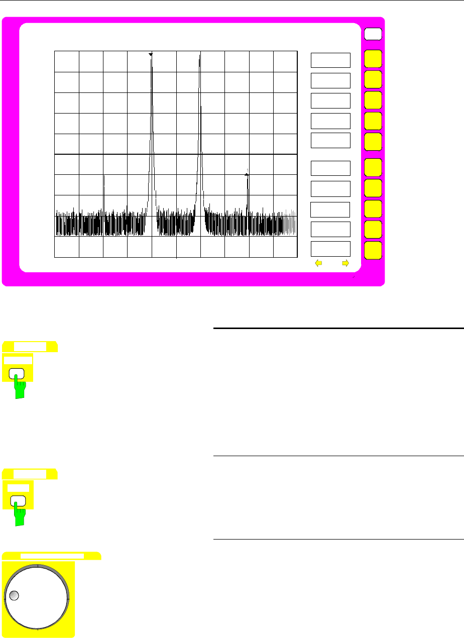
FSE Intermodulation Distortions
1065.6016.12 2.29 E-10
USER
-10
-40
-60
-80
-100
-20
-30
-50
-70
-90
CENTER 100 MHz 500 kHz/ Span 5MHz
MARKER
SEARCH
PEAK
NEXT PEAK
NEXT PEAK
RIGHT
NEXT PEAK
LEFT
SELECT
ACTIVE
MKR DELTA
Ref Lvl
-10 dBm
Delta 1 [T1] RWB 10 kHz RF Att 20 dB
-59.78 dB VBW 10 kHz
2.00000000 MHz SWT 150 ms Unit dBm
-110
1
1
SEARCH LIMIT
ON OFF
Fig.2-13 Measuring diagram in low distortion mode
MARKER
NORMAL
7. Measure the intercept point using the markers
½Press the NORMAL key in the MARKER key field.
The marker appears on the fundamental (see also
level and frequency measurement step 5, PEAK
SEARCH function).
The measured values can be read off at the upper
left of screen.
MARKER
DELTA
½Press the DELTA key in the MARKER key field.
The delta marker is active. It appears on the
fundamental.
DATA VARIATION
either
½Move the marker to an intermodulation product
using the roll-key (see Fig.2-13).
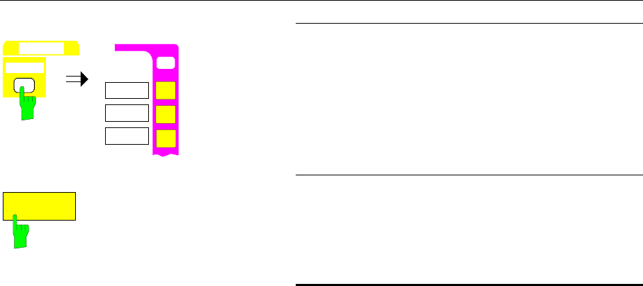
Intermodulation Distortions FSE
1065.6016.12 2.30 E-10
MARKER
SEARCH
O
N
USER
SEARCH
PEAK
NEXT PEAK
NEXT PEAK
RIGHT
MARKER
or
½Press the SEARCH key of the MARKER keys.
The SEARCH-MARKER menu is opened.
NEXT PEAK
½Press the NEXT PEAK RIGHT softkey until the delta
marker appears on one of the IM products (see
Fig.2-13).
8. Calculate IP3 from the measured offset and the
signal level according to (4)
In the example, an intermodulation ratio of approx.
60 dB at a level of -10 dBm was measured. IP3 is
thus:
IP3 = 60 dB/2 + (-10dBm) = 20 dBm
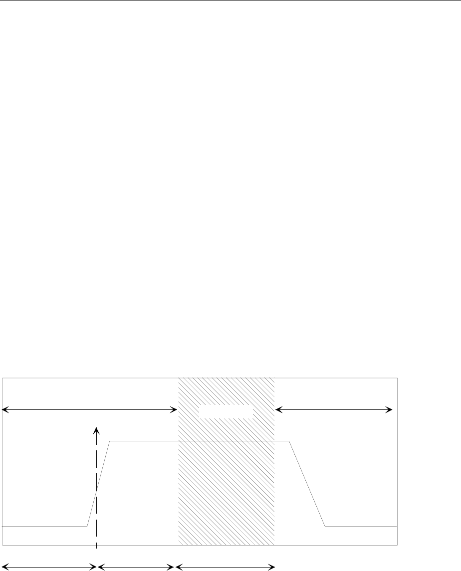
FSE Time-domain Measurements with Pulsed Signals
1065.6016.12 2.31 E-10
Time-domain Measurements with Pulsed Signals
Measuring Task
A lot of systems which handle pulsed signals do not only require measurement of the pulse width and
the pulse repetition rate which can be derived from the spectrum but also assess the rise and fall time
as well as the power ramping during the pulse. In particular, modern digital mobile radio systems which,
like GSM e.g., employ the TDMA method, require the power to be measured versus time over a wide
dynamic range.
Time-domain measurements are performed using the spectrum analyzer with ZERO SPAN selected.
The analyzer operates as fix-tuned receiver on the set center frequency such that the signal power
versus time is displayed.
Important Spectrum Analyzer Functions
Trigger functions such as video trigger and sweep settings such as blanking of the measured value
(GAP SWEEP) are of particular importance for time-domain measurements. The pretrigger function of
the GAP SWEEP just enables measurement of rise times since it allows for representation of
measurements prior to the trigger point. The GAP function, which enables cutout of a part of the pulse
allows for simultanous representation of both edges of a pulse signal on the screen at high time
resolution. During the GAP time, the sweep and thus data acquisition at the time marked by the "GAP"
line is interrupted and thus the pulse is not completely displayed (the part which is not important for this
measurement is blanked) (see Fig. 2-14).
trigger
time
time gap
time
(not displayed)
displayed displayed
pre-trigger trigger to gap
time
Fig. 2-14 Parameters of Gap Sweep
Note: If the pretrigger time and the trg-to-gap time is 0 s, the gap time function has the same effect as
a delayed trigger.

Timedomain Measurements with Pulsed Signals FSE
1065.6016.12 2.32 E-10
Measurement
This example shows the measurement of the rise and fall times as well as the power ramping during the
pulse.
The signal generator SME with built-in pulse modulation source SME-B4 is used as signal source. A
signal generator providing for pulse modulation in conjunction with an external pulse generator may be
used, instead.
Settings on the signal generator:
Frequency 900 MHz
Level –5 dBm
Modulation Pulse
Pulse width ca. 600 µs
Pulse frequency ca. 500 Hz
The following measuring steps are made:
1. Reset the instrument.
The video bandwidth is thus set to 3 MHz.
2. Set the center frequency to 900 MHz.
3. Set the frequency display range to zero span.
4. Set the reference level to 0 dBm.
5. Set the resolution bandwidth to 2 MHz.
6. Set the sweep time to 1 ms.
7. Connect the RF output of the SME to the RF input of the FSE.
8. Set the video trigger.
9. Set the sweep time to 100 µs.
10. Set the trigger points.
11. Activate the gap sweep.
comp. measuring example - level and frequency
measurement (steps 1 to 3)
1. Set the instrument to the default state. I.e., the
video bandwidth is set to 3 MHz.
2. Set the center frequency to 900 MHz.
3. Set the frequency-display range to zero span.
Note: With first calling of the zero span following
preset, a resolution bandwidth of 1 MHz is
automatically set. Apart from that, switching on
the zero span always causes that resolution
bandwidth to be set that was last set in zero
span.
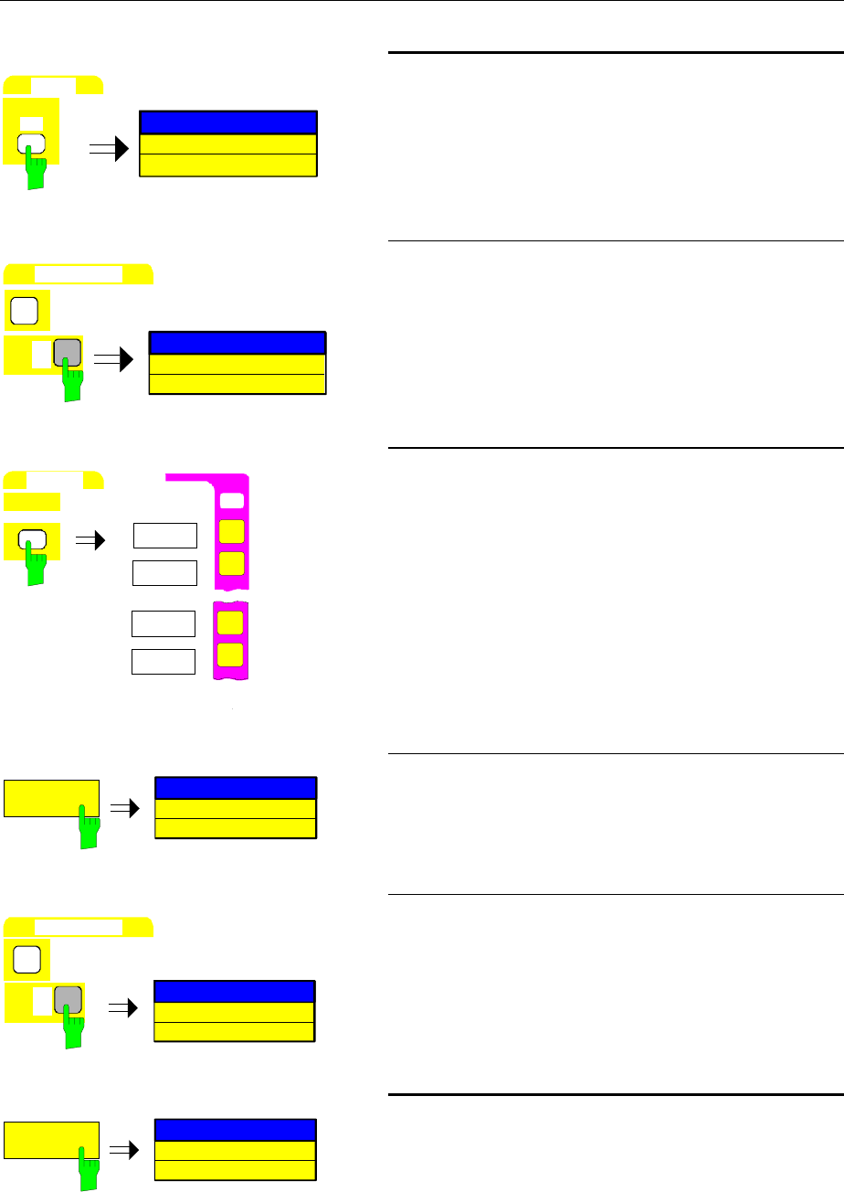
FSE Time-domain Measurements with Pulsed Signals
1065.6016.12 2.33 E-10
LEVEL
REF
REFERENCE LEVEL
-20 dBm
4. Set the reference level to 0 dBm.
½Press the REF key in the LEVEL key field.
The entry field for the reference level appears on the
display screen.
DATA ENTRY
dBm
mV
ms
0
REFERENCE LEVEL
0 dBm
MHz
½Enter 0 in the entry field via the numeric keypad and
terminate the entry by pressing the MHz/ms key.
SWEEP
COUPLING
SWEEP TIME
AUTO
COUPLED
FUNCTION
USER
RES BW
AUTO
RES BW
MANUAL
SWEEP TIME
MANUAL
5. Set the resolution bandwidth to 2 MHz
½Press the COUPLING key in the SWEEP key field.
The SWEEP-COUPLING menu is opened.
RES BW
MANUAL
RESOLUTION BANDWIDTH
1 MHz
½Press the RES BW MANUAL softkey.
The entry field for the resolution bandwidth appears
on the display screen.
DATA ENTRY
2
RESOLUTION BANDWIDTH
2 MHz
dBm
mV
ms
MHz
½Enter 2 via the numeric key pad and terminate the
entry by pressing the MHz key.
SWEEP TIME
MANUAL
SWEEP TIME
5 ms
6. Set the sweep time to 1 ms
½Press the SWEEP TIME MANUAL softkey.
The entry field for the sweep time is opened.
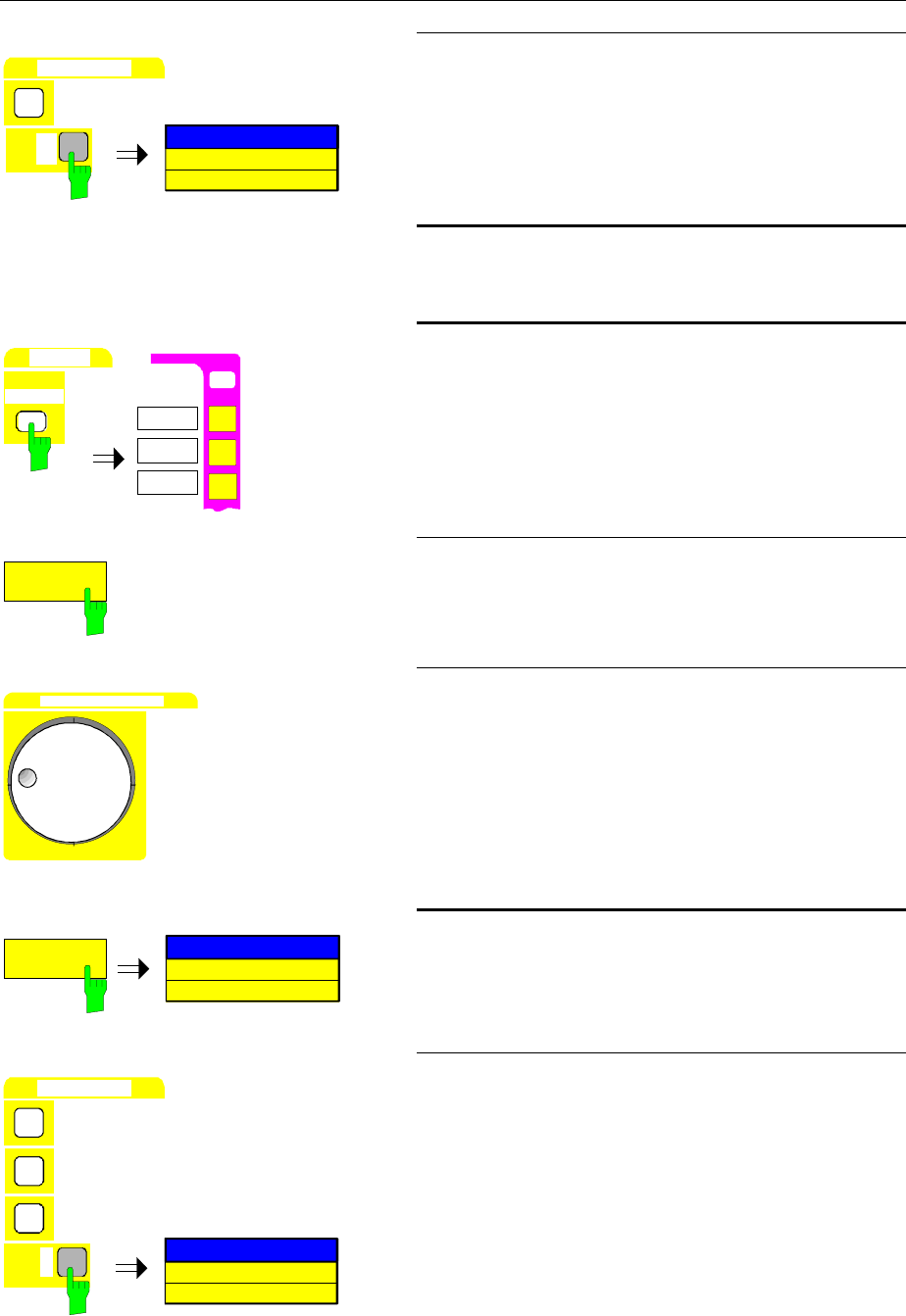
Timedomain Measurements with Pulsed Signals FSE
1065.6016.12 2.34 E-10
DATA ENTRY
1
SWEEP TIME
1 ms
dBm
mV
ms
MHz
½Enter 1 in the entry field via the numeric keypad and
terminate the entry by pressing the MHz key.
7. Connect the RF output of the SME to the RF
input of the FSE.
SWEEP
TRIGGER
O
N
USER
FREE RUN
VIDEO
LINE
TRIGGER
8. Initiate triggering by means of the display
voltage (video trigger)
½Press the TRIGGER key in the SWEEP key field
The TRIGGER menu is opened.
VIDEO
½Press the VIDEO softkey.
A dashed horizontal line is displayed which marks
the trigger level.
DATA VARIATION
½Set the trigger level using the roll key such that a
triggered display is obtained.
(see Fig. 2-15)
SWEEP TIME
MANUAL
SWEEP TIME
5 ms
9. Set the sweep time to 100
µ
s
½Press the SWEEP TIME MANUAL softkey.
The window for entering the sweep time is opened.
DATA ENTRY
1
SWEEP TIME
100
µ
s
0
0
dB
µ
V
µ
s
kHz
½Enter 100 via the numeric keypad and terminate the
entry by pressing the kHz/µs key.
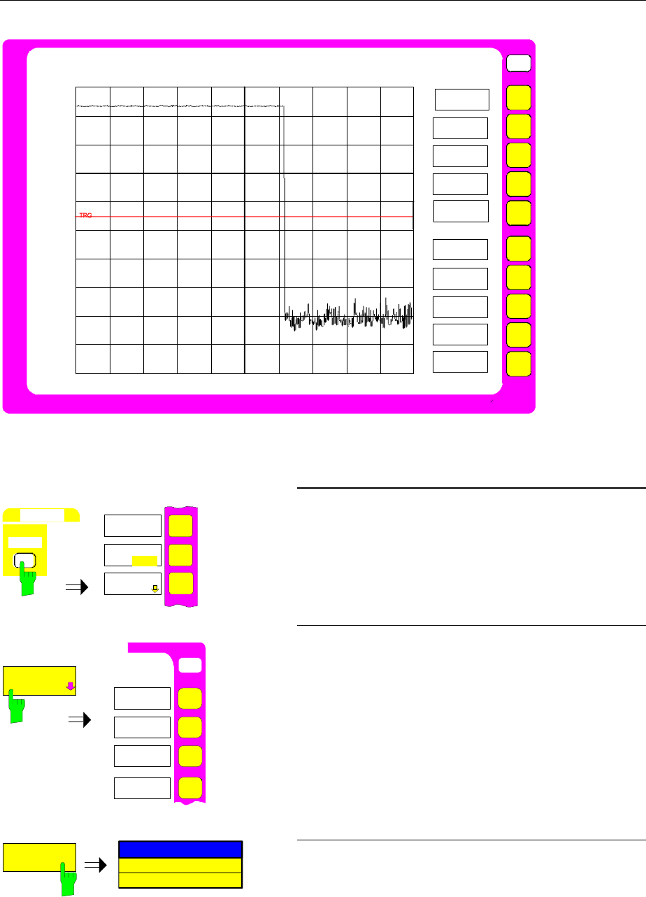
FSE Time-domain Measurements with Pulsed Signals
1065.6016.12 2.35 E-10
USER
0
-40
-60
-80
-100
-10
-30
-50
-70
-90
START 0 s 100
µ
s/ Stop 1 ms
TRIGGER
FREE RUN
VIDEO
LINE
EXTERN
TRIGGER
DELAY
SLOPE
POS NEG
Ref Lvl
0 dBm
RWB 1 MHz RF Att 10 dB
VBW 1 MHz Mixer -20 dBm
SWT 1 ms Unit dBm
RF POWER
-20
Fig. 2-15 Representation of pulse sequence with video trigger
SWEEP
SW EEP
GAP SWEEP
SETTINGS
GAP SWEEP
ON OFF
SWEEP
COUNT
10. Set the trigger points.
½Press the SWEEP key in the SWEEP keyfield.
The SWEEP menu is opened.
USER
GAP SWEEP
SETTINGS
TRIGGER
LEVEL
GAP SWEEP
SETTINGS
PRE
TRIGGER
TRG TO GAP
TIME
GAP
LENGTH
½Press the GAP SWEEP SETTINGS softkey.
The GAP SWEEP SETTINGS submenu for setting
the trigger points is opened.
PRE
TRIGGER
GAP PRETRIGGER
0 ms
½Press the PRE TRIGGER softkey.
The entry field for the pretrigger is opened.
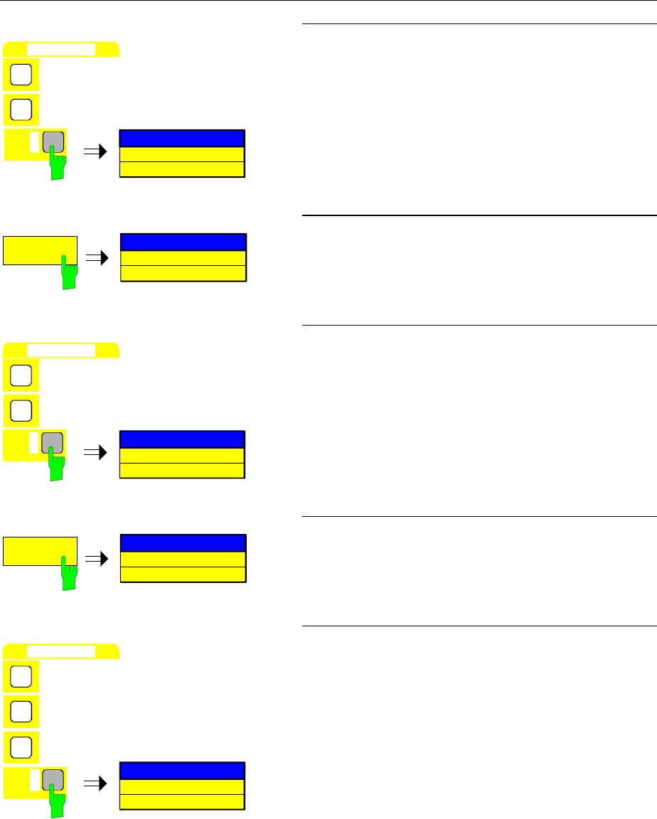
Timedomain Measurements with Pulsed Signals FSE
1065.6016.12 2.36 E-10
DATA ENTRY
1
GAP PRETRIGGER
10
µ
s
0
dB
µ
V
µ
s
kHz
½Enter 10 via the numeric keypad in the entry field
and terminate the entry by pressing the kHz/µs key.
TRG TO GAP
TIME
TRG TO GAP
0 ms
½Press the TRG TO GAP softkey.
The entry field for the trigger-to-gap-time is opened.
DATA ENTRY
4
TRG TO GAP
40
µ
s
0
dB
µ
V
µ
s
kHz
½Enter 40 via the numeric keypad in the entry field
and terminate the entry by pressing the kHz/µs key.
GAP
LENGTH
GAP LENGTH
0 ms
½Press the GAP LENGTH softkey.
The entry field for the length of the time gap is
opened.
DATA ENTRY
5
GAP LENGTH
540
µ
s
4
0
dB
µ
V
µ
s
kHz
½Enter 540 in the entry field via the numeric keypad
and terminate the entry by pressing the kHz/µs key.
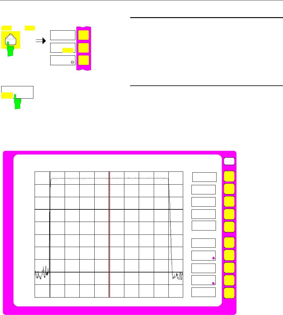
FSE Time-domain Measurements with Pulsed Signals
1065.6016.12 2.37 E-10
MENU
GAP SWEEP
SETTINGS
GAP SWEEP
ON OFF
11. Activate the measurement with mask-out of
measured value
½Press the menu change key.
The right supplementary menu is opened.
GAP SWEEP
ON OFF
½Press the GAP SWEEP ON/OFF key.
The measurement with blanking of measured value
is activated. The measurement results are shown in
Fig. 2-16
USER
0
-40
-60
-80
-100
-10
-30
-50
-70
-90
0 s 10
µ
s/ 50
µ
s 590
µ
s 10
µ
s 640
µ
s
SWEEP
CONTINOUS
SWEEP
SINGLE
SWEEP
SWEEP TIME
AUTO
SWEEP
COUNT
GAP SWEEP
SETTINGS
SGL SWEEP
DISP OFF
Ref Lvl
0 dBm
RWB 1 MHz RF Att 10 dB
VBW 1 MHz Mixer -20 dBm
SWT 100
µ
s Unit dBm
GAP SWEEP
ON OFF
-20
EXT GATE
ON OFF
EXT GATE
SETTINGS
SWEEP TIME
MANUAL
Fig. 2-16 Measured-value blanking for simultaneous display of rising and falling edge of a pulse
signal. The position of the gap is indicated by the thick vertical line. The gap time is
indicated via the double label 50 µs and 590 µs in the time axis.

FSE Contents - Manual Operation
1065.6016.12 I-3.1 E-1
Contents - Chapter 3 "Manual Operation"
3 Manual Operation ................................................................................................ 3.1
The Screen........................................................................................................................................ 3.2
Diagram Area .......................................................................................................................... 3.3
Displays in the Diagram Area........................................................................................ 3.4
Full Screen............................................................................................................................... 3.9
Split Screen ............................................................................................................................. 3.9
Softkey Area .......................................................................................................................... 3.10
Changing the Menu ...............................................................................................................3.11
Setting the Parameters.................................................................................................................. 3.13
Data Entry.............................................................................................................................. 3.13
Numeric Keypad on the Front Panel ........................................................................... 3.13
Roll-key and Cursor Keys............................................................................................ 3.14
Entry Windows....................................................................................................................... 3.15
Setting Up the Entry Window ...................................................................................... 3.15
Editing of Numeric Parameters ................................................................................... 3.16
Editing of Alphanumeric Parameters........................................................................... 3.17
Help Line Editor........................................................................................................... 3.17
Table Entry ............................................................................................................................ 3.18
Shifting Mode............................................................................................................... 3.18
Editing Mode................................................................................................................ 3.18
Disabling the Control Elements - HOLD Key .............................................................................. 3.19
Setting the Stepsize - STEP Key................................................................................................... 3.20
Mouse and External Keyboard Control ....................................................................................... 3.21
External Keyboard Control..................................................................................................... 3.21
Data Entry Windows with Mouse Control .............................................................................. 3.22
Mouse Control of Further Display Elements.......................................................................... 3.23
Menu Overview .............................................................................................................................. 3.24
System Key Group................................................................................................................. 3.24
Configuration Key Group ....................................................................................................... 3.27
Setup for Instruments with Windows NT Controller Option......................................... 3.28
Setup for Instruments with MS DOS Controller Option or without Controller.............. 3.29
Hardcopy Key Group ............................................................................................................. 3.30
Frequency Key Group............................................................................................................ 3.31
Level Key Group, Input Key................................................................................................... 3.32
Marker Key Group ................................................................................................................. 3.34
Lines Key Group.................................................................................................................... 3.38
Trace Key Group ................................................................................................................... 3.40
Sweep Key Group.................................................................................................................. 3.41
Memory Key Group................................................................................................................3.43
User Key Group..................................................................................................................... 3.46

Contents - Manual Operation FSE
1065.6016.12 I-3.2 E-1

FSE Manual Operation
1065.6016.12 3.1 E-13
3 Manual Operation
Chapter 3 verviews manual operation of the FSE. This includes a description of the screen, menu
operation and the setting of parameters. There is an overview of the menus at the end of this chapter.
The functions of the menus are described in detail in Chapter 4. Chapter 2 contains a short introduction
which goes through simple measurements step-by-step. The remote control is described in Chapters 5,
6 and 7.
The FSE is menu-controlled via keys and softkeys. Instrument parameters and test parameters can be
set directly via softkeys or by entering values in entry fields and by making selections from tables.
Softkey are used to select operating modes and the screen mode.
If required, data entry windows and tables also be displayed on the measurement screen.
After switching on the instrument a message about the BIOS version installed is displayed for a few
seconds (e.g. "Analyzer BIOS Rev. 1.2").
The results of the self test is displayed next.
MAINPROCESSOR
SELFTEST STARTING ...
TESTING CMOS ...
DMA CHANNEL ...
INTERRUPTS ...
NMI ...
BASE MEMORY ...
EXTENDED MEMORY ...
HD CAPACITY ...
INIT FLOPPY DRIVE ...
INIT HD ...
SELFTEST DONE,
SYSTEM IS BOOTING ...
Subsequently, the instrument then starts measuring. The type of measurement which was activated
prior to last switch-off is performed, as long as no other instrument configuration was selected via AUTO
RECALL in the MEMORY RECALL menu. While the measurement is being performed other menus and
measuring modes can be entered simultaneously. The measurement results and the settings of the
parameters are displayed on the screen.
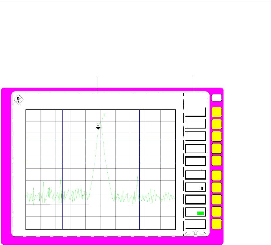
Screen FSE
1065.6016.12 3.2 E-13
The Screen
The screen informs continuously on the results and parameters for the selected measuring functions.
The display mode for test results, the softkey labeling and the type of menu depend on the selected
measuring function.
The screen is divided into two areas:
USER
Diagram area Softkey area
A
Marker 1 [T1 CNT]
-36.42 dBm
100.002 MHz
Ref Lvl
-20 dBm
RBW 1 MHz
VBW 1 MHz
SWT 5 ms
RF Att 20 dB
Mixer -40 dBm
Unit dBm
D1
D2
F1 F2
-20
-30
-40
-50
-60
-70
-80
-90
-100
-110
Center 100.0 MHz Span 50.0 MHz
DELTA
MARKER
DELTA 1
DELTA 2
DELTA 3
DELTA 4
NOISE
PHASE
REFERENCE
POINT
FIXED
ALL DELTA
OFF
DELTA MKR
ABS REL
SAMPLES
NOISE MEAS
REFERENCE
5 MHz/
-120
Fig. 3-1 Basic screen areas
Diagram area This area contains the measuring diagrams and other result displays as well
as the parameters and status information which are important for analyzing
the results.
Message fields, entry windows and tables may also be shown in this area.
Softkey area This area displays the instrument functions which can be selected via the
softkeys. No other images are superimposed on the softkey area.
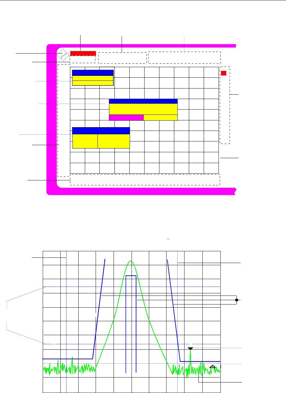
FSE Screen
1065.6016.12 3.3 E-13
Diagram Area
E
R
Entry window
Message field
Table
Level scale
labelling
Frequency scale
or time scale
labelling
Hardware settingsStatus
0
Instrument settings
(enhancement
labels)
0
UNCAL OVLD
LVL
FRQ
1-R
2-R
3-R
4-R
GAT
TRG
75
Ω
MAC
*
A
R
S
-10.0
-20.0
-30.0
-40.0
-60.0
-50.0
-70.0
-80.0
-90.0
-100.0
Reference-/
max level
Marker /deltamarker
Span 50.0 MHz
Center 100.0 MHz
Grid
Logo
MOUSE
Interface
Owner PS/2
Instrument
WARNING
Hardcopy not completed.
Stop printer?
YES NO
START FREQUENCY
1.000000 MHz
Marker 1 [T1 CNT]
-36.42 dBm
100.002 MHz
Ref Lvl
-20 dBm
RBW 1 MHz
VBW 1 MHz
SWT 5 ms
RF Att 20 dB
Mixer -40 dBm
Unit dBm
Fig. 3-2 Screen areas in analyzer mode
D2
F1 F2
L1 L3
L2
Marker
Deltamarker
Trace
Display lines
(level lines)
2
3
D1
Display line
(frequency line)
Display line
(frequency line)
Limit lines
Fig. 3-3 Measuring diagram

Screen FSE
1065.6016.12 3.4 E-13
Displays in the Diagram Area
The following graphic elements are displayed in the diagram area:
Status information A status information indicates that a problem has occurred.
In addition the status display displays MAX / REF LVL, if the maximum
level and the reference level have different values .
UNCAL "UNCAL" is displayed under the following circumstances:
•no valid correction data (Status CALIBRATION FAILED in
table CAL RESULTS), may occur after a cold start
following a firmware update
⇒record correction data (CAL TOTAL)
•correction data are switched off (menu CAL, CAL CORR
OFF).
⇒switch on CAL CORR ON or PRESET
•Sweep time too short for current instrument settings
(span, resolution bandwidth, video band width).
⇒increase sweep time
•resolution bandwidth too small for set symbol rate (Vector
Anaylsis, option FSE-B7): digital demodulation) .
⇒increase resolution bandwidth
OVLD „Overload“ is displayed when the input mixer is overloaded
⇒Increase input attenuation
IFOVLD „IF Overload“ is displayed when an overload occurs after the
input mixer.
⇒ Increase reference level
DIFOVL „Digital IF Overload“ is displayed when the digital resolution
filter is overloaded.
⇒ Increase reference level
ExtRef „External Reference“ is displayed when the instrument is set
to REFERENCE EXT (menu SETUP), but the reference
signal is missing at the rear panel connector.
⇒Ceck input signal of external reference
LO unl „LO unlock“ is indicated when the 1st LO is unlocked
(module error).
LO Lvl „LO Level“ is displayed when the output level of the 1st LO
is too small (module error).
LO LvD „LO Level Digital IF“ is displayed when the output level of
the oscillator of module Digital IF is too small (module
error).
OCXO 'OCXO cold' is indicated when the crystal oscillator has not
yet reached ist operating temperature. This indication
vanishes after a few minutes after switch on.
UNLD 'Underload' is displayed when the analyzer is not in its
optimal dynamic range. In this case the measuring accuracy
is not optimal. This indication is only output in vector
analyzer operating mode (option FSE-B7).
⇒Decrease reference level

FSE Screen
1065.6016.12 3.5 E-13
Marker/Deltamarker This label displays the position of the last selected marker or
deltamarker in the x and y-directions and the marker/deltamarker index.
As additional information, 2 fields in square brackets are provided which
contain the curve which the marker is assigned to and the active
measuring function of the marker indicated. The measuring function of
the markers in the second field is indicated by the following
abbreviations:
CNT frequency counter active
TRK signal track active
NOI noise measurement active
The marker text has the same color as the trace which the marker is
assigned to. If, for example, the active marker is assigned to trace 1,
and trace 1 is yellow, the marker text will be yellow, too.
Hardware settings
Analyzer mode RBW
VBW
SWT
RF Att
Mixer
Unit
Tracking generator mode
TG Lvl
Display of the set resolution bandwidth.
Display of the set video bandwidth.
Display of the set sweep time.
Display of the set RF attenuation.
Display of the user set level at the input mixer (only when level differs
from standard settings) ( = level of the reference level REF LVL).
Display of the level unit of the measuring results and the associated
setting and test parameters in full length. This label is particularly
important for selection of units with more than 4 digits, since they can
only be indicated as dB* in the other labels (except for marker).
Only available with one of the options FSE-B8/9/10/11
Indication of the set output level of the tracking generator
Vector Analyzer mode
CF
SR
Demod
Standard
Only available with option FSE-B7
Display of the set center frequency
Display of the symbol rate
Display of the switched on demodulator.
Display of the set standard (e.g. GSM)
Grid X-axis: frequency or time,
Y-axis: level

Screen FSE
1065.6016.12 3.6 E-13
Instrument settings
(Enhancement Labels) Display of user instrument settings which influence the measuring result
and which are not immediately obvious when viewing the measured
values.
*The current instrument setting is not the same as the setting selected
when one of the traces was stored. This occurs under the following
circumstances:
•The instrument setting is modified while a sweep is being performed.
•The instrument setting is modified in SINGLE SWEEP mode after the
end of the sweep and no new sweep is started.
•The instrument setting is modified after setting the trace to VIEW.
The display will not change until the cause is eliminated by the user. I.e.,
either a new sweep is started (SINGLE SWEEP mode), or the trace in
question is switched to BLANK (all cases).
AIdentification for screen A. Screen A is activated for the entry of test
parameters.
BIdentification for screen B. Screen B is activated for the entry of test
parameters.
C
D
If, in the Vector Analyzer (Option FSE-B7) mode, the inphase and
quadrature signal is displayed in the measurement window A, the
window is subdivided into two diagrams. The upper diagram is marked
with an A and the bottom one with C.
If, in the Vector Analyzer (Option FSE-B7) mode, the inphase and
quadrature signal is displayed in the measurement window B, the
window is subdivided into two diagrams. The upper diagram is marked
with an B and the bottom one with D.
LN The automatic setting of the input attenuation is set to ATTEN LOW
NOISE .
LD The automatic setting of the input attenuation is set to ATTEN LOW
DISTORTION.
NOR Normalization is activated; high accuracy (only with one of the
options FSE-B8/9/10/11).
APP Normalization is activated; medium accuracy (only with one of the options
FSE-B8/9/10/11).
TDF An antenna correction factor (TRANSDUCER FACTOR) is switched on.
TDS A set of antenna correction factors (TRANSDUCER SETS) is switched
on.
LVL A level offset ≠ 0 dB has been set. A level offset of the installed tracking
generator (option) leads to the same display.
FRQ A frequency offset ≠ 0 Hz has been set.
SGL The sweep is set to SINGLE SWEEP.

FSE Screen
1065.6016.12 3.7 E-13
1-<n> Subtraction Trace 1 - Trace <n> active (<n>: numeric value) or
subtraction Trace 1 - Reference Line active (<n>: R)
2-<n> Subtraction Trace 2 - Trace <n> active (<n>: numeric value) or
subtraction Trace 1 - Reference Line active (<n>: R)
3-<n> Subtraction Trace 3 - Trace <n> active (<n>: numeric value) or
subtraction Trace 1 - Reference Line active (<n>: R)
4-<n> Subtraction Trace 4 - Trace <n> active (<n>: numeric value) or
subtraction Trace 1 - Reference Line active (<n>: R)
<n>AP For trace <n> (n = 1 to 4) the detector is set to AUTOPEAK.
<n>MA For trace <n> (n = 1 to 4) the detector is set to MAX PEAK.
<n>MI For trace <n> (n = 1 to 4) the detector is set to MIN PEAK.
<n>SA For trace <n> (n = 1 to 4) the detector is set to SAMPLE.
<n>AV For trace <n> (n = 1 to 4) the detector is set to AVERAGE.
<n>RM For trace <n> (n = 1 to 4) the detector is set to RMS.
GAT The frequency sweep is controlled via the EXT TRIG/GATE connector.
TRG The instrument is not triggered in FREE RUN mode.
EXT The unit is configured for operation with external reference
75 Ω The input impedance of the unit is set to 75 Ω.
MAC Macro recording active.
PRN A printout is taking place. PRN overwrites the enhancement label
MAC.
<n>VIEW Trace <n> (n = 1 to 4) is set to VIEW
<n>AVG
MIX
SID
AID
Trace <n> (n = 1 to 4) is set AVERAGE
The external mixer output is switched on (option FSE-B21).
External mixer output: SIGNAL ID is switched on (option FSE-B21).
External mixer output: AUTO ID is switched on (option FSE-B21).
Frequency axis labeling
123.4 ms/Div
Center 1.2345678901234 GHz
Start 1.2345678901234 GHz
Display of the x-scaling.
The distance between two grid lines is displayed in this label.
The set center frequency or start frequency is displayed in this label
depending on whether the keys CENTER/SPAN or START/STOP were
last pressed.
If span = 0 Hz, the center frequency is always displayed.

Screen FSE
1065.6016.12 3.8 E-13
Span 1.2345678901234 GHz
Stop 1.2345678901234 GHz
Trigger 1.234 ms
The set frequency range (SPAN) or the stop frequency is displayed,
depending on whether the keys CENTER/SPAN or START/STOP
were last pressed.
If span = 0 Hz, the trigger moment (PRETRIGGER) is displayed.
Optional labeling
14.Jun 97 12:13
Optional indication of date, time and comment.
Level axis labeling Display of the y-scaling.
Entry window The data entry window is superimposed in the diagram area, if
required.
Reference level/ Max.
level Display of the set reference level or combined display of maximum
level and reference level .
Limit lines Limit lines are are the upper and/or lower limits for level curves or
spectral distributions.
Traces 1 to 4 Up to 4 traces can be displayed simultaneously.
Display lines Utilities for trace analysis.
The FSE provides two display modes:
•Full Screen: 1 window, all traces are displayed in one screen.
•Split Screen: 2 windows, traces, grid and labels are distributed on the two screens.
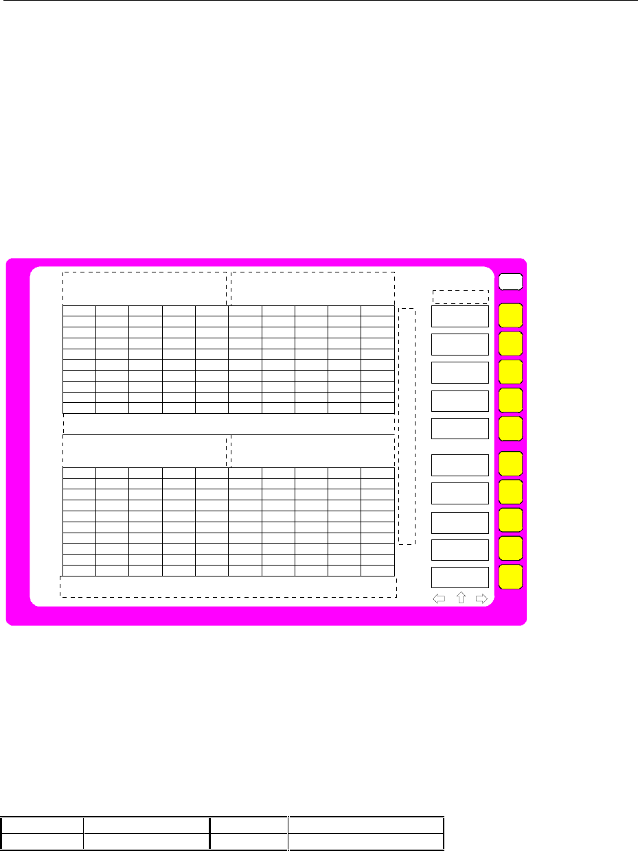
FSE Screen
1065.6016.12 3.9 E-13
Full Screen
In the full-screen mode,, the settings and measurements are performed in the active visible window. All
indications on the screen refer to this window. The designation (SCREEN A or SCREEN B) is inserted
as enhancement label A or B on the right diagram margin.
The DISPLAY key is used to switch between the windows. The current measurement is terminated
when its window goes blank.
Switching from split-screen to full-screen mode is performed in menu SYSTEM DISPLAY.
Split Screen
In the Split Screen mode, the screen is divided into two halves.
USER
SOFTKEY 1
SOFTKEY 2
SOFTKEY 3
SOFTKEY 4
SOFTKEY 5
SOFTKEY 6
SOFTKEY 7
SOFTKEY 8
SOFTKEY 9
SOFTKEY
10
A
Center 100.0 MHz 5 MHz/ Span 50.0 MHz
Center 100.0 MHz 5 MHz/ Span 50.0 MHz
Marker 1 [T1 CNT]
-36.42 dBm
100.002 MHz
Ref Lvl
-20 dBm
RBW 1 MHz
VBW 1 MHz
SWT 5 ms
RF Att
20 dB
Mixer
-40 dBm
Unit
dBm
Marker 1 [T1 CNT]
-36.42 dBm
100.002 MHz
Ref Lvl
-20 dBm
RBW 1 MHz
VBW 1 MHz
SWT 5 ms
RF Att
20 dB
Mixer
-40 dBm
Unit
dBm
-20.0
-40.0
-60.0
-80.0
-100.0
-120.0
-20.0
-40.0
-60.0
-80.0
-100.0
-120.0
Fig. 3-4 Split Screen mode
The upper half is always assigned to Screen A, the lower to Screen B. The measurement settings can
be selected independently for both screens. E.g., a spectrum may be displayed in Screen A and a time
amplitude in the time range is displayed in Screen B. The window for entry of the measuring parameters
or the marker operation is selected using the DISPLAY key.
The indications which apply only to one window appear in the margin of the associated diagram.
Indications which apply to the two windows are displayed between the diagrams.
The assignment of traces to the windows is fixed and cannot be modified.
Table 3-1 Assignment of traces to windows with split screen in the signal or vector analyzer mode
Trace 1: upper (screen A) Trace 3: upper (screen A)
Trace 2: lower (screen B) Trace 4: lower (screen B)
The two windows can be subdivided into two measurement diagrams. This applies to separate display
of measurement values, eg to the display of the inphase and quadrature signal in vector analysis.
Screen A is divided into diagrams A and C, screen B is divided in diagrams B and D.
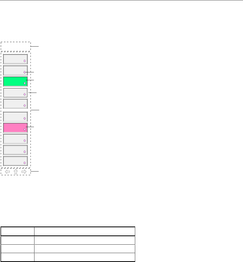
Screen FSE
1065.6016.12 3.10 E-13
Softkey Area
The layout of the softkey area is independent of the operating mode. It consists of the following graphic
elements:
SOFTKEY
MENU TITLE
SOFTKEY
LABEL 1
Menu title
Softkey menu
Menu display
SOFTKEY
LABEL 2
SOFTKEY
LABEL 3
SOFTKEY
LABEL 4
SOFTKEY
LABEL 5
SOFTKEY
LABEL 6
SOFTKEY
LABEL 7
SOFTKEY
LABEL 8
SOFTKEY
LABEL 9
SOFTKEY
LABEL 10
Softkey function not available
(without 3D frame)
Indication of submenu (arrow)
Softkey active (green)
Softkey active, opens a data
entry field (red)
Fig. 3-5 Layout of the softkey area
The softkeys have different functions depending on the instrument state. Therefore, their labeling
changes. The current state of the softkeys is indicated by color coding. The color code is factory-set as
follows:
Table 3-2 Factory-set color code for softkeys
Softkey color Meaning
gray Softkey off
green Softkey on
red Softkey on and data entry active
These colors can be changed by the user as desired in the SYSTEM DISPLAY-CONFIG DISPLAY
menu.
A softkey is switched on or off by pressing it. If a mouse is connected to the instrument, the softkey label
on the display can be clicked.
Softkey labels are not displayed if the function they represent is not available. There are two cases:
•If an instrument function depends on an option, and this option is not fitted, the associated softkey
label will not be displayed.
•If the instrument function is not available temporarily due to specific settings, the softkey is displayed
without the 3D frame.
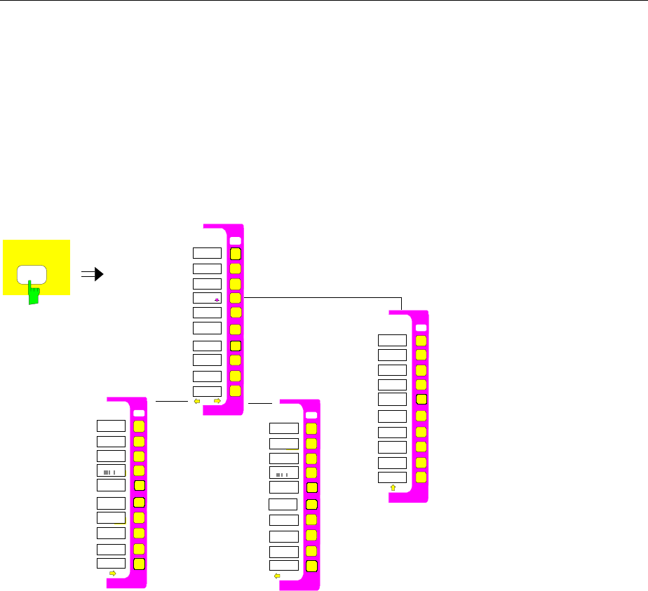
FSE Screen
1065.6016.12 3.11 E-13
Changing the Menu
With manual control, the FSE can be operated via the front-panel keys, the external keyboard or with a
mouse.
Operation is menu-controlled. Various softkey menus are displayed depending on the instrument
status. The menus are organized using a tree structure. The start menu (the root of the menu tree) is
always called by pressing a hardkey. The softkeys are then used to branch into further menus
(submenus).
Root menu
Submenu
SCREEN
USER
Supplementary
menus
Fig. 3-6 Theory of menu selection
Each softkey menu consists of max. 30 softkeys, 10 softkeys being arranged in a main menu, 10 in a
left-hand supplementary menu and 10 in a right-hand supplementary menu. In contrast to empty main
menus, empty supplementary menus are not displayed. Arrows at the lower edge of the softkey area
indicate whether a supplementary menu exists or not.
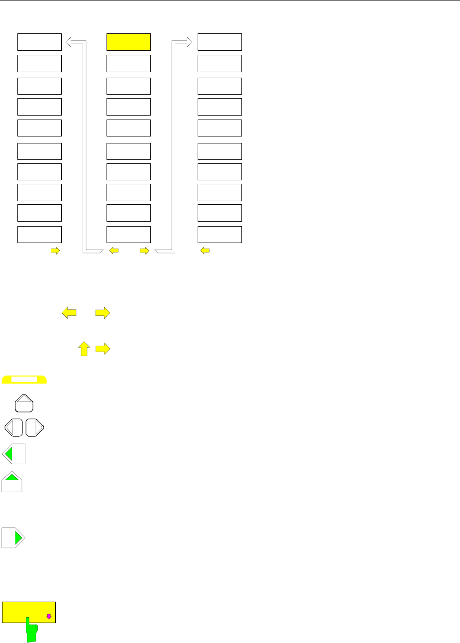
Screen FSE
1065.6016.12 3.12 E-13
Main menu
Left-hand supplementary menu
Softkey
21
Softkey
22
Softkey
23
Softkey
24
Softkey
25
Softkey
26
Softkey
27
Softkey
28
Softkey
29
Softkey
30
Softkey
1
Softkey
2
Softkey
3
Softkey
4
Softkey
5
Softkey
6
Softkey
7
Softkey
8
Softkey
9
Softkey
10
Softkey
11
Softkey
12
Softkey
13
Softkey
14
Softkey
15
Softkey
16
Softkey
17
Softkey
18
Softkey
19
Softkey
20
Right-hand supplementary menu
Fig. 3-7 Switching between main menu and supplementary menu
The menu arrows help to orient inside the menu tree.
Examples: This menu has a right-hand and a lefthand supplementary menu. It is the
root menu since there is no ⇑ arrow.
Only a right-hand supplementary menu or the upper menu can be accessed
from this menu.
MENU
The MENU keys allow for selecting the main menu and the supplementary
menus. If a mouse is connected to the instrument, the menu arrows can be
selected to enter the respective menus. The MENU keys have the following
functions:
When this key is pressed, the FSE enters the left-hand supplementary menu.
This key is pressed to call the upper menu which is located in the next higher
hierarchical level in the menu tree. Several menus provide for automatic
change, i.e., return to the next higher menu is caused automatically after
pressing a softkey.
The right-hand supplementary menu is selected by pressing this key.
A supplementary menu cannot be selected from another supplementary
menu but only via the main menu.
Submenu are always selected with a softkey.
SOFTKEY
The labeling of all softkeys which call a submenu includes an arrow.
The softkeys are masked out in remote mode and during macro processing.

FSE Setting the Parameters
1065.6016.12 3.13 E-13
Setting the Parameters
Data Entry
Instrument parameters can be entered in an entry window or in a table via the numeric keypad on the
front panel (DATA ENTRY), an external keyboard and the roll-key.
The numeric keypad DATA ENTRY is provided for entry of numeric parameters (e.g., the start
frequency). The roll-key is used for fast incrementing or decrementing of numeric parameters with a
defined step size.
It is advisable to use the external keyboard for definition of alphanumeric parameters (e.g., file names)
since the front panel does not allow for entry of letters. If no external keyboard is provided, the help line
editor is called automatically for entry of alphanumeric parameters.
Numeric Keypad on the Front Panel
The keys are assigned the following functions:
DATA ENTRY
09
...
Number keys
-
DATA ENTRY
Changes the sign of a numeric parameter. A "-" is inserted at the cursor
position in the case of an alphanumeric parameter.
DATA ENTRY
.
Inserts a decimal point "." at the cursor position in the numeric string.
-dBm
V
s
GHz
MHz
kHz
Hz
dBm
mV
ms
dB
µV
µs
dB..
nV
ns
D
ATA E
N
TRY
Append the selected unit to the numeric value that has been entered
The unit keys are all assigned the value "1" if quantities are indicated
without dimensions in order to prevent faulty operations The unit keys,
therefore, also adopt the function of an ENTER key. The same applies to
alphanumeric entries.
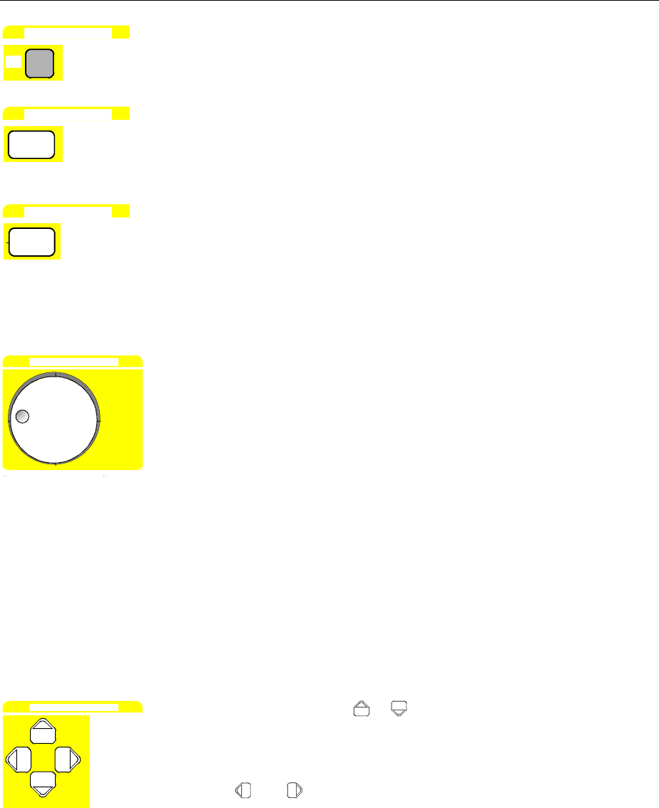
Setting the Parameters FSE
1065.6016.12 3.14 E-13
DATA ENTRY
EXP
Adds an exponent (E-xx) to the end of the numeric string.
DATA ENTRY
BACK
Deletes the character to the left of the cursor with numeric entry.
Toggles between the current parameter and the previous value - but not
when an entry is being made (UNDO function).
DATA ENTRY
CLR
Closes the entry field when entry has been made.
Aborts the entry before it has been confirmed.
Closes the system message windows.
Roll-key and Cursor Keys
DATA VARIATION
The roll-key has several functions.
•With numeric entry, the instrument parameter is incremented (turning
clockwise) or decremented (turning counterclockwise) at a defined step
size.
The step size may be equal to or smaller (e.g., 1/10) than the step size
being defined for the cursor keys (see description of the STEP key).
•In tables, the roll-key can be used to shift the cursor horizontally or
vertically when no entry window is open. The direction (horizontal/
vertical) is changed with the cursor keys.
•The roll-key is used with the help-line editor to select the individual
letters.
•It can be used to shift markers, display lines, limit lines etc.
As the roll-key is turned faster, the step size increases so speeding up the
setting procedure.
Cursor keys:
DATA VARIATION
With numeric entry, the keys or are used to increase or decrease the
instrument parameter by the selected step size. The keys are disabled With
alphanumeric entry, the keys are used to toggle between the editing line
and the help line editor.
The keys and are used to shift the cursor to the required position
within the (alpha)numeric editing line..
In tables, the cursor keys are used to shift the cursor between the lines and
columns of the table.
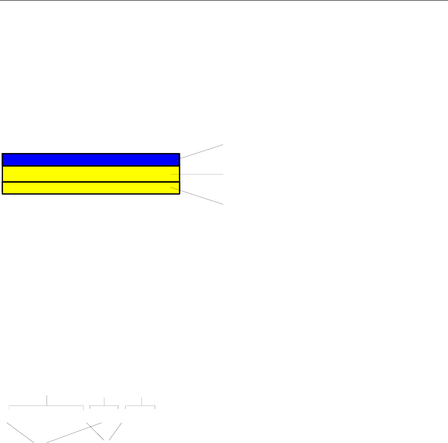
FSE Setting the Parameters
1065.6016.12 3.15 E-13
Entry Windows
Setting Up the Entry Window
The instrument parameters are not entered at the location where the parameter is displayed but in an
individual entry window.
The entry window is called by a softkey or a hardkey and is used for definition of numeric or
alphanumeric instrument parameters (START FREQUENCY by way of example):
START FREQUENCY
10.2457535 GHZ
START FREQUENCY OUT OF RANGE
Headline with
parameter designation
Editing line with
parameter value and unit
Status and error messages
Fig. 3-8 Setup of an entry window
Subsequent to calling the entry window the current parameter value including the unit is displayed in the
editing line. Status and error messges which refer to the current entry are displayed in the third and
(optionally) fourth line.
The entry window is displayed in the left upper edge of the active measuring window with the default
setting. When a mouse is connected to the instrument, open entry windows can be shifted to any
position on the screen provided that they do not cover the softkey line. The new position is valid until
measuring window is selected. The data entry window is represented transparent or non-transparent, as
required.
Alphanumeric parameters are displayed as a simple character string in the editing line. Numeric
parameters which consist of mantissa, exponent and unit are set up as follows:
-123.456789 E-12 MHz
Mantissa Exponent
Space
Sign
Unit
Fig. 3-9 Setup of numeric parameters
Mantissa: The first character is the sign of the mantissa, the positive sign is not displayed. The
actual numeric value follows. The number of digits depends on the instrument
parameter. The cursor may be shifted to the first digit of the mantissa at maximum,
however, it may not precede the sign. The decimal point can be set as required.
Exponent: The exponent is separated from mantissa by a space character. The sign field of the
exponent follows the "E", the positive sign "+" being not displayed similar to the
representation of the mantissa. The cursor skips the "E" and the sign field. Two
characters are fixed for the exponent value.
Unit: The unit (not represented in editing mode) is separated from the exponent by a space
character.
The number of digits which can be entered for each instrument parameter is limited by the width of the
input field only, but not by the amount which is physically enabled. (Example: Levels should be indicated
with two decimals. The user may, however, enter as many decimals as desired - the entered value is
rounded accordingly).
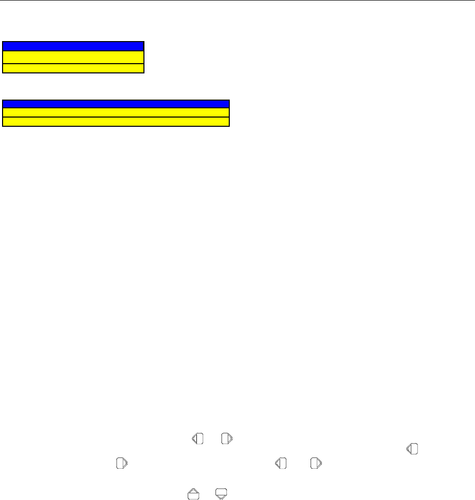
Setting the Parameters FSE
1065.6016.12 3.16 E-13
There are two types of entry windows:
START FREQUENCY
10.2457535 GHZ
START FREQUENCY OUT OF RANGE
The editing line of the entry window for numeric
parameters allows for display of up to 24
characters. Horizontal scrolling is not possible in
the editing line.
HARDCOPY TITLE
BANDPASS-FILTER TEST 23A
The editing line of the entry window for
alphanumeric parameters allows for display of up
to 60 characters (cf. display section). Maximum
256 characters may be entered. Horizontal
scrolling is possible.
If no external keyboard is provided, the three-line
entry window is replaced by a letter field which
allows for individual selection of characters using
the cursor keys (see help line editor).
Editing of Numeric Parameters
Calling the entry window:
•Subsequent to calling the entry window, the current value of the numeric parameter including the unit
is displayed in inverted color. The cursor is not displayed in this state. The transparent data entry
window has no background color.
•The entry window is closed upon pressing the key CLR.
Editing mode:
•Pressing a number, sign or decimal point key causes the value and unit to be deleted. The new value
is output left-justified. The individual characters are entered in insert mode. If the maximum amount of
characters for the mantissa or the exponent has been entered, no further entry is possible (no
horizontal scrolling). If characters are positioned to the right of the cursor, they are shifted right when
reaching the maximum length and get lost.
•Pressing the keys DATA VARIATION or causes normal representation of the current value.
The unit is no longer displayed and the cursor precedes the first digit of the mantissa ( ) or follows
the last digit entered ( ). The DATA VARIATION keys and change the numeric value of the
cursor.
•Pressing the DATA VARIATION keys or or the roll-key causes the original parameter value to
be restored and modified according to the defined step size for this parameter.
•The data management of the instrument stores the previous value of a parameter in addition to the
current value. The BACK key allows for toggling between these two values.
Termination and abortion of entry:
•The editing mode is terminated by pressing a unit key. The validity of the new parameter value is
checked and accepted for the instrument setting. If an error occurs, a corresponding error message is
displayed in the status line of the editing field, e.g., "Out of range", "Value adjusted", etc.
•Editing of a parameter can be aborted by pressing the key CLR. The original parameter is then
displayed again. The entry window is closed by pressing the CLR key again.
•Pressing a key or softkey subsequent to starting the entry causes the entry to be aborted and the
entry window to be closed. If the same softkey which has opened the entry window is activated during
entry, the original value is restored and displayed.
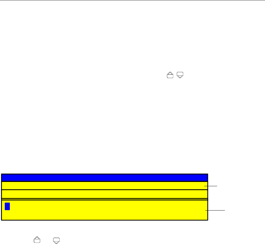
FSE Setting the Parameters
1065.6016.12 3.17 E-13
Editing of Alphanumeric Parameters
Generally, the regulations for numeric parameters analogously apply for alphanumeric parameters. Note
the exceptions given below:
•Alphanumeric parameters are not displayed with a unit.
•The four unit keys adopt the function of the ENTER key.
•Horizontal scrolling is possible in the editing line.
•Incrementing or decrementing cannot be effected via the keys , or the roll-key.
•Pressing the sign key causes a "-" character to be inserted at the cursor position, the decimal point
key causes insertion of a point ".".
•The exponent key has no function.
Help Line Editor
The help line editor allows for labelling or text entries to be made without an external keyboard being
required. In this case, a field containing letters and special characters is added to the standard entry
window. The help line editor is displayed automatically if no external keyboard is provided and an entry
window for alphanumeric entry is opened.
BCDEFGHIJKLMNOPQRSTUVWXYZÄÖÜ!?"$%/(){[]}\+*#~'-_=.:
abcdefghijklmnopqrstuvwxyzäöüß,;<>|@µ²³^°123456789 0
A
CALIBRATION FILE
C:\MEASDATA\STANDARD.CAL
Three-line entry window
Uppercase and
lowercase letters,
special characters
and digits
Fig. 3-10 Help line editor
•The keys and are used to toggle between the editing line and the help line editor.
•The cursor can be positioned to the required character in the help line editor using the cursor keys
and the roll-key.
•A character is entered in the editing line by pressing any of the unit keys.
•If the cursor is already located in the editing line, pressing a unit key terminates data entry.
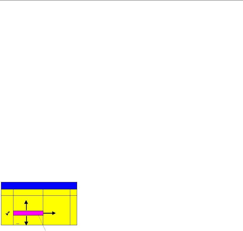
Setting the Parameters FSE
1065.6016.12 3.18 E-13
Table Entry
The FSE uses numerous tables for indication and configuration of instrument parameters. The tables
differ very much in the number of lines, columns and inscriptions and have a different functionality.
Tables are represented in a non-transparent form. The size is predefined and cannot be modified. If a
mouse is connected, the tables may be shifted on the display without covering the softkeys. Tables can
be superimposed by entry windows or suchlike.
Tables are mostly coupled to a softkey menu which provides further functions for editing table entries,
e.g., deletion of tables, copying lines or columns, marking of table elements, restoring of default states
etc. Another kind of tables is exclusively used for indication of instrument parameters and cannot be
edited.
The definition of individual tables and the operation of particular editing functions can be looked up in the
reference section with the description of the corresponding softkey menu.
The basic concept of operation is, however, the same for all tables. A differentiation is made between
shifting mode and editing mode.
Shifting Mode
This mode is active subsequent to opening a table. The cursor is shifted between the table elements by
means of the cursor keys. The table element which is below the cursor is represented in inverted color.
Antenna
Ant_Cab2
Ant_Pre
Probeset
dBµV/m
dBµV/m
dBµV/m
dBµV/m
dBµA
Name Unit
TRANSDUCER SET
Ant_Cab1
Cursor
Fig. 3-11 Shifting mode
Editing Mode
A table element which is marked by a cursor can be editied as follows:
•by pressing one of the unit keys on the front panel or the ENTER key on the external keyboard.
•by a double-click of the mouse on the table element. If the clicked element is not yet marked by the
cursor, the letter is positioned on the element, additionally.
•For numeric or alphanumeric instrument parameters, the editing operation may be started by entry of
any number or letter on the front panel or on the external keyboard.
The data entry window, the selection list or the toggle editor are provided for this purpose.
After the editing operation has been terminated, the table enters the shifting mode again. The cursor is
positioned automatically on the next table element.

FSE Disabling the Control Elements
1065.6016.12 3.19 E-13
Disabling the Control Elements - HOLD Key
The individual softkeys have the following functions:
D A TA V AR I ATI ON
HOLD
The functions of the HOLD menu allow for disabling individual control
elements or the complete instrument control. The LED above the HOLD
key indicates that either the function LOCK DATA or LOCK ALL has been
activated. The control can be enabled again by successively pressing the
two UNLOCK softkeys in any order.
Switching off the instrument resets control such that the instrument can be
normally operated again after subsequent switch-on.
UNLOCK
After selecting the two UNLOCK softkeys, the instrument keyboard is enabled
again. The LED above the HOLD key goes out.
LOCK DATA
Selection of softkey LOCK DATA causes the roll-key to be disabled in order
to prevent a parameter from being varied by mistake.
LOCK ALL
Selection of LOCK ALL softkey disables the complete front panel (including
the PRESET key and roll-key, not including the UNLOCK softkeys), the
mouse and all keys of the external keyboard. Exit from the HOLD menu is no
longer possible. Control is enabled again by actuating the two UNLOCK
softkeys.
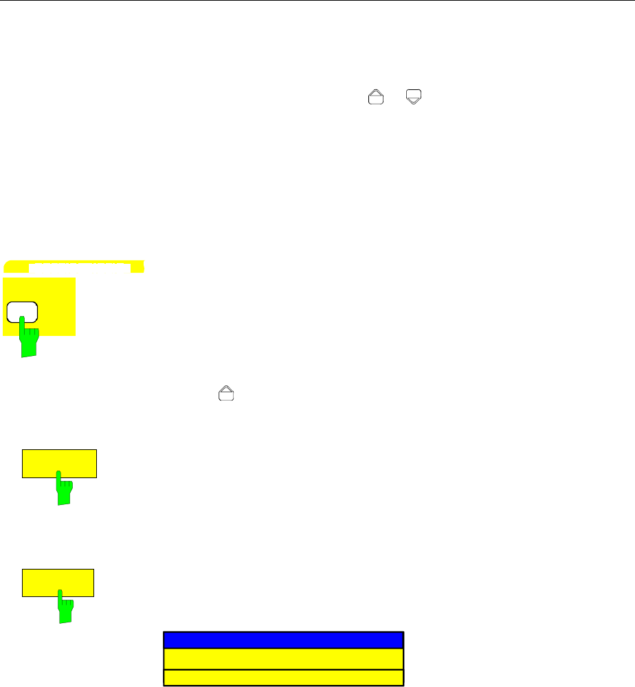
Setting the Stepsize FSE
1065.6016.12 3.20 E-13
Setting the Stepsize - STEP Key
A number of numeric instrument parameters allow for step-by-step incrementing or decrementing the
value in the editing line of the entry window using the keys or or the roll-key. The stepsize used
with the cursor keys can be specified for the selected parameters in the STEP menu.
Notes: – It is not possible to set the stepsize by all of the numeric parameters.
– An extended STEP menu is available by some parameters. The extra functions are
described by the respective parameter.
– Setting the step size has no effect on the roll-key (the resolution of the roll-key is higher than
that of the step size functuion)
D A TA V AR I ATI ON
STEP
The STEP key opens the STEP menu for entry of the stepsize.
The stepsize of an instrument parameter can only be varied when this
parameter is edited in an entry window.
The softkeys in the STEP menu are disabled if no instrumentnparameter is
being varied or if the parameter being edited does not support stepsize
variation (as is the case by all of the alphanumeric parameters.
The key leads to exit from the STEP menu and automatic return to the
previously active menu.
STEPSIZE
AUTO
The softkey STEPSIZE AUTO causes the stepsize for the corresponding
instrument parameter to be set automatically and be continuously varied with
varying instrument settings (in accordance with other parameters).
Example:
The stepsize of the CENTER frequency depends on the selected span.
STEPSIZE
MANUAL
The softkey STEPSIZE NORMAL calls an entry window for definition of a
stepsize by the user. The parameter whose stepsize is varied, is displayed in
the headline of the entry window:
START FREQUENCY STEPSIZE
100 kHz
The stepsize remains constant until a new value is entered or until the
STEPSIZE AUTO softkey is activated. It is no longer coupled to other
instrument parameters.

FSE Mouse and External Keyboard Control
1065.6016.12 3.21 E-13
Mouse and External Keyboard Control
External Keyboard Control
The connection of an external keyboard provides additional characters for the entry (letters and special
characters). It is permitted to use both, front panel keys and the external keyboard, for control. The
number, cursor and sign keys have the same effect as the corresponding front panel keys. A few keys
of the external keyboard provide an extended functionality with entries or tables which is described in the
following table. The table shows the external keyboard key combinations through which the functions of
the front panel keys can be emulated.
Note: –The key combination <ALT><S (German keyboard) or <ALT> <SYSREQ> (English
keyboard)switches between the instrument display screen and the controller display
screen(for an installed option FSE-B15, controller option).
– In instrument mode, the key combination <ALT> <F1> switches the keyboard between
the US-American language and the language selected in the GENERAL SETUP menu
(instruments without controller option).
Table 3-3 Front Panel Keyboard Emulation
FSE front panel keys Key assign. for
the ext. keyboard
Softkeys: SK1
SK2
SK3
SK4
SK5
SK6
SK7
SK8
SK9
SK10
F1
F2
F3
F4
F5
F6
F7
F8
F9
F10
Menu select: Menu left
Menu right
Menu up
CTRL ←
CTRL →
CTRL ↑
Cursor control: Cursor left
Cursor right
Cursor up
Cursor down
←
→
↑
↓
Roll-key: Turn left
Turn right SHIFT ↑
SHIFT ↓
Numeric keys: 0 to 9 0 to 9
Units keys: GHz...
MHz...
kHz...
Hz...
ALT-G
ALT-M
ALT-K
<ENTER>
Edit keys: Clear
Backspace <ESC>
BACK
Misc. data entry keys:
Exponent "Exp"
Sign "+/-"
Decimal point"."
ALT-E
-
.
Hold key: Hold SHIFT-F1
User menu: User SHIFT-F2
System keys: Preset
Cal
Display
Info
SHIFT-F4
ALT-F12
ALT-F10
SHIFT-F5
Configuration key group: Mode
Setup ALT-F2
SHIFT-F8
Hardcopy key group: Start
Settings SHIFT-F6
SHIFT-F9
FSE front panel keys Key assign. for
the ext. keyboard
Status key group : Local SHIFT-F3
Frequency key group: Start
Stop
CenterCenter
Span
CTRL-F7
CTRL-F8
CTRL-F9
CTRL-F10
Level key group: Ref
Range
Input
Cal
CTRL-F11
CTRL-F12
ALT-F11
ALT-F12
Marker key group : Normal
Search
Delta
→ Mkr
CTRL-F1
CTRL-F2
CTRL-F3
CTRL-F4
Lines key group : Display
Limit CTRL-F5
CTRL-F6
Traces key group : 1
2
3
4
ALT-1
ALT-2
ALT-3
ALT-4
Sweep key group : --
--
--
Coupl.
Sweep
Trigger
ALT-F3
ALT-F4
ALT-F5
ALT-F6
ALT-F7
ALT-F8
Memory key group: Config
Save
Recall
SHIFT-F10
SHIFT-F11
SHIFT-F12
Data entry key group : Step SHIFT-F7
Letters and special characters A to Z (ext.)
a to z (ext.)
Special
characters (ext.)
Edit key Delete
Cursor control Home
End
Page up
Page down
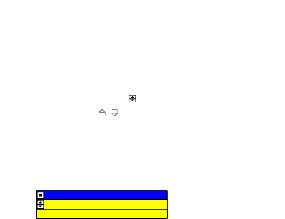
Mouse and External Keyboard Control FSE
1065.6016.12 3.22 E-13
Data Entry Windows with Mouse Control
With a mouse being connected, additional functions are provided in the entry windows. Therefore,
buttons are displayed in the entry window.
Essentially, the definitions which have been made for all types of entry window also apply for mouse
control. However, note the following deviations:
•The so-called close-button is displayed on the left margin of the headline. Selecting this button via the
mouse aborts the entry and closes the entry window. This corresponds to the function of the CLR key
with manual control.
•In the numeric entry window, two buttons ( ) are displayed on the left margin of the editing line.
Simply clicking the buttons causes the parameter in the editing line to be incremented or
decremented (similar to the keys / or the roll-key with manual control).
•The cursor can be positioned in the entry line by clicking a character using the mouse.
•A character in the letter window of the help line editor can be selected by a single click. A double click
copies the character from the letter window into the editing line.
•Open entry windows can be shifted across the complete screen using the mouse; they must not,
however, be superimposed on the softkey line. Shifting is performed by clicking the headline and
pushing the mouse while he mouse-key is being pressed.
Example: Numeric entry window with mouse control
START FREQUENCY
10.2457535 GHZ
START FREQUENCY OUT OF RANGE

FSE Mouse and External Keyboard Control
1065.6016.12 3.23 E-13
Mouse Control of Further Display Elements
All display and control elements (enhancement labels, softkeys, function fields, display and limit lines)
which can be displayed on the display screen can also be controlled by the mouse. Each softkey or key
is assigned to a display element.
Double-klicking an display or control element opens the corresponding softkey menu. The assignment
of softkeys/keys to display elements is shown in the following table.
Klicking the right mouse key call all softkey menus one after the other.
Table 3-4 Mouse Control of Display Elements
Display element for mouse control. Assigned softkey or key
Display field for Softkey 1 to Softkey 10 Softkey 1 to Softkey 10
Display field for menu arrow: right/center/left Key right/center/left supplementary menu
Enhancement labels *
PA
PS
UNS
LVL
FRQ
1-x
2-x
3-x
4-x
TRG
DC
75Ω
MAC
--
SETUP key
SETUP key
COUPLING key
REF key
CENTER key
TRACE 1 key
TRACE 2 key
TRACE 3 key
TRACE 4 key
TRIGGER key
INPUT key
INPUT key
USER key
Status display UNCAL
OVLD
ERR
CAL key
REF key
INFO key
Display fields above the diagram
Ref. Level / Max
Level
Marker
RBW
VBW
SWT
RF Att
Mixer
Unit
REF key
NORMAL key
COUPLING key
COUPLING key
COUPLING key
INPUT key
INPUT key
REF key
Display fields below the diagram
Start
Stop
Center
Span
Trigger
/Div
START key
STOP key
CENTER key
SPAN key
TRIGGER key
--
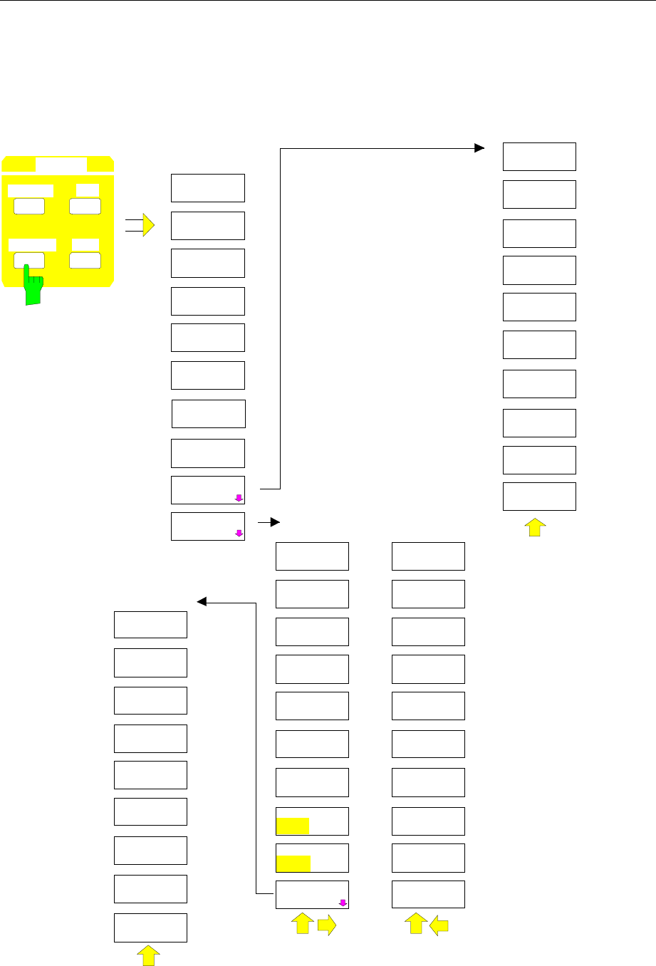
Menu Overview FSE
1065.6016.12 3.24 E-13
Menu Overview
System Key Group
SCREEN
COUPLING
DISPLAY INFO
PRESET CAL
SYSTEM DISPLAY
SPLIT
SCREEN
FULL
SCREEN
CONFIG
DISPLAY
ACTIVE
SCREEN A
ACTIVE
SCREEN B
SCREEN
COUPLING
SCREENS
UNCOUPLED
HORIZONTAL
SCALING
VERTICAL
SCALING
CONFIG
DISPLAY
TINT
SATURATION
DEFAULT
COLORS
SELECT
OBJECT
BRIGHTNESS
LOGO
ON OFF
FREQUENCY
ON OFF
DATAENTRY
FIELD
ACTIVE
SCREEN C
ACTIVE
SCREEN D
MODE
COUPLED
COUPLING
CONTROL
PREDEFINED
COLORS
DISPLAY
COMMENT
TIME
ON OFF
CONFIG
DISPLAY
DATAENTRY
Y
DATAENTRY
X
DEFAULT
POSITION
DATAENTRY
FIELD
DATAENTRY
OPAQUE
SCR SAVER
ON OFF
SCR SAVER
TIME
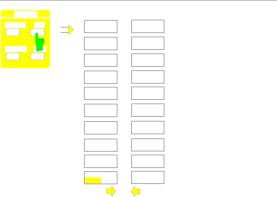
FSE Menu Overview
1065.6016.12 3.25 E-13
PRESET CAL
SYSTEM
DISPLAY INFO
CALIBRATE
CAL
RESULTS
CALIBRATE
CAL TOTAL
CAL
RES BW
CAL SHORT
CAL LOG
CAL I/Q
CAL
LO SUPP
CAL CORR
ON OFF
PRESEL
PEAK PAGE UP
PAGE DOWN
Mod 30
with option
FSE-B7 only
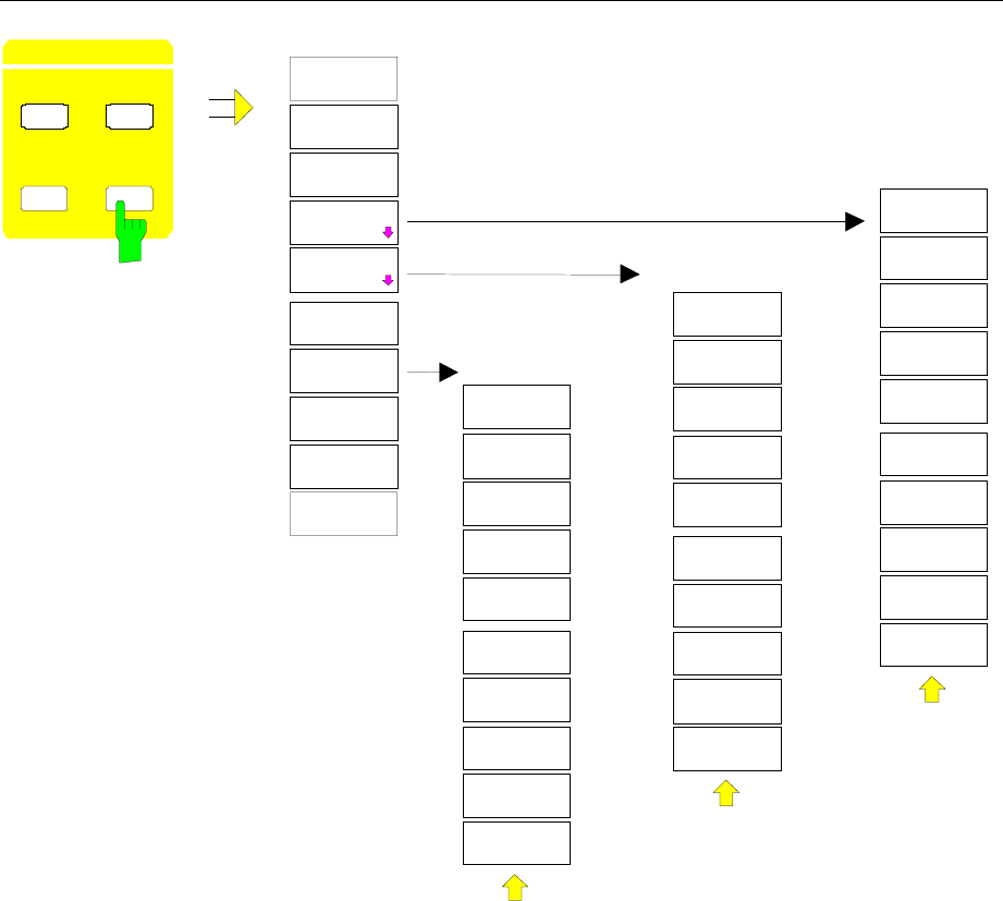
Menu Overview FSE
1065.6016.12 3.26 E-13
SELFTEST
PRESET CAL
SYSTEM
DISPLAY INFO
INFO
FIRMWARE
VERSIONS
HARDWARE+
OPTIONS
SYSTEM
MESSAGES
SELFTEST
EXECUTE
TESTS
SYSTEM
MESSAGES
CLEAR
MESSAGE
CLEAR ALL
MESSAGES
UPDATE
MESSAGES
OPTIONS
STATISTICS
STATISTIC
ATT
SWITCHES
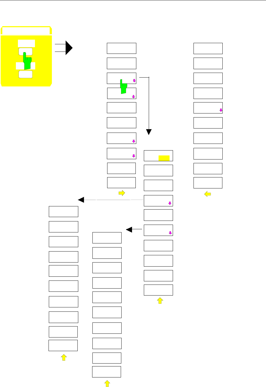
FSE Menu Overview
1065.6016.12 3.27 E-13
Configuration Key Group
MODE
ANALYZER
VECTOR
ANALYZER
CONFIGURATION
MODE
SETUP
TRACKING
GENERATOR
GSM MS
ANALYZER
GSM BTS
ANALYZER
with option
FSE-B9/10/11/12
only
with option FSE-K10 only;
see manual of option
with option FSE-K11 only;
see manual of option
TRACKING
GENERATOR
SOURCE
ON OFF
SOURCE
POWER
POWER
OFFSET
SOURCE
CAL
FREQUENCY
OFFSET
MODULATION
SOURCE
CAL
CAL
TRANS
CAL REFL
SHORT
CAL REFL
OPEN
REF VALUE
POSITION
REF VALUE
NORMALIZE
RECALL
MODULATION
EXT AM
EXT FM
EXT ALC
EXT I/Q
with option FSE-B7 only;
see manual of option
MODE
TV DEMOD
with option
FSE-B3 only
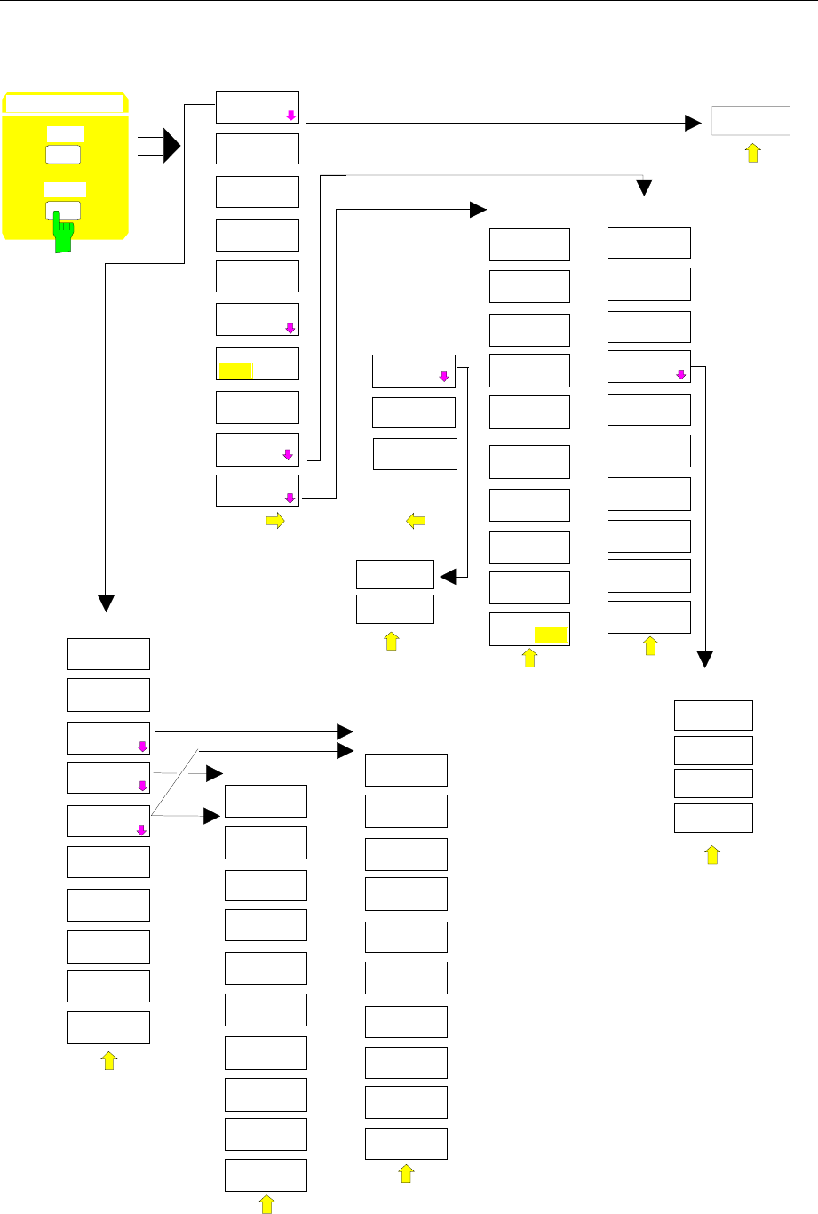
Menu Overview FSE
1065.6016.12 3.28 E-13
Setup for Instruments with Windows NT Controller Option
CONFIGURATION
MODE
SETUP
SETUP
REFERENCE
EXT
INT
GPIB
ADDRESS
GENERAL
SETUP
TIME
DATE
MONITOR
CONNECTED
USER
PORT A
USER
PORT B
SERVICE
GENERAL
SETUP
TRANSDUCER
KEY CLICK
ON OFF
OPTIONS
TRANSDUCER
EDIT TRD
FACTOR
EDIT TRD
SET
TRANSDUCER
FACTOR
TRANSDUCER
SET
PAGE UP
PAGE DOWN
DELETE
FACTOR/SET
NEW
FACTOR/SET
EDIT TRD
FACTOR
TRD FACTOR
NAME
TRD FACTOR
UNIT
TRD FACTOR
VALUES
DELETE
LINE
INSERT
LINE
DRAW TRD
FACTOR
SAVE TRD
FACTOR
TRANSD SET
RANGES
INS ERT
LI NE
TRANSD SET
NAME
TRANSD SET
UNIT
DELETE
LINE
DRAW
TRD SET
SAVE TRD
SET
PAGE UP
PAGE DOWN
OPTIONS
ENABLE NEW
OPTION
REFERENCE
ADJUST
REFERENCE
REFERENCE
PROG
FIRMWARE
UPDATE
UPDATE
RESTORE
COM
PORT2
COM
PORT1
EDIT
TRANSD SET
SERVICE
INPUT
RF
INPUT
CAL
NOISE
SOURCE
REFERENCE
ADJUST
ENTER
PASSWORD
EXT REF
FREQUENCY
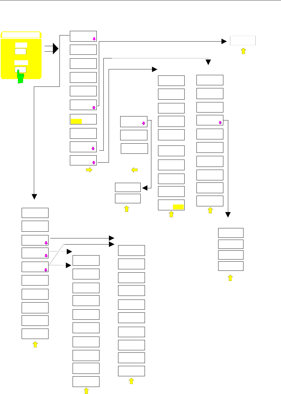
FSE Menu Overview
1065.6016.12 3.29 E-13
Setup for Instruments with MS DOS Controller Option or without Controller
CONFIGURATION
MODE
SETUP
SETUP
REFERENCE
EXT
INT
GPIB
ADDRESS
GENERAL
SETUP
TIME
DATE
EXTERNAL
KEYBOARD
USER
PORT A
USER
PORT B
SERVICE
GENERAL
SETUP
TRANSDUCER
KEY CLICK
ON OFF
OPTIONS
TRANSDUCER
EDIT TRD
FACTOR
EDIT TRD
SET
TRANSDUCER
FACTOR
TRANSDUCER
SET
PAGE UP
PAGE DOWN
DELETE
FACTOR/SET
NEW
FACTOR/SET
EDIT TRD
FACTOR
TRD FACTOR
NAME
TRD FACTOR
UNIT
TRD FACTOR
VALUES
DELETE
LINE
INSERT
LINE
DRAW TRD
FACTOR
SAVE TRD
FACTOR
TRANSD SET
RANGES
INS ERT
LI NE
TRANSD SET
NAME
TRANSD SET
UNIT
DELETE
LINE
DRAW
TRD SET
SAVE TRD
SET
PAGE UP
PAGE DOWN
OPTIONS
ENABLE NEW
OPTION
REFERENCE
ADJUST
REF ERENCE
REFERENCE
PROG
FIRMWARE
UPDATE
UPDATE
RESTORE
COM
PORT2
COM
PORT1
EDIT
TRANSD SET
SERVICE
INPUT
RF
INPUT
CAL
NOISE
SOURCE
REFERENCE
ADJUST
ENTER
PASSWORD
EXT REF
FREQUENCY
MOUSE
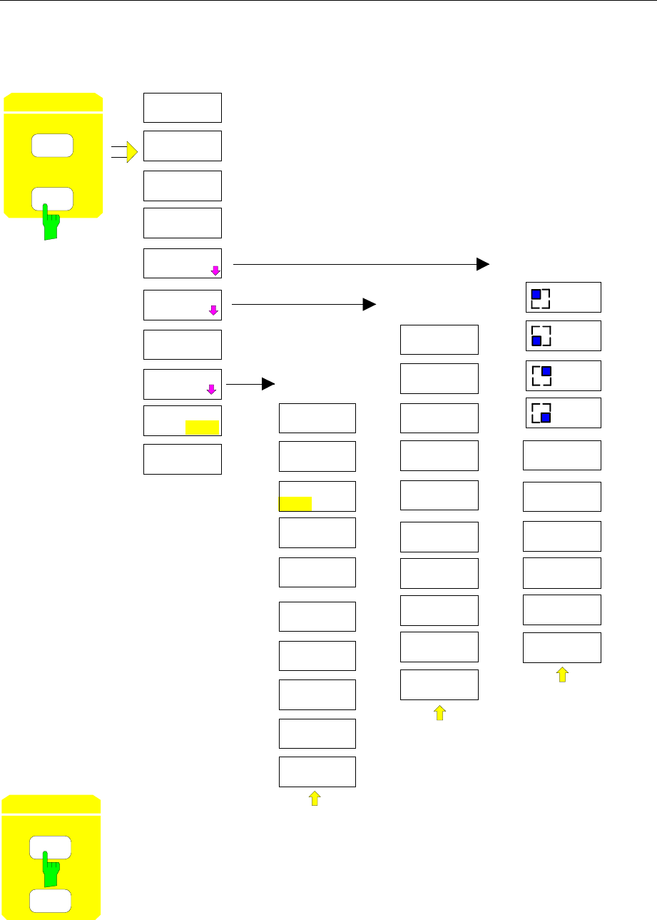
Menu Overview FSE
1065.6016.12 3.30 E-13
Hardcopy Key Group
COPY TRACE
SELECT
QUADRANT
HARDCOPY
DEVICE
TRC COLOR
AUTO INC
ENTER
TEXT
HARDCOPY
SETTINGS
COPY
SCREEN
SELECT
QUADRANT
FULL
PAGE
ENTER
TEXT
COMMENT
SCREEN A
COMMENT
SCREEN B
TITLE
SETTINGS
DEVICE 1
SETTINGS
DEVICE 2
ENABLE
DEV1 DEV2
HARDCOPY
DEVICE
UPPER
LEFT
UPPER
RIGHT
LOWER
LEFT
LOWER
RIGHT
COPY TABLE
w
ithout softkey menu
COLOR
ON OFF
HARDCOPY
START
SETTINGS
HARDCOPY
START
SETTINGS
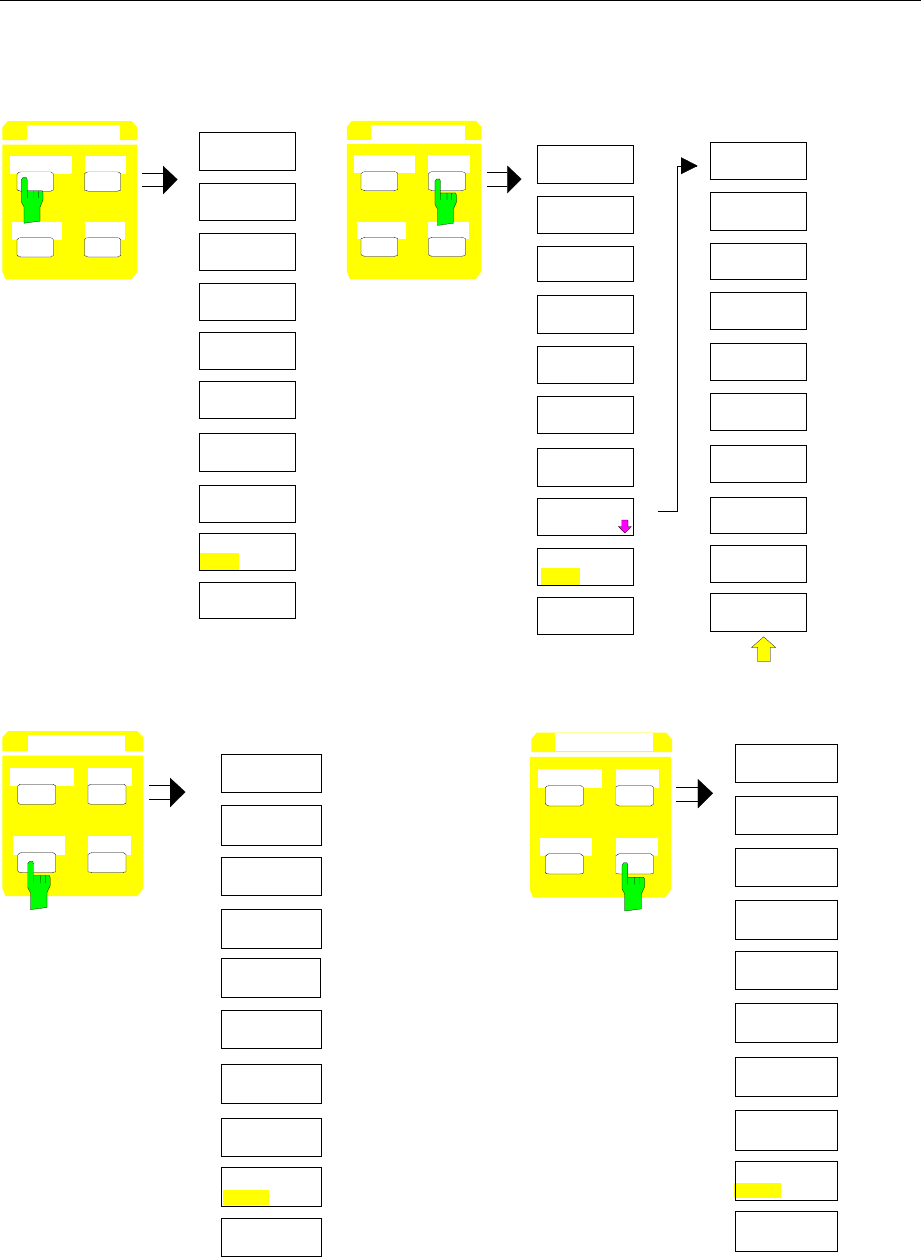
FSE Menu Overview
1065.6016.12 3.31 E-13
Frequency Key Group
CENTER SPAN
START STOP
FREQUENCY
FIXED
CENTER
MANUAL
START
FIXED
SPAN
CENTER
STOP
FIXED
CENTER SPAN
START STOP
FREQUENCY FREQUENCY
MOVE ZOOM
WINDOW
ZOOM
MOVE ZOOM
MOVE ZOOM
STOP
START
ZOOM
OFF
SPAN
SPAN
MANUAL
START
FIXED
CENTER
FIXED
FIXED
STOP
ZERO SPAN
FULL SPAN
LAST SPAN
ZOOM
FREQ AXIS
LINEAR
LOG
FREQUENCY
OFFSET
MIXER
INTERNAL
MIXER
EXTERNAL
FREQ AXIS
LIN LOG MIXER
INTERNAL
FREQ AXIS
LIN LOG
CENTER SPAN
START STOP
FREQUENCY
FIXED
START
CENTER
FIXED
SPAN
START FREQ
MANUAL
STOP
FIXED
STOP
FREQ
STOP
START
CENTER
SPAN
MANUAL
FIXED
FIXED
FIXED
CENTER SPAN
START STOP
FREQUENCY
FREQ AXIS
LIN LOG
FREQ AXIS
LIN LOG
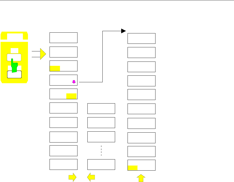
Menu Overview FSE
1065.6016.12 3.32 E-13
Level Key Group, Input Key
REF
RANGE
dBm
dBµV
dBµA
VOLT
AMPERE
WATT
UNIT
PROBE CODE
ON OFF
REF LEVEL
REF LEVEL
GRID
ABS REL
REF LEVEL
AUTO
UNIT
MAX LEVEL
AUTO
MAX LEVEL
MANUAL
REF LEVEL
OFFSET
dB* / MHz
dBmV
dBpW
LEVEL
REF LEVEL
RF ATTEN
MANUAL
MIXER
LEVEL
ATTEN AUTO
NORMAL
ATTEN AUTO
LOW NOISE
ATTEN AUTO
LOW DIST
ATTEN STEP
1dB 10dB
with option
FSE-B13 only
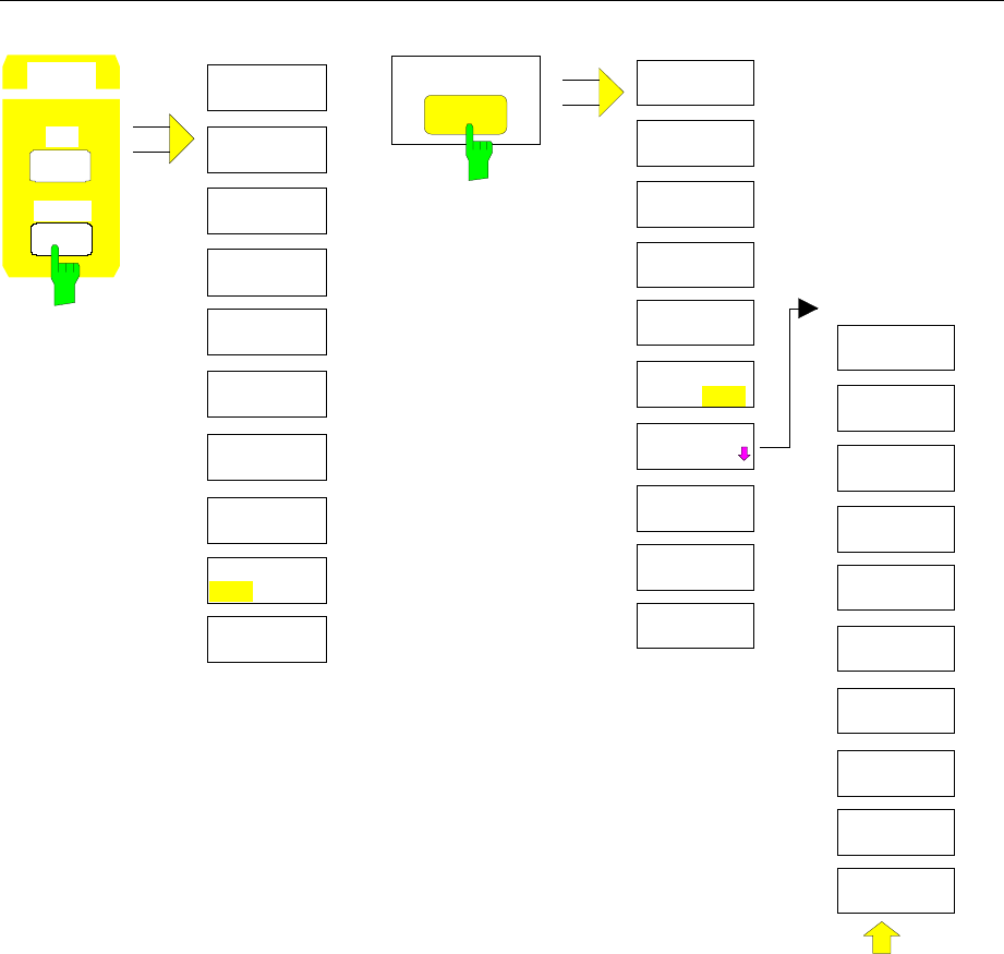
FSE Menu Overview
1065.6016.12 3.33 E-13
LOG 100 dB
LOG 50 dB
LOG 20 dB
LOG 10 dB
LEVEL RANGE
LOG
MANUAL
LOG 120 dB INPUT
ATTEN AUTO
LOW NOISE
RF ATTEN
MANUAL
ATTEN AUTO
LOW DIST
MIXER
LEVEL
INPUT
RF INPUT
50 OHM
RF INPUT
75 OHM/RAZ
RF INPUT
75 OHM/RAM
ATTEN AUTO
NORMAL
INPUT
SELECT
INPUT
SELECT
LEVEL
REF
RANGE
LINEAR/dB
LINEAR/%
GRID
ABS REL
ATTEN STEP
1dB 10dB
with option
FSE-B13 only
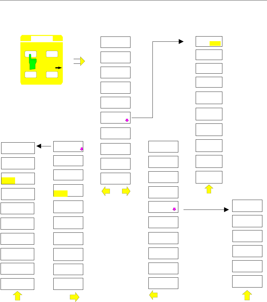
Menu Overview FSE
1065.6016.12 3.34 E-13
Marker Key Group
MARKER
NORMAL
MARKER 2
MARKER 3
SIGNAL
COUNT
NOISE
SIGNAL
TRACK
MARKER
NORMAL
MARKER
DEMOD
MARKER 1
SIGNAL ID
NOISE MEAS
SETTINGS
MARKER 4
ALL MARKER
OFF
ALL MARKER
OFF
COUNTER
RESOL
MARKER
INFO
MARKER
LIST
MARKER
ZOOM
MARKER
NORMAL SEARCH
DELTA MKR
MARKER
DEMOD
AM
FM
MKR
STOP TIME
VOLUME
MKR DEMOD
ON OFF
PM
COUNTER
RESOLUTION
100 Hz
10 kHz
10 Hz
1 kHz
CHANNEL
BANDWIDTH
CHANNEL
POWER
C / No
C / N
OCCUPIED
PWR BANDW
CHANNEL
SPACING
REL
ADJACENT
CHAN POWER
ABS
% POWER
BANDWIDTH
CP/ACP
EDIT
ACP LIMITS
ADJUST CP
SETTINGS
MARKER
NORMAL
1 Hz
0.1 Hz
POWER MEAS
SETTINGS
ACP
STANDARD
SET NO. OF
ADJ CHAN’S
CH FILTER
ON OFF
LIMIT
CHECK
POWER MEAS
SETTINGS
SET CP
REFERENCE
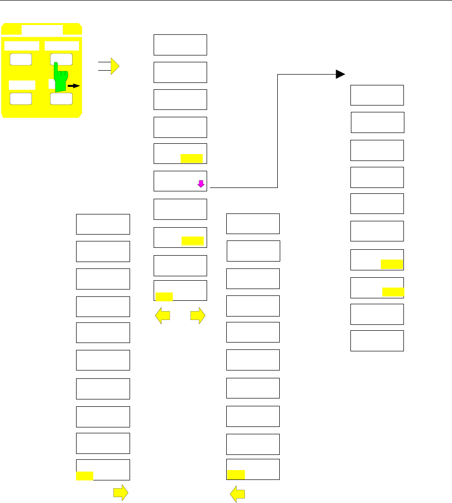
FSE Menu Overview
1065.6016.12 3.35 E-13
MARKER
NORMAL SEARCH
DELTA M
MARKER
SEARCH
N DB DOWN
SHAPE FACT
60/6 DB
MARKER
SEARCH
NEXT PEAK
NEXT PEAK
RIGHT
NEXT PEAK
LEFT
MIN
NEXT MIN
NEXT MIN
RIGHT
SEARCH LIM
ON OFF
MARKER
SEARCH
SELECT
MARKER
SELECT
MARKER
SHAPE FACT
60/3 DB
SELECT
MARKER
ACTIVE
MKR DELTA
NEXT MIN
LEFT
PEAK
ACTIVE
MKR DELTA
ACTIVE
MKR DELTA
PEAK
EXCURSION
SUM MKR
ON OFF
SUMMARY
MARKER
SUMMARY
MARKER
SWEEP
COUNT
RMS
MEAN
ALL SUM
MKR OFF
PEAK HOLD
ON OFF
AVERAGE
ON OFF
EXCLUDE LO
ON OFF
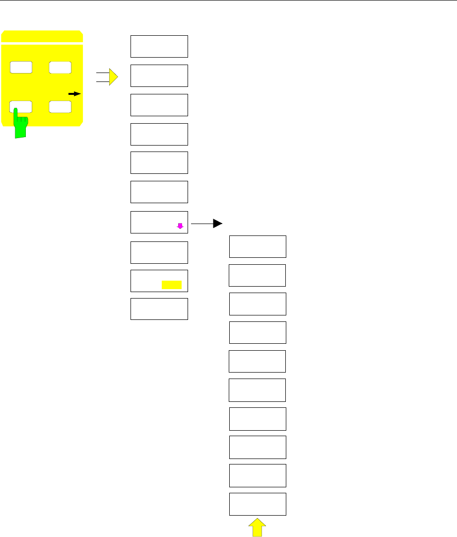
Menu Overview FSE
1065.6016.12 3.36 E-13
DELTA 2
DELTA 3
PHASE
NOISE
DELTA 1
REFERENCE
FIXED
DELTA 4
ALL DELTA
OFF
REFERENCE
POINT
DELTA MKR
ABS REL
REFERENCE
POINT
REF POINT
LEVEL
REF POINT
LVL OFFSET
REF POINT
FREQUENCY
REF POINT
TIME
MARKER
NORMAL SEARCH
DELTA MKR
DELTA
MARKER
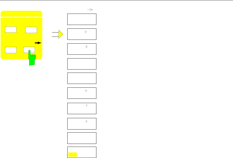
FSE Menu Overview
1065.6016.12 3.37 E-13
CENTER
PEAK
REF LEVEL
ACTIVE
MKR DELTA
MARKER
MKR
MKR
TRACE
MKR
START
MKR
AUTOSCALE
MKR->CF
STEPSIZE
STOP
MKR
SELECT
MARKER
MARKER
NORMAL SEARCH
MKR
DELTA
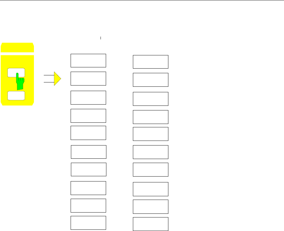
Menu Overview FSE
1065.6016.12 3.38 E-13
Lines Key Group
LINES DISPLAY
LINES
DISPLAY
LINE 2
DISPLAY
LINE 1
DISPLAY
LINE 2
DISPLAY
LINE 1
or
TIME
LINE 1
TIME
LINE 2
REFERENCE
LINE
THRESHOLD
LINE
THRESHOLD
LINE
REFERENCE
LINE
for span = 0 for span = 0
DISPLAY
LINES
FREQUENCY
LINE 1
FREQUENCY
LINE 2
LIMITS
D LINES
BASELINE
CLIPPING BASELINE
CLIPPING
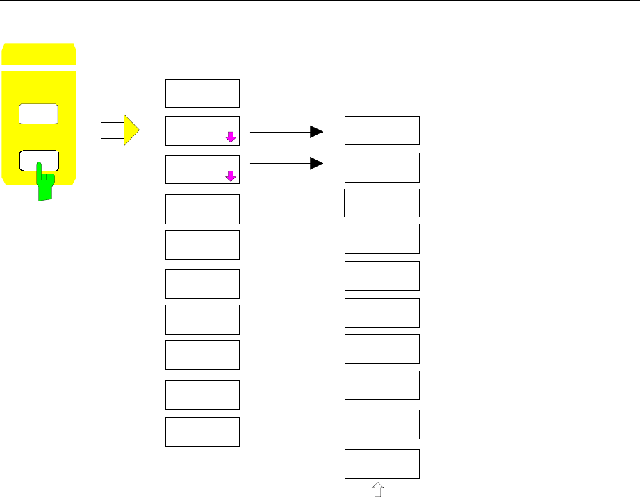
FSE Menu Overview
1065.6016.12 3.39 E-13
LIMIT LINES
PAGE UP
PAGE DOWN
NEW LIMIT
LINE
EDIT
LIMIT LINE
NAME
VALUES
DELETE
VALUE
INSERT
VALUE
EDIT
ACCEPT
POSITION
TABLE GRAPH
PAGE UP
PAGE DOWN
SAVE
LIMIT LINE
SHIFT X
LIMIT LINE
EDIT LIMIT
LINE
NEW LIMIT
LINE
DELETE
LIMIT LINE
SELECT
LIMIT LINE
COPY
LIMIT LINE
X OFFSET
Y OFFSET
SHIFT Y
LIMIT LINE
LINES
D LINES
LIMITS
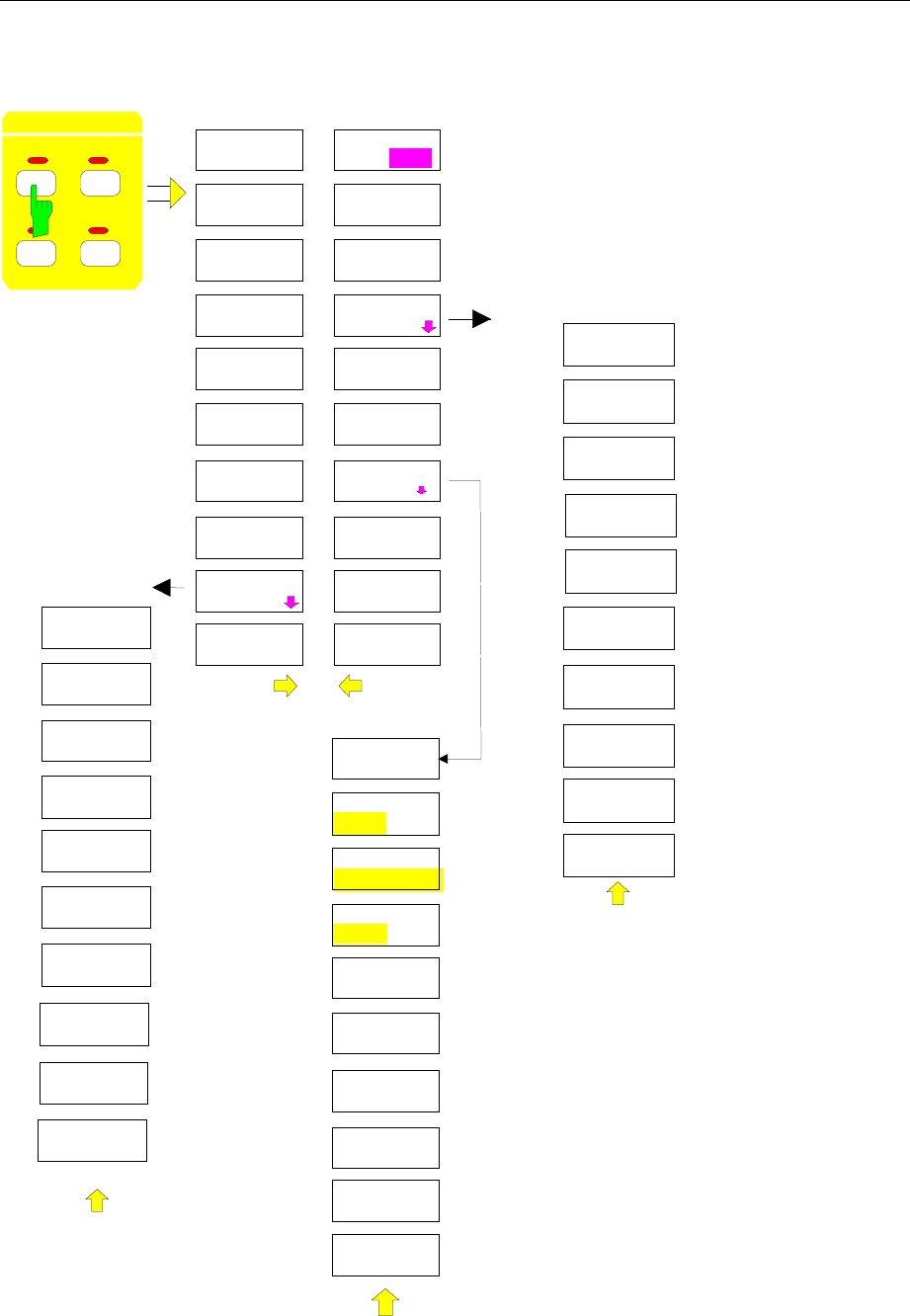
Menu Overview FSE
1065.6016.12 3.40 E-13
Trace Key Group
CLEAR/
WRITE
MAX HOLD
MIN HOLD
AVERAGE TRACE
MATH
VIEW
BLANK
TRACE 1
DETECTOR
SWEEP
COUNT
TRACE 1
COPY..
ANALOG TR
ON OFF
TRACE MATH
OFF
T1-T2+REF
-> T1
T1-REF
->T1
TRACE MATH
T1-T3+REF
-> T1
T1-T4+REF
-> T1
ADJUST TO
TRACE
AUTO
SELECT
DETECTOR
SAMPLE
TRACE 1
DETECTOR
DETECTOR
AUTOPEAK
DETECTOR
MIN PEAK
DETECTOR
MAX PEAK
12
34
TRACE
ASCII
CONFIG
NEW
APPEND
HEADER
ON OFF
EDIT PATH
DECIM SEP
. ,
ASCII
CONFIG
ASCII
EXPORT
HOLD CONT
ON OFF
DETECTOR
RMS
DETECTOR
AVERAGE ASCII
COMMENT
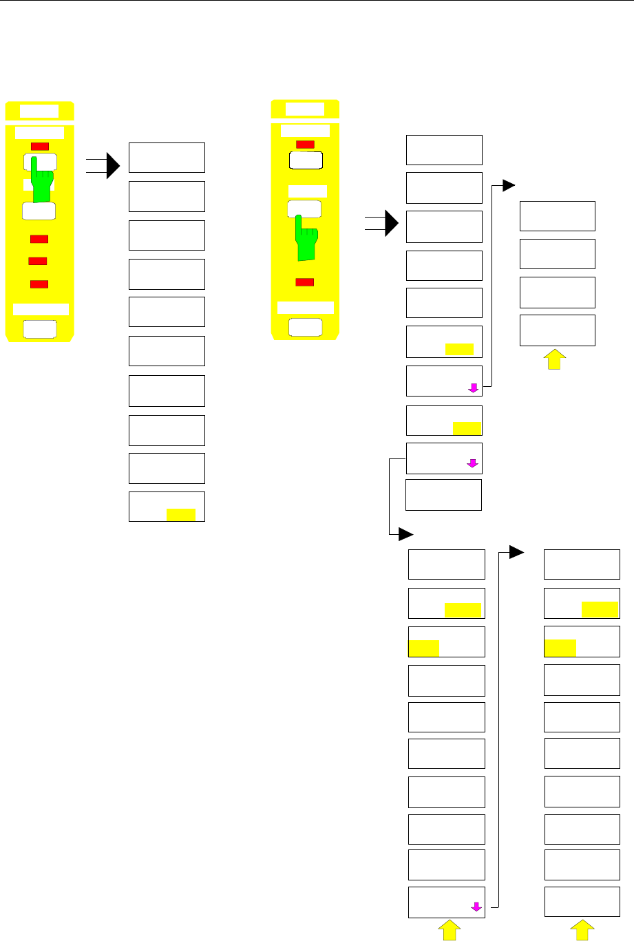
FSE Menu Overview
1065.6016.12 3.41 E-13
Sweep Key Group
GATE
LEVEL
GATE MODE
LEVEL EDGE
GATE
DELAY
GATE POL
POS NEG
GATE
SETTINGS
SWEEP
CONTINOUS
SWEEP
SGL SWEEP
DISP OFF
SWEEP TIME
MANUAL
GATE
SETTINGS
GATE
ON OFF
GAP SWEEP
SETTINGS
GAP SWEEP
ON OFF
SWEEP
COUNT
SINGLE
SWEEP
GATE
LENGTH
TRIGGER
LEVEL
PRE
TRIGGER
GAP
LENGTH
TRG TO GAP
TIME
GAP SWEEP
SETTINGS
SWEEP TIME
AUTO
GATE
ADJUST
GATE
LEVEL
GATE MODE
LEVEL EDGE
GATE
DELAY
GATE POL
POS NEG
GATE
LENGTH
GATE
ADJUST
SWEEPTIME
MANUAL
RES BW
MANUAL
VIDEO BW
MANUAL
VIDEO BW
AUTO
GATE
EXTERN
GATE
RF POWER
SWEEP
TRIGGER
RW
VW
SWT
SWEEP
TRIGGER
RBW
VBW
SW T
S
COUPLING
TRIGGER
FREE RUN
VIDEO
EXTERN
SLOPE
POS NEG
TRIGGER
DELAY
LINE
RF POWER COUPLING
SWEEP
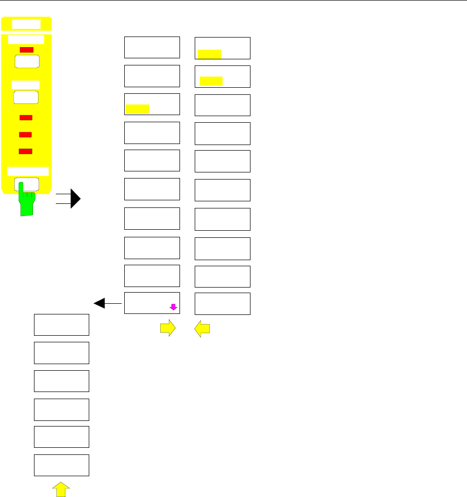
Menu Overview FSE
1065.6016.12 3.42 E-13
COUPLED
FUNCTIONS
RES BW
AUTO
RES BW
MANUAL
VIDEO BW
AUTO
VIDEO BW
MANUAL
SWEEP TIME
AUTO
SWEEP TIME
MANUAL
COUPLING
RATIO
RBW / VBW
PULSE [.1]
RBW / VBW
SINE [1]
RBW / VBW
NOISE [10]
SPAN / RBW
AUTO [50]
RBW / VBW
MANUAL
SPAN / RBW
MANUAL
COUPLING
DEFAULT
MAIN PLL
BANDWIDTH
COUPLED
FUNCTIONS
RBW 1 kHz
ANA DIG
RBW<=1kHz
NORM FFT
SWEEP
TRIGGER
RBW
VBW
SWT
SWEEP
COUPLING
RES BW
3dB 6dB
COUPLING
RATIO
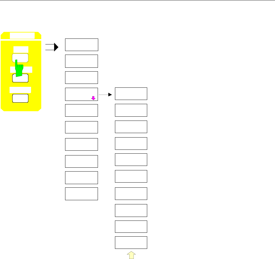
FSE Menu Overview
1065.6016.12 3.43 E-13
Memory Key Group
PAGE DOWN
MEMORY
SAVE
PAGE UP
SEL ITEMS
TO SAVE
DATA SET
LIST
EDIT
PATH
DATA SET
CLEAR
DATA SET
CLEAR ALL
EDIT
NAME
EDIT
COMMENT
ENABLE
ALL ITEMS
DISABLE
ALL ITEMS
SEL ITEMS
TO SAVE
DEFAULT
CONFIG
SELECT
ITEMS
MEMORY
RECALL
SAVE
CONFIG
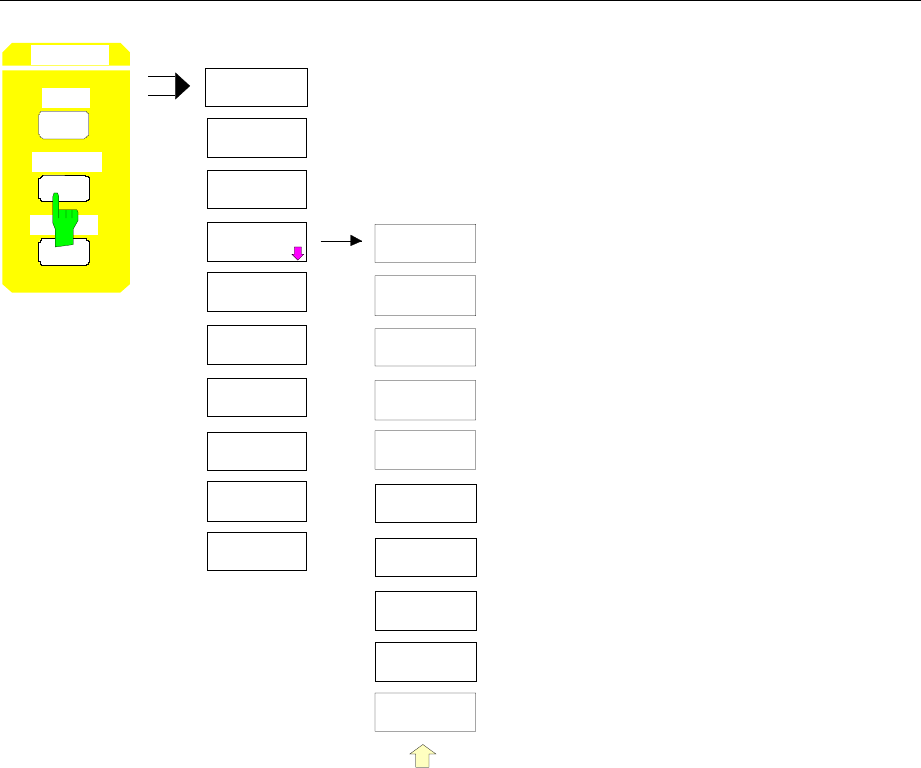
Menu Overview FSE
1065.6016.12 3.44 E-13
MEMORY
RECALL
SAVE
CONFIG
PAGE DOWN
MEMORY
RECALL
PAGE UP
SEL ITEMS
TO RECALL
DATA SET
LIST
EDIT
PATH
DATA SET
CLEAR
DATA SET
CLEAR ALL
EDIT
NAME
AUTO
RECALL
ENABLE
ALL ITEMS
DISABLE
ALL ITEMS
SEL ITEMS
TO RECALL
DEFAULT
CONFIG
SELECT
ITEMS
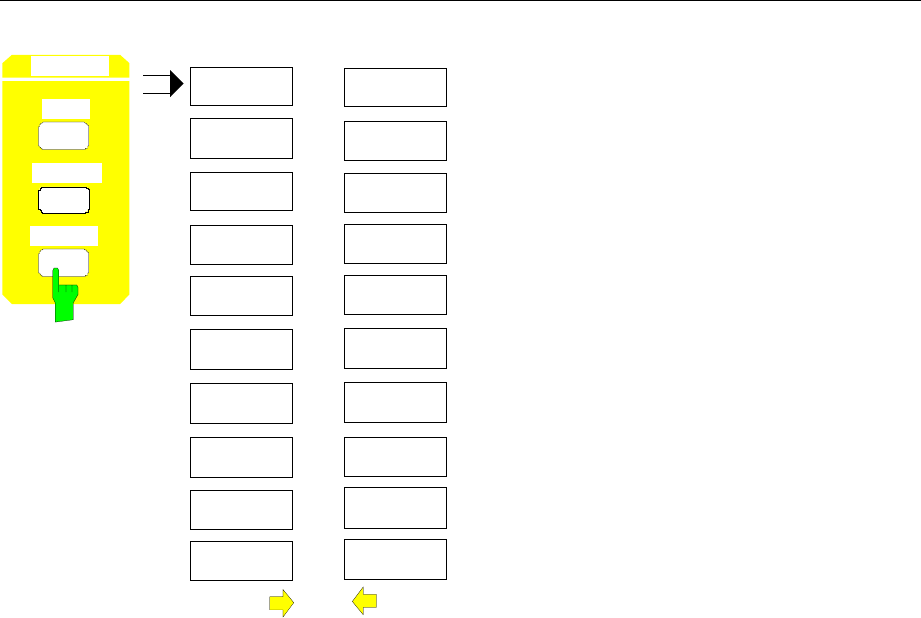
FSE Menu Overview
1065.6016.12 3.45 E-13
EDIT
PATH
COPY
PAGE DOWN
MEMORY
CONFIG
DELETE
RENAME
SORT MODE
MAKE
DIRECTORY
FORMAT
DISK
PAGE UP
PAGE DOWN
PAGE UP
MEMORY
CONFIG
MEMORY
RECALL
SAVE
CONFIG
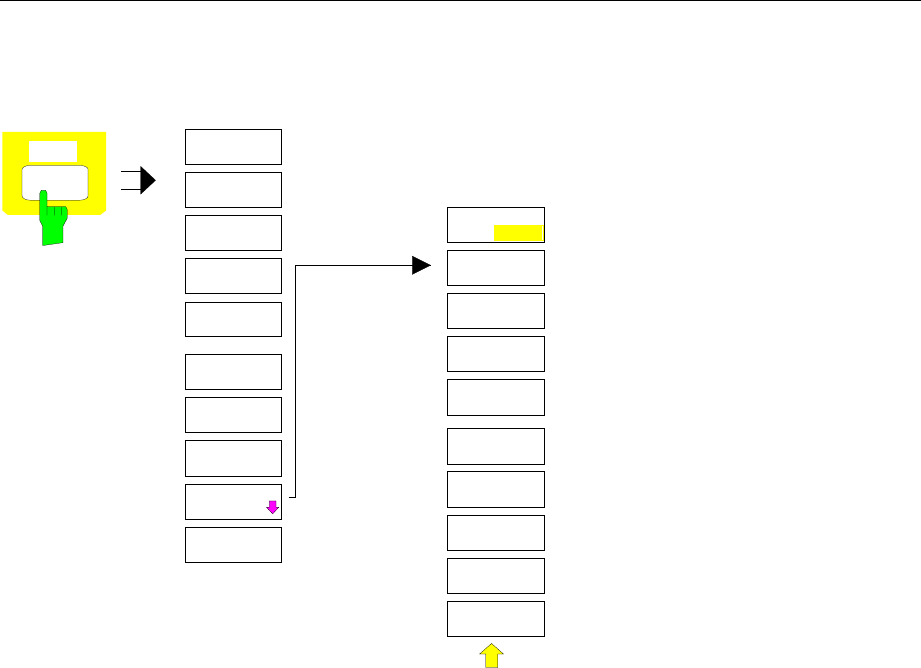
Menu Overview FSE
1065.6016.12 3.46 E-13
User Key Group
USER
(MACRO 1)
(MACRO 2)
(MACRO 3)
(MACRO 4)
(MACRO 5)
(MACRO 6)
(MACRO 7)
DEFINE
MACRO
USER
DEFINE
MACRO
SELECT
MACRO
RECORD
ON OFF
DEFINE
PAUSE
DELETE
MACRO
MACRO
TITLE

FSE Contents - "Instrument Functions"
1065.6016.12 I-4.1 E-1
Contents - Chapter 4 "Instrument Functions"
4 Instrument Functions.......................................................................................... 4.1
General Configuration – SYSTEM and CONFIGURATION Key Groups...................................... 4.2
FSE Initial Configuration – PRESET Key................................................................................. 4.2
Display Configuration – DISPLAY Key .................................................................................... 4.3
Display Screen Mode Selection..................................................................................... 4.4
Measurement Window Coupling ................................................................................... 4.5
Display Screen Configuration........................................................................................ 4.6
Recording the Correction Data – CAL Key.............................................................................. 4.9
Correction Function Calls ............................................................................................ 4.10
Results of System Error Correction............................................................................. 4.12
Instrument Status and Measurement Parameters – INFO Key............................................. 4.13
Firmware Versions ...................................................................................................... 4.13
Hardware Configuration and Options .......................................................................... 4.14
Self Test ...................................................................................................................... 4.15
System Messages ....................................................................................................... 4.16
Statistics Function for Input Attenuator Switching ....................................................... 4.17
Mode Selection – MODE Key................................................................................................ 4.18
Preliminary Setup and Interface Configuration – SETUP Key............................................... 4.20
Using Transducers ...................................................................................................... 4.20
Activating Transducer Factors and Transducer Sets ..................................... 4.21
New Entry and Editing of Transducer Factors................................................ 4.23
New Entry and Editing of Transducer Sets..................................................... 4.27
Enabling Firmware Options......................................................................................... 4.31
External Reference Oscillator...................................................................................... 4.31
Service Functions........................................................................................................ 4.32
Setting the Interface Configuration and Time - with Windows NT Controller.............. 4.34
IEC/IEEE-Bus Address Selection................................................................... 4.34
User Port Configuration.................................................................................. 4.35
Serial Interface Configuration ........................................................................ 4.36
Setting the Date and Time ............................................................................. 4.39
Connecting the External Monitor ................................................................... 4.39
Switching the Beeper ON/OFF ...................................................................... 4.39
Setting the Interface Configuration and Time - without Controller Option
or with MS DOS Controller .......................................................................................... 4.40
IEC Bus Address Selection ............................................................................ 4.40
Switching the Beeper ON/OFF ....................................................................... 4.40
User Port Configuration.................................................................................. 4.41
Serial Interface Configuration......................................................................... 4.42
Setting Date and Time.................................................................................... 4.45
Mouse Configuration ..................................................................................... 4.46
Firmware Update......................................................................................................... 4.47
Status Display-Remote/Manual Control – STATUS Key Group ................................................ 4.49
Measurement Documentation – HARDCOPY Key Group.............................................................. 4.50
Printing Data – START Key - with Windows NT Controller ................................................... 4.50
Printing Data – START Key- with MS DOS Controller or without Controller.......................... 4.52

Contents - "Instrument Functions" FSE
1065.6016.12 I-4.2 E-1
Printing Configuration – SETTINGS Key............................................................................... 4.54
Selection of Displayed Elements and Colour Settings ................................................ 4.55
Selection of Hardcopy Format..................................................................................... 4.56
Entry of Comment Text ............................................................................................... 4.57
Selection and Configuration of the Printer - with Windows NT Controller................... 4.58
Selection and Configuration of the Printer - with DOS Controller/ without Controller.. 4.60
Saving and Recalling Data Sets – MEMORY Key Group............................................................ 4.66
Configuration of Memory – CONFIG Key............................................................................. 4.68
Saving Data Sets – SAVE Key ............................................................................................. 4.70
Selecting the Data Set for Saving................................................................................ 4.71
Selecting the Data subset for Storage......................................................................... 4.73
Recalling of Data Sets – RECALL Key................................................................................. 4.75
Selecting the Data Set for Recalling............................................................................ 4.76
Building a Data Set......................................................................................... 4.78
Macros – USER Key....................................................................................................................... 4.80
Fundamentals........................................................................................................................ 4.80
Starting Macros...................................................................................................................... 4.81
Defining Macros..................................................................................................................... 4.82
Analyzer Mode................................................................................................................................ 4.84
Frequency and Span Selection – FREQUENCY Key Group................................................. 4.84
Start Frequency – START Key.................................................................................... 4.84
Stop Frequency – STOP Key ...................................................................................... 4.86
Center Frequency – CENTER Key.............................................................................. 4.87
Center Frequency Step Size ....................................................................................... 4.89
Frequency Span – SPAN Key ..................................................................................... 4.91
Display Zoom............................................................................................................... 4.93
Level Display and RF Input Configuration – LEVEL Key Group............................................ 4.94
Reference Level – REF key ........................................................................................ 4.94
Display Units................................................................................................................ 4.96
Level Range – RANGE Key ........................................................................................ 4.98
RF Input Configuration – INPUT Key ........................................................................ 4.100
Option 1 dB Attenuator - FSE-B13 ............................................................................ 4.103
Marker Functions – MARKER Key Group ........................................................................... 4.105
Main Markers– NORMAL Key................................................................................... 4.105
LF Demodulation .......................................................................................... 4.109
Frequency Measurement.............................................................................. 4.111
Noise Power Density Measurement ............................................................. 4.112
Channel Power Measurements .................................................................... 4.113
Marker Step Size.......................................................................................... 4.127
Delta Markers – DELTA Key ..................................................................................... 4.128
Phase Noise Measurement .......................................................................... 4.131
Delta-Marker Step Size - STEP Key............................................................. 4.132
Search Functions – SEARCH Key ............................................................................ 4.133
Summary Marker.......................................................................................... 4.138
Instrument Parameter Changes via Markers – MKR Í Key .................................... 4.141
Setup of Display and Limit Lines – LINES Key Field........................................................... 4.143
Display Lines – D LINES Key.................................................................................... 4.143
Limit Lines – LIMITS Key .......................................................................................... 4.147
Limit Line Selection ...................................................................................... 4.148
Entering and Editing of Limit Lines ............................................................... 4.151

FSE Contents - "Instrument Functions"
1065.6016.12 I-4.3 E-1
Trace Selection and Setup –TRACE Key Group................................................................. 4.156
Measurement Function Selection - TRACE 1 to 4 key.............................................. 4.156
Detector Selection ..................................................................................................... 4.161
Quasi Analog Display ................................................................................................ 4.165
Mathematical Functions for Traces........................................................................... 4.165
Trace Export.............................................................................................................. 4.167
Sweep Control – SWEEP Key Group.................................................................................. 4.170
Coupled Settings – COUPLING Key......................................................................... 4.170
Setting and Coupling the Coupling Res., Video Bandw. and Sweep Time... 4.171
Sweep Coupling Ratio .................................................................................. 4.176
Sweep Trigger – TRIGGER Key ............................................................................... 4.178
Sweep Setup – SWEEP Key..................................................................................... 4.180
Gated Sweep................................................................................................ 4.182
Sweep Blanking – Gap Sweep ..................................................................... 4.188
Tracking Generator Option ......................................................................................................... 4.192
Tracking Generator Settings................................................................................................ 4.193
Transmission Measurement................................................................................................ 4.194
Calibration of the Transmission Measurement.......................................................... 4.194
Normalization............................................................................................................. 4.196
Reflection Measurements.................................................................................................... 4.200
Calibration of Reflection Measurement ..................................................................... 4.200
Calibration Methods................................................................................................... 4.201
Frequency-Converting Measurements ................................................................................ 4.202
External Modulation of Tracking Generator......................................................................... 4.203
Option FSE-B3 −TV Demodulator ....................................................................................... 4.206
Configuration of the TV Demodulator........................................................................ 4.206
Triggering on TV Signals........................................................................................... 4.208

Contents - "Instrument Functions" FSE
1065.6016.12 I-4.4 E-1

FSE Instrument Functions
1065.6016.12 4.1 E-15
4 Instrument Functions
All functions of the spectrum analyzer are explained in detail in this chapter.
The instrument functions for general settings, printout and data management are described at the
beginning of this chapter – key groups SYSTEM, CONFIGURATION, HARDCOPY, MEMORY and the
USER key.
The sequence of the following key groups depends on their appearance on the front panel: key groups
FREQUENCY, LEVEL, MARKER, LINES, TRACE, SWEEP and the INPUT key.
All options that provide an additional operating mode and are not supplied with a separate manual are
described at the end of the chapter.
The various softkeys in a menu are described from top to bottom and from the left to the right side
menu. The submenus are indicated by an indentation or displayed in a separate section. The whole path
(key - softkey - ...) is indicated in the line above the menu display.
An overview of the menus is given in chapter 3 which also contains the description of the operating
concept.
For fast reference a list of softkeys with the associated IEC/IEEE-bus commands is given at the end of
Chapter 6.
An index at the end of the handbook provides as further help for the user.

Initial Configuration FSE
1065.6016.12 4.2 E-15
General Configuration – SYSTEM and CONFIGURATION Key
Groups
FSE Initial Configuration – PRESET Key
PRESET CAL
SYSTEM
DI AY INFO
Using the PRESET key, the FSE can be brought to a predefined initial state
equivalent to the state after power on. All previous setting are deleted if they
were not previously saved in memory. Returning to the PRESET state is not
critical with regard to an arbitrary signal which may still be present at the input
as long as the signal is within the specified voltage range.
Note: The initial state set by the PRESET key can be adapted to the
user requirements using the AUTO RECALL function. When the
PRESET key is pressed, the AUTO RECALL dataset is loaded.
For further information refer to Section "Saving and Recalling
Data Sets".
IEC/IEEE- bus command :*RST
Pressing the PRESET key, causes the FSE to enter its initial state according to the following table:
Table 4-1 Initial state of the FSE
Parameter Setting
FSEA FSEB FSEM FSEK
Mode analyzer analyzer analyzer analyzer
Center Frequency 1,75 GHz 3,5 GHz 13,25 GHz 20 GHz
Center Frequency Step Width 350 MHz 700 MHz 2,65 GHz 4GHz auto, 0.1×Span
Span 3,5 GHz 7 GHz 26,5 GHz 40 GHz
RF Attenuation 10 dB 10 dB 10 dB 10 dB auto
Ref Level -20 dBm -20 dBm -20 dBm - 20 dBm
Level Range 100 dB log 100 dB log 100 dB log 100 dB log
Detector auto peak auto peak auto peak auto peak
Sweep Time 5 ms 5 ms 150 ms 225 ms auto
Res BW 3 MHz 3 MHz 3 MHz 3 MHz auto
Video BW 3 MHz 3 MHz 3 MHz 3 MHz auto
Sweep cont cont cont cont
Trigger free run free run free run free run
Trace 1111clr write
Trace 2, 3, 4 2, 3, 4 2, 3, 4 2, 3, 4 blnk
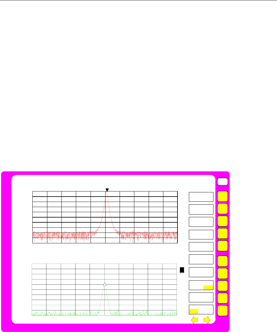
FSE Display Configuration
1065.6016.12 4.3 E-15
Display Configuration – DISPLAY Key
The measurement results are displayed on the screen of the FSE either in a full-screen window or in two
spli-screen windows. In some cases, the two windows can be subdivided into two diagrams each, e. g.
for the representation of the inphase and quadrature signal in the vector analyzer mode (option FSE-
B7).
If only one window is used, this window fills the complete display screen. Two measurement windows
are always placed over each other. The axes labelling and measurement settings are defined
independently in each measurement window.
When two measurement windows are used, the settings can be chosen to be either coupled or fully
independent from each other. The measurement procedure is always sequential.
New instrument settings can only be entered in the active measurement window. This window is marked
on the upper right corner of the grid. Coupled settings are changed simultaneously in both windows at
the time of entry.
The entry of the measurement parameters for each of the two windows can be either independent from
one another using numerical inputs, or by graphical definition of the span through the use of level and
frequency lines. The former case, e.g., may be used for harmonic or frequency converter
measurements, and the latter case, for a zoom display of a frequency or level segment.
USER
Ref Lvl
10 dBm
RBW 1 kHz
VBW 1 kHz
SWT 100 ms
MKR1 [T1]
+9.8 dBm
10.010000 MHz
Span 100 kHz
10.0
-10
-30
-50
-70
-90
10 kHz/
-0
-20
-40
-60
-80
Center 20.000004 MHz
RF ATT 40 dB
Mixer -30 dBm
Unit dBm
Ref Lvl
10 dBm
RBW 1 kHz
VBW 1 kHz
SWT 100 ms
RF ATT 40 dB
Mixer -30 dBm
Unit dBm
Span 100 kHz
10 kHz/
Center 10.000002 MHz
10.0
-10
-30
-50
-70
-90
-0
-20
-40
-60
-80
1
DELTA [T2]
-36.8 dBm
10.000010 MHz
A
B
1
MARKER
SEARCH
NEXT PEAK
NEXT PEAK
RIGHT
NEXT PEAK
LEFT
SEARCH LIM
ON OFF
SELECT
PEAK
ACTIVE
MKR DELTA
Fig. 4-1 Split screen mode, screens uncoupled
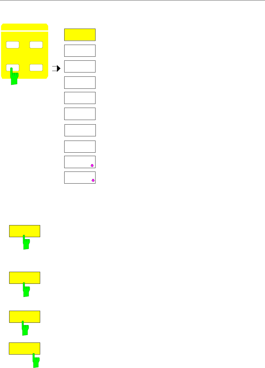
Display Configuration FSE
1065.6016.12 4.4 E-15
SYSTEM DISPLAY menu:
DISPLAY
SPLIT
SCREEN
FULL
SCREEN
CONFIG
DISPLAY
SCREEN
COUPLING
ACTIVE
SCREEN A
ACTIVE
SCREEN B
DISPLAY INFO
PRESET CAL
S
Y
S
T
E
M
ACTIVE
SCREEN C
ACTIVE
SCREEN D
The DISPLAY key calls a menu which is used
to configure the display screen and to select
the active measurement window in SPLIT-
SCREEN mode.
Display Screen Mode Selection
SYSTEM DISPLAY menu:
FULL
SCREEN
The FULL SCREEN softkey selects the full-screen display. This is the default
setting of the FSE.
In this mode, the ACTIVE SCREEN A / ACTIVE SCREEN B and SCREEN
COUPLING softkeys are not used.
IEC/IEEE- bus command :DISPlay:FORMat SINGle
SPLIT
SCREEN
The SPLIT SCREEN softkey selects the split screen mode. The upper screen
is designated SCREEN A, the lower screen SCREEN B.
IEC/IEEE- bus command :DISPlay:FORMat SPLit
ACTIVE
SCREEN A
ACTIVE
SCREEN B
If SPLIT SCREEN display is activated, the ACTIVE SCREEN A and ACTIVE
SCREEN B softkeys activate either screen A or screen B.
The entry of new settings is only possible for the active window.
When switching back to FULL SCREEN mode, the active measurement
window is displayed.
If, in addition, the two screens are both subdivided into two diagrams, the
ACTIVE SCREEN A/B softkeys activate the upper diagram, ACTIVE
SCREEN C/D the lower diagram in each screen.
IEC/IEEE- bus command - (the screen is selected via the numeric suffix)
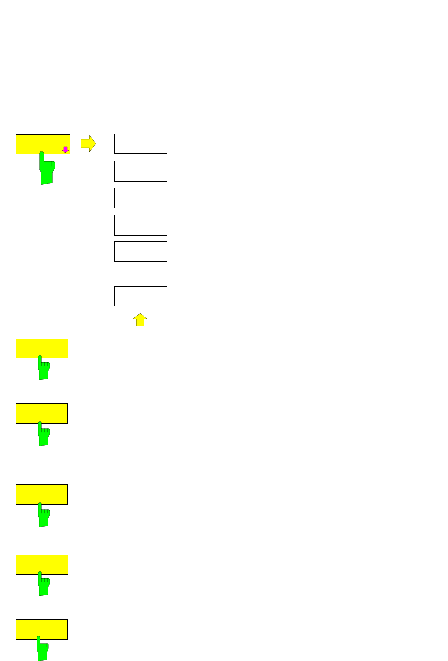
FSE Display Configuration
1065.6016.12 4.5 E-15
Measurement Window Coupling
For the most part, the settings for the two windows can be either independently performed or coupled to
one another. In many cases, when changes are made in one window (e.g., the reference level) it is
desirable to also make the corresponding changes in the second window. The measurement window
parameters which are to be coupled may be selected in the SCREEN COUPLING menu.
SYSTEM DISPLAY-SCREEN COUPLING submenu:
SCREEN
COUPLING
SCREEN
COUPLING
SCREENS
UNCOUPLED
HORIZONTAL
SCALING
VERTICAL
SCALING
MODE
COUPLED
COUPLING
CONTROL
...
The SCREEN COUPLING softkey calls a sub-menu in
which the coupling between the two measurement
windows SCREEN A and SCREEN B can be defined. This
coupling is only effective when both windows are
displayed (SPLIT SCREEN).
In the default setting, all of the items which are selectable
are also coupled.
MODE
COUPLED
The MODE COUPLED softkey switches the coupling of the operating mode
(Analyzer, Vector Analyzer) on/off.
IEC/IEEE- bus command :INSTrument<1|2>:COUPle MODE
HORIZONTAL
SCALING
The HORIZONTAL SCALING softkey switches the coupled scaling of the
horizontal axes on and off. In the frequency domain, the center frequency and
the frequency span are identical. In the time domain, the sweep time for both
windows is the same.
IEC/IEEE- bus command :INSTrument<1|2>:COUPle X
VERTICAL
SCALING
The VERTICAL SCALING softkey switches the coupled scaling of the vertical
axes on and off. For a level measurement, this means that the reference level
and the vertical resolution (LEVEL RANGE) are set to the same values in
both windows.
IEC/IEEE- bus command : INSTrument<1|2>:COUPle Y
COUPLING
CONTROL
The COUPLING CONTROL softkey switches the coupling of the trigger and
gate parameters and of SWEEP COUNT and SWEEP SINGLE/
CONTINOUS on/off.
IEC/IEEE- bus command :INSTrument<1|2>:COUPle CONTrol
SCREENS
UNCOUPLED
The SCREENS UNCOUPLED softkey switches all of the possible couplings
between the measurement windows to off.
IEC/IEEE- bus command : INSTrument<1|2>:COUPle NONE | ALL
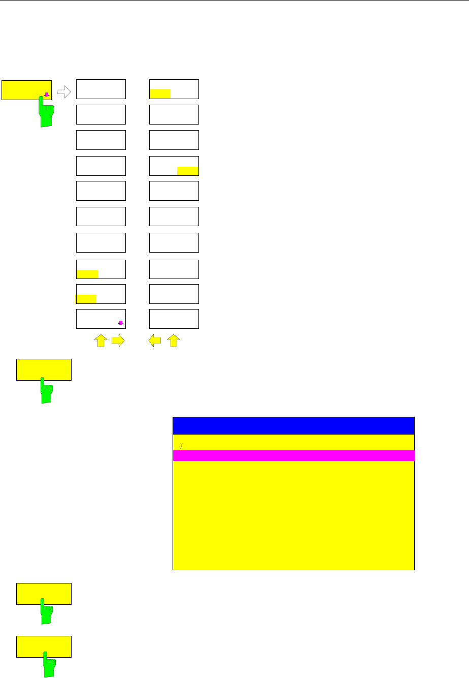
Display Configuration FSE
1065.6016.12 4.6 E-15
Display Screen Configuration
SYSTEM DISPLAY-CONFIG DISPLAY submenu:
DATAENTRY
FIELD
FREQUENCY
ON OFF
CONFIG
DISPLAY
CONFIG
DISPLAY
TINT
SATURATION
DEFAULT
COLORS
SELECT
OBJECT
BRIGHTNESS
LOGO
ON OFF
PREDEFINED
COLORS
TIME
ON OFF
CONFIG
DISPLAY
DISPLAY
COMMENT
SCR SAVER
ON OFF
SCR SAVER
TIME
The CONFIG DISPLAY softkey calls a submenu, in
which the selection of color and brightness for the
individual elements on the display screen takes
place. The actual selection of the elements takes
place in the corresponding menu table.
The color assignment of the softkeys is coupled with
the color assignment of other display elements.
Changing for example the color of SOFTKEY
STATE OFF causes the color of the table
background to be changed at the same time. The
same applies to SOFTKEY STATE DATA ENTRY
and display lines, and to SOFTKEY STATE ON and
enhancement labels.
In the right side menu, date, time and a diagram
label can be displayed on the screen and the energy
saving mode can be activated.
SELECT
OBJECT
The SELECT OBJECT softkey activates the SELECT DISPLAY OBJECT
table, with which a graphics element can be selected. After selection, the
brightness, tint and saturation of the selected element can be changed using
the softkeys of the same name. The color changes can be seen immediately
on the display screen.
SELECT DISPLAY OBJECT
TRACE 1
TRACE 3
TRACE 4
MARKER
GRID
SOFTKEY STATE ON
SOFTKEY STATE DATA ENTRY
SOFTKEY STATE OFF
SOFTKEY SHADE
TEXT
TITLE
BACKGROUND
TRACE 2
BRIGHTNESS
The BRIGHTNESS softkey is used to enter the brightness of the color for the
selected element. The range of input values is 0 to 100%.
IEC/IEEE- bus command :DISPlay:CMAP:HSL <hue>,<sat>,<lum>
TINT
The TINT softkey is used to enter the color tint of the selected element. The
percentage that is entered specifies a point in a color spectrum ranging from
red (0%) to blue (100%).
The TINT function is not available for monochrome (black/white) displays.
IEC/IEEE- bus command :DISPlay:CMAP:HSL <hue>,<sat>,<lum>
FSE Display Configuration
1065.6016.12 4.7 E-15
SATURATION
The SATURATION softkey is used to enter the color saturation of the
selected element.
The range is 0 to 100%.
IEC/IEEE- bus command :DISPlay:CMAP:HSL <hue>,<sat>,<lum>
DEFAULT
COLORS
The DEFAULT COLORS softkey restores the default settings for brightness,
color tint and color saturation for all display screen elements.
IEC/IEEE- bus command :DISPlay:CMAP<1...13>:DEFault
PREDEFINED
COLORS
The PREDEFINED COLORS softkey activates a table, to select the
predefined colors for the diplay screen elements can be selected.
IEC/IEEE- bus command :DISPlay:CMAP<1...13>:PDEFined BLACk
LOGO
ON OFF
The LOGO softkey switches the Rohde & Schwarz company logo displayed in
the upper left corner of the display screen on or off.
IEC/IEEE- bus command :DISPlay:LOGO ON | OFF
FREQUENCY
ON OFF
The FREQUENCY softkey switches the frequency information on the screen
on and off. The softkey is available only in analyzer mode.
ON Frequency information is displayed.
OFF Frequency information is not output to the display. This can be used for
example to protect confidential data.
IEC/IEEE- bus command :DISPlay:ANNotation:FREQuency ON|OFF
TIME
ON OFF
The TIME softkey switches on or off the date and time display at the lower
edge of the diagram.
IEC/IEEE- bus command :DISPlay[:WINDow<1|2>]:TIME ON | OFF
DISPLAY
COMMENT
The DISPLAY COMMENT softkey activates the entry of a label comprising a
maximum of 50 characters. This label is displayed at the lower edge of the
diagram.
Pressing the softkey again causes the label to be switched off. The stored
text, however, is not deleted.
IEC/IEEE- bus command
:DISPlay[:WINDow<1|2>]:TEXT[:DATA] <string>
:DISPlay[:WINDow<1|2>]:TEXT:STATe ON | OFF
SCR.SAVER
ON OFF The SCR. SAVER softkey is used to switch the energy saving mode for the
display on/off.
After the elapse of the shutdown time (SCR. SAVER TIME) the display is
completely switched off, ie including backlighting.
The screen saver is deactivated by pressing any key or by sending the
corresponding IEC/IEEE- bus command.
IEC/IEEE- bus command :DISPlay:PSAVer[:STATe] ON | OFF
Note: If, with option FSE-B15, MS DOS Controller, switchover is made to
the screen of the controller function using the ALT SYSREQ key,
the screen saver is deactivated.
SCR.SAVER
TIME The SCR. SAVER TIME softkey activates the entry of the time for the screen
saver to respond. The shut-down time is entered in minutes between 1 to 100
minutes.
IEC/IEEE- bus command :DISPlay:PSAVer:HOLDoff <num_value>
Display Configuration FSE
1065.6016.12 4.8 E-15
SYSTEM DISPLAY-CONFIG DISPLAY DATAENTRY FIELD Untermenü:
DATAENTRY
OPAQUE
DATAENTRY
FIELD
DATAENTRY
FIELD
DATAENTRY
X
DATAENTRY
Y
DEFAULT
POSITION
The DATAENTRY FIELD softkey displays a submenu used to specify
the position and characteristics of the data entry field.
IEC/IEEE- bus command --
DATAENTRY
X
The DATAENTRY X softkey shifts the position of the data entry field
horizontally.
IEC/IEEE- bus command --
DATAENTRY
Y
The DATAENTRY Y softkey shifts the position of the data entry field
vertically.
IEC/IEEE- bus command --
DEFAULT
POSITION
The DEFAULT POSITION softkey positions the data entry field
automatically. In general, its position is the upper left edge of the grid on the
active screen.
IEC/IEEE- bus command --
DATAENTRY
OPAQUE The DATAENTRY OPAQUE softkey sets the data entry windows to opaque.
This means that entry windows are underlayed with the background color for
tables and that diagrams and traces behind an entry window can no longer be
seen.
IEC/IEEE- bus command --
FSE Calibration
1065.6016.12 4.9 E-15
Recording the Correction Data – CAL Key
The FSE maintains its high measurement accuracy thanks to its integrated system-error correction
method. The CAL hard key provides a series of correction functions which allow not only the system
error correction of the complete instrument, but also correction functions which are specifically
applicable to the measurement requirements of relevant instrument sections.
The measurement settings of the FSE are saved and, after system error correction, completely
restored. The correction data valid before system error correction are saved and, in case of a correction
abort, restored.
A window shows the progress of the correction data recording. ABORT can be used to abort the
procedure at any time.
SYSTEM MESSAGE
Cal BW and CentFreq of 5MHz filt
ABORT
Note: The term "Calibration" formerly used for integrated system error correction was often taken to be
the "true" calibration of the instrument performed during production and service. It is, therefore,
no longer used although it appears in abbreviated form in the name of keys ("CAL...").
SYSTEM CAL menu:
CALIBRATE
CAL
RESULTS
CALIBRATE
CAL TOTAL
CAL
RES BW
CAL SHORT
CAL LOG
CAL
LO SUPP
CAL CORR
ON OFF
PAGE UP
PAGE DOWN
PRESET CAL
SYSTEM
DISPLAY I O
PRESEL
PEAK
CAL I/Q
The CAL key displays a menu with
the system error correction functions.
Calibration FSE
1065.6016.12 4.10 E-15
Correction Function Calls
SYSTEM CAL menu:
CAL
SHORT
The CAL SHORT softkey starts a short calibration, in which the absolute gain
of the analyzer as well as the gain errors of the selected bandwidth are
corrected.
IEC/IEEE- bus command :CALibration:SHORt?
CAL
TOTAL
The CAL TOTAL softkey starts a complete correction of the analyzer
including additional partial corrections shown in the menu.
UNCAL is displayed in the status line if the correction data recording has
failed or if the correction values are deactivated (CAL CORR softkey= OFF).
IEC/IEEE- bus command :CALibration[:ALL]?
CAL
RES BW
The CAL RES BW softkey starts the correction of the center frequency, the
bandwidth and the gain of the resolution filter.
IEC/IEEE- bus command :CALibration:BANDwidth[:RESolution]?
CAL LOG
The CAL LOG softkey starts the correction of the linearity of the logarithmic
amplifier.
IEC/IEEE- bus command :CALibration:LDETector?
CAL
LO SUPP
The CAL LO SUPP softkey starts the correction of the compensation of the
first oscillator at low frequencies. After correction, the display of the internal
oscillator at the frequency 0 Hz is very small.
It is recommended that the correction be performed whenever sensitive
measurements are to be made at low frequencies.
The softkey is only available on model 30 of FSE.
IEC/IEEE- bus command ::CALibration:LOSuppression?
CAL I/Q
The CAL I/Q softkey starts the correction of the gain error of the I/Q
demodulator.
The softkey is only available in conjunction with option FSE-B7.
IEC/IEEE- bus command :CALibration:IQ?
FSE Calibration
1065.6016.12 4.11 E-15
PRESEL
PEAK
The PRESEL PEAK softkey optimizes the tuning of the preselector for input
signals in the frequency range above 7 GHz.
This calibration should be used whenever signal levels in the frequency range
above 7 GHz are to be measured and high accuracy is desired.
If a marker is not active when the PRESEL PEAK softkey is pressed, marker
1 is activated as the reference marker and placed on the signal maximum in
the active trace. Otherwise the active marker is used.
The following window is displayed on the screen while the peaking function is
running. The function can be aborted at any time using the ABORT line. In
this case, the correction value determined at the factory is restored.
ABORT
SYSTEM MESSAGE
PEAKING
The input signal’s signal-to-noise ratio must be at least 10dB in order that the
peaking function runs properly. Otherwise, the preselector may be set
incorrectly, which would cause level errors by subsequent measurements.
If the instrument setting (start/stop frequency, sweep time) is changed after
PRESEL PEAK has been called, the correction value for the preselector
determined by the function is no longer used. Instead, the correction value
determined at the factory is restored.
The softkey is only available by those FSE models which have an input
frequency range above 7 GHz.
IEC/IEEE- bus command :CALibration:PPEak?
CAL CORR
ON OFF
The CAL CORR ON/OFF softkey switches the correction data on/off.
ON The status message depends upon the results of the total correction
OFF The message UNCAL appears in the FSE status line.
IEC/IEEE- bus command :CALibration:STATe ON | OFF
Calibration FSE
1065.6016.12 4.12 E-15
Results of System Error Correction
SYSTEM CAL menu:
CAL
RESULTS
The CAL RESULTS softkey in the right-hand supplementary menu calls the
CALIBRATION RESULTS table, which displays the correction data that has
been recorded.
The CALIBRATION RESULTS table contains the following information:
page 1:
•date and time of the last recorded correction values
•overall results of the correction value recording
•list of the correction procedures according to function/module, including the
correction values, the measured results and the individual results for each
of the correction procedures
The results for the individual correction procedures are categorised and
displayed as follows:
PASSED system error correction was completely successful
CHECK deviations larger than expected, however, corrections could
be performed
FAILED deviations too large, no corrections were possible
ABORTED correction aborted
CALIBRATION RESULTS
CALIBRATION: PASSED
Last cal total: 05.Jun 1997 16:24:54
Calibration of IF Filters PASSED
IF GAIN Adjust PASSED
Bandwidth:
Filter Cal Val [Hz] DAC Val State
1kHz 2.806e+01 1679 PASSED
2kHz 1.603e+01 2887 PASSED
3kHz -6.012e+00 3238 PASSED
5kHz -1.002e+01 3514 PASSED
10kHz 1.804e+02 3703 PASSED
20kHz 3.607e+02 3801 PASSED
30kHz 8.417e+02 3831 PASSED
50kHz 1.403e+03 3743 PASSED
100kHz 1.804e+03 3698 PASSED
200kHz 3.607e+03 3606 PASSED
300kHz 8.417e+03 3516 PASSED
500kHz 1.403e+04 3329 PASSED
1MHz 2.806e+04 2881 PASSED
IEC/IEEE- bus command --
PAGE UP
PAGE DOWN
The PAGE UP and PAGE DOWN softkeys can be used to page through the
table of correction results.
FSE Instrument Status and Measurement Parameters
1065.6016.12 4.13 E-15
Instrument Status and Measurement Parameters – INFO Key
SYSTEM INFO menu:
PRESET CAL
SYSTEM
INFO
DISPLAY
HELP
INFO
INSTRUMENT
SETTINGS
FIRMWARE
VERSIONS
HARDWARE+
OPTIONS
SELFTEST
SYSTEM
MESSAGES
OPTIONS
STATISTIC
The INFO key is used to request general information
concerning the instrument. These include:
•firmware version
•installed hardware and hardware options
•modification level of the individual modules
•self-test results with the option of calling self-test
functions
•list of generated system messages
•installed firmware and hardware options.
•Statistical evaluations
Firmware Versions
SYSTEM INFO menu:
FIRMWARE
VERSION
The FIRMWARE VERSIONS softkey opens two tables, which provide the
following informations:
•Table MODEL displays the exact instrument model.
MODEL
FSEA 30
•In the FIRMWARE VERSION table, the version of each software
component installed in the instrument is listed. The versions of
programmable logic devices are also included if the firmware version of
the device can be determined.
FIRMWARE VERSION
BIOS 1.2
ANALYZER 1.80
SERIAL NUMBER 101379/005
IEC/IEEE- bus command :*IDN?
Instrument Status and Measurement Parameters FSE
1065.6016.12 4.14 E-15
Hardware Configuration and Options
SYSTEM INFO menu:
HARDWARE+
OPTION
The HARDWARE+OPTIONS softkey opens two tables in which the modules
(INSTALLED COMPONENTS) installed in the instrument are listed.
•Table MODEL lists the instrument name and model:
MODEL
FSEA 30
•Table INSTALLED COMPONENTS consists of four columns:
COMPONENT name of module
MODEL INDEX model number of the module
MODIF INDEX main modification index of the module
HW CODE secondary modification index of the module
These lists contain only the modules which are actually present in the
instrument, i.e., the modules which were identified by the module
recognition software.
Main Processor 4 n/a 0
Graphic Board 4 n/a 0
I/O Board 4 n/a 0
FRAC SYN 4 0 4
RF Module 4 0 4
2nd IF Converter 3 2 2
Detector 4 0 2
IF Filter 3 2 3
Digital IF 2 0 2
MODEL INDEX
COMPONENT MODIF INDEX HW CODE
INSTALLED COMPONENTS
IEC/IEEE- bus command *OPT?
:SYSTem:BINFo?
OPTIONS The OPTIONS softkey opens two tables listing the options installed.
TYPE
B5
FIRMWARE OPTIONS
DESIGNATION
FFT
CODE
1938496289
Note: New firmware options can be enabled in the SETUP menu.
HARDWARE OPTIONS
DESIGNATION
Low Phase Noise & OCXO
Vector Signal Analysis
CODE
B4
B7
IEC/IEEE- bus command *OPT?
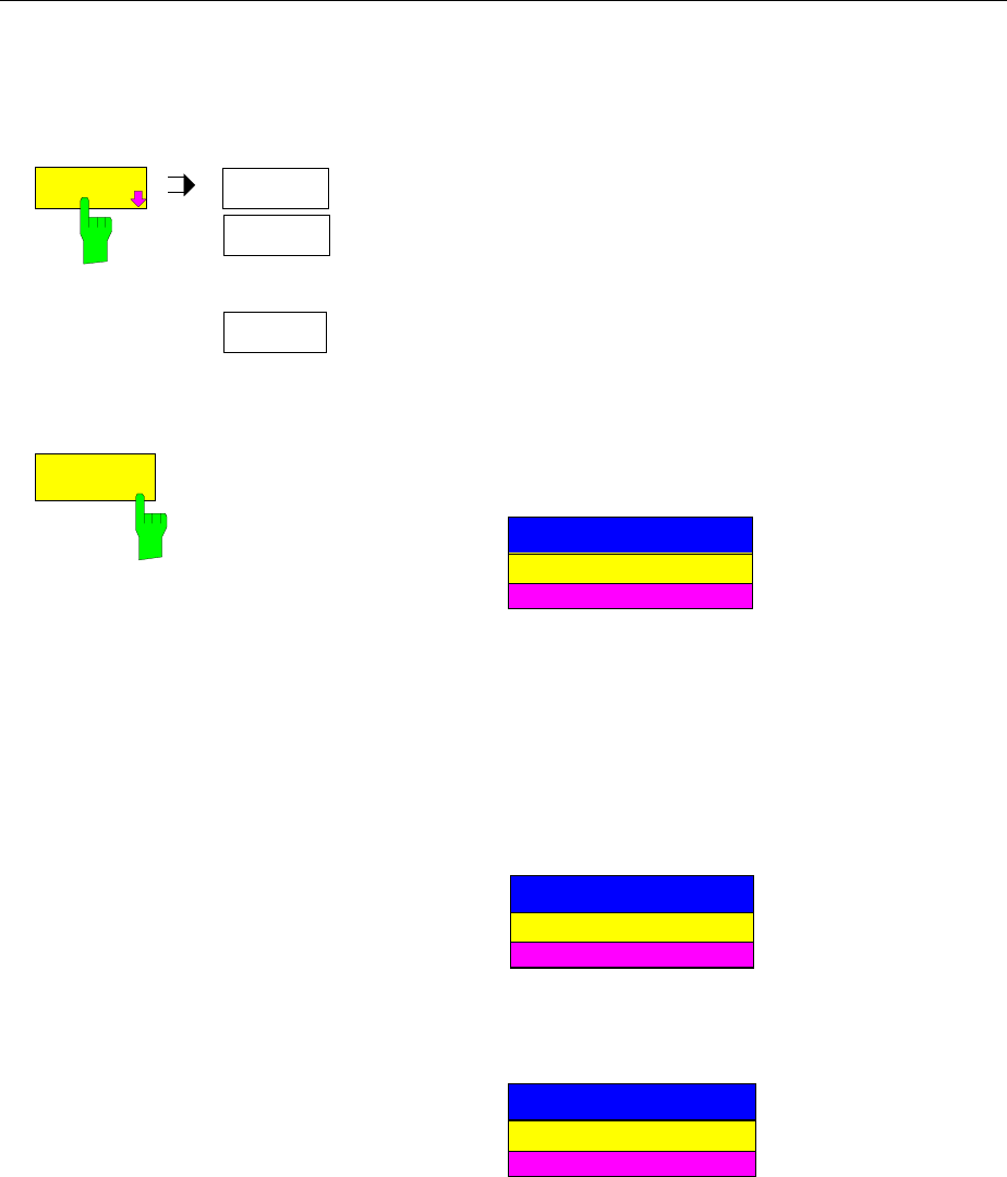
FSE Instrument Status and Measurement Parameters
1065.6016.12 4.15 E-15
Self Test
SYSTEM INFO-SELFTEST submenu:
SELFTEST
SELFTEST EXECUTE
TESTS
.
.
.
The SELFTEST softkey opens a submenu with which the self test
can be started.
The instrument has extensive self test functions which
comprehensively test instrument functionality. In case of a fault,
the instrument can locate a defective module on its own. The self
test sequence is described in more detail in the service manual
instrument (supplied with the FSE).
EXECUTE
TESTS
The EXECUTE TESTS softkey starts the test of the complete instrument.
During the self test a window is displayed:
SELFTEST
ABORT
in progress
The functions are tested in the following order:
1. Modules main CPU, digital motherboard, graphics and the interfaces
2. Reference frequency conditioning, the synthesizer modules and all LO
signals
3. All RF, IF and signal-weighting modules
If no failure occurs during the execution of the self test, the following message
is displayed when the complete self test is finished:
SELFTEST
OK
successfully completed
If a failure occurs during the execution of the self test, the self test is
immediately aborted and a message indicating the defective module and the
defective function is displayed:
SELFTEST FAILED
ABORT
IF Filter Stepgain
Further testing should be performed by an R&S service department.
IEC/IEEE- bus command :*TST?
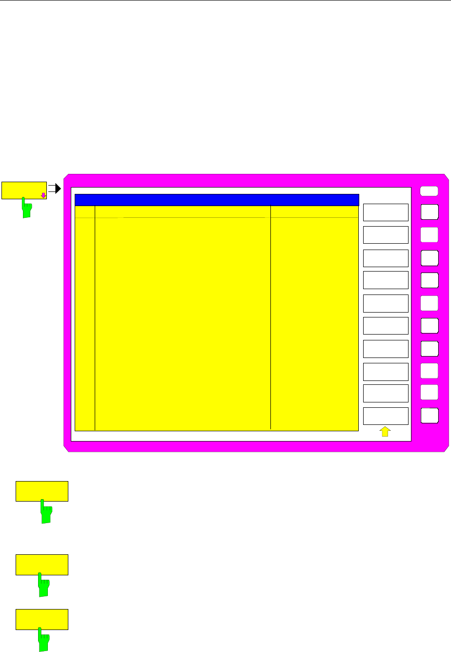
Instrument Status and Measurement Parameters FSE
1065.6016.12 4.16 E-15
System Messages
The SYSTEM MESSAGES softkey opens a submenu with a table in which the generated system
messages are displayed. The most recent messages are at the top of the list.
The following information is presented:
NO Device-specific three-digit error code (shown as XXX in the figure)
MESSAGE Brief description of the reason for the message
DATE/TIME Date and time of the message
Error messages that have occurred since the SYSTEM MESSAGES menu was last called are marked by
an asterix "*".
SYSTEM INFO-SYSTEM MESSAGES submenu:
SYSTEM
MESSAGES
USER
SYSTEM MESSAGES
SYSTEM
MESSAGES
NO MESSAGE DATE/TIME
CLEAR
MESSAGE
CLEAR ALL
MESSAGES
UPDATE
MESSAGES
* CH1 LO unl: frac syn synth. 17.Oct.99; 12:05:33
102
IEC/IEEE- bus command :SYSTem:ERRor?
CLEAR
MESSAGE
The CLEAR MESSAGE softkey deletes the message just selected.
All subsequent messages are shifted automatically one line upwards so that
no empty lines exist. When the last message has been deleted, the selection
bar also disappears.
IEC/IEEE- bus command :SYSTem:ERRor?
CLEAR ALL
MESSAGES
The CLEAR ALL MESSAGES softkey deletes all messages.
IEC/IEEE- bus command --
UPDATE
MESSAGES
The UPDATE MESSAGES softkey causes all newly arrived messages to be
entered at the top of the table. At this time, all messages previously indicated
as "new" are displayed as "old" messages
IEC/IEEE- bus command --
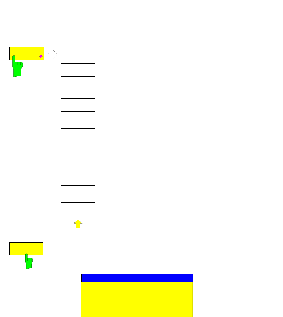
FSE Instrument Status and Measurement Parameters
1065.6016.12 4.17 E-15
Statistics Function for Input Attenuator Switching
SYSTEM INFO menu:
STATISTIC
STATISTICS
ATT
SWITCHES
The STATISTICS softkey calls a submenu for indication of
device statistics.
ATT
SWITCHES The ATT SWITCHES softkey displays various tables listing the mechanical
switches and attenuators fitted in the instrument, plus the number of
switching operations for the respective switch or attenuator.
INPUT ATTENUATOR
Date 5 Aug 1999
Calibration Input 6
10 dB 121
20 dB 217
30 dB 137
IEC/IEEE- bus command
:DIAGnostic:INFO:CCOunt:ATTenuation <1|2|3>
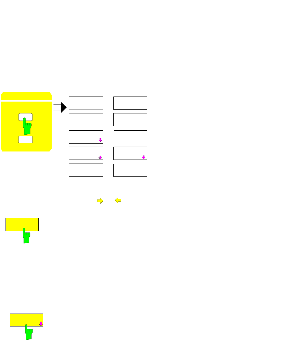
Mode Selection FSE
1065.6016.12 4.18 E-15
Mode Selection – MODE Key
The FSE can be operated in one of several modes, each of which is different with respect to
functionality and control. The differences in control, however, consist not only in the enabling/disabling of
additional softkeys within existing softkey menus, but rather in the fact that existing menus are
completely replaced by new menus and menu trees which are tailored to the functional requirements. In
the simultaneous application of two measurement diagrams, two modes may also simultaneously
enabled. Each mode can be assigned to a measurement window.
CONFIGURATION MODE menu
CONFIGURATION
MODE
SE P
ANALYZER
VECTOR
ANALYZER
MODE
TRACKING
GENERATOR
TV
DEMOD
.
.
.
.
.
.
The MODE key opens the menu for selection
of the mode.
Herein, the modes can be selected according
to the available FSE options.
•Analyzer
•Tracking Generator
•Vector Signal Analysis and
•TV Demodulation
ANALYZER
The ANALYZER softkey selects the ANALYZER mode.
This mode is the default setting of the FSE.
The functions provided correspond to those of a conventional spectrum
analyzer. The analyzer measures the frequency spectrum of the test signal
over the selected frequency range with the selected resolution and sweep
time, or, for a fixed frequency, displays the waveform of the video signal.
IEC/IEEE-bus command :INSTrument[:SELect] SANalyzer
TRACKING
GENERATOR
The TRACKING GENERATOR softkey selects the operating mode Scalar
Network Analysis.
The softkey is only available if FSE is equipped with one of the following
options: FSE-B8/B9/B10 and B11. For a detailed description of operation see
Section ’Option Tracking Generator’.
IEC/IEEE-bus command :OUTPut[:STATe] ON | OFF

FSE Mode Selection
1065.6016.12 4.19 E-15
TV DEMOD
The TV DEMOD softkey selects the operating mode TV Demodulation.
The softkey is only available if FSE is equipped with Option FSE-B3. For a
detailed description of operation see manual of options.
IEC/IEEE-bus command [:SENSe]:TV:STATe ON | OFF
VECTOR
ANALYZER
Softkey VECTOR ANALYZER selects the vector analysis mode.
The softkey is only available if FSE is equipped with Option FSE-B7.
In the vector analyzer mode the FSE is automatically set to a fixed frequency
(center frequency) since vector analysis can only be carried out on one
frequency.
The IF signal is digitized by the selected resolution bandwidth after filtering
and mixed into the baseband by a digital mixer. Further processing is via
digital signal processors which display the time characteristic of the amplitude
or phase. As an option, the baseband can also be demodulated and the
demodulated signal can be displayed. Principally any type of modulation
(digital and analog) can be processed.
The functions of the analyzer mode are supplemented by the vector analysis
functions which are described in detail in a separate manual to the option.
IEC/IEEE-bus command :INSTrument[:SELect] DDEMod
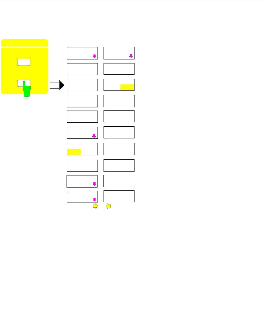
Configuration/Setup FSE
1065.6016.12 4.20 E-15
Preliminary Setup and Interface Configuration – SETUP Key
CONFIGURATION SETUP menu:
SETUP
MODE
CONFIGURATION
SERVICE
SETUP
GENERAL
SETUP
EXT REF
FREQUENCY
REFERENCE
INT EXT
TRANSDUCER
OPTIONS
SETUP
FIRMWARE
UPDATE
FSE MODE
ON OFF
The SETUP key opens the menu for
configuration of the FSE.
The TRANSDUCER softkey opens a
submenu for entering correction characteris-
tics for the measurement transducer.
The OPTIONS softkey allows the enabling of
firmware options (Application Firmware
Modules).
The REFERENCE INT/EXT and EXTERNAL
REF FREQUENCY softkeys determine the
reference to be used.
The SERVICE softkey provides special setup
functions which, although not necessary in
normal use, are useful in instrument service.
The GENERAL SETUP softkey opens a
submenu for all the general settings such as
date and time as well as the configuration of
the device interfaces.
The FIRMWARE UPDATE softkey opens a
submenu for the installation of a firmeware
update.
Using Transducers
A transducer is often connected ahead of FSE both during the measurement of useful signals and EMI
and converts the useful or interference variable such as field strength, current or RFI voltage into a
voltage across 50 Ohm. Transducers with a frequency-independent transducer factor can be coded in
10-dB steps together with the unit at connector PROBE CODE. They are supplied at the same time by
this connector. Transducers such as antennas, probes or current probes mostly have a frequency-
dependent transducer factor which can be stored in FSE and automatically has the correct unit during
level measurement.
If a transducer is switched on it is considered as part of the unit during the measurement, ie the
measured values are displayed in the correct unit and magnitude. When working with two measurement
windows, the transducer is always assigned to two windows.
FSE distinguishes between transducer factor and transducer set. A transducer factor takes the
frequency response of a single transfer element, eg an antenna into consideration. A transducer set can
summarize different transducer factors in several subranges (several transducer factors at the same
time), eg an antenna, a cable and a diplexer.

FSE Configuration/Setup
1065.6016.12 4.21 E-15
A transducer factor consists of max. 50 reference values defined with frequency, transducer factor and
the unit. For the measurement between frequency values linear or logarithmic interpolation of the
transducer factor can be chosen.
Several factors can be compiled in a transducer set provided that all factors have the same unit or unit
"dB". The frequency range covered by a set can be subdivided into max. 10 subranges (each with up to
4 transducer factors) which follow each other without a gap, ie the stop frequency of a subrange is the
start frequency of the next subrange.
The transducer factors used in a subrange have to fully cover the subrange.
The definition of a transducer set is recommended if different transducers are used in the frequency
range to be measured or if a cable attenuation or an amplifier has to be taken into consideration.
If a transducer set is defined during a frequency sweep, the latter can be stopped at the interface
between two transducer ranges and the user is asked to exchange the transducer.
The following message informs the user that the limit has been reached:
TDS Range # reached, CONTINUE / BREAK
He can continue the sweep by confirming the message (CONTINUE) or he can switch off the transducer
(BREAK).
With the automatic switchover of the transducer used, the frequency sweep is not interrupted.
Note: Transducers cannot be used in vector analyzer mode.
Activating Transducer Factors and Transducer Sets
The TRANSDUCER softkey opens a submenu in which already defined transducer factors or sets can
be activated or deactivated, new transducer factors or sets can be generated or existing transducer
factors or sets can be edited. Tables with the defined transducer factors and sets are displayed. The
table (factor or set) in which a transducer is active is set.
By switching on the transducers all the level settings and outputs are automatically made in the unit of
the transducer. A change of the unit in menu LEVEL REF is no longer possible as FSE together with the
transducer used is regarded as a measuring instrument. Only if the transducer has the unit dB, can the
original unit at FSE be maintained and changed.
Note: If one of the units dB
µ
V, dB
µ
V/m, dB
µ
A, or dB
µ
A/m is selected, the LEVEL REF key (see
UNIT-submenu) can be used to switch to the corresponding units referred to the bandwidth,
i.e. dB
µ
V/MHz, dB
µ
V/mMHz, dB
µ
A/MHz, dB
µ
A/mMH.
If a transducer factor is active, TDF is displayed in the column of the enhancement labels and TDS if the
transducer set is active.
After switching off all the transducers, FSE continues to use the unit which was selected before a
transducer was switched on.
In the analyzer mode, an active transducer for a sweep is uniquely calculated for each point displayed
after its setting and added to the result of the level measurement during the sweep. If the sweep range
is changed, the correction values are recalculated. If several measured values are combined, only a
single value is taken into consideration.
If an active transducer factor/set is not defined over the whole sweep or scan range during the
measurement, the missing values are replaced by zero.
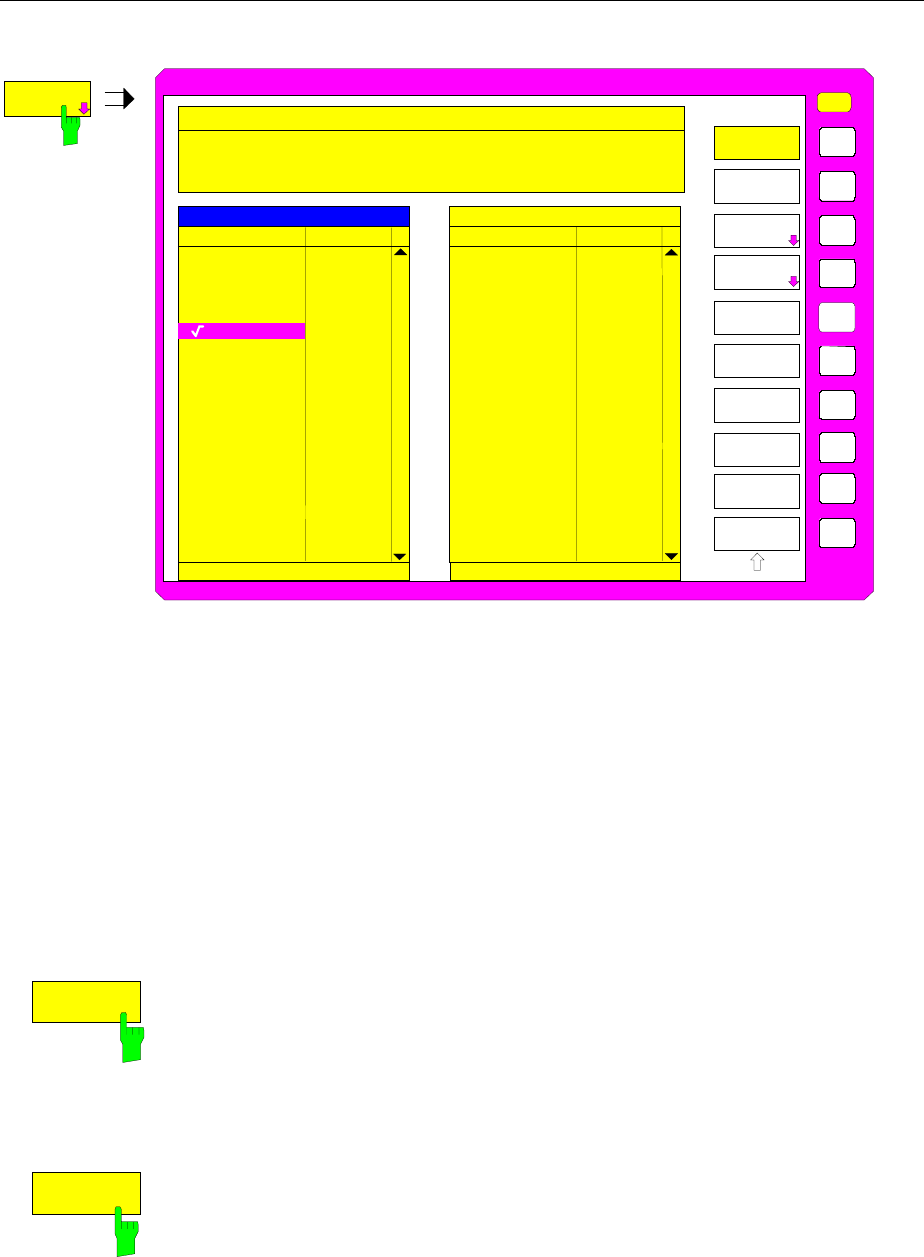
Configuration/Setup FSE
1065.6016.12 4.22 E-15
CONFIGURATION SETUP Menu
USER
TRANSDUCER
EDIT TRD
FACTOR
EDIT
TRD SET
TRANSDUCER
FACTOR
TRANSDUCER
SET
PAGE UP
PAGE DOWN
Name Unit
TRANSDUCER SETTRANSDUCER FACTOR
DELETE
FACTOR/SET
Name
Unit
Cable_1
ACTIVE TRANSDUCER FACTOR
TRANSDUCER
Freq range: 0 Hz
to: 2.000 GHz
Name: Cable_1
Unit: dB
Comment: Cable length 1.50 m, No.112234
Press ENTER to (de)activate
Antenna1
Probe_A
Probe_B
Probe_C
My_Probe
Cable_2
Preamp
_
Antenna
Ant_Cab2
Ant_Pre
Ant_Cab1
Probeset
_
dBµV/m
dBµV/m
dBµV/m
dBµV/m
dBµA
dBµV/m
dBµA
dBµA
dBµA
dBµV
dB
dB
dB
NEW
FACTOR/SET
The upper table ACTIVE TRANSDUCER FACTOR / SET indicates the active transducer factor or the
set with the associated name, frequency range and unit. If no factor or set is active, none is displayed in
the table. Additional information can be entered in a comment line. If a transducer factor is active, the
selected interpolation is displayed in addition, if a set is active, the break setting is displayed.
The left table TRANSDUCER FACTOR comprises all the defined factors with name and unit. If the
number of defined transducer factors exceeds the number of possible lines in the table, the table will be
scrolled.
The right table TRANSDUCER SET comprises all the defined transducer sets with the corresponding
information.
Only one set or transducer can be activated. An already active transducer factor or set is switched off
automatically if another one is switched on. An activated transducer factor or set is marked with a check
sign.
TRANSDUCER
FACTOR
The TRANSDUCER FACTOR softkey sets the selection bar to the position of
the active transducer factor.
If no transducer factor is switched on, the bar is positioned to the first line of
the table.
IEC/IEEE bus commands
:[SENSe<1|2>:]CORRection:TRANsducer:SELect <name>
:[SENSe<1|2>:]CORRection:TRANsducer[:STATe] ON | OFF
TRANSDUCER
SET
The TRANSDUCER SET softkey sets the selection bar to the position of the
active transducer set.
If no transducer set is switched on, the bar is set to the first line of the table.
IEC/IEEE bus commands
:[SENSe<1|2>:]CORRection:TSET:SELect <name>
:[SENSe<1|2>:]CORRection:TSET[:STATe] ON|OFF

FSE Configuration/Setup
1065.6016.12 4.23 E-15
DELETE
FACTOR/SET
The DELETE FACTOR/SET softkey deletes the marked factor or set. To
avoid deletion by mistake, deletion has to be confirmed.
YES
NO
MESSAGE
Do you really want to
delete factor or set?
IEC/IEEE-bus command
:[SENSe<1|2>:]CORRection:TRANsducer:DELete
:[SENSe<1|2>:]CORRection:TSET:DELete
PAGE UP
PAGE DOWN
The PAGE UP and PAGE DOWN softkeys are used to scroll in large tables
which cannot fully be displayed on the screen.
New Entry and Editing of Transducer Factors
A transducer factor is characterized by
•reference values with frequency and transducer factor (Values)
•the unit of the transducer factor (Unit) and
•the name (Name) to distinguish between the different factors.
During the entry, FSE checks the transducer factor according to specific rules that have to be met to
ensure trouble-free operation.
•The frequencies for the reference values always have to be entered in ascending order. Otherwise,
the entry is not accepted and the following message is displayed:
Frequency Sequence!
•The entered frequencies do not necessarily have to be set at FSE, as only the values for the
frequency display range are considered for a set sweep or scan. The minimum frequency for a
reference value is 0 Hz, the maximum frequency 200 GHz.
•The minimum or maximum value for a transducer factor is -200 dB or 200 dB. The unit "dB" means
that the transducer factor is always logarithmic and has nothing to do with the physical transducer
factor, which, for example, establishes the relationship between field strength and voltage into 50
Ohm. If the minimum or maximum value is exceeded, FSE signals:
Min Level -200 dB or
Max Level 200 dB.
•Amplifiers have a negative transducer factor, attenuation values have to be entered as a positive
transducer factor.
Note: A unit activated by switching on the transducer has priority over a coded unit of the
connected probe.
With the exception of dB*/MHz, the softkeys for the unit in the menu under key LEVEL REF
are inoperative with the transducer switched on.
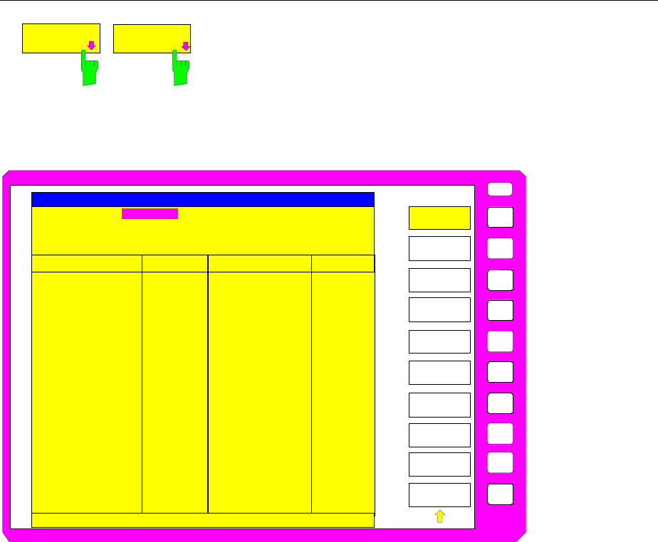
Configuration/Setup FSE
1065.6016.12 4.24 E-15
EDIT TRD
FACTOR
NEW TRD
FACTOR/SET The EDIT TRD FACTOR and NEW FACT/SET softkeys
both open the submenu for editing and entering new
transducer factors. A precondition for the NEW
FACTOR/SET softkey is that the selection bar is located
in the table when the table TRANSDUCER FACTOR is
called up.
USER
TRD FACTOR
NAME
TRD FACTOR
UNIT
TRD FACTOR
VALUES
DRAW TRD
FACTOR
Name: Antenna1
Unit: dBuV/m
Interpolation: LIN
Comment: Ant1 and cable 1
EDIT TRANSDUCER FACTOR
24
25
NO.
48
49
50
FREQUENCY FREQUENCY
TDF/dB..
20.0000 MHz
25.0000 MHz
30.0000 MHz
40.0000 MHz
50.0000 MHz
60.0000 MHz
70.0000 MHz
80.0000 MHz
25.5
23.8
20.5
19.8
20.0
19.5
19.1
18.2
TDF/dB..
SAVE TRD
FACTOR
INSERT
LINE
DELETE
LINE
EDIT TRD
FACTOR
The table with the data of the marked factor (the EDIT TRD FACTOR softkey) or an empty table is
displayed in which the following entries are preset (the NEW FACTOR/SET softkey):
Unit: dB
Interpolation: LIN for linear frequency scaling
LOG for logarithmic frequency scaling
The characteristics of the factor can be entered in the header field of the table, the frequency and the
transducer factor in the columns of the table.
Name Entry of the name
Unit Selection of unit
Interpolation Selection of interpolation
Comment Entry of a comment
FREQUENCY Entry of the frequency of the reference points
TDF/dB Entry of the transducer factor.
An overwritten transducer factor remains stored in the background as long as the edited factor is stored
with the SAVE TRD FACTOR softkey or until the table is closed. A factor overwritten by mistake can be
restored by leaving the entry.
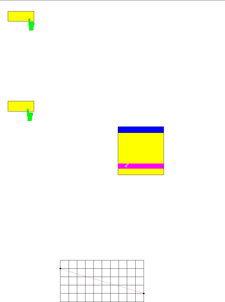
FSE Configuration/Setup
1065.6016.12 4.25 E-15
TRD FACTOR
NAME
The TRD FACTOR NAME softkey activates the entry of the transducer factor
characteristics in the header field of the table.
Name - Entry of name
A maximum of 8 characters is permissible for the name. The characters have
to comply with the convention of DOS file names. The unit automatically
stores all transducer factors with the extension .TDS.
If an existing name is changed, the factor stored under the previous name is
retained and will not be overwritten automatically with the new name. The
previous factor can be deleted at a later time, using DELETE FACTOR/SET.
Thus, factors can be copied.
IEC/IEEE-bus command :[SENSe<1|2>:]CORR:TRAN:SELect <name>
TRD FACTOR
UNIT
Unit - Selection of unit
The unit of the transducer factor is selected from a selection box activated by
the TRD FACTOR UNIT softkey.
FACTOR UNIT
dB
dBm
dBµV
dBµV/m
dBµA
dBµA/m
dBpW
dBpT
The default setting is dB.
IEC/IEEE-bus command :[SENSe<1|2>:]CORR:TRAN:UNIT <string>
Interpolation - Selection of interpolation
Linear or logarithmic interpolation can be carried out between the frequency
reference points of the table. Selection is via the ENTER key which is toggled
between LIN and LOG (toggle function).
The following diagrams indicate the effect of the interpolation on the
calculated characteristic:
IEC/IEEE-bus command :[SENSe<1|2>:]CORR:TRAN:SCAL LIN|LOG
Fig. 4-1 Linear frequency axis and linear interpolation
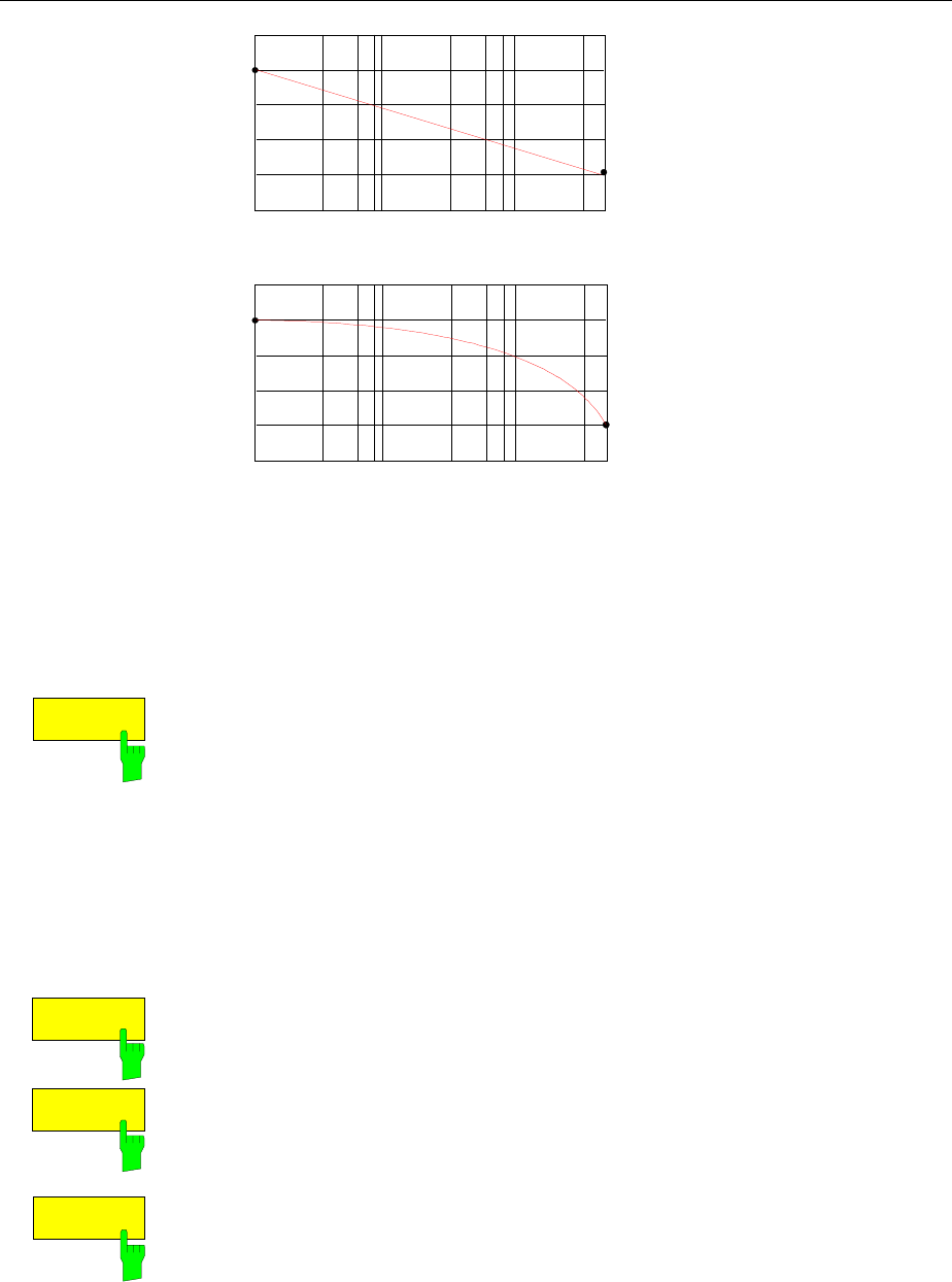
Configuration/Setup FSE
1065.6016.12 4.26 E-15
Fig. 4-2 Logarithmic frequency axis and logarithmic interpolation
Fig. 4-3 Logarithmic frequency axis and linear interpolation
Comment - Entry of a comment
The comment can be freely selected. It can have a maximum number of 50
characters.
IEC/IEEE-bus command :[SENS<1|2>:]CORR:TRAN:COMM <string>
TRD FACTOR
VALUES
The TRD FACTOR VALUES softkey activates the entry for the reference
values of the transducer factor.
The selection bar marks the first reference value. The desired reference
values have to be entered in ascending frequency sequence.
After entering the frequency the selection bar automatically jumps to the
corresponding level value. After entering the first reference value the table
can be edited. The two INSERT LINE and DELETE LINE softkeys are
displayed. Individual values are changed at a later time by marking the field
and by entering the new value.
IEC/IEEE-bus command :[SENS<1|2>:]CORR:TRAN:DATA
<freq>,<level>
DELETE
LINE
INSERT
LINE
The INSERT LINE softkey inserts a free line above the marked reference
value. When entering a new reference value into this line watch out for the
ascending frequency sequence.
The DELETE LINE softkey deletes the marked reference value (the whole
line). The following reference values move up.
IEC/IEEE-bus command --
SAVE TRD
FACTOR
The SAVE TRD FACTOR softkey saves the changed table in a file on the
internal hard disk.
If a transducer factor with the same name already exists, a corresponding
query is performed beforehand.
If the factor to be newly saved is currently switched on, the new values will
immediately be valid. If a transducer set is switched on comprising the factor,
the values will only be used when the set is switched on next time.
IEC/IEEE-bus command - (executed automatically)
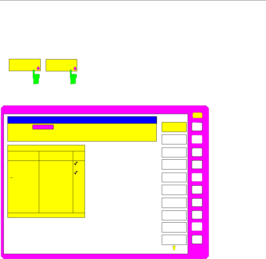
FSE Configuration/Setup
1065.6016.12 4.27 E-15
New Entry and Editing of Transducer Sets
A transducer set is characterized by:
− maximum 10 ranges (Ranges) in which different transducer factors can be active
− the combination of several transducer factors per range (Factor)
− a transducer-set name (Name)
EDIT
TRD SET
NEW TRD
FACTOR/SET The EDIT TRD SET and NEW FACTOR/SET softkeys
both open the submenu for editing and entering new
transducer factors. A precondition for the NEW
FACTOR/SET softkey is that the selection bar is located
in the table TRANSDUCER SET.
USER
EDIT
TRANSD SET
TRANSD SET
RANGES
INSERT
LINE
TRANSD SET
NAME
TRANSD SET
UNIT
TRANSDUCER SET RANGES
Start Stop
Comment: Ant. 1 and cable 1
EDIT TRANSDUCER SET
Unit: dBµV/m
Break: ON
20.00000 MHz 80.00000 MHz
80.00000 MHz 400.00000 MHz
400.0000 MHz 1.00000 GHz
Sel
fac
DELETE
LINE
Name: Ant_Cab1
DRAW
TRD SET
SAVE TRD
SET
PAGE UP
PAGE DOWN
The table with the data of the marked set (the EDIT TRD SET softkey) or an empty table in which the
following entries are preset (the NEW FACTOR/SET softkey) is displayed:
Unit: dB
Break: NO
The characteristics of the set can be entered in the header field of the table, the subranges in the
columns of the set.
Name Entry of the name
Unit Selection of unit
Break Activating the query when changing the subrange
Comment Entry of a comment
Start Entry of the start frequency of the subrange
Stop Entry of the stop frequency of the subrange
Sel Fac Selection of the transducer factors for the subrange
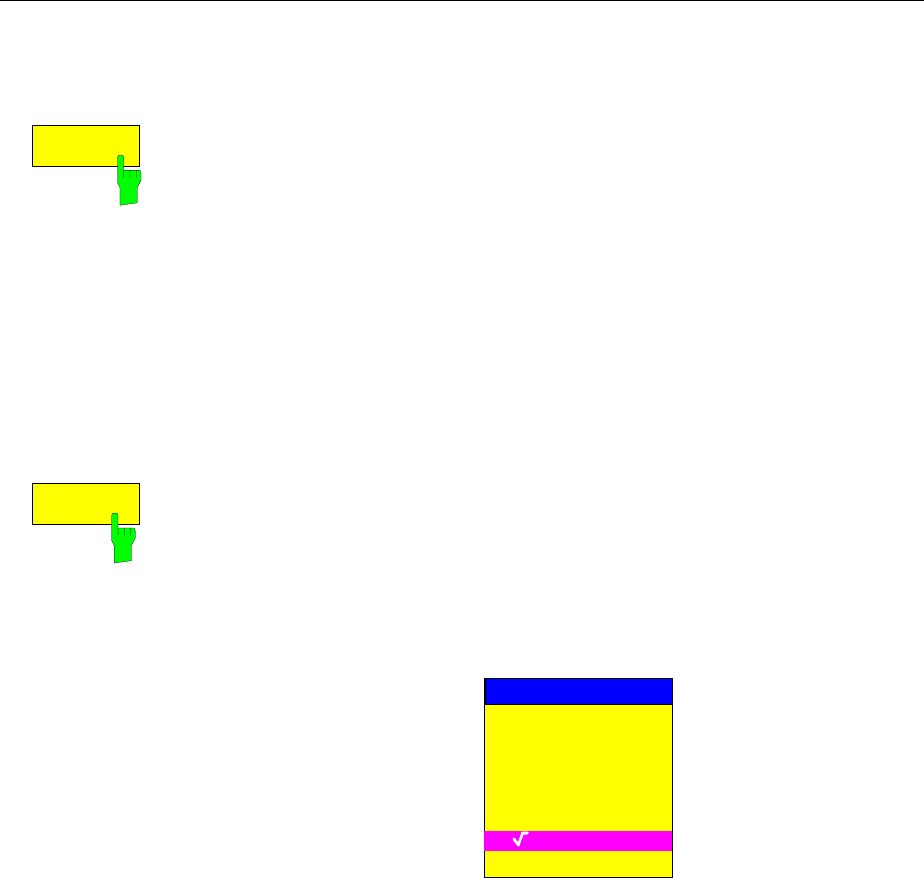
Configuration/Setup FSE
1065.6016.12 4.28 E-15
An overwritten transducer set remains stored in the background as long as the edited factor is stored
with the SAVE TRD SET softkey or until the table is closed. A set overwritten by mistake can be
restored by leaving the entry.
TRANSD SET
NAME
The TRD SET NAME softkey activates the entry of the transducer set
characteristics in the header field of the table.
Name - Entry of name
A maximum of 8 characters is permissible for the name. The characters have
to comply with the convention of DOS file names. The unit automatically
stores all transducer sets with the extension .TDS.
If an existing name is changed, the set stored under the previous name is
retained and will not be overwritten automatically with the new name. The
previous set can be deleted at a later time using DELETE FACTOR/SET.
Thus, sets can be copied.
IEC/IEEE-bus command :[SENSe<1|2>:]CORR:TSET:SELect <name>
TRANSD SET
UNIT
Unit - Selection of unit
The unit of the transducer set is selected from a selection box activated by
the TRANSD SET UNIT softkey.
The unit should be selected prior to the entry as it determines the settable
transducer factors. The preset unit for new sets is "dB". The unit can no
longer be changed when editing a set as the set of selected transducer
factors will otherwise become inconsistent.
SET UNIT
dB
dBm
dBµV
dBµV/m
dBµA
dBµA/m
dBpW
dBpT
IEC/IEEE-bus command :[SENSe<1|2>:]CORR:TSET:UNIT <string>
Break - Activation of query when changing a subrange
The sweep can be stopped if the user changes the subrange and selects a
new subrange of the transducer. A message informs the user that the limit
has been attained. He can continue the sweep or switch off the transducer.
The interruption is activated by setting Break to ON. Selection is by the
ENTER key which toggles between ON and OFF (toggle function).
IEC/IEEE-bus command :[SENSe<1|2>:]CORR:TSET:BREak ON|OFF
Comment - Entry of a comment
The comment can be freely selected. It can have a maximum number of 50
characters.
IEC/IEEE-bus command
:[SENSe<1|2>:]CORR:TSET:COMMent <string>
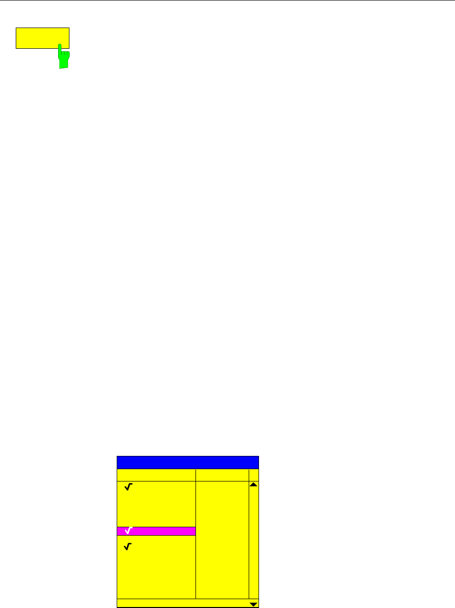
FSE Configuration/Setup
1065.6016.12 4.29 E-15
TRANSD SET
RANGES
Softkey TRANSD SET RANGES activates the entry of subranges and the
associated transducer factors. The selection bar marks the frequency values
last active.
Start - Entry of start frequency of subrange
Stop - Entry of stop frequency of subrange
The individual subranges have to be linked without a gap. That is why the
start frequency is already defined from the second subrange (= stop
frequency of previous range).
After entering the first frequency value the table can be edited. The two
INSERT LINE and DELETE LINE softkeys are displayed. Some values are
changed at a later time by marking the field and by entering the new value. It
should be noted that both the stop frequency of a particular subrange and the
start frequency of the subsequent subrange are changed to the same extent.
IEC/IEEE-bus command
:[SENSe<1|2>:]CORRection:TSET:RANGe<1..10>
<freq>,<freq>,<name>..
Sel fac- Selection of factors for the subrange
A check sign in column Sel Fac (select factor) indicates whether one or
several transducer factors were selected for the subrange.
The permissible transducer factors for the marked subrange can be selected
in a selection box. Only factors matching with the unit of the set and fully
covering the selected subrange are permissible.
After each change of range limits, FSE thus checks the factor list and, if
required, rebuilds it.
After reducing the start frequency or increasing the stop frequency of a range
it may happen that the factors defined for this range no longer fully cover the
range. These factors are deleted for this range when the transducer factor
table is opened next time.
A maximum of 4 transducer factors can be switched on at the same time in
each subrange. If none of them is switched on, 0 dB is assumed as a factor
for the whole subrange.
Antenna1
Probe_A
Probe_B
Cable_2
dBµV/m
dBµV/m
dBµV/m
dB
dB
Name Unit
SELECT TRANSDUCER FACTOR
Cable_1
Probe_C
Preamp
dBµV/m
My_Probe dB
dB
IEC/IEEE-bus command --
Configuration/Setup FSE
1065.6016.12 4.30 E-15
INSERT
LINE
DELETE
LINE
The INSERT LINE softkey inserts a free line above the marked subrange.
The DELETE LINE softkey deletes the marked subrange (whole line). The
following subranges move up.
In both cases FSE checks that the ranges follow each other without a gap.
IEC/IEEE-bus command --
SAVE TRD
SET
The SAVE TRD SET softkey saves the changed table in a file on the internal
hard disk. If a transducer name with the same name already exists, a
corresponding query is performed beforehand:
YES
NO
MESSAGE
File exists! Do you
want to overwrite?
After pressing ENTER, the data set is overwritten on the hard disk.
If the saved set is switched on, the new values will be used immediately.
IEC/IEEE-bus command -- (executed automatically)
PAGE UP
PAGE UP
The PAGE UP and PAGE DOWN softkeys set the table to the next or
previous page.
The softkeys are locked during selection of factors in the right table.
FSE Configuration/Setup
1065.6016.12 4.31 E-15
Enabling Firmware Options
CONFIGURATION SETUP menu:
OPTIONS The OPTIONS softkey opens a submenu for entering keywords for new
firmware options (Application Firmware Modules). Options which are already
available are indicated in a table that is opened when the menu is called.
ENABLE NEW
OPTION The ENABLE OPTION softkey activates the entry of a
keyword for a firmware option.
One or several keywords may be specified in the entry
field. When a valid keyword is entered, the message
OPTION KEY OK appears in the info line and the option
is written into the FIRMWARE OPTIONS table.
The FIRMWARE OPTIONS table can also be displayed
using the FIRMWARE OPTIONS softkey in the INFO
menu.
If a keyword is invalid the message OPTION KEY
INVALID is displayed in the info line.
IEC/IEEE-bus command --
External Reference Oscillator
In general, the FSE can generate all internal oscillators from either the internal or an external reference
oscillator. A 10 MHz crystal oscillator is used as the internal reference source. A reference oscillator
output is also available at the rear panel via the EXT REF IN/OUT connector.
This output can be used, e.g., to synchronize other instruments to the FSE. This connector can also be
used as an input connector for application of an external frequency standard. The FSE requires that the
frequency of the external standard be entered so that the internal oscillators can be synchronized to it.
CONFIGURATION SETUP Menu:
REFERENCE
INT EXT
The REFERENCE INT EXT softkey toggles between the internal and external
references.
IEC/IEEE-bus command :[SENSe<1|2>:]ROSC:SOURce INT | EXT
EXT REF
FREQUENCY
The EXT REF FREQUENCY softkey activates the entry of the frequency of
the external source.
Range of input values is 1 MHz to 16 MHz in 1 MHz steps.
IEC/IEEE-bus command :[SENSe<1|2>:]ROSC:EXT:FREQ 13 MHz
Configuration/Setup FSE
1065.6016.12 4.32 E-15
Service Functions
The service menu offers a variety of additional functions which are used for maintenance and/or trouble
shooting. The service functions are not necessary for normal measurements, however, incorrect use
can impair the functionality and/or data integrity of the FSE. Therefore, many of the functions can only
be used after entering a password.
CONFIGURATION SETUP menu:
SERVICE
INPUT
RF
SERVICE
INPUT
CAL
ENTER
PASSWORD
NOISE
SOURCE
REFERENCE
ADJUST
The SERVICE softkey calls the service
submenu.
INPUT
RF
INPUT
CAL
The INPUT RF and INPUT CAL softkeys are mutually exclusive selection
switches. Only one switch can be activated at any one time. They switch the
input to the FSE between the INPUT RF connector (default) and the internal
calibration source (120 MHz, -40 dBm).
After PRESET, RECALL or FSE power on, the INPUT RF is always selected.
IEC/IEEE-bus command
:DIAGnostic:SERVice:INPut[:SELect] RF| CAL
NOISE
SOURCE
The NOISE SOURCE softkey switches the supply voltage for an external
noise source on or off. The source is connected to the NOISE SOURCE
connector on the instrument’s rear panel.
The dc voltages on the connector are described in Chapter 8.
IEC/IEEE-bus command :DIAGnostic:SERVice:NSOurce ON | OFF
FSE Configuration/Setup
1065.6016.12 4.33 E-15
CONFIGURATION SETUP SERVICE menu:
REFERENCE
ADJUST
REFERENCE
ADJUST REFERENCE
REFERENCE
PROG
The REFERENCE ADJUST softkey opens a submenu used to
adjust the frequency precision of the reference oscillator.
The value should be modified only after the frequency
precision was checked and found to be erroneous (setting
range 0 to 4095).
For more information about how to perform the adjustment of
the frequency precision refer to service manual instrument
(delivered with the FSE).
The modified reference value is preserved when the menu is
closed.
The current adjustment value can be permanently stored in an
EEPROM in the instrument.
Caution: As the specifications of the whole instrument
depend directly on the setting of the reference
oscillator (frequency precision), storing incorrect
adjustment values should be avoided.
Note: If no adjustment value has been stored
(REFERENCE PROG softkey) before the analyzer
is switched off and on again, the factory-set value
of the reference frequency or the value that has
been programmed last will be used.
REFERENCE
The REFERENCE softkey adjusts the frequency precision of the
reference oscillator.
IEC/IEEE-bus command
:[SENSe<1|2>:]ROSC:[INT:]TUNe <num_value>
REFERENCE
PROG
The REFERENCE PROG softkey stores the current adjustment
value in an EEPROM in the instrument.
IEC/IEEE-bus command
:[SENSe<1|2>:]ROSC:[INT:]TUNe:SAVe
ENTER
PASSWORD The ENTER PASSWORD softkey allows the entry of a password.
The FSE has a variety of service functions which, if incorrectly used, can
impair the functionality of the instrument. These functions can only be
accessed with a password (ENTER PASSWORD).
IEC/IEEE-bus command :SYSTem:PASSword[:CENable] <string>
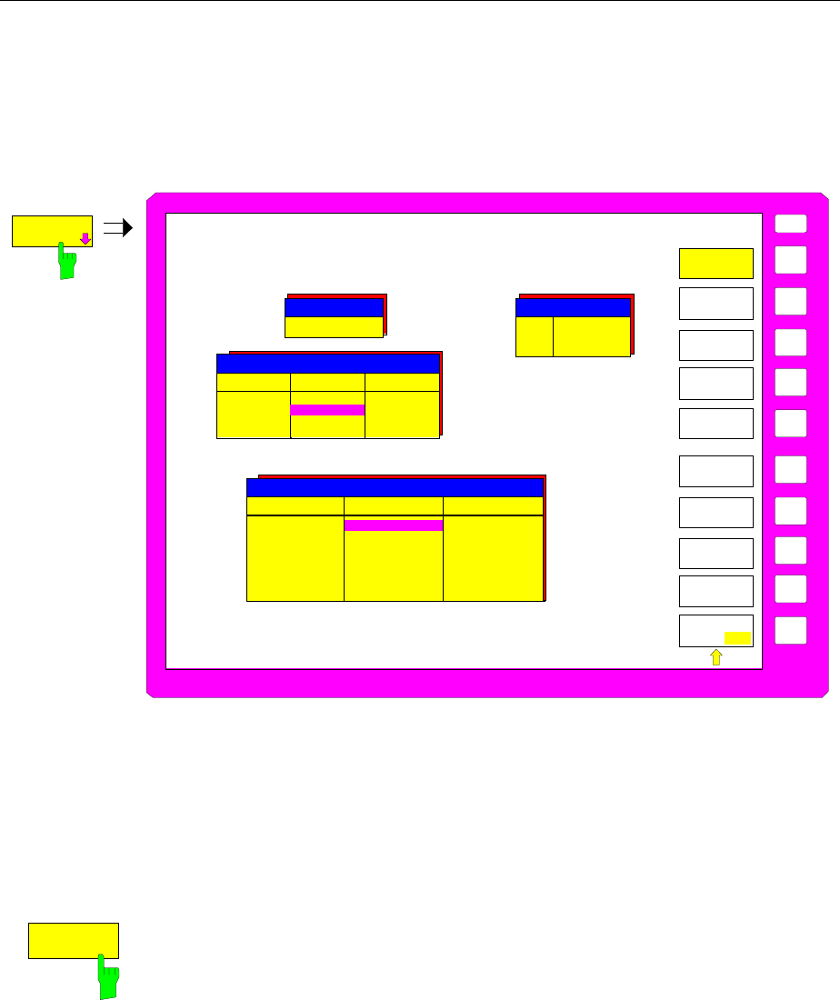
Configuration/Setup FSE
1065.6016.12 4.34 E-15
Setting the Interface Configuration and Time - with Windows NT Controller
The GENERAL SETUP softkey opens a submenu in which the general instrument setup can be entered.
The current settings are displayed as tables on the screen where they may be edited.
CONFIGURATION SETUP menu:
USER
GPIB
ADDRESS
GENERAL
SETUP
TIME
DATE
MONITOR
CONNECTED
USER
PORT A
USER
PORT B
GPIB ADRESS
19
PORT A PORT B
Direction
Value Input
10101010 Output
00010001
USER PORTS
TIME AND DATE
Time
Date 21:59
01 Oct 1994
GENERAL
SETUP
KEY CLICK
ON OFF
COM 1
COM 2
Baud
Bits
Parity
Stopbits
HW-Handshake
SW-Handshake
Owner
COM PORTS
COM 1
8
None
1
None
XON/XOFF
Instrument
COM 2
1200
8
None
1
None
None
Instrument
9600
IEC/IEEE-Bus Address Selection - with Windows NT Controller
CONFIGURATION SETUP-GENERAL SETUP submenu:
GPIB
ADDRESS The GPIB ADDRESS softkey activates the entry of the IEC/IEEE-bus
address.
The range is 0 to 31. The default setting is 20.
IEC/IEEE-bus command
:SYSTem:COMMunicate:GPIB[:SELF]:ADDRess 20
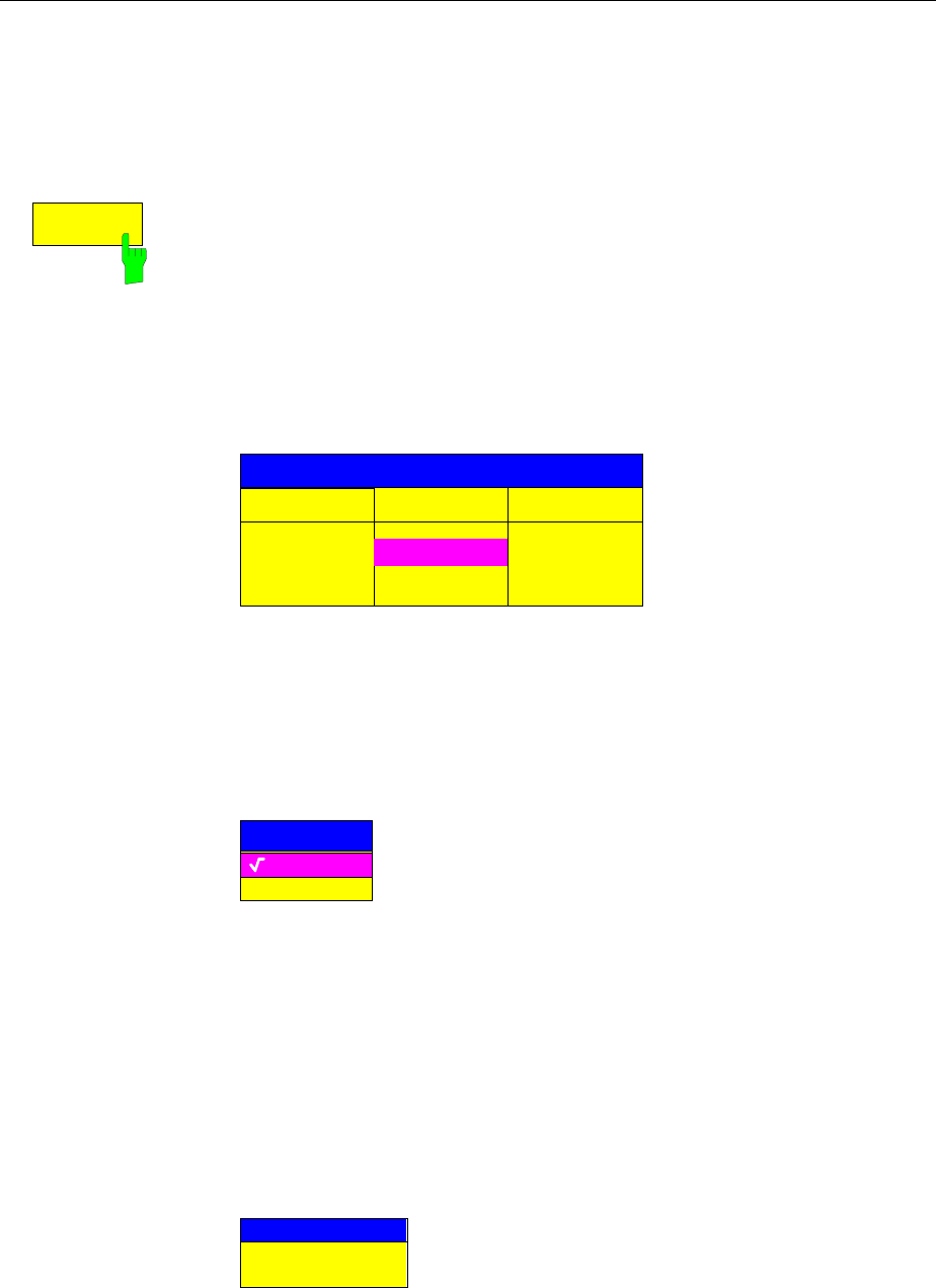
FSE Configuration/Setup
1065.6016.12 4.35 E-15
User Port Configuration - with Windows NT Controller
The instrument provides two parallel interfaces, each of which is 8 bits wide. Over these ports, arbitrary
bit patterns can be output or input. The interfaces are designated USER PORT A and USER PORT B.
CONFIGURATION SETUP-GENERAL SETUP submenu:
USER
PORT A
The USER PORT A and USER PORT B softkeys activate the columns PORT
A and PORT B, respectively, in the USERPORTS table for entry of the
parameters for both of the parallel interfaces in the instrument. Because the
two interfaces are configured in the same manner, how to configure an
interface is described in the following using USER PORT A.
The following parameters need to be configured in the table:
Direction Direction of data transmission
Value Indication/entry of current value
USERPORTS
PORT A
PORT B
OUTPUT
10101010
INPUTDirection
Value
Direction – Direction of data transmission
The DIRECTION parameter determines in which direction the interface
transmits data.
INPUT read operation
OUTPUT write operation
DIRECTION
INPUT
OUTPUT
IEC/IEEE-bus command :INPut<1|2>:UPORt<1|2>:STATe ON|OFF
:OUTPut<1|2>:UPORt<1|2>:STATe ON|OFF
Value – Indication/Entry of current value
The VALUE parameter shows the current value of the data at the port for
data input as well as for data output. The displayed data is in binary format
with the least significant bit (LSB) on the right.
If the port is configured as an OUTPUT then, the displayed value can be
edited. Data entry must also be in binary format (i.e., only the digits 0 and 1
are accepted).
VALUE
00010001
IEC/IEEE-bus command
:INPut<1|2>:UPORt<1|2>[:VALue]?
:OUTPut<1|2>:UPORt<1|2>[:VALue] <Binary>
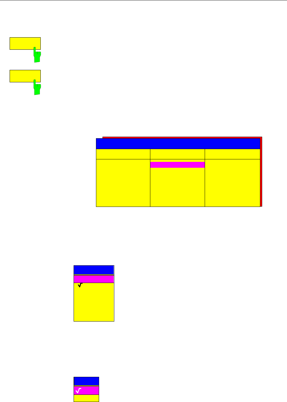
Configuration/Setup FSE
1065.6016.12 4.36 E-15
Serial Interface Configuration - with Windows NT Controller
CONFIGURATION SETUP-GENERAL SETUP submenu:
COM
PORT 1
COM
PORT 2
The COM PORT 1 and COM PORT 2 softkeys activate the columns COM1
and COM2, respectively, for entry of the serial interface parameters Since the
two interfaces are configured in the same manner, how to configure an
interface is described in the following using COM PORT 1.
The following parameters must be in the table:
Baud rate data transmission rate
Bits number of data bits
Parity bit parity check
Stop bits number of stop bits
HW-Handshake hardware handshake protocol
SW-Handshake software handshake protocol
Owner assignment of the serial port to the FSE or computer
Baud
Bits
Parity
Stopbits
HW-Handshake
SW-Handshake
Owner
COM PORTS
COM 1
8
None
1
None
XON/XOFF
Instrument
COM 2
1200
8
None
1
None
None
Instrument
9600
Note: A serial interface (COM1 or COM2) cannot be used for another
purpose if a mouse is connected to it.
Baud – Data transmission rate
Allowed are the indicated values between 110 and 19200 baud. The default
setting is 9600 baud.
BAUD RATE
19200
9600
4800
1200
600
300
110
IEC/IEEE-bus command
:SYSTem:COMMunicate:SERial<1|2>[:RECeive]:BAUD 9600
Bits – Number of data bits per word
For the text transmission without special characters, 7 bits are adequate. For
binary data as well as text with special characters, 8 bits must be selected
(default setting).
BITS
7
8
IEC/IEEE-bus command
:SYSTem:COMMunicate:SERial<1|2>[:RECeive]:BITS 7 | 8
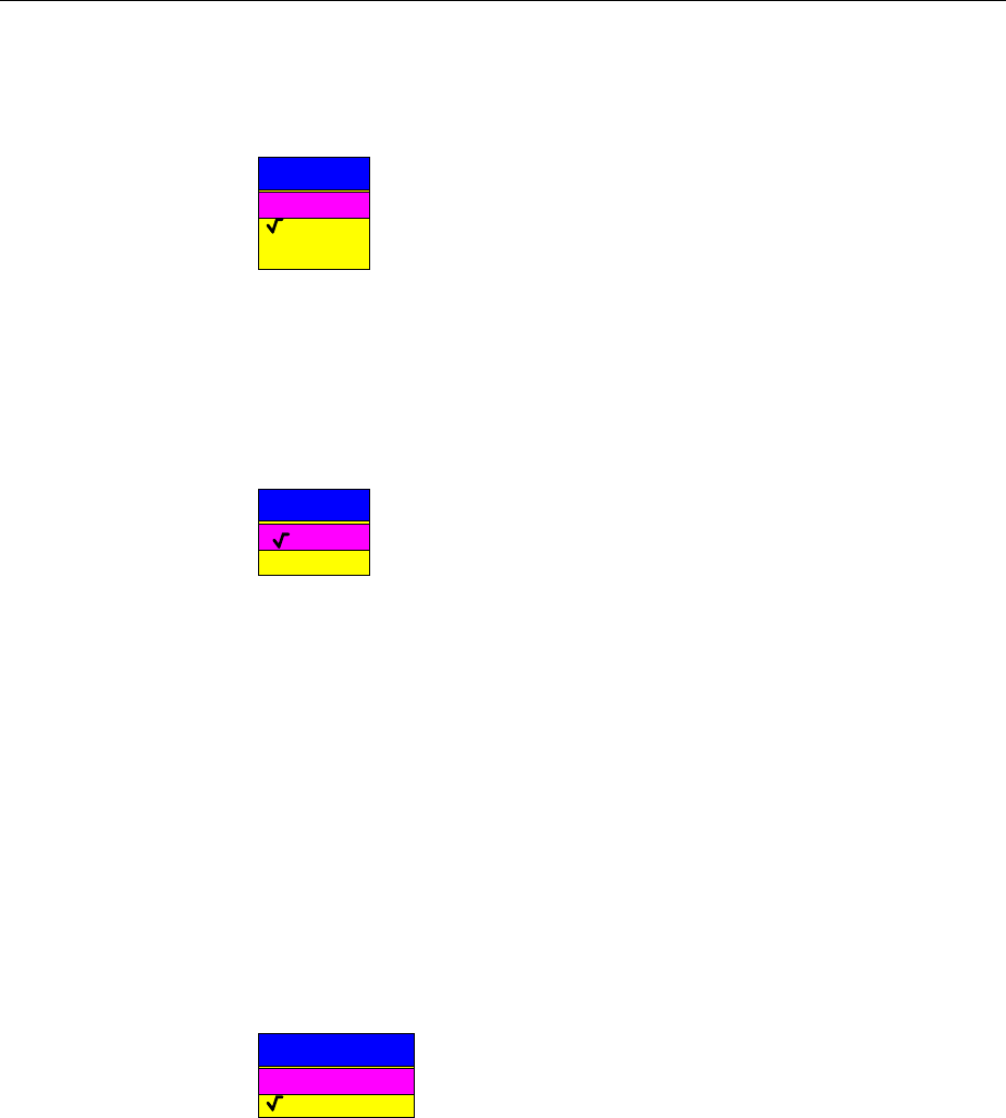
FSE Configuration/Setup
1065.6016.12 4.37 E-15
Parity – Bit parity check
NONE no parity check (default setting)
EVEN even parity check
ODD odd parity check
PARITY
NONE
EVEN
ODD
IEC/IEEE-bus command
:SYSTem:COMM:SERial<1|2>[:RECeive]:PARity[:TYPE]
EVEN| ODD| NONE
Stop bits – Number of stop bits
Available are 1 and 2. The default setting is 1 stop bit.
STOPBITS
1
2
IEC/IEEE-bus command
:SYSTem:COMMunicate:SERial<1|2>[:RECeive]:SBITs 1|2
HW-Handshake – Hardware handshake protocol
The integrity of data transmission can be improved through the use of a
hardware handshake protocol which prevents uncontrolled transmission of
data and the resulting possible loss of data bytes. With the hardware
handshaking procedure, additional interface lines are used to transmit
acknowledge signals with which the data transmission can be controlled and,
if necessary, stopped until the receiver is ready to receive data again.
A prerequisite for handshaking is, however, that the interface lines (DTR and
RTS) are provided between the sender and receiver. For a simple, 3-wire
connection, this is not the case and a hardware handshake cannot be
realized.
Default setting is NONE.
HW-HANDSHAKE
None
DTR/RTS
IEC/IEEE-bus command
:SYSTem:COMM:SERial<1|2>:CONTrol:DTR IBFull|OFF
:SYSTem:COMM:SERial<1|2>:CONTrol:RTS IBFull|OFF
Configuration/Setup FSE
1065.6016.12 4.38 E-15
SW-Handshake – Software handshake protocol
Besides the hardware handshake procedure using interface lines, it is also
possible to achieve the same effect by using a software handshake protocol.
In this case, control bytes are transmitted in addition to the normal data bytes.
These control bytes can be used, as necessary, to stop data transmission
until the receiver is ready to receive data again.
In contrast to hardware handshaking, software handshaking can be realized
even for a simple, 3-wire connection.
Software handshaking, however, does have one limitation. Software
handshaking cannot be used for the transmission of binary data since, the
control characters XON and XOFF require bit combinations that are also
used for binary data transmission.
Default setting is NONE.
SW-HANDSHAKE
None
XON/XOFF
IEC/IEEE-bus command
:SYSTem:COMM:SERial<1|2>[:RECeive]:PACE XON|NONE
Owner – Assignment of the interface
The serial interface can be assigned either to the instrument or the computer
(operating system, OS).
INSTRUMENT Assignment to the instrument means that outputs to the
port by the OS are not possible as any output would be
lost.
OS Assignment to the operating system means that the
instrument cannot use the port, i.e. it is not possible to
remote control the instrument via this port.
OWNER
OS
INSTRUMENT
IEC/IEEE-bus command --
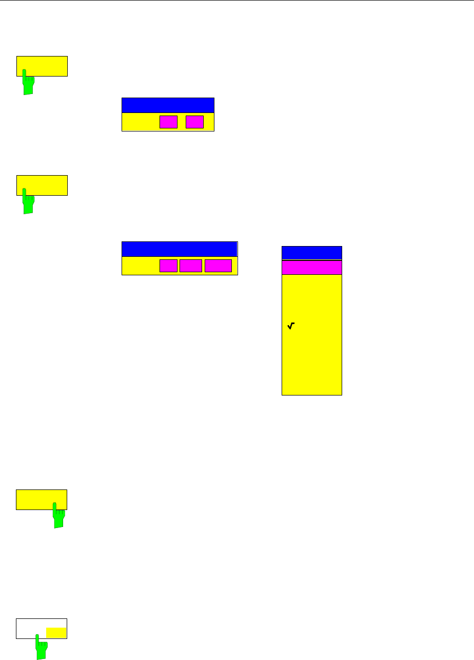
FSE Configuration/Setup
1065.6016.12 4.39 E-15
Setting the Date and Time - with Windows NT Controller
CONFIGURATION SETUP-GENERAL SETUP submenu:
TIME
The TIME softkey activates the entry of time for the internal real time clock. In
the corresponding dialog box, the time is partitioned into two input fields so
that hours and minutes can be entered independently.
TIME
TIME
10 33
:
IEC/IEEE-bus command :SYSTem:TIME 0...23, 0...59, 0...59
DATE
The DATE softkey activates the entry of the date of the internal real-time
clock. In the corresponding dialog box, the date is partitioned into 3 input
fields so that day, month and year can be input separately.
For the selection of the month, pressing a units key opens a list of
abbreviations for the months.
DATE
10 MAY 1995
DATE
MONTH
JAN
FEB
MAR
APR
MAY
JUN
JUL
AUG
SEP
OCT
NOV
DEC
IEC/IEEE-bus command :SYSTem:DATE <num>,<num>,<num>
Connecting the External Monitor - with Windows NT Controller
Submenu CONFIGURATION SETUP-GENERAL SETUP:
MONITOR
CONNECTED The MONITOR CONNECTED softkey informs the unit that an external
monitor is available at PC MONITOR connector
The external monitor displays the Windows NT mask.
IEC/IEEE-bus command --
Switching the Beeper ON/OFF - with Windows NT Controller
CONFIGURATION SETUP-GENERAL SETUP submenu:
KEY CLICK
ON OFF The KEY CLICK ON/OFF softkey switches the beeper on or off. The beeper
acknowledges each key stroke with a beep.
IEC/IEEE-bus command --
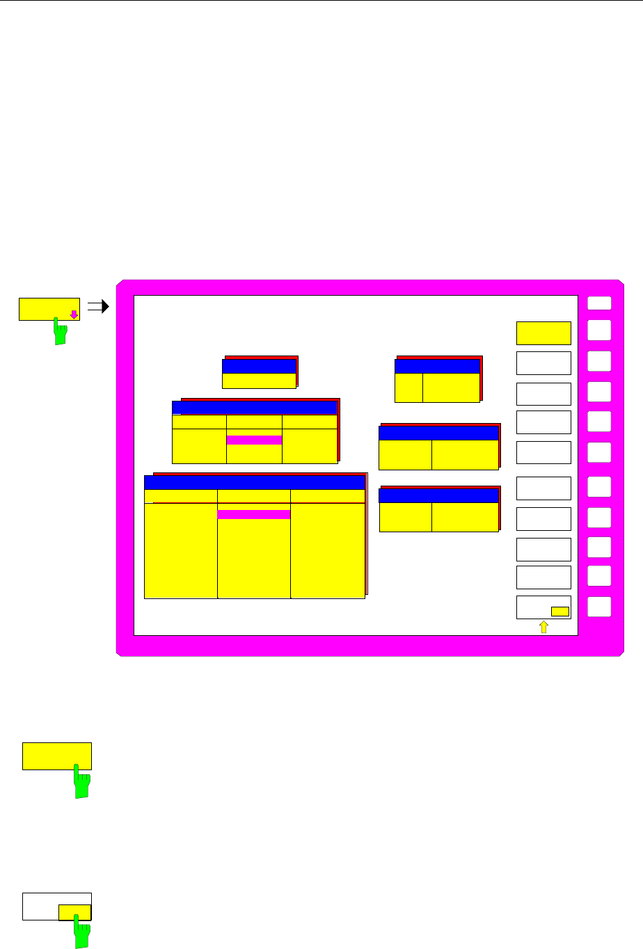
Configuration/Setup FSE
1065.6016.12 4.40 E-15
Setting the Interface Configuration and Time - without Controller Option or with
MS DOS Controller
The GENERAL SETUP soft key branches to a sub-menu in which the basic setup of general instrument
parameters may be performed. In addition to the configuration of the digital interfaces (IECBUS, COM,
LPT and MOUSE), the date and time, the selection of keyboard language as well as the configuration of
the USER PORTS may be entered.
The current settings are displayed in tabular form on the display screen where they may then be edited.
Note: Interface LPT cannot be configured. If the option FSE-B15, DOS controller function, is
installed, LPT1 can be used for printing in both the measurement instrument mode and the
computer mode. However, it can only be used for one mode at a time.
CONFIGURATION SETUP menu:
U
SE
R
Ba
u
d
B
i
ts
Par
i
t
y
S
t
o
p
b
i
t
s
HW-Ha
n
d
sha
k
e
SW-H
an
d
s
h
a
k
e
O
w
n
e
r
Pr
o
t
o
co
l
CO
M
2
C
O
M
1
96
0
0
8
N
o
n
e
1
N
o
n
e
X
ON/
X
OFF
In
str
u
me
n
t
R
e
mote
1
2
00
8
No
n
e
1
No
n
e
No
n
e
I
n
s
t
r
u
me
n
t
Mou
s
e
GPIB
ADDRESS
GENERAL
SETUP
COM
PORT 1
TIME
DATE
EXTERNAL
KEYBOARD
MOUSE
USER
PORT A
COM
PORT 2
USER
PORT B
GPIB ADRESS
19
PORT A PORT B
Direction
Value Input
10101010 Output
00010001
USER PORTS
COM PORTS
TIME AND DATE
MOUSE
EXTERNAL KEYBOARD
Connection
Language
not connected
US American
Interface
Owner PS/2
Instrument
Time
Date 21:59
01 Oct 1994
GENERAL
SETUP
KEY CLICK
ON OFF
IEC Bus Address Selection
CONFIGURATION SETUP-GENERAL SETUP submenu:
GPIB
ADDRESS
The GPIB ADDRESS soft key activates the entry of the IEC Bus address.
Permitted addresses are 0 through 30. The default setting is address 20.
Switching the Beeper ON/OFF
CONFIGURATION SETUP-GENERAL SETUP submenu:
KEY CLICK
ON OFF
The KEY CLICK ON/OFF soft key switches the beeper on or off. The beeper
acknowledges each key stroke with a beep.
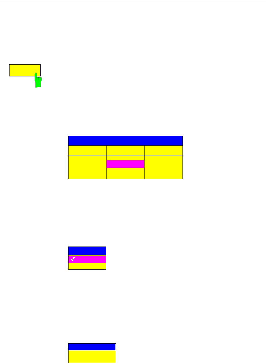
FSE Configuration/Setup
1065.6016.12 4.41 E-15
User Port Configuration - without Controller Option or with MS DOS Controller
The instrument provides two parallel interfaces, each of which is 8 bits wide. Over these ports, arbitrary
bit patterns can be output or input. The interfaces are designated USER PORT A and USER PORT B.
CONFIGURATION SETUP-GENERAL SETUP submenu:
USER
PORT A
The USER PORT A and USER PORT B soft keys activate the columns
PORT A and PORT B, respectively, in the USERPORTS table for entry of the
parameters for both of the parallel interfaces in the instrument. Because the
two interfaces are configured in the same manner, how to configure an
interface is described in the following using USER PORT A.
The following parameters need to be configured in the table:
Direction Direction of data transmission
Value Indication/entry of current value
USERPORTS
PORT A
PORT B
OUTPUT
10101010
INPUTDirection
Value
Direction – Direction of data transmission
The DIRECTION parameter determines in which direction the interface
transmits data.
INPUT read operation
OUTPUT write operation
DIRECTION
INPUT
OUTPUT
Value – Indication/Entry of current value
The VALUE parameter shows the current value of the data at the port for
data input as well as for data output. The displayed data is in binary format
with the least significant bit (LSB) on the right.
If the port is configured as an OUTPUT then, the displayed value can be
edited. Data entry must also be in binary format (i.e., only the digits 0 and 1
are accepted).
VALUE
00010001
Configuration/Setup FSE
1065.6016.12 4.42 E-15
Serial Interface Configuration - without Controller Option or with MS DOS
Controller
CONFIGURATION SETUP-GENERAL SETUP submenu:
COM
PORT 1
COM
PORT 2
The COM PORT 1 and COM PORT 2 soft keys activate the columns COM1
and COM2, respectively, for entry of the serial interface parameters. Since
the two interfaces are configured in the same manner, how to configure an
interface is described in the following using COM PORT 1.
The following parameters need to be configured in the table:
Baud rate data transmission rate
Bits number of data bits
Parity bit parity check
Stop bits number of stop bits
HW-Handshake hardware handshake protocol
SW-Handshake software handshake protocol
Owner assignment to the measuring instrument or computer
Protocol transmission protocol
Baud
Bits
Parity
Stopbits
HW-Handshake
SW-Handshake
Owner
Protocol
COM PORTS
COM 1
8
None
1
None
XON/XOFF
Instrument
Remote
COM 2
1200
8
None
1
None
None
Instrument
Remote
9600
Note: A serial interface (COM1 or COM2) cannot be used for another
purpose if a mouse is connected to it.
Baud – Data transmission rate
Allowed are the indicated values between 110 and 19200 baud. The default
setting is 9600 baud.
BAUD RATE
19200
9600
4800
1200
600
300
150
110
Bits – Number of data bits per word
For the transmission of text without German umlauts (Ä, ä, Ü, ü, Ö, ö) and
special characters, 7 bits are adequate. For binary data as well as text with
special characters or umlauts, 8 bits must be selected (default setting).
BITS
7
8
FSE Configuration/Setup
1065.6016.12 4.43 E-15
Parity – Bit parity check
NONE no parity check (default setting)
EVEN even parity check
ODD odd parity check
PARITY
NONE
EVEN
ODD
Stop bits – Number of stop bits
Available are 1 and 2. The default setting is 1 stop bit.
STOPBITS
1
2
HW-Handshake – Hardware handshake protocol
The integrity of data transmission can be improved through the use of a
hardware handshake protocol which effectively prevents uncontrolled
transmission of data and the resulting possible loss of data bytes. In the
hardware handshaking procedure, additional interface lines are used to
transmit acknowledge signals with which the data transmission can be
controlled and, if necessary, stopped until the receiver is ready to receive
data again.
A prerequisite for handshaking is, however, that the interface lines (DTR and
RTS) are provided between sender and receiver. For a simple, 3-wire
connection, this is not the case and hardware handshake cannot be realized
here.
Default setting is NONE.
HW-HANDSHAKE
None
DTR/RTS
SW-Handshake – Software handshake protocol
Besides the hardware handshake procedure using interface lines, it is also
possible to achieve the same effect by using a software handshake protocol.
Here, control bytes are transmitted in addition to the normal data bytes.
These control bytes can be used, as necessary, to stop data transmission
until the receiver is ready to receive data again.
In contrast to hardware handshaking, software handshaking can be realized
even for a simple, 3-wire connection.
One limitation is, however, present in software handshaking. Software
handshaking cannot be used for the transmission of binary data since, the
control characters XON and XOFF require bit combinations that are also
used for binary data transmission.
Default setting is NONE.
SW-HANDSHAKE
None
XON/XOFF

Configuration/Setup FSE
1065.6016.12 4.44 E-15
Owner – Assignment of the interface
When the option FSE-B15, DOS controller, is installed, the serial interface
can be assigned alternatively to the instrument measurement section, the
DOS section or to both sections of the FSE .
If the interface is assigned to only one section of the instrument, it is not
available to the other section.
INSTRUMENT The interface is assigned to the instrument measurement
section. Outputs to the interface from the computer are
not possible and, so to say, land nowhere.
DOS The interface is assigned to the computer section. It
cannot be used by the instrument measurement section.
This means that hardcopy or remote control of the
instrument via the interface is not possible. An attempt to
start a print job via the interface results in an error
message.
The PROTOCOL parameter has no meaning in this
mode.
INTR AND DOS The interface is allocated to both instrument sections. It
may be used alternately by each section. This means that
a hardcopy job from the measurement section and a data
transfer from the computer are not possible at the same
time. This would lead to a mixing of the data streams.
The set interface parameters, with the exception of
PROTOCOL, are valid for both instrument sections. The
PROTOCOL parameter is only of interest for the
measurement section.
OWNER
INSTR AND DOS
DOS
INSTRUMENT
Note: DOS programs cannot independently recognize changed interface
parameter settings.
Protocol – Transmission protocol
The parameter allows the selection of special transmission protocols for
measurement functions. The interface can be configured for:
–remote control as single instrument
–printer output (hardcopy)
PROTOCOL
HARDCOPY
REMOTE
FSE Configuration/Setup
1065.6016.12 4.45 E-15
Setting Date and Time - without Controller Option or with MS DOS Controller
CONFIGURATION SETUP-GENERAL SETUP submenu:
TIME
The TIME soft key activates the entry of time for the internal real time clock .
In the corresponding dialog box, the time is partitioned into two input fields so
that hours and minutes can be entered independently.
TIME
TIME
10 33
:
DATE
The DATE soft key activates the entry of the date of the internal real-time
clock. In the corresponding dialog box, the date is partitioned into 3 input
fields so that day, month and year can be input separately.
DATE
10 MAY 1995
DATE
For the selection of the month, pressing a units key opens a list of
abbreviations wherein the desired month can be selected.
MONTH
JAN
FEB
MAR
APR
MAY
JUN
JUL
AUG
SEP
OCT
NOV
DEC
Configuration/Setup FSE
1065.6016.12 4.46 E-15
Mouse Configuration - without Controller Option or with MS DOS Controller
How to connect a mouse is described in chapter 1, section "Connecting a Mouse", the operation of the
instrument with a mouse is described in chapter 2, section "Mouse and External Keyboard Control".
Caution:
The keyboard may only be connected when the instrument is switched off
(STANDBY). Otherwise, correct operation of the keyboard cannot be guaranteed.
CONFIGURATION SETUP-GENERAL SETUP submenu:
MOUSE
The MOUSE soft key activates the MOUSE table for configuration of the
mouse.
The following parameters need to be configured in the table:
Interface Selection of interface
Owner Assignment of mouse
Interface
Owner
MOUSE
INSTRUMENT
NOT CONNECTED
Interface – Selection of the interface
If one of the serial interfaces is selected (COM PORT 1 or COM PORT 2), its
interface parameters are automatically reconfigured so that mouse operation
is possible.
NOT CONNECTED No connection
PS/2 MOUSE connector on the rear panel
COM PORT 1 COM1 connector on the rear panel
COM PORT 2 COM2 connector on the rear panel
INTERFACE
PS/2
COM PORT 1
COM PORT 2
NOT CONNECTED
Owner – Assignment of the mouse
If the processor option FSE-B15 is installed, the mouse can alternately be
assigned to the instrument measurement section, the computer section or to
both sections simultaneously.
If the mouse is assigned to one section it is not available to the other section.
INSTRUMENT The mouse is assigned to the instrument measurement
section.
DOS The mouse is assigned to the computer section.
INTR AND DOS The mouse is assigned to both sections.
OWNER
INSTR AND DOS
DOS
INSTRUMENT
FSE Configuration/Setup
1065.6016.12 4.47 E-15
External Keyboard Configuration - without Controller Option or with MS DOS
Controller
How to connect a keyboard is described in chapter 1, section "Connecting an External Keyboard", the
operation of the instrument with an external keyboard is described in chapter 2, section "Mouse and
External Keyboard Control".
Caution:
The keyboard may only be connected when the instrument is switched off
(STANDBY). Otherwise, correct operation of the keyboard cannot be guaranteed.
CONFIGURATION SETUP-GENERAL SETUP submenu:
EXTERNAL
KEYBOARD
The EXTERNAL KEYBOARD soft key activates the EXTERNAL KEYBOARD
table for configuration of the external keyboard.
Connection Activation of the keyboard connection
Language Language definition for measurement instrument operation
Connection
Language
EXTERNAL KEYBOARD
US-AMERICAN
NOT CONNECTED
Connection – Activating the connection
Activating the connection mainly determines whether or not the help line
editor is available.
CONNECTED A keyboard is connected. When an alphanumeric entry
window is opened, the help line editor is no longer
displayed automatically because it is no longer needed
for editing.
NOT CONNECTED The help line editor is opened automatically when
alphanumeric parameters are edited.
CONNECTION
CONNECTED
NOT CONNECTED
Language –Language definition for measurement instrument operation
Available are US-American, German and French.
LANGUAGE
GERMAN
FRENCH
US-AMERICAN
Note: The language definition of the keyboard in DOS mode is
independent of this setting and is determined by the appropriate
MS-DOS command.
Configuration/Setup FSE
1065.6016.12 4.48 E-15
Firmware Update
New firmware versions can be installed from the integral disk drive. The firmware update kit contains
several disks.
The installation program is called in the SETUP menu.
CONFIGURATION SETUP sidemenu:
FIRMWARE
UPDATE
UPDATE
FIRMWARE
UPDATE
RESTORE
The FIRMWARE UPDATE softkey opens the submenu for
the installion of a new firmware version.
UPDATE
The UPDATE softkey starts the installation program and guides the user
through the remaining steps of the update procedure.
RESTORE
The RESTORE softkey restores the previous firmware version

FSE Manual Control
1065.6016.12 4.49 E-15
Status Display-Remote/Manual Control – STATUS Key
Group
STATUS
LOCAL
SRQ
REMOTE
The SRQ LED, the REMOTE LED and the LOCAL. key are contained in the
STATUS key group.
éThe SRQ LED indicates that a service request from the instrument has
been asserted on the IEC Bus.
éThe REMOTE LED indicates that the instrument is under remote control.
éThe LOCAL key switches the instrument from remote to manual control,
with the assumption that the remote controller has not previously set the
LOCAL LOCKOUT function.
A change in the control mode comprises:
-Enabling the Front Panel Keys
Under remote control, the softkey menu is turned off and all keys, with
the exception of PRESET and LOCAL, are disabled. Returning to
manual mode enables all disabled keys. The main menu of the current
mode is selected as the softkey menu..
-Turning off the REMOTE LED
-Generating the message OPERATION COMPLETE
If the synchronization via *OPC, *OPC? or *WAI is active when the
LOCAL softkey is pressed, any measurement procedure that is running
is aborted and synchronization is achieved by setting the corresponding
bits in the registers of the status reporting system.
-Setting Bit 6 (User Request) of the Event Status Register
If the status reporting system is configured appropriately, setting this bit
immediately elicits a service request (SRQ) which is used to inform the
controller that the user wishes to return to front-panel control. This
information can be used, e.g., to interrupt the control program so that the
user can make the necessary manual corrections to instrument settings.
This bit is set each time the LOCAL key is pressed.
é The LOCAL key aborts a running macro. The continuation of the macro is
not possible.
IEC/IEEE-bus command CALL IBLOC(analyzer%)
Documentation of Measurement Results FSE
1065.6016.12 4.50 E-15
Measurement Documentation – HARDCOPY Key Group
Note: The installation of additional printer drives is described in chapter 1, section "Installation and
Configuration of Printers".
Printing Data – START Key - with Windows NT Controller
Note: Printing data for instruments with MS DOS controller or without controller is described page 4.52
The instrument uses the printer function of Windows NT to output hardcopies. Any printer supported by
Windows NT can be used. In addition, the instrument permits data output in the usual data formats
WMF, EWMF and BMP which enable hardcopies to be directly inserted into other documents. Network
printers can be used if the instrument is connected to a network.
SE NG
START
HARDCOPY The START key initiates the printing of measurement/ instrument status data.
The instrument can distinguish between two different printers, each of which
may be individually configured, e.g., a laser printer and a ink jet printer. All
documents are printed on the printer which is currently active.
IEC/IEEE-bus command :HCOPy[:IMMediate<1|2>]
Pressing the HARDCOPY START key starts the print job. The settings under Windows NT and in the
HARDCOPY SETTINGS menu determine the printer configuration. All of the display items to be printed
out are written to the printer buffer of Windows NT. Since the printer runs in the background, the
instrument may be operated immediately after pressing the START key.
When COPY SCREEN is selected in menu HARDCOPY SETTINGS, all the measurememt diagrams
with traces and status displays are printed as they appear on the screen. Softkeys, open tables and data
entry fields are not printed out. Specific traces can be printed out with the COPY TRACE function. With
COPY TABLE, tables can be printed out.
If CLIPBOARD is active in the HARDCOPY DEVICE submenu the clipboard can be used to directly
transfer hardcopies to Windows applications. The copy is written in the clipboard by pressing
HARDCOPY START. The user can then change to another Word document and insert the clipboard
content into the document with EDIT - PASTE by using the key combination CTRL+V.
If the PRINT TO FILE option in the HARDCOPY DEVICE submenu is selected, the printout is directed to
a file. When the HARDCOPY START is pressed , the file name to which the output data are to be
written is requested.
If the START key is pressed while printing is in progress, a second output can be released which can
also be joined to the printer queue. Any number of print jobs can be released consecutively.
Current print jobs can be aborted only by cancelling the entries in the Windows NT printer queue. After
starting the print a printer symbol is displayed in the task bar near the time indication.
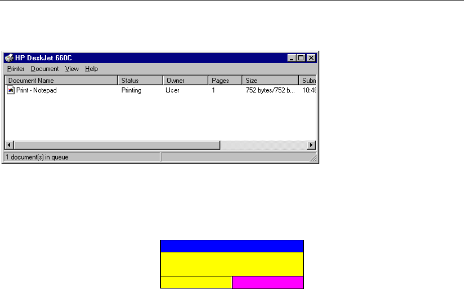
FSE Documentation of Measurement Results
1065.6016.12 4.51 E-15
A double-click on this symbol opens a window containing the entries of the printer queue. The relevant
print order can be cancelled by marking it with the mouse and pressing the DEL key.
While a print job is in progress, problems may occur in the printer. If, while printing, the printer issues a
PAPER OUT message, i.e., no more paper is available, the user will be prompted by the following
message
ERROR
Paper out on device LPT
(manual feed)?
CONTINUE
ABORT
to load paper into the printer. The print job will then be either continued (CONTINUE) or aborted
(ABORT).
Switchover between b/w and colored printouts is possible with the COLOR ON/OFF softkey provided
that an appropriate printer is connected. The colors of the printout correspond exactly to those on the
screen, ie a red trace will be output in red.
To change the colors of the objects on the printout, the screen colors have to be changed in DISPLAY-
CONFIG DISPLAY menu. One exception is the color of the background and the color of the diagrams.
The output background is always white irrespective of the screen color and the diagrams are always
black.
If several traces are to be output one after the other on the same sheet different colors can be chosen
for each trace with the TRC COLOR AUTO INC softkey (Trace Color Auto Increment).
On most b/w printers, a better printout of the color screen is obtained on hardcopies if the color
information is converted into gray shades. For this, the color output in menu HARDCOPY SETTINGS is
to be activated (COLOR ON).
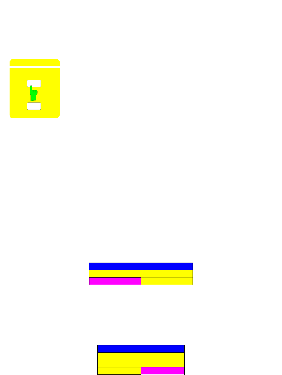
Documentation of Measurement Results FSE
1065.6016.12 4.52 E-15
Printing Data – START Key- with MS DOS Controller or without
Controller
Note: Printing data for instruments with Windows NT controller is described page 4.50
SE NG
START
HARDCOPY The START key initiates the printing of measurement/ instrument status data.
The FSE can distinguish between two different output devices, each of which
may be individually configured, e.g., a laser printer and a plotter. All
documents are printed on the output device which is currently active.
Pressing the HARDCOPY START key initiates the print job. The printer parameters defined in the
HARDCOPY SETTINGS menu are used for setting up the printer configuration. After pressing the
START key, all of the display items to be printed are written to the printer buffer memory. Since the
printer runs in the background, the instrument may be operated immediately after pressing the START
key.
With COPY SCREEN selected in menu HARDCOPY SETTINGS, all the diagrams with traces and
status displays are printed as they occur on the screen. Softkeys, open tables and data entry fields are
not printed out. Function COPY TRACE allows to print out individual traces. With COPY TABLE tables
can be printed out.
If the FILE option in the HARDCOPY DEVICE submenu of the HARDCOPY SETTINGS menu is
selected then, upon pressing HARDCOPY START, the file name to which the output data are to be
written is requested. For this an entry field is opened for entering the file name. If no external keyboard
is connected, the help line editor is activated.
If the START key is pressed again while a print job is in progress, a new print job will be started directly
after completion of the first one. It is not possible to process more than two hardcopies at the same
time. With START pressed again, the following warning appears on the display screen:
WAR
N
I
NG
Hardcopy not completed.Stop printer?
OK CANCEL
Pressing the OK key causes the active print jobs to be interrupted. Selecting CANCEL erases the
warning and the print job continues.
While a print job is in progress, problems may occur in the output device. If, while printing, the output
device issues a PAPER OUT message, i.e., no more paper is available, the user will be prompted by the
following message
ERROR
Paper out on device LPT
(manual feed)?
CONTINUE
ABORT
to load paper into the output device. The print job will then be either continued (CONTINUE selected) or
aborted (ABORT selected).

FSE Documentation of Measurement Results
1065.6016.12 4.53 E-15
Similar SYSTEM MESSAGES appear, e.g., if the IEC Bus address of the printer is incorrectly set , the
printer does not respond, etc.
Switchover between b/w and coloured printouts is possible with softkey COLOR ON/ OFF provided that
the printer connected is able to output such prints. The colours of the printout correspond exactly to
those of the screen, ie a red trace will be output in red.
To change the colours of the objects on the printout, the screen colours have to be changed
correspondingly in menu DISPLAY, submenu CONFIG DISPLAY. One exception is the colour of the
background and the colour of the diagrams. The output background is always white irrespective of the
screen colour and the diagrams are always black.
If several traces are to be output one after the other on the same sheet different colours can be chosen
for each trace with the aid of softkey TRC COLOR AUTO INC (Trace Color Auto Increment).
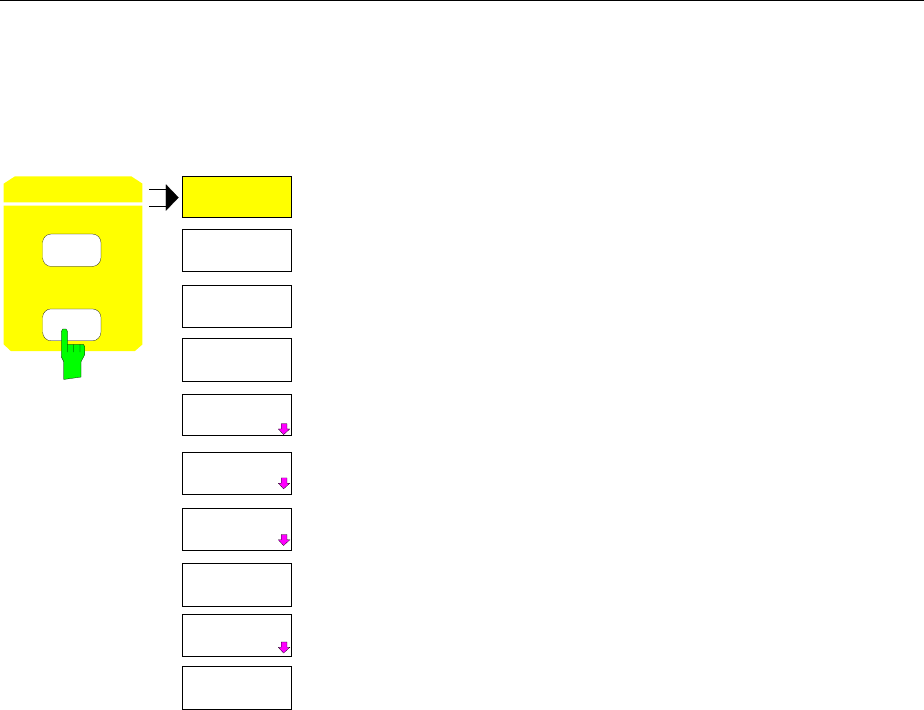
Documentation of Measurement Results FSE
1065.6016.12 4.54 E-15
Printing Configuration – SETTINGS Key
HARDCOPY SETTINGS menu:
TRC COLOR
AUTO INC
HARDCOPY
SETTINGS
START
COPY
TRACE
SELECT
ITEMS
SELECT
QUADRANT
COLOR
ON OFF
HARDCOPY
DEVICE
ENTER
TEXT
HARDCOPY
SETTINGS
COPY
SCREEN
COPY
SEL ITEMS
COPY
TABLE
The SETTINGS key opens the menu to configure the printout.
The recommended procedure for configuring the printout is as
follows:
•Configure the desired printer and select the interface over
which the output is to take place by using Windows NT and
the HARDCOPY DEVICE softkey.
•Select the display items to be printed with the COPY
SCREEN, COPY TRACE softkeys.
•Select between coloured and b/w printouts with the COLOR
ON/ OFF and TRC COLOR AUTO INC softkeys.
•Enter comment applicable to the diagram or add a title for the
overall printout by using the ENTER TEXT softkey.
•Select the page format (QUADRANT, FULL PAGE) through
use of the SELECT QUADRANT softkey.
The COPY SCREEN, COPY TRACE and COPY TABLE
softkeys are selection switches, i.e., only one function can be
enabled at any one time. The push buttons are used for
selection only and do not initiate a print job. The actual printing is
initiated by the HARDCOPY START key.
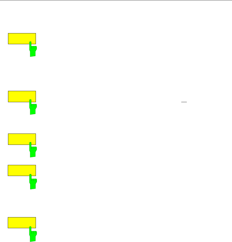
FSE Documentation of Measurement Results
1065.6016.12 4.55 E-15
Selection of Displayed Elements and Colour Settings
HARDCOPY SETTINGS menu:
COPY
SCREEN
The COPY SCREEN softkey selects the output of test results.
All the diagrams, traces, markers, marker lists, display lines, limit lines etc.
are printed out as long as they are displayed on the screen. Softkeys, tables
and open data entry fields are not printed out. However, comments, title,
date, and time entered are printed out at the bottom of the printout. The logo
appears at the top left of the printout.
IEC/IEEE-bus command :HCOPy:ITEM:ALL
COPY
TRACE
The COPY TRACE softkey selects the output of all traces displayed on the
screen without any auxiliary information. Specifically, no markers or display
lines are printed.
IEC/IEEE-bus command
:HCOPy:ITEM:WINDow<1|2>:TRACe:STATe ON|OFF
COPY
TABLE
The COPY TABLE softkey selects the output of all tables visible displayed on
the screen.
IEC/IEEE-bus command
:HCOPy:ITEM:WINDow<1|2>:TABle:STATe ON|OFF
COLOR
ON OFF The COLOR ON/ OFF softkey selects a coloured or b/w printout.
After having changed the printer driver or the hardcopy device (in submenu,
HARDCOPY SETTINGS) the softkey is automatically switched to ON.
One exception is printer driver HP PCL4 which only supports b/w printouts. In
this case, the softkey cannot be operated.
IEC/IEEE-bus command :HCOPy:DEVice:COLor ON | OFF
TRC COLOR
AUTO INC The TRC COLOR AUTO INC softkey automatically switches the colours of
the traces on to the next printout. On the second printout, trace 1 has the
colour of trace 2, trace 2 the colour of trace 3 etc. The fourth printout starts
with the first colour. With the softkey switched off, the colours of the traces
are reset to their original state.
When changing the printer driver or the hardcopy device (both in submenu
HARDCOPY SETTINGS) as well as the selection b/w printout (softkey
COLOR ON/ OFF in position OFF), softkey TRC COLOR AUTO INC is
switched off.
IEC/IEEE-bus command
:HCOPy:ITEM:WINDow<1|2>:TRACe:CAINcrement ON | OFF
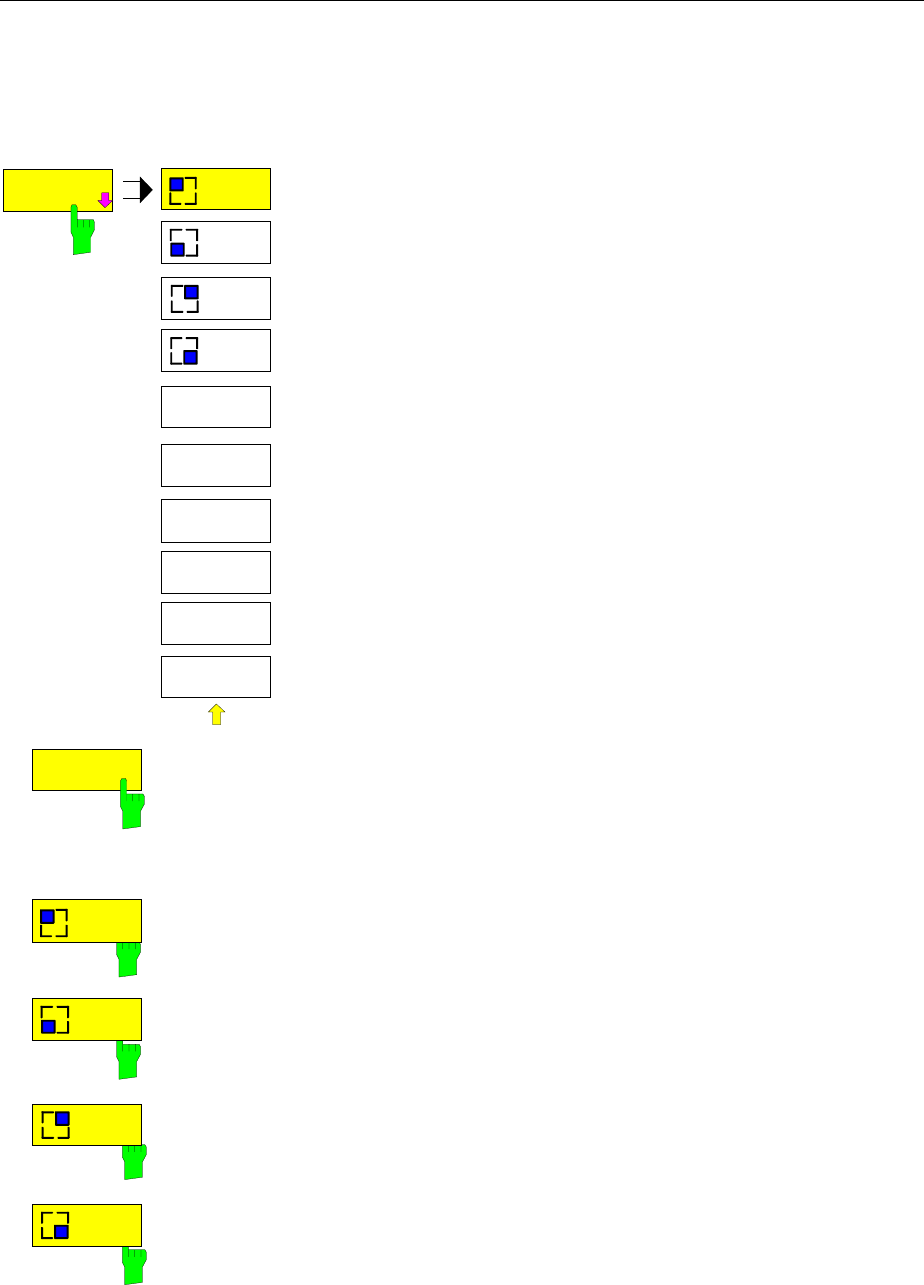
Documentation of Measurement Results FSE
1065.6016.12 4.56 E-15
Selection of Hardcopy Format
HARDCOPY SETTINGS-SELECT QUADRANT submenu:
SELECT
QUADRANT
SELECT
QUADRANT
UPPER
LEFT
UPPER
RIGHT
LOWER
LEFT
LOWER
RIGHT
FULL
PAGE
The SELECT QUADRANT softkey calls the the submenu for
selection of QUADRANTthe location of the display screen
graphics on the printed page.
FULL
PAGE
The FULL PAGE softkey switches quadrant printing off, i.e., printing now
takes place at full size. The information as to which quadrant was last
selected is also lost. FULL PAGE is the default setting.
IEC/IEEE-bus command :HCOPy:PAGE:DIMensions:FULL
UPPER
LEFT
LOWER
LEFT
UPPER
RIGHT
LOWER
RIGHT
The UPPER LEFT, LOWER LEFT as well as UPPER RIGHT, LOWER
RIGHT softkeys select the page quadrants where the printed data will be
positioned. In this case, the actual size of the data printed on the page is
reduced to 25% of normal size. This reduction is independent of how the
graphics are distributed on the display screen. Thus, for two measurement
windows (SPLIT SCREEN), both measurement diagrams shown on the
display are placed in the chosen quadrant. Thus, up to a maximum of 8
measurement windows can be printed on one page. (4 print commands for a
SPLIT SCREEN display, each to a different quadrant)
IEC/IEEE-bus command
:HCOPy:PAGE:DIMensions:QUADrant 1|2|3|4
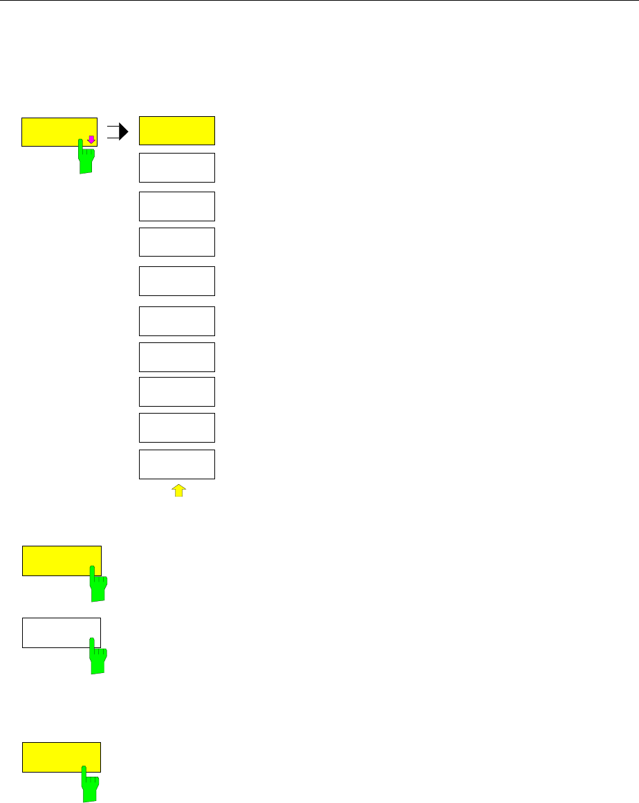
FSE Documentation of Measurement Results
1065.6016.12 4.57 E-15
Entry of Comment Text
HARDCOPY SETTINGS-ENTER TEXT submenu:
ENTER
TEXT
ENTER
TEXT
COMMENT
SCREEN A
COMMENT
SCREEN B
TITLE
The ENTER TEXT softkey calls the submenu for editing the
commentary for the individual windows. The comment text
appears in the print-out, but does not appear on the display
screen.
If a comment is not to appear on the printout, it has to be deleted.
By pressing PRESET, all comments will be deleted.
COMMENT
SCREEN A
COMMENT
SCREEN B
The COMMENT SCREEN A softkey opens an entry field in which
a comment of at most two lines (60 characters per line) can be
entered for screen A or screen B. If the user enters more than 60
characters, the overflow characters appear on the second line on
the print-out. At any point, a manual line-feed can be forced by
entering the @ character. The comment is printed below the
corresponding screen.
IEC/IEEE-bus command
:HCOPy:ITEM:WINDow<1|2>:TEXT <string>
TITLE
The TITLE softkey activates a single line entry box for entering a
title for the complete print-out with a maximum of 60 characters.
IEC/IEEE-bus command
:HCOPy:ITEM:LABel:TEXT <string>
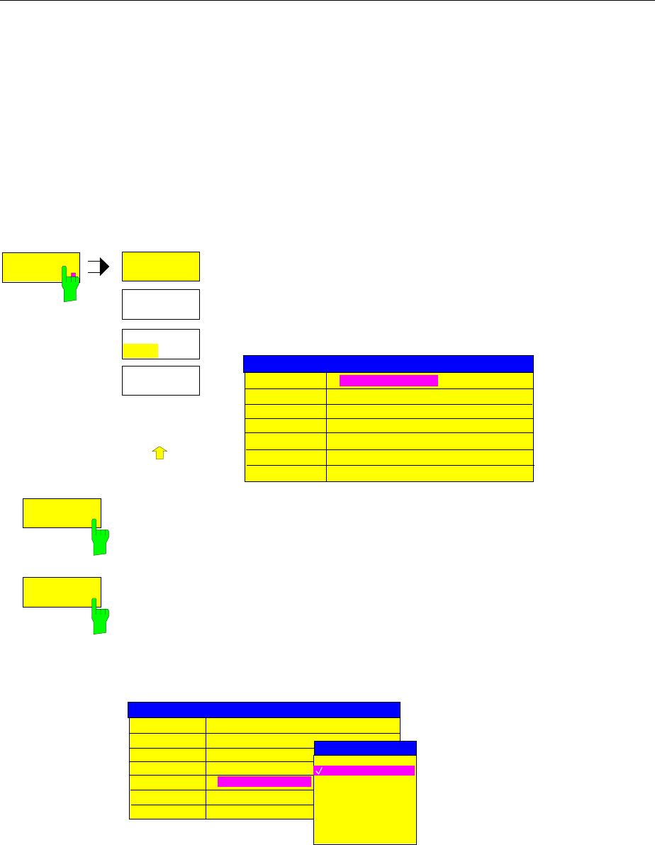
Documentation of Measurement Results FSE
1065.6016.12 4.58 E-15
Selection and Configuration of the Printer - with Windows NT Controller
Note: Selection and configuration of the printer for instruments with MS DOS controller or without
controller is described page 4.60
The instrument permits two different printers to be configured. One of the devices is defined as the
active device and can be used for hardcopies.
The printers are mainly installed and configured under Windows NT and and the settings are valid for all
Windows applications (see Chapter 1, section "Connecting an Printer"). The active device and the
settings which concern only the output of hardcopies are selected in menu HARDCOPY DEVICE..
HARDCOPY SETTINGS submenu:
HARDCOPY
DEVICE
HARDCOPY
DEVICE
SETTINGS
DEVICE 1
SETTINGS
DEVICE 2
ENABLE
DEV1 DEV2
.
.
.
The HARDCOPY DEVICE softkey switches to the submenu
which is used for the selection/configuration of the two printers.
When the sub-menu is called, the corresponding table is
displayed. The SETTINGS DEVICE 1 softkey is active and the
selection bar is located at the DEVICE1 line in the corresponding
column of the table.
HARDCOPY DEVICE SETTINGS
Device1 WINDOWS METAFILE
Print to File YES
Orientation ---
Device2 CLIPBOARD
Print to File ---
Orientation ---
SETTINGS
DEVICE 1
SETTINGS
DEVICE 2
The SETTINGS DEVICE 1 softkey permits the selection and configuration of the
printer DEVICE 1. The SETTINGS DEVICE 2 softkey is used to configure DEVICE
2.
The actual selection of the active printer takes place with the ENABLE DEV1 DEV2
softkey in the HARDCOPY DEVICE sub-menu.
Device
The selection of the printer/language for DEVICE 1 and DEVICE 2 is made in this
line.
Device1 WINDOWS METAFILE
Print to File YES
Orientation ---
Device2 CLIPBOARD
Print to File ---
Orientation ---
HARDCOPY DEVICE SETTINGS
DEVICE
CLIPBOARD
WINDOWS METAFILE
ENHANCED METAFILE
BITMAP FILE
HP DeskJet 660C

FSE Documentation of Measurement Results
1065.6016.12 4.59 E-15
Three file formats and the Windows NT clipboard are always available, even if a
printer has not yet been installed under Windows NT. All installed printers are listed
below in alphabetic order.
The printer installation is described in Chapter 1, Section "Installation and
Configuration of Printers".
CLIPBOARD The hardcopies are copied to the Windows NT clipboard. This
permits to obtain a printout of high quality which can be directly
inserted into other Windows applications (menu EDIT | PASTE or
key combination CTRL+V). The lines ’Print to File’, ’Orientation’ and
’GPIB Address’ are deactivated.
WINDOWS METAFILE and ENHANCED METAFILE
WMF and EWMF are vector graphics formats which can be
imported by most graphics and editing programs. EMF is
recommended for recent Windows32 applications.
BITMAP FILE BMP is a bitmap format which can also be imported by most
programs.
When WMF, EWMF and BMP are selected, the line "Print to File" is automatically
set to ON and line "Orientation" deactivated.
IEC/IEEE-bus commands
:HCOPy:DEVice:LANGuage WMF|EWMF |BMP |GDI
:HCOPy:DESTination<1|2>
"MMEM"|"SYST:COMM:PRIN"|"SYST:COMM:CLIP"
:HCOPy:ITEM:FFEed<1|2>:STATe ON | OFF
Print to File
With "Print to File" ON, the printout is directed to a file. In this case the user is
prompted to enter a file name on starting the printout.
Note: This setting is coupled to the corresponding setting under Windows NT.
IEC/IEEE-bus commands :HCOPy:DESTination<1|2> "MMEM"
:MMEMory:NAME <file_name>
Orientation
In this line, the print format of the output page is set to either vertical (= PORTRAIT)
or horizontal (= LANDSCAPE).
ENABLE
DEV1 DEV2
The ENABLE DEV1 / DEV2 softkey determines the active printer. The default
printer is DEVICE 1, i.e., all output takes place on DEVICE 1.
IEC/IEEE-bus command -- (The numeric suffix after HCOPy:IMMediate
denotes the first or second device.)
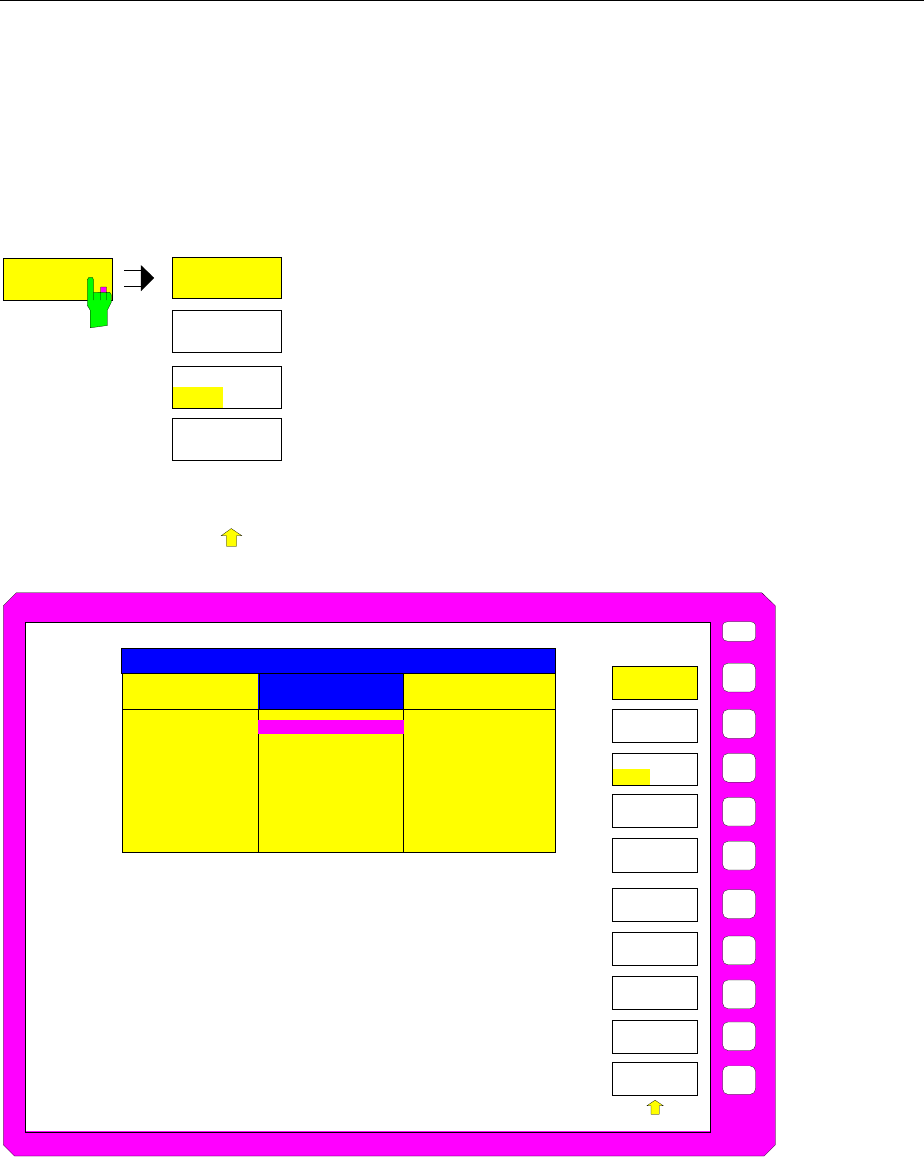
Documentation of Measurement Results FSE
1065.6016.12 4.60 E-15
Selection and Configuration of the Printer - with MS DOS Controller or without
Controller
Note: Selection and configuration of the printer for instruments with Windows NT controller is
described page 4.58
HARDCOPY SETTINGS-HARDCOPY DEVICE submenu:
HARDCOPY
DEVICE
HARDCOPY
DEVICE
SETTINGS
DEVICE 1
SETTINGS
DEVICE 2
ENABLE
DEV1 DEV2
.
.
.
The HARDCOPY DEVICE softkey switches to the sub-menu
which is used for the selection/configuration of the two output
devices and for the connection of the devices to an output
medium.
When the sub-menu is called, the corresponding table is
simultaneously displayed. The SETTINGS DEVICE 1 softkey is
active and the selection bar is located at the
DEVICE/LANGUAGE line in the corresponding column of the
table.
USER
Device/Language
Connection
GPIB Address
Orientation
Device Reset
Formfeed
Paperfeed
SETTINGS DEVICE 1 SETTINGS DEVICE 2
HPGL
GPIB1
4
PORTRAIT
OFF
OFF
MANUAL
POSTSCR
LPT
---
LANDSCAPE
OFF
ON
MANUAL
ITEM
HARDCOPY
DEVICE
SETTINGS
DEVICE 1
SETTINGS
DEVICE 2
ENABLE
DEV1 DEV2
COLOR MAP
DEVICE 1
DEVICE
HANDLING
COLOR MAP
DEVICE 2
DEFAULT
COLOR MAP
DEVICE SETTINGS
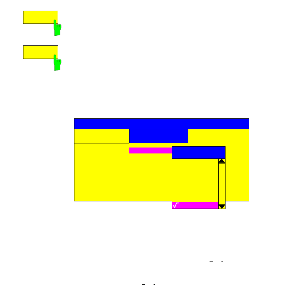
FSE Documentation of Measurement Results
1065.6016.12 4.61 E-15
SETTINGS
DEVICE 1
SETTINGS
DEVICE 2
The FSE permits two different output devices to be configured. One of the
devices is defined as the active device and can be used for hardcopies.
After calling the menu, the SETTINGS DEVICE 1 softkey is active and
permits the selection and configuration of the output device DEVICE 1. The
selection bar is placed the corresponding column of the table. The
SETTINGS DEVICE 2 softkey is used to configure DEVICE 2.
The actual selection of the active output device takes place with the ENABLE
DEV1 DEV2 softkey in the HARDCOPY DEVICE sub-menu.
Device/Language
The selection of the output device/language for DEVICE 1 and DEVICE 2 is
made in this line.
Device/Language
Connection
GPIB Address
Orientation
Device Reset
Formfeed
Paperfeed
SETTINGS DEVICE 1 SETTINGS DEVICE 2
HPGL
GPIB1
4
PORTRAIT
OFF
OFF
MANUAL
ITEM
SELECT DEVICE
DESKJC3H
DESKJ_C
DESKJ_CH
DESKJ_H
EPSON24
HP7470
HP7470LS
HPGL
DEVICE SETTINGS
Sequence, number and name of available devices depends on the driver files
stored on the harddisk:
Data format for printout on a plotter
HPGL standard HPGL format
HPGL_LS output of the traces with variable Line styles
HP7470 plotter hp7470 (reduced HPGL format)
HP7470LS special HP7470format allowing output of the traces with
variable Line styles
Data format for HP-deskjet series
DESKJ black/white
DESKJ_H black/white, high resolution
DESKJC3: Color (3 color cartridges only) e. g. Deskjet 500)
DESKJC3H: Color (3 color cartridges only), high resolution
DESKJ_C: Color (3 color cartridges + black cartridge)
e. g. Deskjet 560)
DESKJ_CH: Color (3 color cartridges + black cartridge) , high resolution

Documentation of Measurement Results FSE
1065.6016.12 4.62 E-15
Data format for a 24-pin printer
EPSON24 data format for Epson-compatible 24-needle printers,
black/white, e. g. Epson LQ-series, R&S PDN
EPSON24C data format for Epson-compatible 24-needle color printers, e.
g. Epson Stylus Color, R&S PDN Color
Data formats for laser and ink-jet printers
HPPCL4 black/white with 300DPI resolution
HPPCL4HI black/white, high resolution
HPPCL5 black/white with 300DPI resolution
LASERJ data format for HP-laserjet starting with series III
PCL4 black/white
PCL4_H black/white, high resolution
PCL4_C color (3 color cartridges + black cartridge)
PCL4_CH color (3 color cartridges + black cartridge), high resolution
PCL4_C3 color (3 color cartridges only)
PCL4_C3H color (3 color cartridges only) , high resolution
Data format PostScript
POSTSCR a printer language (PostScript)
Data formats for output files
WMF WINDOWS Metafile format
PCX pixel graphics (e. g. Paintbrush)
IEC/IEEE-bus command :HCOPy:DEVice:LANGuage<1|2>
HPGL | PCL4 | PCL5 | POSTscript |
ESCP| WMF|PCX | HP7470 | EPSON24|
EPSON24C | PCL4_C | PCL4_C3 |
LASERJ | DESKJ | DESKJ_C |
DESKJ_C3 | HPGL_LS |
HP7470LS | GDI | EWMF | BMP
:HCOPy:DEVice:RESolution<1|2> 150|300
(only for PCL4 and HP deskjet formats)
Connection
The output channel to which the output device is connected is defined in this
line.
Device/Language
Connection
GPIB Address
Orientation
Device Reset
Formfeed
Paperfeed
SETTINGS DEVICE 1 SETTINGS DEVICE 2
HPGL
GPIB1
4
PORTRAIT
OFF
OFF
MANUAL
POSTSCR
LPT
ITEM
CONNECTION
COM1
COM2
LPT
GPIB1
FILE
DEVICE SETTINGS
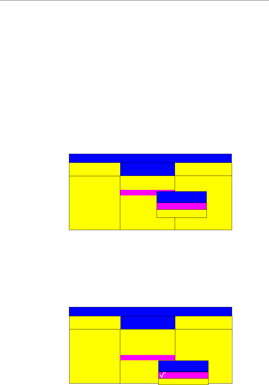
FSE Documentation of Measurement Results
1065.6016.12 4.63 E-15
By selection of the FILE channel, the printer output can be sent to a file. In
this case, pressing HARDCOPY START results in a prompt for the entry of a
file name.
If COM1 or COM2 is selected, recording must be set to HARDCOPY
(CONFIGURATION SETUP - GENERAL SETUP submenu).
Output channels which, at first glance, do not appear to make sense, are also
permitted because, in some cases, adapters are available which allow these
devices to be connected to the interface. For example, adapters for RS232 ↔
IECBUS are available.
IEC/IEEE-bus command :HCOPy:DESTination<1|2>
‘SYST:COMM:GPIB’|’SYST:COMM:SER1’|
’SYST:COMM:SER2’|’SYST:COMM:CENT’|
’MMEM’
Print to file: :HCOPy:DESTination<1|2> "MMEM"
:MMEMory:NAME <file_name>
GPIB Address
The IEC Bus address of the output device is set in this line .
Device/Language
Connection
GPIB Address
Orientation
Device Reset
Formfeed
Paperfeed
SETTINGS DEVICE 1 SETTINGS DEVICE 2
HPGL
GPIB1
4
PORTRAIT
OFF
OFF
MANUAL
POSTSCR
LPT
MANUAL
ITEM
GPIB ADDRESS
4
Range: 0..30
DEVICE SETTINGS
The entry field in the GPIB line can only be opened when GPIB 1 was
selected as an output channel in the connection line. Otherwise, this field is
blank and can not be reached with the cursor keys.
IEC/IEEE-bus command
:SYSTem:COMMunicate:GPIB:RDEVice<1|2>:ADDRess 0...30
Orientation
In this line, the print format of the output page is set to either vertical (=
PORTRAIT) or horizontal (= LANDSCAPE).
Device/Language
Connection
GPIB Address
Orientation
Device Reset
Formfeed
Paperfeed
SETTINGS DEVICE 1 SETTINGS DEVICE 2
HPGL
GPIB1
4
PORTRAIT
OFF
OFF
MANUAL
POSTSCR
LPT
---
LANDSCAPE
OFF
ON
MANUAL
ITEM
ORIENTATION
PORTRAIT
LANDSCAPE
DEVICE SETTINGS
IEC/IEEE-bus command
:HCOPy:PAGE:ORIentation<1|2> LANDscape | PORTrait
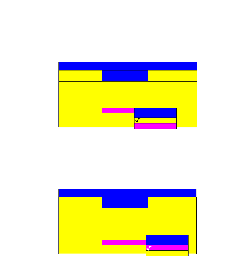
Documentation of Measurement Results FSE
1065.6016.12 4.64 E-15
Device Reset
This line defines if the output device is to be reset (DEVICE RESET ON)
before the actual print job is started or not (DEVICE RESET OFF). Resetting
the output device causes, e.g., the loss of any settings which are made
directly on the output device. For example, the definition of the drawing range
for plotters or the print resolution for printers. The default setting at delivery is,
therefore, DEVICE RESET OFF.
Device/Language
Connection
GPIB Address
Orientation
Device Reset
Formfeed
Paperfeed
SETTINGS DEVICE 1 SETTINGS DEVICE 2
HPGL
GPIB1
4
PORTRAIT
OFF
OFF
MANUAL
POSTSCR
LPT
---
LANDSCAPE
ITEM
DEVICE RESET
OFF
ON
DEVICE SETTINGS
IEC/IEEE-bus command :HCOPy:DEVice:PRESet<1|2> ON | OFF
Formfeed
This line of the table determines whether a formfeed is made (FORMFEED
ON) at the completion of the print job or not (FORMFEED OFF). The entry
field in this line can only be selected when the output device permits a
formfeed. Therefore, for plotters, it is set to OFF and cannot be changed.
Device/Language
Connection
GPIB Address
Orientation
Device Reset
Formfeed
Paperfeed
SETTINGS DEVICE 1 SETTINGS DEVICE 2
HPGL
GPIB1
4
PORTRAIT
OFF
OFF
MANUAL
POSTSCR
LPT
---
LANDSCAPE
ITEM
FORMFEED
OFF
ON
DEVICE SETTINGS
IEC/IEEE-bus command :HCOPy:ITEM:FFEed<1|2>:STATe ON|OFF
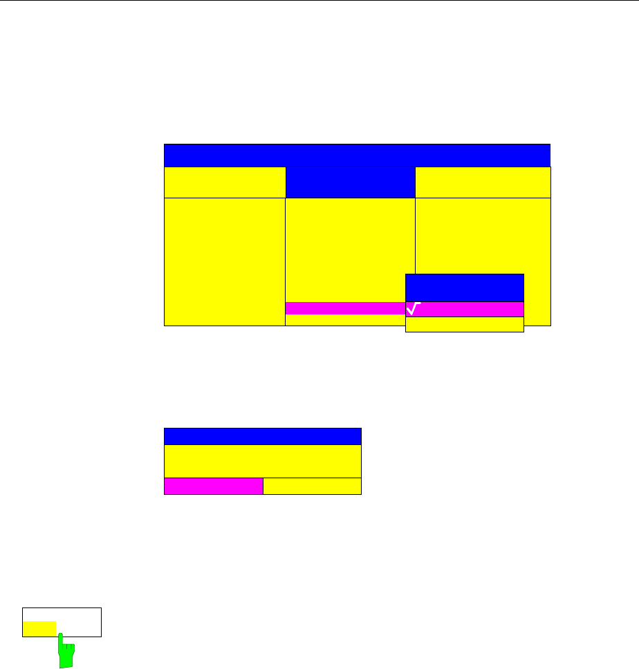
FSE Documentation of Measurement Results
1065.6016.12 4.65 E-15
Paperfeed
This line of the table determines which paper holder is to be used for the print
job. The input field of this line can only be selected when the output device
permits a selection between endless and single-sheet paper types.
Therefore, for plotters it is set to OFF and cannot be changed.
Device/Language
Connection
GPIB Address
Orientation
Device Reset
Formfeed
Paperfeed
SETTINGS DEVICE 1 SETTINGS DEVICE 2
HPGL
GPIB1
4
PORTRAIT
OFF
OFF
AUTO
POSTSCR
LPT
---
LANDSCAPE
ITEM
PAPERFEED
AUTO
MANUAL
DEVICE SETTINGS
MANUAL FEED implies selection of the single-sheet mode so that, after
pressing HARDCOPY START, the print job is stopped after each page and
the user is prompted by the message
ERROR
Paper out on device LPT
(manual feed )?
ABORT CONTINUE
to load a new page in the output device. The print job is then either continued
(CONTINUE selected) or stopped (ABORT selected).
IEC/IEEE-bus command :HCOPy:ITEM:PFEed<1|2>:STATe ON|OFF
ENABLE
DEV1 DEV 2
The ENABLE DEV1 / DEV2 softkey determines the active output device. The
default output device is DEVICE 1, i.e., all output takes place on DEVICE 1.
IEC/IEEE-bus command -- (the device is selected via the suffix <1|2> in
HCOPy:IMMediate )

Memory Configuration FSE
1065.6016.12 4.66 E-15
Saving and Recalling Data Sets – MEMORY Key Group
The keys in the MEMORY group call the following functions:
•Functions for managing storage media (CONFIG). This includes among others functions listing files,
formatting storage media, copying, and deleting/renaming files.
•Save/recall functions for saving (SAVE) settings such as instrument configurations
(measurement/display settings, etc.) and saving measurement results from working memory to
permanent storage media, or for recalling (RECALL) stored data.
The FSE can internally store complete instrument settings with instrument configurations and
measurement data in the form of data-sets. The data are stored on the internal hard disk or, if if
required, on an external disk. The hard-disk drive and the floppy-disk drive are assigned logical names
as usual in PC applications:
Disk drive A:
hard disk C:
In addition to saving and recalling complete instrument settings, it is also possible to save/recall subsets
of settings. Configuration data and measurement values are stored in separate files. These files have
the same name as the data set but have a different extension. A data set therefore comprises several
files which have the same name but different extensions (see Table 4-2).
When saving or recallong a data set, the subsets which are to be saved or recallong can be selected in
the corresponding menus. This makes it easy to recall specific instrument settings.
When saving and recalling data via the SAVE and RECALL menus, data subsets are selected in a table
in the sub-menu SEL ITEMS TO SAVE/RECALL. The relationship between the designations in the table
and the contents of the data subsets is shown in Table 4-2
The saved data set files can be copied from one storage medium (e.g. drive C:) to another (e.g. drive
A:) or to another directory using the functions found in the MEMORY CONFIG menu. However, do not
change the file names and extensions when copying. Table 4-2 hows how extensions are assigned to
data subsets..

FSE Memory Configuration
1065.6016.12 4.67 E-15
Table 4-2 Assignment of extensions to data subsets
Extension Contents Designation in the table
SEL ITEMS TO
SAVE/RECALL
Configuration data: .SET current settings of the measurement
hardware and designation, if present HARDWARE SETTINGS
.LIN data-point tables for the active limit lines LINES
.LIA all defined limit lines ALL LINES
.CFG current configuration of general instrument
parameters GENERAL SETUP
.HCS configuration for hardcopy output HARDCOPY
.TCI tracking generator settings
(only with option FSE-B8/9/10/11) SOURCE CAL
.TS1
.TS2 settings for source calibration
(only with option FSE-B8/9/10/11) SOURCE CAL
.TC1
.TC2 correction data for source calibration
(only with option FSE-B8/9/10/11) SOURCE CAL
.CL used conversion loss (cvl) tables
(only with option FSE-B21, External Mixer
Output)
USED CVL TABLES
.CLA all conversion loss (cvl) tables
(only with option FSE-B21, External Mixer
Output)
ALL CVL TABLES
.TS activated transducer set TRANSDUCER
.TSA all transducer sets ALL TRANSDUCER
.TF transducer factor TRANSDUCER
.TFA all transducer factors ALL TRANSDUCER
.COL user-defined color settings COLOR SETUP
Measurement results: .TR1....4 measurement data trace 1 to trace 4 TRACE1...4
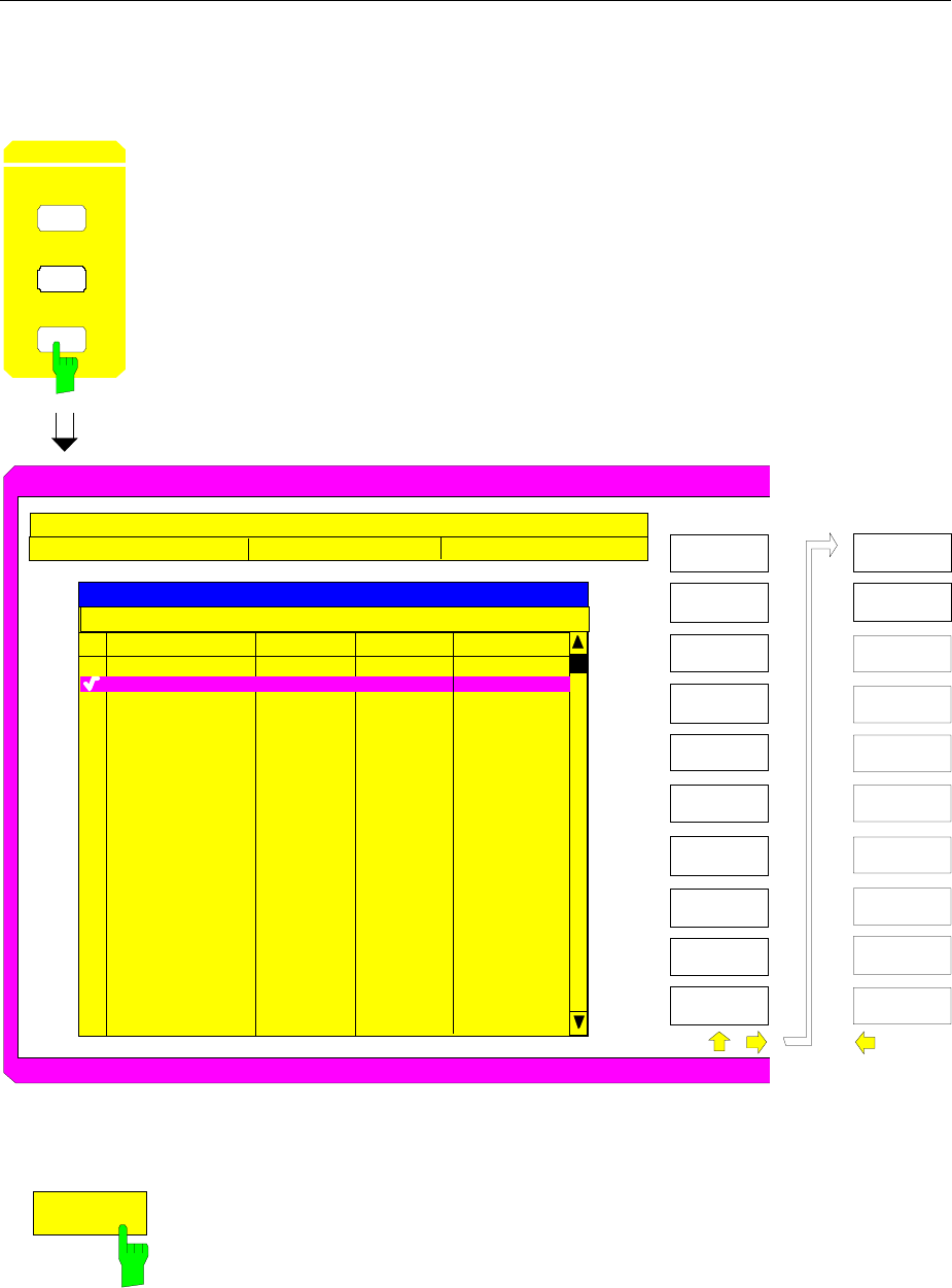
Memory Configuration FSE
1065.6016.12 4.68 E-15
Configuration of Memory – CONFIG Key
MEMORY CONFIG menu:
MEMORY
RECALL
SAVE
CONFIG
The CONFIG key opens a menu for managing storage media and files.
The Drive Management table displays the name and label of the storage
medium as well as the free memory.
The File Management table displays the files in the current directory and
indicates if any subdirectories are present.
If a directory name is selected, the FSE automatically changes to this
directory. Selection of the entry ’..’ moves the FSE to the next highest
directory level.
Note: It is not possible to change menus as long as a file operation is
running.
USER
D
R
IVE MA
N
A
G
E
M
ENT
L
AB
E
L
:
F
I
LE
M
A
N
A
GEM
E
N
T
S
I
Z
E
F
I
L
E
NA
M
E DAT
E
.
.
S
E
T
T
I
N
G1.
D
RW
S
E
T
T
I
N
G2.
D
RW
S
E
T
T
I
N
G3.
D
RW
S
E
T
T
I
N
G4.
D
RW
1
0
.
M
A
Y
.
93
1
5
.
M
A
Y
.
93
1
7
.
M
A
Y
.
93
2
8
.
M
A
Y
.
93
6
8
.
1
7
5
k
B
7
3
.
2
8
3
k
B
1
7
4
.
3
15
k
B
1
.
2
3
6
81
2
MB
PATH:
10
:
25
:
1
8
13
:
08
:
2
7
08
:
15
:
2
1
17
:
05
:
4
2
T
I
ME
E
D
I
T
P
A
T
H
CO
PY
P
AG
E
D
O
W
N
M
E
M
O
R
Y
C
O
N
F
I
G
D
E
L
ET
E
R
EN
A
M
E
S
O
R
T
M
O
D
E
M
A
KE
DIRECT
O
RY
UN
D
E
L
ET
E
PA
G
E
UP
DISK
COPY
D
I
S
K
L
A
BE
L
P
A
G
E
D
OWN
PA
G
E
U
P
F
OR
M
AT
DI
S
K
C:\USER\CONFIG
DRIVE: HARDDISK C:
FREE MEM: 394:510.336
EDIT
PATH
The EDIT PATH softkey activates the entry of the directory which will be used
for subsequent file operations.
The new path is included in the FILE MANAGEMENT table.
IEC/IEEE-bus commands :MMEMory:MSIS ’C:\’
:MMEMory:CDIRectory ’C:\user\data’
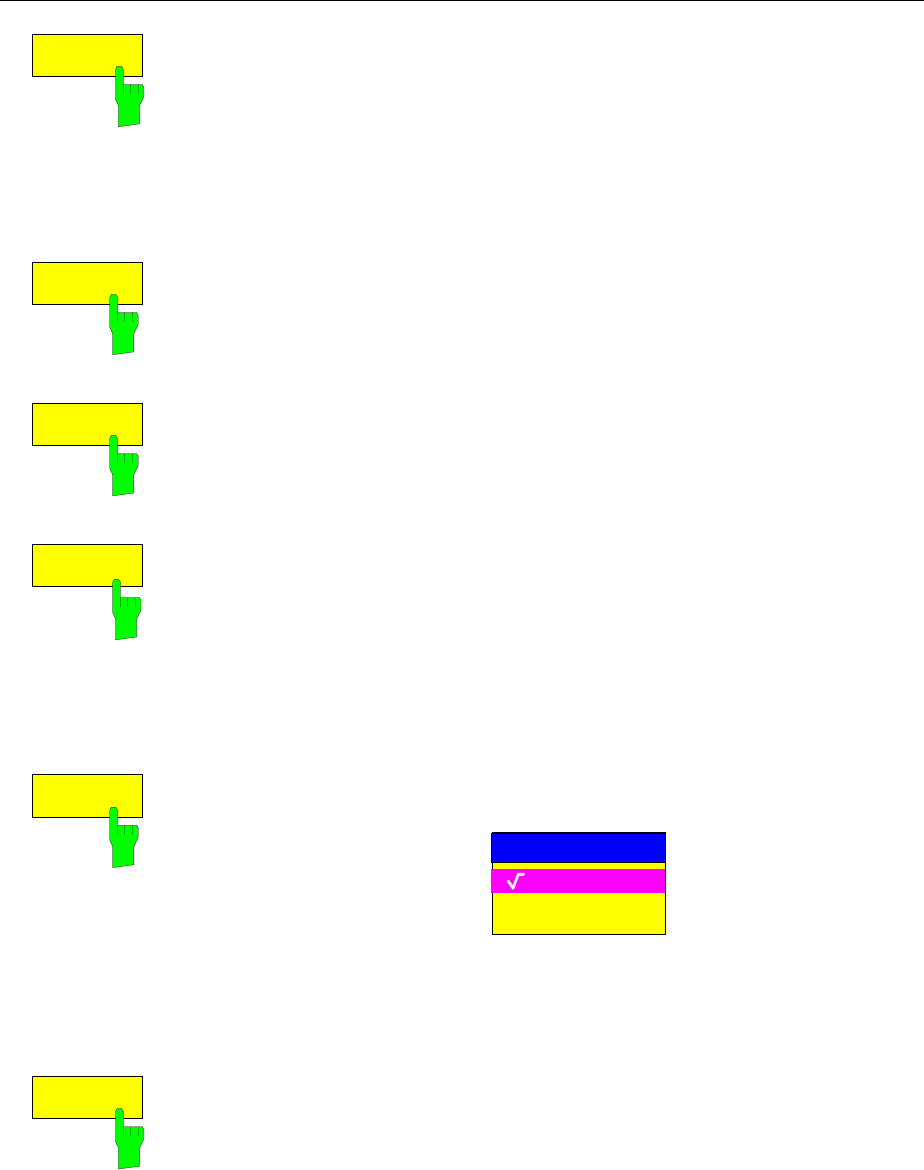
FSE Memory Configuration
1065.6016.12 4.69 E-15
COPY
The COPY softkey activates the entry of the destination for the copy
operation.
By prefixing a disk drive letter (e.g. C:), a file can also be copied to another
storage medium. When the ENTER key is pressed, the selected
files/directories are copied.
IEC/IEEE-bus command
:MMEMory:COPY ’C:\user\data\setup.cfg’,’A:’
DELETE
The DELETE softkey deletes the selected files.
To prevent accidental deletion of data, confirmation by the user is requested.
IEC/IEEE-bus command :MMEMory:DELete ’TEST01.HCP’
:MMEMory:RDIRectory ’C:\test’
RENAME
The RENAME softkey activates the entry of a new name for the selected file
or directory.
IEC/IEEE-bus command
:MMEMory:MOVE ’TEST.CFG’, ’SETUP.CFG’
MAKE
DIRECTORY
The MAKE DIRECTORY softkey creates directories/sub-directories. The use
of sub-directories is recommended as a way of structuring the storage
medium to make it easier to navigate.
When entering a subdirectory, entry of an absolute path name (e.g.;
"\USER\MEAS") as well as the path relative to the current directory (e.g.,
"..\MEAS") is possible.
IEC/IEEE-bus command :MMEMory:MDIRectory ’C:\user\data’
SORT MODE
The SORT MODE softkey activates the selection of the sort criteria for the
files listed in the FILE MANAGEMENT table.
SORT MODE
by NAME
by DATE/TIME
by EXTENSION
Directory names are at the top of the list after the entry for the next highest
directory level ("..").
IEC/IEEE-bus command --
FORMAT
DISK
The FORMAT DISK softkey formats disks located in drive A:.
To prevent accidental destruction of disks data, confirmation by the user is
requested.
IEC/IEEE-bus command :MMEMory:INITialize <msus>
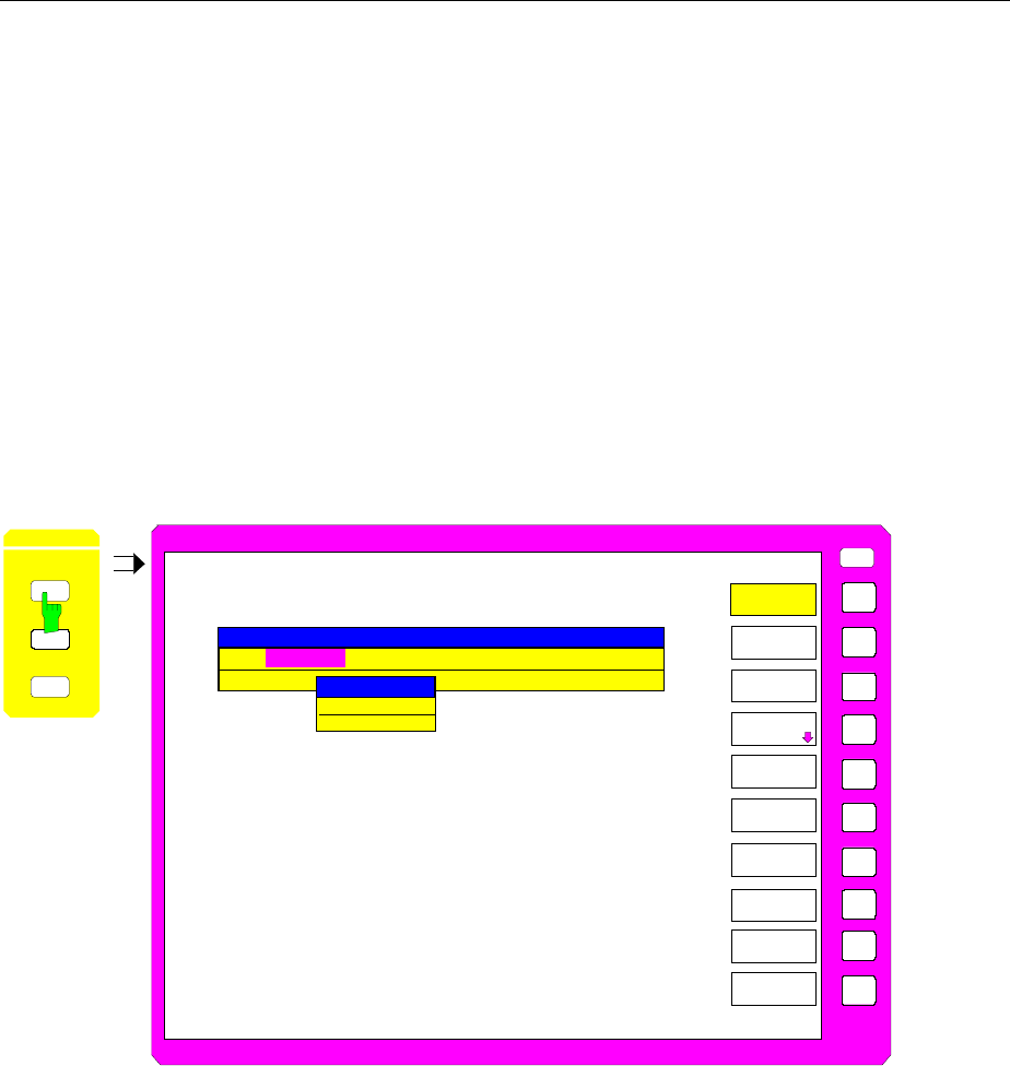
Saving Data Sets FSE
1065.6016.12 4.70 E-15
Saving Data Sets – SAVE Key
The SAVE key activates a menu which contains all functions necessary for saving instrument data.
– Entry of the name of the data set which should be saved. Confirmation of the entry initiates a
save operation to store the data set.
Data set names may contain both alphabetical and numeric characters, in the simplest case
only numbers. The simplest example for the input of a data set name is illustrated by the
following key strokes:
<SAVE> <1> <units key>
– Entry of the directory in which the data set should be saved
–Input of data set description
–Selection of the data subsets to be saved (sub-menu SEL ITEMS TO SAVE)
– Indication of all available data sets
– Deletion of all available data sets
MEMORY SAVE menu
USER
SAVE DATA SET
PAGE DOWN
MEMORY
SAVE
PAGE UP
SEL ITEMS
TO SAVE
DATA SET
LIST
EDIT
PATH
DATA SET
CLEAR
DATA SET
CLEAR ALL
EDIT
NAME
COMMENT: Radio Monitoring
PATH:C:\USER\CONFIG
NAME: DATASET1
EDIT
COMMENT
MEMORY
RE LL
SAVE
CONFIG
EDIT NAME
DATASET1_
ITEMS: DEFAULT
The SAVE DATA SET table shows the current settings regarding the data set:
Name Name of data set
Path Directory in which the data set will be saved
Items Indicates whether the default selection of data subsets
(DEFAULT) or a user-defined selection (SELECTED) will be
saved
Comment Comments about the data set
The EDIT NAME softkey for entering the name of the data set to be saved is activated
automatically.

FSE Saving Data Sets
1065.6016.12 4.71 E-15
Selecting the Data Set for Saving
MEMORY SAVE menu:
EDIT
NAME
The EDIT NAME softkey activates the entry of the name of the data set to be
saved.
Data entry is concluded by pressing one of the units keys which initiates a
save operation to store the data set.
IEC/IEEE-bus command :MMEMory:STORe:STATe 1,’test’
EDIT
PATH
The EDIT PATH softkey activates the input of a directory name where the
data sets are to be stored. Default path is c:\user\config.
IEC/IEEE-bus command --
EDIT
COMMENT
The EDIT COMMENT softkey activates the entry of comments for the current
data set. A total of 60 characters are available for this purpose.
IEC/IEEE-bus command :MMEMory:COMMent <string>
DATA SET
LIST
The DATA SET LIST softkey opens the DATA SET LIST/CONTENTS table.
The DATA SET CLEAR and DATA SET CLEAR ALL softkeys are also
displayed.
The DATA SET LIST column lists all the data sets which are stored in the
selected directory.
The CONTENTS and COMMENT lines in the DATA SET CONTENTS
column indicate the saved data subsets and the comments for the currently
selected data set.
IEC/IEEE-bus command --
Note: The current instrument configuration can be easily stored under the
name of an existing data set:
½Press a units key after selecting a data set
The name and the selection of the data subsets for the currently
selected data set will be placed in the SAVE DATA SET table. The
DATA SET LIST table is closed and, instead, the entry field for the
EDIT NAME function with the name of the selected data set is
opened.
½Press a units key.
The current instrument configuration is saved as a data set under
this name.

Saving Data Sets FSE
1065.6016.12 4.72 E-15
DATA SET
CLEAR
The DATA SET CLEAR softkey clears the marked data set.
IEC/IEEE-bus command :MMEMory:CLEar:STATe 1,’test’
DATA SET
CLEAR ALL
The DATA SET CLEAR ALL softkey deletes all data sets in the current
directory.
To prevent all the data sets from being accidentally lost, confirmation from the
user is required before actual clearing takes place.
IEC/IEEE-bus command :MMEMory:CLEar:ALL
PAGE UP
PAGE DOWN
The PAGE UP or PAGE DOWN softkey sets the DATA SET LIST table to the
next or previous page.
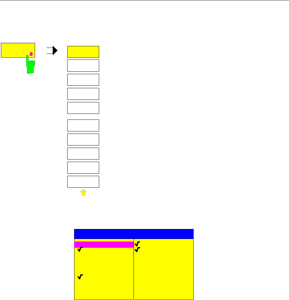
FSE Saving Data Sets
1065.6016.12 4.73 E-15
Selecting the Data subset for Storage
MEMORY SAVE-SELECT ITEMS TO SAVE sub-menu:
SEL ITEMS
TO SAVE
SELECT
ITEM
SEL ITEMS
TO SAVE
ENABLE
ALL ITEMS
DEFAULT
CONFIG
DISABLE
ALL ITEMS
The SEL ITEMS TO SAVE softkey opens a sub-menu for
selection of the data subsets.
The ITEMS TO SAVE table displays the selectable data subsets:
ITEMS TO SAVE
COLOR SETUP
HARDCOPY
MACROS
ACTIVE TRANSDUCER
ALL TRANSDUCER
GENERAL SETUP
HW-SETTINGS
TRACE 1
TRACE 2
TRACE 3
TRACE 4
ACTIVE LINES
ALL LINES
USED CVL TABLES
ALL CVL TABLES
General Setup current configuration of general instrument parameters
HW-Settings current measurement hardware settings
Trace1...4 measurement data trace 1 to trace 4
Active Lines active limit lines
All Lines all limit lines
Used CVL Tables activated conversion loss tables
All CVL Tables all conversion loss tables
Color Setup user-defined color settings
Hardcopy Setup configuration for hardcopy output
Macros macros
Active Transducer active transducer
All Transducer all transducer
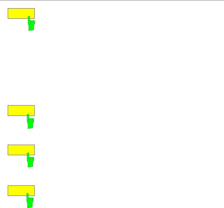
Saving Data Sets FSE
1065.6016.12 4.74 E-15
SELECT
ITEMS
The SELECT ITEMS softkey moves the selection bar to the first line, left
column of the table.
IEC/IEEE-bus commands
:MMEMory:SELect[:ITEM]:GSETup ON|OFF
:MMEMory:SELect[:ITEM]:HWSettings ON|OFF
:MMEMory:SELect[:ITEM]:TRACe<1...4> ON|OFF
:MMEMory:SELect[:ITEM]:LINes[:ACTive] ON|OFF
:MMEMory:SELect[:ITEM]:LINes:ALL ON|OFF
:MMEMory:SELect[:ITEM]:CSETup ON|OFF
:MMEMory:SELect[:ITEM]:HCOPy ON|OFF
:MMEMory:SELect[:ITEM]:CVL[:ACTive] ON | OFF
:MMEMory:SELect[:ITEM]:CVL:ALL ON | OFF
:MMEMory:SELect[:ITEM]:SCData ON | OFF
:MMEMory:SELect[:ITEM]:MACRos ON|OFF
:MMEMory:SELect[:ITEM]:TRANsducer ON|OFF
:MMEMory:SELect[:ITEM]:TRANsducer:ALL ON|OFF
ENABLE
ALL ITEMS
The ENABLE ALL ITEMS softkey marks all entries in the ITEMS TO SAVE.
table.
IEC/IEEE-bus command :MMEMory:SELect[:ITEM]:ALL
DISABLE
ALL ITEMS
The DISABLE ALL ITEMS softkey unmarks all entries in the ITEMS TO SAVE
table.
IEC/IEEE-bus command :MMEMory:SELect[:ITEM]:NONE
DEFAULT
CONFIG
The DEFAULT CONFIG softkey establishes the default selection of the data
subset to be saved and outputs DEFAULT in the ITEMS field of the SAVE
DATA SET table.
IEC/IEEE-bus command :MMEMory:SELect[:ITEM]:DEFault
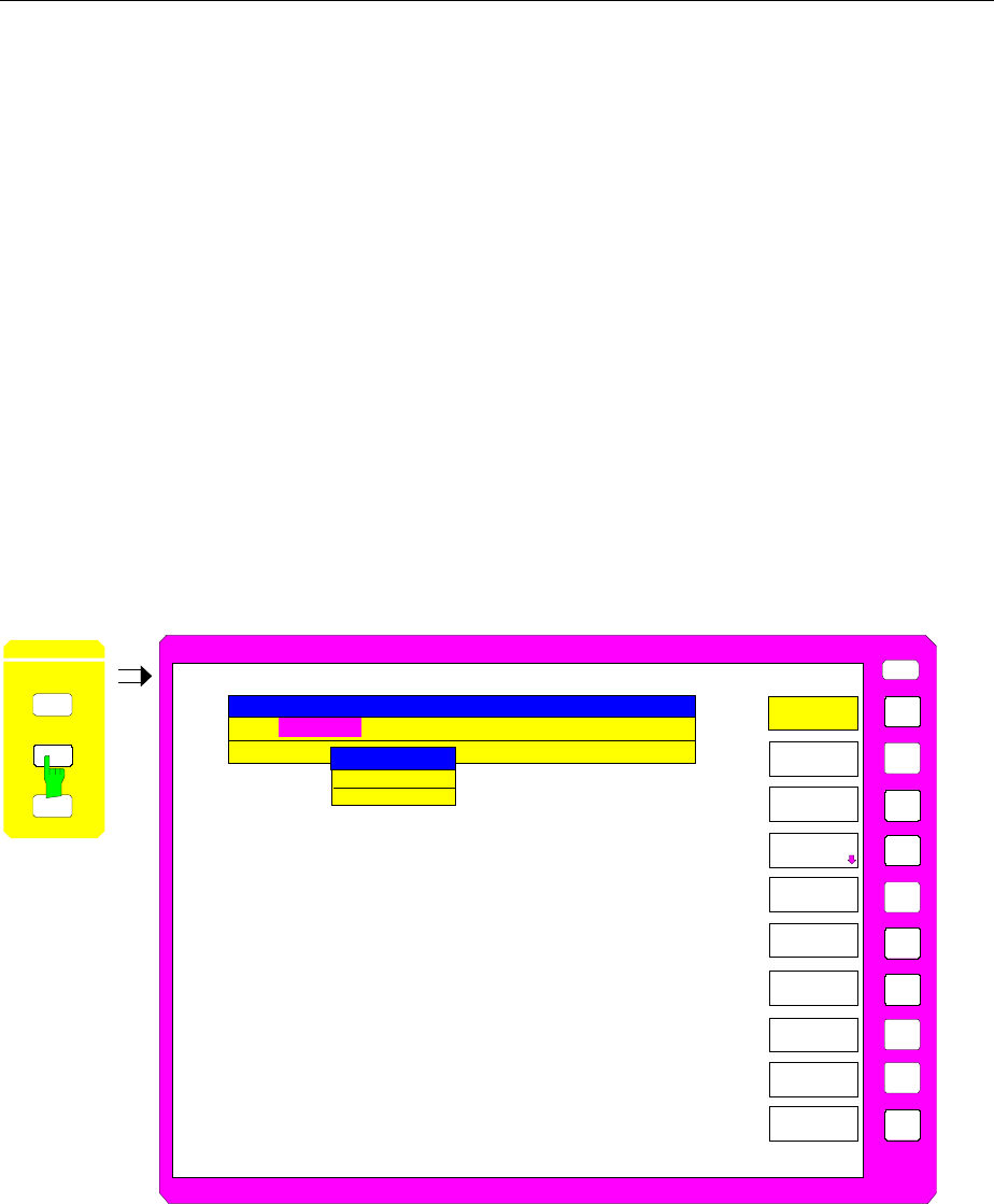
FSE Recalling Data Sets
1065.6016.12 4.75 E-15
Recalling of Data Sets – RECALL Key
The RECALL key activates a menu which contains all functions necessary for recalling data sets.
– Entry of the name of the data set which should be recalled. Confirmation of the entry initiates
a load operation to recall the data set.
– Entry of the directory in which the data set is stored
– Display of data set description
–Selection of a data set which will be automatically loaded upon power-up
– Indication of all available data sets
– Deletion of all available data sets
–Selection of the data subsets which should be loaded (configurations, measurement and
calibration data, sub-menu SEL ITEMS TO RECALL)
Any settings not restored when data subsets are loaded will remain unchanged in the instrument. During
recall operations, the FSE recognises which data subsets are present in the recalled data set and offers
only the corresponding settings for selection in the SELECT ITEM sub-menu.
A new instrument data set can be easily constructed from several existing data sets: the desired data
subsets are selected and recalled out of various data sets in several RECALL operations. When the
desired configuration is completed, the new data set can be saved under a new name.
MEMORY RECALL menu:
USER
PAGE DOWN
MEMORY
RECALL
PAGE UP
SEL ITEMS
TO RECALL
DATA SET
LIST
EDIT
PATH
DATA SET
CLEAR
DATA SET
CLEAR ALL
EDIT
NAME
AUTO
RECALL
MEMORY
RECALL
SAVE
CO FIG
RECALL DATA SET
COMMENT: R
PATH: C:\USER\CONFIG
NAME: DATASET1
EDIT NAME
DATASET1_
ITEMS: DEFAULT
The RECALL DATA SET table shows the current settings regarding the data set:
Name Name of data set
Path Directory in which the data set is located
Items Indicates whether the default selection of data subsets (DEFAULT) or
a user-defined selection (SELECTED) will be loaded
Comment Comments about the data set
The EDIT NAME softkey for entering the name of the data set to be loaded is
activated automatically.
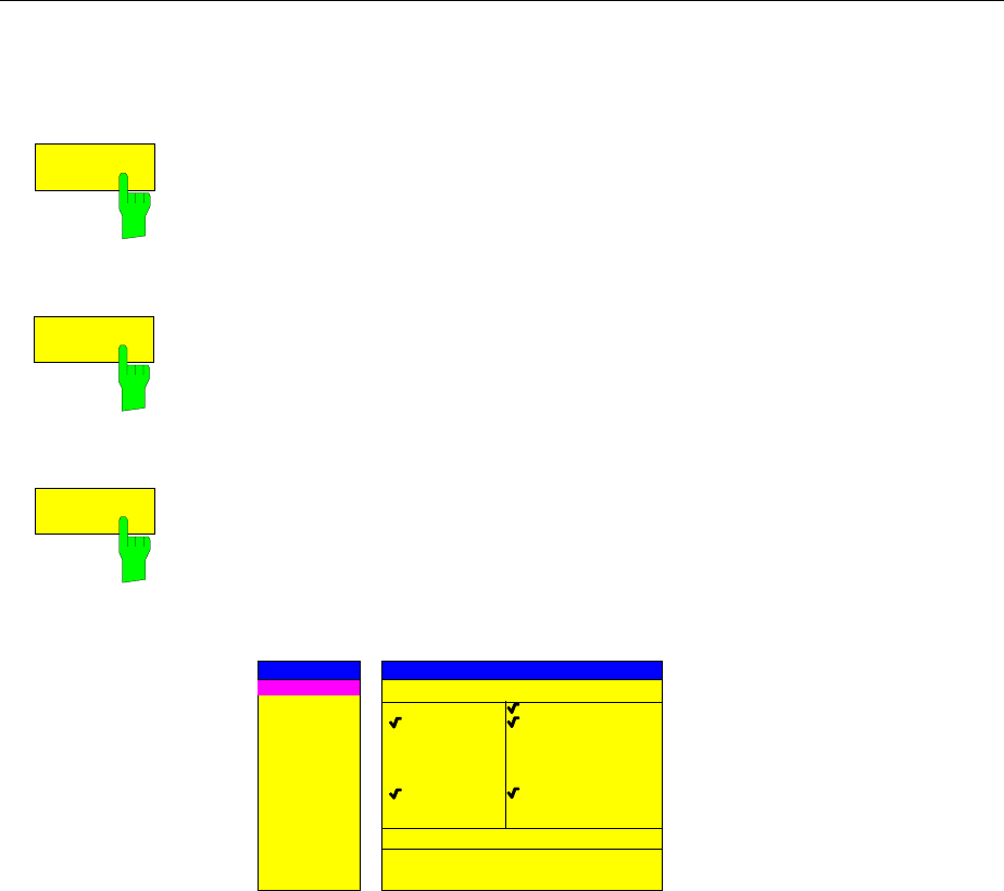
Recalling Data Sets FSE
1065.6016.12 4.76 E-15
Selecting the Data Set for Recalling
MEMORY RECALL menu:
EDIT
NAME
The EDIT NAME softkey activates the entry of a data set name.
The data input is terminated by pressing one of the units keys which
simultaneously initiates the data set recall operation.
IEC/IEEE-bus command :MMEMory:LOAD:STATe 1,’A:test’
EDIT
PATH The EDIT PATH softkey activates the entry of a directory name in which the
data set is located. Default path is c:\user\config.
IEC/IEEE-bus command --
AUTO
RECALL
The AUTO RECALL softkey activates the selection of a data set which will be
automatically recalled when the instrument is powered up. The DATA SET
LIST/CONTENT table is opened to make the selection (analogous to DATA
SET LIST).
IEC/IEEE-bus command
:MMEMory:LOAD:AUTO 1,’C:\user\data\auto’
AUTO RECALL SET CONTENT
DATASET1
DATASET2
DATASET3
COMMENT
GSM_MASK
DATA SET LIST
GENERAL SETUP
HW-SETTINGS
TRACE 1
TRACE 2
TRACE 3
TRACE 4
LINES
CVL TABLES
CONTENTS
COLOR SETUP
HARDCOPY
MACROS
TRANSDUCER
The DATA SET LIST column displays all the data sets in the selected
directory.
The CONTENTS and COMMENT lines in the AUTO RECALL CONTENTS
column indicate the saved data subsets and the comments for the currently
selected data set.
In addition to the data sets saved by the user, the data set FACTORY, which
contains the settings of the instrument before it was last switched off
(Standby), is always included.
If a data set other than FACTORY is chosen the data subsets in the selected
data set that are available are recalled when the FSE is powered up. The
data subsets which are not in this data set are taken from the FACTORY data
set.
Note: The selected data set is also loaded on PRESET if AUTO RECALL
is active. The preset settings can then be configured as required.

FSE Recalling Data Sets
1065.6016.12 4.77 E-15
DATA SET
LIST
see Chapter "Saving Data Sets"
DATA SET
CLEAR
see Chapter "Saving Data Sets"
DATA SET
CLEAR ALL
see Chapter "Saving Data Sets"
PAGE UP
PAGE DOWN
The PAGE UP or PAGE DOWN softkey sets the DATA SET LIST table to the
next or previous page.
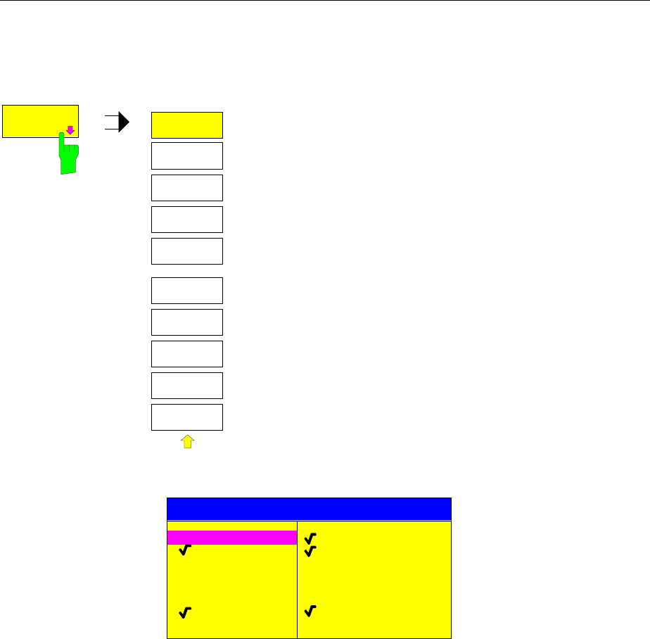
Recalling Data Sets FSE
1065.6016.12 4.78 E-15
Building a Data Set
MEMORY RECALL-SELECT ITEMS TO RECALL sub-menu:
SEL ITEMS
TO RECALL
SELECT
ITEM
SEL ITEMS
TO RECALL
ENABLE
ALL ITEMS
DEFAULT
CONFIG
DISABLE
ALL ITEMS
The SEL ITEMS TO RECALL softkey opens a sub-menu to
select data subsets.
The ITEMS TO RECALL table displays the selectable data subsets:
ITEMS TO RECALL
COLOR SETUP
HARDCOPY SETUP
MACROS
TRANSDUCER
GENERAL SETUP
HW-SETTINGS
TRACE 1
TRACE 2
TRACE 3
TRACE 4
LINES
CVL TABLES
General Setup current configuration of general instrument parameters
HW-Settings current measurement hardware settings
Trace1...4 measurement data trace 1 to trace 4
Lines data point tables for the active limit lines
CVL Tables conversion loss tables
Color Setup user-defined color settings
Hardcopy Setup configuration for hardcopy output
Macros macros
Transducer transducer factor, transducer set

FSE Recalling Data Sets
1065.6016.12 4.79 E-15
SELECT
ITEMS
The SELECT ITEMS softkey activates the ITEMS TO RECALL table and sets
the selection bar to the first line, left column of the table.
IEC/IEEE-bus command see "Selecting the Data subset for Storage"
ENABLE
ALL ITEMS The ENABLE ALL ITEMS softkey marks all entries in the ITEMS TO RECALL
table.
IEC/IEEE-bus command :MMEMory:SELect[:ITEM]:ALL
DISABLE
ALL ITEMS The DISABLE ALL ITEMS softkey unmarks all entries in the ITEMS TO
RECALL table.
IEC/IEEE-bus command :MMEMory:SELect[:ITEM]:NONE
DEFAULT
CONFIG The DEFAULT CONFIG softkey establishes the default selection of the data
subset to be recalled and outputs DEFAULT in the ITEMS field of the
RECALL DATA SET table.
IEC/IEEE-bus command :MMEMory:SELect[:ITEM]:DEFault

Macros FSE
1065.6016.12 4.80 E-15
Macros – USER Key
The FSE menus are so designed that the analyzer can be easily applied to most of the usual
measurement tasks with a minimum number of key operations. However, the USER menu also permits
a tailored adaptation of any necessary setup and measurement functions needed for special
applications. Here, a sequence of key operations, which may occur repeatedly, can be listed in the
USER menu as a key macro, then stored in memory and recalled as required by the application.
Fundamentals
Macros are defined as arbitrary key sequences which need to be defined only once and then can be
recalled as often as desired. Through the use of macros, often-needed measurement functions or
instrument setups, which may require a large number of key operations, can be easily performed. The
writing of macros is possible only under manual control. Macro generation is not possible under remote
control (e.g. via the IEC Bus interface) and when using a mouse.
A total of 7 different macros can be programmed and assigned to the individual softkeys of the USER
menu. Each macro has a title (arbitrarily defined by the user ) which is also used as a label for the
corresponding softkey. To indicate that a macro has not yet been programmed, the softkey label
appears in parenthesis (e.g. (MACRO 1)). After a key-sequence macro has been defined, the
parenthesis are removed and the softkey is replaced by the titel specified by the user.
A macro is executed by pressing the corresponding softkey.
During execution of macros, the key actions are repeated in exactly the same sequence as they were
programmed. The sequential execution of a macro may be interrupted by using the PAUSE instruction.
As soon as a macro is interrupted, adjustments on the Unit Under Test (UUT) may be made, etc. The
interrupted macro is allowed to continue by pressing CONTINUE in the message window and is aborted
by pressing ABORT.
MESSAGE
Macro "MACRO 1" stopped !
CONTINUE ABORT
A running macro can be aborted by pressing the LOCAL key. At this time, the following message is
displayed:
WARNING
Execution of macro "MACRO 1" aborted
OK
During the time a macro is executing, manual operations on the instrument are not possible, and the
softkey panel is disabled. After interruption or conclusion of a macro, the applicable softkey panel is
enabled (i.e., menu state at the conclusion of the macro).
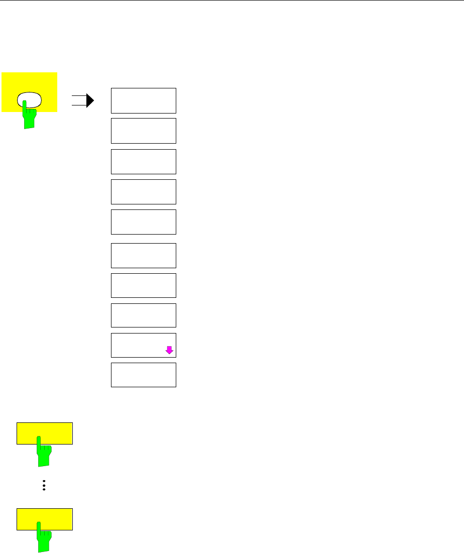
FSE Macros
1065.6016.12 4.81 E-15
Starting Macros
USER menu
USER USER MENU
DEFINE
MACRO
(MACRO 2)
DELETE
LINE
(MACRO 6)
(MACRO 7)
(MACRO 1)
(MACRO 3)
(MACRO 4)
(MACRO 5)
The USER key opens a menu for selection and starting
of macros.
The macros can be defined in the DEFINE MACRO
submenu.
(MACRO 1)
(MACRO 7)
he MACRO 1 to 7 softkeys start the execution of the macros.
IEC/IEEE-bus command --
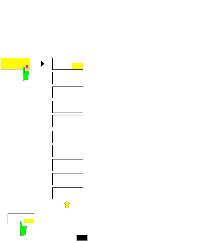
Macros FSE
1065.6016.12 4.82 E-15
Defining Macros
In the DEFINE MACRO menu, all necessary softkeys needed for macro management are available.
Included are functions for starting and ending macro programming, editing of a macro title, etc.
USER DEFINE MACRO menu
DEFINE
MACRO
DEFINE
MACRO
SELECT
MACRO
DEFINE
PAUSE
DELETE
MACRO
MACRO
TITLE
RECORD
ON OFF
The DEFINE MACRO softkey calls the sub-menu to define
the macros.
The SELECT MACRO softkey is active and opens the box to
select the macro to be edited. In case no selection is made,
MACRO 1 is automatically selected.
IEC/IEEE-bus command --
RECORD
ON OFF
The RECORD ON/OFF starts or stops the recording of the macro.
ON All key actions are recorded until the softkey is changed to OFF . To
indicate that macro record is enabled, the enhancement label
MAC
is displayed.
The number of actions which can be stored in a macro is limited. If
the limit is exceeded, the error message "Macro too long.
Recording aborted" is output and the recording operation is aborted,
however, the actions already recorded do remain stored.
OFF The recording is stopped. The key actions are stored under the
macro chosen by the SELECT MACRO softkey.
IEC/IEEE-bus command --
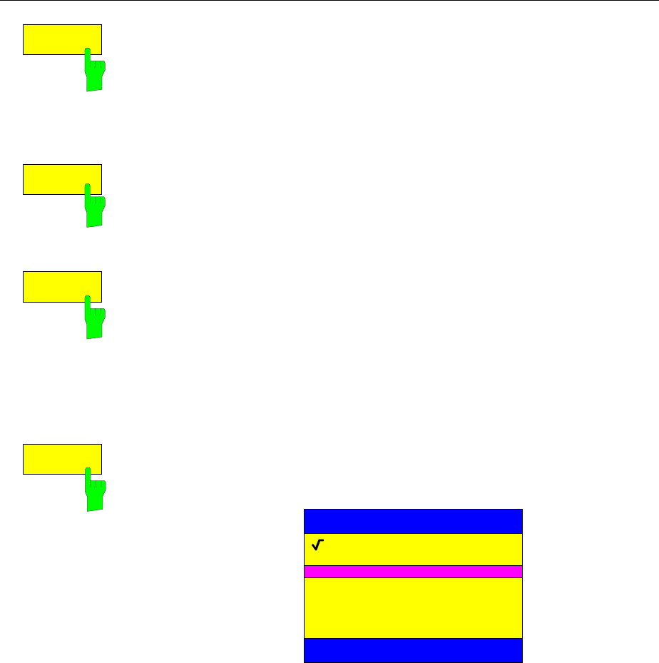
FSE Macros
1065.6016.12 4.83 E-15
DEFINE
PAUSE
The DEFINE PAUSE softkey inserts a pause instruction into the macro
sequence which is being recorded. A running macro will pause when it
reaches this instruction, at which point settings on the unit under test could for
example be made. CONTINUE in the message window is used to continue
the macro execution.
IEC/IEEE-bus command --
DELETE
MACRO
The DELETE MACRO softkey deletes the macro which was previously
selected by the SELECT MACRO softkey. The softkey of the deleted title now
carries its default label (MACRO X, X = macro number)
IEC/IEEE-bus command --
MACRO
TITLE
The MACRO TITLE softkey activates the entry of the title for the selected
macro.
Because the macro title is used for labelling the corresponding softkey, a
maximum of only 20 characters is allowed. All text after the 10 th character is
written to the second line. However, entering the character @ forces a new
line at any point in the softkey title.
IEC/IEEE-bus command --
SELECT
MACRO
The SELECT MACRO softkey open the selection box with a list of all 7
macros. All softkey functions of this menu are related to this macro.
SELECT MACRO
Macro 1
(Macro 2)
(Macro 4)
(Macro 5)
(Macro 6)
(Macro 7)
(Macro 3)
IEC/IEEE-bus command --
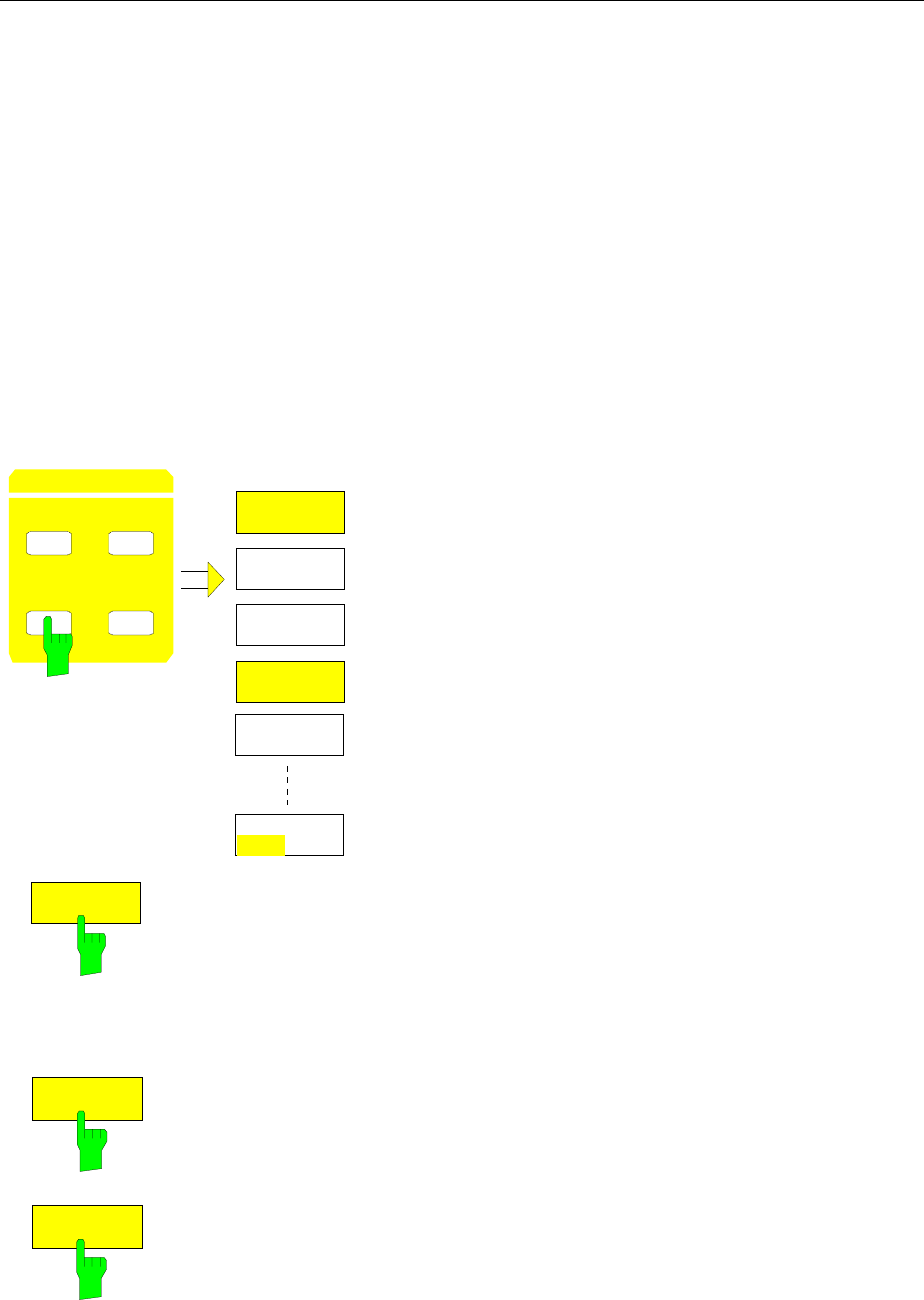
Frequency and Span FSE
1065.6016.12 4.84 E-15
Analyzer Mode
Frequency and Span Selection – FREQUENCY Key Group
The FREQUENCY key group is used to specify the frequency axis of the active measurement window.
The frequency axis can be defined either by the start and stop frequency or by the center frequency and
span. For the case when two measurement windows (SPLIT-SCREEN) are displayed simultaneously,
data entered are always related to the window selected in the SYSTEM-DISPLAY menu.
When one of the keys CENTER, SPAN, START or STOP is pressed, its value can be specified in an
entry window. At the same time, a softkey menu appears, which allows selecting the optional
parameters.
Start Frequency – START Key
FREQUENCY – START menu:
CENTER SPAN
START STOP
FREQUENCY
FIXED
START
CENTER
FIXED
SPAN
START FREQ
MANUAL
STOP
FIXED
FREQ AXIS
LIN LOG
The START key opens a menu which displays the various
options for setting the start frequency of the sweep.
The START MANUAL softkey is automatically active and
opens the entry window for manual input of the start
frequency. At the same time, the coupling of the parameters is
set to STOP FIXED
The STOP FIXED, SPAN FIXED and CENTER FIXED
softkeys are mutually exclusive selection switches. Only one
of these switches may be active at any one time. The
frequency coupling selected by the softkeys defines which of
the dependent parameters stop frequency, center frequency
and span is to remain constant when a change in the start
frequency is made.
The FREQ AXIS LIN/LOG softkey switches between linear
and logarithmic scaling of the frequency axis.
START
MANUAL The START MANUAL softkey activates manual entry of the start frequency.
The allowed range of values for the start frequency is:
0 Hz <= fstart <= fmax - minspan/2 fstart start frequency
minspan smallest selectable span)
fmax max. frequency
IEC/IEEE-bus command :[SENSe<1|2>:]FREQuency:STARt 20 MHz
S
T
O
P
FIXED
If the STOP FIXED key is active, the stop frequency remains constant when
the start frequency is changed. The center frequency is adjusted to the new
frequency range. STOP FIXED coupling is the default setting.
IEC/IEEE-bus command :[SENSe<1|2>:]FREQ:STARt:LINK STOP
SPAN
FIXED
If the SPAN FIXED softkey is active, the span remains constant when the
start frequency is changed. The stop frequency is adjusted to the new
frequency range.
IEC/IEEE-bus command :[SENSe<1|2>:]FREQ:STARt:LINK SPAN

FSE Frequency and Span
1065.6016.12 4.85 E-15
CENTER
FIXED
If the CENTER FIXED softkey is active, the center frequency remains
constant when the start frequency is changed. The stop frequency is adjusted
to the new frequency range.
IEC/IEEE-bus command :[SENSe<1|2>:]FREQ:STARt:LINK CENTer
FREQ AXIS
LIN LOG The FREQ AXIS LIN/LOG softkey switches between linear and logarithmic
scales on the frequency axis.
When the log scale is used, the following restrictions apply:
• For the start/stop frequency ratio the following holds:
Stopfrequency
Startfrequency ≥14.
At ratios below 1.4, a linear frequency scale is automatically selected.
• Up to five decades can be set.
5
10≤
encyStartfrequ
ncyStopfreque
When the start or stop frequency is changed, the stop or start frequency is
adapted to the settable range, as required.
• A frequency offset is not allowed.
• The CHANNEL POWER, C/N, C/N0, ADJACENT CHAN POWER and
OCCUPIED PWR BANDW measurements are disabled.
Note: The function of a limit line is influenced by the FREQ AXIS LIN/LOG
setting at the time of the definition.
Limit lines are entered as tabulated values (level and frequency).
Most regulations and standards prescribe the linking of values by
straight lines both for the linear and logarithmic display. When the
limit line is defined with the desired frequency scale selected, this is
automatically taken into account (linear interpolation).
To be able to use the correct limit values among the tabulated
values after a scale switchover, the limit line is recalculated after the
switchover.
IEC/IEEE-bus command :[SENSe<1|2>:]SWEep:SPACing LIN | LOG
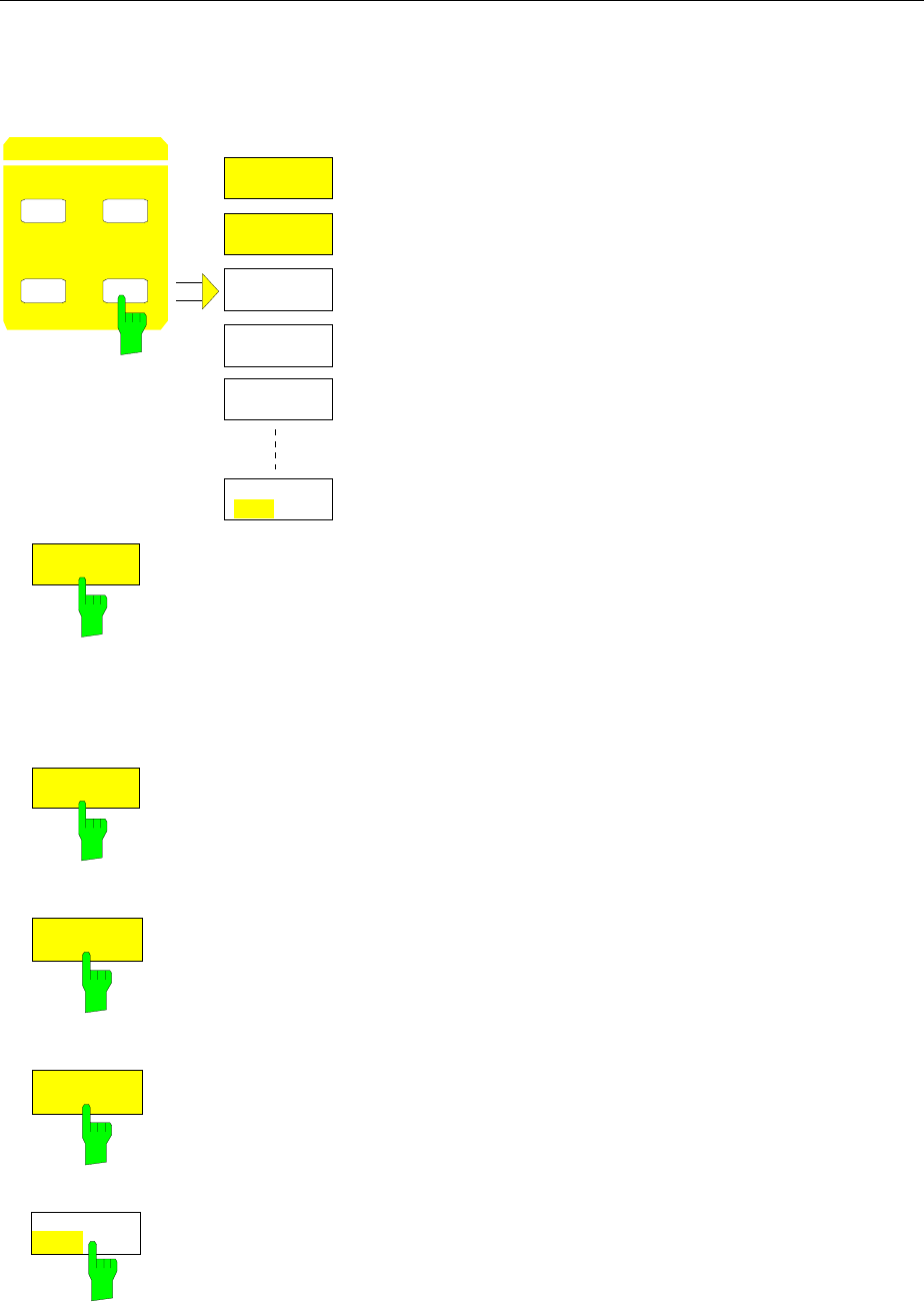
Frequency and Span FSE
1065.6016.12 4.86 E-15
Stop Frequency – STOP Key
FREQUENCY – STOP menu:
CENTER SPAN
START STOP
FREQUENCY STOP
MANUAL
START
FIXED
CENTER
FIXED
SPAN
FIXED
STOP FREQ
FREQ AXIS
LIN LOG
The STOP key opens a menu which displays the various
options for setting the stop frequency of the sweep.
The STOP MANUAL softkey is automatically active and opens
the entry window for manual input of the stop frequency. At the
same time, parameter coupling is set to START FIXED.
The START FIXED, CENTER FIXED and SPAN FIXED
softkeys are mutually exclusive selection switches. Only one
switch can be active at any one time. The softkeys are used to
select the frequency coupling. The frequency coupling defines
which of the dependent parameters start frequency, center
frequency or span is to remain constant when the stop
frequency is changed.
STOP
MANUAL
The STOP MANUAL softkey activates the manual entry window for the stop
frequency.
The allowed range of values for the stop frequency is:
minspan ≤ fstop ≤ fmax fstop stop frequency
minspan smallest selectable span (10Hz)
fmax max. frequency
IEC/IEEE-bus command :[SENSe<1|2>:]FREQuency:STOP 13 GHz
START
FIXED
If the START FIXED softkey is active, the start frequency remains constant
when the stop frequency is changed. The center frequency is adjusted to the
new frequency range. The START FIXED coupling is the default setting.
IEC/IEEE-bus command :[SENSe<1|2>:]FREQ:STOP:LINK STARt
CENTER
FIXED
If the CENTER FIXED softkey is active, the center frequency remains
constant when the stop frequency is changed. The start frequency is adjusted
to the new frequency range.
IEC/IEEE-bus command :[SENSe<1|2>:]FREQ:STOP:LINK CENTer
SPAN
FIXED
If the SPAN FIXED softkey is active, the span remains constant when the
stop frequency is changed. The start frequency is adjusted to the new
frequency range.
IEC/IEEE-bus command :[SENSe<1|2>:]FREQ:STOP:LINK SPAN
FREQ AXIS
LIN LOG The FREQ AXIS LIN/LOG softkey switches between linear and logarithmic
scales on the frequency axis (see START key).
IEC/IEEE-bus command :[SENSe<1|2>:]SWEep:SPACing LIN | LOG
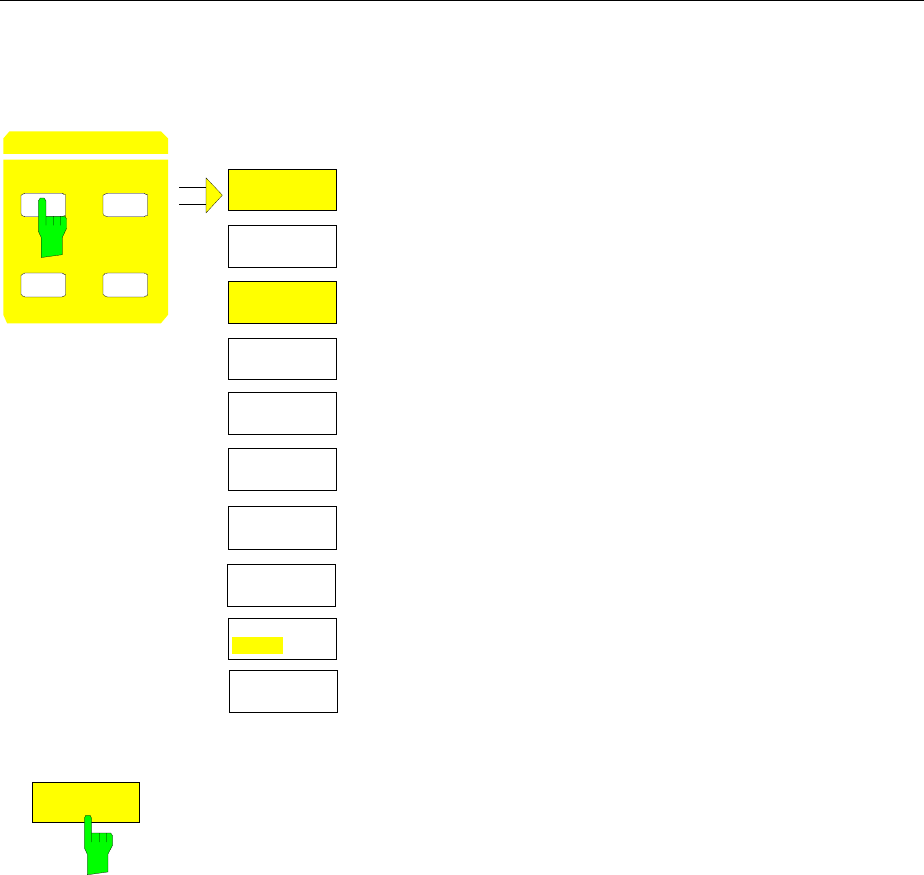
FSE Frequency and Span
1065.6016.12 4.87 E-15
Center Frequency – CENTER Key
FREQUENCY – CENTER menu:
FIXED
CENTER
MANUAL
START
FIXED
SPAN
CENTER
CENTER SPAN
START STOP
FREQUENCY
FREQ AXIS
LIN LOG
STOP
FIXED
FREQUENCY
OFFSET
The CENTER softkey opens a menu which displays the
various options for setting the center frequency of the sweep.
The CENTER MANUAL softkey is automatically active and
opens the entry window for manual input of the center
frequency. At the same time, the coupling of the parameters is
set to SPAN FIXED.
The START FIXED, STOP FIXED and SPAN FIXED softkeys
are mutually exclusive selection switches. Only one switch can
be active at any one time. The softkeys are used to select the
frequency coupling. The frequency coupling defines which of
the dependent parameters start frequency, stop frequency or
span remains constant when the center frequency is changed.
CENTER
MANUAL
The CENTER MANUAL softkey opens the entry window for entering the
center frequency.
The entry range for the center frequency is:
for the frequency domain (span > 0):
0 Hz <= fcenter <= fmax – minspan/2
and for the time domain (span = 0)
0 Hz ≤ fcenter ≤ fmax fcenter center frequency
minspan smallest selectable span (10Hz)
fmax max. frequency
IEC/IEEE-bus command :[SENSe<1|2>:]FREQuency:CENTer 1.3 GHz
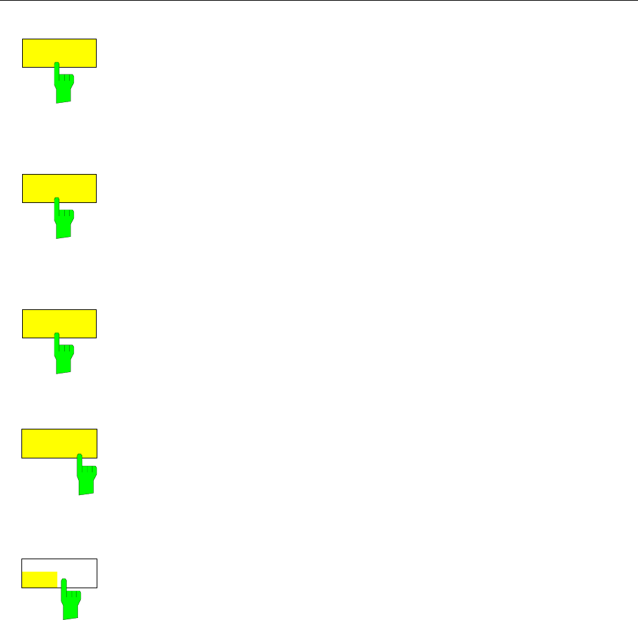
Frequency and Span FSE
1065.6016.12 4.88 E-15
SPAN
FIXED
If the SPAN FIXED softkey is active, the span remains constant when the
center frequency is changed. The start and stop frequency are adjusted to
the new frequency range. SPAN FIXED coupling is the default setting.
IEC/IEEE-bus command :[SENSe<1|2>:]FREQ:CENTer:LINK SPAN
START
FIXED
If the START FIXED softkey is active, the start frequency remains constant
when the center frequency is changed. The span is adjusted to the new
frequency range.
IEC/IEEE-bus command :[SENSe<1|2>:]FREQ:CENTer:LINK STARt
STOP
FIXED
If the STOP FIXED softkey is active, the stop frequency remains constant
when the center frequency is changed. The span is adjusted to the new
frequency range.
IEC/IEEE-bus command :[SENSe<1|2>:]FREQ:CENTer:LINK STOP
FREQUENCY
OFFSET The FREQUENCY OFFSET softkey activates the entry of a straight
frequency offset which is added to the frequency axis. The offset range is -
100 GHz to 100 GHz. The default setting is 0 Hz.
IEC/IEEE-bus command :[SENSe<1|2>:]FREQ:OFFSet 10 GHz
FREQ AXIS
LIN LOG The FREQ AXIS LIN/LOG softkey switches between linear and logarithmic
scales on the frequency axis (see START key).
IEC/IEEE-bus command :[SENSe<1|2>:]SWEep:SPACing LIN | LOG
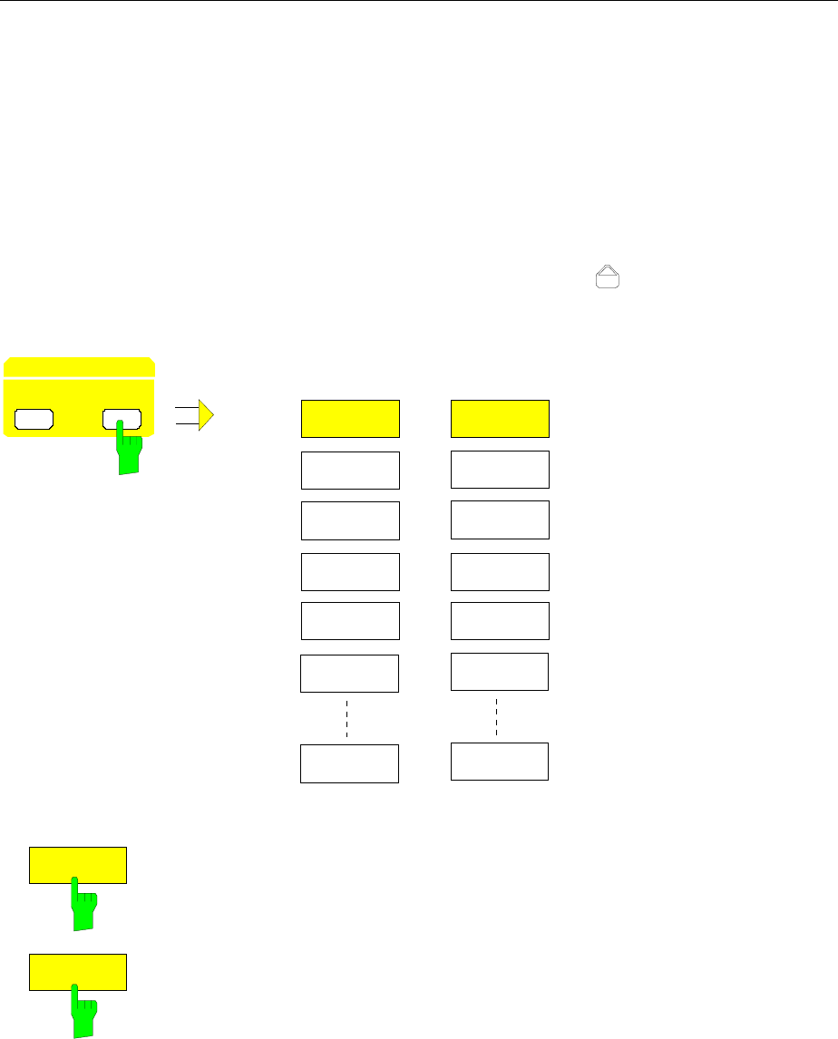
FSE Frequency and Span
1065.6016.12 4.89 E-15
Center Frequency Step Size
The STEP key in the DATA VARIATION key group opens a menu for setting the step size of the center
frequency. The step size can be coupled to the span (frequency domain) or the resolution bandwidth
(time domain) or it can be manually set to a fixed value.
In order to change the step size, the entry window for the center frequency must already be active. After
pressing the STEP key, the CENTER STEP menu appears. The softkeys are presented according to the
selected domain (frequency or time).
Only one of the menu softkeys can be activated at any one time.
Control is returned to the FREQUENCY CENTER menu via the menu key .
DATA VARIATION - STEP menu for span ≠ 0 for span = 0
STEP
DATA VARIATION
HOLD
AUTO
STEPSIZE
CENTER
0.1 * SPAN
AUTO
AUTO
STEPSIZE
0.5 * SPAN
X * SPAN
MANUAL
STEPSIZE
= CENTER
AUTO
STEPSIZE
CENTER
0.1 * RBW
AUTO
AUTO
STEPSIZE
0.5 * RBW
X * RBW
MANUAL
STEPSIZE
= CENTER
AUTO
0.1 * SPAN
AUTO
0.1 * RBW
Frequency domain: The AUTO 0.1 * SPAN softkey sets the step size for center
frequency entry to 10% of the span.
IEC/IEEE-bus command
:[SENSe<1|2>:]FREQuency:CENTer:STEP:LINK SPAN;
:[SENSe<1|2>:]FREQuency:CENTer:STEP:LINK:FACTor 10PCT
Time domain: The AUTO 0.1 * RBW softkey sets the step size of the
center frequency entry to 10% of the resolution
bandwidth
IEC/IEEE-bus command
:[SENSe<1|2>:]FREQuency:CENTer:STEP:LINK RBW;
:[SENSe<1|2>:]FREQuency:CENTer:STEP:LINK:FACTor 10PCT
AUTO 0.1 * RBW is the default setting.
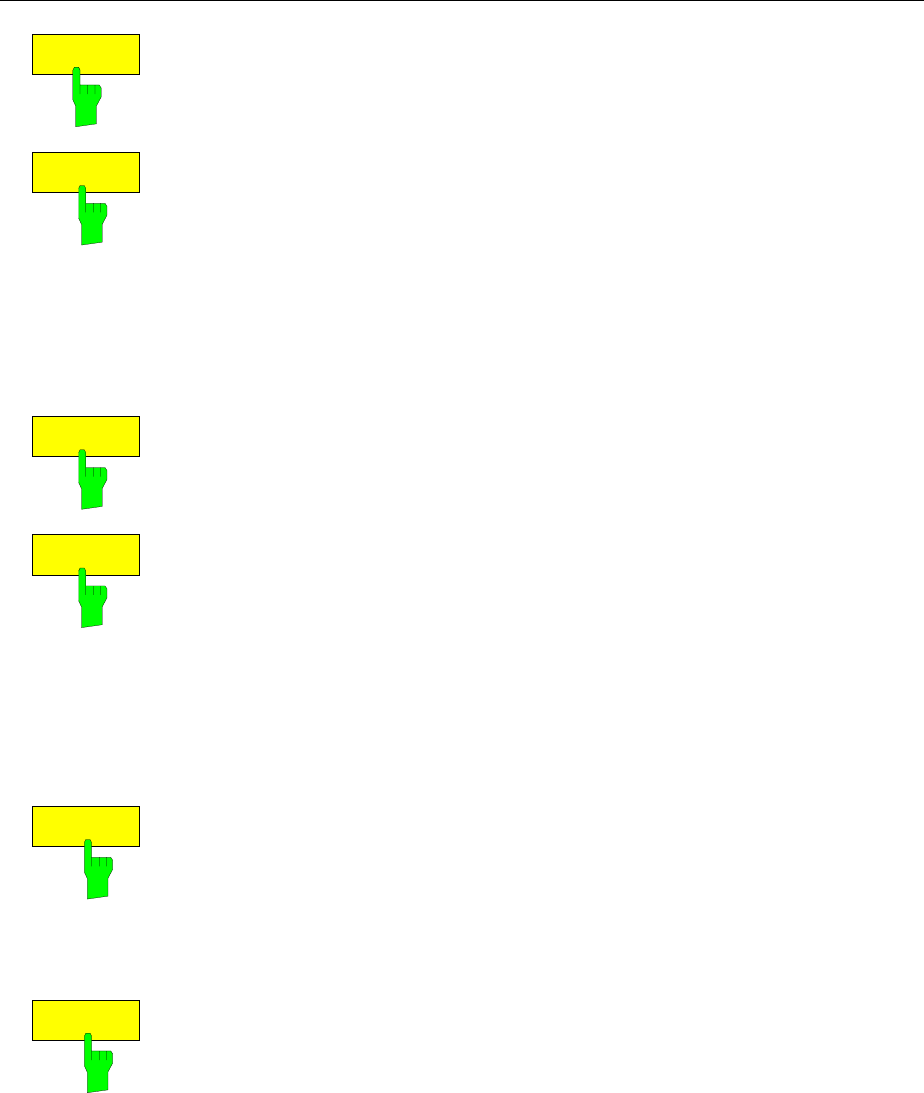
Frequency and Span FSE
1065.6016.12 4.90 E-15
AUTO
0.5 * SPAN
AUTO
0.5 * RBW
Frequency domain: The AUTO 0.5 * SPAN softkey sets the step size for
center frequency entry to 50% of the span.
IEC/IEEE-bus command
:[SENSe<1|2>:]FREQuency:CENTer:STEP:LINK SPAN;
:[SENSe<1|2>:]FREQuency:CENTer:STEP:LINK:FACTor 50PCT
Time domain: The AUTO 0.5 * RBW softkey sets the step size of the
center frequency entry to 50% of the resolution
bandwidth
IEC/IEEE-bus command
:[SENSe<1|2>:]FREQuency:CENTer:STEP:LINK RBW;
:[SENSe<1|2>:]FREQuency:CENTer:STEP:LINK:FACTor 50PCT
AUTO
X * SPAN
AUTO
X * RBW
Frequency domain:The AUTO X * SPAN softkey activates the entry of the
factor defining the center frequency step size as a % of
span.
IEC/IEEE-bus command see AUTO 0.5 * SPAN
Time domain: The AUTO X * RBW softkey activates the entry of the
factor defining the center frequency step size as a % of
the resolution bandwidth.
IEC/IEEE-bus command see AUTO 0.5 * RBW
Values between 1 and 100% in steps of 1% are acceptable. The default
setting is 10%.
STEPSIZE
MANUAL
The STEPSIZE MANUAL softkey activates the entry window for the input of a
fixed step size.
IEC/IEEE-bus command
:[SENSe<1|2>:]FREQuency:CENTer:STEP 1.3 GHz
STEPSIZE
= CENTER
The STEPSIZE = CENTER softkey sets the step size coupling to MANUAL
and the step size to the center frequency. This function is especially useful
when measuring harmonics, because, when the center frequency is entered,
each STEP key stroke slects the center frequency of the next harmonic.
IEC/IEEE-bus command --
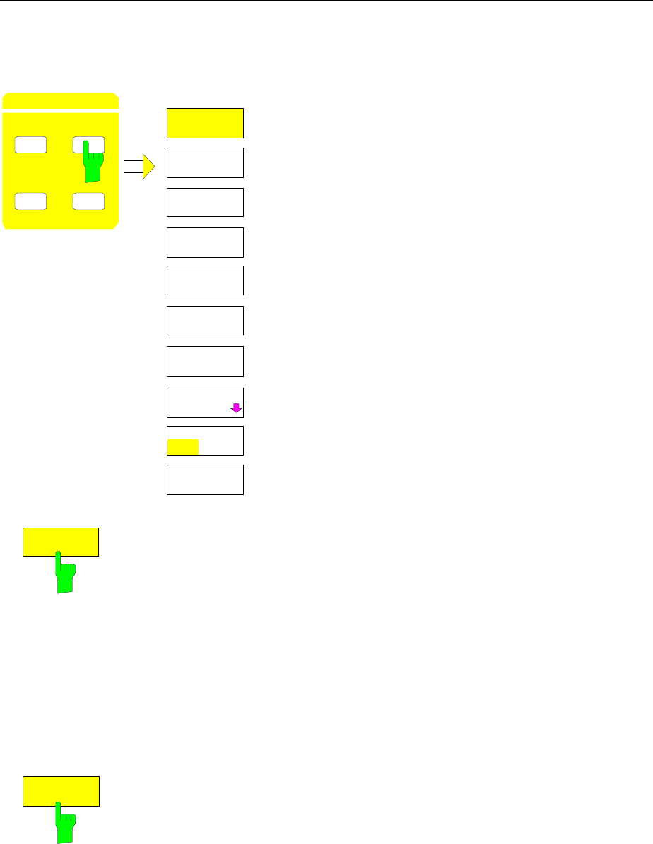
FSE Frequency and Span
1065.6016.12 4.91 E-15
Frequency Span – SPAN Key
FREQUENCY – SPAN menu:
CENTER SPAN
START STOP
FREQUENCY SPAN
SPAN
MANUAL
START
FIXED
CENTER
FIXED
STOP
FIXED
ZERO SPAN
FULL SPAN
LAST SPAN
ZOOM
FREQ AXIS
LIN LOG
The SPAN key opens a menu for setting the sweep span.
The SPAN MANUAL softkey is automatically active and
opens the entry window for manual input of the span. At
the same time, the parameter coupling is set to CENTER
FIXED.
The START FIXED, CENTER FIXED and STOP FIXED
softkeys are mutually exclusive selection switches. Only
one switch can be active at any one time. The frequency
coupling is selected with these softkeys. The frequency
coupling defines which of the dependent parameters start
frequency, center frequency or stop frequency is to remain
constant when the span is changed
SPAN
MANUAL
The SPAN MANUAL softkey activates the manual entry of the span.
The span entry range is for:
time domain (span = 0):
0 Hz
frequency domain (span > 0):
minspan ≤ fspan ≤ fmax fspan frequency span
minspan smallest selectable span (10Hz)
fmax max. frequency
IEC/IEEE-bus command :[SENSe<1|2>:]FREQuency:SPAN 10MHZ
ZERO SPAN
The ZERO SPAN softkey sets the span value to 0 Hz. The x axis becomes
the time axis. The axis labelling corresponds to the sweep time (on the left, 0
ms, on the right, the current sweep time (SWT)).
IEC/IEEE-bus command :[SENSe<1|2>:]FREQuency:SPAN 0HZ
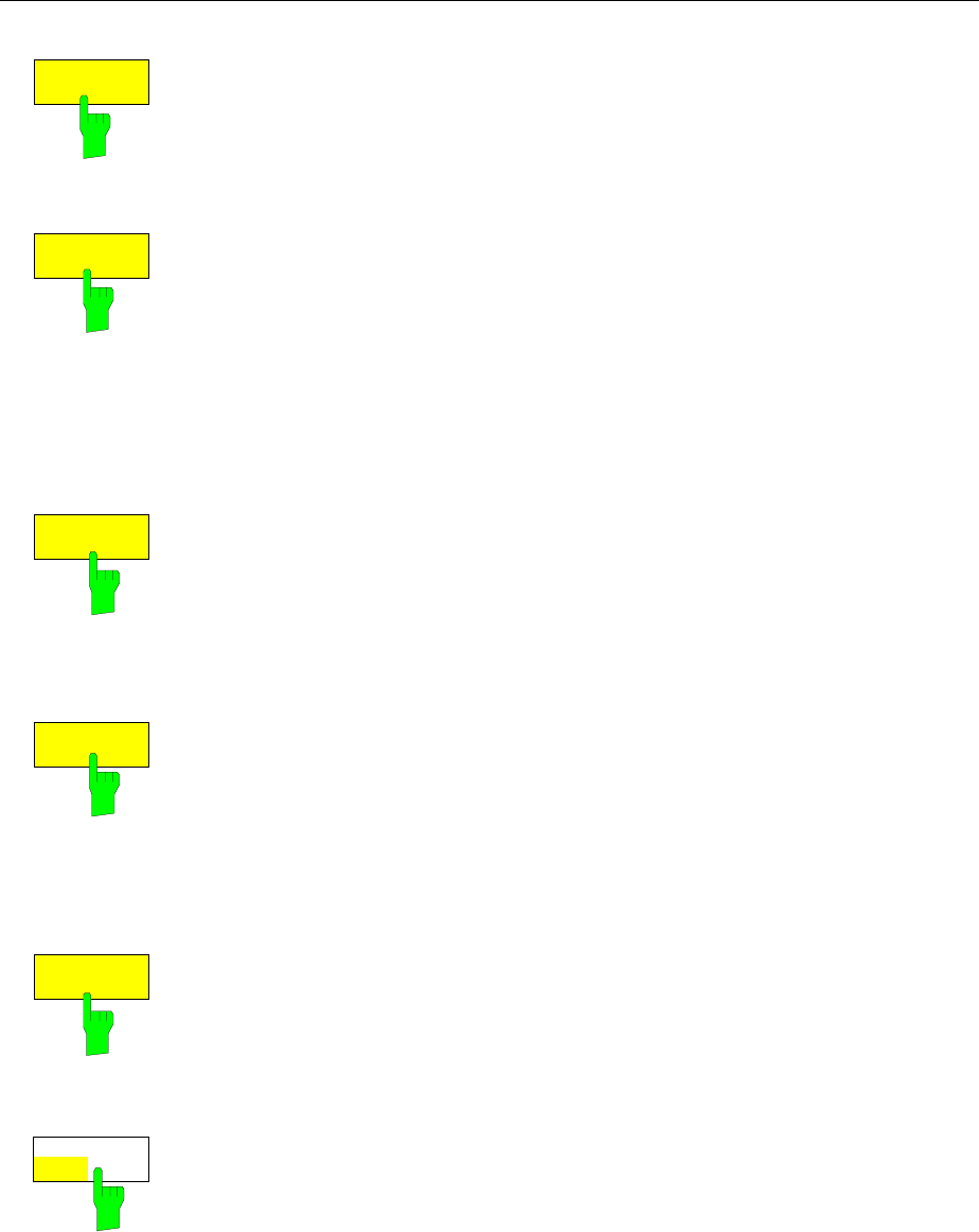
Frequency and Span FSE
1065.6016.12 4.92 E-15
FULL SPAN
The FULL SPAN softkey sets the span value to the maximum span of the
FSE.
IEC/IEEE-bus command :[SENSe<1|2>:]FREQuency:SPAN:FULL
LAST SPAN
The LAST SPAN softkey restores the previous setting if the span has been
changed. This makes it possible to switch over between an overview
measurement (FULL SPAN) and a detailed measurement (manually set
center frequency and span).
The FULL SPAN softkey modifies the center frequency as well as the
selected span. The LAST SPAN softkey cancels this change.
IEC/IEEE-bus command --
START
FIXED
If the START FIXED softkey is activated, the start frequency remains
constant when the span is changed. The center and stop frequency are
adjusted to the new span.
IEC/IEEE-bus command :[SENSe<1|2>:]FREQ:SPAN:LINK START
CENTER
FIXED
If the CENTER FIXED softkey is activated, the center frequency remains
constant when the span is changed. The center and stop frequency are
adjusted to the new span. The CENTER FIXED coupling is the default
setting.
IEC/IEEE-bus command :[SENSe<1|2>:]FREQ:SPAN:LINK CENTer
FIXED
STOP
If the STOP FIXED softkey is activated, the stop frequency remains constant
when the span is changed. The center and start frequency are adjusted to the
new span.
IEC/IEEE-bus command :[SENSe<1|2>:]FREQ:SPAN:LINK STOP
FREQ AXIS
LIN LOG The FREQ AXIS LIN/LOG softkey switches between linear and logarithmic
scales on the frequency axis (see START key).
IEC/IEEE-bus command :[SENSe<1|2>:]SWEep:SPACing LIN | LOG
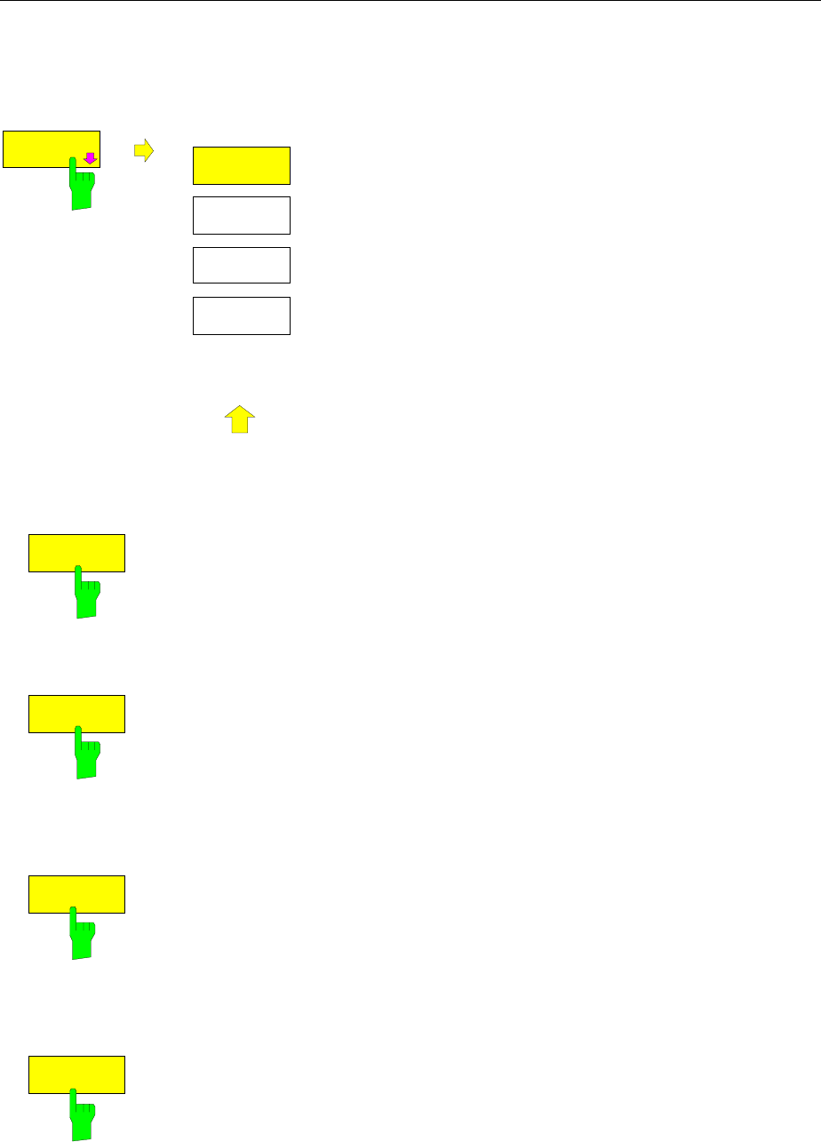
FSE Frequency and Span
1065.6016.12 4.93 E-15
Display Zoom
FREQUENCY SPAN- ZOOM submenu:
ZOOM
MOVE ZOOM
WINDOW
ZOOM
MOVE ZOOM
STOP
ZOOM
OFF
MOVE ZOOM
START
.
.
.
The ZOOM softkey activates the zoom mode and opens a
sub-menu to define the zoom span.
Two frequency lines, which show and define the frequency
range to be zoomed, appear in the active measurement
window when the zoom mode is switched on. The default
setting is a zoom span of 10% to the left and 10% to the right
of the center frequency. The zoomed display is shown in the
second measurement window.
The settings for the second measurement window are taken
from the original window. The second measurement window
thus becomes the active measurement window and its
settings can now be changed.
If only one window is active when the zoom function is
selected, SPLIT SCREEN mode is automatically switched on.
The zoom span can be edited by using the softkeys of the
sub-menu to change the position of the frequency lines.
The softkey ZOOM OFF switches off the zoom.
MOVE ZOOM
WINDOW
The MOVE ZOOM WINDOW softkey shifts the whole zoom window. The
window can shifted until the upper frequency line reaches the stop frequency
or the lower frequency line reaches the start frequency of the original window.
IEC/IEEE-bus commands
:DISPlay[:WINDow<1|2>]:TRACe<1..4>:X[:SCALe]:ZOOM ON
:DISPlay[:WINDow<1|2>]:TRACe<1..4>:X:ZOOM:CENTer 1GHz
MOVE ZOOM
START
The MOVE ZOOM START softkey shifts the lower frequency line. The start
frequency of the zoomed display can then be modified. The frequency line
can be shifted to the start frequency of the original window or to the upper
frequency line (= zero span).
IEC/IEEE-bus commands
:DISPlay[:WINDow<1|2>]:TRACe<1..4>:X[:SCALe]:ZOOM ON
:DISPlay[:WINDow<1|2>]:TRACe<1..4>:X:ZOOM:STARt 100MHz
MOVE ZOOM
STOP
The MOVE ZOOM STOP softkey shifts the upper frequency line. Thus, the
stop frequency of the zoomed display can be modified. The frequency line
can be shifted to the stop frequency of the original window or to the lower
frequency line (= zero span).
IEC/IEEE-bus commands
:DISPlay[:WINDow<1|2>]:TRACe<1..4>:X[:SCALe]:ZOOM ON
:DISPlay[:WINDow<1|2>]:TRACe<1..4>:X:ZOOM:STOP 200MHz
ZOOM
OFF
The ZOOM OFF softkey switches the zoom function off and then returns
control to the main menu.
The frequency lines indicating the zoom range are deleted, SPLIT SCREEN
mode remains active, the settings of both measurement windows are
retained and the coupling of the two measurement windows is cancelled.
IEC/IEEE-bus command
:DISPlay[:WINDow<1|2>]:TRACe<1..4>:X[:SCALe]:ZOOM OFF
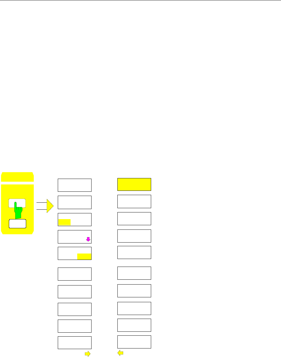
Level Display/RF Input FSE
1065.6016.12 4.94 E-15
Level Display and RF Input Configuration – LEVEL Key Group
The REF and RANGE keys are used to set the reference level (= maximum RF input level, = overload
limit), the maximum level (= upper grid level) , and the display range of the active window. The INPUT
key sets the characteristics of the RF input (input impedance and input attenuation).
Reference Level – REF key
In addition to the reference level (maximum RF input level), the FSE provides a function to define a
maximum level (uppermost grid line on the display):
For a spectrum analyzer, the upper boundary of the measurement diagram (maximum level) is also the
limit of its dynamic range (reference level). This means, that a signal which goes beyond the upper grid
line also overdrives the analyzer.
For compensation of frequency or antenna characteristics, transducer factors can be applied to increase
the signal level. In this case, the calculated values can be above the reference level without actually
being physically applied to the instrument. In order to display these signals on the grid, an upper grid
level which is different from the reference level of the analyzer can be entered.
LEVEL REF menu:
LEVEL
REF
RA E
REF LEVEL
REF LEVEL
GRID
ABS / REL
UNIT
MAX LEVEL
AUTO
MAX LEVEL
MANUAL
REF LEVEL
OFFSET
RF ATTEN
MANUAL
ATTEN AUTO
NORMAL
ATTEN AUTO
LOW NOISE
ATTEN AUTO
LOW DIST
MIXER
LEVEL
REF LEVEL
ATTEN STEP
1dB 10dB
The REF key opens a menu to set the
reference level and the input attenuation
for the active measurement window .
The REF LEVEL softkey is automatically
active with the menu called up and
opens the entry window for manual input
of the reference level.
At the same time various settings
concerning the level and the attenuation
display can be made.
The functions for setting the attenuation
are identical to those under the INPUT
key and are described in Section
"Configuration of the RF Input - INPUT
Key". Softkey ATTEN STEP 1dB/10dB
is only available when the FSE is
equiped with option FSE-B13, 1dB
attenuator (see ’Option 1 dB Attenuator
- FSE-B13’ at the end of this Section.)
FSE Level Display/RF Input
1065.6016.12 4.95 E-15
REF LEVEL
The REF LEVEL softkey activates the entry of the reference level. The unit of
the entry will be the currently active unit (dBm, dBµV, etc.).
If the MAX LEVEL MANUAL softkey is active, a change of the reference level
causes an equal amount of change in maximum level Thus, the separation
between the overload limit of the analyzer to the upper grid edge remains the
same. Thus, with only one entry, it is possible to make a change to the
display and simultaneously to perform an adjustment to the amplifier.
IEC/IEEE-bus command
:DISPlay[:WINDow<1|2>]:TRACe<1..4>:Y:RLEVel -60DBM
REF LEVEL
OFFSET
The REF LEVEL OFFSET softkey activates the entry of a straight level offset
( ±200 dB in 0,1 dB steps). The offset is added to the measured level
irrespective of the selected unit. The scaling of the y axis is changed
accordingly. The input can be used to take into account an external
attenuation.
The setting range is ±200 dB in 0,1-dB steps.
IEC/IEEE-bus command
:DISPlay[:WINDow<1|2>]:TRACe<1..4>:Y:RLEVel:OFFSet -1dB
GRID
ABS REL The GRID ABS/REL softkey toggles between absolute and relative scaling of
the level axis. GRID ABS is the default setting.
For absolute scaling the labeling of the level lines is referenced to the
absolute value of the reference level.
For relative scaling, the upper line of the grid is always at 0 dB and the scale
units are in dB. In contrast, the reference level is always displayed in the set
units (dBm, dBµV,..).
The softkey is not displayed for setting LIN / % (linear scaling, labelling in %)
in the LEVEL-RANGE menu since the % unit itself implies a relative scale.
IEC/IEEE-bus command
:DISPlay[:WINDow<1|2>]:TRACe<1..4>:Y:MODE ABS | REL
The MAX LEVEL MANUAL and MAX LEVEL AUTO softkeys are mutually exclusive selection switches.
Only one switch can be active at one time. The softkeys are used to select whether reference level and
maximum level are identical or not:
MAX LEVEL
AUTO
When MAX LEVEL AUTO softkey is active, the reference level and maximum
level are identical.
In this case, the reference level is displayed above the upper left corner of the
grid in the corresponding function field.
MAX LEVEL AUTO is the default setting.
If the MAX LEVEL MANUAL softkey was active prior to pressing the MAX
LEVEL AUTO softkey, the upper boundary of the grid is set to the reference
level.
IEC/IEEE-bus command
:DISPlay[:WINDow<1|2>]:TRACe<1..4>:Y:RVALue:AUTO ON
MAX LEVEL
MANUAL
The MAX LEVEL MANUAL softkey activates the entry of the maximum level.
The range of input values is ± 200dBm with 0.1 dB resolution.
If the MAX LEVEL MANUAL softkey is activated, the maximum level is
displayed in addition to the reference level to the right above the grid.
IEC/IEEE-bus commands
:DISPlay[:WINDow<1|2>]:TRACe<1..4>:Y:RVALue:AUTO OFF
:DISPlay[:WINDow<1|2>]:TRACe<1..4>:Y:RVALue -20DBM
Level Display/RF Input FSE
1065.6016.12 4.96 E-15
Display Units
Generally, a spectrum analyzer measures the signal voltage at the RF input. The level display is
calibrated in terms of therms values of an unmodulated sine wave. In the initial state, the level is
displayed at a power of 1 milliwatt (= dBm). As the input impedance is known to be 50Ω or 75Ω,
conversion to other units is possible. The units dBm, dBµV, dBµA, dBpW, V, A and W are directly
convertible and can be selected in the REF UNIT menu.
Units dB../MHz have a special status. They are applicable for broadband pulse signals. The measured
pulse voltage or the pulse current is referred to 1 MHz bandwidth. This conversion is not useful for
narrowband or sinewave signals.
If the antenna coded connector on the front panel is used, the coded unit there determines the possible
display units. Connecting to the coded connector deactivates the settings of the UNIT menu.
By certain codings it is nevertheless possible to select a conversion of the unit in the menu. The
dependencies between the unit of the antenna coded connector or the unit of the transducer and the
unit which is to be selected for the display are given in the softkey description.
The default coding defined by the connector can be switched off using the PROBE CODE ON/OFF
softkey. In this case, the unit can be set with the corresponding unit softkeys (dBm, dBµV, ... ) even if a
coded connector is plugged in. The coded entries in the connector are then ignored.
Note: The units dBµV/m and dBµA/m can only be set via the unit of a transducer or via the unit of the
coded connector.
LEVEL REF UNIT submenu:
dBm
dBµV
dBµA
VOLT
AMPERE
WATT
UNIT
PROBE CODE
ON / OFF
UNIT
dBpW
dB* / MHz
dBmV
The UNIT softkey opens a sub-menu in which the desired
units for the level axis can be selected and the coding of the
antenna coded connector can be switched on and off.
The selected units are valid for both displays when two
measurement windows are displayed.
The unit softkeys are mutually exclusive selection switches.
Only one of these switches may be active at any one time.
FSE Level Display/RF Input
1065.6016.12 4.97 E-15
dBm
dBmV
dB Vµ
dB A
µ
dBpW
The dBm, dBµV, dBmV, dBµA, dBpW softkeys set the display units to the
corresponding logarithmic units. The dBm unit is the default unit in analyzer
mode.
The units dBm, dBµV, dBmV, dBµA cannot be selected when the coded
antenna connector or the used transducer defines a unit.
Only for coding dB, the conversion to the desired units is permitted.
IEC/IEEE-bus command
:CALCulate<1|2>:UNIT:POWer DBM |DBMV |DBUV |DBUA |DBPW
dB* / MHz
The dB*/MHz softkey activates/disactivates the display of results in units
relative to the bandwidth. Those units can be derived from the logarithmic
units dBµV, dBµV/m, dBµA and dBµA/m.
This leads to the following relative units:
dBmV
⇒
dBmV/MHz
dBµV
⇒
dBµV/MHz
dBµV/m
⇒
dBµV/mMHz
dBµA
⇒
dBµA/MHz
dBµA/m
⇒
dBµA/mMHz
Switching over is possible also if a coded antenna connector or a transducer
fixes the unit to be used.
Conversion to 1 MHz is via the pulse bandwidth of the selected resolution
bandwidth Bimp according to the following equation (example for dBµV) :
P/(dBV/MHz) 20 logB/MHz
1MHz P/(dBV)
imp
µµ
=⋅ + ,
where P = display level
The dBµV/MHz unit can be combined with the following coded connector or
transducer units
dB (the unit dBµV/MHz remains )
µV/m (yields the display unit dBµV/mMHz)
analogous for dBµA/MHz:
dB and µA (the unit dBµA/MHz remains)
Other combinations are not allowed.
IEC/IEEE-bus command
:CALCulate<1|2>:UNIT:POWer DBUV_MHZ|DBUA_MHZ|DBMV_MHZ
Level Display/RF Input FSE
1065.6016.12 4.98 E-15
VOLT
AMPERE
WATT
The VOLT, AMPERE, WATT softkeys set the display units to the
corresponding linear units.
The units VOLT, AMPERE, WATT cannot be selected when the coded
antenna connector or the transducer table defines one of the following as
units:
µV/m
µA
For coding dB, the conversion to the desired units is permitted.
PROBE CODE
ON OFF The PROBE CODE ON/OFF softkey enables or disables the units defined by
the coded connector.
IEC/IEEE-bus command :UNIT<1|2>:PROBe ON | OFF
Level Range – RANGE Key
LEVEL RANGE menu:
LEVEL
REF
RANGE
LOG 100 dB
LOG 50 dB
LOG 20 dB
LOG 10 dB
LINEAR/dB
LINEAR/ %
LEVEL RANGE
LOG
MANUAL
LOG 120 dB
GRID
ABS REL
The RANGE key calls a menu in which the range, linear or
logarithmic the display scale, absolute or relative and the
level units for the active window can be selected.
The display range of the analyzer can be set in 10 dB
steps from 10 to 200 dB.
The default setting is 100 dB.
The most often used settings (120 dB, 100 dB, 50 dB,
20 dB and 10 dB) are each directly selectable by a
softkey.
All other ranges are chosen with the LOG MANUAL
softkey.
After pressing the RANGE key, the LOG MANUAL entry
window is enabled if the display range is not set to LIN.

FSE Level Display/RF Input
1065.6016.12 4.99 E-15
LOG
MANUAL
The LOG MANUAL softkey activates the entry of the level display range.
Display ranges from 10 to 200 dB are allowed in 10-dB steps. Values which
are not permissible are rounded to the next valid number.
IEC/IEEE-bus commands
:DISPlay[:WINDow<1|2>]:TRACe<1..4>:Y:SPACing LOG
:DISPlay[:WINDow<1|2>]:TRACe<1...4>:Y 110DB
LINEAR/dB
The LINEAR/dB softkey switches the display range of the analyzer to linear
scaling. The horizontal lines are labelled according to the selection GRID
ABS/REL in dB* or *.
IEC/IEEE-bus command
:DISPlay[:WINDow<1|2>]:TRACe<1..4>:Y:SPACing LINear
LINEAR/ %
The LINEAR/% softkey switches the display range of the analyzer to linear
scaling. The horizontal lines are labelled in %. The grid is divided into
decades.
IEC/IEEE-bus command
:DISPlay[:WINDow<1|2>]:TRACe<1..4>:Y:SPACing PERCent
GRID
ABS REL The GRID ABS/REL softkey switches between absolute and relative scaling
of the level axis. GRID ABS is the default setting.
ABS The labelling of the level lines is referenced to the absolute value of the
reference level.
REL The upper line of the grid is always at 0 dB and the scale units are in
dB. In contrast, the reference level is always displayed in the set units
(dBm, dBµV,..).
The softkey is not displayed for setting LIN / % (linear scaling, labelling in %)
since the % unit itself implies a relative scale.
IEC/IEEE-bus command
:DISPlay[:WINDow<1|2>]:TRACe<1..4>:Y:MODE ABS | REL
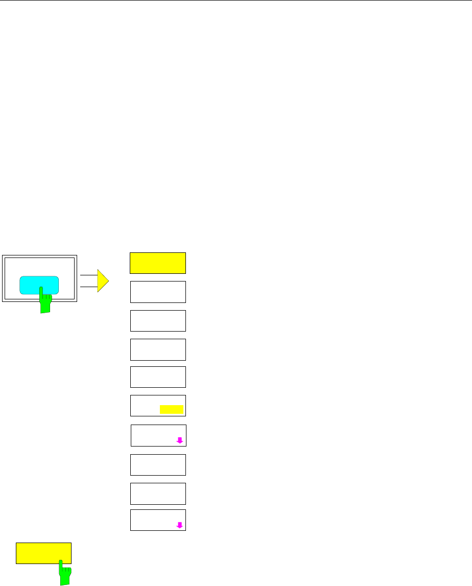
Level Display/RF Input FSE
1065.6016.12 4.100 E-15
RF Input Configuration – INPUT Key
In addition to manual entry of the input attenuation, the FSE provides an option which allows the RF
attenuation, dependent on the selected reference level, to be automatically set. Thus, it is guaranteed
that an optimum combination of RF attenuation and IF amplification is always used. For the automatic
selection process, three modes are provided. The AUTO LOW NOISE mode selects the
amplification/attenuation combination so that the display of noise on the FSE is at a minimum. The
signal/noise ratio is maximised. The AUTO LOW DISTORTION mode is tuned for minimisation of the
internally generated interference products. This causes, however, a lower signal/noise ratio. The ATTEN
AUTO NORMAL mode is a compromise between low noise and low distortion.
When the FSE is equipped with option FSE-B13, 1 dB Attenuator, the attenuator can be set with a step
size of 1 dB up to an upper limit frequency of 7 GHz.
When the instruemnt is equipped with option FSE-B21, External Mixer Output, the FSEM and FSEK can
be operated with external mixer.
INPUT menu:
INPUT
ATTEN AUTO
NORMAL
ATTEN AUTO
LOW NOISE
ATTEN AUTO
LOW DIST
MIXER
LEVEL
INPUT
SELECT
INPUT
RF ATTEN
MANUAL
ATTEN STEP
1 dB 10dB
INTERNAL
MIXER
EXTERNAL
MIXER
The INPUT key opens the menu for configuring the RF
input. It contains the input attenuator and mixer level for
matching the RF input to the input signal.
The RF ATTEN MANUAL, ATTEN AUTO NORMAL,
ATTEN AUTO LOW NOISE and ATTEN AUTO LOW
softkeys are mutually exclusive selection switches. only
one can be active at any one time.
Softkey ATTEN STEP 1dB/10dB is only available when
the FSE is equiped with option FSE-B13, 1dB attenuator
(see ’Option 1 dB Attenuator - FSE-B13’ at the end of
this Section.)
Softkeys INTERNAL MIXER and EXTERNAL MIXER are
only available when the FSE is equiped with option FSE-
B21, External Mixer Input (see manual of option).
The INPUT SELECT softkey calls a submenu for
selection of the input impedance.
RF ATTEN
MANUAL The RF ATTEN MANUAL softkey activates the entry of an attenuation factor
independent of the reference level.
The attenuation can be modified in 10 dB steps between 0 and 70 dB.
Other inputs will be rounded to the next higher integer value.
If the defined reference level cannot be set for the given RF attenuation, the
reference level will be adjusted accordingly and the warning "Limit reached"
will be output.
IEC/IEEE-bus command :INPut<1|2>:ATTenuation 40DB
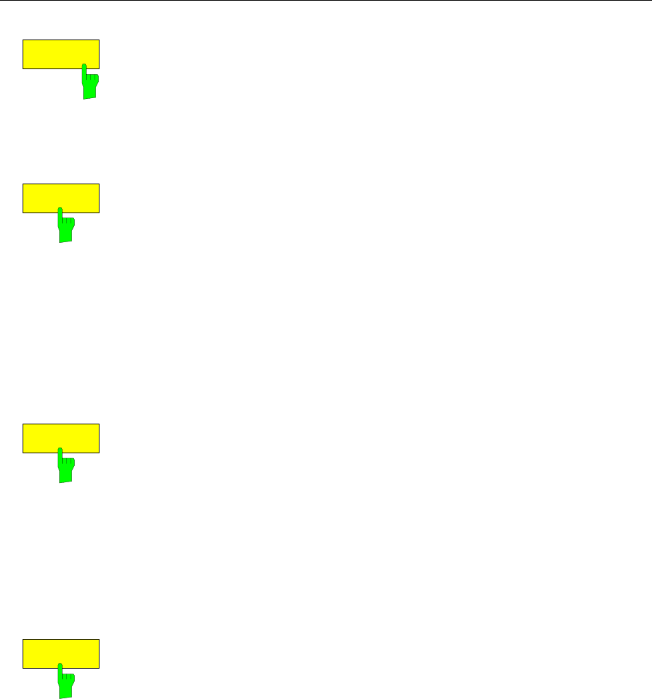
FSE Level Display/RF Input
1065.6016.12 4.101 E-15
ATTEN AUTO
NORMAL
The ATTEN AUTO NORMAL softkey sets the RF attenuation automatically as
a function of the selected reference level.
IEC/IEEE-bus commands
:INPut<1|2>:ATTenuation:AUTO:MODE NORMal
:INPut<1|2>:ATTenuation:AUTO ON
ATTEN AUTO
LOW NOISE
The ATTEN AUTO LOW NOISE softkey sets the RF attenuation always 10dB
lower than in the RF ATTEN AUTO mode. Therefore, for 10 dB RF
attenuation, the maximum reference level is -10 dBm. For reference levels
which are lower, at least 10 dB is always set (see above).
Setting Low Noise means that the indicated inherent noise level is low. This
setting is recommended if signals with a low level have to be measured as
the highest S/N ratio is then obtained.
IEC/IEEE-bus commands
:INPut<1|2>:ATTenuation:AUTO:MODE LNOise
:INPut<1|2>:ATTenuation:AUTO ON
ATTEN AUTO
LOW DIST
The ATTEN AUTO LOW DIST softkey sets the RF attenuation 10 dB higher
than in RF ATT AUTO mode. This means that for 10 dB RF attenuation, the
maximum reference level is -30 dBm (-40 dBm at the mixer).
This setting is recommended whenever a small signal is to be measured in
the presence of larger signals. Here, the intermodulation-free range of the
FSE is large and the internal distortion products are minimised.
IEC/IEEE-bus commands
:INPut<1|2>:ATTenuation:AUTO:MODE LDIStortion
:INPut<1|2>:ATTenuation:AUTO ON
MIXER
LEVEL
The MIXER LEVEL softkey activates the entry of the maximum mixer level
attainable for a given reference level. At the same time it enables softkeys
ATTEN AUTO LOW NOISE and ATTEN AUTO LOW DIST .
Range of input values is -10 to -100 dBm
IEC/IEEE-bus command :INPut<1|2>:MIXer -30DBM
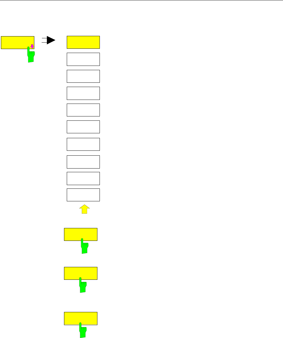
Level Display/RF Input FSE
1065.6016.12 4.102 E-15
INPUT INPUT SELECT submenu:
RF INPUT
50 OHM
RF INPUT
75 OHM/RAZ
RF INPUT
75 OHM/RAM
INPUT
SELECT
INPUT
SELECT
The INPUT SELECT softkey calls a submenu for selection of the
input impedance of the RF input.
The basic setting is 50 Ohm. By connecting an impedance
converter RAM or RAZ ahead, the 50-Ohm input can be
transformed to 75 Ohm. FSE automatically takes the
corresponding correction values for the level display into
account.
The softkeys used to select the input impedance are selection
switches. Only one of them can be active at any one time
RF INPUT
50 OHM
The RF INPUT 50 OHM softkey sets the input impedance to 50
Ohm (= default setting). All level indications are referenced to 50
Ohm.
IEC/IEEE-bus command :INPut<1|2>:IMPedance 50
RF INPUT
75 OHM/RAM
The RF INPUT 75 OHM/RAM softkey sets the input impedance
of the FSE to 75 Ohm including the matching element RAM. All
level indications are referenced to 75 Ohm.
IEC/IEEE-bus command
:INPut<1|2>:IMPedance:CORR RAM
RF INPUT
75 OHM/RAZ
The RF INPUT 75 OHM/RAZ softkey sets the input impedance
of the FSE to 75 Ohm including the matching element RAZ. All
level indications are referenced to 75 Ohm.
IEC/IEEE-bus command
:INPut<1|2>:IMPedance:CORR RAZ
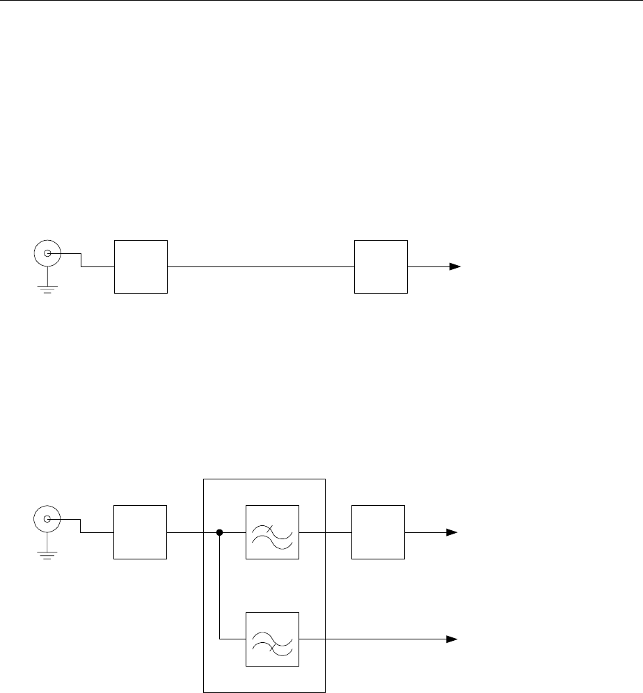
FSE Level Display/RF Input
1065.6016.12 4.103 E-15
Option 1 dB Attenuator - FSE-B13
The option 1 dB Attenuator FSE-B13 is used to set the attenuator with a step size of 1 dB up to an upper
limit frequency of 7 GHz.
The attenuator with 1 dB stepping is connected in series after the main attenuator.
Instruments with an Upper Limit Frequency of up to 7 GHz
The optional attenuator is in the signal path for all settable frequencies in instruments with a maximum
upper limit frequency of 7 GHz. When it is activated, it is used without any restriction for setting the input
attenuation or the reference level.
dB dB
to RF converter
RF-input Attenuator 0 to 70 dB FSE-B13, 1 dB attenuator,
0 to 9 dB
Instruments with an Upper Limit Frequency of more than 7 GHz
In instruments with an upper limit frequency of more than 7 GHz a diplexer is placed before the optional
attenuator for separating the frequency ranges ≤ 7GHz and > 7 GHz. The optional attenuator is in the
signal path only for frequencies ≤ 7 GHz.
dB dB
to RF converter
to YIG and
microwave unit
Diplexer
RF input Attenuator
0 to 70 dB FSE-B13, 1 dB attenuator
0 to 9 dB
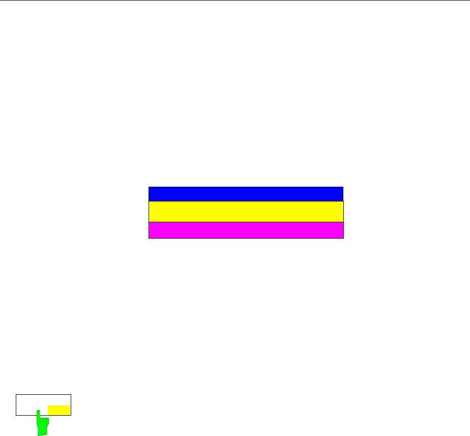
Level Display/RF Input FSE
1065.6016.12 4.104 E-15
On changing the frequency range for the stop frequency, the attenuator can be set as follows:
Instrument setting: ATTENUATOR AUTO
- After switching from Fstop ≤ 7 GHz to Fstop > 7 GHz the reference level is re-calculated provided
the attenuation previously set contained 1 dB steps. A warning is not displayed.
- After switching from Fstop > 7 GHz to Fstop ≤ 7 GHz the reference level is re-calculated. A
warning is not displayed.
Instrument setting: ATTENUATOR MANUAL
- After switching from Fstop ≤ 7 GHz to Fstop > 7 GHz, the attenuation is rounded off to a value
divisible by 10 provided the attenuation previously set contained 1 dB steps. A warning is
displayed:
WARNING
1dB Stepsize Attenuator only available
for stop frequencies <= 7 GHz
OK
- After switching from Fstop > 7 GHz to Fstop ≤ 7 GHz the current value of the input attenuation is
maintained.
The 1 dB attenuator is inactive as default. In this case the attenuation can be set only in 10 dB steps, ie
the attenuation of the optional attenuator is fixed at 0 dB.
The optional attenuator is activated either in the INPUT menu or in the REF LEVEL menu (the two
settings are equivalent):
ATTEN STEP
1dB 10db The ATTEN STEP 1dB/10dB softkey switches between the 10 dB step and 1
dB step settings.
After activating the optional attenuator with the ATTEN STEP 10dB/1dB
softkey, setting in 1 dB steps is possible, the total attenuation is divided into
- a 10 dB contribution from the main attenuator and
- a residual contribution of 0 to 9 dB from the optional attenuator.
The attenuation setting range in the instrument remains to be 0 to 70 dB, it is
not extended by the optional attenuator.
After a reset the attenuator step size is automatically set to 10 dB.
IEC/IEEE-bus command :INPut<1|2>:ATTenuation:STEPsize 1|10
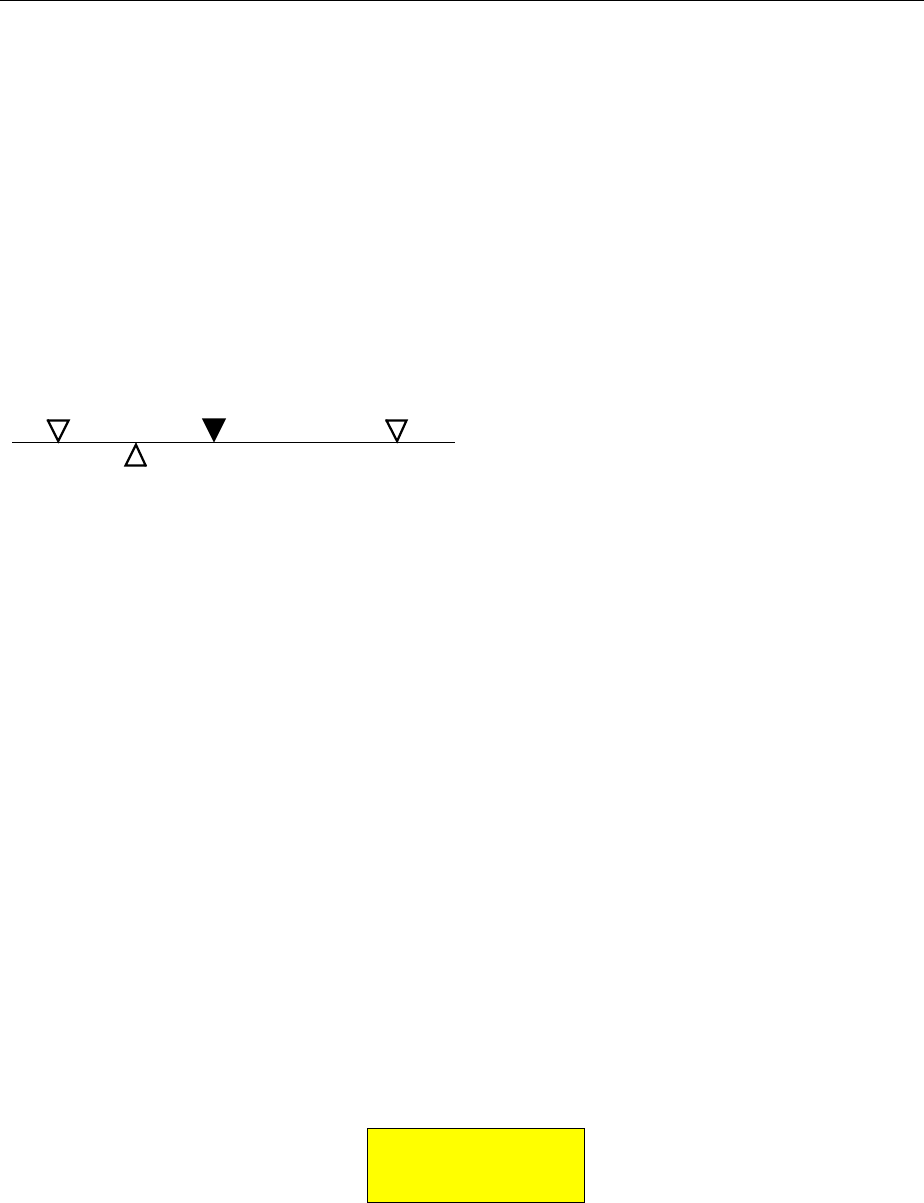
FSE Main Markers
1065.6016.12 4.105 E-15
Marker Functions – MARKER Key Group
The markers are used for marking points on measurement curves (traces), reading out measurement
values and for quickly selecting a screen mode. Preselected measurement routines can be called by
pressing a key in the marker menu. The FSE has four markers and four delta markers per
measurement window. The currently activated marker can be shifted with the cursor keys, the roll-key or
the softkeys. The softkeys are defined according to the type of display representation selected
(frequency or time domain).
The marker which can be moved by the user is defined as the active marker.
Examples of marker displays:
1 3
2
T1
marker active marker temporary marker
delta marker
Temporary markers are used in addition to the markers and delta markers to evaluate the measurement
results. They disappear when the associated function is deactivated.
The measurement values of the active marker (also called marker values) are displayed in the marker
field. In the marker info list, the measurement values from all enabled markers are sorted in ascending
order. The marker info list can be switched off with the MARKER INFO softkey so that only the values
for the active marker are shown.
The summary markers have a special function. They read out the rms or average value of the current
trace or the trace averaged over several sweeps in the marker info list. These markers are not
displayed.
Main Markers– NORMAL Key
The NORMAL key calls a menu which contains all the standard marker functions. The current state of
the markers is indicated by a colored illumination of the softkeys. If no marker is enabled prior to
pressing the NORMAL key, MARKER 1 will be enabled as the reference marker and a peak search on
the trace is carried out (assumption: at least one trace is active). Otherwise, the peak search is omitted
and the entry window for the reference marker is activated.
The marker field in the upper right corner of the display screen shows the marker values, in this case,
the frequency, the level and the currently selected trace.
MARKER 1 [T1]
123.4567 MHz
-27.5 dBm
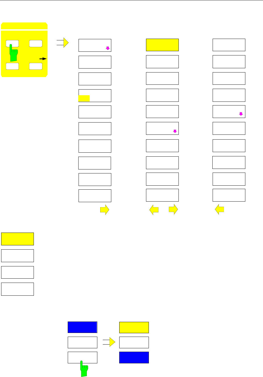
Main Markers FSE
1065.6016.12 4.106 E-15
MARKER NORMAL menu:
MARKER
NORMAL
MARKER 2
MARKER 3
SIGNAL
COUNT
NOISE
SIGNAL
TRACK
MARKER
NORMAL
MARKER
DEMOD
MARKER 1
MARKER 4
ALL MARKER
OFF
COUNTER
RESOL
MARKER
INFO
MARKER
ZOOM
MARKER
NORMAL SEARCH
DE A MKR
C / No
C / N
MARKER
NORMAL
POWER MEAS
SETTING
CHANNEL
POWER
SET CP
REFERENCE
ADJACENT
CHAN POWER
ADJUST CP
SETTINGS
OCCUPIED
PWR BANDW
CP / ACP
ABS REL
MARKER
NORMAL
MARKER 2
MARKER 3
ON
MARKER 1
MARKER 4
The MARKER 1 to MARKER 4 softkeys switch the corresponding marker
on/off or activate it as the reference marker. If the marker is activated as a
reference marker, an entry field for manually setting the position of the
reference marker is opened simultaneously. If the marker is disabled, the
softkey is not illuminated. Enabled markers and the reference marker are
indicated by illuminating the corresponding softkeys in different colors.(In
the instrument default state, the active reference marker is displayed in red
and enabled markers are displayed in green.)
Operating example:
MARKER 1 is shown as the reference marker by the colored background
illumination. MARKER 2 through MARKER 4 are turned off.
MARKER
NORMAL MARKER
NORMAL
MARKER 2
MARKER 3
ON
MARKER 1
MARKER 2
MARKER 3
MARKER 1
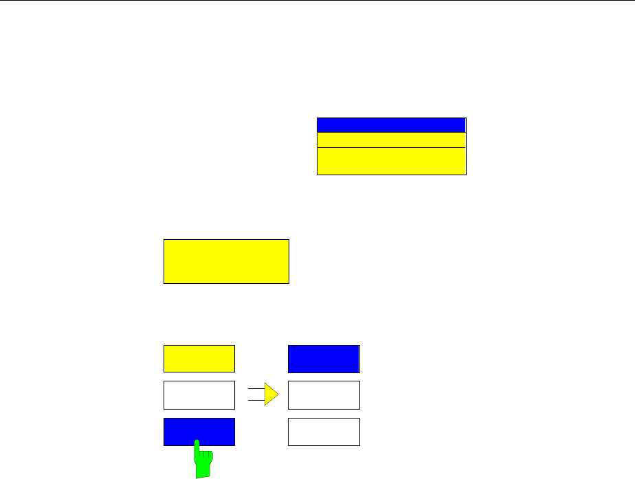
FSE Main Markers
1065.6016.12 4.107 E-15
Pressing the MARKER 3 softkey switches MARKER 3 on and it becomes
the reference maker. The previous reference marker remains enabled and
the softkey remains illuminated. However, the entry mode for this marker is
not now active. Instead, the entry window for MARKER 3 is opened and the
position of MARKER 3 can be shifted.
MARKER 3
123.4567 MHz
The information in the marker field also changes to describe the new
reference marker.
MARKER 3 [T1]
23.4567891 MHz
-27.5 dBm
MARKER
NORMAL
MARKER
NORMAL
MARKER 2
MARKER 3
MARKER 1
MARKER 2
MARKER 3
MARKER 1
Pressing the current reference marker (MARKER 3) softkey again switches
MARKER 3 off. If at least one marker is enabled, the marker with the
smallest number will be selected as the new reference marker (in the
example, MARKER 1). Switching off the last active marker also deletes are
delta markers.
IEC/IEEE-bus commands
:CALCulate<1|2>:MARKer<1..4>[:STATe] ON | OFF;
:CALCulate<1|2>:MARKer<1..4>:X 10.7MHz;
:CALCulate<1|2>:MARKer<1..4>:Y?
When several traces are displayed, the marker is set to the maximum value (peak) of the active trace
with the lowest number (1 to 4). if a marker is already positioned there, it will be set to the frequency of
the next highest level (next peak).
When the split screen mode is active, the marker will be placed in the active window (for SCREEN A:
trace 1 or 3, for SCREEN B: trace 2 or 4). Since markers are attached to a trace, the marker can only be
enabled when at least one trace is displayed in the corresponding window.
If a trace is turned off, the markers and marker functions attached to the trace are also switched off. If
the trace is switched on again (VIEW, CLR/WRITE;..), these markers, along with any coupled functions
will be restored to their original positions. A prerequisite for the restoration of the marker positions is that
individual markers have not been used on another trace or that the sweep data (start/stop frequency for
span > 0 or sweep time for span = 0) have not been changed.
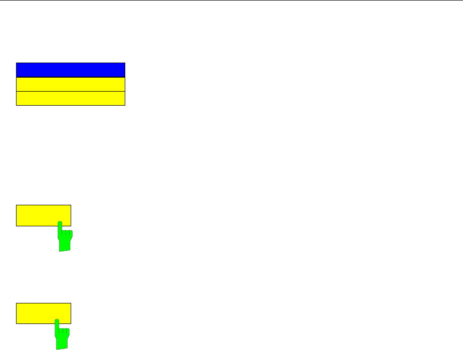
Main Markers FSE
1065.6016.12 4.108 E-15
If a marker (or, delta marker) necessary for a marker function is not available, it will be automatically
checked whether or not the enabling of the corresponding marker is possible (see above). If this is not
the case, a warning is issued.
No trace active
WARNING:
The activation of the desired marker function is then not possible.
On the other hand, if the marker can be enabled, a peak search is automatically performed. Thereafter,
the desired marker function can be executed.
MARKER NORMAL menu:
ALL MARKER
OFF
The ALL MARKER OFF softkey switches off all markers (reference and delta
markers). Similarly, it switches off all functions and displays correlated with
the markers/delta markers (signal count, signal track, marker zoom, N dB
down, shape factor, marker list and marker info).
IEC/IEEE-bus command :CALCulate<1|2>:MARKer<1...4>:AOFF
SIGNAL
TRACK
After each sweep, the SIGNAL TRACK softkey starts a search for the
maximum signal level on the screen (PEAK SEARCH) and then sets the
center frequency to the frequency of this signal (MARKER ->CENTER).
If a threshold line is enabled, only signals above the threshold level are
considered. If no signal is over the threshold, the center frequency remains
constant until a signal is available which is over the threshold.
If no marker is switched to the active trace, the next unused marker is
automatically activated and positioned by the peak search routine.
In order to reduce the search range, it is possible to apply the SEARCH LIMIT
ON/OFF function (see section: "Search Functions"). If the center frequency is
changed, the position of the frequency line relative to the center frequency
remains the same, ie its absolute position is correspondingly changed.
The softkey is only available in the frequency domain (spectrum) display
mode (span > 0.)
IEC/IEEE-bus commands
:CALCulate<1|2>:MARKer<1..4>:COUNt ON |OFF;
:CALCulate<1|2>:MARKer<1..4>:COUNt:FREQuency?

FSE Main Markers
1065.6016.12 4.109 E-15
MARKER
ZOOM
The MARKER ZOOM softkey expands the area around the active marker.
With the zoom function, more details of the spectrum can be seen. The
desired display range can be defined in an entry window.
The sweep is stopped at the reference marker. The frequency of the signal is
counted and the measured frequency becomes the new center frequency.
The zoomed display is set and the new settings are used by the FSE for
further measurements.
As long as the switchover to the new frequency display range has not yet
taken place, pressing the softkey will abort the procedure.
If no marker is activated when the softkey is pressed, then MARKER 1 is
automatically activated and set to the highest peak in the measurement
window.
If an instrument setting is changed after selection of MARKER ZOOM, the
function is aborted.
The MARKER ZOOM softkey is only available for frequency domain
measurements (span > 0).
IEC/IEEE-bus command
:CALCulate<1|2>:MARKer<1..4>:FUNCtion:ZOOM 1KHZ
MARKER
INFO
The MARKER INFO softkey opens the display of several markers within the
grid. In the upper right corner of the grid, a maximum of 4 markers/delta
markers with the marker symbols ∆/∇, marker number (1 to 4), position and
measurement value are listed. For the output of the marker position, the
number or displayed characters will be limited as required.
If the number of lines available is not enough for all the enabled markers and
delta markers, first the markers and then the delta markers are entered into
the info list
In the SPLIT SCREEN display, the info list is partitioned into 2 partial lists and
assigned to the corresponding measurement window (SCREEN A and
SCREEN B). The info list for SCREEN A contains the markers which are
assigned to trace 1 or trace 3. The info list for SCREEN B contains the
markers which are assigned to trace 2 and trace 4.
For the two measurement windows, it is not possible to turn the MARKER
INFO function selectively on/off .
IEC/IEEE-bus command :DISPlay:WINDow<1|2>:MINFo ON | OFF
LF Demodulation
The FSE provides demodulators for AM and FM signals. With these demodulators, a displayed signal
can be identified acoustically with of the internal loudspeaker or with external headphones. The
frequency at which demodulation is activated is coupled to the markers. The sweep stops at the
frequency determined by the set marker for the selected time and the RF signal is demodulated.
During time domain measurements (span = 0) the demodulation is switched on continuously.
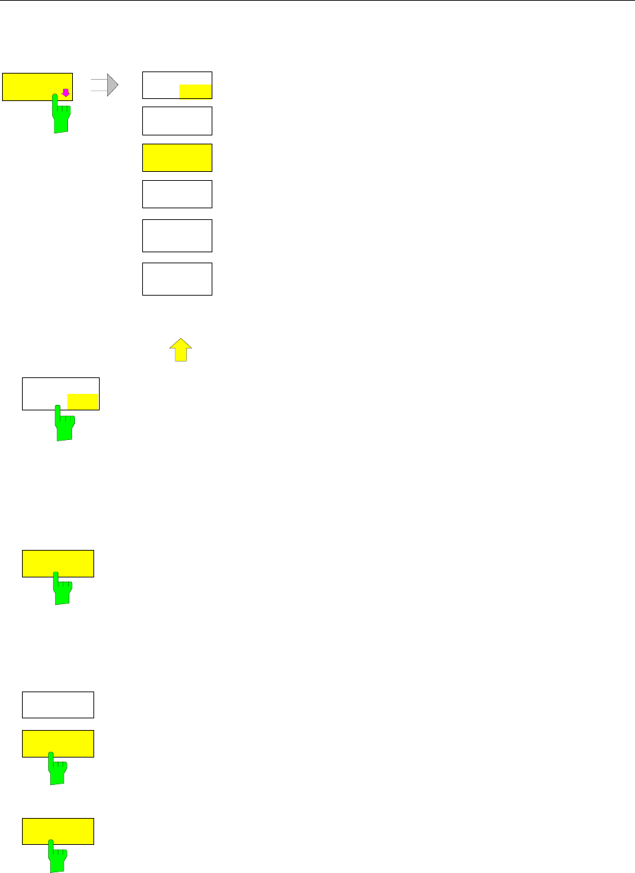
Main Markers FSE
1065.6016.12 4.110 E-15
MARKER NORMAL-MARKER DEMOD submenu:
MARKER
DEMOD
MARKER
DEMOD
AM
FM
MKR
STOP TIME
VOLUME
MKR DEMOD
ON OFF
.
.
.
The MARKER DEMOD softkey calls a sub-menu in which the
type of demodulation desired, the duration of the
demodulation and the loudness may be selected
MKR DEMOD
ON OFF
The MKR DEMOD ON/OFF softkey switches the demodulation on/off. When
the demodulation is on, the sweep is stopped at all marker frequencies,
assuming the signal is over the threshold, and the signal is demodulated until
the entered sweep stop time elapses. A total of four stopping points (four
markers) can be programmed.
If no marker is set when the demodulation is switched on, the FSE switches the
first marker on (MARKER 1) and positions it on the trace peak.
IEC-Bus-Befehl
:CALCulate<1|2>:MARKer<1..4>:FUNCtion:DEM ON|OFF
MKR
STOP TIME
The MKR STOP TIME softkey activates the entry window for setting the stop
time.
The FSE stops the sweep at the marker or the marker for the duration of the
defined stop time and then switches the demodulation on (see also MKR
DEMOD ON/OFF).
IEC-Bus-Befehl
:CALCulate<1|2>:MARKer<1..4>:FUNCtion:DEM:HOLDoff 3s
FM
AM
The AM and FM are selection switches of which only one can be activated at
any one time. They are used to set the desired demodulation type, FM or AM.
The default setting is AM.
IEC-Bus-Befehl
:CALCulate<1|2>:MARKer<1..4>:FUNCtion:DEM:SELect AM|FM
VOLUME
The VOLUME softkey opens the entry window for setting the loudness.
The volume can be set between 0 and 100%.
IEC-Bus-Befehl :SYSTem:SPEaker<1|2>:VOLume 0.5

FSE Main Markers
1065.6016.12 4.111 E-15
Frequency Measurement
To accurately determine the frequency of a signal, the FSE is equipped with an internal frequency
counter. The frequency counter measures the frequency of the RF signal at the intermediate frequency.
Using the value found at the intermediate frequency, the FSE calculates the frequency of the RF signal
by applying the known frequency conversion relationships.
The frequency measurement error depends only upon the accuracy of the frequency standard used
(external or internal reference). Although the FSE always performs the frequency sweep in sync - no
matter what frequency range is set - the frequency counter gives a more exact frequency measurement
than a measurement performed with a marker. This is explained by the following:
•The marker only gives the position of a pixel on the trace and the frequency of the signal is deduced
from this. The trace, however, contains only a limited number of pixels, so each pixel may represent
a number of measurement values that depends on the selected span. This reduces the frequency
resolution.
•The resolution with which the frequency can be measured is proportional to the measurement time.
For measurement time reasons, the bandwidth is normally held as wide as possible and the sweep
time is set a short as possible. This results in a loss of frequency resolution.
For the measurement with the frequency counter, the sweep is stopped at the reference marker, the
frequency is measured to the desired resolution and then the sweep is allowed to continue (see also
Chapter 2, "Measurement Examples").
MARKER NORMAL menu:
SIGNAL
COUNT
The SIGNAL COUNT softkey switches the frequency counter on/off.
The frequency is counted at the position of the reference marker. The sweep
stops at the reference marker until the frequency counter outputs a result.
The time required for a frequency measurement depends on the selected
frequency resolution. The resolution is set in the COUNTER RESOL sub-
menu.
If no marker is enabled when the SIGNAL COUNT softkey is pressed,
MARKER 1 is switched on and set to the trace peak.
The SIGNAL COUNT function is also indicated by [T x CNT] in the marker
field on the display screen.
MARKER 2 [T1 CNT]
23.4567891 MHz
-27.5 dBm
Switching the SIGNAL COUNT function off is accomplished by pressing the
softkey once again.
Note: For digital resolution filters (RBW < 1kHz or softkey RBW 1kHz set to
DIG), a analog prefilter of 2 kHz is active.
IEC/IEEE-bus command
:CALCulate<1|2>:MARKer<1..4>:COUNt ON | OFF;
:CALCulate<1|2>:MARKer<1..4>:COUNt:FREQuency?
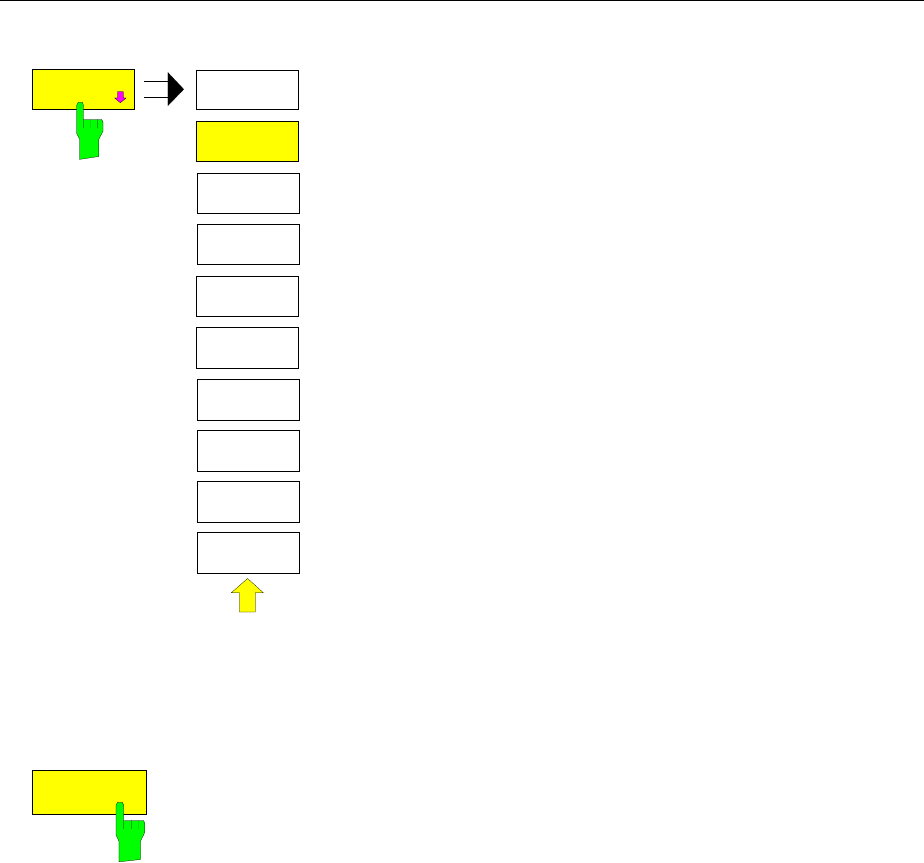
Main Markers FSE
1065.6016.12 4.112 E-15
COUNTER
RESOL
COUNTER
RESOLUTION
100 Hz
10 kHz
10 Hz
1 kHz
1 Hz
0.1 Hz
The COUNTER RESOL softkey in the right side menu opens
a sub-menu in which the resolution of the frequency counter
can be defined.
The value can be selected between 0.1 Hz and 10 kHz.
The time which the frequency counter requires for a
measurement is proportional to the selected resolution. For
example, a 1 Hz resolution will require approximately one
second measurement time. In order to prevent slowing the
sweep time unnecessarily, it is recommended that the
frequency resolution be set as low as possible.
IEC/IEEE-bus command
:CALCulate<1|2>:MARKer<1..4>:COUNt:RES 1KHZ
Noise Power Density Measurement
MARKER NORMAL menu (right side menu):
NOISE
The NOISE softkey switches noise measurement on/off.
During a noise measurement, the noise power density is measured at the
position of the reference marker. The noise power density is displayed in
the marker field dependent upon the vertical units in dBx/Hz (for logarithmic
scale) or in V/Hz, A/Hz or W/Hz for linear scales. The correction factors for
the selected bandwidth and the conversion of the IF logarithmic converter
are automatically taken into consideration.
For trace setting AUTO SELECT, the sample detector is automatically
switched on and off with the noise marker to provide for displayof the rms
value of the noise power. For single sweep, a new sweep has to be started
after the marker has been switched on in order to ensure that the trace is
recorded with the correct detector.
For all other detector settings, the user is prompted to select the sample
detector for optimum results as soon as the noise marker is switched on. In
this case the sample detector has to be switched on manually.
In order to produce a smoother noise display, neighboring points
(symmetrical to measurement frequency) on the trace are averaged.
In the time domain display, an average of the measurement values takes
place in time (after each sweep).
IEC/IEEE-bus command
:CALCulate<1|2>:MARKer<1..4>:FUNCtion:NOISe ON | OFF;
:CALCulate<1|2>:MARKer<1..4>:FUNCtion:NOISe:RESult?
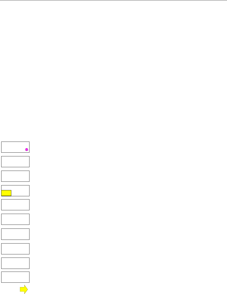
FSE Main Markers
1065.6016.12 4.113 E-15
Channel Power Measurements
A modulated carrier is almost always used (exception e.g.,.: SSB-AM) for high-frequency transmission
of information. Due to the information modulated onto the carrier, the latter covers a spectrum which is
defined by the modulation, the data transmission rate and the signal filtering. Within a transmission
band, each carrier is assigned a channel taking into account these parameters. In order to ensure error-
free transmission, each transmitter must keep within its specified parameters. These include among
others:
•the output power,
•the occupied bandwidth, i.e., the bandwidth within which a defined percentage of the power must be
contained and
•the power received by adjacent channels.
Using the power measurement function, the FSE is capable of measuring all the specified parameters
with high precision and at high speed.
The power measurements settings are performed in the left-hand side-menu MARKER NORMAL.
MARKER NORMAL menu:
C / No
C / N
MARKER
NORMAL
POWER MEAS
SETTINGS
CHANNEL
POWER
SET CP
REFERENCE
ADJACENT
CHAN POWER
ADJUST CP
SETTINGS
OCCUPIED
PWR BANDW
CP / ACP
ABS REL
The following measurements can be made:
•channel power (CHANNEL POWER)
•signal / noise power (C/N)
•signal / noise power density (C/No)
•adjacent channel power (ADJACENT CHAN POWER)
•occupied bandwidth (OCCUPIED PWR BANDWIDTH)
The channel power and the adjacent channel power can be measured either
relative (CP/ACP REL) to the power in the utilised channel or in absolute terms
(CP/ACP ABS).
Channel configuration is via sub menu POWER MEAS SETTINGS.
The above mentioned power measurements can be performed alternately.
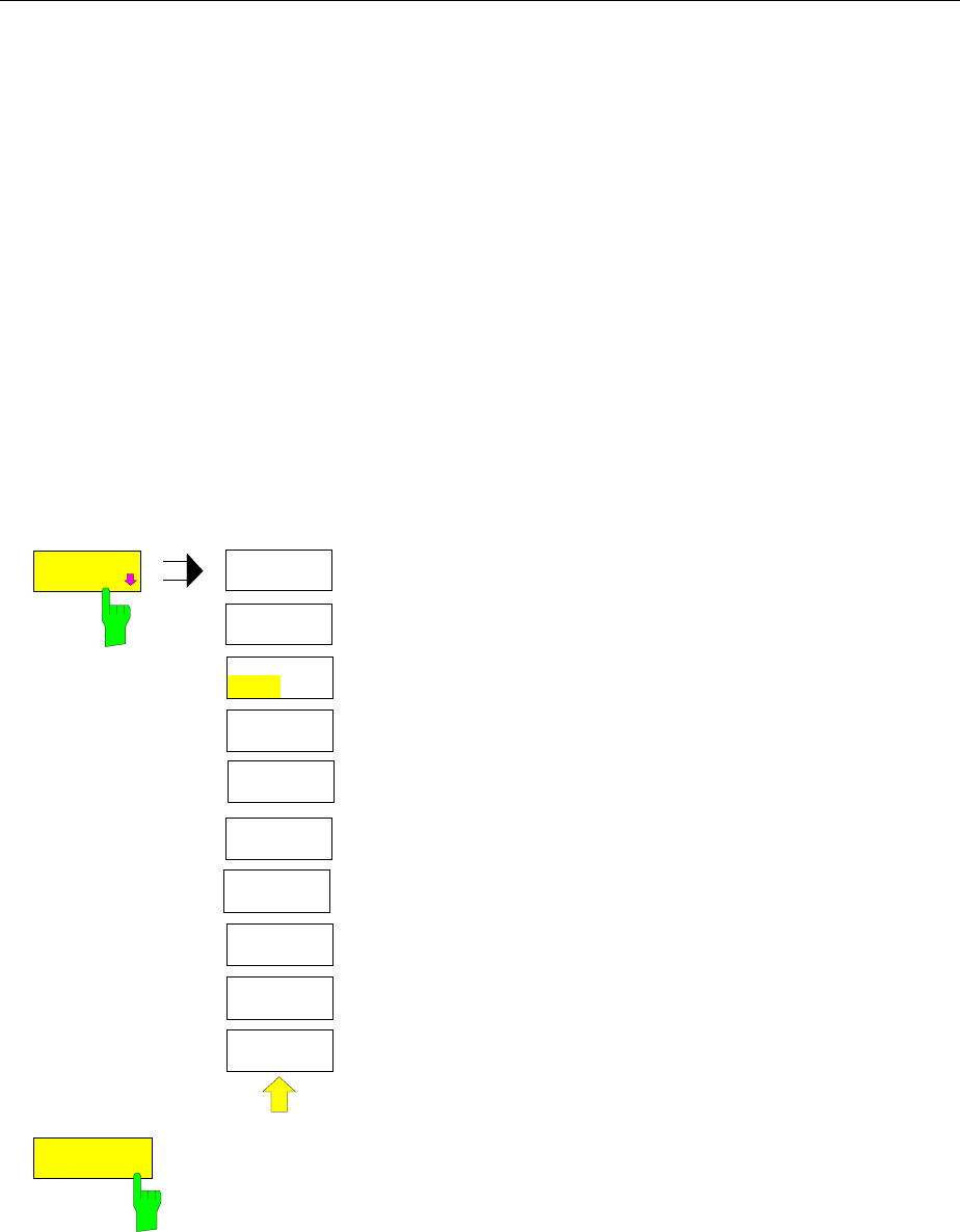
Main Markers FSE
1065.6016.12 4.114 E-15
Channel Configuration
For all power measurements, a specified channel configuration is assumed which is, e.g. oriented on a
specific radio communications system.
The channel configuration is defined by the nominal channel frequency ( = center frequency of the FSE),
the channel bandwidth (CHANNEL BANDWIDTH) and the channel spacing (CHANNEL SPACING).
The channel is indicated on the display screen by vertical lines located at a half-channel bandwidth to
the left and to the right of the channel frequency. For the adjacent channel power measurement, the
adjacent channels are also indicated by vertical lines. The lines of the utilised channel are labelled with
CO for easier recognition.
Depending on the radio communication service, the power of the 1st alternate channel and/or 2nd
alternate channel can be measured in addition (softkey SET NO.OF ADJ CHAN’S).
With the ACP STANDARD softkey, the channel configuration can be set automatically according to the
regulations of different digital mobile-radio standards. For some standards, the channel power has to be
evaluated by means of a root-cosine filter corresponding to the transmit filter. This filter is switched on
automatically if the corresponding standards are selected but can be switched off manually (softkey CH
FILTER ON/OFF).
MARKER NORMAL - POWER MEAS SETTINGS submenu:
POWER MEAS
SETTING
POWER MEAS
SETTINGS
CHANNEL
BANDWIDTH
CHANNEL
SPACING
% POWER
BANDWIDTH
SET NO. OF
ADJ CHAN’S
CH FILTER
ON OFF
ACP
STANDARD
EDIT
ACP LIMITS
LIMIT
CHECK
The POWER MEAS SETTINGS softkey calls the sub-menu
for the definition of the channel configuration.
SET NO. OF
ADJ CHAN’S
The SET NO. OF ADJ CHAN’S softkey activates the input of number ±n
adjacent channels to be considered for adjacent channel power measurement
The individual powers are indicated separately. Example n=3:
CH0 Pwr -20.00 dBm
ACP UP -45.23 dBm
ACP LOW -52.11 dBm
ALT1 UP -60.04 dBm
ALT1 LOW -61.00 dBm
ALT2 UP -63.34 dBm
ALT2 LOW -64.00 dBm
1, 2 or 3 adjacent channels are possible. ALT1 and
ALT2 (Alternate Channel Power) indicate the channel
power at ± 2 × channel spacing and ± 3 × channel
spacing from the center of the channel.
IEC/IEEE-bus command :[SENSe<1|2>:]POWer:ACHannel:ACPairs 2

FSE Main Markers
1065.6016.12 4.115 E-15
ACP
STANDARD
The ACP STANDARD softkey activates the selection of a digital mobile-radio
standard. The parameters for the adjacent channel power measurement are
set according to the regulations of the selected standard.
ACP STANDARD
NONE
NADC
TETRA
PDC
PHS
CDPD
CDMA800 FWD
CDMA800 REV
CDMA1900 FWD
CDMA1900 REV
W-CDMA FWD
W-CDMA REV
W-CDMA 3GPP FWD
W-CDMA 3GPP REV
CDMA2000 MC
CDMA2000 DS
CDMA ONE 800 FWD
CDMA ONE 800 REV
CDMA ONE 1900 FWD
CDMA ONE 1900 REV
The following standards can be selected:
NADC (IS-54 B)
TETRA
PDC (RCR STD-27)
PHS (RCR STD-28)
CDPD
CDMA800FWD
CDMA800REV
CDMA1900REV
CDMA1900FWD
W-CDMA FWD
W-CDMA REV
W-CDMA 3GPP FWD
W-CDMA 3GPP REV
CDMA2000 Multi Carrier
CDMA2000 Direct Sequence
CDMA ONE 800 FWD
CDMA ONE 800 REV
CDMA ONE 1900 REV
CDMA ONE 1900 FWD
If the full dynamic range of the analyzer is to be utilized for the W-CDMA
measurement (for a power measurement in this standard), the RF attenuation
has to be set to 0 dB.
However this is not done automatically to avoid damaging the analyzer input.
Instead, a window displaying the following note is shown if one of the W-
CDMA standards is selected: ’Attention: For higher dynamic range use RF
ATTEN MANUAL=0dB.
The following parameters change according to the standard selected:
• channel spacing
• channel bandwidth
• modulation filter
• resolution bandwidth
• video bandwidth
• detector
Trace Maths and Trace Averaging are switched off.
The reference level is not changed when a standard is selected. It has to be
set for an optimum dynamic range so that the signal maximum is in the
vicinity of the reference level.
The basic setting ACP STANDARD NONE.
IEC/IEEE-bus command
:CALCulate<1|2>:MARKer<1...4>:FUNCtion:POWer:PRESet
NONE |NADC |TETRA |PDC |PHS |CDPD |F8CDma |R8CDma|
F19Cdma |R19Cdma |FWCDma | RWCDma |FW3Gppcdma |
RW3Gppcdma |M2CDma |D2CDma |FO8Cdma |RO8Cdma |
FO19cdma |RO19cdma
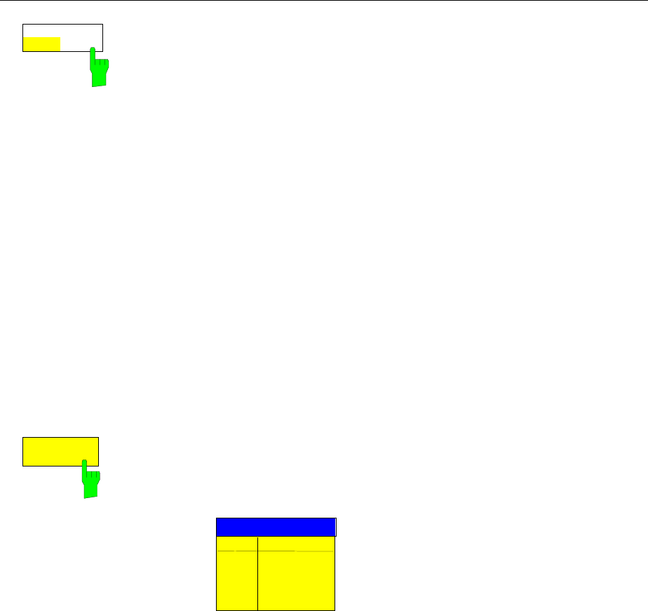
Main Markers FSE
1065.6016.12 4.116 E-15
CH FILTER
ON OFF
The CH FILTER ON/OFF softkey switches a modulation filter for the channel
power and adjacent channel power measurement on or off.
When selecting the digital mobile-radio standards NADC, TETRA and W-
CDMA 3 GPP (FWD and REV) using the ACP STANDARD softkey, the
softkey is automatically set to ON. When the other standards are selected,
weighting is not selectable and the softkey is not available.
CH FILTER ON The channel bandwidth is defined by the filter weighting
alone. Therefore, the CHANNEL BANDWIDTH softkey
cannot be operated.
The activated modulation filter influences the channel
and adjacent channel power measurement.
Within the definition range of the filter, the individual
pixels are weighted with the calculated filter attenuation
as a function of the spacing to the channel center. The
weighted display points are then added to the total
channel power.
CH FILTER OFF No modulation filter is switched on.
IEC/IEEE-bus command
:CALCulate<1|2>:MARKer<1..4>:FUNCtion:POWer:CFIL ON|OFF
CHANNEL
BANDWIDTH
The CHANNEL BANDWIDTH softkey opens an entry window for setting the
channel bandwidth for the transmission channel and the corresponding
adjacent channels.
For all channels, the default setting is 14 kHz.
ACP CHANNEL BW
CHAN BANDWIDTH
CH 14 kHz
ADJ 14 kHz
ALT1 14 kHz
ALT2 14 kHz
Note: If the bandwidth of one channel is changed, the new value is also
assigned to all subsequent channels in the table. The bandwidths
for the individual channels can be set independently, however, by
overwriting the table from the top to the bottom.
IEC/IEEE-bus commands
:[SENSe<1|2>:]POWer:ACHannel:BWIDth[:CHANnel] 24KHZ
:[SENSe<1|2>:]POWer:ACHannel:BWIDth:ACHannel 24KHZ
:[SENSe<1|2>:]POWer:ACHannel:BWIDth:ALTernate<1|2> 24KHZ
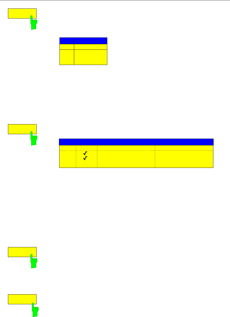
FSE Main Markers
1065.6016.12 4.117 E-15
CHANNEL
SPACING
The CHANNEL SPACING softkey opens an table for defining the channel
spacing. The channel spacing is the spacing of the center frequency of a
given channel relative to the center of the transmission channel.
The default setting for channel spacing is 20 kHz.
CHANNEL SPACING
CHAN SPACING
ADJ 20 kHz
ALT1 40 kHz
ALT2 60 kHz
Note: Channel spacings can be selected separately for each channel. If a
spacing value is changed in the table, the following values are
changed automatically.
IEC/IEEE-bus commands
:[SENSe<1|2>:]POWer:ACHannel:SPACing[:UPPer] 24KHZ
:[SENSe<1|2>:]POWer:ACHannel:SPACing:ACHannel 24KHZ
:[SENSe<1|2>:]POWer:ACHannel:SPACing:ALT<1|2> 24KHZ
EDIT
ACP LIMITS
The EDIT ACP LIMITS opens a table for defining the limits for ACP-
measurement.
ACP LIMITS
CHAN CHECK LOWER CHANNEL LIMIT UPPER CHANNEL LIMIT
ADJ -50 dB -50 dB
ALT1 -60 dB -60 dB
ALT2
The limit values are defined either in units of dB (forCP/ACP REL) or in dBm
(for CP/ACP ABS).
Note: Measured values that exceed one of the limits are marked with an
preceding asterisk.
IEC/IEEE-bus commands
:CALCulate<1|2>:LIMit<1..8>:ACP:ACHannel 30DB, 30DB
:CALCulate<1|2>:LIMit<1..8>:ACP:ACHannel:STATe ON|OFF
:CALCulate<1|2>:LIMit<1..8>:ACP:ALT<1|2> 30DB, 30DB
:CALCulate<1|2>:LIMit<1..8>:ACP:ALT<1|2>:STATe ON|OFF
LIMIT
CHECK
The LIMIT CHECK softkey switches on or off the limit check of the ACp
measurement.
IEC/IEEE-bus commands
:CALCulate<1|2>:LIMit:ACPower[:STATe] ON | OFF
:CALCulate<1|2>:LIMit<1..8>:ACP:ACHannel:RESult?
:CALCulate<1|2>:LIMit<1..8>:ACP:ALTernate<1|2>:RESult?
% POWER
BANDWIDTH
The % POWER BANDWIDTH softkey opens an entry window for defining the
percentage of the power with respect to the total power in the displayed
frequency range. This defines the occupied bandwidth (percent of the total
power).
The permitted range is 10 % - 99,9 %
IEC/IEEE-bus command :[SENSe<1|2>:]POWer:BANDwidth 99PCT
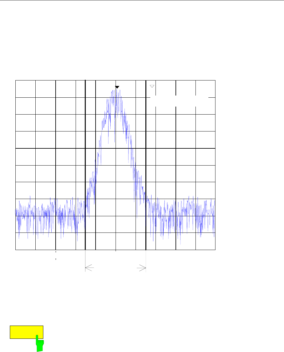
Main Markers FSE
1065.6016.12 4.118 E-15
Channel Power Measurement
The CHANNEL POWER measurement is performed by an integration of the measurement points within
the channel bandwidth. The channel is marked by two vertical lines to the left and to the right of the
center frequency as defined by the channel bandwidth (see Fig. 4-4).
Ref Lvl
-20 dBm
RBW 300 Hz
VBW 300 Hz
SWT 100 ms
Marker [T1]
200.0100 MHz
-22.4 dBm
Span 100 kHz
0
-20
-40
-60
-80
-100
10 kHz/
-10
-30
-50
-70
-90
1
Center 200 MHz
RF ATT 10 dB
Mixer -30 dBm
Unit dBm
channel width
CH BW 30.0 kHz
CH PWR -18.0 dBm
1 -24.5 dBm
200.000590 MHz
Fig. 4-4 Determination of the channel width
MARKER NORMAL menu:
CHANNEL
POWER
The CHANNEL POWER softkey initiates the calculation of the power in the
measurement channel. The display takes place in the units of the y axis, e.g.,
in dBm, dBµV.
The calculation is performed by summing the power at the pixels within the
specified channel.
The measurement is either absolute or relative to a reference power (see the
CP/ACP ABS/ REL softkey).
IEC/IEEE-bus commands
:CALCulate<1|2>:MARKer<1..4>:FUNC:POW:SELect CPOWer;
:CALCulate<1|2>:MARKer<1..4>:FUNC:POW:RESult? CPOWer;
:CALCulate<1|2>:MARKer<1..4>:FUNC:POW[:STATe] OFF

FSE Main Markers
1065.6016.12 4.119 E-15
CP/ACP
ABS REL
The CP/ACP ABS/REL softkey (Channel Power/Adjacent Channel Power
Absolute /Relative) switches between an absolute and relative display of the
power measured in the channel or adjacent channel.
Channel power measurement
CP ABS The absolute value of the power is displayed in the unit of the
Y axis, eg in dBm, dBV.
CP REL The power of a freely selected channel is measured. This
power is set in relation to the power of a reference channel.
The reference channel power is selected beforehand using
the SET CP REFERENCE softkey, ie:
1. Declare the power in the currently measured channel as
the reference value using the SET CP REFERENCE
softkey.
2. Set the channel of interest by changing the channel
frequency (FSE center frequency).
In case of linear scale of the Y axis the relative power
(CP/CPref) of the new channel is displayed in addition to the
reference channel. In case of dB scale, the logarithmic ratio
20×log (CP/CPref) is displayed.
Therefore, the relative channel power measurement can also
be used for universal adjacent channel power measurements.
Example:
Measurement of the 1597-QCDMA adjacent channel power.
The useful channel and the adjacent channels have different
bandwidths (1.23 MHz or 30 kHz).
Adjacent channel power measurement
The power of the adjacent channels is measured. The
reference value is the power of the useful channels (see
measurement of the adjacent channel power). The useful
channel is marked by two vertical lines that are labelled with
C0.
ACP ABS The powers of the useful channel and of the adjacent
channels are displayed as absolute values in the unit of the Y
axis.
ACP REL The logarithmic ratio 20×log (CP/CP0) of the powers of the
adjacent channels to the useful channel is displayed
The softkey is not available for OCCUPIED PWR BANDWIDTH, C/N and
C/N0
IEC/IEEE-bus command
:[SENSe<1|2>:]POWer:ACHannel:MODE ABS|REL
SET CP
REFERENCE
The SET CP REFERENCE softkey sets the reference value to the currently
measured channel power for an activated CHANNEL POWER power
measurement,.
IEC/IEEE-bus command
:[SENSe<1|2>:]POWer:ACHannel:REF:AUTO ONCE

Main Markers FSE
1065.6016.12 4.120 E-15
Signal / Noise Power Measurement
MARKER NORMAL menu:
C / N
The C/N (Carrier to Noise) softkey calculates the ratio of carrier power to
noise power and the power of interference signals in the channel defined
under POWER MEAS SETTING. For the measurement, a marker must be
set to the carrier of interest.
The unit of C/N is dB when the display is logarithmic. When the display is
linear, C/N is shown without a unit.
IEC/IEEE-bus commands
:CALCulate<1|2>:MARKer<1...4>:FUNCtion:POW:SELect CN;
:CALCulate<1|2>:MARKer<1...4>:FUNCtion:POW:RESult? CN;
:CALCulate<1|2>:MARKer<1...4>:FUNCtion:POW[:STATe] OFF
C / N
0
The C/N0 softkey starts the C/N0 measurement.
In contrast to the C/N measurement, C/N calculates the ratio of carrier
power to noise and interference signals based on a 1 Hz bandwidth in the
channel defined under POWER MEAS SETTING.
The unit of C/No is dB/Hz when the display is logarithmic and 1/Hz when the
display is linear.
IEC/IEEE-bus commands
:CALCulate<1|2>:MARKer<1...4>:FUNCtion:POW:SELect CN0;
:CALCulate<1|2>:MARKer<1...4>:FUNCtion:POW:RESult? CN0;
:CALCulate<1|2>:MARKer<1...4>:FUNCtion:POW[:STATe] OFF
Measurement procedure:
1. Activate a marker and position it to the peak of the carrier signal (e.g., with the Marker -> Peak
softkey).
2. Select With the desired frequency range (channel) with the FREQUENCY CENTER and CHANNEL
BANDWIDTH (POWER MEAS SETTING sub-menu) softkeys.
3. Press the C/N or C/N0 softkey. The marker is set to reference fixed and activates each
measurement. It must be observed that the carrier is either located outside of the measurement
channel or turned off at the UUT (Unit Under Test).
4. Press the ADJUST CP SETTINGS softkey to active the default settings with modified channel
parameters.
The measurement values for C/N or C/No are displayed in the marker info field.
Notes: – If no carrier marker was set, only N or No with the appropriate units is displayed.
–Is the carrier located inside the measurement channel, C/C+N or C/C+N0 will be displayed
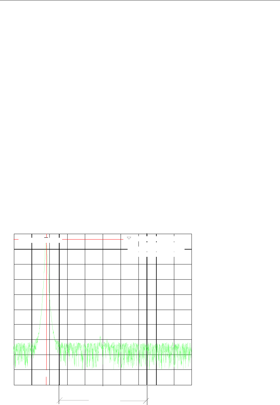
FSE Main Markers
1065.6016.12 4.121 E-15
Example:
The signal-to-noise ratio of the carrier (f = 199.9 MHz) in the channel with +100 kHz separation from 200
MHz (channel center frequency) is to be measured. The channel bandwidth is 150 kHz.
1. Using the CENTER key, set the center frequency to the channel center frequency 200 MHz.
2. Using the SPAN key, set the span, e.g., to 1 MHz (carrier must be visible).
3. Using the MARKER NORMAL key, activate MARKER 1 (If Marker 1 was not yet active, the function
MARKER
→
PEAK is automatically executed. In this case, skip step 4.)
4. Using the MARKER
→
PEAK key, set MARKER 1 on the carrier (assumption: the 200 MHz carrier has
the highest level in the selected span).
5. Press the MARKER NORMAL key and change to the left-hand supplementary menu.
6. Using the POWER MEAS SETTING softkey, call the sub-menu for defining the measurement channel.
7. Using the CHANNEL BANDWIDTH: softkey, set the bandwidth to 150 kHz (The channel spacing
does not need to be entered for this measurement). Then press ⇑ menu change key.
8. Using the C/N softkey, start the C/N measurement. In the marker info field, the outputs CHANNEL
CENTER, CHANNEL BANDWIDTH as well as the corresponding C/N measurement values appear.
MARKER 1 is also set to reference fixed.
9. Using the ADJUST CP SETTINGS softkey, activate the default settings with modified channel
parameters (channel bandwidth = 150kHz) for the correct C/N measurement (span = 2 × channel
bandwidth = 300 kHz, RBW = 3 kHz, VBW = 10 kHz, detector: sampling ).
Two vertical lines mark the channel 200 MHz ± 75 kHz in which the noise measurement is performed
(see Fig.4-5). The reference value is the measurement from MARKER 1 (Reference Fixed).
Ref Lvl
-20 dBm
RBW 3 kHz
VBW 10 kHz
SWT 100 ms
Marker [T1]
-24.4 dBm
199.9020 MHz
Span 300 kHz
0
-20
-40
-60
-80
-100
30 kHz/
-10
-30
-50
-70
-90
1
Center 200 MHz
RF ATT 10 dB
Unit dBm
CHANNEL
BANDWIDTH
CH BW 150.00000000 kHz
C/N 65.43 dB
1
-24.4 dBm
199.90200000 MHz
FXD -20.702 dBm
FXD
Fig.4-5 Example: measurement of the signal/noise power

Main Markers FSE
1065.6016.12 4.122 E-15
Adjacent Channel Power
MARKER NORMAL menu:
ADJACENT
CHAN POWER
The ADJACENT CHAN POWER softkey starts the measurement of the
adjacent channel power.
The ADJACENT CHAN POWER measures the power which the transmitter
delivers to the two adjacent channels (upper channel , lower channel). The
measurement values are displayed according to the setting of the CH/ACD
ABS/REL softkey as absolute values in the scale of the X axis (see Fig.4-6)
or as a logarithmic ratio of adjacent channel to useful channel in dB (20 × log
(CP/CP0).
If the power of the other neighbouring channels is to be measured in addition
to the adjacent channel power, the number of adjacent channels can be
extended (on one side only) using SET NO. OF ADJ CHAN’S in the submenu
POWER MEAS SETTINGS.
IEC/IEEE-bus commands
:CALCulate<1|2>:MARKer<1...4>:FUNCtion:POW:SELect ACP;
:CALCulate<1|2>:MARKer<1...4>:FUNCtion:POW:RESult? ACP;
:CALCulate<1|2>:MARKer<1...4>:FUNCtion:POW[:STATe] OFF
A prerequisite for the correct measurement of the adjacent channel power is the correct setting of the
FSE center frequency, the channel bandwidth and the channel spacing. The CHANNEL SPACING and
CHANNEL BANDWIDTH are defined in the POWER MEAS SETTINGS sub-menu.
For an activated measurement of adjacent channel power, the analyzer itself optimally sets all other
values (span, resolution bandwidth, detector, etc.) after the ADJUST CP SETTINGS softkey is pressed.
The carrier power in the utilised channel, the power (absolute or relative to the utilised channel) in the
upper and lower adjacent channels as well as the largest of the two power values and the channel raster
with channel spacing and bandwidth are displayed as the result of the measurement. The C0 lines mark
the bandwidth of the carrier channel. Other unlabelled frequency lines mark the adjacent channels (see
Fig.4-6). With SET NO. OF ADJ CHAN’S 2 selected, the other two neighbouring channels (1st Alternate
Channels) are displayed as well, with SET NO. OF ADJ CHAN’S 3 selected, an additional channel each
(2nd Alternate Channels).
The measurement values are updated and displayed until the ADJACENT CHAN POWER softkey is
pressed again and the measurement of the adjacent channel power is stopped.
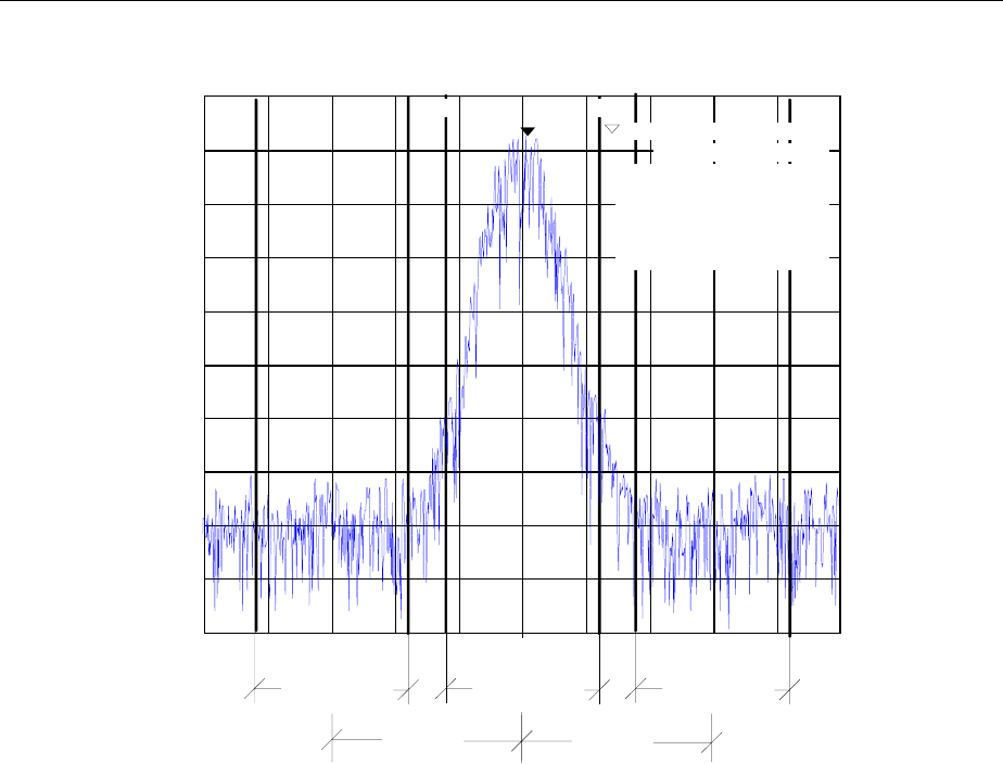
FSE Main Markers
1065.6016.12 4.123 E-15
Ref Lvl
-20 dBm
RBW 300 Hz
VBW 300 Hz
SWT 100 ms
Marker [T1]
-28.4 dBm
200.0100 MHz
Span 100 kHz
0
-20
-40
-60
-80
-100
10 kHz/
-10
-30
-50
-70
-90
1
Center 200 MHz
RF ATT 10 dB
Mixer -30 dBm
Unit dBm
Channel BW
C0 C0
Channel BWChannel BW
Channel
Spacing
Channel
Spacing
Upper
Channel
Lower
Channel
Transmit
Channel
1 -28.4 dBm
200.0100 MHz
CH0 PWR -18.3 dBm
ACP Max -67.23 dBm
ACP UP -67.23 dBm
ACP LOW -69.45 dBm
CH Space 30 kHz
Ch BW 24 kHz
Fig.4-6 Measurement of the adjacent channel power.
If the limit check is activated for ACP measurements, the result of the limit check (PASSED/FAILED) is
displayed as well as an asterisk preceding each measured ACP power that exceeded one of the limits.
Note: The limit check is activated and the limits are defined in the POWER MEAS SETTINGS menu.

Main Markers FSE
1065.6016.12 4.124 E-15
Occupied Bandwidth Measurement
An important characteristic of a modulated signal is the bandwidth which it occupies. In a radio
communications system, for instance, the occupied bandwidth must be limited prevent in adjacent
channel interferences. The occupied bandwidth is defined as the bandwidth in which a defined
percentage of the total transmitter power is contained. The percentage of the power can be set between
10 and 99% in the FSE.
MARKER NORMAL menu:
OCCUPIED
PWR BANDW
The OCCUPIED PWR BANDW (occupied power bandwidth) softkey starts
the measurement for determining the occupied bandwidth.
In the spectrum display mode, the bandwidth is determined in which a
predefined percentage of the power in the displayed bandwidth is contained.
(selectable in the POWER MEAS SETTINGS sub-menu with the : % POWER
BANDWIDTH softkey). The occupied bandwidth is output to the marker
display field and marked on the trace with temporary markers.
IEC/IEEE-bus command
:CALCulate<1|2>:MARKer<1...4>:FUNCtion:POW:SELect OBW
:CALCulate<1|2>:MARKer<1...4>:FUNCtion:POW:RESult? OBW
:CALCulate<1|2>:MARKer<1...4>:FUNCtion:POW[:STATe] OFF
Measurement principle:
For example, the bandwidth is to be found in which 99% of the signal power is contained. The routine
calculates first the total power of all displayed points (pixels) of the trace. In the next step, the
measurement points from the right edge of the trace are integrated until 0.5% of the total power is
reached. Then the FSE integrates, in an analog fashion, from the left edge of the trace until 0.5% of the
power is reached. The delta marker is positioned at this point. Thus, 99% of the power is located
between the two markers. The difference between the two frequency markers is the occupied bandwidth
which is displayed in the marker info field.
A prerequisite for the correct operation of the measurement is that only the signal to be measured is
visible on the display screen of the FSE. An additional signal would falsify the measurement.
In order to be able to perform correct power measurements, especially for noisy signals, and thus to
achieve the correct occupied bandwidth, the selection of the following parameters should be observed:
RBW << occupied bandwidth (≤ approx. 1/20 of the occupied bandwidth, for voice
communications, typ. 300 Hz or 1 kHz)
VBW ≥ 3 x RBW
detector sampling
span ≥ 2 to 3 x occupied bandwidth
According to the application or other measurement guidelines, it may be necessary or reasonable to
average a definite number of sweeps in order to achieve a usable value for the occupied bandwidth.
This is provided by the TRACE (1....4) key group and the averaging function. With the SWEEP COUNT
softkey, the number of averages is defined.
Some measurement instructions (e.g. PDC, RCR, STD-27B) require the occupied bandwidth to be
measured by means of a peak detector. In this case, the detector of the FSE must be corrected
appropriately.

FSE Main Markers
1065.6016.12 4.125 E-15
Parameters for Channel Power Measurements / Configuration
For the correct measurement of channel power, C/N, C/N0, adjacent channel power and occupied
bandwidth, it is recommended that an automatic optimisation of the analyzer settings be performed after
enabling the corresponding measurement and selecting the channel configuration (channel power
settings).
MARKER NORMAL menu:
ADJUST CP
SETTINGS
The ADJUST CP SETTINGS softkey optimises automatically the settings of
the analyzer for the selected power measurement (see below).
All relevant analyzer settings for a power measurement within a defined
frequency range (channel bandwidth) are optimally set including:
•span
•resolution bandwidth
•video bandwidth
•detector
dependent upon the channel configuration (channel bandwidth and, if
needed, channel spacing).
The trace mathematical functions and trace averaging are switched off.
The reference level is not influenced by the automatic optimisation routine.
The reference level is to be so adjusted that the signal maximum is located
near the reference level.
The optimisation is performed only once, however, if necessary, the
instrument settings may be changed later.
IEC/IEEE-bus command
:[SENSe<1|2>:]POWer:ACHannel:PRESet ADJust
Span The span should cover at least the frequency range that is to be observed. For
channel power measurements, C/N and C/N0, this is the channel bandwidth.
For adjacent channel power measurements, this is the utilised channel
bandwidth and the adjacent channels located within the channel spacing.
If the span is large compared to the observed frequency band(s), then only a
few points on the trace are available for the measurement.
The ADJUST CP SETTINGS softkey sets the span as follows:
2 × channel bandwidth for channel power, C/N, C/No or
2 × channel spacing + channel width for adjacent channel power
4 × channel bandwidth for adjacent channel power and NO.
OF ADJ CHAN‘S 2
6 × channel spacing + channel width for adjacent channel power and NO.
OF ADJ CHAN‘S 3
For measurements of the occupied bandwidth, the span is not influenced.

Main Markers FSE
1065.6016.12 4.126 E-15
Resolution bandwidth (RBW)
In order to achieve acceptable speed as well as the necessary selectivity (to
suppress spectral components outside of the channel to be measured and,
especially adjacent channels), the resolution bandwidth that is selected must
not be too narrow or too broad.
If the resolution bandwidth is too narrow, the measurement speed becomes
very slow and it is possible that relative spectral components are not displayed
(due to the sampling detector necessary for power measurements and the
finite number of points).
On the other hand, the resolution bandwidth should not be so broad that, due
to insufficient selection, spectral components outside of the observed
frequency range (from adjacent channel) falsify the measurement results.
The ADJUST CP SETTINGS softkey sets the resolution bandwidth (RBW)
dependent upon the channel bandwidth as follows:
RBW ≤ 1/40 of the channel bandwidth. The maximum possible RBW, with
due regard to the 1, 2, 3, 5 step size and the requirement RBW ≤ 1/40 will be
selected.
The RBW is not influenced by measurements of the occupied bandwidth.
Video bandwidth (VBW) Since a power measurement of the noise components is also necessary
(otherwise, errors occur due to the logarithmic characteristics of the spectrum
analyzer), the video bandwidth should be slected to be substantially larger
than the resolution bandwidth.
The ADJUST CP SETTINGS softkey adjusts the video bandwidth (VBW)
dependent upon the channel bandwidth as follows:
VBW ≥ 3* RBW. The minimum VWB with regard to the available 1, 2, 3, 5
step size is selected.
Grid scale The ADJUST CP SETTINGS softkey sets the grid scale to the 100-dB range.
Thereby, a wide dynamic range in channel power measurements is achieved.
Detector The ADJUST CP SETTINGS softkey selects the sampling detector.
The sampling detector is to be selected, above all, for correct power
measurements of noisy signals within the observed frequency range.
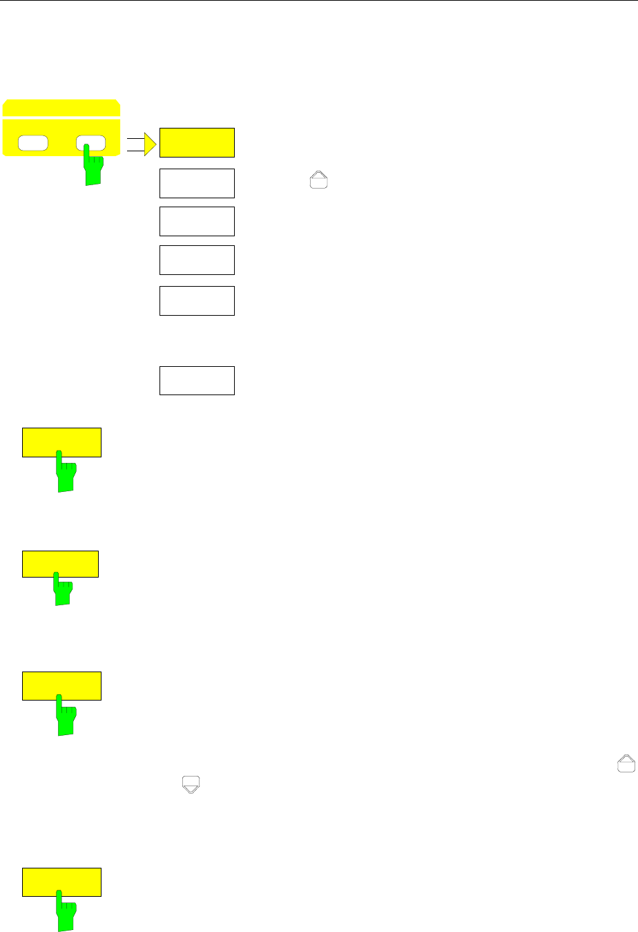
FSE Main Markers
1065.6016.12 4.127 E-15
Marker Step Size
DATA VARIATION – STEP menu:
STEPSIZE
MANUAL
MKR TO
STEPSIZE
MARKER
STEP SIZE
STEP
DATA VARIATION
HOLD
STEPSIZE
AUTO
.
.
.
DELTA TO
STEPSIZE
The STEP key in the DATA VARIATION key group opens a
menu to match the marker step size to each individual
application. In order to change the step size, the marker entry
mode must already be active.
Control is returned to the MARKER NORMAL menu via the
menu key .
STEPSIZE
AUTO
The STEPSIZE AUTO softkey sets the marker step size to AUTO. In this
case, the step size is exactly 10% of the grid. A one-raster movement of the
roll-key corresponds to one pixel.
STEPSIZE AUTO is the default setting.
IEC/IEEE-bus command
:CALCulate<1|2>:MARKer<1..4>:STEP:AUTO ON|OFF
STEPSIZE
MANUAL
The STEPSIZE MANUAL softkey activates the entry window for defining a
fixed value for the marker step size.
Pressing the step key shifts the marker position by the selected step size.
The resolution of the roll-key is always one pixel per raster.
IEC/IEEE-bus command
:CALCulate<1|2>:MARKer<1..4>:STEP 10KHZ
MKR TO
STEPSIZE
The MKR TO STEPSIZE softkey sets the marker step size to the current
marker frequency or marker time.
In the frequency domain, this function is well suited to harmonic
measurements. The marker is set to the largest signal using the peak search
function. After activation of the MKR TO STEPSIZE function, the marker is
set to the corresponding harmonic of the signal each time the cursor key
or is pressed when entering the marker position (see also Chapter 2,
"Measurement Examples").
IEC/IEEE-bus command
:CALCulate<1|2>:MARKer<1..4>:FUNCtion:MSTep
DELTA TO
STEPSIZE
The DELTA TO STEPSIZE softkey sets the marker step size to the
difference between the reference marker and the last active delta marker.
The softkey is only available when at least one delta marker is enabled.
IEC/IEEE-bus command --
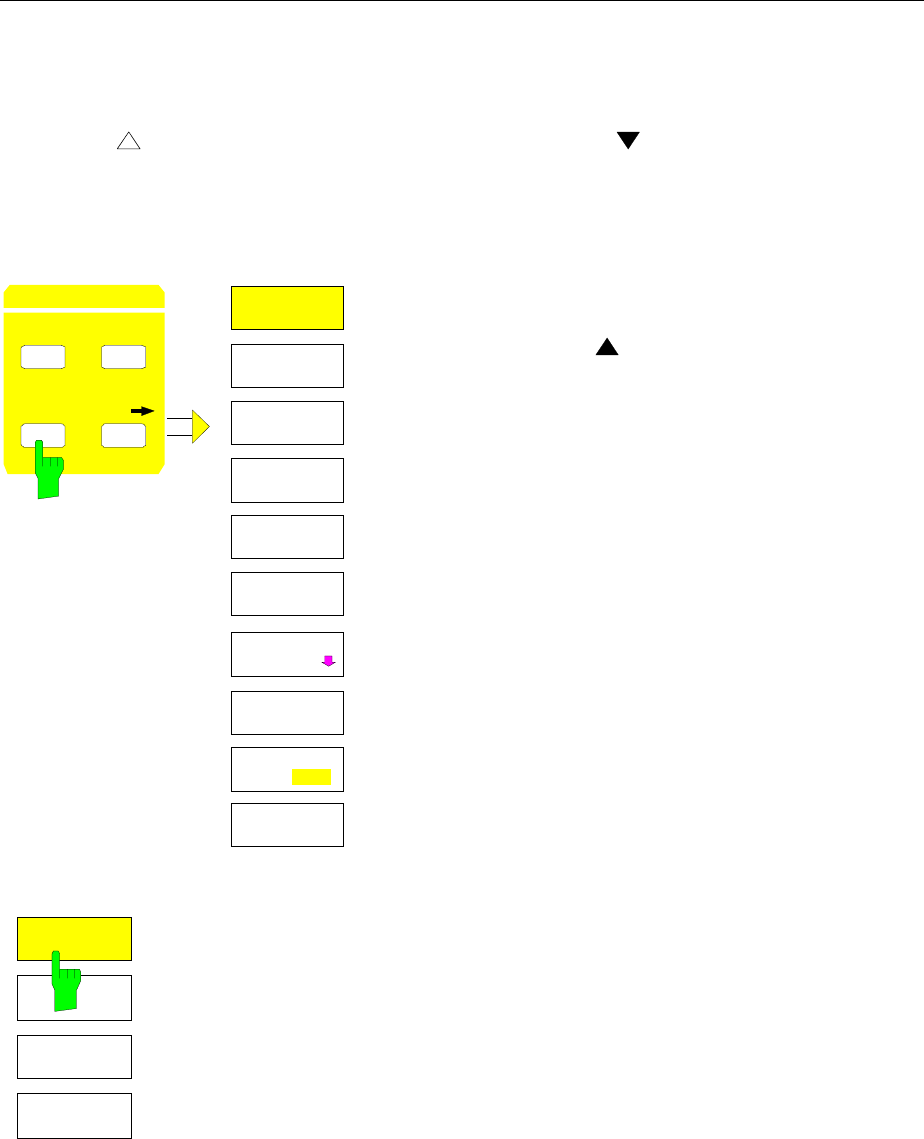
Delta Markers FSE
1065.6016.12 4.128 E-15
Delta Markers – DELTA Key
The delta marker.s are used to measure a level or frequency referred to a reference marker. They are
always referenced to the marker whose position was last changed. A delta marker is displayed
as an empty symbol. The reference marker is displayed as a filled symbol.
MARKER DELTA menu:
NORMAL SEARCH
MARKER
DELTA
MKR
DELTA
MARKER
DELTA 2
DELTA 3
PHASE
NOISE
DELTA 1
REFERENCE
FIXED
DELTA 4
ALL DELTA
OFF
REFERENCE
POINT
DELTA MKR
ABS REL
The DELTA key switches a delta marker on and calls the
menu for its control. If no marker is enabled, MARKER 1 is
automatically activated when the delta marker is switched on.
The delta marker activated to entry mode is shown on the
display screen as a filled symbol.
DE A 2
DELTA 3
DELTA 1
DELTA 4
The DELTA 1 to 4 softkeys are used to enable delta markers 1...4. The
control of the delta markers corresponds to that of the markers. After a delta
marker has been enabled, all entries are now applicable to this marker. The
main marker must be activated anew if its position is to be changed.
The delta marker field on the display screen contains the delta marker
number, the difference frequency from the delta marker to reference marker
and the level difference between the active delta markers and reference
markers.
The indicated differences are, in general, referred to the reference marker. If
the PHASE NOISE or REFERENCE FIXED functions are enabled, the
reference values under REFERENCE POINT are applicable.
IEC/IEEE-bus commands
:CALCulate<1|2>:DELTamarker<1..4> ON|OFF
:CALCulate<1|2>:DELTamarker<1..4>:X 10.7MHZ
:CALCulate<1|2>:DELTamarker<1..4>:X:REL?
:CALCulate<1|2>:DELTamarker<1..4>:Y

FSE Delta Markers
1065.6016.12 4.129 E-15
DELTA MKR
ABS REL
The DELTA ABS REL softkey switches between relative and absolute entry
modes for the delta-marker frequency.
In the REL position, the delta marker frequency is entered relative to the
reference marker. In this case, the entry mode for the delta-marker
frequencies is also relative.
In the ABS position, the entry of the delta-marker frequency is in terms of
absolute frequency.
The default setting is REL.
IEC/IEEE-bus command
:CALCulate<1|2>:DELTamarker<1..4>:MODE ABS | REL
ALL DELTA
OFF The ALL DELTA OFF softkey switches off all active delta markers and any
associated functions (e.g. REFERENCE FIXED, PHASE NOISE).
IEC/IEEE-bus command
:CALCulate<1|2>:DELTamarker<1...4>:AOFF
REFERENCE
FIXED
The REFERENCE FIXED softkey enables/disables relative measurements
with respect to a fixed, measurement-curve-independent reference value.
The information in the delta-marker field on the display screen is referenced
to this fixed reference value. For the generation of the marker lists using
MARKER INFO list, the delta markers are also output relative to a fixed
reference. In the lists, the REFERENCE POINT is tagged by the number of
the reference marker (only one enabled)
When REFERENCE FIXED is enabled, the current settings of the reference
marker become the reference values. If no marker is active, MARKER 1 (with
peak search) is activated. After transferring the reference values, all markers
are deleted, and the active delta marker is set to the position of the reference
value. Additional delta markers can be switched on.
The reference value can be subsequently changed
1. by shifting it in the REFERENCE POINT sub-menu.
2. by starting a search:
In the MARKER NORMAL menu the REF POINT is handled as a reference
marker (even though it is not bound to the trace). This means, that it will be
shown as enabled and can also be changed in position. The co-ordinates
of the REF POINT are overwritten by the marker values (they lie, by
definition, on the trace). Thus, it is possible, even for an enabled
REFERENCE FIXED, to define a new reference point function with search
functions.
The REFERENCE FIXED function is particularly useful for measurements
which are performed relative to a reference signal that is not available during
the whole measurement time (e. g. harmonics measurements, see chapter
"Measurement Example").
IEC/IEEE-bus command
:CALCulate<1|2>:DELTamarker<1..4>:FUNCtion:FIXed ON|OFF
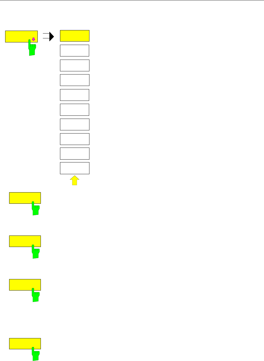
Delta Markers FSE
1065.6016.12 4.130 E-15
MARKER DELTA- REFERENCE POINT submenu:
REFERENCE
POINT
REFERENCE
POINT
REF POINT
LEVEL
REF POINT
LVL OFFSET
REF POINT
FREQUENCY
REF POINT
TIME
The REFERENCE POINT softkey opens a sub-menu in which
the reference value the REFERENCE FIXED and PHASE
NOISE functions can be modified.
The position of the reference value is indicated by two
additional display lines (horizontal and vertical). In addition, an
offset level may be defined which is added to each difference
during output.
The softkey is only available when the REFERENCE FIXED or
PHASE NOISE function is switched on.
REF POINT
LEVEL
The REF POINT LEVEL softkey activates an entry box for setting the
reference level relevant to the REFERENCE FIXED or PHASE NOISE.
functions.
IEC/IEEE-bus command
:CALCulate<1|2>:DELT<1..4>:FUNC:FIXed:RPOint:Y -10DBM
REF POINT
FREQUENCY
The REF POINT FREQUENCY softkey activates the entry box for the input of
a reference frequency for the REFERENCE FIXED or PHASE NOISE.
functions.
IEC/IEEE-bus command
:CALCulate<1|2>:DELT<1..4>:FUNC:FIXed:RPOint:X 10.7MHZ
REF POINT
LVL OFFSET
The REF POINT LVL OFFSET softkey activates the entry box for the entry of
an additional offset level during output when the REFERENCE FIXED or
PHASE NOISE. functions are enabled.
The offset level is set to 0 dB when the REFERENCE FIXED or PHASE
NOISE. functions are switched on.
IEC/IEEE-bus command
:CALCulate<1|2>:DELT<1..4>:FUNC:FIX:RPO:Y:OFFSet 10DB
REF POINT
TIME
The REF POINT TIME softkey activates the entry box for the input of a
reference time for the REFERENCE FIXED function in the time domain
(span = 0).
The entry of a reference time for the PHASE NOISE function is not possible.
IEC/IEEE-bus command
:CALCulate<1|2>:DELT<1..4>:FUNC:FIXed:RPOint:X 100ms

FSE Delta Markers
1065.6016.12 4.131 E-15
Phase Noise Measurement
MARKER DELTA menu:
PHASE
NOISE The PHASE NOISE softkey switches the PHASE NOISE function on/off.
When PHASE NOISE measurement is switched on, the frequency and level
of the reference marker are used as fixed reference values, i.e. the
REFERENCE FIXED function is activated.
The difference between this reference point and the active delta markers is
determined. The correction factors for bandwidth and the logarithmic
converter are automatically taken into account. The sampling detector is
automatically seleced to allow the effective noise power to be displayed. The
measured values are displayed in the delta marker field in units of dBc/Hz.
If several delta markers are enabled, only the measurement value output of
the active marker is shown in the marker field. Using MARKER INFO and
MARKER LIST the measurement data of all delta markers can be displayed.
If no marker is present when the PHASE NOISE function is enabled,
MARKER 1 is automatically switched on (peak search), and the marker
values are saved as reference values. The reference value can be changed
later in the NORMAL menu, SEARCH menu or REFERENCE POINT sub-
menu (see REFERENCE FIXED softkey).
Turning on an additional marker causes the PHASE NOISE function to be
disabled.
IEC/IEEE-bus commands
:CALCulate<1|2>:DELTamarker<1..4>:FUNC:PNOise ON | OFF
:CALCulate<1|2>:DELTamarker<1..4>:FUNC:PNOise:RESult?
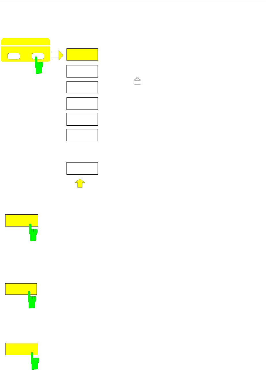
Delta Markers FSE
1065.6016.12 4.132 E-15
Delta-Marker Step Size - STEP Key
STEP-DELTA STEP menu:
STEPSIZE
MANUAL
DELTA
STEP SIZE
STEP
DATA VARIATION
HOLD
STEPSIZE
AUTO
DELTA TO
STEPSIZE
.
.
.
The STEP key in the DATA VARIATION key group opens a
menu to match the step size of the individual delta markers
to the specific application. In order to change the step size,
the entry mode for a delta marker must already be active.
Control is returned to the DELTA MARKER menu via the
menu key .
STEPSIZE
AUTO
The STEPSIZE AUTO softkey sets the delta marker step size to AUTO. In
this case, the step size of the delta marker is exactly 10% of the grid. The
roll-key corresponds to 1/500, i.e., for each rotational pulse, the delta
marker is shifted one pixel position.
IEC/IEEE-bus command
:CALCulate<1|2>:DELTamarker<1..4>:STEP:AUTO ON | OFF
STEPSIZE
MANUAL
The STEPSIZE MANUAL softkey permits the entry of a fixed value for the
delta marker step size.
Pressing the step-key shifts the marker position by the selected step size.
The roll-key resolution, however, always remains constant at 1 pixel.
IEC/IEEE-bus command --
DELTA TO
STEPSIZE
The DELTATO STEPSIZE softkey sets the delta marker step size to a
quantity equal to the difference between the delta and reference markers.
The softkey is only presented when at least one delta marker is switched
on.
IEC/IEEE-bus command
:CALCulate<1|2>:DELTamarker<1..4>:STEP 10HZ
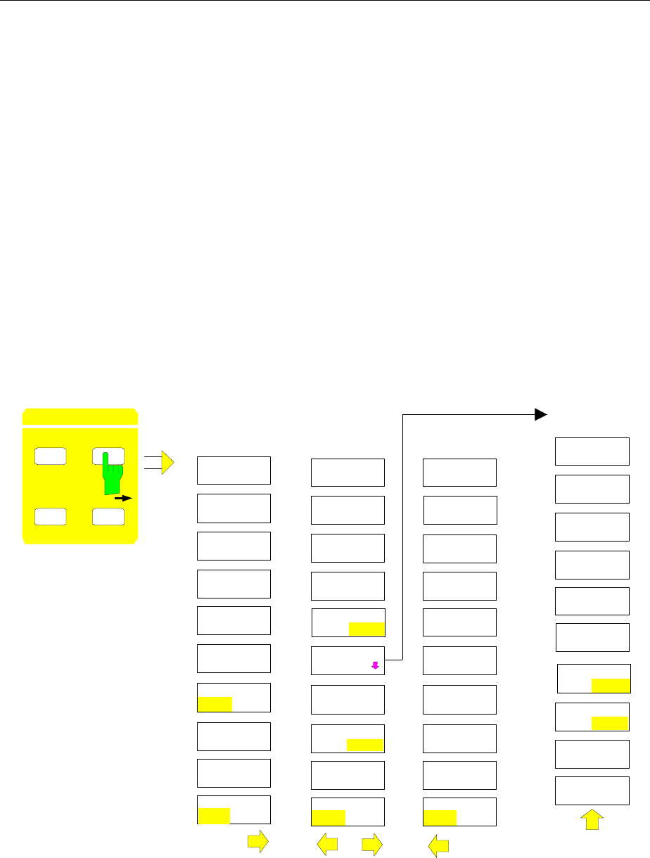
FSE Search Functions
1065.6016.12 4.133 E-15
Search Functions – SEARCH Key
The FSE offers numerous functions useful for peak/min. peak searching. The search functions can be
used for marker as well as delta marker functions.
The setups applicable to the available search functions are performed in the MARKER-SEARCH menu.
The search functions are always related to the currently active marker. If the SEARCH key is pressed
while the marker entry mode is active, then all search functions are related to the current reference
marker. If the entry mode of a delta marker is active, then the functions will be applied to the
corresponding delta marker. For the case where no marker is active, MARKER 1 will be automatically
enabled (with peak search). The ACTIVE MKR / DELTA softkey allows toggling between the active
marker and the active delta marker.
If the threshold line is turned on, the peak/min. search functions will only evaluate signals which have a
level above/below the selected threshold. In addition, the search range can also be limited (SEARCH
LIM ON/OFF softkey) by the frequency/time lines (FREQUENCY LINE 1/2, TIME LINE 1/2).
For all peak search functions, the first local oscillator is omitted at 0 Hz if it happens to be displayed.
In the time domain display, the summary markers can be activated and set in addition to the search
functions in menu MARKER-SEARCH.
MARKER SEARCH menu:
MARKER
DELTA MKR
NORMAL SEARCH MARKER
SEARCH
N DB DOWN
SHAPE FACT
60 /6 DB
MARKER
SEARCH
NEXT PEAK
NEXT PEAK
RIGHT
NEXT PEAK
LEFT
MIN
NEXT MIN
NEXT MIN
RIGHT
MARKER
SEARCH
SELECT
MARKER
SHAPE FACT
60 /3 DB
ACTIVE
MKR DELTA
NEXT MIN
LEFT
PEAK
PEAK
EXCURSION
ACTIVE
MKR DELTA
ACTIVE
MKR DELTA
SEARCH LIM
ON OFF
SUM MKR
ON OFF
SUMMARY
MARKER
RMS
SUMMARY
MARKER
AVERAGE
SWEEP
COUNT
ALL SUM
MKR OFF
MEAN
ON OFF
PEAK HOLD
ON OFF
SELECT
MARKER SELECT
MARKER
EXCLUDE LO
ON OFF
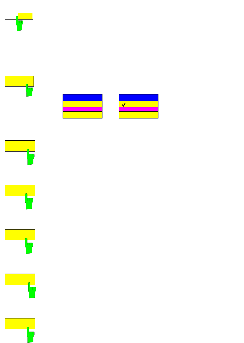
Search Functions FSE
1065.6016.12 4.134 E-15
ACTIVE
MKR DELTA
The ACTIVE MKR / DELTA softkey toggles between the active marker and
the active delta marker.
If DELTA is illuminated, the following search functions are performed with the
active delta marker.
Note: Switching between marker and delta marker entry modes may
also be performed using the NORMAL and DELTA keys.
IEC/IEEE-bus command --
SELECT
MARKER
The SELECT MARKER softkey activates the selection of the marker/delta
markers. The selection box lists the currently enabled markers/delta markers.
MARKER SELECT
MARKER 1
MARKER 3
MARKER 4
DELTA SELECT
DELTA 1
DELTA 2
DELTA 3
IEC/IEEE-bus command --
PEAK
The PEAK softkey sets the active marker/delta marker to the maximum
displayed value on the corresponding trace.
IEC/IEEE-bus commands
:CALCulate<1|2>:MARKer<1..4>:MAXimum
:CALCulate<1|2>:DELTamarker<1..4>:MAXimum
NEXT PEAK
The NEXT PEAK softkey sets the active marker/delta marker to the trace
value next in magnitude after the peak.
IEC/IEEE-bus commands
:CALCulate<1|2>:MARKer<1..4>:MAX:NEXT
:CALCulate<1|2>:DELTamarker<1..4>:MAX:NEXT
NEXT PEAK
The NEXT PEAK RIGHT softkey sets the active marker to the next peak to
the right of the current marker position.
IEC/IEEE-bus commands
:CALCulate<1|2>:MARKer<1..4>:MAX:RIGHt
:CALCulate<1|2>:DELTamarker<1..4>:MAX:RIGHt
NEXT PEAK
RIGHT
The NEXT PEAK LEFT softkey sets the active marker to the next peak to the
left of the current marker position.
IEC/IEEE-bus commands
:CALCulate<1|2>:MARKer<1..4>:MAX:LEFT
:CALCulate<1|2>:DELTamarker<1..4>:MAX:LEFT
MIN
The MIN softkey sets the active marker to minimum displayed value on the
corresponding trace.
IEC/IEEE-bus commands
:CALCulate<1|2>:MARKer<1..4>:MIN
:CALCulate<1|2>:DELTamarker<1..4>:MIN
FSE Search Functions
1065.6016.12 4.135 E-15
NEXT MIN
The NEXT MIN softkey sets the active marker to the next higher of the low
peaks on the corresponding trace.
IEC/IEEE-bus commands
:CALCulate<1|2>:MARKer<1..4>:MIN:NEXT
:CALCulate<1|2>:DELTamarker<1..4>:MIN:NEXT
NEXT MIN
RIGHT
The NEXT MIN RIGHT softkey set the active marker to the next low peak to
the right of the current marker position.
IEC/IEEE-bus commands
:CALCulate<1|2>:MARKer<1..4>:MIN:RIGHt
:CALCulate<1|2>:DELTamarker<1..4>:MIN:RIGHt
NEXT MIN
LEFT
The NEXT MIN LEFT softkey sets the active marker to the next low peak to
the left of the current marker position.
IEC/IEEE-bus command
:CALCulate<1|2>:MARKer<1...4>:MIN:LEFT
:CALCulate<1|2>:DELTamarker<1...4>:MIN:LEFT
EXCLUDE LO
ON OFF
The EXCLUDE LO ON/OFF softkey switches between a restriced (ON) and
an unrestricted search range (OFF).
ON Because of non-ideal input mixer, the first LO of any analyzer can be
seen at 0 Hz. The search functions can possibly respond to this LO
level, in particular in the preset setting (FULL SPAN). To prevent
this, the search range is restricted according to the following
formula:
Search range ≥ 6 × resolution bandwidth
OFF No restriction on the search range. The search functions find also
signals below the frequency limit quoted above.
IEC/IEEE-bus command
:CALCulate<1|2>:MARKer<1..4>:LOEXclude ON|OFF
PEAK
EXCURSION
The PEAK EXCURSION softkey activates the entry box which sets the
minimum amount a signal level must decrease/increase before it is
recognised by the search functions (except PEAK and MIN) as a maximum or
minimum.
Input values from 0 dB to 80 dB are allowed with a resolution of 0.1 dB.
IEC/IEEE-bus command
:CALCulate<1|2>:MARKer<1..4>:PEXCursion 10DB
The peak excursion is preset to 6 dB. This is sufficient for the functions NEXT
PEAK (or NEXT MIN) as the next smallest (or next largest) signal is always
searched for.
Functions NEXT PEAK LEFT and NEXT PEAK RIGHT (or NEXT MIN LEFT
and NEXT MIN RIGHT) search for the next relative maximum (or minimum)
irrespective of the current signal amplitude.
As for wide bandwidths, the intrinsic noise of the FSE may equal the 6 dB level
change preset for PEAK EXCURSION and so noise peaks are identified as
signal peaks
In this case, a value for PEAK EXCURSION which is higher than the
difference between the maximum and minimum noise display reading must be
entered.
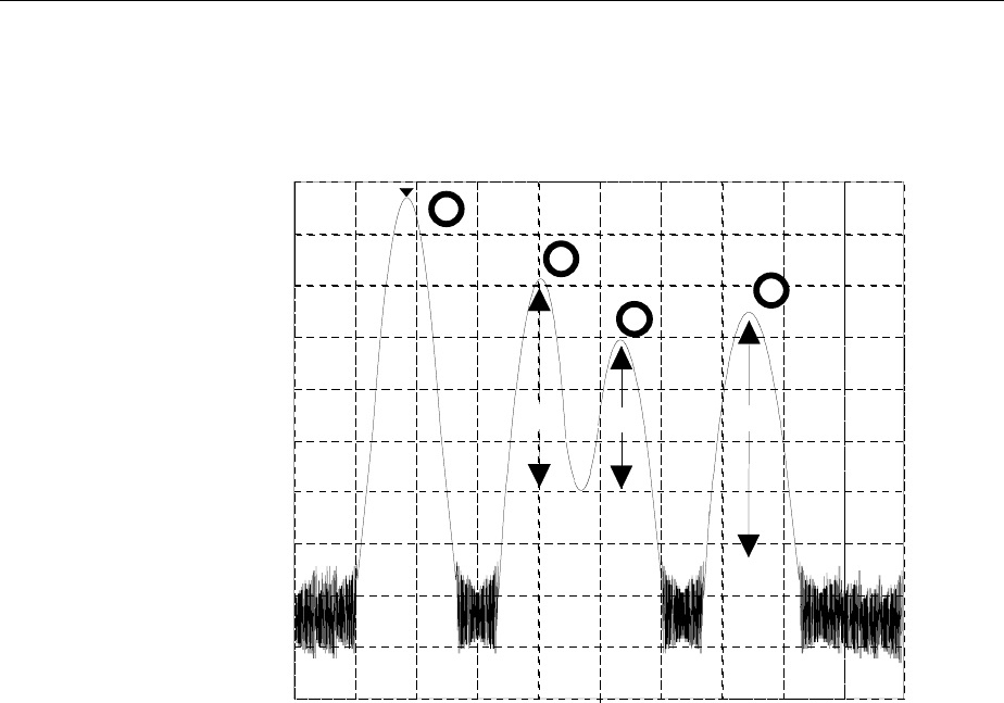
Search Functions FSE
1065.6016.12 4.136 E-15
The following example shows the effect of different PEAK EXCURSION
settings.
Marker [T1]
199.0140 MHz
-22.4 dBm
0
-20
-40
-60
-80
-100
-10
-30
-50
-70
-90
1
42dB 30dB 46dB
1
2
3
4
Fig. 4-7 Example for level measurements at various peak excursion settings
Maximum relative level change of the measured signals:
Signal 2: 42dB
Signal 3 30dB
Signal 4: 46dB
With Peak Excursion 40dB signals 2 and 4 are detected by NEXT PEAK or
NEXT PEAK RIGHT. Signal 3 is not detected since it is only decreased by 30
dB before rising again.
Order in which signals are found:
PEAK: Signal 1 or PEAK: Signal 1
NEXT PEAK: Signal 2 NEXT PEAK RIGHT: Signal 2
NEXT PEAK: Signal 4 NEXT PEAK RIGHT: Signal 4
With Peak Excursion 20dB signal 3 is detected as well since its highest level
change of 30 dB is now higher than the peak excursion.
Order in which signals are found:
PEAK: Signal 1 or PEAK: Signal 1
NEXT PEAK: Signal 2 NEXT PEAK RIGHT: Signal 2
NEXT PEAK: Signal 4 NEXT PEAK RIGHT: Signal 3
NEXT PEAK: Signal 3 NEXT PEAK RIGHT: Signal 4
FSE Search Functions
1065.6016.12 4.137 E-15
Whith Peak Excursion 6dB all signals are detected, NEXT PEAK RIGHT
does not produce the required results.
Order in which signals are found:
PEAK: Signal 1
NEXT PEAK: Signal 2
NEXT PEAK: Signal 4
NEXT PEAK: Signal 3
or PEAK: Signal 1
NEXT PEAK RIGHT: Marker in noise between signal 1 and signal 2
NEXT PEAK RIGHT: Marker in noise between signal 1 and signal 2
SEARCH LIM
ON OFF
The SEARCH LIMIT ON/OFF softkey switches between a limited (ON) and
unlimited (OFF) search range.
For peak and min. search functions, the search range can also be limited by
the frequency and time lines (FREQUENCY LINE 1, 2/TIME LINE 1, 2). If
SEARCH LIMIT = ON, the appropriate signal level will only be searched for
between the specified frequency/time lines.
The default setting is SEARCH LIMIT = OFF.
When only one line is enabled, frequency/time line 1 is defined as the lower
limit and the upper limit is defined by the stop frequency. If frequency/time
line 2 turned on, then it determines the upper limit.
For the case in which no line is active the search range is unlimited.
IEC/IEEE-bus command
:CALCulate<1|2>:MARKer<1..4>:X:SLIMits ON|OFF
N dB DOWN
The N dB DOWN softkey automatically activates the temporary markers T1
and T2 and sets them n dB below the active reference marker. Marker T1 is
located on the left, the marker T2 is located on the right of the reference
marker. The value n can be entered in an entry window. The default value is
6 dB.
The frequency difference between the two temporary markers is indicated in
the level output field.
If, e.g., due to the noise level, it is not possible to determine the frequency
difference for the n dB value, dashes are displayed instead of the measured
value.
Entry mode is switched to the reference marker for the case in which the
delta maker entry mode is to be active. The position of the reference marker
can be changed in the usual way (numeric input, step-keys, roll-key, peak
search, etc.).
Pressing the N dB DOWN softkey again switches the function off, however,
the entry function for the reference marker remains turned on.
IEC/IEEE-bus commands
:CALCulate<1|2>:MARKer<1..4>:FUNCtion:NDBDown 3DB
:CALCulate<1|2>:MARKer<1..4>:FUNCtion:NDBDown:STATe ON
:CALCulate<1|2>:MARKer<1..4>:FUNCtion:NDBDown:RESult?
:CALCulate<1|2>:MARKer<1..4>:FUNCtion:NDBDown:FREQ?

Search Functions FSE
1065.6016.12 4.138 E-15
SHAPE FACT
60/3 DB
SHAPE FACT
60/6 DB
The SHAPE FACT 60/3dB.and SHAPE FACT 60/6dB softkeys activate the
automatic measurement of the form factor for the displayed signals.
For this purpose, four temporary markers are used. The markers T1 to T4
indicate, in increasing order, the 3 dB/6 dB positions below the reference
marker level.
In the level output field, the relationship between the two frequency
differences ∆f60dB / ∆f3dB and ∆f60dB / ∆f6dB are displayed
The display of the measurement value takes place in the marker field. When
the level differences cannot be determined, the measurement value is
marked as invalid. The update of the shape-factor display takes place at the
end of sweep.
The entry mode is switched to the reference marker if the delta marker entry
mode is to be active. The position of the reference marker can be changed in
the usual way (numeric input, step-keys, roll-key, peak search, etc.).
The SHAPE FACTOR function is turned off by pressing SHAPE FACTOR
softkey once again, or by enabling another marker.
The SHAPE FACTOR function is available only in the frequency domain.
IEC/IEEE-bus commands
:CALCulate<1|2>:MARKer<1..4>:FUNCtion:SFACtor
(60dB/3dB) | (60dB/6dB)
:CALCulate<1|2>:MARKer<1..4>:FUNCtion:SFACtor:STATe ON
:CALCulate<1|2>:MARKer<1..4>:FUNCtion:SFACtor:RESult?
:CALCulate<1|2>:MARKer<1..4>:FUNCtion:SFACtor:FREQ?
Summary Marker
The summary markers are available for measurements in the time domain (SPAN = 0).
Unlike the markers and delta markers, the summary markers are not used to mark the pixels of a trace.
They activate a measurement of the rms value (RMS) or of the average value (MEAN) of the whole
trace. The result is displayed in the marker info field.
The measured values are either updated after every sweep or averaged according to a defined number
of sweeps (AVERAGE ON/OFF and SWEEP COUNT). In case of maximum peak evaluation (PEAK
HOLD ON) the measured values are held until the occurrence of the next higher value.
Example:
Marker info field switched on with summary marker: MEAN, AVERAGE ON and PEAK HOLD ON
MEAN HOLD 2.33 Watt
MEAN AV 2.29 Watt
The evaluation range can be limited with the function SEARCH LIMITS ON and the time lines (TIME
LINE1,2), eg when measuring the average power of a sampled signal from the beginning to the end of a
burst.
With the summary marker switched on, the sampling detector is activated (TRACE-DETECTOR-AUTO).
MARKER SEARCH menu
SUM MKR
ON OFF
The SUM MKR softkey activates the summary marker
The measurement, rms or average value and the settings for maximum peak
evaluation and averaging is selected in the submenu SUMMARY MARKER.
The softkey is only available in the time domain.
IEC/IEEE-bus command
:CALCulate<1|2>:MARKer<1..4>:FUNCtion:SUMMary ON|OFF
FSE Search Functions
1065.6016.12 4.139 E-15
MARKER SEARCH menu
SUMMARY
MARKER
RMS
SUMMARY
MARKER
AVERAGE
SWEEP
COUNT
ALL SUM
MKR OFF
MEAN
ON OFF
PEAK HOLD
ON OFF
The SUMMARY MARKER softkey calls up the submenu for
selecting the summary marker measurements.
The softkey is only available in the time domain.
RMS
The RMS softkey selects the measurement of the rms value of the signal per
sweep.
In case of maximum peak evaluation the highest rms value since the activation of
PEAK HOLD ON is displayed. In case of AVERAGE ON the rms values of a trace
are averaged and displayed over several sweeps.
The number of sweeps is set with the SWEEP COUNT softkey. If PEAK HOLD =
ON is active at the same time, the display is held until the occurrence of the next
higher average value.
IEC/IEEE-bus commands
:CALCulate<1|2>:MARKer<1..4>:FUNCtion:SUMM:RMS ON
:CALCulate<1|2>:MARKer<1..4>:FUNCtion:SUMM:RMS:RES?
:CALCulate<1|2>:MARKer<1..4>:FUNCtion:SUMM:RMS:AVER:RES?
:CALCulate<1|2>:MARKer<1..4>:FUNCtion:SUMM:RMS:PHOL:RES?
MEAN
The MEAN softkey selects the measurement of the average value of the signal per
sweep.
Thus, the mean power can be measured, for example during a GSM burst.
In case of maximum peak evaluation, the highest average value since the
activation of PEAK HOLD ON is displayed.
In case of AVERAGE ON, the average values of a trace are averaged and
displayed over several sweeps.
The number of sweeps is set with the SWEEP COUNT softkey. If PEAK HOLD =
ON is active at the same time, the display is held until the occurrence of the next
higher average value.
IEC/IEEE-bus commands :
:CALCulate<1|2>:MARKer<1..4>:FUNCtion:SUMM:MEAN ON
:CALCulate<1|2>:MARKer<1..4>:FUNCtion:SUMM:MEAN:RES?
:CALCulate<1|2>:MARKer<1..4>:FUNCtion:SUMM:MEAN:AVER:RES?
:CALCulate<1|2>:MARKer<1..4>:FUNCtion:SUMM:MEAN:PHOL:RES?
Search Functions FSE
1065.6016.12 4.140 E-15
PEAK HOLD
ON
OFF
The PEAK HOLD ON/OFF softkey switches the maximum peak evaluation on and
off.
For all active summary markers, the displays are updated after each sweep only if
higher values have occurred.
The measured values can be reset by switching the PEAK HOLD ON / OFF
softkey on and off again.
IEC/IEEE-bus command
:CALCulate<1|2>:MARKer<1..4>:FUNCtion:SUMMary:PHOLd ON
AVERAGE
ON OFF
The AVERAGE ON/OFF softkey switches the averaging of the summary markers
on and off.
The measured values can be reset by switching the AVERAGE HOLD ON / OFF
softkey on and off again.
IEC/IEEE-bus command
:CALCulate<1|2>:MARKer<1...4>:FUNCtion:SUMMary:AVERage ON
SWEEP
COUNT
The SWEEP COUNT softkey activates the entry of the number of sweeps in the
SINGLE SWEEP mode.
The permissible range of values is 0 to 32767.
In case of AVERAGE ON:
If an averaging has been selected, SWEEP COUNT also determines the
number of measurements required for averaging.
SWEEP COUNT = 0 10 measured values are required for running
averaging.
SWEEP COUNT = 1 No averaging is carried out.
SWEEP COUNT > 1 An averaging is carried out over the set number of
measured values.
In the CONTINUOUS SWEEP mode averaging is performed until the number
of sweeps set under SWEEP COUNT is attained and then running averaging
is performed.
The maximum peak evaluation is infinite independent of the entry under SWEEP
COUNT.
Note: This setting is equivalent to the settings of the number of sweeps of menus
TRACE and SWEEP-SWEEP.
IEC/IEEE-bus command :[SENSe<1|2>:]SWEep:COUNt 20
ALL SUM
MKR OFF
The ALL SUM MKR OFF softkey switches all the summary markers off.
IEC/IEEE-bus command
:CALCulate<1|2>:MARKer<1..4>:FUNCtion:SUMMary:AOFF
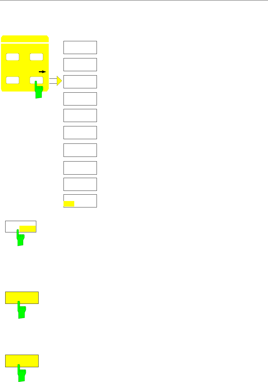
FSE Marker
Å
Menu
1065.6016.12 4.141 E-15
Instrument Parameter Changes via Markers – MKR Í Key
MARKER MKR
→
menu:
NORMAL SEARCH
DELTA MKR
MARKER
PEAK
ACTIVE
MKR DELTA
SELECT
MARKER
MKR->
STOP
MKR->
TRACE
MKT->
START
MKR->CF
STEPSIZE
MKR->
REF LEVEL
MKR->
CENTER
MARKER-> The MKR → menu offers functions that can be used to
change instrument settings with the currently active marker.
Exactly as in the SEARCH menu, these functions can also be
applied to the delta markers.
The choice between marker and delta marker is made
according to the currently active frequency entry mode for the
marker/delta marker. If no entry mode is active, the marker
with the lowest number will be activated as the reference
marker.
ACTIVE
MKR DELTA
The ACTIVE MKR /DELTA softkey toggles between the active marker and
the active delta marker.
If DELTA is illuminated, the following marker functions are carried out with the
active delta marker.
Note: Switching between marker and delta marker can also be done with
the NORMAL and DELTA keys.
IEC/IEEE-bus command --
PEAK
To simplify control, the PEAK search function (see section "Search Functions
- SEARCH Key") is also available in the MRK
→
menu. Thus, the most
important functions MARKER
→
PEAK, MKR
→
CENTER and MKR
→
REF
LEVEL can be selected in one menu.
IEC/IEEE-bus commands
:CALCulate<1|2>:MARKer<1..4>:MAX
:CALCulate<1|2>:DELTamarker<1..4>:MAX
MKR->
CENTER
The MKR
→
CENTER softkey sets the center frequency to the current
marker/delta marker frequency .
The softkey is not available in the time domain.
IEC/IEEE-bus command
:CALCulate<1|2>:MARKer<1..4>:FUNCtion:CENTer
Marker
Å
Menu FSE
1065.6016.12 4.142 E-15
MKR->
REF LEVEL
The MKR
→
REF LEVEL softkey sets the reference level to that of the current
marker.
IEC/IEEE-bus command
:CALCulate<1|2>:MARKer<1..4>:FUNCtion:REFerence
MKR->CF
STEPSIZE
The MKR
→
CF STEPSIZE softkey sets the step size for the center frequency
variation to the current marker frequency, and also sets step-size adaptation
to MANUAL. The CF STEP SIZE remains at this value until the center
frequency entry mode in the STEP menu is switched from MANUAL to AUTO
again.
The MKR
→
CF STEPSIZE function is, above all, useful when measuring
harmonics with a large dynamic range (small bandwidth and small span).
The softkey is not available in the time domain.
IEC/IEEE-bus command
:CALCulate<1|2>:MARKer<1..4>:FUNCtion:CSTep
MKR->
START
The MKR
→
START softkey sets the start frequency to the current marker
frequency.
The softkey is not available in the time domain.
IEC/IEEE-bus command
:CALCulate<1|2>:MARKer<1..4>:FUNCtion:STARt
MKR->
STOP
The MKR
→
STOP softkey sets the stop frequency to the current marker
frequency.
The softkey is not available in the time domain.
IEC/IEEE-bus command
:CALCulate<1|2>:MARKer<1..4>:FUNCtion:STOP
MKR->
TRACE
The MKR
→
TRACE softkey places the active marker on a new trace. The
traces available for selection appear in the selection window.
TRACE1
TRACE3
TRACE4
SELECT TRACE
TRACE2
IEC/IEEE-bus commands
:CALCulate<1|2>:MARKer<1..4>:TRACe 2
:CALCulate<1|2>:DELTamarker<1..4>:TRACe 2

FSE Display and Limit Lines
1065.6016.12 4.143 E-15
Setup of Display and Limit Lines – LINES Key Field
Display Lines – D LINES Key
Display lines are aids which, similar to markers, make the evaluation of trace data more convenient. The
function of display lines is similar to that of a movable scale which can be used to measure absolute and
differential values on traces.
In addition, the display lines can also be used to limit the range of search for marker functions.
The FSE provides four different types of display lines:
•two horizontal threshold lines for setting levels or for defining level search ranges – Display Line 1/2,
•two vertical frequency/time lines for indicating frequencies/times or for determining frequency or time
search ranges – Frequency/Time Line 1/2,
•a threshold line which, for example, sets the search threshold for maximum levels (Peak Search) –
Threshold Line
•a reference line which serves as the basis for mathematical correlation between traces – Reference
Line
For purposes of clarity, each line is annotated on the right side of the display diagram by the following
abbreviations:
D1 Display Line 1 T1 Time Line 1
D2 Display Line 2 T2 Time Line 2
F1 Frequency Line 1 TH Threshold Line
F2 Frequency Line 2 REF Reference Line
The lines for level, threshold and reference are displayed as continuous, horizontal lines over the full
width of the diagram. They are movable in the y-direction.
The lines for frequency and time are displayed as vertical, continuous lines over the total height of the
diagram. They are movable in the x-direction.
For measurement operations in two separate windows, (Split Screen-Modus), the display lines are
available independently in both windows. In the currently active window, the display lines can be
activated and/or shifted. Lines previously defined in the currently inactive window remain unchanged.
The LINES-D LINES menu, used for switching on and setting the display lines, is dedicated to the
chosen display in the active measurement window (span or time). For the display of a spectrum (span ≠
0), the FREQUENCY LINE 1 and FREQUENCY LINE 2 softkeys appear, For the time display (span =
0), the TIME LINE 1 and TIME LINE 2 softkeys are displayed.
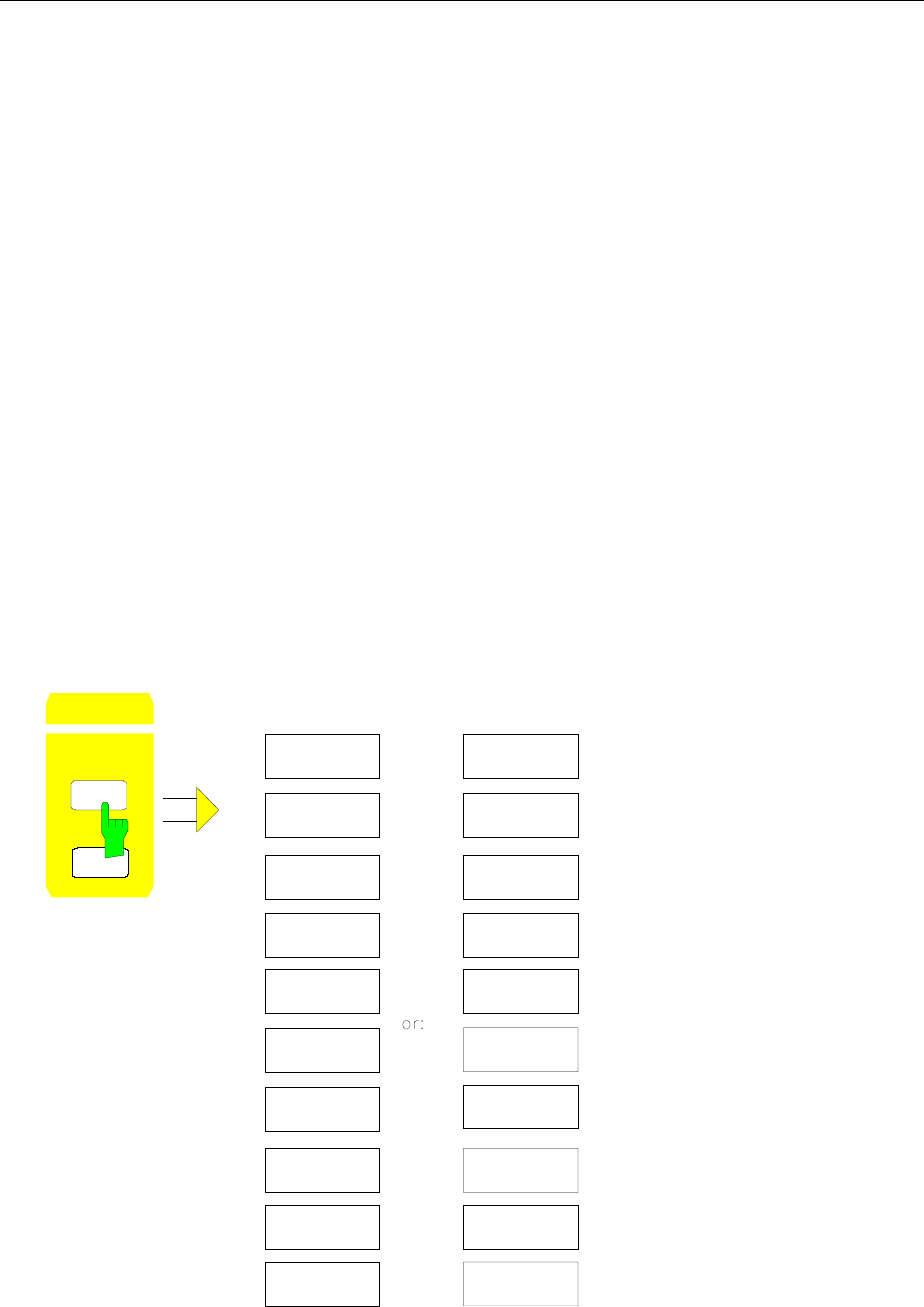
Display and Limit Lines FSE
1065.6016.12 4.144 E-15
Note: The softkeys for setting and switching the display lines on and off operate similar to a three-
position switch:
Initial condition: The line is switched off (softkey has grey background)
1st press: The line is switched on (softkey has red background) and data entry is
activated. The position of the display line can be adjusted by using the roll-
key, the step keys or through direct numerical inputs via the data-entry
keypad. If some other arbitrary function is requested, the data-entry keypad is
disabled. In this case, the display line remains switched on (softkey has green
background).
2nd press: The display line is switched off (softkey has grey background).
Initial condition: The line is switched on (softkey has green background)
1st press: The line is switched on (softkey has red background) and data entry is
activated. The position of the display line can be adjusted by using the roll-
key, the step keys or through direct numerical inputs via the data-entry
keypad. If any other arbitrary function is requested, the data-entry keypad is
disabled. In this case, the display line remains switched on (softkey has green
background).
2nd press: The display line is switched off (softkey has grey background).
Menu LINES-D-LINES for Span ≠ 0 for Span = 0
LINES
D LINES
LIMITS
DISPLAY
LINES
DISPLAY
LINE 2
FREQUENCY
LINE 1
DISPLAY
LINE 1
FREQUENCY
LINE 2
DISPLAY
LINE 2
DISPLAY
LINE 1
TIME
LINE 1
TIME
LINE 2
REFERENCE
LINE
REFERENCE
LINE
THRESHOLD
LINE
THRESHOLD
LINE
DISPLAY
LINES
BASELINE
CLIPPING
BASELINE
CLIPPING
FSE Display and Limit Lines
1065.6016.12 4.145 E-15
DISPLAY
LINE 1
DISPLAY
LINE 2
The DISPLAY LINE 1/2 softkeys switch the display lines on/off and activate
the entry of the line location.
The display lines mark the selected levels in the measurement window.
IEC/IEEE-bus commands
:CALCulate<1|2>:DLINe<1|2>:STATe ON | OFF;
:CALCulate<1|2>:DLINe<1|2> -20dBm
THRESHOLD
LINE
The THRESHOLD LINE softkey switches the threshold line on/off and
activates the entry of the line location.
The threshold line is a display line which defines a threshold value. This
threshold value serves as a lower search limit for maximums/minimums in
the marker functions (MAX PEAK, MIN PEAK, NEXT PEAK etc.). For signal
tracking (SIGNAL TRACK function), this threshold value defines the lower
search limit (see section "Marker Functions")..
IEC/IEEE-bus commands :CALCulate<1|2>:THReshold ON | OFF;
:CALCulate<1|2>:THReshold -82dBm
REFERENCE
LINE
The REFERENCE LINE softkey switches the reference line on/off and
activates the entry of the line position.
The reference line serves as the basis for mathematical correlation between
trace data (see section "Mathematical Operations on Measurement Curves"
IEC/IEEE-bus commands
:CALCulate<1|2>:RLINe:STATe ON | OFF;
:CALCulate<1|2>:RLINe -10dBm
FREQUENCY
LINE 1
FREQUENCY
LINE 2
The FREQUENCY LINE 1/2 softkeys switch the frequency lines 1/2 on/off
and activate the entry of the line locations.
The frequency lines mark the selected frequencies in the measurement
window or define search ranges (see section "Marker Functions").
IEC/IEEE-bus commands
:CALCulate<1|2>:FLINe<1|2>:STATe ON | OFF;
:CALCulate<1|2>:FLINe<1|2> 120 MHz

Display and Limit Lines FSE
1065.6016.12 4.146 E-15
TIME
LINE 1
TIME
LINE 2
The TIME LINE 1/2 softkeys switch the time lines 1/2 on/off and activate the
entry of line locations.
The time lines mark the selected times or define the search range (see
section "Marker Functions").
IEC/IEEE-bus commands
:CALCulate<1|2>:TLINe<1|2>:STATe ON | OFF;
:CALCulate<1|2>:TLINe<1|2> 10ms
BASELINE
CLIPPING The BASELINE CLIPPING softkey switches on or off the BASELINE
CLIPPING function and allows a limit value to be entered.
The BASELINE CLIPPING function is for blanking measured values (for
example noise) which are below a preset threshold.
If the BASELINE CLIPPING function is active and a measured value is below
the preset threshold, the value is set to a lower boundary (-400 dBm).
Measured values above the clipping level are not changed.
Note: It is advisable not to combine the BASELINE CLIPPING function
with the AUTOPEAK detector.
If the set clipping value is within the displayed noise band
(AUTOPEAK detector), activation of the CLIPPING function and
the resulting clipping of the MIN PEAK values will lead to a drastic
enlargement of the displayed noise band.
IEC/IEEE-bus commands
:CALCulate<1|2>:CTHReshold:STATe ON | OFF
:CALCulate<1|2>:CTHReshold -82dBm

FSE Display and Limit Lines
1065.6016.12 4.147 E-15
Limit Lines – LIMITS Key
Limit lines are used to define limits for amplitude curves or spectral distributions on the screen. They
indicate, for example, the upper limits for interference radiation or spurious waves which are permissible
from a Unit Under Test (UUT). In the case of TDMA transmissions (e.g., GSM), the amplitude curve of
the bursts in a time slot must fall within a specified tolerance band. The lower and upper limits may each
be specified by a limit line. Then, the amplitude curve can be cecked either visually or automatically for
any violations of the upper or lower limits (GO/NOGO test).
The FSE instrument supports up to 300 limit lines, each of which may have a maximum of 50 data
points. For each limit line, the following characteristics must be defined:
•The name of the limit line. The limit line is stored under this name and is diplayed in the LIMIT LINES
table.
•The domain in which the limit line is to be used. A distinction is made between the time domain (span
= 0 Hz) and the frequency domain (span > 0 Hz).
•The X-coordinates of the interpolation points. The limit line can be specified either in terms of
absolute frequencies or times or in terms of frequencies referred to the set center frequency and
times referred to the time represented by the left-hand edge of the diagram.
• The Y-coordinates of the interpolation points. The limit line can be selected either for absolute levels
or voltages or referred to the set maximum level (Ref Lvl or Max Lvl). If the reference line is switched
on, it is used as reference when relative setting has been selected.
•The type of limit line (upper or lower limit). With this definition and the limit checking function on
(LIMIT CHECK), the FSE checks for compliance with each limit.
•The limit line units. The units for the limit line must be compatible with the level axis in the active
measurement window.
•The trace to which the limit line is assigned. For the FSE, this defines the trace to which the limit is to
be applied when several traces are simultaneously displayed.
•For each limit line, a margin can be defined which serves as a threshold for automatic evaluation.
•A comment can also be entered for each limit line, e.g., a description of the application.
In the LINES LIMIT menu, the compatible limit lines can be enabled in the LIMIT LINES table. The
SELECTED LIMIT LINE display field provides information about the characteristics of the marked limit
lines. New limit lines can be specified and edited in the NEW LIMIT LINE and EDIT LIMIT LINE sub-
menus.
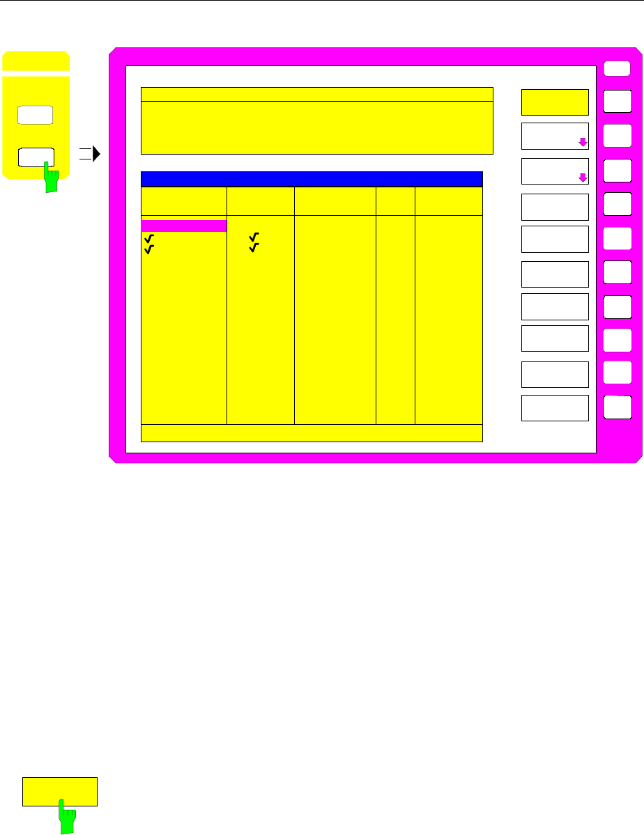
Display and Limit Lines FSE
1065.6016.12 4.148 E-15
LINES LIMIT menu
USER
LIMIT
LINES
EDIT LIMIT
LINE
SELECT
LIMIT LINE
PAGE UP
PAGE DOWN
SELECETED LIMIT LINE
NAME
LP1GHz
Press ENTER to activate / deactivate Limit Line
TRACE
1
1 0 dB
LP1GHz 1 0 dB
LIMIT CHECK
LINES
D LINES
LIMITS
off
on
off
MIL461A 2 off -10 dB
GSM22UP
MARGIN
LIMIT LINES
0 dB
COMPATIBLE COPY
LIMIT LINE
NEW LIMIT
LINE
DELETE
LIMIT LINE
Name: GSM22UP Limit: LOWER
Domain: FREQUENCY X-Axis: LOG
Unit: dB X-Scaling: ABSOLUTE
Comment: Line 1 Y-Scaling: RELATIVE
X OFFSET
Y OFFSET
Limit Line Selection
The SELECTED LIMIT LINES table provides information about the
characteristics of the marked limit line :
Name name
Domain frequency or time
Limit upper/lower limit
X-Axis linear or logarithmic interpolation
X-Scaling absolute or relative frequencies/times
Y-Scaling absolute or relative Y-units
Unit for vertical scale
Comment comment
The characteristics of the limit line are set in the EDIT LIMIT LINE (=NEW
LIMIT LINE) submenu.
SELECT
LIMIT LINE
The SELECT LIMIT LINE softkey activates the LIMIT LINES table and the
selection bar jumps to the uppermost name in the table.
The columns headfings are as follows:
Name NAme of the limit line to be selected.
Compatible Indicates if the limit line is compatible with the measurement
window of the given trace.
Limit Check Activates the automatic "within limits" check.
Trace Selects the trace to which the limit is assigned.
Margin Defines a margin.

FSE Display and Limit Lines
1065.6016.12 4.149 E-15
Name and Compatible - Switching on limit lines
A maximum of 8 limit lines can be switched at any one time. A check mark at
the left edge of a cell indicates that this limit line is switched on. A limit line
can only be switched on when it has a check mark in the Compatible column,
i.e., only when the display mode of the x-axis (time or frequency) and y-axis
units are identical to those in the measurement window.
It should be noted that lines with dB scales are compatible with all dB(..)
scales of the Y-axis.
If the trace assigned to a line is not switched on, the line is displayed in the
window the trace would be displayed in.
Example:
In split screen mode, trace 2 is assigned measuring window B. A line
assigned to trace 2 is always displayed in measurement window B.
If the y-axis unit or the domain (frequency or time) are changed, all non-
compatible limit lines are automatically switched off in order to avoid
misinterpretations. The limit lines must be switched on again when the
original display mode is restored.
IEC/IEEE-bus commands
:CALCulate<1|2>:LIMit<1..8>:NAME <string>;
:CALCulate<1|2>:LIMit<1..8>:STATe ON | OFF
Limit Check - Activating the limit check
When LIMIT CHECK ON is activated, a limit check is performed automatically
on the active screen. In the center of the screen, a display window containing
the results of the limit check test appears:
LIMIT CHECK: PASSED No out-of-limits conditions.
LIMIT CHECK: FAILED One or more out-of-limits conditions. The
message contains the names of the limit lines
which were violated or whose margins were not
complied with.
LIMIT CHECK: MARGIN The margin of at least one active limit line was not
complied with, however, no limit line was violated.
The message contains the names of the limit lines
whose margins were not complied with.
The following example shows three active limit lines:
LIMIT CHECK: FAILED
LINE VHF_MASK: Failed
LINE UHF2MASK: Margin
A limit check is performed only if the trace associated with the limit line is
turned on.
If LIM CHECK is set to OFF for all active limit lines, then the limit line check is
not executed and the display field not activated.
IEC/IEEE-bus command :CALCulate<1|2>:LIMit<1...8>:FAIL?
Display and Limit Lines FSE
1065.6016.12 4.150 E-15
Trace - Selecting the trace to which the limit line is assigned.
The trace is selected in an entry window. An integer entries 1, 2, 3 or 4
indicating the trace is entered. The default setting is trace 1. If the selected
limit line is not compatible with the assigned trace, the limit line is disabled.
(display and limit check).
IEC/IEEE-bus command
:CALCulate<1|2>:LIMit<1...8>:TRACe 1|2|3|4
Margin - Setting a margin.
The margin is defined as the level difference between the limit line and the
signal . When the limit line is defined as an upper limit, the margin means
that the level is below the limit line. When the limit line is defined as a lower
limit, the margin means that the level is above the limit line. The default
setting is 0 dB (i.e., no margin).
IEC/IEEE-bus commands
:CALCulate<1|2>:LIMit<1..8>:UPPer:MARGin 10DB
:CALCulate<1|2>:LIMit<1..8>:LOWer:MARGin 10DB
COPY
LIMIT LINE
The COPY LIMIT LINE softkey copies the data set of the marked limit line
and saves it under a new name. In this way, a new limit line can be easily
generated by parallel translation or editing of an existing limit line. The name
can be arbitrarily chosen and input via an entry window (max. of 8
characters).
IEC/IEEE-bus command
:CALCulate<1|2>:LIMit<1..8>:COPY 1..8|<name>
LIMIT LINE
DELETE
The DELETE LIMIT LINE softkey erases the selected limit line. Before
deletion, a message appears requesting confirmation.
IEC/IEEE-bus command :CALCulate<1|2>:LIMit<1...8>:DELete
X OFFSET
The X OFFSET softkey horizontally shift a limit lines which has been
specified for relative frequencies or times (X-axis). The softkey opens an
entry window, where the value for shifting may be entered numerically or via
the roll-key.
Note: When changing the start or the stop frequency, the line on the
display only remains unchanged, if SPAN FIXED is set.
IEC/IEEE-bus command
:CALCulate<1|2>:LIMit<1..8>:CONT:OFFSet 100us
Y OFFSET
The Y OFFSET softkey vertically shifts a limit line, which has relative values
for the Y-axis (levels or linear units such as volt). The softkey opens an entry
window where the value for shifting may be entered numerically or via the roll-
key.
IEC/IEEE-bus commands
:CALCulate<1|2>:LIMit<1..8>:UPP:OFFSet 3dB
:CALCulate<1|2>:LIMit<1..8>:LOW:OFFSet 3dB

FSE Display and Limit Lines
1065.6016.12 4.151 E-15
Entering and Editing of Limit Lines
A limit line is characterized by
• its name
•the domain assignment (frequency or time)
•whether the scale is absolute or relative (time or frequency)
•linear or logarithmic interpolation
•the vertical unit
•the vertical scale
•the definition of the limit line as either an upper or lower limit.
•the interpolation points for frequency/time and level
When the limit line is entered, the FSE immediately checks all limit lines according to rules that
guarantee correct operation.
•The frequencies/times for each interpolation point must be entered in ascending order, however, for
any single frequency/time, twodata points may be entered (vertical segment of a limit line).
The interpolation points are allocated in order of ascending frequency/time. Gaps are not allowed. If
gaps are desired, two separate limit lines must be defined and then both enabled.
•The entered frequencies/times need not necessarily be capable of selection on the FSE. A limit line
may also exceed the frequency or time display range. The minimum frequency for an interpolation
point is -200 GHz, the maximum frequency is 200 GHz. For the time domain, negative times may also
be entered. The range is -1000 s to +1000 s.
•The minimum/maximum value for a limit line is -200 dB/ +200 dB for the logarithmic scale or 10-20/
10+20 or-99.9%/ + 999.9% for linear amplitude scales.
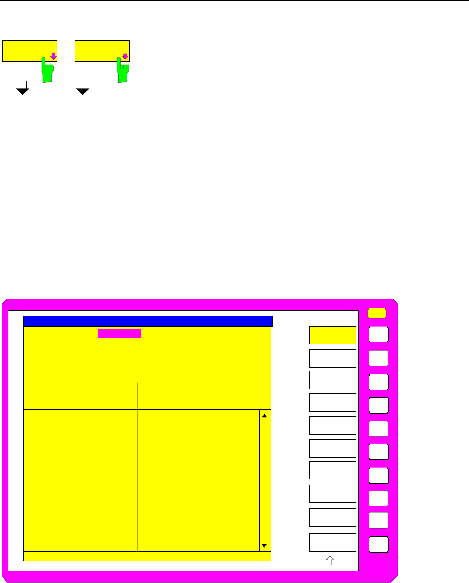
Display and Limit Lines FSE
1065.6016.12 4.152 E-15
LINES LIMIT-EDIT LIMIT LINE menu
EDIT LIMIT
LINE
NEW LIMIT
LINE
The EDIT LIMIT LINE and NEW LIMIT LINE softkeys both call the EDIT
LIMIT LINE submenu used for editing limit lines. In the table heading,
the characteristics of the limit line can be entered. The frequency/time
and level points are entered in the columns.
Name Enter name.
Domain Select domain.
Unit Select units.
X-Axis Select interpolation
X-Scaling Entry of absolute or relative values for the X-axis
Y-Scaling Entry of absolute or relative values for the Y-axis
Limit Select upper/lower limit.
Comment Enter comments.
Time/Frequency Enter time/frequency points.
Limit/dBm Enter level points.
25
26
49
50
USER
EDIT
LIMIT LINE
NAME
FREQUENCY LIMIT/dBuV/m
VALUES
Name: Limit_22
EDIT LIMIT LINE TABLE
Press ENTER to edit field.
SAVE
LIMIT LINE
DELETE
VALUE
SHIFT X
LIMIT LINE
INSERT
VALUE
PAGE UP
PAGE DOWN
30.000 MHz
230.000 MHz
230.000 MHz
1.000 GHz
30.0000
30.0000
37.0000
37.0000
Domain: FREQUENCY
Unit: dBuV/m
X-Axis: LOG
X-Scaling: ABSOLUTE
Y-Scaling: ABSOLUTE
Limit: UPPER
Comment: Limit 22
SHIFT Y
LIMIT LINE

FSE Display and Limit Lines
1065.6016.12 4.153 E-15
NAME
The NAME softkey activates the entry of characteristics in the table heading.
Name - Entry of name
A maximum of 8 characters are permitted for each name. All names must be
compatible with the MS DOS conventions for file names. The instrument
automatically stores all limit lines with the .LIM extension.
IEC/IEEE-bus command
:CALCulate<1|2>:LIMit<1...8>:NAME <string>
Domain - Selection of time or frequency domain
The domain (frequency/time) can only be changed when the limit-line point
table is empty. The default setting is frequency.
IEC/IEEE-bus command
:CALCulate<1|2>:LIMit<1..8>:CONTrol:DOMain FREQ | TIME
X-Axis - Indication of interpolation
Linear or logarithmic interpolation can be carried out between the frequency
reference points of the table. The ENTER key toggels between LIN and LOG
selection.
IEC/IEEE-bus commands
:CALCulate<1|2>:LIMit<1..8>:CONTrol:SPACing LIN | LOG
:CALCulate<1|2>:LIMit<1..8>:UPPer:SPACing LIN | LOG
:CALCulate<1|2>:LIMit<1..8>:LOWer:SPACing LIN | LOG
Scaling - Selection of absolute or relative scale
The limit line scale can either be absolute (frequency or time) or relative. Any of
the unit keys may be used to toggle between ABSOLUTE and RELATIVE, the
cursor must in the X-Scaling or the Y-Scaling line
X-Scaling ABSOLUTE The frequencies or times are interpreted as absolute
physical units.
X-Scaling RELATIVE The frequencies in the limit-line point table are
referred to the currently set center frequency. In the
time domain, the left boundary of the diagram
constitutes the reference.
Y-Scaling ABSOLUTE The limit values are absolute levels or voltages.
Y-Scaling RELATIVE The limit values refer to the reference level or, in
case a reference line is set, to the reference line.
Limit values in dB or % are always relative values.
RELATIVE scaling is always recommended, if masks for bursts are to be
defined in the time domain, or if masks for modulated signals are required in
the frequency domain.
An X-offset equal to half the sweep time may be entered to shift the mask in
the time domain to the center of the screen.
IEC/IEEE-bus commands
:CALCulate<1|2>:LIMit<1..8>:CONTrol:MODE REL | ABS
:CALCulate<1|2>:LIMit<1..8>:UPPer:MODE REL | ABS
:CALCulate<1|2>:LIMit<1..8>:LOWer:MODE REL | ABS
Display and Limit Lines FSE
1065.6016.12 4.154 E-15
Unit - Selection of the vertical scale units for the limit line
Units are selected in a selection box. The default setting is dBm.
UNITS
VERTICAL SCALE
dB
dBm
dBuV
dBmV
dBuA
dBpW
dBpT
V
A
W
dBuV/MHz
dBmV/MHz
dBuA/MHz
%
IEC/IEEE-bus command :CALCulate<1|2>:LIMit<1...8>:UNIT
DB| DBM| PCT |DBUV| DBMW | DBUA |
DBPW| DBPT | WATT| VOLT | AMPere |
DBUV_MHZ | DBMV_MHZ| DBUA_MHZ |
DBUV_M | DBUV_MMHZ | DBUA_M |
DBUA_MMHZ
Limit - Selection of upper/lower limit
A limit line can be defined as either an upper or lower limit.
IEC/IEEE-bus command --
(defined by the key words :UPPer or :LOWer)
Comment - Enter comments
Comments are user selectable, but may not exceed 40 characters in length.
IEC/IEEE-bus command
:CALCulate<1|2>:LIMit<1..8>:COMMent ’string’
VALUES
The VALUES softkey activates the entry of the data points in the table
columns Time/Frequency and Limit/dB. Which table column appears
depends on the Domain selection in the table heading.
The frequency/time points are entered in ascending order (two repeated
frequencies/times are permitted).
IEC/IEEE-bus commands
:CALCulate<1|2>:LIMit<1...8>:CONTrol[:DATA]
<num_value>, <num_value>..
:CALCulate<1|2>:LIMit<1...8>:UPPer[:DATA]
<num_value>, <num_value>..
:CALCulate<1|2>:LIMit<1...8>:LOWer[:DATA]
<num_value>,<num_value>..
FSE Display and Limit Lines
1065.6016.12 4.155 E-15
INSERT
VALUE
The INSERT VALUE softkey creates an empty line above the current cursor
position where a new data point can be entered. However, when entering new
values, the ascending order for frequency/time values must be kept.
IEC/IEEE-bus command --
DELETE
VALUE
The DELETE VALUE softkey erases the data point (complete line) at the
cursor position. The data points that follow are moved along to fill the gap.
IEC/IEEE-bus command --
SHIFT X
LIMIT LINE
The SHIFT X LIMIT LINE softkey calls an entry window where the complete
limit line may be shifted horizontally.
The shift units are the same as the horizontal scale units:
– in the frequency domain in Hz, kHz, MHz or GHz
– in the time domain in ns, µs, ms or s
This means that it is easy to create a new limit line from existing limit line
which has been shifted horizontally and stored (SAVE LIMIT LINE softkey)
under a new name (NAME softkey).
IEC/IEEE-bus command
:CALCulate<1|2>:LIMit<1..8>:CONTrol:SHIFt 50kHz
SHIFT Y
LIMIT LINE
The SHIFT Y LIMIT LINE softkey calls an entry window where the complete
limit line may be shifted vertically.
The shift units are the same as the vertical scale units:
– for relative logarithmic units in dB
– for linear units, as a factor
This means that a new limit line can easily be created from an existing limit
line which has been shifted vertically and stored (SAVE LIMIT LINE softkey)
under a new name (NAME softkey).
IEC/IEEE-bus commands
:CALCulate<1|2>:LIMit<1..8>:UPPer:SHIFt 20dB
:CALCulate<1|2>:LIMit<1..8>:LOWer:SHIFt 20dB
SAVE
LIMIT LINE
The SAVE LIMIT LINE softkey stores the currently edited limit line . The
name can be entered in an entry window (max. 8 characters)
IEC/IEEE-bus command -- (automatically executed)
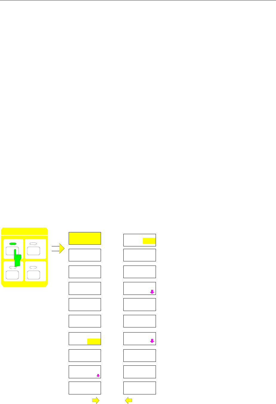
Traces FSE
1065.6016.12 4.156 E-15
Trace Selection and Setup –TRACE Key Group
The FSE can display up to four separate traces at a time on a screen. A trace has of a maximum of 500
pixels along the horizontal axis (frequency or time). If more measured values than pixels are available,
several measurement values are assigned to one pixel.
The traces are selected using keys 1 to 4 of the TRACES key group. When two measurement windows
(SPLIT SCREEN) are displayed, traces 1 and 3 are assigned to the upper (SCREEN A) and traces 2
and 4 are assigned to the lower (SCREEN B) measurement window.
The traces can be individually activated for a measurement or frozen after completion of a
measurement. Traces that are not activated are not displayed.
A display mode can be selected for each trace. The traces can be overwritten (CLEAR/WRITE mode)
after each sweep, averaged (AVERAGE mode) over several sweeps, or the maximum/ minimum value
from several sweeps can be displayed (MIN HOLD/MAX HOLD).
Individual detectors are selectable for each of the traces. The auto-peak detector displays the maximum
and minimum values on a vertical line. The max-peak detector and min-peak detector display the
maximum and /minimum levels represented by a pixel. The sampling detector displays the
instantaneous value of the level at a pixel. The rms detector displays the power (rms) of the spectrum at
a pixel, the average detector the average value.
Measurement Function Selection - TRACE 1 to 4 key
The trace functions are categorized as follows:
•type of trace display (CLEAR/WRITE, VIEW and BLANK)
•evaluation of the trace as a whole (AVERAGE, MAX HOLD and MIN HOLD)
•evaluation of the individual pixels of a trace (AUTOPEAK, MAX PEAK, MIN PEAK, SAMPLE, RMS
and AVERAGE)
TRACE 1 menu
3
12
4
3
TRACE CLEAR/
WRITE
MAX HOLD
MIN HOLD
AVERAGE TRACE
MATH
VIEW
BLANK
TRACE 1
DETECTOR
SWEEP
COUNT
TRACE 1
COPY
ANALOG TR
ON OFF
HOLD CONT
ON OFF
ASCII
EXPORT
ASCII
CONFIG
FSE Traces
1065.6016.12 4.157 E-15
The TRACE keys 1...4 call a menu whith the setting options for the selected trace.
This menu is used to determine the method for compressing the measurement data in the frequency or
time domain to the 500 representable points of the display is determined.
When the measurement is started, a new trace can be displayed or the trace can be based on previous
results. The traces can be displayed, blanked and copied.
Traces can also be corrected with the mathematical functions.
The measurement detector for each of the display types may be chosen either directly or selected
automatically by the FSE.
All activated traces are marked with a LED at the corresponding key (here, TRACE 1). The default
setting is TRACE 1 with CLEAR / WRITE selected. The remaining traces 2...4 are switched off
(BLANK). For the split screen display, the selection of the trace automatically selects the corresponding
screen for entry.
Only one of the CLEAR/WRITE, MAX HOLD, MIN HOLD, AVERAGE, VIEW and BLANK softkeys can
be activated at any one time.
CLEAR/
WRITE
The CLEAR/WRITE softkey activates the clear/write display mode.
The trace is displayed without additional trace evaluation. The trace memory
is overwritten by each sweep. If more than one data point falls within a pixel,
the trace is displayed in bar form with the maximum and minimum values
being assigned to one pixel. In the clear/write display mode, all the available
detectors are selectable. The autopeak detector is selected in the default
mode (detector to AUTO).
Whenever the CLEAR/WRITE softkey is pressed, the FSE clears the
selected trace memory and restarts the measurement.
IEC/IEEE-bus command
:DISPlay[:WINDow<1|2>]:TRACe<1..4>:MODE WRITe
VIEW
The VIEW softkey freezes the current contents of the trace memory and
displays them.
If the trace data were formed through MAX HOLD, MIN HOLD or AVERAGE,
the sweep is restarted and the trace contents are cleared, after switching to
these trace modes.
If a trace is frozen by VIEW, the instrument settings can be modified without
modifying the displayed trace. The fact that the trace and the current
instrument setting do not agree anymore is indicated by an enhancement
label "*" at the right edge of the grid. The initial instrument setting can be
restored using the ADJUST TO TRACE softkey in the TRACE MATH sub-
menu.
If LEVEL RANGE or REF LEVEL is changed in the VIEW display mode, the
FSE adjusts the measurement data to the changed display range. Thus, an
amplitude zoom can be performed after the measurement so that details of
the trace can be seen better.
IEC/IEEE-bus command
:DISPlay[:WINDow<1|2>]:TRACe<1..4>:MODE VIEW

Traces FSE
1065.6016.12 4.158 E-15
BLANK
The BLANK softkey activates the blanking of the trace.
However, the trace remains stored in memory and can be displayed again by
pressing VIEW. The markers for the blanked trace are also erased. After
reactivation of the trace (with VIEW, CLEAR / WRITE, MAX HOLD, MIN
HOLD, AVERAGE) the markers will be restored their their previous positions.
IEC/IEEE-bus command
:DISPlay[:WINDow<1|2>]:TRACe<1..4> OFF
AVERAGE
The AVERAGE softkey activates the trace averaging function. The average is
formed over several sweeps. The average can be calculated for each
available detector. If the detector is automatically selected by the FSE , the
sampling detector is used.
After enabling the averaging mode, the first trace is recorded in
CLEAR/WRITE mode with the selected detector. After the second sweep, the
average is then formed for each succeeding sweep. Here, the average is
formed over the samples/pixels, i.e., according to the LIN or LOG setting,
over amplitudes or levels.
Averaging is restarted every time the AVERAGE softkey is pressed. The
trace memory is also cleared. This is also the case when the trace is
switched from the setting AVERAGE to VIEW or BLANK
IEC/IEEE-bus command
:DISPlay[:WINDow<1|2>]:TRACe<1..4>:MODE AVER
Description of averaging:
Averaging is carried out using the pixels which are derived from the measurement value samples.
These pixels may in some cases be comprised of several combined measurement values. This means
that the average is formed over linear amplitude values when the level display is linear and over levels
when the level display is logarithmic. Because of this, the trace must be measured anew when changing
between the LIN and LOG display mode. The settings CONT/SINGLE SWEEP and the sliding average
apply to the average display analogously.
Two calculation procedures are available for averaging. For SWEEP COUNT= 0 , a sliding average is
calculated using the following equation:
10
Meas_Value TRACE*9
TRACE 1-n
n+
=
Because of the relative weighting of the new measurement value and the trace average, past values
have practically no no influence on the displayed trace after about 10 sweeps. For this setting, the signal
noise is effectively reduced without the need to restart the averaging process even if the signal is
changed.
If the SWEEP COUNT is >1 averaging takes place over the selected number of sweeps. In this case,
the displayed trace is given by the following formula during averaging::
()
+= ∑
−
=
Value Meas
1
TRACE 1
1
n
n
i
i
T
n
where n is the number of the current sweep (n = 2 ... SWEEP COUNT). For the first sweep, an average
is not calculated. The measurement values are stored directly in trace memory. With growing n, the
displayed trace becomes increasingly smoother since more individual trace data are available for
averaging.
The average is stored in trace memory after the defined number of sweeps. Until this number of sweeps
is reached, a preliminary average is displayed.

FSE Traces
1065.6016.12 4.159 E-15
On completion of averaging, ie when the number of sweeps defined with SWEEP COUNT has been
reached, a sliding average given by the following formula is obtained with CONTINUOUS SWEEP
, where Trace = new trace
Traceold = old trace
N = SWEEP COUNT
The display "Sweep 200 of 200" then remains constant until there is a new start.
In SINGLE SWEEP mode, SWEEP START initiates n single sweeps. The sweeps are stopped as soon
as the selected number of sweeps has been reached. The number of the current sweep and the total
number of sweeps are shown in the display: "Sweep 3 of 200".
SWEEP
COUNT
The SWEEP COUNT softkey activates the entry of the number of sweeps
used for averaging.
The range for SWEEP COUNT is 0 through 32767. For 0, the FSE performs
a sliding average over 10 sweeps. For 1, no averaging takes place.
The default setting is 10 sweeps. The programming naturally influences the
sweep duration. The number of sweeps used for averaging is the same for
all 4 traces.
Note : The setting of the SWEEP COUNT in the trace menu is equivalent
to the setting in the sweep menu.
IEC/IEEE-bus command :[SENSe<1|2>:]SWEep:COUNt 10
MAX HOLD
The MAX HOLD softkey activates the max hold mode.
In this display mode, the FSE saves for each sweep the largest of the
previously stored/currently measured values in the trace memory. The
detector is set automatically to MAX PEAK. In this way, the maximum value
of a signal can be determined over several sweeps.
This is especially useful for measurement of modulated or pulsed signals.
The signal spectrum is built up sweep by sweep until all the signal
components have been captured.
Pressing of the MAX HOLD softkey again clears the trace memory and
restarts the max hold mode.
If MAX HOLD is enabled, a new start is made after clearing the trace memory
for each frequency change, (start frequency, stop frequency, center
frequency or frequency span), a reference level change or switching between
linear/logarithmic scales.
IEC/IEEE-bus command
:DISPlay[:WINDow<1|2>]:TRACe<1..4>:MODE MAXH
N
Value MeasT1)(N
T1-n +⋅−
=RACE
RACEn
Traces FSE
1065.6016.12 4.160 E-15
MIN HOLD
The MIN HOLD softkey activates the min hold mode.
In this display mode, the FSE saves for each sweep the smallest of the
previously stored/currently measured values in the trace memory. The
detector is set automatically to MIN PEAK. In this way, the minimum value of
a signal can be determined over several sweeps. This function is, e.g., useful
for making an unmodulated carrier in a signals mixture easier to see on the
display. Noise, interference or modulated signals are suppressed by the MIN
HOLD function, whereas a CW signal maintains a constant level.
Pressing the MIN HOLD softkey clears the trace memory and the minimum
value function starts anew.
IEC/IEEE-bus command
:DISPlay[:WINDow<1|2>]:TRACe<1..4>:MODE MINH
HOLD CONT
ON OFF
The HOLD CONT softkey defines whether the traces in the average mode
and min hold/max hold mode are reset after some definite parameter
changes.
OFF The traces are reset after some definite parameter changes.
ON This mechanism is switched off.
In general, parameter changes require a restart of the measurement before
results are evaluated (e. g. with markers). For those changes that are known
to require a new measurement (e. g. modification of the span), the trace is
automatically reset so that erroneous evaluations of previous results are
avoided.
This mechanism can be switched off for those exceptional cases where the
described behavior is unwelcome.
IEC/IEEE-bus command
:DISPlay[:WINDow<1|2>]:TRACe<1..4>:MODE HCON ON|OFF
COPY..
The COPY softkey copies the current trace as display on the screen to
another trace memory. A table appears in which the copy procedure can be
selected.
COPY TRACE 1 TO
TRACE 2
TRACE 3
TRACE 4
For only one window, the selected trace can be copied to any of the other
trace memories since here, all four traces are displayed in one diagram with
the same frequency boundaries.
In the split screen display, this is only possible as long as the frequencies of
screen A and screen B are identical. If this is not the case, the selected trace
can only be copied to the corresponding trace memory, i.e., trace 1 to trace 3
and trace 2 to trace 4 or vice versa. In this case, only the available trace is
displayed.
After copying, the contents of the destination memory are lost. The
destination memory now changes automatically to view mode with the new
data.
IEC/IEEE-bus command
:TRACe:COPY TRACE1| TRACE2| TRACE3| TRACE4,
TRACE1| TRACE2| TRACE3| TRACE4

FSE Traces
1065.6016.12 4.161 E-15
Detector Selection
The FSE detectors are all-digital. The detectors available are the max-peak detector which derives the
maximum value from a number of sample values, the min-peak detector which derivess the minimum
value from a number of sample values and the sampling detector. The sampling detector passes on the
sampled data without modification or performs a data reduction by suppressing non-displayable values.
The peak detectors compare the current level with the maximum/minimum levels of the previously
sampled data. When the number of samples defined by the instrument settings is reached, the samples
are combined as displayable pixels. Each of the 500 pixels of the display therefore represents 1/500 of
the sweep range and so all the individual measurements (frequency samples) that fall within this
subrange in a compressed form. Even though the recording rate is high, there are no recording gaps
thanks to the internal pipeline structure. For each trace display mode, an optimized detector is selected
automatically. Since the peak detectors and the sample detector are connected in parallel, a single
sweep is sufficient for record and display four traces with four detectors.
Peak value detectors
(MAX PEAK / MIN PEAK)Peak value detectors are implemented with digital comparators.
For each of the levels measured at each of the frequencies
represented by one of the 500 pixels, they determine the
maximum (max peak) of all positive peaks and the minimum (min
peak) of all the negative peaks.
This is repeated for each pixel so that, for wide frequency spans
and inspite of the limited display resolution, a larger number of
measurements than would otherwise be possible can be used to
display the spectrum.
AUTOPEAK detector The AUTOPEAK detector combines the two peak detectors. The
max-peak detector and min-peak detector determine the
maximum and minimum level over a displayed pixel at the same
time and display it as a common measurement value. The
maximum and minimum level over a frequency point are joined
with a vertical line.
SAMPLE detector The SAMPLE detector passes on all sampled data without further
evaluation and either displays them directly or, for speed (short
sweep times), first writes them to a memory and subsequently
processes them.
Data reduction, i.e., summing of measurement values of
neighboring frequencies or time samples is not performed here.
If, during a sweep, more measurement values are generated
than can be displayed, measurement values will be lost. Discrete
signals can thus be lost
Therefore, the sampling detector can only be recommended for a
ratio of span-to-resolution bandwidth of up to approximately 250.
To ensure that no signal will be suppressed (example: span 1
MHz --> min. bandwidth 5 kHz).

Traces FSE
1065.6016.12 4.162 E-15
RMS detector The rms detector finds the rms value of the measured values
over a pixel.
The FSE uses the linear display voltage after the envelope
detection. The linear samples are squared, summed and the
sum is divided through the number of samples (= mean of
squares). With the logarithmic display, the logarithm of the sum
of squares is taken. With the linear display the mean of the
squares is displayed directly. Each pixel represents the total
power of the measured values assigned to the pixel.
The rms detector supplies the power of the signal irrespective of
the waveform (CW carrier, modulated carrier, white noise or
pulse signal). There is no need for the various waveform
correction factors which are required when other detectors are
used for the power measurement.
Average detector The average detector averages the measured values over a
pixel.
The FSE uses the linear display voltage after envelope
detection. The linear samples are summed and the sum is
divided by the number of measurement samples (= linear
average). With the logarithmic display, the logarithm of the
average is taken. With the linear display the average is
displayed directly. Each pixel therefore represents the average
of the measured values assigned the pixel.
The average detector gives the true average of the signal
irrespective of the waveform (CW carrier, modulated carrier,
white noise or pulse signal).
Notes: During a sweep, the FSE switches the first oscillator frequency in steps which are smaller than
approximately 1/10 of the bandwidth. This guarantees that the level of a signal is correctly
measured. For narrow bandwidths and wide spans, a very large number of measurement values
are generated. The number of frequency steps is, however, always a multiple of 500 (= number
of displayable points). In the sampling mode, only every nth value is displayed. The quantity n
depends upon the number of measurement values, i.e on the span, resolution bandwidth and
the measurement rate.
For sweep times < 5ms in the time domain, the same detector is used for all active traces.
FSE Traces
1065.6016.12 4.163 E-15
TRACE 1-DETECTOR submenu
AUTO
SELECT
DETECTOR
SAMPLE
TRACE 1
DETECTOR
DETECTOR
AUTO PEAK
DETECTOR
MIN PEAK
DETECTOR
MAX PEAK
DETECTOR
CAPT MEM
OFF
ON
DETECTOR
RMS
DETECTOR
AVERAGE
The DETECTOR softkey opens a submenu to select the
detector.
The detector may be independently selected for each trace.
Mode AUTO SELECT sets the best suitable detector for each
trace display mode (Clear Write, Max Hold oder Min Hold).
Only one of the softkeys for the detectors can be activated at
any one time.
AUTO
SELECT
The AUTO SELECT softkey (= default) selects the optimum detector for the
selected trace display mode (clear write, max hold, min hold).
Trace-mode Detector
Clear/Write Autopeak
Average Sample
Max Hold Max Peak
Min Hold Min Peak
IEC/IEEE-bus command
:[SENSe<1|2>:]DETector<1..4>:AUTO ON|OFF
DETECTOR
AUTOPEAK
The DETECTOR AUTOPEAK softkey selects the autopeak detector.
IEC/IEEE-bus command :[SENSe<1|2>:]DETector<1..4> APEak
DETECTOR
MAX PEAK
DETECTOR
MIN PEAK
The DETECTOR MAX PEAK softkey selects the max peak detector. It is
recommended for pulse-like signals.
IEC/IEEE-bus command :[SENSe<1|2>:]DETector<1..4> POSitive
The DETECTOR MIN PEAK softkey selects the min peak detector. Weak
sinewave signals can be brought out clearly against noise by using this
detector. For a composite signal made up of sinewaves and pulse-like-like
signals the pulse signals are suppressed.
IEC/IEEE-bus command :[SENSe<1|2>:]DETector<1..4> NEGative

Traces FSE
1065.6016.12 4.164 E-15
DETECTOR
SAMPLE
The DETECTOR SAMPLE softkey selects the sample detector.
It is used for measuring uncorrelated signals such as noise. The power can
be determined by means of fixed correction factors for evaluation and the log
amplifier.
IEC/IEEE-bus command :[SENSe<1|2>:]DETector<1...4> SAMPle
DETECTOR
RMS
The DETECTOR RMS softkey activates the rms detector.
The rms detector gives the true power of the signal irrespective of the
waveform. The mean of the squares of all level samples is formed as a pixel
is swept. The sweep time, therefore, determines the number of values
averaged and, with increasing sweep time, better averaging is obtained. The
rms detector is therefore an alternative to averaging over several sweeps
(see TRACE AVERAGE).
In the time domain (SPAN = 0), the rms detector is only available for sweep
times ≥ 5 ms. Moreover, the combination of the rms detector with the
pretrigger function and the gaped sweep function is not permissible.
The video bandwidth has to be set to at least 10 times the resolution
bandwidth (RBW) so that the rms value of the signal is not invalidated by
video filtering.
IEC/IEEE-bus command :[SENSe<1|2>:]DETector<1...4> RMS
DETECTOR
AVERAGE
The DETECTOR AVERAGE softkey activates the average detector.
In contrast to the rms detector, the average detector supplies the straight
average of all the level sampleds as a pixel is swept over.
The same restrictions as those of the rms detector apply (see above).
IEC/IEEE-bus command :[SENSe<1|2>:]DETector<1...4> AVERage
FSE Traces
1065.6016.12 4.165 E-15
Quasi Analog Display
Normally, when measured values are displayed they are joined together with line segments to form a
trace which is deleted and redrawn after each sweep. When analog measurements are performed, the
persistence of the screen makes it possible to assess the signal’s frequency of occurrence. Frequently
occurring events appear brighter on the screen than events that occur less frequently.
The ANALOG TRACE function simulates an analog display.
In this case, a measured value is represented by a single pixel on the screen. After the trace has been
explicitly cleared with CLEAR / WRITE, this pixel is reset. As the trace is build up from several sweeps,
the frequency distribution is, in effect, indicated by the varying brightness of the trace.
TRACE 1 side menu
ANALOG TR
ON
OFF
The ANALOG TR ON/OFF switches the quasi-analog display mode on and off for
the selected trace
The measurement is always made with the selected detector.
IEC/IEEE-bus command
:DISPlay[:WINDow<1|2>]:TRACe<1..4>:MODE:ANALog ON | OFF
Mathematical Functions for Traces
TRACE 1-TRACE MATH submenu:
TRACE MATH
OFF
T1-T2+REF
-> T1
T1-REF
->T1
TRACE MATH
T1-T3+REF
-> T1
T1-T4+REF
-> T1
ADJUST TO
TRACE
TRACE
MATH
The TRACE MATH softkey opens a submenu in which a
differential curve for the selected trace is calculated.
Traces FSE
1065.6016.12 4.166 E-15
T1-T2+REF
-> T1
T1-REF
->T1
TRACE MATH
T1-T3+REF
-> T1
T1-T4+REF
-> T1
The T1-T2+REF, T1-T3+REF, T1-T3+REF and T1-REF softkeys subtract the
traces and add the set level to the difference. If the reference line is switched
on (see key D LINES), the level value of the reference line instead of the
reference level is added to the difference. Thus, the differential curve can be
positioned anywhere on the screen by shifting the reference line. The
difference of the two traces with respect to the reference line is displayed.
The T1-REF softkey subtracts the level of the reference line from the trace
level.
To indicate that the trace is a difference trace, a enhancement label is
displayed at the right margin of the measurement value diagram (1-2, 1-3, 1-
4, 1-R). In TRACE 1 main menu, the TRACE MATH softkey is on a coloured
background to show that the function is being used.
Important: For a display with two measurement windows, not all
combinations are allowed if the sweep data for screen A and
screen B are not the same. Only the traces allowed in the screen
can be combined (in screen A, only trace 1 with trace 3; in
screen B, only trace 2 with trace 4).
IEC/IEEE-bus command
:CALCulate<1|2>:MATH<1..4>:STATe ON
:CALCulate<1|2>:MATH<1..4>[:EXPRession][:DEFine] <expr>
TRACE MATH
OFF
The TRACE MATH OFF softkey switches the math function off. The softkey
is only available when a conversion function is enabled.
IEC/IEEE-bus command :CALCulate<1|2>:MATH<1...4>:STATe OFF
ADJUST TO
TRACE
The ADJUST TO TRACE softkey restores the original instrument settings
when the corresponding trace is set to VIEW and the current instrument
settings are different than those of the trace data.
If a trace is frozen with VIEW, changes in the instrument settings can be
made without influencing the trace. An asterisk( * ) at the edge of the display
screen indicates that the current instrument settings are different than those
in effect when the trace was recorded. In this case, the ADJUST TO TRACE
softkey is presented with which the original instrument setting can be
restored.
IEC/IEEE-bus command --
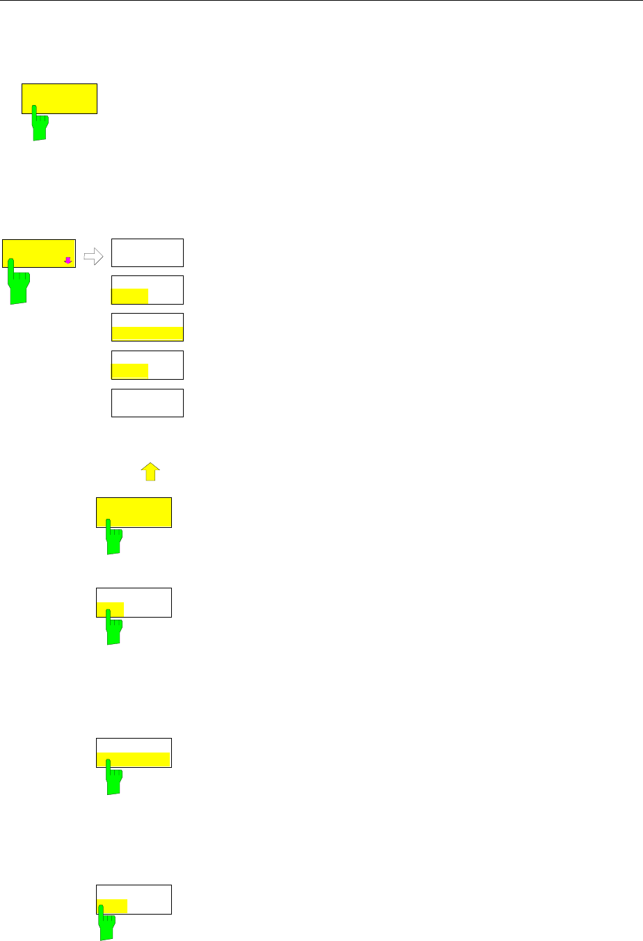
FSE Traces
1065.6016.12 4.167 E-15
Trace Export
TRACE 1 menu:
ASCII
EXPORT The ASCII EXPORT softkey stores the active trace in a file with ASCII format.
Upon pressing the ASCII EXPORT softkey, a file name can be entered. The
default name is TRACE.DAT. Then the measured data of the trace are stored.
The function can be configured in the ASCII CONFIG submenu.
IEC/IEEE-bus command :MMEMory:STORe:TRACe 1..4,<path>
TRACE 1 menu:
ASCII
CONFIG
ASCII
CONFIG
NEW
APPEND
HEADER
ON OFF
EDIT PATH
DECIM SEP
. ,
.
.
.
ASCII
COMMENT
The ASCII CONFIG softkey calls a submenu for various settings for
the TRACE ASCII EXPORT function.
EDIT PATH The EDIT PATH softkey defines the directory in which the file is to be
stored.
IEC/IEEE-bus command --
DECIM SEP
. , The DECIM SEP softkey selects the decimal separator for the ASCII
file. The choice is ’.’ (decimal point) or ’,’ (comma).
This means that the decimal separator used in various language
versions of evaluation programs (e.g. MS-Excel) can be selected so
that the packages are supported. .
IEC/IEEE-bus command
:FORMat:DEXPort:DSEParator POINt|COMMA
NEW
APPEND The APPEND NEW softkey defines whether output data are to be
written to an existing file or a new file.
• With APPEND, the data are added to an existing file.
• With NEW, either a new file is generated or an existing file is
overwritten by storage of the data.
IEC/IEEE-bus command :FORMat:DEXPort:APPend ON | OFF
HEADER
ON OFF The HEADER ON/OFF softkey defines whether important instrument
settings should be stored at the beginning of the file.
IEC/IEEE-bus command :FORMat:DEXPort:HEADer ON | OFF

Traces FSE
1065.6016.12 4.168 E-15
ASCII
COMMENT The ASCII COMMENT softkey activates the entry of commentary
concerning the current ASCII data set. A total of 60 characters are
available for this purpose.
IEC\IEEE bus command :FORMat:DEXPort:COMMent ’string’
Structure of the ASCII file:
The file consists of the header containing important scaling parameters and a data section containing
the trace data. The data of the file header consist of three columns, each separated by a semicolon:
parameter name; numeric value; basic unit
The data section starts with the keyword " Trace <n> " (<n> = number of stored trace), followed by the
measured data in one or several columns (depending on measurement) which are also separated by a
semicolon.
This format can be read in from spreadsheet calculation programs, eg MS-Excel. It is necessary to
define ’;’ as a separator.
Content of file Description
File header Type;FSEA 30;
Version;1.93;
Date;01.Jul 1999;
Comment; test
Mode;Spectrum;
Start;10000;Hz
Stop;100000;Hz
Center Freq;55000;Hz
Span;90000;Hz
Freq Offset;0;Hz
x-Axis;LIN;
y-Axis;LOG;
Ref.Level;-30;dBm
Level Offset;0;dB
Max Level
Level Range;100;dB
RF Att;20;dB
RBW;100000;Hz
VBW;30000;Hz
SWT;0.005;s
Trace Mode;AVERAGE;
Detector;SAMPLE;
Sweep Count;20;
Instrument model
Firmware version
Date record storage date
Comment
Instrument operating mode
Start/stop of the display range.
Unit: Hz for span > 0, s for span = 0,
Center frequency
Frequency range (0 Hz for zero span)
Frequency offset
Scaling of x axis linear (LIN) or logarithmic (LOG)
Scaling of y axis linear (LIN) or logarithmic (LOG)
Reference level
Level offset
Maximium level
Display range in y direction. Unit: dB for x axis LOG, % for x axis LIN
Input attenuation
Resolution bandwidth
Video bandwidth
Sweep time
Display mode of trace: CLR/WRITE,AVERAGE,MAXHOLD,MINHOLD
Detector set:
AUTOPEAK,MAXPEAK,MINPEAK,AVERAGE, RMS,SAMPLE
Number of sweeps set
Data section of
the file Trace 1:;
x-Unit;Hz;
y-Unit;dBm;
Values;500;
10000;-10.3;-15.7
10180;-11.5;-16.9
10360;-12.0;-17.4
...;...;
Selected trace
Unit of x values:
Hz for span > 0; s for span = 0; dBm/dB for statistics measurements
Unit of y values:
dB*/V/A/W depending on the selected unit for y axis LOG or % for y axis
LIN
Number of measurement points
Measured values:
<x value>, <y1>, <y2>
<y2> being available only with AUTOPEAK detector and containing in this
case the smaller of the two measured values for a measurement point.

FSE Traces
1065.6016.12 4.169 E-15
Example:
Type;FSEA 30;
Version;1.93;
Date;20.Sep 1999;
Comment; test
Mode;Spectrum;
Start;0.000000;Hz
Stop;3500000000.000000;Hz
Center Freq;1750000000.000000;Hz
Span;3500000000.000000;Hz
Freq Offset;0.000000;Hz
x-Axis;LIN;
y-Axis;LOG;
Level Range;100.000000;dB
Ref. Level;-20.000000;dBm
Level Offset;0.000000;dBm
Max. Level;-20.000000;dBm
RF Att;10.000000;dB
RBW;3000000.000000;Hz
VBW;3000000.000000;Hz
SWT;0.005000;s
Trace Mode;CLR/WRITE;
Detector;AUTOPEAK;
Sweep Count;0;
TRACE 1:
x-Unit;Hz;
y-Unit;dBm;
Values;500;
0.000000;-44.465958;-60.190887
7014028.056112;-49.233063;-81.451668
14028056.112224;-75.692101;-101.811501
21042084.168337;-75.147057;-101.229843
28056112.224449;-75.114517;-95.358429
35070140.280561;-71.769005;-100.755981
...
If all traces are to be stored in one file with the header information stored only once, the following
procedure is recommended:
[TRACE 1] [MENU ⇒][ASCII CONFIG]
[ASCII CONFIG] [NEW] Generate new file
[ASCII CONFIG] [HEADER ON] with header
[TRACE 1] [MENU ⇒][ASCII EXPORT] Store trace 1 with header
[TRACE 2] [MENU ⇒][ASCII CONFIG]
[ASCII CONFIG] [APPEND] Append to end of file
[ASCII CONFIG] [HEADER OFF] without header
[TRACE 2] [MENU ⇒][ASCII EXPORT] Write trace 2 to file
[TRACE 3] [MENU ⇒][ASCII EXPORT] Write trace 3 to file
[TRACE 4] [MENU ⇒][ASCII EXPORT] Write trace 4 to file

Coupled Settings FSE
1065.6016.12 4.170 E-15
Sweep Control – SWEEP Key Group
Using the SWEEP key group, the parameters are entered which determine the sweep characteristics.
These are the coupled functions resolution bandwidth, video bandwidth and sweep time (COUPLING
key), the trigger used for starting the sweep (TRIGGER key) and the type of sweep (SWEEP key).
Coupled Settings – COUPLING Key
The COUPLING key calls a menu for entering the sweep parameters resolution bandwidth (RBW),
video bandwidth (VBW) and sweep time (SWT). The parameters may be coupled as a function of the
span, coupled to each other or set by the user. When working with a split screen display, the settings
always refer to the active window.
The models of the FSE family offer the following resolution bandwidths:
• models 20: 10 Hz to 10 MHz in 1/2/3/5 steps
• models 30: 1 Hz to 10 MHz in 1/2/3/5 steps
The FSE resolution bandwidths up to 1 kHz have been implemented using digital filters with Gaussian
characteristics. They behave like analog filters. The 1-kHz filter has been implemented both as a
decoupled quartz filter and as a digital filter. One of the two filter types can be selected. The bandwidths
from 2 kHz to 30 kHz have been implemented using decoupled quartz filters, the bandwidths between
50 kHz and 5 MHz using decoupled LC filters. These filters consist of 4 circuits for models 20 and 5
circuits for models 30. Moreover, the filters for models 20 and 30 differ in their shape factor: The
60 dB :3 dB shape factor of the 4-circuit filters is < 15, typ. 12; the shape factor of the 5-circuit filters is
< 12, typ. 9.5.
The 10-MHz filter is a critically coupled LC filter.
For bandwidths up to about 1 kHz, the FFT-algorithm, as compared to other filter methods with identical
settings, offers clear advantages with respect to the measurement time. The reason is that with analog
filters the sweep time required for a particular span is proportional to (Span/RBW2). The FFT-algorithm
reduces that time to a value proportional to (Span/RBW).
FFT-filters are provided for models 30 and for bandwiths between 1 Hz and 1kHz as an alternative to
the analog filters. This function is provided as an option (FSE-B5).
The video bandwidths are available in 1/2/3/5 steps between 1 Hz and 10 MHz. They can be set as a
function of the resolution bandwidth. Video bandwidths between 1 Hz and 10 kHz are available for
resolution bandwidths up to 1 kHz and video bandwidths between 1 Hz and 10 MHz are available for
resolution bandwidths greater than or equal to 2 kHz. The video filters are used to smooth the traces.
Small video bandwidths in relation to the resolution bandwidth average out noise peaks and pulse-like
signals, so that only the signal average is displayed. A large video bandwidth in relation to the resolution
bandwidth is therefore recommended when measuring pulse-like signals (VBW ≥ 10 x RBW) so that the
amplitude of pulses can be measured correctly.
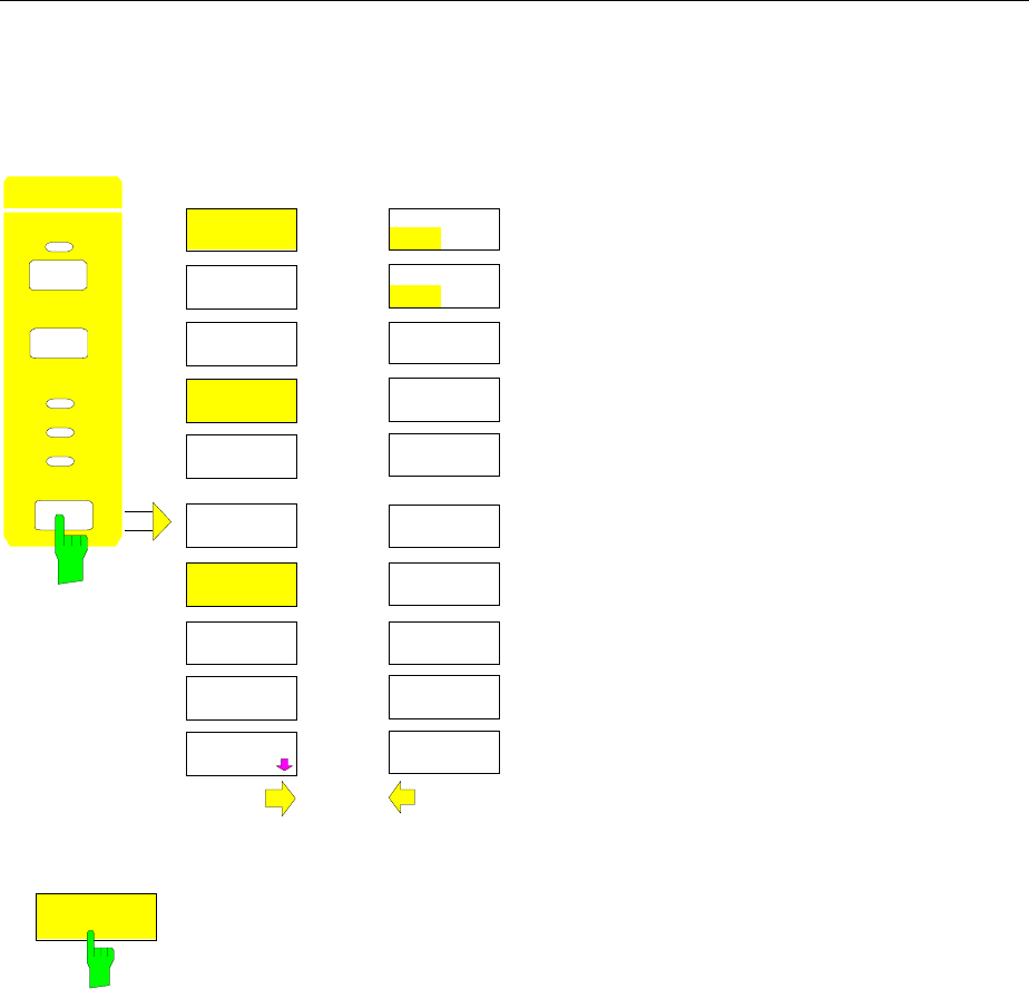
FSE Coupled Settings
1065.6016.12 4.171 E-15
Setting and Coupling the Coupling Resolution, Video Bandwidth and Sweep
Time
SWEEP COUPLING menu
COUPLING
DEFAULT
COUPLING
TRIGGER
SWEEP
RBW
VBW
SWT
SWEEP COUPLED
FUNCTIONS
RES BW
MANUAL
RES BW
AUTO
VIDEO BW
MANUAL
VIDEO BW
AUTO
SWEEP TIME
AUTO
SWEEP TIME
MANUAL
COUPLING
RATIO
COUPLED
FUNCTIONS
RBW<=1 KHZ
NORM FFT
MAIN PLL
BANDWIDTH
RBW 1 KHZ
ANA DIG
The COUPLING key calls a menu and a
supplementary menu for setting the resolution
bandwidth, video bandwidth, sweep time and their
coupled states.
The AUTO softkeys are used to couple the
functions. The coupling ratios are selected in the
COUPLING RATIO sub-menu.
The MANUAL softkeys request that the respective
parameter be entered in the entry window. This
parameter is not coupled to the other parameters.
RES BW
AUTO
The RES BW AUTO softkey couples the resolution bandwidth to the selected span.
Changing the span causes automatic compensation of the resolution bandwidth.
Automatic coupling of the resolution bandwidth to span is always recommended
when, for the measurement problem on hand, a favorable setting of the resolution
bandwidth in relation to the selected span is desired.
The coupling ratio is set in the COUPLING RATIO sub-menu.
The coupling is indicated by illumination of the softkey and the active RBW LED.
The RES BW AUTO softkey is only available in the frequency domain (span >
0 Hz). The softkey is blanked in the time domain.
IEC/IEEE-bus command :[SENSe<1|2>:]BWIDth[:RESolution]:AUTO ON
Coupled Settings FSE
1065.6016.12 4.172 E-15
RES BW
MANUAL
The RES BW MANUAL softkey activates the manual entry mode for the
resolution bandwidth.
The resolution bandwidth for models 20 can be set in 1/2/3/5 steps in the
range between 10 Hz and 10 MHz. The nominal resolution bandwidth is the 3-
dB bandwidth. For models 20 equipped with an FFT-filter (option FSE-B5) and
for models 30 the lower limit of the bandwidth is 1 Hz.
For numerical inputs, the values are always rounded to the next valid
bandwidth. For rollkey or the UP/DOWN key entries, the bandwidth is
adjusted in steps either upwards or downwards.
For manual input of the resolution bandwidth (coupling off), the RBW LED on
the front panel remains off.
IEC/IEEE-bus commands
:[SENSe<1|2>:]BWIDth[:RESolution]:AUTO OFF
:[SENSe<1|2>:]BWIDth[:RESolution] 1MHz
VIDEO BW
AUTO
The VIDEO BW AUTO softkey couples the video bandwidth of the FSE to
the resolution bandwidth. If the resolution bandwidth is changed, the video
bandwidth is automatically adjusted.
The coupling of the video bandwidth is always recommended when the
maximum sweep time for a selected resolution bandwidth is to be obtained.
Small video bandwidths require longer sweep times due to the longer settling
time. Large bandwidths reduce the signal/noise ratio.
The coupling ratio is set in the COUPLING RATIO menu.
The coupling is indicated by illumination of the softkey and the lighted VBW
LED on the front panel.
The coupling of the video bandwidth to the resolution filter is also permitted
for display in the time domain (span = 0).
IEC/IEEE-bus command :[SENSe<1|2>:]BWIDth:VIDeo:AUTO ON
VIDEO BW
MANUAL
The VIDEO BW MANUAL softkey activates the manual entry for the video
bandwidth.
The video bandwidth can be selected in 1/2/3/5 steps between 1 Hz and 10
MHz. For bandwidths up to 1 kHz, the maximum video bandwidth is 10 kHz,
for larger resolution bandwidths, there is no restriction to the video bandwidth.
For numerical entries, rounding is made to the next valid bandwidth. For roll-
key or UP/DOWN entries, the bandwidth is adjusted in steps either
downwards or upwards.
For manual input, the video bandwidth (coupling disabled) VBW LED on the
front panel is turned off.
IEC/IEEE-bus commands :[SENSe<1|2>:]BWIDth:VIDeo:AUTO OFF
:[SENSe<1|2>:]BWIDth:VIDeo 10kHz
FSE Coupled Settings
1065.6016.12 4.173 E-15
SWEEP TIME
AUTO
The SWEEP TIME AUTO softkey couples the sweep time to the span, video
bandwidth (VBW) and resolution bandwidth (RBW). The sweep time is
automatically adjusted whenever the span, resolution bandwidth or video
bandwidth are changed. The FSE always selects the shortest sweep time
which will not lead to spurious measurements.
The coupling is indicated by illumination of the softkey and turning on the
SWT LED.
The softkey is only available in the frequency domain (span > 0 Hz). The
softkey is blanked in the time domain.
IEC/IEEE-bus command :[SENSe<1|2>:]SWEep:TIME:AUTO ON
SWEEP TIME
MANUAL
The SWEEP TIME MANUAL softkey activates the manual entry for the sweep
time. At the same time, the coupling of the sweep is cancelled and the SWT
LED is turned off. Other couplings (VIDEO BW, RES BW) remain in effect.
In the frequency domain (span > 0 Hz) and for resolution bandwidths ≥ 1 kHz,
sweep times from 5 ms through 16000 s are allowed in steps that are at most
5% of the sweep time. The digital resolution filters from 10 Hz to 1 kHz allow
a minimum sweep time of 20 ms.
If an FFT-filter is used (models 20 with option FSE-B5 or models 30) the
sweep time is fixed by the display range and resolution bandwidth selected
and therefore can not be changed.
In the time domain (span = 0 Hz), the sweep time range is 1 µs to 2500 s,
selectable in steps that are at most 5% of the sweep time.
Numerical entries are rounded to the next valid sweep time. For rollkey or
UP/DOWN entries, the sweep time is adjusted in steps either downwards or
upwards.
If the selected sweep time is too small for the selected span and bandwidth,
measurement errors will occur. This happens because the available settling
time for the resolution filter or the video filter is too short. The FSE, therefore,
outputs UNCAL on the display
IEC/IEEE-bus commands :[SENSe<1|2>:]SWEep:TIME:AUTO OFF
:[SENSe<1|2>:]SWEep:TIME 10s
COUPLING
DEFAULT
The COUPLING DEFAULT softkey sets all coupled functions to AUTO. The
RBW / VBW ratio is also set to SINE [1] and the SPAN/RBW ratio is set to 50
in the COUPLING RATIO submenu (default setting, COUPLING RATIO
softkey not illuminated).
The relevant softkeys are then illuminated.
IEC/IEEE-bus commands
:[SENSe<1|2>:]BWIDth[:RESolution]:AUTO ON;
:[SENSe<1|2>:]BWIDth:VIDeo:AUTO ON;
:[SENSe<1|2>:]SWEep:TIME:AUTO ON
RBW 1KHZ
ANA DIG
The RBW 1kHz ANA/DIG softkey enables either the analog quartz filter
(ANA) or the digital filter (DIG) for the instruments's resolution bandwidth of 1
kHz. In the default setting, the instrument uses the analog IF filter for the 1-
kHz bandwidth.
IEC/IEEE-bus command
:[SENSe<1|2>:]BWIDth:MODE ANALog | DIGital

Coupled Settings FSE
1065.6016.12 4.174 E-15
RBW <=1KHZ
NORM FFT
The RBW<=1kHz NORM/FFT softkey toggles between fixed filter and FFT-
filter.
This softkey for models 30 of the FSE or for models 20 equipped with option
FFT-filter (FSE-B5).
NORM For resolution bandwidths up to 1 kHz fixed IF-filters are used.
FFT An FFT is performed. The filtered IF-signal is digitalized by the 3-
kHz resolution filters and then transformed into a spectrum by
FFT. The transformation range is equal to the selected span but
covers 4 kHz at maximum. If the span is larger than the
transformation range, serveral subsequent transformations are
performed, the results are combined to form a complete
spectrum. The frequency response of the 3-kHz preselection
filter is compensated for so that the amplitude response within
the transformation range is offset. A flattop window serves as a
window in the time domain so that a high amplitude precision
with good selectivity is obtained.
Span:
- minimum display range: 50× resolution bandwidth selected
- maximum display range:
Resolution bwidths > 20 Hz: 2 MHz (500 FFT-transf./sweep
at maximum)
Resolution bwidths < 20Hz: Reduction to 125 kHz
at 1 Hz resolution bandwidth
Level display range: 100 dB at max. With greater spans, the
trace is limited to 100 dB below the
reference level.
Sweep time: fixed by the bandwidth selected and the
span.
(reason: an FFT-filter represents a block
transformation). The sweep time can not
be changed (softkey inactive).
Detector All settings of the sample detector are
fixed, no other detector can be selected
(softkeys inactive)
Video bandwidth not defined for FFT-transf. therefore it can
not be set (softkeys inactive).
Compared to fixed filters, FFT-filters cut sweep times
considerably. For a display range of 50 kHz and a resolution
bandwith of 100 Hz, e. g., the sweep time is reduced from 25 s to
520 ms. FFT-filters are ideal for stationary signals (sinusoidal
signals or signals that are continuously modulated in time). For
burst signals (TDMA) or pulses, fixed filters should be preferred.
The FFT is a block transformation so that the result depends on
the time relation between the dataset to be transformed and the
burst or pulse signal. A ’gated sweep’ measurement for TDMA
signals is therefore not provided if FFT-filters are used.
IEC/IEEE-bus command :[SENSe<1|2>:]BWIDth:MODE:FFT ON|OFF
FSE Coupled Settings
1065.6016.12 4.175 E-15
MAIN PLL
BANDWIDTH
The MAIN PLL BANDWIDTH softkey opens a selection window for setting
the PLL control bandwidth.
MAIN PLL BANDWIDTH
HIGH
MEDIUM
LOW
AUTO
The first local oscillator is synchronized with the PLL control bandwidth. The
control bandwidth determines the characteristic of the phase noise. A
medium or high control bandwidth improves the phase noise for frequency
differences smaller than 10 kHz to the carrier, whereas a low control
bandwidth improves the phase noise for frequency differences larger than
100 kHz to the carrier. If the control bandwidth is set unfavorably, the phase
noise is deteriorated.
The PLL bandwidth is set in the AUTO mode depending on the RBW and
SPAN according to the following tables:
Models 20 without option B4:
MAIN PLL BANDWIDTH SPAN ≤ 50 kHz
and RBW < 1kHz SPAN > 50 kHz
or RBW ≥ 1kHz
HIGH
MEDIUM X
LOW X
Models 30 or models 20 with Option B4:
MAIN PLL BANDWIDTH SPAN ≤ 100 kHz
and RBW < 3kHz SPAN > 100 kHz
or RBW ≥ 3kHz
HIGH X
MEDIUM X
LOW
The setting is chosen such that the phase noise for small spans with small
resolution bandwidth near the carrier is optimized.
For measurements with small span but with a relatively large frequency
difference to the carrier (>100kHz), the automatic bandwidth setting
deteriorates the phase noise relative to the optimal setting. The MAIN PLL
BANDWIDTH softkey allows to by-pass this automatic setting. Optimal
settings are, as a function of the carrier difference @:
Models 20 without option B4:
MAIN PLL BANDWIDTH @ ≤ 10 kHz @ > 10 kHz
HIGH
MEDIUM X
LOW X
Models 30 or Models 20 with Option B4:
MAIN PLL BANDWIDTH @ ≤ 10 kHz 10 kHz < @ < 100
kHz @ ≥ 100 kHz
HIGH X
MEDIUM X
LOW X
If a larger control bandwidth is needed due to the sweep velocity, the
processor automatically increases the control bandwidth as far as
necessary.
Coupled Settings FSE
1065.6016.12 4.176 E-15
Sweep Coupling Ratio
SWEEP COUPLING-COUPLING RATIO submenu:
COUPLING
RATIO
RBW / VBW
PULSE [.1]
RBW / VBW
SINE [1]
RBW / VBW
NOISE [10]
SPAN / RBW
AUTO [50]
RBW / VBW
MANUAL
COUPLING
RATIO
SPAN / RBW
MANUAL
The COUPLING RATIO softkey opens a sub-menu in
which the coupling ratio between resolution bandwidth,
video bandwidth and the span can be defined.
These settings are effective only for the selected
parameters in ...AUTO of the main menu.
The softkeys RBW/VBW PULSE, RBW/VBW SINE, RBW/
VBW NOISE, RBW/VBW MANUAL are selection keys.
Only one softkey can be enabled (illuminated) at any one
time.
The same is valid for the softkeys SPAN/RWB AUTO [50]
and SPAN / RWB MANUAL.
RBW / VBW
SINE [1]
The RBW / VBW SINE [1] softkey always sets the video bandwidth equal to
the resolution bandwidth.
This is the default setting for the coupling ratio resolution bandwidth to video
bandwidth.
This coupling ratio is recommended when sine-wave signals are to be
measured.
This setting is only effective for the VBW AUTO selection in the main menu.
IEC/IEEE-bus command :[SENSe<1|2>:]BWIDth:VIDeo:RATio SINe
FSE Coupled Settings
1065.6016.12 4.177 E-15
RBW / VBW
PULSE [.1]
The RBW / VBW PULSE softkey sets the following coupling ratio:
video bandwidth = 10 x resolution bandwidth
or
video bandwidth = 10 MHz (= maximum video bandwidth).
This coupling ratio is recommended when the amplitude of pulsed signals is
to be measured. The IF filter characteristics alone determine the pulse shape.
No additional weighting is provided by the video filter.
This setting is only effective for the VBW AUTO selection in the main menu.
IEC/IEEE-bus command :[SENSe<1|2>:]BWIDth:VIDeo:RATio PULSe
RBW / VBW
NOISE [10]
The RBW / VBW NOISE softkey sets the following coupling ratio:
video bandwidth = resolution bandwidth/10
At this coupling ratio, noise and pulsed signals are suppressed in the video
section. For noise signals, the FSE displays the average value.
This softkey is disabled unless VBW AUTO is selected in the main menu.
IEC/IEEE-bus command
:[SENSe<1|2>:]BWIDth:VIDeo:RATio NOISe
RBW / VBW
MANUAL
The RBW / VBW MANUAL softkey activates the entry of the coupling ratio for
resolution bandwidth to video bandwidth.
The range for the RBW/VBW ratio is 0,001 to 1000.
This softkey is disabled unless VBW AUTO is selected in the main menu.
IEC/IEEE-bus command :[SENSe<1|2>:]BWIDth:VIDeo:RATio 10
SPAN / RBW
AUTO [50]
The SPAN / RBW AUTO [50] softkey sets the following coupling (rounding is
made to the next higher value):
resolution bandwidth = span/50
This coupling corresponds to the default state.
This softkey is disabled unless RBW AUTO is selected in the main menu.
IEC/IEEE-bus command
:[SENSe<1|2>:]BWIDth[:RESolution]:RATio 0.02
SPAN / RBW
MANUAL
The SPAN / RBW MANUAL softkey activates the entry for the coupling of
resolution bandwidth and span.
The range for the SPAN/RBW ratio is 1 to 10000.
This softkey is disabled unless RBW AUTO is selected in the main menu.
IEC/IEEE-bus command
:[SENSe<1|2>:]BWIDth[:RESolution]:RATio 0.1
Sweep Trigger FSE
1065.6016.12 4.178 E-15
Sweep Trigger – TRIGGER Key
SWEEP TRIGGER menu:
COUPLING
TRIGGER
SW P
RBW
VBW
SWT
SWEEP TRIGGER
FREE RUN
VIDEO
LINE
EXTERN
TRIGGER
DELAY
RF POWER
SLOPE
POS NEG
The TRIGGER key opens a menu for selecting the various
trigger sources and the trigger polarity. The active trigger
mode is indicated by illumination of the corresponding
softkey.
For triggering modes in which the trigger threshold can be
entered, the corresponding entry window is activated and, if
appropriate, a horizontal trigger line is displayed.
The FREE RUN, VIDEO, LINE, EXTERN and RF-POWER
softkeys are selection switches. Only one key can be
enabled at any one time (illuminated). For sweep operations
controlled by a gate signal, the FREE RUN setting is the only
setting possible.
If triggering has taken place, the trigger LED is turned on at
the beginning of the sweep and then turned off at the end of
sweep.
To indicate that the FSE is set for triggering (= not free run),
the enhancement label TRG is shown on the display. If two
measurement windows are displayed, TRG appears next to
the window which is configured for triggering.
FREE RUN
The FREE RUN softkey activates the free-run sweep mode (default setting),
i.e. the start of a sweep is not explicitly triggered. Once a measurement is
completed, another is started immediately.
IIEC/IEEE-bus command
:TRIGger<1|2>[:SEQuence]:SOURce IMMediate
VIDEO
The VIDEO softkey activates triggering by the displayed voltage.
For the video triggering mode, a level line showing the trigger threshold is
displayed. Using the level line, the threshold can be adjusted with the roll-key
or the UP/DOWN keys.
IEC/IEEE-bus commands
:TRIGger<1|2>[:SEQuence]:SOURce VIDeo
:TRIGger<1|2>[:SEQuence]:LEVel:VIDeo 50PCT
LINE
The LINE softkey activates triggering derived from the mains (line) frequency.
The power supply generates a trigger pulse at the line frequency which is
used to trigger a new sweep.
IEC/IEEE-bus commands
:TRIGger<1|2>[:SEQuence]:SOURce LINE
FSE Sweep Trigger
1065.6016.12 4.179 E-15
EXTERN
The EXTERN softkey activates triggering by an external voltage
(-5V...+5V) at the input connector EXT TRIGGER/GATE on the rear panel.
The trigger threshold can be set in an entry window within a range
of -5V...+5V.
External triggering in the sweep mode "gated sweep" (SWEEP SWEEP-
GATE ON) is not possible, because the EXT TRIG/GATE connector is used
to control the sweep. The softkey is not illuminated in these modes.
IEC/IEEE-bus commands
:TRIGger<1|2>[:SEQuence]:SOURce EXTernal
:TRIGger<1|2>[:SEQuence]:LEVel 2.5V
RF POWER
The RF POWER softkey activates triggering of the measurement by signals
which are outside the measurement channel.
The FSE uses a level detector at the intermediate frequency. The detector
threshold is approximately -20 dBm at the input mixer. This means that the
actual trigger level at the RF input is approx. -20 dBm plus the set RF
attenuation.
The bandwidth at the intermediate frequency is approximately 60 MHz for
model FSEA, approx. 160 MHz for FSEB, FSEM and FSEK. Triggering takes
place when the trigger threshold is exceeded within a 100 MHz band about
the selected frequency. Therefore, the measurement of noise emissions, e.g.,
for pulsed carriers, is possible. The carrier itself is suppressed via the
selected resolution filter.
IEC/IEEE-bus command
:TRIGger<1|2>[:SEQuence]:SOURce RFPower
TRIGGER
DELAY
The TRIGGER DELAY softkey activates the entry window for delay time or a
pretrigger.
The triggering is delayed or advanced relative to the trigger signal by the
entered delay time. The delay time can be set in the range from -100 s to 100
s (default = 0 s).
Note: A negative delay time (pretrigger) can be set in the time domain
(SPAN < 0 Hz) only. The maximum range and the maximum
resolution of the pretrigger is limited by the set sweep time:
max. range = - 499/500 x sweep time
max. resolution = sweep time/500.
Pretriggering is not possible when the rms or the average detector is
activated.
IEC/IEEE-bus command
:TRIGger<1|2>[:SEQuence]:HOLDoff 500us
SLOPE
POS NEG
The SLOPE POS/NEG softkey selects the trigger slope.
The sweep starts after a positive or negative trigger signal edge. The
selected setting is illuminated.
The selection is valid for all trigger modes with the exception of FREE RUN.
The default mode is SLOPE POS.
IEC/IEEE-bus command
:TRIGger<1|2>[:SEQuence]:SLOPe POS |NEG
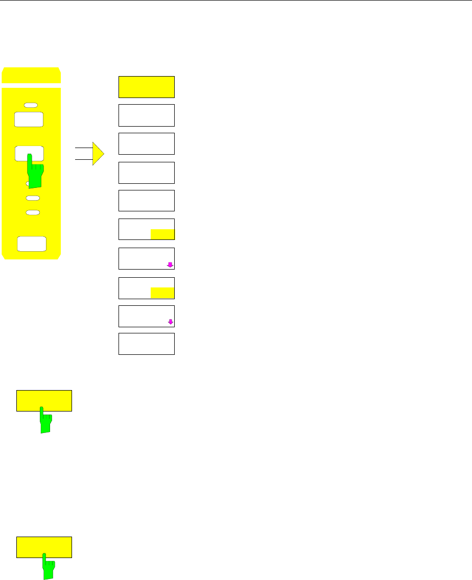
Sweep Control FSE
1065.6016.12 4.180 E-15
Sweep Setup – SWEEP Key
SWEEP SWEEP menu:
COUPLING
TRIGGER
SWEEP
R
VBW
SWT
SWEEP SWEEP
CONTINUOUS
SWEEP
SINGLE
SWEEP
GAP SWEEP
SETTINGS
GAP SWEEP
ON OFF
SWEEP
COUNT
SWEEP TIME
MANUAL
SGL SWEEP
DISP OFF
SWEEP TIME
AUTO
GATE
ON OFF
GATE
SETTINGS
The SWEEP key calls a menu in which the type of sweep
(sweep mode) is determined. In split screen mode, the entries
are valid only for the active measurement window.
In the menu, continuous or single sweep mode, gap-sweep
settings or the external gate function can be selected.
The CONTINUOUS SWEEP and SINGLE SWEEP softkeys
are selection switches. Only one softkey can be active at any
one time.
CONTINUOUS
SWEEP
The CONTINUOUS SWEEP softkey sets the continuous sweep mode. This
means, that the sweep takes place continuously according to the trigger
conditions.
In the case of split screen display with different settings in each measurement
window, screen A is swept first and then screen B. After pressing the softkey,
the sweep is initialized and restarted.
CONTINUOUS SWEEP is the default setting of the FSE.
IEC/IEEE-bus commands :INITiate<1|2>:CONTinuous ON;
:INITiate
SINGLE
SWEEP
The SINGLE SWEEP softkey starts a series of n sweeps according to the
triggering definition. The number of sweeps, n, is determined by the SWEEP
COUNT softkey.
In split screen display mode, the spans of each window are swept
sequentially. If a displayed curve is averaged, the span is swept n times (n =
sweep count). For n = 0, a single sweep takes place.
To indicate that the FSE is set for single sweep, the enhancment label SGL is
shown on the display.
IEC/IEEE-bus commands :INITiate<1|2>:CONTinuous OFF;
:INITiate

FSE Sweep Control
1065.6016.12 4.181 E-15
SWEEPTIME
MANUAL
SWEEPTIME
AUTO
The SWEEPTIME AUTO and SWEEPTIME MANUAL softkeys activate the
automatic or manual selection of the sweep time. These functions are
identical to the entries in the COUPLING menu (see section "Setting and
Coupling the Coupling Resolution, Video Bandwidth and Sweep Time").
IEC/IEEE-bus commands
:[SENSe<1|2>:]SWEep:TIME:AUTO ON | OFF
:[SENSe<1|2>:]SWEep:TIME 10s
SGL SWEEP
DISP OFF
The SGL SWEEP DISP OFF softkey switches off the display during a single
sweep. The trace is displayed when the sweep has been completed.
IEC/IEEE-bus commands :INITiate<1|2>:DISPlay ON | OFF;
:INITiate
SWEEP
COUNT
The SWEEP COUNT softkey activates the entry of the number of sweeps
performed by the FSE after the start of a single sweep. If trace average, max
hold or min hold is switched on, this also determines the number of averages
or minimua/maxima that are taken.
Example:
[TRACE1: MAX HOLD]
[SWEEP: SWEEP COUNT: {10} ENTER]
[SINGLE SWEEP]
The FSE performs the max hold function over 10 sweeps.
The sweep count range is 0 through 32767. For sweep count = 0 or 1, a
sweep is performed. For trace averaging (AVERAGE), sweep count = 0 and
continuous sweep, the FSE performs a sliding average over 10 sweeps in
average mode. For sweep count = 1, no averaging takes place.
The default setting totals 10 sweeps.
Note: The setting for the number of sweeps in the TRACE menu is
equivalent to the setting in the SWEEP menu. In SINGLE SWEEP
mode, the measurement is stopped after reaching the chosen
number of sweeps.
IEC/IEEE-bus command :[SENSe<1|2>:]SWEep:COUNt 0
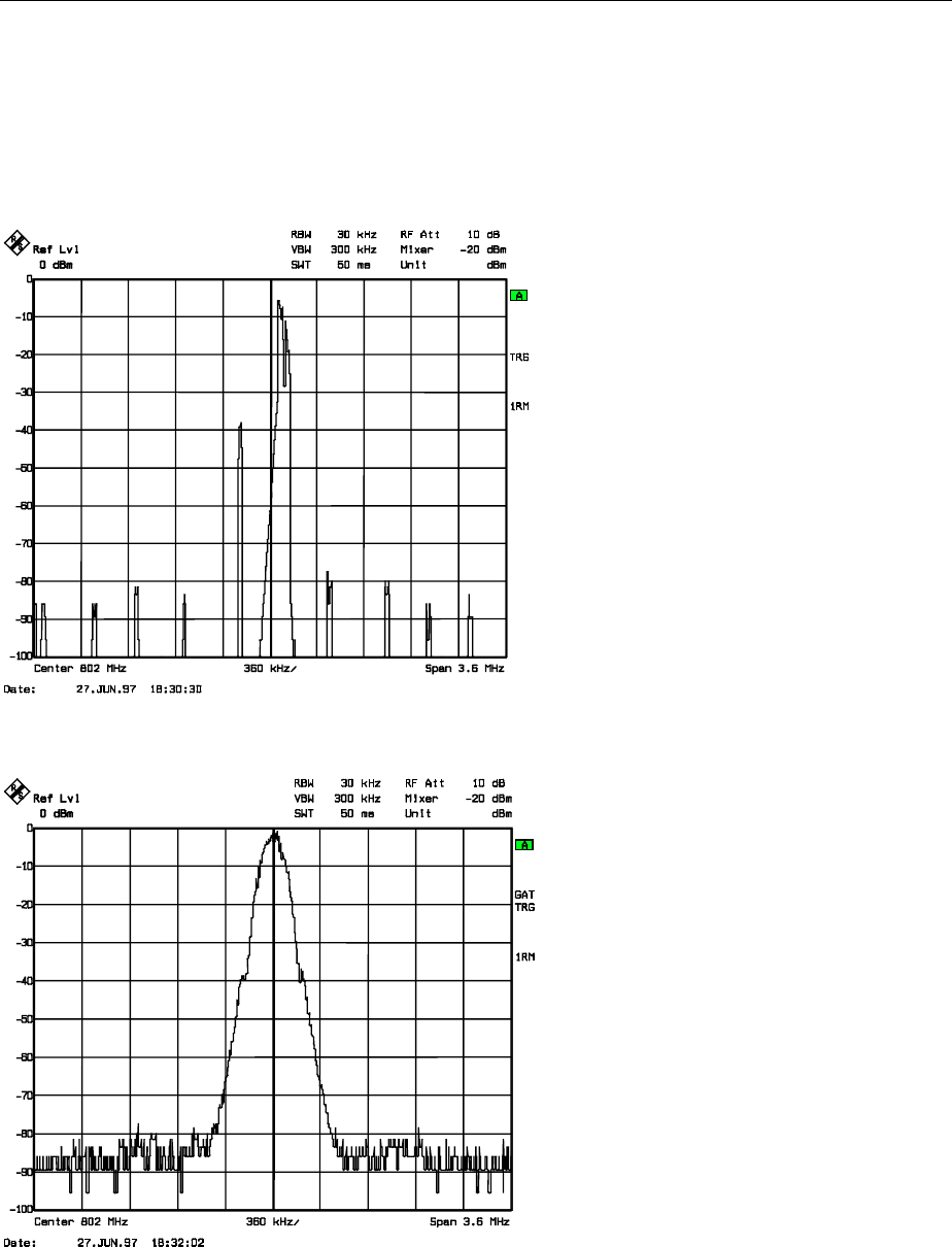
Sweep Control FSE
1065.6016.12 4.182 E-15
Gated Sweep
By using a gate in the sweep mode and stopping the measurement while the gate signal is inactive, the
spectrum of pulsed carriers can be displayed without overlaid frequency components caused by
switching. Similarly, the spectrum can also be examined when the carrier is inactive. The sweep can be
controlled by an external gate or by the internal power trigger.
Fig. 4-8 Pulsed signal with GATE OFF
Fig 4-9 TDMA-signal with GATE ON
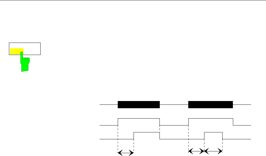
FSE Sweep Control
1065.6016.12 4.183 E-15
The ’gated sweep’ mode is activated by the GATE ON/OFF softkey. The mode is set in the GATE
SETTINGS sub-menu.
SWEEP SWEEP menu:
GATE
ON OFF The GATE ON / OFF softkey switches the sweep mode with an internal or
external gate on/off.
When GATE ON is selected, a signal applied to the rear panel connector EXT
TRIGGER/GATE or the internal RF power detector controls the sweep of the
analyzer. The sweep can be stopped and then continued. A switch from an
edge triggered to a level triggered mode can also be made.
RF
ext. Gate
Meas. active
Delay Length
Gate Mode LEVEL Gate Mode EDGE
Delay
Fig. 4-10 Interaction of the parameters GATE MODE, GATE DELAY and
GATE LENGTH
The softkey is only available in the frequency domain (span > 0).
GATE ON is only possible when the trigger mode is set to FREE RUN
(SWEEP TRIGGER menu) .
To indicate that the FSE is set for sweep mode with external gate, the
enhancement label GAT is displayed on the screen. GAT appears next to the
window for which the gate is configured.
IEC/IEEE-bus command :[SENSe<1|2>:]SWEep:EGATe ON | OFF
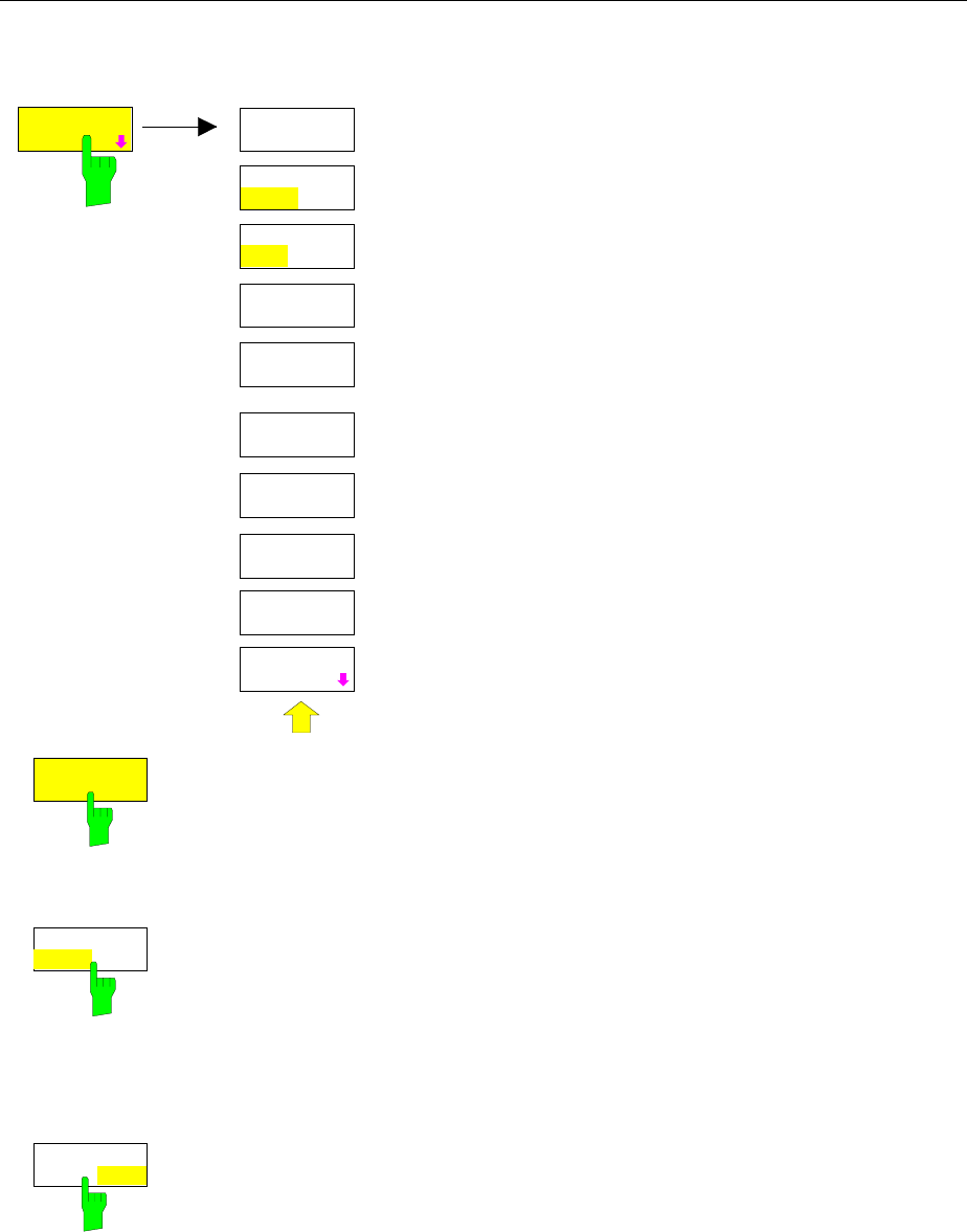
Sweep Control FSE
1065.6016.12 4.184 E-15
SWEEP SWEEP-GATE SETTINGS sub-menu:
GATE
LEVEL
GATE MODE
LEVEL EDGE
GATE
DELAY
GATE POL
POS NEG
GATE
SETTINGS
GATE
SETTINGS
GATE
LENGTH
GATE
EXTERN
GATE
RF POWER
GATE
ADJUST
In the GATE SETTINGS submenu, all settings are made
which are necessary for ’gated sweep’ operation.
On switching to the time domain, the GATE DELAY and
GATE LENGTH times are represented by horizontal time
lines which allow simple adjustment of the gate time.
The softkeys GATE EXTERN and GATE RF POWER provide
alternative settings, only one of them can be active at one
time.
GATE
LEVEL
The GATE LEVEL softkey activates the entry window for defining the
threshold value of the external gate signal.
The threshold can be set between -5V and +5V.
IEC/IEEE-bus command :[SENSe<1|2>:]SWEep:EGATe:LEVel 3V
GATE MODE
LEVEL EDGE
The GATE MODE LEVEL/EDGE softkey selects the trigger mode. The sweep
mode GATE can be operated either as level or as edge triggered.
For level triggering, the GATE LENGTH softkey is deactivated and can not be
used.
IEC/IEEE-bus command
:[SENSe<1|2>:]SWEep:EGATe:TYPE LEVel | EDGE
GATE POL
POS NEG
The GATE POL softkey determines the polarity of the GATE control line.
If level triggering with GATE POL POS is set, the sweep is stopped when the
gate signal is a logic ´ 0 ' (input signal < gate level) at the EXT
TRIGGER/GATE input and then, when the gate signal goes to a logic ' 1 ', the
sweep is continued after a delay time of GATE DELAY.
In the case of edge triggering, the sweep is continued on a ' 0 ' to ' 1'
transition for the duration of GATE LENGTH after a delay (GATE DELAY) has
elapsed.
IEC/IEEE-bus command
:[SENSe<1|2>:]SWEep:EGATe:POLarity POS|NEG
FSE Sweep Control
1065.6016.12 4.185 E-15
GATE
DELAY
The GATE DELAY softkey activates the entry window for setting the delay
time between the gate signal and the continuation of the sweep.
This may be usefull in allowing for a delay between the gate signal and the
stabilization of an RF carrier.
Gate delay values can be selected between 1 µs and 100 s. The resolution is
dependent upon the absolute value of the delay time:
Gate delay Resolution
0 - 500 µs 1 µs
0.5 - 5 ms 5 µs
5 - 50 ms 50 µs
50 - 500 ms 500 µs
0.5 - 5 s 5 ms
5 - 50 s 50 ms
50 - 100 s 500 ms
In the time domain, a time line is displayed separated from the trigger point by
the gate delay time. This simplifies the adjustment of the necessary delay
time.
The values for GATE DELAY and GATE LENGTH are displayed by two time
lines. The duration of the active sweep for span > 0 (continuation of sweep:
GATE DELAY line, stopping of sweep: GATE LENGTH line) is described by
these two lines. A change in parameters causes a shift of the corresponding
line position. After switching to span > 0, the selected times for the gated
sweep are effective.
IEC-bus command :[SENSe<1|2>:]SWEep:EGATe:HOLDoff 100us
GATE
LENGTH
The GATE LENGTH softkey activates the entry window for defining the FSE
sweep duration.
GATE LENGTH can be set to values between 1µs and 100 s. The resolution
is dependent upon the absolute value of the gate length:
Gate length Resolution
0 - 500 µs 1 µs
0.5 - 5 ms 5 µs
5 - 50 ms 50 µs
50 - 500 ms 500 µs
0.5 - 5 s 5 ms
5 - 50 s 50 ms
50 - 100 s 500 ms
In the time domain (ZERO SPAN), a time line is displayed separated from the
GATE DELAY time by the GATE LENGTH time.
The softkey is only available for the GATE MODE EDGE setting (edge
triggering). It is disabled for the GATE MODE LEVEL setting (level triggering).
IEC/IEEE-bus command :[SENSe<1|2>:]SWEep:EGATe:LENGth 10ms
GATE
EXTERN
The GATE EXTERN softkey selects a signal applied to the EXT
TRIGGER/GATE connector on the rear panel of the instrument as a gate
source.
IEC/IEEE-bus command :[SENSe<1|2>:]SWEep:EGATe:SOURce EXT
GATE
RF POWER
The GATE RF POWER softkey selects the internal RF power detector as a
gate source.
IEC-bus command :[SENSe<1|2>:]SWEep:EGATe:SOURce RFPower
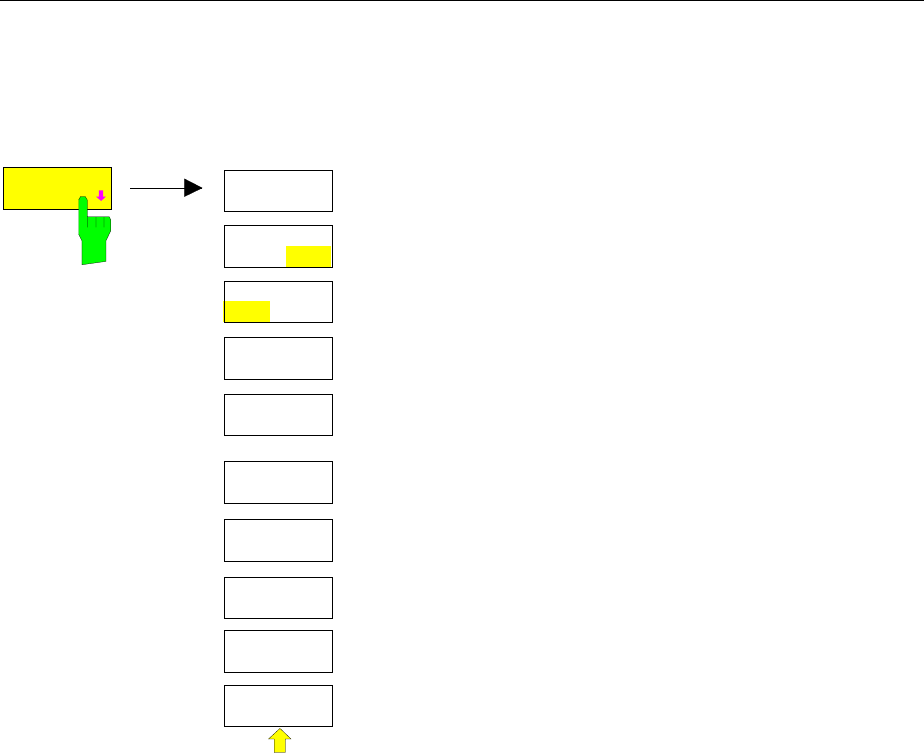
Sweep Control FSE
1065.6016.12 4.186 E-15
Setting the Gate Times
SWEEP SWEEP- GATE SETTINGS - GATE ADJUST submenu:
GATE
LEVEL
GATE MODE
LEVEL EDGE
GATE
DELAY
GATE POL
POS NEG
GATE
LENGTH
GATE
ADJUST
SWEEPTIME
MANUAL
RES BW
MANUAL
VIDEO BW
MANUAL
VIDEO BW
AUTO
GATE
ADJUST The GATE ADJUST softkey opens a submenu comprising all
softkeys that are used to set the parameters relevant for the
’gated sweep’ function.
On pressing this softkey, the display is switched to the time
domain (zero span setting) so that all necessary times can be
checked by means of cursor lines.
The values for Res BW, Video BW and sweep time are taken
from the corresponding settings in the frequency domain.
To make sure that the times can be set correctly
corresponding to the conditions in the frequency domain, the
settings for the resolution bandwidth and the video bandwidth
should not be changed.
The sweep time must be selected such that, e. g., a full burst
is displayed. It usually differs from the sweep time in the
frequency range.
Finally, GATE DELAY and GATE LENGTH can be used to
set the times in such a way that the desired section in the
spectral range is covered.
On quitting the submenu, the original settings in the
frequency range are restored so that the measurement can
be directly performed with the required parameters.
Measurement example:
The modulation spectrum of a GSM or PCS1900 signal to be measured using the ’gated sweep’
function. The signal is generated by the test sender SME03. Its RF-output is directly connected to the
RF input of the FSE.
Settings on the SME03:
FREQ: 802 MHz
Level: 0 dBm: Return
Digital Mod: Select: GMSK: Select
Source: Select: PRBS: Select: Return
Level Attenuation: Select: 60 dB: Return
The SME03 provides a GMSK-modulated TDMA-signal (GSM)
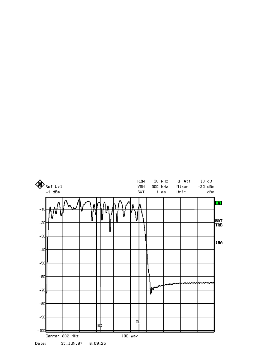
FSE Sweep Control
1065.6016.12 4.187 E-15
Operation steps on the FSE:
[PRESET]
[CENTER: {802} MHz]
[SPAN {3.6} MHz]
[REF LVL: {0} dBm: RF ATTEN MANUAL: {10} dB]
[COUPLING: RES BW MANUAL: {30} kHz]
[TRACE 1: DETECTOR: RMS]
[SWEEP: SWEEPTIME MANUAL: {50} ms;
GATE ON
GATE SETTINGS: GATE MODE EDGE: GATE POL POS: GATE RF POWER
GATE ADJUST: SWEEPTIME MANUAL {1} ms: GATE DELAY {300} µs:
GATE LENGTH: {250} µs]
Note: [KEY] Menu called by the KEY. All indications inside the bracket refer to this menu.
{Number} Numeric value to be entered for the corresponding parameter
SOFTKEY Softkey used to select a parameter or enter a value.
The following figure shows the screen display for gate parameter setting: The vertical lines for gate
delay (GL) and gate length (GL) can be adapted to the burst signal by entering numbers or with the
rollkey.
Fig. 4-11 Setting the GATE DELAY and GATE LENGTH times in the time domain using the GD
and GL lines
On quitting the menu GATE ADJUST, the FSE returns to spectral representation.
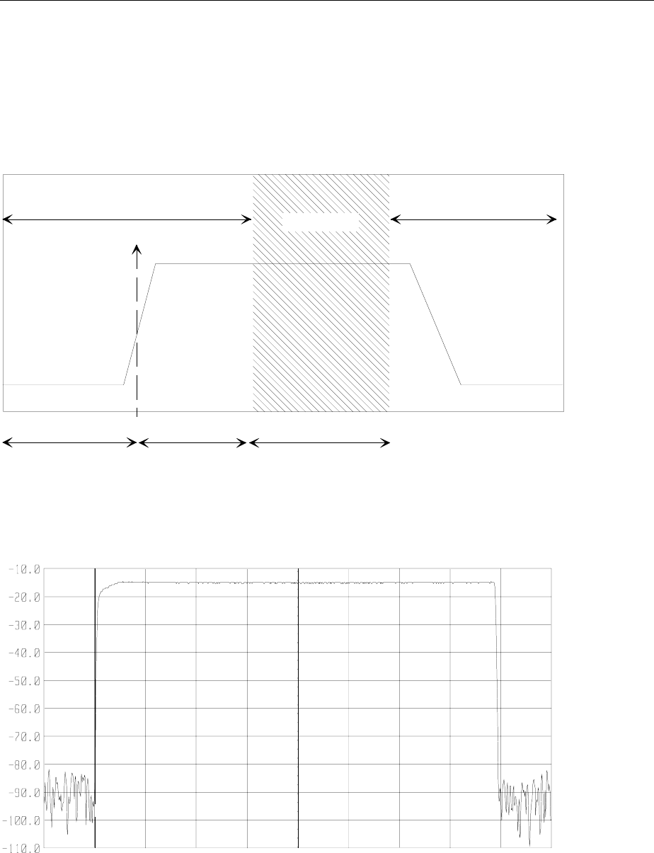
Sweep Control FSE
1065.6016.12 4.188 E-15
Sweep Blanking – Gap Sweep
For measurements in the time domain, the GAP SWEEP function offers a high degree of flexibility with
regard to the display of measurement data. With the PRE TRIGGER softkey, it is possible to display
measurements taken before the trigger time. With the GAP TIME softkey, the measurements within a
predefined time range can be blanked. Thus, it is possible to display the rising and falling edge of a
signal with high resolution on a single diagram.
Trigger
Time
Gap
Time
(not displayed)
Displayed picture Displayed picture
Pre-Trigger Trigger to Gap
Time
Fig 4-12 Trace blanking in sweep mode.– Gap Sweep
Ref Lev
-10.0 dBm
RBW 1 MHz
VBW 300 kHz
SWT 800 µs
RF Att 20 dB
Unit (dBm)
Span 0 Hz 80 µs / Div Center 914 MHz
Fig. 4-13 Display of a burst without gaps
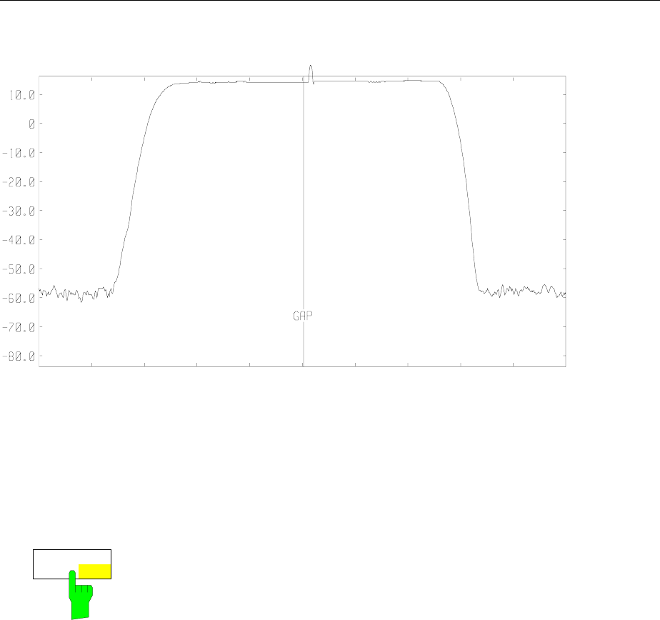
FSE Sweep Control
1065.6016.12 4.189 E-15
Span 0 Hz 50 us / Div Center 914 MHz
Ref Lev
-10.0 dBm
RBW 100 kHz
VBW 100 kHz
SWT 500 us
RF Att 20 dB
Unit (dBm)
Fig. 4-14 Display of a burst with a gap
The GAP SWEEP measurement is activated by the GAP SWEEP ON/OFF softkey. The mode settings
are made in the GAP SWEEP SETTINGS sub-menu.
SWEEP SWEEP menu:
GAP SWEEP
ON OFF
The GAP SWEEP ON/OFF softkey switches the GAP SWEEP measurement
on/off.
The softkey is available only in the time domain.
IEC/IEEE-bus command :[SENSe<1|2>:]SWEep:GAP ON | OFF
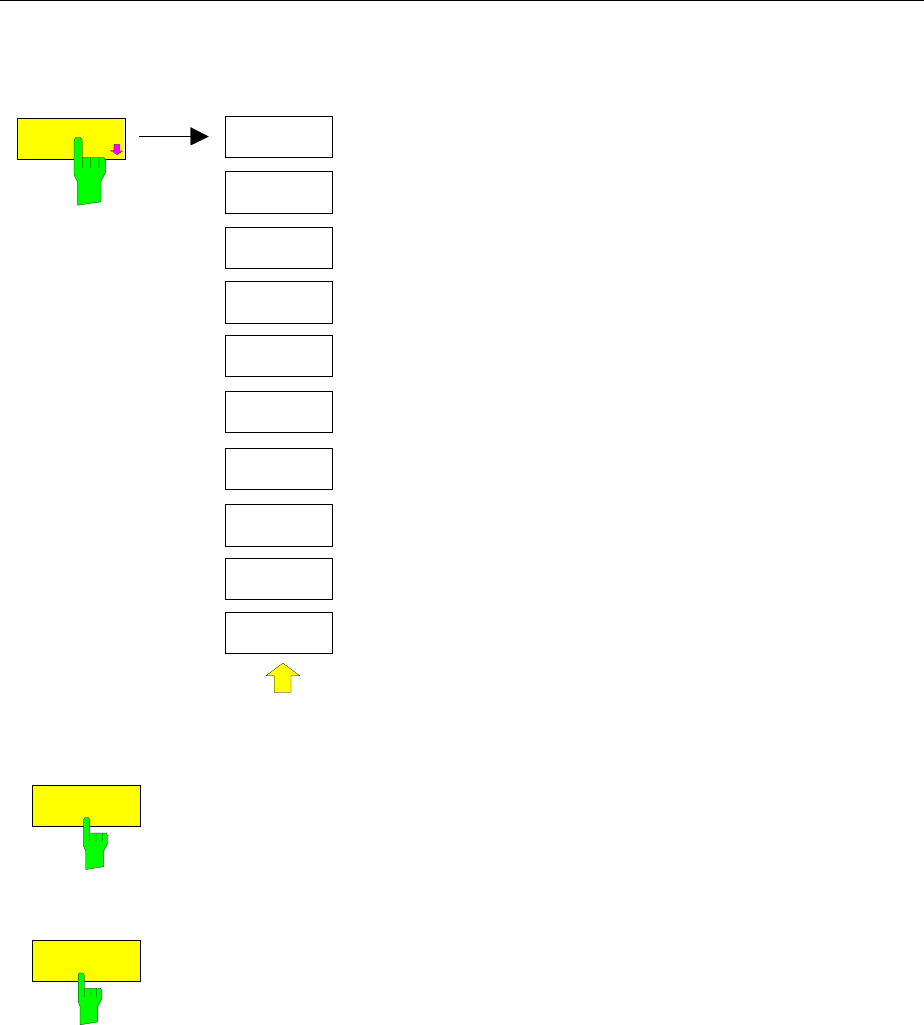
Sweep Control FSE
1065.6016.12 4.190 E-15
SWEEP SWEEP-GAP SWEEP SETTINGS sub-menu:
TRIGGER
LEVEL
PRE
TRIGGER
GAP
LENGTH
TRG TO GAP
TIME
GAP SWEEP
SETTINGS
GAP SWEEP
SETTINGS
The GAP SWEEP SETTINGS softkey opens a sub-menu in
which the parameters for the gap can be selected.
The trigger time corresponds to t = 0. Events occurring
before the trigger time are displayed in negative time.
TRIGGER
LEVEL
The TRIGGER LEVEL softkey activates the entry window for trigger level.
This function corresponds to the setting in the trigger menu.
IEC/IEEE-bus command
:TRIGger<1|2>[:SEQuence]:LEVel:VIDeo 50PCT
PRE
TRIGGER
The PRE TRIGGER softkey activates the entry window for the pre-trigger
time. The pre-trigger time defines the separation between the left edge of the
grid and the trigger time (t = 0).
At the same time the gap sweep is switched on (exception : entry t = 0)
The minimum pre-trigger time is −100 s, the maximum pre-trigger time
depends on the sweep time and the trigger to gap time (max = 100 s). The
maximum resolution is 50 ns.
The PRE TRIGGER value can be entered in the frequency domain (span > 0)
as well as in the time domain and GAP SWEEP OFF mode. It is, however,
only effective when the GAP SWEEP measurement is enabled.
IEC/IEEE-bus command
:SENSe<1|2>:]SWEep:GAP:PRETrigger 100us

FSE Sweep Control
1065.6016.12 4.191 E-15
TRG TO GAP
TIME
The TRG TO GAP TIME softkey opens an entry window for defining the
distance between the trigger time and the beginning of the gap.
The TRIGGER TO GAP TIME range is from 0 to 100 s with a resolution of 50
ns. The length of the gap is defined by GAP LENGTH. If the GAP LENGTH is
0 s, the entered value of TRG TO GAP TIME is only stored.
The TRG TO GAP TIME value can be entered in the frequency domain (span
> 0) as well as in the time domain and for the GAP SWEEP OFF mode. It has
an effect on the measurement only after the GAP SWEEP ON is switched on.
IEC/IEEE-bus command
:[SENSe<1|2>:]SWEep:GAP:TRGTogap 50us
GAP
LENGTH
The GAP LENGTH softkey activates the entry window for defining the gap
within which the measurement values are to be blanked.
The beginning of the gap is defined by TRG TO GAP TIME.
GAP LENGTH can be set to values between 150 ns and 100 s in 1/2/3/5
steps. The resolution is dependent upon the absolute value of the gap length:
Gap length Resolution
150 ns - 50 µs 50 ns
50 - 500 µs 500 ns
0.5 - 5 ms 5 µs
5 - 50 ms 50 µs
50 - 500 ms 500 µs
0.5 - 5 s 5 ms
5 - 50 s 50 ms
50 - 100 s 500 ms
The GAP LENGTH value can be entered in the frequency domain (span > 0)
as well as in the time domain and for the GAP SWEEP OFF mode. It has an
effect on the measurement only after the GAP SWEEP ON is switched on.
IEC/IEEE-bus command :[SENSe<1|2>:]SWEep:GAP:LENGth 400us
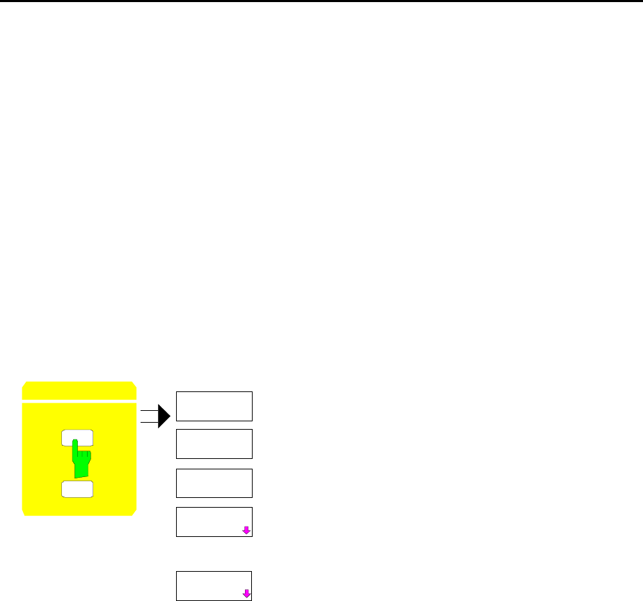
Tracking generator FSE
1065.6016.12 4.192 E-15
Tracking Generator Option
In the normal mode, the tracking generator sends a signal exactly at the input frequency of the
instrument without a frequency offset.
For frequency-converting measurements it is possible to set a constant frequency offset of ±200 MHz
between the output signal of the tracking generator and the receive frequency of the instrument.
Also, two analog input signals can be used to I/Q or AM and BB-FM modulate the output signal (options
FSE-B9, FSE-B11).
The output level is level-controlled and can be set from -20 to 0 dBm in 0.1-dB steps The level control
can also be operated with external detectors. When the tracking generator is equipped with the optional
attenuator, the setting range is extended from -90 dBm to 0 dBm.
The tracking generator can be used in all operating modes. The recording of test setup calibration
values (SOURCE CAL) and the normalization with this correction values (NORMALIZE) is only possible
in operating mode ANALYZER MODE.
SYSTEM MODE menu:
CONFIGURATION
MODE
SE P
MODE
ANALYZER
TRACKING
GENERATOR
VECTOR
ANALYZER
.
.
TV
DEMOD
The MODE key activates the menu in which the
submenu for setting the tracking generator can be
selected in addition to different operating modes.
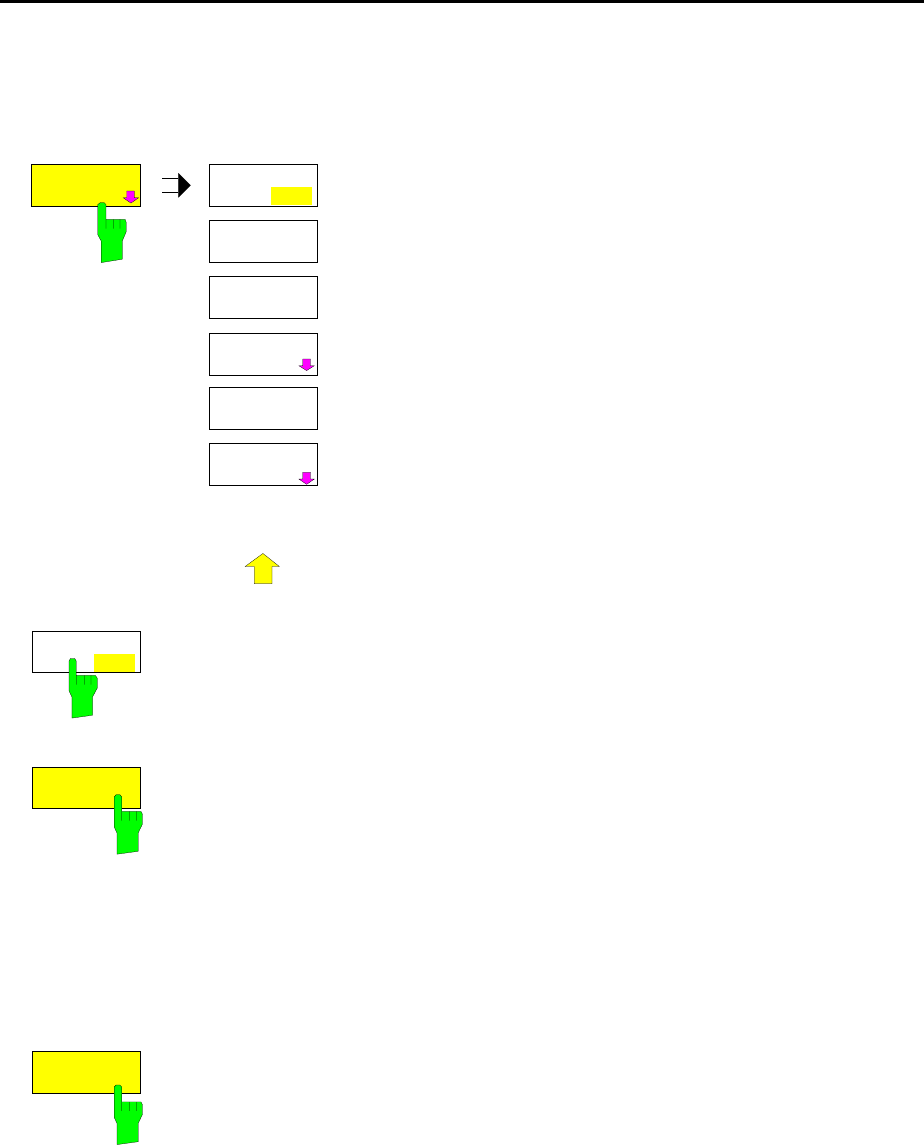
FSE Tracking generator
1065.6016.12 4.193 E-15
Tracking Generator Settings
SYSTEM MODE menu:
TRACKING
GENERATOR
SOURCE
ON OFF
SOURCE
POWER
SOURCE
CAL
FREQUENCY
OFFSET
MODULATION
POWER
OFFSET
TRACKING
GENERATOR
.
.
.
The TRACKING GENERATOR softkey opens a menu for
setting the functions of the tracking generator.
SOURCE
ON / OFF
The SOURCE ON/OFF softkey switches the tracking generator on or off.
Default setting is OFF
IEC/IEEE bus command :OUTPut[:STATe] ON | OFF
SOURCE
POWER
The SOURCE POWER softkey activates the entry of the tracking generator
output level.
The output level can be set from 0 dBm to -20 dBm in 0.1-dB steps. The
setting range is extended to -90 dBm when the tracking generator is equipped
with the optional attenuator FSE-B12.
If the tracking generator is off, it is automatically switched on by the SOURCE
PWR softkey.
Default setting is -20 dBm.
IEC/IEEE bus command
:SOURce:POWer[:LEVel][:IMMediate][:AMPLitude] <num_value>
POWER
OFFSET
The POWER OFFSET softkey activates the entry of a constant level offset of
the tracking generator.
With this offset it is possible to consider attenuators or amplifiers at the output
connector of the tracking generator during the input or output of output levels,
for example.
The permissible setting range is -200 dB to +200 dB in 0.1-dB steps. Positive
offsets apply to a subsequent amplifier and negative offsets to an attenuator.
Default setting is 0 dB.
IEC/IEEE bus command
:SOURce:POWer[:LEVel][:IMMediate]:OFFSet <num_value>
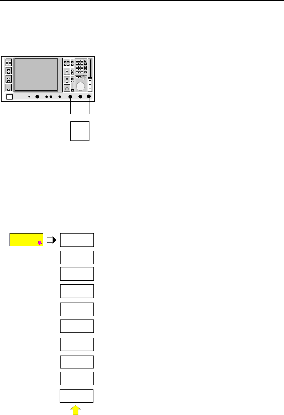
Transmission measurement - Tracking generator FSE
1065.6016.12 4.194 E-15
Transmission Measurement
In this measurement, the transmission characteristic of a two-port network is measured. The built-in
tracking generator is the a signal source. The tracking generator is connected to the input of the DUT.
The input of the instrument is connected to the output of the DUT.
RF INPUTGEN OUTPUT
DUT
Fig. 4-15 Test setup for reflection measurements
Calibration can be carried out to allow for the effects from the test setup (eg. frequency response of
connecting cables).
Calibration of the Transmission Measurement
SYSTEM MODE-TRACKING GENERATOR menu:
REF VALUE
POSITION
SOURCE
CAL
REF VALUE
SOURCE
CAL
NORMALIZE
CAL
TRANS
CAL REFL
OPEN
RECALL
CAL REFL
SHORT
The SOURCE CAL softkey opens a submenu with the
calibration functions for transmission and reflection
measurements.
The calibration for the reflection measurement is described
of the following sections .
To carrry out a calibration for transmission measurements
the whole test setup is through-connected (THRU).
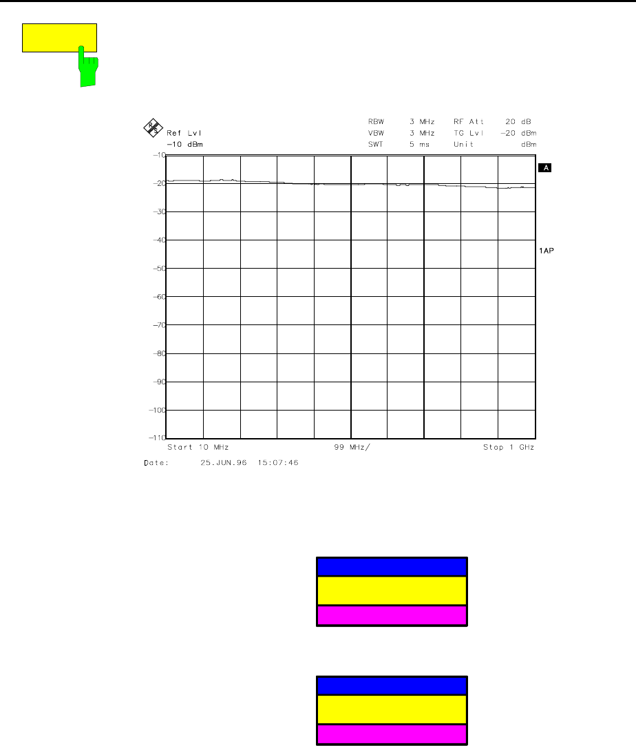
FSE Tracking generator - Transmission measurement
1065.6016.12 4.195 E-15
CAL
TRANS
The CAL TRANS softkey triggers the calibration for the transmission
measurement.
It starts a sweep that records a reference curve. This trace is then used to
obtain the differences to the normalized values.
Fig. 4-16 Trace of a transmission calibration procedure
During the calibration sweep the following message is displayed:
SOURCE CAL
in progress
ABORT
After the calibration sweep the following message is displayed:
NOTE
Calibration complete
ABORT
This message is cleared after approx. 3 seconds.
By saving and recalling the reference data set with the SAVE and RECALL
keys, several calibration datasets can be saved and, then, if necessary, any of
these sets can be selected without going through a new calibration routine.
IEC/IEEE bus command
:[SENSe:]CORRection:METHod TRANsmission
:[SENSe:]CORRection:COLLect[:ACQuire] THRough
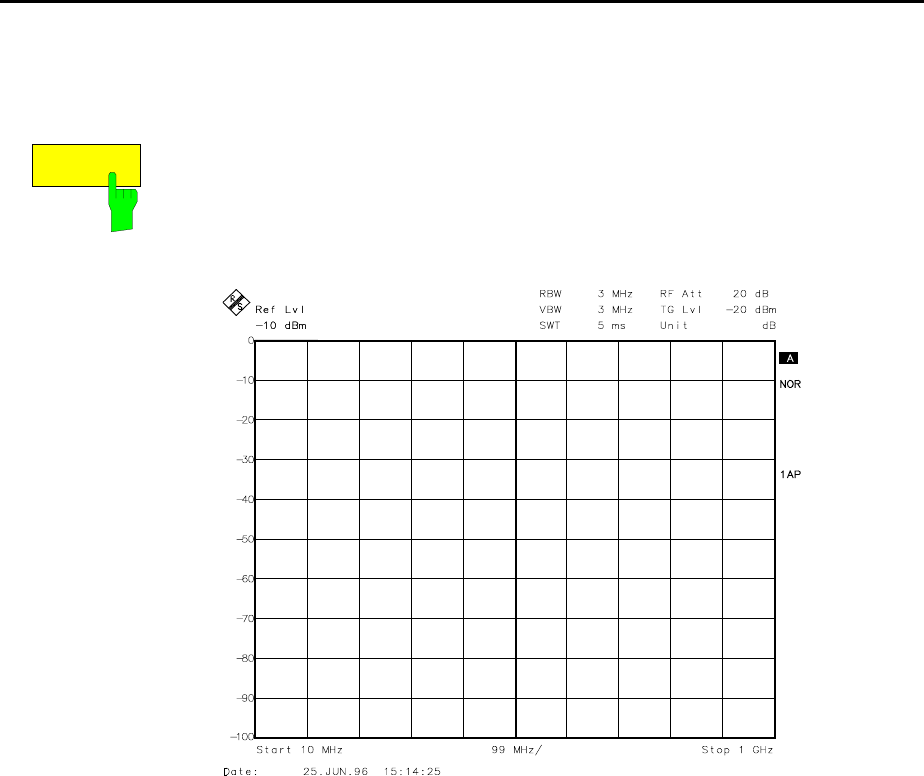
Transmission measurement - Tracking generator FSE
1065.6016.12 4.196 E-15
Normalization
SYSTEM MODE-TRACKING GENERATOR -SOURCE CAL menu:
NORMALIZE
The NORMALIZE softkey switches the normalization on or off. The softkey is
only enabled if the memory contains a correction trace.
If no reference line is switched on when activating the normalization, all
measured values are with reference to the top grid line. The effects of the
test setup is corrected in such a way that the measured values are displayed
at the top grid margin.
Fig. 4-17 Normalized display
In SPLIT SCREEN mode, normalization is switched on in the currently active
screen. Different types of normalization can be activated in the two split
screens.
Normalization is aborted when the ANALYZER operating mode is quit but
can be switched on again as long as the reference trace stored in the
memory has not been overwritten.
IEC/IEEE bus command :[SENSe:]CORRection[:STATe] ON | OFF
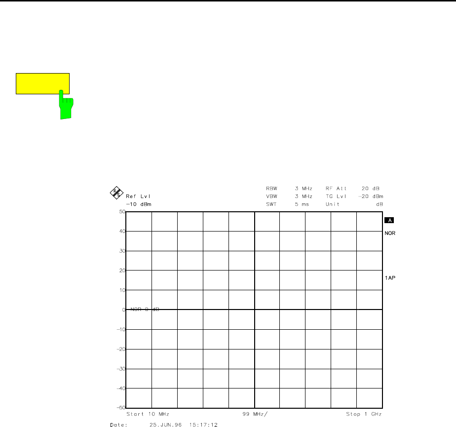
FSE Tracking generator - Transmission measurement
1065.6016.12 4.197 E-15
It is now possible to shift the relative reference point within the grid by using the REF VALUE POSITION
softkey. This means that the trace can be shifted from the upper edge of the grid towards the center of
the grid:
REF VALUE
POSITION
The REF VALUE POSITION softkey (reference position) marks a reference
position in the active screen at which normalization is performed (difference
between trace and reference trace).
If no reference line is switched on, the softkey switches on a reference line
and activates the input of its position. The line can be moved within the grid
limits.
The reference line is switched off by pressing the softkey again.
The function of the reference line is explained in section "Calibration Method"
Fig. 4-18 Normalized measurement, shifted with REF POSITION 50 %
IEC/IEEE bus command
:DISPlay[:WINDow<1|2>]:TRACe<1..4>:Y[:SCALe]:RPOSition
0 to 100PCT
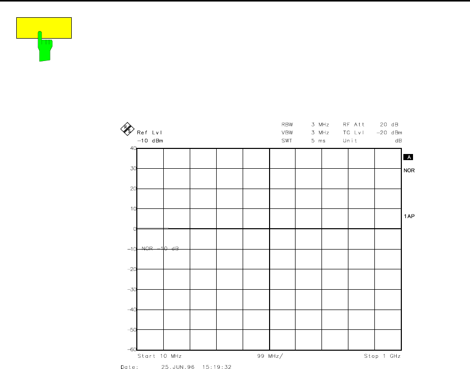
Transmission measurement - Tracking generator FSE
1065.6016.12 4.198 E-15
REF VALUE
The REF VALUE softkey activates the entry of a level difference which is
assigned to the reference line.
With normalization switched on, all measured values are displayed relative
to the reference line, or if the latter is switched off relative to the top grid line
which corresponds to 0 dB with default setting.
REF VALUE always refers to the ative screen.
Fig. 4-19 Measurement with REF VALUE 20 dB and REF VALUE
POSITION 50%
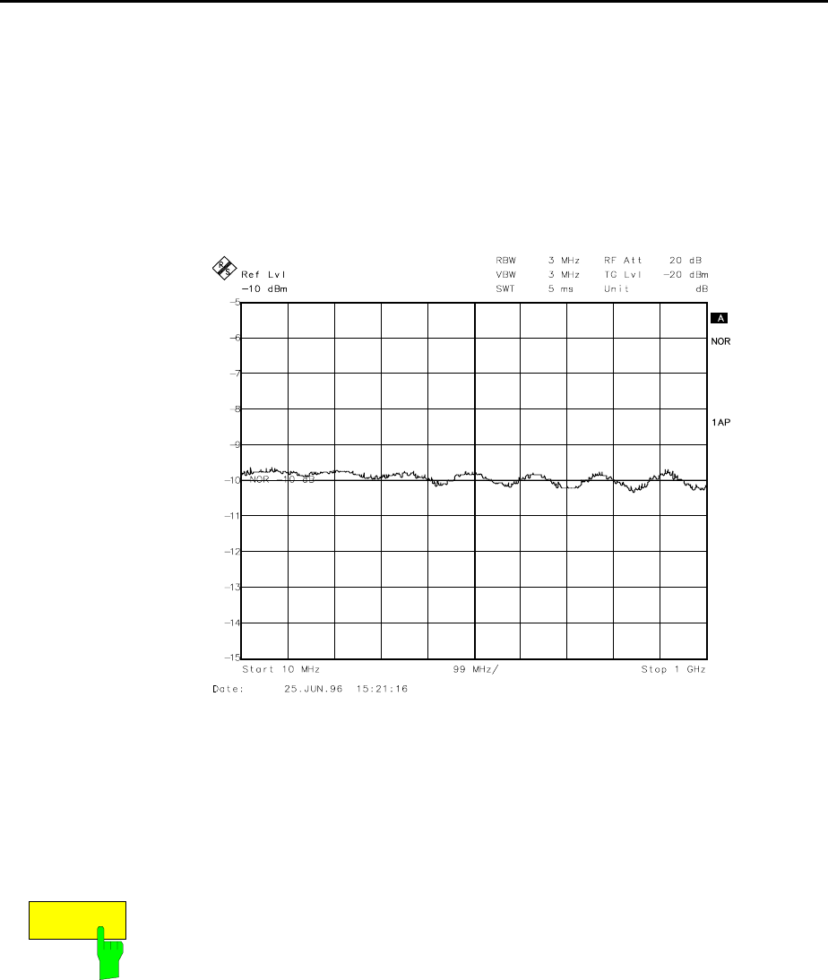
FSE Tracking generator - Transmission measurement
1065.6016.12 4.199 E-15
If, after source calibration, a 10 dB attenuator is inserted into the signal
path between DUT and analyzer input, the measurement trace will be
moved down by 10 dB. Entering a REF VALUE of –10 dB then moves the
reference line down 10 dB. This means that the measured trace and the
reference trace coincide again.
After the reference line has been moved by entering a REF VALUE of –10
dB, deviations from the nominal power level can then be displayed with a
high resolution (e.g. 1 dB/div). The power is still displayed in absolute
values, which means that in the above example 1 dB below the nominal
power (reference line) is equivalent to an attenuation of 11 dB.
Fig. 4-20 Measurement of a 10dB attenuator pad with 1 dB / Div
IEC/IEEE bus command
:DISPlay[:WINDow<1|2>]:TRACe<1...4>:Y[:SCALe]:RVALue
<num_value>
RECALL
The RECALL softkey restores the instrument setting that were used during
calibration.
This can be useful if the device setting was changed after calibration (eg
center frequency setting, frequency deviation, reference level, etc. ).
The softkey is only offered if:
•the analyzer mode has been selected
•the memory contains a calibration data set.
IEC/IEEE bus command :[SENSe:]CORRection:RECall
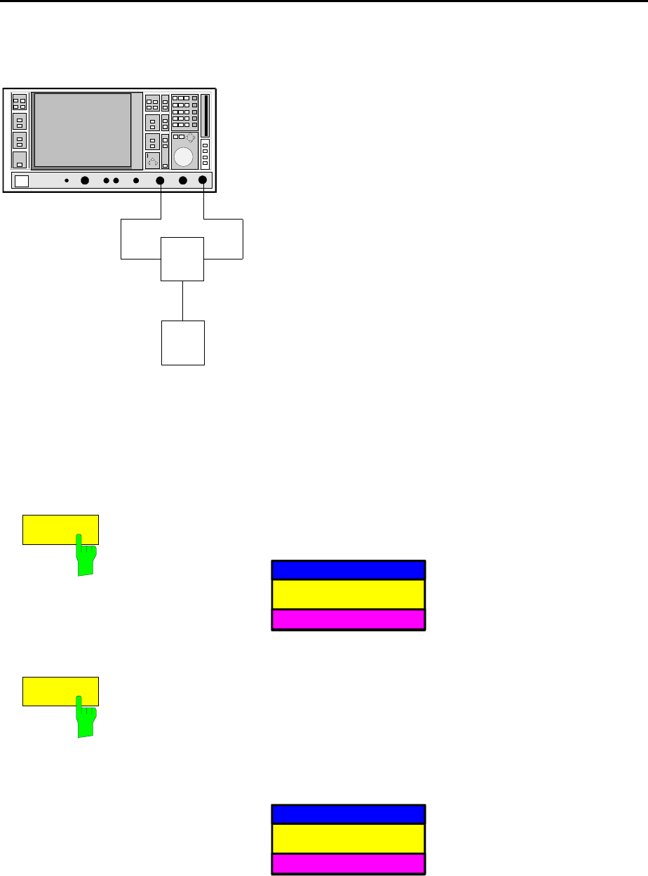
Functioning of Calibration - Tracking generator FSE
1065.6016.12 4.200 E-15
Reflection Measurements
Scalar reflection measurements can be carried out with a reflection-coefficient bridge.
RF INPUTGEN OUTPUT
DUT
BRIDGE
Fig. 4-21 Test setup for reflection measurements
Calibration of Reflection Measurement
This calibration procedure essentially corresponds to that of the transmission measurement.
SYSTEM MODE-TRACKING-SOURCE CAL submenu
CAL REFL
OPEN
CAL REFL
SHORT
The CAL REFL OPEN softkey starts the open-circuit calibration.
During calibration the following message is displayed
SOURCE CAL
in progress
ABORT
IEC/IEEE bus command
:[SENSe:]CORRection:METHod REFLexion
:[SENSe:]CORRection:COLLect[:ACQuire] OPEN
The CAL REFL SHORT softkey starts the short-circuit calibration.
If both calibrations (open circuit, short circuit) are carried out, the calibration
curve is formed by averaging the two measurements and is stored in the
memory. The order of measurements is optional.
The completion of the calibration is indicated by
NOTE
calibration complete
OK
The display is cleared after 3 seconds.
IEC/IEEE bus command
:[SENSe:]CORRection:METHod REFLexion
:[SENSe:]CORRection:COLLect[:ACQuire] THRough

FSE Frequency Converting Measurements
1065.6016.12 4.201 E-15
Calibration Methods
Calibration means forming the difference between current measured values and a reference curve, no
matter what the selected measurement type is (transmission/reflection). The hardware settings used for
measuring the reference curve are included in the reference dataset.
When normalization is switched on, a wide range of device settings can be changed without aborting
normalization. In other words, the number of repeat normalizations is kept to a minimum.
The reference dataset (trace with 500 measured values) is stored internally as a table of 500 points
(frequency/level).
Differences in level settings between the reference curve and the current device setting are calculated
automatically. For small spans, a linear interpolation is used. If the span is increased, , the values at the
left or right border of the reference dataset are extrapolated out to the new start or stop frequency; in
other words, additional linearly extrapolated values are added to the reference dataset.
An enhancement label is used to mark the different levels of measurement accuracy. This enhancement
label is displayed at the right display margin when normalization is switched on and in case of an error
from the reference setting. Three accuracy levels are defined:
Table 4-1 Measurement accuracy levels
Accuracy Enhancement
label Reason/Limitation
High NOR No difference between reference setting and measurement
Medium APP
(approximation) Changes in the following settings:
•coupling (RBW, VBW, SWT)
•reference level, RF attenuation
•start or stop frequency
•output level of tracking generator
•frequency offset of tracking generator
•detector (max peak, min peak, sample...)
Change of frequency:
•at most 500 frozen continuation points within the set sweep limits (corresponds to
a doubling of the span)
- Abortion of
calibration •more than 500 frozen points within the set sweep limits (span doubling)
Note: At a reference level (REF LEVEL) of -10 dBm and at a tracking generator output level of the
same value the instrument operates without a headroom. ie the instrument is in danger of being
overloaded by any signal whose amplitude exeeds the reference line. In this case, either the
message "OVLD" for overload is displayed in the status line or the display range is exceeded
(clipping the top of the trace = Overrange).
This overload can be avoided as follows:
•Reducing the output level of the tracking generator (SOURCE POWER, SYSTEM-MODE-
TRACKING GENERATOR menu)
•Increasing the reference level (REF LEVEL, LEVEL-REF menu)
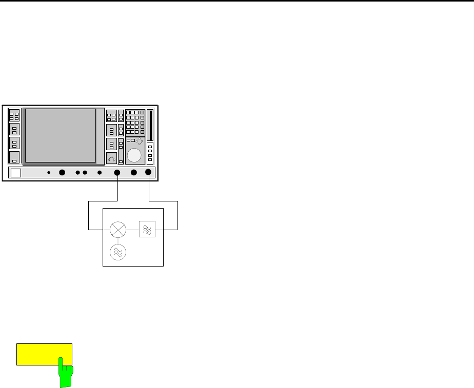
Functioning of Calibration - Tracking generator FSE
1065.6016.12 4.202 E-15
Frequency-Converting Measurements
For frequency-converting measurements (eg on converters) the tracking generator is able to set a
constant frequency offset between the output frequency of the tracking generator and the receive
frequency of the instrument. Up to an output frequency of 200 MHz the measurement can be carried out
in inverted and normal position.
RF INPUTGEN OUTPUT
DUT
Fig. 4-22 Test setup for frequency-converting measurements
SYSTEM MODE-TRACKING GENERATOR menu:
FREQUENCY
OFFSET
The FREQUENCY OFFSET softkey activates the entry of the frequency
offset between the output frequency of the tracking generator and the input
frequency of the instrument. The setting range is ±200 MHz in 1-Hz steps.
The default setting is 0 Hz.
If a positive frequency offset is entered, the tracking generator generates
an output signal frequency above the receive frequency of the instrument.
With a negative frequency offset it generates a signal frequency below the
receive frequency of the instrument. The output frequency of the tracking
generator is calculated as follows:
Tracking generator frequency = receive frequency + frequency offset.
A frequency offset cannot be entered if an external I/Q or FM modulation is
switched on. In this case, the FREQUENCY OFFSET softkey is blocked.
IEC/IEEE bus command
:SOURce:FREQuency:OFFSet <numeric value>
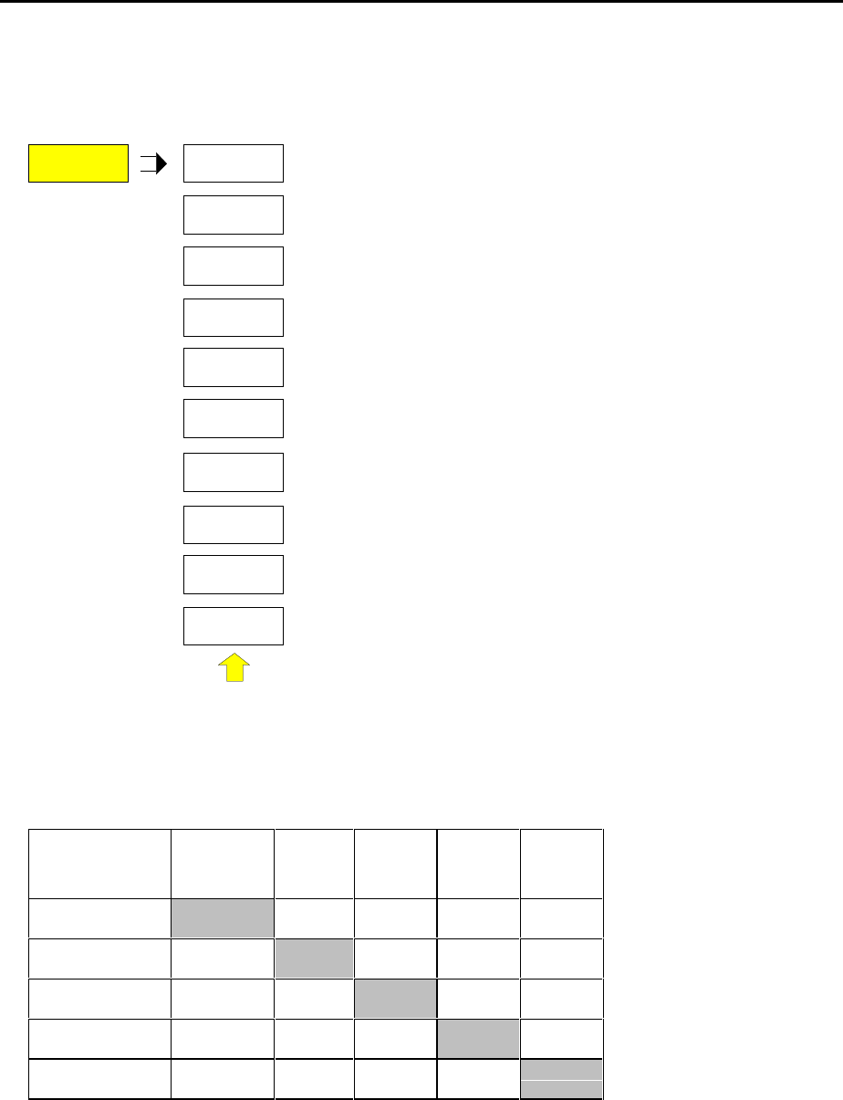
FSE Tracking generator - External modulation
1065.6016.12 4.203 E-15
External Modulation of Tracking Generator
SYSTEM MODE-TRACKING GENERATOR menu:
MODULATION
EXT I/Q
EXT ALC
EXT AM
EXT FM
MODULATION
The MODULATION softkey opens a submenu for
selecting the different modulation types.
The time characteristic of the output signal of the tracking
generator can be varied by applying external signals (input
voltage range -1 V to +1 V).
The functions for amplitude and frequency modulation and
for external level control are always available.
The function IQ modulation is only available in models of
tracking generators that are equipped with the IQ
modulator (FSE-B9 and FSE-B11).
Two BNC connectors at the rear panel are available as
signal inputs. Their function changes depending on
selected modulation type:
TG-INPUT I / AM / ALC and
TG-INPUT Q / FM
The types of modulation can partly be combined with each other and with the frequency offset function.
The following table shows which modulation types can be selected simultaneously and which can be
combined with the frequency offset function.
Table 4-2 Simultaneous modulation types (tracking generator)
Modulation Frequency
offset EXT AM EXT ALC EXT FM EXT I/Q
Frequency offset •••
EXT AM • •
EXT ALC •
EXT FM ••
EXT I/Q
• modulations can be combined

External Modulation - Tracking generator FSE
1065.6016.12 4.204 E-15
EXT AM
The EXT AM softkey activates AM modulation of the tracking generator
output signal.
The modulation signal is connected to the TG-INPUT AM connector. The
maximum possible modulation depth is 80% which corresponds to an input
voltage of 0.8 V.
Switching on external AM deactivates the following functions:
–active external level control
–active I/Q modulation.
IEC/IEEE bus command :SOURce:AM:STATe ON | OFF
EXT ALC
The EXT ALC softkey activates the external level control.
In case of external level control the output level of the tracking generator is
determined from the signal of an external detector. The external detector
has to supply a negative voltage in the range of -0.1 to -1 V which is applied
to the TG-INPUT ALC connector. The setting of the output level is the same
as that of the internal level control but the output level depends on the
external detector.
Switching on an external level control deactivates the following functions:
–active external AM
–active I/Q modulation.
IEC/IEEE bus command :SOURce:POWer:ALC:SOURce INT | EXT
EXT FM
The EXT FM softkey activates FM modulation of the tracking generator
output signal.
The modulation frequency range is 1 kHz to 100 kHz, the deviation is
approx. 1 MHz at an input voltage of 1 V.
The modulation signal is connected to the TG-INPUT FM connector.
Switching on external FM deactivates the following function:
–active I/Q modulation.
IEC/IEEE bus command :SOURce:FM:STATe ON | OFF
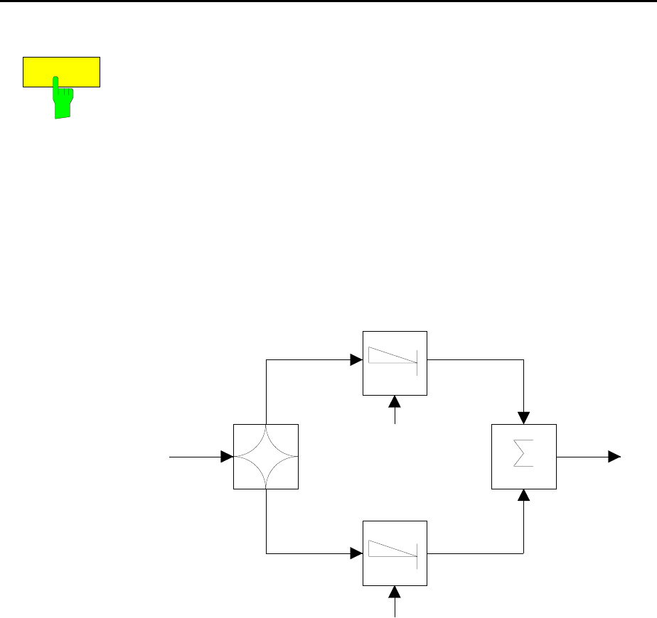
FSE Tracking generator - External modulation
1065.6016.12 4.205 E-15
EXT I/Q
The EXT I/Q softkey is only offered with I/Q modulator option built-in. It
activates external I/Q modulation of the tracking generator (FSE-B9 and
FSE B-11).
The modulation signals are connected to the two input connectors TG-
INPUT IN and TG-INPUT Q at the rear of the unit. The input voltage range
is ±1 V into 50 Ω.
Switching on external I/Q modulation deactivates the following functions:
–active external AM
–active external level control
–active external FM or
–a level offset.
Functional description of quadrature modulator:
0°
90°
I channel
Q channel
I mod
Q mod
RF IN RF OUT
Fig. 4-23 I/Q modulation
I/Q modulation is performed by means of the built-in quadrature modulator.
The RF signal is divided into the two orthogonal components, I and Q
(inphase and quadrature phase). Amplitude and phase are controlled in
each path by the I and Q modulation signal. Adding the two components
generates an RF output signal whose amplitude and phase can be
controlled.
IEC/IEEE bus command :SOURce:DM:STATe ON | OFF
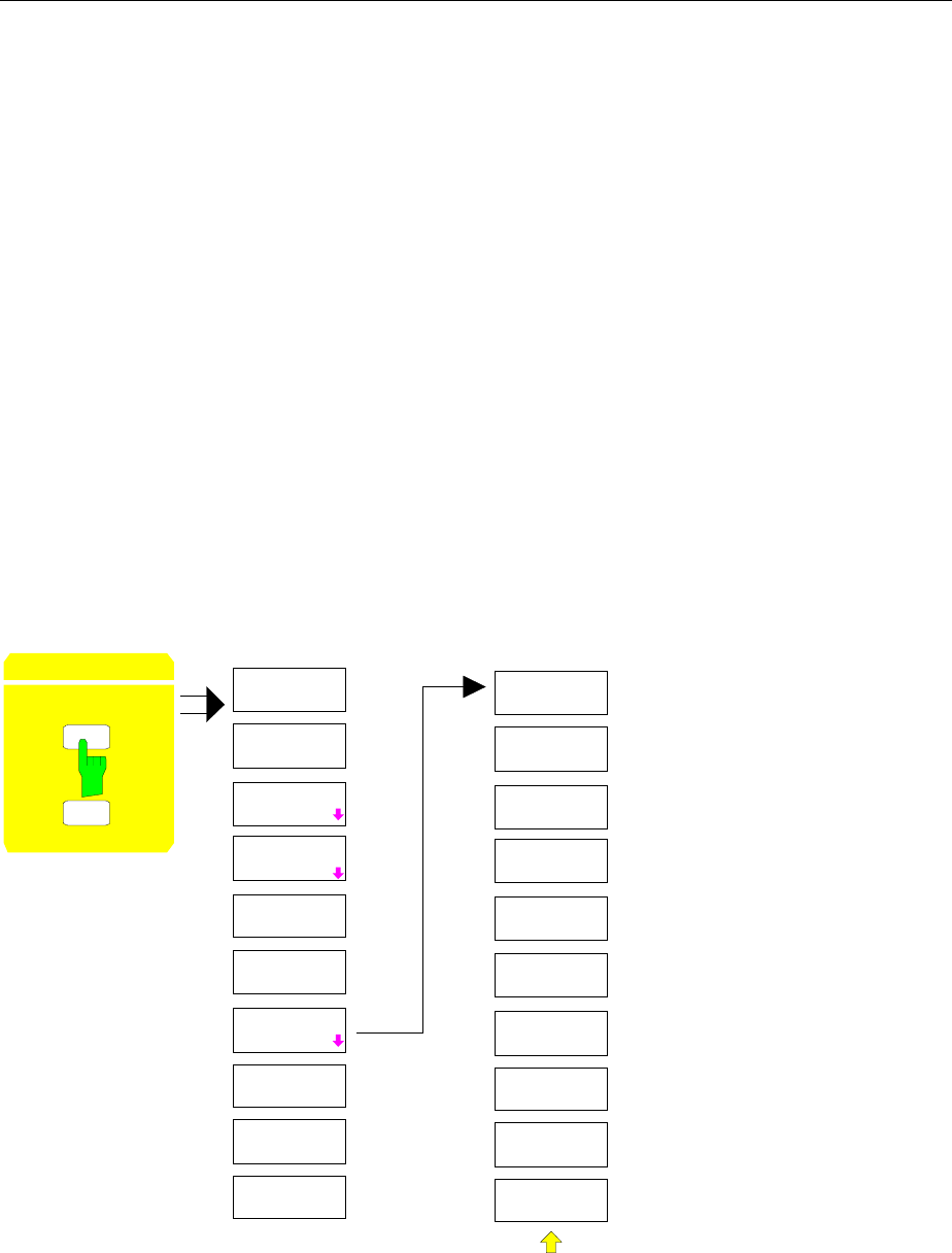
Option TV Demodulator FS
1065.6016.12 4.206 E-15
Option FSE-B3 −TV Demodulator
With the Option TV Demodulator FSE-B3, the FSE permits to demodulate TV signals and synchronize
the trigger signal with the TV signal.
The demodulated TV signal is available at the rear panel of the FSE as CCVS signal for operation of a
TV monitor. The possible settings of video polarity and offset between picture and sound carrier permit
to cover all known standards.
In order to represent particular sections of the TV signal in the time domain, the FSE derives different
trigger signals from the video signal. It is possible to trigger on the frame repetition and on each
individual line of the TV signal.
Configuration of the TV Demodulator
The TV standard is preset using the MODE menu of the FSE. If the Option TV Demodulator is installed,
the MODE menu is supplemented by the softkey TV DEMOD. When the demodulation of TV signals is
switched on using TV DEMOD, the FSE automatically changes to the time domain (zero-span mode).
The default settings following preset of the FSE are sweep time 100 µs, linear level display (LIN %) and
5 MHz IF bandwidth. Measurement of the spectrum is still possible.
Menu: CONFIGURATION MODE
CONFIGURATION
MODE
SETUP
ANALYZER
RECEIVER
TRACKING
GENERATOR
VECTOR
ANALYZER
FFT
AF DEMOD
MODE
TV DEMOD
TV DEMOD
VIDEO POL
POSITIVE
VIDEO POL
NEGATIVE
PICT/SOUND
OFFSET
625 LINE
SYSTEM
525 LINE
SYSTEM
TV DEMOD
OFF
The softkey TV DEMOD switches on the TV demodulator and simultaneously opens a submenu in
which the parameters of the video signal can be set. If the TV demodulator is switched on, the softkey is
backlighted. The other available modes are switched off.
FSE TV Demodulator
1065.6016.12 4.207 E-15
VIDEO POL
NEGATIVE
VIDEO POL
POSITIVE
The soft keys VIDEO POL NEGATIVE and VIDEO POL POSITIVE determine
the polarity of the video signal. The two softkeys are selector switches.
Positive video polarity is to be selected e.g. for standard L signals, negative
video polarity for signals according to the standards B/G/I/M (color standard
PAL or NTSC). Default setting is VIDEO POL NEGATIVE.
IEC/IEEE bus command
:TRIGger<1|2>[:SEQuence]:VIDeo:SSIGnal:POLarity POS|NEG
625 LINE
SYSTEM
525 LINE
SYSTEM
The soft keys 625 LINE SYSTEM and 525 LINE SYSTEM permit to select
the line system to be used. The two softkeys are selector switches.
Default setting is 625 LINE SYSTEM.
IEC/IEEE bus command
:TRIGger<1|2>[:SEQuence]:VIDeo:FORMat:LPFRame 625|525
PICT/SOUND
OFFSET
The soft key PICT/SOUND OFFSET is used to set the offset between the
demodulated picture carrier and the test channel of the FSE.
The setting range is 0 to 6.5 MHz. The frequency resolution for the offset is
25 kHz.
No offset is set in the default setting.
With the offset 0 MHz, the FSE measures at the frequency of the picture
carrier. This setting permits to measure the time characteristic of the video
signal.
If an appropriate offset between picture and sound carrier is set, the picture
can be seen on a connected TV monitor and the sound simultaneously
monitored via the AF demodulator. To this end, the FSE needs to be tuned to
the frequency of the sound carrier.
The picture/sound carrier offsets for the most commonly used TV standards
are as follows:
Standard B/G and L 5.5 MHz
Standard M and N 4.5 MHz
Standard I 6 MHz
IEC/IEEE bus command <:SENSe1|2>:TV:POFFset 0 ... 6.5 MHz
TV DEMOD
OFF
The soft key TV DEMOD OFF switches off the TV demodulator.
IEC/IEEE bus command <:SENSe1|2>:TV[:STATe] ON | OFF
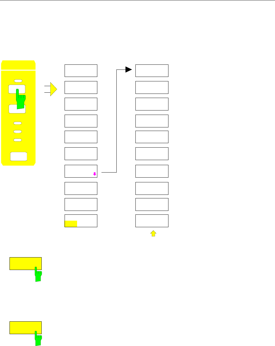
Option TV Demodulator FS
1065.6016.12 4.208 E-15
Triggering on TV Signals
If the Option TV Demodulator is installed, the trigger menu is supplemented by the TV trigger (softkey
TV) and the settings for the trigger condition (TV TRIGGER SETTING).
Menu: SWEEP TRIGGER
COUPLING
TRIGGER
SWEEP
RBW
VBW
SWT
SWEEP
T
R
I
G
G
ER
D
E
L
A
Y
S
L
OP
E
POS
N
E
G
TV
TV TRIGGER
SETTINGS
TRIGGER
VERT SYNC
HOR SYNC
TV TRIGGER
SETTINGS
FREE RUN
VIDEO
LINE
EXTERN
RF POWER
VERT SYNC
ODD FIELD
VERT SYNC
EVEN FIELD
TV
The softkey TV sets the trigger of the FSE to a TV signal according to the
trigger condition selected under TV TRIGGER SETTINGS. The TV trigger
can be set as an alternative to the remaining trigger sources.
IEC/IEEE bus command
:TRIGger<1|2>[:SEQuence]:SOURce TV
TV TRIGGER
SETTINGS
The softkey TV TRIGGER SETTINGS opens a submenu for the TV trigger
settings.
The trigger source can be selected:
It is possible to trigger on the frame repetition (VERT SYNC), on a field
(VERT SYNC EVEN FIELD or VERT SYNC ODD FIELD) or on any line of
the TV picture (HOR SYNC SIGNAL).
IEC/IEEE bus command
:TRIGger<1|2>[:SEQuence]:VIDeo:FIELd:SELect ALL

FSE TV Demodulator
1065.6016.12 4.209 E-15
VERT SYNC
The softkey VERT SYNC sets the trigger to the vertical sync signal. It is
possible to trigger on the frame repetition without a differentiation being
made between the two fields.
IEC/IEEE bus command
:TRIGger<1|2>[:SEQuence]:VIDeo:FIELd:SELect ALL
VERT SYNC
ODD FIELD
VERT SYNC
EVEN FIELD
The softkeys VERT SYNC ODD FIELD or VERT SYNC EVEN FIELD set the
trigger to the vertical sync signal of the first or second field.
IEC/IEEE bus command
:TRIGger<1|2>[:SEQuence]:VIDeo:FIELd:SELect ODD | EVEN
HOR SYNC
The softkey HOR SYNC sets the trigger to the horizontal sync signal. It
activates line input.
The trigger can be set to any line. Depending on the setting of the line
systems, lines 1 to 525 or 625 are possible. If a higher line number is
entered, the trigger is set to the highest possible number.
In order to trigger on test line 17 according to CCIR 473-4, for example, the
line value is to be set to 17. This is also the default setting after switching on
of the TV demodulator.
IEC/IEEE bus command
:TRIGger<1|2>[:SEQuence]:VIDeo:LINE:NUMBer <num_value>

FSE Index
1065.6016.12 10.1 E-1
10 Index
A
Abort
hardcopy ........................................................4.51, 4.52
macro ..................................................................... 4.49
ACP measurement ..................................................... 4.114
absolute/relative ................................................... 4.119
bandwidth............................................................. 4.116
channel spacing ................................................... 4.117
channels............................................................... 4.114
filter ...................................................................... 4.116
limits..................................................................... 4.117
standard ............................................................... 4.115
Addressed command...................................................... 8.5
Adjacent channel power measurement....................... 4.114
Administrator identification............................................ 1.23
Alphanumeric parameter
editing..................................................................... 3.17
AM modulation............................................................ 4.204
Analog trace ............................................................... 4.165
Ascii #........................................................................... 5.14
Attenuation ................................................................. 4.100
Attenuator (tracking generator)................................... 4.193
AUI connector.......................................................1.45, 1.74
Autopeak detector ...................................................... 4.163
Average...................................................................... 4.158
continuous sweep................................................. 4.159
signal per sweep .................................................. 4.139
single sweep ........................................................ 4.159
summary markers................................................. 4.140
sweep count ......................................................... 4.158
Average detector ........................................................ 4.164
Axis labelling .................................................................. 3.7
B
Bandwidth
channel................................................................. 4.116
occupied............................................................... 4.124
resolution.............................................................. 4.171
video .................................................................... 4.172
Beeper......................................................................... 4.40
Block data..................................................................... 5.14
BNC connector .....................................................1.44, 1.73
Boolean parameter ....................................................... 5.13
C
Calibration ...................................................................... 4.9
method ................................................................. 4.201
CCVS signal................................................................4.206
CD-ROM installation......................................................1.36
Center frequency...........................................................4.87
Channel
bandwidth .............................................................4.116
power measurement .............................................4.118
power, absolute/relative ........................................4.119
spacing .................................................................4.117
Characters, special .........................................................6.2
Clear/Write..................................................................4.157
Clock.............................................................................4.39
Colon.............................................................................5.14
COM1/2 interface.................................................4.36, 4.42
Comma .........................................................................5.14
Command
#..............................................................................5.14
addressed.................................................................8.5
colon.......................................................................5.14
comma....................................................................5.14
header.....................................................................5.10
line..........................................................................5.12
long form.................................................................5.11
overlapping execution .............................................5.17
query.......................................................................5.12
question mark ................................................5.12, 5.14
quotation mark ........................................................5.14
recognition ..............................................................5.16
sequence ................................................................5.17
short form................................................................5.11
structure....................................................................5.9
suffix .......................................................................5.11
synchronization.......................................................5.17
syntax elements......................................................5.14
univeral .....................................................................8.5
white space.............................................................5.14
Common commands .......................................................6.4
CONDition register part .................................................5.19
Configuration.................................................................4.20
recall.......................................................................4.75
reset..........................................................................4.2
save........................................................................4.66
Copy
file...........................................................................4.69
limit line.................................................................4.150
trace......................................................................4.160
Coupling......................................................................4.170
default settings......................................................4.173
define....................................................................4.176
Cursor keys...................................................................3.14
Note:
-The softkeys are listed alphabetically under the keyword "Softkey".
- For each softkey, the page in chapter 6 containing the description of the corresponding remote
command is quoted in addition.
- The assignment between IEEE-bus commands and softkeys is described in Chapter 6, Section
"Table of Softkeys with IEC/IEEE-Bus Command Assignment".
- Chapter 6 contains an alphabetical list of all IEEE-bus commands

Index FSE
1065.6016.12 10.2 E-1
D
D Lines ....................................................................... 4.144
Data set
creation .................................................................. 4.75
partial ..................................................................... 4.73
recall ...................................................................... 4.75
save ....................................................................... 4.70
Date............................................................................. 4.45
dB*/MHz ....................................................................... 4.97
dBµA/MHz .................................................................... 4.97
dBµA/mMHz ................................................................. 4.97
dBµV/MHz .................................................................... 4.97
dBµV/mMHz ................................................................. 4.97
dBmV/MHz ................................................................... 4.97
DCL.............................................................................. 5.16
Default
commands................................................................ 6.1
instrument settings ................................................... 4.2
Delete
file .......................................................................... 4.69
line of transducer table ........................................... 4.26
macro ..................................................................... 4.83
message................................................................. 4.16
transducer factor/set............................................... 4.23
Delta marker............................................................... 4.128
step size............................................................... 4.132
Demodulation ............................................................. 4.109
Detector
auto select............................................................ 4.163
autopeak .............................................................. 4.163
average ................................................................ 4.164
max peak.............................................................. 4.163
min peak............................................................... 4.163
RMS..................................................................... 4.164
sample.................................................................. 4.164
Device
reset (hardcopy) ..................................................... 4.64
reset (overall) ........................................................... 4.2
status ..................................................................... 4.13
DIFOVL .......................................................................... 3.4
Directory
create..................................................................... 4.69
rename................................................................... 4.69
Disable
front panel .............................................................. 3.19
keyboard ................................................................ 3.19
Disk formatting.............................................................. 4.69
Display
configuration............................................................. 4.3
energy-saving......................................................... 1.21
mean value........................................................... 4.139
rms value.............................................................. 4.139
Display mode
full screen.......................................................... 3.9, 4.4
split screen........................................................ 3.8, 4.4
Double dagger.............................................................. 5.14
Driver
installation .............................................................. 1.75
NDIS ...................................................................... 1.76
ODI......................................................................... 1.75
packet .................................................................... 1.78
printer..................................................................... 1.28
software.................................................................. 1.39
E
Electrostatic discharge.................................................. 1.18
ENABle register part..................................................... 5.19
Energy saving mode..................................................... 1.21
Enhancement labels........................................................3.6
Entry
abortion...................................................................3.16
alphanumeric parameters........................................3.17
mouse control .........................................................3.22
numeric parameter..................................................3.16
table........................................................................3.18
termination..............................................................3.16
window....................................................................3.15
Error messages...............................................................9.1
Error-queue query .........................................................5.33
ESE (event status enable register)................................5.22
ESR (event status register) ...........................................5.22
Ethernet Adapter..................................................1.44, 1.73
EVENt register part .......................................................5.19
Event status enable register (ESE) ...............................5.22
Event status register (ESR)...........................................5.22
EXT ALC modulation...................................................4.204
Ext Trig/Gate input ........................................................8.24
External noise source....................................................4.32
ExtRef.............................................................................3.4
F
FFT filter......................................................................4.174
Filecopy........................................................................4.69
delete......................................................................4.69
rename....................................................................4.69
sort..........................................................................4.69
Firmware
options (enabling)....................................................4.31
options (info) ...........................................................4.14
update................................................... 1.38, 1.70, 4.47
version....................................................................4.13
FM modulation ............................................................4.204
Frequency
axis labelling .............................................................3.7
counter..................................................................4.111
line........................................................................4.143
measurement window .............................................4.84
offset.......................................................................4.88
start.........................................................................4.84
stop.........................................................................4.86
zoom.......................................................................4.93
Front panel
disable ....................................................................3.19
keyboard emulation........................................3.21, 3.23
FTP operation ......................................................1.55, 1.85
Full screen ...............................................................3.9, 4.4
Function test .................................................................1.22
Fuse.....................................................................1.19, 1.57
G
GET (Group Execute Trigger) .......................................5.16
GPIB
address...................................................................4.34
interface....................................................................8.2
H
Handshake......................................................................8.8
Hardcopy
abort ..............................................................4.51, 4.52
comments ...............................................................4.57
format.............................................................4.59, 4.63
items.......................................................................4.55

FSE Index
1065.6016.12 10.3 E-1
output device.......................................................... 4.60
position................................................................... 4.56
printer..................................................................... 4.58
settings................................................................... 4.54
start................................................................4.50, 4.52
Hardware
configuration........................................................... 4.14
indication of settings................................................. 3.5
installed options...................................................... 4.14
Header.......................................................................... 5.10
Help line editor.............................................................. 3.17
I
I/Q modulation ............................................................ 4.205
IEC/IEEE-bus
address ..........................................................4.34, 4.40
interface ................................................................... 8.2
output device address ............................................ 4.63
IFOVLD .......................................................................... 3.4
Indication
hardware settings..................................................... 3.5
instrument settings ................................................... 3.6
marker information.................................................... 3.5
screen ...................................................................... 3.4
Input
attenuator............................................................. 4.100
Ext Trig/Gate.......................................................... 8.24
external reference................................................... 8.24
Input buffer ................................................................... 5.15
Installation
CD-ROM ................................................................ 1.36
firmware update..............................................1.38, 4.47
keyboard ................................................................ 1.25
monitor ................................................................... 1.26
mouse .................................................................... 1.24
network printer........................................................ 1.34
printer..................................................................... 1.28
rack ........................................................................ 1.19
Windows NT software ............................................ 1.39
Instrument functions ....................................................... 4.1
Instrument settings
indication.................................................................. 3.6
power up ................................................................ 4.76
preset .............................................................. 4.2, 4.76
Interface
IEC/IEEE-bus ........................................................... 8.2
printer..................................................................... 8.22
RS-232-C ................................................................. 8.6
RSIB....................................................................... 8.10
Interrupt........................................................................ 5.32
IST flag......................................................................... 5.22
K
KERMIT........................................................................ 1.86
KeyCAL.......................................................................... 4.9
CENTER ......................................................4.87, 6.193
CONFIG ................................................................. 4.68
COUPLING........................................................... 4.170
cursor..................................................................... 3.14
D LINES ............................................................... 4.143
DELTA.................................................................. 4.128
DISPLAY.................................................................. 4.3
HOLD ..................................................................... 3.19
INFO ...................................................................... 4.13
INPUT .................................................................. 4.100
LIMITS ................................................................. 4.147
LOCAL....................................................................4.49
MENU.....................................................................3.12
MKR......................................................................4.141
MODE.....................................................................4.18
NORMAL ..............................................................4.105
numeric keypad.......................................................3.13
PRESET ........................................................4.2, 6.231
RANGE...................................................................4.98
RECALL..................................................................4.75
REF ........................................................................4.94
roll-key ....................................................................3.14
SAVE......................................................................4.70
SEARCH...............................................................4.133
SETTINGS..............................................................4.54
SETUP....................................................................4.20
SPAN......................................................................4.91
START (frequency).................................................4.84
START (hardcopy).............................. 4.50, 4.52, 6.122
STEP ......................................................................3.20
STOP......................................................................4.86
SWEEP.................................................................4.180
TRACE1 to 4.........................................................4.156
TRIGGER .............................................................4.178
USER......................................................................4.80
Keyboard
configuration ...........................................................4.47
connection .....................................................1.25, 1.62
connector................................................................8.25
disable ....................................................................3.19
external...................................................................3.21
L
Level
attenuation............................................................4.100
control, external ....................................................4.204
line........................................................................4.145
maximum ................................................................4.95
mixer.....................................................................4.101
offset (tracking generator).....................................4.193
range.......................................................................4.98
reference.................................................................4.94
unit..........................................................................4.96
LF demodulation..........................................................4.109
Limit line......................................................................4.147
copy......................................................................4.150
delete....................................................................4.150
edit........................................................................4.151
save......................................................................4.155
select ....................................................................4.148
shift.......................................................................4.155
value.....................................................................4.154
Linedisplay 1,2.............................................................4.145
frequency 1, 2.......................................................4.145
limit .......................................................................4.148
reference...............................................................4.145
threshold...............................................................4.145
time 1, 2................................................................4.146
LO LvD............................................................................3.4
LO Lvl .............................................................................3.4
LO unl .............................................................................3.4
Login/logout (NT controller)...........................................1.23
Lower case......................................................................6.2
LPT interface.................................................................8.22

Index FSE
1065.6016.12 10.4 E-1
M
Macro
abort....................................................................... 4.49
definition................................................................. 4.82
start........................................................................ 4.80
Maintenance................................................................... 8.1
Manual operation............................................................ 3.1
return to........................................................... 4.49, 5.3
Marker ........................................................................ 4.105
center................................................................... 4.141
delta ..................................................................... 4.128
demodulation........................................................ 4.110
indication.................................................................. 3.5
info ....................................................................... 4.109
n-dB-down............................................................ 4.137
normal .................................................................. 4.105
peak ...........................................................4.134, 4.141
search .................................................................. 4.133
search limit........................................................... 4.137
signal track........................................................... 4.108
step size............................................................... 4.127
zoom .................................................................... 4.109
Max hold..................................................................... 4.159
Max peak detector...................................................... 4.163
Mean power (GSM burst)............................................ 4.139
Measurement
frequency-converting............................................ 4.202
recall ...................................................................... 4.75
save ....................................................................... 4.66
transmission ......................................................... 4.194
window ..................................................................... 4.3
Measurement converters.............................................. 4.20
connector .......................................................8.22, 8.23
Memory
battery-backed-up................................................... 1.21
battery-powered ..................................................... 1.58
configuration........................................................... 4.68
Menu overview ............................................................. 3.24
Menu switching............................................................. 3.11
MICROSOFT NET operation ................................1.49, 1.83
Min hold...................................................................... 4.160
Min peak detector....................................................... 4.163
Minimum search ......................................................... 4.134
Mixer level .................................................................. 4.101
Mode ............................................................................ 4.18
signal analysis........................................................ 4.84
tracking generator................................................. 4.192
Modification level of modules........................................ 4.14
Modulation
AM........................................................................ 4.204
EXT ALC .............................................................. 4.204
FM........................................................................ 4.204
I/Q ........................................................................ 4.205
Modulation filter .......................................................... 4.116
Monitor
connecting.............................................................. 4.39
connection.............................................................. 1.26
connector ............................................................... 8.25
Mouse
configuration........................................................... 4.46
connection......................................................1.24, 1.58
connector ............................................................... 8.25
control .................................................................... 3.22
N
NDIS (driver)................................................................. 1.76
Network drivers............................................................. 1.75
Network operating system
FTP................................................................1.55, 1.85
MICROSOFT NET .........................................1.49, 1.80
NOVELL NETWARE............................. 1.49, 1.78, 1.81
TCP/IP...........................................................1.54, 1.85
Network printer connection............................................1.34
Noise power density measurement .............................4.112
Noise source, external...................................................4.32
NOVELL NETWARE operation ............................1.49, 1.81
NT controller..................................................................1.23
NTRansition register part...............................................5.19
Numeric keypad ............................................................3.13
Numeric parameter
editing .....................................................................3.16
Numerical values (command)........................................5.13
O
OCXO .............................................................................3.4
ODI drivers....................................................................1.75
Offset frequency............................................................4.88
Operating mode
signal analysis ........................................................4.84
tracking generator.................................................4.192
Option
FSE-B3 - TV Demodulator ....................................4.206
FSE-B5 - FFT Filter........................................1.42, 1.43
FSE-B8/B9/B10/B11 - Tracking Generator............4.192
FSE-B13 - 1 dB Attenuator ........................ 4.102, 4.103
FSE-B16 - Ethernet Adapter ..........................1.44, 1.73
FSE-B17 - Second IEC/IEEE bus interface.............1.40
Output
AF..................................................................8.22, 8.24
buffer ......................................................................5.17
IF ............................................................................8.24
level (tracking generator).......................................4.193
noise source control................................................8.24
reference.................................................................8.24
sweep .....................................................................8.24
video out .................................................................8.24
Output device
formfeed..................................................................4.64
paperfeed................................................................4.65
OVLD..............................................................................3.4
P
Packet driver.................................................................1.78
Parallel poll ...................................................................5.33
Parallel poll enable register (PPE).................................5.22
Parameter
block data ...............................................................5.14
boolean...................................................................5.13
numerical values.....................................................5.13
string.......................................................................5.14
text..........................................................................5.14
Password
service function.......................................................4.33
Windows NT ...........................................................1.23
Path ..............................................................................4.68
Peak
detector.................................................................4.161
excursion ..............................................................4.135
search...................................................................4.134
Plotter connection .........................................................1.66
Power mean................................................................4.139
Power measurement
adjacent channel...................................................4.122
automatic optimisation of settings .........................4.125
bandwidth, occupied .............................................4.124

FSE Index
1065.6016.12 10.5 E-1
channel................................................................. 4.118
channel configuration ........................................... 4.113
signal/noise .......................................................... 4.120
PPE (parallel poll enable register)................................. 5.22
Preset............................................................................. 4.2
Pre-trigger................................................................... 4.190
Printer connection........................................1.28, 1.66, 8.22
Printing
abort....................................................................... 4.51
Configuration.......................................................... 4.54
start........................................................................ 4.50
Probe Code connector................................................. 8.23
Probe Power connector ................................................ 8.23
PTRansition register part.............................................. 5.19
Q
Quasi analog display .................................................. 4.165
Query....................................................................5.12, 5.33
Question mark ......................................................5.12, 5.14
Quotation mark............................................................. 5.14
R
Rack installation ...................................................1.19, 1.56
Range
level........................................................................ 4.98
Recall data set.............................................................. 4.75
Recording the correction data......................................... 4.9
Reference
dataset (tracking generator).................................. 4.201
external .................................................................. 4.31
line ....................................................................... 4.145
Reference level............................................................. 4.94
offset ...................................................................... 4.95
Remote control
basics....................................................................... 5.1
IEC-bus .................................................................... 5.3
indication......................................................... 4.49, 5.2
RS-232-C ................................................................. 5.4
RSIB................................................................ 5.6, 8.10
switch over............................................................... 5.2
Rename
directory ................................................................. 4.69
file .......................................................................... 4.69
Reset
device....................................................................... 4.2
status reporting system .......................................... 5.34
Resolution bandwidth ................................................. 4.171
RF attenuation............................................................ 4.100
auto...................................................................... 4.101
auto low distortion ................................................ 4.101
auto low noise ...................................................... 4.101
RF input...................................................................... 4.100
RJ45 (star topology) .............................................1.45, 1.74
RMS detector.............................................................. 4.164
RMS value (summary marker).................................... 4.139
Roll-key ........................................................................ 3.14
RS-232-C
interface ................................................................... 8.6
interface functions .................................................... 8.7
transmission parameters .......................................... 8.7
RSIB interface .............................................................. 8.10
S
Sample detector..........................................................4.164
Save
configuration ...........................................................4.66
data set...................................................................4.70
limit line.................................................................4.155
measurement..........................................................4.66
SCPI
conformance information...........................................6.1
introduction ...............................................................5.9
Screen......................................................................3.2, 4.4
full screen .................................................................3.9
indications.................................................................3.4
split screen................................................................3.9
Search
limit .......................................................................4.137
minimum ...............................................................4.134
peak......................................................................4.134
Self test.........................................................................4.15
Serial interface
configuration ..................................................4.36, 4.42
Serial poll ......................................................................5.32
Service functions...........................................................4.32
Service Pack.................................................................1.39
Service request (SRQ) .........................................5.21, 5.32
indication.................................................................4.49
Service request enable register (SRE) ..........................5.21
Setup ............................................................................4.20
general...........................................................4.34, 4.40
Softkey
% POWER BANDWIDTH...........................4.117, 6.205
ACP STANDARD.........................................4.115, 6.52
ACTIVE MKR / DELTA .........................................4.134
ACTIVE SCREEN A/B ..............................................4.4
ADJACENT CHAN POWER................ 4.122, 6.50, 6.51
ADJUST CP SETTINGS ............................ 4.125, 6.205
ADJUST TO TRACE..................................4.165, 4.166
ALL DELTA OFF.......................................... 4.129, 6.10
ALL MARKER OFF......................................4.108, 6.39
ALL SUM MKR OFF ....................................4.140, 6.59
AM .................................................... 4.109, 4.110, 6.45
AMPERE........................................................4.98, 6.62
ANALOG TR ON/OFF..................................4.165, 6.99
ANALYZER......................................... 4.18, 4.84, 6.130
APPEND NEW........................................... 4.167, 6.118
area ........................................................................3.10
ASCII COMMENT...................................... 4.168, 6.118
ASCII CONFIG......................................................4.167
ASCII EXPORT.......................................... 4.167, 6.138
ATT SWITCHES............................................4.17, 6.90
ATTEN AUTO LOW DIST..........................4.101, 6.127
ATTEN AUTO LOW NOISE....................... 4.101, 6.127
ATTEN AUTO NORMAL............................ 4.101, 6.127
ATTEN STEP 1dB/10dB ................. 4.102, 4.104, 6.128
AUTO 0.1 * RBW .........................................4.89, 6.194
AUTO 0.1 * SPAN........................................4.89, 6.194
AUTO 0.5 * RBW .........................................4.90, 6.194
AUTO 0.5 * SPAN........................................4.90, 6.194
AUTO RECALL............................................ 4.76, 6.136
AUTO SELECT.......................................... 4.163, 6.181
AUTO x * RBW ............................................4.90, 6.194
AUTO x * SPAN...........................................4.90, 6.194
AVERAGE ........................................ 4.158, 6.98, 6.166
AVERAGE ON/OFF.....................................4.140, 6.59
BASELINE CLIPPING..................................4.146, 6.16
BLANK......................................................... 4.158, 6.99
BRIGHTNESS..................................................4.6, 6.93
C/N ..................................................... 4.120, 6.50, 6.51
C/No ................................................... 4.120, 6.50, 6.51
CAL CORR ON/OFF......................................4.11, 6.64
CAL I/Q..........................................................4.10, 6.63

Index FSE
1065.6016.12 10.6 E-1
CAL LO SUPP................................................4.10, 6.64
CAL LOG........................................................4.10, 6.64
CAL REFL OPEN.......................................4.200, 6.172
CAL REFL SHORT.....................................4.200, 6.172
CAL RES BW .................................................4.10, 6.63
CAL RESULTS....................................................... 4.12
CAL SHORT...................................................4.10, 6.64
CAL TOTAL....................................................4.10, 6.63
CAL TRANS...............................................4.195, 6.172
CENTER FIXED..............4.85, 4.86, 4.92, 6.194, 6.195
CENTER MANUAL.......................................4.87, 6.193
CH FILTER ON/OFF ....................................4.116, 6.52
CHANNEL BANDWIDTH............................4.116, 6.204
CHANNEL POWER.............................4.118, 6.50, 6.51
CHANNEL SPACING .................................4.117, 6.203
CLEAR ALL MESSAGES....................................... 4.16
CLEAR MESSAGE.......................................4.16, 6.230
CLEAR/WRITE.............................................4.157, 6.98
COLOR ON/ OFF.........................................4.55, 6.121
COM PORT 1/2........................4.36, 4.42, 6.227, 6.228
COMMENT SCREEN A/B ............................4.57, 6.123
CONFIG ............................................................... 4.167
CONFIG DISPLAY ................................................... 4.6
CONTINUOUS SWEEP .............................4.180, 6.125
COPY...........................................................4.69, 6.134
COPY (TRACE)..........................................4.160, 6.234
COPY LIMIT LINE........................................4.150, 6.28
COPY SCREEN ...........................................4.55, 6.122
COPY TABLE...............................................4.55, 6.123
COPY TRACE..............................................4.55, 6.124
COUNTER RESOL.......................................4.112, 6.40
COUPLING CONTROL ..................................4.5, 6.131
COUPLING DEFAULT ....................4.173, 6.168, 6.207
COUPLING RATIO............................................... 4.176
CP/ACP ABS/REL.....................................4.119, 6.205
DATA ENTRY FIELD................................................ 4.8
DATA SET CLEAR.......................................4.72, 6.138
DATA SET CLEAR ALL................................4.72, 6.138
DATA SET LIST..................................................... 4.71
DATAENTRY OPAQUE ........................................... 4.8
DATAENTRY X ........................................................ 4.8
DATAENTRY Y ........................................................ 4.8
DATE ...........................................................4.45, 6.229
dB*/MHz.........................................................4.97, 6.62
dBµA ..............................................................4.97, 6.62
dBµV ..............................................................4.97, 6.62
dBm................................................................4.97, 6.62
dBmV .............................................................4.97, 6.62
dBpW .............................................................4.97, 6.62
DECIM SEP ...............................................4.167, 6.118
DEFAULT COLORS ........................................ 4.7, 6.93
DEFAULT CONFIG......................................4.74, 6.142
DEFAULT POSITION............................................... 4.8
DEFINE MACRO.................................................... 4.82
DEFINE PAUSE..................................................... 4.83
DELETE ............................................4.69, 6.135, 6.137
DELETE FACTOR/SET.....................4.23, 6.175, 6.177
DELETE LIMIT LINE ....................................4.150, 6.28
DELETE MACRO................................................... 4.83
DELETE VALUE (limit line)................................... 4.155
DELTA 1 to 4................................4.128, 6.9, 6.10, 6.11
DELTA 1/2...............................................6.9, 6.10, 6.11
DELTA ABS REL..........................................4.129, 6.10
DELTA TO STEPSIZE ......................................... 4.127
DETECTOR.......................................................... 4.163
DETECTOR AUTOPEAK ...........................4.163, 6.181
DETECTOR AVERAGE .............................4.164, 6.181
DETECTOR MAX PEAK ............................4.163, 6.181
DETECTOR MIN PEAK..............................4.163, 6.181
DETECTOR RMS.......................................4.164, 6.181
DETECTOR SAMPLE................................4.164, 6.181
DISABLE ALL ITEMS..........................4.74, 4.79, 6.142
DISPLAY COMMENT ......................................4.7, 6.94
DISPLAY LINE 1/2.......................................4.145, 6.15
EDIT ACP LIMITS...................... 4.117, 6.33, 6.34, 6.35
EDIT COMMENT ......................................... 4.71, 6.142
EDIT LIMIT LINE..........................................4.152, 6.22
EDIT NAME ............................. 4.71, 4.76, 6.135, 6.137
EDIT PATH...........4.68, 4.71, 4.76, 4.167, 6.133, 6.137
EDIT TRD FACTOR..................................... 4.24, 6.174
EDIT TRD SET ............................................ 4.27, 6.176
ENABLE ALL ITEMS .......................... 4.74, 4.79, 6.141
ENABLE DEV1 / DEV2 ..................................4.59, 4.65
ENABLE OPTION...................................................4.31
ENTER PASSWORD................................... 4.33, 6.230
ENTER TEXT .........................................................4.57
EXCLUDE LO ON/OFF................................4.135, 6.40
EXECUTE TESTS ...........................................4.15, 6.7
EXT ALC.................................................... 4.204, 6.213
EXT AM ..................................................... 4.204, 6.212
EXT FM .....................................................4.204, 6.213
EXT I/Q...................................................... 4.205, 6.212
EXT REF FREQUENCY ..............................4.31, 6.206
EXTERN (trigger)............................ 4.179, 6.235, 6.236
EXTERNAL KEYBOARD ........................................4.47
FIRMWARE UPDATE..................................4.47, 6.230
FIRMWARE VERSION ....................................4.13, 6.5
FM .................................................... 4.109, 4.110, 6.45
FORMAT DISK ............................................4.69, 6.135
FREE RUN ................................................4.178, 6.235
FREQ AXIS LIN/LOG...................................4.85, 6.210
FREQUENCY LINE 1/2................................4.145, 6.17
FREQUENCY OFFSET .................... 4.88, 4.202, 6.196
FREQUENCY ON/OFF....................................4.7, 6.92
FULL PAGE.................................................4.56, 6.124
FULL SCREEN ................................................4.4, 6.92
FULL SPAN .................................................4.92, 6.194
GAP LENGTH............................................4.191, 6.210
GAP SWEEP ON/OFF............................... 4.189, 6.209
GAP SWEEP SETTINGS .....................................4.190
GATE ADJUST.....................................................4.186
GATE DELAY ............................................ 4.185, 6.209
GATE EXTERN..........................................4.185, 6.209
GATE LENGTH..........................................4.185, 6.209
GATE LEVEL............................................. 4.184, 6.208
GATE MODE LEVEL/EDGE ......................4.184, 6.208
GATE ON / OFF.........................................4.183, 6.208
GATE POL................................................. 4.184, 6.208
GATE RF POWER..................................... 4.185, 6.209
GATE SETTINGS.................................................4.184
GENERAL SETUP.........................................4.34, 4.40
GPIB ADDRESS................................. 4.34, 4.40, 6.226
GRID ABS/REL..................................... 4.95, 4.99, 6.96
HARDCOPY DEVICE ......................... 4.58, 4.60, 6.121
HARDWARE+OPTIONS..................................4.14, 6.6
HEADER ON/OFF .....................................4.167, 6.118
HOLD CONT ON/OFF .................................4.160, 6.99
HORIZONTAL SCALING ...............................4.5, 6.131
INPUT CAL....................................................4.32, 6.89
INPUT RF ......................................................4.32, 6.89
INPUT SELECT.........................................4.101, 4.102
INSERT VALUE (limit line)....................................4.155
KEY CLICK ON/OFF...............................................4.40
LAST SPAN............................................................4.92
LIMIT CHECK............................ 4.117, 6.33, 6.34, 6.35
LINE (trigger) .............................................4.178, 6.235
LINEAR/%......................................................4.99, 6.98
LINEAR/dB ....................................................4.99, 6.98
LOCK ALL...............................................................3.19
LOCK DATA ...........................................................3.19
LOG 10dB/20dB/50dB/100dB/120dB ......................4.98
LOG MANUAL ...................................... 4.99, 6.96, 6.98
LOGO ON/OFF................................................4.7, 6.92

FSE Index
1065.6016.12 10.7 E-1
LOWER LEFT ..............................................4.56, 6.124
LOWER RIGHT............................................4.56, 6.124
MACRO 1 to 7........................................................ 4.81
MACRO TITLE ....................................................... 4.83
MAIN PLL BANDWIDTH ............................4.175, 6.170
MAKE DIRECTORY.....................................4.69, 6.136
MARGIN................................................................. 6.61
MARKER 1 to 4...................................4.106, 6.39, 6.41
MARKER 1/2..................................................6.39, 6.41
MARKER DEMOD......................................4.109, 4.110
MARKER INFO 4.109, 6.14, 6.44, 6.51, 6.57, 6.58, 6.94
MARKER ZOOM ..........................................4.109, 6.45
MAX HOLD .......................................4.159, 6.98, 6.166
MAX LEVEL AUTO ........................................4.95, 6.97
MAX LEVEL MANUAL....................................4.95, 6.97
MEAN...........................................................4.139, 6.58
MIN .....................................................4.134, 6.12, 6.42
MIN HOLD.........................................4.160, 6.98, 6.166
MIXER LEVEL............................................4.101, 6.129
MKR -> CENTER .........................................4.141, 6.59
MKR -> CF STEPSIZE.................................4.142, 6.59
MKR -> REF LEVEL.....................................4.142, 6.60
MKR -> START ............................................4.142, 6.60
MKR -> STOP ..............................................4.142, 6.60
MKR -> TRACE...................................4.142, 6.10, 6.39
MKR DEMOD ON/OFF......................4.109, 4.110, 6.46
MKR STOP TIME..............................4.109, 4.110, 6.46
MKR TO STEPSIZE.....................................4.127, 6.60
MODE COUPLED ..........................................4.5, 6.131
MODULATION ..................................................... 4.203
MONITOR CONNECTED....................................... 4.39
MOUSE.................................................................. 4.46
MOVE ZOOM START ....................................4.93, 6.95
MOVE ZOOM STOP ......................................4.93, 6.95
MOVE ZOOM WINDOW ................................4.93, 6.96
N dB DOWN.................................................4.137, 6.44
NAME (limit line)...........................................4.153, 6.28
NEW FACT/SET.......................4.24, 4.27, 6.173, 6.175
NEW LIMIT LINE.................................................. 4.152
NEXT MIN...........................................4.135, 6.12, 6.42
NEXT MIN LEFT .................................4.135, 6.12, 6.42
NEXT MIN RIGHT...............................4.135, 6.12, 6.42
NEXT PEAK........................................4.134, 6.11, 6.41
NEXT PEAK LEFT ..............................4.134, 6.12, 6.42
NEXT PEAK RIGHT............................4.134, 6.11, 6.41
NOISE..........................................................4.112, 6.45
NOISE SOURCE............................................4.32, 6.89
NORMALIZE ..............................................4.196, 6.172
OCCUPIED PWR BANDW..................4.124, 6.50, 6.51
OPTIONS................................................4.14, 4.31, 6.6
PEAK ..................................................4.134, 6.11, 6.41
PEAK EXCURSION .....................................4.135, 6.43
PEAK HOLD ON/OFF ..................................4.140, 6.59
PHASE NOISE.............................................4.131, 6.13
POWER MEAS SETTINGS.................................. 4.114
POWER OFFSET.......................................4.193, 6.213
PRE TRIGGER (gap sweep) ......................4.190, 6.209
PREDEFINED COLORS ................................. 4.7, 6.93
PRESEL PEAK ..............................................4.11, 6.64
PROBE CODE ON/OFF...............................4.98, 6.240
RBW / VBW MANUAL................................4.177, 6.169
RBW / VBW NOISE....................................4.177, 6.169
RBW / VBW PULSE...................................4.177, 6.169
RBW / VBW SINE [1] .................................4.176, 6.169
RBW <= NORM/FFT ..................................4.174, 6.168
RBW 1kHz ANA/DIG ..................................4.173, 6.168
RBW UP/DOWN................................................... 4.173
RECALL .....................................................4.199, 6.172
RECORD ON/OFF ................................................. 4.82
REF LEVEL....................................................4.95, 6.96
REF LEVEL OFFSET.....................................4.95, 6.97
REF POINT FREQUENCY...........................4.130, 6.13
REF POINT LEVEL......................................4.130, 6.13
REF POINT LVL OFFSET ...........................4.130, 6.13
REF POINT TIME ........................................4.130, 6.13
REF VALUE.................................................4.198, 6.97
REF VALUE POSITION............................... 4.197, 6.98
REFERENCE...............................................4.33, 6.206
REFERENCE FIXED ...................................4.129, 6.13
REFERENCE INT/EXT................................4.31, 6.206
REFERENCE LINE...................................... 4.145, 6.17
REFERENCE POINT...................................4.130, 6.13
REFERENCE PROG ...................................4.33, 6.206
RENAME .....................................................4.69, 6.136
RES BW 3dB/6dB......................................4.172, 6.168
RES BW AUTO.......................................... 4.171, 6.168
RES BW MANUAL..................................... 4.172, 6.167
RESTORE ..............................................................4.47
RF ATTEN MANUAL..................................4.100, 6.127
RF INPUT 50 OHM ......................... 4.101, 4.102, 6.128
RF INPUT 75 OHM/RAM ................ 4.101, 4.102, 6.129
RF INPUT 75 OHM/RAZ................. 4.101, 4.102, 6.129
RF POWER (trigger) .................................. 4.179, 6.235
RMS.............................................................4.139, 6.57
SATURATION..................................................4.7, 6.93
SAVE LIMIT LINE.................................................4.155
SCR. SAVER ON/OFF...................................4.7, 6.100
SCR. SAVER TIME........................................4.7, 6.100
SCREEN A BARGRAPH...........................................4.4
SCREEN A SWEEP..................................................4.4
SCREEN COUPLING ...............................................4.5
SCREENS UNCOUPLED ..............................4.5, 6.131
SEARCH LIMIT ON/OFF .............................4.137, 6.39
SELECT ITEMS..4.74, 4.79, 6.138, 6.139, 6.140, 6.141
SELECT LIMIT LINE.................. 4.148, 6.21, 6.22, 6.28
SELECT MACRO....................................................4.83
SELECT MARKER................................................4.134
SELECT OBJECT.....................................................4.6
SELECT QUADRANT.............................................4.56
SELFTEST.......................................................4.15, 6.7
SERVICE.......................................................4.32, 6.89
SET CP REFERENCE...............................4.119, 6.205
SET NO. OF ADJ CHAN’S......................... 4.114, 6.204
SETTINGS DEVICE 1/2.................................4.58, 4.61
SGL SWEEP DISP OFF ............................ 4.181, 6.126
SHAPE FACT 60/3dB.................................. 4.138, 6.46
SHAPE FACT 60/6dB.................................. 4.138, 6.46
SHIFT X LIMIT LINE....................................4.155, 6.23
SHIFT Y LIMIT LINE........................... 4.155, 6.25, 6.26
SIGNAL COUNT.......................................... 4.111, 6.40
SIGNAL TRACK...........................................4.108, 6.47
SINGLE SWEEP........................................4.180, 6.125
SLOPE POS/NEG......................................4.179, 6.237
SORT MODE ..........................................................4.69
SOURCE CAL.......................................................4.194
SOURCE ON/OFF ..................................... 4.193, 6.143
SOURCE POWER ..................................... 4.193, 6.213
SPAN / RBW AUTO [50]............................ 4.177, 6.168
SPAN / RBW MANUAL.............................. 4.177, 6.168
SPAN FIXED ...................4.84, 4.86, 4.88, 6.193, 6.195
SPAN MANUAL ...........................................4.91, 6.194
SPLIT SCREEN...............................................4.4, 6.92
START FIXED ......4.86, 4.88, 4.92, 6.193, 6.194, 6.195
START MANUAL .........................................4.84, 6.195
STATISTICS..................................................4.17, 6.90
STEPSIZE = CENTER............................................4.90
STEPSIZE AUTO................................ 4.127, 6.14, 6.43
STEPSIZE MANUAL........4.90, 4.127, 6.14, 6.43, 6.193
STOP FIXED ........4.84, 4.88, 4.92, 6.193, 6.194, 6.195
STOP MANUAL........................................... 4.86, 6.195
SUM MKR....................................................4.138, 6.52
SUMMARY MARKER ...........................................4.139
SWEEP COUNT.................. 4.140, 4.159, 4.181, 6.208
SWEEP TIME AUTO .................................4.173, 6.207

Index FSE
1065.6016.12 10.8 E-1
SWEEP TIME MANUAL.............................4.173, 6.207
SYSTEM MESSAGES .................................4.16, 6.230
T1-REF..............................................4.165, 4.166, 6.61
T1-T2+REF .......................................4.165, 4.166, 6.61
T1-T3+REF .......................................4.165, 4.166, 6.61
THRESHOLD LINE ......................................4.145, 6.16
TIME ..................................................4.39, 4.45, 6.231
TIME LINE 1/2..............................................4.146, 6.17
TIME ON/OFF................................................. 4.7, 6.95
TINT................................................................ 4.6, 6.93
TITLE ...........................................................4.57, 6.123
TRACE MATH...................................................... 4.165
TRACE MATH OFF...........................4.165, 4.166, 6.61
TRACKING GENERATOR .....4.18, 4.193, 6.130, 6.143
TRANSD SET RANGES...............................4.29, 6.176
TRANSD SET UNIT .....................................4.28, 6.176
TRANSDUCER FACTOR.............................4.22, 6.174
TRANSDUCER SET..........................4.22, 6.175, 6.177
TRC COLOR AUTO INC ..............................4.55, 6.124
TRD FACTOR NAME...................................4.25, 6.173
TRD FACTOR UNIT .....................................4.25, 6.173
TRD FACTOR VALUES ...............................4.26, 6.174
TRD SET NAME...........................................4.28, 6.175
TRG TO GAP TIME....................................4.191, 6.210
TRIGGER DELAY ......................................4.179, 6.236
TRIGGER LEVEL (gap sweep) ..................4.190, 6.236
UNIT.............................................................4.96, 6.240
UNLOCK ................................................................ 3.19
UPDATE................................................................. 4.47
UPDATE MESSAGES............................................ 4.16
UPPER LEFT ...............................................4.56, 6.124
UPPER RIGHT.............................................4.56, 6.124
USER PORT A/B......................4.35, 4.41, 6.128, 6.143
VALUES (limit line).......................................4.154, 6.25
VECTOR ANALYZER...................................4.19, 6.130
VERTICAL SCALING.....................................4.5, 6.131
VIDEO (trigger)................................4.178, 6.235, 6.236
VIDEO BW AUTO ......................................4.172, 6.169
VIDEO BW MANUAL .................................4.172, 6.169
VIEW............................................................4.157, 6.98
VOLT..............................................................4.98, 6.62
VOLUME....................................................4.110, 6.231
WATT.............................................................4.98, 6.62
X OFFSET....................................................4.150, 6.23
Y OFFSET...........................................4.150, 6.24, 6.26
ZERO SPAN ................................................4.91, 6.194
ZOOM ............................................................4.93, 6.95
ZOOM OFF ....................................................4.93, 6.95
Span............................................................................. 4.91
measurement window............................................. 4.84
Special characters.......................................................... 6.2
Split screen.............................................................. 3.9, 4.4
Split screen mode........................................................... 4.4
SRE (service request enable register) .......................... 5.21
SRQ (service request) ..........................................5.21, 5.32
Start frequency
sweep..................................................................... 4.84
Start-Up................................................................1.18, 1.56
Status byte (STB) ......................................................... 5.21
Status information........................................................... 3.4
DIFOVL .................................................................... 3.4
ExtRef ...................................................................... 3.4
IFOVLD .................................................................... 3.4
LO LvD..................................................................... 3.4
LO Lvl....................................................................... 3.4
LO unl....................................................................... 3.4
MAX / REF LVL........................................................ 3.4
OCXO....................................................................... 3.4
OVLD ....................................................................... 3.4
UNCAL..................................................................... 3.4
Status register
CONDition part....................................................... 5.19
ENABle part ............................................................5.19
ESE ........................................................................5.22
ESR ........................................................................5.22
EVENt part..............................................................5.19
NTRansition part.....................................................5.19
overview..................................................................5.20
PPE ........................................................................5.22
PTRansition part .....................................................5.19
SRE ........................................................................5.21
STATus OPERation................................................5.23
STATus QUEStionable ...........................................5.24
ACPLimit...........................................................5.25
FREQuency......................................................5.26
LIMit..................................................................5.27
LMARgin...........................................................5.28
POWer..............................................................5.29
SYNC ...............................................................5.30
TRANsducer.....................................................5.31
STB.........................................................................5.21
structure..................................................................5.18
sum bit ....................................................................5.19
Status reporting system.................................................5.18
resetting values................................... 5.18, 5.34, 6.214
STB (status byte) ..........................................................5.21
Step size
center frequency .....................................................4.89
delta marker..........................................................4.132
marker...................................................................4.127
setting.....................................................................3.20
Stop frequency
sweep .....................................................................4.86
String ............................................................................5.14
Suffix.............................................................................5.11
Sum bit..........................................................................5.19
Supply voltage, external noise source...........................4.32
Sweep
count.......................................................... 4.159, 4.181
coupling ................................................................4.170
gap........................................................................4.188
gap length.............................................................4.191
gated.....................................................................4.182
mode.....................................................................4.180
single ....................................................................4.180
time.......................................................................4.173
Switching on/off.............................................................1.20
Switching operations .....................................................4.17
Syntax elements
command ................................................................5.14
System messages.........................................................4.16
T
Table entry....................................................................3.18
TCP/IP operation..................................................1.54, 1.85
Test functional...............................................................1.58
Text parameter..............................................................5.14
Thick Ethernet......................................................1.45, 1.74
Thin Ethernet........................................................1.44, 1.73
Time.....................................................................4.39, 4.45
Trace...........................................................................4.156
copy......................................................................4.160
detector.................................................................4.161
export....................................................................4.167
mathematics..........................................................4.165
Transducer....................................................................4.20
entry........................................................................4.23
set...........................................................................4.27
switch on.................................................................4.21
Transmission parameters of RS-232-C ................4.194, 8.7

FSE Index
1065.6016.12 10.9 E-1
Trigger
delay .................................................................... 4.179
external ................................................................ 4.179
free run................................................................. 4.178
gap sweep............................................................ 4.190
line ....................................................................... 4.178
pre-trigger............................................................. 4.190
RF power.............................................................. 4.179
slope .................................................................... 4.179
video .................................................................... 4.178
TV demodulator.......................................................... 4.206
TV-Trigger .................................................................. 4.208
U
UNCAL ........................................................................... 3.4
Units............................................................................. 4.96
Universal command........................................................ 8.5
UNLD.............................................................................. 3.4
Upper case..................................................................... 6.2
User port
configuration..................................................4.35, 4.41
interface ................................................................. 8.21
V
Vector analyzer mode................................................... 4.19
Video bandwidth......................................................... 4.172
View ........................................................................... 4.157
Volume .............................................................4.109, 4.110
W
White space.................................................................. 5.14
Windows NT................................................................. 1.23
administrator........................................................... 1.23
login ....................................................................... 1.23
password................................................................ 1.23
Z
Zero span ..................................................................... 4.91
Zoom..................................................................4.93, 4.157
amplitude.............................................................. 4.157
