R&S/R&S FSE Series Operation Vol 2 R&S
R&S FSEA 20/R+S FSEA 20 remote R+S FSEA 20 remote
R+S FSEA 20 remote R+S FSEA 20 remote
User Manual: R&S/R&S FSE Series Operation Vol 2
Open the PDF directly: View PDF ![]() .
.
Page Count: 429 [warning: Documents this large are best viewed by clicking the View PDF Link!]
- Operating Manual
- Remote Control - Basics
- Introduction
- Brief Instructions
- Switchover to Remote Control
- Messages
- Structure and Syntax of the Device Messages
- Instrument Model and Command Processing
- Status Reporting System
- Structure of an SCPI Status Register
- Overview of the Status Registers
- Description of the Status Registers
- Status Byte (STB) and Service Request Enable Register (SRE)
- IST Flag and Parallel Poll Enable Register (PPE)
- Event-Status Register (ESR) and Event-Status-Enable Register (ESE)
- STATus:OPERation Register
- STATus:QUEStionable Register
- STATus QUEStionable:ACPLimit Register
- STATus QUEStionable:LIMit Register
- STATus QUEStionable:LMARgin Register
- STATus QUEStionable:POWer Register
- STATus QUEStionable:SYNC Register
- Bit No.
- STATus QUEStionable:TRANsducer Register
- Application of the Status Reporting Systems
- Resetting Values of the Status Reporting System
- Description of Commands
- Notation
- Common Commands
- ABORt Subsystem
- CALCulate Subsystem
- CALibration Subsystem
- CONFigure Subsystem
- DIAGnostic Subsystem
- DISPlay Subsystem
- FETCh Subsystem
- FORMat Subsystem
- HCOPy Subsystem
- INITiate Subsystem
- INPut Subsystem
- INSTrument Subsystem
- MMEMory Subsystem
- OUTPut Subsystem
- READ Subsystem
- SENSe Subsystem
- SENSe:ADEMod Subsystem
- SENSe:AVERage Subsystem
- SENSe:BANDwidth Subsystem
- SENSe:CORRection-Subsystem
- SENSe:DETector Subsystem
- SENSe:DDEMod Subsystem
- SENSe:FILTer Subsystem
- SENSe:FREQuency Subsystem
- SENSe:MIXer - Subsystem
- SENSe:MSUMmary Subsystem
- SENSe:POWer Subsystem
- SENSe:ROSCillator Subsystem
- SENSe:SWEep Subsystem
- SENSe:TV Subsystem
- SOURce Subsystem
- STATus Subsystem
- SYSTem Subsystem
- TRACe Subsystem
- TRIGger Subsystem
- UNIT Subsystem
- Alphabetical List of Commands
- Table of Softkeys with IEC/IEEE-Bus Command Assignment
- Basic Instrument - Signal Analysis Mode
- Basic Instrument - General Device Settings
- Operating Mode Vector-Signal Analyzer (Option FSE-B7)
- Operating Mode Tracking Generator (Option FSE-B8 to B11)
- Operating Mode TV Demodulation (Option FSE-B3)
- Operating Mode GSM BTS Analyzer (Option FSE-K11)
- Operating Mode GSM MS Analyzer (Option FSE-K10)
- External Mixer Output (Option FSE-B21)
- Programming Examples
- Maintenance and Instrument Interfaces
- Maintenance
- Instrument Interfaces
- IEC Bus Interface
- RS-232-C Interface
- RSIB Interface
- User Interface (USER)
- Printer Interface (LPT)
- Measurement Converters (PROBE CODE)
- IF Output 21.4 MHz (21.4 MHz OUT)
- Video Output (VIDEO OUT)
- Reference Output/Input (EXT REF IN/OUT)
- Sweep Output (SWEEP)
- External Trigger Input (EXT TRIGGER/GATE)
- Noise Source Control (NOISE SOURCE)
- External Keyboard (KEYBOARD)
- Mouse Connector (MOUSE)
- Monitor Connector (MONITOR)
- List of Error Messages
- Index

1065.6016.12-14- II 10/01
Test and
Measurement Division
Operating Manual
SPECTRUM ANALYZER
FSEA20/30
1065.6000.20/.25/35
FSEB20/30
1066.3010.20/.25/35
FSEM20/30
1080.1505.20/.21/.25
1079.8500.30/.31/.35
FSEK20/30
1088.1491.20/.21/.25
1088.3494.30/.31/.35
Volume 2
Operating manual consists of 2 volumes
Printed in the Federal
Republic of Germany

FSE Tabbed Divider Overview
1065.6016.12 RE E-2
Tabbed Divider Overview
Volume 1
Data Sheet
Safety Instructions
Certificate of quality
EC Certificate of Conformity
Support Center
List of R & S Representatives
Manuals for Signal Analyzer FSE
Tabbed Divider
1 Chapter 1: Putting into Operation
2 Chapter 2: Getting Started
3 Chapter 3: Operation
4 Chapter 4: Functional Description
10 Index
Volume 2
Safety Instructions
Manuals for Signal Analyzer FSE
Tabbed Divider
5 Chapter 5: Remote Control – Basics
6 Chapter 6: Remote Control – Commands
7 Chapter 7: Remote Control – Program Examples
8 Chapter 8: Maintenance and Hardware Interfaces
9 Chapter 9: Error Messages
10 Index
Safety Instructions
1065.6016.12 SI.1 E-1
This unit has been designed and tested in accordance with the EC Certificate of Conformity and has left the
manufacturer’s plant in a condition fully complying with safety standards.
To maintain this condition and to ensure safe operation, the user must observe all instructions and warnings
given in this operating manual.
Safety-related symbols used on equipment and documentation from R&S:
Observe
operating
instructions
Weight
indication for
units >18 kg
PE terminal Ground
terminal Danger!
Shock hazard
Warning!
Hot surfaces Ground Attention!
Electrostatic
sensitive de-
vices require
special care
1. The unit may be used only in the operating con-
ditions and positions specified by the manufac-
turer. Unless otherwise agreed, the following
applies to R&S products:
IP degree of protection 2X, pollution severity 2
overvoltage category 2, only for indoor use, al-
titude max. 2000 m.
The unit may be operated only from supply net-
works fused with max. 16 A.
Unless specified otherwise in the data sheet, a
tolerance of 10% shall apply to the nominal
voltage and of 5% to the nominal frequency.
2. For measurements in circuits with voltages Vrms
> 30 V, suitable measures should be taken to
avoid any hazards.
(using, for example, appropriate measuring
equipment, fusing, current limiting, electrical
separation, insulation).
3. If the unit is to be permanently wired, the PE
terminal of the unit must first be connected to
the PE conductor on site before any other con-
nections are made. Installation and cabling of
the unit to be performed only by qualified techni-
cal personnel.
4. For permanently installed units without built-in
fuses, circuit breakers or similar protective de-
vices, the supply circuit must be fused such as
to provide suitable protection for the users and
equipment.
5. Prior to switching on the unit, it must be ensured
that the nominal voltage set on the unit matches
the nominal voltage of the AC supply network.
If a different voltage is to be set, the power fuse
of the unit may have to be changed accordingly.
6. Units of protection class I with disconnectible
AC supply cable and appliance connector may
be operated only from a power socket with
earthing contact and with the PE conductor con-
nected.
7. It is not permissible to interrupt the PE conduc-
tor intentionally, neither in the incoming cable
nor on the unit itself as this may cause the unit
to become electrically hazardous.
Any extension lines or multiple socket outlets
used must be checked for compliance with rele-
vant safety standards at regular intervals.
8. If the unit has no power switch for disconnection
from the AC supply, the plug of the connecting
cable is regarded as the disconnecting device.
In such cases it must be ensured that the power
plug is easily reachable and accessible at all
times (length of connecting cable approx. 2 m).
Functional or electronic switches are not suit-
able for providing disconnection from the AC
supply.
If units without power switches are integrated in
racks or systems, a disconnecting device must
be provided at system level.
9. Applicable local or national safety regulations
and rules for the prevention of accidents must
be observed in all work performed.
Prior to performing any work on the unit or
opening the unit, the latter must be discon-
nected from the supply network.
Any adjustments, replacements of parts, main-
tenance or repair may be carried out only by
authorized R&S technical personnel.
Only original parts may be used for replacing
parts relevant to safety (eg power switches,
power transformers, fuses). A safety test must
be performed after each replacement of parts
relevant to safety.
(visual inspection, PE conductor test, insulation-
resistance, leakage-current measurement, func-
tional test).
continued overleaf

Safety Instructions
1065.6016.12 SI.2 E-1
10. Ensure that the connections with information
technology equipment comply with IEC950 /
EN60950.
11. Lithium batteries must not be exposed to high
temperatures or fire.
Keep batteries away from children.
If the battery is replaced improperly, there is
danger of explosion. Only replace the battery by
R&S type (see spare part list).
Lithium batteries are suitable for environmen-
tally-friendly disposal or specialized recycling.
Dispose them into appropriate containers, only.
Do not short-circuit the battery.
12. Equipment returned or sent in for repair must be
packed in the original packing or in packing with
electrostatic and mechanical protection.
13. Electrostatics via the connectors may dam-
age the equipment. For the safe handling and
operation of the equipment, appropriate
measures against electrostatics should be im-
plemented.
14. The outside of the instrument is suitably
cleaned using a soft, lint-free dustcloth. Never
use solvents such as thinners, acetone and
similar things, as they may damage the front
panel labeling or plastic parts.
15. Any additional safety instructions given in this
manual are also to be observed.
Patent Information
This product contains technology licensed by Marconi Instruments LTD. under US patent 4609881 and
under the corresponding patent in Germany and elsewhere.

FSE Manuals
1065.6016.12 0.1 E-1
Contents of Manuals for Spectrum Analyzer FSE
Operating Manual FSE
The operating manual describes the following models and options:
• FSEA20/30 9kHz/20 Hz to 3,5 GHz
• FSEB20/30 9kHz/20 Hz to 7 GHz
• FSEM20/30 9kHz/20 Hz to 26,5 GHz
• FSEK20/30 9kHz/20 Hz to 40 GHz
• Option FSE-B3 TV Demodulator
• Option FSE-B5 FFT Filter
• Option FSE-B8/9/10/11 Tracking Generator
• Option FSE-B13 1 dB Attenuator
• Option FSE-B15 DOS Controller (Id.-Nr: 1073.5696.02/.03)
• Option FSE-B15 Windows NT Controller (Id.-Nr.: 1073.5696.06)
• Option FSE-B16 Ethernet Adapter
• Option FSE-B17 Second IEC/IEEE Bus Interface
Options FSE-B7, Vector Signal Analysis, and FSE-B21, External Mixer Output, are described in se-
parate manuals.
The present operating manual contains comprehensive information about the technical data of the
instrument, the setup and putting into operation of the instrument, the operating concept and controls
as well as the operation of the FSE via the menus and via remote control. Typical measurement
tasks for the FSE are explained using the functions offered by the menus and a selection of program
examples.
In addition the operating manual gives information about maintenance of the instrument and about
error detection listing the error messages which may be output by the instrument. It is subdivided into
2 volumes containing the data sheet plus 9 chapters:
Volume 1
The data sheet informs about guaranteed specifications and characteristics of the instrument.
Chapter 1 describes the control elements and connectors on the front and rear panel as
well as all procedures required for putting the FSE into operation and integra-
tion into a test system.
Chapter 2 gives an introduction to typical measurement tasks of the FSE which are ex-
plained step by step.
Chapter 3 describes the operating principles, the structure of the graphical interface and
offers a menu overview.
Chapter 4 forms a reference for manual control of the FSE and contains a detailed de-
scription of all instrument functions and their application.
Chapter 10 contains an index for the operating manual.
Volume 2
Chapter 5 describes the basics for programming the FSE, command processing and the
status reporting system.
Chapter 6 lists all the remote-control commands defined for the instrument. At the end of
the chapter a alphabetical list of commands and a table of softkeys with com-
mand assignment is given.
Chapter 7 contains program examples for a number of typical applications of the FSE.
Chapter 8 describes preventive maintenance and the characteristics of the instrument’s
interfaces.
Chapter 8 gives a list of error messages that the FSE may generate.
Chapter 9 contains a list of error messages.
Chapter 10 contains an index for the operating manual.

Manuals FSE
1065.6016.12 0.2 E-1
Service Manual - Instrument
The service manual - instrument informs on how to check compliance with rated specifications (per-
formance test) and on the self tests.
Service Manual
The service manual is not delivered with the instrument but may be obtained from your R&S service
department using the order number 1065.6016.94.
The service manualinforms on instrument function, repair, troubleshooting and fault elimination. It
contains all information required for the maintenance of FSE by exchanging modules.It contains in-
formation about the individual modules of FSE. This comprises the test and adjustment of the mod-
ules, fault detection within the modules and the interface description.

FSE Contents - Remote Control - Basics
1065.6016.12 I-5.1 E-1
Contents - Chapter 5 "Remote Control - "Basics"
5 Remote Control - Basics..................................................................................... 5.1
Introduction...................................................................................................................................... 5.1
Brief Instructions ............................................................................................................................. 5.2
Switchover to Remote Control ....................................................................................................... 5.2
Indications during Remote Control .......................................................................................... 5.2
Remote Control via IEC Bus.................................................................................................... 5.3
Setting the Device Address ........................................................................................... 5.3
Return to Manual Operation .......................................................................................... 5.3
Remote Control via RS-232-Interface ..................................................................................... 5.4
Setting the Transmission Parameters........................................................................... 5.4
Return to Manual Operation .......................................................................................... 5.4
Limitations .....................................................................................................................5.5
Remote Control via RSIB Interface ......................................................................................... 5.6
Windows Environment .................................................................................................. 5.6
Unix Enviroment – with Windows NT Controller ........................................................... 5.6
Remote Control ............................................................................................................. 5.6
Return to Manual Operation .......................................................................................... 5.6
Messages.......................................................................................................................................... 5.7
IEE/IEEE-Bus Interface Messages.......................................................................................... 5.7
RSIB Interface Messages........................................................................................................ 5.7
Device Messages (Commands and Device Responses) ........................................................ 5.8
Structure and Syntax of the Device Messages............................................................................. 5.9
SCPI Introduction..................................................................................................................... 5.9
Structure of a Command ......................................................................................................... 5.9
Structure of a Command Line................................................................................................ 5.12
Responses to Queries ........................................................................................................... 5.12
Parameters............................................................................................................................ 5.13
Overview of Syntax Elements................................................................................................ 5.14
Instrument Model and Command Processing ............................................................................ 5.15
Input Unit ............................................................................................................................... 5.15
Command Recognition .......................................................................................................... 5.16
Data Set and Instrument Hardware....................................................................................... 5.16
Status Reporting System....................................................................................................... 5.16
Output Unit............................................................................................................................. 5.17
Command Sequence and Command Synchronization.......................................................... 5.17
Status Reporting System .............................................................................................................. 5.18
Structure of an SCPI Status Register .................................................................................... 5.18
Overview of the Status Registers .......................................................................................... 5.20
Description of the Status Registers ....................................................................................... 5.21
Status Byte (STB) and Service Request Enable Register (SRE)................................ 5.21
IST Flag and Parallel Poll Enable Register (PPE)....................................................... 5.22
Event-Status Register (ESR) and Event-Status-Enable Register (ESE)..................... 5.22
STATus:OPERation Register...................................................................................... 5.23
STATus:QUEStionable Register ................................................................................. 5.24
STATus QUEStionable:ACPLimit Register ................................................................. 5.25

Contents - Remote Control - Basics FSE
1065.6016.12 I-5.2 E-1
STATus QUEStionable:FREQuency Register............................................................. 5.26
STATus QUEStionable:LIMit Register ........................................................................ 5.27
STATus QUEStionable:LMARgin Register ................................................................. 5.28
STATus QUEStionable:POWer Register .................................................................... 5.29
STATus QUEStionable:SYNC Register ...................................................................... 5.30
STATus QUEStionable:TRANsducer Register ........................................................... 5.31
Application of the Status Reporting Systems......................................................................... 5.32
Service Request, Making Use of the Hierarchy Structure........................................... 5.32
Serial Poll .................................................................................................................... 5.32
Parallel Poll.................................................................................................................. 5.33
Query by Means of Commands................................................................................... 5.33
Error-Queue Query...................................................................................................... 5.33
Resetting Values of the Status Reporting System................................................................. 5.34

FSE Introduction
1065.6016.12 5.1 E-16
5 Remote Control - Basics
In this chapter you find:
• instructions how to put the FSE into operation via remote control,
• a general introduction to remote control of programmable instruments. This includes the description
of the command structure and syntax according to the SCPI standard, the description of command
execution and of the status registers,
• diagrams and tables describing the status registers used in the FSE.
In chapter 6, all remote control functions are described in detail. The subsystems are listed by
alphabetical order according to SCPI. All commands and their parameters are listed by alphabetical
order in the command list at the end of chapter 6.
Program examples for the FSE can be found in chapter 7.
The remote control interfaces and their interface functions are described in chapter 8.
Introduction
The instrument is equipped with an IEC-bus interface according to standard IEC 625.1/IEEE 488.2 and
two RS-232 interfaces. The connector is located at the rear of the instrument and permits to connect a
controller for remote control.
The option FSE-B15, (controller function) together with the option FSE B17 (2nd IEC-bus interface) may
also be used as a controller (see chapter 1, section "Option FSE-B17 - Second IEC/IEEE Interface).
In addition, the instrument is equipped with an RSIB interface that allows instrument control by Visual
C++ and Visual Basic programs
The instrument supports the SCPI version 1994.0 (Standard Commands for Programmable
Instruments). The SCPI standard is based on standard IEEE 488.2 and aims at the standardization of
device-specific commands, error handling and the status registers (see section "SCPI Introduction").
This section assumes basic knowledge of IEC-bus programming and operation of the controller. A
description of the interface commands is to be obtained from the relevant manuals. The RSIB interface
functions are matched to the function interface for IEC/IEEE-bus programming from National
Instruments. The functions supported by the DLLs are listed in chapter 8.
The requirements of the SCPI standard placed on command syntax, error handling and configuration of
the status registers are explained in detail in the respective sections. Tables provide a fast overview of
the commands implemented in the instrument and the bit assignment in the status registers. The tables
are supplemented by a comprehensive description of every command and the status registers. Detailed
program examples of the main functions are to be found in chapter 7.
The program examples for IEC-bus programming are all written in Quick BASIC.

Brief Instructions FSE
1065.6016.12 5.2 E-16
Brief Instructions
The short and simple operating sequence given below permits fast putting into operation of the
instrument and setting of its basic functions. As a prerequisite, the IEC-bus address, which is factory-set
to 20, must not have been changed.
1. Connect instrument and controller using IEC-bus cable.
2. Write and start the following program on the controller:
CALL IBFIND("DEV1", analyzer%) ’Open port to the instrument
CALL IBPAD(analyzer%, 20) ’Inform controller about instrument address
CALL IBWRT(analyzer%, "*RST;*CLS") ’Reset instrument
CALL IBWRT(analyzer%, ’FREQ:CENT 100MHz’) ’Set center frequency to 100 MHz
CALL IBWRT(analyzer%, ’FREQ:SPAN 10MHz’) ’Set span to 10 MHz
CALL IBWRT(analyzer%, ’DISP:TRAC:Y:RLEV -10dBm’)
’Set reference level to -10 dBm
The instrument now performs a sweep in the frequency range of 95 MHz to 105 MHz.
3. To return to manual control, press the LOCAL key at the front panel
Switchover to Remote Control
On power-on, the instrument is always in the manual operating state ("LOCAL" state) and can be
operated via the front panel.
It is switched to remote control ("REMOTE" state)
IEC-bus as soon as it receives an addressed command from a controller.
RS-232 as soon as it receives the command ’@REM’ from a controller.
RSIB as soon as it receives an addressed command from a controller.
During remote control, operation via the front panel is disabled. The instrument remains in the remote
state until it is reset to the manual state via the front panel or via remote control interfaces. Switching
from manual operation to remote control and vice versa does not affect the remaining instrument
settings.
Indications during Remote Control
Remote control mode is indicated by the LED "REMOTE" on the instrument’s front panel. In this mode
the softkeys, the function fields and the diagram labelling on the display are not shown.
Note: Command SYSTem:DISPlay:UPDate ON activates all indications during remote control to
check the instrument settings.

FSE Switchover to Remote Control
1065.6016.12 5.3 E-16
Remote Control via IEC Bus
Setting the Device Address
In order to operate the instrument via the IEC-bus, it must be addressed using the set IEC-bus address.
The IEC-bus address of the instrument is factory-set to 20. It can be changed manually in the SETUP -
GENERAL SETUP menu or via IEC bus. Addresses 0 to 31 are permissible.
Manually: ½Call SETUP - GENERAL SETUP menu
½Enter desired address in table GPIB ADDRESS
½Terminate input using one of the unit keys (=ENTER).
Via IEC bus:
CALL IBFIND("DEV1", analyzer%) ’Open port to the instrument
CALL IBPAD(analyzer%, 20) ’Inform controller about old address
CALL IBWRT(analyzer%, "SYST:COMM:GPIB:ADDR 18")’Set instrument to new address
CALL IBPAD(analyzer%, 18) ’Inform controller about new address
Return to Manual Operation
Return to manual operation is possible via the front panel or the IEC bus.
Manually: ½ Press the LOCAL key.
Notes:–Before switchover, command processing must be completed as
otherwise switchover to remote control is effected immediately.
– The LOCAL key can be disabled by the universal command LLO
(see chapter 8) in order to prevent unintentional switchover. In
this case, switchover to manual mode is only possible via the IEC
bus.
– The LOCAL key can be enabled again by deactivating the REN
line of the IEC bus (see chapter 8).
Via IEC bus: ...
CALL IBLOC(analyzer%) ’Set instrument to manual operation.
...

Switchover to Remote Control FSE
1065.6016.12 5.4 E-16
Remote Control via RS-232-Interface
Setting the Transmission Parameters
To enable an error-free and correct data transmission, the parameters of the unit and the controller
should have the same setting. Parameters can be manually changed in menu SETUP-GENERAL
SETUP in table COM PORT 1/2 or via remote control using the command
SYSTem:COMMunicate:SERial1|2:... .
The transmission parameters of the interfaces COM1 and COM2 are factory-set to the following values:
Instruments with Windows NT controller:
baudrate = 9600, data bits = 8, stop bits = 1, parity = NONE and owner = INSTRUMENT.
Manually: Setting interface COM1|2
½Call SETUP-GENERAL SETUP menu
½Select desired baudrate, bits, stopbit, parity and protocoll in table
COM PORT 1/2.
½Set owner to Instrument or INSTR and DOS in table COM PORT1/2 (with
option FSE-B15 only)
½Terminate input using one of the unit keys (=ENTER).
Instruments with MS DOS controller or without controller:
baudrate = 9600, data bits = 8, stop bits = 1, parity = NONE, protocoll = NONE
and owner = INSTRUMENT.
Manually: Setting interface COM1|2
½Call SETUP-GENERAL SETUP menu
½Select desired baudrate, bits, stopbit, parity and protocoll in table
COM PORT 1/2.
½Set owner to Instrument or INSTR and DOS in table COM PORT1/2 (with
MS DOS option FSE-B15 only)
½Terminate input using one of the unit keys (=ENTER).
Return to Manual Operation
Return to manual operation is possible via the front panel or via RS-232 interface.
Manually: ½ Press the LOCAL key.
Notes: Before switchover, command processing must be completed as
otherwise switchover to remote control is effected immediately.
–The LOCAL key can be disabled by the universal command LLO
(see chapter 8) in order to prevent unintentional switchover. In this
case, switchover to manual mode is only possible via remote
control.
–The LOCAL key can be enabled again by sending the control
codes "@LOC" via RS-232 (see chapter 8).
Via RS-232: ...
V24puts(port, ’@LOC’); Set instrument to manual operation.
...

FSE Switchover to Remote Control
1065.6016.12 5.5 E-16
Limitations
The following limitations apply if the unit is remote-controlled via the RS-232-C interface:
− No interface messages, some control codes are defined (see chapter 8).
− Only the Common Commands *OPC? can be used for command synchronization, *WAI and *OPC
are not available.
− Block data cannot be transmitted.
When Windows NT is booted, data are output via the COM interface because of automatic external
device recognition. Therefore, it is recommended to clear the input buffer of the controller before remote
operation of the instrument via the COM interface.

Switchover to Remote Control FSE
1065.6016.12 5.6 E-16
Remote Control via RSIB Interface
Notes: The RSIB interface is only available for instruments equipped with controller option, FSE-B15.
Windows Environment
To access the measuring instruments via the RSIB interface the DLLs should be installed in the
corresponding directories:
Instruments with Windows NT controller:
•RSIB.DLL in Windows NT system directory or control application directory.
•RSIB32.DLL in Windows NT system32 directory or control application directory.
On the measuring instrument the DLL is already installed in the corresponding directory.
Instruments with MS DOS controller
•RSIB.DLL in Windows NT system directory or control application directory.
Unix Enviroment – with Windows NT Controller
In order to access the measuring equipment via the RSIB interface, copy the librsib.so.X.Y file to a
directory for which the control application has read rights. X.Y in the file name indicates the version
number of the library, for example 1.0 (for details see Chapter 8).
Remote Control
The control is performed with Visual C++ or Visual Basic programs. The local link to the internal
controller is established with the name ’@local. If a remote controller is used, the instrument IP address
is to be indicated here(only with Windows NTcontroller) .
Via VisualBasic: internal controller: ud = RSDLLibfind (’@local’, ibsta, iberr, ibcntl)
remote controller: ud = RSDLLibfind (’82.1.1.200’, ibsta, iberr, ibcntl)
Return to Manual Operation
The return to manual operation can be performed via the front panel (LOCAL key) or the RSIB interface.
Manually: ½Press the LOCAL key.
Note: Before switchover, command processing must be completed as
otherwise switchover to remote control is effected immediately.
Via RSIB: ...
ud = RSDLLibloc (ud, ibsta, iberr, ibcntl);
...

FSE Messages
1065.6016.12 5.7 E-16
Messages
The messages transferred via the data lines of the IEC bus or the RSIB interface (see chapter 8) can be
divided into two groups:
–interface messages and
–device messages.
Some control characters are defined for the control of the RS-232-interface (see chapter 8).
IEE/IEEE-Bus Interface Messages
Interface messages are transferred on the data lines of the IEC bus, the "ATN" control line being active.
They are used for communication between controller and instrument and can only be sent by a
controller which has the IEC-bus control. Interface commands can be subdivided into
–universal commands and
–addressed commands.
Universal commands act on all devices connected to the IEC bus without previous addressing,
addressed commands only act on devices previously addressed as listeners. The interface messages
relevant to the instrument are listed in chapter 8.
RSIB Interface Messages
The RSIB interface enables the instrument to be controlled by Visual C++ or Visual Basic programs. The
interface functions are matched to the function interface for IEC/IEEE-bus programming from National
Instruments.
The functions supported by interface are listed in chapter 8.

Messages FSE
1065.6016.12 5.8 E-16
Device Messages (Commands and Device Responses)
Device messages are transferred on the data lines of the IEC bus, the "ATN" control line not being
active. ASCII code is used. The device messages are more or less equal for the different interfaces.
A distinction is made according to the direction in which they are sent on the IEC bus:
–Commands are messages the controller sends to the instrument. They operate the device
functions and request informations.
The commands are subdivided according to two criteria::
1. According to the effect they have on the instrument:
Setting commands cause instrument settings such as reset of the
instrument or setting the center frequency.
Queries cause data to be provided for output on the IEC-bus,
e.g. for identification of the device or polling the
marker.
2. According to their definition in standard IEEE 488.2:
Common Commands are exactly defined as to their function and
notation in standard IEEE 488.2. They refer to
functions such as management of the standar-dized
status registers, reset and selftest.
Device-specific
commands refer to functions depending on the features of the
instrument such as frequency setting. A majority of
these commands has also been standardized by the
SCPI committee (cf. Section 3.5.1).
–Device responses are messages the instrument sends to the controller after a query. They can
contain measurement results, instrument settings and information on the
instrument status (cf. Section 3.5.4).
Structure and syntax of the device messages are described in the following section. The commands are
listed and explained in detail in chapter 6.

FSE Structure and Syntax of the Device Messages
1065.6016.12 5.9 E-16
Structure and Syntax of the Device Messages
SCPI Introduction
SCPI (Standard Commands for Programmable Instruments) describes a standard command set for
programming instruments, irrespective of the type of instrument or manufacturer. The goal of the SCPI
consortium is to standardize the device-specific commands to a large extent. For this purpose, a model
was developed which defines the same functions inside a device or for different devices. Command
systems were generated which are assigned to these functions. Thus it is possible to address the same
functions with identical commands. The command systems are of a hierarchical structure.
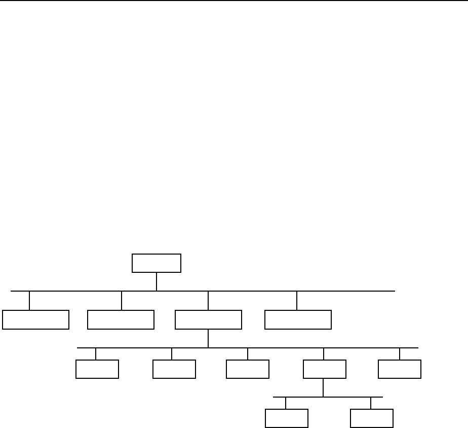
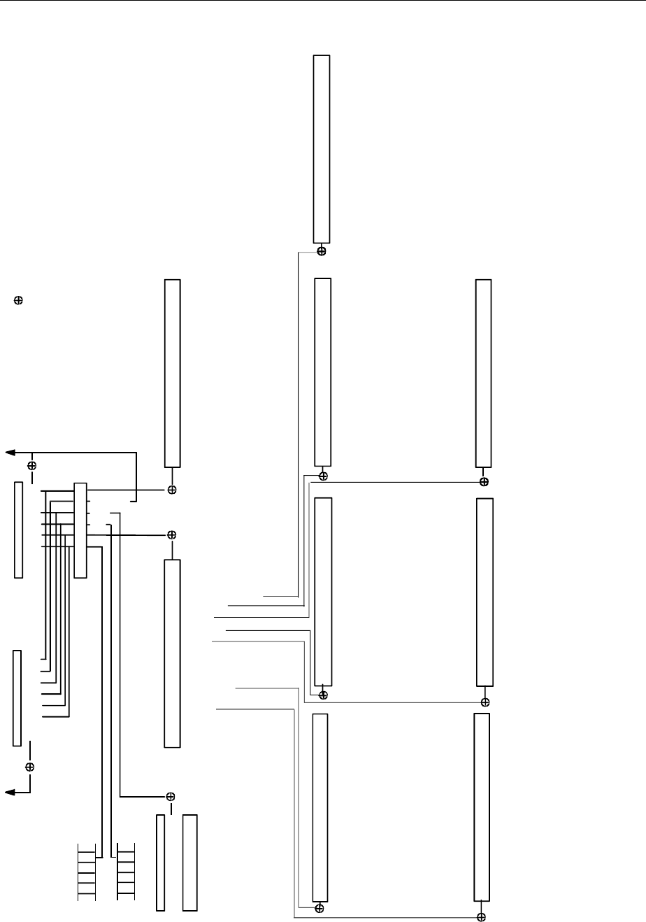
Fig. 5-1 illustrates this tree structure using a section of command system SENSe, which controls the
sensor functions of the devices.
SCPI is based on standard IEEE 488.2, i.e. it uses the same syntactic basic elements as well as the
common commands defined in this standard. Part of the syntax of the device responses is defined with
greater restrictions than in standard IEEE 488.2 (see Section "Responses to Queries").
Structure of a Command
The commands consist of a so-called header and, in most cases, one or more parameters. Header and
parameter are separated by a "white space" (ASCII code 0 to 9, 11 to 32 decimal, e.g. blank). The
headers may consist of several key words. Queries are formed by directly appending a question mark to
the header.
Note: The commands used in the following examples are not in every case implemented in the
instrument.
Common commands Common commands consist of a header preceded by an asterisk "*"
and one or several parameters, if any.
Examples: *RST RESET, resets the device
*ESE 253 EVENT STATUS ENABLE, sets the bits of the
event status enable register
*ESR? EVENT STATUS QUERY, queries the
contents of the event status register.
Structure and Syntax of the Device Messages FSE
1065.6016.12 5.10 E-16
Device-specific commands
Hierarchy:Device-specific commands are of hierarchical structure (see
Fig. 5-1). The different levels are represented by combined headers.
Headers of the highest level (root level) have only one key word. This
key word denotes a complete command system.
Example: SENSe This key word denotes the command system
SENSe.
For commands of lower levels, the complete path has to be specified,
starting on the left with the highest level, the individual key words being
separated by a colon ":".
Example: SENSe:FREQuency:SPAN:LINK STARt
This command lies in the fourth level of the SENSe system. It
determines which parameter remains unchanged when the span is
changed. If LINK is set to STARt, the values of CENTer and STOP are
adjusted when the span is changed.
SENSe
BANDwidth FUNCtion FREQuency
STOP CENTer SPAN OFFSetSTARt
HOLD LINK
DETector
Fig. 5-1 Tree structure the SCPI command systems using the SENSe system by way of example
Some key words occur in several levels within one command system. Their
effect depends on the structure of the command, that is to say, at which
position in the header of a command they are inserted.
Example: SOURce:FM:POLarity NORMal
This command contains key word POLarity in the third
command level. It defines the polarity between modulator and
modulation signal.
SOURce:FM:EXTernal:POLarity NORMal
This command contains key word POLarity in the fourth
command level. It defines the polarity between modulation
voltage and the resulting direction of the modulation only for the
external signal source indicated.

FSE Structure and Syntax of the Device Messages
1065.6016.12 5.11 E-16
Optional key words: Some command systems permit certain key words to be optionally inserted
into the header or omitted. These key words are marked by square
brackets in the description. The full command length must be recognized
by the instrument for reasons of compatibility with the SCPI standard.
Some commands are considerably shortened by these optional key words.
Example: [SENSe]:BANDwidth[:RESolution]:AUTO
This command couples the resolution bandwidth of the
instrument to other parameters. The following command has
the same effect:
BANDwidth:AUTO
Note: An optional key word must not be omitted if its effect is specified
in detail by a numeric suffix.
Long and short form: The key words feature a long form and a short form. Either the short form
or the long form can be entered, other abbreviations are not permissible.
Beispiel: STATus:QUEStionable:ENABle 1= STAT:QUES:ENAB 1
Note: The short form is marked by upper-case letters, the long form
corresponds to the complete word. Upper-case and lower-case
notation only serve the above purpose, the instrument itself
does not make any difference between upper-case and lower-
case letters.
Parameter: The parameter must be separated from the header by a "white space". If
several parameters are specified in a command, they are separated by a
comma ",". A few queries permit the parameters MINimum, MAXimum and
DEFault to be entered. For a description of the types of parameter, refer to
Section 3.5.5.
Example: SENSe:FREQuency:STOP? MAXimum Response: 3.5E9
This query requests the maximal value for the stop frequency.
Numeric suffix: If a device features several functions or features of the same kind, e.g.
inputs, the desired function can be selected by a suffix added to the com-
mand. Entries without suffix are interpreted like entries with the suffix 1.
Example:. SYSTem:COMMunicate:SERial2:BAUD 9600
This command sets the baudrate of the second serial interface.

Structure and Syntax of the Device Messages FSE
1065.6016.12 5.12 E-16
Structure of a Command Line
A command line may consist of one or several commands. It is terminated by a <New Line>, a <New
Line> with EOI or an EOI together with the last data byte. Quick BASIC automatically produces an EOI
together with the last data byte.
Several commands in a command line are separated by a semicolon ";". If the next command belongs
to a different command system, the semicolon is followed by a colon.
Example:
CALL IBWRT(analyzer, "SENSe:FREQuency:CENTer 100MHz;:INPut:ATTenuation 10")
This command line contains two commands. The first command is part of the SENSe
system and is used to specify the center frequency of the analyzer. The second command
is part of the INPut system and sets the attenuation of the input signal.
If the successive commands belong to the same system, having one or several levels in common, the
command line can be abbreviated. To this end, the second command after the semicolon starts with the
level that lies below the common levels (see also Fig. 5-1). The colon following the semicolon must be
omitted in this case.
Example:
CALL IBWRT(analyzer, "SENSe:FREQuency:STARt 1E6;:SENSe:FREQuency:STOP 1E9")
This command line is represented in its full length and contains two commands separated
from each other by the semicolon. Both commands are part of the SENSe command
system, subsystem FREQuency, i.e. they have two common levels.
When abbreviating the command line, the second command begins with the level below
SENSe:FREQuency. The colon after the semicolon is omitted.
The abbreviated form of the command line reads as follows:
CALL IBWRT(analyzer, "SENSe:FREQuency:STARt 1E6;STOP 1E9")
However, a new command line always begins with the complete path.
Example: CALL IBWRT(analyzer, "SENSe:FREQuency:STARt 1E6")
CALL IBWRT(analyzer, "SENSe:FREQuency:STOP 1E9")
Responses to Queries
A query is defined for each setting command unless explicitly specified otherwise. It is formed by adding
a question mark to the associated setting command. According to SCPI, the responses to queries are
partly subject to stricter rules than in standard IEEE 488.2.
1 The requested parameter is transmitted without header.
Example: INPut:COUPling? Response: DC
2. Maximum values, minimum values and all further quantities, which are requested via a special text
parameter are returned as numerical values.
Example: SENSe:FREQuency:STOP? MAX Response: 3.5E9
3. Numerical values are output without a unit. Physical quantities are referred to the basic units or to the
units set using the Unit command.
Example: SENSe:FREQuency:CENTer? Response: 1E6 for 1 MHz
4. Truth values <Boolean values> are returned as 0 (for OFF) and 1 (for ON).
Example: SENSe:BANDwidth:AUTO? Response: 1 for ON
5. Text (character data) is returned in a short form (see also Section 3.5.5).
Example: SYSTem:COMMunicate:SERial:CONTrol:RTS? Response(for standard): STAN

FSE Structure and Syntax of the Device Messages
1065.6016.12 5.13 E-16
Parameters
Most commands require a parameter to be specified. The parameters must be separated from the
header by a "white space". Permissible parameters are numerical values, Boolean parameters, text,
character strings and block data. The type of parameter required for the respective command and the
permissible range of values are specified in the command description (see Section 3.6).
Numerical values Numerical values can be entered in any form, i.e. with sign, decimal point and
exponent. Values exceeding the resolution of the instrument are rounded up or
down. The value range is -9.9E37 to 9.9E37. The exponent is introduced by an
"E" or "e". Entry of the exponent alone is not permissible. In the case of
physical quantities, the unit can be entered. Permissible unit prefixes are G
(giga), MA (mega), MOHM and MHZ are also permissible), K (kilo), M (milli), U
(micro) and N (nano). It the unit is missing, the basic unit is used.
Example:
SENSe:FREQuency:STOP 1.5GHz = SENSe:FREQuency:STOP 1.5E9
Special numerical The texts MINimum, MAXimum, DEFault, UP and DOWN are interpreted as
valuesspecial numerical values.
In the case of a query, the numerical value is provided.
Example: Setting command: SENSe:FREQuency:STOP MAXimum
Query: SENSe:FREQuency:STOP? Response: 3.5E9
MIN/MAX MINimum and MAXimum denote the minimum and maximum value.
DEF DEFault denotes a preset value which has been stored in the EPROM. This
value conforms to the default setting, as it is called by the *RST command
UP/DOWN UP, DOWN increases or reduces the numerical value by one step. The step
width can be specified via an allocated step command for each parameter
which can be set via UP, DOWN.
INF/NINF INFinity, Negative INFinity (NINF) Negative INFinity (NINF) represent the
numerical values -9.9E37 or 9.9E37, respectively. INF and NINF are only sent
as device reponses.
NAN Not A Number (NAN) represents the value 9.91E37. NAN is only sent as
device response. This value is not defined. Possible causes are the division by
zero, the subtraction/addition of infinite and the representation of undefined
values.
Boolean Parameters Boolean parameters represent two states. The ON state (logically true) is
represented by ON or a numerical value unequal to 0. The OFF state (logically
untrue) is represented by OFF or the numerical value 0. 0 or 1 is provided in a
query.
Example: Setting command: DISPlay:WINDow:STATe ON
Query: DISPlay:WINDow:STATe? Response: 1

Structure and Syntax of the Device Messages FSE
1065.6016.12 5.14 E-16
Text Text parameters observe the syntactic rules for key words, i.e. they can be
entered using a short or long form. Like any parameter, they have to be
separated from the header by a white space. In the case of a query, the short
form of the text is provided.
Example: Setting command: INPut:COUPling GROund
Query: INPut:COUPling? Response GRO
Strings Strings must always be entered in quotation marks (’ or ").
Example: SYSTem:LANGuage "SCPI" or
SYSTem:LANGuage ’SCPI’
Block data Block data are a transmission format which is suitable for the transmission of
large amounts of data. A command using a block data parameter has the
following structure:
Example: HEADer:HEADer #45168xxxxxxxx
ASCII character # introduces the data block. The next number indicates how
many of the following digits describe the length of the data block. In the example
the 4 following digits indicate the length to be 5168 bytes. The data bytes follow.
During the transmission of these data bytes all End or other control signs are
ignored until all bytes are transmitted..
Overview of Syntax Elements
The following survey offers an overview of the syntax elements.
:
;
,
?
*
"
#
The colon separates the key words of a command.
In a command line the separating semicolon marks the uppermost
command level.
The semicolon separates two commands of a command line.
It does not alter the path.
The comma separates several parameters of a command.
The question mark forms a query.
The asterisk marks a common command.
Double or single quotation marks introduce a string and terminate it.
The double dagger # introduces block data.
A "white space" (ASCII-Code 0 to 9, 11 to 32 decimal, e.g. blank) separates
header and parameter.
’
FSE Instrument Model and Command Processing
1065.6016.12 5.15 E-16
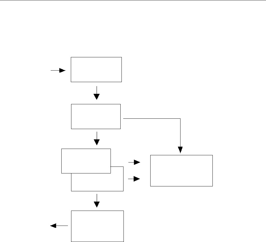
Instrument Model and Command Processing
The instrument model shown in Fig. 5-2 has been made viewed from the standpoint of the servicing of
IEC-bus commands. The individual components work independently of each other and simultaneously.
They communicate by means of so-called "messages".
IEC Bus
Command
recognition
Data set
Instrument
hardware
IEC Bus
Output unit with
output buffer
Input unit with
input puffer
Status reporting-
system
Fig. 5-2 Instrument model in the case of remote control by means of the IEC bus
Input Unit
The input unit receives commands character by character from the IEC bus and collects them in the
input buffer. The input buffer has a size of 256 characters. The input unit sends a message to the
command recognition as soon as the input buffer is full or as soon as it receives a delimiter,
<PROGRAM MESSAGE TERMINATOR>, as defined in IEEE 488.2, or the interface message DCL.
If the input buffer is full, the IEC-bus traffic is stopped and the data received up to then are processed.
Subsequently the IEC-bus traffic is continued. If, however, the buffer is not yet full when receiving the
delimiter, the input unit can already receive the next command during command recognition and
execution. The receipt of a DCL clears the input buffer and immediately initiates a message to the
command recognition.

Instrument Model and Command Processing FSE
1065.6016.12 5.16 E-16
Command Recognition
The command recognition analyses the data received from the input unit. It proceeds in the order in
which it receives the data. Only a DCL is serviced with priority, a GET (Group Execute Trigger), e.g., is
only executed after the commands received before as well. Each recognized command is immediately
transferred to the data set but without being executed there at once.
Syntactical errors in the command are recognized here and supplied to the status reporting system. The
rest of a command line after a syntax error is analysed further if possible and serviced.
If the command recognition recognizes a delimiter or a DCL, it requests the data set to set the
commands in the instrument hardware as well now. Subsequently it is immediately prepared to process
commands again. This means for the command servicing that further commands can already be
serviced while the hardware is still being set ("overlapping execution").
Data Set and Instrument Hardware
Here the expression "instrument hardware" denotes the part of the instrument fulfilling the actual
instrument function - signal generation, measurement etc. The controller is not included.
The instrument data base is a detailed reproduction of the instrument hardware in the software.
IEC-bus setting commands lead to an alteration in the data set. The data base management enters the
new values (e.g. frequency) into the data base, however, only passes them on to the hardware when
requested by the command recognition.
The data are only checked for their compatibility among each other and with the instrument hardware
immediately before they are transmitted to the instrument hardware. If the detection is made that an
execution is not possible, an "execution error" is signalled to the status reporting system. The alteration
of the data base are cancelled, the instrument hardware is not reset.
IEC-bus queries induce the data set management to send the desired data to the output unit.
Status Reporting System
The status reporting system collects information on the instrument state and makes it available to the
output unit on request. The exact structure and function are described in the following section.

FSE Instrument Model and Command Processing
1065.6016.12 5.17 E-16
Output Unit
The output unit collects the information requested by the controller, which it receives from the data set
management. It processes it according to the SCPI rules and makes it available in the output buffer.
The output buffer has a size of 4096 characters. If the information requested is longer, it is made
available "in portions" without this being recognized by the controller.
If the instrument is addressed as a talker without the output buffer containing data or awaiting data from
the data set management, the output unit sends error message "Query UNTERMINATED" to the status
reporting system. No data are sent on the IEC bus, the controller waits until it has reached its time limit.
This behaviour is specified by SCPI.
Command Sequence and Command Synchronization
What has been said above makes clear that all commands can potentially be carried out overlapping.
Equally, setting commands within one command line are not absolutely serviced in the order in which
they have been received.
In order to make sure that commands are actually carried out in a certain order, each command must
be sent in a separate command line, that is to say, with a separate IBWRT()-call.
In order to prevent an overlapping execution of commands, one of commands *OPC, *OPC? or *WAI
must be used. All three commands cause a certain action only to be carried out after the hardware has
been set and has settled. By a suitable programming, the contoller can be forced to wait for the
respective action to occur (cf. Table 5-1).
Table 5-1 Synchronisation using *OPC, *OPC? and *WAI
Commnd Action after the hardware has settled Programming the controller
*OPC Setting the opteration-complete bit in the ESR - Setting bit 0 in the ESE
- Setting bit 5 in the SRE
- Waiting for service request (SRQ)
*OPC? Writing a "1" into the output buffer Addressing the instrument as a talker
*WAI Continuing the IEC-bus handshake Sending the next command
An example as to command synchronization can be found in chapter 7 "Program Examples".
Status Reporting System FSE
1065.6016.12 5.18 E-16
Status Reporting System
The status reporting system (cf. Fig. 5-3) stores all information on the present operating state of the
instrument, e.g. that the instrument presently carries out an AUTORANGE and on errors which have
occurred. This information is stored in the status registers and in the error queue. The status registers
and the error queue can be queried via IEC bus.
The information is of a hierarchical structure. The register status byte (STB) defined in IEEE 488.2 and
its associated mask register service request enable (SRE) form the uppermost level. The STB receives
its information from the standard event status register (ESR) which is also defined in IEEE 488.2 with
the associated mask register standard event status enable (ESE) and registers STATus:OPERation and
STATus:QUEStionable which are defined by SCPI and contain detailed information on the instrument.
The IST flag ("Individual STatus") and the parallel poll enable register (PPE) allocated to it are also part
of the status reporting system. The IST flag, like the SRQ, combines the entire instrument status in a
single bit. The PPE fulfills an analog function for the IST flag as the SRE for the service request.
The output buffer contains the messages the instrument returns to the controller. It is not part of the
status reporting system but determines the value of the MAV bit in the STB and thus is represented in
Fig. 5-3.
Table 5-12 at the end of this chapter comprises the different commands and events causing the status
reporting system to be reset.
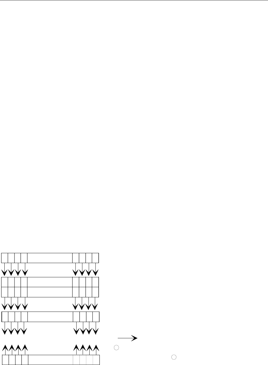
Structure of an SCPI Status Register
Each SCPI register consists of 5 parts which each have a width of 16 bits and have different functions
(cf. Fig. 5-2). The individual bits are independent of each other, i.e. each hardware status is assigned a
bit number which is valid for all five parts. For example, bit 3 of the STATus:OPERation register is
assigned to the hardware status "wait for trigger" in all five parts. Bit 15 (the most significant bit) is set to
zero for all parts. Thus the contents of the register parts can be processed by the controller as positive
integer.
15 14 13 12 PTRansition part 3 2 1 0
15 14 13 12 EVENt part 3 2 1 0
15 14 13 12 ENABle part 3 2 1 0
& & & & & & & & & & & & & & & &
to higher-order register
Sum bit
& = logical AND
= logical OR
of all bits
+
+
15 14 13 12 NTRansition part 3 2 1 0
15 14 13 12 CONDition part 3 2 1 0
Fig. 5-2 The status-register model

FSE Status Reporting System
1065.6016.12 5.19 E-16
CONDition part The CONDition part is directly written into by the hardware or the sum bit of
the next lower register. Its contents reflects the current instrument status. This
register part can only be read, but not written into or cleared. Its contents is
not affected by reading.
PTRansition part The Positive-TRansition part acts as an edge detector. When a bit of the
CONDition part is changed from 0 to 1, the associated PTR bit decides
whether the EVENt bit is set to 1.
PTR bit =1: the EVENt bit is set.
PTR bit =0: the EVENt bit is not set.
This part can be written into and read at will. Its contents is not affected by
reading.
NTRansition part The Negative-TRansition part also acts as an edge detector. When a bit of the
CONDition part is changed from 1 to 0, the associated NTR bit decides
whether the EVENt bit is set to 1.
NTR-Bit = 1: the EVENt bit is set.
NTR-Bit = 0: the EVENt bit is not set.
This part can be written into and read at will. Its contents is not affected by
reading.
With these two edge register parts the user can define which state transition of
the condition part (none, 0 to 1, 1 to 0 or both) is stored in the EVENt part.
EVENt part The EVENt part indicates whether an event has occurred since the last
reading, it is the "memory" of the condition part. It only indicates events
passed on by the edge filters. It is permanently updated by the instrument.
This part can only be read by the user. During reading, its contents is set to
zero. In linguistic usage this part is often equated with the entire register.
ENABle part The ENABle part determines whether the associated EVENt bit contributes to
the sum bit (cf. below). Each bit of the EVENt part is ANDed with the
associated ENABle bit (symbol ’&’). The results of all logical operations of this
part are passed on to the sum bit via an OR function (symbol ’+’).
ENABle-Bit = 0: the associated EVENt bit does not contribute to the sum bit
ENABle-Bit = 1: if the associated EVENT bit is "1", the sum bit is set to "1" as
well.
This part can be written into and read by the user at will. Its contents is not
affected by reading.
Sum bit As indicated above, the sum bit is obtained from the EVENt and ENABle part
for each register. The result is then entered into a bit of the CONDition part of
the higher-order register.
The instrument automatically generates the sum bit for each register. Thus an
event, e.g. a PLL that has not locked, can lead to a service request throughout
all levels of the hierarchy.
Note: The service request enable register SRE defined in IEEE 488.2 can be taken as ENABle
part of the STB if the STB is structured according to SCPI. By analogy, the ESE can be
taken as the ENABle part of the ESR.
Status Reporting System FSE
1065.6016.12 5.20 E-16
Overview of the Status Registers
’
SRE STB
STATus:OPERation
PPE
IST flag
& = logical AND
= logical OR
of all bits
ESE ESR
Error/event
queue
bla
Output
buffer
SRQ
RQS/MSS
ESB
MAV
Power on
User Request
Command Error
Execution Error
Device Dependent Error
Query Error
Request Control
Operation Complete
15
14
13
12
11
10
9
8
7
6
5
4
3
2
1
0
15
14
13
12
11
10
9
8
7
6
5
4
3
2
1
0
-&-
-&-
-&-
-&-
-&-
-&-
-&-
-&-
-&-
-&-
-&-
-&-
-&-
-&-
-&-
-&-
-&-
-&-
-&-
7
6
5
4
3
2
1
0
STATus:QUEStionable
not used
PROGram running
INSTrument summary bit
HCOPy in progress
CORRecting
WAIT for ARM
WAIT for TRIGGER
MEASuring
SWEeping
RANGing
SETTling
CALibrating
not used
COMMand warning
TRANsducer break
ACPLimit
SYNC
LMARgin
LIMit
CALibration (= UNCAL)
MODulation
PHASe
FREQuency
TEMPerature
POWer
TIME
CURRent
VOLTage
15
14
13
12
11
10
9
8
7
6
5
4
3
2
1
0
STATus:QUEStionable:LMARgin
15
14
13
12
11
10
9
8
7
6
5
4
3
2
1
0
STATus:QUEStionable:POWer
15
14
13
12
11
10
9
8
7
6
5
4
3
2
1
0
not used
IF_OVerload (screen B)
UNDerload Option B7 (screen B)
OVERload (screen B)
IF_OVerload (screen A)
UNDerload Option B7 (screen A)
OVERload (screen A)
STATus:QUEStionable:SYNC
not used
ALT2 LOWer FAIL (screen B)
ALT2 UPPer FAIL (screen B)
ALT1 LOWer FAIL (screen B)
ALT1 UPPer FAIL (screen B)
ADJ LOWer FAIL (screen B)
ADJ UPPer FAIL (screen B)
ALT2 LOWer FAIL (screen A)
ALT2 UPPer FAIL (screen A)
ALT1 LOWer FAIL (screen A)
ALT1 UPPer FAIL (screen A)
ADJ LOWer FAIL (screen A)
ADJ UPPer FAIL (screen A)
not used
LMARgin 8 FAIL
LMARgin 7 FAIL
LMARgin 6 FAIL
LMARgin 5 FAIL
LMARgin 4 FAIL
LMARgin 3 FAIL
LMARgin 2 FAIL
LMARgin 1 FAIL
not used
CARRier overload
No carrier
SYNC not found
BURSt not found
7
6
5
4
3
2
1
0
STATus:QUEStionable:ACPLimit
15
14
13
12
11
10
9
8
7
6
5
4
3
2
1
0
STATus:QUEStionable:FREQuency
15
14
13
12
11
10
9
8
7
6
5
4
3
2
1
0
not used
LO LEVel (screen B)
LO UNLocked (screen B)
LO LEVel (screen A)
LO UNLocked (screen A)b
OVEN COLD
STATus:QUEStionable:LIMit
15
14
13
12
11
10
9
8
7
6
5
4
3
2
1
0
not used
LIMit 8 FAIL
LIMit 7 FAIL
LIMit 6 FAIL
LIMit 5 FAIL
LIMit 4 FAIL
LIMit 3 FAIL
LIMit 2 FAIL
LIMit 1 FAIL
15
14
13
12
11
10
9
8
7
6
5
4
3
2
1
0
STATus:QUEStionable:TRANsducer
not used
Subrange limit attained
Subrange 10
Subrange 9
Subrange 8
Subrange 7
Subrange 6
Subrange 5
Subrange 4
Subrange 3
Subrange 2
Subrange 1
Fig. 5-3 Overview of the status registers

FSE Status Reporting System
1065.6016.12 5.21 E-16
Description of the Status Registers
Status Byte (STB) and Service Request Enable Register (SRE)
The STB is already defined in IEEE 488.2. It provides a rough overview of the instrument status by
collecting the pieces of information of the lower registers. It can thus be compared with the CONDition
part of an SCPI register and assumes the highest level within the SCPI hierarchy. A special feature is
that bit 6 acts as the sum bit of the remaining bits of the status byte.
The STATUS BYTE is read out using the command "*STB?" or a serial poll.
The STB implies the SRE. It corresponds to the ENABle part of the SCPI registers as to its function.
Each bit of the STB is assigned a bit in the SRE. Bit 6 of the SRE is ignored. If a bit is set in the SRE
and the associated bit in the STB changes from 0 to 1, a Service Request (SRQ) is generated on the
IEC bus, which triggers an interrupt in the controller if this is appropriately configured and can be further
processed there.
The SRE can be set using command "*SRE" and read using "*SRE?".
Table 5-2 Meaning of the bits in the status byte
Bit No. Meaning
2Error Queue not empty
The bit is set when an entry is made in the error queue.
If this bit is enabled by the SRE, each entry of the error queue generates a Service Request. Thus an error can
be recognized and specified in greater detail by polling the error queue. The poll provides an informative error
message. This procedure is to be recommended since it considerably reduces the problems involved with IEC-
bus control.
3QUEStionable status sum bit
The bit is set if an EVENt bit is set in the QUEStionable-Status register and the associated ENABle bit is set to
1.
A set bit indicates a questionable instrument status, which can be specified in greater detail by polling the
QUEStionable-Status register.
4MAV bit (message available)
The bit is set if a message is available in the output buffer which can be read.
This bit can be used to enable data to be automatically read from the instrument to the controller (cf. chapter 7,
program examples).
5ESB bit
Sum bit of the event status register. It is set if one of the bits in the event status register is set and enabled in
the event status enable register.
Setting of this bit implies an error or an event which can be specified in greater detail by polling the event status
register.
6MSS bit (master status summary bit)
The bit is set if the instrument triggers a service request. This is the case if one of the other bits of this registers
is set together with its mask bit in the service request enable register SRE.
7OPERation status register sum bit
The bit is set if an EVENt bit is set in the OPERation-Status register and the associated ENABle bit is set to 1.
A set bit indicates that the instrument is just performing an action. The type of action can be determined by
polling the OPERation-status register.

Status Reporting System FSE
1065.6016.12 5.22 E-16
IST Flag and Parallel Poll Enable Register (PPE)
By analogy with the SRQ, the IST flag combines the entire status information in a single bit. It can be
queried by means of a parallel poll or using command "*IST?".
The parallel poll enable register (PPE) determines which bits of the STB contribute to the IST flag. The
bits of the STB are ANDed with the corresponding bits of the PPE, with bit 6 being used as well in
contrast to the SRE. The Ist flag results from the ORing of all results. The PPE can be set using
commands "*PRE" and read using command "*PRE?".
Event-Status Register (ESR) and Event-Status-Enable Register (ESE)
The ESR is already defined in IEEE 488.2. It can be compared with the EVENt part of an SCPI register.
The event status register can be read out using command "*ESR?".
The ESE is the associated ENABle part. It can be set using command "*ESE" and read using command
"*ESE?".
Table 5-3 Meaning of the bits in the event status register
Bit No. Meaning
0Operation Complete
This bit is set on receipt of the command *OPC exactly when all previous commands have been executed.
1Request Control
This bit is set if the instrument requests the controller function. This is the case when hardcopy is outputted to a
printer or a plotter via the IEC-bus.
2Query Error
This bit is set if either the controller wants to read data from the instrument without having send a query, or if it
does not fetch requested data and sends new instructions to the instrument instead. The cause is often a query
which is faulty and hence cannot be executed.
3Device-dependent Error
This bit is set if a device-dependent error occurs. An error message with a number between -300 and -399 or a
positive error number, which denotes the error in greater detail, is entered into the error queue (cf. chapter 9,
Error Messages).
4Execution Error
This bit is set if a received command is syntactically correct, however, cannot be performed for other reasons.
An error message with a number between -200 and -300, which denotes the error in greater detail, is entered
into the error queue (cf. chapter 9, Error Messages).
5Command Error
This bit is set if a command which is undefined or syntactically incorrect is received. An error message with a
number between -100 and -200, which denotes the error in greater detail, is entered into the rror queue (cf.
chapter 9, -Error Messages).
6User Request
This bit is set on pressing the LOCAL key.
7Power On (supply voltage on)
This bit is set on switching on the instrument.

FSE Status Reporting System
1065.6016.12 5.23 E-16
STATus:OPERation Register
In the CONDition part, this register contains information on which actions the instrument is being
executing or, in the EVENt part, information on which actions the instrument has executed since the last
reading. It can be read using commands "STATus:OPERation:CONDition?" or "STATus
:OPERation[:EVENt]?".
Table 5-4 Meaning of the bits in the STATus.OPERation register
Bit No. Meaning
0CALibrating
This bit is set as long as the instrument is performing a calibration.
1SETTling
This bit is set as long as the new status is settling after a setting command. It is only set if the settling time is
longer than the command processing time.
2RANGing
This bit is set as long as the instrument is changing a range (e.g. Autorange).
3SWEeping
This bit is set while the instrument is performing a sweep.
4MEASuring
This bit is set while the instrument is performing a measurement.
5WAIT for TRIGGER
This bit is set as long as the instrument is waiting for a trigger event.
6WAIT for ARM
This bit is set as long as the instrument is waiting for an arming event.
7CORRecting
This bit is set while the instrument is performing a correction.
8HardCOPy in progress
This bit is set while the instrument is printing a hardcopy.
9-12 Device dependent
13 INSTrument Summary Bit
This bit is set when one or more logical instruments is reporting a status message.
14 PROGram running
This bit is set while the instrument is performing a program.
15 This bit is always 0
The FSE supports bits 0 and 8.

Status Reporting System FSE
1065.6016.12 5.24 E-16
STATus:QUEStionable Register
This register comprises information about indefinite states which may occur if the unit is operated
without meeting the specifications. It can be queried by commands STATus:QUEStionable:
CONDition? and STATus:QUEStionable[:EVENt]?.
Table 5-5 Meaning of bits in STATus:QUEStionable register
Bit No. Meaning
0VOLTage
This bit is set if a questionable voltage occurs.
1CURRent
This bit is set if a questionable current occurs.
2TIME
This bit is set if a questionable time occurs.
3POWer
This bit is set if a questionable power occurs (cf. also section "STATus:QUEStionable:POWerRegister")
4TEMPerature
This bit is set if a questionable temperature occurs.
5FREQuency
The bit is set if a frequency is questionable (cf. section "STATus:QUEStionable:FREQuency Register")
6PHASe
The bit is set if a phase value is questionable.
7MODulation
The bit is set if a modulation is performed questionably.
8CALibration
The bit is set if a measurement is performed uncalibrated (=
^ label "UNCAL")
9LIMit (unit-dependent)
This bit is set if a limit value is violated (see also section STATus:QUEStionable:LIMit Register)
10 LMARgin (unit-dependent)
This bit is set if a margin is violated (see also section STATus:QUEStionable:LMARgin Register)
11 SYNC (unit-dependent)
This bit is set if, during measurements with Option B7 (Signal Vector Analysis), the synchronization with
midamble or a successful search for bursts cannot be performed (see also STATus:QUEStionable:SYNC
Register)
12 ACPLimit (unit-dependent)
This bit is set if a limit for the adjacent channel power measurement is violated (see also section
STATus:QUEStionable:ACPLimit Register)
13 TRANsducer break
This bit is set when the limit of the transducer set subrange is attained.
14 COMMand Warning
This bit is set if the instrument ignores parameters when executing a command.
15 This bit is always 0.
The FSE supports bits 3, 5, 7, 8, 9, 10, 11, 12 and 13, bits 7 (MODulation) and 11 (SYNC) only with
option FSE-B7, Vector Signal Analysis’.

FSE Status Reporting System
1065.6016.12 5.25 E-16
STATus QUEStionable:ACPLimit Register
This register Tcomprises information about the observance of limits during adjacent power
measurements. It can be queried with commands ’STATus:QUEStionable:ACPLimit
:CONDition?’ and ’STATus:QUEStionable:ACPLimit[:EVENt]?’
Table 5- Meaning of bits in STATus:QUEStionable:ACPLimit register
Bit No. Meaning
0ADJ UPPer FAIL(Screen A)
This bit is set if the limit is exceeded in the upper adjacent channel.
1ADJ LOWer FAIL (Screen A)
This bit is set if the limit is exceeded in the lower adjacent channel.
2ALT1 UPPer FAIL (Screen A)
This bit is set if the limit is exceeded in the upper 1st alternate channel.
3ALT1 LOWer FAIL (Screen A)
This bit is set if the limit is exceeded in the lower 1st alternate channel.
4ALT2 UPPer FAIL (Screen A)
This bit is set if the limit is exceeded in the upper 2nd alternate channel.
5ALT2 LOWer FAIL (Screen A)
This bit is set if the limit is exceeded in the lower 2nd alternate channel.
6 not used
7 not used
8ADJ UPPer FAIL (Screen B)
This bit is set if the limit is exceeded in the upper adjacent channel.
9ADJ LOWer FAIL (Screen B)
This bit is set if the limit is exceeded in the lower adjacent channel.
10 ALT1 UPPer FAIL (Screen B)
This bit is set if the limit is exceeded in the upper 1st alternate channel.
11 ALT1 LOWer FAIL (Screen B)
This bit is set if the limit is exceeded in the lower 1st alternate channel.
12 ALT2 UPPer FAIL (Screen B)
This bit is set if the limit is exceeded in the upper 2nd alternate channel.
13 ALT2 LOWer FAIL (Screen A)
This bit is set if the limit is exceeded in the lower 2nd alternate channel.
14 not used
15 This bit is always 0.

Status Reporting System FSE
1065.6016.12 5.26 E-16
STATus QUEStionable:FREQuency Register
This register comprises information about the reference and local oscillator.
It can be queried with commands STATus:QUEStionable:FREQuency:CONDition? and "STATus
:QUEStionable:FREQuency[:EVENt]?.
Table 5-6 Meaning of bits in STATus:QUEStionable:FREQuency register
Bit No. Meaning
0OVEN COLD
This bit is set if the reference oscillator has not yet attained its operating temperature. ’OCXO’ will then be
displayed.
1LO UNLocked (Screen A)
This bit is set if the local oscillator no longer locks. ’LO unl’ will then be displayed.
2LO LEVel (Screen A)
This bit is set if the level of the local oscillator is smaller than the nominal value. ’LO LVL’ will then be displayed.
3 not used
4 not used
5 not used
6 not used
7 not used
8 not used
9LO UNLocked (Screen B)
This bit is set if the local oscillator no longer locks.’ LO unl’ will then be displayed.
10 LO LEVel (Screen B)
This bit is set if the level of the local oscillator is smaller than the nominal value. ’LO LVL’ will then be displayed.
11 not used
12 not used
13 not used
14 not used
15 This bit is always 0.

FSE Status Reporting System
1065.6016.12 5.27 E-16
STATus QUEStionable:LIMit Register
This register comprises information about the observance of limit lines. It can be queried with
commands STATus:QUEStionable:LIMit:CONDition? and STATus:QUEStionable:LIMit
[:EVENt]?.
Table 5-7 Meaning of bits in STATus:QUEStionable:LIMit register
Bit No. Meaning
0LIMit 1 FAIL
This bit is set if limit line 1 is violated.
1LIMit 2 FAIL
This bit is set if limit line 2 is violated.
2LIMit 3 FAIL
This bit is set if limit line 3 is violated.
3LIMit 4 FAIL
This bit is set if limit line 4 is violated.
4LIMit 5 FAIL
This bit is set if limit line 5 is violated.
5LIMit 6 FAIL
This bit is set if limit line 6 is violated.
6LIMit 7 FAIL
This bit is set if limit line 7 is violated.
7LIMit 8 FAIL
This bit is set if limit line 8 is violated.
8 not used
9 not used
10 not used
11 not used
12 not used
13 not used
14 not used
15 This bit is always 0.

Status Reporting System FSE
1065.6016.12 5.28 E-16
STATus QUEStionable:LMARgin Register
This register comprises information about the observance of limit margins. It can be queried with
commands STATus:QUEStionable:LMARgin:CONDition? and "STATus:QUEStionable
:LMARgin[:EVENt]?.
Table 5-8 Meaning of bits in STATus:QUEStionable:LMARgin register
Bit No. Meaning
0LMARgin 1 FAIL
This bit is set if limit margin 1 is violated.
1LMARgin 2 FAIL
This bit is set if limit margin 2 is violated.
2LMARgin 3 FAIL
This bit is set if limit margin 3 is violated.
3LMARgin 4 FAIL
This bit is set if limit margin 4 is violated.
4LMARgin 5 FAIL
This bit is set if limit margin 5 is violated.
5LMARgin 6 FAIL
This bit is set if limit margin 1 is violated.
6LMARgin 7 FAIL
This bit is set if limit margin 7 is violated.
7LMARgin 8 FAIL
This bit is set if limit margin 8 is violated.
8 not used
9 not used
10 not used
11 not used
12 not used
13 not used
14 not used
15 This bit is always 0.

FSE Status Reporting System
1065.6016.12 5.29 E-16
STATus QUEStionable:POWer Register
This register comprises all information about possible overloads of the unit.
It can be queried with commands STATus:QUEStionable :POWer:CONDition? and "STATus
:QUEStionable:POWer [:EVENt]?.
Table 5-9 Meaning of bits in STATus:QUEStionable:POWer register
Bit No. Meaning
0OVERload (Screen A)
This bit is set if the RF input is overloaded. ’OVLD’ will then be displayed.
1UNDerload (Screen A) - Option FSE-B7
This bit is set if, during measurements in vector analyzer mode without capture buffer used, the lower level limit
in the IF path is violated.
2IF_OVerload (Screen A)
This bit is set if the IF path is overloaded. ’IFOVLD’ will then be displayed.
3 not used
4 not used
5 not used
6 not used
7 not used
8OVERload (Screen B)
This bit is set if the RF input is overloaded. ’OVLD’ will then be displayed.
9UNDerload (Screen B) - Option FSE-B7
This bit is set if, during measurements without capture buffer used, the lower level limit in the IF path is violated.
10 IF_OVerload (Screen B)
This bit is set if the IF path is overloaded. ’IFOVLD’ will then be displayed.
11 not used
12 not used
13 not used
14 not used
15 This bit is always 0.

Status Reporting System FSE
1065.6016.12 5.30 E-16
STATus QUEStionable:SYNC Register
This register comprises information about sync and burst events related to Vector Analyzer mode,
option FSE-B7, and to GSM measurements, options FSE-K10/20/30 and FSE-K11/21/31). It can be
queried with commands STATus:QUEStionable:SYNC:CONDition? and "STATus
:QUEStionable:SYNC[:EVENt]?.
Table 5-10 Meaning of bits in STATus:QUEStionable:SYNC register
Bit No. Meaning
0BURSt not found
This bit is set if a burst was not found.
1SYNC not found
This bit is set if the sync sequence of midamble was not found.
2No carrier
This bit is set if the carrier power determined in the pre-measurement is 20 dB belowof the expected signal
power (options FSE-K10/ FSE-K11).
3Carrier overload
This bit is set if the carrier power determined in the pre-measurement is 4 dB above of the expected signal
power (options FSE-K10/ FSE-K11).
4 to 14 not used
15 This bit is always 0.
The ’SYNC not found’ and ’BURSt not found’ bits are set with all measurements evaluating this
information. The bits are recalculated for each sweep so that they show the current status at the end of
a sweep.
GSM measurements (options FSE-K10 and FSE-K11) carrying along the two bits synchronously with
the sweep:
- CPW Carrier Power activated with ’Sync To Midamble’ (*)
- PVT Power versus Time activated with ’Sync To Midamble’ (*)
- PFE Phase/Frequency Error
- MAC Modulation Accuracy
- TAA Trigger AutoAdjust
* With GMSK modulation, the PVT and CPW measurements do not perform a burst search. The burst search is only active
with 8PSK modulation (EDGE).
The Carrier Overload’ and ’No Carrier’ bits are reset at the beginning of each GSM measurement
(options FSE-K10 and FSE-K11) and, if required, set at the end of the pre-measurement. If single-step
measurements (CPW) are performed, the bits are set after the initial step and reset again at the
beginning of the next.
GSM measurements with bit setting as required:
- CPW Carrier Power (first step only, measurement of full power)
- PVT Power versus Time (setting possible after each of the two pre-measurements)
- MOD Modulation Spectrum
- TRA Transient Spectrum (**)
** With FSE-K10 (mobile) and power coupling OFF selected, a pre-measurement is not performed. Measuring the carrier
power is therefore not possible and so the two bits are not set.

FSE Status Reporting System
1065.6016.12 5.31 E-16
STATus QUEStionable:TRANsducer Register
This register indicates that a transducer hold point is attained (bit 15) and what range is to be swept next
(bit 0 to 10). The sweep can be continued with command INITiate2:CONMeasure.
It can be queried with commands STATus:QUEStionable:TRANsducer:CONDition? and "STATus
:QUEStionable:TRANsducer[:EVENt]?.
Table 5-11 Meaning of bits in STATus:QUEStionable:TRANsducer register
Bit No. Meaning
0Range 1
This bit is set when subrange 1 is attained.
1Range 2
This bit is set when subrange 2 is attained.
2Range 3
This bit is set when subrange 3 is attained.
3Range 4
This bit is set when subrange 4 is attained.
4Range 5
This bit is set when subrange 1 is attained.
5Range 6
This bit is set when subrange 6 is attained.
6Range 7
This bit is set when subrange 7 is attained.
7Range 8
This bit is set when subrange 8 is attained.
8Range 9
This bit is set when subrange 9 is attained.
9Range 10
This bit is set when subrange 10 is attained.
10 not used
11 not used
12 not used
13 not used
14 Subrange limit
This bit is set when the transducer is at the point of changeover from one range to another.
15 This bit is always 0.

Status Reporting System FSE
1065.6016.12 5.32 E-16
Application of the Status Reporting Systems
In order to be able to effectively use the status reporting system, the information contained there must
be transmitted to the controller and further processed there. There are several methods which are
represented in the following. Detailed program examples are to be found in chapter 7, Program
Examples.
Service Request, Making Use of the Hierarchy Structure
Under certain circumstances, the instrument can send a service request (SRQ) to the controller. Usually
this service request initiates an interrupt at the controller, to which the control program can react with
corresponding actions. As evident from Fig. 5-3, an SRQ is always initiated if one or several of bits 2, 3,
4, 5 or 7 of the status byte are set and enabled in the SRE. Each of these bits combines the information
of a further register, the error queue or the output buffer. The corresponding setting of the ENABle parts
of the status registers can achieve that arbitrary bits in an arbitrary status register initiate an SRQ. In
order to make use of the possibilities of the service request, all bits should be set to "1" in enable
registers SRE and ESE.
Examples (cf. Fig. 5-3 and chapter 7, Program Examples, as well):
Use of command "*OPC" to generate an SRQ at the end of a sweep.
½Set bit 0 in the ESE (Operation Complete)
½Set bit 5 in the SRE (ESB)?
After its settings have been completed, the instrument generates an SRQ.
The SRQ is the only possibility for the instrument to become active on its own. Each controller program
should set the instrument such that a service request is initiated in the case of malfunction. The program
should react appropriately to the service request. A detailed example for a service request routine is to
be found in chapter 7, Program Examples.
Serial Poll
In a serial poll, just as with command "*STB", the status byte of an instrument is queried. However, the
query is realized via interface messages and is thus clearly faster. The serial-poll method has already
been defined in IEEE 488.1 and used to be the only standard possibility for different instruments to poll
the status byte. The method also works with instruments which do not adhere to SCPI or IEEE 488.2.
The quick-BASIC command for executing a serial poll is "IBRSP()". Serial poll is mainly used to obtain a
fast overview of the state of several instruments connected to the IEC bus.

FSE Status Reporting System
1065.6016.12 5.33 E-16
Parallel Poll
In a parallel poll, up to eight instruments are simultaneously requested by the controller by means of a
single command to transmit 1 bit of information each on the data lines, i.e., to set the data line allocated
to each instrument to logically "0" or "1". By analogy to the SRE register which determines under which
conditions an SRQ is generated, there is a parallel poll enable register (PPE) which is ANDed with the
STB bit by bit as well considering bit 6. The results are ORed, the result is then sent (possibly inverted)
as a response in the parallel poll of the controller. The result can also be queried without parallel poll by
means of command "*IST".
The instrument first has to be set for the parallel poll using quick-BASIC command "IBPPC()". This
command allocates a data line to the instrument and determines whether the response is to be inverted.
The parallel poll itself is executed using "IBRPP()".
The parallel-poll method is mainly used in order to quickly find out after an SRQ which instrument has
sent the service request if there are many instruments connected to the IEC bus. To this effect, SRE
and PPE must be set to the same value. A detailed example as to the parallel poll is to be found in
chapter 7, Program Examples.
Query by Means of Commands
Each part of every status register can be read by means of queries. The individual commands are
indicated in the detailed description of the registers. What is returned is always a number which
represents the bit pattern of the register queried. Evaluating this number is effected by the controller
program.
Queries are usually used after an SRQ in order to obtain more detailed information on the cause of the
SRQ.
Error-Queue Query
Each error state in the instrument leads to an entry in the error queue. The entries of the error queue
are detailed plain-text error messages which can be looked at in the ERROR menu via manual control
or queried via the IEC bus using command "SYSTem:ERRor?". Each call of "SYSTem:ERRor?"
provides an entry from the error queue. If no error messages are stored there any more, the instrument
responds with 0, "No error".
The error queue should be queried after every SRQ in the controller program as the entries describe the
cause of an error more precisely than the status registers. Especially in the test phase of a controller
program the error queue should be queried regularly since faulty commands from the controller to the
instrument are recorded there as well.

Status Reporting System FSE
1065.6016.12 5.34 E-16
Resetting Values of the Status Reporting System
Table 5-12 comprises the different commands and events causing the status reporting system to be
reset. None of the commands, except for *RST and SYSTem:PRESet influences the functional
instrument settings. In particular, DCL does not change the instrument settings.
Table 5-12 Resetting instrument functions
Event Switching on supply
voltage DCL,SDC
Power-On-Status-
Clear
(Device Clear,
Selected Device
Clear)
*RST or
SYSTem:PRESet STATus:PRESet *CLS
Effect 0 1
Clear STB,ESR yes
yes
Clear SRE,ESE yes
Clear PPE yes
Clear EVENTt parts of the
registers yes
yes
Clear Enable parts of all
OPERation and
QUEStionable registers,
Fill Enable parts of all
other registers with "1".
yes yes
Fill PTRansition parts with
"1" ,
Clear NTRansition parts
yes yes
Clear error queue yes yes
yes
Clear output buffer yes yes yes 1) 1) 1)
Clear command
processing and input
buffer
yes yes yes
1) Every command being the first in a command line, i.e., immediately following a <PROGRAM MESSAGE TERMINATOR>
clears the output buffer.

FSE Contents - Description of Commands
1065.6016.12 I-6.1 E-16
Contents - Chapter 6 "Remote Control - Description
of Commands"
6 Description of Commands.................................................................................. 6.1
Notation ............................................................................................................................................ 6.1
Common Commands....................................................................................................................... 6.4
ABORt Subsystem ........................................................................................................................... 6.8
CALCulate Subsystem..................................................................................................................... 6.8
CALCulate:DELTamarker Subsystem..................................................................................... 6.9
CALCulate:DLINe Subsystem ............................................................................................... 6.15
CALCulate:FEED Subsystem................................................................................................ 6.18
CALCulate:FORMat and CALCulate:FSK Subsystems......................................................... 6.19
CALCulate:LIMit Subsystem.................................................................................................. 6.20
CALCulate:MARKer Subsystem............................................................................................ 6.36
CALCulate:MATH Subsystem ............................................................................................... 6.61
CALCulate:X and CALCulate:UNIT Subsystem .................................................................... 6.62
CALibration Subsystem ................................................................................................................ 6.63
CONFigure Subsystem.................................................................................................................. 6.65
CONFigure:BTS Subsystem.................................................................................................. 6.65
CONFigure:BURSt Subsystem.............................................................................................. 6.73
CONFigure:MS Subsystem ................................................................................................... 6.77
CONFigure:SPECtrum Subsystem........................................................................................ 6.85
CONFigure:SPURious Subsystem ........................................................................................ 6.87
DIAGnostic Subsystem ................................................................................................................. 6.89
DISPlay Subsystem........................................................................................................................ 6.91
FETCh Subsystem ....................................................................................................................... 6.101
FETCh:BURSt Subsystem .................................................................................................. 6.101
FETCh:PTEMplate Subsystem............................................................................................ 6.111
FETCh:SPECtrum Subsystem ............................................................................................ 6.112
FETCh:SPURious Subsystem............................................................................................. 6.115
FORMat Subsystem..................................................................................................................... 6.117
HCOPy Subsystem ...................................................................................................................... 6.119
INITiate Subsystem...................................................................................................................... 6.125
INPut Subsystem ......................................................................................................................... 6.127
INSTrument Subsystem .............................................................................................................. 6.130
MMEMory Subsystem.................................................................................................................. 6.132
OUTPut Subsystem ..................................................................................................................... 6.143
READ Subsystem......................................................................................................................... 6.145
READ:BURSt Subsystem.................................................................................................... 6.145
READ:SPECtrum Subsystem.............................................................................................. 6.159
READ:SPURious Subsystem .............................................................................................. 6.161

Contents - Description of Commands FSE
1065.6016.12 I-6.2 E-16
SENSe Subsystem....................................................................................................................... 6.163
SENSe:ADEMod Subsystem............................................................................................... 6.163
SENSe:AVERage Subsystem ............................................................................................. 6.165
SENSe:BANDwidth Subsystem........................................................................................... 6.167
SENSe:CORRection-Subsystem......................................................................................... 6.171
SENSe:DETector Subsystem.............................................................................................. 6.181
SENSe:DDEMod Subsystem............................................................................................... 6.182
SENSe:FILTer Subsystem .................................................................................................. 6.190
SENSe:FREQuency Subsystem.......................................................................................... 6.193
SENSe:MIXer - Subsystem ................................................................................................. 6.197
SENSe:MSUMmary Subsystem .......................................................................................... 6.201
SENSe:POWer Subsystem ................................................................................................. 6.203
SENSe:ROSCillator Subsystem .......................................................................................... 6.206
SENSe:SWEep Subsystem................................................................................................. 6.207
SENSe:TV Subsystem......................................................................................................... 6.211
SOURce Subsystem .................................................................................................................... 6.212
STATus Subsystem ..................................................................................................................... 6.214
SYSTem Subsystem .................................................................................................................... 6.226
TRACe Subsystem....................................................................................................................... 6.233
TRIGger Subsystem..................................................................................................................... 6.235
UNIT Subsystem .......................................................................................................................... 6.240
Alphabetical List of Commands ................................................................................................. 6.241
Table of Softkeys with IEC/IEEE-Bus Command Assignment ................................................ 6.259
Basic Instrument - Signal Analysis Mode ............................................................................ 6.259
FREQUENCY Key Group.......................................................................................... 6.259
LEVEL Key Group ..................................................................................................... 6.261
INPUT Key................................................................................................................. 6.262
MARKER Key Group................................................................................................. 6.263
LINES Key Group...................................................................................................... 6.267
TRACE Key Group .................................................................................................... 6.269
SWEEP Key Group ................................................................................................... 6.271
Basic Instrument - General Device Settings........................................................................ 6.274
DATA VARIATION Key Group .................................................................................. 6.274
SYSTEM Key Group.................................................................................................. 6.274
CONFIGURATION Key Group.................................................................................. 6.277
STATUS Key Group.................................................................................................. 6.279
HARDCOPY Key Group............................................................................................ 6.280
MEMORY Key Group ................................................................................................ 6.281
USER Key ................................................................................................................. 6.283
Operating Mode Vector-Signal Analyzer (Option FSE-B7).................................................. 6.284
CONFIGURATION Key Group - Digital Demodulation.............................................. 6.284
CONFIGURATION Key Group - Analog Demodulation ............................................ 6.288
FREQUENCY Key Group.......................................................................................... 6.289
LEVEL Key Group ..................................................................................................... 6.290
INPUT Key................................................................................................................. 6.291
MARKER Key Group................................................................................................. 6.291
LINES Key Group...................................................................................................... 6.293

FSE Contents - Description of Commands
1065.6016.12 I-6.3 E-16
TRACE Key Group .................................................................................................... 6.294
SWEEP Key Group ................................................................................................... 6.295
TRIGGER Key Group - Digital Demodulation ........................................................... 6.295
TRIGGER Key Group - Analog Demodulation .......................................................... 6.296
Operating Mode Tracking Generator (Option FSE-B8 to B11)............................................ 6.297
CONFIGURATION Key Group.................................................................................. 6.297
Operating Mode TV Demodulation (Option FSE-B3) .......................................................... 6.298
CONFIGURATION Key Group.................................................................................. 6.298
SWEEP Key Group ................................................................................................... 6.298
Operating Mode GSM BTS Analyzer (Option FSE-K11) ..................................................... 6.299
CONFIGURATION Key Group.................................................................................. 6.299
Operating Mode GSM MS Analyzer (Option FSE-K10)....................................................... 6.309
CONFIGURATION Key Group.................................................................................. 6.309
External Mixer Output (Option FSE-B21) ............................................................................ 6.319
INPUT Key Group...................................................................................................... 6.319

Contents - Description of Commands FSE
1065.6016.12 I-6.4 E-16

FSE Notation
1065.6016.12 6.1 E-16
6 Description of Commands
Notation
In the following sections, all commands implemented in the instrument are first listed in tables and then
described in detail, separated according to the command system. The notation corresponds to the one
of the SCPI standards to a large extent. The SCPI conformity information can be taken from the
individual description of the commands.
Table of Commands
Command: In the command column, the table provides an overview of the commands
and their hierarchical arrangement (see indentations).
Parameter: The parameter column indicates the requested parameters together with
their specified range.
Unit: The unit column indicates the basic unit of the physical parameters.
Remark: In the remark column an indication is made on:
– whether the command does not have a query form,
– whether the command has only one query form
– whether this command is implemented only with a certain option of the
instrument
Indentations The different levels of the SCPI command hierarchy are represented in the
table by means of indentations to the right. The lower the level is, the
farther the indentation to the right is. Please observe that the complete
notation of the command always includes the higher levels as well.
Example: :SENSe:FREQuency:CENTer is represented in the table as
follows:
:SENSe first level
:FREQuency second level
:CENTer third level
Individual description In the individual description, the complete notation of the command is
given. An example for each command, the *RST value and the SCPI
information is written out at the end of the individual description.
The modes for which a command can be used are indicated by the
following abbreviations:
A Spectrum analysis
A-F Spectrum analysis - frequency domain only
A-Z Spectrum analysis - time domain only (zero span)
VA Vector signal analysis (option FSE-B7)
VA-D Vector signal analysis - digital demodulation (option FSE-B7)
VA-A Vector signal analysis - analog demodulation (option FSE-B7)
BTS GSM BTS analysis (option FSE-K11)
MS GSM MS analysis (option FSE-K10)
Note: The spectrum analysis (analyzer) mode is implemented in the
basic unit. For the other modes, the corresponding options are
required.

Notation FSE
1065.6016.12 6.2 E-16
Upper/lower case notation Upper/lower case letters serve to mark the long or short form of the key
words of a command in the description (see Chapter 5). The instrument
itself does not distinguish between upper and lower case letters.
Special characters | A selection of key words with an identical effect exists for several
commands. These key words are indicated in the same line, they are
separated by a vertical stroke. Only one of these key words has to be
indicated in the header of the command. The effect of the command is
independent of which of the key words is indicated.
Example:SENSe:FREQuency:CW|:FIXed
The two following commands of identical meaning can be
formed. They set the frequency of the constantly frequent signal
to 1 kHz:
SENSe:FREQuency:CW 1E3 = SENSe:FREQuency:FIXed 1E3
A vertical stroke in indicating the parameters marks alternative possibilities
in the sense of "or". The effect of the command is different, depending on
which parameter is entered.
Example:Selection of the parameters for the command
INPut:COUPling AC | DC
If parameter AC is selected, only the AC content is fed through, in
the case of DC, the DC as well as the AC content.
[ ] Key words in square brackets can be omitted when composing the header
(cf. Chapter 5, Section "Optional Keywords"). The full command length
must be accepted by the instrument for reasons of compatibility with the
SCPI standards.
Parameters in square brackets can optionally be incorporated in the
command or omitted as well.
{ } Parameters in braces can optionally be incorporated in the command either
not at all, once or several times.
Description of parameters Due to the standardization, the parameter section of SCPI commands
consists always of the same syntactical elements. SCPI has specified a
series of definitions therefore, which are used in the tables of commands.
In the tables, these established definitions are indicated in angled brackets
(<...>) and will be briefly explained in the following (see also Chapter 5,
Section "Parameters").
<Boolean> This indication refers to parameters which can adopt two states, "on" and
"off". The "off" state may either be indicated by the keyword OFF or by the
numeric value 0, the "on" state is indicated by ON or any numeric value
other than zero. Parameter queries are always returned the numeric value
0 or 1.

FSE Notation
1065.6016.12 6.3 E-16
<numeric_value>
<num> These indications mark parameters which may be entered as numeric
values or be set using specific keywords (character data).
The keywords given below are permitted:
MINimum This keyword sets the parameter to the smallest possible
value.
MAXimum This keyword sets the parameter to the largest possible value.
DEFault This keyword is used to reset the parameter to its default
value.
UP This keyword increments the parameter value.
DOWN This keyword decrements the parameter.
The numeric values associated to MAXimum/MINimum/DEFault can be
queried by adding the corresponding keywords to the command. They
must be entered following the quotation mark.
Example:SENSe:FREQuency:CENTer? MAXimum
returns the maximum possible numeric value of the center frequency as
result.
<arbitrary block program data>
This keyword is provided for commands the parameters of which consist of
a binary data block.

Common Commands FSE
1065.6016.12 6.4 E-16
Common Commands
The common commands are taken from the IEEE 488.2 (IEC 625-2) standard. Same commands have
the same effect on different devices. The headers of these commands consist of an asterisk "*" followed
by three letters. Many common commands refer to the status reporting system which is described in
detail in Chapter 5.
Command Designation Parameter Remark
*CAL? Calibration Query query only
*CLS Clear Status no query
*ESE Event Status Enable 0 to 255
*ESR? Standard Event Status Query 0 to 255 query only
*IDN? Identification Query <string> query only
*IST? Individual Status Query 0 to 255 query only
*OPC Operation Complete
*OPT? Option Identification Query query only
*PCB Pass Control Back 0 to 30 no query
*PRE Parallel Poll Register Enable 0 to 255
*PSC Power On Status Clear 0 | 1
*RST Reset no query
*SRE Service Request Enable 0 to 255
*STB? Status Byte Query query only
*TRG Trigger no query
*TST? Self Test Query query only
*WAI Wait to continue no query
*CAL?
CALIBRATION QUERY triggers a calibration of the instrument and subsequently query the
calibration status. Any responses > 0 indicate errors.
*CLS
CLEAR STATUS sets the status byte (STB), the standard event register (ESR) and the EVENt-part
of the QUEStionable and the OPERation register to zero. The command does not alter the mask and
transition parts of the registers. It clears the output buffer.

FSE Common Commands
1065.6016.12 6.5 E-16
*ESE 0 to 255
EVENT STATUS ENABLE sets the event status enable register to the value indicated. Query *ESE?
returns the contents of the event status enable register in decimal form.
*ESR?
STANDARD EVENT STATUS QUERY returns the contents of the event status register in decimal
form (0 to 255) and subsequently sets the register to zero.
*IDN?
IDENTIFICATION QUERY queries the instrument identification.
The instrument identification consists of the following elements which are separated by commas:
Manufacturer
Device (analyzer model)
Serial number of the instrument
Firmware version number
Example: "Rohde&Schwarz, FSEA30, 825082/007, 1.67"
*IST?
INDIVIDUAL STATUS QUERY returns the contents of the IST flag in decimal form (0 | 1). The IST
flag is the status bit which is sent during a parallel poll (cf. Chapter 5).
*OPC
OPERATION COMPLETE sets bit 0 in the event status register when all preceding commands have
been executed. This bit can be used to initiate a service request (cf. Chapter 5).
*OPC?
OPERATION COMPLETE QUERY writes message "1" into the output buffer as soon as all
preceding commands have been executed (cf. Chapter 5).

Common Commands FSE
1065.6016.12 6.6 E-16
*OPT?
OPTION IDENTIFICATION QUERY queries the options included in the instrument and returns a list
of the options installed. The options are separated from each other by means of commas.
Position Option
1 FSE-B3 TV Demodulator
2 FSE-B4 Low Phase Noise & OCXO
3 FSE-B5 FFT-Filter
4 reserved
5 FSE-B7 Vector Signal Analysis
6 FSE-B8 Tracking Generator 3.5 GHz
7 FSE-B9 Tracking Generator 3.5 GHz with I/Q modulator
8 FSE-B10 Tracking Generator 7 GHz
9 FSE-B11 Tracking Generator 7 GHz with I/Q modulator
10 FSE-B12 Output Attenuator for Tracking Generator
11 FSE-B13 1-dB Attenuator
12 reserved
13 FSE-B15 controller option
14 to 18 reserved
19 FSE-B21 External Mixer Output
20 to 21 reserved
22 FSE-B24 Frequency Extension to 44GHz
24 to 25 reserved
26 FSE-K10 GSM Test Software, Mobile
27 FSE-K11 GSM Test Software, Base Station
29 FSE-K20 GSM Test Software, Edge Mobile
30 FSE-K21 GSM Test Software, EDGE Base Station
31 FSE-K30 GSM Test Software, 850 GHz band Mobile
31 FSE-K31 GSM Test Software, 850 GHz band Base Station
Example: 0, FSE-B4, 0, 0, FSE-B7, 0, 0, 0, FSE-B11, FSE-B12, 0, 0, 0, 0, 0, 0, 0, 0, 0, 0, 0,..
*PCB 0 to 30
PASS CONTROL BACK indicates the controller address which the IEC-bus control is to be returned
to after termination of the triggered action.
*PRE 0 to 255
PARALLEL POLL REGISTER ENABLE sets parallel poll enable register to the value indicated.
Query *PRE? returns the contents of the parallel poll enable register in decimal form.

FSE Common Commands
1065.6016.12 6.7 E-16
*PSC 0 | 1
POWER ON STATUS CLEAR determines whether the contents of the ENABle registers is
maintained or reset in switching on.
*PSC = 0 causes the contents of the status registers to be maintained. Thus a service request
can be triggered in switching on in the case of a corresponding configuration of status
registers ESE and SRE.
*PSC
=
0 resets the registers.
Query *PSC? reads out the contents of the power-on-status-clear flag. The response can be 0 or 1.
*RST
RESET sets the instrument to a defined default status. The command essentially corresponds to
pressing the [PRESET] key. The default setting is indicated in the description of the commands.
*SRE 0 to 255
SERVICE REQUEST ENABLE sets the service request enable register to the value indicated. Bit 6
(MSS mask bit) remains 0. This command determines under which conditions a service request is
triggered. Query *SRE? reads the contents of the service request enable register in decimal form. Bit
6 is always 0.
*STB?
READ STATUS BYTE QUERY reads out the contents of the status byte in decimal form.
*TRG
TRIGGER triggers a measurement. This command corresponds to INITiate:IMMediate (cf.
Section "TRIGger subsystem", as well).
*TST?
SELF TEST QUERY triggers all selftests of the instrument and outputs an error code in decimal
form.
*WAI
WAIT-to-CONTINUE only permits the servicing of the subsequent commands after all preceding
commands have been executed and all signals have settled (cf. Chapter 5 and "*OPC" as well).

ABORt / CALCulate Subsystem FSE
1065.6016.12 6.8 E-16
ABORt Subsystem
The ABORt subsystem contains the commands for aborting triggered actions. An action can be
triggered again immediately after being aborted. All commands trigger events which is why they are not
assigned any *RST value.
COMMAND PARAMETERS UNIT COMMENT
ABORt -- -- no query
:ABORt
This command aborts a current measurement and resets the trigger system.
Example: "ABOR;INIT:IMM"
Features: *RST value: 0
SCPI: conforming
Modes: A, VA, BTS, MS
CALCulate Subsystem
The CALCulate subsystem contains commands for converting instrument data, transforming and
carrying out corrections. These functions are carried out subsequent to data acquistion, i.e., following
the SENSe subsystem.
In the split-screen representation, a distinction is made between CALCulate1 and CALCulate2:
CALCulate1 =
^ screen A;
CALCulate2 =
^ screen B
For setting REAL/IMAG PART in Vector Analyzer mode a distinction is also made between CALCulate3
and CALCulate4 in the split-screen representation:
CALCulate3 =
^ screen C;
CALCulate4 =
^ screen D

FSE CALCulate Subsystem
1065.6016.12 6.9 E-16
CALCulate:DELTamarker Subsystem
The CALCulate:DELTamarker subsystem checks the delta-marker functions in the instrument.
COMMAND PARAMETERS UNIT COMMENT
CALCulate<1|2>
:DELTamarker<1 to 4>
[:STATe]
:MODE
:AOFF
:TRACe
:X
:RELative?
:Y?
:MAXimum
[:PEAK]
:APEak
:NEXT
:RIGHt
:LEFT
:MINimum
[:PEAK]
:NEXT
:RIGHt
:LEFT
<Boolean>
ABSolute|RELative
<numeric_value>
<numeric_value>
--
--
--
--
--
--
--
--
--
--
--
--
--
HZ | S | SYM
--
--
--
--
--
--
--
--
--
--
--
no query
query only
query only
no query
no query (vector signal analysis)
no query
no query
no query
no query
no query
no query
no query
:FUNCtion
:FIXed
[:STATe]
:RPOint
:Y
:OFFSet
:X
:PNOise
[:STATe]
:RESult?
<Boolean>
<numeric_value>
<numeric_value>
<numeric_value>
<Boolean>
--
DBM
DB
HZ |S | SYM
-- query only
:STEP
[:INCRement]
:AUTO
<numeric_value>
<Boolean>
HZ |S | SYM
--
:CALCulate<1|2>:DELTamarker<1 to 4>[:STATe] ON | OFF
This command switches on or off the selected delta marker. If no indication is made, delta marker 1
is selected automatically.
Example: ":CALC:DELT3 ON"
Features: *RST value: OFF
SCPI: device-specific
Modes: A, VA, BTS, MS

CALCulate Subsystem FSE
1065.6016.12 6.10 E-16
:CALCulate<1|2>:DELTamarker<1 to 4>:MODE ABSolute | RELative
This command switches over between relative and absolute input of frequency of the delta marker.
Example: ":CALC:DELT:MODE ABS"
Features: *RST value: REL
SCPI: device-specific
Modes: A, VA, BTS, MS
In the RELative mode, the frequency of the delta marker is programmed relative to the reference
marker. In the ABSolute mode, the frequency is defined by the absolute values.
:CALCulate<1|2>:DELTamarker<1 to 4>:AOFF
This command switches off all active delta markers.
Example: ":CALC:DELT:AOFF"
Features: *RST value: -
SCPI: device-specific
Modes: A, VA, BTS, MS
:CALCulate<1|2>:DELTamarker<1 to 4>:TRACe 1 to 4
This command assigns the selected delta marker to the indicated measuring curve.
Example: ":CALC:DELT3:TRAC 2"
Features: *RST value: -
SCPI: device-specific
Modes: A, VA, BTS, MS
:CALCulate<1|2>:DELTamarker<1 to 4>:X 0 to MAX (frequency | sweep time | symbols)
This command positions the selected delta marker to the indicated frequency (span > 0) or time
(span = 0). The query always returns the absolute value of frequency or time.
Example: ":CALC:DELT:X 10.7MHz"
Features: *RST value: -
SCPI: device-specific
Modes: A, VA, BTS, MS
The SYM unit is only valid in Vector Signal Analysis mode.
:CALCulate<1|2>:DELTamarker<1 to 4>:X:RELative?
This command queries the frequency (span > 0) or time (span = 0) of the selected delta marker
relative to the reference marker.
Example: ":CALC:DELT:X:REL?"
Features: *RST value: -
SCPI: device-specific
Modes: A, VA, BTS, MS

FSE CALCulate Subsystem
1065.6016.12 6.11 E-16
:CALCulate<1|2>:DELTamarker<1 to 4>:Y?
This command queries the value of the selected marker.
Example: ":CALC:DELT:Y?"
Features: *RST value: -
SCPI: device-specific
Modes: A, VA, BTS, MS
In complex presentations (vector signal analysis - polar diagrams), the real and the imaginary
component as well as magnitude and phase are output separated by a comma.
:CALCulate<1|2>:DELTamarker<1 to 4>:MAXimum[:PEAK]
This command positions the delta marker to the current maximum value in the trace memory.
Example: ":CALC:DELT:MAX"
Features: *RST value: -
SCPI: device-specific
Modes: A, VA, BTS, MS
This command is an event which is why it is not assigned an *RST value and has no query.
:CALCulate<1|2>:DELTamarker<1 to 4>:MAXimum:APEak
This command positions the delta marker to the maximum absolute value of the trace.
Example: ":CALC:DELT:MAX:APE"
Features: *RST value: -
SCPI: device-specific
Modes: VA
This command is an event which is why it is not assigned an *RST value and has no query.
:CALCulate<1|2>:DELTamarker<1 to 4>:MAXimum:NEXT
This command positions the delta marker to the next smaller maximum value in the trace memory.
Example: ":CALC:DELT:MAX:NEXT"
Features: *RST value: -
SCPI: device-specific
Modes: A, BTS, MS
This command is an event which is why it is not assigned an *RST value and has no query.
:CALCulate<1|2>:DELTamarker<1 to 4>:MAXimum:RIGHt
This command positions the delta marker to the next smaller maximum value to the right of the
current value (i.e., in ascending X direction) in the trace memory.
Example: ":CALC:DELT:MAX:RIGH"
Features: *RST value: -
SCPI: device-specific
Modes: A, BTS, MS
This command is an event which is why it is not assigned an *RST value and has no query.

CALCulate Subsystem FSE
1065.6016.12 6.12 E-16
:CALCulate<1|2>:DELTamarker<1 to 4>:MAXimum:LEFT
This command positions the delta marker to the next smaller maximum value to the left of the
current value (i.e., in descending X direction) in the trace memory.
Example: ":CALC:DELT:MAX:LEFT"
Features: *RST value: -
SCPI: device-specific
Modes: A, BTS, MS
Modes: R, A
This command is an event which is why it is not assigned an *RST value and has no query.
:CALCulate<1|2>:DELTamarker<1 to 4>:MINimum[:PEAK]
This command positions the delta marker to the current minimum value in the trace memory.
Example: ":CALC:DELT:MIN"
Features: *RST value: -
SCPI: device-specific
Modes: A, VA, BTS, MS
This command is an event which is why it is not assigned an *RST value and has no query.
:CALCulate<1|2>:DELTamarker<1 to 4>:MINimum:NEXT
This command positions the delta marker to the next higher minimum value in the trace memory.
Example: ":CALC:DELT:MIN:NEXT"
Features: *RST value: -
SCPI: device-specific
Modes: A, BTS, MS
This command is an event which is why it is not assigned an *RST value and has no query.
:CALCulate<1|2>:DELTamarker<1 to 4>:MINimum:RIGHt
This command positions the delta marker to the next higher minimum value to the right of the current
value (ie in ascending X direction).
Example: ":CALC:DELT:MIN:RIGH"
Features: *RST value: -
SCPI: device-specific
Modes: A, BTS, MS
This command is an event which is why it is not assigned an *RST value and has no query.
:CALCulate<1|2>:DELTamarker<1 to 4>:MINimum:LEFT
This command positions the delta marker to the next higher minimum value to the left of the current
value (ie in descending X direction).
Example: ":CALC:DELT:MIN:LEFT"
Features: *RST value: -
SCPI: device-specific
Modes: A, BTS, MS
This command is an event which is why it is not assigned an *RST value and has no query.

FSE CALCulate Subsystem
1065.6016.12 6.13 E-16
:CALCulate<1|2>:DELTamarker<1 to 4>:FUNCtion:FIXed[:STATe] ON | OFF
This command switches the relative measurement to a fixed reference value on or off.
Example: ":CALC:DELT:FUNC:FIX ON"
Features: *RST value: OFF
SCPI: device-specific.
Modes: A, VA-D, BTS, MS
The reference value is independent of the current trace.
:CALCulate<1|2>:DELTamarker<1 to 4>:FUNCtion:FIXed:RPOint:Y <numeric_value>
This command defines a new fixed reference value for the relative measurement.
Example: ":CALC:DELT:FUNC:FIX:RPO:Y -10dBm"
Features: *RST value: - (FUNction:FIXed[:STATe] is set to OFF)
SCPI: device-specific
Modes: A, VA
The reference value is independent of the current trace.
:CALCulate<1|2>:DELTamarker<1 to 4>:FUNCtion:FIXed:RPOint:Y:OFFSet <numeric_value>
This command defines an additional level offset for the relative measurement.
Example: ":CALC:DELT:FUNC:FIX:RPO:Y:OFFS 10dB"
Features: *RST value: 0 dB
SCPI: device-specific
Modes: A, VA
The level offset is included in the output of the level value.
:CALCulate<1|2>:DELTamarker<1 to 4>:FUNCtion:FIXed:RPOint:X <numeric_value>
This command defines the new fixed reference frequency, time or symbols for the relative
measurement.
Example: ":CALC:DELT:FUNC:FIX:RPO:X 10.7MHz"
Features: *RST value: - (FUNction:FIXed[:STATe] is set to OFF)
SCPI: device-specific
Mode: A
The reference value is independent of the current trace. With span = 0, the reference time, otherwise
the reference frequency is defined.
:CALCulate<1|2>:DELTamarker<1 to 4>:FUNCtion:PNOise[:STATe] ON | OFF
This command switches the measurement of the phase noise on or off.
Example: ":CALC:DELT:FUNC:PNO ON"
Features: *RST value: OFF
SCPI: device-specific
Mode: A
When the phase noise is measured, the correction values for the bandwidth and the log amplifier are
automatically considered. The measurement uses the reference values defined by
FUNCtion:FIXed:RPOint:X or :Y.

CALCulate Subsystem FSE
1065.6016.12 6.14 E-16
:CALCulate<1|2>:DELTamarker<1 to 4>:FUNCtion:PNOise:RESult?
This command queries the result of the phase noise measurement.
Example: ":CALC:DELT:FUNC:PNO:RES?"
Features: *RST value: -
SCPI: device-specific
Modes: A, BTS, MS
This command is only a query which is why it is not assigned an *RST value.
:CALCulate<1|2>:DELTamarker<1 to 4>:STEP[:INCRement] <numeric_value>
This command defines the delta marker step width.
Example: ":CALC:DELT:STEP 10kHz" (frequency domain)
":CALC:DELT:STEP 5ms" (time domain)
Features: *RST value: - (STEP is set to AUTO)
SCPI: device-specific
Mode: A
:CALCulate<1|2>:DELTamarker<1 to 4>:STEP:AUTO ON | OFF
This command switches the automatic adaptation of the marker step width on or off.
Example: ":CALC:DELT:STEP:AUTO OFF"
Features: *RST value: ON
SCPI: device-specific
Mode: A
With AUTO ON, the step width is 10% of the span.

FSE CALCulate Subsystem
1065.6016.12 6.15 E-16
CALCulate:DLINe Subsystem
The CALCulate:DLINe subsystem checks the display lines in the instrument, i.e., the level, frequency
and time lines (depending on the X-axis) as well as threshold and reference lines.
COMMAND PARAMETERS UNIT COMMENT
CALCulate<1|2>
:DLINe<1|2>
:STATe
:THReshold
:STATe
:CTHReshold
:STATe
:RLINe
:STATe
:FLINe<1|2>
:STATe
:TLINe<1|2>
:STATe
<numeric_value>
<Boolean>
<numeric_value>
<Boolean>
<numeric_value>
<Boolean>
<numeric_value>
<Boolean>
<numeric_value>
<Boolean>
<numeric_value>
<Boolean>
DBM | DB | DEG | RAD | S |
HZ | PCT
DBM | DB | DEG | RAD | S |
HZ | PCT
DBM | DB | DEG | RAD | S |
HZ | PCT
DBM | DB | DEG | RAD | S |
HZ | PCT
HZ
S | SYM
:CALCulate<1|2>:DLINe<1|2> MINimum to MAXimum (depending on current unit)
This command defines the position of the display line.
Example: ":CALC:DLIN -20dBm"
Features: *RST value: - (STATe to OFF)
SCPI: device-specific
Modes: A, VA, BTS, MS
The display lines mark the given level in the display. The units DEG, RAD, S, and HZ are only valid in
conjunction with option Vector Signal Analysis, FSE-B7.
:CALCulate<1|2>:DLINe<1|2>:STATe ON | OFF
This command switches the display line on or off.
Example: ":CALC:DLIN2:STAT OFF"
Features: *RST value: OFF
SCPI: device-specific
Modes: A, VA, BTS, MS

CALCulate Subsystem FSE
1065.6016.12 6.16 E-16
:CALCulate<1|2>:THReshold MINimum to MAXimum (depending on current unit)
This command defines the position of the thresholds.
Example: ":CALC:THR -82dBm"
Features: *RST value: - (STATe to OFF)
SCPI: device-specific
Modes: A, VA, BTS, MS
For marker scan functions MAX PEAK, NEXT PEAK etc., the threshold serves as the lowest limit for
maximum or minimum search. The units DEG, RAD, S, and HZ are only valid in conjunction with
option Vector Signal Analysis, FSE-B7.
:CALCulate<1|2>:THReshold:STATe ON | OFF
This command switches the threshold on or off.
Example: ":CALC:THR:STAT ON"
Features: *RST value: OFF
SCPI: device-specific
Modes: A, VA, BTS, MS
:CALCulate<1|2>:CTHReshold MINimum to MAXimum (depending on the current unit)
This command defines the position of a threshold line (base line), below which all measured values
are cleared.
Example: ":CALC:CTHR -82dBm"
Features: *RST value: - (STATe to OFF)
SCPI: device-specific
Mode: A, VA, BTS, MS
The units DEG, RAD, S, and HZ are only valid in conjunction with option Vector Signal Analysis,
FSE-B7.
:CALCulate<1|2>:CTHReshold:STATe ON | OFF
This command is for switching on or off the threshold line (base line), below which all measured
values are cleared.
Example: ":CALC:CTHR:STAT ON"
Features: *RST value: OFF
SCPI: device-specific
Mode: A, VA, BTS, MS
:CALCulate<1|2>:RLINe MINimum to MAXimum (depending on the current unit)
This command defines the position of the reference line.
Example: ":CALC:RLIN -10dBm"
Features: *RST value: - (STATe to OFF)
SCPI: device-specific
Modes: A, VA, BTS, MS
The reference line serves as a reference for the arithmetic operation of traces. The units DEG, RAD,
S, and HZ are only valid in conjunction with option Vector Signal Analysis, FSE-B7.

FSE CALCulate Subsystem
1065.6016.12 6.17 E-16
:CALCulate<1|2>:RLINe:STATe ON | OFF
This command switches the reference line on or off.
Example: ":CALC:RLIN:STAT ON"
Features: *RST value: OFF
SCPI: device-specific
Modes: A, VA, BTS, MS
:CALCulate<1|2>:FLINe<1|2> 0 GHz to fmax
This command defines the position of the frequency lines.
Example: ":CALC:FLIN2 120MHz"
Features: *RST value: - (STATe to OFF)
SCPI: device-specific
Modes: A-F, VA, BTS, MS
The frequency lines mark the given frequencies in the display. Frequency lines are only valid for a
SPAN >0.
:CALCulate<1|2>:FLINe<1|2>:STATe ON | OFF
This command switches the frequency line on or off.
Example: ":CALC:FLIN2:STAT ON"
Features: *RST value: OFF
SCPI: device-specific
Modes: A-F, VA, BTS, MS
:CALCulate<1|2>:TLINe<1|2> 0 to 1000s
This command defines the position of the time lines.
Example: ":CALC:TLIN 10ms"
Features: *RST value: - (STATe to OFF)
SCPI: device-specific
Modes: A-Z, VA, BTS, MS
The time lines mark the given times in the display. Time lines are only valid for a SPAN = 0.
:CALCulate<1|2>:TLINe<1|2>:STATe ON | OFF
This command switches the time line on or off.
Example: ":CALC:TLIN2:STAT ON"
Features: *RST value: OFF
SCPI: device-specific
Modes: A-Z, VA, BTS, MS

CALCulate Subsystem FSE
1065.6016.12 6.18 E-16
CALCulate:FEED Subsystem
The CALCulate:FEED subsystem selects the measured data in operating mode vector signal analysis.
This subsystem is only valid in connection with option FSE-B7, Vector Signal Analysis.
COMMAND PARAMETERS UNIT COMMENT
CALCulate<1|2>
:FEED <string> Vector Signal Analysis/
no query
:CALCulate<1|2>:FEED <string>
This command selects the measured data that are to be displayed.
Parameter: <string>::= ‘XTIM:DDEM:MEAS’ |
‘XTIM:DDEM:REF’ |
‘XTIM:DDEM:ERR:MPH’ |
‘XTIM:DDEM:ERR:VECT’ |
‘XTIM:DDEM:SYMB’ |
‘XTIM:AM’ |
‘XTIM:FM’ |
‘XTIM:PM’ |
‘XTIM:AMSummary’ |
‘XTIM:FMSummary’ |
‘XTIM:PMSummary’ |
‘TCAP’
Features: *RST value: ‘XTIM:DDEM:MEAS’
SCPI: conforming
Mode: VA
The string parameters have the following meaning:
‘XTIM:DDEM:MEAS’Test signal (filtered, synchronized to symbol clock)
‘XTIM:DDEM:REF’Reference signal (internally generated from demodulated test
signal)
‘XTIM:DDEM:ERR:MPH’Error signal (magnitude and phase error)
‘XTIM:DDEM:ERR:VECT’Vector error signal
‘XTIM:DDEM:SYMB’Symbol table (demodulated bits and table with modulation errors)
'XTIM:AM' Demodulated AM signal (analog demodulation)
'XTIM:FM' Demodulated FM signal (analog demodulation)
'XTIM:PM' Demodulated PM signal (analog demodulation)
'XTIM:AMSummary' AM-Summary Marker (analog demodulation)
'XTIM:FMSummary' FM-Summary Marker (analog demodulation)
'XTIM:PMSummary' PM-Summary Marker (analog demodulation)
‘TCAP’Test signal in capture buffer

FSE CALCulate Subsystem
1065.6016.12 6.19 E-16
CALCulate:FORMat and CALCulate:FSK Subsystems
The CALCulate:FORMat and CALCulate:FSK subsystems determine further processing and conversion
of measured data in operating mode vector signal analysis.
This sub system is only valid in connection with option FSE-B7, Vector Signal Analysis.
COMMAND PARAMETERS UNIT COMMENT
CALCulate<1|2>
:FORMat MAGNitude | PHASe | UPHase |
RIMag | FREQuency | IEYE | QEYE |
TEYE | FEYE | COMP | CONS
Vector Signal Analysis
:FSK
:DEViation
:REFerence <numeric_value> HZ Vector Signal Analysis
:CALCulate<1|2>:FORMat MAGNitude | PHASe | UPHase | RIMag | FREQuency | IEYE | QEYE |
TEYE | FEYE | COMP | CONS
This command defines the display of the traces.
Example: ":CALC:FORM CONS"
Features: *RST value: MAGNitude
SCPI: conforming
Mode: VA-D
The availability of the parameters depends on the selected data (see command
:CALCulate:FEED).
Available for selection measurement signal, reference signal and modulation error
(CALCulate:FEED ‘XTIM:DDEM:MEAS’,‘XTIM:DDEM:REF) ,‘XTIM:DDEM:ERR:MPH’):
MAGNitude Display of the magnitude in the time domain (only available for settings
:CALCulate:FEED ‘XTIM:DDEM:ERR:MPH’ (error signal) or
‘XTIM:DDEM:MEAS’ (measurement signal) or ‘XTIM:DDEM:REF’
(reference signal)
PHASe | UPHase Display of the phase in the time domain with or without (”unwrapped”)
limitation to ±180°
RIMag Display of the time characteristic of inphase and quadrature
component
FREQuency Display of the frequency response in the time domain
COMP Display of the polar vector diagram (complex)
CONS Display of the polar vector diagaram (constellation)
Available for selection measurement signal and reference signal (CALCulate:FEED
‘XTIM:DDEM:MEAS’,‘XTIM:DDEM:REF):
IEYE | QEYE Eye diagram of the inphase or quadrature component
TEYE Display of the trellis diagram
FEYE Eye diagram of FSK modulation
:CALCulate<1|2>:FSK:DEViation:REFerence <numeric_value>
This command defines the reference value of the frequency deviation for FSK modulation.
Example: ":CALC:FSK:DEV:REF 20kHz"
Features: *RST value: -
SCPI: device-specific
Mode: VA-D

CALCulate Subsystem FSE
1065.6016.12 6.20 E-16
CALCulate:LIMit Subsystem
The CALCulate:LIMit subsystem comprises the limit lines and the corresponding limit checks. Limit lines
can be defined as upper and lower limit lines. The individual values of the limit lines correspond to the
values of the X-axis (CONTrol) which have to have the same number.
COMMAND PARAMETERS UNIT COMMENT
CALCulate<1|2>
:LIMit<1 to 8>
:ACTive?
:TRACe
:STATe
:UNIT
CATalog?
:CONTrol
[:DATA]
:DOMain
:OFFSet
:MODE
:UNIT
[:TIME]
:SHIFt
:SPACing
:UPPer
[:DATA]
:STATe
:OFFSet
:MARGin
:MODE
:SHIFt
:SPACing
:LOWer
[:DATA]
:STATe
:OFFSet
:MARGin
:MODE
:SHIFt
:SPACing
:FAIL?
:CLEar
[:IMMediate]
<numeric_value>
<Boolean>
DBM | DBPW | DBPT | WATT | DBUV |
DBMV | VOLT | DBUA | AMPere | DB |
DBUV_MHZ | DBMV_MHZ | DBUA_MHZ |
DBUV_M | DBUA_M | DBUV_MMHZ |
DBUA_MMHZ | DEG | RAD | S | HZ | PCT |
UNITLESS
<numeric_value>,<numeric_value>..
FREQuency | TIME
<numeric_value>
RELative | ABSolute
S | SYM
<numeric_value>
LINear | LOGarithmic
<numeric_value>,<numeric_value>..
<Boolean>
<numeric_value>
<numeric_value>
RELative | ABSolute
<numeric_value>
LINear | LOGarithmic
<numeric_value>,<numeric_value>..
<Boolean>
<numeric_value>
<numeric_value>
RELative | ABSolute
<numeric_value>
LINear | LOGarithmic
--
--
HZ | S | SYM
HZ | S | SYM
HZ | S | SYM
DBM | DB | DEG |
RAD | S | HZ | PCT
--
DB | DEG | RAD |
S | HZ | PCT
DB| DEG | RAD |
S | HZ | PCT
--
DB | DEG | RAD|
S | HZ | PCT
DBM | DB | DEG |
RAD | S | HZ | PCT
--
DB| DEG | RAD |
S | HZ | PCT
DB| DEG | RAD |
S | HZ | PCT
--
DB | DEG | RAD |
S | HZ | PCT
--
--
Query only
Query only
Vector Signal Analysis
query only
no query

FSE CALCulate Subsystem
1065.6016.12 6.21 E-16
COMMAND PARAMETERS UNIT COMMENT
CALCulate<1|2>
:LIMit<1 to 8>
:COMMent
:COPY
:NAME
:DELete
:BURSt
:PTEMplate?
:POWer?
:PFERror?
:MACCuracy?
:SPECtrum
:MODulation?
:FAILs?
:EXCeptions?
:SWITching?
:FAILs?
:SPURious?
:FAILs?
:MARGin
:ACPower
[:STATe]
:ACHannel
:STATe
:RESult?
:ALTernate<1|2>
:STATe
:RESult?
<string>
1 to 8 | < name>
<string>
--
--
--
--
--
--
ARFCn | TXBand | RXBand |
COMBined | DCSRx1800
ARFCn | TXBand | RXBand |
COMBined | DCSRx1800
ARFCn | TXBand | RXBand |
COMBined | DCSRx1800
TXBand | OTXBand | RXBand |
IDLeband
TXBand | OTXBand | RXBand |
IDLeband
<numeric_value>
<Boolean>
<numeric_value>, <numeric_value>
<Boolean>
--
<numeric_value>, <numeric_value>
<Boolean>
--
DB
DB; DB
DB; DB
Option FSE-K11 or FSE-K10
query only
query only
query only
query only, option FSE-K20/K21
Option FSE-K11 or FSE-K10
query only
query only
query only
query only; Option FSE-K11or FSE-K10
query only
query only; Option FSE-K11 or FSE-K10
query only
query only
query only
:CALCulate<1|2>:LIMit<1 to 8>:ACTive?
This command queries the names of all activated limit lines. The names are output in alphabetical
order. If no limit line is activated, an empty string will be output. The numeric suffixes in
CALCulate<1|2> and LIMit<1 to 8> are not significant.
Example: ":CALC:LIM:ACT?"
Features: *RST value: -
SCPI: device-specific
Mode: A, VA, BTS, MS
:CALCulate<1|2>:LIMit<1 to 8>:TRACe 1 to 4
This command assigns a trace to a limit line.
Example: ":CALC:LIM2:TRAC 2"
Features: *RST value: 1
SCPI: device-specific
Modes: A, VA, BTS, MS

CALCulate Subsystem FSE
1065.6016.12 6.22 E-16
:CALCulate<1|2>:LIMit<1 to 8>:STATe ON | OFF
This command switches the limit check for the selected limit line on or off. With limit check switched
off, the limit line is disabled.
Example: ":CALC:LIM:STAT ON"
Features: *RST value: OFF
SCPI: conforming
Modes: A, VA, BTS, MS
The result of the limit check can be queried with CALCulate:LIMit:FAIL?.
:CALCulate<1|2>:LIMit<1 to 8>:UNIT DBM | DBPW | DBPT | WATT | DBUV | DBMV | VOLT |DBUA
| AMPere | DB | DBUV_MHZ | DBMV_MHZ | DBUA_MHZ |
DBUV_M | DBUA_M | DBUV_MMHZ | DBUA_MMHZ |
UNITLESS|
This command defines the unit of the selected limit line.
Example: ":CALC:LIM:UNIT DBUV"
Features: *RST value: DBM
SCPI: device-specific
Modes: A, VA, BTS, MS
DBUV_MHZ and DBUA_MHZ denote the units DBUV/MHZ or DBUA/MHZ.
Upon selection of the unit DB the limit line is automatically switched to the relative mode. For units
different from DB the limit line is automatically switched to the absolute mode.
The units DEG, RAD, S, HZ are available in the vector analysis mode only.
:CALCulate<1|2>:LIMit:CATalog?
This command reads out the names of all limit lines stored on the harddisk.
Syntax of output format:
<Sum of file lengths of all subsequent files>,<free memory on hard disk>,
<1st file name>,,<1st file length>,<2nd file name>,,<2nd file length>,....,<nth file name>,
<nth file length>
Example: ":CALC:LIM:CAT?"
Feature: *RST value: -
SCPI: device-specific
Mode: A, VA, BTS, MS
:CALCulate<1|2>:LIMit<1 to 8>:CONTrol[:DATA] <numeric_value>,<numeric_value>..
This command defines the X-axis values (frequencies or times) of the upper or lower limit lines.
Example: ":CALC:LIM:CONT 1MHz,30MHz,300MHz,1GHz"
Features: *RST value: - (LIMit:STATe is set to OFF)
SCPI: conforming
Modes: A, VA, BTS, MS
The number of values for the CONTrol axis and the corresponding UPPer- and/or LOWer limit lines
have to be identical. Available units are HZ | S | SYM, SYM only for vector signal analyzer mode.

FSE CALCulate Subsystem
1065.6016.12 6.23 E-16
:CALCulate<1|2>:LIMit<1 to 8>:CONTrol:DOMain FREQuency | TIME
This command defines the X-axis in the frequency or time domain.
Example: ":CALC:LIM:CONT:DOM TIME"
Features: *RST value: FREQuency
SCPI: device-specific
Modes: A, VA, BTS, MS
:CALCulate<1|2>:LIMit<1 to 8>:CONTrol:OFFSet <numeric_value>
This command defines an offset for the X-axis value of the selected relative limit line in the frequency
or time domain.
Example: ":CALC:LIM:CONT:OFFS 100us"
Features: *RST value: 0
SCPI: device-specific
Modes: A, VA
:CALCulate<1|2>:LIMit<1 to 8>:CONTrol:MODE RELative | ABSolute
This command selects the relative or absolute scaling for the X-axis of the selected limit line.
Example: ":CALC:LIM:CONT:MODE REL"
Features: *RST value: ABSolute
SCPI: device-specific
Modes: A, VA, BTS, MS
Upon selection of RELative, the unit is switched to DB.
:CALCulate<1|2>:LIMit<1 to 8>:CONTrol:UNIT[:TIME] S | SYM
This command defines the unit of the x-axis scaling of limit lines.
Example: ":CALC:LIM:CONT:UNIT SYM"
Features: *RST value: S
SCPI: device-specific
Mode: VA
:CALCulate<1|2>:LIMit<1 to 8>:CONTrol:SHIFt <numeric_value>
This command shifts a limit line which has been specified for relative frequencies or times (X-axis).
Example: ":CALC:LIM:CONT:SHIF 50kHz"
Features: *RST value: --
SCPI: device-specific
Modes: A, VA, BTS, MS
This command is an event which is why it is not assigned an *RST value and has no query.

CALCulate Subsystem FSE
1065.6016.12 6.24 E-16
:CALCulate<1|2>:LIMit<1 to 8>:CONTrol:SPACing LINear | LOGarithmic
This command makes a selection between linear and logarithmic interpolation for determining the
limit line from the frequency points.
Example: ":CALC:LIM:CONT:SPAC LIN"
Features: *RST value: LIN
SCPI: device-specific
Modes: A, VA, BTS, MS
:CALCulate<1|2>:LIMit<1 to 8>:UPPer[:DATA] <numeric_value>,<numeric_value>..
This command defines the values for the upper limit lines.
Example: ":CALC:LIM:UPP -10,0,0,-10"
Features: *RST value: - (LIMit:STATe is set to OFF)
SCPI: conforming
Modes: A, VA, BTS, MS
The number of values for the CONTrol axis and the corresponding UPPer limit line have to be
identical. The unit must be identical with the unit selected by command CALC:LIM:UNIT.
If the measured values exceed the UPPer limit line, the limit check signals errors.
The unit must be identical with the unit selected by CALC:LIM:UNIT.
The units DEG, RAD, S, and HZ are available in the vector signal analysis mode only.
:CALCulate<1|2>:LIMit<1 to 8>:UPPer:STATe ON | OFF
This command defines the selected limit line as upper limit line.
Example: ":CALC:LIM:UPPer:STAT ON"
Features: *RST value: OFF
SCPI: conforming
Modes: A, VA, BTS, MS
The limit check is switched on with command CALCulate:LIMit:STATe ON. The result of the limit
check can be queried with CALCulate:LIMit<1 to 8>:FAIL?.
:CALCulate<1|2>:LIMit<1 to 8>:UPPer:OFFSet <numeric_value>
This command defines an offset for the Y-axis of the selected relative upper limit line.
Example: ":CALC:LIM:UPP:OFFS 3dB"
Features: *RST value: 0
SCPI: device-specific
Modes: A, VA
:CALCulate<1|2>:LIMit<1 to 8>:UPPer:MARGin <numeric_value>
This command defines the margin of the selected upper limit line.
Example: ":CALC:LIM:UPP:MARG 10dB"
Features: *RST value: 0
SCPI: device-specific
Modes: A, VA, BTS, MS

FSE CALCulate Subsystem
1065.6016.12 6.25 E-16
:CALCulate<1|2>:LIMit<1 to 8>:UPPer:MODE RELative | ABSolute
This command selects the relative or absolute scaling for the Y-axis of the selected upper limit line.
Example: ":CALC:LIM:UPP:MODE REL"
Features: *RST value: ABSolute
SCPI: device-specific
Modes: A, VA, BTS, MS
:CALCulate<1|2>:LIMit<1 to 8>:UPPer:SHIFt <numeric_value>
This command shifts a limit line, which has relative values for the Y-axis (levels or linear units such
as volt).
Example: ":CALC:LIM:UPP:SHIF 20dB"
Features: *RST value: --
SCPI: device-specific
Modes: A, VA, BTS, MS
This command is an event which is why it is not assigned an *RST value and has no query.
:CALCulate<1|2>:LIMit<1 to 8>:UPPer:SPACing LINear | LOGarithmic
This command makes a selection between linear and logarithmic interpolation for the upper limit line.
Example: ":CALC:LIM:UPP:SPAC LIN"
Features: *RST value: LIN
SCPI: device-specific
Modes: A, VA, BTS, MS
:CALCulate<1|2>:LIMit<1 to 8>:LOWer[:DATA] <numeric_value>,<numeric_value>..
This command defines the values for the selected lower limit line.
Example: ":CALC:LIM:LOW -30,-40,-40,-30"
Features: *RST value: - (LIMit:STATe is set to OFF)
SCPI: conforming
Modes: A, VA, BTS, MS
The number of values for the CONTrol axis and the corresponding LOWer limit line have to be
identical.If the measured values violate the LOWer limit line, the limit check signals errors.
The unit must be identical with the unit selected by command CALC:LIM:UNIT.
The units DEG, RAD, S, and HZ are available in the vector signal analysis mode only.

CALCulate Subsystem FSE
1065.6016.12 6.26 E-16
:CALCulate<1|2>:LIMit<1 to 8>:LOWer:STATe ON | OFF
This command defines the selected limit line as lower limit line.
Example: ":CALC:LIM:LOWer:STAT ON"
Features: *RST value: OFF
SCPI: conforming
Modes: A, VA, BTS, MS
The limit check is switched on with command CALCulate:LIMit:STATe ON. The result of the limit
check can be queried with CALCulate:LIMit:FAIL?.
:CALCulate<1|2>:LIMit<1 to 8>:LOWer:OFFSet <numeric_value>
This command defines an offset for the Y-axis of the selected relative lower limit line.
Example: ":CALC:LIM:LOW:OFFS 3dB"
Features: *RST value: 0
SCPI: device-specific
Modes: A, VA
:CALCulate<1|2>:LIMit<1 to 8>:LOWer:MARGin <numeric_value>
This command defines the margin of the selected lower limit line.
Example: ":CALC:LIM:LOW:MARG 10dB"
Features: *RST value: 0
SCPI: device-specific
Modes: A, VA, BTS, MS
:CALCulate<1|2>:LIMit<1 to 8>:LOWer:MODE RELative | ABSolute
This command selects the relative or absolute scaling for the Y-axis of the selected lower limit line.
Example: ":CALC:LIM:LOW:MODE REL"
Features: *RST value: ABSolute
SCPI: device-specific
Modes: A, VA, BTS, MS
:CALCulate<1|2>:LIMit<1 to 8>:LOWer:SHIFt <numeric_value>
This command shifts a limit line, which has relative values for the Y-axis (levels or linear units such
as volt).
Example: ":CALC:LIM:LOW:SHIF 20dB"
Features: *RST value: --
SCPI: device-specific
Modes: A, VA, BTS, MS
This command is an event which is why it is not assigned an *RST value and has no query.

FSE CALCulate Subsystem
1065.6016.12 6.27 E-16
:CALCulate<1|2>:LIMit<1 to 8>:LOWer:SPACing LINear | LOGarithmic
This command makes a selection between linear and logarithmic interpolation for the lower limit line.
Example: ":CALC:LIM:LOW:SPAC LIN"
Features: *RST value: LIN
SCPI: device-specific
Modes: A, VA, BTS, MS
:CALCulate<1|2>:LIMit<1 to 8>:FAIL?
This command queries the result of the limit check.
Example: ":CALC:LIM:FAIL?"
Features: *RST value: -
SCPI: conforming
Modes: A, VA, BTS, MS
The result of the limit check responds with 0 in case of PASS and with 1 in case of FAIL.
For measurements spectrum due to modulation and spectrum due to transients (options FSE-K10
and FSE-K11), the result of the limit check is queried with this command in frequency sweep mode.
:CALCulate<1|2>:LIMit<1 to 8>:CLEar[:IMMediate]
This command deletes the result of the current limit check.
Example: ":CALC:LIM:CLE"
Features: *RST value: -
SCPI: conforming
Modes: A, VA, BTS, MS
This command is an event which is why it is not assigned an *RST value.
:CALCulate<1|2>:LIMit<1 to 8>:COMMent <string>
This command defines a comment for the limit line selected.
Example: ":CALC:LIM:COMM ’Upper limit for spectrum’"
Features: *RST value: blank comment
SCPI: device-specific
Modes: A, VA, BTS, MS

CALCulate Subsystem FSE
1065.6016.12 6.28 E-16
:CALCulate<1|2>:LIMit<1 to 8>:COPY 1 to 8 | <name>
This command copies one limit line onto another one.
Parameter: 1 to 8 ::= number of the new limit line or, alternatively:
<name> ::= name of the new limit line given as a string
Example: ":CALC:LIM1:COPY 2"
":CALC:LIM1:COPY ’GSM2’"
Features: *RST value: --
SCPI: device-specific
Modes: A, VA, BTS, MS
The name of the limit line may contain a maximum of 8 characters. This command is an "event"
which is why it is not assigned an *RST value and has no query.
:CALCulate<1|2>:LIMit<1 to 8>:NAME <name of limit line>
This command assigns a name to a limit line numbered 1 to 8. If a limit line of the given name
doesn’t exist previously, a limit line with this name is created. The values of a previous limit line with
the selected line number are kept and the current unit is used. If no limit line with the selected line
number was defined yet, the correct values for the x and y axis have to be entered before the new
limit line will be saved (using commands CALCulate:LIMit:CONTrol:DATA and
CALCulate:LIMit:LOWer|UPPer:DATA).
Example: ":CALC:LIM1:NAME ’GSM1’"
Features: *RST value: ’REM1’ to ’REM8’ for lines 1 to 8
SCPI: device-specific
Modes: A, VA, BTS, MS
The name of the limit line may contain a maximum of 8 characters.
:CALCulate<1|2>:LIMit<1 to 8>:DELete
This command deletes the limit line selected.
Examples: ":CALC:LIM1:DEL"
Features: *RST value: --
SCPI: device-specific
Modes: A, VA, BTS, MS
This command is an "event" which is why it is not assigned an *RST value and has no query.

FSE CALCulate Subsystem
1065.6016.12 6.29 E-16
:CALCulate<1|2>:LIMit<1 to 8>:BURSt:PTEMplate?
This command queries the result of the limit check for a power vs. time measurement.
Parameter: The result is displayed in character data form. Possible values are:
PASSED limit not exceeded
FAILED limit exceeded
RUNNING measurement not completed
Examples: ":CALC:LIM:BURS:PTEM?"
Features: *RST value: --
SCPI: device-specific
Modes: BTS, MS
This command is a query and therefore not assigned a *RST value.
If no measurement has been carried out yet, a query error is triggered off. The numeric suffixes
<1|2> or <1 to 8> are not significant for this command.
:CALCulate<1|2>:LIMit<1 to 8>:BURSt:POWer?
This command queries the total result of the carrier power measurement.
Parameter: The result is displayed in character data form. Possible values are:
PASSED limit not exceeded
FAILED limit exceeded
ABORTED measurement aborted
RUNNING measurement not completed
Examples: ":CALC:LIM:BURS:POW?"
Result: PASSED
Features: *RST value: --
SCPI: device-specific
Modes: BTS, MS
This command is a query and therefore not assigned a *RST value.
If the command is triggered off before the carrier power measurement was started for the first time, a
query error results. The numeric suffixes <1|2> or <1 to 8> are not significant for this command.
:CALCulate<1|2>:LIMit<1 to 8>:BURSt:PFERror?
This command queries the total result of the phase/frequency measurement.
Parameter: Result 1 limit not exceeded
0 limit exceeded
Example: ":CALC:LIM:BURS:PFER?"
Result:1
Features: *RST value: --
SCPI: device-specific
Modes: BTS, MS
This command is a query and therefore not assigned a *RST value.
If the command is triggered off before the phase/frequency measurement was started for the first
time, a query error results. The numeric suffixes <1|2> or <1 to 8> are not significant for this
command.

CALCulate Subsystem FSE
1065.6016.12 6.30 E-16
:CALCulate<1|2>:LIMit<1 to 8>:BURSt:MACCuracy?
This command queries the total result of the modulation accuracy measurement.
Parameter: 1 limit not exceeded
0 limit exceeded
Example: ":CALC:LIM:BURS:MACC?"
Result:1
Features: *RST value: --
SCPI: device-specific
Modes: BTS, MS
This command is a query and therefore not assigned a *RST value.
If the command is triggered off before the cphase-frequency measurement was started for the first
time, a query error results. The numeric suffixes <1|2> or <1 to 8> are not significant for this
command. This command is only available in conjunction with option FSE-K20 / FSE-K21 .
:CALCulate<1|2>:LIMit<1 to 8>:SPECtrum:MODulation? ARFCn | TXBand | RXBand | COMBined |
DCSRx1800
This command queries the total result of the spectrum due to modulation measurement for list mode.
For frequency mode, the limit violations are queried with command CALCulate:LIMit:FAIL?.
Parameter: The result is displayed in character data form. Possible values are:
PASSED limit not exceeded
FAILED limit exceeded
ABORTED measurement aborted
RUNNING measurement not completed
Examples: ":CALC:LIM:SPEC:MOD? RXB"
Result: PASSED
Features: *RST value: --
SCPI: device-specific
Modes: BTS, MS
ARFCn ARFCN ± 1.8 MHz TXBand TX-band
RXBand RX-band COMBined ARFCN ± 1.8 MHz / TX-band
DCSRx1800 RX-Band DCS 1800 (option FSE-K10 only)
This command is a query and therefore not assigned a *RST value.
The numeric suffixes <1|2> or <1 to 8> are not significant for this command.

FSE CALCulate Subsystem
1065.6016.12 6.31 E-16
:CALCulate<1|2>:LIMit<1 to 8>:SPECtrum:MODulation:FAILs? ARFCn | TXBand | RXBand |
COMBined | DCSRx1800
This command queries the number of limit violations of the spectrum due to modulation
measurement for list mode.The number of limit violations is the total of all violations above and below
the carrier. For frequency mode, the limit violations are queried with command
CALCulate:LIMit:FAIL?.
Examples: ":CALC:LIM:SPEC:MOD:FAIL? RXB"
Features: *RST value: --
SCPI: device-specific
Modes: BTS, MS
ARFCn ARFCN ± 1.8 MHz
TXBand TX-band
RXBand RX-band
COMBined ARFCN ± 1.8 MHz / TX-band
DCSRx1800 RX-Band DCS 1800 (option FSE-K10 only)
This command is a query and therefore not assigned a *RST value
The numeric suffixes <1|2> or <1 to 8> are not significant for this command.
:CALCulate<1|2>:LIMit<1 to 8>:SPECtrum:MODulation:EXCeptions? ARFCn | TXBand | RXBand |
COMBined | DCSRx1800
This command queries the number of limit violations of the spectrum due to modulation
measurement which are marked as exceptions. This command is only available for list mode.
Examples: ":CALC:LIM:SPEC:MOD:EXC? RXB"
Features: *RST value: --
SCPI: device-specific
Modes: BTS, MS
ARFCn ARFCN ± 1.8 MHz
TXBand TX-band
RXBand RX-band
COMBined ARFCN ± 1.8 MHz / TX-band
DCSRx1800 RX-Band DCS 1800 (option FSE-K10 only
This command is a query and therefore not assigned a *RST value. The numeric suffixes <1|2> or
<1 to 8> are not significant for this command.

CALCulate Subsystem FSE
1065.6016.12 6.32 E-16
:CALCulate<1|2>:LIMit<1 to 8>:SPECtrum:SWITching?
This command queries the total result of the spectrum due to switching transients measurements for
list mode. For frequency mode, the limit violations are queried with command
CALCulate:LIMit:FAIL?
Parameter: The result is displayed in character data form. Possible values are:
PASSED limit not exceeded
FAILED limit exceeded
ABORTED measurement aborted
RUNNING measurement not completed
Examples: ":CALC:LIM:SPEC:SWIT?"
Result: PASSED
Features: *RST value: --
SCPI: device-specific
Modes: BTS, MS
This command is a query and therefore not assigned a *RST value. The numeric suffixes <1|2> or
<1 to 8> are not significant for this command.
:CALCulate<1|2>:LIMit<1 to 8>:SPECtrum:SWITching:FAILs?
This command queries the number of limit violations of the spectrum due to switching transient
measurement for list mode.The number of limit violations is the total of all violations above and below
the carrier. For frequency mode, the limit violations are queried with command
CALCulate:LIMit:FAIL?.
Examples: ":CALC:LIM:SPEC:SWIT:FAIL?"
Features: *RST value: --
SCPI: device-specific
Modes: BTS, MS
This command is a query and therefore not assigned a *RST value. The numeric suffixes <1|2> or
<1 to 8> are not significant for this command.
:CALCulate<1|2>:LIMit<1 to 8>:SPURious? TXBand | OTXBand | RXBand | IDLeband
This command queries the total result of the spurious emissions measurement.
Parameter: The result is displayed in character data form. Possible values are:
PASSED limit not exceeded
FAILED limit exceeded
ABORTED measurement aborted
RUNNING measurement not completed
Examples: ":CALC:LIM:SPUR? OTXB"
Result:PASSED
Features: *RST value: --
SCPI: device-specific
Modes: BTS, MS
TXBand TX-band
OTXBand Not TX-band
RXBand RX-band (option FSE-K11 only)
IDLeband IDLeband (option FSE-K10 only)
This command is a query and therefore not assigned a *RST value. The numeric suffixes <1|2> or
<1 to 8> are not significant for this command.

FSE CALCulate Subsystem
1065.6016.12 6.33 E-16
:CALCulate<1|2>:LIMit<1 to 8>:SPURious:FAILs? TXBand | OTXBand | RXBand | IDLeband
This command queries the number of limit violations of the spurious emissions measurement.
Examples: ":CALC:LIM:SPUR:FAIL? OTXB"
Features: *RST value: --
SCPI: device-specific
Modes: BTS, MS
TXBand TX-band
OTXBand Not TX-band
RXBand RX-band (option FSE-K11 only)
IDLeband IDLeband (option FSE-K10 only)
This command is a query and therefore not assigned a *RST value. The numeric suffixes <1|2> or
<1 to 8> are not significant for this command.
:CALCulate<1|2>:LIMit<1 to 8>:MARGin 0 to 100DB
This command sets/changes the value of the margin (safe difference to the actual limit) for the limit
check.
Examples: ":CALC:LIM:MARG 6DB"
Features: *RST value: 3DB
SCPI: device-specific
Modes: BTS, MS
The numeric suffixes <1|2> or <1 to 8> are not significant for this command.
:CALCulate<1|2>:LIMit<1 to 8>:ACPower[:STATe] ON | OFF
This command switches on and off the limit check for adjacent channel power measurements. The
commands CALC:LIM:ACP:ACH:STAT or CALC:LIM:ACP:ALT:STAT must be used in addition to
specify whether the limit check is to be performed for the upper/lower adjacent channel or for the
alternate adjacent channels.
Examples: ":CALC:LIM:ACP ON"
Features: *RST value: OFF
SCPI: device-specific
Modes: A, VA
The numeric suffixes <1|2> or <1 to 8> are not significant for this command.
:CALCulate<1|2>:LIMit<1 to 8>:ACPower:ACHannel 0 to 100 dB, 0 to 100 dB
This command defines the limit for the upper/lower adjacent channel for adjacent channel power
measurements.
Parameter: The first (second) numeric value is the limit for the upper (lower) adjacent
channel.
Examples: ":CALC:LIM:ACP:ACH 30DB, 30DB"
Features: *RST value: 0 dB
SCPI: device-specific
Modes: A, VA
The numeric suffixes <1|2> or <1 to 8> are not significant for this command.

CALCulate Subsystem FSE
1065.6016.12 6.34 E-16
:CALCulate<1|2>:LIMit<1 to 8>:ACPower:ACHannel:STATe ON | OFF
This command activates the limit check for the adjacent channel when adjacent channel power
measurement is performed. Before, the limit check must be activated using CALC:LIM:ACP ON.
Examples: ":CALC:LIM:ACP:ACH:STAT ON"
Features: *RST value: OFF
SCPI: device-specific
Modes: A, VA
The numeric suffixes <1|2> or <1 to 8> are not significant for this command.
:CALCulate<1|2>:LIMit<1 to 8>:ACPower:ACHannel:RESult?
This command queries the result of the limit check for the upper/lower adjacent channel when
adjacent channel power measurement is performed.
Parameter: The result is returned in the form <result>, <result> where
<result> = PASSED | FAILED, and where the first returned value denotes the
lower, the second denotes the upper adjacent channel.
Examples: ":CALC:LIM:ACP:ACH:RES?"
Features: *RST value: --
SCPI: device-specific
Modes: A, VA
This command is a query and therefore not assigned a *RST value. If the power measurement of the
adjacent channel is switched off, the command triggers a query error.
The numeric suffixes <1|2> or <1 to 8> are not significant for this command.
:CALCulate<1|2>:LIMit<1 to 8>:ACPower:ALTernate<1|2> 0 to 100DB, 0 to 100 dB.
This command defines the limit for the first/second alternate adjacent channel for adjacent channel
power measurements.
Parameter: The first (second) numeric value is the limit for the lower (upper) alternate
adjacent channel. The numeric suffix after ALTernate<1|2> denotes the first
or the second alternate channel.
Examples: ":CALC:LIM:ACP:ALT2 30DB 30DB"
Features: *RST value: 0DB
SCPI: device-specific
Modes: A, VA
The numeric suffixes <1|2> or <1 to 8> are not significant for this command.

FSE CALCulate Subsystem
1065.6016.12 6.35 E-16
:CALCulate<1|2>:LIMit<1 to 8>:ACPower:ALTernate<1|2>:STATe ON | OFF
This command activates the limit check for the first/second alternate adjacent channel for adjacent
channel power measurements. Before, the limit check must be activated using CALC:LIM:ACP ON.
Examples: ":CALC:LIM:ACP:ALT2:STAT ON"
Features: *RST value: OFF
SCPI: device-specific
Modes: A, VA
The numeric suffixes <1|2> or <1 to 8> are not significant for this command.
:CALCulate<1|2>:LIMit<1 to 8>:ACPower:ALTernate<1|2>:RESult?
This command queries the result of the limit check for the first/second alternate adjacent channel for
adjacent channel power measurements.
Parameter: The result is returned in the form <result>, <result> where
<result> = PASSED | FAILED and where the first (second) returned value
denotes the lower (upper) alternate adjacent channel.
Examples: ":CALC:LIM:ACP:ALT2:RES?"
Features: *RST value: --
SCPI: device-specific
Modes: A, VA
This command is a query and therefore not assigned a *RST value. If the power measurement of the
adjacent channel is switched off, the command triggers a query error.
The numeric suffixes <1|2> or <1 to 8> are not significant for this command.

CALCulate Subsystem FSE
1065.6016.12 6.36 E-16
CALCulate:MARKer Subsystem
The CALCulate:MARKer subsystem checks the marker functions in the instrument.
COMMAND PARAMETERS UNIT COMMENT
CALCulate<1|2>
:MARKer<1 to 4>
[:STATe]
:AOFF
:TRACe
:X
:SLIMits
[:STATe]
:COUNt
:RESolution
:FREQuency?
:COUPled
[:STATe]
:LOEXclude
:Y?
:MAXimum
[:PEAK]
:APEak
:NEXT
:RIGHt
:LEFT
:MINimum
[:PEAK]
:NEXT
:RIGHt
:LEFT
:STEP
[:INCRement]
:AUTO
:PEXCursion
:READout
<Boolean>
<numeric_value>
<numeric_value>
<Boolean>
<Boolean>
<numeric_value>
--
<Boolean>
<Boolean>
--
--
--
--
--
--
--
--
--
--
<numeric_value>
<Boolean>
<numeric_value>
MPHase | RIMaginary
--
--
HZ | S | SYM
--
HZ
--
--
--
--
--
--
--
--
--
--
--
HZ | S | SYM
--
DB
no query
query only
query only
no query
no query,
Vector Signal Analysis
no query
no query
no query
no query
no query
no query
no query
Vector Signal Analysis
:FUNCtion
:NDBDown
:STATe
:RESult?
:FREQuency?
:ZOOM
:NOISe
[:STATe]
:RESult?
:DEModulation
:SELect
[:STATe]
:HOLDoff
:SFACtor
:STATe
:RESult?
:FREQuency?
<numeric_value>
<Boolean>
--
--
<numeric_value>
<Boolean>
--
AM|FM
<Boolean>
<numeric_value>
<expr>
<Boolean>
--
--
DB
--
--
HZ
--
S
--
--
query only
query only
no query
query only
query only
query only

FSE CALCulate Subsystem
1065.6016.12 6.37 E-16
COMMAND PARAMETERS UNIT COMMENT
CALCulate<1|2>
:MARKer
:FUNCtion
:STRack
[:STATe]
:ADEMod
:AM
[:RESult?]
:FM
[:RESult?]
:PM
[:RESult?]
:AFRequency
[:RESult?]
:FERRor
[:RESult?]
:SINad
[:STATe]
:RESult?
:CARRier
[:RESult?]
:DDEMod
:RESult?
:POWer
:SELect
:RESult?
:PRESet
:CFILter
[:STATe]
:SUMMary
[:STATE]
:MAXimum
[:STATe]
:RESult?
:AVERage
:RESult?
:PHOLd
:RESult?
<Boolean>
PPEak | MPEak | MIDDle | RMS
PPEak | MPEak | MIDDle | RMS |
RDEV
PPEak | MPEak | MIDDle | RMS
<Boolean>
MERM | MEPK | MEPS | PERM |
PEPK | PEPS |EVRM | EVPK |
EVPS | IQOF | IQIM | ADR | FERR |
DEV | FSRM | FSPK | FSPS | RHO |
FEPK | DTTS
ACPower | CPOWer | OBANdwidth |
OBWidth | CN | CN0
ACPower | CPOWer | OBANdwidth |
OBWidth | CN | CN0
NADC | TETRA | PDC | PHS |
CDPD | FWCDma | RWCDma |
F8CDma | R8CDma | F19Cdma |
R19Cdma | FW3Gppcdma |
RW3Gppcdma | M2CDma |
D2CDma | NONE | FO8Cdma |
RO8Cdma | FO19CDMA |
RO19CDMA | TCDMa
<Boolean>
OFF
<Boolean>
<Boolean>
Option Vector Analyzer
query only
query only
query only
query only
query only
query only
query only
Option Vector Analyzer
query only
query only
no query
Option Vector Analyzer
query only
query only
query only

CALCulate Subsystem FSE
1065.6016.12 6.38 E-16
COMMAND PARAMETERS UNIT COMMENT
CALCulate<1|2>
:MARKer
:FUNCtion
:SUMMary
:PPEak
[:STATe]
:RESult?
:AVERage
:RESult?
:PHOLd
:RESult?
:MPEak
[:STATe]
:RESult?
:AVERage
:RESult?
:PHOLd
:RESult?
:MIDDle
[:STATe]
:RESult?
:AVERage
:RESult?
:PHOLd
:RESult?
:RMS
[:STATe]
:RESult?
:AVERage
:RESult?
:PHOLd
:RESult?
:MEAN
[:STATe]
:RESult?
:AVERage
:RESult?
:PHOLd
:RESult?
:PHOLd
:AVERage
:AOFF
:CENTer
:CSTep
:STARt
:STOP
:MSTep
:REFerence
<Boolean>
<Boolean>
<Boolean>
<Boolean>
<Boolean>
<Boolean>
<Boolean>
Option Vector Analyzer
query only
query only
query only
Option Vector Analyzer
query only
query only
query only
Option Vector Analyzer
query only
query only
query only
query only
query only
query only
query only
query only
query only
no query
no query
no query
no query
no query
no query
no query

FSE CALCulate Subsystem
1065.6016.12 6.39 E-16
:CALCulate<1|2>:MARKer<1 to 4>[:STATe] ON | OFF
This command switches on or off the currently selected marker. If no indication is made, marker 1 is
selected automatically.
Example: ":CALC:MARK3 ON"
Features: *RST value: OFF
SCPI: device-specific
Modes: A, VA, BTS, MS
:CALCulate<1|2>:MARKer<1 to 4>:AOFF
This command switches off all active markers.
Example: ":CALC:MARK:AOFF"
Features: *RST value: -
SCPI: device-specific
Modes: A, VA, BTS, MS
This command is an event which is why it is not assigned an *RST value and has no query.
:CALCulate<1|2>:MARKer<1 to 4>:TRACe 1 to 4
This command assigns the selected marker (1 to 4) to the indicated test curve.
Example: ":CALC:MARK3:TRAC 2"
Features: *RST value -
SCPI: device-specific
Modes: A, VA, BTS, MS
:CALCulate<1|2>:MARKer<1 to 4>:X 0 to MAX (frequency | sweep time | symbols)
This command positions the selected marker to the indicated frequency (span > 0) or time (span = 0).
Example: ":CALC:MARK:X 10.7MHz"
Features: *RST value: -
SCPI: device-specific
Modes: A, VA, BTS, MS
The unit SYM is available only in the vector signal analysis mode.
:CALCulate<1|2>:MARKer<1 to 4>:X:SLIMits[:STATe] ON | OFF
This command switches between a limited (ON) and unlimited (OFF) search range.
Example: ":CALC:MARK:X:SLIM ON"
features: *RST value: OFF
SCPI: device-specific
Modes: A, VA

CALCulate Subsystem FSE
1065.6016.12 6.40 E-16
:CALCulate<1|2>:MARKer<1 to 4>:COUNt ON | OFF
This command switches on or off the frequency counter at the marker position.
Example: ":CALC:MARK:COUN ON"
Features: *RST value: OFF
SCPI: device-specific
Mode: A
:CALCulate<1|2>:MARKer<1 to 4>:COUNt:RESolution 0.1 | 1 | 10 | 100 | 1000 | 10000 Hz
This command specifies the resolution of the frequency counter.
Example: ":CALC:MARK:COUN:RES 1kHz"
Features: *RST value: 1kHz
SCPI: device-specific
Mode: A
The numeric suffix in MARKer<1 to 4> is not significant.
:CALCulate<1|2>:MARKer<1 to 4>:COUNt:FREQuency?
This command queries the result of the frequency counter.
Example: ":CALC:MARK:COUN:FREQ?"
Features: *RST value: -
SCPI: device-specific
Modes: A, BTS, MS
This command is only a query and thus has no *RST value.
:CALCulate<1|2>:MARKer<1 to 4>:COUPled[:STATe] ON | OFF
This command switches the coupling of markers on or off.
Example: ":CALC:MARK:COUP ON"
Features: *RST value: OFF
SCPI: device-specific
Modes: VA
The numeric suffix in MARKer<1 to 4> is not significant.
:CALCulate<1|2>:MARKer<1 to 4>:LOEXclude ON | OFF
This command switches the local oscillator suppression on or off.
Example: ":CALC:MARK:LOEX ON"
Features: *RST value: OFF
SCPI: device-specific
Mode: A-F
The numeric suffixes 1|2 and 1 to 4 are not significant.

FSE CALCulate Subsystem
1065.6016.12 6.41 E-16
:CALCulate<1|2>:MARKer<1 to 4>:Y?
This command queries the selected marker value.
Example: ":CALC:MARK:Y?"
Features: *RST value: -
SCPI: device-specific
Modes: A, VA, BTS, MS
:CALCulate<1|2>:MARKer<1 to 4>:MAXimum[:PEAK]
This command positions the marker to the current maximum value in the trace memory.
Example: ":CALC:MARK:MAX"
Features: *RST value: -
SCPI: device-specific
Modes: A, VA, BTS, MS
This command is an event which is why it is not assigned an *RST value and has no query.
:CALCulate<1|2>:MARKer<1 to 4>:MAXimum:APEak
This command positions the marker to the maximum absolute value of the trace.
Example: ":CALC:MARK:MAX:APE"
Features: *RST value: -
SCPI: device-specific
Mode: VA
This command is an event which is why it is not assigned an *RST value and has no query.
:CALCulate<1|2>:MARKer<1 to 4>:MAXimum:NEXT
This command positions the marker to the next lower maximum value in the trace memory.
Example: ":CALC:MARK:MAX:NEXT"
Features: *RST value: -
SCPI: device-specific
Modes: A, BTS, MS
This command is an event which is why it is not assigned an *RST value and has no query.
:CALCulate<1|2>:MARKer<1 to 4>:MAXimum:RIGHt
This command positions the marker to the next smaller maximum value to the right of the current
value (i.e., in ascending X direction) in the trace memory.
Example: ":CALC:MARK:MAX:RIGH"
Features: *RST value: -
SCPI: device-specific
Modes: A, BTS, MS
This command is an event which is why it is not assigned an *RST value and has no query.

CALCulate Subsystem FSE
1065.6016.12 6.42 E-16
:CALCulate<1|2>:MARKer<1 to 4>:MAXimum:LEFT
This command positions the marker to the next smaller maximum value to the left of the current
value (i.e., in descending X direction) in the trace memory.
Example: ":CALC:MARK:MAX:LEFT"
Features: *RST value: -
SCPI: device-specific
Modes: A, BTS, MS
This command is an event which is why it is not assigned an *RST value and has no query.
:CALCulate<1|2>:MARKer<1 to 4>:MINimum[:PEAK]
This command positions the marker to the current minimum value in the trace memory.
Example: ":CALC:MARK:MIN"
Features: *RST value: -
SCPI: device-specific
Modes: A, VA, BTS, MS
This command is an event which is why it is not assigned an *RST value and has no query.
:CALCulate<1|2>:MARKer<1 to 4>:MINimum:NEXT
This command positions the marker to the next higher minimum value in the trace memory.
Example: ":CALC:MARK:MIN:NEXT"
Features: *RST value: -
SCPI: device-specific
Modes: A, BTS, MS
This command is an event which is why it is not assigned an *RST value and has no query.
:CALCulate<1|2>:MARKer<1 to 4>:MINimum:RIGHt
This command positions the marker to the next higher minimum value to the right of the current
value (ie in ascending X direction).
Example: ":CALC:MARK:MIN:RIGH"
Features: *RST value: -
SCPI: device-specific
Modes: A, BTS, MS
This command is an event which is why it is not assigned an *RST value and has no query.
:CALCulate<1|2>:MARKer<1 to 4>:MINimum:LEFT
This command positions the marker to the next higher minimum value to the left of the current value
(ie in descending X direction).
Example: ":CALC:MARK:MIN:LEFT"
Features: *RST value: -
SCPI: device-specific
Modes: A, BTS, MS
is command is an event which is why it is not assigned an *RST value and has no query.

FSE CALCulate Subsystem
1065.6016.12 6.43 E-16
:CALCulate<1|2>:MARKer<1 to 4>:STEP[:INCRement] <numeric_value>
This command defines the marker step width.
Example: ":CALC:MARK:STEP 10kHz" (frequency domain)
CALC:MARK:STEP 5ms" (time domain)
Features: *RST value: - (STEP is set to AUTO)
SCPI: device-specific
Mode: A
This command sets STEP:AUTO to OFF. The numeric suffix in MARKer<1 to 4> is not significant.
:CALCulate<1|2>:MARKer<1 to 4>:STEP:AUTO ON | OFF
This command switches the automatic adaptation of the marker step width on or off.
Example: ":CALC:MARK:STEP:AUTO OFF"
Features: *RST value: ON
SCPI: device-specific
Mode: A
With AUTO ON, the step width is 10% of the span. The numeric suffix in MARKer<1 to 4> is not
significant.
:CALCulate<1|2>:MARKer<1 to 4>:PEXCursion <numeric_value>
This command defines the peak excursion.
Example: ":CALC:MARK:PEXC 10dB"
Features: *RST value: 6dB
SCPI: device-specific
Modes: A, VA, BTS, MS
The numeric suffix in MARKer<1 to 4> is not significant.
:CALCulate<1|2>:MARKer<1 to 4>:READout MPHase | RIMaginary
This command determines the type of the marker display.
Example: ":CALC:MARK:READ RIM"
Features: *RST value: -
SCPI: device-specific
Mode: VA-D
The numeric suffix in MARKer<1 to 4> is not significant.

CALCulate Subsystem FSE
1065.6016.12 6.44 E-16
:CALCulate<1|2>:MARKer<1 to 4>:FUNCtion:NDBDown <numeric_value>
This command defines the "N dB Down" value.
Example: ":CALC:MARK:FUNC:NDBD 3dB"
Features: *RST value: 6dB
SCPI: device-specific
Mode: A
The temporary markers T1 and T2 are positioned by n dB below the active reference marker. The
frequency spacing of these markers can be queried with CALCulate:MARKer:FUNCtion:
NDBDown:RESult?.
:CALCulate<1|2>:MARKer<1 to 4>:FUNCtion:NDBDown:STATe ON | OFF
This command switches the "N dB Down" function on or off.
Example: ":CALC:MARK:FUNC:NDBD:STAT ON"
Features: *RST value: OFF
SCPI: device-specific
Modes: A, BTS, MS
:CALCulate<1|2>:MARKer<1 to 4>:FUNCtion:NDBDown:RESult?
This command queries the frequency spacing (bandwidth) of the "N dB Down" markers.
Example: ":CALC:MARK:FUNC:NDBD:RES?"
Features: *RST value: -
SCPI: device-specific
Modes: A, BTS, MS
This command is only a query which is why it is not assigned an *RST value.
:CALCulate<1|2>:MARKer<1 to 4>:FUNCtion:NDBDown:FREQuency?
This command queries the frequencies of the "N dB Down" marker.
Example: ":CALC:MARK:FUNC:NDBD:FREQ?"
Features: *RST value: -
SCPI: device-specific
Modes: A, BTS, MS
The two frequency values are separated by comma and indicated in ascending order. This command
is only a query which is why it is not assigned an *RST value.

FSE CALCulate Subsystem
1065.6016.12 6.45 E-16
:CALCulate<1|2>:MARKer<1 to 4>:FUNCtion:ZOOM <numeric_value>
This command defines the range to be enlarged around the active marker.
Example: ":CALC:MARK:FUNC:ZOOM 1kHz"
Features: *RST value: -
SCPI: device-specific
Mode: A-F
The subsequent frequency sweep is stopped at the marker position and the frequency of the signal is
counted. This frequency becomes the new center frequency, the zoomed span is then set. This
command is an event which is why it is not assigned an *RST value and has no query.
:CALCulate<1|2>:MARKer<1 to 4>:FUNCtion:NOISe[:STATe] ON | OFF
This command switches the noise measurement on or off.
Example: ":CALC:MARK:FUNC:NOIS ON"
Features: *RST value: OFF
SCPI: device-specific
Mode: A
The noise power density is measured at the position of the markers. The result can be queried with
CALCulate:MARKer:FUNCtion:NOISe:RESult?.
:CALCulate<1|2>:MARKer<1 to 4>:FUNCtion:NOISe:RESult?
This command queries the result of the noise measurement.
Example: ":CALC:MARK:FUNC:NOIS:RES?"
Features: *RST value: -
SCPI: device-specific
Modes: A, BTS, MS
This command is an event which is why it is not assigned an *RST value and has no query.
:CALCulate<1|2>:MARKer<1 to 4>:FUNCtion:DEModulation:SELect AM | FM
This command selects the demodulation type.
Example: ":CALC:MARK:FUNC:DEM:SEL FM"
Features: *RST value: AM
SCPI: device-specific
Mode: A

CALCulate Subsystem FSE
1065.6016.12 6.46 E-16
:CALCulate<1|2>:MARKer<1 to 4>:FUNCtion:DEModulation[:STATe] ON | OFF
This command switches the demodulation on or off.
Example: ":CALC:MARK:FUNC:DEM ON"
Features: *RST value: OFF
SCPI: device-specific
Mode: A
With demodulation switched on, the frequency sweep is stopped at the marker position and the
signal is demodulated during the given stop time.
:CALCulate<1|2>:MARKer<1 to 4>:FUNCtion:DEModulation:HOLDoff 10ms to 1000s
This command defines the duration of the stop time for the demodulation.
Example: ":CALC:MARK:FUNC:DEM:HOLD 3s"
Features: *RST value: - (DEModulation is set to OFF)
SCPI: device-specific
Mode: A
With demodulation switched on, the frequency sweep is stopped at the marker position and the
signal is demodulated during the given stop time.
:CALCulate<1|2>:MARKer<1 to 4>:FUNCtion:SFACtor (60dB/3dB) | (60dB/6dB)
This command defines the shape factor measurement 60dB/6dB or 60dB/3dB.
Example: ":CALC:MARK:FUNC:SFAC (60dB/3dB)"
Features: *RST value: (60dB/6dB)
SCPI: device-specific
Modes: A, BTS, MS
The temporary markers T1 to T4 are positioned in pairs by 60dB and by 3dB or 6dB below the active
reference marker. The frequency spacing ratio of these markers - the shape factor - can be queried
with CALCulate:MARKer:FUNCtion:SFACtor:RESult?.
:CALCulate<1|2>:MARKer<1 to 4>:FUNCtion:SFACtor:STATe ON | OFF
This command switches the shape factor measurement on or off.
Example: ":CALC:MARK:FUNC:SFAC:STAT ON"
Features: *RST value: OFF
SCPI: device-specific
Modes: A, BTS, MS
:CALCulate<1|2>:MARKer<1 to 4>:FUNCtion:SFACtor:RESult?
This command queries the result of the shape factor measurement.
Example: ":CALC:MARK:FUNC:SFAC:RES?"
Features: *RST value: -
SCPI: device-specific
Modes: A, BTS, MS
This command is only a query which is why it is not assigned an *RST value.

FSE CALCulate Subsystem
1065.6016.12 6.47 E-16
:CALCulate<1|2>:MARKer<1 to 4>:FUNCtion:SFACtor:FREQuency?
This command queries the frequencies of the shape factor measurement.
Example: ":CALC:MARK:FUNC:SFAC:FREQ?"
Features: *RST value: -
SCPI: device-specific
Modes: A, BTS, MS
Four frequency values (at -60 dB, -6 or. -3 dB, -6 or -3 dB, -60dB) are indicated in ascending order.
They are separated by a comma. This command is only a query which is why it is not assigned an
*RST value.
:CALCulate<1|2>:MARKer<1 to 4>:FUNCtion:STRack[:STATe] ON | OFF
This command switches the signal-track function on or off.
Example: ":CALC:MARK:FUNC:STR ON"
Features: *RST value: OFF
SCPI: device-specific
Mode: A-F
With SIGNAL TRACK function activated, the maximum signal is determined after each frequency
sweep and the center frequency of this signal is set. With drifting signals the center frequency follows
the signal.
:CALCulate<1|2>:MARKer<1 to 4>:FUNCtion:ADEMod:AM[:RESult]? PPEak| MPEak| MIDDle| RMS
This command queries the results of the AM modulation measurement of the analog demodulation.
Example: ":CALC:MARK:FUNC:ADEM:AM? PPE"
Features: *RST value: -
SCPI: device-specific
Mode: VA-A
PPEak Result of the measurement with detector +PK
MPEak Result of the measurement with detector -PK
MIDDle Result of averaging ±PK/2
RMS Result of the measurement with detector RMS
In the modulation modes FM or PM query of the MIDDle-result is possible only. This command is
only a query which is why it is not assigned an *RST value.

CALCulate Subsystem FSE
1065.6016.12 6.48 E-16
:CALCulate<1|2>:MARKer<1 to 4>:FUNCtion:ADEMod:FM[:RESult]? PPEak | MPEak | MIDDle |
RMS | RDEV
This command queries the results of the FM modulation measurement of the analog demodulation.
Example: ":CALC:MARK:FUNC:ADEM:FM? PPE"
Features: *RST value: -
SCPI: device-specific
Mode: VA-A
PPEak Result of the measurement with detector +PK
MPEak Result of the measurement with detector -PK
MIDDle Result of averaging ±PK/2
RMS Result of the measurement with detector RMS
In the modulation modes FM or PM query of the MIDDle-result is possible only. This command is
only a query which is why it is not assigned an *RST value.
:CALCulate<1|2>:MARKer<1 to 4>:FUNCtion:ADEMod:PM[:RESult]?PPEak| MPEak| MIDDle| RMS
This command queries the results of the PM modulation measurement of the analog demodulation.
Example: ":CALC:MARK:FUNC:ADEM:PM? PPE"
Features: *RST value: -
SCPI: device-specific
Mode: VA-A
PPEak Result of the measurement with detector +PK
MPEak Result of the measurement with detector -PK
MIDDle Result of averaging ±PK/2
RMS Result of the measurement with detector RMS
In the modulation modes FM or PM query of the MIDDle-result is possible only. This command is
only a query which is why it is not assigned an *RST value.
:CALCulate<1|2>:MARKer<1 to 4>:FUNCtion:ADEMod:AFRequency[:RESult]?
This command queries the audio frequency of the analog demodulation.
Example: ":CALC:MARK:FUNC:ADEM:AFR? "
Features: *RST value: -
SCPI: device-specific
Mode: VA-A
:CALCulate<1|2>:MARKer<1 to 4>:FUNCtion:ADEMod:FERRor[:RESult]?
This command queries the frequency error of the analog demodulation.
Example: ":CALC:MARK:FUNC:ADEM:FERR? "
Features: *RST value: -
SCPI: device-specific
Mode: VA-A
This command is only a query which is why it is not assigned an *RST value.

FSE CALCulate Subsystem
1065.6016.12 6.49 E-16
:CALCulate<1|2>:MARKer<1 to 4>:FUNCtion:ADEMod:CARRier[:RESult]?
This command queries the results of the carrier frequency measurement.
Example: ":CALC:MARK:FUNC:ADEM:CARR?"
Features: *RST value: -
SCPI: device-specific
Mode: VA-A
This command is only a query which is why it is not assigned an *RST value.
:CALCulate<1|2>:MARKer<1 to 4>:FUNCtion:ADEMod:SINad[:STATe] ON | OFF
This command switches the SINAD measurement on or off.
Example: ":CALC:MARK:FUNC:ADEM:SIN ON"
Features: *RST value: OFF
SCPI: device-specific
Mode: VA-A
This command is valid only in the analog demodulation mode with Real Time ON.
:CALCulate<1|2>:MARKer<1 to 4>:FUNCtion:ADEMod:SINad:RESult?
This command queries the results of the SINAD measurement.
Example: ":CALC:MARK:FUNC:ADEM:SIN:RES?"
Features: *RST value: -
SCPI: device-specific
Mode: VA-A
This command is only a query and thus has no *RST value assigned.

CALCulate Subsystem FSE
1065.6016.12 6.50 E-16
:CALCulate<1|2>:MARKer<1 to 4>:FUNCtion:DDEMod:RESult?
MERM | MEPK | MEPS | PERM | PEPK | PEPS | EVRM | EVPK | EVPS | IQOF | IQIM | ADR | FERR |
FEPK | RHO| DEV | FSRM | FSPK | FSPS | DTTS
This command queries the error measurement results of digital demodulation.The results correspond
to the values obtained when the symbol table (SYMBOL TABLE/ ERRORS softkey) is selected in
manual operation. Marker values can be queried queried with command CALCulate<1|2>:
MARKer<1...4>:Y? and trace data with command TRACe[:DATA].
Example: ":CALC:MARK:FUNC:DDEM:RES? EVRM"
Features: *RST value: -
SCPI: device-specific
Mode: VA-D
MERM magnitude error in %rms FERR frequency error in Hz
MEPK maximum of magnitude error in %pk FEPK maximum of frequency error
MEPS symbol number by which the maximum in Hz
of the magnitude error occurred ADR amplitude drop in dB/symbol
PERM phase error in deg RHO Rho-Factor
PEPK maximum of phase error in deg DEV FSK deviation in Hz
PEPS symbol number by which the maximum
of the phase error occurred
EVRM vector error in %rms FSPK maximum of FSK deviation error
EVPK maximum of vector error in %pk in Hz
EVPS symbol number by which the maximum FSRM FSK deviation error in Hz
of the vector error occurred FSPS symbol number by which the
maximum of error occurred
IQOF I/Q-offset error in % DTTS trigger delay of synchronization
IQIM I/Q Imbalance in %
This command is only a query which is why it is not assigned an *RST value.
:CALCulate<1|2>:MARKer<1 to 4>:FUNCtion:POWer:SELectACPower | CPOWer | OBANdwidth |
OBWidth | CN | CN0
This command selects the type of power measurement without modifying other settings.
Example: ":CALC:MARK:FUNC:POW:SEL ACP"
Features: *RST value: -
SCPI: device-specific
Mode: A-F
This command is an event which is why it is not assigned an *RST value.
ACPower adjacent channel power measurement
CPOWer channel power measurement
OBANdwidth | OBWidth occupied bandwidth power measurement
CN signal / noise power measurement
CN0 signal-/ noise power measurement based on 1Hz bandwidth

FSE CALCulate Subsystem
1065.6016.12 6.51 E-16
:CALCulate<1|2>:MARKer<1 to 4>:FUNCtion:POWer:RESult?ACPower | CPOWer | OBANdwidth |
OBWidth | CN | CN0
This command queries the results of the power measurement (see also CALCulate:MARKer:
FUNCtion:POWer:SELect.)
Example: ":CALC:MARK:FUNC:POW:RES? OBW"
Features: *RST value: -
SCPI: device-specific
Modes: A, VA, BTS, MS
ACPower adjacent channel power measurement; Results are output separated by commas
in the following order: Power of main channel
Power of lower adjacent channel 1
Power of upper adjacent channel 1
Power of lower adjacent channel 2
Power of upper adjacent channel 2
...
The number of results depends on the number of adjacent channels selected.
With logarithmic scaling (RANGE LOG), the power is output in dBm, with linear
scaling (RANGE LIN dB or LIN %) in W. If SENSe:POWer:ACHannel:MODE REL
is selected, adjacent channel power is output in dB.
CPOWer channel power measurement
With logarithmic scaling (RANGE LOG), the channel power is output in dBm, with
linear scaling (RANGE LIN dB or LIN %) in W.
OBANdwidth | OBWidthoccupied bandwidth power measurement
The return value is the occupied bandwidth in Hz
CN signal / noise power measurement
The return value is always in dB..
CN0 signal-/ noise power measurement based on 1Hz bandwidth
The return value is always in dB/Hz
This command is only a query which is why it is not assigned an *RST value.
:CALCulate<1|2>:MARKer<1 to 4>:FUNCtion:POWer[:STATe] OFF
This command switches the power measurement off.
Example: ":CALC:MARK:FUNC:POW OFF"
Features: *RST value: -
SCPI: device-specific
Modes: A-F, VA-D
This command is an event which is why it is not assigned an *RST value.

CALCulate Subsystem FSE
1065.6016.12 6.52 E-16
:CALCulate<1|2>:MARKer<1 to 4>:FUNCtion:POWer:PRESet
NADC | TETRA | PDC | PHS | CDPD | FWCDma | RWCDma | FW3Gppcdma |
RW3Gppcdma| M2CDma | D2CDma | F8CDma | R8CDma | F19Cdma | R19Cdma |
NONE| FO8Cdma | RO8Cdma | FO19CDMA | RO19CDMA | TCDMa
This command selects the settings for power measurement of one of the standards.
Example: ":CALC:MARK:FUNC:POW:PRES NADC"
Features: *RST value: -
SCPI: device-specific
Mode: A-F
FWCDma W-CDMA forward
RWCDma W-CDMA reverse
FW3Gppcdma W-CDMA 3GPP forward
RW3Gppcdma W-CDMA 3GPP reverse
M2CDma CDMA2000 Multi Carrier
D2CDma CDMA2000 Direct Sequence
F8CDma CDMA800 forward
R8CDma CDMA800 reverse
F19Cdma CDMA1900 forward
R19Cdma CDMA1900 reverse
FO8Cdma CDMA One 800 forward
RO8Cdma CDMA One 800 reverse
FO19CDMA CDMA One 1900 forward
RO19CDMA CDMA One 1900 reverse
TCDMa TD-SCDMA
The selection of a standard influences the parameters weighting filter, channel bandwidth and
spacing, resolution and video bandwidth, as well as detector and sweep time.
This command is an event which is why it is not assigned an *RST value and query.
:CALCulate<1|2>:MARKer<1 to 4>:FUNCtion:POWer:CFILter ON | OFF
This command switches the weighting filter for the selected standard on or off.
Example: ":CALC:MARK:FUNC:POW:CFIL ON"
Features: *RST value: OFF
SCPI: device-specific
Mode: A-F
:CALCulate<1|2>:MARKer<1 to 4>:FUNCtion:SUMMary:STATe ON | OFF
This command switches the messages selected by the summary marker (eg RMS and MEAN) on
and off. One or several measurements can be selected with the commands listed in the following
and then switched jointly on and off with SUMMary:STATe.
Example: ":CALC:MARK:FUNC:SUMM:STAT ON"
Features: *RST value: OFF
SCPI: device-specific
Mode: A-Z, VA

FSE CALCulate Subsystem
1065.6016.12 6.53 E-16
:CALCulate<1|2>:MARKer<1 to 4>:FUNCtion:SUMMary:MAXimum[:STATe] ON | OFF
This command switches on or off the measurement of the maximum of the absolute value.
Example: ":CALC:MARK:FUNC:SUMM:MAX ON"
Features: *RST value: OFF
SCPI: device-specific
Mode: VA
When the measurement is switched on, the summary marker is automatically activated (command
SUMMary:STATe set to ON). When it is switched off, the summary marker remains switched on
provided further measurements are selected. Otherwise the marker is switched off automatically.
:CALCulate<1|2>:MARKer<1 to 4>:FUNCtion:SUMMary:MAXimum:RESult?
This command queries the results of the measurement of the maximum of the absolute value.
Results of average calculation and peak hold are queried with commands
...:MAXimum:AVERage:RESult? and ...:MAXimum:PHOLd:RESult?.
Example: ":CALC:MARK:FUNC:SUMM:MAX:RES?"
Features: *RST value: -
SCPI: device-specific
Mode: VA
This command is only a query and thus has no *RST value assigned.
:CALCulate<1|2>:MARKer<1 to 4>:FUNCtion:SUMMary:MAXimum:AVERage:RESult?
This command is used to query the results of the measurement of the maximum of the absolute
value if the average is calculated using the command :CALCulate<1|2>:MARKer<1 to 4>:
FUNCtion:SUMMary:AVERage.
Example: ":CALC:MARK:FUNC:SUMM:MAX:AVER:RES?"
Features: *RST value: -
SCPI: device-specific
Mode: VA
This command is only a query and thus has no *RST value assigned.
:CALCulate<1|2>:MARKer<1 to 4>:FUNCtion:SUMMary:MAXimum:PHOLd:RESult?
This command is used to query the results of the measurement of the maximum of the absolute
value when the peak hold function is switched on with command :CALCulate<1|2>:
MARKer<1 to 4>:FUNCtion:SUMMary:PHOLd.
Example: ":CALC:MARK:FUNC:SUMM:MAX:PHOL:RES?"
Features: *RST value: -
SCPI: device-specific
Mode: VA
This command is only a query and thus has no *RST value assigned.

CALCulate Subsystem FSE
1065.6016.12 6.54 E-16
:CALCulate<1|2>:MARKer<1 to 4>:FUNCtion:SUMMary:PPEak[:STATe] ON | OFF
This command switches on or off the measurement of the positive peak value if the calculation and.
Example: ":CALC:MARK:FUNC:SUMM:PPE ON"
Features: *RST value: OFF
SCPI: device-specific
Mode: VA
When the measurement is switched on, the summary marker is automatically activated (command
SUMMary:STATe set to ON). When it is switched off, the summary marker remains switched on
provided further measurements are selected. Otherwise the marker is switched off automatically.
:CALCulate<1|2>:MARKer<1 to 4>:FUNCtion:SUMMary:PPEak:RESult?
This command is used to query the result of the measurement of the positive peak value. Results of
average calculation and peak hold are queried with commands ...:PPEak:AVERage:RESult?
and ...:PPEak:PHOLd:RESult?.
Example: ":CALC:MARK:FUNC:SUMM:PPE:RES?"
Features: *RST value: -
SCPI: device-specific
Mode: VA
This command is only a query and thus has no *RST value assigned.
:CALCulate<1|2>:MARKer<1 to 4>:FUNCtion:SUMMary:PPEak:AVERage:RESult?
This command is used to query the result of the measurement of the positive peak value if the
average is calculated using the command :CALCulate<1|2>:MARKer<1 to 4>:FUNCtion:
SUMMary:AVERage.
Example: ":CALC:MARK:FUNC:SUMM:PPE:AVER:RES?"
Features: *RST value: -
SCPI: device-specific
Mode: VA
This command is only a query and thus has no *RST value assigned.
:CALCulate<1|2>:MARKer<1 to 4>:FUNCtion:SUMMary:PPEak:PHOLd:RESult?
This command is used to query the result of the measurement of the positive peak value if the peak
hold function is switched on with command :CALCulate<1|2>:MARKer<1 to 4>:FUNCtion:
SUMMary:PHOLd.
Example: ":CALC:MARK:FUNC:SUMM:PPE:PHOL:RES?"
Features: *RST value: -
SCPI: device-specific
Mode: VA
This command is only a query and thus has no *RST value assigned.

FSE CALCulate Subsystem
1065.6016.12 6.55 E-16
:CALCulate<1|2>:MARKer<1 to 4>:FUNCtion:SUMMary:MPEak[:STATe] ON | OFF
This command switches on or off the measurement of the negative peak value.
Example: ":CALC:MARK:FUNC:SUMM:MPE ON"
Features: *RST value: OFF
SCPI: device-specific
Mode: VA
When the measurement is switched on, the summary marker is automatically activated (command
SUMMary:STATe set to ON). When it is switched off, the summary marker remains switched on
provided further measurements are selected. Otherwise the marker is switched off automatically.
:CALCulate<1|2>:MARKer<1 to 4>:FUNCtion:SUMMary:MPEak:RESult?
This command queries the result of the measurement of the negative peak value. Results of average
calculation and peak hold are queried with commands ...:MPEak:AVERage:RESult? and
...:MPEak:PHOLd:RESult?.
Example: ":CALC:MARK:FUNC:SUMM:MPE:RES?"
Features: *RST- value: -
SCPI: device-specific
Mode: VA
This command is only a query and thus has no *RST value assigned.
:CALCulate<1|2>:MARKer<1 to 4>:FUNCtion:SUMMary:MPEak:AVERage:RESult?
This command queries the result of the measurement of the negative peak value if the average is
calculated using the command :CALCulate<1|2>:MARKer<1 to 4>:FUNCtion:
SUMMary:AVERage.
Example: ":CALC:MARK:FUNC:SUMM:MPE:AVER:RES?"
Features: *RST- value: -
SCPI: device-specific
Mode: VA
This command is only a query and thus has no *RST value assigned.
:CALCulate<1|2>:MARKer<1 to 4>:FUNCtion:SUMMary:MPEak:PHOLd:RESult?
This command queries the result of the measurement of the negative peak value if the peak hold
function is switched on with command :CALCulate<1|2>:MARKer<1 to 4>:
FUNCtion:SUMMary:PHOLd.
Example: ":CALC:MARK:FUNC:SUMM:MPE:RES?"
Features: *RST- value: -
SCPI: device-specific
Mode: VA
This command is only a query and thus has no *RST value assigned.

CALCulate Subsystem FSE
1065.6016.12 6.56 E-16
:CALCulate<1|2>:MARKer<1 to 4>:FUNCtion:SUMMary:MIDDle[:STATe] ON | OFF
This command switches on or off the measurement of the arithmetical mean between positive and
negative peak value.
Example: ":CALC:MARK:FUNC:SUMM:MIDD ON"
Features: *RST value: OFF
SCPI: device-specific
Mode: VA
When the measurement is switched on, the summary marker is automatically activated (command
SUMMary:STATe set to ON). When it is switched off, the summary marker remains switched on
provided further measurements are selected. Otherwise the marker is switched off automatically.
:CALCulate<1|2>:MARKer<1 to 4>:FUNCtion:SUMMary:MIDDle:RESult?
This command queries the result of the measurement of the arithmetical mean between positive and
negative peak value. Results of average calculation and peak hold are queried with commands
...:MIDDle:AVERage:RESult? and ...:MIDDle:PHOLd:RESult?.
Example: ":CALC:MARK:FUNC:SUMM:MIDD:RES? "
Features: *RST- value: -
SCPI: device-specific
Mode: VA
This command is only a query and thus has no *RST value assigned
:CALCulate<1|2>:MARKer<1 to 4>:FUNCtion:SUMMary:MIDDle:AVERage:RESult?
This command queries the result of the measurement of the arithmetical mean between positive and
negative peak value if the average is calculated using the command :CALCulate<1|2>:
MARKer<1 to 4>:FUNCtion:SUMMary:AVERage.
Example: ":CALC:MARK:FUNC:SUMM:MIDD:AVER:RES? "
Features: *RST- value: -
SCPI: device-specific
Mode: VA
This command is only a query and thus has no *RST value assigned
:CALCulate<1|2>:MARKer<1 to 4>:FUNCtion:SUMMary:MIDDle:PHOLd:RESult?
This command queries the result of the measurement of the arithmetical mean between positive and
negative peak value if the peak hold function is switched on using the command
:CALCulate<1|2>:MARKer<1 to4>:FUNCtion:SUMMary:PHOLd.
Example: ":CALC:MARK:FUNC:SUMM:MIDD:PHOL:RES? "
Features: *RST- value: -
SCPI: device-specific
Mode: VA
This command is only a query and thus has no *RST value assigned

FSE CALCulate Subsystem
1065.6016.12 6.57 E-16
:CALCulate<1|2>:MARKer<1 to 4>:FUNCtion:SUMMary:RMS[:STATe] ON | OFF
This command switches on or off the measurement of the effective (rms) value of the total trace.
Example: ":CALC:MARK:FUNC:SUM:RMS ON"
Features: *RST value: OFF
SCPI: device-specific
Modes: A-Z, VA
When the measurement is switched on, the summary marker is automatically activated (command
SUMMary:STATe set to ON). When it is switched off, the summary marker remains switched on
provided further measurements are selected. Otherwise the marker is switched off automatically.
:CALCulate<1|2>:MARKer<1 to 4>:FUNCtion:SUMMary:RMS:RESult?
This command queries the result of the measurement of the mean value of the total trace. Results of
average calculation and peak hold are queried with commands ...:RMS:AVERage:RESult? and
...:RMS:PHOLd:RESult?..
Example: ":CALC:MARK:FUNC:SUMM:RMS:RES?"
Features: *RST- value: -
SCPI: device-specific
Modes: A-Z, VA
This command is only a query and thus has no *RST value assigned.
:CALCulate<1|2>:MARKer<1 to 4>:FUNCtion:SUMMary:RMS:AVERage:RESult?
This command queries the result of the measurement of the mean value of the total trace if the
average is calculated using the command :CALCulate<1|2>:MARKer<1 to 4>:FUNCtion:
SUMMary:AVERage.
Example: ":CALC:MARK:FUNC:SUMM:RMS:AVER:RES?"
Features: *RST- value: -
SCPI: device-specific
Modes: A-Z, VA
This command is only a query and thus has no *RST value assigned.
:CALCulate<1|2>:MARKer<1 to 4>:FUNCtion:SUMMary:RMS:PHOLd:RESult?
This command queries the result of the measurement of the mean value of the total trace if the peak
hold function is switched on using the command :CALCulate<1|2>:MARKer<1 to 4>:
FUNCtion:SUMMary:PHOLd.
Example: ":CALC:MARK:FUNC:SUMM:RMS:PHOL:RES?"
Features: *RST- value: -
SCPI: device-specific
Modes: A-Z, VA
This command is only a query and thus has no *RST value assigned.

CALCulate Subsystem FSE
1065.6016.12 6.58 E-16
:CALCulate<1|2>:MARKer<1 to 4>:FUNCtion:SUMMary:MEAN[:STATe] ON | OFF
This command switches on or off the measurement of the mean value of the total trace.
Example: ":CALC:MARK:FUNC:SUMM:MEAN ON"
Features: *RST value: OFF
SCPI: device-specific
Modes: A-Z, VA
When the measurement is switched on, the summary marker is automatically activated (command
SUMMary:STATe set to ON). When it is switched off, the summary marker remains switched on
provided further measurements are selected. Otherwise the marker is switched off automatically.
:CALCulate<1|2>:MARKer<1 to 4>:FUNCtion:SUMMary:MEAN:RESult?
This command queries the result of the measurement of the mean value of the total trace. Results of
average calculation and peak hold are queried with commands ...:MEAN:AVERage:RESult? and
...:MEAN:PHOLd:RESult?..
Example: ":CALC:MARK:FUNC:SUMM:MEAN:RES?"
Features: *RST- value: -
SCPI: device-specific
Modes: A-Z, VA
This command is only a query and thus has no *RST value assigned.
:CALCulate<1|2>:MARKer<1 to 4>:FUNCtion:SUMMary:MEAN:AVERage:RESult?
This command queries the result of the measurement of the mean value of the total trace if the
average is calculated using the command :CALCulate<1|2>:MARKer<1 to 4>:FUNCtion:
SUMMary:AVERage.
Example: ":CALC:MARK:FUNC:SUMM:MEAN:AVER:RES?"
Features: *RST- value: -
SCPI: device-specific
Modes:A-Z, VA
This command is only a query and thus has no *RST value assigned.
:CALCulate<1|2>:MARKer<1 to 4>:FUNCtion:SUMMary:MEAN:PHOLd:RESult?
This command queries the result of the measurement of the mean value of the total trace if the peak
hold function is switched on using the command :CALCulate<1|2>:MARKer<1 to 4>:
FUNCtion:SUMMary:PHOLd.
Example: ":CALC:MARK:FUNC:SUMM:MEAN:PHOL:RES?"
Features: *RST- value: -
SCPI: device-specific
Modes: A-Z, VA
This command is only a query and thus has no *RST value assigned.

FSE CALCulate Subsystem
1065.6016.12 6.59 E-16
:CALCulate<1|2>:MARKer<1 to 4>:FUNCtion:SUMMary:PHOLd ON | OFF
This command switches on or off the peak-hold function.
Example: ":CALC:MARK:FUNC:SUMM:PHOL ON"
Features: *RST value: OFF
SCPI: device-specific
Modes: A-Z, VA
The peak-hold function is reset by switching off and on, again.
:CALCulate<1|2>:MARKer<1 to 4>:FUNCtion:SUMMary:AVERage ON | OFF
This command switches the calculation of the average value on or off.
Example: ":CALC:MARK:FUNC:SUMM:AVER ON"
Features: *RST value: OFF
SCPI: device-specific
Modes: A-Z, VA
The calculation of the average is reset by switching off and on, again.
:CALCulate<1|2>:MARKer<1 to 4>:FUNCtion:SUMMary:AOFF
This command switches off all measuring functions.
Example: ":CALC:MARK:FUNC:SUMM:AOFF"
Features: *RST value: _
SCPI: device-specific
Modes: A-Z, VA
This command is an "event" and therefore has no *RST value assigned and no query.
:CALCulate<1|2>:MARKer<1 to 4>:FUNCtion:CENTer
This command sets the center frequency to that of the current marker.
Example: ":CALC:MARK:FUNC:CENT"
Features: *RST value: -
SCPI: device-specific
Mode: A-F
This command is an "event" and therefore has no *RST value assigned and no query.
:CALCulate<1|2>:MARKer<1 to 4>:FUNCtion:CSTep
This command sets the step width of the center frequency to the x-value of the current marker.
Example: ":CALC:MARK:FUNC:CST"
Features: *RST value: -
SCPI: device-specific
Mode: A-F
This command is an "event" and therefore has no *RST value assigned and no query.

CALCulate Subsystem FSE
1065.6016.12 6.60 E-16
:CALCulate<1|2>:MARKer<1 to 4>:FUNCtion:STARt
This command sets the start frequency to the frequency of the current marker.
Example: ":CALC:MARK:FUNC:STAR"
Features: *RST value: -
SCPI: device-specific
Mode: A-F
This command is an "event" which is why it is not assigned an *RST value and has no query.
:CALCulate<1|2>:MARKer<1 to 4>:FUNCtion:STOP
This command sets the stop frequency to the frequency of the current marker.
Example: ":CALC:MARK:FUNC:STOP"
Features: *RST value: -
SCPI: device-specific
Mode: A-F
This command is an "event" which is why it is not assigned an *RST value and has no query.
:CALCulate<1|2>:MARKer<1 to 4>:FUNCtion:MSTep
This command sets the marker step width to the x-value of the current marker.
Example: ":CALC:MARK:FUNC:MST"
Features: *RST value: -
SCPI: device-specific
Modes: A, VA
This command is an "event" which is why it is not assigned an *RST value and has no query.
:CALCulate<1|2>:MARKer<1 to 4>:FUNCtion:REFerence
This command sets the reference level to that of the current marker.
Example: ":CALC:MARK:FUNC:REF"
Features: *RST value: -
SCPI: device-specific
Modes: A, VA
This command is an "event" and therefore has no *RST value assigned and no query.
This command is an <Event> and has therefore neither *RST value nor query. The numeric suffixes
in CALCulate<1|2> and MARKer<1 to 4> are not significant.

FSE CALCulate Subsystem
1065.6016.12 6.61 E-16
CALCulate:MATH Subsystem
The CALCulate:MATH - subsystem allows to process data from the SENSe-subsystem in numeric
expressions.
COMMAND PARAMETERS UNIT COMMENT
CALCulate<1|2>
:MATH<1 to 4>
[:EXPRession]
[:DEFine]
:STATe
<expr>
<Boolean>
--
--
:CALCulate<1|2>:MATH<1 to 4>[:EXPression][:DEFine] <expr>
This command defines the mathematical expression for relating traces and reference line. Command
CALCulate:MATH:STATe switches the mathematical relation of traces on or off .
Parameter: <expr>::= ‘OP1 - OP2 [ + RLINE]’
OP1 ::= TRACE1 | TRACE2 | TRACE3 | TRACE4
OP2 ::= TRACE1 | TRACE2 | TRACE3 | TRACE4 | RLINE
Examples: ":CALC:MATH1 (TRACE1 - TRACE3 + RLINE)"
":CALC:MATH4 (TRACE4 - RLINE)"
Features: *RST value: -
SCPI: conforming
Modes: A, VA
The operand [+ RLINE] may be used only if OP2 is different from RLINE. The numeric suffix in
CALCULATE<1|2> is not significant. The numeric suffix in MATH<1 to 4> denotes the trace where
the result of the mathematical operation is stored. The number must be identical to the number of the
operand OP1.
:CALCulate<1|2>:MATH<1 to 4>:STATe ON | OFF
This command switches the mathematical relation of traces on or off.
Example: ":CALC:MATH1:STAT ON"
Features: *RST value: OFF
SCPI: conforming
Modes: A, VA
The numeric suffix in CALCULATE<1|2> is not significant. The numeric suffix in MATH<1 to 4>
denotes the trace which the command refers to.

CALCulate Subsystem FSE
1065.6016.12 6.62 E-16
CALCulate:X and CALCulate:UNIT Subsystem
The CALCulate:X and CALCulate:Unit subsystems define the units for vector signal analyzer mode and
power measurements.
COMMAND PARAMETERS UNIT COMMENT
CALCulate<1|2>
:X
:UNIT
:TIME
:UNIT
:ANGLe
:POWer
S | SYM
DEG | RAD
DBM | V | W | DB |
PCT | UNITLESS |
DBPW | WATT |
DBUV | DBMV | VOLT |
DBPT | DBUA | AMPere
DBUV_MHZ | DBMV_MHZ |
DBUA_MHZ | DBUV_M | DBUA_M |
DBUV_MMHZ | DBUA_MMHZ
Vector Signal Analysis
Vector Signal Analysis
:CALCulate<1|2>:X:UNIT:TIME S | SYM
This command selects seconds or symbols as an x-axis unit.
Example: ":CALC:X:UNIT:TIME S"
Features: *RST value: S
SCPI: device-specific
Mode: VA-D
:CALCulate<1|2>: UNIT:ANGLe DEG | RAD
This command selects the unit for angular measurement.
Example: ":CALC:UNIT:ANGL DEG"
Features: *RST- value: RAD
SCPI: device-specific
Mode: VA-D
:CALCulate<1|2>: UNIT:POWer DBM | V | W | DB | PCT | DBPT | UNITLESS | DBPW | WATT |
DBUV |DBMV | VOLT | DBUA | AMPere | DBUV_MHZ |DBMV_MHZ|
DBUA_MHZ | DBUV_M | DBUA_M |DBUV_MMHZ | DBUA_MMHZ
This command selects the unit for power.
Example: ":CALC:UNIT:POW DBM"
Features: *RST value: _
SCPI: device-specific
Modes: A, VA
The units DEG, RAD, S, and HZ are available only in the vector analyzer mode.
DBUV_MHZ and DBUA_MHZ denote the units DBUV/MHZ or DBUA/MHZ.

FSE CALibration Subsystem
1065.6016.12 6.63 E-16
CALibration Subsystem
The commands of the CALibration subsystem perform instrument calibrations.
COMMAND PARAMETERS UNIT COMMENT
CALibration
[:ALL]?
:BANDwidth
[:RESolution]?
:BWIDth
[:RESolution]?
:IQ?
:LDETector?
:LOSuppression?
:PPEak?
:SHORt?
:STATe
--
--
--
--
--
--
--
--
<Boolean>
--
--
--
--
--
--
--
--
--
query only
query only
query only
query only /
Vector Signal Analysis
query only
query only
query only
FSEM/FSEK only
query only
::CALibration[:ALL]?
This command performs a complete calibration of the instrument. A "0" is returned if the calibration
was successful.
Example: "CAL?"
Features: *RST value: -
SCPI: conforming
Modes: A, VA, BTS, MS
:CALibration:BANDwidth | BWIDth[:RESolution]?
This command performs a calibration of the filter bandwidths. A "0" is returned if the calibration was
successful.
Example: ":CAL:BAND?"
Features: *RST value: -
SCPI: device-specific
Modes: A, VA, BTS, MS
:CALibration:IQ?
This command performs a calibration of the vector signal analyzer. A "0" is returned if the calibration
was successful.
Example: ":CAL:IQ?"
features: *RST value: -
SCPI: device-specific
Modes: VA, BTS, MS

CALibration Subsystem FSE
1065.6016.12 6.64 E-16
:CALibration:LDETector?
This command performs a calibration of the log module’s characteristic and of the detectors. A "0" is
returned if the calibration was successful.
Example: ":CAL:LDET?"
Features: *RST value: -
SCPI: device-specific
Modes: A, VA, BTS, MS
:CALibration:LOSuppression?
This command performs a calibration of the local oscillator suppression. . A "0" is returned if the
calibration was successful.
Example: ":CAL:LOS?"
Features: *RST value: -
SCPI: device-specific
Modes: A, VA, BTS, MS
This command is only valid by model ‘30 instruments or by instruments which have been retrofitted.
:CALibration:PPEak?
This command performs a calibration of the tracking YIG filter (preselector peaking). A "0" is
returned if the calibration was successful.
Example: ":CAL:PPE?"
Features: *RST value: -
SCPI: device-specific
Modes: A
This command is only valid by the models FSEM and FSEK.
:CALibration:SHORt?
This command performs a short calibration. A "0" is returned if the calibration was successful.
Example: ":CAL:SHOR?"
Features: *RST value: -
SCPI: device-specific
Modes: A, VA, BTS, MS
:CALibration:STATe ON | OFF
This command determines whether (ON) or not (OFF) the current calibration data are taken into
consideration.
Example: ":CAL:STAT OFF"
Features: *RST value: -
SCPI: conforming
Modes: A, VA, BTS, MS

FSE CONFigure-Subsystem
1065.6016.12 6.65 E-16
CONFigure Subsystem
The CONFigure subsystem contains commands for configuring complex measurement tasks, like those
provided by the options GSM BTS Analyzer (FSE-K11) or GSM MS Analyzer (FSE-K10). The
CONFigure subsystem is closely linked to the functions of the FETCH and READ subsystems, where
the measurement cycles are started and/or the results of the measurements are queried.
CONFigure:BTS Subsystem
This subsystem provides the commands for configuring the GSM BTS Analyzer mode (Option FSE-K11)
for analyzing the behavior of base stations corresponding to the standards P-GSM, E-GSM, R-GSM,
DCS1800 or PCS1900. EDGE measurement require option FSE-K21, and tests in the GSM 850 MHz
band option FSE-K31.
COMMAND PARAMETERS UNIT COMMENT
CONFigure
[:BTS]
:MEASurement?
:ARFCn
:AUTO
:LIMit
:PPEak
:PRMS
:EVMRms
:EVMPeak
:OSUPpress
:PERCentile
:FREQuency
:STANdard
:POWer
:CLASs
:COUPled
:STATic
:DYNamic
:EXPected
:LIMit
:SINGle
[:STATe]
:CLEar
:CHANnel
:SLOT
:AUTO
:TSC
:AUTO
:SFH
:NETWork
[:TYPE]
:PHASe
:COSiting
:TXSupp
:PRESet
:SWEeptime
:MTYPe
:STYPe
<numeric_value>
ONCE
<numeric_value>
<numeric_value>
<numeric_value>
<numeric_value>
<numeric_value>
<numeric_value>
<numeric_value>
<Boolean>
<numeric_value> | M1 | M2 | M3 | P1 |
EG1 | EG2 | EG3
<Boolean>
<numeric_value>
<numeric_value>
<numeric_value>
<numeric_value>
<Boolean>
--
<numeric_value>
ONCE
<numeric_value>
<Boolean>
<Boolean>
PGSM | PGSM900| EGSM |
EGSM900 | DCS | GSM1800 |
PCS | GSM1900 | RGSM |
RGSM900 | GSM850
1|2[,PLUS]
<Boolean>
<Boolean>
--
STANdard | AUTO
GMSK | EDGE
NORMal | MICRo | PICO
--
DEG
DEG
PCT
PCT
DB
PCT
ppm
--
--
--
DBM
DBM
--
--
Option FSE-K11/K21/31
query only
no query
no query
no query
no query
no query

CONFigure-Subsystem FSE
1065.6016.12 6.66 E-16
:CONFigure[:BTS]:MEASurement?
This command queries which measurement is currently set.
PFERror Phase-/Frequency Error
MACCuracy Modulation Accuracy
POWer Carrier Power
PTEMplate Power v. Time
MODulation Modulation Spectrum
SWITching Transient Spectrum
SPURious Spurious
Example: ":CONF:MEAS?" Answer: "PFER"
Features: *RST-value: -
SCPI: device-specific
Mode: BTS
This command is a query and has therefore no *RST value assigned.
:CONFigure[:BTS]:ARFCn <numeric_value>
This command selects the number of the transmission channel of the base station.
Parameter: <numeric_value>::= 1 to 124 (P-GSM phase I/II)
0 to 124, 975 to 1023 (E-GSM)
0 to 124, 955 to 1023 (R-GSM)
512 to 885 (DCS1800 phase I/II/II+)
512 to 810 (PCS1900)
128 to 251 (GSM850)
Example: ":CONF:ARFC 67"
Features: *RST value: 1 (P-GSM phase I/II)
0 (E-GSM; R-GSM)
512 (DCS1800 phase I/II/II+)
512 (PCS1900)
128 (GSM850)
SCPI: device-specific
Mode: BTS
:CONFigure[:BTS]:ARFCn:AUTO ONCE
This command is used to search for the channel number of the transmission channel of the base
station automatically. This requires only one channel to be active.
Example: ":CONF:ARFC:AUTO ONCE"
Features: *RST value: --
SCPI: device-specific
Mode: BTS
This command is an event and thus has no query and no *RST value assigned.

FSE CONFigure-Subsystem
1065.6016.12 6.67 E-16
:CONFigure[:BTS]:LIMit:PPEak <numeric_value>
This command determines the phase error limits in degrees for the phase/frequency measurement
(peak value).
Example: ":CONF:LIM:PPE 66"
Feature: *RST value: depending on standard
SCPI: device-specific
Mode: BTS
:CONFigure[:BTS]:LIMit:PRMS <numeric_value>
This command determines the phase error limits in degrees for the phase/frequency measurement
(mean value).
Example: ":CONF:LIM:PRMS 22"
Feature: *RST value: depending on standard
SCPI: device-specific
Mode: BTS
Betriebsart: BTS
CONFigure[:BTS]:LIMit:EVMRms<numeric_value>
This command determines the value in percent for the error limits of error vector magnitude
measurement with RMS weighting.
Example: ":CONF:LIM:EVMR 40"
Features: *RST value depending on the standard
SCPI: device-specific
Mode: BTS
CONFigure[:BTS]:LIMit:EVMPeak<numeric_value>
This command determines the value in percent for the error limits of error vector magnitude
measurement with PEAK weighting.
Example: ":CONF:LIM:EVMP 30"
Features: *RST value depending on the standard
SCPI: device-specific
Mode: BTS
:CONFigure[:BTS]:LIMit:OSUPpress<numeric_value>
This command defines the limit for the origin offset suppression.
Example: ":CONF:LIM:OSUP 30"
Features: *RST value depending on the standard
SCPI: device-specific
Mode: BTS

CONFigure-Subsystem FSE
1065.6016.12 6.68 E-16
:CONFigure[:BTS]:LIMit:PERCentile<numeric_value>
This command determines the 95% percentile limits. The percentile defines the value which the EVM
may exceed 5% of all symbols at maximum.
Example: ":CONF:LIM:PERC 30"
Features: *RST value depending on the standard
SCPI: device-specific
Mode: BTS
:CONFigure[:BTS]:LIMit:FREQuency <numeric_value>
This command determines the frequency error limits in ppm for the phase/frequency measurement.
Example: ":CONF:LIM:FREQ 36"
Feature: *RST value: depending on standard
SCPI: device-specific
Mode: BTS
:CONFigure[:BTS]:LIMit:STANdard ON | OFF
This command switches between user-defined (OFF) and standard-defined (ON) limit values.
Example: ":CONF:LIM:STAN ON"
Feature: *RST value: ON
SCPI: device-specific
Mode: BTS
:CONFigure[:BTS]:POWer:CLASs <numeric_value> | M1 | M2 | M3 | P1
This command defines the power class of the base station.
Parameter: <numeric_value> ::= 1 to 8 (P-GSM phase I/II, E-GSM, R-GSM, GSM850)
::= 1 to 4 (PCS1900, DCS1800 phase I/II/II+)
M1, M2, M3 ::= Power Classes for Micro BTS
P1 ::= Power Class for Pico BTS
Example: ":CONF:POW:CLAS 4"
Features: *RST value: 4 (P-GSM phase I/II, E-GSM, R-GSM, GSM850)
1 (DCS1800, PCS1900)
SCPI: device-specific
Mode: BTS
:CONFigure[:BTS]:POWer:COUPled ON | OFF
This command switches between user-defined (OFF) and standard-defined (ON) level values.
Example: ":CONF:POW:COUP ON"
Feature: *RST value: ON
SCPI: device-specific
Mode: BTS

FSE CONFigure-Subsystem
1065.6016.12 6.69 E-16
:CONFigure[:BTS]:POWer:STATic 0 to 6
This command defines the static power control level of the base station.
Example: ":CONF:POW:STAT 3"
Features: *RST value: 0
SCPI: device-specific
Mode: BTS
:CONFigure[:BTS]:POWer:DYNamic 0 to 15
This command defines the dynamic power control level of the base station.
Example: ":CONF:POW:DYN 5"
Features: *RST value: 0
SCPI: device-specific
Mode: BTS
:CONFigure[:BTS]:POWer:EXPected <numeric_value>
This command enters directly the rated output level of the base station specified by the
manufacturer.
Example: ":CONF:POW:EXP 43DBM"
Features: *RST value: 46 dBm (P-GSM phase I/II, E-GSM, R-GSM)
43 dBm (DCS1800, PCS1900)
SCPI: device-specific
Mode: BTS
:CONFigure[:BTS]:POWer:LIMit <numeric_value>
This command defines the level for the selection of level-dependent limit lines.
Example: ":CONF:POW:LIM 65DBM"
Feature: *RST value: depending on standard
SCPI: device-specific
Mode: BTS
This command is only available for the setting :CONFigure[:BTS]:POWer:COUPled OFF.
:CONFigure[:BTS]:POWer:SINGle[:STATe] ON | OFF
This command switches single measurement of carrier power on and off.
Example: ":CONF:POW:SING ON"
Feature: *RST value: OFF
SCPI: device-specific
Mode: BTS

CONFigure-Subsystem FSE
1065.6016.12 6.70 E-16
:CONFigure[:BTS]:POWer:SINGle:CLEar
This command clears the table containing the single-step carrier power measurements.
Example: ":CONF:POW:SING:CLE"
Feature: *RST value: --
SCPI: device-specific
Mode: BTS
This command is an event and has therefore neither *RST value nor query.
:CONFigure[:BTS]:CHANnel:SLOT 0 to 7
This command selects the slot number within a transmission frame of the base station.
Example: ":CONF:CHAN:SLOT 3"
Features: *RST value: 0
SCPI: device-specific
Mode: BTS
On changing the slot number, the number of the midamble (TSC) is automatically adapted to the slot.
:CONFigure[:BTS]:CHANnel:SLOT:AUTO ONCE
This command automatically searches for the slot number within a transmission frame of the base
station. This requires only one slot to be active.
Example: ":CONF:CHAN:SLOT:AUTO ONCE"
Features: *RST value: --
SCPI: device-specific
Mode: BTS
This command is an event and thus has no query and no *RST value assigned.
:CONFigure[:BTS]:CHANnel:SFH ON | OFF
This command defines whether the base station uses slow frequency hopping or not.
Example: ":CONF:CHAN:SFH ON"
Features: *RST value: OFF
SCPI: device-specific
Mode: BTS
This command is available only when spurious or transient spectrum measurement is selected. The
settings for spurious measurement are independent from those selected for transient spectrum.

FSE CONFigure-Subsystem
1065.6016.12 6.71 E-16
:CONFigure[:BTS]:CHANnel:TSC:AUTO ON | OFF
This command couples the midamble (training sequence TSC_0 to 7) to the slot, i.e. if the slot
number is changed the training sequence in the ON state is automatically adapted. In the OFF state,
the training sequence set is conserved even if the slot number is changed.
Example: ":CONF:CHAN:TSC:AUTO ON"
Features: *RST value: ON
SCPI: device-specific
Mode: BTS
:CONFigure[:BTS]:CHANnel:TSC 0 to 7
This command selects the midamble (training sequence TSC_0 to 7) of the active slot.
Example: ":CONF:CHAN:TSC 3"
Features: *RST value: 0
SCPI: device-specific
Mode: BTS
:CONFigure[:BTS]:NETWork[:TYPE] PGSM | PGSM900 | EGSM | EGSM900 | DCS |GSM1800 |
PCS | GSM1900 | RGSM | RGSM900 | GSM850
This command selects the standard type according to which the base station will work.
Example: ":CONF:NETW DCS"
Features: *RST value: GSM
SCPI: device-specific
Mode: BTS
:CONFigure[:BTS]:NETWork:PHASe 1|2 [,PLUS]
This command selects the phase of the standard according to which the base station will work.
Example: ":CONF:NETW:PHAS 2"
Features: *RST value: 1
SCPI: device-specific
Mode: BTS
:CONFigure[:BTS]:COSiting ON | OFF
This command selects whether the base station has the "cositing" feature.
Example: ":CONF:COS ON"
Features: *RST value: OFF
SCPI: device-specific
Mode: BTS
This command is available only if spurious emission measurement is selected.

CONFigure-Subsystem FSE
1065.6016.12 6.72 E-16
:CONFigure[:BTS]:TXSupp ON | OFF
This command defines that an additional carrier suppression of min. 20dB is taken into account for
the measurement. If there is already suppression, a more sensitive setting of the instrument is
selected.
Example: ":CONF:TXS ON"
Features: *RST value: OFF
SCPI: device-specific
Mode: BTS
For measurements in the RX-band the value is automatically set to ON.
:CONFigure[:BTS]:PRESet
This command resets the parameters for the standard selected to their default values (DEFAULT
SETTINGS).
Example: ":CONF:PRES"
Features: *RST value: --
SCPI: device-specific
Mode: BTS
This command is an event and has thus no query and no *RST value assigned.
:CONFigure[:BTS]:SWEeptime STANdard | AUTO
This command selects the sweep-time computing mode for the spurious measurement:
Example: ":CONF:SWE AUTO"
Feature: *RST value: STANdard
SCPI: device-specific
Mode: BTS
STANdard The computation of the sweep time is based on a worst-case estimation
AUTO The sweep time is reduced by a factor of 8 (assuming all slots are on).
CONFigure[:BTS]:MTYPe GMSK | EDGE
This command selects the modulation type (GMSK or EDGE (8PSK)).
Example: ":CONF:MTYP EDGE"
Features: **RST value: GMSK
SCPI: device-specific
Mode: BTS
CONFigure[:BTS]:STYPe NORMal | MICRo | PICO
This comman selects the type of base station.
Example: ":CONF:STYP PICO"
Features: *RST value: NORM
SCPI: device-specific
Mode: BTS

FSE CONFigure-Subsystem
1065.6016.12 6.73 E-16
CONFigure:BURSt Subsystem
This subsystem provides the commands for configuring the measurements in the GSM BTS Analyzer
mode (option FSE-K11) or GSM MS Analyzer mode (option FSE-K10) which are performed on individual
bursts. (carrier power, phase/frequency error, power vs. time).
COMMAND PARAMETERS UNIT COMMENT
CONFigure
:BURSt
:PFERror
[:IMMediate]
:COUNt
:CONDition
:MACCuracy
[:IMMediate]
:COUNt
:CONDition
:POWer
[:IMMediate]
:COUNt
:CONDition
:PTEMplate
[:IMMediate]
:COUNt
:SELect
:REFerence
:AUTO
--
<numeric_value>
NORMal | EXTReme
--
<numeric_value>
NORMal | EXTReme
--
<numeric_value>
NORMal | EXTReme
--
<numeric_value>
FULL | TOP | RISing | FALLing
<Boolean>
--
--
--
--
--
--
--
--
no query, Option FSE-K11 or FSE-K10 &
FSE-B7
Option FSE-K11 or FSE-K10
Option FSE-K11 or FSE-K10
no query
Option FSE-K11 or FSE-K10 & FSE-B7
No query
Option FSE-K11 or FSE-K10
no query
Option FSE-K11 or FSE-K10
no query
:CONFigure:BURSt:PFERror[:IMMediate]
This command selects measurement of the phase and frequency error of the base station or mobile.
Example: ":CONF:BURS:PFER"
Features: *RST value: --
SCPI: device-specific
Modes: BTS, MS
This command is an event and thus has no query and no *RST value assigned.
It is available only in conjunction with option GSM BTS Analyzer FSE-K11 or option GSM MS
Analyzer, FSE-K10, and Vector Signal Analysis, FSE-B7.
:CONFigure:BURSt:PFERror:COUNt 1 to 1000
This command sets the number of bursts used for the determination of average and maximum value.
Example: ":CONF:BURS:PFER:COUN 100"
Features: *RST value: 500 (GSM/DCS1800 Phase I)
200 otherwise
SCPI: device-specific
Modes: BTS, MS
It is available only in conjunction with option GSM BTS Analyzer FSE-K11 or option GSM MS
Analyzer, FSE-K10, and Vector Signal Analysis, FSE-B7.

CONFigure-Subsystem FSE
1065.6016.12 6.74 E-16
:CONFigure:BURSt:PFERror:CONDition NORMal | EXTReme
This command defines the conditions for phase-frequency measurement.
Example: ":CONF:BURS:PFER:COND EXTR"
Features: *RST value: NORMal
SCPI: device-specific
Modes: BTS, MS
:CONFigure:BURSt:MACCuracy[:IMMediate]
This command selects measurement of the measurement accuracy of the base station or mobile.
Example: ":CONF:BURS:MACC"
Features: *RST value: --
SCPI: device-specific
Modes: BTS, MS
This command is an event and thus has no query and no *RST value assigned.
It is available only in conjunction with option GSM BTS Analyzer FSE-K11 or option GSM MS
Analyzer, FSE-K10, and Vector Signal Analysis, FSE-B7.
:CONFigure:BURSt:MACCuracy:COUNt 1 to 1000
This command sets the number of bursts used for the determination of average and maximum value.
Example: ":CONF:BURS:MACC:COUN 100"
Features: *RST value: 1
SCPI: device-specific
Modes:BTS, MS
It is available only in conjunction with option GSM BTS Analyzer FSE-K11 or option GSM MS
Analyzer, FSE-K10, and Vector Signal Analysis, FSE-B7.
:CONFigure:BURSt:MACCuracy:CONDition NORMal | EXTReme
This command defines the conditions for modulation accuracy measurement.
Example: ":CONF:BURS:MACC:COND EXTR"
Features: *RST value: NORMal
SCPI: device-specific
Modes: BTS, MS

FSE CONFigure-Subsystem
1065.6016.12 6.75 E-16
:CONFigure:BURSt:POWer[:IMMediate]
This command selects measurement of the average carrier power of the base station or mobile.
Example: ":CONF:BURS:POW"
Features: *RST value: --
SCPI: device-specific
Modes: BTS, MS
This command is an event and thus has no query and no *RST value assigned.
:CONFigure:BURSt:POWer:COUNt 1 to 1000
This command sets the number of bursts used for the determination of measured values.
Example: ":CONF:BURS:POW:COUN 100"
Features: *RST value: 500 (GSM/DCS1800 phase I)
200 otherwise
SCPI: device-specific
Modes: BTS, MS
:CONFigure:BURSt:POWer:CONDition NORMal | EXTReme
This command defines the conditions for power measurement.
Example: ":CONF:BURS:POW:COND EXTR"
Features: *RST value: NORMal
SCPI: device-specific
Modes: BTS, MS
:CONFigure:BURSt:PTEMplate[:IMMediate]
This command selects measurement of power of the base station or mobile vs. time.
Example: ":CONF:BURS:PTEM"
Features: *RST value: --
SCPI: device-specific
Modes: BTS, MS
This command is an event and thus has no query and no *RST value assigned.
:CONFigure:BURSt:PTEMPlate:COUNt 1 to 1000
This command defines the number of bursts used for determining the measured value.
Example: ":CONF:BURS:PTEM:COUN 100"
Features: *RST value: 500 (GSM/DCS1800 phase I)
200 otherwise
SCPI: device-specific
Modes: BTS, MS

CONFigure-Subsystem FSE
1065.6016.12 6.76 E-16
:CONFigure:BURSt:PTEMplate:SELect FULL | TOP | RISing | FALLing
This command defined the burst section to be measured.
Example: ":CONF:BURS:PTEM:SEL TOP"
Features: *RST value: FULL
SCPI: device-specific
Modes: BTS, MS
:CONFigure:BURSt:REFerence:AUTO ON | OFF
This command switches between automatic and user-activated preview of power versus time. When
switched to AUTO, the preview is always performed, when switched to OFF it is omitted. Note: see
READ:BURSt:REF:IMM
Example: ":CONF:BURS:REF:AUTO ON"
Feature: *RST value: AUTO
SCPI: device-specific
Mode: BTS, MS

FSE CONFigure-Subsystem
1065.6016.12 6.77 E-16
CONFigure:MS Subsystem
This subsystem provides the commands for configuring the GSM MS Analyzer mode (Option FSE-
K10/FSE-K20) for analyzing the behavior of mobiles corresponding to the standards P-GSM, E-GSM, R-
GSM, DCS1800 or PCS1900. EDGE measurement require option FSE-K20, and tests in the GSM
850 MHz band option FSE-K30.
COMMAND PARAMETERS UNIT COMMENT
CONFigure
[:MS]
:MEASurement?
:ARFCn
:AUTO
:LIMit
:PPEak
:PRMS
:EVMRms
:EVMPeak
:OSUPpress
:PERCentile
:FREQuency
:STANdard
:POWer
:CLASs
:COUPled
:LEVel
:LIMit
:EXPected
:SINGle
[:STATe]
:CLEar
:SMALl
:CHANnel
:SFH
:TSC
:NETWork
[:TYPE]
:PHASe
:TXSupp
:PRESet
:SWEeptime
:MTYPe
<numeric_value>
ONCE
<numeric_value>
<numeric_value>
<numeric_value>
<numeric_value>
<numeric_value>
<numeric_value>
<numeric_value>
<Boolean>
<numeric_value> | EG1 | EG2 | EG3
| M1 | M2 | M3 | P1
<Boolean>
<numeric_value>
<numeric_value>
<numeric_value>
<Boolean>
--
<Boolean>
<Boolean>
<numeric_value>
PGSM | PGSM900| EGSM |
EGSM900 | DCS | GSM1800 |
PCS | GSM1900 | RGSM |
RGSM900 | GSM850
1|2[,PLUS]
<Boolean>
--
STANdard | AUTO
GMSK | EDGE
--
DEG
DEG
PCT
PCT
DB
PCT
ppm
--
--
DBM
DBM
--
option FSE-K10/K20/K30
query only
no query
no query
no query
no query

CONFigure-Subsystem FSE
1065.6016.12 6.78 E-16
:CONFigure[:MS]:MEASurement?
This command queries which measurement is currently set.
PFERror Phase-/Frequency Error
MACCuracy Modulation Accuracy
POWer Carrier Power
PTEMplate Power v. Time
MODulation Modulation Spectrum
SWITching Transient Spectrum
SPURious Spurious
Example: ":CONF:MEAS?" Answer: "PFER"
Features: *RST value: -
SCPI: device specific
Mode: MS
This command is a query and has therefore no *RST value assigned.
:CONFigure[:MS]:ARFCn <numeric_value>
This command selects the number of the transmission channel of the mobile.
Parameter: <numeric_value>::= 1 to 124 (P-GSM phase I/II)
0 to 124, 975 to 1023 (E-GSM)
0 to 124, 955 to 1023 (R-GSM)
512 to 885 (DCS1800 phase I/II/II+)
512 to 810 (PCS1900)
128 to 251 (GSM850)
Example: ":CONF:ARFC 67"
Features: *RST value: 1 (P-GSM phase I/II)
0 (E-GSM; R-GSM)
512 (DCS1800 phase I/II/II+)
512 (PCS1900)
128 (GSM850)
SCPI: device-specific
Mode: MS
:CONFigure[:MS]:ARFCn:AUTO ONCE
This command selects automatically the transmission channel of the mobile.
Example: ":CONF:ARFC:AUTO ONCE"
Features: *RST value: -
SCPI: device-specific
Mode: MS

FSE CONFigure-Subsystem
1065.6016.12 6.79 E-16
:CONFigure[:MS]:LIMit:PPEak <numeric_value>
This command determines the phase error limits in degrees for the phase/frequency measurement
(peak value).
Example: ":CONF:LIM:PPE 66"
Feature: *RST value: depending on standard
SCPI: device-specific
Mode: MS
:CONFigure[:MS]:LIMit:PRMS <numeric_value>
This command determines the phase error limits in degrees for the phase/frequency measurement
(mean value).
Example: ":CONF:LIM:PRMS 22"
Feature: *RST value: depending on standard
SCPI: device-specific
Mode: MS
:CONFigure[:MS]:LIMit:EVMRms<numeric_value>
This command determines the value in percent for the error limits of error vector magnitude
measurement with RMS weighting.
Example: ":CONF:LIM:EVMR 40"
Features: *RST value depending on the standard
SCPI: device-specific
Mode: BTS
:CONFigure[:MS]:LIMit:EVMPeak<numeric_value>
This command determines the value in percent for the error limits of error vector magnitude
measurement with PEAK weighting.
Example: ":CONF:LIM:EVMP 30"
Features: *RST value depending on the standard
SCPI: device-specific
Mode: BTS
:CONFigure[:MS]:LIMit:OSUPpress<numeric_value>
This command defines the limit for the origin offset suppression.
Example: ":CONF:LIM:OSUP 30"
Features: *RST value depending on the standard
SCPI: device-specific
Mode: BTS

CONFigure-Subsystem FSE
1065.6016.12 6.80 E-16
:CONFigure[:MS]:LIMit:PERCentile<numeric_value>
This command defines the limit for the 95% percentile.
Example: ":CONF:LIM:PERC 30"
Features: *RST value depending on the standard
SCPI: device-specific
Mode: BTS
:CONFigure[:MS]:LIMit:FREQuency <numeric_value>
This command determines the frequency error limits in ppm for the phase/frequency measurement.
Example: ":CONF:LIM:FREQ 36"
Feature: *RST value: depending on standard
SCPI: device-specific
Mode: MS
:CONFigure[:MS]:LIMit:STANdard ON | OFF
This command switches between user-defined (OFF) and standard-defined (ON) limit values.
Example: ":CONF:LIM:STAN ON"
Feature: *RST value: ON
SCPI: device-specific
Mode: MS
:CONFigure[:MS]:POWer:CLASs <numeric_value> | EG1 | EG2 | EG3
This command defines the power class of the mobile.
Parameter: <numeric_value> ::= 1 to 5 (P-GSM phase I)
2 to 5 (P-GSM phase II, R-GSM850)
2 to 5 (E-GSM; R-GSM)
1 to 2 (DCS1800 phase I)
1 to 3 (DCS1800 phase II/II+)
1 to 3 (PCS1900)
Example: ":CONF:POW:CLAS 4"
Features: *RST value: 2 (P-GSM phase I/II, E-GSM, R-GSM, R-GSM850)
1 (DCS1800, PCS1900)
SCPI: device-specific
Mode: MS

FSE CONFigure-Subsystem
1065.6016.12 6.81 E-16
:CONFigure[:MS]:POWer:COUPled ON | OFF
This command switches between user-defined (OFF) and standard-defined (ON) level values.
Example: ":CONF:POW:COUP ON"
Feature: *RST value: ON
ON standard
OFF user-defined
SCPI: device-specific
Mode: MS
:CONFigure[:MS]:POWer:LEVel 0 to 31
This command defines the power control level of the mobile.
Example: ":CONF:POW:LEV 5"
Features: *RST value: 2 (P-GSM Phase I/II, E-GSM, R-GSM, GSM850)
0 (DCS1800, PCS1900)
SCPI: device-specific
Mode: MS
:CONFigure[:MS]:POWer:LIMit <numeric_value>
This command defines the level for the selection of level-dependent limit lines.
Example: ":CONF:POW:LIM 65DBM"
Feature: *RST value: depending on standard
SCPI: device-specific
Mode: MS
This command is only available for the setting :CONFigure[:MS]:POWer:COUPled OFF.
:CONFigure[:MS]:POWer:EXPected <numeric_value>
This command enters directly the rated output level of the mobile.
Example: ":CONF:POW:EXP 43DBM"
Features: *RST value: GMSK:
39 dBm (P-GSM Phase I/II, E-GSM, R-GSM, GSM850)
30 dBm (DCS1800, PCS1900)
EDGE
33 dBm (P-GSM Phase I/II, E-GSM, R-GSM, GSM850)
30 dBm (DCS1800, PCS1900)
SCPI: device-specific
Mode: MS

CONFigure-Subsystem FSE
1065.6016.12 6.82 E-16
:CONFigure[:MS]:POWer:SINGle[:STATe] ON | OFF
This command switches single measurement of carrier power on and off.
Example: ":CONF:POW:SING ON"
Feature: *RST value: OFF
SCPI: device-specific
Mode: MS
:CONFigure[:MS]:POWer:SINGle:CLEar
This command clears the table containing the single-step carrier power measurements.
Example: ":CONF:POW:SING:CLE"
Feature: *RST value: --
SCPI: device-specific
Mode: MS
This command is an event and has therefore neither *RST value nor query.
:CONFigure[:MS]:POWer:SMALl ON | OFF
This command switches the limits for spurious measurement in the RGSM range. It is only available
for phase 2+.
Example: ":CONF:POW:SMAL ON"
Feature: *RST value: OFF
SCPI: device-specific
Mode: MS
:CONFigure[:MS]:CHANnel:SFH ON | OFF
This command switches slow-frequency hopping on or off.
Example: ":CONF:CHAN:SFH ON"
Feature: *RST value: OFF
SCPI: device-specific
Mode: MS
:CONFigure[:MS]:CHANnel:TSC 0 to 7
This command selects the midamble used by the mobile.
Parameter: 0 to 7 (training sequence for the Normal Burst)
Example: ":CONF:CHAN:TSC 3"
Features: *RST value: 0
SCPI: device-specific
Mode: MS

FSE CONFigure-Subsystem
1065.6016.12 6.83 E-16
:CONFigure[:MS]:NETWork[:TYPE] PGSM | PGSM900 | EGSM |EGSM900 | DCS |GSM1800 |
PCS|GSM1900 | RGSM | RGSM900 | GSM850
This command selects the standard type according to which the mobile will work.
Example: ":CONF:NETW DCS"
Features: *RST value: GSM
SCPI: device-specific
Mode: MS
:CONFigure[:MS]:NETWork:PHASe 1 | 2 [,PLUS]
This command selects the phase of the standard according to which the mobile will work.
Example: ":CONF:NETW:PHAS 2"
Features: *RST value: 1
SCPI: device-specific
Mode: MS
:CONFigure[:MS]:TXSupp ON | OFF
This command defines that an additional carrier suppression of min. 20dB is taken into account for
the measurement. If there is already suppression, a more sensitive setting of the instrument is
selected.
Example: ":CONF:TXS ON"
Features: *RST value: OFF
SCPI: device-specific
Mode: MS
For measurements in the RX-band the value is automatically set to ON.
:CONFigure[:MS]:PRESet
This command resets the parameters for the standard selected to their default values (DEFAULT
SETTINGS).
Example: ":CONF:PRES"
Features: *RST value: --
SCPI: device-specific
Mode: MS
This command is an event and has thus no query and no *RST value assigned.

CONFigure-Subsystem FSE
1065.6016.12 6.84 E-16
:CONFigure[:MS]:SWEeptime STANdard | AUTO
This command selects the sweep-time computing mode for the spurious measurement:
Example: ":CONF:SWE AUTO"
Feature: *RST value: STANdard
SCPI: device-specific
Mode: MS
STANdard The computation of the sweep time is based on a worst-case estimation
AUTO The sweep time is reduced by a factor of 8 (assuming all slots are on).
:CONFigure[:MS]:MTYPe GMSK | EDGE
This command selects the standard (GMSK or EDGE).
Example: ":CONF:MTYP EDGE"
Features: *RST value: GMSK
SCPI: device-specific
Mode: MS

FSE CONFigure-Subsystem
1065.6016.12 6.85 E-16
CONFigure:SPECtrum Subsystem
This subsystem provides the commands for configuring the measurements in the GSM BTS Analyzer
mode (FSE-K11) or in the GSM MS Analyzer mode (FSE-K10) used to determine the power of the
spectral contributions due to modulation and switching (modulation spectrum, transient spectrum).
COMMAND PARAMETERS UNIT COMMENT
CONFigure
:SPECtrum
:MODulation
[:IMMediate]
:COUNt
:RANGe
:TGATe
:SWITching
[:IMMediate]
:COUNt
--
<numeric_value>
ARFCn | TXBand | RXBand |
COMBined | DCSRx1800 |
G8Rxband | PCSRx1900
<Boolean>
--
<numeric_value>
--
--
--
--
no query, Option FSE-K11 or FSE-K10
Option FSE-K11 or FSE-K10
Option FSE-K11 or FSE-K10
Option FSE-K11
Option FSE-K11 or FSE-K10
no query
:CONFigure:SPECtrum:MODulation[:IMMediate]
This command selects measurement of the spectrum due to modulation.
Example: ":CONF:SPEC:MOD"
Features: *RST value: --
SCPI: device-specific
Modes: BTS, MS
This command is an event and has thus no query and no *RST value assigned.
:CONFigure:SPECtrum:MODulation:COUNt 1 to 1000
This command sets the number of bursts used for determining the average and maximum values.
Example: ":CONF:SPEC:MOD:COUN 100"
Features: *RST value: 500 (GSM/DCS1800 phase I)
200 otherwise
SCPI: device-specific
Modes: BTS, MS

CONFigure-Subsystem FSE
1065.6016.12 6.86 E-16
:CONFigure:SPECtrum:MODulation:RANGe ARFCn | TXBand | RXBand | COMBined | DCSRx1800
| G8Rxband | PCSRx1900
This command selects the frequency range for the measurement.
Example: ":CONF:SPEC:MOD:RANG TXB"
Features: *RST value: ARFCn
SCPI: device-specific
Modes: BTS, MS
ARFCn ARFCN ± 1.8 MHz
TXBand TX-Band
RXBand RX-Band
COMBined ARFCN ± 1.8 MHz / TX-Band
DCSRx1800 RX band DCS 1800 (option FSE-K10 only)
G8Rxband RX band GSM 850 (option FSE-K10 only)
PCSRx1900 RX band PCS 1900 (option FSE-K10 only)
:CONFigure:SPECtrum:MODulation:TGATe ON | OFF
This command switches on or off the operating mode gating for the TX band. For TGATe OFF, 8
active slots are presumed.
Example: ":CONF:SPEC:MOD:TGAT ON"
Features: *RST value: OFF
SCPI: device-specific
Mode:BTS
:CONFigure:SPECtrum:SWITching[:IMMediate]
This command selects measurement of the spectrum due to switching transients.
Example: ":CONF:SPEC:SWIT"
Features: *RST value: --
SCPI: device-specific
Modes: BTS, MS
This command is an event and has thus no query and no *RST value assigned.
:CONFigure:SPECtrum:SWITching:COUNt 1 to 1000
This command defines the number of bursts used for determining the average and maximum values.
Example: ":CONF:SPEC:SWIT:COUN 100"
Features: *RST value: 500 (GSM/DCS1800 phase I)
200 otherwise
SCPI: device-specific
Modes: BTS, MS

FSE CONFigure-Subsystem
1065.6016.12 6.87 E-16
CONFigure:SPURious Subsystem
This subsystem provides commands for configuring the measurements in the GSM BTS (FSE-K11) or
GSM MS (FSE-K10) Analyzer mode used for measuring the power of spurious emissions.
COMMAND PARAMETERS UNIT COMMENT
CONFigure
:SPURious
[:IMMediate]
:COUNt
:RXBand
:RANGe
:STEP<1..26>
:COUNt?
:ANTenna
--
<numeric_value>
<numeric_value>
TXBand | OTXBand | RXBand |
IDLeband | COMBined
<Boolean>
CONDucted | RADiated
--
--
--
--
--
no query, Option FSE-K11, FSE-K10
Option FSE-K11, FSE-K10
Option FSE-K11
Option FSE-K11, FSE-K10
Option FSE-K11, FSE-K10
query only
Option FSE-K10
:CONFigure:SPURious[:IMMediate]
This command selects measurement of spurious emissions.
Example: ":CONF:SPUR"
Features: *RST value: --
SCPI: device-specific
Modes: BTS, MS
This command is an event and has thus no query and no *RST value assigned.
:CONFigure:SPURious:COUNt 1 to 1000
This command sets the number of bursts used for determining the average and maximum values.
Example: ":CONF:SPUR:COUN 100"
Features: *RST value: 500 (GSM/DCS1800 phase I)
200 otherwise
SCPI: device-specific
Modes: BTS, MS
The number of bursts in measurements of the RX band is set by command
:CONFigure:SPURious:RANGe:RXBand (FSE K11 only).
:CONFigure:SPURious:COUNt:RXBand 1 to 1000
This command ses the number of bursts used for determining the average and maximum values in
measurements of the RX band.
Example: ":CONF:SPUR:COUN:RXB 100"
Features: *RST value: 1
SCPI: device-specific
Modes: BTS

CONFigure-Subsystem FSE
1065.6016.12 6.88 E-16
:CONFigure:SPURious:RANGe TXBand | OTXBand | RXBand | IDLeband | COMBined
This command selects the frequency range used for the measurement.
Example: ":CONF:SPUR:RANG OTX"
Features: *RST value: TXB
SCPI: device-specific
Modes: BTS, MS
TXBand TX-Band
OTXBand Not TX-Band
RXBand RX-Band (option FSE-K11 only)
IDLeband Idle band (option FSE-K10 only)
COMBined TX-Band ± 2 MHz (option FSE-K11 only)
:CONFigure:SPURious:STEP<1 to 26> ON | OFF
This command selects a subband of the selected band for a spurious measurement.
Each band is divided up into 1 to max. 26 subbands, which are selected by the numerical suffix
following STEP. A subband is selected for measurement by setting ON.
Example: ":CONF:SPUR:STEP24 ON"
Feature: *RST value: ON
SCPI: device-specific
Mode: BTS, MS
:CONFigure:SPURious:STEP:COUNt?
This command queries the number of subbands of the currently selected band for a spurious
measurement.
Example: ":CONF:SPUR:STEP:COUNT?"
Feature: *RST value: -
SCPI: device-specific
Mode: BTS, MS
This command is a query and has therefore no *RST value assigned.
:CONFigure:SPURious:ANTenna CONDucted | RADiated
This command selects the features of the measurement of spurious emmissions.
Example: ":CONF:SPUR:ANT RAD"
Feature: *RST value: COND
SCPI: device-specific
Mode:MS

FSE DIAGnostic-Subsystem
1065.6016.12 6.89 E-16
DIAGnostic Subsystem
The DIAGnostic subsystem contains the commands which support instrument diagnostics for
maintenance, service and repair. In accordance with the SCPI standard, all of these commands are
device-specific.
COMMAND PARAMETERS UNIT COMMENT
DIAGnostic
:SERVice
:INPut
[:SELect]
:FUNCtion
:NSOurce
:INFO
:CCOunt
:ATTenuation<1|2|3>?
CALibration | RF
<numeric_value>,>numeric_value>
<Boolean>
--
--
--
no query
query only
:DIAGnostic:SERVice:INPut[:SELect] CALibration | RF
This command toggles between the RF input on the front panel and the internal 120-MHz reference
signal.
Example: ":DIAG:SERV:INP CAL"
Features: *RST value: RF
SCPI: device-specific
Modes: A, VA
:DIAGnostic:SERVice:FUNCtion <numeric_value>,<numeric_value>...
This command activates a service function.
Example: ":DIAG:SERV:FUNC 2,0,2,12,1"
Features: *RST value: -
SCPI: device-specific
Modes: A, VA
The service function is selected via five parameters: functional group number, board number,
function number, parameter 1 and parameter 2 (see service manual).
:DIAGnostic:SERVice:NSOurce ON | OFF
This command switches the 28-V supply at the rear connector of the noise source on and off.
Example: ":DIAG:SERV:NSO ON"
Features: *RST value: OFF
SCPI: device-specific
Modes: A, VA

DIAGnostic Subsystem FSE
1065.6016.12 6.90 E-16
:DIAGnostic:INFO:CCOunt:ATTenuation<1 | 2 | 3>?
This command queries the cycle counters of the attenuators. The suffix selects the attenuator:
1: Basic instrument 2: Tracking Generator 3: FSE-B13
The result is output as a list of values separated by a ’,’. The list starts with the date.
Example: ":DIAG:INFO:CCO:ATT?"
Features: *RST value: --
SCPI: device-specific
Modes: A, VA, MS, BTS
This command is a query and has therefore no *RST value assigned.

FSE DISPlay Subsystem
1065.6016.12 6.91 E-16
DISPlay Subsystem
The DISPlay subsystem controls the selection and presentation of textual and graphic information as
well as of trace data on the display.
The displays in the split-screen mode are assigned to WINDow 1 (screen A) or 2 (screen B) .
COMMAND PARAMETERS UNIT COMMENT
DISPlay
:FORMat
:PROgram
[:MODE]
:ANNotation
:FREQuency
:LOGO
:CMAP<1 to 13>
:DEFault
:HSL
:PDEFined
[:WINDow<1|2>]
:SELect
:TEXT
[:DATA]
:STATe
:TIME
:MINFo
:TRACe<1 to 4>
:X
[:SCALe]
:RVALue
:ZOOM
[:FREQuency]
:STARt
:STOP
:CENTer
:Y
[:SCALe]
:MODE
:RLEVel
:OFFSet
:RVALue
:AUTO
:RPOSition
:PDIVision
:SPACing
SINGle | SPLit
<Boolean>
<Boolean>
<Boolean>
0 to 100,0 to 100,0 to 100
BLACk | BLUE | BROWn | GREen |
CYAN | RED | MAGenta | YELLow |
WHITe | DGRay | LGRay | LBLue |
LGReen | LCYan | LRED | LMAGenta
<string>
<Boolean>
<Boolean>
<Boolean>
<numeric_value>
<Boolean>
<numeric_value>
<numeric_value>
<numeric_value>
<numeric_value>
ABSolute | RELative
<numeric_value>
<numeric_value>
<numeric_value>
<Boolean>
<numeric_value>
<numeric_value>
LINear|LOGarithmic|PERCent
HZ
HZ
HZ
DB
DBM
DB
DBM|DB|HZ|
DEG|RAD
PCT
DBM|DB|HZ|
DEG|RAD
--
Controller option
Vector Signal Analysis
Analyzer mode only
Vector Signal Analysis or
Tracking Generator
Vector Signal Analysis

DISPlay Subsystem FSE
1065.6016.12 6.92 E-16
COMMAND PARAMETERS UNIT COMMENT
[:WINDow<1|2>]
:TRACe<1 to 4>
:MODE
:CWRite
:ANALog
:HCONtinuous
[:STATe]
:SYMBol
:EYE
:COUNt
:PSAVe
[:STATe]
HOLDoff
WRITe | VIEW | AVERage |
MAXHold | MINHold
<Boolean>
<Boolean>
<Boolean>
<Boolean>
DOTS | BARS | OFF
<numeric_value>
<Boolean>
<numeric_value>
--
--
--
--
--
SYM
Vector Signal Analysis
Vector Signal Analysis
Vector Signal Analysis
:DISPlay:FORMat SINGle | SPLit
This command switches the test result display between FULL SCREEN and SPLIT SCREEN.
Example: ":DISP:FORM SPL"
Features: *RST value: SINGle
SCPI: device-specific
Modes: A, VA
:DISPlay:PROGram[:MODE] ON | OFF
This command switches the display between the measuring instrument and the computer function.
Example: ":DISP:PROG ON"
Features: *RST value: OFF
SCPI: device-specific
Modes: A, VA, BTS, MS
This command is only valid in conjunction with Option Computer Function (FSE-B15).
:DISPlay:ANNotation:FREQuency ON | OFF
This command switches the x-axis annotation on or off.
Example: ":DISP:ANN:FREQ OFF"
Features: *RST value: ON
SCPI: conforming
Modes: A, VA, BTS, MS
:DISPlay:LOGO ON | OFF
This command switches the factory logo on the screen on or off.
Example: ":DISP:LOGO OFF"
Features: *RST value: ON
SCPI: device-specific
Modes: A, VA, BTS, MS

FSE DISPlay Subsystem
1065.6016.12 6.93 E-16
:DISPlay:CMAP<1 to 13>:DEFault
This command resets the screen colors of the instrument to their default settings.
Example: ":DISP:CMAP:DEF"
Features: *RST value: --
SCPI: conforming
Modes: A, VA, BTS, MS
This command is an event and has thus no query and no *RST value assigned. The numeric suffix in
CMAP<1 to 13> is not significant.
:DISPlay:CMAP<1 to 13>:HSL <hue>,<sat>,<lum>
This command defines the color table of the instrument.
Parameter: hue = TINT
sat = SATURATION
lum = BRIGHTNESS
The value range is 0.0 to 100.0 for all parameters.
Example: ":DISP:CMAP2:HSL 0.3,0.8,1.0"
Features: *RST value: --
SCPI: conforming
Modes: A, VA, BTS, MS
To each numeric suffix of CMAP is assigned one or several picture elements which can be modified
by varying the corresponding color setting. The following assignment applies:
CMAP1 Trace 1 CMAP8 Soft key State Data Entry
CMAP2 Trace 2 CMAP9 Soft key State OFF
CMAP3 Trace 3 CMAP10 Soft key Shade
CMAP4 Trace 4 CMAP11 Text
CMAP5 Marker CMAP12 Title
CMAP6 Grid CMAP13 Background
CMAP7 softkey State On
The values set are not changed by *RST.
:DISPlay:CMAP<1 to 13>:PDEFined BLACk | BLUE | BROWn | GREen | CYAN | RED | MAGenta |
YELLow |WHITe | DGRay | LGRay | LBLue | LGReen |
LCYan |LRED | LMAGenta
This command defines the color table of the instrument using predefined color values. To each
numeric suffix of CMAP is assigned one or several picture elements which can be modified by
varying the corresponding color setting. The same assignment as for :DISPlay:CMAP<1 to
13>:HSL applies.
Example: ":DISP:CMAP2:PDEF GRE"
Features: *RST value: --
SCPI: conforming
Modes: A, VA, BTS, MS
The values set are not changed by *RST.

DISPlay Subsystem FSE
1065.6016.12 6.94 E-16
:DISPlay[:WINDow<1|2>]:SELect
This command selects the active measurement window via the numeric suffix in WINDow . This way,
a switch is possible from FULL SCREEN A to FULL SCREEN B (see example).
Example: ":DISP:FORM SPLit"
":DISP:WIND2:SEL"
":DISP:FORM SINGle"
Features: *RST value: --
SCPI: device-specific
Modes: A, VA
This command is an event and has thus no query and no *RST value assigned.
:DISPlay[:WINDow<1|2>]:MINFo ON | OFF
This command switches the marker info list on the screen on or off.
Example: ":DISP:MINF ON"
Features: *RST value: OFF
SCPI: device-specific
Modes: A, VA, BTS, MS
:DISPlay[:WINDow<1|2>]:TEXT[:DATA] <string>
This command defines a comment (max. 50 characters) which can be displayed on the screen.
Example: ":DISP:TEXT "signal/noise power measurement"
Features: *RST value: "" (empty)
SCPI: conforming
Modes: A, VA, BTS, MS
The numeric suffix in WINDow<1|2> is not significant.
:DISPlay[:WINDow<1|2>]:TEXT:STATe ON | OFF
This command switches on or off the screen display of the comment.
Example: ":DISP:TEXT:STAT ON"
Features: *RST value: OFF
SCPI: conforming
Modes: A, VA, BTS, MS
The numeric suffix in WINDow<1|2> is not significant.

FSE DISPlay Subsystem
1065.6016.12 6.95 E-16
:DISPlay[:WINDow<1|2>]:TIME ON | OFF
This command switches on or off the screen display of date and time.
Example: ":DISP:TIME ON"
Features: *RST value: OFF
SCPI: device-specific
Modes: A, VA, BTS, MS
The numeric suffix in WINDow<1|2> is not significant.
:DISPlay[:WINDow<1|2>]:TRACe<1 to 4>:X[:SCALe]:RVALue <numeric_value>
This command defines the reference value for the X-axis of the measuring diagram.
Example: ":DISP:TRAC:X:RVAL 20SYM"
Features: *RST value: -
SCPI: device-specific
Mode: VA-D
:DISPlay[:WINDow<1|2>]:TRACe<1 to 4>:X[:SCALe]:ZOOM ON | OFF
This command displays the zoomed current frequency range in the opposite window of the split
screen representation.
Example: ":DISP:TRAC:X:ZOOM ON"
Features: *RST value: OFF
SCPI: device-specific
Mode: A-F
The numeric suffix in TRACe<1 to 4> is not significant.
:DISPlay[:WINDow<1|2>]:TRACe<1 to 4>:X[:SCALe]:ZOOM[:FREQuency]:STARt
<numeric_value>
This command defines the start frequency of the zoomed display range. The value must lie between
start and stop frequency of the original range.
Example: ":DISP:TRAC:X:ZOOM:STAR 100MHZ"
Features: *RST value: -- (depending on the current frequency setting)
SCPI: device-specific
Mode: A-F
The numeric suffix in TRACe<1 to 4> is not significant.
:DISPlay[:WINDow<1|2>]:TRACe<1 to 4>:X[:SCALe]:ZOOM[:FREQuency]:STOP <numeric_value>
This command defines the stop frequency of the zoomed display range. The value must lie between
start and stop frequency of the original range.
Example: ":DISP:TRAC:X:ZOOM:STOP 200MHZ"
Features: *RST value: -- (depending on the current frequency setting)
SCPI: device-specific
Mode: A-F
The numeric suffix in TRACe<1 to 4> is not significant.

DISPlay Subsystem FSE
1065.6016.12 6.96 E-16
:DISPlay[:WINDow<1|2>]:TRACe<1 to 4>:X[:SCALe]:ZOOM[:FREQuency]:CENTer
<numeric_value>
This command shifts the zoomed frequency range to the specified center frequency.
Example: ":DISP:TRAC:X:ZOOM:CENT 1GHZ"
Features: *RST value: -- (depending on the current frequency setting)
SCPI: device-specific
Mode: A-F
The numeric suffix in TRACe<1 to 4> is not significant.
:DISPlay[:WINDow<1|2>]:TRACe<1 to 4>:Y[:SCALe] 10dB to 200dB
This command defines the display range of the Y-axis (level axis) with logarithmic scaling
(DISP:TRAC:Y:SPAC LOG).
Example: ":DISP:TRAC:Y 110dB"
Features: *RST value: 100dB
SCPI: device-specific
Mode: A
For linear scaling, (DISP:TRAC:Y:SPAC LIN | PERC) the display range is fixed and cannot be
set. The numeric suffix in TRACe<1 to 4> is not significant.
:DISPlay[:WINDow<1|2>]:TRACe<1 to 4>:Y[:SCALe]:MODE ABSolute | RELative
This command defines the scale of the y-axis (absolute or relative).
Example: ":DISP:TRAC:Y:MODE REL"
Features: *RST value: ABS
SCPI: device-specific
Mode: A
As long as SYSTem:DISPlay is set to OFF, this command does not directly influence the screen.
The numeric suffix in TRACe<1 to 4> is not significant.
:DISPlay[:WINDow<1|2>]:TRACe<1 to 4>:Y[:SCALe]:RLEVel -200dBm to 200dBm
This command defines the reference level.
Example: ":DISP:TRAC:Y:RLEV -60dBm"
Features: *RST value: -20dBm
SCPI: conforming
Modes: A, VA
The numeric suffix in TRACe<1 to 4> is not significant.

FSE DISPlay Subsystem
1065.6016.12 6.97 E-16
:DISPlay[:WINDow<1|2>]:TRACe<1 to 4>:Y[:SCALe]:RLEVel:OFFSet -200dB to 200dB
This command defines the offset of the reference level.
Example: ":DISP:TRAC:Y:RLEV:OFFS -10dB"
Features: *RST value: 0dB
SCPI: conforming
Modes: A, VA
The numeric suffix in TRACe<1 to 4> is not significant.
:DISPlay[:WINDow<1|2>]:TRACe<1 to 4>:Y[:SCALe]:RVALue <numeric_value>
This command defines the reference value for the y-axis of the measurement diagram.
This defines the upper limit of the display range, the corresponding parameters of the manual control
vary according to the measurement mode.
In the spectrum analysis mode the setting corresponds to the parameter MAX LEVEL.
In the vector signal analysis mode the setting corresponds to the parameter REFERENCE VALUE Y
AXIS.
IF option tracking generator is fitted and the normalization in the analyzer mode is activated, the
value corresponds to the parameter REFERENCE VALUE.
Example: ":DISP:TRAC:Y:RVAL -20dBm" (spectrum analysis)
":DISP:TRAC:Y:RVAL +1.20" (vector signal analysis)
":DISP:TRAC:Y:RVAL 0" (tracking generator)
Features: *RST value: - coupled to reference level
0 (vector signal analysis)
0 dB (tracking generator with active normalization)
SCPI: device specific
Modes: A, VA
The numeric suffix in TRACe<1 to 4> is not significant.
:DISPlay[:WINDow<1|2>]:TRACe<1 to 4>:Y[:SCALe]:RVALue:AUTO ON | OFF
This command defines whether the reference value for the y-axis of the measured diagram is
coupled to the reference level (default) or can be set independently.
Example: ":DISP:TRAC:Y:RVAL:AUTO ON"
Features: *RST value: ON
SCPI: device-specific
Mode: A
This command is available in the analyzer mode only. The numeric suffix in TRACe<1 to 4> is not
significant.

DISPlay Subsystem FSE
1065.6016.12 6.98 E-16
:DISPlay[:WINDow<1|2>]:TRACe<1 to 4>:Y[:SCALe]:RPOSition 0 to 100PCT
This command defines the position of the reference value.
Example: ":DISP:TRAC:Y:RPOS 50PCT"
Features: *RST value: 100PCT (tracking generator)
50PCT (vector analyzer)
SCPI: conforming
Modes: A, VA
The numeric suffix in TRACe<1 to 4> is not significant. This command is only valid in conjunction
with option Tracking Generator or in vector analyzer mode.
:DISPlay[:WINDow<1|2>]:TRACe<1 to 4>:Y[:SCALe]:PDIVision <numeric_value>
This command defines the scaling of the Y-axis in the current unit.
Example: ":DISP:TRAC:Y:PDIV +1.20"
Features: *RST value: -
SCPI: conforming
Mode: VA
The numeric suffix in TRACe<1 to 4> is not significant.
:DISPlay[:WINDow<1|2>]:TRACe<1 to 4>:Y:SPACing LINear | LOGarithmic | PERCent
This command toggles between linear and logarithmic display.
Example: ":DISP:TRAC:Y:SPAC LIN"
Features: *RST value: LOGarithmic
SCPI: conforming
Mode: A
The linear display can be LIN/% (PERCent) or LIN/dB (LINear). The numeric suffix in TRACe<1 to 4>
is not significant.
:DISPlay[:WINDow<1|2>]:TRACe<1 to 4>:MODE WRITe | VIEW | AVERage | MAXHold | MINHold
This command defines the type of display and the evaluation of the traces.
Example: ":DISP:TRAC3:MODE MAXH"
Features: *RST value: WRITe for TRACe1, STATe OFF for TRACe2 to 4
SCPI: device-specific
Modes: A, VA, BTS, MS

FSE DISPlay Subsystem
1065.6016.12 6.99 E-16
:DISPlay[:WINDow<1|2>]:TRACe<1 to 4>:MODE:CWRite ON | OFF
This command selects continuous display of the measured values (continuous write).
Example: ":DISP:TRAC3:MODE:CWR ON"
Features: *RST value: OFF
SCPI: device-specific
Mode: VA
:DISPlay[:WINDow<1|2>]:TRACe<1 to 4>:MODE:ANALog ON | OFF
This command selects continuous display of the measured values in the analyzer mode (analog
trace).
Example: ":DISP:TRAC3:MODE:ANAL ON"
Features: *RST value: OFF
SCPI: device-specific
Mode: A
:DISPlay[:WINDow<1|2>]:TRACe<1 to 4>:MODE:HCONtinuous ON | OFF
This command defines whether the traces in the min hold/max hold mode are reset after some
definite parameter changes.
Example: ":DISP:TRAC3:MODE:HCON ON"
Features: *RST value: OFF
SCPI: device-specific
Mode: A
OFF The traces are reset after some definite parameter changes.
ON This mechanism is switched off.
In general, parameter changes require a restart of the measurement before results are evaluated
(e.g. with markers). For those changes that are known to require a new measurement (e.g.
modification of the span), the trace is automatically reset so that erroneous evaluations of previous
results are avoided. This mechanism can be switched off for those exceptional cases where the
described behavior is unwelcome.
The numeric suffix in WINDow<1|2> is not significant.
:DISPlay[:WINDow<1|2>]:TRACe<1 to 4>[:STATe] ON | OFF
This command switches the display of the corresponding trace on or off.
Example: ":DISP:TRAC3 ON"
Features: *RST value: ON for TRACe1, OFF for TRACe2 to 4
SCPI: conforming
Modes: A, VA, BTS, MS

DISPlay Subsystem FSE
1065.6016.12 6.100 E-16
:DISPlay[:WINDow<1|2>]:TRACe<1 to 4>:SYMBol DOTS | BARS | OFF
This command determines the display of the points of decision on the trace.
Example: ":DISP:TRAC:SYMB BARS"
Features: *RST value: OFF
SCPI: device-specific
Mode: VA-D
:DISPlay[:WINDow<1|2>]:TRACe<1 to 4>:EYE:COUNt 1 to Result Length
This command determines the display range of the eye diagram in symbols.
Example: ":DISP:TRAC:EYE:COUNt 5"
Features: *RST value: 2
SCPI: device-specific
Mode: VA-D
:DISPlay:PSAVe[:STATe] ON | OFF
This command switches the screen saver mode on or off.
Example ":DISP:PSAV ON"
Features: *RST value: OFF
SCPI: device-specific
Modes: A, VA, BTS, MS
:DISPlay: PSAVe:HOLDoff <numeric_value>
This command determines the time after which the screen saver is switched on. Values are input in
minutes, the valid range is 1 to 100 minutes.
Example: ":DISP:PSAV:HOLD 10"
Features: *RST value: 1
SCPI: device-specific
Modes: A, VA, BTS, MS

FSE FETCh-Subsystem
1065.6016.12 6.101 E-16
FETCh Subsystem
The FETCh subsystem contains commands for reading out results of complex measurement tasks like
those provided by options GSM BTS Analyzer, FSE-K11, or GSM MS Analyzer, FSE-K10. The FETCh-
subsystem is closely linked to the functions of the CONFigure and READ-subsystems, where the
measurement sequences are configured, the measurements are started and their results are queried.
FETCh:BURSt Subsystem
This subsystem provides the commands for reading out results of measurements in the GSM BTS
(option FSE-K11) or GSM MS (option FSE-K10) Analyzer mode, which are performed on individual
bursts (Carrier Power, Phase/Frequency Error) without starting the measurement by themselves.
COMMAND PARAMETERS UNIT COMMENT
FETCh
:BURSt
:PERRor
:RMS
:STATus?
:AVERage?
:MAXimum?
:PEAK
:STATus?
:AVERage?
:MAXimum?
:FERRor
:STATus?
:AVERage?
:MAXimum?
:POWer
[:IMMediate]?
:ALL?
:MACCuracy
:RMS
:STATus?
:AVERage?
:MAXimum?
:PEAK
:STATus?
:AVERage?
:MAXimum?
:OSUPpress
:STATus?
:AVERage?
:MAXimum?
:PERCentile
:STATus?
:AVERage?
:MAXimum?
:FREQuency
:STATus?
:AVERage?
:MAXimum?
--
--
--
--
--
--
--
--
--
--
--
--
--
--
--
--
--
--
--
Option FSE-K11 or FSE-K10
query only
query only
query only
query only
query only
query only
query only
query only
query only
query only
query only
query only
query only
query only
query only
query only
query only
query only
query only
query only
query only
query only
query only
query only
query only
query only

FETCh-Subsystem FSE
1065.6016.12 6.102 E-16
:FETCh:BURSt:PERRor:RMS:STATus?
This command reads out the status of the RMS-measurement of the phase error taken over the
selected number of bursts.
0: failed, 1: passed
Example: ":FETC:BURS:PERR:RMS:STAT?"
Features: *RST value: --
SCPI: device-specific
Modes: BTS, MS
If no measurement has been performed yet, a query error results.
This command is a query and has therefore no *RST value assigned.
It is available only when measurement of the phase/frequency error is selected (see
:CONFigure:BURSt:PFERror).
:FETCh:BURSt:PERRor:RMS:AVERage?
This command reads out the average of the RMS-measurement of the phase error taken over the
selected number of bursts.
Example: ":FETC:BURS:PERR:RMS:AVER?"
Features: *RST value: --
SCPI: device-specific
Modes: BTS, MS
If no measurement has been performed yet, a query error results.
This command is a query and has therefore no *RST value assigned.
It is available only when measurement of the phase/frequency error is selected (see
:CONFigure:BURSt:PFERror).
:FETCh:BURSt:PERRor:RMS:MAXimum?
This command reads out the maximum of the RMS-measurement of the phase error for the selected
number of bursts.
Example: ":FETC:BURS:PERR:RMS:MAX?"
Features: *RST value: --
SCPI: device-specific
Modes: BTS, MS
If no measurement has been performed yet, a query error results.
This command is a query only and therefore has no *RST value assigned. It is available only when
measurement of the phase/frequency error is selected (see :CONFigure:BURSt:PFERror).

FSE FETCh-Subsystem
1065.6016.12 6.103 E-16
:FETCh:BURSt:PERRor:PEAK:STATus?
This command reads out the status of the peak measurement of the phase error taken over the
selected number of bursts.
0: failed, 1: passed
Example: ":FETC:BURS:PERR:PEAK:STAT?"
Features: *RST value --
SCPI: device-specific
Modes: BTS, MS
If no measurement has been performed yet, a query error results.
This command is a query only and therefore has no *RST value assigned. It is available only if
measurement of the phase/frequency error is selected (see :CONFigure:BURSt:PFERror).
:FETCh:BURSt:PERRor:PEAK:AVERage?
This command reads out the average of the peak measurement of the phase error taken over the
selected number of bursts.
Example: ":FETC:BURS:PERR:PEAK:AVER?"
Features: *RST value: --
SCPI: device-specific
Modes: BTS, MS
If no measurement has been performed yet, a query error results.
This command is a query only and therefore has no *RST value assigned. It is available only if
measurement of the phase/frequency error is selected (see :CONFigure:BURSt:PFERror).
:FETCh:BURSt:PERRor:PEAK:MAXimum?
This command reads out the maximum of the peak measurement of the phase error for the selected
number of bursts.
Example: ":FETC:BURS:PERR:PEAK:MAX?"
Features: *RST value: --
SCPI: device-specific
Modes: BTS, MS
If no measurement has been performed yet, a query error results.
This command is a query only and therefore has no *RST value assigned. It is available only when
measurement of the phase/frequency error is selected (see :CONFigure:BURSt:PFERror).

FETCh-Subsystem FSE
1065.6016.12 6.104 E-16
:FETCh:BURSt:FERRor:STATus?
This command reads out the status of the measurement of the frequency error taken over the
selected number of bursts.
0: failed, 1: passed
Example: ":FETC:BURS:FERR:STAT?"
Features: *RST value: --
SCPI: device specific
Modes: BTS, MS
If no measurement has been performed yet, a query error results.
This command is a query only and therefore has no *RST value assigned. It is available only if
measurement of the phase/frequency error is selected (see :CONFigure:BURSt:PFERror).
:FETCh:BURSt:FERRor:AVERage?
This command reads out the average of the measurement of the frequency error taken over the
selected number of bursts.
Example: ":FETC:BURS:FERR:AVER?"
Features: *RST value: --
SCPI: device-specific
Modes: BTS, MS
If no measurement has been performed yet, a query error results.
This command is a query only and therefore has no *RST value assigned. It is available only if
measurement of the phase/frequency error is selected (see :CONFigure:BURSt:PFERror).
:FETCh:BURSt:FERRor:MAXimum?
This command reads out the maximum frequency error measured over the selected number of
bursts.
Example: ":FETC:BURS:FERR:MAX?"
Features: *RST value: --
SCPI: device-specific
Modes: BTS, MS
If no measurement has been performed yet, a query error results.
This command is a query only and therefore has no *RST value assigned. It is available only if
measurement of the phase/frequency error is selected (see :CONFigure:BURSt:PFERror).

FSE FETCh-Subsystem
1065.6016.12 6.105 E-16
:FETCh:BURSt:POWer[:IMMediate]?
Carrier Power measurement (:CONFigure:MS:POWer:SINGle:STATe OFF):
This command reads out the result of the last step performed during the measurement of the output
power of the base station or mobile.
Parameter: The result is output as an ASCII string in the following format:
<Static Power Ctrl>,<Dyn Power Ctrl>,<Rat-Level>,<Act-Level>, <Delta>,<Status> with
<Static Power Ctrl>: current static power control level
<Dyn Power Ctrl>: current dynamic power control level
<Rat-Level>: Rated value for the current power control level acc. to
standard dBm
<Act-Level>: measured power in dBm
<Delta>: Difference between the measured power and the power at the previous
static/dynamic power control level.
<Status>: Result of limit check in character data form:
PASSED no limits exceeded
FAILED limit exceeded
Example: ":FETC:BURS:POW?"
Result: 0,0,43,44.1,0,PASSED
Features: *RST value: --
SCPI: device-specific
Modes: BTS, MS
Carrier Power Individual measurement (:CONFigure:MS:POWer:SINGle:STATe ON)
This command reads out the result of the last step performed during the measurement of the output
power of the base station or mobile.
Parameter: The result is output as an ASCII string in the following format:
<Static Power Ctrl>,<Dyn Power Ctrl>,Rat-Level>,<Act-Level>,<RBW>,<ARFCN>,<CF>,
<Attenuation>,<Number of bursts>,<Status>
<Static Power Ctrl>: current static power control level
<Dyn Power Ctrl>: current dynamic power control level
<Rat-Level>: Rated value for the current power control level acc. to
standard dBm
<Act-Level>: measured power in dBm
<RBW>: resolution Bandwidth in kHz
<ARFCN>: channel number
<CF>: carrier frequency in in Hz
<Att>: external attenuation in dBm
<Number of burst>: number of bursts
<Status>: result of limit check in character data form:
PASSED no limits exceeded
FAILED limit exceeded
Example: ":READ:BURS:POW?"
Result: 0,3,37,20.6915,1000,2,8.904E+008,20,1,FAILED
Features: *RST value: --
SCPI: device-specific
Modes: BTS, MS
If no measurement has been performed yet, a query error results.
This command is a query only and therefore has no *RST value assigned. It is available only if
measurement of the phase/frequency error is selected (see :CONFigure:BURSt:PFERror).

FETCh-Subsystem FSE
1065.6016.12 6.106 E-16
:FETCh:BURSt:POWer:ALL?
Carrier Power measurement (:CONFigure:MS:POWer:SINGle:STATe OFF):
This command reads out the results of all individual steps during the measurement of the output
power of the base station or mobile.
Parameter: The result is output as an ASCII string in the following format:
<Static Power Ctrl>,<Dyn Power Ctrl>,<Rat-Level>,<Act-Level>, <Delta>,<Status> with
<Static Power Ctrl>: current static power control level
<Dyn Power Ctrl>: current dynamic power control level
<Rat-Level>: Rated value for the current power control level acc. to
standard dBm
<Act-Level>: measured power in dBm
<Delta>: Difference between the measured power and the power at the previous
static/dynamic power control level.
<Status>: Result of limit check in character data form:
PASSED no limits exceeded
FAILED limit exceeded
Example: ":FETC:BURS:POW:ALL?"
Result:
0,0,43,44.1,0,PASSED,1,0,41,42.5,1.6,PASSED,1,1,35,32.5,5.6,FAILED
Features: *RST value: --
SCPI: device-specific
Modes: BTS, MS
Carrier Power Individual measurement (:CONFigure:MS:POWer:SINGle:STATe ON)
This command reads out the results of all individual steps during the measurement of the output
power of the base station or mobile.
Parameter: The result is output as an ASCII string in the following format:
<Static Power Ctrl>,<Dyn Power Ctrl>,Rat-Level>,<Act-Level>,<RBW>,<ARFCN>,<CF>,
<Attenuation>,<Number of bursts>,<Status>
<Static Power Ctrl>: current static power control level
<Dyn Power Ctrl>: current dynamic power control level
<Rat-Level>: Rated value for the current power control level acc. to
standard dBm
<Act-Level>: measured power in dBm
<RBW>: resolution Bandwidth in kHz
<ARFCN>: channel number
<CF>: carrier frequency in in Hz
<Att>: external attenuation in dBm
<Number of burst>: number of bursts
<Status>: result of limit check in character data form:
PASSED no limits exceeded
FAILED limit exceeded
Example: ":FETC:BURS:POW:ALL?"
Result: 0,3,37,20.6915,1000,2,8.904E+008,20,1,FAILED,
0,3,37,20.3597,1000,2,8.904E+008,20,1,FAILED
Features: *RST value: --
SCPI: device-specific
Modes: BTS, MS
If no measurement has been performed yet, a query error results. This command is a query only and
therefore has no *RST value assigned. It is available only if measurement of the phase/frequency
error is selected (see :CONFigure:BURSt:PFERror).

FSE FETCh-Subsystem
1065.6016.12 6.107 E-16
:FETCh:BURSt:MACCuracy:RMS:STATus?
This command reads out the status of the RMS measurement of the modulation accuracy taken over
the selected number of bursts.
0: failed, 1: passed
Example: ":FETC:BURS:MACC:RMS:STAT?"
Features: *RST value: --
SCPI: device-specific
Modes: BTS, MS
If no measurement has been performed yet, a query error results.
This command is a query only and therefore has no *RST value assigned. It is available only if
measurement of the modulation accuracy is selected (see CONFigure:BURSt:MACCuracy).
:FETCh:BURSt:MACCuracy:RMS:AVERage?
This command reads out the average of the RMS measurement of the modulation accuracy taken
over the selected number of bursts.
Example: ":FETC:BURS:MACC:RMS:AVER?"
Features: *RST value: --
SCPI: device-specific
Modes: BTS, MS
If no measurement has been performed yet, a query error results.
This command is a query only and therefore has no *RST value assigned. It is available only if
measurement of the modulation accuracy is selected (see CONFigure:BURSt:MACCuracy).
:FETCh:BURSt:MACCuracy:RMS:MAXimum?
This command reads out the maximum of the RMS measurement of the modulation accuracy taken
over the selected number of bursts.
Example: ":FETC:BURS:MACC:RMS:MAX?"
Features: *RST value: --
SCPI: device-specific
Modes: BTS, MS
If no measurement has been performed yet, a query error results.
This command is a query only and therefore has no *RST value assigned. It is available only if
measurement of the modulation accuracy is selected (see CONFigure:BURSt:MACCuracy).
:FETCh:BURSt:MACCuracy:PEAK:STATus?
This command reads out the status of the PEAK measurement of the modulation accuracy taken
over the selected number of bursts.
0: failed, 1: passed
Example: ":FETC:BURS:MACC:PEAK:STAT?"
Features: *RST value: --
SCPI: device-specific
Modes: BTS, MS
If no measurement has been performed yet, a query error results.
This command is a query only and therefore has no *RST value assigned. It is available only if
measurement of the modulation accuracy is selected (see CONFigure:BURSt:MACCuracy).

FETCh-Subsystem FSE
1065.6016.12 6.108 E-16
:FETCh:BURSt:MACCuracy:PEAK:AVERage?
This command reads out the average of the PEAK measurement of the modulation accuracy taken
over the selected number of bursts.
Example: ":FETC:BURS:MACC:PEAK:AVER?"
Features: *RST value: --
SCPI: device-specific
Modes: BTS, MS
If no measurement has been performed yet, a query error results.
This command is a query only and therefore has no *RST value assigned. It is available only if
measurement of the modulation accuracy is selected (see CONFigure:BURSt:MACCuracy).
:FETCh:BURSt:MACCuracy:PEAK:MAXimum?
This command reads out the maximum of the PEAK measurement of the modulation accuracy taken
over the selected number of bursts.
Example: ":FETC:BURS:MACC:PEAK:MAX?"
Features: *RST value: --
SCPI: device-specific
Modes: BTS, MS
If no measurement has been performed yet, a query error results.
This command is a query only and therefore has no *RST value assigned. It is available only if
measurement of the modulation accuracy is selected (see CONFigure:BURSt:MACCuracy).
:FETCh:BURSt:MACCuracy:OSUPpress:STATus?
This command reads out the status of the original offset supression measurement of the modulation
accuracy taken over the selected number of bursts.
0: failed, 1: passed
Example: ":FETC:BURS:MACC:OSUP:STAT?"
Features: *RST value: --
SCPI: device-specific
Modes: BTS, MS
If no measurement has been performed yet, a query error results.
This command is a query only and therefore has no *RST value assigned. It is available only if
measurement of the modulation accuracy is selected (see CONFigure:BURSt:MACCuracy).
:FETCh:BURSt:MACCuracy:OSUPpress:AVERage?
This command reads out the average of the original offset supression measurement of the
modulation accuracy taken over the selected number of bursts.
Example: ":FETC:BURS:MACC:OSUP:AVER?"
Features: *RST value: --
SCPI: device-specific
Modes: BTS, MS
If no measurement has been performed yet, a query error results.
This command is a query only and therefore has no *RST value assigned. It is available only if
measurement of the modulation accuracy is selected (see CONFigure:BURSt:MACCuracy).

FSE FETCh-Subsystem
1065.6016.12 6.109 E-16
:FETCh:BURSt:MACCuracy:OSUPpress:MAXimum?
This command reads out the maximum of the original offset supression measurement of the
modulation accuracy taken over the selected number of bursts.
Example: ":FETC:BURS:MACC:OSUP:MAX?"
Features: *RST value: --
SCPI: device-specific
Modes: BTS, MS
If no measurement has been performed yet, a query error results.
This command is a query only and therefore has no *RST value assigned. It is available only if
measurement of the modulation accuracy is selected (see CONFigure:BURSt:MACCuracy).
:FETCh:BURSt:MACCuracy:PERCentile:STATus?
This command reads out the status of the 95% percentile measurement of the modulation accuracy
taken over the selected number of bursts.
0: failed, 1: passed
Example: ":FETC:BURS:MACC:PERC:STAT?"
Features: *RST value: --
SCPI: device-specific
Modes: BTS, MS
If no measurement has been performed yet, a query error results.
This command is a query only and therefore has no *RST value assigned. It is available only if
measurement of the modulation accuracy is selected (see CONFigure:BURSt:MACCuracy).
:FETCh:BURSt:MACCuracy:PERCentile:AVERage?
This command reads out the average of the 95% percentile measurement of the modulation
accuracy taken over the selected number of bursts.
Example: ":FETC:BURS:MACC:PERC:AVER?"
Features: *RST value: --
SCPI: device-specific
Modes: BTS, MS
If no measurement has been performed yet, a query error results.
This command is a query only and therefore has no *RST value assigned. It is available only if
measurement of the modulation accuracy is selected (see CONFigure:BURSt:MACCuracy).
:FETCh:BURSt:MACCuracy:PERCentile:MAXimum?
This command reads out the maximum of the 95% percentile measurement of the modulation
accuracy taken over the selected number of bursts.
Example: ":FETC:BURS:MACC:PERC:MAX?"
Features: *RST value: --
SCPI: device-specific
Modes: BTS, MS
If no measurement has been performed yet, a query error results.
This command is a query only and therefore has no *RST value assigned. It is available only if
measurement of the modulation accuracy is selected (see CONFigure:BURSt:MACCuracy).

FETCh-Subsystem FSE
1065.6016.12 6.110 E-16
:FETCh:BURSt:MACCuracy:FREQuency:STATus?
This command reads out the status of the frequency error measurement of the modulation accuracy
taken over the selected number of bursts.
0: failed, 1: passed
Example: ":FETC:BURS:MACC:FREQ:STAT?"
Features: *RST value: --
SCPI: device-specific
Modes: BTS, MS
If no measurement has been performed yet, a query error results.
This command is a query only and therefore has no *RST value assigned. It is available only if
measurement of the modulation accuracy is selected (see CONFigure:BURSt:MACCuracy).
:FETCh:BURSt:MACCuracy:FREQuency:AVERage?
This command reads out the average of the frequency error measurement of the modulation
accuracy taken over the selected number of bursts.
Example: ":FETC:BURS:MACC:FREQ:AVER?"
Features: *RST value: --
SCPI: device-specific
Modes: BTS, MS
If no measurement has been performed yet, a query error results.
This command is a query only and therefore has no *RST value assigned. It is available only if
measurement of the modulation accuracy is selected (see CONFigure:BURSt:MACCuracy).
:FETCh:BURSt:MACCuracy:FREQuency:MAXimum?
This command reads out the maximum of the frequency error measurement of the modulation
accuracy taken over the selected number of bursts.
Example: ":FETC:BURS:MACC:FREQ:MAX?"
Features: *RST value: --
SCPI: device-specific
Modes: BTS, MS
If no measurement has been performed yet, a query error results.
This command is a query only and therefore has no *RST value assigned. It is available only if
measurement of the modulation accuracy is selected (see CONFigure:BURSt:MACCuracy).

FSE FETCh-Subsystem
1065.6016.12 6.111 E-16
FETCh:PTEMplate Subsystem
This subsystem provides the commands for reading out results of measurements in the GSM BTS
(FSE-K11) or GSM MS (FSE-K10) Analyzer mode which are used to determine the carrier power of ,
power versus time measurement without first restarting a new measurement.
Command Parameter Unit Comment
FETCh Option FSE-K11, FSE-K10
:PTEMplate
:REFerence? query only
:FETCh:PTEMplate:REFerence?
This command reads out the results of the premeasurement
Parameter: The result is output as a list of partial result strings separated by ’,’ in the following
(ASCII) format:
<Level1>,<Level2>,<RBW>
<Level1>: measured level
<Level2>: level corrected by means of the bandwidth
<RBW>: bandwidth
Example: ":FETC:PTEM:REF?"
Result: 43.2,43.2,1000000
Features: *RST value: --
SCPI: devicespecific
Modes: BTS, MS
If no measurement has been performed yet, a query error results.
This command is a query only and therefore has no *RST value assigned. It is available only if
measurement of Power versus Time is selected (see :CONFigure:BURSt:PTEMplate).

FETCh-Subsystem FSE
1065.6016.12 6.112 E-16
FETCh:SPECtrum Subsystem
This subsystem provides the commands for reading out results of measurements in the GSM BTS
(FSE-K11) or GSM MS (FSE-K10) Analyzer mode, used to measure the power of the spectral
contributions due to modulation and switching (modulation spectrum, transient spectrum) without first
restarting a new measurement.
COMMAND PARAMETERS UNIT COMMENT
FETCh Option FSE-K11 or FSE-K10
:SPECtrum
:MODulation
[:ALL]?
:REFerence?
:SWITching
[:ALL]?
:REFerence?
ARFCn | TXBand | RXBand |
COMBined | DCSRx1800
--
query only
query only
query only
query only
:FETCh:SPECtrum:MODulation[:ALL]? ARFCn | TXBand | RXBand | COMBined | DCSRx1800
This command reads out the result of the measurement of the modulation spectrum of the base
station or mobile.
Parameter: The result is output as a list of partial result strings separated by ’,’ in the following
(ASCII) format:
<Index>,<Freq1>,<Freq2>,<Level>,<Limit>, <Abs/Rel>,<Status> [,
<Index>,<Freq1>,<Freq2>,<Level>,<Limit>, <Abs/Rel>,<Status>]...
where the parts between ’[...]’ denote a partial result string that can be repeated n times.
<Index>: 0, if the partial result string characterizes a measurement range
current number <>0,
if the partial result string characterizes a single
limit excess.
<Freq1>: Start frequency of the measurement range or
frequency where the limit line is exceeded
<Freq2>: Start frequency of the measurement range or
frequency exceeding the measurement range. The value of
<Freq2> is equal to the value of <Freq1>, if either the
measurement is performed in the time domain or if the
partial result string contains a limit excess.
<Level>: Measured maximum level of the partial range or
measured level at the test point.
<Limit>: Limit in the partial range or at the test point
<Abs/Rel>: ABS <Level> and <Limit> are in absolute units (dBm)
REL <Level> and <Limit> are in relative units (dB)
<Status>: Result of the limit check in character data form:
PASSED no limit exceeded
FAILED limit exceeded
MARGIN margin exceeded
EXC limit excess marked as an exception
The frequencies <Freq1> and <Freq2> are always absolute i. e. not referred to the carrier frequency.

FSE FETCh-Subsystem
1065.6016.12 6.113 E-16
Example: ":FETC:SPEC:MOD? TXB"
Result: 0,890E6,915E6,-87.4,-108.0,ABS,FAILED,
1,893.2E6,893.2E6,-83.2,-108.0,ABS,FAILED,
2,895.7E6,895.7E6,-87.4,-108.0,ABS,FAILED
Features: *RST value: --
SCPI: device-specific
Modes: BTS, MS
ARFCn ARFCN ± 1.8 MHz
TXBand TX-Band
RXBand RX-Band
COMBined ARFCN ± 1.8 MHz / TX-Band (option FSE-K11 only)
DCSRx1800 RX band DCS 1800 (option FSE-K10 only)
If no measurement has been performed yet, a query error results.
This command is a query only and therefore has no *RST value assigned. It is available only if
measurement of the modulation spectrum is selected (see
:CONFigure:SPECtrum:MODulation).
:FETCh:SPECtrum:MODulation:REFerence?
This command reads out the result of the premeasurement.
Parameter: The result is output as a list of partial result strings separated by ’,’ in the following
(ASCII) format:
<Level1>,<Level2>,<RBW>
<Level1>: measured level
<Level2>: level corrected by means of the bandwidth
<RBW>: bandwidth
Example: ":FETC:SPEC:MOD:REF?"
Result: 36.2,43.2,30000
Features: *RST value: --
SCPI: device-specific
Modes: BTS, MS
If no measurement has been performed yet, a query error results.
This command is a query only and therefore has no *RST value assigned. It is available only if
measurement of the modulation spectrum is selected (see
:CONFigure:SPECtrum:MODulation).

FETCh-Subsystem FSE
1065.6016.12 6.114 E-16
:FETCh:SPECtrum:SWITching[:ALL]?
This command reads out the result of the measurement of the transient spectrum of the base station
or mobile.
Parameter: The result is output as a list of partial result strings separated by ’,’ as for the
command :FETCh:SPECtrum:MODulation[:ALL]?.
Example: ":FETC:SPEC:SWIT?"
Result: 0,833.4E6,833.4E6,37.4,-36.0,ABS,MARGIN,
1,834.0E6,834.0E6,-35.2,-36.0,ABS,FAILED,
2,834.6E6,834.6E6,-74.3,-75.0,REL,FAILED
0,835.0E6,835.0E6,-65,0,-60.0,REL,PASSED
Features: *RST value: --
SCPI: device-specific
Modes: BTS, MS
If no measurement has been performed yet, a query error results.
This command is a query only and therefore has no *RST value assigned. It is available only if
measurement of the transient spectrum is selected (see :CONFigure:SPECtrum:SWITching).
:FETCh:SPECtrum:SWITching:REFerence?
This command queries the result of the premeasurement
Parameter: The result is output as a list of partial result strings separated by ’,’ in the following
(ASCII) format:
<Level1>,<Level2>,<RBW>
<Level1>: measured level
<Level2>: level corrected by means of the bandwidth
<RBW>: bandwidth
Example: ":FETC:SPEC:SWIT:REF?"
Result: 43.2,43.2,300000
Features: *RST value --
SCPI: device specific
Modes: BTS, MS
If no measurement has been performed yet, a query error results.
This command is a query only and therefore has no *RST value assigned. It is available only if
measurement of the transient spectrum is selected (see :CONFigure:SPECtrum:SWITching).

FSE FETCh-Subsystem
1065.6016.12 6.115 E-16
FETCh:SPURious Subsystem
This subsystem provides the commands for reading out results of measurements in the GSM BTS
(FSE-K11) or GSM MS (FSE-K10) Analyzer mode which are used to determine spurious emissions,
without first restarting a new measurement.
COMMAND PARAMETERS UNIT COMMENT
FETCh Option FSE-K11 or FSE-K10
:SPURious
[:ALL]?
:STEP?
TXBand | OTXBand | RXBand |
IDLeband
--
query only
query only
:FETCh:SPURious[:ALL]? TXBand | OTXBand | RXBand | IDLeband
This command reads out the results of the measurement of spurious emissions of the base station
or mobile which is performed in the LIST mode.
Parameter: The result is output as a list of partial result strings separated by ’,’ in the following
(ASCII) format:
<Index>,<Freq1>,<Freq2>,<Level>,<Limit>, <Abs/Rel>,<Status> [,
<Index>,<Freq1>,<Freq2>,<Level>,<Limit>, <Abs/Rel>,<Status>]...
where the parts between ’[...]’ denote a partial result string that can be repeated n times.
<Index>: 0, if the partial result string characterizes a measurement range
current number <>0,
if the partial result string characterizes a single
limit excess.
<Freq1>: Start frequency of the measurement range or
frequency where the limit line is exceeded
<Freq2>: Start frequency of the measurement range or
frequency exceeding the measurement range. The value of
<Freq2> is equal to the value of <Freq1>, if either the
measurement is performed in the time domain or if the
partial result string contains a limit excess.
<Level>: Measured maximum level of the partial range or
measured level at the test point.
<Limit>: Limit in the partial range or at the test point
<Abs/Rel>: ABS <Level> and <Limit> are in absolute units (dBm)
REL <Level> and <Limit> are in absolute units (dBm)
<Status>: Result of the limit check in character data form:
PASSED no limit exceeded
FAILED limit exceeded
MARGIN margin exceeded

FETCh-Subsystem FSE
1065.6016.12 6.116 E-16
Example: ":FETC:SPUR? TXB"
Result: 0,890E6,915E6,-87.4,-108.0,ABS,FAILED,
1,893.2E6,893.2E6,-83.2,-108.0,ABS,FAILED,
2,895.7E6,895.7E6,-87.4,-108.0,ABS,FAILED
Features: *RST value: --
SCPI: device-specific
Modes: BTS, MS
TXBand TX-band
OTXBand Not TX-band
RXBand RX-band (option FSE-K11 only)
IDLeband Idle band (option FSE-K10 only)
If no measurement has been performed yet, a query error results.
This command is a query only and therefore has no *RST value assigned. It is available only if
measurement of the spurious emissions is selected (see :CONFigure:SPURious).
:FETCh:SPURious:STEP?
This command reads out the result of the last single step of the measurement of spurious emissions
performed in the STEP mode.
Parameter: The result is output as a list of partial result strings separated by ’,’ as for the
command :FETCh:SPURious[:ALL]?.
Example: ":FETC:SPUR:STEP?"
Result: 0,890E6,915E6,-87.4,-108.0,ABS,FAILED,
1,893.2E6,893.2E6,-83.2,-108.0,ABS,FAILED,
2,895.7E6,895.7E6,-87.4,-108.0,ABS,FAILED
Features: *RST value: --
SCPI: device-specific
Modes: BTS, MS
If no measurement has been performed yet, a query error results.
This command is a query only and therefore has no *RST value assigned. It is available only if
measurement of the spurious emissions is selected (see :CONFigure:SPURious).

FSE FORMat-Subsystem
1065.6016.12 6.117 E-16
FORMat Subsystem
The FORMat subsystem specifies the data format of the data transmitted from and to the instrument.
COMMAND PARAMETERS UNIT COMMENT
FORMat
[:DATA]
:DEXPort
:DSEParator
:HEADer
[:STATe]
:APPend
[:STATe]
:COMMent
ASCii|REAL|UINT[,<numeric_value>]
POINt|COMMa
<Boolean>
<Boolean>
<string>
-
:FORMat[:DATA] ASCii | REAL | UINT [, 32]
This command specifies the data format of the data transmitted from and to the instrument.
Example: ":FORM REAL,32"
":FORM ASC"
Features: *RST value: ASCii
SCPI: conforming
Modes: A, VA, BTS, MS
The data format is either ASCii or one of the formats REAL or UINT (Unsigned Integer). ASCii data
are transmitted in plain text, separated by commas. REAL data are transmitted as 32-bit IEEE 754
floating-point numbers in the "definite length block". The format UINT is only used in operating mode
Vector Signal Analysis, for the symbol table.
Format setting for the binary transmission of trace data (see also TRACE:DATA?):
Analyzer mode: REAL, 32
Vector analyzer: UINT, 8 with digital demodulation, symbol table
REAL, 32otherwise
Note: Incorrect format setting will result in numerical conversion, which may lead to incorrect
results.
If the format ”FORM REAL, 32” is selected for the above example, the data stream from the analyzer
to the controller is as follows:
#432085334.....
||| ||
|||..|From here follow the data bytes of the data block, here 5334
||Number of bytes of data block stated in ASCII plain text, here 3208
|ASCII byte stating the length of the subsequent length counter, here 4
Head marker of binary data stream
For this example, the number of transmitted data bytes is as follows:
Number = number of test points * bytes/value* 2
3208 = 401 * 4* 2
The FORMat command is valid for the transmission of trace data. The data format of trace data
received by the instrument is automatically recognized, regardless of the format which is
programmed.

FORMat Subsystem FSE
1065.6016.12 6.118 E-16
:FORMat:DEXPort:DSEParator POINt|COMMa
This command determines the decimal separator (decimal point or comma)for the output of the
measurement data in ASCII format. Thus, evaluation programms (i.e. MS-Exel) of different language
versions are supported.
Example: ":FORM:DEXP:DSEP POIN
Features: *RST value: POINt
SCPI: device specific
Modes: A, VA, BTS, MS
:FORMat:DEXPort:HEADer[:STATe] ON | OFF
This commad determines if the output file starts with a header (start frequency, sweep time, detector,
.. = ON) or not. OFF = only measurement data is output.
Example: ":FORM:DEXP:HEAD OFF
Features: *RST value: ON
SCPI: device specific
Modes: A, VA, BTS, MS
:FORMat:DEXPort:APPend[:STATe] ON | OFF
This commad determines if the output file is overwritten or the data is added to the end of the file.
Example: ":FORM:DEXP:APP OFF
Features: *RSTvalue: ON
SCPI: device-specific
Modes: A, VA, BTS, MS
:FORMat:DEXPort:COMMent <string>
This command defines a comment for the output file.
Example: ":FORM:DEXP:COMM ’ASCII EXPORT TRACE 1’"
Features: *RST value: „“
SCPI: conforming
Modes: A, VA, BTS, MS

FSE HCOPy Subsystem
1065.6016.12 6.119 E-16
HCOPy Subsystem
The HCOPy subsystem controls the output of display information for documentation purposes on output
devices or files.
COMMAND PARAMETERS UNIT COMMENT
HCOPy
:ABORt
:DESTination<1|2>
:DESTination<1|2>
:DEVice
:COLor
:LANGuage<1|2>
:LANGuage<1|2>
:PRESet<1|2>
:RESolution<1|2>
[:IMMediate<1|2>]
:ITEM
:ALL
:FFEed<1|2>
:STATe
:LABel
:TEXT
:PFEed<1|2>
:STATe
:WINDow<1|2>
:TABLe
:STATe
:TEXT
:TRACe
:STATe
:CAINcrement
:PAGE
:DIMensions
:QUADrant<1 to 4>
:FULL
:ORIentation<1|2>
--
‘SYST:COMM:PRIN’|
’SYST:COMM:CLIP’|
’MMEM’
‘SYST:COMM:GPIB’|
’SYST:COMM:SER1’|
’SYST:COMM:SER2’|
’SYST:COMM:CENT’|
’MMEM’
<Boolean>
GDI | EWMF | BMP| WMF
HPGL | PCL4 | PCL5 | POSTscript |
ESCP | WMF| PCX | HP7470 |
EPSON24 | EPSON24C | PCL4_C |
PCL4_C3 | LASERJ | DESKJ |
DESKJ_C | DESKJ_C3 | HPGL_LS |
HP7470LS
<Boolean>
<numeric_value>
--
<Boolean>
<string>
<Boolean>
<Boolean>
<string>
<Boolean>
<Boolean>
LANDscape|PORTrait
no query
no query, FSE with Windows NT
controller
no query, FSE without controller
or with DOS controller
FSE with Windows NT controller
FSE without controller or with
DOS controller
FSE without controller or with
DOS controller
FSE without controller or with
DOS controller
no query
no query
no query
no query

HCOPy Subsystem FSE
1065.6016.12 6.120 E-16
:HCOPy:ABORt
This command aborts a running hardcopy output.
Example: ":HCOP:ABOR"
Features: *RST value: -
SCPI: conforming
Modes: A, VA, BTS, MS
This command is an event which is why it is not assigned an *RST value and no query.
:HCOPy:DESTination<1|2> <string>
This command selects the interface and the configuration (1 or 2) for the hardcopy device. The
availability of the parameters depends on the selected data format (see command
:HCOPy:DEVice:LANGuage). { XE "Softkey:SETTINGS DEVICE 1/2" }{ XE "Softkey:HARDCOPY
DEVICE" }
Parameter:
FSE with NT controller <string>::= ‘SYST:COMM:GPIB’ |
’SYST:COMM:SER1’ |
’SYST:COMM:SER2’ |
’SYST:COMM:CENT’ |
’MMEM’
FSE without controller / with DOS controller
Parameter: <string>::= ’MMEM’ |
’SYST:COMM:PRIN’ |
’SYST:COMM:CLIP’
Example: ":HCOP:DEST2 ’MMEM’"
Features: *RST value: -
SCPI: conforming
Modes: A, VA, BTS, MS
This command is an event which is why it is not assigned an *RST value and no query.
:HCOPy:DESTination ’MMEM’ creates a file for the hardcopy output. Command MMEM:NAME
<file_name> defines the file name.
’MMEM’ creates a file for the hardcopy output. Command MMEM:NAME
<file_name> defines the file name. All formats can be selected for
:HCOPy:DEVice:LANGuage.
’SYST:COMM:PRIN’directs the hardcopy to the printer. The printer is selected with command
SYSTEM:COMMunicate:PRINter:SELect.
GDI should be selected for :HCOPy:DEVice:LANGuage.
’SYST:COMM:CLIP’directs the hardcopy to the clipboard. EWMF should be selected for
:HCOPy:DEVice:LANGuage.
’SYST:COMM:GPIB’directs the hardcopy to the IEC/IEEE interface. All formats can be selected
for :HCOPy:DEVice:LANGuage.
’SYST:COMM:SER1’directs the hardcopy to the serial interface COM1. All formats can be
selected for :HCOPy:DEVice:LANGuage.
’SYST:COMM:CENT’directs the hardcopy to the parallel IEC/IEEE interface LPT. All formats can
be selected for :HCOPy:DEVice:LANGuage.
This command is an event which is why it is not assigned an *RST value and no query.

FSE HCOPy Subsystem
1065.6016.12 6.121 E-16
:HCOPy:DEVice:COLor ON | OFF
This command selects between color and monochrome hardcopy of the screen.
Example: ":HCOP:DEV:COL ON"
Features: *RST value: OFF
SCPI: conforming
Modes: A, VA, BTS, MS
:HCOPy:DEVice:LANGuage<1|2> WMF| EWMF | GDI | BMP (FSE with NT controller)
:HCOPy:DEVice:LANGuage<1|2> HPGL | PCL4 | PCL5 | POSTscript | ESCP | WMF| PCX | HP7470 |
EPSON24| EPSON24C | PCL4_C | PCL4_C3 | LASERJ | DESKJ |
DESKJ_C | DESKJ_C3 | HPGL_LS | HP7470LS
This command determines the data format of the printout.
Example: ":HCOP:DEV:LANG WMF"
Features: *RST value: -
SCPI: conforming
Modes: A, VA, BTS, MS
HPGL data format for printout on a plotter in HPGL,
HP7470 special format for printout on a plotter hp7470 (reduced HPGL format)
HPGL_LS and special HPGL/HP7470-format allowing output of the traces with
HP7470LS variable Line styles
PCL4.and PCL5 generic data formats for laser and ink-jet printers, with
PCL4: Black/white
PCL4_C: Color (3 color cartridges + black cartridge)
PCL4_C3: Color (3 color cartridges only)
PCL5: Black/white with 300DPI resolution, new language version.
LASERJ Data format for HP-laserjet starting with series III
DESKJ... Data formats for printers of HP-deskjet series, with
DESKJ: Black/white
DESKJ_C: Color (3 color cartridges + black cartridge, e. g. Deskjet 560)
DESKJ_C3: Color (3 color cartridges only, e. g. Deskjet 500)
POSTscript a printer language,
ESCP data format for a 24-pin printer.
EPSON24 data format for Epson-compatible 24-needle printers, black/white, e. g.
Epson LQ-series, R&S PDN
EPSON24C data format for Epson-compatible 24-needle color printers, e. g.
Epson Stylus Color, R&S PDN Color
WMF (WINDOWS Metafile Format), PCX (pixel graphics) and EWMF(Enhanced Metafile Format)
data formats for output files which can at a later time be directly integrated in
corresponding programs for documentation purposes.
BMP (Bitmap) Data format for output files (FSE with NT controller only).
GDI (Graphics Device Interface) Default format for the output to a printer configured
under Windows. For the output file the printer driver configured under Windows is
used and thus a printer-specific format is generated (FSE with NT controller only).

HCOPy Subsystem FSE
1065.6016.12 6.122 E-16
:HCOPy:DEVice:PRESet<1|2> ON | OFF
This command resets the hardcopy unit (1 or 2) prior to generating the hardcopy (FSE without
controller or with DOS controller only)
Example: ":HCOP:DEV:PRES2 ON"
Features: *RST value: OFF
SCPI: device-specific
Modes: A, VA, BTS, MS
:HCOPy:DEVice:RESolution<1|2> 150 | 300
This command controls the resolution of the printout in PCL4 and HP-deskjet format (hardcopy unit 1
or 2) (FSE without controller or with DOS controller only).
Example: ":HCOP:DEV:RES 300"
Features: *RST value: 150
SCPI: conforming
Modes: A, VA, BTS, MS
The resolution for an output in PCL4 format is between 150 dpi or 300 dpi.
:HCOPy[:IMMediate<1|2>]
This command starts a hardcopy output.
Example: "HCOP"
Features: *RST value: -
SCPI: conforming
Modes: A, VA, BTS, MS
HCOP[1] starts the hardcopy output to device 1 (default), HCOP2 starts the output to device 2.
This command is an event which is why it is not assigned an *RST value and has no query.
:HCOPy:ITEM:ALL
This command selects the complete screen to be output.
Example: ":HCOP:ITEM:ALL"
Features: *RST value: OFF
SCPI: conforming
Modes: A, VA, BTS, MS
The hardcopy output is always provided with comments, title, time and date. As an alternative to the
whole screen, only traces (commands ’:HCOPy:DEVice:WINDow:TRACe: STATe ON’) or tables
(command ’:HCOPy:DEVice:WINDow:TABLe:STATe ON’) can be output.

FSE HCOPy Subsystem
1065.6016.12 6.123 E-16
:HCOPy:ITEM:FFEed<1|2>:STATe ON | OFF
The command adds a form feed command to the hardcopy output of the screen.
Example: ":HCOP:ITEM:FFE2:STAT ON"
Features: *RST value: OFF
SCPI: conforming
Modes: A, VA, BTS, MS
:HCOPy:ITEM:LABel:TEXT <string>
This command defines the title of the screen with a maximum of 60 characters.
Example: ":HCOP:ITEM:LAB:TEXT ’My Title’"
Features: *RST value: OFF
SCPI: conforming
Modes: A, VA, BTS, MS
:HCOPy:ITEM:PFEed<1|2>:STATe ON | OFF
This command adds a paper feed command to the hardcopy output of the screen (ON).
Example: ":HCOP:ITEM:PFE2:STAT ON"
Features: *RST value: OFF
SCPI: device-specific
Modes: A, VA, BTS, MS
:HCOPy:ITEM:WINDow<1|2>:TABLe:STATe ON | OFF
This command selects the output of the currently displayed tables (ON).
Example: ":HCOP:ITEM:WIND:TABL:STAT ON"
Features: *RST value: OFF
SCPI: device-specific
Modes: A, VA, BTS, MS
The command :HCOPy:ITEM:WINDow<1|2>:TABLe:STATe OFF same as command
:HCOPy:ITEM:ALL enables the output of the whole screen.
:HCOPy:ITEM:WINDow<1|2>:TEXT <string>
This command defines the comment text for printout to trace 1 or 2 with a maximum of 100
characters.
Example: ":HCOP:ITEM:WIND2:TEXT ‘comment’"
Features: *RST value: -
SCPI: device-specific
Modes: A, VA, BTS, MS

HCOPy Subsystem FSE
1065.6016.12 6.124 E-16
:HCOPy:ITEM:WINDow<1|2>:TRACe:STATe ON | OFF
This command selects the output of the currently displayed trace (ON).
Example: ":HCOP:ITEM:WIND:TRACe:STAT ON"
Features: *RST value: OFF
SCPI: device-specific
Modes: A, VA, BTS, MS
The command :HCOPy:ITEM:WINDow<1|2>:TRACe:STATe OFF same as command
:HCOPy:ITEM:ALL enables the output of the whole screen.
:HCOPy:ITEM:WINDow<1|2>:TRACe:CAINcrement ON | OFF
The command automatically changes the colour of the currently displayed trace after printout (ON).
Example: ":HCOP:ITEM:WIND:TRACe:CAIN ON"
Features: *RST value: OFF
SCPI: device-specific
Modes: A, VA, BTS, MS
The automatic change of colour of the trace allows outputting to a plotter of several traces of the
same diagram. For a better distinction, the colour of the trace is changed (”Color Auto Increment”).
:HCOPy:PAGE:DIMensions:QUADrant<1 to 4>
The command defines the quadrant which is allocated to the screen output.
Example: ":HCOP:PAGE:DIM:QUAD1"
Features: *RST value: -
SCPI: conforming
Modes: A, VA, BTS, MS
The quadrants are defined as QUAD1 at the top right, QUAD2 at the top left, QUAD3 at the bottom
left and QUAD4 at the bottom right. This command is an event which is why it is not assigned an
*RST value and has no query.
:HCOPy:PAGE:DIMensions:FULL
This command defines that the full screen is to be printed out.
Example: ":HCOP:PAGE:DIM:FULL"
Features: *RST value: -
SCPI: device-specific
Modes: A, VA, BTS, MS
This command is an event which is why it is not assigned and *RST value and has no query.
:HCOPy:PAGE:ORIentation<1|2> LANDscape | PORTrait
The command selects the format of the output (portrait and landscape) (hardcopy unit 1 or 2).
Example: ":HCOP:PAGE:ORI LAND"
Features: *RST value: -
SCPI: conforming
Modes: A, VA, BTS, MS

FSE INITiate Subsystem
1065.6016.12 6.125 E-16
INITiate Subsystem
The INITiate subsystem checks the initialization of the trigger subsystem.
In the split-screen representation, a distinction is made between INITiate1 (screen A) and INITiate2
(screen B)
COMMAND PARAMETERS UNIT COMMENT
INITiate<1|2>
:CONTinuous
:CONMeas
[:IMMediate]
:DISPlay
<boolean>
--
--
<boolean>
--
--
--
--
no query
no query
:INITiate<1|2>:CONTinuous ON | OFF
This command determines if the trigger system is continuously initiated ("Free Run").
Example: ":INIT:CONT OFF"
Features: *RST value: ON
SCPI: conforming
Modes: A, VA, BTS, MS
Setting "INITiate:CONTinuous ON" corresponds to function SWEEP CONTinuous, ie the sweep
of the analyzer is cyclically repeated. The setting "INITiate:CONTinuous OFF" corresponds to
function SWEEP SINGLE.
:INITiate<1|2>:CONMeas
This command continues the sweep from the current sweep position.
Example: ":INIT:CONM"
Features: *RST value: -
SCPI: device-specific
Modes: A, VA, BTS, MS
This command is an event and therefore has no *RST value and no query.
Sweeps are stopped, for example, in the case of transducer sets between the different transducer
factors.
:INITiate<1|2>[:IMMediate]
The command initiates a new sweep or starts a single sweep.
Example: "INIT"
Features: *RST value: -
SCPI: conforming
Modes: A, VA, BTS, MS
This command is an event which is why it is not assigned an *RST value and has no query.

INITiate Subsystem FSE
1065.6016.12 6.126 E-16
:INITiate<1|2>:DISPlay ON | OFF
This command switches the display on or off during a single sweep.
Example: ":INIT:DISP OFF"
Features: *RST value: ON
SCPI: device-specific
Modes: A, VA, BTS, MS

FSE INPut Subsystem
1065.6016.12 6.127 E-16
INPut Subsystem
The INPut subsystem checks the input features of the instrument. In the split-screen representation, a
distinction is made between INPut1 (screen A) and INPut2 (screen B).
COMMAND PARAMETERS UNIT COMMENT
INPut<1|2>
:ATTenuation
:AUTO
:MODE
:STEPsize
:UPORt<1|2>
[:VALue]?
:STATe
:IMPedance
:CORRection
:MIXer
<numeric_value>
<Boolean>
NORMal | LNOise|LDIStortion
1 | 10
--
<Boolean>
50 | 75
RAM | RAZ
<numeric_value>
DB
--
--
dB
--
--
OHM
DBM
Option 1-dB attenuator
query only
:INPut<1|2>:ATTenuation 0 to 70 dB
This command programs the input attenuator.
Example: ":INP:ATT 40dB"
Features: *RST value: - (AUTO is set to ON)
SCPI: conforming
Modes: A, VA
The attenuation of the input calibration line can be programmed in steps of 10 dB. If the attenuation
is programmed directly, the coupling to the reference level is switched off.
:INPut<1|2>:ATTenuation:AUTO ON | OFF
This command automatically couples the input attenuation to the reference level (analyzer).
Example: ":INP:ATT:AUTO ON"
Features: *RST value: ON
SCPI: conforming
Modes: A, VA
:INPut<1|2>:ATTenuation:AUTO:MODE NORMal | LNOise | LDIStortion
This command optimizes the coupling of the input attenuation to the reference level to high sensitivity
or to high intermodulation immunity.
Example: ":INP:ATT:AUTO:MODE LDIS"
Features: *RST value: ON
SCPI: device-specific
Modes: A, VA
For LNOise, the input attenuator value is set 10 dB lower than for INPut:ATTenuation:
AUTO:MODE NORMal, for LDIStortion it is set 10 dB higher.

INPut Subsystem FSE
1065.6016.12 6.128 E-16
:INPut<1|2>:ATTenuation:STEPsize 1dB | 10dB
This command defines the attenuator stepsize.
Example: ":INP:ATT:STEP 1dB"
Features: *RST value: 10dB
SCPI: device-specific
Mode: A, VA, BTS, MS
This command is only available in conjunction with option FSE-B13, 1-dB attenuator.
:INPut<1|2>:UPORt<1|2>[:VALue]?
This command queries the control lines of the user ports.
Example: ":INP:UPOR2?"
Features: *RST value: -
SCPI: device-specific
Modes: A, VA, BTS, MS
This command is a query command which is why it is not assigned an *RST value.
:INPut<1|2>:UPORt<1|2>:STATe ON | OFF
This command toggles the control lines of the user ports between INPut and OUTPut.
Example: ":INP:UPOR2:STAT ON"
Features: *RST value: ON
SCPI: device-specific
Modes: A, VA, BTS, MS
With ON, the user port is switched to INPut, with OFF to OUTPut.
:INPut<1|2>:IMPedance 50 | 75
This command sets the nominal input impedance of the instrument.
Example: ":INP:IMP 75"
Features: *RST value: 50
SCPI: conforming
Modes: A, VA, BTS, MS
Switching the input impedance to 75 Ω includes the matching elements RAM or RAZ selected by the
command INPut:IMPedance:CORRection.

FSE INPut Subsystem
1065.6016.12 6.129 E-16
:INPut<1|2>:IMPedance:CORRection RAM | RAZ
This command selects the matching element for 75 Ω input impedance.
Example: ":INP:IMP:CORR RAM"
Features: *RST value: - (INPut:IMPedance = 50 Ω)
SCPI: device-specific
Modes: A, VA, BTS, MS
:INPut<1|2>:MIXer -10 to -100 dBm
This command defines the nominal mixer level of the instrument.
Example: ":INP:MIX -30"
Features: *RST value: -
SCPI: device-specific
Modes: A, VA

INSTrument Subsystem FSE
1065.6016.12 6.130 E-16
INSTrument Subsystem
The INSTrument subsystem selects the operating mode of the unit either via text parameters or fixed
numbers. In the split-screen representation, a distinction is made between INSTrument1 (screen A) and
INSTrument2 (screen B).
COMMAND PARAMETERS UNIT COMMENT
INSTrument<1|2>
[:SELect]
:NSELect
:COUPled
SANalyzer | DDEMod | ADEMod |
BSGM | MGSM
<numeric_value>
NONE | MODE | X | Y | CONTrol |
XY | XCONtrol | YCONtrol | ALL
Vector Signal Analysis
FSE-K11 or FSE-K10,
:INSTrument<1|2>[:SELect] SANalyzer | DDEMod | ADEMod | BGSM | MGSM
This command switches between the operating modes by means of text parameters.
Parameter: SANalyzer: spectrum analysis
DDEMod: vector signal analysis, digital demodulation
ADEMod: vector signal analysis, analog demodulation
BGSM: GSM BTS analysis
MGSM: GSM MS analysis
Example: ":INST DDEM"
Features: *RST value: SANalyzer
SCPI: conforming
Modes: A, VA, BTS, MS
Switchover to DDEMod or ADEMod is only possible in conjunction with option FSE-B7, Vector Signal
Analysis.
Switchover to BGSM is only possible in conjunction with option FSE-K11, GSM BTS Analyzer
Switchover to MGSM is only possible in conjunction with option FSE-K10, GSM MS Analyzer
:INSTrument<1|2>:NSELect 1 to 5
This command switches between the two modes by means of numbers.
Example: ":INST:NSEL 2"
Features: *RST value: 1
SCPI: conforming
Modes: A, VA, BTS, MS
1: spectrum analysis
2: vector signal analysis, digital demodulation
3: vector signal analysis, analog demodulation
4: GSM BTS analysis
5: GSM MS analysis
Switchover to 2 or 3 is only possible in conjunction with option FSE-B7, Vector Signal Analysis.
Switchover to 4 is only possible in conjunction with option FSE-K11, GSM BTS Analyzer
Switchover to 5 is only possible in conjunction with option FSE-K10, GSM MS Analyzer

FSE INSTrument Subsystem
1065.6016.12 6.131 E-16
:INSTrument<1|2>:COUPle NONE | MODE | X | Y | CONTrol | XY | XCONtrol | YCONtrol | ALL
This command defines the coupling between the two measurement windows screen A and B.
Example: ":INST:COUP NONE"
Features: *RST value: ALL
SCPI: device specific
Modes: A, VA
NONE no coupling.
MODE the operating mode of the two screens is coupled.
X or Y the scaling of the x- or y axis of the two screens is coupled.
CONTrol the trigger and gate parameter ,and the sweep parameters SINGle/ CONTinous
and COUNt of the two screens are coupled.
XY the scaling of the x- and y-axis of the two screens are coupled.
XCONTrol bzw. the trigger and gate parameter, and the sweep parameters SINGle CONTinous/
YCONTrol COUNt of the two screens are coupled.
ALL the scaling of the x- or y axis the trigger and gate parameter and the sweep
parameters SINGle/ CONTinous/ COUNt of the two screens are coupled.
The numeric suffix in INSTrument<1|2> is not significant.

MMEMory Subsystem FSE
1065.6016.12 6.132 E-16
MMEMory Subsystem
The MMEMory (mass memory) subsystem provides commands which allow for access to the storage
media of the instrument and for storing and loading various instrument settings.
The NAME command stores the HCOPy outputs in a file.
The various drives can be addressed via the mass storage unit specifier <msus> using the conventional
DOS syntax. The internal hard disk is addressed by "C:", the floppy-disk drive installed by "A:".
The file names <file_name> are indicated as string parameters with the commands being enclosed in
quotation marks. They correspond to the DOS conventions.
DOS file names consist of max. 8 ASCII characters and an extension of up to three characters
separated from the file name by a colon "." Both, the colon and the extension are optional. The colon is
not part of the file name. DOS file names do not differ between uppercase and lowercase notation. All
letters and digits are permitted as well as the special characters "_", "^", "$", "~", "!", "#", "%", "&", "-", "{",
"}", "(", ")", "@" and "‘". Reserved file names are CLOCK$, CON, AUX, COM1 to COM4, LPT1 to LPT3,
NUL and PRN.
The two characters "*" and "?" have the function of so-called "wildcards", i.e., they are variables for
selection of several files. The question mark "?" replaces exactly one character which may be any, the
asterisk means any of the remaining characters in the file name. "*.*" thus means all files in a directory.
COMMAND PARAMETERS UNIT COMMENT
MMEMory
:CATalog
:CDIRectory
:COPY
:DATA
:DELete
:INITialize
:LOAD
:STATe
:AUTO
:MDIRectory
:MOVE
:MSIS
:NAME
:RDIRectory
:STORe
:STATe
:TRACe
:CLEar
:STATe
:ALL
<string>
<directory_name>
<file_name>,<file_name>
<file name>[,<block>]
<file_name>
<msus>
1,<file_name>
1,<file_name>
<directory_name>
<file_name>,<file_name>
<msus>
<file_name>
<directory_name>
1,<file_name>
<numeric_value>, <file_name>
1,<file_name>
--
--
--
--
--
--
--
--
--
--
--
--
--
--
no query
no query
no query
no query
no query
no query
no query
no query
no query
no query
no query
no query

FSE MMEMory Subsystem
1065.6016.12 6.133 E-16
COMMAND PARAMETERS UNIT COMMENT
MMEMory
:SELect
[:ITEM]
:GSETup
:HWSettings
:TRACE<1 to 4>
:LINes
[:ACTive]
:ALL
:CSETup
:HCOPy
:MACRos
:SCData
:TRANsducer
[:ACTive]
:ALL
:CVL
[:ACTive]
:ALL
:ALL
:NONE
:DEFault
:COMMent
<Boolean>
<Boolean>
<Boolean>
<Boolean>
<Boolean>
<Boolean>
<Boolean>
<Boolean>
<Boolean>
<Boolean>
<Boolean>
<Boolean>
<Boolean>
--
--
--
<string>
Option Tracking Generator
no query
no query
no query
:MMEMory:CATalog? <string>
This command reads out the files and subdirectories of the current directory. A mask, eg "*.bat", can
be defined so that only files with "bat" as extension are selected.
Syntax of output format:
<Sum of file lengths of all subsequent files>,<free memory on hard disk>,
<1st file name or name of subdirectory>,<file or subdirectory>,<1st file length>,<2nd file name or
name of subdirectory>,<file or subdirectory>,<2nd file length>,....,<nth file name>,<file or
subdirectory>, <nth file length>.
<File or subdirectory>: in case of a file the field remains empty,
in case of a subdirectory the field contains "DIR".
Parameter: <string>::= DOS file name
Example: ":MMEM:CAT ’rem?.lin’"
Characteristics: *RST value: -
SCPI: conformal
Modes: A, VA, BTS, MS

MMEMory Subsystem FSE
1065.6016.12 6.134 E-16
:MMEMory:CDIRectory <directory_name>
This command changes the current directory.
Parameter: <directory_name>::= DOS path name
Example: ":MMEM:CDIR ’C:\USER\DATA’"
Features: *RST value: -
SCPI: conforming
Modes: A, VA, BTS, MS
In addition to the path name, the indication of the directory may contain the drive name. The path
name complies with the DOS conventions.
:MMEMory:COPY <file_source>,<file_destination>
This command copies the files indicated.
Parameter: <file_source>,<file_destination> ::= <file_name>
<file_name> ::= DOS file name
Example: ":MMEM:COPY ’C:\USER\DATA\SETUP.CFG’,’A:’"
Features: *RST value: -
SCPI conforming
Modes: A, VA, BTS, MS
The indication of the file name may include the path and the drive. The file names and path
information must be in accordance with the DOS conventions. This command is an event which is
why it is not assigned an *RST value and has no query.
:MMEMory:DATA <file_name>[,<block data>]
This command writes block data to the specified file.
Syntax: :MMEMory:DATA <file_name>,<block data>
:MMEMory:DATA? <file_name>
Example: ":MMEM:DATA? ’TEST01.HCP’"
":MMEM:DATA ’TEST01.HCP’, #217This is the file"
Features: *RST value: -
SCPI: conforming
Modes: A, VA, BTS, MS
Each <block> starts with the character ‘#’, followed by the value stating the length of the length
information. This is followed by one or several characters for the length information; then come the
data themselves. The end character must be set to EOI to ensure correct data transmission.

FSE MMEMory Subsystem
1065.6016.12 6.135 E-16
:MMEMory:DELete <file_name>
This command deletes the files indicated.
Parameter: <file_name> ::= DOS file name
Example: ":MMEM:DEL ’TEST01.HCP’"
Features: *RST value: -
SCPI: conforming
Modes: A, VA, BTS, MS
The indication of the file name contains the path and, optionally, the drive. Indication of the path
corresponds to the DOS conventions. The file name includes indication of the path and may also
include the drive. The path name corresponds to the DOS conventions. This command is an event
which is why it is not assigned an *RST value and has no query.
:MMEMory:INITialize ’A:’
This command formats the disk in drive A.
Example: ":MMEM:INIT ’A:’"
Features: *RST value: -
SCPI: conforming
Modes: A, VA, BTS, MS
Formatting deletes all data stored on the floppy disk. This command is an event which is why it is not
assigned an *RST value and has no query.
:MMEMory:LOAD:STATe 1,<file_name>
This command loads instrument settings from files.
Parameter: <file_name> ::= DOS file name without extension
Example: ":MMEM:LOAD:STAT 1,’A:TEST’"
Features: *RST value: -
SCPI: conforming
Modes: A, VA, BTS, MS
The contents of the file is loaded and set as new instrument state. The file name includes indication
of the path and may also include the drive. The path name corresponds to the DOS conventions.
This command is an event which is why it is not assigned an *RST value and has no query.

MMEMory Subsystem FSE
1065.6016.12 6.136 E-16
:MMEMory:LOAD:AUTO 1,<file_name>
This command defines which device setting is automatically loaded after the instrument is switched
on.
Parameter: <file_name> ::= DOS file name without extension;
FACTORY denotes the data set previously in the
instrument
Example: ":MMEM:LOAD:AUTO 1,’C:\USER\DATA\TEST’"
Features: *RST value: -
SCPI: device-specific
Modes: A, VA, BTS, MS
The contents of the file are read after switching on the instrument and used to define the new device
state. The file name includes indication of the path and may also include the drive. The path name
corresponds to the DOS conventions. This command is an event which is why it is not assigned an
*RST value and has no query.
:MMEMory:MDIRectory <directory_name>
This command creates a new directory.
Parameter: <directory_name>::= DOS path name
Example: ":MMEM:MDIR ’C:\USER\DATA’"
Features: *RST value: -
SCPI: device-specific
Modes: A, VA, BTS, MS
The file name includes indication of the path and may also include the drive. The path name
corresponds to the DOS conventions. This command is an event which is why it is not assigned an
*RST value and has no query.
:MMEMory:MOVE <file_source>,<file_destination>
This command renames existing files.
Parameter: <file_source>,<file_destination> ::= <file_name>
<file_name> ::= DOS file name
Example: ":MMEM:MOVE ’TEST01.CFG’,’SETUP.CFG’"
Features: *RST value: -
SCPI: conforming
Modes: A, VA, BTS, MS
The file name includes indication of the path and may also include the drive. The path name
corresponds to the DOS conventions. This command is an event which is why it is not assigned an
*RST value and has no query.

FSE MMEMory Subsystem
1065.6016.12 6.137 E-16
:MMEMory:MSIS ’A:’ | ’C:’
This command changes to the drive indicated.
Example: ":MMEM:MSIS ’A:’"
Features: *RST value: "C:’
SCPI: conforming
Modes: A, VA, BTS, MS
The drive may be the internal hard disk C: or the floppy-disk drive A:. The drive is indicated according
to the DOS conventions.
:MMEMory:NAME <file_name>
This command specifies a file which is printed or plotted to.
Parameter: <file_name> ::= DOS filename
Example: ":MMEM:NAME ’PLOT1.HPG’"
Features: *RST value: -
SCPI: conforming
Modes: A, VA, BTS, MS
The file name includes indication of the path and may also include the drive. The file name and path
information correspond to the DOS conventions. The output to the printer is routed into a file using
the command ":HCOP:DEST ’MMEM’".
:MMEMory:RDIRectory <directory_name>
This command deletes the directory indicated.
Parameter: <directory_name>::= DOS path name
Example: ":MMEM:RDIR ’C:\TEST’"
Features: *RST value: -
SCPI: device-specific
Modes: A, VA, BTS, MS
The directory name includes indication of the path and may also include the drive. The path name
corresponds to the DOS conventions. This command is an event which is why it is not assigned an
*RST value and has no query.
:MMEMory:STORe:STATe 1,<file_name>
This command stores the current instrument setting in a file.
Parameter: <file_name> ::= DOS file name without extension
Example: ":MMEM:STOR:STAT 1,’TEST’"
Features: *RST value: -
SCPI: conforming
Modes: A, VA, BTS, MS
The current instrument state is stored as a file. The file name includes indication of the path and may
also include the drive. The path name corresponds to the DOS conventions. This command is an
event which is why it is not assigned an *RST value and has no query.

MMEMory Subsystem FSE
1065.6016.12 6.138 E-16
:MMEMory:STORe:TRACe 1 to 4,<file_name>
This command stores the selected trace (1 to 4) in ASCII format in a file.
Parameter: 1 to 4 := selected trace 1 to 4
<file_name> := DOS file name
Example: ":MMEM:STOR:TRAC 3,’A:\TEST.ASC’"
Features: *RST value: -
SCPI: device-specific
Modes: A, VA, BTS, MS
The file name includes indication of the path and may also include the drive. The file name and path
information correspond to the DOS conventions.This command is an event which is why it is not
assigned an *RST value and has no query.
:MMEMory:CLEar:STATe 1,<file_name>
This command deletes the instrument setting denoted by <file_name>.
Parameter: <file_name> ::= DOS file name without extension
Example: ":MMEM:CLE:STAT 1,’TEST’"
Features: *RST value: -
SCPI: device-specific
Modes: A, VA, BTS, MS
The device data set specified is deleted. The file name includes indication of the path and may also
include the drive. The path name corresponds to the DOS conventions. This command is an event
which is why it is not assigned an *RST value and has no query.
:MMEMory:CLEar:ALL
This command deletes all instrument settings in the current directory.
Example: ":MMEM:CLE:ALL"
Features: *RST value: -
SCPI: device-specific
Modes: A, VA, BTS, MS
This command is an "event" which is why it is not assigned an *RST value and has no query.
:MMEMory:SELect[:ITEM]:GSETup ON | OFF
This command includes the data of the general setup in the list of data subsets of a device setting to
be stored/loaded.
Example: ":MMEM:SEL:GSET ON"
Features: *RST value: OFF
SCPI: device-specific
Modes: A, VA, BTS, MS

FSE MMEMory Subsystem
1065.6016.12 6.139 E-16
:MMEMory:SELect[:ITEM]:HWSettings ON | OFF
This command includes the hardware settings in the list of data subsets of a device setting to be
stored/loaded.
Example: ":MMEM:SEL:HWS ON"
Features: *RST value: ON
SCPI: device-specific
Modes: A, VA, BTS, MS
Level and frequency lines are stored with this command as well.
:MMEMory:SELect[:ITEM]:TRACe<1 to 4> ON | OFF
This command includes the data of the selected trace in the list of data subsets of a device setting to
be stored/loaded.
Example: ":MMEM:SEL:TRACE3 ON"
Features: *RST value: OFF for all Traces
SCPI: device-specific
Modes: A, VA, BTS, MS
:MMEMory:SELect[:ITEM]:LINes[:ACTive] ON | OFF
This command includes the active limit lines in the list of data subsets of a device setting to be
stored/loaded.
Example: ":MMEM:SEL:LIN ON"
Features: *RST value: ON
SCPI: device-specific
Modes: A, VA, BTS, MS
Upon MMEM:LOAD the limit lines which are not currently active but contained in the data set are
restored as well.
:MMEMory:SELect[:ITEM]:LINes:ALL ON | OFF
This command includes all limit lines in the list of data subsets of a device setting to be
stored/loaded.
Example: ":MMEM:SEL:LIN:ALL ON"
Features: *RST value: ON
SCPI: device-specific
Modes: A, VA, BTS, MS
This command includes selection of the active limit lines.

MMEMory Subsystem FSE
1065.6016.12 6.140 E-16
:MMEMory:SELect[:ITEM]:CSETup ON | OFF
This command includes the current color setting in the list of partial datasets of a device setting to be
stored/loaded.
Example: ":MMEM:SEL:CSET ON"
Features: *RST value: ON
SCPI: device-specific
Modes: A, VA, BTS, MS
:MMEMory:SELect[:ITEM]:HCOPy ON | OFF
This command includes the hardcopy settings in the list of data subsets of a device setting to be
stored/loaded.
Example: ":MMEM:SEL:HCOPy ON"
Features: *RST value: ON
SCPI: device-specific
Modes: A, VA, BTS, MS
:MMEMory:SELect[:ITEM]:MACRos ON | OFF
This command includes the keyboard macros in the list of data subsets of a device setting to be
stored/loaded.
Example: ":MMEM:SEL:MACRos ON"
Features: *RST value: OFF
SCPI: device-specific
Modes: A, VA, BTS, MS
:MMEMory:SELect[:ITEM]:SCData ON | OFF
This command includes the tracking generator calibration data in the list of data subsets of a device
setting to be stored/loaded.
Example: ":MMEM:SEL:SCData ON"
Features: *RST value: OFF
SCPI: device-specific
Modes:A, VA
This command only available in conjunction with the option Tracking Generator.
:MMEMory:SELect[:ITEM]:TRANsducer[:ACTive] ON | OFF
This command includes the active transducer factors and set in the list of data subsets of a device
setting to be stored/loaded.
Example: ":MMEM:SEL:TRAN ON"
Features: *RST value: ON
SCPI: device-specific
Modes: A, VA, BTS, MS
Upon MMEM:LOAD the transducer factors and sets which are not currently active but contained in the
data set are restored as well.

FSE MMEMory Subsystem
1065.6016.12 6.141 E-16
:MMEMory:SELect[:ITEM]:TRANsducer:ALL ON | OFF
This command includes all transducer factors and sets in the list of data subsets of a device setting
to be stored/loaded.
Example: ":MMEM:SEL:TRAN:ALL ON"
Features: *RST value: ON
SCPI: device-specific
Modes: A, VA, BTS, MS
This command is an event and therefore has no *RST value assigned.
:MMEMory:SELect[:ITEM]:CVL[:ACTive] ON | OFF
This command includes the active conversion loss table into the list of data subrecords to be stored /
loaded for a device setup.
Example: ":MMEM:SEL:CVL ON"
Features: *RST value: OFF
SCPI: device-specific
Modes: A, VA, BTS, MS
This command is available only in conjunction with option External Mixer Output, FSE-B21.
:MMEMory:SELect[:ITEM]:CVL:ALL ON | OFF
This command includes all conversion loss table into the list of data subrecords to be stored / loaded
for a device setup.
Example: ":MMEM:SEL:CVL ON"
Features: *RST value: OFF
SCPI: device-specific
Modes: A, VA, BTS, MS
This command is available only in conjunction with option External Mixer Output, FSE-B21.
:MMEMory:SELect[:ITEM]:ALL
This command includes all data subsets in the list of data subsets of a device setting to be
stored/loaded.
Example: ":MMEM:SEL:ALL"
Features: *RST value: --
SCPI: device-specific
Modes: A, VA, BTS, MS
This command is an event and therefore has no *RST value assigned.

MMEMory Subsystem FSE
1065.6016.12 6.142 E-16
:MMEMory:SELect[:ITEM]:NONE
This command deletes all data subsets in the list of data subsets of a device setting to be
stored/loaded.
Example: ":MMEM:SEL:NONE"
Features: *RST value: --
SCPI: device-specific
Modes: A, VA, BTS, MS
This command is an event and therefore has no *RST value assigned.
:MMEMory:SELect[:ITEM]:DEFault
This command sets the default list of the data subsets of a device setting to be stored/loaded.
Example: ":MMEM:SEL:DEFault"
Features: *RST value: --
SCPI: device-specific
Modes: A, VA, BTS, MS
This command is an event and therefore has no *RST value assigned.
:MMEMory:COMMent <string>
This command defines a comment for a device setting to be stored.
Example: ":MMEM:COMM ’Setup for GSM measurement’"
Features: *RST value: blank comment
SCPI: device-specific
Modes: A, VA, BTS, MS

FSE OUTPut Subsystem
1065.6016.12 6.143 E-16
OUTPut Subsystem
The OUTPut subsystem checks the output features of the instrument.
In conjunction with option tracking generator, in the split screen mode, a distinction is made between
OUTPut1 (screen A) and OUTPut2 (screen B).
COMMAND PARAMETERS UNIT COMMENT
OUTPut<1|2>
[:STATe]
:UPORt<1|2>
[:VALue]
:STATe
:AF
:SENSitivity
<boolean>
<binary>
<boolean>
<numeric_value
--
--
--
PCT |
HZ | KHZ |
DEG | RAD
Option Tracking Generator
Vector Signal Analysis
:OUTPut<1|2>[:STATe] ON | OFF
This command switches the tracking generator on or off.
Example: ":OUTP ON"
Features: *RST value: -
SCPI: conforming
Modes:A, VA
This command is only valid in conjunction with one of the options tracking generator.
:OUTPut<1|2>UPORt<1|2>[:VALue] #B00000000 to #B11111111
This command sets the control lines of the user ports.
Example: ":OUTP:UPOR2 #B10100101"
Features: *RST value: -
SCPI: device-specific
Modes: A, VA, BTS, MS
User port 1 or 2 is written with the given binary pattern. If the user port is programmed to INPut
instead of OUTPut, the output value is temporarily stored.
:OUTPut<1|2>UPORt<1|2>:STATe ON | OFF
This command switches the control line of the user ports between INPut and OUTPut.
Example: ":OUTP:UPOR:STAT ON"
Features: *RST value: OFF
SCPI: device-specific
Modes: A, VA, BTS, MS
With ON, the user port is switched to OUTPut, with OFF to INPut.

OUTPut Subsystem FSE
1065.6016.12 6.144 E-16
:OUTPut<1|2>AF:SENSitivity <numeric_value>
This command changes the sensitivity of the AF-output.
Parameter: <numeric_value> ::= 0.1 PCT to 100 PCTfor AM
0.1 KHZ to 100 KHZfor FM
0.0 1RAD to 10 RADfor PM
Example: ":OUTP:AF:SENS 20PCT"
Features: *RST value: 100 % for AM
100 kHz for FM
10 rad for PM
SCPI: device-specific
Mode: VA-A

FSE READ-Subsystem
1065.6016.12 6.145 E-16
READ Subsystem
The READ-subsystem contains commands for starting complex measurement tasks such as those
provided by options GSM BTS Analyzer (FSE-K11) or GSM MS Analyzer (FSE-K10), and for querying
the results subsequently. The READ-subsystem is closely linked to the functions of the CONFigure- and
FETCh-subsystems, where the measurement sequences are configured or the results are queried
without restarting a new measurement.
READ:BURSt Subsystem
This subsystem provides the commands for starting measurements in the GSM BTS Analyzer mode
(option FSE-K11), which are performed on individual bursts (carrier power, phase/frequency error), and
for reading out the results subsequently.
COMMAND PARAMETERS UNIT COMMENT
READ
:BURSt
:PERRor
:RMS
:STATus?
:AVERage?
:MAXimum?
:PEAK
:STATus?
:AVERage?
:MAXimum?
:FERRor
:STATus?
:AVERage?
:MAXimum?
:POWer?
:STATic?
:DYNamic?
:LEVel?
:REFerence
[:IMMediate]?
:MACCuracy
:RMS
:STATus?
:AVERage?
:MAXimum?
:PEAK
:STATus?
:AVERage?
:MAXimum?
--
--
--
--
--
--
--
--
--
--
--
--
--
--
--
--
--
--
--
--
Option FSE-K11 or FSE-K10
query only
query only
query only
query only
query only
query only
query only
query only
query only
query only; FSE-K11 only
query only; FSE-K11 only
query only; FSE-K10 only
query only
query only
query only
query only
query only
query only
query only

READ-Subsystem FSE
1065.6016.12 6.146 E-16
COMMAND PARAMETERS UNIT COMMENT
READ
:BURSt
:MACCuracy
:OSUPpress
:STATus?
:AVERage?
:MAXimum?
:PERCentile
:STATus?
:AVERage?
:MAXimum?
:FREQuency
:STATus?
:AVERage?
:MAXimum?
--
--
--
--
--
--
--
--
--
query only
query only
query only
query only
query only
query only
query only
query only
query only
:READ:BURSt:PERRor:RMS:STATus?
This command starts the measurement of the phase and frequency error of the base station or
mobile and reads out the status of the RMS-measurement of the phase error taken over the selected
number of bursts.
0: failed, 1: passed
Example: ":READ:BURS:PERR:RMS:STAT?"
Features: *RST value: --
SCPI: device-specific
Modes:BTS, MS
When the measurement is started the instrument automatically assumes the SINGLE mode.
An ongoing measurement can be aborted via the command ABORt. Further results of the
phase/frequency error measurement can be then queried without restart of the measurement via the
:FETCh:BURSt-subsystem.
This command is a query only and therefore has no *RST value assigned. It is available only if
measurement of the phase/frequency error is selected (see :CONFigure:BURSt:PFERror).
:READ:BURSt:PERRor:RMS:AVERage?
This command starts the measurement of the phase and frequency error of the base station or
mobile and reads out the average of the RMS-measurement of the phase error taken over the
selected number of bursts.
Example: ":READ:BURS:PERR:RMS:AVER?"
Features: *RST value: --
SCPI: device-specific
Modes: BTS, MS
When the measurement is started the instrument automatically assumes the SINGLE mode.
An ongoing measurement can be aborted via the command ABORt. Further results of the
phase/frequency error measurement can be then queried without restart of the measurement via the
:FETCh:BURSt-subsystem.
This command is a query only and therefore has no *RST value assigned. It is available only if
measurement of the phase/frequency error is selected (see :CONFigure:BURSt:PFERror).

FSE READ-Subsystem
1065.6016.12 6.147 E-16
:READ:BURSt:PERRor:RMS:MAXimum?
This command starts the measurement of the phase and frequency error of the base station or
mobile and reads out the maximum of the RMS-measurement of the phase error for the selected
number of bursts.
Example: ":READ:BURS:PERR:RMS:MAX?"
Features: *RST value: --
SCPI: device-specific
Modes: BTS, MS
When the measurement is started the instrument automatically assumes the SINGLE mode.
An ongoing measurement can be aborted via the command ABORt. Further results of the
phase/frequency error measurement can be then queried without restart of the measurement via the
:FETCh:BURSt-subsystem.
This command is a query only and therefore has no *RST value assigned. It is available only if
measurement of the phase/frequency error is selected (see :CONFigure:BURSt:PFERror).
:READ:BURSt:PERRor:PEAK:STATus?
This command starts the measurement of the phase and frequency error of the base station or
mobile and reads out the status of the peak measurement of the phase error taken over the selected
number of bursts.
0: failed, 1: passed
Example: ":READ:BURS:PERR:PEAK:STAT?"
Features: *RST value: --
SCPI: device-specific
Modes:BTS, MS
When the measurement is started the instrument automatically assumes the SINGLE mode.
An ongoing measurement can be aborted via the command ABORt. Further results of the
phase/frequency error measurement can be then queried without restart of the measurement via the
:FETCh:BURSt-subsystem.
This command is a query only and therefore has no *RST value assigned. It is available only if
measurement of the phase/frequency error is selected (see :CONFigure:BURSt:PFERror).
:READ:BURSt:PERRor:PEAK:AVERage?
This command starts the measurement of the phase and frequency error of the base station or
mobile and reads out the maximum of the peak measurement of the phase error taken over the
selected number of bursts.
Example: ":READ:BURS:PERR:PEAK:AVER?"
Features: *RST value: --
SCPI: device-specific
Modes: BTS, MS
When the measurement is started the instrument automatically assumes the SINGLE mode.
An ongoing measurement can be aborted via the command ABORt. Further results of the
phase/frequency error measurement can be then queried without restart of the measurement via the
:FETCh:BURSt-subsystem.
This command is a query only and therefore has no *RST value assigned. It is available only if
measurement of the phase/frequency error is selected (see :CONFigure:BURSt:PFERror).

READ-Subsystem FSE
1065.6016.12 6.148 E-16
:READ:BURSt:PERRor:PEAK:MAXimum?
This command starts the measurement of the phase and frequency error of the base station or
mobile and reads out the maximum of the peak measurement of the phase error for the selected
number of bursts.
Example: ":READ:BURS:PERR:PEAK:MAX?"
Features: *RST value: --
SCPI: device-specific
Modes: BTS, MS
When the measurement is started the instrument automatically assumes the SINGLE mode.
An ongoing measurement can be aborted via the command ABORt. Further results of the
phase/frequency error measurement can be then queried without restart of the measurement via the
:FETCh:BURSt-subsystem.
This command is a query only and therefore has no *RST value assigned. It is available only if
measurement of the phase/frequency error is selected (see :CONFigure:BURSt:PFERror).
:READ:BURSt:FERRor:STATus?
This command starts the measurement of the phase and frequency error of the base station or
mobile and reads out the status of the frequency error taken over the selected number of bursts.
0: failed, 1: passed
Example: ":READ:BURS:FERR:STAT?"
Features: *RST value: --
SCPI: device-specific
Modes:BTS, MS
When the measurement is started the instrument automatically assumes the SINGLE mode.
An ongoing measurement can be aborted via the command ABORt. Further results of the
phase/frequency error measurement can be then queried without restart of the measurement via the
:FETCh:BURSt-subsystem.
This command is a query only and therefore has no *RST value assigned. It is available only if
measurement of the phase/frequency error is selected (see :CONFigure:BURSt:PFERror).
:READ:BURSt:FERRor:AVERage?
This command starts the measurement of the phase and frequency error of the base station or
mobile and reads out the average of the frequency error taken over the selected number of bursts.
Example: ":READ:BURS:FERR:AVER?"
Features: *RST value: --
SCPI: device-specific
Modes: BTS, MS
When the measurement is started the instrument automatically assumes the SINGLE mode.
An ongoing measurement can be aborted via the command ABORt. Further results of the
phase/frequency error measurement can be then queried without restart of the measurement via the
:FETCh:BURSt-subsystem.
This command is a query only and therefore has no *RST value assigned. It is available only if
measurement of the phase/frequency error is selected (see :CONFigure:BURSt:PFERror).

FSE READ-Subsystem
1065.6016.12 6.149 E-16
:READ:BURSt:FERRor:MAXimum?
This command starts the measurement of the phase and frequency error of the base station or
mobile and reads out the maximum of the frequency error for the selected number of bursts.
Example: ":READ:BURS:FERR:MAX?"
Features: *RST value: --
SCPI: device-specific
Modes: BTS, MS
When the measurement is started the instrument automatically assumes the SINGLE mode.
An ongoing measurement can be aborted via the command ABORt. Further results of the
phase/frequency error measurement can be then queried without restart of the measurement via the
:FETCh:BURSt-subsystem.
This command is a query only and therefore has no *RST value assigned. It is available only if
measurement of the phase/frequency error is selected (see :CONFigure:BURSt:PFERror).
:READ:BURSt:POWer?
Carrier Power measurement: (:CONFigure:MS:POWer:SINGle:STATe OFF)
This command starts the measurement of the maximum output power of the base station or mobile
and reads out the result.
Measurement of the maximum output power marks the beginning of a measurement cycle where
subsequently the limits of the static and dynamic power control levels are checked step by step
(READ:BURSt:STATic? or READ:BURSt:DYNamic?).
Parameter: The result is read out as an ASCII string in the following format:
<Static Power Ctrl>,<Dyn Power Ctrl>,<Rat-Level>,<Act-Level>,
<Delta>,<Status>
<Static Power Ctrl>: 0
<Dyn Power Ctrl>: 0
<Rat-Level>: rated value for the current power control level acc.
to standard in dBm
<Act-Level>: measured power in dBm
<Delta>: 0
<Status>: result of limit check in character data form:
PASSED no limits exceeded
FAILED limit exceeded
Example: ":READ:BURS:POW?"
Result: 0,0,43,44.1,0,PASSED
Features: *RST value: --
SCPI: device-specific
Modes: BTS, MS
When the measurement is started any ongoing measurement cycle is aborted.
An ongoing measurement can be aborted with the command ABORT. This command is a query only
and has therefore no *RST value assigned. It is available only when measurement of the maximum
carrier power is selected (see :CONFigure:BURSt:POWer).

READ-Subsystem FSE
1065.6016.12 6.150 E-16
Carrier Power Individual Messung: (:CONFigure:MS:POWer:SINGle:STATe ON)
This command starts the measurement of the maximum output power of the base station or mobile
and reads out the result. The power control level is preset ( command :CONFigure<1|2>[:MS]:
POWer:LEVel <num_value>)
Parameter: The result is read out as an ASCII string in the following format: single
measurements are retrieved:
<Static Power Ctrl>,<Dyn Power Ctrl>,<Rat-Level>,<Act-
Level>,<RBW>,<Arfcn>,<CF>,<Attenuation>,<Number of bursts>,<Status>
<Static Power Ctrl>: current static power control level
<Dyn Power Ctrl>: current dynamic power control levell
<Rat-Level>: rated value for the current power control level acc.
to standard in dBm
<Act-Level>: measured power in dBm
<RBW>: resolution bandwidth in kHz
<ARFCN>: channel number
<CF>: carrier frequencyin Hz
<Att>: external attenuation in dBm
<Number of burst>: number of bursts
<Status>: result of limit check in character data form:
PASSED no limits exceeded
FAILED limit exceeded
Example: ":READ:BURS:POW?"
Result:: 0,3,37,20.6915,1000,2,8.904E+008,20,1,FAILED,
0,3,37,20.3597,1000,2,8.904E+008,20,1,FAILED
Features: *RST value: --
SCPI: device-specific
Modes: BTS, MS
When the measurement is started any ongoing measurement cycle is aborted.
An ongoing measurement can be aborted with the command ABORT. This command is a query only
and has therefore no *RST value assigned. It is available only when measurement of the maximum
carrier power is selected (see :CONFigure:BURSt:POWer).

FSE READ-Subsystem
1065.6016.12 6.151 E-16
:READ:BURSt:POWer:STATic?
This command increases the static power control level for the measurement by one step, measures
the output power of the base station and reads out the result.
If the command READ:BURSt:POWer:STATic? is repeated after the maximum static power
control level is reached, the measurement sequence is terminated and the result of the maximum
static power control level is read out again. In this case the value ’FINISHED’ indicating the status is
read out. Before the status value ’FINISHED’ is read out, the value ’RUNNING’ is output if the total
result of the limit check is queried via :CALCulate<1|2>:LIMit<1 to 8>:BURSt:POWer?.
Parameter: The result is read out as an ASCII string in the following format:
<Static Power Ctrl>,<Dyn Power Ctrl>,<Rat-Level>,<Act-Level>,
<Delta>,<Status>
<Static Power Ctrl>: current static power control level
<Dyn Power Ctrl>: current dynamic power control level
<Rat-Level>: rated value for the current power control level acc.
to standard in dBm
<Act-Level>: measured power in dBm
<Delta>: difference between the measured power and the power
at the previous static power control level.
<Status>: result of the limit check in character data form:
PASSED no limit exceeded
FAILED limit exceeded
FINISHED measurement sequence terminated
Example: ":READ:BURS:POW:STAT?"
Result: 1,0,41,42.5,1.6,PASSED
Features: *RST value: --
SCPI: device-specific
Mode: BTS
The command ABORt terminates an ongoing measurement and resets the static and dynamic power
control level to 0.
This command is only a query and therefore has no *RST value assigned. It is available only if
measurement of the maximum carrier power is selected. (see :CONFigure:BURSt:POWer).

READ-Subsystem FSE
1065.6016.12 6.152 E-16
:READ:BURSt:POWer:DYNamic?
This command increases the dynamic power control level for the measurement by one step,
measures the output power of the base station and reads out the result.
Once the maximum dynamic power control level is reached the command is accepted only after the
static power control level is increased by one step.
Note that the command is no longer accepted after the measurement sequence is terminated which
implies that the static power control level was read out again with READ:BURSt:POWer:STATic?
after the maximum value was reached and marked with the ’FINISHED’ status.
Parameter: The result is read out as an ASCII string in the following format:
<Static Power Ctrl>,<Dyn Power Ctrl>,<Rat-Level>,<Act-Level>,
<Delta>,<Status>
<Static Power Ctrl>: current static power control level
<Dyn Power Ctrl>: current dynamic power control level
<Rat-Level>: rated value for the current power control level acc.
to standard in dBm
<Act-Level>: measured power in dBm
<Delta>: difference between the measured power and the power
at the previous dynamic power control level.
<Status>: result of the limit check in character data form:
PASSED no limit exceeded
FAILED limit exceeded
Example: ":READ:BURS:POW:DYN?"
Result: 1,3,35,32.5,5.6,FAILED
Features: *RST value: --
SCPI: device-specific
Mode: BTS
The command ABORt terminates an ongoing measurement and resets the static and dynamic power
control level to 0.
This command is only a query and therefore has no *RST value assigned. It is available only if
measurement of the maximum carrier power is selected. (see :CONFigure:BURSt:POWer).

FSE READ-Subsystem
1065.6016.12 6.153 E-16
:READ:BURSt:POWer:LEVel?
This command increases the power control level for the measurement by one step, measures the
output power of the mobile and reads out the result.
Note that the command is no longer accepted after the measurement sequence is terminated which
implies that the power control level was read out again with READ:BURSt:POWer:LEVel? after the
maximum value was reached and marked with the ’FINISHED’ status.
Parameter: The result is read out as an ASCII string in the following format:
<0>, <Power Ctrl Level>,<Rat-Level>,<Act-Level>, <Delta>,<Status>
<0>: always 0
<Power Ctrl Level>: current power control level
<Rat-Level>: rated value for the current power control level acc.
to standard in dBm
<Act-Level>: measured power in dBm
<Delta>: difference between the measured power and the power
at the previous power control level.
<Status>: result of the limit check in character data form:
PASSED no limit exceeded
FAILED limit exceeded
Example: ":READ:BURS:POW:LEV?"
Result: 0,3,35,32.5,5.6,FAILED
Features: *RST value: --
SCPI: device-specific
Mode: MS
The command ABORt terminates an ongoing measurement and resets the power control level to 0.
This command is only a query and therefore has no *RST value assigned. It is available only if
measurement of the maximum carrier power is selected. (see :CONFigure:BURSt:POWer).
:READ:BURSt:REFerence[:IMMediate]?
This command starts the premeasurement and as a result provides the measured level in dBm.
Example: ":READ:BURS:REF?"
Feature: *RST value: --
SCPI: device-specific
Mode: MS, BTS
This is a query command only and therefore has no *RST value.

READ-Subsystem FSE
1065.6016.12 6.154 E-16
:READ:BURSt:MACCuracy:RMS:STATus?
This command starts the measurement of the modulation accuracy of the base station or mobile and
reads out the status of the RMS-measurement taken over the selected number of bursts.
0: failed, 1: passed
Example: ":READ:BURS:MACC:RMS:STAT?"
Features: *RST value: --
SCPI: device-specific
Modes:BTS, MS
When the measurement is started the instrument automatically assumes the SINGLE mode.
An ongoing measurement can be aborted via the command ABORt. Further results of the modulation
accuracy measurement can be then queried without restart of the measurement via the
:FETCh:BURSt-subsystem.
This command is a query only and therefore has no *RST value assigned. It is available only if
measurement of the modulation accuracy is selected (see :CONFigure:BURSt:MACCuracy).
:READ:BURSt:MACCuracy:RMS:AVERage?
This command starts the measurement of the modulation accuracy of the base station or mobile and
reads out the average of the RMS-measurement taken over the selected number of bursts.
Example: ":READ:BURS:MACC:RMS:AVER?"
Features: *RST value: --
SCPI: device-specific
Modes: BTS, MS
When the measurement is started the instrument automatically assumes the SINGLE mode.
An ongoing measurement can be aborted via the command ABORt. Further results of the modulation
accuracy measurement can be then queried without restart of the measurement via the
:FETCh:BURSt-subsystem.
This command is a query only and therefore has no *RST value assigned. It is available only if
measurement of the modulation accuracy is selected (see :CONFigure:BURSt:MACCuracy).
:READ:BURSt:MACCuracy:RMS:MAXimum?
This command starts the measurement of the modulation accuracy of the base station or mobile and
reads out the maximum of the RMS-measurement for the selected number of bursts.
Example: ":READ:BURS:MACC:RMS:MAX?"
Features: *RST value: --
SCPI: device-specific
Modes: BTS, MS
When the measurement is started the instrument automatically assumes the SINGLE mode.
An ongoing measurement can be aborted via the command ABORt. Further results of the modulation
accuracy measurement can be then queried without restart of the measurement via the
:FETCh:BURSt-subsystem.
This command is a query only and therefore has no *RST value assigned. It is available only if
measurement of the modulation accuracy is selected (see :CONFigure:BURSt:MACCuracy).

FSE READ-Subsystem
1065.6016.12 6.155 E-16
:READ:BURSt:MACCuracy:PEAK:STATus?
This command starts the measurement of the modulation accuracy of the base station or mobile and
reads out the status of the PEAK-measurement taken over the selected number of bursts.
0: failed, 1: passed
Example: ":READ:BURS:MACC:PEAK:STAT?"
Features: *RST value: --
SCPI: device-specific
Modes:BTS, MS
When the measurement is started the instrument automatically assumes the SINGLE mode.
An ongoing measurement can be aborted via the command ABORt. Further results of the modulation
accuracy measurement can be then queried without restart of the measurement via the
:FETCh:BURSt-subsystem.
This command is a query only and therefore has no *RST value assigned. It is available only if
measurement of the modulation accuracy is selected (see :CONFigure:BURSt:MACCuracy).
:READ:BURSt:MACCuracy:PEAK:AVERage?
This command starts the measurement of the modulation accuracy of the base station or mobile and
reads out the average of the PEAK-measurement taken over the selected number of bursts.
Example: ":READ:BURS:MACC:PEAK:AVER?"
Features: *RST value: --
SCPI: device-specific
Modes: BTS, MS
When the measurement is started the instrument automatically assumes the SINGLE mode.
An ongoing measurement can be aborted via the command ABORt. Further results of the modulation
accuracy measurement can be then queried without restart of the measurement via the
:FETCh:BURSt-subsystem.
This command is a query only and therefore has no *RST value assigned. It is available only if
measurement of the modulation accuracy is selected (see :CONFigure:BURSt:MACCuracy).
:READ:BURSt:MACCuracy:PEAK:MAXimum?
This command starts the measurement of the modulation accuracy of the base station or mobile and
reads out the maximum of the PEAK-measurement for the selected number of bursts.
Example: ":READ:BURS:MACC:PEAK:MAX?"
Features: *RST value: --
SCPI: device-specific
Modes: BTS, MS
When the measurement is started the instrument automatically assumes the SINGLE mode.
An ongoing measurement can be aborted via the command ABORt. Further results of the modulation
accuracy measurement can be then queried without restart of the measurement via the
:FETCh:BURSt-subsystem.
This command is a query only and therefore has no *RST value assigned. It is available only if
measurement of the modulation accuracy is selected (see :CONFigure:BURSt:MACCuracy).

READ-Subsystem FSE
1065.6016.12 6.156 E-16
:READ:BURSt:MACCuracy:OSUPpress:STATus?
This command starts the measurement of the modulation accuracy of the base station or mobile and
reads out the status of the original offset suppression measurement taken over the selected number
of bursts.
0: failed, 1: passed
Example: ":READ:BURS:MACC:OSUP:STAT?"
Features: *RST value: --
SCPI: device-specific
Modes:BTS, MS
When the measurement is started the instrument automatically assumes the SINGLE mode.
An ongoing measurement can be aborted via the command ABORt. Further results of the modulation
accuracy measurement can be then queried without restart of the measurement via the
:FETCh:BURSt-subsystem. This command is a query only and therefore has no *RST value
assigned. It is available only if measurement of the modulation accuracy is selected (see
:CONFigure:BURSt:MACCuracy).
:READ:BURSt:MACCuracy:OSUPpress:AVERage?
This command starts the measurement of the modulation accuracy of the base station or mobile and
reads out the average of the original offset suppression measurement taken over the selected
number of bursts.
Example: ":READ:BURS:MACC:OSUP:AVER?"
Features: *RST value: --
SCPI: device-specific
Modes: BTS, MS
When the measurement is started the instrument automatically assumes the SINGLE mode.
An ongoing measurement can be aborted via the command ABORt. Further results of the modulation
accuracy measurement can be then queried without restart of the measurement via the
:FETCh:BURSt-subsystem. This command is a query only and therefore has no *RST value
assigned. It is available only if measurement of the modulation accuracy is selected (see
:CONFigure:BURSt:MACCuracy).
:READ:BURSt:MACCuracy:OSUPpress:MAXimum?
This command starts the measurement of the modulation accuracy of the base station or mobile and
reads out the maximum of the original offset suppression measurement for the selected number of
bursts.
Example: ":READ:BURS:MACC:OSUP:MAX?"
Features: *RST value: --
SCPI: device-specific
Modes: BTS, MS
When the measurement is started the instrument automatically assumes the SINGLE mode.
An ongoing measurement can be aborted via the command ABORt. Further results of the modulation
accuracy measurement can be then queried without restart of the measurement via the
:FETCh:BURSt-subsystem. This command is a query only and therefore has no *RST value
assigned. It is available only if measurement of the modulation accuracy is selected (see
:CONFigure:BURSt:MACCuracy).

FSE READ-Subsystem
1065.6016.12 6.157 E-16
:READ:BURSt:MACCuracy:PERCentile:STATus?
This command starts the measurement of the modulation accuracy of the base station or mobile and
reads out the status of the 95% percentile measurement taken over the selected number of bursts.
0: failed, 1: passed
Example: ":READ:BURS:MACC:PERC:STAT?"
Features: *RST value: --
SCPI: device-specific
Modes:BTS, MS
When the measurement is started the instrument automatically assumes the SINGLE mode.
An ongoing measurement can be aborted via the command ABORt. Further results of the modulation
accuracy measurement can be then queried without restart of the measurement via the
:FETCh:BURSt-subsystem.
This command is a query only and therefore has no *RST value assigned. It is available only if
measurement of the modulation accuracy is selected (see :CONFigure:BURSt:MACCuracy).
:READ:BURSt:MACCuracy:PERCentile:AVERage?
This command starts the measurement of the modulation accuracy of the base station or mobile and
reads out the average of the 95% percentile measurement taken over the selected number of bursts.
Example: ":READ:BURS:MACC:PERC:AVER?"
Features: *RST value: --
SCPI: device-specific
Modes: BTS, MS
When the measurement is started the instrument automatically assumes the SINGLE mode.
An ongoing measurement can be aborted via the command ABORt. Further results of the modulation
accuracy measurement can be then queried without restart of the measurement via the
:FETCh:BURSt-subsystem.
This command is a query only and therefore has no *RST value assigned. It is available only if
measurement of the modulation accuracy is selected (see :CONFigure:BURSt:MACCuracy).
:READ:BURSt:MACCuracy:PERCentile:MAXimum?
This command starts the measurement of the modulation accuracy of the base station or mobile and
reads out the maximum of the 95% percentile measurement for the selected number of bursts.
Example: ":READ:BURS:MACC:PERC:MAX?"
Features: *RST value: --
SCPI: device-specific
Modes: BTS, MS
When the measurement is started the instrument automatically assumes the SINGLE mode.
An ongoing measurement can be aborted via the command ABORt. Further results of the modulation
accuracy measurement can be then queried without restart of the measurement via the
:FETCh:BURSt-subsystem.
This command is a query only and therefore has no *RST value assigned. It is available only if
measurement of the modulation accuracy is selected (see :CONFigure:BURSt:MACCuracy).

READ-Subsystem FSE
1065.6016.12 6.158 E-16
:READ:BURSt:MACCuracy:FREQuency:STATus?
This command starts the measurement of the modulation accuracy of the base station or mobile and
reads out the status of the frequency error measurement taken over the selected number of bursts.
0: failed, 1: passed
Example: ":READ:BURS:MACC:FREQ:STAT?"
Features: *RST value: --
SCPI: device-specific
Modes:BTS, MS
When the measurement is started the instrument automatically assumes the SINGLE mode.
An ongoing measurement can be aborted via the command ABORt. Further results of the modulation
accuracy measurement can be then queried without restart of the measurement via the
:FETCh:BURSt-subsystem.
This command is a query only and therefore has no *RST value assigned. It is available only if
measurement of the modulation accuracy is selected (see :CONFigure:BURSt:MACCuracy).
:READ:BURSt:MACCuracy:FREQuency:AVERage?
This command starts the measurement of the modulation accuracy of the base station or mobile and
reads out the average of the frequency error measurement taken over the selected number of bursts.
Example: ":READ:BURS:MACC:FREQ:AVER?"
Features: *RST value: --
SCPI: device-specific
Modes: BTS, MS
When the measurement is started the instrument automatically assumes the SINGLE mode.
An ongoing measurement can be aborted via the command ABORt. Further results of the modulation
accuracy measurement can be then queried without restart of the measurement via the
:FETCh:BURSt-subsystem.
This command is a query only and therefore has no *RST value assigned. It is available only if
measurement of the modulation accuracy is selected (see :CONFigure:BURSt:MACCuracy).
:READ:BURSt:MACCuracy:FREQuency:MAXimum?
This command starts the measurement of the modulation accuracy of the base station or mobile and
reads out the maximum of the frequency error measurement for the selected number of bursts.
Example: ":READ:BURS:MACC:FREQ:MAX?"
Features: *RST value: --
SCPI: device-specific
Modes: BTS, MS
When the measurement is started the instrument automatically assumes the SINGLE mode.
An ongoing measurement can be aborted via the command ABORt. Further results of the modulation
accuracy measurement can be then queried without restart of the measurement via the
:FETCh:BURSt-subsystem.
This command is a query only and therefore has no *RST value assigned. It is available only if
measurement of the modulation accuracy is selected (see :CONFigure:BURSt:MACCuracy).

FSE READ-Subsystem
1065.6016.12 6.159 E-16
READ:SPECtrum Subsystem
This subsystem provides the commands for starting measurements in the GSM BTS (option FSE-K11)
and GSM MS (option FSE-K10) Analyzer mode, which are used to measure the power of the spectral
components due to modulation and switching (modulation spectrum, transient spectrum), and for
reading out the results subsequently.
COMMAND PARAMETERS UNIT COMMENT
READ
:SPECtrum
:MODulation
[:ALL]?
:SWITching
[:ALL]?
--
--
Option FSE-K11 or FSE-K10
query only
query only
:READ:SPECtrum:MODulation[:ALL]?
This command starts the measurement of the modulation spectrum of the base station or mobile and
reads out the result. The measurement is performed in the currently set frequency range.
Parameter: The result is read out as a list of partial ASCII result strings separated by ’,’ in the
following format:
<Index>,<Freq1>,<Freq2>,<Level>,<Limit>, <Abs/Rel>,<Status> [,
<Index>,<Freq1>,<Freq2>,<Level>,<Limit>, <Abs/Rel>,<Status>]...
where the part set in ’[...]’ characterizes a partial result string which can be repeated n times.
<Index>: 0, if the partial result string characterizes a
measurement range.
current number <>0,
if the partial result string characterizes a
single limit excess.
<Freq1>: Start frequency of the measurement range or frequency where
the limit is exceeded.
<Freq2>: Stop frequency of the measurement range or frequency where
the measured range is exceeded. The value of <Freq2> is
equal to the value of <Freq1>, if either the measurement is
performed in the time domain or the partial result string contains
a limit excess.
<Level>: Measured maximum level of the partial range or measured level
at the test point.
<Limit>: Limit in the partial range or at the test point.
<Abs/Rel>: ABS <Level> and <Limit> are in absolute units (dBm)
REL <Level> and <Limit> are in relative units (dB)
<Status>: Result of the limit check in character data form:
PASSED no limit exceeded
FAILED limit exceeded
MARGIN margin exceeded
EXC limited excess characterized as an exception
The frequencies <Freq1> and <Freq2> are always absolute and not referred to the carrier frequency.

READ-Subsystem FSE
1065.6016.12 6.160 E-16
Example: ":READ:SPEC:MOD?"
Result: 0,890E6,915E6,-87.4,-108.0,ABS,FAILED,
1,893.2E6,893.2E6,-83.2,-108.0,ABS,FAILED,
2,895.7E6,895.7E6,-87.4,-108.0,ABS,FAILED
Features: *RST value: --
SCPI: device-specific
Modes: BTS, MS
The command ABORt aborts an ongoing measurement.
This command is only a query and therefore has no *RST value assigned. It is available only if
measurement of the modulation spectrum is selected. (see
:CONFigure:SPECtrum:MODulation).
:READ:SPECtrum:SWITching[:ALL]?
This command starts the measurement of the transient spectrum of the base station or mobile and
reads out the result.
Parameter: The result is read out as a list of partial ASCII result strings separated by ’,’ in the
format used for READ:SPECtrum:MODulation[:ALL]?.
Example: ":READ:SPEC:SWIT?"
Result: 0,833.4E6,833.4E6,37.4,-36.0,ABS,MARGIN,
1,834.0E6,834.0E6,-35.2,-36.0,ABS,FAILED,
2,834.6E6,834.6E6,-74.3,-75.0,REL,FAILED
0,835.0E6,835.0E6,-65,0,-60.0,REL,PASSED
Features: *RST value: --
SCPI: device-specific
Modes: BTS, MS
The command ABORt aborts an ongoing measurement.
This command is only a query and therefore has no *RST value assigned. It is available only if
measurement of the transient spectrum is selected. (see :CONFigure:SPECtrum:SWITCHing).

FSE READ-Subsystem
1065.6016.12 6.161 E-16
READ:SPURious Subsystem
This subsystem provides the commands for starting measurements in the GSM BTS (option FSE-K11)
and GSM MS (option FSE-K10) Analyzer mode, which are used to measure the power of spurious
emissions, and for reading out the results subsequently.
COMMAND PARAMETERS UNIT COMMENT
READ
:SPURious
[:ALL]?
:STEP?
Option FSE-K11 or FSE-K10
query only
query only
:READ:SPURious[:ALL]?
This command starts the measurement of the spurious emissions of the base station or mobile and
reads out the result. The measurement is performed in the currently set frequency range.
Parameter: The result is read out as a list of partial ASCII result strings separated by ’,’ in the
following format:
<Index>,<Freq1>,<Freq2>,<Level>,<Limit>, <Abs/Rel>,<Status> [,
<Index>,<Freq1>,<Freq2>,<Level>,<Limit>, <Abs/Rel>,<Status>]...
where the part set in ’[...]’ characterizes a partial result string which can be repeated n times.
<Index>: 0, if the partial result string characterizes a
measurement range.
current number <>0,
if the partial result string characterizes a
single limit excess.
<Freq1>: Start frequency of the measurement range or frequency where
the limit is exceeded.
<Freq2>: Stop frequency of the measurement range or frequency where
the measured range is exceeded. The value of <Freq2> is
equal to the value of <Freq1>, if either the measurement is
performed in the time domain or the partial result string contains
a limit excess.
<Level>: Measured maximum level of the partial range or measured level
at the test point.
<Limit>: Limit in the partial range or at the test point.
<Abs/Rel>: ABS <Level> and <Limit> are in absolute units (dBm)
REL <Level> and <Limit> are in absolute units (dBm)
<Status>: Result of the limit check in character data form:
PASSED no limit exceeded
FAILED limit exceeded
MARGIN margin exceeded
Example: ":READ:SPUR?"
Result: 0,890E6,915E6,-87.4,-108.0,ABS,FAILED,
1,893.2E6,893.2E6,-83.2,-108.0,ABS,FAILED,
2,895.7E6,895.7E6,-87.4,-108.0,ABS,FAILED

READ-Subsystem FSE
1065.6016.12 6.162 E-16
Features: *RST value: --
SCPI: device-specific
Modes: BTS, MS
The command ABORt aborts an ongoing measurement.
This command is only a query and therefore has no *RST value assigned. It is available only if
measurement of the spurious emissions is selected. (see :CONFigure:SPURious).
:READ:SPURious:STEP?
This command starts the next single step for measuring the spurious emissions in the STEP mode
and reads out the results. The measurement is performed in the currently set frequency range.
If the command READ:SPURious:STEP? is sent again after the last single step is reached, the
measurement sequence is terminated, the result of the last single step is output again and
characterized by the value ’FINISHED’ indicating its status. Until the status value ’FINISHED’ is
returned, the value ’RUNNING’ is output when the total result of the limit check is queried with the
command :CALCulate<1|2>:LIMit<1 to 8>:SPURious?.
Afterwards, sending the command again causes a restart of the measurement.
Parameter: The measured result is read out as a list of partial result strings separated by ’,’
and in the same format as for the command READ:SPURious[:ALL]?.
The additional status value ’FINISHED’ marks the end of a measurement sequence.
Example: ":READ:SPUR:STEP?"
Result: First query: 0,890E6,915E6,-87.4,-108.0,ABS,FAILED
...
Second-last query:1,893.2E6,893.2E6,-83.2,-108.0,ABS,FAILED
Last query: 1,893.2E6,893.2E6,-83.2,-108.0,ABS,FINISHED
Features: *RST value: --
SCPI: device-specific
Modes: BTS, MS
The command ABORt aborts an ongoing measurement. If the command READ:SPURious:STEP? is
sent again, the instrument restarts with the first single step.
This command is only a query and therefore has no *RST value assigned. It is available only if
measurement of the spurious emissions is selected. (see :CONFigure:SPURious).

FSE SENSe Subsystem
1065.6016.12 6.163 E-16
SENSe Subsystem
The SENSe subsystem is itself divided up into several subsystems. The commands of these
subsystems directly control device-specific settings, they do not refer to the signal characteristics of the
measurement signal.
The SENSe subsystem controls the essential parameters of the analyzer and vector analyzer. In
accordance with the SCPI standard, it is for this reason optional, which means that it is not necessary to
include the SENSe node in command sequences.
In the split-screen representation, a distinction is made between SENSe1 and SENSe2:
SENSe1 =
^ screen A;
SENSe2 =
^ screen B
SENSe:ADEMod Subsystem
This subsystem controls the parameters for analog demodulation.
It is active only in conjunction with option Vector Signal Analysis, FSE-B7.
COMMAND PARAMETERS UNIT COMMENT
[SENSe<1|2>]
:ADEMod
:AF
:COUPling
:SQUelch
[:STATe]
:LEVel
:SBANd
:RTIMe
AC | DC
<Boolean>
<numeric_value>
NORMal | INVerse
<Boolean>
DBM
Vector Signal Analysis
:[SENSe<1|2>:]ADEMod:AF:COUPling AC | DC
This command selects coupling of the AF-branch.
Example: ":ADEM:AF:COUP DC"
Features: *RST value: AC
SCPI: device-specific
Mode: VA-A
:[SENSe<1|2>:]ADEMod:SQUelch[:STATe] ON | OFF
This command switches the squelch for the audio branch on or off.
Example: ":ADEM:SQU ON"
Features: *RST value: OFF
SCPI: device-specific
Mode: VA-A

SENSe Subsystem FSE
1065.6016.12 6.164 E-16
:[SENSe<1|2>:]ADEMod:SQUelch:LEVel 30 to -150 dBm
This command defines the switching threshold for the squelch referred to the measured signal.
Example: ":ADEM:SQU -10DBM"
Features: *RST value: -40dBm
SCPI: device-specific
Mode: VA-A
:[SENSe<1|2>:]ADEMod:SBANd NORMal | INVerse
This command selects the side band for the demodulation.
Example: ":ADEM:SBAN INV"
Features: *RST value: NORMal
SCPI: device-specific
Mode: VA-A
:[SENSe<1|2>:]ADEMod:RTIMe ON | OFF
This command selects whether the demodulation performed in real time or in blocks.
Example: ":ADEM:RTIM ON"
Features: *RST value: ON
SCPI: device-specific
Mode: VA-A

FSE SENSe Subsystem
1065.6016.12 6.165 E-16
SENSe:AVERage Subsystem
The SENSe:AVERage subsystem calculates the average of the data acquired. A new test result is
obtained from various successive measurements. The amount of test points and the axis reference of
the new result correspond to those of the original measurements.
COMMAND PARAMETERS UNIT COMMENT
[SENSe<1|2>]
:AVERage
:COUNt
:AUTO
[:STATe]
:TYPE
<numeric_value>
<Boolean>
<Boolean>
MAXimum | SCALar
--
--
--
--
:[SENSe<1|2>:]AVERage:COUNt 0 to 32767
The command specifies the number of measurements which are combined.
Example: ":AVER:COUN 16"
Features: *RST value: 0
SCPI: conforming
Modes: A. VA-D
:[SENSe<1|2>:]AVERage:COUNt:AUTO ON | OFF
AUTO ON selects a suitable number of :COUNt for the respective type of measurement.
Example: ":AVER:COUN:AUTO ON"
Features: *RST value: OFF
SCPI: conforming
Modes: A. VA-D
:[SENSe<1|2>:]AVERage[:STATe] ON | OFF
The command switches on or off the average function.
Example: "AVER OFF"
Features: *RST value: OFF
SCPI: conforming
Modes: A, VA, BTS, MS

SENSe Subsystem FSE
1065.6016.12 6.166 E-16
:[SENSe<1|2>:]AVERage:TYPE MAXimum | MINimum | SCALar
The command selects the type of average function.
Example: ":AVER:TYPE SCAL"
Features: *RST value: SCALar
SCPI: conforming
Modes: A, VA, BTS, MS
The following average functions have been defined:
MAXimum (MAX HOLD): AVG(n) = MAX(X1 to .Xn)
MINimum (MIN HOLD): AVG(n) = Min(X1 to .Xn)
SCALar (AVERAGE): AVG n nxi
n
()=×
=
∑
1

FSE SENSe Subsystem
1065.6016.12 6.167 E-16
SENSe:BANDwidth Subsystem
This subsystem controls the setting of the instrument’s filter bandwidths. Both groups of commands
(BANDwidth and BWIDth) perform the same functions.
COMMAND PARAMETERS UNIT COMMENT
[SENSe<1|2>]
:BANDwidth | :BWIDth
[:RESolution]
:AUTO
:MODE
:FFT
:RATio
:VIDeo
:AUTO
:RATio
:DEMod
:PLL
<numeric_value>
<Boolean>
ANALog|DIGital
<Boolean>
<numeric_value>
<numeric_value>
<Boolean>
<numeric_value> | SINe | PULSe |
NOISe
<numeric_value>
AUTO | HIGH | MEDium | LOW
HZ
--
--
--
--
HZ
--
--
HZ
option FFT Filter
Vector Signal Analysis
:[SENSe<1|2>:]BANDwidth|BWIDth[:RESolution] <numeric_value>
This command defines the analyzer’s resolution bandwidth.
Example: ":BAND 1MHz"
Features: *RST value: - (AUTO is set to ON)
SCPI: conforming
Modes: A, VA, BTS, MS
The values for the resolution bandwidth are rounded in 1 | 2 | 3 | 5 steps.
In the GSM BTS/MS ANALYZER mode with option FSE-K11/K10, the command is available for
POWER vs. TIME measurement. In this case, the parameters DEFault (bandwidth setting according
to GSM standard), 300KHZ and 1MHZ are permitted.

SENSe Subsystem FSE
1065.6016.12 6.168 E-16
:[SENSe<1|2>:]BANDwidth|BWIDth[:RESolution]:AUTO ON | OFF
This command either automatically couples the resolution bandwidth of the instrument to the span or
cancels the coupling.
Example: ":BAND:AUTO OFF"
Features: *RST value: ON
SCPI: conforming
Modes: A, VA
The automatic coupling matches the resolution bandwidth to the currently set span according to the
relationship between span and resolution bandwidth.
:[SENSe<1|2>:]BANDwidth|BWIDth[:RESolution]:MODE ANALog | DIGital
This command toggles between analog and digital resolution filters for the 1-kHz bandwidth.
Example: ":BAND:MODE DIG"
Features: *RST value: ANALog
SCPI: device-specific
Mode: A
Depending on the bandwidth, the resolution filters are automatically toggled between digital filters
(<1kHz) and analog filters (>1kHz). The 1-kHz bandwidth is present in the instrument as a digital
filter and as an analog filter and can be toggled using this command. If the analog filter is selected for
the bandwidth 1kHz, the FFT-filtering for bandwidths ≤ 1kHz is switched off.
:[SENSe<1|2>:]BANDwidth|BWIDth[:RESolution]:MODE:FFT ON | OFF
This command toggles the digital filters used for bandwidths ≤ 1 kHz between ordinary mode and
FFT-filter mode.
Example: ":BAND:MODE:FFT ON"
Features: *RST value: OFF
SCPI: device-specific
Mode: A
The filter bandwidth of 1 kHz is switched to digital filtering for both ON and OFF.
This command is only available in conjunction with option FFT Filter.
:[SENSe<1|2>:]BANDwidth|BWIDth[:RESolution]:RATio 0.0001 to 1
This command defines the ratio resolution bandwidth (Hz) / span (Hz).
Example: ":BAND:RAT 0.1"
Features: *RST value: -- (AUTO is set to ON)
SCPI: conforming
Modes: A, VA, R
The ratio to be entered is reciprocal to the ratio Span/RBW used in manual control.

FSE SENSe Subsystem
1065.6016.12 6.169 E-16
:[SENSe<1|2>:]BANDwidth|BWIDth:VIDeo 1Hz to 10MHz
This command defines the instrument’s video bandwidth.
Example: ":BAND:VID 10kHz"
Features: *RST value: - (AUTO is set to ON)
SCPI: conforming
Mode: A
The values for the video bandwidth are rounded in 1 | 2 | 3 | 5 steps.
:[SENSe<1|2>:]BANDwidth|BWIDth:VIDeo:AUTO ON | OFF
This command either automatically couples the instrument’s video bandwidth to the resolution
bandwidth or cancels the coupling.
Example: ":BAND:VID:AUTO OFF"
Features: *RST value: ON
SCPI: conforming
Mode: A
:[SENSe<1|2>:]BANDwidth|BWIDth:VIDeo:RATIO 0.001to 1000 | SINe | PULSe | NOISe
This command defines the ratio video bandwidth (Hz) / resolution bandwidth (Hz).
Parameter: The parameters SINe, PULSe and NOISe may be used as synonyms for the
following values:
SINe: 1
PULSe: 10
NOISe: 0.1
Example: ":BAND:VID:RAT 10"
Features: *RST value: - (AUTO is set to ON)
SCPI: conforming
Modes: A, VA
The ratio to be entered is reciprocal to the ratio RBW/VBW used in manual control.
:[SENSe<1|2>:]BANDwidth|BWIDth:DEMod
5kHz to 200kHz (Real Time on) | 5kHz to 5MHz (Real Time off)
This command defines the demodulation bandwidth of the instrument for analog demodulation.
Example: ":BAND:DEM 100KHZ"
Features: *RST value: 100KHZ
SCPI: device-specific
Mode: VA-A
The values for the demodulation bandwidth are rounded in steps of 1 | 2 | 3 | 5.

SENSe Subsystem FSE
1065.6016.12 6.170 E-16
:[SENSe<1|2>:]BANDwidth|BWIDth:PLL AUTO | HIGH | MEDium | LOW
This command defines the bandwidth of the main PLL of the instrument synthesizer.
Example: ":BAND:PLL HIGH"
Features: *RST value: AUTO
SCPI: device-specific
Mode: A

FSE SENSe Subsystem
1065.6016.12 6.171 E-16
SENSe:CORRection-Subsystem
The SENSe:CORRection-subsystem controls the correction of measured results by means of
frequency-dependent correction factors (e. g. for antenna or cable attenuation).
It also controls calibration and normalization during operation with the option Tracking Generator .
COMMAND PARAMETERS UNIT COMMENT
[SENSe<1|2>]
:CORRection
:METHod
:COLLect
[:ACQuire]
[:STATe]
:RECall
TRANsmission | REFLexion
THRough | OPEN
<Boolean>
option Tracking Generator
no query
no query
:TRANsducer
:CATalog?
:ACTive?
:SELect
:UNIT
:SCALing
:COMMent
:DATA
[:STATe]
:DELete
:TSET
:CATalog?
:ACTive?
:SELect
:UNIT
:BREak
:COMMent
:RANGe<1 to 10>
[:STATe]
:DELete
<name>
<string>
LINear | LOGarithmic
<string>
<freq> , <level> ..
<Boolean>
--
<name>
<string>
<Boolean>
<string>
<freq> , <freq>, <name> ..
<Boolean>
--
HZ , --
--
HZ, HZ, --
--
query only
query only
no query
query only
query only
no query
:LOSS
:INPut
[:MAGNitude] <numeric_value> DB
option FSE-K11 or
FSE-K10
:RXGain
:INPut
[:MAGNitude] <numeric_value> DB
option FSE-K11 or
FSE-K10
:CVL
:CATalog?
:SELect
:MIXer
:SNUMber
:BAND
:TYPE
:PORTs
:BIAS
:COMMent
:DATA
:CLEar
<file_name>
<string>
<string>
A|Q|U|V|E|W|F|D|G|Y|J
ODD | EVEN | EODD
2 | 3
<numeric_value>
<string>
<freq> , <level> ..
--
A
HZ , DB
--
option external mixer output
query only
no query

SENSe Subsystem FSE
1065.6016.12 6.172 E-16
:[SENSe<1|2>:]CORRection[:STATe] ON | OFF
This command activates/deactivates normalization of the measurement results.
Example: ":CORR ON "
Features: *RST value: OFF
SCPI: conforming
Mode: A
This command is only valid in conjunction with option Tracking Generator.
:[SENSe<1|2>:]CORRection:METHod TRANsmission | REFLexion
This command selects the kind of measurement with active tracking generator
(transmission/reflexion).
Example: ":CORR:METH TRAN "
Features: *RST value: TRANsmission
SCPI: device specific
Mode: A
This command is only valid in conjunction with option Tracking Generator.
:[SENSe<1|2>:]CORRection:COLLect[:ACQuire] THRough | OPEN
This command selects the kind of measurement for the reference values of the normalization
(response calibration).
Example: ":CORR:COLL THR"
Features: *RST value:
SCPI: conforming
Mode: A
THRough "TRANsmission" mode: calibration with direct connection between tracking
generator and device input.
"REFLexion" mode: calibration with short circuit at the input
OPEN only valid in "REFLexion" mode:calibration with open input
This command is an event which is why it is not assigned an *RST value an a query. It is only valid in
conjunction with option Tracking Generator.
:[SENSe<1|2>:]CORRection:RECall
This command restores the instrument setting that was valid for the measurement of the reference
data.
Example: ":CORR:REC"
Features: *RST value: -
SCPI: conforming
Mode: A
This command is an event which is why it is not assigned an *RST value and a query. It is only valid
in conjunction with option Tracking Generator.

FSE SENSe Subsystem
1065.6016.12 6.173 E-16
:[SENSe<1|2>:]CORRection:TRANsducer:CATalog?
This command reads out the names of all transducer factors stored on the harddisk.
Syntax of output format:
<Sum of file lengths of all subsequent files>,<free memory on hard disk>,
<1st file name>,,<1st file length>,<2nd file name>,,<2nd file length>,....,<nth file name>,
<nth file length>
Example: ":CORR:TRAN:CAT?"
Feature: *RST value: -
SCPI: device-specific
Mode: A
:[SENSe<1|2>:]CORRection:TRANsducer:ACTive?
This command reveals the active transducer factor. If no transducer factor is switched on, a void
string will be output.
Example: ":CORR:TRAN:ACT?"
Feature: *RST value: -
SCPI: device-specific
Mode: A
:[SENSe<1|2>:]CORRection:TRANsducer:SELect <name>
This command selects the transducer factor designated by <name>. If <name> does not exist yet, a
new transducer factor is created.
Parameter: <name>::= Name of the transducer factor in string data form with a
maximum of 8 characters.
Example: ":CORR:TRAN:SEL ’FACTOR1’"
Features: *RST value: -
SCPI: device-specific
Mode: A
This command must be sent prior to the subsequent commands for modifying/activating transducer
factors.
:[SENSe<1|2>:]CORRection:TRANsducer:UNIT <string>
This command defines the unit of the transducer factor selected.
Parameter: <string>::= ’DB’ | ’DBM’ | ’DBMV’ | ’DBUV’ | ’DBUV/M’ | ’DBUA’
’DBUA/M’ | ’DBPW’ | ’DBPT’
Example: ":CORR:TRAN:UNIT ’DBUV’"
Features: *RST value: ’DB’
SCPI: device-specific
Mode: A
Prior to this command, the command SENS:CORR:TRAN:SEL must be sent.

SENSe Subsystem FSE
1065.6016.12 6.174 E-16
:[SENSe<1|2>:]CORRection:TRANsducer:SCALing LINear | LOGarithmic
This command defines whether the frequency scaling of the transducer factor is linear or logarithmic.
Example: ":CORR:TRAN:SCAL LOG"
Features: *RST value: LINear
SCPI: device-specific
Mode: A
Prior to this command, the command SENS:CORR:TRAN:SEL must be sent.
:[SENSe<1|2>:]CORRection:TRANsducer:COMMent <string>
This command defines the comment for the selected transducer factor.
Example: ":CORR:TRAN:COMM ’FACTOR FOR ANTENNA’"
Features: *RST value ’’ (empty comment)
SCPI: device specific
Mode: A
Prior to this command, the command SENS:CORR:TRAN:SEL must be sent.
:[SENSe<1|2>:]CORRection:TRANsducer:DATA <freq>,<level>..
This command defines the test points for the selected transducer factor. The values are entered as a
series of frequency/level pairs. The frequencies must be in ascending order.
Example: ":CORR:TRAN:TRANsducer:DATA 1MHZ,-30,2MHZ,-40"
Features: *RST value: -
SCPI: device-specific
Mode: A
Prior to this command, the command SENS:CORR:TRAN:SEL must be sent. The level values are
sent as dimensionless numbers; the unit is specified by means of the command
SENS:CORR:TRAN:UNIT.
:[SENSe<1|2>:]CORRection:TRANsducer[:STATe] ON | OFF
This command switches the selected transducer factor on or off.
Example: ":CORR:TRAN ON"
Features: *RST value: OFF
SCPI: device-specific
Mode: A
Prior to this command, the command SENS:CORR:TRAN:SEL must be sent.

FSE SENSe Subsystem
1065.6016.12 6.175 E-16
:[SENSe<1|2>:]CORRection:TRANsducer:DELete
This command deletes the selected transducer factor.
Example: ":CORR:TRAN:DEL"
Features: *RST value: -
SCPI: device-specific
Mode: A
This command is an event and therefore has no *RST value.
Prior to this command, the command SENS:CORR:TRAN:SEL must be sent.
:[SENSe<1|2>:]CORRection:TSET:CATalog?
This command polls the names of all transducer factors stored on the harddisk.
Syntax of output format:
<Sum of file lengths of all subsequent files>,<free memory on hard disk>,
<1st file name>,,<1st file length>,<2nd file name>,,<2nd file length>,....,<nth file name>,
<nth file length>
Example: ":CORR:TSET:CAT?"
Mode: A
Feature: *RST value: -
SCPI: device-specific
:[SENSe<1|2>:]CORRection:TSET:ACTive?
This command reveals the active transducer set. If no transducer set is switched on, a void string will
be output.
Example: ":CORR:TSET:ACT?"
Feature: *RST value: -
SCPI: device-specific
Mode: A
:[SENSe<1|2>:]CORRection:TSET:SELect <name>
This command selected the transducer set designated by <name>. If <name> does not exist yet, a
new set is created.
Parameter: <name>::= name of the transducer set in string data form with a maximum
of 8 characters.
Example: ":CORR:TSET:SEL ’SET1’"
Features: *RST value: -
SCPI: device-specific
Mode: A
This command must be sent prior to the subsequent commands for changing/activating the
transducer sets.

SENSe Subsystem FSE
1065.6016.12 6.176 E-16
:[SENSe<1|2>:]CORRection:TSET:UNIT ’DB’ | ’DBM’ | ’DBUV’ | ’DBUV/M’ | ’DBUA’ | ’DBUA/M’’ |
DBPW’ | ’DBPT’
This command defines the unit of the selected transducer sets. When assigning transducer factors
to the set, only factors which are compatible to the selected unit, i. e. factors with the same unit or the
unit dB, are allowed.
Example: ":CORR:TSET:UNIT ’DBUV’"
Features: *RST value: ’DB’
SCPI: device-specific
Mode: A
Prior to this command, the command SENS:CORR:TSET:SEL must be sent.
:[SENSe<1|2>:]CORRection:TSET:BREak ON | OFF
This command defines if the sweep is to be stopped on changeover from range to another.
Example: ":CORR:TSET:BRE ON"
Features: *RST value: OFF
SCPI: device-specific
Mode: A
Prior to the above command, the command SENS:CORR:TSET:SEL must be sent.
:[SENSe<1|2>:]CORRection:TSET:COMMent <string>
This command defines the comment for the selected transducer set.
Example: ":CORR:TSET:COMM ’SET FOR ANTENNA’"
Features: *RST value ’’ (empty comment)
SCPI: device specific
Mode: A
Prior to this command, the command SENS:CORR:TSET:SEL must be sent.
:[SENSe<1|2>:]CORRection:TSET:RANGe<1 to 10> <freq>,<freq>,<name>..
This command defines a partial range of the selected transducer set. The partial range is determined
by its start and stop frequencies plus a list of names of the assigned transducer factors. The ranges
1 to 10 must be sent in ascending order.
Parameter: <freq>,<freq>::= start frequency, stop frequency of the range
<name>...::= list of names for the assigned transducer factors.
The individual names must be characterized by single
quotation marks (’) and separated by commas.
Example: ":CORR:TRAN:TSET:RANG 1MHZ,2MHZ,’FACTOR1,’FACTOR2’"
Features: *RST value: -
SCPI: device-specific
Mode: A
Prior to this command, the command SENS:CORR:TSET:SEL must be sent.

FSE SENSe Subsystem
1065.6016.12 6.177 E-16
:[SENSe<1|2>:]CORRection:TSET[:STATe] ON | OFF
This command switches the selected transducer set on or off.
Example: ":CORR:TSET ON"
Features: *RST value: OFF
SCPI: device-specific
Mode: A
Prior to this command, the command SENS:CORR:TSET:SEL must be sent.
:[SENSe<1|2>:]CORRection:TSET:DELete
This command deletes the selected transducer set.
Example: ":CORR:TSET:DEL"
Features: *RST value: -
SCPI: device-specific
Mode: A
This command is an event and thus has no *RST value assigned.
Prior to this command, the command SENS:CORR:TSET:SEL must be sent.
:[SENSe<1|2>:]CORRection:LOSS:INPut[:MAGNitude] <numeric_value>
This command announces to the instrument a possibly needed external attenuation of the input
signal, so that it is taken into account later when the level is set.
Parameter: <numeric_value>::= value of external attenuation in dB.
Example: ":CORR:LOSS:INP 30DB "
Features: *RST value: 20dB
SCPI: device-specific
Modes: BTS, MS
The external attenuation must be selected such that the input power of the analyzer does not exceed
27 dBm.
:[SENSe<1|2>:]CORRection:RXGain:INPut[:MAGNitude] <numeric_value>
This command announces to the instrument a possibly needed preamplification in the RX-band (RX
BAND GAIN), so that it is taken into account later when the measured values are read out.
Parameter: <numeric_value>::= value of the amplification in dB.
Example: ":CORR:RXG:INP 30DB "
Features: *RST value: 0 dB
SCPI: device-specific
Modes: BTS, MS

SENSe Subsystem FSE
1065.6016.12 6.178 E-16
:[SENSe<1|2>:]CORRection:CVL:CATalog?
This command polls the names of all conversion-loss tables stored on the harddisk.
Syntax of output format:
<Sum of file lengths of all subsequent files>,<free memory on hard disk>,
<1st file name>,,<1st file length>,<2nd file name>,,<2nd file length>,....,<nth file name>,
<nth file length>
Example: ":CORR:CVL:CAT?"
Feature: *RST value: -
SCPI: device-specific
Mode: A
This command is only valid in conjunction with option External Mixer Output, FSE-B21.
:[SENSe<1|2>:]CORRection:CVL:SELect <file_name>
This command selects the Conversion Loss Table designated with <file_name>. If <file_name> is
not available, a new Conversion Loss Table will be created.
Parameter: <file_name>::= Name of Conversion Loss Table as string data with
a maximum of 8 characters
Example: ":CORR:CVL:SEL ’LOSS_TAB’"
Features: *RST value: -
SCPI: device-specific
Mode: A
This command must be sent prior to the subsequent commands used to change/activate the
Conversion Loss files. It is only valid in conjunction with option External Mixer Output, FSE-B21.
:[SENSe<1|2>:]CORRection:CVL:MIXer <string>
This command defines the type designation of the mixer in the Conversion Loss Table.
Parameter: <string>::= Type designation of mixer with a maximum of 16 characters
Example: ":CORR:CVL:MIX ’FSE_Z60’"
Features: *RST value: -
SCPI: device-specific
Mode: A
Command SENS:CORR:CVL:SEL must be sent prior to this command. This command is only valid
in conjunction with option External Mixer Output, FSE-B21.

FSE SENSe Subsystem
1065.6016.12 6.179 E-16
:[SENSe<1|2>:]CORRection:CVL:SNUMber <string>
This command defines the serial number of the mixer in the Conversion Loss Table.
Parameter: <string>::= Serial number of mixer with a maximum of 16 characters
Example: ":CORR:CVL:SNUM ’123.4567’"
Features: *RST value: -
SCPI: device-specific
Mode: A
Command SENS:CORR:CVL:SEL must be sent prior to this command. This command is only valid
in conjunction with option External Mixer Output, FSE-B21.
:[SENSe<1|2>:]CORRection:CVL:BAND A|Q|U|V|E|W|F|D|G|Y|J
This command defines the waveguide band in the Conversion Loss Table.
Example: ":CORR:CVL:BAND E"
Features: *RST value: -
SCPI: device-specific
Mode: A
Command SENS:CORR:CVL:SEL must be sent prior to this command. This command is only valid
in conjunction with option External Mixer Output, FSE-B21.
:[SENSe<1|2>:]CORRection:CVL:TYPE ODD | EVEN | EODD
This command defines the type of harmonic in the Conversion Loss Table.
Example: ":CORR:CVL:TYPE EODD"
Features: *RST value: -
SCPI: device-specific
Mode: A
Command SENS:CORR:CVL:SEL must be sent prior to this command. This command is only valid
in conjunction with option External Mixer Output, FSE-B21.
:[SENSe<1|2>:]CORRection:CVL:PORTs 2 | 3
This command defines the type of mixer in the Conversion Loss Table.
Example: ":CORR:CVL:PORT 3"
Features: *RST value: -
SCPI: device-specific
Mode: A
Command SENS:CORR:CVL:SEL must be sent prior to this command. This command is only valid
in conjunction with option External Mixer Output, FSE-B21.

SENSe Subsystem FSE
1065.6016.12 6.180 E-16
:[SENSe<1|2>:]CORRection:CVL:BIAS <numeric_value>
This command defines the bias current in the Conversion Loss Table.
Example: ":CORR:CVL:BIAS 7mA"
Features: *RST value: -
SCPI: device-specific
Mode: A
Command SENS:CORR:CVL:SEL must be sent prior to this command. This command is only valid
in conjunction with option External Mixer Output, FSE-B21.
:[SENSe<1|2>:]CORRection:CVL:COMMent <string>
This command defines the comment in the Conversion Loss Table.
Parameter: <string>::= Comment of mixer with a maximum of 60 characters
Example: ":CORR:CVL:COMMENT ’MIXER FOR BAND U’"
Features: *RST value: -
SCPI: device-specific
Mode: A
Command SENS:CORR:CVL:SEL must be sent prior to this command. This command is only valid
in conjunction with option External Mixer Output, FSE-B21.
:[SENSe<1|2>:]CORRection:CVL:DATA <freq>,<level>..
This command defines the reference values of the selected Conversion Loss Tabels. The values are
entered as a result of frequency/level pairs. The frequencies have to be sent in ascending order.
Example: ":CORR:CVL:DATA 1MHZ,-30DB,2MHZ,-40DB"
Features: *RST value: -
SCPI: device-specific
Mode: A
Command SENS:CORR:CVL:SEL must be sent prior to this command. This command is only valid
in conjunction with option External Mixer Output, FSE-B21.
:[SENSe<1|2>:]CORRection:CVL:CLEar
This command deletes the selected Conversion Loss Table.
Example: ":CORR:CVL:CLE"
Features: *RST value: -
SCPI: device-specific
Mode: A
This command is an event which is why it is not assigned an *RST value.
Command SENS:CORR:CVL:SEL must be sent prior to this command. This command is only valid
in conjunction with option External Mixer Output, FSE-B21.

FSE SENSe Subsystem
1065.6016.12 6.181 E-16
SENSe:DETector Subsystem
The SENSe:DETector subsystem controls the recording of measurement values via the type of detector
selected for each trace.
The suffix in SENSe<1|2> is not significant in this subsystem.
COMMAND PARAMETERS UNIT COMMENT
[SENSe<1|2>]
:DETector<1to4>
[:FUNCtion]
:AUTO
APEak | NEGative| POSitive | SAMPle| RMS
| AVERage
<Boolean> --
:[SENSe<1|2>:]DETector<1 to 4>[:FUNCtion] APEak | NEGative | POSitive | SAMPle | RMS |
AVERage
This command switches the detector for recording of the measured value.
Example: ":DET POS"
Features: *RST value: APEak
SCPI: conforming
Mode: A
The value "APEak" (AutoPeak) displays both the positive peak value and the negative peak value
when noise is present. The positive peak value is displayed when one signal is present. The trace is
selected by means of the numeric suffix after DETector.
:[SENSe<1|2>:]DETector<1 to 4>[:FUNCtion]:AUTO ON | OFF
This command either couples the detector to the current trace setting or turns coupling off.
Example: ":DET:AUTO OFF"
Features: *RST value: ON
SCPI: conforming
Mode: A
The trace is defined by the numeric suffix at DETector.

SENSe Subsystem FSE
1065.6016.12 6.182 E-16
SENSe:DDEMod Subsystem
This subsystem controls the parameters for digital demodulation. It is only active in conjunction with
operating mode Vector Signal Analysis (option FSE-B7).
COMMAND PARAMETERS UNIT COMMENT
[SENSe<1|2>]
:DDEMod
:FORMat
:SBANd
:QPSK
:FORMat
:PSK
:NSTate
:FORMat
:MSK
:FORMat
:QAM
:NSTate
:FSK
:NSTate
:SRATe
:TIMe
:PRATe
:FILTer
:MEASurement
:REFerence
:ALPHa
:NORMalize
:PRESet
:SEARch
:PULSe
:STATe
:SYNC
:CATalog?
:SELect
:OFFSet
:PATTern
:STATe
:NAME
:COMMent
:DATA
:DELete
:MONLy
:TIME
QPSK | PSK | MSK | QAM | FSK
NORMal | INVerse
NORMal | DIFFerential | OFFSet | DPI4
2 | 8
NORMal | DIFFerential | N3Pi8
TYPE1 | TYPE2 |
NORMal | DIFFerential
16
2 | 4
<numeric_value>
<numeric_value>
1 | 2 | 4 | 8 | 16
OFF | RCOSine | RRCosine |
GAUSsian | B22 | B25 | B44 | QFM | FM95 | QFR | FR95 |
QRM | RM95 | QRR | RR95 | A25Fm | EMES | EREF
RCOSine | RRCosine | GAUSsian | B22 | B25 | B44 |
QFM | FM95 | QFR | FR95 | QRM | RM95 | QRR | RR95 |
A25Fm | EMES | EREF
<numeric_value>
<Boolean>
GSM | TETRa | DCS1800 | PCS1900 | PHS | PDCup |
PDCDown | APCO25CQPSK | APCO25C4FM | CDPD |
DECT | CT2 | ERMes | MODacom | PWT | TFTS | F16 |
F322 | F324 |F64 | FQCDma | F95Cdma | RQCDma |
R95Cdma | FNADc | RNADc | FWCDma | FCDMa4096 |
RWCDma | RCDMa4096 | FW3Gppcdma |
RW3Gppcdma | EDGe | CDMa2000 |R3CDma2000 |
F3CDma2000 |R1CDma2000 | F1CDma2000
<Boolean>
<string>
<numeric_value>
<string>
<Boolean>
<string>
<string>
<string>
<Boolean>
<numeric value>
HZ
SYM
SYM
SYM
Vector Signal
Analysis
query only
:TCAPture
:LENGth <numeric_value>
Vector Signal
Analysis

FSE SENSe Subsystem
1065.6016.12 6.183 E-16
:[SENSe<1|2>:]DDEMod:FORMat QPSK | PSK | MSK | QAM | FSK
This command selects the digital demodulation type.
Example: ":DDEM:FORM QPSK"
Features: *RST value: MSK
SCPI: device-specific
Mode: VA-D
:[SENSe<1|2>:]DDEMod:SBANd NORMal | INVerse
This command selects the sideband for the demodulation.
Example: ":DDEM:SBAN INV"
Features: *RST value: NORMal
SCPI: device-specific
Mode: VA-D
:[SENSe<1|2>:]DDEMod:QPSK:FORMat NORMal | DIFFerential | OFFSet | DPI4
This command determines the specific demodulation type for QPSK.
Example: ":DDEM:QPSK:FORM DPI4"
Features: *RST value: -
SCPI: device-specific
Mode: VA-D
:[SENSe<1|2>:]DDEMod:PSK:NSTate 2 | 8
This command determines the specific demodulation type for PSK.
Example: ":DDEM:PSK:NST 2"
Features: *RST value: -
SCPI: device-specific
Mode: VA-D
Value 2 (i.e. PSK2) corresponds to BPSK demodulation, value 8 the 8PSK demodulation.
:[SENSe<1|2>:]DDEMod:PSK:FORMat NORMal | DIFFerential | N3Pi8
This command determines the specific demodulation type for PSK.
Example: ":DDEM:PSK:FORM DIFF"
Features: *RST value: -
SCPI: device-specific
Mode: VA-D

SENSe Subsystem FSE
1065.6016.12 6.184 E-16
:[SENSe<1|2>:]DDEMod:MSK:FORMat TYPE1 | TYPE2 | NORMal | DIFFerential
This command determines the specific demodulation type for MSK.
Example: ":DDEM:MSK:FORM TYPE2"
Features: *RST value: TYPE2 | DIFFerential
SCPI: device-specific
Mode: VA-D
TYPE1 | NORMal corresponds to MSK demodulation, TYPE2 | DIFFerential corresponds to
DMSK demodulation.
:[SENSe<1|2>:]DDEMod:QAM:NSTate 16
This command determines the specific demodulation type for QAM.
Example: ":DDEM:QAM:NST 16"
Features: *RST value: 16
SCPI: device-specific.
Mode: VA-D
:[SENSe<1|2>:]DDEMod:FSK:NSTate 2 | 4
This command determines the specific demodulation type for FSK.
Example: ":DDEM:FSK:NST 2"
Features: *RST- value: -
SCPI: device-specific
Mode: VA-D
The parameter 2 corresponds to the demodulation type 2FSK, the parameter 4 to the demodulation
type 4FSK.
:[SENSe<1|2>:]DDEMod:SRATe 160 Hz to 1.6 MHz
This command defines the symbol rate.
Example: ":DDEM:SRAT 18kHz"
Features: *RST value: 270.833333kHz
SCPI: device-specific
Mode: VA-D
:[SENSe<1|2>:]DDEMod:TIME 1 to Frame Length
The command determines the number of displayed symbols (result length).
Example: ":DDEM:TIME 80"
Features: *RST value: 147
SCPI: device-specific
Mode: VA-D

FSE SENSe Subsystem
1065.6016.12 6.185 E-16
:[SENSe<1|2>:]DDEMod:PRATe 1 | 2 | 4 | 8 | 16
This command determines the number of points per symbol.
Example: ":DDEM:PRAT 8"
Features: *RST value: 4
SCPI: device-specific
Mode: VA-D
:[SENSe<1|2>:]DDEMod:FILTer:MEASurement OFF | RCOSine | RRCosine | GAUSsian| B22 | B25 |
B44 | QFM | FM95 | QFR | FR95 | QRM | RM95 |
QRR | RR95 | A25Fm | EMES | EREF
This command selects the input filter for the test signal.
B22 Bessel 22
B25 Bessel 25
B44 Bessel 44
QFM or FM95 IS95-CDMA fm
QFR or FR95 IS95-CDMA fr
QRM or RM95 IS95-CDMA rm
QRR or RR95 IS95-CDMA rr
A25Fm APCO 25 fm
EMES EDGE mes
EREF EDGE ref
Example: ":DDEM:FILT:MEAS RCOS"
Features: *RST value: OFF
SCPI: device-specific
Mode: VA-D
:[SENSe<1|2>:]DDEMod:FILTer:REFerence RCOSine | RRCosine | GAUSsian| B22 | B25 | B44 |
QFM | FM95 | QFR | FR95 | QRM | RM95 | QRR | RR95
| A25Fm | EMES | EREF
This command selects the input filter for the reference signal.
Example: ":DDEM:FILT:REF RCOS"
Features: *RST value: GAUSsian
SCPI: device-specific
Mode: VA-D
:[SENSe<1|2>:]DDEMod:FILTer:ALPHa 0.2 to 1
This command determines the filter characteristic (ALPHA/BT). Step width is 0.05.
Example: ":DDEM:FILT:ALPH 0.5"
Features: *RST value: 0.3
SCPI: device-specific
Mode: VA-D

SENSe Subsystem FSE
1065.6016.12 6.186 E-16
:[SENSe<1|2>:]DDEMod:NORMalize ON | OFF
This command switches normalizing of the unit circle on or off using IQ offset.
Example: ":DDEM:NORM OFF"
Features: *RST value: ON
SCPI: device-specific
Mode: VA-D
:[SENSe<1|2>:]DDEMod:SEARch:PULSe:STATe ON | OFF
This command switches the signal burst search on or off.
Example: ":DDEM:SEAR:PULS:STAT OFF"
Features: *RST value: ON
SCPI: device-specific
Mode: VA-D
:[SENSe<1|2>:]DDEMod:SEARch:SYNC:CATalog?
This command polls the names of all sync-file data sets stored on the harddisk. Syntax of output
format:
<Sum of file lengths of all subsequent files>,<free memory on hard disk>,
<1st file name>,,<1st file length>,<2nd file name>,,<2nd file length>,....,<nth file name>,
Example: ":DDEM:SEAR:SYNC:CAT?"
Feature: *RST value: -
SCPI: device-specific
Mode: VA-D
:[SENSe<1|2>:]DDEMod:SEARch:SYNC:SELect <string>
This command selects a predefined sync file. A file that has been set previously by the command
DDEM:SEARch:SYNC:PATTern becomes invalid.
Example: ":DDEM:SEAR:SYNC:SEL "PATT_1"
Feature: *RST value: ""
SCPI: device-specific
Mode: VA-D
:[SENSe<1|2>:]DDEMod:SEARch:SYNC:OFFSet <numeric_value>
This command defines the offset of the display with reference to the synchronization sequence.
Example: ":DDEM:SEAR:SYNC:OFFS 10SYM"
Features: *RST value: 0 SYM
SCPI: device-specific
Mode: VA-D

FSE SENSe Subsystem
1065.6016.12 6.187 E-16
:[SENSe<1|2>:]DDEMod:SEARch:SYNC:PATTern <string>
This command defines the synchronization sequence.A file that has been set previously by the
command DDEM:SEARch:SYNC:SELect becomes invalid.
Example: ":DDEM:SEAR:SYNC:PATT "1101001"
Features: *RST value: ""
SCPI: device-specific
Mode: VA-D
:[SENSe<1|2>:]DDEMod:SEARch:SYNC:STATe ON | OFF
This command switches the search for a synchronization sequence on or off.
Example: ":DDEM:SEARch:SYNC:STAT ON"
Features: *RST value: OFF
SCPI: device-specific
Mode: VA-D
:[SENSe<1|2>:]DDEMod:SEARch:SYNC:NAME <string>
This command selects a sync file to be edited or entered anew.
Example: ":DDEM:SEAR:SYNC:NAME "PATT_NEW"
Feature: *RST value: ""
SCPI: device-specific
Mode: VA-D
:[SENSe<1|2>:]DDEMod:SEARch:SYNC:COMMent <string>
This command defines a comment on a sync file. This sync file must be previously selected by the
command DDEM:SEARch:SYNC:NAME.
Example: ":DDEM:SEAR:SYNC:COMM "PATTERN FOR PPSK"
Feature: *RST value: ""
SCPI: device-specific
Mode: VA-D
:[SENSe<1|2>:]DDEMod:SEARch:SYNC:DATA <string>
This command defines a synchronization pattern for the sync file. Inputs other than "1" or "0" are
interpreted as "Don’t Care Bits". This sync file must be previously selected by the command
DDEM:SEARch:SYNC:NAME.
Example: ":DDEM:SEAR:SYNC:DATA "1101001"
Feature: *RST value: ""
SCPI: device-specific
Mode: VA-D

SENSe Subsystem FSE
1065.6016.12 6.188 E-16
:[SENSe<1|2>:]DDEMod:SEARch:SYNC:DELete <string>
This command deletes a synchronization pattern on the hard disk. This sync file must be previously
selected by the command DDEM:SEARch:SYNC:NAME.
Example: ":DDEM:SEAR:SYNC:DEL
Features: *RST-value: ""
SCPI: device-specific
Mode: VA-D
:[SENSe<1|2>:]DDEMod:SEARch:SYNC:MONLy ON | OFF
For setting ON, this command sets the analyzer so that the measured values are displayed and
taken into account in the error analysis only if the set sync pattern is found . Bursts with a wrong sync
pattern (sync not found) are ignored. If an invalid sync pattern is found or if there is none, the
measurement is halted and continued in the presence of a valid sync pattern.
This command is available only if the search for a synchronization sequence is activated
(DDEM:SEARch:SYNC:STATe = ON).
Example: ":DDEM:SEAR:SYNC:MONL ON"
Features: *RST value: OFF
SCPI: device specific
Mode: VA-D
:[SENSe<1|2>:]DDEMod:SEARch:TIME 100 to 1600
This command determines the number of symbols required for demodulation (frame length). The
values > 800 are only permissible if the number of points per symbol is <16, the values > 1600 only if
the number of points per symbol is <8. Step width is 100.
Example: ":DDEM:SEAR:TIME 800"
Features: *RST value: 400
SCPI: device-specific
Mode: VA-D

FSE SENSe Subsystem
1065.6016.12 6.189 E-16
:[SENSe<1|2>:]DDEMod:PRESet GSM | EDGe | TETRa | DCS1800 | PCS1900 |PHS | PDCup |
PDCDown | APCO25CQPSK | APCO25C4FM | CDPD | DECT | CT2
| ERMes | MODacom | PWT | TFTS | F16 | F322 | F324 | F64|
FQCDma | F95Cdma | RQCDma | R95Cdma | FNADc | RNADc
This command selects an automatic setting of all modulation parameters according to a standard
transmission method.
Example: ":DDEM:PRES TETR"
Features: *RST value: GSM
SCPI: device-specific
Mode: VA-D
APCO25CQPSK APCO25 Continous Phase QPSK
APCO25C4FM APCO25Continous Phase 4FM
F16 FLEX 1600 - 2FSK
F322 FLEX 3200 - 2FSK,
F324 FLEX 3200 - 4FSK
F64 FLEX 6400 - 4FSK
FNADc Forward NADC
RNADc Reverse NADC
FQCDma or F95Cdma Forward CDMA acc. to IS95 Standard
RQCDma or R95Cdma Reverse CDMA acc. to IS95 Standard
:[SENSe<1|2>:]TCAPture:LENGth 1024 | 2048 | 4096 | 8192 | 16384
This command determines the number of sampling points that are written into the memory for each
measurement (memory size).
Example: "TCAP:LENG 1024"
Features: *RST value: 16384
SCPI: device-specific
Mode: VA-D

SENSe Subsystem FSE
1065.6016.12 6.190 E-16
SENSe:FILTer Subsystem
The SENSe:FILTer subsystem selects the filters in the video signal path.This subsystem is active only in
the Vector Signal Analysis mode (option FSE-B7).
COMMAND PARAMETERS UNIT COMMENT
[SENSe<1|2>]
:FILTer
:HPASs
[:STATe]
:FREQuency
<Boolean>
<numeric_value>
--
HZ
Vector Signal Analyzer
:LPASs
[:STATe]
:FREQuency
:CCITt
[:STATe]
:CMESsage
[:STATe]
:DEMPhasis
[:STATe]
:TCONstant
:LINK
<Boolean>
<numeric_value>
<Boolean>
<Boolean>
<Boolean>
<numeric_value>
DISPlay | AUDio
--
HZ | PCT
--
--
S
Vector Signal Analyzer
:[SENSe<1|2>:]FILTer:HPASs[:STATe] ON | OFF
This command activates the high-pass filter in the AF-branch for analog demodulation.
Example: ":FILT:HPAS ON"
Features: *RST value: OFF
SCPI: conforming
Mode: VA-A
:[SENSe<1|2>:]FILTer:HPASs:FREQuency 30 Hz | 300 Hz
In the Vector Signal Analysis mode with analog demodulation, this command defines the frequency
limit of the high-pass filter in the AF-branch. For REAL TIME ON absolute frequencies are entered,
for REAL TIME OFF, the frequencies are entered relative to the demodulation bandwidth.
Example: ":FILT:HPAS:FREQ 300HZ"
Features: *RST value: - (STATe = OFF)
SCPI: conforming
Mode: VA-A
:[SENSe<1|2>:]FILTer:LPASs[:STATe] ON | OFF
This command activates the low-pass filter in the AF-branch with analog demodulation.
Example: ":FILT:LPAS ON"
Features: *RST value: OFF
SCPI: conforming
Mode: VA-A
On switching to ON, a bandwidth of 3 kHz for REAL TIME ON and a bandwidth of 5 PCT for REAL
TIME OFF is set automatically.

FSE SENSe Subsystem
1065.6016.12 6.191 E-16
:[SENSe<1|2>:]FILTer:LPASs:FREQuency <numeric_value>
This command defines the frequency limit of the low-pass filter in the NF-branch for analog
demodulation.
Parameter: <numeric_value> ::= 3 kHz | 15 kHz for REAL TIME ON
5 PCT | 10 PCT | 25 PCT for REAL TIME OFF
Example: ":FILT:LPAS:FREQ 3KHZ" for REAL TIME ON
":FILT:LPAS:FREQ 25PCT" for REAL TIME OFF
Features: *RST value: - (STATe = OFF)
SCPI: conforming
Mode: VA-A
:[SENSe<1|2>:]FILTer:CCITt[:STATe] ON | OFF
This command activates the weighting filter according to CCITT-recommendation in the AF-branch
for analog demodulation.
Example: ":FILT:CCIT ON"
Features: *RST value: OFF
SCPI: conforming
Mode: VA-A
This command is valid only in vector analysis mode with REAL TIME OFF.
:[SENSe<1|2>:]FILTer:CMESsage[:STATe] ON | OFF
This command activates the C-message weighting filter according to CCITT-recommendation in the
AF-branch for analog demodulation.
Example: ":FILT:CMES ON"
Features: *RST value: OFF
SCPI: conforming
Mode: VA-A
This command is valid only in vector analysis mode with REAL TIME OFF.
:[SENSe<1|2>:]FILTer:DEMPhasis[:STATe] ON | OFF
This command activates the selected de-emphasis for analog demodulation.
Example: ":FILT:DEMP ON"
Features: *RST value: OFF
SCPI: conforming
Mode: VA-A

SENSe Subsystem FSE
1065.6016.12 6.192 E-16
:[SENSe<1|2>:]FILTer:DEMPhasis:TCONstant 50US | 75US | 750US
This command sets the time constant of the de-emphasis for analog demodulation.
Example: ":FILT:DEMP:TCON 75US"
Features: *RST value: 50us
SCPI: conforming
Mode: VA-A
:[SENSe<1|2>:]FILTer:DEMPhasis:LINK DISPlay | AUDio
For analog demodulation, this command selects whether the de-emphasis set is to be active in the
audio branch only or in addition for the display of measured values.
Example: ":FILT:DEMP:LINK DISP"
Features: *RST value: AUDio
SCPI: device-specific
Mode: VA-A
AUDio De-emphasis effective in the audio branch only
DISPlay De-emphasis effective in the audio branch and in the display of measured values

FSE SENSe Subsystem
1065.6016.12 6.193 E-16
SENSe:FREQuency Subsystem
The SENSe:FREQuency subsystem defines the frequency axis of the active display. The frequency axis
can either be defined via the start/stop frequency or via the center frequency and span.
COMMAND PARAMETERS UNIT COMMENT
[SENSe<1|2>]
:FREQuency
:CENTer
:LINK
:STEP
:LINK
:FACTor
:SPAN
:FULL
:LINK
:STARt
:LINK
:STOP
:LINK
:MODE
:OFFSet
<numeric_value>
STARt | STOP | SPAN
<numeric_value>
SPAN | RBW | OFF
<numeric_value>
<numeric value>
--
CENTer | STARt | STOP
<numeric_value>
CENTer | STOP | SPAN
<numeric_value>
CENTer | STARt |SPAN
CW | FIXed | SWEep
<numeric_value>
HZ
--
HZ
--
PCT
HZ
--
--
HZ
--
HZ
--
--
HZ
:[SENSe<1|2>:]FREQuency:CENTer 0 GHz to fmax
This command defines the center frequency of the analyzer.
Example: ":FREQ:CENT 100MHz"
Features: *RST value: fmax / 2
SCPI: conforming
Modes: A, VA, MS, BTS
The automatic coupling of the parameters is set to SPAN FIXED.
:[SENSe<1|2>:]FREQuency:CENTer:LINK STARt | STOP | SPAN
This command defines the coupling of the center frequency to the start, stop frequency or the
frequency span.
Example: ":FREQ:CENT:LINK STAR"
Features: *RST value: SPAN
SCPI: device-specific
Mode: A
:[SENSe<1|2>:]FREQuency:CENTer:STEP 0 to fmax
This command defines the step width of the center frequency.
Example: ":FREQ:CENT:STEP 120MHz"
Features: *RST value: - (AUTO 0.1 × SPAN is switched on)
SCPI: conforming
Modes: A, VA, BTS, MS

SENSe Subsystem FSE
1065.6016.12 6.194 E-16
:[SENSe<1|2>:]FREQuency:CENTer:STEP:LINK SPAN | RBW | OFF
This command couples the step width of the center frequency to span (span >0) or to the resolution
bandwidth (span = 0) or cancels the couplings.
Example: ":FREQ:CENT:STEP:LINK SPAN"
Features: *RST value: SPAN
SCPI: device-specific
Modes: A, BTS, MS
:[SENSe<1|2>:]FREQuency:CENTer:STEP:LINK:FACTor 1 to 100 PCT
This command couples the step width of the center frequency with a factor to the span (span >0) or
to the resolution bandwidth (span = 0).
Example: ":FREQ:CENT:STEP:LINK:FACT 20PCT"
Features: *RST value: - (AUTO 0.1 × SPAN is switched on)
SCPI: device-specific
Modes: A, BTS, MS
:[SENSe<1|2>:]FREQuency:SPAN 0 GHz to fmax
This command defines the frequency span of the analyzer.
Example: ":FREQ:SPAN 10MHz"
Features: *RST value: fmax
SCPI: conforming
Mode: A
The automatic coupling of the parameters is set to CENTER FIXED.
:[SENSe<1|2>:]FREQuency:SPAN:FULL
This command sets the maximum frequency span of the analyzer.
Example: ":FREQ:SPAN:FULL"
Features: *RST value: -
SCPI: conforming
Mode: A
This command is an event which is why it is not assigned an *RST value and has no query.
:[SENSe<1|2>:]FREQuency:SPAN:LINK CENTer | START | STOP
This command defines the coupling for frequency-span changes.
Example: ":FREQ:SPAN:LINK STOP"
Features: *RST value: CENTer
SCPI: conforming
Mode: A

FSE SENSe Subsystem
1065.6016.12 6.195 E-16
:[SENSe<1|2>:]FREQuency:STARt 0 GHz to fmax
This command defines the start frequency of the analyzer.
Example: ":FREQ:STAR 20MHz"
Features: *RST value: 0
SCPI: conforming
Mode: A
The automatic coupling of the parameters is set to STOP FIXED.
:[SENSe<1|2>:]FREQuency:STARt:LINK CENTer | STOP | SPAN
This command defines the coupling for start-frequency changes.
Example: ":FREQ:STAR:LINK SPAN"
Features: *RST value: STOP
SCPI: device-specific
Mode: A
:[SENSe<1|2>:]FREQuency:STOP 0 GHz to fmax
This command defines the stop frequency of the scan in receiver mode or the stop frequency of the
analyzer.
Example: ":FREQ:STOP 2000MHz"
Features: *RST value: fmax
SCPI: conforming
Mode: A
The automatic coupling of the parameters is set to STARt FIXED.
:[SENSe<1|2>:]FREQuency:STOP:LINK CENTer | STARt | SPAN
This command defines the coupling for stop-frequency changes.
Example: ":FREQ:STOP:LINK SPAN"
Features: *RST value: STARt
SCPI: device-specific
Mode: A

SENSe Subsystem FSE
1065.6016.12 6.196 E-16
:[SENSe<1|2>:]FREQuency:MODE CW | FIXed | SWEep
This command switches between frequency (SWEep) and time (CW | FIXed) domain in the analyzer
mode.
Example: ":FREQ:MODE SWE"
Features: *RST value: CW
SCPI: conforming
Mode: A
For CW and FIXed, the frequency setting is via command FREQuency:CENTer. In the SWEep
mode, the setting is via commands FREQuency:STARt, STOP, CENTer and SPAN.
:[SENSe<1|2>:]FREQuency:OFFSet <numeric_value>
This command defines the frequency offset of the instrument.
Example: ":FREQ:OFFS 1GHZ"
Features: *RST value: 0 Hz
SCPI: conforming
Modes: A, VA

FSE SENSe Subsystem
1065.6016.12 6.197 E-16
SENSe:MIXer - Subsystem
The SENSe:MIXer subsystem controls the settings of the external mixer. It is only active in Analyzer
mode (INSTrument SANalyzer).
This subsystem is available only if the instrument is equipped with the external mixer output (option
FSE-B21)
The suffix in SENSe<1|2> is not significant in this subsystem.
COMMAND PARAMETERS UNIT COMMENT
:[SENSe<1|2>:]
:MIXer
[:STATe]
:BLOCk
:PORTs
:SIGNal
:THReshold
:HARMonic
:TYPE
:BAND
:LOSS
[:LOW]
:HIGH
:TABLe
:BIAS
<Boolean>
<Boolean>
2 | 3
OFF | ON | AUTO
<numeric_value>
<numeric_value>
ODD | EVEN | EODD
A|Q|U|V|E|W|F|D|G|Y|J
<numeric_value>
<numeric_value>
<file_name>
<numeric_value>
--
--
DB
DB
A
Only query in band lock on
Not in band lock off
Not in band lock off
Not in band lock off
:[SENSe<1|2>:]MIXer[:STATe] ON | OFF
This command activates or shuts off the external mixer.
Example: ":MIX ON"
Features: *RST value: OFF
SCPI: device-specific
Mode: A
This command is available only in conjunction with option FSE-B21, External Mixer Output.
:[SENSe<1|2>:]MIXer:BLOCk ON | OFF
This command activates the BAND LOCK ON or BAND LOCK OFF mode.
Example: ":MIX:BLOC ON"
Features: *RST value: OFF
SCPI: device-specific
Mode: A
This command is available only if the external mixer (option FSE-B21) is switched on.

SENSe Subsystem FSE
1065.6016.12 6.198 E-16
:[SENSe<1|2>:]MIXer:PORTs 2 | 3
This command activates the 2- or 3-port mixer. In the BAND LOCK ON mode, the command refers
to the active band selected with SENSe:MIXer:HARMonic:BAND .
Example: ":MIX:PORT 3"
Features: *RST value: 2
SCPI: device-specific
Mode: A
This command is available only if the external mixer (option FSE-B21) is switched on.
:[SENSe<1|2>:]MIXer:SIGNal ON | OFF | AUTO
This command activates the Signal ID or Auto ID mode.
Example: ":MIX:SIGN ON"
Features: *RST value: OFF
SCPI: device-specific
Mode: A
This command is available only if the external mixer (option FSE-B21) is switched on.
:[SENSe<1|2>:]MIXer:THReshold 0.1 to 100 dB
This command sets the level threshold for auto ID.
Example: ":MIX:THR 20"
Features: *RST value: 10
SCPI: device-specific
Mode:A
The command is available only if the external mixer (option FSE-B21) is switched on.
:[SENSe<1|2>:]MIXer:HARMonic 1 to 62
With BAND LOCK OFF, this command sets the nth harmonic. The command may be a query with
BAND LOCK ON.
Example: ":MIX:HARM 5"
Features: *RST value: 2
SCPI: conforming
Mode: A
The command is available only if the external mixer (option FSE-B21) is switched on.

FSE SENSe Subsystem
1065.6016.12 6.199 E-16
:[SENSe<1|2>:]MIXer:HARMonic:TYPE ODD | EVEN | EODD
With BAND LOCK ON, this command sets the type of harmonic.
Example: ":MIX:HARM:TYPE EODD"
Features: *RST value: EVEN
SCPI: device-specific
Mode: A
The command is available only if the external mixer (option FSE-B21) is switched on.
:[SENSe<1|2>:]MIXer:HARMonic:BAND A|Q|U|V|E|W|F|D|G|Y|J
With BAND LOCK ON, this command sets the active band.
Example: ":MIX:HARM:BAND E"
Features: *RST value: U
SCPI: device-specific
Mode: A
The command is available only if the external mixer (option FSE-B21) is switched on.
:[SENSe<1|2>:]MIXer:LOSS[:LOW] <numeric_value>
This command sets the conversion loss of the mixer.
Example: ":MIX:LOSS -12DB"
Features: *RST value: 0 dB
SCPI: conforming
Mode: A
The command is available only if the external mixer (option FSE-B21) is switched on.
:[SENSe<1|2>:]MIXer:LOSS:HIGH <numeric_value>
With BAND LOCK ON, this command sets the conversion loss of the mixer for higher harmonics in
bands with two harmonics (band A: even harmonics, band Q: odd harmonics).
Example: ":MIX:LOSS:HIGH -14DB"
Features: *RST value: 0 dB
SCPI: device-specific
Mode: A
The command is available only if the external mixer (option FSE-B21) is switched on.

SENSe Subsystem FSE
1065.6016.12 6.200 E-16
:[SENSe<1|2>:]MIXer:LOSS:TABLe <file_name>
This command sets a conversion loss table.
Parameter: <file_name> := DOS file name
Example: ":MIX:LOSS:table ’mix_1’"
Features: *RST value: no table set
SCPI: device-specific
Mode: A
The command is available only if the external mixer (option FSE-B21) is switched on.
:[SENSe<1|2>:]MIXer:BIAS <numeric_value>
This command sets the bias current.
Example: ":MIX:BIAS 7mA"
Features: *RST value: 0 A
SCPI: conforming
Mode: A
The command is available only if the external mixer (option FSE-B21) is switched on.

FSE SENSe Subsystem
1065.6016.12 6.201 E-16
SENSe:MSUMmary Subsystem
This subsystem controls the modulation summary setting for analog demodulation.
It is active only in conjunction with option Vector Analysis, FSE-B7.
COMMAND PARAMETERS UNIT COMMENT
[SENSe<1|2>]
:MSUMmary
:AHOLd
[:STATe]
:MODE
:RUNit
:REFerence
:AUTO
:MTIMe
<Boolean>
ABSolute | RELative
PCT | DB
<numeric_value>
ONCE
<numeric_value>
PCT | HZ | DEG |
RAD
S
Vector Signal Analysis
no query
:[SENSe<1|2>:]MSUMmary:AHOLd[:STATe] ON | OFF
This command switches on the average/peak hold mode.
Example: ":MSUM:AHOL ON"
Features: *RST value: OFF
SCPI: device-specific
Mode: VA-A
:[SENSe<1|2>:]MSUMmary:MODE ABSolute | RELative
This command selects the absolute or relative indication of the summary marker values.
Example: ":MSUM:MODE REL"
Features: *RST value: ABSolute
SCPI: device-specific
Mode: VA-A
:[SENSe<1|2>:]MSUMmary:RUNit PCT | DB
This command selects the relative unit of the summary marker in the relative result display.
Example: ":MSUM:RUN DB"
Features: *RST value: DB
SCPI: device-specific
Mode: VA-A

SENSe Subsystem FSE
1065.6016.12 6.202 E-16
:[SENSe<1|2>:]MSUMmary:REFerence <numeric_value>
This command selects the reference modulation.
Parameter: <numeric_value> := 0.001PCT to 1000PCT for AM
0.1HZ to 10MHZ for FM
0.0001RAD to 1000RAD for PM
Example: ":MSUM:REF 50PCT"
Features: *RST value: 100PCTfor AM
100KHZfor FM
10RAD for PM
SCPI: device-specific
Mode: VA-A
:[SENSe<1|2>:]MSUMmary:REFerence:AUTO ONCE
This command sets the current absolute measured values of the main modulation signal as
reference values for the relative indication.
Example: ":MSUM:REF:AUTO ONCE"
Features: *RST value: --
SCPI: device-specific
Mode: VA-A
This command is an event and has therefore no query and no *RST value assigned.
:[SENSe<1|2>:]MSUMmary:MTIMe 0.1 s | 1 s
This command selects the measurement time for the summary markers.
Example: ":MSUM:MTIM 100US"
Features: *RST value: 0.1S
SCPI: device-specific
Mode: VA-A

FSE SENSe Subsystem
1065.6016.12 6.203 E-16
SENSe:POWer Subsystem
This subsystem controls the setting of the instrument’s power measurements.
COMMAND PARAMETER UNIT COMMENT
[SENSe<1|2>]
:POWer
:ACHannel
:SPACing
[:UPPer]
:ACHannel
:ALTernate<1|2>
:ACPairs
:BANDwidth
[:CHANnel]
:ACHannel
:ALTernate<1|2>
:BWIDth
[:CHANnel]
:ACHannel
:ALTernate<1|2>
:MODE
:REFerence
:AUTO
:PRESet
:BANDwidth
:BWIDth
<numeric_value>
<numeric_value>
<numeric_value>
1 | 2 | 3
<numeric_value>
<numeric_value>
<numeric_value>
<numeric_value>
<numeric_value>
<numeric_value>
ABSolute | RELative
ONCE
ACPower | CPOWer | OBANdwidth |
OBWidth | CN | CN0 | ADJust
<numeric_value>
<numeric_value>
HZ
HZ
HZ
HZ
HZ
HZ
HZ
HZ
HZ
PCT
PCT
no query
:[SENSe<1|2>:]POWer:ACHannel:SPACing[:UPPer] 0 Hz to 1000 MHz
This command defines the channel spacing of adjacent channel to carrier.
Example: ":POW:ACH:SPAC 28kHz"
Features: *RST value: 24 kHz
SCPI: conforming
Mode: A-F
:[SENSe<1|2>:]POWer:ACHannel:SPACing:ACHannel 0 Hz to 1000 MHz
This command defines the channel spacing of adjacent channel to carrier. This command has the
same effect as POW:ACH:SPAC.
Example: ":POW:ACH:SPAC:ACH 338kHz"
Features: *RST value: 24 kHz
SCPI: device-specific
Mode: A-F
:[SENSe<1|2>:]POWer:ACHannel:SPACing:ALTernate<1|2> 0 Hz to 1000 MHz
This command defines the spacing of the first (ALTernate1) or the second alternate adjacent
channel (ALTernate2) relative to the carrier signal.
Example:":POW:ACH:SPAC:ALT1 99kHz"
Features: *RST value: 24 kHz
SCPI: device-specific
Mode: A-F

SENSe Subsystem FSE
1065.6016.12 6.204 E-16
:[SENSe<1|2>:]POWer:ACHannel:ACPairs 1 | 2 | 3
This command sets the number of adjacent channels (upper and lower channel in pairs).
Example: ":POW:ACH:ACP 3"
Features: *RST value: 1
SCPI: device-specific
Mode: A-F
:[SENSe<1|2>:]POWer:ACHannel:BANDwidth|BWIDth[:CHANnel] 0 Hz to 1000 MHz
This command sets the channel bandwidth of the radio communication system.
Example: ":POW:ACH:BWID 30kHz"
Features: *RST value: 24 kHz
SCPI: device-specific
Mode: A-F
If the channel bandwidth of the adjacent channel is changed the bandwiths of all alternate adjacent
channels are automatically set to the same value.
:[SENSe<1|2>:]POWer:ACHannel:BANDwidth|BWIDth:ACHannel 0 Hz to 1000 MHz
This command defines the channel bandwidth of the adjacent channel of the radio transmission
system.
Example: ":POW:ACH:BWID:ACH 30kHz"
Features: *RST value: 24 kHz
SCPI: device-specific
Mode: A-F
If the channel bandwidth of the adjacent channel is changed the bandwiths of all alternate adjacent
channels are automatically set to the same value.
:[SENSe<1|2>:]POWer:ACHannel:BANDwidth|BWIDth:ALTernate<1|2> 0 Hz to 1000 MHz
This command defines the channel bandwidth of the first/second alternate adjacent channel of the
radio transmission system.
Example: ":POW:ACH:BWID:ALT2 30kHz"
Features: *RST value: 24 kHz
SCPI: device-specific
Mode: A-F
If the channel bandwidth of the alternate adjacent channel no. 1is changed the bandwith of the
alternate adjacent channel no. 2 is automatically set to the same value.

FSE SENSe Subsystem
1065.6016.12 6.205 E-16
:[SENSe<1|2>:]POWer:ACHannel:MODE ABSolute | RELative
This command toggles between absolute and relative measurement.
Example: ":POW:ACH:MODE REL"
Features: *RST value: ABSolute
SCPI: device-specific
Mode: A-F
For the relative measurement the reference value is set to the currently measured channel power by
command POW:ACH:REF:AUTO ONCE.
:[SENSe<1|2>:]POWer:ACHannel:REFerence:AUTO ONCE
This command sets the reference value to the currently measured channel power.
Example: ":POW:ACH:REF:AUTO ONCE"
Features: *RST value: -
SCPI: device-specific
Mode: A-F
This command is an event which is why it is not assigned an *RST value and has no query.
:[SENSe<1|2>:]POWer:ACHannel:PRESet ACPower | CPOWer | OBANdwidth|OBWidth | CN | CN0 |
ADJust
This command selects the type of power measurement and resets the instrument depending on the
selected measurement.
The value ADJust optimizes automatically the settings (span, RBW, VBW and detector) of the
analyzer for the power measurement selected by command
:CALCulate<1|2>:MARKer:FUNCtion:POWer:SELect (see Softkey ADJUST CP SETTINGS).
Example: ":POW:ACH:REF:PRES ACP"
Features: *RST value: -
SCPI: device-specific
Mode: A-F
:[SENSe<1|2>:]POWer:BANDwidth|BWIDth 0 to 100PCT
This command defines the percentage of the power with respect to the total power.
Example: ":POW:BWID 95PCT"
Features: *RST value: 99PCT
SCPI: device-specific
Mode: A-F
This value defines the occupied bandwidth (measurement POW:ACH:PRES OBW).

SENSe Subsystem FSE
1065.6016.12 6.206 E-16
SENSe:ROSCillator Subsystem
This subsystem controls the reference oscillator. The suffix in SENSe<1|2> is not significant in this
subsystem.
COMMAND PARAMETERS UNIT COMMENT
[SENSe<1|2>]
:ROSCillator
:SOURce
:EXTernal
:FREQuency
[:INTernal]
:TUNe
:SAVe
INTernal | EXTernal
<numeric_value>
<numeric_value>
--
HZ
no query
:[SENSe<1|2>:]ROSCillator:SOURce INTernal | EXTernal
This command controls selection of the reference oscillator.
Example: ":ROSC:SOUR EXT"
Features: *RST value: –
SCPI: conforming
Modes: A, VA, BTS, MS
If the external reference oscillator is selected, the reference signal must be connected to the rear
panel of the instrument. *RST has no influence on this setting.
:[SENSe<1|2>:]ROSCillator:EXTernal:FREQuency 1MHz to 16MHz
This command defines the frequency of the external reference oscillator.
Example: ":ROSC:EXT:FREQ 5MHz"
Features: *RST value: 10MHz
SCPI: conforming
Modes: A, VA, BTS, MS
The value of the external reference frequency (1MHz to 16MHz) is rounded in steps of 1MHz.
:[SENSe<1|2>:]ROSCillator[:INTernal]:TUNe 0 to 4095
This command defines the value for the tuning of the internal reference oscillator.
Example: ":ROSC:TUN 128"
Features: *RST value: –
SCPI: device-specific
Modes: A, VA, BTS, MS
The reference oscillator should be tuned only if an error has been detected in the frequency accuracy
check. After PRESET or switching on the instrument, the saved value of the reference frequency is
restored.
:[SENSe<1|2>:]ROSCillator[:INTernal]:TUNe:SAVe
This command saves the new value for the tuning of the internal reference oscillator. The factory-set
value in the EEPROM is overwritten.
Example: ":ROSC:TUN:SAV"
Features: *RST value: –
SCPI: device-specific
Modes: A, VA, BTS, MS

FSE SENSe Subsystem
1065.6016.12 6.207 E-16
SENSe:SWEep Subsystem
This subsystem controls the sweep parameters.
COMMAND PARAMETERS UNIT COMMENT
[SENSe<1|2>]
:SWEep
:TIME
:AUTO
:COUNt
:EGATe
:LEVel
:TYPE
:POLarity
:HOLDoff
:LENGth
:SOURce
:GAP
:PRETrigger
:TRGTogap
:LENGth
:SPACing
<numeric_value>
<Boolean>
<numeric_value>
<Boolean>
<numeric_value>
LEVel | EDGE
POSitive|NEGative
<numeric_value>
<numeric_value>
EXTernal | RFPower
<Boolean>
<numeric_value>
<numeric_value>
<numeric_value>
LINear | LOGarithmic
S
--
--
--
V
--
--
S
S
--
--
S
S
S
:[SENSe<1|2>:]SWEep:TIME <numeric_value>
This command defines the duration of the sweep.
The allowed value range depends on the selected domain and, for frequency domain, on the set
resolution bandwith (see Chapter 4, Softkey SWEEP TIME MANUAL).
Example: ":SWE:TIME 10s"
Features: *RST value - (AUTO is set to ON)
SCPI: conforming
Modes: A, VA-A
If SWEep:TIME is directly programmed, automatic coupling is switched off.
:[SENSe<1|2>:]SWEep:TIME:AUTO ON | OFF
This command switches the automatic coupling of the sweep time for the frequency span or
bandwidth settings.
Example: ":SWE:TIME:AUTO ON"
Features: *RST value: ON
SCPI: conforming
Mode: A
If SWEep:TIME is directly programmed, automatic coupling is switched off.

SENSe Subsystem FSE
1065.6016.12 6.208 E-16
:[SENSe<1|2>:]SWEep:COUNt 0 to 32767
This command defines the number of sweeps started with single sweep.
Example: ":SWE:COUN 64"
Features: *RST value: 0
SCPI: conforming
Modes: A, VA-D
This parameter defines the number of sweeps or the number of averaging procedures. In the
average mode, the value 0 defines a running averaging of measurement data over 10 sweeps.
:[SENSe<1|2>:]SWEep:EGATe ON | OFF
This command controls the sweep with the external gate signal.
Example: ":SWE:EGAT ON"
Features: *RST value: OFF
SCPI: device-specific
Mode: A
:[SENSe<1|2>:]SWEep:EGATe:LEVel -5V to +5V
This command determines the threshold for the external gate signal.
Example: ":SWE:EGAT:LEV 3V"
Features: *RST value: 2V
SCPI: device-specific
Mode: A
If SWEep:TIME is directly programmed, automatic coupling is switched off.
:[SENSe<1|2>:]SWEep:EGATe:TYPE LEVel | EDGE
This command sets the type of triggering (level or edge) by the external gate signal.
Example: ":SWE:EGAT:TYPE EDGE"
Features: *RST value: EDGE
SCPI: device-specific
Mode: A
Parameter EGATe:LENGth is not used for level triggering.
:[SENSe<1|2>:]SWEep:EGATe:POLarity POSitive | NEGative
This command determines the polarity of the external gate signal.
Example: ":SWE:EGAT:POL POS"
Features: *RST value: POSitive
SCPI: device-specific
Mode: A

FSE SENSe Subsystem
1065.6016.12 6.209 E-16
:[SENSe<1|2>:]SWEep:EGATe:HOLDoff 0 to 100s
This command defines the delay time between the external gate signal and the continuation of the
sweep.
Example: ":SWE:EGAT:HOLD 100us"
Features: *RST value: 0s
SCPI: device-specific
Mode: A
The values for the delay time can be set in steps 1, 2, 3 and 5.
:[SENSe<1|2>:]SWEep:EGATe:LENGth 0 to 100s
In case of edge triggering, this command determines the time interval in which the instrument
sweeps.
Example: ":SWE:EGAT:LENG 10ms"
Features: *RST value: 0s
SCPI: device-specific
Modes: A
The values for the delay time can be set in steps 1, 2, 3 and 5.
:[SENSe<1|2>:]SWEep:EGATe:SOURce EXTernal | RFPower
This command toggles between external gate signal and RF power signal.
Example: ":SWE:EGAT:SOUR RFP"
Features: *RST value: EXTernal
SCPI: device-specific
Mode: A
:[SENSe<1|2>:]SWEep:GAP ON | OFF
This command controls the operating mode GAP SWEEP.
Example: ":SWE:GAP ON"
Features: *RST value: OFF
SCPI: device-specific
Mode: A-Z
Operating mode GAP SWEEP for measurements in the time domain controls the display of
measured values. Measured values can be blanked for a defined time range (GAP).
:[SENSe<1|2>:]SWEep:GAP:PRETrigger 0 to 100s
This command defines the evaluation time for measured values before the pretrigger time
(resolution: 50 ns).
Example: ":SWE:GAP:PRET 100us"
Features: *RST value: 0s
SCPI: device-specific
Mode: A

SENSe Subsystem FSE
1065.6016.12 6.210 E-16
:[SENSe<1|2>:]SWEep:GAP:TRGTogap 0 to 100s
This command defines the time between the pretrigger time and the beginning of the gap (trigger-to-
gap time) (resolution: 50 ns).
Example: ":SWE:GAP:TRGT 50us"
Features: *RST value: 0s
SCPI: device-specific
Mode: A
:[SENSe<1|2>:]SWEep:GAP:LENGth 0 to 100s
This command defines the gap length.
Example: ":SWE:GAP:LENG 400us"
Features: *RST value: 0s
SCPI: device-specific
Mode: A
The gap length can be programmed from 0 to 100s in steps of 1, 2, 3 and 5.
:[SENSe<1|2>:]SWEep:SPACing LINear | LOGarithmic
This command toggle between linear and logarithmic sweep.
Example: ":SWE:SPAC LOG"
Features: *RST value: LIN
SCPI: conforming
Modes: A,
The frequency axis is set to linear or logarithmic scaling accordingly.

FSE SENSe Subsystem
1065.6016.12 6.211 E-16
SENSe:TV Subsystem
This subsystem controls the optional TV-demodulator (only in conjunction with option TV-Demodulator,
FSE-B3).
COMMAND PARAMETERS UNIT COMMENT
[SENSe<1|2>]
:TV
[:STATe]
:PSOFfset
<Boolean>
<numeric_value>
--
HZ
Option TV-Demodulator
:[SENSe<1|2>:]TV[:STATe] ON | OFF
This command switches the optional TV-demodulator on or off.
Example: ":TV ON"
Features: *RST value: OFF
SCPI: device-specific
Mode: A-Z
This command is available only in conjunction with option TV-Demodulator, FSE-B3.
:[SENSe<1|2>:]TV:PSOFfset 0 to 6.5 MHz
This command defines the frequency offset between video and audio carrier of the measured signal.
Example: ":TV:PSOF 1 MHz"
Features: *RST value: 5 MHz
SCPI: device-specific
Mode: A-Z
This command is available only in conjunction with option TV-Demodulator, FSE-B3.

SOURce Subsystem FSE
1065.6016.12 6.212 E-16
SOURce Subsystem
The SOURce subsystem controls the output signals of the analyzer when the option Tracking Generator
is installed (FSE-B8 to FSE-B11). In the split screen mode, a distinction is made between SOURce1
(screen A) and SOURce2 (screen B).
COMMAND PARAMETERS UNIT COMMENT
SOURce<1|2>
:AM
:STATe
:DM
:STATe
:FM
:STATe
:FREQuency
:OFFSet
:POWer
:ALC
:SOURce
[:LEVel]
[:IMMediate]
[:AMPLitude]
:OFFSet
<Boolean>
<Boolean>
<Boolean>
<numeric_value>
INTernal | EXTernal
<numeric_value>
<numeric_value>
HZ
DBM
DB
Option Mitlaufgenerator
:SOURce<1|2>:AM:STATe ON | OFF
This command switches on or off the external amplitude modulation of the tracking generator.
Example: ":SOUR:AM:STAT ON "
Features: *RST-value: OFF
SCPI: conforming
Modes: A, VA
External ALC and external I/Q-modulation is switched off, if active. This command is only valid in
conjunction with option Tracking Generator.
:SOURce<1|2>:DM:STATe ON | OFF
This command switches on or off the external delta modulation of the tracking generator.
Example: ":SOUR:DM:STAT ON "
Features: *RST- value: OFF
SCPI: conforming
Modes: A, VA
External AM, external ALC, external FM and external frequency offset are switched off, if active. This
command is only valid in conjunction with option Tracking Generator.

FSE SOURce Subsystem
1065.6016.12 6.213 E-16
:SOURce<1|2>:FM:STATe ON | OFF
This command switches on or off the external frequency modulation of the tracking generator.
Example: ":SOUR:FM:STAT ON "
Features: *RST-value: OFF
SCPI: conforming
Modes: A, VA
External AM, external I/Q-modulation and frequency offset are switched off, if active. This command
is only valid in conjunction with option Tracking Generator.
:SOURce<1|2>:FREQuency:OFFSet -200MHz to 200MHz
This command defines a frequency offset of the tracking generators to the current instrument
frequency.
Example: ":SOUR:FREQ:OFFS "
Features: *RST-value: 0 Hz
SCPI: conforming
Modes: A, VA
External delta modulation is switched off, if active. This command is only valid in conjunction with
option Tracking Generator.
:SOURce<1|2>:POWer:ALC:SOURce INTernal | EXTernal
This command switches on or off the external level control (ALC).
Example: ":SOUR:POW:ALC:SOUR INT "
Features: *RST- value: INT
SCPI: conforming
Modes: A, VA
External AM and external delta modulation are switched off, if active. This command is only valid in
conjunction with option Tracking Generator.
:SOURce<1|2>:POWer[:LEVel][:IMMediate][:AMPLitude] -20dBm to 0dBm /
Option FSE-B12: -90dBm to 0dBm
This command defines the level of the tracking generator.
Example: ":SOUR:POW -20dBm"
Features: *RST- value: -20 dBm
SCPI: conforming
Modes: A, VA
This command is only valid in conjunction with option Tracking Generator.
:SOURce<1|2>:POWer[:LEVel][:IMMediate]:OFFSet -200dB to +200dB
This command defines a level offset for the tracking generator.
Example: ":SOUR:POW:OFFS -10dB"
Features: *RST- value: 0dB
SCPI: conforming
Modes: A, VA
This command is only valid in conjunction with option Tracking Generator.

STATus Subsystem FSE
1065.6016.12 6.214 E-16
STATus Subsystem
The STATus subsystem contains the commands for the status reporting system (see Chapter 5, Section
"Status Reporting System"). *RST does not influence the status registers. The commands and events
causing the status reporting system to be reset are comprised in a table at the end of chapter 5.
COMMAND PARAMETERS UNIT COMMENT
STATus
:OPERation
[:EVENt]?
:CONDition?
:ENABle
:PTRansition
:NTRansition
:PRESet
--
--
0 to 65535
0 to 65535
0 to 65535
--
--
--
--
--
--
--
:QUEStionable
[:EVENt]?
:CONDition?
:ENABle
:PTRansition
:NTRansition
:POWer
[:EVENt]?
:CONDition?
:ENABle
:PTRansition
:NTRansition
:LIMit
[:EVENt]?
:CONDition?
:ENABle
:PTRansition
:NTRansition
:LMARgin
[:EVENt]?
:CONDition?
:ENABle
:PTRansition
:NTRansition
:SYNC
[:EVENt]?
:CONDition?
:ENABle
:PTRansition
:NTRansition
:ACPLimit
[:EVENt]?
:CONDition?
:ENABle
:PTRansition
:NTRansition
--
--
0 to 65535
0 to 65535
0 to 65535
--
--
0 to 65535
0 to 65535
0 to 65535
--
--
0 to 65535
0 to 65535
0 to 65535
--
--
0 to 65535
0 to 65535
0 to 65535
--
--
0 to 65535
0 to 65535
0 to 65535
--
--
0 to 65535
0 to 65535
0 to 65535
--
--
--
--
--
--
--
--
--
--
--
--
--
--
--
--
--
--
--
--
--
--
--
--
--
--
--
--
--
--

FSE STATus Subsystem
1065.6016.12 6.215 E-16
COMMAND PARAMETERS UNIT COMMENT
STATus
:QUEStionable
:FREQuency
[:EVENt]?
:CONDition?
:ENABle
:PTRansition
:NTRansition
:TRANsducer
[:EVENt]?
:CONDition?
:ENABle
:PTRansition
:NTRansition
:QUEue?
[:NEXT]?
--
--
0 to 65535
0 to 65535
0 to 65535
--
--
--
--
0 to 65535
0 to 65535
0 to 65535
--
--
--
--
--
--
--
--
--
--
--
--
--
--
--
--
:STATus:OPERation[:EVENt]?
This command queries the contents of the EVENt section of the :STATus:OPERation register.
Example: ":STAT:OPER?"
Features: *RST value: –
SCPI: conforming
Modes: A, VA, BTS, MS
The contents of the EVENt section is deleted with readout.
:STATus:OPERation:CONDition?
This command queries the CONDition section of the :STATus:OPERation register.
Example: ":STAT:OPER:COND?"
Features: *RST value: –
SCPI: conforming
Modes: A, VA, BTS, MS
Readout does not delete the contents of the CONDition section. The value returned reflects the
current hardware status.

STATus Subsystem FSE
1065.6016.12 6.216 E-16
:STATus:OPERation:ENABle 0 to 65535
This command sets the bits of the ENABle section of the :STATus:QUEStionable register.
Example: ":STAT:OPER:ENAB 65535"
Features: *RST value: –
SCPI: conforming
Modes: A, VA, BTS, MS
The ENABle register selectively enables the individual events of the associated EVENt section for the
sum bit in the status byte.
:STATus:OPERation:PTRansition 0 to 65535
This command sets the edge detectors of all bits of the :STATus:OPERation register from 0 to 1 for
the transitions of the CONDition bit.
Example: ":STAT:OPER:PTR 65535"
Features: *RST value: –
SCPI: conforming
Modes: A, VA, BTS, MS
:STATus:OPERation:NTRansition 0 to 65535
This command sets the edge detectors of all bits of the :STATus:OPERation register from 1 to 0 for
the transitions of the CONDition bit.
Example: ":STAT:OPER:NTR 65535"
Features: *RST value: –
SCPI: conforming
Modes: A, VA, BTS, MS
:STATus:PRESet
This command resets the edge detectors and ENABle parts of all registers to a defined value. All
PTRansition parts are set to FFFFh, i.e., all transitions from 0 to 1 are detected. All NTRansition
parts are set to 0, i.e., a transition from 1 to 0 in a CONDition bit is not detected. The ENABle part of
the :STATus:OPERation and :STATus:QUEStionable registers are set to 0, i.e., all events in these
registers are not passed on.
Example: ":STAT:PRES"
Features: *RST value: –
SCPI: conforming
Modes: A, VA, BTS, MS

FSE STATus Subsystem
1065.6016.12 6.217 E-16
:STATus:QUEStionable[:EVENt]?
This command queries the contents of the EVENt section of the :STATus:QUEStionable register.
Example: ":STAT:QUES?"
Features: *RST value: –
SCPI: conforming
Modes: A, VA, BTS, MS
Readout deletes the contents of the EVENt section.
:STATus:QUEStionable:CONDition?
This command queries the CONDition section of the :STATus:QUEStionable register.
Example: ":STAT:QUES:COND?"
Features: *RST value: –
SCPI: conforming
Modes: A, VA, BTS, MS
Readout does not delete the contents of the CONDition section.
:STATus:QUEStionable:ENABle 0 to 65535
This command sets the bits of the ENABle section of the STATus-QUEStionable register.
Example: ":STAT:QUES:ENAB 65535"
Features: *RST value: –
SCPI: conforming
Modes: A, VA, BTS, MS
The ENABle register selectively enables the individual events of the associated EVENt section for the
sum bit in the status byte.
:STATus:QUEStionable:PTRansition 0 to 65535
This command sets the edge detectors of all bits of the :STATus:OPERation register from 0 to 1 for
the transitions of the CONDition bit.
Example: ":STAT:QUES:PTR 65535"
Features: *RST value: –
SCPI: conforming
Modes: A, VA, BTS, MS
:STATus:QUEStionable:NTRansition 0 to 65535
This command sets the edge detectors of all bits of the :STATus:OPERation register from 1 to 0 for
the transitions of the CONDition bit.
Example: ":STAT:QUES:NTR 65535"
Features: *RST value: –
SCPI: conforming
Modes: A, VA, BTS, MS

STATus Subsystem FSE
1065.6016.12 6.218 E-16
:STATus:QUEStionable:POWer[:EVENt]?
This command queries the contents of the EVENt section of the :STATus:QUEStionable:POWer
register.
Example: ":STAT:QUES?"
Features: *RST value: –
SCPI: conforming
Modes: A, VA, BTS, MS
Readout deletes the contents of the EVENt section.
:STATus:QUEStionable:POWer:CONDition?
This command queries the content of the CONDition section of the :STATus:QUEStionable:POWer
register.
Example: ":STAT:QUES:COND?"
Features: *RST value: –
SCPI: conforming
Modes: A, VA, BTS, MS
Readout does not delete the contents of the CONDition section.
:STATus:QUEStionable:POWer:ENABle 0 to 65535
This command sets the bits of the ENABle section of the :STATus:QUEStionable:POWer register.
Example: ":STAT:QUES:ENAB 65535"
Features: *RST value: –
SCPI: conforming
Modes: A, VA, BTS, MS
The ENABle register selectively enables the individual events of the associated EVENt section for the
sum bit in the status byte.
:STATus:QUEStionable:POWer:PTRansition 0 to 65535
This command sets the edge detectors of all bits of the :STATus:QUEStionable:POWer register from
0 to 1 for the transitions of the CONDition bit.
Example: ":STAT:QUES:PTR 65535"
Features: *RST-value: –
SCPI: conforming
Modes: A, VA, BTS, MS
:STATus:QUEStionable:POWer:NTRansition 0 to 65535
This command sets the edge detectors of all bits of the :STATus:QUEStionable:POWer register from
1 to 0 for the transitions of the CONDition bit.
Example: ":STAT:QUES:NTR 65535"
Features: *RST value: –
SCPI: conforming
Modes: A, VA, BTS, MS

FSE STATus Subsystem
1065.6016.12 6.219 E-16
:STATus:QUEStionable:LIMit[:EVENt]?
This command queries the contents of the EVENt section of the :STATus:QUEStionable:LIMit
register.
Example: ":STAT:QUES?"
Features: *RST value: –
SCPI: device-specific
Modes: A, VA, BTS, MS
Readout deletes the contents of the EVENt section.
:STATus:QUEStionable:LIMit:CONDition?
This command queries the contents of the CONDition section of the :STATus:QUEStionable:LIMit
register.
Example: ":STAT:QUES:COND?"
Features: *RST value: –
SCPI: device-specific
Modes: A, VA, BTS, MS
Readout does not delete the contents of the CONDition section.
:STATus:QUEStionable:LIMit:ENABle 0 to 65535
This command sets the bits of the ENABle section of the :STATus:QUEStionable register.
Example: ":STAT:QUES:ENAB 65535"
Features: *RST value: –
SCPI: device-specific
Modes: A, VA, BTS, MS
The ENABle register selectively enables the individual events of the associated EVENt section for the
sum bit in the status byte.
:STATus:QUEStionable:LIMit:PTRansition 0 to 65535
This command sets the edge detectors of all bits of the :STATus:QUEStionable:LIMit register from 0
to 1 for the transitions of the CONDition bit.
Example: ":STAT:QUES:PTR 65535"
Features: *RST value: –
SCPI: device-specific
Modes: A, VA, BTS, MS
:STATus:QUEStionable:LIMit:NTRansition 0 to 65535
This command sets the edge detectors of all bits of the :STATus:QUEStionable:LIMit register from 1
to 0 for the transitions of the CONDition bit.
Example: ":STAT:QUES:NTR 65535"
Features: *RST value: –
SCPI: device-specific
Modes: A, VA, BTS, MS

STATus Subsystem FSE
1065.6016.12 6.220 E-16
:STATus:QUEStionable:LMARgin[:EVENt]?
This command queries the contents of the EVENt section of the :STATus:QUEStionable:LMARgin
register.
Example: ":STAT:QUES?"
Features: *RST value: –
SCPI: device-specific
Modes: A, VA, BTS, MS
Readout deletes the contents of the EVENt section.
:STATus:QUEStionable:LMARgin:CONDition?
This command queries the contents of the CONDition section of the
:STATus:QUEStionable:LMARgin register.
Example: ":STAT:QUES:COND?"
Features: *RST value: –
SCPI: device-specific
Modes: A, VA, BTS, MS
Readout does not delete the contents of the CONDition section.
:STATus:QUEStionable:LMARgin:ENABle 0 to 65535
This command sets the bits of the ENABle section of the :STATus:QUEStionable:LMARgin register.
Example: ":STAT:QUES:ENAB 65535"
Features: *RST value: –
SCPI: device-specific
Modes: A, VA, BTS, MS
The ENABle register selectively enables the individual events of the associated EVENt section for the
sum bit in the status byte.
:STATus:QUEStionable:LMARgin:PTRansition 0 to 65535
This command sets the edge detectors of all bits of the :STATus:QUEStionable: LMARgin register
from 0 to 1 for the transitions of the CONDition bit.
Example: ":STAT:QUES:PTR 65535"
Features: *RST value: –
SCPI: device-specific
Modes: A, VA, BTS, MS
:STATus:QUEStionable:LMARgin:NTRansition 0 to 65535
This command sets the edge detectors of all bits of the :STATus:QUEStionable: LMARgin register
from 1 to 0 for the transitions of the CONDition bit.
Example: ":STAT:QUES:NTR 65535"
Features: *RST value: –
SCPI: device-specific
Modes: A, VA, BTS, MS

FSE STATus Subsystem
1065.6016.12 6.221 E-16
:STATus:QUEStionable:SYNC[:EVENt]?
This command queries the contents of the EVENt section of the :STATus:QUEStionable:SYNC
register.
Example: ":STAT:QUES?"
Features: *RST value: –
SCPI: device-specific
Modes: A, VA, BTS, MS
Readout deletes the contents of the EVENt section.
:STATus:QUEStionable:SYNC:CONDition?
This command queries the contents of the CONDition section of the :STATus:QUEStionable:SYNC
register.
Example: ":STAT:QUES:COND?"
Features: *RST value: –
SCPI: device-specific
Modes: A, VA, BTS, MS
Readout does not delete the contents of the CONDition section.
:STATus:QUEStionable:SYNC:ENABle 0 to 65535
This command sets the bits of the ENABle section of the :STATus:QUEStionable: SYNC register.
Example: ":STAT:QUES:ENAB 65535"
Features: *RST value: –
SCPI: device-specific
Modes: A, VA, BTS, MS
The ENABle register selectively enables the individual events of the associated EVENt section for the
sum bit in the status byte.
:STATus:QUEStionable:SYNC:PTRansition 0 to 65535
This command sets the edge detectors of all bits of the :STATus:QUEStionable: SYNC register from
0 to 1 for the transitions of the CONDition bit.
Example: ":STAT:QUES:PTR 65535"
Features: *RST value: –
SCPI: device-specific
Modes: A, VA, BTS, MS
:STATus:QUEStionable:SYNC:NTRansition 0 to 65535
This command sets the edge detectors of all bits of the :STATus:QUEStionable: SYNC register from
1 to 0 for the transitions of the CONDition bit.
Example: ":STAT:QUES:NTR 65535"
Features: *RST value: –
SCPI: device-specific
Modes: A, VA, BTS, MS

STATus Subsystem FSE
1065.6016.12 6.222 E-16
:STATus:QUEStionable:ACPLimit[:EVENt]?
This command queries the contents of the EVENt section of the :STATus:QUEStionable:ACPLimit
register.
Example: ":STAT:QUES:ACPL?"
Features: *RST value: –
SCPI: device-specific
Modes: A, VA, BTS, MS
Readout deletes the contents of the EVENt section.
:STATus:QUEStionable:ACPLimit:CONDition?
This command queries the contents of the CONDition section of the
:STATus:QUEStionable:ACPLimit register.
Example: ":STAT:QUES:ACPL:COND?"
Features: *RST value: –
SCPI: device-specific
Modes: A, VA, BTS, MS
Readout does not delete the contents of the CONDition section.
:STATus:QUEStionable:ACPLimit:ENABle 0 to 65535
This command sets the bits of the ENABle section of the :STATus:QUEStionable:ACPLimit register.
Example: ":STAT:QUES:ACPL:ENAB 65535"
Features: *RST value: –
SCPI: device-specific
Modes: A, VA, BTS, MS
The ENABle register selectively enables the individual events of the associated EVENt section for the
sum bit in the status byte.
:STATus:QUEStionable:ACPLimit:PTRansition 0 to 65535
This command sets the edge detectors of all bits of the :STATus:QUEStionable: ACPLimit register
from 0 to 1 for the transitions of the CONDition bit.
Example: ":STAT:QUES:ACPL:PTR 65535"
Features: *RST value: –
SCPI: device-specific
Modes: A, VA, BTS, MS
:STATus:QUEStionable:ACPLimit:NTRansition 0 to 65535
This command sets the edge detectors of all bits of the :STATus:QUEStionable: ACPLimit register
from 1 to 0 for the transitions of the CONDition bit.
Example: ":STAT:QUES:ACPL:NTR 65535"
Features: *RST value: –
SCPI: device-specific
Modes: A, VA, BTS, MS

FSE STATus Subsystem
1065.6016.12 6.223 E-16
:STATus:QUEStionable:FREQuency[:EVENt]?
This command queries the contents of the EVENt section of the :STATus:QUEStionableFREQuency
register.
Example: ":STAT:QUES:FREQ?"
Features: *RST value: –
SCPI: device-specific
Modes: A, VA, BTS, MS
Readout deletes the contents of the EVENt section.
:STATus:QUEStionable:FREQuency:CONDition?
This command queries the contents of the CONDition section of the
:STATus:QUEStionable:FREQuency register.
Example: ":STAT:QUES:FREQ:COND?"
Features: *RST value: –
SCPI: device-specific
Modes: A, VA, BTS, MS
Readout does not delete the contents of the CONDition section.
:STATus:QUEStionable:FREQuency:ENABle 0 to 65535
This command sets the bits of the ENABle section of the :STATus:QUEStionable:FREQuency
register.
Example: ":STAT:QUES:FREQ:ENAB 65535"
Features: *RST value: –
SCPI: device-specific
Modes: A, VA, BTS, MS
The ENABle register selectively enables the individual events of the associated EVENt section for the
sum bit in the status byte.
:STATus:QUEStionable:FREQuency:PTRansition 0 to 65535
This command sets the edge detectors of all bits of the :STATus:QUEStionable:FREQuency register
from 0 to 1 for the transitions of the CONDition bit.
Example: ":STAT:QUES:FREQ:PTR 65535"
Features: *RST value: –
SCPI: device-specific
Modes: A, VA, BTS, MS

STATus Subsystem FSE
1065.6016.12 6.224 E-16
:STATus:QUEStionable:FREQuency:NTRansition 0 to 65535
This command sets the edge detectors of all bits of the :STATus:QUEStionable:FREQuency register
from 1 to 0 for the transitions of the CONDition bit.
Example: ":STAT:QUES:FREQ:NTR 65535"
Features: *RST value: –
SCPI: device-specific
Modes: A, VA, BTS, MS
:STATus:QUEStionable:TRANsducer[:EVENt]?
This command queries the contents of the EVENt section of the
:STATus:QUEStionable:TRANsducer register.
Example: ":STAT:QUES:TRAN?"
Features: *RST value: –
SCPI: device-specific
Modes: A, VA, BTS, MS
Readout deletes the contents of the EVENt section.
:STATus:QUEStionable:TRANsducer:CONDition?
This command queries the contents of the CONDition section of the
:STATus:QUEStionable:FREQuency register.
Example: ":STAT:QUES:TRAN:COND?"
Features: *RST value: –
SCPI: device-specific
Modes: A, VA, BTS, MS
Readout does not delete the contents of the CONDition section.
:STATus:QUEStionable:TRANsducer:ENABle 0 to 65535
This command sets the bits of the ENABle section of the :STATus:QUEStionable:TRANsducer
register.
Example: ":STAT:QUES:TRAN:ENAB 65535"
Features: *RST value: –
SCPI: device-specific
Modes: A, VA, BTS, MS
The ENABle register selectively enables the individual events of the associated EVENt section for the
sum bit in the status byte.

FSE STATus Subsystem
1065.6016.12 6.225 E-16
:STATus:QUEStionable:TRANsducer:PTRansition 0 to 65535
This command sets the edge detectors of all bits of the :STATus:QUEStionable:TRANsducer
register from 0 to 1 for the transitions of the CONDition bit.
Example: ":STAT:QUES:TRAN:PTR 65535"
Features: *RST value: –
SCPI: device-specific
Modes: A, VA, BTS, MS
:STATus:QUEStionable:TRANsducer:NTRansition 0 to 65535
This command sets the edge detectors of all bits of the :STATus:QUEStionable:TRANsducer
register from 1 to 0 for the transitions of the CONDition bit.
Example: ":STAT:QUES:TRAN:NTR 65535"
Features: *RST value: –
SCPI: device-specific
Modes: A, VA, BTS, MS
:STATus:QUEue[:NEXT]?
This command queries the earliest entry to the error queue, thus deleting it.
Example: ":STAT:QUE?"
Features: *RST value: –
SCPI: conforming
Modes: A, VA, BTS, MS
Positive error numbers indicate device-specific errors, negative error numbers are error messages
defined by SCPI (cf. Chapter 9). If the error queue is empty, the error number 0, "no error", is
returned. This command is identical with the command SYSTem:ERRor.

SYSTem Subsystem FSE
1065.6016.12 6.226 E-16
SYSTem Subsystem
This subsystem comprises a series of commands for general functions.
COMMAND PARAMETERS UNIT COMMENT
SYSTem
:COMMunicate
:GPIB
[:SELF]
:ADDRess
:RTERminator
:RDEVice<1|2>
:ADDRess
:SERial<1|2>
:CONTrol
:DTR
:RTS
[:RECeive]
:BAUD
:BITS
:PARity
[:TYPE]
:SBITs
:PACE
:PRINter1|2>
:ENUMerate
[:NEXT]?
:FIRSt?
:SELect
:DATE
:DISPlay
:UPDate
:ERRor?
:FIRMware
:UPDate
:PASSword
[:CENable]
:PRESet
:SET
:SPEaker<1|2>
:VOLume
:TIME
:VERSion?
:BINFo?
0 to 30
LFEoi | EOI
0 to 30
IBFull | OFF
IBFull | OFF
<numeric_value>
7 | 8
EVEN | ODD | NONE
1 | 2
XON | NONE
<printer_name>
<num>, <num>, <num>
ON | OFF
--
<string>
<string>
--
<block>
<numeric_value>
0 to 23, 0 to 59, 0 to 59
--
--
--
--
--
--
--
--
--
--
--
--
--
--
--
FSE with NT controller
query only
query only
query only
FSE with NT controller
no query
no query
no query
query only
query only
:SYSTem:COMMunicate:GPIB[:SELF]:ADDRess 0 to 30
This command changes the IEC/IEEE-bus address of the unit.
Example: ":SYST:COMM:GPIB:ADDR 18"
Features: *RST value: - (no influence on this parameter)
SCPI: conforming
Modes: A, VA, BTS, MS

FSE SYSTem Subsystem
1065.6016.12 6.227 E-16
:SYSTem:COMMunicate:GPIB[:SELF]:RTERminator LFEOI | EOI
This command changes the delimiter.
Example: ":SYST:COMM:GPIB:RTER EOI"
Features: *RST value: LFEOI
SCPI: device-specific
Modes: A, VA, BTS, MS
The instrument contains a DMA-channel for communication via IEC-bus. This ensures maximum
speed for the transfer of commands and data. The parser for command decoding integrated in the
instrument is, however, only activated by the delimiter when the command is completely transferred.
In order to make this possible for the transfer of binary data, too (e. g. trace data which are
retransferred into the instrument), the delimiter recognition must be switched to the EOI signal prior
to the transfer. Output of binary data from the instrument does not require such a switching.
:SYSTem:COMMunicate:GPIB:RDEVice<1|2>:ADDRess 0 to 30
This command changes the IEC/IEEE-bus address of the unit which is selected as hardcopy device
1 or 2, provided that the IEC/IEEE-bus interface of this unit is set as an interface.
Example: ":SYST:COMM:GPIB:RDEV2:ADDR 5"
Features: *RST value: 4
SCPI: conforming
Modes: A, VA, BTS, MS
:SYSTem:COMMunicate:SERial<1|2>:CONTrol:DTR IBFull | OFF
:SYSTem:COMMunicate:SERial<1|2>:CONTrol:RTS IBFull | OFF
These commands switch the hardware handshake procedure for the given serial interface off (OFF)
or on (IBFull).
Examples: ":SYST:COMM:SER:CONT:DTR OFF"
":SYST:COMM:SER2:CONT:RTS IBF"
Features: *RST value: OFF
SCPI: conforming
Modes: A, VA, BTS, MS
The two commands have the same meaning. SERial1 and SERial 2 correspond to device COM1and
COM2, respectively.
:SYSTem:COMMunicate:SERial<1|2>[:RECeive]:BAUD 75 | 150 | 300 | 600 | 1200 | 2400 | 9600
This command sets the transmission speed for the given serial interface.
Example: ":SYST:COMM:SER:BAUD 2400"
Features: *RST value: 9600
SCPI: conforming
Modes: A, VA, BTS, MS
SERial1 and SERial 2 correspond to device interface COM1 and COM2, respectively. Permissible
values are 75 Baud, 150 Baud, 300 Baud, 600 Baud, 1200 Baud, 2400 Baud, 4800 Baud, 9600
Baud.

SYSTem Subsystem FSE
1065.6016.12 6.228 E-16
:SYSTem:COMMunicate:SERial<1|2>[:RECeive]:BITS 7 | 8
This command defines the number of data bits per data word for the given serial interface.
Example: ":SYST:COMM:SER2:BITS 7"
Features: *RST value: 8
SCPI: conforming
Modes: A, VA, BTS, MS
SERial1 and SERial 2 correspond to device interface COM1 and COM2, respectively.
:SYSTem:COMMunicate:SERial<1|2>[:RECeive]:PARity[:TYPE] EVEN | ODD | NONE
This command defines the parity check for the given serial interface.
Example: ":SYST:COMM:SER:PAR EVEN"
Features: *RST value: NONE
SCPI: conforming
Modes: A, VA, BTS, MS
SERial1 and SERial 2 correspond to device interface COM1 and COM2, respectively. Permissible
values are: EVEN even parity
ODD odd parity
NONE no parity check.
:SYSTem:COMMunicate:SERial<1|2>[:RECeive]:SBITs 1|2
This command defines the number of stopbits per data word for the given serial interface.
Example: ":SYST:COMM:SER:SBITs 2"
Features: *RST value: 1
SCPI: conforming
Modes: A, VA, BTS, MS
SERial1 and SERial 2 correspond to device interface COM1 and COM2, respectively.
:SYSTem:COMMunicate:SERial<1|2>[:RECeive]:PACE XON | NONE
This command switches on or off the software handshake for the given serial interface.
Example: ":SYST:COMM:SER:PACE XON"
features: *RST value: NONE
SCPI: conforming
Modes: A, VA, BTS, MS
SERial1 and SERial 2 correspond to device interface COM1 and COM2, respectively.

FSE SYSTem Subsystem
1065.6016.12 6.229 E-16
:SYSTem:COMMunicate:PRINter<1|2>:ENUMerate:FIRSt?
This command queries the name of the first printer (in the list of printers) under Windows NT.
The names of other installed printers can be queried with command :SYSTem:COMMunicate:
PRINter:ENUMerate:NEXT?. The numeric suffix in PRINter<1|2> is not significant.
If no printer is configured an empty string is output.
Example: ":SYST:COMM:PRIN:ENUM:FIRS?"
Features: *RST value: -
SCPI: device-specific
Modes: A, VA
This command is only available for instruments equipped with Windows NT controller.
:SYSTem:COMMunicate:PRINter<1|2>:ENUMerate:NEXT?
This command queries the name of the next printer installed under Windows NT.
This command can only be sent after command :SYSTem:COMMunicate:PRINter:
ENUMerate:FIRSt?.
An empty string is output after all printer names have been output. The numeric suffix in
PRINter<1|2> is not significant.
Example: ":SYST:COMM:PRIN:ENUM:NEXT?"
Features: *RST value: -
SCPI: device-specific
Modes: A, VA
This command is only available for instruments equipped with Windows NT controller.
:SYSTem:COMMunicate:PRINter<1|2>:SELect <printer_name>
This command selects one of the printers installed under Windows NT.
The name of the first printer is queried with FIRSt?. After that the names of other installed printers
can be queried with NEXT?. The numeric suffix in PRINter<1|2> selects the device.
Parameter: <printer_name> ::= string which has been queried with commands
:SYSTem:COMMunicate :PRINter:ENUMerate:FIRSt? and NEXT?.
Example: ":SYST:COMM:PRIN:SEL ‘HP_DESKJET660’"
Features: *RST value: -
SCPI: device-specific
Modes: A, VA
This command is only available for instruments equipped with Windows NT controller.
:SYSTem:DATE 1980 to 2099, 1 to 12, 1 to 31
This command is used to enter the date for the internal calendar.
Example: " SYST:DATE 1994,12,1"
Features: *RST value: –
SCPI: conforming
Modes: A, VA, BTS, MS
The sequence of entry is year, month, day.

SYSTem Subsystem FSE
1065.6016.12 6.230 E-16
:SYSTem:DISPlay:UPDate ON | OFF
This command switches on or off the update of all display elements.
Example: " SYST:DISP:UPD ON
Features: *RST value: OFF
SCPI: device specific
Modes: A, VA, BTS, MS
:SYSTem:ERRor?
This command queries the earliest entry to the error queue, thus deleting it. .
Example: ":SYST:ERR?"
Features: *RST value: –
SCPI: conforming
Modes: A, VA, BTS, MS
Positive error numbers indicate device-specific errors, negative error numbers are error messages
defined by SCPI (cf. Chapter 9). If the error queue is empty, the error number 0, "no error", is
returned. This command is identical with the command :STATus:QUEue:NEXT?. This command is
a query which is why it is not assigned an *RST value.
:SYSTem:FIRMware:UPDate <string>
This command starts a firmware update using the files in the set directory.
Example : ":SYST:FIRM:UPD ‘C:\V4.32’"
Features : *RST value: –
SCPI : conforming
Mode: A, VA, BTS, MS
This command is an event and has therefore no query and no *RST value assigned.
:SYSTem:PASSword[:CENable] <string>
This command enables access to the service functions by means of the password.
Example: ":SYST:PASS ’XXXX’"
Features: *RST value: –
SCPI: conforming
Modes: A, VA, BTS, MS
This command is an event which is why it is not assigned an *RST value and has no query.

FSE SYSTem Subsystem
1065.6016.12 6.231 E-16
:SYSTem:SET <block>
The query :SYSTem:SET? causes the data of the current instrument setting to be transmitted to the
controller in binary form (SAVE function). The data can be read back into the instrument (RECALL
function) by means of command :SYSTem:SET <block>. If the data records are stored on the
instrument harddisk with SAVE/RECALL (:MMEMory:STORe bzw. :MMEMory:LOAD), it is possible
to store the data in an external computer by means of :SYSTem:SET.
Example: ":SYST:SET "
Features: *RST value: –
SCPI: conforming
Modes: A, VA, BTS, MS
The receive terminator has to be set to EOI to ensure reliable transfer of data (setting
SYST:COMM:GPIB:RTER EOI).
:SYSTem:PRESet
This command triggers an instrument reset.
Example: ":SYST:PRES"
Features: *RST value: –
SCPI: conforming
Modes: A, VA, BTS, MS
The effect of this command corresponds to that of the PRESET key with manual control or to the
*RST command.
:SYSTem:SPEaker<1|2>:VOLume 0 to 1
This command sets the volume of the built-in loudspeaker for demodulated signals. The numeric
suffix selects the measurement window.
Example: ":SYST:SPE:VOL 0.5"
Features: *RST value: 0
SCPI: device-specific
Modes: A
The value 0 is the lowest volume, the value 1 is the highest volume.
:SYSTem:TIME 0 to 23, 0 to 59, 0 to 59
This command sets the internal clock.
Example: ":SYST:TIME 12,30,30"
Features: *RST value: –
SCPI: conforming
Modes: A, VA, BTS, MS
The sequence of entry is hour, minute, second.

SYSTem Subsystem FSE
1065.6016.12 6.232 E-16
:SYSTem:VERSion?
This command queries the number of the SCPI version, which is relevant for the instrument.
Example: ":SYST:VERS?"
Features: *RST value: –
SCPI: conforming
Modes: A, VA, BTS, MS
This command is a query which is why it is not assigned an *RST value.
:SYSTem:BINFo?
This command queries all present modules with model index, modification index and HW code.
Entries are separated by commas.
Return format: module1, model index1, modification index1, HW code1, module2, model index2,
modification index2, HW code2, module3,...,moduleN, model indexN, modification indexN, HW
codeN
Example: ":SYST:BINF?"
Features: *RST value: –
SCPI: device-specific
Modes: A, VA, BTS, MS

FSE TRACe Subsystem
1065.6016.12 6.233 E-16
TRACe Subsystem
The TRACe subsystem controls access to the instrument’s internal trace memory.
COMMAND PARAMETERS UNIT COMMENT
TRACe
[:DATA]
:COPY
@TRACE1|TRACE2|TRACE3|TRACE4,@<block>|<numeric_value>...
@TRACE1|TRACE2|TRACE3|TRACE4,
TRACE1|TRACE2|TRACE3|TRACE4
-
:TRACe[:DATA] TRACE1| TRACE2| TRACE3| TRACE4, <block> | <numeric_value>
This command transfers trace data from the controller to the instrument, the query reads trace data
out of the instrument.
Example: ":TRAC TRACE1,"+A$ (A$: data list in the current format)
"TRAC? TRACE1"
Features: *RST value: -
SCPI: conforming
Modes: A, VA, BTS, MS
The trace data are transferred in the current format (corresponding to the command FORMat
ASCii|REAL). The device-internal trace memory is addressed using the trace names ’TRACE1’ to
’TRACE4’.
The transfer of trace data from the controller to the instrument takes place by indicating the trace
name and then the data to be transferred. In ASCII format, these data are values separated by
commas. If the transfer takes place using the format real (REAL 32), the data are transferred in block
format (see FORMat subsystem).
The parameter of the query is the trace name TRACE1 to FINAL4, it indicates which trace memory
will be read out.
Saving and recalling trace data together with the device settings to/from the device-internal hard disk
or to/from a floppy is controlled via the commands ":MMEMory:STORe:STATe" and
":MMEMory:LOAD:STATe" respectively. Trace data are selected with
":MMEMory:SELect[:ITEM]:ALL" or "":MMEMory:SELect[:ITEM]:TRACe". Trace data in
ASCII format (ASCII FILE EXPORT) are exported with the command ":MMEM:STORe:TRACe".
The transfer format for the trace data depends on the instrument setting
Analyzer mode (span >0 and zero span):
500 results are output in the unit selected for display.
Note: With AUTO PEAK detector, only positive peak values can be read out.
Trace data can be read into instrument with logarithmic display only in dBm, with
linear display only in volts.
FORMAT REAL,32 is to be used as format for binary transmission.

TRACe Subsystem FSE
1065.6016.12 6.234 E-16
Vector analyzer mode, digital demodulation
The number of data transferred (except for the symbol table) is determined by the following
formula number of results = result length * points per symbol
Max. 6400 results can be transferred (for example result length 1600, points per symbol 4).
In all cartesian diagrams (MAGNITUDE CAP BUFFER, MAGNITUDE, PHASE,
FREQUENCY, REAL/IMAG, EYE[I], EYE[Q], ERROR VECT MAGNITUDE) test data are
transferred in the unit selected for display.
FORMAT REAL,32 is to be used for binary transmission.
Note: In the case of the eye pattern, results are simply superimposed in the display, ie
the EYE representation is the same as the REAL/IMAG representation.
In the polar diagrams (POLAR CONSTELL, POLAR VECTOR) the real and the imaginary
component are transferred as a pair for each result.
FORMAT REAL,32 is to be used for binary transmission.
With the SYMB TABLES / ERRORS setting, the displayed symbols can be read out as
traces. Trace assignment is as follows:
Full screen Trace 1
Split screen, screen A: Trace 1
Split screen, screen B: Trace 2
One byte (8 bits) is read out for each symbol.
FORMAT UINT,8 is to be used for binary transmission.
Vector analyzer mode, analog demodulation
The number of results transferred depends on the SWEEP TIME and DEMOD BW
settings. Max. 5000 and min. 10 points are available. The unit for the results depends on
the selected demodulation:
AM unit %
FM unit Hz
PM unit rad or deg
FORMAT REAL,32 is to be used for binary data transmission.
:TRACe:COPY TRACE1| TRACE2| TRACE3| TRACE4 ,
TRACE1| TRACE2| TRACE3| TRACE4
This command copies data from one trace to another. The second operand designates the source,
the first operand the destination of the data to be copied.
Example: ":TRAC:COPY TRACE1,TRACE2"
Features: *RST value:
SCPI: conforming
Modes: A, VA, BTS, MS
This command is an event and therefore has no query and no *RST value assigned.

FSE TRIGger Subsystem
1065.6016.12 6.235 E-16
TRIGger Subsystem
The TRIGger subsystem is used to synchronize instrument actions with events. This makes it possible
to control and synchronize the start of a sweep. An external trigger signal can be fed to the connector at
the rear panel of the instrument. In split screen mode, a distinction is made between TRIGger1 (screen
A) and TRIGger2 (screen B).
COMMAND PARAMETERS UNIT COMMENT
TRIGger<1|2>
[:SEQuence]
:SOURce
:LEVel
[:EXTernal]
:VIDeo
:AF
:HOLDoff
:SLOPe
:VIDeo
:FORMat
:LPFRame
:FIELd
:SELect
:LINE
:NUMBer
:SSIGnal
:POLarity
:SYNChronize
:ADJust
:FRAMe
:AUTO
:SLOT
:AUTO
:SOURCe
IMMediate | LINE | EXTernal |VIDeo |
RFPower | TV | AF
<numeric_value>
<numeric_value>
<numeric_value>
<numeric_value>
POSitive|NEGative
525 | 625
ALL | ODD | EVEN
<numeric_value>
NEGative | POSitive
<numeric_value>
ONCE
<numeric_value>
ONCE
FRAMe | TSC
--
V|MV|UV
PCT
PCT | HZ |
DEG | RAD
S
--
s
s
TV only with option TV
Demodulator
Option TV Demodulator
Option TV Demodulator
Option TV Demodulator
Option TV Demodulator
Option FSE-K11
Option FSE-K11 & FSE-B7
Option FSE-K11
Option FSE-K11 & FSE-B7
Option FSE-K11or FSE-K10
& FSE-B7
:TRIGger<1|2>[:SEQuence]:SOURce IMMediate | LINE | EXTernal | VIDeo | RFPower | TV | AF
This command selects the trigger source for the start of a sweep.
Example: ":TRIG:SOUR EXT"
Features: *RST value: IMMediate
SCPI: conforming
Modes: A, VA, BTS, MS
The value IMMediate corresponds to the "FREE RUN" setting.
Selecting the parameter TV is possible only when the option TV-demodulator is fitted, the parameter
AF only in the vector signal analysis mode with analog demodulation.

TRIGger Subsystem FSE
1065.6016.12 6.236 E-16
:TRIGger<1|2>[:SEQuence]:LEVel[:EXTernal] –5.0 to +5.0V
This command sets the level of the external trigger source.
Example: ":TRIG:LEV 2V"
Features: *RST value: –5.0V
SCPI: conforming
Modes: A, VA, BTS, MS
:TRIGger<1|2>[:SEQuence]:LEVel:VIDeo 0 to 100PCT
This command sets the level of the video trigger source.
Example: ":TRIG:LEV:VID 50PCT"
Features: *RST value: 50 PCT
SCPI: device-specific
Modes: A, VA, BTS, MS
:TRIGger<1|2>[:SEQuence]:LEVel:AF <numeric_value>
This command defines the level of the demodulated trigger source.
The ranges are:
AM-Demod -120 to +120 PCT
FM-Demod -1kHz to +1 kHz
PM-Demod -12 .to.. +12 RAD
Example: ":TRIG:LEV:AF 50PCT"
Features: *RST value: 0 PCT
SCPI: device specific
Mode: VA-A
:TRIGger<1|2>[:SEQuence]:HOLDoff -100s to 100s
This command defines the length of the trigger delay.
Example: ":TRIG:HOLD 500us"
Features: *RST value: 0s
SCPI: conforming
Modes: A, VA
A negative delay time (pretrigger) can be set in the time domain (SPAN < 0 Hz) only. The maximum
permissible range and the maximum effective resolution of the pretrigger are limited by the set
sweep time (max range= - 499/500 x sweep time; max. resolution = sweep time/500). Pretriggering
is not possible when the rms or the average detector is activated.

FSE TRIGger Subsystem
1065.6016.12 6.237 E-16
:TRIGger<1|2>[:SEQuence]:SLOPe POSitive | NEGative
This command selects the slope of the trigger signal.
Example: ":TRIG:SLOP NEG"
Features: *RST value: POSitive
SCPI: conforming
Modes: A, VA, BTS, MS
The selected trigger slope applies to all trigger signal sources.
:TRIGger<1|2>[:SEQuence]:VIDeo::FORMat:LPFRame 525 | 625
This command defines the number of lines per frame to be used (525 or 625 lines)
Example: ":TRIG:VID:FORM:LPFR 525"
Features: *RST value:
SCPI: conforming
Mode: A-Z
This command is only valid if option FSE-B3, TV Demodulator, is fitted.
:TRIGger<1|2>[:SEQuence]:VIDeo:LINE:NUMBer <numeric value>
This command selects the horizontal synchronizing signal for triggering.
Example: ":TRIG:VID:LINE:NUMB 17"
Features: *RST value:
SCPI: conforming
Mode: A-Z
The instrument is triggered at the specified line. This command is only valid if option FSE-B3, TV
Demodulator is fitted.
:TRIGger<1|2>[:SEQuence]:VIDeo:FIELd:SELect ALL | ODD | EVEN
This command selects the vertical synchronizing signal for triggering.
Example: ":TRIG:VID:FIEL:SEL ALL"
Features: *RST value:
SCPI: conforming
Mode: A-Z
With the parameter ALL, the instrument is triggered when the field is changed, irrespective of the half
fields. With ODD, triggering by the first half field, with even, triggering by the second half field is
selected. This command is valid only if option FSE-B3, TV Demodulator, is fitted.

TRIGger Subsystem FSE
1065.6016.12 6.238 E-16
:TRIGger<1|2>[:SEQuence]:VIDeo:SSIGnal:POLarity NEGative | POSitive
This command defines the polarity of the video synchronizing signal.
Example: ":TRIG:VID:SSIG:POL NEG "
Features: *RST value:
SCPI: conforming
Mode: A-Z
This command is valid only if option FSE-B3, TV Demodulator, is fitted.
:TRIGger<1|2>[:SEQuence]:SYNChronize:ADJust:FRAMe -100µs to 100s
This command defines the correction value for the time offset between the frame trigger and the
midamble of the slot selected. The value set is corrected by means of the calculated offsets of the
other slots and used as a base value for the correction of all slots.
This correction value is necessary in order to conserve the exact time relation between the trigger
event and the midamble of the slot in question in cases where there is no midamble triggering.
Example: ":TRIG:SYNC:ADJ:FRAM 30us"
Features: *RST value: -- (depending on the slot selected)
SCPI: device-specific
Modes: BTS
The numeric suffix in TRIGger<1|2> is not significant.
:TRIGger<1|2>[:SEQuence]:SYNChronize:ADJust:FRAMe:AUTO ONCE
This command determines once the correction value for the time offset between the frame trigger
and the midamble of the slot selected. The value set is corrected by means of the calculated offsets
of the other slots and used as a base value for the correction of all slots.
This correction value is necessary in order to conserve the exact time relation between the trigger
event and the midamble of the slot in question in cases where there is no midamble triggering.
Example: ":TRIG:SYNC:ADJ:FRAMe:AUTO ONCE"
Features: *RST value: --
SCPI: device-specific
Modes: BTS
This command is available only in conjunction with option GSM BTS Analyzer, FSE-K11, and with
option Vector Signal Analysis, FSE-B7. The numeric suffix in TRIGger<1|2> is not significant.

FSE TRIGger Subsystem
1065.6016.12 6.239 E-16
:TRIGger<1|2>[:SEQuence]:SYNChronize:ADJust:SLOT -100µs to 100s
This command defines the correction value for the time offset between the frame trigger and the
midamble of the slot selected, without influencing the correction values of the other slots.
This correction value is necessary in order to conserve the exact time relation between the trigger
event and the midamble of the slot in question in cases where there is no midamble triggering. The
value set is corrected by means of the calculated offsets of the other slots and used as a base value
for the correction of all slots.
Example: ":TRIG:SYNC:ADJ:SLOT 30us"
Features: *RST value: -- (depending on slot selected)
SCPI: device-specific
Modes: BTS
The numeric suffix in TRIGger<1|2> is not significant.
:TRIGger<1|2>[:SEQuence]:SYNChronize:ADJust:SLOT:AUTO ONCE
This command defines the correction value for the time offset between the frame trigger and the
midamble of the slot selected. The value set is corrected by means of the calculated offsets of the
other slots and used as a base value for the correction of all slots.
This correction value is necessary in order to conserve the exact time relation between the trigger
event and the midamble of the slot in question in cases where there is no midamble triggering.
Example: ":TRIG:SYNC:ADJ:SLOT:AUTO ONCE"
Features: *RST value: --
SCPI: device-specific
Modes: BTS
This command is available only in conjunction with option GSM BTS Analyzer, FSE-K11, and with
option Vector Signal Analysis, FSE-B7. The numeric suffix in TRIGger<1|2> is not significant.
:TRIGger<1|2>[:SEQuence]:SYNChronize:SOURce FRAME | TSC
This command defines the trigger reference point for measurements in the time domain (carrier
power, power vs. time). The frame trigger of the base station or mobile may be selected as well as
the relation to the midamble (TSC) of the slot to be measured.
Example: ":TRIG:SYNC:SOURce TSC"
Features: *RST value: FRAME
SCPI: device-specific
Modes: BTS, MS
This command is available only in conjunction with option GSM BTS Analyzer, FSE-K11, or GSM MS
Analyzer, FSE-K10. The parameter TSC requires in addition the option Vector Signal Analysis, FSE-
B7. The numeric suffix in TRIGger<1|2> is not significant.

UNIT Subsystem FSE
1065.6016.12 6.240 E-16
UNIT Subsystem
The UNIT subsystem is used to switch the basic unit of setting parameters. In split screen mode, a
distinction is made between UNIT1 (screen A) and UNIT2 (screen B).
COMMAND PARAMETERS UNIT COMMENT
UNIT<1|2>
:POWer
:PROBe
DBM | DBPW | WATT |
DBUV | DBMV | VOLT |
DBUA | AMPere
V | W | DB | PCT | UNITLESS |
DBUV_MHZ | DBMV_MHZ |
DBUA_MHZ | DBUV_M | DBUA_M |
DBUV_MMHZ | DBUA_MMHZ
<Boolean>
:UNIT<1|2>:POWer DBM | DBPW | WATT | DBUV | DBMV | VOLT | DBUA | AMPere | V | W | DB |
PCT | UNITLESS | DBUV_MHZ |DBMV_MHZ | DBUA_MHZ | DBUV_M |
DBUA_M | DBUV_MMHZ | DBUA_MMHZ
This command selects the default unit for input and output.
Example: ":UNIT:POW DBUV"
Features: *RST value: DBM
SCPI: conforming
Mode: A
:UNIT<1|2>:PROBe ON | OFF
This command determines whether the coding of a probe which is connected to the front panel is
taken into consideration (ON) or not (OFF).
Example: ":UNIT:PROB OFF"
Features: *RST value: ON
SCPI: device-specific
Mode: A

FSE Alphabetical List of Commands
1065.6016.12 6.241 E-16
Alphabetical List of Commands
In the following, all remote-control commands are listed with their parameters and page numbers.
Generally, they are arranged alphabetically according to the keywords of the command.
Command Parameter Page
:ABORt 6.8
:CALCulate<1|2>:CTHReshold MIN to MAX
(depending on current unit) 6.16
:CALCulate<1|2>:CTHReshold:STATe ON | OFF 6.16
:CALCulate<1|2>:DELTamarker<1 to 4>:AOFF 6.10
:CALCulate<1|2>:DELTamarker<1 to 4>:FUNCtion:FIXed:RPOint:X <numeric_value> 6.13
:CALCulate<1|2>:DELTamarker<1 to 4>:FUNCtion:FIXed:RPOint:Y 6.13
:CALCulate<1|2>:DELTamarker<1 to 4>:FUNCtion:FIXed:RPOint:Y:OFFSet <numeric_value> 6.13
:CALCulate<1|2>:DELTamarker<1 to 4>:FUNCtion:FIXed[:STATe] ON | OFF 6.13
:CALCulate<1|2>:DELTamarker<1 to 4>:FUNCtion:PNOise:RESult? 6.14
:CALCulate<1|2>:DELTamarker<1 to 4>:FUNCtion:PNOise[:STATe] ON | OFF 6.13
:CALCulate<1|2>:DELTamarker<1 to 4>:MAXimum:APEak 6.11
:CALCulate<1|2>:DELTamarker<1 to 4>:MAXimum:LEFT 6.12
:CALCulate<1|2>:DELTamarker<1 to 4>:MAXimum:NEXT 6.11
:CALCulate<1|2>:DELTamarker<1 to 4>:MAXimum:RIGHt 6.11
:CALCulate<1|2>:DELTamarker<1 to 4>:MAXimum[:PEAK] 6.11
:CALCulate<1|2>:DELTamarker<1 to 4>:MINimum:LEFT 6.12
:CALCulate<1|2>:DELTamarker<1 to 4>:MINimum:NEXT 6.12
:CALCulate<1|2>:DELTamarker<1 to 4>:MINimum:RIGHt 6.12
:CALCulate<1|2>:DELTamarker<1 to 4>:MINimum[:PEAK] 6.12
:CALCulate<1|2>:DELTamarker<1 to 4>:MODE ABSolute | RELative 6.10
:CALCulate<1|2>:DELTamarker<1 to 4>[:STATe] ON | OFF 6.9
:CALCulate<1|2>:DELTamarker<1 to 4>:STEP:AUTO ON | OFF 6.14
:CALCulate<1|2>:DELTamarker<1 to 4>:STEP[:INCRement)] <numeric value> 6.14
:CALCulate<1|2>:DELTamarker<1 to 4>:TRACe 1 to 4 6.10
:CALCulate<1|2>:DELTamarker<1 to 4>:X 0 to MAX
(frequency | sweep time | symbols) 6.10
:CALCulate<1|2>:DELTamarker<1 to 4>:X:RELative? 6.10
:CALCulate<1|2>:DELTamarker<1 to 4>:Y? 6.11
:CALCulate<1|2>:DLINe<1|2> MINimum to MAXimum
(depending on current unit) 6.15
:CALCulate<1|2>:DLINe<1|2>:STATe ON | OFF 6.15
:CALCulate<1|2>:FEED ‘XTIM:DDEM:MEAS’ |
‘XTIM:DDEM:REF’ |
‘XTIM:DDEM:ERR:MPH’ |
‘XTIM:DDEM:ERR:VECT’ |
‘XTIM:DDEM:SYMB’ | 'XTIM:AM' |
'XTIM:FM' | 'XTIM:PM' |
'XTIM:AMSummary' |
'XTIM:FMSummary' |
'XTIM:PMSummary' | ‘TCAP’’
6.18
:CALCulate<1|2>:FLINe<1|2> 0 GHz to fmax 6.17
:CALCulate<1|2>:FLINe<1|2>:STATe ON | OFF 6.17

Alphabetical List of Commands FSE
1065.6016.12 6.242 E-16
Command Parameter Page
:CALCulate<1|2>:FORMat MAGNitude | PHASe | UPHase |
RIMag | FREQuency | IEYE |
QEYE | TEYE | FEYE | COMP |
CONS
6.19
:CALCulate<1|2>:FSK:DEViation:REFerence <numeric_value> 6.19
:CALCulate<1|2>:LIMit<1 to 8>:ACPower:ACHannel 0 to 100 dB, 0 to 100 dB 6.33
:CALCulate<1|2>:LIMit<1 to 8>:ACPower:ACHannel:RESult? 6.34
:CALCulate<1|2>:LIMit<1 to 8>:ACPower:ACHannel:STATe ON | OFF 6.34
:CALCulate<1|2>:LIMit<1 to 8>:ACPower:ALTernate<1|2> 0 to 100 DB, 0 to 100 DB 6.34
:CALCulate<1|2>:LIMit<1 to 8>:ACPower:ALTernate<1|2>:RESult? 6.35
:CALCulate<1|2>:LIMit<1 to 8>:ACPower:ALTernate<1|2>:STATe ON | OFF 6.35
:CALCulate<1|2>:LIMit<1 to 8>:ACPower[:STATe] ON | OFF 6.33
:CALCulate<1|2>:LIMit<1 to 8>:ACTive? 6.21
:CALCulate<1|2>:LIMit<1 to 8>:BURSt:MACCuracy? 6.30
:CALCulate<1|2>:LIMit<1 to 8>:BURSt:PFERror? 6.29
:CALCulate<1|2>:LIMit<1 to 8>:BURSt:POWer? 6.29
:CALCulate<1|2>:LIMit<1 to 8>:BURSt:PTEMplate? 6.29
:CALCulate<1|2>:LIMit<1 to 8>:CATalog? 6.22
:CALCulate<1|2>:LIMit<1 to 8>:CLEar[:IMMediate] 6.27
:CALCulate<1|2>:LIMit<1 to 8>:COMMent <string> 6.27
:CALCulate<1|2>:LIMit<1 to 8>:CONTrol[:DATA] <numeric_value>,<numeric_value>. 6.22
:CALCulate<1|2>:LIMit<1 to 8>:CONTrol:DOMain FREQuency | TIME 6.23
:CALCulate<1|2>:LIMit<1 to 8>:CONTrol:MODE RELative | ABSolute 6.23
:CALCulate<1|2>:LIMit<1 to 8>:CONTrol:OFFSet <numeric_value> 6.23
:CALCulate<1|2>:LIMit<1 to 8>:CONTrol:SHIFt <numeric_value> 6.23
:CALCulate<1|2>:LIMit<1 to 8>:CONTrol:SPACing LINear < LOGarithmic 6.24
:CALCulate<1|2>:LIMit<1 to 8>:CONTrol:UNIT[:TIME] S | SYM 6.23
:CALCulate<1|2>:LIMit<1 to 8>:COPY 1 to 8 | <name> 6.28
:CALCulate<1|2>:LIMit<1 to 8>:DELete 6.28
:CALCulate<1|2>:LIMit<1 to 8>:FAIL? 6.27
:CALCulate<1|2>:LIMit<1 to 8>:LOWer[:DATA] <numeric_value> 6.25
:CALCulate<1|2>:LIMit<1 to 8>:LOWer:MARGin <numeric_value> 6.26
:CALCulate<1|2>:LIMit<1 to 8>:LOWer:MODE RELative | ABSolute 6.26
:CALCulate<1|2>:LIMit<1 to 8>:LOWer:OFFSet <numeric_value> 6.26
:CALCulate<1|2>:LIMit<1 to 8>:LOWer:SHIFt <numeric_value> 6.26
:CALCulate<1|2>:LIMit<1 to 8>:LOWer:SPACing LINear | LOGarithmic 6.27
:CALCulate<1|2>:LIMit<1 to 8>:LOWer:STATe ON | OFF 6.26
:CALCulate<1|2>:LIMit<1 to 8>:MARGin 0 to 100DB 6.33
:CALCulate<1|2>:LIMit<1 to 8>:NAME 1 to 8 | <string> 6.28
:CALCulate<1|2>:LIMit<1 to 8>:SPECtrum:MODulation:EXCeptions? ARFCn | TXBand | RXBand |
COMBined | DCSRx1800 6.31
:CALCulate<1|2>:LIMit<1 to 8>:SPECtrum:MODulation:FAILs? ARFCn | TXBand | RXBand |
COMBined | DCSRx1800 6.31
:CALCulate<1|2>:LIMit<1 to 8>:SPECtrum:MODulation? ARFCn | TXBand | RXBand |
COMBined | DCSRx1800 6.30
:CALCulate<1|2>:LIMit<1 to 8>:SPECtrum:SWITching:FAILs? 6.32
:CALCulate<1|2>:LIMit<1 to 8>:SPECtrum:SWITching? 6.32
:CALCulate<1|2>:LIMit<1 to 8>:SPURious:FAILs? TXBand | OTXBand | RXBand |
IDLeband 6.33

FSE Alphabetical List of Commands
1065.6016.12 6.243 E-16
Command Parameter Page
:CALCulate<1|2>:LIMit<1 to 8>:SPURious? ARFCn | TXBand | RXBand |
IDLeband 6.32
:CALCulate<1|2>:LIMit<1 to 8>:STATe ON | OFF 6.22
:CALCulate<1|2>:LIMit<1 to 8>:TRACe 1 to 4 6.21
:CALCulate<1|2>:LIMit<1 to 8>:UNIT DBM | DBPW | DBPT | WATT |
DBUV | DBMV | VOLT | DBUA |
AMPere | DB | DBUV_MHZ |
DBMV_MHZ | DBUA_MHZ
|DBUV_M | DBUA_M | DBUV_MHZ
| DBUA_MHZ | UNITLESS
6.22
:CALCulate<1|2>:LIMit<1 to 8>:UPPer[:DATA] <numeric_value>,<numeric_value>. 6.24
:CALCulate<1|2>:LIMit<1 to 8>:UPPer:MARGin <numeric_value> 6.24
:CALCulate<1|2>:LIMit<1 to 8>:UPPer:MODE RELative | ABSolute 6.25
:CALCulate<1|2>:LIMit<1 to 8>:UPPer:OFFSet <numeric_value> 6.24
:CALCulate<1|2>:LIMit<1 to 8>:UPPer:SHIFt <numeric_value> 6.25
:CALCulate<1|2>:LIMit<1 to 8>:UPPer:SPACing LINear | LOGarithmic 6.25
:CALCulate<1|2>:LIMit<1 to 8>:UPPer:STATe ON | OFF 6.24
:CALCulate<1|2>:MARKer<1 to 4>:AOFF 6.39
:CALCulate<1|2>:MARKer<1 to 4>:COUNt ON | OFF 6.40
:CALCulate<1|2>:MARKer<1 to 4>:COUNt:FREQuency? 6.40
:CALCulate<1|2>:MARKer<1 to 4>:COUNt:RESolution 0.1 | 1 | 10 | 100 | 1000 | 10000 Hz 6.40
:CALCulate<1|2>:MARKer<1 to 4>:COUPled[:STATe] ON | OFF 6.40
:CALCulate<1|2>:MARKer<1 to 4>:FUNCtion:ADEMod:AFRequency[:RESult]? 6.48
:CALCulate<1|2>:MARKer<1 to 4>:FUNCtion:ADEMod:AM[:RESult]? PPEak | MPEak | MIDDle | RMS 6.47
:CALCulate<1|2>:MARKer<1 to 4>:FUNCtion:ADEMod:CARRier[:RESult]? 6.49
:CALCulate<1|2>:MARKer<1 to 4>:FUNCtion:ADEMod:FERRor[:RESult]? 6.48
:CALCulate<1|2>:MARKer<1 to 4>:FUNCtion:ADEMod:FM[:RESult]? PPEak | MPEak | MIDDle | RMS |
RDEV 6.48
:CALCulate<1|2>:MARKer<1 to 4>:FUNCtion:ADEMod:PM[:RESult]? PPEak | MPEak | MIDDle | RMS 6.48
:CALCulate<1|2>:MARKer<1 to 4>:FUNCtion:ADEMod:SINad:RESult? 6.49
:CALCulate<1|2>:MARKer<1 to 4>:FUNCtion:ADEMod:SINad[:STATe] ON | OFF 6.49
:CALCulate<1|2>:MARKer<1 to 4>:FUNCtion:CENTer: ON | OFF 6.59
:CALCulate<1|2>:MARKer<1 to 4>:FUNCtion:CSTep: ON | OFF 6.59
:CALCulate<1|2>:MARKer<1 to 4>:FUNCtion:DDEMod:RESult? MERM | MEPK | MEPS | PERM
PEPK | PEPS | EVRM | EVPK |
EVPS | IQOF | IQIM |ADR | FERR |
FEPK | RHO | DEV | FSRM | FSPK
| FSPS | DTTS
6.50
:CALCulate<1|2>:MARKer<1 to 4>:FUNCtion:DEModulation:HOLDoff 10ms to 1000s 6.46
:CALCulate<1|2>:MARKer<1 to 4>:FUNCtion:DEModulation:SELect AM | FM 6.45
:CALCulate<1|2>:MARKer<1 to 4>:FUNCtion:DEModulation[:STATe] ON | OFF 6.46
:CALCulate<1|2>:MARKer<1 to 4>:FUNCtion:MSTep 6.60
:CALCulate<1|2>:MARKer<1 to 4>:FUNCtion:NDBDown <numeric_value> 6.44
:CALCulate<1|2>:MARKer<1 to 4>:FUNCtion:NDBDown:FREQuency? 6.44
:CALCulate<1|2>:MARKer<1 to 4>:FUNCtion:NDBDown:RESult? 6.44
:CALCulate<1|2>:MARKer<1 to 4>:FUNCtion:NDBDown:STATe ON | OFF 6.44
:CALCulate<1|2>:MARKer<1 to 4>:FUNCtion:NOISe:RESult? 6.45
:CALCulate<1|2>:MARKer<1 to 4>:FUNCtion:NOISe[:STATe] ON | OFF 6.45
:CALCulate<1|2>:MARKer<1 to 4>:FUNCtion:POWer:CFILter ON | OFF 6.52

Alphabetical List of Commands FSE
1065.6016.12 6.244 E-16
Command Parameter Page
:CALCulate<1|2>:MARKer<1 to 4>:FUNCtion:POWer:PRESet NADC | TETRA | PDC | PHS |
CDPD | FWCDMA | RWCDMA |
FW3Gppcdma | RW3Gppcdma |
M2CDma | D2CDma | F8CDma |
R8CDma | F19Cdma | R19Cdma |
NONE | FO8Cdma | RO8Cdma |
FO19CDMA | RO19CDMA |
TCDMa
6.52
:CALCulate<1|2>:MARKer<1 to 4>:FUNCtion:POWer:RESult? ACPower | CPOWer | OBANdwidth
| OBWidth | CN | CN0 6.51
:CALCulate<1|2>:MARKer<1 to 4>:FUNCtion:POWer:SELect? ACPower | CPOWer | OBANdwidth
| OBWidth | CN | CN0 6.50
:CALCulate<1|2>:MARKer<1 to 4>:FUNCtion:POWer[:STATe] OFF 6.51
:CALCulate<1|2>:MARKer<1 to 4>:FUNCtion:REFerence: ON | OFF 6.60
:CALCulate<1|2>:MARKer<1 to 4>:FUNCtion:SFACtor (60dB/3dB) | (60dB/6dB) 6.46
:CALCulate<1|2>:MARKer<1 to 4>:FUNCtion:SFACtor:FREQuency? 6.47
:CALCulate<1|2>:MARKer<1 to 4>:FUNCtion:SFACtor:RESult? 6.46
:CALCulate<1|2>:MARKer<1 to 4>:FUNCtion:SFACtor:STATe ON | OFF 6.46
:CALCulate<1|2>:MARKer<1 to 4>:FUNCtion:STARt 6.60
:CALCulate<1|2>:MARKer<1 to 4>:FUNCtion:STOP 6.60
:CALCulate<1|2>:MARKer<1 to 4>:FUNCtion:STRack[:STATe] ON | OFF 6.47
:CALCulate<1|2>:MARKer<1 to 4>:FUNCtion:SUMMary:AOFF 6.59
:CALCulate<1|2>:MARKer<1 to 4>:FUNCtion:SUMMary:AVERage ON | OFF 6.59
:CALCulate<1|2>:MARKer<1 to 4>:FUNCtion:SUMMary:MAXimum:AVER:RESult? 6.53
:CALCulate<1|2>:MARKer<1 to 4>:FUNCtion:SUMMary:MAXimum:PHOLd:RES? 6.53
:CALCulate<1|2>:MARKer<1 to 4>:FUNCtion:SUMMary:MAXimum:RESult? 6.53
:CALCulate<1|2>:MARKer<1 to 4>:FUNCtion:SUMMary:MAXimum[:STATe] ON | OFF 6.53
:CALCulate<1|2>:MARKer<1 to 4>:FUNCtion:SUMMary:MEAN:AVERage:RESult? 6.58
:CALCulate<1|2>:MARKer<1 to 4>:FUNCtion:SUMMary:MEAN:PHOLd:RESult? 6.58
:CALCulate<1|2>:MARKer<1 to 4>:FUNCtion:SUMMary:MEAN:RESult? 6.58
:CALCulate<1|2>:MARKer<1 to 4>:FUNCtion:SUMMary:MEAN[:STATe] ON | OFF 6.58
:CALCulate<1|2>:MARKer<1 to 4>:FUNCtion:SUMMary:MIDDle:AVERage:RESult? 6.56
:CALCulate<1|2>:MARKer<1 to 4>:FUNCtion:SUMMary:MIDDle:PHOLd:RESult? 6.56
:CALCulate<1|2>:MARKer<1 to 4>:FUNCtion:SUMMary:MIDDle:RESult? 6.56
:CALCulate<1|2>:MARKer<1 to 4>:FUNCtion:SUMMary:MIDDle[:STATe] ON | OFF 6.56
:CALCulate<1|2>:MARKer<1 to 4>:FUNCtion:SUMMary:MPEak:AVERage:RESult? 6.55
:CALCulate<1|2>:MARKer<1 to 4>:FUNCtion:SUMMary:MPEak:PHOLd:RESult? 6.55
:CALCulate<1|2>:MARKer<1 to 4>:FUNCtion:SUMMary:MPEak:RESult? 6.55
:CALCulate<1|2>:MARKer<1 to 4>:FUNCtion:SUMMary:MPEak[:STATe] ON | OFF 6.55
:CALCulate<1|2>:MARKer<1 to 4>:FUNCtion:SUMMary:PHOLd ON | OFF 6.59
:CALCulate<1|2>:MARKer<1 to 4>:FUNCtion:SUMMary:PPEak:AVERage:RESult? 6.54
:CALCulate<1|2>:MARKer<1 to 4>:FUNCtion:SUMMary:PPEak:PHOLd:RESult? 6.54
:CALCulate<1|2>:MARKer<1 to 4>:FUNCtion:SUMMary:PPEak:RESult? 6.54
:CALCulate<1|2>:MARKer<1 to 4>:FUNCtion:SUMMary:PPEak[:STATe] ON | OFF 6.54
:CALCulate<1|2>:MARKer<1 to 4>:FUNCtion:SUMMary:RMS:AVERage:RESult? 6.57
:CALCulate<1|2>:MARKer<1 to 4>:FUNCtion:SUMMary:RMS:PHOLd:RESult? 6.57
:CALCulate<1|2>:MARKer<1 to 4>:FUNCtion:SUMMary:RMS:RESult? 6.57
:CALCulate<1|2>:MARKer<1 to 4>:FUNCtion:SUMMary:RMS[:STATe] ON | OFF 6.57
:CALCulate<1|2>:MARKer<1 to 4>:FUNCtion:SUMMary:STATe ON | OFF 6.52

FSE Alphabetical List of Commands
1065.6016.12 6.245 E-16
Command Parameter Page
:CALCulate<1|2>:MARKer<1 to 4>:FUNCtion:ZOOM <numeric_value> 6.45
:CALCulate<1|2>:MARKer<1 to 4>:LOEXclude ON | OFF 6.40
:CALCulate<1|2>:MARKer<1 to 4>:MAXimum:APEak 6.41
:CALCulate<1|2>:MARKer<1 to 4>:MAXimum:LEFT 6.42
:CALCulate<1|2>:MARKer<1 to 4>:MAXimum:NEXT 6.41
:CALCulate<1|2>:MARKer<1 to 4>:MAXimum:RIGHt 6.41
:CALCulate<1|2>:MARKer<1 to 4>:MAXimum[:PEAK] 6.41
:CALCulate<1|2>:MARKer<1 to 4>:MINimum:LEFT 6.42
:CALCulate<1|2>:MARKer<1 to 4>:MINimum:NEXT 6.42
:CALCulate<1|2>:MARKer<1 to 4>:MINimum:RIGHt 6.42
:CALCulate<1|2>:MARKer<1 to 4>:MINimum[:PEAK] 6.42
:CALCulate<1|2>:MARKer<1 to 4>:PEXCursion <numeric_value> 6.43
:CALCulate<1|2>:MARKer<1 to 4>:READout MPHase | RIMaginary 6.43
:CALCulate<1|2>:MARKer<1 to 4>:STEP:AUTO ON | OFF 6.43
:CALCulate<1|2>:MARKer<1 to 4>:STEP[:INCRement] <numeric_value> 6.43
:CALCulate<1|2>:MARKer<1 to 4>:TRACe 1 to 4 6.39
:CALCulate<1|2>:MARKer<1 to 4>:X 0 to MAX
(frequency | sweep time | symbols) 6.39
:CALCulate<1|2>:MARKer<1 to 4>:X:SLIMits[:STATe] ON | OFF 6.39
:CALCulate<1|2>:MARKer<1 to 4>:Y? 6.41
:CALCulate<1|2>:MARKer<1 to 4>[:STATe] ON | OFF 6.39
:CALCulate<1|2>:MATH<1 to 4>:STATe ON | OFF 6.61
:CALCulate<1|2>:MATH<1 to 4>[:EXPRession][:DEFine] <expr> 6.61
:CALCulate<1|2>:RLINe MINimum to MAXimum (depending
on current unit) 6.16
:CALCulate<1|2>:RLINe:STATe ON | OFF 6.17
:CALCulate<1|2>:THReshold MINimum to MAXimum (depending
on current unit) 6.16
:CALCulate<1|2>:THReshold:STATe ON | OFF 6.16
:CALCulate<1|2>:TLINe<1|2> 0 to 1000s 6.17
:CALCulate<1|2>:TLINe<1|2>:STATe ON | OFF 6.17
:CALCulate<1|2>:UNIT:ANGLe DEG | RAD 6.62
:CALCulate<1|2>:UNIT:POWer DBM | V | W | DB | PCT |
UNITLESS | DBPT | DBPW |
WATT | DBUV | DBMV | VOLT |
DBUA | AMPere | DBUV_MHZ |
DBMV_MHZ | DBUA_MHZ |
DBUV_M | DBUA_M |
DBUV_MMHZ | DBUA_MMHZ
6.62
:CALCulate<1|2>:X:UNIT:TIME S | SYM 6.62
:CALibration:BANDwidth| BWIDth[:RESolution]? 6.63
:CALibration:IQ? 6.63
:CALibration:LDETector? 6.64
:CALibration:LOSuppression? 6.64
:CALibration:PPEak? 6.64
:CALibration:SHORt? 6.64
:CALibration:STATe ON | OFF 6.64
:CALibration[:ALL] 6.63
:CONFigure:BURSt:MACCuracy:CONDition NORMal | EXTReme 6.74

Alphabetical List of Commands FSE
1065.6016.12 6.246 E-16
Command Parameter Page
:CONFigure:BURSt:MACCuracy:COUNt 1 to 1000 6.74
:CONFigure:BURSt:MACCuracy[:IMMediate] 6.74
:CONFigure:BURSt:PFERror:CONDition NORMal | EXTReme 6.74
:CONFigure:BURSt:PFERror:COUNt 1 to 1000 6.73
:CONFigure:BURSt:PFERror[:IMMediate] 6.73
:CONFigure:BURSt:POWer:CONDition NORMal | EXTReme 6.75
:CONFigure:BURSt:POWer:COUNt 1 to 1000 6.75
:CONFigure:BURSt:POWer[:IMMediate] 6.75
:CONFigure:BURSt:PTEMplate:COUNt 1 to 1000 6.75
:CONFigure:BURSt:PTEMplate:SELect FULL | TOP | RISing | FALLing 6.76
:CONFigure:BURSt:PTEMplate[:IMMediate] 6.75
:CONFigure:BURSt:REFerence:AUTO ON | OFF 6.76
:CONFigure:SPECtrum:MODulation:COUNt 1 to 1000 6.85
:CONFigure:SPECtrum:MODulation:RANGe ARFCn | TXBand | RXBand |
COMBined | DCSRx1800 |
G8Rxband | PCSRx1900
6.86
:CONFigure:SPECtrum:MODulation:TGATe ON | OFF 6.86
:CONFigure:SPECtrum:MODulation[:IMMediate] 6.85
:CONFigure:SPECtrum:SWITching:COUNt 1 to 1000 6.86
:CONFigure:SPECtrum:SWITching[:IMMediate] 6.86
:CONFigure:SPURious:ANTenna CONDucted | RADiated 6.88
:CONFigure:SPURious:COUNt 1 to 1000 6.87
:CONFigure:SPURious:COUNt:RXBand 1 to 1000 6.87
:CONFigure:SPURious:RANGe TXBand | OTXBand | RXBand |
IDLeband | COMBined 6.88
:CONFigure:SPURious:STEP:COUNt? 6.88
:CONFigure:SPURious:STEP<1 to 26> ON | OFF 6.88
:CONFigure:SPURious[:IMMediate] 6.87
:CONFigure[:BTS]: STYPe NORMal | MICRo | PICO 6.72
:CONFigure[:BTS]:ARFCn 1 to 124 (P-GSM phase I/II)
0 to 124, 975 to 1023 (E-GSM)
0 to 124, 955 to 1023 (R-GSM)
512 to 885 (DCS1800 phase I/II/II+)
512 to 810 (PCS1900)
128 to 251 (GSM850)
6.66
:CONFigure[:BTS]:ARFCn:AUTO ONCE 6.66
:CONFigure[:BTS]:CHANnel:SFH ON | OFF 6.70
:CONFigure[:BTS]:CHANnel:SLOT 0 to 7 6.70
:CONFigure[:BTS]:CHANnel:SLOT:AUTO ONCE 6.70
:CONFigure[:BTS]:CHANnel:TSC 0 to 7 6.71
:CONFigure[:BTS]:CHANnel:TSC:AUTO ON | OFF 6.71
:CONFigure[:BTS]:COSiting ON | OFF 6.71
:CONFigure[:BTS]:LIMit:EVMPeak <numeric_value> 6.67
:CONFigure[:BTS]:LIMit:EVMRms <numeric_value> 6.67
:CONFigure[:BTS]:LIMit:FREQuency <numeric_value> 6.68
:CONFigure[:BTS]:LIMit:OSUPpress <numeric_value> 6.67
:CONFigure[:BTS]:LIMit:PERCentile <numeric_value> 6.68
:CONFigure[:BTS]:LIMit:PPEak <numeric_value> 6.67
:CONFigure[:BTS]:LIMit:PRMS <numeric_value> 6.67

FSE Alphabetical List of Commands
1065.6016.12 6.247 E-16
Command Parameter Page
:CONFigure[:BTS]:LIMit:STANdard ON | OFF 6.68
:CONFigure[:BTS]:MEASurement? 6.66
:CONFigure[:BTS]:MTYPe GMSK | EDGE 6.72
:CONFigure[:BTS]:NETWork:PHASe 1 | 2 [,PLUS] 6.71
:CONFigure[:BTS]:NETWork[:TYPE] PGSM |PGSM900 | EGSM
|EGSM900 | DCS |GSM1800 | PCS
| GSM1900 | RGSM | RGSM900
|GSM850
6.71
:CONFigure[:BTS]:POWer:CLASs 1 to 8 | 1 to 4 | M1 | M2 | M3 | P1 6.68
:CONFigure[:BTS]:POWer:COUPled ON | OFF 6.68
:CONFigure[:BTS]:POWer:DYNamic 0 to 15 6.69
:CONFigure[:BTS]:POWer:EXPected <numeric_value> 6.69
:CONFigure[:BTS]:POWer:LIMit <numeric_value> 6.69
:CONFigure[:BTS]:POWer:SINGle:CLEar 6.70
:CONFigure[:BTS]:POWer:SINGle[:STATe] ON | OFF 6.69
:CONFigure[:BTS]:POWer:STATic 0 to 6 6.69
:CONFigure[:BTS]:PRESet 6.72
:CONFigure[:BTS]:SWEeptime STANdard | AUTO 6.72
:CONFigure[:BTS]:TXSupp ON | OFF 6.72
:CONFigure[:MS]: MTYPe GMSK | EDGE 6.84
:CONFigure[:MS]:ARFCn 1 to 124 (P-GSM phase I/II)
0 to 124, 975 to 1023 (E-GSM)
0 to 124, 955 to 1023 (R-GSM)
512 to 885 (DCS1800 phase I/II/II+)
512 to 810 (PCS1900)
128 to 810 (GSM850)
6.78
:CONFigure[:MS]:ARFCn:AUTO ONCE 6.78
:CONFigure[:MS]:CHANnel:SFH ON | OFF 6.82
:CONFigure[:MS]:CHANnel:TSC 0 to 7 6.82
:CONFigure[:MS]:LIMit:EVMPeak <numeric_value> 6.79
:CONFigure[:MS]:LIMit:EVMRms <numeric_value> 6.79
:CONFigure[:MS]:LIMit:FREQuency <numeric_value> 6.80
:CONFigure[:MS]:LIMit:OSUPpress <numeric_value> 6.79
:CONFigure[:MS]:LIMit:PERCentile <numeric_value> 6.80
:CONFigure[:MS]:LIMit:PPEak <numeric_value> 6.79
:CONFigure[:MS]:LIMit:PRMS <numeric_value> 6.79
:CONFigure[:MS]:LIMit:STANdard ON | OFF 6.80
:CONFigure[:MS]:MEASurement? 6.78
:CONFigure[:MS]:NETWork:PHASe 1 | 2 [,PLUS] 6.83
:CONFigure[:MS]:NETWork[:TYPE] PGSM |PGSM900 | EGSM
|EGSM900 | DCS |GSM1800 | PCS
| GSM1900 | RGSM | RGSM900|
GSM850
6.83
:CONFigure[:MS]:POWer:CLASs <num_value> | EG1 | EG2 | EG3 6.80
:CONFigure[:MS]:POWer:COUPled ON | OFF 6.81
:CONFigure[:MS]:POWer:EXPected <numeric_value> 6.81
:CONFigure[:MS]:POWer:LEVel 0 to 31 6.81
:CONFigure[:MS]:POWer:LIMit <numeric_value> 6.81
:CONFigure[:MS]:POWer:SINGle:CLEar 6.82
:CONFigure[:MS]:POWer:SINGle[:STATe ON | OFF 6.82

Alphabetical List of Commands FSE
1065.6016.12 6.248 E-16
Command Parameter Page
:CONFigure[:MS]:POWer:SMALl ON | OFF 6.82
:CONFigure[:MS]:PRESet 6.83
:CONFigure[:MS]:SWEeptime STANdard | AUTO 6.84
:CONFigure[:MS]:TXSupp ON | OFF 6.83
:DIAGnostic:INFO:CCOunt:ATTenuation<1 | 2 | 3>? 6.90
:DIAGnostic:SERVice:FUNCtion <num_value>,<num_value>... 6.89
:DIAGnostic:SERVice:INPut[:SELect] CALibration | RF 6.89
:DIAGnostic:SERVice:NSOurce ON | OFF 6.89
:DISPlay:ANNotation:FREQuency ON | OFF 6.92
:DISPlay:CMAP<1 to 13>:DEFault 6.93
:DISPlay:CMAP<1 to 13>:HSL 0.0 to 100.0 (tint),
0.0 to 100.0 (saturation),
0.0 to 100.0 (brightness)
6.93
:DISPlay:CMAP<1 to 13>:PDEFined <color> 6.93
:DISPlay:FORMat SINGle | SPLit 6.92
:DISPlay:LOGO ON | OFF 6.92
:DISPlay:PROGram[:MODE] ON | OFF 6.92
:DISPlay:PSAVe:HOLDoff 6.100
:DISPlay:PSAVe[:STATe] ON | OFF 6.100
:DISPlay[:WINDow<1|2>]:MINFo ON | OFF 6.94
:DISPlay[:WINDow<1|2>]:SELect ’ 6.94
:DISPlay[:WINDow<1|2>]:TEXT[:DATA] <string> 6.94
:DISPlay[:WINDow<1|2>]:TEXT:STATe ON | OFF 6.94
:DISPlay[:WINDow<1|2>]:TIME ON | OFF 6.95
:DISPlay[:WINDow<1|2>]:TRACe<1 to 4>:EYE:COUNt 1 to result length 6.100
:DISPlay[:WINDow<1|2>]:TRACe<1 to 4>:MODE WRITe | VIEW | AVERage |
MAXHold | MINHold 6.98
:DISPlay[:WINDow<1|2>]:TRACe<1 to 4>:MODE:ANALog ON | OFF 6.99
:DISPlay[:WINDow<1|2>]:TRACe<1 to 4>:MODE:CWRite ON | OFF 6.99
:DISPlay[:WINDow<1|2>]:TRACe<1 to 4>:MODE:HCONtinuous ON | OFF 6.99
:DISPlay[:WINDow<1|2>]:TRACe<1 to 4>[:STATe] ON | OFF 6.99
:DISPlay[:WINDow<1|2>]:TRACe<1 to 4>:SYMBol DOTS | BARS | OFF 6.100
:DISPlay[:WINDow<1|2>]:TRACe<1 to 4>:X[:SCALe]:RVALue <numeric_value> 6.95
:DISPlay[:WINDow<1|2>]:TRACe<1 to 4>:X[:SCALe]:ZOOM ON | OFF 6.95
:DISPlay[:WINDow<1|2>]:TRACe<1 to 4>:X[:SCALe]:ZOOM[:FREQuency]:CENTer <numeric_value> 6.96
:DISPlay[:WINDow<1|2>]:TRACe<1 to 4>:X[:SCALe]:ZOOM[:FREQuency]:STARt <numeric_value> 6.95
:DISPlay[:WINDow<1|2>]:TRACe<1 to 4>:X[:SCALe]:ZOOM[:FREQuency]:STOP <numeric_value> 6.95
:DISPlay[:WINDow<1|2>]:TRACe<1 to 4>:Y:SPACing LINear | LOGarithmic | PERCent 6.98
:DISPlay[:WINDow<1|2>]:TRACe<1 to 4>:Y[:SCALe] 10dB to 200dB 6.96
:DISPlay[:WINDow<1|2>]:TRACe<1 to 4>:Y[:SCALe]:MODE ABSolute | RELative 6.96
:DISPlay[:WINDow<1|2>]:TRACe<1 to 4>:Y[:SCALe]:PDIVision <numeric_value> 6.98
:DISPlay[:WINDow<1|2>]:TRACe<1 to 4>:Y[:SCALe]:RLEVel -200dBm to 200dBm 6.96
:DISPlay[:WINDow<1|2>]:TRACe<1 to 4>:Y[:SCALe]:RLEVel:OFFSet -200dB to 200dB 6.97
:DISPlay[:WINDow<1|2>]:TRACe<1 to 4>:Y[:SCALe]:RPOSition 0 to 100 PCT 6.98
:DISPlay[:WINDow<1|2>]:TRACe<1 to 4>:Y[:SCALe]:RVALue <numeric_value> 6.97
:DISPlay[:WINDow<1|2>]:TRACe<1 to 4>:Y[:SCALe]:RVALue:AUTO ON | OFF 6.97
:FETCh:BURSt:FERRor:AVERage? 6.104

FSE Alphabetical List of Commands
1065.6016.12 6.249 E-16
Command Parameter Page
:FETCh:BURSt:FERRor:MAXimum? 6.104
:FETCh:BURSt:FERRor:STATus? 6.104
:FETCh:BURSt:MACCuracy:FREQuency:AVERage? 6.110
:FETCh:BURSt:MACCuracy:FREQuency:MAXimum? 6.110
:FETCh:BURSt:MACCuracy:FREQuency:STATus? 6.110
:FETCh:BURSt:MACCuracy:OSUPpress:AVERage? 6.108
:FETCh:BURSt:MACCuracy:OSUPpress:MAXimum? 6.109
:FETCh:BURSt:MACCuracy:OSUPpress:STATus? 6.108
:FETCh:BURSt:MACCuracy:PEAK:AVERage? 6.108
:FETCh:BURSt:MACCuracy:PEAK:MAXimum? 6.108
:FETCh:BURSt:MACCuracy:PEAK:STATus? 6.107
:FETCh:BURSt:MACCuracy:PERCentile:AVERage? 6.109
:FETCh:BURSt:MACCuracy:PERCentile:MAXimum? 6.109
:FETCh:BURSt:MACCuracy:PERCentile:STATus? 6.109
:FETCh:BURSt:MACCuracy:RMS:AVERage? 6.107
:FETCh:BURSt:MACCuracy:RMS:MAXimum? 6.107
:FETCh:BURSt:MACCuracy:RMS:STATus? 6.107
:FETCh:BURSt:PERRor:PEAK:AVERage? 6.103
:FETCh:BURSt:PERRor:PEAK:MAXimum? 6.103
:FETCh:BURSt:PERRor:PEAK:STATus? 6.103
:FETCh:BURSt:PERRor:RMS:AVERage? 6.102
:FETCh:BURSt:PERRor:RMS:MAXimum? 6.102
:FETCh:BURSt:PERRor:RMS:STATus? 6.102
:FETCh:BURSt:POWer:ALL? 6.106
:FETCh:BURSt:POWer[:IMMediate]? 6.105
:FETCh:PTEMplate:REFerence? TXBand 6.111
:FETCh:SPECtrum:MODulation[:ALL]? ARFCn | TXBand | RXBand |
COMBined | DCSRx1800 6.112
:FETCh:SPECtrum:MODulation:REFerence? TXBand 6.113
:FETCh:SPECtrum:SWITching[:ALL]? 6.114
:FETCh:SPECtrum:SWITching:REFerence? TXBand 6.114
:FETCh:SPURious:STEP? 6.116
:FETCh:SPURious[:ALL]? TXBand OTXBand | RXBand |
IDLeband 6.115
:FORMat[:DATA] ASCii | REAL | UINT [,32] 6.117
:FORMat:DEXPort:APPend[:STATe] ON | OFF 6.118
:FORMat:DEXPort:COMMent <string> 6.118
:FORMat:DEXPort:DSEParator POINt|COMMa 6.118
:FORMat:DEXPort:HEADer[:STATe] ON | OFF 6.118
:HCOPy:ABORt 6.120
:HCOPy:DESTination<1|2> '‘SYST:COMM:GPIB’ |
’SYST:COMM:SER1’ |
’SYST:COMM:SER2’ |
’SYST:COMM:CENT’ | ’MMEM’
6.120
:HCOPy:DESTination<1|2>? 'MMEM’ | ‘SYST:COMM:PRIN’ |
‘SYST:COMM:CLIP’6.120
:HCOPy:DEVice:COLor ON | OFF 6.121
:HCOPy:DEVice:LANGuage<1|2> WMF | EWMF | GDI | BMP 6.121

Alphabetical List of Commands FSE
1065.6016.12 6.250 E-16
Command Parameter Page
:HCOPy:DEVice:LANGuage<1|2> HPGL | PCL4 | PCL5 | POSTscript |
ESCP | WMF | PCX | HP7470... 6.121
:HCOPy:DEVice:PRESet<1|2> ON | OFF 6.122
:HCOPy:DEVice:RESolution<1|2> 150 | 300 6.122
:HCOPy:ITEM:ALL 6.122
:HCOPy:ITEM:FFEed<1|2>:STATe ON | OFF 6.123
:HCOPy:ITEM:LABel:TEXT <string> 6.123
:HCOPy:ITEM:PFEed<1|2>:STATe ON | OFF 6.123
:HCOPy:ITEM:WINDow<1|2>:TABLe:STATe ON | OFF 6.123
:HCOPy:ITEM:WINDow<1|2>:TEXT <string> 6.123
:HCOPy:ITEM:WINDow<1|2>:TRACe:CAINcrement ON | OFF 6.124
:HCOPy:ITEM:WINDow<1|2>:TRACe:STATe ON | OFF 6.124
:HCOPy:PAGE:DIMensions:FULL 6.124
:HCOPy:PAGE:DIMensions:QUADrant<1 to 4> 6.124
:HCOPy:PAGE:ORIentation<1|2> LANDscape | PORTrait 6.124
:HCOPy[:IMMediate] 6.122
:INITiate<1|2>:CONMeas 6.125
:INITiate<1|2>:CONTinuous ON | OFF 6.125
:INITiate<1|2>:DISPlay ON | OFF 6.126
:INITiate<1|2>[:IMMediate] 6.125
:INPut<1|2>:ATTenuation 0 to 70dB 6.127
:INPut<1|2>:ATTenuation:AUTO ON | OFF 6.127
:INPut<1|2>:ATTenuation:AUTO:MODE NORMal | LNOise | LDIStorsion 6.127
:INPut<1|2>:ATTenuation:STEPsize 1dB | 10dB 6.128
:INPut<1|2>:IMPedance 50 | 75 6.128
:INPut<1|2>:IMPedance:CORRection RAM | RAZ 6.129
:INPut<1|2>:MIXer -10 to -100 dBm 6.129
:INPut<1|2>:UPORt<1|2>:STATe ON | OFF 6.128
:INPut<1|2>:UPORt<1|2>[:VALue] 6.128
:INSTrument:COUPle NONE | MODE | X | Y | CONTrol |
XY | XCONtrol | YCONtrol | ALL 6.131
:INSTrument<1|2>:NSELect 1to 5 6.130
:INSTrument<1|2>[:SELect] SANalyzer | DDEMod | ADEMod |
BGSM | MGSM 6.130
:MMEMory:CATalog? <string> 6.133
:MMEMory:CDIRectory directory name 6.134
:MMEMory:CLear:ALL 6.138
:MMEMory:CLear:STATe 1,path 6.138
:MMEMory:COMMent <string> 6.142
:MMEMory:COPY path, file name 6.134
:MMEMory:DATA <file name>,<block data> 6.134
:MMEMory:DELete path, file name 6.135
:MMEMory:INITialize ’A:’6.135
:MMEMory:LOAD:AUTO 1,path 6.136
:MMEMory:LOAD:STATe path, file name 6.135
:MMEMory:MDIRectory path 6.136
:MMEMory:MOVE path, file name 6.136

FSE Alphabetical List of Commands
1065.6016.12 6.251 E-16
Command Parameter Page
:MMEMory:MSIS ’A:’ | ’C:’6.137
:MMEMory:NAME path, file name 6.137
:MMEMory:RDIRectory directory name 6.137
:MMEMory:SELect[:ITEM]:ALL 6.141
:MMEMory:SELect[:ITEM]:CSETup ON | OFF 6.140
:MMEMory:SELect[:ITEM]:CVL[:ACTive] ON | OFF 6.141
:MMEMory:SELect[:ITEM]:CVL:ALL ON | OFF 6.141
:MMEMory:SELect[:ITEM]:DEFault 6.142
:MMEMory:SELect[:ITEM]:GSETup ON | OFF 6.138
:MMEMory:SELect[:ITEM]:HCOPy ON | OFF 6.140
:MMEMory:SELect[:ITEM]:HWSettings ON | OFF 6.139
:MMEMory:SELect[:ITEM]:LINes[:ACTive] ON | OFF 6.139
:MMEMory:SELect[:ITEM]:LINes:ALL ON | OFF 6.139
:MMEMory:SELect[:ITEM]:MACRos ON | OFF 6.140
:MMEMory:SELect[:ITEM]:NONE 6.142
:MMEMory:SELect[:ITEM]:SCData ON | OFF 6.140
:MMEMory:SELect[:ITEM]:TRACe<1 to 4> ON | OFF 6.139
:MMEMory:SELect[:ITEM]:TRANsducer[:ACTive] ON | OFF 6.140
:MMEMory:SELect[:ITEM]:TRANsducer:ALL ON | OFF 6.141
:MMEMory:STORe:STATe path, file name 6.137
:MMEMory:STORe:TRACe 1 to 4, path 6.138
:OUTPut:AF:SENSitivity 0.1 PCT to 100 PCT for AM 0.1
KHZ to 100 KHZfor FM 0.0 1RAD
to 10 RADfor PM
6.144
:OUTPut:UPORt<1|2>:STATe ON | OFF 6.143
:OUTPut:UPORt<1|2>[:VALue] #B00000000 to #B11111111 6.143
:OUTPut[:STATe] ON | OFF 6.143
:READ:BURSt:FERRor:AVERage? 6.148
:READ:BURSt:FERRor:MAXimum? 6.149
:READ:BURSt:FERRor:STATus? 6.148
:READ:BURSt:MACCuracy:FREQuency:AVERage? 6.158
:READ:BURSt:MACCuracy:FREQuency:MAXimum? 6.158
:READ:BURSt:MACCuracy:FREQuency:STATus? 6.158
:READ:BURSt:MACCuracy:OPSUPpress:AVERage? 6.156
:READ:BURSt:MACCuracy:OPSUPpress:MAXimum? 6.156
:READ:BURSt:MACCuracy:OPSUPpress:STATus? 6.156
:READ:BURSt:MACCuracy:PEAK:AVERage? 6.155
:READ:BURSt:MACCuracy:PEAK:MAXimum? 6.155
:READ:BURSt:MACCuracy:PEAK:STATus? 6.155
:READ:BURSt:MACCuracy:PERCentile:AVERage? 6.157
:READ:BURSt:MACCuracy:PERCentile:MAXimum? 6.157
:READ:BURSt:MACCuracy:PERCentile:STATus? 6.157
:READ:BURSt:MACCuracy:RMS:AVERage? 6.154
:READ:BURSt:MACCuracy:RMS:MAXimum? 6.154
:READ:BURSt:MACCuracy:RMS:STATus? 6.154
:READ:BURSt:PERRor:PEAK:AVERage? 6.147
:READ:BURSt:PERRor:PEAK:MAXimum? 6.148

Alphabetical List of Commands FSE
1065.6016.12 6.252 E-16
Command Parameter Page
:READ:BURSt:PERRor:PEAK:STATus? 6.147
:READ:BURSt:PERRor:RMS:AVERage? 6.146
:READ:BURSt:PERRor:RMS:MAXimum? 6.147
:READ:BURSt:PERRor:RMS:STATus? 6.146
:READ:BURSt:POWer:DYNamic? 6.152
:READ:BURSt:POWer:POWer:LEVel? 6.153
:READ:BURSt:POWer:STATic? 6.151
:READ:BURSt:POWer? 6.149
:READ:BURSt:REFerence[:IMMediate]? 6.153
:READ:SPECtrum:MODulation[:ALL]? 6.159
:READ:SPECtrum:SWITching[:ALL]? 6.160
:READ:SPURious[:ALL]? 6.161
:READ:SPURious:STEP? 6.162
:[SENSe<1|2>:]ADEMod:AF:COUPling AC | DC 6.163
:[SENSe<1|2>:]ADEMod:RTIMe ON | OFF 6.164
:[SENSe<1|2>:]ADEMod:SBANd NORMal | INVerse 6.164
:[SENSe<1|2>:]ADEMod:SQUelch:LEVel 30 to -150 dBm 6.164
:[SENSe<1|2>:]ADEMod:SQUelch[:STATe] ON | OFF 6.163
:[SENSe<1|2>:]AVERage:AUTO ON | OFF 6.165
:[SENSe<1|2>:]AVERage:COUNt 0 to 256 6.165
:[SENSe<1|2>:]AVERage[:STATe] ON | OFF 6.165
:[SENSe<1|2>:]AVERage:TYPE MAXimum | SCALar 6.166
:[SENSe<1|2>:]BANDwidth|BWIDth:DEMod 5 kHz to 200 kHz (Real Time on)
5 kHz to 5 MHz (Real Time off) 6.169
:[SENSe<1|2>:]BANDwidth|BWIDth:PLL AUTO | HIGH | MEDium | LOW 6.170
:[SENSe<1|2>:]BANDwidth|BWIDth[:RESolution] 10Hz to 10MHz (model 20),
1Hz to 10MHz (model 30) 6.167
:[SENSe<1|2>:]BANDwidth|BWIDth[:RESolution]:AUTO ON | OFF 6.168
:[SENSe<1|2>:]BANDwidth|BWIDth[:RESolution]:MODE ANALog | DIGital 6.168
:[SENSe<1|2>:]BANDwidth|BWIDth[:RESolution]:MODE:FFT ON | OFF 6.168
:[SENSe<1|2>:]BANDwidth|BWIDth[:RESolution]:RATio 0.0001 to 1 6.168
:[SENSe<1|2>:]BANDwidth|BWIDth:VIDeo 1Hz to 10MHz 6.169
:[SENSe<1|2>:]BANDwidth|BWIDth:VIDeo:AUTO ON | OFF 6.169
:[SENSe<1|2>:]BANDwidth|BWIDth:VIDeo:RATio 0.001 to 1000 | SINe | PULSe |
NOISe 6.169
:[SENSe<1|2>:]CORRection:COLLect[:ACQuire] THRough | OPEN 6.172
:[SENSe<1|2>:]CORRection:CVL:BAND A|Q|U|V|E|W|F|D|G|Y|J] 6.179
:[SENSe<1|2>:]CORRection:CVL:BIAS <numeric_value> 6.180
:[SENSe<1|2>:]CORRection:CVL:CATalog? 6.178
:[SENSe<1|2>:]CORRection:CVL:CLEar 6.180
:[SENSe<1|2>:]CORRection:CVL:COMMent <string> 6.180
:[SENSe<1|2>:]CORRection:CVL:DATA <freq>,<level>.. 6.180
:[SENSe<1|2>:]CORRection:CVL:MIXer <string> 6.178
:[SENSe<1|2>:]CORRection:CVL:PORTs 2 | 3 6.179
:[SENSe<1|2>:]CORRection:CVL:SELect <file_name> 6.178
:[SENSe<1|2>:]CORRection:CVL:SNUMber <string> 6.179
:[SENSe<1|2>:]CORRection:CVL:TYPE ODD | EVEN | EODD 6.179

FSE Alphabetical List of Commands
1065.6016.12 6.253 E-16
Command Parameter Page
:[SENSe<1|2>:]CORRection:LOSS:INPut[:MAGNitude] <value of ext. attenuation in dB> 6.177
:[SENSe<1|2>:]CORRection:METHod TRANsmission | REFLexion 6.172
:[SENSe<1|2>:]CORRection:RECall 6.172
:[SENSe<1|2>:]CORRection:RXGain:INPut[:MAGNitude] <value of the amplification in dB> 6.177
:[SENSe<1|2>:]CORRection:TRANsducer:ACTive? 6.173
:[SENSe<1|2>:]CORRection:TRANsducer:CATalog? 6.173
:[SENSe<1|2>:]CORRection:TRANsducer:COMMent <string> 6.174
:[SENSe<1|2>:]CORRection:TRANsducer:DATA <freq>,<level>.. 6.174
:[SENSe<1|2>:]CORRection:TRANsducer:DELete 6.175
:[SENSe<1|2>:]CORRection:TRANsducer:SCALing LINear|LOGarithmic 6.174
:[SENSe<1|2>:]CORRection:TRANsducer:SELect <name> 6.173
:[SENSe<1|2>:]CORRection:TRANsducer[:STATe] ON | OFF 6.174
:[SENSe<1|2>:]CORRection:TRANsducer:UNIT <string> 6.173
:[SENSe<1|2>:]CORRection:TSET:ACTive? 6.175
:[SENSe<1|2>:]CORRection:TSET:BREak ON | OFF 6.176
:[SENSe<1|2>:]CORRection:TSET:CATalog? 6.175
:[SENSe<1|2>:]CORRection:TSET:COMMent <string> 6.176
:[SENSe<1|2>:]CORRection:TSET:DELete 6.177
:[SENSe<1|2>:]CORRection:TSET:RANGe<1 to 10> <freq>,<freq>,<name>.. 6.176
:[SENSe<1|2>:]CORRection:TSET:SELect <name> 6.175
:[SENSe<1|2>:]CORRection:TSET[:STATe] ON | OFF 6.177
:[SENSe<1|2>:]CORRection:TSET:UNIT <string> 6.176
:[SENSe<1|2>:]CORRection[:STATe] ON | OFF 6.172
:[SENSe<1|2>:]DDEMod:FILTer:ALPHa 0.2 to 1 6.185
:[SENSe<1|2>:]DDEMod:FILTer:MEASurement OFF | RCOSine | RRCosine |
GAUSsian | B22 | B25 | B44 | QFM
| FM95 | QFR | FR95 | QRM | RM95
| QRR | RR95 | A25Fm | EMES |
EREF
6.185
:[SENSe<1|2>:]DDEMod:FILTer:REFerence RCOSine | RRCosine | GAUSsian |
B22 | B25 | B44 | QFM | FM95 |
QFR | FR95 | QRM | RM95 | QRR |
RR95 | A25Fm | EMES | EREF
6.185
:[SENSe<1|2>:]DDEMod:FORMat QPSK | PSK | MSK | QAM | FSK 6.183
:[SENSe<1|2>:]DDEMod:FSK:NSTate 2 | 4 6.184
:[SENSe<1|2>:]DDEMod:MSK:FORMat TYPE1 | TYPE2 | NORMal |
DIFFerential 6.184
:[SENSe<1|2>:]DDEMod:NORMalize ON | OFF 6.186
:[SENSe<1|2>:]DDEMod:PRATe 1 | 2 | 4 | 8 | 16 6.185
:[SENSe<1|2>:]DDEMod:PRESet GSM | EDGe | NADC | TETRa |
DCS1800 | PCS1900 | PHS |
PDCup | PDCDown |
APCO25CQPSK | APCO25C4FM |
CDPD | DECT | CT2 | ERMes |
MODacom | PWT | TFTS | F16 |
F322 | F324 | F64 | FQCDma |
F95Cdma | RQCDma | R95Cdma |
FNADc | RNADc
6.189
:[SENSe<1|2>:]DDEMod:PSK:FORMat NORMal | DIFFerential | N3Pi8 6.183
:[SENSe<1|2>:]DDEMod:PSK:NSTate 2 | 8 6.183
:[SENSe<1|2>:]DDEMod:QAM:NSTate 16 6.184

Alphabetical List of Commands FSE
1065.6016.12 6.254 E-16
Command Parameter Page
:[SENSe<1|2>:]DDEMod:QPSK:FORMat NORMal | DIFFerential | OFFSet |
DPI4 6.183
:[SENSe<1|2>:]DDEMod:SBANd NORMal | INVerse 6.183
:[SENSe<1|2>:]DDEMod:SEARch:PULSe:STATe ON | OFF 6.186
:[SENSe<1|2>:]DDEMod:SEARch:SYNC:CATalog? 6.186
:[SENSe<1|2>:]DDEMod:SEARch:SYNC:COMMent <string> 6.187
:[SENSe<1|2>:]DDEMod:SEARch:SYNC:DATA <string> 6.187
:[SENSe<1|2>:]DDEMod:SEARch:SYNC:DELete <string> 6.188
:[SENSe<1|2>:]DDEMod:SEARch:SYNC:MONLy ON | OFF 6.188
:[SENSe<1|2>:]DDEMod:SEARch:SYNC:NAME <string> 6.187
:[SENSe<1|2>:]DDEMod:SEARch:SYNC:OFFSet <numeric_value> 6.186
:[SENSe<1|2>:]DDEMod:SEARch:SYNC:PATTern <string> 6.187
:[SENSe<1|2>:]DDEMod:SEARch:SYNC:SELect <string> 6.186
:[SENSe<1|2>:]DDEMod:SEARch:SYNC:STATe ON | OFF 6.187
:[SENSe<1|2>:]DDEMod:SEARch:TIME 100 to 1600 6.188
:[SENSe<1|2>:]DDEMod:SRATe 160 Hz to 1.6 MHz 6.184
:[SENSe<1|2>:]DDEMod:TIME 1 to Frame Length 6.184
:[SENSe<1|2>:]DETector<1 to 4>[:FUNCtion] APEak |NEGative | POSitive |
SAMPle | RMS | AVERage 6.181
:[SENSe<1|2>:]DETector<1 to 4>[:FUNCtion]:AUTO ON | OFF 6.181
:[SENSe<1|2>:]FILTer:CCITt[:STATe] ON | OFF 6.191
:[SENSe<1|2>:]FILTer:CMESsage[:STATe] ON | OFF 6.191
:[SENSe<1|2>:]FILTer:DEMPhasis:LINK DISPlay | AUDio 6.192
:[SENSe<1|2>:]FILTer:DEMPhasis:TCONstant <numeric_value> 6.192
:[SENSe<1|2>:]FILTer:DEMPhasis[:STATe] ON | OFF 6.191
:[SENSe<1|2>:]FILTer:HPASs:FREQuency 30 Hz | 300 Hz 6.190
:[SENSe<1|2>:]FILTer:HPASS[:STATe] ON | OFF 6.190
:[SENSe<1|2>:]FILTer:LPASs:FREQuency 3 kHz | 15 kHz (real time on)
5 PCT|10 PCT|25 PCT (real time
off)
6.191
:[SENSe<1|2>:]FILTer:LPASs[:STATe] ON | OFF 6.190
:[SENSe<1|2>:]FREQuency:CENTer 0 GHz to fmax 6.193
:[SENSe<1|2>:]FREQuency:CENTer:LINK STARt | STOP | SPAN 6.193
:[SENSe<1|2>:]FREQuency:CENTer:STEP 0 to fmax 6.193
:[SENSe<1|2>:]FREQuency:CENTer:STEP:LINK SPAN | RBW | OFF 6.194
:[SENSe<1|2>:]FREQuency:CENTer:STEP:LINK:FACTor 1 to 100 PCT 6.194
:[SENSe<1|2>:]FREQuency:MODE CW|FIXed | SWEep 6.196
:[SENSe<1|2>:]FREQuency:OFFSet <numeric_value> 6.196
:[SENSe<1|2>:]FREQuency:SPAN 0 GHz to fmax 6.194
:[SENSe<1|2>:]FREQuency:SPAN:FULL 6.194
:[SENSe<1|2>:]FREQuency:SPAN:LINK CENTer | STOP | SPAN 6.194
:[SENSe<1|2>:]FREQuency:STARt 0 GHz to fmax 6.195
:[SENSe<1|2>:]FREQuency:STARt:LINK CENTer | STOP | SPAN 6.195
:[SENSe<1|2>:]FREQuency:STOP 0 GHz to fmax 6.195
:[SENSe<1|2>:]FREQuency:STOP:LINK CENTer | STARt | SPAN 6.195
:[SENSe<1|2>:]MIXer:BIAS <numeric_value> 6.200
:[SENSe<1|2>:]MIXer:BLOCk ON | OFF 6.197
:[SENSe<1|2>:]MIXer:HARMonic 1 to 62 6.198

FSE Alphabetical List of Commands
1065.6016.12 6.255 E-16
Command Parameter Page
:[SENSe<1|2>:]MIXer:HARMonic:BAND A | Q | U | V | E | W | F | D | G | Y |J 6.199
:[SENSe<1|2>:]MIXer:HARMonic:TYPE ODD | EVEN | EODD 6.199
:[SENSe<1|2>:]MIXer:LOSS:HIGH <numeric_value> 6.199
:[SENSe<1|2>:]MIXer:LOSS:TABLE <file_name> 6.200
:[SENSe<1|2>:]MIXer:LOSS[:LOW] <numeric_value> 6.199
:[SENSe<1|2>:]MIXer:PORTs 2 | 3 6.198
:[SENSe<1|2>:]MIXer:SIGNal ON | OFF | AUTO 6.198
:[SENSe<1|2>:]MIXer:THReshold 0.1 to 100 dB 6.198
:[SENSe<1|2>:]MIXer[:STATe] ON | OFF 6.197
:[SENSe<1|2>:]MSUMmary:AHOLd[:STATe] ON | OFF 6.201
:[SENSe<1|2>:]MSUMmary:MODE ABSolute | RELative 6.201
:[SENSe<1|2>:]MSUMmary:MTIMe 0.1 s | 1 s 6.202
:[SENSe<1|2>:]MSUMmary:REFerence <numeric_value> 6.202
:[SENSe<1|2>:]MSUMmary:REFerence:AUTO ONCE 6.202
:[SENSe<1|2>:]MSUMmary:RUNit PCT | DB 6.201
:[SENSe<1|2>:]POWer:ACHannel:ACPairs 1 to 3 6.204
:[SENSe<1|2>:]POWer:ACHannel:BANDwidth|BWIDth:ACHannel 0 to 1000MHz 6.204
:[SENSe<1|2>:]POWer:ACHannel:BANDwidth|BWIDth:ALTernate<1|2> 0 to 1000MHz 6.204
:[SENSe<1|2>:]POWer:ACHannel:BANDwidth|BWIDth[:CHANnel] 0 to 1000 MHz 6.204
:[SENSe<1|2>:]POWer:ACHannel:MODE ABSolute | RELative 6.205
:[SENSe<1|2>:]POWer:ACHannel:PRESet ACPower | CPOWer | OBANdwidth
| OBWidth | CN | CN0| ADJust 6.205
:[SENSe<1|2>:]POWer:ACHannel:REFerence:AUTO ONCE 6.205
:[SENSe<1|2>:]POWer:ACHannel:SPACing:ACHannel 0 to 1000MHz 6.203
:[SENSe<1|2>:]POWer:ACHannel:SPACing:ALTernate<1|2> 0 to 1000MHz 6.203
:[SENSe<1|2>:]POWer:ACHannel:SPACing[:UPPer] 0 to 1000 MHz 6.203
:[SENSe<1|2>:]POWer:BANDwidth|BWIDth 0 to 100PCT 6.205
:[SENSe<1|2>:]ROSCillator:EXTernal:FREQuency 1MHz to 16MHz 6.206
:[SENSe<1|2>:]ROSCillator[:INTernal]:TUNe 0 to 4095 6.206
:[SENSe<1|2>:]ROSCillator[:INTernal]:TUNe:SAVe 6.206
:[SENSe<1|2>:]ROSCillator:SOURce INTernal | EXTernal 6.206
:[SENSe<1|2>:]SWEep:COUNt 0 to 32767 6.208
:[SENSe<1|2>:]SWEep:EGATe ON | OFF 6.208
:[SENSe<1|2>:]SWEep:EGATe:HOLDoff 0 to 100s 6.209
:[SENSe<1|2>:]SWEep:EGATe:LENGth 0 to 100s 6.209
:[SENSe<1|2>:]SWEep:EGATe:LEVel -5V to +5V 6.208
:[SENSe<1|2>:]SWEep:EGATe:POLarity POSitive | NEGative 6.208
:[SENSe<1|2>:]SWEep:EGATe:SOURce EXTernal | RFPower 6.209
:[SENSe<1|2>:]SWEep:EGATe:TYPE LEVel | EDGE 6.208
:[SENSe<1|2>:]SWEep:GAP ON | OFF 6.209
:[SENSe<1|2>:]SWEep:GAP:LENGth 0 to 100s 6.210
:[SENSe<1|2>:]SWEep:GAP:PRETrigger 0 to 100s 6.209
:[SENSe<1|2>:]SWEep:GAP:TRGTogap 0 to 100s 6.210
:[SENSe<1|2>:]SWEep:POINts 500 to 2000 6.210
:[SENSe<1|2>:]SWEep:TIME <numeric_value> 6.207
:[SENSe<1|2>:]SWEep:TIME:AUTO ON | OFF 6.207
:[SENSe<1|2>:]TCAPture:LENGth 1024 | 2048 | 4096 | 8192 | 16384 6.189

Alphabetical List of Commands FSE
1065.6016.12 6.256 E-16
Command Parameter Page
:[SENSe<1|2>:]TV:PSOFfset 0 to 6.5 MHz 6.211
:[SENSe<1|2>:]TV[:STATe] ON | OFF 6.211
:SOURce:AM:STATe ON | OFF 6.212
:SOURce:DM:STATe ON | OFF 6.212
:SOURce:FREQuency:OFFSet -200 MHz to 200 MHz 6.213
:SOURce:POWer:ALC:SOURce INTernal | EXTernal 6.213
:SOURce:POWer[:LEVel][:IMMediate]:OFFSet -200 dB to +200 dB 6.213
:SOURce:POWer[:LEVel][:IMMediate][:AMPLitude] 20dBm to 0dBm /
Option FSE-B12: -90 to 0 dBm 6.213
:STATus:OPERation:CONDition? 6.215
:STATus:OPERation:ENABle 0 to 65535 6.216
:STATus:OPERation[:EVENt]? 6.215
:STATus:OPERation:NTRansition 0 to 65535 6.216
:STATus:OPERation:PTRansition 0 to 65535 6.216
:STATus:QUEStionable:CONDition? 6.217
:STATus:QUEStionable:ENABle 0 to 65535 6.217
:STATus:QUEStionable[:EVENt]? 6.217
:STATus:QUEStionable:NTRansition 0 to 65535 6.217
:STATus:QUEStionable:PTRansition 0 to 65535 6.217
:STATus:PRESet 6.216
:STATus:QUEStionable:ACPLimit:CONDition? 6.222
:STATus:QUEStionable:ACPLimit:ENABle 0 to 65535 6.222
:STATus:QUEStionable:ACPLimit[:EVENt]? 6.222
:STATus:QUEStionable:ACPLimit:NTRansition 0 to 65535 6.222
:STATus:QUEStionable:ACPLimit:PTRansition 0 to 65535 6.222
:STATus:QUEStionable:FREQuency:CONDition? 6.223
:STATus:QUEStionable:FREQuency:ENABle 0 to 65535 6.223
:STATus:QUEStionable:FREQuency[:EVENt]? 6.223
:STATus:QUEStionable:FREQuency:NTRansition 0 to 65535 6.224
:STATus:QUEStionable:FREQuency:PTRansition 0 to 65535 6.223
:STATus:QUEStionable:LIMit:CONDition? 6.219
:STATus:QUEStionable:LIMit:ENABle 0 to 65535 6.219
:STATus:QUEStionable:LIMit[:EVENt]? 6.219
:STATus:QUEStionable:LIMit:NTRansition 0 to 65535 6.219
:STATus:QUEStionable:LIMit:PTRansition 0 to 65535 6.219
:STATus:QUEStionable:LMARgin:CONDition? 6.220
:STATus:QUEStionable:LMARgin:ENABle 0 to 65535 6.220
:STATus:QUEStionable:LMARgin[:EVENt]? 6.220
:STATus:QUEStionable:LMARgin:NTRansition 0 to 65535 6.220
:STATus:QUEStionable:LMARgin:PTRansition 0 to 65535 6.220
:STATus:QUEStionable:POWer:CONDition? 6.218
:STATus:QUEStionable:POWer:ENABle 0 to 65535 6.218
:STATus:QUEStionable:POWer[:EVENt]? 6.218
:STATus:QUEStionable:POWer:NTRansition 0 to 65535 6.218
:STATus:QUEStionable:POWer:PTRansition 0 to 65535 6.218
:STATus:QUEStionable:SYNC:CONDition? 6.221
:STATus:QUEStionable:SYNC:ENABle 0 to 65535 6.221

FSE Alphabetical List of Commands
1065.6016.12 6.257 E-16
Command Parameter Page
:STATus:QUEStionable:SYNC[:EVENt]? 6.221
:STATus:QUEStionable:SYNC:NTRansition 0 to 65535 6.221
:STATus:QUEStionable:SYNC:PTRansition 0 to 65535 6.221
:STATus:QUEStionable:TRANsducer:CONDition? 6.224
:STATus:QUEStionable:TRANsducer:ENABle 0 to 65535 6.224
:STATus:QUEStionable:TRANsducer[:EVENt]? 6.224
:STATus:QUEStionable:TRANsducer:NTRansition 0 to 65535 6.225
:STATus:QUEStionable:TRANsducer:PTRansition 0 to 65535 6.225
:STATus:QUEue[:NEXT]? 6.225
:SYSTem:BINFo? 6.232
:SYSTem:COMMunicate:GPIB:RDEVice<1|2>:ADDRess 0 to 30 6.227
:SYSTem:COMMunicate:GPIB[:SELF]:ADDRess 0 to 30 6.226
:SYSTem:COMMunicate:GPIB[:SELF]:RTERminator LFEOI | EOI 6.227
:SYSTem:COMMunicate:PRINter<1|2>:ENUMerate:FIRSt? 6.229
:SYSTem:COMMunicate:PRINter<1|2>:ENUMerate:NEXT? 6.229
:SYSTem:COMMunicate:PRINter<1|2>:SELect <printer_name> 6.229
:SYSTem:COMMunicate:SERial<1|2>:CONTrol:DTR IBFull | OFF 6.227
:SYSTem:COMMunicate:SERial<1|2>:CONTrol:RTS IBFull | OFF 6.227
:SYSTem:COMMunicate:SERial<1|2>[:RECeive]:BAUD <numeric_value> 6.227
:SYSTem:COMMunicate:SERial<1|2>[:RECeive]:BITS 7 | 8 6.228
:SYSTem:COMMunicate:SERial<1|2>[:RECeive]:PACE XON | NONE 6.228
:SYSTem:COMMunicate:SERial<1|2>[:RECeive]:PARity[:TYPE] EVEN | ODD | NONE 6.228
:SYSTem:COMMunicate:SERial<1|2>[:RECeive]:SBITs 1 | 2 6.228
:SYSTem:DATE 1980 to 2099, 1 to 12, 1 to 31 6.229
:SYSTem:DISPlay:UPDate ON | OFF 6.230
:SYSTem:ERRor? 6.230
:SYSTem:FIRMware:UPDate ’string’’ 6.230
:SYSTem:PASSword[:CENable] ’password’6.230
:SYSTem:PRESet 6.231
:SYSTem:SET <block> 6.231
:SYSTem:SPEaker<1|2>:VOLume 0 to 1 6.231
:SYSTem:TIME 0 to 23, 0 to 59, 0 to 59 6.231
:SYSTem:VERSion? 6.232
:TRACe:COPY TRACE1 | TRACE2 | TRACE3 |
TRACE4 ,TRACE1 | TRACE2 |
TRACE3 | TRACE4
6.234
:TRACe[:DATA] TRACE1 | TRACE2 | TRACE3 |
TRACE4, <block> |
<numeric_value>
6.233
:TRIGger<1|2>[:SEQuence]:HOLDoff -100s to 100 s 6.236
:TRIGger<1|2>[:SEQuence]:LEVel:AF AM-Demod -120 to +120 PCT,
FM-Demod -1kHz to +1 kHz,
PM-Demod -12 .to.. +12 RAD
6.236
:TRIGger<1|2>[:SEQuence]:LEVel:VIDeo 0 to 100 PCT 6.236
:TRIGger<1|2>[:SEQuence]:LEVel[:EXTernal] –5.0 V to +5.0 V 6.236
:TRIGger<1|2>[:SEQuence]:SLOPe POSitive | NEGative 6.237
:TRIGger<1|2>[:SEQuence]:SOURce IMMediate | LINE | EXTernal |
VIDeo | RFPower | TV | AF 6.235
:TRIGger<1|2>[:SEQuence]:SYNChronize:ADJust:FRAMe:AUTO ONCE 6.238

Alphabetical List of Commands FSE
1065.6016.12 6.258 E-16
Command Parameter Page
:TRIGger<1|2>[:SEQuence]:SYNChronize:ADJust:SLOT -100 6.239
:TRIGger<1|2>[:SEQuence]:SYNChronize:ADJust:SLOT:AUTO ONCE 6.239
:TRIGger<1|2>[:SEQuence]:SYNChronize:SOURce FRAMe | TSC 6.239
:TRIGger<1|2>[:SEQuence]:VIDeo::FORMat:LPFRame 525 | 625 6.237
:TRIGger<1|2>[:SEQuence]:VIDeo:FIELd:SELect ALL | ODD | EVEN 6.237
:TRIGger<1|2>[:SEQuence]:VIDeo:LINE:NUMBer <numeric value> 6.237
:TRIGger<1|2>[:SEQuence]:VIDeo:SSIGnal:POLarity NEGative | POSitive 6.238
:UNIT<1|2>:POWer DBM | DBPW | WATT | DBUV |
DBMV | VOLT | DBUA | AMP | DB |
PCT | UNITLESS | DBUV_MHZ |
DBMV_MHZ | DBUA_MHZ |
DBUV_M | DBIA_M | DBUV_MMHZ
| DBUA_MMHZ
6.240
:UNIT<1|2>:PROBe ON | OFF 6.240
FSE Command Assignment - Signal Analysis
1065.6016.12 6.259 E-16
Table of Softkeys with IEC/IEEE-Bus Command Assignment
Basic Instrument - Signal Analysis Mode
FREQUENCY Key Group
START
START
MANUAL
:[SENSe<1|2>:]FREQuency:STARt <num_value>
CENTER
FIXED
:[SENSe<1|2>:]FREQuency:STARt:LINK CENTer
SPAN
FIXED
:[SENSe<1|2>:]FREQuency:STARt:LINK SPAN
STOP
FIXED
:[SENSe<1|2>:]FREQuency:STARt:LINK STOP
FREQ AXIS
LIN LOG
:[SENSe<1|2>:]SWEep:SPACing LIN | LOG
STOP
STOP
MANUAL
:[SENSe<1|2>:]FREQuency:STOP <num_value>
START
FIXED
:[SENSe<1|2>:]FREQuency:STOP:LINK STARt
CENTER
FIXED
:[SENSe<1|2>:]FREQuency:STOP:LINK CENTer
SPAN
FIXED
:[SENSe<1|2>:]FREQuency:STOP:LINK SPAN
SPAN
FIXED
:[SENSe<1|2>:]FREQuency:STOP:LINK SPAN
FREQ AXIS
LIN LOG
:[SENSe<1|2>:]SWEep:SPACing LIN | LOG
CENTER
CENTER
MANUAL
:[SENSe<1|2>:]FREQuency:CENTer <num_value>
START
FIXED
:[SENSe<1|2>:]FREQuency:CENTer:LINK STARt
SPAN
FIXED
:[SENSe<1|2>:]FREQuency:CENTer:LINK SPAN
STOP
FIXED
:[SENSe<1|2>:]FREQuency:CENTer:LINK STOP
FREQUENCY
OFFSET
:[SENSe<1|2>:]FREQuency:OFFSet <num_value>
FREQ AXIS
LIN LOG
:[SENSe<1|2>:]SWEep:SPACing LIN | LOG

Command Assignment - Signal Analysis FSE
1065.6016.12 6.260 E-16
STEP
AUTO
0.1 * SPAN
or
:[SENSe<1|2>:]FREQuency:CENTer:STEP:LINK SPAN;
:[SENSe<1|2>:]FREQuency:CENTer:STEP:LINK:FACTor 10PCT
AUTO
0.1 * RBW
:[SENSe<1|2>:]FREQuency:CENTer:STEP:LINK RBW;
:[SENSe<1|2>:]FREQuency:CENTer:STEP:LINK:FACTor 10PCT
AUTO
0.5 * SPAN
or
:[SENSe<1|2>:]FREQuency:CENTer:STEP:LINK SPAN;
:[SENSe<1|2>:]FREQuency:CENTer:STEP:LINK:FACTor 50PCT
AUTO
0.5 * RBW
:[SENSe<1|2>:]FREQuency:CENTer:STEP:LINK RBW;
:[SENSe<1|2>:]FREQuency:CENTer:STEP:LINK:FACTor 50PCT
AUTO
X * SPAN
or
:[SENSe<1|2>:]FREQuency:CENTer:STEP:LINK SPAN;
:[SENSe<1|2>:]FREQuency:CENTer:STEP:LINK:FACTor <num_value>
AUTO
X * RBW
:[SENSe<1|2>:]FREQuency:CENTer:STEP:LINK RBW;
:[SENSe<1|2>:]FREQuency:CENTer:STEP:LINK:FACTor <num_value>
STEPSIZE
MANUAL
:[SENSe<1|2>:]FREQuency:CENTer:STEP <num_value>
STEPSIZE
= CENTER no corresponding IEC/IEEE-bus command
SPAN
SPAN
MANUAL
:[SENSe<1|2>:]FREQuency:SPAN <num_value>
START
FIXED
:[SENSe<1|2>:]FREQuency:SPAN:LINK START
CENTER
FIXED
:[SENSe<1|2>:]FREQuency:SPAN:LINK CENTer
STOP
FIXED
:[SENSe<1|2>:]FREQuency:SPAN:LINK STOP
ZERO
SPAN :[SENSe<1|2>:]FREQuency:SPAN 0HZ or
:[SENSe<1|2>:]FREQuency:MODE CW | FIXed
FULL
SPAN
:[SENSe<1|2>:]FREQuency:SPAN:FULL
LAST
SPAN no corresponding IEC/IEEE-bus command
ZOOM :DISPlay[:WINDow<1|2>]:TRACe<1...4>:X[:SCALe]:ZOOM ON| OFF
MOVE ZOOM
WINDOW
:DISPlay[:WINDow<1|2>]:TRACe<1...4>:X[:SCALe]:ZOOM[:FREQuency]:CENTer
<num_value>
MOVE ZOOM
START
:DISPlay[:WINDow<1|2>]:TRACe<1...4>:X[:SCALe]:ZOOM[:FREQuency]:STARt
<num_value>
MOVE ZOOM
STOP
:DISPlay[:WINDow<1|2>]:TRACe<1...4>:X[:SCALe]:ZOOM[:FREQuency]:STOP
<num_value>
ZOOM OFF :DISPlay[:WINDow<1|2>]:TRACe<1...4>:X[:SCALe]:ZOOM OFF
FREQ AXIS
LIN LOG
:[SENSe<1|2>:]SWEep:SPACing LIN | LOG

FSE Command Assignment - Signal Analysis
1065.6016.12 6.261 E-16
LEVEL Key Group
REF
REF
LEVEL
:DISPlay[:WINDow<1|2>]:TRACe<1...4>:Y[:SCALe]:RLEVel <num_value>
REF LEVEL
OFFSET
:DISPlay[:WINDow<1|2>]:TRACe<1...4>:Y[:SCALe]:RLEVel:OFFSet <num_value>
GRID
ABS/REL
:DISPlay[:WINDow<1|2>]:TRACe<1...4>:Y[:SCALe]:MODE ABSolute|RELative
UNIT --
dBm :CALCulate<1|2>:UNIT:POWer DBM
dBmV :CALCulate<1|2>:UNIT:POWer DBMV
dBµV :CALCulate<1|2>:UNIT:POWer DBUV
dBµA :CALCulate<1|2>:UNIT:POWer DBUA
dBpW :CALCulate<1|2>:UNIT:POWer DBPW
dB*/MHz :CALCulate<1|2>:UNIT:POWer DBUV_MHZ
:CALCulate<1|2>:UNIT:POWer DBUA_MHZ
:CALCulate<1|2>:UNIT:POWer DBMV_MHZ
VOLT :CALCulate<1|2>:UNIT:POWer VOLT
AMPERE :CALCulate<1|2>:UNIT:POWer AMPere
WATT :CALCulate<1|2>:UNIT:POWer WATT
PROBE CODE
ON / OFF
:UNIT<1|2>:PROBe ON | OFF
ATTEN STEP
1dB / 10dB :INPut<1|2>:ATTenuation:STEPsize 1dB |10dB (with option FSE-B13 only)
RF ATTEN
MANUAL
:INPut<1|2>:ATTenuation <num_value>
ATTEN AUTO
NORMAL
:INPut<1|2>:ATTenuation:AUTO:MODE NORMal;
:INPut<1|2>:ATTenuation:AUTO ON
ATTEN AUTO
LOW NOISE
:INPut<1|2>:ATTenuation:AUTO:MODE LNOise;
:INPut<1|2>:ATTenuation:AUTO ON
ATTEN AUTO
LOW DIST
:INPut<1|2>:ATTenuation:AUTO:MODE LDIStortion;
:INPut<1|2>:ATTenuation:AUTO ON
MIXER
LEVEL
:INPut<1|2>:MIXer <num_value>
MAX LEVEL
AUTO
:DISPlay[:WINDow<1|2>]:TRACe<1...4>:Y[:SCALe]:RVALue:AUTO ON
MAX LEVEL
MANUAL
:DISPlay[:WINDow<1|2>]:TRACe<1...4>:Y[:SCALe]:RVALue:AUTO OFF;
:DISPlay[:WINDow<1|2>]:TRACe<1...4>:Y[:SCALe]:RVALue <num_value>
Command Assignment - Signal Analysis FSE
1065.6016.12 6.262 E-16
RANGE
LOG ... :DISPlay[:WINDow<1|2>]:TRACe<1...4>:Y:SPACing LOGarithmic;
:DISPlay[:WINDow<1|2>]:TRACe<1...4>:Y[:SCALe] <num_value>
LINEAR/% :DISPlay[:WINDow<1|2>]:TRACe<1...4>:Y:SPACing PERCent
LINEAR/dB :DISPlay[:WINDow<1|2>]:TRACe<1...4>:Y:SPACing LINear
LOG MANUAL :DISPlay[:WINDow<1|2>]:TRACe<1...4>:Y:SPACing LOGarithmic;
:DISPlay[:WINDow<1|2>]:TRACe<1...4>:Y[:SCALe] <num_value>
GRID
ABS/REL
:DISPlay[:WINDow<1|2>]:TRACe<1...4>:Y[:SCALe]:MODE ABSolute|RELative
INPUT Key
INPUT
RF ATTEN
MANUAL
:INPut<1|2>:ATTenuation <num_value>
ATTEN AUTO
NORMAL
:INPut<1|2>:ATTenuation:AUTO:MODE NORMal;
:INPut<1|2>:ATTenuation:AUTO ON
ATTEN AUTO
LOW NOISE
:INPut<1|2>:ATTenuation:AUTO:MODE LNOise;
:INPut<1|2>:ATTenuation:AUTO ON
ATTEN AUTO
LOW DIST
:INPut<1|2>:ATTenuation:AUTO:MODE LDIStortion;
:INPut<1|2>:ATTenuation:AUTO ON
MIXER
LEVEL
:INPut<1|2>:MIXer <num_value>
ATTEN STEP
1dB / 10dB :INPut<1|2>:ATTenuation:STEPsize 1dB |10dB (with option FSE-B13 only)
INPUT
SELECT
--
RF INPUT
50 OHM
:INPut<1|2>:IMPedance 50
RF INPUT
75 OHM/RAM
:INPut<1|2>:IMPedance:CORRection RAM
RF INPUT
75OHM/RAZ
:INPut<1|2>:IMPedance:CORRection RAZ

FSE Command Assignment - Signal Analysis
1065.6016.12 6.263 E-16
MARKER Key Group
NORMAL
MARKER
1..4
:CALCulate<1|2>:MARKer<1...4>[:STATe] ON | OFF;
:CALCulate<1|2>:MARKer<1...4>:X <num_value>;
:CALCulate<1|2>:MARKer<1...4>:Y?
SIGNAL
COUNT
:CALCulate<1|2>:MARKer<1...4>:COUNt ON | OFF;
:CALCulate<1|2>:MARKer<1...4>:COUNt:FREQuency?
MARKER
DEMOD
MKR DEMOD
ON/OFF
:CALCulate<1|2>:MARKer<1...4>:FUNCtion:DEModulation[:STATe] ON | OFF
AM :CALCulate<1|2>:MARKer<1...4>:FUNCtion:DEModulation:SELect AM
FM :CALCulate<1|2>:MARKer<1...4>:FUNCtion:DEModulation:SELect FM
MKR STOP
TIME
:CALCulate<1|2>:MARKer<1..4>:FUNCtion:DEModulation:HOLDoff <num_value>
VOLUME :SYSTem:SPEaker<1|2>:VOLume <num_value>
MARKER
ZOOM
:CALCulate<1|2>:MARKer<1...4>:FUNCtion:ZOOM <num_value>
MARKER
INFO DISPlay<1|2>:WINDow<1|2>:MINFo ON | OFF (screen display)
ALL MARKER
OFF
:CALCulate<1|2>:MARKer<1...4>:AOFF
POWER MEAS
SETTINGS
SET NO OF
ADJ CHAN’S
:[SENSe<1|2>:]POWer:ACHannel:ACPairs <num_value>
ACP
STANDARD
:CALCulate<1|2>:MARKer<1...4>:FUNCtion:POWer:PRESet NADC| TETRA| PDC|
PHS| CDPD| F8CDma| R8Cdma| F19Cdma| R19Cdma | NONE | FO8Cdma | RO8Cdma
| FO19CDMA | RO19CDMA | TCDMa
CH FILTER
ON/OFF
:CALCulate<1|2>:MARKer<1...4>:FUNCtion:POWer:CFILter ON | OFF
CHANNEL
BANDWIDTH
:[SENSe<1|2>:]POWer:ACHannel:BANDwidth|BWIDth[:CHANnel] <num_value>
:[SENSe<1|2>:]POWer:ACHannel:BANDwidth|BWIDth:ACHannel <num_value>
:[SENSe<1|2>:]POWer:ACHannel:BANDwidth|BWIDth:ALTernate<1|2>
<num_value>
CHANNEL
SPACING
:[SENSe<1|2>:]POWer:ACHannel:SPACing[:UPPer] <num_value>
:[SENSe<1|2>:]POWer:ACHannel:SPACing:ACHannel <num_value>
:[SENSe<1|2>:]POWer:ACHannel:SPACing:ALTernate<1|2> <num_value>
EDIT
ACP LIMITS
:CALCulate<1|2>:LIMit<1...8>:ACPower:ACHannel <num_value>,<num_value>
:CALCulate<1|2>:LIMit<1...8>:ACPower:ACHannel:STATe ON | OFF
:CALCulate<1|2>:LIMit<1...8>:ACPower:ALTernate<1|2> <num_value>,
<num_value>
:CALCulate<1|2>:LIMit<1...8>:ACPower:ALTernate<1|2>:STATe ON | OFF
LIMIT
CHECK
:CALCulate<1|2>:LIMit:ACPower[:STATe] ON | OFF
:CALCulate<1|2>:LIMit<1...8>:ACPower:ACHannel:RESult?
:CALCulate<1|2>:LIMit<1...8>:ACPower:ALTernate<1|2>:RESult?

Command Assignment - Signal Analysis FSE
1065.6016.12 6.264 E-16
% POWER
BANDWIDTH
:[SENSe<1|2>:]POWer:BANDwidth|BWIDth <num_value>
CHANNEL
POWER
:CALCulate<1|2>:MARKer<1...4>:FUNCtion:POWer:SELect CPOWer;
:CALCulate<1|2>:MARKer<1...4>:FUNCtion:POWer:RESult? CPOWer;
:CALCulate<1|2>:MARKer<1...4>:FUNCtion:POWer[:STATe] OFF
CP/ACP
ABS/REL
:[SENSe<1|2>:]POWer:ACHannel:MODE ABSolute|RELative
SET CP
REFERENCE
:[SENSe<1|2>:]POWer:ACHannel:REFerence:AUTO ONCE
C/N :CALCulate<1|2>:MARKer<1...4>:FUNCtion:POWer:SELect CN;
:CALCulate<1|2>:MARKer<1...4>:FUNCtion:POWer:RESult? CN;
:CALCulate<1|2>:MARKer<1...4>:FUNCtion:POWer[:STATe] OFF
C/No :CALCulate<1|2>:MARKer<1...4>:FUNCtion:POWer:SELect CN0;
:CALCulate<1|2>:MARKer<1...4>:FUNCtion:POWer:RESult? CN0;
:CALCulate<1|2>:MARKer<1...4>:FUNCtion:POWer[:STATe] OFF
ADJACENT
CHAN POWER
:CALCulate<1|2>:MARKer<1...4>:FUNCtion:POWer:SELect ACPower;
:CALCulate<1|2>:MARKer<1...4>:FUNCtion:POWer:RESult? ACPower;
:CALCulate<1|2>:MARKer<1...4>:FUNCtion:POWer[:STATe] OFF
ADJUST CP
SETTINGS
:[SENSe<1|2>:]POWer:ACHannel:PRESet ADJust
OCCUPIED
PWR BANDW
:CALCulate<1|2>:MARKer<1...4>:FUNCtion:POWer:SELect OBANdwidth |
BWidth
:CALCulate<1|2>:MARKer<1...4>:FUNCtion:POWer:RESult? OBANdwidth|
BWidth
:CALCulate<1|2>:MARKer<1...4>:FUNCtion:POWer[:STATe] OFF
COUNTER
RESOL
:CALCulate<1|2>:MARKer<1...4>:COUNt:RESolution <num_value>
SIGNAL
TRACK
:CALCulate<1|2>:MARKer<1...4>:FUNCtion:STRack[:STATe] ON | OFF
NOISE :CALCulate<1|2>:MARKer<1...4>:FUNCtion:NOISe[:STATe] ON | OFF;
:CALCulate<1|2>:MARKer<1...4>:FUNCtion:NOISe:RESult?
STEP
STEPSIZE
AUTO
:CALCulate<1|2>:MARKer<1...4>:STEP:AUTO ON | OFF
STEPSIZE
MANUAL
:CALCulate<1|2>:MARKer<1...4>:STEP[:INCRement] <num_value>
MKR TO
STEPSIZE
:CALCulate<1|2>:MARKer<1...4>:FUNCtion:MSTep
DELTA TO
STEPSIZE
--

FSE Command Assignment - Signal Analysis
1065.6016.12 6.265 E-16
DELTA
DELTA
1...4
:CALCulate<1|2>:DELTamarker<1...4>[:STATe] ON | OFF
:CALCulate<1|2>:DELTamarker<1...4>:X <num_value>
:CALCulate<1|2>:DELTamarker<1...4>:X:RELative?
:CALCulate<1|2>:DELTamarker<1...4>:Y?
PHASE
NOISE
:CALCulate<1|2>:DELTamarker<1...4>:FUNCtion:PNOise[:STATe] ON | OFF
:CALCulate<1|2>:DELTamarker<1...4>:FUNCtion:PNOise:RESult?
REFERENCE
POINT
--
REF POINT
LEVEL
:CALCulate<1|2>:DELTamarker<1..4>:FUNCtion:FIXed:RPOint:Y <num_value>
REF POINT
LVL OFFSET
:CALCulate<1|2>:DELTamarker<1..4>:FUNCtion:FIXed:RPOint:Y:OFFSet
<num_value>
REF POINT
FREQUENCY
:CALCulate<1|2>:DELTamarker<1..4>:FUNCtion:FIXed:RPOint:X <num_value>
REF POINT
TIME
:CALCulate<1|2>:DELTamarker<1..4>:FUNCtion:FIXed:RPOint:X <num_value>
REFERENCE
FIXED
:CALCulate<1|2>:DELTamarker<1...4>:FUNCtion:FIXed[:STATe] ON | OFF
DELTA MKR
ABS REL
:CALCulate<1|2>:DELTamarker<1...4>:MODE ABSolute | RELative
ALL DELTA
OFF
:CALCulate<1|2>:DELTamarker<1...4>:AOFF
STEP
STEPSIZE
AUTO
:CALCulate<1|2>:DELTamarker<1...4>:STEP:AUTO ON | OFF
MANUAL
STEPSIZE
:CALCulate<1|2>:DELTamarker<1...4>:STEP[:INCRement] <num_value>
DELTA TO
STEPSIZE
--
SEARCH
PEAK :CALCulate<1|2>:MARKer<1...4>:MAXimum[:PEAK]
:CALCulate<1|2>:DELTamarker<1...4>:MAXimum[:PEAK]
NEXT
PEAK
:CALCulate<1|2>:MARKer<1...4>:MAXimum:NEXT
:CALCulate<1|2>:DELTamarker<1...4>:MAXimum:NEXT
NEXT PEAK
RIGHT
:CALCulate<1|2>:MARKer<1...4>:MAXimum:RIGHt
:CALCulate<1|2>:DELTamarker<1...4>:MAXimum:RIGHt
NEXT PEAK
LEFT
:CALCulate<1|2>:MARKer<1...4>:MAXimum:LEFT
:CALCulate<1|2>:DELTamarker<1...4>:MAXimum:LEFT
SUM MKR
ON/OFF
:CALCulate<1|2>:MARKer<1...4>:FUNCtion:SUMMary[:STATe] ON | OFF
SUMMARY
MARKER

Command Assignment - Signal Analysis FSE
1065.6016.12 6.266 E-16
RMS :CALCulate<1|2>:MARKer<1...4>:FUNCtion:SUMMary:RMS[:STATe] ON | OFF
:CALCulate<1|2>:MARKer<1...4>:FUNCtion:SUMMary:RMS:RESult?
:CALCulate<1|2>:MARKer<1...4>:FUNCtion:SUMMary:RMS:AVERage:RESult?
:CALCulate<1|2>:MARKer<1...4>:FUNCtion:SUMMary:RMS:PHOLd:RESult?
MEAN :CALCulate<1|2>:MARKer<1...4>:FUNCtion:SUMMary:MEAN[:STATe] ON | OFF
:CALCulate<1|2>:MARKer<1...4>:FUNCtion:SUMMary:MEAN:RESult?
:CALCulate<1|2>:MARKer<1...4>:FUNCtion:SUMMary:MEAN:AVERage:RESult?
:CALCulate<1|2>:MARKer<1...4>:FUNCtion:SUMMary:MEAN:PHOLd:RESult?
PEAK HOLD
ON/OFF
:CALCulate<1|2>:MARKer<1...4>:FUNCtion:SUMMary:PHOLd ON | OFF
AVERAGE
ON/OFF
:CALCulate<1|2>:MARKer<1...4>:FUNCtion:SUMMary:AVERage ON | OFF
SWEEP
COUNT
:[SENSe<1|2>:]SWEep:COUNt <num_value>
ALL SUM MKR
OFF
:CALCulate<1|2>:MARKer<1...4>:FUNCtion:SUMMary:AOFF
SEARCH LIM
ON/OFF
:CALCulate<1|2>:MARKer<1...4>:X:SLIMits[:STATe] ON | OFF
SELECT
MARKER no corresponding IEC/IEEE-bus command
ACTIVE
MKR/DELTA no corresponding IEC/IEEE-bus command
MIN :CALCulate<1|2>:MARKer<1...4>:MINimum[:PEAK]
:CALCulate<1|2>:DELTamarker<1...4>:MINimum[:PEAK]
NEXT
MIN
:CALCulate<1|2>:MARKer<1...4>:MINimum:NEXT
:CALCulate<1|2>:DELTamarker<1...4>:MINimum:NEXT
NEXT MIN
LEFT
:CALCulate<1|2>:MARKer<1...4>:MINimum:LEFT
:CALCulate<1|2>:DELTamarker<1...4>:MINimum:LEFT
NEXT MIN
RIGHT
:CALCulate<1|2>:MARKer<1...4>:MINimum:RIGHt
:CALCulate<1|2>:DELTamarker<1...4>:MINimum:RIGHt
EXCLUDE LO
ON/OFF
:CALCulate<1|2>:MARKer<1...4>:LOEXclude ON | OFF
PEAK
EXCURSION
:CALCulate<1|2>:MARKer<1...4>:PEXCursion <num_value>
N dB DOWN :CALCulate<1|2>:MARKer<1...4>:FUNCtion:NDBDown <num_value>
:CALCulate<1|2>:MARKer<1...4>:FUNCtion:NDBDown:STATe ON | OFF
:CALCulate<1|2>:MARKer<1...4>:FUNCtion:NDBDown:RESult?
:CALCulate<1|2>:MARKer<1...4>:FUNCtion:NDBDown:FREQuency?
SHAPE FACT
60/3 dB
:CALCulate<1|2>:MARKer<1...4>:FUNCtion:SFACtor (60dB/3dB)
:CALCulate<1|2>:MARKer<1...4>:FUNCtion:SFACtor:STATe ON | OFF
:CALCulate<1|2>:MARKer<1...4>:FUNCtion:SFACtor:RESult?
:CALCulate<1|2>:MARKer<1...4>:FUNCtion:SFACtor:FREQuency?
SHAPE FACT
60/6 dB
:CALCulate<1|2>:MARKer<1...4>:FUNCtion:SFACtor (60dB/6dB)
:CALCulate<1|2>:MARKer<1...4>:FUNCtion:SFACtor:STATe ON | OFF
:CALCulate<1|2>:MARKer<1...4>:FUNCtion:SFACtor:RESult?
:CALCulate<1|2>:MARKer<1...4>:FUNCtion:SFACtor:FREQuency?
FSE Command Assignment - Signal Analysis
1065.6016.12 6.267 E-16
MKR->
PEAK :CALCulate<1|2>:MARKer<1...4>:MAXimum[:PEAK]
:CALCulate<1|2>:DELTamarker<1...4>:MAXimum[:PEAK]
MKR->
CENTER
:CALCulate<1|2>:MARKer<1...4>:FUNCtion:CENTer
MKR->
REF LEVEL
:CALCulate<1|2>:MARKer<1...4>:FUNCtion:REFerence
MKR->
CF STEPSIZE
:CALCulate<1|2>:MARKer<1...4>:FUNCtion:CSTep
MKR->
START
:CALCulate<1|2>:MARKer<1...4>:FUNCtion:STARt
MKR->
STOP
:CALCulate<1|2>:MARKer<1...4>:FUNCtion:STOP
MKR->
TRACE
:CALCulate<1|2>:MARKer<1...4>:TRACe <num_value>
:CALCulate<1|2>:DELTamarker<1...4>:TRACe <num_value>
LINES Key Group
D LINES
DISPLAY
LINE 1/2
:CALCulate<1|2>:DLINe<1|2>:STATe ON | OFF;
:CALCulate<1|2>:DLINe<1|2> <num_value>
THRESHOLD
LINE
:CALCulate<1|2>:THReshold ON | OFF;
:CALCulate<1|2>:THReshold <num_value>
REFERENCE
LINE
:CALCulate<1|2>:RLINe:STATe ON | OFF;
:CALCulate<1|2>:RLINe <num_value>
FREQUENCY
LINE 1/2
or
:CALCulate<1|2>:FLINe<1|2>:STATe ON | OFF;
:CALCulate<1|2>:FLINe<1|2> <num_value>
TIME
LINE 1/2
:CALCulate<1|2>:TLINe<1|2>:STATe ON | OFF;
:CALCulate<1|2>:TLINe<1|2> <num_value>
BASELINE
CLIPPING
:CALCulate<1|2>:CTHReshold:STATe ON | OFF
:CALCulate<1|2>:CTHReshold <num_value>
LIMITS
SELECT
LIMIT LINE
:CALCulate<1|2>:LIMit<1...8>:NAME <string>;
:CALCulate<1|2>:LIMit<1...8>:STATe ON | OFF
NEW
LIMIT LINE see EDIT LIMIT LINE
NAME :CALCulate<1|2>:LIMit<1...8>:NAME <string>
VALUES no corresponding IEC/IEEE-bus command

Command Assignment - Signal Analysis FSE
1065.6016.12 6.268 E-16
INSERT
VALUE no corresponding IEC/IEEE-bus command
DELETE
VALUE no corresponding IEC/IEEE-bus command
SHIFT X
LIMIT LINE
:CALCulate<1|2>:LIMit<1...8>:CONTrol:SHIFt <num_value>
SHIFT Y
LIMIT LINE
:CALCulate<1|2>:LIMit<1...8>:UPPer:SHIFt <num_value>
:CALCulate<1|2>:LIMit<1...8>:LOWer:SHIFt <num_value>
SAVE
LIMIT LINE automatically executed during IEC/IEEE-bus operationh
EDIT LIMIT
LINE
:CALCulate<1|2>:LIMit<1...8>:UNIT DB| DBM| PCT |DBUV| DBMW | DBUA |
DBPW| DBPT | WATT| VOLT | AMPere | DBUV_MHZ | DBMV_MHZ| DBUA_MHZ |
DBUV_M | DBUV_MMHZ | DBUA_M | DBUA_MMHZ
:CALCulate<1|2>:LIMit<1...8>:COMMent ’string’
:CALCulate<1|2>:LIMit<1...8>:TRACe <num_value>
:CALCulate<1|2>:LIMit<1...8>:CONTrol[:DATA] <num_value>, <num_value>..
:CALCulate<1|2>:LIMit<1...8>:CONTrol:DOMain FREQuency|TIME
:CALCulate<1|2>:LIMit<1...8>:CONTrol:OFFset <num_value>
:CALCulate<1|2>:LIMit<1...8>:CONTrol:MODE RELative | ABSolute
:CALCulate<1|2>:LIMit<1...8>:CONTrol:SPACing LINear | LOGarithmic
:CALCulate<1|2>:LIMit<1...8>:UPPer[:DATA] <num_value>, <num_value>..
:CALCulate<1|2>:LIMit<1...8>:UPPer:STATe ON | OFF
:CALCulate<1|2>:LIMit<1...8>:UPPer:OFFset <num_value>
:CALCulate<1|2>:LIMit<1...8>:UPPer:MARGin <num_value>
:CALCulate<1|2>:LIMit<1...8>:UPPer:MODE RELative | ABSolute
:CALCulate<1|2>:LIMit<1...8>:UPPer:SPACing LINear | LOGarithmic
:CALCulate<1|2>:LIMit<1...8>:LOWer[:DATA] <num_value>,<num_value>..
:CALCulate<1|2>:LIMit<1...8>:LOWer:STATe ON | OFF
:CALCulate<1|2>:LIMit<1...8>:LOWer:OFFset <num_value>
:CALCulate<1|2>:LIMit<1...8>:LOWer:MARGin <num_value>
:CALCulate<1|2>:LIMit<1...8>:LOWer:MODE RELative | ABSolute
:CALCulate<1|2>:LIMit<1...8>:LOWer:SPACing LINear | LOGarithmic
:CALCulate<1|2>:LIMit<1...8>:FAIL?
:CALCulate<1|2>:LIMit<1...8>:CLEar[:IMMediate]
COPY
LIMIT LINE
:CALCulate<1|2>:LIMit<1...8>:COPY 1...8 | <name>
DELETE
LIMIT LINE
:CALCulate<1|2>:LIMit<1...8>:DELete
X OFFSET :CALCulate<1|2>:LIMit<1...8>:CONTrol:OFFset <num_value>
Y OFFSET :CALCulate<1|2>:LIMit<1...8>:UPPer:OFFset <num_value>
:CALCulate<1|2>:LIMit<1...8>:LOWer:OFFset <num_value>

FSE Command Assignment - Signal Analysis
1065.6016.12 6.269 E-16
TRACE Key Group
TRACE 1
CLEAR/
WRITE
:DISPlay[:WINDow<1|2>]:TRACe<1...4>:MODE WRITe
VIEW :DISPlay[:WINDow<1|2>]:TRACe<1...4>:MODE VIEW
BLANK :DISPlay[:WINDow<1|2>]:TRACe<1...4>[:STATe] OFF
AVERAGE :DISPlay[:WINDow<1|2>]:TRACe<1...4>:MODE AVERage or
:[SENSe<1|2>:]AVERage:MODE SCALe
MAX HOLD :DISPlay[:WINDow<1|2>]:TRACe<1...4>:MODE MAXHold or
:[SENSe<1|2>:]AVERage:MODE MAX
MIN HOLD :DISPlay[:WINDow<1|2>]:TRACe<1...4>:MODE MINHold or
:[SENSe<1|2>:]AVERage:MODE MIN
HOLD CONT
ON/OFF
:DISPlay[:WINDow<1|2>]:TRACe<1...4>:MODE:HCONtinuous ON | OFF
SWEEP
COUNT
:[SENSe<1|2>:]SWEep:COUNt <num_value>
DETECTOR --
AUTO
SELECT
:[SENSe<1|2>:]DETector<1...4>[:FUNCtion]:AUTO ON | OFF
DETECTOR
AUTOPEAK
:[SENSe<1|2>:]DETector<1...4>[:FUNCtion] APEak
DETECTOR
MAX PEAK
:[SENSe<1|2>:]DETector<1...4>[:FUNCtion] POSitive
DETECTOR
MIN PEAK
:[SENSe<1|2>:]DETector<1...4>[:FUNCtion] NEGative
DETECTOR
SAMPLE
:[SENSe<1|2>:]DETector<1...4>[:FUNCtion] SAMPle
DETECTOR
RMS
:[SENSe<1|2>:]DETector<1...4>[:FUNCtion] RMS
DETECTOR
AVERAGE
:[SENSe<1|2>:]DETector<1...4>[:FUNCtion] AVERage
COPY.. TRACe:COPY TRACE1| TRACE2| TRACE3| TRACE4 ,
TRACE1| TRACE2| TRACE3| TRACE4
ANALOG TR
ON/OFF
:DISPlay[:WINDow<1|2>]:TRACe<1...4>:MODE:ANALog ON | OFF
TRACE
MATH
--
T1-T2/T3/T4
+REF ->T1
:CALCulate<1|2>:MATH<1...4>:STATe ON
:CALCulate<1|2>:MATH<1...4>[:EXPRession][:DEFine] <expr>
T1-REF
->T1
:CALCulate<1|2>:MATH<1...4>:STATe ON
:CALCulate<1|2>:MATH<1...4>[:EXPRession][:DEFine] <expr>

Command Assignment - Signal Analysis FSE
1065.6016.12 6.270 E-16
ADJUST
TO TRACE no corresponding IEC/IEEE-bus command
TRACE MATH
OFF
:CALCulate<1|2>:MATH<1...4>:STATe OFF
ASCII
EXPORT
:MMEMory:STORe:TRACe 1...4,<path with file name>
ASCII
CONFIG
--
EDIT PATH the path is included in command MMEMory:STORe:TRACe
DECIM SEP
. ,
FORMat:DEXPort:DSEParator POINt|COMMA
NEW
APPEND
FORMat:DEXPort:APPend[:STATe] ON | OFF
HEADER
ON OFF
FORMat:DEXPort:HEADer[:STATe] ON | OFF
ASCII
COMMENT
FORMat:DEXPort:COMMent ‚comment‘

FSE Command Assignment - Signal Analysis
1065.6016.12 6.271 E-16
SWEEP Key Group
COUPLING
RES BW
MANUAL
:[SENSe<1|2>:]BANDwidth|BWIDth[:RESolution] <num_value>
RES BW
AUTO
:[SENSe<1|2>:]BANDwidth|BWIDth[:RESolution]:AUTO ON | OFF
VIDEO BW
MANUAL
:[SENSe<1|2>:]BANDwidth|BWIDth:VIDeo <num_value>
VIDEO BW
AUTO
:[SENSe<1|2>:]BANDwidth|BWIDth:VIDeo:AUTO ON | OFF
SWEEP TIME
MANUAL
:[SENSe<1|2>:]SWEep:TIME <num_value>
SWEEP TIME
AUTO
:[SENSe<1|2>:]SWEep:TIME:AUTO ON | OFF
COUPLING
DEFAULT
:[SENSe<1|2>:]BANDwidth|BWIDth[:RESolution]:AUTO ON;
:[SENSe<1|2>:]BANDwidth|BWIDth:VIDeo:AUTO ON;
:[SENSe<1|2>:]SWEep:TIME:AUTO ON
COUPLING
RATIO
:[SENSe<1|2>:]BANDwidth|BWIDth[:RESolution]:RATio 0.02
:[SENSe<1|2>:]BANDwidth|BWIDth:VIDeo:RATio SINe
RBW / VBW
SINE [1]
:[SENSe<1|2>:]BANDwidth|BWIDth:VIDeo:RATio SINe
RBW / VBW
PULSE [.1]
:[SENSe<1|2>:]BANDwidth|BWIDth:VIDeo:RATio PULSe
RBW / VBW
NOISE [10]
:[SENSe<1|2>:]BANDwidth|BWIDth:VIDeo:RATio NOISe
RBW / VBW
MANUAL
:[SENSe<1|2>:]BANDwidth|BWIDth:VIDeo:RATio <num_value>
SPAN / RBW
AUTO [50]
:[SENSe<1|2>:]BANDwidth|BWIDth[:RESolution]:RATio 0.02
SPAN / RBW
MANUAL
:[SENSe<1|2>:]BANDwidth|BWIDth[:RESolution]:RATio <num_value>
RBW 1kHz
ANA/DIG
:[SENSe<1|2>:]BANDwidth|BWIDth[:RESolution]:MODE ANALog | DIGital
RBW <=1kHz
FFT/NORM
:[SENSe<1|2>:]BANDwidth|BWIDth[:RESolution]:MODE:FFT ON | OFF
MAIN PLL
BANDWIDTH
:[SENSe<1|2>:]BANDwidth|BWIDth:PLL AUTO|HIGH|MEDium|LOW
TRIGGER
FREE RUN :TRIGger<1|2>[:SEQuence]:SOURce IMMediate
VIDEO :TRIGger<1|2>[:SEQuence]:SOURce VIDeo
:TRIGger<1|2>[:SEQuence]:LEVel:VIDeo <num_value>

Command Assignment - Signal Analysis FSE
1065.6016.12 6.272 E-16
LINE :TRIGger<1|2>[:SEQuence]:SOURce LINE
EXTERN :TRIGger<1|2>[:SEQuence]:SOURce EXTernal
:TRIGger<1|2>[:SEQuence]:LEVel[:EXTernal] -5.0...+5.0V
RF POWER :TRIGger<1|2>[:SEQuence]:SOURce RFPower
TRIGGER
DELAY
:TRIGger<1|2>[:SEQuence]:HOLDoff <num_value>
SLOPE
POS/NEG
:TRIGger<1|2>[:SEQuence]:SLOPe POSitive|NEGative
SWEEP
CONTINUOUS
SWEEP
:INITiate<1|2>:CONTinuous ON; :INITiate<1|2>[:IMMediate]
SINGLE
SWEEP
:INITiate<1|2>:CONTinuous OFF; :INITiate<1|2>[:IMMediate]
SWEEP TIME
AUTO
:[SENSe<1|2>:]SWEep:TIME:AUTO ON | OFF
SWEEP TIME
MANUAL
:[SENSe<1|2>:]SWEep:TIME <num_value>
SWEEP
COUNT
:[SENSe<1|2>:]SWEep:COUNt <num_value>
GAP SWEEP
ON/OFF
:[SENSe<1|2>:]SWEep:GAP ON | OFF
GAP SWEEP
SETTINGS
--
TRIGGER
LEVEL
:TRIGger<1|2>[:SEQuence]:LEVel:VIDeo <num_value>
PRE TRIGGER :[SENSe<1|2>:]SWEep:GAP:PRETrigger <num_value>
TRG TO
GAP TIME
:[SENSe<1|2>:]SWEep:GAP:TRGTogap <num_value>
GAP
LENGTH
:[SENSe<1|2>:]SWEep:GAP:LENGth <num_value>
GATE
ON / OFF
:[SENSe<1|2>:]SWEep:EGATe ON | OFF
GATE
SETTINGS
--
GATE
LEVEL
:[SENSe<1|2>:]SWEep:EGATe:LEVel <num_value>
GATE MODE
LEVEL/EDGE
:[SENSe<1|2>:]SWEep:EGATe:TYPE LEVel | EDGE
GATE POL
POS/NEG
:[SENSe<1|2>:]SWEep:EGATe:POLarity POSitive | NEGative
GATE
DELAY
:[SENSe<1|2>:]SWEep:EGATe:HOLDoff <num_value>

FSE Command Assignment - Signal Analysis
1065.6016.12 6.273 E-16
GATE
LENGTH
:[SENSe<1|2>:]SWEep:EGATe:LENGth <num_value>
GATE
EXTERN
:[SENSe<1|2>:]SWEep:EGATe:SOURce EXTernal
GATE
RF POWER
:[SENSe<1|2>:]SWEep:EGATe:SOURce RFPower
GATE
ADJUST
GATE
LEVEL
:[SENSe<1|2>:]SWEep:EGATe:LEVel <num_value>
GATE MODE
LEVEL/EDGE
:[SENSe<1|2>:]SWEep:EGATe:TYPE LEVel | EDGE
GATE POL
POS/NEG
:[SENSe<1|2>:]SWEep:EGATe:POLarity POSitive | NEGative
GATE
DELAY
:[SENSe<1|2>:]SWEep:EGATe:HOLDoff <num_value>
GATE
LENGTH
:[SENSe<1|2>:]SWEep:EGATe:LENGth <num_value>
SWEEP TIME
MANUAL
:[SENSe<1|2>:]SWEep:TIME <num_value>
RES BW
MANUAL
:[SENSe<1|2>:]BANDwidth|BWIDth[:RESolution] <num_value>
VIDEO
MANUAL
:[SENSe<1|2>:]BANDwidth|BWIDth:VIDeo <num_value>
VIDEO
AUTO
:[SENSe<1|2>:]BANDwidth|BWIDth:VIDeo:AUTO ON | OFF
SGL SWEEP
DISP OFF
:INITiate<1|2>:DISPlay ON | OFF
:INITiate<1|2>[:IMMediate]
Command Assignment - General Device Settings FSE
1065.6016.12 6.274 E-16
Basic Instrument - General Device Settings
DATA VARIATION Key Group
HOLD
UNLOCK no corresponding IEC/IEEE-bus command
LOCK DATA no corresponding IEC/IEEE-bus command
LOCK ALL no corresponding IEC/IEEE-bus command
STEP if needed, the step width is entered in the subsystem of the corresponding parameter.
STEPSIZE
AUTO
--
STEPSIZE
MANUAL
--
SYSTEM Key Group
DISPLAY
FULL SCREEN DISPlay:FORMat SINGle
SPLIT
SCREEN
DISPlay:FORMat SPLit
ACTIVE
SCREEN A The screen is selected via the numeric suffix of the individual commands.
SCREEN
COUPLING
--
MODE
COUPLED
:INSTrument<1|2>:COUPle MODE
HORIZONTAL
SCALING
::INSTrument<1|2>:COUPle X
VERTICAL
SCALING
::INSTrument<1|2>:COUPle Y
COUPLING
CONTROL
::INSTrument<1|2>:COUPle CONTrol
SCREENS
UNCOUPLED
::INSTrument<1|2>:COUPle NONE | ALL

FSE Command Assignment - General Device Settings
1065.6016.12 6.275 E-16
CONFIG
DISPLAY
--
SELECT
OBJECT
--
BRIGHTNESS DISPlay:CMAP:HSL <hue>,<sat>,<lum>
TINT DISPlay:CMAP<1...13>:HSL <hue>,<sat>,<lum>
SATURATION DISPlay:CMAP<1...13>:HSL <hue>,<sat>,<lum>
DEFAULT
COLORS
DISPlay:CMAP<1...13>:DEFault
PREDEFINED
COLORS
DISPlay:CMAP<1...13>:PDEFined BLACk | BLUE | BROWn | GREen | CYAN | RED
| MAGenta | YELLow | WHITe | DGRAy | LGRAy | LBLUe | LGREen | LCYan |
LRED | LMAGenta
LOGO
ON/OFF
DISPlay:LOGO ON | OFF
FREQUENCY
ON/OFF
DISPlay:ANNotation:FREQuency ON | OFF
DATA ENTRY
FIELD --
DATAENTRY
Xno corresponding IEC/IEEE-bus command
DATAENTRY
Yno corresponding IEC/IEEE-bus command
DEFAULT
POSITION no corresponding IEC/IEEE-bus command
DATAENTRY
OPAQUE no corresponding IEC/IEEE-bus command
TIME
ON OFF
:DISPlay[:WINDow<1|2>]:TIME ON | OFF
DISPLAY
COMMENT
:DISPlay[:WINDow<1|2>]:TEXT[:DATA] <string>
:DISPlay[:WINDow<1|2>]:TEXT:STATe ON | OFF
SCR.SAVER
ON OFF
DISPlay:PSAVer[:STATe] ON | OFF
SCR.SAVER
TIME
DISPlay:PSAVer:HOLDoff <num_value>
CAL
CAL
SHORT
CALibration:SHORt?
CAL
TOTAL
CALibration[:ALL]?
CAL
RES BW
CALibration:BANDwidth|BWIDth[:RESolution]?

Command Assignment - General Device Settings FSE
1065.6016.12 6.276 E-16
CAL
LOG
CALibration:LDETector?
CAL
LO SUPP
CALibration:LOSuppression?
CAL
I/Q
CALibration:IQ?
CAL CORR
ON/OFF
CALibration:STATe ON | OFF
CAL
RESULTS no corresponding IEC/IEEE-bus command
PRESEL
PEAK
CALibration:PPEak?
INFO
FIRMWARE
VERSION
*IDN?
HARDWARE+
OPTIONS
*OPT?
:SYSTem:BINFo?
SELFTEST *TST?
EXECUTE
TEST
*TST?
SYSTEM
MESSAGES
:SYSTem:ERRor?
CLEAR
MESSAGE
:SYSTem:ERRor?
CLEAR ALL
MESSAGES
--
UPDATE
MESSAGES
--
OPTIONS *OPT?
STATISTIC --
ATT
SWITCHES Query of number of switches operations for the attenuator:
:DIAGnostic:INFO:CCOunt:ATTenuation<1|2|3>

FSE Command Assignment - General Device Settings
1065.6016.12 6.277 E-16
CONFIGURATION Key Group
MODE The submenus are described at the corresponing operating mode.
ANALYZER :INSTrument<1|2>[:SELect] SANalyzer
:INSTrument<1|2>:NSELect 1
TRACKING
GENERATOR
OUTPut[:STATe] ON | OFF
VECTOR
ANALYZER
:INSTrument<1|2>[:SELect] ADEMod | DDEMod
:INSTrument<1|2>:NSELect 2 | 3
TV DEMOD :[SENSe<1|2>:]TV[:STATe] ON | OFF
GSM MS
ANALYZER
:INSTrument<1|2>[:SELect] MGSM
:INSTrument<1|2>:NSELect 5
GSM BTS
ANALYZER
:INSTrument<1|2>[:SELect] BGSM
:INSTrument<1|2>:NSELect 4
SETUP
TRANSDUCER --
TRANSDUCER
FACTOR
:[SENSe<1|2>:]CORRection:TRANsducer:SELect <name>
:[SENSe<1|2>:]CORRection:TRANsducer[:STATe] ON | OFF
TRANSDUCER
SET
:[SENSe<1|2>:]CORRection:TSET:SELect <name>
:[SENSe<1|2>:]CORRection:TSET[:STATe] ON | OFF
EDIT TRD
FACTOR
:[SENSe<1|2>:]CORRection:TRANsducer:SCALing LINear|LOGarithmic
:[SENSe<1|2>:]CORRection:TRANsducer:COMMent <string>
TRD FACTOR
NAME
:[SENSe<1|2>:]CORRection:TRANsducer:SELect <name>
TRD FACTOR
UNIT
:[SENSe<1|2>:]CORRection:TRANsducer:UNIT <string>
TRD FACTOR
VALUES
:[SENSe<1|2>:]CORRection:TRANsducer:DATA <freq>,<level>..
INSERT
LINE no corresponding IEC/IEEE-bus command
DELETE
LINE no corresponding IEC/IEEE-bus command
SAVE TRD
FACTOR automatically executed during IEC/IEEE-bus operationh
EDIT TRD
SET
:[SENSe<1|2>:]CORRection:TSET:BREak ON | OFF
:[SENSe<1|2>:]CORRection:TSET:COMMent <string>
TRANSD SET
NAME
:[SENSe<1|2>:]CORRection:TSET:SELect <name>
TRANSD SET
UNIT
:[SENSe<1|2>:]CORRection:TSET:UNIT <string>

Command Assignment - General Device Settings FSE
1065.6016.12 6.278 E-16
TRANSD SET
RANGES
:[SENSe<1|2>:]CORRection:TSET:RANGe<1...10> <freq>,<freql>,<name>..
INSERT
LINE no corresponding IEC/IEEE-bus command
DELETE
LINE no corresponding IEC/IEEE-bus command
SAVE TRD
SET automatically executed during IEC/IEEE-bus operationh
NEW
FACT/SET see EDIT TRD FACTOR or EDIT TRD SET
DELETE
FACTOR/SET
:[SENSe<1|2>:]CORRection:TRANsducer:DELete
:[SENSe<1|2>:]CORRection:TSET:DELete
OPTIONS no corresponding IEC/IEEE-bus command
REFERENCE
INT/EXT
:[SENSe<1|2>:]ROSCillator:SOURce INTernal|EXTernal
EXT REF
FREQUENCY
:[SENSe<1|2>:]ROSCillator:EXTernal:FREQuency <num_value>
SERVICE --
INPUT RF :DIAGnostic:SERVice:INPut[:SELect] RF
INPUT CAL :DIAGnostic:SERVice:INPut[:SELect] CALibration
NOISE
SOURCE
:DIAGnostic:SERVice:NSOurce ON | OFF
REFERENCE
ADJUST
--
REFERENCE :[SENSe<1|2>:]ROSCillator:[INTernal:]TUNe <num_value>
REFERENCE
PROG
:[SENSe<1|2>:]ROSCillator:[INTernal:]TUNe:SAVe
SERVICE
FUNCTION
:DIAGnostic:SERVice:FUNCtion <num_value>,<num_value>...
ENTER
PASSWORD
:SYSTem:PASSword[:CENable] <string>
GENERAL
SETUP
--
GPIB
ADDRESS
:SYSTem:COMMunicate:GPIB[:SELF]:ADDRess 0...30
USER PORT
A/B
:INPut<1|2>:UPORt<1|2>[:VALue]?
:INPut<1|2>:UPORt<1|2>:STATe ON | OFF
:OUTPut<1|2>:UPORt<1|2>:STATe ON | OFF
:OUTPut<1|2>:UPORt<1|2>[:VALue] <Binary>

FSE Command Assignment - General Device Settings
1065.6016.12 6.279 E-16
COM PORT
1/2
:SYSTem:COMMunicate:SERial<1|2>:CONTrol:DTR IBFull | OFF
:SYSTem:COMMunicate:SERial<1|2>:CONTrol:RTS IBFull | OFF
:SYSTem:COMMunicate:SERial<1|2>[:RECeive]:BAUD <num_value>
:SYSTem:COMMunicate:SERial<1|2>[:RECeive]:BITS 7 | 8
:SYSTem:COMMunicate:SERial<1|2>[:RECeive]:PARity[:TYPE] EVEN|ODD|NONE
:SYSTem:COMMunicate:SERial<1|2>[:RECeive]:SBITs 1|2
:SYSTem:COMMunicate:SERial<1|2>[:RECeive]:PACE XON | NONE
TIME :SYSTem:TIME 0...23, 0...59, 0...59
DATE :SYSTem:DATE <num>,<num>,<num>
MOUSE no corresponding IEC/IEEE-bus command (not FSE with Windows NT)
EXTERNAL
KEYBOARD no corresponding IEC/IEEE-bus command (not FSE with Windows NT)
MONITOR
CONNECTED no corresponding IEC/IEEE-bus command ( FSE with Windows NT only)
KEY CLICK
ON/OFF no corresponding IEC/IEEE-bus command
FIRMWARE
UPDATE no corresponding IEC/IEEE-bus command
STATUS Key Group
LOCAL Device message "Go to LOCAL (GTL)"

Command Assignment - General Device Settings FSE
1065.6016.12 6.280 E-16
HARDCOPY Key Group
START :HCOPy[:IMMediate<1|2>]
SETTINGS
COPY
SCREEN
:HCOPy:ITEM:ALL
COPY
TRACE
:HCOPy:ITEM:WINDow<1|2>:TRACe:STATe ON | OFF
COPY
TABLE
:HCOPy:ITEM:WINDow<1|2>:TABLe:STATe ON | OFF
SELECT
QUADRANT
--
UPPER
LEFT
:HCOPy:PAGE:DIMensions:QUADrant 1
LOWER
LEFT
:HCOPy:PAGE:DIMensions:QUADrant 2
UPPER
RIGHT
:HCOPy:PAGE:DIMensions:QUADrant 3
LOWER
RIGHT
:HCOPy:PAGE:DIMensions:QUADrant 4
FULL
PAGE
:HCOPy:PAGE:DIMensions:FULL
ENTER
TEXT
--
COMMENT
SCREEN A/B
:HCOPy:ITEM:WINDow<1|2>:TEXT <string>
TITLE :HCOPy:ITEM:LABel:TEXT <string>
HARDCOPY
DEVICE :HCOPy:DEVice:LANGuage WMF|EWMF | BMP | GDI (FSE with Windows NT)
:HCOPy:DEVice:LANGuage HPGL | PCL4 | PCL5 | POSTscript | ESCP | WMF |
PCX | HP7470 | EPSON24| EPSON24C | PCL4_C |
PCL4_C3 | LASERJ | DESKJ | DESKJ_C | DESKJ_C3 |
HPGL_LS | HP7470LS (FSE with DOS or without controller)
SETTINGS
DEVICE 1/2
:HCOPy:DESTination<1|2> <string>
:MMEMory:NAME <file_name>
:HCOPy:ITEM:FFEed<1|2>:STATe ON | OFF
:HCOPy:PAGE:ORIentation<1|2> LANDscape | PORTrait
:HCOPy:DEVice:PRESet<1|2> ON | OFF (FSE with DOS or without controller)
:HCOPy:DEVice:RESolution<1|2> 150 | 300 (FSE with DOS or without controller)
ENABLE
DEV1/DEV2 the numeric suffix after HCOPy:IMMediate denotes the first or second device.
COLOR
ON/OFF
:HCOPy:DEVice:COLor ON | OFF
TRC COLOR
AUTO INC
:HCOPy:ITEM:WINDow<1|2>:TRACe:CAINcrement ON | OFF

FSE Command Assignment - General Device Settings
1065.6016.12 6.281 E-16
MEMORY Key Group
CONFIG
EDIT
PATH
:MMEMory:MSIS <device>
:MMEMory:CDIRectory <directory_name>
DELETE :MMEMory:DELete <file_name>
:MMEMory:RDIRectory <directory_name>
FORMAT
DISK
:MMEMory:INITialize <msus>
MAKE
DIRECTORY
:MMEMory:MDIRectory <directory_name>
RENAME :MMEMory:MOVE <file_source>,<file_destination>
SORT
MODE no corresponding IEC/IEEE-bus command
COPY :MMEMory:COPY <file_source>,<file_destination>
SAVE
EDIT
NAME
:MMEMory:STORe:STATe 1,<file_name>
EDIT
PATH the path is included in the file name.
EDIT
COMMENT
:MMEMory:COMMent <string>
SELECT ITEMS
TO SAVE
--
SELECT
ITEMS
:MMEMory:SELect[:ITEM]:GSETup ON | OFF
:MMEMory:SELect[:ITEM]:HWSettings ON | OFF
:MMEMory:SELect[:ITEM]:TRACe<1...4> ON | OFF
:MMEMory:SELect[:ITEM]:LINes[:ACTive] ON | OFF
:MMEMory:SELect[:ITEM]:LINes:ALL ON | OFF
:MMEMory:SELect[:ITEM]:CSETup ON | OFF
:MMEMory:SELect[:ITEM]:HCOPy ON | OFF
:MMEMory:SELect[:ITEM]:MACRos ON | OFF
:MMEMory:SELect[:ITEM]:SCData ON | OFF
:MMEMory:SELect[:ITEM]:TRANsducer[:ACTive] ON | OFF
:MMEMory:SELect[:ITEM]:TRANsducer:ALL ON | OFF
:MMEMory:SELect[:ITEM]:CVL[:ACTive] ON | OFF
:MMEMory:SELect[:ITEM]:CVL:ALL ON | OFF
ENABLE
ALL ITEMS
:MMEMory:SELect[:ITEM]:ALL
DISABLE
ALL ITEMS
:MMEMory:SELect[:ITEM]:NONE
DEFAULT
CONFIG
:MMEMory:SELect[:ITEM]:DEFault
DATA SET
LIST --
Command Assignment - General Device Settings FSE
1065.6016.12 6.282 E-16
DATA SET
CLEAR
:MMEMory:CLEar:STATe 1,<file_name>
DATA SET
CLEAR ALL
:MMEMory:CLEar:ALL
RECALL
EDIT
NAME
:MMEMory:LOAD:STATe 1,<file_name>
EDIT
PATH the path is included in the file name.
AUTO
RECALL
:MMEMory:LOAD:AUTO 1,<file_name>
SELECT ITEMS
TO RECALL
--
SELECT
ITEMS
:MMEMory:SELect[:ITEM]:GSETup ON | OFF
:MMEMory:SELect[:ITEM]:HWSettings ON | OFF
:MMEMory:SELect[:ITEM]:TRACe<1...4> ON | OFF
:MMEMory:SELect[:ITEM]:LINes[:ACTive] ON | OFF
:MMEMory:SELect[:ITEM]:LINes:ALL ON | OFF
:MMEMory:SELect[:ITEM]:CSETup ON | OFF
:MMEMory:SELect[:ITEM]:HCOPy ON | OFF
:MMEMory:SELect[:ITEM]:CDATa ON | OFF
:MMEMory:SELect[:ITEM]:MACRos ON | OFF
:MMEMory:SELect[:ITEM]:SCData ON | OFF
:MMEMory:SELect[:ITEM]:TRANsducer[:ACTive] ON | OFF
:MMEMory:SELect[:ITEM]:TRANsducer:ALL ON | OFF
:MMEMory:SELect[:ITEM]:CVL[:ACTive] ON | OFF
:MMEMory:SELect[:ITEM]:CVL:ALL ON | OFF
ENABLE
ALL ITEMS
:MMEMory:SELect[:ITEM]:ALL
DISABLE
ALL ITEMS
:MMEMory:SELect[:ITEM]:NONE
DEFAULT
CONFIG
:MMEMory:SELect[:ITEM]:DEFault
DATA SET
LIST
--
DATA SET
CLEAR
:MMEMory:CLEar:STATe 1,<file_name>
DATA SET
CLEAR ALL
:MMEMory:CLEar:ALL

FSE Command Assignment - General Device Settings
1065.6016.12 6.283 E-16
USER Key
USER
MACRO
1...7 no corresponding IEC/IEEE-bus command
DEFINE
MACRO no corresponding IEC/IEEE-bus command
RECORD
ON/OFF no corresponding IEC/IEEE-bus command
DEFINE
PAUSE no corresponding IEC/IEEE-bus command
DELETE
MACRO no corresponding IEC/IEEE-bus command
MACRO
TITLE no corresponding IEC/IEEE-bus command
SELECT
MACRO no corresponding IEC/IEEE-bus command

Command Assignment - Vector Signal Analysis FSE
1065.6016.12 6.284 E-16
Operating Mode Vector-Signal Analyzer (Option FSE-B7)
CONFIGURATION Key Group - Digital Demodulation
MODE --
VECTOR
ANALYZER
--
DIGITAL
STANDARD
PWT
WCPE
:[SENSe<1|2>:]DDEMod:PRESet PWT
IS-95 CDMA
FWD CH
:[SENSe<1|2>:]DDEMod:PRESet F95Cdma | FQCDma
IS-95 CDMA
REV CH
:[SENSe<1|2>:]DDEMod:PRESet R95Cdma | RQCDma
APCO25
C4FM
:[SENSe<1|2>:]DDEMod:PRESet APCO25C4FM
APCO25
CQPSK
:[SENSe<1|2>:]DDEMod:PRESet APCO25CQPSK
NADC
REV CH
:[SENSe<1|2>:]DDEMod:PRESet RNADc
PDC UP :[SENSe<1|2>:]DDEMod:PRESet PDCup
TFTS :[SENSe<1|2>:]DDEMod:PRESet TFTS
GSM :[SENSe<1|2>:]DDEMod:PRESet GSM | DCS1800 | PCS1900
EDGE :[SENSe<1|2>:]DDEMod:PRESet EDGe
NADC
FWD CH
:[SENSe<1|2>:]DDEMod:PRESet FNADc
CDPD :[SENSe<1|2>:]DDEMod:PRESet CDPD
DECT :[SENSe<1|2>:]DDEMod:PRESet DECT
CT2 :[SENSe<1|2>:]DDEMod:PRESet CT2
PDC DOWN :[SENSe<1|2>:]DDEMod:PRESet PDCDown
PHS :[SENSe<1|2>:]DDEMod:PRESet PHS
TETRA :[SENSe<1|2>:]DDEMod:PRESet TETRa
ERMES :[SENSe<1|2>:]DDEMod:PRESet ERMes

FSE Command Assignment - Vector Signal Analysis
1065.6016.12 6.285 E-16
MODACOM :[SENSe<1|2>:]DDEMod:PRESet MODacom
FLEX16_2 :[SENSe<1|2>:]DDEMod:PRESet F16
FLEX32_2 :[SENSe<1|2>:]DDEMod:PRESet F322
FLEX32_4 :[SENSe<1|2>:]DDEMod:PRESet F324
FLEX64_4 :[SENSe<1|2>:]DDEMod:PRESet F64
DIGITAL
DEMOD
::INSTrument[:SELect] DDEMod
:[SENSe<1|2>:]DDEMod:FORMat QPSK | PSK | MSK |QAM | FSK
:[SENSe<1|2>:]DDEMod:QPSK:FORMat NORMal | DIFFerential | OFFSet | DPI4
:[SENSe<1|2>:]DDEMod:PSK:NSTate 2 | 8
:[SENSe<1|2>:]DDEMod:PSK:FORMat NORMal | DIFFerential | N3Pi8
:[SENSe<1|2>:]DDEMod:MSK:FORMat TYPE1 | TYPE2 | NORMal | DIFFerential
:[SENSe<1|2>:]DDEMod:QAM:NSTate 16
:[SENSe<1|2>:]DDEMod:FSK:NSTate 2 | 4
Quering the results:
:CALCulate<1|2>:MARKer<1|2>:FUNCtion:DDEMod:RESult? MERM| MEPK| MEPS|
PERM| PEPK| PEPS| EVRM| EVPK| EVPS| IQOF| IQIM| ADR| FERR| DEV|
FSRM| FSPK| FSPS| RHO| FEPK
:CALCulate<1|2>:MARKer<1|2>:FUNCtion:Y?
:TRACe:DATA?
MODULATION
PARAMETERS
--
SYMBOL
RATE
:[SENSe<1|2>:]DDEMod:SRATe <num_value>
SIDE BAND
NORM INV
:[SENSe<1|2>:]DDEMod:SBANd NORMal|INVerse
MEAS
FILTER
:[SENSe<1|2>:]DDEMod:FILTer:MEASurement OFF | RCOSine | RRCosine |
GAUSsian | B22 | B25 | B44 | QFM|FM95 | QFR|FR95 | QRM|RM95 | QRR|RR95
| A25Fm | EMES | EREF
REFERENCE
FILTER
:[SENSe<1|2>:]DDEMod:FILTer:REFerence RCOSine | RRCosine | GAUSsian |
B22 | B25 | B44 | QFM|FM95 | QFR|FR95 | QRM|RM95 | QRR|RR95 | A25Fm |
EMES | EREF
ALPHA/BT :[SENSe<1|2>:]DDEMod:FILTer:ALPHa <num_value>
FSK REF
DEVIATION
:CALCulate<1|2>:FSK:DEViation:REFerence <num_value>
NORMALIZE
ON / OFF
:[SENSe<1|2>:]DDEMod:NORMalize ON | OFF
MEAS RESULT --
MAGNITUDE
CAP BUFFER
:CALCulate<1|2>:FEED ‘TCAP’
MEAS
SIGNAL
:CALCulate<1|2>:FEED ‘XTIM:DDEM:MEAS’
Quering the results:
:CALCulate<1|2>:MARKer<1|2>:FUNCtion:DDEMod:RESult? MERM| MEPK| MEPS|
PERM| PEPK| PEPS| EVRM| EVPK| EVPS| IQOF| IQIM| ADR| FERR| DEV|
FSRM| FSPK| FSPS| RHO| FEPK
The following commands select the display mode:
MAGNITUDE :CALCulate<1|2>:FORMat MAGNitude

Command Assignment - Vector Signal Analysis FSE
1065.6016.12 6.286 E-16
PHASE :CALCulate<1|2>:FORMat PHASe
FREQUENCY :CALCulate<1|2>:FORMat FREQuency
REAL/IMAG
PART
:CALCulate<1|2>:FORMat RIMag
EYE DIAG
[FREQ]
:CALCulate<1|2>:FORMat FEYE
EYE DIAG
[I]
:CALCulate<1|2>:FORMat IEYE
EYE DIAG
[Q]
:CALCulate<1|2>:FORMat QEYE
EYE DIAG
TRELLIS
:CALCulate<1|2>:FORMat TEYE
POLAR [IQ]
VECTOR
:CALCulate<1|2>:FORMat COMP
POLAR [IQ]
CONSTELL
:CALCulate<1|2>:FORMat CONS
SYMBOL
DISPLAY
:DISPlay[:WINDow<1|2>]:TRACe<1...4>:SYMBol DOTS | BARS |OFF
PHASE WRAP
ON/OFF
:CALCulate<1|2>:FORMat PHASe | UPHase
EYE
LENGTH
:DISPlay[:WINDow<1|2>]:TRACe<1...4>:EYE:COUNt <num_value>
REFERENCE
SIGNAL
:CALCulate<1|2>:FEED ‘XTIM:DDEM:REF’
Querying the results:
:CALCulate<1|2>:MARKer<1|2>:FUNCtion:DDEMod:RESult? MERM| MEPK| MEPS|
PERM| PEPK| PEPS| EVRM| EVPK| EVPS| IQOF| IQIM| ADR| FERR| DEV|
FSRM| FSPK| FSPS| RHO| FEPK
The following commands select the display mode:
MAGNITUDE :CALCulate<1|2>:FORMat MAGNitude
PHASE :CALCulate<1|2>:FORMat PHASe
FREQUENCY :CALCulate<1|2>:FORMat FREQuency
REAL/IMAG
PART
:CALCulate<1|2>:FORMat RIMag
EYE DIAG
[FREQ]
:CALCulate<1|2>:FORMat FEYE
EYE DIAG
[I]
:CALCulate<1|2>:FORMat IEYE
EYE DIAG
[Q]
:CALCulate<1|2>:FORMat QEYE
EYE DIAG
TRELLIS
:CALCulate<1|2>:FORMat TEYE
POLAR [IQ]
VECTOR
:CALCulate<1|2>:FORMat COMP
POLAR [IQ]
CONSTELL
:CALCulate<1|2>:FORMat CONS

FSE Command Assignment - Vector Signal Analysis
1065.6016.12 6.287 E-16
SYMBOL
DISPLAY
:DISPlay[:WINDow<1|2>]:TRACe<1...4>:SYMBol DOTS | BARS |OFF
PHASE WRAP
ON/OFF
:CALCulate<1|2>:FORMat PHASe | UPHase
EYE
LENGTH
:DISPlay[:WINDow<1|2>]:TRACe<1...4>:EYE:COUNt <num_value>
ERROR
SIGNAL
:CALCulate<1|2>:FEED ‘XTIM:DDEM:ERR:MPH’
(Querying the results)
:CALCulate<1|2>:MARKer<1|2>:FUNCtion:DDEMod:RESult? MERM| MEPK| MEPS|
PERM| PEPK| PEPS| EVRM| EVPK| EVPS| IQOF| IQIM| ADR| FERR| DEV|
FSRM| FSPK| FSPS| RHO| FEPK
The following commands select the display mode:
MAGNITUDE :CALCulate<1|2>:FORMat MAGNitude
PHASE :CALCulate<1|2>:FORMat PHASe
FREQUENCY :CALCulate<1|2>:FORMat FREQuency
REAL/IMAG
PART
:CALCulate<1|2>:FORMat RIMag
ERROR VECT
MAGNITUDE
:CALCulate<1|2>:FORMat MAGNitude
:CALCulate<1|2>:FEED ‘XTIM:DDEM:ERR:VECT’
POLAR [IQ]
VECTOR
:CALCulate<1|2>:FORMat COMP
:CALCulate<1|2>:FEED ‘XTIM:DDEM:ERR:VECT’
POLAR [IQ]
CONSTELL
:CALCulate<1|2>:FORMat CONS
:CALCulate<1|2>:FEED ‘XTIM:DDEM:ERR:VECT’
SYMBOL
DISPLAY
:DISPlay[:WINDow<1|2>]:TRACe<1...4>:SYMBol DOTS | BARS | OFF
SYMB TABLE
/ ERRORS
:CALCulate<1|2>:FEED ‘XTIM:DDEM:SYMB’
MEMORY
SIZE
:[SENSe<1|2>:]TCAPture:LENGth 1024 | 2048 | 4096 | 8192 | 16384
FRAME
LENGTH
:[SENSe<1|2>:]DDEMod:SEARch:TIME <num_value>
RESULT
LENGTH
:[SENSe<1|2>:]DDEMod:TIME <num_value>
POINTS
PER SYMBOL
:[SENSe<1|2>:]DDEMod:PRATe 1| 2| 4| 8| 16
TRIGGER see section "SWEEP - TRIGGER"
RANGE see section "LEVEL - RANGE"
IF
BANDWIDTH
--
IF BW
AUTO
:[SENSe<1|2>:]BANDwidth|BWIDth:RESolution:AUTO ON | OFF
IF BW
MANUAL
:[SENSe<1|2>:]BANDwidth|BWIDth:RESolution <num_value>

Command Assignment - Vector Signal Analysis FSE
1065.6016.12 6.288 E-16
CONFIGURATION Key Group - Analog Demodulation
MODE --
VECTOR
ANALYZER
--
ANALOG
DEMOD
::INSTrument<1|2>[:SELect] ADEMod
MODULATION
PARAMETER
--
HIGH PASS
AF FILTER
SENSe<1|2>:FILTer:HPASs[:STATe] ON | OFF
SENSe<1|2>:FILTer:HPASs:FREQuency <num_value>
LOW PASS
AF FILTER
SENSe<1|2>:FILTer[:LPASs][:STATe] ON | OFF
SENSe<1|2>:FILTer[:LPASs]:FREQuency <num_value>
WEIGHTING
AF FILTER
SENSe<1|2>:FILTer:CCITt[:STATe] ON | OFF
SENSe<1|2>:FILTer:CMESsage[:STATe] ON | OFF
AF COUPL’G
AC DC
SENSe<1|2>:ADEMod:AF:COUPling AC|DC
SQUELCH
ON OFF
SENSe<1|2>:ADEMod:SQUelch[:STATe] ON | OFF
SQUELCH
LEVEL
SENSe<1|2>:ADEMod:SQUelch:LEVel <num_value>
SIDE BAND
NORM INV
SENSe<1|2>:ADEMod:SBANd NORMal|INVerse
AM/FM
DEEMPH
SENSe<1|2>:FILTer:DEMPhasis:TCONstant <num_value>
PRE DISPL
ON OFF
SENSe<1|2>:FILTer:DEMPhasis:LINK DISPlay|AUDio
MEAS
RESULT
--
AM
SIGNAL
:CALCulate<1|2>:FEED ‘XTIM:AM’
FM
SIGNAL
:CALCulate<1|2>:FEED ‘XTIM:FM’
PM
SIGNAL
:CALCulate<1|2>:FEED ‘XTIM:PM’
MODULATION
SUMMARY
:CALCulate<1|2>:FEED ‘XTIM:AMSummary’
:CALCulate<1|2>:FEED ‘XTIM:FMSummary’
:CALCulate<1|2>:FEED ‘XTIM:PMSummary’
:CALCulate<1|2>:MARKer<1...4>:FUNCtion:ADEMod:AM[:RESult?]
PPEak | MPEak | MIDDle | RMS
:CALCulate<1|2>:MARKer<1...4>:FUNCtion:ADEMod:FM[:RESult?]
PPEak | MPEak | MIDDle | RMS | RDEV
:CALCulate<1|2>:MARKer<1...4>:FUNCtion:ADEMod:PM[:RESult?]
PPEak | MPEak | MIDDle | RMS
:CALCulate<1|2>:MARKer<1...4>:FUNCtion:ADEMod:AFRequency[:RESult?]
:CALCulate<1|2>:MARKer<1...4>:FUNCtion:ADEMod:FERRor [:RESult?]
:CALCulate<1|2>:MARKer<1...4>:FUNCtion:ADEMod:SINad:RESult?
:CALCulate<1|2>:MARKer<1...4>:FUNCtion:ADEMod:CARRier[:RESult?]
SUMMARY
SETTINGS
--
FSE Command Assignment - Vector Signal Analysis
1065.6016.12 6.289 E-16
AVERAGE
HOLD ON
SENSe<1|2>:MSUMmary:AHOLd[:STATe] ON | OFF
SWEEP
COUNT
SENSe<1|2>:SWEep:COUNt <num_value>
RELUNIT
DB %
SENSe<1|2>:MSUMmary:RUNit PCT | DB
INDICATION
ABS REL
SENSe<1|2>:MSUMmary:MODE ABSolute | RELative
SET
REFERENCE
SENSe<1|2>:MSUMmary:REFerence <num_value>
MEAS->
REF
SENSe<1|2>:MSUMmary:REFerence:AUTO ONCe
SINAD 1kHz
ON OFF
:CALCulate<1|2>:MARKer<1...4>:FUNCtion:ADEMod:SINad[:STATe]
:CALCulate<1|2>:MARKer<1...4>:FUNCtion:ADEMod:SINad:RESult?
SUMMARY
MEAS TIME
SENSe<1|2>:MSUMmary:MTIMe <num_value>
REAL TIME
ON OFF
SENSe<1|2>:ADEMod:RTIMe[:STATe] ON | OFF
SENSITIV
AF OUTPUT
:OUTPut<1|2>:AF:SENSitivity <num_value>
VOLUME :SYSTem:SPEaker<1|2>:VOLume <num_value>
DEMOD
BANDWIDTH
SENSe<1|2>:BANDwidth|BWIDth:DEMod <num_value>
DEEMPHASIS
ON OFF
SENSe<1|2>:FILTer:DEMPhasis[:STATe] ON | OFF
FREQUENCY Key Group
CENTER :[SENSe<1|2>:]FREQuency:CENTer <num_value>
CENTER
FREQUENCY
:[SENSe<1|2>:]FREQuency:CENTer <num_value>
FREQUENCY
OFFSET
:[SENSe<1|2>:]FREQuency:OFFSet <num_value>
Command Assignment - Vector Signal Analysis FSE
1065.6016.12 6.290 E-16
LEVEL Key Group
REF --
REF
LEVEL
:DISPlay[:WINDow<1|2>]:TRACe<1...4>:Y[:SCALe]:RLEVel <num_value>
REF LEVEL
OFFSET
:DISPlay[:WINDow<1|2>]:TRACe<1...4>:Y[:SCALe]:RLEVel:OFFSet <num_value>
RF ATTEN
MANUAL
:INPut<1|2>:ATTenuation <num_value>
ATTEN AUTO
NORMAL
:INPut<1|2>:ATTenuation:AUTO:MODE NORMal;
:INPut<1|2>:ATTenuation:AUTO ON
ATTEN AUTO
LOW NOISE
:INPut<1|2>:ATTenuation:AUTO:MODE LNOise;
:INPut<1|2>:ATTenuation:AUTO ON
ATTEN AUTO
LOW DIST
:INPut<1|2>:ATTenuation:AUTO:MODE LDIStortion;
:INPut<1|2>:ATTenuation:AUTO ON
MIXER
LEVEL
:INPut<1|2>:MIXer <num_value>
RANGE --
Y PER DIV :DISPlay[:WINDow<1|2>]:TRACe<1...4>:Y[:SCALe]:PDIVision <num_value>
REF VALUE
Y AXIS
:DISPlay[:WINDow<1|2>]:TRACe<1...4>:Y[:SCALe]:RVALue <num_value>
REF VALUE
X AXIS
:DISPlay[:WINDow<1|2>]:TRACe<1...4>:X[:SCALe]:RVALue <num_value>
REF VALUE
POSITION
:DISPlay[:WINDow<1|2>]:TRACe<1...4>:Y[:SCALe]:RPOSition 0..100PCT
SCALE UNIT --
Y UNIT
LOG[dB]
:CALCulate<1|2>:UNIT:POWer DB
Y UNIT
LINEAR
:CALCulate<1|2>:UNIT:POWer UNITless
Y UNIT
DEG
:CALCulate<1|2>:UNIT:ANGLe DEG
Y UNIT
RAD
:CALCulate<1|2>:UNIT:ANGLe RAD
Y UNIT
DBM
:CALCulate<1|2>:UNIT:POWer DBM
Y UNIT
VOLT
:CALCulate<1|2>:UNIT:POWer VOLT
Y UNIT
WATT
:CALCulate<1|2>:UNIT:POWer WATT
X UNIT
TIME
:CALCulate<1|2>:X:UNIT:TIME S
X UNIT
SYMBOL
:CALCulate<1|2>:X:UNIT:TIME SYMB
SENSITIV
AF OUTPUT
:OUTPut<1|2>:AF:SENSitivity <num_value>
VOLUME :SYSTem:SPEaker:VOLume <num_value>
FSE Command Assignment - Vector Signal Analysis
1065.6016.12 6.291 E-16
INPUT Key
INPUT
RF ATTEN
MANUAL
:INPut<1|2>:ATTenuation <num_value>
ATTEN AUTO
NORMAL
:INPut<1|2>:ATTenuation:AUTO:MODE NORMal;
:INPut<1|2>:ATTenuation:AUTO ON
ATTEN AUTO
LOW NOISE
:INPut<1|2>:ATTenuation:AUTO:MODE LNOise;
:INPut<1|2>:ATTenuation:AUTO ON
ATTEN AUTO
LOW DIST
:INPut<1|2>:ATTenuation:AUTO:MODE LDIStortion;
:INPut<1|2>:ATTenuation:AUTO ON
MIXER
LEVEL
:INPut<1|2>:MIXer <num_value>
ATTEN STEP
1dB 10 dB :INPut<1|2>:ATTenuation:STEPsize 1dB | 10dB (with option FSE-B13 only)
INPUT
SELECT
--
RF INPUT
50 OHM
:INPut<1|2>:IMPedance 50
RF INPUT
75 OHM/RAM
:INPut<1|2>:IMPedance:CORRection RAM
RF INPUT
75OHM/RAZ
:INPut<1|2>:IMPedance:CORRection RAZ
MARKER Key Group
NORMAL
MARKER
1..2
:CALCulate<1|2>:MARKer<1|2>[:STATe] ON | OFF;
:CALCulate<1|2>:MARKer<1|2>:X <num_value>;
:CALCulate<1|2>:MARKer<1|2>:Y?
POLAR MARKER
R/I / MA/PH
:CALCulate<1|2>:MARKer<1|2>::READout MPHase | RIMaginary
POLAR MARKER
DEG/ RAD
:CALCulate<1|2>:UNIT:ANGLe DEG | RAD
COUPLED
MARKER
:CALCulate<1|2>:MARKer<1|2>:COUPled[:STATe] ON | OFF
MARKER
INFO DISPlay:WINDow<1|2>:MINFo ON | OFF (screen display)
ALL MARKER
OFF
:CALCulate<1|2>:MARKer<1|2>:AOFF

Command Assignment - Vector Signal Analysis FSE
1065.6016.12 6.292 E-16
DELTA
DELTA
1/2
:CALCulate<1|2>:DELTamarker<1|2>[:STATe] ON | OFF
:CALCulate<1|2>:DELTamarker<1|2>:X <num_value>
:CALCulate<1|2>:DELTamarker<1|2>:Y?
DELTA MKR
ABS / REL
:CALCulate<1|2>:DELTamarker<1|2>:MODE ABSolute | RELative
ALL DELTA
OFF
:CALCulate<1|2>:DELTamarker<1|2>:AOFF
MARKER
SEARCH
PEAK :CALCulate<1|2>:MARKer<1|2>:MAXimum[:PEAK]
:CALCulate<1|2>:DELTamarker<1|2>:MAXimum[:PEAK]
ACTIVE MKR
/ DELTA
--
MIN :CALCulate<1|2>:MARKer<1|2>:MINimum[:PEAK]
:CALCulate<1|2>:DELTamarker<1|2>:MINimum[:PEAK]
MAX |PEAK| :CALCulate<1|2>:MARKer<1|2>:MAXimum:APEak
:CALCulate<1|2>:DELTamarker<1|2>:MAXimum:APEak
SUMMARY
ON OFF
:CALCulate<1|2>:MARKer<1|2>:FUNCtion:SUMMary[:STATe] ON | OFF
SUMMARY
MARKER
--
MAX |PEAK| :CALCulate<1|2>:MARKer<1|2>:FUNCtion:SUMMary:MAXimum[:STATe] ON | OFF
:CALCulate<1|2>:MARKer<1|2>:FUNCtion:SUMMary:MAXimum:RESult?
:CALCulate<1|2>:MARKer<1|2>:FUNCtion:SUMMary:MAXimum:AVERage:RESult?
:CALCulate<1|2>:MARKer<1|2>:FUNCtion:SUMMary:MAXimum:PHOLd:RESult?
+PEAK :CALCulate<1|2>:MARKer<1|2>:FUNCtion:SUMMary:PPEak[:STATe] ON | OFF
:CALCulate<1|2>:MARKer<1|2>:FUNCtion:SUMMary:PPEak:RESult?
:CALCulate<1|2>:MARKer<1|2>:FUNCtion:SUMMary:PPEak:AVERage:RESult?
:CALCulate<1|2>:MARKer<1|2>:FUNCtion:SUMMary:PPEak:PHOLd:RESult?
-PEAK :CALCulate<1|2>:MARKer<1|2>:FUNCtion:SUMMary:MPEak[:STATe] ON | OFF
:CALCulate<1|2>:MARKer<1|2>:FUNCtion:SUMMary:MPEak:RESult?
:CALCulate<1|2>:MARKer<1|2>:FUNCtion:SUMMary:MPEak:AVERage:RESult?
:CALCulate<1|2>:MARKer<1|2>:FUNCtion:SUMMary:MPEak:PHOLd:RESult?
±PEAK/2 :CALCulate<1|2>:MARKer<1|2>:FUNCtion:SUMMary:MIDDle[:STATe] ON | OFF
:CALCulate<1|2>:MARKer<1|2>:FUNCtion:SUMMary:MIDDle:RESult?
:CALCulate<1|2>:MARKer<1|2>:FUNCtion:SUMMary:MIDDle:AVERage:RESult?
:CALCulate<1|2>:MARKer<1|2>:FUNCtion:SUMMary:MIDDle:PHOLd:RESult?
RMS :CALCulate<1|2>:MARKer<1|2>:FUNCtion:SUMMary:RMS[:STATe] ON | OFF
:CALCulate<1|2>:MARKer<1|2>:FUNCtion:SUMMary:RMS:RESult?
:CALCulate<1|2>:MARKer<1|2>:FUNCtion:SUMMary:RMS:AVERage:RESult?
:CALCulate<1|2>:MARKer<1|2>:FUNCtion:SUMMary:RMS:PHOLd:RESult?
MEAN :CALCulate<1|2>:MARKer<1|2>:FUNCtion:SUMMary:MEAN[:STATe] ON | OFF
:CALCulate<1|2>:MARKer<1|2>:FUNCtion:SUMMary:MEAN:RESult?
:CALCulate<1|2>:MARKer<1|2>:FUNCtion:SUMMary:MEAN:AVERage:RESult?
:CALCulate<1|2>:MARKer<1|2>:FUNCtion:SUMMary:MEAN:PHOLd:RESult?
PEAK HOLD
ON / OFF
:CALCulate<1|2>:MARKer<1|2>:FUNCtion:SUMMary:PHOLd ON | OFF
AVERAGE/HOLD
ON / OFF
:CALCulate<1|2>:MARKer<1|2>:FUNCtion:SUMMary:AVERage ON | OFF
FSE Command Assignment - Vector Signal Analysis
1065.6016.12 6.293 E-16
SWEEP
COUNT
:[SENSe<1|2>:]SWEep:COUNt <num_value>
ALL SUM MKR
OFF
:CALCulate<1|2>:MARKer<1|2>:FUNCtion:SUMMary:AOFF
SEARCH LIMIT
ON/OFF
:CALCulate<1|2>:MARKer<1|2>:X:SLIMits[:STATe] ON | OFF
SELECT
MARKER
--
MKR ->
PEAK :CALCulate<1|2>:MARKer<1|2>:MAXimum[:PEAK]
:CALCulate<1|2>:DELTamarker<1|2>:MAXimum[:PEAK]
MKR →
TRACE
:CALCulate<1|2>:MARKer<1|2>:TRACe <num_value>
SELECT
MARKER
--
ACTIVE MKR
/ DELTA no corresponding IEC/IEEE-bus command
LINES Key Group
D LINES --
DISPLAY
LINE 1/2
:CALCulate<1|2>:DLINe<1|2>:STATe ON | OFF;
:CALCulate<1|2>:DLINe<1|2> <num_value>
REFERENCE
LINE
:CALCulate<1|2>:RLINe:STATe ON | OFF;
:CALCulate<1|2>:RLINe <num_value>
THRESHOLD
LINE
:CALCulate<1|2>:THReshold ON | OFF;
:CALCulate<1|2>:THReshold <num_value>
TIME/SYMB
1/2
:CALCulate<1|2>:TLINe<1|2>:STATe ON | OFF;
:CALCulate<1|2>:TLINe<1|2> <num_value>
LIMITS
SELECT LIMIT
LINE
:CALCulate<1|2>:LIMit<1...8>:NAME <string>;
:CALCulate<1|2>:LIMit<1...8>:STATe ON | OFF
NEW LIMIT
LINE see EDIT LIMIT LINE
NAME :CALCulate<1|2>:LIMit<1...8>:NAME <string>
VALUES no corresponding IEC/IEEE-bus command
INSERT
VALUE no corresponding IEC/IEEE-bus command
DELETE
VALUE no corresponding IEC/IEEE-bus command
Command Assignment - Vector Signal Analysis FSE
1065.6016.12 6.294 E-16
SHIFT X
LIMIT LINE
:CALCulate<1|2>:LIMit<1...8>:CONTrol:SHIFt <num_value>
SHIFT Y
LIMIT LINE
:CALCulate<1|2>:LIMit<1...8>:UPPer:SHIFt <num_value>
:CALCulate<1|2>:LIMit<1...8>:LOWer:SHIFt <num_value>
SAVE
LIMIT LINE automatically executed during IEC/IEEE-bus operation
EDIT LIMIT
LINE
:CALCulate<1|2>:LIMit<1...8>:UNIT DB| DBM | RAD | DEG | PCT | HZ | S |
VOLT | WATT | UNITless
:CALCulate<1|2>:LIMit<1...8>:TRACe <num_value>
:CALCulate<1|2>:LIMit<1...8>:COMMent ’string’
:CALCulate<1|2>:LIMit<1...8>:CONTrol[:DATA] <num_value>,<num_value>..
:CALCulate<1|2>:LIMit<1...8>:CONTrol:DOMain FREQuency|TIME
:CALCulate<1|2>:LIMit<1...8>:CONTrol:OFFset <num_value>
:CALCulate<1|2>:LIMit<1...8>:CONTrol:MODE RELative | ABSolute
:CALCulate<1|2>:LIMit<1...8>:CONTrol:UNIT[:TIME] S | SYM
:CALCulate<1|2>:LIMit<1...8>:CONTrol:SPACing LINear | LOGarithmic
:CALCulate<1|2>:LIMit<1...8>:UPPer[:DATA] <num_value>,<num_value>..
:CALCulate<1|2>:LIMit<1...8>:UPPer:STATe ON | OFF
:CALCulate<1|2>:LIMit<1...8>:UPPer:OFFset <num_value>
:CALCulate<1|2>:LIMit<1...8>:UPPer:MARGin <num_value>
:CALCulate<1|2>:LIMit<1...8>:UPPer:MODE RELative | ABSolute
:CALCulate<1|2>:LIMit<1...8>:UPPer:SPACing LINear | LOGarithmic
:CALCulate<1|2>:LIMit<1...8>:LOWer[:DATA] <num_value>,<num_value>..
:CALCulate<1|2>:LIMit<1...8>:LOWer:STATe ON | OFF
:CALCulate<1|2>:LIMit<1...8>:LOWer:OFFset <num_value>
:CALCulate<1|2>:LIMit<1...8>:LOWer:MARGin <num_value>
:CALCulate<1|2>:LIMit<1...8>:LOWer:MODE RELative | ABSolute
:CALCulate<1|2>:LIMit<1...8>:LOWer:SPACing LINear | LOGarithmic
:CALCulate<1|2>:LIMit<1...8>:FAIL?
:CALCulate<1|2>:LIMit<1...8>:CLEar[:IMMediate]
COPY LIMIT
LINE
:CALCulate<1|2>:LIMit<1...8>:COPY 1...8 | <name>
DELETE LIMIT
LINE
:CALCulate<1|2>:LIMit<1...8>:DELete
X OFFSET :CALCulate<1|2>:LIMit<1...8>:CONTrol:OFFset <num_value>
Y OFFSET :CALCulate<1|2>:LIMit<1...8>:UPPer:OFFset <num_value>
:CALCulate<1|2>:LIMit<1...8>:LOWer:OFFset <num_value>
TRACE Key Group
TRACE --
CLEAR/WRITE :DISPlay[:WINDow<1|2>]:TRACe<1...4>:MODE WRITe
VIEW :DISPlay[:WINDow<1|2>]:TRACe<1...4>:MODE VIEW
BLANK :DISPlay[:WINDow<1|2>]:TRACe<1...4>[:STATe] OFF
CONTINUOUS
WRITE
:DISPlay[:WINDow<1|2>]:TRACe<1...4>:MODE:CWRite ON | OFF
AVERAGE :DISPlay[:WINDow<1|2>]:TRACe<1...4>:MODE AVERage or
:[SENSe<1|2>:]AVERage:MODE SCALe
FSE Command Assignment - Vector Signal Analysis
1065.6016.12 6.295 E-16
MAX HOLD :DISPlay[:WINDow<1|2>]:TRACe<1...4>:MODE MAXHold or
:[SENSe<1|2>:]AVERage:MODE MAX
MIN HOLD :DISPlay[:WINDow<1|2>]:TRACe<1...4>:MODE MINHold or
:[SENSe<1|2>:]AVERage:MODE MIN
SWEEP COUNT :[SENSe<1|2>:]SWEep:COUNt <num_value>
SWEEP Key Group
COUPLING --
IF BW
AUTO
:[SENSe<1|2>:]BANDwidth|BWIDth[:RESolution]:AUTO ON | OFF
IF BW
MANUAL
:[SENSe<1|2>:]BANDwidth|BWIDth[:RESolution] <num_value>
MAIN PLL
BANDWIDTH
:[SENSe<1|2>:]BANDwidth|BWIDth:PLL AUTO|HIGH|MEDium|LOW
SWEEP
CONTINUOUS
SWEEP
:INITiate<1|2>:CONTinuous ON; :INITiate<1|2>[:IMMediate]
SINGLE
SWEEP
:INITiate<1|2>:CONTinuous OFF; :INITiate<1|2>[:IMMediate]
SWEEP
COUNT
:[SENSe<1|2>:]SWEep:COUNt <num_value>
SWEEP
TIME
:[SENSe<1|2>:]SWEep:TIME <num_value>
(analog demodulation only)
RESULT
LENGTH
:[SENSe<1|2>:]DDEMod:TIME <num_value>
(digital demodulation only)
TRIGGER Key Group - Digital Demodulation
TRIGGER
FREE RUN :TRIGger<1|2>[:SEQuence]:SOURce IMMediate
VIDEO :TRIGger<1|2>[:SEQuence]:SOURce VIDeo
:TRIGger<1|2>[:SEQuence]:LEVel:VIDeo <num_value>
EXTERN :TRIGger<1|2>[:SEQuence]:SOURce EXTernal
:TRIGger<1|2>[:SEQuence]:LEVel:EXTernal <num_value>
TRIGGER
OFFSET
:TRIGger<1|2>[:SEQuence]:HOLDoff <num_value>

Command Assignment - Vector Signal Analysis FSE
1065.6016.12 6.296 E-16
SLOPE
POS NEG
:TRIGger<1|2>[:SEQuence]:SLOPe POSitive|NEGative
MEAS ONLY
IF SYNC’D
:[SENSe<1|2>:]DDEMod:SEARch:SYNC:MONLy ON | OFF
FIND BURST
ON OFF
:[SENSe<1|2>:]DDEMod:SEARch:PULSe:STATe ON | OFF
FIND SYNC
ON OFF
:[SENSe<1|2>:]DDEMod:SEARch:SYNC:STATe ON | OFF
SYNC
OFFSET
:[SENSe<1|2>:]DDEMod:SEARch:SYNC:OFFSet <num_value>
SYNC
PATTERN
--
SELECT
PATTERN
:[SENSe<1|2>:]DDEMod:SEARch:SYNC:SELect <pattern_name>
NEW SYNC
PATTERN
:[SENSe<1|2>:]DDEMod:SEARch:SYNC:PATTern <string>
NAME :[SENSe<1|2>:]DDEMod:SEARch:SYNC:NAME <pattern_name>
COMMENT :[SENSe<1|2>:]DDEMod:SEARch:SYNC:COMMent <string>
VALUE :[SENSe<1|2>:]DDEMod:SEARch:SYNC:DATA <string>
:[SENSe<1|2>:]DDEMod:SEARch:SYNC:PATTern <string>
(the pattern is set in the instrument and automatically saved under the name remote.pat)
SAVE
PATTERN automatically executed during IEC/IEEE-bus operation (see command
[SENSe<1|2>:]DDEMod:SEARch:SYNC:PATTern <string>)
EDIT SYNC
PATTERN
:[SENSe<1|2>:]DDEMod:SEARch:SYNC:PATTern <string>
DELETE
PATTERN
:[SENSe<1|2>:]DDEMod:SEARch:SYNC:DELete
TRIGGER Key Group - Analog Demodulation
TRIGGER
FREE RUN :TRIGger<1|2>[:SEQuence]:SOURce IMMediate
VIDEO :TRIGger<1|2>[:SEQuence]:SOURce VIDeo
:TRIGger<1|2>[:SEQuence]:LEVel:VIDeo <num_value>
EXTERN :TRIGger<1|2>[:SEQuence]:SOURce EXTernal
:TRIGger<1|2>[:SEQuence]:LEVel[:EXTernal] -5.0...+5.0V
AF SIGNAL :TRIGger<1|2>[:SEQuence]:SOURce AF
:TRIGger<1|2>[:SEQuence]:LEVel:AF -120...+120PCT
SLOPE
POS/NEG
:TRIGger<1|2>[:SEQuence]:SLOPe POSitive|NEGative
TRIGGER
OFFSET
:TRIGger<1|2>[:SEQuence]:HOLDoff <num_value>

FSE Command Assignment – Tracking Generator
1065.6016.12 6.297 E-16
Operating Mode Tracking Generator (Option FSE-B8 to B11)
CONFIGURATION Key Group
MODE
TRACKING
GEN --
SOURCE
ON/OFF
:OUTPut<1|2>[:STATe] ON | OFF
SOURCE
POWER
SOURce:POWer[:LEVel][:IMMediate][:AMPLitude] <num_value>
POWER
OFFSET
SOURce:POWer[:LEVel][:IMMediate]:OFFSet <num_value>
SOURCE
CAL --
CAL TRANS :[SENSe<1|2>:]CORRection:METHod TRANsmission
:[SENSe<1|2>:]CORRection:COLLect[:ACQuire] THRough
CAL REFL
SHORT
:[SENSe<1|2>:]CORRection:METHod REFLexion
:[SENSe<1|2>:]CORRection:COLLect[:ACQuire] THRough
CAL REFL
OPEN
:[SENSe<1|2>:]CORRection:METHod REFLexion
:[SENSe<1|2>:]CORRection:COLLect[:ACQuire] OPEN
NORMALIZE :[SENSe<1|2>:]CORRection[:STATe] ON | OFF
REF VALUE
POSITION
:DISPlay[:WINDow<1|2>]:TRACe<1...4>:Y[:SCALe]:RPOSition 0...100PCT
REF VALUE :DISPlay[:WINDow<1|2>]:TRACe<1...4>:Y[:SCALe]:RVALue <num_value>
RECALL :[SENSe<1|2>:]CORRection:RECall
FREQUENCY
OFFSET
SOURce:FREQuency:OFFSet <num_value>
MODULATION --
EXT AM SOURce:AM:STATe ON | OFF
EXT ALC SOURce:POWer:ALC:SOURce INTernal | EXTernal
EXT FM SOURce:FM:STATe ON | OFF
EXT I/Q SOURce:DM:STATe ON | OFF

Command Assignment – TV Demodulator FSE
1065.6016.12 6.298 E-16
Operating Mode TV Demodulation (Option FSE-B3)
CONFIGURATION Key Group
MODE
TV DEMOD :[SENSe<1|2>:]TV[:STATe] ON | OFF
VIDEO POL
NEGATIVE
:TRIGger<1|2>[:SEQuence]:VIDeo:SSIGnal:POLarity NEGative
VIDEO POL
POSITIVE
:TRIGger<1|2>[:SEQuence]:VIDeo:SSIGnal:POLarity POSitive
625 LINE
SYSTEM
:TRIGger<1|2>[:SEQuence]:VIDeo:FORMat:LPFRame 625
525 LINE
SYSTEM
:TRIGger<1|2>[:SEQuence]:VIDeo:FORMat:LPFRame 525
PICT/SOUND
OFFSET
:[SENSe<1|2>:]TV:PSOFfset <num_value>
TV DEMOD
OFF
:[SENSe<1|2>:]TV[:STATe] ON | OFF
SWEEP Key Group
TRIGGER
TV :TRIGger<1|2>[:SEQuence]:SOURce TV
TV TRIGGER
SETTINGS --
VERT SYNC :TRIGger<1|2>[:SEQuence]:VIDeo:FIELd:SELect ALL
HOR SYNC :TRIGger<1|2>[:SEQuence]:VIDeo:LINE:NUMBer <num_value>
VERT SYNC
EVEN FIELD
:TRIGger<1|2>[:SEQuence]:VIDeo:FIELd:SELect EVEN
VERT SYNC
ODD FIELD
:TRIGger<1|2>[:SEQuence]:VIDeo:FIELd:SELect ODD

FSE Command Assignment – GSM BTS Analyzer
1065.6016.12 6.299 E-16
Operating Mode GSM BTS Analyzer (Option FSE-K11)
CONFIGURATION Key Group
MODE
GSM BTS
ANALYZER
::INSTrument<1|2>[:SELect] BGSM
SETTINGS --
EXTERNAL
ATTEN
:[SENSe<1|2>:]CORRection:LOSS:INPut[:MAGNitude] <num_value>
ARFCN /
FREQUENCY
--
ARFCN CONFigure[:BTS]:ARFCn <num_value>
ARFCN
AUTOSELECT
CONFigure[:BTS]:ARFCn:AUTO ONCE
FREQUENCY SENSe<1|2>:FREQuency:CENTer <num_value>
POWER
SETTINGS
--
EXTERNAL
ATTEN
SENSe<1|2>:CORRection:LOSS:INPut[:MAGNitude] <num_value>
NOMINAL
OUTPUT PWR
CONFigure[:BTS]:POWer:EXPected <num_value>
POWER
CLASS
CONFigure[:BTS]:POWer:CLASs <num_value> | M1 | M2 | M3 | P1
STATIC PWR
CTRL LEVEL
CONFigure[:BTS]:POWer:STATic <num_value>
DYNAM PWR
CTRL LEVEL
CONFigure[:BTS]:POWer:DYNamic <num_value>
STATION
TYPE
CONFigure[:BTS]:STYPe NORMal | MICRo | PICO
LIMIT/PWR
COUPLED
CONFigure[:BTS]:POWer:COUPled ON | OFF
SIGNAL
POWER
CONFigure[:BTS]:POWer:EXPected <num_value>
LIMIT LINE
REF POWER
CONFigure[:BTS]:POWer:LIMit <num_value>
LIMIT
MARGIN
:CALCulate<1|2>:LIMit<1...8>:MARGin <num_value>
SLOT NO. --
SLOT NO. CONFigure[:BTS]:CHANnel:SLOT 0...7

Command Assignment – GSM BTS Analyzer FSE
1065.6016.12 6.300 E-16
SLOT NO.
AUTOSELECT
CONFigure[:BTS]:CHANnel:SLOT:AUTO ONCE
MIDAMBLE CONFigure[:BTS]:CHANnel:TSC 0...7
CONFigure[:BTS]:CHANnel:TSC:AUTO ON | OFF
TRIGGER --
FREE RUN :TRIGger<1|2>[:SEQuence]:SOURce IMMediate
EXTERN :TRIGger<1|2>[:SEQuence]:SOURce EXTernal
:TRIGger<1|2>[:SEQuence]:LEVel[:EXTernal] -5.0...+5.0V
SLOPE
POS NEG
:TRIGger<1|2>[:SEQuence]:SLOPe POSitive|NEGative
TRIGGER
ADJUST
--
FRAME
COARSE
:TRIGger<1|2>[:SEQuence]:SYNChronize:ADJust:FRAMe <num_value>
FRAME
FINE
:TRIGger<1|2>[:SEQuence]:SYNChronize:ADJust:FRAMe <num_value>
AUTO FRAME
ADJUST
:TRIGger<1|2>[:SEQuence]:SYNChronize:ADJust:FRAMe:AUTO ONCE
SLOT
ADJUST
:TRIGger<1|2>[:SEQuence]:SYNChronize:ADJust:SLOT <num_value>
AUTO SLOT
ADJUST
:TRIGger<1|2>[:SEQuence]:SYNChronize:ADJust:SLOT:AUTO ONCE
TRIGGER
LEVEL
:TRIGger<1|2>[:SEQuence]:LEVel[:EXTernal] <num_value>
SLOPE
POS NEG
:TRIGger<1|2>[:SEQuence]:SLOPe POSitive|NEGative
DEFAULT
SETTINGS
CONFigure[:BTS]:PRESet
P-GSM 900 CONFigure[:BTS]:NETWork[:TYPE] PGSM | PGSM900
GSM 1800
(DCS 1800)
CONFigure[:BTS]:NETWork[:TYPE] DCS | GSM1800
GSM 1900
(PCS 1900)
CONFigure[:BTS]:NETWork[:TYPE] PCS | GSM1900
R-GSM 900 CONFigure[:BTS]:NETWork[:TYPE] RGSM | RGSM900
GSM 850 CONFigure[:BTS]:NETWork[:TYPE] GSM850
PHASE I CONFigure[:BTS]:NETWork:PHASe 1
PHASE II CONFigure[:BTS]:NETWork:PHASe 2
PHASE II+ CONFigure[:BTS]:NETWork:PHASe 2,PLUS
MODULATION
GMSK EDGE
:CONFigure<1|2>[:MS]:MTYPe GMSK | EDGE
with option FSE-K20 only

FSE Command Assignment – GSM BTS Analyzer
1065.6016.12 6.301 E-16
PHASE/FREQ
ERROR
CONFigure:BURSt:PFERror[:IMMediate]
SINGLE :INITiate<1|2>:CONTinuous OFF; :INITiate<1|2>[:IMMediate]
:READ:BURSt:PERRor:RMS:STATus?
:READ:BURSt:PERRor:RMS:AVERage?
:READ:BURSt:PERRor:RMS:MAXimum?
:READ:BURSt:PERRor:PEAK:STATus?
:READ:BURSt:PERRor:PEAK:AVERage?
:READ:BURSt:PERRor:PEAK:MAXimum?
:READ:BURSt:FERRor:STATus?
:READ:BURSt:FERRor:AVERage?
:READ:BURSt:FERRor:MAXimum?
CONTINUOUS :INITiate<1|2>:CONTinuous ON; :INITiate<1|2>[:IMMediate]
:FETCh:BURSt:PERRor:RMS:STATus?
:FETCh:BURSt:PERRor:RMS:AVERage?
:FETCh:BURSt:PERRor:RMS:MAXimum?
:FETCh:BURSt:PERRor:PEAK:STATus?
:FETCh:BURSt:PERRor:PEAK:AVERage?
:FETCh:BURSt:PERRor:PEAK:MAXimum?
:FETCh:BURSt:FERRor:STATus?
:FETCh:BURSt:FERRor:AVERage?
:FETCh:BURSt:FERRor:MAXimum?
NO. OF
BURSTS
--
SET
MANUAL
:CONFigure<1|2>:BURSt:PFERror:COUNt <num_value>
SET TO
STANDARD
--
ARFCN /
FREQUENCY see submenu SETTINGS
POWER
SETTINGS see submenu SETTINGS
X UNIT
SYMB TIME
:CALCulate<1|2>:X:UNIT:TIME S|SYM
CONDITIONS
NORM EXTR
:CONFigure<1|2>:BURSt:PFERror:CONDitions NORMal | EXTReme
TRIGGER see submenu SETTINGS
EDIT --
PHASE
PEAK
:CONFigure<1|2>[:BTS]:LIMit:PPEak <num_value>
PHASE
RMS
:CONFigure<1|2>[:BTS]:LIMit:PRMS <num_value>
FREQUENCY :CONFigure<1|2>[:BTS]:LIMit:FREQuency <num_value>
USER LIMIT
ON OFF
:CONFigure<1|2>[:BTS]:LIMit:STANdard ON | OFF
MODULATION
ACCURACY
:CONFigure<1|2>:BURSt:MACCuracy[:IMMediate]
with option FSE-K21 only

Command Assignment – GSM BTS Analyzer FSE
1065.6016.12 6.302 E-16
SINGLE :INITiate<1|2>:CONTinuous OFF; :INITiate<1|2>[:IMMediate]
:READ:BURSt:MACCuracy:RMS:STATus
:READ:BURSt:MACCuracy:RMS:AVERage
:READ:BURSt:MACCuracy:RMS:MAXimum
:READ:BURSt:MACCuracy:PEAK:STATus
:READ:BURSt:MACCuracy:PEAK:AVERage
:READ:BURSt:MACCuracy:PEAK:MAXimum
:READ:BURSt:MACCuracy:OSUPpress:STATus
:READ:BURSt:MACCuracy:OSUPpress:AVERage
:READ:BURSt:MACCuracy:OSUPpress:MAXimum
:READ:BURSt:MACCuracy:PERCentile:STATus
:READ:BURSt:MACCuracy:PERCentile:AVERage
:READ:BURSt:MACCuracy:PERCentile:MAXimum
:READ:BURSt:MACCuracy:FREQuency:STATus
:READ:BURSt:MACCuracy:FREQuency:AVERage
:READ:BURSt:MACCuracy:FREQuency:MAXimum
CONTINUOUS :INITiate<1|2>:CONTinuous ON; :INITiate<1|2>[:IMMediate]
:FETCh:BURSt:MACCuracy:RMS:STATus
:FETCh:BURSt:MACCuracy:RMS:AVERage
:FETCh:BURSt:MACCuracy:RMS:MAXimum
:FETCh:BURSt:MACCuracy:PEAK:STATus
:FETCh:BURSt:MACCuracy:PEAK:AVERage
:FETCh:BURSt:MACCuracy:PEAK:MAXimum
:FETCh:BURSt:MACCuracy:OSUPpress:STATus
:FETCh:BURSt:MACCuracy:OSUPpress:AVERage
:FETCh:BURSt:MACCuracy:OSUPpress:MAXimum
:FETCh:BURSt:MACCuracy:PERCentile:STATus
:FETCh:BURSt:MACCuracy:PERCentile:AVERage
:FETCh:BURSt:MACCuracy:PERCentile:MAXimum
:FETCh:BURSt:MACCuracy:FREQuency:STATus
:FETCh:BURSt:MACCuracy:FREQuency:AVERage
:FETCh:BURSt:MACCuracy:FREQuency:MAXimum
NO. OF
BURSTS
SET
MANUAL
:CONFigure<1|2>:BURSt:MACCuracy:COUNt <num_value>
SET TO
STANDARD
--
ARFCN /
FREQUENCY See submenu SETTINGS
POWER
SETTINGS See submenu SETTINGS
X UNIT
SYMB TIME
:CALCulate<1|2>::X:UNIT:TIME S|SYM
CONDITIONS
NORM EXTR
:CONFigure<1|2>:BURSt:MACCuracy:CONDitions NORMal | EXTReme
TRIGGER See submenu SETTINGS
EDIT --
RMS EVM :CONFigure<1|2>[:BTS]:LIMit:EVMRms <num_value>
PEAK EVM :CONFigure<1|2>[:BTS]:LIMit:EVMPeak <num_value>
ORIG OFFS
SUPPRESS
:CONFigure<1|2>[:BTS]:LIMit:OSUPpress <num_value>
95%
PERCENTILE
:CONFigure<1|2>[:BTS]:LIMit:PERCentile <num_value>

FSE Command Assignment – GSM BTS Analyzer
1065.6016.12 6.303 E-16
FREQUENCY :CONFigure<1|2>[:BTS]:LIMit:FREQuency <num_value>
USER LIMIT
ON OFF
:CONFigure<1|2>[:BTS]:LIMit:STANdard ON | OFF
CARRIER
POWER
:CONFigure<1|2>:BURSt:POWer[:IMMediate]
:CALCulate<1|2>:LIMit:BURSt:POWer?
MEAS MAX
OUTPUT PWR
:READ:BURSt:POWer?
INC STATIC
PWR CTRL
:READ:BURSt:POWer:STATic?
INC DYNAM
PWR CTRL
:READ:BURSt:POWer:DYNamic?
NO. OF
BURSTS
--
SET
MANUAL
:CONFigure<1|2>:BURSt:POWer:COUNt <num_value>
SET TO
STANDARD
--
SGL MEAS
ON OFF
:CONFigure<1|2>[:BTS]:POWer:SINGle[:STATe] ON | OFF
MEAS SGL
PWR LEVEL
:READ:BURSt:POWer?
STATIC PWR
CTRL LEVEL
:CONFigure<1|2>[:BTS]:POWer:STATic <num_value>
DYNAM PWR
CTRL LEVEL
:CONFigure<1|2>[:BTS]:POWer:DYNamic <num_value>
CLEAR SGL
RESULT TAB
:CONFigure<1|2>[:BTS]:POWer:SINGle:CLEar
SIGNAL
POWER
:CONFigure<1|2>[:BTS]:POWer:EXPected <num_value>
ARFCN /
FREQUENCY see submenu SETTINGS
POWER
SETTINGS see submenu SETTINGS
CONDITIONS
NORM EXTR
:CONFigure<1|2>:BURSt:POWer:CONDition NORMal | EXTReme
MEAS
BANDWIDTH
:[SENSe<1|2>:]BANDwidth|BWIDth[:RESolution] DEF | 300kHz | 1MHz
SYNC TO
MIDAMBLE
:TRIGger<1|2>[:SEQuence]:SYNChronize:SOURce FRAMe | TSC
TRIGGER see submenu SETTINGS
POWER VS
TIME
:CONFigure<1|2>:BURSt:PTEMplate[:IMMediate]
:CALCulate<1|2>:LIMit:BURSt:PTEMplate?
SINGLE :INITiate<1|2>:CONTinuous OFF; :INITiate<1|2>[:IMMediate]

Command Assignment – GSM BTS Analyzer FSE
1065.6016.12 6.304 E-16
CONTINUOUS :INITiate<1|2>:CONTinuous ON; :INITiate<1|2>[:IMMediate]
BURST HIGH
RESOLUTION
:CONFigure<1|2>:BURSt:PTEMplate:SELect TOP
NO. OF
BURSTS
--
SET
MANUAL
:CONFigure<1|2>:BURSt:PTEMplate:COUNt <num_value>
SET TO
STANDARD
--
FULL BURST :CONFigure<1|2>:BURSt:PTEMplate:SELect FULL
RISING
EDGE
:CONFigure<1|2>:BURSt:PTEMplate:SELect RISing
FALLING
EDGE
:CONFigure<1|2>:BURSt:PTEMplate:SELect FALLing
START
REF MEAS
:READ:BURSt:REFerence[:IMMediate]?
REF MEAS
AUTO USER
:CONFigure<1|2>:BURSt:REFerence:AUTO ON | OFF
ARFCN /
FREQUENCY see submenu SETTINGS
POWER
SETTINGS see submenu SETTINGS
X UNIT
SYMB TIME
CALCulate:X:UNIT:TIME S|SYM
MEAS
BANDWIDTH
:[SENSe<1|2>:]BANDwidth|BWIDth[:RESolution] DEF | 300 kHz | 1 MHz
SYNC TO
MIDAMBLE
:TRIGger<1|2>[:SEQuence]:SYNChronize:SOURce FRAMe | TSC
TRIGGER see submenu SETTINGS
EDIT --
LIMIT LINE
FILTER
--
NEW LIMIT
LINE see basic instrument
EDIT LIMIT
LINE see basic instrument
COPY
LIMIT LINE see basic instrument
DELETE
LIMIT LINE see basic instrument
USER LIMIT
ON OFF
:CONFigure<1|2>[:BTS]:LIMit:STANdard ON | OFF
PAGE UP --

FSE Command Assignment – GSM BTS Analyzer
1065.6016.12 6.305 E-16
PAGE DOWN --
MODULATION
SPECTRUM
:CONFigure<1|2>:SPECtrum:MODulation[:IMMediate]
:CALCulate<1|2>:LIMit:SPECtrum:MODulation? ARFCn|TXBand|RXBand|COMBined
:CALCulate<1|2>:LIMit:SPECtrum:MODulation:FAILs?
ARFCn|TXBand|RXBand|COMBined
:CALCulate<1|2>:LIMit:SPECtrum:MODulation:EXCeptions?
ARFCn|TXBand|RXBand|COMBined
SINGLE
FREQ SWEEP
:INITiate<1|2>:CONTinuous OFF; :INITiate<1|2>[:IMMediate]
CONTINUOUS
FREQ SWEEP
:INITiate<1|2>:CONTinuous ON; :INITiate<1|2>[:IMMediate]
START
LIST
:READ:SPECtrum:MODulation[:ALL]?
NO. OF
BURSTS
--
SET
MANUAL
:CONFigure<1|2>:SPECtrum:MODulation:COUNt <num_value>
SET TO
STANDARD
--
ARFCN
±1.8 MHZ
:CONFigure<1|2>:SPECtrum:MODulation:RANGe ARFCn
TX BAND :CONFigure<1|2>:SPECtrum:MODulation:RANGe TXBand
±1.8 MHZ /
TX BAND
:CONFigure<1|2>:SPECtrum:MODulation:RANGe COMBined
RX BAND :CONFigure<1|2>:SPECtrum:MODulation:RANGe RXBand
ARFCN /
FREQUENCY see submenu SETTINGS
POWER
SETTINGS see submenu SETTINGS
RX BAND
GAIN
:[SENSe<1|2>:]CORRection:RXGain:INPut[:MAGNitude] <num_value>
TX GATE
ON OFF
:CONFigure<1|2>:SPECtrum:MODulation:TGATe ON | OFF
TRIGGER see submenu SETTINGS
EDIT --
LIMIT LINE
FILTER
--
NEW LIMIT
LINE see basic instrument
EDIT LIMIT
LINE see basic instrument
COPY
LIMIT LINE see basic instrument
DELETE
LIMIT LINE see basic instrument

Command Assignment – GSM BTS Analyzer FSE
1065.6016.12 6.306 E-16
USER LIMIT
ON OFF
:CONFigure<1|2>[:BTS]:LIMit:STANdard ON | OFF
PAGE UP --
PAGE DOWN --
TRANSIENT
SPECTRUM
:CONFigure<1|2>:SPECtrum:SWITching[:IMMediate]
:CALCulate<1|2>:LIMit:SPECtrum:SWITching?
:CALCulate<1|2>:LIMit:SPECtrum:SWITching:FAILs?
SINGLE
FREQ SWEEP
:INITiate<1|2>:CONTinuous OFF; :INITiate<1|2>[:IMMediate]
CONTINUOUS
FREQ SWEEP
:INITiate<1|2>:CONTinuous ON; :INITiate<1|2>[:IMMediate]
START
LIST
:READ:SPECtrum:SWITching[:ALL]?
NO. OF
BURSTS
--
SET
MANUAL
:CONFigure<1|2>:SPECtrum:SWITching:COUNt <num_value>
SET TO
STANDARD
--
ARFCN /
FREQUENCY see submenu SETTINGS
POWER
SETTINGS see submenu SETTINGS
BTS SFH
ON OFF
:CONFigure<1|2>[:BTS]:CHANnel:SFH ON | OFF
MEAS
BANDWIDTH
:[SENSe<1|2>:]BANDwidth|BWIDth[:RESolution] DEF | 300kHz | 1MHz
TRIGGER see submenu SETTINGS
EDIT --
LIMIT LINE
FILTER
--
NEW LIMIT
LINE see basic instrument
EDIT LIMIT
LINE see basic instrument
COPY
LIMIT LINE see basic instrument
DELETE
LIMIT LINE see basic instrument
USER LIMIT
ON OFF
:CONFigure<1|2>[:BTS]:LIMit:STANdard ON | OFF
PAGE UP --
PAGE DOWN --

FSE Command Assignment – GSM BTS Analyzer
1065.6016.12 6.307 E-16
SPURIOUS :CONFigure<1|2>:SPURious[:IMMediate]
:CALCulate<1|2>:LIMit:SPURious? TXBand | OTXBand | RXBand
:CALCulate<1|2>:LIMit:SPURious:FAILs? TXBand | OTXBand | RXBand
START LIST
SGL STEP
ABORT;:READ:SPURious:STEP?
CONT LIST
SGL STEP
:READ:SPURious:STEP?
START
LIST
:READ:SPURious [:ALL]?
SWEEP
COUNT
--
SWP COUNT
TX / <> TX
:CONFigure<1|2>:SPURious:COUNt <num_value>
SWP COUNT
RX BAND
:CONFigure<1|2>:SPURious:COUNt:RXBand <num_value>
SET TO
STANDARD
--
TX BAND :CONFigure<1|2>:SPURious:RANGe TXBand
<> TX BAND :CONFigure<1|2>:SPURious:RANGe OTXBand
RX BAND :CONFigure<1|2>:SPURious:RANGe RXBand
TX BAND
±2.MHZ
:CONFigure<1|2>:SPURious:RANGe COMBined
SELECT
STEP
:CONFigure<1|2>:SPURious:STEP:COUNT?
:CONFigure<1|2>:SPURious:STEP<1..26> ON | OFF
ARFCN /
FREQUENCY see submenu SETTINGS
POWER
SETTINGS see submenu SETTINGS
BTS SFH
ON OFF
:CONFigure<1|2>[:BTS]:CHANnel:SFH ON | OFF
TX SUPPR
ON OFF
:CONFigure<1|2>[:BTS]:TXSupp ON | OFF
RX BAND
GAIN
:[SENSe<1|2>:]CORRection:RXGain:INPut[:MAGNitude] <num_value>
COSITING :CONFigure<1|2>[:BTS]:COSiting ON | OFF
SWEEPTIME
STD AUTO
:CONFigure<1|2>[:BTS]:SWEeptime STANdard|AUTO
TRIGGER see submenu SETTINGS
EDIT --
LIMIT LINE
FILTER
--

Command Assignment – GSM BTS Analyzer FSE
1065.6016.12 6.308 E-16
NEW LIMIT
LINE see basic instrument
EDIT LIMIT
LINE see basic instrument (Einheiten DB | DBM)
COPY
LIMIT LINE see basic instrument
DELETE
LIMIT LINE see basic instrument
USER LIMIT
ON OFF
:CONFigure<1|2>[:BTS]:LIMit:STANdard ON | OFF
PAGE UP --
PAGE DOWN --

FSE Command Assignment – GSM MS Analyzer
1065.6016.12 6.309 E-16
Operating Mode GSM MS Analyzer (Option FSE-K10)
CONFIGURATION Key Group
MODE
GSM MS
ANALYZER
::INSTrument<1|2>[:SELect] MGSM
SETTINGS --
EXTERNAL
ATTEN
:[SENSe<1|2>:]CORRection:LOSS:INPut[:MAGNitude] <num_value>
ARFCN /
FREQUENCY
--
ARFCN :CONFigure<1|2>[:MS]:ARFCn <num_value>
ARFCN
AUTOSELECT
:CONFigure<1|2>[:MS]:ARFCn:AUTO ONCE
FREQUENCY :[SENSe<1|2>:]FREQuency:CENTer <num_value>
POWER
SETTINGS
--
EXTERNAL
ATTEN
:[SENSe<1|2>:]CORRection:LOSS:INPut[:MAGNitude] <num_value>
OUTPUT
MS POWER
:CONFigure<1|2>[:MS]:POWer:EXPected <num_value> | EG1 | EG2| EG3
EG1, EG1, EG3 only for EDGE (option K20)
POWER
CLASS
:CONFigure<1|2>[:MS]:POWer:CLASs <num_value>
POWER
CTRL LEVEL
:CONFigure<1|2>[:MS]:POWer:LEVel <num_value>
SMALL MS
ON OFF
:CONFigure<1|2>[:MS]:POWer:SMALl ON | OFF
SMALL MS
ON OFF
:CONFigure<1|2>[:MS]:POWer:SMALl ON | OFF
LIMIT/PWR
COUPLED
:CONFigure<1|2>[:MS]:POWer:COUPled ON | OFF
SIGNAL
POWER
:CONFigure<1|2>[:MS]:POWer:EXPected <num_value>
LIMIT LINE
REF POWER
:CONFigure<1|2>[:MS]:POWer:LIMit <num_value>
LIMIT
MARGIN
:CALCulate<1|2>:LIMit:MARGin <num_value>
MIDAMBLE :CONFigure<1|2>[:MS]:CHANnel:TSC 0...7

Command Assignment – GSM MS Analyzer FSE
1065.6016.12 6.310 E-16
TRIGGER --
FREE RUN :TRIGger<1|2>[:SEQuence]:SOURce IMMediate
VIDEO :TRIGger<1|2>[:SEQuence]:SOURce VIDeo
EXTERN :TRIGger<1|2>[:SEQuence]:SOURce EXTernal
:TRIGger<1|2>[:SEQuence]:LEVel[:EXTernal] -5.0...+5.0V
RF POWER :TRIGger<1|2>[:SEQuence]:SOURce RFPower
SLOPE
POS NEG
:TRIGger<1|2>[:SEQuence]:SLOPe POSitive|NEGative
TRIGGER
ADJUST
--
COARSE
ADJUST
:TRIGger<1|2>[:SEQuence]:SYNChronize:ADJust:SLOT <num_value>
FINE
ADJUST
:TRIGger<1|2>[:SEQuence]:SYNChronize:ADJust:SLOT <num_value>
AUTO
ADJUST
:TRIGger<1|2>[:SEQuence]:SYNChronize:ADJust:SLOT:AUTO ONCE
TRIGGER
LEVEL
:TRIGger<1|2>[:SEQuence]:LEVel[:EXTernal] <num_value>
SLOPE
POS NEG
:TRIGger<1|2>[:SEQuence]:SLOPe POSitive|NEGative
DEFAULT
SETTINGS
:CONFigure<1|2>[:MS]:PRESet
P-GSM 900 :CONFigure<1|2>[:MS]:NETWork[:TYPE] PGSM | PGSM900
E-GSM 900 :CONFigure<1|2>[:MS]:NETWork[:TYPE] EGSM | EGSM900
GSM 1800
(DCS 1800)
:CONFigure<1|2>[:MS]:NETWork[:TYPE] DCS | GSM1800
GSM 1900
(PCS 1900)
:CONFigure<1|2>[:MS]:NETWork[:TYPE] PCS | GSM1900
R-GSM 900 :CONFigure<1|2>[:MS]:NETWork[:TYPE] RGSM | RGSM900
GSM 850 :CONFigure<1|2>[:MS]:NETWork[:TYPE] GSM850
PHASE I :CONFigure<1|2>[:MS]:NETWork:PHASe 1
PHASE II :CONFigure<1|2>[:MS]:NETWork:PHASe 2
PHASE II+ :CONFigure<1|2>[:MS]:NETWork:PHASe 2,PLUS

FSE Command Assignment – GSM MS Analyzer
1065.6016.12 6.311 E-16
MODULATION
GMSK EDGE
:CONFigure<1|2>[:MS]:MTYPe GMSK | EDGE
with option FSE-K20 only
PHASE/FREQ
ERROR
:CONFigure<1|2>:BURSt:PFERror[:IMMediate]
SINGLE :INITiate<1|2>:CONTinuous OFF; :INITiate<1|2>[:IMMediate]
CONTINUOUS :INITiate<1|2>:CONTinuous ON; :INITiate<1|2>[:IMMediate]
NO. OF
BURSTS
SET
MANUAL
:CONFigure<1|2>:BURSt:PFERror:COUNt <num_value>
SET TO
STANDARD
--
ARFCN /
FREQUENCY see submenu SETTINGS
POWER
SETTINGS see submenu SETTINGS
X UNIT
SYMB TIME
:CALCulate<1|2>::X:UNIT:TIME S|SYM
CONDITIONS
NORM EXTR
:CONFigure<1|2>:BURSt:PFERror:CONDitions NORMal | EXTReme
TRIGGER see submenu SETTINGS
EDIT --
PHASE
PEAK
:CONFigure<1|2>[:MS]:LIMit:PPEak <num_value>
PHASE
RMS
:CONFigure<1|2>[:MS]:LIMit:PRMS <num_value>
FREQUENCY :CONFigure<1|2>[:MS]:LIMit:FREQuency <num_value>
USER LIMIT
ON OFF
:CONFigure<1|2>[:MS]:LIMit:STANdard ON | OFF
MODULATION
ACCURACY
:CONFigure<1|2>:BURSt:MACCuracy[:IMMediate]
with option FSE-K20 only

Command Assignment – GSM MS Analyzer FSE
1065.6016.12 6.312 E-16
SINGLE :INITiate<1|2>:CONTinuous OFF; :INITiate<1|2>[:IMMediate]
:READ:BURSt:MACCuracy:RMS:STATus
:READ:BURSt:MACCuracy:RMS:AVERage
:READ:BURSt:MACCuracy:RMS:MAXimum
:READ:BURSt:MACCuracy:PEAK:STATus
:READ:BURSt:MACCuracy:PEAK:AVERage
:READ:BURSt:MACCuracy:PEAK:MAXimum
:READ:BURSt:MACCuracy:OSUPpress:STATus
:READ:BURSt:MACCuracy:OSUPpress:AVERage
:READ:BURSt:MACCuracy:OSUPpress:MAXimum
:READ:BURSt:MACCuracy:PERCentile:STATus
:READ:BURSt:MACCuracy:PERCentile:AVERage
:READ:BURSt:MACCuracy:PERCentile:MAXimum
:READ:BURSt:MACCuracy:FREQuency:STATus
:READ:BURSt:MACCuracy:FREQuency:AVERage
:READ:BURSt:MACCuracy:FREQuency:MAXimum
CONTINUOUS :INITiate<1|2>:CONTinuous ON; :INITiate<1|2>[:IMMediate]
:FETCh:BURSt:MACCuracy:RMS:STATus
:FETCh:BURSt:MACCuracy:RMS:AVERage
:FETCh:BURSt:MACCuracy:RMS:MAXimum
:FETCh:BURSt:MACCuracy:PEAK:STATus
:FETCh:BURSt:MACCuracy:PEAK:AVERage
:FETCh:BURSt:MACCuracy:PEAK:MAXimum
:FETCh:BURSt:MACCuracy:OSUPpress:STATus
:FETCh:BURSt:MACCuracy:OSUPpress:AVERage
:FETCh:BURSt:MACCuracy:OSUPpress:MAXimum
:FETCh:BURSt:MACCuracy:PERCentile:STATus
:FETCh:BURSt:MACCuracy:PERCentile:AVERage
:FETCh:BURSt:MACCuracy:PERCentile:MAXimum
:FETCh:BURSt:MACCuracy:FREQuency:STATus
:FETCh:BURSt:MACCuracy:FREQuency:AVERage
:FETCh:BURSt:MACCuracy:FREQuency:MAXimum
NO. OF
BURSTS
SET
MANUAL
:CONFigure<1|2>:BURSt:MACCuracy:COUNt <num_value>
SET TO
STANDARD
--
ARFCN /
FREQUENCY see submenu SETTINGS
POWER
SETTINGS see submenu SETTINGS
X UNIT
SYMB TIME
:CALCulate<1|2>::X:UNIT:TIME S|SYM
CONDITIONS
NORM EXTR
:CONFigure<1|2>:BURSt:MACCuracy:CONDitions NORMal | EXTReme
TRIGGER see submenu SETTINGS
EDIT --
RMS EVM :CONFigure<1|2>[:MS]:LIMit:EVMRms <num_value>
PEAK EVM :CONFigure<1|2>[:MS]:LIMit:EVMPeak <num_value>
ORIG OFFS
SUPPRESS
:CONFigure<1|2>[:MS]:LIMit:OSUPpress <num_value>
95%
PERCENTILE
:CONFigure<1|2>[:MS]:LIMit:PERCentile <num_value>

FSE Command Assignment – GSM MS Analyzer
1065.6016.12 6.313 E-16
FREQUENCY :CONFigure<1|2>[:MS]:LIMit:FREQuency <num_value>
USER LIMIT
ON OFF
:CONFigure<1|2>[:MS]:LIMit:STANdard ON | OFF
CARRIER
POWER
:CONFigure<1|2>:BURSt:POWer[:IMMediate]
:CALCulate<1|2>:LIMit:BURSt:POWer?
MEAS MAX
OUTPUT PWR
:READ:BURSt:POWer?
INC PWR
CTRL LEVEL
:READ:BURSt:POWer:LEVel?
NO. OF
BURSTS
--
SET
MANUAL
:CONFigure<1|2>:BURSt:POWer:COUNt <num_value>
SET TO
STANDARD
--
SGL MEAS
ON OFF
:CONFigure<1|2>[:MS]:POWer:SINGle[:STATe] ON | OFF
MEAS SGL
PWR LEVEL
:READ:BURSt:POWer?
POWER
CTRL LEVEL
:CONFigure<1|2>[:MS]:POWer:LEVel <num_value>
CLEAR SGL
RESULT TAB
:CONFigure<1|2>[:MS]:POWer:SINGle:CLEar
SIGNAL
POWER
:CONFigure<1|2>[:MS]:POWer:EXPected <num_value>
ARFCN /
FREQUENCY see submenu SETTINGS
POWER
SETTINGS see submenu SETTINGS
CONDITIONS
NORM EXTR
:CONFigure<1|2>:BURSt:POWer:CONDition NORMal | EXTReme
MEAS
BANDWIDTH
:[SENSe<1|2>:]BANDwidth|BWIDth[:RESolution] DEF | 300 kHz | 1 MHz
SYNC TO
MIDAMBLE
:TRIGger<1|2>[:SEQuence]:SYNChronize:SOURce FRAMe | TSC
TRIGGER see submenu SETTINGS
POWER VS
TIME
:CONFigure<1|2>:BURSt:PTEMplate[:IMMediate]
:CALCulate<1|2>:LIMit:BURSt:PTEMplate?
SINGLE :INITiate<1|2>:CONTinuous OFF; :INITiate<1|2>[:IMMediate]
CONTINUOUS :INITiate<1|2>:CONTinuous ON; :INITiate<1|2>[:IMMediate]

Command Assignment – GSM MS Analyzer FSE
1065.6016.12 6.314 E-16
BURST HIGH
RESOLUTION
:CONFigure<1|2>:BURSt:PTEMplate:SELect TOP
NO. OF
BURSTS
--
SET
MANUAL
:CONFigure<1|2>:BURSt:PTEMplate:COUNt <num_value>
SET TO
STANDARD
--
FULL BURST :CONFigure<1|2>:BURSt:PTEMplate:SELect FULL
RISING
EDGE
:CONFigure<1|2>:BURSt:PTEMplate:SELect RISing
FALLING
EDGE
:CONFigure<1|2>:BURSt:PTEMplate:SELect FALLing
START
REF MEAS
:READ:BURst:REFerence[:IMMediate]?
REF MEAS
AUTO USER
:CONFigure<1|2>:BURst:REFerence:AUTO ON | OFF
ARFCN /
FREQUENCY see submenu SETTINGS
POWER
SETTINGS see submenu SETTINGS
X UNIT
SYMB TIME
:CALCulate<1|2>:X:UNIT:TIME S|SYM
MEAS
BANDWIDTH
:[SENSe<1|2>:]BANDwidth|BWIDth[:RESolution] DEF | 300kHz | 1MHz
SYNC TO
MIDAMBLE
:TRIGger<1|2>[:SEQuence]:SYNChronize:SOURce FRAMe | TSC
TRIGGER see submenu SETTINGS
EDIT --
LIMIT LINE
FILTER
--
EDIT LIMIT
LINE
see basic instrument
USER LIMIT
ON OFF
:CONFigure<1|2>[:MS]:LIMIt:STANdard ON | OFF
PAGE UP --
PAGE DOWN --

FSE Command Assignment – GSM MS Analyzer
1065.6016.12 6.315 E-16
MODULATION
SPECTRUM
:CONFigure<1|2>:SPECtrum:MODulation[:IMMediate]
:CALCulate<1|2>:LIMit:SPECtrum:MODulation?
ARFCn|TXBand|RXBand|COMBined|DCSRx1800
:CALCulate<1|2>:LIMit:SPECtrum:MODulation:FAILs?
ARFCn|TXBand|RXBand|COMBined|DCSRx1800
:CALCulate<1|2>:LIMit:SPECtrum:MODulation:EXCeptions?
ARFCn|TXBand|RXBand|COMBined|DCSRx1800
SINGLE
FREQ SWEEP
:INITiate<1|2>:CONTinuous OFF; :INITiate<1|2>[:IMMediate]
CONTINUOUS
FREQ SWEEP
:INITiate<1|2>:CONTinuous ON; :INITiate<1|2>[:IMMediate]
START
LIST
:READ:SPECtrum:MODulation[:ALL]?
NO. OF
BURSTS
--
SET
MANUAL
:CONFigure<1|2>:SPECtrum:MODulation:COUNt <num_value>
SET TO
STANDARD
--
ARFCN
± 1.8 MHz
:CONFigure<1|2>:SPECtrum:MODulation:RANGe ARFCn
TX BAND :CONFigure<1|2>:SPECtrum:MODulation:RANGe TXBand
±1.8 MHZ
TX BAND
:CONFigure<1|2>:SPECtrum:MODulation:RANGe COMBined
RX BAND
GSM 900
:CONFigure<1|2>:SPECtrum:MODulation:RANGe RXBand
RX BAND
DCS 1800
:CONFigure<1|2>:SPECtrum:MODulation:RANGe DCSRx1800
RX BAND :CONFigure<1|2>:SPECtrum:MODulation:RANGe RXBand
RX BAND
GSM 850
:CONFigure<1|2>:SPECtrum:MODulation:RANGe G8RXband
RX BAND
PCS 1900
:CONFigure<1|2>:SPECtrum:MODulation:RANGe PCSRx1900
ARFCN /
FREQUENCY see submenu SETTINGS
POWER
SETTINGS see submenu SETTINGS
RX BAND
GAIN
:[SENSe<1|2>:]CORRection:RXGain:INPut[:MAGNitude] <num_value>
TRIGGER see submenu SETTINGS
EDIT --

Command Assignment – GSM MS Analyzer FSE
1065.6016.12 6.316 E-16
LIMIT LINE
FILTER
--
EDIT LIMIT
LINE see basic instrument
USER LIMIT
ON OFF
:CONFigure<1|2>[:MS]:LIMIt:STANdard ON | OFF
PAGE UP --
PAGE DOWN --
TRANSIENT
SPECTRUM
:CONFigure<1|2>:SPECtrum:SWITching[:IMMediate]
:CALCulate<1|2>:LIMit:SPECtrum:SWITching?
:CALCulate<1|2>:LIMit:SPECtrum:SWITching:FAILs?
SINGLE
FREQ SWEEP
:INITiate<1|2>:CONTinuous OFF; :INITiate<1|2>[:IMMediate]
CONTINUOUS
FREQ SWEEP
:INITiate<1|2>:CONTinuous ON; :INITiate<1|2>[:IMMediate]
START
LIST
:READ:SPECtrum:SWITching[:ALL]?
NO. OF
BURSTS
--
SET
MANUAL
:CONFigure<1|2>:SPECtrum:SWITching:COUNt <num_value>
SET TO
STANDARD
--
ARFCN /
FREQUENCY see submenu SETTINGS
POWER
SETTINGS see submenu SETTINGS
MS SFH
ON OFF
:CONFigure<1|2>[:MS]:CHANnel:SFH ON | OFF
MEAS
BANDWIDTH
:[SENSe<1|2>:]BANDwidth|BWIDth[:RESolution] DEF | 300 kHz | 1 MHz
TRIGGER see submenu SETTINGS
EDIT --
LIMIT LINE
FILTER
--
EDIT LIMIT
LINE see basic instrument
USER LIMIT
ON OFF
:CONFigure<1|2>[:MS]:LIMIt:STANdard ON | OFF
PAGE UP --

FSE Command Assignment – GSM MS Analyzer
1065.6016.12 6.317 E-16
PAGE DOWN --
SPURIOUS :CONFigure<1|2>:SPURious[:IMMediate]
:CALCulate<1|2>:LIMit:SPURious? TXBand | OTXBand | IDLeband
:CALCulate<1|2>:LIMit:SPURious:FAILs? TXBand | OTXBand | IDLeband
START LIST
SGL STEP
ABORT;:READ:SPURious:STEP?
CONT LIST
SGL STEP
:READ:SPURious:STEP?
START
LIST
:READ:SPURious [:ALL]?
SWEEP
COUNT
--
SWP COUNT
TX / <>TX
:CONFigure<1|2>:SPURious:COUNt <num_value>
TX BAND :CONFigure<1|2>:SPURious:RANGe TXBand
<> TX BAND :CONFigure<1|2>:SPURious:RANGe OTXBand
IDLE
MODE
:CONFigure<1|2>:SPURious:RANGe IDLeband
TX BAND
±2.0 MHZ
:CONFigure<1|2>:SPURious:RANGe COMBined
SELECT
STEP
:CONFigure<1|2>:SPURious:STEP:COUNT?
:CONFigure<1|2>:SPURious:STEP<1..26> ON | OFF
ARFCN /
FREQUENCY see submenu SETTINGS
POWER
SETTINGS see submenu SETTINGS
MS SFH
ON OFF
:CONFigure<1|2>[:MS]:CHANnel:SFH ON | OFF
TX SUPPR
ON OFF
:CONFigure<1|2>[:MS]:TXSupp ON | OFF
ANTENNA
COND RAD
:CONFigure<1|2>:SPURious:ANTenna CONDucted|RADiated
SWEEPTIME
STD AUTO
:CONFigure<1|2>[:MS]:SWEeptime STANdard|AUTO
TRIGGER see submenu SETTINGS
EDIT --
LIMIT LINE
FILTER --

Command Assignment – GSM MS Analyzer FSE
1065.6016.12 6.318 E-16
EDIT LIMIT
LINE see basic instrument
USER LIMIT
ON OFF
:CONFigure<1|2>[:MS]:LIMIt:STANdard ON | OFF
PAGE UP --
PAGE DOWN --

FSE Command Assignment – External Mixer Output
1065.6016.12 6.319 E-16
External Mixer Output (Option FSE-B21)
INPUT Key Group
INPUT
MIXER
INTERNAL
:[SENSe<1|2>:]MIXer[:STATe] OFF
MIXER
EXTERNAL
:[SENSe<1|2>:]MIXer[:STATe] ON
BAND LOCK
ON OFF
:[SENSe<1|2>:]MIXer:BLOCk ON | OFF
SELECT
BAND
--
BAND :[SENSe<1|2>:]MIXer:HARMonic:BAND A|Q|U|V|E|W|F|D|G|Y|J
EVEN
HARMONICS
:[SENSe<1|2>:]MIXer:HARMonic:TYPE ODD|EVEN|EODD
ODD
HARMONICS
:[SENSe<1|2>:]MIXer:HARMonic:TYPE ODD|EVEN|EODD
PORTS
2 3
:[SENSe<1|2>:]MIXer:PORT 2|3
BIAS :[SENSe<1|2>:]MIXer:BIAS <value>
ACCEPT
BIAS
--
AVG CONV
LOSS LOW
:[SENSe<1|2>:]MIXer:LOSS[:LOW] <value>
AVG CONV
LOSS HIGH
:[SENSe<1|2>:]MIXer:LOSS:HIGH <value>
CONV LOSS
TABLE
--
EDIT
TABLE
--
TABLE
NAME
:[SENSe<1|2>:]CORRection:CVL:SELect <name>
VALUES :[SENSe<1|2>:]CORRection:CVL:DATA <x1-val>,<y1-val>,<x2-val>,...
input of further values in CVL table:
:[SENSe<1|2>:]CORRection:CVL:MIXer <string>
:[SENSe<1|2>:]CORRection:CVL:SNUMber <string>
:[SENSe<1|2>:]CORRection:CVL:BAND A|Q|U|V|E|W|F|D|G|Y|J
:[SENSe<1|2>:]CORRection:CVL:TYPE ODD|EVEN|EODD
:[SENSe<1|2>:]CORRection:CVL:PORTs 2|3
:[SENSe<1|2>:]CORRection:CVL:BIAS <value>
:[SENSe<1|2>:]CORRection:CVL:COMMent <string>
INSERT
LINE
--

Command Assignment – External Mixer Output FSE
1065.6016.12 6.320 E-16
DELETE
LINE
--
COPY
TABLE
--
SAVE
TABLE Each change of value is saved automatically
PAGE
UP
--
PAGE
DOWN
--
NEW
TABLE See softkey EDIT TABLE
LOAD
TABLE
--
DELETE
TABLE
:[SENSe<1|2>:]CORRection:CVL:CLEar
PAGE
UP
--
PAGE
DOWN
--
DEFAULT
SETTINGS
--
HARMONIC# :[SENSe<1|2>:]MIXer:HARMonic <value>
PORTS
2 3
:[SENSe<1|2>:]MIXer:PORT 2|3
AVG CONV
LOSS
:[SENSe<1|2>:]MIXer:LOSS[:LOW] <num_value>
BIAS --
BIAS :[SENSe<1|2>:]MIXer:BIAS <num_value>
BIAS OFF --
SIGNAL ID --
SIGNAL ID :[SENSe<1|2>:]MIXer:SIGNal OFF | ON
AUTO ID :[SENSe<1|2>:]MIXer:SIGNal OFF | AUTO
AUTO ID
THRESHOLD :[SENSe<1|2>:]MIXer:THReshold <value>

FSE Contents - Programming Examples
1065.6016.12 I.7.1 E-1
Contents - Chapter 7 "Remote Control - Programming
Examples"
7 Programming Examples ..................................................................................... 7.1
Programming via IEC/IEEE Bus...................................................................................................... 7.1
Including IEC-Bus Library for QuickBasic................................................................................ 7.1
Initialization and Default Status ...............................................................................................7.1
Initiate Controller ........................................................................................................... 7.1
Initiate Instrument.......................................................................................................... 7.1
Transmission of Instrument Setting Commands ..................................................................... 7.2
Switchover to Manual Control.................................................................................................. 7.2
Reading out Instrument Settings ............................................................................................. 7.2
Positioning a Marker and Displaying Values ........................................................................... 7.2
Command synchronization ...................................................................................................... 7.3
Service Request ...................................................................................................................... 7.4
Programming via the RSIB Interface ............................................................................................. 7.6
Visual Basic ............................................................................................................................. 7.6
Visual Basic for Applications (Winword and Excel) ................................................................. 7.9
C / C++ .................................................................................................................................. 7.10

Contents - Programming Examples FSE
1065.6016.12 I-7.2 E-1

FSE Programming Examples
1065.6016.12 7.1 E-16
7 Programming Examples
The examples explain the programming of the instrument and can serve as a basis to solve more
complex programming tasks.
QuickBASIC has been used as programming language. However, the programs can be translated into
other languages.
Programming via IEC/IEEE Bus
Including IEC-Bus Library for QuickBasic
REM ----------- Include IEC-bus library for quickbasic ----------------
’$INCLUDE: ’c:\qbasic\qbdecl4.bas’
Initialization and Default Status
The IEC bus as well as the settings of the instrument are brought into a defined default status at the
beginning of every program. Subroutines "InitController" and "InitDevice" are used to this
effect.
Initiate Controller
REM ------------ Initiate controller -----------
REM InitController
iecaddress% = 20 ’IEC-bus address of the
’instrument
CALL IBFIND("DEV1", analyzer%) ’Open port to the instrument
CALL IBPAD(analyzer%, iecaddress%) ’Inform controller on instrument
’address
CALL IBTMO(analyzer%, 11) ’Response time to 1 sec
REM ************************************************************************
Initiate Instrument
The IEC-bus status registers and instrument settings of the instrument are brought into the default
status.
REM ------------ Initiate instrument --------------
REM InitDevice
CALL IBWRT(analyzer%, "*CLS") ’Reset status register
CALL IBWRT(analyzer%, "*RST") ’Reset instrument
REM*************************************************************************

Programming Examples FSE
1065.6016.12 7.2 E-16
Transmission of Instrument Setting Commands
Center frequency, span, and reference level of the instrument are set in this example.
REM -------- Instrument setting commands -------------
CALL IBWRT(analyzer%, "FREQUENCY:CENTER 120MHz") ’Center frequency 120 MHz
CALL IBWRT(analyzer%, "FREQUENCY:SPAN 10MHZ") ’Span 10 MHz
CALL IBWRT(analyzer%, "DISPLAY:TRACE:Y:RLEVEL -10dBm")
’Reference level -10dBm
REM ***********************************************************************
Switchover to Manual Control
REM -------- Switch instrument over to manual control -----------
CALL IBLOC(analyzer%) ’Set instrument to Local state
REM ***********************************************************************
Reading out Instrument Settings
The settings made in example 3 are read out here. The abbreviated commands are used.
REM --------- Reading out instrument settings ---------
CFfrequency$ = SPACE$(20) ’Provide text variables (20 characters)
CALL IBWRT(analyzer%, "FREQ:CENT?") ’Request center frequency
CALL IBRD(analyzer%, CFfrequency$) ’Read value
CFspan$ = SPACE$(20) ’Provide text variables (20 characters)
CALL IBWRT(analyzer%, "FREQ:SPAN?") ’Request span
CALL IBRD(analyzer%, CFspan$) ’Read value
RLevel$ = SPACE$(20) ’Provide text variables (20 characters)
CALL IBWRT(analyzer%, "DISP:TRAC:Y:RLEV?")
’Request reference level
CALL IBRD(analyzer%, RLevel$) ’Read value
REM -------- Display values on the screen -----------
PRINT "Center frequency: "; CFfrequency$,
PRINT "Span: "; CFspan$,
PRINT "Reference level: "; RLevel$,
REM*************************************************************************
Positioning a Marker and Displaying Values
REM -------- Examples of marker functions -----------
CALL IBWRT(analyzer%, "CALC:MARKER ON;MARKER:MAX")
’Activate marker1 and start peak search
MKmark$ = SPACE$(30) ’Provide text variables (30 characters)
CALL IBWRT(analyzer%, "CALC:MARK:X?;Y?") ’Request frequency and level
CALL IBRD(analyzer%, MKmark$) ’Read value
REM -------- Display values on the screen -----------
PRINT "Center frequency / level "; MKmark$,
REM **********************************************************************

FSE Programming Examples
1065.6016.12 7.3 E-16
Command synchronization
The possibilities for synchronization implemented in the following example are described in Chapter 5,
Section "Command Order and Command Synchronization".
REM -------- Examples of command synchronization ---------
REM The command INITiate[:IMMediate] starts a single sweep if the command
REM INIT:CONT OFF was previously sent. It should be ensured that the next
REM command is only then executed when the entire sweep is complete.
CALL IBWRT(analyzer%, "INIT:CONT OFF")
REM -------- First possibility: Use of *WAI ---------
CALL IBWRT(analyzer%, "ABOR;INIT:IMM; *WAI")
REM -------- Second possibility: Use of *OPC? ---------
OpcOk$ = SPACE$(2) ’Space for *OPC? - Provide response
CALL IBWRT(analyzer%, "ABOR;INIT:IMM; *OPC?")
REM -------- here the controller can service other instruments ---------
CALL IBRD(analyzer%, OpcOk$) ’Wait for "1" from *OPC?
REM -------- Third possibility: Use of *OPC ---------
REM In order to be able touse the service request function in conjugation
REM with a National Instruments GPIB driver, the setting "Disable
REM Auto Serial Poll" must be changed to "yes" by means of IBCONF!
CALL IBWRT(analyzer%, "*SRE 32") ’Permit service request for ESR
CALL IBWRT(analyzer%, "*ESE 1") ’Set event-enable bit for
’operation-complete bit
ON PEN GOSUB OpcReady ’Initialization of the
’service request routine
PEN ON
CALL IBWRT(analyzer%, "ABOR;INIT:IMM; *OPC")
REM Continue main program here
STOP ’End of program
OpcReady:
REM As soon as the sweep has ended, this subroutine is activated
REM Program suitable reaction to the OPC service request.
ON PEN GOSUB OpcReady ’Enable service request routine again
RETURN
REM ***********************************************************************

Programming Examples FSE
1065.6016.12 7.4 E-16
Service Request
The service request routine requires an extended initialization of the instrument in which the respective
bits of the transition and enable registers are set.
In order to use the service request function in conjugation with National Instruments GPIB driver, the
setting "Disable Auto Serial Poll" must be changed to "yes" by means of IBCONF!
REM ---- Example of initialization of the SRQ in the case of errors ------
CALL IBWRT(analyzer%, "*CLS") ’Reset Status Reporting System
CALL IBWRT(analyzer%,"*SRE 168") ’Permit service request for
’STAT:OPER,STAT:QUES and ESR
’register
CALL IBWRT(analyzer%,"*ESE 60") ’Set event-enable bit for
’command, execution, device-
’dependent and query error
CALL IBWRT(analyzer%,"STAT:OPER:ENAB 32767") ’Set OPERation enable bit for
’all events
CALL IBWRT(analyzer%,"STAT:OPER:PTR 32767") ’Set appropriate OPERation
’Ptransition bits
CALL IBWRT(analyzer%,"STAT:QUES:ENAB 32767") ’Set questionable enable bits
’for all events
CALL IBWRT(analyzer%,"STAT:QUES:PTR 32767") ’Set appropriate questionable
’Ptransition bits
ON PEN GOSUB Srq ’Initialization of the service
’request routine
PEN ON
REM Continue main program here
STOP
A service request is then processed in the service request routine.
Note: the variables userN% and userM% must be pre-assigned usefully!
Srq:
REM ------------ Service request routine -----------
DO SRQFOUND% = 0
FOR I% = userN% TO userM% ’Poll all bus users
ON ERROR GOTO nouser ’No user existing
CALL IBRSP(I%, STB%) ’Serial poll, read status byte
IF STB% > 0 THEN ’This instrument has bits set
’in the STB
SRQFOUND% = 1
IF (STB% AND 16) > 0 THEN GOSUB Outputqueue
IF (STB% AND 4) > 0 THEN GOSUB Failure
IF (STB% AND 8) > 0 THEN GOSUB Questionablestatus
IF (STB% AND 128) > 0 THEN GOSUB Operationstatus
IF (STB% AND 32) > 0 THEN GOSUB Esrread
END IF
nouser:
NEXT I%
LOOP UNTIL SRQFOUND% = 0
ON ERROR GOTO error handling
ON PEN GOSUB Srq: RETURN ’Enable SRQ routine again
’End of SRQ routine

FSE Programming Examples
1065.6016.12 7.5 E-16
Reading out the status event registers, the output buffer and the error/event queue is effected in
subroutines.
REM -------- Subroutines for the individual STB bits ------
Outputqueue: ’Reading the output buffer
Message$ = SPACE$(100) ’Make space for response
CALL IBRD(analyzer%, Message$)
PRINT "Message in output buffer :"; Message$
RETURN
Failure: ’Read error queue
ERROR$ = SPACE$(100) ’Make space for error variable
CALL IBWRT(analyzer%, "SYSTEM:ERROR?")
CALL IBRD(analyzer%, ERROR$)
PRINT " Error text :"; ERROR$
RETURN
Questionablestatus: ’Read questionable status register
Ques$ = SPACE$(20) ’Preallocate blanks to text variable
CALL IBWRT(analyzer%, "STATus:QUEStionable:EVENt?")
CALL IBRD(analyzer%, Ques$)
PRINT "Questionable Status:"; Ques$
RETURN
Operationstatus: ’Read operation status register
Oper$ = SPACE$(20) ’Preallocate blanks to text variable
CALL IBWRT(analyzer%, "STATus:OPERation:EVENt?")
CALL IBRD(analyzer%, Oper$)
PRINT "Operation Status:"; Oper$
RETURN
Esrread: ’Read event status register
Esr$ = SPACE$(20) ’Preallocate blanks to text variable
CALL IBWRT(analyzer%, "*ESR?") ’Read ESR
CALL IBRD(analyzer%, Esr$)
IF (VAL(Esr$) AND 1) > 0 THEN PRINT "Operation complete"
IF (VAL(Esr$) AND 4) > 0 THEN GOTO Failure
IF (VAL(Esr$) AND 8) > 0 THEN PRINT "Device dependent error"
IF (VAL(Esr$) AND 16) > 0 THEN GOTO Failure
IF (VAL(Esr$) AND 32) > 0 THEN GOTO Failure
IF (VAL(Esr$) AND 64) > 0 THEN PRINT "User request"
IF (VAL(Esr$) AND 128) > 0 THEN PRINT "Power on"
RETURN
REM **********************************************************************
REM ------------- Error routine ----------------
Error handling:
PRINT "ERROR ’Output error message
STOP ’Stop software

Programming Examples FSE
1065.6016.12 7.6 E-16
Programming via the RSIB Interface
The following hints apply to both the 16-bit and the 32-bit DLL versions (RSIB.DLL and RSIB32.DLL)
unless an explicit distinction is made. The 32-bit DLL version is only available for instruments with
Windows NT controller option. The RSIB interface supports links to max. 16 measuring instruments at
the same time.
Visual Basic
Programming Hints:
•Access to RSIB.DLL functions
Instruments with Windows NT controller option:
To generate Visual Basic control applications, the file RSIB.BAS for 16 bit basic programs or
RSIB32.BAS for 32 bit basic programs (C:/R_S/INSTR/RSIB) s added to a project to enable call-up
of the RSIB.DLL or RSIB32.DLL functions.
Instruments with MS DOS controller option:
To generate Visual Basic control applications, the file RSIB.BAS (D:/runtime/rsib) is added to a
project to enable call-up of the RSIB.DLL functions.
•Generating a response buffer
Prior to calling the functions RSDLLibrd() and RSDLLilrd(), a string of sufficient length must
be generated. This is possible either by defining the string or using the command Space$().
Generating a string of the length 100: - Dim Response as String * 100
- Dim Response as String
Response = Space$(100)
If a response is to be output as a string from the measuring instrument, the appended blanks can be
removed using the Visual Basic Function RTrim().
Example:
Response = Space$(100)
Call RSDLLibrd(ud, Response, ibsta, iberr, ibcntl)
Response = RTrim(Response)
’ Output of Response
•Reading trace data in real format
Using the function declarations in the file RSIB.BAS or RSIB32.BAS the responses of the device can
be assigned to one string only. If the data are to be read into an array with float values, the header
and the useful data must be read out with separate function calls.
Example of a header
Prefix for
binary data Number of digits of
the following length
indication
Length of data, e.g.
501 pixels
4 bytes/pixel
# 20044
In order to enable the trace data to be directly read into a float array, a special function declaration
must be created.
Note: Address ’@local’ and DLL rsib.dll must be used for instruments with MS-DOS controller.
Declare Function RSDLLilrdTraceReal Lib "rsib32.dll" Alias "RSDLLilrd"
(ByVal ud%, Rd As Single, ByVal Cnt&, ibsta%, iberr%, ibcntl&) As Integer

FSE Programming Examples
1065.6016.12 7.7 E-16
Example:
Dim ibsta As Integer ’ Status variable
Dim iberr As Integer ’ Error variable
Dim ibcntl As Long ’ Count variable
Dim ud As Integer ’ Handle for measuring instrument
Dim Result As String ’ Buffer for simple results
Dim Digits As Byte ’ Number of digits of length indication
Dim TraceBytes As Long ’ Length of trace data in bytes
Dim TraceData(501) As Single ’ Buffer for floating point
’ Binary data
’ Set up connection to instrument
ud = RSDLLibfind("89.10.38.97", ibsta, iberr, ibcntl)
’ Query trace data in real format
Call RSDLLibwrt(ud, "FORM:DATA REAL,32", ibsta, iberr, ibcntl)
Call RSDLLibwrt(ud, "TRACE? TRACE1", ibsta, iberr, ibcntl)
’Read number of digits of length indication
Result = Space$(20)
Call RSDLLilrd(ud, Result, 2, ibsta, iberr, ibcntl)
Digits = Val(Mid$(Result, 2, 1))
’Read length indication
Result = Space$(20)
Call RSDLLilrd(ud, Result, Digits, ibsta, iberr, ibcntl)
TraceBytes = Val(Left$(Result, Digits)) ’and store
’ Read out trace data
Call RSDLLilrdTraceReal(ud, TraceData(0), TraceBytes, ibsta, iberr,ibcntl)
Programming examples:
•In this example, the start frequency of the instrument is queried.
Dim ibsta As Integer ’ Status variable
Dim iberr As Integer ’ Error variable
Dim ibcntl As Long ’ Count variable
Dim ud As Integer ’ Handle for measuring instrument
Dim Response As String ’ Response string
’ Set up connection to measuring instrument
ud = RSDLLibfind("89.10.38.97", ibsta, iberr, ibcntl)
If (ud < 0) Then
’ Error treatment
End If
’ Send query command
Call RSDLLibwrt(ud, "FREQ:START?", ibsta, iberr, ibcntl)
’ Provide space for response
Response = Space$(100)
’ Read response from measuring instrument
Call RSDLLibrd(ud, Response, ibsta, iberr, ibcntl)

Programming Examples FSE
1065.6016.12 7.8 E-16
•In this example, a Save/Recall of the instrument setups is performed.
Dim ibsta As Integer ’ Status variable
Dim iberr As Integer ’ Error variable
Dim ibcntl As Long ’ Count variable
Dim ud As Integer ’ Handle for measuring instrument
Dim Cmd As String ’ Command string
’ Set up connection to measuring instrument
ud = RSDLLibfind("89.10.38.97", ibsta, iberr, ibcntl)
If (ud < 0) Then
’ Error treatment
End If
’ Request instrument settings
Cmd = "SYST:SET?"
Call RSDLLibwrt(ud, Cmd, ibsta, iberr, ibcntl)
’ Store instrument response in file
Call RSDLLibrdf(ud, "C:\db.sav", ibsta, iberr, ibcntl)
’ Reset instrument
Call RSDLLibwrt(ud, "*RST", ibsta, iberr, ibcntl)
’ and restore the previous settings
’ to this end disable the END message
Call RSDLLibeot(ud, 0, ibsta, iberr, ibcntl)
’ first send off command
Call RSDLLibwrt(ud, "SYST:SET ", ibsta, iberr, ibcntl)
’ enable the END message again
Call RSDLLibeot(ud, 1, ibsta, iberr, ibcntl)
’ and send the data
Call RSDLLibwrtf(ud, "C:\db.sav", ibsta, iberr, ibcntl)

FSE Programming Examples
1065.6016.12 7.9 E-16
Visual Basic for Applications (Winword and Excel)
Programming hints:
The programming language Visual Basic for Applications (VBA) is supported as a macro language by
various manufacturers. The programs Winword and Excel use this language for the versions Winword
97 or Excel 5.0 and higher.
For macros created with Visual Basic for Applications, the same hints are valid as for Visual Basic
Applications.
Programming example:
• Using the macro QueryMaxPeak a single sweep with subsequent query of the maximum peak is
performed. The result is entered in a Winword or Excel document.
Sub QueryMaxPeak()
Dim ibsta As Integer ’ Status variable
Dim iberr As Integer ’ Error variable
Dim ibcntl As Long ’ transferred characters
Dim ud As Integer ’ Unit Descriptor (handle)for instrument
Dim Response As String ’ Response string
’ Set up connection to measuring instrument
ud = RSDLLibfind("89.10.38.97", ibsta, iberr, ibcntl)
If (ud < 0) Then
Call MsgBox("Device with address 89.10.38.97 could" & _
"not be found", vbExclamation)
End
End If
’ Determine maximum peak in the range 1-2MHZ
Call RSDLLibwrt(ud, "*RST", ibsta, iberr, ibcntl)
Call RSDLLibwrt(ud, "INIT:CONT OFF", ibsta, iberr, ibcntl)
Call RSDLLibwrt(ud, "FREQ:START 1MHZ", ibsta, iberr, ibcntl)
Call RSDLLibwrt(ud, "FREQ:STOP 2MHZ", ibsta, iberr, ibcntl)
Call RSDLLibwrt(ud, "INIT:IMM;*WAI", ibsta, iberr, ibcntl)
Call RSDLLibwrt(ud, "CALC:MARK:MAX;Y?", ibsta, iberr, ibcntl)
Response = Space$(100)
Call RSDLLibrd(ud, Response, ibsta, iberr, ibcntl)
Response = RTrim(Response) ’ Cut off space
’ Insert value in current document (Winword)
Selection.InsertBefore (Response)
Selection.Collapse (wdCollapseEnd)
’ Terminate connection to measuring instrument
Call RSDLLibonl(ud, 0, ibsta, iberr, ibcntl)
End Sub
The entry of the peak value in the Winword document can be replaced as follows for Excel:
’ Insert value in current document (Excel)
ActiveCell.FormulaR1C1 = Response

Programming Examples FSE
1065.6016.12 7.10 E-16
C / C++
Programming Hint:
• Access to the functions of the RSIB.DLL or RSIB32.DLL (Windows platforms)
The functions of the RSIB.DLL or RSIB32.DLL are declared in the header file RSIB.H. The DLL
functions can be linked to a C/C++ program in different ways.
1. Enter one of the supplied import libraries (RSIB.LIB or RSIB32.DLL) into the linker options.
2. Load the library using the function LoadLibrary() during runtime and determine the function
pointers of the DLL functions using GetProcAddress(). Before the end of the program, the
RSIB.DLL must be unloaded again using the function FreeLibrary().
When import libraries are used, the DLL is automatically loaded immediately before the application is
started. At the end of the program, the DLL is unloaded again unless it is still used by other
applications.
• Access to librsib.so functions (Unix platforms)
The functions of librsib.so are declared in the header file RSIB.H. Upper/lower case characters
for file names are typically observed under Unix. The library functions are linked to a C/C++ program
by entering the -lrsib linker option.
The shared library librsib.so is automatically loaded on starting the application. The accessibility
(for example via standard path) of the library must be ensured. Refer to the beginning of this main
chapter under „Unix Environment“.
• Query of strings
If instrument responses are to be further processed as strings, a zero termination must be appended.
Example:
char buffer[100];
...
RSDLLibrd( ud, buffer, &ibsta, &iberr, &ibcntl );
buffer[ibcntl] = 0;

FSE Programming Examples
1065.6016.12 7.11 E-16
Programming example:
In the following C program, a single sweep is started on the instrument with the IP address
89.10.38.97 and a marker is set to the maximum level. Before the maximum level can be
determined, the sweep must be terminated. Synchronization to the end of the sweep is made by
triggering a service request at the end of the sweep with command "*OPC" (operation complete).
The control program waits for the SRQ with the function RSDLLWaitSrq(). Then the maximum
level is determined ("CALC:MARK:MAX") and the level is read out ("Y?"). Prior to readout a check
is made with serial poll whether data are available (MAV bit set in status register(only for instruments
with Windows NT controller).
Note: Address ’@local’ and DLL rsib.dll must be used for instruments with MS-DOS controller.
#define MAX_RESP_LEN 100
short ibsta, iberr;
unsigned long ibcntl;
short ud;
short srq;
char Maxlevel[MAX_RESP_LEN];
char spr;
// Determining the handle for the instrument
ud = RSDLLibfind( "89.10.38.97", &ibsta, &iberr, &ibcntl );
// If instrument exists
if ( ud >= 0 ) {
// Setting timeout for RSDLLWaitSrq() to 10 seconds
RSDLLibtmo( ud, 10, &ibsta, &iberr, &ibcntl );
// Activate SRQ generation through event status register (ESR)
// and enable ESB bit of SRE register
RSDLLibwrt( ud, "*ESE 1;*SRE 32", &ibsta, &iberr, &ibcntl );
// Set single sweep, trigger sweep
// and generate SRQ at the end of the sweep with "*OPC"
RSDLLibwrt( ud, "INIT:CONT off;INIT;*OPC", &ibsta, &iberr, &ibcntl );
// Wait for SRQ (end of sweep)
RSDLLWaitSrq( ud, &srq, &ibsta, &iberr, &ibcntl );
// Clear RQS/MSS bit
RSDLLibrsp( ud, &spr, &ibsta, &iberr, &ibcntl );
// If sweep is terminated
if (srq) {
// Set marker to first maximum and query level
RSDLLibwrt( ud, "CALC:MARK:MAX;Y?", &ibsta, &iberr, &ibcntl );
// Check if data are available (MAV bit in status register set)
RSDLLibrsp( ud, &spr, &ibsta, &iberr, &ibcntl );
if (spr & 0x10) {
// then read out data
RSDLLilrd( ud, MaxPegel, MAX_RESP_LEN, &ibsta, &iberr, &ibcntl );
}
}
// end connection to instrument
RSDLLibonl (ud, 0, &ibsta, &iberr, &ibcntl ) ;}
else {
; // Error - instrument not found
}

FSE Contents - Maintenance and Instrument Interfaces
1065.6016.12 I-8.1 E-15
Contents - Chapter 8 "Maintenance and Instrument
Interfaces"
8 Maintenance and Instrument Interfaces............................................................ 8.1
Maintenance ..................................................................................................................................... 8.1
Mechanical Maintenance......................................................................................................... 8.1
Electrical Maintenance............................................................................................................. 8.1
Testing the Level Measuring Accuracy ......................................................................... 8.1
Testing the Frequency Accuracy................................................................................... 8.1
Instrument Interfaces ...................................................................................................................... 8.2
IEC Bus Interface .................................................................................................................... 8.2
Interface Characteristics................................................................................................ 8.2
Bus Lines.......................................................................................................................8.3
Interface Functions........................................................................................................ 8.4
IEC Bus Messages........................................................................................................ 8.4
Interface Messages....................................................................................................... 8.4
Instrument Messages.................................................................................................... 8.5
RS-232-C Interface.................................................................................................................. 8.6
Interface Characteristics................................................................................................ 8.6
Signal Lines................................................................................................................... 8.6
Interface Functions........................................................................................................ 8.7
Transmission Parameters ............................................................................................. 8.7
Handshake .................................................................................................................... 8.8
RSIB Interface ....................................................................................................................... 8.10
Windows Environment ................................................................................................ 8.10
Unix Environment........................................................................................................ 8.11
RSIB Interface Functions ............................................................................................ 8.12
Variables ibsta, iberr, ibcntl ......................................................................................... 8.12
List of Interface Functions ........................................................................................... 8.13
Description of Interface Functions............................................................................... 8.14
User Interface (USER)...........................................................................................................8.21
Printer Interface (LPT)........................................................................................................... 8.22
Measurement Converters (PROBE CODE)........................................................................... 8.23
Probe Connector (PROBE POWER)..................................................................................... 8.23
AF-Output (AF OUTPUT) ...................................................................................................... 8.24
IF Output 21.4 MHz (21.4 MHz OUT).................................................................................... 8.24
Video Output (VIDEO OUT) .................................................................................................. 8.24
Reference Output/Input (EXT REF IN/OUT) ......................................................................... 8.24
Sweep Output (SWEEP) ....................................................................................................... 8.24
External Trigger Input (EXT TRIGGER/GATE) ..................................................................... 8.24
Noise Source Control (NOISE SOURCE) ............................................................................. 8.24
External Keyboard (KEYBOARD).......................................................................................... 8.25
Mouse Connector (MOUSE).................................................................................................. 8.25
Monitor Connector (MONITOR)............................................................................................. 8.25

Contents - Maintenance and Instrument Interfaces FSE
1065.6016.12 I-8.2 E-15

FSE Maintenance
1065.6016.12 8.1 E-15
8 Maintenance and Instrument Interfaces
The following chapter contains information on the maintenance of the FSE and on the instrument
interfaces.
The address of our support center and a list of all Rohde & Schwarz service centers can be found at the
beginning of this manual.
Maintenance
Mechanical Maintenance
The FSE does not require any mechanical maintenance. The front panel can be cleaned from time to
time using a damp, soft cloth.
Electrical Maintenance
Testing the Level Measuring Accuracy
Due to the total calibration facility by means of the built-in calibration generator, high long-term stability
of the level measuring characteristics is guaranteed. It is recommended to check the measuring
accuracy every two years according to the performance test. Reprogramming of the correction data by a
R&S servicing shop is necessary, if tolerances are exceeded.
Testing the Frequency Accuracy
The frequency accuracy of the reference oscillator is to be checked once a year according to section 5.
It is not necessary to perform this test if the instrument is operated using an external reference.
Test utility: Frequency counter of signal generator
Test setup: Measurement with frequency counter
Connect frequency counter to the REF OUT/IN socket at the rear of the
instrument.
Measurement with signal generator
Apply signal with 1GHz, -10dBm to RFin.
Measurement: Settings on FSE:
[CENTER 1000 MHz]
[SPAN 0 MHz]
[REF REF LEVEL -10 dBm]
[MARKER COUNT ON
COUNTER RESOL 0.1 Hz]
Activate internal frequency counter (marker function)

Contents - Maintenance and Instrument Interfaces FSE
1065.6016.12 8.2 E-15
Instrument Interfaces
IEC Bus Interface
The standard instrument is equipped with an IEC/IEEE Bus connector. An IEEE 488 interface connector
is located on the rear panel of the FSE. An external controller for remote control of the instrument can
be connected via the IEEE 488 interface connector using a shielded cable.
A further optional IEC/IEEE-bus interface can be installed in the FSE and is, with an installed computer
option, assigned to the controller. This interface can be controlled by standard software (R&S-Basic,
QUICK-Basic, etc.). It enables the remote control of the instrument via an external link to the two
IEC/IEEE-bus interfaces and in addition the control of other equipment via the IEC/IEEE-bus connector
at the rear of the unit (eg control of a complete test setup).
The following section describes the first IEC Bus interface over which the instrument can be remotely
controlled. The characteristics of the PC2A/PC-AT controller interface depend upon the user-installed
software running on the controller and is, therefore, not described here.
Interface Characteristics
•8-bit parallel data transfer
•bidirectional data transfer
•three-line handshake
•high data transfer rate of max. 350 kbyte/s
•up to 15 instruments can be connected
•maximal length of the interconnecting cables 15 m (single connection, 2m)
•wired-OR connection if several instruments are connected in parallel.
12 1
13
24
SHIELD SRQ NDAC DAV DIO4 DIO2
LOGIC GND GND(10) GND(8) GND(6) DIO8 DIO6
GND(11) GND(9) GND(7) REN DIO7 DIO5
ATN IFC NRFD EOI DIO3 DIO1
Fig. 8-1 Pin assignment of IEC-Bus interface

FSE Instrument Interfaces
1065.6016.12 8.3 E-15
Bus Lines
1. Data bus with 8 lines DIO 1 to DIO 8.
The transmission is bit-parallel and byte-serial in the ASCII/ISO code. DIO1 is the least significant,
DIO8 the most significant bit.
2. Control bus with 5 lines.
IFC (Interface Clear),
active low resets the interfaces of the devices connected to the default setting.
ATN (Attention),
active low signals the transmission of interface messages
inactive high signals the transmission of device messages.
SRQ (Service Request),
active low enables a device connected to send a service request to the controller.
REN (Remote Enable),
active low permits the switch over to remote control.
EOI (End or Identify),
has two functions in connection with ATN:
active low marks the end of data transmission when ATN=high
active low triggers a parallel poll when ATN=low.
3. Handshake bus with three lines.
DAV (Data Valid),
active low signals a valid data byte on the data bus.
NRFD (Not Ready For Data),
active low signals that one of the devices connected is not ready for data transfer .
NDAC (Not Data Accepted),
active low as long as the device connected is accepting the data present on the data bus.

Contents - Maintenance and Instrument Interfaces FSE
1065.6016.12 8.4 E-15
Interface Functions
Instruments which can be remote controlled via the IEC bus can be equipped with different interface
functions. Table 8-1 lists the interface functions appropriate for the instrument.
Table 8-1 Interface functions
Control character Interface function
SH1 Handshake source function (source handshake), full capability
AH1 Handshake sink function (acceptor handshake), full capability
L4 Listener function, full capability, deaddressed by MTA.
T6 Talker function, full capability, ability to respond to serial poll, deaddressed by MLA
SR1 Service request function (Service Request), full capability
PP1 Parallel poll function, full capability
RL1 Remote/Local switch over function, full capability
DC1 Reset function (Device Clear), full capability
DT1 Trigger function (Device Trigger), full capability
C12 Controller function, capability to send interface messages, to accept or relinquish the
controller function
IEC Bus Messages
The messages transferred via the data lines of the IEC bus can be divided into two groups:
–interface messages
and
–instrument messages.
Interface Messages
Interface messages are transferred on the data lines of the IEC Bus when the "ATN" control line is
active (LOW). They are used for communication between controller and instruments and can only be
sent by the controller which currently has control of the IEC Bus.

FSE Instrument Interfaces
1065.6016.12 8.5 E-15
Universal Commands
The universal commands are encoded 10 - 1F hex. They affect all instruments connected to the bus
without addressing.
Table 8-2 Universal Commands
Command QuickBASIC command Effect on the instrument
DCL (Device Clear) IBCMD (controller%, CHR$(20)) Aborts the processing of the commands just received
and sets the command processing software to a
defined initial state. Does not change the instrument
settings.
IFC (Interface Clear) IBSIC (controller%) Resets the interfaces to the default setting.
LLO (Local Lockout) IBCMD (controller%, CHR$(17)) The LOC/IEC ADDR key is disabled.
SPE (Serial Poll Enable) IBCMD (controller%, CHR$(24)) Ready for serial poll.
SPD (Serial Poll Disable) IBCMD (controller%, CHR$(25)) End of serial poll.
PPU (Parallel Poll
Unconfigure) IBCMD (controller%, CHR$(21)) End of the parallel-poll state.
Addressed Commands
The addressed commands are encoded 00 - 0F hex. They are only effective for instruments addressed
as listeners.
Table 8-3 Addressed Commands
Command QuickBASIC command Effect on the instrument
SDC (Selected Device Clear) IBCLR (device%) Aborts the processing of the commands just received
and sets the command processing software to a
defined initial state. Does not change the instrument
setting.
GTL (Go to Local) IBLOC (device%) Transition to the "Local" state (manual control).
PPC (Parallel Poll Configure) IBPPC (device%, data%) Configure instrument for parallel poll. Additionally, the
QuickBASIC command executes PPE/PPD.
Instrument Messages
Instrument messages are transferred on the data lines of the IEC bus when the "ATN" control line is not
active. ASCII code is used.
Structure and syntax of the instrument messages are described in Chapter 5. The commands are listed
and explained in detail in Chapter 6.

Contents - Maintenance and Instrument Interfaces FSE
1065.6016.12 8.6 E-15
RS-232-C Interface
The standard FSE is equipped with two serial interfaces (RS-232-C). The RS-232-C interfaces are two
independent, remote-control channels, both of which may be active at the same time. The programming
and interrogation commands affect the same instrument hardware. The interfaces can be set up
manually in the SETUP-GENERAL SETUP menu in the COM PORT1/2 table.
Each of the active RS-232-C interfaces is assigned to one of the 9-pin connectors located on the rear
panel. Interface 1 is assigned to the connector COM1 and Interface 2 is assigned to the connector
COM2.
Interface Characteristics
•Serial data transmission in asynchronous mode
•Bidirectional data transfer via two separate lines
•Transmission rate selectable from 110 to 19200 baud
•Logic ’0’ signal from+3 V to +15 V
•Logic ’1’ signal from -15 V to -3 V
•An external instrument (controller) can be connected.
•Software handshake (XON, XOFF)
•Hardware handshake
15
6789
234
DCD
RxD
TxD
DTR
SG
DSR
RTS
CTS
RI
Fig. 8-2 Pin assignment of the RS-232-C interface
Signal Lines
1. Data lines
The data transmission is bit-serial in ASCII code starting with the LSB. Two lines, RxD and TxD are
necessary as the minimum requirement for transmission; however, no hardware handshake is
possible. For handshaking, only the XON/XOFF software handshake protocol can be used .
RxD (Receive Data)
Input, LOW = logic ’1’, HIGH = logic ’0’.
Data line, local terminal receives data from remote station.
TxD (Transmit Data)
Output, LOW = logic ’1’, HIGH = logic ’0’.
Data line, local terminal transmits data to remote station.
2. Control lines
DCD (Data Carrier Detect),
Not used in FSE.
DTR (Data Terminal Ready),
Output, active LOW,
Indicates that the local terminal is ready to receive data.

FSE Instrument Interfaces
1065.6016.12 8.7 E-15
DSR (Data Set Ready),
Input, active LOW,
Indicates that the remote station is ready to receive data.
RTS (Request To Send),
Output, active LOW.
Indicates that the local terminal wants to transmit data.
CTS (Clear To Send),
Input, active LOW.
Used to tell the local terminal that the remote station is ready to receive data.
RI (Ring Indicator),
Not used in FSE.
Interface Functions
For interface control, several strings are defined and control characters are reserved which are based
upon IEC-\IEEE bus control.
Table 8-4 Control strings or control characters of the RS-232 interface
Control string or character Interface function
"@REM" Switch over to remote
"@LOC" Switch over to local
<Ctrl Q> 11 Hex Enables character output
<Ctrl S> 13 Hex Inhibits character output
0D Hex, 0A Hex Terminator <CR>, <LF>
Transmission Parameters
To ensure error-free data transmission, the parameters of the instrument and the controller must have
the same settings. The parameters are defined in the SETUP-GENERAL SETUP menu.
Transmission rate the following transmission rates can be set in the analyzer:
(baud rate) 110, 300, 600, 1200, 2400, 4800, 9600, 19200.
Data bits Data transmission is in 7- or 8-bit ASCII code. The first bit
transmitted is the LSB (least significant bit).
Start bit Each data byte starts with a start bit. The falling edge of the start
bit indicates the beginning of the data byte.
Parity bit In order to detect errors, a parity bit may be transmitted. No
parity, even parity or odd parity may be selected. In addition, the
parity bit can be set to logic ’0’ or to logic ’1’.
Stop bits The transmission of a data byte is terminated by 1, 1,5 or 2 stop bits.
Example:
Transmission of character ’A’ (41 hex) in 7-bit ASCII code,
with even parity and 2 stop bits:
01 02 03 04 05 06 07 08 09 10 11
Bit 01 Bit 02...08 Bit 09 Bit 10...11
Start bit Data bits Parity bit Stop bits
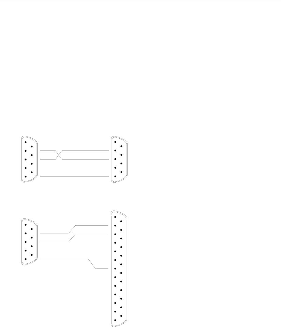
Contents - Maintenance and Instrument Interfaces FSE
1065.6016.12 8.8 E-15
Handshake
Software handshake
In the software handshake mode of operation, the data transfer is controlled using the two control
characters XON / XOFF.
The instrument uses the control character XON to indicate that it is ready to receive data. If the receive
buffer is full, it sends the XOFF character via the interface to the controller. The controller then interrupts
the data output until it receives another XON from the instrument. The controller indicates to the
instrument that it is ready to receive data in the same way.
Cable required for software handshake
The connection of the instrument with a controller for software handshake is made by crossing the data
lines. The following wiring diagram applies to a controller with a 9-pin or 25-pin configuration.
1
2
3
4
5
6
7
8
9
DSUB connector female / 9 poles
1
2
3
4
5
6
7
8
9
DSR
RxD
RTS
TxD
CTS
DTR
GND
DSUB connector female / 9 poles
Instrument Controller
DSR
RxD
RTS
TxD
CTS
DTR
GND
Instrument Controller / PC
1
2
3
4
5
6
7
8
9
DSR
RxD
RTS
TxD
CTS
DTR
GND
1
2
3
4
5
14
15
16
17
6
7
8
9
18
19
20
21
10
11
12
22
23
24
13 25
TxD
RxD
RTS
CTS
DSR
GND
DTR
DSUB connector female / 9 poles
DSUB connector female / 25 poles
Fig. 8-3 Wiring of the data lines for software handshake
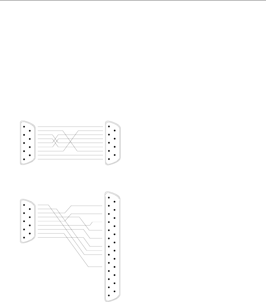
FSE Instrument Interfaces
1065.6016.12 8.9 E-15
Hardware handshake
For hardware handshake, the instrument indicates that it is ready to receive data via the lines DTR and
RTS. A logic ’0’ on both lines means ’ready’ and a logic ’1’ means ’not ready’. The RTS line is always
active (logic ’0’) as long as the serial interface is switched on. The DTR line thus controls the readiness
of the instrument to receive data.
The readiness of the remote station to receive data is reported to the instrument via the CTS and DSR
line. A logic ’0’ on both lines activates the data output and a logic ’1’ on both lines stops the data output
of the instrument. The data output takes place via the TxD line.
Cable for hardware handshake
The connection of the instrument to a controller is made with a so-called zero modem cable. Here, the
data, control and acknowledge lines must be crossed. The following wiring diagram applies to a
controller with a 9-pin or 25-pin configuration.
1
2
3
4
5
6
7
8
9
DSUB connector, 9 poles / female
1
2
3
4
5
6
7
8
9
DSR
RxD
RTS
TxD
CTS
DTR
GND
Instrument Controller / PC
DSR
RxD
RTS
TxD
CTS
DTR
GND
Instrument Controller / PC
1
2
3
4
5
6
7
8
9
DSR
RxD
RTS
TxD
CTS
DTR
GND
1
2
3
4
5
14
15
16
17
6
7
8
9
18
19
20
21
10
11
12
22
23
24
13 25
TxD
RxD
RTS
CTS
DSR
GND
DTR
DSUB connector, 9 poles / female
DSUB connector, 9 poles / female
DSUB connector, 25 poles / female
Fig. 8-4 Wiring of the data, control and acknowledge lines for hardware handshake
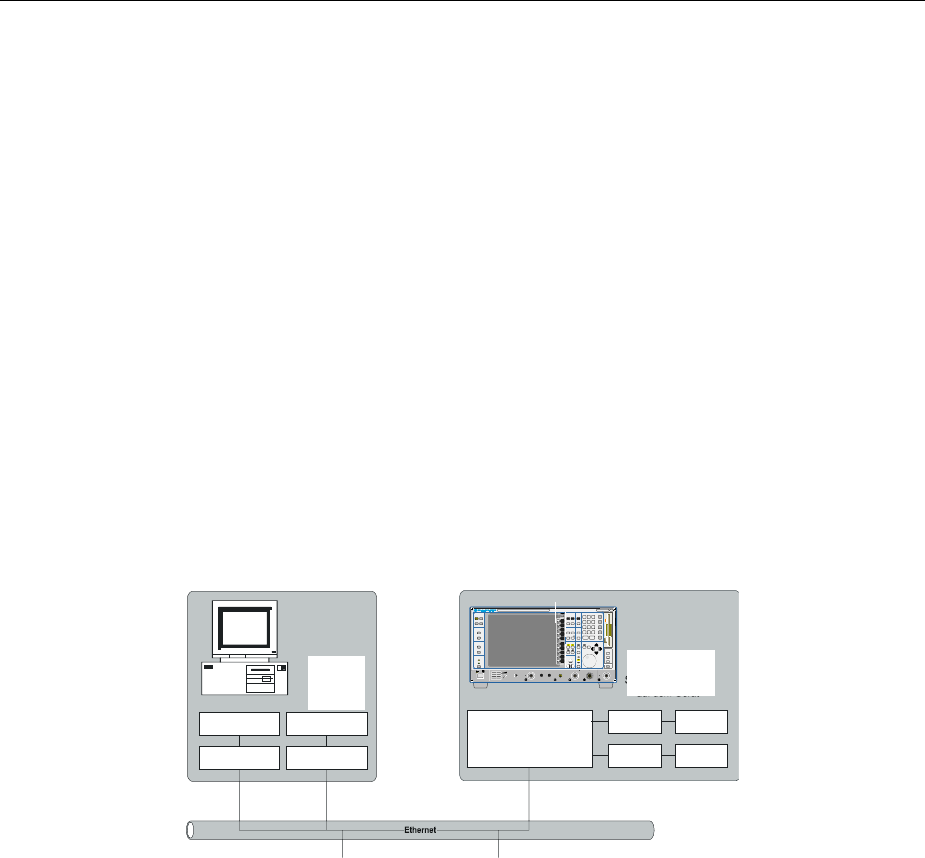
Contents - Maintenance and Instrument Interfaces FSE
1065.6016.12 8.10 E-15
RSIB Interface
The RSIB interface is only available if the FSE is equipped with a controller option, FSE-B15. It allows
the control of FSE by Visual C++ and VisualBasic programs but also by using the Windows applications
WinWord and Excel. The functions for the programming of control applications are provided by DLLs
RSIB32.DLL (for 32-bit applications) and RSIB.DLL (for 16-bit applications). Instruments with MS DOS
controller option are restricted to 16-bit applications and local control in a Windows enviroment.
A Unix operating system can be installed on an external computer in addition to a Windows operating
system. In this case, the control applications are created either in C or C++. The supported Unix
operating systems include:
•Sun Solaris 2.6 Sparc Station
•Sun Solaris 2.6 Intel Platform
•Red Hat Linux 6.2 x86 Processors
Control applications may run locally on the measuring instrument as well as on a remote controller in a
network. With local control, the name ’@local’ is specified for link setup by means of function
RSDLLibfind(). If ’@local’ is not specified, the RSIB.DLL interprets the name as an IP address
and attempts to set up a link to the device via the Winsock interface.
Remote controller
(Windows NT or Windows 95) FSE
0
123
456
789
.-
CLR BACK
GHz
MHz
kHz
Hz
EXP
-dBm
V
s
dBm
mV
ms
dB
µV
µs
dB..
nV
ns
AF OUTPUT PROBE POWER PROBE / CODE
30 dBm+DC 0V
MAX
MADE IN GER MANY
HOLD STEP
50
SYSTEM
CONFIGURATION
PRESET CAL
DISPLAY INFO
MODE
SETUP
SETTING
START
HARDCOPY
STATUS
SRQ
REMOTE
LOCAL
FREQUENCY LEVEL DATA ENTRY
CENTER / SPA N / UNIT
START STOP RANGE
MARKER LINES
NORMAL SEARCH D LINES
DELTA LIMITSMKR
TRACE SWEEP DATA VARIATION
TRIGGER
SWEEP /
12
34
RBW
VBW
SWT
MENU
MEMORY
CONFIG
SAVE
RECALL
INPUT
FREQ ZOOM
SCAN
COUPL I NG /
RUN
GEN OUT PUT 50 RF INPUT 1
MAX
REF /
REMOTE
EMI TEST RECEIVER 20 Hz . . . 7 GHz ESI 1088.7490
.. 07
RF INPUT 2 20Hz ... 1GHz
30 dBm+
MAX
50
Windows Environment
To access the measuring instruments via the RSIB interface the DLL should be installed in the
corresponding directories:
•RSIB.DLL in Windows NT system directory or control application directory.
•RSIB32.DLL in Windows NT system32 directory or control application directory.
The DLLs are already installed in the corresponding directories on the measuring instruments.
For the different programming languages, files exist containing the declarations for the DLL functions
and the error code definitions.
Instruments witht Windows NT controller:
Visual Basic (16 bit): ’RSIB.BAS’ (C:/R_S/Instr/RSIB)
Visual Basic (32 bit): ’RSIB32.BAS’ (C:/R_S/Instr/RSIB)
C: ’RSIB.H’ (C:/R_S/Instr/RSIB)
Remote
control via
network
16-bit app.
16-bit application
32-bit app.
32-bit application
Local
applications
on instrument
RSIB network interface
RSIB DLL
RSIB.DLL RSIB32.DLL
RSIB32.DLL

FSE Instrument Interfaces
1065.6016.12 8.11 E-15
Instruments with MS DOS controller:
Visual Basic: ’RSIB.BAS’ (D:/runtime/RSIB)
C: ’RSIBC.H’ (D:/runtime/RSIB)
Winword: ’RSIBWB.BAS’(D:/runtime/RSIB)
Thus, the RSIB directory features a program ‘RSIBCNTR.EXE’ with SCPI commands which can be sent
to the instrument by the RSIB interface. This program can be used as a test for the function of the
interface. Transit-time module VBRUN3200.DLL in the path or the Windows directory are required.
The control is performed with Visual C++ or Visual Basic programs. The local link to the internal
controller is established with the name '@local'.If a remote controller is used, the instrument IP address
is to be indicated here.
Via VisualBasic: internal controller: ud = RSDLLibfind ("@local", ibsta, iberr, ibcntl)
remote controller: ud = RSDLLibfind ('82.1.1.200', ibsta, iberr, ibcntl)
The return to manual operation can be performed via the front panel (LOCAL key) or the RSIB interface.
Via RSIB: ...
ud = RSDLLibloc (ud, ibsta, iberr, ibcntl);
...
Unix Environment
In order to access the measuring equipment via the RSIB interface, copy the librsib.so.X.Y file to a
directory for which the control application has read rights. X.Y in the file name indicates the version
number of the library, for example 1.0.
The librsib.so.X.Y library is created as a shared library. The applications using the library have
nothing to do with versions. They simply link the library with the lrsib option. The following instructions
have to be observed so that linking can be successfully performed and the library can be found during
the program run:
File link:
• Use the operating system command In to create a file with the link name librsib.so and
pointing to librsib.so.X.Y in a directory for which the control application has read rights.
Example:
$ ln –s /usr/lib/librsib.so.1.0 /usr/lib/librsib.so
Linker options for creating applications:
• -lrsib : import library
• -Lxxx : path information where the import library can be found. This is where the above file
link has been created. Example: -L/usr/lib.
Additional linker options for creating applications (only under Solaris):
• -Rxxx: path information where the library is searched for during the program run:
-R/usr/lib.
Run-time environment:
• Set environment variable LD_RUN_PATH to the directory in which the file link has been
created. This is necessary only if librsib.so cannot be found in the standard search path of
the operating system and the -R linker option (only Solaris) was not specified.
For C/C++ programming, the declarations of the library functions and the definition of error codes are
contained in:
C/C++: 'RSIB.H' (C:\R_S\Instr\RSIB)

Contents - Maintenance and Instrument Interfaces FSE
1065.6016.12 8.12 E-15
RSIB Interface Functions
This following sections describe all functions of libraries ’RSIB.DLL’, ’RSIB32.DLL’ or
"librsib.so" by means of which control applications can be written.
Variables ibsta, iberr, ibcntl
Same as with the National Instrument interface, successful execution of a command can be checked by
means of the variables ibsta, iberr and ibcntl. To this end, references to the three variables are
transferred to all RSIB functions. In addition, the status word ibsta is returned as a function value by all
functions.
Status word ibsta
All functions send back a status word that provides information on the status of the RSIB interface. The
following bits are defined:
Bit name Bit Hex code Description
ERR 15 8000 This bit is set if an error occurs during a function call. If this bit is set, iberr
contains an error code which specifies the error.
TIMO 14 4000 This bit is set if a timeout occurs during a function call. A timeout may occur in
the following situations:
•while waiting for an SRQ with the function RSDLLWaitSrq().
•if no acknowledgment is received for data sent to an instrument with
RSDLLibwrt() or RSDLLilwrt().
•if no response from server to a data request with function RSDLLibrd() or
RSDLLilrd().
CMPL 8 0100 This bit is set if the reply of the IEC/IEEE-bus parser is completely read. If a
reply of the parser is read with the function RSDLLilrd() and the buffer
length is not sufficient, the bit is cleared.
Error variable iberr
If the ERR bit (8000h) is set in the status word, iberr contains an error code that specifies the error.
The RSIB has error codes of its own independent of the National Instrument interface.
Error Error code Description
IBERR_DEVICE_REGISTER 1 RSIB.DLL cannot register any new device.
IBERR_CONNECT 2 Link to the device has failed.
IBERR_NO_DEVICE 3 An interface function was called with an invalid device handle.
IBERR_MEM 4 No free memory available.
IBERR_TIMEOUT 5 Timeout has occurred.
IBERR_BUSY 6 The RSIB interface is blocked by a function not yet completed.
Windows is not blocked, for example, by function RSDLLibrd() if data are still
to be transmitted in response to this function. In this case a new call is
possible. Further calls are however rejected by RSIB.DLL with error code
IBERR_BUSY.
IBERR_FILE 7 Error in reading from or writing to a file.
IBERR_SEMA 8 Error upon creating or assigning a semaphore (only under Unix)
Count variable - ibcntl
The variable ibcntl is updated with the number of bytes transmitted on every read and write function call.

FSE Instrument Interfaces
1065.6016.12 8.13 E-15
List of Interface Functions
The DLL functions are matched to the interface functions for IEC/IEEE-bus programming from National
Instruments. Functions supported by the DLLs are listed in the following table.
Function Description
RSDLLibfind() Provides a handle for accessing a device.
RSDLLibwrt() Sends a string terminated with a null to a device.
RSDLLilwrt() Sends a specific number of bytes to a device.
RSDLLibwrtf() Sends the contents of a file to a device.
RSDLLibrd() Reads data from a device into a string.
RSDLLilrd() Reads a specific number of bytes from a device.
RSDLLibrdf() Reads data from a device into a file.
RSDLLibtmo() Sets timeout period for RSIB functions.
RSDLLibsre() Switches a device to local or remote.
RSDLLibloc() Switches a device temporarily to local.
RSDLLibeot() Enables/disables END message in write operations.
RSDLLibrsp() Starts a serrial poll and reads the status byte, only with Windows NT controller
RSDLLibonl() Switches the instrument online/offline, only with Windows NT controller
RSDLLTestSrq() Checks if a device has generated an SRQ.
RSDLLWaitSrq() Waits until a device generates an SRQ.
RSDLLSwapBytes Swaps the byte sequence for binary numeric display (only required for non-Intel platforms)

Contents - Maintenance and Instrument Interfaces FSE
1065.6016.12 8.14 E-15
Description of Interface Functions
Note: The description of the UNIX format is only relevant to instruments with Windows NT controller.
RSDLLibfind()
The function provides a handle for access to the device with the name udName.
VB format: Function RSDLLibfind (ByVal udName$, ibsta%, iberr%, ibcntl&)
As Integer
C-format: short FAR PASCAL RSDLLibfind( char far *udName, short far
*ibsta, short far *iberr, unsigned long far *ibcntl)
C format (Unix): short RSDLLibfind( char *udName, short *ibsta, short *iberr,
unsigned long *ibcntl)
Parameter: udName IP address of device
Example: ud = RSDLLibfind ("89.10.38.97", ibsta, iberr, ibcntl)
The function must be called before all other interface functions.
The function supplies a handle as a return value. The handle must be specified in all functions for
accessing the instrument. If no instrument with the name udName is found, the handle will take on a
negative value.
The local link on the instrument is established with the name ’@local’. For setting up a link via a
network, on the other hand, the IP address of the instrument must be given (eg ’89.1.1.200’).
RSDLLibwrt
The function sends data to the instrument with the handle ud.
VB format: Function RSDLLibwrt (ByVal ud%, ByVal Wrt$, ibsta%, iberr%,
ibcntl&) As Integer
C format: short FAR PASCAL RSDLLibwrt( short ud, char far *Wrt, short
far *ibsta, short far *iberr, unsigned long far *ibcntl )
C format (Unix): short RSDLLibwrt( short ud, char *Wrt, short *ibsta, short
*iberr, unsigned long *ibcntl )
Parameter: ud Device handle
Wrt String sent to the device.
Example: RSDLLibwrt(ud, "SENS:FREQ:STAR?", ibsta, iberr, ibcntl)
The function allows setting and query commands to be sent to the measuring instruments. The function
RSDLLibeot() is used for defining whether the data are interpreted as a complete command.

FSE Instrument Interfaces
1065.6016.12 8.15 E-15
RSDLLilwrt
The function sends Cnt bytes to the instrument with the handle ud.
VB format: Function RSDLLilwrt (ByVal ud%, ByVal Wrt$, ByVal Cnt&,
ibsta%, iberr%, ibcntl&) As Integer
C format: short FAR PASCAL RSDLLilwrt( short ud, char far *Wrt,
unsigned long Cnt, short far *ibsta, short far *iberr,
unsigned long far *ibcntl)
C format (Unix): short RSDLLilwrt( short ud, char *Wrt, unsigned long Cnt,
short *ibsta, short *iberr, unsigned long *ibcntl)
Parameter: ud Device handle
Wrt String sent to the IEC/IEEE-bus parser.
Cnt Number of bytes sent to the instrument.
Example: RSDLLilwrt (ud, ’......’, 100, ibsta, iberr, ibcntl)
This function sends data to an instrument same as function RSDLLibwrt() but with the difference that
binary data, too, can be sent. The length of the data is determined not by a zero-terminated string but by
the definition of Cnt bytes. If the data are to be terminated with EOS (0Ah), the EOS byte must be
appended to the string.
RSDLLibwrtf
The function sends the contents of a file to the instrument with the handle ud.
VB format: Function RSDLLibwrtf (ByVal ud%, ByVal file$, ibsta%, iberr%,
ibcntl&) As Integer
C format: short FAR PASCAL RSDLLibwrt( short ud, char far *Wrt, short
far *ibsta, short far *iberr, unsigned long far *ibcntl )
C format (Unix): short RSDLLibwrtf( short ud, char *Wrt, short *ibsta, short
*iberr, unsigned long *ibcntl )
Parameter: ud Device handle
file File whose contents are sent to the instrument.
Example: RSDLLibrdf(ud, "C:\db.sav", ibsta, iberr, ibcntl)
The function allows setting and query commands to be sent to the measuring instruments. The function
RSDLLibeot() is used for defining whether the data are interpreted as a complete command.

Contents - Maintenance and Instrument Interfaces FSE
1065.6016.12 8.16 E-15
RSDLLibrd()
The function reads data from the instrument into the string Rd with the handle ud.
VB format: Function RSDLLibrd (ByVal ud%, ByVal Rd$, ibsta%, iberr%,
ibcntl&) As Integer
C format: short FAR PASCAL RSDLLibrd( short ud, char far *Rd, short far
*ibsta, short far *iberr, unsigned long far *ibcntl )
C format (Unix): short RSDLLibrd( short ud, char *Rd, short *ibsta, short
*iberr, unsigned long *ibcntl )
Parameter: ud Device handle
Rd String into which the read data are copied.
Example: RSDLLibrd (ud, Rd, ibsta, iberr, ibcntl)
This function fetches replies of the IEC/IEEE-bus parser in response to a query command.
For this, a string of sufficient length must be generated when programming in Visual Basic. This can be
accomplished in the definition of the string or with the command Space$().
Generation of a string of the length 100: - Dim Rd as String * 100
- Dim Rd as String
Rd = Space$(100)
RSDLLilrd
The function reads Cnt bytes from the instrument with the handle ud.
VB format: Function RSDLLilrd (ByVal ud%, ByVal Rd$, ByVal Cnt&, ibsta%,
iberr%, ibcntl&) As Integer
C format: short FAR PASCAL RSDLLilrd( short ud, char far *Rd, unsigned
long Cnt, short far *ibsta, short far *iberr, unsigned long
far *ibcntl )
Parameter: ud Device handle
cnt Maximum number of bytes copied to target string Rd by the
DLL.
Example: RSDLLilrd (ud, RD, 100, ibsta, iberr, ibcntl)
The function reads data from an instrument same as function RSDLLibrd() but with the difference that
here the maximum number of bytes is allowed to be copied to target string Rd to be defined with Cnt.
Writing beyond a string can thus be prevented with this function. The number of bytes cut off is lost.
RSDLLibrdf()
Reads data from the instrument into the file file with the handle ud.
VB format: Function RSDLLibrdf (ByVal ud%, ByVal file$, ibsta%, iberr%,
ibcntl&) As Integer
C format: short FAR PASCAL RSDLLibrdf( short ud, char far *file, short
far *ibsta, short far *iberr, unsigned long far *ibcntl )
C format (Unix): short RSDLLibrd( short ud, char *file, short *ibsta, short
*iberr, unsigned long *ibcntl )
Parameter: ud Device handle
file File into which the read data are written.
Example: RSDLLibrdf (ud, c:\db.sav, ibsta, iberr, ibcntl)
This function serves to read replies of the IEC/IEEE-bus parser that are larger than 64 KB. The file
name may include the drive and path.

FSE Instrument Interfaces
1065.6016.12 8.17 E-15
RSDLLibtmo
The function defines the timeout for an instrument. The default value for the timeout is 5 seconds.
VB format: Function RSDLLibtmo (ByVal ud%, ByVal tmo%, ibsta%, iberr%,
ibcntl&) As Integer
C format: void FAR PASCAL RSDLLibtmo( short ud, short tmo, short far
*ibsta, short far *iberr, unsigned long far *ibcntl )
C format (Unix): short RSDLLibtmo( short ud, short tmo, short *ibsta, short
*iberr, unsigned long *ibcntl )
Parameter: ud Device handle
tmo Time in seconds
Example: RSDLLibtmo (ud, 10, ibsta, iberr, ibcntl)
Timeout can occur in the following cases:
•Waiting for an SRQ with the function RSDLLWaitSrq().
•Waiting for an acknowledgment for data sent to an instrument with RSDLLibwrt() or
RSDLLilwrt().
•Waiting for a reply to a data request made with function RSDLLibrd() or RSDLLilrd().
RSDLLibsre
The function switches the instrument to LOCAL or REMOTE mode.
VB format: Function RSDLLibsre (ByVal ud%, ByVal v%, ibsta%, iberr%,
ibcntl&) As Integer
C format: void FAR PASCAL RSDLLibsre( short ud, short v, short far
*ibsta, short far *iberr, unsigned long far *ibcntl)
C format (Unix): short RSDLLibsre( short ud, short v, short *ibsta, short
*iberr, unsigned long *ibcntl)
Parameter: ud Device handle
vInstrument status
0 - local
1 - remote
Example: RSDLLibsre (ud, 0, ibsta, iberr, ibcntl)

Contents - Maintenance and Instrument Interfaces FSE
1065.6016.12 8.18 E-15
RSDLLibloc
The function switches the instrument temporarily to LOCAL mode.
VB format: Function RSDLLibloc (ByVal ud%, ibsta%, iberr%, ibcntl&) As
Integer
C format: void FAR PASCAL RSDLLibloc( short ud, short far *ibsta, short
far *iberr, unsigned long far *ibcntl)
C format (Unix): short RSDLLibloc( short ud, short *ibsta, short *iberr,
unsigned long *ibcntl)
Parameter: ud Device handle
Example: RSDLLibloc (ud, ibsta, iberr, ibcntl)
After switchover the instrument can be manually operated from the front panel. On the next access to
the instrument by means of one of the functions of the RSIB.DLL, the instrument is switched again to the
REMOTE state.
RSDLLibeot
The function enables the END message after write operations or disables it.
VB format: Function RSDLLibeot (ByVal ud%, ByVal v%, ibsta%, iberr%,
ibcntl&) As Integer
C format: void FAR PASCAL RSDLLibeot( short ud, short v, short far
*ibsta, short far *iberr, unsigned long far *ibcntl)
C format (Unix): short RSDLLibsre( short ud, short v, short *ibsta, short
*iberr, unsigned long *ibcntl)
Parameter: ud Device handle.
v0 - no END message
1 - send END message
Example: RSDLLibeot (ud, 1, ibsta, iberr, ibcntl)
If the END message is disabled, the data of a command can be sent by means of several successive
write function calls. The END message must be enabled prior to the last data block.
RSDLLibrsp
The function carries out a Serial Poll and outputs the instrument status (only with Windows NT
controller)..
VB format: Function RSDLLibrsp(ByVal ud%, spr%, ibsta%, iberr%, ibcntl&)
As Integer
C format: void FAR PASCAL RSDLLibrsp( short ud, char far* spr, short far
*ibsta, short far *iberr, unsigned long far *ibcntl)
C format (Unix): short RSDLLibrsp( short ud, char *spr, short *ibsta, short
*iberr, unsigned long *ibcntl)
Parameter: ud Device handle.
spr Reference to status byte
Example: RSDLLibrsp(ud, spr, ibsta, iberr, ibcntl)

FSE Instrument Interfaces
1065.6016.12 8.19 E-15
RSDLLibonl
The function switches the instrument to the 'online' or 'offline' state. When switching to ‘offline’ the
interface is enabled and the device handle made invalid. The next call of RSDLLibfind sets up the
communication again (only with Windows NT controller).
VB format: Function RSDLLibonl (ByVal ud%, ByVal v%, ibsta%, iberr%,
ibcntl&) As Integer
C format: void FAR PASCAL RSDLLibonl( short ud, short v, short far
*ibsta, short far *iberr, unsigned long far *ibcntl)
C format (Unix): short RSDLLibonl( short ud, short v, short *ibsta, short
*iberr, unsigned long *ibcntl)
Parameter: ud Device handle.
vStatus of instrument
0 - local
1 - remote
Example: RSDLLibonl(ud, 0, ibsta, iberr, ibcntl)
RSDLLTestSRQ
The function checks the status of the SRQ bit.
VB format: Function RSDLLTestSrq (ByVal ud%, Result%, ibsta%, iberr%,
ibcntl&) As Integer
C format: void FAR PASCAL RSDLLTestSrq( short ud, short far *result,
short far *ibsta, short far *iberr, unsigned long far *ibcntl)
C format (Unix): short RSDLLTestSrq( short ud, short *result, short *ibsta,
short *iberr, unsigned long *ibcntl)
Parameter: ud Device handle
result Reference to an integer value in which the library
returns the status of the SRQ bit.
0 - no SRQ
1 - SRQ active, instrument has output a service request
Example: RSDLLTestSrq (ud, result%, ibsta, iberr, ibcntl)
The function corresponds to the function RSDLLWaitSrq but with the difference that RSDLLTestSRQ
returns immediately the current status of the SRQ bit whereas RSDLLWaitSrq waits for an SRQ to
occur.

Contents - Maintenance and Instrument Interfaces FSE
1065.6016.12 8.20 E-15
RSDLLWaitSrq
The function waits until the instrument triggers an SRQ with the handle ud.
VB format: Function RSDLLWaitSrq (ByVal ud%, Result%, ibsta%, iberr%,
ibcntl&) As Integer
C format: void FAR PASCAL RSDLLWaitSrq( short ud, short far *result,
short far *ibsta, short far *iberr, unsigned long far *ibcntl)
C format (Unix): short RSDLLWaitSrq( short ud, short *result, short *ibsta,
short *iberr, unsigned long *ibcntl)
Parameter: ud Device handle
result Reference to an integer value in which the library
returns the status of the SRQ bit.
0 - no SRQ occurred within the timeout
1 - SRQ occurred within the timeout
Parameter: RSDLLWaitSrq( ud, result, ibsta, iberr, ibcntl );
The function waits until one of the two following events occurs:
•The instrument triggers an SRQ.
•No SRQ occurs during the timeout defined with RSDLLibtmo().
RSDLLSwapBytes
This function changes the display of binary numbers on non-Intel platforms (only with Windows NT
controller)..
VB format: Not provided at present since it is required only on non-Intel platforms.
C format: void FAR PASCAL RSDLLSwapBytes( void far *pArray, const long
size, const long count)
C format (Unix): void RSDLLSwapBytes( void *pArray, const long size, const long
count)
Parameter: pArray Array in which modifications are made
size Size of a single element in pArray
count Number of elements in pArray
Example: RSDLLSwapBytes( Buffer, sizeof(float), ibcntl/sizeof(float))
This function swaps the display of various elements from Big Endian to Little Endian and vice versa. It is
expected that a coherent storage area of elements of the same file type (size byte) is transferred to
pArray. This function has no effect on Intel platforms.
Different types of processor architecture store data in different byte sequences. For example, Intel
processors store data in the reverse order of Motorola processors. Comparison of byte sequences:
Byte sequence Use in Display in memory Description
Big Endian Motorola processors,
network standard Most significant byte at
least significant address The most significant byte is at the left end
of the word.
Little Endian Intel processors Least significant byte at
least significant address The most significant byte is at the right
end of the word.
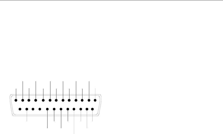
FSE Instrument Interfaces
1065.6016.12 8.21 E-15
User Interface (USER)
The user interface, located on the rear panel of the FSE, is a 25 pin Cannon connector which provides
access to the two user ports (Port A and Port B). Each port is 8 bits wide (A0 - A7 and B0 -B7) and can
be configured either as output or as input. The voltage levels are TTL levels (Low < 0,4 V, High > 2 V).
In addition, an internal +5 V power supply voltage is provided. The maximum load current is 100 mA.
The pin assignments for the USER connector can be seen in the following diagram:
1
14
13
25
A0
A1
A2
A3
A4
A5
A6
A7GND
GND
GND
GND
+5 V
B7
B6
B5
B4
B3
B2
B1
B0
+5 V
Fig. 8-5 Pin assignments for the USER connector.
The configuration of the user ports takes place in the SETUP menu (SETUP key) in the GENERAL
SETUP sub-menu.

Contents - Maintenance and Instrument Interfaces FSE
1065.6016.12 8.22 E-15
Printer Interface (LPT)
The 25-pin LPT connector on the rear panel of the FSE is provided for the connection of a printer.. The
LPT interface is compatible with the CENTRONICS printer interface.
1
14
13
25
D0
D1
D2
D3
D4
D5
D6
D7
ACK
BUSY
PE
SELECT STROBE
AUTOFEED
ERROR
INIT
SELECT IN
GND
GND
GND
GND
GND
GND
GND
GND
Pin Signal Input (I)
Output (O) Description
1 STROBE O Pulse for transmitting a data byte, min. 1µs pulse width
(active LOW)
2 D0 O Data Line 0
3 D1 O Data Line 1
4 D2 O Data Line 2
5 D3 O Data Line 3
6 D4 O Data Line 4
7 D5 O Data Line 5
8 D6 O Data Line 6
9 D7 O Data Line 7
10 ACK I Indicates that the printer is ready to receive the next byte.
(active LOW)
11 BUSY I Signal is active when the printer cannot accept data.
(active HIGH)
12 PE I Signal is active when the paper tray is empty.
(active HIGH)
13 SELECT I Signal is active when the printer is selected.
(active HIGH)
14 AUTOFEED O When signal is active, the printer automatically performs a
linefeed after each line.
(active LOW)
15 ERROR I This signal is high when the printer has no paper, is not
selected or has an error status.
(active LOW)
16 INIT O Initialise the printer.
(active LOW)
17 SELECT IN O If signal is active, the codes DC1/DC3 are ignored by the
printer.
(active LOW).
18 - 25 GND Ground connection.
Fig. 8-6 Pin assignments for the LPT connector.
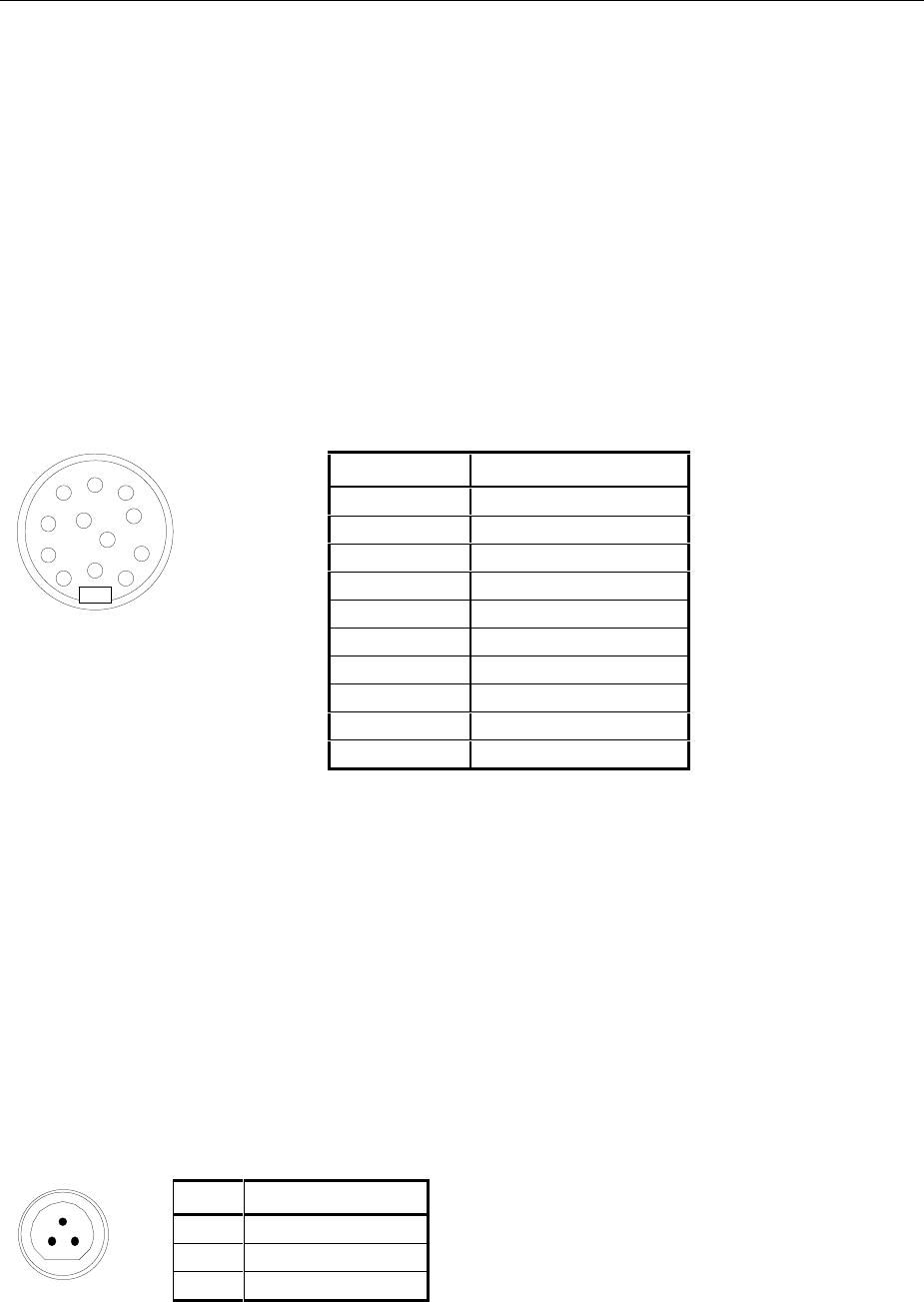
FSE Instrument Interfaces
1065.6016.12 8.23 E-15
Measurement Converters (PROBE CODE)
The PROBE CODE connector is used for supplying power to measurement converters and the providing
the correct conversion factor coding to the FSE. Using it, the conversion factors for high-impedance
probes, current converters and antennas can be encoded in 10dB steps. In addition, the quantity to be
measured (field strength, current and voltage) is also passed to the FSE. Active converters can be
supplied with ±10 V via the PROBE CODE connector. The following R&S accessories are deliverable
with the applicable coding:
· Wide band dipole 20...80 MHz HUF-Z2
· HF current converter 100 kHz..30 MHz ESH2-Z1
· VHF current converter 20...300 MHz ESV-Z1
· Current converter 20 Hz...100 MHz EZ-17
· Preamplifier 20...1000 MHz ESV-Z2.
The pins of the PROBE CODE connector are assigned as follows:
Pin Signal
A ground
B +10 V, max. 50 mA
C µV/m (elec. field strength)
DµA
E 10 dB
F 20 dB
G 40 dB
H 80 dB
K - 10 V, max. 50 mA
M factor sign inversion
Fig 8-7 Pin assignment for the 12-pin Tuchel connector.
A 12-pin connector is used for coding (manufacturer: Tuchel, R&S part number 0018.5362.00, Tuchel
type number: T3635/2). The input pins for implementing the code are connected to ground.
Example: An antenna for measurement of the electromagnetic field strength has an antenna factor of
10 dB, i.e., a field strength of 10 dBµV/m produces a voltage at the RF input of 0 dBµV.
-> Pins C and E are connected to ground.
Probe Connector (PROBE POWER)
To allow the connection of probes, the FSE provides the PROBE POWER power connector. It delivers
the power supply voltages +15 V and -12,6 V and ground.
The connector is also suited for powering the high-impedance probes from Hewlett Packard.
Pin Signal
1GND
2 -12,6 V; max 150 mA
1
23
3 +15 V; max 150 mA
AB
C
D
E
F
G
H
J
K
L
M

Contents - Maintenance and Instrument Interfaces FSE
1065.6016.12 8.24 E-15
AF-Output (AF OUTPUT)
A miniature telephone jack can be used at the AF OUTPUT connector to connect an external
loudspeaker, a headphone set or, e.g., a LF voltmeter. The internal resistance is 10 ohms and the
output voltage can be controlled in the MARKER DEMOD menu. When a jack is plugged in, the internal
loudspeaker is automatically turned off.
IF Output 21.4 MHz (21.4 MHz OUT)
The 21,4 MHz IF signal of the FSE is available at the IF 21.4 MHz OUT BNC connector. The bandwidth
corresponds to the selected bandwidth for a resolution bandwidth between 2 kHz and 10 MHz. For a
resolution bandwidth below 2 kHz, the bandwidth of the output is 5 kHz.
The signal level at the IF output is 0 dBm for signals which correspond to the selected reference level.
Video Output (VIDEO OUT)
The video output delivers the logarithmic envelope curve of the IF signal independent of the level scaling
on the display screen (linear or logarithmic). The bandwidth of the video signal always corresponds to
one-half of the IF bandwidth and is not limited by the video filter in the measurement path.
Reference Output/Input (EXT REF IN/OUT)
When the FSE is operated with the internal reference, the internal 10 MHz reference signal is also
available at the REF IN/OUT connector and thus provides the capability of, e.g., synchronisation of
external instruments to the FSE. The level is 1 V RMS at 50 ohms source impedance.
For operation with an external reference, this connector becomes an input connector. The internal
reference oscillator is then synchronised to the reference applied to the connector. The reference
frequency can be between 1 and 16 MHz in 1 MHz steps. The necessary level is > 0 dBm.
The selection of internal or external references takes place in the SETUP menu.
Sweep Output (SWEEP)
The SWEEP BNC connector delivers a saw-tooth voltage between 0V and + 10 V which, for the
frequency spectrum display, is proportional to the instantaneous frequency. The selected start frequency
corresponds to a voltage of 0V and the stop frequency corresponds to a voltage of +10 V.
External Trigger Input (EXT TRIGGER/GATE)
The EXT TRIG/GATE connector is used for controlling the measurement via an external signal.
Trigger voltage range:: -5 V ... +5 V
Noise Source Control (NOISE SOURCE)
Using the NOISE SOURCE connector, an external noise source can be switched on/off, in order, e.g., to
measure the noise figure of Units Under Test (UUTs). Usual noise sources require a +28 V signal to be
turned on. At 0 V, they are turned off. These switching voltages are delivered by the connector.
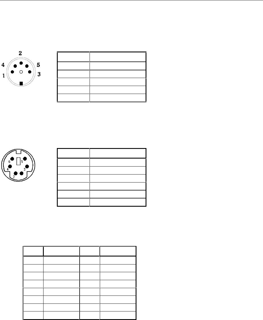
FSE Instrument Interfaces
1065.6016.12 8.25 E-15
External Keyboard (KEYBOARD)
A 5-pin DIN connector is provided to allow connecting an external keyboard. Because of its low
interference radiation, the PSA-Z1 keyboard is recommended (Order No. 1009.5001.31). However, any
other multi-function keyboard may also be used.
Pin Signal
1 Keyboard Clock
2Data
3Free
4 Ground
5 +5-V-Power Supply
Fig. 8-8 Pin assignments of the KEYBOARD connector.
Mouse Connector (MOUSE)
Pin Signal
1 MOUSEDATA
2NC
3 MOUSEGND
4 MOUSEVD5
5 MOUSECLK
6NC
Fig 8-9 Pin assignments for the MOUSE connector.
Monitor Connector (MONITOR)
Pin Signal Pin Signal
1R 9NC
2G 10GND
3 B 11 MID0 (NC)
4 MID2 (NC) 12 MID1 (NC)
5 NC 13 HSYNC
6 R-GND 14 VSYNC
7 G-GND 15 NC
8B-GND
Fig. 8-10 Pin assignments of the MONITOR connector.

FSE Contents - Error Messages
1065.6016.12 I-9.1 E-1
Contents - Chapter 9 "Error Messages"
9 List of Error Messages
SCPI-Specific Error Messages........................................................................................................ 9.1
Command Error - Faulty command; sets bit 5 in the ESR register. ........................................ 9.1
Execution Error - Error on execution of a command; sets bit 4 in the ESR register................ 9.4
Device Specific Error; sets bit 3 in the ESR register ............................................................... 9.7
Query Error - Error in data request; sets bit 2 in the ESR register .......................................... 9.7

Contents - Error Messages FSE
1065.6016.12 I-9.2 E-1

FSE List of Error Messages
1065.6016.12 9.1 E-1
9 List of Error Messages
The following list contains the error messages for errors occurring in the instrument. The meaning of
negative error codes is defined in SCPI, positive error codes mark errors specific of the instrument.
Error messages are entered in the error/event queue of the status reporting system in the remote
control mode and can be queried with the command SYSTem:ERRor?. The answer format of FSE to
the command is as follows:
<error code>, "<error text with queue query>; <remote control command concerned>"
The indication of the remote control command with prefixed semicolon is optional.
Example:
The command "TEST:COMMAND" generates the following answer to the query SYSTem:ERRor? :
-113,"Undefined header;TEST:COMMAND"
The table contains the error code in the left-hand column. In the right-hand column the error text being
entered into the error/event queue or being displayed is printed in bold face. Below the error text, there
is an explanation as to the respective error.
SCPI-Specific Error Messages
No Error
Error code Error text in the case of queue poll
Error explanation
0No error
This message is output if the error queue does not contain any entries.
Command Error - Faulty command; sets bit 5 in the ESR register.
Error code Error text in the case of queue poll
Error explanation
-100 Command Error
The command is faulty or invalid.
-101 Invalid Character
The command contains an invalid sign.
Example: A header contains an ampersand, "SENSe&".
-102 Syntax error
The command is invalid.
Example: The command contains block data the instrument does not accept.
-103 Invalid separator
The command contains an impermissible sign instead of a separator.
Example: A semicolon is missing after the command.

List of Error Messages FSE
1065.6016.12 9.2 E-1
Continuation: Command Error
Error code Error text in the case of queue poll
Error explanation
-104 Data type error
The command contains an invalid value indication.
Example: ON is indicated instead of a numeric value for frequency setting.
-105 GET not allowed
A Group Execute Trigger (GET) is within a command line.
-108 Parameter not allowed
The command contains too many parameters.
Example: Command SENSe:FREQuency:CENTer permits only one frequency indication.
-109 Missing parameter
The command contains too few parameters.
Example: The command SENSe:FREQuency:CENTer requires a frequency indication.
-110 Command header error
The header of the command is faulty.
-111 Header separator error
The header contains an impermissible separator.
Example: the header is not followed by a "White Space", "*ESE255"
-112 Program mnemonic too long
The header contains more than 12 characters.
-113 Undefined header
The header is not defined for the instrument.
Example: *XYZ is undefined for every instrument.
-114 Header suffix out of range
The header contains an impermissible numeric suffix.
Example: SENSe3 does not exist in the instrument.
-120 Numeric data error
The command contains a faulty numeric parameter.
-121 Invalid character in number
A number contains an invalid character.
Example: An "A" in a decimal number or a "9" in an octal number.
-123 Exponent too large
The absolute value of the exponent is greater than 32000.
-124 Too many digits
The number includes too many digits.
-128 Numeric data not allowed
The command includes a number which is not allowed at this position.
Example: The command INPut:COUPling requires indication of a text parameter.
-130 Suffix error
The command contains a faulty suffix.
-131 Invalid suffix
The suffix is invalid for this instrument.
Example: nHz is not defined.
-134 Suffix too long
The suffix contains more than 12 characters.

FSE List of Error Messages
1065.6016.12 9.3 E-1
Continuation: Command Error
Error code Error text in the case of queue poll
Error explanation
-138 Suffix not allowed
A suffix is not allowed for this command or at this position of the command.
Example: The command *RCL does not permit a suffix to be indicated.
-140 Character data error
The command contains a faulty text parameter
-141 Invalid character data
The text parameter either contains an invalid character or it is invalid for this command.
Example: Write error with parameter indication;INPut:COUPling XC.
-144 Character data too long
The text parameter contains more than 12 characters.
-148 Character data not allowed
The text parameter is not allowed for this command or at this position of the command.
Example: The command *RCL requires a number to be indicated.
-150 String data error
The command contains a faulty string.
-151 Invalid string data
The command contains a faulty string.
Example: An END message has been received prior to the terminating apostrophe.
-158 String data not allowed
The command contains a valid string at a position which is not allowed.
Example: A text parameter is set in quotation marks, INPut:COUPling "DC"
-160 Block data error
The command contains faulty block data.
-161 Invalid block data
The command contains faulty block data.
Example: An END message was received prior to reception of the expected number of data.
-168 Block data not allowed
The command contains valid block data at an impermissible position.
Example: The command *RCL requires a number to be indicated.
-170 Expression error
The command contains an invalid mathematical expression.
-171 Invalid expression
The command contains an invalid mathematical expression.
Example: The expression contains mismatching parentheses.
-178 Expression data not allowed
The command contains a mathematical expression at an impermissible position.
-180 Macro error
A faulty macro has been defined, or an error has occurred during execution of a macro.
-181 Invalid outside macro definition
A macro parameter placeholder was encountered outside of a macro definition.
-183 Invalid inside macro definition
A macro definition is syntactically wrong.
-184 Macro parameter error
A command inside the macro definition has the wrong number or type of parameters.

List of Error Messages FSE
1065.6016.12 9.4 E-1
Execution Error - Error on execution of a command; sets bit 4 in the ESR
register
Error code Error text in the case of queue poll
Error explanation
-200 Execution error
Error on execution of the command.
-201 Invalid while in local
The command is not executable while the device is in local due to a hard local control.
Example: The device receives a command which would change the rotary knob state, but the device is in
local so the command can not be executed.
-202 Settings lost due to rtl
A setting associated with hard local control was lost when the device changed to LOCS from REMS or to
LWLS from RWLS.
-210 Trigger error
Error on triggering the device.
-211 Trigger ignored
The trigger (GET, *TRG or trigger signal) was ignored because of device timing considerations.
Example: The device was not ready to respond.
-212 Arm ignored
An arming signal was ignored by the device.
-213 Init ignored
Measurement initialisation was ignored as another measurement was already in progress.
-214 Trigger deadlock
The trigger source for the initiation of measurement is set to GET and subsequent measurement is
received. The measurement cannot be started until a GET is received, but the GET would cause an
interrupted-error)
-215 Arm deadlock
The trigger source for the initiation of measurement is set to GET and subsequent measurement is
received. The measurement cannot be started until a GET is received, but the GET would cause an
interrupted-error.
-220 Parameter error
The command contains a faulty or invalid parameter.
-221 Settings conflict
There is a conflict between setting of parameter value and instrument state.
-222 Data out of range
The parameter value lies out of the permissible range of the instrument.
-223 Too much data
The command contains too many data.
Example: The instrument does not have sufficient storage space.
-224 Illegal parameter value
The parameter value is invalid.
Example: The text parameter is invalid , TRIGger:SWEep:SOURce TASTe

FSE List of Error Messages
1065.6016.12 9.5 E-1
Continuation: Execution Error
Error code Error text in the case of queue poll
Error explanation
-230 Data corrupt or stale
The data are incomplete or invalid.
Example: The instrument has aborted a measurement.
-231 Data questionable
The measurement accuracy is suspect.
-240 Hardware error
The command cannot be executed due to problems with the instrument hardware.
-241 Hardware missing
Hardware is missing.
Example: An option is not fitted.
-250 Mass storage error
A mass storage error occured.
-251 Missing mass storage
The mass storage is missing.
Example: An option is not installed.
-252 Missing media
The media is missing.
Example: There is no floppy in the floppy disk drive.
-253 Corrupt media
The media is corrupt.
Example: The floppy is bad or has the wrong format.
-254 Media full
The media is full.
Example: There is no room on the floppy.
-255 Directory full
The media directory is full.
-256 File name not found
The file name cannot be found on the media.
-257 File name error
The file name is wrong.
Example: An attempt is made to copy to a duplicate file name.
-258 Media protected
The media is protected.
Example: The write-protect tab on the floppy is present.
-260 Expression error
The expression contains an error.
-261 Math error in expression
The expression contains a math error.
Example: Divide-by-zero.

List of Error Messages FSE
1065.6016.12 9.6 E-1
Continuation: Execution Error
Error code Error text in the case of queue poll
Error explanation
-270 Macro error
Error on the execution of a macro.
-271 Macro syntax error
The macro definition contains a syntax error.
-272 Macro execution error
The macro definition contains an error.
-273 illegal macro label
An illegal macro label is defined in the *DMC command.
Example: The label is too long. The label is identical with the common command header or contains an
invalid header syntax.
-274 Macro parameter error
The macro definition improperly uses a macro parameter placeholder.
-275 Macro definition too long
The macro definition is too long.
-276 Macro recursion error
The command sequence defined by the macro is trapped in a program loop.
Example: The event that would allow the loop to be exited does not occur.
-277 Macro redefinition not allowed
The macro label defined in the *DMC command is already defined elsewhere.
-278 Macro header not found
The macro label in the *GMC? query is not yet defined.
-280 Program error
Error on the execution of a down-loaded program.
-281 Cannot create program
The program cannot be created.
-282 illegal program name
The name of the programm is illegal.
Example: The name relates to a non-existing program.
-283 illegal variable name
The inputted variable does not exist in the program.
-284 Program currently running
The desired operation is not possible while the program is running.
Example: A running program cannot be deleted.
-285 Program syntax error
The down-loaded program contains a syntax error.
-286 Program runtime error

FSE List of Error Messages
1065.6016.12 9.7 E-1
Device Specific Error; sets bit 3 in the ESR register
Error code Error test in the case of queue poll
Error explanation
-300 Device-specific error
FSE-specific error not defined in greater detail.
-310 System error
This error message suggests an error within the instrument. Please inform the R&S Service.
-311 Memory error
Error in the instrument memory.
-312 PUD memory lost
Loss of the protected user data stored using the *PUD command.
-313 Calibration memory lost
Loss of the non-volatile calibration data stored using the *CAL? command.
-314 Save/recall memory lost
Loss of the non-volatile data stored using the *SAV command.
-315 Configuration memory lost
Loss of the non-volatile configuration data stored by the instrument.
-330 Self-test failed
The selftest could not be executed.
-350 Queue overflow
This error code is entered in the queue instead of the actual error code if the queue is full. It indicates that
an error has occurred but not been accepted. The queue can accept 5 entries.
Query Error - Error in data request; sets bit 2 in the ESR register
Error code Error text in the case of queue poll
Error explanation
-400 Query error
General error occurring when data are requested by a query.
-410 Query INTERRUPTED
The query has been interrupted.
Example: After a query, the instrument receives new data before the response has been sent completely.
-420 Query UNTERMINATED
The query is incomplete.
Example: The instrument is addressed as a talker and receives incomplete data.
-430 Query DEADLOCKED
The query cannot be processed.
Example: The input and output buffers are full, the instrument cannot continue operation.
-440 Query UNTERMINATED after indefinite response
A query is in the same command line after a query which requests an indefinite response.

FSE Index
1065.6016.12 10.1 E-1
10 Index
A
Abort
hardcopy ........................................................4.51, 4.52
macro ..................................................................... 4.49
ACP measurement ..................................................... 4.114
absolute/relative ................................................... 4.119
bandwidth............................................................. 4.116
channel spacing ................................................... 4.117
channels............................................................... 4.114
filter ...................................................................... 4.116
limits..................................................................... 4.117
standard ............................................................... 4.115
Addressed command...................................................... 8.5
Adjacent channel power measurement....................... 4.114
Administrator identification............................................ 1.23
Alphanumeric parameter
editing..................................................................... 3.17
AM modulation............................................................ 4.204
Analog trace ............................................................... 4.165
Ascii #........................................................................... 5.14
Attenuation ................................................................. 4.100
Attenuator (tracking generator)................................... 4.193
AUI connector.......................................................1.45, 1.74
Autopeak detector ...................................................... 4.163
Average...................................................................... 4.158
continuous sweep................................................. 4.159
signal per sweep .................................................. 4.139
single sweep ........................................................ 4.159
summary markers................................................. 4.140
sweep count ......................................................... 4.158
Average detector ........................................................ 4.164
Axis labelling .................................................................. 3.7
B
Bandwidth
channel................................................................. 4.116
occupied............................................................... 4.124
resolution.............................................................. 4.171
video .................................................................... 4.172
Beeper......................................................................... 4.40
Block data..................................................................... 5.14
BNC connector .....................................................1.44, 1.73
Boolean parameter ....................................................... 5.13
C
Calibration ...................................................................... 4.9
method ................................................................. 4.201
CCVS signal................................................................4.206
CD-ROM installation......................................................1.36
Center frequency...........................................................4.87
Channel
bandwidth .............................................................4.116
power measurement .............................................4.118
power, absolute/relative ........................................4.119
spacing .................................................................4.117
Characters, special .........................................................6.2
Clear/Write..................................................................4.157
Clock.............................................................................4.39
Colon.............................................................................5.14
COM1/2 interface.................................................4.36, 4.42
Comma .........................................................................5.14
Command
#..............................................................................5.14
addressed.................................................................8.5
colon.......................................................................5.14
comma....................................................................5.14
header.....................................................................5.10
line..........................................................................5.12
long form.................................................................5.11
overlapping execution .............................................5.17
query.......................................................................5.12
question mark ................................................5.12, 5.14
quotation mark ........................................................5.14
recognition ..............................................................5.16
sequence ................................................................5.17
short form................................................................5.11
structure....................................................................5.9
suffix .......................................................................5.11
synchronization.......................................................5.17
syntax elements......................................................5.14
univeral .....................................................................8.5
white space.............................................................5.14
Common commands .......................................................6.4
CONDition register part .................................................5.19
Configuration.................................................................4.20
recall.......................................................................4.75
reset..........................................................................4.2
save........................................................................4.66
Copy
file...........................................................................4.69
limit line.................................................................4.150
trace......................................................................4.160
Coupling......................................................................4.170
default settings......................................................4.173
define....................................................................4.176
Cursor keys...................................................................3.14
Note:
-The softkeys are listed alphabetically under the keyword "Softkey".
- For each softkey, the page in chapter 6 containing the description of the corresponding remote
command is quoted in addition.
- The assignment between IEEE-bus commands and softkeys is described in Chapter 6, Section
"Table of Softkeys with IEC/IEEE-Bus Command Assignment".
- Chapter 6 contains an alphabetical list of all IEEE-bus commands

Index FSE
1065.6016.12 10.2 E-1
D
D Lines ....................................................................... 4.144
Data set
creation .................................................................. 4.75
partial ..................................................................... 4.73
recall ...................................................................... 4.75
save ....................................................................... 4.70
Date............................................................................. 4.45
dB*/MHz ....................................................................... 4.97
dBµA/MHz .................................................................... 4.97
dBµA/mMHz ................................................................. 4.97
dBµV/MHz .................................................................... 4.97
dBµV/mMHz ................................................................. 4.97
dBmV/MHz ................................................................... 4.97
DCL.............................................................................. 5.16
Default
commands................................................................ 6.1
instrument settings ................................................... 4.2
Delete
file .......................................................................... 4.69
line of transducer table ........................................... 4.26
macro ..................................................................... 4.83
message................................................................. 4.16
transducer factor/set............................................... 4.23
Delta marker............................................................... 4.128
step size............................................................... 4.132
Demodulation ............................................................. 4.109
Detector
auto select............................................................ 4.163
autopeak .............................................................. 4.163
average ................................................................ 4.164
max peak.............................................................. 4.163
min peak............................................................... 4.163
RMS..................................................................... 4.164
sample.................................................................. 4.164
Device
reset (hardcopy) ..................................................... 4.64
reset (overall) ........................................................... 4.2
status ..................................................................... 4.13
DIFOVL .......................................................................... 3.4
Directory
create..................................................................... 4.69
rename................................................................... 4.69
Disable
front panel .............................................................. 3.19
keyboard ................................................................ 3.19
Disk formatting.............................................................. 4.69
Display
configuration............................................................. 4.3
energy-saving......................................................... 1.21
mean value........................................................... 4.139
rms value.............................................................. 4.139
Display mode
full screen.......................................................... 3.9, 4.4
split screen........................................................ 3.8, 4.4
Double dagger.............................................................. 5.14
Driver
installation .............................................................. 1.75
NDIS ...................................................................... 1.76
ODI......................................................................... 1.75
packet .................................................................... 1.78
printer..................................................................... 1.28
software.................................................................. 1.39
E
Electrostatic discharge.................................................. 1.18
ENABle register part..................................................... 5.19
Energy saving mode..................................................... 1.21
Enhancement labels........................................................3.6
Entry
abortion...................................................................3.16
alphanumeric parameters........................................3.17
mouse control .........................................................3.22
numeric parameter..................................................3.16
table........................................................................3.18
termination..............................................................3.16
window....................................................................3.15
Error messages...............................................................9.1
Error-queue query .........................................................5.33
ESE (event status enable register)................................5.22
ESR (event status register) ...........................................5.22
Ethernet Adapter..................................................1.44, 1.73
EVENt register part .......................................................5.19
Event status enable register (ESE) ...............................5.22
Event status register (ESR)...........................................5.22
EXT ALC modulation...................................................4.204
Ext Trig/Gate input ........................................................8.24
External noise source....................................................4.32
ExtRef.............................................................................3.4
F
FFT filter......................................................................4.174
Filecopy........................................................................4.69
delete......................................................................4.69
rename....................................................................4.69
sort..........................................................................4.69
Firmware
options (enabling)....................................................4.31
options (info) ...........................................................4.14
update................................................... 1.38, 1.70, 4.47
version....................................................................4.13
FM modulation ............................................................4.204
Frequency
axis labelling .............................................................3.7
counter..................................................................4.111
line........................................................................4.143
measurement window .............................................4.84
offset.......................................................................4.88
start.........................................................................4.84
stop.........................................................................4.86
zoom.......................................................................4.93
Front panel
disable ....................................................................3.19
keyboard emulation........................................3.21, 3.23
FTP operation ......................................................1.55, 1.85
Full screen ...............................................................3.9, 4.4
Function test .................................................................1.22
Fuse.....................................................................1.19, 1.57
G
GET (Group Execute Trigger) .......................................5.16
GPIB
address...................................................................4.34
interface....................................................................8.2
H
Handshake......................................................................8.8
Hardcopy
abort ..............................................................4.51, 4.52
comments ...............................................................4.57
format.............................................................4.59, 4.63
items.......................................................................4.55

FSE Index
1065.6016.12 10.3 E-1
output device.......................................................... 4.60
position................................................................... 4.56
printer..................................................................... 4.58
settings................................................................... 4.54
start................................................................4.50, 4.52
Hardware
configuration........................................................... 4.14
indication of settings................................................. 3.5
installed options...................................................... 4.14
Header.......................................................................... 5.10
Help line editor.............................................................. 3.17
I
I/Q modulation ............................................................ 4.205
IEC/IEEE-bus
address ..........................................................4.34, 4.40
interface ................................................................... 8.2
output device address ............................................ 4.63
IFOVLD .......................................................................... 3.4
Indication
hardware settings..................................................... 3.5
instrument settings ................................................... 3.6
marker information.................................................... 3.5
screen ...................................................................... 3.4
Input
attenuator............................................................. 4.100
Ext Trig/Gate.......................................................... 8.24
external reference................................................... 8.24
Input buffer ................................................................... 5.15
Installation
CD-ROM ................................................................ 1.36
firmware update..............................................1.38, 4.47
keyboard ................................................................ 1.25
monitor ................................................................... 1.26
mouse .................................................................... 1.24
network printer........................................................ 1.34
printer..................................................................... 1.28
rack ........................................................................ 1.19
Windows NT software ............................................ 1.39
Instrument functions ....................................................... 4.1
Instrument settings
indication.................................................................. 3.6
power up ................................................................ 4.76
preset .............................................................. 4.2, 4.76
Interface
IEC/IEEE-bus ........................................................... 8.2
printer..................................................................... 8.22
RS-232-C ................................................................. 8.6
RSIB....................................................................... 8.10
Interrupt........................................................................ 5.32
IST flag......................................................................... 5.22
K
KERMIT........................................................................ 1.86
KeyCAL.......................................................................... 4.9
CENTER ......................................................4.87, 6.193
CONFIG ................................................................. 4.68
COUPLING........................................................... 4.170
cursor..................................................................... 3.14
D LINES ............................................................... 4.143
DELTA.................................................................. 4.128
DISPLAY.................................................................. 4.3
HOLD ..................................................................... 3.19
INFO ...................................................................... 4.13
INPUT .................................................................. 4.100
LIMITS ................................................................. 4.147
LOCAL....................................................................4.49
MENU.....................................................................3.12
MKR......................................................................4.141
MODE.....................................................................4.18
NORMAL ..............................................................4.105
numeric keypad.......................................................3.13
PRESET ........................................................4.2, 6.231
RANGE...................................................................4.98
RECALL..................................................................4.75
REF ........................................................................4.94
roll-key ....................................................................3.14
SAVE......................................................................4.70
SEARCH...............................................................4.133
SETTINGS..............................................................4.54
SETUP....................................................................4.20
SPAN......................................................................4.91
START (frequency).................................................4.84
START (hardcopy).............................. 4.50, 4.52, 6.122
STEP ......................................................................3.20
STOP......................................................................4.86
SWEEP.................................................................4.180
TRACE1 to 4.........................................................4.156
TRIGGER .............................................................4.178
USER......................................................................4.80
Keyboard
configuration ...........................................................4.47
connection .....................................................1.25, 1.62
connector................................................................8.25
disable ....................................................................3.19
external...................................................................3.21
L
Level
attenuation............................................................4.100
control, external ....................................................4.204
line........................................................................4.145
maximum ................................................................4.95
mixer.....................................................................4.101
offset (tracking generator).....................................4.193
range.......................................................................4.98
reference.................................................................4.94
unit..........................................................................4.96
LF demodulation..........................................................4.109
Limit line......................................................................4.147
copy......................................................................4.150
delete....................................................................4.150
edit........................................................................4.151
save......................................................................4.155
select ....................................................................4.148
shift.......................................................................4.155
value.....................................................................4.154
Linedisplay 1,2.............................................................4.145
frequency 1, 2.......................................................4.145
limit .......................................................................4.148
reference...............................................................4.145
threshold...............................................................4.145
time 1, 2................................................................4.146
LO LvD............................................................................3.4
LO Lvl .............................................................................3.4
LO unl .............................................................................3.4
Login/logout (NT controller)...........................................1.23
Lower case......................................................................6.2
LPT interface.................................................................8.22

Index FSE
1065.6016.12 10.4 E-1
M
Macro
abort....................................................................... 4.49
definition................................................................. 4.82
start........................................................................ 4.80
Maintenance................................................................... 8.1
Manual operation............................................................ 3.1
return to........................................................... 4.49, 5.3
Marker ........................................................................ 4.105
center................................................................... 4.141
delta ..................................................................... 4.128
demodulation........................................................ 4.110
indication.................................................................. 3.5
info ....................................................................... 4.109
n-dB-down............................................................ 4.137
normal .................................................................. 4.105
peak ...........................................................4.134, 4.141
search .................................................................. 4.133
search limit........................................................... 4.137
signal track........................................................... 4.108
step size............................................................... 4.127
zoom .................................................................... 4.109
Max hold..................................................................... 4.159
Max peak detector...................................................... 4.163
Mean power (GSM burst)............................................ 4.139
Measurement
frequency-converting............................................ 4.202
recall ...................................................................... 4.75
save ....................................................................... 4.66
transmission ......................................................... 4.194
window ..................................................................... 4.3
Measurement converters.............................................. 4.20
connector .......................................................8.22, 8.23
Memory
battery-backed-up................................................... 1.21
battery-powered ..................................................... 1.58
configuration........................................................... 4.68
Menu overview ............................................................. 3.24
Menu switching............................................................. 3.11
MICROSOFT NET operation ................................1.49, 1.83
Min hold...................................................................... 4.160
Min peak detector....................................................... 4.163
Minimum search ......................................................... 4.134
Mixer level .................................................................. 4.101
Mode ............................................................................ 4.18
signal analysis........................................................ 4.84
tracking generator................................................. 4.192
Modification level of modules........................................ 4.14
Modulation
AM........................................................................ 4.204
EXT ALC .............................................................. 4.204
FM........................................................................ 4.204
I/Q ........................................................................ 4.205
Modulation filter .......................................................... 4.116
Monitor
connecting.............................................................. 4.39
connection.............................................................. 1.26
connector ............................................................... 8.25
Mouse
configuration........................................................... 4.46
connection......................................................1.24, 1.58
connector ............................................................... 8.25
control .................................................................... 3.22
N
NDIS (driver)................................................................. 1.76
Network drivers............................................................. 1.75
Network operating system
FTP................................................................1.55, 1.85
MICROSOFT NET .........................................1.49, 1.80
NOVELL NETWARE............................. 1.49, 1.78, 1.81
TCP/IP...........................................................1.54, 1.85
Network printer connection............................................1.34
Noise power density measurement .............................4.112
Noise source, external...................................................4.32
NOVELL NETWARE operation ............................1.49, 1.81
NT controller..................................................................1.23
NTRansition register part...............................................5.19
Numeric keypad ............................................................3.13
Numeric parameter
editing .....................................................................3.16
Numerical values (command)........................................5.13
O
OCXO .............................................................................3.4
ODI drivers....................................................................1.75
Offset frequency............................................................4.88
Operating mode
signal analysis ........................................................4.84
tracking generator.................................................4.192
Option
FSE-B3 - TV Demodulator ....................................4.206
FSE-B5 - FFT Filter........................................1.42, 1.43
FSE-B8/B9/B10/B11 - Tracking Generator............4.192
FSE-B13 - 1 dB Attenuator ........................4.102, 4.103
FSE-B16 - Ethernet Adapter ..........................1.44, 1.73
FSE-B17 - Second IEC/IEEE bus interface.............1.40
Output
AF..................................................................8.22, 8.24
buffer ......................................................................5.17
IF ............................................................................8.24
level (tracking generator).......................................4.193
noise source control................................................8.24
reference.................................................................8.24
sweep .....................................................................8.24
video out .................................................................8.24
Output device
formfeed..................................................................4.64
paperfeed................................................................4.65
OVLD..............................................................................3.4
P
Packet driver.................................................................1.78
Parallel poll ...................................................................5.33
Parallel poll enable register (PPE).................................5.22
Parameter
block data ...............................................................5.14
boolean...................................................................5.13
numerical values.....................................................5.13
string.......................................................................5.14
text..........................................................................5.14
Password
service function.......................................................4.33
Windows NT ...........................................................1.23
Path ..............................................................................4.68
Peak
detector.................................................................4.161
excursion ..............................................................4.135
search...................................................................4.134
Plotter connection .........................................................1.66
Power mean................................................................4.139
Power measurement
adjacent channel...................................................4.122
automatic optimisation of settings .........................4.125
bandwidth, occupied .............................................4.124

FSE Index
1065.6016.12 10.5 E-1
channel................................................................. 4.118
channel configuration ........................................... 4.113
signal/noise .......................................................... 4.120
PPE (parallel poll enable register)................................. 5.22
Preset............................................................................. 4.2
Pre-trigger................................................................... 4.190
Printer connection........................................1.28, 1.66, 8.22
Printing
abort....................................................................... 4.51
Configuration.......................................................... 4.54
start........................................................................ 4.50
Probe Code connector................................................. 8.23
Probe Power connector ................................................ 8.23
PTRansition register part.............................................. 5.19
Q
Quasi analog display .................................................. 4.165
Query....................................................................5.12, 5.33
Question mark ......................................................5.12, 5.14
Quotation mark............................................................. 5.14
R
Rack installation ...................................................1.19, 1.56
Range
level........................................................................ 4.98
Recall data set.............................................................. 4.75
Recording the correction data......................................... 4.9
Reference
dataset (tracking generator).................................. 4.201
external .................................................................. 4.31
line ....................................................................... 4.145
Reference level............................................................. 4.94
offset ...................................................................... 4.95
Remote control
basics....................................................................... 5.1
IEC-bus .................................................................... 5.3
indication......................................................... 4.49, 5.2
RS-232-C ................................................................. 5.4
RSIB................................................................ 5.6, 8.10
switch over............................................................... 5.2
Rename
directory ................................................................. 4.69
file .......................................................................... 4.69
Reset
device....................................................................... 4.2
status reporting system .......................................... 5.34
Resolution bandwidth ................................................. 4.171
RF attenuation............................................................ 4.100
auto...................................................................... 4.101
auto low distortion ................................................ 4.101
auto low noise ...................................................... 4.101
RF input...................................................................... 4.100
RJ45 (star topology) .............................................1.45, 1.74
RMS detector.............................................................. 4.164
RMS value (summary marker).................................... 4.139
Roll-key ........................................................................ 3.14
RS-232-C
interface ................................................................... 8.6
interface functions .................................................... 8.7
transmission parameters .......................................... 8.7
RSIB interface .............................................................. 8.10
S
Sample detector..........................................................4.164
Save
configuration ...........................................................4.66
data set...................................................................4.70
limit line.................................................................4.155
measurement..........................................................4.66
SCPI
conformance information...........................................6.1
introduction ...............................................................5.9
Screen......................................................................3.2, 4.4
full screen .................................................................3.9
indications.................................................................3.4
split screen................................................................3.9
Search
limit .......................................................................4.137
minimum ...............................................................4.134
peak......................................................................4.134
Self test.........................................................................4.15
Serial interface
configuration ..................................................4.36, 4.42
Serial poll ......................................................................5.32
Service functions...........................................................4.32
Service Pack.................................................................1.39
Service request (SRQ) .........................................5.21, 5.32
indication.................................................................4.49
Service request enable register (SRE) ..........................5.21
Setup ............................................................................4.20
general...........................................................4.34, 4.40
Softkey
% POWER BANDWIDTH...........................4.117, 6.205
ACP STANDARD.........................................4.115, 6.52
ACTIVE MKR / DELTA .........................................4.134
ACTIVE SCREEN A/B ..............................................4.4
ADJACENT CHAN POWER................ 4.122, 6.50, 6.51
ADJUST CP SETTINGS ............................ 4.125, 6.205
ADJUST TO TRACE..................................4.165, 4.166
ALL DELTA OFF.......................................... 4.129, 6.10
ALL MARKER OFF......................................4.108, 6.39
ALL SUM MKR OFF ....................................4.140, 6.59
AM .................................................... 4.109, 4.110, 6.45
AMPERE........................................................4.98, 6.62
ANALOG TR ON/OFF..................................4.165, 6.99
ANALYZER......................................... 4.18, 4.84, 6.130
APPEND NEW........................................... 4.167, 6.118
area ........................................................................3.10
ASCII COMMENT...................................... 4.168, 6.118
ASCII CONFIG......................................................4.167
ASCII EXPORT.......................................... 4.167, 6.138
ATT SWITCHES............................................4.17, 6.90
ATTEN AUTO LOW DIST..........................4.101, 6.127
ATTEN AUTO LOW NOISE....................... 4.101, 6.127
ATTEN AUTO NORMAL............................ 4.101, 6.127
ATTEN STEP 1dB/10dB ................. 4.102, 4.104, 6.128
AUTO 0.1 * RBW .........................................4.89, 6.194
AUTO 0.1 * SPAN........................................4.89, 6.194
AUTO 0.5 * RBW .........................................4.90, 6.194
AUTO 0.5 * SPAN........................................4.90, 6.194
AUTO RECALL............................................ 4.76, 6.136
AUTO SELECT.......................................... 4.163, 6.181
AUTO x * RBW ............................................4.90, 6.194
AUTO x * SPAN...........................................4.90, 6.194
AVERAGE ........................................ 4.158, 6.98, 6.166
AVERAGE ON/OFF.....................................4.140, 6.59
BASELINE CLIPPING..................................4.146, 6.16
BLANK......................................................... 4.158, 6.99
BRIGHTNESS..................................................4.6, 6.93
C/N ..................................................... 4.120, 6.50, 6.51
C/No ................................................... 4.120, 6.50, 6.51
CAL CORR ON/OFF......................................4.11, 6.64
CAL I/Q..........................................................4.10, 6.63

Index FSE
1065.6016.12 10.6 E-1
CAL LO SUPP................................................4.10, 6.64
CAL LOG........................................................4.10, 6.64
CAL REFL OPEN.......................................4.200, 6.172
CAL REFL SHORT.....................................4.200, 6.172
CAL RES BW .................................................4.10, 6.63
CAL RESULTS....................................................... 4.12
CAL SHORT...................................................4.10, 6.64
CAL TOTAL....................................................4.10, 6.63
CAL TRANS...............................................4.195, 6.172
CENTER FIXED..............4.85, 4.86, 4.92, 6.194, 6.195
CENTER MANUAL.......................................4.87, 6.193
CH FILTER ON/OFF ....................................4.116, 6.52
CHANNEL BANDWIDTH............................4.116, 6.204
CHANNEL POWER.............................4.118, 6.50, 6.51
CHANNEL SPACING .................................4.117, 6.203
CLEAR ALL MESSAGES....................................... 4.16
CLEAR MESSAGE.......................................4.16, 6.230
CLEAR/WRITE.............................................4.157, 6.98
COLOR ON/ OFF.........................................4.55, 6.121
COM PORT 1/2........................4.36, 4.42, 6.227, 6.228
COMMENT SCREEN A/B ............................4.57, 6.123
CONFIG ............................................................... 4.167
CONFIG DISPLAY ................................................... 4.6
CONTINUOUS SWEEP .............................4.180, 6.125
COPY...........................................................4.69, 6.134
COPY (TRACE)..........................................4.160, 6.234
COPY LIMIT LINE........................................4.150, 6.28
COPY SCREEN ...........................................4.55, 6.122
COPY TABLE...............................................4.55, 6.123
COPY TRACE..............................................4.55, 6.124
COUNTER RESOL.......................................4.112, 6.40
COUPLING CONTROL ..................................4.5, 6.131
COUPLING DEFAULT ....................4.173, 6.168, 6.207
COUPLING RATIO............................................... 4.176
CP/ACP ABS/REL.....................................4.119, 6.205
DATA ENTRY FIELD................................................ 4.8
DATA SET CLEAR.......................................4.72, 6.138
DATA SET CLEAR ALL................................4.72, 6.138
DATA SET LIST..................................................... 4.71
DATAENTRY OPAQUE ........................................... 4.8
DATAENTRY X ........................................................ 4.8
DATAENTRY Y ........................................................ 4.8
DATE ...........................................................4.45, 6.229
dB*/MHz.........................................................4.97, 6.62
dBµA ..............................................................4.97, 6.62
dBµV ..............................................................4.97, 6.62
dBm................................................................4.97, 6.62
dBmV .............................................................4.97, 6.62
dBpW .............................................................4.97, 6.62
DECIM SEP ...............................................4.167, 6.118
DEFAULT COLORS ........................................ 4.7, 6.93
DEFAULT CONFIG......................................4.74, 6.142
DEFAULT POSITION............................................... 4.8
DEFINE MACRO.................................................... 4.82
DEFINE PAUSE..................................................... 4.83
DELETE ............................................4.69, 6.135, 6.137
DELETE FACTOR/SET.....................4.23, 6.175, 6.177
DELETE LIMIT LINE ....................................4.150, 6.28
DELETE MACRO................................................... 4.83
DELETE VALUE (limit line)................................... 4.155
DELTA 1 to 4................................4.128, 6.9, 6.10, 6.11
DELTA 1/2...............................................6.9, 6.10, 6.11
DELTA ABS REL..........................................4.129, 6.10
DELTA TO STEPSIZE ......................................... 4.127
DETECTOR.......................................................... 4.163
DETECTOR AUTOPEAK ...........................4.163, 6.181
DETECTOR AVERAGE .............................4.164, 6.181
DETECTOR MAX PEAK ............................4.163, 6.181
DETECTOR MIN PEAK..............................4.163, 6.181
DETECTOR RMS.......................................4.164, 6.181
DETECTOR SAMPLE................................4.164, 6.181
DISABLE ALL ITEMS..........................4.74, 4.79, 6.142
DISPLAY COMMENT ......................................4.7, 6.94
DISPLAY LINE 1/2.......................................4.145, 6.15
EDIT ACP LIMITS...................... 4.117, 6.33, 6.34, 6.35
EDIT COMMENT .........................................4.71, 6.142
EDIT LIMIT LINE..........................................4.152, 6.22
EDIT NAME ............................. 4.71, 4.76, 6.135, 6.137
EDIT PATH...........4.68, 4.71, 4.76, 4.167, 6.133, 6.137
EDIT TRD FACTOR..................................... 4.24, 6.174
EDIT TRD SET ............................................4.27, 6.176
ENABLE ALL ITEMS .......................... 4.74, 4.79, 6.141
ENABLE DEV1 / DEV2 ..................................4.59, 4.65
ENABLE OPTION...................................................4.31
ENTER PASSWORD................................... 4.33, 6.230
ENTER TEXT .........................................................4.57
EXCLUDE LO ON/OFF................................4.135, 6.40
EXECUTE TESTS ...........................................4.15, 6.7
EXT ALC.................................................... 4.204, 6.213
EXT AM .....................................................4.204, 6.212
EXT FM .....................................................4.204, 6.213
EXT I/Q...................................................... 4.205, 6.212
EXT REF FREQUENCY ..............................4.31, 6.206
EXTERN (trigger)............................ 4.179, 6.235, 6.236
EXTERNAL KEYBOARD ........................................4.47
FIRMWARE UPDATE..................................4.47, 6.230
FIRMWARE VERSION ....................................4.13, 6.5
FM .................................................... 4.109, 4.110, 6.45
FORMAT DISK ............................................4.69, 6.135
FREE RUN ................................................ 4.178, 6.235
FREQ AXIS LIN/LOG...................................4.85, 6.210
FREQUENCY LINE 1/2................................4.145, 6.17
FREQUENCY OFFSET .................... 4.88, 4.202, 6.196
FREQUENCY ON/OFF....................................4.7, 6.92
FULL PAGE................................................. 4.56, 6.124
FULL SCREEN ................................................4.4, 6.92
FULL SPAN .................................................4.92, 6.194
GAP LENGTH............................................4.191, 6.210
GAP SWEEP ON/OFF............................... 4.189, 6.209
GAP SWEEP SETTINGS .....................................4.190
GATE ADJUST.....................................................4.186
GATE DELAY ............................................4.185, 6.209
GATE EXTERN..........................................4.185, 6.209
GATE LENGTH..........................................4.185, 6.209
GATE LEVEL............................................. 4.184, 6.208
GATE MODE LEVEL/EDGE ......................4.184, 6.208
GATE ON / OFF.........................................4.183, 6.208
GATE POL................................................. 4.184, 6.208
GATE RF POWER..................................... 4.185, 6.209
GATE SETTINGS.................................................4.184
GENERAL SETUP.........................................4.34, 4.40
GPIB ADDRESS................................. 4.34, 4.40, 6.226
GRID ABS/REL..................................... 4.95, 4.99, 6.96
HARDCOPY DEVICE ......................... 4.58, 4.60, 6.121
HARDWARE+OPTIONS..................................4.14, 6.6
HEADER ON/OFF .....................................4.167, 6.118
HOLD CONT ON/OFF ................................. 4.160, 6.99
HORIZONTAL SCALING ...............................4.5, 6.131
INPUT CAL....................................................4.32, 6.89
INPUT RF ......................................................4.32, 6.89
INPUT SELECT......................................... 4.101, 4.102
INSERT VALUE (limit line)....................................4.155
KEY CLICK ON/OFF...............................................4.40
LAST SPAN............................................................4.92
LIMIT CHECK............................ 4.117, 6.33, 6.34, 6.35
LINE (trigger) ............................................. 4.178, 6.235
LINEAR/%......................................................4.99, 6.98
LINEAR/dB ....................................................4.99, 6.98
LOCK ALL...............................................................3.19
LOCK DATA ...........................................................3.19
LOG 10dB/20dB/50dB/100dB/120dB ......................4.98
LOG MANUAL ...................................... 4.99, 6.96, 6.98
LOGO ON/OFF................................................4.7, 6.92

FSE Index
1065.6016.12 10.7 E-1
LOWER LEFT ..............................................4.56, 6.124
LOWER RIGHT............................................4.56, 6.124
MACRO 1 to 7........................................................ 4.81
MACRO TITLE ....................................................... 4.83
MAIN PLL BANDWIDTH ............................4.175, 6.170
MAKE DIRECTORY.....................................4.69, 6.136
MARGIN................................................................. 6.61
MARKER 1 to 4...................................4.106, 6.39, 6.41
MARKER 1/2..................................................6.39, 6.41
MARKER DEMOD......................................4.109, 4.110
MARKER INFO 4.109, 6.14, 6.44, 6.51, 6.57, 6.58, 6.94
MARKER ZOOM ..........................................4.109, 6.45
MAX HOLD .......................................4.159, 6.98, 6.166
MAX LEVEL AUTO ........................................4.95, 6.97
MAX LEVEL MANUAL....................................4.95, 6.97
MEAN...........................................................4.139, 6.58
MIN .....................................................4.134, 6.12, 6.42
MIN HOLD.........................................4.160, 6.98, 6.166
MIXER LEVEL............................................4.101, 6.129
MKR -> CENTER .........................................4.141, 6.59
MKR -> CF STEPSIZE.................................4.142, 6.59
MKR -> REF LEVEL.....................................4.142, 6.60
MKR -> START ............................................4.142, 6.60
MKR -> STOP ..............................................4.142, 6.60
MKR -> TRACE...................................4.142, 6.10, 6.39
MKR DEMOD ON/OFF......................4.109, 4.110, 6.46
MKR STOP TIME..............................4.109, 4.110, 6.46
MKR TO STEPSIZE.....................................4.127, 6.60
MODE COUPLED ..........................................4.5, 6.131
MODULATION ..................................................... 4.203
MONITOR CONNECTED....................................... 4.39
MOUSE.................................................................. 4.46
MOVE ZOOM START ....................................4.93, 6.95
MOVE ZOOM STOP ......................................4.93, 6.95
MOVE ZOOM WINDOW ................................4.93, 6.96
N dB DOWN.................................................4.137, 6.44
NAME (limit line)...........................................4.153, 6.28
NEW FACT/SET.......................4.24, 4.27, 6.173, 6.175
NEW LIMIT LINE.................................................. 4.152
NEXT MIN...........................................4.135, 6.12, 6.42
NEXT MIN LEFT .................................4.135, 6.12, 6.42
NEXT MIN RIGHT...............................4.135, 6.12, 6.42
NEXT PEAK........................................4.134, 6.11, 6.41
NEXT PEAK LEFT ..............................4.134, 6.12, 6.42
NEXT PEAK RIGHT............................4.134, 6.11, 6.41
NOISE..........................................................4.112, 6.45
NOISE SOURCE............................................4.32, 6.89
NORMALIZE ..............................................4.196, 6.172
OCCUPIED PWR BANDW..................4.124, 6.50, 6.51
OPTIONS................................................4.14, 4.31, 6.6
PEAK ..................................................4.134, 6.11, 6.41
PEAK EXCURSION .....................................4.135, 6.43
PEAK HOLD ON/OFF ..................................4.140, 6.59
PHASE NOISE.............................................4.131, 6.13
POWER MEAS SETTINGS.................................. 4.114
POWER OFFSET.......................................4.193, 6.213
PRE TRIGGER (gap sweep) ......................4.190, 6.209
PREDEFINED COLORS ................................. 4.7, 6.93
PRESEL PEAK ..............................................4.11, 6.64
PROBE CODE ON/OFF...............................4.98, 6.240
RBW / VBW MANUAL................................4.177, 6.169
RBW / VBW NOISE....................................4.177, 6.169
RBW / VBW PULSE...................................4.177, 6.169
RBW / VBW SINE [1] .................................4.176, 6.169
RBW <= NORM/FFT ..................................4.174, 6.168
RBW 1kHz ANA/DIG ..................................4.173, 6.168
RBW UP/DOWN................................................... 4.173
RECALL .....................................................4.199, 6.172
RECORD ON/OFF ................................................. 4.82
REF LEVEL....................................................4.95, 6.96
REF LEVEL OFFSET.....................................4.95, 6.97
REF POINT FREQUENCY...........................4.130, 6.13
REF POINT LEVEL......................................4.130, 6.13
REF POINT LVL OFFSET ...........................4.130, 6.13
REF POINT TIME ........................................4.130, 6.13
REF VALUE.................................................4.198, 6.97
REF VALUE POSITION............................... 4.197, 6.98
REFERENCE...............................................4.33, 6.206
REFERENCE FIXED ...................................4.129, 6.13
REFERENCE INT/EXT................................4.31, 6.206
REFERENCE LINE...................................... 4.145, 6.17
REFERENCE POINT...................................4.130, 6.13
REFERENCE PROG ...................................4.33, 6.206
RENAME .....................................................4.69, 6.136
RES BW 3dB/6dB......................................4.172, 6.168
RES BW AUTO.......................................... 4.171, 6.168
RES BW MANUAL..................................... 4.172, 6.167
RESTORE ..............................................................4.47
RF ATTEN MANUAL..................................4.100, 6.127
RF INPUT 50 OHM ......................... 4.101, 4.102, 6.128
RF INPUT 75 OHM/RAM ................ 4.101, 4.102, 6.129
RF INPUT 75 OHM/RAZ................. 4.101, 4.102, 6.129
RF POWER (trigger) .................................. 4.179, 6.235
RMS.............................................................4.139, 6.57
SATURATION..................................................4.7, 6.93
SAVE LIMIT LINE.................................................4.155
SCR. SAVER ON/OFF...................................4.7, 6.100
SCR. SAVER TIME........................................4.7, 6.100
SCREEN A BARGRAPH...........................................4.4
SCREEN A SWEEP..................................................4.4
SCREEN COUPLING ...............................................4.5
SCREENS UNCOUPLED ..............................4.5, 6.131
SEARCH LIMIT ON/OFF .............................4.137, 6.39
SELECT ITEMS..4.74, 4.79, 6.138, 6.139, 6.140, 6.141
SELECT LIMIT LINE.................. 4.148, 6.21, 6.22, 6.28
SELECT MACRO....................................................4.83
SELECT MARKER................................................4.134
SELECT OBJECT.....................................................4.6
SELECT QUADRANT.............................................4.56
SELFTEST.......................................................4.15, 6.7
SERVICE.......................................................4.32, 6.89
SET CP REFERENCE...............................4.119, 6.205
SET NO. OF ADJ CHAN’S......................... 4.114, 6.204
SETTINGS DEVICE 1/2.................................4.58, 4.61
SGL SWEEP DISP OFF ............................4.181, 6.126
SHAPE FACT 60/3dB.................................. 4.138, 6.46
SHAPE FACT 60/6dB.................................. 4.138, 6.46
SHIFT X LIMIT LINE....................................4.155, 6.23
SHIFT Y LIMIT LINE........................... 4.155, 6.25, 6.26
SIGNAL COUNT..........................................4.111, 6.40
SIGNAL TRACK...........................................4.108, 6.47
SINGLE SWEEP........................................4.180, 6.125
SLOPE POS/NEG......................................4.179, 6.237
SORT MODE ..........................................................4.69
SOURCE CAL.......................................................4.194
SOURCE ON/OFF ..................................... 4.193, 6.143
SOURCE POWER ..................................... 4.193, 6.213
SPAN / RBW AUTO [50]............................ 4.177, 6.168
SPAN / RBW MANUAL.............................. 4.177, 6.168
SPAN FIXED ...................4.84, 4.86, 4.88, 6.193, 6.195
SPAN MANUAL ...........................................4.91, 6.194
SPLIT SCREEN...............................................4.4, 6.92
START FIXED ......4.86, 4.88, 4.92, 6.193, 6.194, 6.195
START MANUAL .........................................4.84, 6.195
STATISTICS..................................................4.17, 6.90
STEPSIZE = CENTER............................................4.90
STEPSIZE AUTO................................ 4.127, 6.14, 6.43
STEPSIZE MANUAL........4.90, 4.127, 6.14, 6.43, 6.193
STOP FIXED ........4.84, 4.88, 4.92, 6.193, 6.194, 6.195
STOP MANUAL...........................................4.86, 6.195
SUM MKR....................................................4.138, 6.52
SUMMARY MARKER ...........................................4.139
SWEEP COUNT.................. 4.140, 4.159, 4.181, 6.208
SWEEP TIME AUTO ................................. 4.173, 6.207

Index FSE
1065.6016.12 10.8 E-1
SWEEP TIME MANUAL.............................4.173, 6.207
SYSTEM MESSAGES .................................4.16, 6.230
T1-REF..............................................4.165, 4.166, 6.61
T1-T2+REF .......................................4.165, 4.166, 6.61
T1-T3+REF .......................................4.165, 4.166, 6.61
THRESHOLD LINE ......................................4.145, 6.16
TIME ..................................................4.39, 4.45, 6.231
TIME LINE 1/2..............................................4.146, 6.17
TIME ON/OFF................................................. 4.7, 6.95
TINT................................................................ 4.6, 6.93
TITLE ...........................................................4.57, 6.123
TRACE MATH...................................................... 4.165
TRACE MATH OFF...........................4.165, 4.166, 6.61
TRACKING GENERATOR ..... 4.18, 4.193, 6.130, 6.143
TRANSD SET RANGES...............................4.29, 6.176
TRANSD SET UNIT .....................................4.28, 6.176
TRANSDUCER FACTOR.............................4.22, 6.174
TRANSDUCER SET..........................4.22, 6.175, 6.177
TRC COLOR AUTO INC ..............................4.55, 6.124
TRD FACTOR NAME...................................4.25, 6.173
TRD FACTOR UNIT .....................................4.25, 6.173
TRD FACTOR VALUES ...............................4.26, 6.174
TRD SET NAME...........................................4.28, 6.175
TRG TO GAP TIME....................................4.191, 6.210
TRIGGER DELAY ......................................4.179, 6.236
TRIGGER LEVEL (gap sweep) ..................4.190, 6.236
UNIT.............................................................4.96, 6.240
UNLOCK ................................................................ 3.19
UPDATE................................................................. 4.47
UPDATE MESSAGES............................................ 4.16
UPPER LEFT ...............................................4.56, 6.124
UPPER RIGHT.............................................4.56, 6.124
USER PORT A/B......................4.35, 4.41, 6.128, 6.143
VALUES (limit line).......................................4.154, 6.25
VECTOR ANALYZER...................................4.19, 6.130
VERTICAL SCALING.....................................4.5, 6.131
VIDEO (trigger)................................4.178, 6.235, 6.236
VIDEO BW AUTO ......................................4.172, 6.169
VIDEO BW MANUAL .................................4.172, 6.169
VIEW............................................................4.157, 6.98
VOLT..............................................................4.98, 6.62
VOLUME....................................................4.110, 6.231
WATT.............................................................4.98, 6.62
X OFFSET....................................................4.150, 6.23
Y OFFSET...........................................4.150, 6.24, 6.26
ZERO SPAN ................................................4.91, 6.194
ZOOM ............................................................4.93, 6.95
ZOOM OFF ....................................................4.93, 6.95
Span............................................................................. 4.91
measurement window............................................. 4.84
Special characters.......................................................... 6.2
Split screen.............................................................. 3.9, 4.4
Split screen mode........................................................... 4.4
SRE (service request enable register) .......................... 5.21
SRQ (service request) ..........................................5.21, 5.32
Start frequency
sweep..................................................................... 4.84
Start-Up................................................................1.18, 1.56
Status byte (STB) ......................................................... 5.21
Status information........................................................... 3.4
DIFOVL .................................................................... 3.4
ExtRef ...................................................................... 3.4
IFOVLD .................................................................... 3.4
LO LvD..................................................................... 3.4
LO Lvl....................................................................... 3.4
LO unl....................................................................... 3.4
MAX / REF LVL........................................................ 3.4
OCXO....................................................................... 3.4
OVLD ....................................................................... 3.4
UNCAL..................................................................... 3.4
Status register
CONDition part....................................................... 5.19
ENABle part ............................................................5.19
ESE ........................................................................5.22
ESR ........................................................................5.22
EVENt part..............................................................5.19
NTRansition part.....................................................5.19
overview..................................................................5.20
PPE ........................................................................5.22
PTRansition part .....................................................5.19
SRE ........................................................................5.21
STATus OPERation................................................5.23
STATus QUEStionable ...........................................5.24
ACPLimit...........................................................5.25
FREQuency......................................................5.26
LIMit..................................................................5.27
LMARgin...........................................................5.28
POWer..............................................................5.29
SYNC ...............................................................5.30
TRANsducer.....................................................5.31
STB.........................................................................5.21
structure..................................................................5.18
sum bit ....................................................................5.19
Status reporting system.................................................5.18
resetting values................................... 5.18, 5.34, 6.214
STB (status byte) ..........................................................5.21
Step size
center frequency .....................................................4.89
delta marker..........................................................4.132
marker...................................................................4.127
setting.....................................................................3.20
Stop frequency
sweep .....................................................................4.86
String ............................................................................5.14
Suffix.............................................................................5.11
Sum bit..........................................................................5.19
Supply voltage, external noise source...........................4.32
Sweep
count.......................................................... 4.159, 4.181
coupling ................................................................4.170
gap........................................................................4.188
gap length.............................................................4.191
gated.....................................................................4.182
mode.....................................................................4.180
single ....................................................................4.180
time.......................................................................4.173
Switching on/off.............................................................1.20
Switching operations .....................................................4.17
Syntax elements
command ................................................................5.14
System messages.........................................................4.16
T
Table entry....................................................................3.18
TCP/IP operation..................................................1.54, 1.85
Test functional...............................................................1.58
Text parameter..............................................................5.14
Thick Ethernet......................................................1.45, 1.74
Thin Ethernet........................................................1.44, 1.73
Time.....................................................................4.39, 4.45
Trace...........................................................................4.156
copy......................................................................4.160
detector.................................................................4.161
export....................................................................4.167
mathematics..........................................................4.165
Transducer....................................................................4.20
entry........................................................................4.23
set...........................................................................4.27
switch on.................................................................4.21
Transmission parameters of RS-232-C ................4.194, 8.7

FSE Index
1065.6016.12 10.9 E-1
Trigger
delay .................................................................... 4.179
external ................................................................ 4.179
free run................................................................. 4.178
gap sweep............................................................ 4.190
line ....................................................................... 4.178
pre-trigger............................................................. 4.190
RF power.............................................................. 4.179
slope .................................................................... 4.179
video .................................................................... 4.178
TV demodulator.......................................................... 4.206
TV-Trigger .................................................................. 4.208
U
UNCAL ........................................................................... 3.4
Units............................................................................. 4.96
Universal command........................................................ 8.5
UNLD.............................................................................. 3.4
Upper case..................................................................... 6.2
User port
configuration..................................................4.35, 4.41
interface ................................................................. 8.21
V
Vector analyzer mode................................................... 4.19
Video bandwidth......................................................... 4.172
View ........................................................................... 4.157
Volume .............................................................4.109, 4.110
W
White space.................................................................. 5.14
Windows NT................................................................. 1.23
administrator........................................................... 1.23
login ....................................................................... 1.23
password................................................................ 1.23
Z
Zero span ..................................................................... 4.91
Zoom..................................................................4.93, 4.157
amplitude.............................................................. 4.157
