Flash User Guide RTL8762C EN
User Manual:
Open the PDF directly: View PDF ![]() .
.
Page Count: 12
Realtek Confidential
RTL8762C Flash User Guide
V1.1
2018/09/12

Realtek Confidential
RTL8762C Flash User Guide
Copyright 2018 Realtek Semiconductor Corporation.
All Rights Reserved.
2
Revision History
Date
Version
Comments
Author
Reviewer
2018/06/15
V1.0
First release version
Grace
Rui
2018/09/12
V1.1
Modification
Grace
Rui

Realtek Confidential
RTL8762C Flash User Guide
Copyright 2018 Realtek Semiconductor Corporation.
All Rights Reserved.
3
Contents
Revision History ................................................................................................................................................ 2
Figure List ......................................................................................................................................................... 4
1 Introduction ............................................................................................................................................... 5
2 Flash AVL ................................................................................................................................................. 5
3 Basic Operations ........................................................................................................................................ 5
3.1 Flash API ............................................................................................................................................ 6
3.2 Access Mode ...................................................................................................................................... 6
4 Bit Modes .................................................................................................................................................. 7
4.1 Three Bit Modes ................................................................................................................................. 7
4.2 Bit Mode Switch ................................................................................................................................. 8
5 Software Block Protect .............................................................................................................................. 8
6 Power Saving ............................................................................................................................................. 9
7 High Speed Read ..................................................................................................................................... 10
7.1 flash_split_read_locked .................................................................................................................... 10
7.2 flash_auto_dma_read_locked ........................................................................................................... 11
7.3 flash_auto_seq_trans_dma_read_locked .......................................................................................... 11
8 XIP ........................................................................................................................................................... 11


Realtek Confidential
RTL8762C Flash User Guide
Copyright 2018 Realtek Semiconductor Corporation.
All Rights Reserved.
5
1 Introduction
Different from RAM which can be read / written directly,flash is a kind of non-volatile storage for code
shadowing to RAM, executing code directly, or storing data. Flash must be empty or erased before written into.
Flash driver is not preferred to be used by application layer, while FTL is suggested. If really needed, do
remember to call the APIs with “_locked” suffix to prevent resource (flash) access deadlock.
If flash access just needs single mode with read / program / erase, there are lots of flash models meeting the
requirement. If Dual / Quad modes and other enhanced functions are required, such as flash Deep Power-down
(DP) for power saving, or software Block Protect (BP) for flash program / erase protection, choosing flash model
from Approved Vendor List (AVL) provided by RTK is strongly suggested.
In order to enhance the performance, high speed read mechanism is also available in the flash driver. RTL8762C
supports executing code (XIP) on SPI Flash, but there are also some limitations and precautions.
2 Flash AVL
There are so many flash vendors such as MXIC, Winbond, GD, and etc. Even for the same vendor, it also has
different flash models, and maybe with different functions, limitations, and command set usage.
In order to support some flash enhanced functions, it is necessary to pass some checking rules to guarantee that
selected flash is able to meet our requirement for some special functions such as Quad mode, and software Block
Protect. That is why Approved Vendor List (AVL) is needed. Therefore, Realtek provides an AVL listing flash type
that has been verified by Realtek.
3 Basic Operations
There are three basic operations for flash – read, write, and erase operations. All operation interfaces suffixed with
“locked” means that all flash operations must take the semaphore before accessing flash, and release it after
completion. That’s because there is only one resource (flash) and only one path (flash controller) to access it. This
helps to prevent multiple tasks or interrupts from destroying the atomicity of the SPIC command sequence.

Realtek Confidential
RTL8762C Flash User Guide
Copyright 2018 Realtek Semiconductor Corporation.
All Rights Reserved.
6
3.1 Flash API
Read
bool flash_auto_read_locked(uint32_t addr, uint32_t *data);
bool flash_read_locked(uint32_t start_addr, uint32_t data_len, uint8_t *data);
Write
bool flash_auto_write_locked(uint32_t start_addr, uint32_t data);
bool flash_auto_write_buffer_locked(uint32_t start_addr, uint32_t *data, uint32_t len);
bool flash_write_locked(uint32_t start_addr, uint32_t data_len, uint8_t *data);
Erase
bool flash_erase_locked(T_ERASE_TYPE type, uint32_t addr);
3.2 Access Mode
Flash controller supplies two modes for these three basic operations – user mode and auto mode. To operate with
flash, user needs to set registers and transmit serial data to flash. These series sequence steps are called user mode.
For users to control easily, controller supports auto mode to access flash as accessing memory. In RTL8762C SDK,
the interfaces of two access modes are provided. The interface of the auto mode has the word "auto", and others
indicate accessing flash in user mode. For example, using flash_auto_read_locked will read flash in auto mode,
while read flash in user mode with flash_read_locked.
To speed up the flash accessing efficiency, RTL8762C has supported cache and cache size is 16KB. The flash
controller supports two sets of mapped address spaces for at most 8MB size, corresponding to cache address space
[0x00800000, 0x01000000) and non-cache address space [0x01800000, 0x02000000). In the case of enabling the
cache function (the macro "SHARE_CACHE_RAM_SIZE" for mem_config.h is configured to be 8K or 0), on
reading and writing flash in auto mode, user needs to pay attention to the following two points:
1. It is forbidden to write access to flash's cache address space in automatic mode, so when calling interfaces
flash_auto_write_locked and flash_auto_write_buffer_locked, no matter whether the incoming address is
cache address or the non-cache address space, it will be unified into the non-cache address in flash driver.
2. Read flash in automatic mode. If you visit cache address, you can only read read-only data, such as code or

Realtek Confidential
RTL8762C Flash User Guide
Copyright 2018 Realtek Semiconductor Corporation.
All Rights Reserved.
7
const data. Once the RW type data is read, it is possible to read the old value in cache which is not flushed
yet.
Auto mode is easy to use. However, it is dangerous. Flash access address starting from 0x01800000, and within its
length (depends on selected flash model) can easily access via auto mode. However, if programmer misuses the
range to be RAM access, flash data can be destroyed. That is why using BP to protect partial blocks for code
sections and important data is needed. The locked space will not be able to perform flash write and erase
operations, thus protecting the code area and important data area.
4 Bit Modes
Except to the standard Serial Peripheral Interface (SPI), most flash models also support high performance
Dual/Quad modes I/O SPI controlled by six pins :
Serial Clock (CLK)
Chip Select (CS#)
Serial Data I/O0 (DI)
Serial Data I/O1 (DO)
Serial Data IO2 (WP#)
Serial Data I/O3 (HOLD#)
4.1 Three Bit Modes
1. Single Mode – Standard SPI mode as called 1 bit-mode, which only use CLK, CS#, DI, and DO. WP# is still
available for Write Protect Input, and HOLD# is also available for Hold Input.
2. Dual Mode – as called 2-bit mode, uses CLK, CS#, and also uses DI as IO0, DO as IO1. The same with
Single mode, WP# and HOLD# are also available.
3. Quad mode – as called 4-bit mode, needs six pins, uses CLK, CS#, and also uses DI as IO0, DO as IO1,
WP# as IO2, and HOLD# as IO3. Since all pins are used, Write Protect and Hold functions do not work in
Quad mode.
Although almost all flash models support Dual and Quad modes, the command set and mode switch rules are not
all same. That is one of the reasons why we need AVL.

Realtek Confidential
RTL8762C Flash User Guide
Copyright 2018 Realtek Semiconductor Corporation.
All Rights Reserved.
8
4.2 Bit Mode Switch
In order to support as many flash models as possible, single mode (1 bit-mode) is used at boot time. If users need
to switch to high speed bit mode (2 or 4 bit mode), the interface provided in the SDK is called:
flash_try_high_speed (reference SDK Bee2-SDK.chm) to switch to high bit mode. The parameter "bit_mode" is
used to configure bit mode, and return value of the function indicates whether the switch is successful.
If Dual mode (2-bit mode) or Quad mode (4-bit mode) is selected, flash is configured and calibration is performed.
If calibration passed, bit mode is switched to the selected one; otherwise, switch back to Single mode (1-bit mode).
It should be noted that additional pins P1_3 and P1_4 will be used as IO2 and IO3, and hardware circuits should
also support when switching to 4 bit mode.
The prototype of the interface function provided by SDK for bit mode switching is as follows:
uint32_t flash_try_high_speed(T_FLASH_MODE bit_mode);
5 Software Block Protect
Although flash supports HW protect pin (#WP) to lock all flash to prevent writing and erasing operations, there
are still two disadvantages.
1. If #WP is used for flash protection, Quad mode (4-bit mode) is not allowed.
2. HW protection can just choose to protect all or protect none, can’t protect partially.
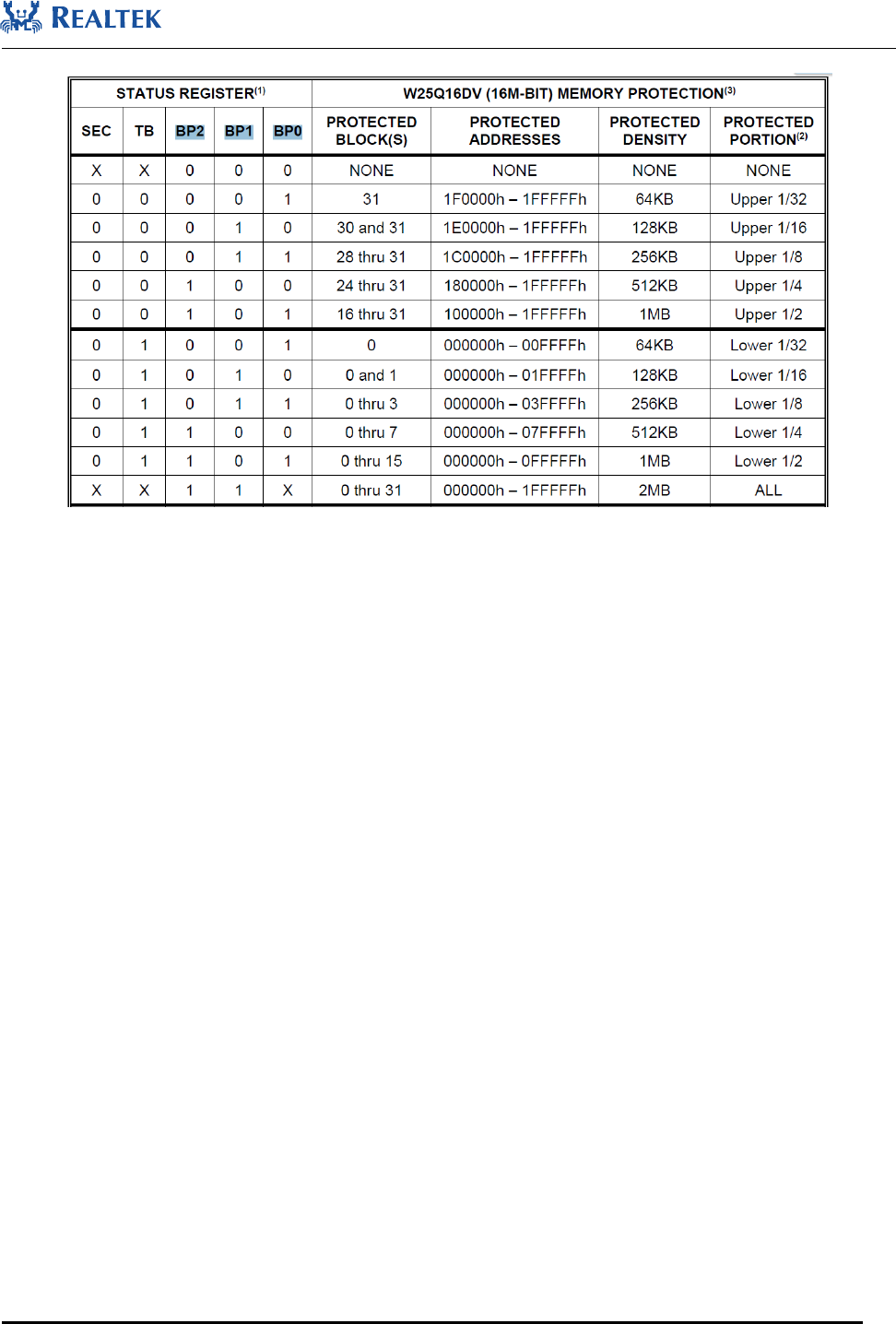
A mechanism to solve these problems is flash software Blocks Protection (BP). It uses some BP bits in flash status
register to select the level (range) to protect as described below.
Flash uses BP(x) bits in status registers to identify numbers of blocks to lock, and TB bit to determine the
direction to lock. RTL8762C only supports locking from the low address ends of flash.
Realtek Confidential
RTL8762C Flash User Guide
Copyright 2018 Realtek Semiconductor Corporation.
All Rights Reserved.
9
Figure 5-1 Flash block protect
Here we just use BP to protect some important data such as configuration, security, and code sections, not all
portions will be protected. BP function is not available for customers because different flash vendors and models
have different rules and limitation. Accessing status registers frequently will damage flash. RTL8762C provides a
configuration option "bp_enable" to determine whether or not to enable the BP function (disabled by default).
Flash status register by default uses NVRAM type to store data. BP function needs to change (write) BP bits to
switch to different protect level, but NVRAM has 100K times programming limitation; although most vendors
support 0x50 command to switch using SRAM type, but not all of them support it, such as MXIC.
At present, if you choose to enable the BP function by configing macro FLASH_BLOCK_PROTECT_ENABLE
in otp_config.h to 1, it will be locked at a maximum lock level based on the configured flash layout that the
selected flash supports. For details of Flash BP locking principle and flash layout configuration, please refer to
RTL8762C Memory User Guide.
6 Power Saving
The power mode of Flash is mainly divided into three scenarios: working, standby and Power Down. The power
consumption of the working mode is generally about 10 mA, while the power consumption of standby mode is

Realtek Confidential
RTL8762C Flash User Guide
Copyright 2018 Realtek Semiconductor Corporation.
All Rights Reserved.
10
usually about 10uA order of magnitude. The power consumption of the Power Down mode is lower, even less
than 1 uA.
Flash automatically enters the standby mode without any access, and automatically enters the working state when
it needs to be accessed again. In order to enter the Power Down mode, you need to use a specific command. Most
Flash use the command 0xB9 to enter into the Power Down mode, and use the command 0xAB to exit the Power
Down mode. But MXIC toggles the #CS pin to wake up flash.
After flash enters into low power mode, it is dangerous to receive commands except for the exit DP command
(0xAB). Because flash only accepts wakeup command to exit lower power mode, other commands will be ignored,
while flash controller may step into an infinite loop waiting for response from flash.
In order to avoid the risk of abusing the Flash Power Down pattern, the system's DLPS mechanism has been
added to the Flash Power Down mode control. When entering DLPS, the instruction automatically makes Flash
enter the Power Down mode and wakes up when out of the DLPS.
7 High Speed Read
Unlike SRAM, flash is a non-volatile second storage. Because of 100K times program / erase limitation, flash is
not suggested for performing write/erase operations frequently. So, we just support other ways to speed up the
flash read operation. Adding sdk\src\flash\flash_hs_read.c to project, the following three interfaces can be used to
support high-speed reading of flash.
7.1 flash_split_read_locked
Limited to flash controller’s FIFO size (64 bytes), User mode can just read 60 bytes data for each operation with 1
byte for read command and 3 bytes for target address. Programmer needs to set the next start address and length if
required length is more than 60 bytes.
Here flash controller adopts a method to speed up the flash read usage if long and continuous data is preferred. It
helps to setup the configuration for read operation, and you can easily use it as its usage is just the same as
flash_read_locked().There is only one thing to pay attention that the length of User Split Read must be 4 bytes
alignment.
Interface prototype is shown below:
bool flash_split_read_locked(uint32_t start_addr, uint32_t data_len, uint8_t *data, uint32_t *counter)

Realtek Confidential
RTL8762C Flash User Guide
Copyright 2018 Realtek Semiconductor Corporation.
All Rights Reserved.
11
7.2 flash_auto_dma_read_locked
Each auto read operation can just read 1 word (4 bytes) at a time. It will take much more expense than user mode
if long and continuous data is read. In order to improve the performance of auto read, DMA is involved in.
bool flash_auto_dma_read_locked(T_FLASH_DMA_TYPE dma_type, FlashCB flash_cb,
uint32_t src_addr, uint32_t dst_addr, uint32_t data_len);
7.3 flash_auto_seq_trans_dma_read_locked
After reading the flash through DMA, FLASH_GDMA_HANDLER will be executed. The function prototype is
as follows:
bool flash_auto_seq_trans_dma_read_locked(T_FLASH_DMA_TYPE dma_type, FlashCB flash_cb,
uint32_t src_addr, uint32_t dst_addr, uint32_t data_len);
8 XIP
The remaining RAM space of about 75K Bytes can be provided for APP development on RTL8762C. RAM usage
details can be referred to RTL8762C Memory User Guide. If the remaining RAM space is enough, APP code can
be directly executed on RAM, which is conducive to improving performance and reducing power consumption.
However, if the APP code is so large that the remaining RAM space is not enough, some or all of the APP codes
need to be executed on flash. The related configuration of XIP on RTL8762C is summarized as follows.
1. Macro FEATURE_RAM_CODE (configuration in mem_config.h): when configured to 1, any code that does
not contain any section modification will be executed on RAM. On the contrary, when configured to 0, any
code that does not include any section modifiers by default will be executed on flash.
2. Section modification (reference app_section.h)
1) APP_FLASH_TEXT_SECTION: The specified code is executed on flash.
2) DATA_RAM_FUNCTION: The specified code is executed on RAM. If RAM space is insufficient, you
should give higher priority to implementing time sensitive code on RAM to ensure efficiency.
3. Scene switching (reference app_section.h and overlay_mgr.h): APP development first divides the different
scenarios according to the needs and defines the loading scene information table, then manually modifies the

Realtek Confidential
RTL8762C Flash User Guide
Copyright 2018 Realtek Semiconductor Corporation.
All Rights Reserved.
12
different scene code with different section keywords, and finally calls the loading function load_overlay in
the place where the scene is switched. At present, RT8762C SDK supports the following three scenarios. But
APP can expand according to certain principles.
#define OVERLAY_SECTION_BOOT_ONCE __attribute__((section(".app.overlay_a")))
#define OVERLAY_B_SECTION __attribute__((section(".app.overlay_b")))
#define OVERLAY_C_SECTION __attribute__((section(".app.overlay_c")))
4. Two ways to improve the efficiency of XIP execution code
1) Enable cache: Configure macro SHARE_CACHE_RAM_SIZE to 8K Bytes or 0. Cache size is 8K
Bytes or 16K Bytes respectively.
2) Flash is switched to 2-bit mode or 4-bit mode by calling flash_try_high_speed.
RTL8762C can access flash with auto mode as accessing RAM through SPIC, and execute code directly on SPI
Flash. However, the operation of accessing flash in user mode is not atomic. Once the accessing is interrupted by
higher priority tasks or interrupts, it is possible to cause flash access error. To ensure atomicity of flash operations
in user mode, XIP should follow the following restrictions and precautions.
Accessing flash operations in user mode require calling APIs with the "_locked" suffix to ensure a critical area
protection. If the time of the flash operation is too long, such as writing a large number of data at one time, it is
not suitable for the critical zone protection, and can be split into a small amount of data written by a few times.
If the time-critical interrupt needs to be processed, it is also necessary to ensure that the ISR (interrupt service
routine) itself cannot be XIP, and the ISR also prohibits accessing to the flash. Besides, the ISR can’t cause task
switch to a XIP task.
