Bee项目文档规范 RTL8762C Peripheral Manual EN
User Manual:
Open the PDF directly: View PDF ![]() .
.
Page Count: 264 [warning: Documents this large are best viewed by clicking the View PDF Link!]
- Revision History
- 1 Overview of Peripheral Firmware
- 2 Analog-Digital Converter (ADC)
- 2. 1 ADC Register Structure
- 2. 2 ADC Library Functions
- 2. 2. 1 Function ADC_Init
- 2. 2. 2 Function ADC_DeInit
- 2. 2. 3 Function ADC_StructInit
- 2. 2. 4 Function ADC_INTConfig
- 2. 2. 5 Function ADC_ ReadByScheduleIndex
- 2. 2. 6 Function ADC_Cmd
- 2. 2. 7 Function ADC_GetIntFlagStatus
- 2. 2. 8 Function ADC_ClearINTPendingBit
- 2. 2. 9 Function ADC_SchTableConfig
- 2. 2. 10 Function ADC_GetFifoData
- 2. 2. 11 Function ADC_ReadFifoData
- 2. 2. 12 Function ADC_GetFifoLen
- 2. 2. 13 Function ADC_HighBypassCmd
- 2. 2. 14 Function ADC_GetHighBypassRes
- 2. 2. 15 Function ADC_GetRes
- 3 COder-DECoder(CODEC)
- 3. 1 Codec Register Architecture
- 3. 2 Codec Library Functions
- 3. 2. 1 Function CODEC_DeInit
- 3. 2. 2 Function CODEC_Init
- 3. 2. 3 Function CODEC_StructInit
- 3. 2. 4 Function CODEC_EQInit
- 3. 2. 5 Function CODEC_EQStructInit
- 3. 2. 6 Function CODEC_Reset
- 3. 2. 7 Function CODEC_SetMicMute
- 3. 2. 8 Function CODEC_SetADCDigitalVolume
- 3. 2. 9 Function CODEC_SetMICBIAS
- 3. 2. 10 Function CODEC_MICBIASCmd
- 4 Direct Memory Access Controller (GDMA)
- 4. 1 GDMA Register Architecture
- 4. 2 GDMA Library Functions
- 4. 2. 1 Function GDMA_DeInit
- 4. 2. 2 Function GDMA_Init
- 4. 2. 3 Function GDMA_StructInit
- 4. 2. 4 Function GDMA_Cmd
- 4. 2. 5 Function GDMA_INTConfig
- 4. 2. 6 Function GDMA_ClearINTPendingBit
- 4. 2. 7 Function GDMA_GetChannelStatus
- 4. 2. 8 Function GDMA_GetTransferINTStatus
- 4. 2. 9 Function GDMA_ClearAllTypeINT
- 4. 2. 10 Function GDMA_SetSourceAddress
- 4. 2. 11 Function GDMA_SetDestinationAddress
- 4. 2. 12 Function GDMA_SetBufferSize
- 4. 2. 13 Function GDMA_SuspendCmd
- 4. 2. 14 Function GDMA_GetFIFOStatus
- 4. 2. 15 Function GDMA_GetTransferLen
- 4. 2. 16 Function GDMA_SetLLPAddress
- 5 General-Purpose Input/Output (GPIO)
- 5. 1 GPIO Register Structure
- 5. 2 GPIO Library Functions
- 5. 2. 1 Function GPIO_DeInit
- 5. 2. 2 Function GPIO_GetPin
- 5. 2. 3 Function GPIO_Init
- 5. 2. 4 Function GPIO_StructInit
- 5. 2. 5 Function GPIO_INTConfig
- 5. 2. 6 Function GPIO_ClearINTPendingBit
- 5. 2. 7 Function GPIO_MaskINTConfig
- 5. 2. 8 Function GPIO_ReadInputDataBit
- 5. 2. 9 Function GPIO_ ReadInputData
- 5. 2. 10 Function GPIO_ReadOutputDataBit
- 5. 2. 11 Function GPIO_ ReadOutputData
- 5. 2. 12 Function GPIO_ SetBits
- 5. 2. 13 Function GPIO_ ResetBits
- 5. 2. 14 Function GPIO_ WriteBit
- 5. 2. 15 Function GPIO_Write
- 5. 2. 16 Function GPIO_GetINTStatus
- 5. 2. 17 Function GPIO_GetNum
- 5. 2. 18 Function GPIO_Debounce_Time
- 5. 2. 19 Function GPIO_DBClkCmd
- 6 Inter-Integrated Circuit (I2C)
- 6. 1 I2C Register Architecture
- 6. 2 I2C Library Functions
- 6. 2. 1 Function I2C_DeInit
- 6. 2. 2 Function I2C_Init
- 6. 2. 3 Function I2C_StructInit
- 6. 2. 4 Function I2C_Cmd
- 6. 2. 5 Function I2C_MasterWrite
- 6. 2. 6 Function I2C_MasterRead
- 6. 2. 7 Function I2C_RepeatRead
- 6. 2. 8 Function I2C_INTConfig
- 6. 2. 9 Function I2C_ClearINTPendingBit
- 6. 2. 10 Function I2C_SetSlaveAddress
- 6. 2. 11 Function I2C_SendCmd
- 6. 2. 12 Function I2C_ReceiveData
- 6. 2. 13 Function I2C_GetRxFIFOLen
- 6. 2. 14 Function I2C_GetTxFIFOLen
- 6. 2. 15 Function I2C_ClearAllINT
- 6. 2. 16 Function I2C_GetFlagState
- 6. 2. 17 Function I2C_CheckEvent
- 6. 2. 18 Function I2C_GetINTStatus
- 6. 2. 19 Function I2C_GDMACmd
- 7 QDEC
- 7. 1 QDEC Register Architecture
- 7. 2 QDEC Library Functions
- 7. 2. 1 Function QDEC_Init
- 7. 2. 2 Function QDEC_DeInit
- 7. 2. 3 Function QDEC_StructInit
- 7. 2. 4 Function QDEC_Cmd
- 7. 2. 5 Function QDEC_INTConfig
- 7. 2. 6 Function QDEC_GetFlagState
- 7. 2. 7 Function QDEC_INTMask
- 7. 2. 8 Function QDEC_ClearINTPendingBit
- 7. 2. 9 Function QDEC_GetAxisDirection
- 7. 2. 10 Function QDEC_GetAxisCount
- 7. 2. 11 Function QDEC_CounterPauseCmd
- 8 Pin Allocation Difinition (PAD)
- 8. 1 PAD Library Functions
- 8.1.1 Function Pad_Config
- 8.1.2 Function Pad_OutputEnableValue
- 8.1.3 Function Pad_OutputControlValue
- 8.1.4 Function Pad_PullEnableValue
- 8.1.5 Function Pad_PullUpOrDownValue
- 8.1.6 Function Pad_ PullConfigValue
- 8.1.7 Function Pad_WakeupEnableValue
- 8.1.8 Function Pad_WakeupPolarityValue
- 8.1.9 Function Pad_PowerOrShutDownValue
- 8.1.10 Pad_ControlSelectValue
- 8.1.11 Function Pad_WKDebounceConfig
- 8.1.12 Function System_WakeUpInterruptValue
- 8.1.13 Function Pad_WakeupInterruptValue
- 8.1.14 Function Pad_ClearWakeupINTPendingBit
- 8.1.15 Function System_WakeUpDebounceTime
- 8.1.16 Function System_WakeUpPinEnable
- 8.1.17 Function System_WakeUpPinDisable
- 8. 1 PAD Library Functions
- 9 Pin Multiplexing (PINMUX)
- 10 Low power comparator(LPC)
- 10. 1 LPC Register Structures
- 10. 2 LPC LIBRARY FUNCTIONS
- 10. 2. 1 Function LPC_Init
- 10. 2. 2 Function LPC_StructInit
- 10. 2. 3 Function LPC_Cmd
- 10. 2. 4 Function LPC_CounterCmd
- 10. 2. 5 Function LPC_CounterReset
- 10. 2. 6 Function LPC_WriteComparator
- 10. 2. 7 Function LPC_ReadComparator
- 10. 2. 8 Function LPC_ReadCounter
- 10. 2. 9 Function LPC_INTConfig
- 10. 2. 10 Function LPC_ClearINTPendingBit
- 10. 2. 11 Function LPC_GetINTStatus
- 11 Real-Time Clock (RTC)
- 11. 1 RTC Register Structure
- 11. 2 RTC Library Functions
- 11. 2. 1 Function RTC_DeInit
- 11. 2. 2 Function RTC_SetPrescaler
- 11. 2. 3 Function RTC_SetComp
- 11. 2. 4 Function RTC_RunCmd
- 11. 2. 5 Function RTC_MaskINTConfig
- 11. 2. 6 Function RTC_CompINTConfig
- 11. 2. 7 Function RTC_TickINTConfig
- 11. 2. 8 Function RTC_GetINTStatus
- 11. 2. 9 Function RTC_SystemWakeupConfig
- 11. 2. 10 Function RTC_GetCounter
- 11. 2. 11 Function RTC_ResetCounter
- 11. 2. 12 Function RTC_GetComp
- 11. 2. 13 Function RTC_ClearCompINT
- 11. 2. 14 Function RTC_ClearOverFlowINT
- 11. 2. 15 Function RTC_ClearTickINT
- 11. 2. 16 Function RTC_SleepModeClkConfig
- 12 Serial Peripheral Interface(SPI)
- 12.1 SPI Register Architecture
- 12.2 SPI SPI Library Functions
- 12.2.1 Function SPI_DeInit
- 12.2.2 Function SPI_Init
- 12.2.3 Function SPI_StructInit
- 12.2.4 Function SPI_Cmd
- 12.2.5 Function SPI_SendBuffer
- 12.2.5 Function SPI_SendWord
- 12.2.5 Function SPI_SendHalfWord
- 12.2.6 Function SPI_INTConfig
- 12.2.7 Function SPI_ClearINTPendingBit
- 12.2.8 Function SPI_SendData
- 12.2.9 Function SPI_ReceiveData
- 12.2.10 Function SPI_GetRxFIFOLen
- 12.2.11 Function SPI_GetTxFIFOLen
- 12.2.12 Function SPI_ChangeDirection
- 12.2.13 Function SPI_SetReadLen
- 12.2.14 Function SPI_SetCSNumber
- 12.2.15 Function SPI_GetFlagState
- 12.2.16 Function SPI_GetINTStatus
- 12.2.17 Function SPI_GDMACmd
- 13 3-Wire SPI
- 13.1 SPI3WIRE Register Structure
- 13.2 SPI3WIRE Library Functions
- 13.2.1 Function SPI3WIRE_ DeInit
- 13.2.2 Function SPI3WIRE_Init
- 13.2.3 Function SPI3WIRE_StructInit
- 13.2.4 Function SPI3WIRE_Cmd
- 13.2.5 Function SPI3WIRE_SetResyncTime
- 13.2.6 Function SPI3WIRE_ResyncSignalCmd
- 13.2.7 Function SPI3WIRE_INTConfig
- 13.2.8 Function SPI3WIRE_GetFlagStatus
- 13.2.9 Function SPI3WIRE_ClearINTPendingBit
- 13.2.10 Function SPI3WIRE_GetRxDataLen
- 13.2.11 Function SPI3WIRE_ClearRxFIFO
- 13.2.12 Function SPI3WIRE_ClearRxDataLen
- 13.2.13 Function SPI3WIRE_StartWrite
- 13.2.14 Function SPI3WIRE_StartRead
- 13.2.15 Function SPI3WIRE_ReadBuf
- 14 Timer & PWM
- 14.1 TIM Register Structure
- 14.2 TIM Library Functions
- 14.2.1 Function TIM_DeInit
- 14.2.2 Function TIM_TimeBaseInit
- 14.2.3 Function TIM_StructInit
- 14.2.4 Function TIM_Cmd
- 14.2.5 Function TIM_ChangePeriod
- 14.2.6 Function TIM_INTConfig
- 14.2.7 Function TIM_GetCurrentValue
- 14.2.8 Function TIM_GetINTStatus
- 14.2.9 Function TIM_ClearINT
- 14.2.10 Function TIM_PWMChangeFreqAndDuty
- 14.2.11 Function PWM_Deadzone_EMStop
- 15 Universal Asynchronous Receiver Transmitter (UART)
- 15. 1 UART Register Architecture
- 15. 2 UART Library Functions
- 15. 2. 1 Function UART_Init
- 15. 2. 2 Function UART_DeInit
- 15. 2. 3 Function UART_StructInit
- 15. 2. 4 Function UART_ReceiveData
- 15. 2. 5 Function UART_SendData
- 15. 2. 6 Function UART_INTConfig
- 15. 2. 7 Function UART_GetFlagState
- 15. 2. 8 Function UART_ClearTxFifo
- 15.2.9 Function UART_LoopBackCmd
- 15. 2. 10 Function UART_ClearRxFifo
- 15.2.11 Function UART_GetTxFIFOLen
- 15.2.12 Function UART_GetRxFIFOLen
- 15. 2. 13 Function UART_ReceiveByte
- 15. 2. 11 Function UART_SendByte
- 15. 2. 12 Function UART_GetIID
- 16 KEYSCAN
- 16. 1 KEYCAN Register Architecture
- 16. 2 KEYSCAN Library Functions
- 16. 2. 1 Function KeyScan_Init
- 16. 2. 2 Function KeyScan_DeInit
- 16. 2. 3 Function KeyScan_StructInit
- 16. 2. 4 Function KeyScan_INTConfig
- 16. 2. 5 Function KeyScan_INTMask
- 16. 2. 6 Function KeyScan_Read
- 16. 2. 7 Function KeyScan_Cmd
- 16. 2. 8 Function KeyScan_GetFifoDataNum
- 16. 2. 9 Function KeyScan_ClearINTPendingBit
- 16. 2. 10 Function KeyScan_ClearFlags
- 16. 2. 11 Function KeyScan_GetFlagState
- 16. 2. 12 Function KeyScan_debounceConfig
- 16. 2. 13 Function KeyScan_FilterDataConfig
- 16. 2. 14 Function KeyScan_ReadFifoData
- 17 Infrared Radiation(IR)
- 17.1 IR Register Architecture
- 17.2 IR Library Functions
- 17.2.1 Function IR_ DeInit
- 17.2.2 Function IR_Init
- 17.2.3 Function IR_StructInit
- 17.2.4 Function IR_Cmd
- 17.2.5 Function IR_StartManualRxTrigger
- 17.2.6 Function IR_SetRxCounterThreshold
- 17.2.7 Function IR_SendBuf
- 17.2.8 Function IR_ReceiveBuf
- 17.2.9 Function IR_INTConfig
- 17.2.10 Function IR_MaskINTConfig
- 17.2.11 Function IR_GetINTStatus
- 17.2.12 Function IR_ClearINTPendingBit
- 17.2.13 Function IR_GetTxFIFOFreeLen
- 17.2.14 Function IR_GetRxDataLen
- 17.2.15 Function IR_SendData
- 17.2.16 Function IR_ReceiveData
- 17.2.17 Function IR_SetTxThreshold
- 17.2.18 Function IR_SetRxThreshold
- 17.2.19 Function IR_ClearTxFIFO
- 17.2.19 Function IR_ClearRxFIFO
- 17.2.20 Function IR_GetFlagStatus
- 17.2.21 Function IR_SetTxInverse
- 17.2.22 Function IR_TxOutputInverse
- 17.2.23 Function IR_ConfigCompenParam
- 17.2.24 Function IR_SendCompenBuf
- 18 Inter-IC Sound(I2S)
- 18.1 I2S Register Architecture
- 18.2 I2S Library Functions
- 18.2.1 Function I2S_ DeInit
- 18.2.2 Function I2S_Init
- 18.2.3 Function I2S_StructInit
- 18.2.4 Function I2S_Cmd
- 18.2.5 Function I2S_INTConfig
- 18.2.6 Function I2S_GetINTStatus
- 18.2.7 Function I2S_SendData
- 18.2.8 Function I2S_ReceiveData
- 18.2.9 Function I2S_GetTxFIFOFreeLen
- 18.2.10 Function I2S_GetRxFIFOLen
- 18.2.11 Function I2S_GetTxErrCnt
- 18.2.12 Function I2S_GetRxErrCnt
- 18.2.13 Function I2S_SwapBytesForSend
- 18.2.14 Function I2S_SwapBytesForRead
- 18.2.15 Function I2S_SwapLRChDataForSend
- 18.2.16 Function I2S_SwapLRChDataForRead
- 19 Liquid Crystal Display Controller(LCD)
- 19.1 LCD Register Structure
- 19.2 LCD Library Functions
- 19.2.1 Function LCD_ DeInit
- 19.2.2 Function LCD_PinGroupConfig
- 19.2.3 Function LCD_Init
- 19.2.4 Function LCD_StructInit
- 19.2.5 Function LCD_Cmd
- 19.2.6 Function LCD_SendCommand
- 19.2.7 Function LCD_SendData
- 19.2.8 Function LCD_ReceiveData
- 19.2.9 Function LCD_Write
- 19.2.10 Function LCD_Read
- 19.2.11 Function LCD_SetCmdSequence
- 19.2.12 Function LCD_MaskINTConfig
- 19.2.13 Function LCD_GetINTStatus
- 19.2.14 Function LCD_GetFlagStatus
- 19.2.15 Function LCD_SwitchMode
- 19.2.16 Function LCD_GDMACmd
- 19.2.17 Function LCD_SetCS
- 19.2.18 Function LCD_ResetCS
- 19.2.19 Function LCD_ClearINTPendingBit
- 19.2.20 Function LCD_SetTxDataLen
- 19.2.21 Function LCD_GetTxDataLen
- 19.2.22 Function LCD_GetDataCounter
- 19.2.23 Function LCD_ClearDataCounter
- 19.2.24 Function LCD_ClearFIFO
- 20 Peripheral User Flow

Realtek Confidential
RTL8762C Peripheral Manual
V1.2
2018/06/28

Realtek Confidential
RTL8762C Peripheral Manual
Copyright 2018 Realtek Semiconductor Corporation.
All Rights Reserved.
2
Revision History
Date
Version
Description
2018/6/8
V1.0
First Release version
2018/6/26
V1.1
Update PINMUX chapter
2018/6/28
V1.2
Add Peripheral User Flow chapter
2018/6/28
V1.3

Realtek Confidential
RTL8762C Peripheral Manual
Copyright 2018 Realtek Semiconductor Corporation.
All Rights Reserved.
3
Contents
Revision History ................................................................................................................................................ 2
Illustration List ................................................................................................................... 错误!未定义书签。
Table List ............................................................................................................................ 错误!未定义书签。
1 Overview of Peripheral Firmware ................................................................................................................ 15
2 Analog-Digital Converter (ADC) ................................................................................................................. 16
2. 1 ADC Register Structure ........................................................................................................................ 16
2. 2 ADC Library Functions ........................................................................................................................ 17
2. 2. 1 Function ADC_Init ....................................................................................................................... 18
2. 2. 2 Function ADC_DeInit .................................................................................................................. 21
2. 2. 3 Function ADC_StructInit ............................................................................................................. 22
2. 2. 4 Function ADC_INTConfig ........................................................................................................... 22
2. 2. 5 Function ADC_Read .................................................................................................................... 23
2. 2. 6 Function ADC_Cmd ..................................................................................................................... 23
2. 2. 7 Function ADC_GetIntFlagStatus.................................................................................................. 24
2. 2. 8 Function ADC_ClearINTPendingBit ........................................................................................... 25
2. 2. 9 Function ADC_SchTableConfig .................................................................................................. 25
2. 2. 10 Function ADC_GetFifoData ....................................................................................................... 26
2. 2. 11 Function ADC_ReadFifoData .................................................................................................... 26
2. 2. 12 Function ADC_GetFifoLen ........................................................................................................ 27
2. 2. 13 Function ADC_HighBypassCmd ............................................................................................... 27
2. 2. 14 Function ADC_GetHighBypassRes ........................................................................................... 28
2. 2. 15 Function ADC_GetRes ............................................................................................................... 28
3 COder-DECoder(CODEC) ........................................................................................................................... 30
3. 1 Codec Register Architecture ................................................................................................................. 30
3. 2 Codec Library Functions ...................................................................................................................... 31
3. 2. 1 Function CODEC_DeInit ............................................................................................................. 31

Realtek Confidential
RTL8762C Peripheral Manual
Copyright 2018 Realtek Semiconductor Corporation.
All Rights Reserved.
4
3. 2. 2 Function CODEC_Init .................................................................................................................. 32
3. 2. 3 Function CODEC_StructInit ........................................................................................................ 35
3. 2. 4 Function CODEC_EQInit............................................................................................................. 36
3. 2. 5 Function CODEC_EQStructInit ................................................................................................... 37
3. 2. 6 Function CODEC_Reset............................................................................................................... 38
3. 2. 7 Function CODEC_SetMicMute ................................................................................................... 38
3. 2. 8 Function CODEC_SetADCDigitalVolume .................................................................................. 39
3. 2. 9 Function CODEC_SetMICBIAS .................................................................................................. 39
3. 2. 10 Function CODEC_MICBIASCmd ............................................................................................. 40
4 Direct Memory Access Controller (GDMA) ................................................................................................ 40
4. 1 GDMA Register Architecture ............................................................................................................... 40
4. 2 GDMA Library Functions .................................................................................................................... 45
4. 2. 1 Function GDMA_DeInit ............................................................................................................... 46
4. 2. 2 Function GDMA_Init ................................................................................................................... 47
4. 2. 3 Function GDMA_StructInit .......................................................................................................... 53
4. 2. 4 Function GDMA_Cmd ................................................................................................................. 53
4. 2. 5 Function GDMA_INTConfig ....................................................................................................... 54
4. 2. 6 Function GDMA_ClearINTPendingBit........................................................................................ 54
4. 2. 7 Function GDMA_GetChannelStatus ............................................................................................ 55
4. 2. 8 Function GDMA_GetTransferINTStatus ..................................................................................... 55
4. 2. 9 Function GDMA_ClearAllTypeINT ............................................................................................ 56
4. 2. 10 Function GDMA_SetSourceAddress.......................................................................................... 56
4. 2. 11 Function GDMA_SetDestinationAddress .................................................................................. 57
4. 2. 12 Function GDMA_SetBufferSize ................................................................................................ 57
4. 2. 13 Function GDMA_SuspendCmd ................................................................................................. 58
4. 2. 14 Function GDMA_GetFIFOStatus ............................................................................................... 58
4. 2. 15 Function GDMA_GetTransferLen ............................................................................................. 59
4. 2. 16 Function GDMA_SetLLPAddress ............................................................................................. 59
5 General-Purpose Input/Output (GPIO) ......................................................................................................... 61

Realtek Confidential
RTL8762C Peripheral Manual
Copyright 2018 Realtek Semiconductor Corporation.
All Rights Reserved.
5
5. 1 GPIO Register Structure ....................................................................................................................... 61
5. 2 GPIO Library Functions ....................................................................................................................... 62
5. 2. 1 Function GPIO_DeInit ................................................................................................................. 63
5. 2. 2 Function GPIO_GetPin ................................................................................................................. 63
5. 2. 3 Function GPIO_Init ...................................................................................................................... 63
5. 2. 4 Function GPIO_StructInit ............................................................................................................. 66
5. 2. 5 Function GPIO_INTConfig .......................................................................................................... 66
5. 2. 6 Function GPIO_ClearINTPendingBit .......................................................................................... 68
5. 2. 7 Function GPIO_MaskINTConfig ................................................................................................. 68
5. 2. 8 Function GPIO_ReadInputDataBit ............................................................................................... 69
5. 2. 9 Function GPIO_ ReadInputData................................................................................................... 69
5. 2. 10 Function GPIO_ReadOutputDataBit .......................................................................................... 70
5. 2. 11 Function GPIO_ ReadOutputData .............................................................................................. 70
5. 2. 12 Function GPIO_ SetBits ............................................................................................................. 71
5. 2. 13 Function GPIO_ ResetBits ......................................................................................................... 71
5. 2. 14 Function GPIO_ WriteBit ........................................................................................................... 72
5. 2. 15 Function GPIO_Write ................................................................................................................. 72
5. 2. 16 Function GPIO_GetINTStatus.................................................................................................... 73
5. 2. 17 Function GPIO_GetNum ............................................................................................................ 73
5. 2. 18 Function GPIO_Debounce_Time ............................................................................................... 74
5. 2. 19 Function GPIO_DBClkCmd ....................................................................................................... 74
6 Inter-Integrated Circuit (I2C) ....................................................................................................................... 75
6. 1 I2C Register Architecture ..................................................................................................................... 75
6. 2 I2C Library Functions .......................................................................................................................... 77
6. 2. 1 Function I2C_DeInit ..................................................................................................................... 78
6. 2. 2 Function I2C_Init ......................................................................................................................... 78
6. 2. 3 Function I2C_StructInit ................................................................................................................ 79
6. 2. 4 Function I2C_Cmd ....................................................................................................................... 80
6. 2. 5 Function I2C_MasterWrite ........................................................................................................... 80

Realtek Confidential
RTL8762C Peripheral Manual
Copyright 2018 Realtek Semiconductor Corporation.
All Rights Reserved.
6
6. 2. 6 Function I2C_MasterRead ............................................................................................................ 81
6. 2. 7 Function I2C_RepeatRead ............................................................................................................ 81
6. 2. 8 Function I2C_INTConfig ............................................................................................................. 82
6. 2. 9 Function I2C_ClearINTPendingBit .............................................................................................. 83
6. 2. 10 Function I2C_SetSlaveAddress .................................................................................................. 84
6. 2. 11 Function I2C_SendCmd ............................................................................................................. 84
6. 2. 12 Function I2C_ReceiveData ......................................................................................................... 85
6. 2. 13 Function I2C_GetRxFIFOLen .................................................................................................... 85
6. 2. 14 Function I2C_GetTxFIFOLen .................................................................................................... 86
6. 2. 15 Function I2C_ClearAllINT ......................................................................................................... 86
6. 2. 16 Function I2C_GetFlagState ........................................................................................................ 87
6. 2. 17 Function I2C_CheckEvent ......................................................................................................... 87
6. 2. 18 Function I2C_GetINTStatus ....................................................................................................... 89
6. 2. 19 Function I2C_GDMACmd ......................................................................................................... 89
7 QDEC ........................................................................................................................................................... 91
7. 1 QDEC Register Architecture ................................................................................................................ 91
7. 2 QDEC Library Functions ..................................................................................................................... 92
7. 2. 1 Function QDEC_Init ..................................................................................................................... 92
7. 2. 2 Function QDEC_DeInit ................................................................................................................ 93
7. 2. 3 Function QDEC_StructInit ........................................................................................................... 96
7. 2. 4 Function QDEC_Cmd .................................................................................................................. 96
7. 2. 5 Function QDEC_INTConfig ........................................................................................................ 97
7. 2. 6 Function QDEC_GetFlagState ..................................................................................................... 98
7. 2. 7 Function QDEC_INTMask ........................................................................................................... 99
7. 2. 8 Function QDEC_ClearINTPendingBit ......................................................................................... 99
7. 2. 9 Function QDEC_GetAxisDirection ............................................................................................ 100
7. 2. 10 Function QDEC_GetAxisCount ............................................................................................... 101
7. 2. 11 Function QDEC_CounterPauseCmd ........................................................................................ 102
8 Pin Allocation Difinition (PAD) ................................................................................................................. 103

Realtek Confidential
RTL8762C Peripheral Manual
Copyright 2018 Realtek Semiconductor Corporation.
All Rights Reserved.
7
8. 1 PAD Library Functions ...................................................................................................................... 103
8.1.1 Function Pad_Config .................................................................................................................... 103
8.1.2 Function Pad_OutputEnableValue ............................................................................................... 106
8.1.3 Function Pad_OutputControlValue .............................................................................................. 106
8.1.4 Function Pad_PullEnableValue .................................................................................................... 107
8.1.5 Function Pad_PullUpOrDownValue ............................................................................................ 107
8.1.6 Function Pad_PullUpResistanceConfig........................................................................................ 108
8.1.7 Function Pad_ControlSelectValue ............................................................................................... 109
8.1.8 Function Pad_PowerOrShutDownValue ...................................................................................... 109
8.1.9 Function System_WakeUpPinEnable ........................................................................................... 110
8.1.10 Function System_WakeUpPinDisable........................................................................................ 110
8.1.11 Function System_WakeUpDebounceTime ................................................................................ 111
8.1.12 Function System_WakeUpInterruptValue .................................................................................. 112
8.1.13 Function Pad_GetWakeUpDebouceStatus ................................................................................. 112
8.1.14 Function Pad_ClearWakeUpDebounceStatus ............................................................................ 113
8.1.15 Function Pad_ClearAllWakeupINT ........................................................................................... 113
8.1.16 Function System_WakeUpPinEnable ......................................................................................... 114
8.1.17 Function System_WakeUpPinDisable........................................................................................ 114
9 Pin Multiplexing (PINMUX)...................................................................................................................... 116
9. 1 PINMUX Library Functions ............................................................................................................... 116
9. 1. 1 Function Pinmux_Config ........................................................................................................... 116
9. 1. 2 Function Pinmux_Deinit ............................................................................................................. 120
9. 1. 3 Function Pinmux_Reset .............................................................................................................. 121
10 Low power comparator(LPC) ................................................................................................................... 122
10. 1 LPC Register Structures ................................................................................................................... 122
10. 2 LPC LIBRARY FUNCTIONS ......................................................................................................... 122
10. 2. 1 Function LPC_Init .................................................................................................................... 123
10. 2. 2 Function LPC_StructInit ........................................................................................................... 126
10. 2. 3 Function LPC_Cmd .................................................................................................................. 127

Realtek Confidential
RTL8762C Peripheral Manual
Copyright 2018 Realtek Semiconductor Corporation.
All Rights Reserved.
8
10. 2. 4 Function LPC_CounterCmd ..................................................................................................... 127
10. 2. 5 Function LPC_CounterReset .................................................................................................... 128
10. 2. 6 Function LPC_WriteComparator.............................................................................................. 128
10. 2. 7 Function LPC_ReadComparator .............................................................................................. 128
10. 2. 8 Function LPC_ReadCounter ..................................................................................................... 129
10. 2. 9 Function LPC_INTConfig ........................................................................................................ 129
10. 2. 10 Function LPC_ClearINTPendingBit ...................................................................................... 130
10. 2. 11 Function LPC_GetINTStatus ................................................................................................. 131
11 Real-Time Clock (RTC) ........................................................................................................................... 132
11. 1 RTC Register Structure .................................................................................................................... 132
11. 2 RTC Library Functions ..................................................................................................................... 132
11. 2. 1 Function RTC_DeInit ............................................................................................................... 133
11. 2. 2 Function RTC_SetPrescaler ..................................................................................................... 134
11. 2. 3 Function RTC_SetComp .......................................................................................................... 134
11. 2. 4 Function RTC_RunCmd ........................................................................................................... 135
11. 2. 5 Function RTC_MaskINTConfig ............................................................................................... 135
11. 2. 6 Function RTC_CompINTConfig .............................................................................................. 136
11. 2. 7 Function RTC_TickINTConfig ................................................................................................ 137
11. 2. 8 Function RTC_GetINTStatus ................................................................................................... 137
11. 2. 9 Function RTC_SystemWakeupConfig ..................................................................................... 138
11. 2. 10 Function RTC_GetCounter ..................................................................................................... 138
11. 2. 11 Function RTC_ResetCounter ................................................................................................. 138
11. 2. 12 Function RTC_GetComp ........................................................................................................ 139
11. 2. 13 Function RTC_ClearCompINT .............................................................................................. 139
11. 2. 14 Function RTC_ClearOverFlowINT ........................................................................................ 140
11. 2. 15 Function RTC_ClearTickINT ................................................................................................. 140
11. 2. 16 Function RTC_SleepModeClkConfig .................................................................................... 141
12 Serial Peripheral Interface(SPI) ................................................................................................................ 143
12.1 SPI Register Architecture .................................................................................................................. 143

Realtek Confidential
RTL8762C Peripheral Manual
Copyright 2018 Realtek Semiconductor Corporation.
All Rights Reserved.
9
12.2 SPI SPI Library Functions ................................................................................................................. 144
12.2.1 Function SPI_DeInit ................................................................................................................... 145
12.2.2 Function SPI_Init ........................................................................................................................ 146
12.2.3 Function SPI_StructInit .............................................................................................................. 151
12.2.4 Function SPI_Cmd ..................................................................................................................... 151
12.2.5 Function SPI_SendBuffer ........................................................................................................... 152
12.2.5 Function SPI_SendWord ............................................................................................................ 152
12.2.5 Function SPI_SendHalfWord ..................................................................................................... 153
12.2.6 Function SPI_INTConfig ........................................................................................................... 153
12.2.7 Function SPI_ClearINTPendingBit ............................................................................................ 154
12.2.8 Function SPI_SendData .............................................................................................................. 155
12.2.9 Function SPI_ReceiveData ......................................................................................................... 155
12.2.10 Function SPI_GetRxFIFOLen .................................................................................................. 156
12.2.11 Function SPI_GetTxFIFOLen .................................................................................................. 156
12.2.12 Function SPI_ChangeDirection ................................................................................................ 157
12.2.13 Function SPI_SetReadLen ........................................................................................................ 157
12.2.14 Function SPI_SetCSNumber .................................................................................................... 158
12.2.15 Function SPI_GetFlagState ...................................................................................................... 158
12.2.16 Function SPI_GetINTStatus ..................................................................................................... 159
12.2.17 Function SPI_GDMACmd ....................................................................................................... 160
13 3-Wire SPI ................................................................................................................................................ 161
13.1 SPI3WIRE Register Structure ........................................................................................................... 161
13.2 SPI3WIRE Library Functions ........................................................................................................... 161
13.2.1 Function SPI3WIRE_ DeInit ...................................................................................................... 162
13.2.2 Function SPI3WIRE_Init ........................................................................................................... 163
13.2.3 Function SPI3WIRE_StructInit .................................................................................................. 165
13.2.4 Function SPI3WIRE_Cmd ......................................................................................................... 165
13.2.5 Function SPI3WIRE_SetResyncTime ........................................................................................ 166
13.2.6 Function SPI3WIRE_ResyncSignalCmd ................................................................................... 166

Realtek Confidential
RTL8762C Peripheral Manual
Copyright 2018 Realtek Semiconductor Corporation.
All Rights Reserved.
10
13.2.7 Function SPI3WIRE_INTConfig ............................................................................................... 167
13.2.8 Function SPI3WIRE_GetFlagStatus .......................................................................................... 167
13.2.9 Function SPI3WIRE_ClearINTPendingBit ................................................................................ 168
13.2.10 Function SPI3WIRE_GetRxDataLen ....................................................................................... 168
13.2.11 Function SPI3WIRE_ClearRxFIFO ......................................................................................... 169
13.2.12 Function SPI3WIRE_ClearRxDataLen .................................................................................... 169
13.2.13 Function SPI3WIRE_StartWrite .............................................................................................. 169
13.2.14 Function SPI3WIRE_StartRead ............................................................................................... 170
13.2.15 Function SPI3WIRE_ReadBuf ................................................................................................. 170
14 Timer & PWM .......................................................................................................................................... 172
14.1 TIM Register Structure ...................................................................................................................... 172
14.2 TIM Library Functions ...................................................................................................................... 172
14. 2. 1 Function TIM_DeInit ............................................................................................................... 173
14.2.2 Function TIM_TimeBaseInit ...................................................................................................... 173
14.2.3 Function TIM_StructInit ............................................................................................................. 176
14.2.4 Function TIM_Cmd .................................................................................................................... 177
14.2.5 Function TIM_ChangePeriod ..................................................................................................... 177
14.2.6 Function TIM_INTConfig .......................................................................................................... 178
14.2.7 Function TIM_GetCurrentValue ................................................................................................ 178
14.2.8 Function TIM_GetINTStatus ..................................................................................................... 179
14.2.9 Function TIM_ClearINT ............................................................................................................ 179
14.2.10 Function TIM_PWMChangeFreqAndDuty .............................................................................. 180
14.2.11 Function PWM_Deadzone_EMStop ........................................................................................ 180
15 Universal Asynchronous Receiver Transmitter (UART) ......................................................................... 182
15. 1 UART Register Architecture ............................................................................................................ 182
15. 2 UART Library Functions.................................................................................................................. 183
15. 2. 1 Function UART_Init................................................................................................................. 183
15. 2. 2 Function UART_DeInit ............................................................................................................ 186
15. 2. 3 Function UART_StructInit ....................................................................................................... 187

Realtek Confidential
RTL8762C Peripheral Manual
Copyright 2018 Realtek Semiconductor Corporation.
All Rights Reserved.
11
15. 2. 4 Function UART_ReceiveData .................................................................................................. 187
15. 2. 5 Function UART_SendData ....................................................................................................... 188
15. 2. 6 Function UART_INTConfig .................................................................................................... 188
15. 2. 7 Function UART_GetFlagState ................................................................................................. 189
15. 2. 8 Function UART_ClearTxFifo .................................................................................................. 190
15. 2. 9 Function UART_ClearRxFifo .................................................................................................. 191
15. 2. 10 Function UART_ReceiveByte ................................................................................................ 192
15. 2. 11 Function UART_SendByte ..................................................................................................... 193
15. 2. 12 Function UART_GetIID ......................................................................................................... 193
16 KEYSCAN ............................................................................................................................................... 194
16. 1 KEYCAN Register Architecture ...................................................................................................... 194
16. 2 KEYSCAN Library Functions.......................................................................................................... 194
16. 2. 1 Function KeyScan_Init ............................................................................................................. 195
16. 2. 2 Function KeyScan_DeInit ........................................................................................................ 197
16. 2. 3 Function KeyScan_StructInit ................................................................................................... 198
16. 2. 4 Function KeyScan_INTConfig ................................................................................................. 198
16. 2. 5 Function KeyScan_INTMask ................................................................................................... 199
16. 2. 6 Function KeyScan_Read .......................................................................................................... 200
16. 2. 7 Function KeyScan_Cmd ........................................................................................................... 200
16. 2. 8 Function KeyScan_GetFifoDataNum ....................................................................................... 201
16. 2. 9 Function KeyScan_ClearINTPendingBit ................................................................................. 201
16. 2. 10 Function KeyScan_ClearFlags ............................................................................................... 202
16. 2. 11 Function KeyScan_GetFlagState ............................................................................................ 202
16. 2. 12 Function KeyScan_debounceConfig ...................................................................................... 203
16. 2. 13 Function KeyScan_FilterDataConfig ..................................................................................... 204
16. 2. 14 Function KeyScan_ReadFifoData .......................................................................................... 204
17 Infrared Radiation(IR) .............................................................................................................................. 205
17.1 IR Register Architecture .................................................................................................................... 205
17.2 IR Library Functions ......................................................................................................................... 206

Realtek Confidential
RTL8762C Peripheral Manual
Copyright 2018 Realtek Semiconductor Corporation.
All Rights Reserved.
12
17.2.1 Function IR_ DeInit .................................................................................................................... 207
17.2.2 Function IR_Init ......................................................................................................................... 207
17.2.3 Function IR_StructInit ................................................................................................................ 211
17.2.4 Function IR_Cmd ....................................................................................................................... 211
17.2.5 Function IR_StartManualRxTrigger ........................................................................................... 212
17.2.6 Function IR_SetRxCounterThreshold ........................................................................................ 212
17.2.7 Function IR_SendBuf ................................................................................................................. 213
17.2.8 Function IR_ReceiveBuf ............................................................................................................ 214
17.2.9 Function IR_INTConfig ............................................................................................................. 214
17.2.10 Function IR_MaskINTConfig .................................................................................................. 215
17.2.11 Function IR_GetINTStatus ....................................................................................................... 216
17.2.12FunctionIR_ClearINTPendingBit .............................................................................................. 216
17.2.13FunctionIR_GetTxFIFOFreeLen ............................................................................................... 217
17.2.14FunctionIR_GetRxDataLen ....................................................................................................... 217
17.2.15FunctionIR_SendData ............................................................................................................... 218
17.2.16FunctionIR_ReceiveData ........................................................................................................... 218
17.2.17 Function IR_SetTxThreshold ................................................................................................... 219
17.2.18 Function IR_SetRxThreshold ................................................................................................... 219
17.2.19 Function IR_ClearTxFIFO ....................................................................................................... 220
17.2.19 Function IR_ClearRxFIFO ....................................................................................................... 220
17.2.20 Function IR_GetFlagStatus ...................................................................................................... 221
17.2.21 Function IR_SetTxInverse ........................................................................................................ 221
17.2.22 Function IR_TxOutputInverse .................................................................................................. 222
17.2.23 Function IR_ConfigCompenParam .......................................................................................... 223
17.2.24 Function IR_SendCompenBuf ................................................................................................. 223
18 Inter-IC Sound(I2S) .................................................................................................................................. 225
18.1 I2S Register Architecture .................................................................................................................. 225
18.2 I2S Library Functions ........................................................................................................................ 225
18.2.1 Function I2S_ DeInit .................................................................................................................. 226

Realtek Confidential
RTL8762C Peripheral Manual
Copyright 2018 Realtek Semiconductor Corporation.
All Rights Reserved.
13
18.2.2 Function I2S_Init ........................................................................................................................ 227
18.2.3 Function I2S_StructInit .............................................................................................................. 231
18.2.4 Function I2S_Cmd ...................................................................................................................... 231
18.2.5 Function I2S_INTConfig ............................................................................................................ 232
18.2.6 Function I2S_GetINTStatus ....................................................................................................... 233
18.2.7 Function I2S_SendData .............................................................................................................. 233
18.2.8 Function I2S_ReceiveData ......................................................................................................... 234
18.2.9 Function I2S_GetTxFIFOFreeLen ............................................................................................. 234
18.2.10 Function I2S_GetRxFIFOLen .................................................................................................. 235
18.2.11 Function I2S_GetTxErrCnt ...................................................................................................... 235
18.2.12 Function I2S_GetRxErrCnt ...................................................................................................... 236
18.2.13 Function I2S_SwapBytesForSend ............................................................................................ 236
18.2.14 Function I2S_SwapBytesForRead ............................................................................................ 237
18.2.15 Function I2S_SwapLRChDataForSend .................................................................................... 237
18.2.16 Function I2S_SwapLRChDataForRead.................................................................................... 238
19 Liquid Crystal Display Controller(LCD) ................................................................................................. 239
19.1 LCD Register Structure ..................................................................................................................... 239
19.2 LCD Library Functions ..................................................................................................................... 240
19.2.1 Function LCD_ DeInit ................................................................................................................ 240
19.2.2 Function LCD_PinGroupConfig ................................................................................................ 241
19.2.3 Function LCD_Init ..................................................................................................................... 241
19.2.4 Function LCD_StructInit ............................................................................................................ 244
19.2.5 Function LCD_Cmd ................................................................................................................... 245
19.2.6 Function LCD_SendCommand .................................................................................................. 245
19.2.7 Function LCD_SendData ........................................................................................................... 245
19.2.8 Function LCD_ReceiveData ....................................................................................................... 246
19.2.9 Function LCD_Write .................................................................................................................. 246
19.2.10 Function LCD_Read ................................................................................................................. 247
19.2.11 Function LCD_SetCmdSequence ............................................................................................. 248

Realtek Confidential
RTL8762C Peripheral Manual
Copyright 2018 Realtek Semiconductor Corporation.
All Rights Reserved.
14
19.2.12 Function LCD_MaskINTConfig .............................................................................................. 248
19.2.13 Function LCD_GetINTStatus ................................................................................................... 249
19.2.14 Function LCD_GetFlagStatus .................................................................................................. 250
19.2.15 Function LCD_SwitchMode ..................................................................................................... 250
19.2.16 Function LCD_GDMACmd ..................................................................................................... 251
19.2.17 Function LCD_SetCS ............................................................................................................... 251
19.2.18 Function LCD_ResetCS ........................................................................................................... 252
19.2.19 Function LCD_ClearINTPendingBit ........................................................................................ 252
19.2.20 Function LCD_SetTxDataLen .................................................................................................. 253
19.2.21 Function LCD_GetTxDataLen ................................................................................................. 253
19.2.22 Function LCD_GetDataCounter ............................................................................................... 254
19.2.23 Function LCD_ClearDataCounter ............................................................................................ 254
19.2.24 Function LCD_ClearFIFO ........................................................................................................ 255
20 Peripheral User Flow Guide ..................................................................................................................... 256
20.1 Peripheral Initialization flow ............................................................................................................. 256
20.1.1 Clock Configuration ................................................................................................................... 256
20.1.2 PinMux Configuration ................................................................................................................ 256
20.1.3 PAD Configuration ..................................................................................................................... 258
20.1.4 Interrupt Configuration ............................................................................................................... 258
20.1.5 GPIO Initialization ..................................................................................................................... 258
20.2 PINMUX and PAD User Flow .......................................................................................................... 260
20.2.1 Overview .................................................................................................................................... 260
20.2.2 PAD wake up Setting ................................................................................................................. 261
22.2.3 Flow of Switching PAD upon Entry to/Exit from DLPS ........................................................... 262
22.2.4 Method to Maintain Pin Output in DLPS Mode ......................................................................... 263
22.2.5 Leakage Protection Setting in DLPS .......................................................................................... 264
Realtek Confidential
RTL8762C Peripheral Manual
Copyright 2018 Realtek Semiconductor Corporation.
All Rights Reserved.
15
1 Overview of Peripheral Firmware
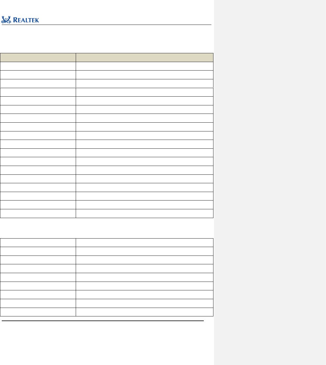
Table 1. 1 All Abbreviations and Definitions for peripherals
Abbreviation
Description
ADC
Analog-to-Digital Converter
CODEC
COder-DECoder
GDMA
General Direct Memory Access Controller
GPIO
General Purpose Input/Output
I2C
Inter-Integrated Circuit
QDEC
Quadrature Demodulator
PAD
Chip Internal Pad
PINMUX
Pin Multiplexing
LPC
Low power comparator
RTC
Real-Time Clock
SPI
Serial Peripheral Interface
SPI3WIRE
Three-Wire SPI
TIM(PWM)
Universal Timer(Pulse Width Modulation)
UART
Universal Asynchronous Receiver Transmitter
KEYSCAN
Key Scan
IR
Infrared module
I2S
Inter-IC Sound
LCD
8080 interface for Liquid crystal display controller
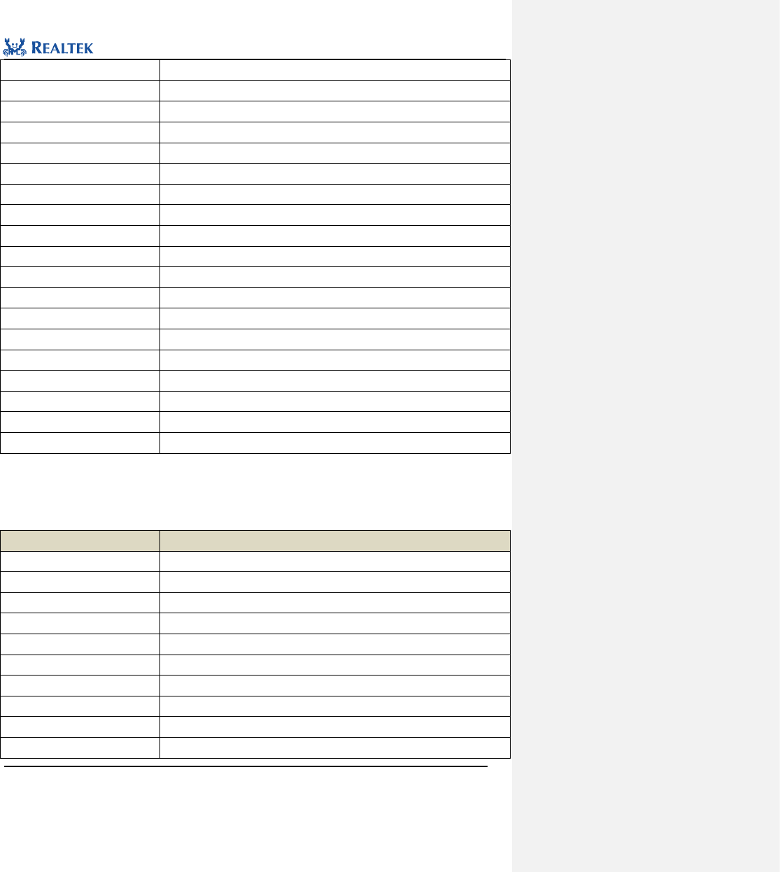
Functions are described in the following format.
Table 1. 2 Function Description Format
Name
Description
Function Name
Name of firmware function
Function Prototype
Statement of function prototype
Function Description
Briefly describe functions to be performed by the function
Input Parameter
Description of input paramter
Output Parameter
Description of output paramter
Return Value
The value returned by the function
Prerequisite
The prerequisite for calling the function
Functions Called
Other firmware library function to be called by the function

Realtek Confidential
RTL8762C Peripheral Manual
Copyright 2018 Realtek Semiconductor Corporation.
All Rights Reserved.
16
2 Analog-Digital Converter (ADC)
2. 1 ADC Register Structure
typedef struct
{
__O uint32_t FIFO;
__IO uint32_t CR;
__IO uint32_t SCHCR;
__IO uint32_t INTCR;
__IO uint32_t SCHTAB0;
__IO uint32_t SCHTAB1;
__IO uint32_t SCHTAB2;
__IO uint32_t SCHTAB3;
__IO uint32_t SCHTAB4;
__IO uint32_t SCHTAB5;
__IO uint32_t SCHTAB6;
__IO uint32_t SCHTAB7;
__IO uint32_t SCHD0;
__IO uint32_t SCHD1;
__IO uint32_t SCHD2;
__IO uint32_t SCHD3;
__IO uint32_t SCHD4;
__IO uint32_t SCHD5;
__IO uint32_t SCHD6;
__IO uint32_t SCHD7;
__IO uint32_t PWRDLY;
__IO uint32_t DATCLK;
__IO uint32_t ANACTL;
} ADC_TypeDef;
} ADC_TypeDef;
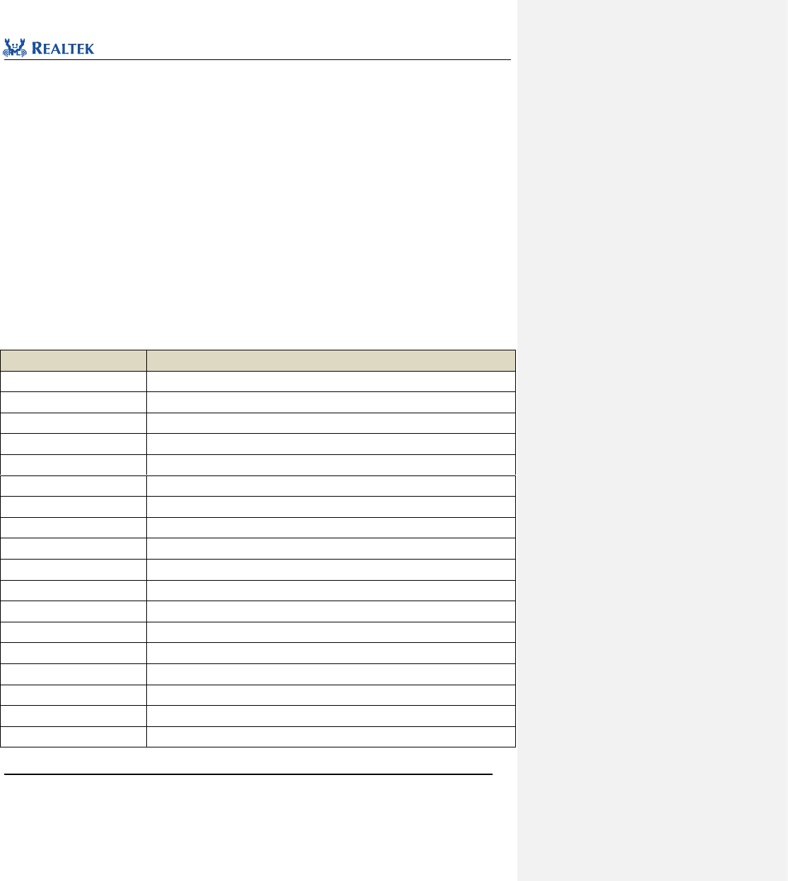
All ADC registers are enumerated in Table 2.1.
Table 2. 1 ADC Registers
Register
Description
FIFO
ADC data FIFO
CR
ADC control register
SCHCR
ADC Schedule Table Mapping Control register
Realtek Confidential
RTL8762C Peripheral Manual
Copyright 2018 Realtek Semiconductor Corporation.
All Rights Reserved.
17
INTCR
ADC interrupt control register
SCHTAB0
ADC schedule table 0
SCHTAB1
ADC schedule table 1
SCHTAB2
ADC schedule table 2
SCHTAB3
ADC schedule table 3
SCHTAB4
ADC schedule table 4
SCHTAB5
ADC schedule table 5
SCHTAB6
ADC schedule table 6
SCHTAB7
ADC schedule table 7
SCHD0
ADC schedule table data register 0
SCHD1
ADC schedule table data register 1
SCHD2
ADC schedule table data register 2
SCHD3
ADC schedule table data register 3
SCHD4
ADC schedule table data register 4
SCHD5
ADC schedule table data register 5
SCHD6
ADC schedule table data register 6
SCHD7
ADC schedule table data register 7
DATCLK
ADC data and control register
ANACTL
ADC analog control register
2. 2 ADC Library Functions
Table 2. 2 All ADC library functions
Function Name
Description
ADC_Init
Initialize ADC module
ADC_DeInit
Disable ADC clock source
ADC_StructInit
Set each parameter in ADC_InitStruct to the default value
ADC_INTConfig
Enable or disable external ADC interrupt
ADC_ReadByScheduleIndex
Read conversion result in specified schedule table
ADC_Cmd
Enable or disable ADC peripheral module
ADC_GetIntFlagStatus
Check whether specified ADC interrupt flag is set
ADC_ClearINTPendingBit
Clear suspended ADC interrupt
ADC_SchTableConfig
Configure specific convert mode to schedule table
ADC_GetFifoData
Get data from ADC FIFO.
Realtek Confidential
RTL8762C Peripheral Manual
Copyright 2018 Realtek Semiconductor Corporation.
All Rights Reserved.
18
ADC_ReadFifoData
Read data from ADC fifo once
ADC_GetFifoLen
Get ADC fifo data length
ADC_HighBypassCmd
Enable ADC high bypass mode
ADC_GetHighBypassRes
Convert raw data to voltage in adc high bypass mode
ADC_GetRes
Convert raw data to voltage in normal mode
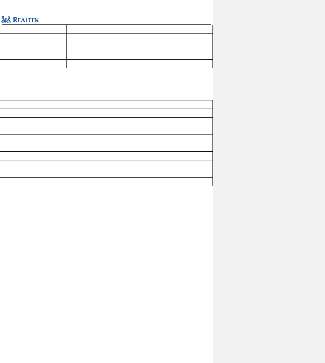
2. 2. 1 Function ADC_Init
Table 2. 3 Function ADC_DeInit
Function Name
ADC_Init
Function Prototype
void ADC_Init(ADC_TypeDef* ADCx, ADC_InitTypeDef* ADC_InitStruct)
Function Description
Initialize ADC register based on parameters specified in ADC_InitStruct
Input Parameter 1
ADCx: Base Address of ADCx pointing to the ADC module selected
Input Parameter 2
ADC_InitStruct: A pointer to ADC_InitTypeDef, and configuration information is contained in
ADC_InitStruct
Output Parameter
None
Return Value
None
Prerequisite
None
Functions Called
None
typedef struct
{
uint8_t adcSamplePeriod;
uint8_t adcFifoThd;
uint8_t adcBurstSize;
uint16_t adcFifoOverWritEn;
uint16_t dataLatchEdge;
uint16_t fifoOREn;
uint16_t schIndex[16];
uint16_t bitmap;
uint8_t timerTriggerEn;
uint32_t dataAligned;
uint8_t dataWriteToFifo;
uint8_t dataMinusEn;
uint8_t dataMinusOffset;
uint32_t pwrmode;
uint16_t datalatchDly;
uint16_t adcRG2X0Dly;
Realtek Confidential
RTL8762C Peripheral Manual
Copyright 2018 Realtek Semiconductor Corporation.
All Rights Reserved.
19
uint16_t adcRG0X1Dly;
uint16_t adcRG0X0Dly;
uint32_t adcRefMode;
} ADC_InitTypeDef;
adcSamplePeriod:This parameter specifies the sample rate of ADC in continuous mode. The actual sample rate:
sample_rate = (adcSamplePeriod +1)/10K, where adcSamplePeriod ranges from 0~255.
adcFifoThd:This parameter set the threshold to trigger ADC interrupt, which ranges from 0 to 31. When data
length in FIFO reaches threshold, inturrpt will be triggered. Inturrpt should be enabled before activating this
funchtion.
adcBurstSize:This parameter specifies the threshold to trigger GDMA transfer data in dma mode.
adcFifoOverWritEn: This parameter specifies adc FIFO behavior when FIFO overflow occurs.
dataLatchEdge: This parameter specifies the way to latch adc data.
adcRG2X0Dly / adcRG0X1Dly / adcRG0X0Dly:This parameter specifies the power on time of ADC analog circuit.
schIndex[16]:ADC schedule table that is used to seclect ADC channel. Table 2. 4 lists possible values.
Table 2. 4 schedule index
schedule index
Description
EXT_SINGLE_ENDED(0)
ADC external channel 0
EXT_SINGLE_ENDED(1)
ADC external channel 1
EXT_SINGLE_ENDED(2)
ADC external channel 2
EXT_SINGLE_ENDED(3)
ADC external channel 3
EXT_SINGLE_ENDED(4)
ADC external channel 4
EXT_SINGLE_ENDED(5)
ADC external channel 5
EXT_SINGLE_ENDED(6)
ADC external channel 6
EXT_SINGLE_ENDED(7)
ADC external channel 7
EXT_DIFFERENTIAL (0)
ADC Diffential mode (Channel P: 0 Channel N: 1)
EXT_DIFFERENTIAL (1)
ADC Diffential mode (channel P: 1 channel N: 0)
EXT_DIFFERENTIAL (2)
ADC Diffential mode (channel P: 2 channel N: 3)
EXT_DIFFERENTIAL (3)
ADC Diffential mode (channel P: 3 channe lN: 2)
EXT_DIFFERENTIAL (4)
ADC Diffential mode (channel P: 4 channel N: 5)
EXT_DIFFERENTIAL (5)
ADC Diffential mode (channel P: 5 channel N: 4)
EXT_DIFFERENTIAL (6)
ADC Diffential mode (channel P: 6 channel N: 7)
EXT_DIFFERENTIAL(7)
ADC Diffential mode (channel P: 7 channel N: 6)
INTERNAL_VBAT_MODE
ADC V battery mode
INTERNAL_VDDCORE_MODE
ADC VDDCORE channel
Realtek Confidential
RTL8762C Peripheral Manual
Copyright 2018 Realtek Semiconductor Corporation.
All Rights Reserved.
20
INTERNAL_VDD_DIGI_MODE
ADC VDD_DIGI channel
bitmap:This parameter specifies the converted schedule table. For example, 0x7 will convert schedule table
index 0, 1, 2.
timerTriggerEn:This parameter determines whether to use TIM7 to trigger ADC convert. Table 2. 5 lists possible
values:
Table 2. 5 timerTriggerEn:
timerTriggerEn
Description
ENABLE
ADC convert data when TIM7 toggle
DISABLE
ADC won’t convert data when TIM7 toggle
dataAligned:ADC data aligned. Table 2. 6 give values available to this parameter.
Table 2. 6 dataAligned
dataAligned
Description
ADC_DATA_LSB
Data starts from lsb
ADC_DATA_MSB
Data starts from msb
dataWriteToFifo :This parameter specifies whether ADC converted data is synchronized to FIFO in
one-shot-mode. Table 2. 7 give values available to this parameter.
Table 2. 7 Value of dataWriteToFifo
dataWriteToFifo
Description
ENABLE
ADC conversion values are synchronized to FIFO
DISABLE
ADC conversion values are not synchronized to FIFO
dataMinusEn:Enable or disable function of ADC conversion value automatically subtracting a particular
value.Table 2. 7 lists values available to this parameter.
Table 2. 8 Value of dataMinusEn
dataMinusEn
Description
ADC_DATA_MINUS_DIS
The ADC conversion value automatically subtracts a particular value
ADC_DATA_MINUS_EN
The ADC conversion value does not automatically subtract a particular value
dataMinusOffset:ADC data offset value. The ADC conversion value automatically subtracts this value if function
is enabled.
pwrmode:ADC power supply mode. Table 2. 9 lists values available to this parameter.
Table 2. 9 Value of pwrmode
pwrmode
Description
ADC_POWER_MANNUAL
Manual power up
ADC_POWER_AUTO
Automatic power up
datalatchDly:Data latching delay time, unit is ADC sample clock. This parameter ranges from 1 to 7 (1 by default),
Realtek Confidential
RTL8762C Peripheral Manual
Copyright 2018 Realtek Semiconductor Corporation.
All Rights Reserved.
21
generally don’t need to set.
adcRG2X0Dly / adcRG0X1Dly / adcRG0X0Dly:Control ADC analog circuit power-on time. Generally default value
is used and there’s no need to set.
adcRefMode:Configure ADC reference voltage mode.
表2. 10 value of adcRefMode
adcRefMode
描述
ADC_Internal_Reference
Internal reference mode.
ADC_External_Reference
External reference mode.
adcPowerAlwaysOnCmd:Configure if ADC analog power should be always on.
表2. 11 value of adcPowerAlwaysOnCmd
adcPowerAlwaysOnCmd
描述
ADC_POWER_ALWAYS_ON_ENABLE
Analog power always on.
ADC_POWER_ALWAYS_ON_DISABLE
Shut down power after ADC conversion is completed in
one-shot mode.
Examples:
ADC_InitTypeDef adcInitStruct;
ADC_StructInit(&adcInitStruct);
/* schedule table 0: external single-ended 0 channel */
adcInitStruct.schIndex[0] = EXT_SINGLE_ENDED(0);
/* schedule table 1: external differential mode, P: 2 N: 3 */
adcInitStruct.schIndex[1] = EXT_DIFFERENTIAL(2);
/* adc convert schedule table 0 & 1 */
adcInitStruct.bitmap = 0x03;
adcInitStruct.adcSamplePeriod = 9;
adcInitStruct.timerTriggerEn = DISABLE;
adcInitStruct.adcFifoThd = 8;
ADC_Init(ADC, &adcInitStruct);
2. 2. 2 Function ADC_DeInit
Table 2. 12 Function ADC_DeInit
Function Name
ADC_DeInit
Function Prototype
void ADC_DeInit(void)
Realtek Confidential
RTL8762C Peripheral Manual
Copyright 2018 Realtek Semiconductor Corporation.
All Rights Reserved.
22
Function Description
Disable ADC clock source
Input Parameter
None
Output Parameter
None
Return Value
None
Prerequisite
None
Functions Called
RCC_PeriphClockCmd Function
Examples:
/* Reset ADC */
ADC_DeInit(ADC);
2. 2. 3 Function ADC_StructInit
Table 2. 13 Function ADC_StructInit
Function Name
ADC_StructInit
Function Prototype
void ADC_StructInit(ADC_InitTypeDef* ADC_InitStruct)
Function Description
Set each parameter in ADC_InitStruct to the default value
Input Parameter
ADC_InitStruct: A pointer points to structure ADC_InitTypeDef, which contains
configuration information about peripheral ADC.
Output Parameter
None
Return Value
None
Prerequisite
None
Functions Called
None
Examples:
/* Configure the ADC Init Structure parameter */
ADC _InitTypeDef ADC _InitStruct;
ADC_ StructInit (&ADC _InitStruct);
2. 2. 4 Function ADC_INTConfig
Table 2. 14 Function ADC_INTConfig
Function Name
ADC_INTConfig
Function Prototype
ADC_INTConfig(ADC_TypeDef* ADCx, uint32_t ADC_IT, FunctionalState newState)
Function Description
Enable or disable external ADC interrupt
Input Parameter 1
ADCx: Base Address of ADCx pointing to the ADC module selected
Input Parameter 2
ADC_IT: Specify enabled interrupt type
Realtek Confidential
RTL8762C Peripheral Manual
Copyright 2018 Realtek Semiconductor Corporation.
All Rights Reserved.
23
Input Parameter 3
newState: Enable or disable the interrupt specified in Parameter 2.
Optional parameters: ENABLE, DISABLE
Output Parameter
None
Return Value
None
Prerequisite
None
Functions Called
None
ADC_IT: Permitted ADC interrupt types are as shown in Table 2. 15. Mutiple interrupts can be enabled at one
time by using operator "|".
Table 2. 15 Values of ADC_IT
ADC_IT
Description
ADC_INT_FIFO_RD_REQ
ADC Read request interrupt
ADC_INT_FIFO_RD_ERR
ADC Read error interrupt
ADC_INT_FIFO_TH
ADC FIFO reach threshold interrupt
ADC_INT_FIFO_FULL
ADC FIFO full interrupt
ADC_INT_ONE_SHOT_DONE
ADC one_shot mode done interrupt
Examples:
/* Enable ADC one shot done interrupt */
ADC_INTConfig(ADC, ADC_INT_ONE_SHOT_DONE, ENABLE);
2. 2. 5 Function ADC_ ReadByScheduleIndex
Table 2. 16 Function ADC_ ReadByScheduleIndex
Function Name
ADC_ReadByScheduleIndex
Function Prototype
uint16_t ADC_ReadByScheduleIndex(ADC_TypeDef *ADCx, uint8_t ScheduleIndex)
Function Description
Read converted result from corresponding channel according to schedule table index.
Input Parameter 1
ADCx:Base Address of ADCx pointing to the ADC module selected
Input Parameter 2
ScheduleIndex:The specified adc schedule table index, ranging from 0 to 15.
Output Parameter
None
Return Value
12-bit converted ADC data
Prerequisite
None
Functions Called
NOne
Examples:
/* Read data by schedule index */
uint16_t value = 0;

Realtek Confidential
RTL8762C Peripheral Manual
Copyright 2018 Realtek Semiconductor Corporation.
All Rights Reserved.
24
value = ADC_ReadByScheduleIndex (ADC, 0);
2. 2. 6 Function ADC_Cmd
Table 2. 17 Function ADC_Cmd
Function Name
ADC_Cmd
Function Prototype
void ADC_Cmd(ADC_TypeDef* ADCx, uint8_t adcMode, FunctionalState NewState)
Function Description
Enable or disable ADC peripheral.
Input Parameter 1
ADCx: Base Address of ADCx pointing to the ADC module selected
Input Parameter 2
adcMode: ADC mode select.
ADC_One_Shot_Mode: one shot mode.
ADC_Auto_Sensor_Mode: Continuous mode.
Input Parameter 3
NewState: new state of the ADC peripheral.
Possible value: ENABLE and DISABLE
Output Parameter
None
Return Value
None
Prerequisite
None
Functions Called
None
Examples:
/* Enable ADC */
ADC_Cmd(ADC, ADC_One_Shot_Mode, ENABLE);
2. 2. 7 Function ADC_GetIntFlagStatus
Table 2. 18 Function ADC_GetIntFlagStatus
Function Name
ADC_GetIntFlagStatus
Function Prototype
FlagStatus ADC_GetIntFlagStatus(ADC_TypeDef* ADCx, uint32_t ADC_INT_FLAG)
Function Description
Check specified interrupt flag is set or not.
Input Parameter 1
ADCx: Base Address of ADCx pointing to the ADC module selected
Input Parameter 2
ADC_INT_FLAG: The specified ADC interrupt flag bit. For more details refer to description
of ADC_IT in 2. 2. 4.
Output Parameter
None
Return Value
None
Prerequisite
None
Realtek Confidential
RTL8762C Peripheral Manual
Copyright 2018 Realtek Semiconductor Corporation.
All Rights Reserved.
25
Functions Called
None
Examples:
/*wait for adc sample ready*/
while (ADC_GetIntFlagStatus(ADC, ADC_INT_ONE_SHOT_DONE) != SET);
2. 2. 8 Function ADC_ClearINTPendingBit
Table 2. 19 Function ADC_ClearINTPendingBit
Function Name
ADC_ClearINTPendingBit
Function Prototype
void ADC_ClearINTPendingBit(ADC_TypeDef* ADCx, uint32_t ADC_IT)
Function Description
Clear ADC interrupt suspended
Input Parameter 1
ADCx: Base Address of ADCx pointing to the ADC module selected
Input Parameter 2
ADC_IT: The specified ADC interrupt. For more details refer to description of ADC_IT in 2.
2. 4.
Output Parameter
None
Return Value
None
Prerequisite
None
Functions Called
None
Examples:
/* Clear ADC interrupt */
ADC_ClearINTPendingBit(ADC, ADC_INT_ONE_SHOT_DONE);
2. 2. 9 Function ADC_SchTableConfig
Table 2. 20 Function ADC_SchTableConfig
Function Name
ADC_SchTableConfig
Function Prototype
void ADC_SchTableConfig(ADC_TypeDef *ADCx, uint16_t Index,
uint8_t adcMode)
Function Description
Config specified ADC channel to ADC schedule table
Input Parameter 1
ADCx: Base Address of ADCx pointing to the ADC module selected
Input Parameter 2
Index: ADC schedule table index, ranging from 0 to 15.
Input Parameter 3
adcMode: specified ADC channel. For detailed information refer to Section 2.2.1
channelMap.
Output Parameter
None
Realtek Confidential
RTL8762C Peripheral Manual
Copyright 2018 Realtek Semiconductor Corporation.
All Rights Reserved.
26
Return Value
None
Prerequisite
None
Functions Called
None
Examples:
/* Enable ADC specific channel */
ADC_ChannelConfig(ADC,0, EXT_SINGLE_ENDED(0));
2. 2. 10 Function ADC_GetFifoData
Table 2. 21 Function ADC_GetFifoData
Function Name
ADC_GetFifoData
Function Prototype
void ADC_GetFifoData(ADC_TypeDef *ADCx, uint16_t *outBuf, uint16_t count)
Function Description
Get specific amount of data from ADC FIFO.
Input Parameter 1
ADCx: Base Address of ADCx pointing to the ADC module selected
Input Parameter 2
outBuf: address of buffer to store converted data.
Input Parameter 3
Count: length of data to be read
Output Parameter
None
Return Value
None
Prerequisite
None
Functions Called
None
Examples:
/* Get ADC data */
ADC_GetFifoData(ADC,data,5);
2. 2. 11 Function ADC_ReadFifoData
Table 2. 22 Function ADC_ReadFifoData
Function Name
ADC_ReadFifoData
Function Prototype
uint16_t ADC_ReadFifoData(ADC_TypeDef *ADCx)
Function Description
Read data from ADC peripheral once.
Input Parameter 1
ADCx: Base Address of ADCx pointing to the ADC module selected
Output Parameter
None
Return Value
ADC converted data.
Prerequisite
None
Realtek Confidential
RTL8762C Peripheral Manual
Copyright 2018 Realtek Semiconductor Corporation.
All Rights Reserved.
27
Functions Called
None
Examples:
/* Receive one half word*/
Uint16_t data = ADC_ReadFifoData (ADC);
2. 2. 12 Function ADC_GetFifoLen
Table 2. 23 Function ADC_GetFifoLen
Function Name
ADC_GetFifoLen
Function Prototype
uint8_t ADC_GetFifoLen(ADC_TypeDef *ADCx)
Function Description
Get ADC FIFO available data length
Input Parameter 1
ADCx: Base Address of ADCx pointing to the ADC module selected
Output Parameter
None
Return Value
ADC FIFO data length
Prerequisite
None
Functions Called
None
Examples:
/* Get ADC fifo number */
Uint8_t length = ADC_GetFifoLen (ADC);
2. 2. 13 Function ADC_HighBypassCmd
Table 2. 24 Function ADC_HighBypassCmd
Function Name
ADC_HighBypassCmd
Function Prototype
void ADC_HighBypassCmd(uint8_t channelNum, FunctionalState NewState)
Function Description
Configure specified ADC external channel to high impedence mode
Input Parameter 1
channelNum: external channel index, ranging from 0~7.
Input Parameter 2
NewState:
ENABLE: configure to high bypass resistance mode. Convertion range: 0 to 1 Volt.
DISABLE: configure to common mode. Convertion range: 0 to 3.3 Volts.
Output Parameter
None
Return Value
None
Prerequisite
None
Functions Called
None
Realtek Confidential
RTL8762C Peripheral Manual
Copyright 2018 Realtek Semiconductor Corporation.
All Rights Reserved.
28
Examples:
/* Get ADC external channel 3 high bypass mode*/
ADC_HighBypassCmd(3,ENABLE);
2. 2. 14 Function ADC_GetHighBypassRes
Table 2. 25 Function ADC_GetHighBypassRes
Function Name
ADC_GetHighBypassRes
Function Prototype
uint16_t ADC_GetHighBypassRes(uint16_t RawData, uint8_t adcMode)
Function Description
Get ADC result in high bypass resistance mode.
Input Parameter 1
RawData: ADC raw data.
Input Parameter 2
adcMode: The specified ADC mode. Can be EXT_SINGLE_ENDED(index)
Output Parameter
None
Return Value
Actual ADC data
Prerequisite
None
Functions Called
None
Examples:
/*Convert ADC raw data to actual voltage*/
uint16_t vol = ADC_GetHighBypassRes (0x88, EXT_SINGLE_ENDED(0));
2. 2. 15 Function ADC_GetRes
Table 2. 26 Function ADC_GetRes
Function Name
ADC_GetRes
Function Prototype
uint16_t ADC_GetRes(uint16_t RawData, uint8_t adcMode)
Function Description
Convert raw data obtained in ADC normal mode to actual value
Input Parameter 1
RawData: ADC raw data.
Input Parameter 2
adcMode: Specified ADC mode.
Output Parameter
None
Return Value
None
Prerequisite
None
Functions Called
None
Examples:
/*Convert ADC raw data to actual voltage*/

Realtek Confidential
RTL8762C Peripheral Manual
Copyright 2018 Realtek Semiconductor Corporation.
All Rights Reserved.
29
Uint16_t vol = ADC_GetRes (0x88, EXT_SINGLE_ENDED(0));
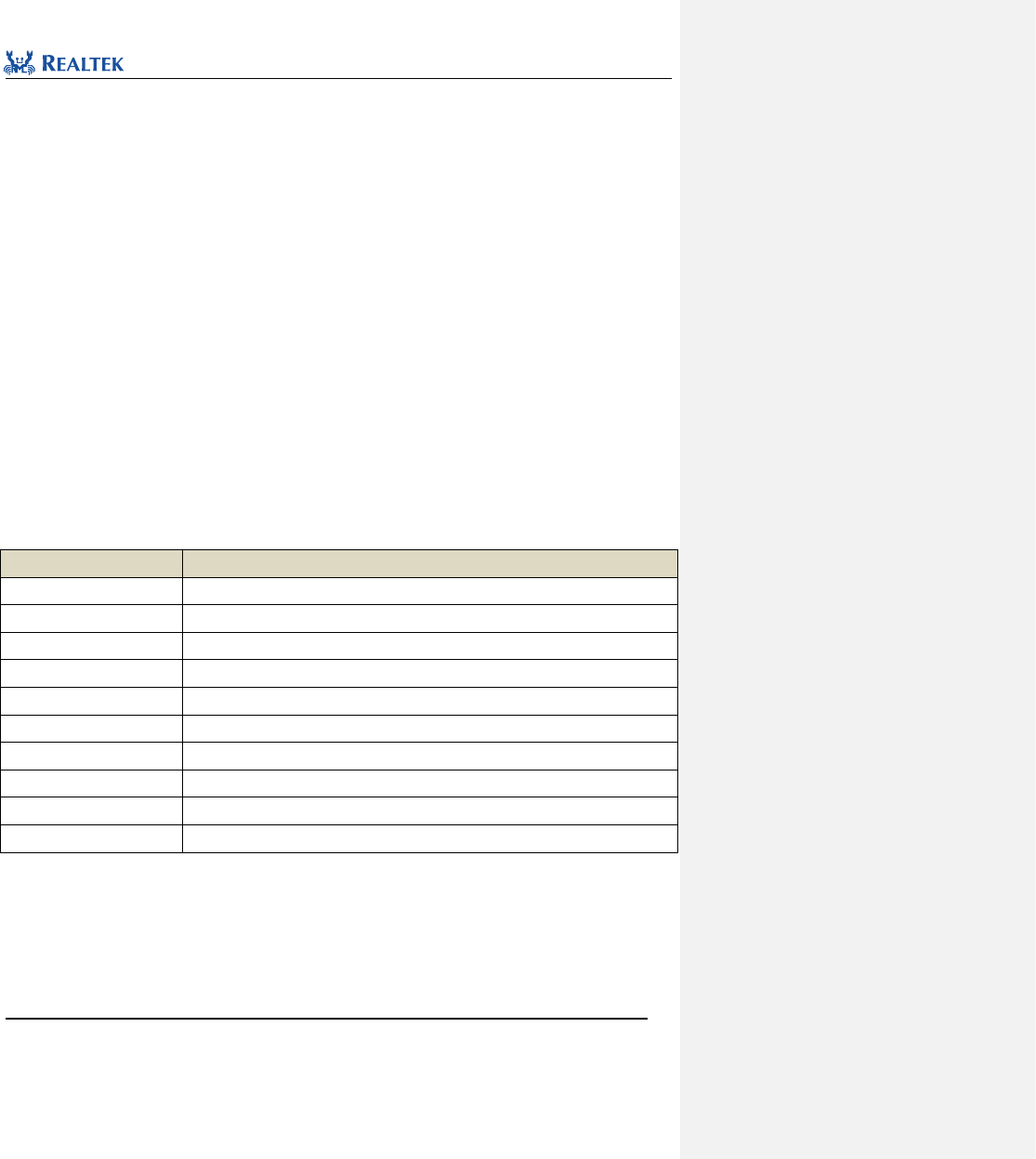
Realtek Confidential
RTL8762C Peripheral Manual
Copyright 2018 Realtek Semiconductor Corporation.
All Rights Reserved.
30
3 COder-DECoder(CODEC)
3. 1 Codec Register Architecture
typedef struct
{
__IO uint32_t CR0;
__IO uint32_t CR1;
__IO uint32_t CR2;
__IO uint32_t RESV0;
__IO uint32_t CR3;
__IO uint32_t I2S_CTRL;
__IO uint32_t AUDIO_CTRL;
__IO uint32_t CLK_CTRL;
__IO uint32_t DAC_CTRL;
__IO uint32_t ADC_CTRL;
} CODEC_TypeDef;
All Codec registers are enumerated in Table 3. 1.
Table 3. 1 Codec Register
Register
Description
CR0
CODEC Control Register 0
CR1
CODEC Control Register 1
CR2
CODEC Control Register 2
RSVD0
Reserved
CR3
CODEC Control Register 3
I2S_CTRL
I2S Control Register
AUDIO_CTRL
Audio Control Register
CLK_CTRL
Clock Control Register
DAC_CTRL
DAC Control Register
ADC_CTRL
ADC Control Register
typedef struct
{
__IO uint32_t EQ_H0; /*!< 0x40 */
__IO uint32_t EQ_B1; /*!< 0x44 */
__IO uint32_t EQ_B2; /*!< 0x48 */
__IO uint32_t EQ_A1; /*!< 0x4C */
__IO uint32_t EQ_A2; /*!< 0x50 */
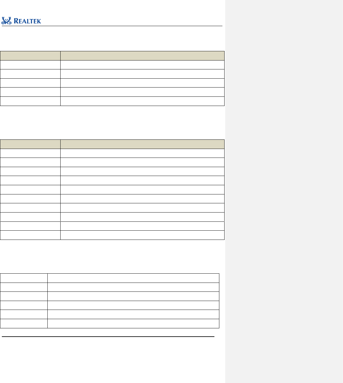
Realtek Confidential
RTL8762C Peripheral Manual
Copyright 2018 Realtek Semiconductor Corporation.
All Rights Reserved.
31
}CODEC_EQTypeDef;
All EQ registers are enumerated in Table 3. 2.
Table 3. 2 CODEC EQ Register
Register
Description
EQ_H0
EQ Control Register H0
EQ_B1
EQ Control Register B1
EQ_B2
EQ Control Register B2
EQ_A1
EQ Control Register A1
EQ_A2
EQ Control Register A2
3. 2 Codec Library Functions
Table 3. 3 All Codec library functions.
Function Name
Description
CODEC_DeInit
Disable Codec clock
CODEC_Init
Initialize Codec registers based on parameters specified in CODEC_InitStruct
CODEC_StructInit
Set each parameter in CODEC_InitStruct to the default value
CODEC_EQInit
Initialize Codec EQ registers based on parameters specified in CODEC_EQInitStruct
CODEC_EQStructInit
Set each parameter in CODEC_EQInitStruct to the default value
CODEC_Reset
Reset CODEC peripheral
CODEC_SetMicMute
Mute microphone
CODEC_SetADCDigitalVolume
Set volume of ADC digital circuit
CODEC_SetMICBIAS
Set voltage range of MICBIAS
CODEC_MICBIASCmd
Enable or disable MICBIAS
3. 2. 1 Function CODEC_DeInit
Table 3. 4 Function CODEC_DeInit
Function Name
CODEC_DeInit
Function Prototype
void CODEC_DeInit(CODEC_TypeDef* CODECx)
Function Description
Disable Codec clock
Input Parameter 1
CODECx: Base Address of CODEC pointing to the Codec module selected
Output Parameter
None
Return Value
None
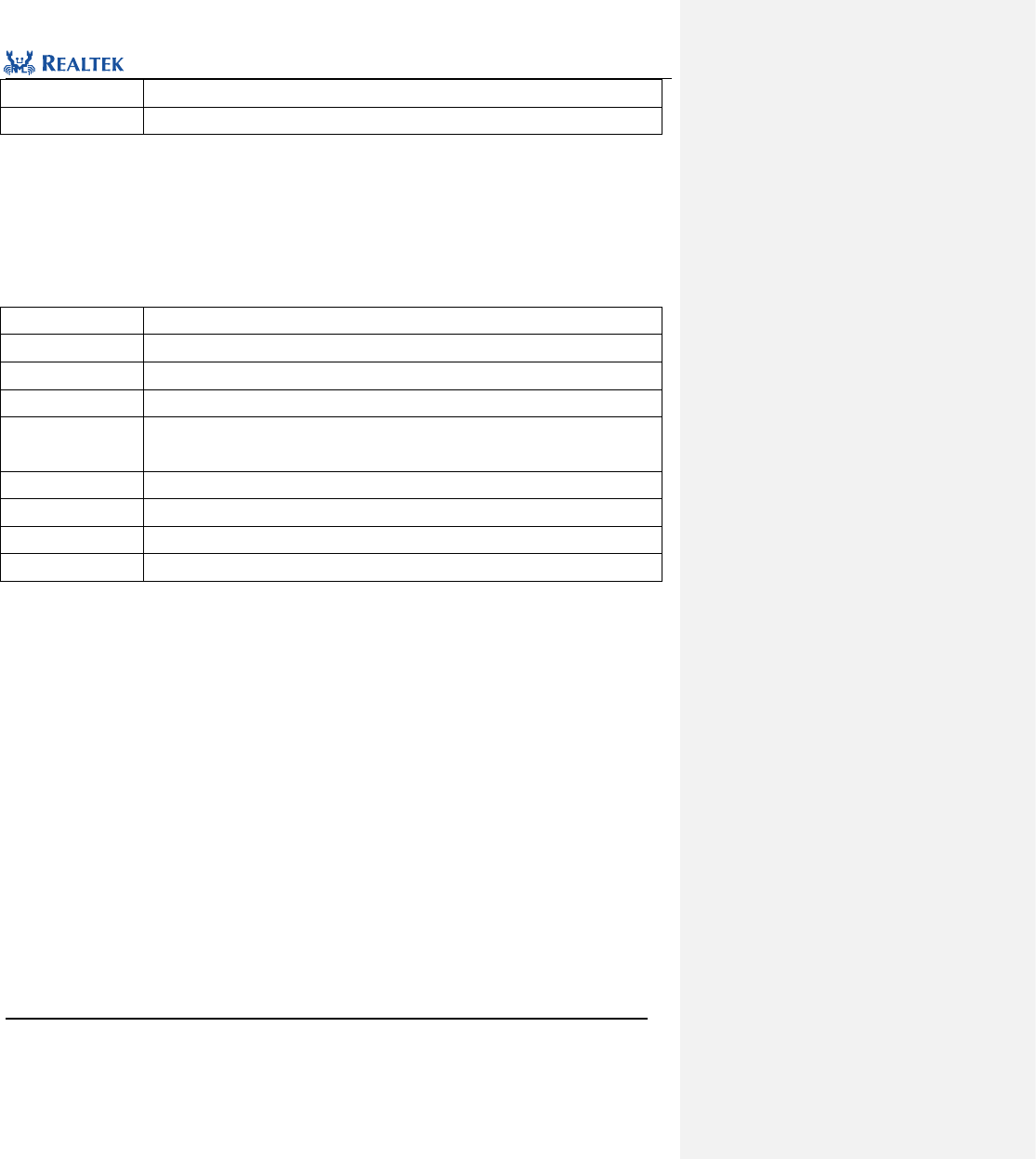
Realtek Confidential
RTL8762C Peripheral Manual
Copyright 2018 Realtek Semiconductor Corporation.
All Rights Reserved.
32
Prerequisite
None
Functions Called
RCC_PeriphClockCmd Function
Examples:
/* Close codec */
CODEC_DeInit(CODEC);
3. 2. 2 Function CODEC_Init
Table 3. 5 Function CODEC_Init
Function Name
CODEC_Init
Function Prototype
CODEC_Init(CODEC_TypeDef* CODECx, CODEC_InitTypeDef* CODEC_InitStruct)
Function Description
Initialize CODEC register based on parameters specified in CODEC_InitStruct
Input Parameter 1
CODECx: Base Address of CODEC pointing to the Codec module selected
Input Parameter 2
CODEC_InitStruct: A pointer to CODEC_InitTypeDef, and related configuration
information is contained in CODEC_InitStruct
Output Parameter
None
Return Value
None
Prerequisite
None
Functions Called
None
typedef struct
{
uint32_t CODEC_MicType; /*!< Specifies the mic type, which can be dmic or amic */
uint32_t CODEC_SampleRate; /*!< Specifies the sample rate */
/* I2S parameters section */
uint32_t CODEC_I2SFormat; /*!< Specifies the I2S format of codec port */
uint32_t CODEC_I2SDataWidth; /*!< Specifies the I2S data width of codec port */
/* Input: ADC parametes section */
uint32_t CODEC_MicBIAS; /*!< Specifies the MICBIAS voltage */
uint32_t CODEC_AdGain; /*!< Specifies the ADC digital volume */
uint32_t CODEC_BoostGain; /*!< Specifies the boost gain */
uint32_t CODEC_AdcZeroDetTimeout; /*!< Specifies the mono ADC zero detection timeout control */
uint32_t CODEC_MICBstGain; /*!< Specifies the MICBST gain */
uint32_t CODEC_MICBstMode; /*!< Specifies the MICBST mode */
/* Input: Dmic parametes section */
uint32_t CODEC_DmicClock; /*!< Specifies the dmic clock */
uint32_t CODEC_DmicDataLatch; /*!< Specifies the dmic data latch type */
/* Output: DAC control */
uint32_t CODEC_DaMute; /*!< Specifies the DAC mute status */
uint32_t CODEC_DaGain; /*!< Specifies the DAC gain control */
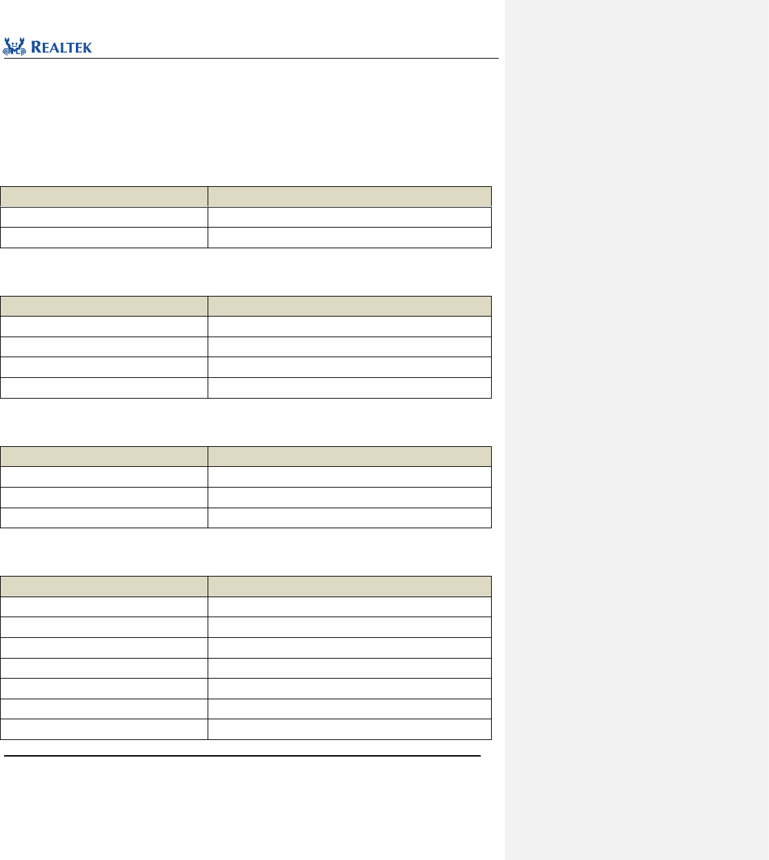
Realtek Confidential
RTL8762C Peripheral Manual
Copyright 2018 Realtek Semiconductor Corporation.
All Rights Reserved.
33
uint32_t CODEC_DacZeroDetTimeout; /*!< Specifies the mono DAC zero detection timeout control */
}CODEC_InitTypeDef;
CODEC_MicType: The defined microphone type, indicating analog or digital microphone, which can be set to
either CODEC_AMIC or CODEC_DMIC.
CODEC_SampleRate: Configure microphone sample rate. Table 3. 6 lists available values..
Table 3. 6 Values of CODEC_SampleRate
CODEC_SampleRate
Description
SAMPLE_RATE_8KHz
Sample rate is 8KHz
SAMPLE_RATE_16KHz
Sample rate is 16KHz
CODEC_I2SFormat: Configure I2S data format. Table 3. 7 lists available values.
Table 3. 7 Values of CODEC_I2SFormat
CODEC_I2SFormat
Description
CODEC_I2S_DataFormat_I2S
I2S format
CODEC_I2S_DataFormat_LeftJustified
Left justified format
CODEC_I2S_DataFormat_PCM_A
PCM A format
CODEC_I2S_DataFormat_PCM_B
PCM B format
CODEC_I2SDataWidth: Configure I2S data width. Table 3. 8 lists available values.
Table 3. 8 Values of CODEC_I2SDataWidth
CODEC_I2SDataWidth
Description
CODEC_I2S_DataWidth_16Bits
16bit data width
CODEC_I2S_DataWidth_24Bits
24bit data width
CODEC_I2S_DataWidth_8Bits
8bit data width
CODEC_MicBIAS: Configure MICBIAS voltage. Table 3. 9 lists available values.
Table 3. 9 Values of CODEC_MicBIAS
CODEC_MicBIAS
Description
MICBIAS_VOLTAGE_1_507
1.507v
MICBIAS_VOLTAGE_1_62
1.62v
MICBIAS_VOLTAGE_1_705
1.705v
MICBIAS_VOLTAGE_1_8
1.8v
MICBIAS_VOLTAGE_1_906
1.906v
MICBIAS_VOLTAGE_2_025
2.025v
MICBIAS_VOLTAGE_2_16
2.16v
Realtek Confidential
RTL8762C Peripheral Manual
Copyright 2018 Realtek Semiconductor Corporation.
All Rights Reserved.
34
MICBIAS_VOLTAGE_2_314
2.314v
CODEC_ AdGain: Set microphone volume. The available value ranges from 0x00 to 0x7f, among which, 0x00 is
-17. 625dB, 0x2f is 0dB, and 0x7f is 30dB.
CODEC_BoostGain: Configure boost gain. Table 3. 10 lists available values.
Table 3. 10 Values of CODEC_BoostGain
CODEC_BoostGain
Description
Boost_Gain_0dB
0dB
Boost_Gain_12dB
12dB
Boost_Gain_24dB
24dB
Boost_Gain_36dB
36dB
CODEC_AdcZeroDetTimeout: Configure ADC zero point detection timeout time. Table 3. 11 lists available values.
Table 3. 11 Values of CODEC_AdcZeroDetTimeout
CODEC_AdcZeroDetTimeout
Description
ADC_Zero_DetTimeout_1024_16_Sample
1024*16 sample times
ADC_Zero_DetTimeout_1024_32_Sample
1024*32 sample times
ADC_Zero_DetTimeout_1024_64_Sample
1024*64 sample times
ADC_Zero_DetTimeout_64_Sample
64 sample times
CODEC_MICBstGain: Configure the MICBST gain.Table 3. 12 lists available values.
Table 3. 12 Values of CODEC_MICBstGain
CODEC_MICBstGain
Description
MICBST_Gain_0dB
0dB
MICBST_Gain_20dB
20dB
MICBST_Gain_30dB
30dB
MICBST_Gain_40dB
40dB
CODEC_DmicClock: Set the DMIC clock.Table 3. 13 lists available values.
Table 3. 13 Values of CODEC_DmicClock
CODEC_DmicClock
Description
DMIC_Clock_4MHz
DMIC clock is 4MHz
DMIC_Clock_2MHz
DMIC clock is 2MHz
DMIC_Clock_1MHz
DMIC clock is 1MHz
DMIC_Clock_500KHz
DMIC clock is 0.5MHz
CODEC_DmicDataLatch: Set the DMIC data latch mode.Table 3. 14 lists available values.

Realtek Confidential
RTL8762C Peripheral Manual
Copyright 2018 Realtek Semiconductor Corporation.
All Rights Reserved.
35
Table 3. 14 Values of CODEC_DmicDataLatch
CODEC_DmicDataLatch
Description
DMIC_Rising_Latch
Rising edge latch
DMIC_Falling_Latch
Falling edge latch
CODEC_DaMute: Enable or disable DAC output.Table 3. 15 lists available values.
Table 3. 15 Values of CODEC_DaMute
CODEC_DaMute
Description
DAC_UuMute
Enable DAC output
DAC_Mute
Disable DAC output
CODEC_DaGain: Set DAC output volume. The available value ranges between 0x00 and 0xff, among which, 0x00
is -65.625dB, 0xaf is 0dB. Each step is 0.375dB.
CODEC_DacZeroDetTimeout: Set the DAC zero point detection timeout time.Table 3. 16 Table lists values
available to this parameter.
Table 3. 16 Values of CODEC_DacZeroDetTimeout
CODEC_DacZeroDetTimeout
Description
DAC_Zero_DetTimeout_1024_16_Sample
1024*16 sample times
DAC_Zero_DetTimeout_1024_32_Sample
1024*32 sample times
DAC_Zero_DetTimeout_1024_64_Sample
1024*64 sample times
DAC_Zero_DetTimeout_256_Sample
256 sample times
Examples:
/* Initialize codec */
CODEC_InitTypeDef CODEC_InitStruct;
CODEC_StructInit(&CODEC_InitStruct);
CODEC_InitStruct.CODEC_MicType = CODEC_DMIC;
CODEC_InitStruct.CODEC_DmicClock = DMIC_Clock_2MHz;
CODEC_InitStruct.CODEC_DmicDataLatch = DMIC_Rising_Latch;
CODEC_InitStruct.CODEC_SampleRate = SAMPLE_RATE_16KHz;
CODEC_InitStruct.CODEC_I2SFormat = CODEC_I2S_DataFormat_I2S;
CODEC_InitStruct.CODEC_I2SDataWidth = CODEC_I2S_DataWidth_16Bits;
CODEC_Init(CODEC, &CODEC_InitStruct);
3. 2. 3 Function CODEC_StructInit
Table 3. 17 Function CODEC_StructInit
Function Name
CODEC_StructInit
Realtek Confidential
RTL8762C Peripheral Manual
Copyright 2018 Realtek Semiconductor Corporation.
All Rights Reserved.
36
Function Prototype
void CODEC_StructInit(CODEC_InitTypeDef* CODEC_InitStruct)
Function Description
Set each parameter in CODEC_InitStruct to the default value
Input Parameter
CODEC_InitStruct: A pointer points to structure CODEC_InitTypeDef, which contains
configuration information about peripheral CODEC.
Output Parameter
None
Return Value
None
Prerequisite
None
Functions Called
None
Examples:
/* Initialize codec */
CODEC_InitTypeDef CODEC_InitStruct;
CODEC_StructInit(&CODEC_InitStruct);
3. 2. 4 Function CODEC_EQInit
Table 3. 18 Function CODEC_EQInit
Function Name
CODEC_EQInit
Function Prototype
void CODEC_EQInit(CODEC_EQTypeDef* CODEC_EQx, CODEC_EQInitTypeDef*
CODEC_EQInitStruct)
Function Description
Initialize CODEC EQ register based on parameters specified in CODEC_EQInitStruct
Input Parameter 1
CODEC_EQx: Base Address of CODEC EQ pointing to the Codec EQ module selected
Input Parameter 2
CODEC_EQInitStruct: A pointer to CODEC_EQInitTypeDef, and related configuration
information is contained in CODEC_EQInitStruct
Output Parameter
None
Return Value
None
Prerequisite
None
Functions Called
None
typedef struct
{
uint32_t CODEC_EQChCmd; /*!< Specifies the EQ channel status */
uint32_t CODEC_EQCoefH0; /*!< Specifies the EQ coef.h0. This value can be 0 to 0x7FFFF,
whose physical meaning represents a range of-8 to 7.99 */
uint32_t CODEC_EQCoefB1; /*!< Specifies the EQ coef.b1. This value can be 0 to 0x7FFFF,
whose physical meaning represents a range of-8 to 7.99 */
uint32_t CODEC_EQCoefB2; /*!< Specifies the EQ coef.b2. This value can be 0 to 0x7FFFF,
whose physical meaning represents a range of-8 to 7.99 */
uint32_t CODEC_EQCoefA1; /*!< Specifies the EQ coef.a1. This value can be 0 to 0x7FFFF,
Realtek Confidential
RTL8762C Peripheral Manual
Copyright 2018 Realtek Semiconductor Corporation.
All Rights Reserved.
37
whose physical meaning represents a range of-8 to 7.99 */
uint32_t CODEC_EQCoefA2; /*!< Specifies the EQ coef.a2. This value can be 0 to 0x7FFFF,
whose physical meaning represents a range of-8 to 7.99 */
}CODEC_EQInitTypeDef;
CODEC_EQChCmd: Enable or disable EQ channel. Table 3. 19 Table lists values available to this parameter.
Table 3. 19 Values of CODEC_EQChCmd
CODEC_EQChCmd
Description
EQ_CH_Cmd_ENABLE
Enable the specified EQ channel function
EQ_CH_Cmd_DISABLE
Disable the specified EQ channel function
CODEC_EQCoefH0: Set EQ H0. The available value ranges from 0x00 to 0x7ffff, among which, 0x00 is -8, 0x2f is 0dB,
and 0x7ffff is 7.99.
CODEC_EQCoefB1: Set EQ B1. The available value ranges from 0x00 to 0x7ffff, among which, 0x00 is -8, 0x2f is 0dB,
and 0x7ffff is 7.99.
CODEC_EQCoefB2: Set EQ B2. The available value ranges from 0x00 to 0x7ffff, among which, 0x00 is -8, 0x2f is 0dB,
and 0x7ffff is 7.99.
CODEC_EQCoefA1: Set EQ A1. The available value ranges from 0x00 to 0x7ffff, among which, 0x00 is -8, 0x2f is 0dB,
and 0x7ffff is 7.99.
CODEC_EQCoefA2: Set EQ A2. The available value ranges from 0x00 to 0x7ffff, among which, 0x00 is -8, 0x2f is 0dB,
and 0x7ffff is 7.99.
Examples:
/* Initialize codec EQ1 */
CODEC_EQInitTypeDef CODEC_EQInitStruct;
CODEC_StructInit(&CODEC_EQInitStruct);
CODEC_EQInitStruct. CODEC_EQChCmd = EQ_CH_Cmd_ENABLE;
CODEC_EQInitStruct.CODEC_EQCoefH0 = 0xFF;
CODEC_EQInitStruct.CODEC_EQCoefB1 = 0xFF;
CODEC_EQInitStruct.CODEC_EQCoefB2 = 0xFF;
CODEC_EQInitStruct.CODEC_EQCoefA1 = 0xFF;
CODEC_EQInitStruct.CODEC_EQCoefA2 = 0xFF;
CODEC_EQInit(CODEC_EQ1, CODEC_EQInitStruct);
3. 2. 5 Function CODEC_EQStructInit
Table 3. 20 Function CODEC_EQStructInit
Function Name
CODEC_EQStructInit
Function Prototype
void CODEC_EQStructInit(CODEC_EQInitTypeDef* CODEC_EQInitStruct)
Function Description
Set each parameter in CODEC_EQInitStruct to the default value
Realtek Confidential
RTL8762C Peripheral Manual
Copyright 2018 Realtek Semiconductor Corporation.
All Rights Reserved.
38
Input Parameter
CODEC_EQInitStruct: A pointer points to structure CODEC_EQInitTypeDef, which contains
configuration information about peripheral CODEC EQ.
Output Parameter
None
Return Value
None
Prerequisite
None
Functions Called
None
Examples:
/* Initialize EQ */
CODEC_EQInitTypeDef CODEC_EQInitStruct;
CODEC_EQStructInit(&CODEC_EQInitStruct);
3. 2. 6 Function CODEC_Reset
Table 3. 21 Function CODEC_Reset
Function Name
CODEC_Reset
Function Prototype
void CODEC_Reset(CODEC_TypeDef* CODECx)
Function Description
Reset CODEC peripheral
Input Parameter 1
CODECx: Base Address of CODEC pointing to the Codec module selected
Output Parameter
None
Return Value
None
Prerequisite
None
Functions Called
None
Examples:
/* Reset codec */
CODEC_Reset(CODEC);
3. 2. 7 Function CODEC_SetMicMute
Table 3. 22 Function CODEC_SetMicMute
Function Name
CODEC_SetAmicMute
Function Prototype
void CODEC_SetAmicMute(CODEC_TypeDef* CODECx, FunctionalState newState)
Function Description
Mute analog microphone.
Input Parameter 1
CODECx: Base Address of CODEC pointing to the Codec module selected
Input Parameter 2
newState: It can be set to either ENABLE or DISABLE.
Realtek Confidential
RTL8762C Peripheral Manual
Copyright 2018 Realtek Semiconductor Corporation.
All Rights Reserved.
39
Output Parameter
None
Return Value
None
Prerequisite
None
Functions Called
None
Examples:
/* Set Mic mute */
CODEC_SetMicMute (CODEC, ENABLE);
3. 2. 8 Function CODEC_SetADCDigitalVolume
Table 3. 23 Function CODEC_SetADCDigitalVolume
Function Name
CODEC_SetADCDigitalVolume
Function Prototype
void CODEC_SetADCDigitalVolume(CODEC_TypeDef* CODECx, uint16_t volume)
Function Description
Set ADC digital volume
Input Parameter 1
CODECx: Base Address of CODEC pointing to the Codec module selected
Input Parameter 2
volume: Volume of microphone. The available value ranges from 0x00 to 0x7f, among
which, 0x00 is -17. 625dB, 0x2f is 0dB, and 0x7f is 30dB
Output Parameter
None
Return Value
None
Prerequisite
None
Functions Called
None
Examples:
/* Set Mic volume to 0 dB*/
CODEC_SetADCDigitalVolume (CODEC, 0x2f);
3. 2. 9 Function CODEC_SetMICBIAS
Table 3. 24 Function CODEC_SetMICBIAS
Function Name
CODEC_SetMICBIAS
Function Prototype
void CODEC_SetMICBIAS(CODEC_TypeDef* CODECx, uint16_t data)
Function Description
Set voltage range of MICBIAS
Input Parameter 1
CODECx: Base Address of CODEC pointing to the Codec module selected
Input Parameter 2
data:MICBIAS voltage value,The available values are listed below:
MICBIAS_VOLTAGE_1_507: Vref voltage is 1.507V.
MICBIAS_VOLTAGE_1_62: Vref voltage is 1.62V.
MICBIAS_VOLTAGE_1_705: Vref voltage is 1.705V.
Realtek Confidential
RTL8762C Peripheral Manual
Copyright 2018 Realtek Semiconductor Corporation.
All Rights Reserved.
40
MICBIAS_VOLTAGE_1_8: Vref voltage is 1.8V.
MICBIAS_VOLTAGE_1_906: Vref voltage is 1.906V.
MICBIAS_VOLTAGE_2_025: Vref voltage is 2.025V.
MICBIAS_VOLTAGE_2_16: Vref voltage is 2.16V.
MICBIAS_VOLTAGE_2_314: Vref voltage is 2.314V.
Output Parameter
None
Return Value
None
Prerequisite
None
Functions Called
None
Examples:
/* Set MICBIAS */
CODEC_SetMICBIAS (CODEC, MICBIAS_VOLTAGE_1_8);
3. 2. 10 Function CODEC_MICBIASCmd
Table 3. 25 Function CODEC_MICBIASCmd
Function Name
CODEC_MICBIASCmd
Function Prototype
void CODEC_MICBIASCmd(CODEC_TypeDef* CODECx, FunctionalState NewState)
Function Description
Enable or disable MICBIAS
Input Parameter 1
CODECx: Base Address of CODEC pointing to the Codec module selected
Input Parameter 2
newState: new state of MICBIAS
Optional parameters: ENABLE, DISABLE
Output Parameter
None
Return Value
None
Prerequisite
None
Functions Called
None
Examples:
/* Enable MICBIAS */
CODEC_MICBIASCmd (CODEC, ENABLE);
4 Direct Memory Access Controller (GDMA)
4. 1 GDMA Register Architecture
typedef struct
{

Realtek Confidential
RTL8762C Peripheral Manual
Copyright 2018 Realtek Semiconductor Corporation.
All Rights Reserved.
41
__I uint32_t RAW_TFR;
uint32_t RSVD0;
__I uint32_t RAW_BLOCK;
uint32_t RSVD1;
__I uint32_t RAW_SRC_TRAN;
uint32_t RSVD2;
__I uint32_t RAW_DST_TRAN;
uint32_t RSVD3;
__I uint32_t RAW_ERR;
uint32_t RSVD4;
__I uint32_t STATUS_TFR;
uint32_t RSVD5;
__I uint32_t STATUS_BLOCK;
uint32_t RSVD6;
__I uint32_t STATUS_SRC_TRAN;
uint32_t RSVD7;
__I uint32_t STATUS_DST_TRAN;
uint32_t RSVD8;
__I uint32_t STATUS_ERR;
uint32_t RSVD9;
__IO uint32_t MASK_TFR;
uint32_t RSVD10;
__IO uint32_t MASK_BLOCK;
uint32_t RSVD11;
__IO uint32_t MASK_SRC_TRAN;
uint32_t RSVD12;
__IO uint32_t MASK_DST_TRAN;
uint32_t RSVD13;
__IO uint32_t MASK_ERR;
uint32_t RSVD14;
__O uint32_t CLEAR_TFR;
uint32_t RSVD15;
__O uint32_t CLEAR_BLOCK;
uint32_t RSVD16;
__O uint32_t CLEAR_SRC_TRAN;
uint32_t RSVD17;
__O uint32_t CLEAR_DST_TRAN;
uint32_t RSVD18;
__O uint32_t CLEAR_ERR;
uint32_t RSVD19;
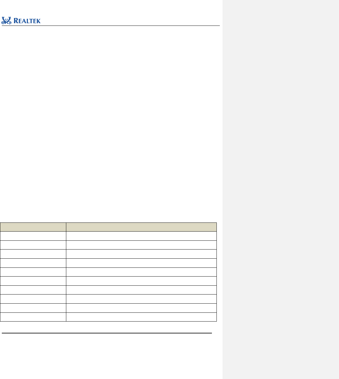
Realtek Confidential
RTL8762C Peripheral Manual
Copyright 2018 Realtek Semiconductor Corporation.
All Rights Reserved.
42
__O uint32_t StatusInt;
uint32_t RSVD191;
__IO uint32_t ReqSrcReg;
uint32_t RSVD20;
__IO uint32_t ReqDstReg;
uint32_t RSVD21;
__IO uint32_t SglReqSrcReg;
uint32_t RSVD22;
__IO uint32_t SglReqDstReg;
uint32_t RSVD23;
__IO uint32_t LstSrcReg;
uint32_t RSVD24;
__IO uint32_t LstDstReg;
uint32_t RSVD25;
__IO uint32_t DmaCfgReg;
uint32_t RSVD26;
__IO uint32_t ChEnReg;
uint32_t RSVD27;
__I uint32_t DmaIdReg;
uint32_t RSVD28;
__IO uint32_t DmaTestReg;
uint32_t RSVD29;
} GDMA_TypeDef;
All GDMA registers are enumerated in Table 4. 1.
Table 4. 1 GDMA Registers
Register
Description
RAW_TFR
Transfer completion interrupt status register before mask
RSVD0
Reserved
RAW_BLOCK
Block completion transfer interrupt status register before mask
RSVD1
Reserved
RAW_SRC_TRAN
Source end transfer completion interrupt status register before mask
RSVD2
Reserved
RAW_DST_TRAN
Destination end transfer completion interrupt status register before mask
RSVD3
Reserved
RAW_ERR
Transfer error interrupt status register before mask
RSVD4
Reserved

Realtek Confidential
RTL8762C Peripheral Manual
Copyright 2018 Realtek Semiconductor Corporation.
All Rights Reserved.
43
STATUS_TFR
Transfer completion interrupt status register
RSVD5
Reserved
STATUS_BLOCK
Block transfer completion interrupt status register
RSVD6
Reserved
STATUS_SRC_TRAN
Source end transfer completion interrupt status register
RSVD7
Reserved
STATUS_DST_TRAN
Destination end transfer completion interrupt status register
RSVD8
Reserved
STATUS_ERR
Transfer error interrupt status register
RSVD9
Reserved
MASK_TFR
Transfer completion interrupt status mask register
RSVD10
Reserved
MASK_BLOCK
Block transfer completion interrupt status mask register
RSVD11
Reserved
MASK_SRC_TRAN
Source end transfer completion interrupt status mask register
RSVD12
Reserved
MASK_DST_TRAN
Destination end transfer completion interrupt status mask register
RSVD13
Reserved
MASK_ERR
Transfer error interrupt status mask register
RSVD14
Reserved
CLEAR_TFR
Transfer completion interrupt status clear register
RSVD15
Reserved
CLEAR_BLOCK
Block transfer completion interrupt status clear register
RSVD16
Reserved
CLEAR_SRC_TRAN
Source end transfer completion interrupt status clear register
RSVD17
Reserved
CLEAR_DST_TRAN
Destination end transfer completion interrupt status clear register
RSVD18
Reserved
CLEAR_ERR
Transfer error interrupt status clear register
RSVD19
Reserved
StatusInt
All interrupt type status register
RSVD191
Reserved
ReqSrcReg
Source end transmission request register

Realtek Confidential
RTL8762C Peripheral Manual
Copyright 2018 Realtek Semiconductor Corporation.
All Rights Reserved.
44
RSVD20
Reserved
ReqDstReg
Destination end transmission request register
RSVD21
Reserved
SglReqSrcReg
Single source end transmission request register
RSVD22
Reserved
SglReqDstReg
Single destination end transmission request register
RSVD23
Reserved
LstSrcReg
Last source end transmission request register
RSVD24
Reserved
LstDstReg
Last destination end transmission request register
RSVD25
Reserved
DmaCfgReg
GDMA configuration register
RSVD26
Reserved
ChEnReg
Channel enable register
RSVD27
Reserved
DmaIdReg
GDMA ID register
RSVD28
Reserved
DmaTestReg
DMA test register
RSVD29
Reserved
typedef struct
{
__IO uint32_t SAR;
uint32_t RSVD0;
__IO uint32_t DAR;
uint32_t RSVD1;
__IO uint32_t LLP;
uint32_t RSVD2;
__IO uint32_t CTL_LOW;
__IO uint32_t CTL_HIGH;
__IO uint32_t SSTAT;
uint32_t RSVD4;
__IO uint32_t DSTAT;
uint32_t RSVD5;
__IO uint32_t SSTATAR;
uint32_t RSVD6;
__IO uint32_t DSTATAR;
uint32_t RSVD7;
__IO uint32_t CFG_LOW;

Realtek Confidential
RTL8762C Peripheral Manual
Copyright 2018 Realtek Semiconductor Corporation.
All Rights Reserved.
45
__IO uint32_t CFG_HIGH;
__IO uint32_t SGR;
uint32_t RSVD9;
__IO uint32_t DSR;
uint32_t RSVD10;
} GDMA_ChannelTypeDef;
All GDMA_Channel registers are enumerated in Table 4. 2.
Table 4. 2 GDMA_Channel Register
Register
Description
SAR
GDMA source address register
RSVD0
Reserved
DAR
GDMA destination address register
RSVD1
Reserved
LLP
GDMA linked list pointer register
RSVD2
Reserved
CTL_LOW
GDMA control register (L)
CTL_HIGH
GDMA control register (H)
SSTAT
GDMA source status register
RSVD4
Reserved
DSTAT
GDMA destination status register
RSVD5
Reserved
SSTATAR
GDMA source status address register
RSVD6
Reserved
DSTATAR
GDMA destination status address register
RSVD7
Reserved
CFG_LOW
GDMA configuration register (L)
CFG_ HIGH
GDMA configuration register (H)
SGR
GDMA channel Source Gather Register
RSVD9
Reserved
DSR
GDMA channel Destination Scatter Register
RSVD10
Reserved
4. 2 GDMA Library Functions
Table 4. 3 All GDMA library functions
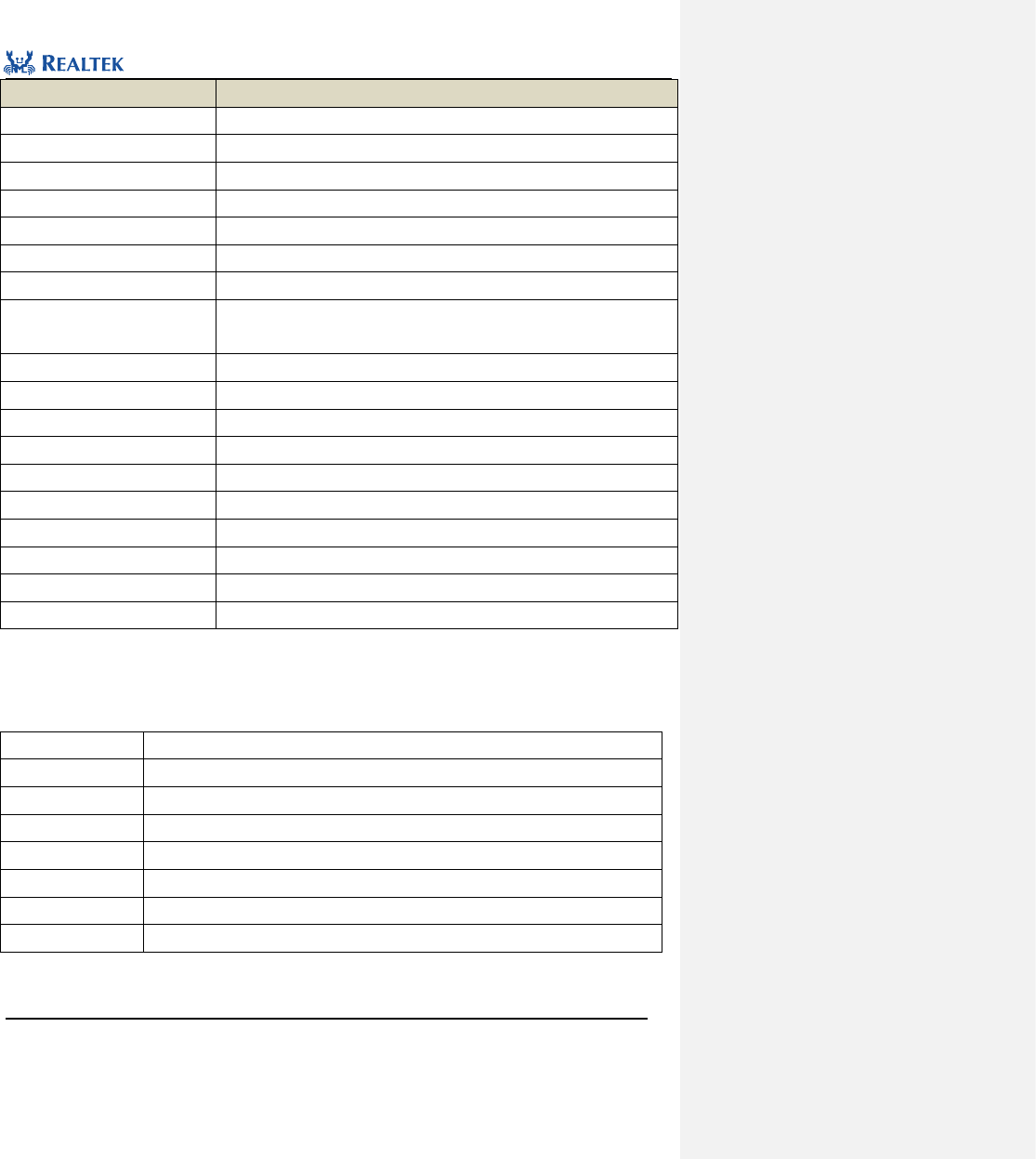
Realtek Confidential
RTL8762C Peripheral Manual
Copyright 2018 Realtek Semiconductor Corporation.
All Rights Reserved.
46
Function Name
Description
GDMA_DeInit
Disable GDMA clock source.
GDMA_Init
Initialize GDMA register based on parameters specified in GDMA_InitStruct.
GDMA_StructInit
Set each parameter in GDMA_InitStruct to the default value.
GDMA_Cmd
Enable or disable the specified GDMA channel.
GDMA_INTConfig
Enable or disable the specified GDMA channel interrupt.
GDMA_ClearINTPendingBit
Clear specified suspended interrupts.
GDMA_GetChannelStatus
Check whether the specified GDMA channel is in use.
GDMA_GetTransferINTStatus
Check total transfer completion interrupt status of the specified GDMA
channel.
GDMA_ClearAllTypeINT
Clear all GDMA interrupt statuses of specified channels.
GDMA_SetSourceAddress
Set source address of the specified GDMA channel.
GDMA_SetDestinationAddress
Set destination address of the specified GDMA channel.
GDMA_SetBufferSize
Set length of data to be transferred through specified GDMA channel.
GDMA_SuspendCmd
Suspend GDMA channel transmission
GDMA_GetFIFOStatus
Get GDMA channel FIFO status
GDMA_GetTransferLen
Get length of transmitted data
GDMA_SetLLPAddress
Setting the GDMA channel linked list pointer address
GDMA_GetSuspendChannelStatus
Get status of specified suppended channel
GDMA_GetSuspendCmdStatus
Get command status of specified suppended channel
4. 2. 1 Function GDMA_DeInit
Table 4. 4 Function GDMA_DeInit
Function Name
GDMA_DeInit
Function Prototype
void GDMA_DeInit(void)
Function Description
Disable GDMA clock source
Input Parameter
None
Output Parameter
None
Return Value
None
Prerequisite
None
Functions Called
RCC_PeriphClockCmd Function
Examples:
/* Close GDMA peripheral clock */
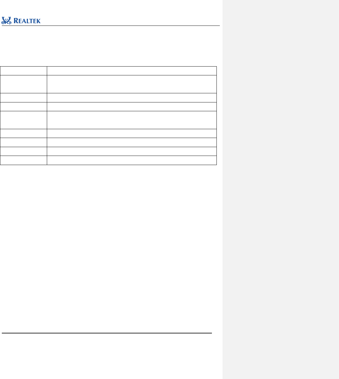
Realtek Confidential
RTL8762C Peripheral Manual
Copyright 2018 Realtek Semiconductor Corporation.
All Rights Reserved.
47
GDMA_DeInit();
4. 2. 2 Function GDMA_Init
Table 4. 5 Function GDMA_Init
Function Name
GDMA_Init
Function Prototype
void GDMA_Init(GDMA_ChannelTypeDef* GDMA_Channelx, GDMA_InitTypeDef*
GDMA_InitStruct)
Function Description
Initialize GDMA register based on parameters specified in GDMA_InitStruct
Input Parameter 1
GDMA_Channelx: select corresponding GDMA channel, ranging from 0 to 5.
Input Parameter 2
GDMA_InitStruct: A pointer to GDMA_InitTypeDef, and related configuration information
is contained in GDMA_InitStruct
Output Parameter
None
Return Value
None
Prerequisite
None
Functions Called
None
typedef struct
{
uint8_t GDMA_ChannelNum;
uint8_t GDMA_DIR;
uint32_t GDMA_BufferSize;
uint8_t GDMA_SourceInc;
uint8_t GDMA_DestinationInc;
uint32_t GDMA_SourceDataSize;
uint32_t GDMA_DestinationDataSize;
uint32_t GDMA_SourceMsize;
uint32_t GDMA_DestinationMsize;
uint32_t GDMA_SourceAddr;
uint32_t GDMA_DestinationAddr;
uint32_t GDMA_ChannelPriority;
uint32_t GDMA_Multi_Block_Struct;
uint8_t GDMA_Multi_Block_En;
uint8_t GDMA_Scatter_En;
uint8_t GDMA_Gather_En;
uint32_t GDMA_GatherCount;
uint32_t GDMA_GatherInterval;
uint32_t GDMA_ScatterCount;
uint32_t GDMA_ScatterInterval;
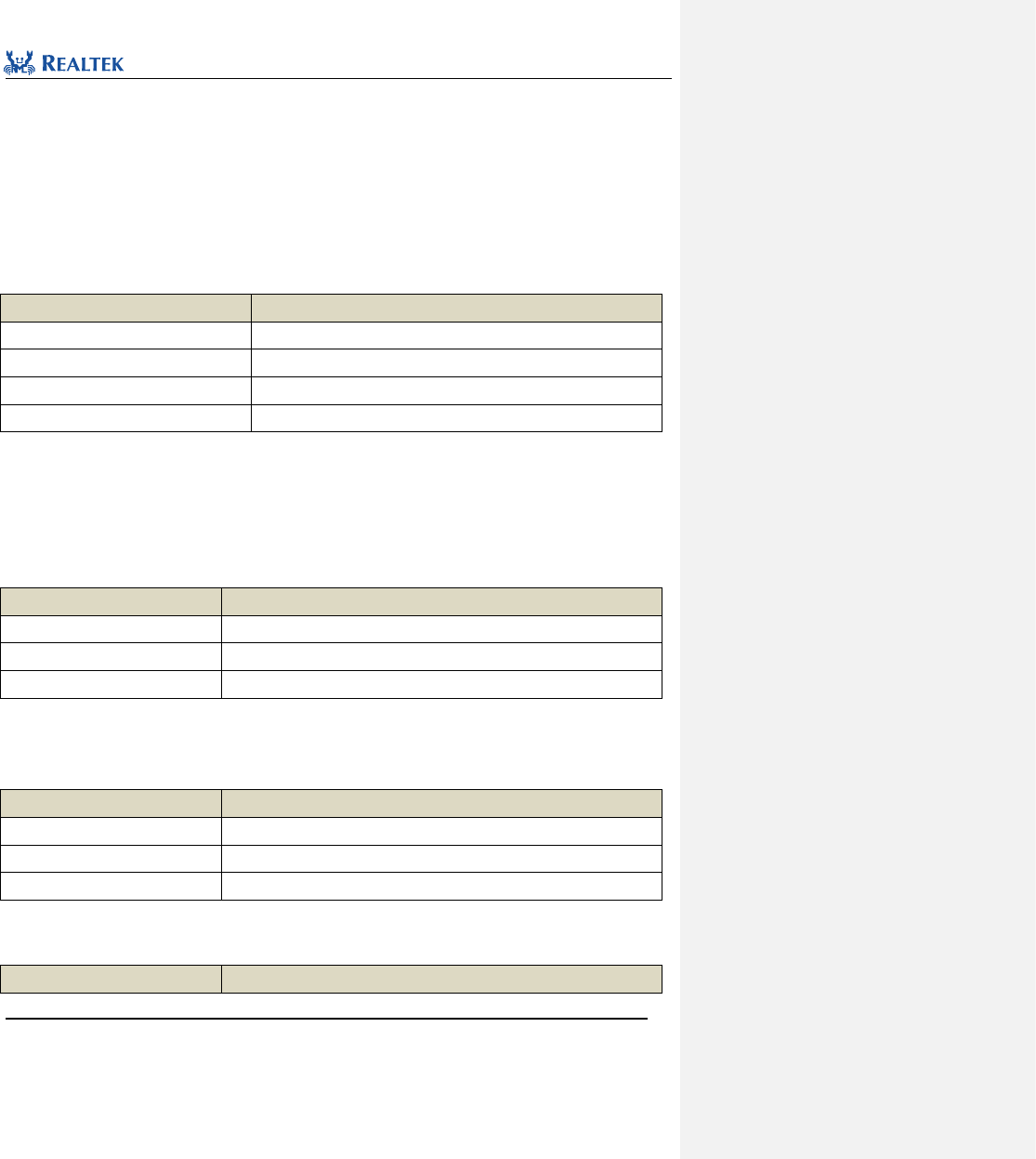
Realtek Confidential
RTL8762C Peripheral Manual
Copyright 2018 Realtek Semiconductor Corporation.
All Rights Reserved.
48
uint32_t GDMA_Multi_Block_Mode;
uint8_t GDMA_SourceHandshake;
uint8_t GDMA_DestHandshake;
}GDMA_InitTypeDef;
ChannelNum: Index of the specified GDMA peripheral carrying channel, ranging from 0 to 5.
GDMA_DIR: GDMA_DIR specifies whether the peripheral is used as the destination or source of data. Table 4. 6
lists the available values of this parameter.
Table 4. 6 Values of GDMA_DIR
GDMA_DIR
Description
GDMA_DIR_MemoryToMemory
Memory-to-memory transfer
GDMA_DIR_MemoryToPeripheral
Memory-to peripheral transfer
GDMA_DIR_PeripheralToMemory
Peripheral-to-memory transfer
GDMA_DIR_PeripheralToPeripheral
Peripheral-to-peripheral transfer
GDMA_BufferSize: Specify size of the data to be transferred in one GDMA transfer. The transmission is divided
into several GDMA burst transmission.
GDMA_SourceInc: Specify whether the source addresses to be oeprated by GDMA is ascending or descending.
Table 4. 7 lists the available values for this parameter.
Table 4. 7 Values of GDMA_SourceInc
GDMA_SourceInc
Description
DMA_SourceInc_Inc
Source address register is ascending
DMA_SourceInc_Dec
Source address register is descending
DMA_SourceInc_Fix
Source address register is fixed
GDMA_DestinationInc: Specify whether the destination addresses to be operated by GDMA is ascending or
descending. Table 4. 8 lists the available values for this parameter.
Table 4. 8 Values of GDMA_DestinationInc
GDMA_DestinationInc
Description
DMA_DestinationInc_Inc
Destination address register is ascending
DMA_DestinationInc_Dec
Destination address register is descending
DMA_DestinationInc_Fix
Destination address register is fixed
GDMA_SourceDataSize: Specify source data width. Table 4. 9 lists the available values for this parameter..
Table 4. 9 Values of GDMA_SourceDataSize
GDMA_SourceDataSize
Description
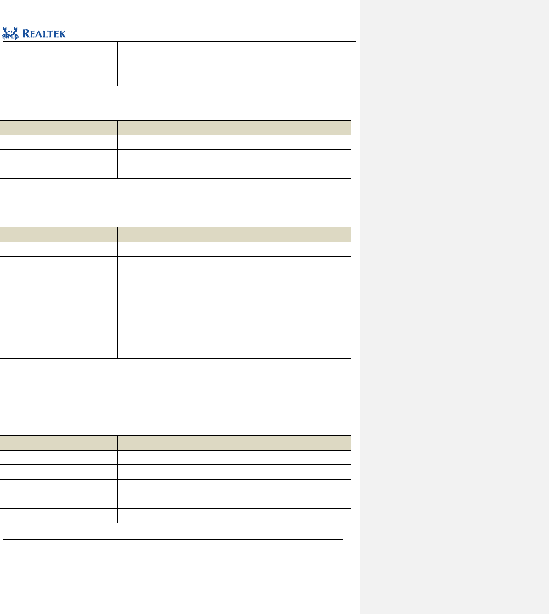
Realtek Confidential
RTL8762C Peripheral Manual
Copyright 2018 Realtek Semiconductor Corporation.
All Rights Reserved.
49
GDMA_DataSize_Byte
Data width of source address is 8 bits
GDMA_DataSize_HalfWord
Data width of source address is 16 bits
GDMA_DataSize_Word
Data width of source address is 32 bits
GDMA_DestinationDataSize: Specify source data width. Table 4. 10 lists the available values for this parameter.
Table 4. 10 Values of GDMA_DestinationDataSize
GDMA_DestinationDataSize
Description
GDMA_DataSize_Byte
Data width of destination address is 8 bits
GDMA_DataSize_HalfWord
Data width of destination address is 16 bits
GDMA_DataSize_Word
Data width of destination address is 32 bits
GDMA_SourceMsize: Specify length of the data at source end in each burst transmission. The minimum data
unit is set in parameter GDMA_SourceDataSize. Table 4. 11 lists the available values for this parameter.
Table 4. 11 Values of GDMA_SourceMsize
GDMA_ SourceMsize
Description
GDMA_Msize_1
Number of the data transferred in a single burst transfer is 1.
GDMA_Msize_4
Number of the data transferred in a single burst transfer is 4.
GDMA_Msize_8
Number of the data transferred in a single burst transfer is 8.
GDMA_Msize_16
Number of the data transferred in a single burst transfer is 16.
GDMA_Msize_32
Number of the data transferred in a single burst transfer is 32.
GDMA_Msize_64
Number of the data transferred in a single burst transfer is 64.
GDMA_Msize_128
Number of the data transferred in a single burst transfer is 128.
GDMA_Msize_256
Number of the data transferred in a single burst transfer is 256.
GDMA_DestinationMsize: Specify length of the data at destination in each burst transfer. The minimum data
unit in it is the data width as set in parameter GDMA_DestinationDataSize.Table 4. 12 lists the available values
for this parameter.
Table 4. 12 Values of GDMA_DestinationMsize
GDMA_DestinationMsize
Description
GDMA_Msize_1
Number of the data transferred in a single burst transfer is 1.
GDMA_Msize_4
Number of the data transferred in a single burst transfer is 4.
GDMA_Msize_8
Number of the data transferred in a single burst transfer is 8.
GDMA_Msize_16
Number of the data transferred in a single burst transfer is 16.
GDMA_Msize_32
Number of the data transferred in a single burst transfer is 32.
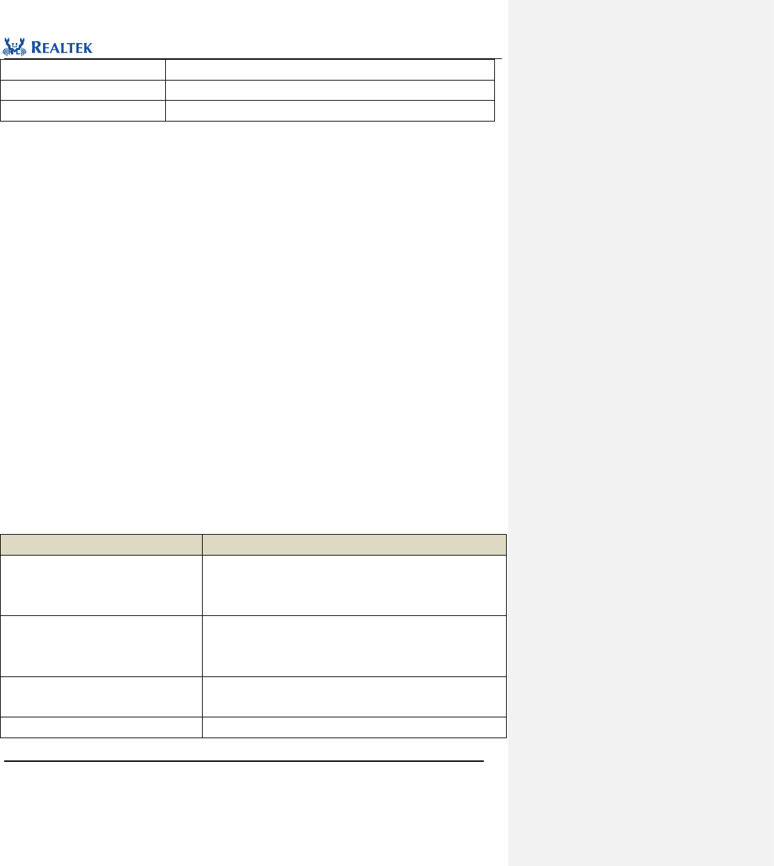
Realtek Confidential
RTL8762C Peripheral Manual
Copyright 2018 Realtek Semiconductor Corporation.
All Rights Reserved.
50
GDMA_Msize_64
Number of the data transferred in a single burst transfer is 64.
GDMA_Msize_128
Number of the data transferred in a single burst transfer is 128.
GDMA_Msize_256
Number of the data transferred in a single burst transfer is 256.
Note: Configuration of the parameters GDMA_SourceDataSize , GDMA_SourceMsize,
GDMA_DestinationDataSize, GDMA_DestinationMsize shall meet the following formula:
GDMA_SourceDataSize* GDMA_SourceMsize = GDMA_DestinationDataSize* GDMA_DestinationMsize.
GDMA_SourceAddr: Set source end address for GDMA transmission.
GDMA_DestinationAddr: Set destination end address for GDMA transmission.
GDMA_ChannelPriority: Specify software priority for GDMA channel transmission. This value ranges between
0~5, with 0 indicating the highest priority. Priority of channel 0 is fixed to highest priority 0 and channel 5 is fixed
at lowest priority 5.
GDMA_Multi_Block_Struct: Set the address of the LLI data type structure in Multi-block transmission.
GDMA_Multi_Block_En: Enable or disable multi-block transmission.
GDMA_Scatter_En: Enable or disable scatter transmission.
GDMA_Gather_En: Enable or disable gather transmission.
GDMA_GatherCount: Set the data length for GDMA to fetch data continuously in gather transmission.
GDMA_GatherInterval: Set the address interval length of GDMA in gather transmission.
GDMA_ScatterCount: Set the data length for GDMA to write data continuously in scatter transmission.
GDMA_ScatterInterval: Set the address interval length of GDMA in scatter transmission.
GDMA_Multi_Block_Mode: Configure the GDMA multi-block transmission type. After each block transmission, it
can be chosen to automatically load the initial value, load the corresponding value in the LLI structure or load the
current value of the corresponding register. Table 4. 13 lists the available values for this parameter.
Table 4. 13 value of GDMA_Multi_Block_Mode
GDMA_Multi_Block_Mode
Description
AUTO_RELOAD_WITH_CONTIGUOUS_SAR
The initial value of the source address and current value in
destination address register are automatically loaded after each
block transmission.
AUTO_RELOAD_WITH_CONTIGUOUS_DAR
The initial value of the destination address and current value in
source address register are automatically loaded after each block
transmission.
AUTO_RELOAD_TRANSFER
The initial value of the source address and destination address are
automatically loaded after each block transmission.
LLI_WITH_CONTIGUOUS_SAR
Current value of source address register and the destination

Realtek Confidential
RTL8762C Peripheral Manual
Copyright 2018 Realtek Semiconductor Corporation.
All Rights Reserved.
51
address value of the LLI structure are automatically loaded after
each block transmission.
LLI_WITH_AUTO_RELOAD_SAR
The initial value of the source address and the destination address
value of the LLI structure are automatically loaded after each block
transmission.
LLI_WITH_CONTIGUOUS_DAR
Current value of destination address register and the source
address value of the LLI structure are automatically loaded after
each block transmission.
LLI_WITH_AUTO_RELOAD_DAR
The initial value of the destination address and the source address
value of the LLI structure are automatically loaded after each block
transmission.
LLI_TRANSFER
The source address and destination address value of the LLI
structure are automatically loaded after each block transmission.
GDMA_SourceHandshake: Set the GDMA source address end handshake index value. Table 4. 14 lists the
available values for this parameter.
Table 4. 14 value of GDMA_SourceHandshake
GDMA_SourceHandshake
Description
GDMA_Handshake_UART0_RX
UART0 is used as the source address to receive data.
GDMA_Handshake_UART2_RX
UART2 is used as the source address to receive data.
GDMA_Handshake_SPI0_RX
SPI0 is used as the source address to receive data.
GDMA_Handshake_SPI1_RX
SPI1 is used as the source address to receive data.
GDMA_Handshake_I2C0_RX
I2C0 is used as the source address to receive data.
GDMA_Handshake_I2C1_RX
I2C1 is used as the source address to receive data.
GDMA_Handshake_ADC
ADC is used as the source address to receive data.
GDMA_Handshake_AES_RX
AES is used as the source address to receive data.
GDMA_Handshake_SPORT0_RX
I2S0 is used as the source address to receive data.
GDMA_Handshake_SPORT1_RX
I2S1 is used as the source address to receive data.
GDMA_Handshake_SPIC_RX
SPIC is used as the source address to receive data.
GDMA_Handshake_UART1_RX
UART is used as the source address to receive data.
GDMA_DestHandshake: Set the GDMA destination address end handshake index value. Table 4. 15 lists the
available values for this parameter.
Table 4. 15 value of GDMA_DestHandshake
GDMA_DestHandshake
Description
GDMA_Handshake_UART0_TX
UART0 is used as the destination address to send data.
Realtek Confidential
RTL8762C Peripheral Manual
Copyright 2018 Realtek Semiconductor Corporation.
All Rights Reserved.
52
GDMA_Handshake_UART2_TX
UART2 is used as the destination address to send data.
GDMA_Handshake_SPI0_TX
SPI0 is used as the destination address to send data.
GDMA_Handshake_SPI1_TX
SPI1 is used as the destination address to send data.
GDMA_Handshake_I2C0_TX
I2C0 is used as the destination address to send data.
GDMA_Handshake_I2C1_TX
I2C1 is used as the destination address to send data.
GDMA_Handshake_AES_TX
AES is used as the destination address to send data.
GDMA_Handshake_UART1_TX
UART1 is used as the destination address to send data.
GDMA_Handshake_SPORT0_TX
I2S0 is used as the destination address to send data.
GDMA_Handshake_SPORT1_TX
I2S1 is used as the destination address to send data.
GDMA_Handshake_SPDIF_TX
SPDIF is used as the destination address to send data.
GDMA_Handshake_LCD
LCD 8080 interface is used as the destination address to send data.
GDMA_Handshake_TIM0
TIM0 is used for GPIO to output data.
GDMA_Handshake_TIM1
TIM1 is used for GPIO to output data.
GDMA_Handshake_TIM2
TIM2 is used for GPIO to output data.
GDMA_Handshake_TIM3
TIM3 is used for GPIO to output data.
GDMA_Handshake_TIM4
TIM4 is used for GPIO to output data.
GDMA_Handshake_TIM5
TIM5 is used for GPIO to output data.
GDMA_Handshake_TIM6
TIM6 is used for GPIO to output data.
GDMA_Handshake_TIM7
TIM7 is used for GPIO to output data.
Examples:
/* Initialize GDMA */
GDMA_InitTypeDef GDMA_InitStruct;
GDMA_StructInit(&GDMA_InitStruct);
GDMA_InitStruct.GDMA_ChannelNum = AudioTrans_GDMA_Channel_NUM;
GDMA_InitStruct.GDMA_DIR = GDMA_DIR_MemoryToPeripheral;
GDMA_InitStruct.GDMA_BufferSize = 0;
GDMA_InitStruct.GDMA_SourceInc = DMA_SourceInc_Inc;
GDMA_InitStruct.GDMA_DestinationInc = DMA_DestinationInc_Fix;
GDMA_InitStruct.GDMA_SourceDataSize = GDMA_DataSize_Word;
GDMA_InitStruct.GDMA_DestinationDataSize = GDMA_DataSize_Word;
GDMA_InitStruct.GDMA_SourceMsize = GDMA_Msize_16;
GDMA_InitStruct.GDMA_DestinationMsize = GDMA_Msize_16;
GDMA_InitStruct.GDMA_SourceAddr = 0;
GDMA_InitStruct.GDMA_DestinationAddr = (uint32_t)(&(I2S_USR->TX_DR));
GDMA_InitStruct.GDMA_DestHandshake = GDMA_Handshake_I2S_USR_TX;
GDMA_Init(AudioTrans_GDMA_Channel, &GDMA_InitStruct);
批注 [张一凡1]: 需和中文手册一并确认
Realtek Confidential
RTL8762C Peripheral Manual
Copyright 2018 Realtek Semiconductor Corporation.
All Rights Reserved.
53
4. 2. 3 Function GDMA_StructInit
Table 4. 16 Function GDMA_StructInit
Function Name
GDMA_StructInit
Function Prototype
void GDMA_StructInit(GDMA_InitTypeDef* GDMA_InitStruct)
Function Description
Set each parameter in GDMA_InitStruct to the default value
Input Parameter
GDMA_InitStruct: A pointer points to structure GDMA_InitTypeDef, which contains
configuration information about peripheral GDMA.
Output Parameter
None
Return Value
None
Prerequisite
None
Functions Called
None
Examples:
/* Configure the GDMA Init Structure parameter */
GDMA_InitTypeDef GDMA _InitStruct;
GDMA _StructInit(&GDMA _InitStruct);
4. 2. 4 Function GDMA_Cmd
Table 4. 17 Function GDMA_Cmd
Function Name
GDMA_Cmd
Function Prototype
void GDMA_Cmd(uint8_t GDMA_ChannelNum, FunctionalState NewState)
Function Description
Enable or disable the specified GDMA channel.
Input Parameter 1
GDMA_ ChannelNum: index of GDMA channel, ranging from 0 to 5.
Input Parameter 2
newState: Enable or disable GDMA channel.
Output Parameter
None
Return Value
None
Prerequisite
None
Functions Called
None
Examples:
/* Enable specify GDMA channel */
GDMA_Cmd(1, ENABLE);
Realtek Confidential
RTL8762C Peripheral Manual
Copyright 2018 Realtek Semiconductor Corporation.
All Rights Reserved.
54
4. 2. 5 Function GDMA_INTConfig
Table 4. 18 Function GDMA_INTConfig
Function Name
GDMA_INTConfig
Function Prototype
void GDMA_INTConfig(uint8_t GDMA_ChannelNum, uint32_t GDMA_IT, FunctionalState
NewState)
Function Description
Enable or disable the specified GDMA channel interrupt
Input Parameter 1
GDMA_ ChannelNum: index of GDMA channel, ranging from 0 to 5.
Input Parameter 2
GDMA _IT: Specify enabled interrupt type, as shown in Table 4. 19.
Input Parameter 3
newState: Enable or disable the interrupt specified in Parameter 2.
Optional parameters: ENABLE, DISABLE
Output Parameter
None
Return Value
None
Prerequisite
None
Functions Called
None
GDMA _IT: Permitted GDMA interrupt types are as shown in Table 4. 19. Mutiple interrupts can be selected as
values of the parameter at one time by using operator "|".
Table 4. 19 Values of GDMA_IT
GDMA_IT
Description
GDMA_INT_Transfer
GDMA total transmission completion interrupt
GDMA_INT_Block
GDMA block transmission completion interrupt (same as GDMA total transmission
completion interrupt)
GDMA_INT_SrcTransfer
Source address end transmission completion interrupt
GDMA_INT_DstTransfer
Destination address end transmission completion interrupt
GDMA_INT_Error
transmission error interrupt
Examples:
/* Enable specify GDMA interrupt */
GDMA_ INTConfig (1, GDMA_INT_Transfer, ENABLE);
4. 2. 6 Function GDMA_ClearINTPendingBit
Table 4. 20 Function GDMA_ClearINTPendingBit
Function Name
GDMA_ClearINTPendingBit
Realtek Confidential
RTL8762C Peripheral Manual
Copyright 2018 Realtek Semiconductor Corporation.
All Rights Reserved.
55
Function Prototype
void GDMA_ClearINTPendingBit(uint8_t GDMA_ChannelNum, uint32_t GDMA_IT)
Function Description
Clear suspended interrupts of the specified type
Input Parameter 1
GDMA_ChannelNum: index of GDMA channel, ranging from 0 to 5
Input Parameter 2
GDMA _IT: Specify enabled interrupt type, as shown in Table 4. 20Table 4. 19.
Output Parameter
None
Return Value
None
Prerequisite
None
Functions Called
None
Examples:
/* Clear specify GDMA interrupt */
GDMA_ClearINTPendingBit (1, GDMA_INT_Transfer);
4. 2. 7 Function GDMA_GetChannelStatus
Table 4. 21 Function GDMA_GetChannelStatus
Function Name
GDMA_GetChannelStatus
Function Prototype
FlagStatus GDMA_GetChannelStatus(uint8_t GDMA_Channel_Num)
Function Description
Check whether the specified GDMA channel is in use.
Input Parameter 1
GDMA_ ChannelNum: index of GDMA channel, ranging from 0 to 5.
Output Parameter
None
Return Value
Status flag
Prerequisite
None
Functions Called
None
Examples:
/* Check GDMA channel status before use it */
BOOL useGDMAChannel = FALSE;
useGDMAChannel = GDMA_ GetChannelStatus (1);
4. 2. 8 Function GDMA_GetTransferINTStatus
Table 4. 22 Function GDMA_GetTransferINTStatus
Function Name
GDMA_GetTransferINTStatus
Function Prototype
ITStatus GDMA_GetTransferINTStatus(uint8_t GDMA_Channel_Num)
Function Description
Check total transfer completion interrupt status of the specified GDMA channel.
Input Parameter 1
GDMA_ ChannelNum: index of GDMA channel, ranging from 0 to 5.
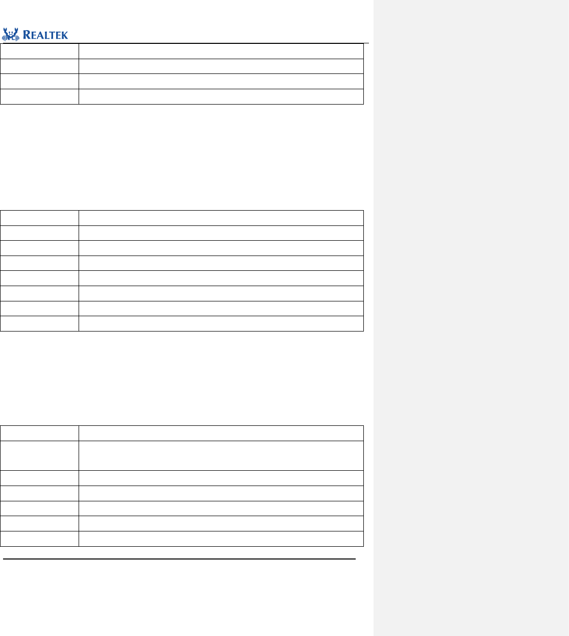
Realtek Confidential
RTL8762C Peripheral Manual
Copyright 2018 Realtek Semiconductor Corporation.
All Rights Reserved.
56
Output Parameter
None
Return Value
Status flag
Prerequisite
None
Functions Called
None
Examples:
/* Check GDMA transfer finish or not */
BOOL isTransfer= FALSE;
isTransfer = GDMA_GetTransferINTStatus (1);
4. 2. 9 Function GDMA_ClearAllTypeINT
Table 4. 23 Function GDMA_ClearAllTypeINT
Function Name
GDMA_ClearAllTypeINT
Function Prototype
void GDMA_ClearAllTypeINT(uint8_t GDMA_Channel_Num)
Function Description
Clear all GDMA interrupt statuses of the specified channel.
Input Parameter 1
GDMA_ ChannelNum: index of GDMA channel, ranging from 0 to 5.
Output Parameter
None
Return Value
None
Prerequisite
None
Functions Called
None
Examples:
/* Clear all interrupt */
GDMA_ ClearAllTypeINT(1);
4. 2. 10 Function GDMA_SetSourceAddress
Table 4. 24 Function GDMA_SetSourceAddress
Function Name
GDMA_SetSourceAddress
Function Prototype
void GDMA_SetSourceAddress(GDMA_ChannelTypeDef* GDMA_Channelx, uint32_t
Address)
Function Description
Set source address of the specified GDMA channel.
Input Parameter 1
GDMA_Channelx: Symbol of GDMA channel, in which x ranges from 0 to 5.
Input Parameter 2
Source address of the specified GDMA channel to be set.
Output Parameter
None
Return Value
None
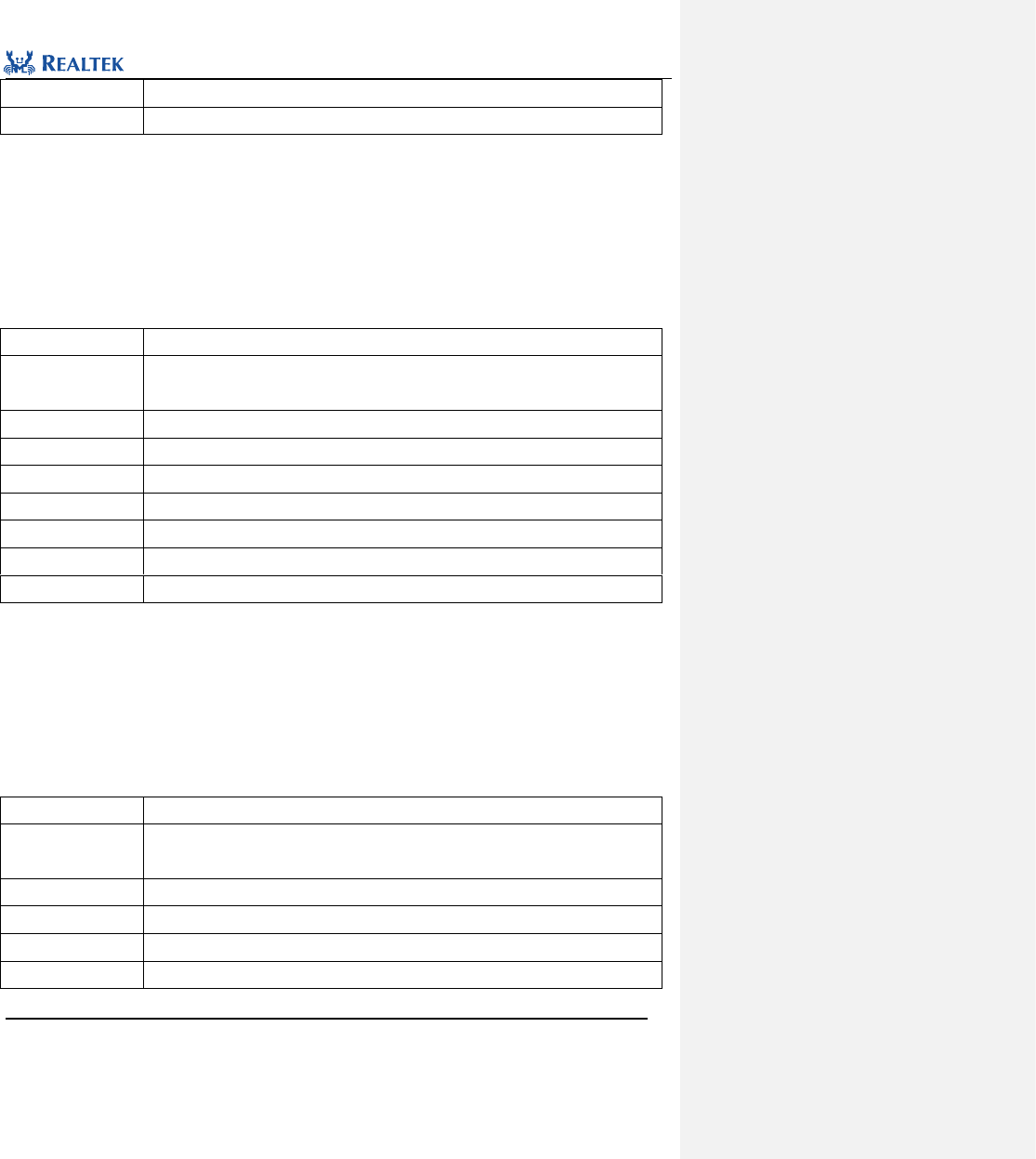
Realtek Confidential
RTL8762C Peripheral Manual
Copyright 2018 Realtek Semiconductor Corporation.
All Rights Reserved.
57
Prerequisite
None
Functions Called
None
Examples:
/* Configure source address */
uint8_t transferBuffer[256];
GDMA_SetSourceAddress(GDMA_Channel1, transferBuffer);
4. 2. 11 Function GDMA_SetDestinationAddress
Table 4. 25 Function GDMA_SetDestinationAddress
Function Name
GDMA_SetDestinationAddress
Function Prototype
void GDMA_SetDestinationAddress(GDMA_ChannelTypeDef* GDMA_Channelx, uint32_t
Address)
Function Description
Set destination address of the specified GDMA channel.
Input Parameter 1
GDMA_Channelx: Symbol of GDMA channel, in which x ranges from 0 to 5.
Input Parameter 2
Source address of the specified GDMA channel to be set.
Output Parameter
None
Return Value
None
Prerequisite
None
Functions Called
None
Examples:
/* Configure destination address */
uint8_t transferBuffer[256];
GDMA_ SetDestinationAddress(GDMA_Channel1, transferBuffer);
4. 2. 12 Function GDMA_SetBufferSize
Table 4. 26 Function GDMA_SetBufferSize
Function Name
GDMA_SetBufferSize
Function Prototype
void GDMA_SetBufferSize(GDMA_ChannelTypeDef* GDMA_Channelx, uint32_t
buffer_size)
Function Description
Set GDMA buffer size.
Input Parameter 1
GDMA_Channelx: Symbol of GDMA channel, in which x ranges from 0 to 5.
Input Parameter 2
Source address of the specified GDMA channel to be set.
Output Parameter
None
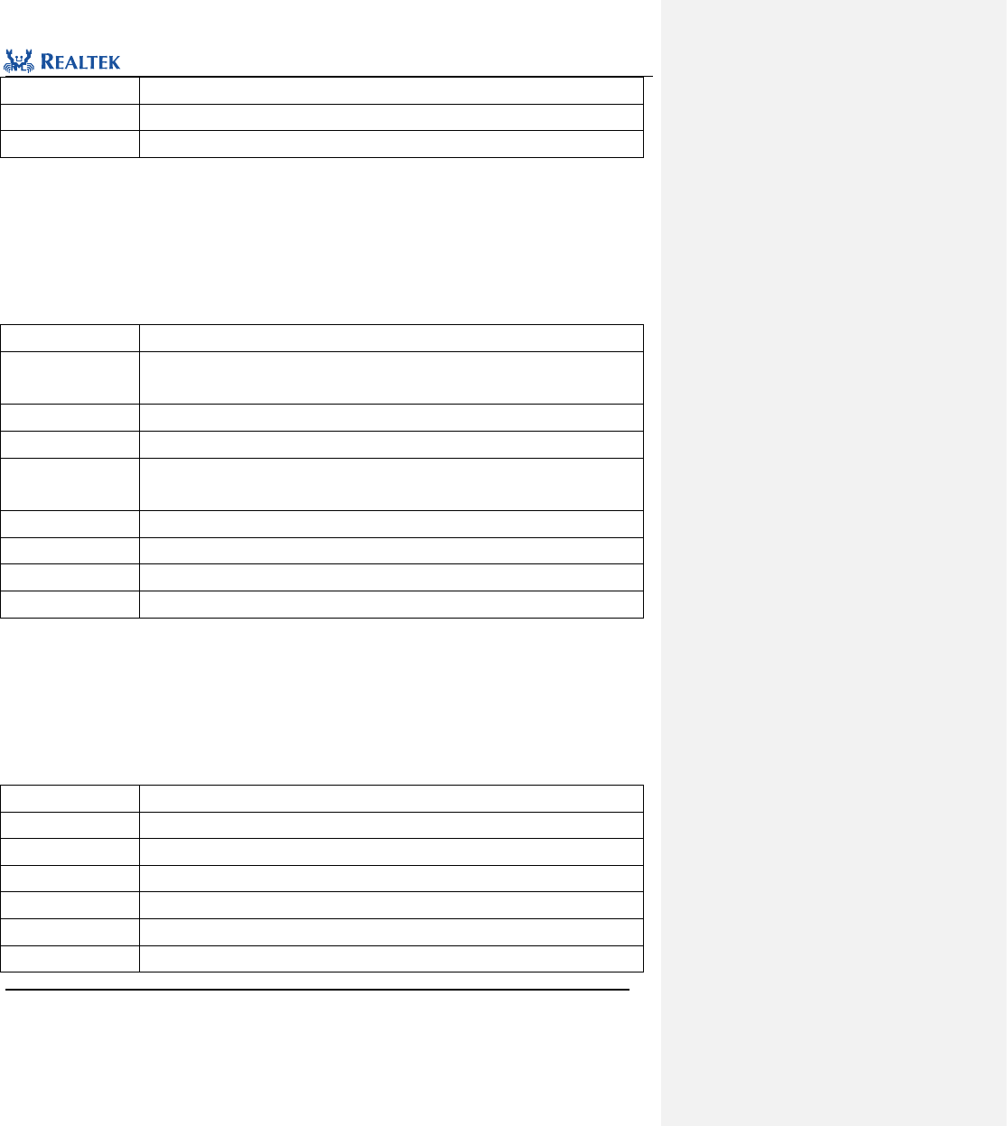
Realtek Confidential
RTL8762C Peripheral Manual
Copyright 2018 Realtek Semiconductor Corporation.
All Rights Reserved.
58
Return Value
None
Prerequisite
None
Functions Called
None
Examples:
/* Configure totoal number of transfer */
GDMA_ SetDestinationAddress (GDMA_Channel1, 256);
4. 2. 13 Function GDMA_SuspendCmd
Table 4. 27 Function GDMA_SuspendCmd
Function Name
GDMA_SuspendCmd
Function Prototype
void GDMA_SuspendCmd(GDMA_ChannelTypeDef *GDMA_Channelx,
FunctionalState NewState)
Function Description
Suspend GDMA transmission.
Input Parameter 1
GDMA_Channelx: Symbol of GDMA channel, in which x ranges from 0 to 5.
Input Parameter 2
newState: Enable or disable suspend GDMA transmission.
Available value: ENABLE, DISABLE
Output Parameter
None
Return Value
None
Prerequisite
None
Functions Called
None
Examples:
/* Abort GDMA channel transfer*/
GDMA_SuspendCmd(GDMA_Channel0, ENABLE);
4. 2. 14 Function GDMA_GetFIFOStatus
Table 4. 28 Function GDMA_GetFIFOStatus
Function Name
GDMA_GetFIFOStatus
Function Prototype
FlagStatus GDMA_GetFIFOStatus(GDMA_ChannelTypeDef *GDMA_Channelx)
Function Description
Get GDMA FIFO status.
Input Parameter
GDMA_Channelx: Symbol of GDMA channel, in which x ranges from 0 to 5.
Output Parameter
None
Return Value
Status flag: SET: empty, RESET: not empty.
Prerequisite
None
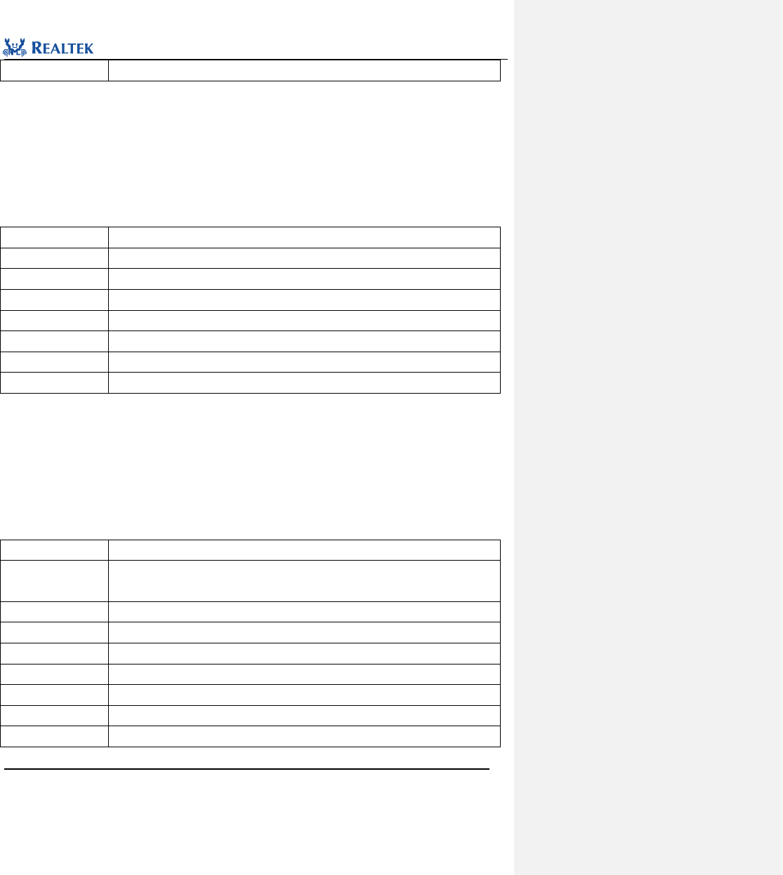
Realtek Confidential
RTL8762C Peripheral Manual
Copyright 2018 Realtek Semiconductor Corporation.
All Rights Reserved.
59
Functions Called
None
Examples:
/* Check GDMA channel FIFO status*/
BOOL GDMAChannelFIFOStatus= FALSE;
GDMAChannelFIFOStatus = GDMA_GetFIFOStatus (GDMA_Channel0);
4. 2. 15 Function GDMA_GetTransferLen
Table 4. 29 Function GDMA_GetTransferLen
Function Name
GDMA_GetTransferLen
Function Prototype
uint16_t GDMA_GetTransferLen (GDMA_ChannelTypeDef *GDMA_Channelx)
Function Description
Get the transmitted data length of the GDMA channel
Input Parameter
GDMA_Channelx: Symbol of GDMA channel, in which x ranges from 0 to 5.
Output Parameter
None
Return Value
The transmitted data length of the GDMA channel
Prerequisite
None
Functions Called
None
Examples:
/* Get GDMA channel transfer data lenth*/
uint16_t datalenth= 0;
datalenth = GDMA_ GetTransferLen (GDMA_Channel0);
4. 2. 16 Function GDMA_SetLLPAddress
Table 4. 30 Function GDMA_SetLLPAddress
Function Name
GDMA_SetLLPAddress
Function Prototype
void GDMA_SetLLPAddress(GDMA_ChannelTypeDef *GDMA_Channelx, uint32_t
Address)
Function Description
Setting the GDMA channel list pointer address.
Input Parameter 1
GDMA_Channelx: x can be set to 0 to 5 for number of DMA channels.
Input Parameter 2
Address: linked list pointer address
Output Parameter
None
Return Value
None
Prerequisite
None
Functions Called
None

Realtek Confidential
RTL8762C Peripheral Manual
Copyright 2018 Realtek Semiconductor Corporation.
All Rights Reserved.
60
Examples:
/* Set GDMA channel LLP address*/
GDMA_LLIDef GDMA_LLIStruct[16] ;
GDMA_ SetLLPAddress (GDMA_Channel0, GDMA_LLIStruct);
Realtek Confidential
RTL8762C Peripheral Manual
Copyright 2018 Realtek Semiconductor Corporation.
All Rights Reserved.
61
5 General-Purpose Input/Output (GPIO)
5. 1 GPIO Register Structure
typedef struct
{
__IO uint32_t DATAOUT;
__IO uint32_t DATADIR;
__IO uint32_t DATASRC;
uint32_t RSVD0[9];
__IO uint32_t INTEN;
__IO uint32_t INTMASK;
__IO uint32_t INTTYPE;
__IO uint32_t INTPOLARITY;
__IO uint32_t INTSTATUS;
__IO uint32_t RAWINTSTATUS;
__IO uint32_t DEBOUNCE;
__O uint32_t INTCLR;
__I uint32_t DATAIN;
uint32_t RSVD1[3];
__IO uint32_t LSSYNC;
__I uint32_t IDCODE;
__IO uint32_t INTBOTHEDGE;
} GPIO_TypeDef;
All GPIO registers are enumerated in Table 5. 1.
Table 5. 1 GPIO Registers
Register
Description
DATAOUT
Data output register
DATADIR
Data direction register
DATASRC
Data source register
RSVD0[9]
Reserved
INTEN
Interrupt control register
INTMASK
Interrupt mask register
INTTYPE
Interrupt type control register
INTPOLARITY
Interrupt polarity control register
INTSTATUS
Interrupt status register
Realtek Confidential
RTL8762C Peripheral Manual
Copyright 2018 Realtek Semiconductor Corporation.
All Rights Reserved.
62
RAWINTSTATUS
Raw interrupt status register (not masked by interrupt mask register)
DEBOUNCE
Debounce enable register
INTCLR
Interrupt clear register
DATAIN
External level input register
RSVD1[3]
Reserved
LSSYNC
Level-sensive synchronization enable register
IDCODE
ID register
INTBOTHEDGE
Bilateral edge triggered interrupt register
5. 2 GPIO Library Functions
All GPIO library functions are enumerated in Table 5. 2.
Table 5. 2 GPIO Library Functions
Function Name
Description
GPIO_DeInit
Disable GPIO clock source.
GPIO_GetPin
Acquire GPIO pin value.
GPIO_Init
Initialize GPIO register based on parameters specified in GPIO_InitStruct.
GPIO_StructInit
Set each parameter in GPIO_InitStruct to the default value.
GPIO_INTConfig
Enable or disable external GPIO interrupt.
GPIO_ClearINTPendingBit
Clear GPIO interrupt flag.
GPIO_MaskINTConfig
Mask or not mask external GPIO interrupt.
GPIO_ReadInputDataBit
Read input from specified pin.
GPIO_ReadInputData
Read input from all GPIO ports.
GPIO_ReadOutputDataBit
Read output from specified pin.
GPIO_ReadOutputData
Read output from all GPIO ports.
GPIO_SetBits
Set specified pin to high level.
GPIO_ResetBits
Set specified pin to low level.
GPIO_WriteBit
Set or clear voltage level of specified pin.
GPIO_Write
Set or clear voltage level of all GPIO ports.
GPIO_GetINTStatus
Read interrupt flag from specified GPIO pin.
GPIO_GetNum
Get the GPIO sequence number value corresponding to the pin
GPIO_Debounce_Time
Set GPIO debounce time
GPIO_DBClkCmd
Enable or disable GPIO Debounce Clock

Realtek Confidential
RTL8762C Peripheral Manual
Copyright 2018 Realtek Semiconductor Corporation.
All Rights Reserved.
63
5. 2. 1 Function GPIO_DeInit
Table 5. 3 Function GPIO_DeInit
Function Name
GPIO_DeInit
Function Prototype
void GPIO_DeInit(void)
Function Description
Disable GPIO clock source
Input Parameter
None
Output Parameter
None
Return Value
None
Prerequisite
None
Functions Called
RCC_PeriphClockCmd()
Examples:
/* Close GPIO clock */
GPIO_DeInit();
5. 2. 2 Function GPIO_GetPin
Table 5. 4 Function GPIO_ GetPin
Function Name
GPIO_GetPin
Function Prototype
uint32_t GPIO_GetPin(uint8_t Pin_num)
Function Description
Acquire value of the initialized parameter GPIO_Pin
Input Parameter
Pin_Num: External pin value, which can be set to: P0_0 to P3_6, P4_0 to P4_3 or H0 to
H2.
Output Parameter
None
Return Value
Value of the parameter GPIO_Pin
Prerequisite
None
Functions Called
None
Examples:
/* Get specified GPIO Pin value*/
uint32_t GPIO_UsePin = GPIO_GetPin(P0_2);
5. 2. 3 Function GPIO_Init
Table 5. 5 Function GPIO_Init
Function Name
GPIO_Init
Realtek Confidential
RTL8762C Peripheral Manual
Copyright 2018 Realtek Semiconductor Corporation.
All Rights Reserved.
64
Function Prototype
void GPIO_Init(GPIO_InitTypeDef* GPIO_InitStruct)
Function Description
Initialize GPIO register based on parameters specified in GPIO_InitStruct
Input Parameter
GPIO_InitStruct: A pointer points to structure GPIO_InitTypeDef, which contains
configuration information about peripheral GPIO.
Output Parameter
None
Return Value
None
Prerequisite
None
Functions Called
None
GPIO _InitTypeDef structure
typedef struct
{
uint32_t GPIO_Pin;
GPIOMode_TypeDef GPIO_Mode;
FunctionalState GPIO_ITCmd;
GPIOIT_LevelType GPIO_ITTrigger;
GPIOIT_PolarityType GPIO_ITPolarity;
GPIOIT_DebounceType GPIO_ITDebounce;
GPIOControlMode_Typedef GPIO_ControlMode;
uint32_t GPIO_DebounceTime;
}GPIO_InitTypeDef;
GPIO_Pin: This parameter is used to select GPIO pins. Multiple pins can be selected at one time by using
operator "|". This parameter can be acquired through function GPIO_GetPin. For more details refer to
description of function GPIO_GetPin.
GPIO_Mode: This parameter is used to set operation mode of selected pin. Table 5.6 lists available values.
Table 5. 6 Values of GPIO_Mode
GPIO_Mode
Description
GPIO_Mode_IN
Input mode
GPIO_Mode_OUT
Output mode
GPIO_Mode_AF
Standby function mode
GPIO_Mode_AN
Analog input/output mode
GPIO_ITCmd: This parameter is used to set operation mode of of selected pin. Table 5.6 lists available values.
Table 5. 7 Values of GPIO_ITCmd
GPIO_ITCmd
Description
DISABLE
Not configure GPIO interrupt mode
Realtek Confidential
RTL8762C Peripheral Manual
Copyright 2018 Realtek Semiconductor Corporation.
All Rights Reserved.
65
ENABLE
Configure GPIO interrupt mode
GPIO_ITTrigger: This parameter is used to set operation state of selected pin in interrupt mode. Table 5.6 lists
available values.
Table 5. 8 Values of GPIO_ITTrigger
GPIO_ITTrigger
Description
GPIO_INT_Trigger_LEVEL
Level trigger interrupt
GPIO_INT_Trigger_EDGE
Edge trigger interrupt
GPIO_ITPolarity: This parameter is used to set operation state of selected pin in interrupt mode. Table 5.6 lists
available values.
Table 5. 9 Values of GPIO_ITPolarity
GPIO_ITPolarity
Description
GPIO_INT_POLARITY_ACTIVE_LOW
Low level trigger or falling edge trigger
GPIO_INT_POLARITY_ACTIVE_HIGH
Edge trigger or rising edge trigger
GPIO_ITDebounce: This parameter is used to set operation state of selected pin in interrupt mode. Table 5.6
lists available values.
Table 5. 10 Values of GPIO_ITDebounce
GPIO_ITPolarity
Description
GPIO_INT_DEBOUNCE_DISABLE
Disable interrupt debouncing
GPIO_INT_DEBOUNCE_ENABLE
Enable interrupt debouncing
GPIO_ControlMode:This parameter is used to set up the GPIO mode of work. Table 5. 11 lists available values.
lists values available to this parameter.
Table 5. 11 lists values available to this parameter.
Table 5. 11 Value of GPIO_ControlMode
GPIO_ControlMode
Description
GPIO_SOFTWARE_MODE
Software mode, general operation.
GPIO_HARDWARE_MODE
Hardware mode for GDMA timing control GPIO pins
GPIO_DebounceTime:This parameter is used to set the GPIO debouncing time in millisecond. The parameter
ranges from 1 to 64.
Examples:
GPIO_InitTypeDef GPIO_InitStruct;
GPIO_StructInit(&GPIO_InitStruct);
Realtek Confidential
RTL8762C Peripheral Manual
Copyright 2018 Realtek Semiconductor Corporation.
All Rights Reserved.
66
GPIO_InitStruct.GPIO_Pin = GPIO_GetPin(P0_0);
GPIO_InitStruct.GPIO_Mode = GPIO_Mode_IN;
GPIO_InitStruct.GPIO_ITCmd = ENABLE;
GPIO_InitStruct.GPIO_ITTrigger = GPIO_INT_Trigger_EDGE;
GPIO_InitStruct.GPIO_ITPolarity = GPIO_INT_POLARITY_ACTIVE_LOW;
GPIO_InitStruct.GPIO_ITDebounce = GPIO_INT_DEBOUNCE_ENABLE;
GPIO_InitStruct.GPIO_DebounceTime = 30;
GPIO_Init(&GPIO_InitStruct);
5. 2. 4 Function GPIO_StructInit
Table 5. 12 Function GPIO_StructInit
Function Name
GPIO_StructInit
Function Prototype
void GPIO_StructInit(GPIO_InitTypeDef* GPIO_InitStruct)
Function Description
Set each parameter in GPIO_InitStruct to the default value
Input Parameter
GPIO_InitStruct: A pointer points to structure GPIO_InitTypeDef, which contains
configuration information about peripheral GPIO.
Output Parameter
None
Return Value
None
Prerequisite
None
Functions Called
None
Table 5. 13 Default Values of GPIO_InitStruct
Member
Default
GPIO_Pin
GPIO_Pin_All
GPIO_Mode
GPIO_Mode_IN
GPIO_ITCmd
DISABLE
GPIO_ITTrigger
GPIO_INT_Trigger_LEVEL
GPIO_ITPolarity
GPIO_INT_POLARITY_ACTIVE_LOW
GPIO_ITDebounce
GPIO_INT_DEBOUNCE_DISABLE
Examples:
/* Configure the GPIO Init Structure parameter */
GPIO_InitTypeDef GPIO_InitStruct;
GPIO_StructInit(&GPIO_InitStruct);
Realtek Confidential
RTL8762C Peripheral Manual
Copyright 2018 Realtek Semiconductor Corporation.
All Rights Reserved.
67
5. 2. 5 Function GPIO_INTConfig
Table 5. 14 Function GPIO_INTConfig
Function Name
GPIO_INTConfig
Function Prototype
void GPIO_INTConfig(uint32_t GPIO_Pin, FunctionalState NewState)
Function Description
Enable or disable external GPIO interrupt
Input Parameter 1
GPIO_Pin: Acquired through return value of function GPIO_GetPin.
Input Parameter 2
newState: new state of GPIO_Pin interrupt
Optional parameters: ENABLE, DISABLE
Output Parameter
None
Return Value
None
Prerequisite
None
Functions Called
None
Examples:
/* Enable P0_2 interrupt */
GPIO_INTConfig(GPIO_GetPin(P0_2), ENABLE);
Table 5.15 Pin and GPIO interrupt handler mapping
Pin_Num
GPIO interrupt handler function
P0_0
Gpio0IntrHandler
P0_1
Gpio1IntrHandler
P0_2
Gpio2IntrHandler
P0_3
Gpio3IntrHandler
P0_4
Gpio4IntrHandler
P0_5
Gpio5IntrHandler
P0_6
Gpio6IntrHandler
P0_7
Gpio7IntrHandler
P1_0
Gpio8IntrHandler
P1_1
Gpio9IntrHandler
P1_2
Gpio10IntrHandler
P1_3
Gpio11IntrHandler
P1_4
Gpio12IntrHandler
P1_5
Gpio13IntrHandler
P1_6
Gpio14IntrHandler
Realtek Confidential
RTL8762C Peripheral Manual
Copyright 2018 Realtek Semiconductor Corporation.
All Rights Reserved.
68
P1_7
Gpio15IntrHandler
P2_0
Gpio16IntrHandler
P2_1
Gpio17IntrHandler
P2_2
Gpio18IntrHandler
P2_3
Gpio19IntrHandler
P2_4
Gpio20IntrHandler
P2_5
Gpio21IntrHandler
P2_6
Gpio22IntrHandler
P2_7
Gpio23IntrHandler
P3_0
Gpio24IntrHandler
P3_1
Gpio25IntrHandler
P3_2
Gpio26IntrHandler
P3_3
Gpio27IntrHandler
P4_0
Gpio28IntrHandler
P4_1
Gpio29IntrHandler
P4_2
Gpio30IntrHandler
P4_3
Gpio31IntrHandler
5. 2. 6 Function GPIO_ClearINTPendingBit
Table 5. 15 Function GPIO_ClearINTPendingBit
Function Name
GPIO_ClearINTPendingBit
Function Prototype
void GPIO_ClearINTPendingBit(uint32_t GPIO_Pin)
Function Description
Clear interrupt flag of GPIO_Pin
Input Parameter 1
GPIO_Pin: Acquired through return value of function GPIO_GetPin.
Output Parameter
None
Return Value
None
Prerequisite
None
Functions Called
None
Examples:
/* Clear P0_2 interrupt */
GPIO_ClearINTPendingBit (GPIO_GetPin(P0_2));
Realtek Confidential
RTL8762C Peripheral Manual
Copyright 2018 Realtek Semiconductor Corporation.
All Rights Reserved.
69
5. 2. 7 Function GPIO_MaskINTConfig
Table 5. 17 Function GPIO_MaskINTConfig
Function Name
GPIO_MaskINTConfig
Function Prototype
void GPIO_MaskINTConfig(uint32_t GPIO_Pin, FunctionalState NewState)
Function Description
Mask or not mask external GPIO interrupt.
Input Parameter 1
GPIO_Pin: Acquired through return value of function GPIO_GetPin.
Input Parameter 2
newState: new state of GPIO_Pin
Optional parameters: ENABLE(mask), DISABLE(not mask)
Output Parameter
None
Return Value
None
Prerequisite
None
Functions Called
None
Examples:
/* mask P0_2 interrupt */
GPIO_MaskINTConfig (GPIO_GetPin(P0_2), ENABLE);
5. 2. 8 Function GPIO_ReadInputDataBit
Table 5. 18 Function GPIO__ReadInputDataBit
Function Name
GPIO_ReadInputDataBit
Function Prototype
uint8_t GPIO_ReadInputDataBit(uint32_t GPIO_Pin)
Function Description
Read input from specified pin.
Input Parameter
GPIO_Pin: acquired through return value of function GPIO_GetPin.
Output Parameter
None
Return Value
Input voltage level: 0 - low level; 1 - high level
Prerequisite
None
Functions Called
None
Examples:
/* Get specified GPIO Pin value */
uint8_t read_value = GPIO_ReadInputDataBit (GPIO_GetPin(P0_2));
5. 2. 9 Function GPIO_ ReadInputData
Table 5. 19 Function GPIO_ReadInputData
Realtek Confidential
RTL8762C Peripheral Manual
Copyright 2018 Realtek Semiconductor Corporation.
All Rights Reserved.
70
Function Name
GPIO_ReadInputData
Function Prototype
uint32_t GPIO_ReadInputData(void)
Function Description
Read input from all GPIO ports.
Input Parameter
None
Output Parameter
None
Return Value
All GPIO input voltage level.
Prerequisite
None
Functions Called
None
Examples:
/* Get all GPIO Pin value */
uint32_t read_value = GPIO_ReadInputData ();
5. 2. 10 Function GPIO_ReadOutputDataBit
Table 5. 20 Function GPIO_ ReadOutputDataBit
Function Name
GPIO_ReadOutputDataBit
Function Prototype
uint8_t GPIO_ReadOutputDataBit(uint32_t GPIO_Pin)
Function Description
Read output from specified pin.
Input Parameter
GPIO_Pin: Acquired through return value of function GPIO_GetPin.
Output Parameter
None
Return Value
GPIO input port value
Prerequisite
None
Functions Called
None
Examples:
/* Get specified GPIO Pin value */
uint8_t read_value = GPIO_ReadOutputDataBit (GPIO_GetPin(P0_2));
5. 2. 11 Function GPIO_ ReadOutputData
Table 5. 21 Function GPIO_ReadOutputData
Function Name
GPIO_ReadOutputData
Function Prototype
uint32_t GPIO_ReadOutputData (void)
Function Description
Read output from all GPIO ports
Input Parameter
None
Output Parameter
None
Realtek Confidential
RTL8762C Peripheral Manual
Copyright 2018 Realtek Semiconductor Corporation.
All Rights Reserved.
71
Return Value
All GPIO output pin voltage level
Prerequisite
None
Functions Called
None
Examples:
/* Get all GPIO Pin value */
uint32_t read_value = GPIO_ReadOutputData ();
5. 2. 12 Function GPIO_ SetBits
Table 5. 22 Function GPIO_ SetBits
Function Name
GPIO_SetBits
Function Prototype
void GPIO_SetBits (uint32_t GPIO_Pin)
Function Description
Set specified pin to high level.
Input Parameter
GPIO_Pin: Acquired through return value of function GPIO_GetPin.
Output Parameter
None
Return Value
None
Prerequisite
None
Functions Called
None
Examples:
/* Configure specified GPIO Pin output high level */
GPIO_SetBits (GPIO_GetPin(P0_2));
5. 2. 13 Function GPIO_ ResetBits
Table 5. 23 Function GPIO_ResetBits
Function Name
GPIO_ ResetBits
Function Prototype
void GPIO_ResetBits (uint32_t GPIO_Pin)
Function Description
Set specified pin to low level.
Input Parameter
GPIO_Pin: Acquired through return value of function GPIO_GetPin.
Output Parameter
None
Return Value
None
Prerequisite
None
Functions Called
None
Examples:
/* Configure specified GPIO Pin output low level */
Realtek Confidential
RTL8762C Peripheral Manual
Copyright 2018 Realtek Semiconductor Corporation.
All Rights Reserved.
72
GPIO_ ResetBits (GPIO_GetPin(P0_2));
5. 2. 14 Function GPIO_ WriteBit
Table 5. 24 Function GPIO_WriteBit
Function Name
GPIO_WriteBit
Function Prototype
void GPIO_WriteBit(uint32_t GPIO_Pin, BitAction BitVal)
Function Description
Set or clear voltage level of a specified pin.
Input Parameter 1
GPIO_Pin: acquired through return value of function GPIO_GetPin.
Input Parameter 2
BitVal: this parameter specifies the value to be written, and must be set to one of the
values enumerated in BitAction.
Bit_RESET: clear data port bit
Bit_SET: set data port bit
Output Parameter
None
Return Value
None
Prerequisite
None
Functions Called
None
Examples:
/*Set specified GPIO Pin */
GPIO_WriteBit (GPIO_GetPin(P0_2), Bit_SET);
5. 2. 15 Function GPIO_Write
Table 5. 25 Function GPIO_Write
Function Name
GPIO_Write
Function Prototype
void GPIO_Write(uint32_t PortVal)
Function Description
Set or clear voltage level of specified pin.
Input Parameter
PortVal: value to be written to port data register
Output Parameter
None
Return Value
None
Prerequisite
None
Functions Called
None
Examples:
/* Get all GPIO Pin value */
uint32_t read_value = GPIO_ReadOutputData ();
Realtek Confidential
RTL8762C Peripheral Manual
Copyright 2018 Realtek Semiconductor Corporation.
All Rights Reserved.
73
/* Configure GPIO_Pin_2 output high level */
GPIO_WriteBit (read_value | BIT(2));
5. 2. 16 Function GPIO_GetINTStatus
Table 5. 26 Function GPIO_GetINTStatus
Function Name
GPIO_GetINTStatus
Function Prototype
ITStatus GPIO_GetINTStatus(uint32_t GPIO_Pin)
Function Description
Check whether interrupt of specified pin occurs
Input Parameter
GPIO_Pin: Acquired through returned value of GPIO_GetPin.
Output Parameter
None
Return Value
Value of interrupt flag at the specified pin, which shall be one of the values enumerated
in ITStatus.
RESET: Interrupt does not occur.
SET: Interrupt occurs
Prerequisite
None
Functions Called
None
Examples:
/* Check if the specified pin interrupt has occurred or not */
ITStatus Status;
Status = GPIO_GetINTStatus (GPIO_GetPin(P0_2));
5. 2. 17 Function GPIO_GetNum
Table 5. 27 Function GPIO_GetNum
Function Name
GPIO_GetNum
Function Prototype
uint8_t GPIO_GetNum(uint8_t Pin_num)
Function Description
Get the GPIO sequence number value corresponding to the pin
Input Parameter
Pin_num: The external pin value can be selected from P0_0 to P3_6 or P4_0 to P4_3
or H_0 to H_2.
Output Parameter
None
Return Value
GPIO sequence number
Prerequisite
None
Functions Called
None
Examples:
Realtek Confidential
RTL8762C Peripheral Manual
Copyright 2018 Realtek Semiconductor Corporation.
All Rights Reserved.
74
/* Get specified GPIO Num value*/
uint8_t GPIO_Num = GPIO_GetNum(P0_2);
5. 2. 18 Function GPIO_Debounce_Time
Table 5. 28 Function GPIO_Debounce_Time
Function Name
GPIO_Debounce_Time
Function Prototype
void GPIO_Debounce_Time(uint32_t DebounceTime)
Function Description
Set GPIO debounce time
Input Parameter
DebounceTime:debounce time in millisecond. The value ranges from 1 to 64.
Output Parameter
None
Return Value
None
Prerequisite
None
Functions Called
None
Examples:
/* Set GPIO debounce value*/
GPIO_Debounce_Time(10);
5. 2. 19 Function GPIO_DBClkCmd
Table 5. 29 Function GPIO_DBClkCmd
Function Name
GPIO_DBClkCmd
Function Prototype
void GPIO_DBClkCmd(FunctionalState NewState)
Function Description
Enable or disable GPIO Debounce Clock
Input Parameter
NewState: Enable or GPIO Debounce Clock.
Optional parameters: ENABLE or DISABLE
Output Parameter
None
Return Value
None
Prerequisite
None
Functions Called
None
Examples:
/* EnableGPIO debounce clock*/
GPIO_DBClkCmd(ENABLE);

Realtek Confidential
RTL8762C Peripheral Manual
Copyright 2018 Realtek Semiconductor Corporation.
All Rights Reserved.
75
6 Inter-Integrated Circuit (I2C)
6. 1 I2C Register Architecture
typedef struct
{
__IO uint32_t IC_CON;
__IO uint32_t IC_TAR;
__IO uint32_t IC_SAR;
__IO uint32_t IC_HS_MADDR;
__IO uint32_t IC_DATA_CMD;
__IO uint32_t IC_SS_SCL_HCNT;
__IO uint32_t IC_SS_SCL_LCNT;
__IO uint32_t IC_FS_SCL_HCNT;
__IO uint32_t IC_FS_SCL_LCNT;
__IO uint32_t IC_HS_SCL_HCNT;
__IO uint32_t IC_HS_SCL_LCNT;
__I uint32_t IC_INTR_STAT;
__IO uint32_t IC_INTR_MASK;
__I uint32_t IC_RAW_INTR_STAT;
__IO uint32_t IC_RX_TL;
__IO uint32_t IC_TX_TL;
__I uint32_t IC_CLR_INTR;
__I uint32_t IC_CLR_RX_UNDER;
__I uint32_t IC_CLR_RX_OVER;
__I uint32_t IC_CLR_TX_OVER;
__I uint32_t IC_CLR_RD_REQ;
__I uint32_t IC_CLR_TX_ABRT;
__I uint32_t IC_CLR_RX_DONE;
__I uint32_t IC_CLR_ACTIVITY;
__I uint32_t IC_CLR_STOP_DET;
__I uint32_t IC_CLR_START_DET;
__I uint32_t IC_CLR_GEN_CALL;
__IO uint32_t IC_ENABLE;
__I uint32_t IC_STATUS;
__I uint32_t IC_TXFLR;
__I uint32_t IC_RXFLR;
__IO uint32_t IC_SDA_HOLD;
__I uint32_t IC_TX_ABRT_SOURCE;
__IO uint32_t IC_SLV_DATA_NACK_ONLY;
__IO uint32_t IC_DMA_CR;

Realtek Confidential
RTL8762C Peripheral Manual
Copyright 2018 Realtek Semiconductor Corporation.
All Rights Reserved.
76
__IO uint32_t IC_DMA_TDLR;
__IO uint32_t IC_DMA_RDLR;
__IO uint32_t IC_SDA_SETUP;
__IO uint32_t IC_ACK_GENERAL_CALL;
__IO uint32_t IC_ENABLE_STATUS;
} I2C_TypeDef;
All I2C registers are enumerated in Table 6. 1.
Table 6. 1 I2C Registers
Register
Description
IC_CON
I2C Control Register
IC_TAR
I2C Target Address Register
IC_SAR
I2C Slave Address Register
IC_HS_MADDR
I2C HS Master Mode Code Address
IC_DATA_CMD
I2C Rx/Tx Data Buffer and Command
IC_SS_SCL_HCNT
Standard speed I2C Clock SCL High Count
IC_SS_SCL_LCNT
Standard speed I2C Clock SCL Low Count
IC_FS_SCL_HCNT
Fast speed I2C Clock SCL High Count
IC_FS_SCL_LCNT
Fast speed I2C Clock SCL Low Count
IC_HS_SCL_HCNT
High speed I2C Clock SCL High Count
IC_HS_SCL_LCNT
High speed I2C Clock SCL Low Count
IC_INTR_STAT
I2C Interrupt Status Register
IC_INTR_MASK
I2C Interrupt Mask Register
IC_RAW_INTR_STAT
I2C Raw Interrupt Status(cannot be masked by IC_INTR_STAT)
IC_RX_TL
I2C Receive FIFO Threshold
IC_TX_TL
I2C Transmit FIFO Threshold
IC_CLR_INTR
Clear Combined and Individual Interrupts Register
IC_CLR_RX_UNDER
Clear RX_UNDER Interrupt
IC_CLR_RX_OVER
Clear RX_OVER Interrupt
IC_CLR_TX_OVER
Clear TX_OVER Interrupt
IC_CLR_RD_REQ
Clear RD_REQ Interrupt
IC_CLR_TX_ABRT
Clear TX_ABRT Interrupt
IC_CLR_RX_DONE
Clear RX_DONE Interrupt
IC_CLR_ACTIVITY
Clear ACTIVITY Interrupt
IC_CLR_STOP_DET
Clear STOP_DET Interrupt
Realtek Confidential
RTL8762C Peripheral Manual
Copyright 2018 Realtek Semiconductor Corporation.
All Rights Reserved.
77
IC_CLR_START_DET
Clear START_DET Interrupt
IC_CLR_GEN_CALL
Clear GEN_CALL Interrupt
IC_ENABLE
I2C Enable Register
IC_STATUS
I2C Status Register
IC_TXFLR
Transmit FIFO Level Register
IC_RXFLR
Receive FIFO Level Register
IC_SDA_HOLD
SDA hold duration register
IC_TX_ABRT_SOURCE
I2C Transmit Abort Status Register
IC_SLV_DATA_NACK_ONLY
Generate SLV_DATA_NACK Register
IC_DMA_CR
DMA Control Register for transmit and receive handshaking interface
IC_DMA_TDLR
DMA Transmit Data Level
IC_DMA_RDLR
DMA Receive Data Level
IC_SDA_SETUP
I2C SDA Setup Register
IC_ACK_GENERAL_CALL
I2C ACK General Call Register
IC_ENABLE_STATUS
I2C Enable Status Register
6. 2 I2C Library Functions
Table 6. 2All I2C library functions
Function Name
Description
I2C_DeInit
Disable I2C clock source.
I2C_Init
Initialize I2C module.
I2C_StructInit
Set each parameter in I2C_InitStruct to the default value.
I2C_Cmd
Enable or disable the specified I2C channel.
I2C_MasterWrite
Send data through I2C peripheral in master mode.
I2C_MasterRead
Read Data through I2C peripheral in master mode.
I2C_RepeatRead
Send and receive data consecutively through I2C peripheral in master mode.
I2C_INTConfig
Enable or disable I2C interrupt.
I2C_ClearINTPendingBit
Clear I2C interrupt suspend bit.
I2C_SetSlaveAddress
Set slave device address.
I2C_SendCmd
Send or read commands in master mode through I2C peripheral.
I2C_ReceiveData
Receive a datum through I2C peripheral.
I2C_GetRxFIFOLen
Get the length of received data in FIFO through I2C peripheral.
I2C_GetTxFIFOLen
Get the length of transmitted data in FIFO through I2C peripheral.
Realtek Confidential
RTL8762C Peripheral Manual
Copyright 2018 Realtek Semiconductor Corporation.
All Rights Reserved.
78
I2C_ClearAllINT
Clear all interrupts suspended by I2C.
I2C_GetFlagState
Get specified flag status.
I2C_CheckEvent
Check specified transmission failure event status.
I2C_GetINTStatus
Get specified I2C interrupt status.
I2C_GDMACmd
Enable or disable specified GDMA data transfer function.
6. 2. 1 Function I2C_DeInit
Table 6. 3 Function I2C_DeInit
Function Name
I2C_DeInit
Function Prototype
void I2C_DeInit(I2C_TypeDef* I2Cx)
Function Description
Disable specified I2C clock
Input Parameter 1
I2Cx: x can be set to 0 or 1 to select the specified I2C peripheral.
Output Parameter
None
Return Value
None
Prerequisite
None
Functions Called
RCC_PeriphClockCmd()
6. 2. 2 Function I2C_Init
Table 6. 4 Function I2C_Init
Function Name
I2C_Init
Function Prototype
void I2C_Init(I2C_TypeDef* I2Cx, I2C_InitTypeDef* I2C_InitStruct)
Function Description
Initialize I2C register based on parameters specified in I2C_InitStruct
Input Parameter 1
I2Cx: x can be set to 0 or 1 to select the specified I2C peripheral.
Input Parameter 2
I2C _InitStruct: A pointer to I2C_InitTypeDef, and related configuration information is
contained in I2C_InitStruct.
Output Parameter
None
Return Value
None
Prerequisite
None
Functions Called
None
typedef struct
{
uint32_t I2C_ClockSpeed;
Realtek Confidential
RTL8762C Peripheral Manual
Copyright 2018 Realtek Semiconductor Corporation.
All Rights Reserved.
79
uint16_t I2C_DeviveMode;
uint16_t I2C_AddressMode;
uint16_t I2C_SlaveAddress;
uint16_t I2C_Ack;
} I2C_InitTypeDef;
I2C_ClockSpeed: Set clock rate on I2C bus.
I2C_DeviveMode: Set current operation mode of I2C peripheral. Table 6. 5 lists values available to this
parameter.
Table 6. 5 Values of I2C_DeviveMode
I2C_DeviveMode
Description
I2C_DeviveMode_Master
Master device
I2C_DeviveMode_Slave
Slave device
I2C_AddressMode: Set current operation mode of I2C peripheral. Table 6. 6 lists values available to this
parameter.
Table 6. 6 Values of I2C_AddressMode
I2C_AddressMode
Description
I2C_AddressMode_7BIT
7-bit address pattern
I2C_AddressMode_10BIT
10-bit address pattern
I2C_SlaveAddress: Address of the specified I2C slave, which can be set to a 7-bit or 10-bit address.
I2C_Ack: Enable or disable response signal when receiving ‘General all’, which can be set to I2C_Ack_Enable or
I2C_Ack_Disable.
Examples:
/* Initialize I2C0 */
I2C_InitTypeDef I2C_InitStructure;
I2C_InitStructure.I2C_ClockSpeed = 100000;
I2C_InitStructure.I2C_DeviveMode = I2C_DeviveMode_Master;
I2C_InitStructure.I2C_AddressMode = I2C_AddressMode_7BIT;
I2C_InitStructure.I2C_SlaveAddress = 0x50;
I2C_InitStructure.I2C_Ack = I2C_Ack_Enable;
I2C_Init(I2C0, &I2C_InitStructure);
6. 2. 3 Function I2C_StructInit
Table 6. 7 Function I2C_StructInit
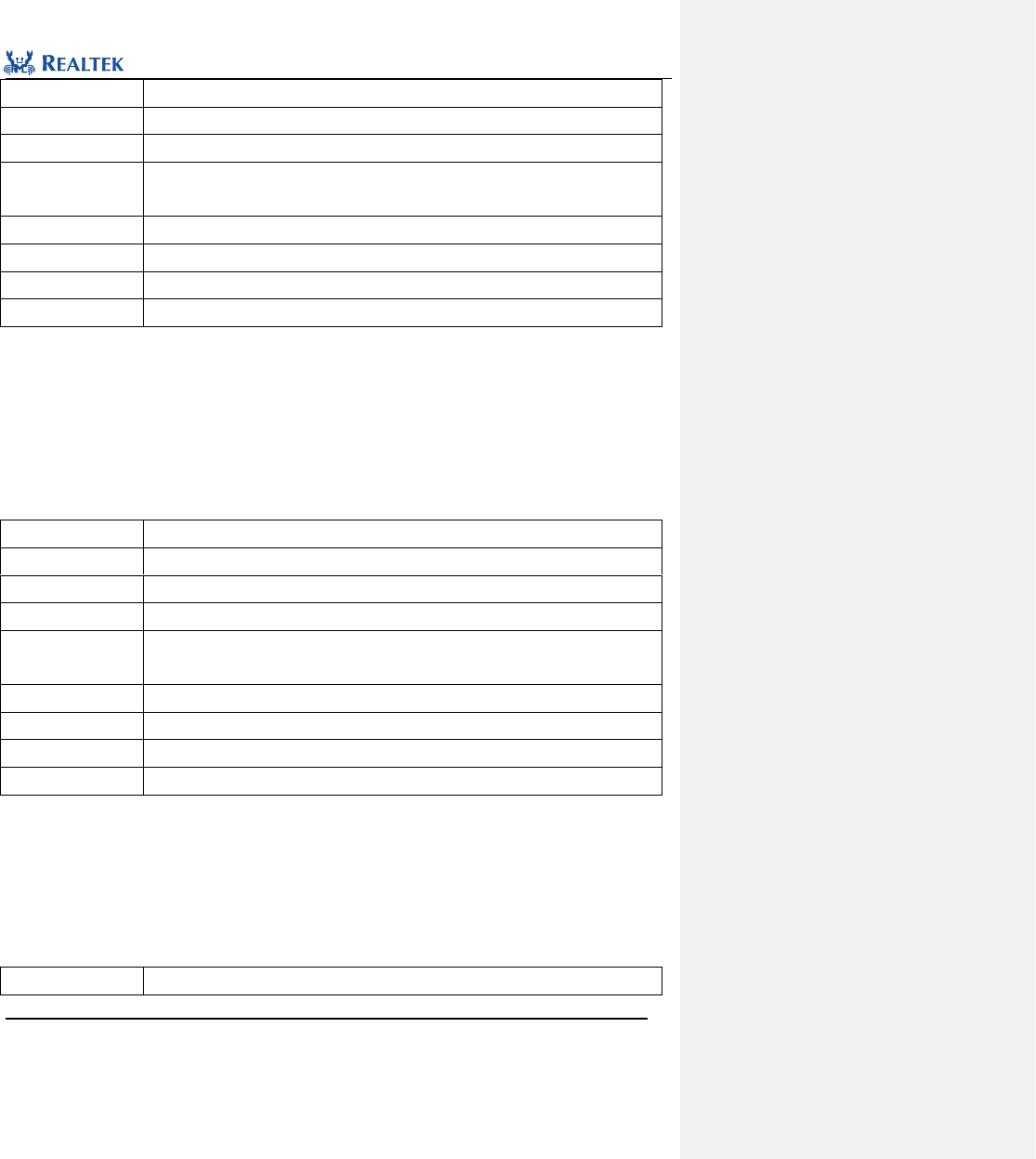
Realtek Confidential
RTL8762C Peripheral Manual
Copyright 2018 Realtek Semiconductor Corporation.
All Rights Reserved.
80
Function Name
I2C_StructInit
Function Prototype
void I2C_StructInit(I2C_InitTypeDef* I2C_InitStruct)
Function Description
Set each parameter in I2C_InitStruct to the default value
Input Parameter
I2C_InitStruct: A pointer points to structure I2C_InitTypeDef, which contains
configuration information about peripheral I2C.
Output Parameter
None
Return Value
None
Prerequisite
None
Functions Called
None
Examples:
/* Initialize I2C */
I2C_InitTypeDef I2C_InitStruct;
I2C_StructInit(&I2C_InitStruct);
6. 2. 4 Function I2C_Cmd
Table 6. 8 Function I2C_Cmd
Function Name
I2C_Cmd
Function Prototype
void I2C_Cmd(I2C_TypeDef* I2Cx, FunctionalState NewState)
Function Description
Enable or disable the specified I2C channel.
Input Parameter 1
I2Cx: x can be set to 0 or 1 to select the specified I2C peripheral.
Input Parameter 2
NewState: new state of I2Cx peripheral
This parameter can be set to: ENABLE, DISABLE
Output Parameter
None
Return Value
None
Prerequisite
None
Functions Called
None
Examples:
/* Enable I2C0 */
I2C_Cmd (I2C0, ENABLE);
6. 2. 5 Function I2C_MasterWrite
Table 6. 9 Function I2C_MasterWrite
Function Name
I2C_MasterWrite

Realtek Confidential
RTL8762C Peripheral Manual
Copyright 2018 Realtek Semiconductor Corporation.
All Rights Reserved.
81
Function Prototype
void I2C_MasterWrite(I2C_TypeDef* I2Cx, uint8_t* pBuf, uint8_t len)
Function Description
Send data through I2C peripheral in master mode.
Input Parameter 1
I2Cx: x can be set to 0 or 1 to select the specified I2C peripheral.
Input Parameter 2
pBuf: A pointer to the data to be sent
Input Parameter 3
len: Length of the data to be sent
Output Parameter
None
Return Value
None
Prerequisite
None
Functions Called
None
Examples:
/* Send data */
uint8_t writeBuf[16] = {0x00,0x01,0x02,0x03};
I2C_MasterWrite (I2C0, writeBuf, 4);
6. 2. 6 Function I2C_MasterRead
Table 6. 10 Function I2C_MasterRead
Function Name
I2C_MasterRead
Function Prototype
void I2C_MasterRead(I2C_TypeDef* I2Cx, uint8_t* pBuf, uint8_t len)
Function Description
Read Data through I2C peripheral in master mode.
Input Parameter 1
I2Cx: x can be set to 0 or 1 to select the specified I2C peripheral.
Input Parameter 2
pBuf: A pointer to the data to be received
Input Parameter 3
len: Length of the received data
Output Parameter
None
Return Value
None
Prerequisite
None
Functions Called
None
Examples:
/* Receive data */
uint8_t receiveBuf[16] = {0};
I2C_ MasterRead (I2C0, receiveBuf, 4);
6. 2. 7 Function I2C_RepeatRead
Table 6. 11 Function I2C_RepeatRead
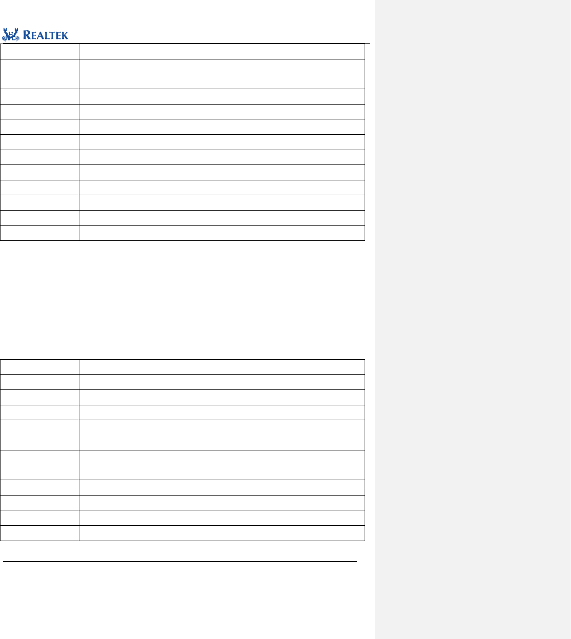
Realtek Confidential
RTL8762C Peripheral Manual
Copyright 2018 Realtek Semiconductor Corporation.
All Rights Reserved.
82
Function Name
I2C_RepeatRead
Function Prototype
uint8_t I2C_RepeatRead(I2C_TypeDef* I2Cx, uint8_t* pWriteBuf, uint8_t Writelen,
uint8_t* pReadBuf, uint8_t Readlen)
Function Description
Send and receive data consecutively through I2C peripheral in master mode.
Input Parameter 1
I2Cx: x can be set to 0 or 1 to select the specified I2C peripheral.
Input Parameter 2
pWriteBuf: A pointer to the data to be sent
Input Parameter 3
Writelen: Length of the sent data
Input Parameter 4
pReadBuf: A pointer to the data to be received
Input Parameter5
Readlen: Length of the received data
Output Parameter
None
Return Value
None
Prerequisite
None
Functions Called
None
Examples:
/* Repeat read data */
uint8_t I2C_WriteBuf[2] = {0x00,0x01};
uint8_t I2C_ReadBuf[4] = {0, 0 , 0, 0};
I2C_RepeatRead(I2C0, I2C_WriteBuf, 2, I2C_ReadBuf, 4);
6. 2. 8 Function I2C_INTConfig
Table 6. 12 Function I2C_INTConfig
Function Name
I2C_INTConfig
Function Prototype
void I2C_INTConfig(I2C_TypeDef* I2Cx, uint16_t I2C_IT, FunctionalState NewState)
Function Description
Enable or disable I2C interrupt
Input Parameter 1
I2Cx: x can be set to 0 or 1 to select the specified I2C peripheral
Input Parameter 2
I2C_IT: Enable or disable I2C interrupt source. Refer to description of I2C_IT for more
details.
Input Parameter 3
NewState: new state of I2C interrupt
This parameter can be set to ENABLE or DISABLE.
Output Parameter
None
Return Value
None
Prerequisite
None
Functions Called
None
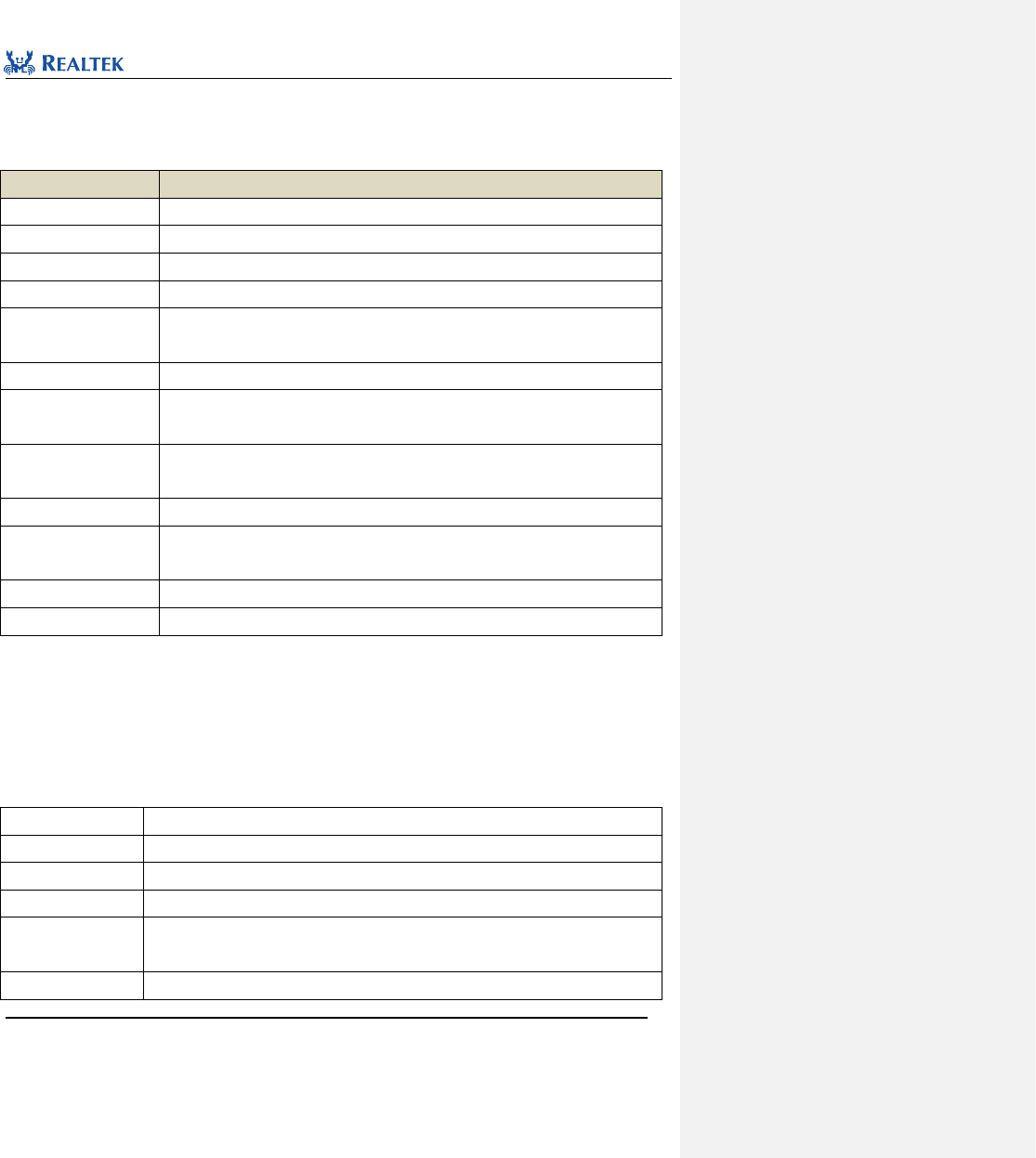
Realtek Confidential
RTL8762C Peripheral Manual
Copyright 2018 Realtek Semiconductor Corporation.
All Rights Reserved.
83
I2C_IT: Permitted I2C interrupt types are listed in Table 6. 13. Multiple interrupts can be selected at one time by
using operator "|".
Table 6. 13 Values of I2C_IT
I2C_IT
Description
I2C_INT_GEN_CALL
This interrupt is raised when a common address call is received and is responded.
I2C_INT_START_DET
This interrupt is raised when start or restart signal is detected.
I2C_INT_STOP_DET
This interrupt is raised when stop signal is detected.
I2C_INT_ACTIVITY
This interrupt is raised when bus is detected to be in communication.
I2C_INT_RX_DONE
This interrupt is raised when device is detected to have finished sending data in slave
mode.
I2C_INT_TX_ABRT
This interrupt is raised when bus communication exception is detected.
I2C_INT_RD_REQ
This interrupt is raised when device is in slave mode and master device is detected to
send a request to read data.
I2C_INT_TX_EMPTY
This interrupt is raised when number of data in transmit buffer is smaller than the
threshold.
I2C_INT_TX_OVER
This interrupt is raised when overflow of transmit buffer is detected.
I2C_INT_RX_FULL
This interrupt is raised when number of data in receive buffer is larger than the
threshold value as set.
I2C_INT_RX_OVER
This interrupt is raised when overflow of receive buffer is detected.
I2C_INT_RX_UNDER
This interrupt is raised when reading empty receive buffer.
Examples:
/* Detect stop signal */
I2C_INTConfig(I2C0, I2C_INT_STOP_DET, ENABLE);
6. 2. 9 Function I2C_ClearINTPendingBit
Table 6. 14 Function I2C_ClearINTPendingBit
Function Name
I2C_ClearINTPendingBit
Function Prototype
void I2C_ClearINTPendingBit(I2C_TypeDef* I2Cx, uint16_t I2C_IT)
Function Description
Clear suspended I2C interrupt bit.
Input Parameter 1
I2Cx: x can be set to 0 or 1 to select the specified I2C peripheral.
Input Parameter 2
I2C_IT: Interrupt source of the I2C peripheral to be checked. Refer to related description
of I2C_IT in 6. 2. 7 for more details.
Output Parameter
None
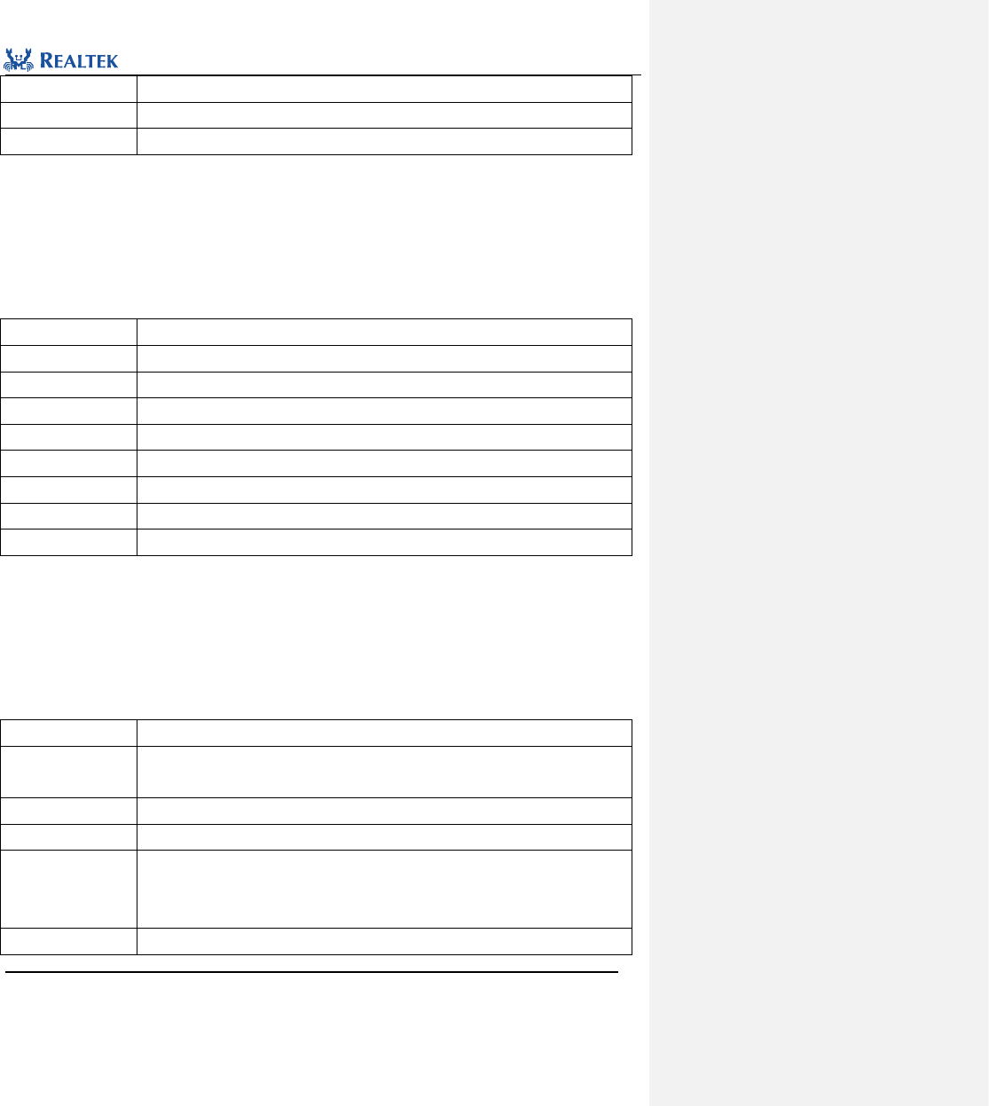
Realtek Confidential
RTL8762C Peripheral Manual
Copyright 2018 Realtek Semiconductor Corporation.
All Rights Reserved.
84
Return Value
None
Prerequisite
None
Functions Called
None
Examples:
/* Clear stop signal interrupt */
I2C_ClearINTPendingBit(I2C0, I2C_INT_STOP_DET);
6. 2. 10 Function I2C_SetSlaveAddress
Table 6. 15 Function I2C_SetSlaveAddress
Function Name
I2C_SetSlaveAddress
Function Prototype
void I2C_SetSlaveAddress(I2C_TypeDef* I2Cx, uint16_t Address)
Function Description
Set target slave device address.
Input Parameter 1
I2Cx: x can be set to 0 or 1 to select the specified I2C peripheral.
Input Parameter 2
Address: Slave device address
Output Parameter
None
Return Value
None
Prerequisite
None
Functions Called
None
Examples:
/* Configure new slave address which the communication is require */
I2C_SetSlaveAddress (I2C0, 0x66);
6. 2. 11 Function I2C_SendCmd
Table 6. 16 Function I2C_SendCmd
Function Name
I2C_SendCmd
Function Prototype
void I2C_SendCmd(I2C_TypeDef *I2Cx, uint16_t command, uint8_t data,
uint16_t StopState)
Function Description
Send or read commands in master mode through I2C peripheral.
Input Parameter 1
I2Cx: x can be set to 0 or 1 to select the specified I2C peripheral.
Input Parameter 2
command:command type. The parameter can be obtained as follows:
I2C_READ_CMD: Data read command
I2C_WRITE_CMD: Data write command
Input Parameter 3
data: data to be sent
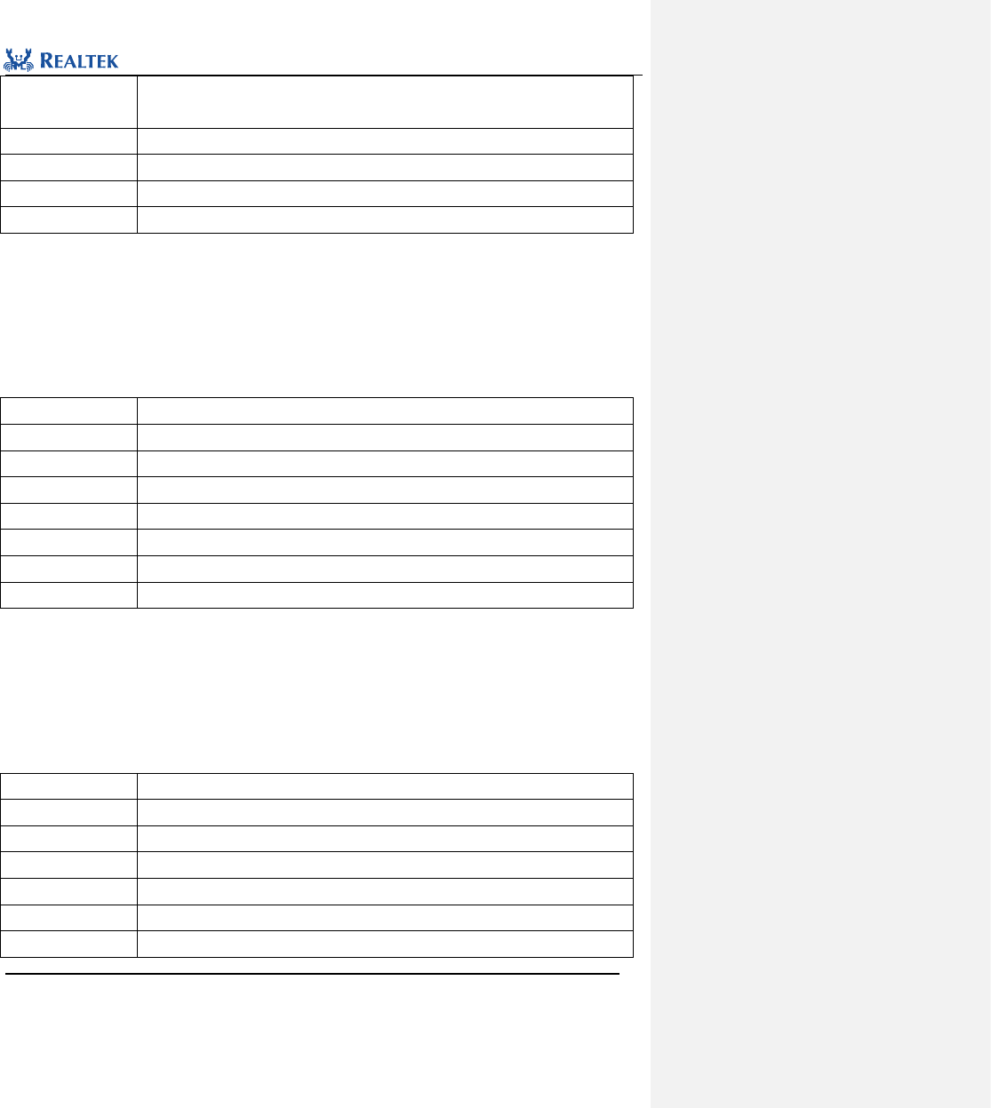
Realtek Confidential
RTL8762C Peripheral Manual
Copyright 2018 Realtek Semiconductor Corporation.
All Rights Reserved.
85
Input Parameter 4
StopState: to generate stop signal or not.
Optional parameters: ENABLE, DISABLE
Output Parameter
None
Return Value
None
Prerequisite
None
Functions Called
None
Examples:
/* Send one byte and generate a stop signal */
I2C_SendCmd (I2C0, I2C_WRITE_CMD, 0x66, ENABLE);
6. 2. 12 Function I2C_ReceiveData
Table 6. 17 Function I2C_ReceiveData
Function Name
I2C_ReceiveData
Function Prototype
uint8_t I2C_ReceiveData(I2C_TypeDef* I2Cx)
Function Description
Receive a datum through I2C peripheral.
Input Parameter 1
I2Cx: x can be set to 0 or 1 to select the specified I2C peripheral.
Output Parameter
None
Return Value
Receive data from I2C bus as slave device.
Prerequisite
None
Functions Called
None
Examples:
/* Receive one byte */
uint8_t data = I2C_ReceiveData (I2C0);
6. 2. 13 Function I2C_GetRxFIFOLen
Table 6. 18 Function I2C_GetRxFIFOLen
Function Name
I2C_GetRxFIFOLen
Function Prototype
uint8_t I2C_GetRxFIFOLen(I2C_TypeDef *I2Cx)
Function Description
Read the data length of receive FIFO
Input Parameter 1
I2Cx: x can be set to 0 or 1 to select the specified I2C peripheral.
Output Parameter
None
Return Value
data length of receive FIFO
Prerequisite
None
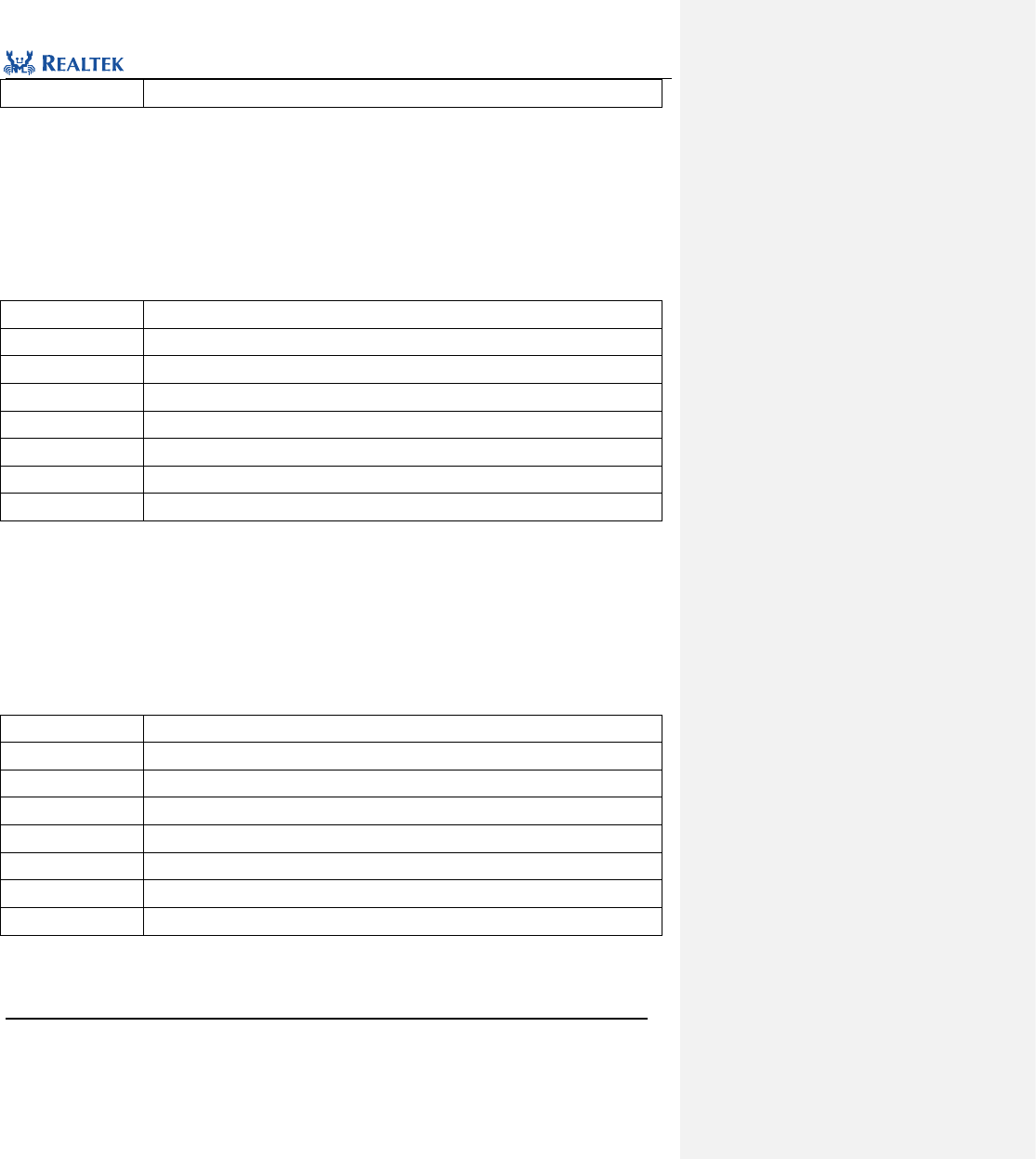
Realtek Confidential
RTL8762C Peripheral Manual
Copyright 2018 Realtek Semiconductor Corporation.
All Rights Reserved.
86
Functions Called
None
Examples:
/* Get data number in RX FIFO */
uint8_t number = 0;
number = I2C_ GetRxFIFOLen (I2C0);
6. 2. 14 Function I2C_GetTxFIFOLen
Table 6. 19 Function I2C_GetTxFIFOLen
Function Name
I2C_GetTxFIFOLen
Function Prototype
uint8_t I2C_GetTxFIFOLen(I2C_TypeDef *I2Cx)
Function Description
Read the data length of transmit FIFO
Input Parameter 1
I2Cx: x can be set to 0 or 1 to select the specified I2C peripheral.
Output Parameter
None
Return Value
data length of transmit FIFO
Prerequisite
None
Functions Called
None
Examples:
/* Get data number inTX FIFO */
uint8_t number = 0;
number = I2C_ GetTxFIFOLen (I2C0);
6. 2. 15 Function I2C_ClearAllINT
Table 6. 20 Function I2C_ClearAllINT
Function Name
I2C_ClearAllINT
Function Prototype
void I2C_ClearAllINT(I2C_TypeDef* I2Cx)
Function Description
Clear all I2C suspended interrupts.
Input Parameter 1
I2Cx: x can be set to 0 or 1 to select the specified I2C peripheral.
Output Parameter
None
Return Value
None
Prerequisite
None
Functions Called
None
Examples:
/* Clear all interrupt state */
I2C_ClearAllINT(I2C0);
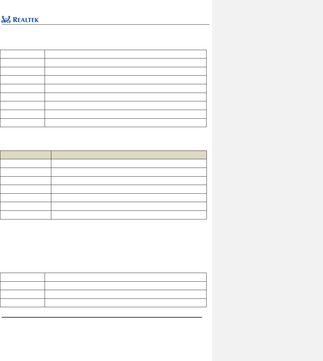
Realtek Confidential
RTL8762C Peripheral Manual
Copyright 2018 Realtek Semiconductor Corporation.
All Rights Reserved.
87
6. 2. 16 Function I2C_GetFlagState
Table 6. 21 Function I2C_GetFlagState
Function Name
I2C_GetFlagState
Function Prototype
FlagStatus I2C_GetFlagState(I2C_TypeDef* I2Cx, uint32_t I2C_FLAG)
Function Description
Check whether the flag specified by I2C is set.
Input Parameter 1
I2Cx: x can be set to 0 or 1 to select the specified I2C peripheral.
Input Parameter 2
I2C_FLAG: Flag to be checked
Output Parameter
None
Return Value
New state (SET or RESET) of the flag specified by I2C.
Prerequisite
None
Functions Called
None
I2C_FLAG: Permitted I2C status flags are as shown in Table 6. 22.
Table 6. 22 Values of I2C_FLAG
I2C_FLAG
Description
I2C_FLAG_SLV_ACTIVITY
When device is in slave device mode and bus is in communication.
I2C_FLAG_MST_ACTIVITY
When device is in master device mode and bus is in communication.
I2C_FLAG_RFF
Receive buffer is full.
I2C_FLAG_RFNE
Receive buffer is not empty.
I2C_FLAG_TFE
Transmit buffer is empty.
I2C_FLAG_TFNF
Transmit buffer is not full.
I2C_FLAG_ACTIVITY
Bus state
Examples:
/* Wait communication end as master. If SET, I2C0 have not finish transmission */
while(I2C_GetFlagState(I2C0, I2C_FLAG_MST_ACTIVITY) == 1);
6. 2. 17 Function I2C_CheckEvent
Table 6. 23 Function I2C_CheckEvent
Function Name
I2C_CheckEvent
Function Prototype
FlagStatus I2C_CheckEvent(I2C_TypeDef* I2Cx, uint32_t I2C_EVENT)
Function Description
Check the transmission failure event state specified by I2C.
Input Parameter 1
I2Cx: x can be set to 0 or 1 to select the specified I2C peripheral.
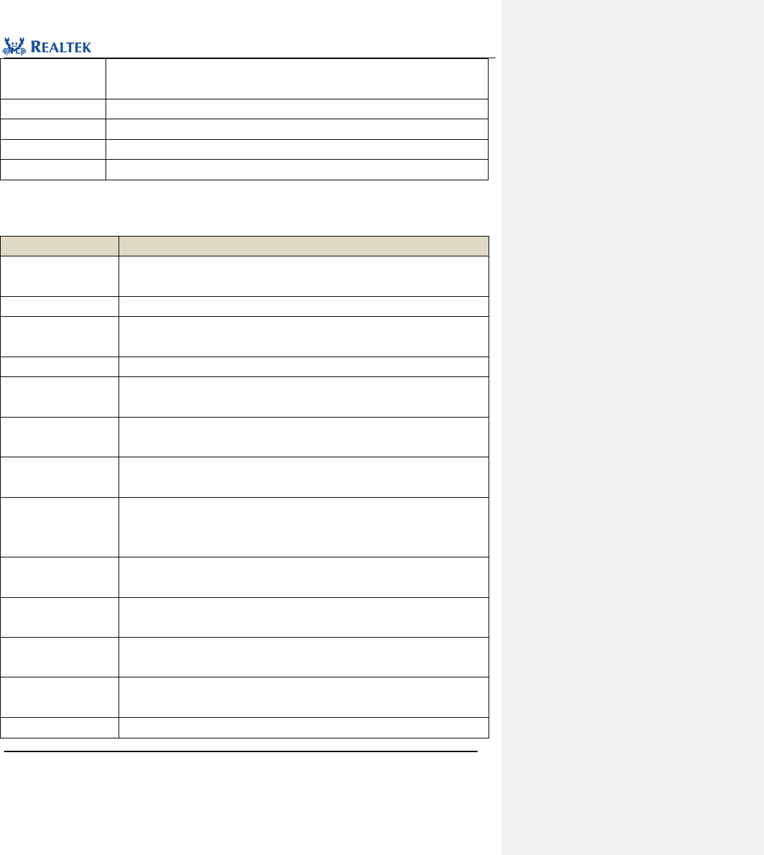
Realtek Confidential
RTL8762C Peripheral Manual
Copyright 2018 Realtek Semiconductor Corporation.
All Rights Reserved.
88
Input Parameter 2
I2C_ EVENT: I2C transfer event flag to be checked. Refer to related description of
I2C_EVENT for more details.
Output Parameter
None
Return Value
new state (SET or RESET) of exception event specified by I2C.
Prerequisite
None
Functions Called
None
I2C_EVENT: Permitted I2C event flags are as shown in Table 6. 24.
Table 6. 24 Values of I2C_EVENT
I2C_EVENT
Description
ABRT_SLVRD_INTX
Sending read command will trigger this exception when device is in slave device mode
and receives a read request from master device.
ABRT_SLV_ARBLOST
Bus will trigger this exception when device is in slave device mode and sending data.
ABRT_SLVFLUSH_TXFIFO
When device is in slave device mode and receives a read request from master device,
this exception will be triggered because overwriting the original data in buffer is.
ARB_LOST
This exception is triggered when device loses arbitration right.
ABRT_MASTER_DIS
This exception is triggered when the disabled master device mode is about to be
started.
ABRT_10B_RD_NORSTRT
When a device is in master device mode and restart function is disabled, this exception
will be triggered if the device sends a read command in 10-bit addressing mode.
ABRT_SBYTE_NORSTRT
When a device is in master device mode and restart function is disabled, this exception
will be triggered if a startup command is sent to this device.
ABRT_HS_NORSTRT
When a device which is in master device mode and whose restart function is
disabled,this exception will be triggered if transmitting data in high speed mode(bus
rate larger than 400kHz).
ABRT_SBYTE_ACKDET
This exception is triggered when a device which is in master device mode receives a
response signal after sending a startup command.
ABRT_HS_ACKDET
This exception is triggered when a device which is in master device mode and high
speed mode transmits data in high speed mode (bus rate larger than 400kHz).
ABRT_GCALL_READ
This exception is triggered when a device in master device mode sends a read
command after sending a common call command.
ABRT_GCALL_NOACK
This exception is triggered when a device in master device mode fails to receive a
response signal after sending a common call command.
ABRT_TXDATA_NOACK
This exception is triggered when a device in master device mode fails to receive a
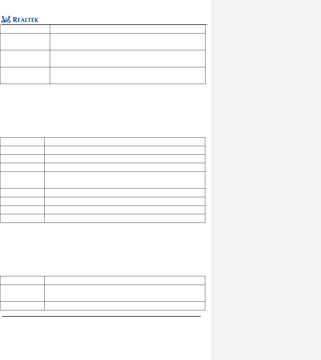
Realtek Confidential
RTL8762C Peripheral Manual
Copyright 2018 Realtek Semiconductor Corporation.
All Rights Reserved.
89
response signal after sending data.
ABRT_10ADDR2_NOACK
This exception is triggered when a device in master device mode and 10-bit addressing
fails to receives response signal after sending the second address datum.
ABRT_10ADDR1_NOACK
This exception is triggered when a device in master device mode and 10-bit addressing
fails to receives response signal after sending the first address datum.
ABRT_7B_ADDR_NOACK
This exception is triggered when a device in master device mode and 7-bit addressing
fails to receives response signal after sending address data.
Examples:
/* Check I2C receive acknowledgement or not after 7-bit address command to be sent */
bool flag_state = I2C_CheckEvent(I2C0, ABRT_7B_ADDR_NOACK);
6. 2. 18 Function I2C_GetINTStatus
Table 6. 25 Function I2C_ GetINTStatus
Function Name
I2C_GetINTStatus
Function Prototype
ITStatus I2C_GetINTStatus(I2C_TypeDef* I2Cx, uint32_t I2C_IT)
Function Description
Get specified I2C interrupt state.
Input Parameter 1
I2Cx: x can be set to 0 or 1 to select the specified I2C peripheral.
Input Parameter 2
I2C_IT: target interrupt source. Refer to related description of I2C_IT in 6. 2. 7 for more
details.
Output Parameter
None
Return Value
New state (SET OR RESET) of the flag specified by I2C.
Prerequisite
None
Functions Called
None
Examples:
/* Check stop singal interrupt state */
Bool int_state = I2C_GetINTStatus(I2C0, I2C_INT_STOP_DET) ;
6. 2. 19 Function I2C_GDMACmd
Table 6. 26 Function I2C_GDMACmd
Function Name
I2C_GDMACmd
Function Prototype
void I2C_GDMACmd(I2C_TypeDef *I2Cx, uint16_t I2C_GDMAReq, FunctionalState
NewState)
Function Description
Enable or disable specified GDMA data transmission function.
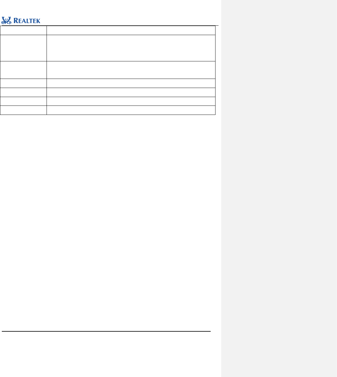
Realtek Confidential
RTL8762C Peripheral Manual
Copyright 2018 Realtek Semiconductor Corporation.
All Rights Reserved.
90
Input Parameter 1
I2Cx: x can be set to 0 or 1 to select the specified I2C peripheral.
Input Parameter 2
GDMAReq: data transmission type, available values listed below:
I2C_GDMAReq_Tx: GDMA data sending function
I2C_GDMAReq_Rx: GDMA data receiving function
Input Parameter 3
NewState: the new state of I2C data transmission
This parameter can be ENABLE or DISABLE
Output Parameter
None
Return Value
None
Prerequisite
None
Functions Called
None
Examples:
/* Enable I2C GDMA data transmission function */
I2C_GDMACmd (I2C0, I2C_GDMAReq_Tx, ENABLE);
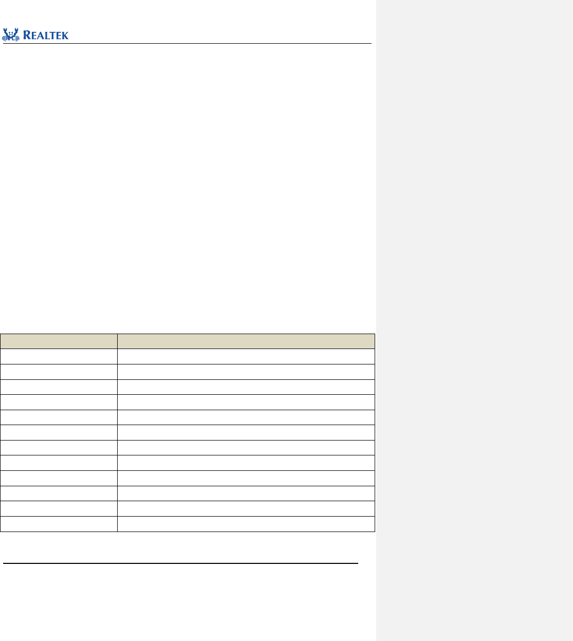
Realtek Confidential
RTL8762C Peripheral Manual
Copyright 2018 Realtek Semiconductor Corporation.
All Rights Reserved.
91
7 QDEC
7. 1 QDEC Register Architecture
typedef struct {
__IO uint32_t REG_DIV;
__IO uint32_t REG_CR_X;
__IO uint32_t REG_SR_X;
__IO uint32_t REG_CR_Y;
__IO uint32_t REG_SR_Y;
__IO uint32_t REG_CR_Z;
__IO uint32_t REG_SR_Z;
__IO uint32_t INT_MASK;
__IO uint32_t INT_SR;
__IO uint32_t INT_CLR;
__IO uint32_t REG_DBG;
__IO uint32_t REG_VERSION;
} QDEC_TypeDef;
All QDEC registers are enumerated in Table 7. 1.
Table 7. 1 QDEC Registers
Register
Description
REG_DIV
Frequency divider register
REG_CR_X
X-axis control register
REG_SR_X
X-axis status register
REG_CR_Y
Y-axis control register
REG_SR_Y
Y-axis status register
REG_CR_Z
Z-axis control register
REG_SR_Z
Z-axis status register
INT_MASK
Interrupt mask register
INT_SR
Interrupt status register
INT_CLR
Interrupt clear register
REG_DBG
Debug register
REG_VERSION
Version register
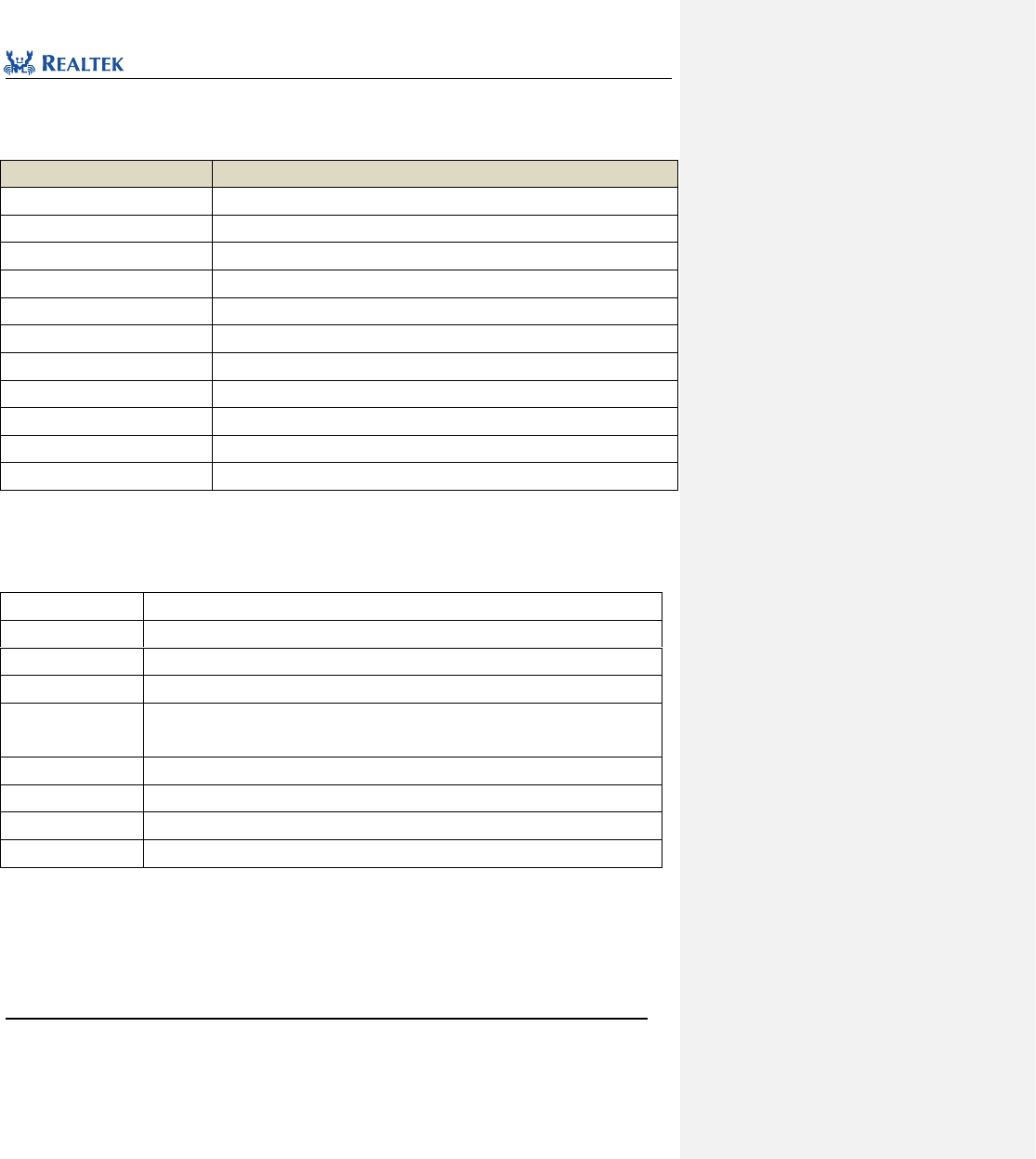
Realtek Confidential
RTL8762C Peripheral Manual
Copyright 2018 Realtek Semiconductor Corporation.
All Rights Reserved.
92
7. 2 QDEC Library Functions
Table 7. 2 All QDEC library functions
Function Name
Description
QDEC_Init
Initialize QDEC register based on parameters specified in QDEC_InitStruct
QDEC_DeInit
Disable QDEC peripheral clock.
QDEC_StructInit
Set each parameter in QDEC_InitStruct to the default value.
QDEC_Cmd
Enable or disable specified QDEC channel.
QDEC_INTConfig
Enable or disable the interrupt source specified by QDEC.
QDEC_GetFlagState
Check whether the specified QDEC interrupt flag is set.
QDEC_INTMask
Mask the specified QDEC interrupt source.
QDEC_ClearINTPendingBit
Clear the interrupt flag suspended by QDEC peripheral.
QDEC_GetAxisDirection
Acquire motion direction of specified axis.
QDEC_GetAxisCount
Acquire acceleration value of Axis X , Y or Z.
QDEC_CounterPauseCmd
Pause the acceleration count of Axis X , Y or Z.
7. 2. 1 Function QDEC_Init
Table 7. 3 Function QDEC_Init
Function Name
QDEC_Init
Function Prototype
void QDEC_Init(QDEC_TypeDef* QDECx, QDEC_InitTypeDef* QDEC_InitStruct)
Function Description
Initialize QDEC register based on parameters specified in QDEC_InitStruct.
Input Parameter 1
QDEC: Point to the selected QDEC module.
Input Parameter 2
QDEC_InitStruct: A pointer to QDEC_InitTypeDef, and related configuration information is
contained in QDEC_InitStruct
Output Parameter
None
Return Value
None
Prerequisite
None
Functions Called
None
typedef struct
{
uint16_t scanClockDiv;
uint16_t debounceClockDiv;
uint8_t axisConfigX;
uint8_t axisConfigY;
Realtek Confidential
RTL8762C Peripheral Manual
Copyright 2018 Realtek Semiconductor Corporation.
All Rights Reserved.
93
uint8_t axisConfigZ;
uint8_t autoLoadInitPhase;
uint16_t counterScaleX;
uint16_t debounceEnableX;
uint16_t debounceTimeX;
uint16_t initPhaseX;
uint16_t counterScaleY;
uint16_t debounceEnableY;
uint16_t debounceTimeY;
uint16_t initPhaseY;
uint16_t counterScaleZ;
uint16_t debounceEnableZ;
uint16_t debounceTimeZ;
uint16_t initPhaseZ;
} QDEC_InitTypeDef;
scanClock: Set frequency division factor of QDEC peripheral scan clock, ranging from 0 to 4095.
scan frequency = peripheralClock/(scanClock + 1), where peripheralClock equals to 20MHz.
debounceClock: Set frequency division factor of QDEC peripheral debounce clock, ranging from 0 to 15.
debounce frequency = scan frequency/(debounceClock + 1)
axisConfigX: Enable or disable the function of axis X. Available values are ENABLE and DISABLE.
debounceTimeX: Set the debounce duration of axis X of QDEC peripheral, ranging from 0 to 255.
counterScaleX: Set counter pattern of axis X. Available values are listed in table 7.4.
Table 7. 4 Values of counterScaleX
counterScaleX
Description
CounterScale_1_Phase
Counter updates every phase transition.
CounterScale_2_Phase
Counter updates every 2 phase transitions.
debounceEnableX: Enable the debounce function of axis X. Available values are listed in table 7.5.
Table 7. 5 Values of debounceEnableX
debounceEnableX
Description
Debounce_Disable
Disable debounce function
Debounce_Enable
Enable debounce function
initPhaseX: Configure initial phase of axis X. Available values are listed in table 7.6.
Realtek Confidential
RTL8762C Peripheral Manual
Copyright 2018 Realtek Semiconductor Corporation.
All Rights Reserved.
94
Table 7. 6 Values of initPhaseX
initPhaseX
Description
phaseMode0
Initial phase is configured as 0
phaseMode1
Initial phase is configured as 1
phaseMode2
Initial phase is configured as 2
phaseMode3
Initial phase is configured as 3
axisConfigY: Enable or disable the function of axis Y. Available values are ENABLE and DISABLE.
debounceTimeY: Set the debounce duration of axis Y of QDEC peripheral, ranging from 0 to 255.
counterScaleY: Set counter pattern of axis Y. Available values are listed in table 7.7.
Table 7. 7 Values of counterScaleY
counterScaleY
Description
CounterScale_1_Phase
Counter updates every phase transition.
CounterScale_2_Phase
Counter updates every 2 phase transitions.
debounceEnableY: Enable the debounce function of axis Y. Available values are listed in table 7.8.
Table 7. 8 Values of debounceEnableY
debounceEnableY
Description
Debounce_Disable
Disable debounce function
Debounce_Enable
Enable debounce function
initPhaseY: Configure initial phase of axis Y. Available values are listed in table 7.9.
Table 7. 9 Values of initPhaseY
initPhaseY
Description
phaseMode0
Initial phase is configured as 0
phaseMode1
Initial phase is configured as 1
phaseMode2
Initial phase is configured as 2
phaseMode3
Initial phase is configured as 3
axisConfigZ: Enable or disable the function of axis Z. Available values are ENABLE and DISABLE.
debounceTimeZ: Set the debounce duration of axis Z of QDEC peripheral, ranging from 0 to 255.
counterScaleZ: Set counter pattern of axis Z. Available values are listed in table 7.10.
Table 7. 10 Values of counterScaleZ
Realtek Confidential
RTL8762C Peripheral Manual
Copyright 2018 Realtek Semiconductor Corporation.
All Rights Reserved.
95
counterScaleZ
Description
CounterScale_1_Phase
Counter updates every phase transition.
CounterScale_2_Phase
Counter updates every 2 phase transitions.
debounceEnableZ: Enable the debounce function of axis Z. Available values are listed in table 7.11.
Table 7. 11 Values of debounceEnableZ
debounceEnableZ
Description
Debounce_Disable
Disable debounce function
Debounce_Enable
Enable debounce function
initPhaseZ: Configure initial phase of axis Z. Available values are listed in table 7.12.
Table 7. 12 Values of initPhaseZ
initPhaseZ
Description
phaseMode0
Initial phase is configured as 0
phaseMode1
Initial phase is configured as 1
phaseMode2
Initial phase is configured as 2
phaseMode3
Initial phase is configured as 3
Examples:
/*Initialize qdecoder */
QDEC_InitTypeDef qdecInitStruct;
qdecInitStruct.axisConfigY = ENABLE;
qdecInitStruct.scanClock = 38;
qdecInitStruct.debounceClock = 0xF;
qdecInitStruct.debounceTimeY = 80;
qdecInitStruct.counterScaleY = counterScaleDisable;
qdecInitStruct.debounceEnableY = Debounce_Enable;
qdecInitStruct.initPhaseY = phase;
QDEC_Init(QDEC, &qdecInitStruct);
7. 2. 2 Function QDEC_DeInit
Table 7. 13 Function QDEC_DeInit
Function Name
QDEC_DeInit
Function Prototype
void QDEC_DeInit(QDEC_TypeDef* QDECx)

Realtek Confidential
RTL8762C Peripheral Manual
Copyright 2018 Realtek Semiconductor Corporation.
All Rights Reserved.
96
Function Description
Disable QDEC peripheral clock.
Input Parameter 1
QDEC: Point to the selected QDEC module.
Output Parameter
None
Return Value
None
Prerequisite
None
Functions Called
RCC_PeriphClockCmd()
Examples:
/* Close qdecoder clock */
QDEC_DeInit(QDEC);
7. 2. 3 Function QDEC_StructInit
Table 7. 14 Function QDEC_StructInit
Function Name
QDEC_StructInit
Function Prototype
void QDEC_StructInit(QDEC_InitTypeDef* QDEC_InitStruct)
Function Description
Set each parameter in QDEC_InitStruct to the default value.
Input Parameter 1
QDEC_InitStruct: A pointer points to structure QDEC_InitTypeDef which needs to be
initialized.
Output Parameter
None
Return Value
None
Prerequisite
None
Functions Called
None
Examples:
/* Initialize qdecoder by default parameter */
QDEC_InitTypeDef QDEC_InitStruct;
QDEC_StructInit(&QDEC_InitStruct);
7. 2. 4 Function QDEC_Cmd
Table 7. 15 Function QDEC_Cmd
Function Name
QDEC_Cmd
Function Prototype
void QDEC_Cmd(QDEC_TypeDef *QDECx, uint32_t QDEC_AXIS,
FunctionalState newState)
Function Description
Enable or disable specified QDEC channel.
Input Parameter 1
QDECx: x can be set to 0 or 1 to select the specified QDEC peripheral.
Realtek Confidential
RTL8762C Peripheral Manual
Copyright 2018 Realtek Semiconductor Corporation.
All Rights Reserved.
97
Input Parameter 2
QDEC_AXIS: specified QDEC channel. Available values are:
QDEC_AXIS_X: Axis X channel
QDEC_AXIS_Y: Axis Y channel
QDEC_AXIS_Z: Axis Z channel
Input Parameter 3
newState: new state of specified QDEC peripheral channel.
ENABLE: Enable the specified axis.
DISABLE: Disable the specified axis.
Output Parameter
None
Return Value
None
Prerequisite
None
Functions Called
None
Examples:
/* Enable QDEC*/
QDEC_Cmd(QDEC, QDEC_AXIS_X, ENABLE);
7. 2. 5 Function QDEC_INTConfig
Table 7. 16 Function QDEC_INTConfig
Function Name
QDEC_INTConfig
Function Prototype
void QDEC_INTConfig(QDEC_TypeDef* QDECx, uint32_t QDEC_IT, FunctionalState
newState)
Function Description
Enable or disable the interrupt source specified by QDEC.
Input Parameter 1
QDECx: Point to the selected QDEC module.
Input Parameter 2
QDEC_IT: QDEC interrupt source to be enabled or disabled. Refer to related description of
QDEC_IT for more details.
Input Parameter 3
newState: new state of interrupt
This parameter can be set to ENABLE or DISABLE.
Output Parameter
None
Return Value
None
Prerequisite
None
Functions Called
None
QDEC_IT: Permitted QDEC interrupt types are as shown in Table 7. . Multiple interrupts can be selected at one
time by using operator "|".
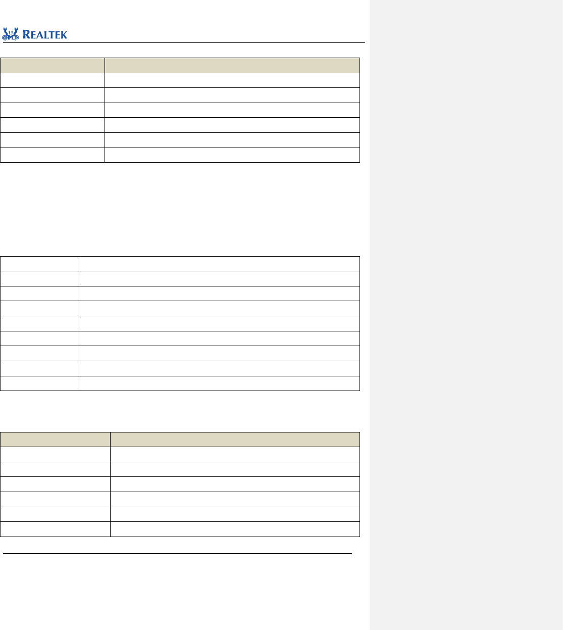
Realtek Confidential
RTL8762C Peripheral Manual
Copyright 2018 Realtek Semiconductor Corporation.
All Rights Reserved.
98
Table 7. 17 Values of QDEC_IT
QDEC_IT
Description
QDEC_X_INT_NEW_DATA
Interrupt is raised whenever new data are generated at axis X.
QDEC_X_INT_ILLEAGE
Interrupt is raised when phase exception occurs at axis X
QDEC_Y_INT_NEW_DATA
Interrupt is raised whenever new data are generated at axis Y.
QDEC_Y_INT_ILLEAGE
Interrupt is raised when phase exception occurs at axis Y
QDEC_Z_INT_NEW_DATA
Interrupt is raised whenever new data are generated at axis Z.
QDEC_Z_INT_ILLEAGE
Interrupt is raised when phase exception occurs at axis Z
Examples:
/* Enable qdecoder specify interrupt */
QDEC_INTConfig(QDEC, QDEC_X_INT_NEW_DATA, ENABLE);
7. 2. 6 Function QDEC_GetFlagState
Table 7. 6 Function QDEC_GetFlagState
Function Name
QDEC_GetFlagState
Function Prototype
FlagStatus QDEC_GetFlagState(QDEC_TypeDef* QDECx, uint32_t QDEC_FLAG)
Function Description
Check whether the specified QDEC interrupt flag is set.
Input Parameter 1
QDECx: Point to the selected QDEC module.
Input Parameter 2
QDEC_FLAG: Target flag
Output Parameter
None
Return Value
State of specified QDEC flag (SET or RESET)
Prerequisite
None
Functions Called
None
QDEC_FLAG: Permitted QDEC state types are as shown in Table 7. 7.
Table 7. 7 Values of QDEC_FLAG
QDEC_IT
Description
QDEC_FLAG_ILLEGAL_STATUS_X
Flag sets when phase transition occurs at Axis X.
QDEC_FLAG_ILLEGAL_STATUS_Y
Flag sets when phase transition occurs at Axis Y.
QDEC_FLAG_ILLEGAL_STATUS_Z
Flag sets when phase transition occurs at Axis Z.
QDEC_FLAG_NEW_STATUS_X
Flag sets when new data is generated at Axis X.
QDEC_FLAG_NEW_STATUS_Y
Flag sets when new data is generated at Axis Y.
QDEC_FLAG_NEW_STATUS_Z
Flag sets when new data is generated at Axis Z.
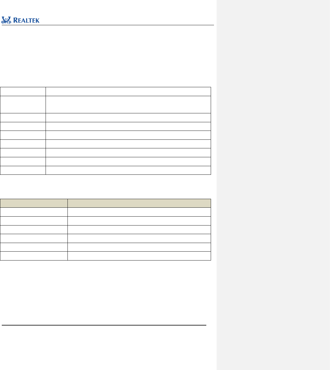
Realtek Confidential
RTL8762C Peripheral Manual
Copyright 2018 Realtek Semiconductor Corporation.
All Rights Reserved.
99
Examples:
/* Check specify QDEC flag */
BOOL state = FALSE;
state = QDEC_GetFlagState(QDEC, QDEC_FLAG_OVERFLOW_X);
7. 2. 7 Function QDEC_INTMask
Table 7. 20 Function QDEC_INTMask
Function Name
QDEC_INTMask
Function Prototype
void QDEC_INTMask(QDEC_TypeDef* QDECx, uint32_t QDEC_AXIS, FunctionalState
newState)
Function Description
Mask the specified QDEC interrupt source.
Input Parameter 1
QDECx: Point to the selected QDEC module.
Input Parameter 2
QDEC_AXIS: Interrupt source to be masked
Output Parameter
None
Return Value
None
Prerequisite
None
Functions Called
None
QDEC_AXIS: Permitted QDEC interrupt types are as shown in Table 7. .
Table 7. 21 Values of QDEC_AXIS
QDEC_AXIS
Description
QDEC_X_CT_INT_MASK
Mask the interrupt raised by new data at axis X.
QDEC_Y_CT_INT_MASK
Mask the interrupt raised by new data at axis Y.
QDEC_Z_CT_INT_MASK
Mask the interrupt raised by new data at axis Z.
QDEC_X_ILLEAGE_INT_MASK
Mask the interrupt raised by phase transition exception at axis X.
QDEC_Y_ILLEAGE_INT_MASK
Mask the interrupt raised by phase transition exception at axis Y.
QDEC_Z_ILLEAGE_INT_MASK
Mask the interrupt raised by phase transition exception at axis Z.
Examples:
/* Mask X axis of qdecoder */
QDEC_INTMask (QDEC, QDEC_X_CT_INT_MASK, ENABLE);
7. 2. 8 Function QDEC_ClearINTPendingBit
Table 7. 22 Function QDEC_ClearINTPendingBit
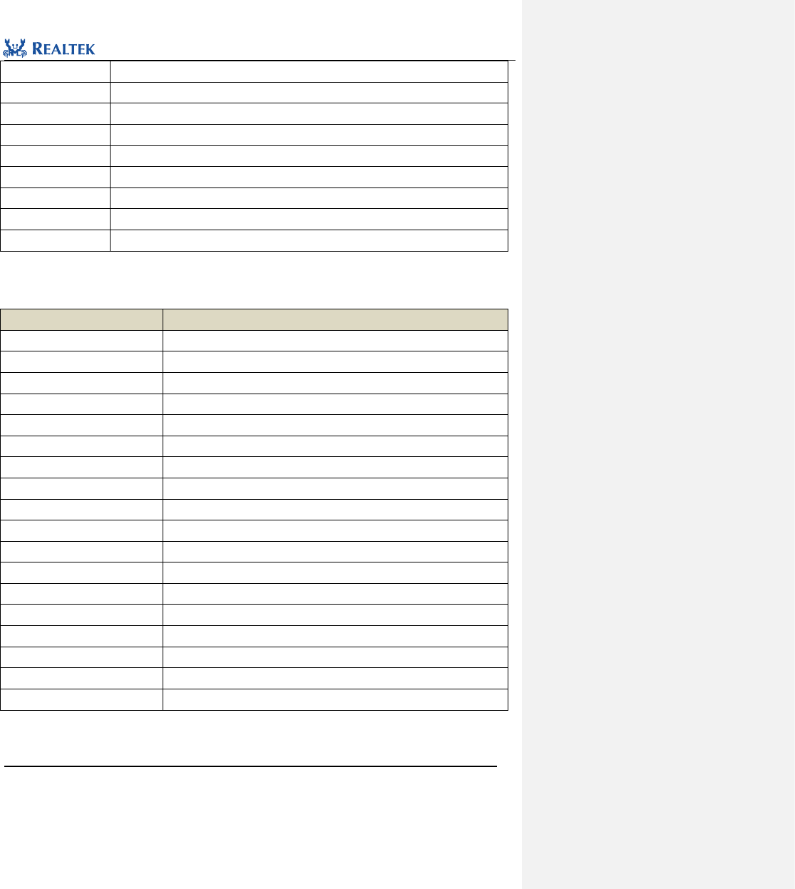
Realtek Confidential
RTL8762C Peripheral Manual
Copyright 2018 Realtek Semiconductor Corporation.
All Rights Reserved.
100
Function Name
QDEC_ClearINTPendingBit
Function Prototype
void QDEC_ClearINTPendingBit(QDEC_TypeDef *QDECx, uint32_t QDEC_CLR_INT)
Function Description
Clear the interrupt flag suspended by QDEC peripheral.
Input Parameter 1
QDECx: Point to the selected QDEC module.
Input Parameter 2
QDEC_INT_FLAG: Interrupt flag to be cleared
Output Parameter
None
Return Value
None
Prerequisite
None
Functions Called
None
QDEC_INT_FLAG: Permitted QDEC interrupt types are as shown in Table 7. .
Table 7. 8 Values of QDEC_AXIS
QDEC_CLEAR_FLAG
Description
QDEC_CLR_ILLEGAL_CT_X
Clear illegal phase counter at X-axis
QDEC_CLR_ILLEGAL_CT_Y
Clear illegal phase counter at Y-axis
QDEC_CLR_ILLEGAL_CT_Z
Clear illegal phase counter at Z-axis
QDEC_CLR_ACC_CT_X
Clear accumulated phase counter at X-axis
QDEC_CLR_ACC_CT_Y
Clear accumulated phase counter at Y-axis
QDEC_CLR_ACC_CT_Z
Clear accumulated phase counter at Z-axis
QDEC_CLR_ILLEGAL_INT_X
Clear phase transition exception interrupt at X-axis
QDEC_CLR_ILLEGAL_INT_Y
Clear phase transition exception interrupt at Y-axis
QDEC_CLR_ILLEGAL_INT_Z
Clear phase transition exception interrupt at Z-axis
QDEC_CLR_UNDERFLOW_X
Clear underflow interrupt at X-axis
QDEC_CLR_UNDERFLOW_Y
Clear underflow interrupt at Y-axis
QDEC_CLR_UNDERFLOW_Z
Clear underflow interrupt at Z-axis
QDEC_CLR_OVERFLOW_X
Clear overflow interrupt at X-axis
QDEC_CLR_OVERFLOW_Y
Clear overflow interrupt at Y-axis
QDEC_CLR_OVERFLOW_Z
Clear overflow interrupt at Z-axis
QDEC_CLR_NEW_CT_X
Clear new count interrupt at X-axis
QDEC_CLR_NEW_CT_Y
Clear new count interrupt at Y-axis
QDEC_CLR_NEW_CT_Z
Clear new count interrupt at Z-axis
Examples:
/* Clear specify QDEC interrupt */
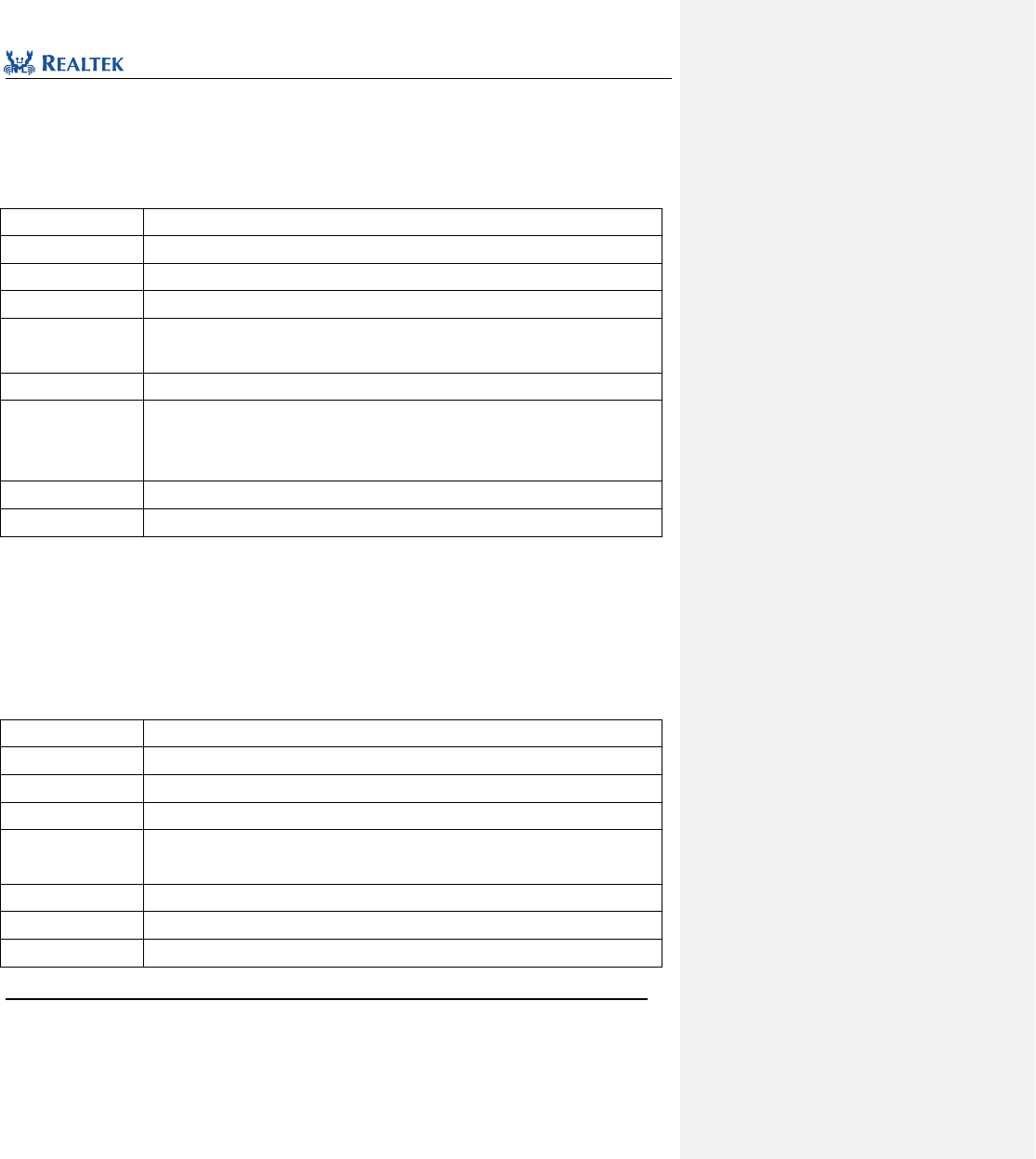
Realtek Confidential
RTL8762C Peripheral Manual
Copyright 2018 Realtek Semiconductor Corporation.
All Rights Reserved.
101
QDEC_ClearINTPendingBit(QDEC, QDEC_CLR_NEW_CT_X);
7. 2. 9 Function QDEC_GetAxisDirection
Table 7. 9 Function QDEC_GetAxisDirection
Function Name
QDEC_GetAxisDirection
Function Prototype
uint16_t QDEC_GetAxisDirection(QDEC_TypeDef* QDECx, uint32_t QDEC_AXIS)
Function Description
Acquire motion direction of specified axis.
Input Parameter 1
QDECx: Point to the selected QDEC module.
Input Parameter 2
QDEC_AXIS: Axis X, Y or Z as specified. Refer to related description of QDEC_AXIS in
section 7.2.6 for more details.
Output Parameter
None
Return Value
Motion direction: The returned value is as shown below.
QDEC_AXIS_DIR_UP: Roll up
QDEC_AXIS_DIR_DOWN: Roll down
Prerequisite
None
Functions Called
None
Examples:
/* Wait for moving upward */
while(QDEC_AXIS_DIR_UP == QDEC_GetAxisDirection(QDEC, QDEC_AXIS_X));
7. 2. 10 Function QDEC_GetAxisCount
Table 7. 10 Function QDEC_GetAxisCount
Function Name
QDEC_GetAxisCount
Function Prototype
uint16_t QDEC_GetAxisCount(QDEC_TypeDef *QDECx, uint32_t QDEC_AXIS)
Function Description
Acquire acceleration of Axis X , Y or Z.
Input Parameter 1
QDECx: Point to the selected QDEC module.
Input Parameter 2
QDEC_AXIS: Axis X, Y or Z as specified. Refer to related description of QDEC_AXIS in
section 7.2.6 for more details.
Output Parameter
None
Return Value
The acceleration of specified axis.
Prerequisite
None
Realtek Confidential
RTL8762C Peripheral Manual
Copyright 2018 Realtek Semiconductor Corporation.
All Rights Reserved.
102
Functions Called
None
Examples:
/* Get data of specify axis */
uint16_t data = 0;
data = QDEC_GetAxisCount (QDEC, QDEC_AXIS_X);
7. 2. 11 Function QDEC_CounterPauseCmd
Table 7. 11 Function QDEC_CounterPauseCmd
Function Name
QDEC_CounterPauseCmd
Function Prototype
void QDEC_CounterPauseCmd(QDEC_TypeDef *QDECx, uint32_t QDEC_AXIS,
FunctionalState newState)
Function Description
Pause the acceleration count of Axis X , Y or Z.
Input Parameter 1
QDECx: Point to the selected QDEC module.
Input Parameter 2
QDEC_AXIS: Axis X, Y or Z as specified.
Input Parameter 3
newState: can be the following value
ENABLE: Pause.
DISABLE: Resume.
Output Parameter
None
Return Value
None
Prerequisite
None
Functions Called
None
Examples:
/* Pause specify axis */
QDEC_CounterPauseCmd (QDEC, QDEC_AXIS_X, ENABLE);
Realtek Confidential
RTL8762C Peripheral Manual
Copyright 2018 Realtek Semiconductor Corporation.
All Rights Reserved.
103
8 Pin Allocation Difinition (PAD)
8. 1 PAD Library Functions
All PINMUX library functions are enumerated in Table 8. 1.
Table 8. 1 PAD Library Functions
Function Name
Description
Pad_Config
Configure operation mode, peripheral circuit of specified pin and its output
voltage level in software mode.
Pad_OutputControlValue
Configure the PAD output voltage level.
Pad_OutputEnableValue
Enable or disable the PAD output function.
Pad_PullEnableValue
Enable or disable PAD pull-up/pull-down resistor function.
Pad_ PullConfigValue
Configure PAD pull-up/pull-down resistor.
Pad_WakeupEnableValue
Enable or disable pin wakeup function.
Pad_WakeupPolarityValue
Configure wakeup polarity.
Pad_PowerOrShutDownValue
Configure PAD power supply mode.
Pad_ControlSelectValue
Configure PAD mode.
Pad_WKDebounceConfig
Enable or disable PAD wakeup debounce function.
Pad_ClearWakeupINTPendingBit
Clear PAD wakeup interrupt flag bit.
Pad_WakeupInterruptValue
Inspect PAD wakeup interrupt status.
System_WakeUpInterruptValue
Inspect system wakeup interrupt status.
System_WakeUpDebounceTime
Configure wakeup debounce time of specified pin
System_WakeUpPinEnable
Enable system wakeup function of specified pin.
System_WakeUpPinDisable
Disable system wakeup function of specified pin.
8.1.1 Function Pad_Config
Table 8. 2 Function Pad_Config
Function Name
Pad_Config
Function Prototype
void Pad_Config(uint8_t Pin_Num, BOOL AON_PAD_Mode, BOOL AON_PAD_PwrOn,
BOOL AON_PAD_Pull, BOOL AON_PAD_E, BOOL AON_PAD_O)
Function Description
Configure operation mode, peripheral circuit of specified pin and its output voltage level
批注 [陈杨洋2]: 函数名更新
Realtek Confidential
RTL8762C Peripheral Manual
Copyright 2018 Realtek Semiconductor Corporation.
All Rights Reserved.
104
in software mode.
Input Parameter 1
Pin_Num: Pin to be configured. Refer to setion of Pin_Num for more details.
Input Parameter 2
AON_PAD_Mode: This parameter is used to select pin mode, available values are
enumerated in PAD_Mode.
PAD_SW_MODE: Software Mode.
PAD_PINMUX_MODE: PINMUX Mode.
Input Parameter 3
AON_PAD_PwrOn: Configure power mode of pin, available values are enumerated in
PAD_PWR_Mode.
PAD_NOT_PWRON: Shut down power supply.
PAD_IS_PWRON: Enable power supply.
Input Parameter 4
AON_PAD_Pull: Configure peripheral circuit of pin, available values are enumerated in
PAD_Pull_Mode.
PAD_PULL_NONE: Both pull-up or pull-down resistors are disconnected.
PAD_PULL_UP: Pull-up resistor is connected internally.
PAD_PULL_DOWN: Pull-down resistor is connected internally.
Input Parameter 5
AON_PAD_E: Enable or disable pin output in software mode, available values are
enumerated in PAD_OUTPUT_ENABLE_Mode.
PAD_OUT_DISABLE: Output disabled
PAD_OUT_ENABLE: Output enabled
Input Parameter 6
AON_PAD_O: Configure pin output voltage level in software mode, a available values are
enumerated in PAD_OUTPUT_VAL.
PAD_OUT_LOW: Low level
PAD_OUT_HIGH: High level
Output Parameter
None
Return Value
None
Prerequisite
None
Functions Called
None
Pin_Num: All optional pin values are as shown in Table 8. 3. Refer to specific pin manual for more details.
Table 8. 3 Values of Pin_Num
Pin_Num
Description
P0_0
Selected pad 0
P0_1
Selected pad 1
P0_2
Selected pad 2

Realtek Confidential
RTL8762C Peripheral Manual
Copyright 2018 Realtek Semiconductor Corporation.
All Rights Reserved.
105
P0_3
Selected pad 3
P0_4
Selected pad 4
P0_5
Selected pad 5
P0_6
Selected pad 6
P0_7
Selected pad 7
P1_0
Selected pad 8
P1_1
Selected pad 9
P1_2
Selected pad 10
P1_3
Selected pad 11
P1_4
Selected pad 12
P1_5
Selected pad 13
P1_6
Selected pad 14
P1_7
Selected pad 15
P2_0
Selected pad 16
P2_1
Selected pad 17
P2_2
Selected pad 18
P2_3
Selected pad 19
P2_4
Selected pad 20
P2_5
Selected pad 21
P2_6
Selected pad 22 (MIC_N)
P2_7
Selected pad 23 (MIC_P)
P3_0
Selected pad 24
P3_1
Selected pad 25
P3_2
Selected pad 26
P3_3
Selected pad 27
P3_4
Selected pad 28
P3_5
Selected pad 29
P3_6
Selected pad 30
P4_0
Selected pad 32
P4_1
Selected pad 33
P4_2
Selected pad 34
P4_3
Selected pad 35
H_0
Selected pad 36 (MICBIAS)
Realtek Confidential
RTL8762C Peripheral Manual
Copyright 2018 Realtek Semiconductor Corporation.
All Rights Reserved.
106
H_1
Selected pad 37 (32K_XI)
H_2
Selected pad 38 (32K_XO)
Examples:
/* Configure P0_5 for specified mode */
Pad_Config(P0_5,PAD_PINMUX_MODE,PAD_IS_PWRON,PAD_PULL_NONE, PAD_OUT_ENABLE, PAD_OUT_HIGH);
8.1.2 Function Pad_OutputEnableValue
Table8. 4Function Pad_OutputEnableValue
Function Name
Pad_OutputEnableValue
Function
Prototype
void Pad_OutputEnableValue(uint8_t Pin_Num, uint8_t value)
Function
Description
Enable or disable the pad output function.
Input Parameter 1
Pin_Num: Pin to be configured. Refer to related description of Pin_Num for more details.
Input Parameter 2
AON_PAD_E: Enable or disable pin output in software mode, available values are enumerated in
PAD_OUTPUT_ENABLE_Mode.
PAD_OUT_DISABLE: Output disabled
PAD_OUT_ENABLE: Output enabled
Output Parameter
None
Return Value
None
Prerequisite
None
Functions Called
None
8.1.3 Function Pad_OutputControlValue
Table8. 5Function Pad_OutputControlValue
Function Name
Pad_OutputControlValue
Function
Prototype
void Pad_OutputControlValue (uint8_t Pin_Num, uint8_t value)
Function
Description
Configure the pad output voltage level.
Input Parameter 1
Pin_Num: Pin to be configured. Refer to related description of Pin_Num for more details.
Input Parameter 2
AON_PAD_O: Configure pin output voltage level in software mode, available values are
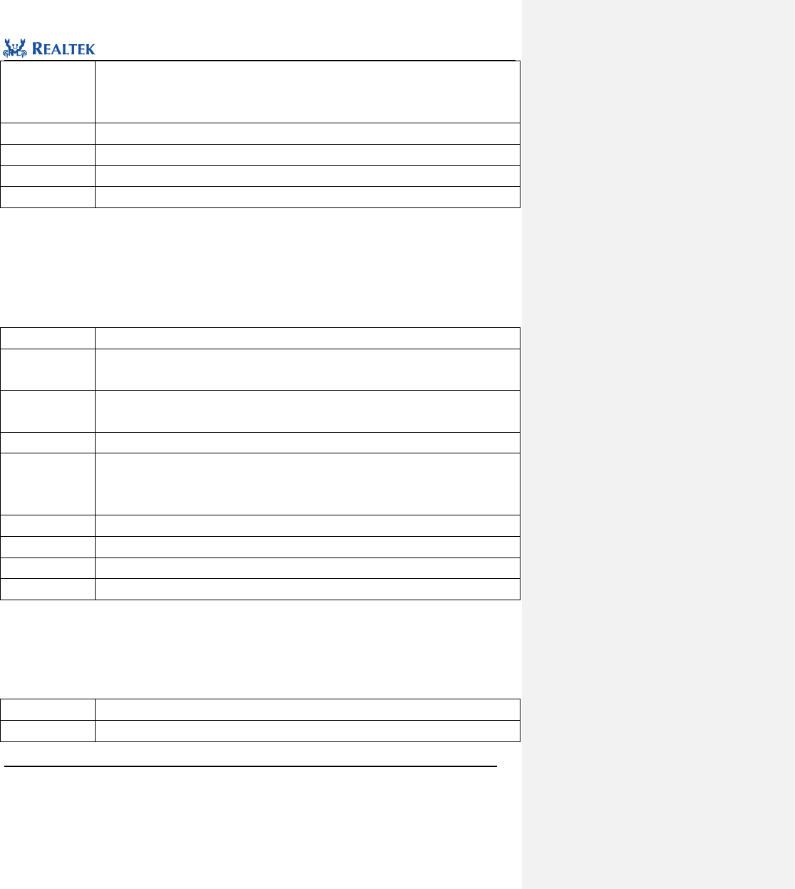
Realtek Confidential
RTL8762C Peripheral Manual
Copyright 2018 Realtek Semiconductor Corporation.
All Rights Reserved.
107
enumerated in PAD_OUTPUT_VAL.
PAD_OUT_LOW: output low level.
PAD_OUT_HIGH: output high level.
Output Parameter
None
Return Value
None
Prerequisite
None
Functions Called
None
Examples: Pad_OutputControlValue(P0_1, PAD_OUT_LOW );
8.1.4 Function Pad_PullEnableValue
Table8. 6Function Pad_PullEnableValue
Function Name
Pad_PullEnableValue
Function
Prototype
void Pad_PullEnableValue (uint8_t Pin_Num, uint8_t value)
Function
Description
Enable or disable PAD pull-up/pull-down function.
Input Parameter 1
Pin_Num: Pin to be configured. Refer to related description of Pin_Num for more details.
Input Parameter 2
value:This parameter specifies the pad pull Function , can be the following value
ENABLE: Enable PAD pull-up/pull-down function
DISABLE: Disable PAD pull-up/pull-down function
Output Parameter
None
Return Value
None
Prerequisite
None
Functions Called
None
Examples: Pad_PullEnableValue(P0_1, ENABLE );
8.1.5 Function Pad_PullUpOrDownValue
Table8. 7Function Pad_PullUpOrDownValue
Function Name
Pad_PullUpOrDownValue
Function
void Pad_PullUpOrDownValue (uint8_t Pin_Num, uint8_t value)
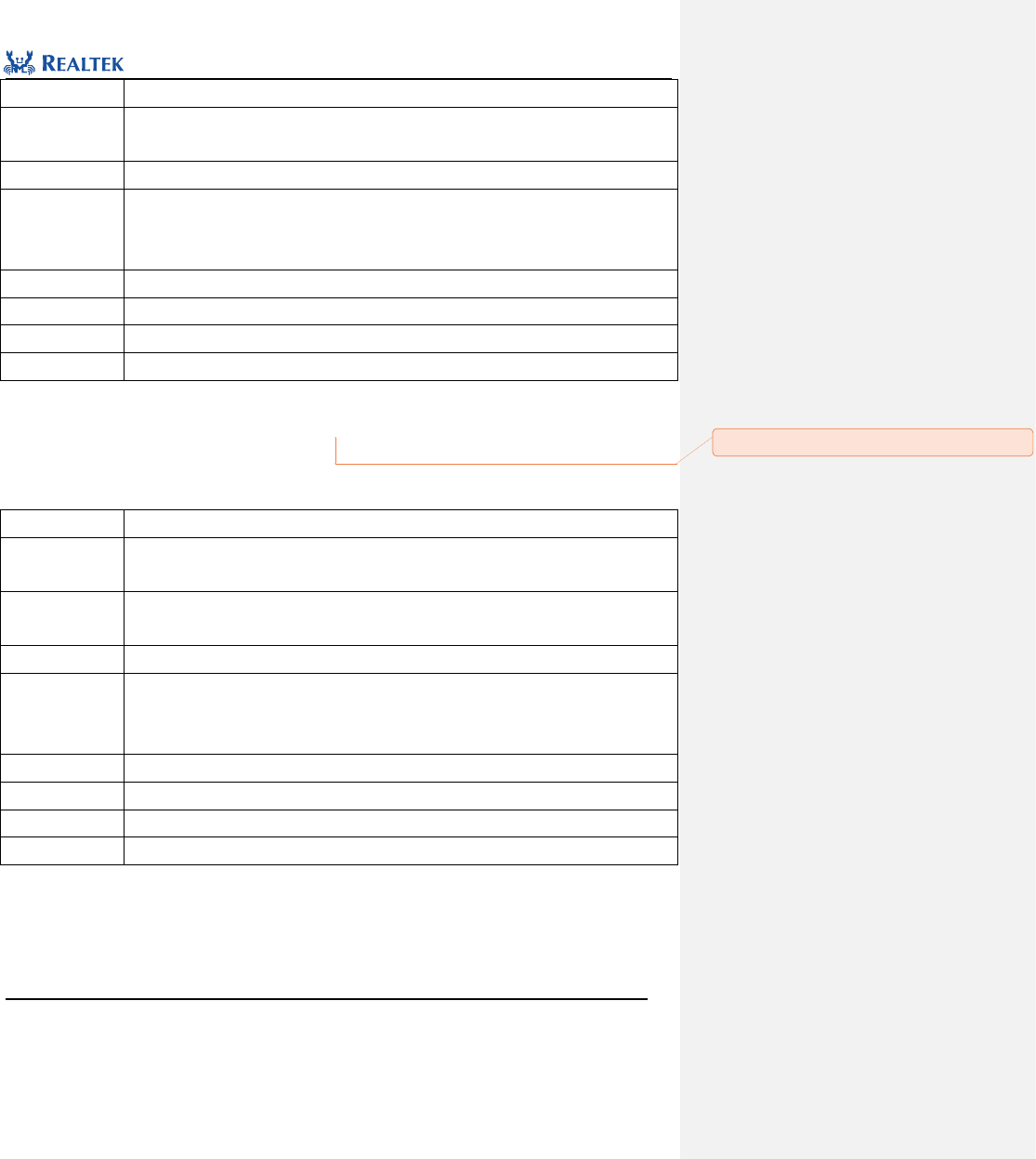
Realtek Confidential
RTL8762C Peripheral Manual
Copyright 2018 Realtek Semiconductor Corporation.
All Rights Reserved.
108
Prototype
Function
Description
PAD pull-up/pull-down function selection.
Input Parameter 1
Pin_Num: Pin to be configured. Refer to related description of Pin_Num for more details.
Input Parameter 2
value:Configure peripheral circuit of pin, available values are enumerated in PAD_Pull_Mode.
true: Configure Pull-down resistor.
false: Configure Pull-up resistor.
Output Parameter
None
Return Value
None
Prerequisite
None
Functions Called
None
Examples: Pad_PullUpOrDownValue(P0_1, 1);
8.1.6 Function Pad_ PullConfigValue
Table8. 8Function Pad_PullUpResistanceConfig
Function Name
Pad_PullUpResistanceConfig
Function
Prototype
void Pad_PullUpResistanceConfig (uint8_t Pin_Num,PAD_PULL_VAL value)
Function
Description
Configuring the resistance for pull-up resistor.
Input Parameter 1
Pin_Num: Pin value to be configured. Refer to related description of Pin_Num for more details.
Input Parameter 2
value: Configure resistance, available values are enumerated in PAD_OUTPUT_VAL.
PAD_WEAK_PULL: PAD weakly pull.
PAD_STRONG_PULL: PAD strongly pull.
Output Parameter
None
Return Value
None
Prerequisite
None
Functions Called
None
Examples:
Pad_PullUpResistanceConfig (P0_1, PAD_STRONG_PULL);
批注 [陈杨洋3]: 函数名更新

Realtek Confidential
RTL8762C Peripheral Manual
Copyright 2018 Realtek Semiconductor Corporation.
All Rights Reserved.
109
8.1.7 Function Pad_WakeupEnableValue
Table8. 9Function Pad_WakeupEnableValue
Function Name
Pad_WakeupEnableValue
Function
Prototype
void Pad_WakeupEnableValue(uint8_t Pin_Num, uint8_t value)
Function
Description
Enable or disable pin wakeup function
Input Parameter 1
Pin_Num: Pin to be configured. Refer to related description of Pin_Num for more details.
Input Parameter 2
value: Enable or disable wakeup function.
0: Disable.
1: Enable.
Output Parameter
None
Return Value
None
Prerequisite
None
Functions Called
None
Examples:
/* Enable P0_2 wake up function*/
Pad_WakeupEnableValue (P0_2, 1);
8.1.8 Function Pad_WakeupPolarityValue
Table8. 10Function Pad_WakeupPolarityValue
Function Name
Pad_WakeupPolarityValue
Function
Prototype
void Pad_WakeupPolarityValue(uint8_t Pin_Num, uint8_t value)
Function
Description
Configure pin wakeup polarity.
Input Parameter 1
Pin_Num: Pin to be configured. Refer to related description of Pin_Num for more details.
Input Parameter 2
Value: Configure wakeup polarity. Available values are enumerated in PAD_WAKEUP_POL_VAL
PAD_WAKEUP_POL_HIGH:High level wakeup
PAD_WAKEUP_POL_LOW:Low level wakeup
Output Parameter
None
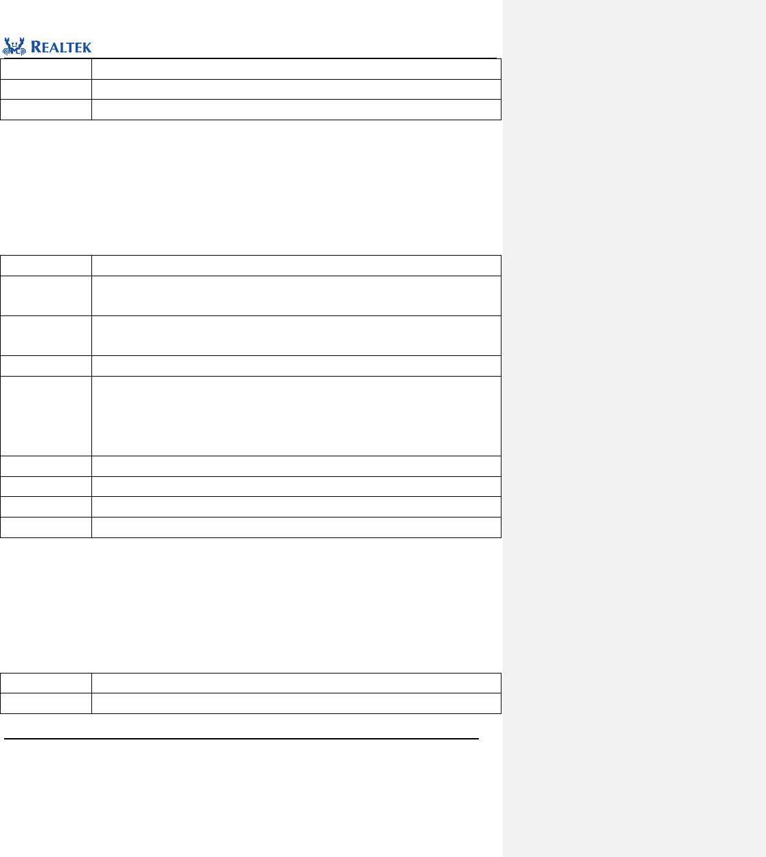
Realtek Confidential
RTL8762C Peripheral Manual
Copyright 2018 Realtek Semiconductor Corporation.
All Rights Reserved.
110
Return Value
None
Prerequisite
None
Functions Called
None
Examples:
/* Config P0_2 wake up polarity*/
Pad_ WakeupPolarityValue(P0_2, PAD_WAKEUP_POL_HIGH);
8.1.9 Function Pad_PowerOrShutDownValue
Table8. 11 Function Pad_PowerOrShutDownValue
Function Name
Pad_PowerOrShutDownValue
Function
Prototype
void Pad_PowerOrShutDownValue (uint8_t Pin_Num, uint8_t value)
Function
Description
Configure pad power mode
Input Parameter 1
Pin_Num: Pin to be configured. Refer to related description of Pin_Num for more details.
Input Parameter 2
AON_PAD_PwrOn: This parameter is used to configure power mode of pin, available values are
enumerated in _PAD_PWR_Mode.
PAD_NOT_PWRON: Shut down power supply.
PAD_IS_PWRON: Turn on power supply.
Output Parameter
None
Return Value
None
Prerequisite
None
Functions Called
None
Examples:
/* Enable P0_2 power on function*/
Pad_PowerOrShutDownValue (P0_2, PAD_IS_PWRON);
8.1.10 Pad_ControlSelectValue
Table8. 12 Pad_ControlSelectValue
Function Name
Pad_ControlSelectValue
Function
void Pad_ControlSelectValue (uint8_t Pin_Num, uint8_t value)
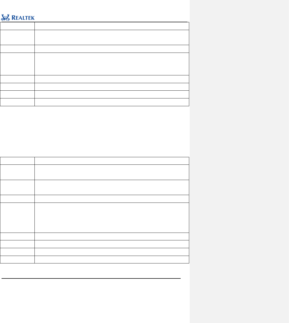
Realtek Confidential
RTL8762C Peripheral Manual
Copyright 2018 Realtek Semiconductor Corporation.
All Rights Reserved.
111
Prototype
Function
Description
Cofigure pin mode.
Input Parameter 1
Pin_Num: Pin to be configured. Refer to related description of Pin_Num for more details.
Input Parameter 2
value:used to configure pin mode, available values are enumerated in PAD_Mode:
PAD_SW_MODE: Software mode
PAD_PINMUX_MODE:PINMUX mode
Output Parameter
None
Return Value
None
Prerequisite
None
Functions Called
None
Examples:
/* Config P0_2 sw mode */
Pad_ControlSelectValue (P0_2, PAD_SW_MODE);
8.1.11 Function Pad_WKDebounceConfig
Table8. 13Function Pad_WKDebounceConfig
Function Name
Pad_WKDebounceConfig
Function
Prototype
void Pad_WKDebounceConfig(uint8_t Pin_Num, uint8_t value)
Function
Description
Configure pin debounce function.
Input Parameter 1
Pin_Num: Pin to be configured. Refer to related description of Pin_Num for more details.
Input Parameter 2
value: Enable or disable debounce function, available values are enumerated in
_PAD_WAKEUP_DEBOUNCE_EN.
PAD_WK_DEBOUNCE_ENABLE: Enable
PAD_WK_DEBOUNCE_DISABLE: Diable
Output Parameter
None
Return Value
None
Prerequisite
None
Functions Called
None
Examples:
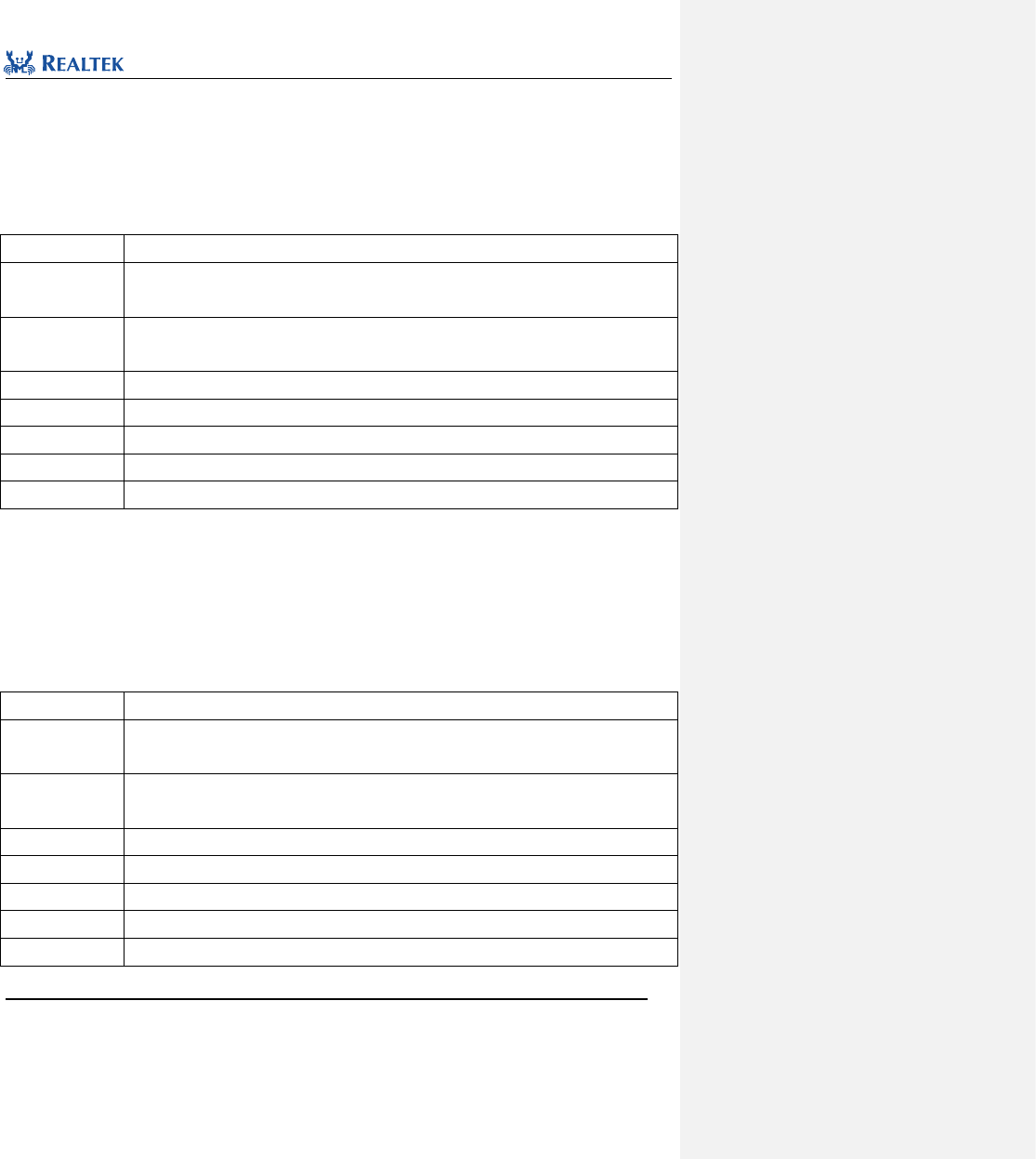
Realtek Confidential
RTL8762C Peripheral Manual
Copyright 2018 Realtek Semiconductor Corporation.
All Rights Reserved.
112
/* Enable P0_2 debounce function */
Pad_WKDebounceConfig(P0_2, PAD_WK_DEBOUNCE_ENABLE);
8.1.12 Function System_WakeUpInterruptValue
Table8. 14Function System_WakeUpInterruptValue
Function Name
System_WakeUpInterruptValue
Function
Prototype
uint8_t System_WakeUpInterruptValue(uint8_t Pin_Num)
Function
Description
Inspect wake up interrupt status of the specific pin.
Input Parameter 1
Pin_Num: Pin to be inspected. Refer to related description of Pin_Num for more details.
Output Parameter
None
Return Value
Interrupt status of the specific pad.
Prerequisite
None
Functions Called
None
Examples:
/* Read P0_2 interrupt value*/
Uint8_t intvalue= System_WakeUpInterruptValue(P0_2);
8.1.13 Function Pad_WakeupInterruptValue
Table8. 15 Function Pad_WakeupInterruptValue
Function Name
Pad_WakeupInterruptValue
Function
Prototype
Uint8_t Pad_WakeupInterruptValue(uint8_t Pin_Num)
Function
Description
Inspect interrupt status of specified pin.
Input Parameter 1
Pin_Num: Pin to be inspected. Refer to related description of Pin_Num for more details.
Output Parameter
None
Return Value
Interrupt status.
Prerequisite
None
Functions Called
None
Examples:

Realtek Confidential
RTL8762C Peripheral Manual
Copyright 2018 Realtek Semiconductor Corporation.
All Rights Reserved.
113
/* Read P0_2 interrupt value*/
Uint8_t intvalue= Pad_WakeupInterruptValue (P0_2);
8.1.14 Function Pad_ClearWakeupINTPendingBit
Table8. 16Function Pad_ClearWakeupINTPendingBit
Function Name
Pad_ClearWakeupINTPendingBit
Function
Prototype
void Pad_ClearWakeupINTPendingBit(uint8_t Pin_Num)
Function
Description
Clear wakeup flag bit of specified pin.
Input Parameter 1
Pin_Num: Pin to be operated. Refer to related description of Pin_Num for more details.
Output Parameter
None
Return Value
None
Prerequisite
None
Functions Called
None
Examples:
/* Clear P0_2 wake up interrupt flag bit*/
Pad_ClearWakeupINTPendingBit (P0_2);
8.1.15 Function System_WakeUpDebounceTime
Table8. 17 System_WakeUpDebounceTime
Function Name
System_WakeUpDebounceTime
Function
Prototype
void System_WakeUpDebounceTime(uint8_t time)
Function
Description
Configure Pad wakeup debounce time
Input Parameter 1
time: configure PAD wakeup debounce time in millisecond, ranging from 1 to 64.
Input Parameter
None
Output Parameter
None
Return Value
None
Prerequisite
None
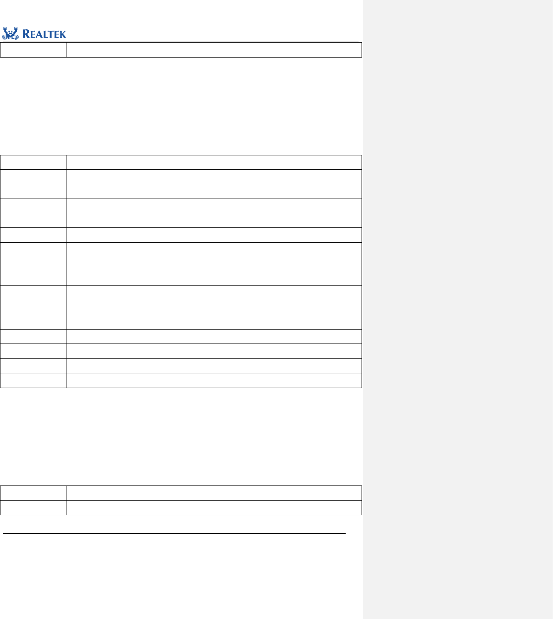
Realtek Confidential
RTL8762C Peripheral Manual
Copyright 2018 Realtek Semiconductor Corporation.
All Rights Reserved.
114
Functions Called
None
Examples:
/* Configure all pin wake up debounce time */
System_WakeUpDebounceTime(10);//10ms
8.1.16 Function System_WakeUpPinEnable
Table8. 18 System_WakeUp_Pin_Enable
Function Name
System_WakeUp_Pin_Enable
Function
Prototype
void System_WakeUp_Pin_Enable(uint8_t Pin_Num, uint8_t Polarity, uint8_t DebounceEn)
Function
Description
Enable the system wake up function of the specified pin
Input Parameter 1
Pin_Num: Pin value to be configured. Refer to related description of Pin_Num for more details.
Input Parameter 2
Polarity: system wake up level polarity,This parameter can be 0 or 1
0:high level active
1:low level active
Input Parameter 3
DebounceEn:Enable or disable PAD debounce function
1: Enable
0: Disable
Output Parameter
None
Return Value
None
Prerequisite
None
Functions Called
None
Examples:
/* Configure P0_2 for low voltage wake up */
System_WakeUpPinEnable(P0_2, 1, 1);
8.1.17 Function System_WakeUpPinDisable
Table8. 19 System_WakeUpPinDisable
Function Name
System_WakeUpPinDisable
Function
void System_WakeUpPinDisable (uint8_t Pin_Num)
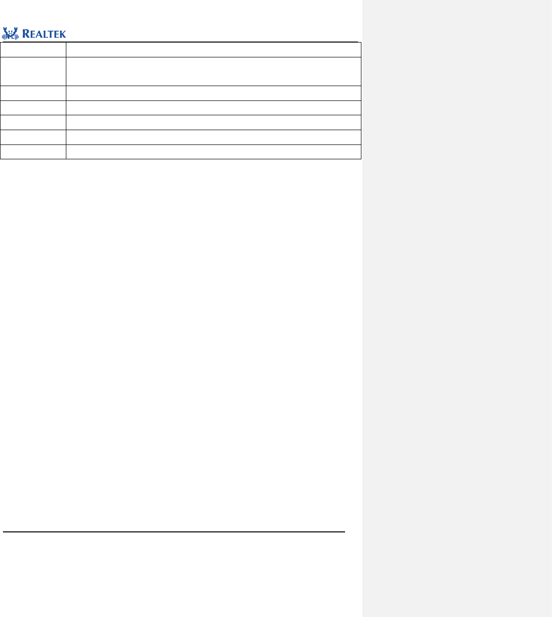
Realtek Confidential
RTL8762C Peripheral Manual
Copyright 2018 Realtek Semiconductor Corporation.
All Rights Reserved.
115
Prototype
Function
Description
Disable system wakeup function of specified pin
Input Parameter
Pin_Num: Pin to be configured. Refer to related description of Pin_Num for more details.
Output Parameter
None
Return Value
None
Prerequisite
None
Functions Called
None
Examples:
/* Disable P0_2 for wake up system */
System_WakeUpPinDisable (P0_2);
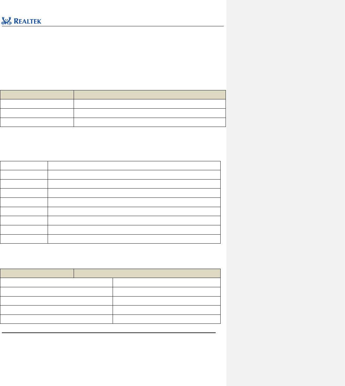
Realtek Confidential
RTL8762C Peripheral Manual
Copyright 2018 Realtek Semiconductor Corporation.
All Rights Reserved.
116
9 Pin Multiplexing (PINMUX)
9. 1 PINMUX Library Functions
All PINMUX library functions are enumerated in Table 9. 1.
Table 9. 1 PINMUX Library Functions
Function Name
Description
Pinmux_Config
Configure function of the pin specified to use
Pinmux_ Deinit
Set specified pins to idle mode (IDLE_MODE)
Pinmux_Reset
Set all pins to idle mode (IDLE_MODE)
9. 1. 1 Function Pinmux_Config
Table 9. 2 Function Pinmux_Config
Function Name
Pinmux_Config
Function Prototype
void Pinmux_Config(uint8_t Pin_Num, uint8_t Pin_Func)
Function Description
Configure function of specified pin
Input Parameter 1
Pin_Num: Pin to be configured. Refer to related description of Pin_Num for more details.
Input Parameter 2
Pin_Func: This parameter is used to set specific functions of target pin.
Output Parameter
None
Return Value
None
Prerequisite
None
Functions Called
None
Pin_Func: All optional functions are as shown in Table 9. 3.
Table 9. 3 Values of Pin_Func
Pin_Func
Description
IDLE
Idle mode
HCI_UART_TX
HCI UART transmission
HCI_UART_RX
HCI UART reception
HCI_UART_CTS
HCI UART sending permitted
HCI_UART_RTS
HCI UART sending requested

Realtek Confidential
RTL8762C Peripheral Manual
Copyright 2018 Realtek Semiconductor Corporation.
All Rights Reserved.
117
I2C0_CLK
Clock line of I2C0
I2C0_DAT
Data line of I2C0
I2C1_CLK
Clock line of I2C1
I2C1_DAT
Data line of I2C1
PWM2_P
PWM2 complementary output channel P
PWM2_N
PWM2 complementary output channel N
PWM3_P
PWM3 complementary output channel P
PWM3_N
PWM3 complementary output channel N
PWM0
PWM Channel 0 output
PWM1
PWM Channel 1 output
PWM2
PWM Channel 2 output
PWM3
PWM Channel 3 output
PWM4
PWM Channel 4 output
PWM5
PWM Channel 5 output
PWM6
PWM Channel 6 output
PWM7
PWM Channel 7 output
qdec_phase_a_x
Axis X of QDEC channel a
qdec_phase_b_x
Axis X of QDEC channel b
qdec_phase_a_y
Axis Y of QDEC channel a
qdec_phase_b_y
Axis Y of QDEC channel b
qdec_phase_a_z
Axis Z of QDEC channel a
qdec_phase_b_z
Axis Z of QDEC channel b
UART2_TX
UART2 transmission
UART2_RX
UART2 reception
UART1_TX
UART1 transmission
UART1_RX
UART1 reception
UART1_CTS
UART1 transmmision permitted
UART1_RTS
UART1 transmmision requested
IRDA_TX
IR transmmision
IRDA_RX
IR reception
UART0_TX
UART0 transmmision
UART0_RX
UART0 reception
UART0_CTS
UART0 transmmision permitted

Realtek Confidential
RTL8762C Peripheral Manual
Copyright 2018 Realtek Semiconductor Corporation.
All Rights Reserved.
118
UART0_RTS
UART0 transmmision requested
SPI1_SS_N_0_MASTER
SPI1 chip select signal channel 0 in master mode
SPI1_SS_N_1_MASTER
SPI1 chip select signal channel 1 in master mode
SPI1_SS_N_2_MASTER
SPI1 chip select signal channel 2 in master mode
SPI1_CLK_MASTER
SPI1 clock line in master mode
SPI1_MO_MASTER
SPI1 MOSI line in master mode
SPI1_MI_MASTER
SPI1 MISO line in master mode
SPI0_SS_N_0_SLAVE
SPI0 chip select signal line in slave mode
SPI0_CLK_SLAVE
SPI0 clock line in slave mode
SPI0_SO_SLAVE
SPI0 MISO line in slave mode
SPI0_SI_SLAVE
SPI0 MOSI line in slave mode
SPI0_SS_N_0_MASTER
SPI0 chip select signal line in master mode
SPI0_CLK_MASTER
SPI0 clock line in master mode
SPI0_MO_MASTER
SPI0 MOSI line in master mode
SPI0_MI_MASTER
SPI0 MISO line in master mode
SPI2W_DATA_MASTER
Data line of two-wire/three-wire SPI in master mode
SPI2W_CLK_MASTER
Clock line of two-wire/three-wire SPI in master mode
SPI2W_CS_MASTER
Chip select line of two-wire/three-wire SPI in master
mode
SWD_CLK
Clock line of SWD
SWD_DIO
Data line of SWD
KEY_COL_0
Column 0 of Keyscan
KEY_COL_1
Column 1 of Keyscan
KEY_COL_2
Column 2 of Keyscan
KEY_COL_3
Column 3 of Keyscan
KEY_COL_4
Column 4 of Keyscan
KEY_COL_5
Column 5 of Keyscan
KEY_COL_6
Column 6 of Keyscan
KEY_COL_7
Column 7 of Keyscan
KEY_COL_8
Column 8 of Keyscan
KEY_COL_9
Column 9 of Keyscan
KEY_COL_10
Column 10 of Keyscan
KEY_COL_11
Column 11 of Keyscan

Realtek Confidential
RTL8762C Peripheral Manual
Copyright 2018 Realtek Semiconductor Corporation.
All Rights Reserved.
119
KEY_COL_12
Column 12 of Keyscan
KEY_COL_13
Column 13 of Keyscan
KEY_COL_14
Column 14 of Keyscan
KEY_COL_15
Column 15 of Keyscan
KEY_COL_16
Column 16 of Keyscan
KEY_COL_17
Column 17 of Keyscan
KEY_COL_18
Column 18 of Keyscan
KEY_COL_19
Column 19 of Keyscan
KEY_ROW_0
Row 0 of Keyscan
KEY_ROW_1
Row 1 of Keyscan
KEY_ROW_2
Row 2 of Keyscan
KEY_ROW_3
Row 3 of Keyscan
KEY_ROW_4
Row 4 of Keyscan
KEY_ROW_5
Row 5 of Keyscan
KEY_ROW_6
Row 6 of Keyscan
KEY_ROW_7
Row 7 of Keyscan
KEY_ROW_8
Row 8 of Keyscan
KEY_ROW_9
Row 8 of Keyscan
KEY_ROW_10
Row 10 of Keyscan
KEY_ROW_11
Row 11 of Keyscan
DWGPIO
GPIO function
LRC_SPORT1
I2S1 Left/Right(Word select) line
BCLK_SPORT1
I2S1 BIT Clock line
ADCDAT_SPORT1
I2S1 Data input line
DACDAT_SPORT1
I2S1 Data output line
DMIC1_CLK
Clock line of Dmic 1
DMIC1_DAT
Data line of Dmic 1
LRC_I_CODEC_SLAVE
Codec I2S Slave Left/Right(Word select) line
BCLK_I_CODEC_SLAVE
I2S BIT clock line
SDI_CODEC_SLAVE
CODEC I2S input
SDO_CODEC_SLAVE
CODEC I2S output
LRC_I_PCM
PCM Left/Right(Word select) line
BCLK_I_PCM
PCM BIT clock line
Realtek Confidential
RTL8762C Peripheral Manual
Copyright 2018 Realtek Semiconductor Corporation.
All Rights Reserved.
120
UART2_CTS
UART2 transmission permitted
UART2_RTS
UART2 transmission requested
BT_COEX_I_0
Reserved
BT_COEX_I_1
Reserved
BT_COEX_I_2
Reserved
BT_COEX_I_3
Reserved
BT_COEX_O_0
Reserved
BT_COEX_O_1
Reserved
BT_COEX_O_2
Reserved
BT_COEX_O_3
Reserved
PTA_I2C_CLK_SLAVE
Reserved
PTA_I2C_DAT_SLAVE
Reserved
PTA_I2C_INT_OUT
Reserved
EN_EXPA
Reserved
EN_EXLNA
Reserved
ANT_SW0
Reserved
ANT_SW1
Reserved
ANT_SW2
Reserved
ANT_SW3
Reserved
LRC_SPORT0
I2S0 Left/Right(Word select) line
BCLK_SPORT0
I2S0 bit clock line
ADCDAT_SPORT0
I2S0 input line
DACDAT_SPORT0
I2S0 output line
MCLK
I2S MCLK output line
Examples:
/* Configure P0_2 for GPIO mode */
Pinmux_Config(P0_2, DWGPIO);
9. 1. 2 Function Pinmux_Deinit
Table 9. 4 Function Pinmux_Deinit
Function Name
Pinmux_Deinit
Function Prototype
void Pinmux_Deinit(uint8_t Pin_Num)
Realtek Confidential
RTL8762C Peripheral Manual
Copyright 2018 Realtek Semiconductor Corporation.
All Rights Reserved.
121
Function Description
Set specified pin to idle mode (IDLE_MODE).
Input Parameter
Pin_Num: Pin to be configured. Refer to related description of Pin_Num for more details.
Output Parameter
None
Return Value
None
Prerequisite
None
Functions Called
None
Examples:
/* Configure P0_2 to idle mode */
Pinmux_Deinit (P0_2);
9. 1. 3 Function Pinmux_Reset
Table 9. 5 Function Pinmux_ Reset
Function Name
Pinmux_Reset
Function Prototype
void Pinmux_Reset(void)
Function Description
Set all pins to idle mode (IDLE_MODE).
Input Parameter
None
Output Parameter
None
Return Value
None
Prerequisite
None
Functions Called
None
Examples:
/* Configure all pin for idle mode */
Pinmux_Reset ();
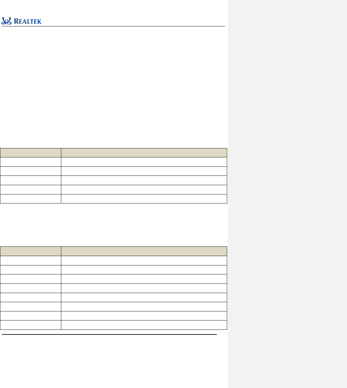
Realtek Confidential
RTL8762C Peripheral Manual
Copyright 2018 Realtek Semiconductor Corporation.
All Rights Reserved.
122
10 Low power comparator(LPC)
10. 1 LPC Register Structures
typedef struct
{
__IO uint32_t LPC_CR0;
__IO uint32_t LPC_SR;
__IO uint32_t LPC_CMP_LOAD;
__IO uint32_t LPC_CMP_CNT;
__IO uint32_t LPC_SR_IN_SLEEP_MODE;
} LPC_TypeDef;
All LPC registers are enumerated in Table 10. 1.
Table 10. 1 LPC Registers
Register
Description
LPC_CR0
Control register 0
LPC_SR
Status register
LPC_CMP_LOAD
Comparator loader register
LPC_CMP_CNT
Comparator counter register
LPC_SR_IN_SLEEP_MODE
Status register in sleep mode
10. 2 LPC LIBRARY FUNCTIONS
All LPC library functions are enumerated in Table 10. 2.
Table 10. 2 LPC Library Functions
Function Name
Description
LPC_Init
Initialize LPC register based on parameters specified in LPC_InitStruct.
LPC_StructInit
Set each parameter in LPC_InitStruct to the default value
LPC_Cmd
Enable or disable LPC
LPC_CounterCmd
Enable or disable LPC counter
LPC_CounterReset
Reset LPC counter
LPC_WriteComparator
Configure LPC comparator value
LPC_ReadComparator
Read LPC comparator value
LPC_ReadCounter
Read LPC counter value
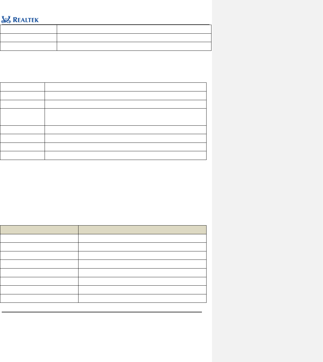
Realtek Confidential
RTL8762C Peripheral Manual
Copyright 2018 Realtek Semiconductor Corporation.
All Rights Reserved.
123
LPC_INTConfig
Enable or disable specified LPC interrupt
LPC_ClearINTPendingBit
Clear specified suspended interrupt.
LPC_GetINTStatus
Acquire specified LPC interrupt status.
10. 2. 1 Function LPC_Init
Table 10. 3 Function LPC_Init
Function Name
LPC_Init
Function Prototype
void LPC_Init(LPC_InitTypeDef *LPC_InitStruct)
Function Description
Initialize LPC register based on parameters specified in LPC_InitStruct.
Input Parameter
LPC_InitStruct: A pointer points to structure LPC_InitTypeDef, which contains
configuration information about peripheral LPC.
Output Parameter
None
Return Value
None
Prerequisite
None
Functions Called
None
LPC_InitTypeDef structure
typedef struct
{
uint16_t LPC_Channel; /*!< Specifies the input pin. */
uint32_t LPC_Edge; /*!< Specifies the comparator output edge */
uint32_t LPC_Threshold; /*!< Specifies the threshold value of comparator voltage. */
} LPC_InitTypeDef;
LPC_Channel: Configure LPC channel. Table 10. 4 lists the available values of this parameter.
Table 10. 4 Values of LPC_Channel
LPC_Channel
Description
LPC_CHANNEL_P2_0
Select P2_0
LPC_CHANNEL_P2_1
Select P2_1
LPC_CHANNEL_P2_2
Select P2_2
LPC_CHANNEL_P2_3
Select P2_3
LPC_CHANNEL_P2_4
Select P2_4
LPC_CHANNEL_P2_5
Select P2_5
LPC_CHANNEL_P2_6
Select P2_6
LPC_CHANNEL_P2_7
Select P2_7
Realtek Confidential
RTL8762C Peripheral Manual
Copyright 2018 Realtek Semiconductor Corporation.
All Rights Reserved.
124
LPC_CHANNEL_VBAT
Select Vbat
LPC_Edge:Set the output polarity of the LPC comparator. Table 10. 5 lists the available values of this parameter.
Table 10. 5 Vaule of LPC_Edge
LPC_Edge
Description
LPC_Vin_Below_Vth
Trigger when channel voltage is lower than threshold
LPC_Vin_Over_Vth
Trigger when channel voltage is higher than threshold
LPC_Threshold:Set the voltage threshold of the LPC comparator. Table 10. 6 lists the available values of this
parameter.
Table 10. 6 Value of LPC_Threshold
LPC_Threshold
Description
LPC_80_mV
The voltage threshold is 80mv
LPC_160_mV
The voltage threshold is 160mv
LPC_240_mV
The voltage threshold is 240mv
LPC_320_mV
The voltage threshold is 320mv
LPC_400_mV
The voltage threshold is 400mv
LPC_480_mV
The voltage threshold is 480mv
LPC_560_mV
The voltage threshold is 560mv
LPC_640_mV
The voltage threshold is 640mv
LPC_680_mV
The voltage threshold is 680mv
LPC_720_mV
The voltage threshold is 720mv
LPC_760_mV
The voltage threshold is 760mv
LPC_800_mV
The voltage threshold is 800mv
LPC_840_mV
The voltage threshold is 840mv
LPC_880_mV
The voltage threshold is 880mv
LPC_920_mV
The voltage threshold is 920mv
LPC_960_mV
The voltage threshold is 960mv
LPC_1000_mV
The voltage threshold is 100mv
LPC_1040_mV
The voltage threshold is 1040mv
LPC_1080_mV
The voltage threshold is 1080mv
LPC_1120_mV
The voltage threshold is 1120mv
LPC_1160_mV
The voltage threshold is 1160mv
LPC_1200_mV
The voltage threshold is 1200mv
LPC_1240_mV
The voltage threshold is 1240mv

Realtek Confidential
RTL8762C Peripheral Manual
Copyright 2018 Realtek Semiconductor Corporation.
All Rights Reserved.
125
LPC_1280_mV
The voltage threshold is 1280mv
LPC_1320_mV
The voltage threshold is 1320mv
LPC_1360_mV
The voltage threshold is 1360mv
LPC_1400_mV
The voltage threshold is 1400mv
LPC_1440_mV
The voltage threshold is 1440mv
LPC_1480_mV
The voltage threshold is 1480mv
LPC_1520_mV
The voltage threshold is 1520mv
LPC_1560_mV
The voltage threshold is 1560mv
LPC_1600_mV
The voltage threshold is 1600mv
LPC_1640_mV
The voltage threshold is 1640mv
LPC_1680_mV
The voltage threshold is 1680mv
LPC_1720_mV
The voltage threshold is 1720mv
LPC_1760_mV
The voltage threshold is 1760mv
LPC_1800_mV
The voltage threshold is 1800mv
LPC_1840_mV
The voltage threshold is 1840mv
LPC_1880_mV
The voltage threshold is 1880mv
LPC_1920_mV
The voltage threshold is 1920mv
LPC_1960_mV
The voltage threshold is 1960mv
LPC_2000_mV
The voltage threshold is 2000mv
LPC_2040_mV
The voltage threshold is 2040mv
LPC_2080_mV
The voltage threshold is 2080mv
LPC_2120_mV
The voltage threshold is 2120mv
LPC_2160_mV
The voltage threshold is 2160mv
LPC_2200_mV
The voltage threshold is 2200mv
LPC_2240_mV
The voltage threshold is 2240mv
LPC_2280_mV
The voltage threshold is 2280mv
LPC_2320_mV
The voltage threshold is 2320mv
LPC_2360_mV
The voltage threshold is 2360mv
LPC_2400_mV
The voltage threshold is 2400mv
LPC_2440_mV
The voltage threshold is 2440mv
LPC_2480_mV
The voltage threshold is 2480mv
LPC_2520_mV
The voltage threshold is 2520mv
LPC_2560_mV
The voltage threshold is 2560mv
Realtek Confidential
RTL8762C Peripheral Manual
Copyright 2018 Realtek Semiconductor Corporation.
All Rights Reserved.
126
LPC_2640_mV
The voltage threshold is 2640mv
LPC_2720_mV
The voltage threshold is 2720mv
LPC_2800_mV
The voltage threshold is 2800mv
LPC_2880_mV
The voltage threshold is 2880mv
LPC_2960_mV
The voltage threshold is 2960mv
LPC_3040_mV
The voltage threshold is 3040mv
LPC_3120_mV
The voltage threshold is 3120mv
LPC_3200_mV
The voltage threshold is 3200mv
Examples:
/* Initialize LPC */
LPC_InitTypeDef LPC_InitStruct;
LPC_InitStruct.LPC_Channel = LPC_CAPTURE_PIN;
LPC_InitStruct.LPC_Edge = LPC_Vin_Below_Vth;
LPC_InitStruct.LPC_Threshold = LPC_1600_mV;
LPC_Init(&LPC_InitStruct);
10. 2. 2 Function LPC_StructInit
Table 10. 7 Function LPC_StructInit
Function Name
LPC_StructInit
Function Prototype
LPC_StructInit(LPC_InitTypeDef* LPC_InitStruct)
Function Description
Set each parameter in LPC_InitStruct to the default value
Input Parameter
LPC_InitStruct: A pointer points to structure LPC_InitTypeDef, which contains
configuration information about peripheral LPC.
Output Parameter
None
Return Value
None
Prerequisite
None
Functions Called
None
Examples:
/* Initialize LPC */
LPC_InitTypeDef LPC_InitStruct;
LPC_StructInit(&LPC_InitStruct);
Realtek Confidential
RTL8762C Peripheral Manual
Copyright 2018 Realtek Semiconductor Corporation.
All Rights Reserved.
127
10. 2. 3 Function LPC_Cmd
Table 10. 8 Function LPC_Cmd
Function Name
LPC_Cmd
Function Prototype
void LPC_Cmd(FunctionalState NewState)
Function Description
Enable or disable LPC
Input Parameter
NewState: New state of LPC channel. This parameter can be:
ENABLE: enable LPC channel
DISABLE: disable LPC channel
Output Parameter
None
Return Value
None
Prerequisite
None
Functions Called
None
Examples:
/* Enable LPC */
LPC_Cmd(ENABLE);
10. 2. 4 Function LPC_CounterCmd
Table 10. 9 Function LPC_CounterCmd
Function Name
LPC_CounterCmd
Function Prototype
void LPC_CounterCmd (FunctionalState NewState)
Function Description
Enable or disable LPC counter
Input Parameter
NewState: New state of LPC channel. This parameter can be:
ENABLE: enable LPC channel
DISABLE: disable LPC channel
Output Parameter
None
Return Value
None
Prerequisite
None
Functions Called
None
Examples:
/* Start LPC counter */
LPC_CounterCmd(ENABLE);
Realtek Confidential
RTL8762C Peripheral Manual
Copyright 2018 Realtek Semiconductor Corporation.
All Rights Reserved.
128
10. 2. 5 Function LPC_CounterReset
Table 10. 10 Function LPC_CounterReset
Function Name
LPC_CounterReset
Function Prototype
void LPC_CounterReset(void)
Function Description
Reset LPC counter
Input Parameter
None
Output Parameter
None
Return Value
None
Prerequisite
None
Functions Called
None
Examples:
/* Reset LPC counter */
LPC_CounterReset();
10. 2. 6 Function LPC_WriteComparator
Table 10. 11 Function LPC_WriteComparator
Function Name
LPC_WriteComparator
Function Prototype
void LPC_WriteComparator(uint32_t data)
Function Description
Configure LPC comparator value
Input Parameter
data: the new comparator value, which ranges from 0x0 to 0xFFF.
Output Parameter
None
Return Value
None
Prerequisite
None
Functions Called
None
Examples:
/*Configure LPC comparator value */
LPC_WriteComparator(0x200);
10. 2. 7 Function LPC_ReadComparator
Table 10. 12 Function LPC_ReadComparator
Function Name
LPC_ReadComparator
Realtek Confidential
RTL8762C Peripheral Manual
Copyright 2018 Realtek Semiconductor Corporation.
All Rights Reserved.
129
Function Prototype
uint16_t LPC_ReadComparator(void)
Function Description
Read LPC comparator value
Input Parameter
None
Output Parameter
None
Return Value
data: the comparator value, which ranges from 0x0 to 0xFFF.
Prerequisite
None
Functions Called
None
Examples:
uint16_t value = 0;
/* Get LPC comparator value */
value = LPC_ReadComparator();
10. 2. 8 Function LPC_ReadCounter
Table 10. 13 Function LPC_ReadCounter
Function Name
LPC_ReadComparator
Function Prototype
uint16_t LPC_ReadCounter (void)
Function Description
Read LPC counter value
Input Parameter
None
Output Parameter
None
Return Value
data: the counter value, which ranges from 0x0 to 0xFFF.
Prerequisite
None
Functions Called
None
Examples:
uint16_t value = 0;
/* Get LPC counter value */
value = LPC_ReadCounter();
10. 2. 9 Function LPC_INTConfig
Table 10. 14 Function LPC_INTConfig
Function Name
LPC_INTConfig
Function Prototype
void LPC_INTConfig(uint32_t LPC_INT, FunctionalState NewState)
Function Description
Enable or disable specified LPC interrupt
Realtek Confidential
RTL8762C Peripheral Manual
Copyright 2018 Realtek Semiconductor Corporation.
All Rights Reserved.
130
Input Parameter 1
LPC_INT: LPC interrupt source need to be enabled or disabled. Refer to related
description in Table 10. 15 for more details.
Input Parameter 2
NewState: new state of interrupt
This parameter can be set to ENABLE or DISABLE.
Output Parameter
None
Return Value
None
Prerequisite
None
Functions Called
None
LPC_INT: Permitted LPC interrupt types are as shown in Table 10. 15. Mutiple interrupts can be selected as values
of the parameter at one time by using operator "|".
Table 10. 15 Value of LPC_INT
LPC_INT
Description
LPC_INT_VOLTAGE_COMP
The interrupt is triggered when the detected voltage meets the output polarity of
the LPC comparator.
LPC_INT_COUNT_COMP
The interrupt is triggered when the counter data equals to the comparator data,.
Examples:
/* Enable voltage detection interrupt.If Vin < Vth, cause this interrupt */
LPC_INTConfig(LPC_INT_VOLTAGE_COMP, ENABLE);
10. 2. 10 Function LPC_ClearINTPendingBit
Table 10. 16 Function LPC_ClearINTPendingBit
Function Name
LPC_ClearINTPendingBit
Function Prototype
void LPC_INTConfig(uint32_t LPC_INT, FunctionalState NewState)
Function Description
Clear specified suspended interrupt.
Input Parameter
LPC_INT: LPC Interrupt flag to be cleared. Refer to related description of Table 10. 17 for
more details.
Output Parameter
None
Return Value
None
Prerequisite
None
Functions Called
None
LPC_INT: The Permitted LPC interruption type is shown as shown in Table 10. 17.
Table 10. 17 Value of LPC_INT
Realtek Confidential
RTL8762C Peripheral Manual
Copyright 2018 Realtek Semiconductor Corporation.
All Rights Reserved.
131
LPC_INT
Description
LPC_INT_COUNT_COMP
The interrupt triggered when the counter data equals to the comparator data.
Examples:
/* Clear comparator interrupt */
LPC_ClearINTPendingBit(LPC_INT_COUNT_COMP);
10. 2. 11 Function LPC_GetINTStatus
Table 10. 18 Function LPC_GetINTStatus
Function Name
LPC_GetINTStatus
Function Prototype
ITStatus LPC_GetINTStatus(uint32_t LPC_INT)
Function Description
Acquire specified LPC interrupt status.
Input Parameter
LPC_INT : the specified interrupt.
Output Parameter
None
Return Value
New state (SET OR RESET) of the interrupt specified by LPC.
Prerequisite
None
Functions Called
None
Examples:
/* Get LPC the specified interrupt status */
ITStatus LPC_Status = RESET;
LPC_Status = LPC_GetINTStatus(LPC_INT_COUNT_COMP);
Realtek Confidential
RTL8762C Peripheral Manual
Copyright 2018 Realtek Semiconductor Corporation.
All Rights Reserved.
132
11 Real-Time Clock (RTC)
11. 1 RTC Register Structure
typedef struct
{
__IO uint32_t CR0;
__IO uint32_t INT_MASK;
__IO uint32_t INT_SR;
__IO uint32_t PRESCALER;
__IO uint32_t COMP0;
__IO uint32_t COMP1;
__IO uint32_t COMP2;
__IO uint32_t COMP3;
__I uint32_t CNT;
} RTC_TypeDef;
All RTC registers are enumerated in Table 11. 1.
Table 11. 1 RTC Registers
Register
Description
CR0
Control Register 0
INT_MASK
Interrupt mask register
INT_SR
Interrupt status register
PRESCALER
Prescaler register
COMP0
Comparator 0 register
COMP1
Comparator 1 register
COMP2
Comparator 2 register
COMP3
Comparator 3 register
CNT
Counter register
11. 2 RTC Library Functions
All RTC library functions are enumerated in Table 11. 2.
Table 11. 2 RTC Library Functions
Function Name
Description
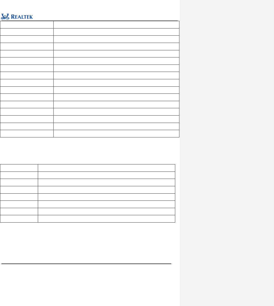
Realtek Confidential
RTL8762C Peripheral Manual
Copyright 2018 Realtek Semiconductor Corporation.
All Rights Reserved.
133
RTC_DeInit
Reset RTC.
RTC_SetPrescaler
Configure frequency division factor of RTC.
RTC_SetComp
Configure RTC comparator channel and value.
RTC_RunCmd
Start or stop RTC peripheral.
RTC_MaskINTConfig
Mask or unmask the specified interrupt.
RTC_CompINTConfig
Enabe or disable comparison interrupt of specified RTC channel.
RTC_TickINTConfig
Enable or disable RTC tick interrupt.
RTC_GetINTStatus
Get specified interrupt status.
RTC_SystemWakeupConfig
Enable or disable RTC system wakeup function.
RTC_GetCounter
Get RTC current counter value.
RTC_ResetCounter
Reset RTC counter.
RTC_GetComp
Get value from specified RTC channel.
RTC_ClearCompINT
Clear comparison interrupt of specified RTC channel.
RTC_ClearOverFlowINT
Clear overflow interrupt.
RTC_ClearTickINT
Clear tick interrupt.
RTC_SleepModeClkConfig
Configure clock source in sleep mode.
11. 2. 1 Function RTC_DeInit
Table 11. 3 Function RTC_DeInit
Function Name
RTC_DeInit
Function Prototype
void RTC_DeInit(void)
Function Description
Reset RTC peripheral.
Input Parameter
None
Output Parameter
None
Return Value
None
Prerequisite
None
Functions Called
None
Examples:
/* Reset RTC */
RTC_DeInit ();
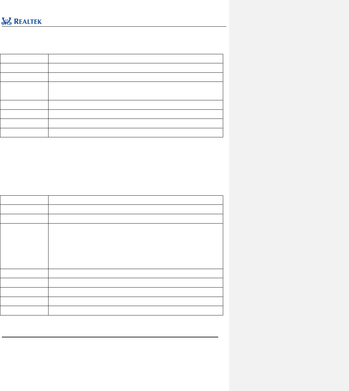
Realtek Confidential
RTL8762C Peripheral Manual
Copyright 2018 Realtek Semiconductor Corporation.
All Rights Reserved.
134
11. 2. 2 Function RTC_SetPrescaler
Table 11. 4 Function RTC_SetPrescaler
Function Name
RTC_SetPrescaler
Function Prototype
void RTC_SetPrescaler(uint32_t PrescaleValue)
Function Description
Set frequency division factor of RTC.
Input Parameter
PrescaleValue:Prescaler value ranges from 0x00 to 0xfff.
counter frequency(Hz) = RTC clock frequency/(𝑃𝑟𝑒𝑠𝑐𝑎𝑙𝑒𝑉𝑎𝑙𝑢𝑒 + 1)
Output Parameter
None
Return Value
None
Prerequisite
This function is only permitted to be called when RTC is stopped.
Functions Called
None
Examples:
/* Configure RTC prescaler */
RTC_ SetPrescaler (0);
11. 2. 3 Function RTC_SetComp
Table 11. 5 Function RTC_SetComp
Function Name
RTC_SetComp
Function Prototype
void RTC_SetComp(uint8_t index, uint32_t value)
Function Description
void RTC_SetComp(uint8_t index, uint32_t value)
Input Parameter 1
index: Index number of comparator channel, which can be set to 0 ~ 3.
0: Comparator 0
1: Comparator 1
2: Comparator 2
3: Comparator 3
Input Parameter 2
vaule: comparator value to be set, ranging from 0x00 to 0xffffff.
Output Parameter
None
Return Value
None
Prerequisite
None
Functions Called
None
Examples:
/* Configure RTC comparator 0 */
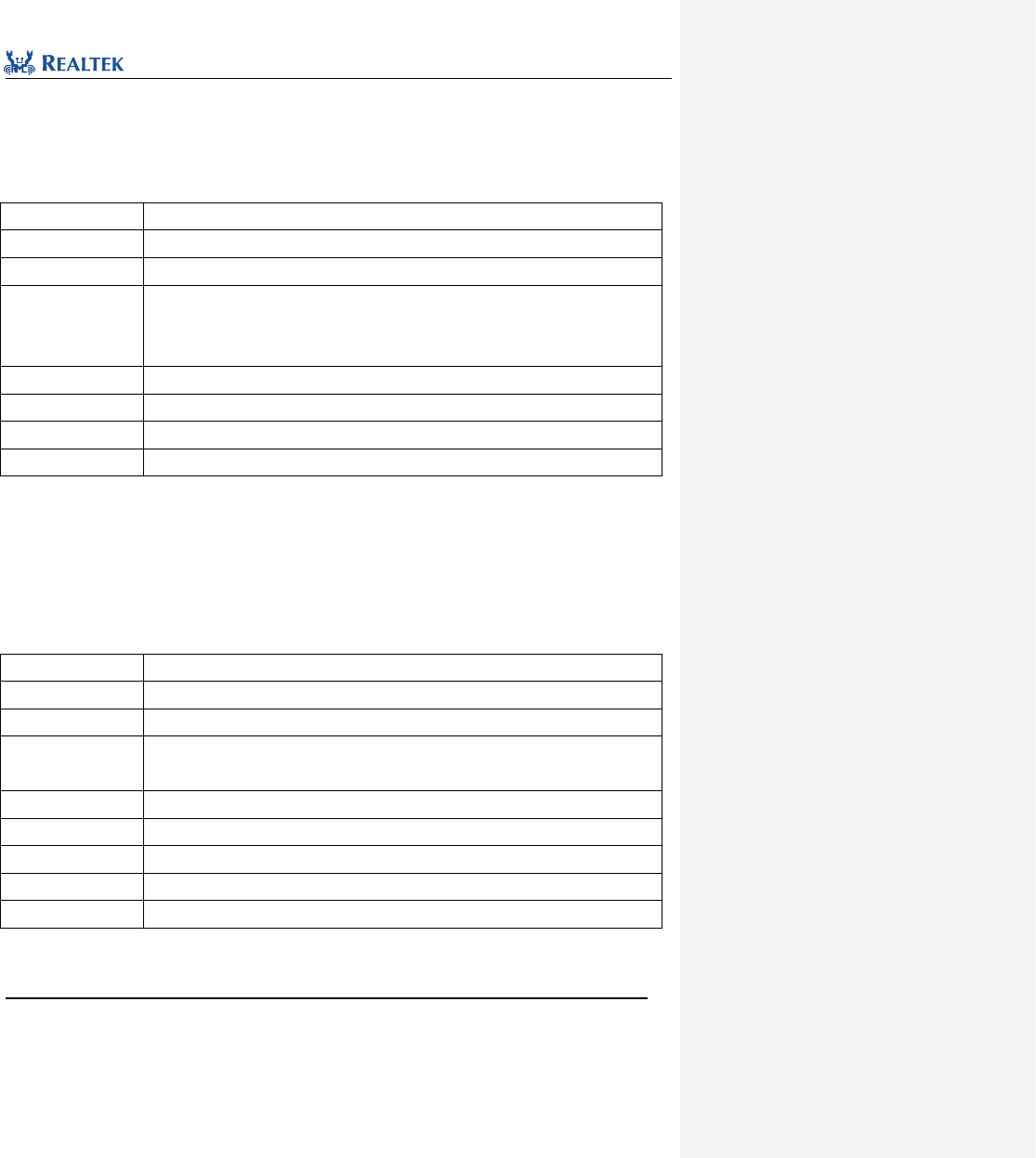
Realtek Confidential
RTL8762C Peripheral Manual
Copyright 2018 Realtek Semiconductor Corporation.
All Rights Reserved.
135
RTC_SetCOMPValue(0, 32768);
11. 2. 4 Function RTC_RunCmd
Table 11. 6 Function RTC_RunCmd
Function Name
RTC_RunCmd
Function Prototype
void RTC_RunCmd(FunctionalState NewState)
Function Description
Start or stop RTC peripheral.
Input Parameter
NewState: New state of RTC peripheral. This parameter can be:
ENABLE: Start RTC.
DISABLE: Stop RTC.
Output Parameter
None
Return Value
None
Prerequisite
None
Functions Called
None
Examples:
/* Start RTC */
RTC_RunCmd(ENABLE);
11. 2. 5 Function RTC_MaskINTConfig
Table 11. 7 Function RTC_MaskINTConfig
Function Name
RTC_MaskINTConfig
Function Prototype
void RTC_MaskINTConfig(uint32_t RTC_INT, FunctionalState NewState)
Function Description
Mask or unmask the specified RTC interrupt.
Input Parameter 1
RTC_INT: RTC interrupt source need to be masked or unmasked. Refer to related
description in Table 11. 8 for more details.
Input Parameter 2
NewState: New state of interrupt. This parameter can be ENALBE or DISABLE.
Output Parameter
None
Return Value
None
Prerequisite
None
Functions Called
None
RTC_INT: Permitted RTC interrupt types are as shown in Table 11. 8. Mutiple interrupts can be selected at one time by
using operator "|".
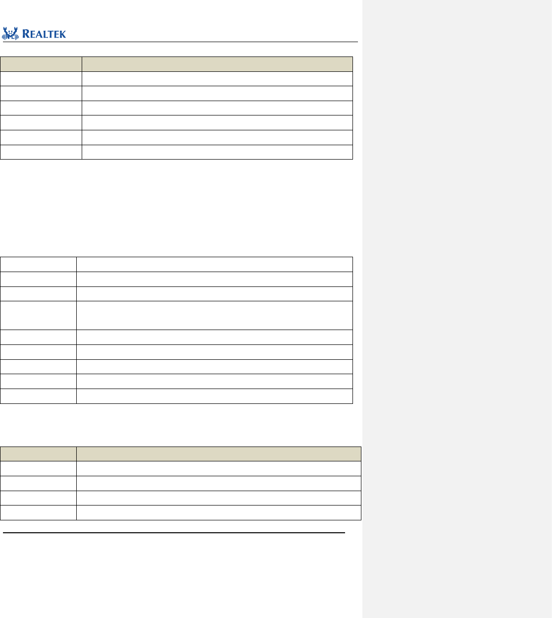
Realtek Confidential
RTL8762C Peripheral Manual
Copyright 2018 Realtek Semiconductor Corporation.
All Rights Reserved.
136
Table 11. 8 Values of RTC_INT
RTC_INT
Description
RTC_INT_TICK
Tick interrupt
RTC_INT_OVF
RTC counter overflow interrupt
RTC_INT_CMP0
Comparator Channel 0 count interrupt
RTC_INT_CMP1
Comparator Channel 1 count interrupt
RTC_INT_CMP2
Comparator Channel 2 count interrupt
RTC_INT_CMP3
Comparator Channel 3 count interrupt
Examples:
/* Unmask RTC overflow interrupt */
RTC_MaskINTConfig(RTC_INT_OVF, DISABLE);
11. 2. 6 Function RTC_CompINTConfig
Table 11. 9 Function RTC_CompINTConfig
Function Name
RTC_CompINTConfig
Function Prototype
void RTC_CompINTConfig(uint32_t RTC_INT, FunctionalState NewState)
Function Description
Enabe or disable RTC comparator interrupt.
Input Parameter 1
RTC_INT: RTC comparator interrupt source needed to be enabled or disabled. Refer to
related description in Table 11. for more details.
Input Parameter 2
NewState: New state of interrupt. This parameter can be ENALBE or DISABLE.
Output Parameter
None
Return Value
None
Prerequisite
None
Functions Called
None
RTC_INT: Permitted RTC interrupt types are as shown in Table 11. 8. Mutiple interrupts can be selected at one
time by using operator "|".
Table 11. 10 Value of RTC_INT
RTC_INT
Description
RTC_INT_CMP0
Comparator Channel 0 count interrupt
RTC_INT_CMP1
Comparator Channel 1 count interrupt
RTC_INT_CMP2
Comparator Channel 2 count interrupt
RTC_INT_CMP3
Comparator Channel 3 count interrupt
Realtek Confidential
RTL8762C Peripheral Manual
Copyright 2018 Realtek Semiconductor Corporation.
All Rights Reserved.
137
Examples:
/* Enable RTC comparator 1 interrupt */
RTC_CompINTConfig(RTC_INT_CMP_1, ENABLE);
11. 2. 7 Function RTC_TickINTConfig
Table 11. 9 Function RTC_TickINTConfig
Function Name
RTC_TickINTConfig
Function Prototype
void RTC_TickINTConfig(FunctionalState NewState)
Function Description
Enable or disable RTC tick interrupt.
Input Parameter
NewState: New state of interrupt. This parameter can be ENALBE or DISABLE.
Output Parameter
None
Return Value
None
Prerequisite
None
Functions Called
None
Examples:
/* Enable RTC tick interrupt */
RTC_TickINTConfig(ENABLE);
11. 2. 8 Function RTC_GetINTStatus
Table 11. 11 Function RTC_GetINTStatus
Function Name
RTC_GetINTStatus
Function Prototype
ITStatus RTC_GetINTStatus(uint32_t RTC_INT)
Function Description
Get the specified interrupt status
Input Parameter
RTC_INT: the specified RTC interrupt source. Refer to related description in Table 11. 8
for more details.
Output Parameter
None
Return Value
New state (SET OR RESET) of the interrupt specified by RTC.
Prerequisite
None
Functions Called
None
Examples:
/* Get RTC comparator 1 interrupt status */
ITStatus status = RESET;
status = RTC_GetINTStatus(RTC_INT_CMP_1);
Realtek Confidential
RTL8762C Peripheral Manual
Copyright 2018 Realtek Semiconductor Corporation.
All Rights Reserved.
138
11. 2. 9 Function RTC_SystemWakeupConfig
Table 11. 10 Function RTC_SystemWakeupConfig
Function Name
RTC_SystemWakeupConfig
Function Prototype
void RTC_SystemWakeupConfig(FunctionalState NewState)
Function Description
Enable or disable RTC system wakeup function
Input Parameter
NewState: New state of interrupt. This parameter can be ENALBE or DISABLE.
Output Parameter
None
Return Value
None
Prerequisite
None
Functions Called
None
Examples:
/* Enable RTC system wake up function */
RTC_SystemWakeupConfig(ENABLE);
11. 2. 10 Function RTC_GetCounter
Table 11. 11 Function RTC_GetCounter
Function Name
RTC_GetCounter
Function Prototype
uint32_t RTC_GetCounter(void)
Function Description
Get RTC current counter value
Input Parameter
None
Output Parameter
None
Return Value
RTC counter value
Prerequisite
None
Functions Called
None
Examples:
/* Get RTC counter value */
uint32_t value = 0;
value = RTC_GetCounter();
11. 2. 11 Function RTC_ResetCounter
Table 11. 12 Function RTC_ResetCounter

Realtek Confidential
RTL8762C Peripheral Manual
Copyright 2018 Realtek Semiconductor Corporation.
All Rights Reserved.
139
Function Name
RTC_ResetCounter
Function Prototype
void RTC_ResetCounter(void)
Function Description
Reset RTC counter
Input Parameter
None
Output Parameter
None
Return Value
None
Prerequisite
None
Functions Called
None
Examples:
/* Clear RTC counter value */
RTC_ResetCounter();
11. 2. 12 Function RTC_GetComp
Table 11. 13 Function RTC_GetComp
Function Name
RTC_GetComp
Function Prototype
uint32_t RTC_GetComp(uint8_t index)
Function Description
Get the specified comparator value
Input Parameter
index: Index number of comparator channel, which can be set to 0 ~ 3.
0: Comparator 0
1: Comparator 1
2: Comparator 2
3: Comparator 3
Output Parameter
None
Return Value
The specified comparator value
Prerequisite
None
Functions Called
None
Examples:
/* Get RTC comparator 1 value */
uint32_t value = 0;
vaue = RTC_GetComp(1);
11. 2. 13 Function RTC_ClearCompINT
Table 11. 14 Function RTC_ClearCompINT
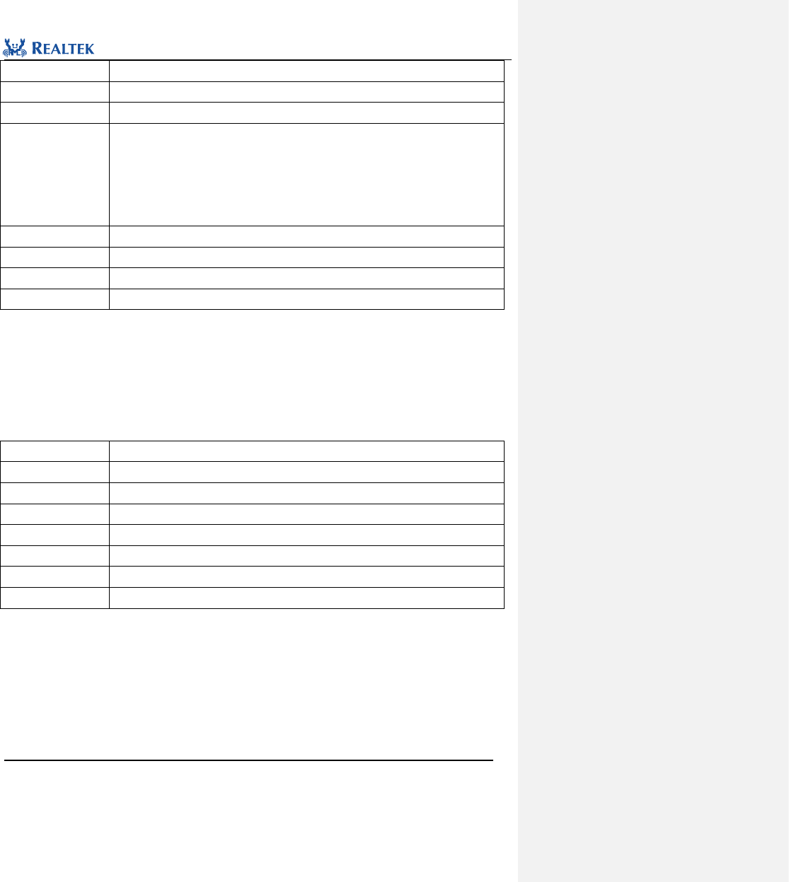
Realtek Confidential
RTL8762C Peripheral Manual
Copyright 2018 Realtek Semiconductor Corporation.
All Rights Reserved.
140
Function Name
RTC_ClearCompINT
Function Prototype
void RTC_ClearCompINT(uint8_t index)
Function Description
Clear the specified comparator interrupt
Input Parameter
index: Index of comparator channel, ranging from 0 to 3.
0: Comparator 0
1: Comparator 1
2: Comparator 2
3: Comparator 3
Output Parameter
None
Return Value
None
Prerequisite
None
Functions Called
None
Examples:
/* Clear RTC comparator 1 interrupt */
RTC_ClearCompINT(1);
11. 2. 14 Function RTC_ClearOverFlowINT
Table 11. 15 Function RTC_ClearOverFlowINT
Function Name
RTC_ClearOverFlowINT
Function Prototype
void RTC_ClearOverFlowINT(void)
Function Description
Clear overflow interrupt
Input Parameter
None
Output Parameter
None
Return Value
None
Prerequisite
None
Functions Called
None
Examples:
/* Clear RTC overflow interrupt */
RTC_ClearOverFlowINT();
11. 2. 15 Function RTC_ClearTickINT
Table 11. 16 Function RTC_ClearTickINT
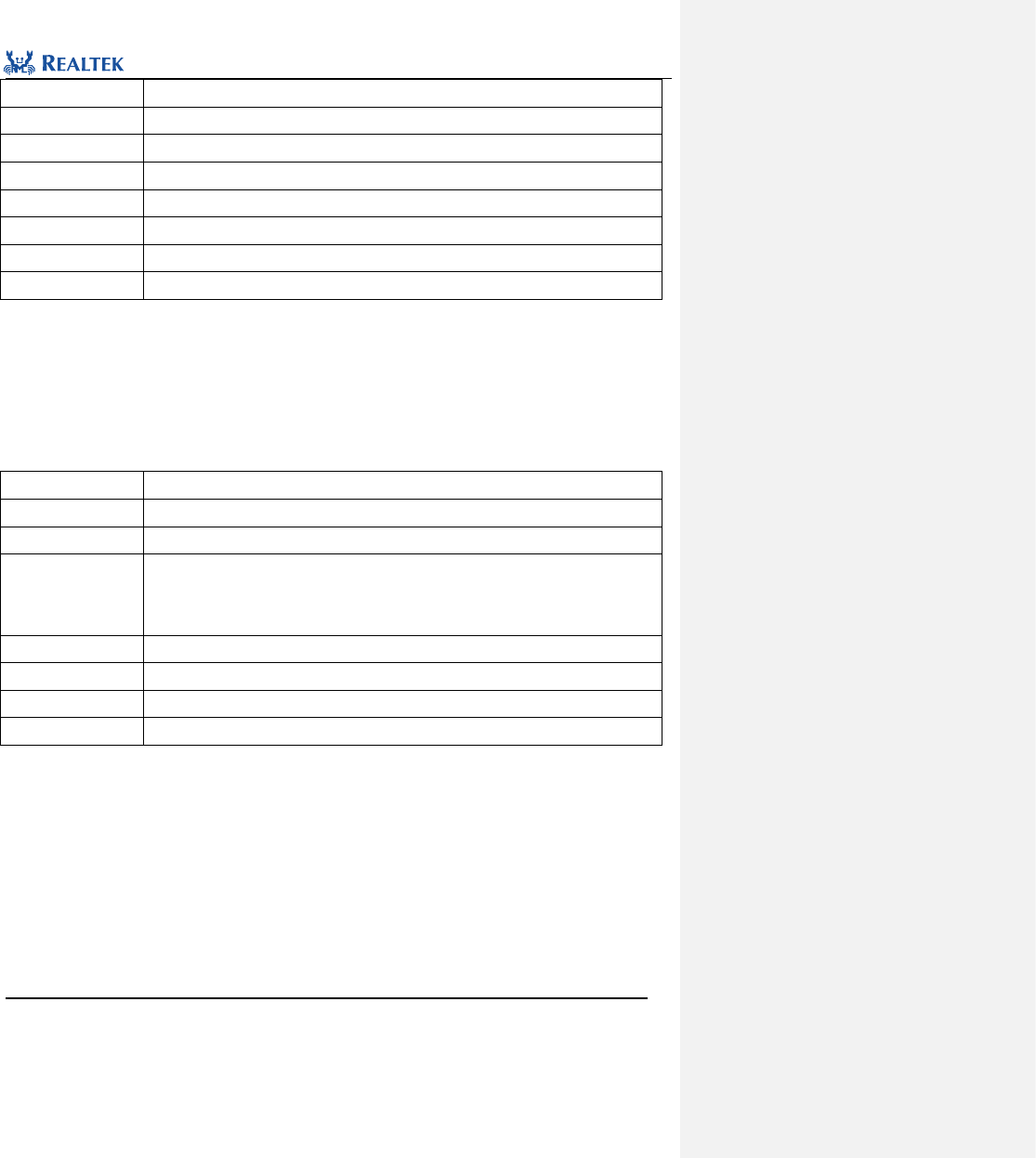
Realtek Confidential
RTL8762C Peripheral Manual
Copyright 2018 Realtek Semiconductor Corporation.
All Rights Reserved.
141
Function Name
RTC_ClearTickINT
Function Prototype
void RTC_ClearTickINT(void)
Function Description
Clear tick interrupt
Input Parameter
None
Output Parameter
None
Return Value
None
Prerequisite
None
Functions Called
None
Examples:
/* Clear RTC tick interrupt */
RTC_ ClearTickINT ();
11. 2. 16 Function RTC_SleepModeClkConfig
Table 11. 17 Function RTC_SleepModeClkConfig
Function Name
RTC_SleepModeClkConfig
Function Prototype
void RTC_SleepModeClkConfig(uint32_t clock)
Function Description
Configure RTC clock source in sleep mode
Input Parameter
Clock:Clock source type, available values are:
RTC_EXTERNAL_CLK: external clock(xtal or osc)
RTC_INTERNAL_CLK: internal 32kHz after calibration
Output Parameter
None
Return Value
None
Prerequisite
None
Functions Called
None
Examples:
/* Configure RTC clock source */
RTC_SleepModeClkConfig(RTC_INTERNAL_CLK);

Realtek Confidential
RTL8762C Peripheral Manual
Copyright 2018 Realtek Semiconductor Corporation.
All Rights Reserved.
142
Realtek Confidential
RTL8762C Peripheral Manual
Copyright 2018 Realtek Semiconductor Corporation.
All Rights Reserved.
143
12 Serial Peripheral Interface(SPI)
12.1 SPI Register Architecture
typedef struct
{
__IO uint32_t CTRLR0;
__IO uint32_t CTRLR1;
__IO uint32_t SSIENR;
__IO uint32_t RSVD_0C;
__IO uint32_t SER;
__IO uint32_t BAUDR;
__IO uint32_t TXFTLR;
__IO uint32_t RXFTLR;
__I uint32_t TXFLR;
__I uint32_t RXFLR;
__I uint32_t SR;
__IO uint32_t IMR;
__I uint32_t ISR;
__I uint32_t RISR;
__I uint32_t TXOICR;
__I uint32_t RXOICR;
__I uint32_t RXUICR;
__I uint32_t RSVD_44;
__I uint32_t ICR;
__IO uint32_t DMACR;
__IO uint32_t DMATDLR;
__IO uint32_t DMARDLR;
__I uint32_t IDR;
__I uint32_t SSI_COMP_VERSION;
__IO uint32_t DR[36];
__IO uint32_t RX_SAMPLE_DLY;
}SPI_TypeDef;
All SPI registers are enumerated in Table 12. 1.
Table 12. 1 SPI Registers
Register
Description
CTRLR0
SPI Control Register 0
CTRLR1
SPI Control Register 1
Realtek Confidential
RTL8762C Peripheral Manual
Copyright 2018 Realtek Semiconductor Corporation.
All Rights Reserved.
144
SSIENR
SPI Enable Register
RSVD_0C
Reserved
SER
Slave Enable Register
BAUDR
Baud Rate Selection Register
TXFTLR
Transmit FIFO Threshold Level Register
RXFTLR
Receive FIFO Threshold Level Register
TXFLR
Transmit FIFO Level Register
RXFLR
Receive FIFO Level Register
SR
Status Register
IMR
Interrupt Mask Register
ISR
Interrupt Status Register
RISR
Raw Interrupt Status Register
TXOICR
Transmit FIFO Overflow Interrupt Clear Register
RXOICR
Receive FIFO Overflow Interrupt Clear Register
RXUICR
Receive FIFO Underflow Interrupt Clear Register
RSVD_44
Reserved
ICR
Interrupt Clear Register
DMACR
DMA Control Register
DMATDLR
DMA Transmit Data Level Register
DMARDLR
DMA Receive Data Level Register
IDR
Identification Register
SSI_COMP_VERSION
SPI IP Core Version register
DR[36]
Data Registers
RX_SAMPLE_DLY
RXD Sample Delay Register
12.2 SPI SPI Library Functions
Table 12. 2 enumerate all SPI library functions.
Function Name
Description
SPI_DeInit
Disable the specified SPI clock.
SPI_Init
Initialize SPI register based on parameters specified in SPI_InitStruct.
SPI_StructInit
Initialize SPI register based on parameters specified in SPI_InitStruct.
SPI_Cmd
Enable or disable the specified SPI peripheral module.
Realtek Confidential
RTL8762C Peripheral Manual
Copyright 2018 Realtek Semiconductor Corporation.
All Rights Reserved.
145
SPI_SendBuffer
Send data through SPI peripheral.
SPI_SendWord
Send 4-byte data through SPI peripheral
SPI_SendHalfWord
Send 2-byte data through SPI peripheral
SPI_INTConfig
Enable or disable the interrupt source specified by SPI.
SPI_ClearINTPendingBit
Clear suspended SPI interrupt flag.
SPI_SendData
Transfer data through SPI peripheral.
SPI_ReceiveData
Receive data through SPI peripheral.
SPI_GetRxFIFOLen
Get data length of receive FIFO.
SPI_GetTxFIFOLen
Get data length of transmit FIFO.
SPI_ChangeDirection
Re-configure SPI data transmission mode.
SPI_SetReadLen
Set length of data to be read.
SPI_SetCSNumber
Set chip select signal.
SPI_GetFlagState
Check the specified SPI peripheral flag.
SPI_GetINTStatus
Check the specified SPI peripheral interrupt source.
SPI_GDMACmd
Set GDMA request type during SPI transmission.
12.2.1 Function SPI_DeInit
Table 12. 3 Function SPI_DeInit
Function Name
SPI_DeInit
Function Prototype
void SPI_DeInit(SPI_TypeDef* SPIx)
Function Description
Disable the specified SPI clock.
Input Parameter 1
SPIx: x can be set to 0 or 1 to select the specified SPI peripheral.
Output Parameter
None
Return Value
None
Prerequisite
None
Functions Called
RCC_PeriphClockCmd()
Examples:
/* Close SPI0 clock */
SPI_DeInit(SPI0);
Realtek Confidential
RTL8762C Peripheral Manual
Copyright 2018 Realtek Semiconductor Corporation.
All Rights Reserved.
146
12.2.2 Function SPI_Init
Table 12. 4 Function SPI_Init
Function Name
SPI_Init
Function Prototype
void SPI_Init(SPI_TypeDef* SPIx, SPI_InitTypeDef* SPI_InitStruct)
Function Description
Initialize SPI register based on parameters specified in SPI_InitStruct.
Input Parameter 1
SPIx: x can be set to 0 or 1 to select the specified SPI peripheral.
Input Parameter 2
SPI_InitStruct: A pointer to SPI_InitTypeDef, and related configuration information is
contained in SPI_InitStruct.
Output Parameter
None
Return Value
None
Prerequisite
None
Functions Called
None
typedef struct
{
uint16_t SPI_Direction;
uint16_t SPI_Mode;
uint16_t SPI_DataSize;
uint16_t SPI_CPOL;
uint16_t SPI_CPHA;
uint32_t SPI_SwapTxBitEn;
uint32_t SPI_SwapRxBitEn;
uint32_t SPI_SwapTxByteEn;
uint32_t SPI_SwapRxByteEn;
uint32_t SPI_ToggleEn;
uint32_t SPI_BaudRatePrescaler;
uint16_t SPI_FrameFormat;
uint32_t SPI_TxThresholdLevel;
uint32_t SPI_RxThresholdLevel;
uint32_t SPI_NDF;
} SPI_InitTypeDef;
SPI_Direction: Set data transer mode of SPI. Table 12. 5 lists values available to this parameter.
Table 12. 5 Values of SPI_Dirention
SPI_Dirention
Description
SPI_Direction_FullDuplex
Full duplex mode
SPI_Direction_TxOnly
Send-only mode
Realtek Confidential
RTL8762C Peripheral Manual
Copyright 2018 Realtek Semiconductor Corporation.
All Rights Reserved.
147
SPI_Direction_RxOnly
receive-only mode
SPI_Direction_EEPROM
EEPROM mode
SPI_Mode: Set operation mode of SPI. Table 12. 6 lists values available to this parameter.
Table 12. 6 Values of SPI_Mode
SPI_Dirention
Description
SPI_Mode_Master
Master device mode
SPI_Mode_Slave
Slave device mode
SPI_DataSize: Set data size of SPI. Table 12. 7 lists values available to this parameter.
Table 12. 7 Values of SPI_DataSize
SPI_DataSize
Description
SPI_DataSize_4b
SPI sends/receives 4-bit frame structure
SPI_DataSize_5b
SPI sends/receives 5-bit frame structure
SPI_DataSize_6b
SPI sends/receives 6-bit frame structure
SPI_DataSize_7b
SPI sends/receives 7-bit frame structure
SPI_DataSize_8b
SPI sends/receives 8-bit frame structure
SPI_DataSize_9b
SPI sends/receives 9-bit frame structure
SPI_DataSize_10b
SPI sends/receives 10-bit frame structure
SPI_DataSize_11b
SPI sends/receives 11-bit frame structure
SPI_DataSize_12b
SPI sends/receives 12-bit frame structure
SPI_DataSize_13b
SPI sends/receives 13-bit frame structure
SPI_DataSize_14b
SPI sends/receives 14-bit frame structure
SPI_DataSize_15b
SPI sends/receives 15-bit frame structure
SPI_DataSize_16b
SPI sends/receives 16-bit frame structure
SPI_DataSize_17b
SPI sends/receives 17-bit frame structure
SPI_DataSize_18b
SPI sends/receives 18-bit frame structure
SPI_DataSize_19b
SPI sends/receives 19-bit frame structure
SPI_DataSize_20b
SPI sends/receives 20-bit frame structure
SPI_DataSize_21b
SPI sends/receives 21-bit frame structure
SPI_DataSize_22b
SPI sends/receives 22-bit frame structure
SPI_DataSize_23b
SPI sends/receives 23-bit frame structure
SPI_DataSize_24b
SPI sends/receives 24-bit frame structure
Realtek Confidential
RTL8762C Peripheral Manual
Copyright 2018 Realtek Semiconductor Corporation.
All Rights Reserved.
148
SPI_DataSize_25b
SPI sends/receives 25-bit frame structure
SPI_DataSize_26b
SPI sends/receives 26-bit frame structure
SPI_DataSize_27b
SPI sends/receives 27-bit frame structure
SPI_DataSize_28b
SPI sends/receives 28-bit frame structure
SPI_DataSize_29b
SPI sends/receives 29-bit frame structure
SPI_DataSize_30b
SPI sends/receives 30-bit frame structure
SPI_DataSize_31b
SPI sends/receives 31-bit frame structure
SPI_DataSize_32b
SPI sends/receives 32-bit frame structure
SPI_CPOL: Set stable state of serial clock. Table 12. 8 lists values available to this parameter.
Table 12. 8 Values of SPI_CPOL
SPI_CPOL
Description
SPI_CPOL_Low
Inactive Clock is low
SPI_CPOL_High
Inactive Clock is high
SPI_CPHA: Set clock active edge for bit capture. Table 12. 9 lists values available to this parameter.
Table 12. 9 Values of SPI_CPHA
SPI_CPOL
Description
SPI_CPHA_1Edge
Data captured at the first clock edge
SPI_CPHA_2Edge
Data captured at the second clock edge
SPI_SwapRxBitEn:Determine if necessary to reverse bit receiving sequence when receiving data through SPI.
Table 12. 10 lists values available to this parameter.
Table 12. 10 values of SPI_SwapRxBitEn
SPI_SwapRxBitEn
Description
SPI_SWAP_DISABLE
Receive data from LSB
SPI_SWAP_ENABLE
Receive data from MSB
SPI_SwapTxBitEn:Determine if necessary to reverse bit receiving sequence when transmitting data through SPI.
Table 12. 11 lists values available to this parameter.
Table 12. 11 Values of SPI_SwapTxBitEn
SPI_SwapTxBitEn
Description
SPI_SWAP_DISABLE
Send data from LSB
Realtek Confidential
RTL8762C Peripheral Manual
Copyright 2018 Realtek Semiconductor Corporation.
All Rights Reserved.
149
SPI_SWAP_ENABLE
Send data from MSB
SPI_SwapRxByteEn:Determine if necessary to reverse byte receive sequence when receiving data through SPI.
Table 12. 12 lists values available to this parameter.
Table 12. 12 Values of SPI_SwapRxByteEn
SPI_SwapRxByteEn
Description
SPI_SWAP_DISABLE
Receive data from low byte
SPI_SWAP_ENABLE
Receive data from high byte
SPI_SwapTxByteEn:Determine if necessary to reverse byte receive sequence when receiving data through
SPI.Table 12. 13 lists values available to this parameter.
Table 12. 13 Values of SPI_SwapTxByteEn
SPI_SwapTxByteEn
Description
SPI_SWAP_DISABLE
Send data from low byte
SPI_SWAP_ENABLE
Send data from high byte
SPI_ToggleEn:Determine if necessary to trigger CS signal when SPI is sending data continuouslyTable 12. 14 lists
values available to this parameter.
Table 12. 14 Values of SPI_ToggleEn
SPI_ToggleEn
Description
DISABLE
cs signal isn’t pulled up for every sending data
ENABLE
cs signal is pulled up for every sending data
SPI_BaudRatePrescaler:Set clock frequency division factor for SPI peripherals. The factor must be even and the
maximum value is divide-by-2.
SPI_FrameFormat:This parameter is used to configure data transmission format for SPI. Table 12. 15 lists values
available to this parameter.
Table 12. 15 Values of SPI_FrameFormat
SPI_FrameFormat
Description
SPI_Frame_Motorola
Motorola transmission format
SPI_Frame_TI_SSP
TI transmission format
SPI_Frame_NS_MICROWIRE
Reserved
SPI_Frame_Reserve
Reserved
Realtek Confidential
RTL8762C Peripheral Manual
Copyright 2018 Realtek Semiconductor Corporation.
All Rights Reserved.
150
SPI_TxThresholdLevel: Set threshold of transmit FIFO, exceeding the threshold will trigger SPI_INT_TXE
interrupt.
SPI_RxThresholdLevel: Set the threshold of receive FIFO. SPI_INT_RXF interrupt will be triggered when number
of the data in receive FIFO is larger than the threshold.
SPI_NDF: Set the threshold for length of data to be read by SPI in EEPROM mode, which shall be the desired data
length minus one. For example, if SPI reads 256 data in EEPROM mode, this parameter shall be set to 255. This
parameter is invalid in other transmission mode.
SPI_RxDmaEn:Enable or disable DMA data receive function.Table 12. 16 lists values available to this parameter.
Table 12. 16 Values of SPI_RxDmaEn
SPI_RxDmaEn
Description
DISABLE
Disable DMA data receive function
ENABLE
Enable DMA data receive function
SPI_TxDmaEn:Enable or disable DMA data send function. lists values available to this parameter.
Table 12. 17 lists values available to this parameter.
Table 12. 17 Values of SPI_TxDmaEn
SPI_TxDmaEn
Description
DISABLE
Disable DMA data send function
ENABLE
Enable DMA data send function
SPI_RxWaterlevel:Set water level value when DMA is receiving data. The recommended value of this parameter
is Msize of DMA.
SPI_TxWaterlevel:Set water level value when DMA is sending data. The recommended value of this parameter is
that the depth of FIFO to be sent minus the Msize of the DMA.
Examples:
/* Initialize SPI */
SPI_InitTypeDef SPI_InitStructure;
SPI_InitStructure.SPI_Direction = SPI_Direction_FullDuplex;
SPI_InitStructure.SPI_Mode = SPI_Mode_Master;
SPI_InitStructure.SPI_DataSize = SPI_DataSize_8b;
SPI_InitStructure.SPI_CPOL = SPI_CPOL_High;
SPI_InitStructure.SPI_CPHA = SPI_CPHA_1Edge;
Realtek Confidential
RTL8762C Peripheral Manual
Copyright 2018 Realtek Semiconductor Corporation.
All Rights Reserved.
151
SPI_InitStructure. SPI_BaudRatePrescaler = 4;
/* cause SPI_INT_RXF interrupt if data length in receive FIFO >= SPI_RxThresholdLevel + 1*/
SPI_InitStructure.SPI_RxThresholdLevel = 0;
SPI_InitStructure.SPI_FrameFormat = SPI_Frame_Motorola;
SPI_Init(SPI0, &SPI_InitStructure);
12.2.3 Function SPI_StructInit
Table 12. 18 Function SPI_StructInit
Function Name
SPI_StructInit
Function Prototype
void SPI_StructInit(SPI_InitTypeDef* SPI_InitStruct)
Function Description
Initialize SPI register based on parameters specified in SPI_InitStruct.
Input Parameter 1
SPIx: x can be set to 0 or 1 to select the specified SPI peripheral.
Input Parameter 2
SPI_InitStruct: A pointer points to structure SPI_InitTypeDef, which contains configuration
information about SPI peripheral.
Output Parameter
None
Return Value
None
Prerequisite
None
Functions Called
None
Examples:
/* Initialize SPI */
SPI_InitTypeDef SPI_InitStructure;
SPI_StructInit(&SPI_InitStructure);
12.2.4 Function SPI_Cmd
Table 12. 19 Function SPI_Cmd
Function Name
SPI_Cmd
Function Prototype
void SPI_Cmd(SPI_TypeDef* SPIx, FunctionalState NewState)
Function Description
Enable or disable the specified SPI peripheral module.
Input Parameter 1
SPIx: x can be set to 0 or 1 to select the specified SPI peripheral.
Input Parameter 2
newState: new state of peripheral SPIx
This parameter can be set to: ENABLE, DISABLE
Realtek Confidential
RTL8762C Peripheral Manual
Copyright 2018 Realtek Semiconductor Corporation.
All Rights Reserved.
152
Output Parameter
None
Return Value
None
Prerequisite
None
Functions Called
None
Examples:
/* Enable SPI */
SPI_Cmd(SPI0, ENABLE);
12.2.5 Function SPI_SendBuffer
Table 12. 20 Function SPI_SendBuffer
Function Name
SPI_SendBuffer
Function Prototype
void SPI_SendBuffer(SPI_TypeDef* SPIx, UINT8 *pBuf, UINT16 len)
Function Description
Send data through SPI peripheral.
Input Parameter 1
SPIx: x can be set to 0 or 1 to select the specified SPI peripheral.
Input Parameter 2
pBuf: A pointer points to the data to be sent.
Input Parameter 3
len: data length
Output Parameter
None
Return Value
None
Prerequisite
None
Functions Called
None
Examples:
/* Send data */
uint8_t SPI_WriteBuf[16] = {0x00,0x01,0x02,0x03};
SPI_SendBuffer(SPI0, SPI_WriteBuf, 4);
12.2.5 Function SPI_SendWord
Table 12. 21 Function SPI_SendWord
Function Name
SPI_SendWord
Function Prototype
void SPI_SendWord(SPI_TypeDef *SPIx, uint32_t *pBuf, uint16_t len)
Function Description
Send 4-byte data through SPI peripheral
Input Parameter 1
SPIx: x can be set to 0 or 1 to select the specified SPI peripheral.
Realtek Confidential
RTL8762C Peripheral Manual
Copyright 2018 Realtek Semiconductor Corporation.
All Rights Reserved.
153
Input Parameter 2
pBuf:A pointer points to the data to be sent.
Input Parameter 3
len:Data lenth
Output Parameter
None
Return Value
None
Prerequisite
None
Functions Called
None
Examples:
/* Send data */
uint32_t SPI_WriteBuf[2] = {0x22446688,0x11335577};
SPI_SendWord (SPI0, SPI_WriteBuf, 4);
12.2.5 Function SPI_SendHalfWord
Table 12. 22 Function SPI_SendHalfWord
Function Name
SPI_SendHalfWord
Function Prototype
void SPI_SendHalfWord(SPI_TypeDef *SPIx, uint16_t *pBuf, uint16_t len)
Function Description
Send 2-byte data through SPI peripheral
Input Parameter 1
SPIx: x can be set to 0 or 1 to select the specified SPI peripheral.
Input Parameter 2
pBuf: A pointer points to the data to be sent.
Input Parameter 3
len: data length
Output Parameter
None
Return Value
None
Prerequisite
None
Functions Called
None
Examples:
/* Send data */
uint32_t SPI_WriteBuf[2] = {0x6688,0x5577};
SPI_SendHalfWord (SPI0, SPI_WriteBuf, 4);
12.2.6 Function SPI_INTConfig
Table 12. 23 Function SPI_INTConfig
Function Name
SPI_INTConfig
Realtek Confidential
RTL8762C Peripheral Manual
Copyright 2018 Realtek Semiconductor Corporation.
All Rights Reserved.
154
Function Prototype
void SPI_INTConfig(SPI_TypeDef* SPIx, uint8_t SPI_IT, FunctionalState NewState)
Function Description
Enable or disable the interrupt source specified by SPI.
Input Parameter 1
SPIx: x can be set to 0 or 1 to select the specified SPI peripheral.
Input Parameter 2
SPI_IT: SPI interrupt source to be enabled or disabled. Refer to related description of SPI_IT
for more details.
Input Parameter 3
newState: New state of interrupt
This parameter can be set to ENABLE or DISABLE.
Output Parameter
None
Return Value
None
Prerequisite
None
Functions Called
None
SPI _IT: Permitted SPI interrupt types are as shown in Table 12. 24. Mutiple interrupts can be selected at one
time by using operator "|".
Table 12. 24 Values of SPI_IT
SPI_IT
Description
SPI_INT_TXE
Transmit buffer empty interrupt
SPI_INT_TXO
Transmit buffer overflow interrupt
SPI_INT_RXU
Receive buffer underflow interrupt
SPI_INT_RXO
Receive buffer overflow interrupt
SPI_INT_RXF
Receive buffer full interrupt
SPI_INT_MST
Reserved
SPI_INT_TUF
Transmit buffer underflow interrupt
SPI_INT_RIG
Chip select signal rising edge interrupt
Examples:
/* Enable receive FIFO full interrupt */
SPI_INTConfig(SPI0, SPI_INT_RXF, ENABLE);
12.2.7 Function SPI_ClearINTPendingBit
Table 12. 25 Function SPI_ClearINTPendingBit
Function Name
SPI_ClearINTPendingBit
Function Prototype
void SPI_ClearINTPendingBit(SPI_TypeDef* SPIx, uint16_t SPI_IT)
Function Description
Clear suspended SPI interrupt flag.
Realtek Confidential
RTL8762C Peripheral Manual
Copyright 2018 Realtek Semiconductor Corporation.
All Rights Reserved.
155
Input Parameter 1
SPIx: x can be set to 0 or 1 to select the specified SPI peripheral.
Input Parameter 2
SPI_IT:SPI interrupt source to be cleared. Refer to related description of SPI_IT in Table
12. 26 for more details.
Output Parameter
None
Return Value
None
Prerequisite
None
Functions Called
None
Examples:
/* Clear receive FIFO overflow interrupt */
SPI_ClearINTPendingBit (SPI0, SPI_INT_RXO);
12.2.8 Function SPI_SendData
Table 12. 27 Function SPI_SendData
Function Name
SPI_SendData
Function Prototype
void SPI_SendData(SPI_TypeDef* SPIx, uint16_t Data)
Function Description
Transmit data through SPI peripheral.
Input Parameter 1
SPIx: x can be set to 0 or 1 to select the specified SPI peripheral.
Input Parameter 2
Data: Data to be transmitted
Output Parameter
None
Return Value
None
Prerequisite
None
Functions Called
None
Examples:
/* Send data */
SPI_ SendData (SPI0, 0x66);
12.2.9 Function SPI_ReceiveData
Table 12. 28 Function SPI_ReceiveData
Function Name
SPI_ReceiveData
Function Prototype
uint16_t SPI_ReceiveData(SPI_TypeDef* SPIx)
Function Description
Data received by SPI peripheral.
Realtek Confidential
RTL8762C Peripheral Manual
Copyright 2018 Realtek Semiconductor Corporation.
All Rights Reserved.
156
Input Parameter 1
SPIx: x can be set to 0 or 1 to select the specified SPI peripheral.
Output Parameter
None
Return Value
Data received
Prerequisite
None
Functions Called
None
Examples:
/* Receive data */
uint8_t value = 0;
value = SPI_ ReceiveData (SPI0);
12.2.10 Function SPI_GetRxFIFOLen
Table 12. 29 Function SPI_GetRxFIFOLen
Function Name
SPI_GetRxFIFOLen
Function Prototype
uint8_t SPI_GetRxFIFOLen(SPI_TypeDef* SPIx)
Function Description
Get data length of receive FIFO.
Input Parameter
SPIx: x can be set to 0 or 1 to select the specified SPI peripheral.
Output Parameter
None
Return Value
Data length
Prerequisite
None
Functions Called
None
Examples:
/* Get data number in RX FIFO */
uint8_t number = 0;
number = SPI_ GetRxFIFOLen (SPI0);
12.2.11 Function SPI_GetTxFIFOLen
Table 12. 30 Function SPI_GetTxFIFOLen
Function Name
SPI_GetTxFIFOLen
Function Prototype
uint8_t SPI_GetTxFIFOLen (SPI_TypeDef* SPIx)
Function Description
Get data length of transmit FIFO.
Input Parameter 1
SPIx: x can be set to 0 or 1 to select the specified SPI peripheral.
Realtek Confidential
RTL8762C Peripheral Manual
Copyright 2018 Realtek Semiconductor Corporation.
All Rights Reserved.
157
Output Parameter
None
Return Value
Data length
Prerequisite
None
Functions Called
None
Examples:
/* Get data number in Tx FIFO */
uint8_t number = 0;
number = SPI_GetTxFIFOLen (SPI0);
12.2.12 Function SPI_ChangeDirection
Table 12. 31 Function SPI_ChangeDirection
Function Name
SPI_ChangeDirection
Function Prototype
void SPI_ChangeDirection(SPI_TypeDef* SPIx, uint16_t dir)
Function Description
Configure SPI data transmission mode.
Input Parameter 1
SPIx: x can be set to 0 or 1 to select the specified SPI peripheral.
Output Parameter2
dir: The established data transmission mode.
Output Parameter
None
Return Value
None
Prerequisite
None
Functions Called
None
Examples:
/* Configure transmission mode */
SPI_ ChangeDirection (SPI0, SPI_Direction_EEPROM);
12.2.13 Function SPI_SetReadLen
Table 12. 32 Function SPI_SetReadLen
Function Name
SPI_SetReadLen
Function Prototype
void SPI_SetReadLen(SPI_TypeDef* SPIx, uint16_t len)
Function Description
Set length of data to be read by SPI in EEPROM mode.
Input Parameter 1
SPIx: x can be set to 0 or 1 to select the specified SPI peripheral.
Output Parameter2
len: Length of data to be read.
Realtek Confidential
RTL8762C Peripheral Manual
Copyright 2018 Realtek Semiconductor Corporation.
All Rights Reserved.
158
Output Parameter
None
Return Value
None
Prerequisite
None
Functions Called
None
Examples:
/* Configure length of data which need to receive in EEPROM mode */
SPI_ SetReadLen (SPI0,256);
12.2.14 Function SPI_SetCSNumber
Table 12. 33 Function SPI_SetCSNumber
Function Name
SPI_SetCSNumber
Function Prototype
void SPI_SetCSNumber(SPI_TypeDef* SPIx, uint8_t number)
Function Description
Set chip select signal index. If SPI0 is selected as peripheral, the number shall be set to
constant 0. If SPI1 is selected as peripheral, the number shall be set to 0, 1, or 2.
Input Parameter 1
SPIx: x can be set to 0 or 1 to select the specified SPI peripheral.
Output Parameter2
number: Chip Select Signal
Output Parameter
None
Return Value
None
Prerequisite
None
Functions Called
None
Examples:
/* Configure CS number */
SPI_SetCSNumber (SPI1,2);
12.2.15 Function SPI_GetFlagState
Table 12. 34 Function SPI_GetFlagState
Function Name
SPI_GetFlagState
Function Prototype
FlagStatus SPI_GetFlagState(SPI_TypeDef* SPIx, uint8_t SPI_FLAG)
Function Description
Check the specified SPI peripheral flag.
Input Parameter 1
SPIx: x can be set to 0 or 1 to select the specified SPI peripheral.
Output Parameter2
SPI_FLAG: flag to be specified. Refer to related description of SPI_FLAG for more details.
Realtek Confidential
RTL8762C Peripheral Manual
Copyright 2018 Realtek Semiconductor Corporation.
All Rights Reserved.
159
Output Parameter
None
Return Value
New state (SET or RESET) of the flag specified by SPI
Prerequisite
None
Functions Called
None
SPI_FLAG: Permitted SPI state types are as shown in Table 12. 35.
Table 12. 35 Values of SPI_FLAG
SPI_IT
Description
SPI_FLAG_DCOL
Data Transer error, which occurs when the current peripheral is in master device mode
but is selected as slave device by an external device.
SPI_FLAG_TXE
Sending error occurs when the current peripheral is in slave device mode and sends data
with empty transmit FIFO.
SPI_FLAG_RFF
Receive FIFO is full.
SPI_FLAG_RFNE
Receive FIFO is not empty.
SPI_FLAG_TFE
Transmit FIFO is empty.
SPI_FLAG_TFNF
Transmit FIFO is not full.
SPI_FLAG_BUSY
SPI is transferring data.
Examples:
/* Check RX FIFO full or not */
SPI_ GetFlagState (SPI0, SPI_FLAG_RFF);
12.2.16 Function SPI_GetINTStatus
Table 12. 36 Function SPI_GetINTStatus
Function Name
SPI_GetINTStatus
Function Prototype
ITStatus SPI_GetINTStatus(SPI_TypeDef* SPIx, uint32_t SPI_IT)
Function Description
Check the specified SPI peripheral interrupt source.
Input Parameter 1
SPIx: x can be set to 0 or 1 to select the specified SPI peripheral.
Output Parameter2
SPI_IT: SPI peripheral interrupt source to be specified. Refer to related description of
SPI_IT in Table 12. 37 for more details.
Output Parameter
None
Return Value
State of interrupt source.
Prerequisite
None
Functions Called
None
Realtek Confidential
RTL8762C Peripheral Manual
Copyright 2018 Realtek Semiconductor Corporation.
All Rights Reserved.
160
/* Check receive FIFO full or not in SPI interrupt handle function */
BOOL isOccur = FALSE;
isOccur = SPI_GetINTStatus(SPI0, SPI_INT_RXF)
12.2.17 Function SPI_GDMACmd
Table 12. 38 Function SPI_GDMACmd
Function Name
SPI_GDMACmd
Function Prototype
void SPI_GDMACmd(SPI_TypeDef* SPIx, uint16_t SPI_GDMAReq, FunctionalState
NewState)
Function Description
Set GDMA request type during SPI transmission.
Input Parameter 1
SPIx: x can be set to 0 or 1 to select the specified SPI peripheral.
Output Parameter2
SPI_GDMAReq: GDMA request to be specified. Refer to related description of
SPI_GDMAReq for more details.
Input Parameter 3
newState: new state of GDMA request.
Optional parameters: ENABLE, DISABLE
Output Parameter
None
Return Value
None
Prerequisite
None
Functions Called
None
SPI_GDMAReq: Permitted data transer types are as shown in Table 12. 39.
Table 12. 39 Values of SPI_GDMAReq
SPI_GDMAReq
Description
SPI_GDMAReq_Tx
Send data through SPI peripheral
SPI_GDMAReq_Rx
Receive data through SPI peripheral
Examples:
/* Configure GDMA request */
SPI_GDMACmd (SPI0, SPI_GDMAReq_Tx,ENABLE);
Realtek Confidential
RTL8762C Peripheral Manual
Copyright 2018 Realtek Semiconductor Corporation.
All Rights Reserved.
161
13 3-Wire SPI
13.1 SPI3WIRE Register Structure
typedef struct
{
__IO uint32_t RSVD0[12];
__IO uint32_t CFGR;
__IO uint32_t CR;
__IO uint32_t INTCR;
__I uint32_t SR;
__IO uint32_t RD0;
__IO uint32_t RD1;
__IO uint32_t RD2;
__IO uint32_t RD3;
} SPI2WIRE_TypeDef;
All 3-WIRE SPI registers are enumerated in Table 13. 1.
Table 13. 1 SPI3WIRE Registers
Register
Description
RSVD0[12]
Reserved
CFGR
Configuration register
CR
Control register
INTCR
Interrupt control register
SR
Status register
RD0
Received data register 0
RD1
Received data register 1
RD2
Received data register 2
RD3
Received data register 3
13.2 SPI3WIRE Library Functions
All SPI3WIRE library functions are enumerated in Table 13. 2.
Table 13. 2 SPI3WIRE Library Functions
Function Name
Description
Realtek Confidential
RTL8762C Peripheral Manual
Copyright 2018 Realtek Semiconductor Corporation.
All Rights Reserved.
162
SPI3WIRE_DeInit
Disable SPI3WIRE clock source.
SPI3WIRE_Init
Initialize SPI3WIRE register based on parameters specified in
SPI3WIRE_InitStruct.
SPI3WIRE_StructInit
Initialize SPI3WIRE register based on parameters specified in
SPI3WIRE_InitStruct.
SPI3WIRE_Cmd
Enable or disable SPI3WIRE
SPI3WIRE_SetResyncTime
Set resync signal duration
SPI3WIRE_ResyncSignalCmd
Enable or disable resync signal output
SPI3WIRE_INTConfig
Enable or disable specified SPI3WIRE interrupt.
SPI3WIRE_GetFlagStatus
Check the specified SPI3WIRE flag status.
SPI3WIRE_ClearINTPendingBit
Clear interrupt flag of SPI3WIRE.
SPI3WIRE_GetRxDataLen
Get received data length during each SPI3WIRE read operation.
SPI3WIRE_ClearRxFIFO
Clear data in receive FIFO of SPI3WIRE.
SPI3WIRE_ClearRxDataLen
Clear number of the data received by SPI3WIRE.
SPI3WIRE_StartWrite
Send data through SPI3WIRE.
SPI3WIRE_StartRead
Send a command to read a single data or multiple data through SPI3WIRE.
SPI3WIRE_ReadBuf
Read data from receive FIFO through SPI3WIRE.
13.2.1 Function SPI3WIRE_ DeInit
Table 13. 3 Function SPI3WIRE_DeInit
Function Name
SPI3WIRE_DeInit
Function Prototype
void SPI3WIRE_DeInit(void)
Function Description
Disable SPI3WIRE clock source.
Input Parameter
None
Output Parameter
None
Return Value
None
Prerequisite
None
Functions Called
RCC_PeriphClockCmd()
Examples:
/* Close SPI3WIRE clock */
SPI3WIRE_DeInit();
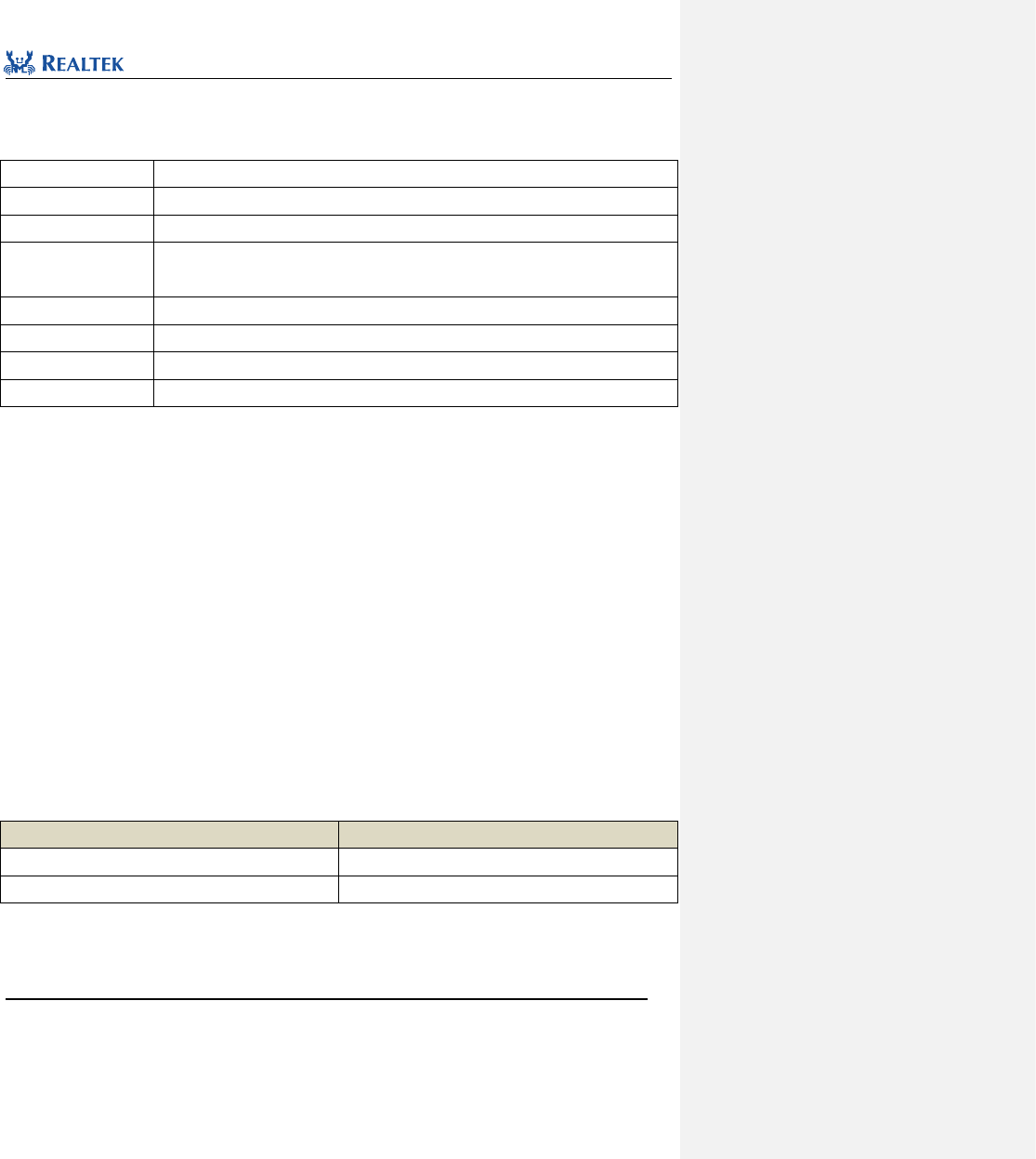
Realtek Confidential
RTL8762C Peripheral Manual
Copyright 2018 Realtek Semiconductor Corporation.
All Rights Reserved.
163
13.2.2 Function SPI3WIRE_Init
Table 13. 4 Function SPI3WIRE_Init
Function Name
SPI3WIRE_Init
Function Prototype
void SPI3WIRE_Init(SPI3WIRE_InitTypeDef* SPI3WIRE_InitStruct)
Function Description
Initialize SPI3WIRE register based on parameters specified in SPI3WIRE_InitStruct.
Input Parameter
SPI3WIRE _InitStruct: A pointer points to structure SPI3WIRE_InitTypeDef, which contains
configuration information about peripheral SPI3WIRE.
Output Parameter
None
Return Value
None
Prerequisite
None
Functions Called
None
typedef struct
{
uint32_t SPI3WIRE_SysClock;
uint32_t SPI3WIRE_Speed;
uint32_t SPI3WIRE_Mode;
uint32_t SPI3WIRE_ReadDelay;
uint32_t SPI3WIRE_OutputDelay;
uint32_t SPI3WIRE_ExtMode;
}SPI3WIRE_InitTypeDef;
SPI3WIRE_SysClock:This parameter is fixed to system clock.
SPI3WIRE_Speed:This parameter configures the SPI3WIRE output clock.
SPI3WIRE_Mode:This parameter is used to select operation mode of SPI3WIRE. Table 13. 5 lists values available
to this parameter.
Table 13. 5 Values of mode
mode
Description
SPI3WIRE_2WIRE_MODE
Two-wire SPI
SPI3WIRE_3WIRE_MODE
Three-wire SPI
SPI3WIRE_ReadDelay:This parameter is used to control data read delay time by SPI3WIRE, which ranges from
0x00 to 0x1f. The formula to calculate delay time is: delay time = (SPI3WIRE_ReadDelay+1)/(2*SPI3WIRE_Speed)
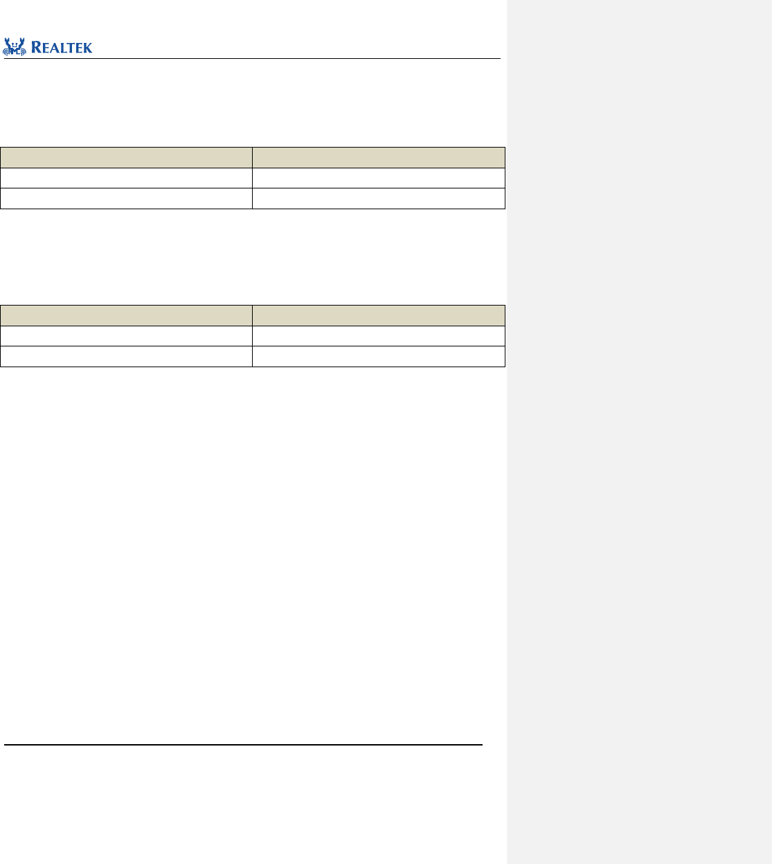
Realtek Confidential
RTL8762C Peripheral Manual
Copyright 2018 Realtek Semiconductor Corporation.
All Rights Reserved.
164
SPI3WIRE_OutputDelay:This parameter is used to determine if output of SPI3WIRE is delayed. Table 13. 6 lists
values available to this parameter.
Table 13. 6 Values of oeDelayCfg
SPI3WIRE_OE_DELAY_NONE
Description
SPI3WIRE_OE_DELAY_1T
Delay for 1T
SPI3WIRE_OE_DELAY_NONE
No delay
SPI3WIRE_ExtMode:This parameter is used to determine whether SPI3WIRE is in expansion mode. Table 13. 7
lists values available to this parameter.
Table 13. 7 Values of endExtMode
SPI3WIRE_ExtMode
Description
SPI3WIRE_EXTEND_MODE
Expansion mode
SPI3WIRE_NORMAL_MODE
Normal mode
Examples:
/* Initialize IR */
SPI3WIRE_InitTypeDef SPI3WIRE_InitStruct;
SPI3WIRE_StructInit(&SPI3WIRE_InitStruct);
SPI3WIRE_InitStruct.SPI3WIRE_SysClock = 20000000;
SPI3WIRE_InitStruct.SPI3WIRE_Speed = 1000000;
SPI3WIRE_InitStruct.SPI3WIRE_Mode = SPI3WIRE_2WIRE_MODE;
/* delay time = (SPI3WIRE_ReadDelay +1)/(2*SPI3WIRE_Speed).
The delay time from the end of address phase to the start of read data phase */
//delay time = (0x05 + 3)/(2 * speed) = 4us
SPI3WIRE_InitStruct.SPI3WIRE_ReadDelay = 0x5;
SPI3WIRE_InitStruct.SPI3WIRE_OutputDelay = SPI3WIRE_OE_DELAY_1T;
SPI3WIRE_InitStruct.SPI3WIRE_ExtMode = SPI3WIRE_NORMAL_MODE;
SPI3WIRE_Init(&SPI3WIRE_InitStruct);
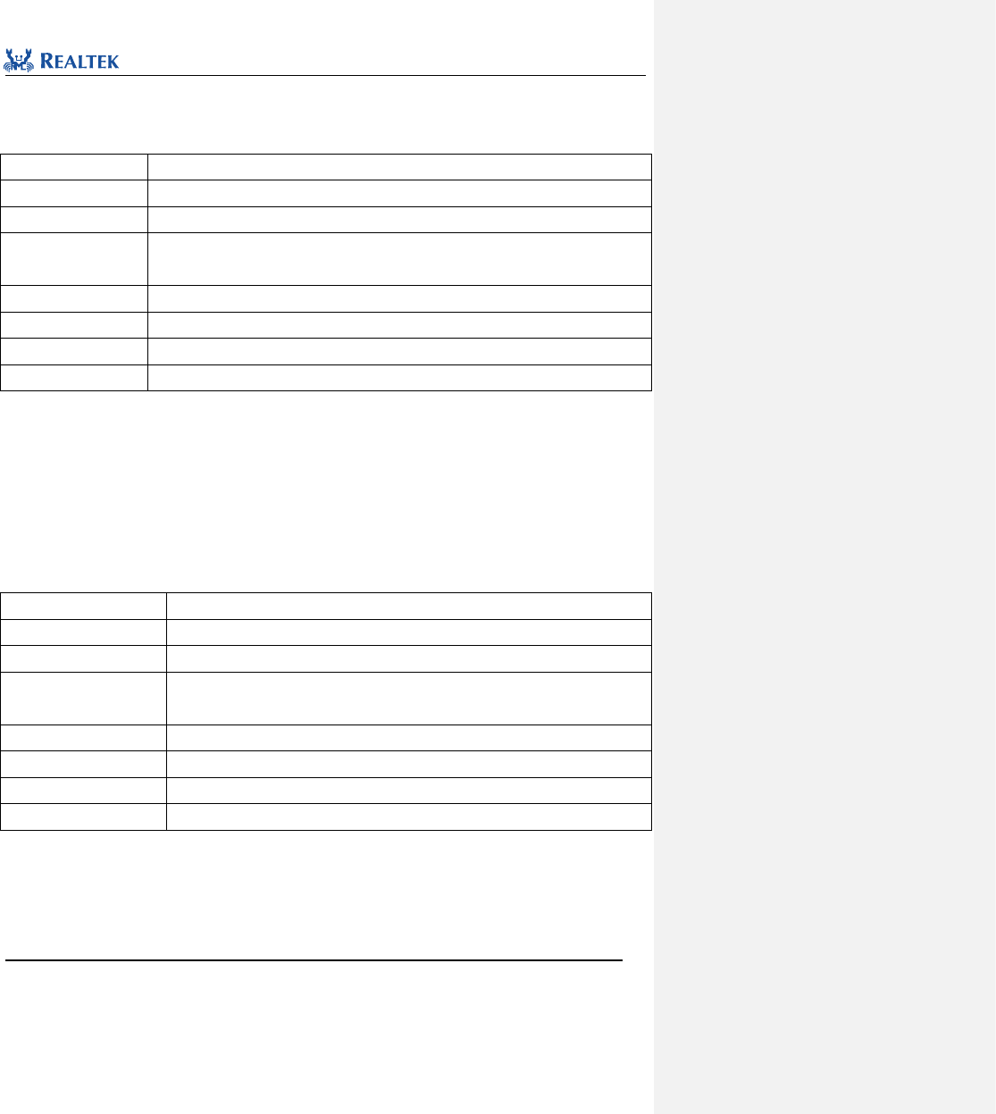
Realtek Confidential
RTL8762C Peripheral Manual
Copyright 2018 Realtek Semiconductor Corporation.
All Rights Reserved.
165
13.2.3 Function SPI3WIRE_StructInit
Table 13. 8 Function SPI3WIRE_StructInit
Function Name
SPI3WIRE_StructInit
Function Prototype
void SPI3WIRE_StructInit(SPI3WIRE_InitTypeDef* SPI3WIRE_InitStruct)
Function Description
Set each parameter in SPI3WIRE_InitStruct to the default value.
Input Parameter
SPI3WIRE _InitStruct: A pointer points to structure SPI3WIRE_InitTypeDef, which contains
configuration information about peripheral SPI3WIRE.
Output Parameter
None
Return Value
None
Prerequisite
None
Functions Called
None
Examples:
/* Configure the SPI3WIRE Init Structure parameter */
SPI3WIRE_InitTypeDef SPI3WIRE_InitStruct;
SPI3WIRE_StructInit(&SPI3WIRE _InitStruct);
13.2.4 Function SPI3WIRE_Cmd
Table 13. 9 Function SPI3WIRE_Cmd
Function Name
SPI3WIRE_Cmd
Function Prototype
void SPI3WIRE_Cmd(FunctionalState NewState)
Function Description
Enable or disable SPI3WIRE
Input Parameter
newState:New state of SPI3WIRE
Optional parameter:ENABLE or DISABLE
Output Parameter
None
Return Value
None
Prerequisite
None
Functions Called
None
Examples:
/* Enable the SPI3WIRE */
SPI3WIRE_Cmd(ENABLE);
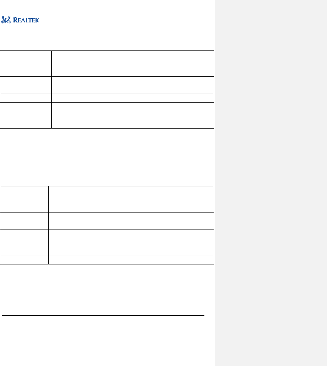
Realtek Confidential
RTL8762C Peripheral Manual
Copyright 2018 Realtek Semiconductor Corporation.
All Rights Reserved.
166
13.2.5 Function SPI3WIRE_SetResyncTime
Table 13. 10 Function SPI3WIRE_SetResyncTime
Function Name
SPI3WIRE_SetResyncTime
Function Prototype
void SPI3WIRE_SetResyncTime(uint32_t value)
Function Description
Set resync signal duration
Input Parameter
value:resync signal duration
This parameter ranges from 0x0 to 0xf, whose unit is: 1/(2*SPI3WIRE_Speed)
Output Parameter
None
Return Value
None
Prerequisite
None
Functions Called
None
Examples:
/* Send resync time. Resync signal time = 2*1/(2*SPI3WIRE_Speed) = 1us */
SPI3WIRE_SetResyncTime(2);
13.2.6 Function SPI3WIRE_ResyncSignalCmd
Table 13. 11 Function SPI3WIRE_ResyncSignalCmd
Function Name
SPI3WIRE_ResyncSignalCmd
Function Prototype
void SPI3WIRE_ResyncSignalCmd(FunctionalState NewState)
Function Description
Enable or disable resync signal output
Input Parameter
newState:New state of resync signal output
optional parameter:ENABLE or DISABLE
Output Parameter
None
Return Value
None
Prerequisite
None
Functions Called
None
Examples:
/* Enable resync output */
SPI3WIRE_ResyncSignalCmd(ENABLE);
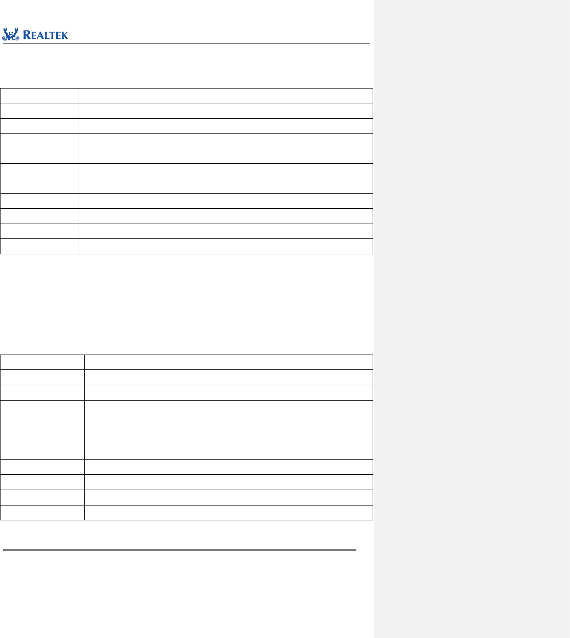
Realtek Confidential
RTL8762C Peripheral Manual
Copyright 2018 Realtek Semiconductor Corporation.
All Rights Reserved.
167
13.2.7 Function SPI3WIRE_INTConfig
Table 13. 12 Function SPI3WIRE_INTConfig
Function Name
SPI3WIRE_INTConfig
Function Prototype
void SPI3WIRE_INTConfig(uint32_t SPI3WIRE_INT, FunctionalState newState)
Function Description
Enable or disable specified SPI3WIRE interrupt.
Input Parameter 1
SPI3WIRE_IT: SPI3WIRE interrupt to be enabled or disabled, which can only be assigned as
SPI3WIRE_IT_INT.
Input Parameter 2
newState: new state of SPI3WIRE interrupt
Optional parameters: ENABLE, DISABLE
Output Parameter
None
Return Value
None
Prerequisite
None
Functions Called
None
Examples:
/* Enable the SPI3WIRE interrupt */
SPI3WIRE_INTConfig(SPI3WIRE_INT_BIT, ENABLE);
13.2.8 Function SPI3WIRE_GetFlagStatus
Table 13. 13 Function SPI3WIRE_GetFlagStatus
Function Name
SPI3WIRE_GetFlagStatus
Function Prototype
FlagStatus SPI3WIRE_GetFlagStatus(uint32_t SPI3WIRE_FLAG)
Function Description
Check the specified SPI3WIRE flag status.
Input Parameter
SPI3WIRE_ FLAG: SPI3WIRE flag to be checked.
Parameter SPI3WIRE_FLAG_BUSY: SPI3WIRE IS BUSY flag
Parameter SPI3WIRE_FLAG_INT_IND: SPI3WIRE GENERATES INTERRUPT flag
Parameter SPI3WIRE_FLAG_RESYNC_BUSY: RESYNC IS BUSY flag
Output Parameter
None
Return Value
new state (SET or RESET) of SPI3WIRE _FLAG
Prerequisite
None
Functions Called
None
Examples:
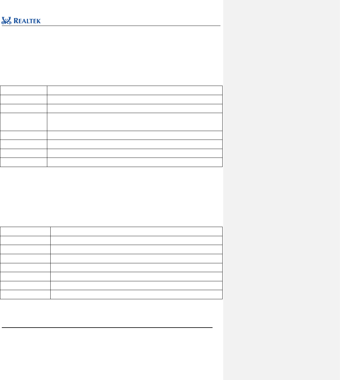
Realtek Confidential
RTL8762C Peripheral Manual
Copyright 2018 Realtek Semiconductor Corporation.
All Rights Reserved.
168
/* Check SPI3WIRE busy or not */
BOOL flagStatus = FALSE;
flagStatus =SPI3WIRE_GetFlagStatus (SPI3WIRE_FLAG_BUSY);
13.2.9 Function SPI3WIRE_ClearINTPendingBit
Table 13. 14 Function SPI3WIRE_ClearINTPendingBit
Function Name
SPI3WIRE_ClearINTPendingBit
Function Prototype
void SPI3WIRE_ClearINTPendingBit(uint32_t SPI3WIRE_INT)
Function Description
Clear interrupt flag of SPI3WIRE
Input Parameter
SPI3WIRE_INT: SPI3WIRE interrupt to be cleared, which can only be assigned
SPI3WIRE_INT_BIT.
Output Parameter
None
Return Value
None
Prerequisite
None
Functions Called
None
Examples:
/* Clear the SPI3WIRE interrupt */
SPI3WIRE_ ClearITPendingBit (SPI3WIRE_INT_BIT);
13.2.10 Function SPI3WIRE_GetRxDataLen
Table 13. 15 Function SPI3WIRE_GetRxDataLen
Function Name
SPI3WIRE_GetRxDataLen
Function Prototype
GetRxDataLen
Function Description
Get received data length during each SPI3WIRE read operation.
Input Parameter
None
Output Parameter
None
Return Value
Size of data in receive FIFO
Prerequisite
None
Functions Called
None
Examples:
/* Get receive data length of SPI3WIRE */
uint16_t receive_length = SPI3WIRE_GetRxDataLen ();
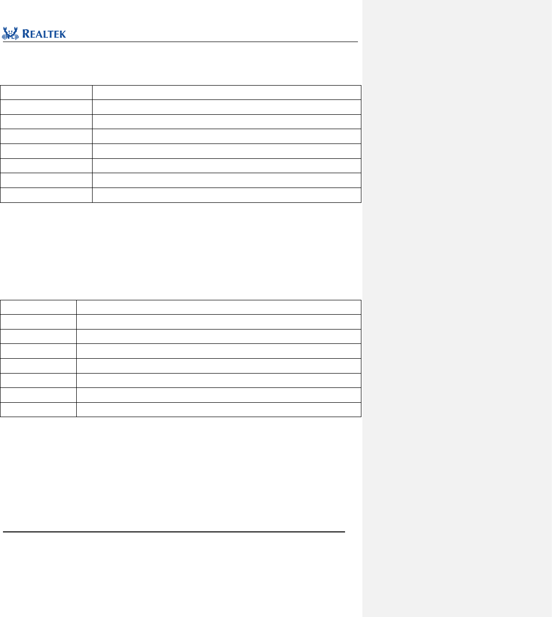
Realtek Confidential
RTL8762C Peripheral Manual
Copyright 2018 Realtek Semiconductor Corporation.
All Rights Reserved.
169
13.2.11 Function SPI3WIRE_ClearRxFIFO
Table 13. 16 Function SPI3WIRE_ClearRxFIFO
Function Name
SPI3WIRE_ClearRxFIFO
Function Prototype
void SPI3WIRE_ClearRxFIFO(void)
Function Description
Clear data in receive FIFO of SPI3WIRE.
Input Parameter
None
Output Parameter
None
Return Value
None
Prerequisite
None
Functions Called
None
Examples:
/* Clear SPI3WIRE RX FIFO */
SPI3WIRE_ClearRxFIFO ();
13.2.12 Function SPI3WIRE_ClearRxDataLen
Table 13. 17 Function SPI3WIRE_ClearRxDataLen
Function Name
SPI3WIRE_ClearRxDataLen
Function Prototype
void SPI3WIRE_ClearRxDataLen(void)
Function Description
Clear number of the data received by SPI3WIRE.
Input Parameter
None
Output Parameter
None
Return Value
None
Prerequisite
None
Functions Called
None
Examples:
/* Clear number of receive data */
SPI3WIRE_ClearRxDataLen();
13.2.13 Function SPI3WIRE_StartWrite
Table 13. 18 Function SPI3WIRE_StartWrite
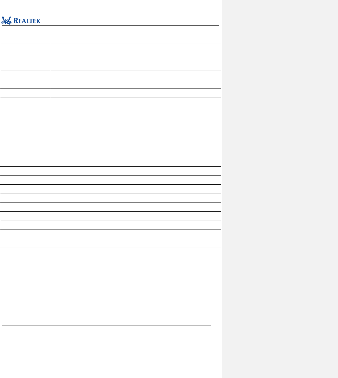
Realtek Confidential
RTL8762C Peripheral Manual
Copyright 2018 Realtek Semiconductor Corporation.
All Rights Reserved.
170
Function Name
SPI3WIRE_StartWrite
Function Prototype
void SPI3WIRE_StartWrite(uint8_t address, uint8_t data)
Function Description
Send data through SPI3WIRE.
Input Parameter 1
address:Address to be written.
Input Parameter 2
data:Data to be written
Output Parameter
None
Return Value
None
Prerequisite
None
Functions Called
None
Examples:
/* Send data */
SPI3WIRE_StartWrite(0x00, 0x66);
13.2.14 Function SPI3WIRE_StartRead
Table 13. 19 Function SPI3WIRE_StartRead
Function Name
SPI3WIRE_StartRead
Function Prototype
void SPI3WIRE_StartRead(uint8_t address, uint32_t len)
Function Description
Send through SPI3WIRE a command to read a single data or multiple data.
Input Parameter 1
address:Address to be read.
Input Parameter 2
len:Number of the data to be read.
Output Parameter
None
Return Value
None
Prerequisite
None
Functions Called
None
Examples:
/* Send read several data command */
SPI3WIRE_StartRead(0x20, 1);
13.2.15 Function SPI3WIRE_ReadBuf
Table 13. 20 Function SPI3WIRE_ReadBuf
Function Name
SPI3WIRE_ReadBuf
Realtek Confidential
RTL8762C Peripheral Manual
Copyright 2018 Realtek Semiconductor Corporation.
All Rights Reserved.
171
Function Prototype
void SPI3WIRE_ReadBuf(uint8_t *pBuf, uint8_t readNum)
Function Description
Read data in receive FIFO
Input Parameter 2
pBuf:Start address of the buffer for storing data.
Input Parameter 3
readNum:Number of the data to be read.
Output Parameter
None
Return Value
None
Prerequisite
None
Functions Called
None
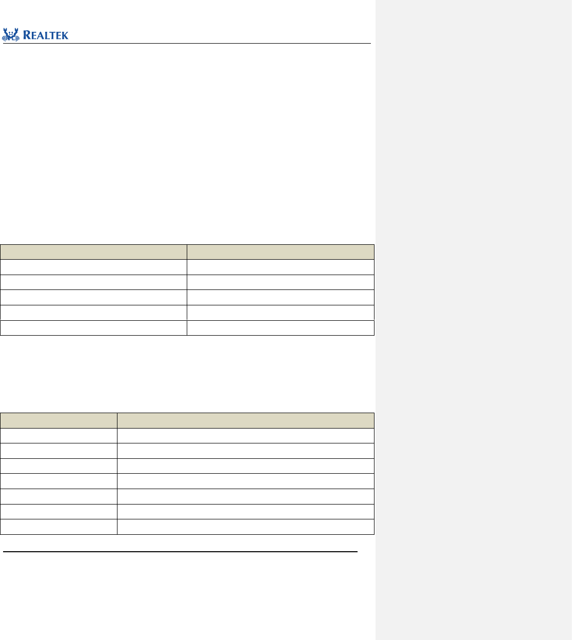
Realtek Confidential
RTL8762C Peripheral Manual
Copyright 2018 Realtek Semiconductor Corporation.
All Rights Reserved.
172
14 Timer & PWM
14.1 TIM Register Structure
typedef struct
{
__IO uint32_t LoadCount;
__I uint32_t CurrentValue;
__IO uint32_t ControlReg;
__I uint32_t EOI;
__I uint32_t IntStatus;
} TIM_TypeDef;
Table 14. 1
Table 14. 1 TIM Registers
Register
Description
LoadCount
Loaded value register
CurrentValue
Current count register
ControlReg
Control register
EOI
Interrupt clear register
IntStatus
Interrupt status register
14.2 TIM Library Functions
All TIM library functions are enumerated in Table 14. 2.
Table 14. 2 TIM Library Functions
Function Name
Description
TIM_DeInit
Disable TIM clock source.
TIM_TimeBaseInit
Initialize TIMx register based on parameters specified in TIMx_InitStruct.
TIM_StructInit
Set each parameter in TIM_InitStruct to default value.
TIM_Cmd
Enable or disable TIMx.
TIM_ChangePeriod
Change period of TIMx.
TIM_INTConfig
Enable or disable TIMx interrupt.
TIM_GetCurrentValue
Acquire current count value of TIMx.
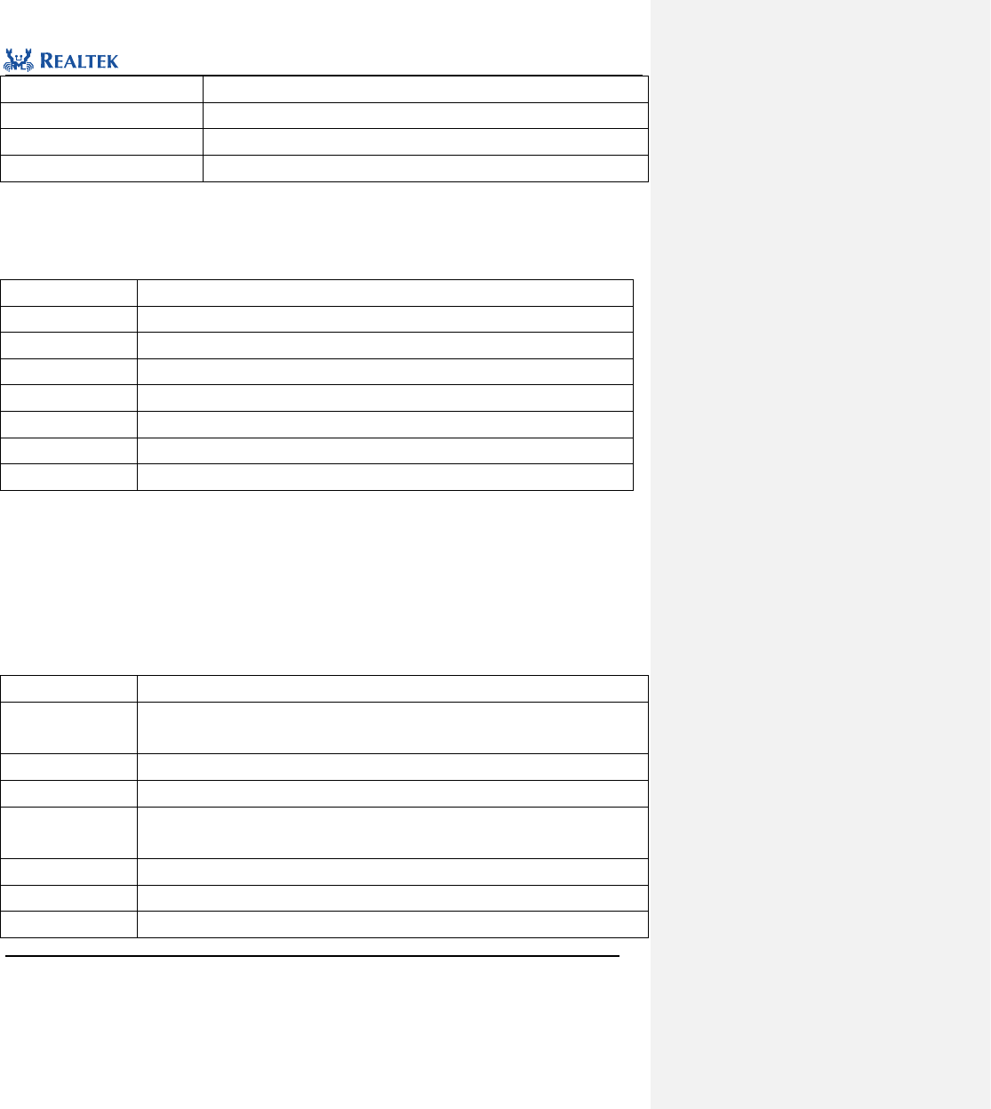
Realtek Confidential
RTL8762C Peripheral Manual
Copyright 2018 Realtek Semiconductor Corporation.
All Rights Reserved.
173
TIM_GetINTStatus
Check whether TIMx interrupt flag is set or not.
TIM_ClearINT
Clear TIMx interrupt.
TIM_PWMChangeFreqAndDuty
Modify PWM frequency and duty cycle corresponding to TIMx
PWM_Deadzone_EMStop
Dual complementary PWM output emergency stop
14.2.1 Function TIM_DeInit
Table 14. 3 Function TIM_DeInit
Function Name
TIM_DeInit
Function Prototype
void TIM_DeInit(void)
Function Description
Disable TIM clock source.
Input Parameter
None
Output Parameter
None
Return Value
None
Prerequisite
None
Functions Called
RCC_PeriphClockCmd()
Examples:
/* Close TIM clock */
TIM_DeInit();
14.2.2 Function TIM_TimeBaseInit
Table 14. 4 Function TIM_TimeBaseInit
Function Name
TIM_TimeBaseInit
Function Prototype
void TIM_TimeBaseInit(TIM_TypeDef* TIMx, TIM_TimeBaseInitTypeDef*
TIM_TimeBaseInitStruct)
Function Description
Initialize TIMx register based on parameters specified in TIMx_InitStruct.
Input Parameter 1
TIMx: Used to select TIMx peripheral. x can be set to 2 ~ 7.
Input Parameter 2
TIM_TimeBaseInitStruct: A pointer points to structure TIM_InitTypeDef, which contains
configuration information about peripheral TIMx.
Output Parameter
None
Return Value
None
Prerequisite
None
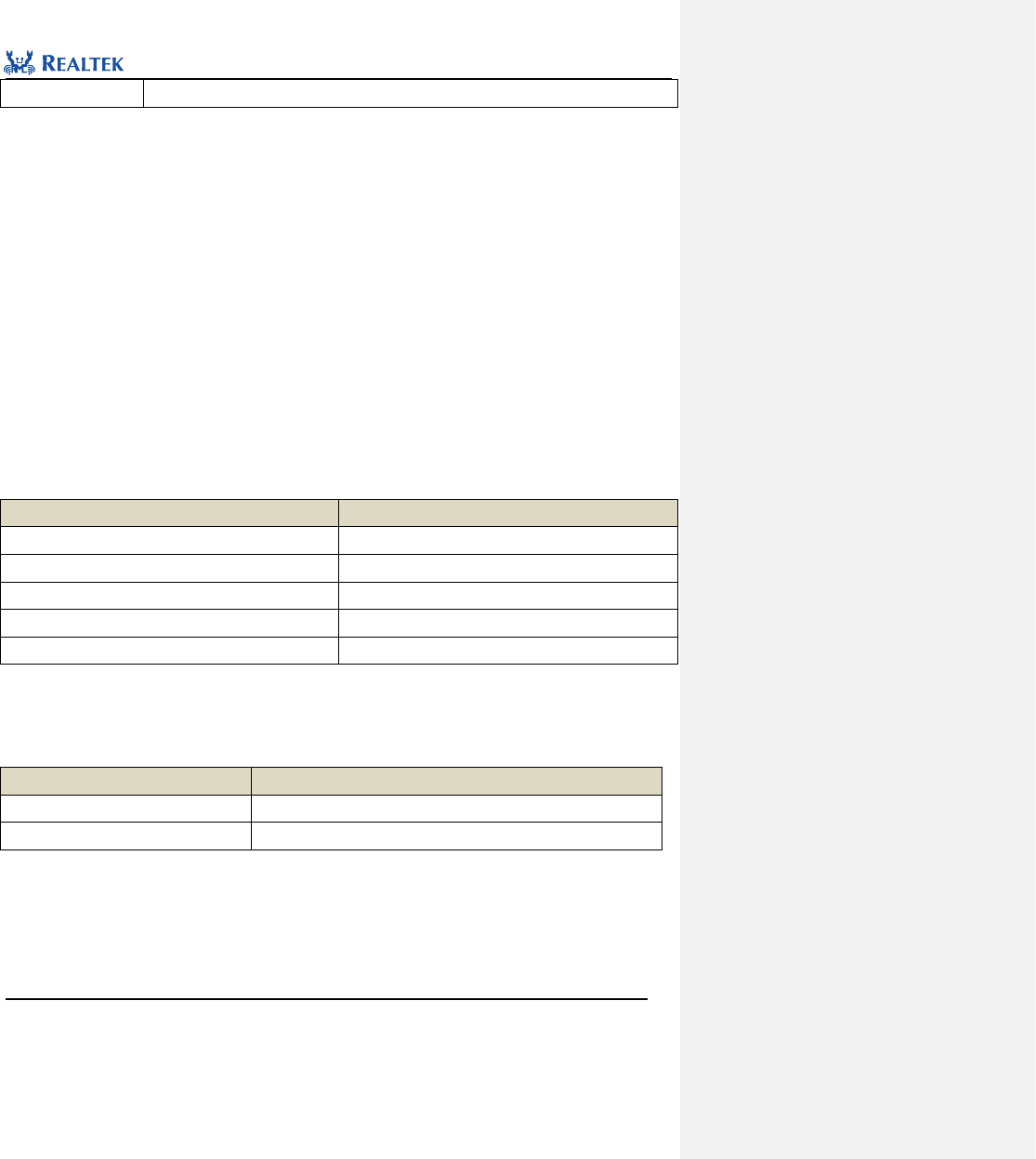
Realtek Confidential
RTL8762C Peripheral Manual
Copyright 2018 Realtek Semiconductor Corporation.
All Rights Reserved.
174
Functions Called
None
typedef struct
{
uint16_t TIM_SOURCE_DIV;
uint16_t TIM_Mode;
uint16_t TIM_PWM_En;
uint32_t TIM_Period;
uint32_t TIM_PWM_High_Count;
uint32_t TIM_PWM_Low_Count;
uint8_t ClockDepend;
uint32_t PWM_Deazone_Size;
uint16_t PWMDeadZone_En;
uint16_t PWM_Stop_State_P;
uint16_t PWM_Stop_State_N;
} TIM_TimeBaseInitTypeDef;
TIM_SOURCE_DIV:This parameter is used to select clock source of TIMx. Table 14. 5 lists values available to this
parameter.
Table 14. 5 Values of TIM_SOURCE_DIV
TIM_SOURCE_DIV
Description
TIM_CLOCK_DIVIDER_1
40MHz clock source
TIM_CLOCK_DIVIDER_2
20MHz clock source
TIM_CLOCK_DIVIDER_4
10MHz clock source
TIM_CLOCK_DIVIDER_8
5MHz clock source
TIM_CLOCK_DIVIDER_40
1MHz clock source
TIM_Mode: This parameter is used to set operation mode of TIMx. Table 14. 6 lists values available to this
parameter.
Table 14. 6 Values of TIM_Mode
TIM_Mode
Description
TIM_Mode_FreeRun
Free operation mode
TIM_Mode_UserDefine
Customized mode
TIM_Period: This parameter is used to set period value of TIMx, which ranges from 0x00 to 0xFFFFFFFF.
TIM_PWM_En:This parameter is used to enable PWM. Table Table 14. 6 lists values available to this parameter.
Note: All TIM can be configured to work in PWM mode, but only TIM2 and TIM3 have complementary output
function.
Realtek Confidential
RTL8762C Peripheral Manual
Copyright 2018 Realtek Semiconductor Corporation.
All Rights Reserved.
175
Table 14. 7 Values of TIM_Mode
TIM_Mode
Description
PWM_ENABLE
Enable PWM Mode
PWM_DISABLE
Disable PWM Mode
TIM_PWM_High_Count:This parameter is used to set period of PWM high level section corresponding to TIMx,
which ranges from 0x00 to 0xFFFFFFFF.
TIM_PWM_Low_Count:This parameter is used to set period value of PWM low level section corresponding to
TIMx, which ranges from 0x00 to 0xFFFFFFFF.
PWMDeadZone_En:This parameter is used to configure dual complementary PWM output function (with
dead-zone).
Note: All TIM can be configured to work in PWM mode, but only TIM2 and TIM3 have complementary output
function.
Table 14. 8 Values of PWMDeadZone_En
TIM_EventMode
Description
DEADZONE_ENABLE
Enable
DEADZONE_DISABLE
Disable
PWM_Deazone_Size:This parameter is used to configure the size of the dual complementary output dead-zone,
which ranges from 0x00 to 0xFFFFFFFF.
PWM_Stop_State_P:This parameter is used to configure the status of the P-channel after dual complementary
output emergency stop. Table 14. 9 lists values available to this parameter.
Table 14. 9 Values of PWM_Stop_State_P
TIM_EventDuration
Description
PWM_STOP_AT_HIGH
P-channel stops at high level after emergency stop
PWM_STOP_AT_LOW
P-channel stops at low level after emergency stop
PWM_Stop_State_N:This parameter is used to configure the status of the N-channel after dual complementary
output emergency stop. Table 14. 10 lists values available to this parameter.
Table 14. 11 Values of PWM_Stop_State_N
TIM_EventDuration
Description
PWM_STOP_AT_HIGH
N-channel stops at high level after emergency stop
Realtek Confidential
RTL8762C Peripheral Manual
Copyright 2018 Realtek Semiconductor Corporation.
All Rights Reserved.
176
PWM_STOP_AT_LOW
N-channel stops at low level after emergency stop
Examples:
/* Initialize TIM */
TIM_TimeBaseInitTypeDef TIM_InitStruct;
TIM_InitStruct.TIM_ClockSrc = TIM_CLOCK_10MHZ;
TIM_InitStruct.TIM_Period = 1000*10000 -1;
TIM_InitStruct.TIM_Mode = TIM_Mode_UserDefine;
TIM_InitStruct.TIM_EventMode = FALSE;
TIM_TimeBaseInit(TIM2, &TIM_InitStruct);
/* Initialize PWM */
TIM_StructInit(&TIM_InitStruct);
TIM_InitStruct.TIM_Mode = TIM_Mode_UserDefine;
TIM_InitStruct.TIM_PWM_En = PWM_ENABLE;
TIM_InitStruct.TIM_Period = 2000 * 10 - 1 ;
TIM_InitStruct.TIM_PWM_High_Count = 1000000 - 1 ;
TIM_InitStruct.TIM_PWM_Low_Count = 1000000 - 1 ;
TIM_InitStruct.TIM_Mode = 1;
TIM_TimeBaseInit(TIM2, &TIM_InitStruct);
14.2.3 Function TIM_StructInit
Table 14. 12 Function TIM_StructInit
Function Name
TIM_StructInit
Function Prototype
void TIM_StructInit(TIM_TimeBaseInitTypeDef* TIM_TimeBaseInitStruct)
Function Description
Set each parameter in TIM_InitStruct to the default value.
Input Parameter
TIM_TimeBaseInitStruct: A pointer points to structure TIM_InitTypeDef, which contains
configuration information about peripheral TIMx.
Output Parameter
None
Return Value
None
Prerequisite
None
Functions Called
None
Examples:
/* Configure the TIMx Init Structure parameter */
TIM_TimeBaseInitTypeDef TIM_InitStruct;
TIM_StructInit(&TIM_InitStruct);
Realtek Confidential
RTL8762C Peripheral Manual
Copyright 2018 Realtek Semiconductor Corporation.
All Rights Reserved.
177
14.2.4 Function TIM_Cmd
Table 14. 13 Function TIM_Cmd
Function Name
TIM_Cmd
Function Prototype
void TIM_Cmd(TIM_TypeDef* TIMx, FunctionalState NewState)
Function Description
Enable or disable TIM.
Input Parameter 1
TIMx: Used to select TIMx peripheral. x ranges from 2 to 7.
Input Parameter 2
newState: new state of TIMx
Optional parameters: ENABLE, DISABLE
Output Parameter
None
Return Value
None
Prerequisite
None
Functions Called
None
Examples:
/* Enable TIM2 */
TIM_ Cmd (TIM2, ENABLE);
14.2.5 Function TIM_ChangePeriod
Table 14. 14 Function TIM_ChangePeriod
Function Name
TIM_ChangePeriod
Function Prototype
void TIM_ChangePeriod(TIM_TypeDef* TIMx, uint32_t period)
Function Description
Change period of TIM.
Input Parameter 1
TIMx: Used to select TIMx peripheral. x ranges from 2 to 7.
Input Parameter 2
period: period of TIMx
Output Parameter
None
Return Value
None
Prerequisite
None
Functions Called
None
Examples:
/* Change TIM2 period value */
TIM_ ChangePeriod (TIM2, 1000*10000 -1);
Realtek Confidential
RTL8762C Peripheral Manual
Copyright 2018 Realtek Semiconductor Corporation.
All Rights Reserved.
178
14.2.6 Function TIM_INTConfig
Table 14. 15 Function TIM_INTConfig
Function Name
TIM_INTConfig
Function Prototype
void TIM_INTConfig(TIM_TypeDef* TIMx, FunctionalState NewState)
Function Description
Enable or disable TIMx interrupt.
Input Parameter 1
TIMx: Used to select TIMx peripheral. x ranges from 2 to 7.
Input Parameter 2
newState: new state of TIMx interrupt
Optional parameters: ENABLE, DISABLE
Output Parameter
None
Return Value
None
Prerequisite
None
Functions Called
None
Examples:
/* Enable TIM2 interrupt */
TIM_INTConfig (TIM2, ENABLE);
14.2.7 Function TIM_GetCurrentValue
Table 14. 16 Function TIM_GetCurrentValue
Function Name
TIM_GetCurrentValue
Function Prototype
uint32_t TIM_GetCurrentValue(TIM_TypeDef* TIMx)
Function
Description
Acquire current count value of TIMx.
Input Parameter
TIMx: Used to select TIMx peripheral. x ranges from 2 to 7.
Output Parameter
None
Return Value
Current count value of TIMx
Prerequisite
None
Functions Called
None
Examples:
/* Get TIM2 current value of counter */
uint32_t value =TIM_GetCurrentValue (TIM2);
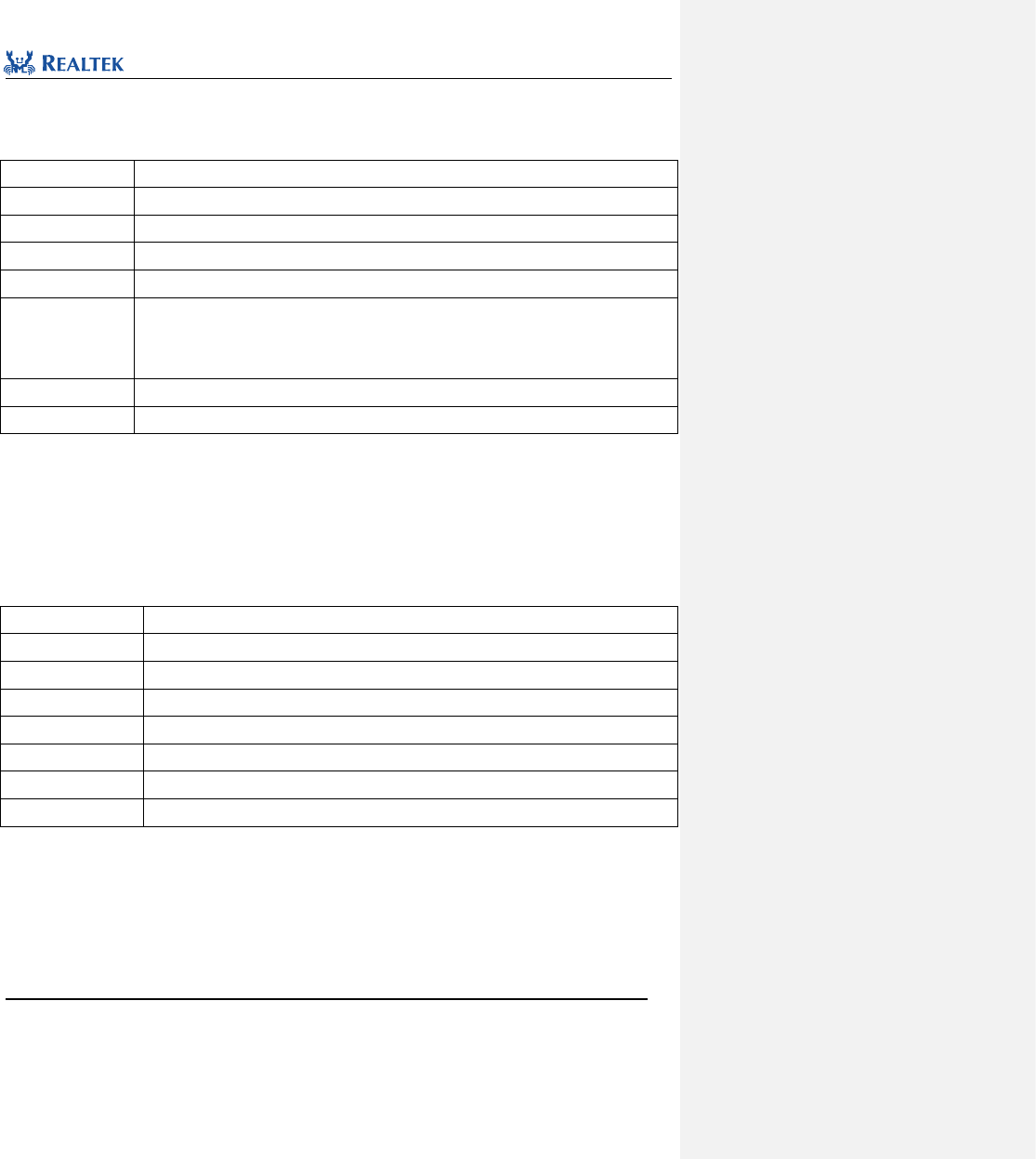
Realtek Confidential
RTL8762C Peripheral Manual
Copyright 2018 Realtek Semiconductor Corporation.
All Rights Reserved.
179
14.2.8 Function TIM_GetINTStatus
Table 14. 17 Function TIM_GetINTStatus
Function Name
TIM_GetINTStatus
Function Prototype
ITStatus TIM_GetINTStatus(TIM_TypeDef* TIMx)
Function Description
Check whether TIMx interrupt flag is set or not.
Input Parameter
TIMx: Used to select TIMx peripheral. x ranges from 2 to 7.
Output Parameter
None
Return Value
Value of TIMx interrupt flag, which shall be one of the values enumerated in ITStatus.
RESET: Interrupt does not occur
SET: Interrupt occurs
Prerequisite
None
Functions Called
None
Examples:
/* Get TIM2 interrupt status */
BOOL intValue =TIM_GetINTStatus (TIM2);
14.2.9 Function TIM_ClearINT
Table 14. 18 Function TIM_ClearINT
Function Name
TIM_ClearINT
Function Prototype
void TIM_ClearINT(TIM_TypeDef* TIMx)
Function Description
Clear TIMx interrupt.
Input Parameter
TIMx: Used to select TIMx peripheral, where x ranges from 2 to 7.
Output Parameter
None
Return Value
None
Prerequisite
None
Functions Called
None
Examples:
/* Clear TIM2 interrupt status */
TIM_ ClearINT (TIM2);
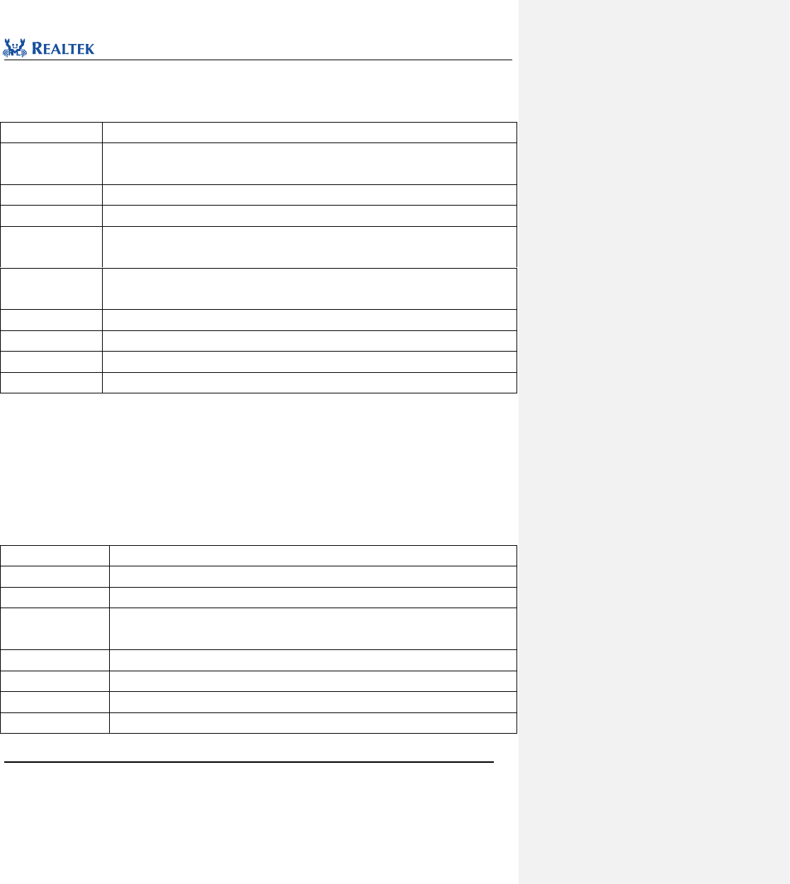
Realtek Confidential
RTL8762C Peripheral Manual
Copyright 2018 Realtek Semiconductor Corporation.
All Rights Reserved.
180
14.2.10 Function TIM_PWMChangeFreqAndDuty
Table 14. 19 Function TIM_PWMChangeFreqAndDuty
Function Name
TIM_PWMChangeFreqAndDuty
Function Prototype
void TIM_PWMChangeFreqAndDuty(TIM_TypeDef *TIMx, uint32_t high_count, uint32_t
low_count)
Function Description
Modify the frequency and duty cycle of the PWM corresponding to TIMx
Parameter 1
TIMx: Used to select TIMx peripheral, where x ranges from 2 to 7.
Parameter 2
high_count: used to configure period of PWM high level counter, ranging from 0x00 to
0xFFFFFFFF
Parameter 3
low_count: used to configure period of PWM low level counter, ranging from 0x00 to
0xFFFFFFFF
Output Parameter
None
Return Value
None
Prerequisite
None
Functions Called
None
Examples:
/* Change TIM2 PWM high count and low count */
TIM_PWMChangeFreqAndDuty (TIM2,0x100, 0x100);
14.2.11 Function PWM_Deadzone_EMStop
Table 14. 20 Function PWM_Deadzone_EMStop
Function Name
PWM_Deadzone_EMStop
Function Prototype
void PWM_Deadzone_EMStop(PWM_TypeDef *PWMx)
Function Description
Dual complementary PWM output emergency stop
Input Parameter
PWMx:Used to select dual complementary PWM output peripheral.
Optional values: PWM2, PWM3
Output Parameter
None
Return Value
None
Prerequisite
None
Functions Called
None
Examples:

Realtek Confidential
RTL8762C Peripheral Manual
Copyright 2018 Realtek Semiconductor Corporation.
All Rights Reserved.
181
/* Stop PWM0 output */
PWM_Deadzone_EMStop(PWM0_PN);

Realtek Confidential
RTL8762C Peripheral Manual
Copyright 2018 Realtek Semiconductor Corporation.
All Rights Reserved.
182
15 Universal Asynchronous Receiver Transmitter
(UART)
15. 1 UART Register Architecture
typedef struct {
__IO uint32_t DLL;
__IO uint32_t DLH_INTCR;
__IO uint32_t INTID_FCR;
__IO uint32_t LCR;
__IO uint32_t MCR;
__I uint32_t LSR;
__I uint32_t MSR;
__IO uint32_t SPR;
__IO uint32_t STSR;
__IO uint32_t RB_THR;
__IO uint32_t MISCR;
} UART_TypeDef;
All UART registers are enumerated in Table 15. 1.
Table 15. 1 UART Registers
Register
Description
DLL
Frequency division register (L)
DLH_INTCR
Frequency division register (H)_Interrupt control register
INTID_FCR
Interrupt type register_FIFO control register
LCR
Line control register
MCR
Model control register
LSR
Line status register
MSR
Model status register
SPR
Scratch pad register
STSR
RB_THR
Receive buffer register/transmit buffer register
MISCR
Mixed register
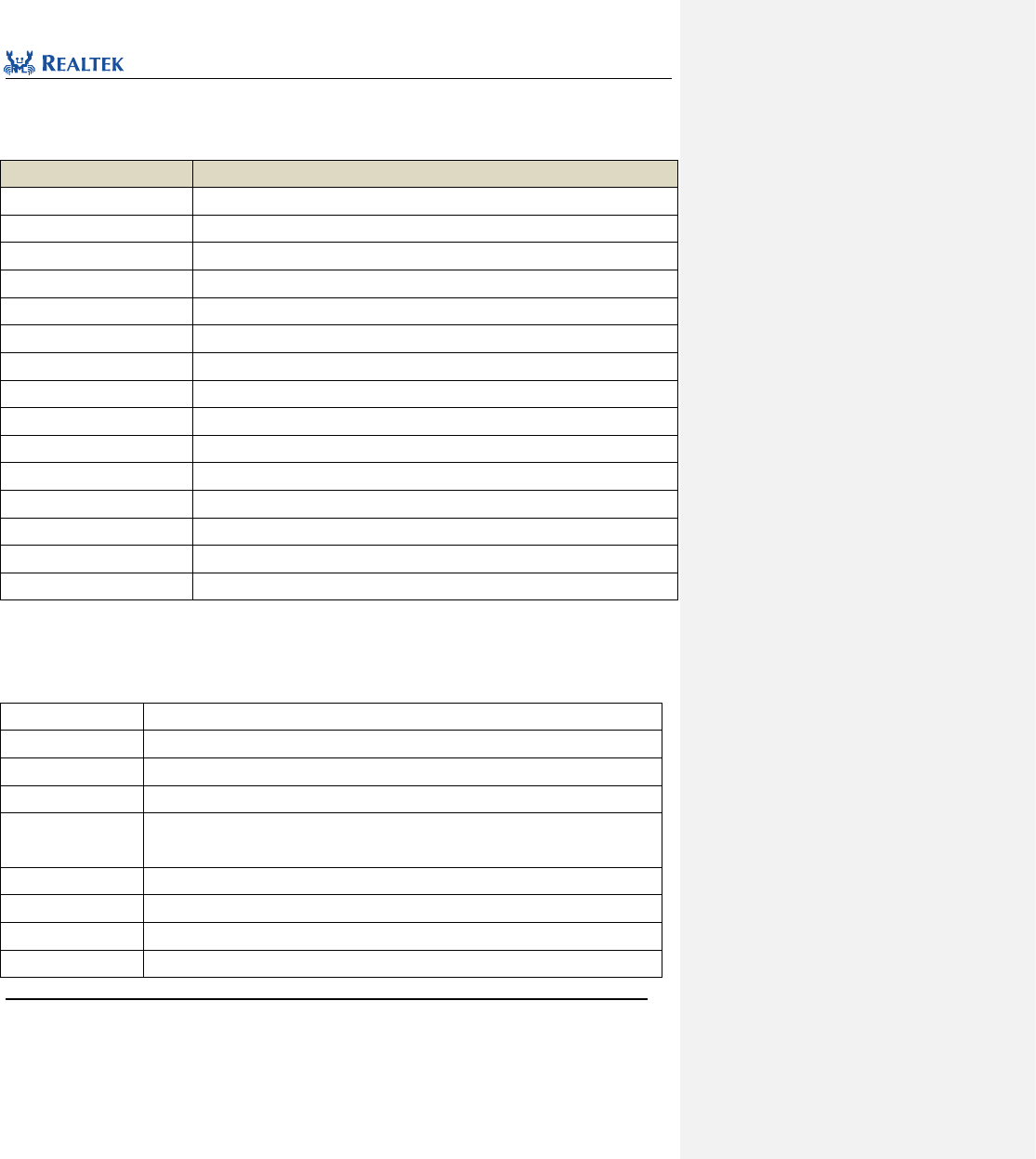
Realtek Confidential
RTL8762C Peripheral Manual
Copyright 2018 Realtek Semiconductor Corporation.
All Rights Reserved.
183
15. 2 UART Library Functions
Table 15. 2 All UART library functions.
Function Name
Description
UART_Init
Initialize UART register based on parameters specified in UART_InitStruct.
UART_DeInit
Disable UART clock.
UART_StructInit
Set each parameter in UART_InitStruct to the default value.
UART_ReceiveData
Receive data through UART.
UART_SendData
Send data through UART.
UART_INTConfig
Enable or disable interrupts specified by UART.
UART_GetFlagState
Check the specified status flag in UART peripheral.
UART_LoopBackCmd
Enable or disable loop back function.
UART_ClearTxFifo
Empty the data in transmit FIFO of UART.
UART_ClearRxFifo
Empty the data in receive FIFO of UART.
UART_GetTxFIFOLen
Get data length from UART transmit FIFO
UART_GetRxFIFOLen
Get data length from UART receive FIFO
UART_ReceiveByte
Read one byte from UART receive FIFO.
UART_SendByte
Write one byte to UART transmit FIFO.
UART_GetIID
Acquire type of UART interrupt source.
15. 2. 1 Function UART_Init
Table 15. 3 Function UART_Init
Function Name
UART_Init
Function Prototype
UART_Init(UART_TypeDef* UARTx, UART_InitTypeDef* UART_InitStruct)
Function Description
Initialize UART register based on parameters specified in UART_InitStruct.
Input Parameter 1
UARTx: x can be assigned as 0 or 1 to select target UART peripheral.
Input Parameter 2
UART_InitStruct: A pointer to UART_InitTypeDef, and related configuration information is
contained in UART_InitStruct.
Output Parameter
None
Return Value
None
Prerequisite
None
Functions Called
None
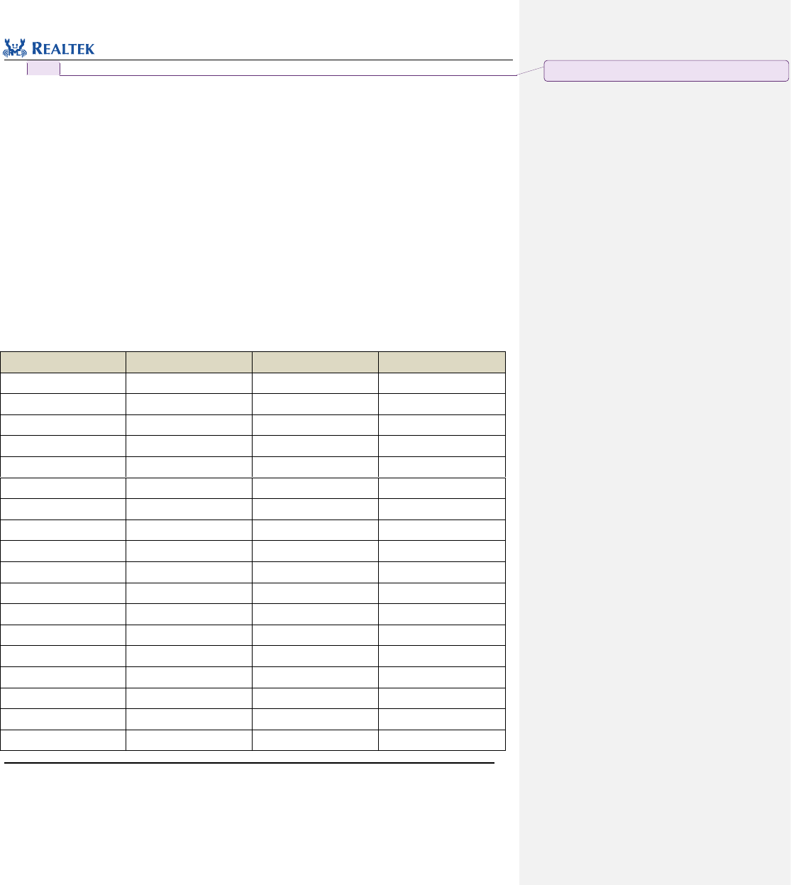
Realtek Confidential
RTL8762C Peripheral Manual
Copyright 2018 Realtek Semiconductor Corporation.
All Rights Reserved.
184
typedef struct
{
uint16_t ovsr_adj;
uint16_t div;
uint16_t ovsr;
uint16_t wordLen;
uint16_t parity;
uint16_t stopBits;
uint16_t autoFlowCtrl;
uint16_t rxTriggerLevel;
uint16_t dmaEn;
}UART_InitTypeDef;
ovsr_adj, div and ovsr: These three parameters are used to set UART baud rate checking parameter. Table 15. 4
lists values available to this parameter.
Table 15. 4 Relationship between OVSR_ADJ, DIV, OVSR Values and Baud Rate
ovsr_adj
div
ovsr
Baud rate value
0x7F7
2589
7
1200Hz
0x24A
271
10
9600Hz
0x222
271
5
14400Hz
0x5AD
165
7
19200Hz
0x5AD
110
7
28800Hz
0x222
85
7
38400Hz
0x5AD
55
7
57600Hz
0x7EF
35
9
76800Hz
0x252
20
12
115200Hz
0x555
25
7
128000Hz
0x252
15
12
153600Hz
0x252
10
12
230400Hz
0x252
5
12
460800Hz
0
8
5
500000Hz
0x3F7
4
5
921600Hz
0
4
5
1000000Hz
0x2AA
2
9
1382400Hz
0x5F7
2
8
1444400Hz
批注 [张一凡4]: 待确认,与代码不符
Realtek Confidential
RTL8762C Peripheral Manual
Copyright 2018 Realtek Semiconductor Corporation.
All Rights Reserved.
185
0x492
2
8
1500000Hz
0x3F7
2
5
1843200Hz
0
2
5
2000000Hz
0x400
1
14
2100000Hz
0x2AA
1
9
2764800Hz
0x492
1
8
3000000Hz
0x112
1
7
3250000Hz
0x5F7
1
5
3692300Hz
0x36D
1
5
3750000Hz
0
1
5
4000000Hz
0x36D
1
1
6000000Hz
wordLen: This parameter is used to set data length of UART. Table 15. 5 lists values available to this parameter.
Table 15. 5 Values of wordLen
wordLen
Description
UART_WROD_LENGTH_7BIT
7-bit data
UART_WROD_LENGTH_8BIT
8-bit data
parity: Set checking pattern of UART. Table 15. 6 lists values available to this parameter.
Table 15. 6 Values of parity
parity
Description
UART_PARITY_NO_PARTY
Parity disabled
UART_PARITY_ODD
Even mode
UART_PARITY_EVEN
Odd mode
stopBits: Set communication stop bits for UART. Table 15. 7 lists values available to this parameter.
Table 15. 7 Values of stopBits
stopBits
Description
UART_STOP_BITS_1
Transfer 1 stop bit at the end of frame
UART_STOP_BITS_2
Transfer 2 stop bit at the end of frame
autoFlowCtrl: Hardware flow control. Table 15. 8 lists values available to this parameter.
Table 15. 8 Values of autoFlowCtrl
autoFlowCtrl
Description
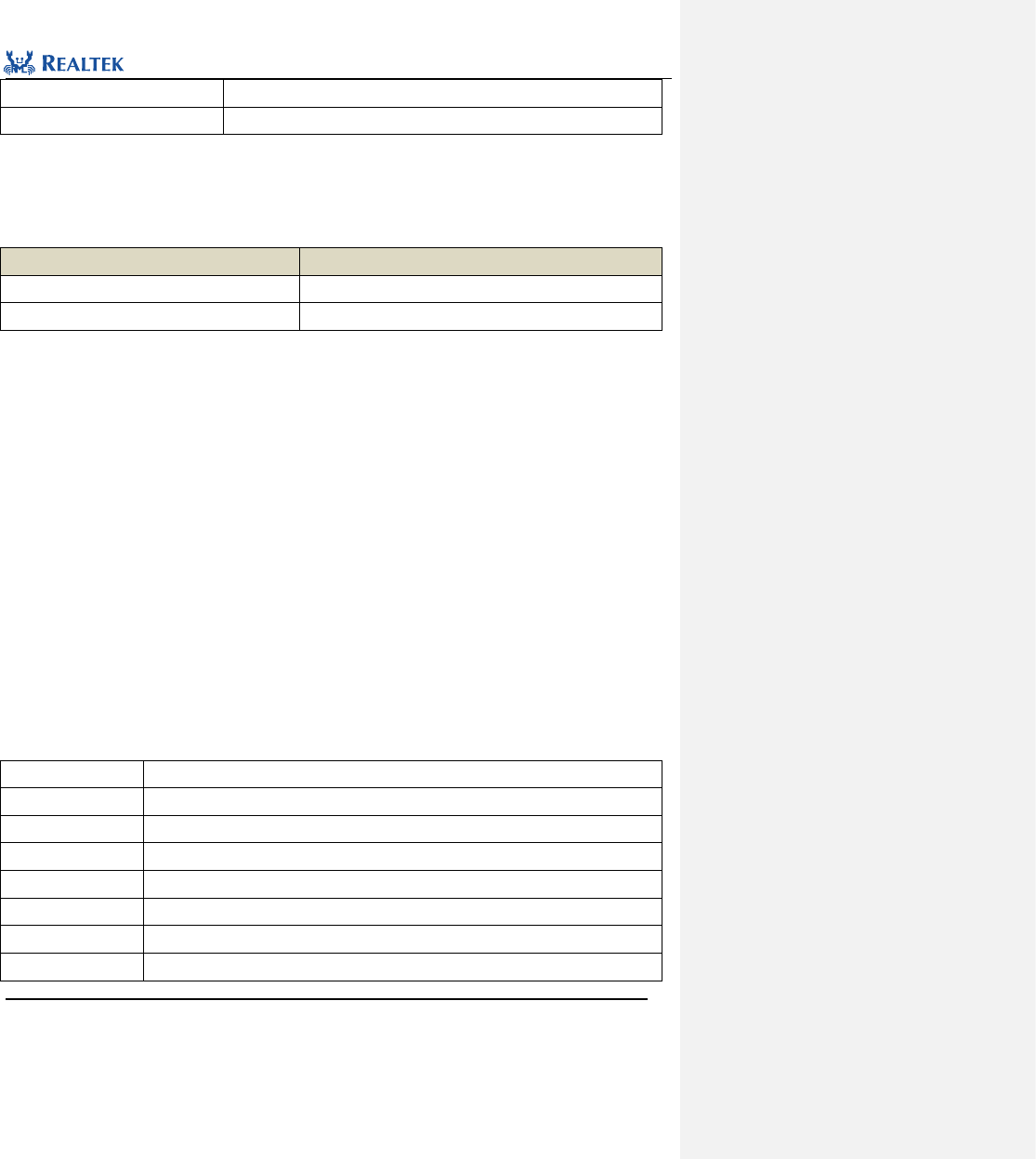
Realtek Confidential
RTL8762C Peripheral Manual
Copyright 2018 Realtek Semiconductor Corporation.
All Rights Reserved.
186
UART_AUTO_FLOW_CTRL_EN
Enable hardware flow control
UART_AUTO_FLOW_CTRL_DIS
Disable hardware flow control
rxTriggerLevel: Set the threshold value for UART receive FIFO, ranging from 0 to 29.
dmaEn: Set whether GDMA transfer mode is enabled. Table 15. 9 lists values available to this parameter.
Table 15. 9 Values of dmaEn
dmaEn
Description
UART_DMA_ENABLE
Enable GDMA transmission mode of UART
UART_DMA_DISABLE
Disable GDMA transmission mode of UART
Examples:
/* Initialize Data UART */
UART_InitTypeDef UART_InitStruct;
/* Configure baudrate to 115200 */
UART_InitStruct.div = 20;
UART_InitStruct.ovsr = 12;
UART_InitStruct.ovsr_adj = 0x252;
/* Configure uart parameters */
UART_InitStruct.parity = UART_PARITY_NO_PARTY;
UART_InitStruct.stopBits = UART_STOP_BITS_1;
UART_InitStruct.wordLen = UART_WROD_LENGTH_8BIT;
UART_InitStruct.dmaEn = UART_DMA_DISABLE;
UART_InitStruct.autoFlowCtrl = UART_AUTO_FLOW_CTRsL_DIS;
UART_InitStruct.rxTriggerLevel = UART_RX_FIFO_TRIGGER_LEVEL_14BYTE;
UART_Init(UART, & UART_InitStruct);
15. 2. 2 Function UART_DeInit
Table 15. 10 Function UART_DeInit
Function Name
UART_DeInit
Function Prototype
UART_DeInit(UART_TypeDef* UARTx)
Function Description
Disable UART clock.
Input Parameter 1
UARTx: x can be assigned as 0, 1 or 2 to select target UART peripheral.
Output Parameter
None
Return Value
None
Prerequisite
None
Functions Called
RCC_PeriphClockCmd()
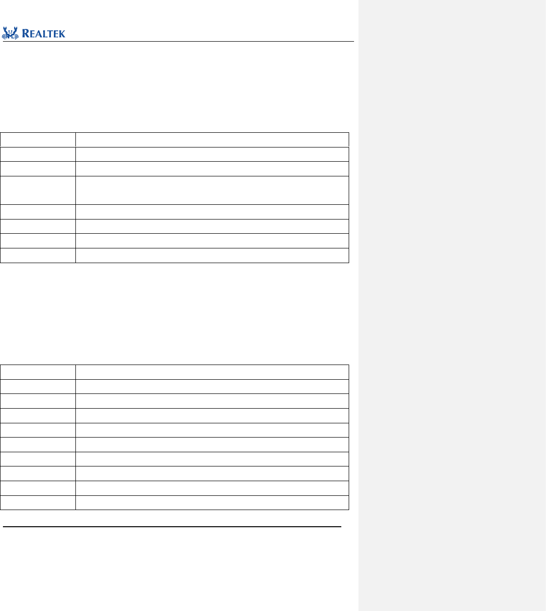
Realtek Confidential
RTL8762C Peripheral Manual
Copyright 2018 Realtek Semiconductor Corporation.
All Rights Reserved.
187
Examples:
/* Deinitialize Data UART */
UART_DeInit(UART);
15. 2. 3 Function UART_StructInit
Table 15. 11 Function UART_StructInit
Function Name
UART_StructInit
Function Prototype
void UART_StructInit(UART_InitTypeDef* UART_InitStruct)
Function Description
Set each parameter in UART_InitStruct to the default value.
Input Parameter 1
UART_InitStruct: A pointer points to structure UART_InitTypeDef, which is to be
initialized.
Output Parameter
None
Return Value
None
Prerequisite
None
Functions Called
None
Examples:
/* Initialize Data UART by default value */
UART_InitTypeDef UART_InitStruct;
UART_StructInit(&UART_InitStruct);
15. 2. 4 Function UART_ReceiveData
Table 15. 12 Function UART_ReceiveData
Function Name
UART_ReceiveData
Function Prototype
void UART_ReceiveData(UART_TypeDef* UARTx, uint8_t* outBuf, uint16_t count)
Function Description
Read data from UART receive FIFO.
Input Parameter 1
UARTx: x can be assigned as 0, 1 or 2 to select target UART peripheral.
Input Parameter 2
outBuf: A buffer used to store receiced data.
Input Parameter 3
Count: Bytes received
Output Parameter
None
Return Value
None
Prerequisite
None
Functions Called
None
Examples:
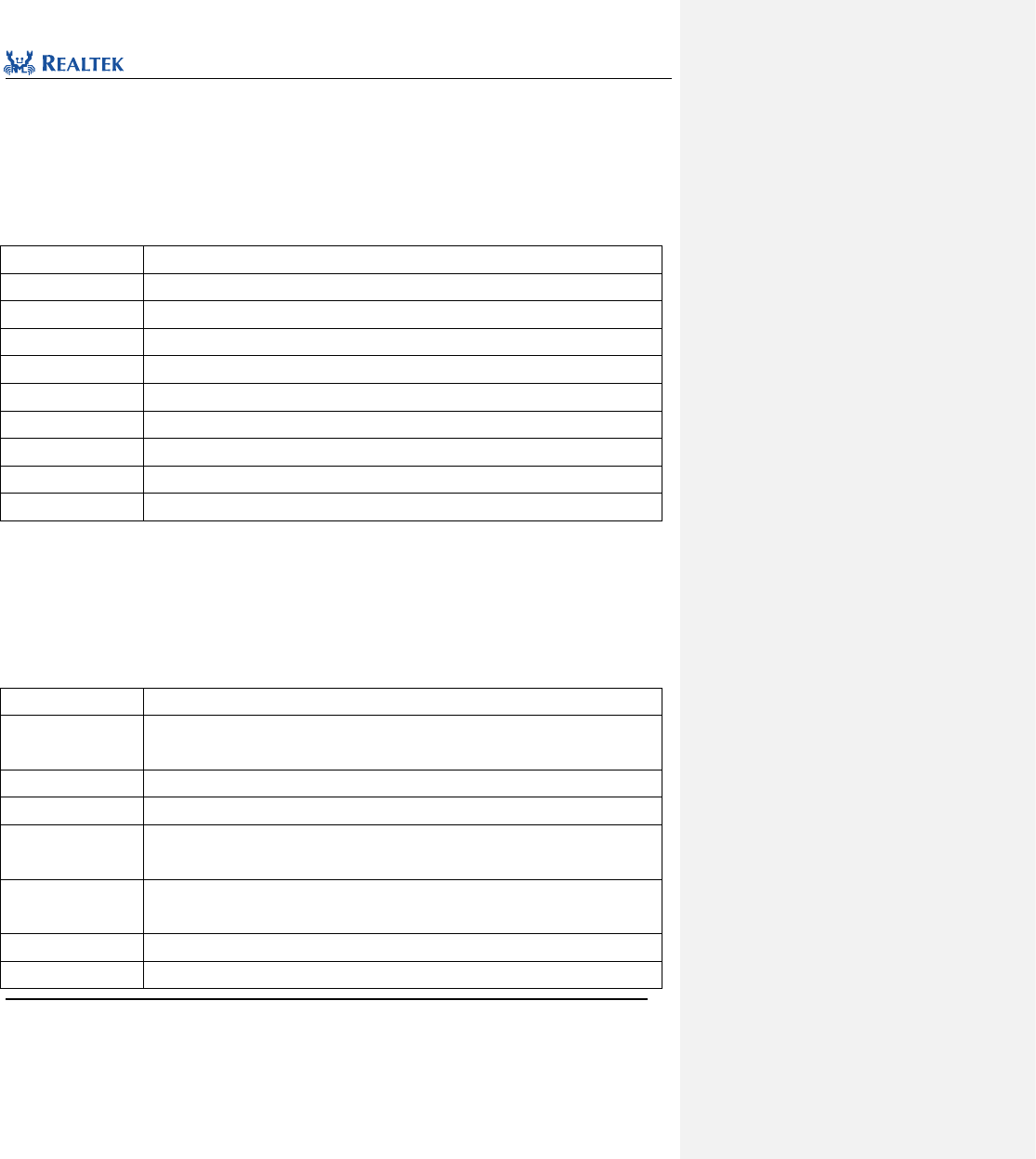
Realtek Confidential
RTL8762C Peripheral Manual
Copyright 2018 Realtek Semiconductor Corporation.
All Rights Reserved.
188
/* Receive data from RX FIFO of data uart */
uint8_t dataBuf[16] = {0};
UART_ReceiveData(UART, dataBuf, 16);
15. 2. 5 Function UART_SendData
Table 15. 13 Function UART_SendData
Function Name
UART_SendData
Function Prototype
UART_SendData(UART_TypeDef* UARTx, uint8_t* inBuf, uint16_t count)
Function Description
Write data to UART transmit FIFO.
Input Parameter 1
UARTx: x can be assigned as 0, 1 or 2 to select target UART peripheral.
Input Parameter 2
inBuf: A buffer that stores data to be sent
Input Parameter 3
Count: Bytes sent
Output Parameter
None
Return Value
None
Prerequisite
None
Functions Called
None
/* Send data to TX FIFO of data uart */
uint8_t dataBuf[6] = {1,2,3,4,5,6};
UART_SendData(UART, dataBuf, 6);
15. 2. 6 Function UART_INTConfig
Table 15. 14 Function UART_INTConfig
Function Name
UART_INTConfig
Function Prototype
void UART_INTConfig(UART_TypeDef* UARTx, uint32_t UART_IT, FunctionalState
newState)
Function Description
Enable or disable interrupts specified by UART.
Input Parameter 1
UARTx: x can be assigned as 0, 1 or 2 to select target UART peripheral.
Input Parameter 2
UART_IT: UART interrupt source to be enabled or disabled. Refer to related description of
UART_IT for more details.
Input Parameter 3
newState: new state of interrupt
This parameter can be set to ENABLE or DISABLE.
Output Parameter
None
Return Value
None

Realtek Confidential
RTL8762C Peripheral Manual
Copyright 2018 Realtek Semiconductor Corporation.
All Rights Reserved.
189
Prerequisite
None
Functions Called
None
UART_IT: Permitted UART interrupt types are as shown in Table 15. 15. Mutiple interrupts can be selected at
one time by using operator "|".
Table 15. 15 Values of UART_IT
UART_IT
Description
UART_INT_RD_AVA
Receive interrupt
UART_INT_FIFO_EMPTY
Transmit buffer empty interrupt
UART_INT_LINE_STS
UART receiving bus error interrupt
UART_INT_MODEM_STS
Modem status interrupt
UART_INT_IDLE
UART idle interrupt
Examples:
/* Enable RX interrupt and line status interrupt */
UART_INTConfig(UART, UART_INT_RD_AVA | UART_INT_LINE_STS, ENABLE);
15. 2. 7 Function UART_GetFlagState
Table 15. 16 Function UART_GetFlagStat
Function Name
UART_GetFlagStat
Function Prototype
FlagStatus UART_GetFlagState(UART_TypeDef* UARTx, uint32_t UART_FLAG)
Function Description
Check the status flag specified in UART peripheral.
Input Parameter 1
UARTx: x can be assigned as 0, 1 or 2 to select target UART peripheral.
Input Parameter 2
UART_FLAG: Flag type to be checked
Output Parameter
None
Return Value
None
Prerequisite
None
Functions Called
None
UART_FLAG: Permitted UART flag types are as shown in Table 15. 17.
Table 15. 17 Values of UART_FLAG
UART_FLAG
Description
UART_FLAG_RX_DATA_RDY
Data received
UART_FLAG_RX_OVERRUN
Overflow error
Realtek Confidential
RTL8762C Peripheral Manual
Copyright 2018 Realtek Semiconductor Corporation.
All Rights Reserved.
190
UART_FLAG_PARTY_ERR
Checking error
UART_FLAG_FRAME_ERR
Data frame error
UART_FLAG_BREAK_ERR
Interrupt error
UART_FLAG_THR_EMPTY
Transmit buffer is empty
UART_FLAG_THR_TSR_EMPTY
Transmit buffer and shift register are both empty
UART_FLAG_RX_FIFO_ERR
Checking error, or data frame error, or interrupt error
Examples:
/* Wait tx fifo empty */
while(UART_GetFlagState(UART, UART_FLAG_THR_TSR_EMPTY) != SET);
15. 2. 8 Function UART_ClearTxFifo
Table 15. 18 Function UART_ClearTxFifo
Function Name
UART_ClearTxFifo
Function Prototype
void UART_ClearTxFifo(UART_TypeDef* UARTx)
Function Description
Empty the data in UART transmit FIFO.
Input Parameter 1
UARTx: x can be assigned as 0, 1 or 2 to select target UART peripheral.
Output Parameter
None
Return Value
None
Prerequisite
None
Functions Called
None
Examples:
/* Clear Tx FIFO */
UART_ClearTxFifo(UART);
15.2.9 Function UART_LoopBackCmd
Table 15. 19 Function UART_LoopBackCmd
Function Name
UART_LoopBackCmd
Function Prototype
void UART_LoopBackCmd(UART_TypeDef *UARTx, FunctionalState NewState)
Function Description
Enable or disable loop back function.
Input Parameter 1
UARTx: x can be assigned as 0, 1 or 2 to select target UART peripheral.
Input Parameter 2
newState: new state of loop back
This parameter can be set to ENABLE or DISABLE.
Realtek Confidential
RTL8762C Peripheral Manual
Copyright 2018 Realtek Semiconductor Corporation.
All Rights Reserved.
191
Output Parameter
None
Return Value
None
Prerequisite
None
Functions Called
None
Examples:
/* Enable loop back function */
UART_LoopBackCmd (UART, ENABLE);
15. 2. 10 Function UART_ClearRxFifo
Table 15. 20 Function UART_ClearRxFifo
Function Name
UART_ClearRxFifo
Function Prototype
void UART_ClearRxFifo(UART_TypeDef* UARTx)
Function Description
Empty the data in UART receive FIFO.
Input Parameter 1
UARTx: x can be assigned as 0, 1 or 2 to select target UART peripheral.
Output Parameter
None
Return Value
None
Prerequisite
None
Functions Called
None
Examples:
/* ClearRx FIFO */
UART_ClearRxFifo(UART);
15.2.11 Function UART_GetTxFIFOLen
Table 15. 21 Function UART_GetTxFIFOLen
Function Name
UART_GetTxFIFOLen
Function Prototype
uint8_t UART_GetTxFIFOLen(UART_TypeDef *UARTx)
Function Description
Get data length from UART transmit FIFO
Input Parameter 1
UARTx: x can be assigned as 0, 1 or 2 to select target UART peripheral.
Output Parameter
None
Return Value
Data length.
Realtek Confidential
RTL8762C Peripheral Manual
Copyright 2018 Realtek Semiconductor Corporation.
All Rights Reserved.
192
Prerequisite
None
Functions Called
None
Examples:
/* Get data number in TX FIFO */
uint8_t number = 0;
number = UART_ GetTxFIFOLen (UART);
15.2.12 Function UART_GetRxFIFOLen
Table 15. 22 Function UART_GetRxFIFOLen
Function Name
UART_GetTxFIFOLen
Function Prototype
uint8_t UART_GetTxFIFOLen(UART_TypeDef *UARTx)
Function
Description
Get data length from UART receive FIFO
Input Parameter 1
UARTx: x can be assigned as 0, 1 or 2 to select target UART peripheral.
Output Parameter
None
Return Value
Data length.
Prerequisite
None
Functions Called
None
Examples:
/* Get data number in RX FIFO */
uint8_t number = 0;
number = UART_ GetRxFIFOLen (UART);
15. 2. 13 Function UART_ReceiveByte
Table 15. 20 Function UART_ReceiveByte
Function Name
UART_ReceiveByte
Function Prototype
uint8_t UART_ReceiveByte(UART_TypeDef* UARTx)
Function Description
Read one byte from UART receive FIFO.
Input Parameter 1
UARTx: x can be assigned as 0, 1 or 2 to select target UART peripheral.
Output Parameter
None
Return Value
None
Realtek Confidential
RTL8762C Peripheral Manual
Copyright 2018 Realtek Semiconductor Corporation.
All Rights Reserved.
193
Prerequisite
None
Functions Called
None
Examples:
/* Receive one byte from Rx FIFO of uart */
uint8_t data = UART_ReceiveByte (UART);
15. 2. 11 Function UART_SendByte
Table 15. 21 Function UART_SendByte
Function Name
UART_SendByte
Function Prototype
void UART_SendByte(UART_TypeDef* UARTx, uint8_t data)
Function Description
Write one byte to UART transmit FIFO.
Input Parameter 1
UARTx: x can be assigned as 0, 1 or 2 to select target UART peripheral.
Output Parameter
None
Return Value
None
Prerequisite
None
Functions Called
None
/* Send one byte to TX FIFO of data uart */
UART_SendData(UART, 0x66);
15. 2. 12 Function UART_GetIID
Table 15. 22 Function UART_GetIID
Function Name
UART_GetIID
Function Prototype
uint16_t UART_GetIID(UART_TypeDef* UARTx)
Function Description
Acquire type of UART interrupt source.
Input Parameter 1
UARTx: x can be assigned as 0, 1 or 2 to select target UART peripheral.
Output Parameter
None
Return Value
Interrupt type
Prerequisite
None
Functions Called
None
Examples:
/* Read interrupt id */
uint32_t int_status = UART_GetIID(UART);
Realtek Confidential
RTL8762C Peripheral Manual
Copyright 2018 Realtek Semiconductor Corporation.
All Rights Reserved.
194
16 KEYSCAN
16. 1 KEYCAN Register Architecture
typedef struct
{
__IO uint32_t CLKDIV;
__IO uint32_t TIMERCR;
__IO uint32_t CR;
__IO uint32_t COLCR;
__IO uint32_t ROWCR;
__I uint32_t FIFODATA;
__IO uint32_t INTMASK;
__IO uint32_t INTCLR;
__I uint32_t STATUS;
} KEYSCAN_TypeDef;
All Keyscan registers are enumeratedin Table 16. 1.
Table 16. 1 KEYSCAN Registers
Register
Description
CLKDIV
Keyscan clock divider
TIMERCR
Keyscan timing control register
CR
Control Register
COLCR
Column control register
ROWCR
Row control register
FIFODATA
KEYSCAN hardware FIFO
INTMASK
Interrupt mask register
STATUS
Status register
16. 2 KEYSCAN Library Functions
Table 16. 2 enumerates all KEYSCAN library functions.
Function Name
Description
KeyScan_Init
Initialize Keyscan register based on parameters specified in KeyScan_InitStruct.
Realtek Confidential
RTL8762C Peripheral Manual
Copyright 2018 Realtek Semiconductor Corporation.
All Rights Reserved.
195
KeyScan_DeInit
Disable Keyscan clock.
KeyScan_StructInit
Set each parameter in Keyscan_InitStruct to the default value.
KeyScan_INTConfig
Enable or disable the interrupt source specified by Keyscan.
KeyScan_INTMask
Mask interrupt source of KeyScan.
KeyScan_Read
Read data from KeyScan FIFO.
KeyScan_Cmd
Enable or disable KeyScan peripheral.
KeyScan_GetFifoDataNum
Acquire length of the data in FIFO.
KeyScan_ClearINTPendingBit
Clear an interrupt source in KeyScan peripheral to interrupt suspension bit.
KeyScan_ClearFlags
Clear flag specified by KeyScan.
KeyScan_GetFlagState
Check whether the specified status flag is set.
KeyScan_FilterDataConfig
Filter FIFO data
KeyScan_debounceConfig
Key debounce configure
KeyScan_ReadFifoData
Read one data from FIFO
16. 2. 1 Function KeyScan_Init
Table 16. 3 Function KeyScan_Init
Function Name
KeyScan_Init
Function Prototype
void KeyScan_Init(KEYSCAN_TypeDef* KeyScan, KEYSCAN_InitTypeDef*
KeyScan_InitStruct)
Function Description
Initialize Keyscan register based on parameters specified in KeyScan_InitStruct.
Input Parameter 1
KeyScan: Point to the selected KeyScan module.
Input Parameter 2
KeyScan_InitStruct: A pointer to KeyScan_InitTypeDef, whose related configuration
information is contained in KeyScan_InitStruct.
Output Parameter
None
Return Value
None
Prerequisite
None
Functions Called
None
typedef struct
{
uint16_t rowSize;
uint16_t colSize;
uint32_t detectPeriod;
uint16_t timeout;
Realtek Confidential
RTL8762C Peripheral Manual
Copyright 2018 Realtek Semiconductor Corporation.
All Rights Reserved.
196
uint16_t scanInterval;
uint32_t debounceEn;
uint32_t scantimerEn;
uint32_t detecttimerEn;
uint16_t debounceTime;
uint32_t detectMode;
uint32_t fifoOvrCtrl;
uint16_t maxScanData;
uint32_t scanmode;
uint16_t clockdiv;
uint8_t delayclk;
uint16_t fifotriggerlevel;
uint8_t debouncecnt;
uint8_t releasecnt;
uint8_t keylimit;
} KEYSCAN_InitTypeDef;
rowSize: This parameter is used to configure number of rows of matrix keyboard, which ranges from 1 to 8.
colSize: This parameter is used to configure number of columns of matrix keyboard, which ranges from 1 to 26.
clockdiv:Clock divider, ranges from 1 to 0x7ff. scan_clock =system clock/(clockdiv +1).
delayclk: Delay clock divider. delay_clock = scan_clock /(delayclk +1).
scanInterval: This parameter set interval between 2 scans. This parameter works when long press occurs. If a
certain key is long pressed, it will detected and system will start next scan. Table 16.4 lists the values available to
this parameter. Actural scan interval is determind by scanInterval and delayclk, scan interval time = scanInterval
* delay_clock
debounceEn: Enable or disable debounce function. Table 15. 4 lists values available to this parameter.
Table 16. 4 debounceEn
debounceEn
Description
KeyScan_Debounce_Enable
Enable keyscan debounce function
KeyScan_Debounce_Disable
Disable keyscan debounce function
debouncecnt: Configure Keyscan debounce time. Debounce time = debouncecnt * delay_clock。
detectMode: This parameter is used to set the detect mode for keyscan. Table 16. lists values available to this
parameter.

Realtek Confidential
RTL8762C Peripheral Manual
Copyright 2018 Realtek Semiconductor Corporation.
All Rights Reserved.
197
Table 16. 5 detectMode
detectMode
Description
KeyScan_Detect_Mode_Edge
Edge trigger Mode
KeyScan_Detect_Mode_Level
Level trigger Mode
releasecnt: This parameter is used to set key scan release time, actual release time = releasecnt * delay_clock.
detecttimerEn: This parameter set the function to release detect, 错误!未找到引用源。 lists values available to
this parameter.
Table 16. 6 detecttimerEn
detectMode
Description
KeyScan_Release_Detect_Enable
Enable key release detect
KeyScan_Release_Detect_Disable
Disable key release detect
fifoOvrCtrl: Configure data storage pattern when FIFO is full. Table 16. lists available values:
Table 16. 7 Value of fifoOvrCtrl
fifoOvrCtrl
Description
KeyScan_FIFO_OVR_CTRL_DIS_ALL
Abandon latest data
KeyScan_FIFO_OVR_CTRL_DIS_LAST
Abandon previous data.
Examples:
/* Initialize KeyScan */
KEYSCAN_InitTypeDef keyScanInitStruct;
KeyScan_StructInit(&keyScanInitStruct);
/* Debounce time is 16 ms */
keyScanInitStruct.debounceTime = (16 * 32);
keyScanInitStruct.rowSize = KEYPAD_ROW_SIZE;
keyScanInitStruct.colSize = KEYPAD_COLUMN_SIZE;
KeyScan_Init(KEYSCAN, &keyScanInitStruct);
16. 2. 2 Function KeyScan_DeInit
Table 16. 8 Function KeyScan_DeInit
Function Name
KeyScan_DeInit
Function Prototype
void KeyScan_DeInit(KEYSCAN_TypeDef* KeyScan)

Realtek Confidential
RTL8762C Peripheral Manual
Copyright 2018 Realtek Semiconductor Corporation.
All Rights Reserved.
198
Function Description
Disable Keyscan clock.
Input Parameter 1
KeyScan: Point to the selected KeyScan module.
Output Parameter
None
Return Value
None
Prerequisite
None
Functions Called
RCC_PeriphClockCmd()
/* Deinitialize keyscan */
KeyScan_DeInit(KEYSCAN);
16. 2. 3 Function KeyScan_StructInit
Table 16. 9 Function KeyScan_StructInit
Function Name
KeyScan_StructInit
Function Prototype
void KeyScan_StructInit(KEYSCAN_TypeDef* KeyScan, KEYSCAN_InitTypeDef*
KeyScan_InitStruct)
Function Description
Set each parameter in Keyscan_InitStruct to the default value.
Input Parameter 1
KeyScan_InitStruct: A pointer points to structure KeyScan_InitTypeDef, which is to be
initialized.
Output Parameter
None
Return Value
None
Prerequisite
None
Functions Called
None
Examples:
/* Initialize KeyScan */
KEYSCAN_InitTypeDef keyScanInitStruct;
KeyScan_StructInit(&keyScanInitStruct);
16. 2. 4 Function KeyScan_INTConfig
Table 16. 10 Function KeyScan_INTConfig
Function Name
KeyScan_INTConfig
Function Prototype
void KeyScan_INTConfig(KEYSCAN_TypeDef* KeyScan, uint32_t KeyScan_IT,
FunctionalState newState)
Function Description
Enable or disable specified Keyscan interrupt source.
Realtek Confidential
RTL8762C Peripheral Manual
Copyright 2018 Realtek Semiconductor Corporation.
All Rights Reserved.
199
Input Parameter 1
KeyScan: Point to the selected KeyScan module.
Input Parameter 2
KeyScan _IT: KeyScan interrupt source to be enabled or disabled. Refer to related
description of KeyScan_IT for more details.
Input Parameter 3
newState: new state of interrupt
This parameter can be set to ENABLE or DISABLE.
Output Parameter
None
Return Value
None
Prerequisite
None
Functions Called
None
KeyScan_IT: Permitted KeyScan interrupt types are as shown in Table 16. 11. Mutiple interrupts can be selected
at one time by using operator "|".
Table 16. 11 Values of KeyScan_IT
KeyScan_IT
Description
KEYSCAN_INT_THRESHOLD
FIFO data exceeding threshold interrupt
KEYSCAN_INT_OVER_READ
FIFO data misreading interrupt
KEYSCAN_INT_SCAN_END
Scan end interrupt
KEYSCAN_INT_FIFO_NOT_EMPTY
FIFO not empty interrupt
KEYSCAN_INT_ALL_RELEASE
All key released interrupt
Examples:
/* Enable scan end interrupt */
KeyScan_INTConfig(KEYSCAN, KEYSCAN_INT_SCAN_END, ENABLE);
16. 2. 5 Function KeyScan_INTMask
Table 16. 12 Function KeyScan_INTMask
Function Name
KeyScan_INTMask
Function Prototype
void KeyScan_INTMask(KEYSCAN_TypeDef* KeyScan, FunctionalState newState)
Function Description
Mask interrupt source of KeyScan.
Input Parameter 1
KeyScan: Point to the selected KeyScan module.
Input Parameter 2
newState: new state of interrupt
This parameter can be set to ENABLE or DISABLE.
Output Parameter
None
Return Value
None
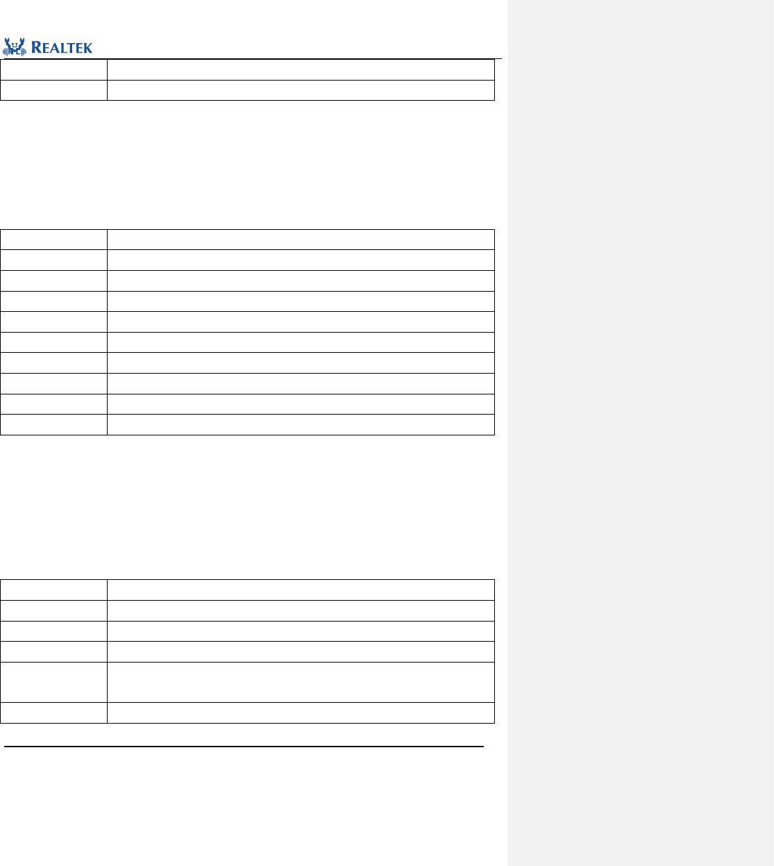
Realtek Confidential
RTL8762C Peripheral Manual
Copyright 2018 Realtek Semiconductor Corporation.
All Rights Reserved.
200
Prerequisite
None
Functions Called
None
Examples:
/* Mask scan end interrupt */
KeyScan_INTMask(KEYSCAN, ENABLE);
16. 2. 6 Function KeyScan_Read
Table 16. 13 Function KeyScan_Read
Function Name
KeyScan_Read
Function Prototype
void KeyScan_Read(KEYSCAN_TypeDef* KeyScan, uint8_t* outBuf, uint16_t count)
Function Description
Read data from FIFO of KeyScan.
Input Parameter 1
KeyScan: Point to the selected KeyScan module.
Input Parameter 2
outBuf: Buffer used to save received data.
Input Parameter 3
Count: Number of the data in FIFO to be read.
Output Parameter
None
Return Value
None
Prerequisite
None
Functions Called
None
Examples:
/* Read FIFO data */
uint8_t dataBuf[26] = {0};
KeyScan_Read(KEYSCAN, dataBuf, 26);
16. 2. 7 Function KeyScan_Cmd
Table 16. 14 Function KeyScan_Cmd
Function Name
KeyScan_Cmd
Function Prototype
void KeyScan_Cmd(KEYSCAN_TypeDef* KeyScan, FunctionalState NewState)
Function Description
Enable or disable KeyScan peripheral.
Input Parameter 1
KeyScan: Point to the selected KeyScan module.
Input Parameter 2
newState: new state of interrupt
This parameter can be set to ENABLE or DISABLE.
Output Parameter
None

Realtek Confidential
RTL8762C Peripheral Manual
Copyright 2018 Realtek Semiconductor Corporation.
All Rights Reserved.
201
Return Value
None
Prerequisite
None
Functions Called
None
Examples:
/* Enable keyscan */
KeyScan_Cmd(KEYSCAN, ENABLE);
16. 2. 8 Function KeyScan_GetFifoDataNum
Table 16. 15 Function KeyScan_GetFifoDataNum
Function Name
KeyScan_GetFifoDataNum
Function Prototype
uint16_t KeyScan_GetFifoDataNum(KEYSCAN_TypeDef* KeyScan)
Function Description
Acquire length of the data in FIFO.
Input Parameter 1
KeyScan: Point to the selected KeyScan module.
Output Parameter
None
Return Value
Length of the data in FIFO
Prerequisite
None
Functions Called
None
Examples:
/* Get data length in FIFO */
uint8_t len = 0;
len = KeyScan_GetFifoDataNum(KEYSCAN);
16. 2. 9 Function KeyScan_ClearINTPendingBit
Table 16. 16 Function KeyScan_ClearINTPendingBit
Function Name
KeyScan_ClearINTPendingBit
Function Prototype
void KeyScan_ClearINTPendingBit(KEYSCAN_TypeDef* KeyScan, uint32_t KeyScan_IT)
Function Description
Clear an interrupt source in KeyScan peripheral to interrupt suspension bit.
Input Parameter 1
KeyScan: Point to the selected KeyScan module.
Input Parameter 2
KeyScan _IT: Suspended KeyScan interrupt source. Refer to related description of
KeyScan_IT in 16. 2. 4 for more details.
Output Parameter
None
Return Value
None
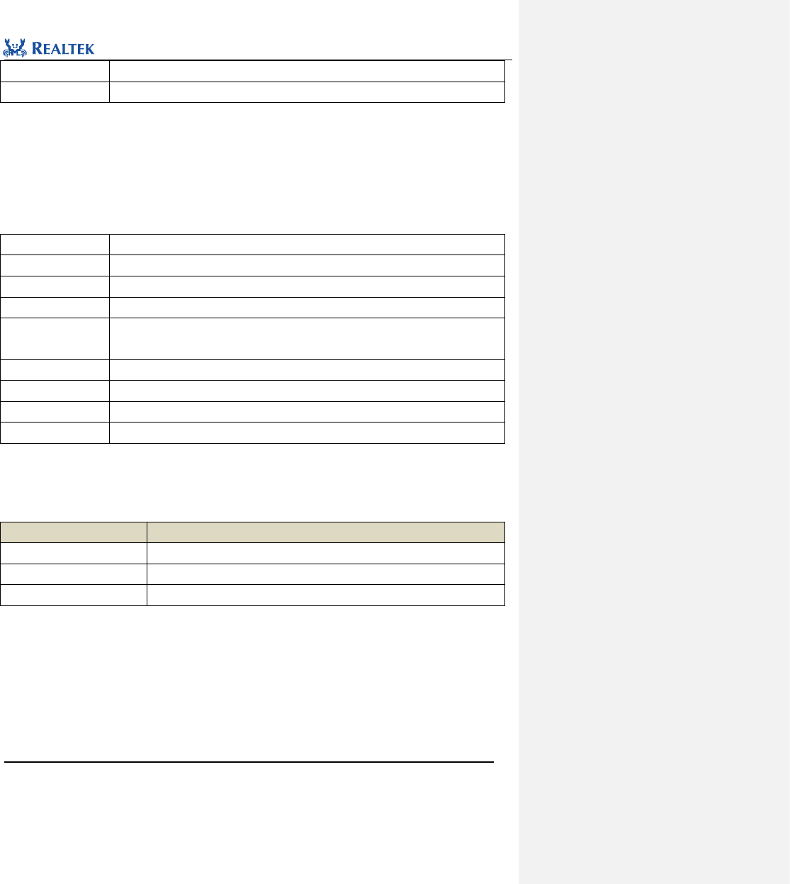
Realtek Confidential
RTL8762C Peripheral Manual
Copyright 2018 Realtek Semiconductor Corporation.
All Rights Reserved.
202
Prerequisite
None
Functions Called
None
Examples:
/* Clear scan end interrupt */
KeyScan_ClearINTPendingBit(KEYSCAN, KEYSCAN_INT_SCAN_END);
16. 2. 10 Function KeyScan_ClearFlags
Table 16. 17 Function KeyScan_ClearFlags
Function Name
KeyScan_ClearFlags
Function Prototype
void KeyScan_ClearFlags(KEYSCAN_TypeDef* KeyScan, uint32_t KeyScan_FLAG)
Function Description
Clear flag specified by KeyScan.
Input Parameter 1
KeyScan: Point to the selected KeyScan module.
Input Parameter 2
KeyScan_ FLAG: Specified flag. Refer to related description of KeyScan_FLAG for more
details.
Output Parameter
None
Return Value
None
Prerequisite
None
Functions Called
None
KeyScan_FLAG: Permitted KeyScan Status types are as shown below. Mutiple interrupts can be selected at one
time by using operator "|".
Table 16. 18 Values of KeyScan_FLAG
KeyScan_FLAG
Description
KEYSCAN_FLAG_FIFOLIMIT
FIFO data exceed limit flag
KEYSCAN_FLAG_DATAFILTER
FIFO data filtered flag
KEYSCAN_FLAG_OVR
FIFO overflow flag
Examples:
/* Clear scan FIFO overflow flag */
KeyScan_ ClearFlags (KEYSCAN, KEYSCAN_FLAG_OVR);
16. 2. 11 Function KeyScan_GetFlagState
Table 16. 19 Function KeyScan_GetFlagState
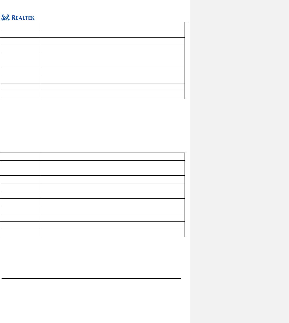
Realtek Confidential
RTL8762C Peripheral Manual
Copyright 2018 Realtek Semiconductor Corporation.
All Rights Reserved.
203
Function Name
KeyScan_GetFlagState
Function Prototype
FlagStatus KeyScan_GetFlagState(KEYSCAN_TypeDef* KeyScan, uint32_t KeyScan_FLAG)
Function Description
Check whether the specified status is set.
Input Parameter 1
KeyScan: Point to the selected KeyScan module.
Input Parameter 2
KeyScan _ FLAG: status flag to be checked. Refer to related description of KeyScan_FLAG
in 16. 2. 10 for more details.
Output Parameter
None
Return Value
Status flag.
Prerequisite
None
Functions Called
None
Examples:
/* Get FIFO overflow flag state */
bool state = FALSE;
state = KeyScan_GetFlagState (KEYSCAN, KEYSCAN_FLAG_OVR);
16. 2. 12 Function KeyScan_debounceConfig
Table 16. 20 Function KeyScan_GetCurState
Function Name
KeyScan_GetCurState
Function Prototype
void KeyScan_debounceConfig(KEYSCAN_TypeDef *KeyScan, uint8_t time,
FunctionalState NewState)
Function Description
Set keyscan hardware debounce function
Input Parameter 1
KeyScan: Point to the selected KeyScan module.
Input Parameter 2
time: debounce time setting
Input Parameter 3
NewState: enable or disable keyscan hw debounce
Output Parameter
None
Return Value
None
Prerequisite
None
Functions Called
None
Examples:
/* Configure debounce of KeyScan */
KeyScan_debounceConfig (KEYSCAN, 0x20, ENABLE);
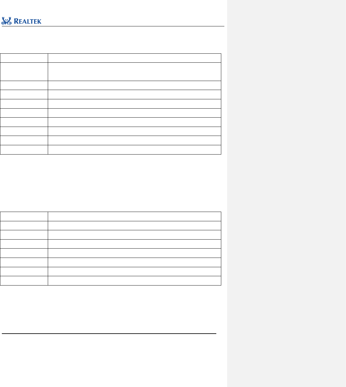
Realtek Confidential
RTL8762C Peripheral Manual
Copyright 2018 Realtek Semiconductor Corporation.
All Rights Reserved.
204
16. 2. 13 Function KeyScan_FilterDataConfig
Table 16. 21 Function KeyScan_FilterDataConfig
Function Name
KeyScan_FilterDataConfig
Function Prototype
void KeyScan_FilterDataConfig(KEYSCAN_TypeDef *KeyScan, uint16_t data,
FunctionalState NewState)
Function Description
Set filter data
Input Parameter 1
KeyScan: Point to the selected KeyScan module.
Input Parameter 2
data: data to filter
Input Parameter 3
NewState: enable or disable filter function
Output Parameter
None
Return Value
None
Prerequisite
None
Functions Called
None
Examples:
/* Enable data filter */
KeyScan_FilterDataConfig(KEYSCAN, 0x01, ENABLE);;
16. 2. 14 Function KeyScan_ReadFifoData
Table 16. 22 Function KeyScan_ReadFifoData
Function Name
KeyScan_ReadFifoData
Function Prototype
uint16_t KeyScan_ReadFifoData(KEYSCAN_TypeDef *KeyScan)
Function Description
Get one data from fifo
Input Parameter
KeyScan: Point to the selected KeyScan module.
Output Parameter
None
Return Value
data in receive FIFO
Prerequisite
None
Functions Called
None
Examples:
/* Read FIFO data */
uint8_t data = KeyScan_ReadFifoData (KEYSCAN);
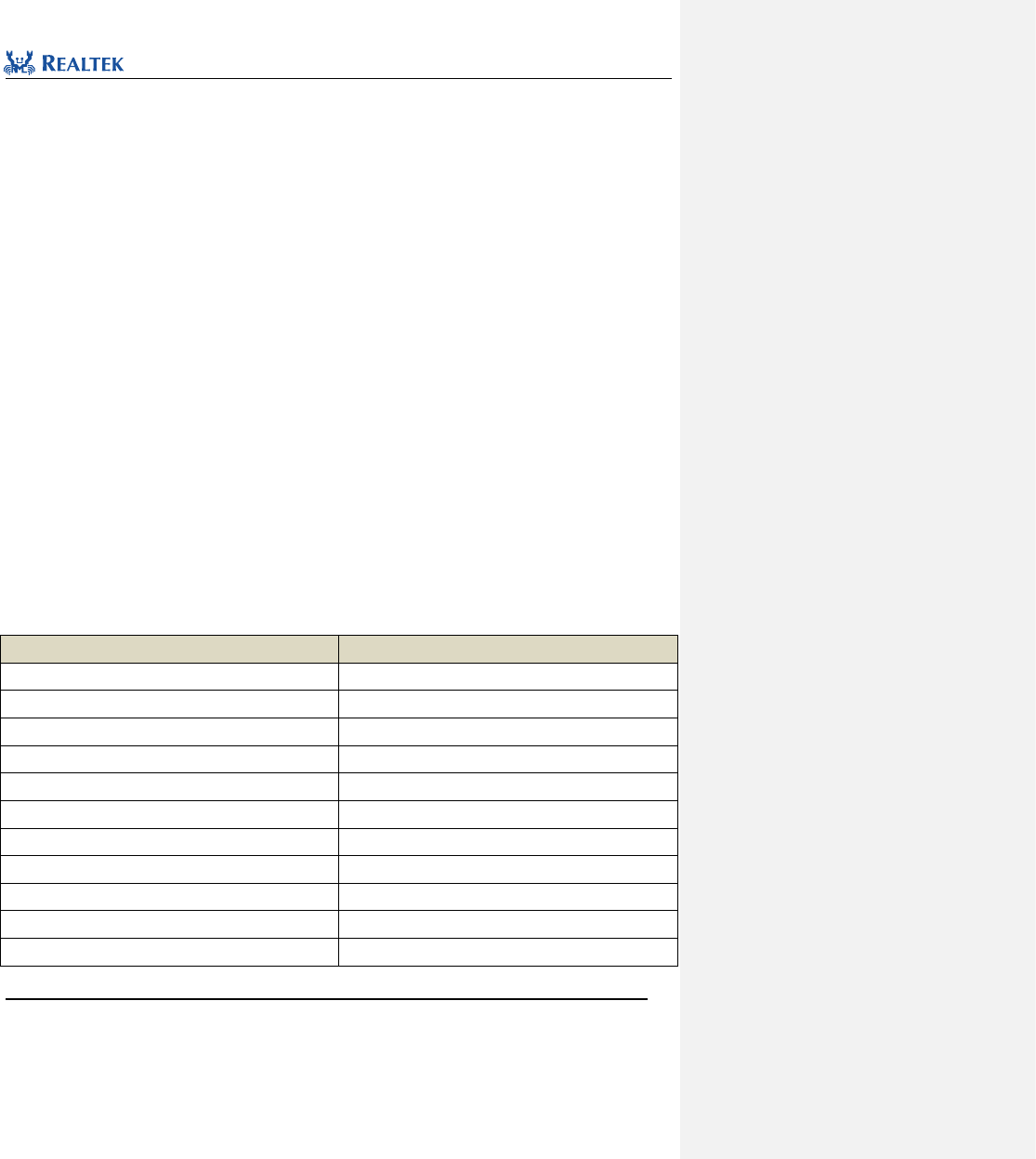
Realtek Confidential
RTL8762C Peripheral Manual
Copyright 2018 Realtek Semiconductor Corporation.
All Rights Reserved.
205
17 Infrared Radiation(IR)
17.1 IR Register Architecture
typedef struct
{
__IO uint32_t CLK_DIV;
__IO uint32_t TX_CONFIG;
__IO uint32_t TX_SR;
__IO uint32_t RESERVER;
__IO uint32_t TX_INT_CLR;
__IO uint32_t TX_FIFO;
__IO uint32_t RX_CONFIG;
__IO uint32_t RX_SR;
__IO uint32_t RX_INT_CLR;
__IO uint32_t RX_CNT_INT_SEL;
__IO uint32_t RX_FIFO;
__IO uint32_t IR_VERSION;
__IO uint32_t REVD[6];
__IO uint32_t IR_TX_COMPE;
} IR_TypeDef;
All IR registers are enumerated in Table 16. 1.
Table17. 1 IR Registers
Register
Description
CLK_DIV
Clock divider register
TX_CONFIG
Configuration registers in sending mode
TX_SR
Status registers in sending mode
RESERVER
Reserved
TX_INT_CLR
Interrupt clear register in receiving mode
TX_FIFO
Transmit FIFO register
RX_CONFIG
Configuration registers in receiving mode
RX_SR
Status registers in receive mode
RX_INT_CLR
Interrupt clear register in receiving mode
RX_CNT_INT_SEL
Counter threshold config register in receiving mode
RX_FIFO
Transmit FIFO register in receiving mode.

Realtek Confidential
RTL8762C Peripheral Manual
Copyright 2018 Realtek Semiconductor Corporation.
All Rights Reserved.
206
IR_VERSION
Reserved
REVD[6]
Reserved
IR_TX_COMPE
Transmit waveform compensation register
17.2 IR Library Functions
Table 17. 2 enumerates all IR library functions.
Table 17. 1 IR Library Functions
Function Name
Description
IR_DeInit
Disable IR clock.
IR_Init
Initialize IR register based on parameters specified in IR_InitStruct.
IR_StructInit
Set each parameter in IR_InitStruct to the default value.
IR_Cmd
Enable or disable IR send or receive mode.
IR_StartManualRxTrigger
Start manual trigger receiving mode.
IR_SetRxCounterThreshold
Set counter threshold in receiving mode
IR_SendBuf
IR sends data.
IR_ReceiveBuf
IR receives data.
IR_INTConfig
Enable or disable the interrupt source specified by IR.
IR_MaskINTConfig
Mask or unmask the interrupt source specified by IR.
IR_GetINTStatus
Get status of the interrupt source specified by IR.
IR_ClearINTPendingBit
Clear the interrupt flag suspended by IR peripheral.
IR_GetTxFIFOFreeLen
Get the spare space of transmit FIFO.
IR_GetRxDataLen
Get the depth of IR receive FIFO.
IR_SendData
Send data through IR peripheral.
IR_ReceiveData
Receive data through IR peripheral.
IR_SetTxThreshold
Set the FIFO threshold for triggering IR_INT_TF_LEVEL interrupt.
IR_SetRxThreshold
Set the FIFO threshold for triggering IR_INT_RF_LEVEL interrupt.
IR_ClearTxFIFO
Clear data in transmit FIFO.
IR_ClearRxFIFO
Clear data in receive FIFO.
IR_GetFlagStatus
Check the status flag specified in IR peripheral.
IR_SetTxInverse
Reverse transmission data .
IR_TxOutputInverse
Reverse transmission output polarity.
IR_ConfigCompenParam
Set the parameter of IR waveform compensation.
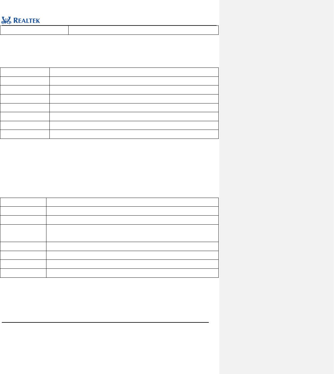
Realtek Confidential
RTL8762C Peripheral Manual
Copyright 2018 Realtek Semiconductor Corporation.
All Rights Reserved.
207
IR_SendCompenBuf
Send data with waveform compensation
17.2.1 Function IR_ DeInit
Table 17. 2 Function IR_DeInit
Function Name
IR_DeInit
Function Prototype
void IR_DeInit(void)
Function Description
Disable IR clock.
Input Parameter
None
Output Parameter
None
Return Value
None
Prerequisite
None
Functions Called
RCC_PeriphClockCmd()
Examples:
/* Close IR clock */
IR_DeInit();
17.2.2 Function IR_Init
Table 17. 3 function IR_Init
Function Name
IR_Init
Function Prototype
void IR_Init(IR_InitTypeDef* IR_InitStruct)
Function Description
Initialize IR register based on parameters specified in IR_InitStruct.
Input Parameter
IR_InitStruct: A pointer to IR_InitTypeDef, whose related configuration information is
contained in IR_InitStruct.
Output Parameter
None
Return Value
None
Prerequisite
None
Functions Called
None
typedef struct
{
uint32_t IR_Clock;
uint32_t IR_Freq; /*!< Specifies the clock frequency. This parameter is IR carrier freqency whose unit is KHz.
This parameter can be a value of @ref IR_Frequency */
uint32_t IR_DutyCycle; /*!< Specifies the IR duty cycle. */

Realtek Confidential
RTL8762C Peripheral Manual
Copyright 2018 Realtek Semiconductor Corporation.
All Rights Reserved.
208
uint32_t IR_Mode; /*!< Specifies the IR mode.
This parameter can be a value of @ref IR_Mode */
uint32_t IR_TxIdleLevel; /*!< Specifies the IR output level in Tx mode
This parameter can be a value of @ref IR_Idle_Status */
uint32_t IR_TxInverse; /*!< Specifies inverse FIFO data or not in TX mode
This parameter can be a value of @ref IR_TX_Data_Type */
uint32_t IR_TxFIFOThrLevel; /*!< Specifies TX FIFO interrupt threshold in TX mode. When TX FIFO depth <=
threshold value, trigger interrupt.
This parameter can be a value of @ref IR_Tx_Threshold */
uint32_t IR_RxStartMode; /*!< Specifies Start mode in RX mode
This parameter can be a value of @ref IR_Rx_Start_Mode */
uint32_t IR_RxFIFOThrLevel; /*!< Specifies RX FIFO interrupt threshold in RX mode. when RX FIFO depth >
threshold value, trigger interrupt.
This parameter can be a value of @ref IR_Rx_Threshold */
uint32_t IR_RxFIFOFullCtrl; /*!< Specifies data discard mode in RX mode when RX FIFO is overflow.
This parameter can be a value of @ref IR_RX_FIFO_DISCARD_SETTING */
uint32_t IR_RxTriggerMode; /*!< Specifies trigger in RX mode
This parameter can be a value of @ref IR_RX_Trigger_Mode */
uint32_t IR_RxFilterTime; /*!< Specifies filter time in RX mode
This parameter can be a value of @ref IR_RX_Filter_Time */
uint32_t IR_RxCntThrType; /*!< Specifies counter level type when trigger IR_INT_RX_CNT_THR interrupt in RX
mode
This parameter can be a value of @ref IR_RX_COUNTER_THRESHOLD_TYPE */
uint32_t IR_RxCntThr; /*!< Specifies counter threshold value when trigger IR_INT_RX_CNT_THR interrupt in RX
mode */
}IR_InitTypeDef;
IR_Clock:This parameter is used to configure the current system clock frequency.
IR_Freq:This parameter is used to set the frequency for sending or receiving IR signal. The value of the
parameter should meet the condition: IR_DIV_NUM = (IR_Clock / IR_Freq) – 1, where the value of IR_DIV_NUM
ranges from 0 to 4095.
E.g., if the system clock is 40MHz and carrier frequency is set to 38 kHz, IR_DIV_NUM = (40000/ 38)-1=1051.
IR_DIV_NUM is between 0 and 4095 and meets the requirement.
IR_DutyCycle:This parameter is used to set the duty cycle of the IR carrier. E.g., a 1/3 duty cycles is required,
IR_DutyCycle should be assigned as 3. The value of the parameter needs to meet the condition:
IR_DUTY_NUM = (IR_DIV_NUM+1)/ dutyCycle -1, IR_DIV_NUM values range from 0 to 4095.
For example, when the output duty cycle is 1/3 and the carrier frequency is 38KHz, so IR_DUTY_NUM =
(IR_DIV_NUM+1)/ 3 -1 = 349. IR_DUTY_NUM is between 0 and 4095 and meets the requirement.
IR_Mode:This parameter is used to set IR mode. Table 17. 4 lists values available to this parameter.

Realtek Confidential
RTL8762C Peripheral Manual
Copyright 2018 Realtek Semiconductor Corporation.
All Rights Reserved.
209
Table 17. 5 values of IR_Mode
IR_Mode
Description
IR_MODE_TX
Transmission mode
IR_MODE_RX
Receiving mode
IR_TxIdleLevel:This parameter is used to set polarity of idle state。Table 17. 6 lists values available to this
parameter.
Table 17. 6 values of IR_TxIdleLevel
IR_TxIdleLevel
Description
IR_IDLE_OUTPUT_HIGH
Output high level in idle state
IR_IDLE_OUTPUT_LOW
Output low level in idle state
IR_TxInverse:This parameter is used to set whether to invert IR transmiting data type. lists values available to
this parameter.
Table 17. 7 lists values available to this parameter.
Table 17. 7 values of IR_TxInverse
IR_TxInverse
Description
IR_TX_DATA_NORMAL
Do not invert IR transmiting data type
IR_TX_DATA_INVERSE
Invert IR transmiting data type
IR_TxFIFOThrLevel:This parameter is used to set threshold of transmit FIFO, which ranges from 0 to 32.
IR_RxStartMode:This parameter is used to set start mode for IR receiving mode. Table 17. 8 lists values available
to this parameter.
Table 17. 8 values of IR_RxStartMode
IR_RxStartMode
Description
IR_RX_AUTO_MODE
Automatic receive mode
IR_RX_MANUAL_MODE
Manual receive mode
IR_RxFIFOThrLevel:This parameter is used to set threshold for receive FIFO, which ranges from 0 to 32.
IR_RxFIFOFullCtrl:This parameter is used to set data coverage mode when receive FIFO is full.Table 17. 9 lists
values available to this parameter.
Table 17. 9 values of IR_RxFIFOFullCtrl
IR_RxFIFOFullCtrl
Description
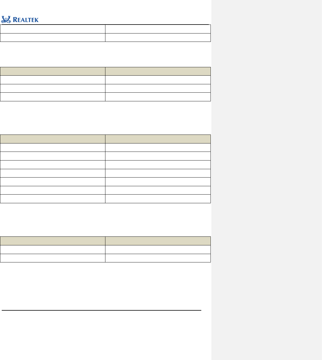
Realtek Confidential
RTL8762C Peripheral Manual
Copyright 2018 Realtek Semiconductor Corporation.
All Rights Reserved.
210
IR_RX_FIFO_FULL_DISCARD_NEWEST
Discard latest data
IR_RX_FIFO_FULL_DISCARD_OLDEST
Discard oldest data
IR_RxTriggerMode:This parameter is used to set the trigger mode in IR receiving mode.Table 17. 10 lists values
available to this parameter.
Table 17. 10 values of IR_RxTriggerMode
IR_RxTriggerMode
Description
IR_RX_FALL_EDGE
Falling edge trigger
IR_RX_RISING_EDGE
Rising edge trigger
IR_RX_DOUBLE_EDGE
Edge trigger.
IR_RxFilterTime:This parameter is used to set clutter time threshold of hardware filter in IR receiving mode.
Table 17. 11 lists values available to this parameter.
Table 17. 11 values of IR_RxFilterTime
IR_RxFilterTime
Description
IR_RX_FILTER_TIME_50ns
Filter clutter data below 50ns
IR_RX_FILTER_TIME_75ns
Filter clutter data below 75ns
IR_RX_FILTER_TIME_100ns
Filter clutter data below 100ns
IR_RX_FILTER_TIME_125ns
Filter clutter data below 125ns
IR_RX_FILTER_TIME_150ns
Filter clutter data below 150ns
IR_RX_FILTER_TIME_175ns
Filter clutter data below 175ns
IR_RX_FILTER_TIME_200ns
Filter clutter data below 200ns
IR_RxCntThrType:This parameter is used to set voltage level which triggers the receiving counter threshold
interrupt. Table 17. 12 lists values available to this parameter.
Table 17. 12 values of IR_RxCntThrType
IR_RxCntThrType
Description
IR_RX_Count_Low_Level
IR receiving level is low
IR_RX_Count_High_Level
IR receiving level is high
IR_RxCntThr:This parameter is used to set time threshold for triggering the receiving counter threshold interrupt,
whose unit is carrier cycle. The parameter ranges from 0x0 to 0x7fffffff. The parameter can be used to decide if IR
reception should be stopped. For example, when the parameter is set to 0x3ff and the carrier frequency is 38KHz,
the time threshold for detecting end signal actually is: (0x3ff-1)/38000=26.89ms. When IR level hold time is set
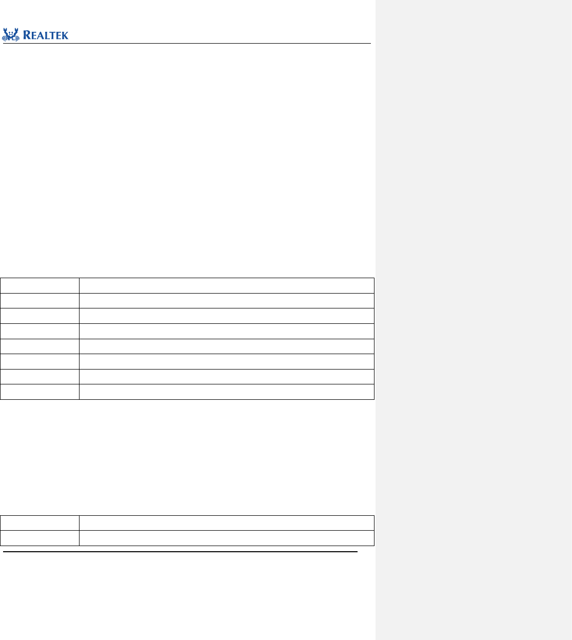
Realtek Confidential
RTL8762C Peripheral Manual
Copyright 2018 Realtek Semiconductor Corporation.
All Rights Reserved.
211
to 26.89ms, the counter threshold interrupt will be triggered.
Examples:
/* Initialize IR */
IR_InitTypeDef IR_InitStruct;
IR_StructInit(&IR_InitStruct);
IR_InitStruct.IR_Freq = 38;
IR_InitStruct.IR_DutyCycle = 2;
IR_InitStruct.IR_Mode = IR_MODE_TX;
IR_InitStruct.IR_TxInverse = IR_TX_DATA_NORMAL;
IR_InitStruct.IR_TxFIFOThrLevel = 2;
IR_Init(&IR_InitStruct);
IR_Cmd(IR_MODE_TX, ENABLE);
17.2.3 Function IR_StructInit
Table 17. 13 Function IR_StructInit
Function Name
IR_StructInit
Function Prototype
IR_StructInit(IR_InitTypeDef* IR_InitStruct)
Function Description
Set each parameter in IR_InitStruct to the default value.
Input Parameter
IR_InitStruct: A pointer points to structure IR_InitTypeDef, which is to be initialized.
Output Parameter
None
Return Value
None
Prerequisite
None
Functions Called
None
Examples:
/* Initialize IR*/
IR_InitTypeDef IRInitStruct;
IR_StructInit(&IRInitStruct);
17.2.4 Function IR_Cmd
Table 17. 14 Function IR_Cmd
Function Name
IR_Cmd
Function Prototype
void IR_Cmd(uint32_t mode, FunctionalState NewState)
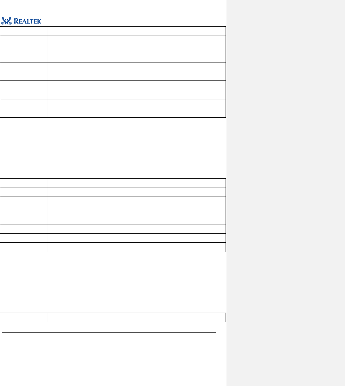
Realtek Confidential
RTL8762C Peripheral Manual
Copyright 2018 Realtek Semiconductor Corporation.
All Rights Reserved.
212
Function Description
Enable or disable IR send or receive mode.
Input Parameter 1
mode:Set IR operation mode, available parameters are as followed:
IR_MODE_TX: IR Transmission mode
IR_MODE_RX: IR Receiving mode
Input Parameter 2
NewState: new state of IR mode.
This parameter can be set to: ENABLE, DISABLE
Output Parameter
None
Return Value
None
Prerequisite
None
Functions Called
None
Examples:
/* Enable IR Tx mode */
IR_Cmd(IR_MODE_TX, ENABLE);
17.2.5 Function IR_StartManualRxTrigger
Table 17. 15 Function IR_StartManualRxTrigger
Function Name
IR_StartManualRxTrigger
Function Prototype
void IR_StartManualRxTrigger(void)
Function Description
Start IR manual receiving mode
Input Parameter
None
Output Parameter
None
Return Value
None
Prerequisite
None
Functions Called
None
Examples:
/* Start IR manual receive mode */
IR_StartManualRxTrigger (IR);
17.2.6 Function IR_SetRxCounterThreshold
Table 17. 16 Function IR_SetRxCounterThreshold
Function Name
IR_SetRxCounterThreshold
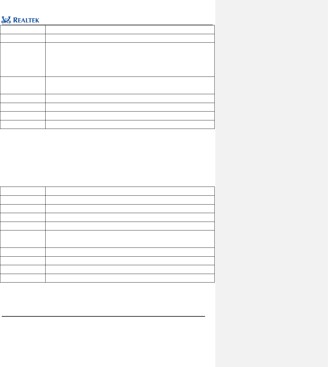
Realtek Confidential
RTL8762C Peripheral Manual
Copyright 2018 Realtek Semiconductor Corporation.
All Rights Reserved.
213
Function Prototype
void IR_SetRxCounterThreshold(uint32_t IR_RxCntThrType, uint32_t IR_RxCntThr)
Function Description
Set time threshold for triggering receive counter threshold interrupt
Input Parameter 1
IR_RxCntThrType: Level type which triggering receive counter threshold interruptis, available
parameters are as followed:
IR_RX_Count_Low_Level: IR receive level is low
IR_RX_Count_High_Level: IR receive level is high
Input Parameter 2
IR_RxCntThr: Time threshold which triggers receive counter threshold interrupt. The
parameters values from 0x0 to 0x7fffffff.
Output Parameter
None
Return Value
None
Prerequisite
None
Functions Called
None
Examples:
/* Configure receive counter threshold type and value */
IR_SetRxCounterThreshold (IR_RX_Count_Low_Level, 0x23a);
17.2.7 Function IR_SendBuf
Table 17. 17 Function IR_SendBuf
Function Name
IR_SendBuf
Function Prototype
void IR_SendBuf(uint32_t *pBuf, uint32_t len, FunctionalState IsLastPacket)
Function Description
Send data through IR peripheral.
Input Parameter 1
pBuf: Data transmit buffer first address
Input Parameter 2
len: Send data length
Input Parameter 3
IsLastPacket: Whether the last data in the buffer is the last packet sent by IR. This
parameter can be set to ENABLE or DISABLE.
Output Parameter
None
Return Value
None
Prerequisite
None
Functions Called
None
Examples:
/* Send data */
uint32_t buf[32];
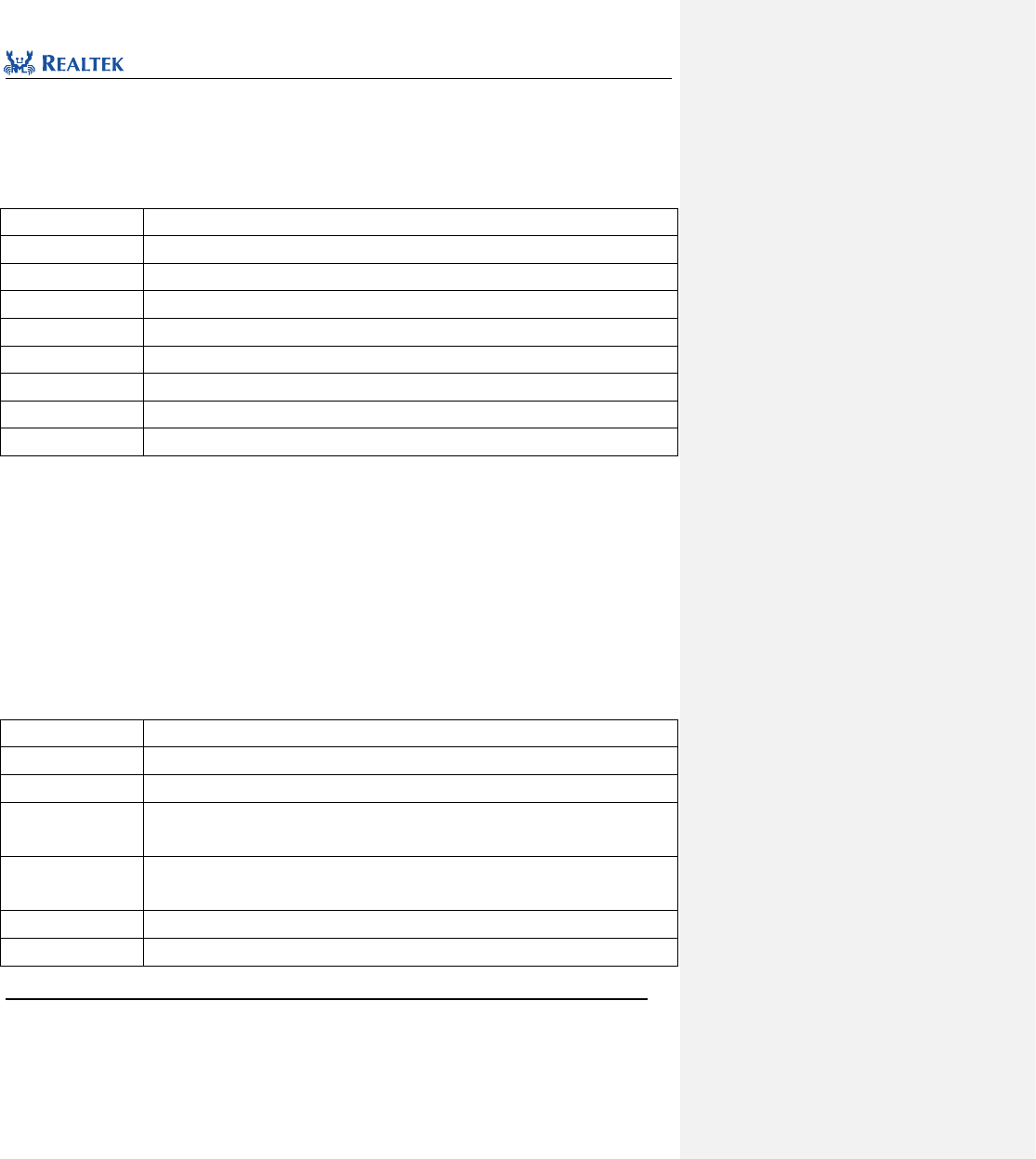
Realtek Confidential
RTL8762C Peripheral Manual
Copyright 2018 Realtek Semiconductor Corporation.
All Rights Reserved.
214
IR_SendBuf(buf, 32, DISABLE);
17.2.8 Function IR_ReceiveBuf
Table 17. 18 Function IR_ReceiveBuf
Function Name
IR_ReceiveBuf
Function Prototype
void IR_ReceiveBuf(uint32_t *pBuf, uint32_t len)
Function Description
Receive IR data
Input Parameter1
pBuf: Data receive buffer first address
Input Parameter 2
len: Receive data length
Output Parameter
None
Return Value
None
Prerequisite
None
Functions Called
None
Examples:
/* Receive data */
uint32_t buf[32];
uint32_t len = 0;
len = IR_GetRxDataLen();
IR_ReceiveBuf(buf, len);
17.2.9 Function IR_INTConfig
Table 17. 19 Function IR_INTConfig
Function Name
IR_INTConfig
Function Prototype
void IR_INTConfig(uint32_t IR_INT, FunctionalState newState)
Function Description
Enable or disable IR specified interrupt source.
Input Parameter 1
IR_INT:IR interrupt source to be enabled or disabled. Refer to related description in Table
17. 20 for more details.
Input Parameter 2
newState: New state of interrupt
This parameter can be set to ENABLE or DISABLE.
Output Parameter
None
Return Value
None
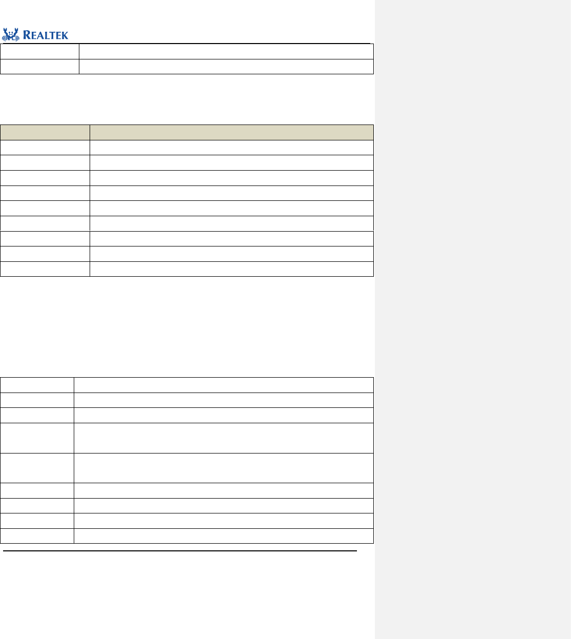
Realtek Confidential
RTL8762C Peripheral Manual
Copyright 2018 Realtek Semiconductor Corporation.
All Rights Reserved.
215
Prerequisite
None
Functions Called
None
IR_INT: Permitted IR interrupt types are as shown in Table 17. 20. Mutiple interrupts can be selected as values of
the parameter at one time by using operator "|".
Table 17. 20 Values of IR_INT
IR_INT
description
IR_INT_TF_EMPTY
This interrupt is raised when the receive buffer is empty.
IR_INT_TF_LEVEL
This interrupt is raised when the data in transmit buffer exceeds threshold.
IR_INT_TF_OF
This interrupt is raised when the transmit buffer overflows.
IR_INT_RF_FULL
This interrupt is raised when the transmit buffer is full.
IR_INT_RF_LEVEL
This interrupt is raised when the data in receive buffer exceeds threshold.
IR_INT_RX_CNT_OF
This interrupt is raised when the counter overflows.
IR_INT_RF_OF
This interrupt is raised when the receive buffer overflows.
IR_INT_RX_CNT_THR
This interrupt is raised when the counter reaches threshold.
IR_INT_RF_ERROR
This interrupt is raised when reading empty receive buffer.
Examples:
/* Enable IR threshold interrupt. When TX FIFO offset <= threshold value, trigger interrupt*/
IR_INTConfig(IR_INT_TF_LEVEL, ENABLE);
17.2.10 Function IR_MaskINTConfig
Table 17. 21 Function IR_MaskINTConfig
Function Name
IR_MaskINTConfig
Function Prototype
void IR_MaskINTConfig(uint32_t IR_INT, FunctionalState newState)
Function Description
Mask or unmask IR specified interrupt source.
Input Parameter 1
IR_INT:IR interrupt source to be masked or unmasked, refer to related description of IR_INT
in Table 17. 20 for more details.
Input Parameter 2
newState: New state of interrupt
This parameter can be set to ENABLE or DISABLE.
Output Parameter
None
Return Value
None
Prerequisite
None
Functions Called
None
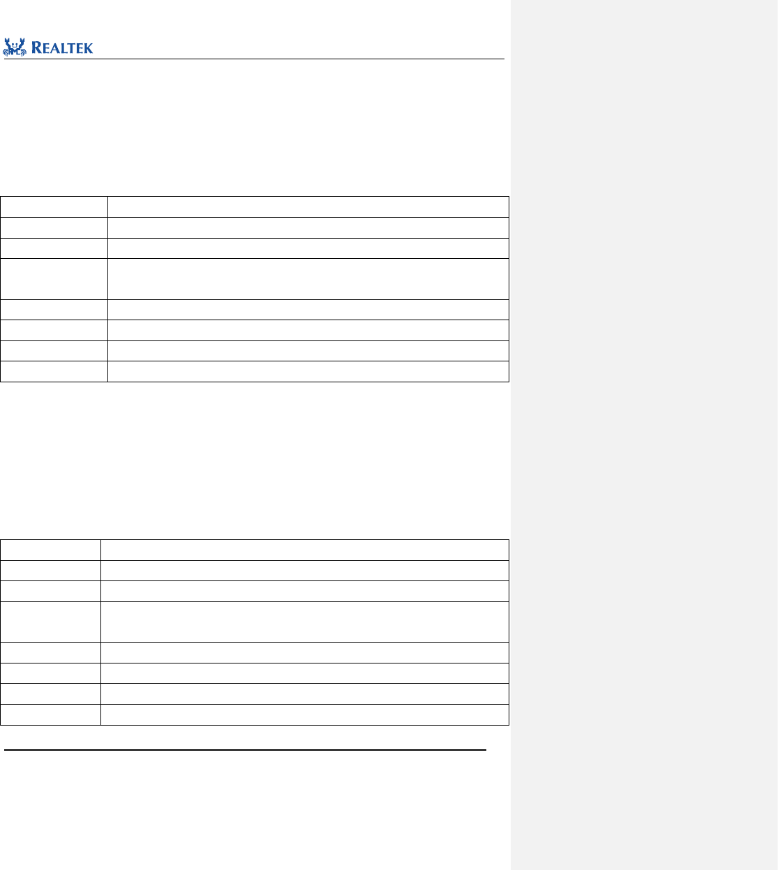
Realtek Confidential
RTL8762C Peripheral Manual
Copyright 2018 Realtek Semiconductor Corporation.
All Rights Reserved.
216
Examples:
/* Mask IR interrupt */
IR_MaskINTConfig(IR_INT_RF_LEVEL | IR_INT_RX_CNT_THR, ENABLE);
17.2.11 Function IR_GetINTStatus
Table 17. 22 Function IR_GetINTStatus
Function Name
IR_GetINTStatus
Function Prototype
ITStatus IR_GetINTStatus(uint32_t IR_INT)
Function Description
Get the specified IR interrupt status
Input Parameter
IR_INT:Specified interrupt source, refer to related description of IR_INT in Table 17. 20
for more details.
Output Parameter
None
Return Value
New state of IR specified interrupt(SET or RESET)
Prerequisite
None
Functions Called
None
Examples:
/* Get IR the specified interrupt status */
ITStatus IR_Status = RESET;
IR_Status = IR_GetINTStatus(IR_INT_RF_LEVEL);
17.2.12 Function IR_ClearINTPendingBit
Table 17. 23 Function IR_ClearINTPendingBit
Function Name
IR_ClearINTPendingBit
Function Prototype
void IR_ClearINTPendingBit(uint32_t IR_CLEAR_INT)
Function Description
Clear the suspend bit of specified IR peripheral interrupt source
Input Parameter
IR_CLEAR_INT: IR interrupt clear type. Refer to related description of IR_CLEAR_INT in Table
17. 20 for more details.
Output Parameter
None
Return Value
None
Prerequisite
None
Functions Called
None
Permitted IR interrupt clear types are as shown in Table 17. 20. Mutiple interrupts can be selected as values of
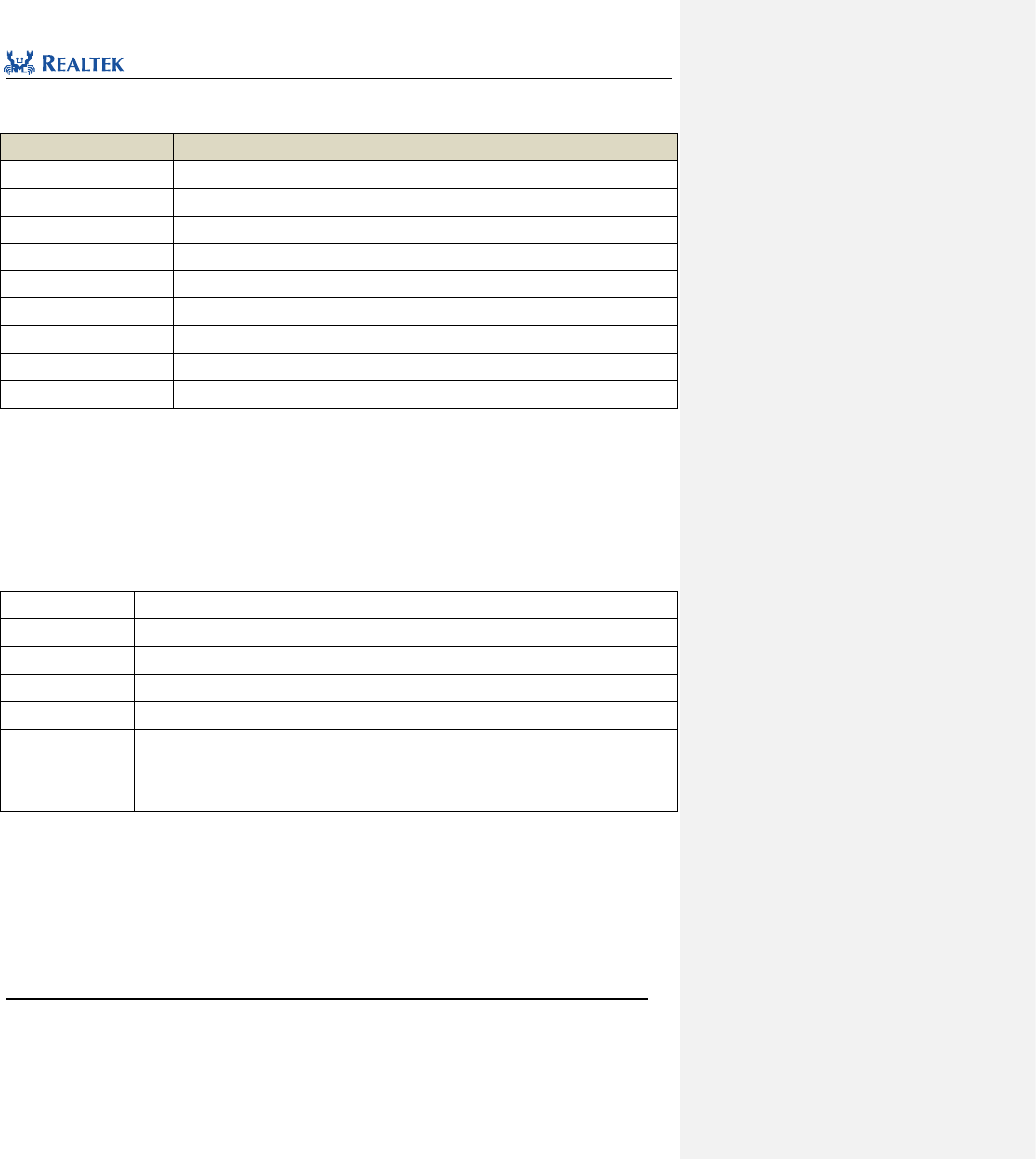
Realtek Confidential
RTL8762C Peripheral Manual
Copyright 2018 Realtek Semiconductor Corporation.
All Rights Reserved.
217
the parameter at one time by using operator "|".
Table 17. 24 values of IR_CLEAR_INT
IR_CLEAR_INT
Description
IR_INT_TF_EMPTY_CLR
Clear the interrupt raised when the clear receive buffer is empty.
IR_INT_TF_LEVEL_CLR
Clear the interrupt raised when the data in clear transmit buffer exceeds threshold.
IR_INT_TF_OF_CLR
Clear the interrupt raised when the clear transmit buffer overflows.
IR_INT_RF_FULL_CLR
Clear the interrupt raised when the clear transmit buffer is full.
IR_INT_RF_LEVEL_CLR
Clear the interrupt raised when the data in clear receive buffer exceeds threshold.
IR_INT_RX_CNT_O_CLR
Clear the interrupt raised when the clear counter overflows.
IR_INT_RF_OF_CLR
Clear the interrupt raised when the clear receive buffer overflows.
IR_INT_RX_CNT_THR _CLR
Clear the interrupt raised when the clear counter reach threshold.
IR_INT_RF_ERROR_CLR
Clear the interrupt raised when reading empty receive buffer.
Examples:
/* Clear receive FIFO threshold interrupt */
IR_ClearINTPendingBit(IR_INT_RF_LEVEL_CLR);
17.2.13 Function IR_GetTxFIFOFreeLen
Table 17. 25 Function IR_GetTxFIFOFreeLen
Function Name
IR_GetTxFIFOFreeLen
Function Prototype
uint16_t IR_GetTxFIFOFreeLen(void)
Function Description
Get The spare space of transmit FIFO.
Input Parameter
None
Output Parameter
None
Return Value
The spare space of transmit FIFO.
Prerequisite
None
Functions Called
None
Examples:
/* Get Tx FIFO free length */
uint16_t len = 0;
len = IR_GetTxFIFOFreeLen();
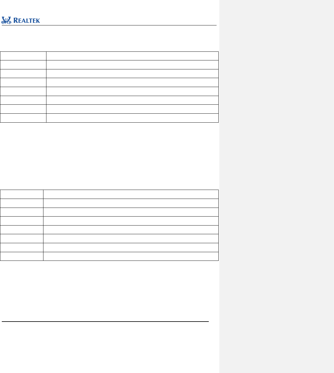
Realtek Confidential
RTL8762C Peripheral Manual
Copyright 2018 Realtek Semiconductor Corporation.
All Rights Reserved.
218
17.2.14 Function IR_GetRxDataLen
Table 17. 26 Function IR_GetRxDataLen
Function Name
IR_GetRxDataLen
Function Prototype
uint16_t IR_GetRxDataLen(void)
Function Description
Get the depth of the IR receive FIFO.
Input Parameter
None
Output Parameter
None
Return Value
Depth of the IR receive FIFO
Prerequisite
None
Functions Called
None
Examples:
/* Get Rx FIFO length */
uint16_t len = 0;
len = IR_GetRxFIFOLen();
17.2.15 Function IR_SendData
Table 17. 27 Function IR_SendData
Function Name
IR_SendData
Function Prototype
void IR_SendData(uint32_t data)
Function Description
Write one data to IR transmit FIFO.
Input Parameter
data: data to be sent through IR.
Output Parameter
None
Return Value
None
Prerequisite
None
Functions Called
None
Examples:
/* Send one data */
IR_SendData(0x032A);
17.2.16 Function IR_ReceiveData
Table 17. 28 Function IR_ReceiveData
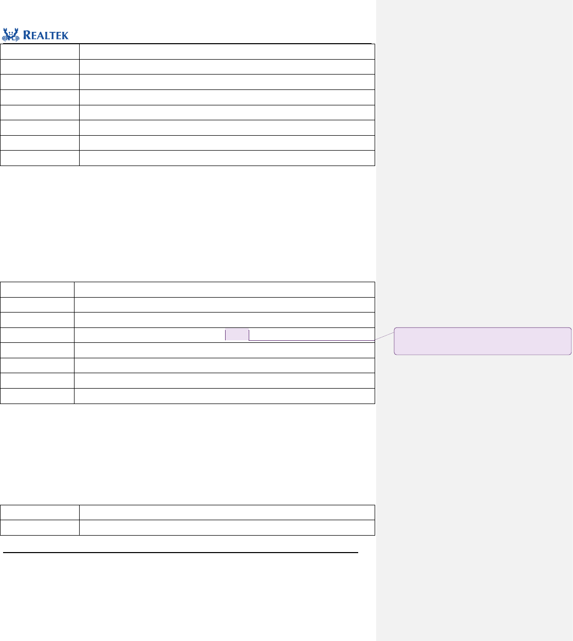
Realtek Confidential
RTL8762C Peripheral Manual
Copyright 2018 Realtek Semiconductor Corporation.
All Rights Reserved.
219
Function Name
IR_ReceiveData
Function Prototype
uint32_t IR_ReceiveData(void)
Function Description
Read one data from IR receive FIFO
Input Parameter
None
Output Parameter
None
Return Value
IR received data.
Prerequisite
None
Functions Called
None
Examples:
/* Read one data */
uint32_t data = 0;
data =IR_ReceiveData();
17.2.17 Function IR_SetTxThreshold
Table 17. 29 Function IR_SetTxThreshold
Function Name
IR_SetTxThreshold
Function Prototype
void IR_SetTxThreshold(uint8_t thd)
Function Description
Set the FIFO threshold for triggering IR_INT_TF_LEVEL interrupt.
Input Parameter
thd:Threshold of transmit FIFO, ranging from 0 to 31.
Output Parameter
None
Return Value
None
Prerequisite
None
Functions Called
None
Examples:
/* Configure Tx threshold level, when TX FIFO offset <= threshold value, trigger interrupt*/
IR_SetTxThreshold(2);
17.2.18 Function IR_SetRxThreshold
Table 17. 30 Function IR_SetRxThreshold
Function Name
IR_SetRxThreshold
Function Prototype
void IR_SetRxThreshold(uint8_t thd)
批注 [张一凡5]: 待核实

Realtek Confidential
RTL8762C Peripheral Manual
Copyright 2018 Realtek Semiconductor Corporation.
All Rights Reserved.
220
Function Description
Set the FIFO threshold for triggering the IR_INT_RF_LEVEL interrupt.
Input Parameter
thd:Threshold of transmit FIFO, ranging from 0 to 31.
Output Parameter
None
Return Value
None
Prerequisite
None
Functions Called
None
Examples:
/* Configure Rx threshold level, when RX FIFO offset >= threshold value, trigger interrupt*/
IR_SetRxThreshold(2);
17.2.19 Function IR_ClearTxFIFO
Table 17. 31 Function IR_ClearTxFIFO
Function Name
IR_ClearTxFIFO
Function Prototype
void IR_ClearTxFIFO(void)
Function Description
Clear transmit FIFO
Input Parameter
None
Output Parameter
None
Return Value
None
Prerequisite
None
Functions Called
None
Examples:
/*Clear Tx FIFO */
IR_ClearTxFIFO();
17.2.19 Function IR_ClearRxFIFO
Table 17. 32 Function IR_ClearRxFIFO
Function Name
IR_ClearRxFIFO
Function Prototype
void IR_ClearRxFIFO(void)
Function Description
Clear receive FIFO
Input Parameter
None
Output Parameter
None
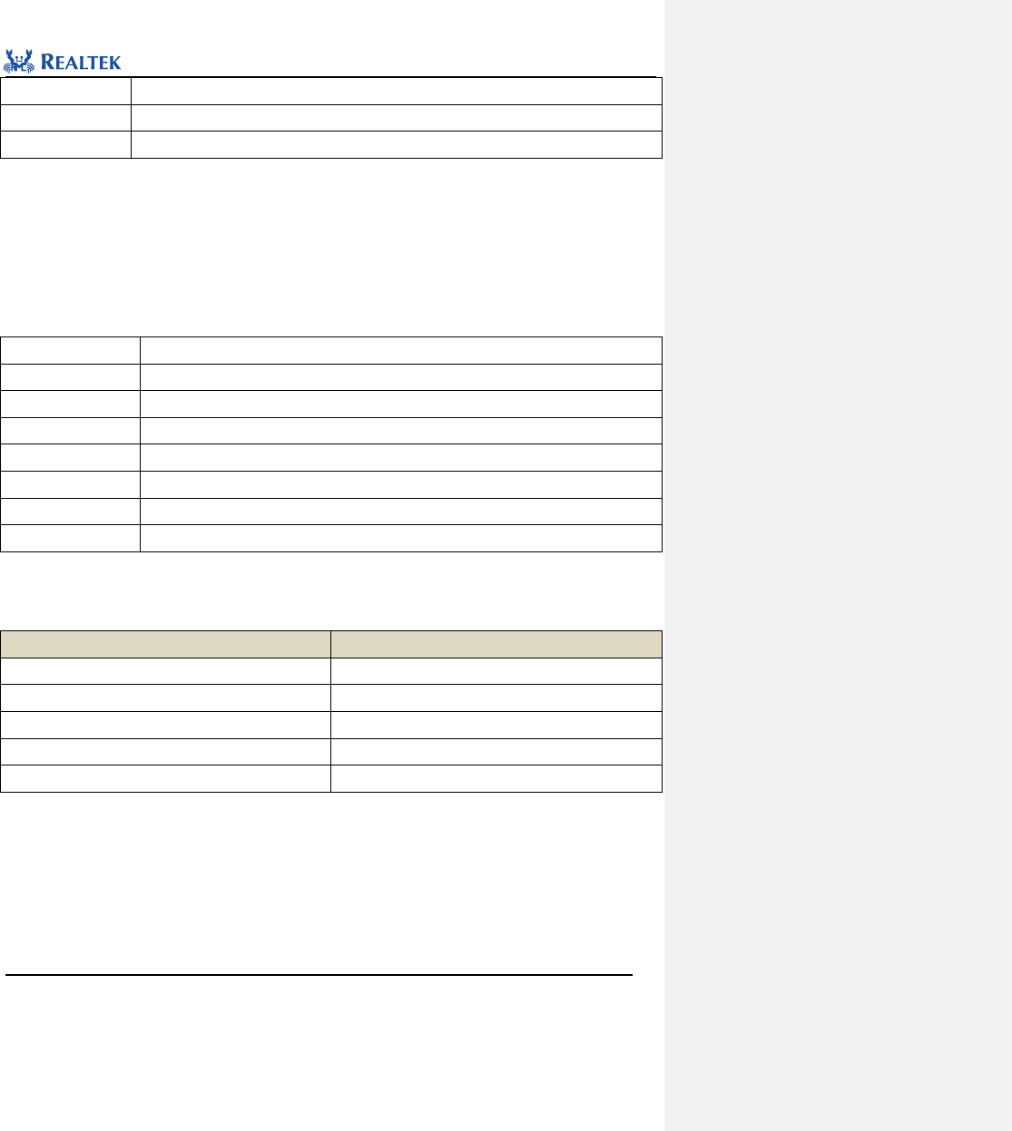
Realtek Confidential
RTL8762C Peripheral Manual
Copyright 2018 Realtek Semiconductor Corporation.
All Rights Reserved.
221
Return Value
None
Prerequisite
None
Functions Called
None
Examples:
/*Clear Rx FIFO */
IR_ClearRxFIFO();
17.2.20 Function IR_GetFlagStatus
Table 17. 33 Function IR_GetFlagStatus
Function Name
IR_GetFlagStatus
Function Prototype
FlagStatus IR_GetFlagStatus(uint32_t IR_FLAG)
Function Description
Check the status flag specified in IR peripheral.
Input Parameter
IR_FLAG: flag to be specified. Refer to related description of IR_FLAG for more details.
Output Parameter
None
Return Value
New state (SET or RESET) of the flag specified by IR
Prerequisite
None
Functions Called
None
IR_FLAG: Permitted IR state types are as shown in Table 17. 34. Mutiple interrupts can be selected as values of
the parameter at one time by using operator "|".
Table 17. 34 values of IR_FLAG
IR_FLAG
Description
IR_FLAG_TF_EMPTY
Transmit FIFO is empty.
IR_FLAG_TF_FULL
Transmit FIFO is full.
IR_FLAG_TX_RUN
IR is in transmission.
IR_FLAG_RF_EMPTY
Receive FIFO is empty.
IR_FLAG_RX_RUN
IR is in receiving.
Examples:
/* Get Tx FIFO empty flag status */
bool state = FALSE;
state = IR_GetFlagStatus (IR_FLAG_TF_EMPTY);
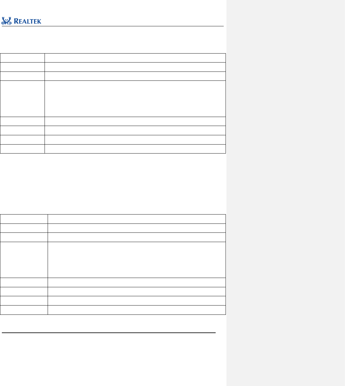
Realtek Confidential
RTL8762C Peripheral Manual
Copyright 2018 Realtek Semiconductor Corporation.
All Rights Reserved.
222
17.2.21 Function IR_SetTxInverse
Table 17. 35 Function IR_SetTxInverse
Function Name
IR_SetTxInverse
Function Prototype
void IR_SetTxInverse(FunctionalState NewState)
Function Description
Inverse transmission data type
Input Parameter
NewState: Whether transmission data type is inversed or not.
Optional parameters: ENABLE, DISABLE
ENABLE: Polarity inversed.
DISABLE: Polarity not inversed.
Output Parameter
None
Return Value
None
Prerequisite
None
Functions Called
None
Examples:
/*Inverse data type */
IR_SetTxInverse(ENABLE);
17.2.22 Function IR_TxOutputInverse
Table 17. 36 Function IR_TxOutputInverse
Function Name
IR_TxOutputInverse
Function Prototype
void IR_TxOutputInverse(FunctionalState NewState)
Function Description
Inverse IR output polarity.
Input Parameter
NewState: Whether polarity of output voltage level is inversed or not.
Optional parameters: ENABLE, DISABLE
ENABLE: Polarity inversed.
DISABLE: Polarity not inversed.
Output Parameter
None
Return Value
None
Prerequisite
None
Functions Called
None
Examples:
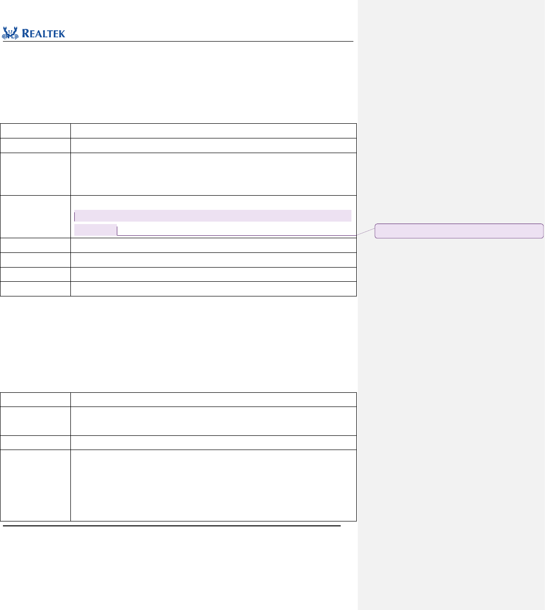
Realtek Confidential
RTL8762C Peripheral Manual
Copyright 2018 Realtek Semiconductor Corporation.
All Rights Reserved.
223
/*Inverse IR output */
IR_TxOutputInverse (ENABLE);
17.2.23 Function IR_ConfigCompenParam
Table 17. 37 Function IR_ConfigCompenParam
Function Name
IR_ConfigCompenParam
Function Prototype
void IR_ConfigCompenParam(uint32_t data)
Function Description
Set parameters of IR waveform compensation
Note: This parameter is valid only when the compensation type is
IR_COMPEN_FLAG_1_N_SYSTEM_CLK
Input Parameter
data: IR parameters of waveform compensation, which ranges from 0x0 to 0xFFF.
IR waveform compensation time = MOD*((data+ (system clock / IR carrier frequency) - 1),
4095)/40MHz
Output Parameter
None
Return Value
None
Prerequisite
None
Functions Called
None
Examples:
/* Configure IR waveform compensation parameter */
IR_ConfigCompenParam (0x06);
17.2.24 Function IR_SendCompenBuf
Table 17. 38 Function IR_SendCompenBuf
Function Name
IR_SendCompenBuf
Function Prototype
void IR_SendCompenBuf(IR_TX_COMPEN_TYPE comp_type, uint32_t *pBuf, uint32_t len,
FunctionalState IsLastPacket)
Function Description
Transmit data with waveform compensation
Input Parameter 1
comp_type:waveform compensation type, available values are:
IR_COMPEN_FLAG_1_2_CARRIER:Compensate carrier-free data segment for 1/2 carrier
cycle
IR_COMPEN_FLAG_1_4_CARRIER:Compensate carrier-free data segment for 1/4 carrier
cycle
批注 [张一凡6]: 该函数待确认
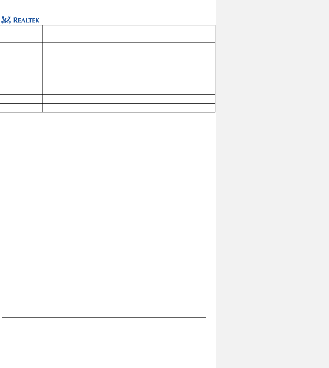
Realtek Confidential
RTL8762C Peripheral Manual
Copyright 2018 Realtek Semiconductor Corporation.
All Rights Reserved.
224
IR_COMPEN_FLAG_1_N_SYSTEM_CLK:Refer to related description of compensation time in
Table 17. 37 for more details.
Input Parameter 2
pBuf: Send data buffer first address
Input Parameter 3
len: Send data length
Input Parameter 4
IsLastPacket: Whether the last data in the buffer is the last data packet sent by IR. This
parameter can be set to ENABLE or DISABLE.
Output Parameter
None
Return Value
None
Prerequisite
None
Functions Called
None
Examples:
/* Send data */
uint32_t buf[32];
IR_SendCompenBuf(IR_COMPEN_FLAG_1_2_CARRIER, buf, 32, DISABLE)
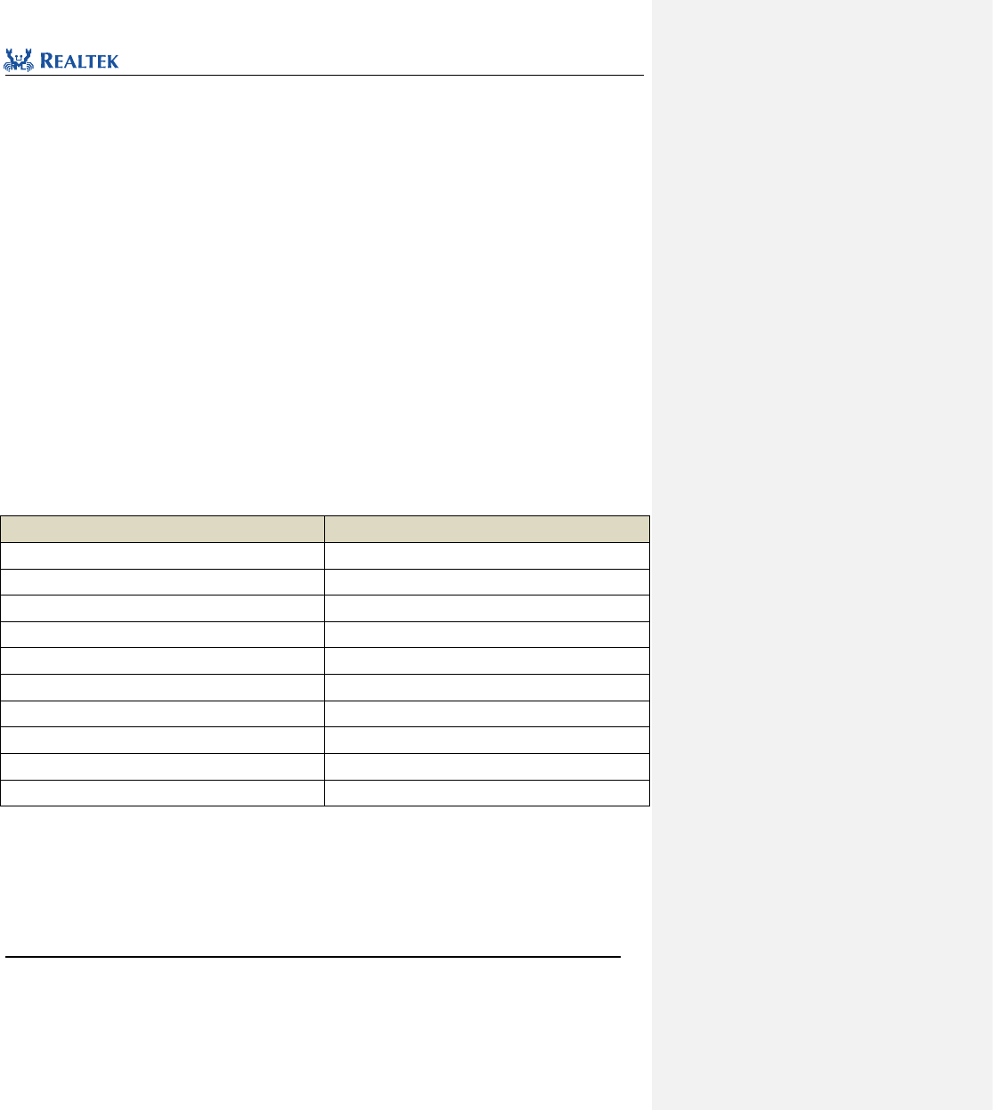
Realtek Confidential
RTL8762C Peripheral Manual
Copyright 2018 Realtek Semiconductor Corporation.
All Rights Reserved.
225
18 Inter-IC Sound(I2S)
18.1 I2S Register Architecture
typedef struct
{
__O uint32_t TX_DR; /*!< 0x00 */
__IO uint32_t CTRL0; /*!< 0x04 */
__IO uint32_t CTRL1; /*!< 0x08 */
__IO uint32_t DSP_INT_CR; /*!< 0x0C */
__I uint32_t RX_DR; /*!< 0x10 */
__I uint32_t FIFO_SR; /*!< 0x14 */
__IO uint32_t ERROR_CNT_SR; /*!< 0x18 */
__IO uint32_t BCLK_DIV; /*!< 0x1C */
__IO uint32_t DMA_TRDLR; /*!< 0x20 */
__I uint32_t SR; /*!< 0x24 */
} I2S_TypeDef;
All I2S registers are enumerated in Table 18. 1
Table 18. 1 I2S Registers
Register
Description
TX_DR
Transmit FIFO data register
CTRL0
Control Register 0
CTRL1
Control Register 1
DSP_INT_CR
Interrupt control register
RX_DR
Receive FIFO data register
FIFO_SR
FIFO status register
ERROR_CNT_SR
Error status register
BCLK_DIV
Clock divider register
DMA_TRDLR
DMA configuration register
SR
Status register
18.2 I2S Library Functions
All I2S registers are enumerated in Table 18. 2
Table 18. 2 I2S library Function

Realtek Confidential
RTL8762C Peripheral Manual
Copyright 2018 Realtek Semiconductor Corporation.
All Rights Reserved.
226
Function name
Description
I2S_DeInit
Disable I2S clock source.
I2S_Init
Initialize I2S register based on parameters specified in I2S _InitStruct.
I2S_StructInit
Set each parameter in I2S_InitStruct to the default value.
I2S_Cmd
Enable or disable the specified I2S mode.
I2S_INTConfig
Enable or disable the specified I2S interrupt source.
I2S_GetINTStatus
Get specified I2S interrupt source status.
I2S_SendData
Write one data to transmit FIFO.
I2S_ReceiveData
Read one data from receive FIFO.
I2S_GetTxFIFOFreeLen
Get spare space of transmit FIFO
I2S_GetRxFIFOLen
Get depth of receive FIFO
I2S_GetTxErrCnt
Get transmission error counter value
I2S_GetRxErrCnt
Get reception error counter value
I2S_SwapBytesForSend
Swap high-byte and low-byte of data to be transmitted.
I2S_SwapBytesForRead
Swap high-byte and low-byte of received data
I2S_SwapLRChDataForSend
Swap left and right channel data of data to be sent
I2S_SwapLRChDataForRead
Swap left and right channel data of receivd data
18.2.1 Function I2S_ DeInit
Table 18. 3 Function I2S_DeInit
Function Name
I2S_DeInit
Function Prototype
void I2S_DeInit(I2S_TypeDef *I2Sx)
Function Description
Disable I2S clock source
Input Parameter
None
Output Parameter
None
Return Value
None
Prerequisite
None
Functions Called
RCC_PeriphClockCmd()
Examples:
/* Close I2S0 clock */
I2S_DeInit(I2S0);

Realtek Confidential
RTL8762C Peripheral Manual
Copyright 2018 Realtek Semiconductor Corporation.
All Rights Reserved.
227
18.2.2 Function I2S_Init
Table 18. 4 Function I2S_Init
Function Name
I2S_Init
Function Prototype
void I2S_Init(I2S_TypeDef *I2Sx, I2S_InitTypeDef *I2S_InitStruct)
Function Description
Initialize I2S register based on parameters specified in I2S_InitStruct
Input Parameter 1
I2Sx: x can be set to 0 or 1 to select specified peripherals of I2S.
Input Parameter 2
I2S_InitStruct:A pointer to I2S_InitTypeDef, and related configuration information is
contained in I2S_InitStruct.
Output Parameter
None
Return Value
None
Prerequisite
None
Functions Called
None
typedef struct
{
uint32_t I2S_ClockSource; /*!< Specifies the I2S clock source.
This parameter can be a value of @ref I2S_clock_Source*/
uint32_t I2S_BClockMi; /*!< Specifies the BLCK clock speed. BCLK = 40MHz*(I2S_BClockNi/I2S_BClockMi).
This parameter must range from 1 to 0xffff */
uint32_t I2S_BClockNi; /*!< Specifies the BLCK clock speed.
This parameter must range from 1 to 0x7FFF */
uint32_t I2S_DeviceMode; /*!< Specifies the I2S device mode.
This parameter can be a value of @ref I2S_device_mode*/
uint32_t I2S_ChannelType; /*!< Specifies the channel type used for the I2S communication.
This parameter can be a value of @ref I2S_Channel_Type */
uint32_t I2S_TxChSequence;/*!< Specifies the transmission channel seqence used for the I2S communication.
This parameter can be a value of @ref I2S_Tx_Ch_Sequence*/
uint32_t I2S_RxChSequence; /*!< Specifies the receiving channel seqence used for the I2S communication.
This parameter can be a value of @ref I2S_Rx_Ch_Sequence*/
uint32_t I2S_DataFormat; /*!< Specifies the I2S Data format mode.
This parameter can be a value of @ref I2S_Format_Mode*/
uint32_t I2S_TxBitSequence; /*!< Specifies the I2S Data bits sequences.
This parameter can be a value of @ref I2S_Tx_Bit_Sequence*/
uint32_t I2S_RxBitSequence; /*!< Specifies the I2S Data bits sequences.
This parameter can be a value of @ref I2S_Rx_Bit_Sequence*/
uint32_t I2S_DataWidth; /*!< Specifies the I2S Data width.
This parameter can be a value of @ref I2S_Data_Width */
uint32_t I2S_MCLKOutput; /*!< Specifies the I2S MCLK output freqency.
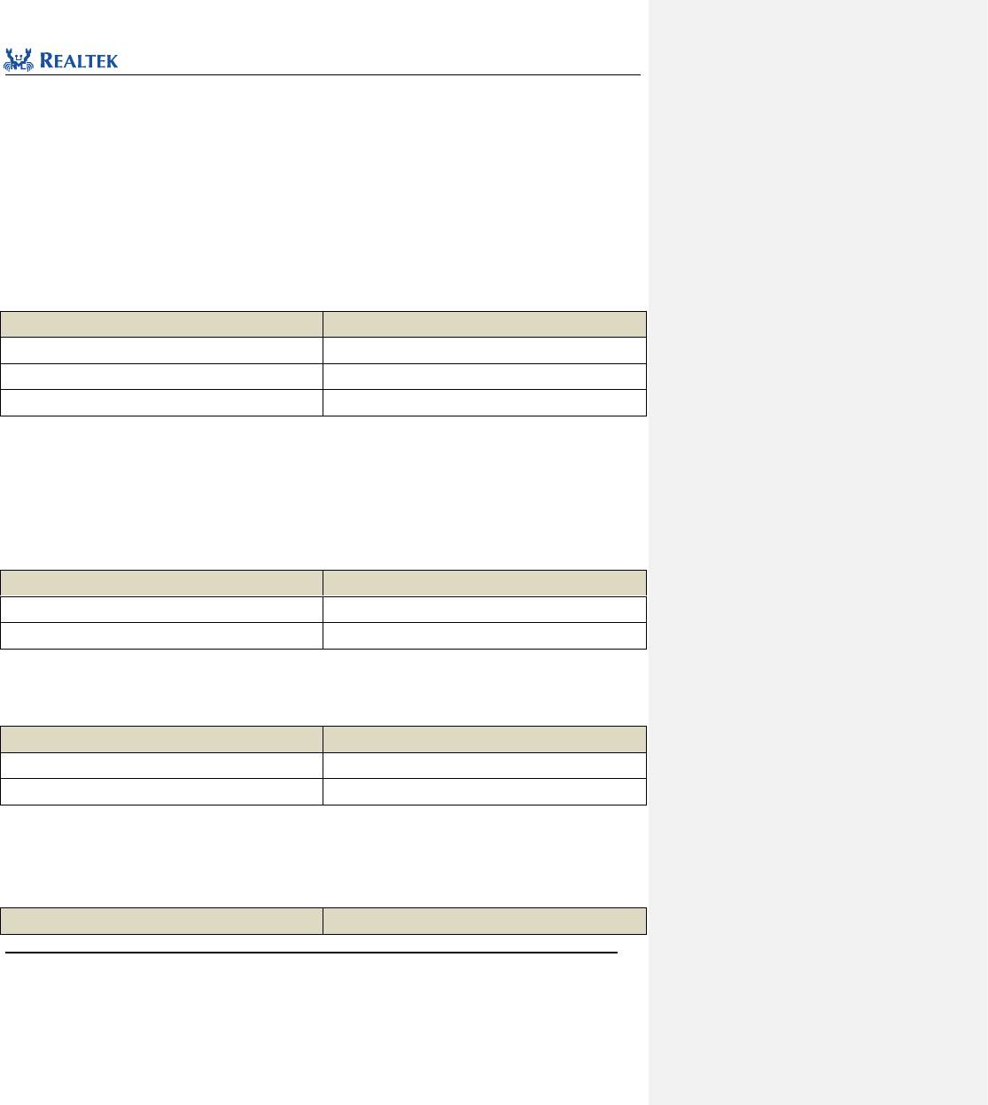
Realtek Confidential
RTL8762C Peripheral Manual
Copyright 2018 Realtek Semiconductor Corporation.
All Rights Reserved.
228
This parameter can be a value of @ref I2S_MCLK_Output */
uint32_t I2S_DMACmd; /*!< Specifies the I2S DMA control.
This parameter can be a value of @ref FunctionalState */
uint32_t I2S_TxWaterlevel; /*!< Specifies the dma watermark level in transmit mode.
This parameter must range from 1 to 63 */
uint32_t I2S_RxWaterlevel; /*!< Specifies the dma watermark level in receive mode.
This parameter must range from 1 to 63 */
}I2S_InitTypeDef;
I2S_ClockSource:Set I2S clock source. Table 18. 5 lists the available value of this parameter.
Table 18. 5 values of I2S_ClockSource
I2S_ClockSource
Description
I2S_CLK_40M
40M
I2S_CLK_128fs
128*fs
I2S_CLK_256fs
256*fs
I2S_BClockMi:Set I2S BClk output parameter Mi, whose range is 1 to 0xffff.
I2S_BClockNi:Set I2S BClk output parameter Ni, whose range is 1 to 0x7FFF. BCLK =
40MHz*(I2S_BClockNi/I2S_BClockMi).
I2S_DeviceMode:Set I2S device mode. Table 18. 6 lists the available value of this parameter.
Table 18. 6 values of I2S_DeviceMode
I2S_DeviceMode
Description
I2S_DeviceMode_Master
Master mode
I2S_DeviceMode_Slave
Slave mode
I2S_ChannelType:Set I2S transmission channel type。Table 18. 7 lists the available value of this parameter.
Table 18. 7 values of I2S_ChannelType
I2S_ChannelType
Description
I2S_Channel_Mono
Mono output
I2S_Channel_stereo
Stereo output
I2S_TxChSequence:Set I2S channel order for sending data. Table 18. 8 gives the available value of this
parameter.
Table 18. 8 values of I2S_TxChSequence
I2S_TxChSequence
Description

Realtek Confidential
RTL8762C Peripheral Manual
Copyright 2018 Realtek Semiconductor Corporation.
All Rights Reserved.
229
I2S_TX_CH_L_R
Left channel/right channel
I2S_TX_CH_R_L
Right channel/left channel
I2S_TX_CH_L_L
Left channel/ left channel
I2S_TX_CH_R_R
Right channel/ right channel
I2S_RxChSequence:Set I2S channel order for receiving data. Table 18. 9 lists the available value of this
parameter.
Table 18. 9 values of I2S_RxChSequence
I2S_RxChSequence
Description
I2S_RX_CH_L_R
Left channel/right channel
I2S_RX_CH_R_L
Right channel/left channel
I2S_RX_CH_L_L
Left channel/ left channel
I2S_RX_CH_R_R
Right channel/ right channel
I2S_DataFormat:Set I2S data format. Table 18. 10 lists the available value of this parameter.
Table 18. 10 values of I2S_DataFormat
I2S_DataFormat
Description
I2S_Mode
I2S format
Left_Justified_Mode
Left-aligned format
PCM_Mode_A
PCM A format
PCM_Mode_B
PCM B format
I2S_TxBitSequence:Set I2S bit order for sending data. Table 18. 11 lists the available value of this parameter.
Table 18. 11 values of I2S_TxBitSequence
I2S_TxBitSequence
Description
I2S_TX_MSB_First
Send MSB first
I2S_TX_LSB_First
Send LSB first
I2S_RxBitSequence:Set I2S bit order for receiving data. Table 18. 12 lists the available value of this parameter.
Table 18. 12 values of I2S_RxBitSequence
I2S_RxBitSequence
Description
I2S_RX_MSB_First
Receive MSB first
I2S_RX_LSB_First
Receive LSB first
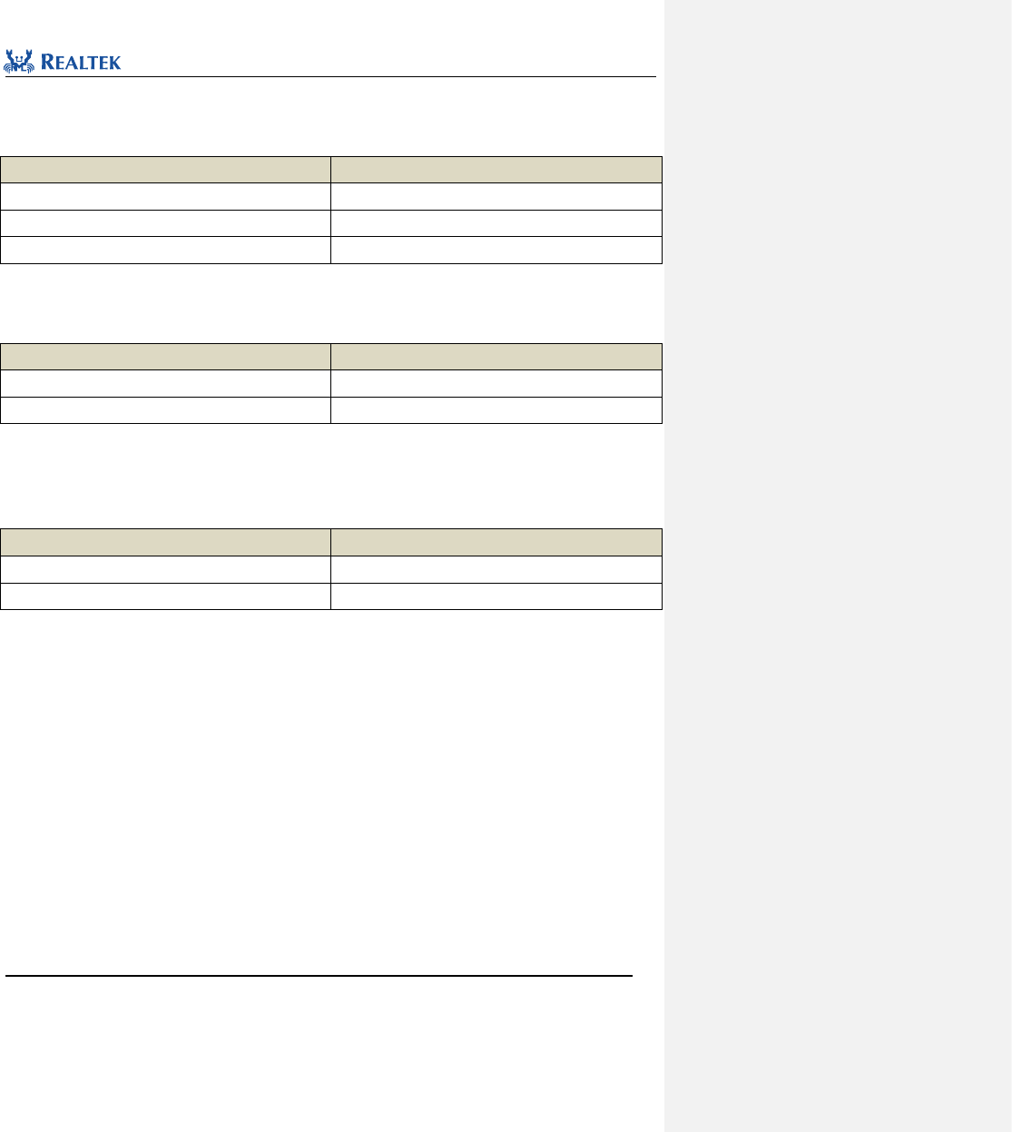
Realtek Confidential
RTL8762C Peripheral Manual
Copyright 2018 Realtek Semiconductor Corporation.
All Rights Reserved.
230
I2S_DataWidth:Set I2S data width. Table 18. 13 lists the available value of this parameter.
Table 18. 13 values of I2S_DataWidth
I2S_DataWidth
Description
I2S_Width_16Bits
16bit data width
I2S_Width_24Bits
24bit data width
I2S_Width_8Bits
8bit data width
I2S_MCLKOutput:Set MCLK output frequency. Table 18. 14 lists the available value of this parameter.
Table 18. 14 values of I2S_MCLKOutput
I2S_MCLKOutput
Description
I2S_MCLK_128fs
128*fs
I2S_MCLK_256fs
256*fs
I2S_DMACmd:Set whether DMA data transfer function is enabled. Table 18. 15 lists the available value of this
parameter.
Table 18. 15 values of I2S_DMACmd
I2S_DMACmd
Description
I2S_DMA_ENABLE
Enable DMA data transmission function
I2S_DMA_DISABLE
Disable DMA data transmission function
I2S_TxWaterlevel:Set I2S watermark size which is sent through GDMA. This parameter ranges from 0x0 to 0x3f.
I2S_RxWaterlevel:Set I2S watermark size which is receivd through GDMA. This parameter ranges from 0x0 to
0x3f.
Examples:
/* Initialize I2S */
I2S_InitTypeDef I2S_InitStruct;
I2S_StructInit(&I2S_InitStruct);
I2S_InitStruct.I2S_ClockSource = I2S_CLK_40M;
I2S_InitStruct.I2S_BClockMi = 0x271;
I2S_InitStruct.I2S_BClockNi = 0x10;
I2S_InitStruct.I2S_DeviceMode = I2S_DeviceMode_Master;
I2S_InitStruct.I2S_ChannelType = I2S_Channel_Mono;
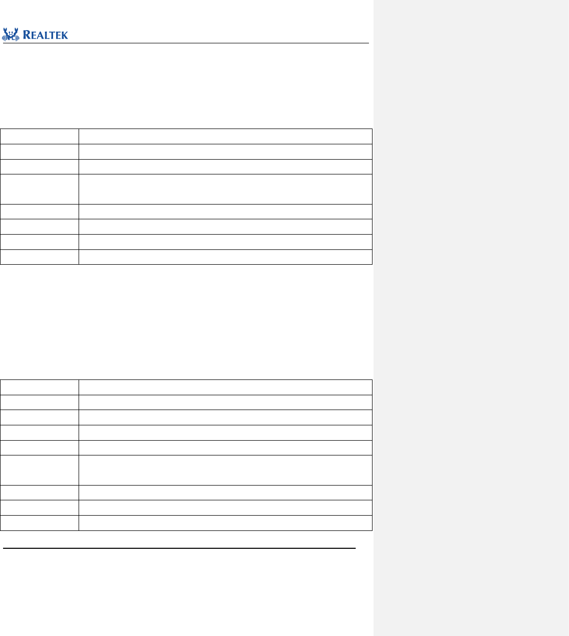
Realtek Confidential
RTL8762C Peripheral Manual
Copyright 2018 Realtek Semiconductor Corporation.
All Rights Reserved.
231
I2S_InitStruct.I2S_DataFormat = I2S_Mode;
I2S_Init(I2S0, &I2S_InitStruct);
18.2.3 Function I2S_StructInit
Table 18. 16 Function I2S_StructInit
Function Name
I2S_StructInit
Function Prototype
I2S_StructInit(I2S_InitTypeDef* I2S_InitStruct)
Function Description
Set each parameter in I2S_InitStruct to the default value.
Input Parameter
I2S_InitStruct: A pointer to I2S_InitTypeDef, related configuration information is contained in
I2S_InitStruct.
Output Parameter
None
Return Value
None
Prerequisite
None
Functions Called
None
Examples:
/* Initialize I2S*/
I2S_InitTypeDef I2SInitStruct;
I2S_StructInit(&I2SInitStruct);
18.2.4 Function I2S_Cmd
Table 18. 17 Function I2S_Cmd
Function Name
I2S_Cmd
Function Prototype
void I2S_Cmd(I2S_TypeDef *I2Sx, uint32_t mode, FunctionalState NewState)
Function Description
Enable or disable speciafied I2S mode
Input Parameter 1
I2Sx: x can be set to 0 or 1 to select specified I2S peripherals.
Input Parameter 2
mode:Set I2S mode, refer to related description of mode in Table 18. 18
Input Parameter 3
NewState: new state of I2S
This parameter can be set to ENABLE or DISABLE.
Output Parameter
None
Return Value
None
Prerequisite
None
Realtek Confidential
RTL8762C Peripheral Manual
Copyright 2018 Realtek Semiconductor Corporation.
All Rights Reserved.
232
Functions Called
None
mode: Permitted I2S mode are as shown in Table 18. 18. Mutiple modes can be selected one time by using
operator "|".
Table 18. 18 vaules of mode
mode
Description
I2S_MODE_TX
Transmission mode
I2S_MODE_RX
Reception mode
Examples:
/* Enable Tx and Rx mode */
I2S_Cmd(I2S0, I2S_MODE_TX | I2S_MODE_RX, ENABLE);
18.2.5 Function I2S_INTConfig
Table 18. 19 Function I2S_INTConfig
Function Name
I2S_INTConfig
Function Prototype
void I2S_INTConfig(I2S_TypeDef *I2Sx, uint32_t I2S_INT, FunctionalState NewState)
Function Description
Enable or disable I2S interrupt source
Input Parameter 1
I2Sx: x can be set to 0 or 1 to select specified I2S peripherals.
Input Parameter 2
I2S_INT:Enable or disable I2S interrupt source, refer to related description of I2S_INT in
Table 18. 20
Input Parameter 3
NewState: new state of interrupt
This parameter can be set to ENABLE or DISABLE.
Output Parameter
None
Return Value
None
Prerequisite
None
Functions Called
None
I2S_INT: Permitted I2S interrupt types are as shown in Table 18. 18. Mutiple interrupts can be selected as values
of the parameter at one time by using operator "|".
Table 18. 20 values of I2S_INT
I2S_INT
Description
I2S_INT_TX_IDLE
This interrupt is raised when transmission channel is in idle state.
I2S_INT_RF_EMPTY
This interrupt is raised when receive buffer is empty.
I2S_INT_TF_EMPTY
This interrupt is raised when transmit buffer is empty.
Realtek Confidential
RTL8762C Peripheral Manual
Copyright 2018 Realtek Semiconductor Corporation.
All Rights Reserved.
233
I2S_INT_RF_FULL
This interrupt is raised when receive buffer is full.
I2S_INT_TF_FULL
This interrupt is raised when transmit buffer is full.
I2S_INT_RX_READY
This interrupt is raised when reception is ready.
I2S_INT_TX_READY
This interrupt is raised when tansmission is ready.
Examples:
/* Enable Tx FIFO full interrupt */
I2S_INTConfig(I2S0, I2S_INT_TF_FULL, ENABLE);
18.2.6 Function I2S_GetINTStatus
Table 18. 21 Function I2S_GetINTStatus
Function Name
I2S_GetINTStatus
Function Prototype
ITStatus I2S_GetINTStatus(I2S_TypeDef *I2Sx, uint32_t I2S_INT)
Function Description
Get I2S specified interrupt status
Input Parameter 1
I2Sx: x can be set to 0 or 1 to select specified I2S peripherals.
Input Parameter 2
I2S_INT: Specified interrupt source type, refer to related description of I2S_INT in Table 18.
18
Output Parameter
None
Return Value
I2S: New state (SET or RESET) of Specified interrupt.
Prerequisite
None
Functions Called
None
Examples:
/* Get I2S the specified interrupt status */
ITStatus IR_Status = RESET;
IR_Status = I2S_GetINTStatus(I2S0, I2S_INT_TF_FULL);
18.2.7 Function I2S_SendData
Table 18. 22 Function I2S_SendData
Function Name
I2S_SendData
Function Prototype
void I2S_SendData(I2S_TypeDef *I2Sx, uint32_t Data)
Function Description
Send one data to transmit FIFO
Input Parameter 1
I2Sx: x can be set to 0 or 1 to select specified I2S peripherals.
Realtek Confidential
RTL8762C Peripheral Manual
Copyright 2018 Realtek Semiconductor Corporation.
All Rights Reserved.
234
Input Parameter 2
Data: I2S data
Output Parameter
None
Return Value
None
Prerequisite
None
Functions Called
None
Examples:
/* Send one data */
I2S_SendData(I2S0, 0x6688);
18.2.8 Function I2S_ReceiveData
Table 18. 23 Function I2S_ReceiveData
Function Name
I2S_ReceiveData
Function Prototype
uint32_t I2S_ReceiveData(I2S_TypeDef *I2Sx)
Function Description
Read one data from receive FIFO
Input Parameter
I2Sx: x can be set to 0 or 1 to select specified I2S peripherals.
Output Parameter
None
Return Value
Received data
Prerequisite
None
Functions Called
None
Examples:
/* Read one data */
uint32_t data = 0;
data =I2S_ReceiveData(I2S0);
18.2.9 Function I2S_GetTxFIFOFreeLen
Table 18. 24 Function I2S_GetTxFIFOFreeLen
Function Name
I2S_GetTxFIFOFreeLen
Function Prototype
uint8_t I2S_GetTxFIFOFreeLen(I2S_TypeDef *I2Sx)
Function Description
Get spare space of transmit FIFO.
Input Parameter
I2Sx: x can be set to 0 or 1 to select specified I2S peripherals.
Output Parameter
None
Realtek Confidential
RTL8762C Peripheral Manual
Copyright 2018 Realtek Semiconductor Corporation.
All Rights Reserved.
235
Return Value
Spare space of transmit FIFO
Prerequisite
None
Functions Called
None
Examples:
/* Get Tx FIFO free length */
uint16_t len = 0;
len = I2S_GetTxFIFOFreeLen(I2S0);
18.2.10 Function I2S_GetRxFIFOLen
Table 18. 25 Function I2S_GetRxFIFOLen
Function Name
I2S_GetRxFIFOLen
Function Prototype
uint8_t I2S_GetRxFIFOLen(I2S_TypeDef *I2Sx)
Function Description
Get spare space of receive FIFO
Input Parameter
I2Sx: x can be set to 0 or 1 to select specified I2S peripherals.
Output Parameter
None
Return Value
Spare space of receive FIFO
Prerequisite
None
Functions Called
None
Examples:
/* Get Rx FIFO length */
uint16_t len = 0;
len = I2S_GetRxFIFOLen(I2S0);
18.2.11 Function I2S_GetTxErrCnt
Table 18. 26 Function I2S_GetTxErrCnt
Function Name
I2S_GetTxErrCnt
Function Prototype
uint8_t I2S_GetTxErrCnt(I2S_TypeDef *I2Sx)
Function Description
Get the value of transmission error counter.
Input Parameter
I2Sx: x can be set to 0 or 1 to select specified I2S peripherals.
Output Parameter
None
Return Value
The value of transmission error counter
Realtek Confidential
RTL8762C Peripheral Manual
Copyright 2018 Realtek Semiconductor Corporation.
All Rights Reserved.
236
Prerequisite
None
Functions Called
None
Examples:
/* Get Tx error counter value*/
uint8_t value = 0;
value = I2S_GetTxErrCnt (I2S0);
18.2.12 Function I2S_GetRxErrCnt
Table 18. 27 Function I2S_GetRxErrCnt
Function Name
I2S_GetRxErrCnt
Function Prototype
uint8_t I2S_GetRxErrCnt(I2S_TypeDef *I2Sx)
Function Description
Get the value of reception error counter
Input Parameter
I2Sx: x can be set to 0 or 1 to select specified I2S peripherals.
Output Parameter
None
Return Value
The value of reception error counter
Prerequisite
None
Functions Called
None
Examples:
/* Get Rx error counter value*/
uint8_t value = 0;
value = I2S_GetRxErrCnt (I2S0);
18.2.13 Function I2S_SwapBytesForSend
Table 18. 28 Function I2S_SwapBytesForSend
Function Name
I2S_SwapBytesForSend
Function Prototype
void I2S_SwapBytesForSend(I2S_TypeDef *I2Sx, FunctionalState NewState)
Function Description
Swap high-byte and low-byte of data to be sent.
Input Parameter 1
I2Sx: x can be set to 0 or 1 to select specified I2S peripherals.
Input Parameter 2
NewState: whether to swap bytes. This parameter can be set to ENABLE or DISABLE.
ENABLE: Swap high-byte and low-byte.
DISABLE: Don’t swap.
Realtek Confidential
RTL8762C Peripheral Manual
Copyright 2018 Realtek Semiconductor Corporation.
All Rights Reserved.
237
Output Parameter
None
Return Value
None
Prerequisite
None
Functions Called
None
Examples:
/* Swap data for transmission */
I2S_SwapBytesForSend (I2S0, ENABLE);
18.2.14 Function I2S_SwapBytesForRead
Table 18. 29 Function I2S_SwapBytesForRead
Function Name
I2S_SwapBytesForRead
Function Prototype
void I2S_SwapBytesForRead(I2S_TypeDef *I2Sx, FunctionalState NewState)
Function Description
Swap high-byte and low-byte of received data.
Input Parameter 1
I2Sx: x can be set to 0 or 1 to select specified I2S peripherals.
Input Parameter 2
NewState: whether to swap bytes. This parameter can be set to ENABLE or DISABLE.
ENABLE: Swap high-byte and low-byte.
DISABLE: Don’t swap.
Output Parameter
None
Return Value
None
Prerequisite
None
Functions Called
None
Examples:
/* Swap data for reception */
I2S_SwapBytesForRead(I2S0, ENABLE);
18.2.15 Function I2S_SwapLRChDataForSend
Table 18. 30 Function I2S_SwapLRChDataForSend
Function Name
I2S_SwapLRChDataForSend
Function Prototype
void I2S_SwapLRChDataForSend(I2S_TypeDef *I2Sx, FunctionalState NewState)
Function Description
Swap left and right channel data to be sent.
Input Parameter 1
I2Sx: x can be set to 0 or 1 to select specified I2S peripherals.
Realtek Confidential
RTL8762C Peripheral Manual
Copyright 2018 Realtek Semiconductor Corporation.
All Rights Reserved.
238
Input Parameter 2
NewState: whether to swap left and right channel data.
This parameter can be set to ENABLE or DISABLE.
ENABLE: Swap left and right channel data.
DISABLE: Don’t swap.
Output Parameter
None
Return Value
None
Prerequisite
None
Functions Called
None
Examples:
/* Swap L/R data for transmission */
I2S_SwapLRChDataForSend (I2S0, ENABLE);
18.2.16 Function I2S_SwapLRChDataForRead
Table 18. 31 Function I2S_SwapLRChDataForRead
Function Name
I2S_SwapLRChDataForRead
Function Prototype
void I2S_SwapLRChDataForRead(I2S_TypeDef *I2Sx, FunctionalState NewState)
Function Description
Swap receivd left and right channel data
Input Parameter 1
I2Sx: x can be set to 0 or 1 to select specified I2S peripherals.
Input Parameter 2
NewState: whether to swap left and right channel data.
This parameter can be set to ENABLE or DISABLE.
ENABLE: Swap left and right channel data.
DISABLE: Don’t swap.
Output Parameter
None
Return Value
None
Prerequisite
None
Functions Called
None
Examples:
/* Swap L/R data for reception */
I2S_SwapLRChDataForRead (I2S0, ENABLE);
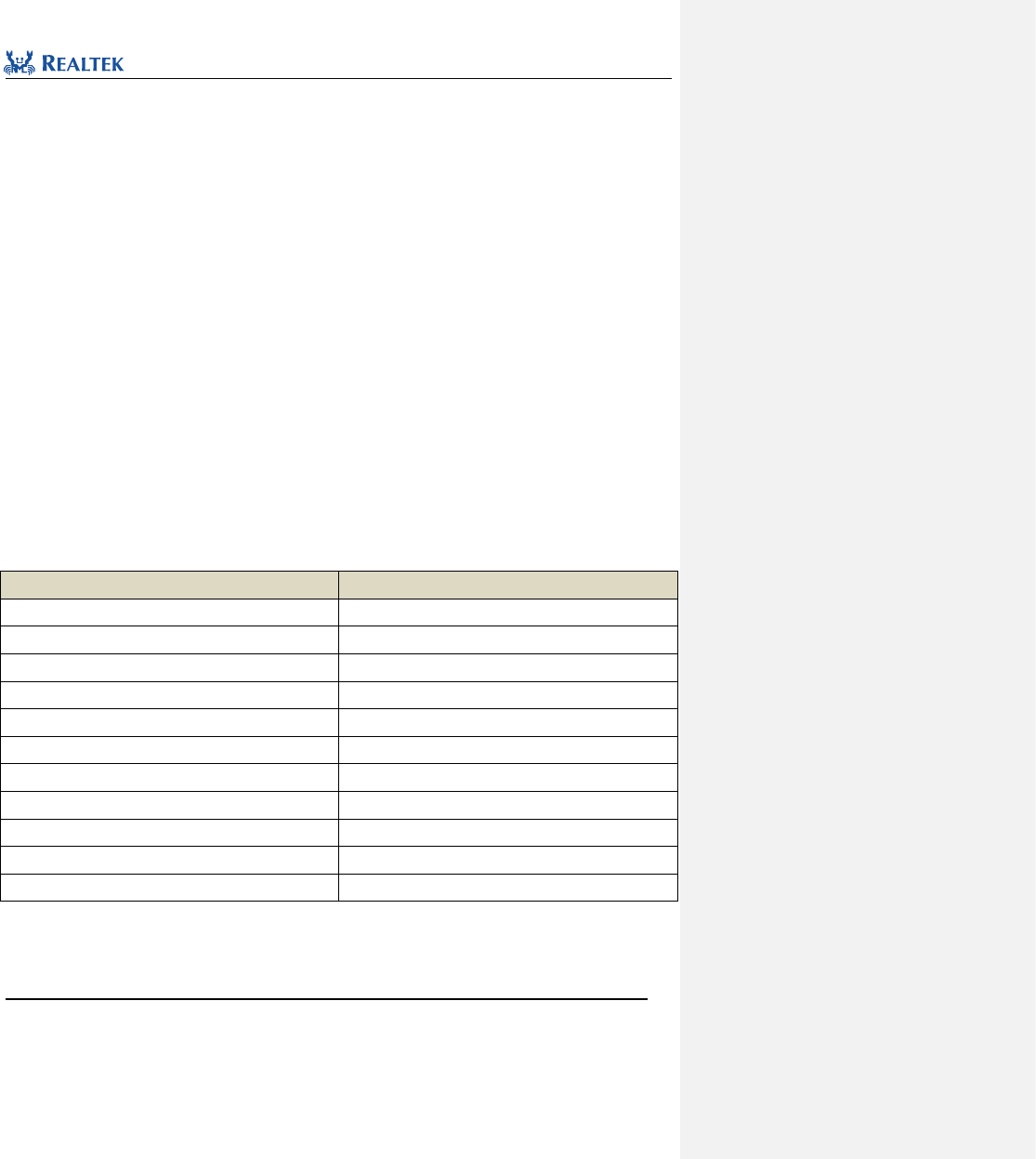
Realtek Confidential
RTL8762C Peripheral Manual
Copyright 2018 Realtek Semiconductor Corporation.
All Rights Reserved.
239
19 Liquid Crystal Display Controller(LCD)
19.1 LCD Register Structure
typedef struct
{
__IO uint32_t CTRL0;
__IO uint32_t CTRL1;
__IO uint32_t IMR;
__I uint32_t SR;
__O uint32_t ICR;
__IO uint32_t CFG;
__IO uint32_t DR;
__IO uint32_t FIFO;
__I uint32_t RXDATA;
__IO uint32_t RGB_LEN;
__I uint32_t DATA_CNT;
} LCD_TypeDef;
All LCD registers are enumerated in Table 19. 1.
Table 19. 1 LCD Registers
Register
Description
CTRL0
Control register 0
CTRL1
Control register 1
IMR
Interrupt mask register
SR
Status register
ICR
Interrupt clear register
CFG
Configuration register
DR
Data register
FIFO
Data buffer register
RXDATA
Data receive register
RGB_LEN
RBG length register
DATA_CNT
Output data count register

Realtek Confidential
RTL8762C Peripheral Manual
Copyright 2018 Realtek Semiconductor Corporation.
All Rights Reserved.
240
19.2 LCD Library Functions
All LCD library functions are enumerated in Table 19. 2.
Table 19. 2 LCD Library Functions
Function Name
Description
LCD_DeInit
Disable LCD clock source
LCD_PinGroupConfig
Configure LCD pin group
LCD_Init
Initialize LCD register based on parameters specified in LCD_InitStruct
LCD_StructInit
Set each parameter in LCD _InitStruct to the default value.
LCD_Cmd
- Enable or disable LCD
LCD_SendCommand
Send a command byte in manual mode
LCD_SendData
Send data in manual mode
LCD_ReceiveData
Receive data in manual mode
LCD_Write
Send command and data in manual mode
LCD_Read
Read data after sending command in manual mode
LCD_SetCmdSequence
Configure command sequence in automatic mode
LCD_MaskINTConfig
Mask or unmask specified LCD interrupt source.
LCD_GetINTStatus
Get specified LCD interrupt status
LCD_GetFlagStatus
Detect whether the flag of speciafied LCD status is set
LCD_SwitchMode
Switch LCD operating mode dynamically.
LCD_GDMACmd
Enable or disable GDMA function
LCD_SetCS
Pull up CS signal.
LCD_ResetCS
Pull down CS signal.
LCD_ClearINTPendingBit
Clear the suspend bit of specified LCD interrupt source.
LCD_SetTxDataLen
Configure LCD send data length.
LCD_GetTxDataLen
Read the data length that LCD has sent
LCD_GetDataCounter
Read the data length that LCD has sent
LCD_ClearDataCounter
Clear data counter
LCD_ClearFIFO
Clear FIFO
19.2.1 Function LCD_ DeInit
Table 19. 3 Function LCD_DeInit
Realtek Confidential
RTL8762C Peripheral Manual
Copyright 2018 Realtek Semiconductor Corporation.
All Rights Reserved.
241
Function Name
LCD_DeInit
Function Prototype
void LCD_DeInit(void)
Function Description
Disable LCD clock source
Input Parameter
None
Output Parameter
None
Return Value
None
Prerequisite
None
Functions Called
RCC_PeriphClockCmd()
Examples:
/* Close LCD clock */
LCD_DeInit();
19.2.2 Function LCD_PinGroupConfig
Table 19. 4 Function LCD_PinGroupConfig
Function Name
LCD_PinGroupConfig
Function Prototype
void LCD_PinGroupConfig(uint32_t LCD_PinGroupType)
Function Description
Configure LCD pin group
Input Parameter
LCD_PinGroupType: Configure LCD pin group, optional parameters:
LCD_PinGroup_DISABLE: Disable LCD pin group
LCD_PinGroup_1: CS(P3_3), RD(P3_2), DCX(P3_4), WR(P3_5),
D0(P0_2), D1(P0_4), D2(P1_3), D3(P1_4), D4(P4_0), D5(P4_1), D6(P4_2), D7(P4_3)
LCD_PinGroup_2: CS(P3_3), DCX(P3_4), WR(P3_2), RD(P2_0)
D0(P3_5), D1(P0_1), D2(P0_2), D3(P0_4), D4(P4_0), D5(P4_1), D6(P4_2), D7(P4_3)
Output Parameter
None
Return Value
None
Prerequisite
None
Functions Called
None
Examples:
LCD_PinGroupConfig(LCD_PinGroup_2);
19.2.3 Function LCD_Init
Table 19. 5 Function LCD_Init
Realtek Confidential
RTL8762C Peripheral Manual
Copyright 2018 Realtek Semiconductor Corporation.
All Rights Reserved.
242
Function Name
LCD_Init
Function Prototype
void LCD_Init(LCD_InitTypeDef *LCD_InitStruct)
Function Description
Initialize LCD register based on parameters specified in LCD_InitStruct
Input Parameter
LCD_InitStruct:A pointer to LCD_InitTypeDef, configuration information is contained in
LCD_InitStruct.
Output Parameter
None
Return Value
None
Prerequisite
None
Functions Called
None
typedef struct
{
uint32_t LCD_ClockDiv; /*!< Specifies the LCD clock speed. */
uint32_t LCD_Mode; /*!< Specifies the LCD operation mode. */
uint32_t LCD_GuardTimeCmd; /*!< Specifies the guard time function. */
uint32_t LCD_GuardTime; /*!< Specifies the guard time. This parameter is 0~3T of divider clock. */
uint32_t LCD_8BitSwap; /*!< Specifies the FIFO data format. */
uint32_t LCD_16BitSwap; /*!<Specifies the FIFO data format. */
uint32_t LCD_TxThr; /*!<Specifies the TX FIFO threshold value. */
uint32_t LCD_TxDMACmd; /*!<Specifies the TX DMA status in auto mode. */
}LCD_InitTypeDef;
LCD_ClockDiv:Set LCD clock divider. Table 19. 6 gives the available value of this parameter.
Table 19. 6 values of LCD_ClockDiv
LCD_ClockDiv
Description
LCD_CLOCK_DIV_2
Divide-by-2 frequency
LCD_CLOCK_DIV_3
Divide-by-3 frequency
LCD_CLOCK_DIV_4
Divide-by-4 frequency
LCD_CLOCK_DIV_5
Divide-by-5 frequency
LCD_CLOCK_DIV_6
Divide-by-6 frequency
LCD_CLOCK_DIV_7
Divide-by-7 frequency
LCD_CLOCK_DIV_8
Divide-by-8 frequency
LCD_CLOCK_DIV_16
Divide-by-16 frequency
LCD_Mode:Set LCD operating mode. Table 19. 7 lists the available value of this parameter.
Table 19. 7 values of LCD_Mode
Realtek Confidential
RTL8762C Peripheral Manual
Copyright 2018 Realtek Semiconductor Corporation.
All Rights Reserved.
243
LCD_Mode
Description
LCD_MODE_AUTO
Automatic mode
LCD_MODE_MANUAL
Manual mode
LCD_GuardTimeCmd:Set whether to open guard time function. Table 19. 8 lists the available value of this
parameter.
Table 19. 8 values of LCD_GuardTimeCmd
LCD_GuardTimeCmd
Description
LCD_GUARD_TIME_ENABLE
Enable guard time function
LCD_GUARD_TIME_DISABLE
Disable guard time function
LCD_GuardTime:Set LCD guard time. Table 19. 9 lists the available value of this parameter.
Table 19. 9 values of LCD_GuardTime
LCD_GuardTime
Description
LCD_GUARD_TIME_1T
1T (divided clock)
LCD_GUARD_TIME_2T
2T (divided clock)
LCD_GUARD_TIME_3T
3T (divided clock)
LCD_GUARD_TIME_4T
4T (divided clock)
LCD_8BitSwap:Set order for swaping bytes of LCD data. Table 19. 10 lists the available value of this parameter.
Table 19. 10 values of LCD_8BitSwap
LCD_8BitSwap
Description
LCD_8BitSwap_DISABLE
Send high-byte first, then send low-byte
LCD_8BitSwap_ENABLE
Send low-byte first, then send high-byte
LCD_16BitSwap:Set order for swaping 16 bits of LCD data. Table 19. 11 lists the available value of this parameter.
Table 19. 11 values of LCD_16BitSwap
LCD_16BitSwap
Description
LCD_16BitSwap_DISABLE
Send high 16 bits first, then send low 16 bits
LCD_16BitSwap_ENABLE
Send low 16 bits first, then send high 16 bits
LCD_TxThr:Set threshold which triggers LCD interrupt. This parameter ranges from 0x0 to 0x10.
LCD_TxDMACmd:Configure LCD GDMA transmit function. lists available values of this parameter.
Realtek Confidential
RTL8762C Peripheral Manual
Copyright 2018 Realtek Semiconductor Corporation.
All Rights Reserved.
244
Table 19. 12 lists available values of this parameter.
Table 19. 12 values of LCD_TxDMACmd
LCD_TxDMACmd
Description
LCD_TX_DMA_ENABLE
Enable GDMA function and internal FIFO control
LCD_TX_DMA_DISABLE
Disable GDMA function and internal FIFO control
Examples:
/* Initialize LCD */
LCD_InitTypeDef LCD_InitStruct;
LCD_StructInit(&LCD_InitStruct);
LCD_InitStruct.LCD_ClockDiv = LCD_CLOCK_DIV_2;
LCD_InitStruct.LCD_Mode = LCD_MODE_MANUAL;
LCD_InitStruct.LCD_GuardTimeCmd = LCD_GUARD_TIME_DISABLE;
LCD_InitStruct.LCD_GuardTime = LCD_GUARD_TIME_2T;
LCD_InitStruct.LCD_8BitSwap = LCD_8BitSwap_ENABLE;
LCD_InitStruct.LCD_16BitSwap = LCD_16BitSwap_DISABLE;
LCD_InitStruct.LCD_TxThr = 10;
LCD_InitStruct.LCD_TxDMACmd = LCD_TX_DMA_DISABLE;
LCD_Init(&LCD_InitStruct);
19.2.4 Function LCD_StructInit
Table 19. 13 Function LCD_StructInit
Function Name
LCD_StructInit
Function Prototype
LCD_StructInit(LCD_InitTypeDef* LCD_InitStruct)
Function Description
Set each parameter in LCD _InitStruct to the default value.
Input Parameter
LCD_InitStruct: A pointer to LCD_InitTypeDef, related configuration information is contained
in LCD.
Output Parameter
None
Return Value
None
Prerequisite
None
Functions Called
None
Examples:
/* Initialize LCD */
LCD_InitTypeDef LCD_InitStruct;
LCD_StructInit(&LCD_InitStruct);
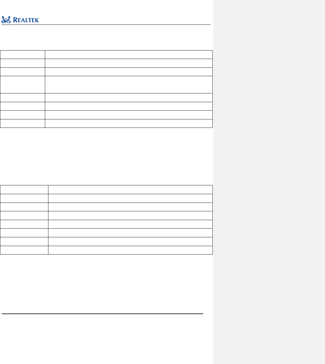
Realtek Confidential
RTL8762C Peripheral Manual
Copyright 2018 Realtek Semiconductor Corporation.
All Rights Reserved.
245
19.2.5 Function LCD_Cmd
Table 19. 14 Function LCD_Cmd
Function Name
LCD_Cmd
Function Prototype
void LCD_Cmd(FunctionalState NewState)
Function Description
Enable or disable LCD
Input Parameter
NewState: new state of LCD
This parameter can be set to ENABLE or DISABLE.
Output Parameter
None
Return Value
None
Prerequisite
None
Functions Called
None
Examples:
/* Enable LCD */
LCD_Cmd(ENABLE);
19.2.6 Function LCD_SendCommand
Table 19. 15 Function LCD_SendCommand
Function Name
LCD_SendCommand
Function Prototype
void LCD_SendCommand(uint8_t cmd)
Function Description
Send a command byte in manual mode
Input Parameter
cmd: command value, which values from 0x0 to 0xFF
Output Parameter
None
Return Value
None
Prerequisite
None
Functions Called
None
Examples:
LCD_SendCommand(0x2A);
19.2.7 Function LCD_SendData
Table 19. 16 Function LCD_SendData
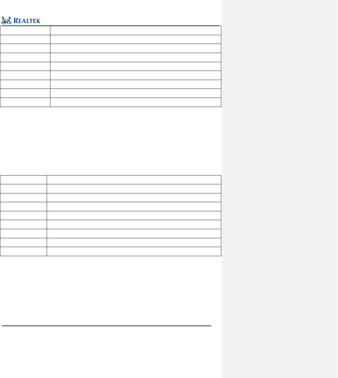
Realtek Confidential
RTL8762C Peripheral Manual
Copyright 2018 Realtek Semiconductor Corporation.
All Rights Reserved.
246
Function Name
LCD_SendData
Function Prototype
void LCD_SendData(uint8_t *pBuf, uint32_t len)
Function Description
Send data in manual mode
Input Parameter 1
pBuf: Transmit buffer first address
Input Parameter 2
len: Data length
Output Parameter
None
Return Value
None
Prerequisite
None
Functions Called
None
Examples:
/* Send data */
uint8_t buf[2] = {0x11, 0x22};
LCD_SendData (buf, 2);
19.2.8 Function LCD_ReceiveData
Table 19. 17 Function LCD_ReceiveData
Function Name
LCD_ReceiveData
Function Prototype
void LCD_ReceiveData (uint8_t *pBuf, uint32_t len)
Function Description
Receive data in manual mode
Input Parameter 1
pBuf: Receive buffer first address
Input Parameter 2
len: Data length
Output Parameter
None
Return Value
None
Prerequisite
None
Functions Called
None
Examples:
/* Read data */
uint8_t buf[2] = {0, 0};
LCD_ReadData (buf, 2);
19.2.9 Function LCD_Write
Table 19. 18 Function LCD_Write
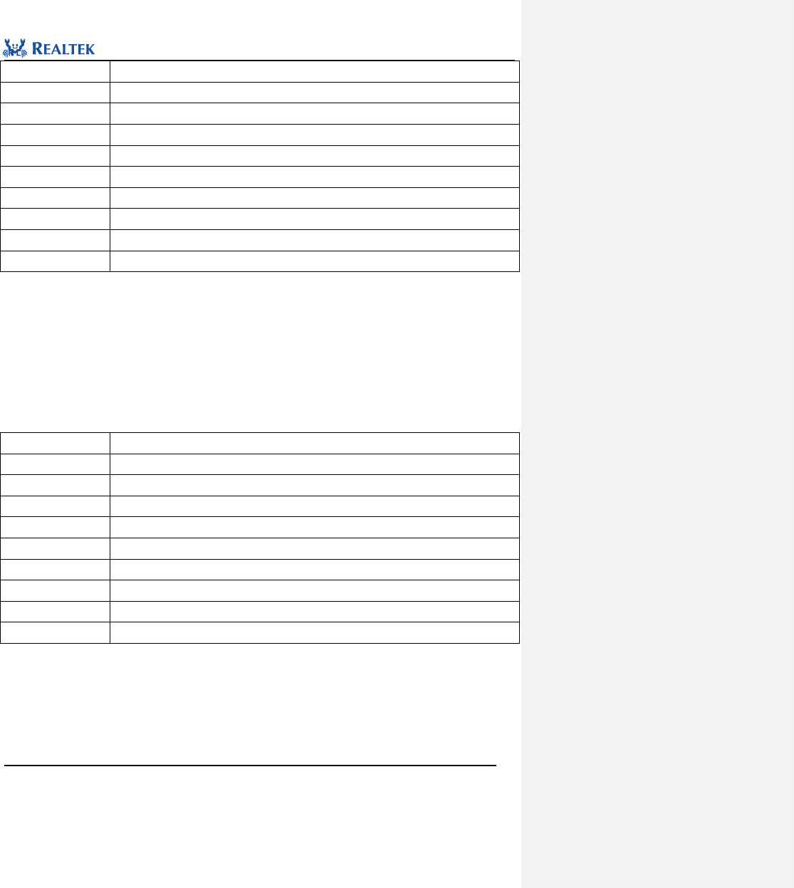
Realtek Confidential
RTL8762C Peripheral Manual
Copyright 2018 Realtek Semiconductor Corporation.
All Rights Reserved.
247
Function Name
LCD_Write
Function Prototype
void LCD_Write(uint8_t cmd, uint8_t *pBuf, uint32_t len)
Function Description
Send command and data in manual mode
Input Parameter 1
cmd: command value, which ranges from 0x0 to 0xFF
Input Parameter 2
pBuf: Transmit buffer first address
Input Parameter 3
len: Data length
Output Parameter
None
Return Value
None
Prerequisite
None
Functions Called
None
Examples:
/* Send command and data */
uint8_t buf[2] = {0x11, 0x22};
LCD_SendData (0x2A, buf, 2);
19.2.10 Function LCD_Read
Table 19. 19 Function LCD_Read
Function Name
LCD_ReadData
Function Prototype
void LCD_Read(uint8_t cmd, uint8_t *pBuf, uint32_t len)
Function Description
Read data after sending command in manual mode
Input Parameter 1
cmd: command value, which ranges from 0x0 to 0xFF
Input Parameter 2
pBuf: Receive buffer first address
Input Parameter 3
len: Length of data to be read
Output Parameter
None
Return Value
None
Prerequisite
None
Functions Called
None
Examples:
/* Send command and read data */
uint8_t buf[2] = {0, 0};
LCD_Read (0x2A, buf, 2);
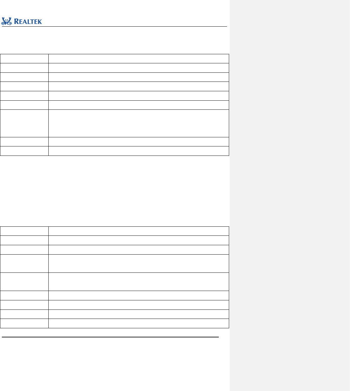
Realtek Confidential
RTL8762C Peripheral Manual
Copyright 2018 Realtek Semiconductor Corporation.
All Rights Reserved.
248
19.2.11 Function LCD_SetCmdSequence
Table 19. 20 Function LCD_SetCmdSequence
Function Name
LCD_SetCmdSequence
Function Prototype
FlagStatus LCD_SetCmdSequence(uint8_t *pCmdBuf, uint8_t len)
Function Description
Configure command sequence in automatic mode
Input Parameter 1
pCmdBuf: Command sequence buffer first address
Input Parameter 2
len: Command length
Output Parameter
None
Return Value
Function: Execution status (SET or RESET)
SET: Configure command sequence succeeded
RESET: Configure command sequence failed
Prerequisite
None
Functions Called
None
Examples:
uint8_t cmd = 0x2C;
/* Configure command */
LCD_SetCmdSequence(&cmd, 1);
19.2.12 Function LCD_MaskINTConfig
Table 19. 21 Function LCD_MaskINTConfig
Function Name
LCD_MaskINTConfig
Function Prototype
void LCD_MaskINTConfig(uint32_t LCD_INT_MSK, FunctionalState NewState)
Function Description
Mask or unmask LCD specified interrupt source.
Input Parameter 1
LCD_INT_MSK:LCD interrupt source to be masked or unmasked. Refer to related
description of LCD_INT_MSK in Table 19. 22 for more details.
Input Parameter 2
newState: new state of LCD interrupt
This parameter can be set to ENABLE or DISABLE.
Output Parameter
None
Return Value
None
Prerequisite
None
Functions Called
None
Realtek Confidential
RTL8762C Peripheral Manual
Copyright 2018 Realtek Semiconductor Corporation.
All Rights Reserved.
249
LCD_INT_MSK: Permitted LCD interrupt mask types are as shown in Table 19. 22. Mutiple interrupts can be selected
at one time by using operator "|".
Table 19. 22 values of LCD_INT_MSK
LCD_INT_MSK
Description
LCD_INT_TF_EMPTY_MSK
This interrupt is raised when transmit buffer is empty.
LCD_INT_TF_OF_MSK
This interrupt is raised when transmit buffer depth exceeds threshold.
LCD_INT_TF_LEVEL_MSK
This interrupt is raised when transmit buffer overflows.
Examples:
/* Enable Tx FIFO threshold interrupt */
LCD_MaskINTConfig (LCD_INT_TF_LEVEL_MSK);
19.2.13 Function LCD_GetINTStatus
Table 19. 23 Function LCD_GetINTStatus
Function Name
LCD_GetINTStatus
Function Prototype
ITStatus LCD_GetINTStatus(uint32_t LCD_INT)
Function Description
Get specified LCD interrupt status
Input Parameter
LCD_INT:Specified interrupt source, refer to related description of LCD_INT in Table 19. 24.
Output Parameter
None
Return Value
New state of speciafied LCD interrupt (SET or RESET)
Prerequisite
None
Functions Called
None
LCD_INT: Permitted LCD interrupt types are as shown in Table 19. 22. Mutiple interrupts can be selected one time by
using operator "|".
Table 19. 24 Values of LCD_INT
LCD_INT
Description
LCD_INT_SR_AUTO_DONE
This interrupt is raised when data has been transmited in automatic mode.
LCD_INT_SR_TF_EMPTY
This interrupt is raised when transmit buffer is empty.
LCD_INT_SR_TF_OF
This interrupt is raised when transmit buffer overflows.
LCD_INT_SR_TF_LEVEL
This interrupt is raised when transmit buffer depth exceeds threshold.
Examples:
/* Get LCD the specified interrupt status */
ITStatus LCD_Status = RESET;
Realtek Confidential
RTL8762C Peripheral Manual
Copyright 2018 Realtek Semiconductor Corporation.
All Rights Reserved.
250
LCD_Status = LCD_GetINTStatus(LCD_INT_SR_AUTO_DONE);
19.2.14 Function LCD_GetFlagStatus
Table 19. 25 Function LCD_GetFlagStatus
Function Name
LCD_GetFlagStatus
Function Prototype
FlagStatus LCD_GetFlagStatus(uint32_t LCD_FLAG)
Function Description
Detect whether the flag of speciafied LCD status is set
Input Parameter
LCD_FLAG: Detected status flag, refer to related description of LCD _ FLAG.
Output Parameter
None
Return Value
None
Prerequisite
New state (SET or RESET) of specified IR flag
Functions Called
None
LCD_FLAG: Permitted LCD status types are as shown in Table 19. 26. Mutiple flags can be selected at one time by
using operator "|".
Table 19. 26 values of LCD_FLAG
LCD_FLAG
Description
LCD_FLAG_TF_EMPTY
Transmit FIFO is empty
LCD_FLAG_TF_FULL
Transmit FIFO is full
Examples:
/* Get Tx FIFO empty flag status */
bool state = FALSE;
state = LCD_GetFlagStatus (LCD_FLAG_TF_EMPTY);
19.2.15 Function LCD_SwitchMode
Table 19. 27 Function LCD_SwitchMode
Function Name
LCD_SwitchMode
Function Prototype
void LCD_SwitchMode(uint32_t mode)
Function Description
Switch LCD operating mode dynamically.
Input Parameter
mode: Configure LCD operating mode, optional value is:
LCD_MODE_AUTO: Automatic mode
LCD_MODE_MANUAL: Manual mode
Realtek Confidential
RTL8762C Peripheral Manual
Copyright 2018 Realtek Semiconductor Corporation.
All Rights Reserved.
251
Output Parameter
None
Return Value
None
Prerequisite
None
Functions Called
None
Examples:
/* Enable Auto mode */
LCD_Cmd(DISABLE);
LCD_SwitchMode(LCD_MODE_AUTO);
19.2.16 Function LCD_GDMACmd
Table 19. 28 Function LCD_GDMACmd
Function Name
LCD_GDMACmd
Function Prototype
void LCD_GDMACmd(FunctionalState NewState)
Function Description
Enable or disable GDMA function
Input Parameter
NewState: New state of GDMA, optional value is:
ENABLE: Enable GDMA function
DISABLE: Disable GDMA function
Output Parameter
None
Return Value
None
Prerequisite
None
Functions Called
None
Examples:
/* Enable LCD GDMA function */
LCD_GDMACmd(ENABLE);
19.2.17 Function LCD_SetCS
Table 19. 29 Function LCD_SetCS
Function Name
LCD_SetCS
Function Prototype
void LCD_SetCS(void)
Function Description
Pull CS signal to high level
Input Parameter
None
Realtek Confidential
RTL8762C Peripheral Manual
Copyright 2018 Realtek Semiconductor Corporation.
All Rights Reserved.
252
Output Parameter
None
Return Value
None
Prerequisite
None
Functions Called
None
Examples:
/* Pull CS up */
LCD_SetCS();
19.2.18 Function LCD_ResetCS
Table 19. 30 Function LCD_ResetCS
Function Name
LCD_ResetCS
Function Prototype
void LCD_ResetCS (void)
Function Description
Pull CS signal down
Input Parameter
None
Output Parameter
None
Return Value
None
Prerequisite
None
Functions Called
None
Examples:
/* Pull CS down */
LCD_ResetCS ();
19.2.19 Function LCD_ClearINTPendingBit
Table 19. 31 Function LCD_ClearINTPendingBit
Function Name
LCD_ClearINTPendingBit
Function Prototype
void LCD_ClearINTPendingBit(uint32_t LCD_CLEAR_INT)
Function Description
Clear the suspend bit of specified LCD interrupt source.
Input Parameter
LCD_CLEAR_INT: LCD interrupt type, refer to related description of LCD_CLEAR_INT in
Table 19. 32.
Output Parameter
None
Return Value
None
Realtek Confidential
RTL8762C Peripheral Manual
Copyright 2018 Realtek Semiconductor Corporation.
All Rights Reserved.
253
Prerequisite
None
Functions Called
None
LCD_CLEAR_INT: Permitted LCD interrupt clear types are as shown in Table 18. 18. Mutiple interrupts can be
selected as values of the parameter at one time by using operator "|".
Table 19. 32 values of LCD_CLEAR_INT
LCD_CLEAR_INT
Description
LCD_INT_AUTO_DONE_CLR
Clear interrupt when the transmission is completed in automatic mode.
LCD_INT_TF_EMPTY_CLR
Clear interrupt when the transmit buffer is empty.
LCD_INT_TF_OF_CLR
Clear interrupt when the transmit buffer overflows.
LCD_INT_TF_LEVEL_CLR
Clear interrupt when depth of data buffer exceeds threshol.
Examples:
/* Clear Tx FIFO threshold interrupt */
LCD_ClearINTPendingBit(LCD_INT_TF_LEVEL_CLR);
19.2.20 Function LCD_SetTxDataLen
Table 19. 33 Function LCD_SetTxDataLen
Function Name
LCD_SetTxDataLen
Function Prototype
uint32_t LCD_SetTxDataLen(uint32_t len)
Function Description
Configure LCD transmit data length
Input Parameter
len: The data length ranges from 0x00 to 0x1FFFF
Output Parameter
None
Return Value
None
Prerequisite
None
Functions Called
None
Examples:
/* Configure pixel number */
LCD_SetTxDataLen(240*240*2);
19.2.21 Function LCD_GetTxDataLen
Table 19. 34 Function LCD_GetTxDataLen
Function Name
LCD_GetTxDataLen
Realtek Confidential
RTL8762C Peripheral Manual
Copyright 2018 Realtek Semiconductor Corporation.
All Rights Reserved.
254
Function Prototype
uint32_t LCD_GetTxDataLen(void)
Function Description
Read the data length that LCD has sent
Input Parameter
None
Output Parameter
None
Return Value
The data length that LCD has sent
Prerequisite
None
Functions Called
None
Examples:
/* GetTx data length */
uint32_t len = 0;
len = LCD_GetTxDataLen();
19.2.22 Function LCD_GetDataCounter
Table 19. 35 Function LCD_GetDataCounter
Function Name
LCD_GetDataCounter
Function Prototype
uint32_t LCD_GetDataCounter(void)
Function Description
Read the data length that LCD has sent
Input Parameter
None
Output Parameter
None
Return Value
The data length that LCD has sent
Prerequisite
None
Functions Called
None
Examples:
/* GetTx data length */
uint32_t len = 0;
len = LCD_GetDataCounter ();
19.2.23 Function LCD_ClearDataCounter
Table 19. 36 Function LCD_ClearDataCounter
Function Name
LCD_ClearDataCounter
Function Prototype
void LCD_ClearDataCounter(void)
Function Description
Clear data counter
Realtek Confidential
RTL8762C Peripheral Manual
Copyright 2018 Realtek Semiconductor Corporation.
All Rights Reserved.
255
Input Parameter
None
Output Parameter
None
Return Value
None
Prerequisite
None
Functions Called
None
Examples:
/* Clear data counter */
LCD_ClearDataCounter();
19.2.24 Function LCD_ClearFIFO
Table 19. 37 Function LCD_ClearFIFO
Function Name
LCD_ClearFIFO
Function Prototype
void LCD_ClearFIFO(void)
Function Description
Clear FIFO
Input Parameter
None
Output Parameter
None
Return Value
None
Prerequisite
None
Functions Called
None
Examples:
/* Clear FIFO */
LCD_ClearFIFO ();
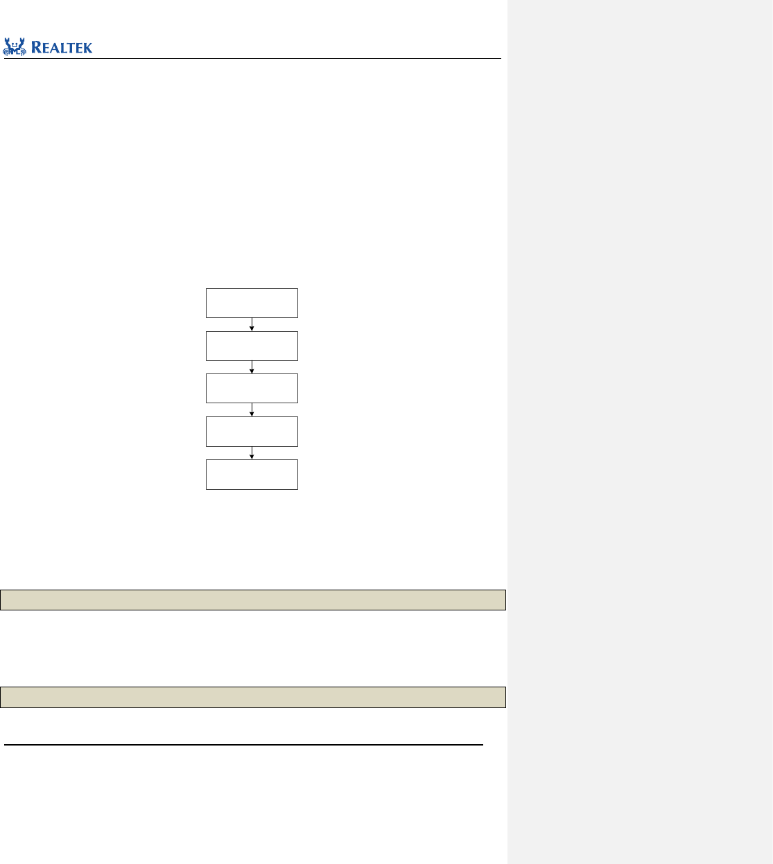
Realtek Confidential
RTL8762C Peripheral Manual
Copyright 2018 Realtek Semiconductor Corporation.
All Rights Reserved.
256
20 Peripheral User Flow
20.1 Peripheral Initialization procedure
Peripheral initialization procedure mainly consists of the following steps:
- Enable IO clock signal
- Configure IO PINMUX and PAD
- Configure IO initialization parameters
- Enable IO
The initialization procedure is shown in Figure 20. 1. XXX is the name of the peripheral to be initialized, such as
GPIO, I2C or SPI.
Open IO clock
(RCC_PeriphClockCmd)
Set Pinmux
(Pinmux_Config)
Set Pad
(Pad_Config)
Set IO parameters
(XXX_Init)
Enable IO module
(XXX_Cmd)
Figure 20. 1 Initialization Flow Chart
20.1.1 Clock Configuration
Enable GPIO clock by calling RCC_PeriphClockCmd() function. For example,
RCC_PeriphClockCmd(APBPeriph_GPIO, APBPeriph_GPIO_CLOCK, ENABLE);
20.1.2 PinMux Configuration
Configure pinmux status of pin by calling Pinmux_Config() function. For example,
Pinmux_Config(P0_5, DWGPIO);
Optional pin values are listed inTable 20. 1.

Realtek Confidential
RTL8762C Peripheral Manual
Copyright 2018 Realtek Semiconductor Corporation.
All Rights Reserved.
257
Table 20. 1 Pin Values
Pin_Num
Description
P0_0
Selected PAD 0
P0_1
Selected PAD 1
P0_2
Selected PAD 2
P0_3
Selected PAD 3
P0_4
Selected PAD 4
P0_5
Selected PAD 5
P0_6
Selected PAD 6
P0_7
Selected PAD 7
P1_0
Selected PAD 8
P1_1
Selected PAD 9
P1_2
Selected PAD 10
P1_3
Selected PAD 11
P1_4
Selected PAD 12
P1_5
Selected PAD 13
P1_6
Selected PAD 14
P1_7
Selected PAD 15
P2_0
Selected PAD 16
P2_1
Selected PAD 17
P2_2
Selected PAD 18
P2_3
Selected PAD 19
P2_4
Selected PAD 20
P2_5
Selected PAD 21
P2_6
Selected PAD 22
P2_7
Selected PAD 23
P3_0
Selected PAD 24
P3_1
Selected PAD 25
P3_2
Selected PAD 26
P3_3
Selected PAD 27
P3_4
Selected PAD 28
P3_5
Selected PAD 29
P3_6
Selected PAD 30
Realtek Confidential
RTL8762C Peripheral Manual
Copyright 2018 Realtek Semiconductor Corporation.
All Rights Reserved.
258
P4_0
Selected PAD 32
P4_1
Selected PAD 33
P4_2
Selected PAD 34
P4_3
Selected PAD 35
H_0/MICBIAS
Selected PAD 36
H_1/32K_XI
Selected PAD 37
H_2/32K_XO
Selected PAD 38
20.1.3 PAD Configuration
Configure PAD status of pin by calling void Pinmux_Config function. For example,
Pad_Config(P0_5, PAD_PINMUX_MODE, PAD_IS_PWRON, PAD_PULL_NONE, PAD_OUT_ENABLE, PAD_OUT_HIGH);
20.1.4 Interrupt Configuration
Enable IRQ interrupt by calling NVIC_Init() function. For example,
NVIC_InitTypeDef NVIC_InitStruct;
NVIC_InitStruct.NVIC_IRQChannel = GPIO5_IRQn;
NVIC_InitStruct.NVIC_IRQChannelPriority = 3;
NVIC_InitStruct.NVIC_IRQChannelCmd = ENABLE;
NVIC_Init(&NVIC_InitStruct);
20.1.5 GPIO Initialization
Initialize GPIO by calling GPIO_Init function, as shown in Figure 20. 2.
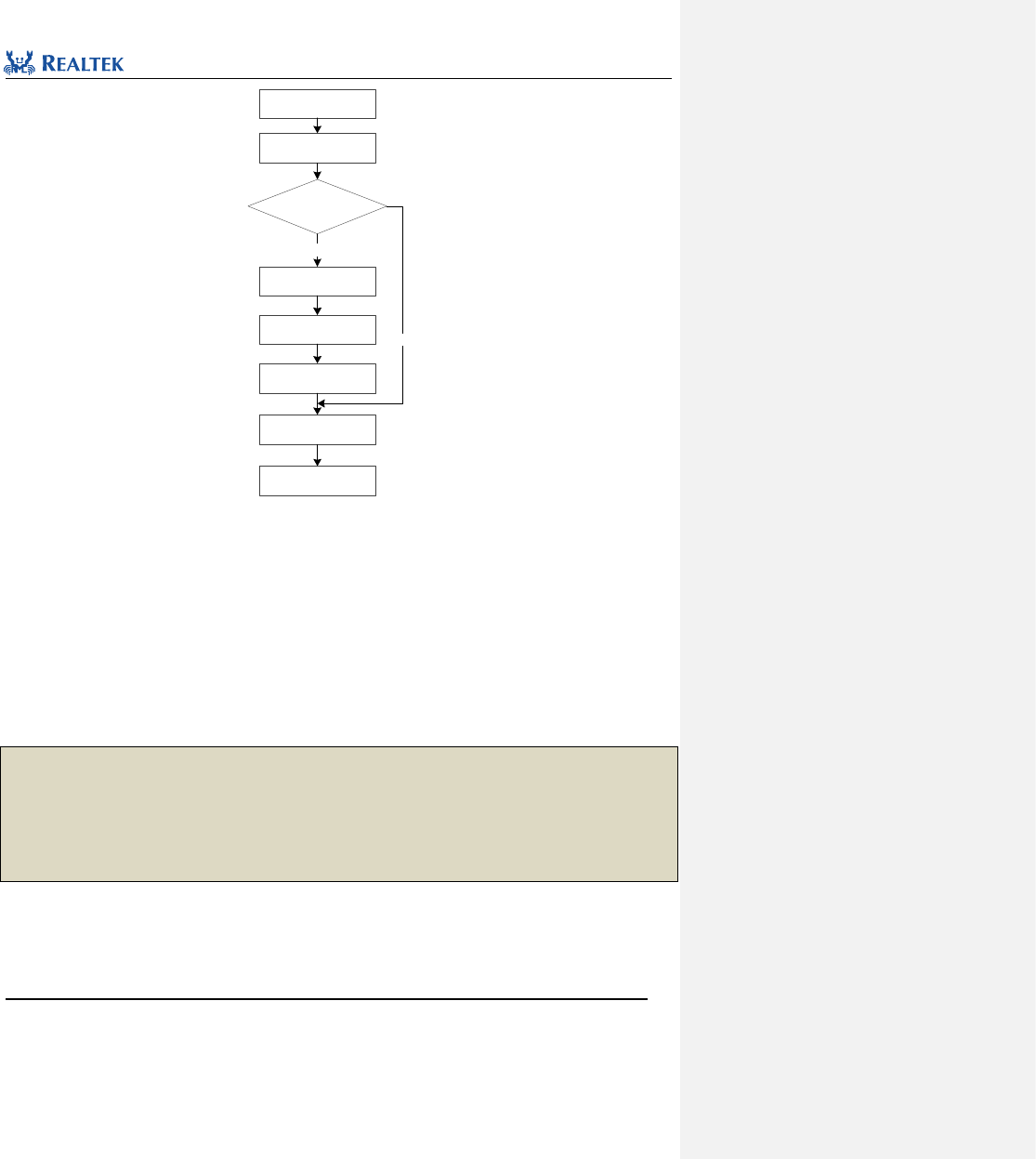
Realtek Confidential
RTL8762C Peripheral Manual
Copyright 2018 Realtek Semiconductor Corporation.
All Rights Reserved.
259
Set GPIO mode
Set trigger
IO is interrupt
mode or not?
Y
Initializing GPIO
N
Set GPIO Pin
Set polarity
Set debounce
Enable GPIO
Figure 20. 2 GPIO Initialization Flow Chart
When configuring parameter GPIO_Pin, multiple pins can be selected at one time by using operator “|”. This
parameter ranges from GPIO_Pin_0 to GPIO_Pin_31 and GPIO_Pin_ALL, or can be acquired through
GPIO_GetPin function.
The sample configuration of each mode is given below.
20.1.5.1 Input Mode
GPIO_InitTypeDef GPIO_InitStruct;
GPIO_InitStruct.GPIO_Pin = GPIO_GetPin(P0_5) | GPIO_GetPin(P0_6);
GPIO_InitStruct.GPIO_Mode = GPIO_Mode_IN;
GPIO_InitStruct.GPIO_ITCmd = DISABLE;
GPIO_Init(&GPIO_InitStruct);

Realtek Confidential
RTL8762C Peripheral Manual
Copyright 2018 Realtek Semiconductor Corporation.
All Rights Reserved.
260
20.1.5.2 Output Mode
GPIO_InitTypeDef GPIO_InitStruct;
GPIO_InitStruct.GPIO_Pin = GPIO_GetPin(P0_5);
GPIO_InitStruct.GPIO_Mode = GPIO_Mode_OUT;
GPIO_InitStruct.GPIO_ITCmd = DISABLE;
GPIO_Init(&GPIO_InitStruct);
20.1.5.3 Interrupt Mode
GPIO_InitTypeDef GPIO_InitStruct;
GPIO_InitStruct.GPIO_Pin = GPIO_GetPin(P0_5);
GPIO_InitStruct.GPIO_Mode = GPIO_Mode_IN;
GPIO_InitStruct.GPIO_ITCmd = ENABLE;
GPIO_InitStruct.GPIO_ITTrigger = GPIO_INT_Trigger_EDGE;
GPIO_InitStruct.GPIO_ITPolarity = GPIO_INT_POLARITY_ACTIVE_LOW;
GPIO_InitStruct.GPIO_ITDebounce = GPIO_INT_DEBOUNCE_ENABLE;
GPIO_Init(&GPIO_InitStruct);
GPIO_INTConfig(GPIO_GetPin(P0_5), ENABLE);
20.2 PINMUX and PAD User Flow
20.2.1 Overview
PINMUX is abbreviation of Pin Multiplexing, which makes RTL8762C able to use its limited pins for various
functions, such as GPIO, I2C, and SPI. PINMUX circuit and all IO modules (except RTC and LPC) are located in OFF
area, which means thet will be powered off and registers will be reset in DLPS mode.
PAD is used to control the behaviors of a pin, such as operating mode, input/output status and wakeup function.
PAD circuit is in ON area and will still be powered on in DLPS mode, so PAD register settings are still valid in DLPS
mode. PAD must be configured if a pin needs to keep its output state or used to wake up the system in DLPS
mode.
Figure 20. 3 illustrates circuits of PINMUX and PAD。
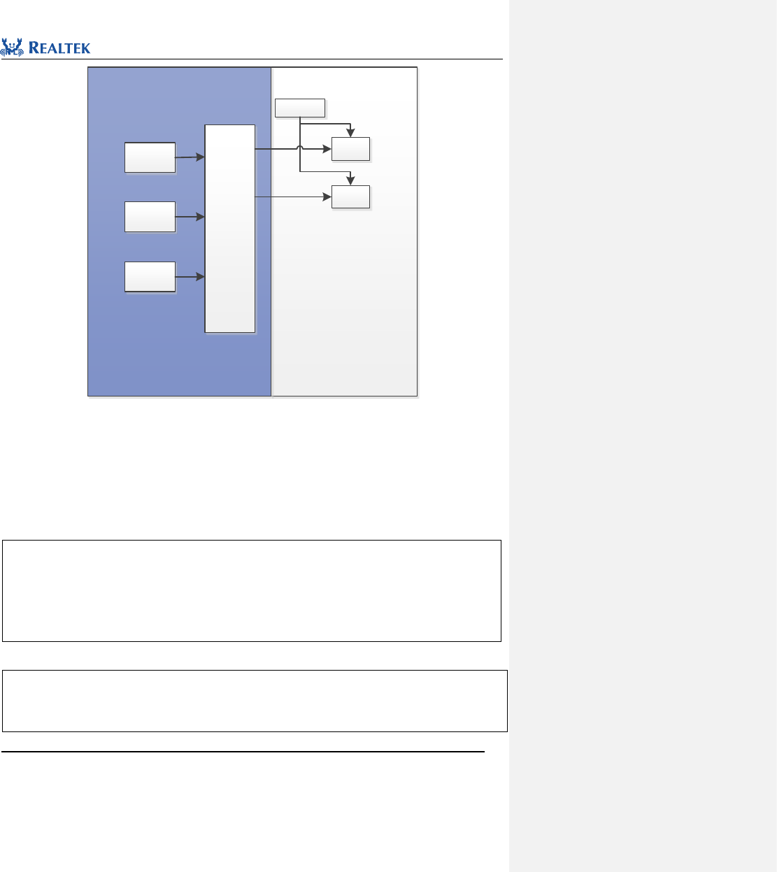
Realtek Confidential
RTL8762C Peripheral Manual
Copyright 2018 Realtek Semiconductor Corporation.
All Rights Reserved.
261
PAD is power on in
DLPS
DLPS POWER OFF AREA
PERI ON(0x40000000)
IO module
GPIO
PERI ON
(0x4000
0000)
PIN MUX
PAD
P0_1
IO module
I2C
IO module
SPI
.
.
.
SW MODE
PAD
P0_2
.
.
.
Figure 20. 3 Peripherals and PAD Circuits Diagram
20.2.2 PAD wakeup Settings
Pin of RTL8762C can aquire system wakeup function by configuring PAD.
Example 1: GPIO KEY wakeup
//define a meaningful name for the pin in board.h.
#define KEY_HOME P3_2
//enable wakeup function of KEY, low level trigger.
System_WakeUp_Pin_Enable(KEY_HOME, 1, 0);
Example 2: Keyscan Key wakeup
//define a meaningful name for the pin in board.h.
#define KEYPAD_ROW0 P4_0
#define KEYPAD_ROW1 P4_1

Realtek Confidential
RTL8762C Peripheral Manual
Copyright 2018 Realtek Semiconductor Corporation.
All Rights Reserved.
262
#define KEYPAD_COLUMN0 P2_2
#define KEYPAD_COLUMN1 P2_3
//enable wakeup function of key row, low level trigger.
System_WakeUp_Pin_Enable(KEYPAD_ROW0, 1, 0);
System_WakeUp_Pin_Enable(KEYPAD_ROW1, 1, 0);
Example 3: UART RX Wakeup
//define a meaningful name for the pin in board.h.
#define UART_TX_PIN P4_0
#define UART_RX_PIN P4_1
//Enable wakeup function of UART_RX_PIN, low level trigger.
System_WakeUp_Pin_Enable(UART_RX_IN, 1, 0);
20.2.3 Flow of Switching PAD upon Entry to/Exit from DLPS
After entering DLPS, PINMUX circuit and IO module (except RTC and LPC) will be powered off, while PAD circuit
can still work. To maintain control of pins, they must be configured to software mode before entering DLPS.
After exiting from DLPS, PINMUX circuit will be powered on and the registers will be restored. To enable IO
functions, the pin must be configured as PINMUX mode again. The configuration procedure is shown below:
1. Upon initialization of application, register ENTER DLPS callback function and EXIT DLPS callback function.
2. In ENTER DLPS callback function, configure the pin as SW Mode.
3. In EXIT DLPS callback function, configure the pin as PINMUX Mode.
Example: Remote Control Application - PAD Mode Switching is set upon Enter/Exit from DLPS.
//define a meaningful name for the pin in board.h.
#define KEY_HOME P3_2
#define KEYPAD_ROW0 P4_0
#define KEYPAD_ROW1 P4_1
#define KEYPAD_COLUMN0 P2_2
#define KEYPAD_COLUMN1 P2_3
//Upon initialization, register ENTER DLPS CB And EXIT DLPS callback function;

Realtek Confidential
RTL8762C Peripheral Manual
Copyright 2018 Realtek Semiconductor Corporation.
All Rights Reserved.
263
DLPS_IORegUserDlpsEnterCb(RcuEnterDlpsSet); //Enter DLPS CB
DLPS_IORegUserDlpsExitCb(RcuExitDlpsInit); //Exit DLPS CB
//Enter DLPS CB
void RcuEnterDlpsSet(void)
{
//Set GPIO KEY as SW MODE; the default status is pull-up
Pad_Config(KEY_HOME, PAD_SW_MODE, PAD_IS_PWRON, PAD_PULL_UP, PAD_OUT_DISABLE, PAD_OUT_LOW);
//Set Keyscan row as SW MODE; the default status is pull-up. Set column as SW MODE; the default status is low level.
Pad_Config(KEYPAD_ROW0, PAD_SW_MODE, PAD_IS_PWRON, PAD_PULL_UP, PAD_OUT_DISABLE, PAD_OUT_LOW);
Pad_Config(KEYPAD_ROW1, PAD_SW_MODE, PAD_IS_PWRON, PAD_PULL_UP, PAD_OUT_DISABLE, PAD_OUT_LOW);
Pad_Config(KEYPAD_COLUMN0, PAD_SW_MODE, PAD_IS_PWRON, PAD_PULL_NONE, PAD_OUT_ENABLE, PAD_OUT_LOW);
Pad_Config(KEYPAD_COLUMN1, PAD_SW_MODE, PAD_IS_PWRON, PAD_PULL_NONE, PAD_OUT_ENABLE, PAD_OUT_LOW);
}
//Exit DLPS CB
void RcuExitDlpsInit(void)
{
//Set GPIO KEY as PINMUX MODE; the default status is pull-up.
Pad_Config(KEY_HOME, PAD_PINMUX_MODE, PAD_IS_PWRON, PAD_PULL_UP, PAD_OUT_DISABLE, PAD_OUT_LOW);
//Set Keyscan row as PINMUX MODE ; the default status is pull-up; SET COLUMN TO SW MODE; the default status is low level.
Pad_Config(KEYPAD_ROW0, PAD_PINMUX_MODE, PAD_IS_PWRON, PAD_PULL_UP, PAD_OUT_DISABLE, PAD_OUT_LOW);
Pad_Config(KEYPAD_ROW1, PAD_PINMUX_MODE, PAD_IS_PWRON, PAD_PULL_UP, PAD_OUT_DISABLE, PAD_OUT_LOW);
Pad_Config(KEYPAD_COLUMN0, PAD_PINMUX_MODE, PAD_IS_PWRON, PAD_PULL_NONE, PAD_OUT_ENABLE, PAD_OUT_LOW);
Pad_Config(KEYPAD_COLUMN1, PAD_PINMUX_MODE, PAD_IS_PWRON, PAD_PULL_NONE, PAD_OUT_ENABLE, PAD_OUT_LOW);
}
22.2.4 Procedure to Maintain Pin Output in DLPS Mode
IO modules stop working upon entering DLPS, so their output is uncertain in DLPS mode. To keep a certain
output, pin must be switched to SW mode in DLPS. For example, a high level output signal may be required to
light LED in DLPS.

Realtek Confidential
RTL8762C Peripheral Manual
Copyright 2018 Realtek Semiconductor Corporation.
All Rights Reserved.
264
Settings: Set PAD to SW Mode, Output Enable, and specify the output level as high or low.
Example: Light LED upon entry to DLPS
//define a meaningful name for the pin in board.h.
#define LED_PIN P3_3
//Set PAD as SW Mode, Output Enable, and output high level.
Pad_Config(LED_PIN, PAD_SW_MODE, PAD_IS_PWRON, PAD_PULL_NONE, PAD_OUT_ENABLE, PAD_OUT_HIGH);
22.2.5 Leakage Protection Setting in DLPS
The following two rules must be followed to avoid leakage.
- Pad cannot be configured as Input and Floating at the same time.
Any unused pins, including pins not enabled in chip, must be set as (SW Mode, Input Mode, Pull Down or Pull
Up). They cannot be set as Pull None (Pull None means Floating status).
Configure unused pins:
Pad_Config(PIN_unused, PAD_SW_MODE, PAD_IS_PWRON, PAD_PULL_DOWN, PAD_OUT_DISABLE,
PAD_OUT_LOW);
In sample project, all pins are set as (Input Mode, Pull Down) by default.
- Driving or Pulling in invert direction shall not exist in one pin/PAD.
For example:
PAD is driven or pulled high, but the component coupled with it is driven or pulled low.
PAD is driven or pulled low, but the component coupled with it is driven or pulled high.
PAD is configured as Output High and Pull Down at the same time.
PAD is configured as Output Low and Pull High at the same time.
