Bee项目文档规范 RTL8762C SDK User Guide EN
User Manual:
Open the PDF directly: View PDF ![]() .
.
Page Count: 54
Realtek Confidential
RTL8762C SDK User Guide
V1.1
2018/09/07

Realtek Confidential
RTL8762C SDK User Guide
Copyright 2018Realtek Semiconductor Corporation.
All Rights Reserved.
2
Revision History
Date
Version
Comments
Author
Reviewer
2017/12/07
V1.0
First Release version
Lory
Rui
2018/09/07 V1.1 Update 8 and 9.1

Realtek Confidential
RTL8762C SDK User Guide
Copyright 2018Realtek Semiconductor Corporation.
All Rights Reserved.
3
Contents
Revision History ................................................................................................................................................ 2
Figure List ......................................................................................................................................................... 6
Table List ........................................................................................................................................................... 7
1 Overview ................................................................................................................................................... 8
2 Getting started ........................................................................................................................................... 9
2.1 Prerequisites ....................................................................................................................................... 9
2.1.1 Keil ............................................................................................................................................. 9
2.1.2 J-Link .......................................................................................................................................... 9
2.1.3 SDK .......................................................................................................................................... 10
2.1.4 EVB Kit .................................................................................................................................... 10
2.2 Environment Setup ........................................................................................................................... 10
2.3 EVB Setup ........................................................................................................................................ 11
2.4 IDE Setup ......................................................................................................................................... 11
2.4.1 Keil Project ............................................................................................................................... 11
2.4.2 Keil Settings ............................................................................................................................. 12
3 Hardware Architecture ............................................................................................................................ 16
4 Software Architecture .............................................................................................................................. 17
4.1 System Architecture ......................................................................................................................... 17
4.2 Operating System ............................................................................................................................. 17
4.3 OS Interfaces .................................................................................................................................... 18
4.4 Task and Priority .............................................................................................................................. 19
4.4.1 Task .......................................................................................................................................... 19
4.4.2 Priority ...................................................................................................................................... 21
5 Application .............................................................................................................................................. 22
5.1 SDK Directory.................................................................................................................................. 22
5.2 Sample Projects ................................................................................................................................ 23
5.3 Application Process Flow ................................................................................................................. 25
5.4 MSG and Event Handling Flow ....................................................................................................... 26

Realtek Confidential
RTL8762C SDK User Guide
Copyright 2018Realtek Semiconductor Corporation.
All Rights Reserved.
4
5.5 IO MSG ............................................................................................................................................ 27
5.5.1 Message Format ........................................................................................................................ 27
5.5.2 Message Type Definition .......................................................................................................... 27
5.5.3 Message Subtype Definition ..................................................................................................... 28
5.5.4 Define User Message ................................................................................................................ 28
5.6 Pin Settings ....................................................................................................................................... 28
5.7 DLPS Settings .................................................................................................................................. 28
6 Memory ................................................................................................................................................... 30
6.1 Memory Map .................................................................................................................................... 30
6.2 ROM ................................................................................................................................................. 30
6.3 RAM ................................................................................................................................................. 30
6.3.1 Data Ram .................................................................................................................................. 31
6.3.2 Buffer Ram ............................................................................................................................... 31
6.4 Cache ................................................................................................................................................ 32
6.5 Flash ................................................................................................................................................. 32
6.5.1 Flash APIs ................................................................................................................................. 33
6.5.2 FTL ........................................................................................................................................... 33
6.6 eFuse ................................................................................................................................................ 34
7 Interrupt ................................................................................................................................................... 35
7.1 Nested Vectored Interrupt Controller (NVIC) ................................................................................. 35
7.2 Interrupt Vector Table ...................................................................................................................... 35
7.3 Interrupt Priority ............................................................................................................................... 39
8 Power Management ................................................................................................................................. 40
9 Download ................................................................................................................................................ 42
9.1 About Images ................................................................................................................................... 42
9.2 Application Image Processing Tool ................................................................................................. 42
9.2.1 fromelf ...................................................................................................................................... 42
9.2.2 CheckSum_Gen ........................................................................................................................ 42
9.2.3 md5 ........................................................................................................................................... 44
9.3 Downloading Pattern ........................................................................................................................ 44

Realtek Confidential
RTL8762C SDK User Guide
Copyright 2018Realtek Semiconductor Corporation.
All Rights Reserved.
5
10 Debug ...................................................................................................................................................... 44
10.1 Log Mechanism ................................................................................................................................ 45
10.1.1 Debug analyzer ......................................................................................................................... 45
10.1.2 Basic Interface for Log Printing ............................................................................................... 47
10.1.3 Wrapped Interfaces for Log Printing ........................................................................................ 47
10.1.4 Auxiliary Interfaces .................................................................................................................. 48
10.1.5 Log Print Example .................................................................................................................... 48
10.1.6 Log Control Interfaces .............................................................................................................. 49
10.1.7 DBG_DIRECT ......................................................................................................................... 51
10.2 Debug with SWD ............................................................................................................................. 51
10.2.1 Using SWD Debug Interface .................................................................................................... 52
10.2.2 Using Trace Port Interface DWT .............................................................................................. 53

Realtek Confidential
RTL8762C SDK User Guide
Copyright 2018Realtek Semiconductor Corporation.
All Rights Reserved.
6
Figure List
Figure 10-1 Main Interface of Debug Analyzer ...................................................................................................... 45
Figure 10-2 Debug Analyzer Setting Page .............................................................................................................. 46

Realtek Confidential
RTL8762C SDK User Guide
Copyright 2018Realtek Semiconductor Corporation.
All Rights Reserved.
7
Table List
Table 5-1 APP Intialization ...................................................................................................................................... 25
Table 7-1 Interrupt Vector Table .............................................................................................................................. 35
Table 7-2 Timer 4~7 ISR ......................................................................................................................................... 37
Table 7-3 Peripheral ISR ......................................................................................................................................... 37
Table 7-4 GPIO Group3 ISR ................................................................................................................................... 38
Table 7-5 GPIO Group2 ISR ................................................................................................................................... 38
Table 7-6 GPIO Group1 ISR ................................................................................................................................... 38
Table 7-7 GPIO Group0 ISR ................................................................................................................................... 39
Table 7-8 Interrupt Priority ...................................................................................................................................... 39
Table 9-1 Downloading Patterns Available for Images ........................................................................................... 44
Table 10-1 Debug Level .......................................................................................................................................... 47

Realtek Confidential
RTL8762C SDK User Guide
Copyright 2018Realtek Semiconductor Corporation.
All Rights Reserved.
8
1 Overview
This document shows you how to develop Bluetooth Low Energy applications using RTL8762C Software
Development Kit (SDK).
Realtek Confidential
RTL8762C SDK User Guide
Copyright 2018Realtek Semiconductor Corporation.
All Rights Reserved.
9
2 Getting started
2.1 Prerequisites
The following software and hardware will be needed during the development:
1. Keil MDK-ARM Lite V5 or later
2. J-Link Software v5.02d or later
3. RTL8762C SDK
4. EVB Kit
2.1.1 Keil
All applications in the SDK can be compiled and used with Keil Microcontroller Development Kit(MDK). So
before starting software development, Keil should be obtained and installed correctly by users themselves, please
visit www.keil.com for more information.
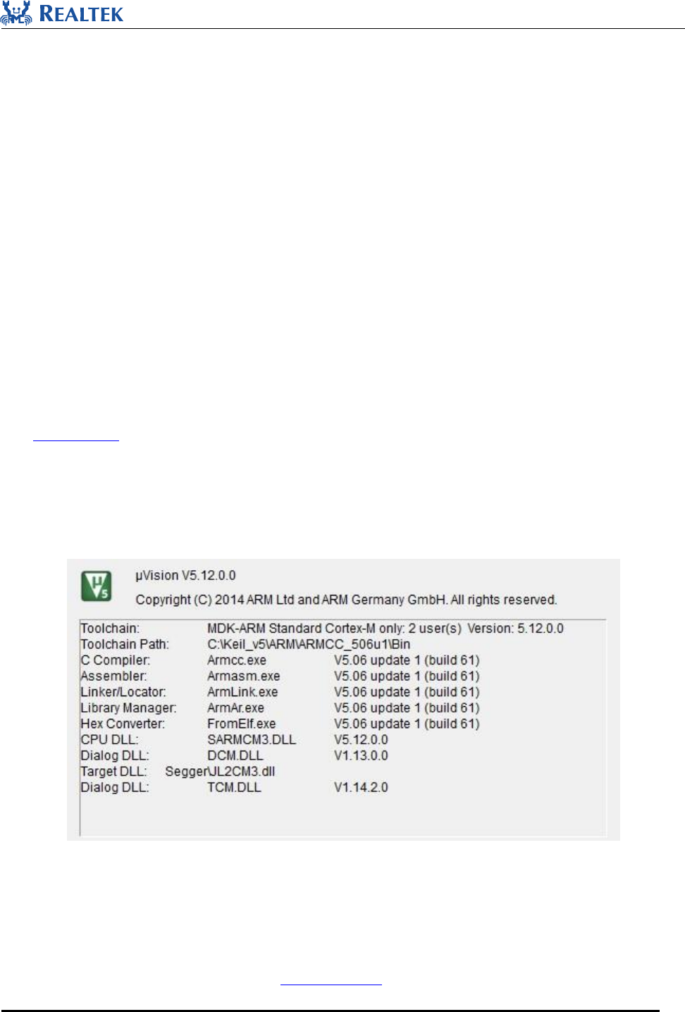
Tool chain version as below is used by Realtek, and this version or higher is suggested to be used to avoid any
compatible issue between the ROM executable programs and user applications.
Figure 2-1 keil
2.1.2 J-Link
J-Link is another prerequisite if more comprehensive debug method is desired besides the logging mechanism. For
installing the SEGGER J-Link software, visit www.segger.com to download related software and documentation.

Realtek Confidential
RTL8762C SDK User Guide
Copyright 2018Realtek Semiconductor Corporation.
All Rights Reserved.
10
The driver should be correctly installed for the device to use the J-Link debugger with Keil MDK.
2.1.3 SDK
The SDK includes sample projects, documentation, and essential tools.
2.1.4 EVB Kit
The EVB is designed to contain necessary hardware to evaluate, develop and debug user applications for
RTL8762C.
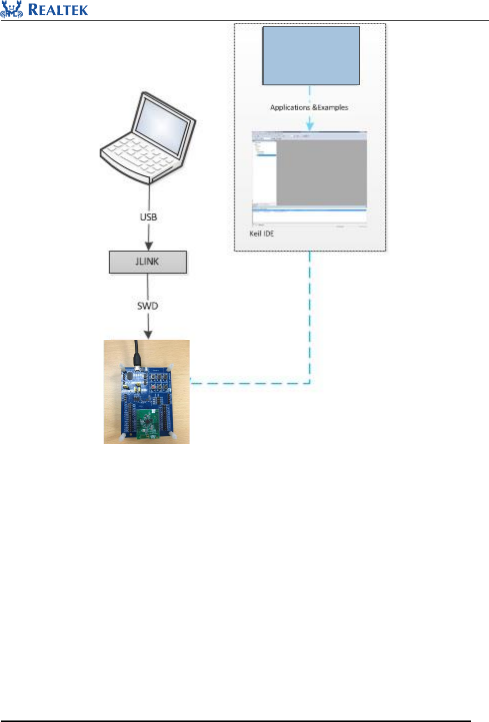
2.2 Environment Setup
Figure 2-2 shows the relationship between the hardware part and software component. The application developed
with Keil could be downloaded into RTL8762C EVB via J-Link, and debug via SWD interface.
Realtek Confidential
RTL8762C SDK User Guide
Copyright 2018Realtek Semiconductor Corporation.
All Rights Reserved.
11
RTL8762C SDK
Figure 2-2 Enviroment Setup
2.3 EVB Setup
EVB kits have a motherboard and one or more RTL8762C daughter-boards. Refer to RTL8762C Evaluation Board
User Guide for more details.
2.4 IDE Setup
2.4.1 Keil Project
Generally it is not recommended to create a new project for development, better to open an existing demo project
and add developer's own function codes to it.
Realtek Confidential
RTL8762C SDK User Guide
Copyright 2018Realtek Semiconductor Corporation.
All Rights Reserved.
12
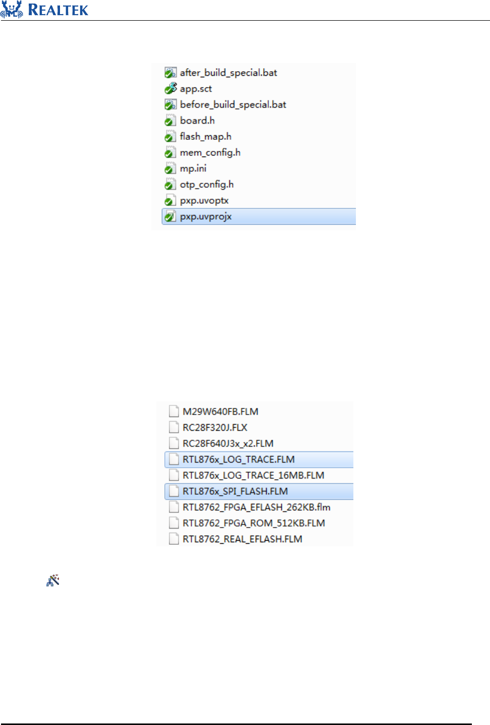
If Keil V5 or later version has been installed, taking pxp project for example, the project will be located at
bee2_sdk_ xxxx \board\evb\pxp, as is shown in Figure 2-3.
Figure 2-3 Keil Project
2.4.2 Keil Settings
For details on settings of Debugger and Flash Download Algorithm in Keil, refer to section “Debugger Adapter
User's Guides - J-Link/J-Trace User's Guide”. A brief description for it is given below.
1. Copy RTL876x_SPI_FLASH.FLM and RTL876x_LOG_TRACE.FLM at sdk\tool\flash to Keil installation
directory: Keil_installed_dir\ ARM\Flash\ as illustrated below:
Figure 2-4 Keil Flash Algo
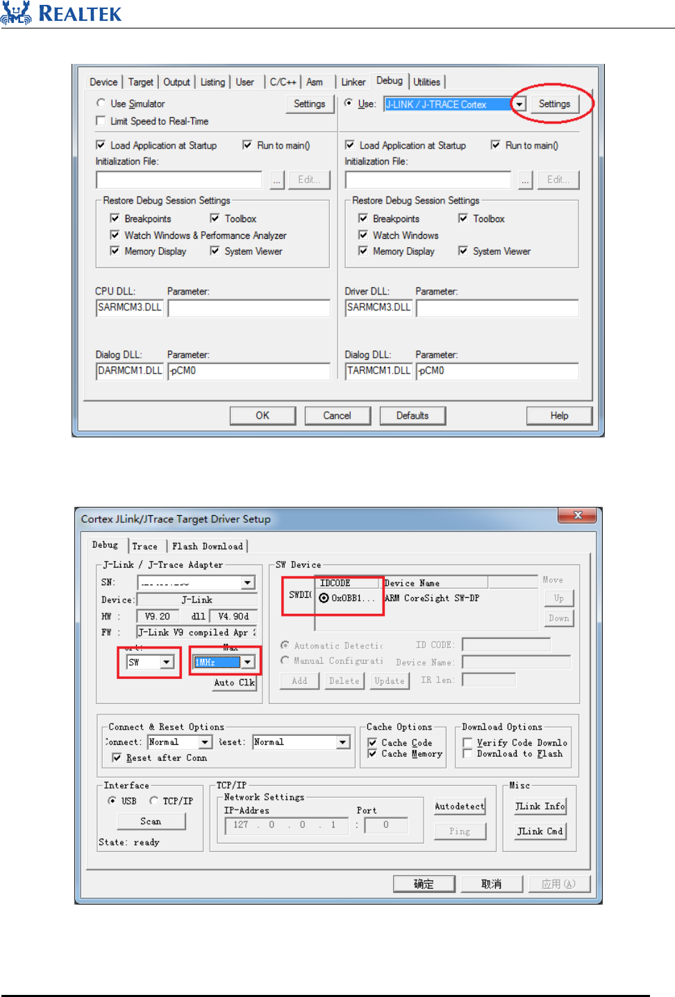
2. Click in toolbar, or navigate to Project > Options for Target ... in the menu, and then click Debug Tab
page. Select J-LINK/J-TRACE Cortex, and then click on “Settings”:
Realtek Confidential
RTL8762C SDK User Guide
Copyright 2018Realtek Semiconductor Corporation.
All Rights Reserved.
13
Figure 2-5 Keil Setting
3. Select SW for J-Link Port. If hardware is connected properly, CPU will be recognized in SW Device list.
Figure 2-6 Keil Debugging Settings
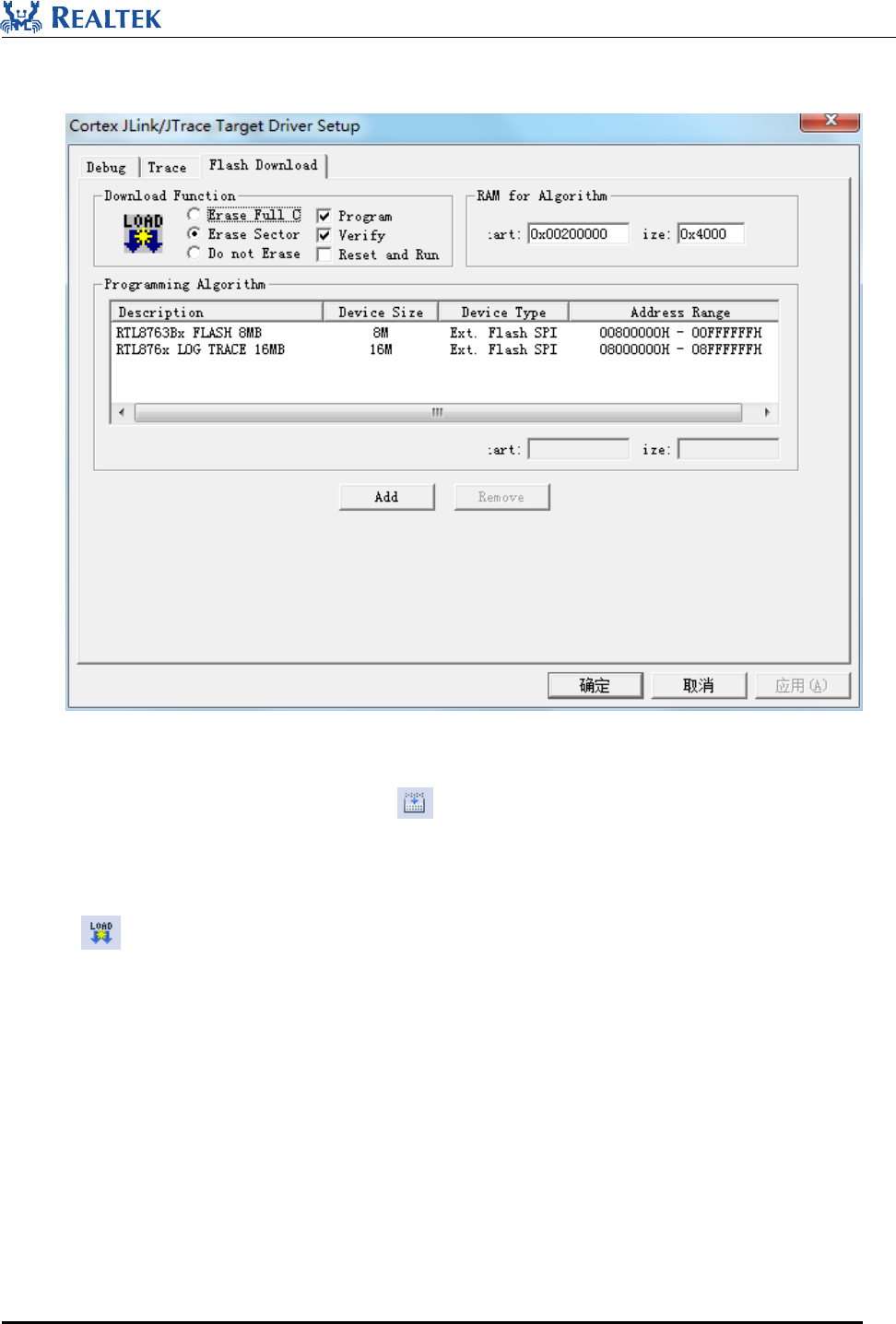
4. Click “Flash Download” page to delete original Programming Algorithm (if any), and then click “Add”
Realtek Confidential
RTL8762C SDK User Guide
Copyright 2018Realtek Semiconductor Corporation.
All Rights Reserved.
14
to add RTL8763Bx_FLASH_8MB.FLM and RTL876x_LOG_TRACE_16MB. Modify the start address of
“RAM for Algorithm” to 0x00200000 and size to 0x4000.
Figure 2-7 Flash Algo Applied
5. Compile the project by clicking “Make” icon in Keil. After fixing compiling and link error if any, user
application could be downloaded into RTL8762C for further verification and debug.
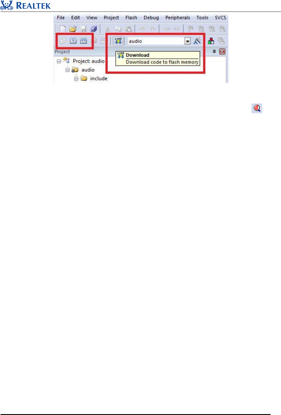
6. If flash algorithm has been successfully set up, download option in Keil could be used by clicking “Load”
icon . During download procedure, no error message is supposed to happen. After application image has
been download successfully to the RTL8762C, you can reset RTL8762C to run your application. And in
debug analyzer tool, you can check whether application run as expected by log messages.
Realtek Confidential
RTL8762C SDK User Guide
Copyright 2018Realtek Semiconductor Corporation.
All Rights Reserved.
15
Figure 2-8 Compile And Run
7. J-Link can be used to debug and trace applications on RTL8762C by clicking “Debug” icon .
NOTE: If DLPS mode is enabled, once the system entering DLPS mode, debugging cannot be
performed. So DLPS should be disabled when debugging using Keil Debugger in early stage of
development.
Enable: lps_mode_set (LPM_DLPS_MODE)
Disable: lps_mode_set (LPM_ACTIVE_MODE)
Realtek Confidential
RTL8762C SDK User Guide
Copyright 2018Realtek Semiconductor Corporation.
All Rights Reserved.
16
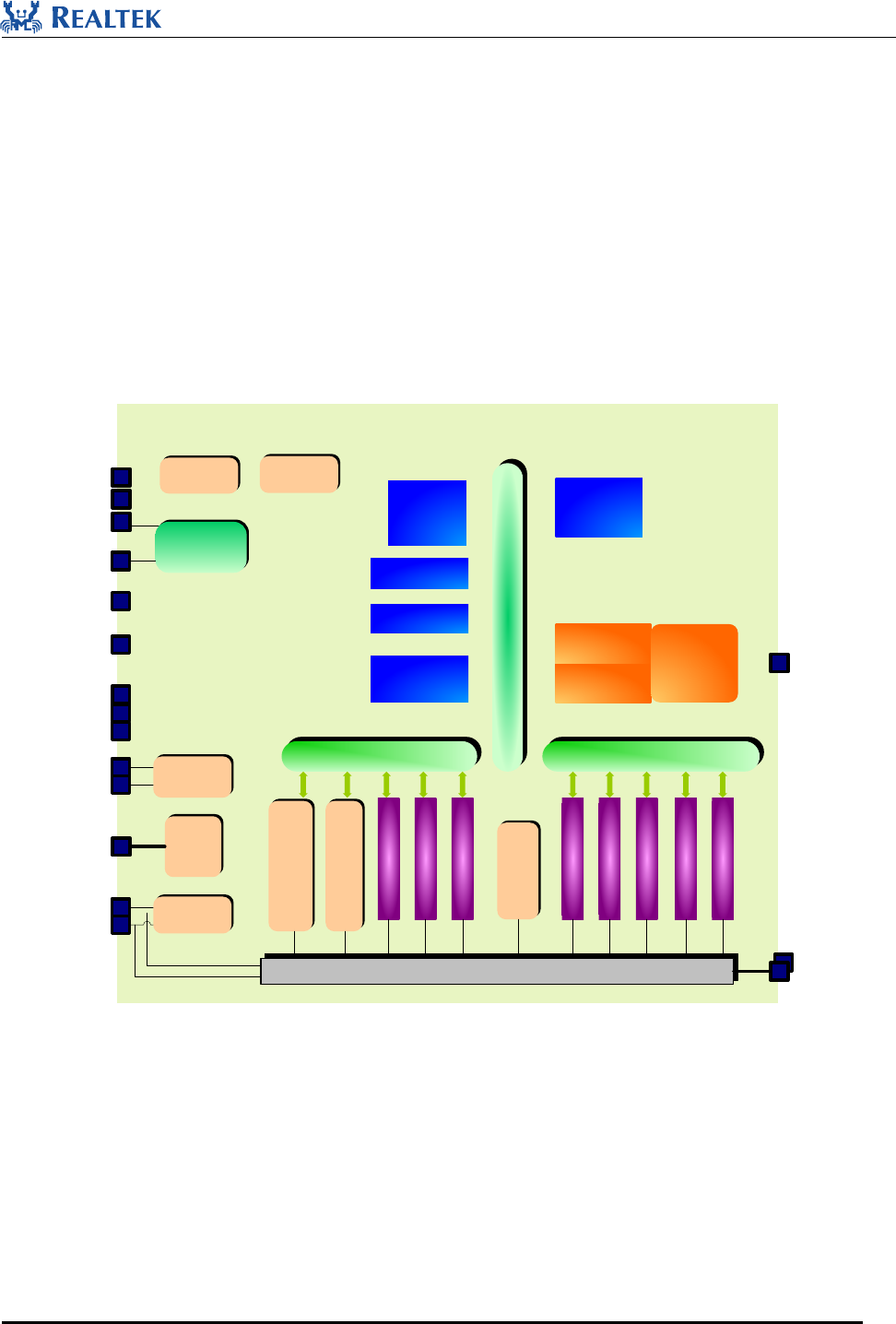
3 Hardware Architecture
Hardware block of RTL8762C is illustrated in Figure 3-1.
Rich peripherals
Flexible RAM configuration
Power Management Unit
Clock Management Unit
BLE module
ARM
CM4
RAM
SPI flash
controller
ROM
LE
Modem RF
tranceiver
OCP Bus
APBAPB
Switching
regulator
40MHz
Crystal OSC
32kHz
Crystal OSC
IO PINMUX
SPI x2
I2C x2
keyscan
UART x2
IR RC
GPIOs
Timers
Log UART
32kHz RC
OSC
PMU
Retention
RAM
VBAT
LX
VDIGI
VD12_PA
VD12_RTX
VD12_SYN
PGA+SDM_
ADC
MIC
Bias
RTL8762C
MIC_BIAS
XO
XI
32K_XO
32K_XI
RFIO
Pm_n
m=0,1..4
n=0,1..7
Low power
comparator
AUXADC
*VDDIO
*HVD
VDDCORE
*only in RTL8762CKF
Figure 3-1 RTL8762C Hardware Block
Realtek Confidential
RTL8762C SDK User Guide
Copyright 2018Realtek Semiconductor Corporation.
All Rights Reserved.
17
4 Software Architecture
4.1 System Architecture
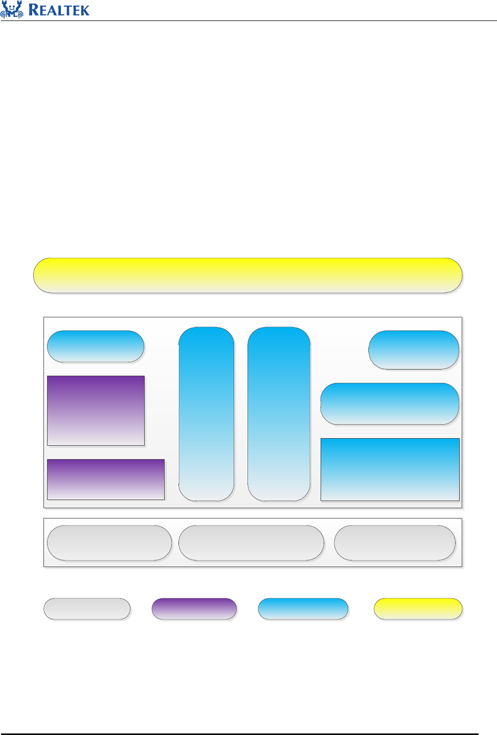
As shown in Figure 4-1, software architecture consists of several major components:
•GAP : Abstraction layer which user application communicates with BLE stack. Details information referred to
GAP Interfaces User Manual;
•Platform : Includes OTA, flash, ftl and etc;
•IO Drivers : Provides APIs for user application to interface with RTL8762C on-board peripherals without
accessing registers;
•OSIF: abstraction of real time OS interfaces for user application;
Application
FreeRTOS
CMSIS-Core
PeripheralsARM Cortex-M4 Bluetooth BB, BF
Bluetooth LE Stack
GAP
LE Profiles/Serivices
Hardware Modules 3rd Party Library Realtek
Implemented
Vendor
Implemented
OSIF
Peripheral
driver
Platform
features
Figure 4-1 RTL8762C Software Architecture
4.2 Operating System
FreeRTOS V8.2 is used in RTL8762C, it is integrated in RTL8762C ROM code, and consists of the following

Realtek Confidential
RTL8762C SDK User Guide
Copyright 2018Realtek Semiconductor Corporation.
All Rights Reserved.
18
components:
1. Task Management
2. Queue Management
3. Interrupt Management
4. Resource Management
5. Memory Management
6. Time Management
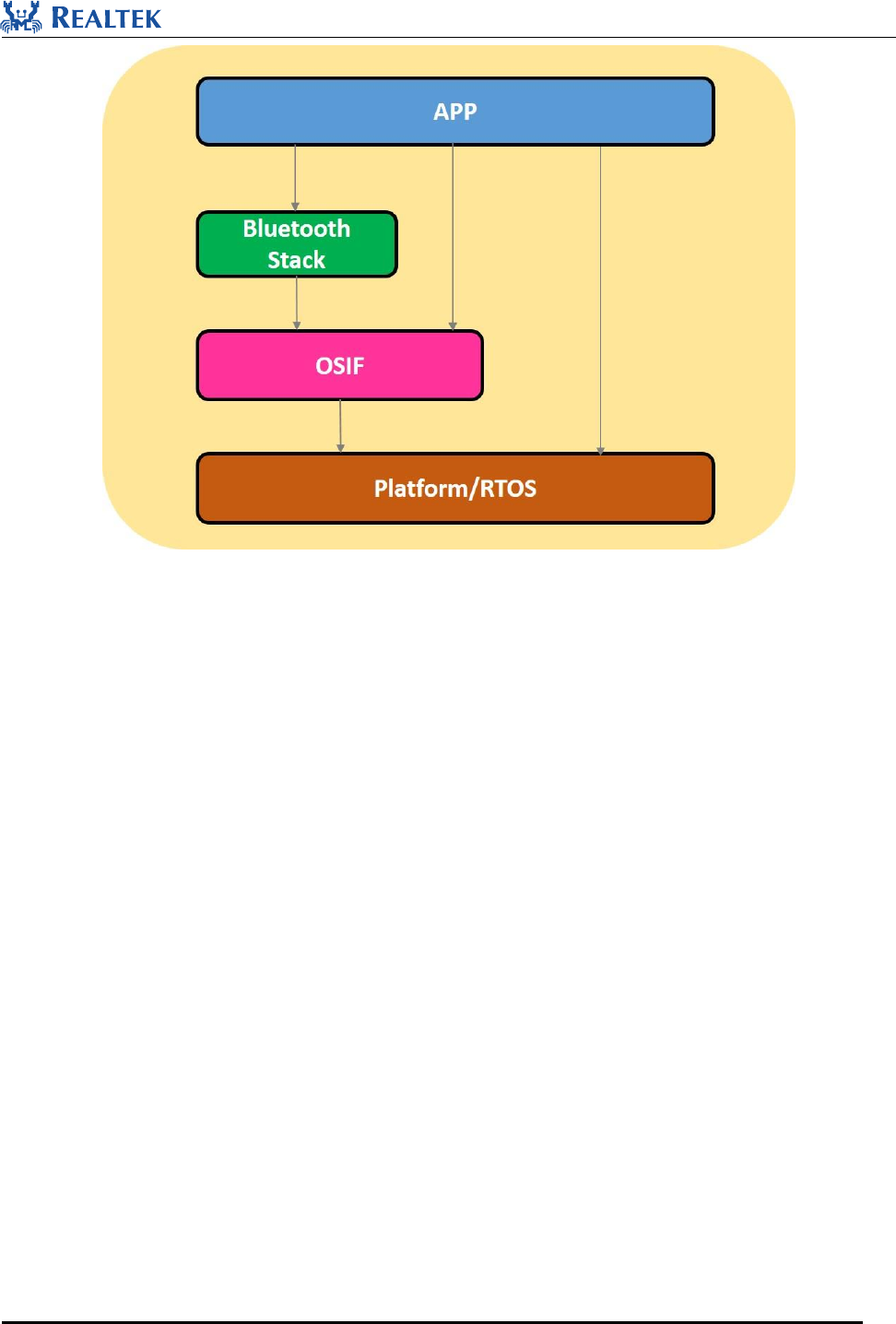
4.3 OS Interfaces
OSIF is implemented for RealBlueTM project. It is quite possible to update the specific RTOS version, and even to
use a different RTOS on RealBlueTM project, so all the incompatible issues related to the specific RTOS interfaces
can be cleared if the OSIF layer is presented.
As depicted by Figure 4-2, the OSIF layer aims to provide a consistent and uniform RTOS API set by wrapping
the specific RTOS interfaces. Other software components that use the OSIF will be portable along with evolution
of the RealBlueTM project. Vendors can also provide their own RTOS implementation inside OSIF layer, but
without any modifications from upper layer software components.
So, it is strongly recommended to use OSIF API in software development instead of accessing the specific RTOS
interfaces.
Realtek Confidential
RTL8762C SDK User Guide
Copyright 2018Realtek Semiconductor Corporation.
All Rights Reserved.
20
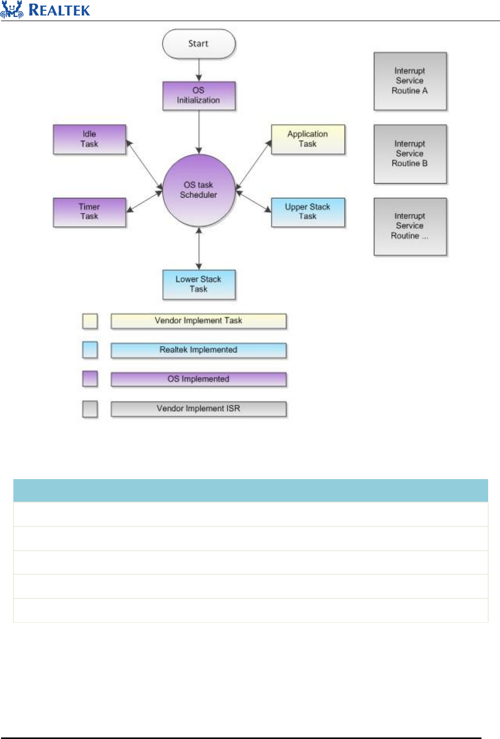
Figure 4-3 RTL8762C Tasks
Task
Description
Priority
timer
implement software timer required by FreeRTOS
4
lower stack
implement BT stack protocols below HCI
4
upper stack
implement BT stack protocols above HCI
3
app
handles user application requirement and interacts with stack
1
Idle
runs background tasks including DLPS
0
Note: multiple app tasks can be created and memory resource will be then allocated
Idle task and timer task are provided by FreeRTOS.
Tasks have been configured as preemptive based on its priority.
Realtek Confidential
RTL8762C SDK User Guide
Copyright 2018Realtek Semiconductor Corporation.
All Rights Reserved.
21
Additionally, hardware interrupt service routines(ISR) are implemented by vendor as well.
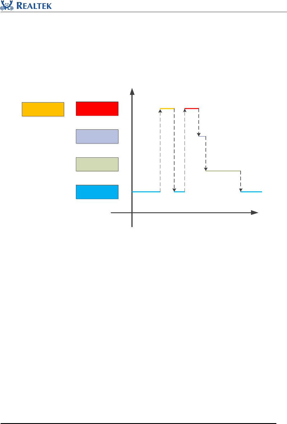
4.4.2 Priority
Tasks are performed in four priorities:
Priority SW Timer = Priority lower stack > Priority upper stack > Priority app> Priority Idle.
LowerStack
Upper Stack
Application Lower
Idle
Task Priorities
SW Timer
Figure 4-4 Task Priority
Realtek Confidential
RTL8762C SDK User Guide
Copyright 2018Realtek Semiconductor Corporation.
All Rights Reserved.
22
5 Application
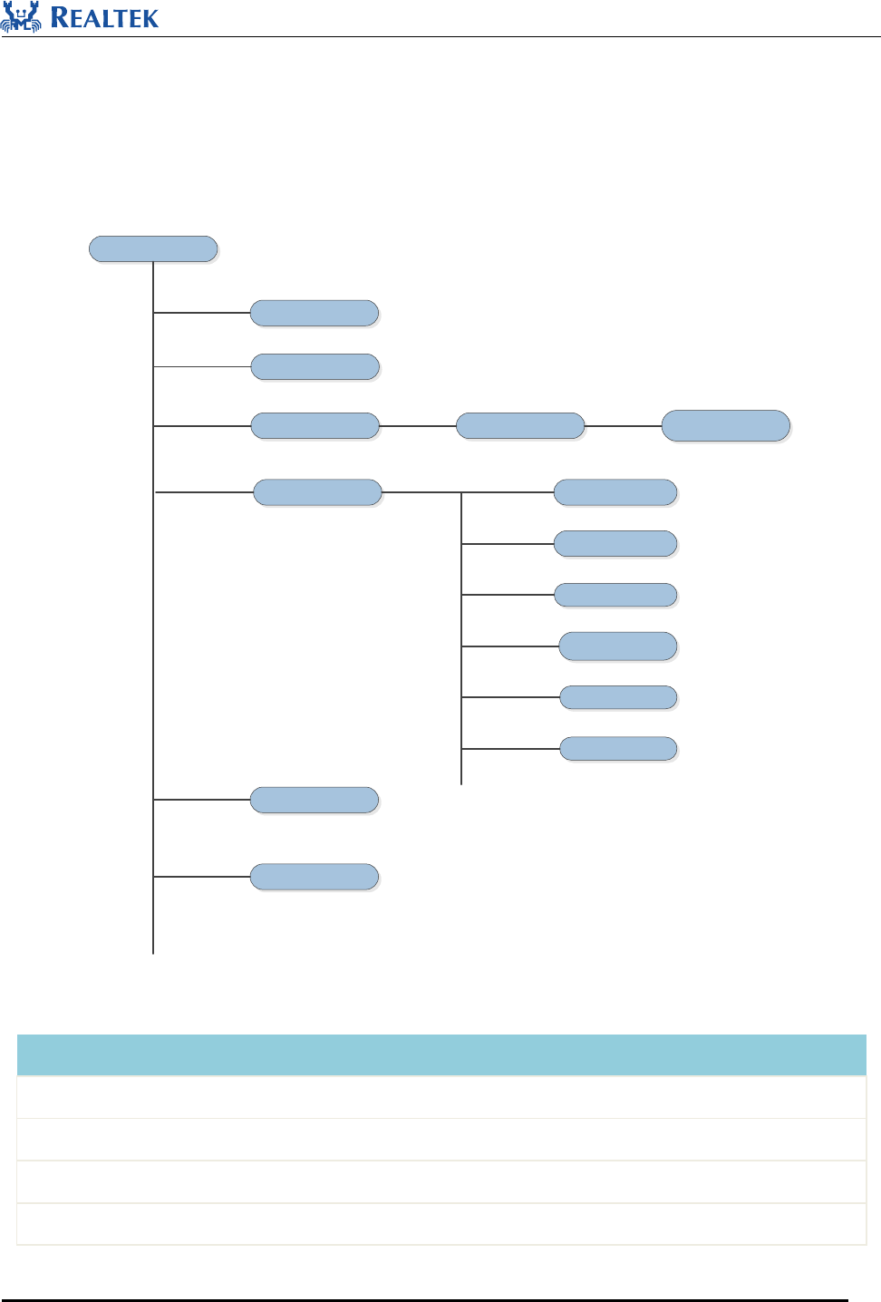
5.1 SDK Directory
SDK directory is as show below.
sdk
board
bin
doc
inc
src
tool
evb Sample project
app
bluetooth
os
peripheral
platform
stack
Figure 5-1 SDK Directory
Directory
Description
board
sample Keil project files which have been already well-configured to start with
doc
SDK documents
inc
header files which provide API definitions export from ROM
bin
binary files for user application to link
Realtek Confidential
RTL8762C SDK User Guide
Copyright 2018Realtek Semiconductor Corporation.
All Rights Reserved.
23
src
source files for sample applications
tool
host tools set for add-on features
5.2 Sample Projects
To help create user application, many sample projects in SDK have been created to start with, such as pxp and
some ble related demo sample projects. Through studying sample projects, customers can easily get familar with
SDK. All sample projects have been configured and memory layout in scatter file is also modified to comply with
RTL8762C SOC.
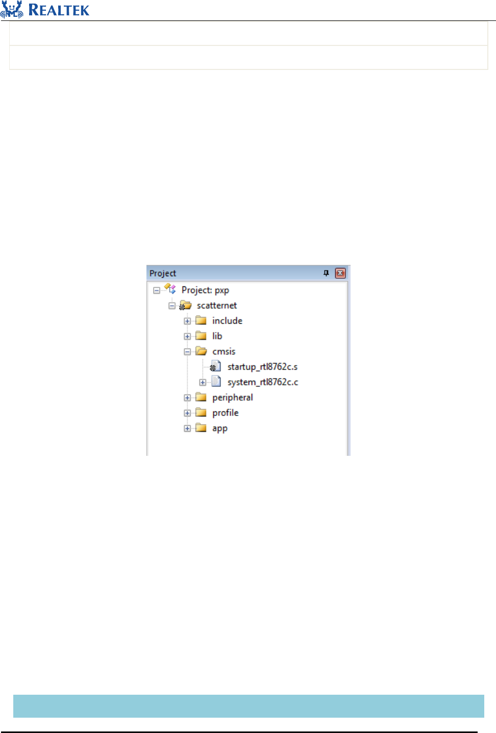
Taking pxp application as an example below, it shows how to start developing the customized user application by
the sample project. The snapshots are captured with current SDK, and may subject to change due to SDK upgrade.
Figure 5-2 PXP Sample Project
Source files in PXP project are currently categorized into several groups as below:
• Include directory is used to export the UUID which is mandatory for any application built for RTL8762C. No
modification is permitted by any 3rd party.
• Lib directory includes all binary symbol files that user application is built on.
• CMSIS directory is used for boot up code.
• APP directory includes the pxp user application implementation.
• Profile directory includes BLE profiles or services used by the sample application.
• Peripheral directory contains all the driver and module code that the pxp project has used.
The common files in sample applications are explained as below:
File name
Description

Realtek Confidential
RTL8762C SDK User Guide
Copyright 2018Realtek Semiconductor Corporation.
All Rights Reserved.
24
rom_uuid.h
UUID header files provided by SDK to identify the ROM, no change needed
ROM.lib
ROM symbol library file, used by user application to link any ROM symbols
gap_utils.lib
Gap library file to implement latest BLE functions
startup_rtl8762c.s
Assembly file for RTL8762C application start-up
system_rtl8762c.c
C file for RTL8762C application start-up
board.h
Header file to configure pin and DLPS settings
flash_map.h
Flash layout file which is generated by FlashMapGenerateTool
mem_config.h
Memory Configuration file
The sample project may upgrade together with the SDK, and to better utilize the upgraded sample code, newly
added user code is suggested to being organized and modularized.
More detail information on each sample project could be found in its user manual.
Realtek Confidential
RTL8762C SDK User Guide
Copyright 2018Realtek Semiconductor Corporation.
All Rights Reserved.
25
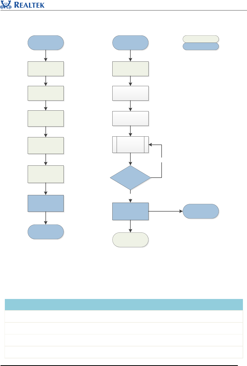
5.3 Application Process Flow
Boot Code
Board Init
Gap Init
Profile Init
Power Manager Init
SW Timer Init
Task init
OS Scheduler
APP Task Entry
APP Queue Init
Start Stack
Driver Init
While(true)
Is there
any messages for
APP?
Message
Distribution BT Stack Handler
APP Handler
Yes
No
Vendor Handlers
Realtek Handlers
Figure 5-3 APP Flow
Table 5-1 APP Intialization
Action
Description
board init
contains initialization of pinmux settings and pad settings
gap init
contains initialization of GAP related parameters
profile init
contains initialization of BLE profiles
power manager init
contains initialization of power management related
Realtek Confidential
RTL8762C SDK User Guide
Copyright 2018Realtek Semiconductor Corporation.
All Rights Reserved.
26
SW timer init
contains initialization of sw timers
app queue init
contains initialization of app queue
driver init
contains initialization of peripherals
System is initialized in main() function, including Board, Peripherals, BT Stack, Profile, Power Mechanism, Task,
etc.
In Application task, BT Stack, Profiles and Peripheral drivers are initialized, and IO MSG mechanism is
implemented. All functions are packaged into IO Events, and the Events are handled in related MSG handlers.
BT stack message is packaged into BT IO Event, which will be handled in the same way as Peripherals.
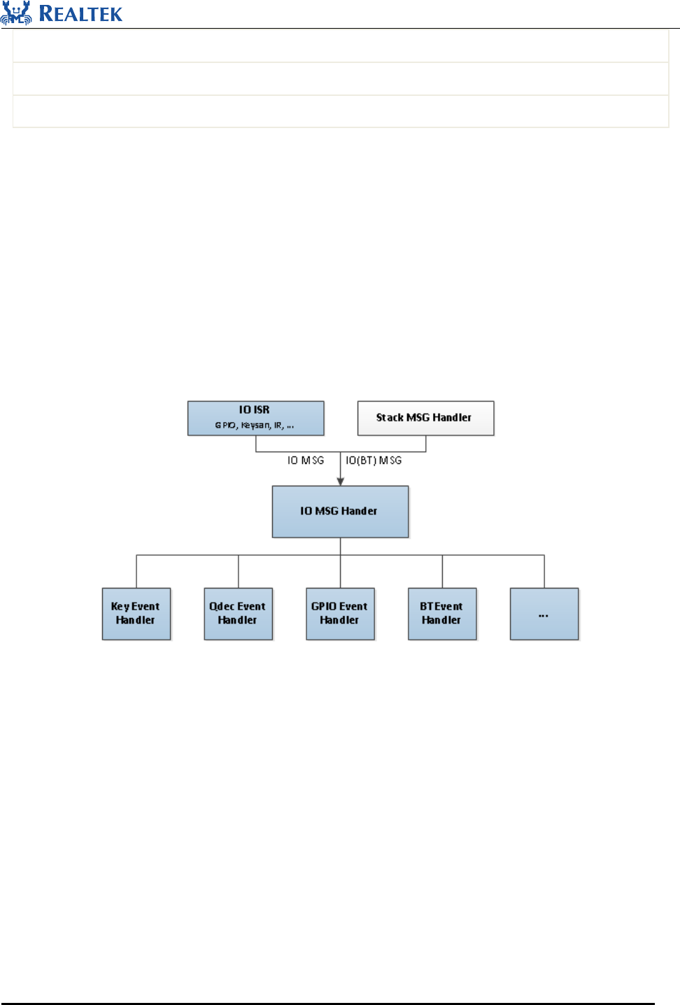
Figure 5-4 IO Message Handling Flowchart
5.4 MSG and Event Handling Flow
An original MSG is sent from universal Peripherals’ ISR or BT Stack, and is handled through the following flow:
1. MSG from Peripherals is forwarded by MSG Distributer to IO MSG Handler for handling;
2. MSG from BT Stack is forwarded by MSG Distributer to BT State Machine. BT State Machine handles MSG and
sends a BT IO MSG. MSG Distributer receives the BT IO MSG and then forwards it to IO MSG Handler for
handling ;
3. After a Message is received, IO MSG Handler shall make judgment and call the related Event Handler.
Developer programs shall:
1. Implement Peripheral ISR and fulfil initial handling in ISR. If further handling is required, a message will be sent.
Blue blocks shall be implemented by developer.

Realtek Confidential
RTL8762C SDK User Guide
Copyright 2018Realtek Semiconductor Corporation.
All Rights Reserved.
27
2. Maintain IO MSG Handler to receive and handle MSGs defined by developer.
3. Implement Event Handler about application.
A lower layer notifies an upper layer with MSG and Event mechanism, while an upper layer calls a lower layer
functions by APIs.
5.5 IO MSG
5.5.1 Message Format
typedef struct
{
uint16_t IoType;
uint16_t subType;
union{
uint32_t parm;
void *pBuf;
};
}BEE_IO_MSG;
5.5.2 Message Type Definition
enum
{
BT_STATUS_UPDATE,
IO_KEYSCAN_MSG_TYPE,
IO_QDECODE_MSG_TYPE,
IO_UART_MSG_TYPE,
IO_KEYPAD_MSG_TYPE,
IO_IR_MSG_TYPE,
IO_GDMA_MSG_TYPE,
IO_ADC_MSG_TYPE,
IO_D3DG_MSG_TYPE,
IO_SPI_MSG_TYPE,
IO_MOUSE_BUTTON_MSG_TYPE,

Realtek Confidential
RTL8762C SDK User Guide
Copyright 2018Realtek Semiconductor Corporation.
All Rights Reserved.
28
IO_GPIO_MSG_TYPE,
MOUSE_SENSOR_MSG,
APP_TIMER_MSG,
IO_WRISTBNAD_MSG_TYPE
};
5.5.3 Message Subtype Definition
Taking MOUSE_BUTTON_SubType for example, developer can define subtypes of MOUSE BUTTON.
typedef enum
{
MOUSE_BTN_LEFT_PRESS,
MOUSE_BTN_LEFT_RELEASE,
MOUSE_BTN_RIGHT_PRESS,
MOUSE_BTN_RIGHT_RELEASE,
MOUSE_BTN_MIDDLE_PRESS,
MOUSE_BTN_MIDDLE_RELEASE
} MOUSE_BUTTON_SubType;
5.5.4 Define User Message
Developer can expand message types and customize message subtypes if needed.
5.6 Pin Settings
Pin configuration can be set in board.h.
#define KEY_0 P4_0
#define BEEP P4_1
#define LED_0 P2_1
#define LED_1 P2_4
5.7 DLPS Settings
DLPS configuration can be set in board.h as following:
1. Enable or disable DLPS mode:

Realtek Confidential
RTL8762C SDK User Guide
Copyright 2018Realtek Semiconductor Corporation.
All Rights Reserved.
29
#define DLPS_EN 1
2. Developer-customized DLPS callbacks which will be called during entering or exiting from DLPS mode.
#define USE_USER_DEFINE_DLPS_EXIT_CB 1
#define USE_USER_DEFINE_DLPS_ENTER_CB 1
3. Enable or disable Peripheral functions: Any peripheral to be used must be enabled properly so that related
register will be saved during entering DLPS mode and restored during exiting from DLPS mode, and any
unnecessary peripherals should be disabled (0 - disabled, 1 - enabled).
#define USE_I2C0_DLPS 0
#define USE_I2C1_DLPS 0
#define USE_TIM_DLPS 0
#define USE_QDECODER_DLPS 0
…
Realtek Confidential
RTL8762C SDK User Guide
Copyright 2018Realtek Semiconductor Corporation.
All Rights Reserved.
30
6 Memory
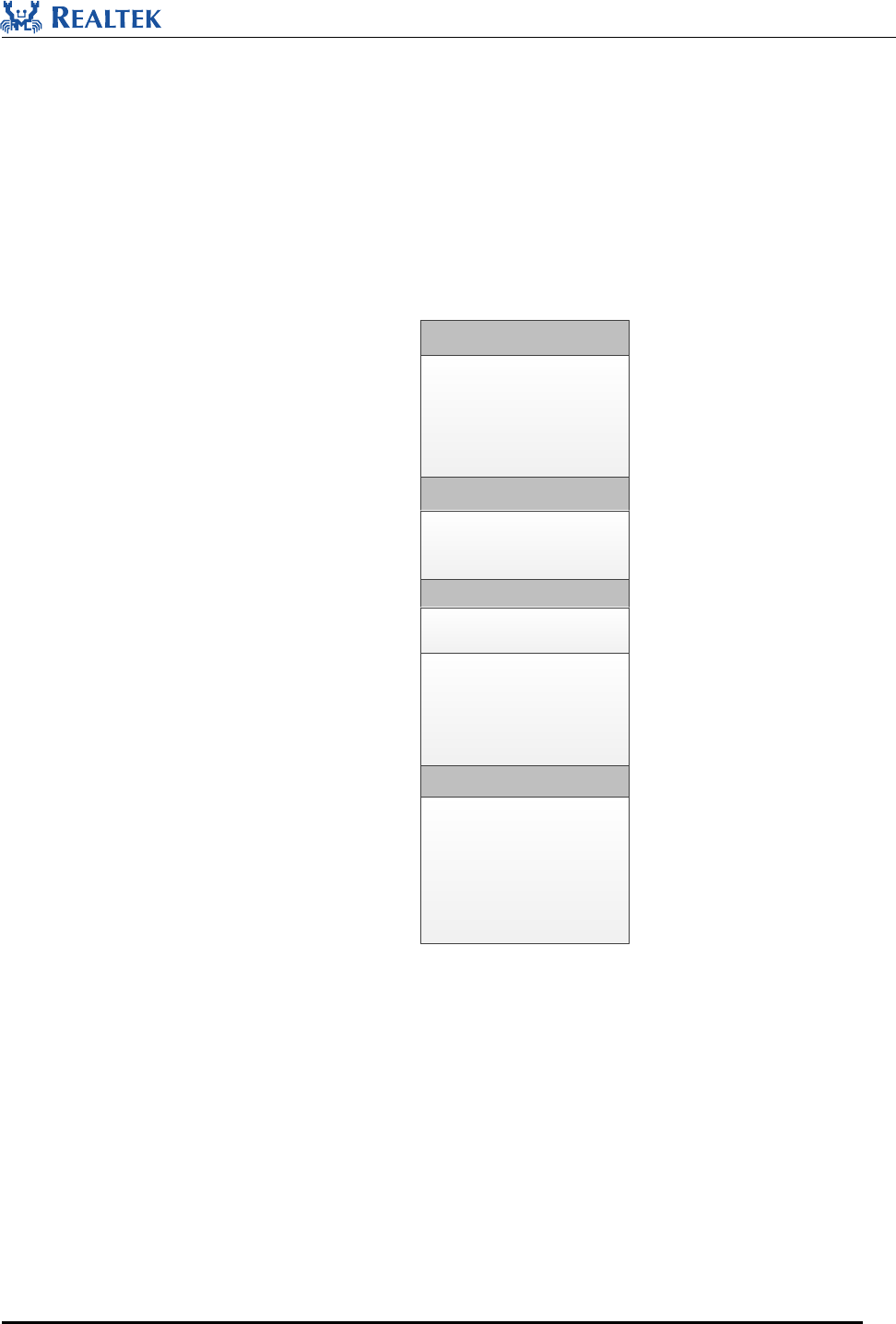
6.1 Memory Map
RTL8762C memory consists of ROM, RAM, external SPI Flash and eFuse. Cache have dedicated RAM, and the
dedicated RAM also can be configured as general RAM using Realtek Vendor registers, as is shown in Figure 6-1.
Refer to RTL8762C Memory User Guide for more details.
ROM
(384kB)
Data RAM
(112kB)
0x0000_0000
0x0005_FFFF
0x0020_0000
0x0021_C000
0x0028_0000
0x0028_8000
Buffer RAM
(32kB)
Cache
(16kB)
0x0022_0000
Ext Flash
(8kk)
0x0080_0000
0x0100_0000
Figure 6-1 Memory Map
6.2 ROM
The ROM code is located at [0x0, 0x60000), in which Bootloader, RTOS, BT Stack, Flash Driver and other
platform modules are built.
6.3 RAM
RTL8762C has two pieces of RAM, the Data RAM located at [0x00200000, 0x0021C000) and the Buffer RAM
Realtek Confidential
RTL8762C SDK User Guide
Copyright 2018Realtek Semiconductor Corporation.
All Rights Reserved.
31
located at [0x00280000, 0x00288000). Cache can also be configured as data RAM, and is located at [0x0021C000,
0x00220000) as data RAM.
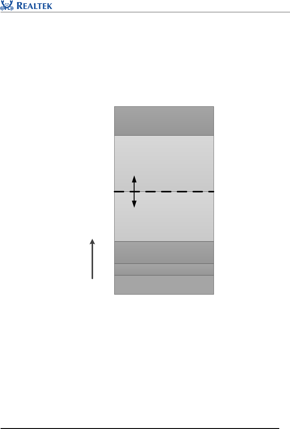
6.3.1 Data Ram
In the current SDK, Data RAM is divided into 6 parts in default, as is shown in Figure 6-2. The total size of APP
RAM and Data RAM Heap are 65K, which is unchangeable, while the size of each block can be adjusted by
modifying mem_config.h.
APP RAM
(35 KB*)
Rom Data (12KB)
Main Stack (2KB)
Patch RAM1 (17 KB)
Patch RAM2 (16 KB)
Data RAM Heap
(30 KB*)
0x00200000
* means the size is adjustable
Figure 6-2 Data ram layout
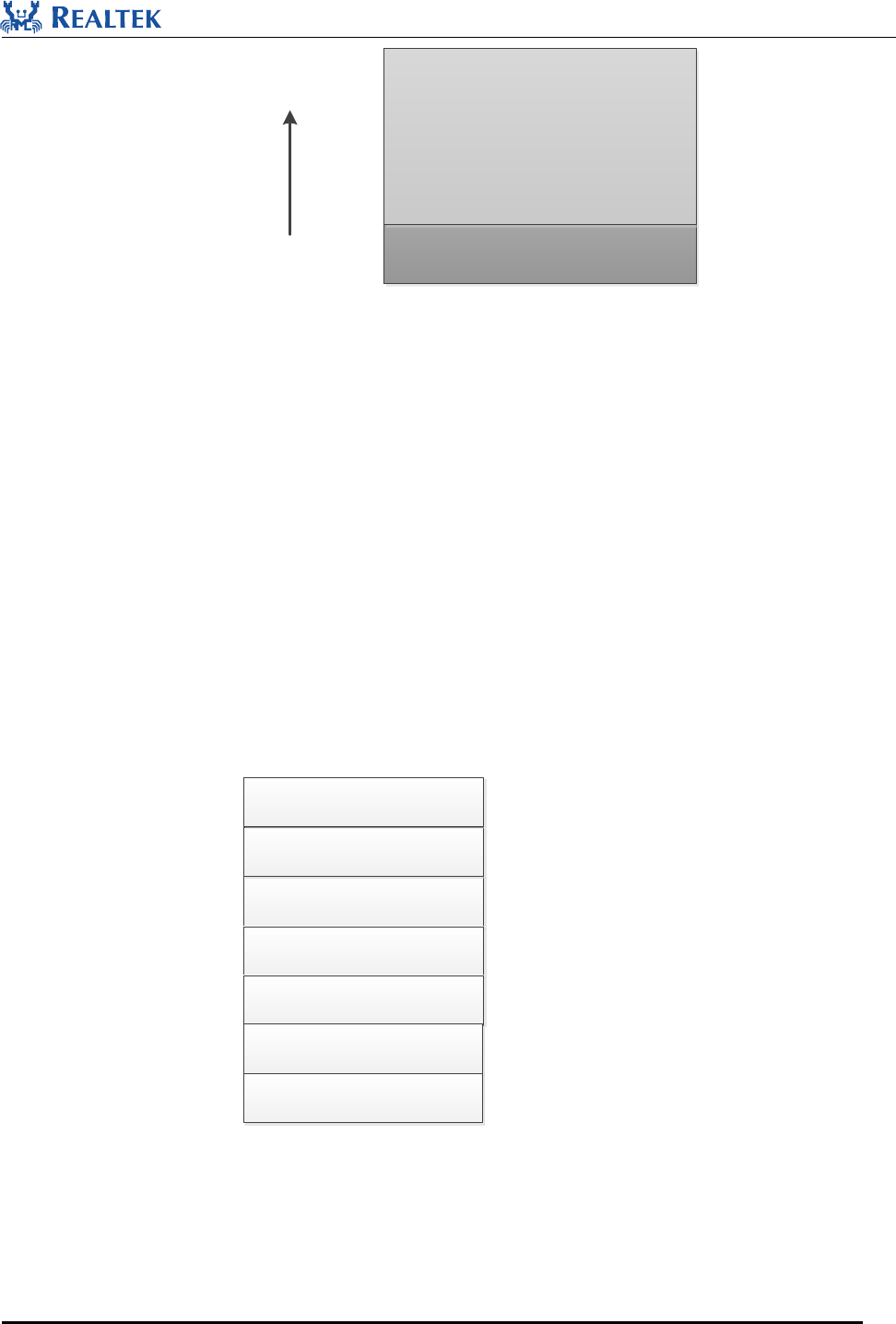
6.3.2 Buffer Ram
In the current SDK, Buffer RAM is divided into 2 parts in default, as is shown in Figure 6-3.
Realtek Confidential
RTL8762C SDK User Guide
Copyright 2018Realtek Semiconductor Corporation.
All Rights Reserved.
32
Rom Data (2KB)
Buffer RAM Heap
(30 KB)
0x280000
Figure 6-3 Buffer RAM Layout
6.4 Cache
RTL8762C has a 16K bytes cache, and it co-works with SPIC (SPI Flash Controller) to speed up the SPI Flash
read. And it also can be used as data RAM. If it is configured as data RAM, it can be used for Data Storage or
Code Execution. If Cache is configured as data RAM, its range is [0x0021C000, 0x0022C000). This range is just
at the end of data RAM.
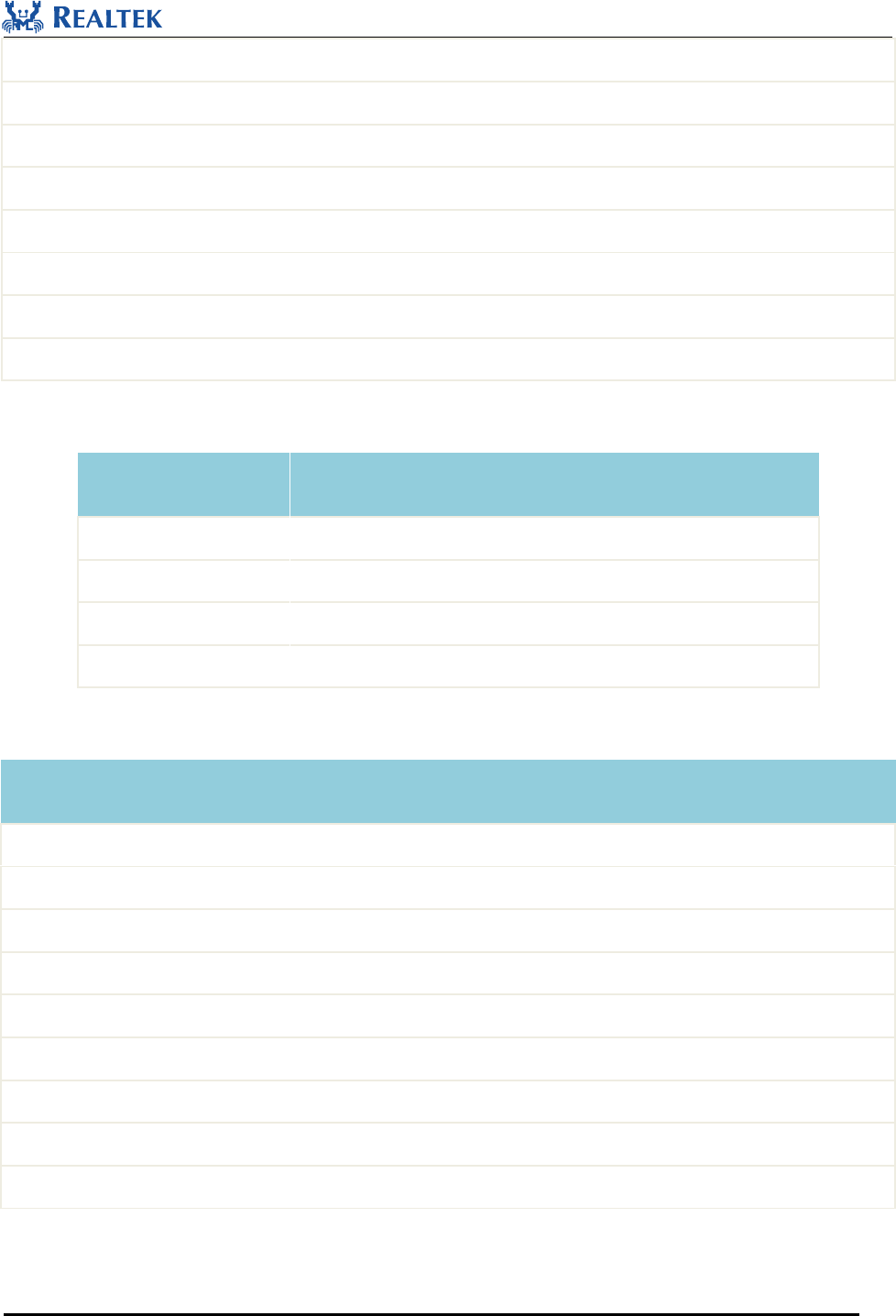
6.5 Flash
RTL8762C supports external SPI Flash with a maximum size of 16M bytes. In the current SDK, External flash is
divided into 7 parts in default, as is shown in Figure 6-4.
OTA Bank 0
OTA Bank 1
FLASH Transport Layer
OTA Temp Area
Starting Address: 0x800000
Starting Address: 0x800000
Starting Address: 0x801000
Starting Address: 0x801000
APP Defined Section
OEM Header
Reserved
Figure 6-4 External Flash layout

Realtek Confidential
RTL8762C SDK User Guide
Copyright 2018Realtek Semiconductor Corporation.
All Rights Reserved.
33
6.5.1 Flash APIs
Flash operation APIs are listed as follows, refer to BEE2-SDK.chm for more details:
void flash_read(uint32_t start_addr, uint32_t data_len, uint8_t *data)
uint32_t flash_split_read(uint32_t start_addr, uint32_t data_len, uint8_t *data);
uint32_t flash_auto_read(uint32_t addr);
bool flash_read_locked(uint32_t start_addr, uint32_t data_len, uint8_t *data);
bool flash_split_read_locked(uint32_t start_addr, uint32_t data_len, uint8_t *data, uint32_t *counter);
bool flash_auto_read_locked(uint32_t addr, uint32_t *data);
void flash_write(uint32_t start_addr, uint32_t data_len, uint8_t *data);
void flash_auto_write(uint32_t start_addr, uint32_t data);
void flash_auto_write_buffer(uint32_t start_addr, uint32_t *data, uint32_t len);
bool flash_write_locked(uint32_t start_addr, uint32_t data_len, uint8_t *data);
bool flash_auto_write_locked(uint32_t start_addr, uint32_t data);
bool flash_auto_write_buffer_locked(uint32_t start_addr, uint32_t *data, uint32_t len);
void flash_erase(T_ERASE_TYPE type, uint32_t addr);
6.5.2 FTL
FTL (flash transport layer) is used as abstraction layer for bt stack and user application to read/write data in flash.
The logical address range of FTL is [0, 0x17f0).
1. BT storage space
Range: [0x0000, 0x0C00).
This region is used to store BT information such as device address, link key, etc.
Refer to RTL8762C BLE Stack User Manual for more details.
2. APP storage space
Range: [0x0C00, 0x17f0)
APP can use this region to store information.
The following APIs can be called to read/write data in this region, these APIs are defined in Ftl.h, refer
to BEE2-SDK.chm for more details:

Realtek Confidential
RTL8762C SDK User Guide
Copyright 2018Realtek Semiconductor Corporation.
All Rights Reserved.
34
static uint32_t ftl_save(void * p_data, uint16_t offset, uint16_t size)
static uint32_t ftl_load(void * p_data, uint16_t offset, uint16_t size)
6.6 eFuse
eFuse is a block of one-time programming memory which is used to store the important and fixed information,
such as UUID, security key and other one-time programming configuration. The single bit of eFuse cannot be
changed from 0 to 1, and there is no erase operation to eFuse, so be careful to update eFuse. Realtek offers MP
Tool to update certain eFuse sections.

Realtek Confidential
RTL8762C SDK User Guide
Copyright 2018Realtek Semiconductor Corporation.
All Rights Reserved.
35
7 Interrupt
7.1 Nested Vectored Interrupt Controller (NVIC)
NVIC features:
- 16 Cortex-M4 exceptions,32 maskable interrupt channels
- 8 programmable priority levels
- Support vector table relocation
- Low-latency exception and interrupt handling
- Implementation of System Control Registers
The NVIC and the processor core interface are closely coupled, which enables low latency interrupt processing
and efficient processing of late arriving interrupts. All interrupts including the core exceptions are managed by the
NVIC.
7.2 Interrupt Vector Table
Table 7-1 Interrupt Vector Table
Exception
Number
NVIC
Number
Exception Type
Description
1
Reset
Reset
2
NMI
Nonmaskable interrupt.
The WDG is linked to the NMI vector
3
Hard Fault
All fault conditions if the corresponding fault handler is not
enabled
4
MemManage
Memory management fault; Memory
Protection Unit (MPU) violation or access to illegal
locations
5
BusFault
Bus error;
6
Usage fault
Exceptions resulting from program error
7 ~ 10
RSVD
11
SVC
Supervisor Call

Realtek Confidential
RTL8762C SDK User Guide
Copyright 2018Realtek Semiconductor Corporation.
All Rights Reserved.
36
12
Debug Monitor
Debug monitor (breakpoints, watch points, or external
debug requests)
13
RSVD
14
PendSV
Pendable Service Call
15
SYSTICK
System Tick Timer
16
[0]
System_ISR
System interrupt
17
[1]
WDG
Watch dog global interrupt
18
[2]
BTMAC_ISR
BT MAC interrupt
19
[3]
Timer3
Timer3 global interrupt
20
[4]
Timer2
Timer2 global interrupt
21
[5]
Platform
Platform interrupt
22
[6]
I2S_0 TX
I2S_0 TX interrupt
23
[7]
I2S_0 RX
I2S_0 RX interrupt
24*
[8]
Timer[4:7]
Timer4-7 interrupt(refer to 错误!未找到引用源。)
25
[9]
GPIO4
GPIO interrupt, P0_4
26
[10]
GPIO5
GPIO interrupt, P0_5
27
[11]
RTK_UART1
RTK_UART1 interrupt
28
[12]
RTK_UART0
RTK_UART0 interrupt
29
[13]
RTC
Real time counter interrupt
30
[14]
SPI_0
SPI_0 interrupt
31
[15]
SPI_1
SPI_1 interrupt
32
[16]
I2C_0
I2C_0 interrupt
33
[17]
I2C_1
I2C_1 interrupt
34
[18]
ADC
ADC global interrupt
35*
[19]
Peripheral_ISR
Peripheral interrupt(refer to 错误!未找到引用源。)
36
[20]
GDMA0_Channel0
RTK-DMA0 channel 0 global interrupt
37
[21]
GDMA0_Channel1
RTK-DMA0 channel 1 global interrupt
38
[22]
GDMA0_Channel2
RTK-DMA0 channel 2 global interrupt
39
[23]
GDMA0_Channel3
RTK-DMA0 channel 3 global interrupt
Realtek Confidential
RTL8762C SDK User Guide
Copyright 2018Realtek Semiconductor Corporation.
All Rights Reserved.
37
40
[24]
GDMA0_Channel4
RTK-DMA0 channel 4 global interrupt
41
[25]
GDMA0_Channel5
RTK-DMA0 channel 5 global interrupt
42
[26]
GPIO_Group3
GPIO group3 interrupt(refer to 错误!未找到引用源。)
43
[27]
GPIO_Group2
GPIO group2 interrupt(refer to 错误!未找到引用源。)
44
[28]
IR
IR module global interrupt
45
[29]
GPIO_Group1
GPIO group1 interrupt(refer to 错误!未找到引用源。)
46
[30]
GPIO_Group0
GPIO group0 interrupt(refer to 错误!未找到引用源。)
47
[31]
RTK_UART2
RTK_UART2 interrupt
Table 7-2 Timer 4~7 ISR
Exception Number
NVIC Number
Exception Type
Description
48
[8]
Timer4
Timer4 interrupt
49
[8]
Timer5
Timer5 interrupt
50
[8]
Timer6
Timer6 interrupt
51
[8]
Timer7
Timer7 interrupt
Table 7-3 Peripheral ISR
Exception Number
NVIC Number
Exception Type
Description
52
[19]
SPI_Flash
SPI_Flash interrupt
53
[19]
qdecode
qdecode global interrupt
54
[19]
keyscan
keyscan global interrupt
55
[19]
2-wire SPI
2-wire/3-wire SPI interrupt
56
[19]
analog comparator
analog comparator interrupt
57
[19]
MailBox
MailBox interrupt
58
[19]
I2S_1 TX
I2S_1 TX interrupt
59
[19]
I2S_1 RX
I2S_1 RX interrupt
60
[19]
LCD
LCD interrupt

Realtek Confidential
RTL8762C SDK User Guide
Copyright 2018Realtek Semiconductor Corporation.
All Rights Reserved.
38
Table 7-4 GPIO Group3 ISR
NVIC Number
Exception Type
Description
[26]
GPIO3
GPIO3 interrupt
[26]
GPIO7
GPIO7 interrupt
[26]
GPIO11
GPIO11 interrupt
[26]
GPIO15
GPIO15 interrupt
[26]
GPIO19
GPIO19 interrupt
[26]
GPIO23
GPIO23 interrupt
[26]
GPIO27
GPIO27 interrupt
[26]
GPIO31
GPIO31 interrupt
Table 7-5 GPIO Group2 ISR
NVIC Number
Exception Type
Description
[27]
GPIO2
GPIO2 interrupt
[27]
GPIO6
GPIO6 interrupt
[27]
GPIO10
GPIO10 interrupt
[27]
GPIO14
GPIO14 interrupt
[27]
GPIO18
GPIO18 interrupt
[27]
GPIO22
GPIO22 interrupt
[27]
GPIO26
GPIO26 interrupt
[27]
GPIO30
GPIO30 interrupt
Table 7-6 GPIO Group1 ISR
NVIC Number
Exception Type
Description
[29]
GPIO1
GPIO1 interrupt
[29]
GPIO9
GPIO9 interrupt
[29]
GPIO13
GPIO13 interrupt
[29]
GPIO17
GPIO17 interrupt
Realtek Confidential
RTL8762C SDK User Guide
Copyright 2018Realtek Semiconductor Corporation.
All Rights Reserved.
39
[29]
GPIO21
GPIO21 interrupt
[29]
GPIO25
GPIO25 interrupt
[29]
GPIO29
GPIO29 interrupt
Table 7-7 GPIO Group0 ISR
NVIC Number
Exception Type
Description
[30]
GPIO0
GPIO0 interrupt
[30]
GPIO8
GPIO8 interrupt
[30]
GPIO12
GPIO12 interrupt
[30]
GPIO16
GPIO16 interrupt
[30]
GPIO20
GPIO20 interrupt
[30]
GPIO24
GPIO24 interrupt
[30]
GPIO28
GPIO28 interrupt
7.3 Interrupt Priority
RTL8762C supports three fixed highest-priority levels and 8 levels of programmable priority.
Table 7-8 Interrupt Priority
Priority
Usage
-3
Reset Handler
-2
NMI
-1
Hard Fault
0
For interrupts which have high real-time requirement
Interrupts at this priority can not be masked by critical section of freeRTOS;
ISR can not call any API provided by freeRTOS
1
2
BT related ISR
3
Normal ISR
4
5
Realtek Confidential
RTL8762C SDK User Guide
Copyright 2018Realtek Semiconductor Corporation.
All Rights Reserved.
40
6
7
SysTick and PendSV
8 Power Management
RTL8762C will enter DLPS mode when certain conditions met and be woken up when it needs to work normally.
Refer to RTL8762C Deep Low Power State for more details.
Conditions for entering DLPS mode are listed as follows:
1. Idle task is running, while all the rest tasks are in blocked or suspended status, and no ISR occurs.
2. All OS messages have been handled.
3. All the DLPS Check callback functions return true, which are registered by BT Stack, peripherals and
application.
4. SW timer timeout > 20ms.
5. BT is in one of the states below and corresponding parameters meet the requirements.
1) Standby State
2) BT Advertising State, Advertising Interval*0.625ms >=20ms
3) BT Scan State, (Scan Interval – Scan Window)*0.625ms >= 15ms
4) BT connection as Master role, Connection interval * 1.25ms >= 12.5ms
5) BT connection as Slave role, Connection interval* (1+ Slave latency)*1.25ms >= 12.5ms
RTL8762C can be woken up from DLPS mode by events as follows:
1. PAD wakeup signal
2. BT interrupt, which will be generated by the following scenarios:
1) Advertising anchor arrives when BT is in advertising state.
2) Connection event anchor arrives when BT connection is established.
3) Any BT event occurs, such as Remote Connection Request, Receiving data.
3. RTC interrupt
This function can be enabled by calling the following API.
void RTC_EnableSystemWakeup(void)
4. SW Timer timeout
Example for sample codes of DLPS mode in application.
1.Register CHECK Callback Function: The system will call the Callback Function to determine whether DLPS

Realtek Confidential
RTL8762C SDK User Guide
Copyright 2018Realtek Semiconductor Corporation.
All Rights Reserved.
41
mode can be entered or not.
if (false == dlps_check_cb_reg(DLPS_PxpCheck))
{
DBG_DIRECT("Error: dlps_check_cb_reg(DLPS_PxpCheck) failed!\n");
}
2.Implement CHECK Callback Function: If True is returned, DLPS mode can be entered. If False is returned,
DLPS mode cannot be entered. Take PXP application for example:
bool DLPS_PxpCheck(void)
{
return allowedPxpEnterDlps;
}
3.Register Callback Function to save and restore peripheral registers:
Peripherals will be powered off once entering DLPS mode, so the peripheral registers must be saved during entering
DLPS mode and restored during exiting from DLPS mode. Peripheral register values shall be saved in
DLPS_IO_EnterDlpsCb function and restored in DLPS_IO_ExitDlpsCb function.
dlps_hw_control_cb_reg(DLPS_IO_EnterDlpsCb, DLPS_ENTER);
dlps_hw_control_cb_reg(DLPS_IO_ExitDlpsCb, DLPS_EXIT4_BT_READY);
4.Enable DLPS mode.
lps_mode_set(LPM_DLPS_MODE);

Realtek Confidential
RTL8762C SDK User Guide
Copyright 2018Realtek Semiconductor Corporation.
All Rights Reserved.
42
9 Download
9.1 About Images
Five Images are provided for BLE applications with RTL8762C: Patch Image, App Image, System Configuration
File, OTA Header File and Secure Boot Loader Image.
1. Patch Image is released by Realtek. Entries to patch functions are retained in ROM code, so original behavior
of ROM code can be modified or extended by patch.
2. Config file records information about hardware configuration and Bluetooth configuration, such as configure
BT Address, change Link number etc. Config file can be generated using MPTool.
3. App Image is a BLE application developed by developer, which is compiled with Keil and processed with
fromelf and other tools.
4. OTA Header File defines flash Bank layout, which is generated by MP PackTool.
5. Secure Boot Loader Image is released by Realtek, and it is used to optimize boot flow. Secure Boot Loader
Image must be programmed if bank switch of OTA update are not used (when using bank switch of OTA
update, Secure Boot Loader Image should not be programmed).
9.2 Application Image Processing Tool
The Application Image directly generated by Keil is in format of ELF, which needs to be converted into a binary
file and processed as necessary to facilitate programing and support OTA function[9].
Three commands are used in demo projects to process Application Image, which are fromelf, CheckSum_Gen
and md5.exe.
9.2.1 fromelf
Fromelf is in Keil installation package, and its default installation path is C:\Keil_v5\ARM\ARMCC\bin\. For
more details, refer to section “Using the fromelf Image Converter” in help documents for Keil.
Bin files to be programmed and disassembling files are both generated by this tool.
9.2.2 CheckSum_Gen
1. Sytax:CheckSum_Gen.exe [Input Binary Filename] [Output Binary Filename]
2. Purpose: To support OTA function, information of checksum and length need to be added to the header of bin
file.

Realtek Confidential
RTL8762C SDK User Guide
Copyright 2018Realtek Semiconductor Corporation.
All Rights Reserved.
43
For Application Image, the image Header of 1024 bytes is stored at the beginning of its address. For more details,
please refer to T_IMG_HEADER_FORMAT defined in system_rtl8762c.c.
Checksum of Application Image can be crc16 or sha256 which are recorded in the member crc16 and sha256 of
structure T_IMG_HEADER_FORMAT, and payload length is recorded in the member payload_len.
typedef struct _IMG_CTRL_HEADER_FORMAT
{
uint8_t ic_type;
uint8_t secure_version;
union
{
uint16_t value;
struct
{
uint16_t xip: 1; // payload is executed on flash
uint16_t enc: 1; // all the payload is encrypted
uint16_t load_when_boot: 1; // load image when boot
uint16_t enc_load: 1; // encrypt load part or not
uint16_t enc_key_select: 3; // referenced to ENC_KEY_SELECT
uint16_t not_ready : 1; //for copy image in ota
uint16_t not_obsolete : 1; //for copy image in ota
uint16_t integrity_check_en_in_boot : 1; // enable image integrity check in boot flow
uint16_t rsvd: 6;
};
} ctrl_flag;
uint16_t image_id;
uint16_t crc16;
uint32_t payload_len;
} T_IMG_CTRL_HEADER_FORMAT;
typedef struct _IMG_HEADER_FORMAT
{
T_IMG_CTRL_HEADER_FORMAT ctrl_header;
uint8_t uuid[16];
uint32_t exe_base;
uint32_t load_base;

Realtek Confidential
RTL8762C SDK User Guide
Copyright 2018Realtek Semiconductor Corporation.
All Rights Reserved.
44
uint32_t load_len;
uint8_t rsvd0[8];
uint32_t magic_pattern;
uint8_t dec_key[16];
uint8_t rsvd1[28];
T_VERSION_FORMAT git_ver;
RSA_PUBLIC_KEY rsaPubKey;
uint8_t sha256[32];
uint8_t rsvd2[76];
} T_IMG_HEADER_FORMAT;
9.2.3 md5
1. Syntax:md5.exe [Input Binary Filename];
2. Purpose: Calculate MD5 of bin file, and append it to the file for verification in programming by MP Tool [11].
Its suffix form is[Original File Name]-[MD5].bin
MP Tool uses MD5 as the check value for programming, and requires the MD5 value to be appended to name of
the file to be programmed.
For example, after file App_ver1.1.0 .bin is processed by md5.exe, a file with the suffix,
App_ver1.1.0-d77dd83cb2848d3e9ac04c7dd9367e69.bin, will be created in the same directory.
9.3 Downloading Pattern
The downloading patterns available respectively for Patch Image, Config File and App Image are listed in 错误!
未找到引用源。.
Table 9-1 Downloading Patterns Available for Images
Patch Image
Config File
APP Image
Keil
×
×
√
SWDTool
√
√
√
MPTool
√
√
√
10 Debug
Two debugging methods have been provided to debug applications:
Realtek Confidential
RTL8762C SDK User Guide
Copyright 2018Realtek Semiconductor Corporation.
All Rights Reserved.
45
1. Use log mechanism to trace your code procedure and data
2. Use Keil MDK and SWD to do the running control, add/delete breakpoints, access/trace memory and so on
10.1 Log Mechanism
Debug analyzer is designed to help trace application via printing messages and capturing BT data which could be
analyzed by 3rd party BT analyzing tool. Refer to Debug analyzer user manual for more details.
There is a dedicated log UART pin (P0_3 as default) to print log of application (Log function can be
re-configured to another pin in application). It is connected to PC via UART-to-USB adapter, and log data shall be
received from PC COM port.
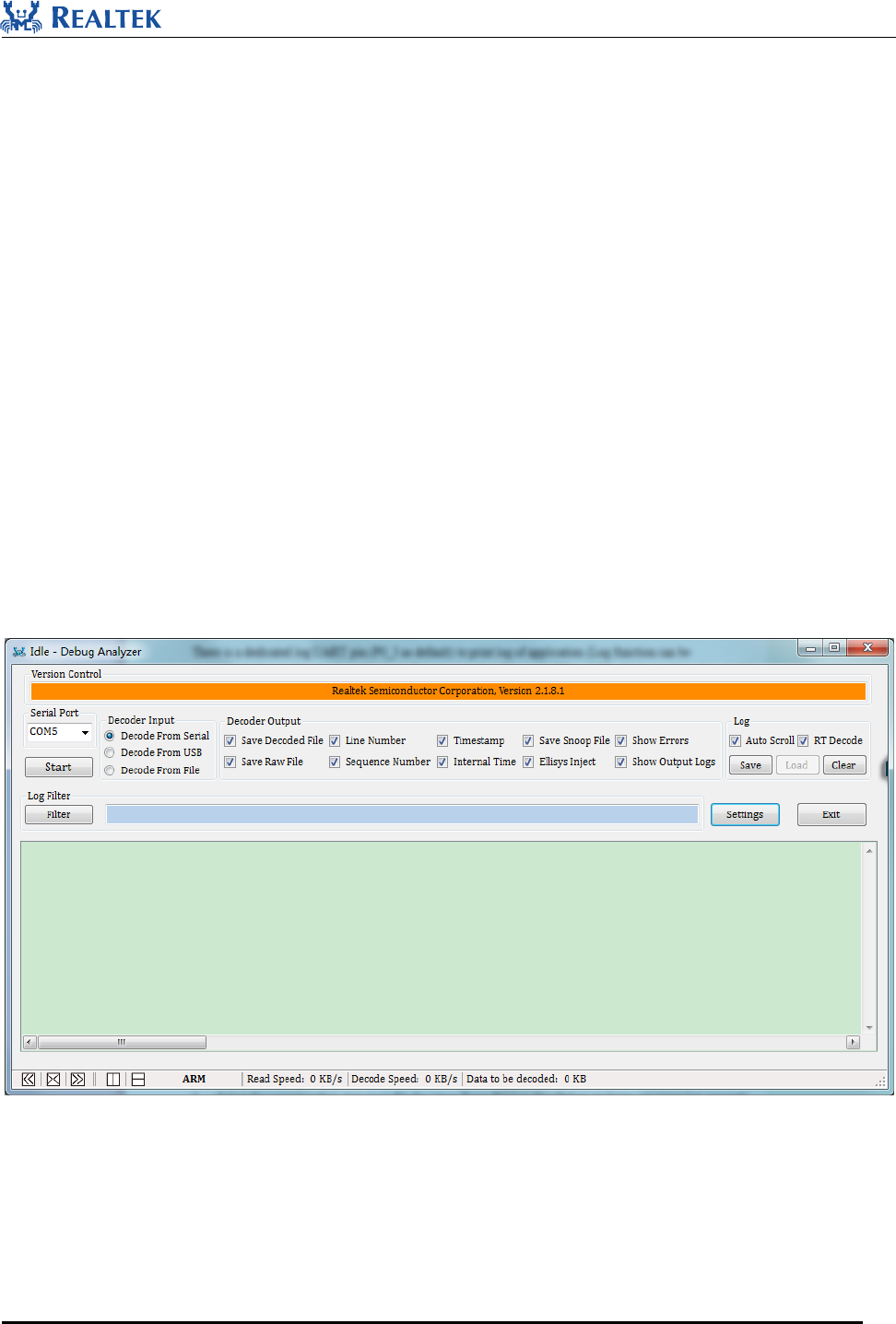
10.1.1 Debug analyzer
Follow below steps to use Debug analyzer:
1. Run DebugAnalyzer.exe, and click “Settings“, then click “Start “.
Figure 10-1 Main Interface of Debug Analyzer
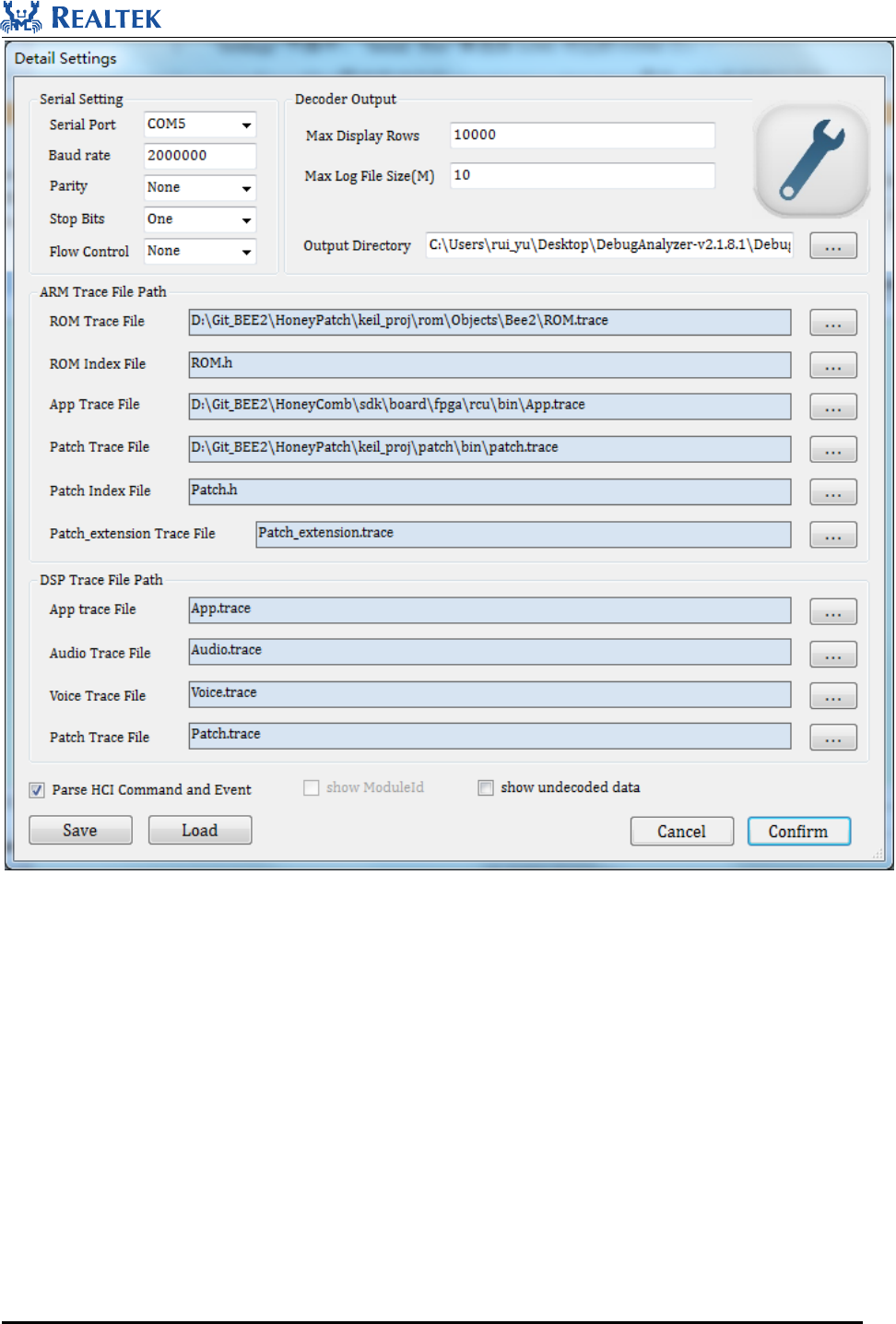
2. Select the corresponding COM for “Serial Port” in “Settings” window.
3. Select the corresponding App.trace file for “App Trace File” so that Debug analyzer can parse log correctly.
App.trace is created under the same directory of App.bin after the compilation of each project.
Realtek Confidential
RTL8762C SDK User Guide
Copyright 2018Realtek Semiconductor Corporation.
All Rights Reserved.
46
Figure 10-2 Debug Analyzer Setting Page
Debug analyzer also provides some advanced functions as below:
1. “Save Raw File” (it is recommended to check it): Save LOG to xxx.bin file, which can be used by Realtek
to carry out further analysis.
2. “Log Filter”: Filter Display - a new window pops up to display the filtered logs only.
3. “Keyword search”: Highlight the keyword in log printing window.
4. “Clear Trace”: Clear the log in the display frame.
Debug analyzer will automatically save the log data as a file, which is named based on port number and creation
date and time, such as COM 5_2015-06 -12_18-05-00.log.
Realtek Confidential
RTL8762C SDK User Guide
Copyright 2018Realtek Semiconductor Corporation.
All Rights Reserved.
47
10.1.2 Basic Interface for Log Printing
Hardware has implemented a specialized GDMA channel for log printing, and the interface function prototype is:
DBG_BUFFER(T_LOG_TYPE type, T_LOG_SUBTYPE sub_type, T_MODULE_ID module, uint8_t level,
char* fmt, unit8_t param_num,...).
The parameter type is always TYPE_BEE2, and sub_type is always SUBTYPE_FORMAT. You may only pay
attention to the parameters module and level.
There are several predefined modules in T_MODULE_ID, and they are used to indicate which module the log
belongs to, and Debug Analyzer Tool will recognize and print the module name before log data.
There is also a concept named Debug Level, and this indicates what level the log is displayed in. Four levels are
defined:
Table 10-1 Debug Level
Debug Level
Usage Scenario
LEVEL_ERROR
Fatal, Procedure Cannot Advance (Log Token !!!)
LEVE_WARN
Abnormal Condition Occurred, But Procedure Can Advance (Log Token !!*)
LEVEL_INFO
Important Notification (Log Token !**)
LEVEL_TRACE
Verbose Debug
The DBG_BUFFER() API is flexible and powerful, but may be difficult to use. RTL8762C SDK have wrapped
the interface, and provided some readable APIs in trace.h.
10.1.3 Wrapped Interfaces for Log Printing
There are several wrapped APIs for you to print specific log, and all of them have a common syntax as:
{MODULE}_PRINT_{LEVEL}_{PARAMNUM}(...)
{MODULE} can be replaced with the module name defined in trace.h, such as APP/GAP/USB/FLASH...
{LEVEL} can be replaced with the debug level, as well as one of the four levels:
ERROR/WARN/INFO/TRACE.
{PARAMNUM} can be replaced with number 0 to 8, which means the number of parameters this log will print
out.

Realtek Confidential
RTL8762C SDK User Guide
Copyright 2018Realtek Semiconductor Corporation.
All Rights Reserved.
48
For example, if you are trying to print a warning log with 2 parameters in your application, you may write code
like this:
APP_PRINT_WARN2("Test app: ID = %d, data = 0x%x", id, data);
Then Debug Analyzer Tool will show this log like:
00494 10-13#17:06:45.994 087 02145 [APP] !!*Test app: ID = 3, data = 0xF0
Note:
1. Do not exceed 8 parameters (Maximum 20 parameters if directly use DBG_BUFFER()).
2. Do not exceed 128 char string for a single print.
3. Put all parameters into a single print if possible.
10.1.4 Auxiliary Interfaces
The DBG_BUFFER() API can only print simple format like Integer (d, i, u, o, x), Character (c) and Pointer (p).
Sometimes you may need to print string, binary array or BT Address, thus we have provided three auxiliary
interfaces to do that.
1. TRACE_STRING(char* data)
Directly put string into log data, the conversion directive is %s.
2. TRACE_BINARY(uint16_t length, uint8_t* data)
Output binary stream in Hex format, the conversion directive is %b.
3. TRACE_BDADDR(char* bd_addr)
Output binary array in BT address format, for example:
Hex Array: 0xaa 0xbb 0xcc 0xdd 0xee 0xff –> Literal String: FF::EE::DD::CC::BB::AA
Note: the maximum addresses numbers in a single log is 4. The conversion directive is %s.
10.1.5 Log Print Example
Below is an example to show the common use of log APIs and the corresponding output in Debug Analyzer Tool.
Log print code:
uint32_t n = 77777;
uint8_t m = 0x5A;
uint8_t bd1[6] = {0x00, 0x11, 0x22, 0x33, 0x44, 0x55};
uint8_t bd2[6] = {0xAA, 0xBB, 0xCC, 0xDD, 0xEE, 0xFF};
char c1[10] = {'1', '2', '3', '4', '5', '6', '7', '8', '9', '0'};

Realtek Confidential
RTL8762C SDK User Guide
Copyright 2018Realtek Semiconductor Corporation.
All Rights Reserved.
49
char c2[8] = {'a', 'b', 'C', 'd', 'E', 'F', 'g', 'H'};
char *s1 = "Hello world!";
char *s2 = "Log Test";
ADC_PRINT_TRACE1("ADC value is %d", n);
UART_PRINT_INFO3("Serial data: 0x%x, c1[%b], s1[%s]", m, TRACE_BINARY(10, c1),
TRACE_STRING(s1));
GAP_PRINT_WARN6("n[%d], m[%c] bd1[%s], bd2[%s], c2[%b], s2[%s]", n, m, TRACE_BDADDR(bd1),
TRACE_BDADDR(bd2), TRACE_BINARY(8, c2), TRACE_STRING(s2));
APP_PRINT_ERROR0("APP ERROR OCCURED...");
Corresponding result shown in Debug Analyzer:
00252 10-25#17:12:02.021 132 10241 [ADC] ADC value is 77777
00253 10-25#17:12:02.021 133 10241 [UART] !**Serial data: 0x5a, c1[31-32-33-34-35-36-37-38-39-30],
s1[Hello world!]
00254 10-25#17:12:02.022 134 10241 [GAP] !!*n[77777], m[Z] bd1[55::44::33::22::11::00],
bd2[FF::EE::DD::CC::BB::AA], c2[61-62-43-64-45-46-67-48], s2[Log Test]
00255 10-25#17:12:02.022 135 10241 [APP] !!!APP ERROR OCCURED...
10.1.6 Log Control Interfaces
Sometimes you may decide to turn on some logs and turn off others. One method is to set the trace mask in Bee2
Config Tool, and then burn the config file to Bee2. However this is not flexible enough as you may want to
frequently change the log level, and it is not convenient to re-burn the config file everytime. So we provide you
three APIs to control the log of specific level of specific module:
1.log_module_trace_init()
2.log_module_trace_set()
3.log_module_bitmap_trace_set()
Refer to SDK API document for parameters detail.
Here are some sample scenarios to help you understand how to use log control APIs in your own applications.
Assume that log print is already enabled and all of the log trace mask have been set to 1 in Config Tool, which
means all types of all level of logs can be output.
Senario 1: Disable all trace level and info level logs of APP module.

Realtek Confidential
RTL8762C SDK User Guide
Copyright 2018Realtek Semiconductor Corporation.
All Rights Reserved.
50
int main(void)
{
log_module_trace_set(MODULE_APP, LEVEL_INFO, false);
log_module_trace_set(MODULE_APP, LEVEL_TRACE, false);
...
}
Senario 2: Only enable logs of PROFILE module.
int main(void)
{
uint64_t mask[LEVEL_NUM];
memset(mask, 0, sizeof(mask));
log_module_trace_init(mask);
log_module_trace_set(MODULE_PROFILE, LEVEL_ERROR, true);
log_module_trace_set(MODULE_PROFILE, LEVEL_WARN, true);
log_module_trace_set(MODULE_PROFILE, LEVEL_INFO, true);
log_module_trace_set(MODULE_PROFILE, LEVEL_TRACE, true);
...
}
Senario 3: Disable trace level logs of PROFILE/PROTOCOL/GAP/APP modules.
int main(void)
{
log_module_bitmap_trace_set(MODULE_BIT_PROFILE | MODULE_BIT_PROTOCOL |
MODULE_BIT_GAP |MODULE_BIT_APP, LEVEL_TRACE, false);
...
}
Senario 4: Disable all trace level and info level logs except APP module, and also disable BT Snoop logs.
int main(void)
{
for (uint8_t i = 0; i < MODULE_NUM; i++)
{
log_module_trace_set((T_MODULE_ID)i, LEVEL_TRACE, false);

Realtek Confidential
RTL8762C SDK User Guide
Copyright 2018Realtek Semiconductor Corporation.
All Rights Reserved.
51
log_module_trace_set((T_MODULE_ID)i, LEVEL_INFO, false);
}
log_module_trace_set(MODULE_APP, LEVEL_INFO, true);
log_module_trace_set(MODULE_APP, LEVEL_TRACE, true);
log_module_trace_set(MODULE_SNOOP, LEVEL_ERROR, false);
...
}
Note that Debug Analyzer Tool can generate BT Snoop log file (*.cfa) if the LEVEL_ERROR log of
MODULE_SNOOP is enable, in other words, if you turn off log of MODULE_SNOOP, BT Snoop log file will
not be generated, such as Senario 2 and Senario 4.
10.1.7 DBG_DIRECT
Invoking APIs based on DBG_BUFFER has less effect on system performance, but the log will not be printed in
real-time, because log printed by these APIs will be cached in buffer and sent to Log Uart when system is idle.
DBG_DIRECT can be used to print real-time log. This API has great influence on system performance for it will
directly send Log to Log UART, and suspend execution of any program till log printing is completed, so it is
strongly recommended that it is only used under specific situations as follows:
1. Before reboot
2. Scenario when real-time log is necessary
3. In DLPS exit callback
Example:
Log print code:
DBG_DIRECT("Bee2 ROM version: %s %s", __DATE__, __TIME__);
Corresponding result shown in Debug Analyzer:
00002 12-22#19:19:32.573 004 00000 Bee2 ROM version: Dec 22 2017 14:54:04
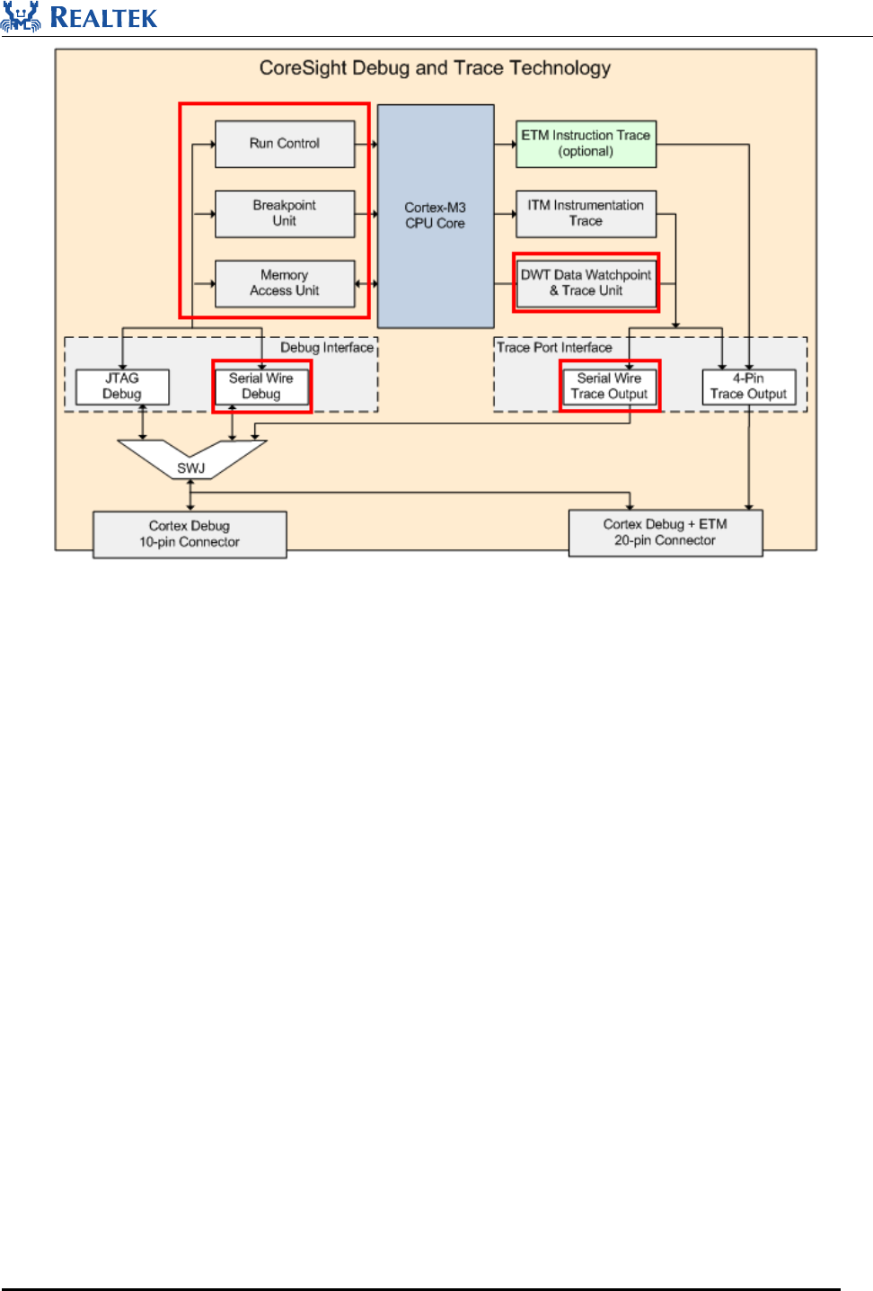
10.2 Debug with SWD
As is shown in Figure 10-1, Bee2 have implemented the following three basic debug interfaces: run control,
breakpoint and memory access, and one trace port interface: DWT. JTAG is not supported in Bee2, while SWD is
supported.
Realtek Confidential
RTL8762C SDK User Guide
Copyright 2018Realtek Semiconductor Corporation.
All Rights Reserved.
52
Figure 10-1 Debug and Trace port interface in Bee2
10.2.1 Using SWD Debug Interface
Before using SWD, you should properly install and configure your Keil MDK-ARM and SWD debugger.
Key debug features supported by Bee2 are introduced in the UI:
1. Running control buttons: Running/Reset/Step
2. Breakpoints buttons: Add/Delete/Conditional
3. Several functional windows for debugging:
1) Core registers window to view/modify MCU register values.
2) Disassembly window to view disassembly code, support breakpoints and mixed mode (show C code).
3) Source code window to view C code, support breakpoints and variable value real-time display.
4) Variable watch window to trace interested variable added in.
5) Memory window to view/modify interested memory, support direct address input and variable address
input.
6) Call stack and local variable window to show current call stack and local variable (variable in the stack).
Sometimes you may encounter problems that your image can not be successfully burned to flash of Bee2, or Keil
just can not find SWD even if you have connected Bee2 and J-link properly. In these cases, checking the
following configurations are helpful:

Realtek Confidential
RTL8762C SDK User Guide
Copyright 2018Realtek Semiconductor Corporation.
All Rights Reserved.
53
1. Change debug clock to a smaller value (e.g. From 2 MHz to 1 MHz), or just replace your SWD debug wire to
a shorter one.
2. Bee2 may have entered DLPS mode, reset Bee2 and system will keep active for the first 5 seconds.
10.2.2 Using Trace Port Interface DWT
Bee2 provides a way to trace memory using DWT. And a group of four APIs are provided to monitor up to four
memory areas:
watch_point_0_setting()
watch_point_1_setting()
watch_point_2_setting()
watch_point_3_setting()
Refer to debug_monitor.h for the detail usage.
Below is a sample to show you how to use the debug monitor APIs.
void debug_monitor_enable(void)
{
//set debug monitor priority
NVIC_SetPriority(DebugMonitor_IRQn, 3);
//enable exception and monitor control register
CoreDebug->DEMCR |= CoreDebug_DEMCR_MON_EN_Msk | CoreDebug_DEMCR_TRCENA_Msk;
//comment: set appropriate parameter and enable watch point to specific address if desired
//set DWT compare registers (max 4 comparators)
watch_point_0_setting(0x1000180C, DWT_DATAVSIZE_WORD, DWT_FUNCTION_WRITE);
watch_point_1_setting(0x10000004,DWT_DATAVSIZE_WORD,DWT_FUNCTION_READ_OR_WRITE);
watch_point_2_setting(0x10000008,DWT_DATAVSIZE_WORD,DWT_FUNCTION_READ_OR_WRITE);
watch_point_3_setting(0x1000000C,DWT_DATAVSIZE_WORD,DWT_FUNCTION_READ_OR_WRITE);
//enable DWT control register
DWT->CTRL |= DWT_CTRL_CYCCNTENA_Msk;
return;
}

Realtek Confidential
RTL8762C SDK User Guide
Copyright 2018Realtek Semiconductor Corporation.
All Rights Reserved.
54
If the memory you are interested in is accessed, the changing value will be printed to the log UART and you can
trace them by using Debug Analyzer Tool.
