Racal Vadic_18008 049_VA811_Automatic_Calling_Unit_Installation_Operation_Manual_May1985 Vadic 18008 049 VA811 Automatic Calling Unit Installation Operation Manual May1985
User Manual: Racal-Vadic_18008-049_VA811_Automatic_Calling_Unit_Installation_Operation_Manual_May1985
Open the PDF directly: View PDF ![]() .
.
Page Count: 49
Racal-Vadic
VA811 AUTOMATIC CALLING
UNIT
INSTALLATION/OPERATION
MANUAL
ml3~m[J
The
Electronics
Group
Publication
Number
18008-049
VA811 AUTOMATIC CALLING
UNIT
INSTALLATION/OPERATION
MANUAL
REPRINTED
MAY
1985
Racal-Vadic offers afree, call-in diagnostic service to assist
in
the operation
and
testing of all Racal-Vadic
products. Racal-Vadic Diagnostic Center personnel are available to perform free, over-the-telephone diagnostic "
tests of malfunctioning equipment, to clarify options
and
test procedures
outlined
in
this manual,
and
to describe the operation
of
the
controls
and
indicators
on
Racal-Vadic products. Call the Racal-Vadic
Diagnostic Center before shipping any
equipment
in for repair.
TOLL-FREE
NUMBER
(800)
22-VADIC
or
(800) 228-2342
When using this
product
outside the continental
U.S.
or
Canada, please call your local distributor regard-
ing any problems.
The information
in
this
manual
has
been
carefully compiled
and
checked for technical accuracy. However,
Racal-Vadic accepts no responsibility for inaccuracies
which
may occur.
Comments
or
correspondence
regarding this
manual
should
be
addressed to:
Racal-Vadic
Corporate Communications
Department
1525
McCarthy Boulevard
Milpitas, California
95035
U.S.A.
Tel.
(408)
946-2227
TWX:
4112-62782187
Copyright ©
1985
by Racal-Vadic
FCC REQUIREMENTS
Connection of
terminal
equipment
to
the
public switched-telephone
network
is regulated
by
the
Federal
Communications
Commission
(FCC)
as defined by
FCC
Rules
and
Regulations, Part 68.
These
regulations
require
the
following:
1. Before
connecting
this
equipment
to
the
switched-telephone network,1notify
the
telephone
company
of
the
following information:
Name of
Manufacturer
RACAL-VADIC
Equipment
Model
Number.
. . . . . . . . . . . . . . . . . . . . . . . . . . . . . . . . . . .
..
VA811-PS/SS
FCC Registration
Number
AJ496M-68137-DI-E
Ringer Equivalence
Number
O.OB
If
other
devices are to be
connected
with
this equipment, equivalent
information
must
be
provided
for
each device.
2.
When
trouble
is
experienced,
disconnect
this
equipment
from
the
telephone
line
to
determine
if it is
malfunctioning.
If
this
equipment
is
determined
to be malfunctioning,
discontinue
use
until
the
problem
has
been
corrected.2
3.
Where
such
action
is reasonably required
in
the operation of its business,
the
telephone
company
~
may make changes
in
its
communications
facilities, equipment, operations,
and
procedures.
If
this
occurs,
you
will
be notifed
by
the
telephone
company
in
writing.
1Connection of this
equipment
to party lines
and
coin
telephone
service is prohibited.
2
Should
this
equipment
cause
harm
to the telephone network,
the
telephone
company
may
temporarily
discontinue
service
until
the
problem
has been corrected.
WARNING
This
equipment
generates, uses,
and
can
radiate radio frequency energy and, if
not
installed
and
used
in
accordance
with
the instructions manual, may cause interference to radio communications. It has been
tested
and
found to comply
with
the limits for aClass A
computing
device
pursuant
to
Subpart
Jof Part
15 of FCC Rules,
which
are
designed
to provide reasonable
protection
against
such
interference
when
operated in a
commercial
environment.
Operation
ofthis
equipment
in aresidential
area
is likely to cause
interference;
the
user
will be
required
to take whatever
measures
may be
required
at his
own
expense
to
correct
the interference.
/~
CANADIAN
DEPARTMENT
OF
COMMUNICATIONS
REQUIREMENTS
FOR
END USERS
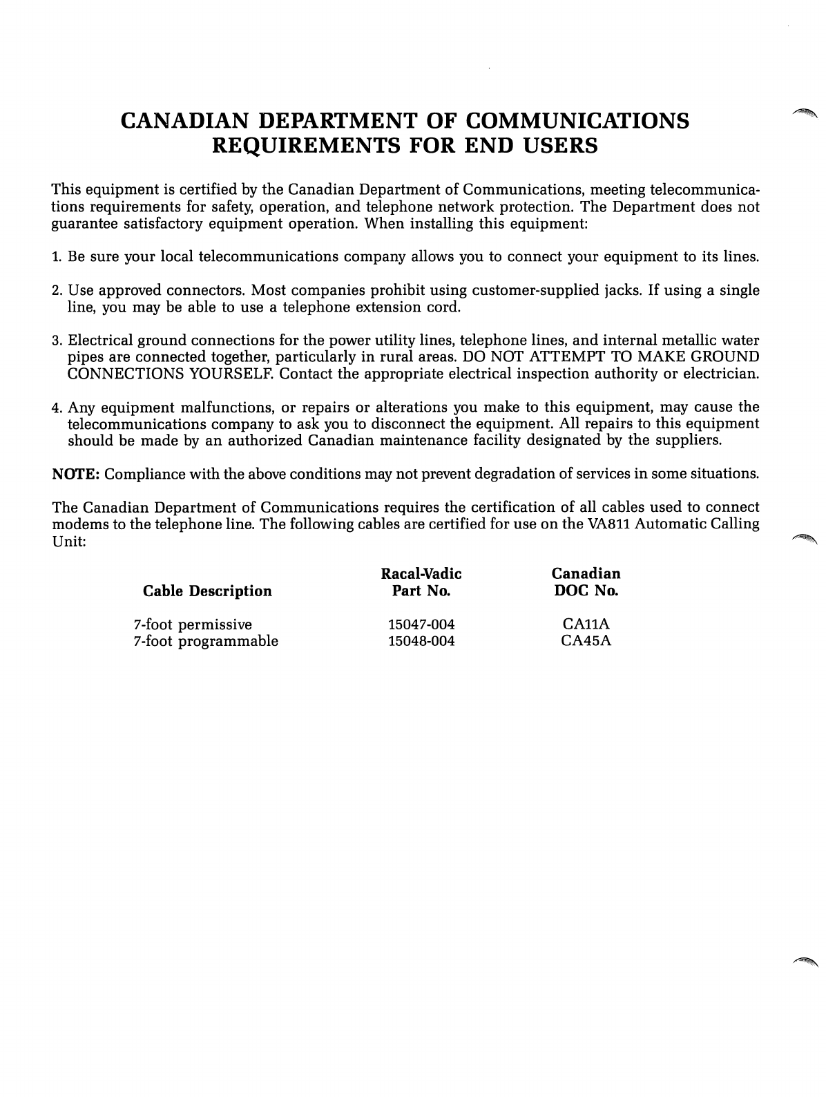
This equipment is certified by
the
Canadian
Department of Communications, meeting telecommunica-
tions requirements for safety, operation,
and
telephone network protection.
The
Department
does not
guarantee satisfactory
equipment
operation. When installing this equipment:
1.
Be
sure your local telecommunications company allows you to
connect
your
equipment
to its lines.
2. Use approved connectors. Most companies prohibit using customer-supplied jacks. If using asingle
line, you may be able to use atelephone extension cord.
3.
Electrical ground connections for the power utility lines, telephone lines,
and
internal metallic water
pipes are connected together, particularly
in
rural areas.
DO
NOT ATTEMPT TO MAKE GROUND
CONNECTIONS YOURSELF. Contact
the
appropriate electrical inspection authority
or
electrician.
4.
Any equipment malfunctions,
or
repairs or alterations you make to this equipment, may cause the
telecommunications company to ask you to disconnect the equipment. All repairs to this equipment
should be made by
an
authorized
Canadian
maintenance facility designated by the suppliers.
NOTE: Compliance with the above conditions may not prevent degradation of services
in
some situations.
~.
,.
...
~!.~"
The
Canadian
Department of Communications requires the certification of all cables
used
to connect
modems to the telephone line. The following cables are certified for use
on
the
VA811
Automatic Calling
Unit:
~
Cable
Description
7-foot permissive
7-foot programmable
Racal-Vadic
Part
No.
15047-004
15048-004
Canadian
DOC No.
CAllA
CA45A
SECTION 1
SECTION
2
SECTION 3
SECTION
4
SECTION
5
TABLE
OF
CONTENTS
GENERAL
INFORMATION
1-1
INTRODUCTION
1-1
FEATURES
1-1
CABLE
INFORMATION
1-1
PHYSICAL
DESCRIPTION
1-2
CONFIGURATIONS
1-2
Single-line
1-2
Multiline
1-4
OPTIONS
2-1
INTRODUCTION
2-1
OPTION
DESCRIPTIONS
2-1
Single-line/Multiline
Options
2-1
Interconnect
Options
2-2
Operating
Protocol
Options
2-2
INSTALLATION
3-1
INTRODUCTION
3-1
PRELIMINARY
PROCEDURES
3-1
Unpacking
and
Inspection
3-1
Equipment
Supplied
3-2
Additional
Equipment
Required
3-2
Preinstallation
Checks
3-2
VA811-PS/SS INSTALLATION
3-3
VA811-XM INSTALLATION 3-4
CHECKOUT
AND
OPERATION
4-1
INTRODUCTION
4-1
CHARACTER
SET
4-2
EXAMPLE
CALLS
4-4
CONTROLS
AND
INDICATORS 4-4
OPERATIONAL
CHECKOUT
4-6
VA811-PS/SS 4-6
VA811-XM 4-7
SUPPLEMENTAL
INFORMATION
5-1
INTRODUCTION
5-1
EQUIPMENT
INTERFACES
5-1
LINE
INTERFACE
5-2
Introduction
5-2
RS366
INTERFACE
5-4
Introduction
5-4
RS366
Signal
Descriptions
5-4
RS366
Protocol
5-7
CHASSIS
INTERFACE
5-8
SPECIFICATIONS
5-11
v
Table 2-1
Table 3-1
Table
3-2
Table 4-1
Table 4-2
Table 4-3
Table
4-4
Table 5-1
Table 5-2
Table 5-3
Table
5-4
Table 5-5
Table
5-6
Table
5-7
LIST
OF
TABLES
VA8110ptions
.
Equipment
Supplied
.
Additional
Equipment
Required .
Telephone Digits .
Dialer Address/Modem Type .
Modem
(Slot) Address .
Controls
and
Indicators .
RJllC
Connector
Pin
Assignments .
RJ41S,45S Connector
Pin
Assignments .
TelCo Interface Signal Definitions .
RS366 Interface Connector
(J5)
.
RS366 Interface Dial Sequence .
RS366 Interface Address Sequence
(MACS
only) .
Edge Connector
Pin
Assignments (Pi) .
vi
2-4
3-2
3-2
4-2
4-3
4-3
4-5
5-2
5-3
5-3
5-6
~
5-7
5-8
5-9
Figure
1-1
Figure
1-2
Figure
1-3
Figure 2-1
Figure
3-1
Figure
3-2
Figure 4-1
Figure
5-1
LIST OF FIGURES
Basic Single-line Dialer Configuration. . . . . . . . . . . . . . . . . . . . . . . . . . . . . . . .
..
1-2
Single-line Dialer
with
VA831
Adapter.
. . . . . . . . . . . . . . . . . . . . . . . . . . . . . .
..
1-3
Multiline
Dialer (MACS) Configuration. . . . . . . . . . . . . . . . . . . . . . . . . . . . . . .
..
1-4
VA811
Switch
and
Strap Locations. . . . . . . . . . . . . . . . . . . . . . . . . . . . . . . . . . .
..
2-4
VA811-PS/SS (SLD)
Connections.
...................................
..
3-3
VA811-XM (MACS) Connections 3-4
Diagnostic Display
Indicators.
. . . . . . . . . . . . . . . . . . . . . . . . . . . . . . . . . . . . . .
..
4-5
RS366 Interface Signals. . . . . . . . . . . . . . . . . . . . . . . . . . . . . . . . . . . . . . . . . . . .
..
5-4
vii

INTRODUCTION
FEATURES
Section 1
GENERAL INFORMATION
The
VA811
Automatic Calling
Unit
is a
single-line/multiline
automatic
dialer
that
allows a
computer
to
initiate
calls
through
an
RS366 interface
(or
through
a
standard
RS232C interface
when
the
VA831
adapter
is
used).
The
VA811, available
in
three
basic
configurations
listed
below,
replaces
both
Bell 801
and
RACAL-VADIC VA821 ACUs:
•VA811-PS single-line
version
supplied
with
a
P-type
(permissive
direct-connect) cable.
•VA811-SS single-line version
supplied
with
an
S-type
(programmable
direct-connect) cable.
•VA811-XM
multiline
version for
use
in
the
RACAL-VADIC
Multiline
Automatic
Calling System (MACS).
The
VA811
provides
many
standard
and
optional
features
that
allow
custom
tailoring to fit
the
needs
of a
particular
installation.
Features
available
on
this
unit
include:
•
Switched-network
(DDD)
and
teletype
(TWX)
compatible
•
Automatic
selection of
pulse
or
tone
dialing
•Positive dial tone,
answer
tone,
and
busy
signal
detection
•Tandem-dial
and
blind-dial
capability
•Selectable automatic call
and
retry
(ACR)
control
•End-of-number
and
invalid-digit
detect
options
•Compatible
with
RACAL-VADIC
direct-connect series
modems,
MACS,
and
single-line chassis
•Extensive
user
diagnostics
capability
The
following cable
has
been
certified for
use
with
this dialer.
CABLE
INFORMATION
Racal-Vadic Part
Number
Government
of
Canada
DOC Old
Connector
Code
DOC New
Connector
Code
(U
se this code
and
the
part
number
for any
communications
or
ordering
information
from
Racal-Vadic.)
Description:
1-1
15047-004
H473185
CAllA
7ft
(P
type)
6
position
modular
(voice
or
data-perm)
T,
R
PHYSICAL
DESCRIPTION
CONFIGURATIONS
Single-line
The
VA811
dialer consists of a
single-width
printed
circuit
board
(PCB)
assembly
that
occupies
one
card
slot
in
RACAL-VADIC VA1601-,
VA1616
...
,or VA1680-series chassis.
The
dialer
accepts
dc
power
and
interfaces to
the
chassis controls
and
indicators
via
the
standard
card-
edge
connector
located at
one
end
of
the
PCB. A
25-pin
female
connector
mounted
on
the
rear
panel
of
the
unit
provides
an
EIA RS366
connection
to
the
computer
(data
terminal
equipment)
and
a
corresponding
25-pin
male
connector
provides buffered
expansion
capability
(daisy-chain) for
up
to
three
additional
dialers (in aMACS system). Two
miniature
8-
position
telephone
(TelCo) jacks
provide
line
connection
to
the
modem
and
to
the
sWitched-telephone
network
for
single-line
application.
The
VA811
dialer will operate as
either
asingle-line (SLD)
or
a
multiline
(MACS) dialer,
depending
on
the
internal
option
settings
selected
at
the
factory (per dialer
type
ordered). Typical SLD
and
MACS
equipment
configurations are
discussed
below.
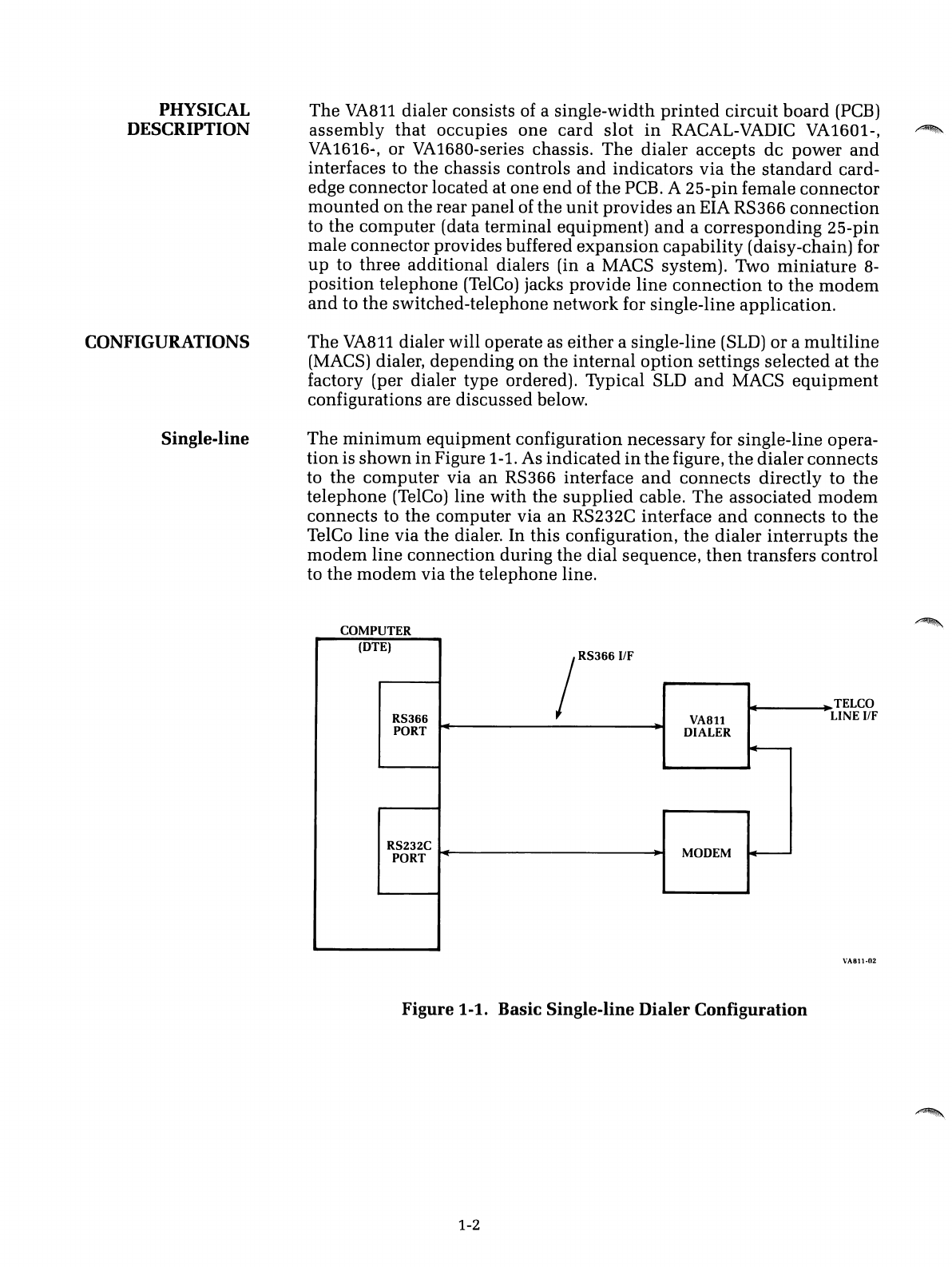
The
minimum
equipment
configuration
necessary
for single-line opera-
tion
is
shown
in
Figure 1-1. As
indicated
in
the
figure,
the
dialer
connects
to
the
computer
via
an
RS366 interface
and
connects
directly
to
the
telephone
(TelCo) line
with
the
supplied
cable.
The
associated
modem
connects
to
the
computer
via
an
RS232C interface
and
connects
to
the
TelCo
line
via
the
dialer. In
this
configuration,
the
dialer
interrupts
the
modem
line
connection
during
the
dial
sequence,
then
transfers
control
to
the
modem
via
the
telephone
line.
COMPUTER
(DTE)
jRS366I1F
RS366
VA8ll
PORT
DIALER
~
RS232C MODEM
~
PORT
......
TELCO
LINE IfF
VA811·02
Figure
1-1.
Basic Single-line
Dialer
Configuration
1-2
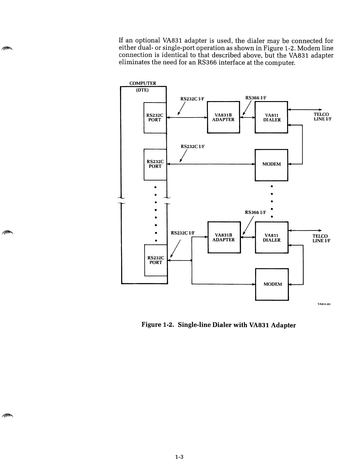
If
an
optional VA831 adapter is used,
the
dialer may be
connected
for
either dual- or single-port operation as
shown
in
Figure
1-2.
Modem
line
connection
is identical to that described above,
but
the
VA831 adapter
eliminates
the
need for an
RS366
interface at
the
computer.
COMPUTER
CO
E
IIF
(DTE)
RS232C IIF
RS366I/F
I!
RS232C VA831B
VA8ll
TEL
PORT
ADAPTER
~
DIALER LIN
~
RS232C IIF
RS232C IMODEM
0+---
PORT
••
••
-10...--
-v
CO
E
IIF
•
•
--...-
-I-'
••
RS3661/F
•/•
•-
•RS232C ifF VA831B
VA8ll
TEL
---+
~
•/ADAPTER DIALER LIN
~
RS232C
PORT
MODEM
4--
VA811·0J
Figure
1-2. Single-line
Dialer
with
VA831
Adapter
1-3
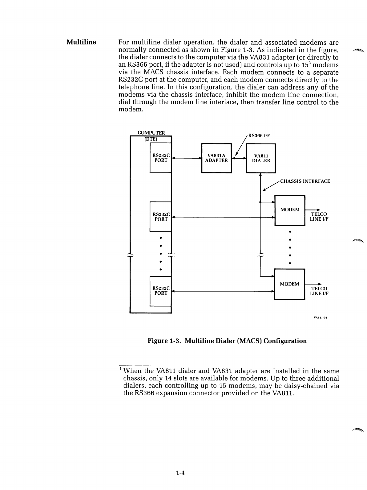
Multiline
For
multiline
dialer operation,
the
dialer
and
associated
modems
are
normally connected as
shown
in
Figure 1-3. As
indicated
in
the
figure,
the
dialer connects to the
computer
via
the
VA831
adapter
(or directly to
an
RS366 port, if the adapter is not used)
and
controls
up
to
15
1
modems
via
the
MACS chassis interface. Each
modem
connects
to aseparate
RS232C
port
at the computer,
and
each
modem
connects
directly to the
telephone
line. In this configuration,
the
dialer
can
address
any
of
the
modems
via the chassis interface,
inhibit
the
modem
line
connection,
dial through the modem line interface,
then
transfer
line
control to
the
modem.
ACE
CO
IfF
CO
IfF
•
RS366
IfF
COMPUTER
(DTE)
~
RS232C VA831A VA811
PORT
ADAPTER DIALER
/CHASSIS INTERF
~
MODEM
~
RS232C TEL
PORT
LINE
•
••
••
r-~
•
-I.,...-
-,--,
-~
-I'-"
-I'-'"
••
•----..
MODEM
--...
RS232C TEL
PORT
LINE
VA811-04
Figure 1-3. Multiline
Dialer
(MACS) Configuration
1
When
the
VA811
dialer
and
VA831
adapter
are
installed
in
the
same
chassis, only 14 slots are available for modems. Up to
three
additional
dialers, each controlling
up
to
15
modems,
may
be
daisy-chained
via
the RS366 expansion connector
provided
on
the
VA811.
1-4
,~
,~
'~
INTRODUCTION
OPTION
DESCRIPTIONS
Single-line/
Multiline
Options
Section 2
OPTIONS
The
VA811
dialer may be configured to
meet
the
needs
of a
particular
installation
by selecting
appropriate
hardware
options
on
the
printed
circuit
board
assembly.
Options
typically
changed
onsite
are imple-
mented
with
DIP switches
Al-A8
and
Bl-B8; less
commonly
changed
options
are
implemented
with
solder
straps
(jumpers) a-x.
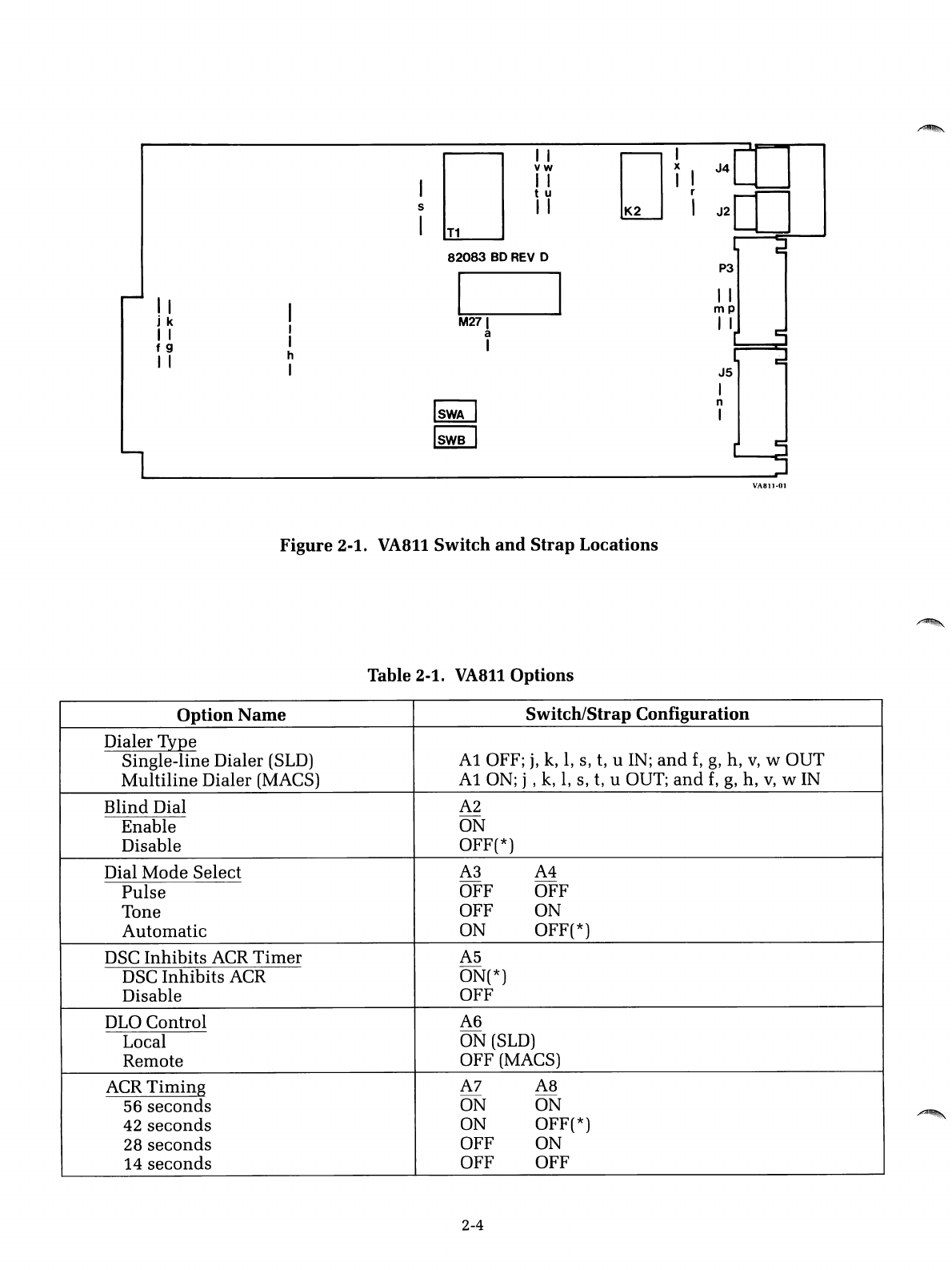
Figure
2-1
and
Table
2-1
at
the
end
of
this
section
indicate
the
location
and
function
of
switches
and
straps,
and
abrief
description
of
each
option
is
presented
below.
NOTE:
The
VA811
is configured for
"standard"
single-line
or
multiline
operation
when
shipped
from
the
factory, as
indicated
in
Table
2-1. Before installing
the
unit,
it
would
be
prudent
to
read
the
option
descriptions,
mark
Table 2-1
with
the
settings necessary
for
your
installation,
then
verify
the
switch
and
strap
settings
selected
on
the
board.
The
seemingly endless array of
switches
and
straps
used
on
the
VA811
can
be categorized by
function
into
three
basic groups:
•
Those
that
configure
the
dialer
for single-line (SLD) or
multiline
(MACS) operation.
•
Those
that
relate to
interconnecting
the
dialer
to
external
equipment.
•
Those
that
establish
the
operating
protocol of
the
dialer.
Each group of options is described below.
Dialer Type
(Al,
f,
g,
h, j,
k,
1,
s, t, u,
v,
w)-This
option
selects
either
single-line or
multiline
operation
as
indicated
in
Table 2-1.
Dialer
Address
(B7,
B8)-If
more
than
one
dialer
is
used
on
the
same
RS366 interface,
these
two
switches
provide
a
unique
address
for
each
dialer.
When
only
one dialer is
used,
the
switches
should
be
off, selecting
address
O.
2-1
Interconnect
Options
Operating
Protocol
Options
Signal Ground Reference
(p)-
This
option
connects signal
ground
(RS366 interface,
pin
7) to chassis ground
within
the
dialer if required
by the installation.
RS366A Interface (m,
n)-This
option configures
the
dialer for RS366A
connections.
If
enabled, interface pins 18
and
19 (Receive Common,
Send
Common) are connected to signal ground,
and
pin
1(Protective Ground)
is isolated from chassis ground
within
the
dialer.
If
disabled,
standard
RS366 connections are selected (Le.,
pin
1is
connected
to chassis ground
within
the
dialer
and
pins
18
and
19
are not connected).
PC/MIC Jumper
(r)-This
option allows
connection
of
PC
(Programming
Common) to
MIC
(Mode Indicator Common)
in
the
TelCo
line
interface.
This
option
is
used
in
single-line dialer
application
where
asingle
conductor is provided
in
the modem line interface cable for PC/MIC.
Applies only to
VA811S
versions.
Dial Mode Select
(A3,
A4)-This
option
provides
either
manual
or au-
tomatic selection of dial mode as follows:
•Pulse: Forces pulse dial only.
•Tone: Forces tone dial only.
•Automatic:
If
this position is selected,
the
dialer
will
tone
dial
the
first
digit
and
monitor dial tone.
If
dial tone
disappears
within
.5
second,
the dialer will tone dial the remaining digits; if dial tone is still
present
,~.
after
.5
second, the dialer will
pulse
dial
the
entire
number
instead.
Blind Dial
(A2)-
The
VA811
incorporates apositive dial-tone detector
and
normally inhibits the dial sequence
until
adial
tone
has
been
de-
tected. With this option enabled,
blind
dialing is
initiated
after CRQ (Call
Request) is ON for 5seconds,
independent
of dial tone.
Line Transfer Control
(B5,
B6)-This
option
determines
when
the
dialer
transfers control of the telephone line to
the
modem
(single-line dialer
version only). The three possibilities are:
•End-of-Number:
If
this setting is selected,
the
dialer transfers control
to the modem immediately after
the
last digit is dialed.
When
this
setting is used, the modem is responsible for detecting carrier
and
completing the line-connect protocol.
•Start-of-Answer Tone:
If
this
option
is selected,
the
dialer waits for
answer tone from the remote
modem
and
transfers control 1.5 seconds
after the beginning of answer tone is detected.
This
setting is
used
for
Bell 103-
and
212-type protocols,
where
MARK is
used
in
lieu
of a
separate answer-tone frequency.
•End-of-Answer Tone:
If
this setting is selected,
the
dialer waits for
answer tone
and
transfers control after
answer
tone is complete. (An-
swer tone duration must be at least 1.5 seconds.)
This
setting is
used
for all other modems except
the
Bell 103
and
212.
2-2
~.
/~
DLO Control
(A6)-DLO
(Data Line Occupied),
sent
to
the
computer
via
interface
pin
22, indicates
that
the
communication
channel
is busy.
If
the
local position is selected,
DLO
is
turned
ON
when
the
dialer
or
the
local
modem
is off hook (busy).
If
the
remote
position
is selected, DLO is
turned
ON
when
the called
number
is
busy
(Le., if a
busy
tone
is detected
by
the
dialer).
ACR
Select (Bl, B2,
B3)-ACR
(Abandon Call
and
Retry),
sent
to
the
computer
via interface
pin
3, suggests
that
the
call
attempt
be
aborted
and
retried at alater time. This
option
allows
user
selection
of
the
conditions
that generate
ACR.
Since
the
switches
operate
independently,
the
dialer may be
commanded
to
turn
on
ACR
under
any
or
all of
the
following conditions:
•If
an
invalid digit is dialed
•
If
a
busy
tone is detected
•
If
the
local
modem
is
busy
ACR
Timing
(A7,
A8)-
To
avoid
inordinately
long waiting
periods
on
calls,
the
VA811
incorporates a
timer
that
turns
on
ACR at
the
end
of the
selected delay period (see Table 2-1).
The
timer
is
started
each
time
CRQ
(Call Request) is
turned
ON
and
reset
each
time
PND (Present Next Digit)
is
turned
OFF.
DSC Inhibits
ACR
Timer
(A5)-DSC
2(Distant
Station
Connected), re-
turned
to
the
computer
via interface
pin
13,
indicates
that
the
dialer
has
completed
the
call
and
transferred control to
the
modem.
If
this
option
is enabled,
the
ACR
timer
is
stopped
when
DSC is
turned
on.
If
disabled,
the
ACR
timer
will
continue
to
run
(and
time
out) after control has
been
transferred to
the
modem. (The latter setting is
useful
when
the
Line
Transfer Control option is set to
End
of Number.)
Teletype Interface
(B4)-
This
option
allows
the
dialer
to be
used
for
teletype (TWX) operation.
Must
be
disabled
for
switched-network
(DDD)
operation.
2
This
signal is also identified as DDS (Data Set Status) or COS (Call
Origination Status)
in
certain RS366
documents.
2-3
II
jk
II
f9
I I
I
I
I
h
I
I
5
I
I I
vw
II
tu
II
T1
82083
BO
REV
0
I~
M271
a
I
DI
iI
J4
-------.L---~
I
J2[1]
J5
I
n
I
VA811·01
Figure
2-1.
VA811
Switch
and
Strap
Locations
Table 2-1.
VA8l10ptions
Option
Name
Switch/Strap
Configuration
Dialer Type
Single-line Dialer (SLD)
Ai
OFF;
j,
k,
1,
s, t, uIN;
and
f,
g,
h,
v,
w
OUT
Multiline
Dialer (MACS)
Ai
ON; j , k,
1,
s, t, uOUT;
and
f,
g,
h,
v,
WIN
Blind
Dial
A2
Enable ON
Disable OFF(*)
Dial
Mode
Select
A3
A4
Pulse
OFF OFF
Tone OFF ON
Automatic
ON OFF(*)
DSC
Inhibits
ACR
Timer
A5
DSC
Inhibits
ACR ON(*)
Disable OFF
DLO
Control
A6
Local ON
(SLD)
Remote OFF (MACS)
ACR
Timing
A7
A8
56
seconds
ON ON
42
seconds
ON OFF(*)
28
seconds
OFF ON
14
seconds
OFF OFF
2-4
/~
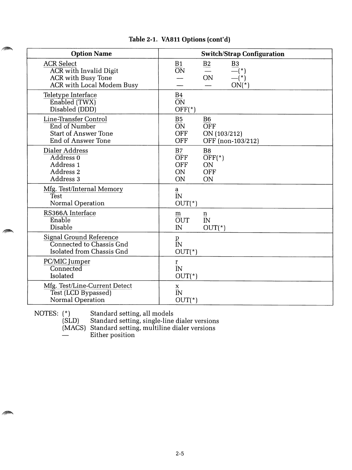
Table 2-1. VA811
Options
(cont'd)
Option
Name
Switch/Strap
Configuration
ACR
Select
Bl
B2 B3
-
ACR
with
Invalid
Digit
ON
-
-(*)
ACR
with
Busy
Tone
-
ON
-(*)
ACR
with
Local
Modem
Busy
--ON(*)
Teletype
Interface
B4
Enabled
(TWX)
ON
Disabled
(DDD) OFF(*)
Line-Transfer
Control
B5
B6
End
of
Number
ON
OFF
Start
of
Answer
Tone
OFF
ON
(103/212)
End
of
Answer
Tone
OFF
OFF
(non-l03/212)
Dialer
Address
B7
B8
Address
0
OFF
OFF(*)
Address
1
OFF
ON
Address
2
ON
OFF
Address
3
ON
ON
Mfg.
Test/Internal
Memory
a
Test IN
Normal
Operation
OUT(*)
RS366A
Interface
ill
n
Enable
OUT
IN
Disable
IN OUT(*)
Signal
Ground
Reference
p
Connected
to
Chassis
Gnd
IN
Isolated
from
Chassis
Gnd
OUT(*)
PC/MIC
Jumper
r
Connected
IN
Isolated
OUT(*)
Mfg.
Test/Line-Current
Detect
x
Test (LCD
Bypassed)
IN
Normal
Operation
OUT(*)
NOTES: (*)
Standard
setting,
all
models
(SLD)
Standard
setting,
single-line
dialer
versions
(MACS)
Standard
setting,
multiline
dialer
versions
Either
position
2-5

/~
\
i~
J
,,~
INTRODUCTION
PRELIMINARY
PROCEDURES
Unpacking
And Inspection
Section 3
INSTALLATION
This
section provides installation
procedures
for
the
VA811
dialer. In
case of difficulty during any of
the
following
procedures,
contact
the
nearest
RACAL-VADIC
Regional Service Center
listed
at
the
front of this
manual.
~: ~: ~:
~:~:
~:
~:~:
~:
~:
~:~:~:
~:
~: ~:
~: ~:
·CAlifi
ON
::
~:
~
:~:~:
~:~:
~
:~:~:
~:~:
~:
~:~:~:~:~:
....................................................
Procedures
in
this
section
should
be performed
in
the
sequence
and
manner
prescribed.
Any
devia-
tion may damage
the
equipment.
Inspect
the
shipping
carton
immediately
upon
receipt.
If
the
carton
has
been
damaged, request
that
the
carrier's agent be
present
during
unpack-
ing. Inspect contents for physical damage
and/or
missing parts.
If
the
contents have been damaged or parts are missing,
immediately
notify the
nearest
RACAL-VADIC
sales office.
3-1
Equipment
Supplied
Additional
Equipment
Required
Preinstallation
Checks
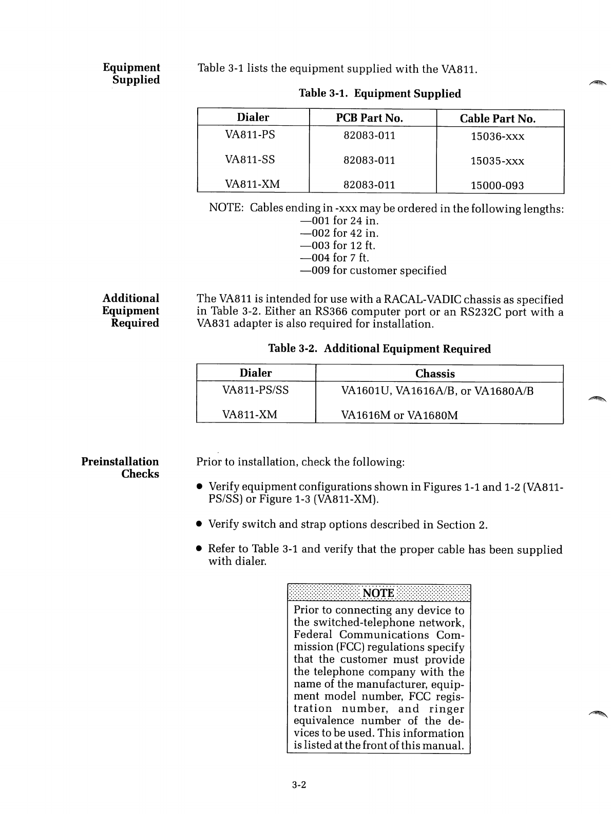
Table
3-1
lists the
equipment
supplied
with
the
VA811.
Table 3-1.
Equipment
Supplied
Dialer
PCB
Part
No. Cable
Part
No.
VA811-PS 82083-011 15036-xxx
VA811-SS 82083-011 15035-xxx
VA811-XM 82083-011 15000-093
NOTOE:
Cables
ending
in
-xxx may be
ordered
in
the
following lengths:
-001
for 24 in.
-002
for 42 in.
-003
for 12
ft.
-004
for 7
ft.
-009
for
customer
specified
The
VA811
is
intended
for use
with
aRACAL-VADIC chassis as
specified
in
Table 3-2. Either
an
RS366
computer
port
or
an
RS232C
port
with
a
VA831
adapter
is also required for installation.
Table 3-2.
Additional
Equipment
Required
Dialer Chassis
VA811-PSISS
VA1601U,
VA1616A/B,
or
VA1680A/B
VA811-XM VA1616M or VA1680M
Prior to installation, check the following:
•Verify
equipment
configurations
shown
in
Figures 1-1
and
1-2 (VA811-
PS/SS) or Figure 1-3 (VA811-XM).
•Verify
switch
and
strap options described
in
Section
2.
•Refer to Table
3-1
and
verify
that
the
proper
cable
has
been
supplied
with
dialer.
.,.
..
.....
.
-.
~
:
~
:
~
:
~
:
~
:
~
:
~
:
~
:
~
:
~
:
~
:
~
:
~
:
~
:
~
:
~
:
~
:
~
:
~
:
~
:
~
.N
O'TE
~:
~
:
~
:
~
:
~
:
~
:
~
:
~
:
~
:
~
:
~
:
~
:
~
:
~
:
~
:
~
:
~
:
~
:
~
:
~
:
~
:
....................................................
Prior to connecting
any
device to
the
switched-telephone
network,
Federal
Communications
Com-
mission
(FCC)
regulations
specify
that
the
customer
must
provide
the
telephone
company
with
the
name of the manufacturer,
equip-
ment
model number, FCC regis-
tration
number,
and
ringer
equivalence
number
of
the
de-
vices to be used.
This
information
is listed at
the
front of
this
manual.
3-2
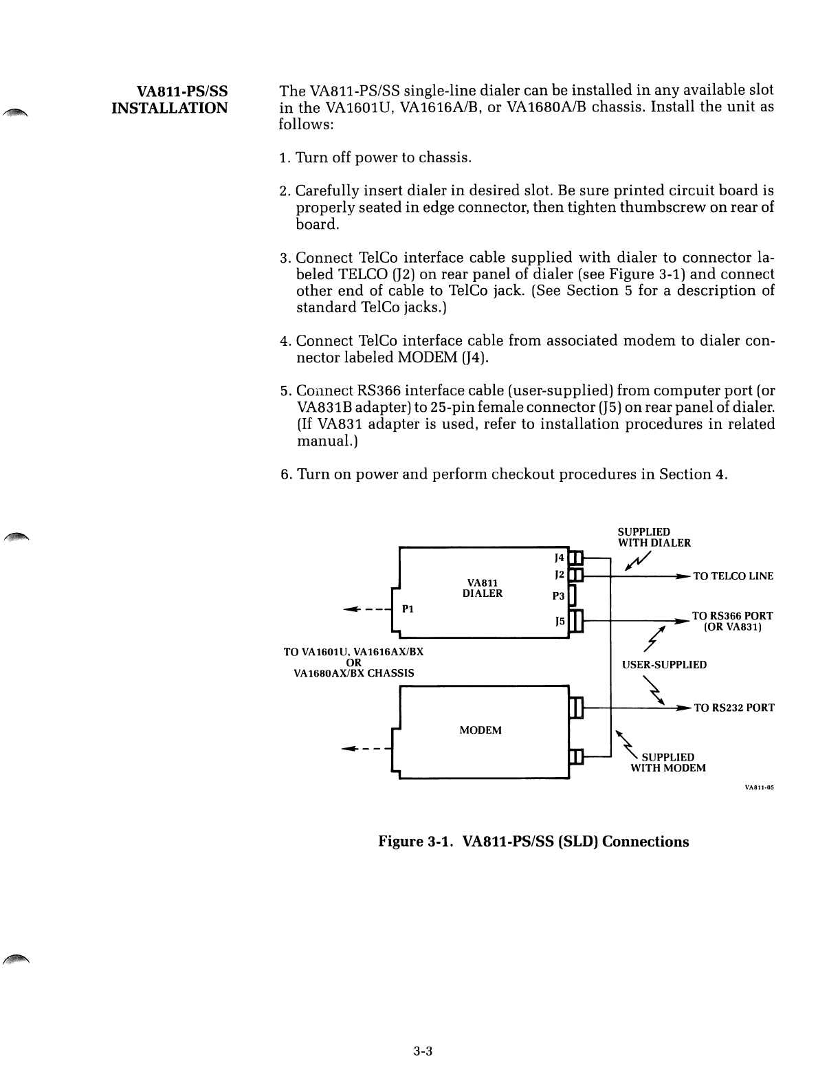
VA811-PS/SS
INSTALLATION
The
VA811-PSISS single-line dialer
can
be
installed
in
any
available slot
in
the
VA1601U,
VA1616A/B,
or
VA1680A/B
chassis. Install
the
unit
as
follows:
1. Turn off power to chassis.
2. Carefully
insert
dialer
in
desired
slot. Be
sure
printed
circuit
board
is
properly
seated
in
edge connector,
then
tighten
thumbscrew
on
rear of
board.
3. Connect TelCo interface cable
supplied
with
dialer
to
connector
la-
beled TELCO
(J2)
on
rear
panel
of
dialer
(see Figure 3-1)
and
connect
other
end
of cable to TelCo jack. (See Section 5for a
description
of
standard
TelCo jacks.)
4. Connect TelCo interface cable from associated
modem
to dialer con-
nector labeled MODEM
(J4).
5.
COllnect RS366 interface cable (user-supplied) from
computer
port
(or
VA831B adapter) to 25-pinfemale
connector
(J5)
on
rear
panel
of dialer.
(If
VA831
adapter
is used, refer to
installation
procedures
in
related
manual.)
6. Turn
on
power
and
perform
checkout
procedures
in
Section
4.
SUPPLIED
WITH
DIALER
/
\
SUPPLIED
WITH
MODEM
......-........
---~
TO
TELCO LINE
/
USER-SUPPLIED
......----+---\-~~
TO
RS232
PORT
......----+-
~TO
RS366
PORT
(OR
VA83l)
'5
}4
}2
P3
VA8ll
DIALER
MODEM
~--
Pl
~--
TO
VA1601U, VA16l6AX/BX
OR
VA1680AX/BX
CHASSIS
VASll-0S
Figure
3-1.
VA811-PS/SS
(SLD)
Connections
3-3
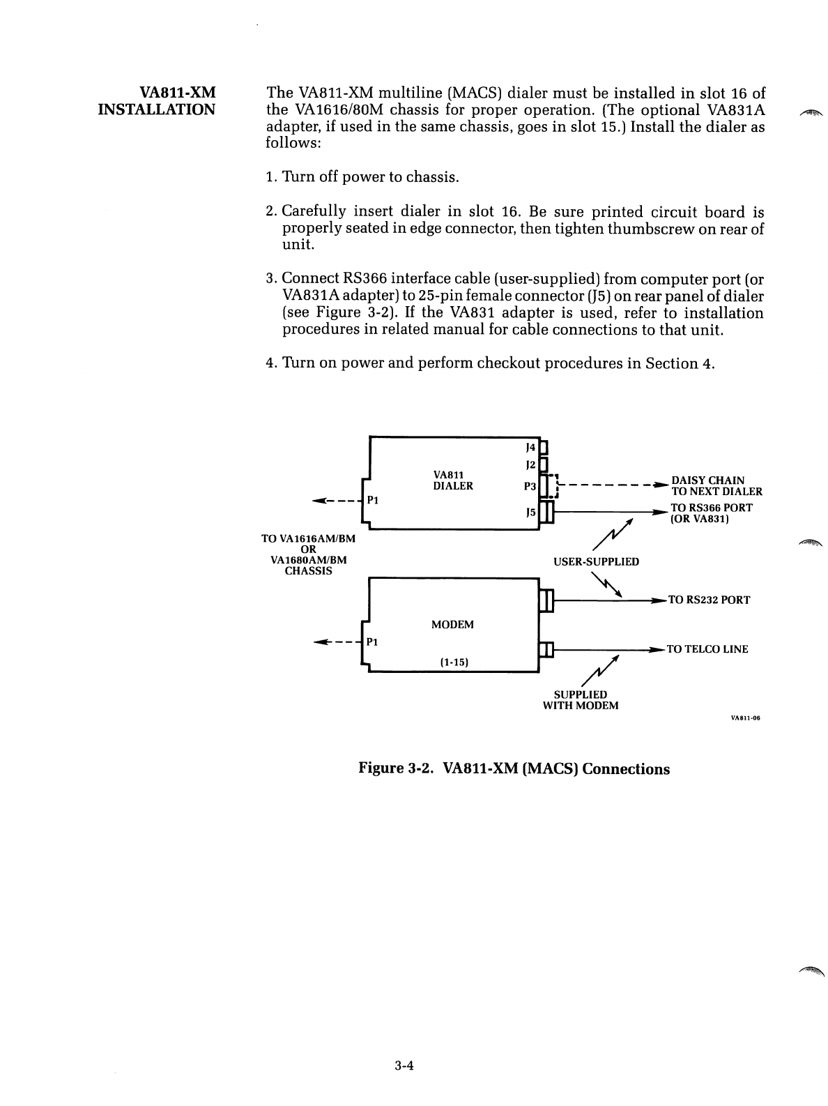
VA811-XM
INSTALLATION
The
VA811-XM
multiline
(MACS) dialer
must
be
installed
in
slot
16 of
the
VA1616/80M
chassis for
proper
operation.
(The
optional
VA831A
adapter, if
used
in
the
same chassis, goes
in
slot
15.)
Install
the
dialer
as
follows:
1.
Turn
off
power
to chassis.
2.
Carefully
insert
dialer
in
slot 16. Be
sure
printed
circuit
board
is
properly
seated
in
edge connector,
then
tighten
thumbscrew
on
rear
of
unit.
3.
Connect
RS366 interface cable (user-supplied) from
computer
port
(or
VA831A adapter) to 25-pinfemale
connector
(J5)
on
rear
panel
of
dialer
(see Figure 3-2).
If
the
VA831
adapter
is
used,
refer
to
installation
procedures
in
related
manual
for cable
connections
to
that
unit.
4.
Turn
on
power
and
perform
checkout
procedures
in
Section
4.
/
~----~TO
TELCO LINE
/
USER-SUPPLIED
.......---~---~TO
RS232 PORT
'5
'4
'2
LDAISY CHAIN
P3 .J - - - - - -
-~TO
NEXT DIALER
........
..
TO RS366 PORT
(OR VA831)
(1-15)
VA811
DIALER
MODEM
~---
P1
TO
VA1616AM/BM
OR
VA1680AM/BM
CHASSIS
SUPPLIED
WITH MODEM
VA811·06
Figure
3-2. VA811-XM (MACS)
Connections
3-4
INTRODUCTION
Section 4
CHECKOUT AND OPERATION
This
section introduces the character
set
used
by
the
VA8ll,
describes
the controls
and
indicators available
on
the
associated chassis,
and
pre-
sents operational checkout procedures for
the
dialer. Abasic knowledge
of RS366 interface operation is assumed. Readers
unfamiliar
with
this
interface are encouraged to read Section 5before proceeding.
4-1
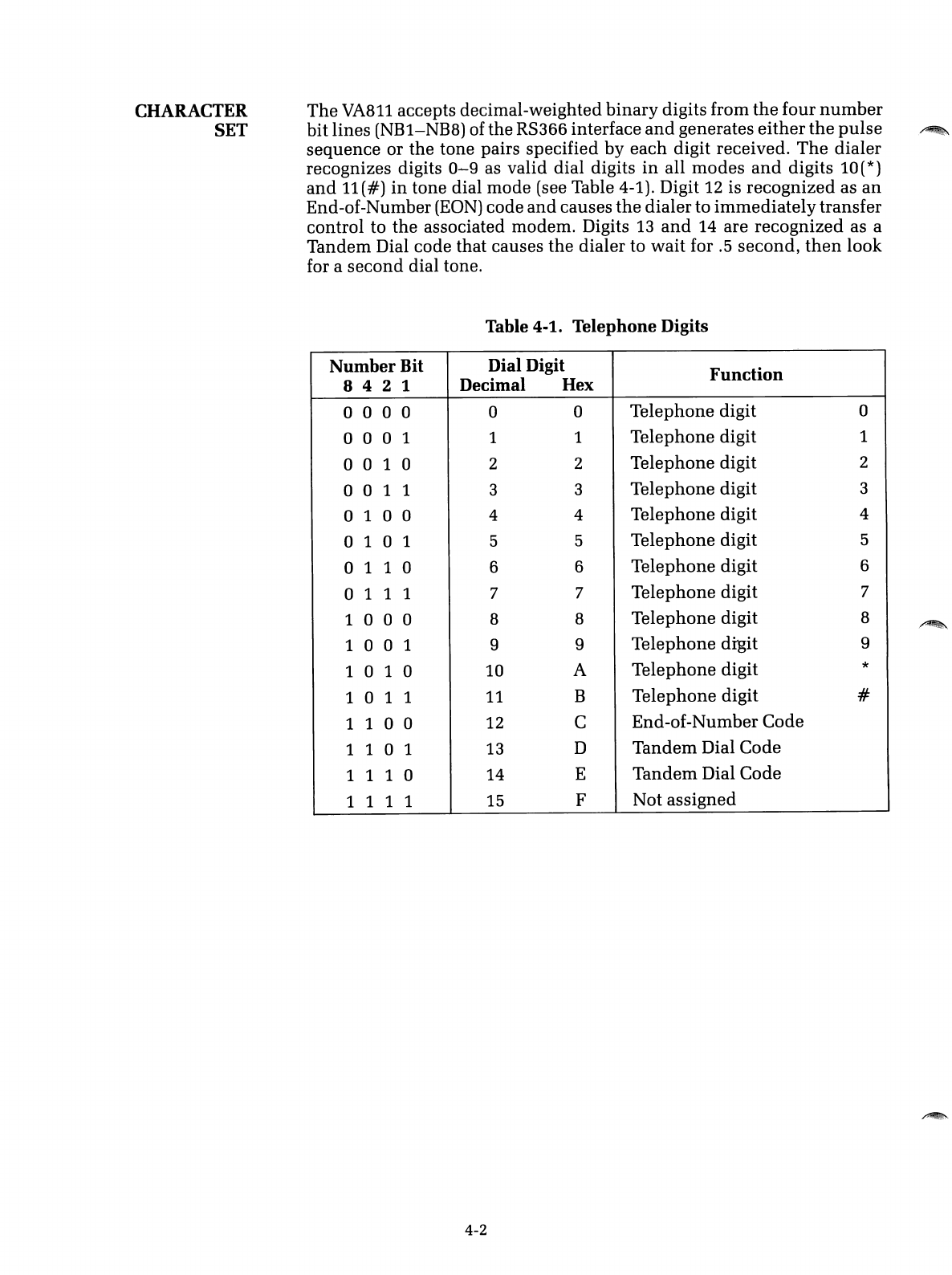
CHARACTER
SET
The
VA811 accepts decimal-weighted
binary
digits from
the
four
number
bit lines
(NB1-NB8)
of the
RS366
interface
and
generates
either
the
pulse
sequence or the tone pairs specified by each digit received.
The
dialer
recognizes digits 0
.....
9as valid dial digits
in
all modes
and
digits
10(*)
and
11(#)
in
tone dial mode (see Table 4-1). Digit 12 is recognized as
an
End-of-Number
(EON)
code
and
causes
the
dialer to
immediately
transfer
control to the associated modem. Digits 13
and
14 are recognized as a
Tandem Dial code that causes the dialer to wait for .5 second,
then
look
for asecond dial tone.
Table 4-1. Telephone Digits
Number
Bit Dial Digit
Function
842
1Decimal Hex
o0 0 0 0 0 Telephone digit 0
o0 0 1 1 1Telephone digit 1
o0 1 0 2 2 Telephone digit 2
001
13 3 Telephone digit 3
o1 0 0 4 4Telephone digit 4
o1 0 1 5 5 Telephone digit 5
o1 1 0 66Telephone digit 6
o1 1 1 7 7 Telephone digit 7
1
000
88Telephone digit 8
1
001
9 9 Telephone digit 9
1 0 1 0
10
ATelephone digit *
101
111 BTelephone digit #
1
100
12 CEnd-of-Number Code
1
101
13 DTandem Dial Code
1 1 1 0
14
ETandem Dial Code
1
111
15 FNot assigned
4-2
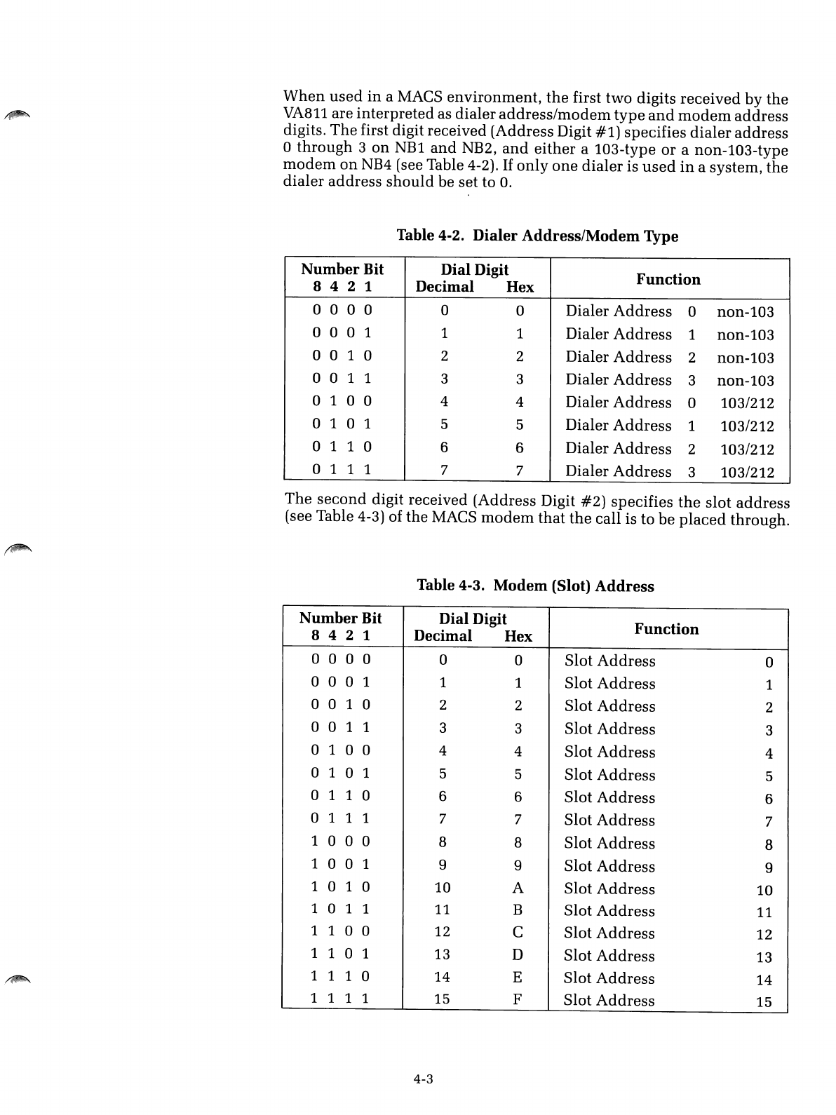
When
used
in
aMACS
environment,
the
first
two
digits
received
by
the
VA811
are
interpreted
as
dialer
address/modem
type
and
modem
address
digits.
The
first digit received (Address Digit
#1)
specifies
dialer
address
o
through
3
on
NBl
and
NB2,
and
either
a103-type
or
anon-103-type
modem
on
NB4 (see Table 4-2).
If
only
one
dialer
is
used
in
asystem,
the
dialer
address
should
be set to
O.
Table 4-2.
Dialer
Address/Modem
Type
Number
Bit Dial Digit
Function
842
1Decimal Hex
o0 0 0 0 0 Dialer
Address
0non-103
000
11 1 Dialer
Address
1non-103
o0 1 0 2 2 Dialer
Address
2non-103
001
133Dialer
Address
3
non-l03
o1 0 0 4 4Dialer
Address
0103/212
o1 0 1 5 5 Dialer
Address
1103/212
o1 1 0 66Dialer
Address
2103/212
o1 1 1 77Dialer
Address
3103/212
The
second
digit received (Address Digit
#2)
specifies
the
slot
address
(see Table 4-3) of the MACS
modem
that
the
call is
to
be
placed
through.
Table
4-3.
Modem
(Slot)
Address
Number
Bit Dial Digit
Function
842
1Decimal Hex
o0 0 0 0 0 Slot
Address
0
000
1 1 1 Slot
Address
1
001
022Slot
Address
2
001
133Slot
Address
3
o1 0 0 44Slot
Address
4
o1 0 1 55Slot
Address
5
o1 1 0 66Slot
Address
6
o1 1 1 77Slot
Address
7
1
000
88Slot
Address
8
100
199Slot
Address
9
1 0 1 0 10 A
Slot
Address
10
101
1
11
BSlot
Address
11
1
100
12 CSlot
Address
12
1
101
13 D
Slot
Address
13
1 1 1 0 14 ESlot
Address
14
1111 15 FSlot
Address
15
4-3
EXAMPLE
CALLS
The following hexidecimal digit strings represent calls to (408) 744-0810
under
various conditions.
•Single-line dialer:
4087440810
4087440810C
9D4087440810
•MACS dialer:
474087440810
474087440810C
479D4087440810C
Immediate transfer to
modem
(EON code)
Tandem dial through local (9-level) exchange
Dialer address
0,
103-type modem,
modem
address 7
Same as above
with
immediate transfer to
modem (EON code)
Same as above
with
tandem
dial throughlocal
(9-level) exchange
CONTROLS
AND
INDICATORS
The
VA811
interfaces to the chassis display
and
control bus
through
card-
edge connector
Pl.
When the dialer card slot is
addressed
from
the
front
panel, the chassis diagnostic indicators display
the
significant interface
signals
used
by the dialer. Figure
4-1
shows
the
diagnostic indicators
used
on
RACAL-VADIC
chassis. The
upper
legend
in
the
figure shows
the standard indicator functions as labeled
on
the
front panel;
the
lower
legend identifies the indicator functions displayed
when
the
adapter
is
selected'. Table 4-4 identifies the function of each control
and
indicator.
4-4
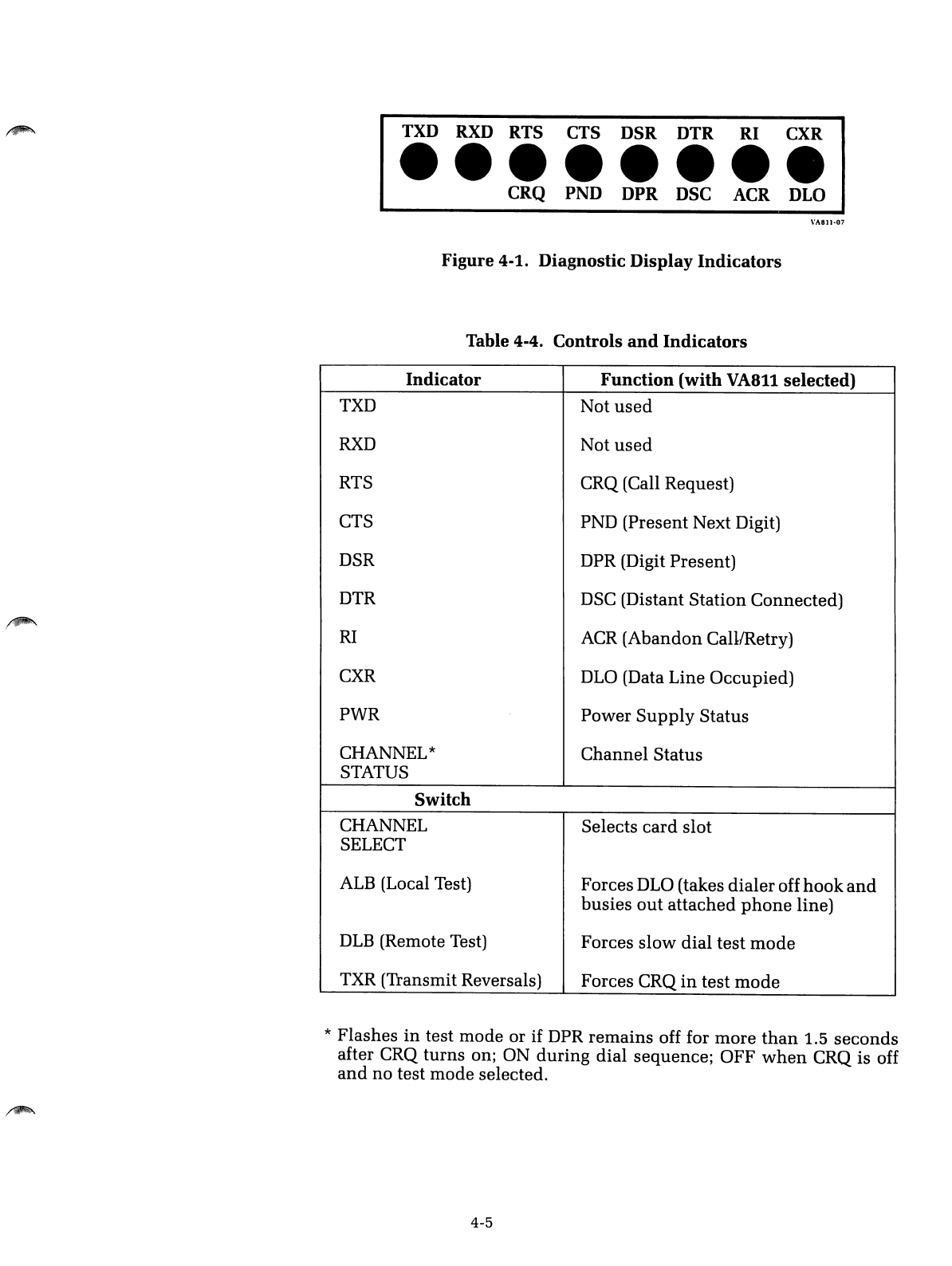
TXD RXD RTS CTS DSR DTR RI CXR
••••••••
CRQ PND DPR DSC ACR DLO
\'1\811-07
Figure
4-1.
Diagnostic Display
Indicators
Table
4-4.
Controls
and
Indicators
Indicator
Function
(with
VA8ll
selected)
TXD Not
used
RXD
Not
used
RTS CRQ (Call Request)
CTS PND
(Present
Next
Digit)
DSR DPR (Digit
Present)
DTR DSC (Distant
Station
Connected)
RI
ACR
(Abandon
Call1Retry)
CXR DLO (Data
Line
Occupied)
PWR
Power
Supply
Status
CHANNEL*
Channel
Status
STATUS
Switch
CHANNEL Selects
card
slot
SELECT
ALB (Local Test) Forces DLO (takes
dialer
off
hook
and
busies
out
attached
phone
line)
DLB
(Remote Test) Forces
slow
dial
test
mode
TXR (Transmit Reversals) Forces CRQ
in
test
mode
*
Flashes
in
test
mode
or if DPR
remains
off for
more
than
1.5
seconds
after CRQ
turns
on; ON
during
dial
sequence;
OFF
when
CRQ is off
and
no
test
mode
selected.
4-5
OPERATIONAL
CHECKOUT
VA811-PS/SS
The
following procedures verify
the
operational integrity of
the
VA811.
The
first set of procedures applies to single-line
dialer
(VA811-PS/SS)
installations,
the
second set to MACS (VA811-XM) installations.
To
check operation of the
VA811
in
asingle-line
environment,
perform
the
following steps:
1.
Select dialer (slot) address
with
CHANNEL SELECT
switch
on
front of
chassis.
2. Set ALB/OFF switch to
ALB
and
verify
that
DLO(CXR)
indicator
illu-
minates. (This takes the dialer off
hook
and
busies
out
the
telephone
line attached to the dialer.) Return ALB/OFF
switch
to OFF.
3. Set TXR/OFF switch to TXR
and
verify
that
CRQ(RTS)
and
DLO(CXR)
indicators illuminate. Verify that PND(CTS)
indicator
illuminates
after
abrief delay, indicating that dial tone detector is operating properly.
Return TXR/OFF switch to OFF.
4. Set TXR/OFF to
TXR
once again
and
monitor
delay interval
between
CRQ(RTS) turn-on
and
ACR(RI) turn-on. Verify
that
delay
corresponds
to
ACR
timing selected
in
Table 2-1. Return TXR/OFF
switch
to OFF.
5. Set DLB/OFF switch to
DLB.
Initiate call from
computer
and
verify
the
following sequence
with
chassis display indicators:
a.
CRQ(RTS)
turns
ON (call request from computer).
b.
PND(CTS)
turns
ON (dial tone detected).
c.
DPR(DSR)
turns
ON (digit
present
from computer).
d.
PND(CTS)
turns
OFF after being
on
for 1second.
e.
DPR(DSR)
turns
OFF also.
f.
PND(CTS) remains OFF for 1second,
then
turns
ON.
g.
Steps
c,
d,
e,
and
frepeat
until
all digits have
been
dialed.
6. Set DLB/OFF switch to OFF to terminate test.
4-6
/~.
VA811-XM To
check
operation
of
the
VA811
in
a
multiline
(MACS)
installation,
perform
the
following
steps:
1.
Select
dialer
(slot)
address
with
CHANNEL
SELECT
switch
on
front
of
chassis.
2.
Set
TXR/OFF
switch
to TXR
and
verify
that
CRQ(RTS)
and
PND(CTS)
indicators
illuminate.
Return
TXR/OFF
switch
to
OFF.
3.
Set
TXR/OFF to TXR
once
again
and
monitor
delay
interval
between
CRQ(RTS)
turn-on
and
ACR(RI)
turn-on.
Verify
that
delay
corresponds
to ACR
timing
selected
in
Table 2-1.
Return
TXR/OFF
switch
to
OFF.
4.
Set
ALB/OFF
switch
to
ALB.
Send
dialer
address/modem
type
and
modem
address
digits
to
dialer
and
verify
that
DLO
indicator
illumi-
nates.
(If
only
one
dialer
is
used
in
the
system
and
a
MACS
modem
is
installed
in
the
first
card
slot,
the
address
digits
can
be
0,0.)
If
this
test
fails,
verify
that
dialer
address/modem
type
digit
corresponds
to
the
Dialer
Address
selected
in
Table 2-1.
5.
Set
DLB/OFF
switch
to DLB.
Initiate
a
call
from
the
computer
and
verify
the
following
sequence
of
events
with
the
chassis
display
indicators.
a. CRQ(RTS)
turns
ON
(call
request
from
computer).
b. PND(CTS)
turns
ON
(dial
tone
detected).
c. DPR(DSR)
turns
ON
(digit
present
from
computer).
d. PND(CTS)
turns
OFF
after
being
on
for 1
second.
e. DPR (DSR)
turns
OFF
also.
£.
PND(CTS)
remains
OFF
for 1
second,
then
turns
ON.
g.
Steps
c, d, e,
and
f
repeat
until
all
digits
have
been
dialed.
6.
Set
DLB/OFF
switch
to
OFF
to
terminate
test.
4-7

/~
, I
,~.
INTRODUCTION
EQUIPMENT
INTERFACES
Section 5
SUPPLEMENTAL INFORMATION
This
section
describes the
hardware
interfaces
used
by
the
VA8ll
and
briefly discusses the operational characteristics of
the
dialer
in
both
a
single-line
and
multiline
environment.
Except
where
noted,
the
follow-
ing information applies to
both
the
VA8li-PS/SS (single-line)
and
VA8ii-
XM
(multiline) dialer.
The
VA8ll
contains four connectors (J2,
J4,
J5,
and
P3)
mounted
on
the
rear
panel
of
the
unit
and
acard-edge
connector
(Pi)
at
the
opposite
end
of
the
printed
circuit
board
(PCB).
These
connectors
are
used
as follows:
J2-
This
8-position
miniature
connector
(labeled TELCO)
provides
di-
rect
connection
to
the
TelCo
line
in
single-line
dialer
(VA8ii-PS/SS)
installations. The line interface cable
supplied
with
the
VA8il-PS/SS
connects between the TelCo-supplied jack
and
this
connector. Not
used
for
multiline
(MACS) operation.
J4-
This
8-position
miniature
connector
(labeled MODEM)
provides
a
loop-through connection to
the
TelCo
line
for
the
associated
modem
in
single-line dialer installations.
The
line
interface cable
supplied
with
the
modem
connects to this jack. Not
used
for
multiline
(MACS)
operation.
J5-
This
25-pin female
connector
provides
an
RS366 interface to
the
.
computer
equipment
(or VA831 adapter, if used)
in
both
single-line
and
multiline
installations.
When
the
VA83i is
not
used,
the
user-
supplied
cable from
an
RS366
port
connects
to
this
jack.
When
the
VA831
is used,
the
RS366 cable from P3
on
the
adapter
connects
to
this jack (see VA83i installation/operation manual).
P3-This
25-pin male connector
provides
buffered RS366
expansion
capability (daisy-chain) for
multiline
dialer
installations
using
two,
three, or four dialers
on
the
same
RS366 interface.
Where
applicable,
the
expansion
cable
provided
with
the
VA8ii-XM
connects
between
this jack
and
J5
on
the
next dialer. Not
used
for single-line operation.
Pi-This
36-pin (dual-sided 18-pin) edge
connector
provides
an
interface
to
the
display
and
control
bus
used
in
RACAL-VADIC chassis.
5-1
LINE INTERFACE
Introduction
When
ordered for single-line operation,
the
VA8ll
is
supplied
with
a
telephone interface cable terminated at
both
ends
with
miniature
tele-
phone
connectors. One
end
of the cable connects to
J2
on
the
dialer
and
the other
end
of the cable mates
with
standard
jacks
supplied
by
the
telephone company. The cable establishes apermissive (VA8ll-PS) or a
programmable (VA8ll-SS) direct connection to
the
switched-telephone
network, as defined by Part
68
of the
FCC
Rules
and
Regulations.
The VA8ll-PS,
supplied
with
acable
terminated
in
a6-position minia-
ture
connector, is registered for permissive direct connection. This ver-
sion of
the
dialer may be connected to a
standard
RJllC
voice jack (the
type normally
used
by the telephone
company
for
standard
home
or
office phones). Optionally, the VA811-PS may be
connected
to either
an
RJ41S or RJ45S data jack.
The VA8ll-SS,
supplied
with
acable
terminated
in
a8-position minia-
ture connector, is registered only for programmable direct connection.
This version of the dialer requires an RJ41S or RJ45S data jack.
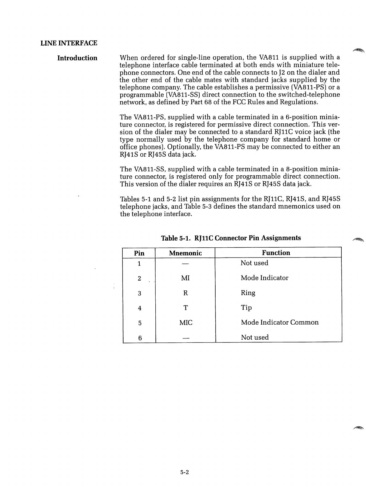
Tables
5-1
and
5-2
list
pin
assignments for
the
RJllC,
RJ41S,
and
RJ45S
telephone jacks,
and
Table
5-3
defines
the
standard
mnemonics
used
on
the telephone interface.
Table 5-1.
RJllC
Connector
Pin
Assignments
Pin
Mnemonic
Function
1-Not
used
2
MI
Mode Indicator
,.
3RRing
4T
Tip
5
MIC
Mode Indicator
Common
6-Not
used
5-2
.~.
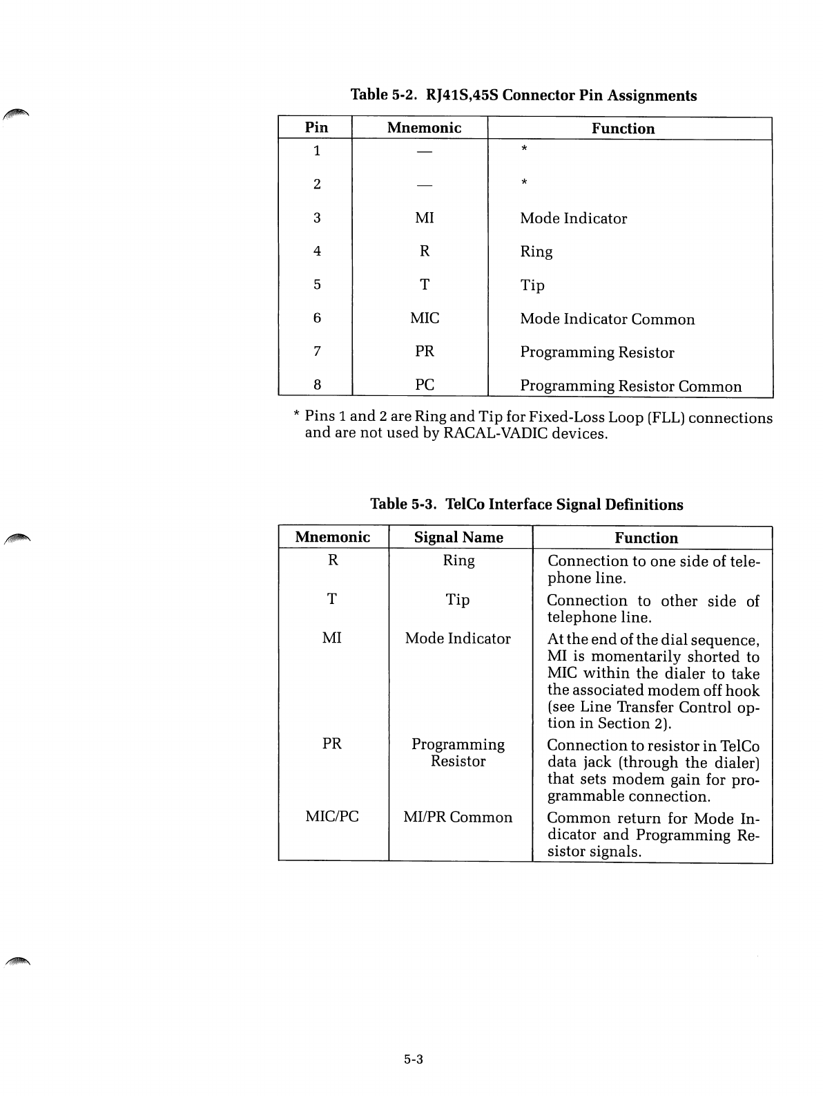
Table 5-2. RJ41S,45S Connector
Pin
Assignments
Pin
Mnemonic
Function
1-*
2-*
3
MI
Mode Indicator
4RRing
5T
Tip
6
MIC
Mode
Indicator
Common
7PR Programming Resistor
8
PC
Programming Resistor
Common
*Pins 1
and
2are Ring
and
Tip
for Fixed-Loss Loop
(FLL)
connections
and
are not
used
by RACAL-VADIC devices.
Table 5-3. TelCo
Interface
Signal
Definitions
Mnemonic
Signal
Name
Function
RRing
Connection
to
one
side
of tele-
phone
line.
T
Tip
Connection
to
other
side
of
telephone
line.
MI
Mode Indicator At
the
end
of
the
dial
sequence,
MI is
momentarily
shorted
to
MIC
within
the
dialer
to take
the
associated
modem
off
hook
(see Line Transfer Control op-
tion
in
Section 2).
PR Programming
Connection
to resistor
in
TelCo
Resistor data jack (through
the
dialer)
that
sets
modem
gain for pro-
grammable
connection.
MIC/PC MI/PR Common
Common
return
for
Mode
In-
dicator
and
Programming Re-
sistor signals.
5-3
RS366 INTERFACE
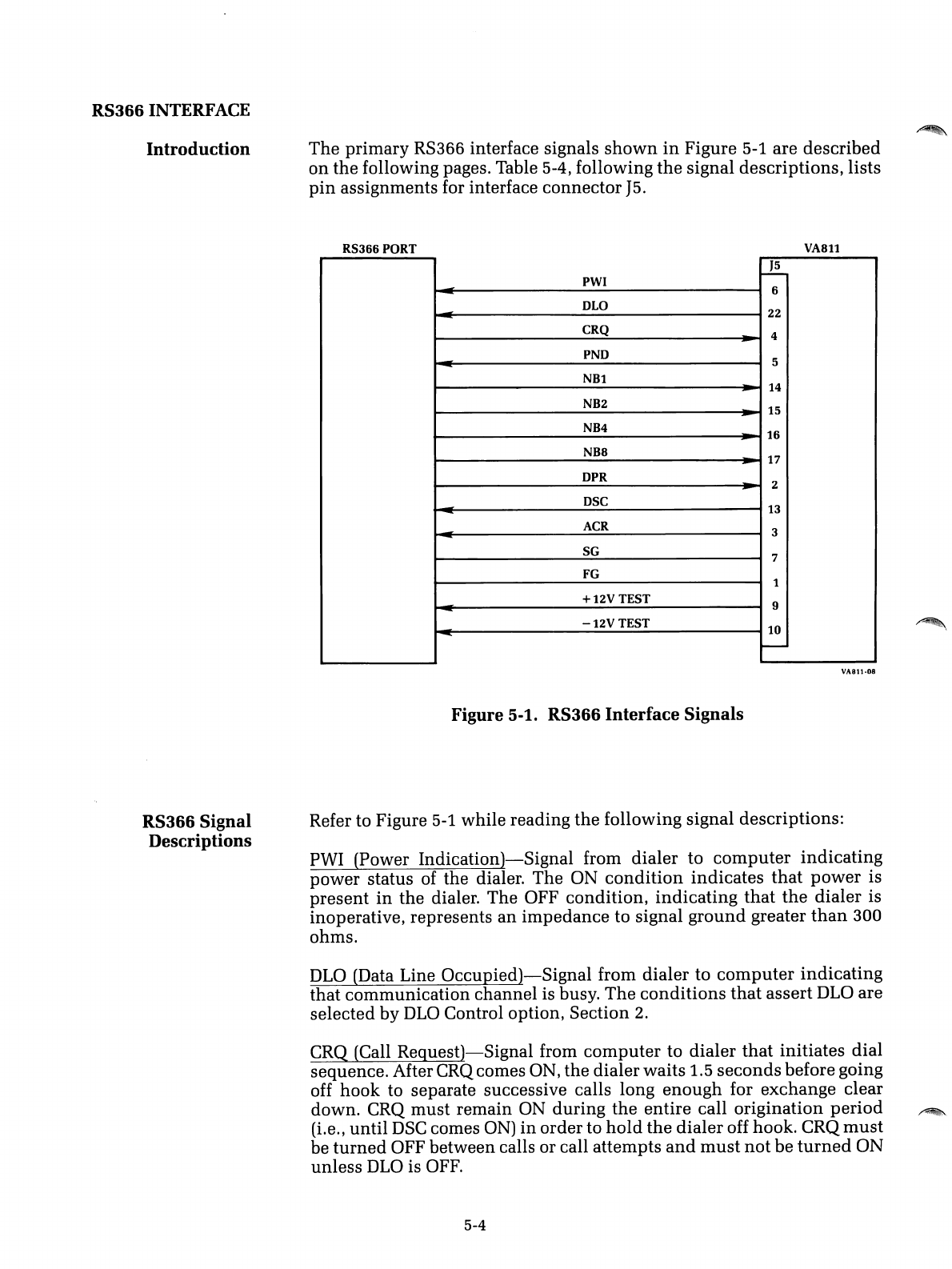
Introduction
The
primary RS366 interface signals
shown
in
Figure 5-1 are described
on
the following pages. Table 5-4, following
the
signal descriptions, lists
pin
assignments for interface connector
J5.
RS366 PORT
J5
PWI
I--i--o
=6
~
OLO 22
CRQ
~
4
-=
PNO 5
NB1
~
14
NB2 15
~
NB4 16
-
NB8 17
-
OPR 2
~
OSC 13
-ACR 3
-SG 7
FG 1
+12V
TEST 9
-
.::
-12V
TEST 10
-
Figure 5-1. RS366
Interface
Signals
VA811
VA811·08
RS366 Signal
Descriptions Refer to Figure 5-1 while reading the following signal descriptions:
PWI (Power
Indication)-Signal
from dialer to
computer
indicating
power status of the dialer. The ON
condition
indicates
that
power
is
present
in
the dialer. The OFF condition, indicating
that
the
dialer is
inoperative, represents
an
impedance to signal
ground
greater
than
300
ohms.
DLO
(Data Line
Occupied)-Signal
from dialer to
computer
indicating
that communication channel is busy.
The
conditions
that
assert
DLO
are
selected by
DLO
Control option, Section 2.
CRQ (Call
Request)-Signal
from
computer
to dialer
that
initiates dial
sequence. After CRQ comes ON, the dialer waits
1.5
seconds
before going
off hook to separate successive calls long enough for exchange clear
down. CRQ
must
remain ON during
the
entire call origination
period
~
(Le., until
DSC
comes
ON)
in
order to
hold
the
dialer off hook. CRQ
must
be
turned
OFF between calls or call attempts
and
must
not
be
turned
ON
unless
DLO
is
OFF.
5-4
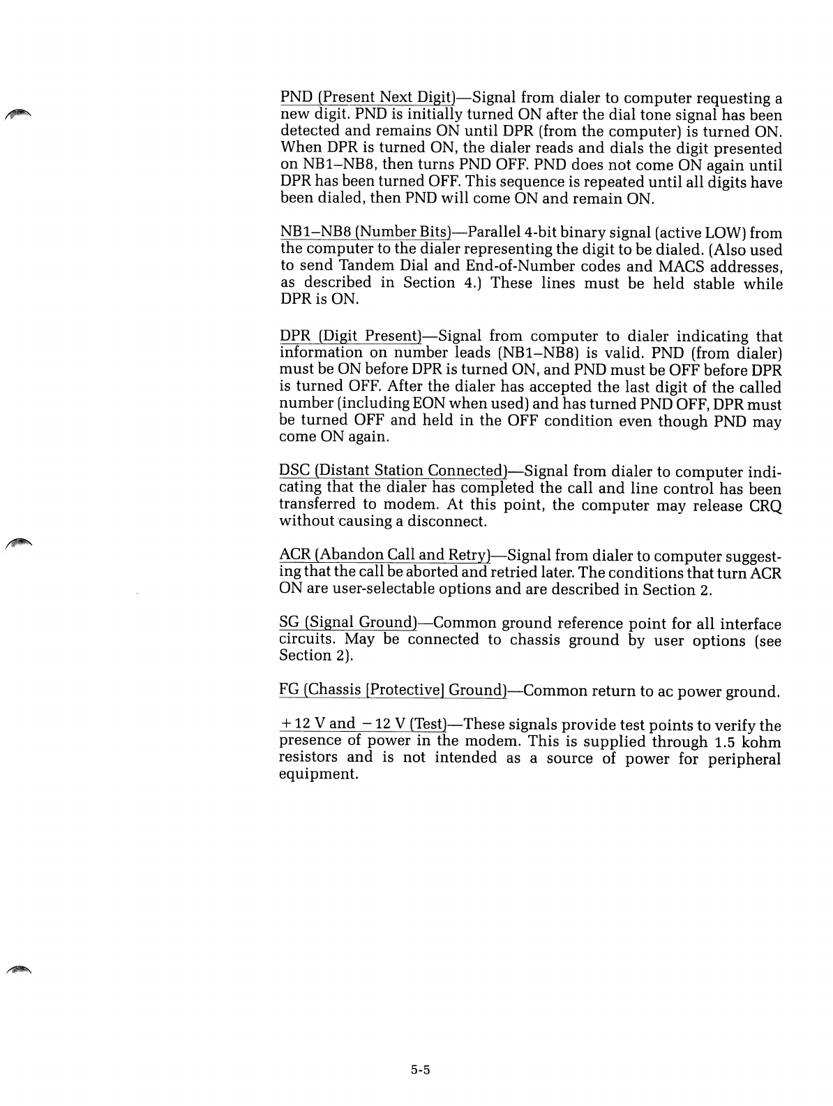
PND (Present Next
Digit)-Signal
from dialer to
computer
requesting a
new
digit. PND is initially
turned
ON after
the
dial
tone
signal has been
detected
and
remains ON
until
DPR (from
the
computer) is
turned
ON.
When
DPR is
turned
ON,
the
dialer reads
and
dials the digit
presented
on
NB1-NB8,
then
turns
PND OFF. PND does
not
come ON again until
DPR has been
turned
OFF. This sequence is
repeated
until
all digits have
been dialed,
then
PND will come ON
and
remain
ON.
NB1-NB8 (Number
Bits)-ParalleI4-bit
binary
signal (active LOW) from
the
computer
to the dialer representing
the
digit to be dialed. (Also
used
to
send
Tandem Dial
and
End-of-Number codes
and
MACS addresses,
as described
in
Section 4.) These lines
must
be
held
stable while
DPRis
ON.
DPR (Digit
Present)-Signal
from
computer
to dialer
indicating
that
information
on
number
leads (NB1-NB8) is valid. PND (from dialer)
must
be ON before
DPR
is
turned
ON,
and
PND
must
be OFF before
DPR
is
turned
OFF. After the dialer has accepted
the
last digit of
the
called
number
(including EON
when
used)
and
has
turned
PND OFF, DPR
must
be
turned
OFF
and
held
in
the
OFF
condition
even
though
PND may
come ON again.
DSC
(Distant Station
Connected)-Signal
from
dialer
to
computer
indi-
cating that the dialer has completed
the
call
and
line control has been
transferred to modem. At this point,
the
computer
may release CRQ
without
'causing adisconnect.
ACR
(Abandon Call
and
Retry)-Signal
from dialer to
computer
suggest-
ing
that
the
call be aborted
and
retried later.
The
conditions
that
turn
ACR
ON are user-selectable options
and
are described
in
Section
2.
SG
(Signal
Ground)-Common
ground
reference
point
for all interface
circuits. May be connected to chassis
ground
by
user
options
(see
Section
2).
FG
(Chassis [Protective]
Ground)-Common
return
to ac
power
ground.
+
12
V
and
-
12
V
(Test)-
These signals
provide
test
points
to verify
the
presence
of power
in
the modem. This is
supplied
through
1.5
kohm
resistors
and
is not
intended
as asource of
power
for
peripheral
equipment.
5-5
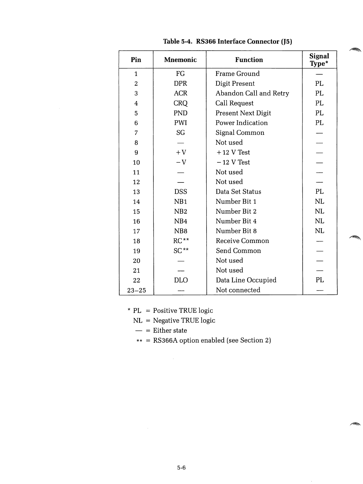
Table 5-4.
RS366
Interface
Connector
(J5)
Pin Mnemonic Function Signal
Type*
1FG
Frame
Ground
-
2DPR Digit
Present
PL
3ACR
Abandon
Call
and
Retry PL
4 CRQ Call
Request
PL
5PND
Present
Next Digit PL
6PWI
Power
Indication
PL
7
SG
Signal
Common
-
B-Not
used
-
9
+V
+12 VTest -
10
-V
-12
VTest -
11 -Not
used
-
12 -Not
used
-
13 DSS Data Set
Status
PL
14
NBl
Number
Bit 1NL
15
NB2
Number
Bit 2NL
16 NB4
Number
Bit 4NL
17 NBB
Number
Bit 8NL
18 RC** Receive
Common
-
19 SC**
Send
Common
-
20 -Not
used
-
21
-Not
used
-
22 DLO Data Line
Occupied
PL
23-25
-Not
connected
-
*PL =Positive TRUE logic
NL =Negative TRUE logic
- = Either state
)(.*
=RS366A
option
enabled
(see
Section
2)
5-6
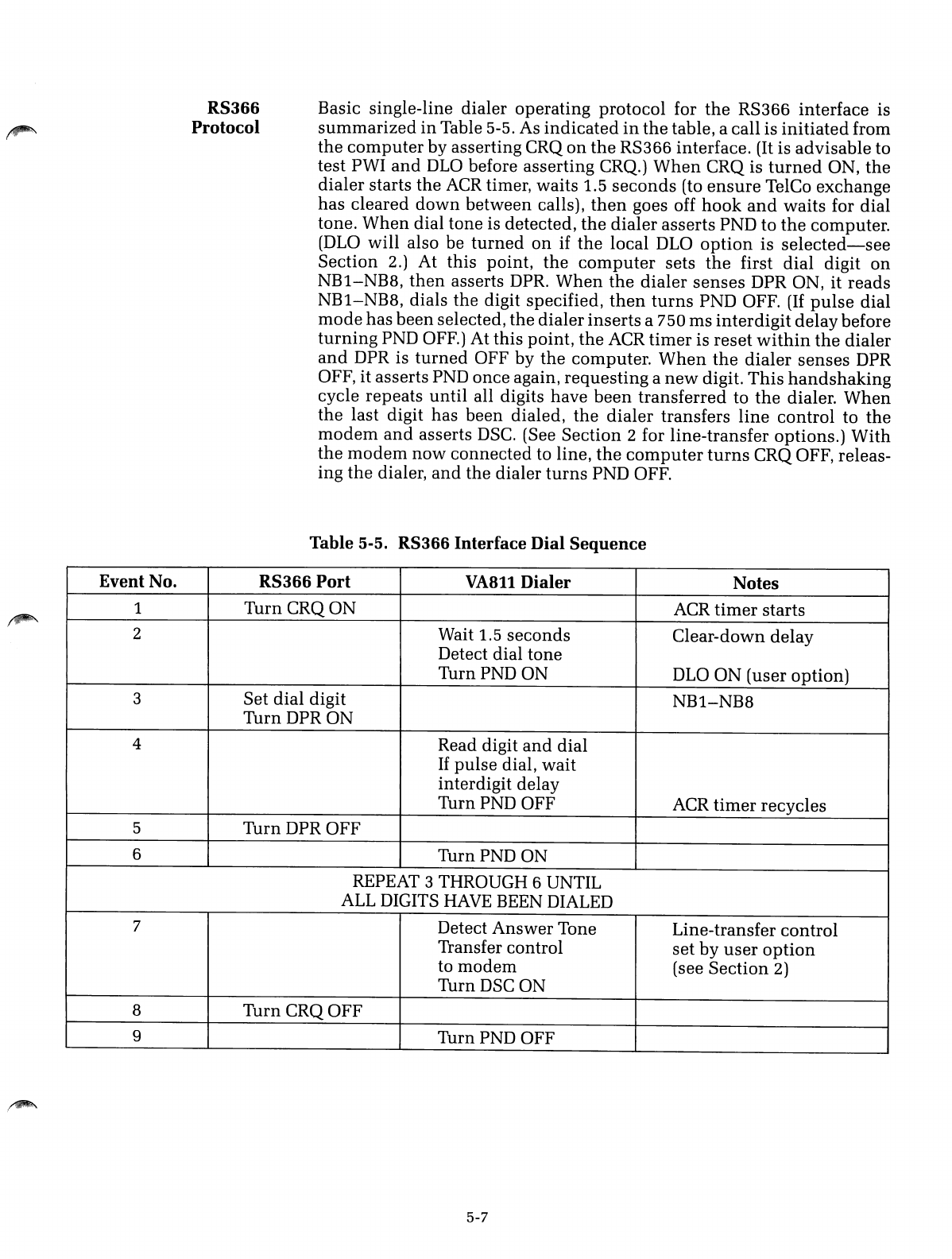
RS366
Protocol
Basic single-line dialer operating protocol for
the
RS366 interface is
summarized
in
Table 5-5. As
indicated
in
the
table, acall is
initiated
from
the
computer
by asserting CRQ
on
the
RS366 interface. (It is advisable to
test PWI
and
DLO
before asserting CRQ.)
When
CRQ is
turned
ON,
the
dialer starts the
ACR
timer, waits 1.5
seconds
(to
ensure
TelCo exchange
has cleared
down
between calls),
then
goes off
hook
and
waits for dial
tone.
When
dial tone is detected,
the
dialer
asserts PND to
the
computer.
(DLO
will also be
turned
on
if
the
local DLO
option
is
selected-see
Section 2.) At this point,
the
computer
sets
the
first
dial
digit
on
NB1-NB8,
then
asserts DPR.
When
the
dialer
senses
DPR ON, it reads
NB1-NB8, dials the digit specified,
then
turns
PND OFF.
(If
pulse
dial
mode
has
been
selected, the dialer
inserts
a750 ms
inter
digit delay before
turning
PND OFF.) At this point,
the
ACR
timer
is reset
within
the
dialer
and
DPR is
turned
OFF by
the
computer.
When
the
dialer
senses
DPR
OFF, it asserts PND once again, requesting a
new
digit.
This
handshaking
cycle repeats
until
all digits have
been
transferred to
the
dialer.
When
the
last digit has been dialed,
the
dialer
transfers
line
control to
the
modem
and
asserts
DSC.
(See Section 2for line-transfer options.)
With
the
modem
now
connected to line,
the
computer
turns
CRQ OFF, releas-
ing
the
dialer,
and
the dialer
turns
PND OFF.
Table
5-5.
RS366
Interface
Dial
Sequence
Event No. RS366
Port
VA811
Dialer
Notes
1Turn
CRQON
ACR
timer
starts
2Wait 1.5
seconds
Clear-down delay
Detect dial tone
TurnPNDON
DLO
ON (user option)
3Set
dial
digit
NB1-NB8
Turn
DPRON
4Read digit
and
dial
If
pulse
dial,
wait
interdigit delay
TurnPND
OFF ACR
timer
recycles
5Turn DPR OFF
6
TurnPND
ON
REPEAT 3THROUGH 6UNTIL
ALL
DIGITS
HAVE
BEEN DIALED
7Detect Answer Tone Line-transfer control
Transfer control
set
by
user
option
to
modem
(see Section 2)
TurnDSC ON
8
TurnCRQOFF
9
TurnPND
OFF
5-7
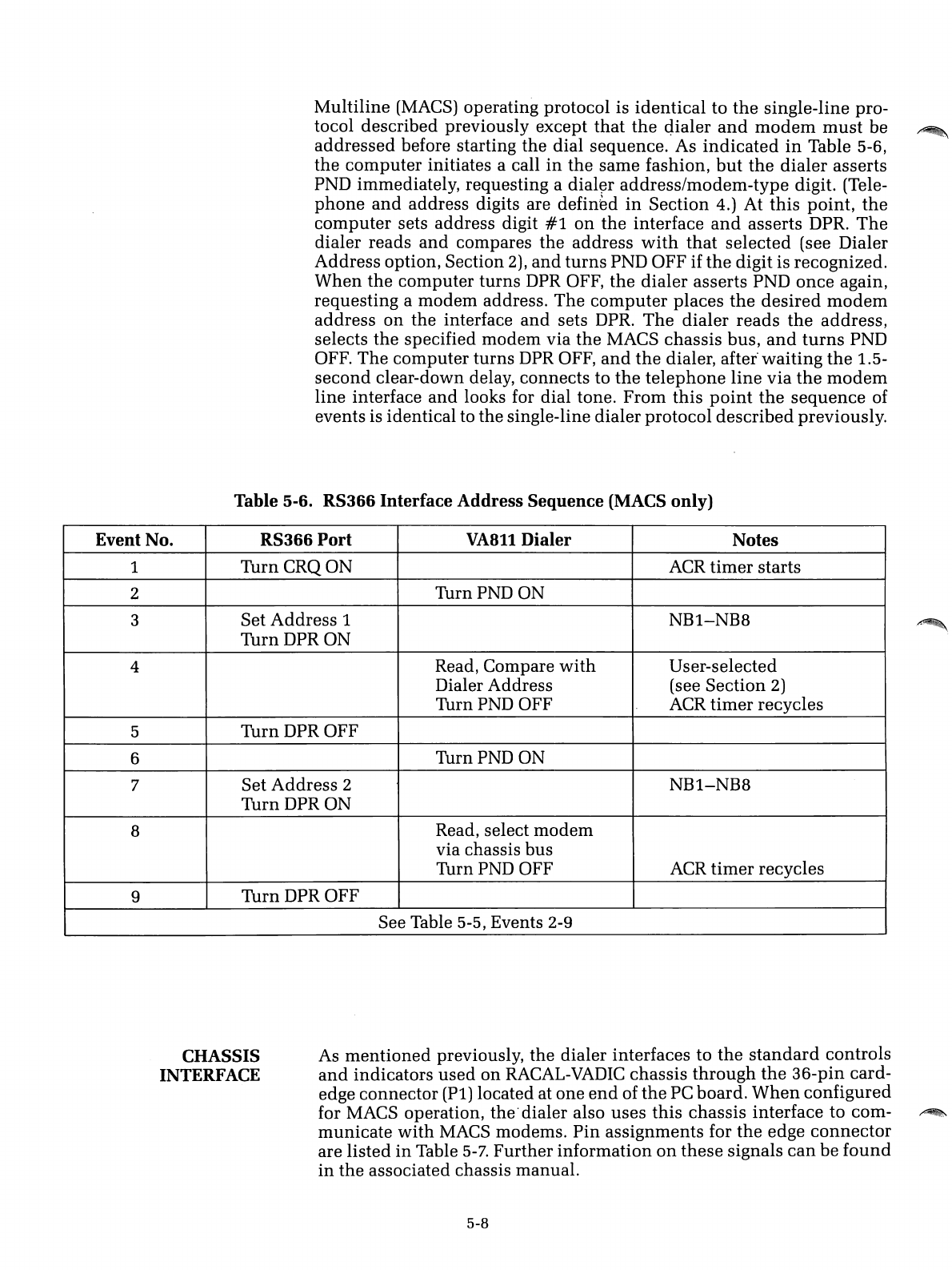
Multiline (MACS) operating protocol is
identical
to
the
single-line pro-
tocol described previously except
that
the
qialer
and
modem
must
be
~
addressed
before starting the dial sequence. As
indicated
in
Table 5-6,
the
computer
initiates acall
in
the
same fashion,
but
the
dialer
asserts
PND immediately, requesting a
dial~r
address/modem-type
digit. (Tele-
phone
and
address digits are
defin~d
in
Section 4.) At
this
point,
the
computer
sets address digit
#1
on
the
interface
and
asserts DPR.
The
dialer reads
and
compares the address
with
that
selected (see Dialer
Address option, Section 2),
and
turns
PND OFF if
the
digit is recognized.
When
the
computer
turns
DPR OFF,
the
dialer
asserts PND
once
again,
requesting a
modem
address. The
computer
places
the
desired
modem
address
on
the interface
and
sets DPR.
The
dialer
reads
the
address,
selects
the
specified
modem
via
the
MACS chassis bus,
and
turns
PND
OFF. The
computer
turns DPR OFF,
and
the
dialer,
after"
waiting
the
1.5-
second
clear-down delay, connects to
the
telephone
line
via
the
modem
line interface
and
looks for dial tone.
From
this
point
the
sequence
of
events is identical to the single-line dialer protocol
described
previously.
Table 5-6. RS366 Interface Address Sequence (MACS only)
Event No. RS366 Port
VA8ll
Dialer Notes
1
TurnCRQON
ACR
timer
starts
2
TurnPNDON
3Set
Address
1NB1-NBB
TurnDPRON
4Read, Compare
with
User-selected
Dialer Address (see Section 2)
TurnPND OFF
ACR
timer
recycles
5Turn DPR OFF
6TurnPND ON
7Set
Address
2NB1-NBB
Turn DPR ON
BRead, select
modem
via chassis bus
TurnPND OFF ACR
timer
recycles
9Turn
DPROFF
See Table 5-5, Events 2-9
CHASSIS
INTERFACE As
mentioned
previously, the dialer interfaces to
the
standard
controls
and
indicators
used
on
RACAL-VADIC
chassis
through
the
36-pin card-
edge connector (Pi) located at one
end
of
the
PC board.
When
configured
for MACS operation, the'dialer also uses
this
chassis interface to com-
~
municate
with
MACS modems.
Pin
assignments for
the
edge
connector
are listed
in
Table
5-7.
Further information
on
these
signals
can
be
found
in
the
associated chassis manual.
5-8
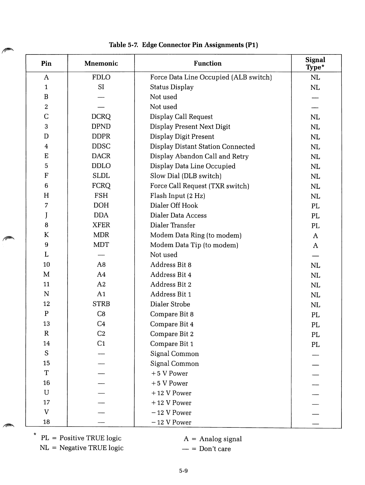
Table 5-7. Edge Connector
Pin
Assignments
(Pt)
Pin
Mnemonic
Function
Signal
Type*
AFDLO Force Data Line
Occupied
(ALB
switch)
NL
1SI Status Display NL
B-Not
used
-
2-Not
used
-
CDCRQ Display Call Request NL
3DPND Display
Present
Next Digit
NL
DDDPR Display Digit
Present
NL
4DDSC Display Distant
Station
Connected
NL
EDACR Display
Abandon
Call
and
Retry NL
5DDLO Display Data Line
Occupied
NL
FSLDL
Slow
Dial
(DLB
switch) NL
6FCRQ Force Call Request (TXR
switch)
NL
HFSH
Flash
Input
(2
Hz) NL
7DOH Dialer Off Hook PL
JDDA Dialer Data Access PL
8XFER Dialer Transfer PL
KMDR
Modem
Data Ring (to
modem)
A
9MDT
Modem
Data
Tip
(to
modem)
A
L-Not
used
-
10 A8
Address
Bit 8NL
MA4
Address
Bit 4NL
11
A2
Address
Bit 2NL
NA1
Address
Bit 1NL
12
STRB Dialer Strobe NL
pC8 Compare Bit 8PL
13
C4
Compare
Bit 4PL
R
C2
Compare Bit 2PL
14
Cl
Compare Bit 1PL
S-Signal
Common
-
15 -Signal
Common
-
T-
+5
VPower -
16 -
+5
VPower -
U-
+12
VPower -
17 -
+12
VPower -
V-
-12
VPower -
18 -
-12
VPower -
*
PL
=Positive TRUE logic
NL
=Negative TRUE logic
A=
Analog
signal
- =
Don't
care
5-9

i~
'~;)
./
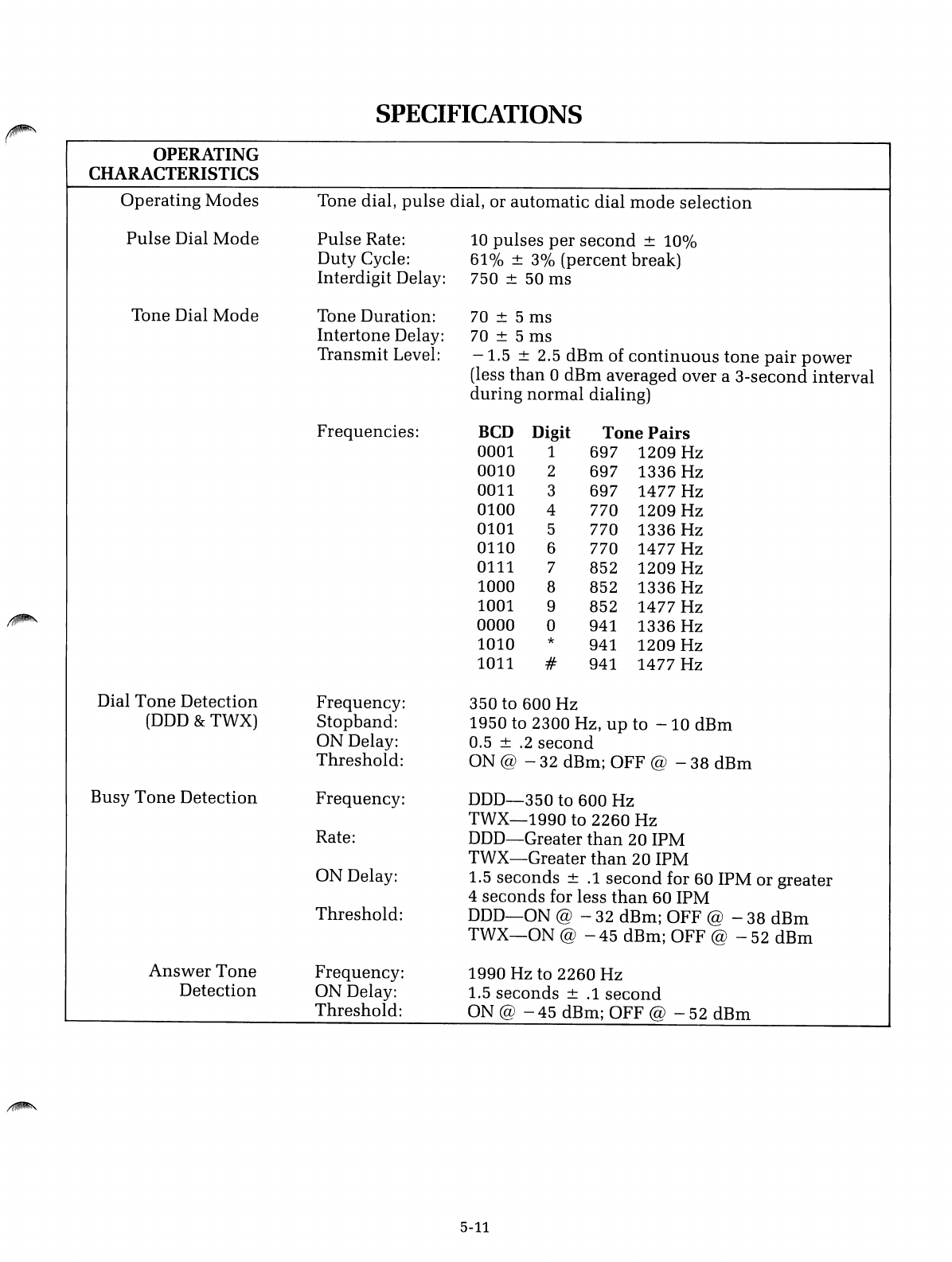
SPECIFICATIONS
~
OPERATING
CHARACTERISTICS
Operating
Modes
Tone dial,
pulse
dial, or automatic dial
mode
selection
Pulse
Dial
Mode
Pulse
Rate:
10
pulses
per
second
±100/0
Duty Cycle:
61
0/0± 30/0
(percent
break)
Interdigit Delay: 750 ±50 ms
Tone Dial
Mode
Tone Duration:
70
± 5 ms
Intertone
Delay:
70
± 5 ms
Transmit Level:
-1.5
±2.5
dBm
of
continuous
tone
pair
power
(less
than
0dBm averaged over a
3-second
interval
during
normal
dialing)
Frequencies:
BCD
Digit
Tone
Pairs
0001 1697 1209 Hz
0010 2697 1336 Hz
0011 3697 1477 Hz
0100 4770 1209 Hz
0101 5770 1336 Hz
0110 6770 1477 Hz
0111 7852 1209 Hz
1000 8852 1336 Hz
1001 9852 1477 Hz
~
0000 a941 1336 Hz
1010 *941 1209 Hz
1011 #941 1477 Hz
Dial
Tone
Detection Frequency: 350 to 600 Hz
(DDD
&TWX) Stopband: 1950 to 2300 Hz,
up
to
-10
dBm
ON Delay: 0.5 ±
.2
second
Threshold:
ON @
-32
dBm; OFF @
-38
dBm
Busy
Tone
Detection Frequency:
DDD-350
to 600 Hz
TWX-1990
to 2260 Hz
Rate:
DDD-Greater
than
20 IPM
TWX-Greater
than
20 IPM
ON Delay: 1.5 seconds ±
.1
second
for 60 IPM or greater
4seconds for less
than
60 IPM
Threshold:
DDD-ON
@ - 32 dBm; OFF @ - 38
dBm
TWX-ON
@ - 45 dBm; OFF @ - 52
dBm
Answer
Tone
Frequency: 1990 Hz to 2260
Hz
Detection ON Delay: 1.5
seconds
±
.1
second
Threshold:
ON @
-45
dBm; OFF @
-52
dBm
5-11
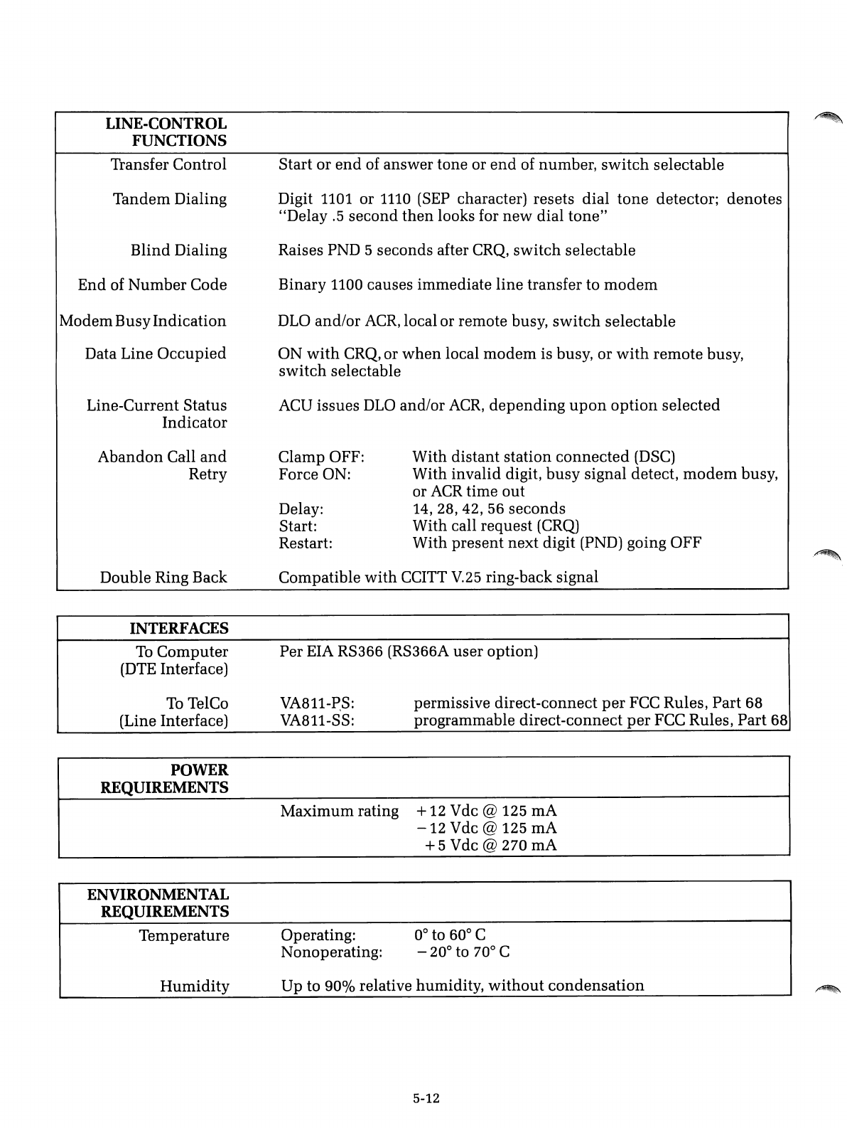
LINE-CONTROL
FUNCTIONS
Transfer Control
Tandem Dialing
Blind Dialing
End of Number Code
Modem BusyIndication
Data Line
Occupied
Line-Current Status
Indicator
Start or
end
of answer tone or
end
of number,
switch
selectable
Digit 1101 or
1110
(SEP
character) resets dial
tone
detector; denotes
"Delay
.5
second
then
looks for
new
dial
tone"
Raises PND 5seconds after
CRQ,
switch
selectable
Binary 1100 causes immediate line transfer to
modem
DLO
and/or
ACR,
local or remote busy,
switch
selectable
ON
with
CRQ, or
when
local
modem
is busy, or
with
remote busy,
switch
selectable
ACU issues
DLO
and/or
ACR,
depending
upon
OptiOIl
selected
Abandon
Call
and
Retry Clamp OFF:
Force ON:
Delay:
Start:
Restart:
With distant station
connected
(DSC)
With invalid digit,
busy
signal detect,
modem
busy,
or
ACR
time out
14,
28,42,
56
seconds
With call request
(CRQ)
With present next digit (PND) going OFF
.~
Double Ring Back
INTERFACES
Compatible
with
CCITT
V.25
ring-back signal
Per EIA RS366 (RS366A user option)
To
Computer
(DTE
Interface)
To
TelCo
(Line Interface)
POWER
REQUIREMENTS
VA811-P,S:
VA811-SS: permissive direct-connect
per
FCC Rules, Part 68
programmable direct-connect
per
FCC Rules, Part 68
ENVIRONMENTAL
REQUIREMENTS
Maximum rating +12 Vdc @125 rnA
-12
Vdc @125 rnA
+5
Vdc @270 rnA
Temperature Operating:
Nonoperating: 0° to 60° C
-20° to 70° C
Humidity
Up to
90%
relative humidity,
without
condensation
5-12
.~
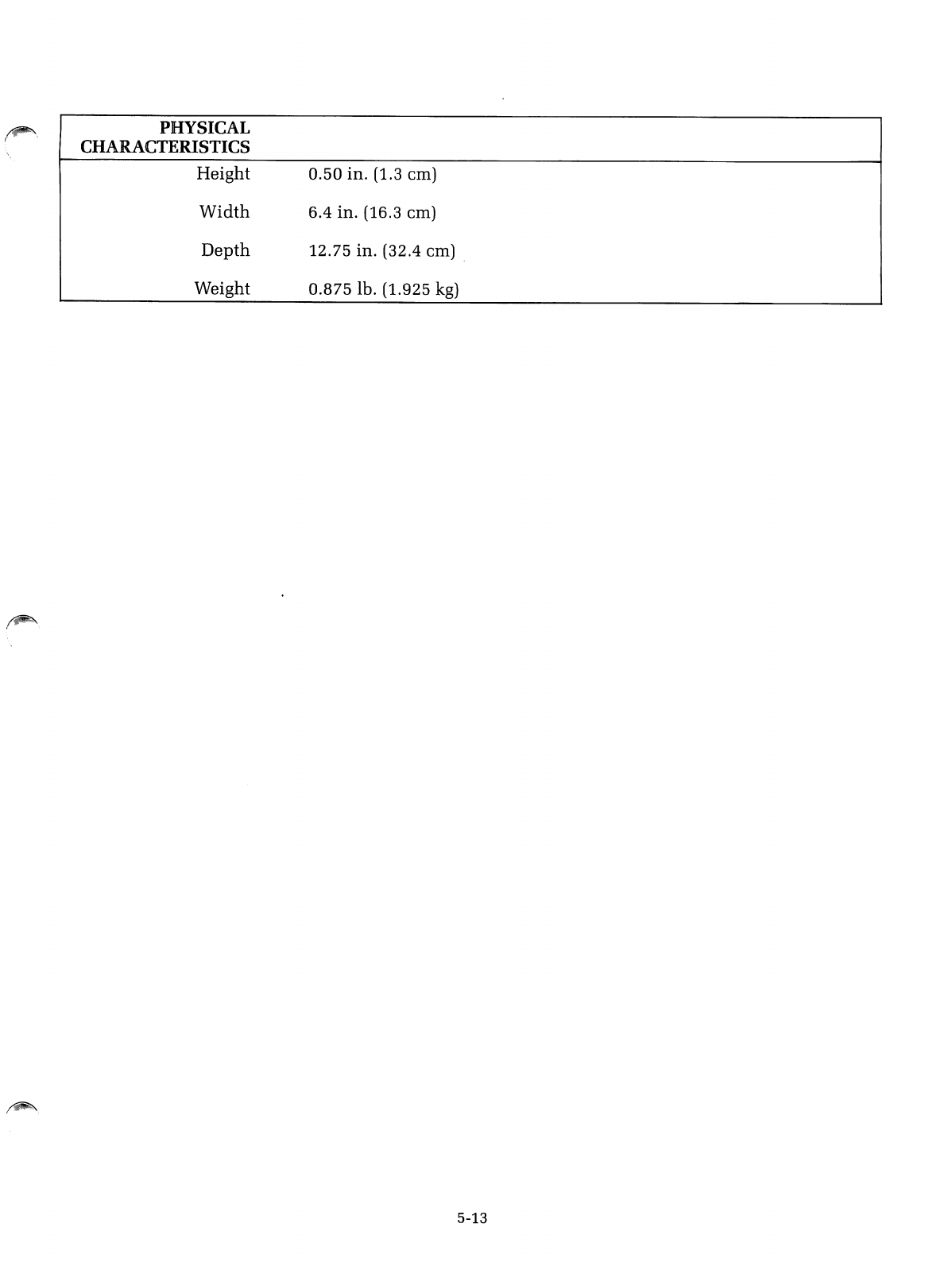
~\
(PHYSICAL
CHARACTERISTICS
Height
Width
Depth
Weight
0.50
in. (1.3 em)
6.4
in. (16.3 em)
12.75
in. (32.4 em) .
0.875
lb. (1.925
kg)
5-13

:~.
/
w
w
en
en
w
a:
o
o
<
>-
CD
o
;(
0-
W
CD
-I
-I
~
W
(!)
<
.-
en
o
0-
)
RACAL-VADIC--
wants your response
Any manual can be improved.
Our
major
source
of
feedback
is
you-the
person actually using
the
book.
Please tell us
how
we
are
doing
by
completing
the
attached card and
mailing
it
to
us.
Thank
You
Technical Publications, RACAL-VADIC
ll
Help us help you
by
returning this card with your comments.
Overall rating of
this
document
DExcellent DAdequate 0Poor
Readability of text 0Very Clear 0Adequate 0Difficult
Usefulness of format 0Helpful 0Adequate 0Inconvenient
Any errors? 0Yes 0No
If so, identify _
Anything missing
that
should
be
added?
D
Yes
If so, describe _
Any
additional
comments?
_
Do
you have other
modem
requirements? 0
Yes
Would you like service/repair information?
DYes
Would you like
the
latest catalog?
DYes
Name: Job Title: _
Address: Company: _
No. of Racal-Vadic modems being
used?
_
18008-049
WARRANTY,
LIMITATION
OF
LIABILITY
AND
SERVICE
INFORMATION
RACAL-VADIC
warrants
that
its
products
will
perform
in
accordance
with
RACAL-
VADIC's
published
spncifications
(or
the
specification
agreed
to. in
writing.
by
Buyer
and
RACAL-VADIC.
and
made
a
part
of
the
sales
contract),
for a
period
of
12
months
from
date
of
original
shipment.
During
this
\\'arranty
period
RACAL-VADIC will,
at
no
cost.
promptly
repair
or
replace
any
defective
equipment
returned
to RACAL-VADIC.
transportation
charges
prepaid
by
Buyer.
and
will
return
such
equipment.
transportation
charges
prepaid
via
the
same
or
like
method
as received.
except
where
special
handling
or
shipment
is
requested
by Buyer.
in
which
case
Buyer
shall
pay
all
such
charges.
This
warranty
shall not
apply
to
damage
resulting
from
abuse.
negligence.
accident
or
loss
or
damage
in
transit.
The
warranty
shall
be
voided
should
the
Buyer
attempt
any
repairs
or
alterations
without
prior
written
permission
of
RACAL-VADIC.
RACAL-VADIC
makes
no
other
warranty,
expressed
or
implied.
and
RACAL-VADIC
DISCLAIMS ANY IMPLIED WARRANTY
OF
MERCHANTABILITY OR
FITNESS
FOR
APARTICULAR PURPOSE.
THE
BUYER
AND
RACAL-VADIC AGREE
THAT
THE
SOLE
AND
EXCLUSIVE
REMEDIES
FOR BREACH
OF
ANY WARRANTY
CONCERNING
THE
GOODS SHALL
BE REPAIR OR
REPLACEMENT
OF
DEFECTIVE PARTS UPON
THE
TERMS
ABOVE
DESCRIBED OR.
AT
RACAL-VADIC'S OPTION, REFUND
OF
THE
PURCHASE
PRICE.
RACAL-VADIC
SHALL
NOT
BE LIABLE FOR
CONTINGENT
OR
CONSEQUENTIAL
DAMAGES
TO
PERSONS
OR PROPERTY AND ITS SOLE LIABILITY IS AS ABOVE
SET
FORTH.
Any
action by Buyer for
any
alleged
breach
of the
warranty
set forth
herein
shall be
brought
to
the
attention
of
RACAL-VADIC by
Buyer
within
the
warranty
period,
but
not
later
than
30
days
after
the
alleged
Breach.
THIS
STATEMENT
OF
WARRANTY AND
LIMITATION
OF
LIABILITY IS ACOM-
PLETE
AND
EXCLUSIVE
STATEMENT
OF
ALL WARRANTY
AND
LIABILITY
REPRESENTATIONS
OF
RACAL-VADIC.
It
may
not be varied.
supplemented,
qualified
or
interpreted
by
any
prior
dealings
between
the
parties
or
by
any
usage
of
the
trade
or
upon
the
face
or
reverse
of
any
form to
which
this is
attached
or
a
part
of,
nor
may
it
be
modified
by
any
agenl.
employee
or
representative
of
RACAL-VADIC
unless
such
modification
or
representation
is
made
in
writing
and
signed
by a
duly
authorized
of-
ficer
of
RACAL-VADIC.
Repairs
and/or
replacement
under
the
terms
of
this
warranty
SHALL NOT EXTEND
THE
WARRANTY LIFE
OF
THE
ORIGINAL
EQUIPMENT
SUPPLIED.
Equipment
returned
lo
the
factory
should
be
accompanied
by
the
following
information:
the
reason
for
return.
with
a
comprehensive
description
of
the
malfunction;
shipping
instructions:
and
the
name
and
telephone
number
of
a
contact
in
the
event
of
problems.
Further
inquiries may be
directed
to RACAL-VADIC's Diagnostic
Center
at (800) 22-VADIC
or
(800) 228-2342.
Racal-Vadic
222 Caspian Drive, Sunnyvale, California 94089-9874 Telephone (408) 744-0810
Printed
in
USA
