Rapid Sheet Metal Design Guide
User Manual:
Open the PDF directly: View PDF ![]() .
.
Page Count: 20
Rapid Sheet Metal
Overview ............................................................................................................ 3
Capabilies ......................................................................................................... 4
Cercaons & Registraons .............................................................................. 4
Stock Materials ................................................................................................... 5
Design Guidelines
Uniform Wall Thickness ....................................................................................... 6
Bends ................................................................................................................. 7
Hems .................................................................................................................. 8
Osets ................................................................................................................ 9
Holes & Slots ...................................................................................................... 10
Counter Sinks ..................................................................................................... 11
Notches & Tabs .................................................................................................. 12
Bend Relief ......................................................................................................... 13
Welding ............................................................................................................... 14
PEM Hardware .................................................................................................... 15
Design Tools
Standard Tooling ................................................................................................ 17
Finishing
Plang ................................................................................................................ 18
Powder Coang & Silk Screening ......................................................................... 19
Resources .......................................................................................................................... 20
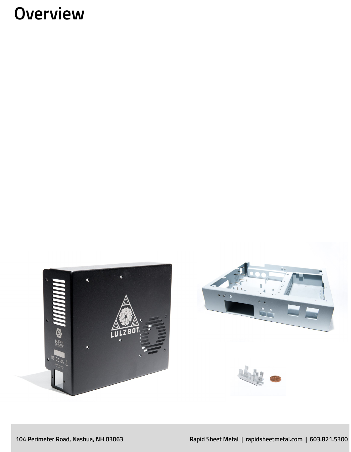
Rapid Sheet Metal began in 2001 with the mission: “Prototypes First”
and it is sll the foundaon of our business. The shop is structured
similar to an addive manufacturing facility. This approach uses 3D CAD
data to streamline the quong and manufacturing processes which
eliminates long que mes. Currently, Rapid Sheet Metal has two facilies
totaling 75,000 square feet of space servicing prototype and low
volume producon quanes.
Sheet Metal Fabricaon is the creaon of parts through forming,
bending, punching and cung sheets of metal. This guide will cover
sheet metal best pracces and ps to ensure your sheet metal parts are
opmally designed for durability, manufacturability, and end-use
applicaons.
Rapid Sheet Metal

Laser Cung
Punching
Shearing
Forming & Bending
TIG, MIG & Spot
Welding
PEM Hardware
Hardware Inseron
Rolling
Riveng
Basic Tool Making
Tumbling
Secondary Machining
Assembly
Plang
Powder Coang
Silk Screening
Part Marking
Part Size: Max 8’ length
Rapid Sheet Metal
ITAR Registered
ISO 9001:2008
Aerospace Welding
RoHS Compliant
Joint Cercate Program
Central Contractor Registered
SOLIDWORKS Cered Soluon Partner
In-House Capabilies:
Cercaons & Registraons:
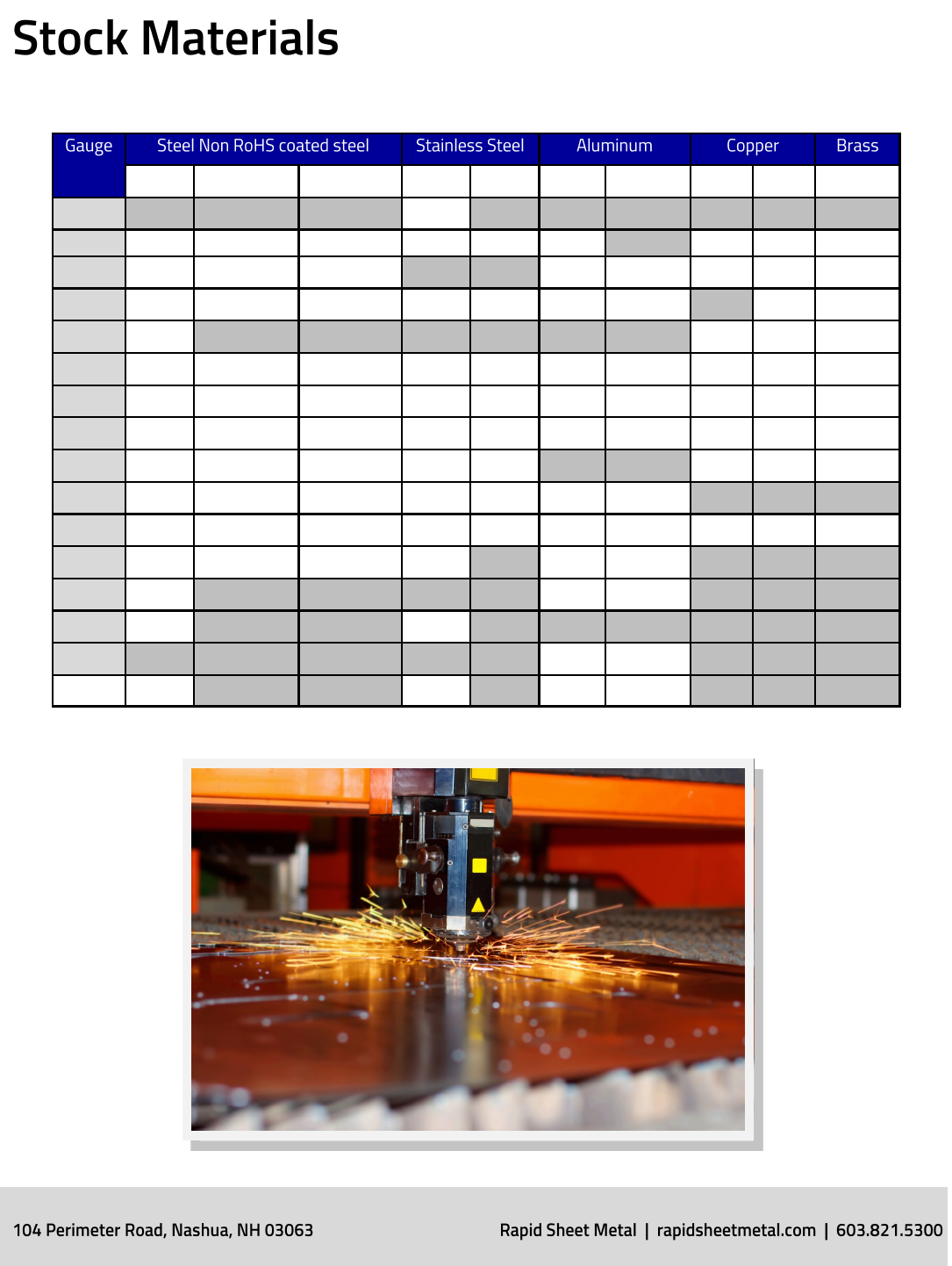
CRS Galvanneal Galvanized 304 316 5052 6061-T6 C101 C110 CDA260
26 0.018
24 0.024 0.024 0.024 0.024 0.024 0.020 0.020 0.020 0.020
22 0.030 0.029 0.029 0.025 0.025 0.025 0.025 0.025
20 0.036 0.036 0.036 0.036 0.036 0.030 0.030 0.032 0.032
19 0.042 0.040 0.040 0.040
18 0.048 0.048 0.048 0.047 0.047 0.040 0.040 0.050 0.050 0.050
16 0.060 0.060 0.060 0.059 0.059 0.050 0.050 0.062 0.062 0.062
14 0.075 0.075 0.075 0.074 0.074 0.062 0.062 0.080 0.080 0.080
13 0.090 0.089 0.089 0.089 0.089 0.090 0.090 0.090
12 0.104 0.104 0.104 0.104 0.104 0.080 0.080
11 0.119 0.119 0.119 0.119 0.119 0.090 0.090 0.125 0.125 0.125
10 0.134 0.134 0.134 0.134 0.100 0.100
8 0.164 0.125 0.125
7 0.179 0.179
6 0.160 0.160
0.250 0.250 0.250 0.250
Rapid Sheet Metal
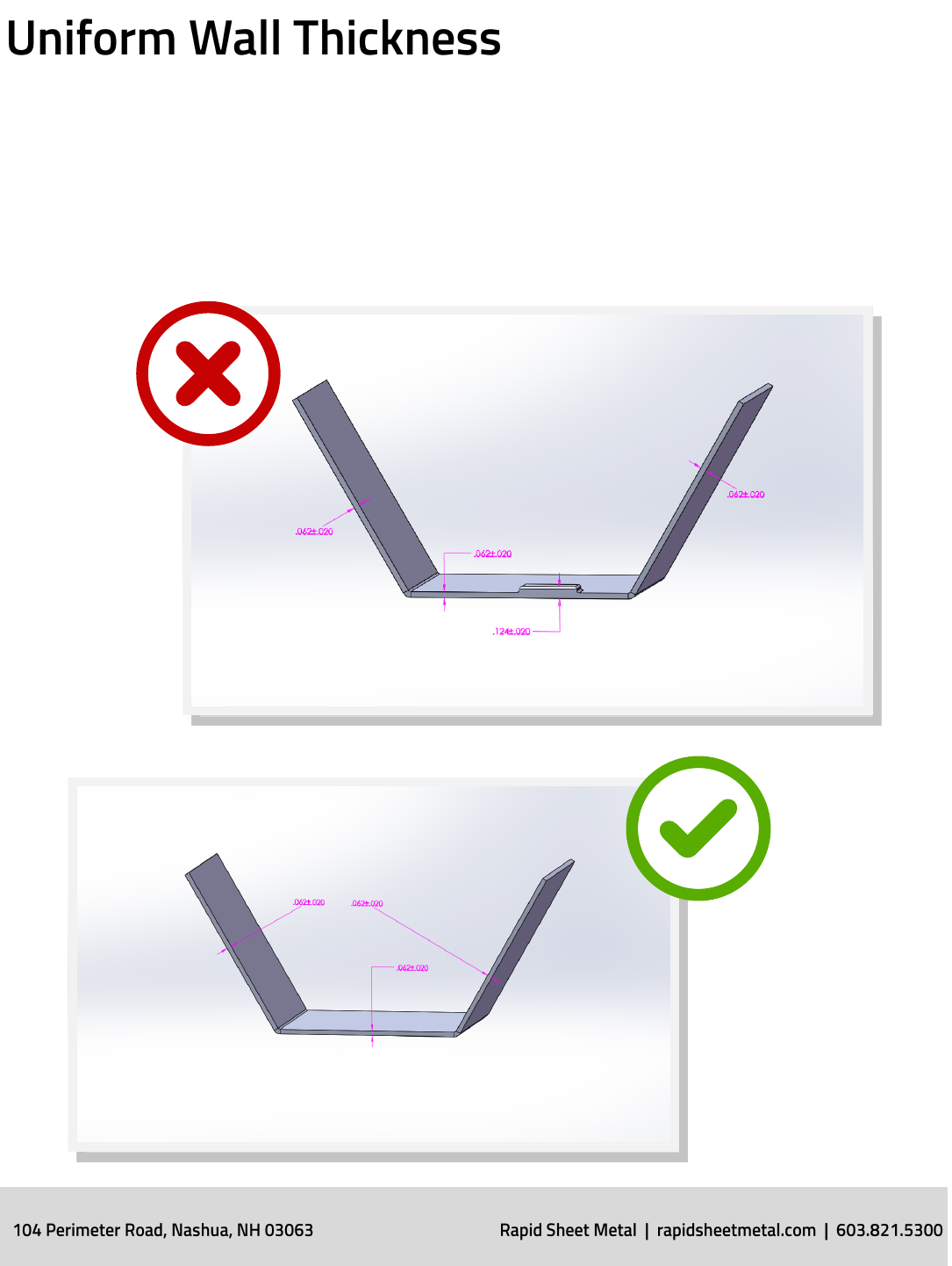
Because Sheet Metal parts are manufactured from a single sheet of
metal the part must maintain a uniform wall thickness. Rapid Sheet
Metal is capable of manufacturing sheet metal parts with a minimum of
0.010” to 0.25” in thickness.
Design Guidelines
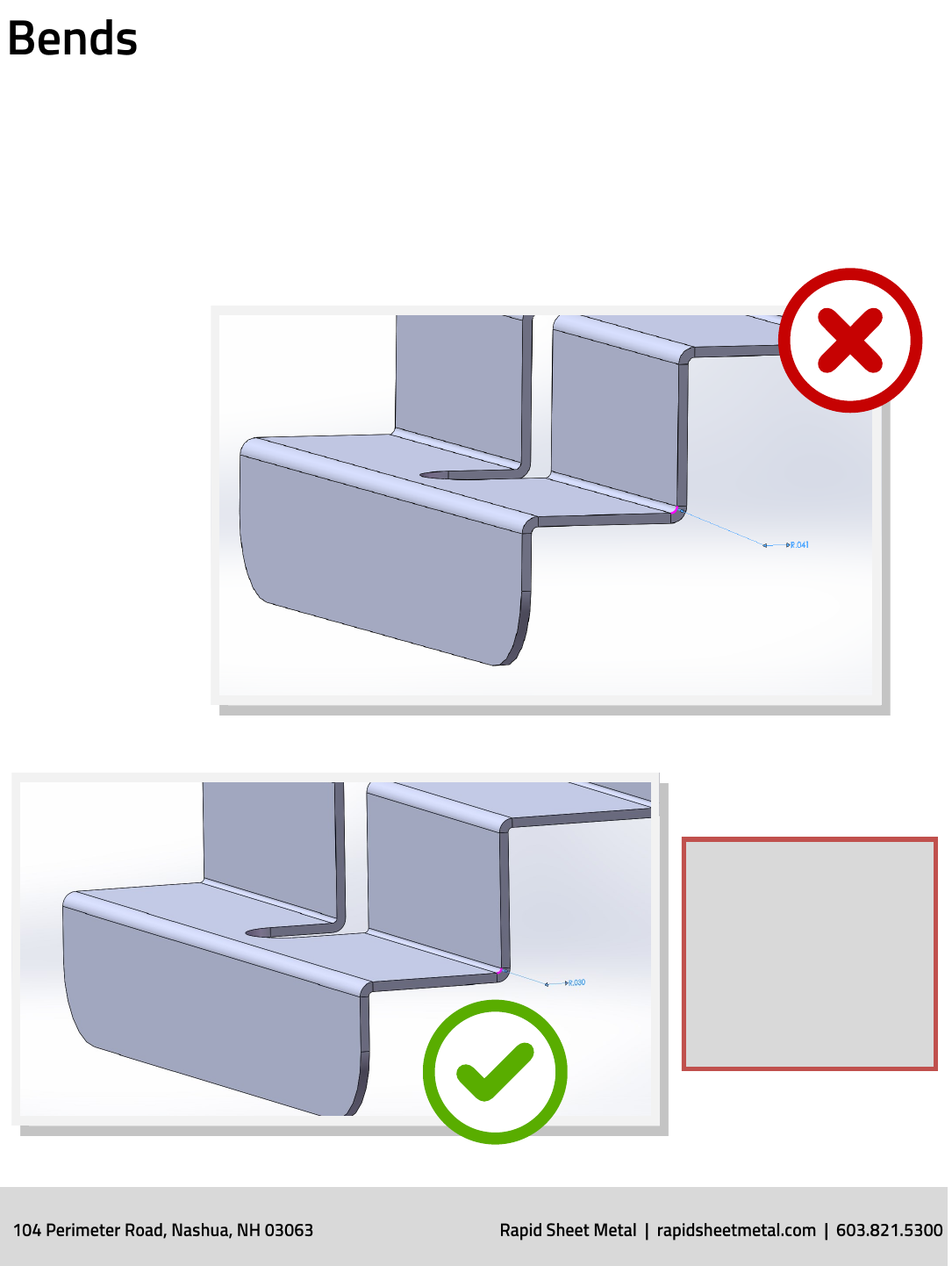
Bends in sheet metal are manufactured using sheet metal brakes. RAPID
will hold a +/- 1 degree tolerance on all bend angles. RAPID’s preferred
bend radius is 0.030”. Other standard bend radii available, some of which
will add addional cost to your part, include:
0.060”
0.090”
0.120”
0.188”
0.250”
0.375”
0.500”
0.750”
1.000”
NOTE: RAPID recommends
keeping the same bend ra-
dii across all bends when
possible. This helps mini-
mize the amount of brake
setups and keeps cost
down.
Design Guidelines
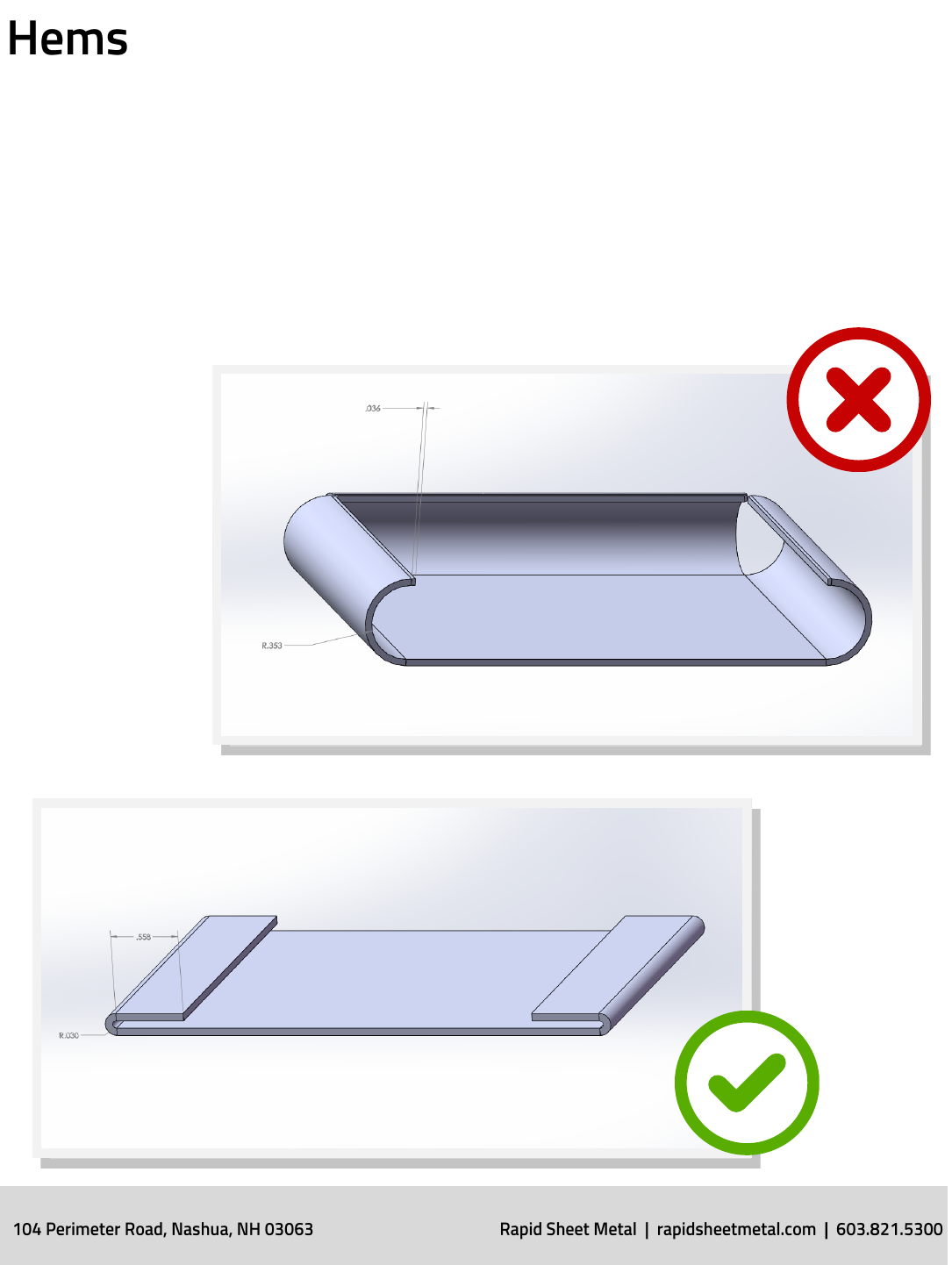
Hems are folds at the end of a part to create a rounded edge. RAPID can
form both open and closed hems as required. The tolerance of a hem is
dependent upon the hem’s radius, material thickness and features near
the hem. It is recommended the minimum inside diameter equals the
material thickness and the hem return length is 4 mes the thickness.
Design Guidelines
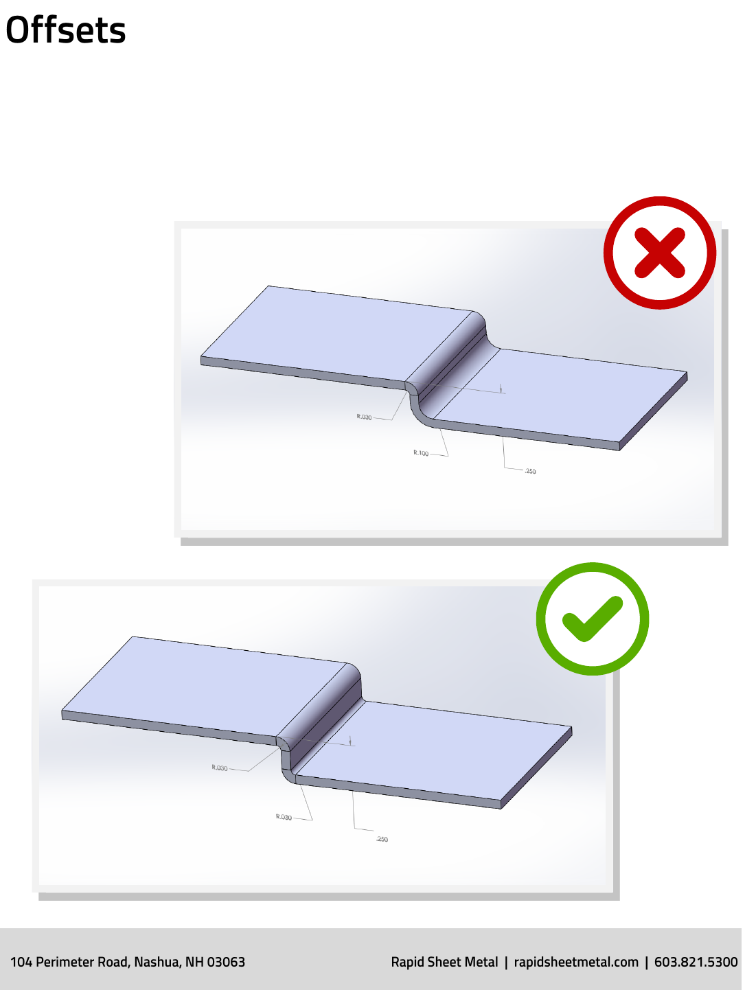
An oset is used to create a “Z” shaped prole in a sheet metal part.
RAPID’s oset height tolerance is +/- 0.012” top of sheet / top of form.
RAPID’s preferred oset is 0.030”. Other standard osets, which can add
costs to your part, include:
0.060”
0.093”
0.125”
0.187”
0.213”
0.250”
0.281”
0.312”
Design Guidelines
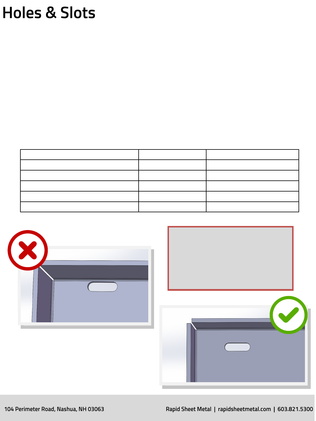
Holes and slots should be a minimum of material thickness in diameter. If
a material is 0.036” or thinner the hole should be 0.062” from the
material edge. If the material is thicker than 0.036” then the hole should
be at least 0.125” from the material edge to avoid distoron. If hardware
inserts are required the spacing should be according to manufacturer’s
specicaons.
Hole Tolerances:
Hole Diameter +/- 0.005” Unless otherwise specied
Hardware Hole Diameter +0.003”/-0.000” Per manufacturers specicaons
Counterbore & Spoacing 0.063 to 0.250 +0.010”/-0.005”
Counterbore & Spoacing 0.251 to 0.500 +0.015”/-0.005”
Counterbore & Spoacing >0.500 +0.020”/-0.005”
Machined Diameter +/-0.001”
NOTE: If using eRAPID, all holes and cut-
outs need to be a minimum of 4x the ma-
terial thickness away from the material
edge to avoid addional costs in es-
mang.
Design Guidelines
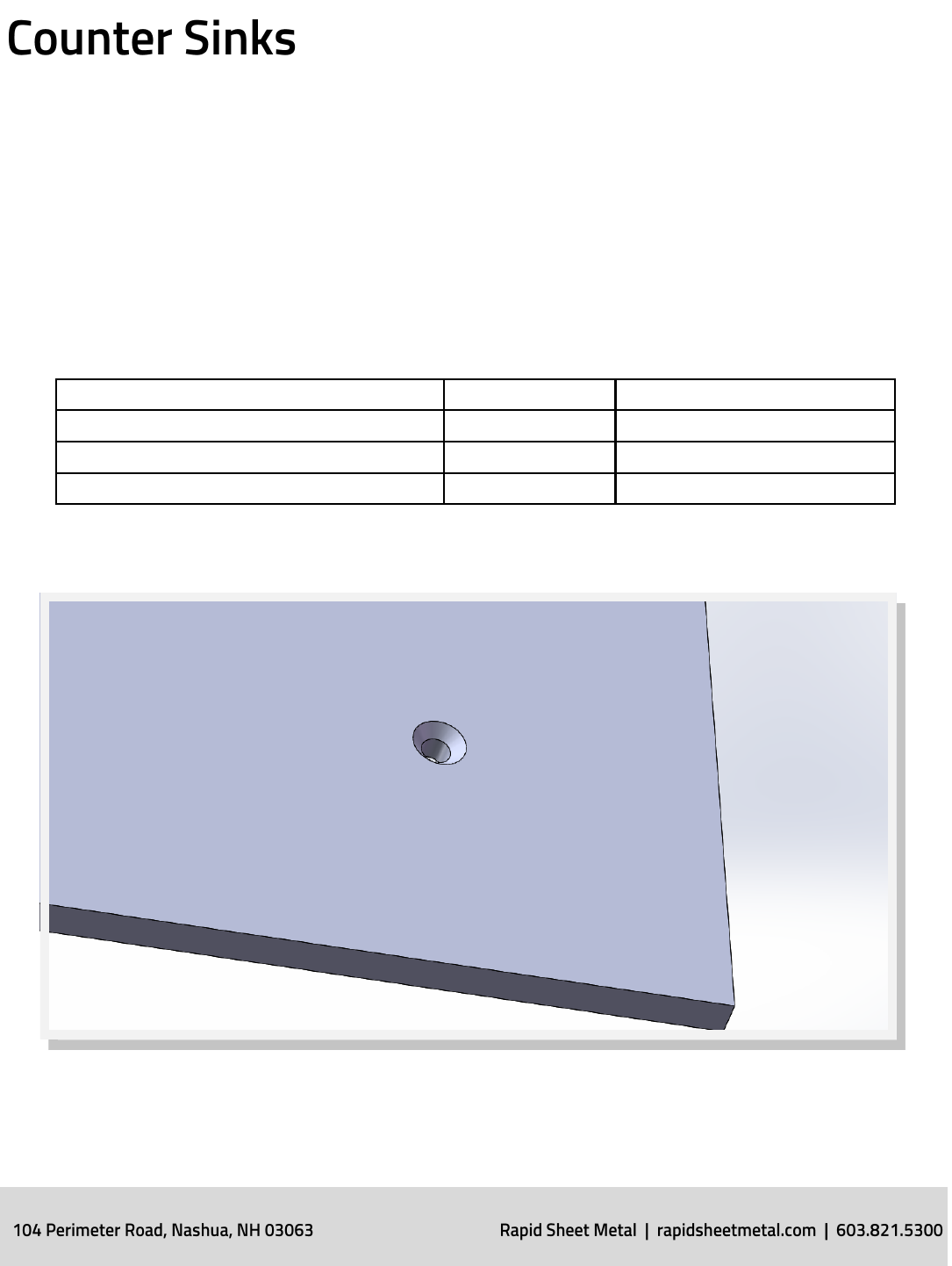
Rapid Sheet Metal oers both machined and formed countersinks.
Machined counter sinks are created with a drill press while formed
counter sinks are created with punch press tooling.
Counter Sink Tolerances:
Machined Counter Sink Major Diameter +/-0.010”
Machined Counter Sink Minor Diameter +/-0.010” 2/3 thickness
Formed Counter Sink Major Diameter +/-0.015”
Formed Counter Sink Minor Diameter +/-0.015”
Design Guidelines
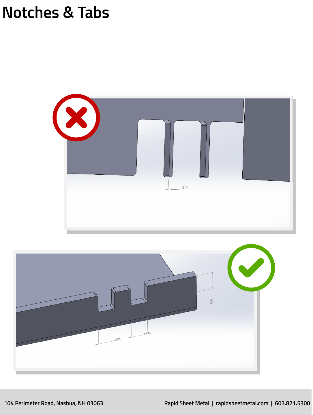
Notches must be at least the material’s thickness or 0.04”, whichever is
greater, and can be no longer than 5 mes its width. Tabs must be at
least 2 mes the material’s thickness or 0.126”, whichever is greater, and
can be no longer than 5 mes its width.
Design Guidelines
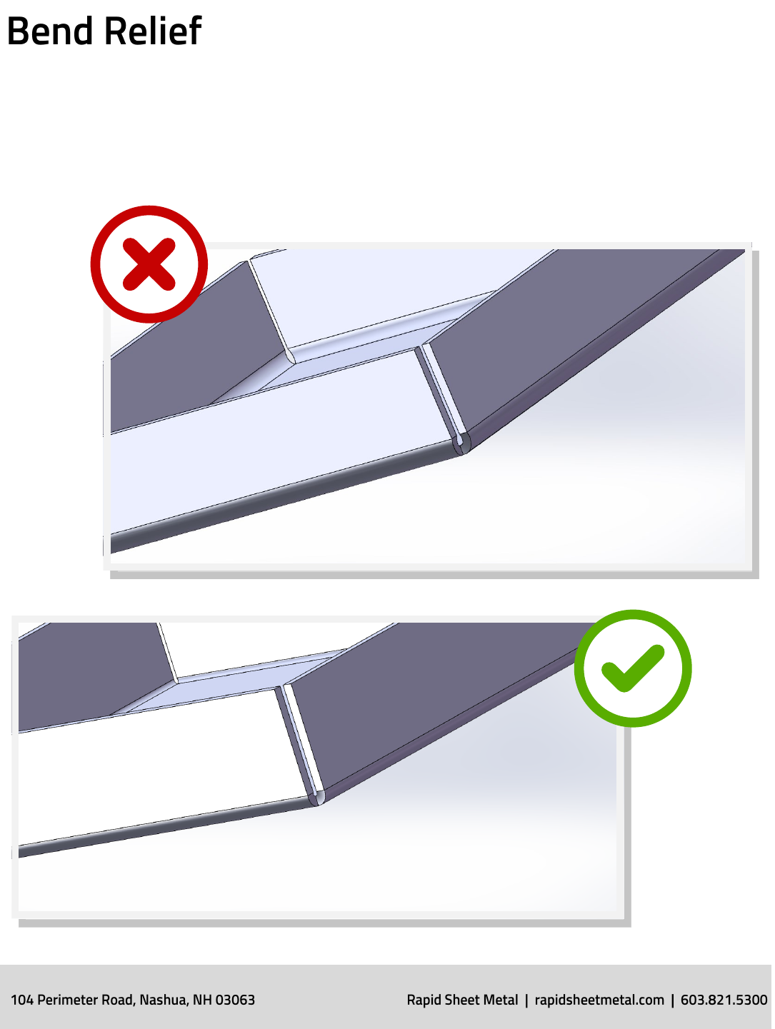
Bend reliefs are implemented where a bend extends on an edge. The
relief notch is added to prevent tearing. Bend reliefs will be no deeper
than the material thickness plus the bend radius and no wider than
0.030”.
Design Guidelines

Design Guidelines
When designing a part requiring welding, it is best to not specify the
exact method or type of welding unless required for funcon. This
provides the manufacturer increased exibility when fabricang the
sheet metal part which oen results in the most economical and fastest
lead-me choice for the customer.
The three most common types of welding include Resistance Spot
Welding (RSW), Gas Metal Arc Welding (MIG), and Gas Tungsten Arc
Welding (TIG).
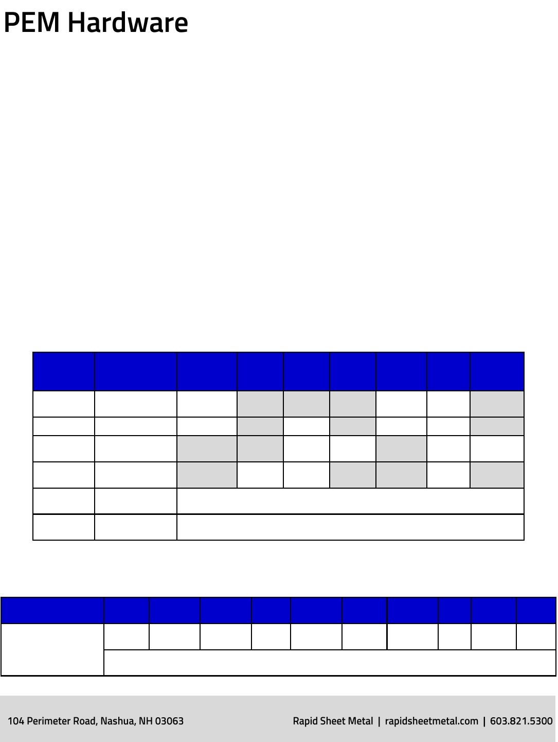
When designing sheet metal parts with PEM Hardware it is important to
make sure the hardware is not too close to a bend, edge or other
fastener. When designing near a bend or edge, use the Centerline-to-
Edge (C/L to Edge) value to nd the minimum distance to the outside
edge. When calculang the spacing between mulple pieces of
hardware, use the C/L to Edge formula plus ½ the diameter of the second
mounng hole.
Hardware Plang Specics
“Before” means hardware is required to be inserted before plang.
“Aer” means hardware is required to be installed aer plang.
Material Hardware
Iridite,
Chromate,
Alodine
Zinc Nickel
Plate
Black
Oxide Anodize Tin
Plate Passivate
Aluminum AC, CLS, CLSS,
FHS, SOS, BSOS Before Aer Aer
Aluminum CLA & FHA Before Aer Before Aer
Stainless
Steel
SP, FH4, SO4,
BSO4 Before Before Before Before
CRS AS, BSO, FH, S,
SO, SS Before Before Before
Galvanneal AS, BSO, FH, S,
SO, SS PAINT / POWDER ONLY
Galvanized AS, BSO, FH, S,
SO, SS PAINT / POWDER ONLY
Hardware Lengths
Hardware Type 0.25” 0.312” 0.375” 0.5” 0.625” 0.75” 0.875” 1” 1.25” 1.5”
FH, FHS, FH4, FHL,
FHLS, TFH, TFHS,
HFH, HFHS
4 5 6 8 10 12 14 16 20 24
All metric lengths are in millimeters (ex. Dash 10 is 10MM long)
Design Guidelines
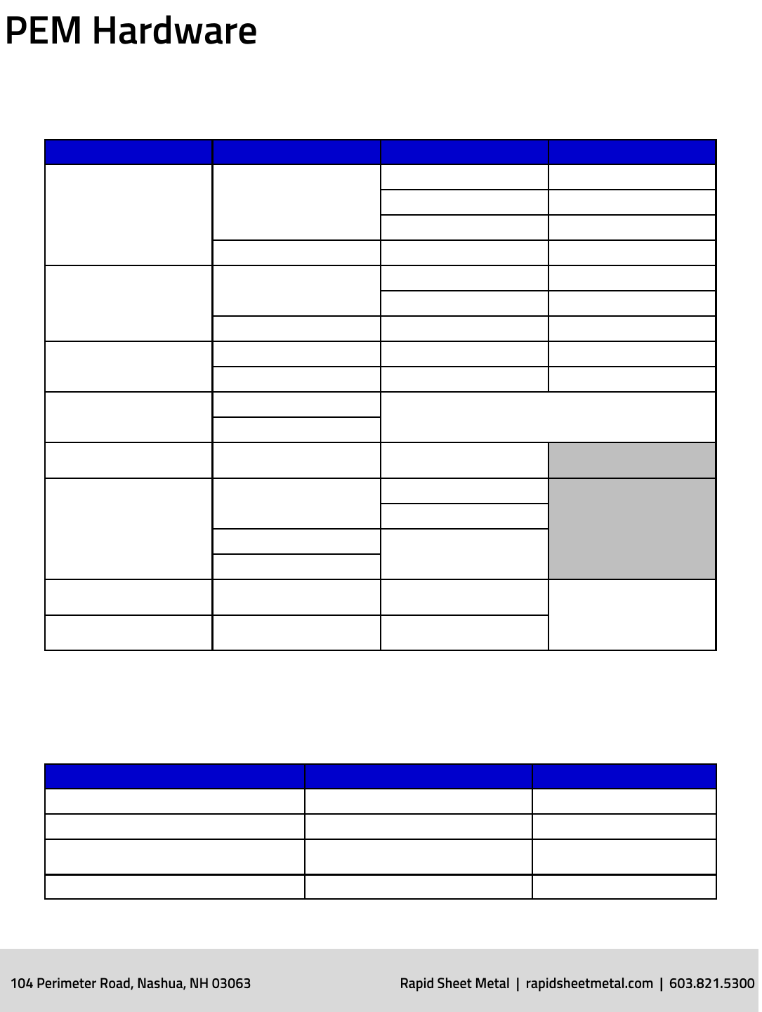
Material Thickness vs. Shank Numbers
Hardware Type Thread Code Min Sheet Thickness Shank
S, SS, CLS, SP, CLA
AC, CLS, CLSS, F, FHS, SOS,
BSOS, CLA
0.03” 0
0.04” 1
0.056” 2
632, 832, 024, 032 0.091” 3
S, SS, CLS, SP, CLA
0420, 0428, 0518
0.056” 1
0.091” 2
M6, M8 0.0125” 3
F
256, 440, 632, 832, 032 0.060” – 0.090” 1
M2.5, M3, M4, M5 0.090” – UP 2
SO, SOS, SO4, BSO, BSOS,
BSO4
440, 6440, 632 0.040” IF LESS THAN 0.40” USE TSO TO TSIS (0.025”
MINIMUM)
M3, M4
SO, SOS, SO4, BSO, BSOS,
BSO4 8362, 832, 032 0.050”
FH, FHS, FH4, FHA
256, 440, 632, 832, 024,
032, M2.5, M3, M4, M5
0.040”
0.062”
.0420.
0.93”
.0518.
FEO (Locking), FEOX 440, 632, 832, 0.032. M3,
M4, M5 0.039” - 0.045”
AFTER PLATING
FE (Locking), FEX 440, 632, 832, 0.032. M3,
M4, M5 0.059” - 0.070”
Special Cases
Hardware Type Special Info Install In Stainless
PL, PLC Nylon Threads NO
TD, RAS, RSS Steel Only NO
All Panel Fasteners: PF11, PF12, PFC2 Installed Post Finishing
(This includes powder coat) NO
LK, LKS, LKA Treated w/ Black Dry Lubricant NO
Design Guidelines
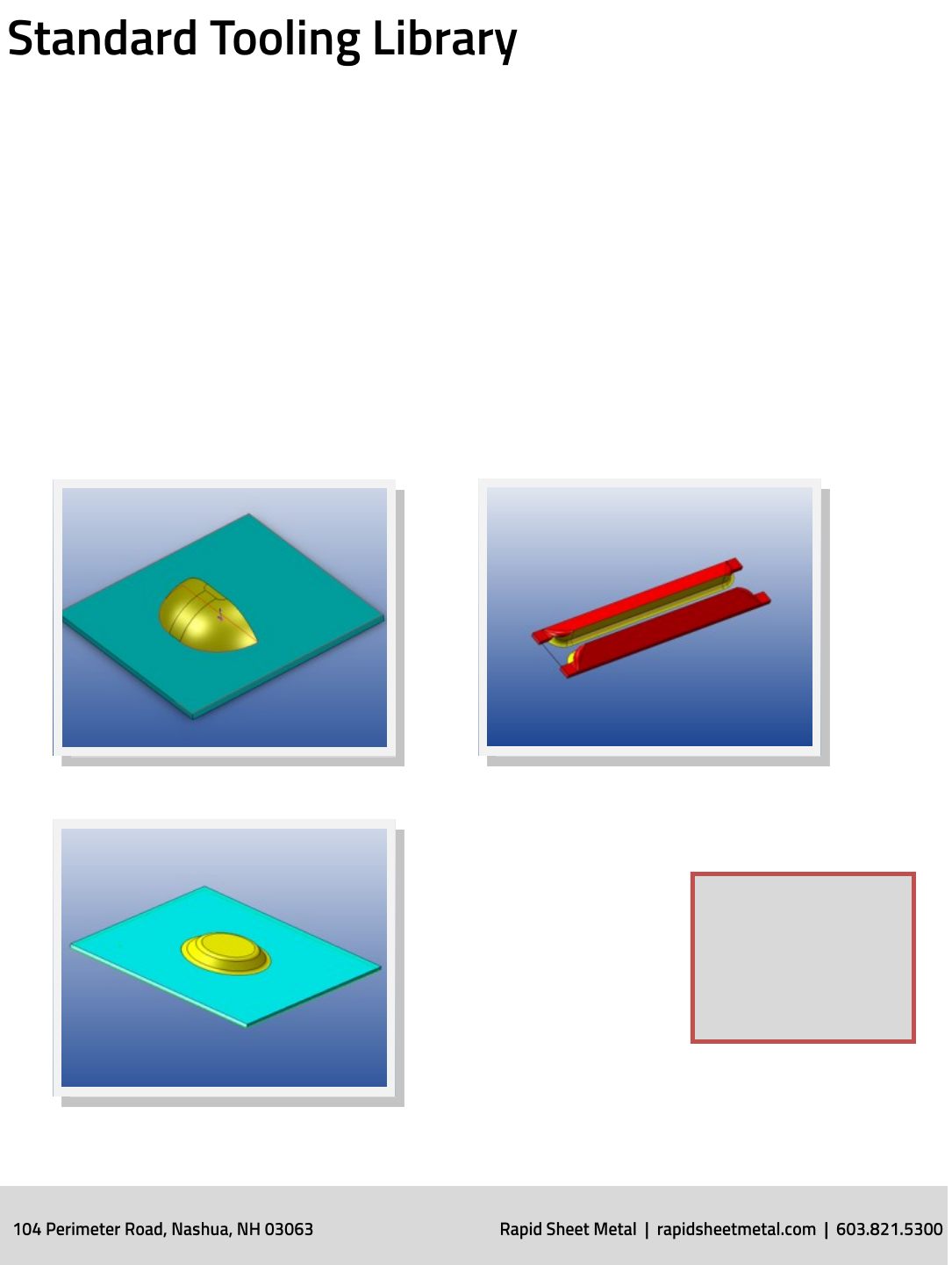
Design Tools
By using standard tooling features you can be assured we have the
in-house punch tooling to create the geometry you are modeling. This
eliminates the phone calls and e-mails back and forth to match your
needs with our in-house tooling, and avoids the me and expense of
ordering custom tooling. SOLIDWORKS and PTC Creo™ users can
download a model of their specic tooled feature and immediately
integrate it into their design.
NOTE: In addion to
nave le formats, STEP
les are also available
in either SOLIDWORKS
or PTC Creo.
Embossments
Card Guides
Louvers
Lances
Forming Tools
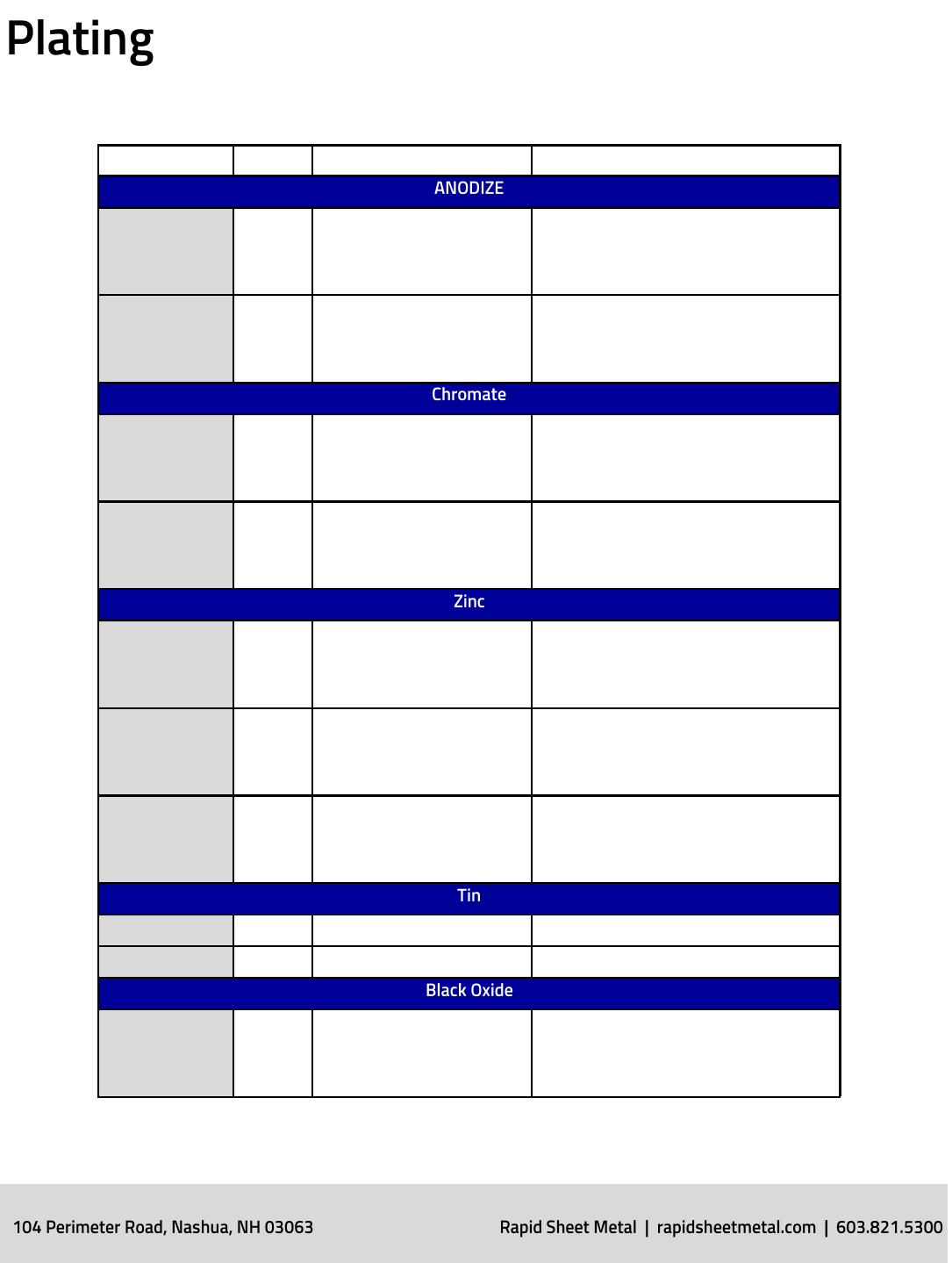
Plang Type Descripon Class
MIL-A-8625 Type II Sulphuric Acid Electrolyte
Standard
Class I – Non Dyed
Natural or Clear
Class II – Dyed
Specify Color: Black, Blue, Red, etc.
MIL-A-8625 Type III Hard Coat
Specialty
Class I – Non Dyed
Natural or Clear
Class II – Dyed
Specify Color: Black, Blue, Red, etc.
MIL-DTL-5541 Type I
Contains Hex Chrome
Non RoHS Yellow Unless
Specied
Class IA – Maximum Protecon, Thick
Coang
Class II – Corrosion Protecon, Thin
Coang
MIL-DTL-5541 Type II Contains Non-Hex Chrome
RoHS Clear Only
Class IA – Maximum Protecon, Thick
Coang
Class II – Corrosion Protecon, Thin
Coang
ASTM-B-633 Type I Non Chromate Conversion
SC1- Durability Mild
SC2 – Durability Moderate
SC3 – Durability Severe
SC4 – Durability Very Severe
ASTM-B-633 Type II
Colored Chromate Conver-
sion
Black or Yellow, Yellow is
RoHS Compliant
SC1- Durability Mild
SC2 – Durability Moderate
SC3 – Durability Severe
SC4 – Durability Very Severe
ASTM-B-633 Type III
Colorless Chromate Con-
version
Please Specify RoHS Com-
pliancy
SC1- Durability Mild
SC2 – Durability Moderate
SC3 – Durability Severe
SC4 – Durability Very Severe
MIL-T-10727 Type I Electrodeposited
MIL-T-10727 Type II Hot-dipped
MIL-C-13924
Class I – Iron & Steel
Class II – 400 Series Stainless Steel
Class III – Fused Salt Process
Class Iv – Stainless Steel MIL-f-495
Finishing
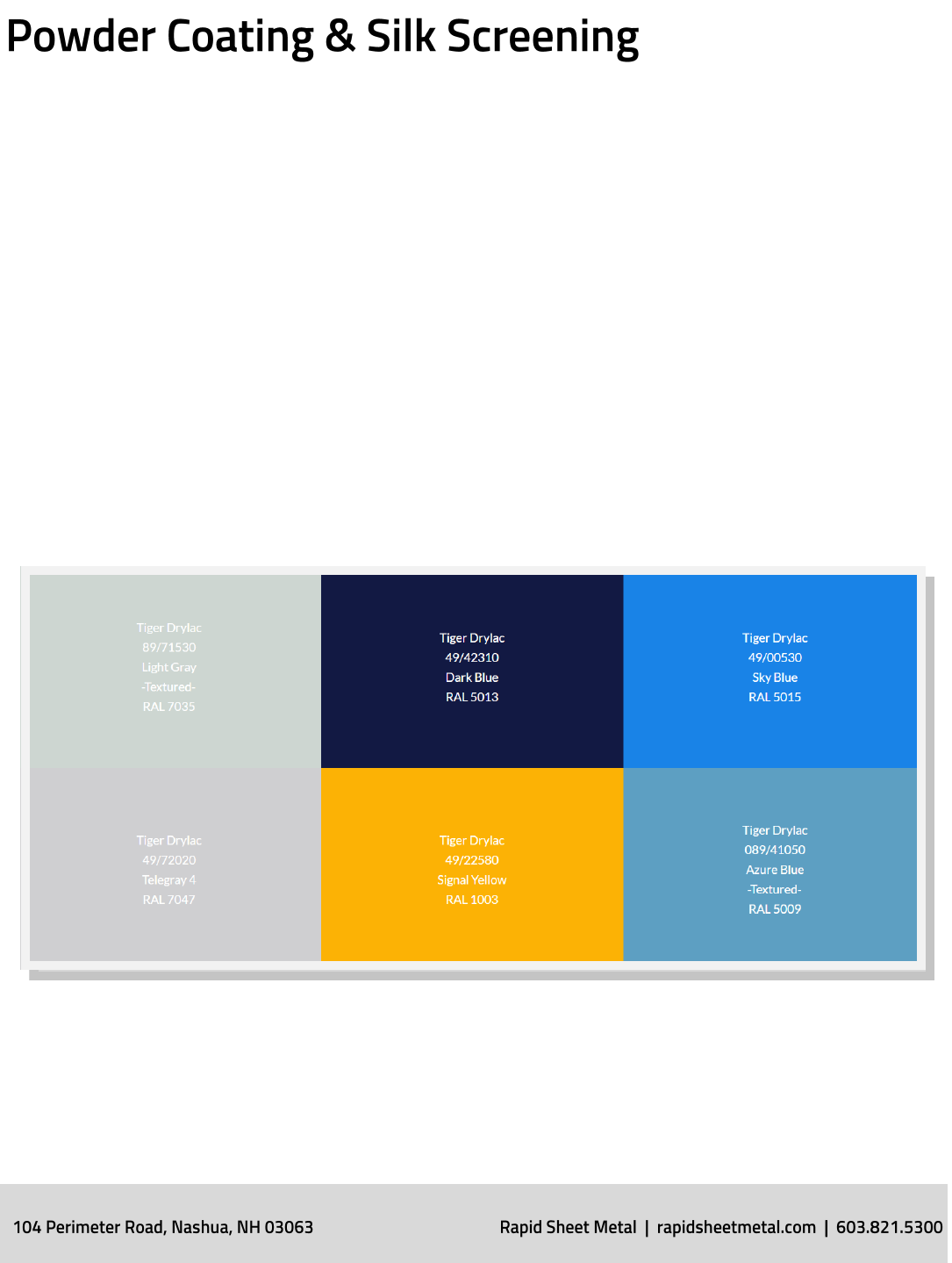
RAPID oers in-house powder coang and silk screening to ensure fast
deliveries. RAPID facilies are ITAR registered and we powder coat or
silk screen your parts in compliance with government regulaons. In
addion, we can order any other powder you need but it will extend
lead-mes. Silk screen colors can be matched to any Pantone number
you provide and all inks are in stock.
Finishing
eRAPID:
eRAPID is a FREE instant sheet metal part quong, ordering and design for
manufacturing feedback plugin for SOLIDWORKS.
To download the plugin go to www.erapid.com
myRAPID:
myRAPID is the RAPID customer portal. It allows you to quote mulple les at
once (instantly quong sheet metal parts), see past quotes, update contact and
shipping informaon, and order mulple parts.
Visit: rapidmanufacturing.com/myrapid
RapidQuote:
Upload 3D CAD les and our team of engineers will process your request and
send a quote out within 24 hours.
Visit: quote.rapidmanufacturing.com/
Powder Coat Library:
To see a list of powders we keep in stock.
Visit: rapidmanufacturing.com/powdercoat
CAD Tooling Library:
To download the CAD Tooling Library.
Visit: rapidmanufacturing.com/3d
Sheet Metal Design for Manufacturing – LinkedIn Group:
This group is designed for engineers who design sheet metal parts. It provides
them with an on-line forum to collaborate and discuss techniques to beer
design sheet metal parts for manufacturability.
Join: hps://www.linkedin.com/groups/8531417
Resources
