Raptor 660
User Manual: Raptor 660
Open the PDF directly: View PDF ![]() .
.
Page Count: 328 [warning: Documents this large are best viewed by clicking the View PDF Link!]
- Yamaha Raptor
- How to use this manual
- Table Of Contents
- Machine Identifacation
- Important Information
- Special Tools
- Specifications
- Lubrication Points
- Coolant Flow Diagrams
- Oil Flow Diagrams
- Cable Routing
- Periodic Checks And Adjustments
- Seat, Fender and Fuel Tank
- Adjusting The Valve Clearance
- Adjusting the Idling Speed
- Adjusting The Throttle Leaver
- Adjusting the Speed Limiter
- Adjusting The Starter Cable
- Checking The Spark Plug
- Checking The Ignition Timing
- Measuring The Compression Preasure
- Checking Engine Oil
- Changing The Engine Oil
- Adjusting The Clutch Cable
- Cleaning The Air Filter
- Changing The Coolant
- Cleaning The Spark Arrester
- Adjusting The Brakes
- Checking The Brake Fluid
- Checking Brakes
- Adjusting The Drive Chain Slack
- Adjusting the Toe-In
- Adjusting Front Shock
- Adjusting Rear Shock
- Checking The Tires
- Checking The Battery
- Checking The Fuses
- Adjusting And Changing Lights
- Front Wheels
- Rear Wheels And Axle
- Front And Rear Brakes
- Steering System
- Front Arms And Shocks
- Rear Shocks And Relay Arm
- Swingarm And Drive Chain
- Engine Removal
- Cylinder Head Cover
- Rocker Arms
- Camshaft And Cylinder Head
- Valves And Valve Springs
- Cylinder And Piston
- AC Magneto
- Clutch
- Oil Pump
- Shift Shaft
- Crankcase
- Camshaft And Balancer
- Transmission
- Radiator
- Thermostat
- Water Pump
- Carburetors
- Electrical Components
- Trouble Shooting

YFM660RN
YFM660RNC
SERVICE MANUAL
LIT-11616-14-21 5LP-28197-E0
EB001000 NOTICE
This manual was produced by the Yamaha Motor Company primarily for use by Yamaha dealers
and their qualified mechanics. It is not possible to include all the knowledge of a mechanic in one
manual, so it is assumed that anyone who uses this book to perform maintenance and repairs on
Yamaha machine has a basic understanding of the mechanical ideas and the procedures of
machine repair. Repairs attempted by anyone without this knowledge are likely to render the
machine unsafe and unfit for use.
Yamaha Motor Company, Ltd. is continually striving to improve all its models. Modifications and sig-
nificant changes in specifications or procedures will be forwarded to all authorized Yamaha dealers
and will appear in future editions of this manual where applicable.
NOTE:
Designs and specifications are subject to change without notice.
IMPORTANT INFORMATION
Particularly important information is distinguished in this manual by the following notations.
The Safety Alert Symbol means ATTENTION! BECOME ALERT! YOUR
SAFETY IS INVOLVED!
Failure to follow WARNING instructions could result in severe injury or death
to the machine operator, a bystander or a person inspecting or repairing the
machine.
A CAUTION indicates special precautions that must be taken to avoid dam-
age to the machine.
A NOTE provides key information to make procedures easier or clearer.
WARNING
CAUTION:
NOTE:
EB002000 HOW TO USE THIS MANUAL
MANUAL ORGANIZATION
This manual consists of chapters for the main categories of subjects. (See “Illustrated symbols”)
1st title 1: This is the title of the chapter with its symbol in the upper right corner of each page.
2nd title 2: This title indicates the section of the chapter and only appears on the first page of each
section. It is located in the upper left corner of the page.
3rd title 3: This title indicates a sub-section that is followed by step-by-step procedures accompa-
nied by corresponding illustrations.
EXPLODED DIAGRAMS
To help identify parts and clarify procedure steps, there are exploded diagrams at the start of each
removal and disassembly section.
1. An easy-to-see exploded diagram 4 is provided for removal and disassembly jobs.
2. Numbers 5 are given in the order of the jobs in the exploded diagram. A number that is enclosed
by a circle indicates a disassembly step.
3. An explanation of jobs and notes is presented in an easy-to-read way by the use of symbol marks
6. The meanings of the symbol marks are given on the next page.
4. A job instruction chart 7 accompanies the exploded diagram, providing the order of jobs, names
of parts, notes in jobs, etc.
5. For jobs requiring more information, the step-by-step format supplements 8 are given in addition
to the exploded diagram and the job instruction chart.
EB003000
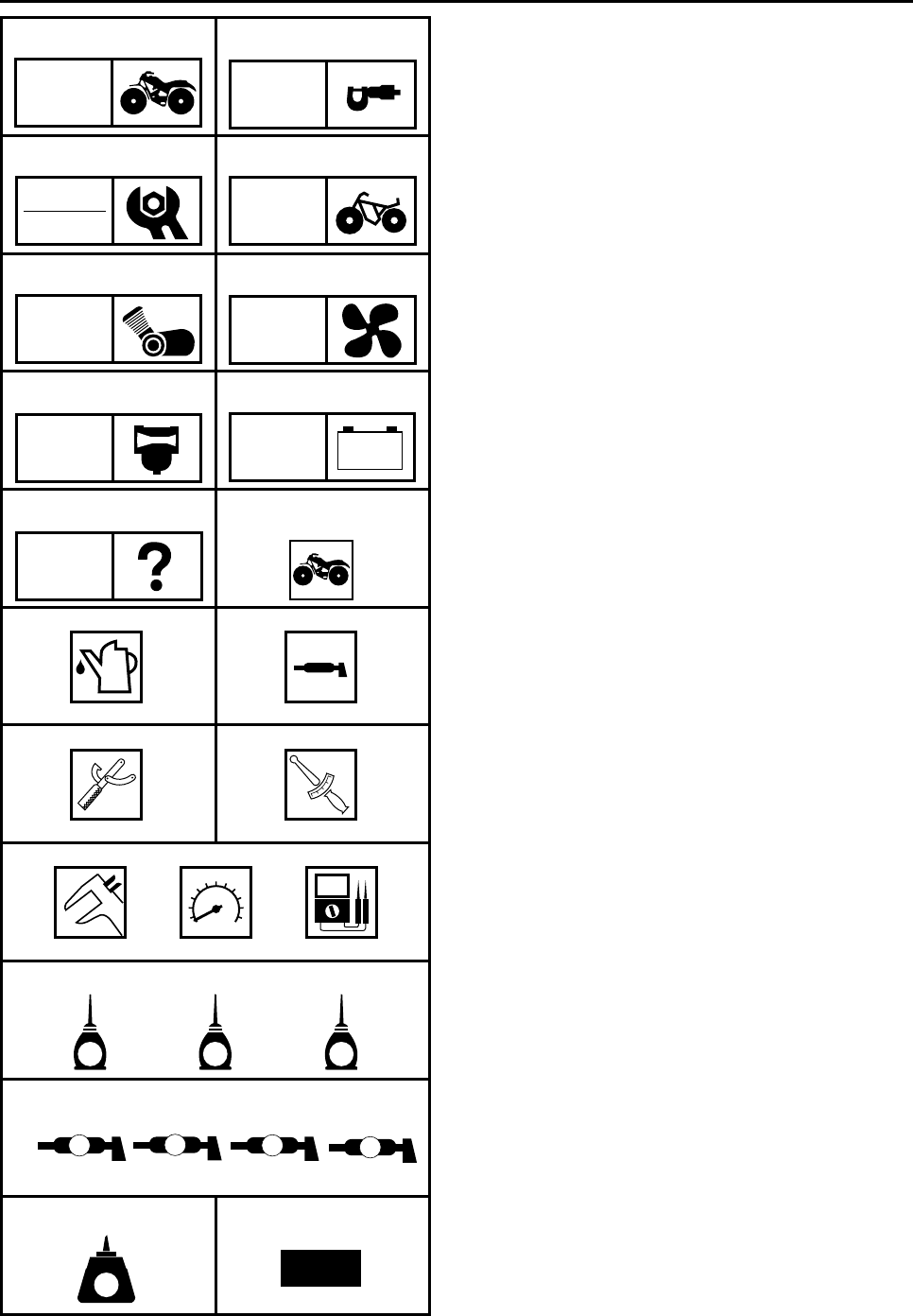
ILLUSTRATED SYMBOLS
Illustrated symbols 1 to 9 are printed on the
top right of each page and indicate the subject
of each chapter.
1General information
2Specifications
3Periodic checks and adjustments
4Chassis
5Engine
6Cooling system
7Carburetion
8Electrical
9Troubleshooting
Illustrated symbols 0 to G are used to identify
the specifications appearing in the text.
0Can be serviced with engine mounted
AFilling fluid
BLubricant
CSpecial tool
DTorque
EWear limit, clearance
FEngine speed
GΩ, V, A
Illustrated symbols H to N in the exploded
diagrams indicate the types of lubricants and
lubrication points.
HApply engine oil
IApply gear oil
JApply molybdenum disulfide oil
KApply wheel bearing grease
LApply lightweight lithium soap base grease
MApply molybdenum disulfide grease
NApply silicon grease
Illustrated symbols O to P in the exploded
diagrams indicate where to apply a locking
agent O and when to install a new part P.
OApply the locking agent (LOCTITE)
PReplace
12
34
56
78
90
AB
CD
EFG
HIJ
K
OP
GEN
INFO SPEC
CHK
ADJ
CHAS
ENG
COOL
CARB
–+
ELEC
TRBL
SHTG
T
R
.
.
EGM
BLS MS
LMN
LT New
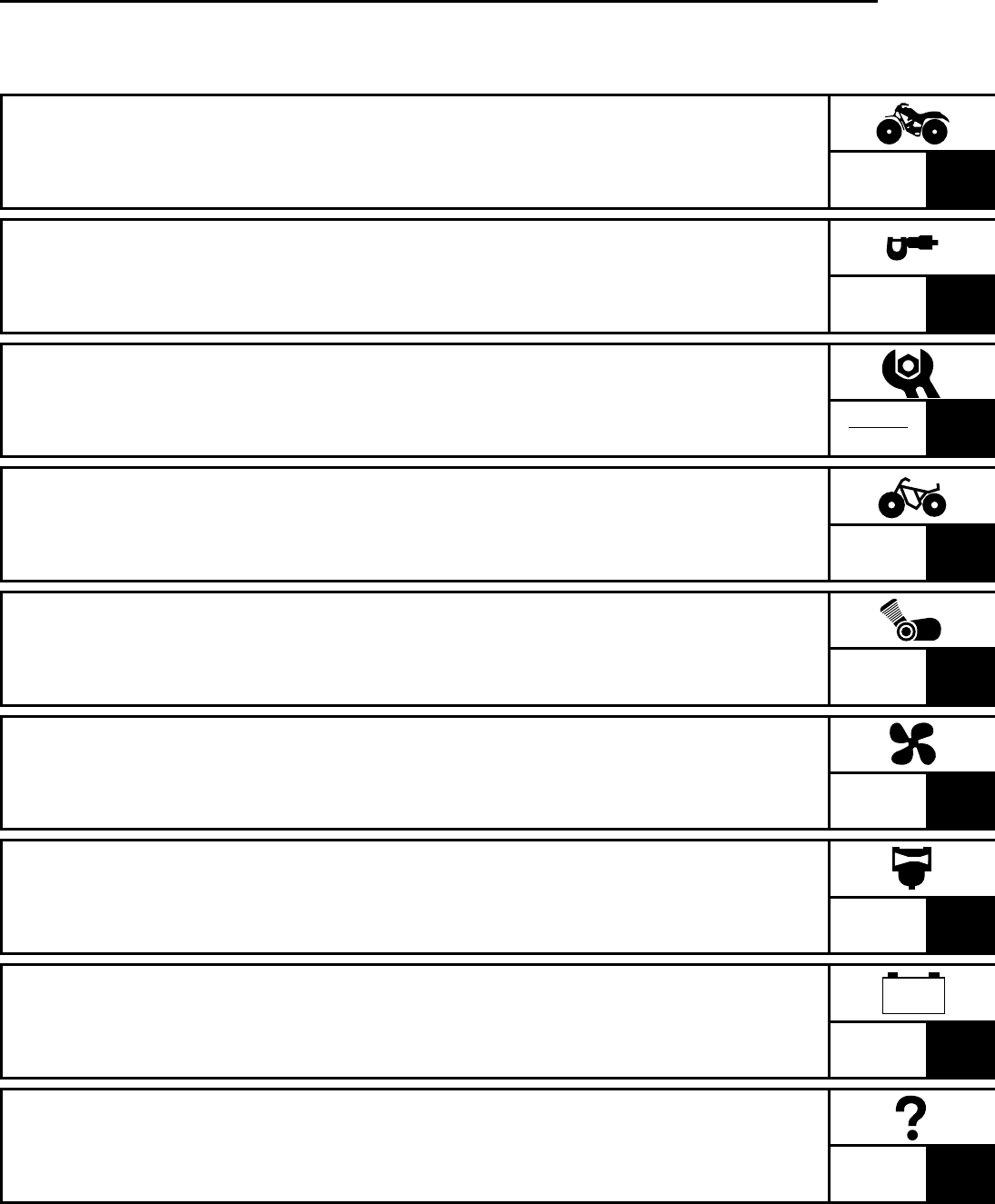
TABLE OF CONTENTS
GENERAL INFORMATION GEN
INFO 1
SPECIFICATIONS SPEC 2
PERIODIC CHECKS AND
ADJUSTMENTS CHK
ADJ 3
CHASSIS CHAS 4
ENGINE ENG 5
COOLING SYSTEM COOL 6
CARBURETION CARB 7
ELECTRICAL ELEC 8
TROUBLESHOOTING TRBL
SHTG 9
–+

CHAPTER 1.
GENERAL INFORMATION
MACHINE IDENTIFICATION ........................................................................1-1
VEHICLE IDENTIFICATION NUMBER .................................................1-1
MODEL LABEL ......................................................................................1-1
IMPORTANT INFORMATION .......................................................................1-2
PREPARATION FOR REMOVAL PROCEDURES ...............................1-2
REPLACEMENT PARTS .......................................................................1-2
GASKETS, OIL SEALS AND O-RINGS ................................................1-2
LOCK WASHERS/PLATES AND COTTER PINS .................................1-3
BEARINGS AND OIL SEALS ................................................................1-3
CIRCLIPS ..............................................................................................1-3
CHECKING OF CONNECTIONS ..................................................................1-4
SPECIAL TOOLS ..........................................................................................1-5
CHAPTER 2.
SPECIFICATIONS
GENERAL SPECIFICATIONS ......................................................................2-1
MAINTENANCE SPECIFICATIONS .............................................................2-4
ENGINE .................................................................................................2-4
CHASSIS .............................................................................................2-14
ELECTRICAL ......................................................................................2-18
HOW TO USE THE CONVERSION TABLE ...............................................2-20
GENERAL TORQUE SPECIFICATIONS ...................................................2-20
LUBRICATION POINTS AND LUBRICANT TYPES ..................................2-21
ENGINE ...............................................................................................2-21
COOLANT FLOW DIAGRAMS ...................................................................2-22
OIL FLOW DIAGRAMS ..............................................................................2-23
CABLE ROUTING .......................................................................................2-27
GEN
INFO 1
SPEC 2
CHK
ADJ 3
CHAS 4
ENG 5
COOL 6
CARB 7
ELEC 8
TRBL
SHTG 9
–+
CHAPTER 3.
PERIODIC CHECKS AND ADJUSTMENTS
INTRODUCTION ........................................................................................... 3-1
PERIODIC MAINTENANCE/LUBRICATION INTERVALS .......................... 3-1
SEAT, FENDERS AND FUEL TANK ............................................................3-3
SEAT, FRONT PANEL, FOOTREST GUARDS
AND ENGINE SKID PLATE ...............................................................3-3
HEADLIGHTS AND FRONT FENDER ..................................................3-4
REAR FENDER .....................................................................................3-5
FUEL TANK ...........................................................................................3-6
ENGINE .........................................................................................................3-8
ADJUSTING THE VALVE CLEARANCE ..............................................3-8
ADJUSTING THE TIMING CHAIN ......................................................3-11
ADJUSTING THE IDLING SPEED ......................................................3-11
ADJUSTING THE THROTTLE LEVER FREE PLAY .......................... 3-12
ADJUSTING THE SPEED LIMITER .................................................... 3-14
ADJUSTING THE STARTER CABLE .................................................3-15
CHECKING THE SPARK PLUG .........................................................3-16
CHECKING THE IGNITION TIMING ...................................................3-17
MEASURING THE COMPRESSION PRESSURE ..............................3-18
CHECKING THE ENGINE OIL LEVEL ................................................ 3-19
CHANGING THE ENGINE OIL ...........................................................3-20
ADJUSTING THE CLUTCH CABLE ....................................................3-23
CLEANING THE AIR FILTER ..............................................................3-24
CHECKING THE COOLANT LEVEL ...................................................3-27
CHANGING THE COOLANT ...............................................................3-27
CHECKING THE COOLANT TEMPERATURE WARNING LIGHT ..... 3-31
CLEANING THE SPARK ARRESTER ................................................3-31
CHASSIS ....................................................................................................3-33
ADJUSTING THE FRONT BRAKE .....................................................3-33
ADJUSTING THE REAR BRAKE ........................................................3-33
ADJUSTING THE PARKING BRAKE ..................................................3-34
CHECKING THE BRAKE FLUID LEVEL .............................................3-35
CHECKING THE FRONT BRAKE PAD ..............................................3-36
CHECKING THE REAR BRAKE PAD .................................................3-36
ADJUSTING THE REAR BRAKE LIGHT SWITCH ............................. 3-36
CHECKING THE BRAKE HOSE .........................................................3-37
BLEEDING THE HYDRAULIC BRAKE SYSTEM ...............................3-38
ADJUSTING THE SHIFT PEDAL ........................................................3-39
ADJUSTING THE REVERSE CONTROL CABLE .............................. 3-40
ADJUSTING THE DRIVE CHAIN SLACK ...........................................3-40
CHECKING THE STEERING SYSTEM ..............................................3-42
ADJUSTING THE TOE-IN ...................................................................3-42
ADJUSTING THE FRONT SHOCK ABSORBER ................................3-44
ADJUSTING THE REAR SHOCK ABSORBER ..................................3-45

CHECKING THE TIRE ........................................................................3-47
CHECKING THE WHEEL ....................................................................3-49
CHECKING AND LUBRICATING THE CABLE ...................................3-49
LUBRICATING THE LEVERS AND PEDAL ........................................3-50
ELECTRICAL ..............................................................................................3-51
CHECKING THE BATTERY ................................................................3-51
CHECKING THE FUSE .......................................................................3-56
ADJUSTING THE HEADLIGHT BEAM ...............................................3-58
REPLACING THE HEADLIGHT BULB ................................................3-58
CHAPTER 4.
CHASSIS
FRONT WHEELS ..........................................................................................4-1
FRONT WHEELS ..................................................................................4-1
CHECKING THE WHEEL ......................................................................4-3
CHECKING THE WHEEL HUB .............................................................4-3
CHECKING THE BRAKE DISC .............................................................4-4
INSTALLING WHEEL HUB ...................................................................4-5
INSTALLING THE WHEEL ....................................................................4-5
REAR WHEELS, WHEEL AXLE AND HUB .................................................4-6
REAR WHEELS ....................................................................................4-6
WHEEL AXLE AND HUB ......................................................................4-7
REMOVING THE REAR AXLE ..............................................................4-9
CHECKING THE WHEEL ....................................................................4-10
CHECKING THE WHEEL HUB ...........................................................4-10
CHECKING THE REAR AXLE ............................................................4-10
CHECKING THE HUB .........................................................................4-11
CHECKING THE BRAKE DISC ...........................................................4-11
INSTALLING THE NUTS (REAR AXLE) .............................................4-11
INSTALLING THE WHEEL HUB .........................................................4-12
INSTALLING THE WHEEL ..................................................................4-12
FRONT AND REAR BRAKES ....................................................................4-13
FRONT BRAKE PADS ........................................................................4-13
REAR BRAKE PADS ...........................................................................4-14
REPLACING THE FRONT BRAKE PAD .............................................4-15
REPLACING THE REAR BRAKE PAD ...............................................4-17
FRONT BRAKE MASTER CYLINDER ................................................4-19
REAR BRAKE MASTER CYLINDER ..................................................4-21
CHECKING THE MASTER CYLINDER ..............................................4-24
ASSEMBLING THE FRONT
AND REAR BRAKE MASTER CYLINDER ......................................4-25
INSTALLING THE FRONT BRAKE MASTER CYLINDER ..................4-25
INSTALLING THE REAR BRAKE MASTER CYLINDER .................... 4-27
FRONT BRAKE CALIPERS ................................................................4-29
REAR BRAKE CALIPER .....................................................................4-31
DISASSEMBLING THE FRONT AND REAR BRAKE CALIPER ........4-34

GEN
INFO 1
SPEC 2
CHK
ADJ 3
CHAS 4
ENG 5
COOL 6
CARB 7
ELEC 8
TRBL
SHTG 9
–+
CHECKING THE FRONT AND REAR BRAKE CALIPER ...................4-34
ASSEMBLING THE FRONT BRAKE CALIPER .................................. 4-35
ASSEMBLING THE REAR BRAKE CALIPER ....................................4-36
INSTALLING THE FRONT BRAKE CALIPER ....................................4-37
INSTALLING THE REAR BRAKE CALIPER .......................................4-38
STEERING SYSTEM ..................................................................................4-40
HANDLEBAR .......................................................................................4-40
REMOVING THE FRONT BRAKE SWITCH, PARK SWITCH
AND CLUTCH SWITCH ..................................................................4-42
REMOVING THE HANDLEBAR GRIP ................................................4-42
CHECKING THE HANDLEBAR ..........................................................4-42
INSTALLING THE HANDLEBAR ........................................................4-43
INSTALLING THE HANDLEBAR GRIP ...............................................4-43
INSTALLING THE CLUTCH LEVER ...................................................4-43
INSTALLING THE BRAKE MASTER CYLINDER ...............................4-44
STEERING STEM ...............................................................................4-45
REMOVING THE BEARING RETAINER ............................................4-47
CHECKING THE STEERING STEM ...................................................4-47
INSTALLING THE BEARING RETAINER ...........................................4-47
INSTALLING THE LOCK WASHER ....................................................4-47
TIE-ROD AND STEERING KNUCKLE ................................................4-48
REMOVING THE STEERING KNUCKLE ...........................................4-49
CHECKING THE TIE-ROD ..................................................................4-49
CHECKING THE STEERING KNUCKLE ............................................ 4-49
INSTALLING THE TIE-ROD ................................................................4-49
FRONT ARMS AND FRONT SHOCK ABSORBERS ................................4-50
REMOVING THE FRONT ARM ..........................................................4-52
CHECKING THE FRONT ARM ...........................................................4-52
CHECKING THE FRONT SHOCK ABSORBER .................................4-52
CHECKING THE BALL JOINT ............................................................4-53
INSTALLING THE FRONT ARM .........................................................4-54
REAR SHOCK ABSORBER AND RELAY ARM ........................................4-55
HANDLING THE REAR SHOCK ABSORBER
AND GAS CYLINDER .....................................................................4-57
DISPOSING OF A REAR SHOCK ABSORBER
AND GAS CYLINDER .....................................................................4-57
REMOVING THE REAR SHOCK ABSORBER ...................................4-58
CHECKING THE REAR SHOCK ABSORBER ....................................4-58
CHECKING THE RELAY ARM AND CONNECTING ARM .................4-58
INSTALLING THE RELAY ARM AND CONNECTING ARM ...............4-59
INSTALLING THE REAR SHOCK ABSORBER ..................................4-59
SWINGARM AND DRIVE CHAIN ...............................................................4-60
REMOVING THE SWINGARM ............................................................4-62
CHECKING THE SWINGARM ............................................................4-62
CHECKING THE DRIVE CHAIN .........................................................4-63
INSTALLING THE SWINGARM ..........................................................4-65
INSTALLING THE DRIVE SPROCKET ...............................................4-65

CHAPTER 5.
ENGINE
ENGINE REMOVAL ......................................................................................5-1
MUFFLER AND EXHAUST PIPES .......................................................5-1
LEFT FOOTREST .................................................................................5-2
LEADS, CABLES AND HOSES ............................................................5-3
ENGINE MOUNTING BOLTS ...............................................................5-5
INSTALLING THE ENGINE ...................................................................5-7
CYLINDER HEAD COVER ...........................................................................5-8
REMOVING THE CYLINDER HEAD COVER .....................................5-10
CHECKING THE CYLINDER HEAD COVER .....................................5-10
CHECKING THE TAPPET COVER ..................................................... 5-11
INSTALLING THE CYLINDER HEAD COVER ...................................5-11
ROCKER ARMS .........................................................................................5-12
REMOVING THE ROCKER ARM .......................................................5-14
CHECKING THE ROCKER ARM ........................................................5-14
INSTALLING THE ROCKER ARM ......................................................5-15
CAMSHAFT AND CYLINDER HEAD .........................................................5-16
REMOVING THE CAMSHAFT AND CYLINDER HEAD .....................5-18
CHECKING THE CAMSHAFT .............................................................5-19
CHECKING THE CAMSHAFT SPROCKET ........................................5-19
CHECKING THE DECOMPRESSION SYSTEM .................................5-19
CHECKING THE TIMING CHAIN GUIDE ...........................................5-20
CHECKING THE TIMING CHAIN TENSIONER ..................................5-20
CHECKING THE CYLINDER HEAD ...................................................5-20
INSTALLING THE CAMSHAFT AND CYLINDER HEAD ....................5-21
VALVES AND VALVE SPRINGS ...............................................................5-24
REMOVING THE VALVE AND VALVE SPRING ................................5-25
CHECKING THE VALVE AND VALVE SPRING .................................5-26
INSTALLING THE VALVE AND VALVE SPRING ...............................5-30
CYLINDER AND PISTON ...........................................................................5-32
REMOVING THE PISTON ..................................................................5-33
CHECKING THE CYLINDER AND PISTON .......................................5-33
CHECKING THE PISTON RING .........................................................5-35
CHECKING THE PISTON PIN INSPECTION .....................................5-36
INSTALLING THE PISTON .................................................................5-36
INSTALLING THE CYLINDER ............................................................5-37
AC MAGNETO ............................................................................................5-38
REMOVING THE AC MAGNETO ROTOR ..........................................5-40
CHECKING THE COIL ........................................................................5-40
CHECKING THE STARTER CLUTCH ................................................5-41
INSTALLING THE AC MAGNETO ROTOR ........................................5-42

GEN
INFO 1
SPEC 2
CHK
ADJ 3
CHAS 4
ENG 5
COOL 6
CARB 7
ELEC 8
TRBL
SHTG 9
–+
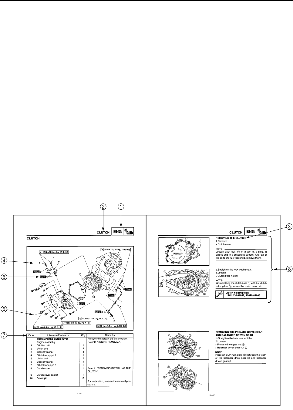
CLUTCH ......................................................................................................5-43
REMOVING THE CLUTCH .................................................................5-47
REMOVING THE PRIMARY DRIVE GEAR
AND BALANCER DRIVEN GEAR ...................................................5-47
CHECKING THE FRICTION PLATE ...................................................5-48
CHECKING THE CLUTCH PLATE .....................................................5-48
CHECKING THE CLUTCH SPRING ...................................................5-49
CHECKING THE CLUTCH HOUSING ................................................5-49
CHECKING THE CLUTCH BOSS .......................................................5-49
CHECKING THE PRESSURE PLATE ................................................5-49
CHECKING THE PULL LEVER SHAFT AND PULL ROD ..................5-50
CHECKING THE PRIMARY DRIVE ....................................................5-50
CHECKING THE BALANCER DRIVE .................................................5-50
INSTALLING THE PRIMARY DRIVE GEAR
AND BALANCER DRIVEN GEAR ...................................................5-51
INSTALLING THE CLUTCH ................................................................5-52
OIL PUMP ...................................................................................................5-54
CHECKING THE OIL PUMP ...............................................................5-56
ASSEMBLING THE OIL PUMP............................................................5-56
SHIFT SHAFT .............................................................................................5-57
CHECKING THE SHIFT SHAFT .........................................................5-59
CHECKING THE STOPPER LEVER ..................................................5-59
CHECKING THE SHIFT GUIDE AND SHIFT LEVER .........................5-59
CHECKING THE SEGMENT ...............................................................5-59
INSTALLING THE SHIFT LEVER .......................................................5-59
INSTALLING THE STOPPER LEVER ................................................5-60
INSTALLING THE SHIFT SHAFT .......................................................5-61
CRANKCASE ..............................................................................................5-62
TIMING CHAIN AND SPEED SENSOR ROTOR ................................5-62
CRANKCASE ......................................................................................5-64
CRANKCASE BEARING .....................................................................5-65
SEPARATING THE CRANKCASE.......................................................5-66
CHECKING THE TIMING CHAIN AND GUIDE ...................................5-66
CHECKING THE OIL STRAINER .......................................................5-66
CHECKING THE CRANKCASE ..........................................................5-67
CHECKING THE BEARINGS ..............................................................5-67
ASSEMBLING THE CRANKCASE ......................................................5-67
CRANKSHAFT AND BALANCER ..............................................................5-69
REMOVING THE CRANKSHAFT .......................................................5-70
CHECKING THE CRANKSHAFT ........................................................5-70
INSTALLING THE CRANKSHAFT ......................................................5-71

TRANSMISSION .........................................................................................5-72
MAIN AXLE .........................................................................................5-74
DRIVE AXLE .......................................................................................5-75
CHECKING THE SHIFT FORK ...........................................................5-77
CHECKING THE SHIFT DRUM ..........................................................5-77
CHECKING THE TRANSMISSION .....................................................5-77
ASSEMBLING THE MAIN AXLE AND DRIVE AXLE ..........................5-78
INSTALLING THE TRANSMISSION ...................................................5-79
CHAPTER 6.
COOLING SYSTEM
RADIATOR ....................................................................................................6-1
CHECKING THE RADIATOR ................................................................6-3
INSTALLING THE RADIATOR ..............................................................6-4
THERMOSTAT ..............................................................................................6-5
CHECKING THE THERMOSTAT ..........................................................6-7
ASSEMBLING THE THERMOSTAT .....................................................6-7
WATER PUMP ..............................................................................................6-8
DISASSEMBLING THE WATER PUMP ..............................................6-11
CHECKING THE WATER PUMP ........................................................6-11
ASSEMBLING THE WATER PUMP ....................................................6-12
CHAPTER 7.
CARBURETION
CARBURETORS ...........................................................................................7-1
DISASSEMBLING THE CARBURETOR ...............................................7-5
CHECKING THE CARBURETOR ......................................................... 7-5
ASSEMBLING THE CARBURETOR .....................................................7-7
ADJUSTING THE FUEL LEVEL ............................................................ 7-8

GEN
INFO 1
SPEC 2
CHK
ADJ 3
CHAS 4
ENG 5
COOL 6
CARB 7
ELEC 8
TRBL
SHTG 9
–+
CHAPTER 8.
ELECTRICAL
ELECTRICAL COMPONENTS .....................................................................8-1
CHECKING THE SWITCH ............................................................................8-2
CHECKING THE SWITCH ....................................................................8-2
CHECKING A SWITCH SHOWN IN THE MANUAL .............................8-2
CHECKING THE SWITCH CONTINUITY .............................................8-3
IGNITION SYSTEM .......................................................................................8-5
CIRCUIT DIAGRAM ..............................................................................8-5
TROUBLESHOOTING ..........................................................................8-6
ELECTRIC STARTING SYSTEM ...............................................................8-11
CIRCUIT DIAGRAM ............................................................................8-11
STARTING CIRCUIT OPERATION ..................................................... 8-12
TROUBLESHOOTING ........................................................................8-13
STARTER MOTOR .............................................................................8-16
CHECKING THE STARTER MOTOR .................................................8-17
ASSEMBLING THE STARTER MOTOR .............................................8-18
CHARGING SYSTEM .................................................................................8-19
CIRCUIT DIAGRAM ............................................................................8-19
TROUBLESHOOTING ........................................................................8-20
LIGHTING SYSTEM ....................................................................................8-22
CIRCUIT DIAGRAM ............................................................................8-22
TROUBLESHOOTING ........................................................................8-23
CHECKING THE LIGHTING SYSTEM ................................................8-25
SIGNAL SYSTEM .......................................................................................8-27
CIRCUIT DIAGRAM ............................................................................8-27
TROUBLESHOOTING ........................................................................8-28
CHECKING THE SIGNAL SYSTEM ...................................................8-30
COOLING SYSTEM ....................................................................................8-36
CIRCUIT DIAGRAM ............................................................................8-36
TROUBLESHOOTING .......................................................................8-37

CHAPTER 9.
TROUBLESHOOTING
STARTING FAILURE/HARD STARTING .....................................................9-1
FUEL SYSTEM ......................................................................................9-1
ELECTRICAL SYSTEM .........................................................................9-1
COMPRESSION SYSTEM ....................................................................9-2
POOR IDLE SPEED PERFORMANCE ........................................................9-2
POOR IDLE SPEED PERFORMANCE .................................................9-2
POOR MEDIUM AND HIGH-SPEED PERFORMANCE ...............................9-2
POOR MEDIUM AND HIGH-SPEED PERFORMANCE .......................9-2
FAULTY GEAR SHIFTING ...........................................................................9-3
HARD SHIFTING ...................................................................................9-3
SHIFT PEDAL DOES NOT MOVE ........................................................9-3
JUMP-OUT GEAR .................................................................................9-3
CLUTCH SLIPPING/DRAGGING .................................................................9-3
CLUTCH SLIPPING ..............................................................................9-3
CLUTCH DRAGGING ...........................................................................9-3
OVERHEATING ............................................................................................9-4
OVERHEATING ....................................................................................9-4
OVER COOLING ...........................................................................................9-4
COOLING SYSTEM ..............................................................................9-4
FAULTY BRAKE ........................................................................................... 9-4
POOR BRAKING EFFECT ....................................................................9-4
SHOCK ABSORBER MALFUNCTION .........................................................9-5
MALFUNCTION .....................................................................................9-5
UNSTABLE HANDLING ...............................................................................9-5
UNSTABLE HANDLING ........................................................................9-5
LIGHTING SYSTEM ......................................................................................9-5
HEADLIGHT DARK ...............................................................................9-5
BULB BURNT OUT ...............................................................................9-5
1 - 1
GEN
INFO
MACHINE IDENTIFICATION
GENERAL INFORMATION
MACHINE IDENTIFICATION
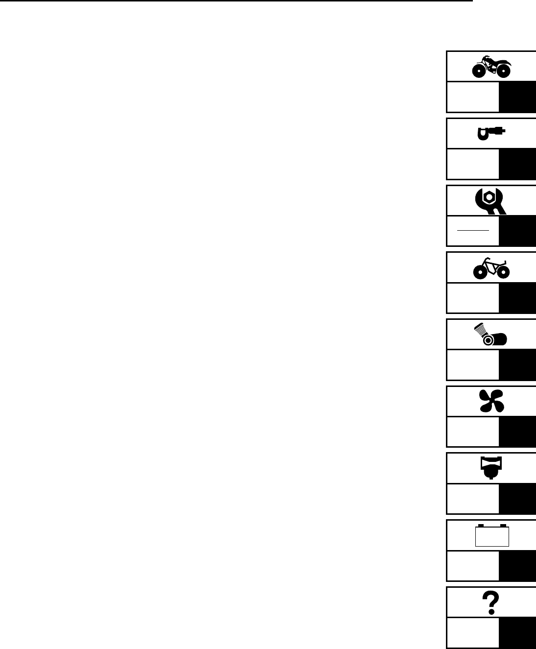
VEHICLE IDENTIFICATION NUMBER
The vehicle identification number 1 is
stamped into the left side of the frame.
MODEL LABEL
The model label 1 is affixed to the air filter
case cover. This information will be needed to
order spare parts.

1 - 2
GEN
INFO
EB101000
IMPORTANT INFORMATION
PREPARATION FOR REMOVAL
PROCEDURES
1.Remove all dirt, mud, dust and foreign mate-
rial before removal and disassembly.
2.Use proper tools and cleaning equipment.
Refer to the “SPECIAL TOOLS” section.
3.When disassembling the machine, always
keep mated parts together. This includes
gears, cylinder, piston and other parts that
have been “mated” through normal wear.
Mated parts must always be reused or
replaced as an assembly.
4.During machine disassembly, clean all parts
and place them in trays in the order of disas-
sembly. This will speed up assembly and
allow for the correct installation of all parts.
5.Keep all parts away from any source of fire.
EB101010
REPLACEMENT PARTS
1.Use only genuine Yamaha parts for all
replacements. Use oil and grease recom-
mended by Yamaha for all lubrication jobs.
Other brands may be similar in function and
appearance, but inferior in quality.
EB101020
GASKETS, OIL SEALS AND O-RINGS
1.Replace all gaskets, seals and O-rings when
overhauling the engine. All gasket surfaces,
oil seal lips and O-rings must be cleaned.
2.Properly oil all mating parts and bearings
during reassembly. Apply grease to the oil
seal lips.
IMPORTANT INFORMATION
1 - 3
GEN
INFO
EB101030
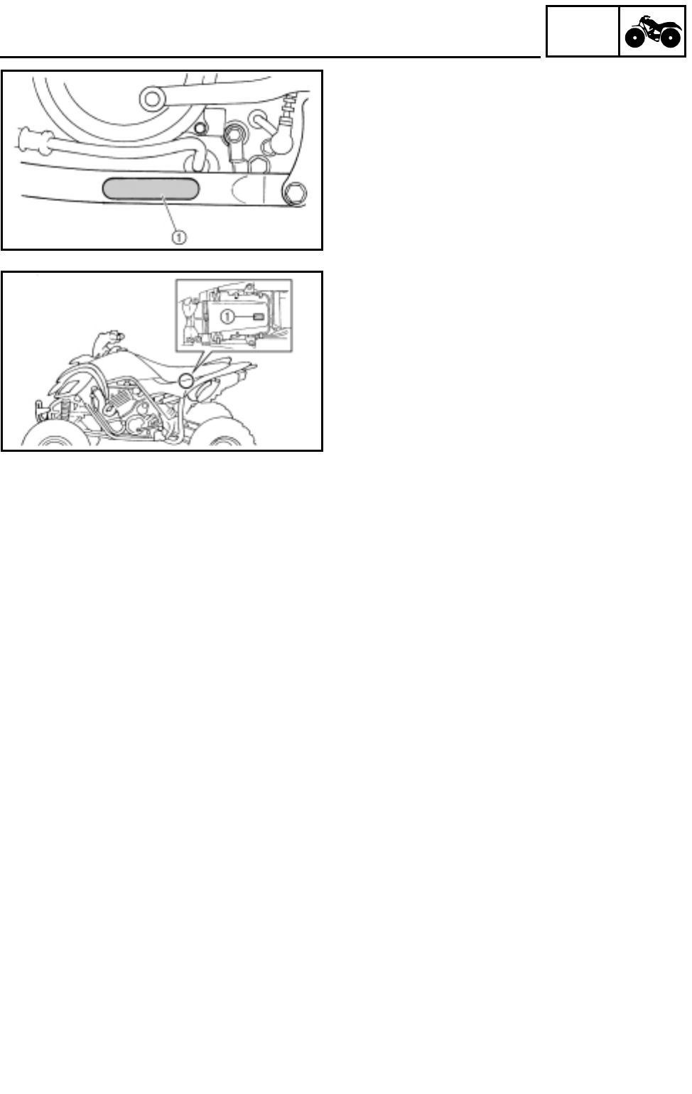
LOCK WASHERS/PLATES AND COTTER
PINS
1.Replace all lock washers/plates 1 and cotter
pins after removal. Bend lock tabs along the
bolt or nut flats after the bolt or nut has been
tightened to specification.
EB101040
BEARINGS AND OIL SEALS
1.Install bearings and oil seals so that the
manufacturer’s marks or numbers are visible.
When installing oil seals, apply a light coat-
ing of lightweight lithium base grease to the
seal lips. Oil bearings liberally when install-
ing, if appropriate.
1Oil seal
CAUTION:
Do not use compressed air to spin the
bearings dry. This will damage the bearing
surfaces.
1Bearing
EB101050
CIRCLIPS
1.Check all circlips carefully before reassem-
bly. Always replace piston pin clips after one
use. Replace distorted circlips. When install-
ing a circlip 1, make sure that the sharp-
edged corner 2 is positioned opposite the
thrust 3 it receives. See sectional view.
4Shaft
IMPORTANT INFORMATION
1 - 4
GEN
INFO
CHECKING OF CONNECTIONS
EB801000
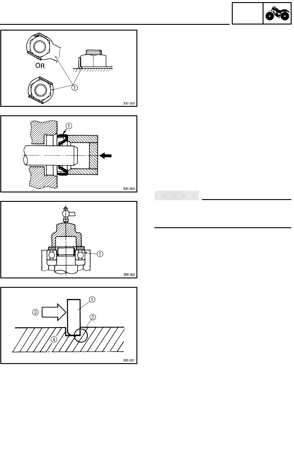
CHECKING OF CONNECTIONS
Check the connectors for stains, rust, mois-
ture, etc.
1.Disconnect:
●Connector
2.Check:
●Connector
Moisture → Dry each terminal with an air
blower.
Stains/rust → Connect and disconnect the
terminals several times.
3.Check:
●Connector leads
Looseness → Bend up the pin 1 and con-
nect the terminals.
4.Connect:
●Connector terminals
NOTE:
The two terminals “click” together.
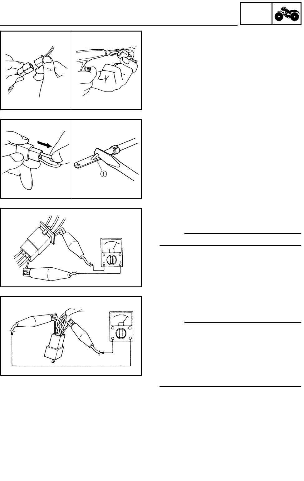
5.Check:
●Continuity (using a pocket tester)
NOTE:
●If there is no continuity, clean the terminals.
●When checking the wire harness be sure to
perform steps 1 to 3.
●As a quick remedy, use a contact revitalizer
available at most part stores.
●Check the connector with a pocket tester as
shown.
1 - 5
GEN
INFO
SPECIAL TOOLS
EB102001
SPECIAL TOOLS
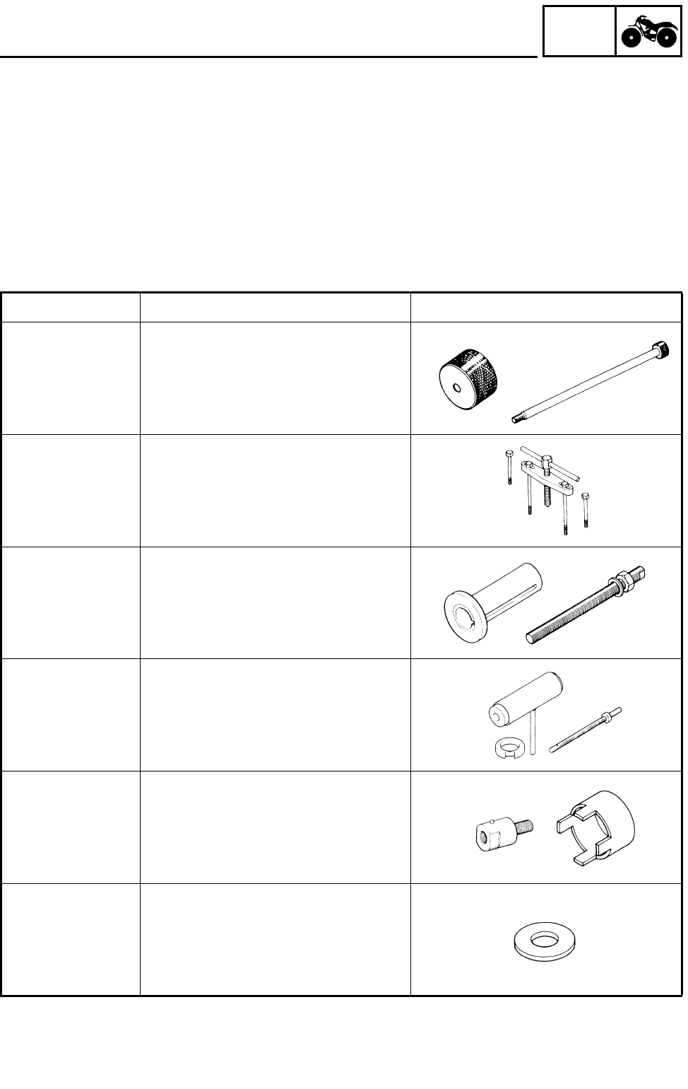
The following special tools are necessary for complete and accurate tune-up and assembly. Use
only the appropriate special tools; this will help prevent damage caused by the use of inappropriate
tools or improvised techniques. Special tools may differ by shape and part number from country to
country. In such a case, two types are provided.
When placing an order, refer to the list provided below to avoid any mistakes.
For US and CDN
P/N. YM-, YU-, YS-, YK-, ACC-
Except for US and CDN
P/N. 90890-
Tool No. Tool name/How to use Illustration
Bolt
90890-01083
Weight
90890-01084
Set
YU-01083-A
Slide hammer bolt (M6)/weight/set
These tools are used to remove the rocker
arm shaft.
90890-01135
YU-01135-A
Crankcase separating tool
This tool is used to separate the crank-
case.
Pot
90890-01274
Bolt
90890-01275
Crankshaft installer pot
Crankshaft installer bolt
These tools are used to install the crank-
shaft.
YU-90050
Crankshaft installer set
These tools are used to install the crank-
shaft.
Adapter
90890-04059
YM-90069
Spacer
90890-04081
YM-91044
Adapter
Spacer (crankshaft installer)
These tools are used to install the crank-
shaft.
90890-01016
Spacer
This tool is used to install the crankshaft.
1 - 6
GEN
INFO
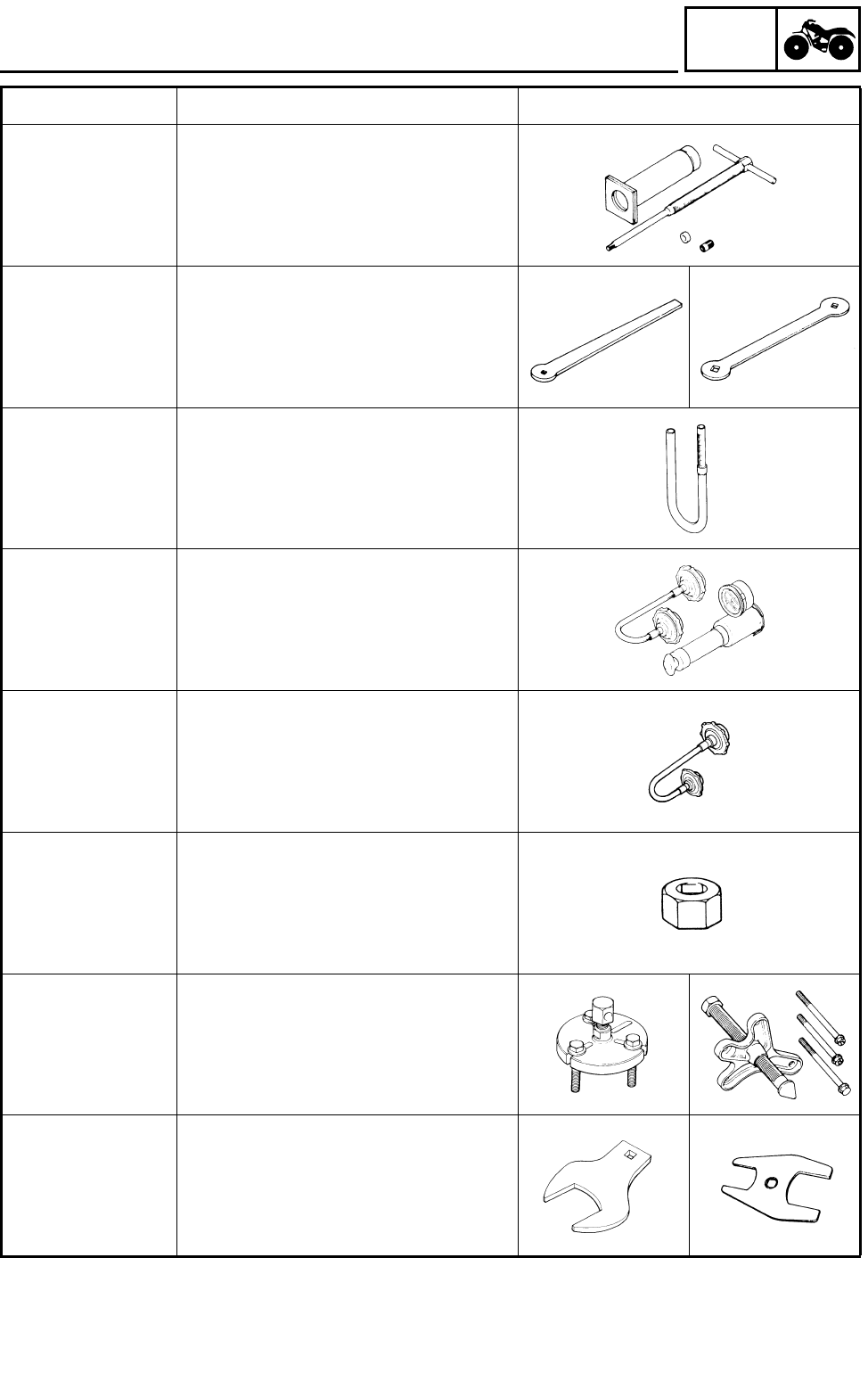
SPECIAL TOOLS
90890-01304
YU-01304
Piston pin puller
This tool is used to remove the piston pin.
90890-01311
YM-08035
Tappet adjusting tool (3 mm)
This tool is necessary for adjusting the
valve clearance.
90890-01312
YM-01312-A
Fuel level gauge
This gauge is used to measure the fuel
level in the float chamber.
90890-01325
YU-24460-01
Radiator cap tester
This tool is used to check the cooling sys-
tem.
90890-01352
YU-33984
Adapter
This tool is used to check the cooling sys-
tem.
90890-01327
YM-01327
Damper rod holder (30 mm)
This tool is needed to loosen and tighten
the steering stem bearing retainer.
90890-01362
YU-33270
Flywheel puller
These tools are needed to remove the
rotor.
90890-01419
YM-37132
Axle nut wrench (50 mm)
This tool is needed to loosen or tighten the
rear axle nut.
Tool No. Tool name/How to use Illustration
1 - 7
GEN
INFO
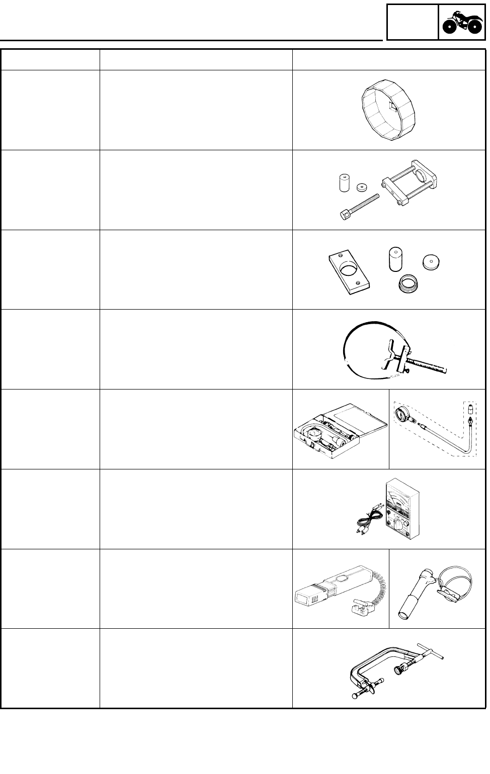
SPECIAL TOOLS
90890-01469
YM-01469
Oil filter wrench
This tool is needed to loosen or tighten
the oil filter cartridge.
90890-01474
YM-01474
Ball joint remover/installer set
These tools are used to removing or
installing the ball joint.
90890-01480
YM-01480
Ball joint remover/installer attachment set
These tools are used to removing or
installing the ball joint.
90890-01701
YS-01880
Sheave holder
This tool is needed to hold the AC mag-
neto rotor when removing or installing the
AC magneto rotor bolts.
Set
90890-03081
YU-33223
Adapter
90890-04082
YU-33223-3
Compression gauge set
Adapter
These tools are needed to measure
engine compression.
90890-03112
YU-03112
Pocket tester
This instrument is needed for checking the
electrical system.
90890-03141
YM-33277-A
Timing light
This tool is necessary for checking ignition
timing.
Compressor
90890-04019
YM-04019
Attachment
90890-01243
Valve spring compressor
Valve spring compressor attachment
This tool is needed to remove and install
the valve assemblies.
Tool No. Tool name/How to use Illustration
1 - 8
GEN
INFO
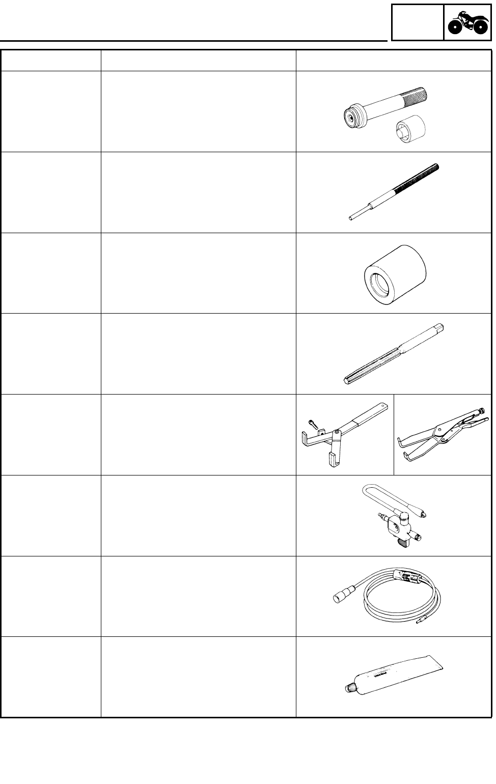
SPECIAL TOOLS
Middle driven shaft
bearing driver
90890-04058
YM-04058-1
Mechanical seal
installer
90890-04078
YM-33221
Middle driven shaft bearing driver
Mechanical seal installer
These tools are used to install the water
pump seal.
90890-04064
YM-4064-A
Valve guide remover (ø 6)
This tool is needed to remove and install
the valve guide.
90890-04065
YM-04065-A
Valve guide installer (ø 6)
This tool is needed to install the valve
guide.
90890-04066
YM-04066
Valve guide reamer (ø 6)
This tool is needed to rebore the new
valve guide.
90890-04086
YM-91042
Clutch holding tool
This tool is needed to hold the clutch car-
rier when removing or installing the carrier
nut.
90890-06754
Ignition checker
This instrument is necessary for checking
the ignition system components.
YM-34487
Dynamic spark tester
This instrument is necessary for checking
the ignition system components.
Bond
90890-85505
Sealant
ACC-11001-05-01
Yamaha bond No. 1215
Sealant (Quick Gasket®)
This sealant (bond) is used on crankcase
mating surfaces, etc.
Tool No. Tool name/How to use Illustration
2 - 1
SPEC
SPECIFICATIONS
GENERAL SPECIFICATIONS
Item Standard
Model code: 5LP1 : (Except for California)
5LP3 : (For California)
Dimensions:
Overall length 1,830 mm (72.0 in)
Overall width 1,100 mm (43.3 in)
Overall height 1,150 mm (45.3 in)
Seat height 860 mm (33.9 in)
Wheelbase 1,245 mm (49.0 in)
Minimum ground clearance 265 mm (10.4 in)
Minimum turning radius 3,300 mm (129.9 in)
Basic weight:
With oil and full fuel tank 193 kg (426 lb)
Engine:
Engine type Liquid-cooled 4-stroke, SOHC
Cylinder arrangement Forward-inclined single cylinder
Displacement 660 cm3
Bore × stroke 100.0 × 84.0 mm (3.94 × 3.31 in)
Compression ratio 9.2 : 1
Standard compression pressure (at sea level) 1,250 kPa (12.5 kg/cm2, 181 psi)
Starting system Electric starter
Lubrication system: Dry sump
Oil type or grade:
Engine oil
API service SE, SF, SG type or higher
Oil capacity:
Engine oil
Periodic oil change 1.9 L (1.67 lmp qt, 2.01 US qt)
With oil filter replacement 1.95 L (1.72 lmp qt, 2.06 US qt)
Total amount 2.3 L (2.02 lmp qt, 2.43 US qt)
Radiator capacity (including all routes) 1.3 L (1.14 lmp qt, 1.37 US qt)
Air filter: Wet type element
Fuel:
Type Unleaded fuel
Fuel tank capacity 12 L (2.64 lmp gal, 3.17 US gal)
Fuel reserve amount 2.6 L (0.57 lmp gal, 0.69 US gal)
0
°
10
°
30
°
50
°
70
°
90
°
110
°
YAMALUBE 4 (10W30) or SAE 10W30
-20
°
-10
°
0
°
10
°
20
°
30
°
40
°
YAMALUBE 4 (20W40) or SAE 20W40
SAE 5W30
130°F
50
°C
GENERAL SPECIFICATIONS

2 - 2
SPEC
Carburetor:
Type/quantity BSR33/2
Manufacturer MIKUNI
Spark plug:
Type/manufacturer DPR8EA-9/NGK
Spark plug gap 0.8 ~ 0.9 mm (0.031 ~ 0.035 in)
Clutch type: Wet, multiple disc
Transmission:
Primary reduction system Spur gear
Primary reduction ratio 71/34 (2.088)
Secondary reduction system Chain drive
Secondary reduction ratio 40/13 (3.076)
Transmission type Constant mesh, 5-speed/forward.
1-speed/reverse
Operation Left foot operation
Gear ratio
1st gear 34/14 (2.428)
2nd gear 29/19 (1.526)
3rd gear 26/21 (1.238)
4th gear 22/21 (1.047)
5th gear 19/21 (0.904)
Reverse gear 28/23 × 23 × 16 (1.750)
Chassis:
Frame type Steel tube frame
Caster angle 8°
Camber angle –1°
Kingpin angle 14.5°
Kingpin offset 5 mm (0.20 in)
Trail 47 mm (1.85 in)
Tread (STD) front 925 mm (36.42 in)
rear 840 mm (33.07 in)
Toe-in 0 ~ 10 mm (0 ~ 0.39 in)
Tire:
Type Tubeless
Size front AT21 × 7–10
rear AT20 × 10–9
Manufacturer front DUNLOP
rear DUNLOP
Type front KT331 Radial
rear KT335 Radial
Item Standard
GENERAL SPECIFICATIONS
2 - 3
SPEC
Tire pressure (cold tire):
Maximum load* 100 kg (220 lb)
Off-road riding front 27.5 kPa (0.275 kg/cm2, 4.0 psi)
rear 27.5 kPa (0.275 kg/cm2, 4.0 psi)
*Load in total weight of cargo, rider and acces-
sories
Brake:
Front brake type Dual disc brake
operation Right hand operation
Rear brake type Single disc brake
operation Right foot operation
Suspension:
Front suspension Double wishbone
Rear suspension Swingarm (link suspension)
Shock absorber:
Front shock absorber Coil spring/oil damper
Rear shock absorber Coil spring/gas-oil damper
Wheel travel:
Front wheel travel 230 mm (9.06 in)
Rear wheel travel 220 mm (8.66 in)
Electrical:
Ignition system DC-C.D.I.
Generator system A.C. magneto
Battery type YTX14-BS
Battery capacity 12 V 12 Ah
Headlight type: Krypton bulb
Bulb voltage/wattage × quantity:
Headlight 12 V 30 W/30 W × 2
Tail/brake light 12 V 5 W/21 W × 1
Indicator and warning lights
Neutral 12 V 1.7 W × 1
Reverse 12 V 1.7 W × 1
Coolant temperature 12 V 1.7 W × 1
Item Standard
GENERAL SPECIFICATIONS
2 - 4
SPEC
MAINTENANCE SPECIFICATIONS
ENGINE
Item Standard Limit
Cylinder head:
Warp limit ---- 0.05 mm
(0.002 in)
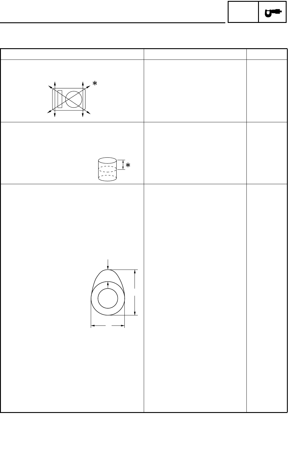
Cylinder:
Bore size 100.005 ~ 100.045 mm
(3.9372 ~ 3.9388 in) 100.1 mm
(3.94 in)
Measuring point *50 mm (2.0 in) ----
Camshaft:
Drive method Chain drive (Left) ----
Camshaft cap inside diameter 23.000 ~ 23.021 mm
(0.9055 ~ 0.9063 in) ----
Camshaft journal diameter 22.967 ~ 22.980 mm
(0.9042 ~ 0.9047 in) ----
Camshaft journal-to-camshaft cap clearance 0.020 ~ 0.054 mm
(0.0008 ~ 0.0021 in) ----
Cam dimensions
Intake “A” 35.69 ~ 35.79 mm
(1.4051 ~ 1.4091 in) 35.59 mm
(1.4012 in)
“B” 30.15 ~ 30.25 mm
(1.1870 ~ 1.1909 in) 30.05 mm
(1.1831 in)
“C” 5.74 mm (0.2260 in) ----
Exhaust “A” 36.50 ~ 36.60 mm
(1.437 ~ 1.441 in) 36.40 mm
(1.4331 in)
“B” 30.15 ~ 30.25 mm
(1.187 ~ 1.191 in) 30.05 mm
(1.1831 in)
“C” 6.55 mm (0.2579 in) ----
C
A
B
MAINTENANCE SPECIFICATIONS
2 - 5
SPEC
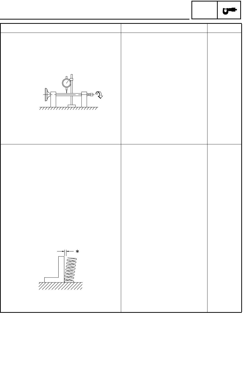
Camshaft runout limit ---- 0.03 mm
(0.0012 in)
Timing chain:
Timing chain type/No. of links 75-RH2015/126 ----
Timing chain adjustment method Automatic ----
Rocker arm/rocker arm shaft:
Shaft outside diameter 11.976 ~ 11.991 mm
(0.4715 ~ 0.4721 in) ----
Arm-to-shaft clearance 0.009 ~ 0.042 mm
(0.0004 ~ 0.0017 in) ----
Valve, valve seat, valve guide:
Valve clearance (cold) IN 0.10 ~ 0.15 mm
(0.0039 ~ 0.0059 in) ----
EX 0.15 ~ 0.20 mm
(0.0059 ~ 0.0079 in) ----
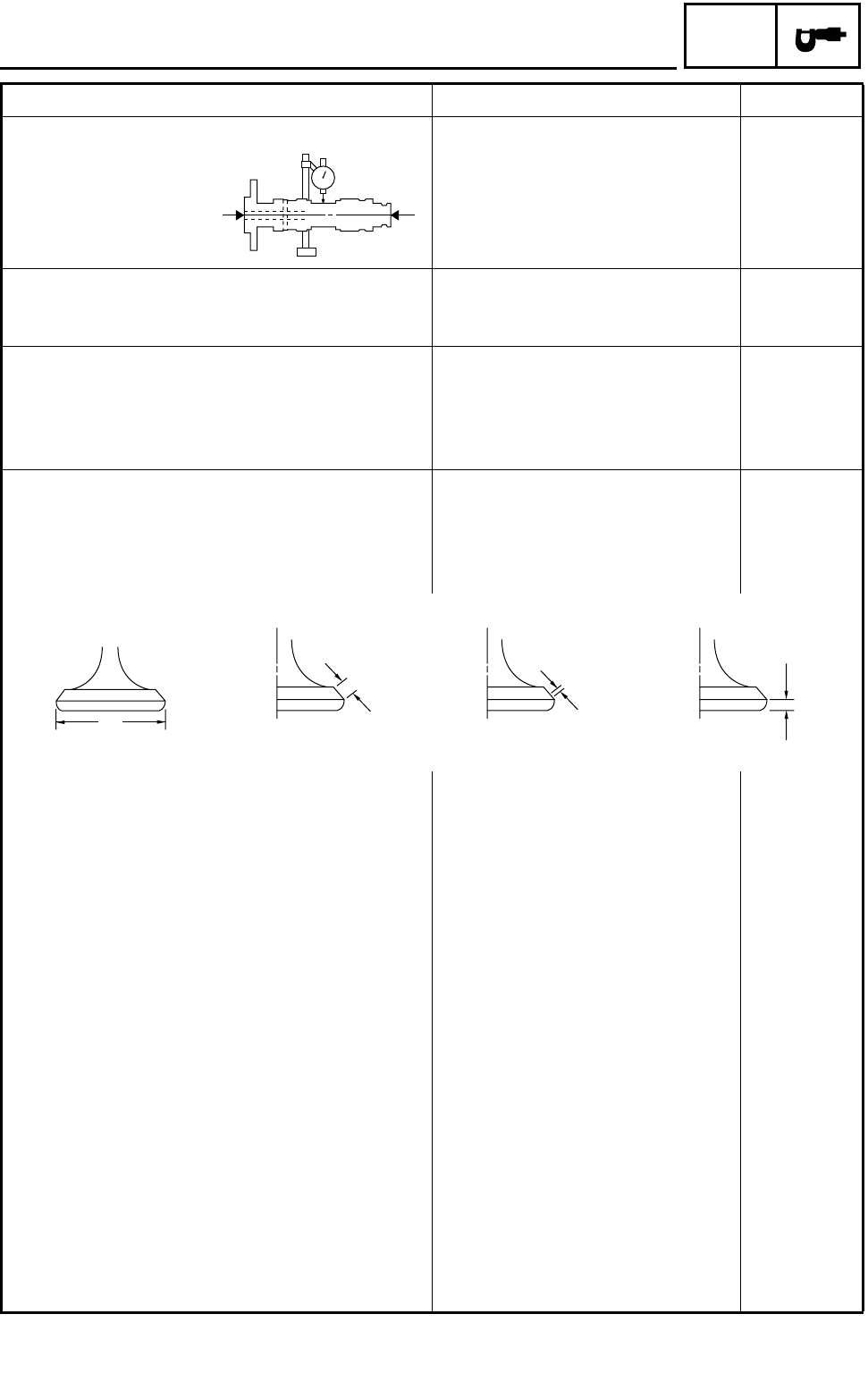
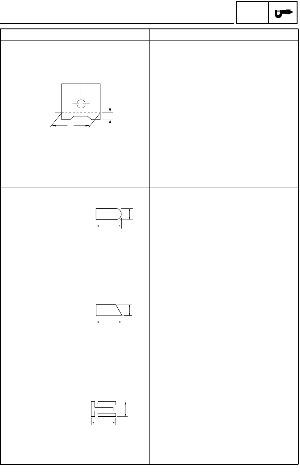
Valve dimensions
“A” head diameter IN 29.9 ~ 30.1 mm
(1.1772 ~ 1.1850 in) ----
EX 31.9 ~ 32.1 mm
(1.2559 ~ 1.2638 in) ----
“B” face width IN 2.25 mm (0.0886 in) ----
EX 2.26 mm (0.0890 in) ----
“C” seat width IN 0.9 ~ 1.1 mm
(0.0354 ~ 0.0433 in) 1.6 mm
(0.0630 in)
EX 0.9 ~ 1.1 mm
(0.0354 ~ 0.0433 in) 1.6 mm
(0.0630 in)
“D” margin thickness IN 0.85 ~ 1.15 mm
(0.0335 ~ 0.0453 in) ----
EX 0.85 ~ 1.15 mm
(0.0335 ~ 0.0453 in) ----
Stem outside diameter IN 5.975 ~ 5.990 mm
(0.2352 ~ 0.2358 in) 5.945 mm
(0.2341 in)
EX 5.960 ~ 5.975 mm
(0.2346 ~ 0.2352 in) 5.930 mm
(0.2335 in)
Guide inside diameter IN 6.000 ~ 6.012 mm
(0.2362 ~ 0.2367 in) 6.040 mm
(0.2378 in)
EX 6.000 ~ 6.012 mm
(0.2362 ~ 0.2367 in) 6.040 mm
(0.2378 in)
Item Standard Limit
Head Diameter
B
Face Width
C
Seat Width
D
Margin Thickness
A
MAINTENANCE SPECIFICATIONS
2 - 6
SPEC
Stem-to-guide clearance IN 0.010 ~ 0.037 mm
(0.0004 ~ 0.0015 in) 0.08 mm
(0.0031 in)
EX 0.025 ~ 0.052 mm
(0.0010 ~ 0.0020 in) 0.10 mm
(0.0039 in)
Stem runout limit ---- 0.01 mm
(0.0004 in)
Valve seat width IN 0.9 ~ 1.1 mm
(0.0354 ~ 0.0433 in) 1.6 mm
(0.0630 in)
EX 0.9 ~ 1.1 mm
(0.0354 ~ 0.0433 in) 1.6 mm
(0.0630 in)
Valve spring:
Free length IN 35.95 mm (1.42 in) 34.15 mm
(1.34 in)
EX 37.75 mm (1.49 in) 35.86 mm
(1.41 in)
Set length (valve closed) IN 27.2 mm (1.07 in) ----
EX 30.7 mm (1.21 in) ----
Compressed pressure
(installed) IN 149 ~ 173 N (15.19 ~ 17.64 kg,
33.50 ~ 38.89 lb) ----
EX 165 ~ 191 N (16.83 ~ 19.49 kg,
37.09 ~ 42.94 lb) ----
Tilt limit IN 2.5°/1.6 mm
(2.5°/0.06 in)
EX 2.5°/1.6 mm
(2.5°/0.06 in)
Direction of winding
(top view) IN Clockwise ----
EX Clockwise ----
Item Standard Limit
*
MAINTENANCE SPECIFICATIONS
2 - 7
SPEC
Piston:
Piston to cylinder clearance 0.05 ~ 0.07 mm
(0.0020 ~ 0.0028 in) 0.15 mm
(0.0059 in)
Piston size “D” 99.945 ~ 99.995 mm
(3.9348 ~ 3.9368 in) ----
Measuring point “H” 2.5 mm (0.10 in) ----
Piston off-set 1.0 mm (0.04 in) ----
Piston pin bore inside diameter 22.004 ~ 22.015 mm
(0.8663 ~ 0.8667 in) 22.045 mm
(0.8679 in)
Piston pin outside diameter 21.991 ~ 22.000 mm
(0.8658 ~ 0.8661 in) 21.971 mm
(0.8650 in)
Piston rings:
Top ring
Type Barrel ----
Dimensions (B × T) 1.2 × 3.8 mm
(0.0472 × 0.1496 in) ----
End gap (installed) 0.30 ~ 0.45 mm
(0.0118 ~ 0.0177 in) 0.70 mm
(0.0276 in)
Side clearance (installed) 0.04 ~ 0.08 mm
(0.0016 ~ 0.0031 in) 0.13 mm
(0.0051 in)
2nd ring
Type Taper ----
Dimensions (B × T) 1.2 × 4.0 mm
(0.0472 × 0.1575 in) ----
End gap (installed) 0.30 ~ 0.45 mm
(0.0118 ~ 0.0177 in) 0.80 mm
(0.0315 in)
Side clearance 0.03 ~ 0.07 mm
(0.0012 ~ 0.0028 in) 0.13 mm
(0.0051 in)
Oil ring
Dimensions (B × T) 2.5 × 3.4 mm
(0.0984 × 0.1339 in) ----
End gap (installed) 0.2 ~ 0.7 mm
(0.0079 ~ 0.0276 in) ----
Item Standard Limit
H
D
T
B
B
T
B
T
MAINTENANCE SPECIFICATIONS
2 - 8
SPEC
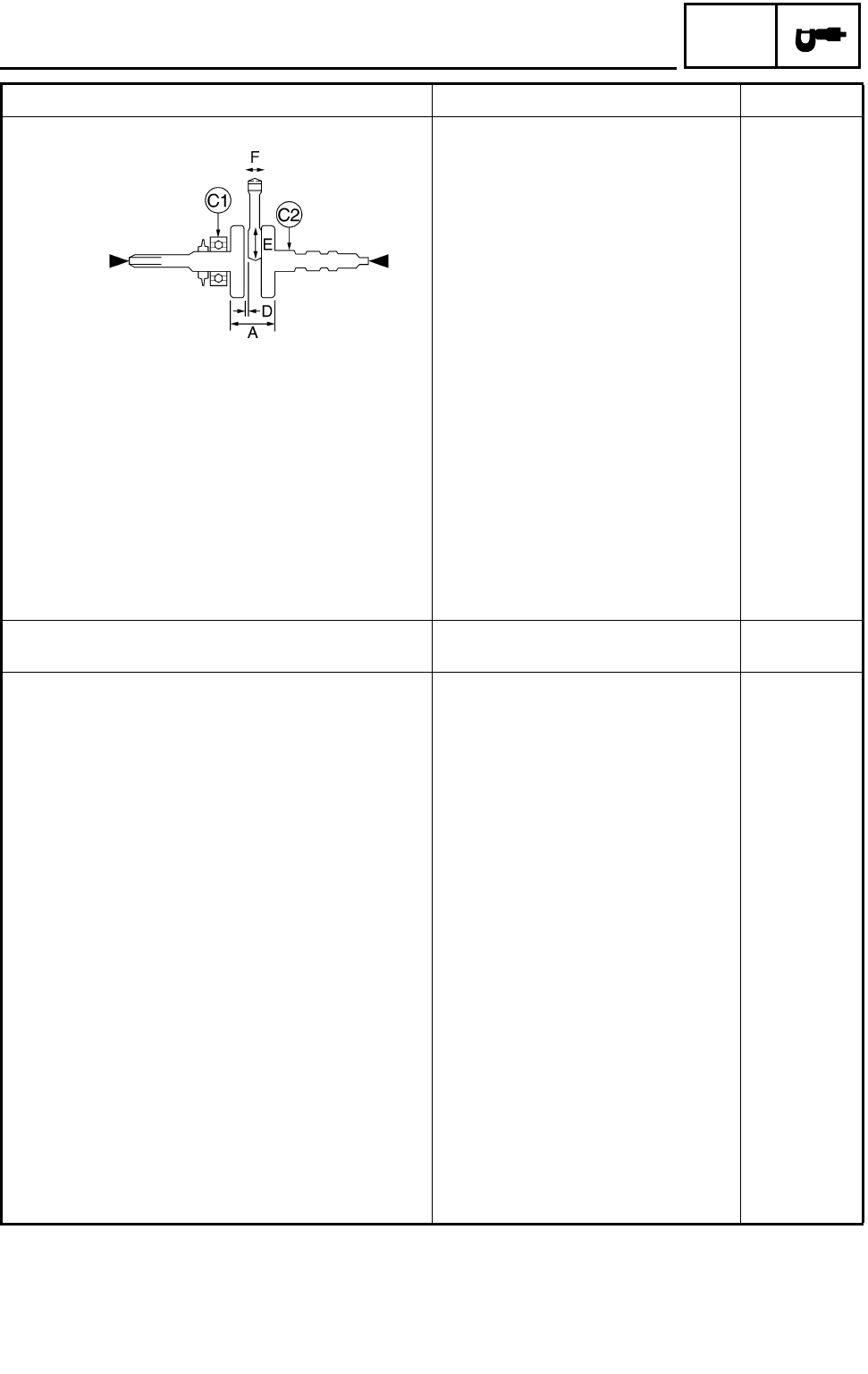
Crankshaft:
Crank width “A” 74.95 ~ 75.00 mm
(2.9508 ~ 2.9528 in) ----
Runout limit C1 ---- 0.03 mm
(0.0012 in)
C2 ---- 0.03 mm
(0.0012 in)
Big end side clearance “D” 0.32 ~ 0.64 mm
(0.0126 ~ 0.0252 in) 1.0 mm
(0.0394 in)
Big end radial clearance “E” 0.010 ~ 0.025 mm
(0.0004 ~ 0.0010 in) ----
Small end free play “F” 0.8 mm (0.0315 in) ----
Balancer:
Balancer drive method Gear ----
Clutch:
Friction plate 1
Thickness 2.74 ~ 2.86 mm
(0.108 ~ 0.113 in) 2.6 mm
(0.102 in)
Quantity 6 ----
Friction plate 2
Thickness 2.94 ~ 3.06 mm
(0.116 ~ 0.120 in) 2.8 mm
(0.110 in)
Quantity 2 ----
Clutch plate
Thickness 1.1 ~ 1.3 mm
(0.043 ~ 0.051 in) ----
Quantity 7 ----
Max. warpage ---- 0.2 mm
(0.008 in)
Clutch spring
Free length 42.8 mm (1.69 in) 40.7 mm
(1.60 in)
Quantity 5 ----
Min. length ---- 40.8 mm
(1.61 in)
Clutch release method Outer pull, rack and pinion pull ----
Item Standard Limit
MAINTENANCE SPECIFICATIONS
2 - 9
SPEC
Transmission:
Main axle deflection limit ---- 0.08 mm
(0.0031 in)
Drive axle deflection limit ---- 0.08 mm
(0.0031 in)
Shifter:
Shifter type Shift drum and guide bar ----
Decompression device:
Device type Auto decomp ----
Air filter oil grade: Engine oil ----
Carburetors:
I. D. mark 5LP1 00 ----
Main jet (M.J) Carburetor #1 : #140
Carburetor #2 : #145 ----
Main air jet (M.A.J) #130 ----
Jet needle (J.N) 5ND16-56-3 ----
Needle jet (N.J) P-6M (#826) ----
Pilot air jet (P.A.J.1) Carburetor #1 : #80
Carburetor #2 : #150 ----
Pilot air jet (P.A.J.2) 1.3 ----
Pilot outlet (P.O) Carburetor #1 : 1.0
Carburetor #2 : 0.9 ----
Pilot jet (P.J) #22.5 ----
Bypass 1 (B.P.1) 0.8 ----
Bypass 2 (B.P.2) 0.8 ----
Valve seat size (V.S) 2.0 ----
Starter jet (G.S.1) #95 ----
Starter jet (G.S.2) 0.5
Throttle valve size (Th.V) #80 ----
Float height (F.H) 13 mm (0.51 in) ----
Fuel level (F.L) 3 ~ 4 mm (0.12 ~ 0.16 in) ----
Engine idle speed 1,450 ~ 1,550 r/min ----
Intake vacuum 32.0 ~ 33.3 kPa (240 ~ 250 mmHg,
9.45 ~ 9.83 inHg) ----
Oil pump:
Oil filter type Paper ----
Oil pump type Trochoid ----
Tip clearance “A” or “B” 0.12 mm (0.005 in) 0.2 mm
(0.008 in)
Side clearance 0.03 ~ 0.08 mm
(0.001 ~ 0.003 in) ----
Bypass valve setting pressure 80 ~ 120 kPa (0.8 ~ 1.2 kg/cm2,
11.6 ~ 17.4 psi) ----
Oil pressure (hot) 65 kPa (0.65 kg/cm2, 9.4 psi) at
1,500 r/min ----
Pressure check location Cylinder head ----
Item Standard Limit
MAINTENANCE SPECIFICATIONS
2 - 10
SPEC
Cooling system:
Radiator core
Width 219 mm (8.62 in) ----
Height 300 mm (11.8 in) ----
Depth 16 mm (0.63 in) ----
Radiator cap opening pressure 95 ~ 125 kPa (0.95 ~ 1.25 kg/cm2,
13.8 ~ 18.1 psi) ----
Radiator capacity 0.55 L (0.48 Imp qt, 0.58 US qt) ----
Coolant reservoir
Capacity 0.29 L (0.26 Imp qt, 0.31 US qt) ----
From low to full level 0.165 L (0.15 Imp qt, 0.17 US qt) ----
Water pump:
Type Single suction centrifugal pump ----
Reduction ratio 33/34 (0.971)
Lubrication chart:
Item Standard Limit
MAINTENANCE SPECIFICATIONS
2 - 11
SPEC
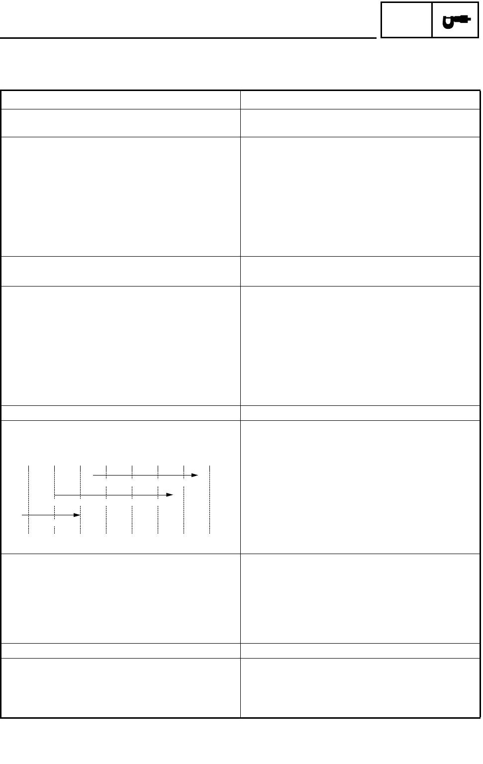
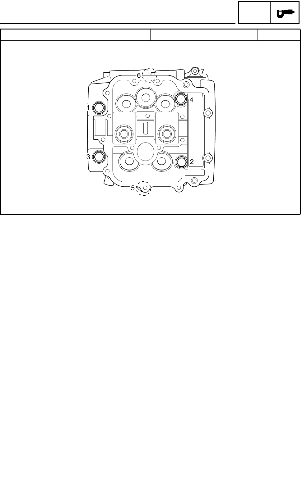
Cylinder head tightening sequence:
Item Standard Limit
MAINTENANCE SPECIFICATIONS
2 - 12
SPEC
Tightening torques
Part to be tightened Part
name Thread
size Q’ty Tightening torque Remarks
Nm m·kg ft·lb
Cylinder head (exhaust pipe) Stud bolt M6 4 7 0.7 5.1
Cylinder head Bolt M9 4 38 3.8 27
Bolt M9 2 38 3.8 27
Bolt M6 1 10 1.0 7.2
Spark plug — M12 1 18 1.8 13
Cylinder head cover Bolt M6 17 10 1.0 7.2
Camshaft end cap Bolt M6 1 10 1.0 7.2
Oil check bolt — M6 1 7 0.7 5.1
Tappet cover (exhaust) — M32 2 12 1.2 8.7
Tappet cover (intake) Bolt M6 4 10 1.0 7.2
Cylinder Bolt M10 2 42 4.2 30
Bolt M10 2 42 4.2 30
Bolt M6 2 10 1.0 7.2
Timing chain tensioner Bolt M6 2 10 1.0 7.2
Timing chain tensioner cap Bolt M16 1 22 2.2 16
Timing chain guide (intake) Bolt M6 2 8 0.8 5.8
Camshaft sprocket Bolt M7 2 20 2.0 14
Rocker arm shaft Bolt M6 2 10 1.0 7.2
Valve adjusting screw Nut M6 5 14 1.4 10
Radiator Bolt M6 2 7 0.7 5.1
Coolant drain bolt — M6 1 10 1.0 7.2
Engine oil drain bolt (oil tank) — M10 1 25 2.5 18
Engine oil drain bolt (engine) — M14 1 30 3.0 22
Oil filter bolt Union bolt M20 1 63 6.3 45 E
Oil filter cartridge — M20 1 17 1.7 12
Oil delivery pipe 1 Union bolt M10 2 20 2.0 14
Oil delivery pipe 2 Union bolt M8 2 18 1.8 13
Oil pipe joint — M14 1 50 5.0 36
Oil pipe 1 and oil pipe joint Nut M16 1 35 3.5 25
Oil pipe 2 and oil tank Nut M16 1 35 3.5 25
Air filter case Bolt M6 2 7 0.7 5.1
Carburetor clamp Bolt M4 4 5 0.5 3.6
Exhaust pipe 1 and exhaust pipe 2 Bolt M8 1 16 1.6 12
Exhaust pipe protector Bolt M6 4 10 1.0 7.2 LT
Spark arrester Bolt M6 1 8 0.8 5.8
Muffler and exhaust pipe 2 Bolt M8 1 20 2.0 14
Muffler Bolt M8 2 26 2.6 19
Silencer cap Bolt M6 3 10 1.0 7.2 LT
Exhaust pipe Nut M6 4 10 1.0 7.2
MAINTENANCE SPECIFICATIONS
2 - 13
SPEC
Bearing retainer Screw M6 4 7 0.7 5.1 LT
AC magneto rotor Nut M14 1 150 15.0 110
Starter clutch Bolt M6 6 16 1.6 11 LT
Balancer driven gear Nut M18 1 140 14.0 100 M
Use a lock
washer.
Primary drive gear Nut M20 1 150 15.0 110 M
Use a lock
washer.
Clutch spring Bolt M6 5 8 0.8 5.8
Clutch boss Nut M20 1 90 9.0 65 Use a lock
washer.
Pull lever shaft Bolt M6 1 7 0.7 5.1
Drive sprocket Nut M18 1 70 7.0 50 Use a lock
washer.
Oil seal retainer Bolt M6 2 10 1.0 7.2
Shift drum segment Bolt M8 1 30 3.0 22
Shift guide Bolt M6 2 10 1.0 7.2 LT
Stopper lever Bolt M6 1 10 1.0 7.2
Reverse shift lever Bolt M6 1 13 1.3 9.4
Shift arm Bolt M6 1 10 1.0 7.2
Shift pedal adjusting rod Nut M6 1 8 0.8 5.8 Left-hand
threads
Nut M6 1 8 0.8 5.8
Stator assembly Bolt M5 3 7 0.7 5.1 LT
Pick up coil Bolt M5 2 7 0.7 5.1 LT
AC magneto lead holder Bolt M6 2 10 1.0 7.2 LT
Ignition coil Bolt M6 2 7 0.7 5.1
Starter motor Bolt M6 2 10 1.0 7.2
Neutral switch — M10 1 20 2.0 14
Reverse switch — M10 1 20 2.0 14
Thermo switch 1 — M18 1 28 2.8 20
Thermo switch 2 — M18 1 28 2.8 20
Part to be tightened Part
name Thread
size Q’ty Tightening torque Remarks
Nm m·kg ft·lb
MAINTENANCE SPECIFICATIONS

2 - 14
SPEC
CHASSIS
Item Standard Limit
Steering system:
Steering bearing type Ball and race bearing ----
Front suspension:
Shock absorber travel 110 mm (4.33 in) ----
Fork spring free length 316.5 mm (12.46 in) ----
Spring fitting length 293.5 mm (11.56 in) ----
Spring rate (K1) 19.6 N/mm
(2.00 kg/mm, 111.92 lb/in) ----
Spring rate (K2) 29.4 N/mm
(3.00 kg/mm, 167.87 lb/in) ----
Optional spring No ----
Rear suspension:
Shock absorber travel 100 mm (3.94 in) ----
Spring free length 273 mm (10.75 in) ----
Spring fitting length 253 mm (9.96 in) ----
Spring rate (K1) 55 N/mm
(5.61 kg/mm, 314.05 lb/in) ----
Stroke (K1) 0 ~ 100 mm (0 ~ 3.94 in) ----
Optional spring No ----
Swingarm:
Free play limit end ---- 1 mm
(0.04 in)
side ---- 1 mm
(0.04 in)
Front wheel:
Type Panel wheel ----
Rim size 10 × 5.5 AT ----
Rim material Aluminum ----
Rim runout limit radial ---- 2 mm
(0.08 in)
lateral ---- 2 mm
(0.08 in)
Rear wheel:
Type Panel wheel ----
Rim size 9 × 8.5 AT ----
Rim material Aluminum ----
Rim runout limit radial ---- 2 mm
(0.08 in)
lateral ---- 2 mm
(0.08 in)
MAINTENANCE SPECIFICATIONS
2 - 15
SPEC
Front disc brake:
Type Dual ----
Disc outside diameter × thickness 161.0 × 3.5 mm (6.34 × 0.14 in) ----
Pad thickness inner 4.2 mm (0.17 in) 1 mm
(0.04 in)
Pad thickness outer 4.2 mm (0.17 in) 1 mm
(0.04 in)
Master cylinder inside diameter 12.7 mm (0.50 in) ----
Caliper cylinder inside diameter 32.03 mm (1.26 in) ----
Brake fluid type DOT 4 ----
Rear disc brake:
Type Single ----
Disc outside diameter × thickness 220.0 × 3.6 mm (8.66 × 0.14 in) ----
Pad thickness inner 4.5 mm (0.18 in) 1 mm
(0.04 in)
Pad thickness outer 4.5 mm (0.18 in) 1 mm
(0.04 in)
Master cylinder inside diameter 12.7 mm (0.50 in) ----
Caliper cylinder inside diameter 33.96 mm (1.34 in) ----
Brake fluid type DOT 4 ----
Brake lever and brake pedal:
Brake lever free play (at lever end) 0 mm (0 in) ----
Brake pedal position 4 mm (0.16 in)
(Below the top of footrest) ----
Throttle lever free play 3 ~ 5 mm (0.12 ~ 0.20 in) ----
Item Standard Limit
MAINTENANCE SPECIFICATIONS
2 - 16
SPEC
Tightening torques
Part to be tightened Thread size Tightening torque Remarks
Nm m·kg ft·lb
Engine bracket (upper) and frame M8 33 3.3 24
Engine bracket (upper) and engine M10 40 4.0 29
Engine bracket (lower) and frame M10 56 5.6 40
Engine bracket (lower) and engine M10 56 5.6 40
Engine bracket (middle and lower) and engine M10 56 5.6 40
Swingarm pivot shaft, engine and frame M16 95 9.5 68
Rear shock absorber and frame M10 32 3.2 23
Relay arm and swingarm M10 32 3.2 23
Connecting arm and frame M10 32 3.2 23
Relay arm and rear shock absorber M10 32 3.2 23
Relay arm and connecting arm M10 32 3.2 23
Drive chain guide and swingarm M6 7 0.7 5.1
Hub, brake caliper bracket and swingarm M12 90 9.0 65
Drive chain adjusting bolt and locknut M8 16 1.6 11
Front shock absorber and frame M10 45 4.5 32
Front shock absorber and front arm (lower) M10 45 4.5 32
Front arm (upper) and frame M10 38 3.8 27
Front arm (lower) and frame M10 32 3.2 23
Brake hose holder and front arm (upper) M6 7 0.7 5.1
Steering stem, pitman arm and frame M14 110 11 80
Steering stem bushing and frame M8 23 2.3 17 Use a lock
washer.
Steering stem and handlebar holder M8 23 2.3 17
Tie-rod end and locknut M10 15 1.5 11
Steering knuckle and front wheel hub M14 70 7.0 50
Steering knuckle and front arm (upper and lower) M10 25 2.5 18
Steering knuckle and tie-rod ball joint M10 25 2.5 18
Pitman arm and tie-rod ball joint M10 25 2.5 18
Frame and bearing retainer M42 40 4.0 29
Fuel tank and fuel cock M6 4 0.4 2.9
Fuel tank and frame M6 7 0.7 5.1
Front wheel and front wheel hub M10 45 4.5 32
Steering knuckle and front brake caliper M8 28 2.8 20
Front brake disc and front wheel hub M8 28 2.8 20 LT
Rear axle and rear wheel hub M14 120 12 85
Rear brake caliper and brake caliper bracket M8 28 2.8 20
Rear wheel and rear wheel hub M10 45 4.5 32
Driven sprocket and sprocket bracket M8 24 2.4 17
Front brake pipe nut M10 19 1.9 13
Front brake master cylinder and handlebar M6 7 0.7 5.1
MAINTENANCE SPECIFICATIONS
2 - 17
SPEC
HINWEIS:
NOTE:
Apply locking agent (LOCTITE®) to ring nuts threads.
1st: Tighten the inside ring nut 55 Nm (5.5 m • kg, 40 ft • lb).
2nd: Tighten the outside ring nut while holding the inside ring nut 190 Nm (19 m • kg, 140 ft • lb).
3rd: Loosen the inside ring nut while holding the outside ring nut 240 Nm (24 m • kg, 170 ft • lb).
Front brake master cylinder and brake lever M6 6 0.6 4.3
Front brake master cylinder and brake hose M10 27 2.7 19
Brake hose joint and frame M6 10 1.0 7.2
Bleed screw M8 6 0.6 4.3
Front brake pad holding bolt M10 18 1.8 13
Front brake caliper and brake hose M10 27 2.7 19
Front brake caliper retaining bolt M8 23 2.3 17
Rear axle ring nut M38 SEE NOTE
Rear brake pad holding bolt M10 18 1.8 13 Use a lock
washer.
Rear brake caliper and brake hose M10 30 3.0 22
Rear brake master cylinder and frame M8 20 2.0 14
Rear brake master cylinder and brake hose M10 30 3.0 22
Parking brake adjusting bolt and locknut M8 16 1.6 11
Rear brake disc and brake disc bracket M8 28 2.8 20
Rear brake fluid reservoir cover and bracket M6 4 0.4 2.9
Rear brake fluid reservoir and bracket M6 4 0.4 2.9
Brake hose holder and swingarm M6 7 0.7 5.1
Front bumper and frame M8 31 3.1 22
Front fender bracket and frame M8 16 1.6 11
Rear carrier bar and frame M8 23 2.3 17
Footrest and frame M10 65 6.5 48
Footrest guard bracket and frame M8 33 3.3 24
Footrest and footrest guard bracket M8 16 1.6 11
Footrest guard bracket and rear fender M6 7 0.7 5.1
Battery holding bracket and frame M6 7 0.7 5.1
Air filter case and frame M6 7 0.7 5.1
Carburetor clamp screw M4 5 0.5 3.6
Tail/brake light bracket and frame M6 7 0.7 5.1
Tail/brake light bracket and tail/brake light M6 7 0.7 5.1
Swingarm skid plate and swingarm M6 7 0.7 5.1
Swingarm skid plate and swingarm M8 16 1.6 11
Drive chain tensioner and frame M8 32 3.2 23
Engine skid plate and frame M6 7 0.7 5.1
Main frame and rear frame M10 53 5.3 38
Part to be tightened Thread size Tightening torque Remarks
Nm m·kg ft·lb
MAINTENANCE SPECIFICATIONS
2 - 18
SPEC
ELECTRICAL
Item Standard Limit
Voltage: 12 V ----
Ignition system:
Ignition timing (B.T.D.C.) 12°/ 1,500 r/min ----
Advancer type Digital type ----
C.D.I.:
Magneto model/manufacturer F4T260/MITSUBISHI ----
Pickup coil resistance/color 445 ~ 545 Ω at 20 °C (68 °F)/
White/Red – White/Green ----
Rotor rotation direction detection coil resis-
tance/color 0.069 ~ 0.085 Ω at 20 °C (68 °F)/
Red – White/Blue ----
C.D.I. unit model/manufacturer F8T37971/MITSUBISHI ----
Ignition coil:
Model/manufacturer 2JN/YAMAHA ----
Minimum spark gap 6 mm (0.24 in) ----
Primary winding resistance 0.18 ~ 0.28 Ω at 20 °C (68 °F) ----
Secondary winding resistance 6.32 ~ 9.48 kΩ at 20 °C (68 °F) ----
Spark plug cap:
Type Resin type ----
Resistance 10 kΩ----
Charging system:
Type A.C. magneto generator ----
Model/manufacturer F4T260/MITSUBISHI ----
Nominal output 14 V 16 A at 5,000 r/min ----
Charging coil resistance/color 0.43 ~ 0.65 Ω at 20 °C (68 °F)/
White – White ----
Rectifier:
Type Semi conductor-short circuit ----
Model/manufacturer SH640E-11/SHINDENGEN ----
No load voltage (DC) 14.1 ~ 14.9 V ----
Capacity 14 A ----
Withstand voltage 200 V ----
Electric starter system:
Type Constantmesh type ----
Starter motor
Model/manufacturer SM-13/MITSUBA ----
Output 0.8 kW ----
Armature coil resistance 0.025 ~ 0.035 Ω at 20 °C (68 °F) ----
Brush overall length 12.5 mm (0.49 in) 5 mm
(0.20 in)
Spring force 7.65 ~ 10.01 N (27.54 ~ 36.03 oz) ----
Commutator diameter 28 mm (1.10 in) 27 mm
(1.06 in)
Mica undercut 0.7 mm (0.03 in) ----
MAINTENANCE SPECIFICATIONS

2 - 19
SPEC
Starter relay
Model/manufacturer MS5F-721/JIDECO ----
Amperage rating 180 A ----
Coil winding resistance 4.18 ~ 4.62 Ω at 20 °C (68 °F) ----
Thermostat switch:
Thermostat switch 1
Model/manufacturer 5GH/NIPPON THERMOSTAT ----
Thermostat switch 2
Model/manufacturer 5LP/NIPPON THERMOSTAT ----
Circuit breaker:
Type Fuse ----
Amperage for individual circuit
Fuse 20 A × 1 ----
Reserve 20 A × 1 ----
Item Standard Limit
MAINTENANCE SPECIFICATIONS
2 - 20
SPEC
EB201000
HOW TO USE THE CONVERSION
TABLE
All specification data in this manual are listed
in SI and METRIC UNITS.
Use this table to convert METRIC unit data to
IMPERIAL unit data.
Ex.
CONVERSION TABLE
EB202001
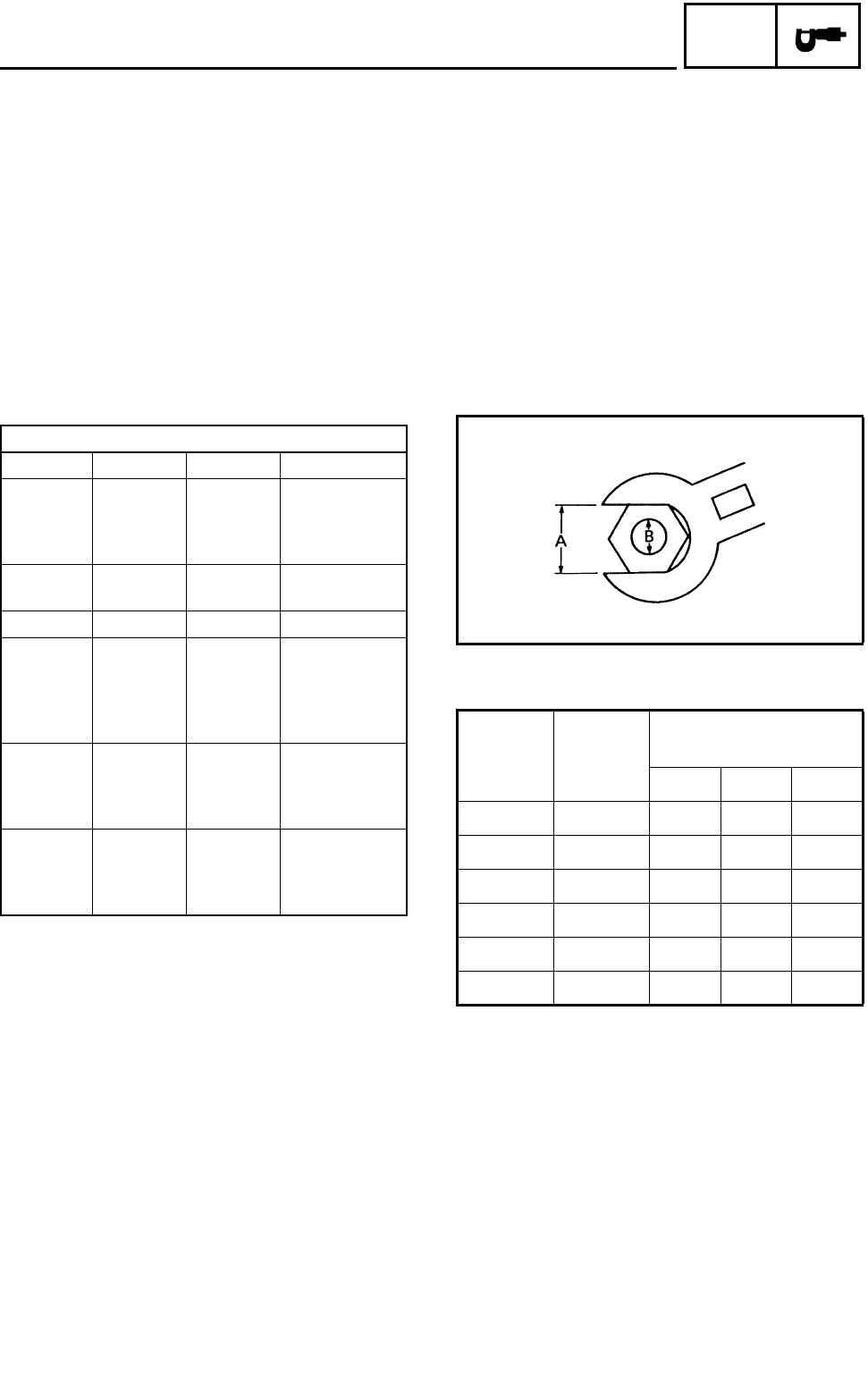
GENERAL TORQUE
SPECIFICATIONS
This chart specifies torque for standard fasten-
ers with standard I.S.O. pitch threads. Torque
specifications for special components or
assemblies are provided for each chapter of
this manual. To avoid warpage, tighten multi-
fastener assemblies in a crisscross fashion, in
progressive stages, until the specified torque is
reached. Unless otherwise specified, torque
specifications require clean, dry threads. Com-
ponents should be at room temperature.
A: Distance between flats
B: Outside thread diameter
METRIC MULTIPLIER IMPERIAL
** mm × 0.03937 = ** in
2 mm × 0.03937 = 0.08 in
METRIC TO IMPERIAL
Metric unit Multiplier Imperial unit
Torque
m·kg
m·kg
cm·kg
cm·kg
7.233
86.794
0.0723
0.8679
ft·lb
in·lb
ft·lb
in·lb
Weight kg
g2.205
0.03527 lb
oz
Speed km/hr 0.6214 mph
Distance
km
m
m
cm
mm
0.6214
3.281
1.094
0.3937
0.03937
mi
ft
yd
in
in
Volume/
Capacity
cc (cm3)
cc (cm3)
lt (liter)
lt (liter)
0.03527
0.06102
0.8799
0.2199
oz (IMP liq.)
cu·in
qt (IMP liq.)
gal (IMP liq.)
Misc.
kg/mm
kg/cm2
Centigrade
(°C)
55.997
14.2234
9/5+32
lb/in
psi (lb/in2)
Fahrenheit (°F)
A
(nut) B
(bolt)
General torque
specifications
Nm m•kg ft•lb
10 mm 6 mm 6 0.6 4.3
12 mm 8 mm 15 1.5 11
14 mm 10 mm 30 3.0 22
17 mm 12 mm 55 5.5 40
19 mm 14 mm 85 8.5 61
22 mm 16 mm 130 13.0 94
HOW TO USE THE CONVERSION TABLE/
GENERAL TORQUE SPECIFICATIONS
2 - 21
SPEC
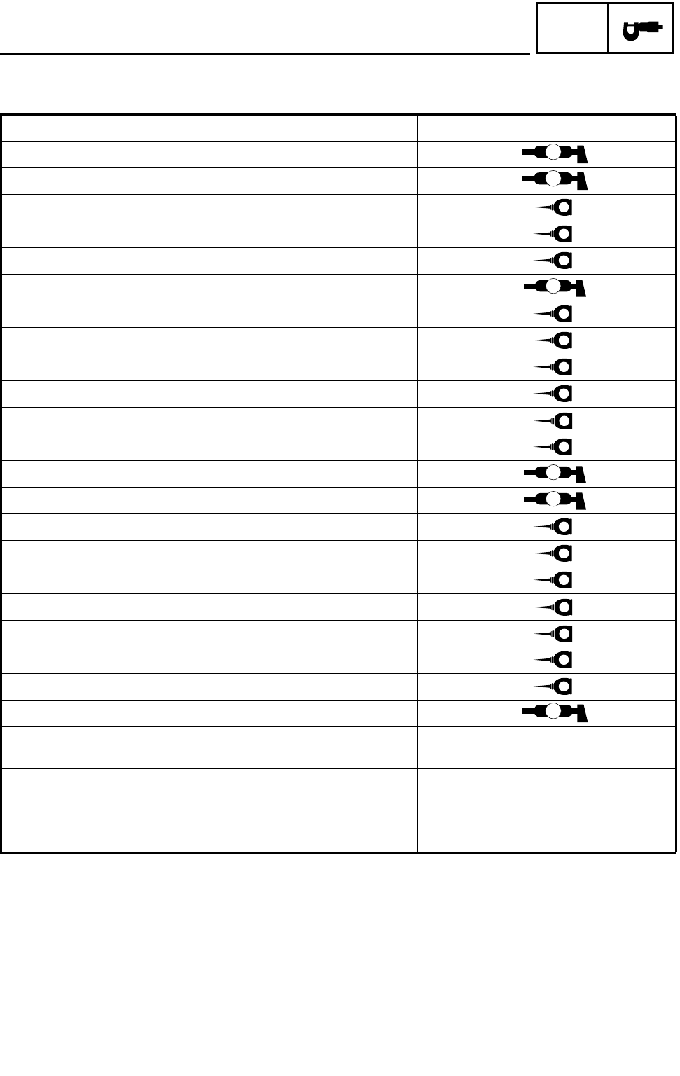
LUBRICATION POINTS AND LUBRICANT TYPES
ENGINE
Lubrication points Lubricant type
Oil seal lips (all) LS
O-ring (all) LS
Bearings (all) E
Crank pin E
Connecting rod (bearing) E
Camshaft sprocket M
Crankshaft E
Piston surface/piston rings E
Piston pin E
Primary drive gear/primary driven gear E
Valve stem/valve stem end M
Rocker arm shaft E
Rocker arm M
Camshaft lobe/journal M
Oil pump shaft, rotor, housing E
Oil filter O-ring E
Starter idle gear/shaft E
Transmission gear (wheel/pinion) M
Axle (main/drive) M
Shift fork/guide bar E
Shift drum/shift shaft/shift cam stopper ball E
Shift lever/shift guide LS
Crankcase mating surfaces Sealant (Quick Gasket)
Yamaha bond No.1215
Cylinder head and cylinder head cover mating surfaces Sealant (Quick Gasket)
Yamaha bond No.1215
AC magneto lead grommet
(AC magneto cover) Sealant (Quick Gasket)
Yamaha bond No.1215
LUBRICATION POINTS AND LUBRICANT TYPES
2 - 22
SPEC
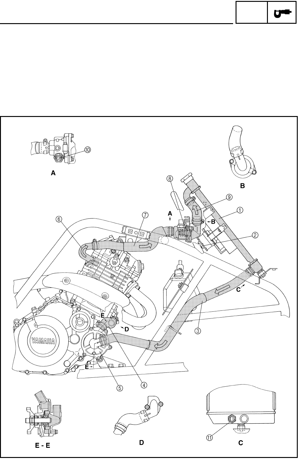
COOLANT FLOW DIAGRAMS
1Radiator
2Radiator fan
3Radiator outlet hose
4Water pump inlet hose
5Water pump
6Water jacket outlet pipe
7Thermostat inlet hose
8Thermostat
9Radiator inlet hose
0Thermo switch 2
AThermo switch 1
COOLANT FLOW DIAGRAMS
2 - 23
SPEC
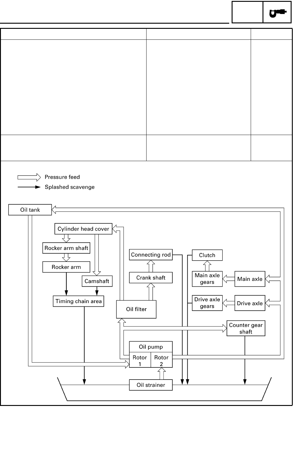
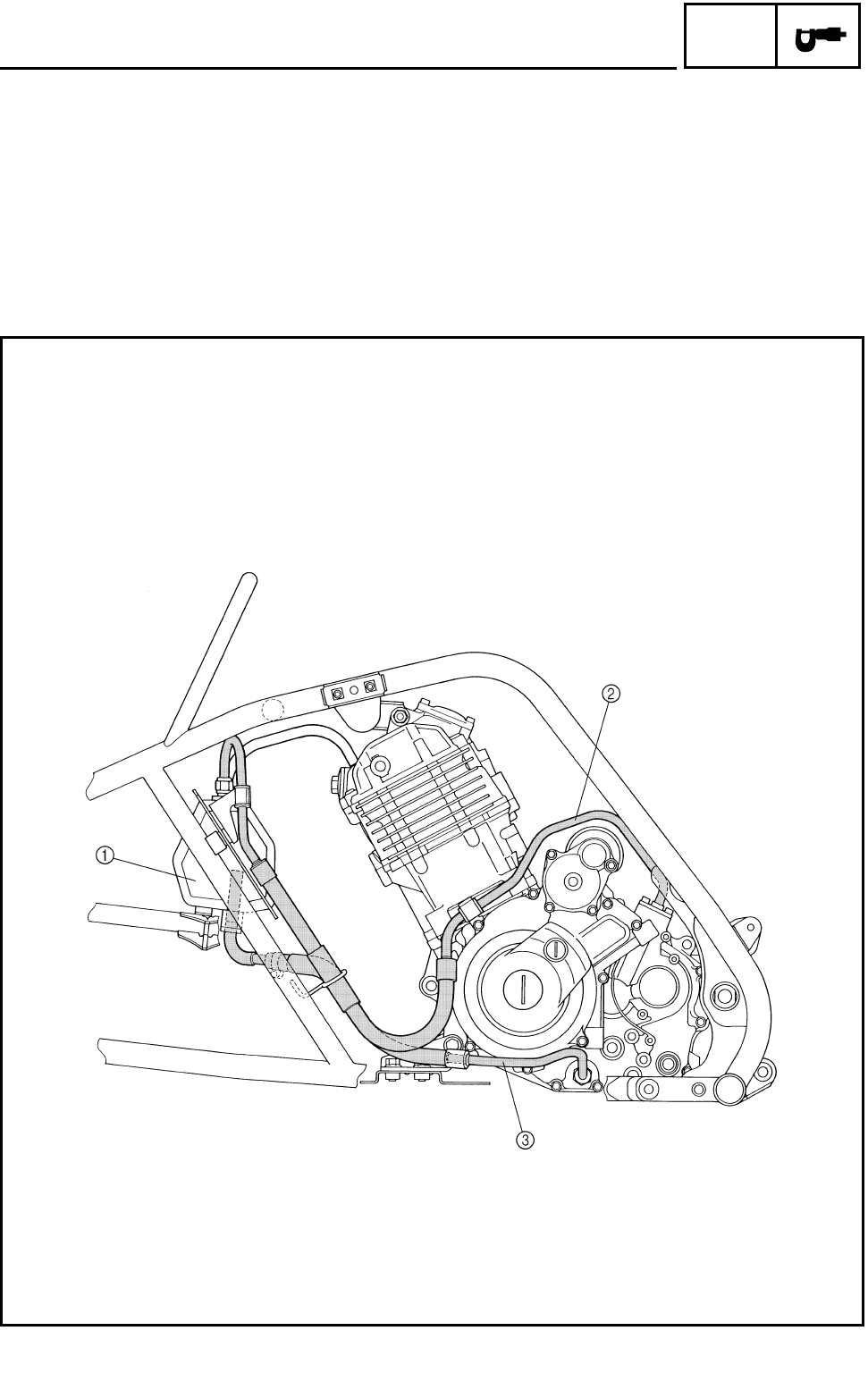
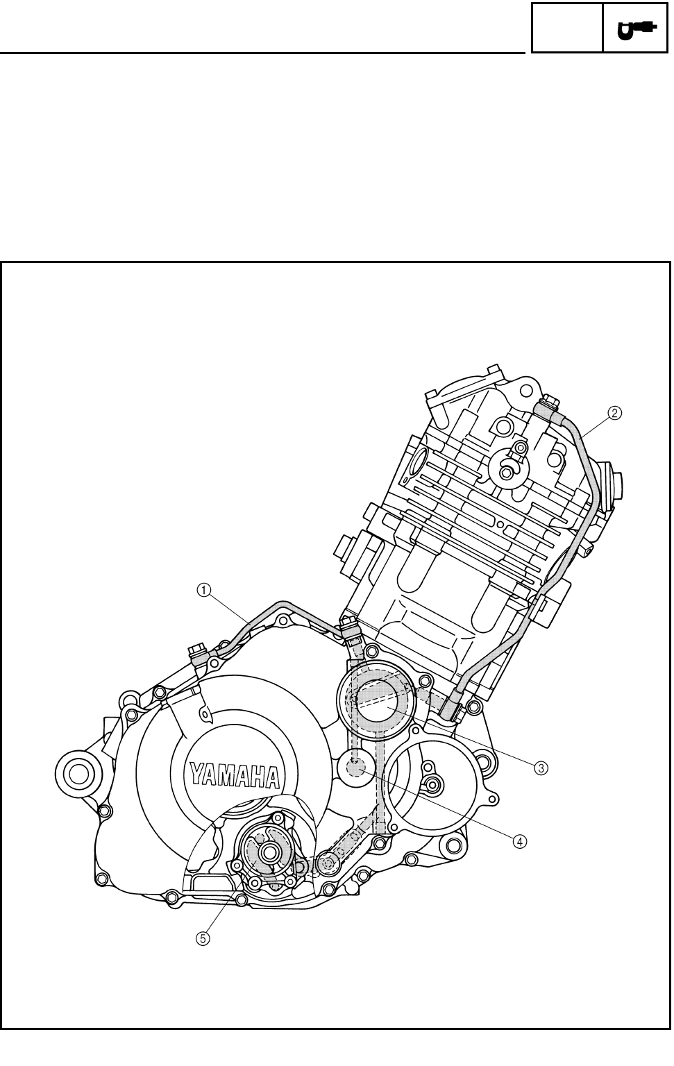
OIL FLOW DIAGRAMS
1Oil tank
2Oil pipe 2
3Oil pipe 1
OIL FLOW DIAGRAMS
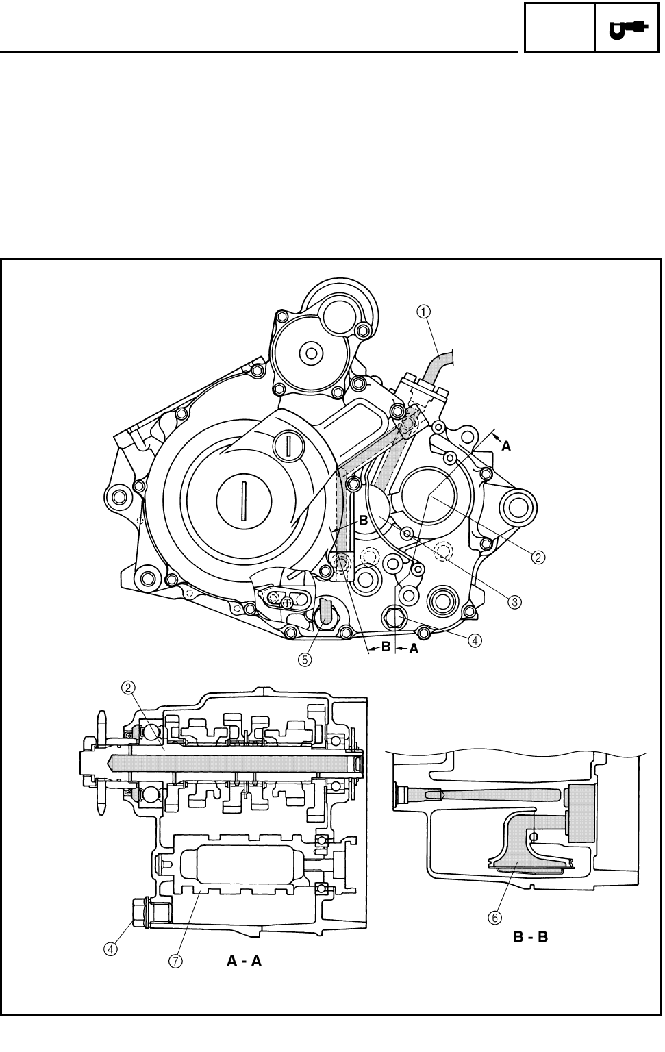
2 - 24
SPEC
1Oil delivery pipe 2
2Oil delivery pipe 1
3Oil filter
4Crankshaft
5Oil pump
OIL FLOW DIAGRAMS
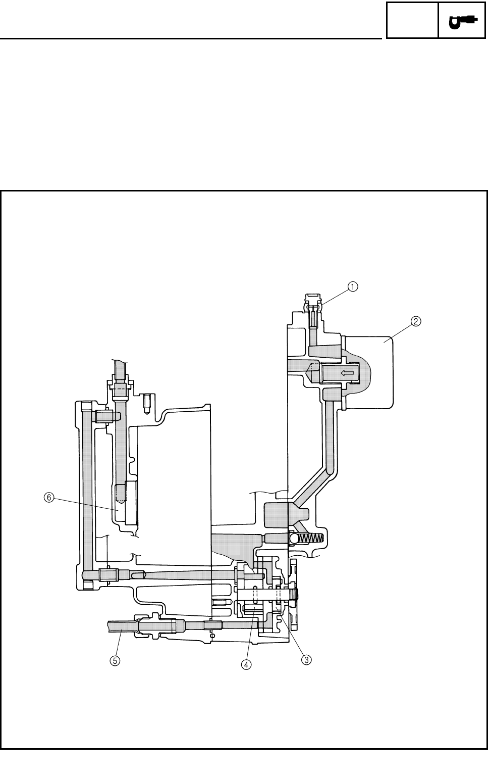
2 - 25
SPEC
1Oil pipe 2
2Drive axle
3Main axle
4Engine oil drain bolt (engine)
5Oil pipe 1
6Oil strainer
7Shift drum
OIL FLOW DIAGRAMS
2 - 26
SPEC
1Oil delivery pipe 2
2Oil filter cartridge
3Oil pump rotor 1
4Oil pump rotor 2
5Oil pipe 1
6Main axle
OIL FLOW DIAGRAMS
2 - 27
SPEC
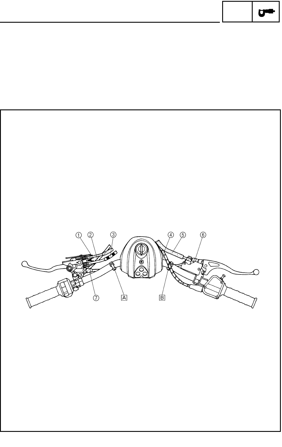
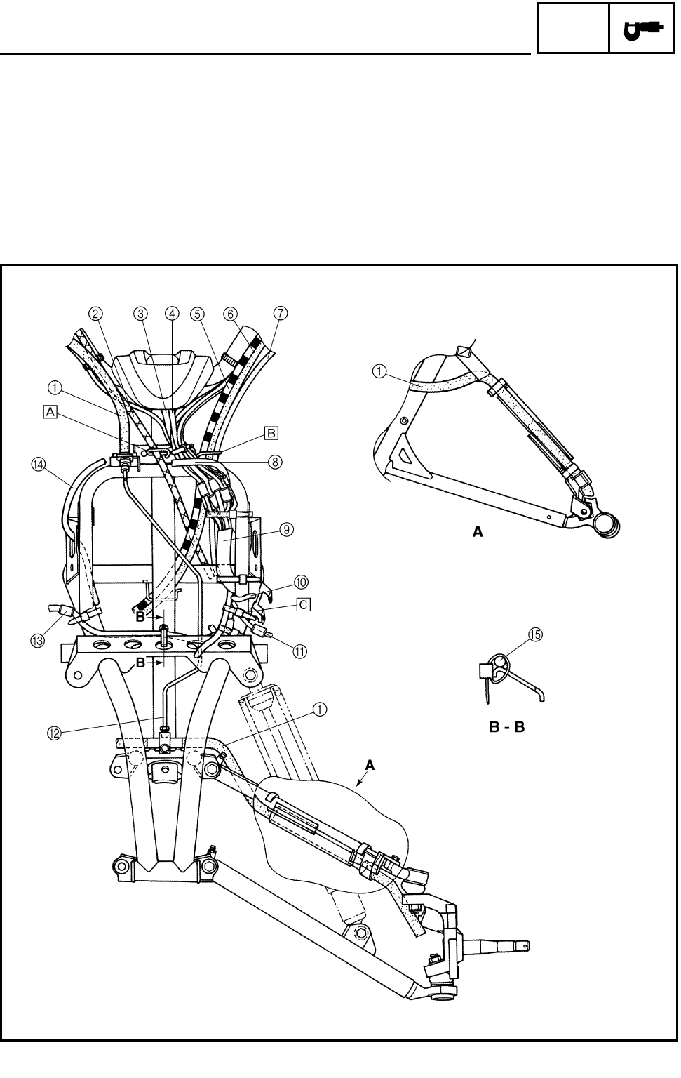
CABLE ROUTING
1Parking brake cable
2Starter cable
3Clutch cable
4Throttle cable
5Front brake hose
6Front brake switch
7Park switch
ÈFasten the handlebar switch lead, park switch
lead and clutch switch lead to the handlebar with
the plastic band.
ÉFasten the front brake switch lead to the handle-
bar with the plastic band.
CABLE ROUTING
2 - 28
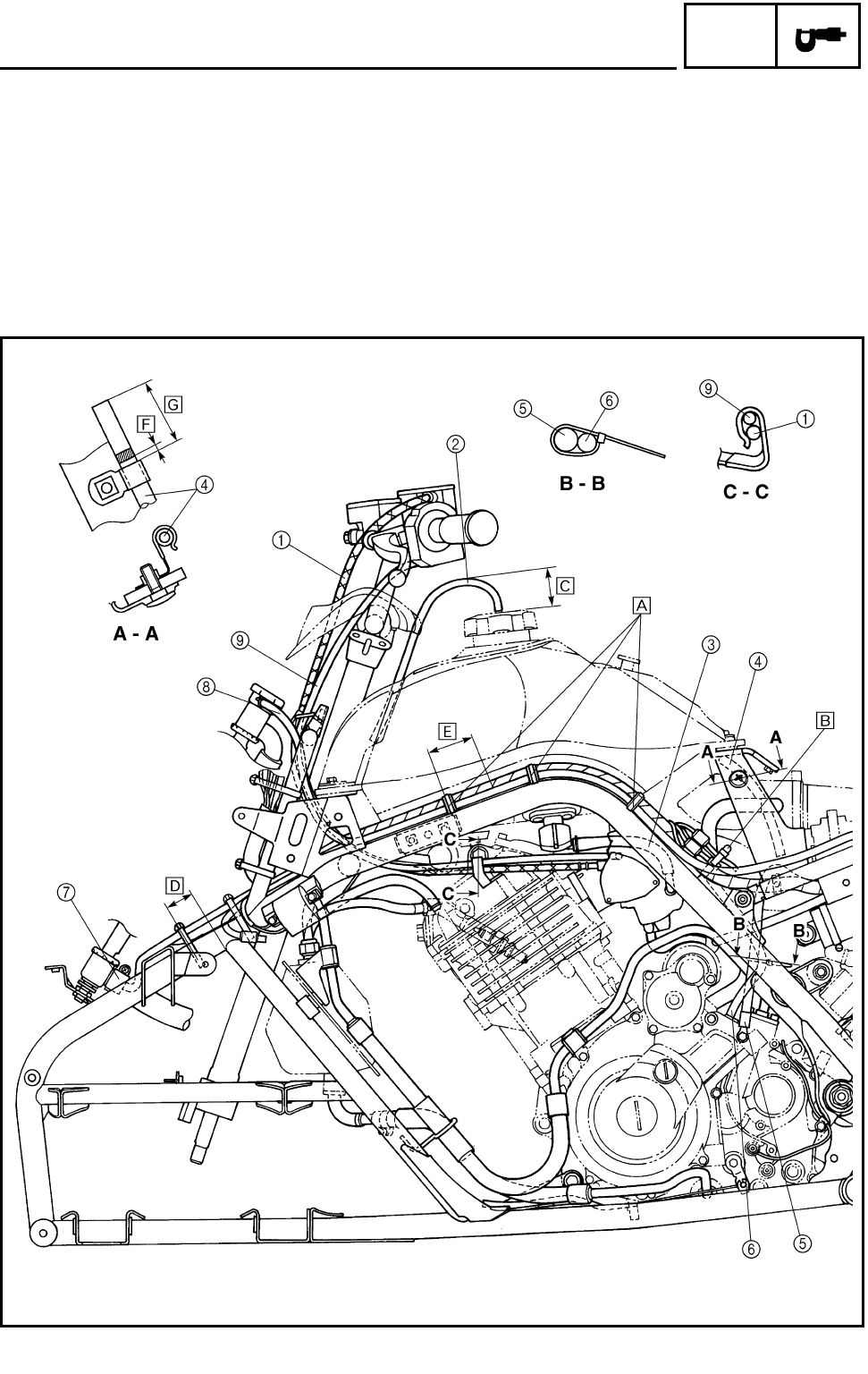
SPEC
1Front brake hose
2Throttle cable
3Main switch lead
4Indicator light lead
5Clutch cable
6Parking brake cable
7Starter cable
8Coolant reservoir hose
9Wire harness
0Ignition coil lead
AHeadlight lead coupler (left)
BBrake pipe
CHeadlight lead coupler (right)
DRadiator fan breather hose
EHeadlight lead (right)
ÈPass the throttle cable through the cable guide.
ÉPass the clutch cable, parking brake cable and
starter cable through the cable guide.
ÊFasten the left and right headlight lead, radiator
fan lead and thermo switch 1 lead to the frame
with the plastic band.
CABLE ROUTING
2 - 29
SPEC
1Throttle cable
2Fuel tank breather hose
3Fuel hose
4Carburetor air vent hose
5Negative battery lead
6AC magneto lead
7Thermo switch 1
8Coolant reservoir hose
9Starter cable
ÈPut the wire harness and coolant reservoir hose
with the plastic holder.
ÉFasten the wire harness, AC magneto lead,
speed sensor lead, negative battery lead and
rear brake switch lead with the plastic band.
Ê70 mm (2.76 in)
Ë25 ~ 35 mm (0.98 ~ 1.38 in)
Ì60 mm (2.36 in)
Í0 ~ 5 mm (0 ~ 0.20 in)
Î80 ~ 90 mm (3.15 ~ 3.54 in)
CABLE ROUTING
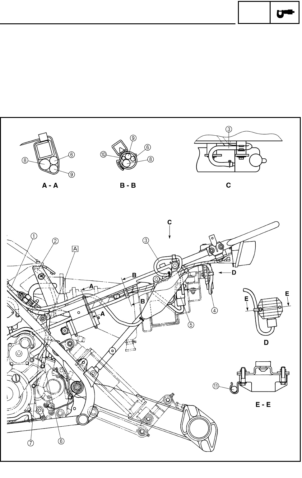
2 - 30
SPEC
1Coolant reservoir hose
2Carburetor air vent hose
3Reservoir tank breather hose
4Rectifier/regulator
5CDI unit
6Negative battery lead
7AC magneto lead
8Wire harness
9Starter motor lead
0Tail/brake light lead
ARectifier/regulator lead
ÈPass the negative battery lead between the wire
harness and frame.
CABLE ROUTING
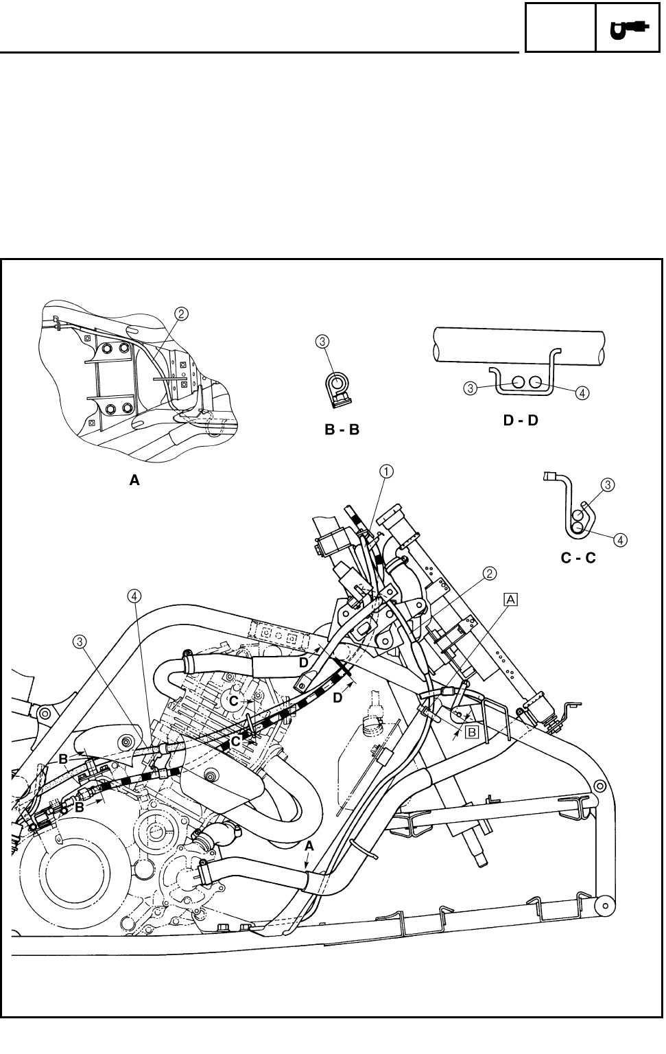
2 - 31
SPEC
1Radiator fan breather hose
2Reverse control cable
3Parking brake cable
4Clutch cable
ÈFasten the reverse control cable to the frame
with the plastic band.
É15 ~ 25 mm (0.59 ~ 0.98 in)
CABLE ROUTING

2 - 32
SPEC
1Rear brake hose
2Parking brake cable
3Negative battery lead
4AC magneto lead
5Crankcase breather hose
6Carburetor drain hose
7Rear brake switch
8Speed sensor
9Speed sensor lead
0Rear brake switch lead
CABLE ROUTING
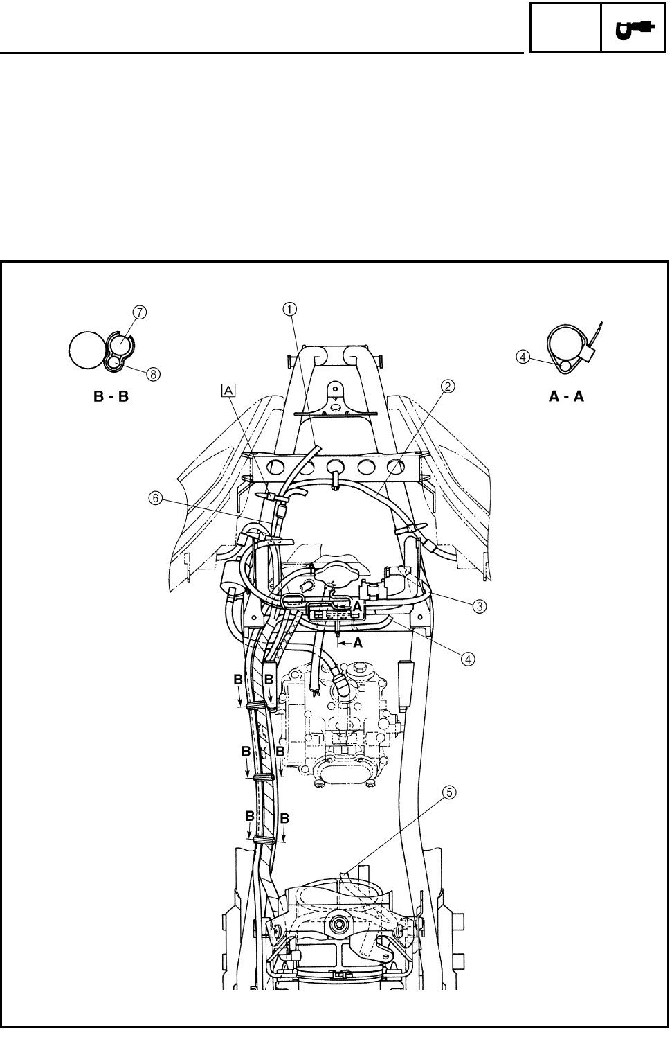
2 - 33
SPEC
1Thermo switch 1 lead
2Headlight lead (right)
3Radiator fan breather hose
4Thermo switch 2 lead
5Carburetor breather hose
6Headlight lead (left)
7Wire harness
8Coolant reservoir hose
ÈFasten the fan motor lead, headlight lead (right)
and thermo switch 1 lead to the frame with the
plastic band.
CABLE ROUTING
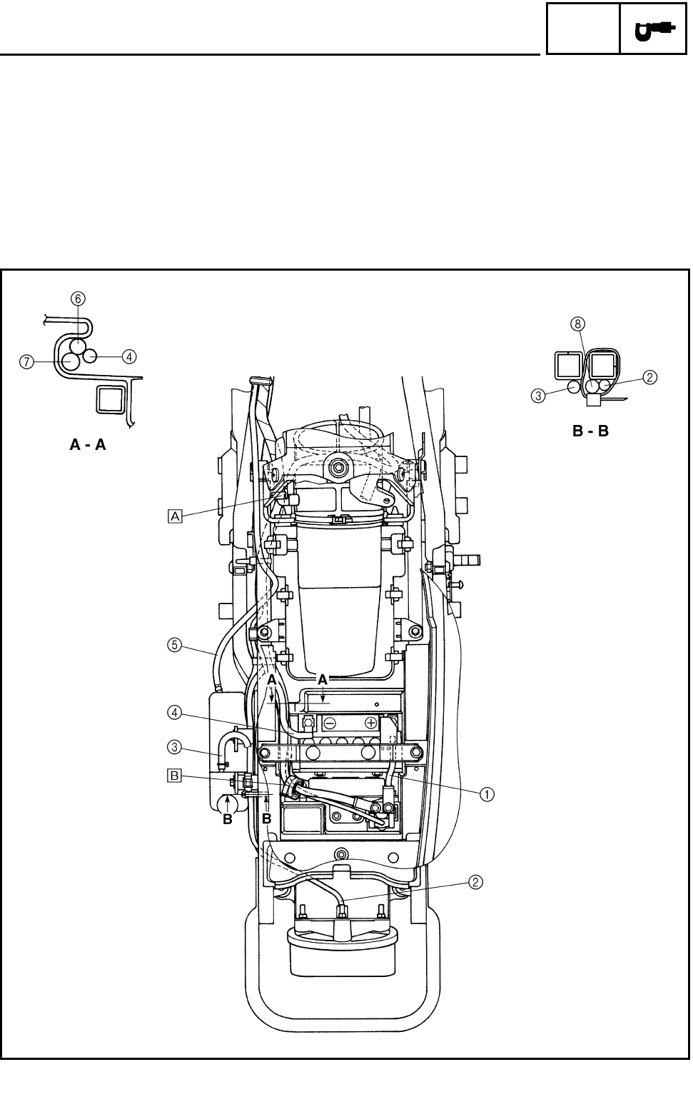
2 - 34
SPEC
1Positive battery lead
2Tail/brake light lead
3Coolant reservoir breather hose
4Negative battery lead
5Coolant reservoir hose
6Starter motor lead
7Wire harness
8Rectifier/regulator lead
ÈFasten the wire harness with the plastic clamp.
ÉFasten the starter motor lead and starter relay
lead with the plastic clamp.
CABLE ROUTING
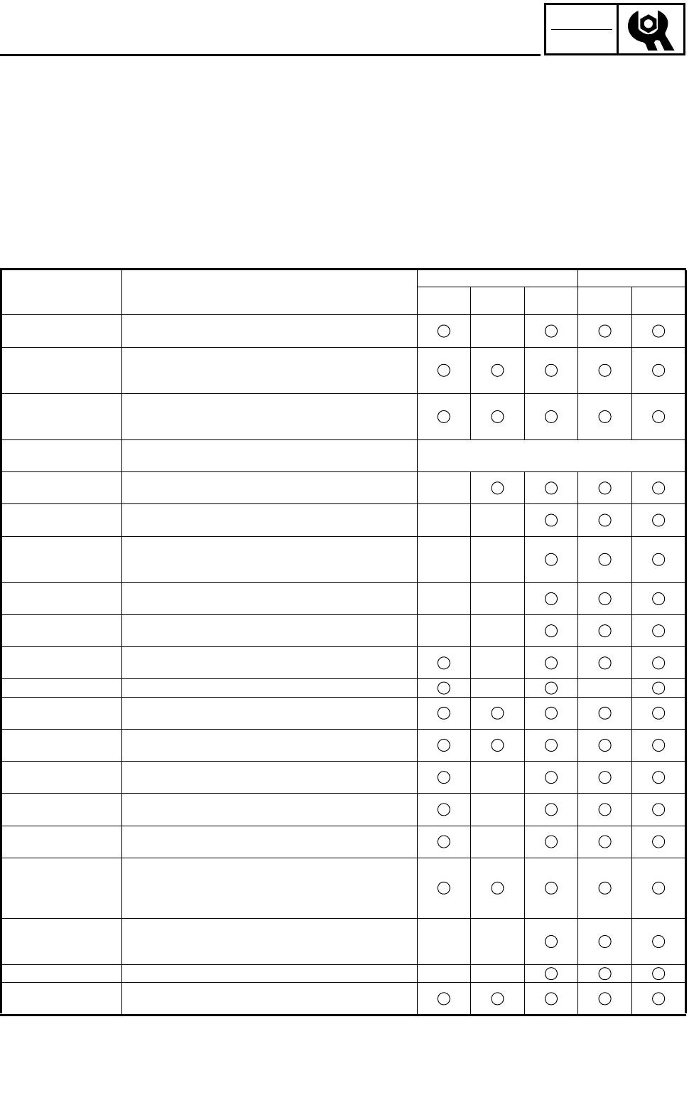
3 - 1
CHK
ADJ
INTRODUCTION/PERIODIC MAINTENANCE/
LUBRICATION INTERVALS
EB300000 PERIODIC CHECKS AND ADJUSTMENTS
INTRODUCTION
This chapter includes all information necessary to perform recommended inspections and adjust-
ments. These preventive maintenance procedures, if followed, will ensure more reliable vehicle
operation and a longer service life. The need for costly overhaul work will be greatly reduced. This
information applies to vehicles already in service as well as to new vehicles that are being prepared
for sale. All service technicians should be familiar with this entire chapter.
EB301000
PERIODIC MAINTENANCE/LUBRICATION INTERVALS
* It is recommended that these items be serviced by a Yamaha dealer.
** Lithium soap base grease
ITEM ROUTINE INITIAL EVERY
1
month 3
months 6
months 6
months 1
year
Valves*
(See page 3-8.) • Check valve clearance.
• Adjust if necessary.
Cooling system
(See page 3-27.)
• Check coolant leakage.
• Repair if necessary.
• Replace coolant every 24 months.
Spark plug
(See page 3-16.)
• Check condition.
• Adjust gap and clean.
• Replace if necessary.
Air filter
(See page 3-24.) • Clean.
• Replace if necessary.
Every 20~40 hours
(More often in wet or dusty areas.)
Carburetor*
(See page 3-11.) • Check and adjust idle speed/starter operation.
• Adjust if necessary.
Crankcase breather
system* • Check breather hose for cracks or damage.
• Replace if necessary.
Exhaust system* • Check for leakage.
• Retighten if necessary.
• Replace gasket if necessary.
Spark arrester
(See page 3-31.) • Clean.
Fuel line* • Check fuel hose for cracks or damage.
• Replace if necessary.
Engine oil
(See page 3-19.) • Replace (Warm engine before draining).
Engine oil filter • Replace if necessary.
Drive chain
(See page 3-40.) • Check and adjust slack/alignment/clean/lube.
Brake*
(See page 3-33.) • Check operation/fluid leakage/See NOTE page 3-2.
• Correct if necessary.
Clutch*
(See page 3-23.) • Check operation.
• Adjust if necessary.
Wheels*
(See page 4-3.) • Check balance/damage/runout.
• Replace if necessary.
Wheel bearings* • Check bearing assembly for looseness/damage.
• Replace if damaged.
Steering system*
(See page 3-42.)
• Check operation.
• Replace if damaged.
• Check toe-in.
• Adjust if necessary.
Upper and lower arm
pivot and steering
shaft* • Lubricate every 6 months.**
Rear arm pivot* • Lubricate every 6 months.**
Fittings and fasten-
ers* • Check all chassis fittings and fasteners.
• Correct if necessary.

3 - 2
CHK
ADJ
PERIODIC MAINTENANCE/LUBRICATION INTERVALS
NOTE:
●Recommended brake fluid: DOT 4
●Brake fluid replacement:
1.When disassembling the master cylinder or caliper cylinder, replace the brake fluid.
Normally check the brake fluid level and add fluid as required.
2.On the inner parts of the master cylinder and caliper cylinder, replace the oil seals every two
years.
3.Replace the brake hoses every four years, or if cracked or damaged.
WARNING
Indicates a potential hazard that could result in serious injury or death.
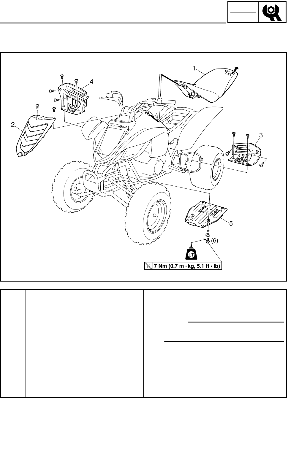
3 - 3
CHK
ADJ
SEAT, FENDERS AND FUEL TANK
SEAT, FENDERS AND FUEL TANK
SEAT, FRONT PANEL, FOOTREST GUARDS AND ENGINE SKID PLATE
Order Job name/Part name Q’ty Remarks
Removing the seat, front panel, foot-
rest guard and engine skid plate Remove the parts in the order below.
1Seat 1
NOTE:
Pull back the seat lock lever, than pull up
on the rear of the seat.
2 Front panel 1
3 Left footrest guard 1
4 Right footrest guard 1
5 Engine skid plate 1
For installation, reverse the removal pro-
cedure.
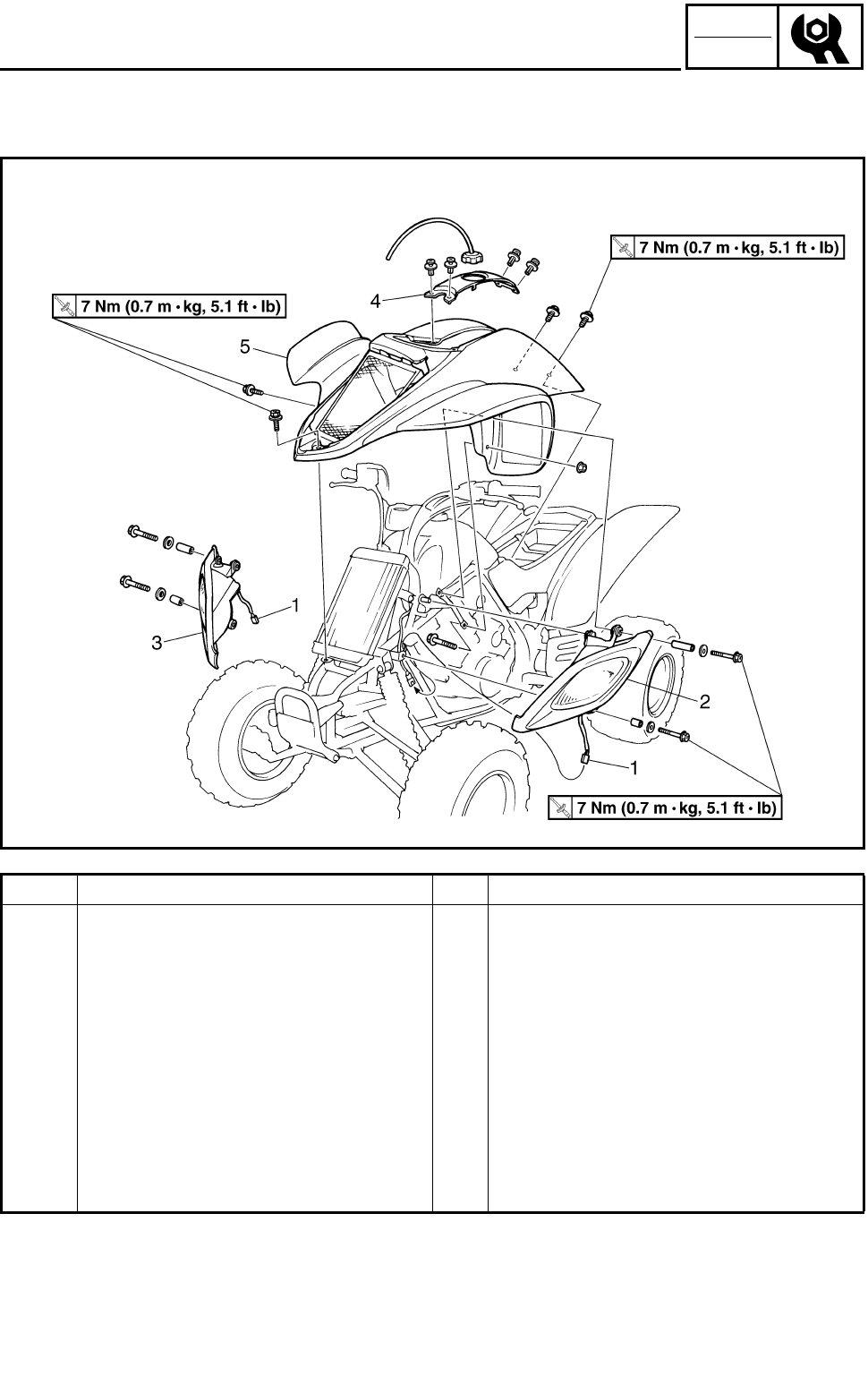
3 - 4
CHK
ADJ
SEAT, FENDERS AND FUEL TANK
HEADLIGHTS AND FRONT FENDER
Order Job name/Part name Q’ty Remarks
Removing the headlight and front
fender Remove the parts in the order below.
Seat and front panel Refer to “SEAT, FRONT PANEL, FOOT-
REST GUARDS AND ENGINE SKID
PLATE”.
1 Headlight coupler 2 Disconnect.
2 Left headlight 1
3 Right headlight 1
4 Fuel tank top panel 1
5 Front fender 1
For installation, reverse the removal pro-
cedure.
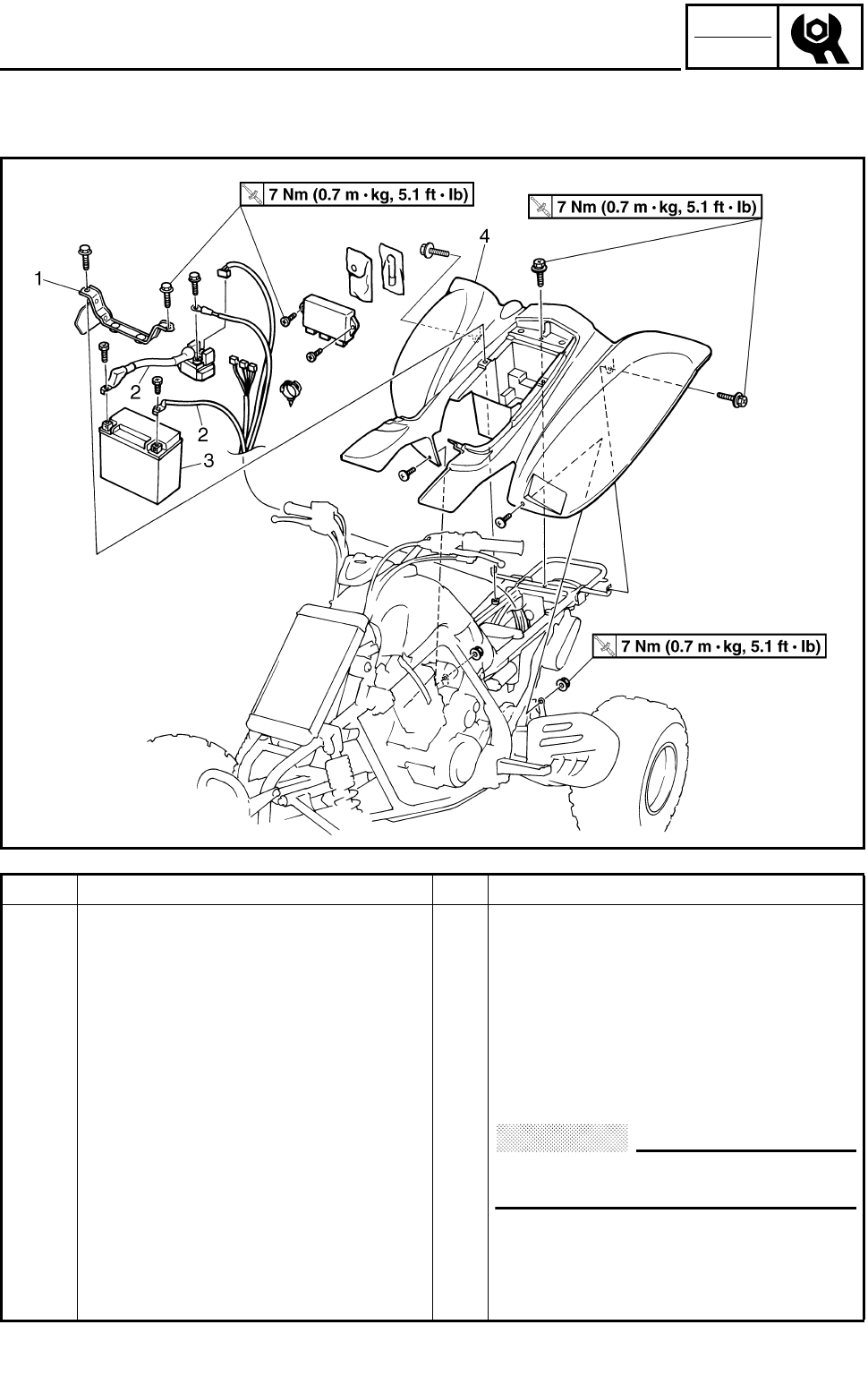
3 - 5
CHK
ADJ
SEAT, FENDERS AND FUEL TANK
REAR FENDER
Order Job name/Part name Q’ty Remarks
Removing the rear fender Remove the parts in the order below.
Seat Refer to “SEAT, FRONT PANEL, FOOT-
REST GUARDS AND ENGINE SKID
PLATE”.
Front fender Refer to “HEADLIGHTS AND FRONT
FENDER”.
1 Battery holding bracket 1
2 Battery lead 2 Disconnect.
CAUTION:
First disconnect the negative lead,
then disconnect the positive lead.
3 Battery 1
4 Rear fender 1
For installation, reverse the removal pro-
cedure.
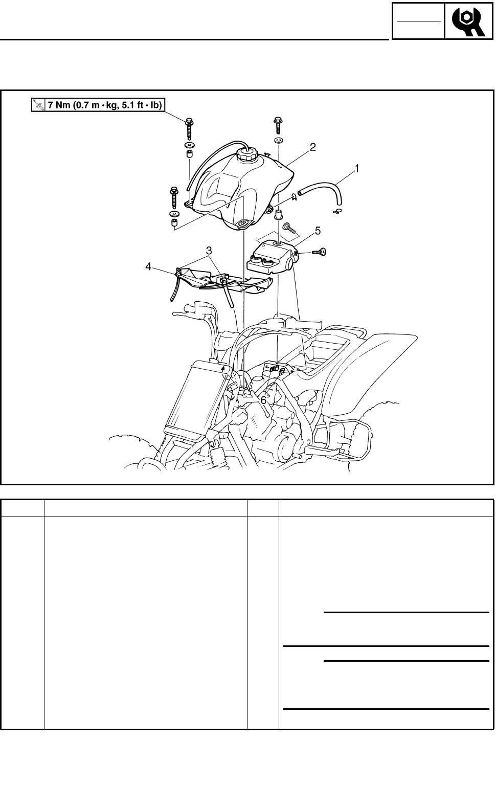
3 - 6
CHK
ADJ
SEAT, FENDERS AND FUEL TANK
FUEL TANK
Order Job name/Part name Q’ty Remarks
Removing the fuel tank Remove the parts in the order below.
Seat and front panel Refer to “SEAT, FRONT PANEL, FOOT-
REST GUARDS AND ENGINE SKID
PLATE”.
Front fender Refer to “HEADLIGHTS AND FRONT
FENDER”.
1 Fuel hose 1 NOTE:
Before disconnecting the fuel hose, turn
the fuel cock to “OFF”.
2 Fuel tank 1 NOTE:
When installing the fuel tank, pass the
fuel tank breather hose through the hole
in the handlebar protector.
3 Plastic band 2
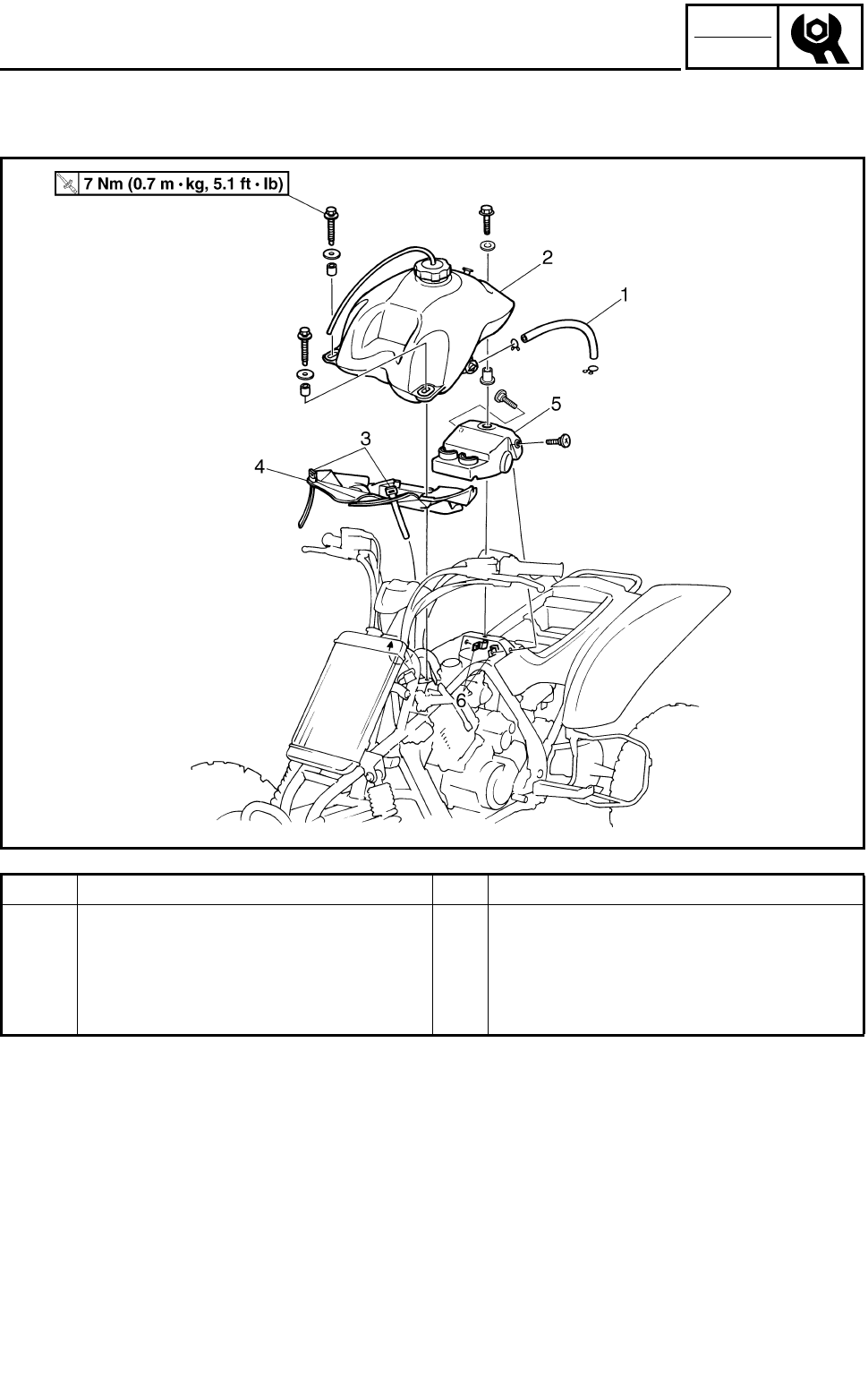
3 - 7
CHK
ADJ
SEAT, FENDERS AND FUEL TANK
Order Job name/Part name Q’ty Remarks
4 Rubber cover 1 1
5 Rubber cover 2 1
6 Hose holder 2
For installation, reverse the removal pro-
cedure.
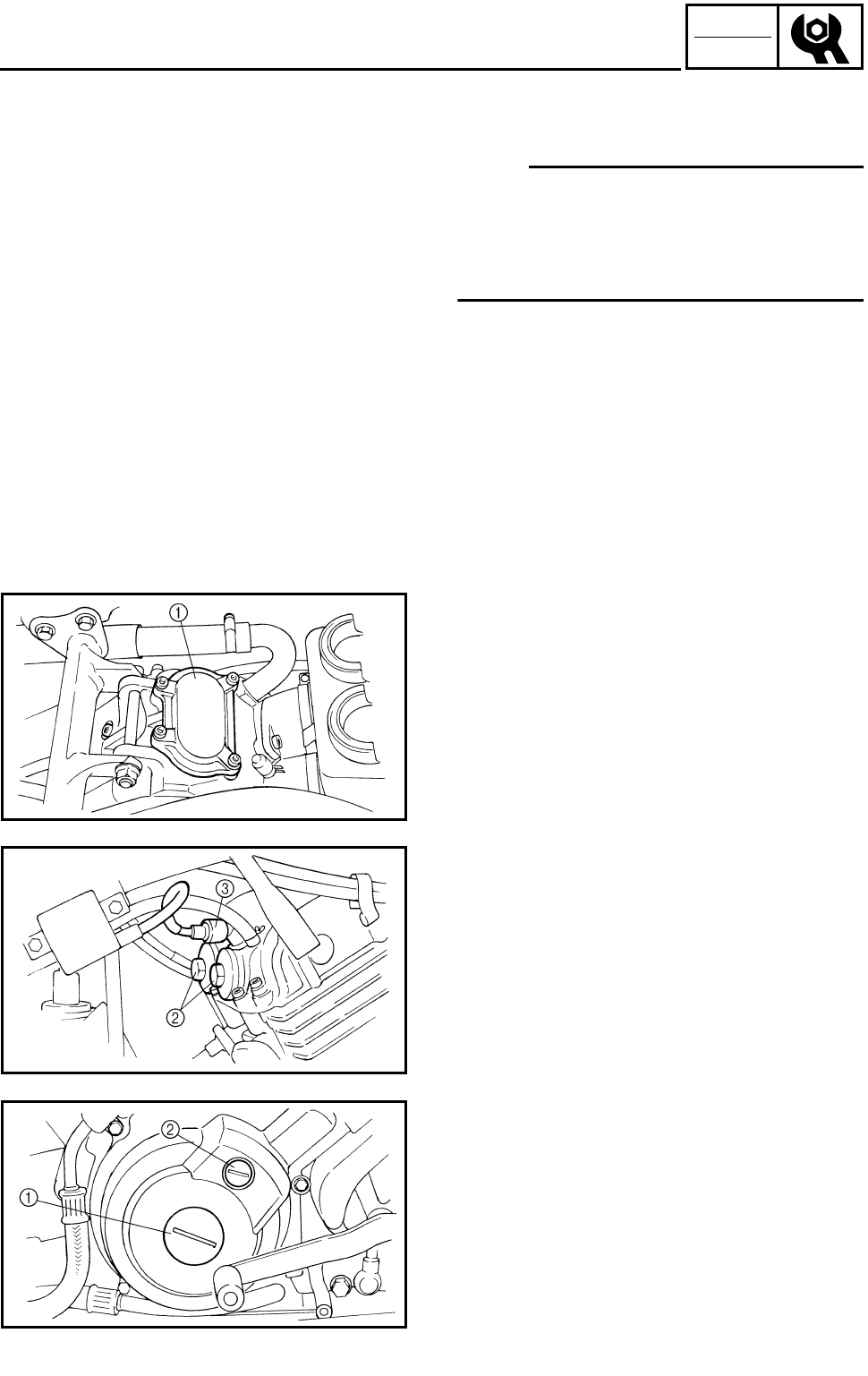
3 - 8
CHK
ADJ
ADJUSTING THE VALVE CLEARANCE
ENGINE
ADJUSTING THE VALVE CLEARANCE
NOTE:
●The valve clearance must be adjusted when
the engine is cool to the touch.
●Adjust the valve clearance when the piston is
at the Top Dead Center (T.D.C.) on the com-
pression stroke.
1.Remove:
●Seat
●Front fender
●Fuel tank
Refer to “SEAT, FENDERS AND FUEL
TANK”.
2.Remove:
●Tappet cover (intake) 1
●Tappet covers (exhaust) 2
3.Disconnect:
●Spark plug cap 3
4.Remove:
●Spark plug
5.Remove:
●Crankshaft end accessing screw 1
●Timing mark accessing screw 2
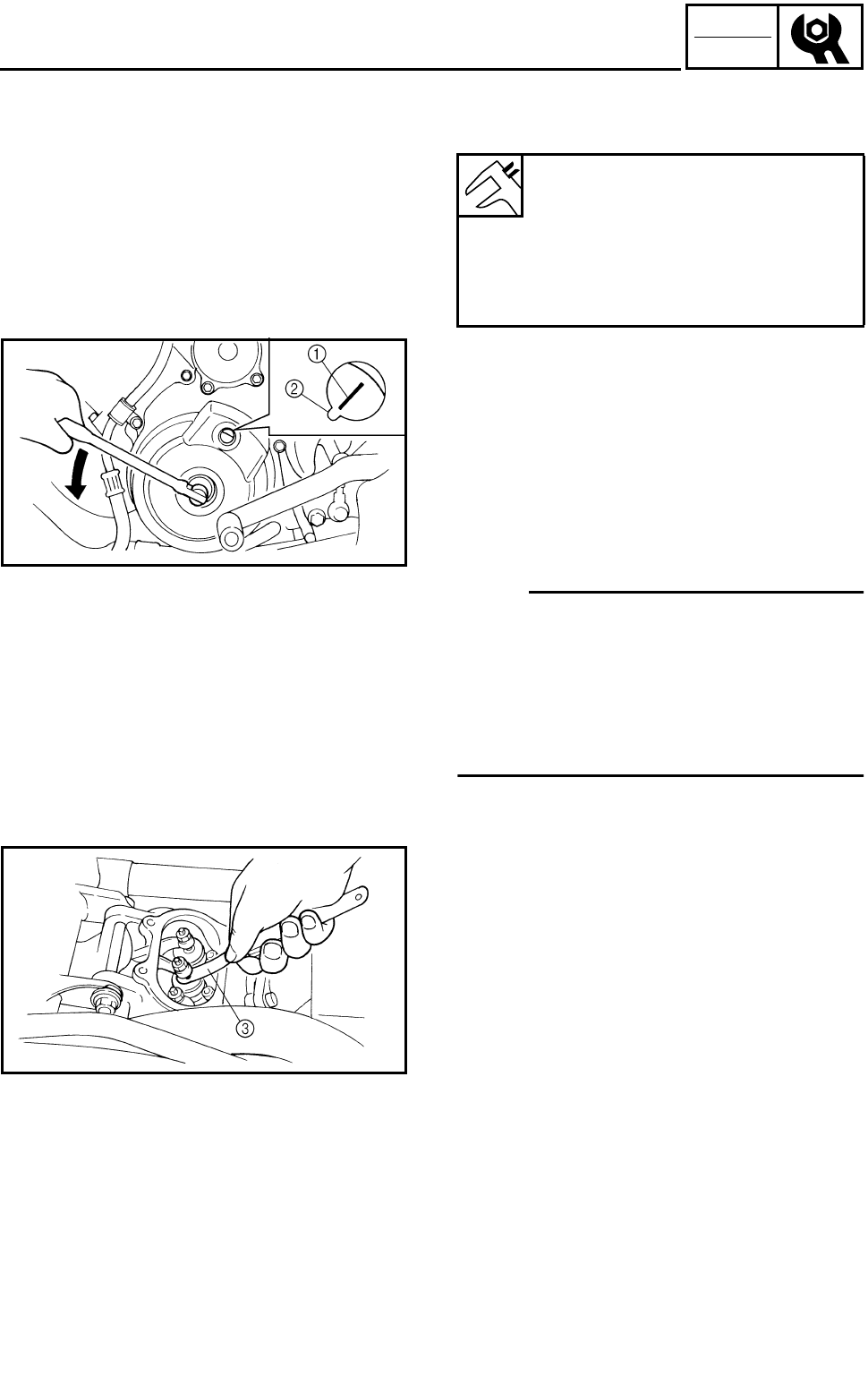
3 - 9
CHK
ADJ
ADJUSTING THE VALVE CLEARANCE
6.Check:
●Valve clearance
Out of specification → Adjust.
***********************************************
Checking steps:
●Turn the crankshaft counterclockwise with a
wrench.
●Align the “I” mark 1 on the rotor with the sta-
tionary pointer 2 on the crankcase cover.
When the “I” mark is aligned with the station-
ary pointer, the piston is at the Top Dead
Center (T.D.C.).
NOTE:
●When the piston is at the Top Dead Center
(T.D.C.) on the compression stroke, there
should be clearance between the valve stem
tips and their respective rocker arm adjusting
screws.
●If there is no clearance, rotate the crankshaft
counterclockwise one turn.
Valve clearance (cold):
Intake:
0.10 ~ 0.15 mm
(0.0039 ~ 0.0059 in)
Exhaust:
0.15 ~ 0.20 mm
(0.0059 ~ 0.0079 in)
●Measure the valve clearance using a feeler
gauge 3.
***********************************************
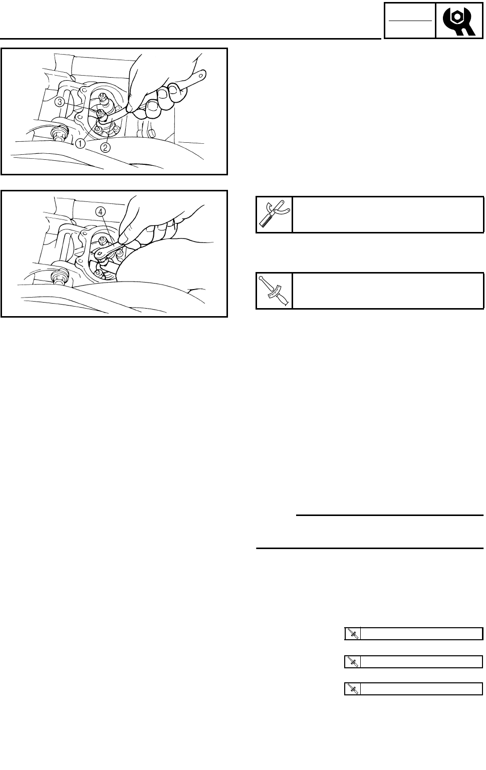
3 - 10
CHK
ADJ
ADJUSTING THE VALVE CLEARANCE
7.Adjust:
●Valve clearance
***********************************************
Adjustment steps:
●Loosen the locknut 1.
●Insert a feeler gauge 2 between the adjuster
end and the valve end.
●Turn the adjuster 3 clockwise or counter-
clockwise with the tappet adjusting tool 4
until the proper clearance is obtained.
●Hold the adjuster to prevent it from moving
and then tighten the locknut.
●Measure the valve clearance.
●If the clearance is incorrect, repeat the above
steps until the proper clearance is obtained.
***********************************************
Tappet adjusting tool:
P/N. YM-08035, 90890-01311
T
R
.
.
Locknut:
14 Nm (1.4 m • kg, 10 ft • lb)
8.Install:
●All removed parts
NOTE:
Install all removed parts in the reverse order of
their disassembly. Note the following points.
9.Install:
●Spark plug
●Tappet cover (intake)
●Tappet covers (exhaust)
T
R
.
.
18 Nm (1.8 m • kg, 13 ft • lb)
T
R
.
.
10 Nm (1.0 m • kg, 7.2 ft • lb)
T
R
.
.
12 Nm (1.2 m • kg, 8.7 ft • lb)
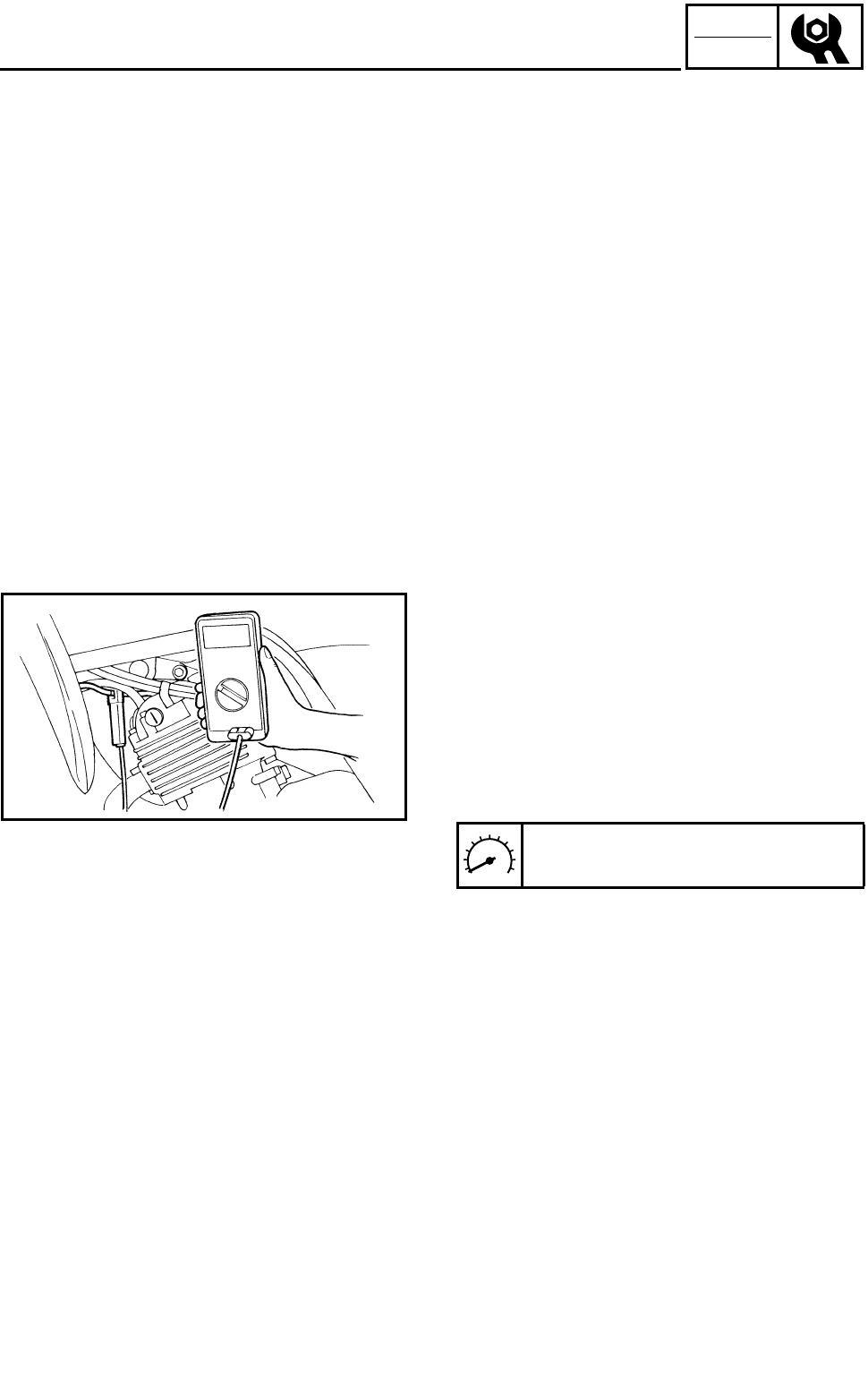
3 - 11
CHK
ADJ
ADJUSTING THE VALVE CLEARANCE/ADJUSTING THE
TIMING CHAIN/ADJUSTING THE IDLING SPEED
10.Install:
●Fuel tank
●Front fender
●Seat
Refer to “SEAT, FENDERS AND FUEL
TANK”.
ADJUSTING THE TIMING CHAIN
Adjustment free.
ADJUSTING THE IDLING SPEED
1.Start the engine and let it warm up for sev-
eral minutes.
2.Attach:
●Tachometer
(to the spark plug lead)
3.Check:
●Engine idling speed
Out of specification → Adjust.
Engine idling speed:
1,450 ~ 1,550 r/min
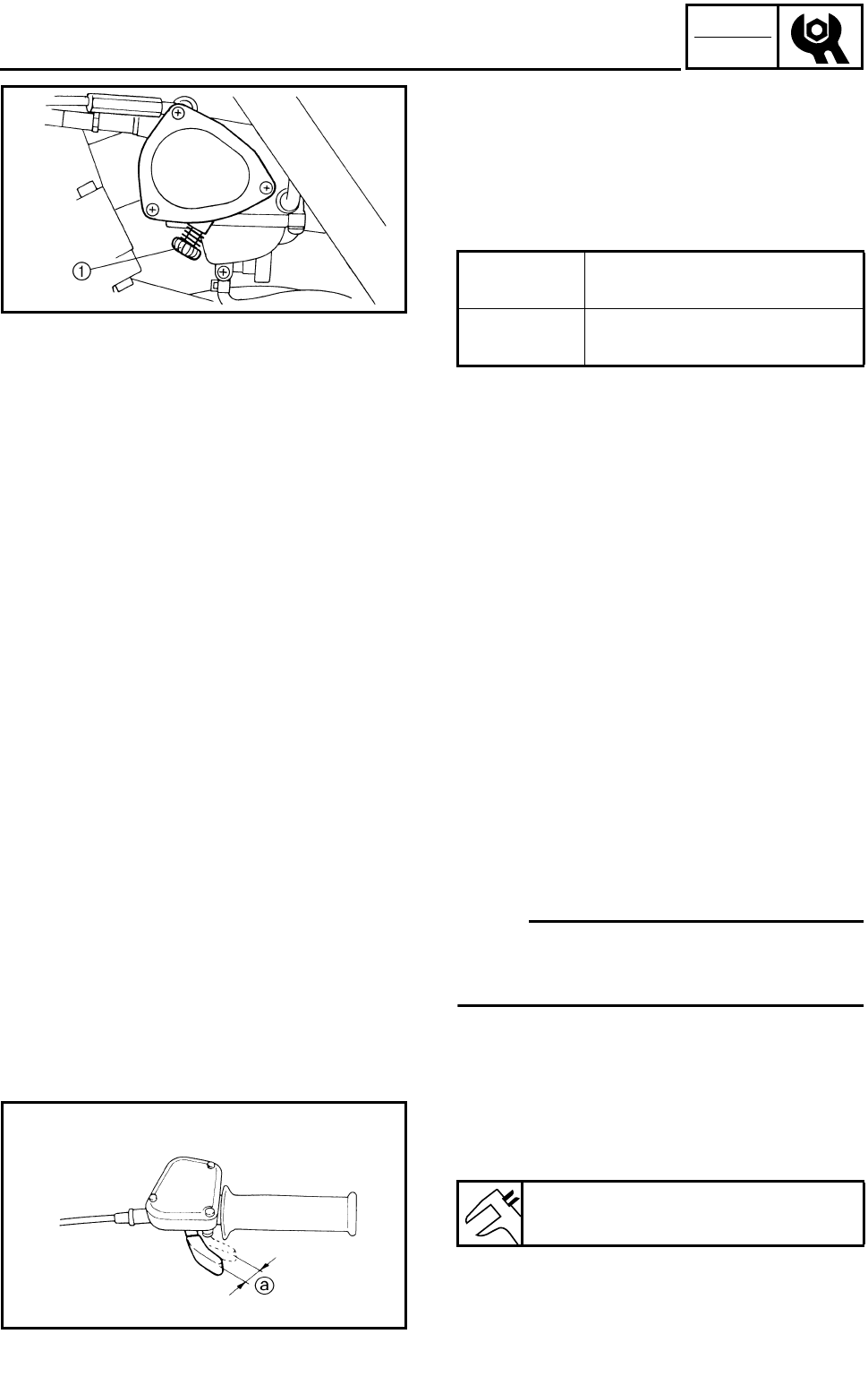
3 - 12
CHK
ADJ
ADJUSTING THE IDLING SPEED/
ADJUSTING THE THROTTLE LEVER FREE PLAY
4.Adjust:
●Engine idling speed
***********************************************
Adjustment steps:
●Turn the throttle stop screw 1 in or out until
the specified idling speed is obtained.
***********************************************
5.Detach:
●Tachometer
6.Adjust:
●Throttle lever free play
Refer to “ADJUSTING THE THROTTLE
LEVER FREE PLAY”.
Turning in Idling speed becomes
higher.
Turning out Idling speed becomes
lower.
ADJUSTING THE THROTTLE LEVER FREE
PLAY
NOTE:
Engine idling speed should be adjusted prop-
erly before adjusting the throttle lever free
play.
1.Check:
●Throttle lever free play a
Out of specification → Adjust.
Throttle lever free play:
3 ~ 5 mm (0.12 ~ 0.20 in)
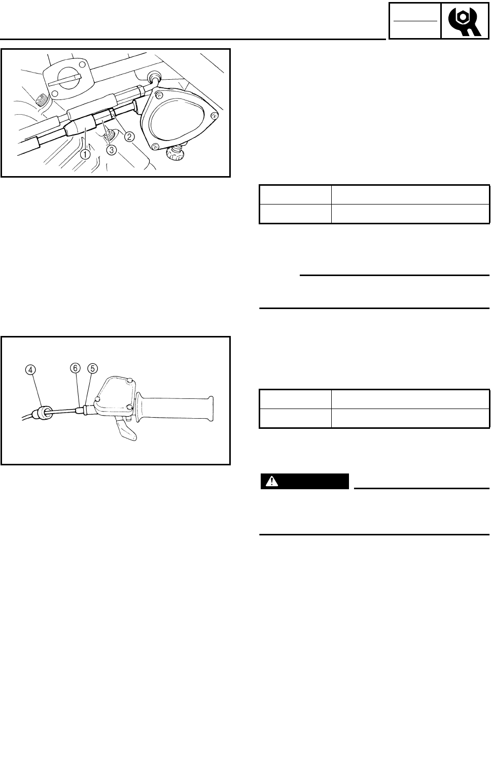
3 - 13
CHK
ADJ
ADJUSTING THE THROTTLE LEVER FREE PLAY
2.Adjust:
●Throttle lever free play
***********************************************
Adjustment steps:
First step:
●Pull back the adjuster cover 1.
●Loosen the locknut 2 on the carburetor side.
●Turn the adjuster 3 in or out until the correct
free play is obtained.
●Tighten the locknut 2.
●Push in the adjuster cover 1.
NOTE:
If the free play cannot be adjusted here, adjust
it at the throttle lever side of the cable.
Second step:
●Pull back the adjuster cover 4.
●Loosen the locknut 5.
●Turn the adjuster 6 in or out until the correct
free play is obtained.
●Tighten the locknut 5.
●Push in the adjuster cover 4.
WARNING
After adjusting the free play, turn the handle-
bar to the right and left to make sure that the
engine idling speed does not increase.
***********************************************
Turning in Free play is increased.
Turning out Free play is decreased.
Turning in Free play is increased.
Turning out Free play is decreased.
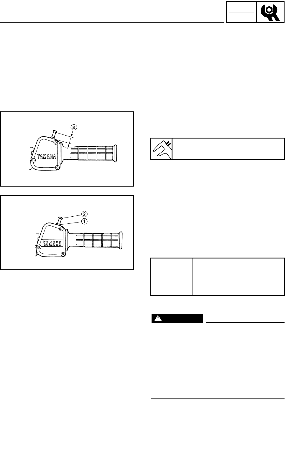
3 - 14
CHK
ADJ
ADJUSTING THE SPEED LIMITER
ADJUSTING THE SPEED LIMITER
The speed limiter keeps the carburetor throttle
from becoming fully-opened even when the
throttle lever is applied to the maximum posi-
tion. Screwing in the adjuster stops the engine
speed from increasing.
1.Check:
●Speed limiter length a
Out of specification → Adjust.
Speed limiter length:
12 mm (0.47 in)
2.Adjust:
●Speed limiter length
***********************************************
Speed limiter length adjustment steps:
●Loosen the locknut 1.
●Turn the adjuster 2 in or out until the speci-
fied speed limiter length is obtained.
●Tighten the locknut.
WARNING
●Particularly for a beginner rider, the
speed limiter should be screwed in com-
pletely. Screw it out little by little as their
riding technique improves. Never remove
the speed limiter for a beginning rider.
●For proper throttle lever operation do not
turn out the adjuster more than 12 mm
(0.47 in). Also, always adjust the throttle
lever free play to 3 ~ 5 mm (0.12 ~ 0.20 in).
***********************************************
Turning in Speed limiter length is
decreased.
Turning out Speed limiter length is
increased.
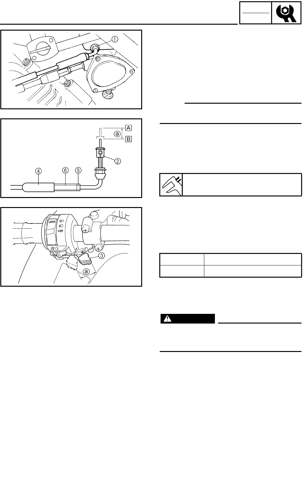
3 - 15
CHK
ADJ
ADJUSTING THE STARTER CABLE
ADJUSTING THE STARTER CABLE
1.Adjust:
●Starter cable
***********************************************
Adjustment steps:
●Disconnect the starter cable 1 from the car-
buretor body.
NOTE:
Do not remove the starter plunger 2 from the
starter cable.
●Measure the starter plunger stroke distance
a of the starter lever 3 fully close-to-fully
open position.
If the distance is out of specification adjust it
as described below.
ÈFully closed position
ÉFully open position
●Pull back the boot 4.
●Loosen the locknut 5.
●Turn the adjuster 6 in or out until the correct
distance is obtained.
●Tighten the locknut 5.
●Push in the boot 4.
●Connect the starter cable.
WARNING
After adjusting the cable, turn the handle-
bar to right to left, and make sure that the
engine idling speed does not increase.
***********************************************
Starter plunger stroke distance a:
15 mm (0.59 in)
Turning in Distance increased.
Turning out Distance decreased.
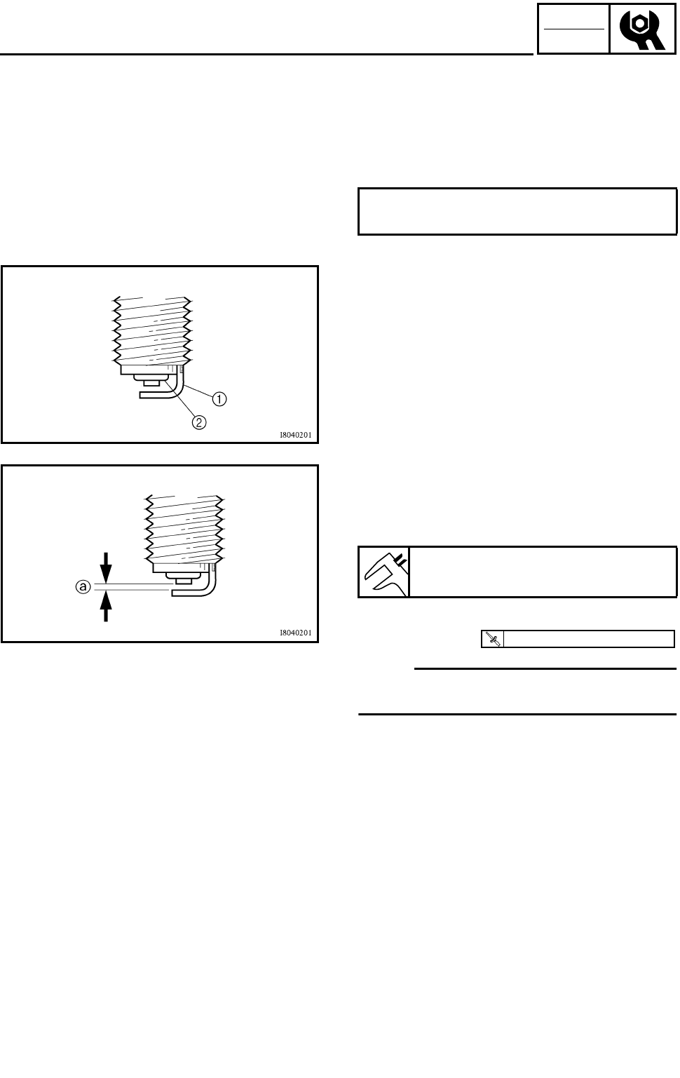
3 - 16
CHK
ADJ
CHECKING THE SPARK PLUG
1.Remove:
●Spark plug
2.Check:
●Spark plug type
Incorrect → Replace.
Standard spark plug:
DPR8EA-9/NGK
3.Check:
●Electrode 1
Wear/damage → Replace.
●Insulator 2
Abnormal color → Replace.
Normal color is a medium-to-light tan color.
4.Clean the spark plug with a spark plug
cleaner or wire brush.
5.Measure:
●Plug gap a
Use a wire gauge or feeler gauge.
Out of specification → Regap.
6.Tighten:
●Spark plug
NOTE:
Before installing a spark plug, clean the gasket
surface and plug surface.
Spark plug gap:
0.8 ~ 0.9 mm (0.031 ~ 0.035 in)
T
R
.
.
18 Nm (1.8 m • kg, 13 ft • lb)
CHECKING THE SPARK PLUG
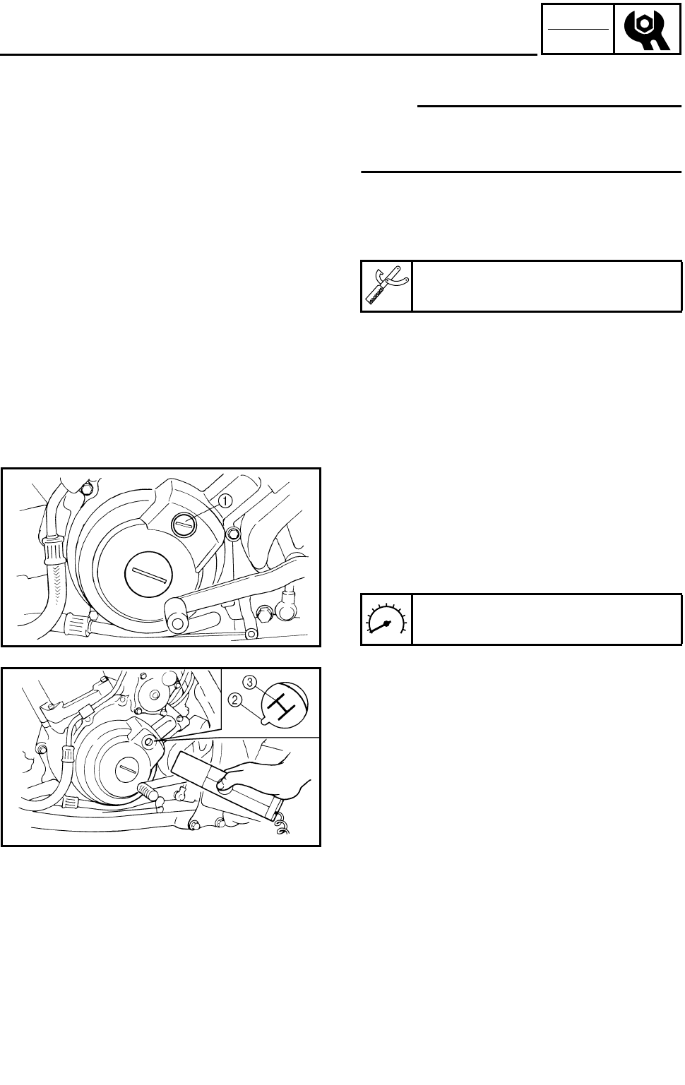
3 - 17
CHK
ADJ
CHECKING THE IGNITION TIMING
CHECKING THE IGNITION TIMING
NOTE:
Engine idling speed and throttle cable free play
should be adjusted properly before checking
the ignition timing.
1.Attach:
●Tachometer
●Timing light
(to spark plug lead)
Timing light:
P/N. YM-33277-A, 90890-03141
2.Check:
●Ignition timing
***********************************************
Checking steps:
●Warm up the engine and keep it at the speci-
fied speed.
●Remove the timing mark accessing screw 1.
●Visually check the stationary pointer 2 to
verify it is within the required firing range 3
indicated on the flywheel.
Incorrect firing range → Check the pulser coil
assembly.
●Install the timing mark accessing screw.
***********************************************
3.Detach:
●Timing light
●Tachometer
Engine speed:
1,450 ~ 1,550 r/min
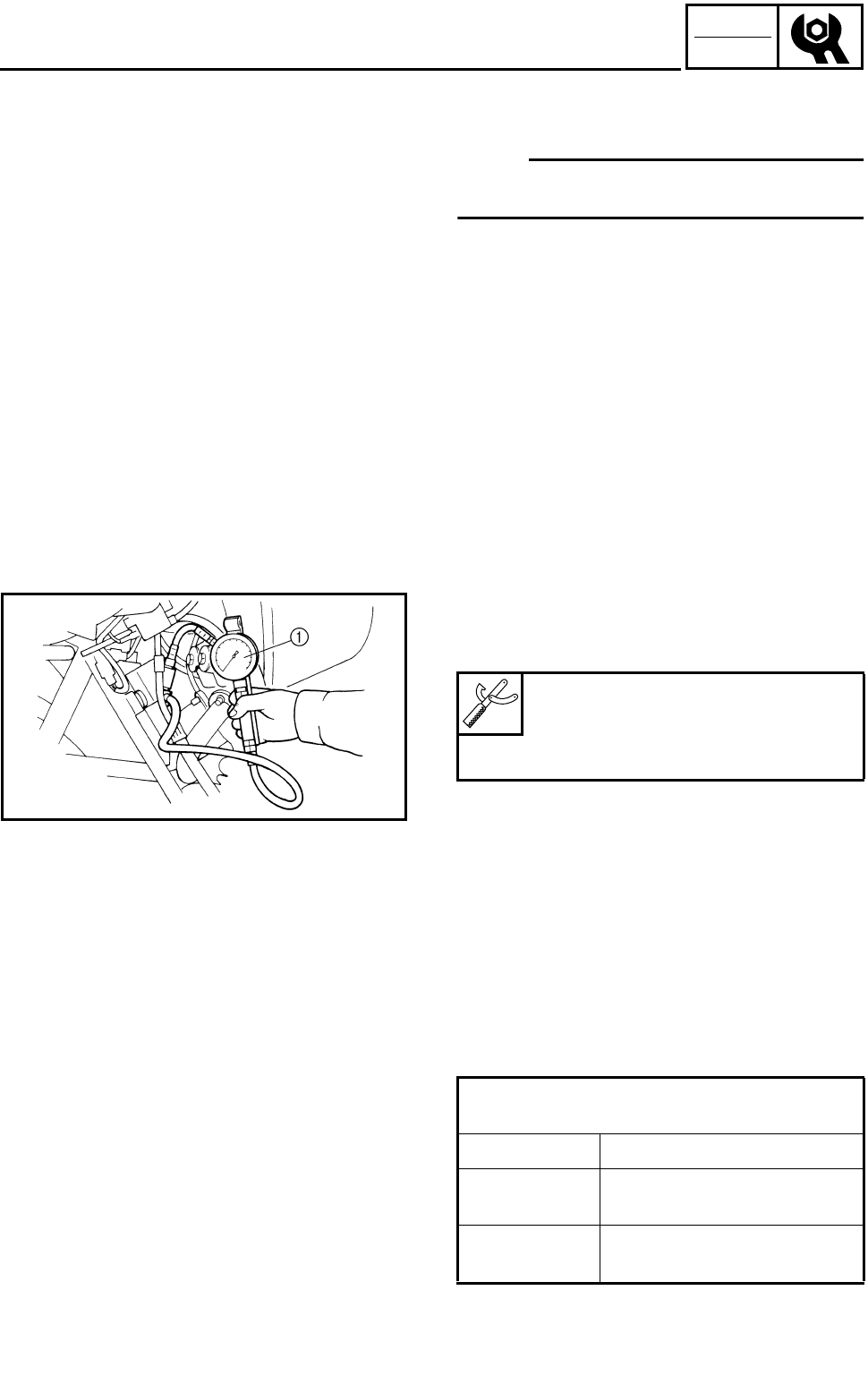
3 - 18
CHK
ADJ
MEASURING THE COMPRESSION PRESSURE
MEASURING THE COMPRESSION
PRESSURE
NOTE:
Insufficient compression pressure will result in
a loss of performance.
1.Check:
●Valve clearance
Out of specification → Adjust.
Refer to “ADJUSTING THE VALVE CLEAR-
ANCE”.
2.Start the engine and let it warm up for sev-
eral minutes.
3.Stop the engine.
4.Remove:
●Spark plug
5.Attach:
●Adapter
●Compression gauge 1
Compression gauge:
P/N. YU-33223, 90890-03081
Adapter:
P/N. YU-33223-3, 90890-04082
6.Measure:
●Compression pressure
Above the maximum pressure:
Inspect the cylinder head, valve surfaces,
and piston crown for carbon deposits.
Below the minimum pressure:
Squirt a few drops of oil into the affected cyl-
inder and measure again.
●Refer to the table below.
Compression pressure
(with oil introduced into cylinder)
Reading Diagnosis
Higher than
without oil Worn or damaged piston,
rings or cylinder wall.
Same as
without oil Defective valves or
cylinder head gasket.
3 - 19
CHK
ADJ
MEASURING THE COMPRESSION PRESSURE/
CHECKING THE ENGINE OIL LEVEL
***********************************************
Measurement steps:
●Crank over the engine with the electric
starter (be sure the battery is fully charged)
with the throttle fully-open until the compres-
sion reading on the gauge stabilizes.
WARNING
When cranking the engine, ground the
spark plug lead to prevent sparking.
***********************************************
7.Install:
●Spark plug
Compression pressure (at sea level):
Standard:
1,250 kPa (12.5 kg/cm2, 181 psi)
Minimum:
1,050 kPa (10.5 kg/cm2, 149 psi)
Maximum:
1,350 kPa (13.5 kg/cm2, 192 psi)
T
R
.
.
18 Nm (1.8 m • kg, 13 ft • lb)
CHECKING THE ENGINE OIL LEVEL
1.Place the machine on a level surface.
2.Start the engine, warm it up until the engine
oil has reached a normal temperature of
60 °C (140 °F), let it continue to idle for ten
seconds, and then turn the engine off.
NOTE:
To achieve the proper engine oil temperature
for an accurate oil level reading, the engine
must have first completely cooled down, and
then warmed up again for several minutes to
normal operating temperature.
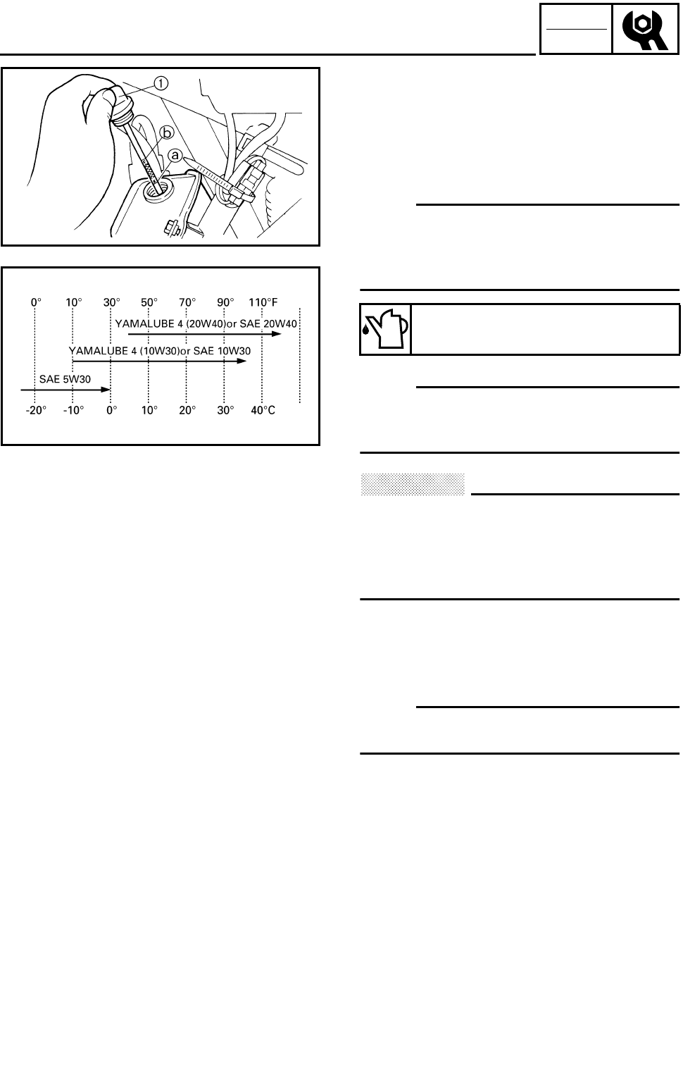
3 - 20
CHK
ADJ
CHECKING THE ENGINE OIL LEVEL/
CHANGING THE ENGINE OIL
3.Check:
●Engine oil level
Oil level should be between the minimum
level mark a and the maximum level mark
b.
Low oil level → Add oil to the proper level.
NOTE:
●Wait a few minutes until the oil settles before
inspecting the oil level.
●Do not screw the dipstick 1 in when inspect-
ing the oil level.
NOTE:
Recommended oil classification:
API Service “SE”, “SF”, “SG” type or equiva-
lent (e.g. “SF–SE–CC”, “SF–SE–SD” etc.)
CAUTION:
●Do not add any chemical additives.
Engine oil also lubricates the clutch and
additives could cause clutch slippage.
●Do not allow foreign material to enter the
crankcase.
4.Start the engine and let it warm up for sev-
eral minutes.
5.Stop the engine and inspect the oil level
again.
NOTE:
Wait a few minutes until the oil settles before
inspecting the oil level.
Recommended oil:
Follow the left chart.
CHANGING THE ENGINE OIL
1.Remove:
●Engine skid plate
Refer to “SEAT, FENDERS AND FUEL
TANK”.
2.Start the engine and let it warm up for sev-
eral minutes.
3.Stop the engine and place a container under
the engine oil drain bolt.

3 - 21
CHK
ADJ
CHANGING THE ENGINE OIL
4.Remove:
●Dipstick 1
●Engine oil drain bolt (oil tank) 2
●Engine oil drain bolt (crankcase) 3
Drain the engine oil from the oil tank and
crankcase.
5.If the oil filter cartridge is also to be replaced,
perform the following procedure.
***********************************************
Replacement steps:
●Remove the oil filter cartridge 1 with an oil
filter wrench 2.
●Apply a thin coat of engine oil to the O-ring
3 of the new oil filter cartridge.
CAUTION:
Make sure that the O-ring 3 is properly
seated in the groove of the oil filter car-
tridge.
Oil filter wrench:
P/N. YM-01469, 90890-01469
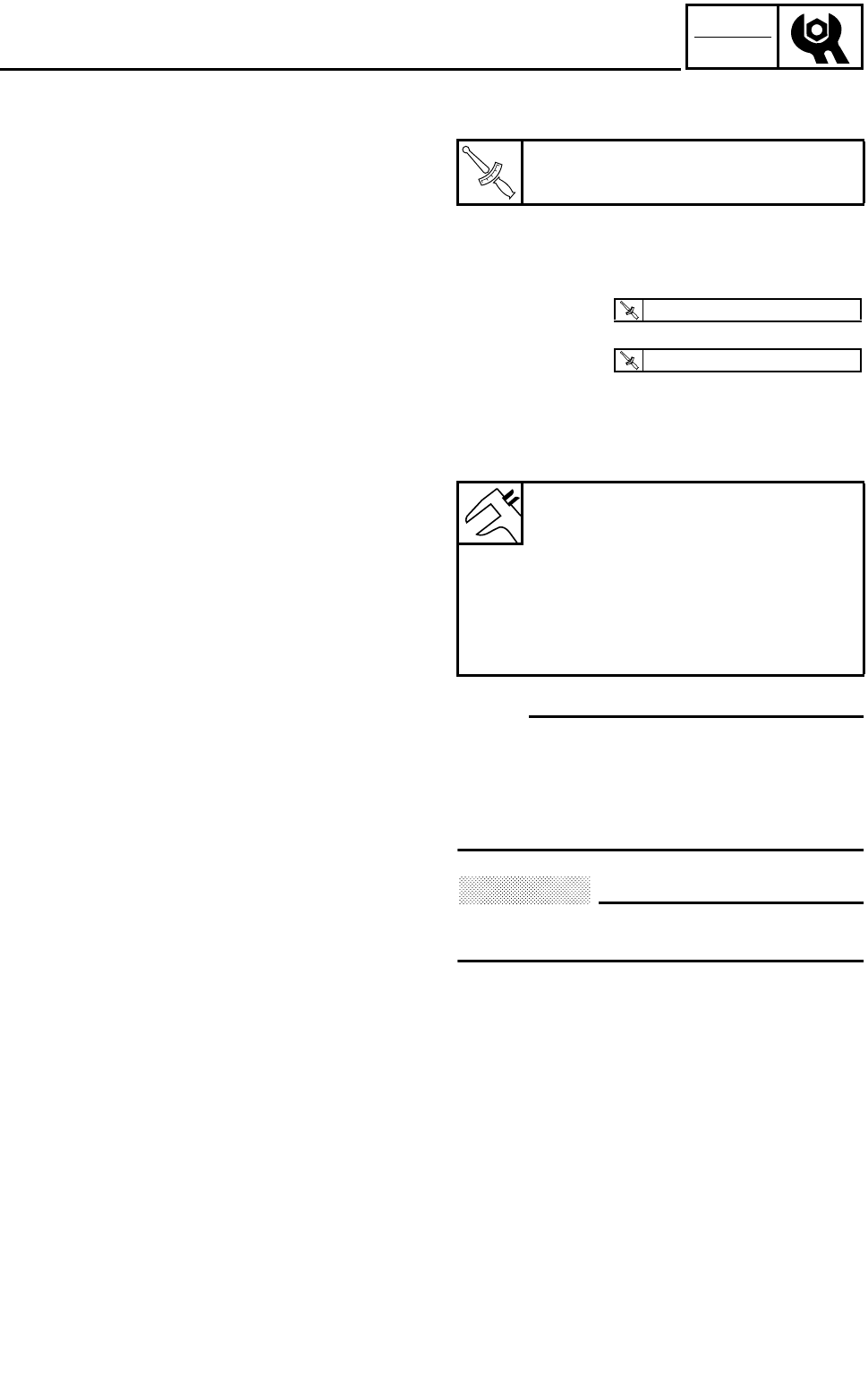
3 - 22
CHK
ADJ
CHANGING THE ENGINE OIL
●Tighten the new oil filter cartridge to specifi-
cation with an oil filter wrench.
***********************************************
6.Install:
●Engine oil drain bolt (crankcase)
●Engine oil drain bolt (oil tank)
7.Fill:
●Oil tank
(with the specified amount of the recom-
mended engine oil)
NOTE:
●Pour the engine oil in several stages.
●First, pour in 1.75 L (1.54 Imp qt, 1.85 US qt)
of oil, and then start the engine and rev it 3 to
5 times. Stop the engine, and then pour in
the remainder of the specified amount.
CAUTION:
When starting the engine make sure the
dipstick is securely fitted into the oil tank.
8.Install:
●Dipstick
9.Warm up the engine for a few minutes, then
stop the engine.
10.Check:
●Engine
(for engine oil leaks)
●Oil level
Refer to “CHECKING THE ENGINE OIL
LEVEL”.
T
R
.
.
Oil filter cartridge:
17 Nm (1.7 m • kg, 12 ft • lb)
Quantity:
Total amount:
2.3 L (2.02 Imp qt, 2.43 US qt)
Periodic oil replacement:
1.9 L (1.67 Imp qt, 2.01 US qt)
With oil filter cartridge replace-
ment:
1.95 L (1.72 Imp qt, 2.06 US qt)
T
R
.
.
30 Nm (3.0 m • kg, 22 ft • lb)
T
R
.
.
25 Nm (2.5 m • kg, 18 ft • lb)
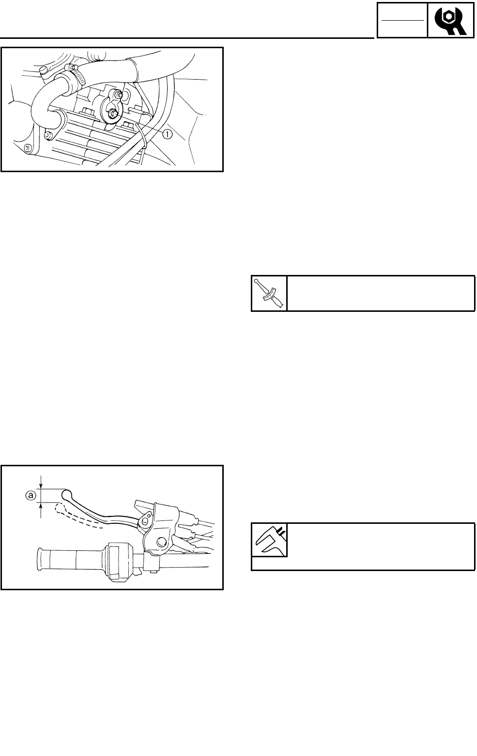
3 - 23
CHK
ADJ
CHANGING THE ENGINE OIL/
ADJUSTING THE CLUTCH CABLE
11.Check:
●Engine oil pressure
***********************************************
●Slightly loosen the oil gallery bolt 1.
●Start the engine and keep it idling until
engine oil starts to seep from the oil gallery
bolt. If no engine oil comes out after one
minute, turn the engine off so that it will not
seize.
●Check the engine oil passages, the oil filter
cartridge and the oil pump for damage or
leakage.
Refer to “OIL PUMP” in CHAPTER 5.
●Start the engine after solving the problem(s)
and check the engine oil pressure again.
●Tighten the oil gallery bolt to specification.
***********************************************
12.Install:
●Engine skid plate
Refer to “SEAT, FENDERS AND FUEL
TANK”.
T
R
.
.
Oil gallery bolt:
7 Nm (0.7 m • kg, 5.1 ft • lb)
ADJUSTING THE CLUTCH CABLE
1.Check:
●Clutch lever free play a
Out of specification → Adjust.
Clutch lever free play
(at the clutch lever end):
5 ~ 10 mm (0.20 ~ 0.39 in)
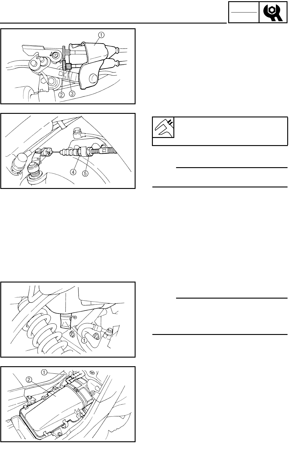
3 - 24
CHK
ADJ
ADJUSTING THE CLUTCH CABLE/
CLEANING THE AIR FILTER
2.Adjust:
●Clutch lever free play
***********************************************
Adjustment steps:
●Pull the rubber cover 1 off.
●Loosen the locknut 2 and finger tighten the
adjusting bolt 3.
●Loosen the locknut 4.
●Turn the adjusting nut 5 until the clutch lever
free play is within the specified limits.
●Tighten the locknut 4.
NOTE:
If the specified clutch lever free play cannot be
obtained on it, use the adjusting bolt 3.
●Turn the adjusting bolt 3 until the clutch
lever free play is within the specified limits.
●Tighten the locknut 2.
●Pull the rubber cover 1 in.
***********************************************
Clutch lever free play
(at the clutch lever end):
5 ~ 10 mm (0.20 ~ 0.39 in)
CLEANING THE AIR FILTER
NOTE:
There is a check hose 1 at the bottom of the
air filter case. If dust and/or water collects in
this hose, clean the air filter element and air fil-
ter case.
1.Remove:
●Seat
Refer to “SEAT, FENDERS AND FUEL
TANK”.
2.Disconnect:
●Crankcase breather hose 1
3.Remove:
●Air filter case cover 2
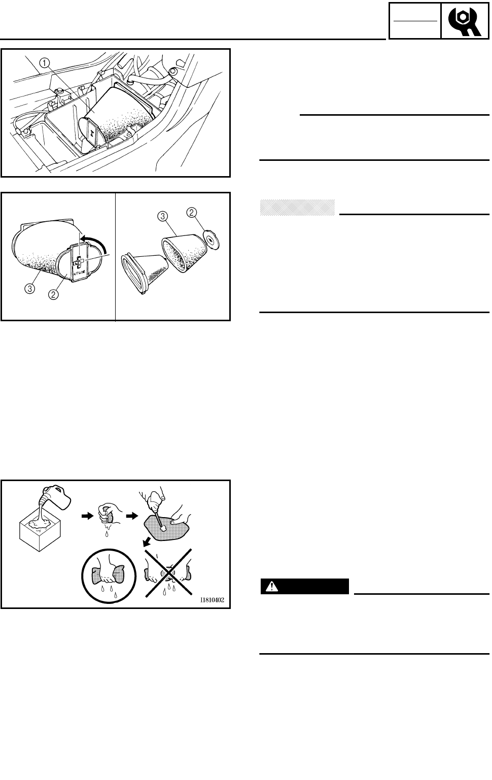
3 - 25
CHK
ADJ
CLEANING THE AIR FILTER
4.Remove:
●Air filter element assembly 1
●Air filter element cap 2
●Air filter element 3
NOTE:
When removing the air filter element, rotate
the air filter element cap 1/4 of a turn and
remove the element.
CAUTION:
Never operate the engine with the air filter
element removed. This will allow unfiltered
air to enter, causing rapid wear and possible
engine damage. Additionally, operation
without the filter element will affect carbure-
tor tuning with subsequent poor perfor-
mance and possible engine overheating.
5.Check:
●Air filter element
Damaged → Replace.
6.Clean:
●Air filter element
***********************************************
Cleaning steps:
●Wash the element gently, but thoroughly in
solvent.
WARNING
Use a cleaning solvent which is designed
to clean parts only. Never use gasoline or
low flash point solvents as they may cause
a fire or explosion.
●Squeeze the excess solvent out of the ele-
ment and let it dry.
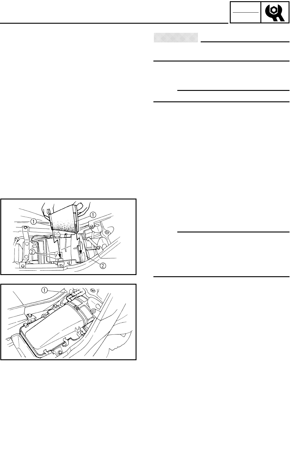
3 - 26
CHK
ADJ
CLEANING THE AIR FILTER
CAUTION:
Do not twist or wring out the element. This
could damage the foam material.
●Apply engine oil to the element.
●Squeeze out the excess oil.
NOTE:
The element should be wet but not dripping.
***********************************************
7.Install:
●Air filter element
●Air filter case cover
NOTE:
●Insert the lobes 1 on the filter element into
the receptacles 2 on the filter case.
●To prevent air leaks make sure that the seal-
ing surface of the element matches the seal-
ing surface of the case.
8.Connect:
●Crankcase breather hose 1
9.Install:
●Seat
Refer to “SEAT, FENDERS AND FUEL
TANK”.
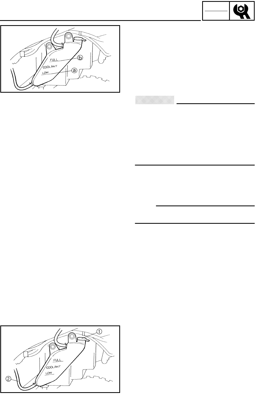
3 - 27
CHK
ADJ
CHECKING THE COOLANT LEVEL
1.Place the machine on a level surface.
2.Check:
●Coolant level
The coolant level should be between the
minimum level mark a and maximum level
mark b.
Below the minimum level mark → Add the
recommended coolant to the proper level.
CAUTION:
●Adding water instead of coolant lowers
the antifreeze content of the coolant. If
water is used instead of coolant, check
and if necessary, correct the antifreeze
concentration of the coolant.
●Use only distilled water. However, soft
water may be used if distilled water is not
available.
3.Start the engine, warm it up for several min-
utes, and then turn it off.
4.Check:
●Coolant level
NOTE:
Before inspecting the coolant level, wait a few
minutes until the coolant has settled.
CHANGING THE COOLANT
1.Remove:
●Front panel
Refer to “SEAT, FENDERS AND FUEL
TANK”.
2.Remove:
●Coolant reservoir cap 1
3.Disconnect:
●Coolant reservoir hose 2
CHECKING THE COOLANT LEVEL/
CHANGING THE COOLANT
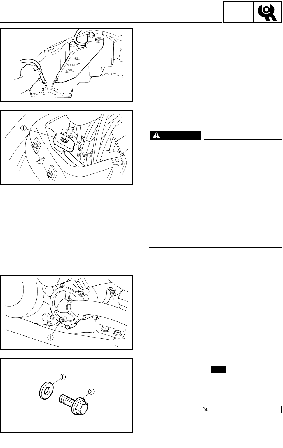
3 - 28
CHK
ADJ
CHANGING THE COOLANT
4.Drain:
●Coolant
(from the coolant reservoir)
5.Connect:
●Coolant reservoir hose
6.Remove:
●Radiator cap 1
WARNING
A hot radiator is under pressure. Therefore,
do not remove the radiator cap when the
engine is hot. Scalding hot fluid and steam
may be blown out, which could cause seri-
ous injury. When the engine has cooled,
open the radiator cap as follows:
Place a thick rag or a towel over the radia-
tor cap and slowly turn the radiator cap
counterclockwise toward the detent to
allow any residual pressure to escape.
When the hissing sound has stopped, turn
the radiator cap counterclockwise while
pressing down on it and then remove it.
7.Remove:
●Coolant drain bolt 1
(along with the copper washer)
8.Drain:
●Coolant
9.Check:
●Copper washer 1
●Coolant drain bolt 2
Damage → Replace.
10.Install:
●Coolant drain bolt
New
T
R
.
.
10 Nm (1.0 m • kg, 7.2 ft • lb)
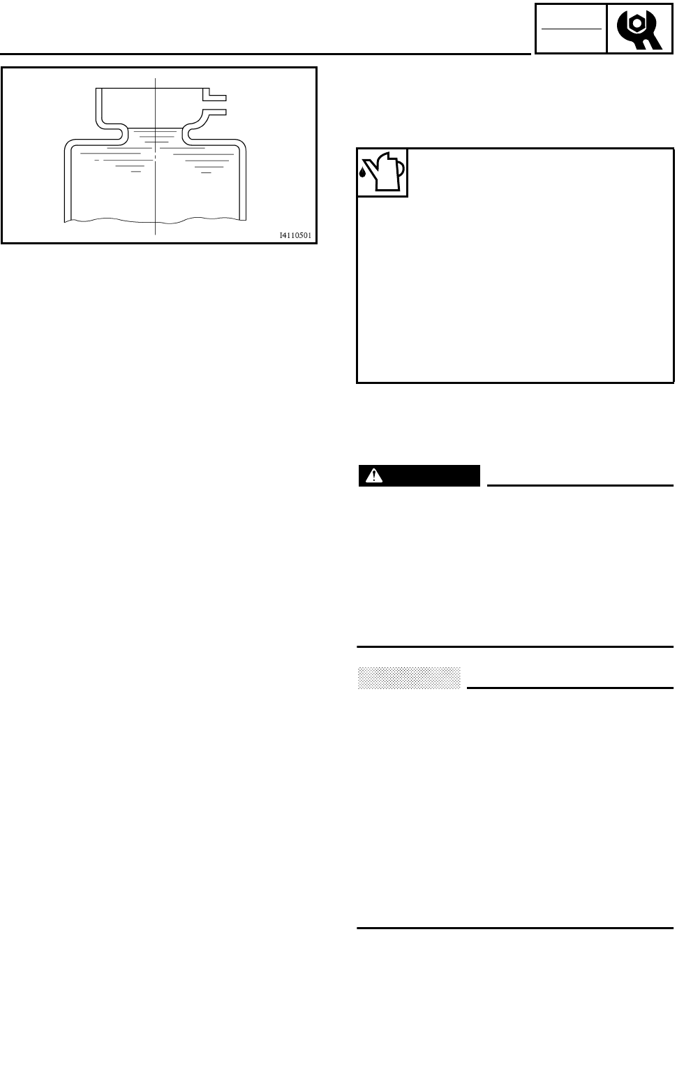
3 - 29
CHK
ADJ
CHANGING THE COOLANT
11.Fill:
●Cooling system
(with the specified amount of the recom-
mended coolant)
Handling notes for coolant
Coolant is potentially harmful and should be
handled with special care.
WARNING
●If coolant splashes in your eyes, thor-
oughly wash them with water and consult
a doctor.
●If coolant splashes on your clothes,
quickly wash it away with water and then
with soap and water.
●If coolant is swallowed, induce vomiting
and get immediate medical attention.
CAUTION:
●Adding water instead of coolant lowers
the antifreeze content of the coolant. If
water is used instead of coolant, check,
and if necessary, correct the antifreeze
concentration of the coolant.
●Use only distilled water. However, soft
water may be used if distilled water is not
available.
●If coolant comes into contact with painted
surfaces, immediately wash them with
water.
●Do not mix different types of antifreeze.
12.Install:
●Radiator cap
Recommended antifreeze:
High-quality ethylene glycol
antifreeze containing corrosion
inhibitors for aluminum engines
Mixing ratio:
1:1 (antifreeze:water)
Quantity:
Total amount:
1.3 L
(1.14 lmp qt, 1.37 US qt)
Coolant reservoir capacity:
0.29 L
(0.26 lmp qt, 0.31 US qt)
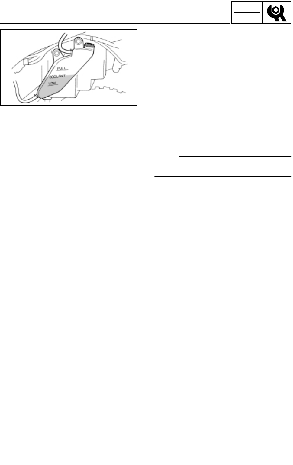
3 - 30
CHK
ADJ
CHANGING THE COOLANT
13.Fill:
●Coolant reservoir
(with the recommended coolant to the proper
level)
14.Install:
●Coolant reservoir cap
15.Start the engine, warm it up for several min-
utes, and then turn it off.
16.Check:
●Coolant level
Refer to “CHECKING THE COOLANT
LEVEL”.
NOTE:
Before inspecting the coolant level, wait a few
minutes until the coolant has settled.
17.Install:
●Front panel
Refer to “SEAT, FENDERS AND FUEL
TANK”.
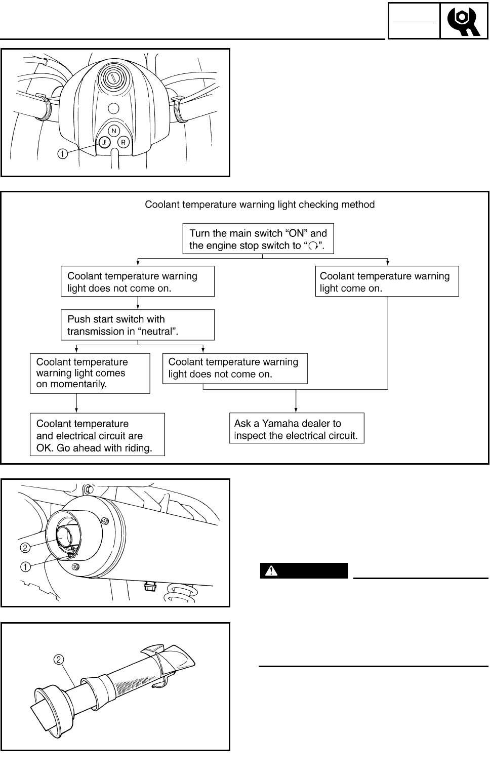
3 - 31
CHK
ADJ
CHECKING THE COOLANT TEMPERATURE WARNING
LIGHT/CLEANING THE SPARK ARRESTER
CHECKING THE COOLANT TEMPERATURE
WARNING LIGHT
1Coolant temperature warning light
CLEANING THE SPARK ARRESTER
1.Clean:
●Spark arrester
***********************************************
Cleaning steps:
WARNING
●Select a well-ventilated area free of com-
bustible materials.
●Always let the exhaust system cool
before performing this operation.
●Do not start the engine when removing
the tailpipe from the muffler.
●Remove the bolt 1.
●Remove the tailpipe 2 by pulling it out of the
muffler.
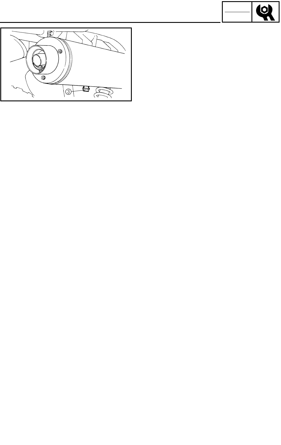
3 - 32
CHK
ADJ
●Tap the tailpipe lightly with a soft-face ham-
mer or suitable tool, then use a wire brush to
remove any carbon deposits from the spark
arrester portion of the tailpipe and the inner
contact surfaces of the muffler.
●Insert the tailpipe into the muffler and align
the bolt holes.
●Insert the bolt and tighten it.
●Remove the purging bolt 3.
●Start the engine and rev it up approximately
twenty times while momentarily creating
exhaust system back pressure by blocking
the end of the muffler with a shop towel.
●Stop the engine and allow the exhaust pipe
to cool.
●Install the purging bolt 3 and tighten it.
***********************************************
CLEANING THE SPARK ARRESTER
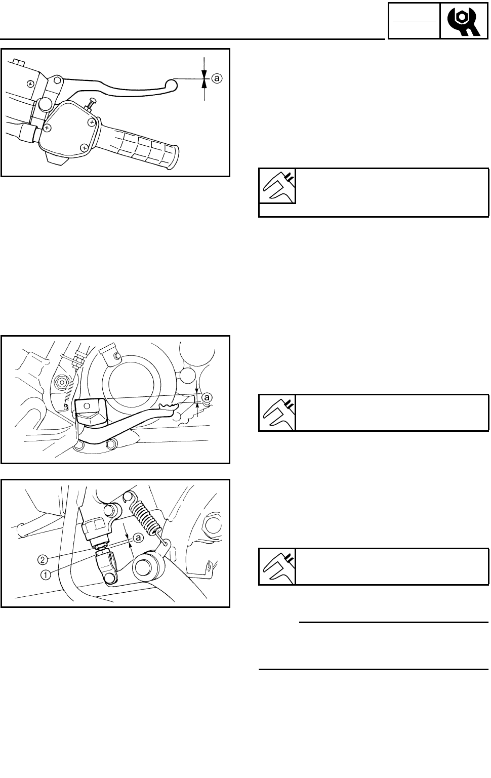
3 - 33
CHK
ADJ
ADJUSTING THE FRONT BRAKE/
ADJUSTING THE REAR BRAKE
CHASSIS
ADJUSTING THE FRONT BRAKE
1.Check:
●Brake lever free play a
Out of specification → Bleed the front brake
system.
Refer to “AIR BLEEDING (HYDRAULIC
BRAKE SYSTEM)”.
Brake lever free play (at the brake
lever end):
0 mm (0 in)
ADJUSTING THE REAR BRAKE
1.Check:
●Rear brake pedal height a
Out of specification → Adjust.
2.Adjust:
●Rear brake pedal height
***********************************************
Adjustment steps:
●Loosen the locknut 1.
●Turn the adjusting bolt 2 until the brake
pedal height is within the specified limits.
●Tighten the locknut 1.
NOTE:
When adjusting the brake pedal height make
sure the locknut-to-adjusting bolt clearance a
does not exceed 2.2 ~ 3.2 mm (0.09 ~ 0.13 in).
Rear brake pedal height:
4 mm (0.16 in)
Brake pedal height:
4 mm (0.16 in)
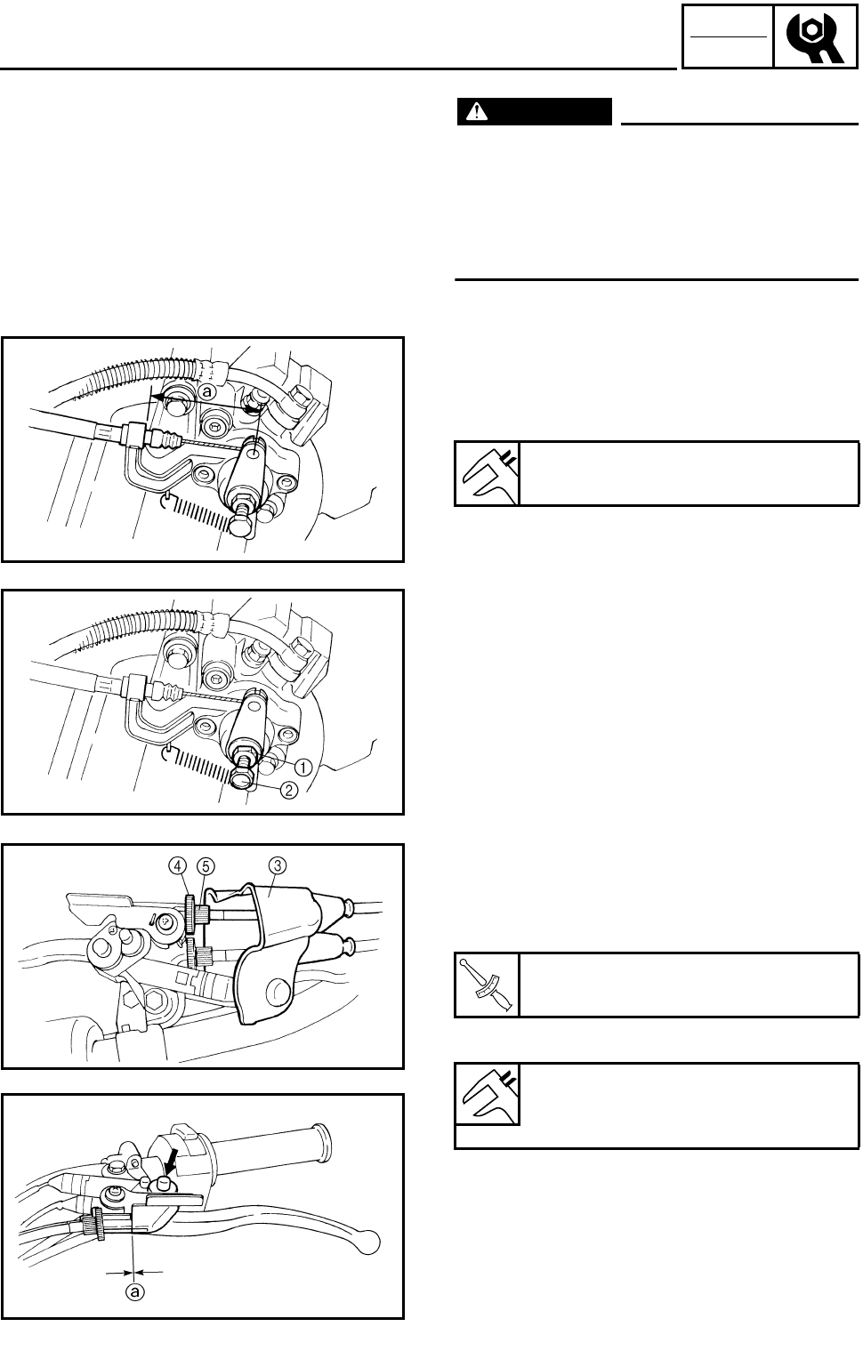
3 - 34
CHK
ADJ
ADJUSTING THE REAR BRAKE/
ADJUSTING THE PARKING BRAKE
WARNING
After this adjustment is performed, lift the
rear wheels off the ground by placing a
block under the engine, and spin the rear
wheels to ensure there is no brake drag. If
any brake drag is noticed perform the
above steps again.
***********************************************
ADJUSTING THE PARKING BRAKE
1.Check:
●Parking brake cable end length a
Out of specification → Adjust.
Parking brake cable end length:
64 ~ 68 mm (2.5 ~ 2.7 in)
2.Adjust:
●Parking brake cable end length
***********************************************
Adjustment steps:
●Loosen the locknut 1 and adjusting bolt 2.
●Pull the rubber cover 3 off.
●Loosen the locknut 4.
●Turn the adjuster 5 in or out until the speci-
fied brake cable end length is obtained.
●Tighten the locknut 4.
●Slowly turn the adjusting bolt 2 clockwise
until resistance is felt.
●Turn it 1/8 counterclockwise.
●Tighten the locknut 1.
●Check the parking brake cable free play a.
●If the free play is incorrect, adjust the free
play by adjuster 5.
●Pull the rubber cover 3 in.
T
R
.
.
Locknut:
16 Nm (1.6 m • kg, 11 ft • lb)
Free play (parking brake cable):
0 mm (0 in)
at parking brake lever pivot
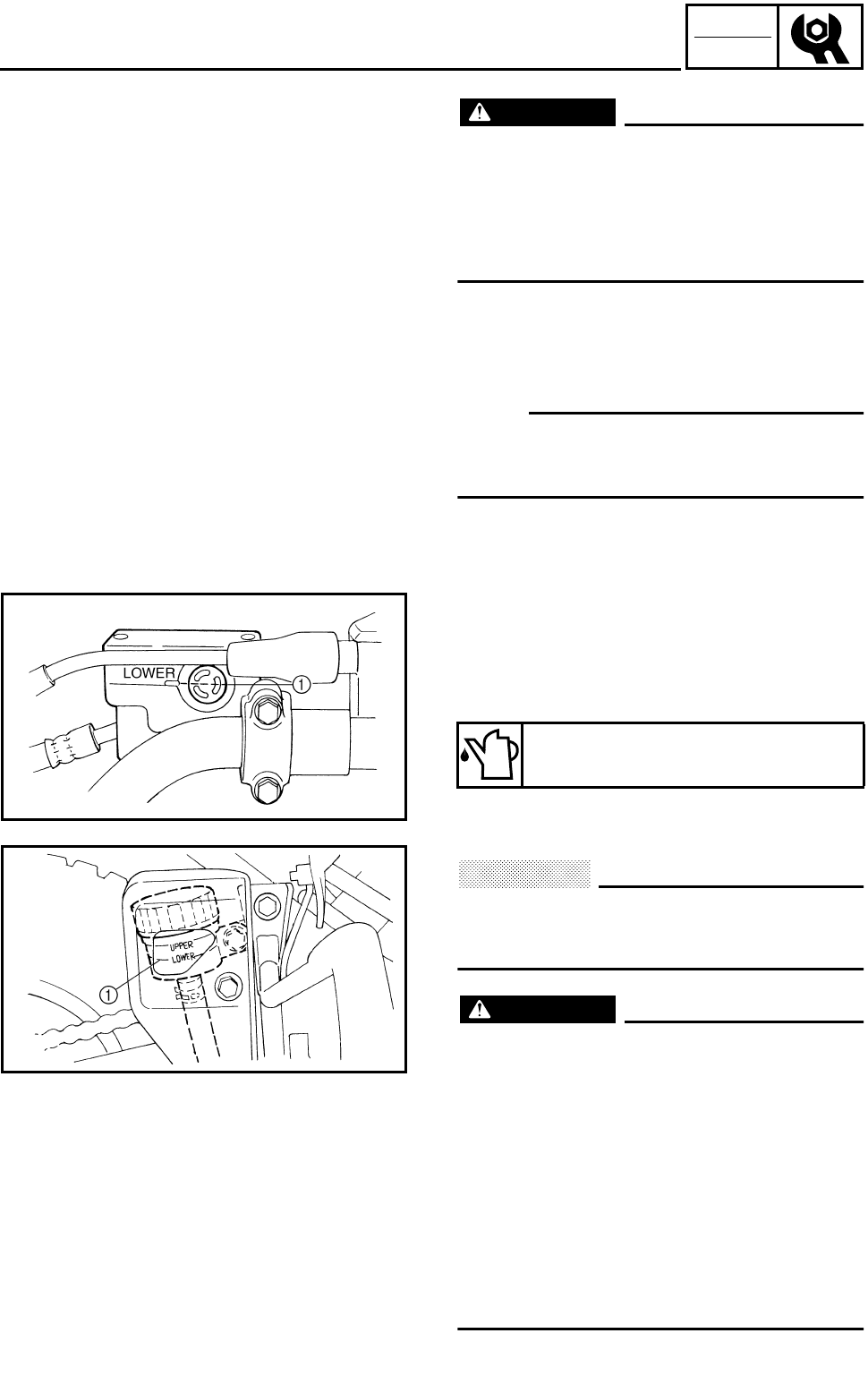
3 - 35
CHK
ADJ
ADJUSTING THE PARKING BRAKE/
CHECKING THE BRAKE FLUID LEVEL
WARNING
After this adjustment is performed, lift the
rear wheels off the ground by placing a
block under the engine, and spin the rear
wheels to ensure there is no brake drag. If
any brake drag is noticed perform the
above steps again.
***********************************************
CHECKING THE BRAKE FLUID LEVEL
1.Place the machine on a level surface.
NOTE:
When inspecting the brake fluid level, make
sure that the top of the brake fluid reservoir top
is horizontal.
2.Check:
●Brake fluid level
Fluid level is below the “LOWER” level line
1 → Add the recommended brake fluid to
the proper level.
ÈFront brake
ÉRear brake
CAUTION:
Brake fluid may erode painted surfaces or
plastic parts. Always clean up spilled fluid
immediately.
WARNING
●Use only the designated quality brake
fluid: Otherwise, the rubber seals may
deteriorate, causing leakage and poor
brake performance.
●Refill with the same type of brake fluid:
Mixing fluids may result in a harmful
chemical reaction and lead to poor perfor-
mance.
●Be careful that water does not enter the
master cylinder when refilling. Water will
significantly lower the boiling point of the
fluid and may result in a vapor lock.
Recommended brake fluid:
DOT 4
È
É
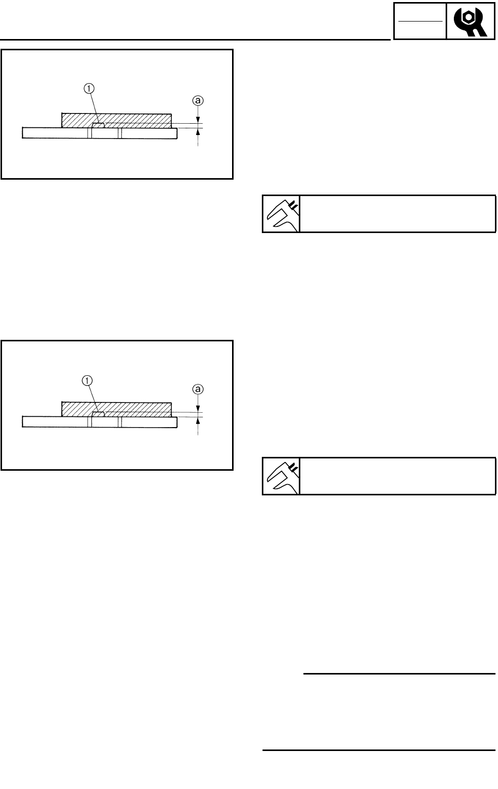
3 - 36
CHK
ADJ
CHECKING THE FRONT BRAKE PAD/
CHECKING THE REAR BRAKE PAD/
ADJUSTING THE REAR BRAKE LIGHT SWITCH
CHECKING THE FRONT BRAKE PAD
1.Remove:
●Front wheels
2.Check:
●Brake pad
Wear indicators 1 almost in contact with the
brake disc → Replace the brake pads as a
set.
Refer to “FRONT AND REAR BRAKES” in
CHAPTER 4.
3.Operate the brake lever.
4.Install:
●Front wheels
Brake pad wear limit a:
1 mm (0.04 in)
CHECKING THE REAR BRAKE PAD
1.Check:
●Brake pad
Wear indicators 1 almost in contact with the
brake disc → Replace the brake pads as a
set.
Refer to “FRONT AND REAR BRAKES” in
CHAPTER 4.
2.Operate the brake pedal.
Brake pad wear limit a:
1 mm (0.04 in)
ADJUSTING THE REAR BRAKE LIGHT
SWITCH
NOTE:
The rear brake light switch is operated by
movement of the brake pedal.
The rear brake light switch is properly adjusted
when the brake light comes on just before the
braking effect starts.
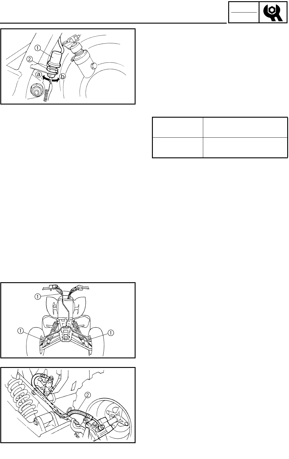
3 - 37
CHK
ADJ
ADJUSTING THE REAR BRAKE LIGHT SWITCH/
CHECKING THE BRAKE HOSE
1.Check:
●Rear brake light operation timing
Incorrect → Adjust.
2.Adjust:
●Rear brake light operation timing
***********************************************
●Hold the main body 1 of the rear brake light
switch so that it does not rotate and turn the
adjusting nut 2 in direction a or b until the
rear brake light comes on at the proper time.
***********************************************
Direction a Brake light comes on
sooner.
Direction b Brake light comes on
later.
CHECKING THE BRAKE HOSE
1.Remove:
●Seat
●Front fender
Refer to “SEAT, FENDERS AND FUEL
TANK”.
2.Check:
●Front brake hoses 1
●Rear brake hoses 2
Cracks/wear/damage → Replace.
3.Check:
●Brake hose clamp
Loosen → Tighten.
4.Hold the machine in an upright position and
apply the front or rear brake.
5.Check:
●Brake hoses
Apply the brake lever several times.
Fluid leakage → Replace the hose.
Refer to “FRONT AND REAR BRAKE” in
CHAPTER 4.
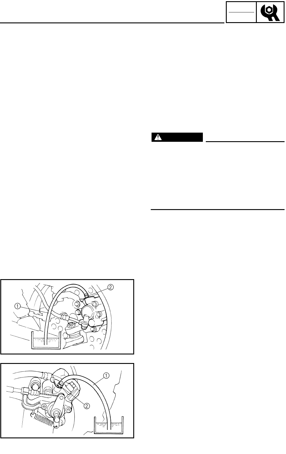
3 - 38
CHK
ADJ
CHECKING THE BRAKE HOSE/
BLEEDING THE HYDRAULIC BRAKE SYSTEM
6.Install:
●Front fender
●Seat
Refer to “SEAT, FENDERS AND FUEL
TANK”.
BLEEDING THE HYDRAULIC BRAKE
SYSTEM
WARNING
Bleed the brake system if:
●The system has been disassembled.
●A brake hose or brake pipe have been
loosened or removed.
●The brake fluid has been very low.
●The brake operation has been faulty.
A loss of braking performance may occur if
the brake system is not properly bled.
1.Bleed:
●Brake system
***********************************************
Air bleeding steps:
a. Add the proper brake fluid to the reservoir.
b. Install the diaphragm. Be careful not to spill
any fluid or allow the reservoir to overflow.
c. Connect the clear plastic hose 1 tightly to
the caliper bleed screw 2.
ÈFront
ÉRear
d. Place the other end of the hose into a con-
tainer.
e. Slowly apply the brake lever or pedal sev-
eral times.
f. Pull the lever in or push down on the pedal
and hold it.
g. Loosen the bleed screw and allow the lever
or pedal to travel towards its limit.
h. Tighten the bleed screw when the lever or
pedal limit has been reached, then release
the lever or pedal.
i. Repeat steps (e) to (h) until all the air bub-
bles have disappeared from the fluid.
È
É
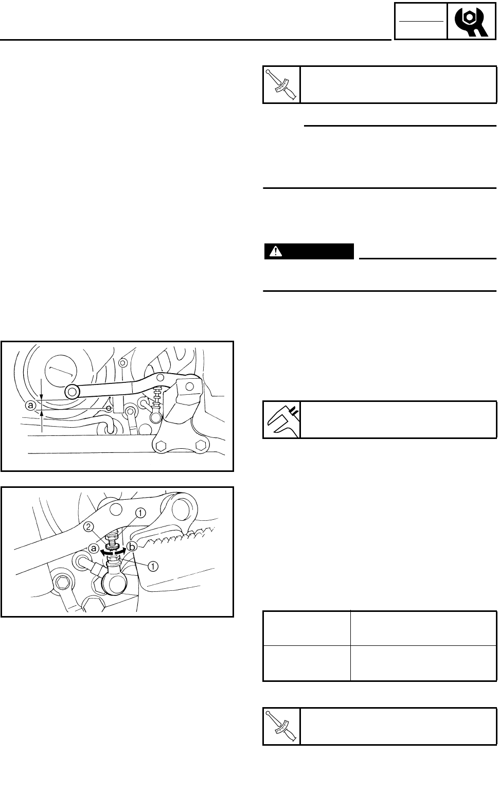
3 - 39
CHK
ADJ
j. Tighten the bleed screw.
NOTE:
If bleeding is difficult, it may be necessary to
let the brake fluid settle for a few hours.
Repeat the bleeding procedure when the tiny
bubbles in the system have disappeared.
k. Add brake fluid to the proper level.
Refer to “CHECKING THE BRAKE FLUID
LEVEL”.
WARNING
Check the operation of the brake after
bleeding the brake system.
***********************************************
T
R
.
.
Bleed screw:
6 Nm (0.6 m • kg, 4.3 ft • lb)
ADJUSTING THE SHIFT PEDAL
1.Check:
●Shift pedal height a
Out of specification → Adjust.
Shift pedal height:
22 mm (0.89 in)
2.Adjust:
●Shift pedal height
***********************************************
Adjustment steps:
●Loosen the locknuts 1.
●Turn the adjusting rod 2 in direction a or b
until the specified shift pedal position
obtained.
●Tighten the locknuts.
***********************************************
Direction a Shift pedal position is
down.
Direction b Shift pedal position is
up.
T
R
.
.
Locknut:
8 Nm (0.8 m • kg, 5.8 ft • lb)
BLEEDING THE HYDRAULIC BRAKE SYSTEM/
ADJUSTING THE SHIFT PEDAL
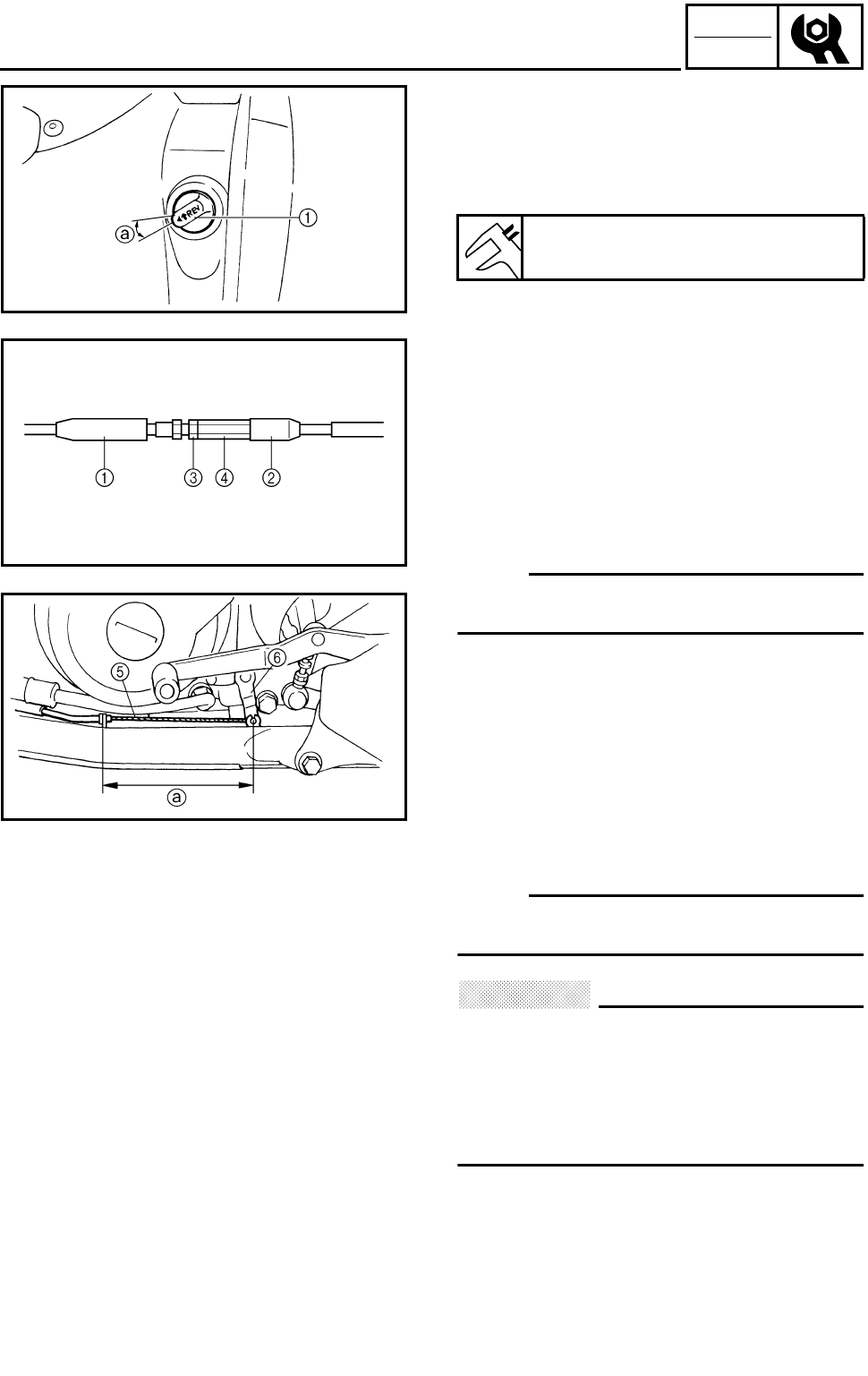
3 - 40
CHK
ADJ
ADJUSTING THE REVERSE CONTROL CABLE/
ADJUSTING THE DRIVE CHAIN SLACK
ADJUSTING THE REVERSE CONTROL
CABLE
1.Check:
●Reverse knob free play a
Out of specification → Adjust.
Reverse knob free play:
0 mm (0 in)
2.Adjust:
***********************************************
Adjustment steps:
●Pull the boots 1 and 2 off.
●Loosen the locknut 3.
●Turn the adjusting nut 4 until the reverse
control cable 5 is taut or the length a is
135 mm (5.31 in).
NOTE:
Be sure to hold the reverse shift lever 6 when
make this adjustment so that it does not move.
●Tighten the locknut 3.
●Pull the boots 1 and 2 in.
***********************************************
ADJUSTING THE DRIVE CHAIN SLACK
NOTE:
The drive chain slack must be checked at the
tightest point on the chain.
CAUTION:
A drive chain that is too tight will overload
the engine and other vital parts, and one
that is too loose can skip and damage the
swingarm or cause an accident. Therefore,
keep the drive chain slack within the speci-
fied limits.
1.Elevate the rear wheels by placing the suit-
able stand under the frame.
2.Rotate the rear wheel several times and
check the drive chain to locate its tightest
point.
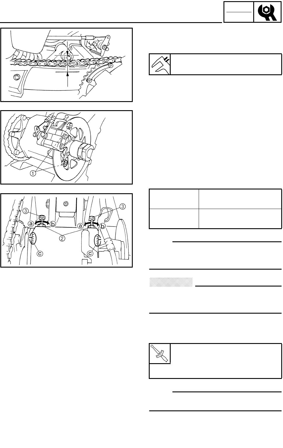
3 - 41
CHK
ADJ
ADJUSTING THE DRIVE CHAIN SLACK
3.Measure:
●Drive chain slack a
Out of specification → Adjust.
Drive chain slack:
30 ~ 45 mm (1.18 ~ 1.77 in)
4.Adjust:
●Drive chain slack
***********************************************
Adjustment steps:
●Loosen the hub nuts 1.
●Loosen the locknuts 2.
●Turn both adjusting bolts 3 in direction a or
b until the specified drive chain slack is
obtained.
NOTE:
To maintain the proper axle alignment, adjust
both sides evenly. (There are marks c on
each side of hub.)
CAUTION:
Excessive chain slack will overload the
engine and other vital parts; keep the slack
within the specified limits.
●If the chain slack cannot be adjusted, replace
the sprockets and drive chain as a set.
●Tighten the hub nuts and locknuts.
NOTE:
The chain should be cleaned and lubricated
after every use of the machine.
***********************************************
Direction a Drive chain slack is
reduced.
Direction b Drive chain slack is
increased.
T
R
.
.
Hub nut:
90 Nm (9.0 m • kg, 65 ft • lb)
Locknut (chain puller):
16 Nm (1.6 m • kg, 11 ft • lb)
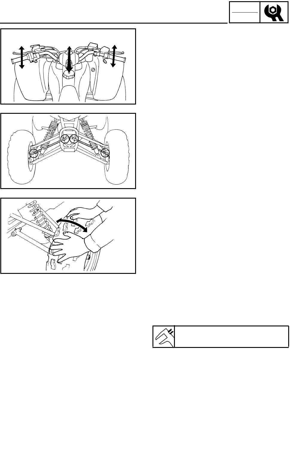
3 - 42
CHK
ADJ
CHECKING THE STEERING SYSTEM/
ADJUSTING THE TOE-IN
CHECKING THE STEERING SYSTEM
1.Place the machine on a level surface.
2.Check:
●Steering assembly bushings
Move the handlebar up and down, and/or
back and forth.
Excessive play → Replace the steering stem
bushings.
3.Check:
●Tie-rod ends
Turn the handlebar to the left and/or right
until it stops completely, then move the han-
dlebar from the left to the right slightly. Tie-
rod end has any vertical play → Replace the
tie-rod end(s).
4.Raise the front end of the machine so that
there is no weight on the front wheels.
5.Check:
●Ball joints and/or wheel bearings
Move the wheels laterally back and forth.
Excessive free play → Replace the front
arms (upper and lower) and/or wheel bear-
ings.
ADJUSTING THE TOE-IN
1.Place the machine on a level surface.
2.Measure:
●Toe-in
Out of specification → Adjust.
Toe-in:
0 ~ 10 mm (0 ~ 0.39 in)
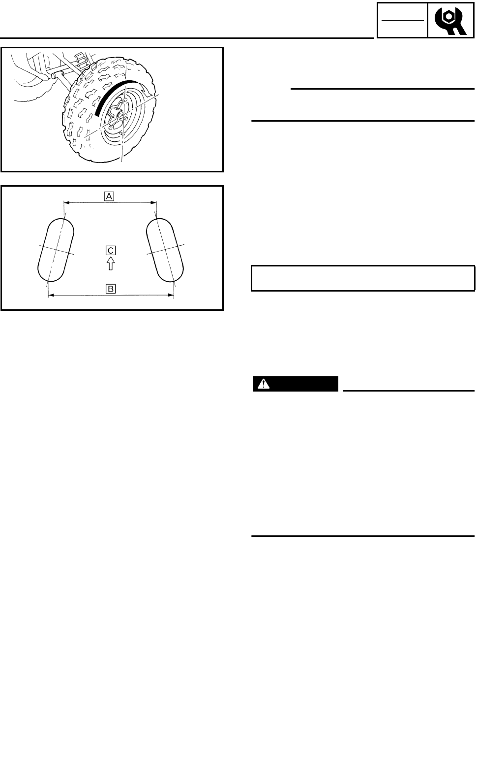
3 - 43
CHK
ADJ
***********************************************
Toe-in measurement steps:
NOTE:
Before measuring the toe-in, make sure that
the tire pressure is correct.
●Mark both front tire tread centers.
●Raise the front end of the machine so that
there is no weight on the front tires.
●Face the handlebar straight ahead.
●Measure the width È between the marks.
●Rotate the front tires 180° until the marks are
exactly opposite one another.
●Measure the width É between the marks.
●Calculate the toe-in using the formula given
below.
●If the toe-in is incorrect, adjust it.
ÊForward
***********************************************
3.Adjust:
●Toe-in
WARNING
●Be sure that both tie-rods are turned the
same amount. If not, the machine will drift
right or left even though the handlebar is
positioned straight. This may lead to mis-
handling and an accident.
●After setting the toe-in to specification, run
the machine slowly for some distance with
both hands lightly holding the handlebar
and check that the handlebar responds cor-
rectly. If not, turn either the right or left tie-
rod within the toe-in specification.
Toe-in = É – È
ADJUSTING THE TOE-IN
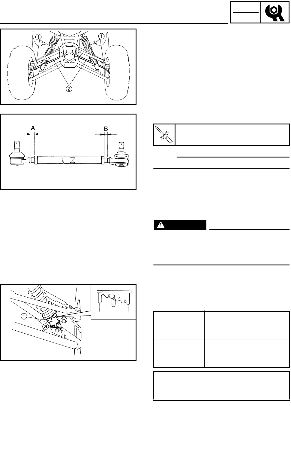
3 - 44
CHK
ADJ
***********************************************
Adjustment steps:
●Mark both tie-rods ends.
This reference point will be needed during
adjustment.
●Loosen the locknuts (tie-rod end) 1 of both
tie-rods.
●The same number of turns should be given
to both the right and left tie-rods 2 until the
specified toe-in is obtained. This is to keep
the length of the rods the same.
●Tighten the rod end locknuts of both tie rods.
NOTE:
Adjust the rod ends so that A and B are equal.
***********************************************
T
R
.
.
Locknut (rod end):
15 Nm (1.5 m • kg, 11 ft • lb)
ADJUSTING THE FRONT SHOCK
ABSORBER
WARNING
Always adjust both front shock absorber
spring preload to the same setting. Uneven
adjustment can cause poor handling and
loss of stability.
1.Adjust:
●Spring preload
Turn the adjuster 1 in direction a or b.
Direction a Spring preload is
increased (suspension
is harder).
Direction b Spring preload is
decreased (suspension
is softer).
Standard position: 3
Minimum position: 1
Maximum position: 5
ADJUSTING THE TOE-IN/
ADJUSTING THE FRONT SHOCK ABSORBER
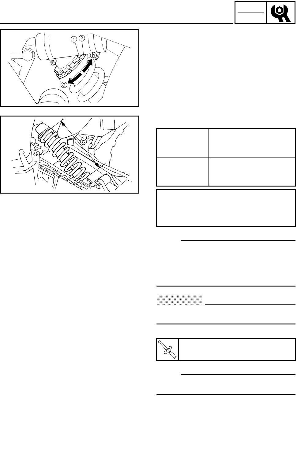
3 - 45
CHK
ADJ
ADJUSTING THE REAR SHOCK
ABSORBER
1.Adjust:
●Spring preload
***********************************************
Adjustment steps:
●Elevate the rear wheels by placing a suitable
stand under the frame.
●Loosen the locknut 1.
●Turn the adjusting ring 2 in direction a or
b.
NOTE:
●Be sure to remove all dirt and mud from
around the locknut and adjusting ring before
adjustment.
●The length of the spring (installed) changes
1.5 mm (0.06 in) per turn of the adjuster.
CAUTION:
Never attempt to turn the adjusting ring
beyond the maximum or minimum setting.
●Tighten the locknut 1.
NOTE:
Always tighten the locknut against the adjust-
ing ring, then torque it to specification.
***********************************************
Direction a Spring preload is
increased (suspension
is harder).
Direction b Spring preload is
decreased (suspension
is softer).
Adjusting length c:
Standard: 253 mm (9.96 in)
Minimum: 245 mm (9.65 in)
Maximum: 260 mm (10.24 in)
T
R
.
.
Locknut:
42 Nm (4.2 m • kg, 30 ft • lb)
ADJUSTING THE REAR SHOCK ABSORBER
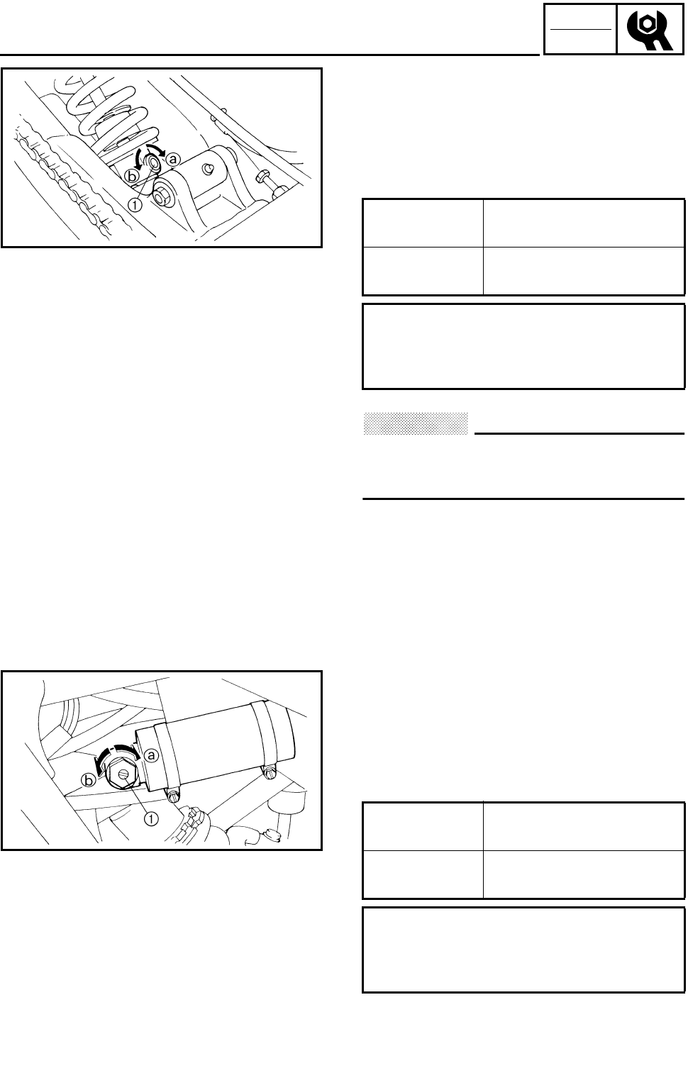
3 - 46
CHK
ADJ
2.Adjust:
●Rebound damping force
***********************************************
Adjustment steps:
●Turn the adjusting screw 1 in direction a or
b.
CAUTION:
Do not force the adjuster past the minimum
or maximum extent of adjustment. The
adjuster may be damaged.
***********************************************
Direction a Rebound damping force
is increased.
Direction b Rebound damping force
is decreased.
From the fully turned-in position:
Standard: 10 clicks out
Minimum: 20 clicks out
Maximum: 3 clicks out
3.Adjust:
●Compression damping force
***********************************************
Adjustment steps:
●Turn the adjusting screw 1 in direction a or
b.
Direction a Compression damping
force is increased.
Direction b Compression damping
force is decreased.
From the fully turned-out position:
Standard: 7 clicks in
Minimum: 1 click in
Maximum: 12 clicks in
ADJUSTING THE REAR SHOCK ABSORBER
3 - 47
CHK
ADJ
ADJUSTING THE REAR SHOCK ABSORBER/
CHECKING THE TIRE
CAUTION:
Do not forc the adjuster past the minimum
or maximum extent of adjustment. The
adjuster may be damaged.
***********************************************
CHECKING THE TIRE
WARNING
This model is equipped with low pressure
tires. It is important that they be inflated cor-
rectly and maintained at the proper pressures.
●TIRE CHARACTERISTICS
1)Tire characteristics influence the handling
of ATV’s. The tires listed below have been
approved by Yamaha Motor Co., Ltd. for
this model. If other tire combinations are
used, they can adversely affect your
machine’s handling characteristics and
are therefore not recommended.
●TIRE PRESSURE
1)Recommended tire pressure
Front 27.5 kPa (0.275 kg/cm2, 4.0 psi)
Rear 27.5 kPa (0.275 kg/cm2, 4.0 psi)
2)Tire pressure below the minimum specifi-
cation could cause the tire to dislodge
from the rim under severe riding condi-
tions.
The following are minimums:
Front 24.5 kPa (0.245 kg/cm2, 3.5 psi)
Rear 24.5 kPa (0.245 kg/cm2, 3.5 psi)
3)Use no more than
Front 250 kPa (2.5 kg/cm2, 36 psi)
Rear 250 kPa (2.5 kg/cm2, 36 psi)
when seating the tire beads. Higher pres-
sures may cause the tire to burst.
Inflate the tires slowly and carefully.
Fast inflation could cause the tire to
burst.
Manufacturer Size Type
Front DUNLOP AT21×7-10 KT311
Radial
Rear DUNLOP AT20×10-9 KT335
Radial
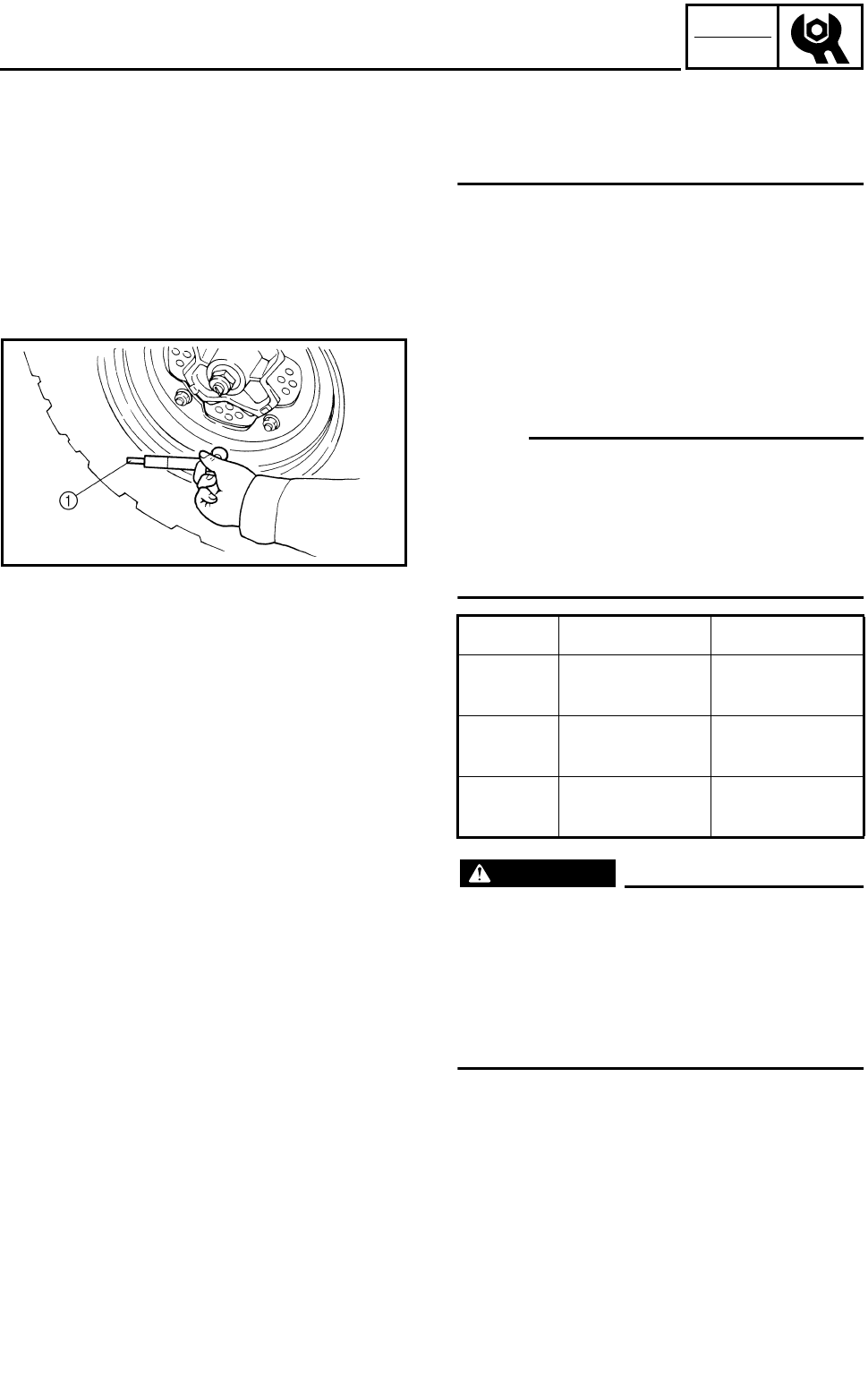
3 - 48
CHK
ADJ
CHECKING THE TIRE
●MAXIMUM LOADING LIMIT
1)Vehicle load limit (total weight of cargo,
rider and accessories, and tongue
weight): 100 kg (220 lb)
1.Measure:
●Tire pressure (cold tire pressure)
Out of specification → Adjust.
NOTE:
●The low-pressure tire gauge 1 is included
as standard equipment.
●If dust or the like is stuck to this gauge, it will
not provide the correct readings. Therefore,
take two measurements of the tire’s pressure
and use the second reading.
WARNING
Uneven or improper tire pressure may
adversely affect the handling of this
machine and may cause loss of control.
●Maintain proper tire pressures.
●Set tire pressures when the tires are cold.
●Tire pressures must be equal in both front
tires and equal in both rear tires.
Cold tire
pressure Front Rear
Standard 27.5 kPa
(0.275 kg/cm2,
4.0 psi)
27.5 kPa
(0.275 kg/cm2,
4.0 psi)
Minimum 24.5 kPa
(0.245 kg/cm2,
3.5 psi)
24.5 kPa
(0.245 kg/cm2,
3.5 psi)
Maximum 30.5 kPa
(0.305 kg/cm2,
4.4 psi)
30.5 kPa
(0.305 kg/cm2,
4.4 psi)
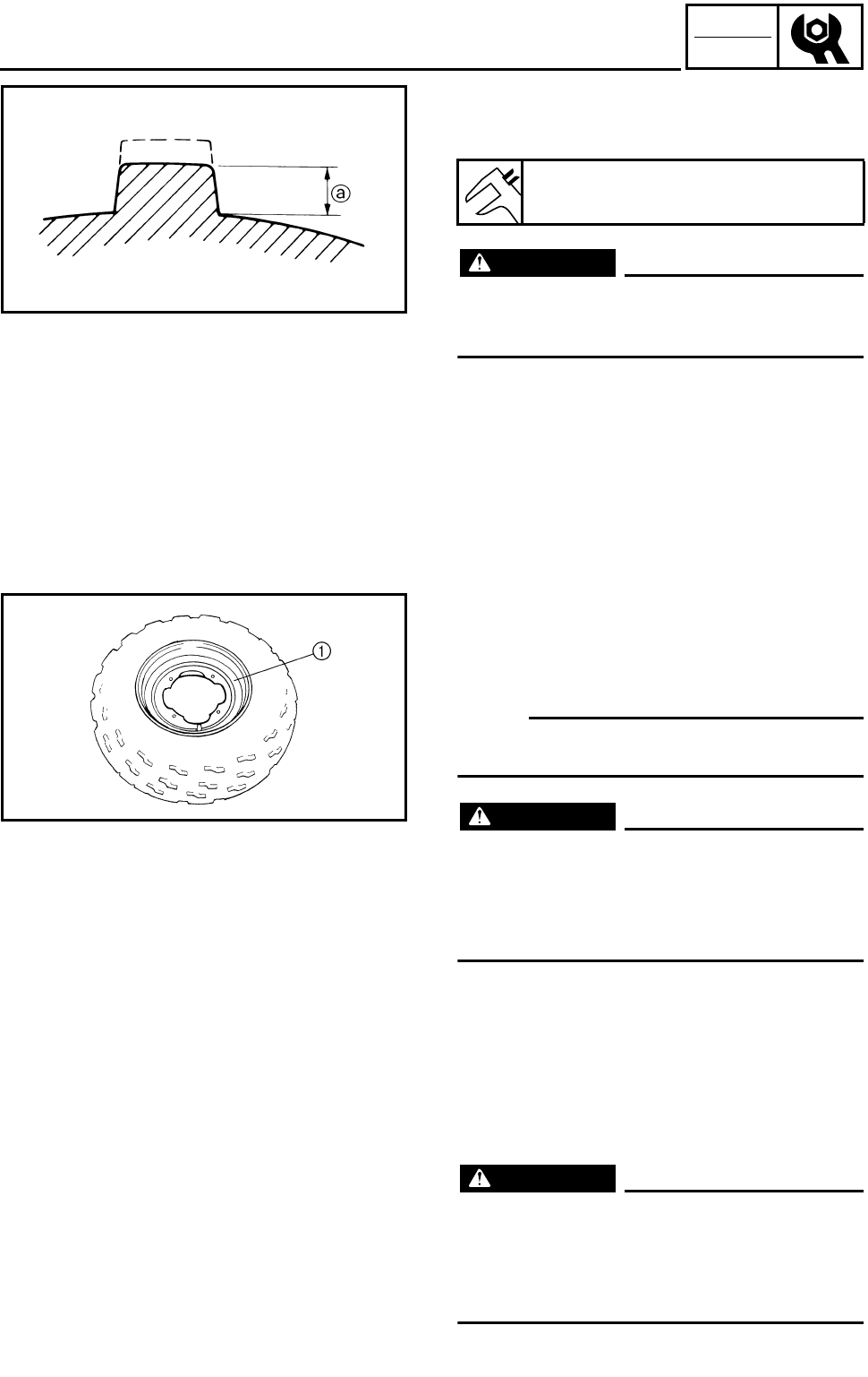
3 - 49
CHK
ADJ
CHECKING THE TIRE/CHECKING THE WHEEL/
CHECKING AND LUBRICATING THE CABLE
2.Check:
●Tire surfaces
Wear/damage → Replace.
WARNING
It is dangerous to ride with a worn-out tire.
When tire wear is out of specification,
replace the tire immediately.
Tire wear limit a:
Front and rear: 3.0 mm (0.12 in)
CHECKING THE WHEEL
1.Check:
●Wheels 1
Damage/bends → Replace.
NOTE:
Always balance the wheel when a tire or wheel
has been changed or replaced.
WARNING
●Never attempt even small repairs to the
wheel.
●Ride conservatively after installing a tire
to allow it to seat itself properly on the
rim.
CHECKING AND LUBRICATING THE
CABLE
WARNING
A damaged cable sheath may cause corro-
sion and interfere with the cable move-
ment. An unsafe condition may result so
replace a damaged cable as soon as possi-
ble.
3 - 50
CHK
ADJ
CHECKING AND LUBRICATING THE CABLE/
LUBRICATING THE LEVERS AND PEDAL
1.Check:
●Cable sheath
Damage → Replace.
2.Check:
●Cable operation
Unsmooth operation → Lubricate or replace.
NOTE:
Hold the cable end up and apply several drops
of lubricant to the cable.
3.Apply:
●Lithium soap base grease
(onto end of the cable)
Recommended lubricant:
Yamaha chain and cable lube or
Engine oil
LUBRICATING THE LEVERS AND PEDAL
1.Lubricate the pivoting parts.
Recommended lubricant:
Lithium soap base grease
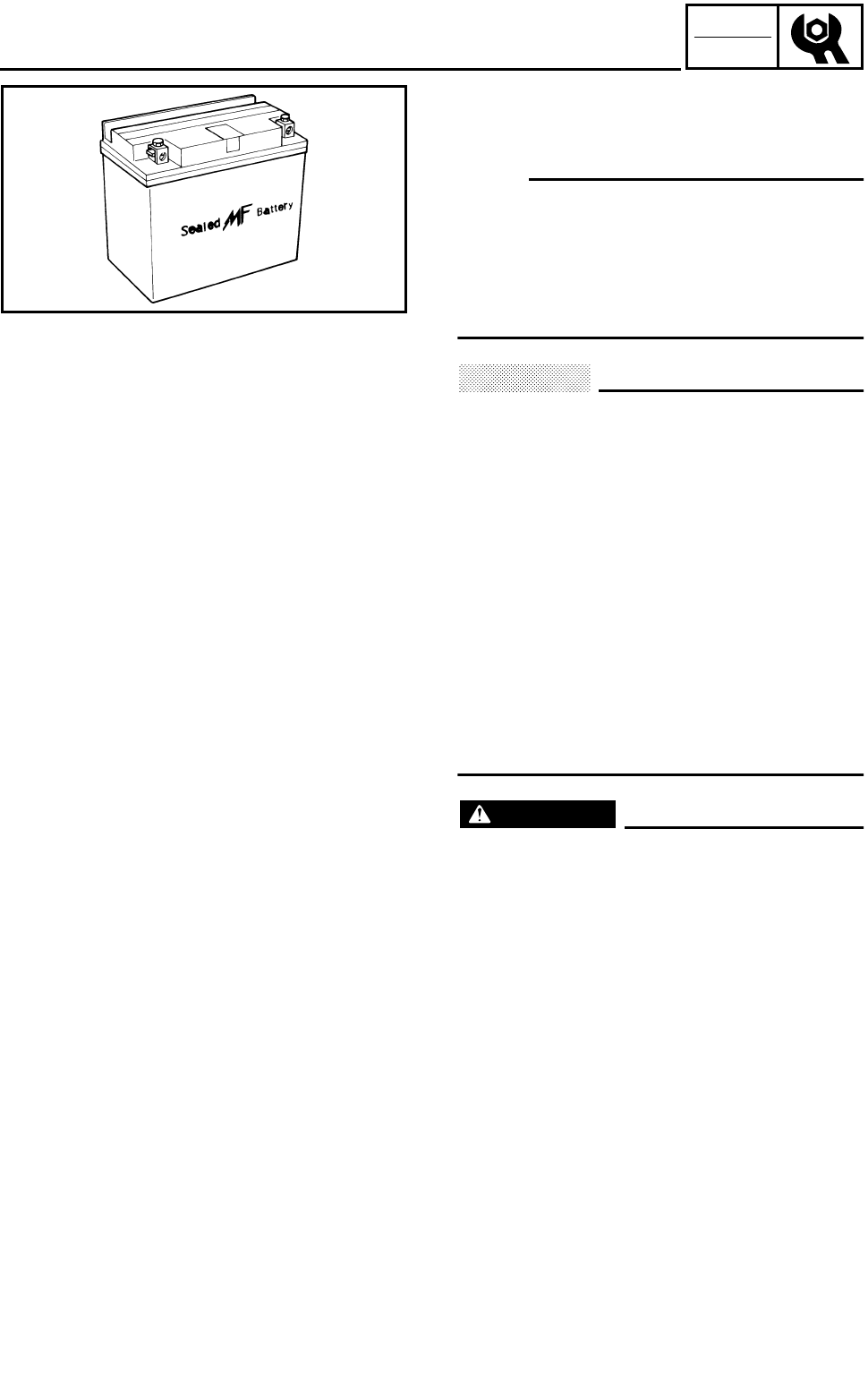
3 - 51
CHK
ADJ
CHECKING THE BATTERY
EB305000
ELECTRICAL
CHECKING THE BATTERY
NOTE:
Since the MF battery is a sealed type battery, it
is not possible to measure the specific gravity
of the electrolyte in order to check the charge
state of the battery. Therefore the charge of
the battery has to be checked by measuring
the voltage at the battery terminals.
CAUTION:
CHARGING METHOD
●This is a sealed type battery. Never
remove the sealing caps. If the sealing
caps have been removed, the balance will
not be maintained and battery perfor-
mance will deteriorate.
●Charging time, charging current and
charging voltage for the MF battery are
different from those of general type bat-
teries. The MF battery should be charged
as explained in “CHARGING METHOD”. If
the battery is overcharged, the electrolyte
level will drop considerably. Therefore,
take special care when charging the bat-
tery.
WARNING
Battery electrolyte is dangerous; it con-
tains sulfuric acid which is poisonous and
highly caustic.
Always follow these preventive measures:
●Avoid bodily contact with electrolyte as it
can cause severe burns or permanent eye
injury.
●Wear protective eye gear when handling
or working near batteries.
Antidote (EXTERNAL):
●SKIN - Wash with water.
●EYES - Flush with water for 15 minutes
and get immediate medical attention.
Antidote (INTERNAL):
●Drink large quantities of water or milk fol-
lowed with milk of magnesia, beaten egg
or vegetable oil. Get immediate medical
attention.
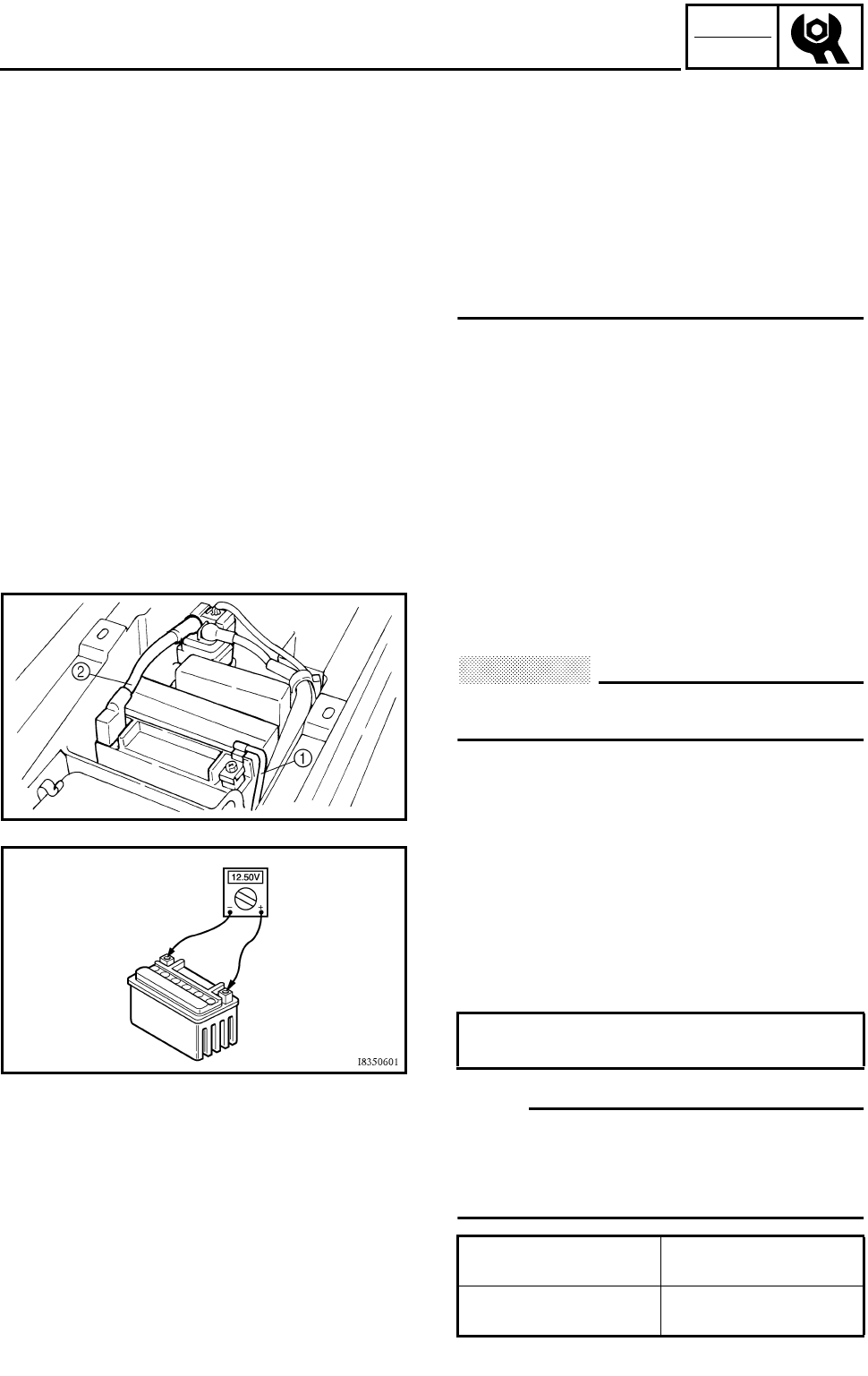
3 - 52
CHK
ADJ
CHECKING THE BATTERY
Batteries generate explosive hydrogen gas.
Always follow these preventive measures:
●Charge batteries in a well-ventilated area.
●Keep batteries away from fire, sparks or
open flames (e.g., welding equipment,
lighted cigarettes, etc.).
●DO NOT SMOKE when charging or han-
dling batteries.
KEEP BATTERIES AND ELECTROLYTE
OUT OF REACH OF CHILDREN.
1.Remove:
●Seat
●Battery holding bracket
Refer to “SEAT, FENDERS AND FUEL
TANK”.
2.Disconnect:
●Battery leads
CAUTION:
First disconnect the negative lead 1, then
disconnect the positive lead 2.
3.Remove:
●Battery
4.Check:
●Battery condition
***********************************************
Battery condition checking steps:
●Connect a digital voltmeter to the battery ter-
minals.
NOTE:
The charge state of an MF battery can be
checked by measuring the open-circuit voltage
(i.e. the voltage when the positive terminal is
disconnected).
Tester (+) lead → battery (+) terminal
Tester (–) lead → battery (–) terminal
Open-circuit
voltage Charging time
12.8 V or higher No charging is
necessary.
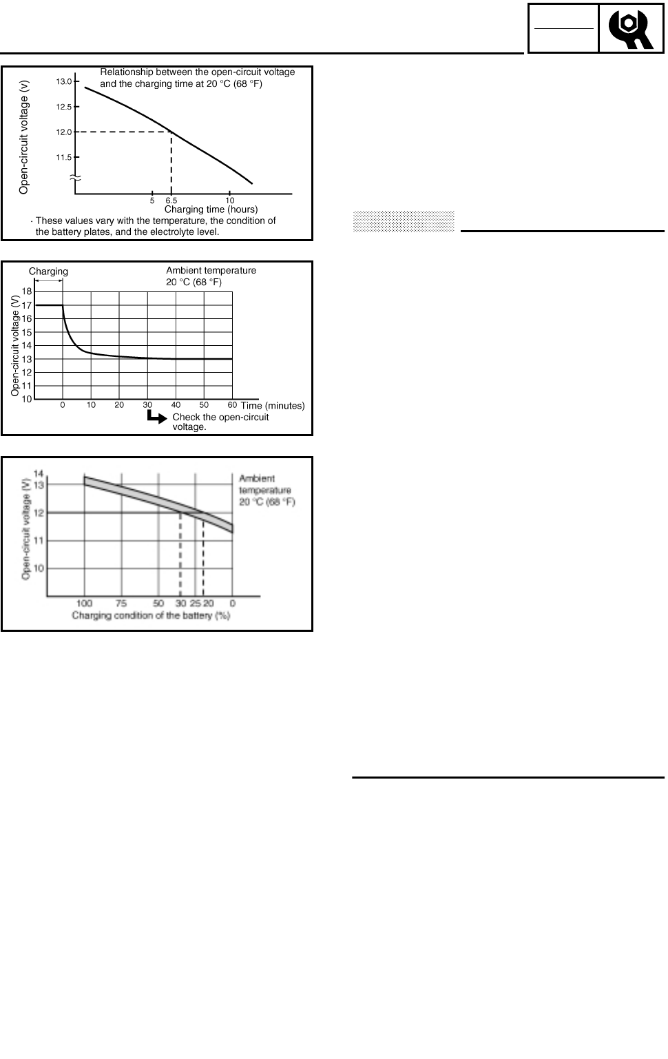
3 - 53
CHK
ADJ
●Check the condition of the battery using the
following charts.
Example:
●Open-circuit voltage = 12.0 V
●Charging time = 6.5 hours
●Charge condition of the battery = 20 ~ 30%
●Charging method for MF batteries
CAUTION:
●If it is impossible to set the standard
charging current, be careful not to over-
charge.
●When charging the battery, be sure to
remove it from the motorcycle. (If charg-
ing has to be done with the battery
mounted on the motorcycle, be sure to
disconnect the wire at the negative termi-
nal.)
●Never remove the sealing caps of an MF
battery.
●Make sure that the charging clips are in
full contact with the terminal and that they
are not shorted together. (A corroded clip
on the charger may cause the battery to
generate heat in the contact area. A weak
clip spring may cause sparks.)
●Before removing the clips from the bat-
tery terminals, be sure to turn off the
charger’s power switch.
●The open-circuit voltage variation for the
MF battery, after charging, is shown
below. As shown in the figure, the open-
circuit voltage stabilizes about 30 min-
utes after charging has been completed.
Therefore, wait 30 minutes after charging
is completed before measuring the open-
circuit voltage.
***********************************************
CHECKING THE BATTERY
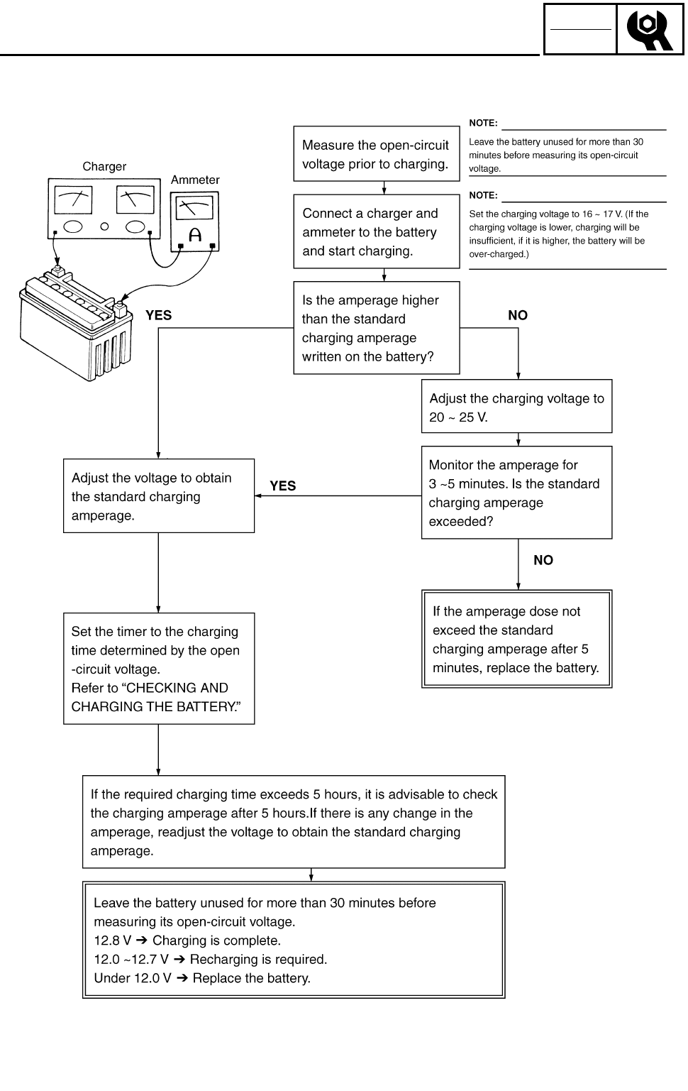
3 - 54
CHK
ADJ
CHECKING THE BATTERY
Charging method using a variable voltage charger
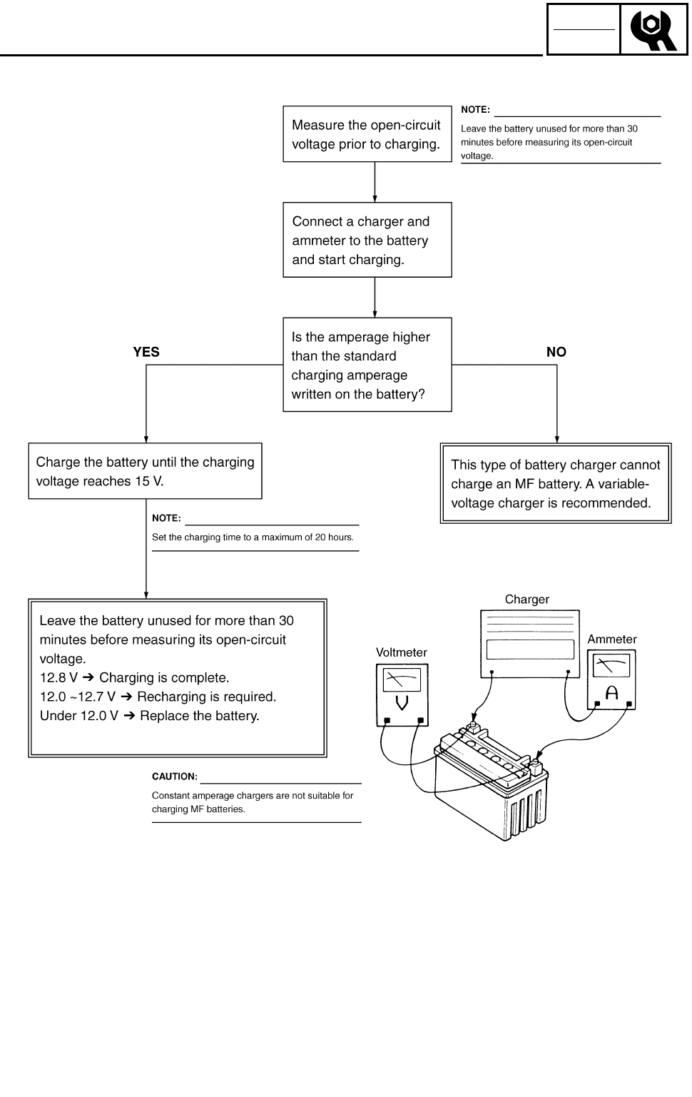
3 - 55
CHK
ADJ
CHECKING THE BATTERY
Charging method using a constant voltage charger
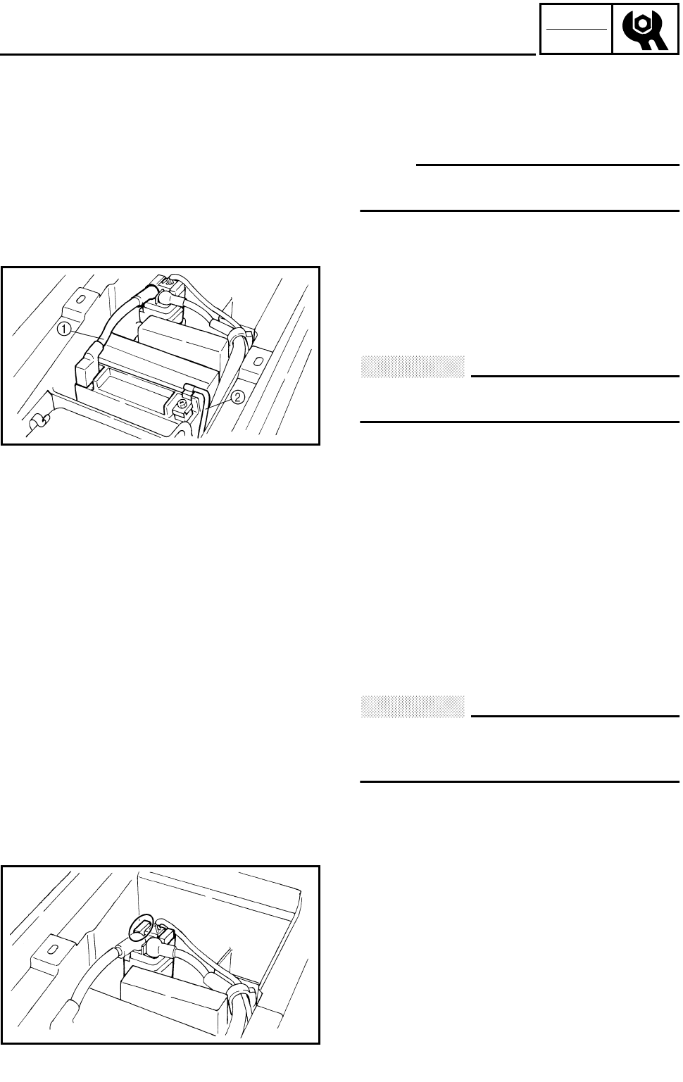
3 - 56
CHK
ADJ
CHECKING THE BATTERY/CHECKING THE FUSE
5.Check:
●Battery terminals
Dirty → Clean with a wire brush.
Poor connection → Correct.
NOTE:
After cleaning the terminals, apply a light coat
of grease.
6.Install:
●Battery
7.Connect:
●Battery leads
CAUTION:
First, connect the positive lead 1, then
connect the negative lead 2.
8.Install:
●Battery holding bracket
●Seat
Refer to “SEAT, FENDERS AND FUEL
TANK”.
CHECKING THE FUSE
CAUTION:
Always turn off the main switch when
checking or replacing a fuse. Otherwise, a
short circuit may occur.
1.Remove:
●Seat
Refer to “SEAT, FENDERS AND FUEL
TANK”.
2.Check:
●Fuse
***********************************************
Checking steps:
●Connect the pocket tester to the fuse and
check it for continuity.
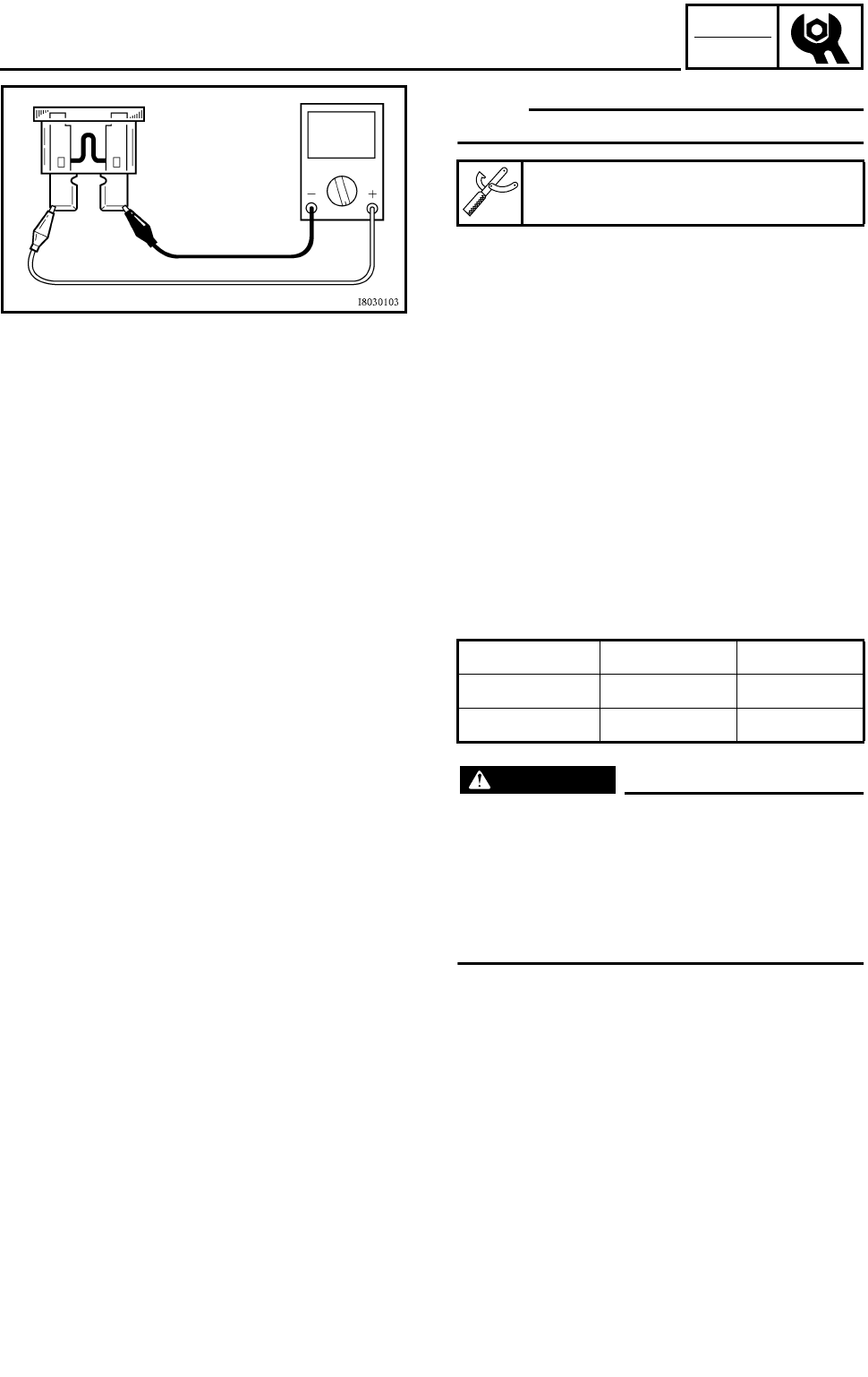
3 - 57
CHK
ADJ
CHECKING THE FUSE
NOTE:
Set the tester to the “Ω × 1” position.
●If the tester indicates 0, replace the fuse.
***********************************************
Pocket tester:
P/N. YU-03112, 90890-03112
3.Replace:
●Blown fuse
***********************************************
Replacement steps:
●Turn off the ignition.
●Install a new fuse of the proper amperage.
●Turn on switches to verify operation of the
related electrical devices.
●If the fuse immediately blows again, check
the electrical circuit.
***********************************************
WARNING
Never use a fuse with a rating other than
that specified. Never use other materials in
place of a fuse. An improper fuse may
cause extensive damage to the electrical
system, a malfunction of the lighting and
ignition systems and could possibly cause
a fire.
4.Install:
●Seat
Refer to “SEAT, FENDERS AND FUEL
TANK”.
Description Current rating Quantity
Main 20 A 1
Reserve 20 A 1
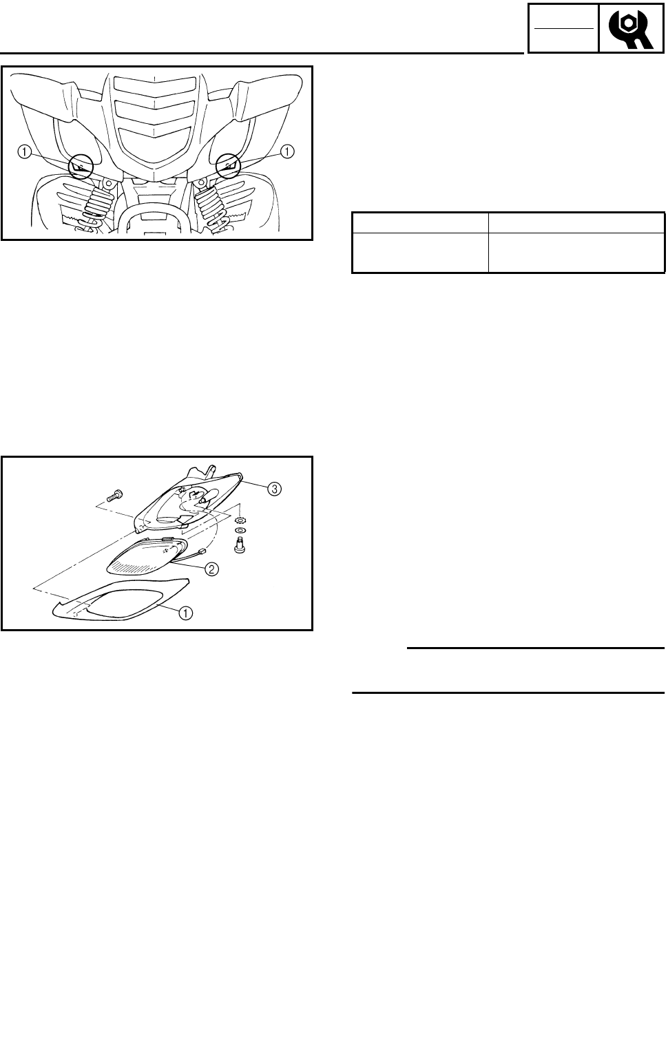
3 - 58
CHK
ADJ
ADJUSTING THE HEADLIGHT BEAM/
REPLACING THE HEADLIGHT BULB
ADJUSTING THE HEADLIGHT BEAM
1.Adjust:
●Headlight beam (vertically)
***********************************************
Adjustment steps:
●Loosen the screw 1.
●Slide the headlight lens unit under.
●Tighten the screw 1.
***********************************************
Slide forward Headlight beam raises.
Slide backward Headlight beam low-
ers.
REPLACING THE HEADLIGHT BULB
1.Remove:
●Headlight
Refer to “SEAT, FENDERS AND FUEL
TANK”.
2.Remove:
●Cover 1
●Headlight unit 2
●Case 3
NOTE:
Pull outward on the rear of the headlight unit
2, and then pull out ward on the front.
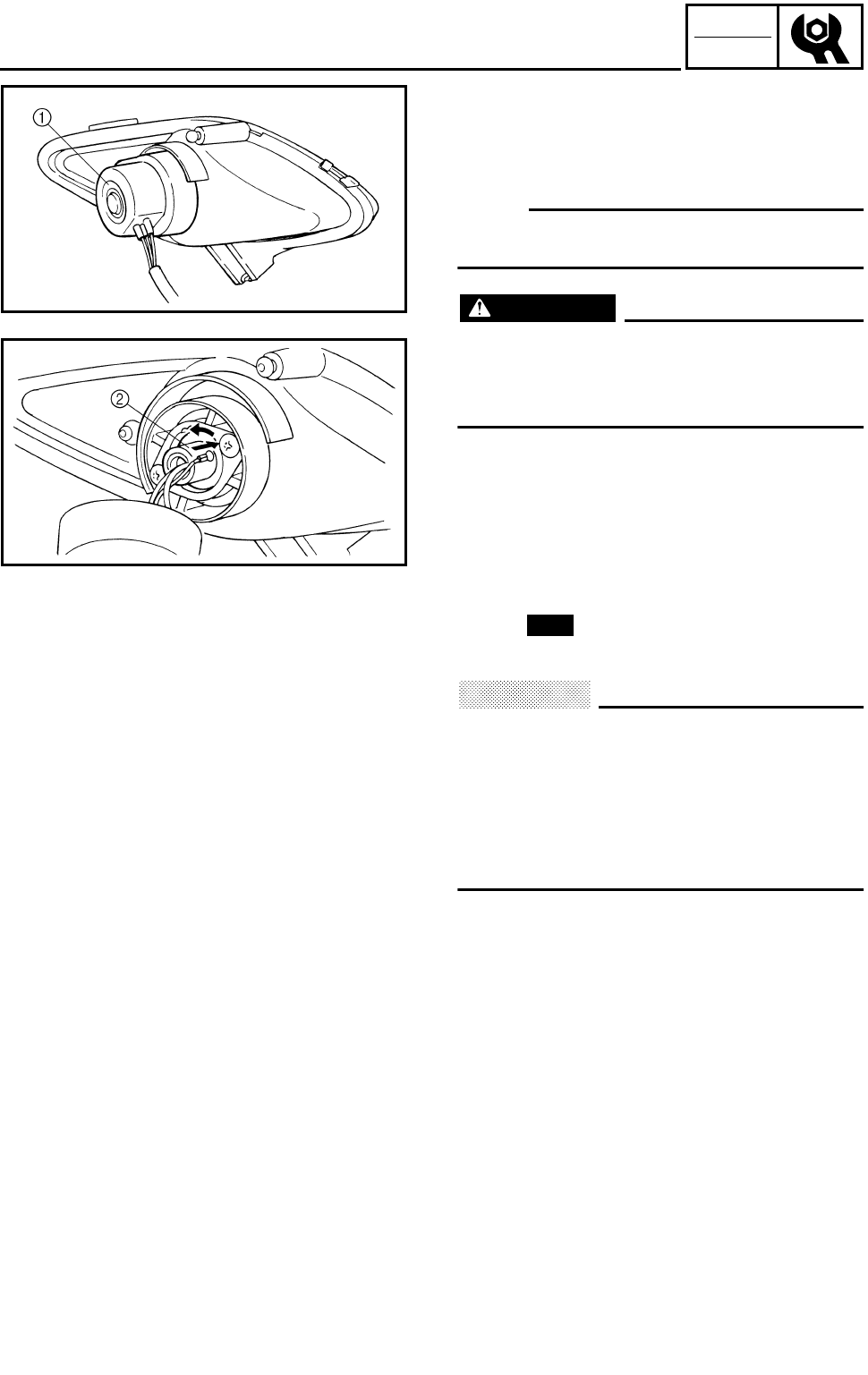
3 - 59
CHK
ADJ
REPLACING THE HEADLIGHT BULB
3.Remove:
●Cover 1
●Bulb holder 2
●Bulb
NOTE:
Turn the bulb holder counterclockwise and
remove the defective bulb.
WARNING
Keep flammable products and your hands
away from the bulb while it is on, since it
will be hot. Do not touch the bulb until it
cools down.
4.Install:
●Bulb
Secure the new bulb with the headlight unit.
CAUTION:
Avoid touching the glass part of the bulb.
Keep it free from oil; otherwise, the trans-
parency of the glass, life of the bulb, and
luminous flux will be adversely affected. If
oil gets on the bulb, thoroughly clean it
with a cloth moistened with alcohol or lac-
quer thinner.
5.Install:
●Bulb holder
●Cover
●Cover
6.Install:
●Headlight
Refer to “SEAT, FENDERS AND FUEL
TANK”.
New
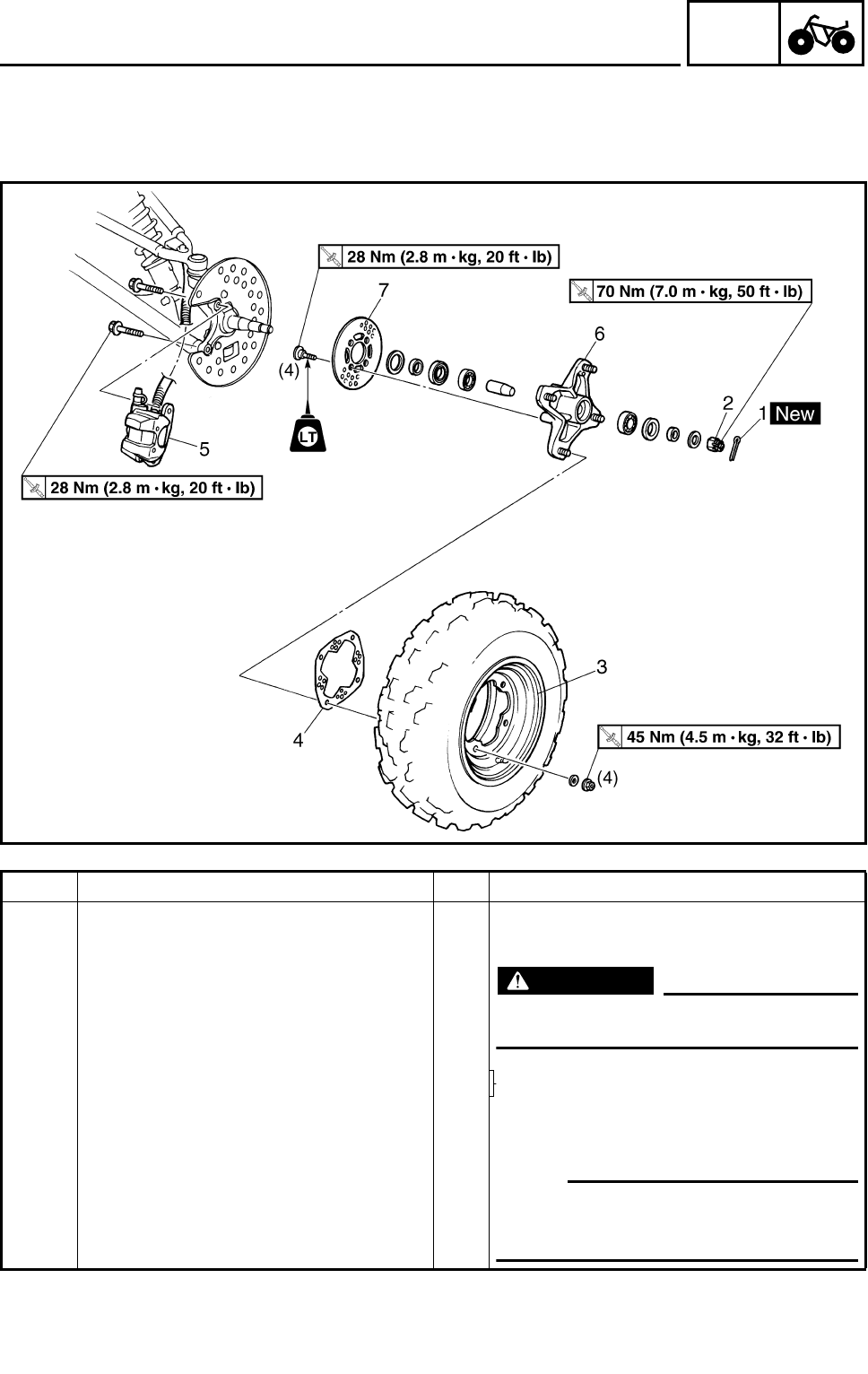
4 - 1
CHAS
FRONT WHEELS
CHASSIS
FRONT WHEELS
FRONT WHEELS
Order Job name/Part name Q’ty Remarks
Removing the front wheel Remove the parts in the order below.
Place the machine on a level surface.
WARNING
Securely support the machine so there
is no danger of it falling over.
1 Cotter pin 1 Refer to “INSTALLING THE WHEEL
HUB”.
2 Axle nut 1
3 Front wheel 1 Refer to “INSTALLING THE WHEEL”.
4 Brake disc guard (outer) 1
5 Brake caliper assembly 1 NOTE:
Do not apply the brake lever after the
brake calipers have been removed, other-
wise the brake pads will be forced shut.
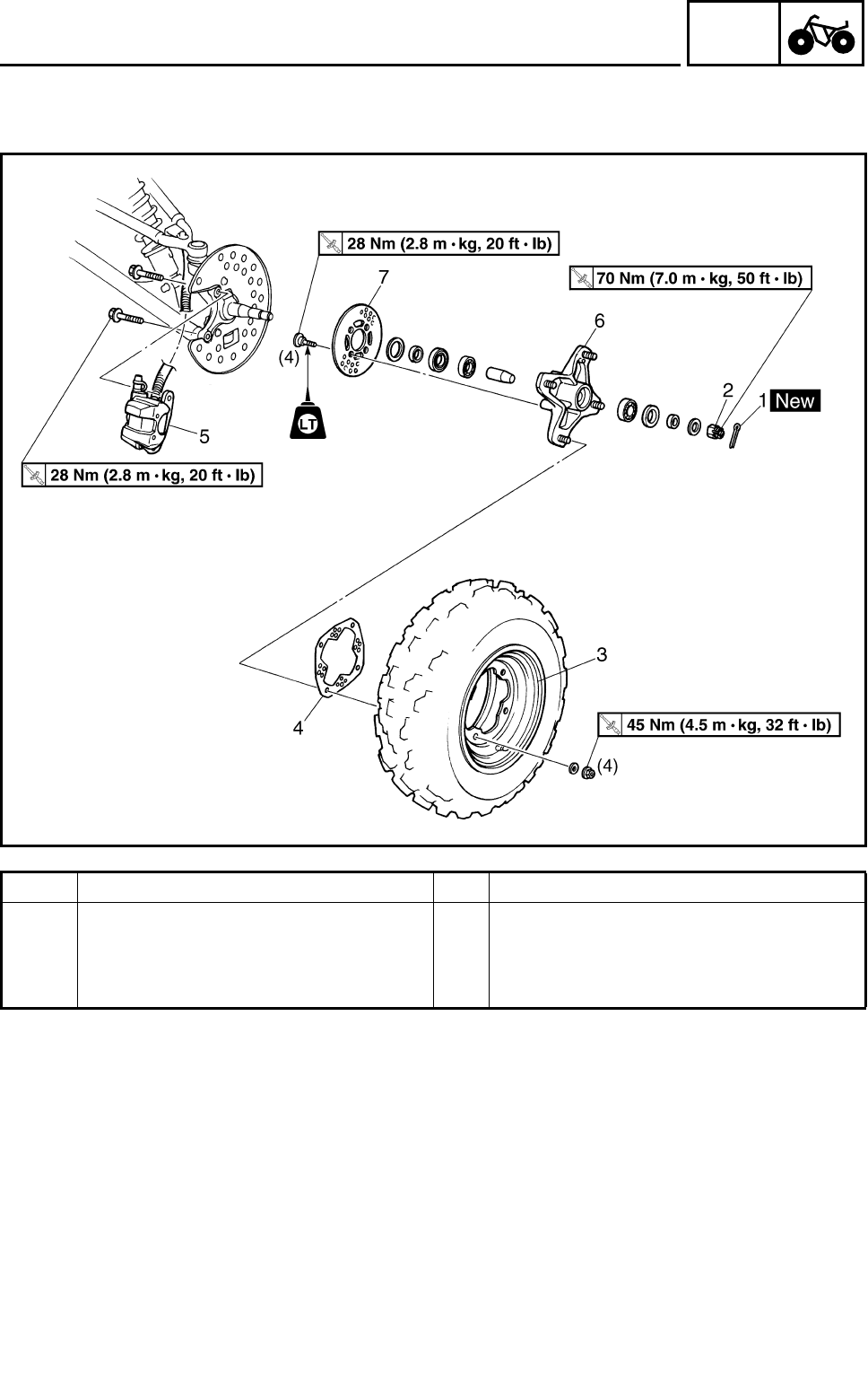
4 - 2
CHAS
FRONT WHEELS
Order Job name/Part name Q’ty Remarks
6 Wheel hub 1
7 Brake disc 1
For installation, reverse the removal pro-
cedure.
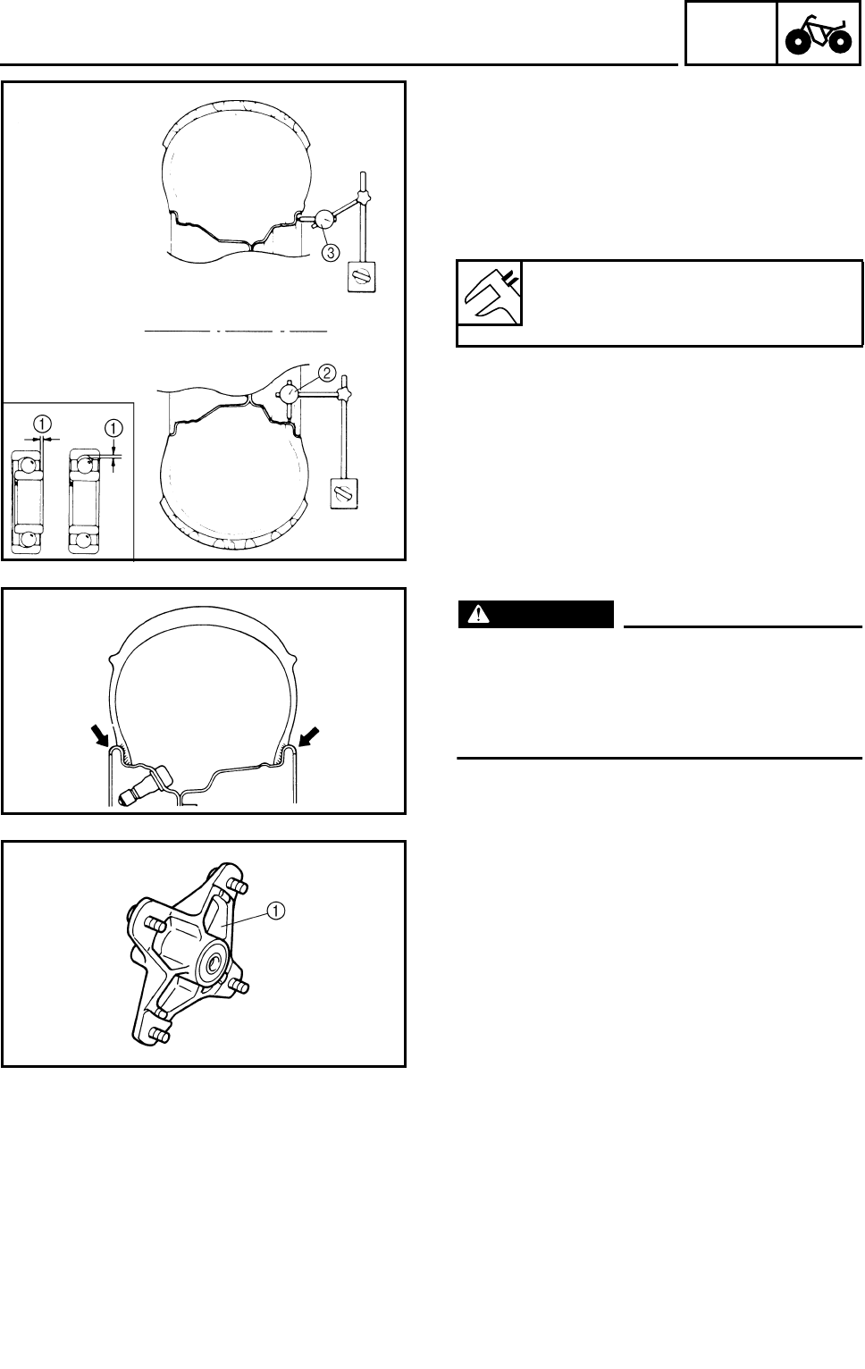
4 - 3
CHAS
FRONT WHEELS
CHECKING THE WHEEL
1.Check:
●Wheel
2.Measure:
●Wheel runout
Over the specified limit → Replace the wheel
or check the wheel bearing play 1.
3.Check:
●Wheel balance
Out of balance → Adjust.
Wheel runout limit:
Radial 2: 2.0 mm (0.08 in)
Lateral 3: 2.0 mm (0.08 in)
WARNING
After replacing the tire, ride conservatively
to allow the tire to be properly seated in the
rim. Failure to do so may cause an accident
resulting in machine damage and possible
operator injury.
CHECKING THE WHEEL HUB
1.Check:
●Wheel hub 1
Cracks/damage → Replace.
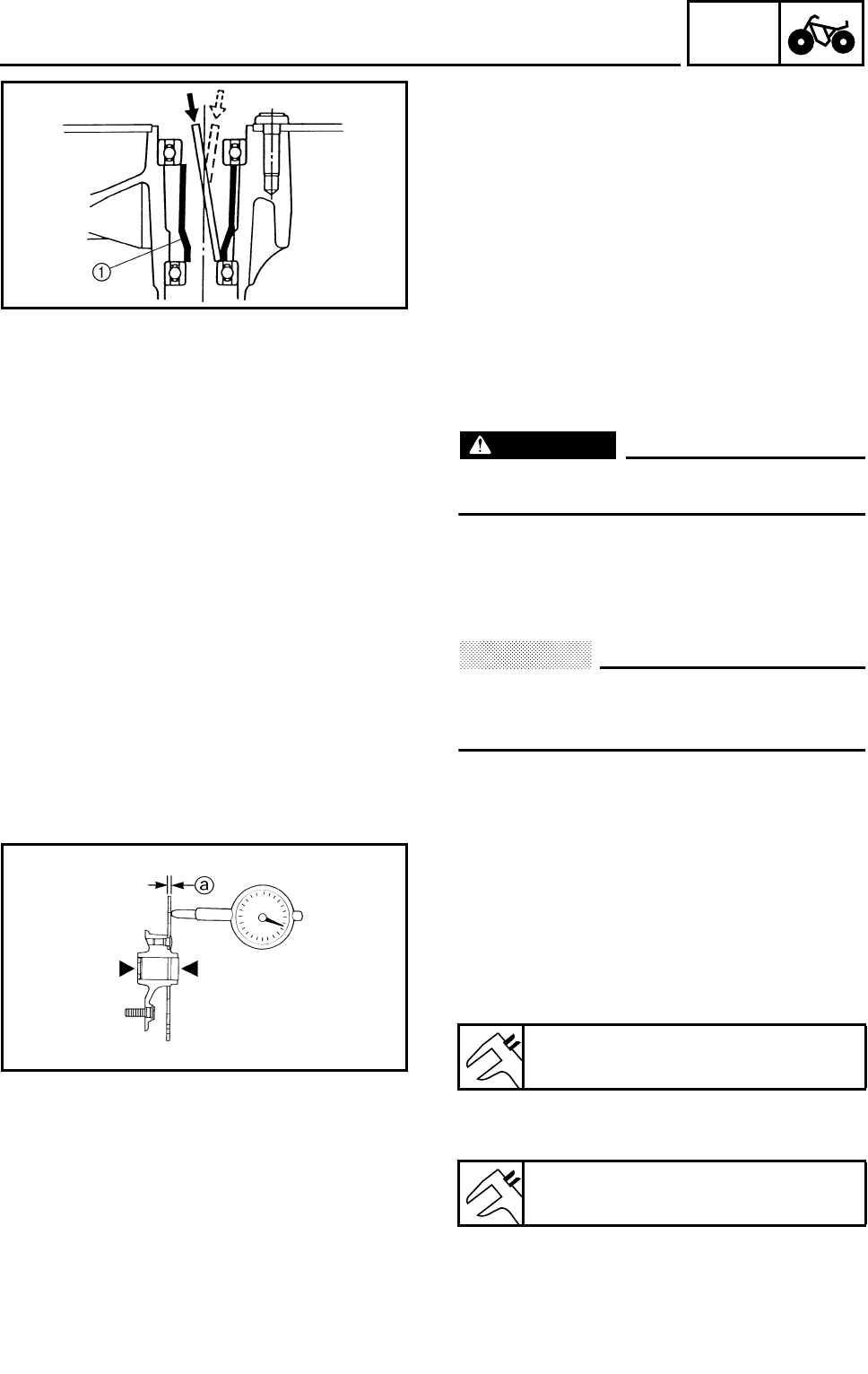
4 - 4
CHAS
FRONT WHEELS
2.Check:
●Wheel bearings
Wheel hub play/wheel turns roughly →
Replace.
***********************************************
Wheel bearing replacement steps:
●Clean wheel hub exterior.
●Drive bearing out by pushing spacer aside
and tapping around perimeter of bearing
inner race. Use soft metal drift punch and
hammer. The spacer 1 “floats” between
bearings. Remove both bearings as
described.
WARNING
Eye protection is recommended when
using striking tools.
●To install the wheel bearings, reverse the
above sequence. Use a socket that matches
outside diameter of bearing outer race to
drive in bearing.
CAUTION:
Do not strike the center race or balls of the
bearing. Contact should be made only with
the outer race.
***********************************************
CHECKING THE BRAKE DISC
1.Check:
●Brake disc
Galling/damage → Replace.
2.Measure:
●Brake disc deflection
Out of specification → Replace.
●Brake disc thickness a
Out of specification → Replace.
Brake disc maximum deflection:
0.15 mm (0.006 in)
Brake disc minimum thickness:
3 mm (0.12 in)
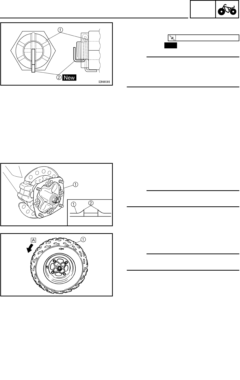
4 - 5
CHAS
FRONT WHEELS
INSTALLING WHEEL HUB
1.Install:
●Axle nut 1
●Cotter pin 2
NOTE:
Do not loosen the axle nut after torquing it. If
the axle nut groove is not aligned with the cot-
ter pin hole, align the groove with the hole by
tightening the axle nut.
T
R
.
.
70 Nm (7.0 m • kg, 50 ft • lb)
New
INSTALLING THE WHEEL
1.Install:
●Brake disc guard (outer) 1
NOTE:
Install the brake disc guard (outer) with
punched burrs 2 on the wheel hub side.
2.Install:
●Wheel
NOTE:
The arrow mark 1 on the tire must point in the
direction of rotation È of the wheel.
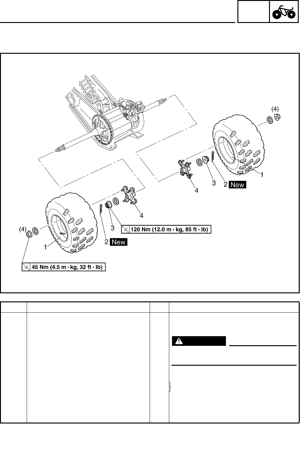
4 - 6
CHAS
REAR WHEELS, WHEEL AXLE AND HUB
REAR WHEELS, WHEEL AXLE AND HUB
REAR WHEELS
Order Job name/Part name Q’ty Remarks
Removing the rear wheel Remove the parts in the order below.
Place the machine on a level surface.
WARNING
Securely support the machine so there
is no danger of it falling over.
1 Rear wheel 2 Refer to “INSTALLING THE WHEEL”.
2 Cotter pin 2 Refer to “INSTALLING THE WHEEL
HUB”.
3 Axle nut 2
4 Wheel hub 2
For installation, reverse the removal pro-
cedure.
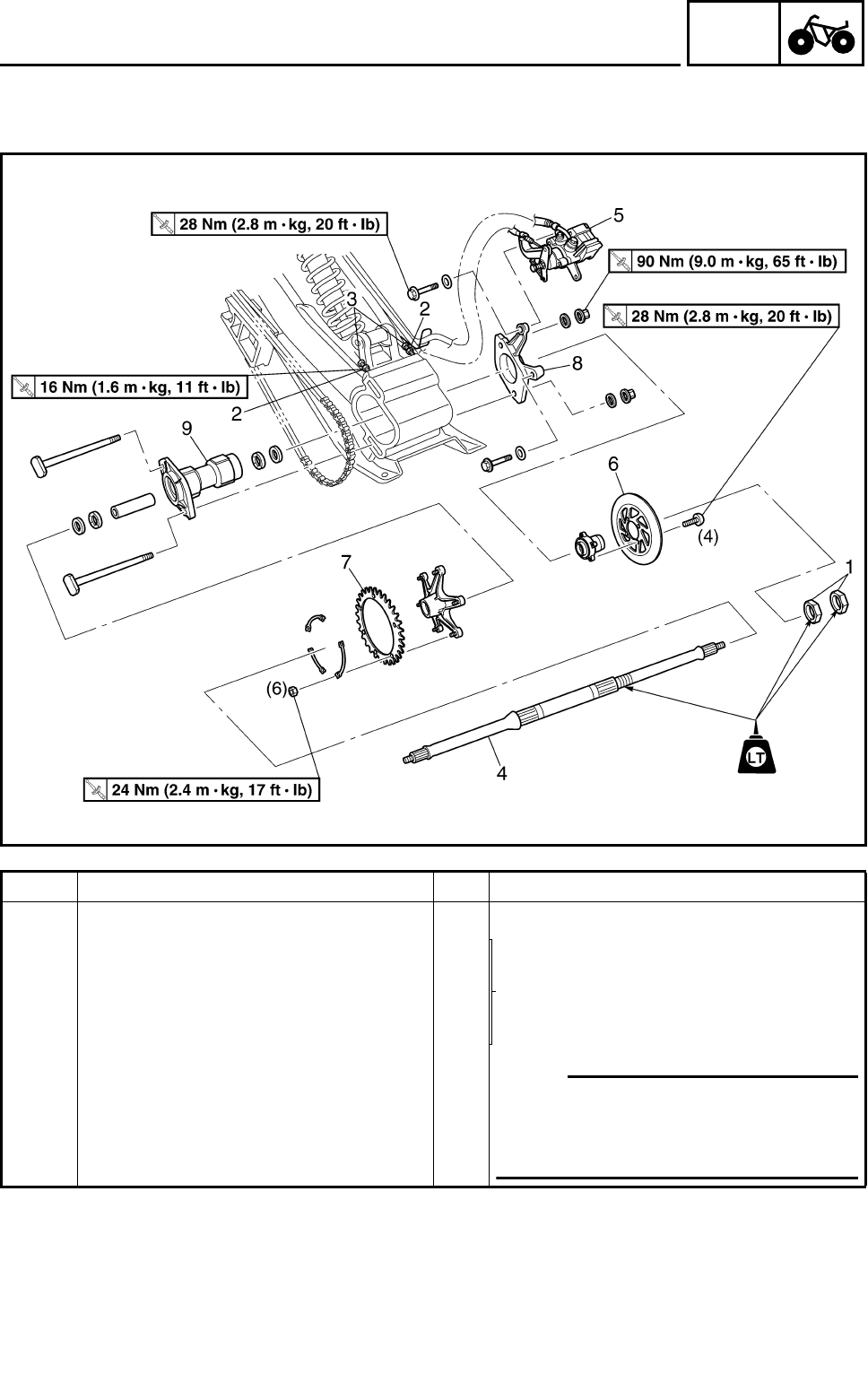
4 - 7
CHAS
REAR WHEELS, WHEEL AXLE AND HUB
WHEEL AXLE AND HUB
Order Job name/Part name Q’ty Remarks
Removing the wheel axle and hub Remove the parts in the order below.
1 Nut 2 Refer to “INSTALLING THE NUTS
(REAR AXLE)”.
2 Locknut 2 Refer to “REMOVING THE REAR AXLE”.
3 Adjusting bolt 2
4 Rear axle 1
5 Brake caliper 1 NOTE:
Do not apply the brake pedal and do not
use the parking brake when the brake
caliper is off of the brake disc as the
brake pad will be force shut.
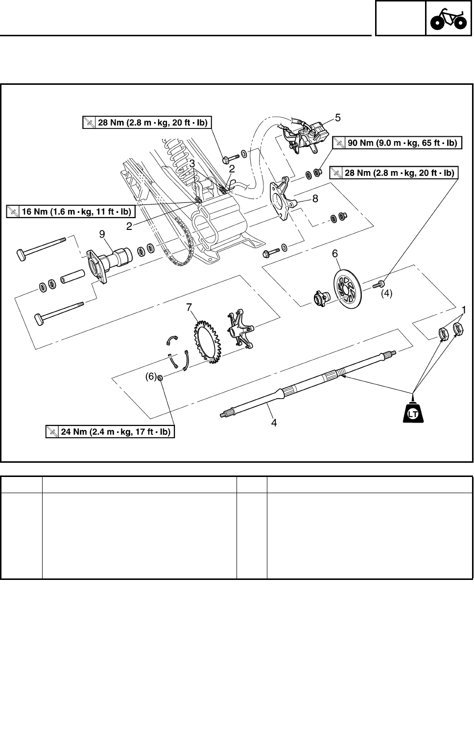
4 - 8
CHAS
REAR WHEELS, WHEEL AXLE AND HUB
Order Job name/Part name Q’ty Remarks
6 Brake disc 1
7 Driven sprocket 1
8 Brake caliper bracket 1
9Hub 1
For installation, reverse the removal pro-
cedure.
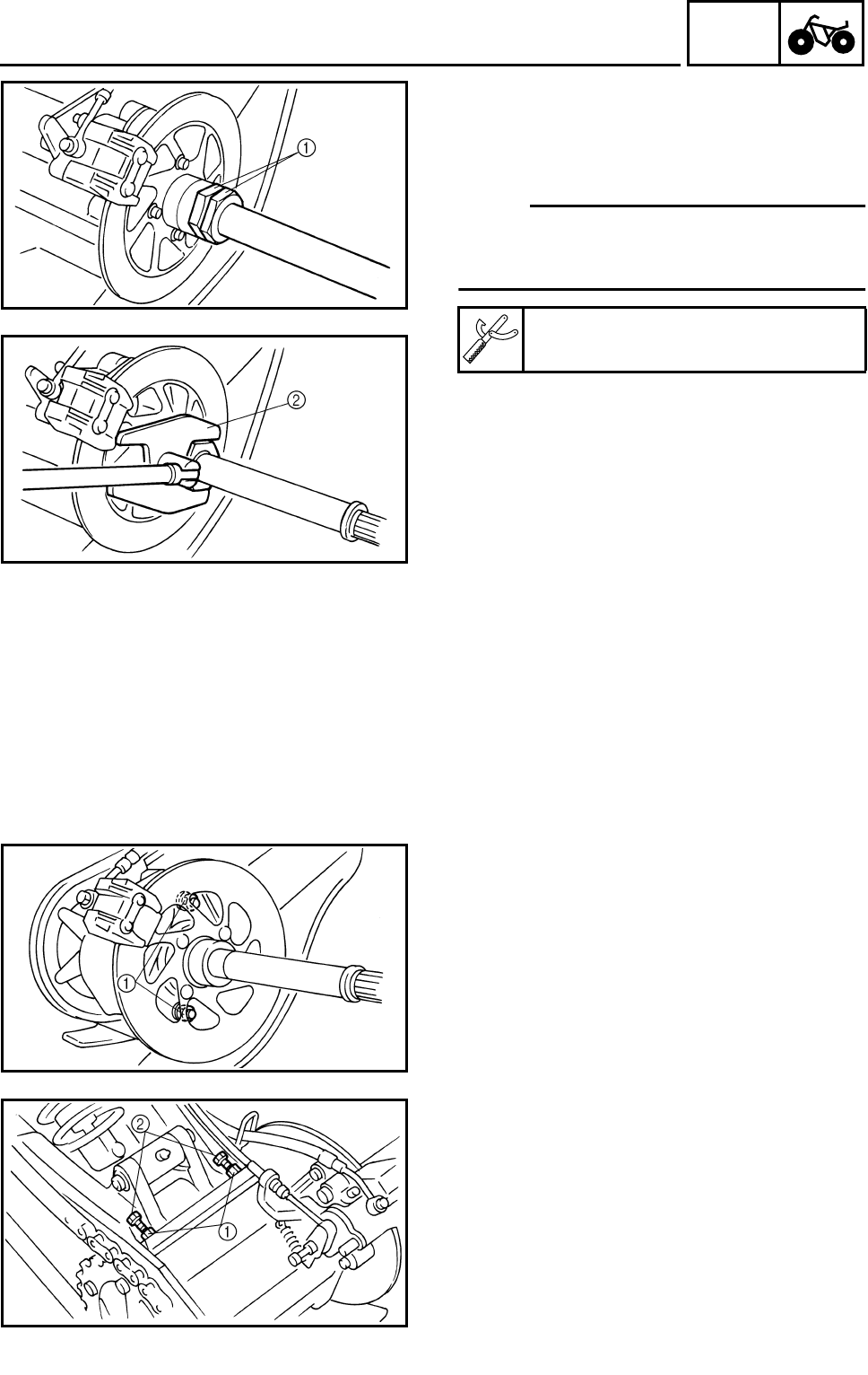
4 - 9
CHAS
REAR WHEELS, WHEEL AXLE AND HUB
REMOVING THE REAR AXLE
1.Place the machine on a level surface.
2.Loosen:
●Nuts (rear axle) 1
NOTE:
●Apply the brake pedal so that the rear axle
does not turn, when loosening the nuts.
●Use a axle nut wrench (50 mm) 2.
Axle nut wrench (50 mm):
P/N. YM-37132, 90890-01419
3.Elevate the rear wheels by placing the suit-
able stand under the frame.
4.Remove:
●Rear wheels
●Wheel hubs
●Nuts (rear axle)
5.Loosen:
●Hub nuts 1
6.Loosen:
●Locknuts 1
●Adjusting bolts 2
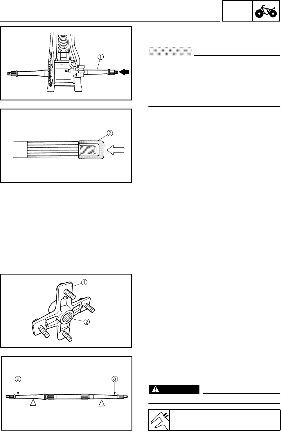
4 - 10
CHAS
REAR WHEELS, WHEEL AXLE AND HUB
7.Remove:
●Rear axle 1
CAUTION:
●Never directly tap the axle end with a
hammer, since this will result in damage
to the axle thread and spline.
●Attach a suitable socket 2 on the axle
end and tap it with a soft hammer. Pull out
the rear axle to the right.
CHECKING THE WHEEL
Refer to “FRONT WHEELS”.
CHECKING THE WHEEL HUB
1.Check:
●Wheel hub 1
Cracks/damage → Replace.
●Splines (wheel hub) 2
Wear/damage → Replace the wheel hub.
CHECKING THE REAR AXLE
1.Check:
●Rear axle runout a
Out of specification → Replace.
WARNING
Do not attempt to straighten a bent axle.
Rear axle runout limit:
1.5 mm (0.06 in)
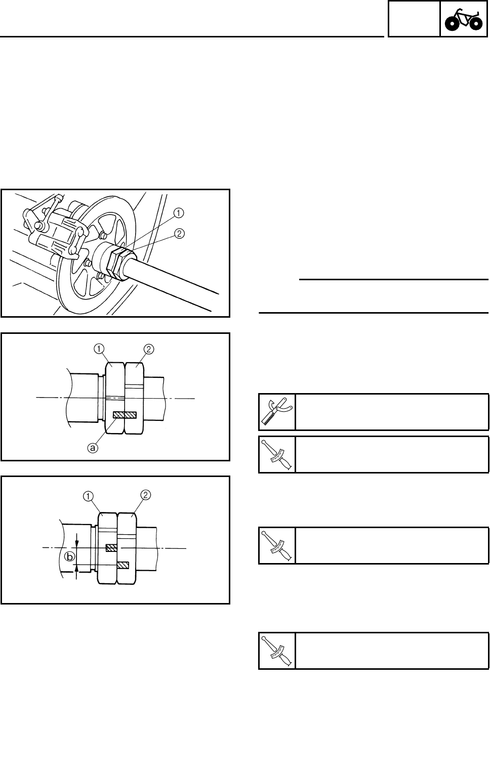
4 - 11
CHAS
REAR WHEELS, WHEEL AXLE AND HUB
CHECKING THE HUB
1.Check:
●Hub bearings
Refer to “FRONT WHEELS-WHEEL HUB
INSPECTION”.
CHECKING THE BRAKE DISC
Refer to “FRONT WHEELS”.
INSTALLING THE NUTS (REAR AXLE)
1.Tighten:
Nuts (rear axle) 1, 2
***********************************************
Nuts tightening steps:
NOTE:
Before tightening the nuts, apply the LOC-
TITE® to the thread portion of the rear axle.
●Finger tighten the inside nut 1 while check-
ing the ring gear engagement.
●Tighten the inside nut with rear axle nut
wrench to specification while holding the rear
axle.
●Hold the inside nut 1 and tighten the outside
nut 2 with rear axle nut wrench to specifica-
tion.
●Draw the line a on inside and outside nut.
●Hold the outside nut 2 and tighten back the
inside nut 1 with rear axle nut wrench to
specification.
●Measure the distance b between lines. If
distance b is less than 15 mm (0.59 in),
retighten back the inside nut.
***********************************************
Axle nut wrench (50 mm):
P/N. YM-37132, 90890-01419
T
R
.
.
Inside nut (first tightening):
55 Nm (5.5 m • kg, 40 ft • lb)
T
R
.
.
Outside nut:
190 Nm (19.0 m • kg, 140 ft • lb)
T
R
.
.
Inside nut (final tightening):
240 Nm (24.0 m • kg, 170 ft • lb)
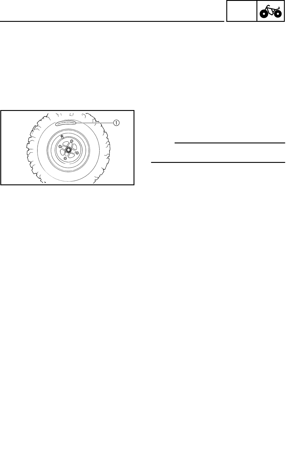
4 - 12
CHAS
REAR WHEELS, WHEEL AXLE AND HUB
INSTALLING THE WHEEL HUB
Refer to “FRONT WHEELS”.
INSTALLING THE WHEEL
1.Install:
●Wheel
NOTE:
The wording on the tire “SIDE FACING OUT-
WARDS” 1 must be facing outwards.
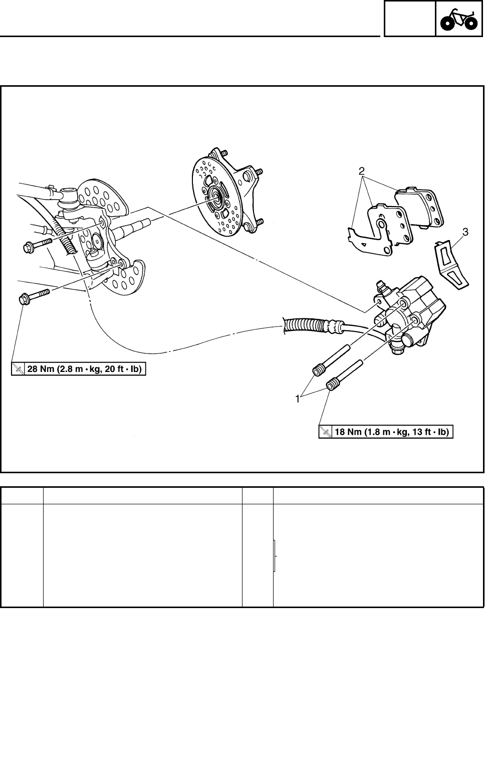
4 - 13
CHAS
FRONT AND REAR BRAKES
FRONT AND REAR BRAKES
FRONT BRAKE PADS
Order Job name/Part name Q’ty Remarks
Removing the front brake pad Remove the parts in the order below.
Front wheel/wheel hub Refer to “FRONT WHEELS”.
1 Brake pad holding bolt 2 Refer to “REPLACING THE FRONT
BRAKE PAD”.
2 Brake pad/pad shim 2/1
3 Brake pad spring 1
For installation, reverse the removal pro-
cedure.
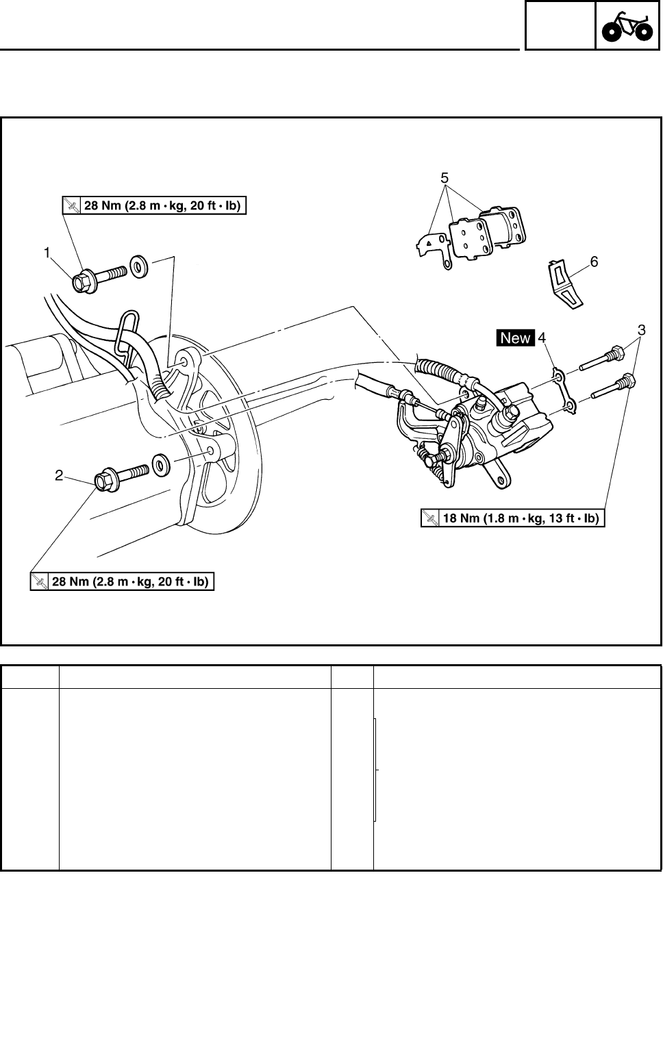
4 - 14
CHAS
FRONT AND REAR BRAKES
REAR BRAKE PADS
Order Job name/Part name Q’ty Remarks
Removing rear brake pad Remove the parts in the order below.
1 Brake caliper mounting bolt 1
Refer to “REPLACING THE REAR
BRAKE PAD”.
2 Brake caliper mounting bolt 1
3 Brake pad holding bolt 2
4 Lock washer 1
5 Brake pad/pad shim 2/1
6 Brake pad spring 1
For installation, reverse the removal pro-
cedure.
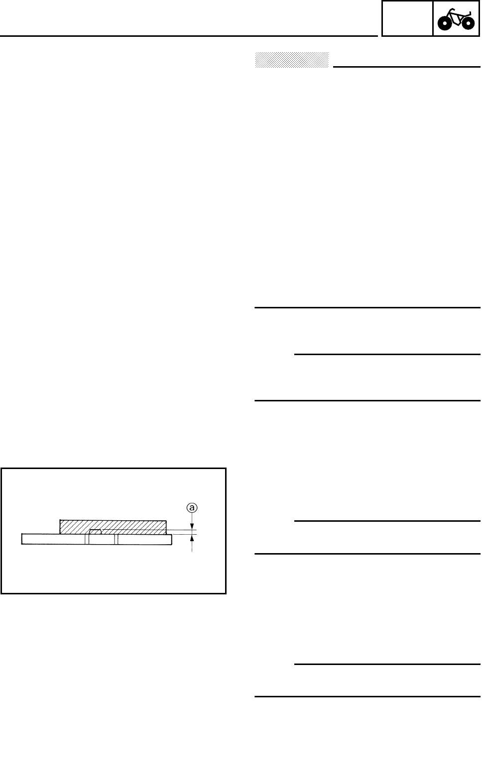
4 - 15
CHAS
FRONT AND REAR BRAKES
CAUTION:
Disc brake components rarely require dis-
assembly. DO NOT:
●disassemble components unless abso-
lutely necessary;
●use solvents on internal brake compo-
nents;
●use spent brake fluid for cleaning; (use
only clean brake fluid)
●allow brake fluid to come in contact with
the eyes, as this may cause eye injury;
●splash brake fluid onto painted surfaces or
plastic parts, as this may cause damage;
●disconnect any hydraulic connection, as
this would require the entire brake sys-
tem to be disassembled, drained,
cleaned, properly filled and bled after
reassembly.
REPLACING THE FRONT BRAKE PAD
NOTE:
It is not necessary to disassemble the brake
caliper and brake hose to replace the brake
pads.
1.Remove:
●Brake pads
aWear limit
NOTE:
Replace the brake pads as a set if either is
found to be worn to the wear limit.
2.Install:
●Brake pads
●Brake pad spring
NOTE:
Always install new brake pads, brake pad shim
and brake pad spring as a set.
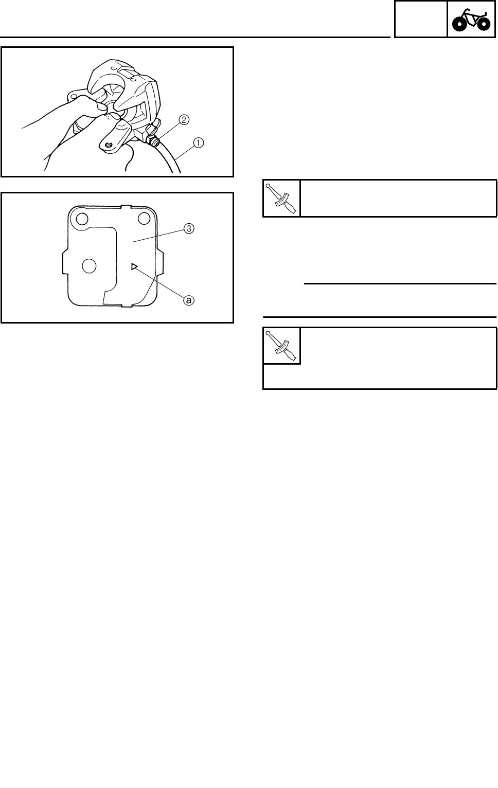
4 - 16
CHAS
FRONT AND REAR BRAKES
***********************************************
Installation steps:
●Connect a suitable hose 1 tightly to the
brake caliper bleed screw 2. Put the other
end of this hose into an open container.
●Loosen the brake caliper bleed screw and,
using a finger, push the caliper piston into
the brake caliper.
●Tighten the brake caliper bleed screw.
●Install new brake pads, new pad shim 3 and
a new brake pad spring.
●Install the holding bolts and brake caliper.
NOTE:
The arrow mark a on the pad shim must point
in the direction of the disc rotation.
***********************************************
T
R
.
.
Brake caliper bleed screw:
6 Nm (0.6 m • kg, 4.3 ft • lb)
T
R
.
.
Brake pad holding bolt:
18 Nm (1.8 m • kg, 13 ft • lb)
Brake caliper mounting bolt:
28 Nm (2.8 m • kg, 20 ft • lb)
3.Check:
●Brake fluid level
Refer to “CHECKING THE BRAKE FLUID
LEVEL” in CHAPTER 3.
4.Check:
●Brake lever operation
Soft or spongy feeling → Bleed the front
brake system.
Refer to “BLEEDING THE HYDRAULIC
BRAKE SYSTEM” in CHAPTER 3.
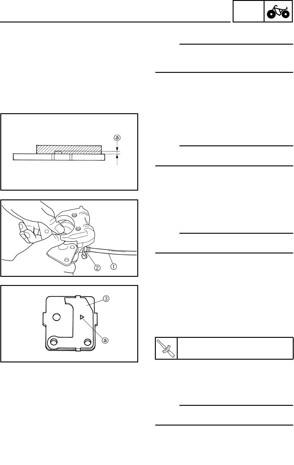
4 - 17
CHAS
FRONT AND REAR BRAKES
REPLACING THE REAR BRAKE PAD
NOTE:
It is not necessary to disassemble the brake
caliper and brake hose to replace the brake
pads.
1.Remove:
●Brake pads
aWear limit
NOTE:
Replace the brake pads as a set if either is
found to be worn to the wear limit.
2.Install:
●Brake pads
●Brake pad spring
NOTE:
Always install new brake pads, brake pad shim
and brake pad spring as a set.
***********************************************
Installation steps:
●Connect a suitable hose 1 tightly to the
brake caliper bleed screw 2. Put the other
end of this hose into an open container.
●Loosen the brake caliper bleed screw and,
using a finger, push the caliper piston into
the brake caliper.
●Tighten the brake caliper bleed screw.
●Install new brake pads, new pad shim 3 and
a new brake pad spring.
●Install a new lock washer, holding bolts and
brake caliper.
NOTE:
The arrow mark a on the pad shim must point
in the direction of the disc rotation.
T
R
.
.
Brake caliper bleed screw:
6 Nm (0.6 m • kg, 4.3 ft • lb)

4 - 18
CHAS
FRONT AND REAR BRAKES
●Bend the lock washer tabs along a flat side
of the bolts.
***********************************************
T
R
.
.
Brake pad holding bolt:
18 Nm (1.8 m • kg, 13 ft • lb)
Brake caliper mounting bolt:
28 Nm (2.8 m • kg, 20 ft • lb)
3.Check:
●Brake fluid level
Refer to “CHECKING THE BRAKE FLUID
LEVEL” in CHAPTER 3.
4.Check:
●Brake pedal operation
Soft or spongy feeling → Bleed the rear
brake system.
Refer to “BLEEDING THE HYDRAULIC
BRAKE SYSTEM” in CHAPTER 3.
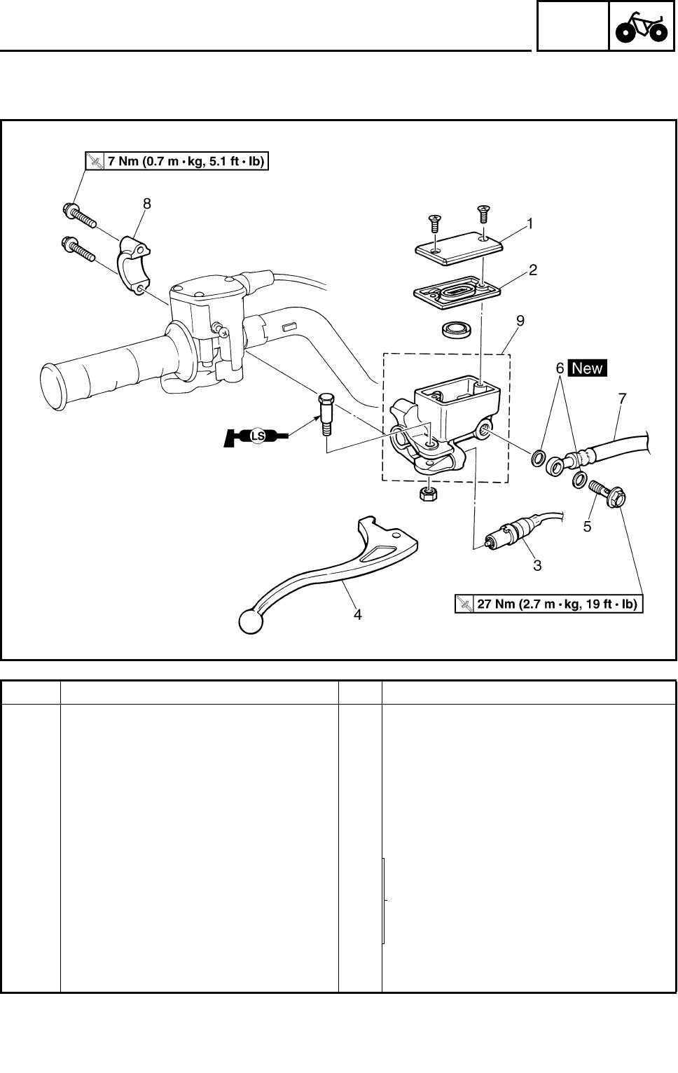
4 - 19
CHAS
FRONT AND REAR BRAKES
FRONT BRAKE MASTER CYLINDER
Order Job name/Part name Q’ty Remarks
Removing front brake master cylin-
der Remove the parts in the order below.
Brake fluid Drain.
1 Brake fluid reservoir cap 1
2 Brake fluid reservoir diaphragm 1
3 Front brake switch 1
4 Brake lever 1
5 Union bolt 1
Refer to “INSTALLING THE FRONT
BRAKE MASTER CYLINDER”.
6 Copper washer 2
7 Brake hose 1
8 Brake master cylinder bracket 1
9 Brake master cylinder 1
For installation, reverse the removal pro-
cedure.
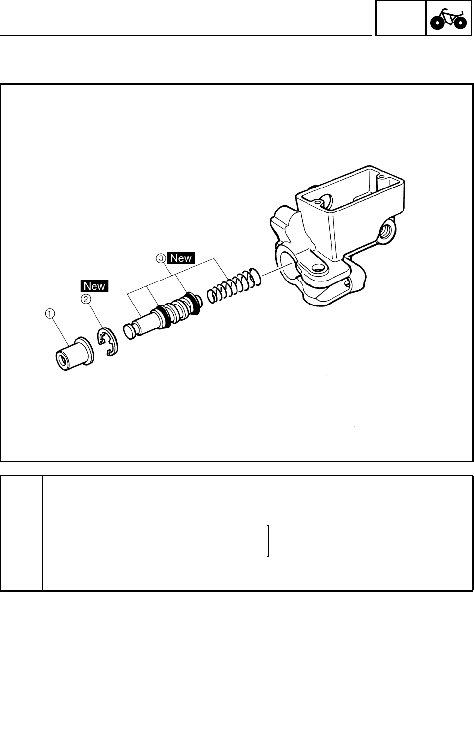
4 - 20
CHAS
FRONT AND REAR BRAKES
Order Job name/Part name Q’ty Remarks
Disassembling the front brake mas-
ter cylinder Remove the parts in the order below.
1 Dust boot 1 Refer to “ASSEMBLING THE FRONT
AND REAR BRAKE MASTER CYLIN-
DER”.
2 Circlip 1
3 Brake master cylinder kit 1
For assembly, reverse the disassembly
procedure.
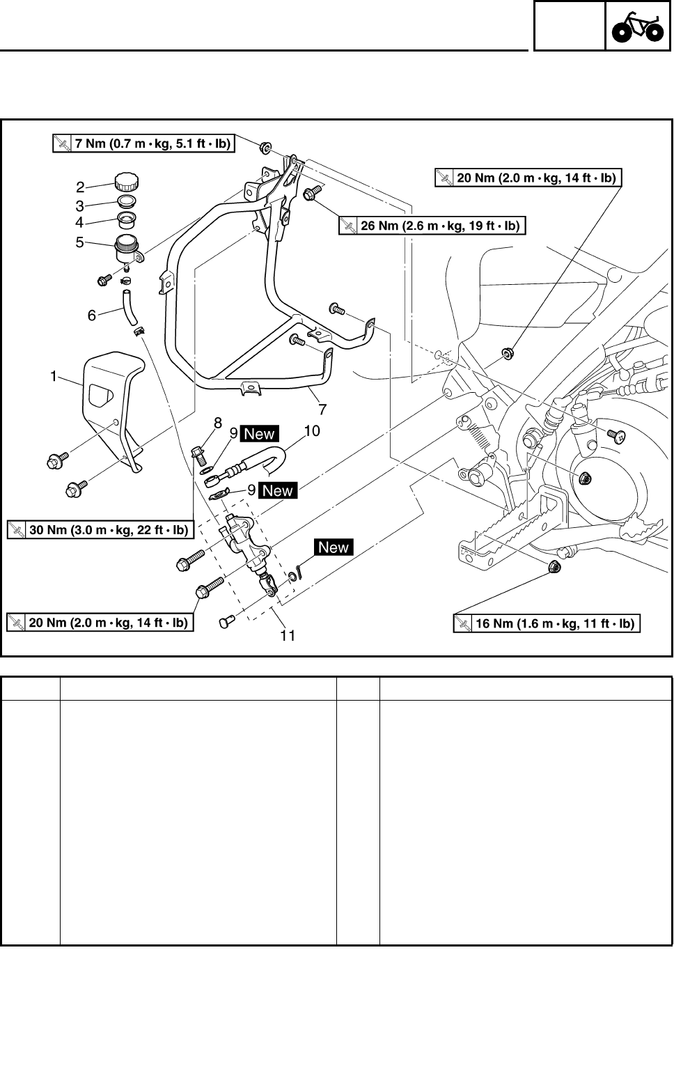
4 - 21
CHAS
FRONT AND REAR BRAKES
REAR BRAKE MASTER CYLINDER
Order Job name/Part name Q’ty Remarks
Removing the rear brake master cyl-
inder Remove the parts in the order below.
Right footrest guard Refer to “SEAT, FENDERS AND FUEL
TANK” in CHAPTER 3.
Brake fluid Drain.
1 Brake fluid reservoir cover 1
2 Brake fluid reservoir cap 1
3 Brake fluid reservoir diaphragm holder 1
4 Brake fluid reservoir diaphragm 1
5 Brake fluid reservoir 1
6 Brake fluid reservoir hose 1
7 Right footrest guard bracket 1
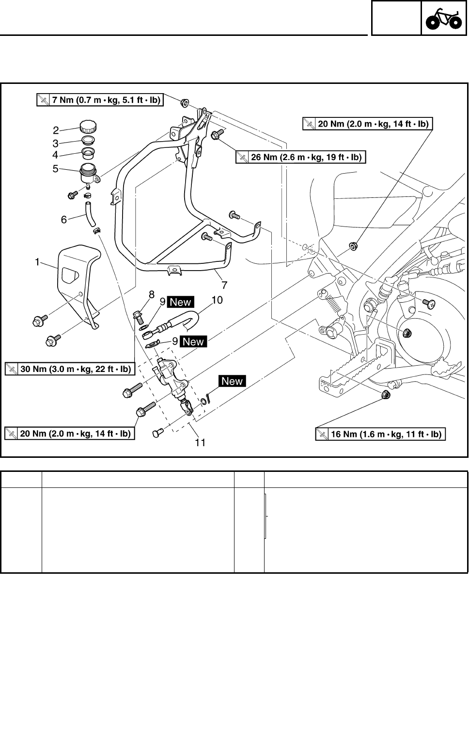
4 - 22
CHAS
FRONT AND REAR BRAKES
Order Job name/Part name Q’ty Remarks
8 Union bolt 1
Refer to “INSTALLING THE REAR
BRAKE MASTER CYLINDER”.
9 Copper washer 2
10 Brake hose 1
11 Brake master cylinder 1
For installation, reverse the removal pro-
cedure.
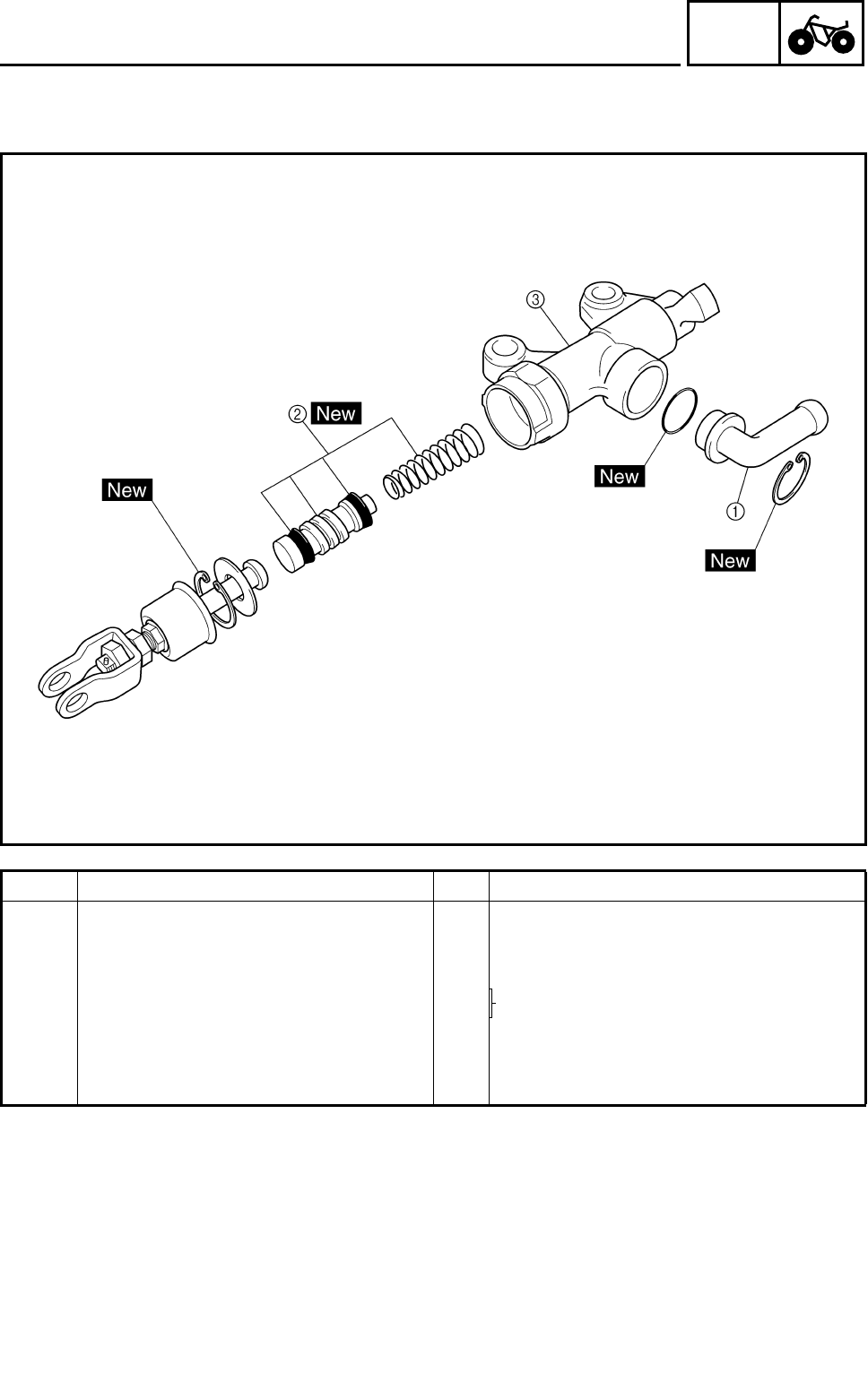
4 - 23
CHAS
FRONT AND REAR BRAKES
Order Job name/Part name Q’ty Remarks
Disassembling the rear brake mas-
ter cylinder Remove the parts in the order below.
1Hose joint 1
2Brake master cylinder kit 1 Refer to “ASSEMBLING THE FRONT
AND REAR BRAKE MASTER CYLIN-
DER”.
3Brake master cylinder 1
For assembly, reverse the disassembly
procedure.
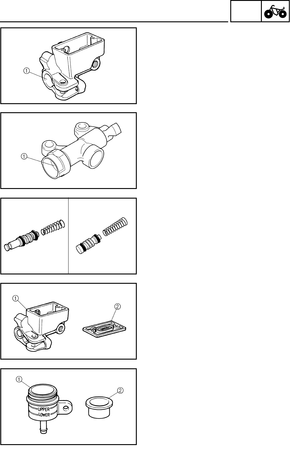
4 - 24
CHAS
FRONT AND REAR BRAKES
CHECKING THE MASTER CYLINDER
1.Check:
●Brake master cylinder 1
Wear/scratches → Replace the brake master
cylinder assembly.
●Brake master cylinder body
Cracks/damage → Replace.
●Brake fluid delivery passage
(brake master cylinder body)
Blockage → Blow out with compressed air.
ÈFront
ÉRear
È
É
2.Check:
●Brake master cylinder kit
Scratches/wear/damage → Replace as a set.
ÈFront
ÉRear
É
È
3.Check:
●Front brake master cylinder reservoir 1
●Front brake master cylinder reservoir dia-
phragm 2
Cracks/damage → Replace.
4.Check:
●Rear brake fluid reservoir 1
●Rear brake fluid reservoir diaphragm 2
Cracks/damage → Replace.
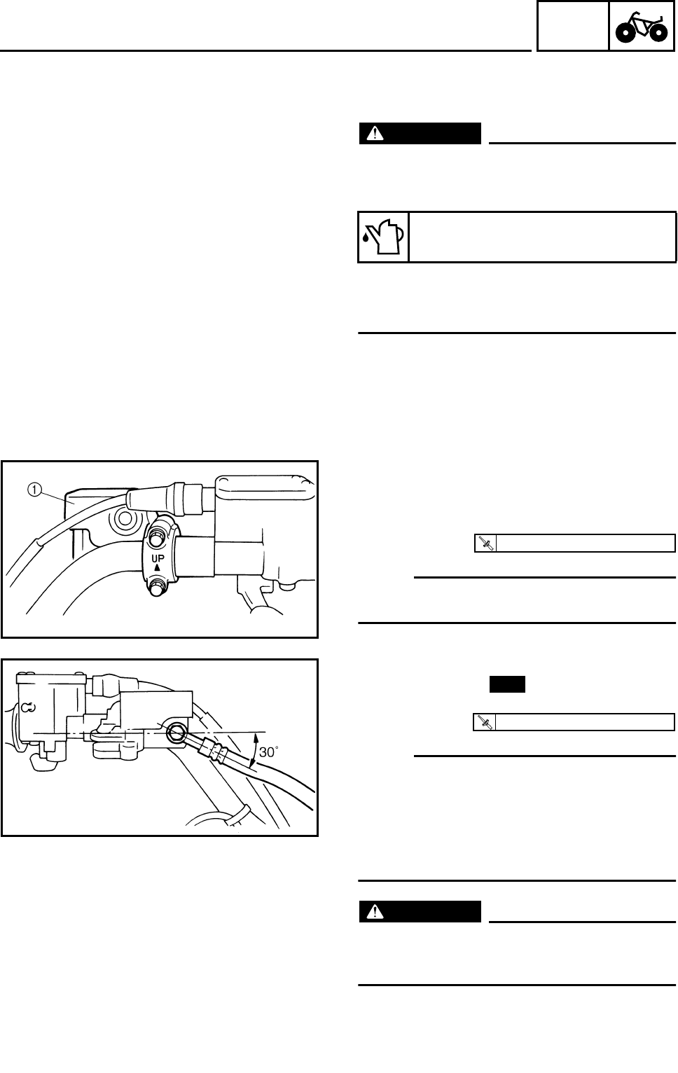
4 - 25
CHAS
FRONT AND REAR BRAKES
EB702060
ASSEMBLING THE FRONT AND REAR
BRAKE MASTER CYLINDER
WARNING
●All internal brake components should be
cleaned and lubricated with new brake
fluid only before installation.
●Whenever a master cylinder is disassem-
bled, replace the piston seals and dust
seals.
Recommended brake fluid:
DOT 4
INSTALLING THE FRONT BRAKE MASTER
CYLINDER
1.Install:
●Brake master cylinder 1
NOTE:
The “UP” mark on the brake master cylinder
bracket should face up.
T
R
.
.
7 Nm (0.7 m • kg, 5.1 ft • lb)
2.Install:
●Copper washers
●Brake hose
●Union bolt
NOTE:
●Tighten the union bolt while holding the
brake hose as shown.
●Turn the handlebar to the left and to the right
to check that the brake hose does not touch
other parts (throttle cable, wire harness,
leads, etc.). Correct if necessary.
WARNING
Proper brake hose routing is essential to
insure safe machine operation. Refer to
“CABLE ROUTING”.
New
T
R
.
.
27 Nm (2.7 m • kg, 19 ft • lb)
4 - 26
CHAS
FRONT AND REAR BRAKES
3.Fill:
●Brake fluid reservoir
CAUTION:
Brake fluid may damage painted surfaces
or plastic parts. Always clean up spilled
brake fluid immediately.
WARNING
●Use only the designated quality brake
fluid: Other brake fluids may deteriorate
the rubber seals, causing leakage and
poor brake performance.
●Refill with the same type of brake fluid:
Mixing brake fluids may result in a harm-
ful chemical reaction and lead to poor
brake performance.
●Be careful that water does not enter the
brake master cylinder when refilling.
Water will significantly lower the boiling
point of the brake fluid and may result in
vapor lock.
Recommended brake fluid:
DOT 4
4.Air bleed:
●Brake system
Refer to “BLEEDING THE HYDRAULIC
BRAKE SYSTEM” in CHAPTER 3.
5.Check:
●Brake fluid level
Brake fluid level is below the “LOWER” level
line → Add the recomended brake fluid to the
proper level.
Refer to “CHECKING THE BRAKE FLUID
LEVEL” in CHAPTER 3.
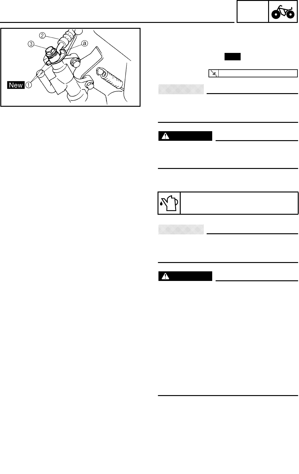
4 - 27
CHAS
FRONT AND REAR BRAKES
INSTALLING THE REAR BRAKE MASTER
CYLINDER
1.Install:
●Copper washers 1
●Brake hose 2
●Union bolt 3
CAUTION:
When installing the brake hose onto the
brake master cylinder, make sure the brake
pipe touches the projection a as shown.
WARNING
Proper brake hose routing is essential to
insure safe machine operation. Refer to
“CABLE ROUTING”.
2.Fill:
●Brake fluid reservoir
CAUTION:
Brake fluid may damage painted surfaces
or plastic parts. Always clean up spilled
brake fluid immediately.
WARNING
●Use only the designated quality brake
fluid: Other brake fluids may deteriorate
the rubber seals, causing leakage and
poor brake performance.
●Refill with the same type of brake fluid:
Mixing brake fluids may result in a harm-
ful chemical reaction and lead to poor
brake performance.
●Be careful that water does not enter the
brake master cylinder when refilling.
Water will significantly lower the boiling
point of the brake fluid and may result in
vapor lock.
Recommended brake fluid:
DOT 4
New
T
R
.
.
30 Nm (3.0 m • kg, 22 ft • lb)

4 - 28
CHAS
3.Air bleed:
●Brake system
Refer to “BLEEDING THE HYDRAULIC
BRAKE SYSTEM” in CHAPTER 3.
4.Check:
●Brake fluid level
Brake fluid level is below the “LOWER” level
line → Add the recommended brake fluid to
the proper level.
Refer to “CHECKING THE BRAKE FLUID
LEVEL” in CHAPTER 3.
FRONT AND REAR BRAKES
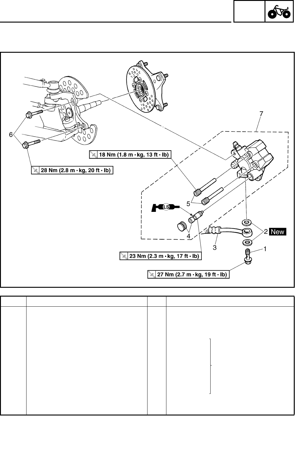
4 - 29
CHAS
FRONT AND REAR BRAKES
FRONT BRAKE CALIPERS
Order Job name/Part name Q’ty Remarks
Removing the front brake caliper Remove the parts in the order below.
Brake fluid Drain.
Front wheel Refer to “FRONT WHEELS”.
1 Union bolt 1
Refer to “INSTALLING
THE FRONT BRAKE CAL-
IPER”.
2 Copper washer 2
3 Brake hose 1 Disconnect.
4 Cap/retaining bolt 1/1 Loosen.
5 Brake pad holding bolt 2 Loosen.
6 Brake caliper mounting bolt 2
7 Brake caliper assembly 1
For installation, reverse the removal pro-
cedure.
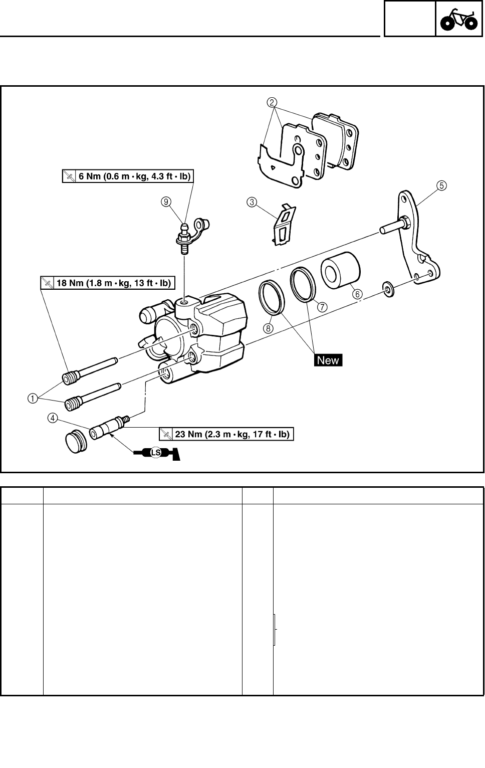
4 - 30
CHAS
FRONT AND REAR BRAKES
Order Job name/Part name Q’ty Remarks
Disassembling the front brake cali-
per Remove the parts in the order below.
1 Brake pad holding bolt 2
2 Brake pad/pad shim 2/1
3 Brake pad spring 1
4 Retaining bolt 1
5 Caliper bracket 1
6 Brake caliper piston 1 Refer to “DISASSEMBLING THE FRONT
AND REAR BRAKE CALIPER/ASSEM-
BLING THE FRONT BRAKE CALIPER”.
7 Dust seal 1
8 Caliper piston seal 1
9 Bleed screw 1
For assembly, reverse the disassembly
procedure.
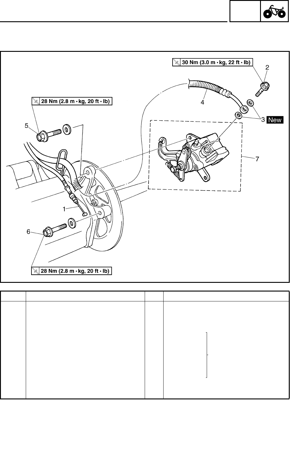
4 - 31
CHAS
FRONT AND REAR BRAKES
REAR BRAKE CALIPER
Order Job name/Part name Q’ty Remarks
Removing the rear brake caliper Remove the parts in the order below.
Brake fluid Drain.
1 Parking brake cable 1 Disconnect.
2 Union bolt 1
Refer to “INSTALLING
THE REAR BRAKE CALI-
PER”.
3 Copper washer 2
4 Brake hose 1 Disconnect.
5 Brake caliper mounting bolt 1
6 Brake caliper mounting bolt 1
7 Brake caliper assembly 1
For installation, reverse the removal pro-
cedure.
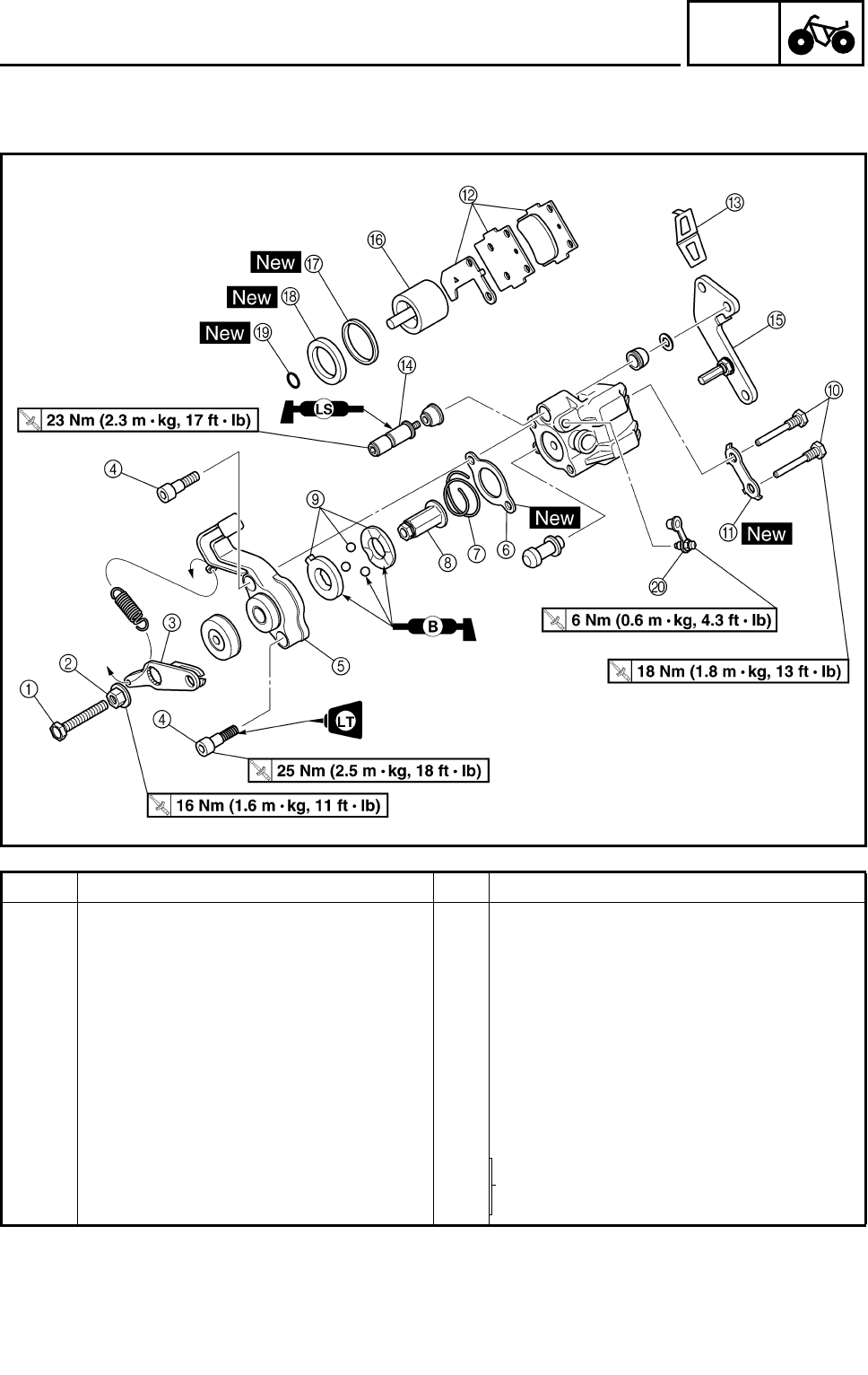
4 - 32
CHAS
FRONT AND REAR BRAKES
Order Job name/Part name Q’ty Remarks
Disassembling the rear brake caliper Remove the parts in the order below.
1 Adjusting bolt 1
2 Locknut 1
3 Parking brake lever 1
4 Parking brake case mounting bolt 2
5 Parking brake case 1
6 Gasket 1
7 Spring 1
8 Nut 1
9Bearing 1 Refer to “ASSEMBLING THE REAR
BRAKE CALIPER”.
0Brake pad holding bolt 2
ALock washer 1
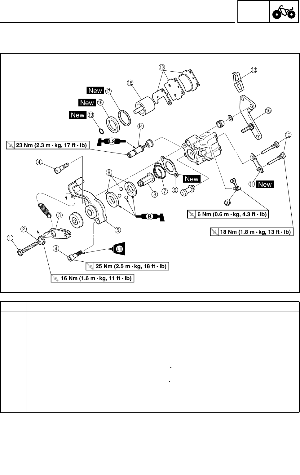
4 - 33
CHAS
FRONT AND REAR BRAKES
Order Job name/Part name Q’ty Remarks
B Brake pad/pad shim 2/1
C Brake pad spring 1
D Retaining bolt 1
E Caliper bracket 1
F Brake caliper piston 1 Refer to “DISASSEMBLING THE FRONT
AND REAR BRAKE CALIPER/ASSEM-
BLING THE REAR BRAKE CALIPER”.
G Dust seal 1
H Caliper piston seal 1
I O-ring 1
JBleed screw 1
For assembly, reverse the disassembly
procedure.
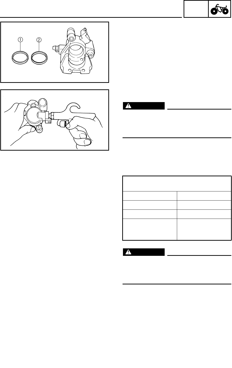
4 - 34
CHAS
FRONT AND REAR BRAKES
DISASSEMBLING THE FRONT AND REAR
BRAKE CALIPER
1.Remove:
●Brake caliper piston
●Dust seal 1
●Caliper piston seal 2
***********************************************
Removal steps:
●Blow compressed air into the hose joint
opening to force out the caliper piston from
the brake caliper body.
WARNING
●Never try to pry out the caliper piston.
●Cover the caliper piston with a rag. Be
careful not to get injured when the piston
is expelled from the master cylinder.
●Remove the caliper piston seals.
***********************************************
EB702040
CHECKING THE FRONT AND REAR BRAKE
CALIPER
WARNING
All internal brake components should be
cleaned in new brake fluid only. Do not use
solvents as they will cause seals to swell
and distort.
Recommended brake component
replacement schedule:
Brake pads As required
Piston seal, dust seal Every two years
Brake hoses Every two years
Brake fluid Replace when
brakes are disas-
sembled.
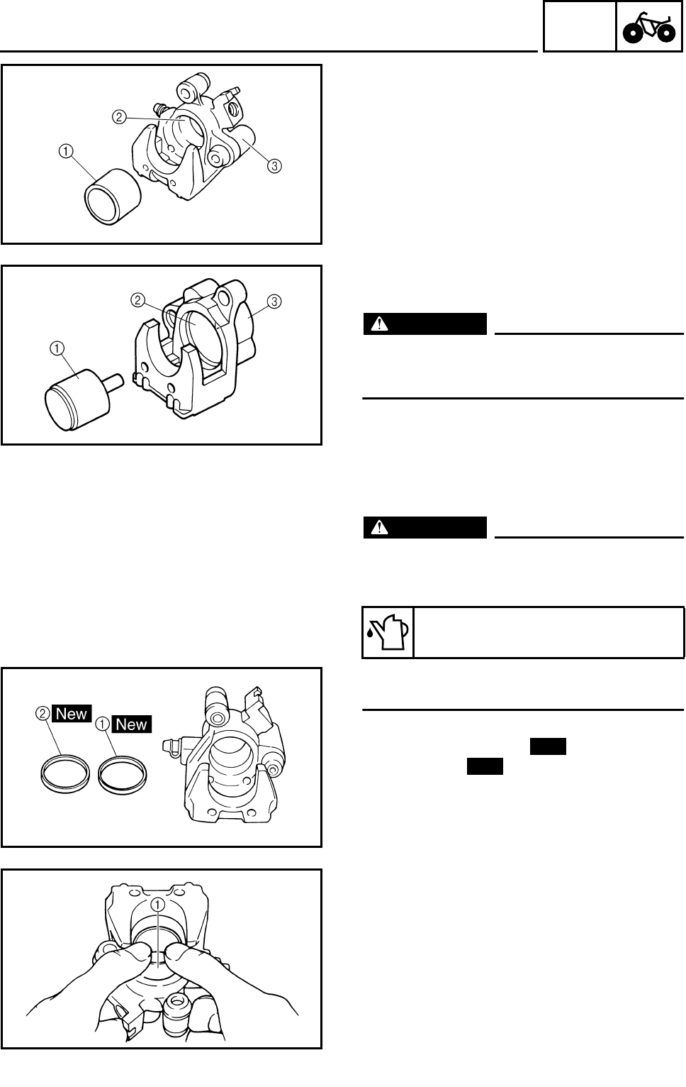
4 - 35
CHAS
FRONT AND REAR BRAKES
1.Check:
●Brake caliper piston 1
Scratches/rust/wear → Replace the brake
caliper assembly.
●Brake caliper cylinder 2
Wear/scratches → Replace the brake caliper
assembly.
●Brake caliper body 3
Cracks/damage → Replace.
●Brake fluid delivery passage (brake caliper
body)
Blockage → Blow out with compressed air.
WARNING
Replace the caliper piston seal and dust
seal whenever the brake caliper is disas-
sembled.
ÈFront
ÉRear
È
É
ASSEMBLING THE FRONT BRAKE
CALIPER
WARNING
●All internal brake components should be
cleaned and lubricated with new brake
fluid only before installation.
●Replace the caliper piston seal whenever
a brake caliper is disassembled.
1.Install:
●Caliper piston seal 1
●Dust seal 2
Recommended brake fluid:
DOT 4
New
New
2.Install:
●Brake caliper piston 1
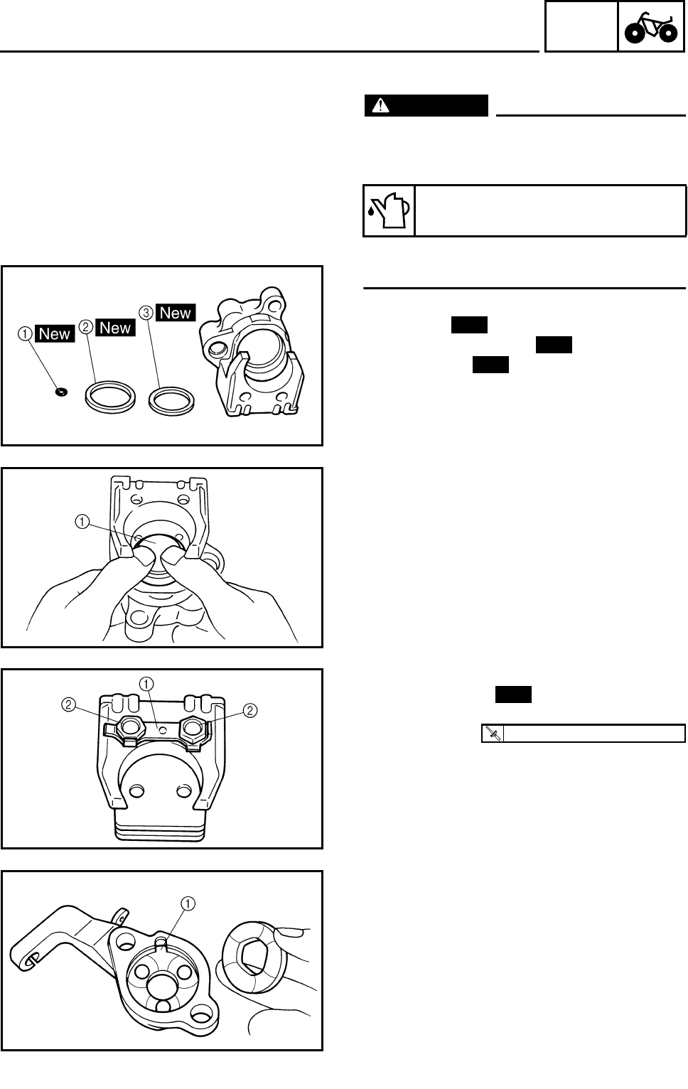
4 - 36
CHAS
FRONT AND REAR BRAKES
ASSEMBLING THE REAR BRAKE CALIPER
WARNING
●All internal brake components should be
cleaned and lubricated with new brake
fluid only before installation.
●Replace the caliper piston seal whenever
a brake caliper is disassembled.
1.Install:
●O-ring 1
●Caliper piston seal 2
●Dust seal 3
Recommended brake fluid:
DOT 4
New
New
New
2.Install:
●Brake caliper piston 1
3.Install:
●Lock washer 1
●Brake pad holding bolts 2
4.Bend the lock washer tabs along a flat side
of the bolts.
New
T
R
.
.
18 Nm (1.8 m • kg, 13 ft • lb)
5.Mesh the bearing race tab 1 with parking
brake case slit.
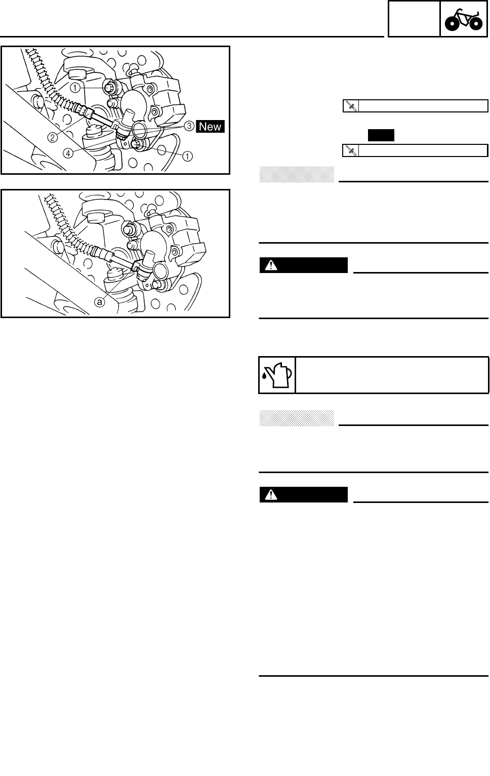
4 - 37
CHAS
FRONT AND REAR BRAKES
INSTALLING THE FRONT BRAKE CALIPER
1.Install:
●Brake caliper assembly
●Brake caliper mounting bolts 1
●Brake hose 2
●Copper washers 3
●Union bolt 4
CAUTION:
When installing the brake hose on the
brake caliper, make sure that the brake
pipe touches the projection a on the brake
caliper.
WARNING
Proper brake hose routing is essential to
insure safe motorcycle operation. Refer to
“CABLE ROUTING”.
2.Fill:
●Brake reservoir
CAUTION:
Brake fluid may damage painted surfaces
or plastic parts. Always clean up spilled
brake fluid immediately.
WARNING
●Use only the designated quality brake
fluid: Other brake fluids may deteriorate
the rubber seals, causing leakage and
poor brake performance.
●Refill with the same type of brake fluid:
Mixing brake fluids may result in a harm-
ful chemical reaction and lead to poor
brake performance.
●Be careful that water does not enter the
master cylinder when refilling. Water will
significantly lower the boiling point of the
brake fluid and may result in vapor lock.
3.Air bleed
●Brake system
Refer to “BLEEDING THE HYDRAULIC
BRAKE SYSTEM” in CHAPTER 3.
Recommended brake fluid:
DOT 4
T
R
.
.
28 Nm (2.8 m • kg, 20 ft • lb)
New
T
R
.
.
27 Nm (2.7 m • kg, 19 ft • lb)
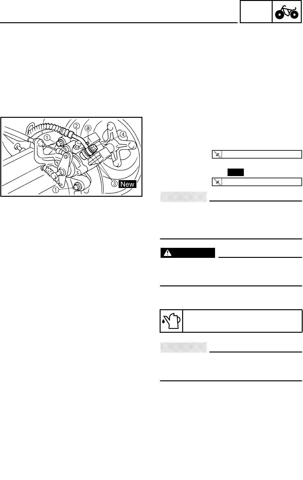
4 - 38
CHAS
4.Check:
●Brake fluid level
Brake fluid level is below the “LOWER” level
line → Add the recommended brake fluid to
the proper level.
Refer to “CHECKING THE BRAKE FLUID
LEVEL” in CHAPTER 3.
INSTALLING THE REAR BRAKE CALIPER
1.Install:
●Brake caliper assembly
●Brake caliper mounting bolts 1
●Brake hose 2
●Copper washers 3
●Union bolt 4
CAUTION:
When installing the brake hose on the
brake caliper, make sure that the brake
pipe touches the projection a on the brake
caliper.
WARNING
Proper brake hose routing is essential to
insure safe motorcycle operation. Refer to
“CABLE ROUTING”.
2.Fill:
●Brake reservoir
CAUTION:
Brake fluid may damage painted surfaces
or plastic parts. Always clean up spilled
brake fluid immediately.
Recommended brake fluid:
DOT 4
T
R
.
.
28 Nm (2.8 m • kg, 20 ft • lb)
New
T
R
.
.
30 Nm (3.0 m • kg, 22 ft • lb)
FRONT AND REAR BRAKES

4 - 39
CHAS
WARNING
●Use only the designated quality brake
fluid: Other brake fluids may deteriorate
the rubber seals, causing leakage and
poor brake performance.
●Refill with the same type of brake fluid:
Mixing brake fluids may result in a harmful
chemical reaction and lead to poor brake
performance.
●Be careful that water does not enter the
master cylinder when refilling. Water will
significantly lower the boiling point of the
brake fluid and may result in vapor lock.
3.Air bleed
●Brake system
Refer to “BLEEDING THE HYDRAULIC
BRAKE SYSTEM” in CHAPTER 3.
4.Check:
●Brake fluid level
Brake fluid level is below the “LOWER” level
line → Add the recommended brake fluid to
the proper level.
Refer to “CHECKING THE BRAKE FLUID
LEVEL” in CHAPTER 3.
5.Adjust:
●Parking brake cable end length
Refer to “ADJUSTING THE PARKING
BRAKE” in CHAPTER 3.
FRONT AND REAR BRAKES
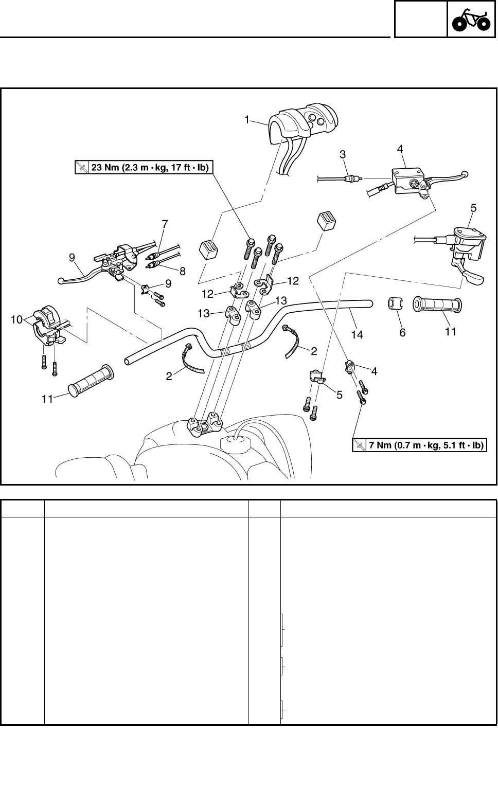
4 - 40
CHAS
STEERING SYSTEM
STEERING SYSTEM
HANDLEBAR
Order Job name/Part name Q’ty Remarks
Removing the handlebar Remove the parts in the order below.
1 Handlebar cover 1
2Band 2
3 Front brake switch 1 Refer to “REMOVING THE FRONT
BRAKE SWITCH, PARK SWITCH AND
CLUTCH SWITCH”.
4 Brake master cylinder/bracket 1/1 Refer to “INSTALLING THE BRAKE
MASTER CYLINDER”.
5 Throttle lever assembly/bracket 1/1
6 Collar 1
7 Park switch 1 Refer to “REMOVING THE FRONT
BRAKE SWITCH, PARK SWITCH AND
CLUTCH SWITCH”.
8 Clutch switch 1
9 Clutch lever/bracket 1/1 Refer to “INSTALLING THE CLUTCH
LEVER”.
10 Handlebar switch 1
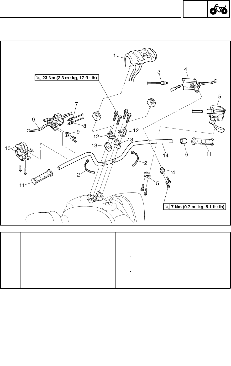
4 - 41
CHAS
STEERING SYSTEM
Order Job name/Part name Q’ty Remarks
11 Handlebar grip 2 Refer to “REMOVING/INSTALLING THE
HANDLEBAR GRIP”.
12 Handlebar cover bracket 2 Refer to “INSTALLING THE HANDLE-
BAR”.
13 Handlebar holder 2
14 Handlebar 1
For installation, reverse the removal pro-
cedure.
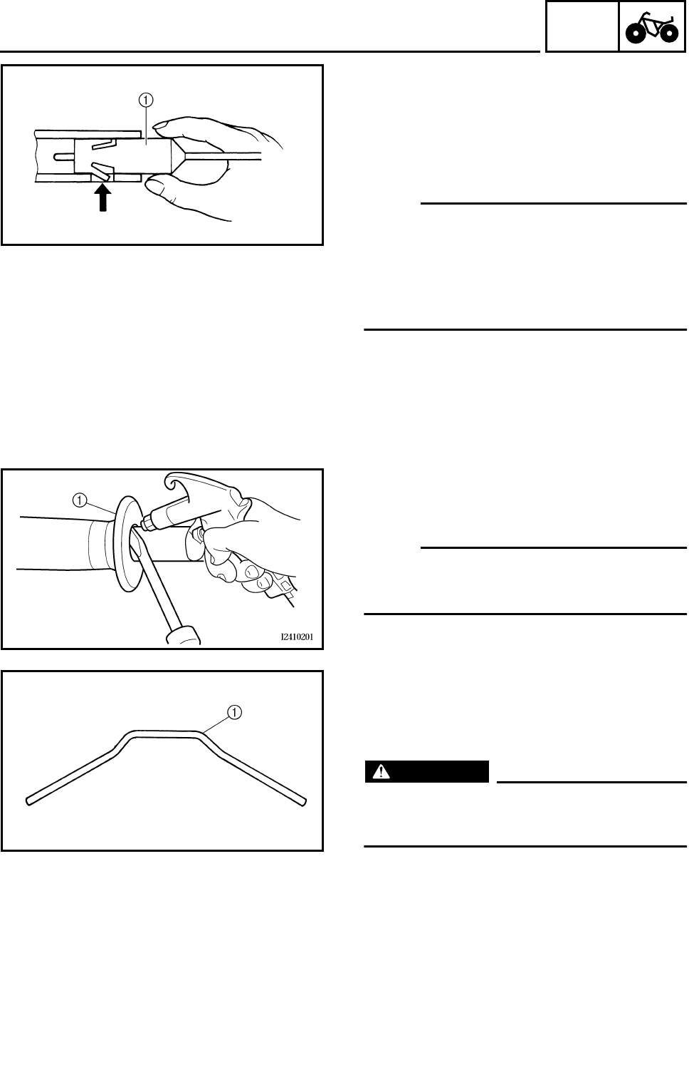
4 - 42
CHAS
STEERING SYSTEM
REMOVING THE FRONT BRAKE SWITCH,
PARK SWITCH AND CLUTCH SWITCH
1.Remove:
●Front brake switch 1
●Park switch
●Clutch switch
NOTE:
●Push the fastener when removing the front
brake switch out of the brake master cylin-
der.
●Push the fastener when removing the park
switch and clutch switch out of the clutch
lever holder.
REMOVING THE HANDLEBAR GRIP
1.Remove:
●Handlebar grips 1
NOTE:
Blow compressed air between the handlebar
and handlebar grip, and gradually push the
grip off the handlebar.
CHECKING THE HANDLEBAR
1.Check:
●Handlebar 1
Bends/cracks/damage → Replace.
WARNING
Do not attempt to straighten a bent handle-
bar as this may dangerously weaken the
handlebar.
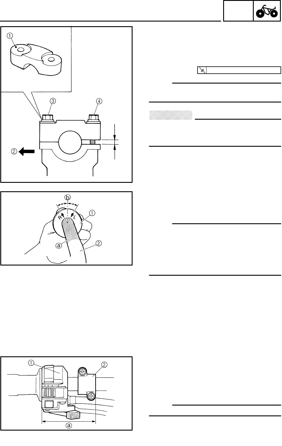
4 - 43
CHAS
STEERING SYSTEM
INSTALLING THE HANDLEBAR
1.Install:
●Handlebar
●Handlebar holders
●Handlebar cover brackets
NOTE:
The upper handlebar holder should be
installed with the punched mark 1 forward 2.
CAUTION:
First tighten the bolts 3 on the front side of
the handlebar holder, and then tighten the
bolts 4 on the rear side.
T
R
.
.
23 Nm (2.3 m • kg, 17 ft • lb)
INSTALLING THE HANDLEBAR GRIP
1.Install:
●Handlebar grips 1
NOTE:
●Before applying the adhesive, wipe off
grease or oil on the handlebar surface a
with a lacquer thinner.
●Install the handlebar grips to the handlebar
so that the line b between the two arrow
marks faces straight upward.
INSTALLING THE CLUTCH LEVER
1.Install:
●Handlebar switch 1
●Clutch lever
●Lever bracket 2
NOTE:
Install the lever bracket as shown.
a80 mm (3.1 in)
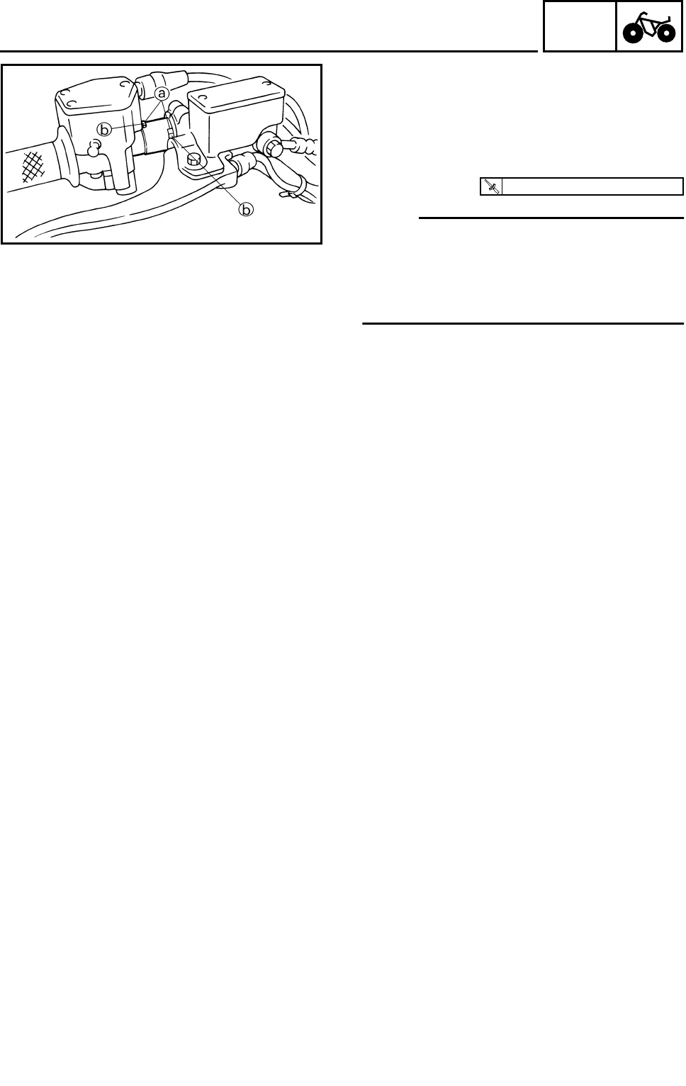
4 - 44
CHAS
INSTALLING THE BRAKE MASTER
CYLINDER
1.Install:
●Throttle lever assembly
●Collar
●Brake master cylinder
NOTE:
●Engage the indentations a in the collar with
the lobes b on the throttle lever assembly
and brake master cylinder.
●The “UP” mark on the brake master cylinder
bracket should face up.
T
R
.
.
7 Nm (0.7 m • kg, 5.1 ft • lb)
STEERING SYSTEM
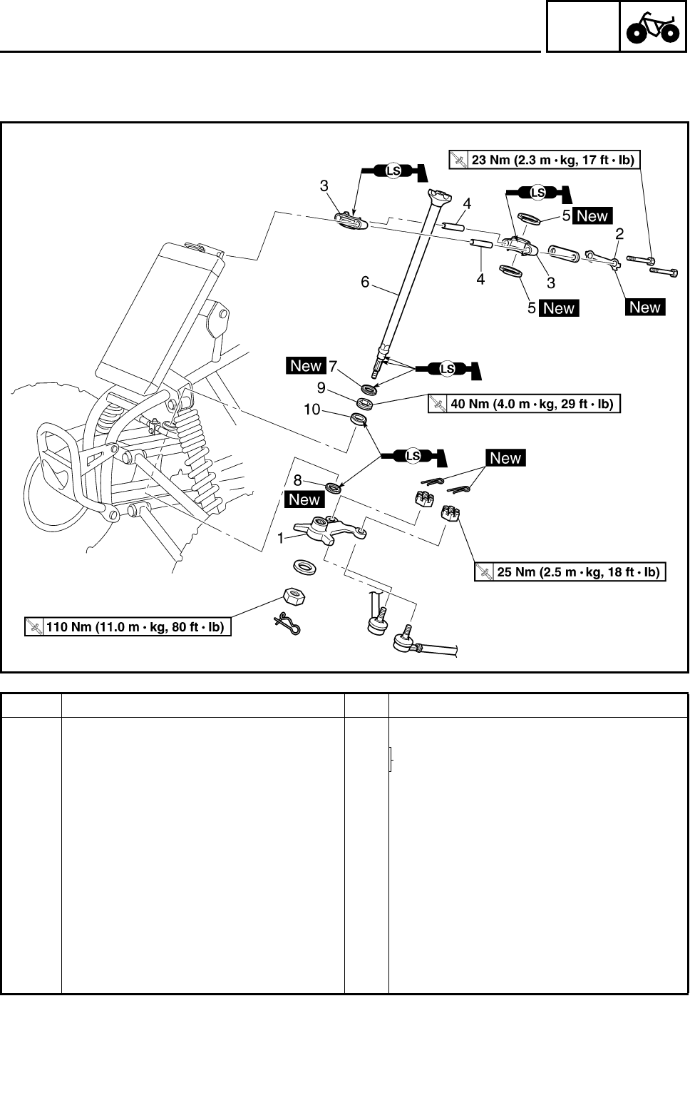
4 - 45
CHAS
STEERING SYSTEM
STEERING STEM
Order Job name/Part name Q’ty Remarks
Removing the steering stem Remove the parts in the order below.
Front fender Refer to “SEAT, FENDERS AND FUEL
TANK” in CHAPTER 3.
Fuel tank
Handlebar Refer to “HANDLEBAR”.
1 Pitman arm 1
2 Lock washer 1 Refer to “INSTALLING THE LOCK
WASHER”.
3 Steering stem bushing 2
4 Collar 2
5 Oil seal 2
6 Steering stem 1
7 Oil seal 1
8 Oil seal 1
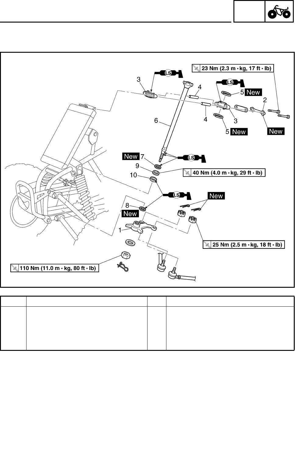
4 - 46
CHAS
STEERING SYSTEM
Order Job name/Part name Q’ty Remarks
9 Bearing retainer 1 Refer to “REMOVING/INSTALLING THE
BEARING RETAINER”.
10 Bearing 1
For installation, reverse the removal pro-
cedure.
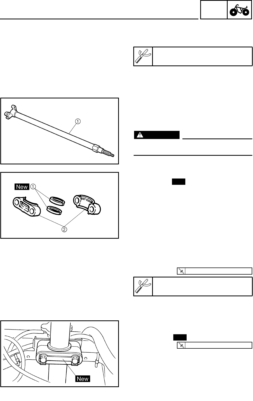
4 - 47
CHAS
STEERING SYSTEM
REMOVING THE BEARING RETAINER
1.Remove:
●Bearing retainer (steering stem)
Damper rod holder:
P/N. YM-01327, 90890-01327
CHECKING THE STEERING STEM
1.Check:
●Steering stem 1
Bends → Replace.
WARNING
Do not attempt to straighten a bent stem;
this may dangerously weaken the stem.
2.Check:
●Oil seals 1
●Steering stem bushings 2
Wear/damage → Replace.
New
INSTALLING THE BEARING RETAINER
1.Install:
●Bearing retainer (steering stem)
Damper rod holder:
P/N. YM-01327, 90890-01327
T
R
.
.
40 Nm (4.0 m • kg, 29 ft • lb)
INSTALLING THE LOCK WASHER
1.Install:
●Lock washer
2.Bend the lock washer tab along a flat side of
the bolt.
New
T
R
.
.
23 Nm (2.3 m • kg, 17 ft • lb)
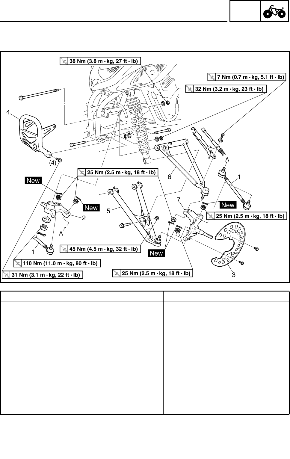
4 - 48
CHAS
STEERING SYSTEM
TIE-ROD AND STEERING KNUCKLE
Order Job name/Part name Q’ty Remarks
Removing the tie-rod and steering
knuckle Remove the parts in the order below.
Front wheel/brake disc Refer to “FRONT WHEELS”.
1 Tie-rod 2 Refer to “INSTALLING THE TIE-ROD”.
2 Pitman arm 1
3 Brake disc guard (inner) 1
4 Front bumper 1
5 Front arm (lower) 1
6 Front arm (upper) 1
7 Steering knuckle 1 Refer to “REMOVING THE STEERING
KNUCKLE”.
For installation, reverse the removal pro-
cedure.
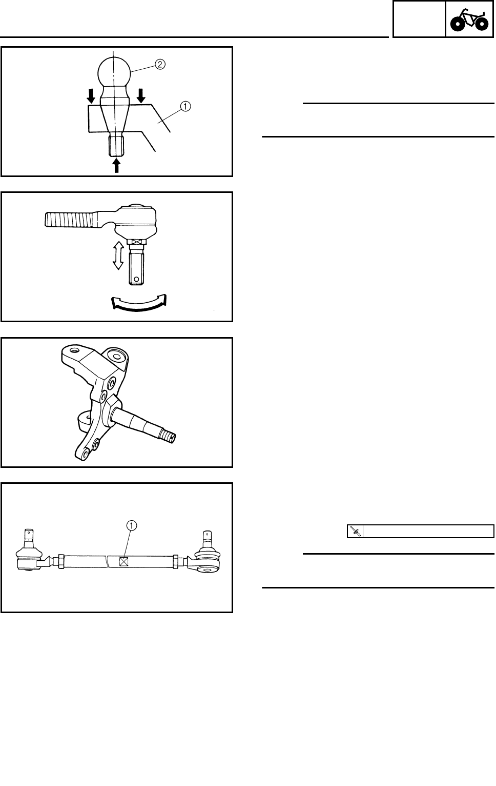
4 - 49
CHAS
STEERING SYSTEM
REMOVING THE STEERING KNUCKLE
1.Remove:
●Steering knuckle 1
NOTE:
Use a general puller to separate the ball joint
2 and steering knuckle.
CHECKING THE TIE-ROD
1.Check:
●Tie-rod free play and movement
Free play → Replace the tie-rod end.
Turns roughly → Replace the tie-rod end.
2.Check:
●Tie-rod
●Bends/damage → Replace.
CHECKING THE STEERING KNUCKLE
1.Check:
●Steering knuckle
Damage/pitting → Replace.
INSTALLING THE TIE-ROD
1.Install:
●Tie-rods (left and right)
NOTE:
The tie-rod which must be installed on the out
side has grooves 1.
T
R
.
.
25 Nm (2.5 m • kg, 18 ft • lb)
2.Adjust:
●Toe-in
Refer to “ADJUSTING THE TOE-IN” in
CHAPTER 3.
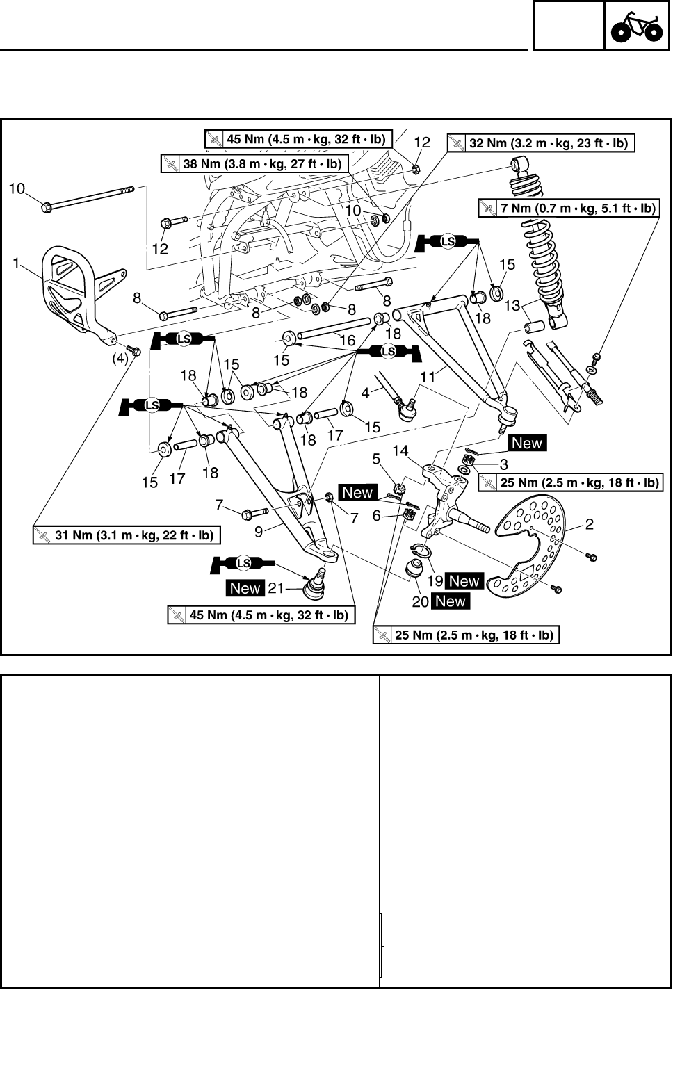
4 - 50
CHAS
FRONT ARMS AND FRONT SHOCK ABSORBERS
FRONT ARMS AND FRONT SHOCK ABSORBERS
Order Job name/Part name Q’ty Remarks
Removing the front arm and front
shock absorber Remove the parts in the order below.
Front wheel/brake disc Refer to “FRONT WHEELS”.
1 Front bumper 1
2 Brake disc guard (inner) 1
3Nut 1
4 Tie-rod 1 Disconnect.
5Nut 1
6Nut 1
7 Nut/bolt 1/1
8 Nut/bolt 2/2
Refer to “REMOVING/INSTALLING THE
FRONT ARMS”.
9 Front arm (lower) 1
10 Nut/bolt 1/1
11 Front arm (upper) 1

4 - 51
CHAS
FRONT ARMS AND FRONT SHOCK ABSORBERS
Order Job name/Part name Q’ty Remarks
12 Nut/bolt 1/1
13 Front shock absorber/collar 1/1
14 Steering knuckle 1
15 Dust cover 6
16 Collar 1
17 Collar 2
18 Bushing 6
19 Circlip 1
20 Rubber boot 1
21 Ball joint 1
For installation, reverse the removal pro-
cedure.
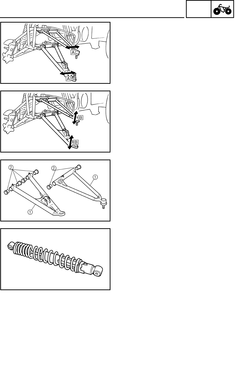
4 - 52
CHAS
FRONT ARMS AND FRONT SHOCK ABSORBERS
REMOVING THE FRONT ARM
1.Check:
●Front arm free play
***********************************************
Checking steps:
●Check the front arm side play È by moving it
from side to side.
If side play is noticeable, check the bushings.
●Check the front arm vertical movement É by
moving it up and down.
If the vertical movement is tight or rough, or if
there is binding, check the bushings.
***********************************************
2.Remove:
●Front arms
CHECKING THE FRONT ARM
1.Check:
●Front arms 1
Bends/damage → Replace.
2.Check:
●Bushings 2
Wear/damage → Replace.
CHECKING THE FRONT SHOCK
ABSORBER
1.Check:
●Shock absorber rod
Bends/damage → Replace the shock
absorber assembly.
●Shock absorber assembly
Oil leaks → Replace the shock absorber
assembly.
●Spring
Fatigue → Replace the shock absorber
assembly.
Move the spring up and down.
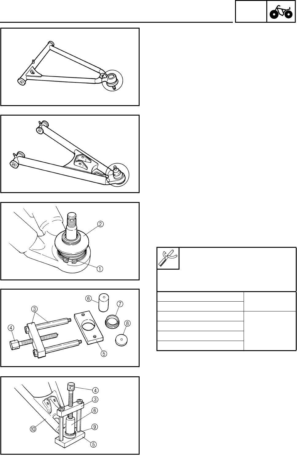
4 - 53
CHAS
FRONT ARMS AND FRONT SHOCK ABSORBERS
CHECKING THE BALL JOINT
1.Check:
●Ball joint (front arm-upper)
Damage/pitting → Replace the front arm
(upper).
Free play → Replace the front arm.
Turns roughly → Replace the front arm
(upper).
2.Check:
●Ball joint (front arm-lower)
Damage/pitting → Replace the ball joint.
Free play → Replace the ball joint.
Turns roughly → Replace the ball joint.
***********************************************
Ball joint replacement steps:
●Clean the outside of the front lower arm.
●Remove the circlip 1 and rubber boot 2.
Use the ball joint remover and installer set.
●Install the body 3, long bolt 4, base 5 and
attachment 6 onto ball joint.
●Hold the body 3 in place while turning in the
long bolt 4 to remove the ball joint 9 from
the front lower arm 0.
●Remove the ball joint remover/installer.
Ball joint remover/installer set:
P/N. YM-01474, 90890-01474
Ball joint remover/installer attach-
ment set:
P/N. YM-01480, 90890-01480
3Body YM-01474
90890-01474
4Long bolt
5Base
YM-01480
90890-01480
6Remover attachment
7Installer spacer
8Installer washer
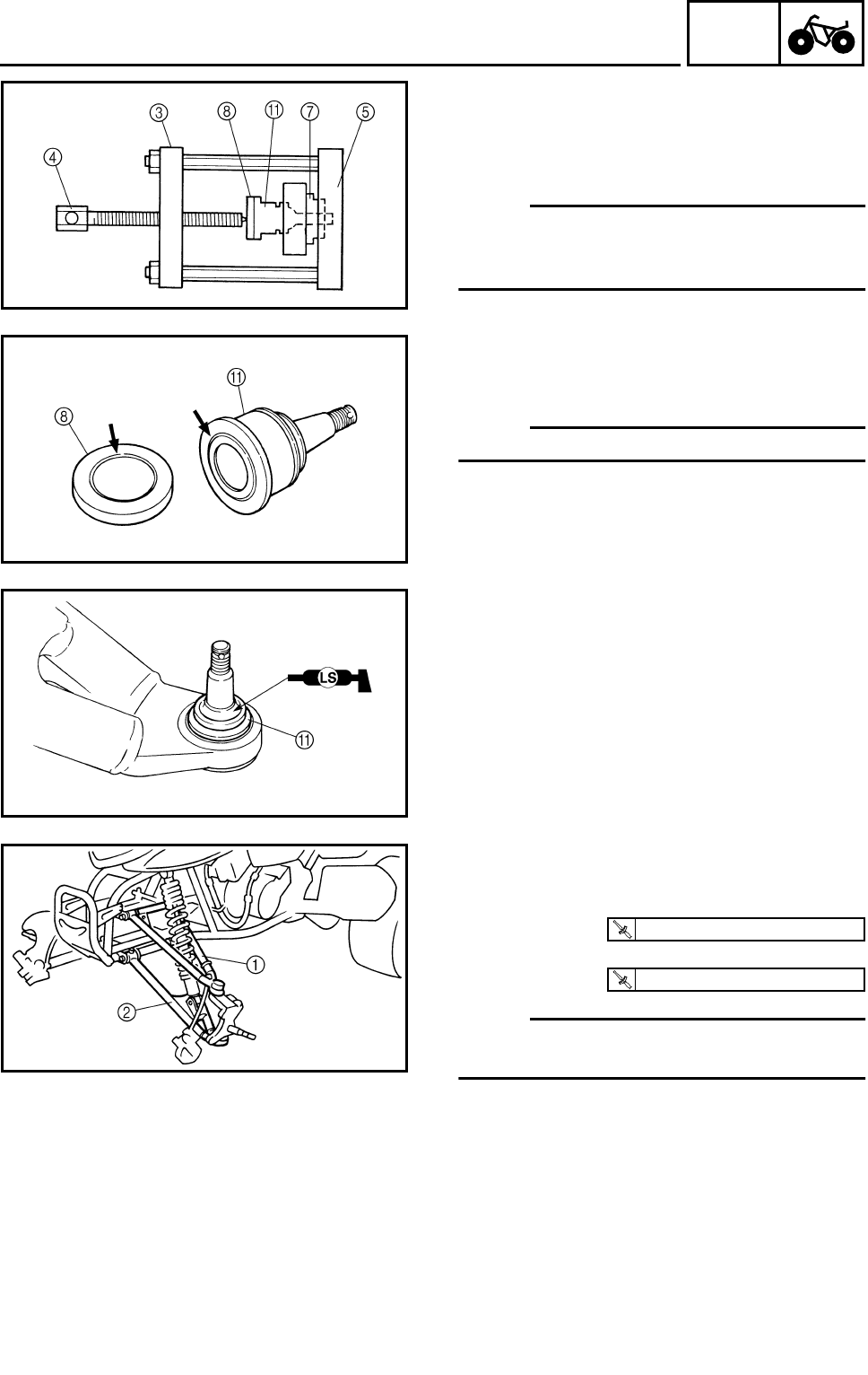
4 - 54
CHAS
●Attach the assembled ball joint remover/
installer, new ball joint A, installer spacer 7
and installer washer 8 to the front lower arm
0.
NOTE:
●Do not tap or damage the top of the ball joint.
●Installer spacer 7 must be aligned with the
projection on the head of the ball joint A.
●Remove the ball joint remover/installer.
●Apply lithium-soap base grease to the new
ball joint A.
●Install a new rubber boot and new circlip.
NOTE:
Always use a new ball joint set.
***********************************************
INSTALLING THE FRONT ARM
1.Install:
●Front upper arm 1
●Front lower arm 2
NOTE:
Be sure to position the bolts (upper and lower)
so that the bolt head faces outward.
T
R
.
.
38 Nm (3.8 m • kg, 27 ft • lb)
T
R
.
.
32 Nm (3.2 m • kg, 23 ft • lb)
FRONT ARMS AND FRONT SHOCK ABSORBERS
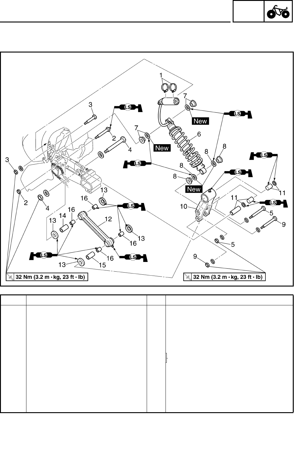
4 - 55
CHAS
REAR SHOCK ABSORBER AND RELAY ARM
REAR SHOCK ABSORBER AND RELAY ARM
Order Job name/Part name Q’ty Remarks
Removing the rear shock absorber
and relay arm Remove the parts in the order below.
Rear wheels and hub Refer to “REAR WHEELS, WHEEL AXLE
AND HUB”.
1 Metal screw clamp 2
2 Self-locking nut/bolt 1/1 Refer to “REMOVING THE REAR
SHOCK ABSORBER”.
3 Self-locking nut/bolt 1/1
4 Self-locking nut/bolt 1/1
5 Self-locking nut/bolt 1/1
6 Rear shock absorber 1
7 Collar/oil seal 2/2
8 Collar/oil seal 2/2

4 - 56
CHAS
REAR SHOCK ABSORBER AND RELAY ARM
Order Job name/Part name Q’ty Remarks
9 Self-locking nut/bolt 1/1
10 Relay arm 1
11 Spacer/oil seal/bushing 1/2/2 Refer to “INSTALLING THE RELAY ARM
AND CONNECTING ARM”.
12 Connecting arm 1
13 Dust cover 4
14 Spacer 1
15 Spacer 1
16 Bushing 4 Refer to “INSTALLING THE RELAY ARM
AND CONNECTING ARM”.
For installation, reverse the removal pro-
cedure.
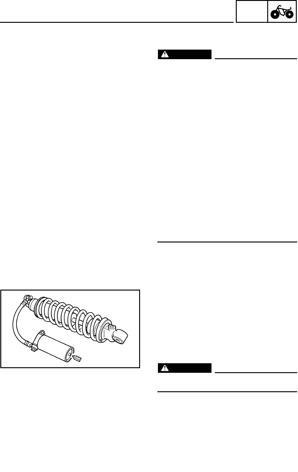
4 - 57
CHAS
REAR SHOCK ABSORBER AND RELAY ARM
HANDLING THE REAR SHOCK ABSORBER
AND GAS CYLINDER
WARNING
This rear shock absorber and gas cylinder
contain highly compressed nitrogen gas.
Before handling the rear shock absorber or
gas cylinder, read and make sure you
understand the following information. The
manufacturer cannot be held responsible
for property damage or personal injury that
may result from improper handling of the
rear shock absorber and gas cylinder.
●Do not tamper or attempt to open the rear
shock absorber or gas cylinder.
●Do not subject the rear shock absorber or
gas cylinder to an open flame or any
other source of high heat. High heat can
cause an explosion due to excessive gas
pressure.
●Do not deform or damage the rear shock
absorber or gas cylinder in any way. If the
rear shock absorber, gas cylinder or both
are damaged, damping performance will
suffer.
DISPOSING OF A REAR SHOCK
ABSORBER AND GAS CYLINDER
Gas pressure must be released before dispos-
ing of a rear shock absorber and gas cylinder.
To release the gas pressure, press on the gas
valve needle with a suitable tool as shown,
until all of the gas is released (the hissing has
stopped).
WARNING
Wear eye protection to prevent eye damage
from released gas or metal chips.
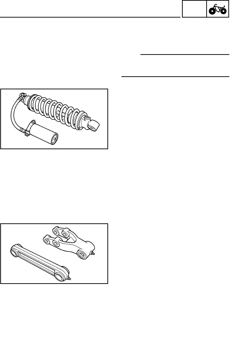
4 - 58
CHAS
REAR SHOCK ABSORBER AND RELAY ARM
REMOVING THE REAR SHOCK ABSORBER
1.Remove:
●Connecting arm-to-frame bolt
●Rear shock absorber upper bolt
NOTE:
While removing the connecting arm-to-frame
bolt, hold the swingarm so that it does not drop
down.
CHECKING THE REAR SHOCK ABSORBER
1.Check:
●Shock absorber
Oil leaks → Replace the rear shock absorber
assembly.
●Shock absorber rod
Bends/damage → Replace the rear shock
absorber assembly.
●Spring
Fatigue → Replace the rear shock absorber
assembly.
Move the spring up and down.
●Gas cylinder
Damage/gas leaks → Replace the rear
shock absorber assembly.
CHECKING THE RELAY ARM AND
CONNECTING ARM
1.Check:
●Relay arm
●Connecting arm
Damage/wear → Replace.
●Bushings
●Spacers
●Oil seals
Damage/pitting/scratches → Replace.
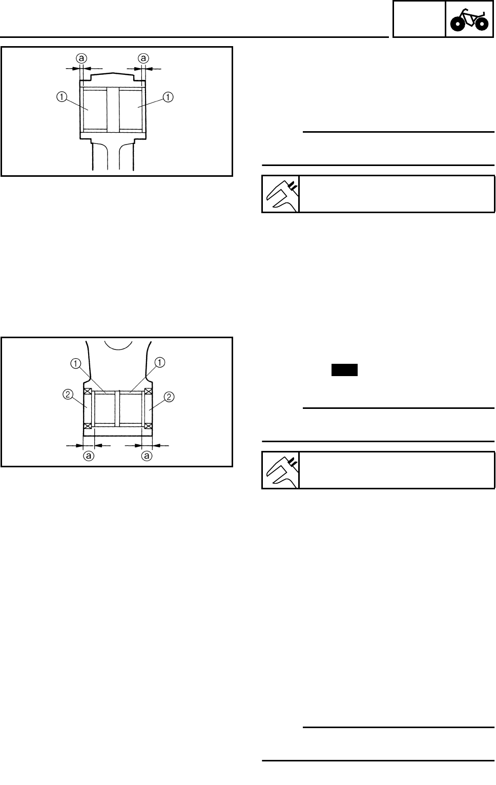
4 - 59
CHAS
REAR SHOCK ABSORBER AND RELAY ARM
INSTALLING THE RELAY ARM AND
CONNECTING ARM
1.Install:
●Bushing 1
(to connecting arm)
NOTE:
Apply the lithium soap base grease on the
bushing when installing.
Installed depth of bushing a:
1 mm (0.04 in)
2.Install:
●Bushing 1
●Oil seal 2
(to relay arm)
NOTE:
Apply the lithium soap base grease on the
bushing when installing.
Installed depth of bushing a:
6.5 mm (0.26 in)
New
INSTALLING THE REAR SHOCK
ABSORBER
1.Install:
●Connecting arm
●Relay arm
●Rear shock absorber
NOTE:
When installing the rear shock absorber, lift up
the swingarm.

4 - 60
CHAS
SWINGARM AND DRIVE CHAIN
SWINGARM AND DRIVE CHAIN
Order Job name/Part name Q’ty Remarks
Removing the swingarm and drive
chain Remove the parts in the order below.
Rear wheels and hub Refer to “REAR WHEELS, WHEEL AXLE
AND HUB”.
Rear shock absorber Refer to “REAR SHOCK ABSORBER
AND RELAY ARM”.
Left footrest and left footrest guard
bracket Refer to “ENGINE REMOVAL” in CHAP-
TER 5.
1 Adjusting bolt/nut 2/2
2 Swingarm skid plate 1
3 Drive chain guide 1
4 Pivot shaft nut/washer 1/1
5 Pivot shaft 1
6 Swingarm 1 Refer to “REMOVING THE SWINGARM”.
7 Drive sprocket cover 1
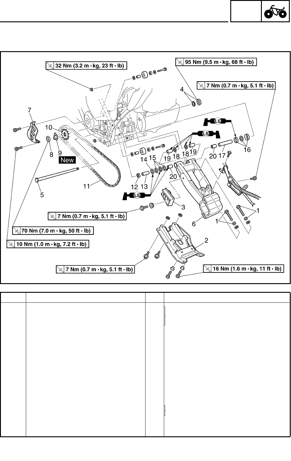
4 - 61
CHAS
SWINGARM AND DRIVE CHAIN
Order Job name/Part name Q’ty Remarks
8Nut 1
Refer to “INSTALLING THE DRIVE
SPROCKET”.
9 Lock washer 1
10 Drive sprocket 1
11 Drive chain 1
12 Collar 1
13 Spacer 1
14 Oil seal 1
15 Bearing 1
16 Dust cover/oil seal/washer 1/1/1
17 Spacer 1
18 Oil seal 2
19 Bushing 2 Refer to “INSTALLING THE SWING-
ARM”.
20 Bearing 2
For installation, reverse the removal pro-
cedure.
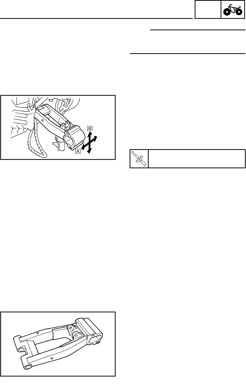
4 - 62
CHAS
SWINGARM AND DRIVE CHAIN
NOTE:
Before removing the drive chain and the
sprockets, measure the drive chain slack and
a ten link section of the drive chain.
REMOVING THE SWINGARM
1.Check:
●Swingarm free play
***********************************************
Checking steps:
●Check the tightening torque of the pivot shaft
nut.
●Check the swingarm side play È by moving
it from side to side.
If side play is noticeable, check the collar,
spacers, bearings, bushings and frame pivot.
●Check the swingarm vertical movement É
by moving it up and down.
If vertical movement is tight or rough, or if
there is binding, check the collar, spacers,
bearings, bushings and frame pivot.
***********************************************
2.Remove:
●Pivot shaft nut
●Pivot shaft
●Swingarm
T
R
.
.
Pivot shaft nut:
95 Nm (9.5 m • kg, 68 ft • lb)
CHECKING THE SWINGARM
1.Check:
●Swingarm
Bends/cracks/damage → Replace.
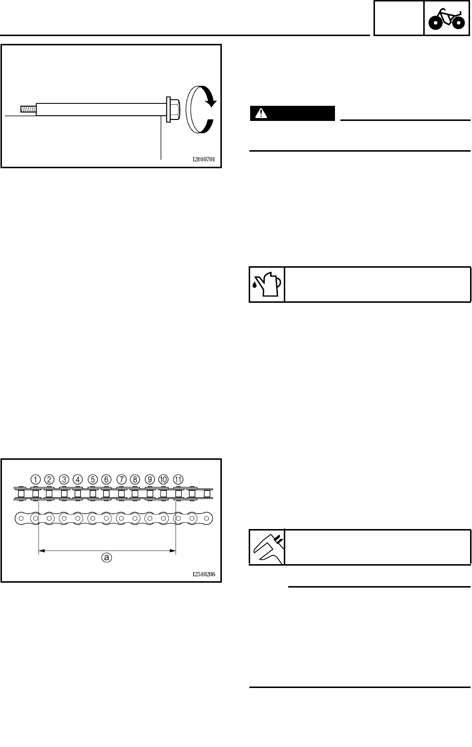
4 - 63
CHAS
SWINGARM AND DRIVE CHAIN
2.Check:
●Pivot shaft
Roll the axle on a flat surface.
Bends → Replace.
WARNING
Do not attempt to straighten a bent pivot
shaft.
3.Clean:
●Pivot shaft
●Collar
●Spacers
●Bearings
●Bushings
4.Check:
●Spacers
●Oil seals
Damage/wear → Replace.
●Bearings
●Bushings
Damage/pitting → Replace.
Recommended cleaning solvent:
Kerosine
CHECKING THE DRIVE CHAIN
1.Measure:
●Ten-link section a of the drive chain
Out of specification → Replace the drive
chain.
NOTE:
●While measuring the ten-link section, push
down on the drive chain to increase its ten-
sion.
●Measure the length between drive chain
roller 1 and A as shown.
●Perform this measurement at two or three
different places.
Max. ten-link drive chain section:
150.1 mm (5.91 in)
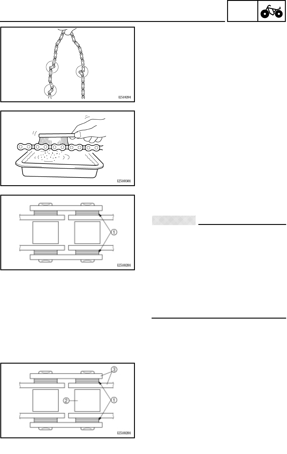
4 - 64
CHAS
SWINGARM AND DRIVE CHAIN
2.Check:
●Drive chain
Stiffness → Clean and lubricate or replace.
3.Clean:
●Drive chain
***********************************************
●Wipe the drive chain with a clean cloth.
●Put the drive chain in kerosine and remove
any remaining dirt.
●Remove the drive chain from the kerosine
and completely dry it.
CAUTION:
This machine has a drive chain with small
rubber O-rings 1 between the drive chain
side plates. Never use high-pressure water
or air, steam, gasoline, certain solvents
(e.g., benzine), or a coarse brush to clean
the drive chain. High-pressure methods
could force dirt or water into the drive
chain’s internals, and solvents will deterio-
rate the O-rings. A coarse brush can also
damage the O-rings. Therefore, use only
kerosine to clean the drive chain.
***********************************************
4.Check:
●O-rings 1
Damage → Replace the drive chain.
●Drive chain rollers 2
Damage/wear → Replace the drive chain.
●Drive chain side plates 3
Cracks/damage/wear → Replace the drive
chain.
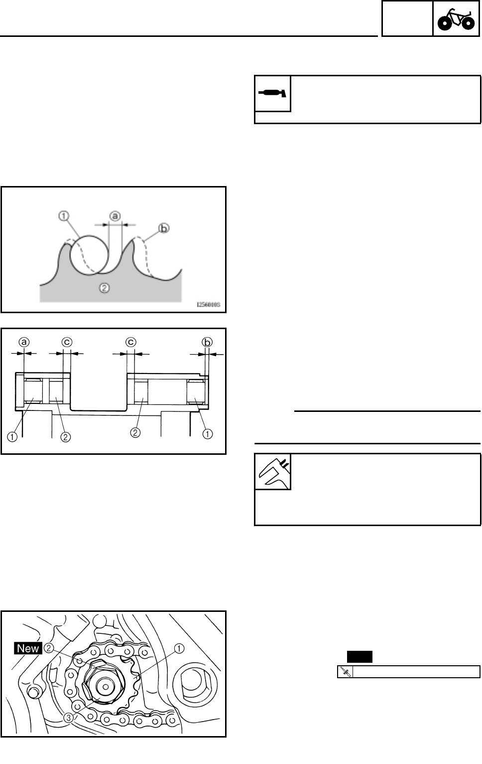
4 - 65
CHAS
SWINGARM AND DRIVE CHAIN
5.Lubricate:
●Drive chain
Recommended lubricant:
Engine oil or chain lubricant
suitable for O-ring chains
6.Check:
●Drive sprocket
●Driven sprocket
More than 1/4 tooth a wear → Replace the
drive chain sprockets as a set.
Bent teeth → Replace the drive chain
sprockets as a set.
bCorrect
1Drive chain roller
2Drive chain sprocket
INSTALLING THE SWINGARM
1.Install:
●Bearings 1
●Bushings 2
(to swingarm)
NOTE:
Apply the lithium soap base grease on the
bearing and bushing when installing.
Installed depth of bearing:
Left a: 0 mm (0 in)
Right b: 4 mm (0.16 in)
Installed depth of bushing c:
8 mm (0.31 in)
INSTALLING THE DRIVE SPROCKET
1.Install:
●Drive sprocket 1
●Lock washer 2
●Nut 3
2.Bend the lock washer tab along a flat side of
the nut.
New
T
R
.
.
70 Nm (7.0 m • kg, 50 ft • lb)
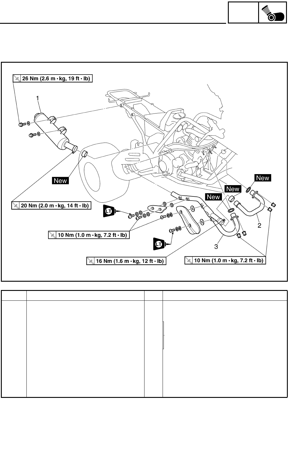
5 - 1
ENG
ENGINE REMOVAL
ENGINE
ENGINE REMOVAL
MUFFLER AND EXHAUST PIPES
Order Job name/Part name Q’ty Remarks
Removing the muffler and exhaust
pipes
Remove the parts in the order below.
Seat/left footrest guard/engine
Refer to “SEAT, FENDERS AND FUEL
TANK” in CHAPTER 3.
Skid plate
Front and rear fenders
Fuel tank and rubber covers
1 Muffler 1
2 Exhaust pipe 1 1
3 Exhaust pipe 2 1
For installation, reverse the removal pro-
cedure.
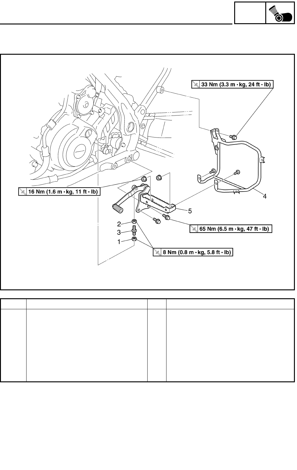
5 - 2
ENG
ENGINE REMOVAL
LEFT FOOTREST
Order Job name/Part name Q’ty Remarks
Removing the left footrest Remove the parts in the order below.
1 Locknut 1
2 Locknut 1 Left-hand threads
3 Adjusting rod 1
4 Left footrest guard bracket 1
5 Left footrest 1
For installation, reverse the removal pro-
cedure.

5 - 3
ENG
ENGINE REMOVAL
LEADS, CABLES AND HOSES
Order Job name/Part name Q’ty Remarks
Removing the leads, cables and
hoses
Remove the parts in the order below.
Engine oil Drain.
Coolant Drain.
Water jacket outlet pipe Refer to “THERMOSTAT” in CHAPTER 6.
Radiator outlet hose Refer to “WATER PUMP” in CHAPTER 6.
Carburetors Refer to “CARBURETORS” in CHAPTER
7.
Rear shock absorber and connecting
arm
Refer to “REAR SHOCK ABSORBER
AND RELAY ARM” in CHAPTER 4.
Drive sprocket and swingarm Refer to “SWINGARM AND DRIVE
CHAIN” in CHAPTER 4.
1 Spark plug cap 1
2 Starter motor lead 1
3 Band 1
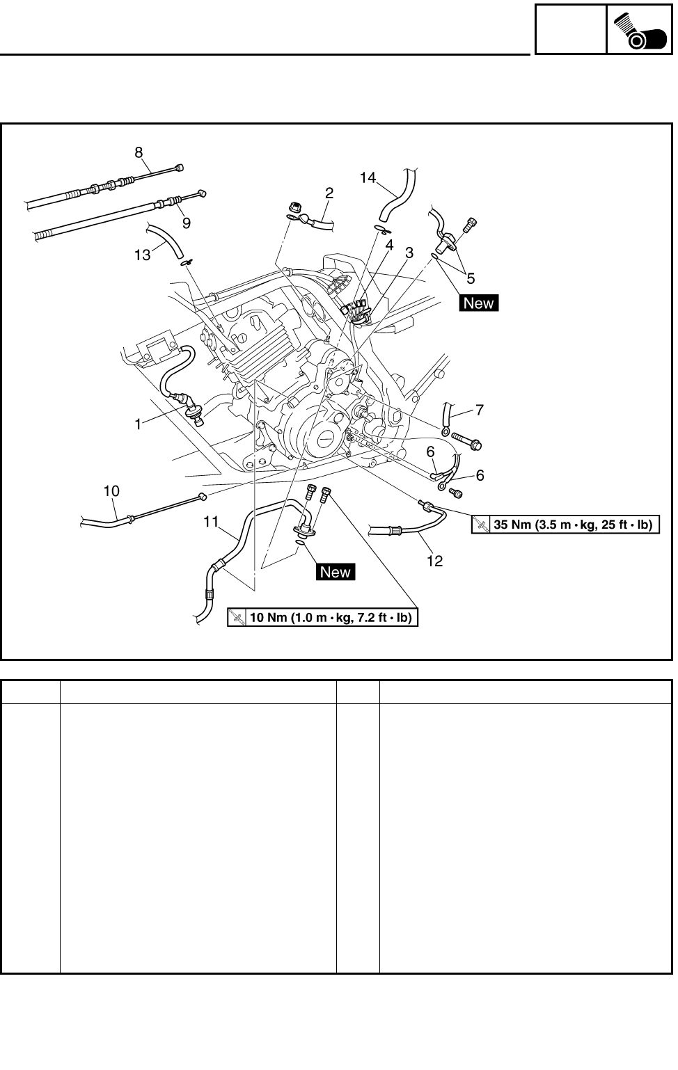
5 - 4
ENG
ENGINE REMOVAL
Order Job name/Part name Q’ty Remarks
4 Coupler 5 Disconnect.
5 Speed sensor/O-ring 1/1
6 Neutral switch lead/reverse switch lead 1/1
7 Ground lead 1
8 Clutch cable 1
9 Parking brake cable 1
10 Reverse control cable 1
11 Oil pipe 2 1 Disconnect.
12 Oil pipe 1 1 Disconnect.
13 Oil tank breather hose 1 Disconnect.
14 Crankcase breather hose 1 Disconnect.
For installation, reverse the removal pro-
cedure.
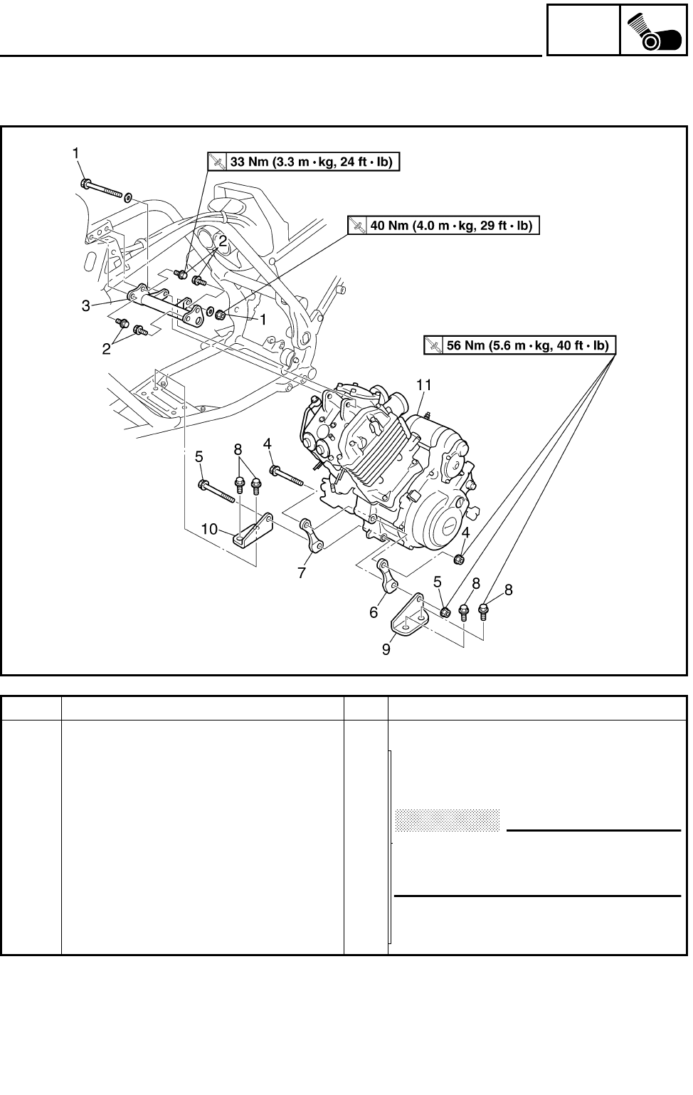
5 - 5
ENG
ENGINE REMOVAL
ENGINE MOUNTING BOLTS
Order Job name/Part name Q’ty Remarks
Removing the engine mounting bolt Remove the parts in the order below.
1 Engine mounting bolt (upper)/nut 1/1
2 Engine bracket bolt (upper) 4
CAUTION:
Install all of the bolts/nuts and then
tighten them to full torque specifica-
tions.
Refer to “INSTALLING THE ENGINE”.
3 Engine bracket (upper) 1
4 Engine mounting bolt (middle)/nut 1/1
5 Engine mounting bolt (lower)/nut 1/1
6 Engine bracket (middle-left) 1
7 Engine bracket (middle-right) 1
8 Engine bracket bolt (lower) 4
9 Engine bracket (lower-left) 1
10 Engine bracket (lower-right) 1
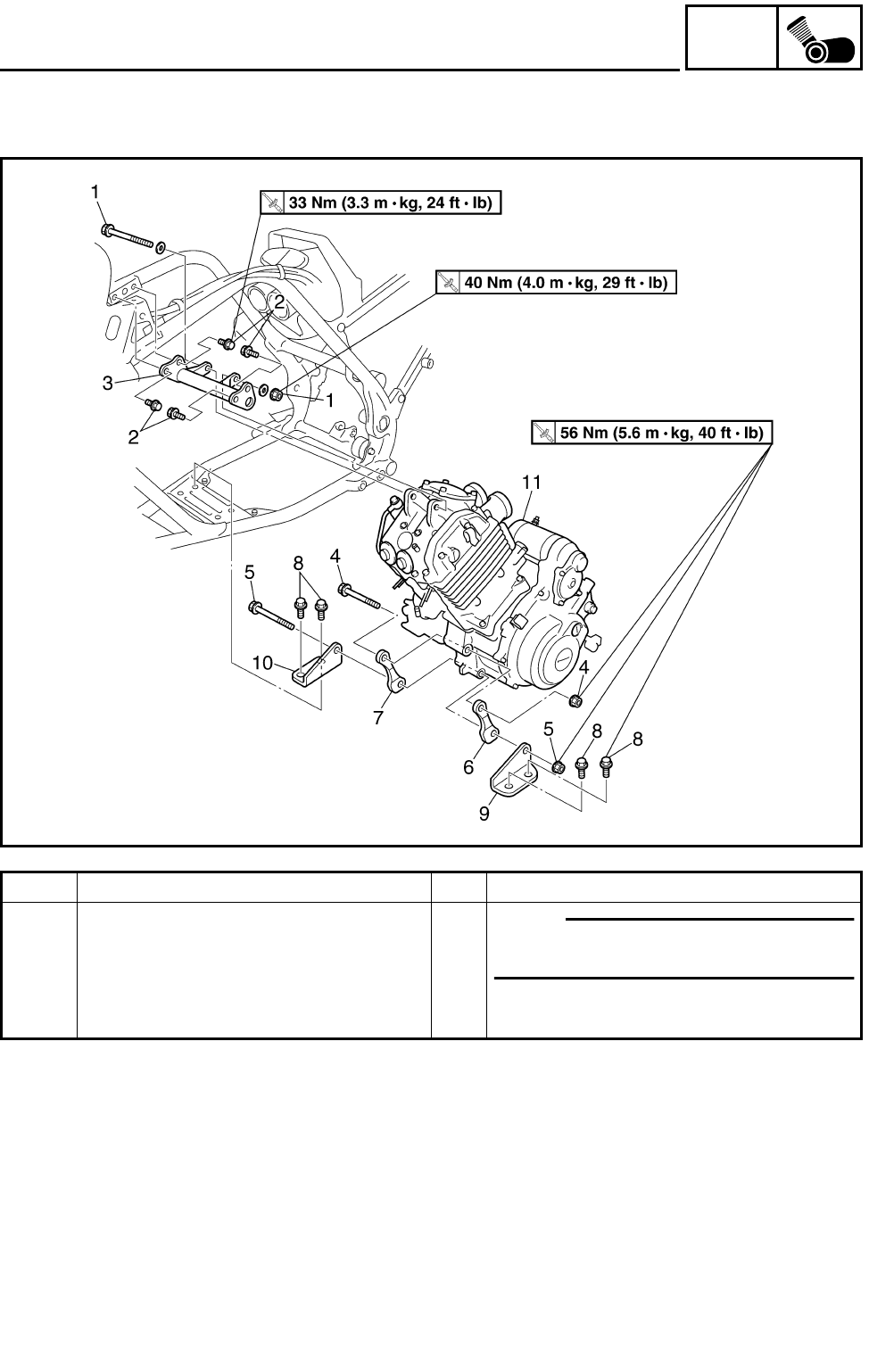
5 - 6
ENG
ENGINE REMOVAL
Order Job name/Part name Q’ty Remarks
11 Engine assembly 1 NOTE:
Remove the engine assembly from the
left side of the machine.
For installation, reverse the removal pro-
cedure.
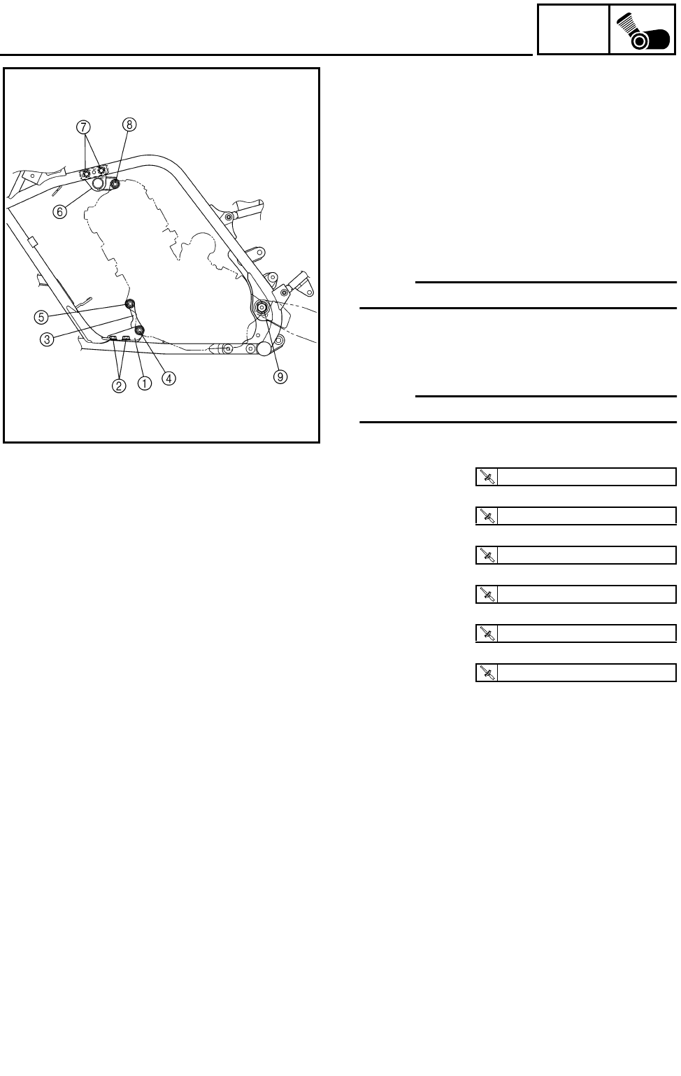
5 - 7
ENG
INSTALLING THE ENGINE
1.Install:
●Engine brackets (lower) 1
●Engine bracket bolts (lower) 2
●Engine brackets (middle) 3
●Engine mounting bolt (lower)/nut 4
●Engine mounting bolt (middle)/nut 5
●Engine bracket (upper) 6
●Engine bracket bolts (upper) 7
●Engine mounting bolt (upper)/nut 8
NOTE:
Do not fully tighten the bolts and nuts.
2.Install:
●Swingarm
●Pivot shaft/nut 9
NOTE:
Do not fully tighten the pivot shaft nut.
3.Tighten:
●Engine bracket bolt (lower) 2
●Engine bracket bolt (upper) 7
●Engine mounting bolt (lower)/nut 4
●Engine mounting bolt (middle)/nut 5
●Engine mounting bolt (upper)/nut 8
●Pivot shaft/nut 9
T
R
.
.
56 Nm (5.6 m • kg, 40 ft • lb)
T
R
.
.
33 Nm (3.3 m • kg, 24 ft • lb)
T
R
.
.
56 Nm (5.6 m • kg, 40 ft • lb)
T
R
.
.
56 Nm (5.6 m • kg, 40 ft • lb)
T
R
.
.
40 Nm (4.0 m • kg, 29 ft • lb)
T
R
.
.
95 Nm (9.5 m • kg, 68 ft • lb)
ENGINE REMOVAL
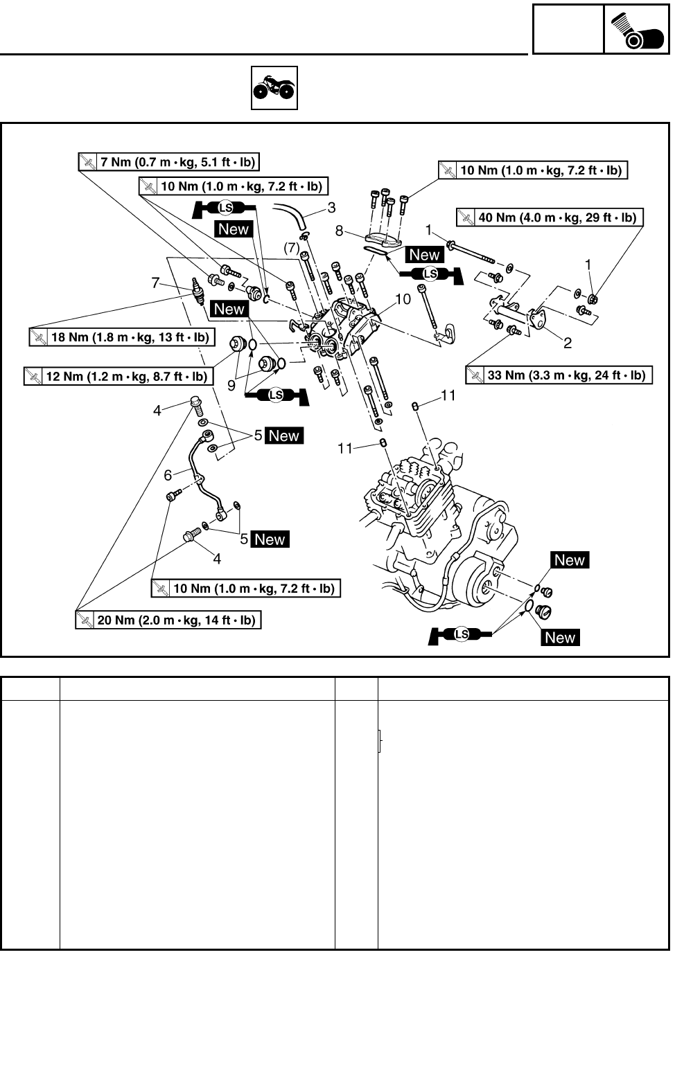
5 - 8
ENG
CYLINDER HEAD COVER
CYLINDER HEAD COVER
Order Job name/Part name Q’ty Remarks
Removing the cylinder head cover Remove the parts in the order below.
Seat/front fender Refer to “SEAT, FENDERS AND FUEL
TANK” in CHAPTER 3.
Fuel tank/rubber cover 2
1 Engine mounting bolt/nut 1/1
2 Engine bracket (front-upper) 1
3 Oil tank breather hose 1
4 Union bolt 2
5 Copper washer 4
6 Oil delivery pipe 1 1
7 Spark plug 1
8 Tappet cover (intake) 1
9 Tappet cover (exhaust) 2
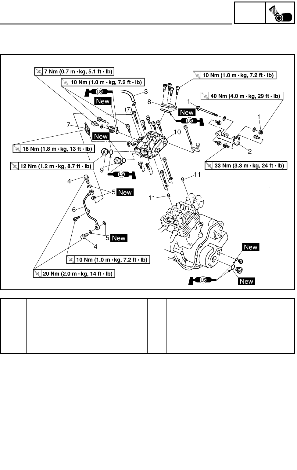
5 - 9
ENG
CYLINDER HEAD COVER
Order Job name/Part name Q’ty Remarks
10 Cylinder head cover 1 Refer to “REMOVING/INSTALLING CYL-
INDER HEAD COVER”.
11 Dowel pin 2
For installation, reverse the removal pro-
cedure.
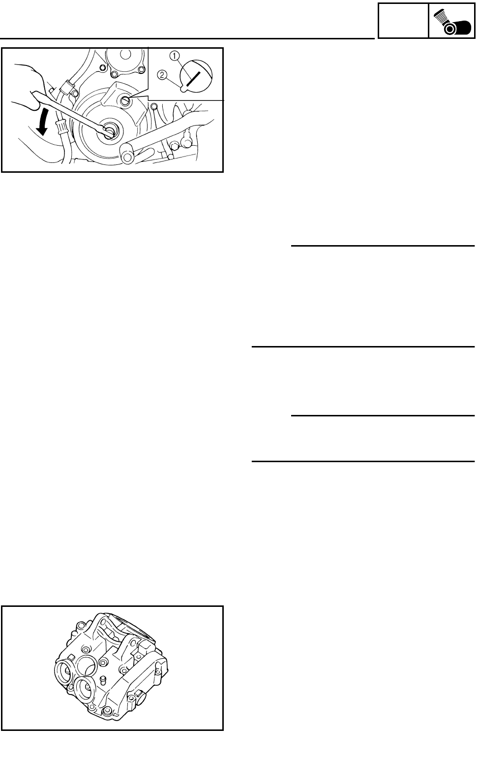
5 - 10
ENG
CYLINDER HEAD COVER
REMOVING THE CYLINDER HEAD COVER
1.Align:
●“I” mark
(with stationary pointer)
***********************************************
Checking steps:
●Turn the crankshaft counterclockwise with a
wrench.
●Align the “I” mark 1 on the rotor with the sta-
tionary pointer 2 on the crankcase cover.
When the “I” mark is aligned with the station-
ary pointer, the piston is at the Top Dead
Center (T.D.C.).
NOTE:
●When the piston is at the top dead center
(T.D.C.) on the compression stroke, there
should be clearance between the valve stem
tips and their respective rocker arm adjusting
screws.
●If there is no clearance, rotate the crankshaft
counterclockwise one turn.
***********************************************
2.Remove:
●Cylinder head cover
NOTE:
Loosen each bolt 1/4 of a turn at a time, in
stages and in a crisscross pattern. After all the
bolts are loosened, remove them.
CHECKING THE CYLINDER HEAD COVER
1.Check:
●Cylinder head cover
Cracks/damage → Replace the cylinder
head cover and cylinder head as a set.
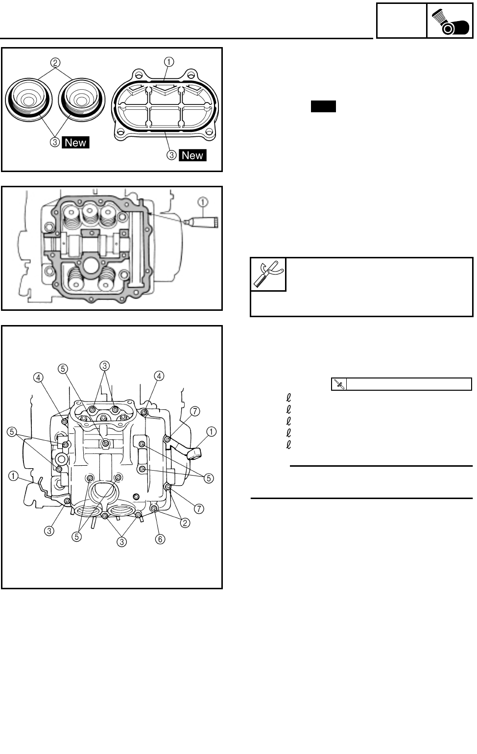
5 - 11
ENG
CYLINDER HEAD COVER
CHECKING THE TAPPET COVER
1.Check:
●Tappet cover (intake) 1
●Tappet cover (exhaust) 2
●O-ring 3 New
INSTALLING THE CYLINDER HEAD COVER
1.Apply:
●Sealant (Quick Gasket) 1
(to the mating surfaces of the cylinder head
and cylinder head cover)
2.Install:
●Cylinder head cover
●Cable guides 1
●Washers 2
●Bolts
3Bolt: = 25 mm
4Bolt: = 40 mm
5Bolt: = 55 mm
6Bolt: = 115 mm
7Bolt: = 130 mm
NOTE:
Tighten the cylinder head cover bolts in
stages, using a crisscross pattern.
Sealant (Quick Gasket) 1:
P/N. ACC-11001-05-01
Yamaha bond No. 1215:
P/N. 90890-85505
T
R
.
.
10 Nm (1.0 m • kg, 7.2 ft • lb)
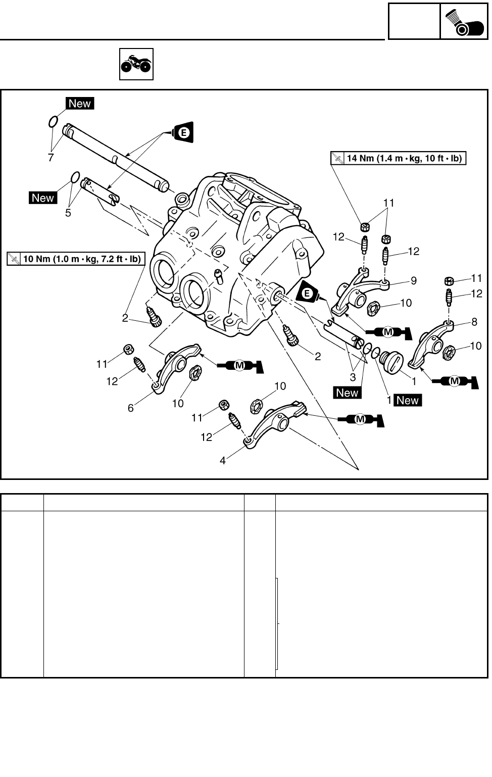
5 - 12
ENG
ROCKER ARMS
ROCKER ARMS
Order Job name/Part name Q’ty Remarks
Removing the rocker arm Remove the parts in the order below.
Cylinder head cover Refer to “CYLINDER HEAD COVER”.
1 Plug/O-ring 1/1
2Bolt 2
3 Rocker arm shaft 2/O-ring 1/1
Refer to “REMOVING/INSTALLING THE
ROCKER ARM”.
4 Rocker arm 3 1
5 Rocker arm shaft 3/O-ring 1/1
6 Rocker arm 4 1
7 Rocker arm shaft 1/O-ring 1/1
8 Rocker arm 1 1
9 Rocker arm 2 1
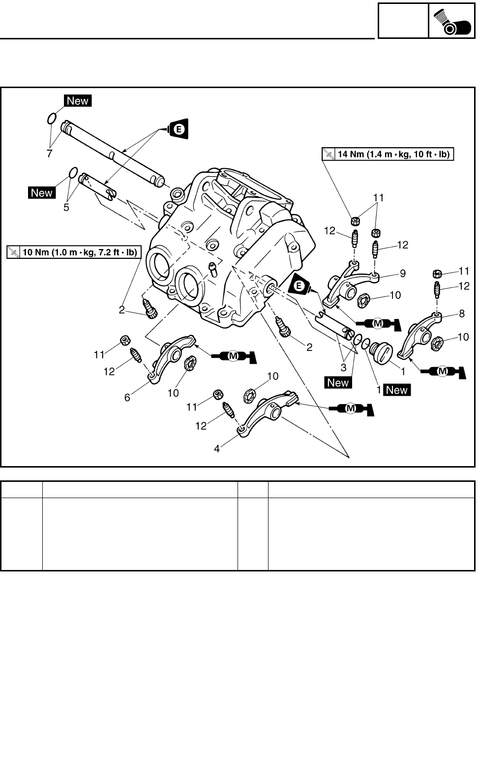
5 - 13
ENG
ROCKER ARMS
Order Job name/Part name Q’ty Remarks
10 Spring 4
11 Locknut 5
12 Valve adjuster 5
For installation, reverse the removal pro-
cedure.
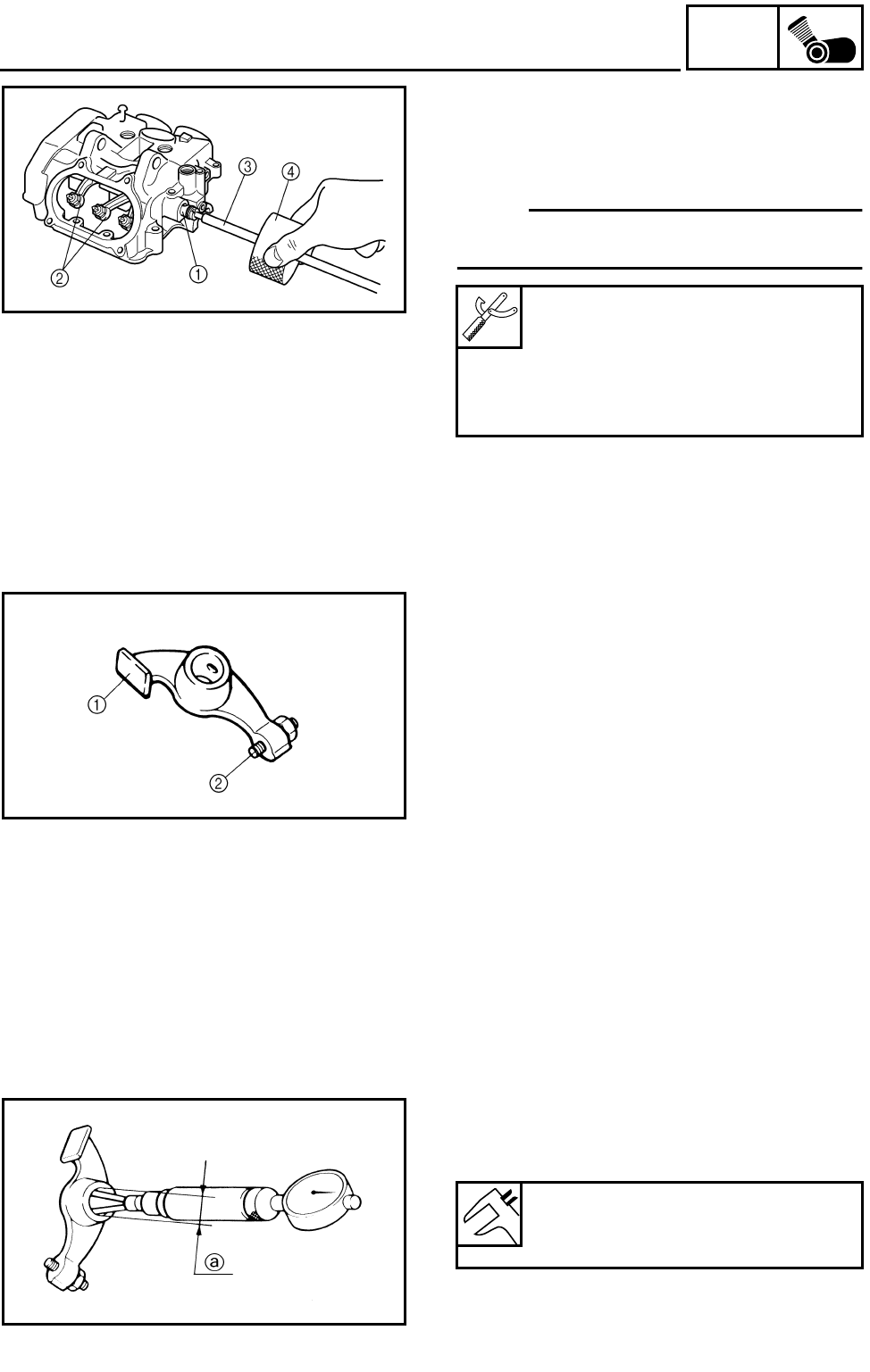
5 - 14
ENG
ROCKER ARMS
REMOVING THE ROCKER ARM
1.Remove:
●Rocker arm shafts 1
●Rocker arms 2
NOTE:
Use a slide hammer bolt 3 and weight 4 to
remove the rocker arm shafts.
Slide hammer set:
P/N. YU-01083-A
Slide hammer bolt (M6):
P/N. 90890-01083
Weight:
P/N. 90890-01084
CHECKING THE ROCKER ARM
1.Check:
●Rocker arm lobes 1
●Valve adjusters 2
Blue discoloration/pitting/scratches →
Replace.
2.Check:
●Rocker arms
●Rocker arm shafts
Damage/wear → Replace.
***********************************************
Checking steps:
●Check the two contact areas on the rocker
arms for signs of abnormal wear.
1) Rocker arm shaft hole.
2) Camshaft lobe contact surface.
Excessive wear → Replace.
●Check the surface of the rocker arm shafts.
Blue discoloration/pitting/scratches →
Replace/check lubrication.
●Measure the inside diameter a of the rocker
arm holes.
Out of specification → Replace.
Rocker arm inside diameter:
12.000 ~ 12.018 mm
(0.4724 ~ 0.4731 in)
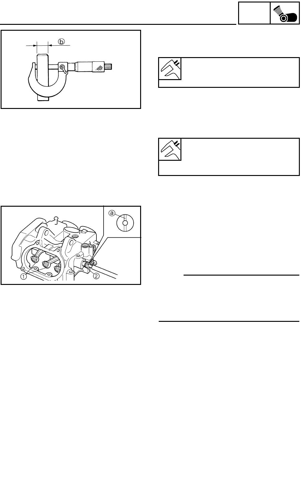
5 - 15
ENG
ROCKER ARMS
●Measure the outside diameter b of the
rocker arm shafts.
Out of specification → Replace.
●Calculate the clearance by subtracting the
rocker arm shaft outside diameter from the
rocker arm inside diameter.
Clearance greater than 0.08 mm (0.003 in)
→ Replace the defective part(s).
***********************************************
Rocker arm outside diameter:
11.976 ~ 11.991 mm
(0.4715 ~ 0.4721 in)
Rocker arm to shaft standard
clearance:
0.009 ~ 0.042 mm
(0.0004 ~ 0.0017 in)
INSTALLING THE ROCKER ARM
1.Apply:
●Engine oil
(onto the rocker arm shafts)
2.Install:
●Rocker arms 1
●Rocker arm shafts 2
NOTE:
●The thread hole a of the rocker arm shaft
must face to the outside.
●After installation, make sure that the thread
hole a of the rocker arm shaft is positioned
correctly, as shown in the illustration.
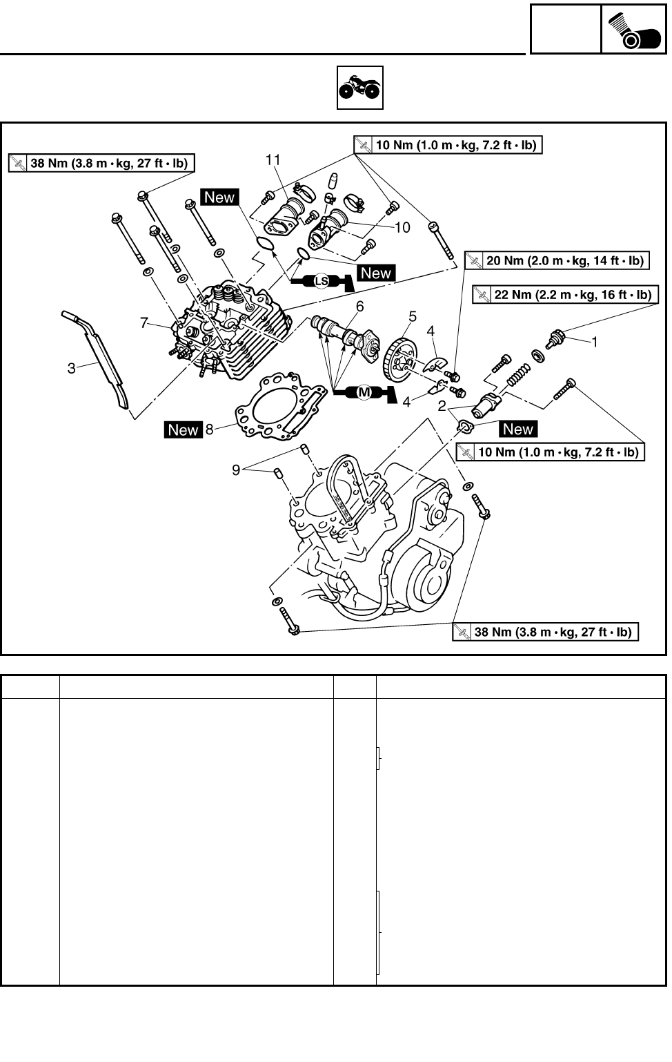
5 - 16
ENG
CAMSHAFT AND CYLINDER HEAD
CAMSHAFT AND CYLINDER HEAD
Order Job name/Part name Q’ty Remarks
Removing the camshaft and cylin-
der head
Remove the parts in the order below.
Seat/front fender Refer to “SEAT, FENDERS AND FUEL
TANK” in CHAPTER 3.
Fuel tank/rubber covers
Carburetors Refer to “CARBURETORS” in CHAPTER
7.
Water jacket outlet pipe Refer to “THERMOSTAT” in CHAPTER 6.
Muffler/exhaust pipe Refer to “ENGINE REMOVAL”.
Cylinder head cover Refer to “CYLINDER HEAD COVER”.
1 Timing chain tensioner cap bolt 1
Refer to “REMOVING/INSTALLING THE
CAMSHAFT AND CYLINDER HEAD”.
2 Timing chain tensioner/gasket 1/1
3 Timing chain guide (exhaust) 1
4 Decompressor cam guide plate 2
5 Camshaft sprocket 1
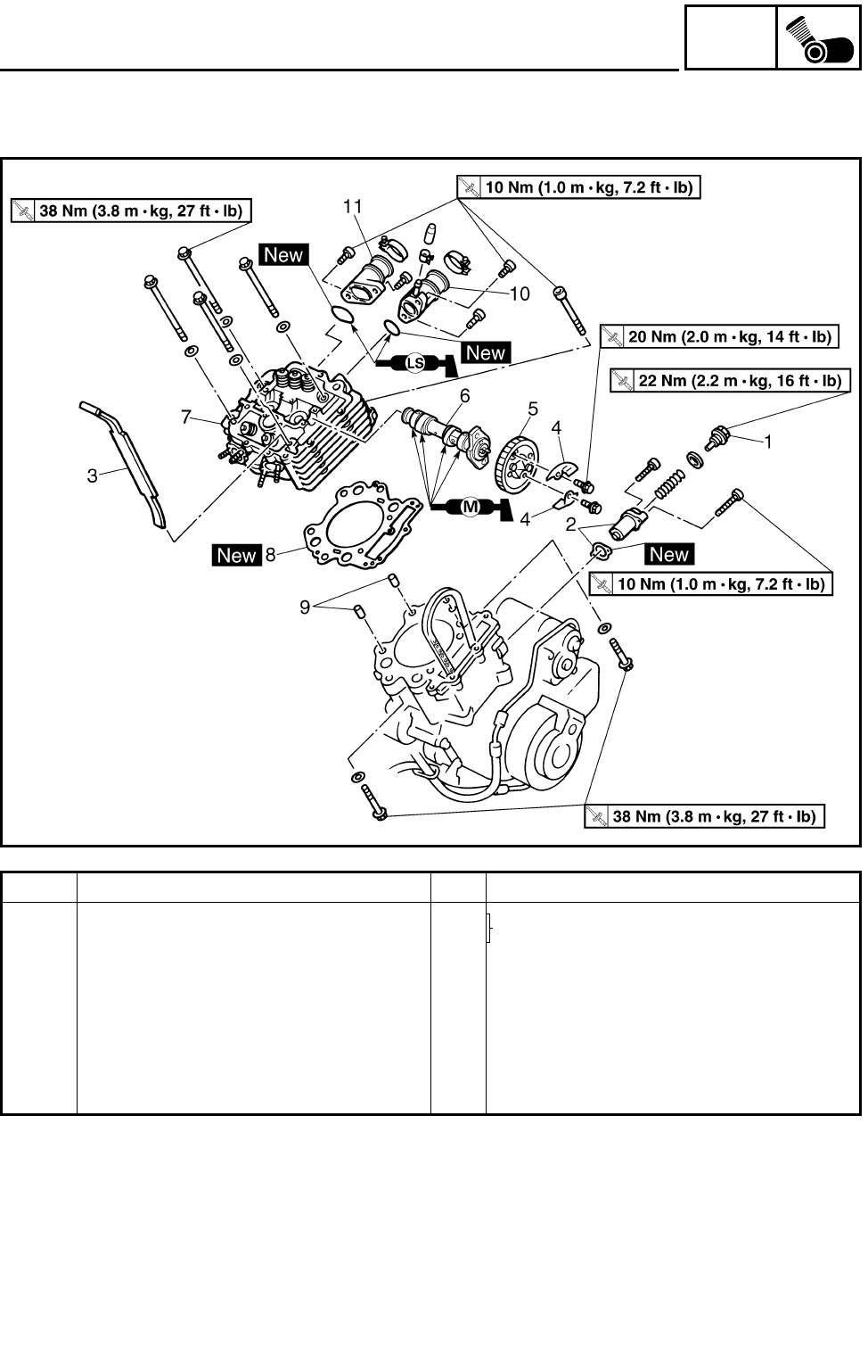
5 - 17
ENG
CAMSHAFT AND CYLINDER HEAD
Order Job name/Part name Q’ty Remarks
6 Camshaft 1 Refer to “CAMSHAFT AND CYLINDER
HEAD”.
7 Cylinder head 1
8 Cylinder head gasket 1
9 Dowel pin 2
10 Carburetor joint 1 1
11 Carburetor joint 2 1
For installation, reverse the removal pro-
cedure.
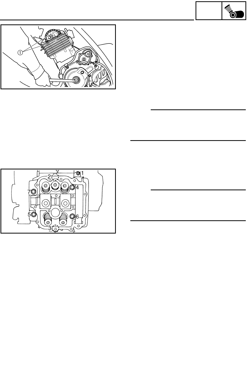
5 - 18
ENG
CAMSHAFT AND CYLINDER HEAD
REMOVING THE CAMSHAFT AND CYLIN-
DER HEAD
1.Loosen:
●Camshaft sprocket bolts 1
2.Loosen:
●Timing chain tensioner cap bolt
3.Remove:
●Timing chain tensioner
●Timing chain guide (exhaust)
●Decompressor cam guide plates
●Camshaft sprocket
NOTE:
●Fasten a safety wire to the timing chain to
prevent it from falling into the crankcase.
●When removing the camshaft sprocket, it is
not necessary to separate the timing chain.
4.Remove:
●Cylinder head
NOTE:
●Loosen the bolts in the proper sequence.
●Follow the numerical order shown in the illus-
tration. Loosen each bolt 1/4 of a turn at a
time until all of the bolts are loose.
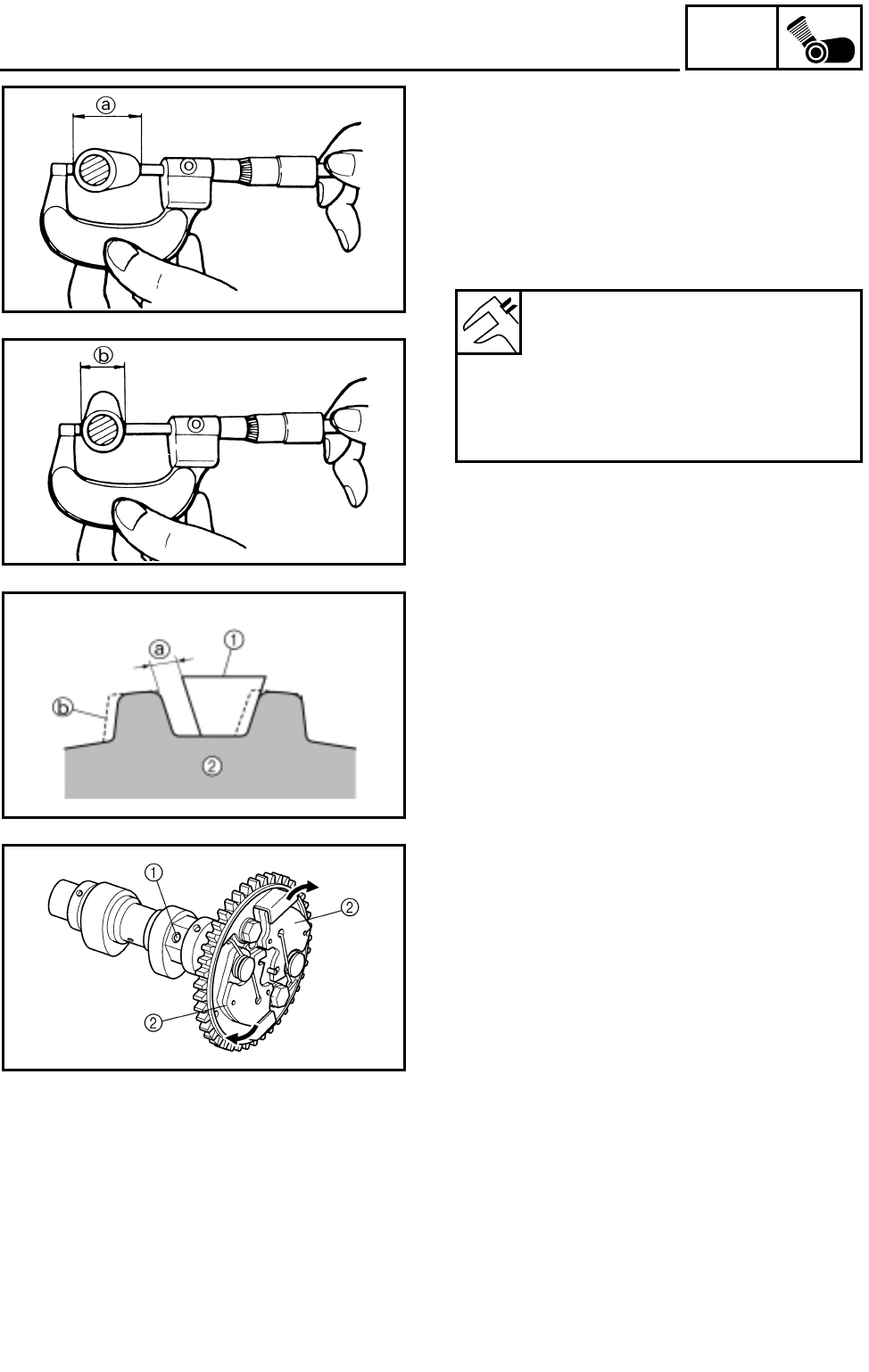
5 - 19
ENG
CAMSHAFT AND CYLINDER HEAD
CHECKING THE CAMSHAFT
1.Check:
●Cam lobes
Pitting/scratches/blue discoloration →
Replace.
2.Measure:
●Cam lobes length a and b.
Out of specification → Replace.
Camshaft lobe limit:
Intake:
a 35.59 mm (1.4012 in)
b 30.05 mm (1.1831 in)
Exhaust:
a 36.40 mm (1.4331 in)
b 30.05 mm (1.1831 in)
CHECKING THE CAMSHAFT SPROCKET
1.Check:
●Camshaft sprocket
Wear/damage → Replace the camshaft
sprocket and timing chain as a set.
a1/4 of a tooth
bCorrect
1Timing chain
2Sprocket
CHECKING THE DECOMPRESSION SYS-
TEM
1.Check:
●Decompression system
***********************************************
Checking steps:
Check while the camshaft sprocket is installed
on the camshaft.
●Check that the decompressor lever pin 1
projects from the camshaft.
●Check that the decompressor cam 2 moves
smoothly.
***********************************************
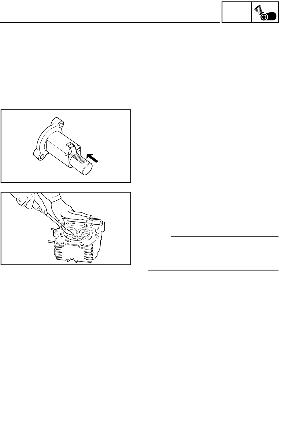
5 - 20
ENG
CAMSHAFT AND CYLINDER HEAD
CHECKING THE TIMING CHAIN GUIDE
1.Check:
●Exhaust side timing chain guide
Wear/damage → Replace.
CHECKING THE TIMING CHAIN TEN-
SIONER
1.Check:
●One-way cam operation (tensioner)
Unsmooth operation → Replace.
CHECKING THE CYLINDER HEAD
1.Eliminate:
●Carbon deposits (from the combustion
chambers)
Use a rounded scraper.
NOTE:
Do not use a sharp instrument to avoid damag-
ing or scratching:
●Spark plug threads
●Valve seats
2.Check:
●Cylinder head
Scratches/damage → Replace the cylinder
head cover and cylinder head as a set.
●Cylinder head water jacket
Mineral deposits/rust → Eliminate.
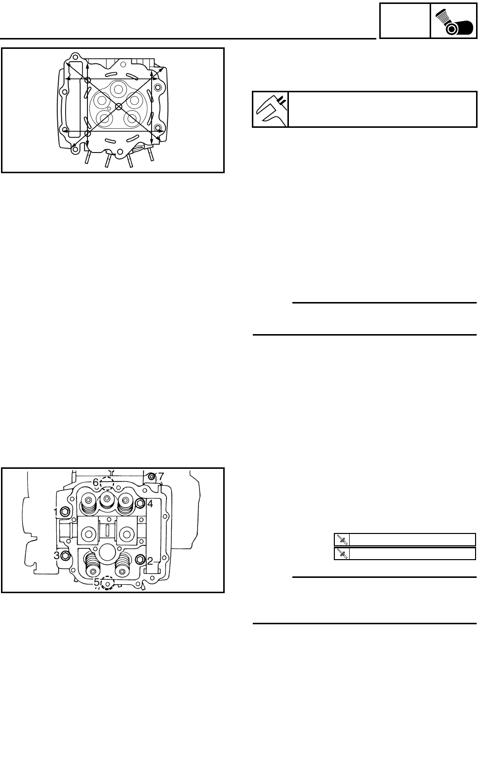
5 - 21
ENG
CAMSHAFT AND CYLINDER HEAD
3.Measure:
●Cylinder head warpage
Out of specification → Resurface.
***********************************************
Warpage measurement and resurfacing
steps:
●Place a straightedge and a feeler gauge
across the cylinder head.
●Use a feeler gauge to measure the warpage.
●If the warpage is out of specification, resur-
face the cylinder head.
●Place a 400 ~ 600 grit wet sandpaper on the
surface plate, and resurface the head using
a figure-eight sanding pattern.
NOTE:
To ensure an even surface rotate the cylinder
head several times.
***********************************************
Cylinder head warpage:
Less than 0.05 mm (0.002 in)
INSTALLING THE CAMSHAFT AND CYLIN-
DER HEAD
1.Install:
●Cylinder head
●Bolts (M9 : 1 ~ 6)
●Bolt (M6 : 7)
NOTE:
●Tighten the bolts in the proper sequence.
●Follow the numerical order shown in the illus-
tration. Tighten the bolts in two stages.
T
R
.
.
38 Nm (3.8 m · kg, 27 ft · lb)
T
R
.
.
10 Nm (1.0 m · kg, 7.2 ft · lb)
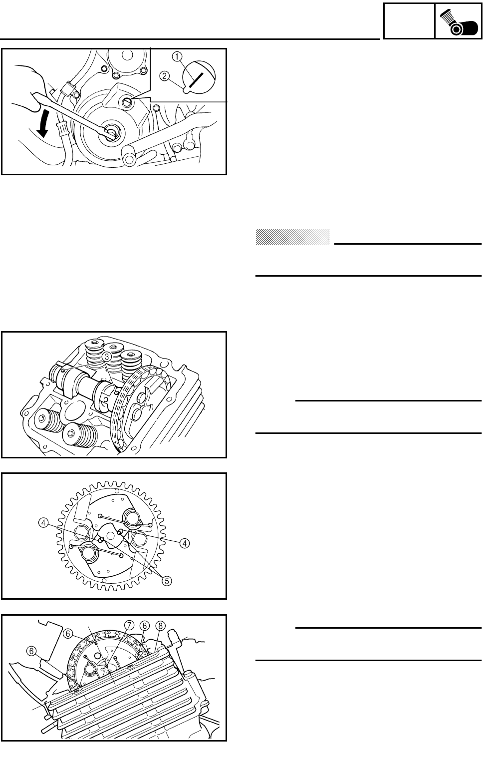
5 - 22
ENG
CAMSHAFT AND CYLINDER HEAD
2.Install:
●Camshaft
●Camshaft sprocket
***********************************************
Installation steps:
●Turn the crankshaft counterclockwise with a
wrench.
●Align the “I” mark 1 on the rotor with the sta-
tionary pointer 2 on the crankcase cover.
When the “I” mark is aligned with the station-
ary pointer, the piston is at the Top Dead
Center (T.D.C.).
CAUTION:
Do not turn the crankshaft during the cam-
shaft installation.
●Temporarily install the camshaft sprocket on
the camshaft. (Do not install the bolts.) Then,
install the timing chain on the camshaft
sprocket.
NOTE:
Make sure the small holes 3 on the camshaft
face upward.
●Align the notches 4 on the decompressor
cams with the projections 5 on the decom-
pressor spring lever, then install the cam-
shaft sprocket on the camshaft.
NOTE:
Check that each part is positioned as shown in
the illustration.
6Small holes on camshaft sprocket
7Punch mark on decompressor spring lever
8Top front of cylinder head
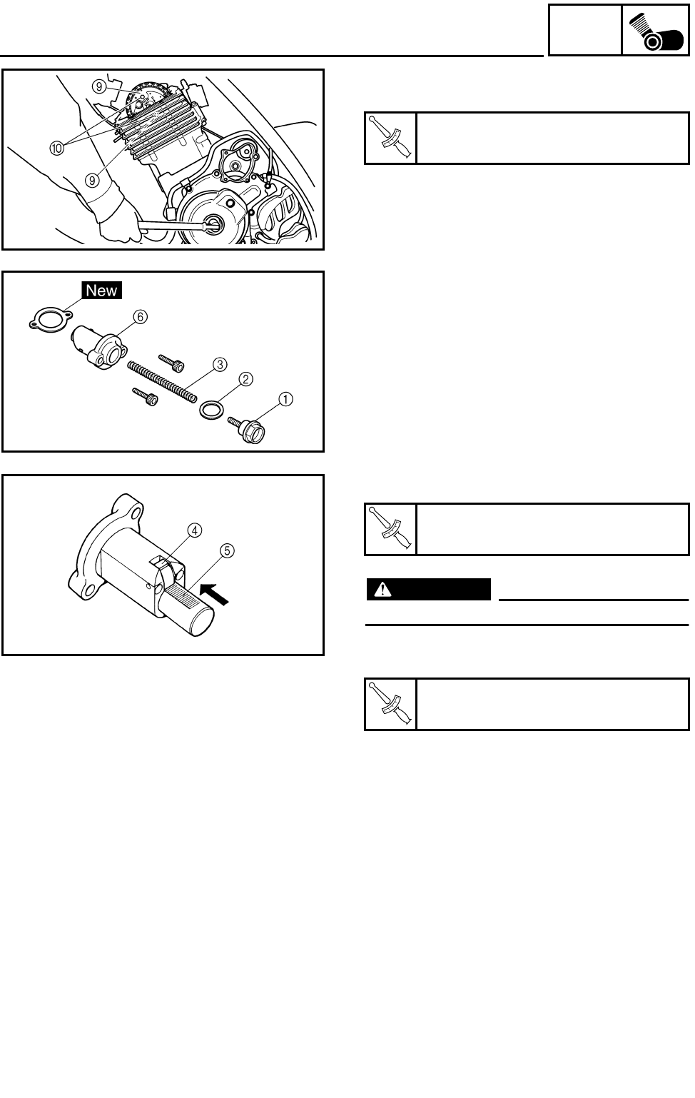
5 - 23
ENG
CAMSHAFT AND CYLINDER HEAD
●Install the decompressor cam guide plates 9
and camshaft sprocket bolts 0.
●Remove the retaining wire.
***********************************************
T
R
.
.
Camshaft sprocket bolt:
20 Nm (2.0 m • kg, 14 ft • lb)
3.Install:
●Timing chain tensioner
***********************************************
Installation steps:
●Remove the timing chain tensioner cap bolt
1, washer 2 and spring 3.
●Release the timing chain tensioner one-way
cam 4 and push the tensioner rod 5 all the
way in.
●Install the tensioner 6 with a new gasket into
the cylinder.
WARNING
Always use a new gasket.
●Install the spring, washer and timing chain
tensioner cap bolt.
***********************************************
4.Check:
●Small holes on camshaft sprocket
●Rotor “I” mark
Out of alignment → Adjust.
T
R
.
.
Bolts (timing chain tensioner):
10 Nm (1.0 m • kg, 7.2 ft • lb)
T
R
.
.
Timing chain tensioner cap bolt:
22 Nm (2.2 m • kg, 16 ft • lb)
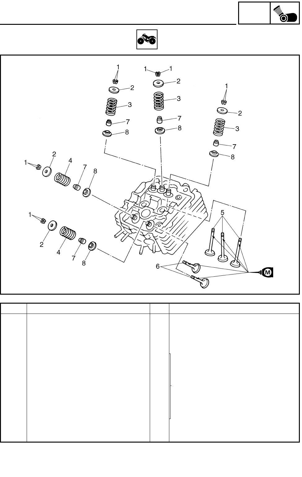
5 - 24
ENG
VALVES AND VALVE SPRINGS
VALVES AND VALVE SPRINGS
Order Job name/Part name Q’ty Remarks
Removing the valve and valve
spring
Remove the parts in the order below.
Cylinder head Refer to “CAMSHAFT AND CYLINDER
HEAD”.
1 Valve cotter 10
Refer to “REMOVING/INSTALLING THE
VALVE AND VALVE SPRING”.
2 Valve spring retainer 5
3 Intake valve spring 3
4 Exhaust valve spring 2
5 Intake valve 3
6 Exhaust valve 2
7 Valve stem seal 5
8 Valve spring seat 5
For installation, reverse the removal pro-
cedure.
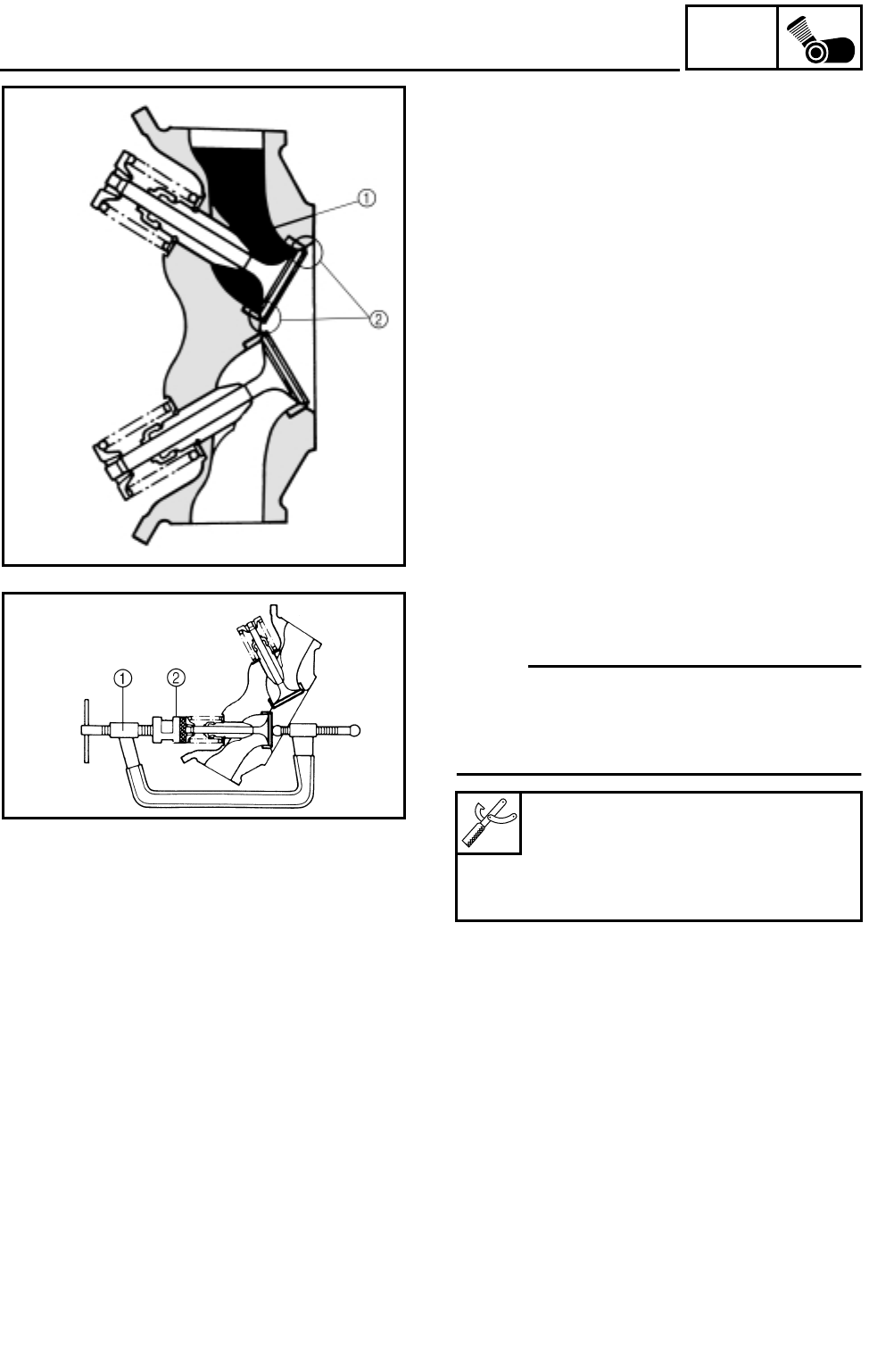
5 - 25
ENG
VALVES AND VALVE SPRINGS
REMOVING THE VALVE AND VALVE
SPRING
1.Check:
●Valve sealing
Leakage at the valve seat → Inspect the
valve face, valve seat and valve seat width.
Refer to “VALVE AND VALVE SPRING
INSPECTION”.
***********************************************
Checking steps:
●Pour a clean solvent 1 into the intake and
exhaust ports.
●Check that the valve seals properly.
There should be no leakage at the valve seat
2.
***********************************************
2.Remove:
●Valve cotters
NOTE:
Attach a valve spring compressor 1 and
attachment 2 between the valve spring
retainer and the cylinder head to remove the
valve cotters.
Valve spring compressor:
P/N. YM-04019, 90890-04019
Valve spring compressor
attachment:
P/N. 90890-01243
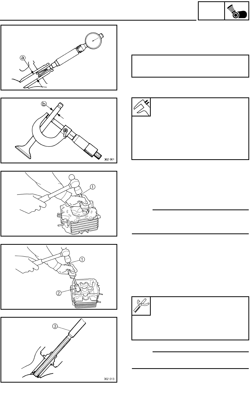
5 - 26
ENG
VALVES AND VALVE SPRINGS
CHECKING THE VALVE AND VALVE
SPRING
1.Measure:
●Stem-to-guide clearance
Out of specification → Replace the valve
guide.
Stem-to-guide clearance =
valve guide inside diameter a –
valve stem diameter b
Clearance (stem to guide):
Intake:
0.010 ~ 0.037 mm
(0.0004 ~ 0.0015 in)
<Limit>: 0.08 mm (0.0031 in)
Exhaust:
0.025 ~ 0.052 mm
(0.0010 ~ 0.0020 in)
<Limit>: 0.10 mm (0.0039 in)
2.Replace:
●Valve guide
***********************************************
Replacement steps:
NOTE:
To ease guide removal, installation and to
maintain correct fit, heat the cylinder head to
100 °C (212 °F) in an oven.
●Remove the valve guide using a valve guide
remover 1.
●Install the new valve guide using a valve
guide remover 1 and valve guide installer
2.
●After installing the valve guide, bore the
valve guide using a valve guide reamer 3 to
obtain proper stem-to-guide clearance.
NOTE:
After replacing the valve guide reface the valve
seat.
***********************************************
Valve guide remover (ø 6):
P/N. YM-4064-A, 90890-04064
Valve guide installer (ø 6):
P/N. YM-04065-A, 90890-04065
Valve guide reamer (ø 6):
P/N. YM-04066, 90890-04066
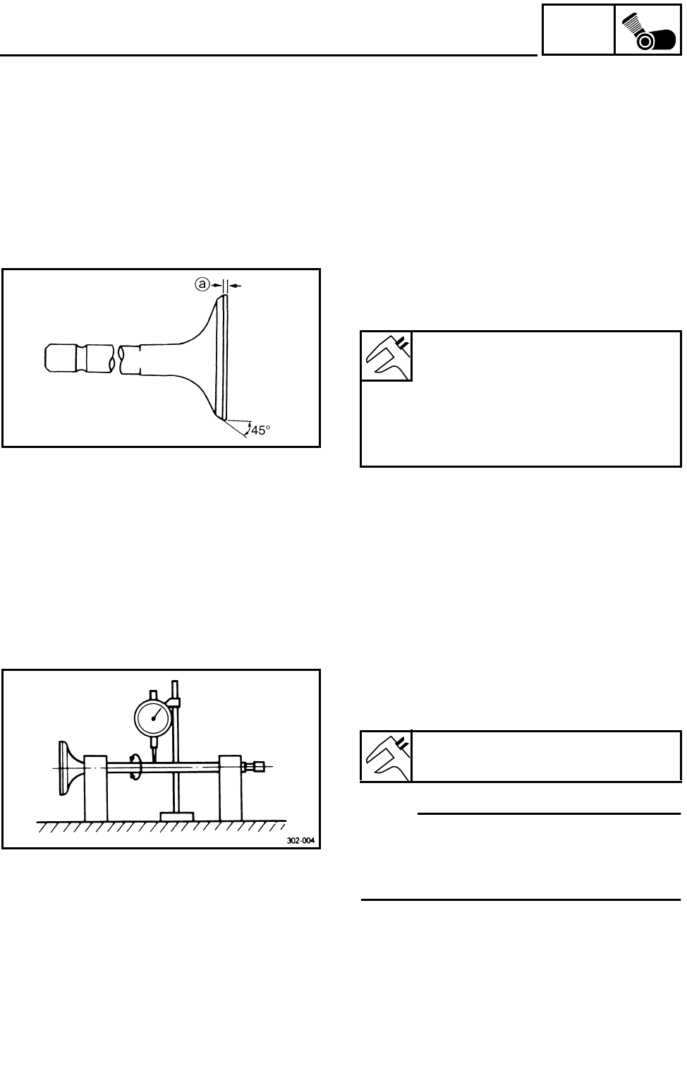
5 - 27
ENG
VALVES AND VALVE SPRINGS
3.Check:
●Valve face
Pitting/wear → Grind the face.
●Valve stem end
Mushroom shape or diameter larger than the
body of the stem → Replace.
4.Measure:
●Margin thickness a
Out of specification → Replace.
Margin thickness:
Intake:
0.85 ~ 1.15 mm
(0.0335 ~ 0.0453 in)
Exhaust:
0.85 ~ 1.15 mm
(0.0335 ~ 0.0453 in)
5.Measure:
●Runout (valve stem)
Out of specification → Replace.
NOTE:
●When installing a new valve always replace
the guide.
●If the valve is removed or replaced always
replace the oil seal.
6.Eliminate:
●Carbon deposits
(from the valve face and valve seat)
7.Check:
●Valve seats
Pitting/wear → Reface the valve seat.
Runout limit:
0.01 mm (0.0004 in)
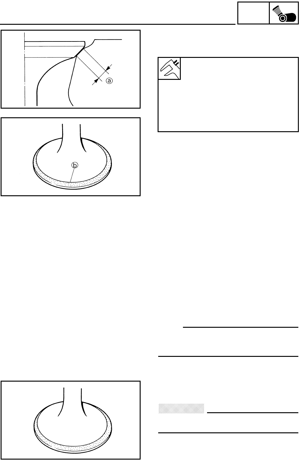
5 - 28
ENG
VALVES AND VALVE SPRINGS
8.Measure:
●Valve seat width a
Out of specification → Reface the valve seat.
***********************************************
Measurement steps:
●Apply Mechanic’s blueing dye (Dykem) b to
the valve face.
●Install the valve into the cylinder head.
●Press the valve through the valve guide and
onto the valve seat to make a clear pattern.
●Measure the valve seat width. Where the
valve seat and valve face made contact,
blueing will have been removed.
●If the valve seat is too wide, too narrow, or
the seat is not centered, the valve seat must
be refaced.
***********************************************
Valve seat width:
Intake:
0.9 ~ 1.1 mm
(0.0354 ~ 0.0433 in)
<Limit>: 1.6 mm (0.0630 in)
Exhaust:
0.9 ~ 1.1 mm
(0.0354 ~ 0.0433 in)
<Limit>: 1.6 mm (0.0630 in)
9.Lap:
●Valve face
●Valve seat
NOTE:
After refacing the valve seat or replacing the
valve and valve guide, the valve seat and
valve face should be lapped.
***********************************************
Lapping steps:
●Apply a coarse lapping compound to the
valve face.
CAUTION:
Do not let the compound enter the gap
between the valve stem and the guide.
●Apply molybdenum disulfide oil to the valve
stem.
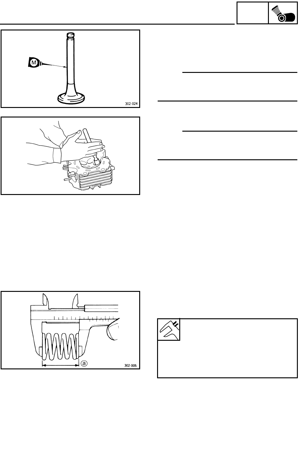
5 - 29
ENG
VALVES AND VALVE SPRINGS
●Install the valve into the cylinder head.
●Turn the valve until the valve face and valve
seat are evenly polished, then clean off all of
the compound.
NOTE:
For best lapping results, lightly tap the valve
seat while rotating the valve back and forth
between your hands.
●Apply a fine lapping compound to the valve
face and repeat the above steps.
NOTE:
After every lapping operation be sure to clean
off all of the compound from the valve face and
valve seat.
●Apply Mechanic’s blueing dye (Dykem) to the
valve face.
●Install the valve into the cylinder head.
●Press the valve through the valve guide and
onto the valve seat to make a clear pattern.
●Measure the valve seat width again. If the
valve seat width is out of specification, reface
and relap the valve seat.
***********************************************
10.Measure:
●Valve spring free length a
Out of specification → Replace.
Free length (valve spring):
Inner:
35.95 mm (1.42 in)
<Limit>: 34.15 mm (1.34 in)
Outer:
37.75 mm (1.49 in)
<Limit>: 35.86 mm (1.41 in)
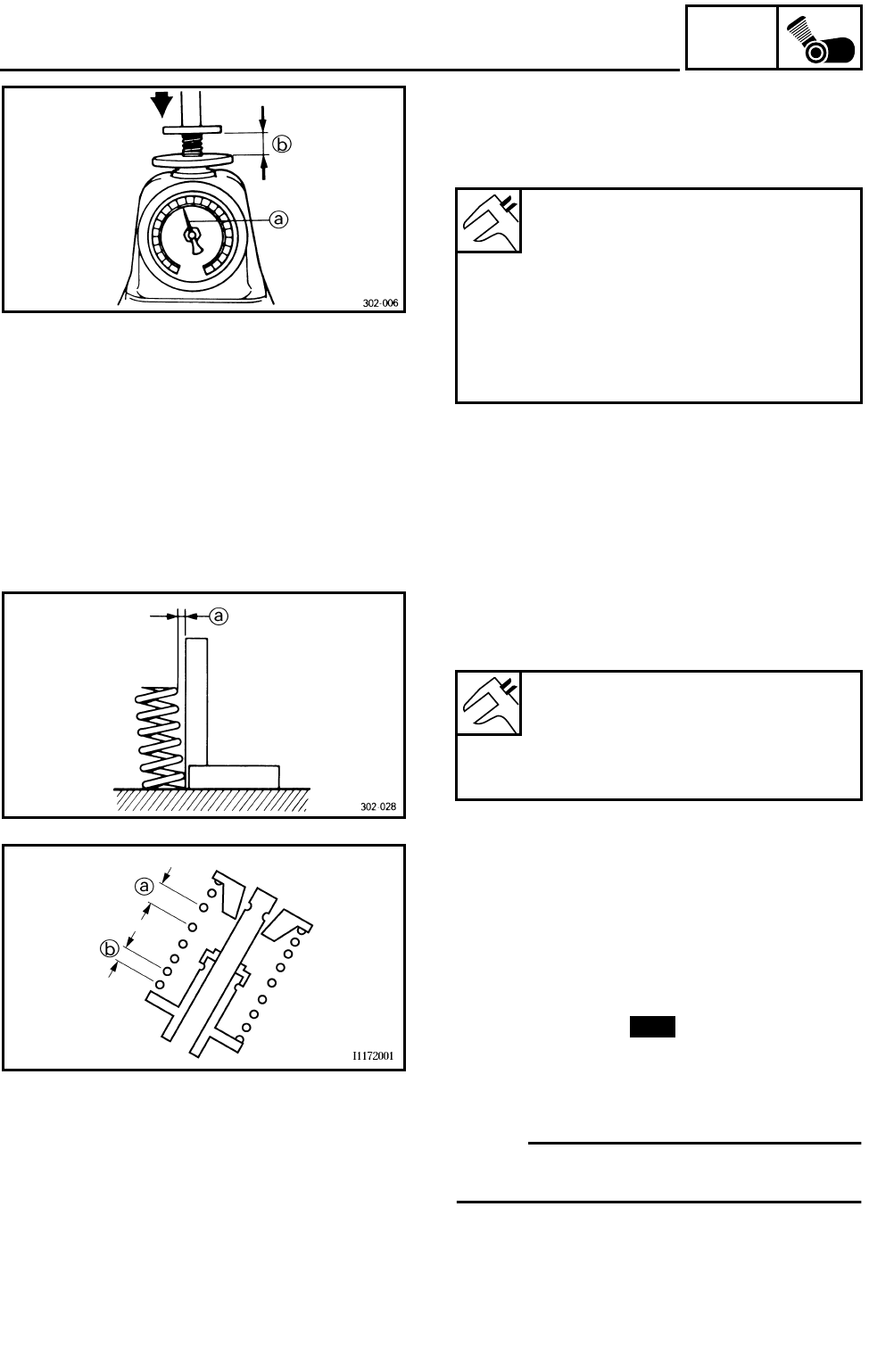
5 - 30
ENG
VALVES AND VALVE SPRINGS
11.Measure:
●Compressed spring force a
Out of specification → Replace.
bInstalled length
Compressed spring force:
Inner:
149 ~ 173 N at 27.2 mm
(15.19 ~ 17.64 kg,
33.50 ~ 38.89 lb at 1.07 in)
Outer:
165 ~ 191 N at 30.7 mm
(16.83 ~ 19.49 kg,
37.09 ~ 42.94 lb at 1.21 in)
12.Measure:
●Spring tilt a
Out of specification → Replace.
Spring tilt limit:
Inner:
2.5°/1.6 mm (0.06 in)
Outer:
2.5°/1.6 mm (0.06 in)
INSTALLING THE VALVE AND VALVE
SPRING
1.Apply:
●Molybdenum disulfide oil
(onto the valve stem and valve stem seal)
2.Install:
●Valve spring seats
●Valve stem seals
●Valves
●Valve springs
●Valve spring retainers
NOTE:
Install the valve springs with the larger pitch a
facing upwards.
bSmaller pitch
New
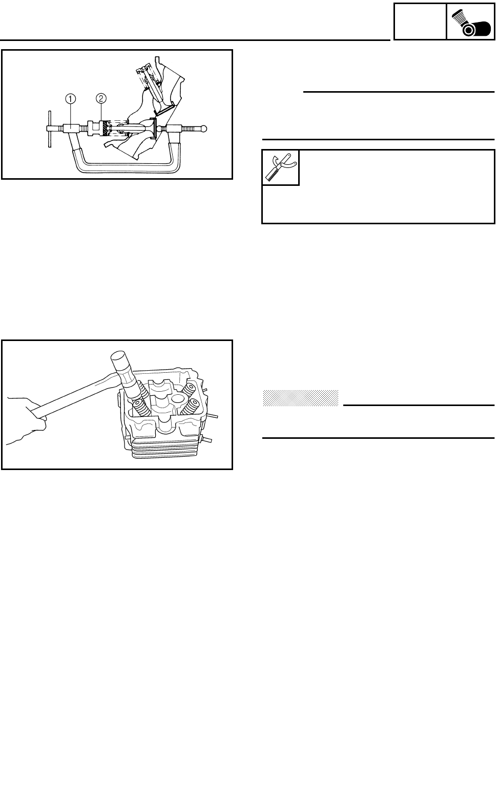
5 - 31
ENG
VALVES AND VALVE SPRINGS
3.Install:
●Valve cotters
NOTE:
Install the valve cotters while compressing the
valve spring with the valve spring compressor
1 and attachment 2.
Valve spring compressor:
P/N. YM-04019, 90890-04019
Valve spring compressor
attachment:
P/N. 90890-01243
4.To secure the valve cotters onto the valve
stem, lightly tap the valve tip with a piece of
wood.
CAUTION:
Hitting the valve tip with excessive force
could damage the valve.
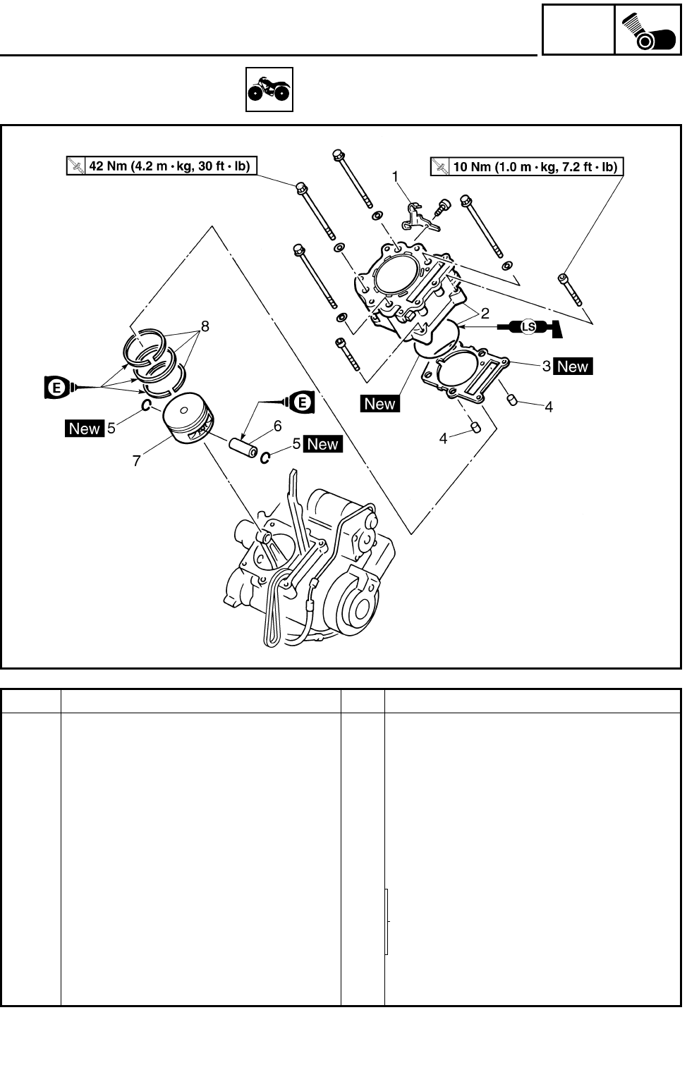
5 - 32
ENG
CYLINDER AND PISTON
CYLINDER AND PISTON
Order Job name/Part name Q’ty Remarks
Removing the cylinder and piston Remove the parts in the order below.
Water jacket inlet housing Refer to “WATER PUMP” in CHAPTER 6.
Cylinder head Refer to “CAMSHAFT AND CYLINDER
HEAD”.
1 Cable guide 1
2 Cylinder/O-ring 1/1 Refer to “INSTALLING THE CYLINDER”.
3 Cylinder gasket 1
4 Dowel pin 2
5 Piston pin clip 2
Refer to “REMOVING/INSTALLING THE
PISTON”.
6 Piston pin 1
7 Piston 1
8 Piston ring set 1
For installation, reverse the removal pro-
cedure.
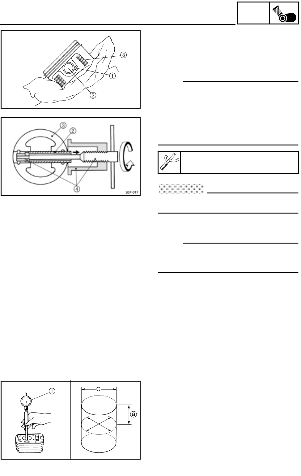
5 - 33
ENG
CYLINDER AND PISTON
REMOVING THE PISTON
1.Remove:
●Piston pin clips 1
●Piston pin 2
●Piston 3
NOTE:
●Put identification marks on each piston head
for reference during reinstallation.
●Before removing each piston pin, deburr the
clip groove and pin hole area. If the piston
pin groove is deburred and the piston pin is
still difficult to remove, use the piston pin
puller 4.
CAUTION:
Do not use a hammer to drive the piston
pin out.
2.Remove:
●Piston rings
NOTE:
Spread the end gaps apart while at the same
time lifting the piston ring over the top of the
piston crown, as shown in the illustration.
Piston pin puller:
P/N. YU-01304, 90890-01304
CHECKING THE CYLINDER AND PISTON
1.Check:
●Cylinder and piston walls
Vertical scratches → Rebore or replace the
cylinder and the piston.
2.Measure:
●Piston-to-cylinder clearance
***********************************************
Measurement steps:
1st step:
●Measure the cylinder bore “C” with a cylinder
bore gauge 1.
a50 mm (2.0 in) from the top of the cylinder
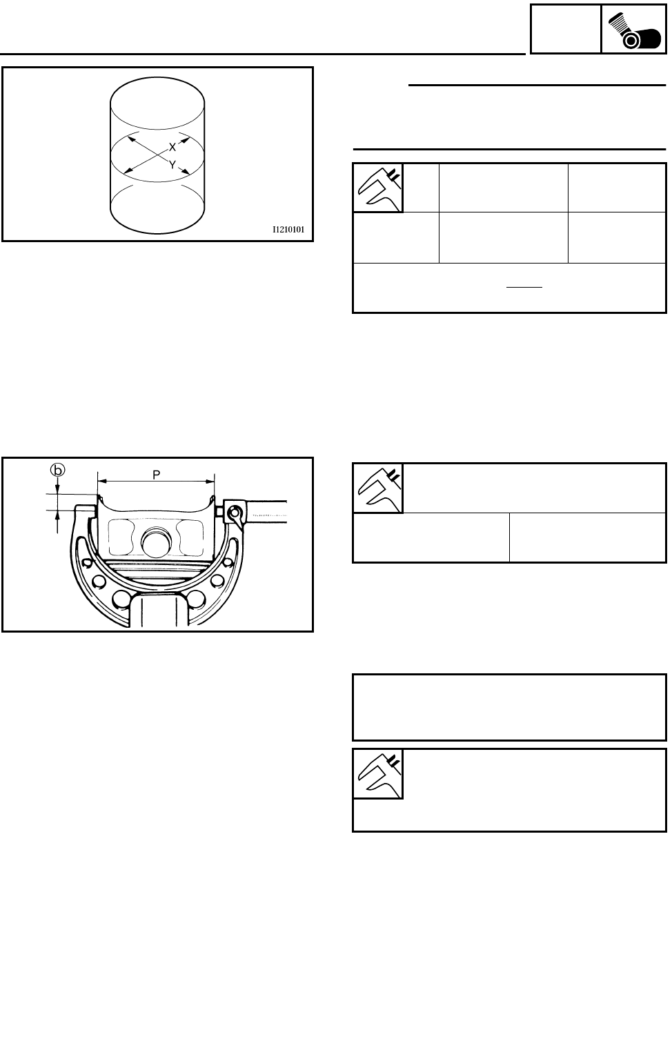
5 - 34
ENG
CYLINDER AND PISTON
NOTE:
Measure cylinder bore “C” in parallel to and at
right angles to the cylinder matching surface.
Then, find the average of the measurements.
●If out of specification, rebore or replace the
cylinder, and replace the piston and piston
rings as a set.
2nd step:
●Measure piston skirt diameter “P” with a
micrometer.
b5.0 mm (0.20 in) from the piston bottom edge
●If out of specification, replace the piston and
piston rings as a set.
3rd step:
●Find the piston-to-cylinder clearance with the
following formula.
●If out of specification, rebore or replace the
cylinder, and replace the piston and piston
rings as a set.
***********************************************
Standard Wear limit
Cylinder
bore “C”
100.005 ~
100.045 mm
(3.9372 ~ 3.9388 in)
100.100 mm
(3.9404 in)
C =
Piston skirt diameter “P”:
Standard 99.945 ~ 99.995 mm
(3.9348 ~ 3.9368 in)
Piston-to-cylinder clearance =
Cylinder bore “C” –
Piston skirt diameter “P”
Piston-to-cylinder clearance:
0.05 ~ 0.07 mm
(0.0020 ~ 0.0028 in)
<Limit>: 0.15 mm (0.0059 in)
X+Y
2
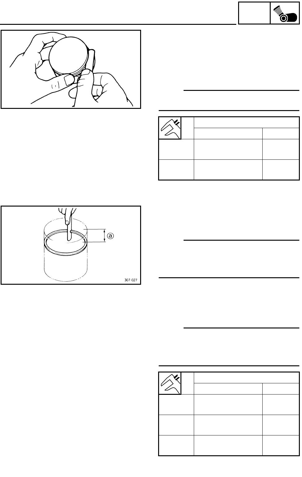
5 - 35
ENG
CYLINDER AND PISTON
CHECKING THE PISTON RING
1.Measure:
●Ring side clearance
Use a feeler gauge.
Out of specification → Replace the piston
and rings as a set.
NOTE:
Clean carbon from the piston ring grooves and
rings before measuring the side clearance.
Side clearance
Standard Limit
Top
ring 0.04 ~ 0.08 mm
(0.0016 ~ 0.0031 in) 0.13 mm
(0.0051 in)
2nd
ring 0.03 ~ 0.07 mm
(0.0012 ~ 0.0028 in) 0.13 mm
(0.0051 in)
2.Position:
●Piston ring
(in cylinder)
NOTE:
Insert a ring into the cylinder and push it
approximately 50 mm (2.0 in) into the cylinder.
Push the ring with the piston crown so that the
ring will be at a right angle to the cylinder bore.
a50 mm (2.0 in)
3.Measure:
●Ring end gap
Out of specification → Replace.
NOTE:
You cannot measure the end gap on the
expander spacer of the oil control ring. If the oil
control ring rails show excessive gap, replace
all three rings.
End gap
Standard Limit
Top
ring 0.30 ~ 0.45 mm
(0.0118 ~ 0.0177 in) 0.70 mm
(0.0276 in)
2nd
ring 0.30 ~ 0.45 mm
(0.0118 ~ 0.0177 in) 0.80 mm
(0.0315 in)
Oil
ring 0.2 ~ 0.7 mm
(0.0079 ~ 0.0276 in) —
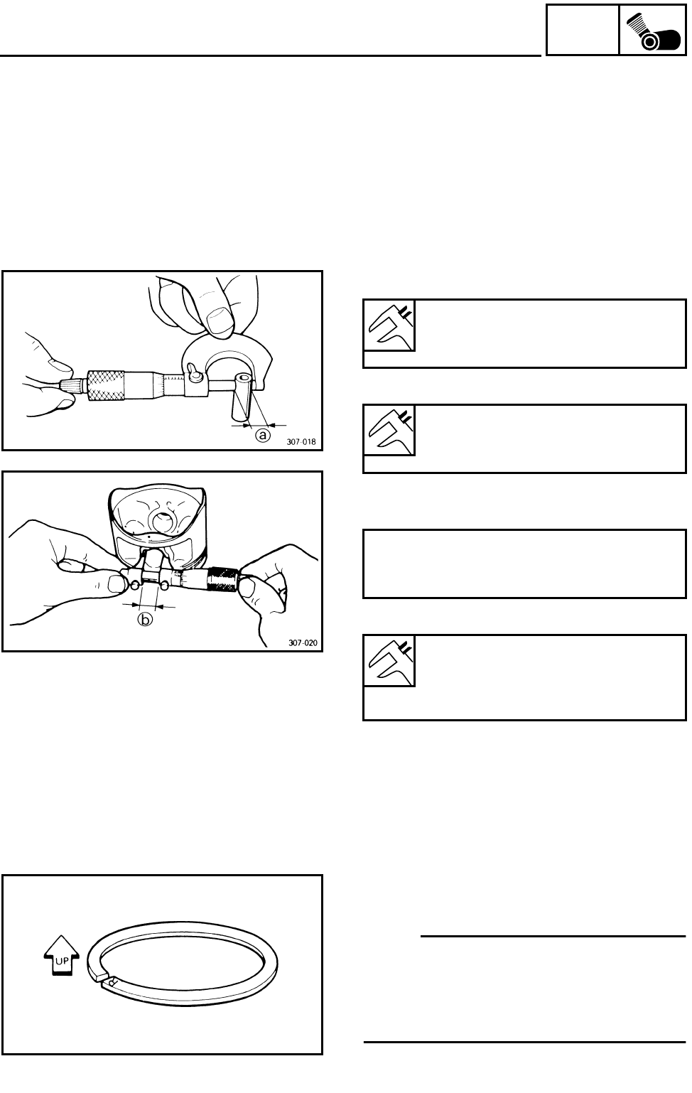
5 - 36
ENG
CYLINDER AND PISTON
CHECKING THE PISTON PIN INSPECTION
1.Check:
●Piston pin
Blue discoloration/grooves → Replace, then
inspect the lubrication system.
2.Measure:
●Piston pin-to-piston clearance
***********************************************
Measurement steps:
●Measure the piston pin outside diameter a.
If out of specification, replace the piston pin.
●Measure the piston inside diameter b.
●Calculate the piston pin-to-piston clearance
with the following formula.
●If out of specification, replace the piston.
***********************************************
INSTALLING THE PISTON
1.Install:
●Piston rings
(onto the piston)
NOTE:
●Be sure to install the piston rings so that the
manufacturer’s marks or numbers are
located on the upper side of the rings.
●Lubricate the piston and piston rings liberally
with engine oil.
Outside diameter (piston pin):
21.991 ~ 22.000 mm
(0.8658 ~ 0.8661 in)
Piston pin bore inside diameter:
22.004 ~ 22.015 mm
(0.8663 ~ 0.8667 in)
Piston pin-to-piston clearance =
Bore size (piston pin) b –
Outside diameter (piston pin) a
Piston pin-to-piston clearance:
0.004 ~ 0.024 mm
(0.00016 ~ 0.00094 in)
<Limit>: 0.07 mm (0.003 in)
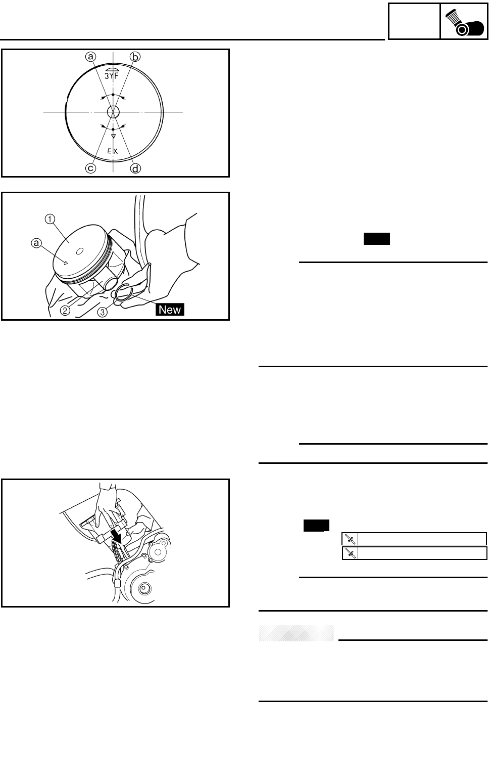
5 - 37
ENG
CYLINDER AND PISTON
2.Position:
●Top ring
●2nd ring
●Oil ring
Offset the piston ring end gaps as shown.
aTop ring end
bOil ring end (lower)
cOil ring end (upper)
d2nd ring end
3.Install:
●Piston 1
●Piston pin 2
●Piston pin clips 3
NOTE:
●Apply engine oil onto the piston pin, piston
ring and piston.
●Be sure that the arrow mark a on the piston
points to the exhaust side of the engine.
●Before installing the piston pin clip, cover the
crankcase with a clean rag to prevent the
piston pin clip from falling into the crankcase.
4.Lubricate:
●Piston
●Piston rings
●Cylinder
NOTE:
Apply a liberal coating of engine oil.
New
INSTALLING THE CYLINDER
1.Install:
●Cylinder
●O-ring
●Bolts (M10)
●Bolts (M6)
NOTE:
Install the cylinder with one hand while com-
pressing the piston rings with the other hand.
CAUTION:
●Be careful not to damage the timing chain
damper during installation.
●Pass the timing chain through the timing
chain cavity.
New
T
R
.
.
42 Nm (4.2 m · kg, 30 ft · lb)
T
R
.
.
10 Nm (1.0 m · kg, 7.2 ft · lb)
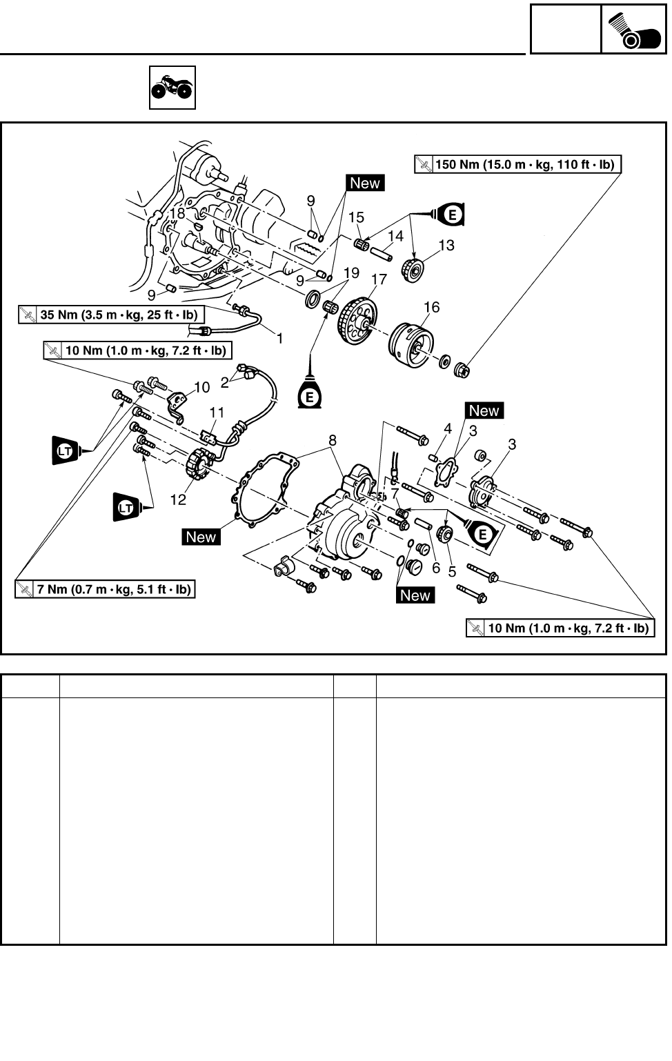
5 - 38
ENG
AC MAGNETO
AC MAGNETO
Order Job name/Part name Q’ty Remarks
Removing the AC magneto Remove the parts in the order below.
Engine oil Drain.
Shift pedal link Disconnect.
1 Oil pipe 1 1 Disconnect.
2 AC magneto coupler 2
3 Starter idle gear cover/gasket 1/1
4 Dowel pin 1
5 Starter idle gear 1 1
6 Starter idle gear 1 shaft 1
7 Bearing 1
8 AC magneto cover/gasket 1/1 Refer to “REMOVING/INSTALLING THE
AC MAGNETO ROTOR”.
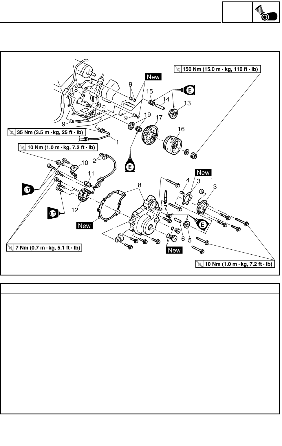
5 - 39
ENG
AC MAGNETO
Order Job name/Part name Q’ty Remarks
9 Dowel pin/O-ring 3/2
10 Lead holder 1
11 Pickup coil 1
12 Stator assembly 1
13 Starter idle gear 2 1
14 Starter idle gear 2 shaft 1
15 Bearing 1
16 AC magneto rotor 1 Refer to “REMOVING/INSTALLING THE
AC MAGNETO ROTOR”.
17 Starter wheel gear 1
18 Woodruff key 1
19 Bearing/washer 1/1
For installation, reverse the removal pro-
cedure.
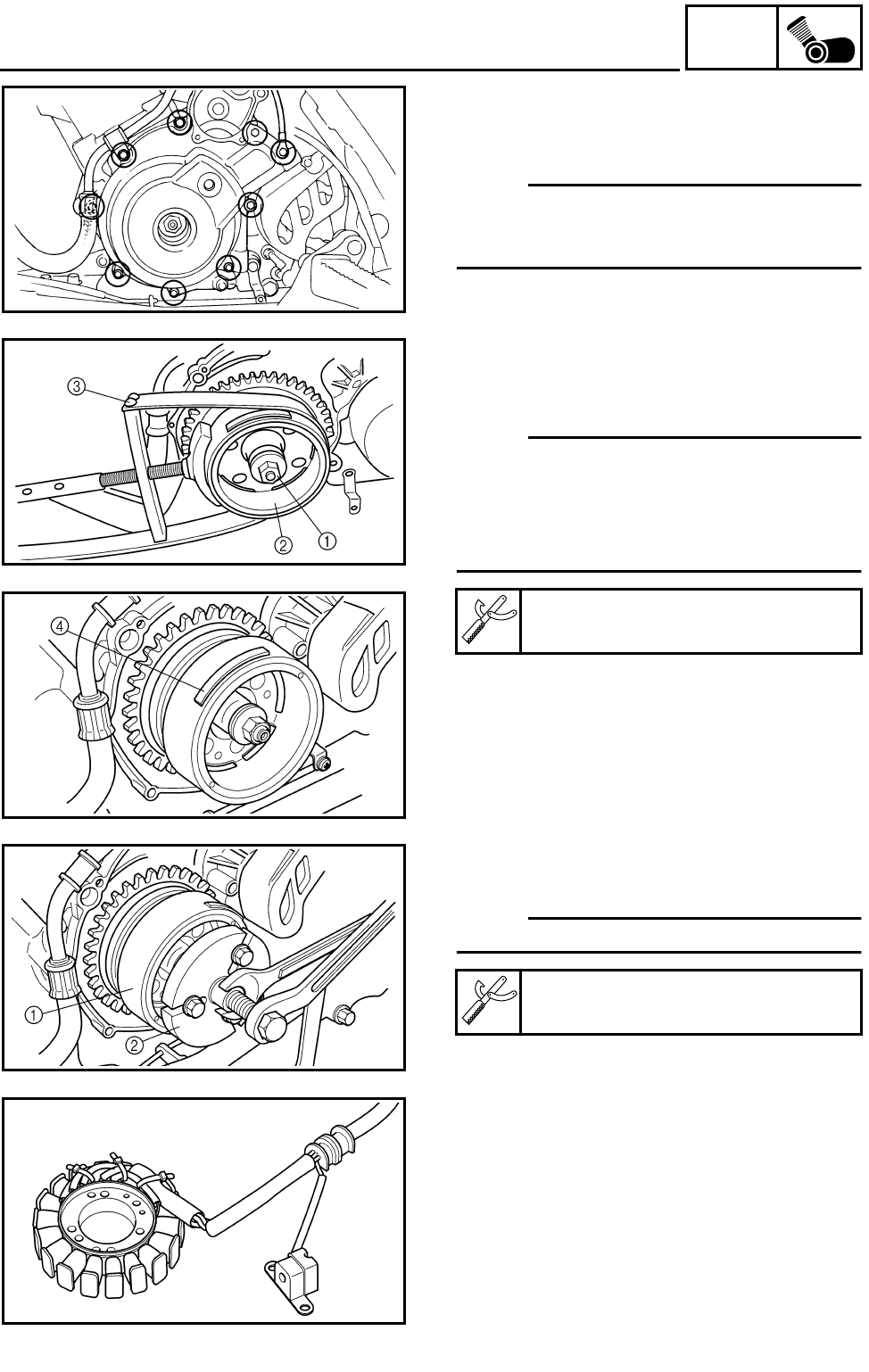
5 - 40
ENG
AC MAGNETO
REMOVING THE AC MAGNETO ROTOR
1.Remove:
●AC magneto cover
NOTE:
Loosen each bolt 1/4 of a turn at a time, in
stages and in a crisscross pattern. After all of
the bolts are fully loosened, remove them.
2.Remove:
●AC magneto rotor nut 1
●Washer
NOTE:
●While holding the AC magneto rotor 2 with
the sheave holder 3, loosen the generator
rotor nut.
●Do not allow the sheave holder to touch the
projection 4 on the rotor.
Sheave holder:
P/N. YS-01880, 90890-01701
3.Remove:
●AC magneto rotor 1
NOTE:
Use the flywheel puller 2.
Flywheel puller:
P/N. YU-33270, 90890-01362
CHECKING THE COIL
1.Check:
●Stator assembly
●Pickup coil
Damage → Replace.
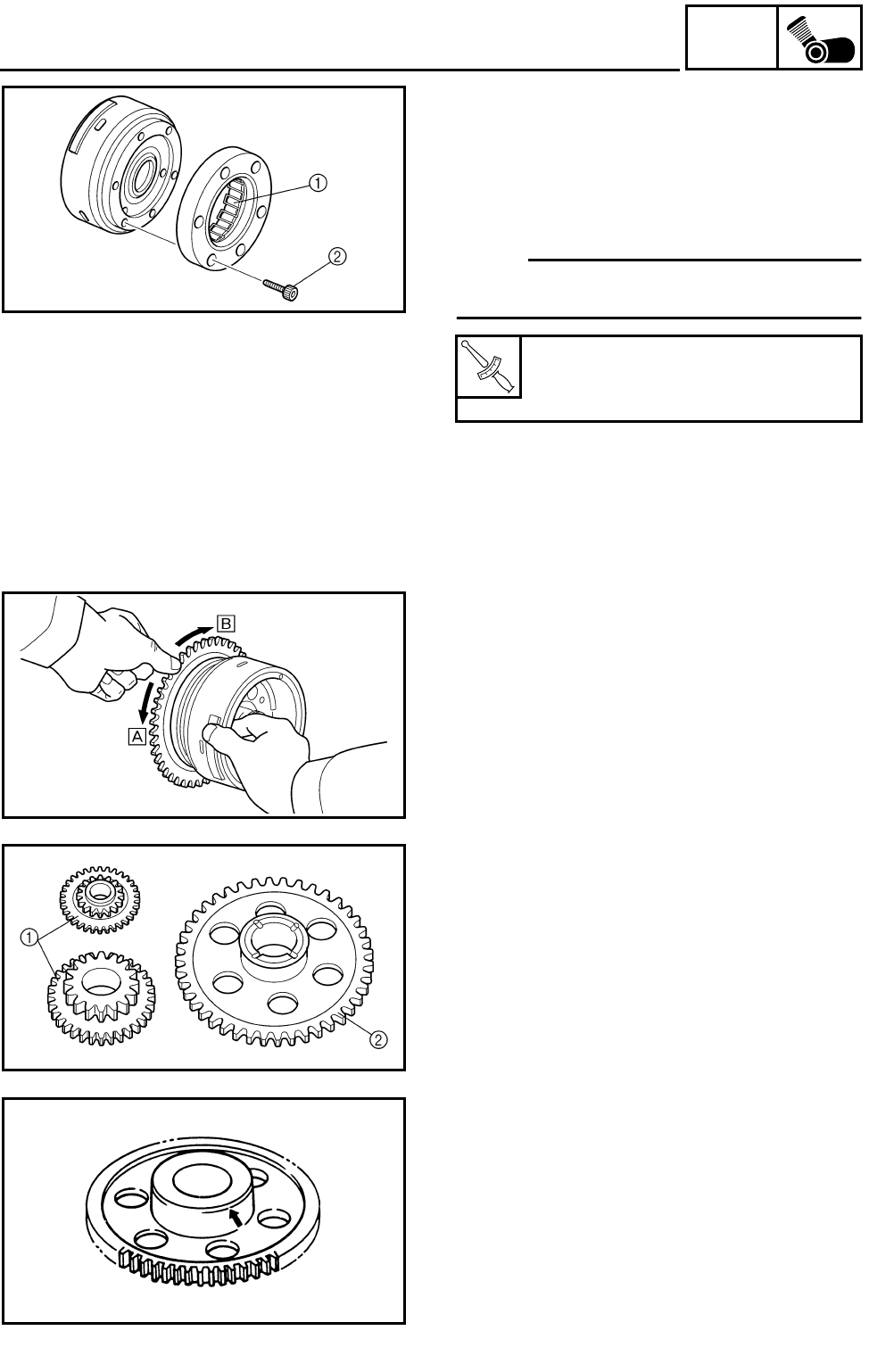
5 - 41
ENG
AC MAGNETO
CHECKING THE STARTER CLUTCH
1.Check:
●Starter one-way clutch 1
Cracks/damage → Replace.
●Bolts 2 (starter clutch)
Loose → Replace.
NOTE:
The arrow mark on the starter clutch must face
inward, away from the AC magneto rotor.
***********************************************
Checking steps:
●Install the starter wheel gear to the starter
clutch, and hold the starter clutch.
●When turning the starter wheel gear counter
clockwise È, the starter clutch and the wheel
gear should be engaged.
If not, the starter clutch is faulty. Replace it.
●When turning the starter wheel gear clock-
wise É, the starter wheel gear should turn
freely.
If not, the starter clutch is faulty. Replace it.
***********************************************
T
R
.
.
Bolts (starter clutch):
16 Nm (1.6 m • kg, 11 ft • lb)
LOCTITE®
2.Check:
●Gear teeth (starter idle) 1
●Gear teeth (starter wheel) 2
Burrs/chips/roughness/wear → Replace.
3.Check:
●Starter wheel gear
(contacting surface)
Damage/pitting/wear → Replace.
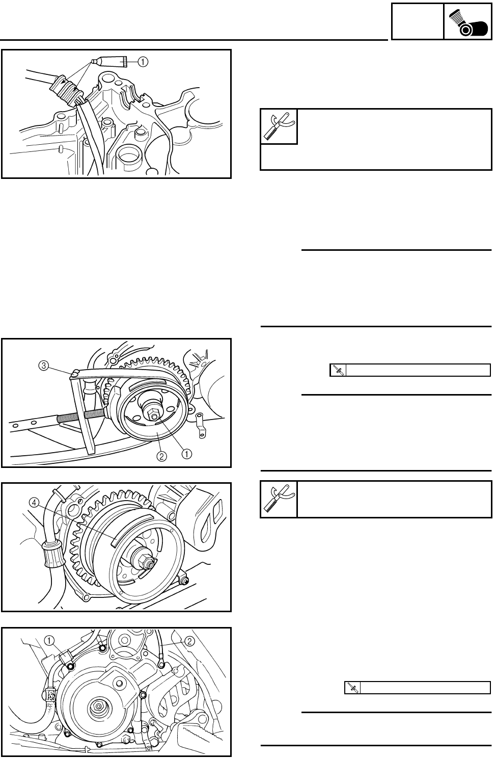
5 - 42
ENG
AC MAGNETO
INSTALLING THE AC MAGNETO ROTOR
1.Apply:
●Sealant (Quick Gasket®) 1
(into the slit)
Sealant (Quick Gasket®):
P/N. ACC-11001-05-01
Yamaha bond No. 1215®:
P/N. 90890-85505
2.Install:
●Woodruff key
●AC magneto rotor
NOTE:
●Before installing the rotor, clean the outside
of the crankshaft and the inside of the rotor.
●After installing the rotor, check that the rotor
rotates smoothly. If not, reinstall the key and
rotor.
3.Tighten:
●AC magneto rotor nut 1
NOTE:
●While holding the AC magneto rotor 2 with
the sheave holder 3, tighten the generator
rotor nut.
●Do not allow the sheave holder to touch the
projection 4 on the rotor.
Sheave holder:
P/N. YS-01880, 90890-01701
T
R
.
.
150 Nm (15.0 m • kg, 110 ft • lb)
4.Install:
●AC magneto cover
●Oil pipe holder 1
●Ground lead 2
●Bolts
NOTE:
Tighten the AC magneto cover bolts in stages,
using a crisscross pattern.
T
R
.
.
10 Nm (1.0 m • kg, 7.2 ft • lb)
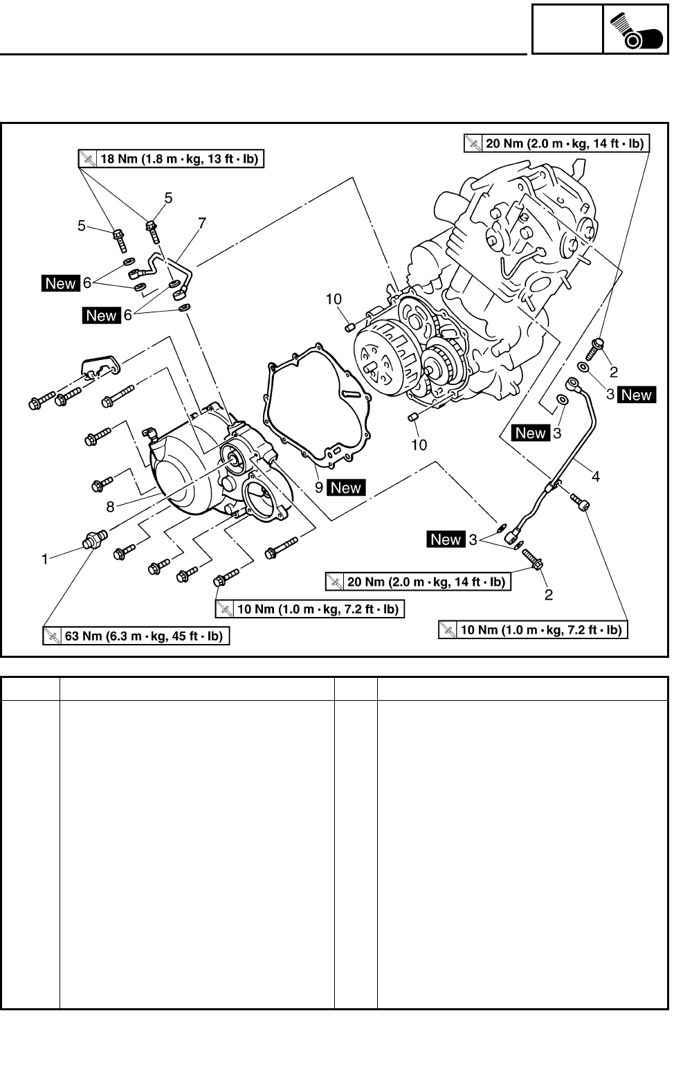
5 - 43
ENG
CLUTCH
CLUTCH
Order Job name/Part name Q’ty Remarks
Removing the clutch cover Remove the parts in the order below.
Engine assembly Refer to “ENGINE REMOVAL”.
1 Oil filter bolt 1
2 Union bolt 2
3 Copper washer 4
4 Oil delivery pipe 1 1
5 Union bolt 2
6 Copper washer 4
7 Oil delivery pipe 2 1
8 Clutch cover 1 Refer to “REMOVING/INSTALLING THE
CLUTCH”.
9 Clutch cover gasket 1
10 Dowel pin 2
For installation, reverse the removal pro-
cedure.
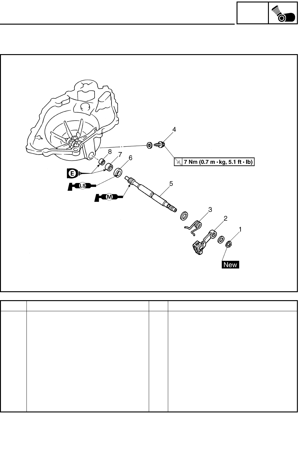
5 - 44
ENG
CLUTCH
Order Job name/Part name Q’ty Remarks
Removing the pull lever shaft Remove the parts in the order below.
1 Circlip 1
2Pull lever 1
3 Pull lever spring 1
4Bolt 1
5Pull lever shaft 1
6 Oil seal 1
7 Bearing 1
8 Bearing 1
For installation, reverse the removal pro-
cedure.
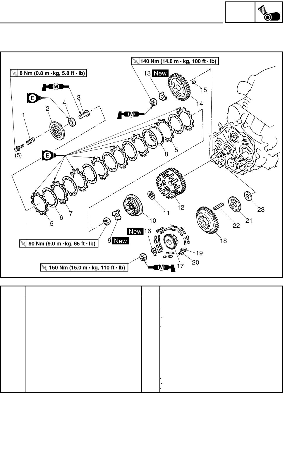
5 - 45
ENG
CLUTCH
Order Job name/Part name Q’ty Remarks
Removing the clutch Remove the parts in the order below.
1 Clutch spring 5
Refer to “INSTALLING THE CLUTCH”.2 Pressure plate 1
3Pull rod 1
4 Bearing 1
5 Friction plate 2 2 Inside diameter = 116 mm (4.57 in)
6 Clutch plate 7
7 Friction plate 1 6 Inside diameter = 112 mm (4.41 in)
8 Cushion spring 1
9 Lock washer 1 Refer to “REMOVING/INSTALLING THE
CLUTCH”.
10 Clutch boss 1
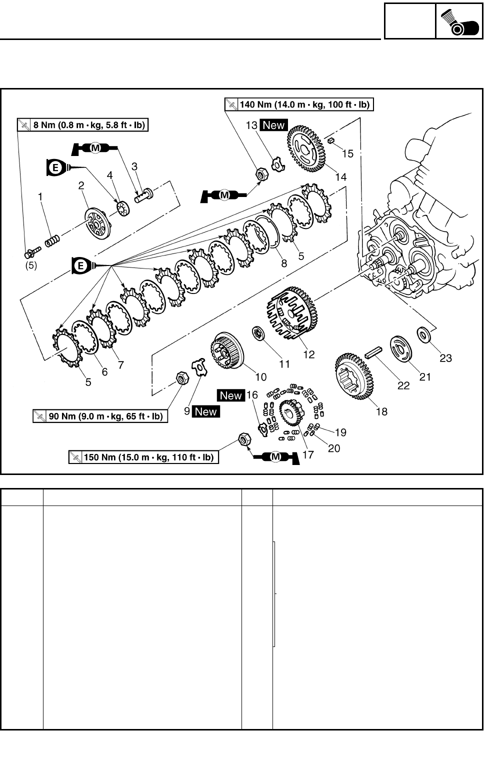
5 - 46
ENG
CLUTCH
Order Job name/Part name Q’ty Remarks
11 Thrust washer 1
12 Clutch housing 1 Refer to “INSTALLING THE CLUTCH”.
13 Lock washer 1
Refer to “REMOVING/INSTALLING THE
PRIMARY DRIVE GEAR AND BAL-
ANCER DRIVEN GEAR”.
14 Balancer driven gear 1
15 Straight key 1
16 Lock washer 1
17 Primary drive gear 1
18 Balancer drive gear 1
19 Spring 16
20 Dowel pin 16
21 Plate 1
22 Straight key 1
23 Washer 1
For installation, reverse the removal pro-
cedure.
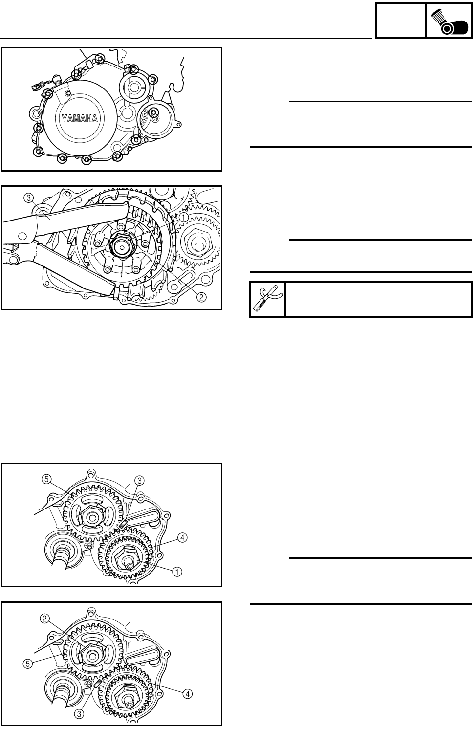
5 - 47
ENG
CLUTCH
REMOVING THE CLUTCH
1.Remove:
●Clutch cover
NOTE:
Loosen each bolt 1/4 of a turn at a time, in
stages and in a crisscross pattern. After all of
the bolts are fully loosened, remove them.
2.Straighten the lock washer tab.
3.Loosen:
●Clutch boss nut 1
NOTE:
While holding the clutch boss 2 with the clutch
holding tool 3, loosen the clutch boss nut.
Clutch holding tool:
P/N. YM-91042, 90890-04086
REMOVING THE PRIMARY DRIVE GEAR
AND BALANCER DRIVEN GEAR
1.Straighten the lock washer tabs.
2.Loosen:
●Primary drive gear nut 1
●Balancer driven gear nut 2
NOTE:
Place an aluminum plate 3 between the teeth
of the balancer drive gear 4 and balancer
driven gear 5.
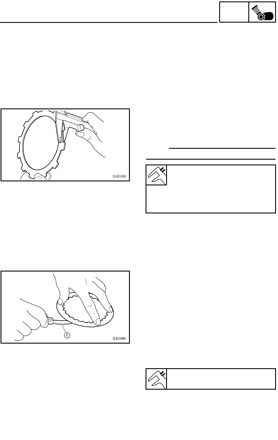
5 - 48
ENG
CLUTCH
CHECKING THE FRICTION PLATE
The following procedure applies to all of the
friction plates.
1.Check:
●Friction plate
Damage/wear → Replace the friction plates
as a set.
2.Measure:
●Friction plate thickness
Out of specification → Replace the friction
plates as a set.
NOTE:
Measure the friction plate at four places.
Friction plate 1 thickness:
2.74 ~ 2.86 mm (0.108 ~ 0.113 in)
<Limit>: 2.6 mm (0.102 in)
Friction plate 2 thickness:
2.94 ~ 3.06 mm (0.116 ~ 0.120 in)
<Limit>: 2.8 mm (0.110 in)
CHECKING THE CLUTCH PLATE
The following procedure applies to all of the
clutch plates.
1.Check:
●Clutch plate
Damage → Replace the clutch plates as a
set.
2.Measure:
●Clutch plate warpage
(with a surface plate and thickness gauge 1)
Out of specification → Replace the clutch
plates as a set.
Maximum clutch plate warpage:
0.2 mm (0.008 in)
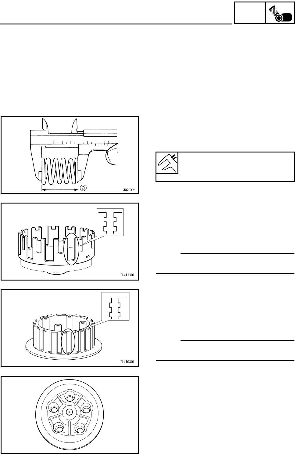
5 - 49
ENG
CLUTCH
CHECKING THE CLUTCH SPRING
The following procedure applies to all of the
clutch springs.
1.Check:
●Clutch spring
Damage → Replace the clutch springs as a
set.
2.Measure:
●Clutch spring free length a
Out of specification → Replace the clutch
springs as a set.
Clutch spring free length:
42.8 mm (1.69 in)
<Limit>: 40.7 mm (1.60 in)
CHECKING THE CLUTCH HOUSING
1.Check:
●Clutch housing dogs
Damage/pitting/wear → Deburr the clutch
housing dogs or replace the clutch housing.
NOTE:
Pitting on the clutch housing dogs will cause
erratic clutch operation.
CHECKING THE CLUTCH BOSS
1.Check:
●Clutch boss splines
Damage/pitting/wear → Replace the clutch
boss.
NOTE:
Pitting on the clutch boss splines will cause
erratic clutch operation.
CHECKING THE PRESSURE PLATE
1.Check:
●Pressure plate
Cracks/damage → Replace.
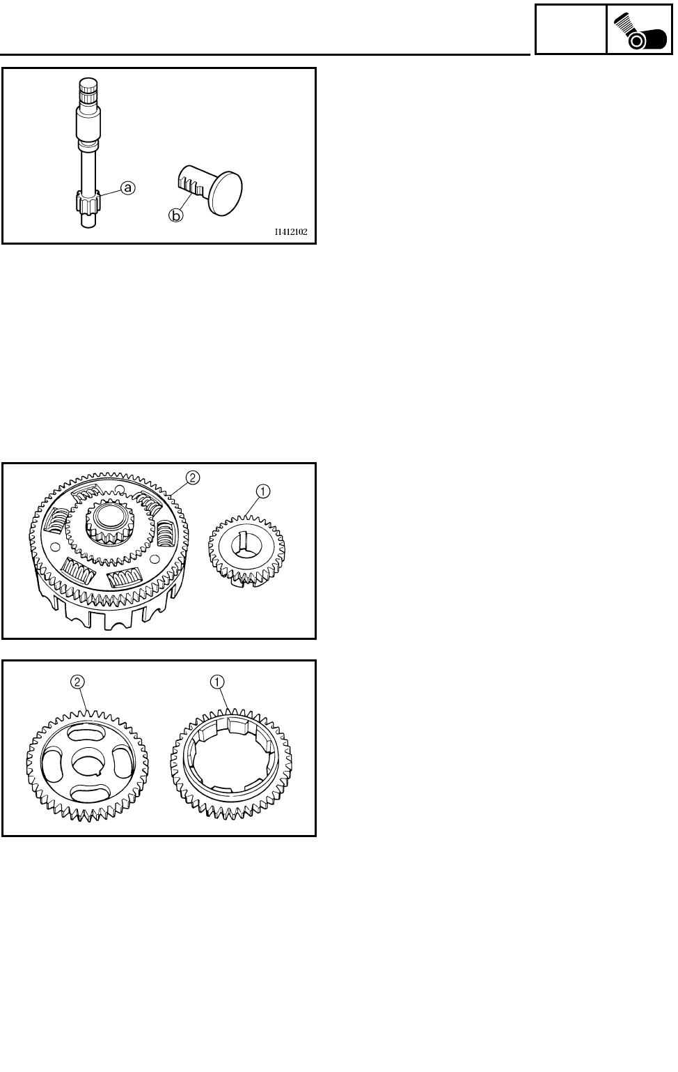
5 - 50
ENG
CLUTCH
CHECKING THE PULL LEVER SHAFT AND
PULL ROD
1.Check:
●Pull lever shaft pinion gear teeth a
●Pull rod teeth b
Damage/wear → Replace the pull lever shaft
and pull rod as a set.
2.Check:
●Pull rod bearing
Damage/wear → Replace.
CHECKING THE PRIMARY DRIVE
1.Check:
●Primary drive gear 1
●Primary driven gear 2
Damage/wear → Replace the primary drive
gear and clutch housing as a set.
Excessive noise during operation → Replace
the primary drive gear and clutch housing as
a set.
CHECKING THE BALANCER DRIVE
1.Check:
●Balancer drive gear 1
●Balancer driven gear 2
Damage/wear → Replace the balancer drive
gear and balancer driven gear as a set.
Excessive noise during operation → Replace
the balancer drive gear and balancer driven
gear as a set.
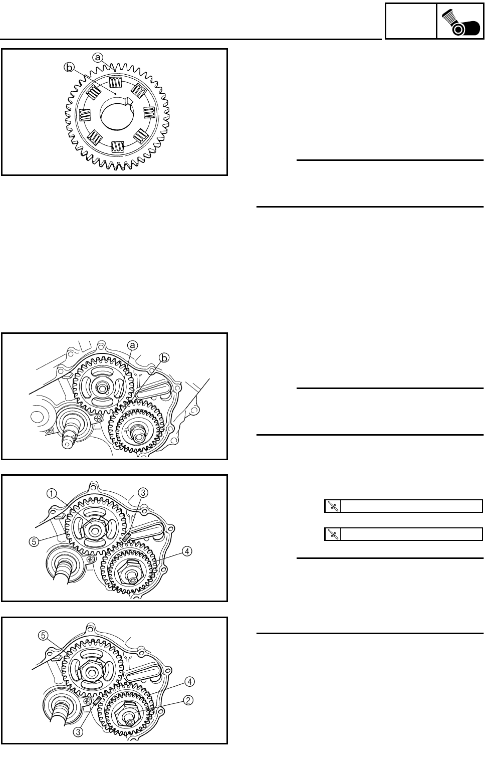
5 - 51
ENG
CLUTCH
INSTALLING THE PRIMARY DRIVE GEAR
AND BALANCER DRIVEN GEAR
1.Install:
●Dowel pin
●Spring
●Balancer drive gear
(onto the primary drive gear)
NOTE:
Align the punch mark a on the balancer drive
gear with the punch mark b on the primary
drive gear.
2.Install:
●Primary drive gear
●Balancer driven gear
NOTE:
Align the punch mark a on the balancer driven
gear with the punch mark b on the primary
drive gear.
3.Tighten:
●Balancer driven gear nut 1
●Primary drive gear nut 2
NOTE:
●Place an aluminum plate 3 between the
teeth of the balancer drive gear 4 and bal-
ancer driven gear 5.
●Apply the molybdenum disulfide grease to
the thread of axles and nuts.
4.Bend the lock washer tabs along the bal-
ancer driven gear nut.
5.Bend the lock washer tabs along a flat side
of the primary drive gear nut.
T
R
.
.
140 Nm (14.0 m • kg, 100 ft • lb)
T
R
.
.
150 Nm (15.0 m • kg, 110 ft • lb)
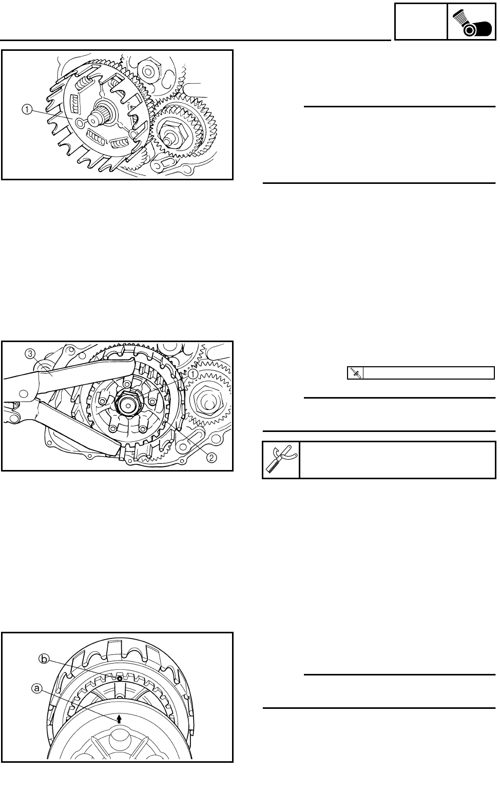
5 - 52
ENG
CLUTCH
INSTALLING THE CLUTCH
1.Install:
●Clutch housing 1
NOTE:
●Make sure that the primary driven gear teeth
and primary drive gear teeth mesh correctly.
●Make sure that the oil pump drive gear teeth
and oil pump driven gear teeth mesh cor-
rectly.
2.Tighten:
●Clutch boss nut 1
NOTE:
While holding the clutch boss 2 with the clutch
holding tool 3, tighten the clutch boss nut.
3.Bend the lock washer tab along a flat side of
the nut.
Clutch holding tool:
P/N. YM-91042, 90890-04086
T
R
.
.
90 Nm (9.0 m • kg, 65 ft • lb)
4.Install:
●Pressure plate 1
NOTE:
Align the punch mark a on the pressure plate
with the punch mark b on the clutch boss.
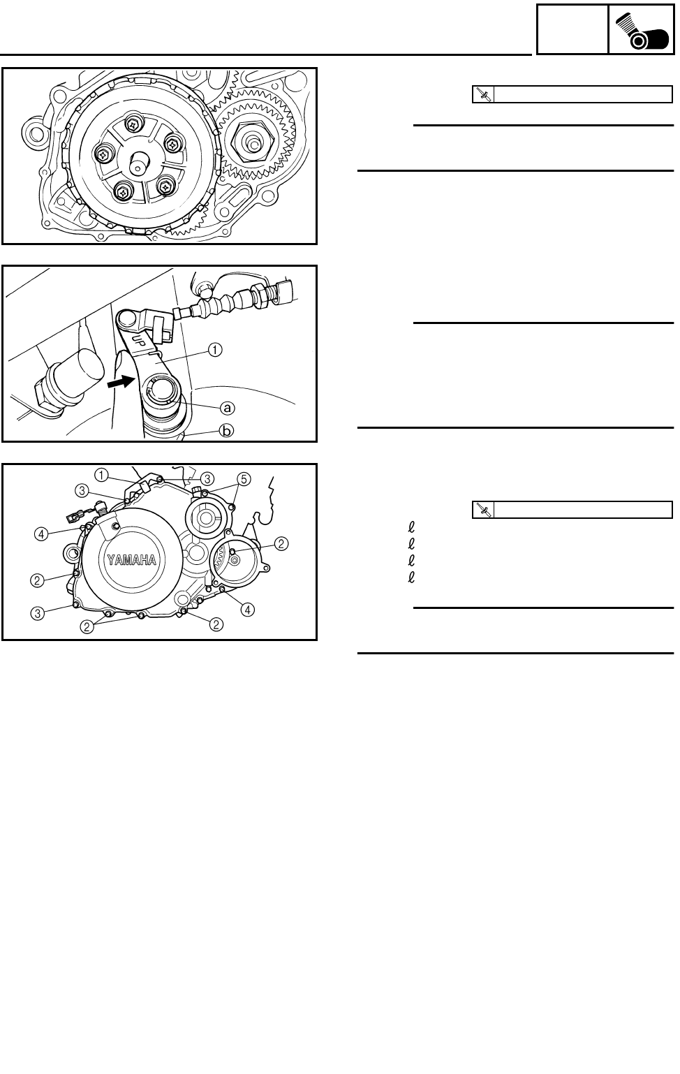
5 - 53
ENG
CLUTCH
5.Install:
●Clutch spring
NOTE:
Tighten the bolts in stages, using a crisscross
pattern.
T
R
.
.
8 Nm (0.8 m • kg, 5.8 ft • lb)
6.Install:
●Clutch cover
NOTE:
Be sure to mesh the pull lever shaft with the
pull rod teeth to ensure that the mark a on pull
lever 1 is at the closest position to stationary
pointer b onto the clutch cover when the
clutch is engaged.
7.Install:
●Clutch cable holder 1
●Bolts
2Bolt: = 25 mm
3Bolt: = 30 mm
4Bolt: = 35 mm
5Bolt: = 50 mm
NOTE:
Tighten the bolts in stages, using a crisscross
pattern.
T
R
.
.
10 Nm (1.0 m • kg, 7.2 ft • lb)
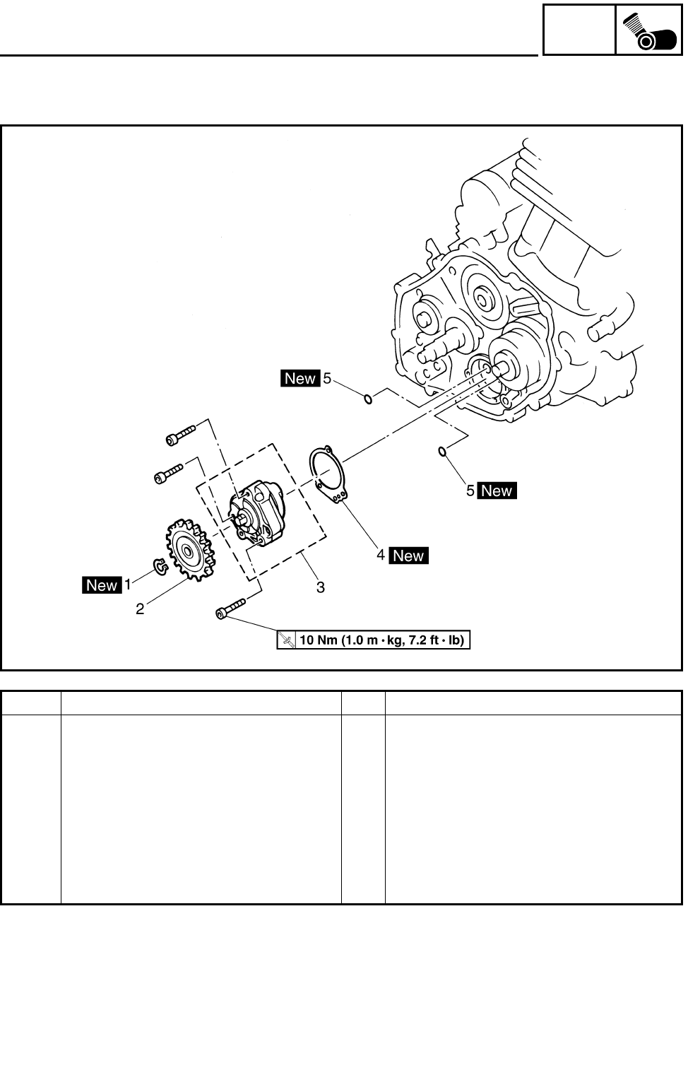
5 - 54
ENG
OIL PUMP
OIL PUMP
Order Job name/Part name Q’ty Remarks
Removing the oil pump Remove the parts in the order below.
Clutch Refer to “CLUTCH”.
1 Circlip 1
2 Oil pump driven gear 1
3 Oil pump 1
4 Oil pump gasket 1
5 O-ring 2
For installation, reverse the removal pro-
cedure.
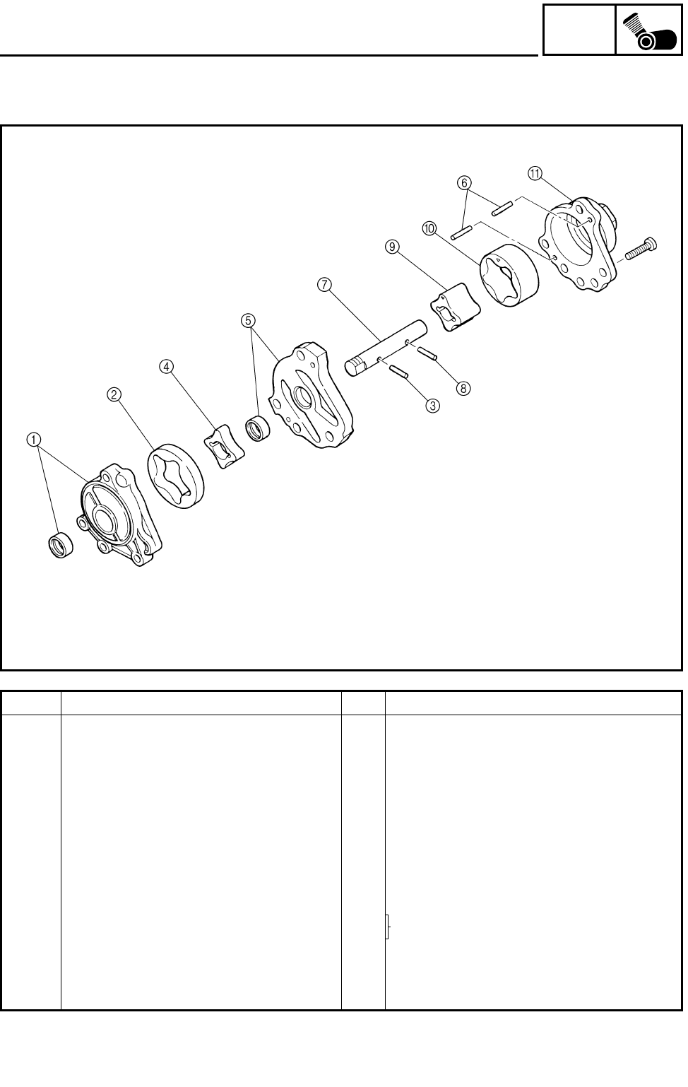
5 - 55
ENG
OIL PUMP
Order Job name/Part name Q’ty Remarks
Disassembling the oil pump Remove the parts in the order below.
1Oil pump housing 1/oil seal 1/1
2Oil pump outer rotor 1 1
3Dowel pin 1
4Oil pump inner rotor 1 1
5Oil pump housing cover/oil seal 1/1
6Dowel pin 2
7Oil pump shaft 1
8Dowel pin 1
9Oil pump inner rotor 2 1 Refer to “ASSEMBLING THE OIL
PUMP”.
0Oil pump outer rotor 2 1
AOil pump housing 2 1
For assembly, reverse the disassembly
procedure.
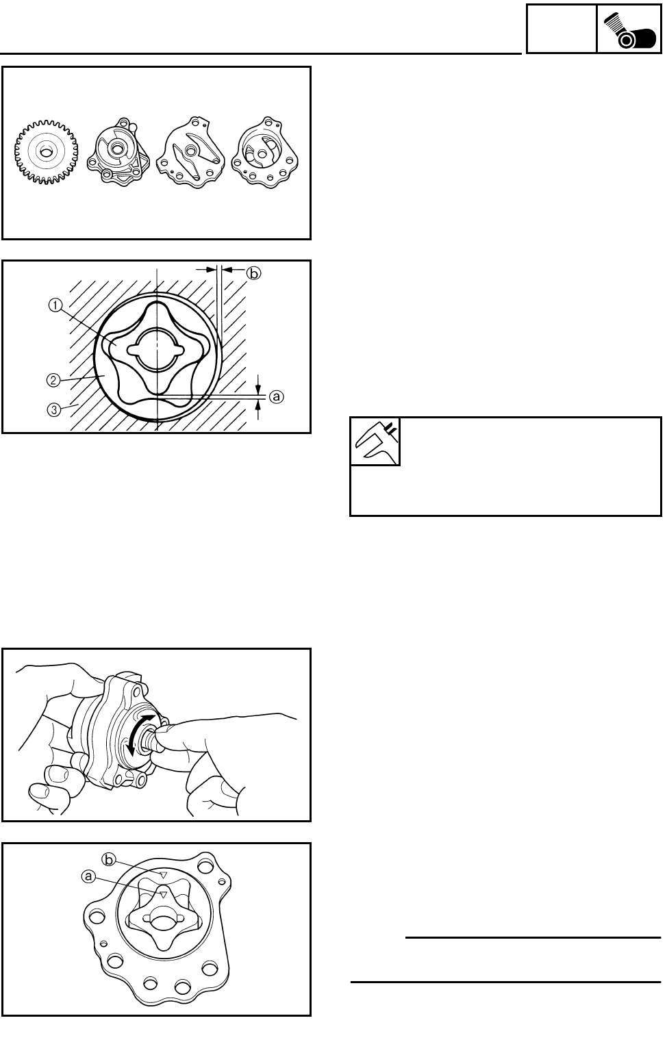
5 - 56
ENG
OIL PUMP
CHECKING THE OIL PUMP
1.Check:
●Oil pump driven gear
●Oil pump housings
●Oil pump housing cover
Cracks/wear/damage → Replace.
2.Measure:
●Tip clearance a
(between the inner rotor 1 and the outer
rotor 2)
●Side clearance b
(between the outer rotor 2 and the pump
housing 3)
Out of specification → Replace the oil pump.
Tip clearance a:
0.12 mm (0.005 in)
<Limit>: 0.2 mm (0.008 in)
Side clearance b:
0.03 ~ 0.08 mm (0.001 ~ 0.003 in)
3.Check:
●Oil pump operation
Unsmooth → Repeat steps (1) and (2) or
replace the defective parts.
ASSEMBLING THE OIL PUMP
1.Install:
●Oil pump inner rotor 2
●Oil pump outer rotor 2
NOTE:
Align the match mark a on the inner rotor 2
with the match mark b on the outer rotor 2.
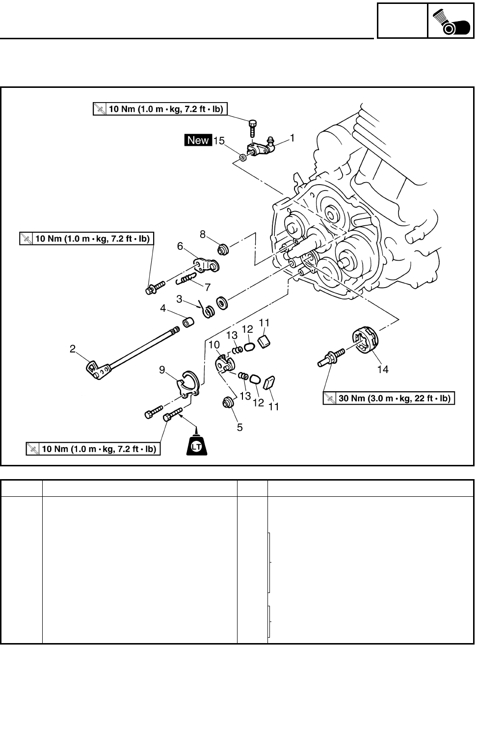
5 - 57
ENG
SHIFT SHAFT
SHIFT SHAFT
Order Job name/Part name Q’ty Remarks
Removing the shift shaft Remove the parts in the order below.
Clutch Refer to “CLUTCH”.
1 Shift arm 1
Refer to “INSTALLING THE SHIFT
SHAFT”.
2 Shift shaft 1
3 Shift shaft spring 1
4Collar 1
5Roller 1
6 Stopper lever 1 Refer to “INSTALLING THE STOPPER
LEVER”.
7 Stopper lever spring 1
8Roller 1

5 - 58
ENG
SHIFT SHAFT
Order Job name/Part name Q’ty Remarks
9 Shift guide 1
Refer to “INSTALLING THE SHIFT
LEVER”.
10 Shift lever 1
11 Pawl 2
12 Pawl pin 2
13 Spring 2
14 Segment 1
15 Oil seal 1
For installation, reverse the removal pro-
cedure.
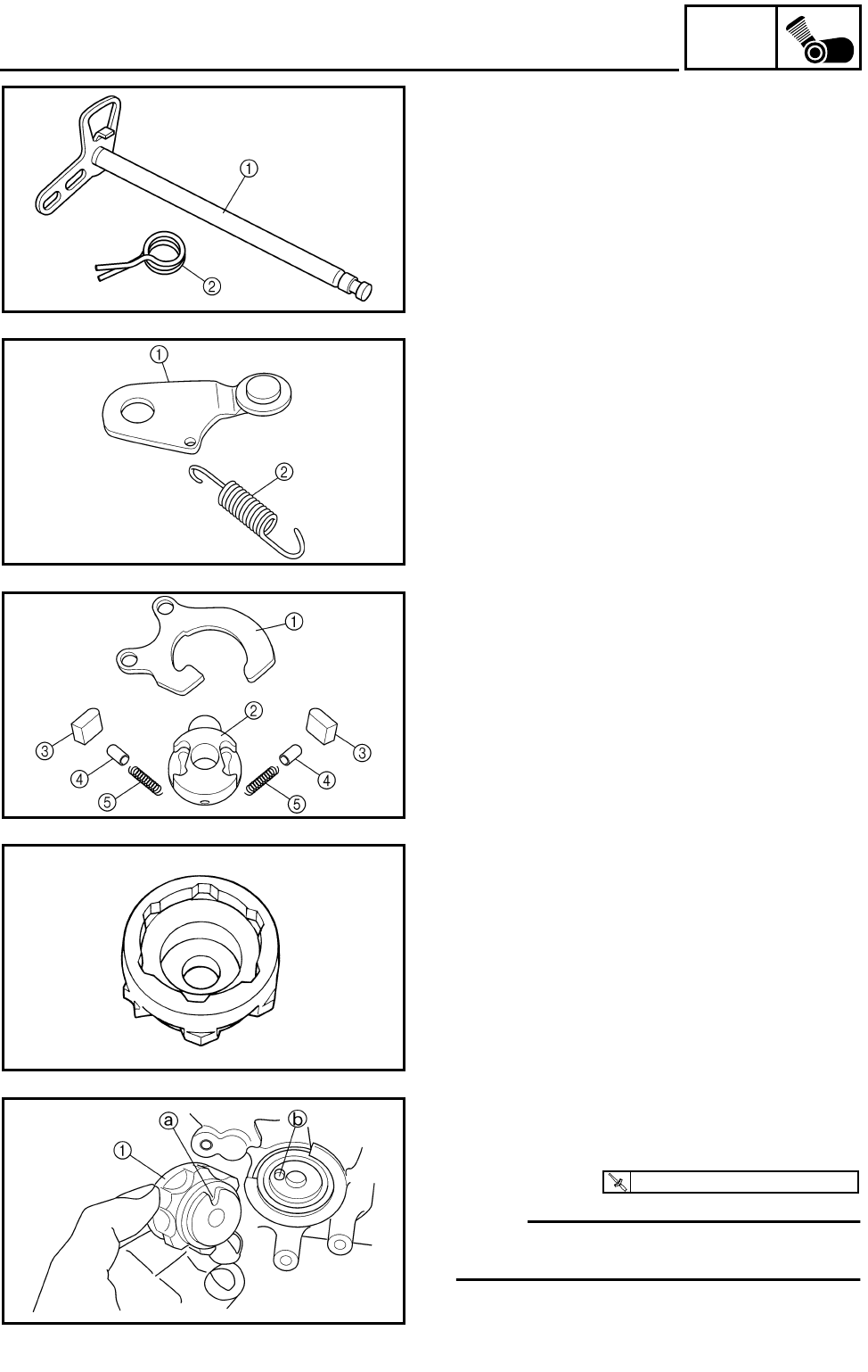
5 - 59
ENG
SHIFT SHAFT
CHECKING THE SHIFT SHAFT
1.Check:
●Shift shaft 1
Bends/damage/wear → Replace.
●Shift shaft spring 2
Damage/wear → Replace.
CHECKING THE STOPPER LEVER
1.Check:
●Stopper lever 1
Bends/damage → Replace.
Roller turns roughly → Replace the stopper
lever.
●Stopper spring 2
Damage → Replace.
CHECKING THE SHIFT GUIDE AND SHIFT
LEVER
1.Check:
●Shift guide 1
●Shift lever 2
●Pawl 3
●Pawl pin 4
●Spring 5
Damage/wear → Replace.
CHECKING THE SEGMENT
1.Check:
●Segment
Damage/wear → Replace.
INSTALLING THE SHIFT LEVER
1.Install:
●Segment 1
●Segment bolt
NOTE:
Align the notch a on the segment with the pin
b on the shift cam.
T
R
.
.
30 Nm (3.0 m • kg, 22 ft • lb)
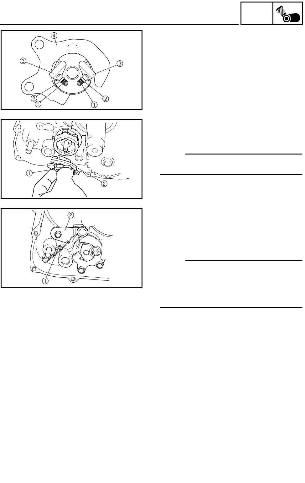
5 - 60
ENG
SHIFT SHAFT
2.Install:
●Springs 1
●Pawl pins 2
●Pawls 3
●Shift guide 4
(to the shift lever)
3.Install:
●Shift lever assembly 1
●Shift guide 2
NOTE:
The shift lever assembly is installed at the
same time as the shift guide.
INSTALLING THE STOPPER LEVER
1.Install:
●Roller
●Stopper lever spring 1
●Stopper lever 2
NOTE:
●Hook the ends of the stopper lever spring
onto the stopper lever and the crankcase
boss.
●Mesh the stopper lever with the shift drum
segment.

5 - 61
ENG
SHIFT SHAFT
INSTALLING THE SHIFT SHAFT
1.Install:
●Roller 1
●Collar
●Shift shaft spring
●Shift shaft 2
NOTE:
●Install the end of the shift shaft spring onto
the shift shaft spring stopper 3.
●Install the end of the shift shaft lever onto the
roller 1.
2.Install:
●Shift arm 1
●Bolt 2
NOTE:
Be sure to install the shaft arm so that position
a is horizontal.
T
R
.
.
10 Nm (1.0 m • kg, 7.2 ft • lb)

5 - 62
ENG
CRANKCASE
CRANKCASE
TIMING CHAIN AND SPEED SENSOR ROTOR
Order Job name/Part name Q’ty Remarks
Removing the timing chain and
speed sensor rotor
Remove the parts in the order below.
Engine assembly Refer to “ENGINE REMOVAL”.
Cylinder head cover Refer to “CYLINDER HEAD COVER”.
Cylinder head Refer to “CAMSHAFT AND CYLINDER
HEAD”.
Cylinder and piston Refer to “CYLINDER AND PISTON”.
AC rotor Refer to “AC MAGNETO”.
Clutch, balancer drive gear and bal-
ancer driven gear
Refer to “CLUTCH”.
Oil pump Refer to “OIL PUMP”.
Shift shaft and shift drum segment Refer to “SHIFT SHAFT”.
1 Timing chain guide (intake) 1
2 Timing chain 1
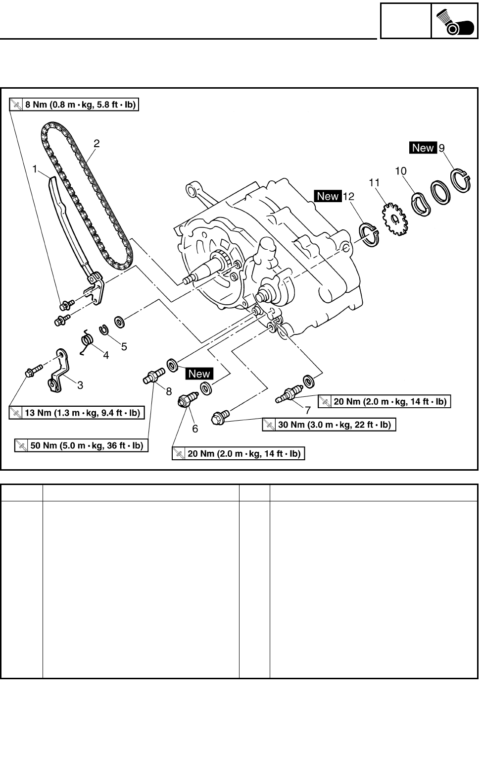
5 - 63
ENG
CRANKCASE
Order Job name/Part name Q’ty Remarks
3 Reverse shift lever 1
4 Reverse shift lever spring 1
5 Circlip 1
6 Neutral switch 1
7 Reverse switch 1
8 Oil pipe joint 1
9 Circlip 1
10 Wave washer 1
11 Speed sensor rotor 1
12 Circlip 1
For installation, reverse the removal pro-
cedure.
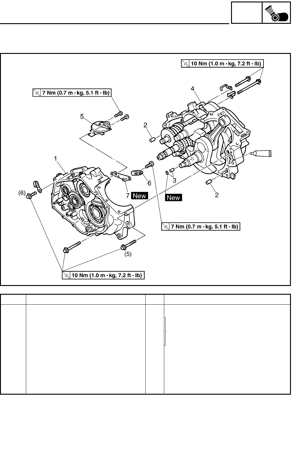
5 - 64
ENG
CRANKCASE
CRANKCASE
Order Job name/Part name Q’ty Remarks
Separating the crankcase Remove the parts in the order below.
1 Right crankcase 1
Refer to “CRANKCASE”.
2 Dowel pin 2
3 Dowel pin/O-ring 1/1
4 Left crankcase 1
5 Oil strainer 1
6 Cover 1
7 Oil strainer gasket 1
For installation, reverse the removal pro-
cedure.
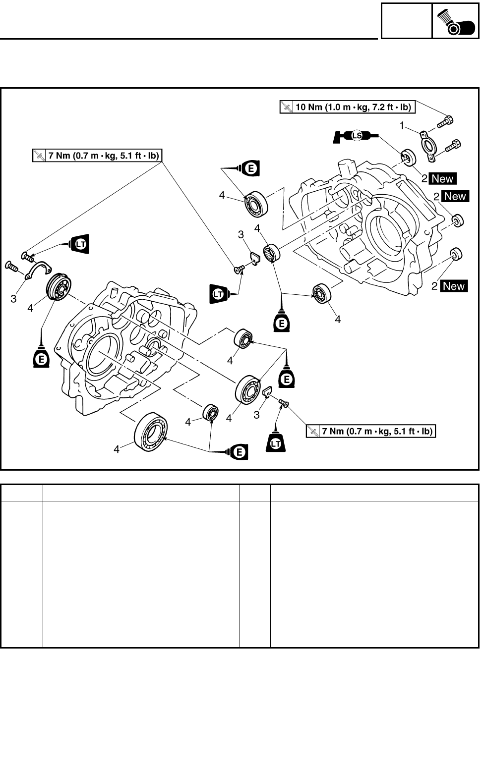
5 - 65
ENG
CRANKCASE
CRANKCASE BEARING
Order Job name/Part name Q’ty Remarks
Removing the crankcase bearing Remove the parts in the order below.
Crankshaft and balancer Refer to “CRANKSHAFT AND BAL-
ANCER”.
Transmission Refer to “TRANSMISSION”.
1 Oil seal retainer 1
2 Oil seal 3
3 Bearing retainer 3
4 Bearing 8
For installation, reverse the removal pro-
cedure.
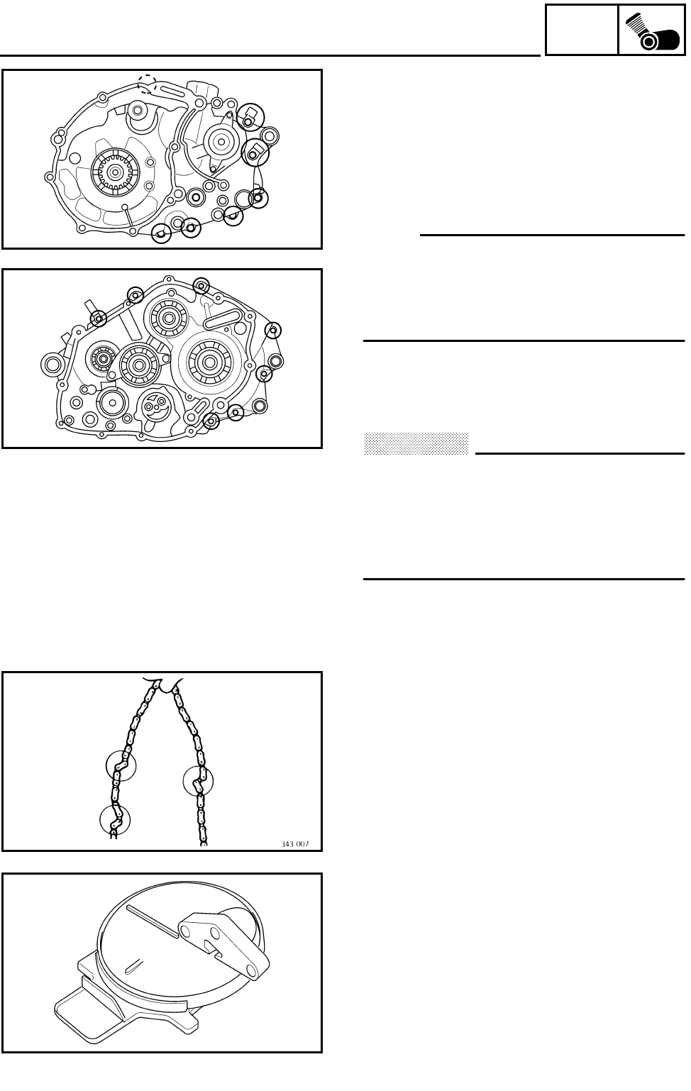
5 - 66
ENG
CRANKCASE
SEPARATING THE CRANKCASE
1.Separate:
●Left crankcase
●Right crankcase
***********************************************
Separation steps:
●Remove the crankcase bolts.
NOTE:
●Loosen each bolt 1/4 of a turn at a time and
after all the bolts are loosened, remove
them.
●Loosen the bolts in stages, using a criss-
cross pattern.
ÈLeft crankcase
ÉRight crankcase
●Remove the right crankcase.
CAUTION:
Use a soft hammer to tap on one side of the
crankcase. Tap only on reinforced portions
of the crankcase. Do not tap on the crank-
case mating surfaces. Work slowly and
carefully. Make sure that the crankcase
halves separate evenly.
●Remove the dowel pins and O-ring.
***********************************************
È
É
CHECKING THE TIMING CHAIN AND GUIDE
1.Check:
●Timing chain
Cracks/stiff → Replace the timing chain and
camshaft sprocket as a set.
2.Check:
●Intake side timing chain guide
Wear/damage → Replace.
CHECKING THE OIL STRAINER
1.Check:
●Oil strainer
Damage → Replace.
Contaminations → Clean with engine oil.
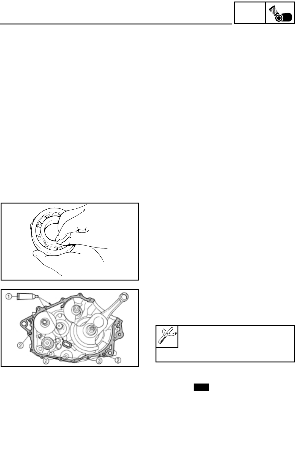
5 - 67
ENG
CRANKCASE
CHECKING THE CRANKCASE
1.Thoroughly wash the case halves in a mild
solvent.
2.Clean all the gasket mating surfaces and
crankcase mating surfaces thoroughly.
3.Check:
●Crankcase
Cracks/damage → Replace.
●Oil delivery passages
Clogged → Blow out with compressed air.
CHECKING THE BEARINGS
1.Check:
●Bearing
Clean and lubricate, then rotate the inner
race with a finger.
Roughness → Replace.
ASSEMBLING THE CRANKCASE
1.Apply:
●Sealant (Quick Gasket®) 1
(to the mating surfaces of both case halves)
2.Install:
●Dowel pin 2
●O-ring 3
Sealant (Quick Gasket®):
P/N. ACC-11001-05-01
Yamaha bond No. 1215:
P/N. 90890-85505
New
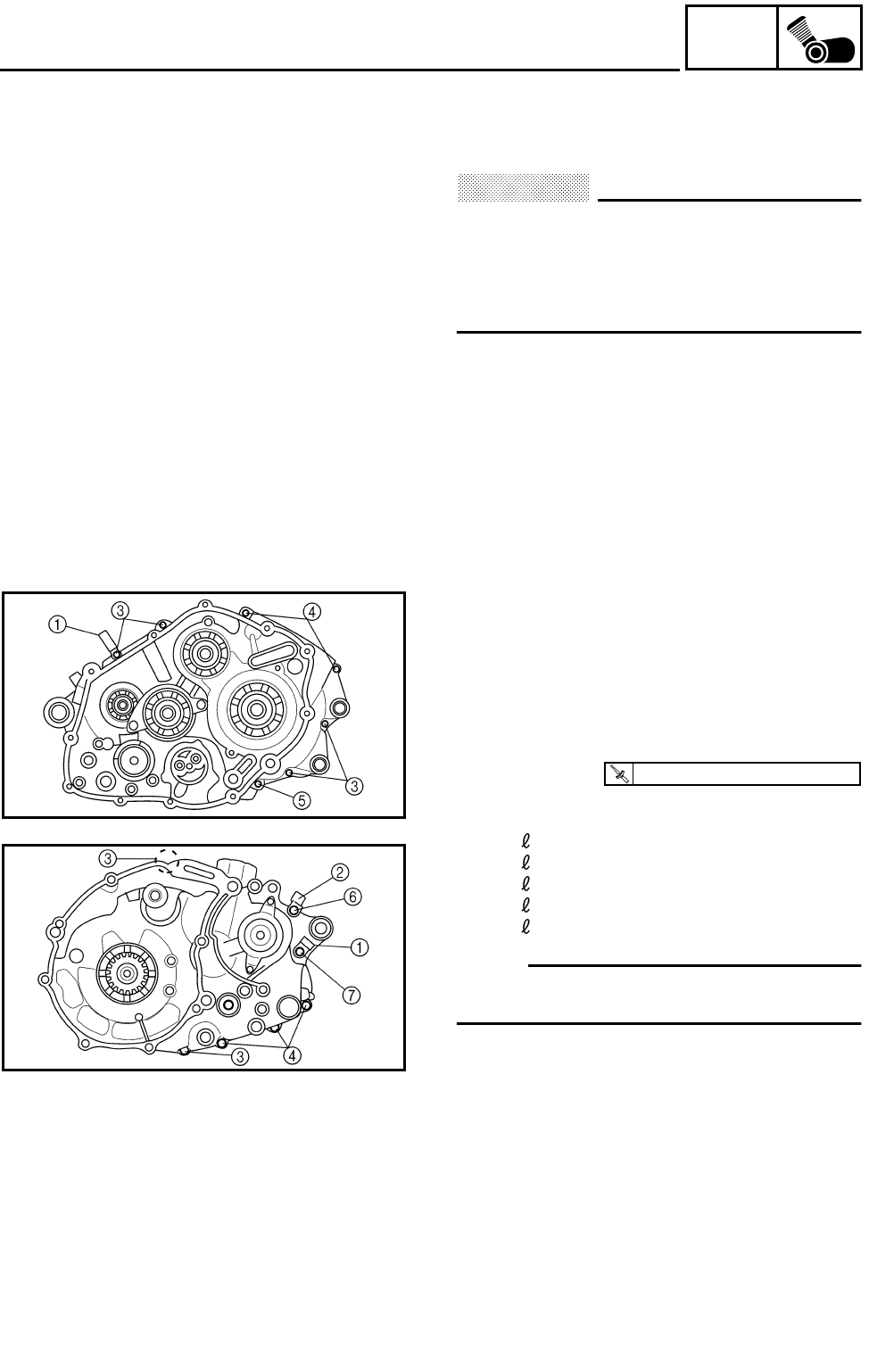
5 - 68
ENG
CRANKCASE
3.Fit the right crankcase onto the left crank-
case. Tap lightly on the case with a soft ham-
mer.
CAUTION:
Before installing and torquing the crank-
case holding bolts, be sure to check
whether the transmission is functioning
properly by manually rotating the shift cam
in both directions.
4.Install:
●Lead guides 1
●Hose guide 2
●Crankcase bolts
5.Tighten:
●Crankcase bolts
(follow the proper tightening sequence)
ÈRight crankcase
ÉLeft crankcase
3Bolt: = 30 mm
4Bolt: = 45 mm
5Bolt: = 60 mm
6Bolt: = 65 mm
7Bolt: = 80 mm
NOTE:
Tighten the bolts in stages, using a crisscross
pattern.
È
É
T
R
.
.
10 Nm (1.0 m • kg, 7.2 ft • lb)
6.Apply:
●4-stroke engine oil
(to the crank pin, bearing and oil delivery
hole)
7.Check:
●Crankshaft and transmission operation
Unsmooth operation → Repair.
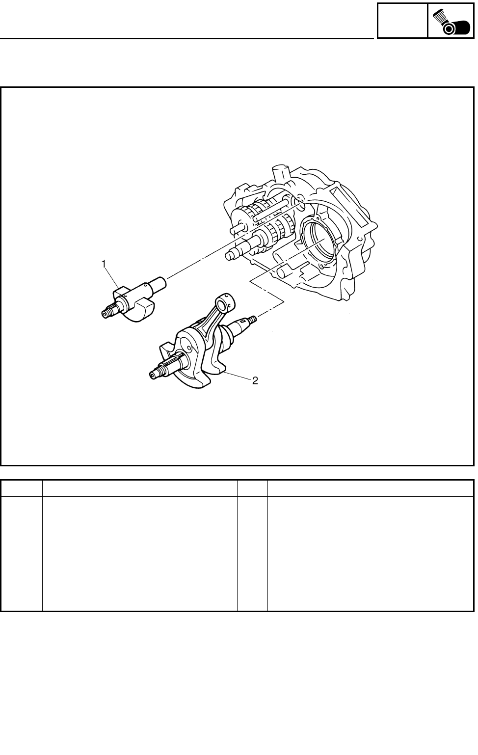
5 - 69
ENG
CRANKSHAFT AND BALANCER
CRANKSHAFT AND BALANCER
Order Job name/Part name Q’ty Remarks
Removing the crankshaft and bal-
ancer
Remove the parts in the order below.
Crankcase Separate. Refer to “CRANKCASE”.
1 Balancer 1
2 Crankshaft 1 Refer to “REMOVING/INSTALLING THE
CRANKSHAFT”.
For installation, reverse the removal pro-
cedure.
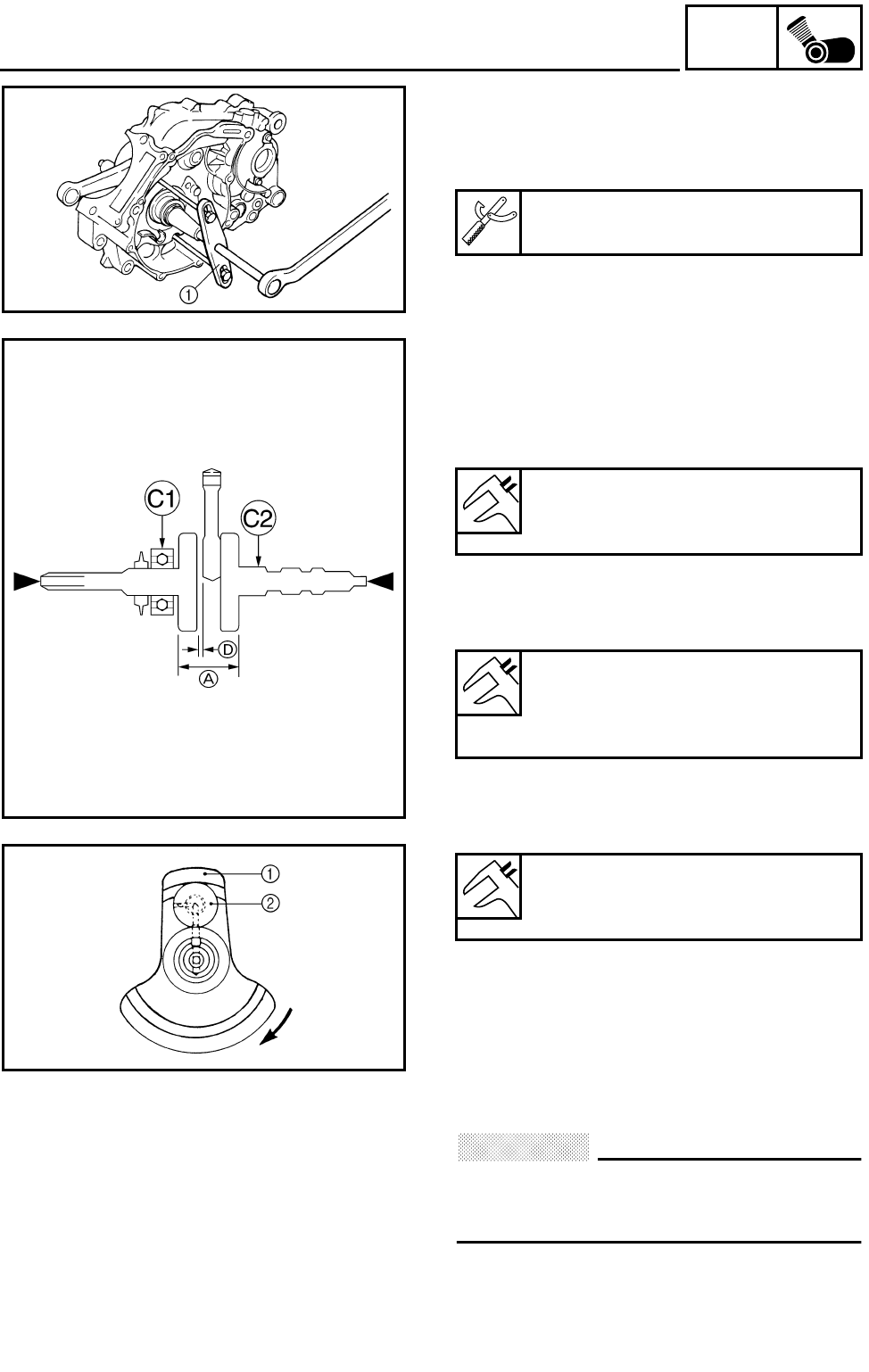
5 - 70
ENG
CRANKSHAFT AND BALANCER
REMOVING THE CRANKSHAFT
1.Remove:
●Crankshaft
Use a crankcase separating tool 1.
Crankcase separating tool:
P/N. YU-01135-A, 90890-01135
CHECKING THE CRANKSHAFT
1.Measure:
●Crank width A
Out of specification → Replace the crank-
shaft.
●Side clearance D
Out of specification → Replace the crank-
shaft.
●Runout C
Out of specification → Replace the crank-
shaft.
***********************************************
Crankshaft reassembling point:
The crankshaft 1 and the crank pin 2 oil pas-
sages must be properly interconnected with a
tolerance of less than 1 mm (0.04 in).
***********************************************
CAUTION:
The buffer boss and woodruff key should
be replaced when removed from the crank-
shaft.
Crank width:
74.95 ~ 75.00 mm
(2.9508 ~ 2.9528 in)
Big end side clearance:
0.32 ~ 0.64 mm
(0.0126 ~ 0.0252 in)
<Limit>: 1.0 mm (0.040 in)
Runout limit:
C1: 0.03 mm (0.0012 in)
C2: 0.03 mm (0.0012 in)
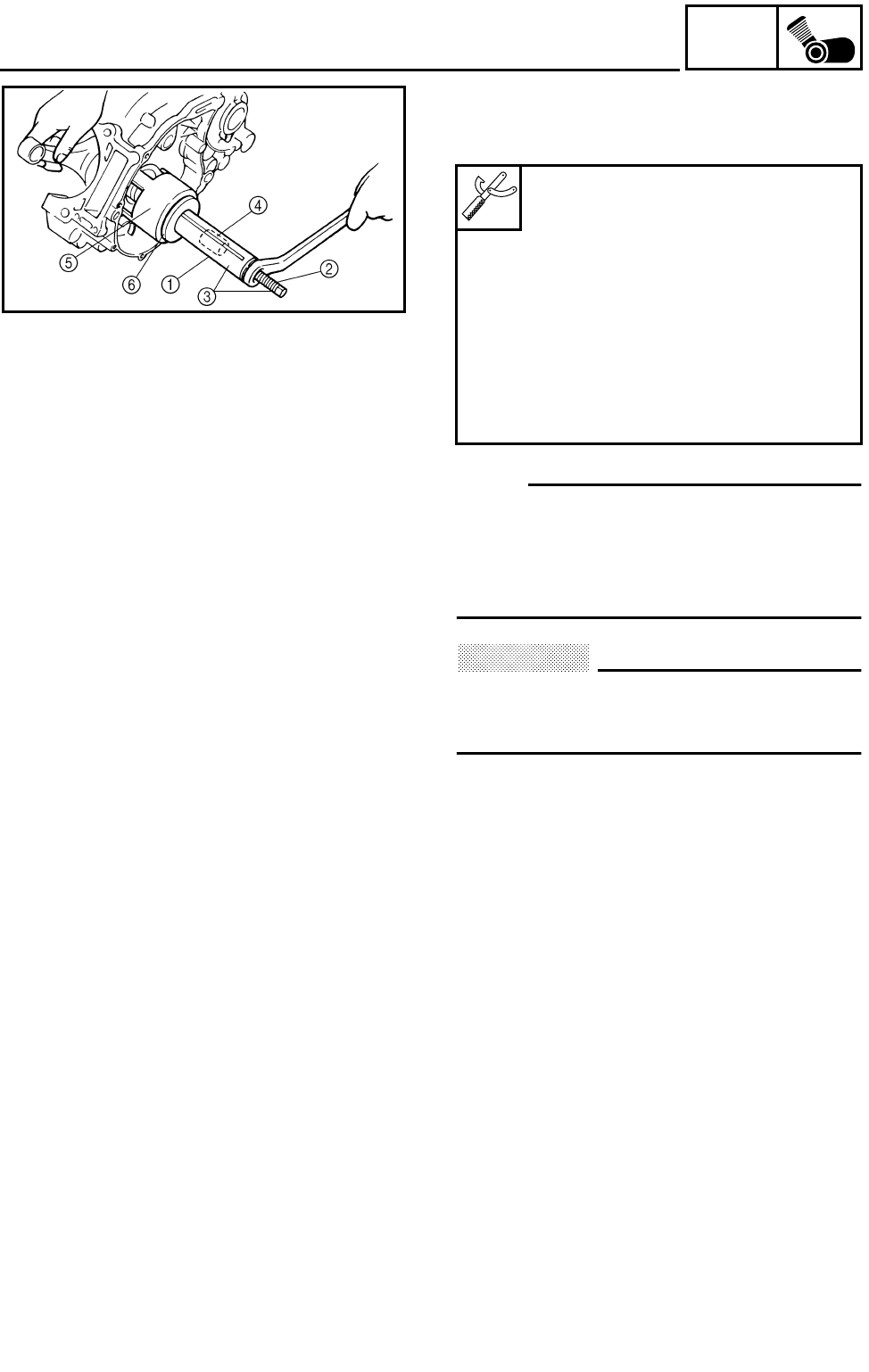
5 - 71
ENG
CRANKSHAFT AND BALANCER
INSTALLING THE CRANKSHAFT
1.Install:
●Crankshaft
NOTE:
Hold the connecting rod at the Top Dead Cen-
ter (TDC) with one hand while turning the nut
of the installing tool with the other. Operate the
installing tool until the crankshaft bottoms
against the bearing.
CAUTION:
Apply engine oil to each bearing to protect
the crankshaft against scratches and to
make installation easier.
Crankshaft installer pot 1:
P/N. 90890-01274
Crankshaft installer bolt 2:
P/N. 90890-01275
Crankshaft installer set 3:
P/N. YU-90050
Adapter 4:
P/N. YM-90069, 90890-04059
Spacer (crankshaft installer) 5:
P/N. YM-91044, 90890-04081
Spacer 6:
P/N. 90890-01016
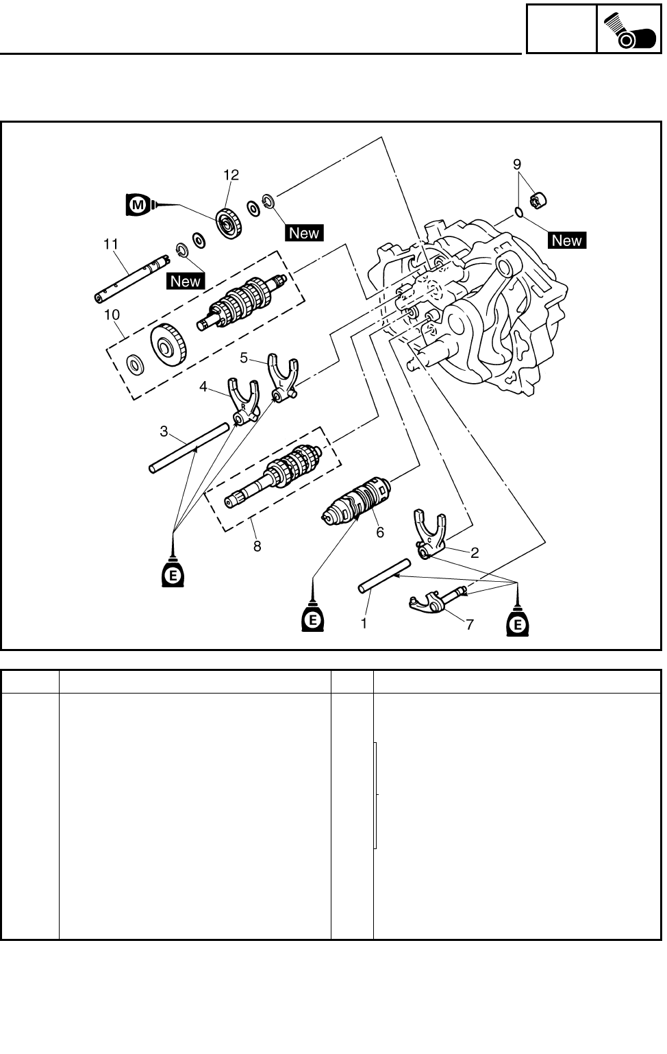
5 - 72
ENG
TRANSMISSION
TRANSMISSION
Order Job name/Part name Q’ty Remarks
Removing the transmission Remove the parts in the order below.
Crankcase Separate. Refer to “CRANKCASE”.
1 Shift fork guide bar (short) 1
Refer to “INSTALLING THE TRANSMIS-
SION”.
2 Shift fork “C” 1
3 Shift fork guide bar (long) 1
4 Shift fork “R” 1
5 Shift fork “L” 1
6 Shift drum 1
7 Reverse shift shaft 1
8 Main axle assembly 1
9 Spacer/O-ring 1/1
10 Drive axle 1
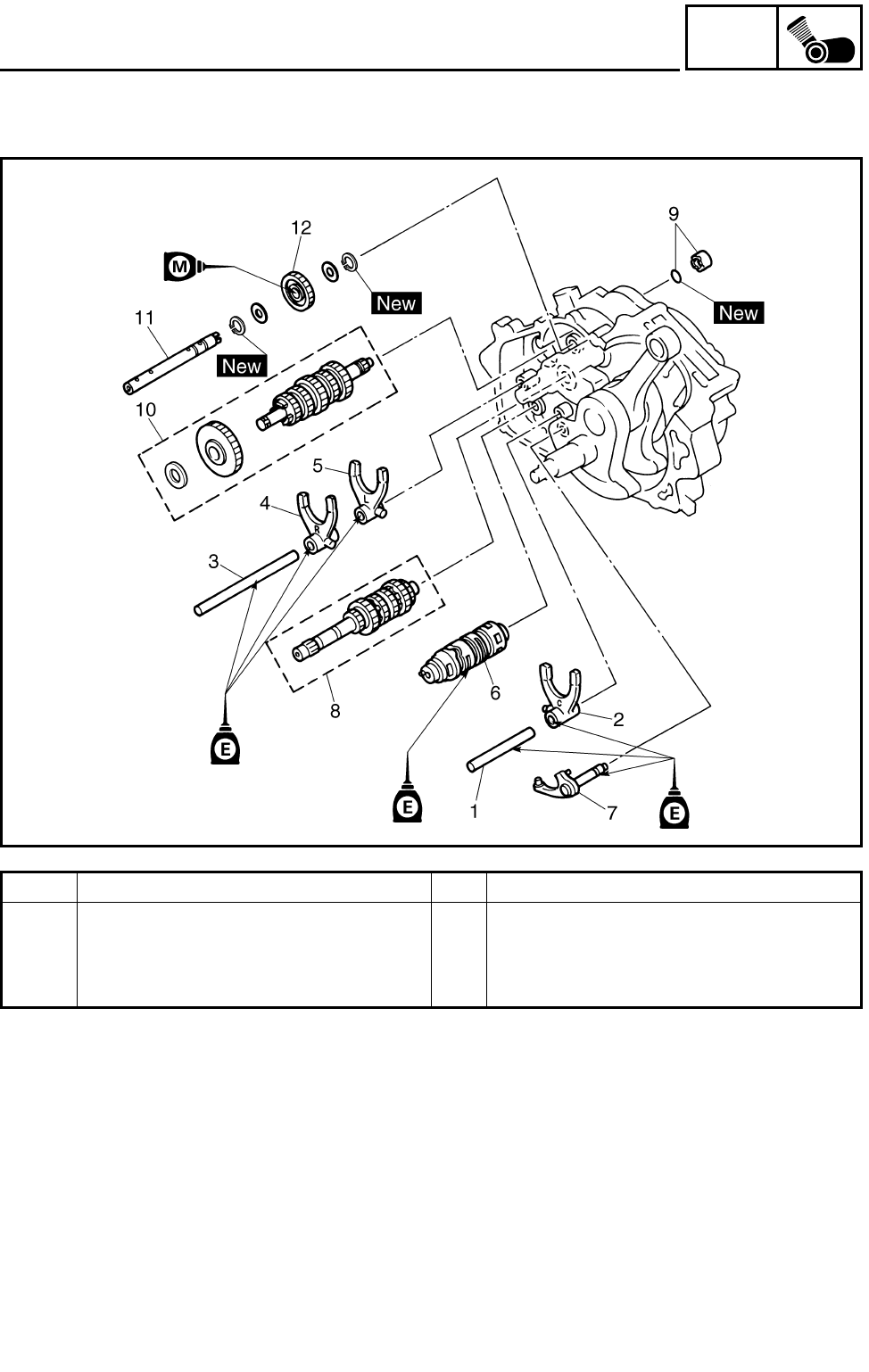
5 - 73
ENG
TRANSMISSION
Order Job name/Part name Q’ty Remarks
11 Counter axle 1
12 Counter gear 1
For installation, reverse the removal pro-
cedure.
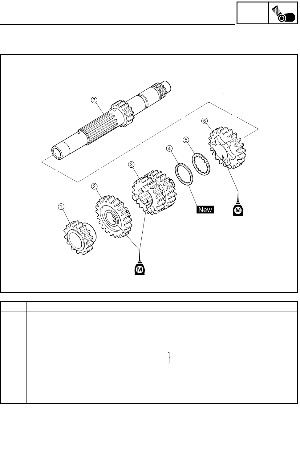
5 - 74
ENG
TRANSMISSION
MAIN AXLE
Order Job name/Part name Q’ty Remarks
Disassembling the main axle Remove the parts in the order below.
1Reverse pinion gear 1
24th pinion gear 1
32nd/3rd pinion gear 1
4Circlip 1 Refer to “ASSEMBLING THE MAIN
AXLE AND DRIVE AXLE”.
5Toothed washer 1
65th pinion gear 1
7Main axle/1st pinion gear 1
For assembly, reverse the disassembly
procedure.
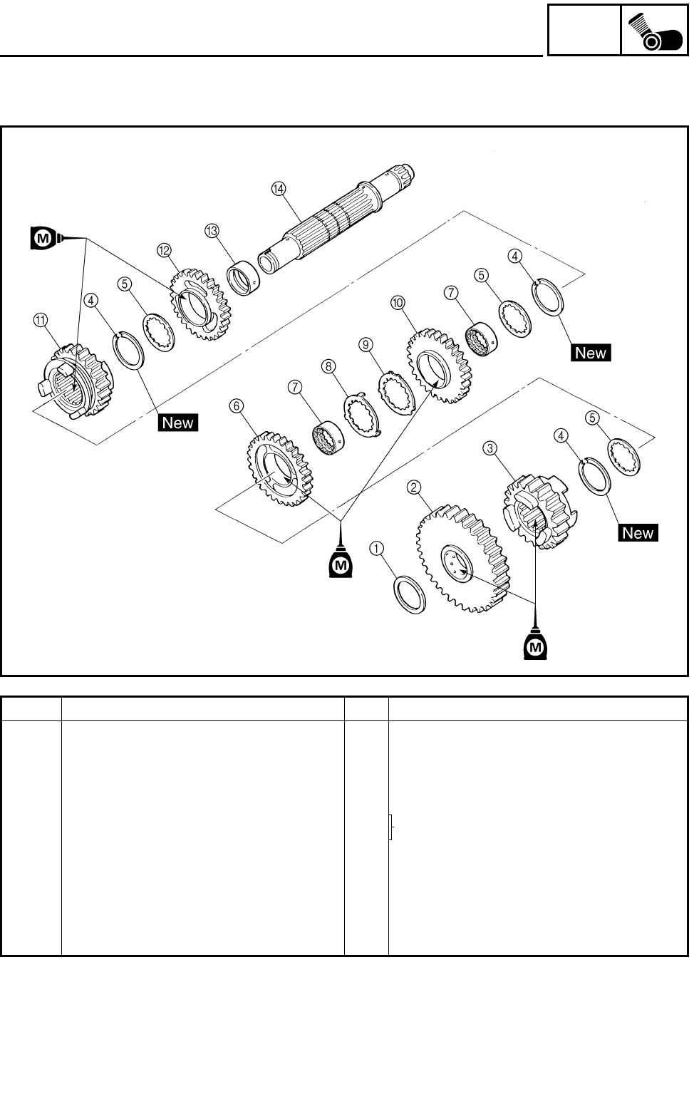
5 - 75
ENG
TRANSMISSION
DRIVE AXLE
Order Job name/Part name Q’ty Remarks
Disassembling the drive axle Remove the parts in the order below.
1Washer 1
21st wheel gear 1
35th wheel gear 1
4Circlip 3 Refer to “ASSEMBLING THE MAIN
AXLE AND DRIVE AXLE”.
5Toothed washer 3
63rd wheel gear 1
7Toothed collar 2
8Toothed lock washer 1
9Toothed lock washer retainer 1
02nd wheel gear 1
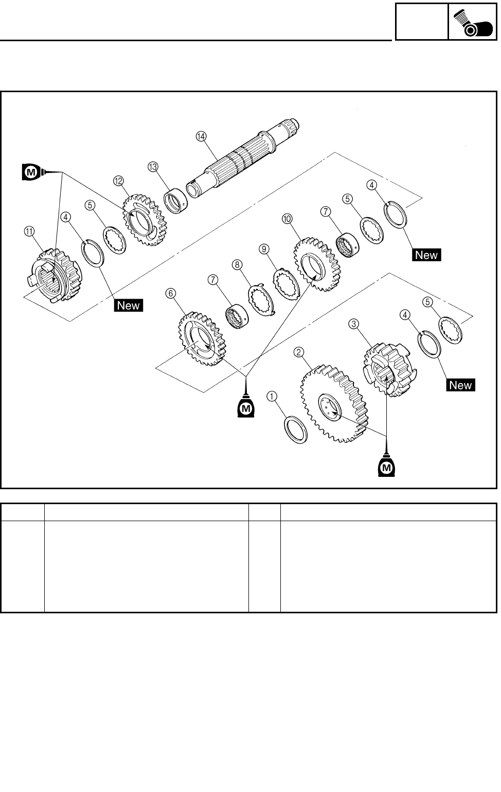
5 - 76
ENG
TRANSMISSION
Order Job name/Part name Q’ty Remarks
A4th wheel gear 1
BReverse wheel gear 1
CCollar 1
DDrive axle 1
For assembly, reverse the disassembly
procedure.
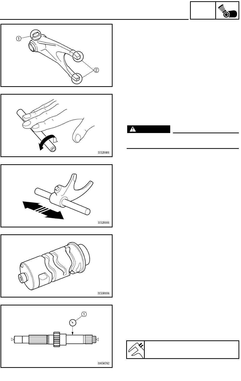
5 - 77
ENG
TRANSMISSION
CHECKING THE SHIFT FORK
1.Check:
●Shift fork cam follower 1
●Shift fork pawl 2
Scoring/bends/wear/damage → Replace.
2.Check:
●Guide bar
Roll the guide bar on a flat surface.
Bends → Replace.
WARNING
Do not attempt to straighten a bent guide
bar.
3.Check:
●Shift fork movement
(on the guide bar)
Unsmooth operation → Replace the shift fork
and the guide bar as a set.
CHECKING THE SHIFT DRUM
1.Check:
●Shift cam grooves
Scratches/wear/damage → Replace.
CHECKING THE TRANSMISSION
1.Measure:
●Main axle runout
(with a centering device and dial gauge 1)
Out of specification → Replace the main axle.
Maximum main axle runout:
0.08 mm (0.0031 in)
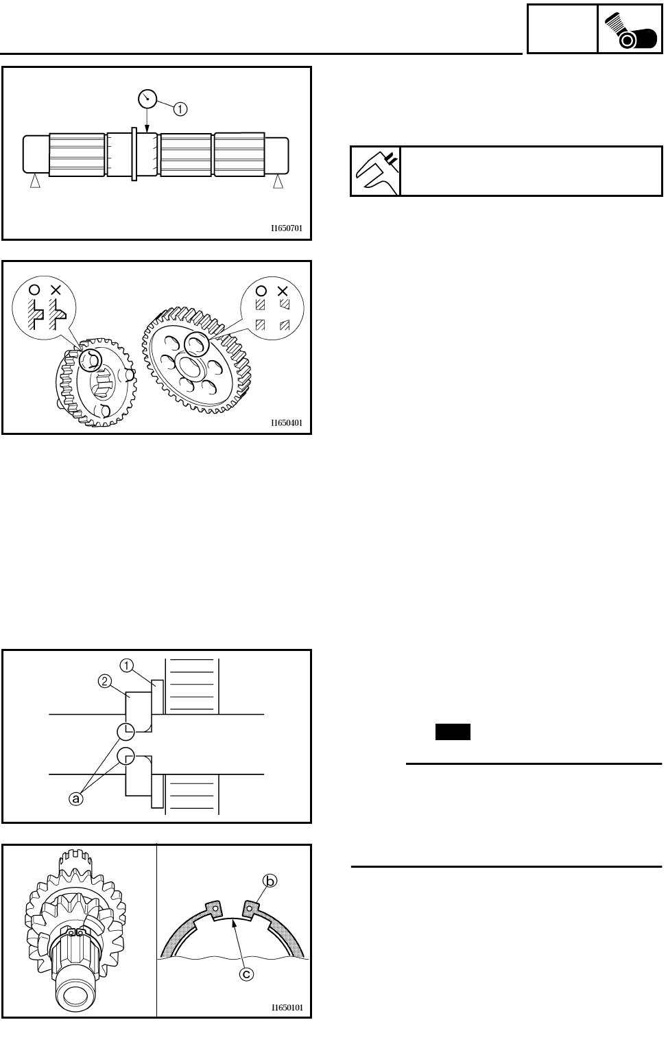
5 - 78
ENG
TRANSMISSION
2.Measure:
●Drive axle runout
(with a centering device and dial gauge 1)
Out of specification → Replace the drive axle.
Maximum drive axle runout:
0.08 mm (0.0031 in)
3.Check:
●Transmission gears
Blue discoloration/pitting/wear → Replace
the defective gear(s).
●Transmission gear dogs
Cracks/damage/rounded edges → Replace
the defective gear(s).
4.Check:
●Transmission gear engagement
(each pinion gear to its respective wheel
gear)
Incorrect → Reassemble the transmission
axle assemblies.
5.Check:
●Transmission gear movement
Rough movement → Replace the defective
part(s).
6.Check:
●Circlips
Bends/damage/looseness → Replace.
ASSEMBLING THE MAIN AXLE AND DRIVE
AXLE
1.Install:
●Toothed washer 1
●Circlip 2
NOTE:
●Be sure the circlip shap-edged corner a is
positioned opposite side to the toothed
washer and gear.
●Be sure the circlip end b is positioned at
axle spline groove c.
New
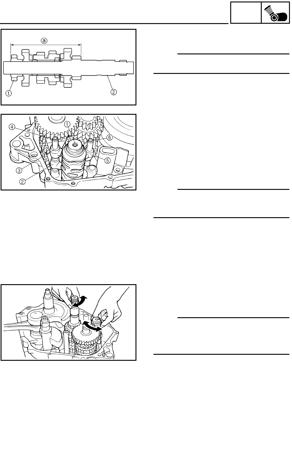
5 - 79
ENG
TRANSMISSION
2.Install:
●Reverse pinion gear 1
NOTE:
Press the reverse pinion gear into the main
axle 2, as shown in the illustration.
a115.65 ~ 115.85 mm (4.553 ~ 4.561 in)
INSTALLING THE TRANSMISSION
1.Install:
●Shift drum 1
●Shift fork “L” 2
●Shift fork “R” 3
●Shift fork guide bar (long) 4
●Shift fork “C” 5
●Shift fork guide bar (short) 6
NOTE:
The embossed marks on the shift forks should
face towards the right side of the engine and
be in the following sequence: “R”, “C”, “L”.
2.Check:
●Transmission
Rough movement → Repair.
NOTE:
●Oil each gear and bearing thoroughly.
●Before assembling the crankcase, be sure
that the transmission is in neutral and that
the gears turn freely.
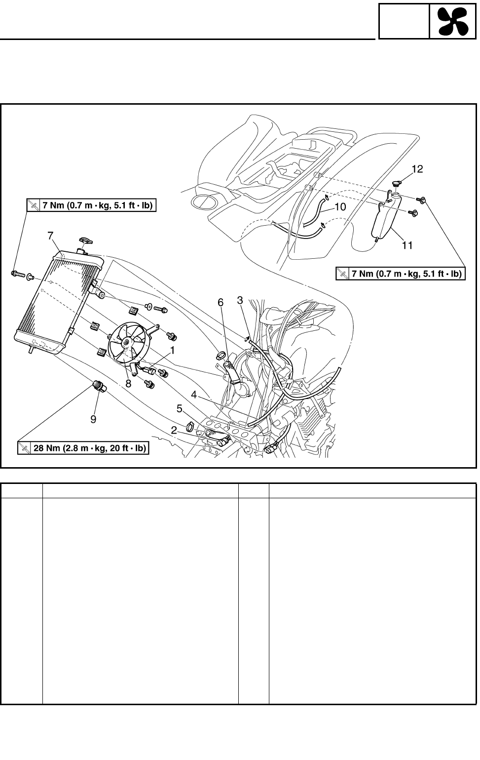
6 - 1
COOL
RADIATOR
COOLING SYSTEM
RADIATOR
Order Job name/Part name Q’ty Remarks
Removing the radiator Remove the parts in the order below.
Front panel and front fender Refer to “SEAT, FENDERS AND FUEL
TANK” in CHAPTER 3.
Coolant Drain.
1 Radiator fan coupler 1 Disconnect.
2 Thermo switch coupler 1 Disconnect.
3 Coolant reservoir hose 1
4 Radiator fan breather hose 1 Disconnect.
5 Radiator outlet hose 1 Disconnect.
6 Radiator inlet hose 1 Disconnect.
7 Radiator 1
8 Radiator fan 1
9 Thermo switch 1 1
10 Coolant reservoir breather hose 1
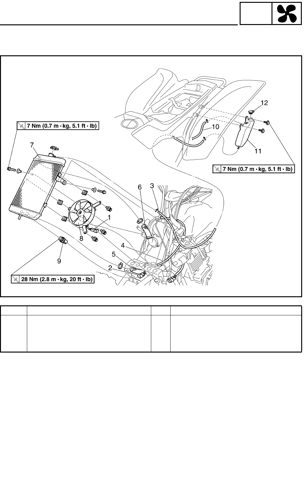
6 - 2
COOL
RADIATOR
Order Job name/Part name Q’ty Remarks
11 Coolant reservoir 1
12 Coolant reservoir cap 1
For installation, reverse the removal pro-
cedure.
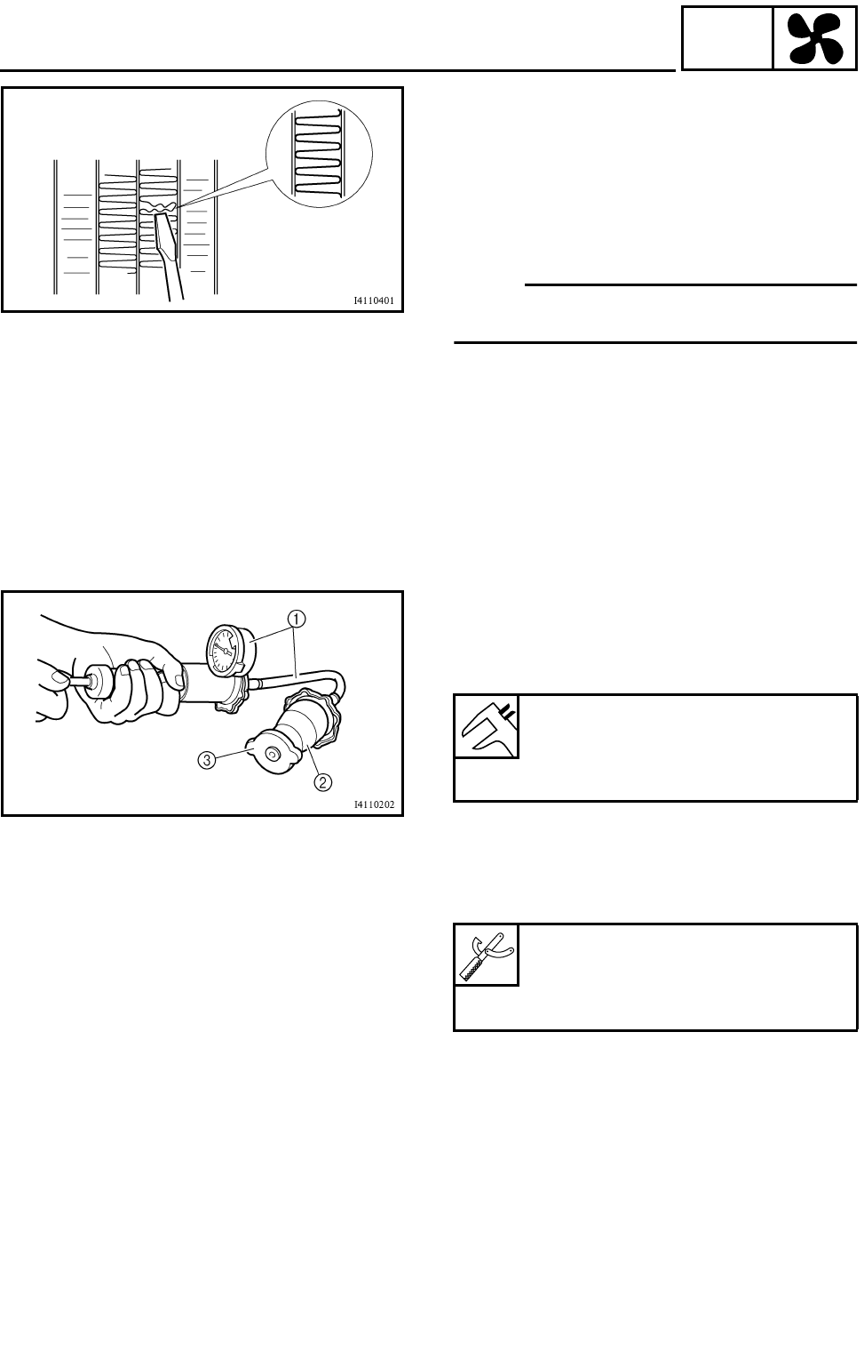
6 - 3
COOL
RADIATOR
CHECKING THE RADIATOR
1.Check:
●Radiator fins
Obstruction → Clean.
Apply compressed air to the rear of the radia-
tor.
Damage → Repair or replace.
OTE:
Straighten any flattened fins with a thin, flat-
head screwdriver.
2.Check:
●Radiator hoses
Cracks/damage → Replace.
3.Measure:
●Radiator cap opening pressure
Below the specified pressure → Replace the
radiator cap.
***********************************************
Measurement steps:
●Install the radiator cap tester 1 and adapter
2 onto the radiator cap 3.
●Apply the specified pressure for ten seconds
and make sure that there is no drop in pres-
sure.
***********************************************
4.Check:
●Radiator fan
Damage → Replace.
Malfunction → Check and repair.
Refer to “COOLING SYSTEM” in CHAPTER
9.
Radiator cap opening pressure:
95 ~ 125 kPa
(0.95 ~ 1.25 kg/cm2,
13.8 ~ 18.1 psi)
Radiator cap tester:
P/N. YU-24460-01, 90890-01325
Adapter:
P/N. YU-33984, 90890-01352

6 - 4
COOL
RADIATOR
INSTALLING THE RADIATOR
1.Fill:
●Cooling system
(with the specified amount of the recom-
mended coolant)
Refer to “CHANGING THE COOLANT” in
CHAPTER 3.
2.Check:
●Cooling system
Leaks → Repair or replace any faulty part.
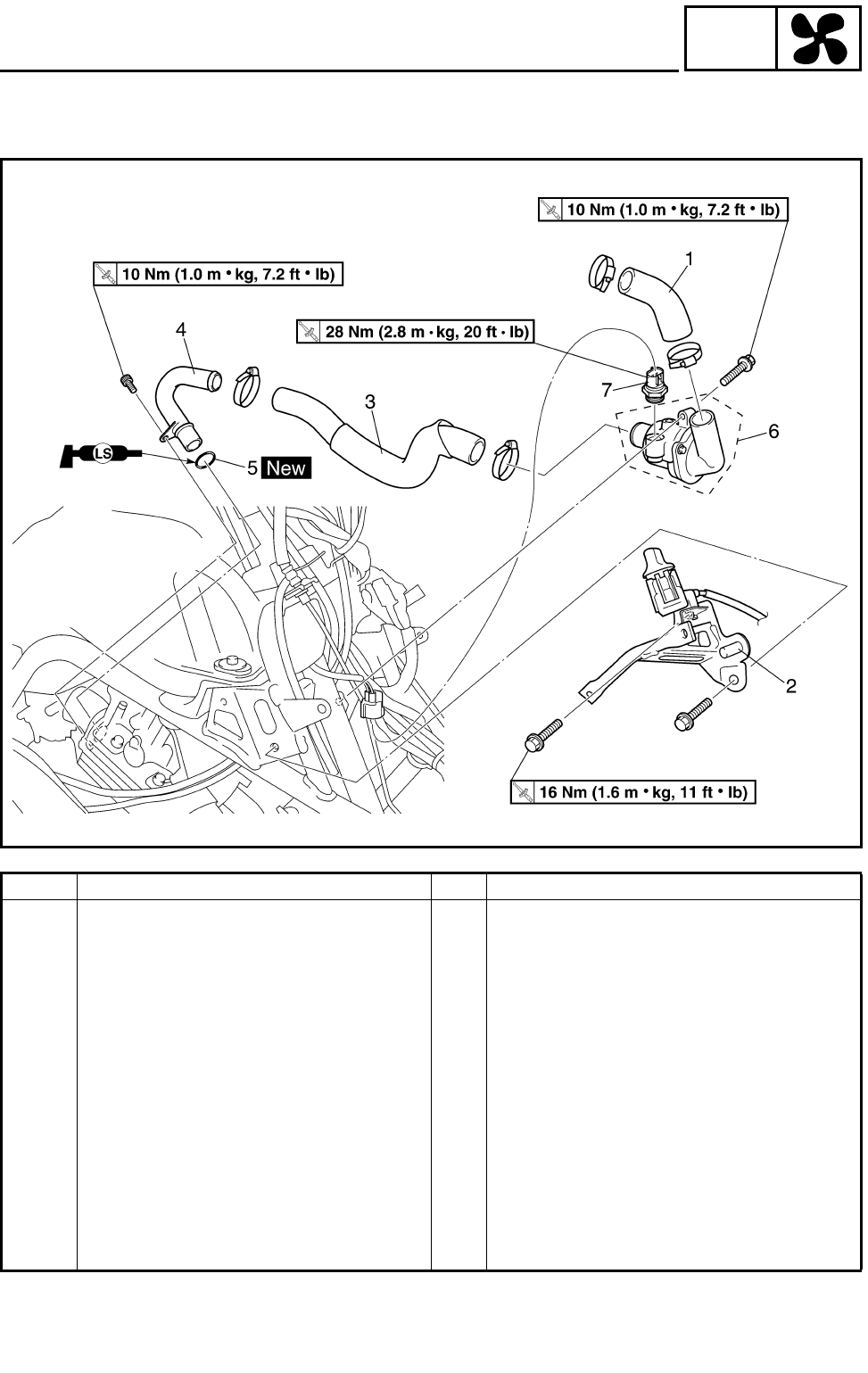
6 - 5
COOL
THERMOSTAT
THERMOSTAT
Order Job name/Part name Q’ty Remarks
Removing the thermostat Remove the parts in the order below.
Front panel and front fender Refer to “SEAT, FENDERS AND FUEL
TANK” in CHAPTER 3.
Coolant Drain.
Radiator Refer to “RADIATOR”.
1 Radiator inlet hose 1
2 Front fender bracket 1
3 Thermostat inlet hose 1
4 Water jacket outlet pipe 1
5 O-ring 1
6 Thermostat assembly 1
7 Thermo switch 2 1
For installation, reverse the removal pro-
cedure.
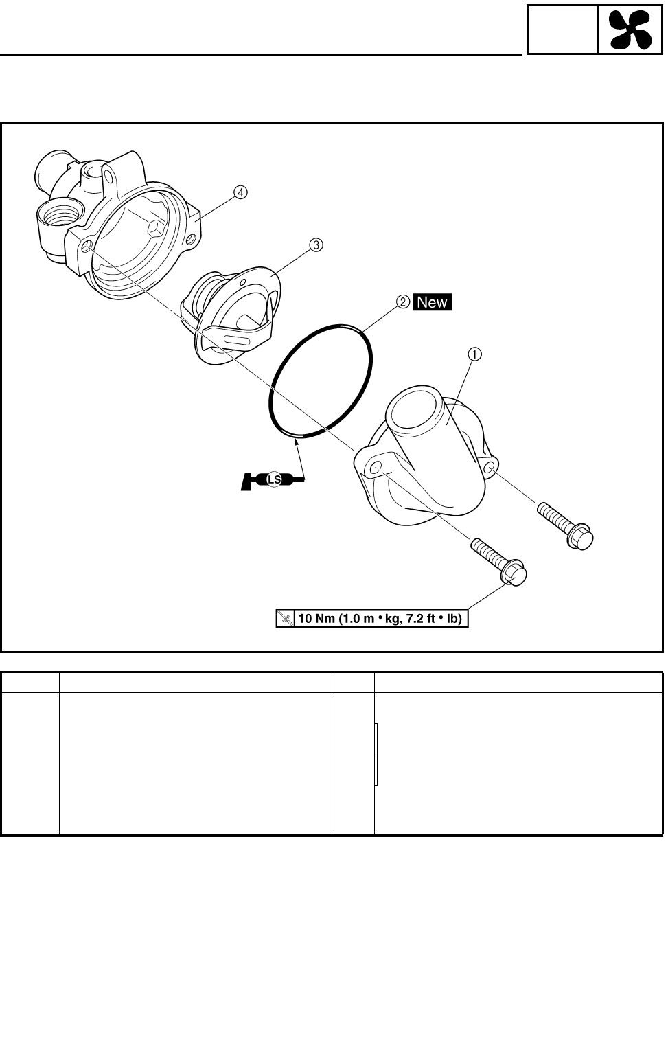
6 - 6
COOL
THERMOSTAT
Order Job name/Part name Q’ty Remarks
Disassembling the thermostat Remove the parts in the order listed.
1Thermostat cover 1
Refer to “ASSEMBLING THE THERMO-
STAT”.
2O-ring 1
3Thermostat 1
4Thermostat housing 1
For assembly, reverse the disassembly
procedure.
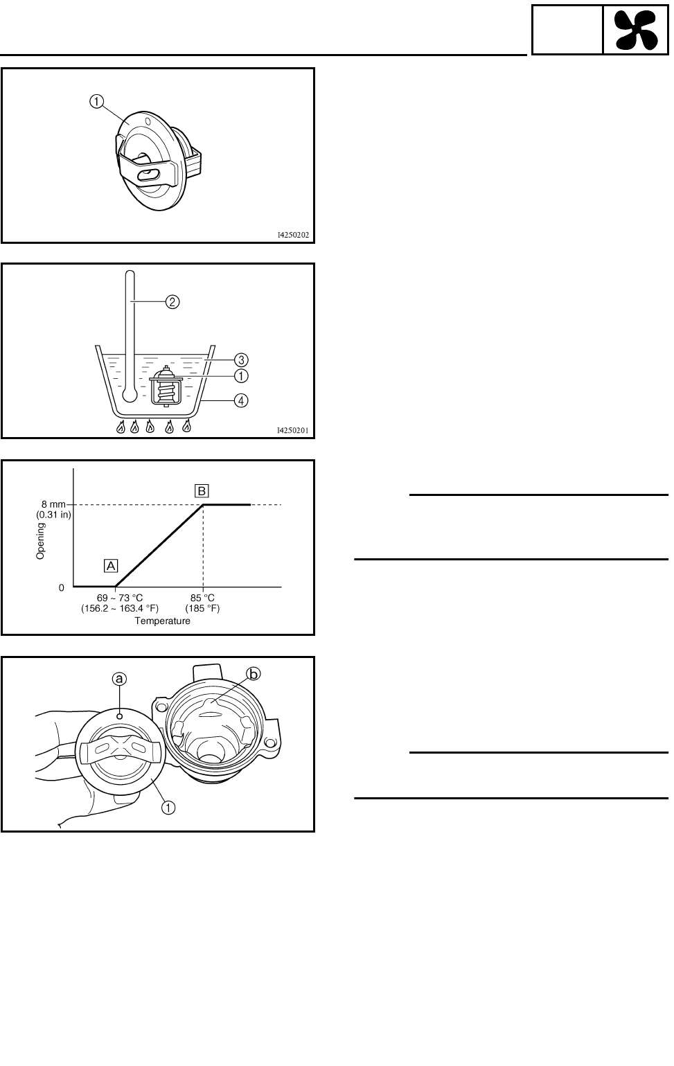
6 - 7
COOL
THERMOSTAT
CHECKING THE THERMOSTAT
1.Check:
●Thermostat 1
Does not open at 69 ~ 73 °C (156.2 ~
163.4 °F) → Replace.
***********************************************
Checking steps:
●Suspend the thermostat in a container filled
with water.
●Slowly heat the water.
●Place a thermometer in the water.
●While stirring the water, observe the thermo-
stat and thermometer’s indicated tempera-
ture.
***********************************************
1Thermostat
2Thermometer
3Water
4Container
ÈFully closed
ÉFully open
OTE:
If the accuracy of the thermostat is in doubt,
replace it. A faulty thermostat could cause seri-
ous overheating or overcooling.
2.Check:
●Thermostat housing cover
●Thermostat housing
Cracks/damage → Replace.
ASSEMBLING THE THERMOSTAT
1.Install:
●Thermostat 1
●Thermostat housing cover
OTE:
Install the thermostat with its breather hole a
toward the projection b.
2.Fill:
●Cooling system
(with the specified amount of the recom-
mended coolant)
Refer to “CHANGING THE COOLANT” in
CHAPTER 3.
3.Check:
●Cooling system
Leak → Repair or replace any faulty part.
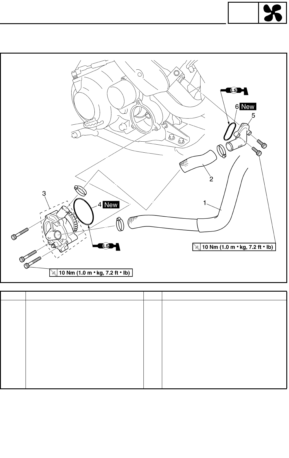
6 - 8
COOL
WATER PUMP
WATER PUMP
Order Job name/Part name Q’ty Remarks
Removing the water pump Remove the parts in the order below.
Coolant Drain.
1 Radiator outlet hose 1 Disconnect.
2 Water pump outlet hose 1
3 Water pump assembly 1
4 O-ring 1
5 Water jacket inlet housing 1
6 O-ring 1
For installation, reverse the removal pro-
cedure.
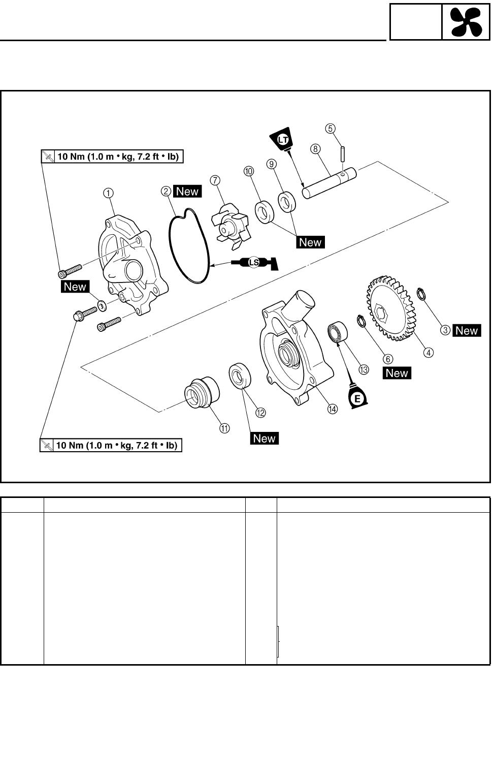
6 - 9
COOL
WATER PUMP
Order Job name/Part name Q’ty Remarks
Disassembling the water pump Remove the parts in the order below.
1Water pump housing cover 1
2O-ring 1
3Circlip 1
4Impeller shaft gear 1
5Pin 1
6Circlip 1
7Impeller 1 Refer to “DISASSEMBLING/ASSEM-
BLING THE THERMOSTAT”.
8Impeller shaft 1
9Rubber damper holder 1
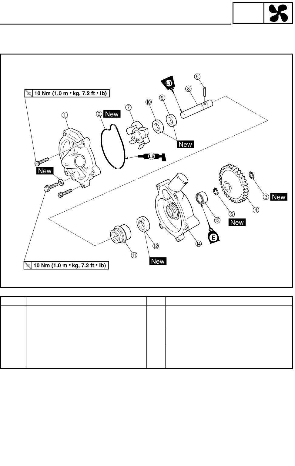
6 - 10
COOL
WATER PUMP
Order Job name/Part name Q’ty Remarks
0Rubber damper 1
Refer to “DISASSEMBLING/ASSEM-
BLING THE THERMOSTAT”.
AWater pump seal 1
BOil seal 1
CBearing 1
DWater pump housing 1
For assembly, reverse the disassembly
procedure.
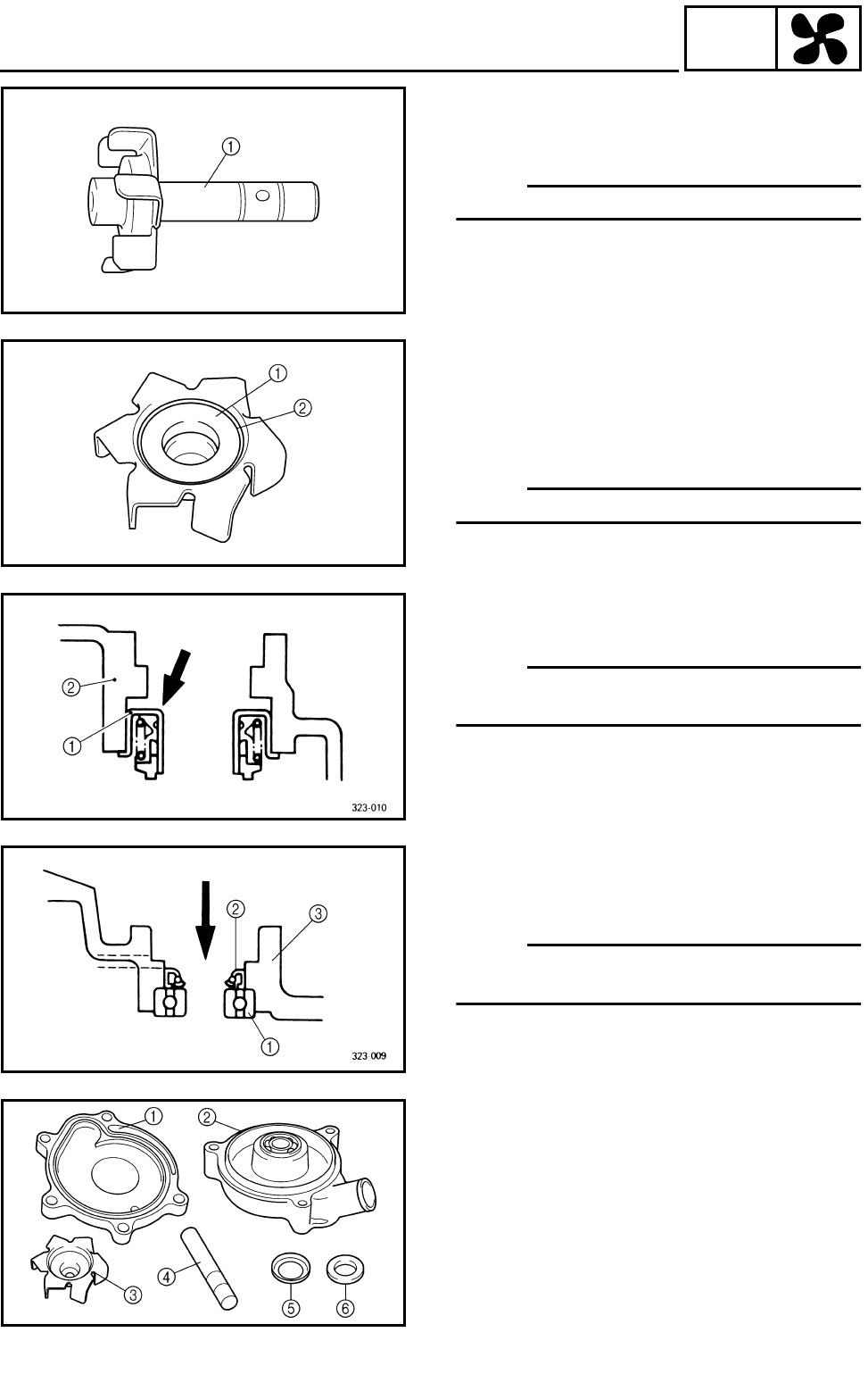
6 - 11
COOL
WATER PUMP
DISASSEMBLING THE WATER PUMP
1.Remove:
●Impeller shaft 1
OTE:
Tap out the impeller shaft from the impeller.
2.Remove:
●Rubber damper holder 1
●Rubber damper 2
(from the impeller, with a thin, flathead
screwdriver)
OTE:
Do not scratch the impeller.
3.Remove:
●Water pump seal 1
OTE:
Tap out the water pump seal from the inside of
the water pump housing.
2Water pump housing
4.Remove:
●Oil seal 1
●Bearing 2
OTE:
Tap out the bearing and oil seal from the out-
side of the water pump housing.
3Water pump housing
CHECKING THE WATER PUMP
1.Check:
●Water pump housing cover 1
●Water pump housing 2
●Impeller 3
●Impeller shaft 4
●Rubber damper 5
●Rubber damper holder 6
Cracks/damage/wear → Replace.
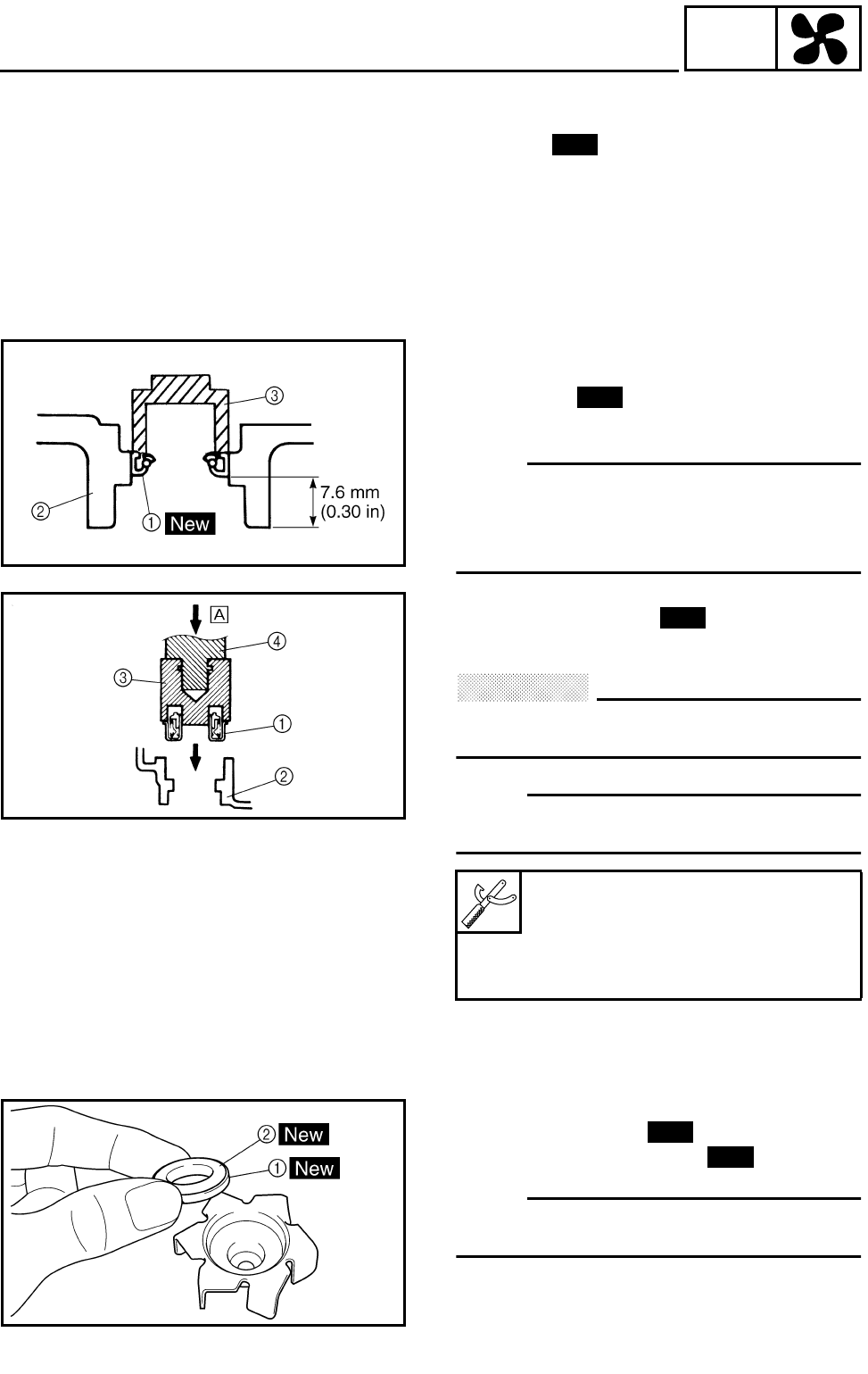
6 - 12
COOL
WATER PUMP
2.Check:
●Water pump seal
●Oil seal
●Water pump outlet pipe
Cracks/damage/wear → Replace.
●Bearing
Rough movement → Replace.
New
ASSEMBLING THE WATER PUMP
1.Install:
●Oil seal 1
(into the water pump housing 2)
OTE:
●Before installing the oil seal, apply tap water
or coolant onto its outer surface.
●Install the oil seal with a socket 3 that
matches its outside diameter.
2.Install:
●Water pump seal 1
(into the water pump housing 2)
CAUTION:
Never lubricate the water pump seal sur-
face with oil or grease.
OTE:
Install the water pump seal with the special
tools.
ÈPush down.
Mechanical seal installer 3:
P/N. YM-33221, 90890-04078
Middle driven shaft bearing driver
4:
P/N. YM-04058-1, 90890-04058
New
New
3.Install:
●Rubber damper 1
●Rubber damper holder 2
OTE:
Before installing the rubber damper, apply tap
water or coolant onto its outer surface.
New
New
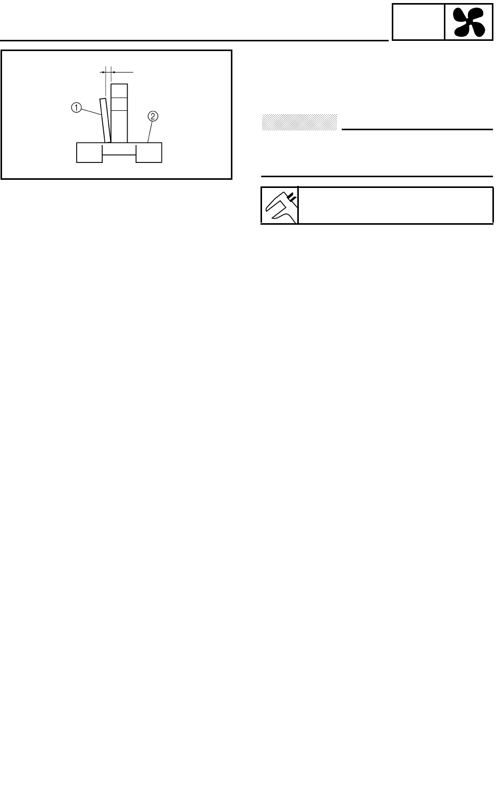
6 - 13
COOL
WATER PUMP
4.Measure:
●Impeller shaft tilt
Out of specification → Repeat steps (3) and
(4).
CAUTION:
Make sure that the rubber damper and rub-
ber damper holder are bottom with the
impeller.
1Straightedge
2Impeller
Max. impeller shaft tilt:
0.15 mm (0.006 in)
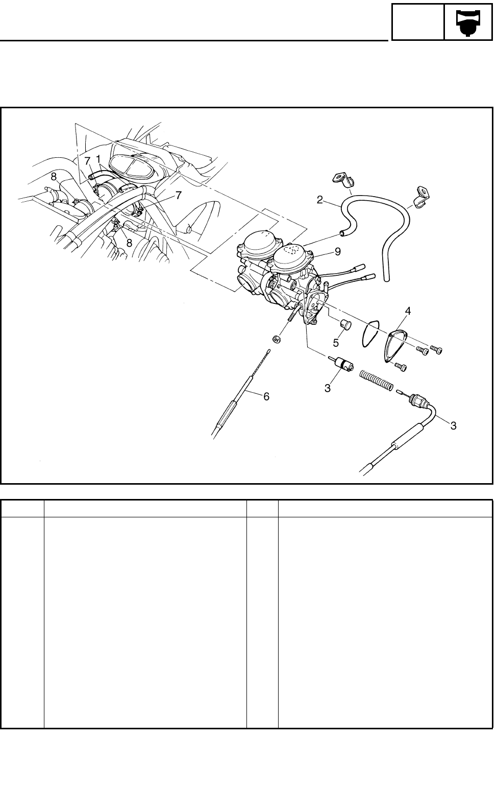
7 - 1
CARB
CARBURETORS
CARBURETION
CARBURETORS
Order Job name/Part name Q’ty Remarks
Removing the carburetors Remove the parts in the order below.
Seat/front fender/fuel tank/rubber cover
2Refer to “SEAT, FENDERS AND FUEL
TANK” in CHAPTER 3.
1 Air vent hose 2
2 Float chamber breather hose 1
3 Starter cable/starter plunger 1/1
4 Throttle valve cover 1
5 Throttle cable end 1
6 Throttle cable 1
7 Clamp screw (air filter case) 2 Loosen.
8 Clamp screw (carburetor joint) 2 Loosen.
9 Carburetors 1
For installation, reverse the removal pro-
cedure.
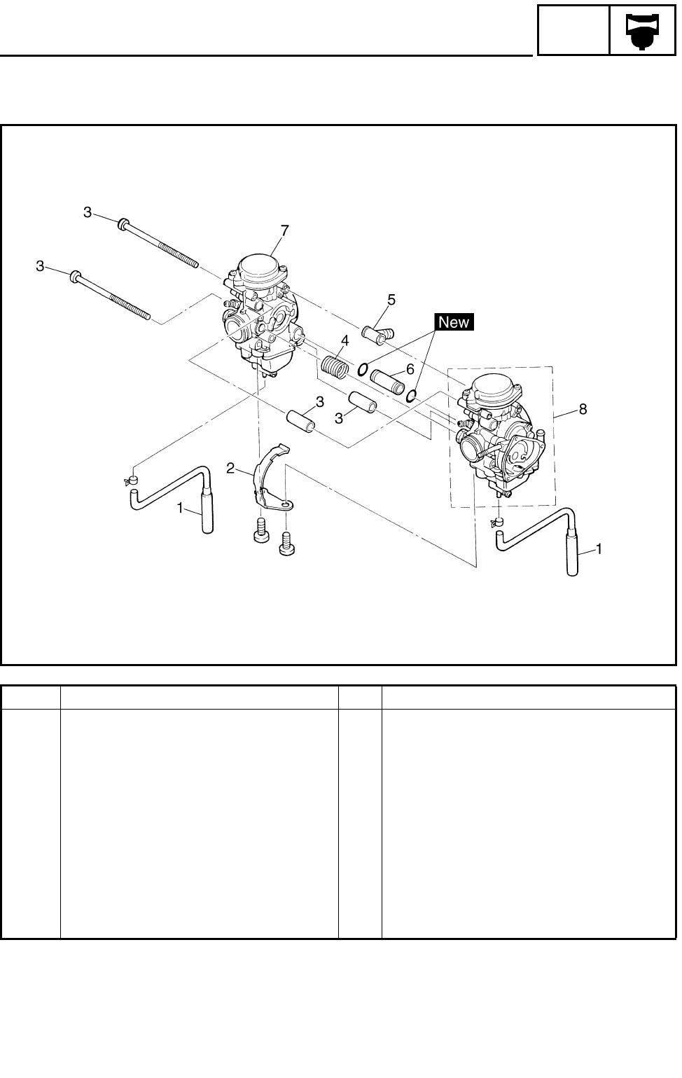
7 - 2
CARB
CARBURETORS
Order Job name/Part name Q’ty Remarks
Separating the carburetors Remove the parts in the order below.
1 Drain hose 2
2 Plate 1
3 Connecting bolt/spacer 2/2
4Spring 1
5Hose joint 1
6Pipe 1
7 Carburetor 2 1
8 Carburetor 1 1
For installation, reverse the separating
procedure.
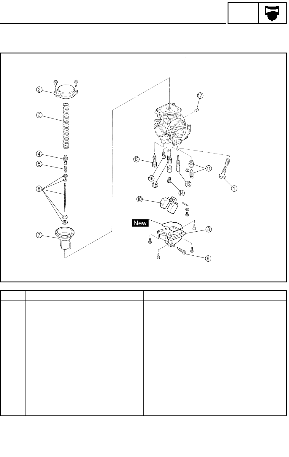
7 - 3
CARB
CARBURETORS
Order Job name/Part name Q’ty Remarks
Disassembling the carburetor Remove the parts in the order below.
1 Throttle stop screw 1
2 Vacuum chamber cover 1
3 Spring 1
4 Jet needle holder 1
5 Spring 1
6 Jet needle set 1
7 Piston valve 1
8 Float chamber 1
9 Drain screw 1
0 Float 1 Refer to “ASSEMBLING THE CARBURE-
TOR”.
A Needle valve set 1
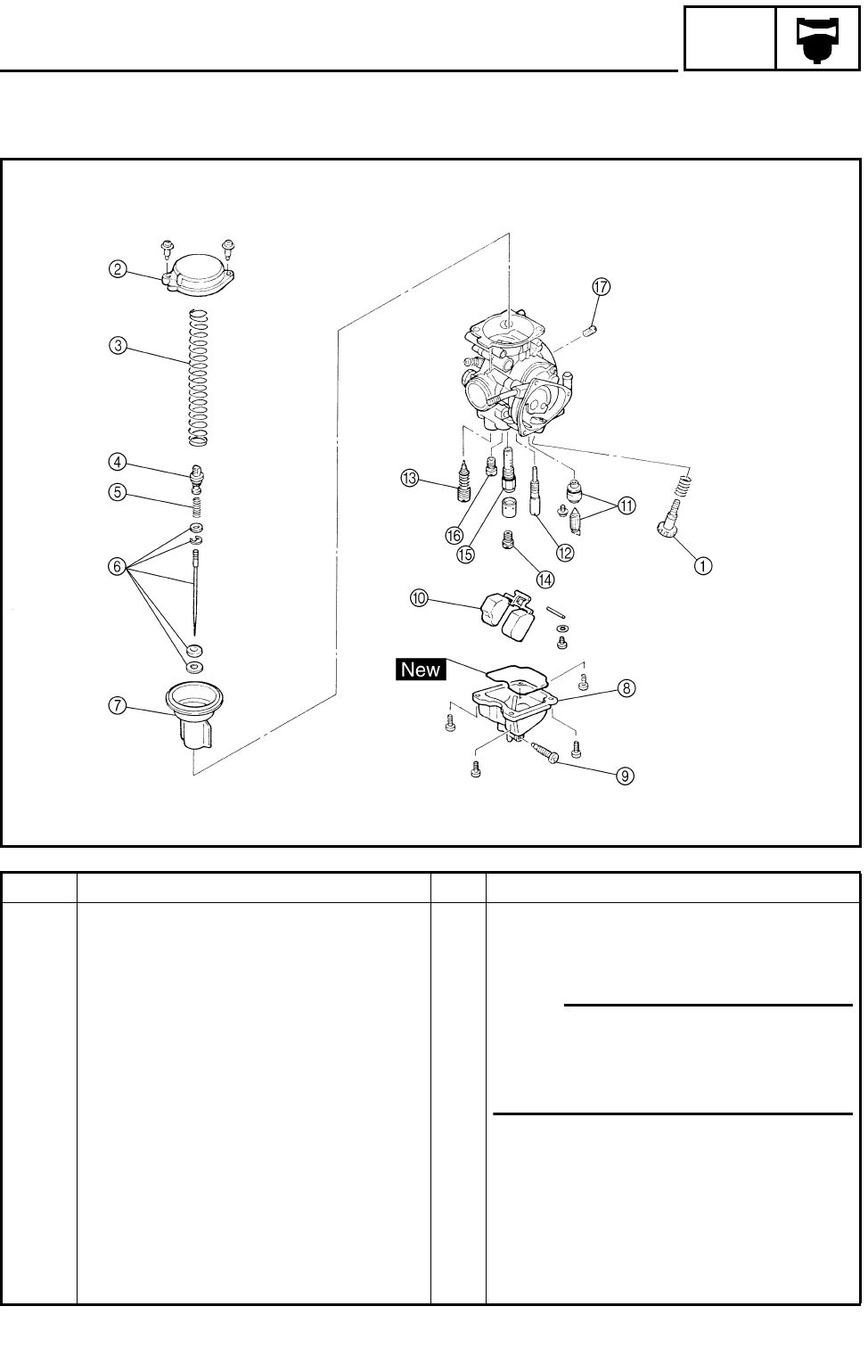
7 - 4
CARB
CARBURETORS
Order Job name/Part name Q’ty Remarks
B Pilot jet 1
C Pilot screw set 1 Refer to “DISASSEMBLING/
ASSEMBLING THE CARBURETOR”.
OTE:
Before disassembling the carburetor,
make sure to note the number of times
the pilot screw is turned out from the
seated position to its set position.
D Main jet 1
E Needle jet 1 Refer to “ASSEMBLING THE CARBURE-
TOR”.
F Starter jet 1
G Pilot air jet 1
For assembly, reverse the disassembly
procedure.
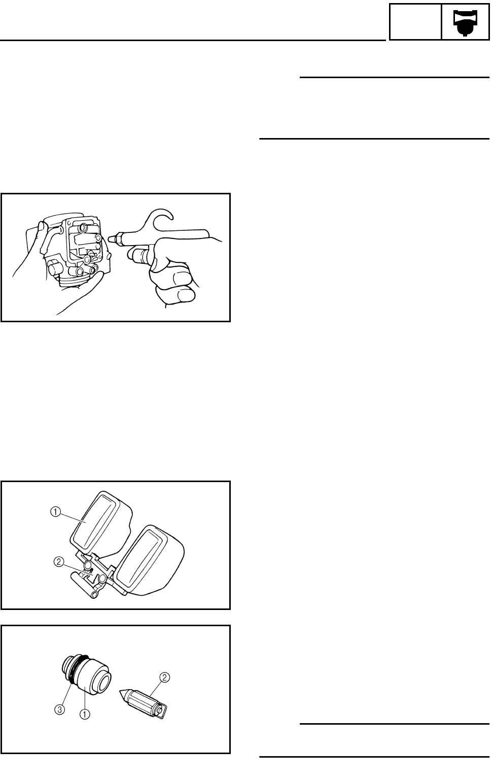
7 - 5
CARB
CARBURETORS
DISASSEMBLING THE CARBURETOR
OTE:
Before disassembling the carburetor, make
sure to note the number of times the pilot
screw is turned out from the seated position to
its set position.
CHECKING THE CARBURETOR
1.Check:
●Carburetor body
●Float chamber
Cracks/damage → Replace.
●Fuel passage
Contamination → Clean as indicated.
●Fuel chamber body
Contamination → Clean.
***********************************************
Cleaning steps:
●Wash the carburetor in a petroleum based
solvent.
(Do not use any caustic carburetor cleaning
solution.)
●Blow out all of the passages and jets with
compressed air.
***********************************************
2.Check:
●Float 1
●Float tang 2
Damage → Replace.
3.Check:
●Valve seat 1
●Needle valve 2
●O-ring 3
Contamination/wear/damage → Replace as
a set.
OTE:
Always replace the needle valve and valve
seat as a set.
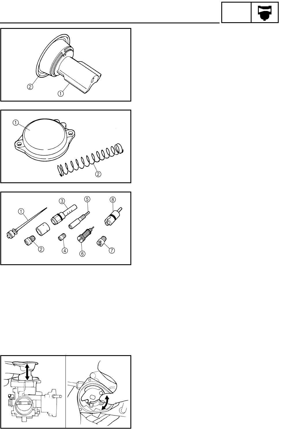
7 - 6
CARB
CARBURETORS
4.Check:
●Piston valve 1
Scratches/wear/damage → Replace.
●Rubber diaphragm 2
Tears → Replace.
5.Check:
●Vacuum chamber cover 1
●Spring 2
Cracks/damage → Replace.
6.Check:
●Jet needle 1
●Main jet 2
●Needle jet 3
●Pilot air jet 4
●Pilot jet 5
●Pilot screw 6
●Starter jet 7
●Starter plunger 8
Bends/wear/damage → Replace.
●Blockage → Blow out the jets with
compressed air.
7.Check:
●Free movement (piston valve)
Sticks → Replace the piston valve guide and
the piston valve.
Insert the piston valve into the carburetor
body, and check for free movement.
8.Check:
●Free movement (throttle valve)
Sticks → Replace.
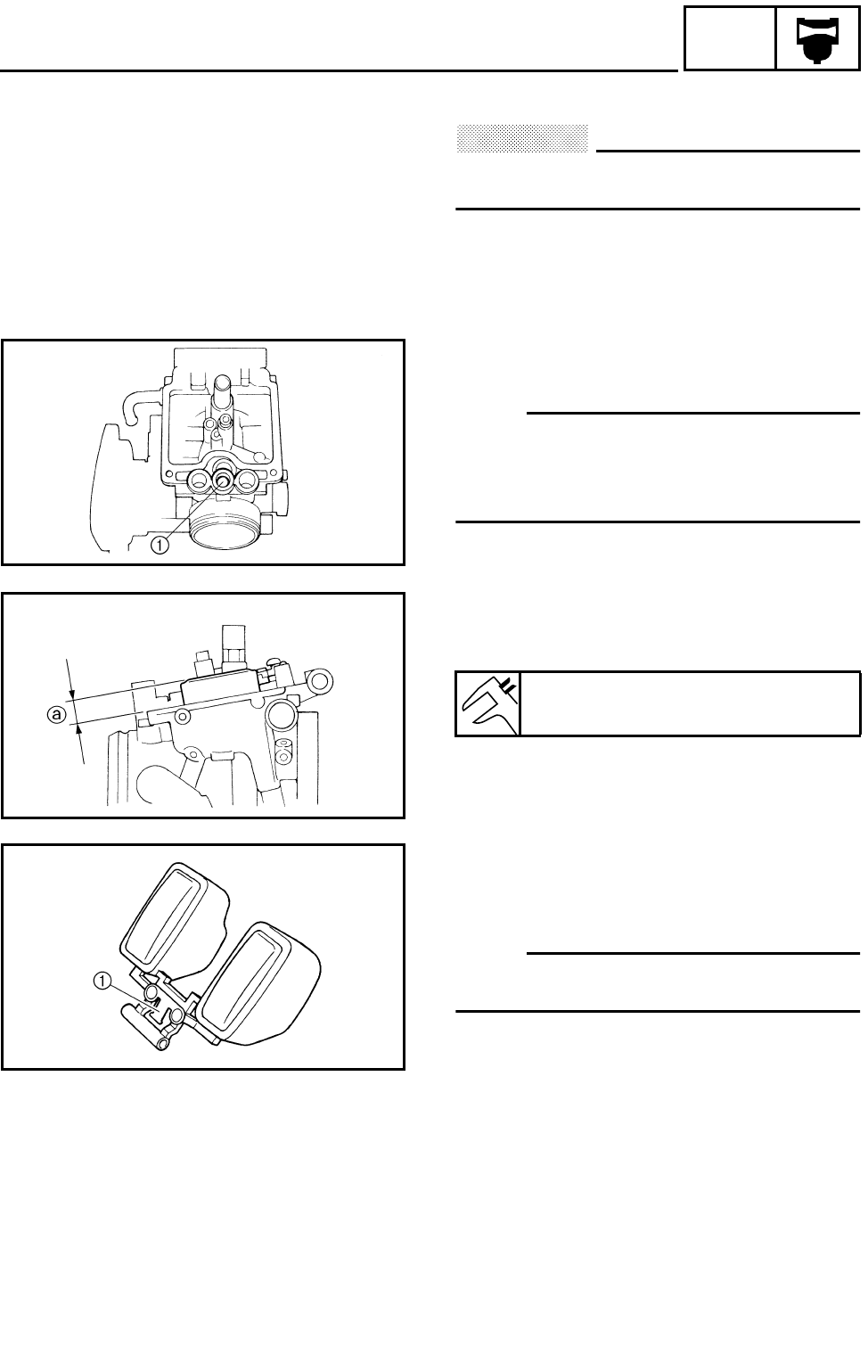
7 - 7
CARB
CARBURETORS
ASSEMBLING THE CARBURETOR
CAUTION:
Before reassembling, wash all of the parts
in a clean petroleum based solvent.
1.Install:
●Pilot screw 1
OTE:
Before assembling the carburetor, make sure
to turn out the pilot screw the same number of
times, as noted before disassembly, from the
seated position to the set position.
2.Measure:
●Float height a
Out of specification → Adjust.
***********************************************
Measurement and adjustment steps:
●Hold the carburetor in an upside down
position.
●Measure the distance from the front mating
surface of the float chamber (gasket
removed) to the top of the float.
OTE:
The float arm should be resting on the needle
valve, but not compressing it.
●If the float height is not within the
specification, inspect the valve seat and
needle valve.
●If either is worn, replace them both.
●If both are fine, adjust the float height by
bending the float tang 1 on the float.
●Recheck the float height.
***********************************************
Float height (F.H.):
13 mm (0.51 in)
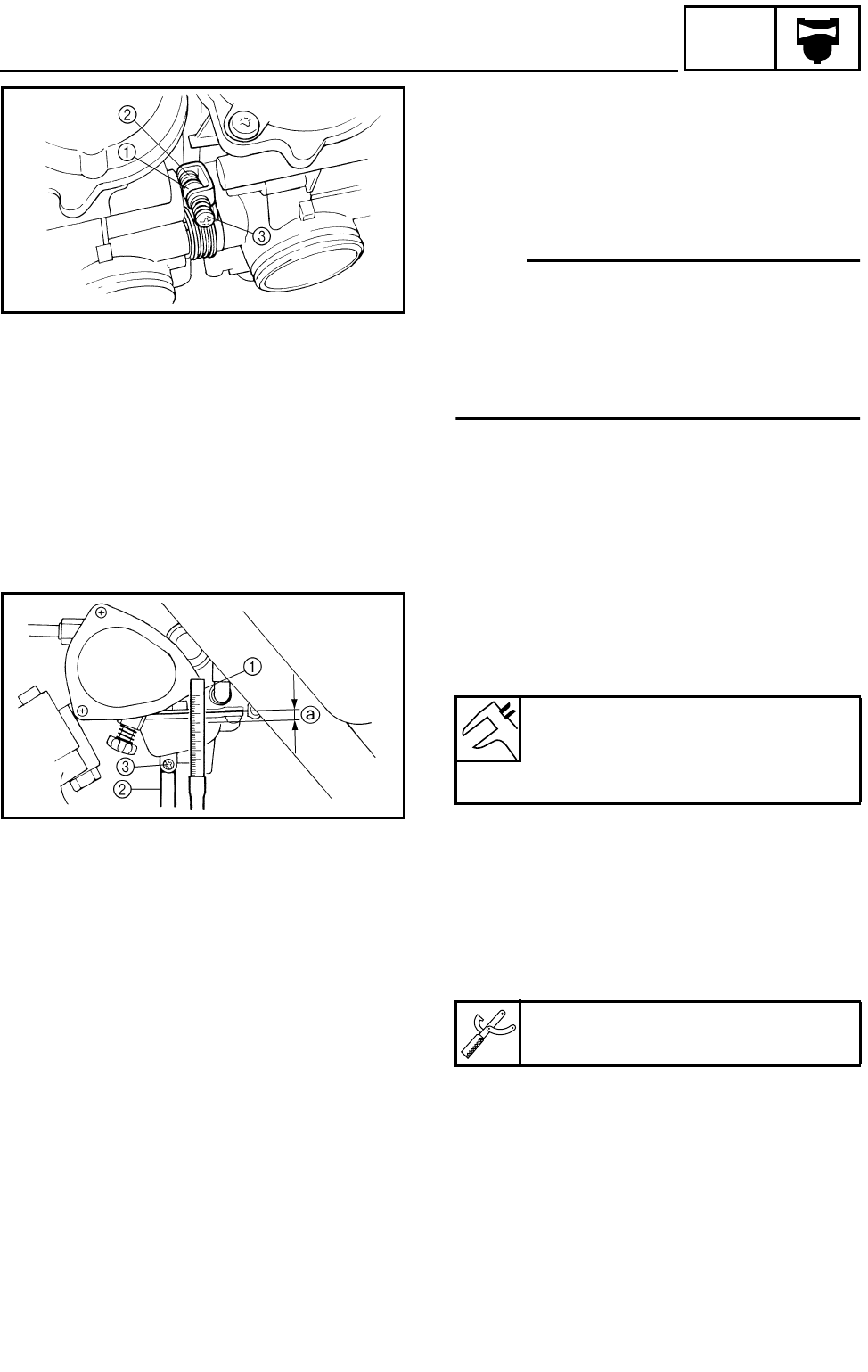
7 - 8
CARB
CARBURETORS
3.Install:
●Carburetor 1
●Carburetor 2
●Pipe
●Hose joint
●Spring
OTE:
●Install the throttle valve lever 1 onto
carburetor 2 between the spring 2 and
synchronizing screw 3.
●Make sure the throttle valves operate
smoothly and that the synchronization is
correct.
ADJUSTING THE FUEL LEVEL
1.Measure:
●Fuel level a
Out of specification → Adjust.
Fuel level:
3 ~ 4 mm (0.12 ~ 0.16 in)
Below the float chamber mating
surface
***********************************************
Fuel level measurement and adjustment
steps:
●Place the machine on a level surface.
●Connect the fuel level gauge 1 to the drain
pipe 2.
●Loosen the drain screw 3.
●Hold the gauge vertically next to the float
chamber line.
●Measure the fuel level a with the gauge.
●If the fuel level is incorrect, adjust the fuel
level.
Fuel level gauge:
P/N. YM-01312-A, 90890-01312
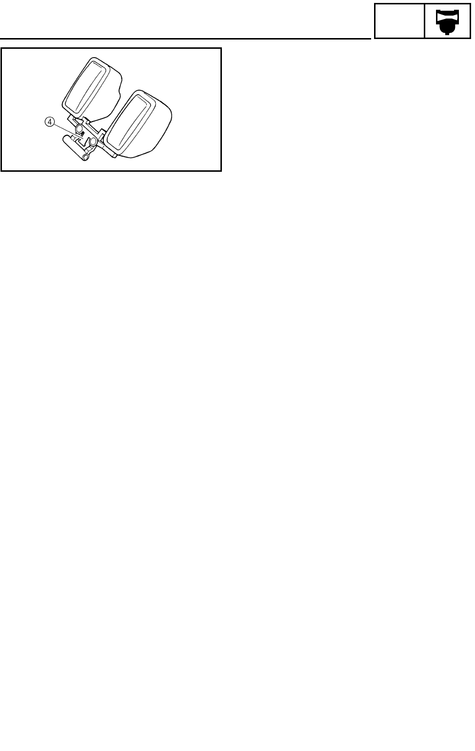
7 - 9
CARB
CARBURETORS
●Remove the carburetor.
●Inspect the valve seat and needle valve.
●If either is worn, replace them both.
●If both are fine, adjust the float level by
bending the float tang 4 slightly.
●Install the carburetor.
●Recheck the fuel level.
***********************************************
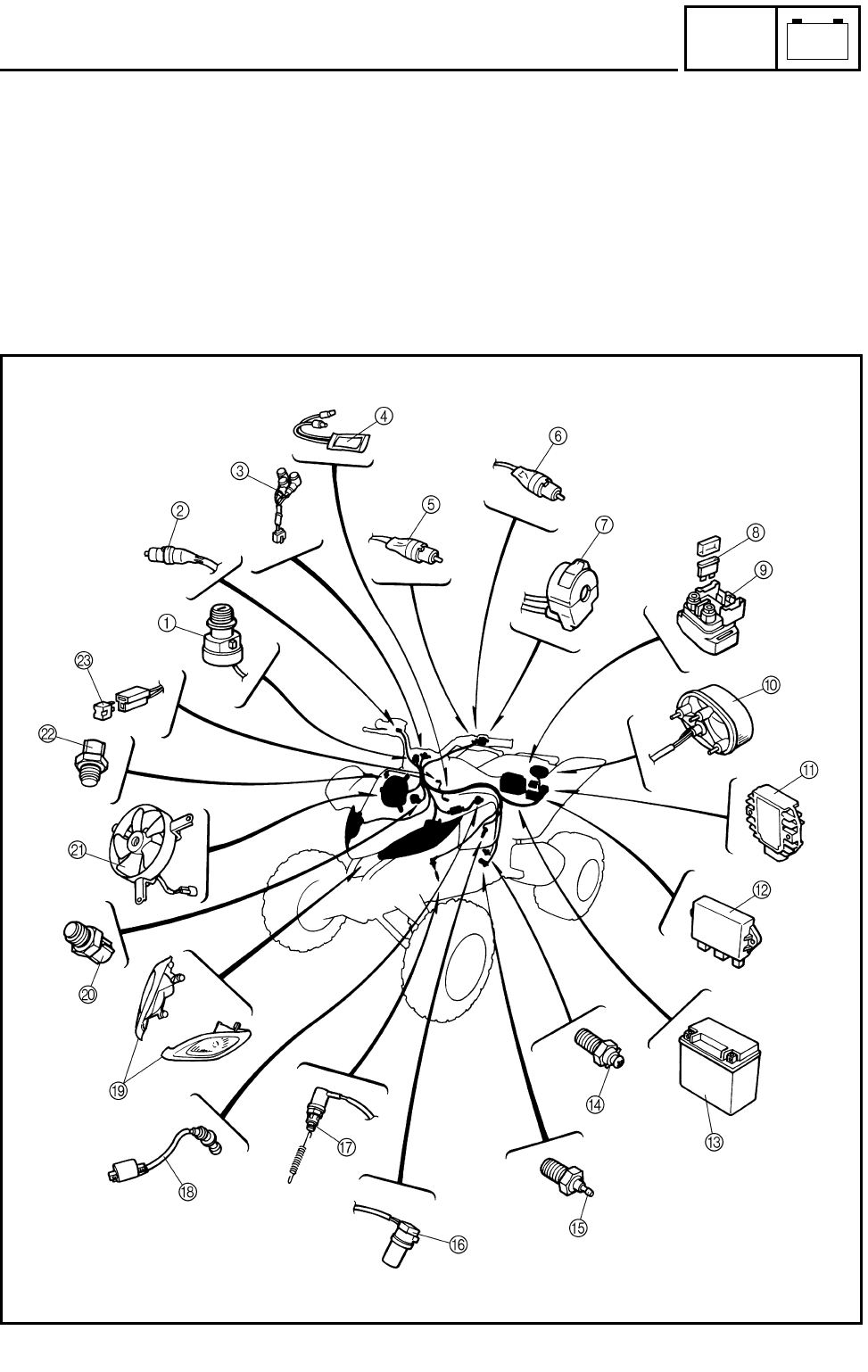
8 - 1
–+
ELEC
ELECTRICAL COMPONENTS
EB800000 ELECTRICAL
ELECTRICAL COMPONENTS
1Main switch
2Front brake switch
3Indicator light
4Circuit breaker (fan)
5Park switch
6Clutch switch
7Handlebar switch (left)
8Fuse
9Starter relay
0Tail/brake light
ARectifier/regulator
BCDI unit
CBattery
DNeutral switch
EReverse switch
FSpeed sensor
GRear brake switch
HIgnition coil
IHeadlight
JThermo switch 1
KFan
LThermo switch 2
MDiode
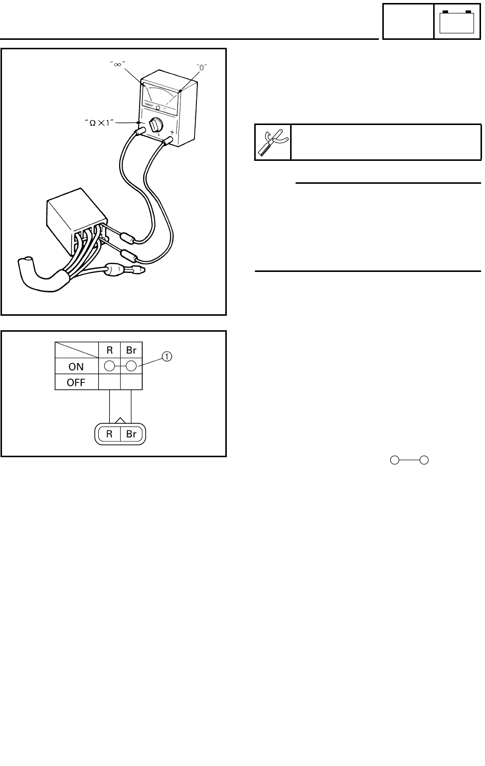
8 - 2
–+
ELEC
CHECKING THE SWITCH
CHECKING THE SWITCH
CHECKING THE SWITCH
Use a pocket tester to check the terminals for
continuity. If the continuity is faulty at any
point, replace the switch.
OTE:
●Set the pocket tester to “0” before starting
the test.
●The pocket tester should be set to the “Ω × 1”
range when testing the switch for continuity.
●Turn the switch on and off a few times when
checking it.
Pocket tester:
P/N. YU-03112, 90890-03112
CHECKING A SWITCH SHOWN IN THE
MANUAL
The terminal connections for switches (main
switch, handlebar switch, engine stop switch,
light switch, etc.) are shown in a chart similar
to the one on the left.
This chart shows the switch positions in the
column and the switch lead colors in the top
row.
For each switch position, “ ” indicates
the terminals with continuity.
The example chart shows that:
1There is continuity between the “Red and
Brown” leads when the switch is set to “ON”.
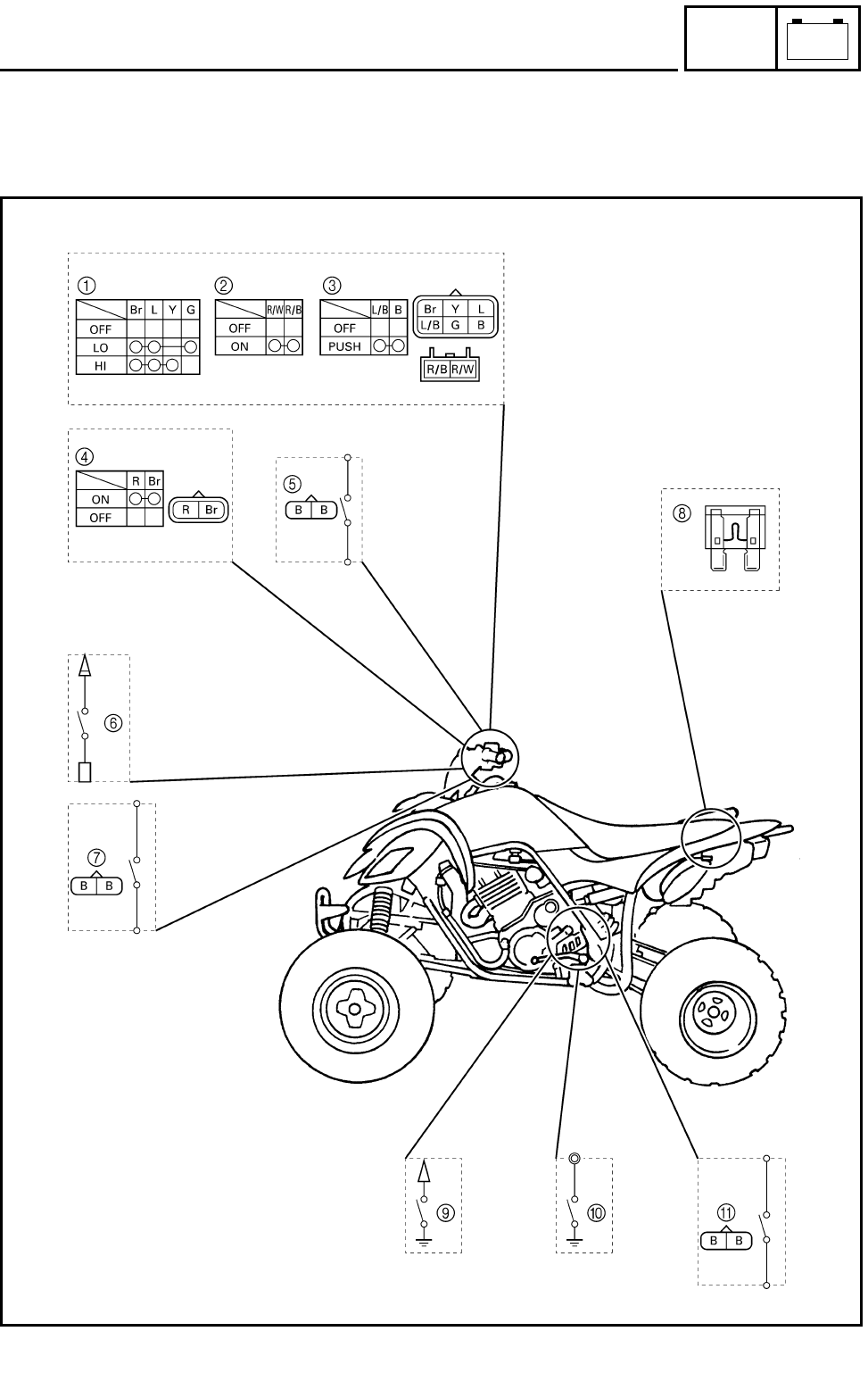
8 - 3
–+
ELEC
CHECKING THE SWITCH
CHECKING THE SWITCH CONTINUITY
Refer to “CHECKING THE SWITCH” and check for continuity between lead terminals.
Poor connection, no continuity → Correct or replace.
* The coupler locations are circled.

8 - 4
–+
ELEC
CHECKING THE SWITCH
1Lights switch
2Engine stop switch
3Start switch
4Main switch
5Front brake switch
6Clutch switch
7Park switch
8Fuse
9Reverse switch
0Neutral switch
ARear brake switch
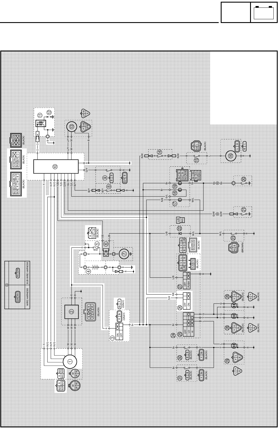
8 - 5
–+
ELEC
IGNITION SYSTEM
EB802000
IGNITION SYSTEM
CIRCUIT DIAGRAM
1AC magneto
3Main switch
4Battery
5Fuse
0CDI unit
AIgnition coil
BSpark plug
PEngine stop switch
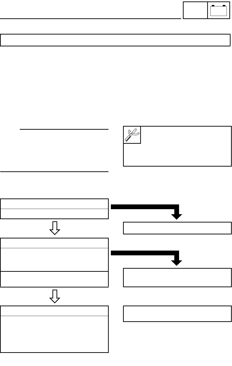
8 - 6
–+
ELEC
IGNITION SYSTEM
EB802010
TROUBLESHOOTING
Procedure
Check:
1.Fuse
2.Battery
3.Spark plug
4.Ignition spark gap
5.Spark plug cap resistance
6.Ignition coil resistance
IF THE IGNITION SYSTEM FAILS TO OPERATE (NO SPARK OR INTERMITTENT SPARK):
7.Engine stop switch
8.Main switch
9.Pickup coil resistance
10.Charging/rotor rotation direction detection
coil resistance
11.Wiring connection (the entire ignition sys-
tem)
OTE:
●Remove the following part(s) before trouble-
shooting:
1)Seat
2)Front fender
●Use the following special tool(s) for trouble-
shooting.
Dynamic spark tester:
P/N. YM-34487
Ignition checker:
P/N. 90890-06754
Pocket tester:
P/N. YU-03112, 90890-03112
EB802011
CONTINUITY
1.Fuse
Refer to “CHECKING THE SWITCH”.
NO CONTINUITY
Replace the fuse.
EB802012
CORRECT
2.Battery
●Check the battery condition.
Refer to “CHECKING THE BATTERY” in
CHAPTER 3.
Open-circuit voltage:
12.8 V or more at 20 °C (68 °F)
INCORRECT
●Clean the battery terminals.
●Recharge or replace the battery.
3.Spark plug
●Check the spark plug condition.
●Check the spark plug type.
●Check the spark plug gap.
Refer to “CHECKING THE SPARK PLUG”
in CHAPTER 3.
Standard spark plug:
DPR8EA-9/NGK
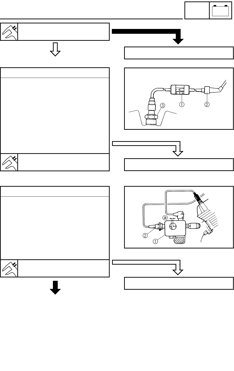
8 - 7
–+
ELEC
IGNITION SYSTEM
CORRECT
Spark plug gap:
0.8 ~ 0.9 mm (0.031 ~ 0.035 in)
INCORRECT
Repair or replace the spark plug.
For USA and CDN
4.Ignition spark gap
●Disconnect the spark plug cap from the
spark plug.
●Connect the dynamic spark tester 1 as
shown.
2 Spark plug cap
3 Spark plug
●Turn the main switch to “ON”.
●Check the ignition spark gap.
●Crank the engine by pushing the starter
switch, and increase the spark gap until a
misfiring occurs.
Minimum spark gap:
6.0 mm (0.24 in)
MEETS SPECIFICATION
The ignition system is not faulty.
For Europe
OUT OF
SPECIFICATION
OR NO SPARK
4.Ignition spark gap
●Disconnect the spark plug cap from the
spark plug.
●Connect the ignition checker 1 as shown.
2 Spark plug cap
●Turn the main switch to “ON”.
●Check the ignition spark gap a.
●Crank the engine by pushing the starter
switch, and increase the spark gap until a
misfiring occurs.
Minimum spark gap:
6.0 mm (0.24 in)
*
MEETS SPECIFICATION
The ignition system is not faulty.
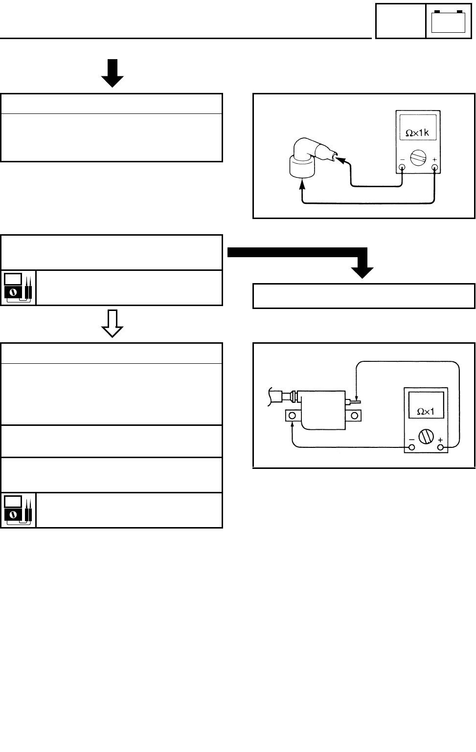
8 - 8
–+
ELEC
IGNITION SYSTEM
5.Spark plug cap resistance
●Remove the spark plug cap.
●Connect the pocket tester (Ω × 1k) to the
spark plug cap.
*
MEETS
SPECIFICATION
●Check that the spark plug cap has the
specified resistance.
Spark plug cap resistance:
10 kΩ at 20 °C (68 °F)
OUT OF SPECIFICATION
Replace the spark plug cap.
6.Ignition coil resistance
●Disconnect the ignition coil connector from
the wire harness.
●Connect the pocket tester (Ω × 1) to the
ignition coil.
Tester (+) lead → Orange lead terminal
Tester (–) lead → Ignition coil base
●Check that the primary coil has the speci-
fied resistance.
Primary coil resistance:
0.18 ~ 0.28 Ω at 20 °C (68 °F)
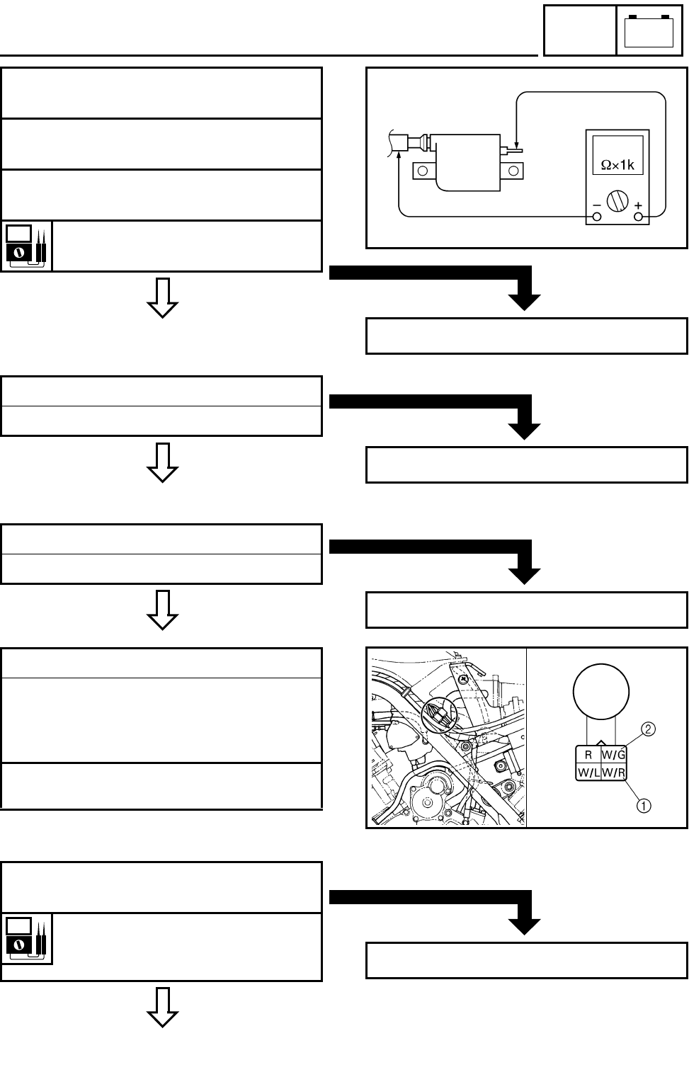
8 - 9
–+
ELEC
IGNITION SYSTEM
BOTH MEET
SPECIFICATION
●Connect the pocket tester (Ω × 1k) to the
ignition coil.
Tester (+) lead → Orange lead terminal
Tester (–) lead → Spark plug lead
●Check that the secondary coil has the
specified resistance.
Secondary coil resistance:
6.32 ~ 9.48 kΩ at 20 °C (68 °F)
Replace the ignition coil.
CORRECT
7.Engine stop switch
Refer to “CHECKING THE SWITCH”.
INCORRECT
Replace the handlebar switch (left).
CORRECT
8.Main switch
Refer to “CHECKING THE SWITCH”.
INCORRECT
Replace the main switch.
9.Pickup coil resistance
●Disconnect the AC magneto coupler from
the wire harness.
●Connect the pocket tester (Ω × 100) to the
pickup coil terminal.
Tester (+) lead → White/Red terminal 1
Tester (–) lead → White/Green terminal 2
MEETS
SPECIFICATION
●Check the pickup coil for the specified
resistance.
Pickup coil resistance:
445 ~ 545 Ω at 20 °C (68 °F)
(White/Red – White/Green)
*
OUT OF SPECIFICATION
Replace the pickup coil/starter assembly.
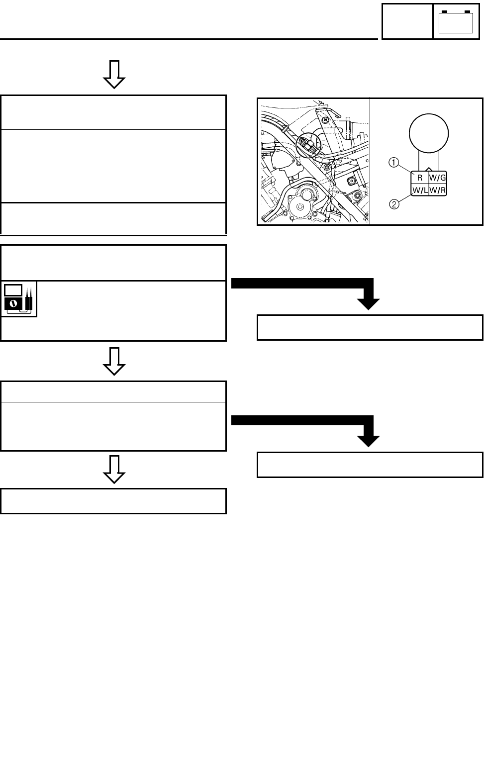
8 - 10
–+
ELEC
IGNITION SYSTEM
C0NTINUITY
MEETS
SPECIFICATION
10.Charging/rotor rotation direction detec-
tion coil resistance
●Disconnect the AC magneto coupler from
the wire harness.
●Connect the pocket tester (Ω × 100) to the
charging/rotor rotation direction detection
coil terminal.
Tester (+) lead → Red terminal 1
Tester (–) lead → White/Blue terminal 2
●Check the charging/rotor rotation direction
detection coil for the specified resistance.
Rotor rotation direction detec-
tion coil resistance:
0.069 ~ 0.085 Ω at 20 °C (68 °F)
(Red – White/Blue)
*
OUT OF SPECIFICATION
Replace the pickup coil/stator assembly.
CORRECT
11.Wiring connection
●Check the connections of the entire ignition
system.
Refer to “CIRCUIT DIAGRAM”.
Replace the CDI unit.
POOR CONNECTION
Properly connect the ignition system.
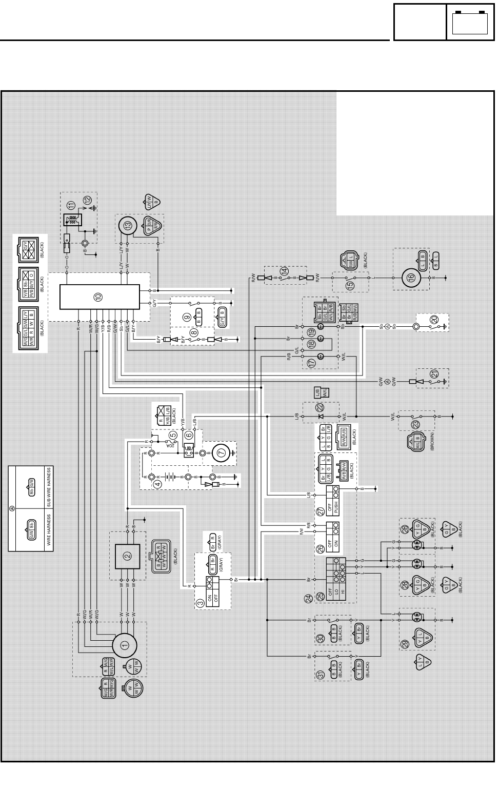
8 - 11
–+
ELEC
ELECTRIC STARTING SYSTEM
EB803000
ELECTRIC STARTING SYSTEM
CIRCUIT DIAGRAM
3Main switch
4Battery
5Fuse
6Starter relay
7Starter motor
8Clutch switch
9Park switch
0CDI unit
JNeutral switch
PEngine stop switch
QStart switch
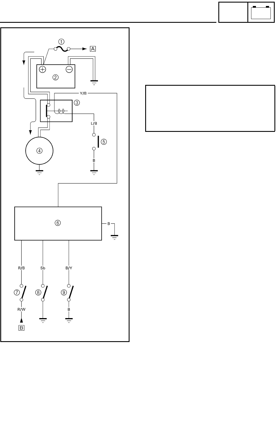
8 - 12
–+
ELEC
ELECTRIC STARTING SYSTEM
STARTING CIRCUIT OPERATION
The starting circuit on this model consists of
the starter motor, starter relay, clutch switch,
CDI unit and neutral switch. If the main switch
is on and the engine stop switch is in the RUN
position, the starter motor can be operated
only if:
1Fuse
2Battery
3Starter relay
4Starter motor
5Start switch
6CDI unit
7Engine stop switch
8Neutral switch
9Clutch switch
ÈTO MAIN SWITCH
ÉFROM MAIN SWITCH
●The transmission is in neutral (the neutral
switch is closed).
or
●You pull in the clutch lever (the clutch
switch is closed).
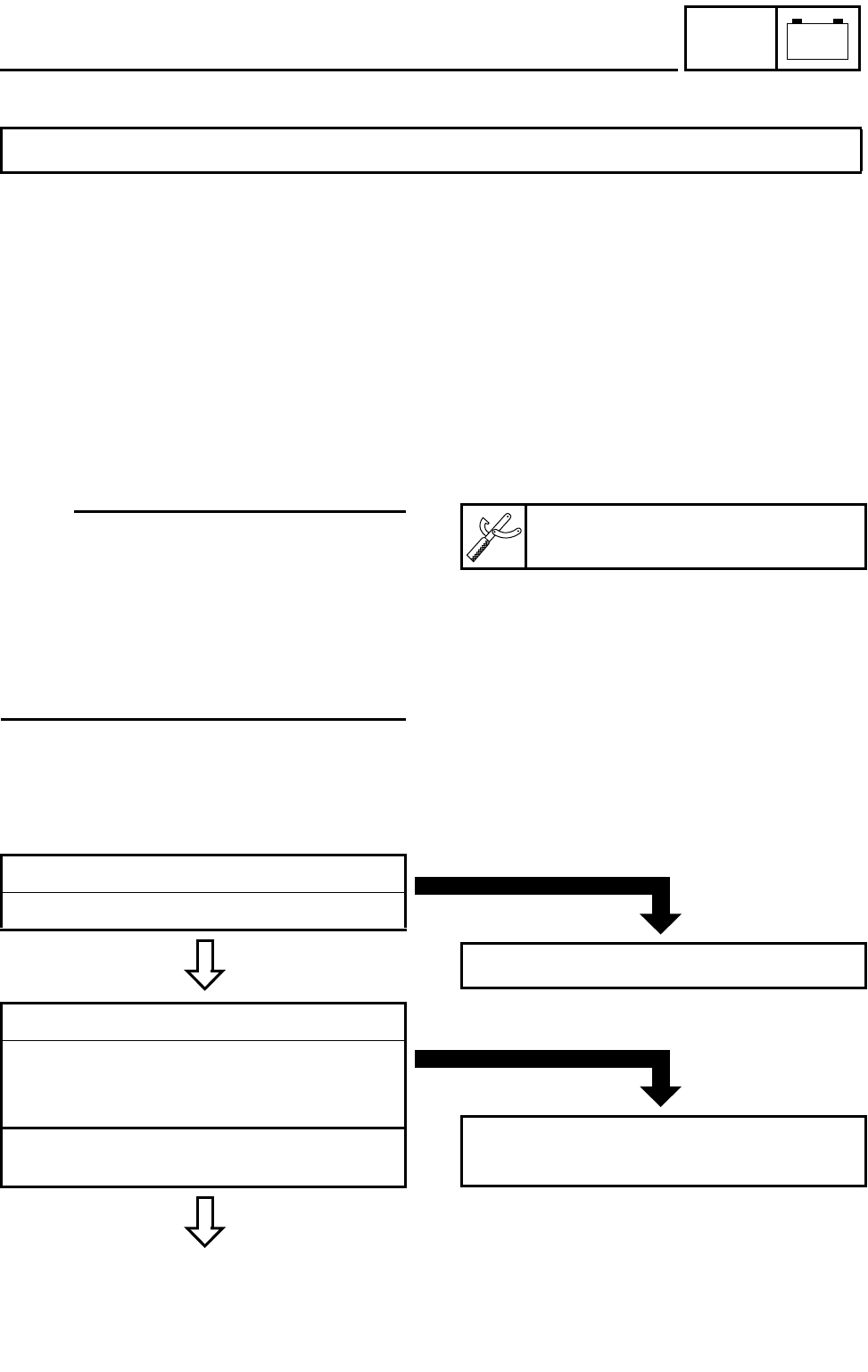
8 - 13
–+
ELEC
ELECTRIC STARTING SYSTEM
EB803020
TROUBLESHOOTING
Procedure
Check:
1.Fuse
2.Battery
3.Starter motor
4.Starter relay
5.Main switch
6.Engine stop switch
IF THE STARTER MOTOR FAILS TO OPERATE:
7.Start switch
8.Neutral switch
9.Clutch switch
10.Wiring connection (the entire starting sys-
tem)
OTE:
●Remove the following part(s) before trouble-
shooting:
1)Seat
2)Front fender
3)Rear fender
4)Exhaust pipe
●Use the following special tool(s) for trouble-
shooting.
Pocket tester:
P/N. YU-03112, 90890-03112
EB802011
CONTINUITY
1.Fuse
Refer to “CHECKING THE SWITCH”.
NO CONTINUITY
Replace the fuse.
EB802012
CORRECT
2.Battery
●Check the battery condition.
Refer to “CHECKING THE BATTERY” in
CHAPTER 3.
Open-circuit voltage:
12.8 V or more at 20 °C (68 °F)
*
INCORRECT
●Clean the battery terminals.
●Recharge or replace the battery.
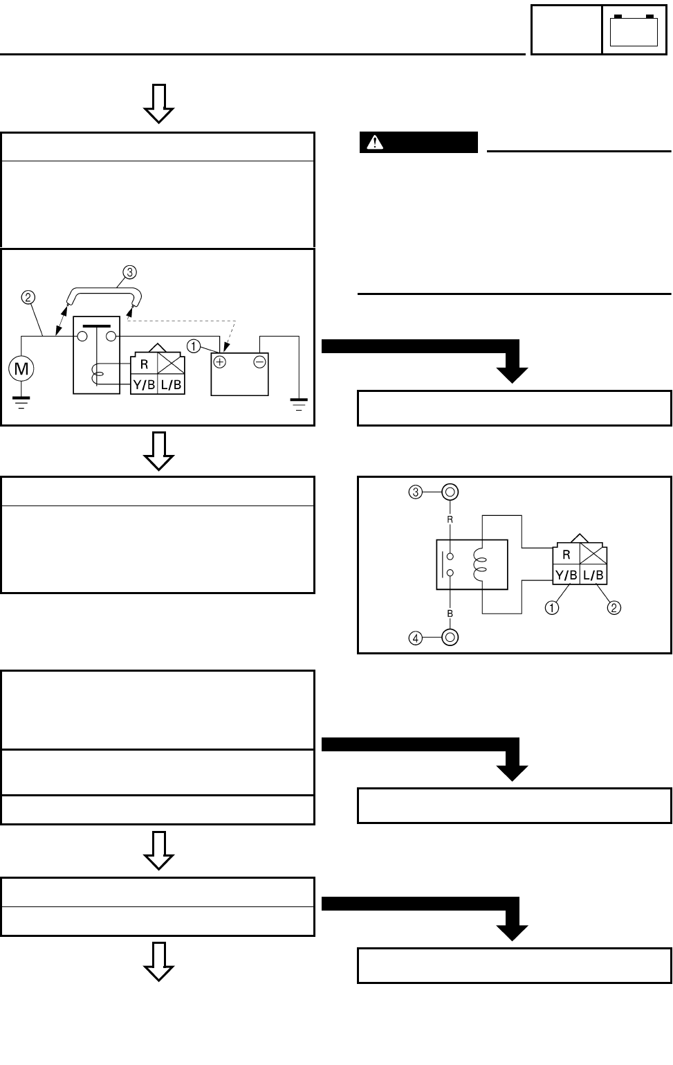
8 - 14
–+
ELEC
ELECTRIC STARTING SYSTEM
C0NTINUITY
TURNS
3.Starter motor
●Connect the battery positive terminal 1
and starter motor cable 2 using a jumper
lead 3 .
●Check the operation of the starter motor.
*
*
WARNING
●A wire that is used as a jumper lead must
have the equivalent capacity or more as
that of the battery lead, otherwise the
jumper lead may burn.
●This check is likely to produce sparks, so
be sure that no flammable gas or fluid is
in the vicinity.
*
DOES NOT TURN
Repair or replace the starter motor.
4.Starter relay
●Remove the starter relay from the wire har-
ness.
●Connect the pocket tester (Ω × 1) and the
battery (12 V) to the starter relay terminals.
CONTINUITY
Battery (+) terminal →
Yellow/Black terminal 1
Battery (–) terminal →
Blue/Black terminal 2
Tester (+) lead → Red terminal 3
Tester (–) lead → Black terminal 4
●Check the starter relay for continuity.
NO CONTINUITY
Replace the starter relay.
CORRECT
5.Main switch
Refer to “CHECKING THE SWITCH”.
*
INCORRECT
Replace the main switch.
8 - 15
–+
ELEC
ELECTRIC STARTING SYSTEM
C0NTINUITY
CORRECT
6.Engine stop switch
Refer to “CHECKING THE SWITCH”.
*
INCORRECT
Replace the handlebar switch (right).
CORRECT
7.Start switch
Refer to “CHECKING THE SWITCH”.
INCORRECT
Replace the handlebar switch (left).
CORRECT
8.Neutral switch
Refer to “CHECKING THE SWITCH”.
INCORRECT
Replace the neutral switch.
CORRECT
9.Clutch switch
Refer to “CHECKING THE SWITCH”.
INCORRECT
Replace the clutch switch.
EB803028
10.Wiring connection
●Check the connections of the entire starting
system.
Refer to “CIRCUIT DIAGRAM”.
POOR CONNECTION
Properly connect the starting system.
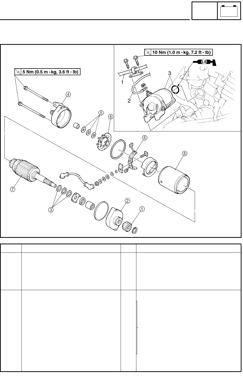
8 - 16
–+
ELEC
ELECTRIC STARTING SYSTEM
STARTER MOTOR
Order Job name/Part name Q’ty Remarks
Removing the starter motor Remove the parts in the order below.
Exhaust pipe Refer to “ENGINE REMOVAL”.
1 Parking brake cable 1 Disconnect.
2 Starter motor lead 1
3Starter motor/O-ring 1/1
Disassembling the starter motor Remove the parts in the order below.
1 Starter motor drive gear 1
2 Bracket 1 1
Refer to “ASSEMBLING THE STARTER
MOTOR”.
3 Washer kit
4 Bracket 2 1
5 Shims
6 Brush seat 1/brush seat 2 1/1
7 Armature coil 1
8 Yoke 1
For assembly, reverse the disassembly
procedure.
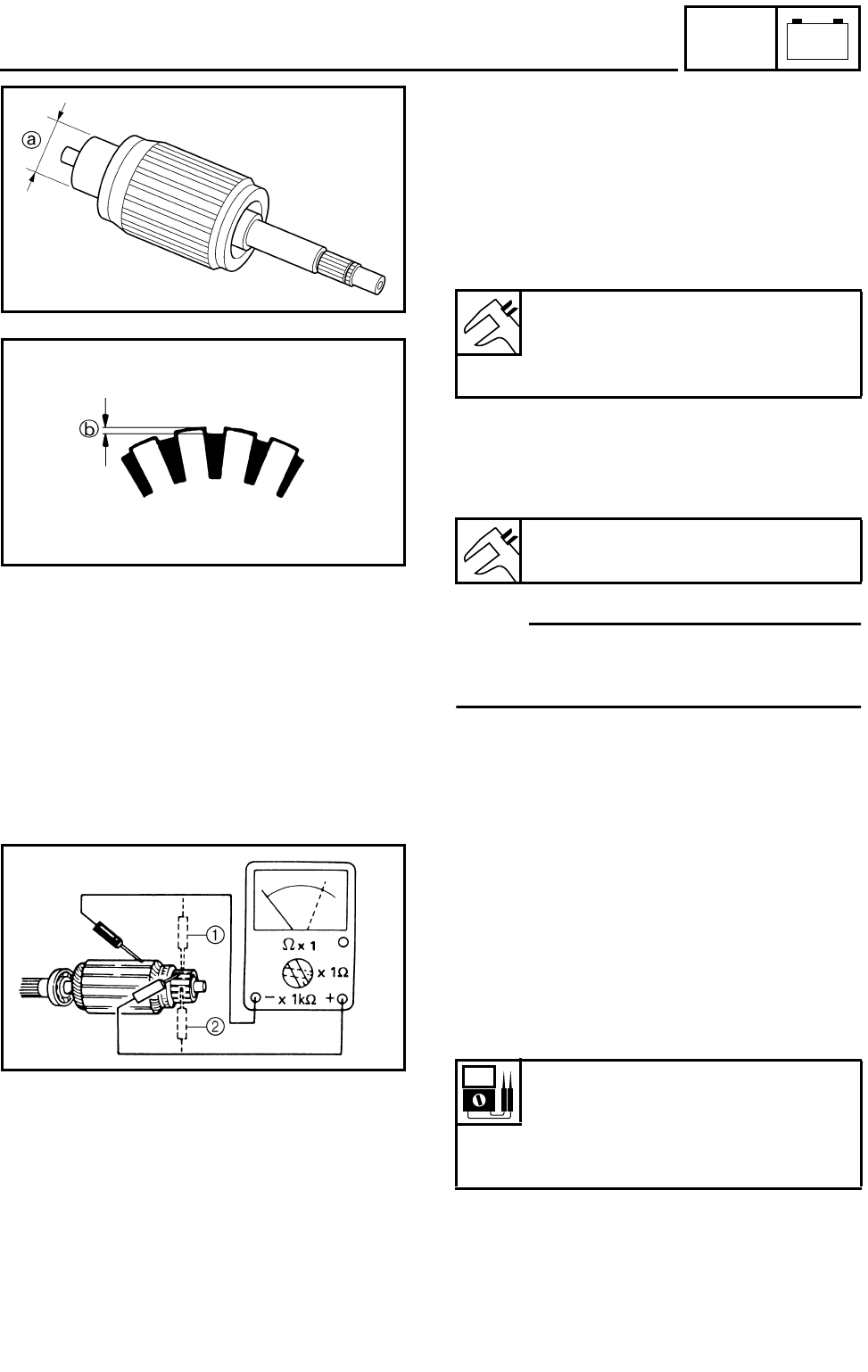
8 - 17
–+
ELEC
ELECTRIC STARTING SYSTEM
CHECKING THE STARTER MOTOR
1.Check:
●Commutator
Dirty → Clean it with #600 grit sandpaper.
2.Measure:
●Commutator diameter a
Out of specification → Replace the starter
motor.
3.Measure:
●Mica undercut b
Out of specification → Scrape the mica using
a hacksaw blade.
OTE:
Scrape the mica to the proper measurement
using a hacksaw blade which has been
grounded to fit the commutator.
Outside diameter:
28 mm (1.10 in)
<Wear limit:>
27 mm (1.06 in)
Mica undercut:
0.7 mm (0.03 in)
4.Check:
●Armature coil (insulation/continuity)
Defects → Replace the starter motor.
***********************************************
Armature coil checking steps:
●Connect the pocket tester for the continuity
check 1 and insulation check 2.
●Measure the armature resistances.
●If the resistance is incorrect, replace the
starter motor.
***********************************************
Armature coil resistance:
Continuity check 1:
0.025 ~ 0.035 Ω at 20 °C (68 °F)
Insulation check 2:
More than 1 MΩ at 20 °C (68 °F)
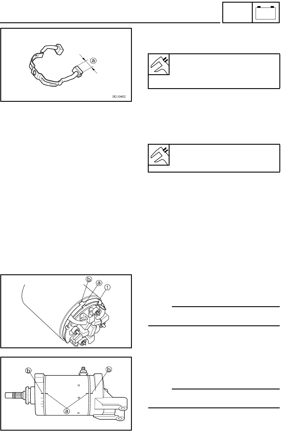
8 - 18
–+
ELEC
ELECTRIC STARTING SYSTEM
5.Measure:
●Brush length a (each)
Out of specification → Replace the brush.
Brush length:
12.5 mm (0.49 in)
<Wear limit:>
5 mm (0.20 in)
6.Measure:
●Brush spring force
Fatigue/out of specification → Replace as a
set.
Brush spring force:
7.65 ~ 10.01 Nm
(27.5 ~ 36.0 oz)
7.Check:
●Oil seal
●Bushing
●O-rings
Wear/damage → Replace.
ASSEMBLING THE STARTER MOTOR
1.Install:
●Brush seat 1
OTE:
Align the projection a on the brush seat with
the slot b on the housing.
2.Install:
●Yoke
●Brackets
OTE:
Align the match marks a on the yoke with the
match marks b on the brackets.
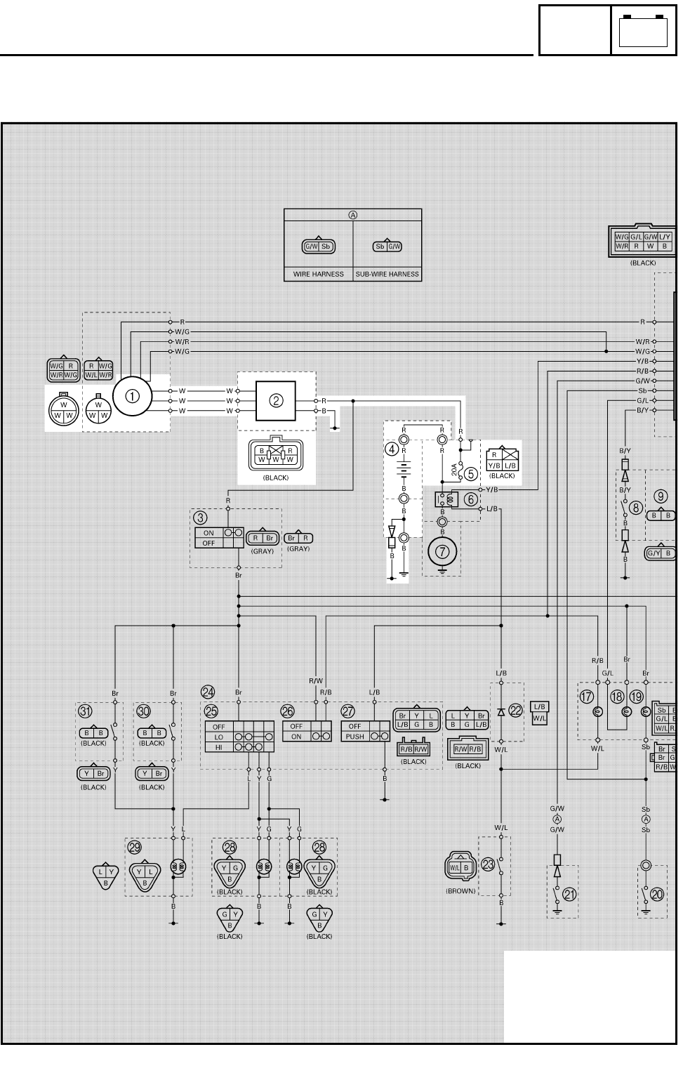
8 - 19
–+
ELEC
CHARGING SYSTEM
EB804000
CHARGING SYSTEM
CIRCUIT DIAGRAM
1AC magneto
2Rectifier/regulator
4Battery
5Fuse
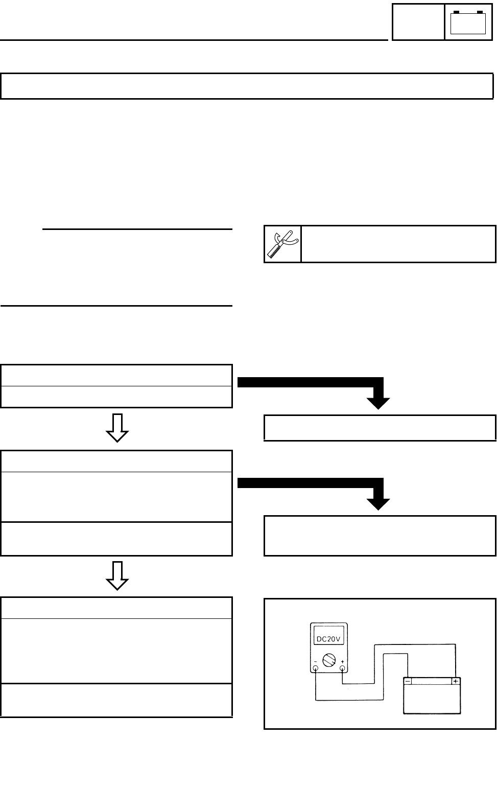
8 - 20
–+
ELEC
CHARGING SYSTEM
EB804010
TROUBLESHOOTING
Procedure
Check:
1.Fuse
2.Battery
3.Charging voltage
IF THE BATTERY IS NOT CHARGED:
4.Charging coil resistance
5.Wiring connections
(the entire charging system)
OTE:
●Remove the following part(s) before trouble-
shooting:
1)Seat
●Use the following special tool(s) for trouble-
shooting.
Pocket tester:
P/N. YU-03112, 90890-03112
EB802011
CONTINUITY
1.Fuse
Refer to “CHECKING THE SWITCH”.
NO CONTINUITY
Replace the fuse.
EB802012
CORRECT
2.Battery
●Check the battery condition.
Refer to “CHECKING THE BATTERY” in
CHAPTER 3.
Open-circuit voltage:
12.8 V or more at 20 °C (68 °F)
INCORRECT
●Clean the battery terminals.
●Recharge or replace the battery.
EB804011
3.Charging voltage
●Connect the tachometer to the spark plug
lead.
●Connect the pocket tester (DC 20V) to the
battery.
Tester (+) lead → Battery (+) terminal
Tester (–) lead → Battery (–) terminal
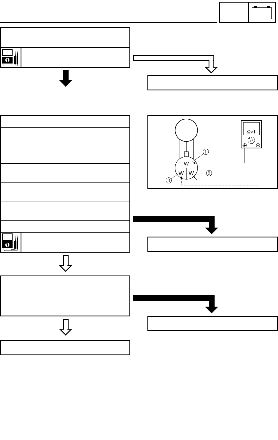
8 - 21
–+
ELEC
CHARGING SYSTEM
OUT OF
SPECIFICATION
●Start the engine and accelerate to about
5,000 r/min.
Charging voltage:
14 V at 5,000 r/min
MEETS SPECIFICATION
The charging circuit is not faulty.
EB804012
MEETS
SPECIFICATION
4.Charging coil resistance
●Disconnect the AC magneto coupler from
the wire harness.
●Connect the pocket tester (Ω × 1) to the
charging coils.
Tester (+) lead → White terminal 1
Tester (–) lead → White terminal 2
Tester (+) lead → White terminal 1
Tester (–) lead → White terminal 3
Tester (+) lead → White terminal 2
Tester (–) lead → White terminal 3
●Measure the stator coil resistance.
Charging coil resistance:
0.43 ~ 0.65 Ω at 20 °C (68 °F)
OUT OF SPECIFICATION
Replace the pickup coil/stator assembly.
EB804015
CORRECT
5.Wiring connections
●Check the connections of the entire charg-
ing system.
Refer to “CIRCUIT DIAGRAM”.
Replace the rectifier/regulator.
POOR CONNECTION
Properly connect the charging system.
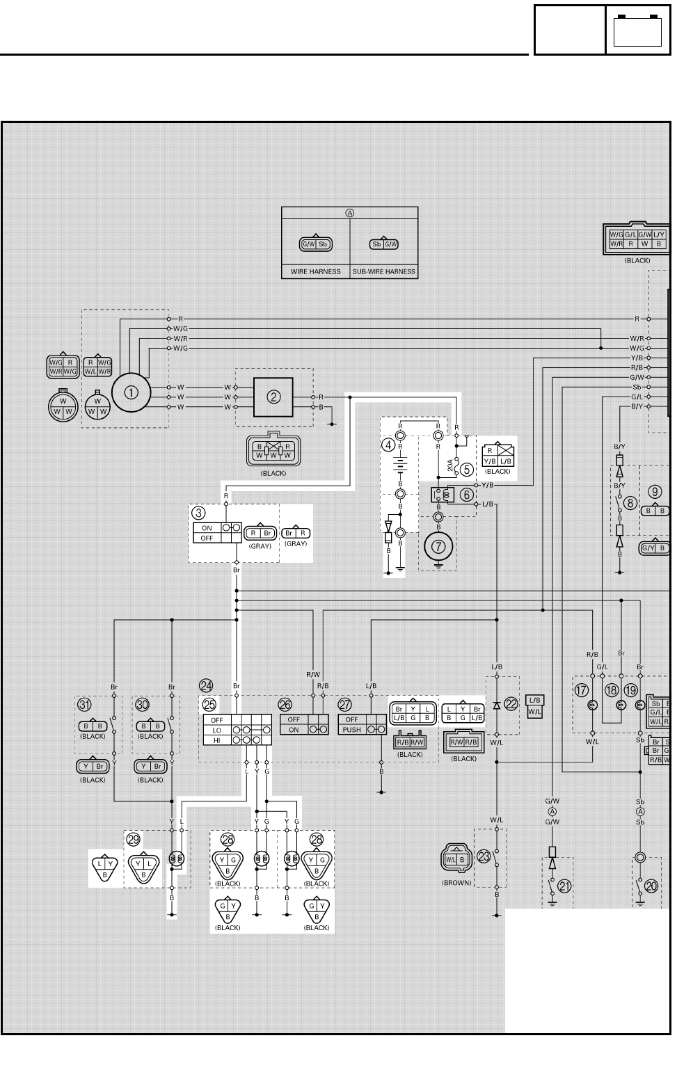
8 - 22
–+
ELEC
LIGHTING SYSTEM
EB805000
LIGHTING SYSTEM
CIRCUIT DIAGRAM
3Main switch
4Battery
5Fuse
OLights switch
RHeadlight
STail/brake light
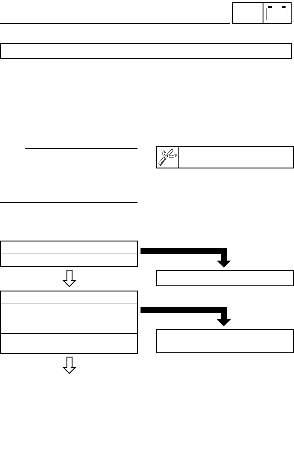
8 - 23
–+
ELEC
LIGHTING SYSTEM
EB805010
TROUBLESHOOTING
Procedure
Check:
1.Fuse
2.Battery
3.Main switch
IF THE HEADLIGHT AND/OR TAIL/BRAKE LIGHT FAIL TO COME ON:
4.Lights switch
5.Wiring connections
(the entire lighting system)
OTE:
●Remove the following part(s) before trouble-
shooting:
1)Seat
2)Front fender
●Use the following special tool(s) for trouble-
shooting.
Pocket tester:
P/N. YU-03112, 90890-03112
EB802011
CONTINUITY
1.Fuse
Refer to “CHECKING THE SWITCH”.
NO CONTINUITY
Replace the fuse.
EB802012
CORRECT
2.Battery
●Check the battery condition.
Refer to “CHECKING THE BATTERY” in
CHAPTER 3.
Open-circuit voltage:
12.8 V or more at 20 °C (68 °F)
*
INCORRECT
●Clean the battery terminals.
●Recharge or replace the battery.
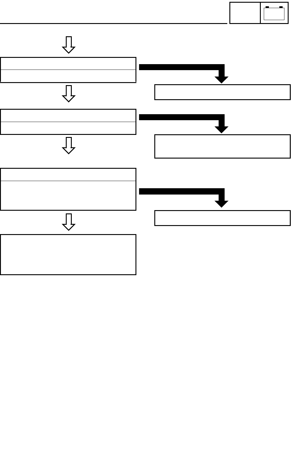
8 - 24
–+
ELEC
LIGHTING SYSTEM
C0NTINUITY
CORRECT
3.Main switch
Refer to “CHECKING THE SWITCH”.
*
INCORRECT
Replace the main switch.
CORRECT
4.Lights switch
Refer to “CHECKING THE SWITCH”.
INCORRECT
Lights switch is faulty, replace the handlebar
switch (left).
EB805013
CORRECT
5.Wiring connection
●Check the connections of the entire lighting
system.
Refer to “WIRING DIAGRAM”.
Check the condition of each of the lighting
system’s circuits.
Refer to “CHECKING THE LIGHTING SYS-
TEM”.
POOR CONNECTION
Properly connect the lighting system.
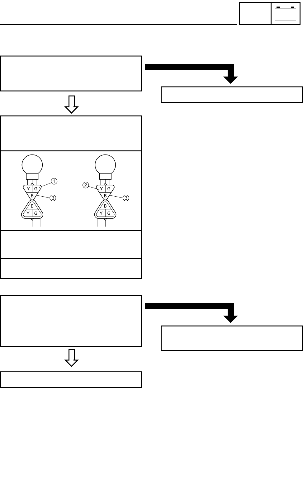
8 - 25
–+
ELEC
LIGHTING SYSTEM
EB805020
CHECKING THE LIGHTING SYSTEM
1.If the headlights fail to come on:
CONTINUITY
1.Bulb and bulb socket
●Check the bulb and bulb socket for continu-
ity.
NO CONTINUITY
Replace the bulb and/or bulb socket.
2.Voltage
●Connect the pocket tester (DC 20V) to the
headlight couplers.
Tester (+) lead →
Green terminal 1 or Yellow terminal 2
Tester (–) lead → Black terminal 3
ÈWhen the lights switch is on “LO”.
ÉWhen the lights switch is on “HI”.
ÈÉ
MEETS
SPECIFICATION
●Turn the main switch to “ON”.
●Turn the lights switch to “LO” or “HI”.
●Check the voltage (12 V) of the “Green”
and “Yellow” leads on the bulb socket con-
nector.
This circuit is not faulty.
OUT OF SPECIFICATION
The wiring circuit from the main switch to the
bulb socket connector is faulty, repair it.
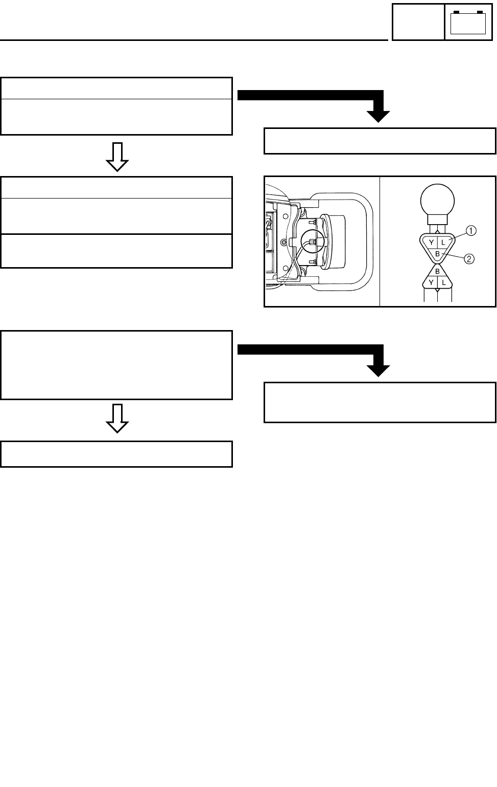
8 - 26
–+
ELEC
LIGHTING SYSTEM
EB805021
2.If the tail/brake light fails to come on:
CONTINUITY
1.Bulb and bulb socket
●Check the bulb and bulb socket for continu-
ity.
NO CONTINUITY
Replace the bulb and/or bulb socket.
2.Voltage
●Connect the pocket tester (20 V) to the bulb
socket coupler.
Tester (+) lead → Blue terminal 1
Tester (–) lead → Black terminal 2
MEETS
SPECIFICATION
●Turn the main switch to “ON”.
●Turn the lights switch to “LO” or “HI”.
●Check the voltage (12 V) of the “Blue” lead
on the bulb socket connector.
This circuit is not faulty.
OUT OF SPECIFICATION
The wiring circuit from the main switch to the
bulb socket connector is faulty, repair it.
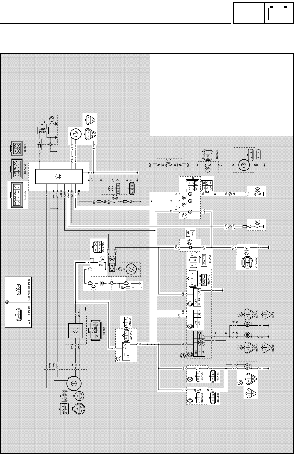
8 - 27
–+
ELEC
SIGNAL SYSTEM
EB806000
SIGNAL SYSTEM
CIRCUIT DIAGRAM
3Main switch
4Battery
5Fuse
0CDI unit
CSpeed sensor
GCoolant temperature
warning light
HReverse indicator light
INeutral indicator light
JNeutral switch
KReverse switch
LDiode
MThermo switch 2
PEngine stop switch
QStart switch
STail/brake light
TRear brake switch
UFront brake switch
8 - 28
–+
ELEC
SIGNAL SYSTEM
EB806010
TROUBLESHOOTING
Procedure
Check:
1.Fuse
2.Battery
3.Main switch
4.Wiring connections
(the entire signal system)
IF THE TAIL/BRAKE LIGHT AND/OR INDICATOR LIGHT FAILS TO COME ON:
OTE:
●Remove the following part(s) before trouble-
shooting:
1)Seat
2)Front fender
3)Rear fender
●Use the following special tool(s) for trouble-
shooting.
Pocket tester:
P/N. YU-03112, 90890-03112
EB802011
CONTINUITY
1.Fuse
Refer to “CHECKING THE SWITCH”.
NO CONTINUITY
Replace the fuse.
EB802012
CORRECT
2.Battery
●Check the battery condition.
Refer to “CHECKING THE BATTERY” in
CHAPTER 3.
Open-circuit voltage:
12.8 V or more at 20 °C (68 °F)
*
INCORRECT
●Clean the battery terminals.
●Recharge or replace the battery.
8 - 29
–+
ELEC
SIGNAL SYSTEM
C0NTINUITY
CORRECT
3.Main switch
Refer to “CHECKING THE SWITCH”.
*
INCORRECT
Replace the main switch.
EB806011
CORRECT
4.Wiring connections
●Check the connections of the entire signal
system.
Refer to “CIRCUIT DIAGRAM”.
Check the condition of each of the signal sys-
tem’s circuits.
Refer to “CHECKING THE SIGNAL SYS-
TEM”.
POOR CONNECTION
Properly connect the signal system.

8 - 30
–+
ELEC
SIGNAL SYSTEM
CHECKING THE SIGNAL SYSTEM
1.If the tail/brake light fails to come on:
CONTINUITY
1.Bulb and bulb socket
●Check the bulb and bulb socket for continu-
ity.
NO CONTINUITY
Replace the bulb and/or bulb socket.
CONTINUITY
2.Brake switches
Refer to “CHECKING THE SWITCH”.
NO CONTINUITY
Replace the brake switch.
3.Voltage
●Connect the pocket tester (DC 20V) to the
bulb socket coupler.
Tester (+) lead → Yellow terminal 1
Tester (–) lead → Black terminal 2
MEETS
SPECIFICATION
●Turn the main switch to “ON”.
●Turn the lights switch to “LO” or “HI”.
●Check the voltage (12 V) of the “Yellow”
lead on the bulb socket connector.
This circuit is not faulty.
OUT OF SPECIFICATION
The wiring circuit from the main switch to the
bulb socket connector is faulty, repair it.
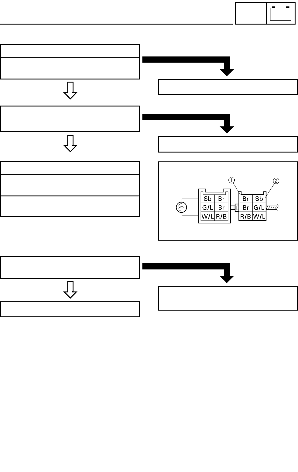
8 - 31
–+
ELEC
SIGNAL SYSTEM
EB806024
2.If the neutral indicator light fails to come on:
CONTINUITY
1.Bulb and bulb socket
●Check the bulb and bulb socket for continu-
ity.
NO CONTINUITY
Replace the bulb and/or bulb socket.
CONTINUITY
2.Neutral switch
Refer to “CHECKING THE SWITCH”.
NO CONTINUITY
Replace the neutral switch.
3.Voltage
●Connect the pocket tester (DC 20V) to the
bulb socket coupler.
Tester (+) lead → Brown terminal 1
Tester (–) lead → Sky blue terminal 2
MEETS
SPECIFICATION
●Turn the main switch to “ON”.
●Check the voltage (12 V).
This circuit is not faulty.
OUT OF SPECIFICATION
The wiring circuit from the main switch to the
bulb socket connector is faulty, repair it.
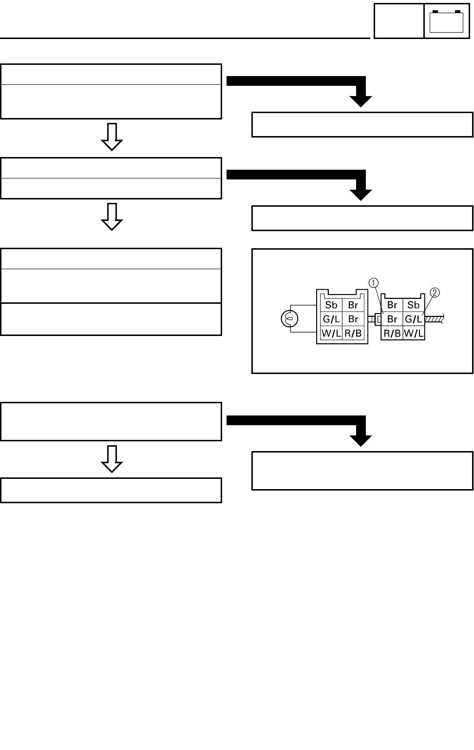
8 - 32
–+
ELEC
SIGNAL SYSTEM
3.If the reverse indicator light fails to come on:
CONTINUITY
1.Bulb and bulb socket
●Check the bulb and bulb socket for continu-
ity.
NO CONTINUITY
Replace the bulb and/or bulb socket.
CONTINUITY
2.Reverse switch
Refer to “CHECKING THE SWITCH”.
NO CONTINUITY
Replace the reverse switch.
3.Voltage
●Connect the pocket tester (DC 20V) to the
bulb socket coupler.
Tester (+) lead → Brown terminal 1
Tester (–) lead → Green/Blue terminal 2
MEETS
SPECIFICATION
●Turn the main switch to “ON”.
●Check the voltage (12 V).
This circuit is not faulty.
OUT OF SPECIFICATION
The wiring circuit from the main switch to the
bulb socket connector is faulty, repair it.
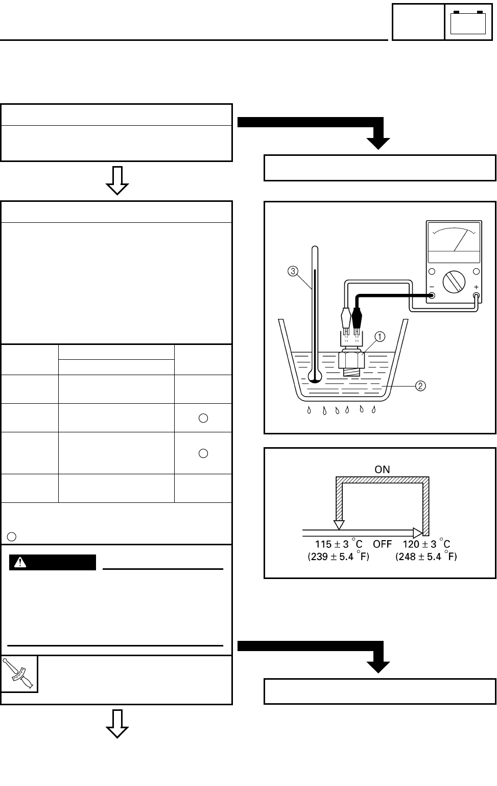
8 - 33
–+
ELEC
SIGNAL SYSTEM
4.If the coolant temperature warning light does not come on when the start switch is pushed on, or if
the coolant temperature warning light does not come on when the temperature is high (more than
117 ~ 123 °C (242.6 ~ 253.4 °F)):
CONTINUITY
1.Bulb and bulb socket
●Check the bulb and bulb socket for continu-
ity.
NO CONTINUITY
Replace the bulb and/or bulb socket.
GOOD
CONDITION
2.Thermo switch 2
●Remove the thermo switch from the ther-
mostat housing.
●Connect the pocket tester (Ω × 1) to the
thermo switch 1.
●Immerse the thermo switch in coolant 2.
●Check the thermo switch for continuity.
While heating the coolant use a thermome-
ter 3 to record the temperatures.
Test
step Water temperature Good
condition
Thermo switch
10 ~ 115 ± 3 °C
(32 ~ 239 ± 5.4 °F) ×
2More than 120 ± 3 °C
(248 ± 5.4 °F)
3* 120 ± 3 to 115 ± 3 °C
(248 ± 5.4 to
239 ± 5.4 °F)
4* Less than 115 ± 3 °C
(239 ± 5.4 °F) ×
Tests 1 & 2; Heat-up tests
Tests 3* & 4*; Cool-down tests
: Continuity × : No continuity
T
R
.
.
Thermo switch:
2.8 Nm (2.8 m • kg, 20 ft • lb)
Three bond sealock® #10
WARNING
Handle the thermo switch with special
care.
Never subject it to a strong shock or
allow it to be dropped. Should it be
dropped, it must be replaced.
*
BAD CONDITION
Replace the thermo switch 2.
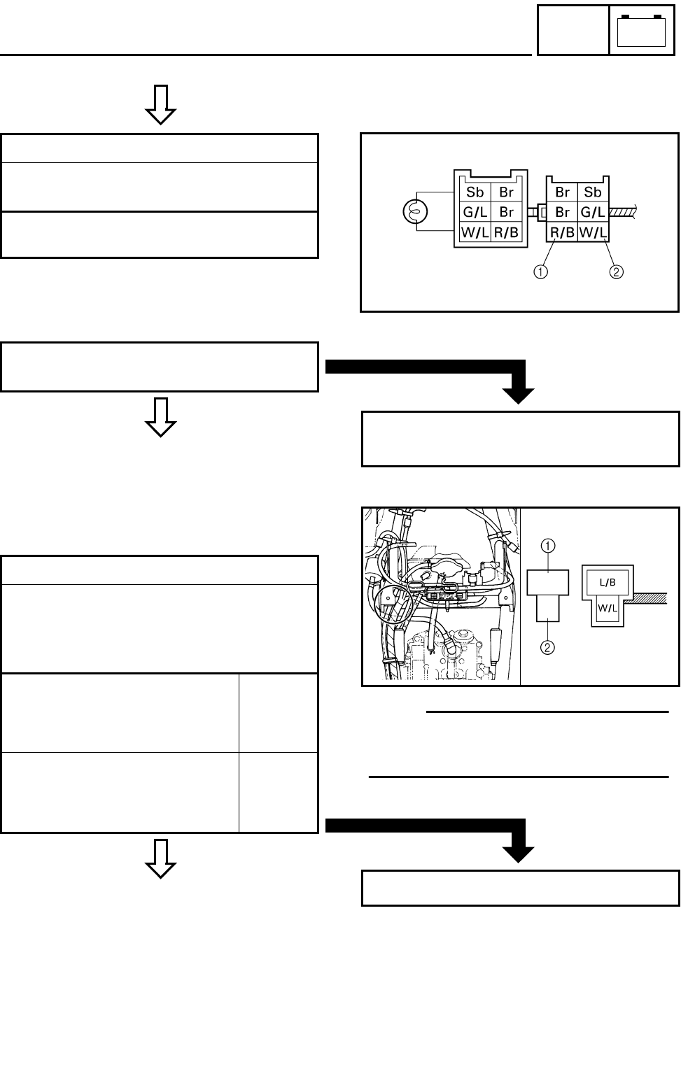
8 - 34
–+
ELEC
SIGNAL SYSTEM
C0NTINUITY
3.Voltage
●Connect the pocket tester (DC 20V) to the
bulb socket coupler.
Tester (+) lead → Red/Black terminal 1
Tester (–) lead → White/Blue terminal 2
*
MEETS
SPECIFICATION
●Turn the main switch to “ON”.
●Check the voltage (12 V).
OUT OF SPECIFICATION
The wiring circuit from the main switch to the
bulb socket connector is faulty, repair it.
CORRECT
4.Diode
• Remove the diode from the coupler.
• Connect the pocket tester (Ω × 1) to the
diode terminals as shown.
• Check the diode for continuity as follows.
Tester positive probe →
Blue/Black 1
Tester negative probe →
White/Blue 2
Continu-
ity
Tester positive probe →
White/Blue 2
Tester negative probe →
Blue/Black 1
No conti-
nuity
*
OTE:
When you switch the tester’s positive and
negative probes, the readings in the left
chart will be reversed.
INCORRECT
Replace the diode.
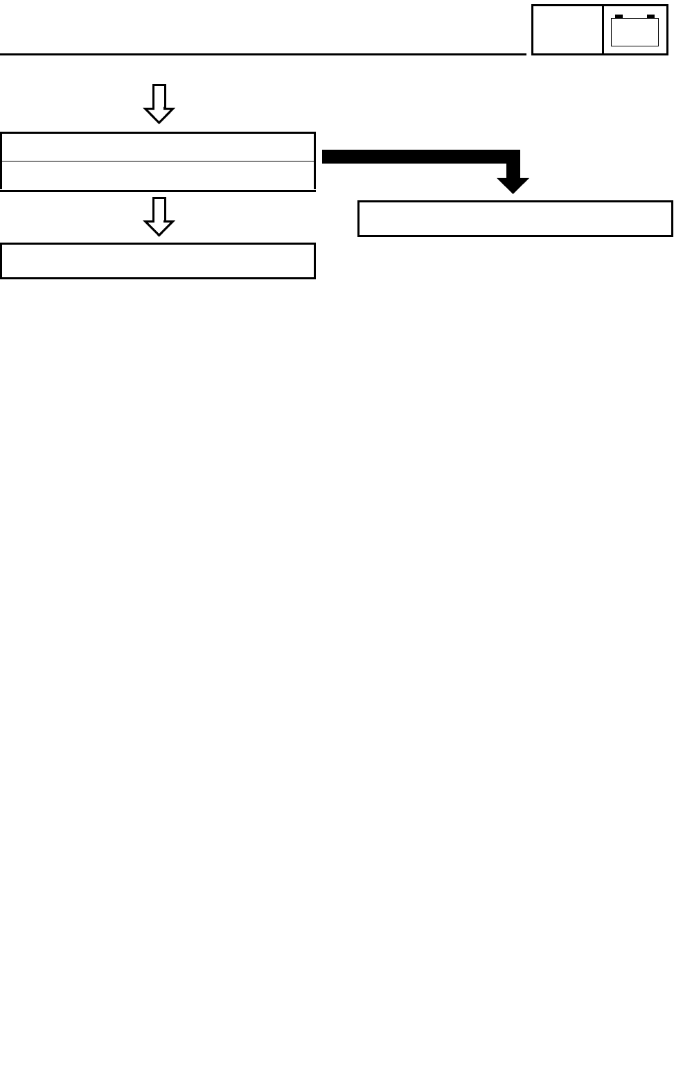
8 - 35
–+
ELEC
SIGNAL SYSTEM
C0NTINUITY
CORRECT
5.Start switch
Refer to “CHECKING THE SWITCH”.
This circuit is not faulty.
*
INCORRECT
Replace the handlebar switch (left).
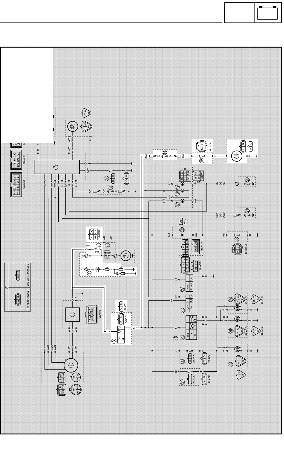
8 - 36
–+
ELEC
COOLING SYSTEM
COOLING SYSTEM
CIRCUIT DIAGRAM
3Main switch
4Battery
5Fuse
DCircuit breaker (fan motor)
EThermo switch 1
FFan motor
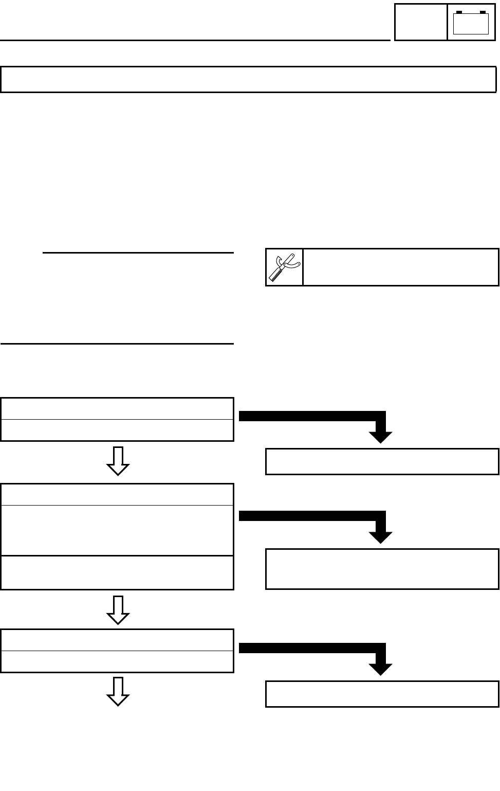
8 - 37
–+
ELEC
COOLING SYSTEM
TROUBLESHOOTING
Procedure
Check:
1.Fuse
2.Battery
3.Main switch
4.Fan motor
5.Circuit breaker (fan motor)
IF THE FAN MOTOR DOES NOT MOVE:
6.Thermo switch 1
7.Wiring connection
(the entire cooling system)
OTE:
●Remove the following part(s) before trouble-
shooting.
1)Seat
2)Front fender
●Use the following special tool(s) for trouble-
shooting.
Pocket tester:
P/N. YU-03112, 90890-03112
EB802011
CONTINUITY
1.Fuse
Refer to “CHECKING THE SWITCH”.
NO CONTINUITY
Replace the fuse.
EB802012
CORRECT
2.Battery
●Check the battery condition.
Refer to “CHECKING THE BATTERY” in
CHAPTER 3.
Open-circuit voltage:
12.8 V or more at 20 °C (68 °F)
INCORRECT
●Clean the battery terminals.
●Recharge or replace the battery.
CORRECT
3.Main switch
Refer to “CHECKING THE SWITCH”.
*
INCORRECT
Replace the main switch.
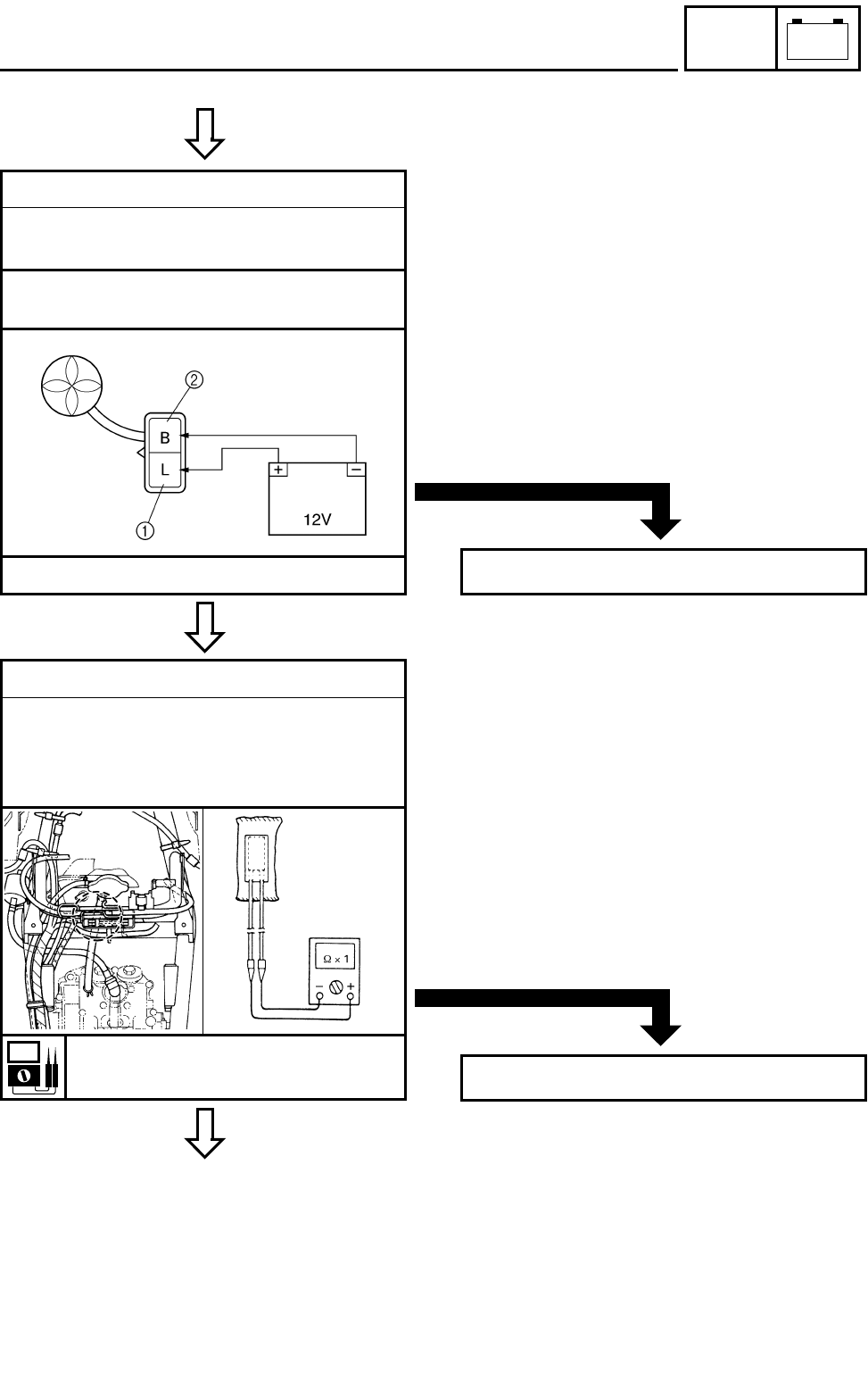
8 - 38
–+
ELEC
COOLING SYSTEM
C0NTINUITY
TURNS
4.Fan motor
●Disconnect the fan motor coupler.
●Connect the battery (12 V) as shown.
Battery (+) lead → Blue terminal 1
Battery (–) lead → Black terminal 2
●Check the operation of the fan motor.
*
DOES NOT TURN
Replace the fan motor.
MEETS
SPECIFICATION
5.Circuit breaker (fan motor)
●Remove the circuit breaker from the wire
harness.
●Connect the pocket tester (Ω × 1) to the cir-
cuit breaker.
Circuit breaker resistance:
Zero Ω at 20 °C (68 °F)
*
OUT OF SPECIFICATION
Replace the circuit breaker.
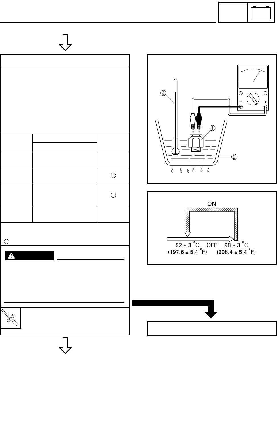
8 - 39
–+
ELEC
COOLING SYSTEM
C0NTINUITY
GOOD
CONDITION
6.Thermo switch 1
●Remove the thermo switch from the radia-
tor.
●Connect the pocket tester (Ω × 10) to the
thermo switch 1.
●Immerse the thermo switch in coolant 2.
●Check the thermo switch for continuity.
While heating the coolant use a thermome-
ter 3 to record the temperatures.
Test
step Water temperature Good
condition
Thermo switch
10 ~ 92 ± 3 °C
(32 ~ 197.6 ± 5.4 °F) ×
2More than 98 ± 3 °C
(208.4 ± 5.4 °F)
3* 98 ± 3 to 92 ± 3 °C
(208.4 ± 5.4 to
197.6 ± 5.4 °F)
4* Less than 92 ± 3 °C
(197.6 ± 5.4 °F) ×
Tests 1 & 2; Heat-up tests
Tests 3* & 4*; Cool-down tests
: Continuity × : No continuity
T
R
.
.
Thermo switch:
28 Nm (2.8 m • kg, 20 ft • lb)
Three bond sealock® #10
*
WARNING
Handle the thermo switch with special
care.
Never subject it to a strong shock or
allow it to be dropped. Should it be
dropped, it must be replaced.
*
BAD CONDITION
Replace the thermo switch 1.
8 - 40
–+
ELEC
COOLING SYSTEM
C0NTINUITY
EB803028
CORRECT
7.Wiring connection
●Check the connections of the entire starting
system.
Refer to “CIRCUIT DIAGRAM”.
This circuit is not faulty.
*
POOR CONNECTION
Properly connect the cooling system.

9 - 1
TRBL
SHTG
STARTING FAILURE/HARD STARTING
TROUBLESHOOTING
NOTE:
The following troubleshooting does not cover all the possible causes of trouble. It should be helpful,
however, as a guide to troubleshooting. Refer to the relative procedure in this manual for inspection,
adjustment and replacement of parts.
STARTING FAILURE/HARD STARTING
FUEL SYSTEM
Fuel tank
●Empty
●Clogged fuel filter
●Clogged fuel strainer
●Clogged fuel breather hose
●Deteriorated or contaminated fuel
Fuel cock
●Clogged fuel hose
ELECTRICAL SYSTEM
Spark plug
●Improper plug gap
●Worn electrodes
●Wire between terminals broken
●Improper heat range
●Faulty spark plug cap
Ignition coil
●Broken or shorted primary/secondary
●Faulty spark plug lead
●Broken body
CDI system
●Faulty CDI unit
●Faulty pickup coil
●Broken woodruff key
Carburetor
●Deteriorated or contaminated fuel
●Clogged pilot jet
●Clogged pilot air passage
●Sucked-in air
●Deformed float
●Worn needle valve
●Improperly sealed valve seat
●Improperly adjusted fuel level
●Improperly set pilot jet
●Clogged starter jet
●Starter plunger malfunction
Air filter
●Clogged air filter element
Switches and wiring
●Faulty main switch
●Faulty engine stop switch
●Broken or shorted wiring
●Faulty neutral switch
●Faulty start switch
●Faulty clutch switch
Starter motor
●Faulty starter motor
●Faulty starter relay
●Faulty starter circuit cut-off relay
●Faulty starter clutch
Battery
●Faulty battery

9 - 2
TRBL
SHTG
STARTING FAILURE/HARD STARTING/POOR IDLE SPEED
PERFORMANCE/POOR MEDIUM AND HIGH-SPEED PERFORMANCE
COMPRESSION SYSTEM
Cylinder and cylinder head
●Loose spark plug
●Loose cylinder head or cylinder
●Broken cylinder head gasket
●Broken cylinder gasket
●Worn, damaged or seized cylinder
Valve, camshaft and crankshaft
●Improperly sealed valve
●Improperly contacted valve and valve seat
●Improper valve timing
●Broken valve spring
●Seized camshaft
●Seized crankshaft
Piston and piston rings
●Improperly installed piston ring
●Worn, fatigued or broken piston ring
●Seized piston ring
●Seized or damaged piston
Crankcase and crankshaft
●Improperly seated crankcase
●Seized crankshaft
Valve train
●Improperly adjusted valve clearance
●Improperly adjusted valve timing
POOR IDLE SPEED PERFORMANCE
POOR IDLE SPEED PERFORMANCE
Carburetor
●Improperly returned starter plunger
●Loose pilot jet
●Clogged pilot jet
●Clogged pilot air jet
●Improperly adjusted idle speed
(Throttle stop screw)
●Improper throttle cable play
●Flooded carburetor
Electrical system
●Faulty spark plug
●Faulty CDI unit
●Faulty pickup coil
●Faulty ignition coil
Valve train
●Improperly adjusted valve clearance
Air filter
●Clogged air filter element
POOR MEDIUM AND HIGH-SPEED PERFORMANCE
POOR MEDIUM AND HIGH-SPEED PERFORMANCE
Refer to “STARTING FAILURE/HARD STARTING” and “POOR IDLE SPEED PERFORMANCE-
VALVE TRAIN”.
Carburetor
●Improper jet needle clip position
●Improperly adjusted fuel level
●Clogged or loose main jet
●Deteriorated or contaminated fuel
Air filter
●Clogged air filter element

9 - 3
TRBL
SHTG
FAULTY GEAR SHIFTING/
CLUTCH SLIPPING/DRAGGING
FAULTY GEAR SHIFTING
HARD SHIFTING
Refer to “CLUTCH DRAGGING”.
SHIFT PEDAL DOES NOT MOVE
Shift shaft
●Bent shift shaft
Shift drum and shift fork
●Groove jammed with impurities
●Seized shift fork
●Bent shift fork guide bar
Transmission
●Seized transmission gear
●Jammed impurities
●Incorrectly assembled transmission
Shift guide
●Broken shift guide
JUMP-OUT GEAR
Shift shaft
●Improperly adjusted shift lever position
●Improperly returned stopper lever
Shift fork
●Worn shift fork
Shift drum
●Improper thrust play
●Worn shift drum groove
Transmission
●Worn gear dog
CLUTCH SLIPPING/DRAGGING
CLUTCH SLIPPING
Clutch
●Loose clutch spring
●Fatigued clutch spring
●Worn friction plate
●Worn clutch plate
●Incorrectly assembled clutch
Engine oil
●Low oil level
●Improper quality (low viscosity)
●Deterioration
CLUTCH DRAGGING
Clutch
●Warped pressure plate
●Unevenly tensioned clutch springs
●Match marks not aligned
●Loose clutch boss nut
●Burnt primary driven gear bushing
●Bent clutch plate
●Swollen friction plate
●Broken clutch boss
Transmission oil
●High oil level
●Improper quality (high viscosity)
●Deterioration

9 - 4
TRBL
SHTG
OVERHEATING/OVER COOLING/
FAULTY BRAKE
OVERHEATING
OVERHEATING
Ignition system
●Improper spark plug gap
●Improper spark plug heat range
●Faulty CDI unit
Fuel system
●Improper carburetor main jet
(improper setting)
●Improper fuel level
●Clogged air filter element
Compression system
●Heavy carbon deposit
Engine oil
●Improper oil level
●Improper oil viscosity
●Inferior oil quality
Brake
●Brake drag
Cooling system
●Low coolant level
●Clogged or damaged radiator
●Damaged or faulty water pump
●Thermostat stays closed
OVER COOLING
COOLING SYSTEM
Thermostat
●Thermostat stays open
FAULTY BRAKE
POOR BRAKING EFFECT
Disc brake
●Worn brake pads
●Worn disc
●Air in brake fluid
●Leaking brake fluid
●Faulty master cylinder kit cup
●Faulty caliper kit seal
●Loose union bolt
●Broken brake hose and pipe
●Oily or greasy disc/brake pads
●Improper brake fluid level

9 - 5
TRBL
SHTG
SHOCK ABSORBER MALFUNCTION
MALFUNCTION
●Bent or damaged damper rod
●Damaged oil seal lip
●Fatigued shock absorber spring
SHOCK ABSORBER MALFUNCTION/
UNSTABLE HANDLING/LIGHTING SYSTEM
UNSTABLE HANDLING
UNSTABLE HANDLING
Handlebar
●Improperly installed or bent
Steering
●Incorrect toe-in
●Bent steering stem
●Improperly installed steering stem
●Damaged bearing or bearing race
●Bent tie rods
●Deformed steering knuckles
Tires
●Uneven tire pressures on both sides
●Incorrect tire pressure
●Uneven tire wear
Wheels
●Deformed wheel
●Loose bearing
●Bent or loose wheel axle
●Excessive wheel runout
Frame
●Bent
●Damaged frame
Swingarm
●Worn bearing or bushing
●Bent or damaged
LIGHTING SYSTEM
HEADLIGHT DARK
●Improper bulb
●Too many electric accessories
●Hard charging (broken charging coil and/or
faulty rectifier/regulator)
●Incorrect connection
●Improperly grounded
●Poor contacts (main or lights switch)
●Bulb life expired
BULB BURNT OUT
●Improper bulb
●Faulty battery
●Faulty rectifier/regulator
●Improperly grounded
●Faulty main and/or lights switch
●Bulb life expired

YAMAHA MOTOR CO., LTD.
2500 SHINGAI IWATA SHIZUOKA JAPAN
PRINTED IN U.S.A.
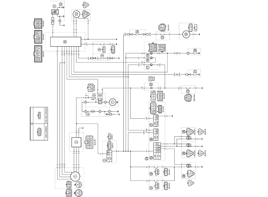
YFM660R WIRING DIAGRAM
1AC magneto
2Rectifier/regulator
3Main switch
4Battery
5Fuse
6Starter relay
7Starter motor
8Clutch switch
9Park switch
0CDI unit
AIgnition coil
BSpark plug
CSpeed sensor
DCircuit breaker (fan motor)
EThermo switch 1
FFan motor
GCoolant temperature warning light
HReverse indicator light
INeutral indicator light
JNeutral switch
KReverse switch
LDiode
MThermo switch 2
NHandlebar switch (left)
OLights switch
PEngine stop switch
QStart switch
RHeadlight
STail/brake light
TRear brake switch
UFront brake switch
COLOR CODE
B ............Black
Br...........Brown
G............Green
L.............Blue
O............Orange
P ............Pink
R............Red
Sb ..........Sky blue
W ...........White
Y ............Yellow
B/W........Black/White
B/Y.........Black/Yellow
Br/L........Brown/Blue
Br/R .......Brown/Red
Br/W.......Brown/White
G/L.........Green/Blue
G/W........Green/White
G/Y.........Green/Yellow
L/B .........Blue/Black
L/G.........Blue/Green
L/R .........Blue/Red
L/W ........Blue/White
L/Y .........Blue/Yellow
O/R ........Orange/Red
R/B........ Red/Black
R/W....... Red/White
R/Y........ Red/Yellow
W/B ....... White/Black
W/G....... White/Green
W/L ....... White/Blue
W/R....... White/Red
Y/B ........ Yellow/Black
