Raspi_QuickGuide Raspi Quick Guide
User Manual:
Open the PDF directly: View PDF ![]() .
.
Page Count: 237 [warning: Documents this large are best viewed by clicking the View PDF Link!]
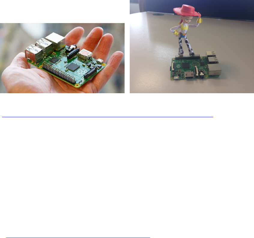
Quick Guide für Raspberry Pi
Copyright (C): Helmut Wunder 2015, 2016, 2017, 2018
Anleitungen und Einstellungen insb. für Raspberry Pi 2 mit Raspbian Jessie Betriebssystem
https://www.raspberrypi.org/wp-content/uploads/2015/09/IMG_0727.jpg
Lizenz-Hinweise:
für alle hier veröffentlichten Software-Source-Codes gilt:
/*
// (C) Helmut Wunder (HaWe) 2015
// freie Verwendung für private Zwecke
// für kommerzielle Zwecke nur nach Genehmigung durch den Autor.
// Programming language: C/C++
// protected under the friendly
// Creative Commons Attribution-NonCommercial-ShareAlike 3.0 Unported License
// http://creativecommons.org/licenses/by-nc-sa/3.0/
//
// alle Codes wurden zur Verfügung gestellt in der Hoffnung, dass sie nützlich sind,
// Irrtümer vorbehalten, Benutzung auf eigenes Risiko,
// ohne Anspruch auf Schadenersatz, Garantie oder Gewährleistung
// für irgendwelche eventuellen Schäden, die aus ihrer Benutzung entstehen könnten.
//
// unabhängig hiervon gelten die Lizenz-rechtlichen Besimmungen der Original-Autoren
//
*/

DONATE / SPENDE:
Gefällt dir dieses Kompendium und möchtest du dafür einen kleinen Betrag über PAYPAL spenden ?
Dann klicke einfach auf diesen Link -
Ab einer Spende ab EUR 5,- kannst du auf Wunsch dieses Kompendium auch als kostenloses
WORD.doc erhalten (per Download-Link als .zip, z.T. ein bisschen weniger Geräte-Fotos aus
urheberrechtlichen Gründen, dafür aber zusätzliche Infos und Code Beispiele):
-> Ja, ich möchte etwas als Anerkennung spenden <-
https://www.paypal.com/cgi-bin/webscr?cmd=_s-xclick&hosted_button_id=Q58RCVK67EM9Q
Ein ganz herzliches Dankeschön!

Inhaltsverzeichnis
QUICK GUIDE FÜR RASPBERRY PI 1
LIZENZ-HINWEISE: 1
TUTORIALS UND SPEZ. LINKS: 10
Raspberry Pi Tutorials: 10
C/C++ Tutorials: 10
GPIOS: 11
QUICK-LINKS ZUM KOMPENDIUM IM INTERNET: 12
RASPBERRY PI: ERSTINSTALLATION MIT NOOBS 14
Vorbereitungen und erste Schritte: 14
Raspberry Pi: Netzwerk, Internet, USB, externe Laufwerke 15
LAN, WLAN und Internet: a) Kabelgebundenes LAN einrichten 15
b) WLAN einrichten 16
c) alternativen Internet-Browser einrichten 17
OPTIONALE SETTINGS UND TOOLS : 19
a) mobiles Internet mit Surfstick / GSM Card 19
b) Leistung an USB-Ports maximal erhöhen: 19
c) externe USB-Laufwerke einbinden 19
d) SD-Card : Linux Partition auf SD-Karte komplett löschen zur Neukonfiguration 19
e) SD-card Backup erstellen: 19
f) SD-card Backup lokal auf Raspi erstellen (via Raspi USB SD-Adapter) : 20
g) externe SD-Laufwerke mounten und browsen : 20
optional: Heimnetz und Windows Workgroup : 21
h) RaspberryPi ins Windows Heimnetz einbinden und freigeben 21
i) CUPS Drucker Service installieren 26
j) Windows PC fernsteuern: 27
EINFACHE VORVERSUCHE MIT PYTHON: 32
RASPBERRY PI: GEANY MIT GCC/G++ 33
a) System-Update und github Zugang installieren 33
b) Geany IDE installieren und konfigurieren 33

c) 1. Testprogramm in ANSI-C, ob alle wichtigen libs vorhanden und korrekt
eingebunden werden...! 34
d) Einstellungen für C++: 35
e) ...und das erste Testprogramm für C++ ... !! 35
f) Links zu C/C++ source code Examples: 36
g) Compile / build mit Standard C++(11) : 36
h) Upgrade zu gcc/gpp 6.x : 36
i) für Raspbian Stretch: keine Ausgabe im Terminal: 37
OPENVG GRAFIK LIBS FÜR HDMI-AUSGABE INSTALLIEREN 38
a) C/C++ openvg Grafik Basis-lib: 38
b) erweiterte Grafik-API: openvg von Paeryn 38
Re: How to increase OpenVG time performances 39
Re: Stretch: how to install latest openVG version with Dot() function? 39
Demo-Programm: 39
Testcode von Paeryn: 40
zusätzliche outlined shapes i Paryn's Lib: 41
Generelle Syntax zu Initialisieren und Beenden von openVG: 41
c) Installation: Update für Raspbian Stretch 42
d) Farbnamen / Farbkonstanten (Decimal Color Codes) 42
e) Geschwindigkeit mit GPU erhöhen: 43
f) Benchmark Testcode für Mathematik-, Textausgabe- und Grafik-Funktionen: 44
RAYLIB: NEUE ALTERNATIVE GRAFIK-LIB: 51
GPIO-ACCESS: WIRINGPI UND PIGPIO 52
a) GPIO Libs installieren: 52
wiringPi: 52
pigpio: 53
b) Beispiele für GPIO-Access: 53
c) gesamte neue Compile- und Build-Einstellungen für Geany: 56
d) Übersicht über die GPIO-Belegung und Nummerierung 56
(Raspberry Pi B+ oder 2B mit 40 Pins) 56
e) Testprogramm für GPIO Pins wiringPi 57
a) Verkabelung von Pins als Output mit pwm für LEDs und für stärkere Lasten 57

b) Programmierung: 1 Pin (pin 0) als Output für 1 LED 59
d) Verkabelung von Schaltern mit externen Widerständen: 61
ANSTEUERN VON DC (ENCODER-) MOTOREN PER L293D H-BRÜCKE: 63
L293D doppel-H-Bridge chip: 63
Schematische Verkabelung: 64
ROTATIONSENCODER AUSLESEN 73
Code von Gordon Henderson per "Pinchange-Interrupts" 74
eigener Testcode mit "High Priority pthread Task" für Encoder als eine Art "Timer
Interrupt": 75
ANSTEUERN VON DC MOTOREN PER L293D H-BRÜCKE PLUS ENCODER-
WERTE: 79
Steuerlogik: 80
Schematische Verkabelung: 80
Demo-Code zum Ansteuern per L293-H-Bridge plus Encoder: 82
RASPBERRY PI: UART SCHNITTSTELLE (PI B+ UND PI 2) 90
UART mit Raspbian benutzen: Vorbereitungen 91
UART mit wiringPi 93
Raspberry Pi mit Arduino über UART verbinden 94
Raspberry Pi <-> Arduino UART Kommunikationsprogramm 95
für den Raspi : 95
für den Arduino Due: 99
UBLOX NEO-GY-6M 103
NUTZUNG VON USB, ZUM VERBINDEN ÜBER USB-SCHNITTSTELLEN: 104
RASPBERRY PI: I2C SCHNITTSTELLE (PI B+ UND PI 2) 106
a) Übersicht: 106
b) Den RasPi für I2C vorbereiten 106
Test: scan the I2C bus: 107
c) Den RasPi per I2C mit Arduino verbinden: 108
d) RasPi <-> Arduino I2C-Kommunikationsprogramm: 108

I2C SENSOREN: SOURCE CODE EXAMPLES 113
( I2C ) CMPS11 (IMU = 3D-Gyroscope, 3D-Compass, 3D-Accelerometer): 113
( I2C ) Real Time Clock RTC DS3231 : 116
Synchronisierung der Systemzeit 120
Einbinden der RTC in den Kernel 120
( I2C ) Adafruit TSL2561 Digital Light Sensor : 121
( I2C ) Ultraschall Sensoren Devantech SRF-02 und SRF-08 123
( I2C ) Board MD25 - Dual H Bridge Motor Drive : 126
EMG30 Getriebemotoren mit Encodern 126
Adafruit DC and Stepper Motor HAT for Raspberry Pi 130
(dig. GPIO) : Pololu Dual MC33926 Motortreiber 131
Adafruit DC and Stepper Motor HAT for Raspberry Pi 133
SERVO-STEUERUNG 134
Servo-Controller-Board Lynxmotion SSC-32U 134
Servo-Controller PCA9685 135
PivotPi Servor Controller Board 135
PORT - MULTIPLEXER 136
( I2C ) MCP23017 : 16x I/O-Multiplexer 136
a) wiringPi Basis-Funktionen (Teststadium): 138
b) Demo Code von Gordon Henderson: 138
c) Code ohne wiringPi: 139
( SPI ) MCP23S17 : 16x I/O-Multiplexer 145
( I2C ) MCP23008 : 8x I/O Multiplexer 146
a) mit wiring Pi: 146
b) per I2C-dev.h, ohne wiringPi: 146
( I2C ) PCF8591: 4x ADC + 1x DAC 149
( SPI ) MCP3008 : 8x ADC 151
( I2C ) ADS1115 4xADC 16-bit 152
WEITERE SENSOREN 153
( 1-wire ) DHT11 Humidity & Temperature Sensor Module: 153

MULTITHREADING / MULTITASKING (C/C++, POSIX PTHREAD) 156
b) prinzipielle Benutzung von pthread 156
c) Code example für pthread: 157
d) ergänzende hilfreiche Befehle: 159
SD-CARD UND USB-LAUFWERKE: (C/C++) DATEIEN SCHREIBEN UND LESEN
162
LEGO SENSOREN ANSCHLIEßEN (BAUSTELLE): 163
Lego Berührungs-/ Touch Sensor (ADC): 163
Lego Licht / Light Sensor (ADC): 165
Lego Berührungs-/ Touch Sensor (ADC): 165
Lego Licht / Light Sensor (ADC): 165
Lego Ultraschall / Ultrasonic Sensor (I2C): 166
BRICKPI3 SHIELD 167
Kurzer Einblick in die BrickPi3 C++ API 168
Inhalt des BrickPi3 Basis Kits: 170
BrickPi3 Aufbau-Anleitung: 171
Allgemeine Links für Anfänger 172
Installation von Raspbian: 172
Installation der BrickPi3-Driver, C++ API Files und der Code Examples: 173
Quick Install 173
Verbindungstest (Hardware/Firmware/Driver): 174
Check / Update Firmware: 174
spätere Driver- und C++ Library-Updates: 174
Trouble Shooting: 174
Erster BrickPi3 Compile-/Build-Test mit Geany: 175
BrickPi3 Motoren und Sensoren anschließen: 176
BrickPi3 Example: NXT Sensor Test Programm sensors_nxt.c 179
BrickPi3 Example: Motor Test Programm motors.c: 181
Update Motor API: 182
Muster für eine BrickPi3 Multithreading-Architektur 183
DISPLAYS 187

OLED 128x64 SSD1306, SH1106 187
einfacher Testcode, testweise zusammen mit wiringPi : 188
HaWe Brickbench-Test mit OLED: 191
Display HDMI 5" / 7" 800x480 und 1024x600 200
LCD 16x2 Keypad Shield 201
LCD I2C 20x4 203
SINNVOLLE C/C++ ZUSATZFUNKTIONEN UND TIPPS 206
Verwendung der C11 Datentypen int8_t, int16_t usw...: 206
wmctrl - Terminal-Window mit veränderlicher Position und Größe: 206
signal.h : catch key strokes (ctrl+C u. a.) : 206
rpiconio.h: Ersatz für kbhit() und getch(): 207
Zenity : Datei-Auswahl im Fenster-Menü 211
ähnlich OpenFileDialog/SaveFileDialog: zenity --file-selection über pipe einlesen: 211
AUDIO AUFNAHME UND WIEDERGABE 213
A.) Töne über die Konsole abspielen 213
a) Töne abspielen 213
b) .wav files abspielen 213
B. Audio Files (.wav) in C-Programmen abspielen und aufnehmen: 214
a) System Funktion verwenden: 214
b) eigene programmierte Funktion verwenden (nicht getestet): 214
ARDUINO-IDE UND RASPBERRY PI : 223
Arduino-IDE auf Raspberry Pi installieren 223
Arduino Framework für den Raspberry Pi 223
PI CAM C/C++ LIBS UND TUTORIALS (BAUSTELLE): 224
OPENCV COMPUTERVISION 225
b) openCV: Installation, Libraries, Compile/Link Flags 225
c) openCV Anwendungen: 226
1.) Color Blob separieren, Anzeige auf s/w Threshold Image 226
2.) Tracking von farbigen Objekten: 229
3.) Hinweise und weitere Links 231

GTK+, GTK++ : GTKIOSTREAM 232
einfacher Einstieg über gtkiostream: 232
Tutorial über GTK3 und Glade: 232
QT : 234
1.) Qt 4 (5) und Qt Creator installieren : 234
2.) Tutorials und weiterführende Literatur: 235
Nachteile: 235

Tutorials und spez. Links:
Raspberry Pi Tutorials:
Tutorial dt. Raspberry Pi Forum:
http://www.forum-raspberrypi.de/Thread-tutorial-raspberry-pi-starter-guide
Einführung Embedded Linux:
http://rn-wissen.de/wiki/index.php/Embedded_Linux_Einstieg_leicht_gemacht
Raspberry Pi magazine:
https://www.raspberrypi.org/magpi/issues
Raspberry Pi C/C++ projects:
http://www.raspberry-projects.com/pi/category/programming-in-c
Link zu Raspberry Pi Ressources:
http://www.robot-electronics.co.uk/htm/raspberry_pi_examples.htm
INFO: updates to Raspbian:
https://www.raspberrypi.org/blog/another-update-raspbian/
https://www.raspberrypi.org/blog/introducing-pixel/
Raspberry Pi für Dummies:
https://www.thalia.de/shop/home/rubrikartikel/ID64103087.html?ProvID=11000522
C/C++ Tutorials:
Einsteiger-Programmierkurs: C für Raspberry Pi (free download)
https://www.raspberrypi.org/magpi/issues/essentials-c-v1/
berichtigte Auflage: http://fractal.math.unr.edu/~ejolson/pi/Essentials_C_Modified.pdf
C++ for dummies:
http://www.cs.uah.edu/~rcoleman/Common/C_Reference/C++%20For%20DUMMIES.pdf
Tutorial C language:
http://c-language.com/
GPIOs:
DONATE / SPENDE:
Gefällt dir dieses Kompendium und möchtest du dafür einen kleinen Betrag über PAYPAL spenden ?
Dann klicke einfach auf diesen Link -
Ab einer Spende ab EUR 5,- kannst du auf Wunsch dieses Kompendium auch als kostenloses
WORD.doc erhalten (per Download-Link als .zip, z.T. ein bisschen weniger Geräte-Fotos aus
urheberrechtlichen Gründen, dafür aber zusätzliche Infos und Code Beispiele):
-> Ja, ich möchte etwas als Anerkennung spenden <-
https://www.paypal.com/cgi-bin/webscr?cmd=_s-xclick&hosted_button_id=Q58RCVK67EM9Q
Ein ganz herzliches Dankeschön!

Quick-Links zum Kompendium im Internet:
(soweit Links verfügbar)
Erstinstallation: viewtopic.php?f=78&t=8689&p=69665#p69665
LAN, WiFi, USB, Laufwerke: viewtopic.php?f=78&t=8689#p67769
USB Leistung, USB Laufwerke: viewtopic.php?f=78&t=8689&p=70017#p70017
SD-Card: viewtopic.php?f=78&t=8689&p=70017#p67770
Heimnetz-Integration: viewtopic.php?f=78&t=8689&p=70017#p67777
Linux Tipps, Tools, Add-Ons: viewtopic.php?f=78&t=8689&p=70019#p70019
gcc (ANSI C) und Geany: viewtopic.php?f=78&t=8689&p=67771#p70020
g++ (C++) und Geany: viewtopic.php?f=78&t=8689&p=67771#p67772
C/C++ source code examples: viewtopic.php?f=78&t=8689&p=67860#p67773
openVG Graphic: viewtopic.php?f=78&t=8689&p=67838#p67774
GPIOs: wiringPi + pigpio: viewtopic.php?f=78&t=8689&start=15#p67924
GPIO Beispiele: viewtopic.php?f=78&t=8689&p=67780#p67785
Encoder-Motoren: viewtopic.php?f=78&t=8689&p=67780#p67780
Motor Shields: ab viewtopic.php?f=78&t=8689&start=45#p70057
UART: viewtopic.php?f=78&t=8689&start=15#p67781
UART-Verbindung zu Arduino: viewtopic.php?f=78&t=8689&start=30#p70513
USB als UART nutzen: viewtopic.php?f=78&t=8689&start=30#p70052
I2C: viewtopic.php?f=78&t=8689&start=30#p67908
I2C Raspi-Arduino-Kommunikation: viewtopic.php?f=78&t=8689&p=67909#p67909
I2C Sensoren/Geräte : viewtopic.php?f=78&t=8689&p=70055#p70055
I2C ud SPI Muxer (MCP..., PCF...): viewtopic.php?f=78&t=8689&p=68574#p70516
Motor Shields: ab viewtopic.php?f=78&t=8689&start=45#p70057
DHT11 Temperatur/Luftfeuchtesensor (1-Wire):
viewtopic.php?f=78&t=8689&p=69022#p69022
Multitasking: viewtopic.php?f=78&t=8689&p=70061#p70061
SD- und HD-Dateioperationen: viewtopic.php?f=78&t=8689&p=70062#p70062
Lego-Sensoren am Raspi: viewtopic.php?f=78&t=8689&p=69023#p69178
Display OLED I2C : viewtopic.php?f=78&t=8689&p=69371#p69370
Display HDMI TFT : viewtopic.php?f=78&t=8689&p=69371#p69719
LCD 1602 + 2004 I2C : viewtopic.php?f=78&t=8689&p=69371#p69788

Audio Libs: viewtopic.php?f=78&t=8689&p=69383#p69383
C/C++ Zusatzfunktionen und Tipps: viewtopic.php?f=78&t=8689&start=75#p69661
Arduino-IDE auf Raspi installieren: viewtopic.php?f=78&t=8689&p=70103#p70103
Arduino-Framework für Raspi:
Pi Cam: viewtopic.php?f=78&t=8689&p=70115#p70115
openCV: viewtopic.php?f=78&p=70117#p70116
GTK, GTK++ : viewtopic.php?f=78&p=70791#p70791

Raspberry Pi: Erstinstallation mit NOOBS
Vorbereitungen und erste Schritte:
a) SD-Karte ab 8GB, besser aber 16 -32 GB
mit FAT32-formatieren, am besten nicht über Windows sondern mit dem SD Formatter der
SD Association:
https://www.sdcard.org/downloads/formatter_4/
b) Download des NOOBS zip-Files und weitere Anleitung:
https://www.raspberrypi.org/downloads/noobs/
zip-File entpacken und Inhalt des entpackten Ordners einfach auf die SD-Karte kopieren.
alternativ: Download NUR von Raspbian (Jessie oder Stretch):
https://www.raspberrypi.org/downloads/raspbian/
Installation Guide:
https://www.raspberrypi.org/documentation/installation/installing-images/README.md
das .img Image mit Win32DiskImager auf SD schreiben.
c) An den Raspi Maus, Tastatur und ein HDMI-Display anschließen.
Eine LAN-Kabelverbindung mit Internet ist sehr hilfreich für alle Installationsoptionen.
Am besten daher auch ein LAN-Kabel anschließen oder notfalls einen WiFi-Stick einsetzen.
d) SD-Karte in Raspi einstecken und dann Raspi starten.
(Noobs erstellt selbstständig das LINUX File System samt aller Installations- und
Programmdateien.)
e) Aus den dann angezeigten Optionen Raspbian auswählen.
Aufpassen, dass man bereits hier vorher [b][i]deutsche Sprache und deutsches Keyboard als
Option mit anwählt (ganz unten, unter der Liste).
Der Rest läuft jetzt vollautomatisch!
f) Update/Upgrade auf aktuelle Version:
Nach abgeschlossener Installation Terminal/Konsolen-Fenster öffnen:
Menu > Other > LX Terminal [/code]
und eingeben:
sudo apt-get update
sudo apt-get upgrade
#dann
sudo reboot now
sudo apt-get autoremoveweitere spezielle Upgrade-Prozeduren finden sich bei den jeweiligen
Releases, die letzten (4/16 und 10/16) unter
[url]https://www.raspberrypi.org/blog/another-update-raspbian/[/url]
[url]https://www.raspberrypi.org/blog/introducing-pixel/[/url]
Jetzt holt sich der RPi automatisch übers Internet die aktuellsten Daten (wenn das Internet
funktioniert).

Kontrolle der eingespielten Version im LXTerminal:
cat /etc/os-release
Ausgabe dann z.B.:
PRETTY_NAME="Raspbian GNU/Linux 8 (jessie)"
NAME="Raspbian GNU/Linux"
VERSION_ID="8"
VERSION="8 (jessie)"
ID=raspbian
ID_LIKE=debian
HOME_URL="http://www.raspbian.org/"
SUPPORT_URL="http://www.raspbian.org/RaspbianForums"
BUG_REPORT_URL="http://www.raspbian.org/RaspbianBugs"
genaue Version:
uname -a
ergibt z.B.: Linux raspberrypi 4.4.13-v7+
wenn das Internet nicht funktioniert: s. nächsters Kapitel!
Raspberry Pi: Netzwerk, Internet, USB, externe Laufwerke
LAN, WLAN und Internet: a) Kabelgebundenes LAN einrichten
wenn nicht automatisch erkannt: network/interfaces manuell abändern:
dazu erst eine Sicherheitskopie erstellen:
sudo cp /etc/network/interfaces /etc/network/interfaces_bak
Einstellungen in network/interfaces :
Standardeinträge in network/interfaces sind:
# interfaces(5) file used by ifup(8) and ifdown(8)
# Please note that this file is written to be used with dhcpcd
# For static IP, consult /etc/dhcpcd.conf and 'man dhcpcd.conf'
# Include files from /etc/network/interfaces.d:
source-directory /etc/network/interfaces.d
auto lo
iface lo inet loopback
iface eth0 inet manual
#alternativ:
#iface eth0 inet dhcp
allow-hotplug wlan0
iface wlan0 inet manual
wpa-conf /etc/wpa_supplicant/wpa_supplicant.conf
#alternativ:
#iface eth0 inet dhcp
allow-hotplug wlan1

iface wlan1 inet manual
wpa-conf /etc/wpa_supplicant/wpa_supplicant.conf
#alternativ:
#iface eth0 inet dhcp
b) WLAN einrichten
Lit.: https://www.raspberrypi.org/documentation/configuration/wireless/
[ A ] WLAN-Netzwerk-Verbindung über die GUI verbinden und überprüfen
[color=#008000][u] Raspbian Desktop:[/u][/color]
das WLAN-Netzwerk-Tool der GUI zeigt beim Anklicken die verfügbaren Netzwerke und
beim Anklicken des Netzwerkes wird das Passwort abgefragt.
falls die GUI noch nicht gestartet wurde: Eingabe von der Konsole: [b]startx[/b]
wenn die GUI gestartet ist, oben rechts in der Taskleiste auf das Antennen-Symbol klicken
(auf der rechten Seite, neben dem Lautstärke Icon). Dort klickt man mit der linken Maustaste
drauf und es wird eine Liste mit verfügbaren WLAN-Netzwerken angezeigt.
Sollte das nicht der Fall sein, einfach etwas warten, ggf. mal neustarten, wenn man den
WLAN USB-Stick gerade neu eingesteckt hat. Dort einfach auf das richtige Netzwerk klicken
und den Schlüssel eingeben.
[ B ] manuelle Installation und Konfiguration
Quelle: http://www.forum-raspberrypi.de/Thread-raspbian-wlan-geht-nicht-bin-am-durch-
checken?pid=179585#pid179585
1. Terminal starten (z.B LX-Terminal)
2. Update des Systems:
sudo apt-get update
sudo apt-get upgrade
sudo apt-get autoremove
(bei Problemen mit LAN-Schnittstelle überspringen)
3. überprüfen, ob der WLAN-Stick angeschlossen ist:
lsusb listet alle via USB angeschlossenen Geräte auf.
Darunter müsste sich auch der WLAN-Stick befinden
(Anm.: WLan-Stick kurz rausziehen, dann sollte wlan0 gar nicht mehr auftauchen, wenn man
ifconfig eingibt.
Das heißt also, wenn wlan0 auftaucht, wird auch der Stick erkannt )
4. Ist der WLAN-Stick erfolgreich erkannt worden, die Netzwerk-Config aufrufen:
sudo ifconfig
Dort müsste mit wlan0 der Stick als Schnittstelle fürs WLAN eingetragen sein.
5. Sicherheitskopie der WLAN-Einstellungen erstellen:
sudo cp /etc/wpa_supplicant/wpa_supplicant.conf
/etc/wpa_supplicant/wpa_supplicant.conf.bak
für den Fall, dass etwas schief läuft, kann man den alten Stand leicht wieder herstellen.
6. dann WLAN-Config-Dateien editieren:
sudo leafpad /etc/wpa_supplicant/wpa_supplicant.conf
unter der Zeile:
ctrl_interface=DIR=/var/run/wpa_supplicant GROUP=netdev update_config=1
folgendes eintragen:
network={
ssid="meinWLANNETZNAME"
psk="meinPASSWORT"
}
zwischen den Anführungszeichen den echten Namen für SSID und das WLAN-Passwort
(PSK) einfügen.
7. statische IP setzen:
um eine statische IP zu setzen, funktionieren IP- Einträge in /etc/network/interfaces meistens
nicht.
Stattdessen:
Einträge in /etc/network/interfaces auf "manual" setzen, also z.B.
iface wlan0 inet manual
Dann diese Datei öffnen: sudo leafpad /etc/dhcpcd.conf
und am Ende hinzufügen(# hier ntl die richtigen/gewünschten IP einsetzen!) [code]interface
wlan0
static ip_address=192.168.1.10/24
static routers=192.168.1.1
static domain_name_servers=192.168.1.1[/code] Anm.: /24 steht für subnet mask
255.255.255.0
als letztes dann immer neu starten:
sudo reboot
c) alternativen Internet-Browser einrichten
Iceweasel (Firefox-Klon):
[code]sudo apt-get install iceweasel
# neuerdings auch:
sudo apt-get install firefox[/code]
weiter geht's mit der Geany IDE hier:

RASPBERRY PI: GEANY MIT GCC/G++ FEHLER! TEXTMARKE NICHT
DEFINIERT.
Optionale Settings und Tools :
a) mobiles Internet mit Surfstick / GSM Card
s.u.a.:
[url]http://tutorials-raspberrypi.de/raspberry-pi-gsm-modul-mobiles-internet/[/url]
[url]https://www.video2brain.com/de/tutorial/internetverbindung-mit-usb-surfstick-
herstellen[/url]
b) Leistung an USB-Ports maximal erhöhen:
USB Ports haben normalerweise ein zu niedrieges Strom-Limit, daher muss dies manuell auf
>1A erhöht werden:
[code]
sudo leafpad /boot/config.txt
# am Schluss einfügen
max_usb_current=1 [/code]
c) externe USB-Laufwerke einbinden
wenn die GUI läuft, wird ein eingestecktes USB-Laufwerk automatisch erkannt
("gemounted"). Am besten klappt der Zugriff mit FAT/FAT32-Formatierung.
Man findet das Laufwerk mit Namen [drvname] im Verzeichnisbaum als Verzeichnis
(Ordner) unter
/media/pi/[drvname]
Jetzt kann man Daten drauf speichern wie von PCs her bekannt und sogar vom Windowws
Netzwerk darauf zugreifen.
d) SD-Card : Linux Partition auf SD-Karte komplett löschen zur
Neukonfiguration
SDFormatter
https://www.google.de/url?sa=t&rct=j&q=&esrc=s&source=web&cd=2&cad=rja&uact=8&v
ed=0ahUKEwjAp6_93tfMAhUGfywKHR8eDk0QFggwMAE&url=https%3A%2F%2Fwww.
sdcard.org%2Fdownloads%2Fformatter_4%2Feula_windows%2F&usg=AFQjCNG_DdXIm
BYCXUCPBOFR_NwcR-C0_g
e) SD-card Backup erstellen:
Win32DiskImager
[url]https://sourceforge.net/projects/win32diskimager/[/url]

Roadkil’s Disk Image [
url]https://linuxundich.de/raspberry-pi/linux-images-fuer-den-raspberry-pi-auf-sd-karte-
installieren/[/url]
[url]http://www.roadkil.net/program.php/P12/Disk%20Image[/url]
f) SD-card Backup lokal auf Raspi erstellen (via Raspi USB SD-Adapter) :
Das Raspbian Release mit Pixel Desktop (ab 2016-04-14) enthält in Menu -> Zubehör das
Tool [color=#0040FF][b]SD Card Copier[/b][/color], mit dem man im laufenden Betrieb die
interne SD Card auf eine externe SD-Card (im USB Card Reader) samt allen Partitionen
kopieren kann!
https://www.raspberrypi.org/blog/another-update-raspbian/
g) externe SD-Laufwerke mounten und browsen :
Partitionen auflisten:
[code]ls /dev/sd*[/code]
zeigt z.B.
[background=black][color=#FFFF00]/dev/sda1 /dev/sda2 /dev/sda5 /dev/sda6
/dev/sda7[/color][/background]
ebenfalls kann man mit fdisk eine Übersicht über die SD Partitionen bekommen:
sudo fdisk -l /dev/sda
sda7 ist z.B. die Linux Partition.
Mounten des Drives:
sudo mkdir /media/pi/ext_root
sudo mount /dev/sda7 /media/pi/ext_root[/code]
Jetzt kann man sich die Daten auf ext_root ansehen
[code]cd /media/pi/ext_root
ls
und auch mit Original-Ordnern vergleichen:
diff /home/pi /media/pi/ext_root/home/pi
diff -r /home/pi /media/pi/ext_root/home/pi
weiter geht's mit der Geany IDE hier:
weiter geht's mit der Geany IDE hier:
RASPBERRY PI: GEANY MIT GCC/G++ FEHLER! TEXTMARKE NICHT
DEFINIERT.

optional: Heimnetz und Windows Workgroup :
h) RaspberryPi ins Windows Heimnetz einbinden und freigeben
klappt nicht immer leider, viele Quellen geben verschiedene, teilw. widersprüchliche
Anweisungen, wo immer irendwas nicht 100% sicher funktioniert:
Version 1) http://raspberrywebserver.com/serveradm ... twork.html
angeblich besser auf Raspbian (Jessie, Stretch) zugeschnitten:
Version 2) http://simplesi.net/auto-install-a-simple-samba-setup/
(hat gut funktioniert mit Raspbian Stretch !)
wget https://dl.dropbox.com/s/wjlshn22z80rzpv/simplesamba.sh
and then run
sudo bash simplesamba.sh
Version 3) https://oshlab.com/setting-samba-raspberry-pi/
hat gut funktioniert mit Raspbian Jessie, wenn smb.conf aber stattdessen in dieser folgenden
abgeänderten Weise gepatcht wurde:
#
# Sample configuration file for the Samba suite for Debian GNU/Linux.
#
#
# This is the main Samba configuration file. You should read the
# smb.conf(5) manual page in order to understand the options listed
# here. Samba has a huge number of configurable options most of which
# are not shown in this example
#
# Some options that are often worth tuning have been included as
# commented-out examples in this file.
# - When such options are commented with ";", the proposed setting
# differs from the default Samba behaviour
# - When commented with "#", the proposed setting is the default
# behaviour of Samba but the option is considered important
# enough to be mentioned here
#
# NOTE: Whenever you modify this file you should run the command
# "testparm" to check that you have not made any basic syntactic
# errors.
#======================= Global Settings =======================
[global]
## Browsing/Identification ###
# Change this to the workgroup/NT-domain name your Samba server will part
of
workgroup = WORKGROUP
#################
wide links = yes
#################
# Windows Internet Name Serving Support Section:
# WINS Support - Tells the NMBD component of Samba to enable its WINS
Server
wins support = no
#wins support = yes
# WINS Server - Tells the NMBD components of Samba to be a WINS Client
# Note: Samba can be either a WINS Server, or a WINS Client, but NOT both
; wins server = w.x.y.z
# This will prevent nmbd to search for NetBIOS names through DNS.
dns proxy = no
#### Networking ####
# The specific set of interfaces / networks to bind to
# This can be either the interface name or an IP address/netmask;
# interface names are normally preferred
; interfaces = 127.0.0.0/8 eth0
# Only bind to the named interfaces and/or networks; you must use the
# 'interfaces' option above to use this.
# It is recommended that you enable this feature if your Samba machine is
# not protected by a firewall or is a firewall itself. However, this
# option cannot handle dynamic or non-broadcast interfaces correctly.
; bind interfaces only = yes
#### Debugging/Accounting ####
# This tells Samba to use a separate log file for each machine
# that connects
log file = /var/log/samba/log.%m
# Cap the size of the individual log files (in KiB).
max log size = 1000
# If you want Samba to only log through syslog then set the following
# parameter to 'yes'.
# syslog only = no
# We want Samba to log a minimum amount of information to syslog.
Everything
# should go to /var/log/samba/log.{smbd,nmbd} instead. If you want to log
# through syslog you should set the following parameter to something
higher.
syslog = 0
# Do something sensible when Samba crashes: mail the admin a backtrace
panic action = /usr/share/samba/panic-action %d
####### Authentication #######
# Server role. Defines in which mode Samba will operate. Possible
# values are "standalone server", "member server", "classic primary
# domain controller", "classic backup domain controller", "active
# directory domain controller".
#
# Most people will want "standalone sever" or "member server".
# Running as "active directory domain controller" will require first
# running "samba-tool domain provision" to wipe databases and create a
# new domain.
server role = standalone server
# If you are using encrypted passwords, Samba will need to know what
# password database type you are using.
passdb backend = tdbsam
obey pam restrictions = yes
# This boolean parameter controls whether Samba attempts to sync the Unix
# password with the SMB password when the encrypted SMB password in the
# passdb is changed.
unix password sync = yes
# For Unix password sync to work on a Debian GNU/Linux system, the
following
# parameters must be set (thanks to Ian Kahan <<kahan@informatik.tu-
muenchen.de> for
# sending the correct chat script for the passwd program in Debian Sarge).
passwd program = /usr/bin/passwd %u
passwd chat = *Enter\snew\s*\spassword:* %n\n
*Retype\snew\s*\spassword:* %n\n *password\supdated\ssuccessfully* .
# This boolean controls whether PAM will be used for password changes
# when requested by an SMB client instead of the program listed in
# 'passwd program'. The default is 'no'.
pam password change = yes
# This option controls how unsuccessful authentication attempts are mapped
# to anonymous connections
map to guest = bad user
########## Domains ###########
#
# The following settings only takes effect if 'server role = primary
# classic domain controller', 'server role = backup domain controller'
# or 'domain logons' is set
#
# It specifies the location of the user's
# profile directory from the client point of view) The following
# required a [profiles] share to be setup on the samba server (see
# below)
; logon path = \\%N\profiles\%U
# Another common choice is storing the profile in the user's home directory
# (this is Samba's default)
# logon path = \\%N\%U\profile
# The following setting only takes effect if 'domain logons' is set
# It specifies the location of a user's home directory (from the client
# point of view)
; logon drive = H:
# logon home = \\%N\%U
# The following setting only takes effect if 'domain logons' is set
# It specifies the script to run during logon. The script must be stored
# in the [netlogon] share
# NOTE: Must be store in 'DOS' file format convention
; logon script = logon.cmd
# This allows Unix users to be created on the domain controller via the
SAMR
# RPC pipe. The example command creates a user account with a disabled
Unix
# password; please adapt to your needs
; add user script = /usr/sbin/adduser --quiet --disabled-password --gecos
"" %u
# This allows machine accounts to be created on the domain controller via
the
# SAMR RPC pipe.
# The following assumes a "machines" group exists on the system
; add machine script = /usr/sbin/useradd -g machines -c "%u machine
account" -d /var/lib/samba -s /bin/false %u
# This allows Unix groups to be created on the domain controller via the
SAMR
# RPC pipe.
; add group script = /usr/sbin/addgroup --force-badname %g
############ Misc ############
# Using the following line enables you to customise your configuration
# on a per machine basis. The %m gets replaced with the netbios name
# of the machine that is connecting
; include = /home/samba/etc/smb.conf.%m
# Some defaults for winbind (make sure you're not using the ranges
# for something else.)
; idmap uid = 10000-20000
; idmap gid = 10000-20000
; template shell = /bin/bash
# Setup usershare options to enable non-root users to share folders
# with the net usershare command.
# Maximum number of usershare. 0 (default) means that usershare is
disabled.
; usershare max shares = 100
# Allow users who've been granted usershare privileges to create
# public shares, not just authenticated ones
usershare allow guests = yes
#======================= Share Definitions =======================
[homes]
comment = Home Directories
browseable = no
# By default, the home directories are exported read-only. Change the
# next parameter to 'no' if you want to be able to write to them.
read only = yes
# File creation mask is set to 0700 for security reasons. If you want to
# create files with group=rw permissions, set next parameter to 0775.
create mask = 0700
# Directory creation mask is set to 0700 for security reasons. If you want
to
# create dirs. with group=rw permissions, set next parameter to 0775.
directory mask = 0700
# By default, \\server\username shares can be connected to by anyone
# with access to the samba server.
# The following parameter makes sure that only "username" can connect
# to \\server\username
# This might need tweaking when using external authentication schemes
valid users = %S
# Un-comment the following and create the netlogon directory for Domain
Logons
# (you need to configure Samba to act as a domain controller too.)
;[netlogon]
; comment = Network Logon Service
; path = /home/samba/netlogon
; guest ok = yes
; read only = yes
# Un-comment the following and create the profiles directory to store
# users profiles (see the "logon path" option above)
# (you need to configure Samba to act as a domain controller too.)
# The path below should be writable by all users so that their
# profile directory may be created the first time they log on
;[profiles]
; comment = Users profiles
; path = /home/samba/profiles
; guest ok = no
; browseable = no
; create mask = 0600
; directory mask = 0700
[printers]
comment = All Printers
browseable = no
path = /var/spool/samba
printable = yes
guest ok = no
read only = yes
create mask = 0700
# Windows clients look for this share name as a source of downloadable
# printer drivers
[print$]
comment = Printer Drivers
path = /var/lib/samba/printers
browseable = yes
read only = yes
guest ok = no
# Uncomment to allow remote administration of Windows print drivers.
# You may need to replace 'lpadmin' with the name of the group your
# admin users are members of.
# Please note that you also need to set appropriate Unix permissions
# to the drivers directory for these users to have write rights in it
; write list = root, @lpadmin
[root]
comment = Admin Config Share
path = /
browseable = yes
force user = root
force group = root
admin users = pi
writeable = yes
read only = no
guest ok = yes
create mask = 0777
directory mask = 0777

#-------------------------------------------------------------------"
[pi]
comment = pi user /homepi folder
path = /home/pi
browseable = yes
force user = pi
force group = pi
admin users = pi
writeable = yes
read only = no
guest ok = yes
create mask = 0777
directory mask = 0777
i) CUPS Drucker Service installieren
für einen stand-allone WiFi-Drucker, der im selben Netz wie der Pi direkt am Router
angemeldet ist:
http://www.penguintutor.com/linux/printing-cups
sudo apt-get install printer-driver-gutenprint
sudo apt install cups
sudo usermod -a -G lpadmin pi
## Connect via web browser on local computer to http://127.0.0.1:631
für Drucker, der an einem Windows-PC angeschlossen ist (USB) und dann im Heimnetz
freigegeben ist:
erfordert samba, aber klappt leider auch nicht immer, viele Quellen geben verschiedene
Anweisungen, die aber alle nicht immer 100% funktionieren...:
http://www.penguintutor.com/linux/printing-cups
sudo aptitude install smbclient
sudo apt-get install cups
sudo service cups restart
# falls der Drucker letztendlich nicht erkannt wird, zusätzlich dies hier einfügen:
# sudo apt-get install smbclient printer-driver-gutenprint
# sudo service cups restart
sudo usermod -a -G lpadmin pi

# Internet-Browser:
http://127.0.0.1:631
choose the Administration Tab and then select "Add Printer",
login:
pi
raspberry
manually provide service name, as:
smb://host/printername
follow driver installation menu
editieren: /etc/modules-load.d/cups-filters.conf,
alles auskommentieren
j) Windows PC fernsteuern:
http://c64-online.com/?p=1471
weiter geht's mit der Geany IDE hier:
Raspberry Pi: Geany mit gcc/g++ Fehler! Textmarke nicht definiert.
Linux Tipps, Tools und Add-Ons (optional)
(aus verschiedenen Foren zusammengetragen)
###########################################################
uninstall packages
[code]sudo apt-get --purge remove <package>[/code]
###########################################################
freier Speicherplatz auf SD:
Im Terminal eingeben: [code]df
# oder
df -h[/code]
###########################################################
Sicherungskopie einer Datei erstellen, bevor man sie editiert:
Im Terminal eingeben (z.B.) [code]sudo cp /mypath/myfilename
/mypath/myfilename_bak[/code]Leerzeichen u/o Minuszeichen im Dateipfad/namen
vermeiden!
###########################################################
Keyboard-Layout ändern deutsch/englisch:
setxkbmap de
setxkbmap us
###########################################################
Systemeinstellungen ändern:
Boot-Options etc., für Schnittstellen: Advanced Settings:
LX Terminal starten, Eingabe:
sudo raspi-config
###########################################################
Mausgeschwindigkeit für Funkmaus anpassen:
[quote]/boot/cmdline.txt editieren [code]sudo leafpad /boot/cmdline.txt[/code] und am Ende
eintragen:
usbhid.mousepoll=0
(muss alles in einer Zeile bleiben)[/quote]
###########################################################
NumLock auf Nummernblock beim Booten einschalten
sudo apt-get update
sudo apt-get install numlockx
Then:

sudo crontab -e
#and add the line
@reboot numlockx on
Next, open the file /etc/kbd/config, and un comment the line
LEDS=+num
near the end of the file.
Reboot.[/quote]
###########################################################
ausführbare Bash-Scripte erstellen
[quote](ähnlich wie .BAT-Dateien unter MSDOS/Windows):
(sudo) leafpad im LX Terminal oder den Texteditor öffnen ,
ins gewünschte Verzeichnis wechseln,
Befehle untereinanderschreiben
sichern unter *.sh
Datei per Dateimanager auswählen,
Maus-Rechtsklick:
-> Permissions tab -> ändern auf 'Execute' to 'Anyone'.
für eine Script-Datei mit Namen "meinscript.sh" geht das auch per Kommandozeile mit
chmod 755 meinscript.sh[/quote]
Benutzer-Eingabe abfragen (y/n etc):
https://stackoverflow.com/questions/226703/how-do-i-prompt-for-yes-no-cancel-input-in-a-
linux-shell-script
###########################################################
Verknüpfung erstellen:
[quote]ebenfalls aus Dateinamanger -> rechter Maus-Click -> Edit
-> Verknüpfung erstellen (Create Link), -> Ziel z.B. Desktop o.a.
[/quote]
###########################################################
wav-Dateien mit Audio-Player verknüpfen
wav-File auswählen, rechter Mausklick
-> Kontext-Menü
-> Datei-Eigenschaften
-> "Öffnen mit"
-> Kartei-Karte für "eigene Befehlszeile"
-> Kommandozeile: omxplayer %f
-> Anwendungs-Name: Omxplayer
-> OK[/quote]
###########################################################
Screenshot erstellen
[quote]s. scrot:
https://developer-blog.net/raspberry-pi-screenshot-erstellen/[/quote]
###########################################################
cpu-Temperatur kontrollieren:
aus Raspberrypi Forum:
You can read the CPU temp via bash script. Save this script as getTemp.sh in /usr/local/bin
folder and give execute permission with chmod +x /usr/local/bin/getTemp.sh command. Then
run it, you will get temp values.
#!/bin/bash
cpuTemp0=$(cat /sys/class/thermal/thermal_zone0/temp)
cpuTemp1=$(($cpuTemp0/1000))
cpuTemp2=$(($cpuTemp0/100))
cpuTempM=$(($cpuTemp2 % $cpuTemp1))
echo CPU temp"="$cpuTemp1"."$cpuTempM"'C"
echo GPU $(/opt/vc/bin/vcgencmd measure_temp)[/code]
C-code:
[code]float systemp, millideg;
FILE *thermal;
int n;
thermal = fopen("/sys/class/thermal/thermal_zone0/temp","r");
n = fscanf(thermal,"%f",&milldeg);
fclose(thermal);
systemp = millideg / 1000;
printf("CPU temperature is %f degrees C\n",systemp);
###########################################################
Task killen, der ungewollt noch läuft :
[quote="FTrevorGowen"] I would try ps aux to list running processes and their Process ID's,
look for the(your) user name and the relevant program name and then kill -9 pid, replacing
"pid" by the actual Process ID number.
HTH,
Trev.[/quote]
###########################################################
disable screensaver:
(danke an Rive, Raspberry.org Forum!)
It is easy (if you have anything on like xscreensaver, or light-locker, remove it)
Then, in terminal, open:
sudo leafpad ~/.config/lxsession/LXDE-pi/autostart
add:
@xset s 0 0
@xset s noblank

@xset s noexpose
@xset dpms 0 0 0
'select all', then right click 'copy', then scroll to bottom with down arrow key, then 'paste'
so it looks like this:
@pcmanfm --desktop --profile LXDE-pi
@xscreensaver -no-splash
@xset s 0 0
@xset s noblank
@xset s noexpose
@xset dpms 0 0 0
then
sudo reboot
#---------------------------------------------------------------------------------------
Raspbian Stretch:
https://www.raspberrypi.org/forums/viewtopic.php?t=202859
https://www.raspberrypi.org/documentation/configuration/screensaver.md
sudo apt-get install xscreensaver
###########################################################
Auto running a program after boot :
https://www.raspberrypi.org/forums/viewtopic.php?p=921354#p921354

einfache Vorversuche mit Python:
https://tutorials-raspberrypi.de/raspberry-pi-gpio-erklaerung-beginner-programmierung-
lernen/
https://raspuino.wordpress.com/2014/03/24/raspberry-pi-led-blinken-lassen-mit-python/
https://thepihut.com/blogs/raspberry-pi-tutorials/27968772-turning-on-an-led-with-your-
raspberry-pis-gpio-pins

Raspberry Pi: Geany mit gcc/g++
http://www.geany.org/
http://plugins.geany.org/downloads.html
Anm.: bei den aktuellen Jessie-Builds mit Pixel-Oberfläche ist Geany bereits komplett
vorinstalliert und kann über das Untermenü "Programmierung" gestartet werden!
a) System-Update und github Zugang installieren
Terminal/Konsolen-Fenster öffnen:[code] Menu > Other > LX Terminal[/code]
Zum Download und zur Installation eingeben:
[code]sudo apt-get update
sudo apt-get upgrade
sudo reboot now
sudo apt-get install git[/code]
b) Geany IDE installieren und konfigurieren
Terminal/Konsolen-Fenster öffnen:[code] Menu > Other > LX Terminal[/code]
Zum Download und zu Installation von Geany eingeben:
[code]sudo apt-get install geany[/code]
Geany wird im Menü unter "Entwicklungswerkzeuge" abgelegt. Hier kann man auch eine
Verknüpfung für den Desktop erstellen.
Einstellungen für Geany vornehmen:
[color=#FF0000]Geany -> Datei -> Neu(aus Vorlage)[/color] -> main.c;
[code]
#include <stdio.h>
#include <stdlib.h>
#include <string.h>
#include <errno.h>
#include <unistd.h>
#include <fcntl.h>
#include <termios.h>
#include <math.h>[/code]
die Standard-Vorlagen sind im Systemverzeichnis /usr/share/geany/templates/files/.
Falls man die Vorlagen nicht systemweit ändern will, kann man sie ins Benutzer-Verzeichnis
$HOME/.config/grany/templates/files/ kopieren und dort bearbeiten.
edit: klappt noch nicht... :falsch:
Erstellen -> Kommandos zum Kompilieren/Erstellen konfigurieren :
Kompilieren: gcc -Wall -c "%f"
Erstellen: gcc -Wall -o "%e" "%f"

(Die letzten Parameterübergaben können varieren, je nachdem, welche GPIO
Verwaltungssoftware benutzt wird (alternativ z.B. pigpio, s.u.). )
Ausführen: „sudo ./%e"
// Sollte der aktuelle Benutzer zur Gruppe root gehören, entfällt sudo.
Nun kann man
Kompilieren mit F8
Erstellen mit F9 und
Ausführen mit F5
das ist schon alles für die Raspi-C-Compiler Basis-Installation, jetzt kann's schon losgehen!
c) 1. Testprogramm in ANSI-C, ob alle wichtigen libs vorhanden und
korrekt eingebunden werden...!
(was kommt jetzt wohl...)
//----------------------------------------------------------------------
/*
* test_gcc
*
* version
*
*/
#include <stdio.h>
#include <stdlib.h>
#include <string.h>
#include <unistd.h>
int main(int argc, char **argv)
{
printf("Hello World!");
return 0;
}
//----------------------------------------------------------------------

d) Einstellungen für C++:
genau wie oben, nur jetzt immer g++ statt gcc :
Erstellen -> Kommandos zum Kompilieren/Erstellen konfigurieren ->[/color]
Kompilieren: g++ -Wall -c "%f"
Erstellen: g++ -Wall -o "%e" "%f"
optionaler Parameter für C(++)11:
-std=c++11
Ausführen: “sudo ./%e"
// Sollte der aktuelle Benutzer zur Gruppe root gehören, entfällt sudo.
e) ...und das erste Testprogramm für C++ ... !!
//----------------------------------------------------------------------
/*
* test_g++
*
* version
*
*/
#include <iostream>
#include <limits>
using namespace std;
const int SIZE = 81;
int main ()
{
char array[SIZE];
cout << "Bitte einen Text eingeben: ";
cin.getline(array, SIZE);
array[SIZE-1] = 0;
cin.ignore(std::numeric_limits<std::streamsize>::max(), '\n');
cout << "Eingabe war: " << array << endl;
}
//----------------------------------------------------------------------

f) Links zu C/C++ source code Examples:
(wird später noch teilw. detaillierter darauf eingegangen)
http://www.robot-electronics.co.uk/htm/raspberry_pi_examples.htm
https://git.drogon.net/?p=wiringPi;a=commit;h=b1dfc186efe327aa1d59de43ef631a2fa24e7c9
5
g) Compile / build mit Standard C++(11) :
zusätzlicher compile/build flag:
-std=c++11
h) Upgrade zu gcc/gpp 6.x :
# Pi 2 (old) ARM 7:
wget ftp://ftp.fu-berlin.de/unix/languages/gcc/releases/gcc-6.3.0/gcc-
6.3.0.tar.bz2
tar xvf gcc-6.3.0.tar.bz2
cd gcc-6.3.0
contrib/download_prerequisites
mkdir obj
cd obj
../configure -v --enable-languages=c,c++ --with-cpu=cortex-a7 \
--with-fpu=neon-vfpv4 --with-float=hard --build=arm-linux-gnueabihf \
--host=arm-linux-gnueabihf --target=arm-linux-gnueabihf
sudo dd if=/dev/zero of=/swapfile1GB bs=1M count=1024
sudo chmod 0600 /swapfile1GB
sudo mkswap /swapfile1GB
sudo swapon /swapfile1GB
make -j5
sudo make install
# Pi 3 ARMv8 (Cortex-A53):
für den neuen Pi 2 oder den Pi 3 den configure block ersetzen durch:
../configure -v --enable-languages=c,c++ --with-cpu=cortex-a53 \
--with-fpu=neon-fp-armv8 --with-float=hard --build=arm-linux-gnueabihf \
--host=arm-linux-gnueabihf --target=arm-linux-gnueabihf
i) für Raspbian Stretch: keine Ausgabe im Terminal:
I found another solution (to my own problem !) after much searching and some
experimentation :
Change the first line after [tools] in ~/.config/geany/geany.conf
to
terminal_cmd=x-terminal-emulator --command="/bin/sh %c"
and reboot

openVG Grafik Libs für HDMI-Ausgabe installieren
a) C/C++ openvg Grafik Basis-lib:
Inzwischen stehen 2 Github-openvg Libs mit etwas unterschiedlichem Funktionsumfang zur
Verfügung, beide lassen sich einzeln auf identische Weise installieren:
Original-Libs von ajstarks: [url]https://github.com/ajstarks/openvg[/url]
erweiterte Fork von Paeryn: [url]https://github.com/paeryn/openvg/[/url] (s. auch nächster
Punkt b ! )
wegen eingeschränkter Features bei ajstark's fork beschreibe ich hier nur Paeryn's fork:
b) erweiterte Grafik-API: openvg von Paeryn
Diese Lib bietet zusätzliche Grafik-API Erweiterung für umrandete grafische Figuren,
ermöglicht die Definition einer Grafik-Fenster-Position und Größe (nicht nur Full-Screen !),
außerdem vereinfachen sie das Sichtbarmachen und Verstecken des Grafik-Screens gegenüber
dem Konsolen-Fenster und dem Desktop erheblich, inklusive einer einstellbaren Transparenz
(!!);
Die folgende Seite ist im Aufbau begriffen und wird zunehmend erweitert.
[b]Inzwischen ist die Komplett-Installation dieser "Fork" sehr ähnlich mit der von ajstarks
(s.o.), nur eben aus einem anderen Github-Stammverzeichnis, aber sie wird auch künftig
weitere zusätzliche Funktionen erhalten (geplant u.a.: einfachere TTF-Font-Einbindung) :[/b]
Installationsanleitung:
https://github.com/paeryn/openvg/
[url]https://github.com/paeryn/openvg/tree/windowsave[/url]
die folgenden Schritte kann man als bash script speichern (z.B openvg_setup.sh) und dann
einfach durchlaufen lassen:
# ggf alte Version deinstallieren:
cd /home/pi/
cd openvg
sudo make uninstall
cd ..
if [ -e openvg.old/ ]; then
rm -rf openvg.old/
fi
mv openvg openvg.old
# neue Version installieren:
# libs mit apt-get updaten (nur zur Sicherheit)
cd /home/pi/
sudo apt-get install libjpeg8-dev indent libfreetype6-dev ttf-dejavu-core
libpng12-dev libfontconfig1-dev
git clone git://github.com/paeryn/openvg

cd openvg
git checkout windowsave
make
sudo make install
cd client
make all
make test
# **make test** will compile the **./shapedemo** program and run it.
Re: How to increase OpenVG time performances
Yes, I tried gpu_freq=400 and force_turbo=1 in config.txt and it really makes the difference.
Re: Stretch: how to install latest openVG version with Dot() function?
The latest version of the helper library is the screenshot branch, if you don't switch to a
specific branch then you end up with the initial version which doesn't have a lot of the
features I added.
From within the main directory of the library you need to checkout the version you want, to
get the screenshot version :-
git checkout screenshot
Demo-Programm:
[quote]The program "shapedemo" exercises a high-level API built on OpenVG found in
libshapes.c.[/quote]
./shapedemo # show a reference card
./shapedemo raspi # show a self-portrait
./shapedemo image # show four test images
./shapedemo astro # the sun and the earth, to scale
./shapedemo text # show blocks of text in serif, sans, and
mono fonts
./shapedemo rand 10 # show 10 random shapes
./shapedemo rotate 10 a # rotated and faded "a"
./shapedemo test "hello, world" # show a test pattern, with "hello, world"
at mid-display in sans, serif, and mono.
./shapedemo fontsize # show a range of font sizes (per
<https://speakerdeck.com/u/idangazit/p/better-products-through-typography>)
./shapedemo demo 10 # run through the demo, pausing 10 seconds
between each one; contemplate the awesome.
#includes für die eigenen Programme:
#include "VG/openvg.h"
#include "VG/vgu.h"
#include "fontinfo.h"
#include "shapes.h"

Compilieren per Kommandozeile:
gcc -I/opt/vc/include -I/opt/vc/include/interface/vmcs_host/linux -
I/opt/vc/include/interface/vcos/pthreads anysource.c -o anysource -lshapes
./anysource
entsprechende Settings für Geany - bisherige Einstellungen abändern! :
Geany settings for compile:
g++ -Wall -pthread -I/opt/vc/include -lshapes -c "%f" -lwiringPi
Geany settings for make/build:
g++ -Wall -pthread -I/opt/vc/include -lshapes -o "%e" "%f" -lwiringPi
Testcode von Paeryn:
// first OpenVG program
// Anthony Starks (ajstarks@gmail.com)
// Adapted for paeryn's fork by paeryn
#include <stdio.h>
#include <stdlib.h>
#include <unistd.h>
#include "VG/openvg.h"
#include "VG/vgu.h"
#include "fontinfo.h"
#include "shapes.h"
int main() {
int width, height;
char s[3];
// Request a window size of 600x360 with top-left at 20,20
InitWindowSize(20, 20, 600, 360);
InitShapes(&width, &height); // init Graphics
initialization
Start(width, height); // Start the picture
Background(0, 0, 0); // Black background
Fill(44, 77, 232, 1); // Big blue marble
Circle(width / 2, 0, width); // The "world"
Fill(255, 255, 255, 1); // White text
TextMid(width / 2, height / 2, "hello, world", SerifTypeface, width /
10); // Greetings
End(); // End the picture
WindowOpacity(128); // Make the window half opacity
// Can now see what is behind it
fgets(s, 2, stdin); // look at the pic, end with
[RETURN]
FinishShapes(); // finish, Graphics
cleanup
exit(0);
}

[img]https://camo.githubusercontent.com/21b4855b88bc797c5f1d54a2ceda5fc97feb175f/687
474703a2f2f6661726d392e737461746963666c69636b722e636f6d2f383433362f3738323839
36393138305f623733646233626631392e6a7067[/img]
zusätzliche outlined shapes i Paryn's Lib:
void RectOutline(VGfloat x, VGfloat y, VGfloat w, VGfloat h)
void RoundrectOutline(VGfloat x, VGfloat y, VGfloat w, VGfloat h, VGfloat
rw, VGfloat rh)
void CircleOutline(VGfloat x, VGfloat y, VGfloat r)
void EllipseOutline(VGfloat x, VGfloat y, VGfloat w, VGfloat h)
void ArcOutline(VGfloat x, VGfloat y, VGfloat w, VGfloat h, VGfloat sa,
VGfloat aext)
void QbezierOutline(VGfloat sx, VGfloat sy, VGfloat cx, VGfloat cy, VGfloat
ex, VGfloat ey)
void CbezierOutline(VGfloat sx, VGfloat sy, VGfloat cx, VGfloat cy, VGfloat
px, VGfloat py, VGfloat ex, VGfloat ey)
ganz neu: Punkt an (x,y) setzen (feine oder grobe Auflösung als true/false)
void Dot(VGfloat x, VGfloat y, bool smooth);
Generelle Syntax zu Initialisieren und Beenden von openVG:
InitWindowSize(1,1, 520,400);
InitShapes(&_scrwidth_, &_scrheight_);
Start(width, height);
Background(0, 0, 0);
StrokeWidth(1.0);
Stroke(255, 255, 255, 1.0);
RectOutline(100, 100, 50, 50);
End();
FinishShapes();
c) Installation: Update für Raspbian Stretch
In the Makefile change
-lGLESv2 -lEGL
to
-lbrcmGLESv2 -lbrcmEGL
Stretch has libjpeg9 available which is fine (Jessie only had libjpeg8 in the main repo), I think
libjpeg8 is still available if you want but libshapes works with either.
d) Farbnamen / Farbkonstanten (Decimal Color Codes)
zusätzlich mein eigener Beitrag zu Farbnamen / Farbkonstanten:
// decimal Color Codes
#define RED 255, 0, 0
#define SIGNRED 175, 30, 45
#define STRAWBERRY 190, 38, 37
#define RASPBERRY 135, 38, 87
#define MAGENTA 255, 0, 255
#define DARKMAGENTA 139, 0, 139
#define ROSE 255, 0, 204
#define PURPLE 160, 32, 240
#define PINK 255, 192, 203
#define DEEPPINK 255, 20, 147
#define YELLOW 255, 255, 0
#define SIGNYELLOW 255, 209, 22
#define LIGHTYELLOW 255, 255, 224
#define PAPAYA 255, 255, 126
#define PEACH 254, 240, 219
#define COPPER 184, 115, 51
#define LIGHTCOPPER 237, 195, 147
#define GOLD 255, 215, 0
#define ORANGE 255, 102, 0
#define SIGNORANGE 221, 117, 0
#define TANGERINE 255, 114, 22
#define SALMON 250, 128, 114
#define APRICOT 251, 161, 108
#define LIME 0, 255, 0
#define GREEN 0, 128, 0
#define SIGNGREEN 0, 107, 87
#define LIGHTGREEN 144, 238, 144
#define DARKGREEN 47, 79, 47
#define MINTGREEN 189, 252, 201
#define CYAN 0, 255, 255
#define LIGHTCYAN 224, 255, 255
#define BLUE 0, 0, 255
#define SIGNBLUE 0, 63, 135
#define DARKBLUE 0, 0, 139
#define NAVY 0, 0, 128
#define ULTRAMARINE 18, 10, 143
#define MARBLEBLUE 44, 77, 232
#define SKYBLUE 135, 206, 235
#define LIGHTBLUE 173, 216, 230
#define BLUEBERRY 117, 161, 208
#define AQUA 102, 204, 204
#define AQUAMARINE 112, 219, 147
#define VIOLET 143, 94, 153
#define WILDVIOLET 130, 11, 187
#define BROWN 128, 42, 42
#define SIGNBROWN 96, 51, 17
#define OCHRE 204, 119, 34
#define BRONZE 140, 120, 83
#define BLACK 0, 0, 0
#define WHITE 255, 255, 255
#define GRAY25 64, 64, 64
#define GRAY50 127, 127, 127
#define GRAY75 191, 191, 191
#define LIGHTGRAY 211, 211, 211
#define SILVER 192, 192, 192
Quelle: http://www.december.com/html/spec/colordeccompact.html
Anwendung mit Stroke und Fill:
Stroke(RED, 1);
Fill (VIOLET, 0.3);
Update: Im neuen Release (Stand: Feb. 2016) hat Paeryn am Ende von shapes.h auch eigene
Farbnamen-Konstanten definiert, sie beginnen alle mit colour_....
e) Geschwindigkeit mit GPU erhöhen:
in config.txt:
gpu_freq=400
force_turbo=1
f) Benchmark Testcode für Mathematik-, Textausgabe- und Grafik-
Funktionen:
// HaWe Brickbench
// benchmark test for NXT/EV3 and similar Micro Controllers
// PL: GCC, Raspi, Raspbian Linux
// Autor: (C) Helmut Wunder 2013,2014
// ported to Raspi by "HaWe"
//
// freie Verwendung für private Zwecke
// für kommerzielle Zwecke nur nach schriftlicher Genehmigung durch den
Autor.
// protected under the friendly Creative Commons Attribution-NonCommercial-
ShareAlike 3.0 Unported License
// http://creativecommons.org/licenses/by-nc-sa/3.0/
// version 1.09.007 25.10.2015
#include <stdio.h>
#include <stdlib.h>
#include <unistd.h>
#include <math.h>
#include <fcntl.h>
#include <string.h>
#include <sys/ioctl.h>
#include <stdint.h>
#include <time.h>
#include <sys/time.h>
//#include "VG/openvg.h"
#include "VG/vgu.h"
#include "fontinfo.h"
#include "shapes.h"
unsigned long runtime[8];
int a[500], b[500], c[500], t[500];
uint32_t timer()
{
struct timeval now;
uint32_t ticks;
gettimeofday(&now, NULL);
ticks=now.tv_sec*1000+now.tv_usec/1000;
return(ticks);
}
//--------------------------------------------
// Mersenne Twister
//--------------------------------------------
unsigned long randM(void) {
const int M = 7;
const unsigned long A[2] = { 0, 0x8ebfd028 };
static unsigned long y[25];
static int index = 25+1;
if (index >= 25) {
int k;
if (index > 25) {
unsigned long r = 9, s = 3402;
for (k=0 ; k<25 ; ++k) {
r = 509845221 * r + 3;
s *= s + 1;
y[k] = s + (r >> 10);
}
}
for (k=0 ; k<25-M ; ++k)
y[k] = y[k+M] ^ (y[k] >> 1) ^ A[y[k] & 1];
for (; k<25 ; ++k)
y[k] = y[k+(M-25)] ^ (y[k] >> 1) ^ A[y[k] & 1];
index = 0;
}
unsigned long e = y[index++];
e ^= (e << 7) & 0x2b5b2500;
e ^= (e << 15) & 0xdb8b0000;
e ^= (e >> 16);
return e;
}
//--------------------------------------------
// Matrix Algebra
//--------------------------------------------
// matrix * matrix multiplication (matrix product)
void MatrixMatrixMult(int N, int M, int K, double *A, double *B, double
*C) {
int i, j, s;
for (i = 0; i < N; ++i) {
for (j = 0; j < K; ++j) {
C[i*K+j] = 0;
for (s = 0; s < M; ++s) {
C[i*K+j] = C[i*K+j] + A[i*N+s] * B[s*M+j];
}
}
}
}
// matrix determinant
double MatrixDet(int N, double A[]) {
int i, j, i_count, j_count, count = 0;
double Asub[N - 1][N - 1], det = 0;
if (N == 1)
return *A;
if (N == 2)
return ((*A) * (*(A+1+1*N)) - (*(A+1*N)) * (*(A+1)));
for (count = 0; count < N; count++) {
i_count = 0;
for (i = 1; i < N; i++) {
j_count = 0;
for (j = 0; j < N; j++) {
if (j == count)
continue;
Asub[i_count][j_count] = *(A+i+j*N);
j_count++;
}
i_count++;
}
det += pow(-1, count) * A[0+count*N] * MatrixDet(N - 1, &Asub[0][0]);
}
return det;
}
//--------------------------------------------
// shell sort
//--------------------------------------------
void shellsort(int size, int* A)
{
int i, j, increment;
int temp;
increment = size / 2;
while (increment > 0) {
for (i = increment; i < size; i++) {
j = i;
temp = A[i];
while ((j >= increment) && (A[j-increment] > temp)) {
A[j] = A[j - increment];
j = j - increment;
}
A[j] = temp;
}
if (increment == 2)
increment = 1;
else
increment = (unsigned int) (increment / 2.2);
}
}
//--------------------------------------------
// gnu quick sort
// (0ptional)
//--------------------------------------------
int compare_int (const int *a, const int *b)
{
int temp = *a - *b;
if (temp > 0) return 1;
else if (temp < 0) return -1;
else return 0;
}
// gnu qsort:
// void qsort (void *a , size_a count, size_a size, compare_function)
// gnu qsort call for a[500] array of int:
// qsort (a , 500, sizeof(a), compare_int)
//--------------------------------------------
// benchmark test procedures
//--------------------------------------------
int test_Int_Add() {
int i=1, j=11, k=112, l=1111, m=11111, n=-1, o=-11, p=-111, q=-1112, r=-
11111;
int x;
volatile long s=0;
for(x=0;x<10000;++x) {
s+=i; s+=j; s+=k; s+=l; s+=m; s+=n; s+=o; s+=p; s+=q; s+=r;
}
return s;
}
long test_Int_Mult() {
int x,y;
volatile long s;
for(y=0;y<2000;++y) {
s=1;
for(x=1;x<=13;++x) { s*=x;}
for(x=13;x>0;--x) { s/=x;}
}
return s;
}
#define PI M_PI
double test_float_math() {
volatile double s=PI;
int y;
for(y=0;y<1000;++y) {
s*=sqrt(s);
s=sin(s);
s=exp(s);
s*=s;
}
return s;
}
long test_rand_MT(){
volatile unsigned long s;
int y;
for(y=0;y<5000;++y) {
s=randM()%10001;
}
return s;
}
double test_matrix_math() {
int x;
double A[2][2], B[2][2], C[2][2];
double S[3][3], T[3][3];
unsigned long s;
for(x=0;x<250;++x) {
A[0][0]=1; A[0][1]=3;
A[1][0]=2; A[1][1]=4;
B[0][0]=10; B[0][1]=30;
B[1][0]=20; B[1][1]=40;
MatrixMatrixMult(2, 2, 2, A[0], B[0], C[0]); // <<<<<<<<<<<<<<<<<<<
A[0][0]=1; A[0][1]=3;
A[1][0]=2; A[1][1]=4;
MatrixDet(2, A[0]); // <<<<<<<<<<<<<<<<<<<
S[0][0]=1; S[0][1]=4; S[0][2]=7;
S[1][0]=2; S[1][1]=5; S[1][2]=8;
S[2][0]=3; S[2][1]=6; S[2][2]=9;
MatrixDet(3, S[0]); // <<<<<<<<<<<<<<<<<<<
}
s=(S[0][0]*S[1][1]*S[2][2]);
return s;
}
// for array copy: void *memcpy(void *dest, const void *src, size_t n);
long test_Sort(){
unsigned long s;
int y;
int t[500];
for(y=0;y<30;++y) {
memcpy(t, a, sizeof(a));
shellsort(500, t);
memcpy(t, a, sizeof(b));
shellsort(500, t);
memcpy(t, a, sizeof(c));
shellsort(500, t);
}
return y;
}
sprintf (buf, "%3d %7ld int_Add", 0, runtime[0]); printf(buf);
printf("\n");
sprintf (buf, "%3d %7ld int_Mult", 1, runtime[1]); printf(buf);
printf("\n");
sprintf (buf, "%3d %7ld float_op", 2, runtime[2]); printf(buf);
printf("\n");
sprintf (buf, "%3d %7ld randomize", 3, runtime[3]); printf(buf);
printf("\n");
sprintf (buf, "%3d %7ld matrx_algb", 4, runtime[4]); printf(buf);
printf("\n");
sprintf (buf, "%3d %7ld arr_sort", 5, runtime[5]); printf(buf);
printf("\n");
sprintf (buf, "%3d %7ld displ_txt", 6, runtime[6]); printf(buf);
printf("\n");
sprintf (buf, "%3d %7ld graphics", 7, runtime[7]); printf(buf);
printf("\n");
}
int main(){
unsigned long time0, x, y;
float s;
char buf[120];
int width, height;
char str[3];
init(&width, &height); // Graphics initialization
Start(width, height); // Start the picture
WindowClear();
WindowOpacity(255); // Hide the picture
printf("hw brickbench"); printf("\n");
printf("initializing..."); printf("\n");
for(y=0;y<500;++y) {
a[y]=randM()%30000; b[y]=randM()%30000; c[y]=randM()%30000;
}
time0= timer();
s=test_Int_Add();
runtime[0]=timer()-time0;
sprintf (buf, "%3d %7ld int_Add", 0, runtime[0]); printf(buf);
printf("\n");
time0=timer();
s=test_Int_Mult();
runtime[1]=timer()-time0;
sprintf (buf, "%3d %7ld int_Mult", 0, runtime[1]); printf(buf);
printf("\n");
time0=timer();
s=test_float_math();
runtime[2]=timer()-time0;
sprintf (buf, "%3d %7ld float_op", 0, runtime[2]); printf(buf);
printf("\n");
time0=timer();
s=test_rand_MT();
runtime[3]=timer()-time0;
sprintf (buf, "%3d %7ld randomize", 0, runtime[3]); printf(buf);
printf("\n");
time0=timer();
s=test_matrix_math();
runtime[4]=timer()-time0;
sprintf (buf, "%3d %7ld matrx_algb", 0, runtime[4]); printf(buf);
printf("\n");
time0=timer();
s=test_Sort();
runtime[5]=timer()-time0;
sprintf (buf, "%3d %7ld arr_sort", 0, runtime[5]); printf(buf);
printf("\n");
time0=timer();
s=test_TextOut();
runtime[6]=timer()-time0;
time0=timer();
s=test_graphics();
runtime[7]=timer()-time0;
WindowOpacity(0); // Hide the picture
y=0;
for(x=0;x<8;++x) {y+= runtime[x];}
printf("\n");
printf("\n");
displayValues();
sprintf (buf, "gesamt ms: %ld ", y); printf(buf); printf("\n");
sprintf (buf, "benchmark: %ld ", 50000000/y ); printf(buf); printf("\n");
fgets(str, 2, stdin); // look at the pic, end with
[RETURN]
finish(); // Graphics cleanup
exit(0);
}

raylib: neue alternative Grafik-Lib:
möglicherweise auch sehr interessanter Link zu einer sehr übersichtlich strukturierten
Graphic-Lib:
http://www.raylib.com/
https://github.com/raysan5/raylib/wiki/Compile-for-GNU-Linux
https://github.com/raysan5/raylib/wiki/raylib-platforms-and-graphics

GPIO-Access: wiringPi und pigpio
a) GPIO Libs installieren:
wiringPi:
Anm.: bei den aktuellen Jessie-Builds mit Pixel-Oberfläche ist wiringPi bereits komplett
vorinstalliert!
Download wiringPi here: http://wiringpi.com/download-and-install/
There is a version of wiringPi hosted on Github. Do not use this version of wiringPi.
It only exists to facilitate building the Ruby and Python wrappers which have been written
by Gadgetoid
Homepage: http://wiringpi.com/download-and-install/
wiringPi Summary:
https://git.drogon.net/?p=wiringPi;a=summary
Installation:
# make sure your Pi is up to date with the latest versions of Raspbian:
sudo apt-get update
sudo apt-get upgrade
sudo reboot
sudo apt-get install git-core[/code]
wiringPi Libs:
# for updating an older version do first:
# sudo apt-get purge wiringpi
sudo apt-get install wiringpi
the "apt" installation will install under "/usr/lib" and *.h in "/usr/local/include"
(installation from git source will install under "/usr/local/lib" and *.h in "/usr/local/include" )
// Kontrolle der wiringPi-Installation und Version:
gpio -v
gpio readall
weblinks:
http://wiringpi.com/
https://projects.drogon.net/
https://git.drogon.net/?p=wiringPi;a=tree;f=wiringPi;hb=HEAD

pigpio:
Anm.: bei den aktuellen Jessie-Builds mit Pixel-Oberfläche ist pigpio bereits komplett
vorinstalliert!
Installation:
http://abyz.co.uk/rpi/pigpio/download.html
wget abyz.co.uk/rpi/pigpio/pigpio.zip
unzip pigpio.zip
cd PIGPIO
make
sudo make install
To check the library
sudo ./x_pigpio # check C I/F
sudo pigpiod # start daemon
./x_pigpiod_if # check C I/F to daemon
./x_pigpio.py # check Python I/F to daemon
./x_pigs # check pigs I/F to daemon
./x_pipe # check pipe I/F to daemon[/code]
b) Beispiele für GPIO-Access:
Quelle: http://elinux.org/RPi_GPIO_Code_Samples#Direct_register_access
(kurze Beispielcodes zum Gucken, wie die Syntax aussieht, und zum Test, ob fehlerfrei
kompiliert wird)
Beispielcode für wiringPi:
GPIO-Nummerierungen müssen anfangs deklariert werden:
http://wiringpi.com/reference/setup/
int wiringPiSetup (void) ;
int wiringPiSetupGpio (void) ;
int wiringPiSetupPhys (void) ;
int wiringPiSetupSys (void) ;
http://wiringpi.com/examples/blink/
//-----------------------------------------------------------------
/*
* blink.c:
* blinks the first LED
* Gordon Henderson, http://wiringpi.com/examples/blink/
*/
#include <stdio.h>
#include <wiringPi.h>
int main (void)
{
printf ("Raspberry Pi blink\n") ;
if (wiringPiSetup () == -1)
return 1 ;
pinMode (0, OUTPUT) ; // aka BCM_GPIO pin 17
for (;;)
{
digitalWrite (0, 1) ; // On
delay (500) ; // mS
digitalWrite (0, 0) ; // Off
delay (500) ;
}
return 0 ;
}
[/code]
[code] gcc -o blink blink.c -lwiringPi
//and run with:
sudo ./blink
//-----------------------------------------------------------------
Beispielcode für pigpio:
ALL gpios are identified by their Broadcom number.
//-----------------------------------------------------------------
/*
pulse.c
gcc -o pulse pulse.c -lpigpio -lrt -lpthread
sudo ./pulse
*/
#include <stdio.h>
#include <pigpio.h>
int main(int argc, char *argv[])
{
double start;
if (gpioInitialise() < 0)
{
fprintf(stderr, "pigpio initialisation failed\n");
return 1;
}
/* Set GPIO modes */
gpioSetMode(4, PI_OUTPUT);
gpioSetMode(17, PI_OUTPUT);
gpioSetMode(18, PI_OUTPUT);
gpioSetMode(23, PI_INPUT);
gpioSetMode(24, PI_OUTPUT);
/* Start 1500 us servo pulses on GPIO4 */
gpioServo(4, 1500);
/* Start 75% dutycycle PWM on GPIO17 */
gpioPWM(17, 192); /* 192/255 = 75% */
start = time_time();
while ((time_time() - start) < 60.0)
{
gpioWrite(18, 1); /* on */
time_sleep(0.5);
gpioWrite(18, 0); /* off */
time_sleep(0.5);
/* Mirror GPIO24 from GPIO23 */
gpioWrite(24, gpioRead(23));
}
/* Stop DMA, release resources */
gpioTerminate();
return 0;
}
//-----------------------------------------------------------------
// build:
gcc -o pulse pulse.c -lpigpio -lrt -pthread
// Run:
sudo ./pulse
c) gesamte neue Compile- und Build-Einstellungen für Geany:
will man die bisher genannten Libs (openVG + pthread + wiringPi + pigpio) alle gemeinsam
als Standard-Einstellung für die Geany-IDE verwenden, lautet diese nunmehr:
compile:
g++ -Wall -I/opt/vc/include -c "%f" -pthread -lshapes -lOpenVG -lwiringPi
–lpigpio -lrt
(die für den Linker gedachten Lib-Parameter, die mit [i] -l...[/i] (kleines "L") beginnen, kann
man hier für compile rauslassen, denn per "compile" wird noch gar nicht gelinkt )
build:
g++ -Wall -I/opt/vc/include -o "%e" "%f" -pthread -I/opt/vc/include -
lshapes -lwiringPi –lpigpio -lrt
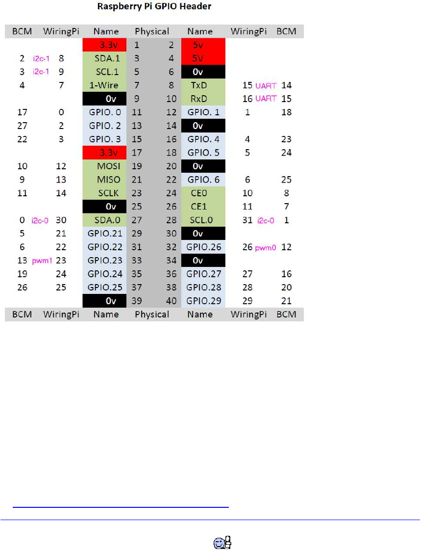
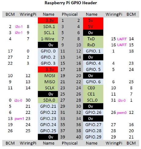
d) Übersicht über die GPIO-Belegung und Nummerierung
(Raspberry Pi B+ oder 2B mit 40 Pins)
Wie man sieht, werden völlig unterschiedliche Pin-Nummerierungen verwendet:
WiringPi benutzt auch (zusätzlich) seine eigene...
Vielleicht wäre es am besten, die Broadcom-Nummern (BCM) verwenden, da sie außer von
WiringPi auch von pigpio verwendet werden.
Bei wiringPi werden die GPIO-Pins wie folgt initialisiert:
wiringPiSetup(); # WiringPi pin numbers
wiringPiSetupGpio(); # bcm pin numbers
wiringPiSetupPhys(); # Physical P1 pin numbers
e) Testprogramm für GPIO Pins wiringPi
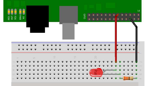
a) Verkabelung von Pins als Output mit pwm für LEDs und für stärkere
Lasten
Aufbau:
2 LEDs, 2x Widerstand 470 Ohm
1 LED an pin 0 (Header_pin 11 == BCM_GPIO_17) in Serie mit 470 Ohm an +3.3V
1 LED an pin 1 (Header_pin 12 == BCM_GPIO_18) in Serie mit 470 Ohm an +3.3V
Quelle: https://www.raspberrypi.org/documentation/usage/gpio-plus-and-raspi2/
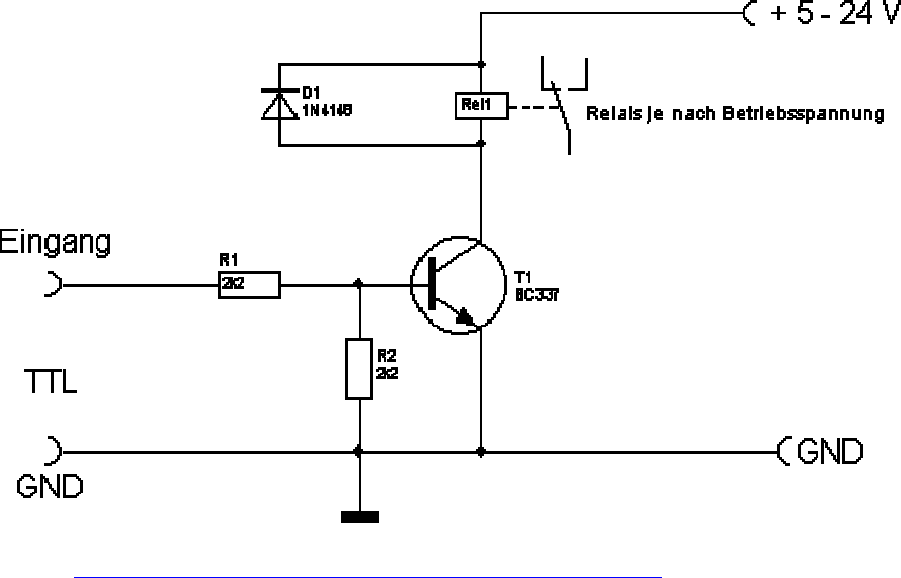
Um stärkere Verbraucher als nur wenige mA zu schalten, braucht man dagegen eine H-
Brücke (s.u.) oder ein Relais (als Basiswiderstand R1 für RPi (3.3V) besser ca. 1kOhm
verwenden), welche man über Transistoren oder MOSFETs schalten kann:
Quelle: http://www.elektronik-kompendium.de/sites/slt/1201131.htm

NPN Transistor vs. MOSFET
Quelle: https://forum.arduino.cc/index.php?topic=527226.msg3596917#msg3596917

b) Programmierung: 1 Pin (pin 0) als Output für 1 LED
http://wiringpi.com/examples/blink/
//----------------------------------------------------------------------
#include <wiringPi.h>
int main (void)
{
wiringPiSetup () ;
pinMode (0, OUTPUT) ;
for (;;)
{
digitalWrite (0, HIGH) ; delay (500) ;
digitalWrite (0, LOW) ; delay (500) ;
}
return 0 ;
}
//----------------------------------------------------------------------
c) Programmierung: 2 Pins als Output mit pwm für LEDs
Steuerung von Hardware-pwm: GPIO.18 und GPIO.13:
BCM_GPIO 18, pin 12 (wiringPi pin 1)
BCM_GPIO 13, pin 33 (wiringPi pin 23)
pinMode (18, PWM_OUTPUT);
pinMode (13, PWM_OUTPUT);
pwmWrite (18, 512) ; // 1024 is the default range
pwmWrite (13, 512) ; // 1024 is the default range[/code]
Das folgende Programm fährt beide LEDs von Helligkeit 0 (aus) bis 100 (max) und wieder
zurück auf 0 usw.
aus Github-Beispiel "pwm.c", verändert.
Weitere Beispiele : https://github.com/WiringPi/WiringPi/tree/master/examples
(Achtung, diese github Seite ist nicht von Gordon Henderson, daher nicht unbedingt auf dem
aktuellen Stand!)
//----------------------------------------------------------------------
/*
* pwm.c:
* Test of the software PWM driver.
*
* Copyright (c) 2012-2013 Gordon Henderson. <projects@drogon.net>
***********************************************************************
* This file is part of wiringPi:
* https://projects.drogon.net/raspberry-pi/wiringpi/
*
* wiringPi is free software: you can redistribute it and/or modify
* it under the terms of the GNU Lesser General Public License
* as published by
* the Free Software Foundation, either version 3 of the License, or
* (at your option) any later version.
*
* wiringPi is distributed in the hope that it will be useful,
* but WITHOUT ANY WARRANTY; without even the implied warranty of
* MERCHANTABILITY or FITNESS FOR A PARTICULAR PURPOSE. See the
* GNU Lesser General Public License for more details.
*
* You should have received a copy of the GNU Lesser General Public
License
* along with wiringPi. If not, see <http://www.gnu.org/licenses/>.
***********************************************************************
*/
#include <stdio.h>
#include <errno.h>
#include <string.h>
#include <wiringPi.h>
#include <softPwm.h>
#define RANGE 100
#define NUM_LEDS 2 // 2 LEDs
int ledMap [NUM_LEDS] = { 0, 1 } ; // GPIO.0=BCM_17, GPIO.1=BCM_18
int main ()
{
int i, j ;
if (wiringPiSetup () == -1)
{
fprintf (stdout, "oops: %s\n", strerror (errno)) ;
return 1 ;
}
for (i = 0 ; i < NUM_LEDS ; ++i) { // init softPWM
softPwmCreate (ledMap [i], 0, RANGE) ;
}
while(1) { // loop:
for (j=0; j<100; ++j) { // all LEDs 0...100
for (i = 0 ; i < NUM_LEDS ; ++i) {
softPwmWrite (ledMap [i], j) ;
printf ("%3d, %3d, %3d\n", i, ledMap [i], j) ;
delay(20);
}
}
for (j=100; j>0; --j) { // all LEDs 100...0
for (i = 0 ; i < NUM_LEDS ; ++i) {
softPwmWrite (ledMap [i], j) ;
printf ("%3d, %3d, %3d\n", i, ledMap [i], j) ;
delay(20);
}
}
}
}
//----------------------------------------------------------------------

d) Verkabelung von Schaltern mit externen Widerständen:
Aufbau:
1 Schalter, optional 1x Widerstand 10 kOhm
GPIO pin über 10k an +3.3V verbinden und ebenfalls an Schalter-Eingang,
Schalter-Ausgang an Masse.
[img]https://learn.adafruit.com/system/assets/assets/000/000/887/medium800/raspberry_pi_b
utt-schem.png?1396766649[/img]
aus: https://learn.adafruit.com/playing-sounds-and-using-buttons-with-raspberry-pi/bread-
board-setup-for-input-buttons
e) Alternativ: Programmierung von Schaltern mit [i] internen [/i] Widerständen und pwm:
Quelle: https://learn.sparkfun.com/tutorials/raspberry-gpio/c-wiringpi-example
Achtung!
Dies ist ein älteres Beispiel, inzwischen ist die softPwmWrite- Syntax etwas anders:
pwm-lib include:
#include <softPwm.h>
// pwm-pin init:
pinMode(PWMpinnumber, PWM_OUTPUT);
// pwm-Range:
softPwmCreate(PWMpinnumber, 0, MAXPWMRANGE) // 0=Startvalue, MAXPWMRANGE
z.B. 255
// pwm-Command:
softPwmWrite(PWMpinnumber, pwm);
//----------------------------------------------------------------------
#include <stdio.h> // Used for printf() statements
#include <wiringPi.h> // Include WiringPi library!
// Pin number declarations. We're using the Broadcom chip pin numbers.
const int pwmPin = 1; // Hardware PWM LED - Broadcom pin 18
const int ledPin = 2; // Regular LED - Broadcom pin 27
const int butPin = 3; // Active-low button - Broadcom pin 22
const int pwmValue = 75; // Use this to set an LED brightness
int main(void)
{
// Setup stuff:
pinMode(pwmPin, PWM_OUTPUT); // Set PWM LED as PWM output
pinMode(ledPin, OUTPUT); // Set regular LED as output
pinMode(butPin, INPUT); // Set button as INPUT
pullUpDnControl(butPin, PUD_UP); // Enable pull-up resistor on button
printf("blinker is running! Press CTRL+C to quit.");
// Loop (while(1)):
while(1)
{
if (digitalRead(butPin)) // Button is released if this returns 1
{
pwmWrite(pwmPin, pwmValue); // PWM LED at bright setting
digitalWrite(ledPin, LOW); // Regular LED off
}
else // If digitalRead returns 0, button is pressed
{
pwmWrite(pwmPin, 1024 - pwmValue); // PWM LED at dim setting
// Do some blinking on the ledPin:
digitalWrite(ledPin, HIGH); // Turn LED ON
delay(75); // Wait 75ms
digitalWrite(ledPin, LOW); // Turn LED OFF
delay(75); // Wait 75ms again
}
}
return 0;
}
//----------------------------------------------------------------------
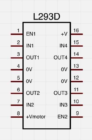
Ansteuern von DC (Encoder-) Motoren per L293D H-
Brücke:
L293D doppel-H-Bridge chip:
Die Dokus zu den L293D sind ziemlich besch***** durcheinander im Web, jeder bezeichnet
sie anders. Hier mal ganz super-ausführlich auch für komplette Neulinge:
enable1: pwm Signal Motor1
in1, in2: dig Richtungs-Pins für Motor1
out1, out2: Ausgänge für Motor1
enable2: pwm Signal Motor2
in3, in4: digit. Richtungs-Pins für Motor2
out3, out4: Ausgänge für Motor2
VSS: 5V vom Arduino
VS: Borne (+): +9...12V von Batterie
GND: Arduino-GND (-) mit Leistungs-Batterie (Borne (-)) verbinden;
im L293D sind alle 4 GND Leitungen bereits intern verbunden, es reicht auf dem Steckbrett
also 1 einziges GND-Verbindungskabel
(verändert, ergänzt)
Quelle: http://img.gunook.com/upload/5/d7/5d79ba256e128ba594184b2b1c6c6ffc.jpg
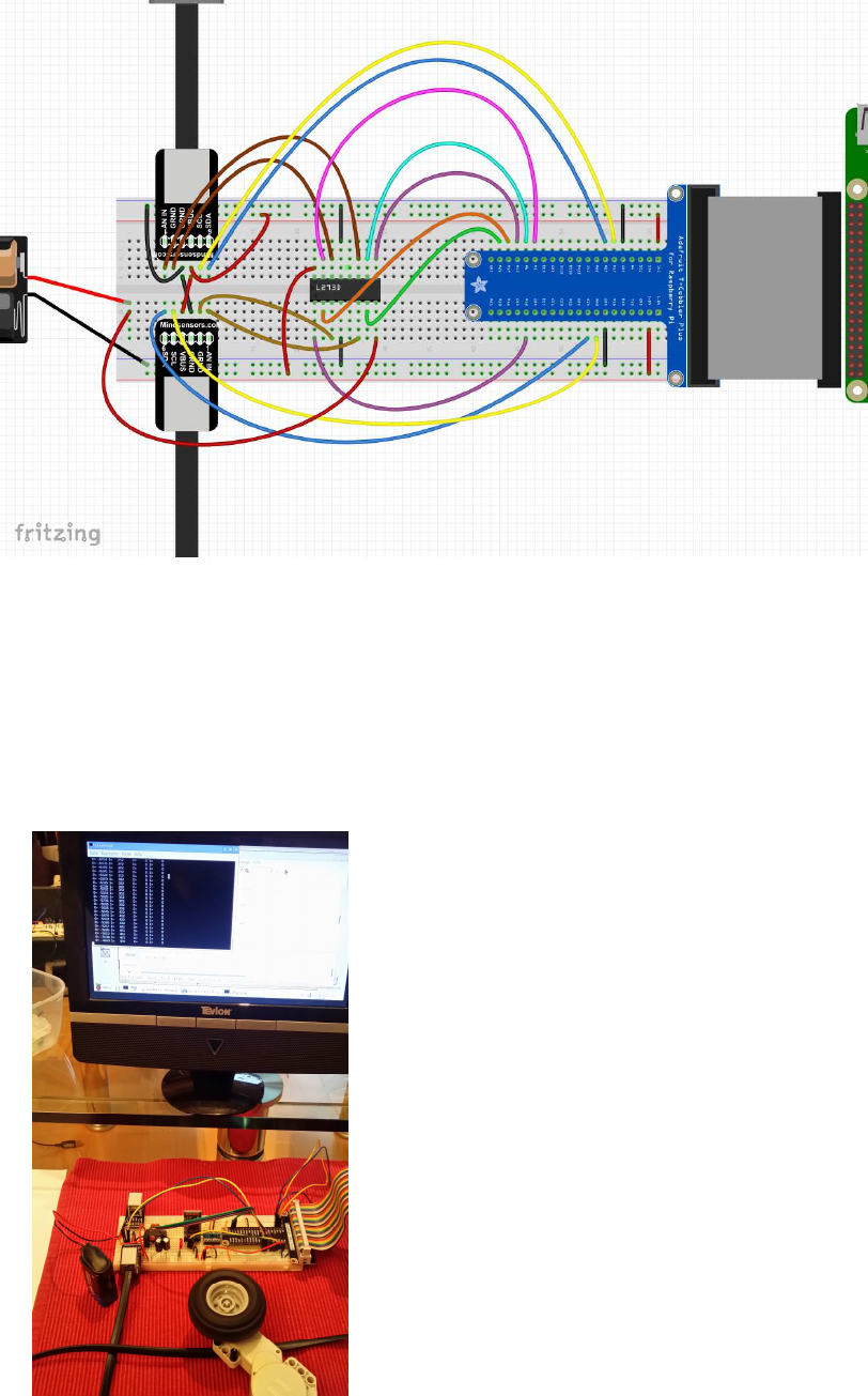
Schematische Verkabelung:
(die hellbraunen und dunkelbraunen Litzen (pins 1+2) sind die Motor-Leistungs-Anschlüsse
der L293D H-Brücken, die blauen und gelben Litzen (pins 5+6) sind für die Encoder)
Testbild:

als H-Brücke kann man natürlich auch fertige Boards verwenden:
ich verwende das folgende Pin-Setup für meine 2 Motoren (vgl. Foto):
// motor pins, wiringPi numbering (in parenthesis: BCM numbering)
motor[0].pinQa = 5; // (BCM 24) change for rotation direction
motor[0].pinQb = 4; // (BCM 23)
motor[0].pind1 =24; // (BCM 19)
motor[0].pind2 =25; // (BCM 26)
motor[0].pinpwm=26; // (BCM 12) pwm
motor[1].pinQa = 0; // (BCM 17) change for rotation direction
motor[1].pinQb = 2; // (BCM 27)
motor[1].pind1 =21; // (BCM 5)
motor[1].pind2 =22; // (BCM 6)
motor[1].pinpwm=23; // (BCM 13) pwm
Demo-Code zum Ansteuern per L293-H-Bridge mit wiringPi API Funktionen:
mit diesen API-Kommandos können die Motoren auf vorwärts, rückwärts, coast (rollen) und
brake (bremsen) geschaltet werden:
//----------------------------------------------------------------------
motorOn(nr, motor_pwm) // pwm==signed, also mit Richtungs-Signal,
0=coast
motorCoast(nr)
motorBrake(nr, motor_pwm) // brakes motor by adjustable pwm power
//----------------------------------------------------------------------
//----------------------------------------------------------------------
// Raspberry Pi Encoder Motor Control
//
// High Priority phread task for Encoder Timer
// H-Bridge control: direction + pwm (L293 type)
//
// ver 0013
// protected under the Creative Commons Attribution-NonCommercial-ShareAlike 3.0
Unported License
// http://creativecommons.org/licenses/by-nc-sa/3.0/
#include <stdio.h>
#include <stdlib.h>
#include <unistd.h>
#include <math.h>
#include <fcntl.h>
#include <string.h>
#include <sys/ioctl.h>
#include <stdint.h>
#include <errno.h>
#include <pthread.h>
#include <termios.h>
#include "VG/openvg.h"
#include "VG/vgu.h"
#include "fontinfo.h"
#include "shapes.h"
#include <wiringPi.h>
#include <wiringSerial.h>
#include <softPwm.h>
#include <stdbool.h>
#include <termio.h>
#define byte uint8_t;
#define MAXMOTORS 2 // max number of encoder motors
typedef struct {
// electrical motor pins
uint8_t pind1, pind2, pinpwm; // dir + pwm L293 H-Bridge type
uint8_t pinQa, pinQb; // rotary enc pins Qa,Qb
// pwm and encoder values
int32_t dirpwm;
int32_t motenc, oldenc; // rotary encoder values
} tEncMotor;
tEncMotor motor[MAXMOTORS];
//*************************************************************
// motor functions
//*************************************************************
#define motorCoast(nr) motorOn(nr, 0) // alias for motor coast
void motorBrake(int nr, int dirpwm) { // brake by pwm power
int pwm;
pwm = abs(dirpwm);
digitalWrite(motor[nr].pind1, HIGH);
digitalWrite(motor[nr].pind2, HIGH);
motor[nr].dirpwm = pwm;
softPwmWrite(motor[nr].pinpwm, pwm); // brake power always > 0
}
void motorOn(int nr, int dirpwm) { // motor On (nr, dir_pwm)
int dir, pwm; // signed pwm:
if(dirpwm > 0) dir = +1; // pwm > 0: forward
else if(dirpwm < 0) dir = -1; // pwm < 0: reverse
else dir = 0; // pwm = 0: coast
pwm = abs(dirpwm);
if(dir> 0) {
digitalWrite( motor[nr].pind1, HIGH);
digitalWrite( motor[nr].pind2, LOW);
}
else
if(dir==0) {
digitalWrite( motor[nr].pind1, LOW);
digitalWrite( motor[nr].pind2, LOW);
}
else {
digitalWrite( motor[nr].pind1, LOW);
digitalWrite( motor[nr].pind2, HIGH);
}
motor[nr].dirpwm = dirpwm;
softPwmWrite( motor[nr].pinpwm, pwm);
}
//*************************************************************
// rpi_conio
//*************************************************************
bool kbhit(void)
{
struct termios original;
tcgetattr(STDIN_FILENO, &original);
struct termios term;
memcpy(&term, &original, sizeof(term));
term.c_lflag &= ~ICANON;
tcsetattr(STDIN_FILENO, TCSANOW, &term);
int characters_buffered = 0;
ioctl(STDIN_FILENO, FIONREAD, &characters_buffered);
tcsetattr(STDIN_FILENO, TCSANOW, &original);
bool pressed = (characters_buffered != 0);
return pressed;
}
//*************************************************************
void echoOff(void)
{
struct termios term;
tcgetattr(STDIN_FILENO, &term);
term.c_lflag &= ~ECHO;
tcsetattr(STDIN_FILENO, TCSANOW, &term);
}
//*************************************************************
void echoOn(void)
{
struct termios term;
tcgetattr(STDIN_FILENO, &term);
term.c_lflag |= ECHO;
tcsetattr(STDIN_FILENO, TCSANOW, &term);
}
//*************************************************************
// Encoder Handler Routine
//*************************************************************
volatile int8_t ISRab[MAXMOTORS];
// 1/2 resolution
int8_t enctab[16] = {0, 0,0,0,1,0,0,-1, 0,0,0,1,0,0,-1,0};
void updateEncoders() {
int i;
for( i=0; i<MAXMOTORS; ++i ) {
ISRab [ i] <<= 2;
ISRab [ i] &= 0b00001100;
ISRab [ i] |= (digitalRead( motor[ i].pinQa ) << 1) | digitalRead( motor[ i].pinQb );
motor[ i].motenc += enctab[ISRab[ i] ];
}
}
//*************************************************************
// pthread tasks
//*************************************************************
volatile static int8_t threadrun = 1;
void* thread3Go(void *) // high priority encoder task
{
while(threadrun) {
updateEncoders();
usleep(100);
}
return NULL;
}
//*************************************************************
void* thread2Go(void *) // higher priority motor control task
{
while(threadrun) {
for(int pwm = -1023; pwm < 1023; ++pwm ) {
motorOn(0, pwm);
motorOn(1, pwm);
if (!threadrun) return NULL;
delay(10);
}
for(int pwm = 1023; pwm > -1023; --pwm ) {
motorOn(0, pwm);
motorOn(1, pwm);
if (!threadrun) return NULL;
delay(10);
}
}
return NULL;
}
//*************************************************************
void* thread1Go(void *) // medium priority task for keyboard monitoring
{
char sbuf[128];
int c;
while(threadrun) {
c=0;
if (kbhit()) {
c = getchar(); // ESC to quit program
if( c==27 ) {
threadrun=0; // semaphore to stop all tasks
printf("\n\n ESC pressed - program terminated by user \n\n");
return NULL;
}
}
delay(50);
}
return NULL;
}
//*************************************************************
void* thread0Go(void *) // low priority display task
{
char sbuf[128];
while(threadrun) {
sprintf(sbuf, " m0=%8ld pwm=%6d m1=%8ld pwm=%6d \n ",
motor[0].motenc, motor[0].dirpwm, motor[1].motenc, motor[1].dirpwm );
printf(sbuf);
delay(100);
}
return NULL;
}
/*************************************************************
* setup
*************************************************************/
void setup() {
int i, err;
// motor pin settings
// encoder pin settings
// setup for L293D motor driver
// motor pins, wiringPi numbering (in parenthesis: BCM numbering)
motor[0].pinQa = 5; // (BCM 24) change for rotation direction
motor[0].pinQb = 4; // (BCM 23) change for rotation direction
motor[0].pind1 =24; // (BCM 19)
motor[0].pind2 =25; // (BCM 26)
motor[0].pinpwm=26; // (BCM ..) pwm
motor[1].pinQa = 0; // (BCM 17) change for rotation direction
motor[1].pinQb = 2; // (BCM 27) change for rotation direction
motor[1].pind1 =21; // (BCM 5)
motor[1].pind2 =22; // (BCM 6)
motor[1].pinpwm=23; // (BCM ..) pwm
for( i=0; i< MAXMOTORS; ++i) {
pinMode( motor[i].pinQa, INPUT); // encA
pinMode( motor[i].pinQb, INPUT); // encB
pinMode( motor[i].pind1, OUTPUT); // dir-1
pinMode( motor[i].pind2, OUTPUT); // dir-2
pinMode( motor[i].pinpwm, PWM_OUTPUT); // pwm
err= softPwmCreate( motor[i].pinpwm, 0, 1024);
printf("err %-4d qa %-4d qb %-4d d1 %-4d d2 %-4d pwm %-4d \n",
err, motor[i].pinQa, motor[i].pinQb, motor[i].pind1, motor[i].pind2, motor[i].pinpwm);
motor[i].motenc = 0;
motor[i].oldenc = 0;
ISRab[i] = 0;
}
printf("press ENTER");
getchar();
}
/*************************************************************
* main
*************************************************************/
int main() {
char sbuf[128];
int ioerr;
pthread_t thread0, thread1, thread2, thread3;
struct sched_param param;
ioerr = wiringPiSetup();
if( ioerr == -1 ) return 1;
setup();
pthread_create(&thread0, NULL, thread0Go, NULL); // lowest priority task: screen
output
param.sched_priority = 10;
pthread_setschedparam(thread0, SCHED_RR, ¶m);
pthread_create(&thread1, NULL, thread1Go, NULL); // medium priority task: keyboard
monitoring (stop program)
param.sched_priority = 25;
pthread_setschedparam(thread1, SCHED_RR, ¶m);
pthread_create(&thread2, NULL, thread2Go, NULL); // higher priority task: !!! motor
control program !!!
param.sched_priority = 50;
pthread_setschedparam(thread2, SCHED_RR, ¶m);
pthread_create(&thread3, NULL, thread3Go, NULL); // highest priority task: encoder
reading
param.sched_priority = 90;
pthread_setschedparam(thread3, SCHED_RR, ¶m);
pthread_join(thread0, NULL);
pthread_join(thread1, NULL);
pthread_join(thread2, NULL);
pthread_join(thread3, NULL);
for(int i=0; i< MAXMOTORS; ++i) {
motorOn(i, 0);
}
delay(1000);
exit(0);
}
//----------------------------------------------------------------------
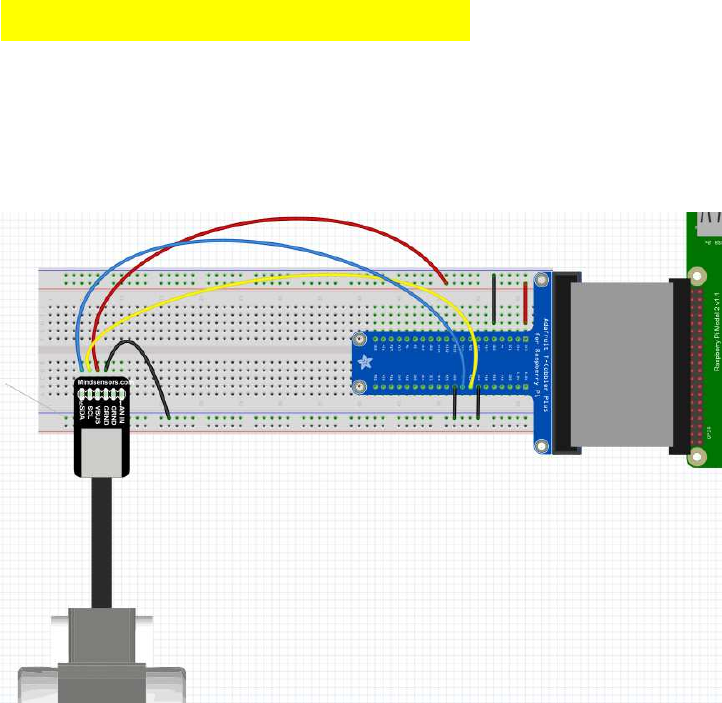
Rotationsencoder auslesen
(syn: Quadratur-Encoder, Rotary Encoder)
Verkabelungsschema für Lego Motor-Encoder:
[i](zu pthread Tasks: siehe Kapitel 11!)[/i]
Unter normalen Bedingungen ist das Linux user space zu wenig echtzeitfähig, um schnelle
Encoder-Änderungen verlässlich zu registrieren und die Werte korrekt upzudaten. Beim
Arduino reichen Timer-Interrupts im 200µs-Takt aus, um 8 Encoder-Motoren korrekt zu
überwachen, bei Linux ist selbst ein Task im 100µs-Takt schon für 2 Encoder-Motore nicht
verlässlich genug: Es laufen beim Raspi einfach zu viele Linux-Prozesse parallel, als dass so
ein Endlos-Task im korrekten Takt durchläuft. So kommt es häufig dazu, dass Drehungen
teilweise nicht mitgezählt werden oder sie vorwärts oder rückwärts springen (wurde von
Usern im Raspi-Forum dokumentiert). Pinchange-Interrupts wiederum werden bei mehreren
sich schnell drehenden Motoren viel zu häufig aufgerufen, als dass man beim registrieren der
Flankenänderungen überhaupt noch nachkommen könnte.
Wenn man aber nun dem Encoder-Task eine höhere Priorität als anderen Tasks zuweist,
werden sie bevorzugt abgearbeitet - und genau das habe ich nun gemacht. Plötzlich läuft auch
eine 100µs Endlosschleife mit hoher Priorität zuverlässig im korrekten Takt durch!
Anm.:
Lego Encoder-Motore haben sogar eine Auflösung von 0,5° ( 720 encoder ticks/360°), dies
wird aber von der Lego-Firmware nicht ausgeschöpft. Da meist eine 1° Auflösung ausreicht
und das rechnen mit 1°= 1 EncoderTick einfacher ist, arbeite ich ebenfalls mit der halben,
also "1°-Lego-Auflösung".
Code von Gordon Henderson per "Pinchange-Interrupts"
(liest bisher leider nur 180 ticks / 360°, bei 4 Motoren fehlerhaft! ):
//----------------------------------------------------------------------
#include <stdio.h>
#include <wiringPi.h>
#define PIN_A 8
#define PIN_B 9
static volatile int counter ;
void encoder (void)
{
static unsigned int debounce = 0 ;
// If PIN_A is high then ignore it
// This may be due to bouncing, or a bug/feature of the edge detect
if (digitalRead (PIN_A) == HIGH)
return ;
// Ignore multiple interrupts inside our debounce time
if (millis () < debounce)
return ;
if (digitalRead (PIN_B) == LOW) // Anti-clockwise
--counter ;
else
++counter ;
}
int main ()
{
int last ;
wiringPiSetup () ;
last = counter = 0 ;
wiringPiISR (PIN_A, INT_EDGE_FALLING, encoder) ;
printf ("\nRunning... \n") ;
for (;;)
{
if (counter != last)
{
printf ("%5d\n", counter) ;
last = counter ;
}
delay (1) ;
}
return 0 ;
}
//----------------------------------------------------------------------
eigener Testcode mit "High Priority pthread Task" für Encoder als eine
Art "Timer Interrupt":
(scheint bisher sicher und schnell zu funktionieren, auch bei >4 Motoren und bei 360
ticks/360° ! )
//-----------------------------------------------------------------
-----
// encoder test
// wiringPi,
// Encoder Timer High Priority Thread
// ver 0008
// protected under the Creative Commons Attribution-NonCommercial-
ShareAlike 3.0 Unported License
// http://creativecommons.org/licenses/by-nc-sa/3.0/
#include <stdio.h>
#include <stdlib.h>
#include <unistd.h>
#include <math.h>
#include <fcntl.h>
#include <string.h>
#include <sys/ioctl.h>
#include <stdint.h>
#include <errno.h>
#include <pthread.h>
#include <termios.h>
#include "VG/openvg.h"
#include "VG/vgu.h"
#include "fontinfo.h"
#include "shapes.h"
#include <wiringPi.h>
#include <wiringSerial.h>
#define byte uint8_t;
#define MAXMOTORS 2 // max number of encoder motors
typedef struct {
uint8_t pind1, pind2, pinpwm; // L293 dir and pwm
uint8_t pinQa, pinQb; // rotary enc pins Qa,Qb
int32_t motenc, oldenc; // rotary encoder values
} tEncMotor;
tEncMotor motor[MAXMOTORS];
/*************************************************************
* Encoder Handler Routine
*************************************************************/
volatile int8_t ISRab[MAXMOTORS];
// 1/1 resolution (720)
// int8_t enctab[16] = {0,-1,1,0,1,0,0,-1,-1,0,0,1,0,1,-1,0};
// 1/2 resolution (360)
int8_t enctab[16] = {0, 0,0,0,1,0,0,-1, 0,0,0,1,0,0,-1,0};
void updateEncoders() {
int i;
for( i=0; i<MAXMOTORS; ++i ) {
ISRab [ i] <<= 2;
ISRab [ i] &= 0b00001100;
ISRab [ i] |= (digitalRead( motor[ i].pinQa ) << 1) |
digitalRead( motor[ i].pinQb );
motor[ i].motenc += enctab[ISRab[ i] ];
}
}
void* thread3Go(void *) // encoder high priority thread
{
while(1) {
updateEncoders();
usleep(100);
}
return NULL;
}
void* thread2Go(void *)
{
while(1) {
delay(10);
}
return NULL;
}
void* thread1Go(void *) // low priority display thread
{
char sbuf[128];
while(1) {
delay(10);
}
return NULL;
}
void* thread0Go(void *)
{
char sbuf[128];
while(1) {
sprintf(sbuf, " 0=%6ld 1=%6ld \n ", motor[0].motenc,
motor[1].motenc );
printf(sbuf);
delay(100);
}
return NULL;
}
void setup() {
int i;
// motor pins, wiringPi numbering (in parenthesis: BCM numbering)
motor[0].pinQa = 5; // (BCM 24) change for rotation direction
motor[0].pinQb = 4; // (BCM 23) change for rotation direction
motor[0].pind1 =21; // (BCM 5)
motor[0].pind2 =22; // (BCM 6)
motor[0].pinpwm= 1; // (BCM 18) hardware pwm
motor[1].pinQa = 0; // (BCM 17) change for rotation direction
motor[1].pinQb = 2; // (BCM 27) change for rotation direction
motor[1].pind1 =21; // (BCM 5)
motor[1].pind2 =22; // (BCM 6)
motor[1].pinpwm=23; // (BCM 13) hardware pwm
for( i=0; i< MAXMOTORS; ++i) {
pinMode(motor[i].pinQa, INPUT); // encA
pinMode(motor[i].pinQb, INPUT); // encB
pinMode(motor[i].pind1, OUTPUT); // dir-1
pinMode(motor[i].pind2, OUTPUT); // dir-2
pinMode(motor[i].pinpwm ,OUTPUT); // pwm
motor[i].motenc = 0;
motor[i].oldenc = 0;
ISRab[i] = 0;
}
}
int main() {
char sbuf[128];
pthread_t thread0, thread1, thread2, thread3;
wiringPiSetup();
if(wiringPiSetup() == -1) return 1;

setup();
struct sched_param param;
pthread_create(&thread0, NULL, thread0Go, NULL);
param.sched_priority = 10;
pthread_setschedparam(thread0, SCHED_RR, ¶m);
pthread_create(&thread1, NULL, thread1Go, NULL);
param.sched_priority = 25;
pthread_setschedparam(thread1, SCHED_RR, ¶m);
pthread_create(&thread2, NULL, thread2Go, NULL);
param.sched_priority = 50;
pthread_setschedparam(thread2, SCHED_RR, ¶m);
pthread_create(&thread3, NULL, thread3Go, NULL);
param.sched_priority = 90;
pthread_setschedparam(thread3, SCHED_RR, ¶m); // altern.:
SCHED_FIFO
pthread_join(thread0, NULL);
pthread_join(thread1, NULL);
pthread_join(thread2, NULL);
pthread_join(thread3, NULL);
exit(0);
}
//------------------------------------------------------------------
----
Weitere Links zu Rotationsencodern
[url]https://github.com/astine/rotaryencoder/blob/master/rotaryencoder.c[/url]
hier ein Link zu einer Seite mit pigpio-Codebeispielen:
[url]http://abyz.co.uk/rpi/pigpio/examples.html[/url]
speziell zum Rotationsencoder:
http://abyz.co.uk/rpi/pigpio/ex_rotary_encoder.html
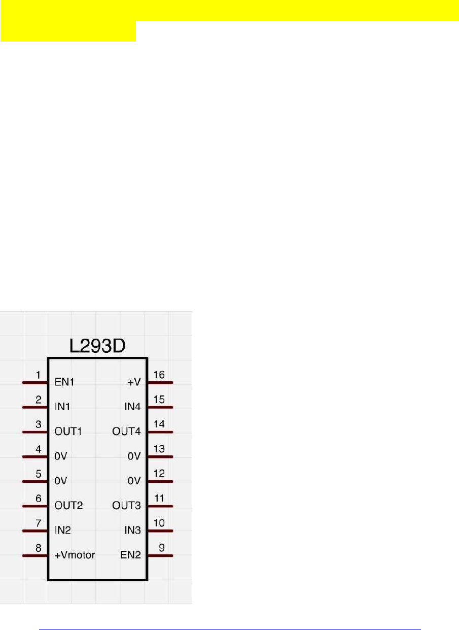
Ansteuern von DC Motoren per L293D H-Brücke plus
Encoder-Werte:
Die Dokus zu den L293D sind ziemlich durcheinander im Web, jeder bezeichnet sie anders.
enable1: pwm Signal Motor1
in1, in2: dig Richtungs-Pins für Motor1
out1, out2: Ausgänge für Motor1
enable2: pwm Signal Motor2
in3, in4: digit. Richtungs-Pins für Motor2
out3, out4: Ausgänge für Motor2
Vcc: 5V vom Arduino
Vc: (V Motor, Borne +): +9...12V von Batterie
GND: Arduino-GND (-) mit Leistungs-Batterie (Borne (-)) verbinden;
im L293D sind alle 4 GND Leitungen bereits intern verbunden, es reicht auf dem Steckbrett
also 1 einziges GND-Verbindungskabel
(verändert, ergänzt)
Quelle: http://img.gunook.com/upload/5/d7/5d79ba256e128ba594184b2b1c6c6ffc.jpg
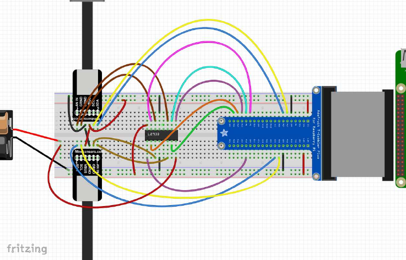
Steuerlogik:
in1(3) in2(4) en1(2)==pwm Funktion
==========================================================
LOW LOW LOW coast
LOW HIGH pwm rechts pwm
HIGH LOW pwm links pwm
HIGH HIGH pwm brake pwm
Schematische Verkabelung:
(die hellbraunen und dunkelbraunen Litzen (pins 1+2) sind die Motor-Leistungs-Anschlüsse
der L293D H-Brücken, die blauen und gelben Litzen (pins 5+6) sind für die Encoder)
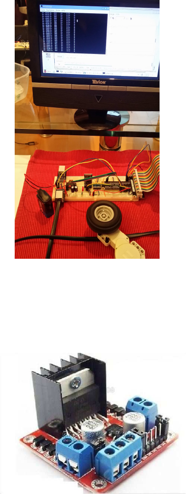
Testbild:
als H-Brücke kann man natürlich auch fertige Boards verwenden:
ich verwende das folgende Pin-Setup für meine 2 Motoren (vgl. Foto):
// motor pins, wiringPi numbering (in parenthesis: BCM numbering)
motor[0].pinQa = 5; // (BCM 24) change for rotation direction
motor[0].pinQb = 4; // (BCM 23)
motor[0].pind1 =24; // (BCM 19)
motor[0].pind2 =25; // (BCM 26)
motor[0].pinpwm=26; // (BCM 12) pwm
motor[1].pinQa = 0; // (BCM 17) change for rotation direction
motor[1].pinQb = 2; // (BCM 27)
motor[1].pind1 =21; // (BCM 5)
motor[1].pind2 =22; // (BCM 6)
motor[1].pinpwm=23; // (BCM 13) pwm
Demo-Code zum Ansteuern per L293-H-Bridge plus Encoder:
mit diesen API-Kommandos können die Motoren auf vorwärts, rückwärts, coast (rollen) und
brake (bremsen) geschaltet werden:
//----------------------------------------------------------------------
motorOn(nr, motor_pwm) // pwm==signed, also mit Richtungs-Signal,
0=coast
motorCoast(nr)
motorBrake(nr, motor_pwm) // brakes motor by adjustable pwm power
//----------------------------------------------------------------------
//----------------------------------------------------------------------
// Raspberry Pi Encoder Motor Control
//
// High Priority phread task for Encoder Timer
// H-Bridge control: direction + pwm (L293 type)
//
// ver 0013
// protected under the Creative Commons Attribution-NonCommercial-ShareAlike 3.0
Unported License
// http://creativecommons.org/licenses/by-nc-sa/3.0/
#include <stdio.h>
#include <stdlib.h>
#include <unistd.h>
#include <math.h>
#include <fcntl.h>
#include <string.h>
#include <sys/ioctl.h>
#include <stdint.h>
#include <errno.h>
#include <pthread.h>
#include <termios.h>
#include "VG/openvg.h"
#include "VG/vgu.h"
#include "fontinfo.h"
#include "shapes.h"
#include <wiringPi.h>
#include <wiringSerial.h>
#include <softPwm.h>
#include <stdbool.h>
#include <termio.h>
#define byte uint8_t;
#define MAXMOTORS 2 // max number of encoder motors
typedef struct {
// electrical motor pins
uint8_t pind1, pind2, pinpwm; // dir + pwm L293 H-Bridge type
uint8_t pinQa, pinQb; // rotary enc pins Qa,Qb
// pwm and encoder values
int32_t dirpwm;
int32_t motenc, oldenc; // rotary encoder values
} tEncMotor;
tEncMotor motor[MAXMOTORS];
//*************************************************************
// motor functions
//*************************************************************
#define motorCoast(nr) motorOn(nr, 0) // alias for motor coast
void motorBrake(int nr, int dirpwm) { // brake by pwm power
int pwm;
pwm = abs(dirpwm);
digitalWrite(motor[nr].pind1, HIGH);
digitalWrite(motor[nr].pind2, HIGH);
motor[nr].dirpwm = pwm;
softPwmWrite(motor[nr].pinpwm, pwm); // brake power always > 0
}
void motorOn(int nr, int dirpwm) { // motor On (nr, dir_pwm)
int dir, pwm; // signed pwm:
if(dirpwm > 0) dir = +1; // pwm > 0: forward
else if(dirpwm < 0) dir = -1; // pwm < 0: reverse
else dir = 0; // pwm = 0: coast
pwm = abs(dirpwm);
if(dir> 0) {
digitalWrite( motor[nr].pind1, HIGH);
digitalWrite( motor[nr].pind2, LOW);
}
else
if(dir==0) {
digitalWrite( motor[nr].pind1, LOW);
digitalWrite( motor[nr].pind2, LOW);
}
else {
digitalWrite( motor[nr].pind1, LOW);
digitalWrite( motor[nr].pind2, HIGH);
}
motor[nr].dirpwm = dirpwm;
softPwmWrite( motor[nr].pinpwm, pwm);
}
//*************************************************************
// rpi_conio
//*************************************************************
bool kbhit(void)
{
struct termios original;
tcgetattr(STDIN_FILENO, &original);
struct termios term;
memcpy(&term, &original, sizeof(term));
term.c_lflag &= ~ICANON;
tcsetattr(STDIN_FILENO, TCSANOW, &term);
int characters_buffered = 0;
ioctl(STDIN_FILENO, FIONREAD, &characters_buffered);
tcsetattr(STDIN_FILENO, TCSANOW, &original);
bool pressed = (characters_buffered != 0);
return pressed;
}
//*************************************************************
void echoOff(void)
{
struct termios term;
tcgetattr(STDIN_FILENO, &term);
term.c_lflag &= ~ECHO;
tcsetattr(STDIN_FILENO, TCSANOW, &term);
}
//*************************************************************
void echoOn(void)
{
struct termios term;
tcgetattr(STDIN_FILENO, &term);
term.c_lflag |= ECHO;
tcsetattr(STDIN_FILENO, TCSANOW, &term);
}
//*************************************************************
// Encoder Handler Routine
//*************************************************************
volatile int8_t ISRab[MAXMOTORS];
// 1/2 resolution
int8_t enctab[16] = {0, 0,0,0,1,0,0,-1, 0,0,0,1,0,0,-1,0};
void updateEncoders() {
int i;
for( i=0; i<MAXMOTORS; ++i ) {
ISRab [ i] <<= 2;
ISRab [ i] &= 0b00001100;
ISRab [ i] |= (digitalRead( motor[ i].pinQa ) << 1) | digitalRead( motor[ i].pinQb );
motor[ i].motenc += enctab[ISRab[ i] ];
}
}
//*************************************************************
// pthread tasks
//*************************************************************
volatile static int8_t threadrun = 1;
void* thread3Go(void *) // high priority encoder task
{
while(threadrun) {
updateEncoders();
usleep(100);
}
return NULL;
}
//*************************************************************
void* thread2Go(void *) // higher priority motor control task
{
while(threadrun) {
for(int pwm = -1023; pwm < 1023; ++pwm ) {
motorOn(0, pwm);
motorOn(1, pwm);
if (!threadrun) return NULL;
delay(10);
}
for(int pwm = 1023; pwm > -1023; --pwm ) {
motorOn(0, pwm);
motorOn(1, pwm);
if (!threadrun) return NULL;
delay(10);
}
}
return NULL;
}
//*************************************************************
void* thread1Go(void *) // medium priority task for keyboard monitoring
{
char sbuf[128];
int c;
while(threadrun) {
c=0;
if (kbhit()) {
c = getchar(); // ESC to quit program
if( c==27 ) {
threadrun=0; // semaphore to stop all tasks
printf("\n\n ESC pressed - program terminated by user \n\n");
return NULL;
}
}
delay(50);
}
return NULL;
}
//*************************************************************
void* thread0Go(void *) // low priority display task
{
char sbuf[128];
while(threadrun) {
sprintf(sbuf, " m0=%8ld pwm=%6d m1=%8ld pwm=%6d \n ",
motor[0].motenc, motor[0].dirpwm, motor[1].motenc, motor[1].dirpwm );
printf(sbuf);
delay(100);
}
return NULL;
}
/*************************************************************
* setup
*************************************************************/
void setup() {
int i, err;
// motor pin settings
// encoder pin settings
// setup for L293D motor driver
// motor pins, wiringPi numbering (in parenthesis: BCM numbering)
motor[0].pinQa = 5; // (BCM 24) change for rotation direction
motor[0].pinQb = 4; // (BCM 23) change for rotation direction
motor[0].pind1 =24; // (BCM 19)
motor[0].pind2 =25; // (BCM 26)
motor[0].pinpwm=26; // (BCM ..) pwm
motor[1].pinQa = 0; // (BCM 17) change for rotation direction
motor[1].pinQb = 2; // (BCM 27) change for rotation direction
motor[1].pind1 =21; // (BCM 5)
motor[1].pind2 =22; // (BCM 6)
motor[1].pinpwm=23; // (BCM ..) pwm
for( i=0; i< MAXMOTORS; ++i) {
pinMode( motor[i].pinQa, INPUT); // encA
pinMode( motor[i].pinQb, INPUT); // encB
pinMode( motor[i].pind1, OUTPUT); // dir-1
pinMode( motor[i].pind2, OUTPUT); // dir-2
pinMode( motor[i].pinpwm, PWM_OUTPUT); // pwm
err= softPwmCreate( motor[i].pinpwm, 0, 1024);
printf("err %-4d qa %-4d qb %-4d d1 %-4d d2 %-4d pwm %-4d \n",
err, motor[i].pinQa, motor[i].pinQb, motor[i].pind1, motor[i].pind2, motor[i].pinpwm);
motor[i].motenc = 0;
motor[i].oldenc = 0;
ISRab[i] = 0;
}
printf("press ENTER");
getchar();
}
/*************************************************************
* main
*************************************************************/
int main() {
char sbuf[128];
int ioerr;
pthread_t thread0, thread1, thread2, thread3;
struct sched_param param;
ioerr = wiringPiSetup();
if( ioerr == -1 ) return 1;
setup();
pthread_create(&thread0, NULL, thread0Go, NULL); // lowest priority task: screen
output
param.sched_priority = 10;
pthread_setschedparam(thread0, SCHED_RR, ¶m);
pthread_create(&thread1, NULL, thread1Go, NULL); // medium priority task: keyboard
monitoring (stop program)
param.sched_priority = 25;
pthread_setschedparam(thread1, SCHED_RR, ¶m);
pthread_create(&thread2, NULL, thread2Go, NULL); // higher priority task: !!! motor
control program !!!
param.sched_priority = 50;
pthread_setschedparam(thread2, SCHED_RR, ¶m);
pthread_create(&thread3, NULL, thread3Go, NULL); // highest priority task: encoder
reading
param.sched_priority = 90;
pthread_setschedparam(thread3, SCHED_RR, ¶m);
pthread_join(thread0, NULL);
pthread_join(thread1, NULL);
pthread_join(thread2, NULL);
pthread_join(thread3, NULL);
for(int i=0; i< MAXMOTORS; ++i) {
motorOn(i, 0);
}
delay(1000);
exit(0);
}
//----------------------------------------------------------------------
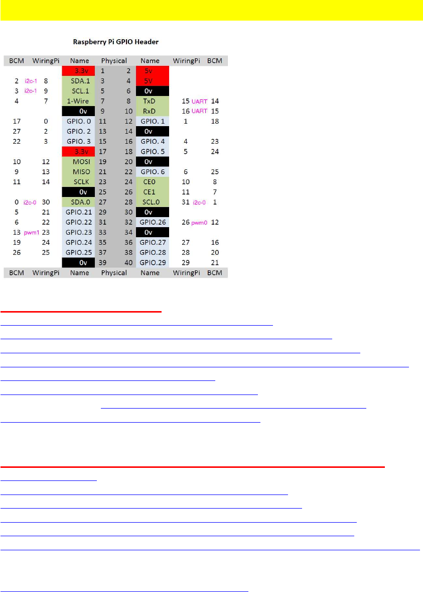
Raspberry Pi: UART Schnittstelle (Pi B+ und Pi 2)
Links: [ A ] UART-Setup:
http://www.forum-raspberrypi.de/Forum-a ... ersprachen
http://www.netzmafia.de/skripten/hardware/RasPi/RasPi_Serial.html (!)
https://github.com/WiringPi/WiringPi/blob/master/wiringPi/wiringSerial.h
http://www.einplatinencomputer.com/raspberry-pi-uart-senden-und-empfangen-in-c/ (!)
http://kampis-elektroecke.de/?page_id=1682
http://www.loetstelle.net/praxis/seriellport/seriell.php
Pi3 Besonderheiten: http://www.forum-raspberrypi.de/Thread- ... berry-pi-3
https://spellfoundry.com/2016/05/29/con ... ding-pi-3/
Links: [ B ] : UART verwenden (z.B. mit Arduino verbinden):
http://wiringpi.com/
http://wiringpi.com/wiringpi-and-the-raspberry-pi-model-b/
https://projects.drogon.net/raspberry-pi/wiringpi/serial-library/
http://blog.oscarliang.net/raspberry-pi-and-arduino-connected-serial-gpio/
http://blog.simtronyx.de/raspberry-pi-und-arduino-serielle-verbindungen/
http://www.raspberry-projects.com/pi/programming-in-c/uart-serial-port/using-the-uart
video:
https://www.youtube.com/watch?v=IZC9G3U58Sc

UART mit Raspbian benutzen: Vorbereitungen
Quelle: http://www.einplatinencomputer.com/raspberry-pi-uart-senden-und-empfangen-in-c/
(verändert)
Anm: die UART Port-Bezeichnung "ttyAMA0" hat sich vom Raspberry Pi 2 zum Pi 3 und
zum Pi Zero geändert; man kann jetzt aber für alle gemeinsam die neue, einheitliche
Portbezeichnung "serial0" verwenden, die automatisch richtig auf der entspr. Plattform
konfiguriert wird!
Unter Raspbian wird die UART-Schnittstelle standardmäßig als serielle Konsole
bereitgestellt.
Damit wir die UART-Schnittstelle in unseren eigenen Anwendungen nutzen können können,
müss die Funktion der seriellen Konsole deaktiviert werden.
manuelle Methode:
Hierzu machen wir erst ein Backup der Datei
cp /boot/cmdline.txt /boot/cmdline.bak
Dann editieren wir die Datei /boot/cmdline.txt mit nano:
sudo nano /boot/cmdline.txt
Aus der Datei /boot/cmdline.txt entfernen wir in der Zeile
dwc_otg.lpm_enable=0 console=ttyAMA0,115200 kgdboc=ttyAMA0,115200 console=tty1
root=/dev/mmcblk0p2 rootfstype=ext4 elevator=deadline rootwait
folgenden Teil:
console=ttyAMA0,115200 kgdboc=ttyAMA0,115200
Den Rest stehen lassen !
Ist dies erledigt, sollte anschließend der im Bild gezeigte Ausdruck noch vorhanden sein.
Nach dem Editieren kann die Datei gespeichert (^O) und geschlossen werden (^X).
Der Inhalt lautet jetzt:
dwc_otg.lpm_enable=0 console=tty1 root=/dev/mmcblk0p2 rootfstype=ext4
elevator=deadline rootwait
Anschließend bearbeiten wir die Datei /etc/inittab.
sudo nano /etc/inittab
Am Ende der Datei befindet sich eine Zeile mit folgendem Inhalt:
T0:23:respawn:/sbin/getty -L ttyAMA0 115200 vt100
Diese Zeile müssen wir durch Einfügen des Zeichens # (Raute) am Zeilenanfang
auskommentieren.
Haben wir die Zeile erfolgreich auskommentiert, kann die Datei mit der Tastenkombination
Strg+X, Y (?) und Enter gespeichert und geschlossen werden.
Damit die Einstellungen übernommen und aktiviert werden, muss der Raspberry Pi neu
gestartet werden.
sudo reboot
alte alternative Methode:
per LX Terminal das Config-Menü starten:
sudo raspi-config
unter
9. Advanced Options
A8. Serial
die Frage

"Would you like a login shell to be accessable over Serial?"
mit <Nein> beantworten (anklicken) und die Eingabe mit ENTER abschließen.
Es kommt der Hinweis
"Serial is now disabled". <OK> bestätigen.
Das gilt natürlich nur für die Konsole, nicht für die Pins.
Verlassen des Config-Menüs:
per TAB-Taste auf <Finish>,dan wieder ENTER.
Die Frage
"Would you like to reboot now?" mit<JA> bestätigen.
neuere alternative Methode:
1. Add the line
enable_uart=1
to the '/boot/config.txt' file, this line will set up the Serial Port UART and the necessary clocks
on all Pi models.
2. Remove the phrase "console=serial0,115200" from the '/boot/cmdline.txt' file.
This action prevents Linux from starting a Console on the Serial Port.
Endlich fertig.
Jetzt wurde die UART-Schnittstelle auf dem Pi aktiviert und kann verwendet werden.
Soll eine Kommunikation vom Raspberry Pi zu einem anderen kompatiblem Gerät via UART
aufgebaut werden, so müssen die entsprechenden UART-GPIO-Pins am Raspberry Pi
beschalten werden. Zur Kommunikation benötigen wir lediglich 3 Pins am Pi:
- GPIO_Pin 8: TxD, Sendeleitung (WiringPi: 15)
- GPIO_Pin 10: RxD, Empfangsleitung (WiringPi: 16)
- zusätzlich GND, Masse
Zur Kommunikation mit einem anderen Gerät wird der Sendepin mit dem Empfangspin des
Kommunikationspartnes und umgekehrt verbunden. Außerdem wird eine Verbindung
zwischen 2 GND-Pins (Masse) hergestellt.
Achtung! Die UART-Schnittstelle des Raspberry Pi arbeitet mit einem Pegel von 3,3 Volt.
Viele andere Geräte hingegen nutzen einen Pegel von 5 Volt. Will man zwischen diesen
Geräten eine UART-Kommunikation aufbauen, so muss ein Pegelwandler dazwischen
geschalten werden, um den Pi nicht zu beschädigen oder zu zerstören.

UART mit wiringPi
http://wiringpi.com/reference/serial-library/
Anm.:
Leider sind die wiringPi examples schwer zu finden; Gordon henderson hat keine
aufgelistet in einem github accout.
Allerdings gibt es einige inoffizielle examples in einer branch, die aber wiederum nicht
offiziell supportet und teilw. überholt sind:
https://github.com/WiringPi/WiringPi/tree/master/examples
Beispielcode zum Initialisieren etc:
#include <stdio.h>
#include <string.h>
#include <errno.h>
#include <wiringSerial.h>
int main ()
{
int fd ;
if ((fd = serialOpen ("/dev/ttyAMA0", 115200)) < 0)
// neu, besser: "/dev/serial0"
{
fprintf (stderr, "Unable to open serial device: %s\n", strerror
(errno)) ;
return 1 ;
}
// Loop, getting and printing characters
for (;;)
{
putchar (serialGetchar (fd)) ;
fflush (stdout) ;
}
}
aus: https://github.com/WiringPi/WiringPi/blob/master/examples/serialRead.c
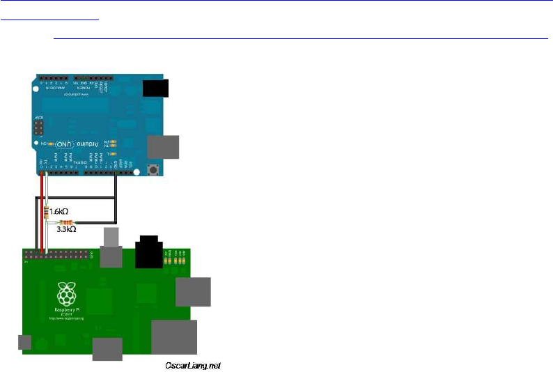
Raspberry Pi mit Arduino über UART verbinden
die RX/TX-Pins der beiden Geräte werden über Kreuz verbunden (d.h. RX mit TX und TX
mit RX).
Arduinos, die wie der Raspi ebenfalls 3.3V Level haben, sind z.B. der ZERO und der DUE
(der DUE ist meine persönliche 1. Wahl wegen der vielen IOs, trotz Problemen manchmal
mit verbugten libs).
5V-Boards brauchen dafür zusätzlich einen Levelshifter oder (viel einfacher) einen
Spannungsteiler mit 2 Widerständen.
Schaltplan z.B. für den UNO oder den MEGA etc. (5V),
für den DUE oder ZERO (3.3V) den Arduino-TX-Pin direkt ohne Widerstände mit dem Raspi
verbinden:
http://blog.oscarliang.net/ctt/uploads/2013/05/arduino-raspberry-pi-serial-connect-
schematics.jpg
Quelle: http://blog.oscarliang.net/raspberry-pi-and-arduino-connected-serial-gpio/

Raspberry Pi <-> Arduino UART Kommunikationsprogramm
erster Verbindungstest zwischenRaspi und Arduino, basierend auf meinem Arduino-Arduino-
Serial-Comm Programm:
http://www.mindstormsforum.de/viewtopic.php?f=78&t=8491&start=15#p67476
direkt nach Portieren des Arduino Codes auf Raspi C, offenbar, überraschenderweise: es
funktioniert auf Anhieb !... :shock:
funktioniert auch sehr schnell, dabei scheint die Display-Ausgabe auf dem Arduino zu Debug-
Zwecken noch am meisten die UART-comm auszubremsen....
Die Arduino Display Ausgabe muss künftig unbedingt als eigener Task per Multitasking
(Arduino Due: <Scheduler.h> ) laufen !!
share and enjoy!
für den Raspi :
//----------------------------------------------------------------------
/*
UART communication
send/receive byte array (64 bytes)
*
Raspberry Pi master
ver 0666nrm2
*/
// (C) Helmut Wunder (HaWe) 2015
// freie Verwendung für private Zwecke
// für kommerzielle Zwecke nur nach Genehmigung durch den Autor.
// Programming language: gcc C/C++
// protected under the friendly Creative Commons Attribution-NonCommercial-
ShareAlike 3.0 Unported License
// http://creativecommons.org/licenses/by-nc-sa/3.0/
#include <stdio.h>
#include <stdlib.h>
#include <unistd.h>
#include <math.h>
#include <fcntl.h>
#include <string.h>
#include <sys/ioctl.h>
#include <stdint.h>
#include <time.h>
#include <sys/time.h>
#include <errno.h>
#include <pthread.h>
#include <wiringPi.h>
#include <wiringSerial.h>
#define byte uint8_t
char * uart = "/dev/ttyAMA0";
int Serial1;
//==================================================================
// debug monitor
void displayvalues(char * caption, uint8_t array[]) {
int cnt;
char sbuf[128];
sprintf(sbuf, "%s ", caption);
printf(sbuf); printf("\n");
for(cnt=0; cnt<8; ++cnt) {
sprintf(sbuf, "%3d ", array[cnt]); // print on TFT
printf(sbuf);
}
printf("\n");
}
//==================================================================
// serial TCP
const uint8_t MSGSIZE=64;
uint8_t bsync=255;
uint8_t sendbuf[MSGSIZE];
uint8_t recvbuf[MSGSIZE];
uint8_t calcchecksum(uint8_t array[]) {
int32_t sum=0;
for(int i=2; i<MSGSIZE; ++i) sum+=(array[i]);
return (sum & 0x00ff);
}
bool checksumOK(uint8_t array[]){
return (calcchecksum(array)==array[1]);
}
// ================================================================
// addToBuffer and receive function courtesy of chucktodd
bool addToBuffer( uint8_t buf[], uint8_t *cnt, uint16_t timeout){
bool inSync = *cnt>0;
unsigned long start=millis();
while((*cnt<MSGSIZE)&&(millis()-start<timeout)){
if( serialDataAvail( Serial1 ) ) { // grab new char, test for sync char,
if so start adding to buffer
buf[*cnt] = (uint8_t)serialGetchar( Serial1 );
if(inSync) *cnt += 1;
else{
if(buf[*cnt]==0xFF){
inSync = true;
*cnt +=1;
}
}
}
}
return (*cnt==MSGSIZE);
}
//==================================================================
bool receive(uint8_t * buf, uint16_t timeout, uint8_t *cnt){ // by passing
cnt in and out,
// i can timeout and still save a partial buffer, so a resync costs less
(less data lost)
bool inSync=false;
unsigned long start=millis();
uint8_t * p; // pointer into buf for reSync operation
bool done=false;
do{
done = addToBuffer(buf,cnt,timeout); // if this return false, a timeout
has occured, and the while will exit.
if(done){ // do checksumOK test of buffer;
done=checksumOK(buf);
if(!done){ // checksumOK failed, scan buffer for
next sync char
p = (uint8_t*)memchr((buf+1),0xff,(MSGSIZE-1));
if(p){ // found next sync char, shift buffer content, refill buffer
*cnt = MSGSIZE -(p-buf); // count of characters to salvage from
this failure
memcpy(buf,p,*cnt); //cnt is now where the next character from
Serial is stored!
}
else *cnt=0; // whole buffer is garbage
}
}
} while(!done&&(millis()-start<timeout));
return done; // if done then buf[] contains a sendbufid buffer, else a
timeout occurred
}
//==================================================================
void loop()
{
char sbuf[128], resOK;
static uint8_t cnt=0;
uint8_t cbuf[MSGSIZE], chk;
// send to slave
//Serial.println();
sendbuf[0]=bsync;
sendbuf[1]=calcchecksum(sendbuf);
for(uint8_t i=0; i<MSGSIZE; i++) { //
serialPutchar( Serial1, sendbuf[i]); // Send values to the slave
}
sprintf(sbuf, "send : %4d %4d ", sendbuf[4], sendbuf[6]);
printf(sbuf);
// Receive from slave
memset(cbuf, 0, sizeof(cbuf));
resOK = receive ( cbuf, 10000,&cnt);
if( resOK ) { // receive ok?
cnt=0;
memcpy(recvbuf, cbuf, sizeof(cbuf));
// debug
sprintf(sbuf, "received: %4d %4d \n ", recvbuf[4], recvbuf[6]);
printf(sbuf);
memset(sendbuf, 0, sizeof(sendbuf)); // clear send buf
// debug: test values to send back!
sendbuf[4]=recvbuf[4]+10; // change [4] to send back
sendbuf[6]=recvbuf[6]+20; // change [6] to send back
}
}
//==================================================================
int main() {
unsigned long timesav;
char sbuf[128];
printf("initializing..."); printf("\n");
// UART Serial com port
Serial1 = serialOpen (uart, 115200); // for Arduino code compat.
while(1) { loop(); }
serialClose( Serial1);
exit(0);
}
//----------------------------------------------------------------------
für den Arduino Due:
//----------------------------------------------------------------------
/*
UART communication
send/receive byte array (64 bytes)
Arduino slave
( Arduino Due + Mega; for small AVR use SoftwareSerial ! )
ver 0666nas2
*/
// (C) Helmut Wunder (HaWe) 2015
// freie Verwendung für private Zwecke
// für kommerzielle Zwecke nur nach Genehmigung durch den Autor.
// Programming language: Arduino Sketch C/C++ (IDE 1.6.1 - 1.6.5)
// protected under the friendly Creative Commons Attribution-NonCommercial-
ShareAlike 3.0 Unported License
// http://creativecommons.org/licenses/by-nc-sa/3.0/
//==================================================================
const uint8_t MSGSIZE=64;
uint8_t bsync=255;
uint8_t sendbuf[MSGSIZE];
uint8_t recvbuf[MSGSIZE];
//==================================================================
const uint32_t UARTclock = 115200;
//==================================================================
void displayvalues(char * caption, uint8_t array[]) {
int cnt;
char sbuf[128];
sprintf(sbuf, "%s ", caption);
Serial.println(sbuf);
for(cnt=0; cnt<8; ++cnt) {
if(cnt%8==0) Serial.println();
sprintf(sbuf, "%3d ", array[cnt]); // print on TFT
Serial.print(sbuf); // Print sendbufue to the
Serial Monitor
}
Serial.println();
}
//==================================================================
// serial transmission
uint8_t calcchecksum(uint8_t array[]) {
int32_t sum=0;
for(int i=2; i<MSGSIZE; ++i) sum+=(array[i]);
return (sum & 0x00ff);
}
#define checksumOK(array) (calcchecksum(array)==array[1])
// ================================================================
// addToBuffer and receive function courtesy of chucktodd
bool addToBuffer( uint8_t buf[], uint8_t *cnt, uint16_t timeout){
bool inSync = *cnt>0;
unsigned long start=millis();
while((*cnt<MSGSIZE)&&(millis()-start<timeout)){
if(Serial1.available()){ // grab new char, test for sync char, if so
start adding to buffer
buf[*cnt] = (uint8_t)Serial1.read();
if(inSync) *cnt += 1;
else{
if(buf[*cnt]==0xFF){
inSync = true;
*cnt +=1;
}
}
}
}
return (*cnt==MSGSIZE);
}
//==================================================================
bool receive(uint8_t * buf, uint16_t timeout, uint8_t *cnt){ // by passing
cnt in and out,
// i can timeout and still save a partial buffer, so a resync costs less
(less data lost)
bool inSync=false;
unsigned long start=millis();
uint8_t * p; // pointer into buf for reSync operation
bool done=false;
do{
done = addToBuffer(buf,cnt,timeout); // if this return false, a timeout
has occured, and the while will exit.
if(done){ // do checksumOK test of buffer;
done=checksumOK(buf);
if(!done){// checksumOK failed, scan buffer for next sync char
p = (uint8_t*)memchr((buf+1),0xff,(MSGSIZE-1));
if(p){ // found next sync char, shift buffer content, refill buffer
*cnt = MSGSIZE -(p-buf); // count of characters to salvage from
this failure
memcpy(buf,p,*cnt); //cnt is now where the next character from
Serial is stored!
}
else *cnt=0; // whole buffer is garbage
}
}
}while(!done&&(millis()-start<timeout));
return done; // if done then buf[] contains a sendbufid buffer, else a
timeout occurred
}
//==================================================================
void loop()
{
char sbuf[128], resOK;
static uint8_t cnt=0;
uint8_t cbuf[MSGSIZE], chk;
// Receive from master
memset(cbuf, 0, sizeof(cbuf));
resOK = receive ( cbuf, 10000,&cnt);
if( resOK ) { // receive ok?
cnt=0;
//displayvalues(60, "Received...:", cbuf);
memcpy(recvbuf, cbuf, sizeof(cbuf));
memset(sendbuf, 0, sizeof(sendbuf));
// debug: test values to send back!
sendbuf[4]=recvbuf[4]+1; // change [4] to send back
sendbuf[6]=recvbuf[6]+1; // change [6] to send back
}
// send to master
//Serial.println();
sendbuf[0]=bsync;
sendbuf[1]=calcchecksum(sendbuf);
for(uint8_t i=0; i<MSGSIZE; i++) {
Serial1.write(sendbuf[i]); // Send values to the master
}
//Serial1.flush(); // clear output buffer
//displayvalues(20, "Transmitted...: ", sendbuf);
sprintf(sbuf, "recieve: %4d %4d send: %4d %4d", recvbuf[4],
recvbuf[6], sendbuf[4], sendbuf[6]);
Serial.println(sbuf);
}
//==================================================================
void setup() {
char sbuf[128];
int32_t i=0;
// Serial
Serial.begin(115200); // USB terminal
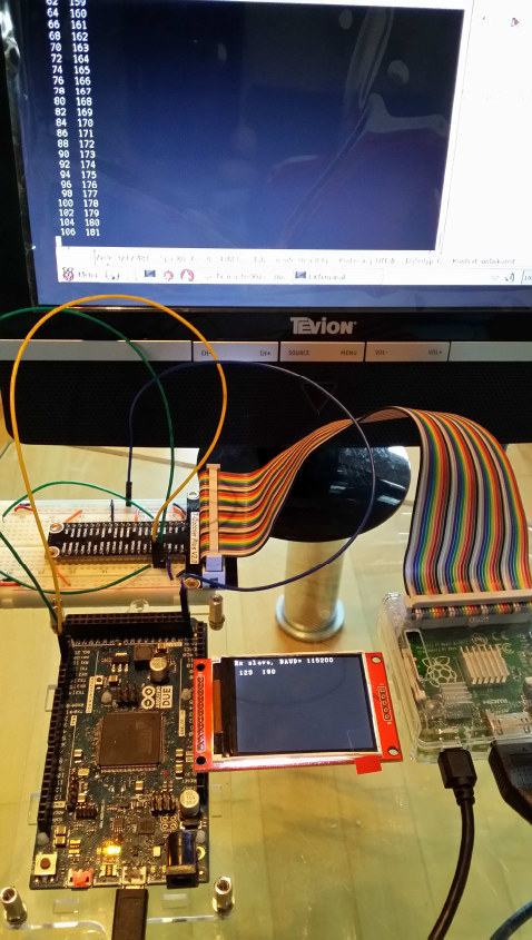
Serial1.begin(UARTclock); // RX-TX UART
while(Serial1.available()) Serial1.read(); // clear output buffer
sprintf(sbuf, "setup(): done.");
Serial.println(); Serial.println(sbuf);
sprintf(sbuf, "Rx slave, BAUD= %ld", UARTclock );;
}
//----------------------------------------------------------------------

Ublox Neo-Gy-6M
(Baustelle)
https://github.com/jacketizer/libnmea/tree/master/examples
https://github.com/wdalmut/libgps/blob/master/examples/position_logger.c
Code, um Datum und Zeit (System) anzuzeigen:
#include <stdio.h>
#include <time.h>
int main ()
{
struct tm *timeinfo ;
time_t rawtime ;
char strResponse [128] ;
rawtime = time (NULL) ;
timeinfo = localtime(&rawtime) ;
strftime(strResponse,128,"%H:%M:%S %d-%b-%Y",timeinfo);
printf ("%s\n", strResponse) ;
}

Nutzung von USB, zum Verbinden über USB-
Schnittstellen:
Nachdem beide Geräte (Raspi und Arduino) USB-Schnittstellen besitzen, und USB auch nur
ein serielles Protokoll ist, kann man beide Geräte auch direkt über ihre USB-Buchsen
verbinden. Die Ardino-USB-Buchse ist immer schon mit UART0 (RX0/TX0 auf pins 0+1)
verbunden, beim Raspi muss man die genaue Adresse des Ports, mit dem der Arduino
verbunden ist, erst noch herausfinden.
bisher wird auf dem Raspi dies als GPIO-Schnittstellen-Adresse verwendet (BCM 14+15):
[b][color=#008000]/dev/ttyAMA0[/color][/b].
Um den Namen des Raspi-USB-Ports herauszufinden, an dem der Arduino angeschlossen ist,
lässt man den erst mal ab und öffnet eine Linux Konsole.
Dann steckt man den Arduino ein und tippt in der Konsole
[code]dmesg | tail[/code]
Da kommt dann u.a.
new full-speed USB device ...
...
cdc_acm ...: ttyACM0: USB ACM device
usbcore: registered new interface driver cdc_acm
Will heißen, der Arduino hängt per USB an einem virtuellen UART mit dem Namen:
/dev/ttyACM0
Dies ist die neue serielle Adresse auf dem Raspi.
Am Arduino ist der serielle Port dann automatisch
Serial (RX0/TX0)
über den USB-Stecker, mit dem man ansonsten mit dem PC verbindet zum Programmieren
oder für das Serielle Terminal Window.
Soll dagegen das Raspi-USB-Kabel direkt mit einem Arduino-UART-Pin verbunden werden,
braucht man einen gesonderten USB-UART-Adapter:
f) Nutzung von USB-ch341 uart converter:

http://www.ebay.de/itm/USB-Seriell-TTL-LVTTL-Adapter-Converter-fur-z-B-Arduino-inkl-
Kabel-/301883482496
Jumper für Arduino DUE auf 3.3V ändern !!!
Diesen Adapter einfach in die USB-Buchse einstecken, dann lassen sich die RX/TX Pins mit
einem anderen seriellen Gerät (UART-Sensor oder Arduino Serial) verbinden.
Eingabe im Terminal:
dmesg | tail
Da kommt dann u.a.
usb 1-1.3: new USB device found, idvendor=...
...
USB serial support registered cor ch341 -uart
ch341 1-1.3:1.0: ch341 uart converter detected
Will heißen, der ch341-UART-Konverter hängt an einem virtuellen UART mit dem Namen:
/dev/ttyUSB0
(Danke an Mxt (Roboternetz-Forum) und Marco Niesen ! )

Raspberry Pi: I2C Schnittstelle (Pi B+ und Pi 2)
Lit.:
http://www.raspberry-pi-geek.de/Magazin/2015/01/Der-I2C-Bus-des-Raspberry-Pi-Teil-1
a) Übersicht:
Die Pins für I2C liegen auf dem Raspi auf den folgenden GPIOs:
[code]I2C-1:
phys.
3 SDA.1 wiringPi 8 (BCM 2)
5 SCL.1 wiringPi 9 (BCM 3)
I2C-0
phys.
27 SDA.0 wiringPi 30 (BCM 0)
28 SCL.0 wiringPi 31 (BCM 1) [/code]
Links:
[url]http://www.netzmafia.de/skripten/hardware/RasPi/RasPi_I2C.html[/url]
[url]http://blog.retep.org/2014/02/15/connecting-an-arduino-to-a-raspberry-pi-using-I2C/[/url]
[url]http://blog.oscarliang.net/raspberry-pi-arduino-connected-I2C/[/url]
b) Den RasPi für I2C vorbereiten
(abweichend von der Vorschrift in den Links: keine Blacklist, kein manuelles Patchen einer
boot-config-Datei für I2C-1 etc.):
[code]sudo raspi-config[/code][code]=> (9) Advanced Options
=> (A7) I2C
=> I2C Modul enablen: <Ja>
=> beim Booten automatisch laden: <OK>[/code]
Trotzdem wird dann zwar I2C-1, aber nicht I2C-0 geladen. Dazu ist dann doch wieder mal ein
extra Schritt nötig:
[code]sudo nano /boot/config.txt
# am Schluss hinzufügen:
dtparam=I2C_vc=on[/code]
weitere / optionale settings:
[code]#I2C enable
dtparam=I2C_arm=on
#I2C-0 enable
dtparam=I2C_vc=on
#I2C baud rate
dtparam=I2C_arm_baudrate=400000
dtparam=I2C_vc_baudrate=400000
# I2C access without root privileges
SUBSYSTEM="I2C-dev", MODE="0666" [/code]
Schießlich Linux I2C-Tools installieren :
[code]
sudo apt-get update
sudo apt-get install I2C-tools # I2C-Toolkit fuer die Kommandozeile
sudo apt-get install python-smbus # optional: Python-Bibliothek fuer I2C
sudo apt-get install libI2C-dev # Bibliothek fuer C
[/code]
Jetzt RPI neu booten. Danach soll man die 2 I2C devices sehen können:
[code]pi@raspberrypi ~ $ ls -l /dev/I2C*
crw-rw---T 1 root I2C 89, 0 May 25 11:56 /dev/I2C-0
crw-rw---T 1 root I2C 89, 1 May 25 11:56 /dev/I2C-1[/code]
Test: scan the I2C bus:
pi@raspberrypi ~ $ I2Cdetect -y 1
0 1 2 3 4 5 6 7 8 9 a b c d e f
00: -- -- -- -- -- -- -- -- -- -- -- -- --
10: -- -- -- -- -- -- -- -- -- -- -- -- -- -- -- --
20: -- -- -- -- -- -- -- -- -- -- -- -- -- -- -- --
30: -- -- -- -- -- -- -- -- -- -- -- -- -- -- -- --
40: -- -- -- -- -- -- -- -- -- -- -- -- -- -- -- --
50: -- -- -- -- -- -- -- -- -- -- -- -- -- -- -- --
60: -- -- -- -- -- -- -- -- -- -- -- -- -- -- -- --
70: -- -- -- -- -- -- -- --
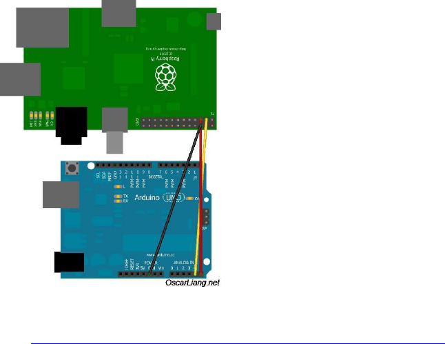
c) Den RasPi per I2C mit Arduino verbinden:
[img]http://blog.oscarliang.net/ctt/uploads/2013/05/RaspberryPI-I2C-Arduino.jpg[/img]
aus: http://blog.oscarliang.net/raspberry-pi-arduino-connected-I2C/
RPI Arduino (Uno/Mega)
--------------------------------------------
GPIO 0 (SDA) <--> Pin A4/20 (SDA)
GPIO 1 (SCL) <--> Pin A5/21 (SCL)
Ground <--> Ground
Keine Level-Konverter nötig, wenn der Raspi master ist, denn er besitzt bereits interne
Pullups auf +3,3V !
Nach Verbinden mit Arduino (slave addr=0x04) z.B.:
pi@mimas ~ $ I2Cdetect -y 1
0 1 2 3 4 5 6 7 8 9 a b c d e f
00: -- 04 -- -- -- -- -- -- -- -- -- -- --
10: -- -- -- -- -- -- -- -- -- -- -- -- -- -- -- --
20: -- -- -- -- -- -- -- -- -- -- -- -- -- -- -- --
30: -- -- -- -- -- -- -- -- -- -- -- -- -- -- -- --
40: -- -- -- -- -- -- -- -- -- -- -- -- -- -- -- --
50: -- -- -- -- -- -- -- -- -- -- -- -- -- -- -- --
60: -- -- -- -- -- -- -- -- -- -- -- -- -- -- -- --
70: -- -- -- -- -- -- -- --
What you are now seeing is a list of all I2C devices connected. The one you are interested in
is 04 which happens to be your arduino.
d) RasPi <-> Arduino I2C-Kommunikationsprogramm:
funktioniert momentan nur mit Arduino DUE (ARM), nicht mit MEGA (AVR)
(Clock Stretching Fehler? eingebaute Pullups beim Mega?)

Testcode Raspi I2C Master:
//----------------------------------------------------------------------
// Raspberry Pi Master code to send/receive byte arrays
// to an Arduino as an I2C slave
//
// ver. 0.002a
#include <stdio.h>
#include <unistd.h>
#include <stdlib.h>
#include <wiringPi.h>
#include <wiringPiI2C.h>
#include <errno.h>
#include <string.h>
#define MSGSIZE 30
unsigned char calcchecksum( unsigned char array[]) {
int32_t sum=0;
for(int i=2; i<MSGSIZE; ++i) sum+=(array[i]);
return (sum & 0x00ff);
}
int main (void)
{
int fd, i ;
unsigned char test=0;
unsigned char data [MSGSIZE] ;
if ((fd = wiringPiI2CSetup (0x04) ) < 0)
{
fprintf (stderr, "Can't open RTC: %s\n", strerror (errno)) ;
exit (EXIT_FAILURE) ;
}
for (;;)
{
memset(data, 0, sizeof(data) );
data[0]= 0xff; // init for transmission error check
read (fd, data, MSGSIZE) ;
if( data[1] != calcchecksum( data ) ) {
// handle transmission error !
}
else {
printf (" read: ");
for (i = 0 ; i < 7 ; ++i)
printf (" %3d", data [i]) ;
//printf ("\n") ;
delay(10) ;
memset(data, 0, sizeof(data) );
data[5]= test++;
data[0]= 0xff;

data[MSGSIZE-1]= 0x04;
data[1] = calcchecksum( data );
write(fd, data, MSGSIZE) ;
printf (" write: ");
for (i = 0 ; i < 7; ++i)
printf (" %3d", data [i]) ;
printf ("\n\n") ;
delay(10) ;
}
}
return 0 ;
}
//----------------------------------------------------------------------
Testcode Arduino I2C Slave:
//----------------------------------------------------------------------
// Arduino code to send/receive byte arrays
// Arduino as an I2C slave
//
// ver. 0.002
#include <Wire.h>
#define SLAVE_ADDRESS 0x04
#define MSGSIZE 30
byte recvarray[MSGSIZE]; // 0=0xff; 1=chksum; ...data...; MSGSIZE-
1=SLAVE_ADDRESS
byte sendarray[MSGSIZE];
volatile int8_t flag=0;
//==================================================================
//==================================================================
void setup() {
int32_t i=0;
// Serial terminal window
i=115200;
Serial.begin(i);
Serial.print("Serial started, baud=");
Serial.println(i);
// Wire (I2C)
Wire.begin(SLAVE_ADDRESS); // start Arduino as a I2C slave,
addr=0x04 (7-bit coded)
Wire.onReceive(receiveData ); // event when master array is sent
Wire.onRequest(sendData ); // event when master requests array to
read
memset(sendarray, 0, sizeof(sendarray) ); // init send- and recv arrays
memset(recvarray, 0, sizeof(recvarray) );
Serial.print("I2C init: my slave address= ");
Serial.println(SLAVE_ADDRESS);
Serial.println("I2C init: done.");
Serial.println();
Serial.println("setup(): done.");
}
//==================================================================
uint8_t calcchecksum(uint8_t array[]) {
int32_t sum=0;
for(int i=2; i<MSGSIZE; ++i) sum+=(array[i]);
return (sum & 0x00ff);
}
//==================================================================
void loop()
{
char sbuf[128];
Serial.println(); Serial.println();
// do something with the received data
// and then do something to build the sendarray [3]...[MSG_SIZE-2]
if (flag==1) {
//debug
sendarray[4] +=1;
}
sendarray[0] = 0xff; // 0 = start: 0xff == msg
start flag
sendarray[2] = flag; // 2 = send back msg error
flag
sendarray[MSGSIZE-1] = SLAVE_ADDRESS; // end of array: ID check
sendarray[1] = calcchecksum(sendarray); // 1 = calc new chksum
flag=0;
// debug output
sprintf(sbuf, "Sendarr[4]=%4d, [5]=%4d, Recvarr[4]=%4d, [5]=%4d",
sendarray[4], sendarray[5], recvarray[4],
recvarray[5]) ;
Serial.println(sbuf);
delay(1); // short break for the cpu
and the bus
}
//==================================================================
void receiveData(int byteCount) {
int32_t i;
byte val;
while(Wire.available()<MSGSIZE) ; // wait for all bytes to
complete
i=0; // init counter var
while(Wire.available()&& (i<MSGSIZE) ) // read all recv array
bytes
{
val=Wire.read();
recvarray[i++]=val;
}
// check for transmission error
if( (recvarray[0] == 0xff)
&& (recvarray[1] == calcchecksum(recvarray))
&& (recvarray[MSGSIZE-1] == SLAVE_ADDRESS ) )
flag=1; // data ok
else
flag=127; // data faulty => handle rcv-error => flag =127
}
//==================================================================
void sendData(){
// Wire.write writes data from a slave device in response to a request
from a master
Wire.write(sendarray, MSGSIZE); // send own byte array back to
master..
}
//----------------------------------------------------------------------
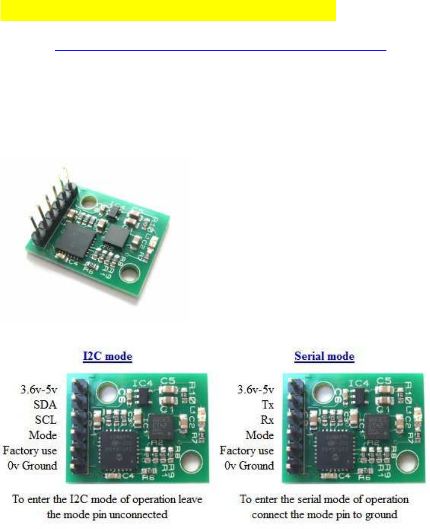
I2C Sensoren: Source Code Examples
(vgl. auch: http://www.robot-electronics.co.uk/htm/raspberry_pi_examples.htm )
( I2C ) CMPS11 (IMU = 3D-Gyroscope, 3D-Compass, 3D-
Accelerometer):
[size=120][b][color=#FF0000][u] ( I2C ) CMPS11 (IMU = 3D-Gyroscope, 3D-Compass,
3D-Accelerometer):[/u][/color][/b][/size]
Interface: I2C oder auch UART möglich
I2C Bus speed: STANDARD + FAST-I2C (100-400kHz, getestet)
[img]http://www.hobbytronics.co.uk/image/cache/data/devantech/cmps11-tilt-compass-
250x250.jpg[/img]
[url]http://www.hobbytronics.co.uk/cmps11-tilt-compass[/url]
[url]http://www.robot-electronics.co.uk/htm/cmps11I2C.htm[/url]
Besonderheiten:
IMU Sensor mit 3D-Gyro, 3D-Kompass, 3D-Accelerometer, Temperatur-kompensiert
Integrierte Sensor-Fusion per eingebautem Kalman-Filter
Ausgabe des gefilterten Kurses oder auch aller einzelnen Sensor-raw-Daten
einfaches Auslesen von I2C-Registern für Kurs (Kompasskurs, heading), Neigung (pitch) und
Schräglage (roll).
Keine komplizierten Umrechnungen mehr nötig!
//----------------------------------------------------------------------
/*
* CMPS11 IMU
* 3D gyro + 3D compass + 3D accelerometer
* author: originally by James Henderson for Arduino
* ported to Raspberry Pi code by HaWe
* test demo
* ver 0001a
*
*/
#include <string.h>
#include <unistd.h>
#include <errno.h>
#include <stdio.h>
#include <stdlib.h>
#include <linux/I2C-dev.h>
#include <sys/ioctl.h>
#include <fcntl.h>
#include <unistd.h>
#include <wiringPi.h>
#include <wiringPiI2C.h>
// CMPS11 IMU
#define CMPS11_ADDR 0x60
int cmps11;
int main() {
unsigned char ver, high_byte, low_byte, angle8;
signed char pitch, roll;
int angle16;
char sbuf[100];
cmps11 = wiringPiI2CSetupInterface("/dev/I2C-1", 0x60);
ver = wiringPiI2CReadReg8 (cmps11, 0) ;
sprintf(sbuf, "\n CMPS11 - fw version: %3d \n\n", ver); //
printf(sbuf);
while(1) {
angle8 = wiringPiI2CReadReg8 (cmps11, 1) ;
high_byte = wiringPiI2CReadReg8 (cmps11, 2) ;
low_byte = wiringPiI2CReadReg8 (cmps11, 3) ;
pitch = wiringPiI2CReadReg8 (cmps11, 4) ;
roll = wiringPiI2CReadReg8 (cmps11, 5 ) ;
angle16 = high_byte; // Calculate 16 bit angle
angle16 <<= 8;
angle16 += low_byte;
sprintf(sbuf, "roll: %3d ", roll); // Display roll data
printf(sbuf);
sprintf(sbuf, " pitch: %3d ", pitch); // Display pitch data
printf(sbuf);
sprintf(sbuf, " angle full: %d.%d ", angle16/10, angle16%10);
// Display 16 bit angle with decimal place
printf(sbuf);
sprintf(sbuf, " angle 8: %3d ", angle8); // Display 8bit angle
printf(sbuf);
printf("\n");
printf("\n");
delay(100); // Short delay before next loop
}
return (0);
}
//----------------------------------------------------------------------
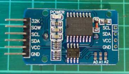
( I2C ) Real Time Clock RTC DS3231 :
http://tronixstuff.com/2014/12/01/tutorial-using-ds1307-and-ds3231-real-time-clock-modules-
with-arduino/
angelehnt an Arduino Sketch Code:
http://www.mindstormsforum.de/viewtopic.php?f=78&t=8491&start=15#p67456
//----------------------------------------------------------------------
/*
*
* RTC DS3231
*
* test demo
* taken from http://tronixstuff.com/2014/12/01/tutorial-using-ds1307-and-
ds3231-real-time-clock-modules-with-arduino/
* ported to Raspberry Pi by HaWe, 2016
* ver 0001
*
*/
#include <string.h>
#include <unistd.h>
#include <errno.h>
#include <stdio.h>
#include <stdint.h>
#include <stdlib.h>
#include <linux/I2C-dev.h>
#include <sys/ioctl.h>
#include <fcntl.h>
#include <unistd.h>
#include <wiringPi.h>
#include <wiringPiI2C.h>
#define byte uint8_t
// RTC DS3231
#define ADDR_RTCDS3231 0x68
int frtcds3231;
//==================================================================
// Convert normal decimal numbers to binary coded decimal
//==================================================================
byte decToBcd(byte val) { return( (val/10*16) + (val%10) ); }
//==================================================================
// Convert binary coded decimal to normal decimal numbers
//==================================================================
byte bcdToDec(byte val) { return( (val/16*10) + (val%16) ); }
//==================================================================
void setDS3231time( byte year, byte month, byte dayOfMonth, byte hour, byte
minute, byte second, byte dayOfWeek)
{
// sets time and date data to DS3231
wiringPiI2CWriteReg8(frtcds3231, 0, decToBcd(second)); // set
seconds
wiringPiI2CWriteReg8(frtcds3231, 1, decToBcd(minute)); // set
minutes
wiringPiI2CWriteReg8(frtcds3231, 2, decToBcd(hour)); // set hours
wiringPiI2CWriteReg8(frtcds3231, 3, decToBcd(dayOfWeek)); // (
1=Sunday, 7=Saturday)
wiringPiI2CWriteReg8(frtcds3231, 4, decToBcd(dayOfMonth)); // set
dayOfMonth (1 to 31)
wiringPiI2CWriteReg8(frtcds3231, 5, decToBcd(month)); // set month
wiringPiI2CWriteReg8(frtcds3231, 6, decToBcd(year)); // set year
(0 to 99)
}
//==================================================================
int main() {
int year, month, dayOfMonth, hour, minute, second, dayOfWeek;
int i=0, check;
char sbuf[100];
// frtcds3231 = wiringPiI2CSetupInterface( "/dev/I2C-0", ADDR_RTCDS3231
); // I2C-0
frtcds3231 = wiringPiI2CSetupInterface( "/dev/I2C-1", ADDR_RTCDS3231 );
// I2C-1
printf(" RTC DS3231 \n");
printf("Set new Date/Time: enter 1\n");
printf("else: display time\n\n");
i = getchar();
//debug
//printf("%d \n", i);
while (i=='1') {
// get string yy mm dd hh mm ss dw : gets() ?
printf("yy mm dd hh mm ss dw (DayOfWeek) \n");
check=scanf("%d %d %d %d %d %d %d", &year, &month, &dayOfMonth,
&hour, &minute, &second, &dayOfWeek);
getchar();
printf("check=%d\n", check);
if(check==7) {
printf("%d \n", year);
printf("%d \n", month);
printf("%d \n", dayOfMonth);
printf("%d \n", hour);
printf("%d \n", minute);
printf("%d \n", second);
printf("%d \n", dayOfWeek);
setDS3231time( year, month, dayOfMonth, hour, minute, second,
dayOfWeek );
}
printf(" RTC DS3231 \n");
printf("Set new Date/Time: enter 1\n");
printf("else: display time\n\n");
i=0;
i = getchar();
}
while(1) {
second = bcdToDec(wiringPiI2CReadReg8 (frtcds3231, 0) & 0x7f );
minute = bcdToDec(wiringPiI2CReadReg8 (frtcds3231, 1) );
hour = bcdToDec(wiringPiI2CReadReg8 (frtcds3231, 2) & 0x3f );
dayOfWeek = bcdToDec(wiringPiI2CReadReg8 (frtcds3231, 3) );
dayOfMonth = bcdToDec(wiringPiI2CReadReg8 (frtcds3231, 4) );
month = bcdToDec(wiringPiI2CReadReg8 (frtcds3231, 5) );
year = bcdToDec(wiringPiI2CReadReg8 (frtcds3231, 6) );
-
sprintf(sbuf, "20%02d/%02d/%02d %02d:%02d:%02d", year, month,
dayOfMonth, hour, minute, second);
printf(sbuf);
printf(" Day of week %1d: ", dayOfWeek);
switch(dayOfWeek){
case 1:
printf("Sunday");
break;
case 2:
printf("Monday");
break;
case 3:
printf("Tuesday");
break;
case 4:
printf("Wednesday");
break;
case 5:
printf("Thursday");
break;
case 6:
printf("Friday");
break;
case 7:
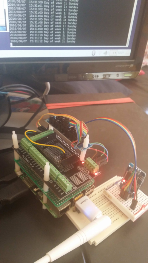
printf("Saturday");
break;
}
printf("\n");
delay (1000);
}
return (0);
}
//----------------------------------------------------------------------

Synchronisierung der Systemzeit
Man kann jetzt die RTC zur Synchronisierung der Systemzeit wahlweise mit der Internet-
oder der RTC-Zeit verwenden:
http://www.roboternetz.de/community/threads/69120-C-C-Raspi-Systemzeit-aus-Internet-
geupdated-oder-von-File-gelesen-und-expoliert?p=626041&viewfull=1#post626041
if (system("ping -c1 -s1 www.google.com")){
cout<<"There is no internet connection \n";
}
if (system("ping -c1 -s1 www.google.com")){
cout<<"There is no internet connection \n";
}
Einbinden der RTC in den Kernel
(Zeit wird von RTC gelesen, nicht vom Internet Server):
sudo bash
sudo leafpad /etc/rc.local
# vor exit:
echo ds3231 0x68 > /sys/class/I2C-adapter/I2C-1/new_device
sudo hwclock -s
#sudo bash beenden mit:
exit
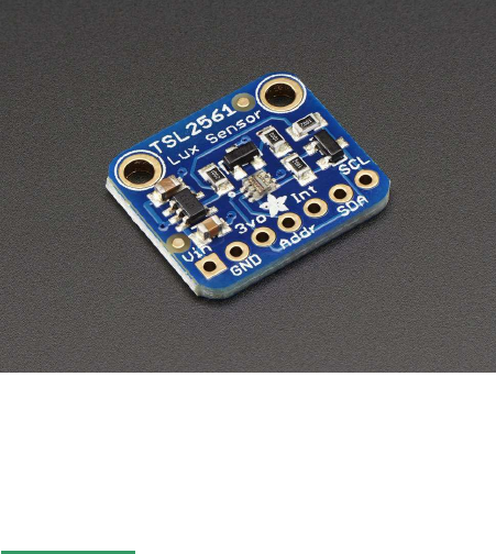
( I2C ) Adafruit TSL2561 Digital Light Sensor :
(Adafruit TSL2561 Digital Luminosity/Lux/Light Sensor)
[img]https://cdn-shop.adafruit.com/145x109/439-00.jpg[/img]
https://www.adafruit.com/product/439
Driver Lib: https://github.com/lexruee/tsl2561
Installation:
apt-get -install git
# clone repository:
git clone git://github.com/lexruee/tsl2561.git
Beispielcode, gibt 5 LUX Werte aus:
//----------------------------------------------------------------------
#include "tsl2561.h"
#include <stdlib.h>
#include <stdio.h>
#include <unistd.h>
int main(int argc, char **argv) {
int address = 0x39;
char *I2C_device = "/dev/I2C-1";
void *tsl = tsl2561_init(address, I2C_device);
tsl2561_enable_autogain(tsl);
tsl2561_set_integration_time(tsl, TSL2561_INTEGRATION_TIME_13MS);
if(tsl == NULL){ // check if error is present
exit(1);
}
int c;
long lux;
for(c = 0; c < 5; c++){
lux = tsl2561_lux(tsl);
printf("lux %lu\n", lux);
usleep(3 * 1000 * 1000);
}
tsl2561_close(tsl);
I2C_device = NULL;
return 0;
}
//----------------------------------------------------------------------]

( I2C ) Ultraschall Sensoren Devantech SRF-02 und SRF-08
[img]https://www.robot-electronics.co.uk/images/srf02.jpg[/img]
[img]http://www.roboter-teile.de/Oxid/out/pictures/master/product/1/srf08_250_p1.jpg[/img]
Interface: I2C
Bezugsquellen:
z.B.:
http://www.exp-tech.de/srf02-ultrasonic-ranger
http://www.exp-tech.de/srf08-high-performance-ultrasonic-ranger-finder
http://www.robot-electronics.co.uk/htm/srf02techI2C.htm
http://www.ebay.de/sch/i.html?_from=R40&_trksid=m570.l1313&_nkw=%28SRF-
02%2C+SRF-08+%29&_sacat=0
[b][u]Literatur, Source Codes und Treiber :[/u][/b]
http://www.robot-electronics.co.uk/htm/raspberry_pi_examples.htm
Beispiel-Sourcecode:
//----------------------------------------------------------------------
// SRF02 example coder for the Raspberry pi
//
// This code will work for the SRF02/ 10/ 235 and 08.
// It will take a ranging from the module and print results
// to the screen.
//
// By James Henderson, 2016.
#include <stdio.h>
#include <stdlib.h>
#include <linux/I2C-dev.h>
#include <fcntl.h>
#include <string.h>
#include <sys/ioctl.h>
#include <sys/types.h>
#include <sys/stat.h>
#include <unistd.h>
int main(int argc, char **argv)
{
printf("**** SRF02/10/235 example program ****\n");
int fd; // File descrition
// For older raspberry pi modules use "/dev/I2C-0" instead of "/dev/I2C-
1" for the I2C port
char *fileName = "/dev/I2C-1"; // Name of the port we will
be using
int address = 0x70; // Address of the SRF02
shifted right one bit
unsigned char buf[10]; // Buffer for data being
read/ written on the I2C bus
if ((fd = open(fileName, O_RDWR)) < 0) { // Open port for reading
and writing
printf("Failed to open I2C port\n");
exit(1);
}
if (ioctl(fd, I2C_SLAVE, address) < 0) { // Set the port options and
set the address of the device
printf("Unable to get bus access to talk to slave\n");
exit(1);
}
buf[0] = 0; // Commands for performing
a ranging
buf[1] = 81;
if ((write(fd, buf, 2)) != 2) { // Write commands to the
I2C port
printf("Error writing to I2C slave\n");
exit(1);
}
usleep(900000); // This sleep waits for the
ping to come back
buf[0] = 0; // This is the register we
wish to read from
if ((write(fd, buf, 1)) != 1) { // Send the register to
read from
printf("Error writing to I2C slave\n");
exit(1);
}
if (read(fd, buf, 4) != 4) { // Read back data into
buf[]
printf("Unable to read from slave\n");
exit(1);
}
else {
unsigned char highByte = buf[2];
unsigned char lowByte = buf[3];
unsigned int result = highByte; // Calculate range as a
word value
result <<= 8;
result += lowByte;
printf("Software v: %d\n",buf[0]);
printf("Range was: %u\n",result);
}
close(fd);
return 0;
}
//----------------------------------------------------------------------
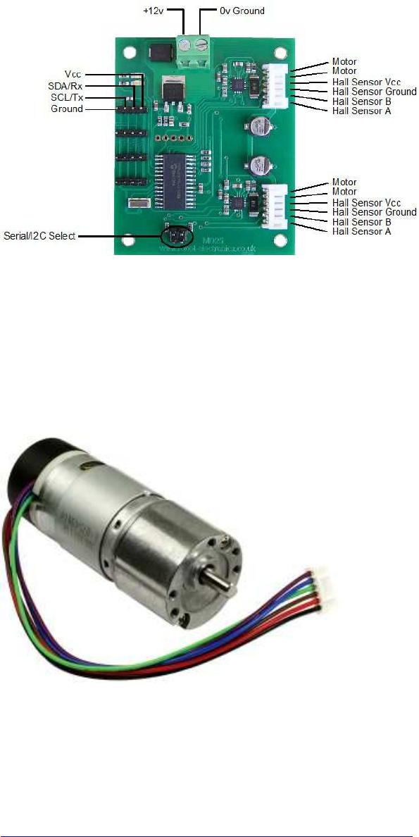
( I2C ) Board MD25 - Dual H Bridge Motor Drive :
(MD25 - Dual 12Volt 2.8Amp H Bridge Motor Drive, I2C Motortreiberplatine für
Encodermotoren)
[img]https://www.robot-electronics.co.uk/images/md25connection.jpg[/img]
https://www.robot-electronics.co.uk/htm/md25tech.htm
passende Encodermotoren :
EMG30 Getriebemotoren mit Encodern
[img]https://www.robot-electronics.co.uk/images/emg30.jpg[/img]
https://www.robot-electronics.co.uk/htm/emg30.htm
Bezugsquellen z.B.:
http://www.roboter-teile.de/Oxid/Motor-Servotreiber/DC-Motortreiber/Dual-Motortreiber-
MD25.html
http://www.exp-tech.de/emg30-getriebemotor-mit-drehgeber

Beispiel für die Ansteuerung
Quelle: http://www.robot-electronics.co.uk/htm/raspberry_pi_examples.htm
http://www.robot-electronics.co.uk/files/rpi_md25.c
//----------------------------------------------------------------------
// MD25 example c code for the Raspberry pi.
//
// Drives both motors untill an encoder count of over 0x2000
// is reached and stops the motors. Displays the current decoder value.
//
// By James Henderson, 2016
#include <stdio.h>
#include <stdlib.h>
#include <linux/I2C-dev.h>
#include <fcntl.h>
#include <string.h>
#include <sys/ioctl.h>
#include <sys/types.h>
#include <sys/stat.h>
#include <unistd.h>
long readEncoderValues(void); //
Reads encoder data for both motors and displays to the screen
void resetEncoders(void);
// Resets the encoders to 0
void driveMotors(void);
// Drive the motors forwards
void stopMotors(void);
// Stop the motors
int fd;
// File descrition
// For older raspberry pi modules use "/dev/I2C-0" instead of "/dev/I2C-1"
for the I2C port
char *fileName = "/dev/I2C-1";
// Name of the port we will be using
int address = 0x58;
// Address of MD25 shifted one bit
unsigned char buf[10];
// Buffer for data being read/ written on the I2C bus
int main(int argc, char **argv)
{
printf("**** MD25 test program ****\n");
if ((fd = open(fileName, O_RDWR)) < 0) { //
Open port for reading and writing
printf("Failed to open I2C port\n");
exit(1);
}
if (ioctl(fd, I2C_SLAVE, address) < 0) { //
Set the port options and set the address of the device we wish to speak to
printf("Unable to get bus access to talk to slave\n");
exit(1);
}
buf[0] = 13;
// This is the register we wish to read software version from
if ((write(fd, buf, 1)) != 1) {
// Send regiter to read software from from
printf("Error writing to I2C slave\n");
exit(1);
}
if (read(fd, buf, 1) != 1) {
// Read back data into buf[]
printf("Unable to read from slave\n");
exit(1);
}
else {
printf("Software version: %u\n", buf[0]);
}
resetEncoders();
// Reset the encoder values to 0
while(readEncoderValues() < 0x2000) {
// Check the value of encoder 1 and stop after it has traveled a set
distance
driveMotors();
usleep(200000);
// This sleep just gives us a bit of time to read what was printed to
the screen in driveMortors()
}
stopMotors();
return 0;
}
void resetEncoders(void) {
buf[0] = 16;
// Command register
buf[1] = 32;
// command to set decoders back to zero
if ((write(fd, buf, 2)) != 2) {
printf("Error writing to I2C slave\n");
exit(1);
}
}
long readEncoderValues (void) {
long encoder1, encoder2;
buf[0] = 2;
// register for start of encoder values
if ((write(fd, buf, 1)) != 1) {
printf("Error writing to I2C slave\n");
exit(1);
}
if (read(fd, buf, 8) != 8) {
// Read back 8 bytes for the encoder values into buf[]
printf("Unable to read from slave\n");
exit(1);
}
else {
encoder1 = (buf[0] <<24) + (buf[1] << 16) + (buf[2] << 8) +
buf[3]; // Put encoder values together
encoder2 = (buf[4] <<24) + (buf[5] << 16) + (buf[6] << 8) +
buf[7];
printf("Encoder 1: %08lX Encoder 2: %08lX\n",encoder1,
encoder2);
}
return encoder1;
}
void driveMotors(void){
buf[0] = 0;
// Register to set speed of motor 1
buf[1] = 200;
// speed to be set
if ((write(fd, buf, 2)) != 2) {
printf("Error writing to I2C slave\n");
exit(1);
}
buf[0] = 1;
// motor 2 speed
buf[1] = 200;
if ((write(fd, buf, 2)) != 2) {
printf("Error writing to I2C slave\n");
exit(1);
}
}
void stopMotors(void){
buf[0] = 0;
buf[1] = 128;
// A speed of 128 stops the motor
if ((write(fd, buf, 2)) != 2) {
printf("Error writing to I2C slave\n");
exit(1);
}
buf[0] = 1;
buf[1] = 128;
if ((write(fd, buf, 2)) != 2) {
printf("Error writing to I2C slave\n");
exit(1);
}
}
//----------------------------------------------------------------------

Adafruit DC and Stepper Motor HAT for Raspberry Pi
[img]https://cdn-
learn.adafruit.com/assets/assets/000/022/680/thumb160/raspberry_pi_adjust.jpg?1422308181[
/img]
https://learn.adafruit.com/adafruit-dc-and-stepper-motor-hat-for-raspberry-pi/installing-
software
nicht brauchbar und nicht empfehlenswert, da für C/C++ keine Libraries, kein
Treiber-Sourcecode und kein Support
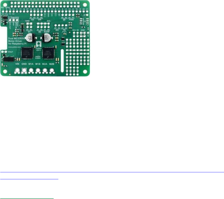
(dig. GPIO) : Pololu Dual MC33926 Motortreiber
[img]https://a.pololu-files.com/picture/0J6593.300.jpg[/img]
ein alternatives, sehr leistungsstarkes und kompaktes Motortreiber HAT mit einer etwas
anderen Pin-Belegung und Steuer-Logik:
http://www.ebay.de/itm/272182305548?_trksid=p2060353.m2749.l2649&ssPageName=STR
K%3AMEBIDX%3AIT
MC33926
http://www.ebay.de/itm/272182305548?_trksid=p2060353.m2749.l2649&ssPageName=STR
K%3AMEBIDX%3AIT
Default pin mappings
This table shows how the Raspberry Pi’s GPIO pins are used to interface with the motor
drivers:
-----------------------------------------------------------------------------------
RPi
GPIO Motor driver pin Description
-----------------------------------------------------------------------------------
5 Motor 1 SF Status flag output: When the driver is functioning
normally,
this pin should be pulled high by the Raspberry Pi.
In the event of a driver fault , the driver IC
drives SF low.
If either of the disable pins (D1 or D2) is
disabling the outputs,
SF will also be low.
6 Motor 2 SF dto.
-----------------------------------------------------------------------------------
12 Motor 1 PWM Motor speed input: A PWM (pulse-width modulation)
signal on this pin
corresponds to a PWM output on the corresponding
driver’s motor outputs.
When this pin is low, the motor brakes low.
When it is high, the motor is on.
The maximum allowed PWM frequency is 20 kHz.
13 Motor 2 PWM dto.
-----------------------------------------------------------------------------------
22 Motor 1 EN Enable input: This pin is internally pulled low,
putting the motor driver IC into a low-current
sleep mode
and disabling the motor outputs (setting them to
high impedance).
EN must be driven high to enable the motor driver.
23 Motor 2 EN dto.
-----------------------------------------------------------------------------------
24 Motor 1 DIR Motor direction input: When DIR is low, motor current
flows
from output A to output B;
when DIR is high, current flows from B to A.
25 Motor 2 DIR dto.
---------------------------------------------------------------------------
Simplified motor control truth table
This table shows how the drivers’ control inputs affect the motor outputs:
-----------------------------------------------------------------------------------
Inputs Outputs
-----------------------------------------------------------------------------------
EN DIR PWM MxA MxB operating mode
-----------------------------------------------------------------------------------
1 0 PWM PWM(H/L) L forward/brake at speed PWM %
1 1 PWM L PWM(H/L) reverse/brake at speed PWM %
1 X 0 L L brake low (outputs shorted to ground)
0 X X Z Z coast (outputs off)
-----------------------------------------------------------------------------------
----

Adafruit DC and Stepper Motor HAT for Raspberry Pi
https://learn.adafruit.com/adafruit-dc- ... g-software
nicht brauchbar und nicht empfehlenswert, da für C/C++ keine Libraries, kein Treiber-
Sourcecode und kein Support
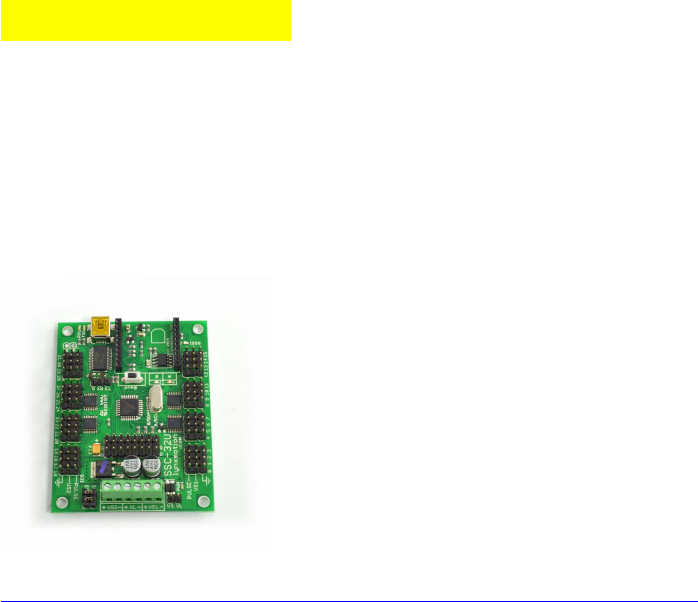
Servo-Steuerung
Servo-Steuerung direkt per GPIO-pwm : schwierig bis unmöglich, daher am besten per Servo-
Controller-Boards!
Servo-Controller-Board Lynxmotion SSC-32U
https://www.mybotshop.de/Lynxmotion-SSC-32U-Servocontrollerboard
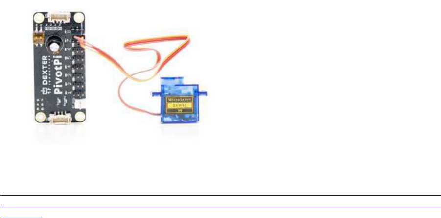
Servo-Controller PCA9685
z.B.:
PivotPi Servor Controller Board
Driver lib:
https://forum.dexterindustries.com/clicks/track?url=https%3A%2F%2Fgithub.co
m%2FDexterInd%2FPivotPi%2Ftree%2Fmaster%2FSoftware%2FC&post_id=20559&topic_
id=4351
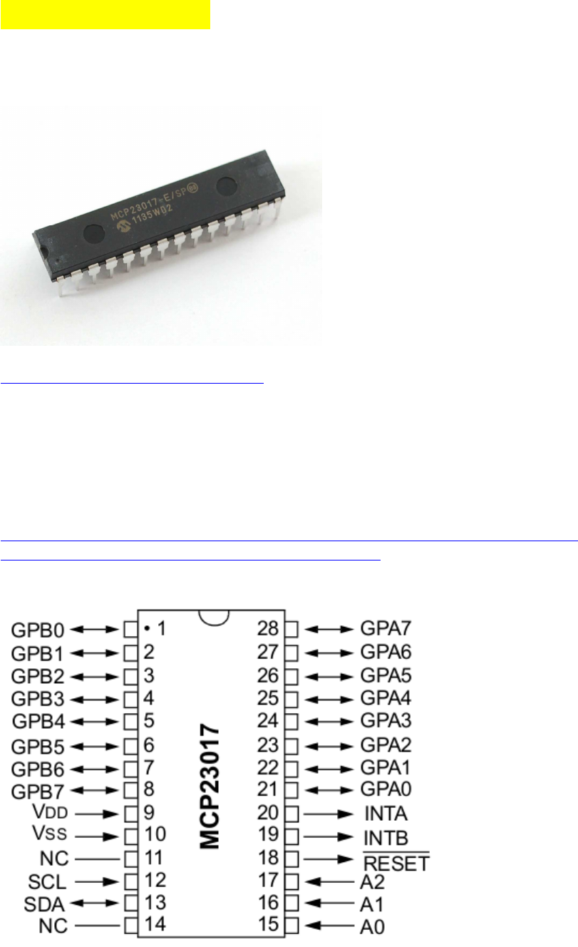
Port - Multiplexer
( I2C ) MCP23017 : 16x I/O-Multiplexer
https://www.adafruit.com/product/732
Der Baustein arbeitet bereits ab 1,8 V Versorgungsspannung einwandfrei, was für den RasPi
mit seinen 3.3V ideal ist,
außerdem unterstützt er Normal-, Fast- und High-speed I2C ( 100 kHz, 400 kHz, 1.7MHz).
Die Pins können bankweise (8er-Gruppen) in Output-oder Input-Modus gesetzt werden, im
Input-Modus können wahlweise zusätzlich interne Pullps zugeschaltet werden (Tasten dann
gegen Masse, d.h. LOW wenn gedrückt).
http://www.netzmafia.de/skripten/hardware/RasPi/Projekt-I2C-Expander/index.html
https://cdn-shop.adafruit.com/datasheets/mcp23017.pdf
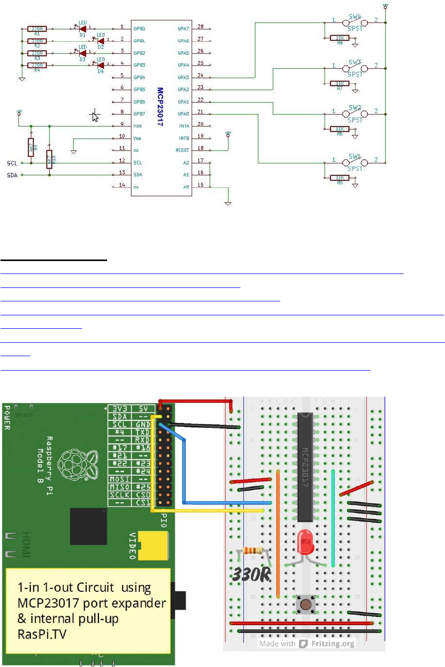
Programmier-Links:
http://www.netzmafia.de/skripten/hardware/RasPi/Projekt-I2C-Expander/index.html
http://wiringpi.com/examples/testing-wiringpi-v2/
http://wiringpi.com/extensions/I2C-mcp23008-mcp23017/
http://raspi.tv/2013/using-the-mcp23017-port-expander-with-wiringpi2-to-give-you-16-new-
gpio-ports-part-3
http://hertaville.com/interfacing-an-I2C-gpio-expander-mcp23017-to-the-raspberry-pi-using-
c.html
https://github.com/ve3wwg/raspberry_pi/blob/master/mcp23017/mcp23017.c

a) wiringPi Basis-Funktionen (Teststadium):
uint8_t data;
#define MCP23017_0_addr 0x20 // I2C base addr:
0x20...0x27 by A0-A2 low or high
// WiringPi I2C Setup: I2C-1, dev_addr=0x20
int fmcp23017_0= wiringPiI2CSetupInterface("/dev/I2C-1",
MCP23017_0_addr);
// init banks for read or write:
// SET I/O direction register 0x00 is bank A ( bank B == 0x01)
// set bank pins A or B 0x00 = output mode , 0xFF = input mode
+ internal pullups
wiringPiI2CWriteReg8 (fmcp23017_0, 0x00, 0x00); // bank A :=
init as output (0x00)
wiringPiI2CWriteReg8 (fmcp23017_0, 0x01, 0xff); // bank B :=
init as input_pullup (0xff)
// read data or write data to banks A or B:
// DATA register 0x12 = bank "A" ( bank "B" = 0x13)
wiringPiI2CWriteReg8 (fmcp23017_0, data, 0x12); // write data
to bank A register (0x12)
data = wiringPiI2CReadReg8 (fmcp23017_0, 0x13); // read bank B
data register (0x13)
b) Demo Code von Gordon Henderson:
http://wiringpi.com/extensions/i2c-mcp23008-mcp23017/
/*
* q2w.c:
* Using the Quick 2 wire board for its mcp23017
*
* Copyright (c) 2012-2013 Gordon Henderson. <projects@drogon.net>
***********************************************************************
*/
#include <stdio.h>
#include <wiringPi.h>
#include <mcp23017.h>
int main (void)
{
int i, bit ;
wiringPiSetup () ;
mcp23017Setup (100, 0x20) ;
printf ("Raspberry Pi - MCP23017 Test\n") ;

for (i = 0 ; i < 10 ; ++i)
pinMode (100 + i, OUTPUT) ;
pinMode (100 + 15, INPUT) ;
pullUpDnControl (100 + 15, PUD_UP) ;
for (;;)
{
for (i = 0 ; i < 1024 ; ++i)
{
for (bit = 0 ; bit < 10 ; ++bit)
digitalWrite (100 + bit, i & (1 << bit)) ;
delay (5) ;
while (digitalRead (100 + 15) == 0)
delay (1) ;
}
}
return 0 ;
}
//----------------------------------------------------------------------
WiringPi driver code ( „stress test“ ) :
http://wiringpi.com/examples/testing-wiringpi-v2/
c) Code ohne wiringPi:
http://www.netzmafia.de/skripten/hardware/RasPi/Projekt-I2C-Expander/index.html
expander_lib.h
//------------------------------------------------------------------
----
#ifndef _EXPANDERLIB_H_
#define _EXPANDERLIB_H_
/* Richtungsregister von Port A und Port B */
#define IODIRA 0x00
#define IODIRB 0x01
/* Datenregister Port A und Port B */
#define GPIOA 0x12
#define GPIOB 0x13
/* Register um Logik-Polaritaet umzustellen */
#define IPOLA 0x02
#define IPOLB 0x03
/* Interne Pull-Up-Widerstände einschalten */
#define GPPUA 0x0C
#define GPPUB 0x0D
/* Pins am Port */
#define P1 0x01
#define P2 0x02
#define P3 0x04
#define P4 0x08
#define P5 0x10
#define P6 0x20
#define P7 0x40
#define P8 0x80
/* Struktur fuer den Expander-Datentyp */
struct expander
{
int address; /* I2C-Bus-Adresse des Bausteines */
int directionA; /* Datenrichtung Port A */
int directionB; /* Datenrichtung Port B */
char* I2CBus; /* I2C-Device ("/dev/I2C-1" für Bus 1) */
};
/* Expander-Datentyp */
typedef struct expander mcp23017;
/* Init des Expanders; gibt den Expander zurück
* address: I2C-Busadresse des Bausteines (I2Cdetect -y 1)
* directionA/B: Richtungen der Ports
* I2CBus: Pfad zum I2CBus ("/dev/I2C-1" für Bus 1)
*/
mcp23017 init_mcp23017(int address, int directionA, int directionB,
char* I2CBus);
/* Datenrichtung der Ports festlegen
* richtungsregister: muss "IODIRA" oder "IODIRB" sein!
* value: Zuordnung der Bits (Input: 1, Output: 0)
* Bei den Eingangspins wird der Pullup-Widerstand eingeschaltet und
die Logik umgekehrt
*/
void setdir_mcp23017(mcp23017 expander, int richtungsregister, int
value);
/* Oeffnet den Bus und gibt Filedescriptor zurueck
* (write_mcp23017 und read_mcp23017 übernehmen das selbst)
*/
int open_mcp23017(mcp23017 expander);
/* Schreibt in ein Register des Expanders
* reg: Register in das geschrieben werden soll
* value: Byte das geschrieben werden soll
*/
void write_mcp23017(mcp23017 expander, int reg, int value);
/* Liest Register des Expanders
* reg: Register, das ausgelesen wird;
* gibt ausgelesenen Registerwert zurück
*/
int read_mcp23017(mcp23017 expander, int reg);
#endif /* EXPANDERLIB_H */
//------------------------------------------------------------------
----
expander_lib.c
//------------------------------------------------------------------
----
#include <unistd.h>
#include <stdio.h>
#include <stdlib.h>
#include <linux/I2C-dev.h>
#include <sys/ioctl.h>
#include <sys/types.h>
#include <sys/stat.h>
#include <fcntl.h>
#include "expander_lib.h"
/* defined in <linux/I2C-dev.h>
#define I2C_SLAVE 0x703 */
/* Init des Expanders; gibt den Expander zurück
* address: I2C-Busadresse des Bausteines (I2Cdetect -y 1)
* directionA/B: Richtungen der Ports
* I2CBus: Pfad zum I2CBus ("/dev/I2C-1" für Bus 1)
*/
mcp23017 init_mcp23017(int address, int directionA, int directionB,
char* I2CBus)
{
int fd; /* Filehandle */
mcp23017 expander; /* Rueckgabedaten */
/* Structure mit Daten fuellen */
expander.address = address;
expander.directionA = directionA;
expander.directionB = directionB;
expander.I2CBus = I2CBus;
// Port-Richtung (Eingabe/Ausgabe) setzen
fd = open_mcp23017(expander);
setdir_mcp23017(expander, IODIRA, expander.directionA);
setdir_mcp23017(expander, IODIRB, expander.directionB);
close(fd);
return expander;
}
/* Datenrichtung der Ports festlegen
* richtungsregister: muss "IODIRA" oder "IODIRB" sein!
* value: Zuordnung der Bits (Input: 1, Output: 0)
* Bei den Eingangspins wird der Pullup-Widerstand eingeschaltet und
die Logik umgekehrt
*/
void setdir_mcp23017(mcp23017 expander, int richtungsregister, int
value)
{
if(richtungsregister == IODIRA)
{
/* Datenrichtung schreiben */
write_mcp23017(expander, IODIRA, value);
/* Pull-Up-Widerstaende einschalten Port A */
write_mcp23017(expander, GPPUA, value);
/* Logik umkehren */
write_mcp23017(expander, IPOLA, value);
}
else if(richtungsregister == IODIRB)
{
/* Datenrichtung schreiben */
write_mcp23017(expander, IODIRB, value);
/* Pull-Up-Widerstaende einschalten Port B */
write_mcp23017(expander, GPPUB, value);
/*Logik umkehren */
write_mcp23017(expander, IPOLB, value);
}
else
{
printf("Richtungsregister falsch!\n");
exit(1);
}
}
/* Oeffnet den Bus und gibt Filedescriptor zurueck
* (write_mcp23017 und read_mcp23017 übernehmen das selbst)
*/
int open_mcp23017(mcp23017 expander)
{
int fd;
if ((fd = open(expander.I2CBus, O_RDWR)) < 0)
{
printf("Failed to open the I2C bus\n");
exit(1);
}
/* Spezifizieren der Adresse des slave device */
if (ioctl(fd, I2C_SLAVE, expander.address) < 0)
{
printf("Failed to acquire bus access and/or talk to slave\n");
exit(1);
}
return fd;
}
/* Schreibt in ein Register des Expanders
* reg: Register in das geschrieben werden soll
* value: Byte das geschrieben werden soll
*/
void write_mcp23017(mcp23017 expander, int reg, int value)
{
int fd;
fd = open_mcp23017(expander);
if(I2C_smbus_write_byte_data(fd,reg,value) < 0)
{
printf("Failed to write to the I2C bus\n");
exit(1);
}
close(fd);
}
/* Liest Register des Expanders
* reg: Register, das ausgelesen wird;
* gibt ausgelesenen Registerwert zurück
*/
int read_mcp23017(mcp23017 expander, int reg)
{
int value,fd;
fd = open_mcp23017(expander);
if((value = I2C_smbus_read_byte_data(fd, reg)) < 0)
{
printf("Failed to read from the I2C bus\n");
close(fd);
exit(1);
return 0;
}
else
{
close(fd);
return value;
}
}
//------------------------------------------------------------------
----
Beispiel: Lauflicht
//------------------------------------------------------------------
----
#include <stdio.h>
#include <stdlib.h>
#include <unistd.h>
#include "expander_lib.h"
int main(int argc, char *argv[])
{
mcp23017 expander; /* Verwaltungs-Structure */
int data = 0x01; /* Ausgabewert */
int down = 0; /* Richtungsangabe */
expander = init_mcp23017(0x20,0,0,"/dev/I2C-1");
while(1)
{
/* beide Ports identisch "bedienen" */
write_mcp23017(expander,GPIOA,data);
write_mcp23017(expander,GPIOB,data);
if (data == 0x80) /* ganz links - umdrehen */
down = 1;
if (data == 0x01) /* ganz rechts - umdrehen */
down = 0;
if (down)
data = data >> 1;
else
data = data << 1;
usleep(100000); /* 100 ms Pause */
}
return 0;
}
//------------------------------------------------------------------
----

( SPI ) MCP23S17 : 16x I/O-Multiplexer
für den MCP23017 gibt es auch diese SPI Ausführung, per WiringPi ähnlich
simpel zu programmieren wie die I2C Variante
http://wiringpi.com/extensions/spi-mcp23s08-mcp23s17/
In mcp23s17Setup(), there are 3 parameters: pinBase, spiPort and devId.
The pinBase is the new pin number of the first pin of the device - any number >= 64 that you
like.
The spiPort is the CE line - 0 or 1
The devId is the devuce sub-address 0 through 7.
So if you have 2 mcp23s17's on the same SPI bus, then you initialise the first one with
mcp23s17Setup (base1, 0, 0);
and the second with
mcp23s17Setup (base2, 1, 0);
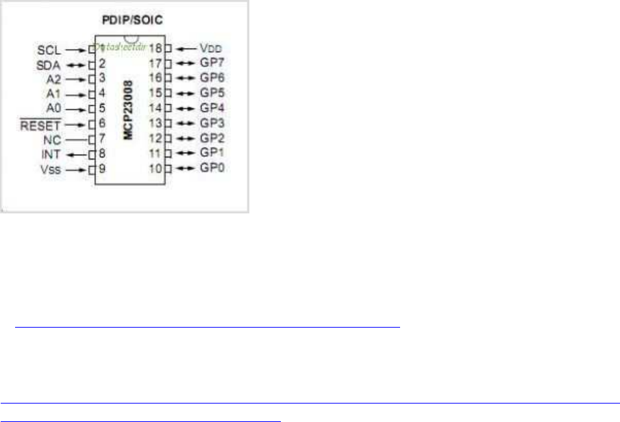
( I2C ) MCP23008 : 8x I/O Multiplexer
a) mit wiring Pi:
s. http://wiringpi.com/extensions/I2C-mcp23008-mcp23017/
Zitat Gordon Henderson
https://www.raspberrypi.org/forums/viewtopic.php?f=33&t=54366&p=1234104&sid=21346a
6cb02bfb0b70e078a168cb061a#p1234104
:
If this work at the command-line level:
gpio -xmcp3004:777:0 aread 777
then this will work in code:
mcp3004Setup (777, 0) ;
value = analogRead (777 + 0) ; // Reads channel 0
value2 = analogRead (777+7) ; // Reads channel 7
b) per I2C-dev.h, ohne wiringPi:
Schema zum Lesen von x Bytes vom Register y eines I2C Gerätes.
1) 1 Byte schreiben mit dem Wert y an das Gerät (file handle).
2) Lesen von x Bytes vom Gerät.
//----------------------------------------------------------------------
int fd = open("/dev/I2C-1", O_RDWR);
int result = ioctl(fd, I2C_SLAVE, ADDR); // I2C_SLAVE: macro in I2C-
dev.h; ADDR = device address
unsigned char buffer[x]; // x = buffer size
buf[0] = regaddr;
write(fd, buf, 1);
c = read(fd, buf, x);
if (c == x)
{
/* good read */
}
//----------------------------------------------------------------------
für MCP23008 read 2 bytes (input registers):
write 1 Byte 0x09 to device (data address)
read 2 bytes (from data-address 0x09)
should get a value of 0xF0 with no inputs
Code:
//----------------------------------------------------------------------
#include <linux/I2C-dev.h>
#include <stdio.h>
#include <stdlib.h>
#include <fcntl.h>
#include <unistd.h>
#include <stdint.h>
#include <errno.h>
#include <string.h>
#define ADDR 0x20
#define IODIR 0x00
#define GPINTEN 0x02
#define DEFVAL 0x03
#define INTCON 0x04
#define IOCON 0x05
#define GPPU 0x06
#define INTCAP 0x08
#define GPIOA 0x09
#define a(...) (unsigned char[])__VA_ARGS__
int i, fd, result;
unsigned char buffer[60]={0};
unsigned char data;
int MCPinit(){
printf("start\n");
fd = open("/dev/I2C-1", O_RDWR);
if (fd < 0) fprintf(stderr," Error Opening Device!\n");
result = ioctl(fd, I2C_SLAVE, ADDR);
if (result < 0) fprintf(stderr," Error bus access!\n");
write(fd, a({GPIOA,0xF0}), 2);
write(fd, a({IODIR,0xF0}), 2);
write(fd, a({INTCON,0xF0}), 2);
write(fd, a({DEFVAL,0xF0}), 2);
write(fd, a({GPINTEN,0xF0}), 2);
write(fd, a({GPPU,0xF0}), 2);
}
int main(){
MCPinit();
while(1){
buffer[0] = 0x09;
write(fd,buffer,1);
result = read(fd, buffer, 2);
if (result = 2){
printf("Data read: %d %d \n", buffer[0], buffer[1] );
}
}
return 0;
}
//----------------------------------------------------------------------

( I2C ) PCF8591: 4x ADC + 1x DAC
http://we.easyelectronics.ru/AVR/easy_i2c-avr-asm-praktikum-pcf8591-ds1307.html
Resolution: 10 bit
Der IC arbeitet bei 2,5-6,0V, ist also auch für ARM cpus geeignet; max Bustakt ist 100kHz.
https://www.mikrocontroller.net/part/PCF8591
driver source code:
Potentiometer als analoge Inputs steuern LED Helligkeit (analoger output) simultan:
http://wiringpi.com/examples/quick2wire-and-wiringpi/the-analog-interface-board/
Code: Alles auswählen
//----------------------------------------------------------------------
/*
* bright.c:
* Vary the Q2W LED brightness with the analog card
*
* Copyright (c) 2012-2013 Gordon Henderson. <projects@drogon.net>
***********************************************************************
*/
#include <stdio.h>
#include <wiringPi.h>
#include <pcf8591.h>
#define LED 1
#define Q2W_ABASE 120
int main (void)
{
int value ;
// Enable the on-goard GPIO
wiringPiSetup () ;
// Add in the pcf8591 on the q2w board
pcf8591Setup (Q2W_ABASE, 0x48) ;
printf ("Raspberry Pi - Quick2Wire Analog Test\n") ;
// Setup the LED
pinMode (LED, PWM_OUTPUT) ;
pwmWrite (LED, 0) ;
for (;;) {
value = analogRead (Q2W_ABASE + 0) ;
pwmWrite (LED, value * 4) ;
delay (5) ;
}
return 0 ;
}
//----------------------------------------------------------------------
( SPI ) MCP3008 : 8x ADC
#include <wiringPi.h>
#include <mcp3004.h>
#include <stdio.h>
#include <stdlib.h>
#define SPI_CHAN 0
#define MY_PIN 12345
int main(void)
{
int x[8],i;
float v[8];
float k = 3.3/1024;
wiringPiSetup() ;
mcp3004Setup (MY_PIN, SPI_CHAN); // 3004 and 3008 are the same 4/8
channels
for (i=0;i<8;i++)
{
x[i] = analogRead (MY_PIN + i ) ;
v[i] = k * (float)(x[i]);
}
printf("AD ch: = %4d %4d %4d %4d %4d %4d %4d %4d \n",
x[0],x[1],x[2],x[3],x[4],x[5],x[6],x[7]);
printf("AD vd: = %2.2f %2.2f %2.2f %2.2f %2.2f %2.2f %2.2f
%2.2f\n",
v[0],v[1],v[2],v[3],v[4],v[5],v[6],v[7]);
return 0;
}
+-----+-----+---------+------+---+---Pi 3---+---+------+---------+-----+-----+
| BCM | wPi | Name | MCP | V | Physical | V | MCP | Name | wPi | BCM |
+-----+-----+---------+------+---+----++----+---+------+---------+-----+-----+
| 10 | 12 | MOSI | 11 | 0 | 19 || 20 | | | 0v | | |
| 9 | 13 | MISO | 12 | 0 | 21 || 22 | 1 | | GPIO. 6 | 6 | 25 |
| 11 | 14 | SCLK | 13 | 0 | 23 || 24 | 1 | 10 | CE0 | 10 | 8 |
+-----+-----+---------+------+---+---Pi 3---+---+------+---------+-----+-----+
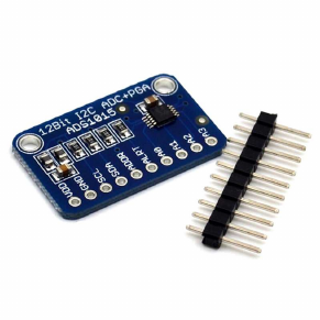
( I2C ) ADS1115 4xADC 16-bit
Preis: ca. 3 EUR (Ebay)
driver in wiringPi:
#include <ads1115.h>
#define MY_BASE 200 // BASE frei wählbar für versch. i2c Geräte
...
ads1115Setup (MY_BASE, 0x48) ;
int ch0 = analogRead (MY_BASE + 0) ;
int ch3 = analogRead (MY_BASE + 3) ;
// and so on
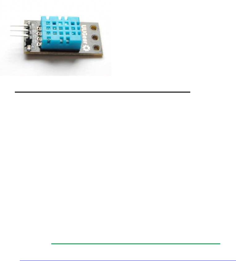
weitere Sensoren
( 1-wire ) DHT11 Humidity & Temperature Sensor Module:
Lit.: http://www.uugear.com/portfolio/dht11-h ... or-module/
Preis: ab 1 EUR (z.B. Ebay)
Power Supply: 3.3~5.5V DC
Output: 4 pin single row
Measurement Range: Humidity 20-90%RH, Temperature 0~50℃
Accuracy: Humidity +-5%RH, Temperature +-2℃
Resolution: Humidity 1%RH, Temperature 1℃
Interchangeability: Fully Interchange
Anschluss-Schema:
Raspberry Pi ——————– DHT11 Module
3.3v P1 —————————– VCC (V)
GND P6 —————————- GND (G)
GPIO4 P7 ————————– DATA (S)
Test-Code (nach http://www.uugear.com/portfolio/dht11-h ... or-module/)
Code: http://www.mindstormsforum.de/viewtopic.php?f=78&t=8689&start=45
//----------------------------------------------------------------------
/*
* dht11.c:
* Simple test program to test the wiringPi functions
* DHT11 test
*/
#include <wiringPi.h>
#include <stdio.h>
#include <stdlib.h>
#include <stdint.h>
#define MAXTIMINGS 85
#define DHTPIN 7
int dht11_dat[5] = { 0, 0, 0, 0, 0 };
void read_dht11_dat()
{
uint8_t laststate = HIGH;
uint8_t counter = 0;
uint8_t j = 0, i;
float f; /* fahrenheit */
dht11_dat[0] = dht11_dat[1] = dht11_dat[2] = dht11_dat[3] = dht11_dat[4]
= 0;
/* pull pin down for 18 milliseconds */
pinMode( DHTPIN, OUTPUT );
digitalWrite( DHTPIN, LOW );
delay( 18 );
/* then pull it up for 40 microseconds */
digitalWrite( DHTPIN, HIGH );
delayMicroseconds( 40 );
/* prepare to read the pin */
pinMode( DHTPIN, INPUT );
/* detect change and read data */
for ( i = 0; i < MAXTIMINGS; i++ )
{
counter = 0;
while ( digitalRead( DHTPIN ) == laststate )
{
counter++;
delayMicroseconds( 1 );
if ( counter == 255 )
{
break;
}
}
laststate = digitalRead( DHTPIN );
if ( counter == 255 )
break;
/* ignore first 3 transitions */
if ( (i >= 4) && (i % 2 == 0) )
{
/* shove each bit into the storage bytes */
dht11_dat[j / 8] <<= 1;
if ( counter > 16 )
dht11_dat[j / 8] |= 1;
j++;
}
}
/*
* check we read 40 bits (8bit x 5 ) + verify checksum in the last byte
* print it out if data is good
*/
if ( (j >= 40) &&
(dht11_dat[4] == ( (dht11_dat[0] + dht11_dat[1] + dht11_dat[2] +
dht11_dat[3]) & 0xFF) ) )
{
f = dht11_dat[2] * 9. / 5. + 32;
printf( "Humidity = %d.%d %% Temperature = %d.%d *C (%.1f *F)\n",
dht11_dat[0], dht11_dat[1], dht11_dat[2], dht11_dat[3], f );
}else {
printf( "Data not good, skip\n" );
}
}
int main( void )
{
printf( "Raspberry Pi wiringPi DHT11 Temperature test program\n" );
if ( wiringPiSetup() == -1 )
exit( 1 );
while ( 1 )
{
read_dht11_dat();
delay( 1000 ); /* wait 1sec to refresh */
}
return(0);
}
//----------------------------------------------------------------------

Multithreading / Multitasking (C/C++, POSIX pthread)
a) Links:
[ A ] pthread
http://pc2.uni-
paderborn.de/fileadmin/pc2/media/staffweb/Jens_Simon/Courses/WS08_APR/ParalleleProgra
mmierung.pdf
http://www.ijon.de/comp/tutorials/threads/index.html
http://www.ijon.de/comp/tutorials/threads/synchro.html
http://randu.org/tutorials/threads/
[ B ] wiringPi simplified Posix threads interface
http://wiringpi.com/reference/priority-interrupts-and-threads/
b) prinzipielle Benutzung von pthread
//----------------------------------------------------------------------
#include <stdio.h>
#include <unistd.h>
#include <pthread.h>
//...
void* thread1Name(void *) {
while(1) { // or while another statement is true
///... (code/loop)
usleep(100000); // adjust loop speed
}
return NULL;
}
void* thread2Name(void *) {
while(1) { // or while another statement is true
///... (code/loop)
usleep(10000); // adjust loop speed
}
return NULL;
}
void* thread3Name(void *) {
while(1) { // or while another statement is true
///... (code/loop)
usleep(1000); // adjust loop speed
}
return NULL;
}
int main() {
//create the threads
pthread_t thread1ID, thread2ID, thread3ID;
pthread_create(&thread1ID, NULL, thread1Name, NULL);
pthread_create(&thread2ID, NULL, thread2Name, NULL);
pthread_create(&thread3ID, NULL, thread3Name, NULL);
//wait for threads to join before exit
pthread_join(thread1ID, NULL);
pthread_join(thread2ID, NULL);
pthread_join(thread3ID, NULL);
return 0;
}
// compile/build with -pthread
//----------------------------------------------------------------------
c) Code example für pthread:
//----------------------------------------------------------------------
#include <stdio.h>
#include <pthread.h>
#include <wiringPi.h>
typedef struct {
int start;
int end;
int step;
}data;
int isPrime(long int number) {
long int i;
for(i=2; i<number; i++)
{
if(number % i == 0)
{
//not a prime
return 0;
}
}
return number;
}
int calcPrimes(int start, int stop, int step) {
int c=0;
long int s;
for(s=start; s<=stop; s+=step)
{
if (isPrime(s) > 0) { c++; }
}
return c;
}
void* thread0Name(void *) {
int c;
c=calcPrimes(3, 100000, 8); //stepping 8 numbers for 4 cores
printf("thread1 found %d primes.\n",c);
return NULL;
}
void* thread1Name(void *) {
int c;
c=calcPrimes(5, 100000, 8); //starting thread 2 at the next odd
//number jumping 8 spaces for 4 cores
printf("thread2 found %d primes.\n",c);
return NULL;
}
void* thread2Name(void *) {
int c;
c=calcPrimes(7, 100000, 8); //starting thread 2 at the next odd
//number and jumping 8 spaces
printf("thread3 found %d primes.\n",c);
return NULL;
}
void* thread3Name(void *) {
int c;
c=calcPrimes(9, 100000, 8); // think you get it.
printf("thread4 found %d primes.\n",c);
return NULL;
}
int main() {
unsigned long timerms;
printf("Calculate Prime Numbers\n");
printf("==================================================\n\n");
timerms=millis();
//create the threads
pthread_t thread0ID;
pthread_create(&thread0ID, NULL, thread0Name, NULL);
pthread_t thread1ID;
pthread_create(&thread1ID, NULL, thread1Name, NULL);
pthread_t thread2ID;
pthread_create(&thread2ID, NULL, thread2Name, NULL);
pthread_t thread3ID;
pthread_create(&thread3ID, NULL, thread3Name, NULL);
//wait for threads to join before exiting
pthread_join(thread0ID, NULL);
pthread_join(thread1ID, NULL);
pthread_join(thread2ID, NULL);
pthread_join(thread3ID, NULL);
timerms=millis()-timerms;
printf("runtime= %ld", timerms);
return 0;
}
//----------------------------------------------------------------------

compilieren mit den oben genannten Geany-Settings für Compile und Build
d) ergänzende hilfreiche Befehle:
Thread - Rückgabewerte:
statt NULL kann man auch eigene Rückgabewerte von Threads an die aufrufende Funktion
beim Verlassen zurückliefern.
Will man dazu einen int-Wert verwenden, würde die Thread-Funktion z.B. so aussehen
können:
void* threadName2(void *) {
int RETVAL = 0;
// hier steht der Code für den Thread
return (void*)RETVAL; // variabler Rückgabewert
}
die retvals kann man dann anschließend in pthread_join() abfragen und auswerten:
void *retval0, *retval1, *retval2;
pthread_join( threadID0, &retval0 );
pthread_join( threadID1, &retval1 );
pthread_join( threadID2, &retval2 );
// DEBUG
printf("\nretval0 = %d \n", (int)retval0);
printf("\nretval1 = %d \n", (int)retval1);
printf("\nretval2 = %d \n", (int)retval2);
Thread- Priorität:
http://man7.org/linux/man-pages/man7/sched.7.html
rurwin hat geschrieben:SCHED_FIFO allows the task to run as long as it
wants to unless a higher priority task wants to run, even if there are other tasks
with the same priority. SCHED_RR only allows it to run for a certain period
before being preempted by task with the same priority. Most of the proceses
running under Linux use SCHED_OTHER, which allows the task to be
preempted by lower priority tasks in order to allow every task at least some
time to run.
struct sched_param param;
param.sched_priority = 50;
pthread_setschedparam(thread1ID, SCHED_RR, ¶m);

// altern.: SCHED_FIFO
weitere Links zu pthread_setschedprio: http://pubs.opengroup.org/onlinepubs/00 ... dprio.html
Thread vorzeitig abbrechen:
int pthread_cancel(pthread_t threadID);
Dieser Befehl schickt (nur) eine Art "Abbruch-Anfrage" an den anderen Thread, keinen
zwangsweise sofortigen Kill-Befehl; wann dieser andere Thread darauf reagiert, kann nicht
vorrausgesagt werden.
Will man dort im anderen Thread (gerade bei langen Kalkulationen etc.) "bevorzugte
Abbruchstellen" oder quasi "Sollbruchstellen" definieren, kann man es dort mithilfe des
Befehles
pthread_testcancel()
bewerkstelligen.
Im Falle eines Abbruchs durch pthread_cancel() wird der dortige Thread mit dem Exit-Code
PTHREAD_CANCELED verlassen, der einen Pointer auf eine Variable setzt, und die als int
gecastet dem Wert -1 entspricht (siehe pthread Exit-Codes wie oben unter "Thread -
Rückgabewerte:" erklärt), d.h. nach
void *retval1;
pthread_cancel(threadID1);
pthread_join( threadID1, &retval1 );
// DEBUG
printf("\nretval1 = %d \n", (int)retval1);
gibt dann der print-Befehl für (int)retval1 den Wert -1 aus.

Mutexe (aus wiringPi lib) :
http://wiringpi.com/reference/priority-interrupts-and-threads/
piLock (int keyNum) ;
piUnlock (int keyNum) ;
Zitat Gordon Henderson:
“These allow you to synchronise variable updates from your main program to
any threads running in your program. keyNum is a number from 0 to 3 and
represents a “key”. When another process tries to lock the same key, it will be
stalled until the first process has unlocked the same key.”
Mutexe (aus original POSIX pthread lib) :
pthread_mutex_t mutexBP; // arbitrary mutex variable
pthread_mutex_init (&mutexBP, NULL); // init a mutex
pthread_mutex_lock (&mutexBP); // lock the following operations
pthread_mutex_unlock (&mutexBP); // release the mutex to write/read
// by different threads

SD-Card und USB-Laufwerke: (C/C++) Dateien
schreiben und lesen
Da das Filesystem von Linux bereits gemounted ist, kann man direkt die stdio.h Befehle
verwenden
(fopen(), fclose(), fwrite(), fprintf(), fgetc(), fscanf(),..)
mit den entsprechenden Dateinamen inkl. SD- bzw. HD-Dateipfaden:
//----------------------------------------------------------------------
#include <stdio.h>
#include <stdint.h>
#include <string.h>
int main ()
{
FILE * fp;
char myFilename[100];
int c;
strcpy(myFilename, "/home/pi/mytextfile.txt");
printf("\n\n open file and write string, then close file: \n\n");
uint8_t text[] = "Mary had a little lamb";
fp = fopen( myFilename , "w" );
fwrite(text, sizeof(uint8_t), sizeof(text), fp );
fclose(fp);
printf("\n\n open file, read, output to stdout, then close file:
\n\n");
fp = fopen( myFilename, "r" );
if (fp) {
do {
c = fgetc( fp );
if( c != EOF ) putchar( (char)c );
} while (c != EOF);
fclose(fp);
}
return(0);
}
//----------------------------------------------------------------------
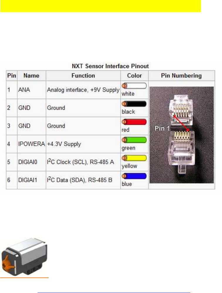
Lego Sensoren anschließen (Baustelle):
Pin-Belegung für die Verwendung von Lego Mindstorms RJ11-Steckern:
Encoder auf pins 5+6 (gelb + blau)
Lego Berührungs-/ Touch Sensor (ADC):
Lit: s.a. http://www.dexterindustries.com/howto/l ... pberry-pi/
pins 2+3 verbinden, dann --> 1kOhm --> GND
pin 4 --> +3,3V
pin 1 --> GPIO (z.B. GPIO pin BCM_18 )
kurzes Testprogramm in Python:
# ----------------------------------------------------------------------
import time
import RPi.GPIO as GPIO
GPIO.setmode(GPIO.BCM)
GPIO.setwarnings(False)
button = 18
GPIO.setup(button, GPIO.IN, GPIO.PUD_UP)
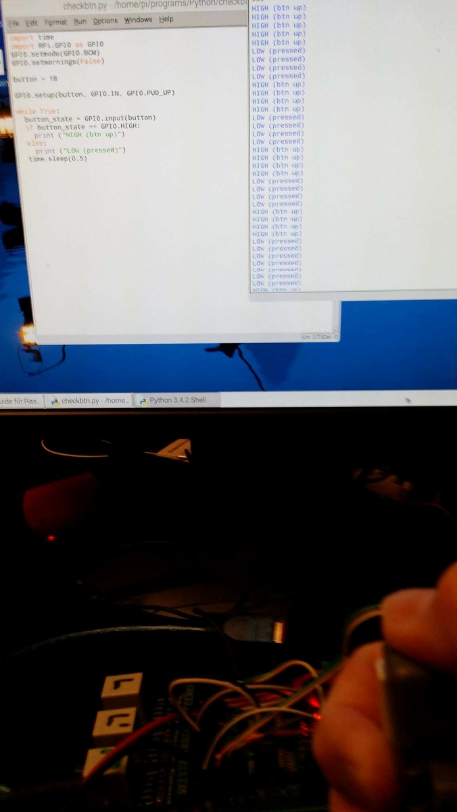
while True:
button_state = GPIO.input(button)
if button_state == GPIO.HIGH:
print ("HIGH")
else:
print ("LOW")
time.sleep(0.5)
# ----------------------------------------------------------------------
Bei gedücktem Touch-Btn zeigt das Programm "LOW", ansonsten "HIGH". Funktioniert
nicht mit EV3 Touch Sensoren!
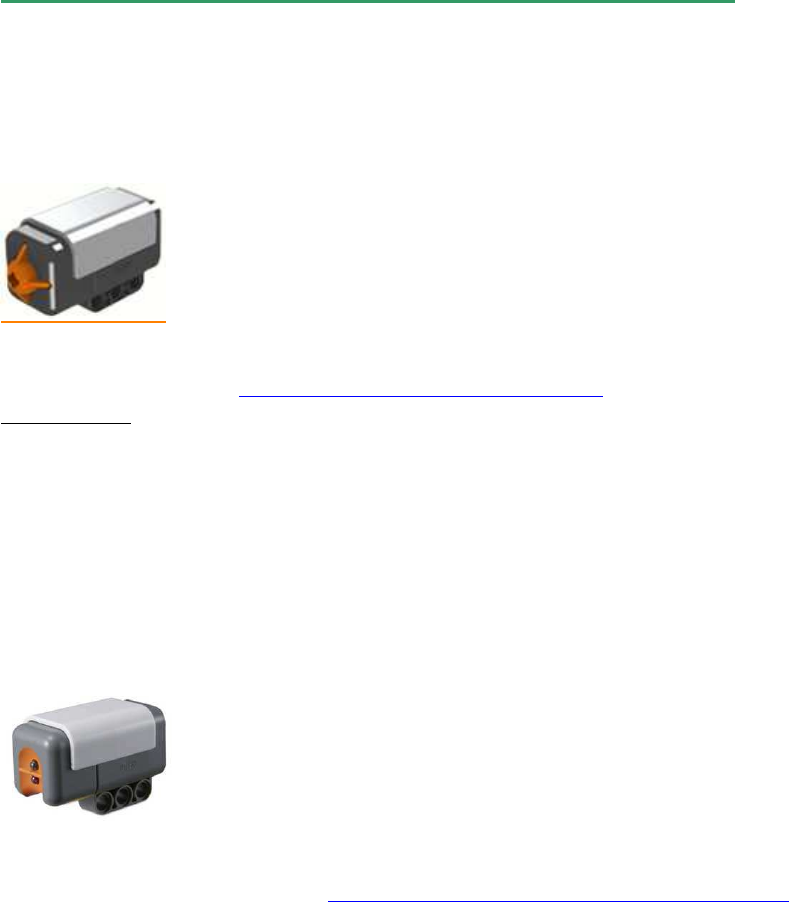
Lego Licht / Light Sensor (ADC):
Der Raspi hat keinen Analog-Eingang (ADC), daher Anschluss über das Arduino Muxer
board oder einen PCF8591! (s.u.!)
Lego-Sensoren am Arduino Multiplexer-Board:
Lego Berührungs-/ Touch Sensor (ADC):
Code für Arduino siehe: viewtopic.php?f=70&t=8624#p67346
Verkabelung:
pins 2+3 verbinden, dann --> 1kOhm --> GND
pin 4 --> +3,3V
pin 1 --> digitaler Arduino-PIN
Lego Licht / Light Sensor (ADC):
Code für Arduino siehe / refer to: viewtopic.php?f=78&t=8491&start=15#p67546
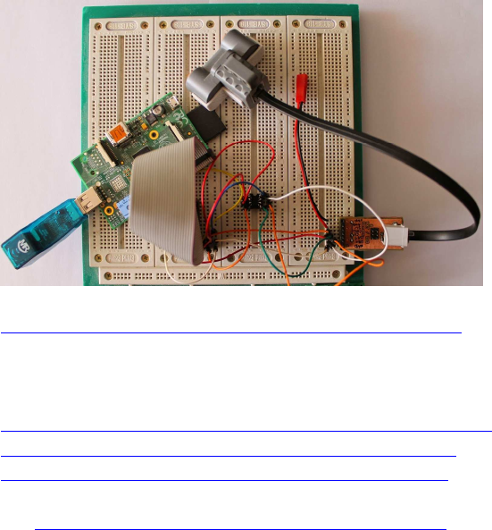
Lego Ultraschall / Ultrasonic Sensor (I2C):
http://stefanshacks.blogspot.de/2015/03 ... xt_84.html
(per modifiziertem I2C Protokoll, ist auch an Raspi nutzbar, wenn dieser per UART mit dem
Arduino verbunden ist.
http://www.thecompblog.com/2012/08/hack ... art-3.html
http://blog.tkjelectronics.dk/2011/10/nxt-shield-ver2/
http://blog.tkjelectronics.dk/wp-conten ... otocol.pdf
s.a. viewtopic.php?f=78&t=8491&start=15#p67546 )
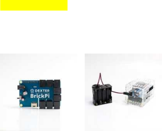
BrickPi3 Shield
auf meine Anfrage hin hat Dexter Industries für deren BrickPi3 jetzt auch begonnen, die
ersten C/C++ API libs zur Verfügung zu stellen und außerdem auch die Firmware der
BrickPi3 Shields zu überarbeiten, sodass sie jetzt "stackable = stapelbar" sind, d.h., man kann
mehrere davon aufeinanderstecken und hat dann ein Vielfaches der jew. IOs.
Man kann je Shield je 4 Lego-Sensoren (NXT, EV3) und 4 Lego-Motoren anschließen, z.B.
die NXT Ultraschall- und die EV3 IR-Sensoren, sie lassen sich mit einfacher C/C++ Syntax
programmieren (nicht ganz so einfach wie NXC, aber annähernd), und wenn man Geany als
IDE direkt auf dem Raspi verwendet, muss man sich auch nicht mit ssh und puTTY oder mit
Crosscompilern wie Eclipse rumschlagen:
Einfach HDMI Bildschirm an den Pi anschließen (5", 7", 10", 15", 24", was man grade halt da
hat, ggf. auch Touchscreens, es skaliert sich automatisch) und eine Maus und ein keyboard
(auch wireless), und man kann sofort loslegen.
BrickPi3 ist per SPI über die GPIO Steckerleiste mit dem Pi verbunden, ist stapelbar (ich
meine mich zu erinnern: mindestens 8 Stück) und man hat so ohne weiteres 32 Lego-Sensoren
und 32 Lego-Motoren zum Ansteuern (ggf sogar mehr), und das mit 1 einzigen Raspi.
Außerdem hat jedes Shield je 1 Grove Stecker für I2C-Sensoren, von denen man über 100
Stück einfach zusätzlich aneinanderhängen kann (wie bei I2C üblich).
Daneben sind die Raspi I2C- und UART ports und die meisten normalen digitalen GPIOS
unbenutzt und weiter frei verfügbar, und man kann also jede Menge Raspi-Standard-Sensoren
(Taster, Multiplexer, I2C-Sensoren etc.pp.) wie bei einem ganz normalen Raspi zusätzlich
weiter verwenden, es können sogar noch weitere Bus-Ports wie 1-Wire, USB, und sogar der
versteckte I2C-0 Bus genutzt werden.
Für Python-Fans etc. sind Raspi und BrickPi3 Shields außer mit C übrigens auch per Python,
Scratch u.v.m. programmierbar.

Kurzer Einblick in die BrickPi3 C++ API
Hier sind die ersten Links:
https://github.com/DexterInd/BrickPi3/tree/master/Software/C/Examples
ein Beispiel, um die Shield IDs auszulesen und zu initialisieren (Stand 15.4.2017):
https://github.com/DexterInd/BrickPi3/blob/master/Software/C/Examples/info.c
/*
* https://www.dexterindustries.com/BrickPi/
* https://github.com/DexterInd/BrickPi3
*
* Copyright (c) 2017 Dexter Industries
* Released under the MIT license (http://choosealicense.com/licenses/mit/).
* For more information, see
* https://github.com/DexterInd/BrickPi3/blob/master/LICENSE.md
*
* This code is an example for reading BrickPi3 information
*
* Results: Print information about the attached BrickPi3.
*
* Example compile command:
* g++ -o program "info.c"
* Example run command:
* sudo ./program
*
*/
#include "BrickPi3.cpp" // for BrickPi3
#include <stdio.h> // for printf
BrickPi3 BP; // Create a BrickPi3 instance with the default address of 1
//BrickPi3 BP_7(7); // Create a BrickPi3 instance with address 7
int main(){
// set BrickPi3 with any id to the default address of 1
//BrickPi3_set_address(1, "");
// set BrickPi3 with id 192A0F96514D4D5438202020FF080C23 to address 7
//BrickPi3_set_address(7, "192A0F96514D4D5438202020FF080C23");
BP.detect(); // Make sure that the BrickPi3 is communicating and that the
firmware is compatible with the drivers.
char string[33]; // Room for the 32-character serial number string plus the NULL
terminator.
BP.get_manufacturer(string);
printf("Manufacturer : %s\n", string);
BP.get_board(string);
printf("Board : %s\n", string);
BP.get_id(string);
printf("Serial Number : %s\n", string);
BP.get_version_hardware(string);
printf("Hardware version: %s\n", string);
BP.get_version_firmware(string);
printf("Firmware version: %s\n", string);
printf("Battery voltage : %.3f\n", BP.get_voltage_battery());
printf("9v voltage : %.3f\n", BP.get_voltage_9v());
printf("5v voltage : %.3f\n", BP.get_voltage_5v());
printf("3.3v voltage : %.3f\n", BP.get_voltage_3v3());
}
Weitere Beispiele im oben verlinkten Github "Examples" Ordner
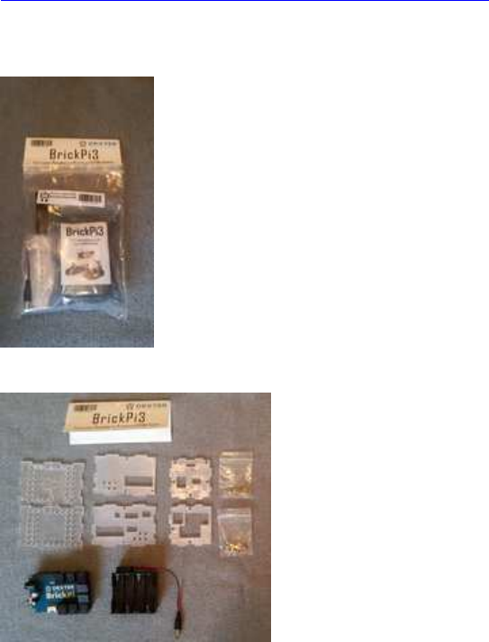
Inhalt des BrickPi3 Basis Kits:
(Bezugsquelle: Generation Robots, Frankreich, ca. 130 EUR inkl. Versand;
https://www.generationrobots.com/de/402 ... &results=7
momentan noch keine anderen Händler für Deutschland gefunden!)
( allerdings keine Beschreibung dabei! )
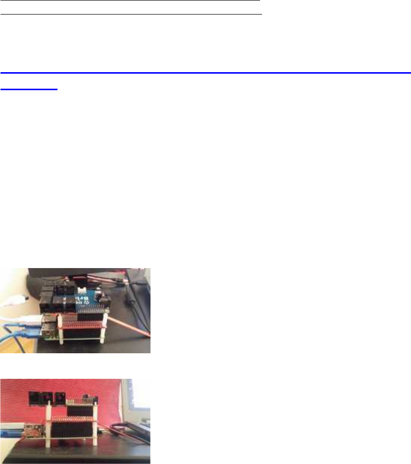
BrickPi3 Aufbau-Anleitung:
https://www.dexterindustries.com/BrickP ... g-started/
https://www.dexterindustries.com/BrickP ... ed/basics/
Montieren auf Standard-RaspberryPi- Abstandhalter: leider nicht
möglich !
Entgegen Aussage von Dexter Ind. ist es nicht möglich, die BrickPi3 Shields mit 4 normalen
Abstandshaltern zu befestigen -
es sind nur 2 Löcher für die Befestigung vorhanden, keine 4 wie eigentlich erforderlich, denn
die restlichen 2, die nötig wären, sind mit Lego-Plugs verbaut.
17mm wie angegeben gingen eh nicht, weil der stacking header vom BrickPi3 Shield nur
14mm hoch ist, aber das ist natürlich nur das allerkleinste Problem: Das Problem ist, dass
keine 4 Befestigungsbolzen möglich sind. sondern nur 2, dadurch wird die Montage extrem
wackelig, speziell bei mehreren aufeinandergesteckten Shields oder HATs:
Zum anderen hat der BrickPi3 nur 26 Pins (wie der alte Raspi B), nicht 40 wie der neuere B+
und 2+3. Oben drauf lassen sich demnach überhaupt keine 40er HATs mehr draufsetzen....

Allgemeine Links für Anfänger
(nicht spezifisch für C Programmierer):
https://www.dexterindustries.com/BrickP ... g-started/
Assemble The Case
The SD Card
Powering Up
Using the Raspberry Pi
Controlling the BrickPi
Attaching LEGO
Programming Your Robot
Installation von Raspbian:
Anm.:
BrickPi3 läuft mit den Standard-Raspbian SD Cards, wie sie z.B. automatisch von NOOBS
erstellt und installiert werden.
Ich empfehle 16GB oder 32GB SD cards, möglichst hohe Datenübertragungsrate.
NOOBS-Link zur Installation:
https://www.raspberrypi.org/downloads/noobs/
Wichtig:
Nach jeder Neu-Installation und vor jeder neuen Zusatzinstallation immer obligatorisch erst
einmal:
sudo apt-get update
sudo apt-get upgrade
#dann
sudo reboot now
#dann
sudo apt-get autoremove

Installation der BrickPi3-Driver, C++ API Files und der Code Examples:
https://github.com/DexterInd/BrickPi3/b ... /README.md
alt:
Clone this repository onto the Raspberry Pi:
sudo git clone http://www.github.com/DexterInd/BrickPi3.git
/home/pi/Dexter/BrickPi3
# altern., matt's fork, experimental:
sudo git clone http://www.github.com/mattallen37/BrickPi3.git
/home/pi/Dexter/BrickPi3
Run the install script:
sudo bash /home/pi/Dexter/BrickPi3/Install/install.sh
Reboot the Raspberry Pi to make the settings take effect:
sudo reboot
neuer:
For install, clone this repository onto the Raspberry Pi:
Code: Alles auswählen
sudo git clone http://www.github.com/DexterInd/BrickPi3.git
/home/pi/Dexter/BrickPi3
+ For update, pull the repository:
sudo git --work-tree=/home/pi/Dexter/BrickPi3 --git-
dir=/home/pi/Dexter/BrickPi3/.git pull
+ 2. Run the install script:
sudo bash /home/pi/Dexter/BrickPi3/Install/install.sh
ganz neu: https://github.com/DexterInd/BrickPi3
Quick Install
In order to quick install the BrickPi3 repository, open up a terminal and type the following
command:
sudo curl -kL dexterindustries.com/update_brickpi3 | bash
The same command can be used for updating the BrickPi3 to the latest version.
matt hat geschrieben: When you install the BrickPi3 software, the C++ drivers and examples
are included
(they get installed in the directory /home/pi/Dexter/BrickPi3/Software/C).
For compiling, see the example compile command in the C examples.

Verbindungstest (Hardware/Firmware/Driver):
Zum Verbindungstest kann dieses Python-Programm verwendet werden:
python3 /home/pi/Dexter/BrickPi3/Software/Python/Examples/Test_Connected.py
Achtung: Es gibt auch einen Fehler aus, wenn nur die Firmware Version zu alt ist, auch
wenn sonst alles ok sein sollte.
Check / Update Firmware:
matt hat geschrieben:To check the firmware version, you can either run the python example
"Read_Info.py" or you can compile and run the C program "info.c".
You can update the firmware as described here:
https://github.com/DexterInd/BrickPi3/b ... /README.md
python3 /home/pi/Dexter/BrickPi3/Software/Python/Examples/Read_Info.py
bei mir war es ver 1.0.1, verlangt wird 1.4.x, daher:
sudo bash /home/pi/Dexter/BrickPi3/Firmware/brickpi3samd_flash_firmware.sh
spätere Driver- und C++ Library-Updates:
neu:
sudo curl -kL dexterindustries.com/update_brickpi3 | bash
optional:
sudo rm -rf /home/pi/Dexter/BrickPi3
#dann wie oben
sudo git clone http://www.github.com/DexterInd/BrickPi3.git
/home/pi/Dexter/BrickPi3
sudo bash /home/pi/Dexter/BrickPi3/Install/install.sh
sudo reboot
Trouble Shooting:
https://www.dexterindustries.com/BrickP ... -brickpi3/

Erster BrickPi3 Compile-/Build-Test mit Geany:
Anm.:
Geany ist automatisch bei Raspbian Jessie bereits mit installiert, ebenso der komplette C-
Compiler gcc (g++)
Geany ist im GUI Desktop-Menü unter "Entwicklung" bereits als Shortcut hinterlegt
(genau wie Python 2+3 und Scratch) und lässt sich von dort auch als zusätzlicher Shortcut
auf dem Desktop ablegen.
Programm info.c in Geany geladen/geöffnet (Code siehe im TO Post)
Geany Einstellungen (Preferences) für compile und build:
keine besonderen zusätzlichen Flags nötig!
(aus Bequemlichkeitsgründen habe ich die Compile-Flags aus den Build-Flags übernommen,
nur mit -c statt -o)
# Compile:
g++ -Wall -c "%e" "%f"
# Build:
g++ -Wall -o "%e" "%f"
# Make:
make %e.o
# Ausführen:
sudo "./%e"
Ab jetzt kann man ganz bequem mit Funktionstasten als short-cuts arbeiten:
F8 (compile)
F9 (build)
F5 (run)
Tipp:
wie die meisten C/C++ Programmierer sicher wissen, kann man (eigene) .c, .cpp, .h, .hpp etc.
files in den Raspi-Ordner
/usr/local/include/
kopieren, dadurch werden sie anschließend von gcc automatisch gefunden, wenn man sie mit
#include einbindet.
Im Falle von BrickPi3 betrifft das ausschließlich 2 Files, nämlich
BrickPi3.cpp
und
BrickPi.h
Sie müssen dann danach also nicht mehr immer zusätzlich im aktuellen Arbeits-Directory
vorhanden sein.
update: matt hat geschrieben:As of BrickPi3 PR #67 BrickPi3.h and BrickPi3.cpp are now
installed to /usr/local/include.

BrickPi3 Motoren und Sensoren anschließen:
Anm.:
Nicht unbedingt für Sensoren, aber auf jeden Fall für Motoren wird eine externe Zusatz-
Spannungsquelle benötigt (ca. 8-12V).
Zusätzlich den Spannungsschalter einschalten.
Jetzt wird auch der Raspi über die Zusatzspannungsquelle und den 5V GPIO-Header Pin
versorgt.
Die gelbe Blink-LED auf dem BrickPi3 gibt Aufschluss über den Batteriestatus:
schnelles Blinken (4x/s.): zu schwach, 2x/s.: gerade halbwegs ausreichend, 1x/s.: sehr gut.
Zusätzlich gibt die rote Status-LED auf dem Raspi Aufschluss darüber, ob 5V anliegen (rot
an: OK, rot aus: low voltage!)
Die Buchsen halte ich für etwas sehr seltsam angeordnet und ausgerichtet, abe das ist sicher
auch teilw. Geschmackssache.
Definition der Sensor- und Motor-Ports:
Code: Alles auswählen
// Sensor ports
#define PORT_1 0x01
#define PORT_2 0x02
#define PORT_3 0x04
#define PORT_4 0x08
// Motor ports
#define PORT_A 0x01
#define PORT_B 0x02

#define PORT_C 0x04
#define PORT_D 0x08
BrickPi class (public):
Code: Alles auswählen
class BrickPi3{
public:
// Default to address 1, but the BrickPi3 address could have been
changed.
BrickPi3(uint8_t addr = 1);
// Confirm that the BrickPi3 is connected and up-to-date
int detect(bool critical = true);
// Get the manufacturer (should be "Dexter Industries")
int get_manufacturer(char *str);
// Get the board name (should be "BrickPi3")
int get_board(char *str);
// Get the hardware version number
int get_version_hardware(char *str);
// Get the firmware version number
int get_version_firmware(char *str);
// Get the serial number ID that is unique to each BrickPi3
int get_id(char *str);
// Control the LED
int set_led(uint8_t value);
// Get the voltages of the four power rails
int get_voltage_3v3 (float &voltage);
float get_voltage_3v3 ();
int get_voltage_5v (float &voltage);
float get_voltage_5v ();
int get_voltage_9v (float &voltage);
float get_voltage_9v ();
int get_voltage_battery(float &voltage);
float get_voltage_battery();
// Configure a sensor
int set_sensor_type(uint8_t port, uint8_t type, uint16_t flags = 0,
I2C_struct_t *I2C_struct = NULL);
// Configure and trigger an I2C transaction
int transact_I2C(uint8_t port, I2C_struct_t *I2C_struct);
// Get sensor value(s)
int get_sensor(uint8_t port, void *value);
// Set the motor PWM power
int set_motor_power(uint8_t port, int8_t power);
// Set the motor target position to run to
int set_motor_position(uint8_t port, int32_t position);
// Set the motor speed in degrees per second. As of FW version 1.4.0,
the algorithm regulates the speed, but it is not accurate.
int set_motor_dps(uint8_t port, int16_t dps);
// Set the motor limits. Only the power limit is implemented. Use the
power limit to limit the motor speed/torque.
int set_motor_limits(uint8_t port, uint8_t power, uint16_t dps);
// Get the motor status. State, PWM power, encoder position, and speed
(in degrees per second)
int get_motor_status(uint8_t port, uint8_t &state, int8_t &power,
int32_t &position, int16_t &dps);
// Offset the encoder position. By setting the offset to the current
position, it effectively resets the encoder value.
int offset_motor_encoder(uint8_t port, int32_t position);
// Get the encoder position
int get_motor_encoder(uint8_t port, int32_t &value);
int32_t get_motor_encoder(uint8_t port);
// Reset the sensors (unconfigure), motors (float with no limits), and
LED (return control to the firmware).
int reset_all();
};

BrickPi3 Example: NXT Sensor Test Programm sensors_nxt.c
Anm.:
Analoge Sensorwerte sind 12-bit ADC, also 0-4095 (statt 10-bit ADC von 0-1023 wie bei
Lego üblich).
Wenn man will, kann man sie durch 4 dividieren (oder >>2), dann hat man wieder den
Genauigkeits-Bereich von Lego-Analog-Sensoren.
Code: Alles auswählen
/*
* https://www.dexterindustries.com/BrickPi/
* https://github.com/DexterInd/BrickPi3
*
* Copyright (c) 2017 Dexter Industries
* Released under the MIT license
(http://choosealicense.com/licenses/mit/).
* For more information, see
https://github.com/DexterInd/BrickPi3/blob/master/LICENSE.md
*
* This code is an example for reading the encoders of motors connected to
the BrickPi3.
*
* Hardware: Connect NXT sensors to the sensor ports. Color sensor to
PORT_1. Ultrasonic sensor to PORT_2. Light sensor to PORT_3. Touch sensor
to PORT_4 (EV3 or NXT touch sensor).
*
* Results: When you run this program, you should see the values for each
sensor.
*
* Example compile command:
* g++ -o program "sensors_nxt.c"
* Example run command:
* sudo ./program
*
*/
#include "BrickPi3.cpp" // for BrickPi3
#include <stdio.h> // for printf
#include <unistd.h> // for usleep
#include <signal.h> // for catching exit signals
BrickPi3 BP;
void exit_signal_handler(int signo);
int main(){
signal(SIGINT, exit_signal_handler); // register the exit function for
Ctrl+C
BP.detect(); // Make sure that the BrickPi3 is communicating and that the
firmware is compatible with the drivers.
int error;
BP.set_sensor_type(PORT_1, SENSOR_TYPE_NXT_COLOR_FULL);
BP.set_sensor_type(PORT_2, SENSOR_TYPE_NXT_ULTRASONIC);
BP.set_sensor_type(PORT_3, SENSOR_TYPE_NXT_LIGHT_ON);
BP.set_sensor_type(PORT_4, SENSOR_TYPE_TOUCH);
sensor_color_t Color1;
sensor_ultrasonic_t Ultrasonic2;
sensor_light_t Light3;
sensor_touch_t Touch4;
while(true){
error = 0;
if(BP.get_sensor(PORT_1, &Color1)){
error++;
}else{
printf("Color sensor (S1): detected %d red %4d green %4d blue %4d
ambient %4d ", Color1.color, Color1.reflected_red,
Color1.reflected_green, Color1.reflected_blue, Color1.ambient);
}
if(BP.get_sensor(PORT_2, &Ultrasonic2)){
error++;
}else{
printf("Ultrasonic sensor (S2): CM %5.1f Inches %5.1f ",
Ultrasonic2.cm, Ultrasonic2.inch);
}
if(BP.get_sensor(PORT_3, &Light3)){
error++;
}else{
printf("Light sensor (S3): reflected %4d ", Light3.reflected);
}
if(BP.get_sensor(PORT_4, &Touch4)){
error++;
}else{
printf("Touch sensor (S4): pressed %d ", Touch4.pressed);
}
if(error == 4){
printf("Waiting for sensors to be configured");
}
printf("\n");
usleep(20000);
}
}
// Signal handler that will be called when Ctrl+C is pressed to stop the
program
void exit_signal_handler(int signo){
if(signo == SIGINT){
BP.reset_all(); // Reset everything so there are no run-away motors
exit(-2);
}
}
BrickPi3 Example: Motor Test Programm motors.c:
Achtung:
Man muss darauf achten, dass die Zusatz-Batterien für die Motor-Treiber genügend
Spannung liefern, sonst schaltet sie der BrickPi3 automatisch ab, mit SPI Fehler - und
dann hilft nur ein Reboot mit frischen Batterien!
/*
* https://www.dexterindustries.com/BrickPi/
* https://github.com/DexterInd/BrickPi3
*
* Copyright (c) 2017 Dexter Industries
* Released under the MIT license
(http://choosealicense.com/licenses/mit/).
* For more information, see
https://github.com/DexterInd/BrickPi3/blob/master/LICENSE.md
*
* This code is an example for reading the encoders of motors connected to
the BrickPi3.
*
* Hardware: Connect EV3 or NXT motor(s) to any of the BrickPi3 motor
ports.
*
* Results: When you run this program, you should see the encoder value
for each motor. By manually rotating motor A, the other motor(s) will be
controlled. Motor B power will be controlled, Motor C speed will be
controlled, and motor D position will be controlled.
*
* Example compile command:
* g++ -o program "motors.c"
* Example run command:
* sudo ./program
*
*/
#include "BrickPi3.cpp" // for BrickPi3
#include <stdio.h> // for printf
#include <unistd.h> // for usleep
#include <signal.h> // for catching exit signals
BrickPi3 BP;
void exit_signal_handler(int signo);
int main(){
signal(SIGINT, exit_signal_handler); // register the exit function for
Ctrl+C
BP.detect(); // Make sure that the BrickPi3 is communicating and that the
firmware is compatible with the drivers.
// Reset the encoders
BP.offset_motor_encoder(PORT_A, BP.get_motor_encoder(PORT_A));
BP.offset_motor_encoder(PORT_B, BP.get_motor_encoder(PORT_B));
BP.offset_motor_encoder(PORT_C, BP.get_motor_encoder(PORT_C));
BP.offset_motor_encoder(PORT_D, BP.get_motor_encoder(PORT_D));
while(true){
// Read the encoders
int32_t EncoderA = BP.get_motor_encoder(PORT_A);
int32_t EncoderB = BP.get_motor_encoder(PORT_B);
int32_t EncoderC = BP.get_motor_encoder(PORT_C);
int32_t EncoderD = BP.get_motor_encoder(PORT_D);
// Use the encoder value from motor A to control motors B, C, and D
BP.set_motor_power(PORT_B, EncoderA < 100 ? EncoderA > -100 ? EncoderA
: -100 : 100);
BP.set_motor_dps(PORT_C, EncoderA);
BP.set_motor_position(PORT_D, EncoderA);
// Display the encoder values
printf("Encoder A: %6d B: %6d C: %6d D: %6d\n", EncoderA, EncoderB,
EncoderC, EncoderD);
// Delay for 20ms
usleep(20000);
}
}
// Signal handler that will be called when Ctrl+C is pressed to stop the
program
void exit_signal_handler(int signo){
if(signo == SIGINT){
BP.reset_all(); // Reset everything so there are no run-away motors
exit(-2);
}
}
Update Motor API:
neue Funktionen für
reset Motor-Encoder
und
rotate relative Degrees
(s. github Repository, Link s. oben)
Update, was die Unterstützung für IO-Hardware am BrickPi angeht:
Dexter bietet ausschließlich Support für Original Lego Sensoren, Treiber-Anfragen zu 3rd
Party Sensoren etc. werden kategorisch abgelehnt.

Muster für eine BrickPi3 Multithreading-Architektur
compile/build flags:
-pthread -lwiringPi
wiringPi Installation:
siehe viewtopic.php?f=78&t=8689&start=15#p67924
Code: Alles auswählen
#include <stdbool.h> // boolean types and values
#include <stdio.h> // files, keyboard IO (getchar())
#include <termio.h> // low level XBD (termios, ioctl)
#include <unistd.h> // POSIX/LINUX symbolic constants and types
#include <string.h> // strings+arrays (memcpy())
#include <pthread.h> // multithreading
#include <wiringPi> // GPIOs, delay, millis
#include "BrickPi3.cpp" // for BrickPi3
#include <signal.h> // for catching exit signals
//===============================================
// create BrickPi instance
//===============================================
BrickPi3 BP;
//===============================================
// Signal handler to be called when Ctrl+C is pressed
//===============================================
void exit_signal_handler(int signo){
if(signo == SIGINT){
MT_active = 0; // signalize threads to terminate by themselves
fprintf( stdout, "\naborted by [CTRL+C]\n" ); // optional
}
}
//===============================================
// mimics conio.h kbhit()
//===============================================
bool kbhit(void)
{
struct termios original;
tcgetattr(STDIN_FILENO, &original);
struct termios term;
memcpy(&term, &original, sizeof(term));
term.c_lflag &= ~ICANON;
tcsetattr(STDIN_FILENO, TCSANOW, &term);
int characters_buffered = 0;
ioctl(STDIN_FILENO, FIONREAD, &characters_buffered);
tcsetattr(STDIN_FILENO, TCSANOW, &original);
bool pressed = (characters_buffered != 0);
return pressed;
}
//===============================================
// single threads & MT thread control
//===============================================
pthread_mutex_t mutexBP;
volatile int MT_active=1, Ts1=0, Ts2=0, Ts3=0; // semaphores to control
and monitor MT
void* thread1Name(void *) {
Ts1=1; // indicate thread 1 was started
while(MT_active) {
///... (code/loop)
delay(1); // optional, arbitrarily
}
Ts1=0; // indicate thread 1 was stopped
fprintf( stdout, "\nthread 1 exit message\n" ); // optional
return NULL;
}
void* thread2Name(void *) {
Ts2=1; // indicate thread 2 was started
while(MT_active) {
///... (code/loop)
delay(10); // optional, arbitrarily
}
Ts2=0; // indicate thread 2 was stopped
fprintf( stdout, "\nthread 2 exit message\n" ); // optional
return NULL;
}
void* thread3Name(void *) {
Ts3=1; // indicate thread 3 was started
while(MT_active) {
///... (code/loop)
delay(100); // optional, arbitrarily
}
Ts3=0; // indicate thread 3 was stopped
fprintf( stdout, "\nthread 3 exit message\n" ); // optional
return NULL;
}
//===============================================
// main()
//===============================================
int main() {
signal(SIGINT, exit_signal_handler); // register the exit function
for Ctrl+C
pthread_mutex_init (&mutexBP, NULL); // init a mutex for Brickpi
access
//----------------------------------------
// mutex handling: lock and unlock
//----------------------------------------
pthread_mutex_lock (&mutexBP); // lock the following variable
operations by the BrickPi mutex
// Make sure that the BrickPi3 is communicating and that the
firmware is compatible with the drivers:
BP.detect();
// Reset the encoders:
BP.offset_motor_encoder(PORT_A, BP.get_motor_encoder(PORT_A));
BP.offset_motor_encoder(PORT_B, BP.get_motor_encoder(PORT_B));
BP.offset_motor_encoder(PORT_C, BP.get_motor_encoder(PORT_C));
BP.offset_motor_encoder(PORT_D, BP.get_motor_encoder(PORT_D));
pthread_mutex_unlock (&mutexBP); // release the mutex to write/read
by different threads
//----------------------------------------
//create and start the pthread threads
//----------------------------------------
pthread_t tid1, tid2, tid3; // thread IDs
pthread_create(&tid1, NULL, thread1Name, NULL);
pthread_create(&tid2, NULL, thread2Name, NULL);
pthread_create(&tid3, NULL, thread3Name, NULL);
delay(1); // give the threads a chance to start
//----------------------------------------
// keyboard handler: terminate by ESC key
//----------------------------------------
while(MT_active) {
if ( kbhit() ) {
int key = getchar();
if (key==27) { // ESC == ASCII 27
MT_active = 0;
fprintf( stdout, "\naborted by [ESC]\n" ); // optional
break();
}
}
// optional: rest of a perpetual main() code
// instead, put BP code into a proprietary thread
delay(100); // optional
}
//----------------------------------------
// wait for threads to join before exiting
//----------------------------------------
pthread_join(tid1, NULL);
pthread_join(tid2, NULL);
pthread_join(tid3, NULL);
//----------------------------------------
// reset and then terminate
//----------------------------------------
pthread_mutex_lock (&mutexBP); // not compellingly required here, just
to demonstrate mutexes
BP.reset_all(); // Reset everything so there are no run-away
motors
pthread_mutex_unlock (&mutexBP);
return 0;
}
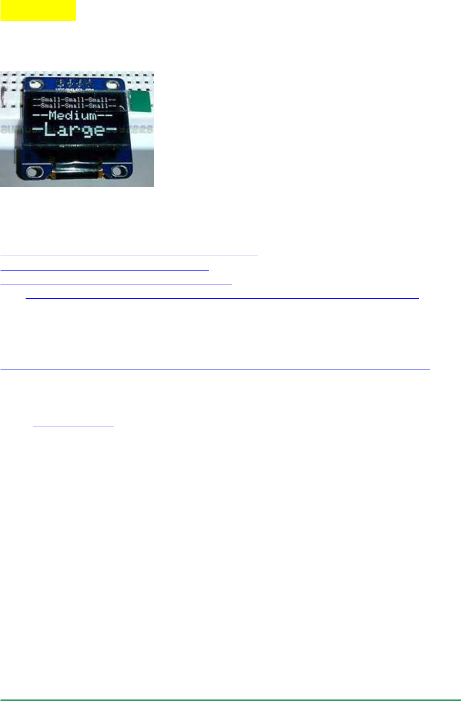
Displays
OLED 128x64 SSD1306, SH1106
I2C Bus speed: STANDARD + FAST-I2C (100-400kHz, getestet)
aktuelle Treiber-Version:
http://hallard.me/adafruit-oled-display-driver-for-pi/
https://github.com/hallard/ArduiPi_OLED
https://github.com/jonesman/ArduiPi_OLED // neue i2c Treiber ohne sudo
vgl.: https://github.com/hallard/ArduiPi_OLED/issues/14#issuecomment-399179723
Anwendungsbeispiel:
https://raspilab.blog/2015/03/31/meine-smartwatch-mit-i2c-ein-oled-display-ansteuern/
Zur Verwendung mit Geany: zusätzlicher build-Parameter
Code: Alles auswählen
-lArduiPi_OLED // lowercase "-L"
7 verschiedene OLED Typen werden unterstützt:
0 Adafruit SPI 128x32 SSD1306
1 Adafruit SPI 128x64 SSD1306
2 Adafruit I2C 128x32 SSD1306
3 Adafruit I2C 128x64 SSD1306
4 Seeed I2C 128x64 SSD1308
5 Seeed I2C 96x96 SSD1327
6 NoName I2C 128x64 SH1106
Den richtigen OLED Type muss man ausprobieren, bei mir funktioniert Type 6, d.h. also für
den Konsole-Aufruf des Bespielprogramms in examples:
sudo ./oled_demo --verbose --oled 6
vereinfachter Start der demo mit festem I2C oled Type 6, ohne Command Line Parameter :
//----------------------------------------------------------------------
int main(int argc, char **argv)
{
int i;
// Oled supported display in ArduiPi_SSD1306.h
// I2C change parameters to fit to your LCD
if ( !display.init(OLED_I2C_RESET, 6) )
exit(EXIT_FAILURE);
display.begin();
// init done
//.... Code!
display.close();
}
//----------------------------------------------------------------------
einfacher Testcode, testweise zusammen mit wiringPi :
//----------------------------------------------------------------------/*
*
*
* OLED Display
* plus wringPi millis + delay
*
* http://hallard.me/adafruit-oled-display-driver-for-pi/
* https://github.com/hallard/ArduiPi_OLED
*
* ver 0001
*
*/
#include <string.h>
#include <unistd.h>
#include <errno.h>
#include <stdio.h>
#include <stdint.h>
#include <stdlib.h>
#include <linux/I2C-dev.h>
#include <sys/ioctl.h>
#include <fcntl.h>
#include <unistd.h>
#include <stdbool.h>
#include <string.h>
#include <termio.h>
#include <wiringPi.h>
#include <wiringPiI2C.h>
#include <ArduiPi_OLED_lib.h>
#include <Adafruit_GFX.h>
#include <ArduiPi_OLED.h>
#define byte uint8_t
// Instantiate the OLED display
ArduiPi_OLED oledtft;
void oled_cls() {
oledtft.clearDisplay();
oledtft.display();
}
void oled_printxy(int x, int y, char * str) {
oledtft.setCursor(x,y);
oledtft.print(str);
oledtft.display();
}
// mimic conio.h kbhit
bool kbhit(void)
{
struct termios original;
tcgetattr(STDIN_FILENO, &original);
struct termios term;
memcpy(&term, &original, sizeof(term));
term.c_lflag &= ~ICANON;
tcsetattr(STDIN_FILENO, TCSANOW, &term);
int characters_buffered = 0;
ioctl(STDIN_FILENO, FIONREAD, &characters_buffered);
tcsetattr(STDIN_FILENO, TCSANOW, &original);
bool pressed = (characters_buffered != 0);
return pressed;
}
//=========================================================================
int main() {
int check;
char sbuf[100];
uint32_t msec, millisav;
// wiringPi
setenv("WIRINGPI_GPIOMEM", "1", 1); // no sudo for gpios required
check = wiringPiSetup(); // init by wiringPi pin
numbering
if( check == -1 ) return 1;
// Oled supported display in ArduiPi_SSD1306.h
// change parameters to fit to your LCD
if ( !oledtft.init(OLED_I2C_RESET, 6) )
exit(EXIT_FAILURE);
oledtft.begin();
// init done
oled_cls();
// test
oledtft.setTextSize(1);
oledtft.setTextColor(WHITE);
oledtft.setTextSize(1);
oledtft.setCursor(0, 0); oledtft.print(" 0 Hello, world!\n");
oledtft.setCursor(0, 8); oledtft.print(" 8 I2C OLED");
oledtft.setCursor(0,16); oledtft.print("16 128x64 addr 0x3c");
oledtft.setCursor(0,24); oledtft.print("24 8x21 char size=1");
oledtft.setCursor(0,32); oledtft.print("32 ");
oledtft.setCursor(0,40); oledtft.print("40 ");
oledtft.setCursor(0,48); oledtft.print("48 456789112345678921");
oledtft.setCursor(0,56); oledtft.print("56 ");
oledtft.display();
sleep(1);
oled_cls();
millisav=millis();
while(1) {
msec = millis() - millisav;
sprintf(sbuf, " millisec = %ld \n", msec);
printf(sbuf);
oledtft.setTextColor(WHITE, BLACK);
oled_printxy( 0,16, sbuf);
if (kbhit())
{
int c = getchar();
if(c==27) break;
}
delay(500);
}
oled_cls();
oledtft.close();
return (0);
}
//----------------------------------------------------------------------

HaWe Brickbench-Test mit OLED:
sehr langsam (bei Fast-I2C mit 400kHz etwa halb so schnell wie große HDMI Screens),
aber ansonsten brauchbar.
bench test ms B+ 2B 2B .
cpu clock 800MHz 900MHz 900MHz
Grafik: openvg openvg openvg
Screen: HDMI 1060x600 OLED 128x64
int_add 1 1 1
int_mult 3 3 3
float_op 13 1 1
mersenne 2 1 1
matrix 1 1 1
arr_sort 88 46 30
text 2630 2626 6036
graph 13333 13333 27289
gesamt ms: 16072 16012 33362
Benchmark: 3111 3122 1498
//----------------------------------------------------------------------
// HaWe Brickbench
// benchmark test for NXT/EV3 and similar Micro Controllers
// PL: GCC, Raspi, Raspbian Linux
// Autor: (C) Helmut Wunder 2013,2014
// ported to Raspi by "HaWe"
//
// freie Verwendung für private Zwecke
// für kommerzielle Zwecke nur nach schriftlicher Genehmigung durch den
Autor.
// protected under the friendly Creative Commons Attribution-NonCommercial-
ShareAlike 3.0 Unported License
// http://creativecommons.org/licenses/by-nc-sa/3.0/
// version 1.09.OLED.007 16.08.2015
// OLED 128x64 I2C-1 clock = 400000
#include <stdio.h>
#include <stdlib.h>
#include <unistd.h>
#include <math.h>
#include <fcntl.h>
#include <string.h>
#include <sys/ioctl.h>
#include <stdint.h>
#include <time.h>
#include <sys/time.h>
#include <ArduiPi_OLED_lib.h>
#include <Adafruit_GFX.h>
#include <ArduiPi_OLED.h>
#include <getopt.h>
// Instantiate the display
ArduiPi_OLED display;
unsigned long runtime[8];
int a[500], b[500], c[500], t[500];
uint32_t timer()
{
struct timeval now;
uint32_t ticks;
gettimeofday(&now, NULL);
ticks=now.tv_sec*1000+now.tv_usec/1000;
return(ticks);
}
//--------------------------------------------
// Mersenne Twister
//--------------------------------------------
unsigned long randM(void) {
const int M = 7;
const unsigned long A[2] = { 0, 0x8ebfd028 };
static unsigned long y[25];
static int index = 25+1;
if (index >= 25) {
int k;
if (index > 25) {
unsigned long r = 9, s = 3402;
for (k=0 ; k<25 ; ++k) {
r = 509845221 * r + 3;
s *= s + 1;
y[k] = s + (r >> 10);
}
}
for (k=0 ; k<25-M ; ++k)
y[k] = y[k+M] ^ (y[k] >> 1) ^ A[y[k] & 1];
for (; k<25 ; ++k)
y[k] = y[k+(M-25)] ^ (y[k] >> 1) ^ A[y[k] & 1];
index = 0;
}
unsigned long e = y[index++];
e ^= (e << 7) & 0x2b5b2500;
e ^= (e << 15) & 0xdb8b0000;
e ^= (e >> 16);
return e;
}
//--------------------------------------------
// Matrix Algebra
//--------------------------------------------
// matrix * matrix multiplication (matrix product)
void MatrixMatrixMult(int N, int M, int K, double *A, double *B, double
*C) {
int i, j, s;
for (i = 0; i < N; ++i) {
for (j = 0; j < K; ++j) {
C[i*K+j] = 0;
for (s = 0; s < M; ++s) {
C[i*K+j] = C[i*K+j] + A[i*N+s] * B[s*M+j];
}
}
}
}
// matrix determinant
double MatrixDet(int N, double A[]) {
int i, j, i_count, j_count, count = 0;
double Asub[N - 1][N - 1], det = 0;
if (N == 1)
return *A;
if (N == 2)
return ((*A) * (*(A+1+1*N)) - (*(A+1*N)) * (*(A+1)));
for (count = 0; count < N; count++) {
i_count = 0;
for (i = 1; i < N; i++) {
j_count = 0;
for (j = 0; j < N; j++) {
if (j == count)
continue;
Asub[i_count][j_count] = *(A+i+j*N);
j_count++;
}
i_count++;
}
det += pow(-1, count) * A[0+count*N] * MatrixDet(N - 1, &Asub[0][0]);
}
return det;
}
//--------------------------------------------
// shell sort
//--------------------------------------------
void shellsort(int size, int* A)
{
int i, j, increment;
int temp;
increment = size / 2;
while (increment > 0) {
for (i = increment; i < size; i++) {
j = i;
temp = A[i];
while ((j >= increment) && (A[j-increment] > temp)) {
A[j] = A[j - increment];
j = j - increment;
}
A[j] = temp;
}
if (increment == 2)
increment = 1;
else
increment = (unsigned int) (increment / 2.2);
}
}
//--------------------------------------------
// gnu quick sort
// (0ptional)
//--------------------------------------------
int compare_int (const int *a, const int *b)
{
int temp = *a - *b;
if (temp > 0) return 1;
else if (temp < 0) return -1;
else return 0;
}
// gnu qsort:
// void qsort (void *a , size_a count, size_a size, compare_function)
// gnu qsort call for a[500] array of int:
// qsort (a , 500, sizeof(a), compare_int)
//--------------------------------------------
// benchmark test procedures
//--------------------------------------------
int test_Int_Add() {
int i=1, j=11, k=112, l=1111, m=11111, n=-1, o=-11, p=-111, q=-1112, r=-
11111;
int x;
volatile long s=0;
for(x=0;x<10000;++x) {
s+=i; s+=j; s+=k; s+=l; s+=m; s+=n; s+=o; s+=p; s+=q; s+=r;
}
return s;
}
long test_Int_Mult() {
int x,y;
volatile long s;
for(y=0;y<2000;++y) {
s=1;
for(x=1;x<=13;++x) { s*=x;}
for(x=13;x>0;--x) { s/=x;}
}
return s;
}
#define PI M_PI
double test_float_math() {
volatile double s=PI;
int y;
for(y=0;y<1000;++y) {
s*=sqrt(s);
s=sin(s);
s=exp(s);
s*=s;
}
return s;
}
long test_rand_MT(){
volatile unsigned long s;
int y;
for(y=0;y<5000;++y) {
s=randM()%10001;
}
return s;
}
double test_matrix_math() {
int x;
double A[2][2], B[2][2], C[2][2];
double S[3][3], T[3][3];
unsigned long s;
for(x=0;x<250;++x) {
A[0][0]=1; A[0][1]=3;
A[1][0]=2; A[1][1]=4;
B[0][0]=10; B[0][1]=30;
B[1][0]=20; B[1][1]=40;
MatrixMatrixMult(2, 2, 2, A[0], B[0], C[0]); // <<<<<<<<<<<<<<<<<<<
A[0][0]=1; A[0][1]=3;
A[1][0]=2; A[1][1]=4;
MatrixDet(2, A[0]); // <<<<<<<<<<<<<<<<<<<
S[0][0]=1; S[0][1]=4; S[0][2]=7;
S[1][0]=2; S[1][1]=5; S[1][2]=8;
S[2][0]=3; S[2][1]=6; S[2][2]=9;
MatrixDet(3, S[0]); // <<<<<<<<<<<<<<<<<<<
}
s=(S[0][0]*S[1][1]*S[2][2]);
return s;
}
// for array copy using void *memcpy(void *dest, const void *src, size_t
n);
long test_Sort(){
unsigned long s;
int y;
int t[500];
for(y=0;y<30;++y) {
memcpy(t, a, sizeof(a));
shellsort(500, t);
memcpy(t, a, sizeof(b));
shellsort(500, t);
memcpy(t, a, sizeof(c));
shellsort(500, t);
}
return y;
}
long test_TextOut(){
int y=77;
char buf[120];
display.setTextSize(1);
display.setTextColor(WHITE);
for(y=0;y<20;++y) {
display.clearDisplay();
sprintf (buf, "%3d %4d int_Add", 0, 1000); display.setCursor(6,
0); display.printf(buf); display.display();
sprintf (buf, "%3d %4d int_Mult", 1, 1010); display.setCursor(6,
8); display.printf(buf); display.display();
sprintf (buf, "%3d %4d float_op", 2, 1020);
display.setCursor(6,16); display.printf(buf); display.display();
sprintf (buf, "%3d %4d randomize", 3, 1030);
display.setCursor(6,24); display.printf(buf); display.display();
sprintf (buf, "%3d %4d matrx_algb", 4, 1040);
display.setCursor(6,32); display.printf(buf); display.display();
sprintf (buf, "%3d %4d arr_sort", 5, 1050);
display.setCursor(6,40); display.printf(buf); display.display();
sprintf (buf, "%3d %4d displ_txt", 6, 1060);
display.setCursor(6,48); display.printf(buf); display.display();
sprintf (buf, "%3d %4d testing...", 7, 1070);
display.setCursor(6,56); display.printf(buf); display.display();
}
return y;
}
long test_graphics(){
int y=0;
for(y=0;y<100;++y) {
display.clearDisplay();
display.drawCircle(50, 40, 10, WHITE); // circles
display.display();
display.fillCircle(30, 24, 10, WHITE);
display.display();
display.drawLine(10, 10, 60, 60, WHITE); // just 2 intersecting
lines
display.display();
display.drawLine(50, 20, 97, 63, WHITE);
display.display();
display.drawRect(20, 20, 40, 40, WHITE); // rectangles
display.display();
display.fillRect(65, 25, 20, 30, WHITE);
display.display();
display.drawCircle(70, 30, 20, WHITE); // no ellipse
display.display();
}
return y;
}
inline void displayValues() {
char buf[120];
sprintf (buf, "%3d %7ld int_Add", 0, runtime[0]); printf(buf);
printf("\n");
sprintf (buf, "%3d %7ld int_Mult", 1, runtime[1]); printf(buf);
printf("\n");
sprintf (buf, "%3d %7ld float_op", 2, runtime[2]); printf(buf);
printf("\n");
sprintf (buf, "%3d %7ld randomize", 3, runtime[3]); printf(buf);
printf("\n");
sprintf (buf, "%3d %7ld matrx_algb", 4, runtime[4]); printf(buf);
printf("\n");
sprintf (buf, "%3d %7ld arr_sort", 5, runtime[5]); printf(buf);
printf("\n");
sprintf (buf, "%3d %7ld displ_txt", 6, runtime[6]); printf(buf);
printf("\n");
sprintf (buf, "%3d %7ld graphics", 7, runtime[7]); printf(buf);
printf("\n");
}
int main(){
unsigned long time0, x, y;
float s;
char buf[120];
char str[3];
int i;
// Oled supported display in ArduiPi_SSD1306.h
// I2C change parameters to fit to your LCD
if ( !display.init(OLED_I2C_RESET, 6) )
exit(EXIT_FAILURE);
display.begin();
printf("hw brickbench"); printf("\n");
printf("initializing..."); printf("\n");
for(y=0;y<500;++y) {
a[y]=randM()%30000; b[y]=randM()%30000; c[y]=randM()%30000;
}
time0= timer();
s=test_Int_Add();
runtime[0]=timer()-time0;
sprintf (buf, "%3d %7ld int_Add", 0, runtime[0]); printf(buf);
printf("\n");
time0=timer();
s=test_Int_Mult();
runtime[1]=timer()-time0;
sprintf (buf, "%3d %7ld int_Mult", 0, runtime[1]); printf(buf);
printf("\n");
time0=timer();
s=test_float_math();
runtime[2]=timer()-time0;
sprintf (buf, "%3d %7ld float_op", 0, runtime[2]); printf(buf);
printf("\n");
time0=timer();
s=test_rand_MT();
runtime[3]=timer()-time0;
sprintf (buf, "%3d %7ld randomize", 0, runtime[3]); printf(buf);
printf("\n");
time0=timer();
s=test_matrix_math();
runtime[4]=timer()-time0;
sprintf (buf, "%3d %7ld matrx_algb", 0, runtime[4]); printf(buf);
printf("\n");
time0=timer();
s=test_Sort();
runtime[5]=timer()-time0;
sprintf (buf, "%3d %7ld arr_sort", 0, runtime[5]); printf(buf);
printf("\n");
time0=timer();
s=test_TextOut();
runtime[6]=timer()-time0;
time0=timer();
s=test_graphics();
runtime[7]=timer()-time0;
y=0;
for(x=0;x<8;++x) {y+= runtime[x];}
printf("\n");
printf("\n");
displayValues();
sprintf (buf, "gesamt ms: %ld ", y); printf(buf); printf("\n");
sprintf (buf, "benchmark: %ld ", 50000000/y ); printf(buf); printf("\n");
fgets(str, 2, stdin); // look at the pic, end with
[RETURN]
exit(0);
}
//----------------------------------------------------------------------

Display HDMI 5" / 7" 800x480 und 1024x600
Patch, damit 800x480 bzw. 1024x600 angezeigt wird statt 640x480 :
If the screen can't display in the middle, Do not worry, it is not a hardware
problem.
This belongs to the Raspberry software system Setting problems, according to
the following operation instruction set the resolution, can solve the problem.
Step1: Open the ''config.txt''
sudo nano /boot/config.txt
Step2: Modified parameters as the following:
# uncomment if hdmi display is not detected and composite is being output
hdmi_force_hotplug=1
# uncomment to force a specific HDMI mode (here we are forcing 800x480!)
hdmi_cvt=800 480 60 6 ## hdmi_cvt=1024 600 60 6
framebuffer_width=800 ## 1024
framebuffer_height=480 ## 600
hdmi_group=2
hdmi_mode=1
hdmi_mode=87
# uncomment optionally
# start_file=start_x.elf
# fixup_file=fixup_x.elf
# uncomment optionally
# gpu_mem=128
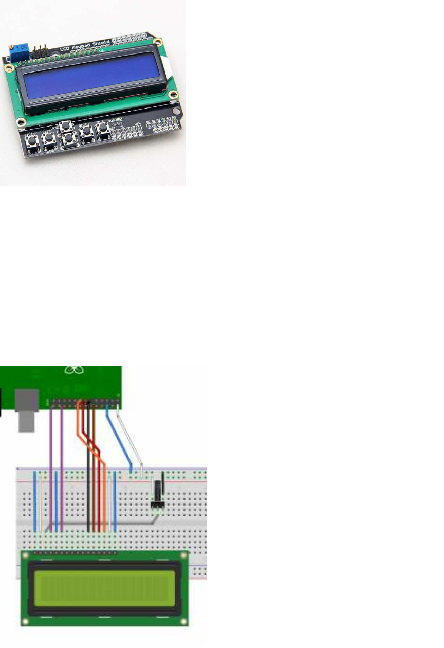
LCD 16x2 Keypad Shield
(Baustelle)
Anleitungen z.B. :
https://projects.drogon.net/raspberry-p ... d-library/
http://wiringpi.com/examples/adafruit-r ... -wiringpi/
Tutorial von Sunfounder (mit IC PCF8574):
https://www.sunfounder.com/learn/lesson-30-i2c-lcd1602-sensor-kit-v2-0-for-b-plus.html
Verkabelungs-Schema:

Original: https://projects.drogon.net/wp-content/ ... 5x1024.png
Beispiel-Code (ungetestet):
// LCD1602 test program acc. to wiringPi website
// https://projects.drogon.net/raspberry-pi/wiringpi/lcd-library/
// code taken from external website
// not tested
#include <wiringPi.h> // WiringPi headers
#include <lcd.h> // LCD headers from WiringPi
#include <stdio.h> // Needed for the printf function below
int main()
{
int flcd; //Handle for LCD
wiringPiSetup(); // Initialise WiringPi, Pin numbers are the WiringPi
pin numbers
// In the above Fritzing diagrams, the 4-bit one would be initialised by:
flcd = lcdInit (2, 16, 4, 11,10 , 0,1,2,3,0,0,0,0) ;
lcdPosition(flcd,0,0); //Pos. cursor on the 1st line in the 1st column
lcdPuts(flcd, "Hello World!"); //Print the text at the current cursor postion
lcdPosition(flcd,0,1); //Pos. cursor on the 2nd line in the 1st column
lcdPuts(flcd, "LCD1602 keypad"); //Print the text at the current cursor postion
getchar(); //Wait for key press
lcdClear(flcd); //Clear the display
return 0;
}
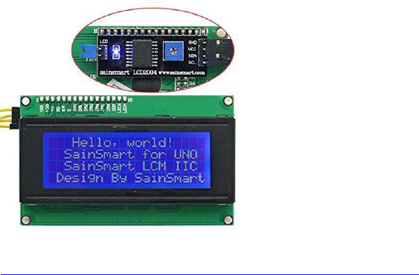
LCD I2C 20x4
z.B. SainSmart I2C/I2C/TWI Serial 2004 Character 20x4
https://www.amazon.de/SainSmart-Charact ... B007XRHBKA
Beispiel-Code (ungetestet):
#include <wiringPi.h> //WiringPi headers
#include <lcd.h> //LCD headers from WiringPi
#include <stdio.h> //Needed for the printf function below
#include <pcf8574.h>
#define AF_BASE 100
#define AF_RS AF_BASE
#define AF_RW (AF_BASE + 1)
#define AF_E (AF_BASE + 2)
#define AF_BL (AF_BASE + 3)
#define AF_DB4 (AF_BASE + 4)
#define AF_DB5 (AF_BASE + 5)
#define AF_DB6 (AF_BASE + 6)
#define AF_DB7 (AF_BASE + 7)
int main()
{
int flcd; //Handle for LCD
wiringPiSetup(); // Initialise WiringPi, Pin numbers are the
WiringPi pin numbers
pcf8574Setup(AF_BASE, 0x27) ;
flcd = lcdInit (4, 20, 4, AF_RS, AF_E, AF_DB4,AF_DB5,AF_DB6,AF_DB7,
0,0,0,0) ;
lcdPosition(flcd,0,0); //Position cursor on the first line in
the first column (0,0)
lcdPuts(flcd, "Hello World!"); //Print the text on the LCD at the
current cursor postion
lcdPosition(flcd,0,1); //Position cursor on the second line
in the first column (0,1)
lcdPuts(flcd, "LCD1602 keypad"); //Print the text on the LCD at the
current cursor postion
lcdPosition(flcd,0,2); //Position cursor on the 3rd line in
the first column (0,2)
lcdPuts(flcd, "3rd line");
lcdPosition(flcd,0,3); //Position cursor on the 4th line in
the first column (0,3)

lcdPuts(flcd, "4th line");
getchar(); //Wait for key press
lcdClear(flcd); //Clear the display
return 0;
Nativer Code:
/*
* lcd.c:
* Simple program to send a string to the LCD
*
https://www.raspberrypi.org/forums/viewtopic.php?f=33&t=93613&sid=3d66049c
784af04183fc1bd603f0ebb2
*/
#include <stdio.h>
#include <stdlib.h>
#include <wiringPi.h>
#define LCD_E 23
#define LCD_RS 22
#define LCD_D4 24
#define LCD_D5 25
#define LCD_D6 8
#define LCD_D7 7
void pulseEnable ()
{
digitalWrite (LCD_E, HIGH) ;
delay(0.5); // 1/2 microsecond pause - enable pulse must be > 450ns
digitalWrite (LCD_E, LOW) ;
}
/*
send a byte to the lcd in two nibbles
before calling use SetChrMode or SetCmdMode to determine whether to send
character or command
*/
void lcd_byte(char bits)
{
digitalWrite (LCD_D4,(bits & 0x10)) ;
digitalWrite (LCD_D5,(bits & 0x20)) ;
digitalWrite (LCD_D6,(bits & 0x40)) ;
digitalWrite (LCD_D7,(bits & 0x80)) ;
pulseEnable();
digitalWrite (LCD_D4,(bits & 0x1)) ;
digitalWrite (LCD_D5,(bits & 0x2)) ;
digitalWrite (LCD_D6,(bits & 0x4)) ;
digitalWrite (LCD_D7,(bits & 0x8)) ;
pulseEnable();
}
*
void SetCmdMode()
{
digitalWrite (LCD_RS, 0); // set for commands
}
void SetChrMode()
{
digitalWrite (LCD_RS, 1); // set for characters
}
void lcd_text(char *s)
{
while(*s)
lcd_byte(*s++);
}
void lcd_init()
{
wiringPiSetupGpio () ; // use BCIM numbering
// set up pi pins for output
pinMode (LCD_E, OUTPUT);
pinMode (LCD_RS, OUTPUT);
pinMode (LCD_D4, OUTPUT);
pinMode (LCD_D5, OUTPUT);
pinMode (LCD_D6, OUTPUT);
pinMode (LCD_D7, OUTPUT);
// initialise LCD
SetCmdMode(); // set for commands
lcd_byte(0x33); // full init
lcd_byte(0x32); // 4 bit mode
lcd_byte(0x28); // 2 line mode
lcd_byte(0x0C); // display on, cursor off, blink off
lcd_byte(0x01); // clear screen
delay(3); // clear screen is slow!
}
int main (int argc, char *argv [])
{
lcd_init();
SetChrMode();
if (argc>1)
lcd_text(argv[1]);
else
lcd_text("hello world!");
return 0 ;
}

sinnvolle C/C++ Zusatzfunktionen und Tipps
(optional, aus verschiedenen Foren zusammengetragen)
Verwendung der C11 Datentypen int8_t, int16_t usw...:
notwendig ist dafür das #include
#include <stdint.h>
Datentypen-Liste s. hier: http://www.raspberry-projects.com/pi/programming-in-
c/memory/variables
###########################################################
wmctrl - Terminal-Window mit veränderlicher Position und Größe:
wmctrl installieren:
sudo apt install wmctrl
Nun kann man im C-Programm die Fensterposition und -Größe per system call aufrufen:
// LXTerminal window at pos 200,200, size 800x640
system("wmctrl -r LXTerminal -e 0,200,200,800,640"); // no blanks between
numbers!
###########################################################
signal.h : catch key strokes (ctrl+C u. a.) :
#include <signal.h>
void signal_handler(int signum){ // signal handler function for key
strokes
if(signum == SIGINT ) { // ctrl+C pressed
// insert your command to close serial
exit(-3); // mimics ^C == (ASCII) 3
}
}
int main() {
signal(SIGINT, signal_handler); // register signal handler function to
catch SIGINT==^C
//...
}
###########################################################
rpiconio.h: Ersatz für kbhit() und getch():
#ifndef _RPICONIO_H
#define _RPICONIO_H
// courtesy of AndyD, raspberrypi.org forums, and peterfido, roboternetz.de
forum
// version 003
#include <stdbool.h>
#include <stdio.h>
#include <string.h>
#include <termio.h>
#include <unistd.h>
#include <linux/input.h>
#include <termios.h>
#include <signal.h>
#include <sys/types.h>
#include <dirent.h>
#include <sys/stat.h>
#include <sys/select.h>
// Terminal: move cursor
#define cursup "\033[A"
#define curshome "\033[0;0H"
#define cls_lxt "\033[2J"
// keyboard dev
int fkbd;
char * kbdin = "/dev/input/event0";
struct input_event ev[64];
int shiftl=0;
int shiftr=0;
int _keyshift_=0; // mod keypress state
int ctrll=0;
int ctrlr=0;
int _keyctrl_=0; // mod keypress state
int capsl=0;
int altl=0;
int altgr=0;
int _keyalt_=0; // mod keypress state
int windows=0;
int kontext=0;
int _keypress_=0; // keypress state
int modscode=0;
volatile int _kbscode_ ;
#define _ESC_ 1
#define _F1_ 59
#define _F2_ 60
#define _F3_ 61
#define _F4_ 62
#define _F5_ 63
#define _F6_ 64
#define _F7_ 65
#define _F8_ 66
#define _F9_ 67
#define _F10_ 68
#define _F11_ 69
#define _F12_ 70
//*************************************************************
// conio.h - mimics
//*************************************************************
bool kbhit(void)
{
struct termios original;
tcgetattr(STDIN_FILENO, &original);
struct termios term;
memcpy(&term, &original, sizeof(term));
term.c_lflag &= ~ICANON;
tcsetattr(STDIN_FILENO, TCSANOW, &term);
int characters_buffered = 0;
ioctl(STDIN_FILENO, FIONREAD, &characters_buffered);
tcsetattr(STDIN_FILENO, TCSANOW, &original);
bool pressed = (characters_buffered != 0);
return pressed;
}
void echoOff(void)
{
struct termios term;
tcgetattr(STDIN_FILENO, &term);
term.c_lflag &= ~ECHO;
tcsetattr(STDIN_FILENO, TCSANOW, &term);
}
void echoOn(void)
{
struct termios term;
tcgetattr(STDIN_FILENO, &term);
term.c_lflag |= ECHO;
tcsetattr(STDIN_FILENO, TCSANOW, &term);
}
//*************************************************************
// keyboard scancode
//*************************************************************
int getkbscancode() {
int rd, size = sizeof (struct input_event);
int keybscan=0; // scan code "normal key"
if ((rd = read (fkbd, ev, size * 64)) < size)
printf ("Fehler mit Tastatur");
if (ev[1].type != EV_KEY) return 0;
if (ev[1].value==0){ //Taste losgelassen
switch (ev[1].code) {
case 42: shiftl=0; break;
case 54: shiftr=0; break;
case 29: ctrll=0; break;
case 97: ctrlr=0; break;
case 56: altl=0; break;
case 125: windows=0; break;
case 100: altgr=0; break;
case 127: kontext=0; break;
}
}
else
{
if (ev[1].value==1){
//==1 fuer nur einen Druck ohne Wiederholung. >=1 fuer
Erkennung von gedrueckt gehaltener Taste
modscode = 0;
switch (ev[1].code) {
case 42: shiftl=1; break;
case 54: shiftr=1; break;
case 29: ctrll=1; break;
case 97: ctrlr=1; break;
case 56: altl=1; break;
case 125: windows=1; break;
case 100: altgr=1; break;
case 127: kontext=1; break;
// Ab hier 'normale Tasten'
default: keybscan=ev[1].code;// Scancode ablegen
_keypress_ = keybscan; // standard keypress state
_keyshift_ = 0; // reset modifier key pressed
_keyalt_ = 0;
_keyctrl_ = 0;
if(shiftl || shiftr ) { modscode+=1024; _keyshift_=1; }
if(ctrll || ctrlr ) { modscode+=2048; _keyctrl_=1; }
if(altl) { modscode+=4096; _keyalt_=1; }
if(altgr) { modscode+=(2048+4096);
_keyalt_=1; _keyctrl_=1; }
if(windows) modscode+=8192;
if(kontext) modscode+=16384;
if(keybscan>0) {
_kbscode_= keybscan + modscode;
return keybscan;
}
else return 0 ;
//break;
}
}
}
return 0 ;
}
int setupKbdin() {
if ((fkbd = open (kbdin, O_RDONLY)) == -1){
printf ("Keyboard error");
return -1;
}
else return 0;
}
#endif
Testcode:
Code:
//=========================================================================
// Testcode:
//=========================================================================
#include <stdio.h>
#include <unistd.h>
#include "rpiconio.h"
int main(void)
{
long i=0;
int c = '\0';
while (c != 'q') { // press 'q' to quit
if (kbhit())
{
echoOff();
c = getchar();
echoOn();
printf("(hier ggf. auskommentieren: got key \'%c\'\n", c);
if(c==27) { printf("\nuser break\n"); return 1; }
}
delay(100);
}
echoOn();
return 0;
}
###########################################################

Zenity : Datei-Auswahl im Fenster-Menü
ähnlich OpenFileDialog/SaveFileDialog:
zenity --file-selection über pipe einlesen:
Code: http://www.mindstormsforum.de/viewtopic.php?f=78&t=8689&start=75
popen("zenity --file-selection", "r"))
Beispielcode (Danke an peterfido und Sisor, Roboternetz-Forum):
FILE *f;
if(!(f = popen("zenity --file-selection", "r"))){
strcpy(Dateiname,"Falsch");
exit(1);
}
char Text[1024]="";
fgets(Text, sizeof(Text), f);
fclose(f);
if(strlen(Text)<2){ //Kein Dateiname / Abbrechen geklickt, etc
strcpy(Dateiname,"Falsch");
}
else
{ //Dateiname sollte in Text stehen.
strcpy(Dateiname,Text);
}
#include <stdio.h>
#include <string.h>
#include <stdlib.h>
int main() {
FILE *f;
char Dateiname[1024] = "";
int c;
/* Zenity für File-Dialog benutzen */
freopen("/dev/null", "w", stderr); // Warnungen von zenity ignorieren
if(!(f = popen("zenity --file-selection", "r"))){
strcpy(Dateiname, "Falsch");
exit(1);
}
freopen("/dev/tty", "w", stderr);
fgets(Dateiname, sizeof(Dateiname), f);
fclose(f);
if(strlen(Dateiname) < 2){ //Kein Dateiname übergeben / Abbrechen
geklickt, etc
strcpy(Dateiname, "Falsch");
}
/* Inhalt der Datei ausgeben */
printf("Dateiname: %s", Dateiname);
Dateiname[strlen(Dateiname)-1] = '\0'; // '\n'-Stringende entfernen

f = fopen(Dateiname, "r");
if (f) {
while ((c = fgetc(f)) != EOF) putchar(c);
fclose(f);
}
}
http://www.roboternetz.de/community/thr ... post628328
###########################################################

Audio Aufnahme und Wiedergabe
(Kopfhörerausgang, ggf. HDMI)
A.) Töne über die Konsole abspielen
a) Töne abspielen
http://workshop.raspberrypiaustralia.co ... ing-audio/
speaker-test -t sine -f 440 -l 1
b) .wav files abspielen
Code: Alles auswählen
aplay ~/sample.wav
Beispiel-Sounds: /usr/share/sounds/alsa directory
c) wav-Dateien mit Audio-Player verknüpfen
wav-File auswählen, rechter Mausklick
-> Kontext-Menü
-> Datei-Eigenschaften
-> "Öffnen mit"
-> Kartei-Karte für "eigene Befehlszeile"
-> Kommandozeile: omxplayer %f
-> Anwendungs-Name: Omxplayer
-> OK
Nachteil: Lautstärke nicht über Menü-Leiste regelbar
B. Audio Files (.wav) in C-Programmen abspielen und aufnehmen:
a) System Funktion verwenden:
Muster:
#include <cstdlib>
using namespace std;
void PlaySound(std::string filename){
system( ("aplay " + filename).c_str() );
}
// ...
PlaySound("m1.wav");
b) eigene programmierte Funktion verwenden (nicht getestet):
sudo apt-get install libasound2-dev
Compile / Build Parameter: -lasoundlib
Sound Chips listen:
aplay -l
Sound-Chip auswählen:
1. Soundchip intern: plughw:0,0
2. Soundchip extern: plughw:0,1
Beispielcode (Beispiel-wav- File = "/home/pi/programs/sounds/well.wav")
// alsa implementation: courtesy of "hirnfrei" :)
#include <alsa/asoundlib.h>
#include <iostream>
#include <vector>
#include <stdio.h>
#include <stdlib.h>
#include <unistd.h>
#include <fcntl.h>
#include <time.h>
using namespace std;
typedef struct _FILE_head
{
unsigned char ID[4];
unsigned int Length;
unsigned char Type[4];
} FILE_head;
typedef struct _FORMAT
{
short wFormatTag;
unsigned short wChannels;
unsigned int dwSamplesPerSec;
unsigned int dwAvgBytesPerSec;
unsigned short wBlockAlign;
unsigned short wBitsPerSample;
} FORMAT;
typedef struct _CHUNK_head
{
unsigned char ID[4];
unsigned int Length;
} CHUNK_head;
snd_pcm_t *soundKarte;
bool Init(string name, unsigned int channels, unsigned int actualRate,
unsigned short WaveBits)
{
int err;
snd_pcm_format_t bits;
unsigned int resample = 1;
switch(WaveBits)
{
case 8:
bits = SND_PCM_FORMAT_U8;
break;
case 16:
bits = SND_PCM_FORMAT_S16;
break;
case 24:
bits = SND_PCM_FORMAT_S24;
break;
case 32:
bits = SND_PCM_FORMAT_S32;
break;
}
snd_pcm_hw_params_t *hw_params;
if(name.length() == 0)
{
err = snd_pcm_open(&soundKarte, "plughw:1,0",
SND_PCM_STREAM_PLAYBACK, 0);
}
else
{
err = snd_pcm_open(&soundKarte, name.c_str(),
SND_PCM_STREAM_PLAYBACK, 0);
}
if(err < 0)
{
cout << "Init: Kann die Soundkarte nicht öffnen! " << name << " (" <<
snd_strerror (err) << ")" << endl;
return false;
}
if((err = snd_pcm_hw_params_malloc(&hw_params)) < 0)
{
cout << "Init: Parameter können nicht initialisiert werden (" <<
snd_strerror (err) << ")" << endl;
return false;
}
if((err = snd_pcm_hw_params_any(soundKarte, hw_params)) < 0)
{
cout << "Init: Parameter können nicht ermittelt werden (" <<
snd_strerror (err) << ")" << endl;
return false;
}
err = snd_pcm_hw_params_set_rate_resample(soundKarte, hw_params,
resample);
if(err < 0)
{
cout << "Init: Resampling kann nicht eingeschaltet werden " <<
snd_strerror(err) << endl;
return err;
}
if((err = snd_pcm_hw_params_set_access(soundKarte, hw_params,
SND_PCM_ACCESS_RW_INTERLEAVED)) < 0)
{
cout << "Init: Zugriffstyp kann nicht gesetzt werden (" <<
snd_strerror (err) << ")" << endl;
return false;
}
if((err = snd_pcm_hw_params_set_format(soundKarte, hw_params, bits)) <
0)
{
cout << "Init: Sample-Format kann nicht gesetzt werden (" <<
snd_strerror (err) << ")" << endl;
return false;
}
if((err = snd_pcm_hw_params_set_channels(soundKarte, hw_params,
channels)) < 0)
{
cout << "Init: Anzahl der Kanäle kann nicht gesetzt werden (" <<
snd_strerror (err) << ")" << endl;
return false;
}
if((err = snd_pcm_hw_params_set_rate_near(soundKarte, hw_params,
&actualRate, 0)) < 0)
{
cout << "Init: Sample-Rate kann nicht auf " << actualRate << "
gesetzt werden (" << snd_strerror (err) << ")" << endl;
return false;
}
if((err = snd_pcm_hw_params(soundKarte, hw_params)) < 0)
{
cout << "Init: Parameters können nicht gesetzt werden(" <<
snd_strerror (err) << ")" << endl;
return false;
}
snd_pcm_hw_params_free(hw_params);
if((err = snd_pcm_prepare(soundKarte)) < 0)
{
cout << "Init: Audio kann nicht zur Nutzung vorbereitet werden (" <<
snd_strerror (err) << ")" << endl;
return false;
}
return true;
}
bool InitCapture(string name, unsigned int channels, unsigned int
actualRate, unsigned short WaveBits)
{
int err;
snd_pcm_format_t bits;
switch(WaveBits)
{
case 8:
bits = SND_PCM_FORMAT_U8;
break;
case 16:
bits = SND_PCM_FORMAT_S16;
break;
case 24:
bits = SND_PCM_FORMAT_S24;
break;
case 32:
bits = SND_PCM_FORMAT_S32;
break;
}
snd_pcm_hw_params_t *hw_params;
if(name.length() == 0)
{
err = snd_pcm_open(&soundKarte, "plughw:1,0", SND_PCM_STREAM_CAPTURE,
0);
}
else
{
err = snd_pcm_open(&soundKarte, name.c_str(), SND_PCM_STREAM_CAPTURE,
0);
}
if(err < 0)
{
cout << "Init: Kann die Soundkarte nicht öffnen! " << name << " (" <<
snd_strerror (err) << ")" << endl;
return false;
}
if((err = snd_pcm_hw_params_malloc(&hw_params)) < 0)
{
cout << "Init: Parameter können nicht initialisiert werden (" <<
snd_strerror (err) << ")" << endl;
return false;
}
if((err = snd_pcm_hw_params_any(soundKarte, hw_params)) < 0)
{
cout << "Init: Parameter können nicht ermittelt werden (" <<
snd_strerror (err) << ")" << endl;
return false;
}
if((err = snd_pcm_hw_params_set_access(soundKarte, hw_params,
SND_PCM_ACCESS_RW_INTERLEAVED)) < 0)
{
cout << "Init: Zugriffstyp kann nicht gesetzt werden (" <<
snd_strerror (err) << ")" << endl;
return false;
}
if((err = snd_pcm_hw_params_set_format(soundKarte, hw_params, bits)) <
0)
{
cout << "Init: Sample-Format kann nicht gesetzt werden (" <<
snd_strerror (err) << ")" << endl;
return false;
}
if((err = snd_pcm_hw_params_set_channels(soundKarte, hw_params,
channels)) < 0)
{
cout << "Init: Anzahl der Kanäle kann nicht gesetzt werden (" <<
snd_strerror (err) << ")" << endl;
return false;
}
if((err = snd_pcm_hw_params_set_rate_near(soundKarte, hw_params,
&actualRate, 0)) < 0)
{
cout << "Init: Sample-Rate kann nicht auf " << actualRate << "
gesetzt werden (" << snd_strerror (err) << ")" << endl;
return false;
}
if((err = snd_pcm_hw_params(soundKarte, hw_params)) < 0)
{
cout << "Init: Parameters können nicht gesetzt werden(" <<
snd_strerror (err) << ")" << endl;
return false;
}
snd_pcm_hw_params_free(hw_params);
if((err = snd_pcm_prepare(soundKarte)) < 0)
{
cout << "Init: Audio kann nicht zur Nutzung vorbereitet werden (" <<
snd_strerror (err) << ")" << endl;
return false;
}
return true;
}
bool UnInit()
{
snd_pcm_close(soundKarte);
return true;
}
int playwave(string waveDatei, string name)
{
FORMAT format;
FILE_head head;
CHUNK_head chead;
char *wave;
register snd_pcm_uframes_t count, frames;
int datei;
unsigned int WaveSize;
datei = open(waveDatei.c_str(), 00);
read(datei, &head, sizeof(FILE_head));
read(datei, &chead, sizeof(CHUNK_head));
read(datei, &format, sizeof(FORMAT));
wave = (char *) malloc(head.Length);
read(datei, wave, head.Length);
WaveSize = head.Length * 8 / ((unsigned int)format.wBitsPerSample *
(unsigned int)format.wChannels);
close(datei);
Init(name, format.wChannels, format.dwSamplesPerSec,
format.wBitsPerSample);
count = 0;
do
{
frames = snd_pcm_writei(soundKarte, wave + count, WaveSize - count);
if (frames < 0) frames = snd_pcm_recover(soundKarte, frames, 0);
if (frames < 0)
{
printf("Kann wav nicht abspielen: %s\n", snd_strerror(frames));
break;
}
count += frames;
} while (count < WaveSize);
if (count == WaveSize) snd_pcm_drain(soundKarte);
free(wave);
UnInit();
return 0;
}
vector<int> audioCapture(int sek, string name, unsigned int channels,
unsigned int actualRate, unsigned short WaveBits)
{
int err, zielzeit;
char *puffer;
vector<int> input;
time_t t;
t = time(NULL);
zielzeit = t + sek;
puffer = (char *) malloc(1);
cout << "Beginne Aufnahme von " << sek << " Sekunden!" << endl;
if(InitCapture(name, channels, actualRate, WaveBits))
{
while(t < zielzeit)
{
err = snd_pcm_readi(soundKarte, puffer, 1);
if(err < 0) cout << "Fehler bei der Aufnahme!" << endl;
input.push_back(puffer[0]);
t = time(NULL);
}
UnInit();
}
else cout << "Bei der Initialisierung ist ein Fehler aufgetreten!" <<
endl;
cout << "Aufnahme beendet!" << endl;
return input;
}
void playCaptured(char *wave, unsigned int WaveSize, string name, unsigned
int channels, unsigned int actualRate, unsigned short WaveBits)
{
register snd_pcm_uframes_t count, frames;
Init(name, channels, actualRate, WaveBits);
WaveSize = WaveSize * 8 / WaveBits * channels;
count = 0;
// for(int i=0;i<WaveSize-2;i++) printf("%d/%d -> %d\n", i, WaveSize,
wave[i]);
do
{
frames = snd_pcm_writei(soundKarte, wave + count, WaveSize - count);
if(frames < 0) frames = snd_pcm_recover(soundKarte, frames, 0);
if(frames < 0)
{
printf("Kann wav nicht abspielen: %s\n", snd_strerror(frames));
break;
}
count += frames;
} while (count < WaveSize);
if (count == WaveSize) snd_pcm_drain(soundKarte);
UnInit();
}
Aufruf der Play-wav-Funktion:
playwave(Dateiname, Soundkarte);
//zB:
playwave("/home/pi/Music/cantalow.wav", "plughw:1,0");
Beispiel für main():
#include <iostream>
#include <vector>
#include <stdio.h>
#include "diaSound.hpp"
int main()
{
vector<int> input;
unsigned int i;
char *wave;
input = audioCapture(5, "plughw:1,0", 1, 44100, 8);
wave = (char *) malloc(input.size());
for(i=0;i<input.size();i++)
{
wave[i] = input[i];
}
playCaptured(wave, input.size(), "plughw:1,0", 1, 44100, 8);
free(wave);
return 1;
}

Arduino-IDE und Raspberry Pi :
Arduino-IDE auf Raspberry Pi installieren
(Arduino IDE zum Programmieren von Arduinos wie vom PC aus)
neue Anleitung:
wget http://downloads.arduino.cc/arduino-1.8.5-linuxarm.tar.xz
tar -x -f arduino-1.8.5-linuxarm.tar.xz
alte Anleitung:
661#p1070661 hat geschrieben:1. Go to https://www.arduino.cc and download
the Arduino IDE 1.6.12 for the ARM processor.
2. Open a terminal window.
3. Type cd ~/Downloads
4. Type tar -xvf arduino -1.6.12-*.tar.xz
5. Type sudo mv arduino-1.6.12 /opt
6. Type cd /opt/arduino-1.6.12/
7. Type chmod +x install.sh
8. Type ./install.sh
Arduino Framework für den Raspberry Pi
(Arduino Sketch-kompatible API um den Raspi zu programmieren)
https://github.com/me-no-dev/RasPiArduino
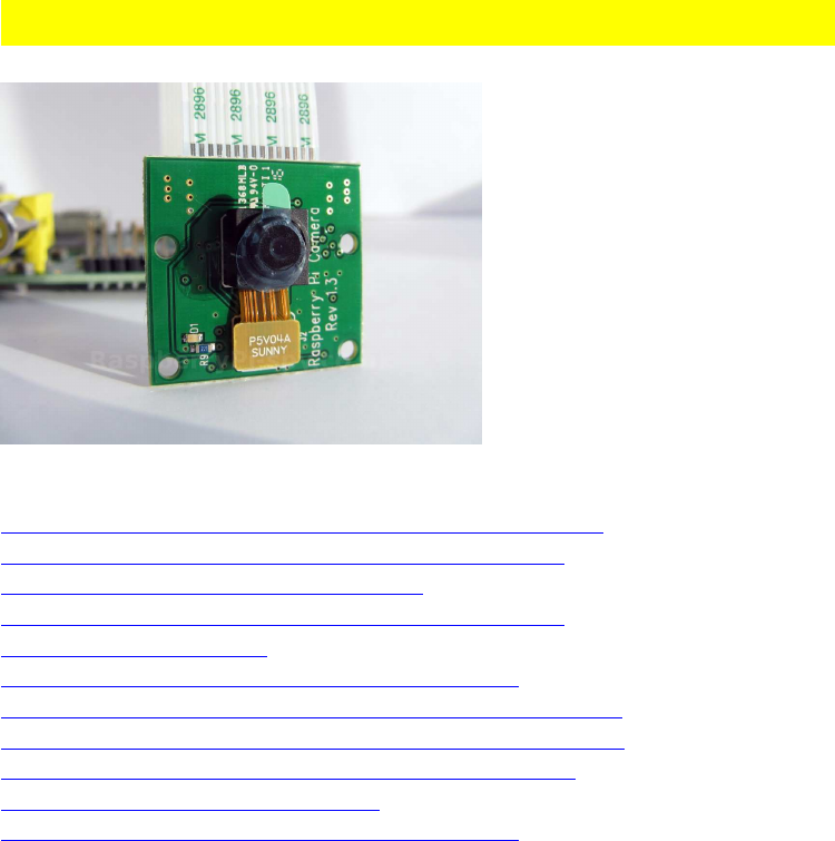
Pi Cam C/C++ libs und Tutorials (Baustelle):
Basis-Informationen, Installation, Low-level-Funktionen:
https://www.raspberrypi.org/help/camera-module-setup/
http://robotblogging.blogspot.de/2013/1 ... i-for.html
https://github.com/raspberrypi/userland
http://robotblogging.blogspot.co.uk/201 ... i-for.html
http://lodev.org/lodepng/
http://www.uco.es/investiga/grupos/ava/node/40
https://www.raspberrypi.org/forums/view ... 9&p=447001
https://www.raspberrypi.org/forums/view ... 20from%20C
http://opencv-srf.blogspot.com/2010/09/ ... ation.html
https://github.com/omwah/pixy_rpi
http://www.uco.es/investiga/grupos/ava/node/40 C++ API, mit/ohne openCV

openCV ComputerVision
(CV == Computer Vision)
a) openCV Literatur, Quellen:
http://opencv.org/
https://de.wikipedia.org/wiki/OpenCV
https://en.wikipedia.org/wiki/OpenCV
https://github.com/opencv/opencv
https://sourceforge.net/projects/opencvlibrary/
http://opencv-srf.blogspot.de/p/opencv-c-tutorials.html
https://www.heise.de/developer/meldung/ ... 79528.html
https://www.learnopencv.com/
praktische Beispiele für openCV mit Python (!) zur Einstimmung:
https://www.youtube.com/watch?v=MWK55A0RH0U
https://www.youtube.com/watch?v=qcF5PFXZC3o
https://www.youtube.com/watch?v=fns19y9NOpM
https://www.youtube.com/watch?v=tpwokAPiqfs
https://www.youtube.com/watch?v=o2ul4KrLT-s
https://www.youtube.com/watch?v=el7RR_QN1ts
https://gist.github.com/flyboy74/1dfe40 ... e36a38496f
b) openCV: Installation, Libraries, Compile/Link Flags
Installation:
sudo apt-get update
sudo apt-get upgrade
# opencv
sudo apt-get install libopencv-dev
#Auswahl von Cam Tools:
apt sarch webcam
# cam tool guvcview
sudo apt install guvcview
# alternativ z.B.:
# cam tool camorama
sudo apt install camorama
Test Programm:
#include "opencv2/opencv.hpp"
using namespace cv;
int main(int argc, char** argv)

{
VideoCapture cap;
// open the default camera, use something different from 0 otherwise;
// Check VideoCapture documentation.
if(!cap.open(0))
return 0;
for(;;)
{
Mat frame;
cap >> frame;
if( frame.empty() ) break; // end of video stream
imshow("this is you, smile! :)", frame);
if( (waitKey(10)%256) == 27 ) break; // waitKeypatch: check for
10ms: then stop capturing by pressing ESC=27
}
// the camera will be closed automatically upon exit
// cap.close();
return 0;
}
compile parameters/flags:
gcc -o test test.cpp -lopencv_highgui -lopencv_core -lstdc++
g++ -o test test.cpp -lopencv_highgui -lopencv_core
komplette Übersicht über alle vorhandenen flags für alle verfügbaren Module:
pkg-config --libs-only-l opencv
Code:
-lopencv_calib3d -lopencv_contrib -lopencv_core -lopencv_features2d -
lopencv_flann -lopencv_gpu -lopencv_highgui -lopencv_imgproc -
lopencv_legacy -lopencv_ml -lopencv_objdetect -lopencv_ocl -lopencv_photo -
lopencv_stitching -lopencv_superres -lopencv_ts -lopencv_video -
lopencv_videostab
es scheint möglich zusein, dass man alle evtl. nötigen openCV libs auf einen Schlag
mitcompiliert/linkt stattdessen durch den Flag
Code:
$(pkg-config --cflags --libs opencv)
c) openCV Anwendungen:
1.) Color Blob separieren, Anzeige auf s/w Threshold Image
http://opencv-srf.blogspot.de/2010/09/object-detection-using-color-seperation.html
#include <iostream>
#include "opencv2/highgui/highgui.hpp"
#include "opencv2/imgproc/imgproc.hpp"
/*
* build flags:
-lopencv_calib3d -lopencv_contrib -lopencv_core -lopencv_features2d -
lopencv_flann -lopencv_gpu -lopencv_highgui -lopencv_imgproc -
lopencv_legacy -lopencv_ml -lopencv_objdetect -lopencv_ocl -lopencv_photo -
lopencv_stitching -lopencv_superres -lopencv_ts -lopencv_video -
lopencv_videostab
*/
/* exp. thesholds:
* blue red
*
* LowH 125 0
* HighH 150 179
* LowS 100 127
* HighS 250 255
* LowV 50 255
* HighV 255 255
* */
using namespace cv;
using namespace std;
int main( int argc, char** argv )
{
VideoCapture cap(0); //capture the video from web cam
if ( !cap.isOpened() ) // if not success, exit program
{
cout << "Cannot open the web cam" << endl;
return -1;
}
namedWindow("Control", CV_WINDOW_AUTOSIZE); //create a window called
"Control"
int iLowH = 0;
int iHighH = 179;
int iLowS = 0;
int iHighS = 255;
int iLowV = 0;
int iHighV = 255;
//Create trackbars in "Control" window
cvCreateTrackbar("LowH", "Control", &iLowH, 179); //Hue (0 - 179)
cvCreateTrackbar("HighH", "Control", &iHighH, 179);
cvCreateTrackbar("LowS", "Control", &iLowS, 255); //Saturation (0 - 255)
cvCreateTrackbar("HighS", "Control", &iHighS, 255);
cvCreateTrackbar("LowV", "Control", &iLowV, 255); //Value (0 - 255)
cvCreateTrackbar("HighV", "Control", &iHighV, 255);
while (true)
{
Mat imgOriginal;
bool bSuccess = cap.read(imgOriginal); // read a new frame from
video
if (!bSuccess) //if not success, break loop
{
cout << "Cannot read a frame from video stream" << endl;
break;
}
Mat imgHSV;
cvtColor(imgOriginal, imgHSV, COLOR_BGR2HSV); //Convert the captured
frame from BGR to HSV
Mat imgThresholded;
inRange(imgHSV, Scalar(iLowH, iLowS, iLowV), Scalar(iHighH, iHighS,
iHighV), imgThresholded); //Threshold the image
//morphological opening (remove small objects from the foreground)
erode(imgThresholded, imgThresholded,
getStructuringElement(MORPH_ELLIPSE, Size(5, 5)) );
dilate( imgThresholded, imgThresholded,
getStructuringElement(MORPH_ELLIPSE, Size(5, 5)) );
//morphological closing (fill small holes in the foreground)
dilate( imgThresholded, imgThresholded,
getStructuringElement(MORPH_ELLIPSE, Size(5, 5)) );
erode(imgThresholded, imgThresholded,
getStructuringElement(MORPH_ELLIPSE, Size(5, 5)) );
imshow("Thresholded Image", imgThresholded); //show the thresholded image
imshow("Original", imgOriginal); //show the original image
if (waitKey(30) == 27) //wait for 'esc' key press for 30ms. If
'esc' key is pressed, break loop
{
cout << "esc key is pressed by user" << endl;
break;
}
}
return 0;
}
Hinweis:
Hue values of basic colors
Orange 0-22
Yellow 22- 38
Green 38-75
Blue 75-130
Violet 130-160
Red 160-179

2.) Tracking von farbigen Objekten:
tracking colored objects:
http://opencv-srf.blogspot.de/2010/09/o ... ation.html
#include <iostream>
#include "opencv2/highgui/highgui.hpp"
#include "opencv2/imgproc/imgproc.hpp"
using namespace cv;
using namespace std;
int main( int argc, char** argv )
{
VideoCapture cap(0); //capture the video from webcam
if ( !cap.isOpened() ) // if not success, exit program
{
cout << "Cannot open the web cam" << endl;
return -1;
}
namedWindow("Control", CV_WINDOW_AUTOSIZE); //create a window called
"Control"
int iLowH = 170;
int iHighH = 179;
int iLowS = 150;
int iHighS = 255;
int iLowV = 60;
int iHighV = 255;
//Create trackbars in "Control" window
createTrackbar("LowH", "Control", &iLowH, 179); //Hue (0 - 179)
createTrackbar("HighH", "Control", &iHighH, 179);
createTrackbar("LowS", "Control", &iLowS, 255); //Saturation (0 - 255)
createTrackbar("HighS", "Control", &iHighS, 255);
createTrackbar("LowV", "Control", &iLowV, 255);//Value (0 - 255)
createTrackbar("HighV", "Control", &iHighV, 255);
int iLastX = -1;
int iLastY = -1;
//Capture a temporary image from the camera
Mat imgTmp;
cap.read(imgTmp);
//Create a black image with the size as the camera output
Mat imgLines = Mat::zeros( imgTmp.size(), CV_8UC3 );;
while (true)
{
Mat imgOriginal;
bool bSuccess = cap.read(imgOriginal); // read a new frame from
video
if (!bSuccess) //if not success, break loop
{
cout << "Cannot read a frame from video stream" << endl;
break;
}
Mat imgHSV;
cvtColor(imgOriginal, imgHSV, COLOR_BGR2HSV); //Convert the captured
frame from BGR to HSV
Mat imgThresholded;
inRange(imgHSV, Scalar(iLowH, iLowS, iLowV), Scalar(iHighH, iHighS,
iHighV), imgThresholded); //Threshold the image
//morphological opening (removes small objects from the foreground)
erode(imgThresholded, imgThresholded,
getStructuringElement(MORPH_ELLIPSE, Size(5, 5)) );
dilate( imgThresholded, imgThresholded,
getStructuringElement(MORPH_ELLIPSE, Size(5, 5)) );
//morphological closing (removes small holes from the foreground)
dilate( imgThresholded, imgThresholded,
getStructuringElement(MORPH_ELLIPSE, Size(5, 5)) );
erode(imgThresholded, imgThresholded,
getStructuringElement(MORPH_ELLIPSE, Size(5, 5)) );
//Calculate the moments of the thresholded image
Moments oMoments = moments(imgThresholded);
double dM01 = oMoments.m01;
double dM10 = oMoments.m10;
double dArea = oMoments.m00;
// if the area <= 10000, I consider that the there are no object in the
image and it's because of the noise, the area is not zero
if (dArea > 10000)
{
//calculate the position of the ball
int posX = dM10 / dArea;
int posY = dM01 / dArea;
if (iLastX >= 0 && iLastY >= 0 && posX >= 0 && posY >= 0)
{
//Draw a red line from the previous point to the current point
line(imgLines, Point(posX, posY), Point(iLastX, iLastY),
Scalar(0,0,255), 2);
}
iLastX = posX;
iLastY = posY;
}
imshow("Thresholded Image", imgThresholded); //show the thresholded image
imgOriginal = imgOriginal + imgLines;

imshow("Original", imgOriginal); //show the original image
if ( (waitKey(30)%256) == 27) //wait for 'esc' key press for 30ms.
If 'esc' key is pressed, break loop
{
cout << "esc key is pressed by user" << endl;
break;
}
}
return 0;
}
3.) Hinweise und weitere Links
a) Hinweise:
Die openCV waitKey() Funktion arbeitet offenbar (zumindest) nicht korrekt mit Raspian
zusammen -
Man muss aus dem gelesenen Wert das LSB extrahieren, damit eine Taste per ASCII Code
erkannt wird:
Code: Alles auswählen
(waitKey(30)%256) == 27 // anstelle waitKey(30) == 27
ein kleines #define behebt das Problem:
#define waitkey(n) (waitKey(n)%256)
b) weitere Links:
Object tracking:
https://www.youtube.com/watch?v=6Sw_KEe4a9c
https://www.youtube.com/watch?v=hQ-bpfdWQh8 Code:
https://github.com/akaifi/MultiObjectTr ... sedOnColor
https://www.youtube.com/watch?v=j0POMSW ... freload=10 (kein Code bisher)
Face recognition:
http://docs.opencv.org/2.4/modules/cont ... ition.html

GTK+, GTK++ : gtkIOStream
einfacher Einstieg über gtkiostream:
http://www.flatmax.org/gtkiostream/html/index.html
http://www.flatmax.org/gtkiostream/html ... ample.html
einfacher Programm-Rumpf:
Code: http://www.mindstormsforum.de/viewtopic.php?f=78&t=8689&start=75
#include <gtkInterface.H>
int main(){
gtk_init( &argc, &argv ); // init GTK
GtkInterface topWindow; // Create the top box
gtk_main(); // run GTK+
}
zusätzliche compile/build flags für gcc mit Geany:
Code: http://www.mindstormsforum.de/viewtopic.php?f=78&t=8689&start=75
$(pkg-config gtk+-2.0 --cflags --libs) -I/home/pi/gtkiostream-
1.5.0/include
weitere Tutorials hierzu sind hier verlinkt:
Overview: https://www.raspberrypi.org/forums/view ... 7&t=173531
Nachteil:
für sehr einfache Anwendungen zwar einigermaßen schnell zu benutzen, aber dann wird's
schnell schwierig, auch wegen ziemlich schlechtem Support von Seiten des Autors.
Tutorial über GTK3 und Glade:
http://www.peteronion.org.uk/GtkExamples/GladeTutorials.html

GTK 3 : glade-3
Installation:
http://prognotes.net/2015/12/installing ... -in-linux/
Tutorial:
http://prognotes.net/2016/03/gtk-3-c-co ... g-glade-3/
Nachteil:
arbeitet nicht direkt mit der Geany IDE und deren compiler/linker build Parametern
zusammen, sondern erfordert einen großen Overhead bezüglich makefiles und zusätzlichen
project files etc.
s. http://prognotes.net/2015/06/gtk-3-c-program-using-glade-3/
a) Installation von GTK+ 3:
Code: Alles auswählen
sudo apt-get install libgtk-3-dev
b) Installation von Glade:
Code: Alles auswählen
sudo apt-get install glade
c) Compile/build- Befehl:
Code: Alles auswählen
gcc -o gladewin main.c -Wall `pkg-config --cflags --libs gtk+-3.0` -export-
dynamic
für Geany: Zusatz zu "kompilieren" und "erstellen":
wie üblich
gcc/g++ -Wall "%f" "%e" ........ plus:
Code: Alles auswählen
$(pkg-config --cflags --libs gtk+-3.0) -export-dynamic

Qt :
1.) Qt 4 (5) und Qt Creator installieren :
sudo apt update
sudo apt upgrade
sudo apt-get install qt4-dev-tools libqt4-dev libqt4-dev-bin qt4-qmake
sudo apt install qtcreator
neu:
https://www.raspberrypi.org/forums/viewtopic.php?f=33&t=69163&p=1215892#p1043324
If anyone is trying to install Qt in a raspberry pi, and develop GUI in rpi, following are the
steps that you want to follow in a nutshell
1. Update your raspberry pi -
sudo apt-get update
2. Upgrade your raspberry pi -
sudo apt-get upgrade
3. Install Qt - (I have used Qt5) -
sudo apt-get install qt5-default
4. Install Qt creator
sudo apt-get install qtcreator
5. Open Qtcreator and go to Help > about plugins and and untick Remote Linux
6. Restart your raspberry pi
7. Again open Qt creator, go to "Tools > Options > Build and Run" and go to Compilers. Add
"GCC" set compiler path as /usr/bin/gcc
8. Normally Qt version and Debugger will be automatically set, but you can also set them
9. Then go to Kits (Still inside the Build and Run) and check whether Compiler, Debugger
and Qt version are set
10. That's it , click Ok and create a new project

2.) Tutorials und weiterführende Literatur:
https://wiki.qt.io/Basic_Qt_Programming_Tutorial
http://www.elektronik.nmp24.de/?Einplat ... _erstellen
https://de.wikibooks.org/wiki/Qt_f%C3%B ... %C3%A4nger
pdf-Download: https://de.wikibooks.org/wiki/Datei:QT_ ... A4nger.pdf
https://www.matse.itc.rwth-aachen.de/di ... hp?id=8048
3.) Schema zum Erstellen von Qt Projekten:
in beliebiges Arbeitsverzeichnis wechseln
ein Unterverzeichnis <projektname> erstellen und dort hinein wechseln
mit qtdesigner das spätere Fenster samt Qlabels, Qedits und QPushbuttons etc. entwerfen
+ speichern als "projektname.ui"
dann die zugehörigen .h und .cpp files per Editor programmieren
in diesem Unterverzeichnis sollen sich dann letztendlich befinden:
main.cpp, projektname.h, projektname.cpp, projektname.ui
in diesem Unterverzeichnis das LXterminal öffnen und nacheinander eingeben:
qmake -project
qmake
make
./projektname
Nachteile:
Wegen "make" und dem von qmake erzeugten makefile leider nicht aus Geany heraus
möglich, was die Fehlersuche und das Kompilieren/Erstellen in der Geany IDE erheblich
erschwert. Weiterhin muss alles haarklein selber programmiert werden, selbst jeder Rahmen
für jedes Element, alles längst nicht so einfach wie z.B. bei Borland C++ Builder wo dies
automatisch geschieht.
Vorteil gegenüber gtk: man muss wenigstens kein makefile per Hand editieren.

DONATE / SPENDE:
Gefällt dir dieses Kompendium und möchtest du dafür einen kleinen Betrag über PAYPAL spenden ?
Dann klicke einfach auf diesen Link -
Ab einer Spende ab EUR 5,- kannst du auf Wunsch dieses Kompendium auch als kostenloses
WORD.doc erhalten (per Download-Link als .zip, z.T. ein bisschen weniger Geräte-Fotos aus
urheberrechtlichen Gründen, dafür aber zusätzliche Infos und Code Beispiele):
-> Ja, ich möchte etwas als Anerkennung spenden <-
https://www.paypal.com/cgi-bin/webscr?cmd=_s-xclick&hosted_button_id=Q58RCVK67EM9Q
Ein ganz herzliches Dankeschön!
