Rational Rose Manual Part 2
User Manual:
Open the PDF directly: View PDF ![]() .
.
Page Count: 27
Rational Rose
1. Starting Rational Rose ...........................................................................................2
2. Creating a project Model in Rational Rose............................................................2
3. To set up a Use Case Diagram...............................................................................6
4. Draw a Class Diagram in Rational Rose..............................................................11
Adding other associations........................................................................................17
Generalisation ......................................................................................................17
Aggregation..........................................................................................................17
Composition.........................................................................................................18
5. Activity Diagram .................................................................................................18
6. Sequence Diagram ...............................................................................................19
7. Drawing a State Diagram.....................................................................................22
8. Collaboration Diagrams.......................................................................................22
9. Generating tables from classes.............................................................................24
Converting classes to tables.................................................................................24
In the component view:........................................................................................24
In the logical view:...............................................................................................24
Generating SQL ...........................................................................................................26
• Right click on the database ..............................................................................26
• Choose Data modeler.......................................................................................26
• Forward Engineer….........................................................................................26
What if??......................................................................................................................27

1. Starting Rational Rose
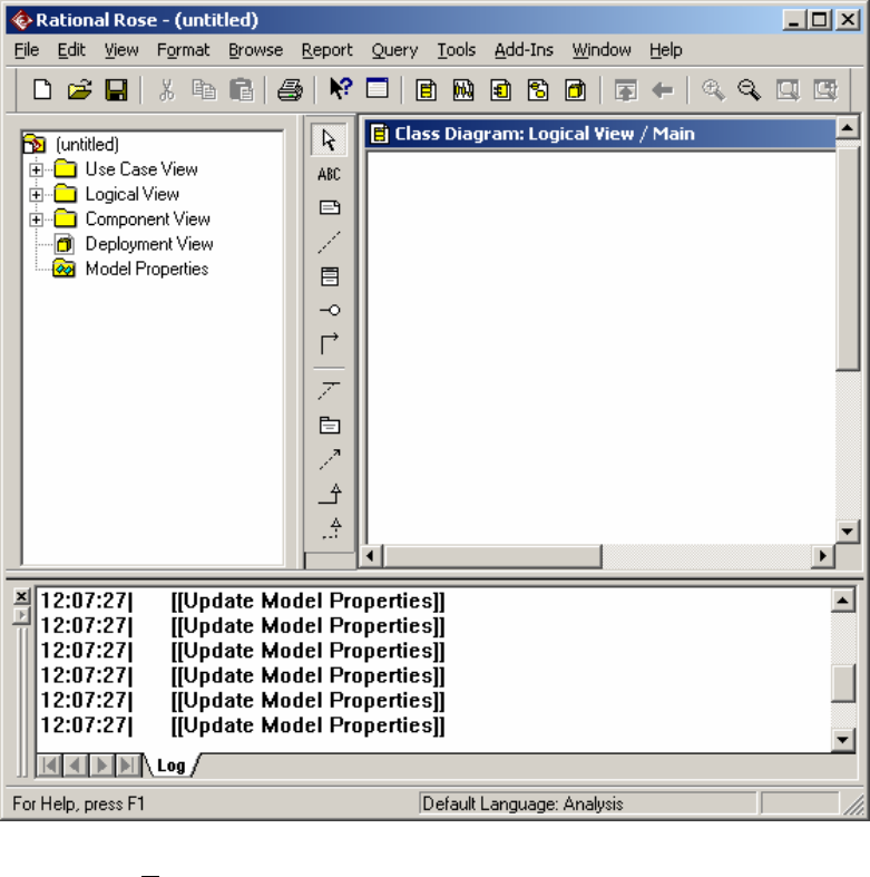
When Rational Rose starts up, the following screen is displayed.
Create a new model, using Rational Unified Process.
2. Creating a project Model in Rational Rose
1. Start up Rational Rose Enterprise Edition.
2. Create a new model using the Rational Unified Process icon.
3. The window you will see will look something like this:
4. Using the View menu, turn off the log window. You will be left with the
browser area on the left hand side, the application window, the standard
toolbar and the diagram toolbox. This toolbox changes depending on which
diagram you are drawing. The example shown is for a class diagram.
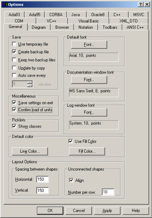
5. Configure the modelling tool, by double clicking Model Properties in the
browser. Configure the tabs General, Diagram, Browser, Notation and
Toolbars.
6. General, as follows
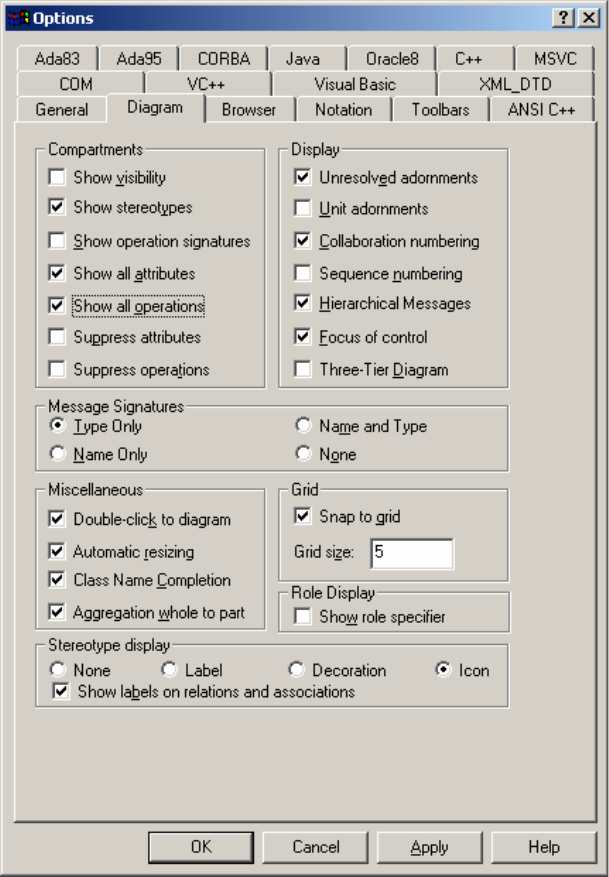
7. Diagram as follows:
8. Tick everything in the browser window and in the Notation window, use
Unified notation, with a default language of Java. Leave other tick boxes
blank.
9. In the toolbars tab, tick ‘Show standard toolbar’ and ‘Enable Docking’, ‘Show
Diagram toolbar’ and ‘Enable docking’. Click the ‘…’ beside UML class
diagram and add the following toolbar buttons to the current toolbar: ‘Creates
an Association relationship’, ‘Creates an aggregation’ and ‘creates a
unidirectional aggregation’. Click ‘close’ when all required buttons have been
added.
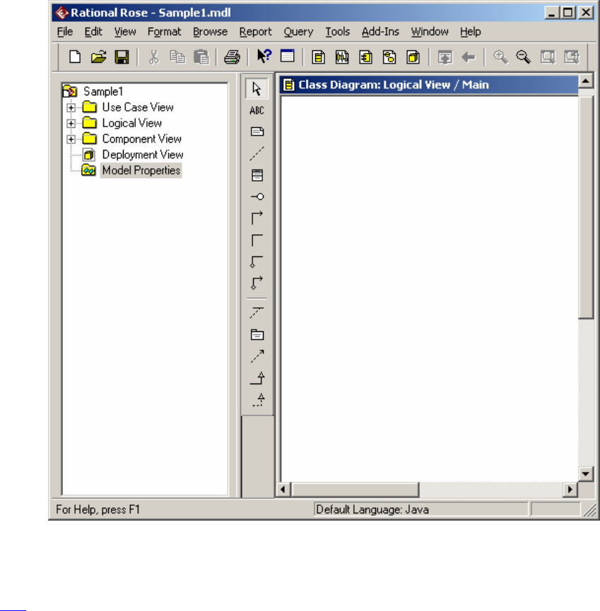
10. Save your empty project model in a directory that is easily identifiable to you:
e.g. F:/UML/Sample1. In future, this model will appear in the ‘recent’ tab
when you go to open a model.
11. Close the model and the tool.
Top
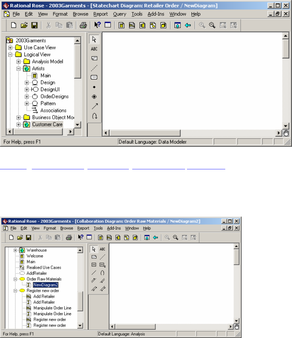
3. To set up a Use Case Diagram.
1. Open the model previously created by starting up Rational Rose Enterprise
Edition, choosing Create New Model and clicking the Existing tab and
selecting the model by name. If a class diagram is open in the application
window, close it.
2. In the Browser window, select Use Case View. Double click on Main. This
opens the main Use Case. Note that the diagram toolbar has changed to reflect
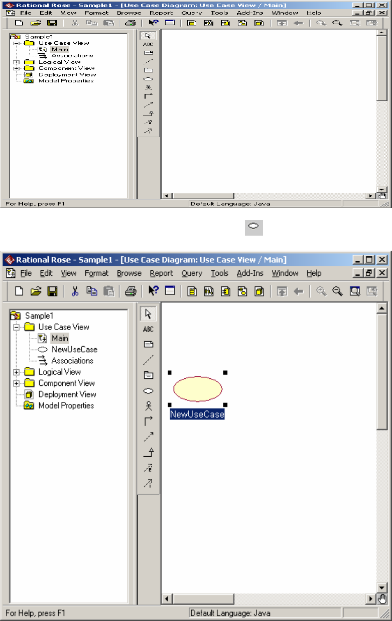
the fact that the active diagram is a Use Case diagram.
A Use Case can be added by clicking on the Use Case icon on the toolbar
and then clicking in the active diagram.
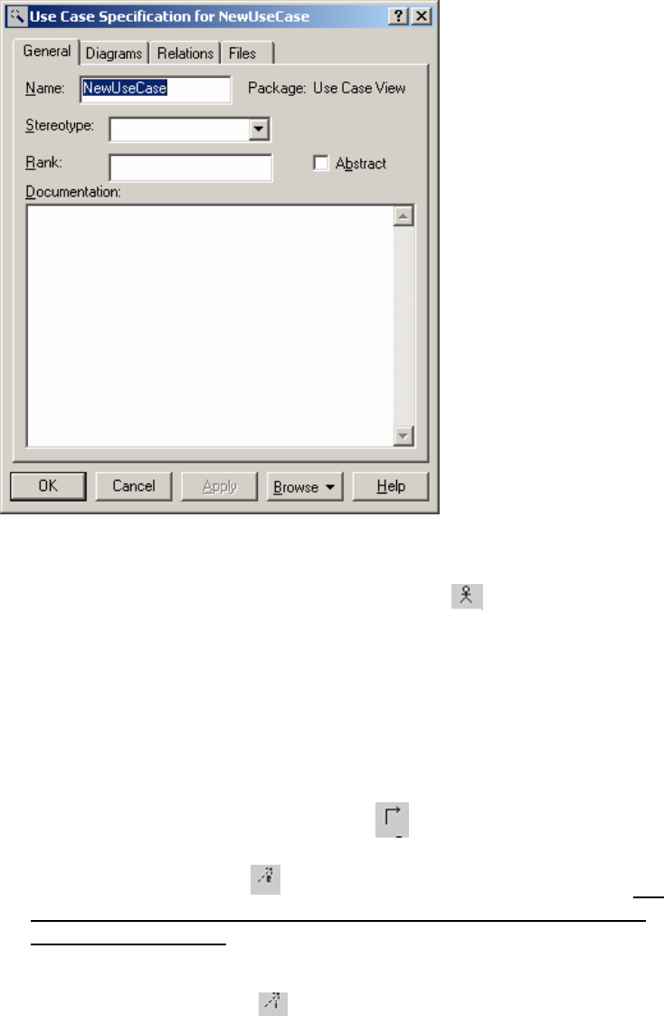
3. The Use Case can be renamed while it is highlighted in blue. To rename it
later, right click the use case and choose the Specification from the menu:
The use case can be renamed here.
4. Continue to add all necessary Use Cases to the diagram.
5. Add actors to the diagram by clicking on the Actor icon and clicking on
the active diagram. As new actors are named, they appear in a list below any
new actor that is represented on the diagram until such time as the new actor is
named. This allows for the same actor to appear on a diagram twice. If the
user decides to place the actor on the diagram twice, then (s)he will be
prompted with the warning ‘Newclass will be deleted from the model’
Yes/No. WARNING: If you want to delete a duplicate icon from the model,
be sure to use DEL – not Delete from Model. Delete from Model will remove
all information on that actor / usecase/ class from the model.!!!
6. Use the ‘Unidirectional Association’ icon to draw the associations
between actors and use cases.
7. Use the ‘Extend Use Case’ icon to extend a use case from another one. If
there is no button on the toolbar for this, right click on the toolbar and
choose “customize…”. This will bring up the set of possible buttons.
‘Extend Use Case’ and ‘Include Use Case’ are about half way down the list.
Add these to the toolbar and close the dialogue box.
8. Use the ‘Include Use Case’ to include the functionality of one use case in
another.
9. Note that the items appear in the browser window when you insert them into
the diagram.
10. If you wish to copy the diagram into Word, while the diagram is active,
choose Edit from the standard toolbar and ‘Copy Active Diagram’. This will
put the diagram into the paste buffer.
11. An actor can be a generalisation of another actor or actors.
12. The Font of the diagram can be changed by changing the ‘General’ tab in the
model properties, or by using the ‘format’ menu from the toolbar.
13. If you want to name a Use Case and you have left it, you can select it, right
click and choose ‘Open Specification’. Type over the current highlighted
name.
14. When you ‘save’ it saves the entire model. If you want to add another
diagram to this model, reopen the model.
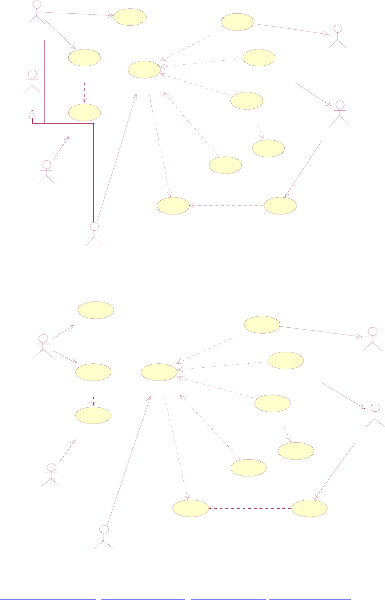
Settle with Payment
View Claim details
Make Payment
Report Incident
Third Party
Report Claim
<<extend>>
Assessor
Assess Claim
Refer to Underwriter
Underwriting
Company
Refer to Expert Witness
Driver Verify Incident
<<include>>
Expert Witness
Lodge Report
<<include>>
<<include>>
<<extend>>
Reject
<<extend>>
<<extend>>
<<extend>>
Employee
Settle with Payment
View Claim details
Make Payment
Report Incident
Third Party
Report Claim
<<extend>>
Assessor
Assess Claim
Refer to Underwriter
Underwriting
Company
Refer to Expert Witness
Driver
Verify Incident
<<include>>
Expert Witness
Lodge Report
<<include>>
<<include>>
<<extend>>
Reject
<<extend>>
<<extend>>
<<extend>>
Top of the Document Use Case Diagram ActivityDiagram SequenceDiagram
4. Draw a Class Diagram in Rational Rose
1. Start up Rational Rose using the Start Menu, Rational Suite Development
Studio and Rational Rose Enterprise Edition (with red diamond beside it).
2. Using the Create New Model dialogue box, click on the Recent tab. Your
project may be there. Alternately, click on the existing tab and browse to find
your model.
The following screen is automatically displayed:
3. In the browser window, Click on the ‘Logical View’ folder, right click, click
‘New’ and ‘Class Diagram’ to create a new class diagram, naming it
appropriately.
4. Open the new diagram by double-clicking its icon in the browser window.
5. Move the cursor over the icons on the Diagram Toolbox area to see what their
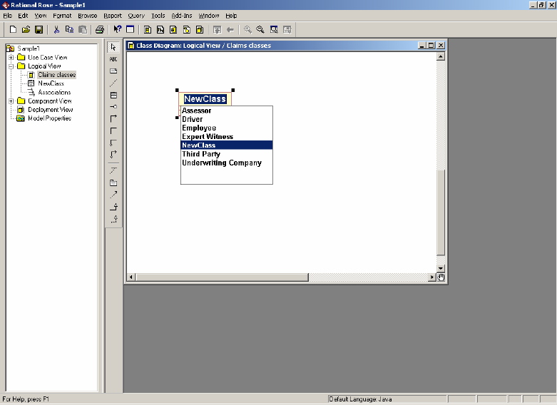
functions are. Use the class icon to create and place a class in the diagram.
Note that the actors are included as possible labels for the class. Ignore these and
replace the name NewClass with the name you want to put on the class. If you
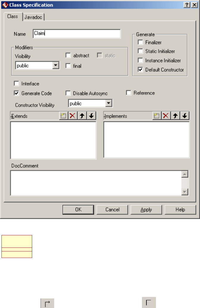
have omitted this step, you can rename it at any time by right-clicking on the class
and choosing ‘Open Specification’ as follows:
Leave all other boxes as they are for now. The class will be labelled, with two
empty compartments below it:
Claim
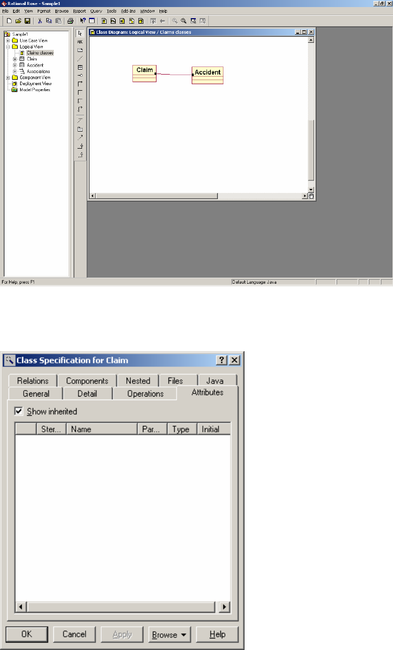
6. Create the rest of the classes from the diagram you have developed in tutorials.
7. You can modify the display format to display or suppress attributes or
operations, or to show the signature of an operation.
8. When the classes are put in, you can add associations, using either the uni-
directional association or the bi-directional association.
9. Right click on the association and ensure that ‘Stereotype label’, ‘Public’ and
‘Navigable’ are ticked. To specify the association further ‘Open standard
specification’. You can add multiplicity and roles.
10. To add attributes, click the ‘attributes’ tab on the class specification.
Right click in the empty box and fill in the attribute name
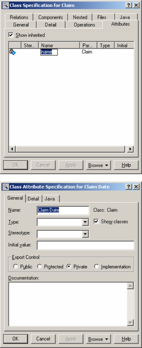
Double click on the attribute to add more detail:
Operations are added using the operations tab:
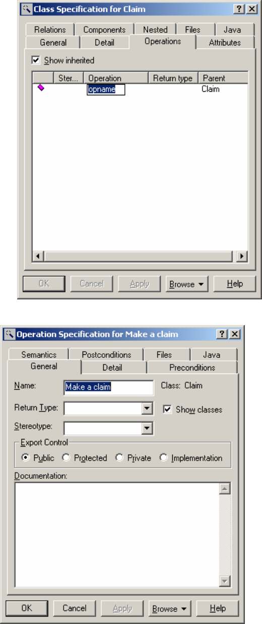
Operations can be further specified:
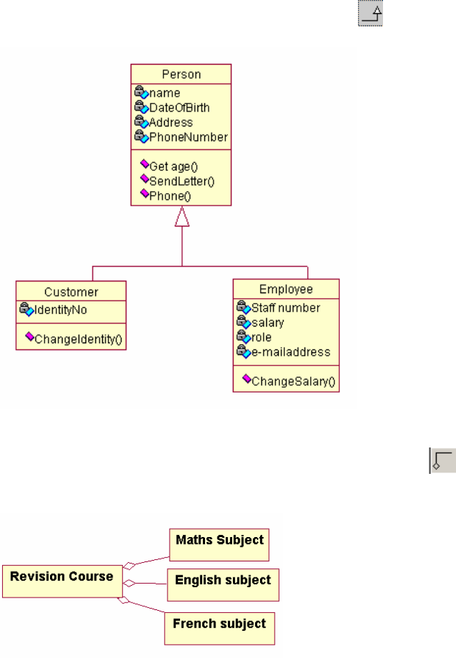
Adding other associations
Generalisation
To add a generalisation, click on the Generalisation icon . Start from the
specialised class and draw towards the general class.
Aggregation
To create an aggregate relationship, either use the Aggregation icon or right click
on an association and click the aggregate tick box. Start at class A, where A is the
containing class. Draw to class B, where B is the part class.

Composition
To create a composition relationship, add an aggregation. Open the Specification of
the aggregation and choose Role B detail (If the aggregate tick box is not ticked, then
choose Role A detail instead). Tick the ‘containment’ radio button to fill in the
aggregate diamond.
11. When the model is saved, the diagram will be saved along with it.
Top of the Document Use Case Diagram ClassDiagram
5. Activity Diagram
If you are not already running Rational Rose, start it using the Start menu, Program
Files, Rational Rose Enterprise Edition. Open the model from where you previously
saved it. If you have not saved a model previously, read section 1.
Right click on the Use Case View and choose New and Activity diagram. The tools
in the toolbar that you will need are:
This is the start state, which signifies the start of the workflow.
This is the end state, which signifies the end of the workflow.
This is the transition between activities, activity and state, activity and
decision, decision and activity or state and activity.
This is the decision diamond.
body limb
This is the activity.
This is the state.
Use the lecture to explain how to draw the diagrams.
Top of the Document Use Case Diagram ClassDiagram ActivityDiagram
6. Sequence Diagram
When drawing a Sequence diagram, it is assumed that you have previously:-
• Drawn a Use Case diagram in the Use Case View and populated it with actors
and use cases.
• Set up (business) entity classes in the Logical View complete with attributes
and operations.
• Set up boundary classes in the Logical View, complete with attributes and
operations and any inherited classes.
Before you draw a sequence diagram, you must have a realisation of the Use Case that
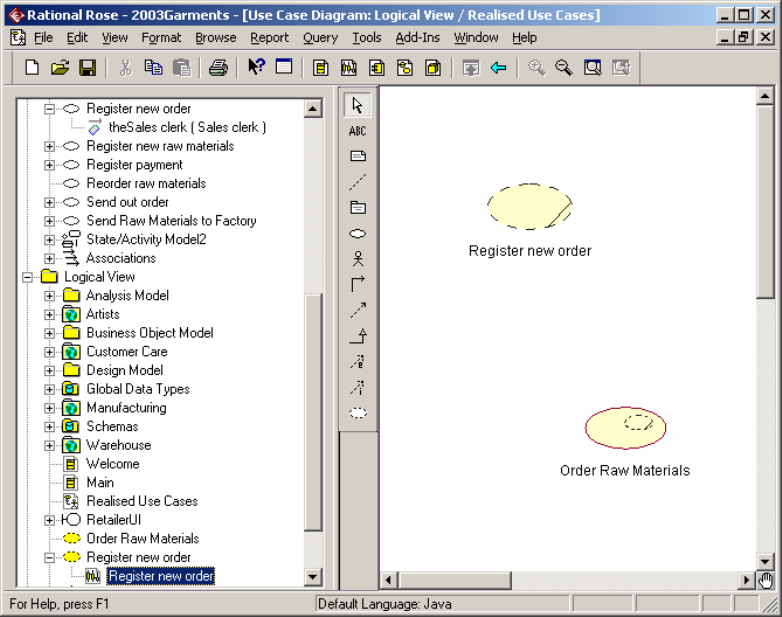
you are representing. To create this, right click on Logical view in the browser and
pick New Use Case Diagram
Call it ‘Use Case Realisation’
Populate the new Use Case diagram with one Use case for each one from the Use
Case view. USE THE ICON FROM THE TOOLBAR TO DO THIS. If
necessary, customise the toolbar to add this icon. It is called ‘Creates a Use Case
realisation’. Open the specification on the Use case, give it the same name as the one
in the Use Case view and give it a stereotype of ‘Use Case Realisation’. When this
has been done, the realisations will come up in the diagram and in the logical view
browser as dotted ovals. Right click
on the dotted oval in the browser and choose ‘New
Sequence Diagram’. Give it the same name as the Use
Case.
Register new order
Pick required actors and classes from the browser and drag them onto the diagram.
Depending on the options you have on the view, they may all be shown as rectangles,
or may use the icon representing their stereotype.

To add an event / signal / message between classes; use the straight arrow icon
from the toolbar. Start at the originating class and drag it to the receiving class. Right
click on the event and pick the operation from the list shown. If the operation is not
in the class already, add it.
The message can be edited and its specification altered to make it synchronous or to
make sure there is a significant return value:
To add a new sequence diagram (e.g. for another use case), develop the other
sequence diagram (e.g. DiagramB) add a note to the original diagram (e.g.
Diagram A). Drag DiagramB from the browser into the note on Diagram A. To end
an object’s lifeline in the Use Case, use the icon on its lifeline.
7. Drawing a State Diagram
Select the persistent class for which you wish to draw a state diagram. Right click
and choose Subdiagrams, ‘New Statechart diagram’.
Using the icons on offer, draw the diagram.
Go to top Use Case Diagram Class Diagram Sequence Diagram Collaboration
8. Collaboration Diagrams
To create a collaboration diagram in Rational Rose, ensure first that the Use Case that
you want to illustrate is present and that all classes have been set up, complete with
their stereotypes.
Right click on the Use Case in the browser and choose ‘New’ and ‘Collaboration
Diagram’. Give the diagram the same name as the Use Case and double click on it to
open it. Note the toolbar should look as above.
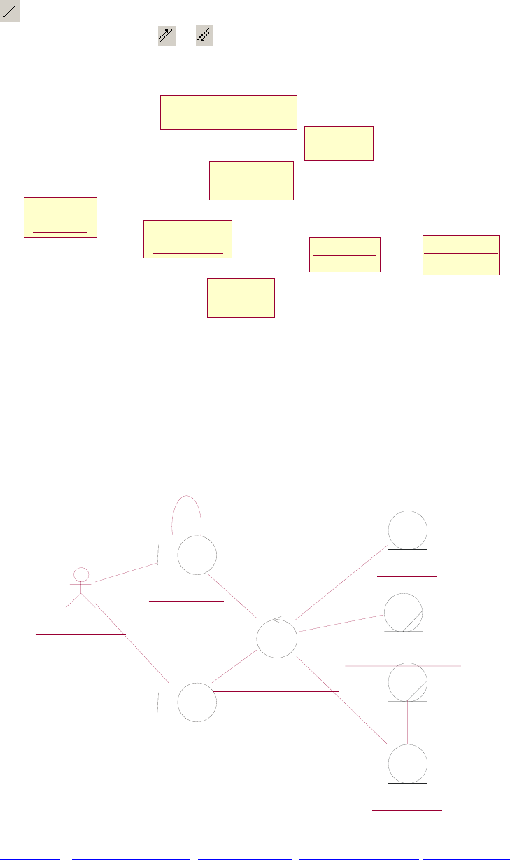
A Collaboration diagram has classes, links and messages. The links show how the
classes communicate, while the messages travel on the links. Any two classes that
communicate must be joined by links. Two classes may only be joined by one link
, but there can be many messages passing between them. The messages are
directional, so use either or .
To draw the diagram, drag the objects from the browser.
: Sales
clerk
: OrderUI
: RegisterNewOrder
: Design
: DesignUI
: Retailer
Order
: Retailer
Order Line : Retailer
When you do this, they may appear as boxes. When you have all of the objects on the
diagram, do the following:
Select all from the edit menu. Go to Format menu and set stereotype to icon. At
format menu, disable ‘use fill colour’ (if you wish!)At format menu, choose font and
change the font to something that will distinguish the objects from the message
names. (I chose bold italic 12 point bookman old style). Connect with links all
objects that send messages to each other.
: Sales clerk
: OrderUI
:
RegisterNewOrder
: Design
: DesignUI
: Retailer Order
: Retailer
: Retailer Order
Line
Go to top Use Case Diagram Class Diagram Sequence Diagram Collaboration
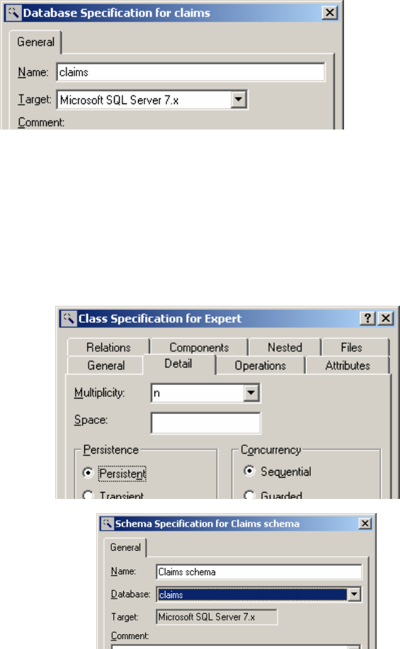
9. Generating tables from classes
Converting classes to tables
Remember:
• You can only generate tables from PERSISTENT classes.
• To generate tables, there must be a defined schema.
• The schema must be associated with a database in the component view.
In the component view:
Set up a database
(Right click on logical
view, choose data
modeler, new,
database).
Open the specification
for the database and
associate it with
whichever implementation route suits (e.g. SQL Server 7)
In the logical view:
(a) Classify the classes, using a 3-tier system. (To do this, tick the ‘Three-tier
diagram’ box in the tools - options menu in Rational Rose.)
Move all persistent classes into one package.
For each persistent class:
Open the standard
specification
Select the ‘detail’ tab
Turn on the ‘persistent’
radio button.
If you have not already
given the attributes data
types, do so now.
(b) Set up a new schema (Right click on
logical view, choose data modeler,
new, schema.)
Open the schema specification.
Associate it with the database you
have created.
(c) Transform the objects to data. Right click on the package that holds the
classes in the Logical view.
Choose data modeler
Choose ‘Transform to data
model’
Fill in destination schema and
target database that you have
set up. Execute the
transformation. (To see your
tables, expand the schema. If
they aren’t there, maybe you
didn’t make them persistent?).
To see your data model, right
click on the schema, choose
data modeller, new, data
model diagram)
(d) Generate (and optionally
execute) SQL. Right click on the
schema, choose data modeller,
forward engineer…
This results in your tables being generated into your database.
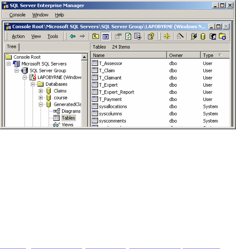
Open a new data model diagram
Populate it with tables
Result
This creates a set of tables in the database.
You can view them by setting up a new data model diagram.
Right click on schema
Choose data modeler
Choose new
Choose data model diagram
Go to top Use Case Diagram Class Diagram Sequence Diagram Collaboration
10. Generating SQL
•Right click on the database
•Choose Data modeler
•Forward Engineer…
What if??
1) I add a business class that has the same name as an actor and the drawing tool
shows me the actor:
Before naming the class, open its specification. Change the stereotype to
business entity, and then rename it to the actor name. You will be warned that
the name appears in multiple domains, but that is OK.
2) When I add my class, it doesn’t look like the one in the sample.
When you add a class, the stereotype may default to none. This will give
the normal 3-compartment box display. When you change the stereotype,
this can change the way in which the class is displayed. To change the
display, right click on the class and choose stereotype. If you want the 3-
box compartment, choose ‘none’.
