Storage Administration Guide Red Hat Enterprise Linux 7 En US
User Manual:
Open the PDF directly: View PDF ![]() .
.
Page Count: 252 [warning: Documents this large are best viewed by clicking the View PDF Link!]
- Table of Contents
- Chapter 1. Overview
- Part I. File Systems
- Chapter 2. File System Structure and Maintenance
- 2.1. Overview of Filesystem Hierarchy Standard (FHS)
- 2.1.1. FHS Organization
- 2.1.1.1. Gathering File System Information
- 2.1.1.2. The /boot/ Directory
- 2.1.1.3. The /dev/ Directory
- 2.1.1.4. The /etc/ Directory
- 2.1.1.5. The /mnt/ Directory
- 2.1.1.6. The /opt/ Directory
- 2.1.1.7. The /proc/ Directory
- 2.1.1.8. The /srv/ Directory
- 2.1.1.9. The /sys/ Directory
- 2.1.1.10. The /usr/ Directory
- 2.1.1.11. The /var/ Directory
- 2.1.1. FHS Organization
- 2.2. Special Red Hat Enterprise Linux File Locations
- 2.3. The /proc Virtual File System
- 2.4. Discard unused blocks
- 2.1. Overview of Filesystem Hierarchy Standard (FHS)
- Chapter 3. Btrfs (Technology Preview)
- 3.1. Creating a btrfs File System
- 3.2. Mounting a btrfs file system
- 3.3. Resizing a btrfs file system
- 3.4. Integrated Volume Management of Multiple Devices
- 3.4.1. File System Creation with Multiple Devices
- 3.4.2. Device scanning btrfs multiple devices
- 3.4.3. Adding new devices to a btrfs file system
- 3.4.4. Converting a btrfs file system
- 3.4.5. Removing btrfs devices
- 3.4.6. Replacing failed devices on a btrfs file system
- 3.4.7. Registering a btrfs file system in /etc/fstab
- 3.5. SSD Optimization
- 3.6. btrfs references
- Chapter 4. The Ext3 File System
- Chapter 5. The Ext4 File System
- Chapter 6. The XFS File System
- 6.1. Creating an XFS File System
- 6.2. Mounting an XFS File System
- 6.3. XFS Quota Management
- 6.4. Increasing the Size of an XFS File System
- 6.5. Repairing an XFS File System
- 6.6. Suspending an XFS File System
- 6.7. Backup and Restoration of XFS File Systems
- 6.8. Other XFS File System Utilities
- 6.9. Migrating from ext4 to XFS
- Chapter 7. Global File System 2
- Chapter 8. Network File System (NFS)
- Chapter 9. FS-Cache
- Part II. Storage Administration
- Chapter 10. Storage Considerations During Installation
- Chapter 11. File System Check
- Chapter 12. Partitions
- Chapter 13. Creating and Maintaining Snapshots with Snapper
- Chapter 14. Swap Space
- Chapter 15. System Storage Manager (SSM)
- Chapter 16. Disk Quotas
- Chapter 17. Redundant Array of Independent Disks (RAID)
- Chapter 18. Using the mount Command
- Chapter 19. The volume_key Function
- Chapter 20. Access Control Lists
- Chapter 21. Solid-State Disk Deployment Guidelines
- Chapter 22. Write Barriers
- Chapter 23. Storage I/O Alignment and Size
- Chapter 24. Setting Up A Remote Diskless System
- Chapter 25. Online Storage Management
- 25.1. Target Setup
- 25.2. Create an iSCSI Initiator
- 25.3. Fibre Channel
- 25.4. Configuring a Fibre Channel over Ethernet Interface
- 25.5. Configuring an FCoE Interface to Automatically Mount at Boot
- 25.6. iSCSI
- 25.7. Persistent Naming
- 25.8. Removing a Storage Device
- 25.9. Removing a Path to a Storage Device
- 25.10. Adding a Storage Device or Path
- 25.11. Scanning Storage Interconnects
- 25.12. iSCSI Discovery Configuration
- 25.13. Configuring iSCSI Offload and Interface Binding
- 25.14. Scanning iSCSI Interconnects
- 25.15. Logging in to an iSCSI Target
- 25.16. Resizing an Online Logical Unit
- 25.17. Adding/Removing a Logical Unit Through rescan-scsi-bus.sh
- 25.18. Modifying Link Loss Behavior
- 25.19. Controlling the SCSI Command Timer and Device Status
- 25.20. Online Storage Configuration Troubleshooting
- Chapter 26. Device Mapper Multipathing and Virtual Storage
- Chapter 27. External Array Management (libStorageMgmt)
- Appendix A. Revision History
- Index

Red Hat Subject Matter ExpertsJosef Bacik
Kamil Dudka Hans de Goede Harald Hoyer
Doug Ledford Daniel Novotny Nathan Straz
David Wysochanski Contributors Michael Christie
Sachin Prabhu Rob Evers David Howells
David Lehman Jeff Moyer Eric Sandeen
Mike Snitzer
Red Hat Enterprise Linux 7
Storage Administration Guide
Deploying and configuring single-node storage in Red Hat Enterprise Linux
7

Red Hat Enterprise Linux 7 Storage Administration Guide
Deploying and configuring single-node storage in Red Hat Enterprise Linux
7
Jo sef Bacik
Server Development Kernel File System
jwhiter@redhat.co m
Disk Quo tas
Kamil Dudka
Base Operating System Co re Services - BRNO
kdudka@redhat.co m
Access Co ntrol Lists
Hans de Go ede
Base Operating System Installer
hdegoede@redhat.com
Partitio ns
Harald Hoyer
Engineering Software Engineering
harald@redhat.com
File Systems
Do ug Ledfo rd
Server Development Hardware Enablement
dledford@redhat.co m
RAID
Daniel Novo tny
Base Operating System Co re Services - BRNO
dno vo tny@redhat.co m
The /pro c File System
Nathan Straz
Quality Engineering QE - Platform
nstraz@redhat.co m
GFS2
David Wyso chanski
Server Development Kernel Storage
dwyso cha@redhat.com
LVM/LVM2
Michael Christie
Server Development Kernel Storage
mchristi@redhat.co m
Online Sto rage
Sachin Prabhu
So ftware Maintenance Engineering
sprabhu@redhat.co m
NFS
Ro b Evers
Server Development Kernel Storage
revers@redhat.com
Online Sto rage
David Howells
Server Development Hardware Enablement
dho wells@redhat.com
FS-Cache
David Lehman
Base Operating System Installer
dlehman@redhat.com
Storage co nfiguratio n during installatio n
Jeff Moyer
Server Development Kernel File System
jmo yer@redhat.co m
So lid-State Disks
Eric Sandeen
Server Development Kernel File System
esandeen@redhat.com
ext3, ext4 , XFS, Encrypted File Systems
Mike Snitzer
Server Development Kernel Storage
msnitzer@redhat.com
I/O Stack and Limits
Red Hat Subject Matter Experts
Co ntributo rs
Edited by
Milan Navratil
Red Hat Custo mer Co ntent Services
mnavrati@redhat.co m
Jacquelynn East
Red Hat Custo mer Co ntent Services
Do n Do mingo
Red Hat Custo mer Co ntent Services

Legal Notice
Co pyright © 20 16 Red Hat Inc. and others.
This do cument is licensed by Red Hat under the Creative Commo ns Attributio n-ShareAlike 3.0
Unpo rted License. If yo u distribute this do cument, o r a modified version o f it, yo u must provide
attributio n to Red Hat, Inc. and provide a link to the original. If the do cument is mo dified, all Red
Hat trademarks must be removed.
Red Hat, as the licenso r of this do cument, waives the right to enfo rce, and agrees no t to assert,
Sectio n 4d o f CC-BY-SA to the fullest extent permitted by applicable law.
Red Hat, Red Hat Enterprise Linux, the Shadowman logo, JBoss, MetaMatrix, Fedo ra, the Infinity
Lo go , and RHCE are trademarks o f Red Hat, Inc., registered in the United States and o ther
co untries.
Linux ® is the registered trademark of Linus To rvalds in the United States and other countries.
Java ® is a registered trademark of Oracle and/or its affiliates.
XFS ® is a trademark of Silico n Graphics International Co rp. or its subsidiaries in the United
States and/o r other countries.
MySQL ® is a registered trademark of MySQL AB in the United States, the Euro pean Union and
other co untries.
No de.js ® is an official trademark of Jo yent. Red Hat Software Co llectio ns is no t formally
related to or endo rsed by the official Jo yent No de.js o pen so urce o r commercial pro ject.
The OpenStack ® Word Mark and OpenStack Logo are either registered trademarks/service
marks o r trademarks/service marks of the OpenStack Foundatio n, in the United States and o ther
co untries and are used with the OpenStack Foundatio n's permissio n. We are no t affiliated with,
endo rsed o r sponso red by the OpenStack Foundatio n, o r the OpenStack community.
All other trademarks are the pro perty o f their respective o wners.
Abstract
This guide pro vides instructio ns on ho w to effectively manage storage devices and file systems
on Red Hat Enterprise Linux 7. It is intended fo r use by system administrators with basic to
intermediate knowledge o f Red Hat Enterprise Linux o r Fedo ra.

. . . . . . . . . . . . . . . . . . . . . . . . . . . . . . . . . . . . . . . . . . . . . . . . . . . . . . . . . . . . . . . . . . . . . . . . . . . . . . . . . . . . . . . . . . . . . . . . . . . . . . . . . . . . . . . . . . . . . . . . . . . . . . . . . . . . . . . . . . . . . . . . . . . . . . . . . . . . . . . . . . . . . . . . . . . . . . . . . . . . . . . . . . . . . . . . . . . . . . . . . . . . . . . . . . . . . . . . . . . . . . . . . . . . . . . . . . . . . . . . . . . . . . . . . . . . . . . . . . . . . . . . . . . . . . . . . . . . . . . .
. . . . . . . . . . . . . . . . . . . . . . . . . . . . . . . . . . . . . . . . . . . . . . . . . . . . . . . . . . . . . . . . . . . . . . . . . . . . . . . . . . . . . . . . . . . . . . . . . . . . . . . . . . . . . . . . . . . . . . . . . . . . . . . . . . . . . . . . . . . . . . . . . . . . . . . . . . . . . . . . . . . . . . . . . . . . . . . . . . . . . . . . . . . . . . . . . . . . . . . . . . . . . . . . . . . . . . . . . . . . . . . . . . . . . . . . . . . . . . . . . . . . . . . . . . . . . . . . . . . . . . . . . . . . . . . . . . . . . . . .
. . . . . . . . . . . . . . . . . . . . . . . . . . . . . . . . . . . . . . . . . . . . . . . . . . . . . . . . . . . . . . . . . . . . . . . . . . . . . . . . . . . . . . . . . . . . . . . . . . . . . . . . . . . . . . . . . . . . . . . . . . . . . . . . . . . . . . . . . . . . . . . . . . . . . . . . . . . . . . . . . . . . . . . . . . . . . . . . . . . . . . . . . . . . . . . . . . . . . . . . . . . . . . . . . . . . . . . . . . . . . . . . . . . . . . . . . . . . . . . . . . . . . . . . . . . . . . . . . . . . . . . . . . . . . . . . . . . . . . . .
. . . . . . . . . . . . . . . . . . . . . . . . . . . . . . . . . . . . . . . . . . . . . . . . . . . . . . . . . . . . . . . . . . . . . . . . . . . . . . . . . . . . . . . . . . . . . . . . . . . . . . . . . . . . . . . . . . . . . . . . . . . . . . . . . . . . . . . . . . . . . . . . . . . . . . . . . . . . . . . . . . . . . . . . . . . . . . . . . . . . . . . . . . . . . . . . . . . . . . . . . . . . . . . . . . . . . . . . . . . . . . . . . . . . . . . . . . . . . . . . . . . . . . . . . . . . . . . . . . . . . . . . . . . . . . . . . . . . . . . .
. . . . . . . . . . . . . . . . . . . . . . . . . . . . . . . . . . . . . . . . . . . . . . . . . . . . . . . . . . . . . . . . . . . . . . . . . . . . . . . . . . . . . . . . . . . . . . . . . . . . . . . . . . . . . . . . . . . . . . . . . . . . . . . . . . . . . . . . . . . . . . . . . . . . . . . . . . . . . . . . . . . . . . . . . . . . . . . . . . . . . . . . . . . . . . . . . . . . . . . . . . . . . . . . . . . . . . . . . . . . . . . . . . . . . . . . . . . . . . . . . . . . . . . . . . . . . . . . . . . . . . . . . . . . . . . . . . . . . . . .
. . . . . . . . . . . . . . . . . . . . . . . . . . . . . . . . . . . . . . . . . . . . . . . . . . . . . . . . . . . . . . . . . . . . . . . . . . . . . . . . . . . . . . . . . . . . . . . . . . . . . . . . . . . . . . . . . . . . . . . . . . . . . . . . . . . . . . . . . . . . . . . . . . . . . . . . . . . . . . . . . . . . . . . . . . . . . . . . . . . . . . . . . . . . . . . . . . . . . . . . . . . . . . . . . . . . . . . . . . . . . . . . . . . . . . . . . . . . . . . . . . . . . . . . . . . . . . . . . . . . . . . . . . . . . . . . . . . . . . . .
. . . . . . . . . . . . . . . . . . . . . . . . . . . . . . . . . . . . . . . . . . . . . . . . . . . . . . . . . . . . . . . . . . . . . . . . . . . . . . . . . . . . . . . . . . . . . . . . . . . . . . . . . . . . . . . . . . . . . . . . . . . . . . . . . . . . . . . . . . . . . . . . . . . . . . . . . . . . . . . . . . . . . . . . . . . . . . . . . . . . . . . . . . . . . . . . . . . . . . . . . . . . . . . . . . . . . . . . . . . . . . . . . . . . . . . . . . . . . . . . . . . . . . . . . . . . . . . . . . . . . . . . . . . . . . . . . . . . . . . .
. . . . . . . . . . . . . . . . . . . . . . . . . . . . . . . . . . . . . . . . . . . . . . . . . . . . . . . . . . . . . . . . . . . . . . . . . . . . . . . . . . . . . . . . . . . . . . . . . . . . . . . . . . . . . . . . . . . . . . . . . . . . . . . . . . . . . . . . . . . . . . . . . . . . . . . . . . . . . . . . . . . . . . . . . . . . . . . . . . . . . . . . . . . . . . . . . . . . . . . . . . . . . . . . . . . . . . . . . . . . . . . . . . . . . . . . . . . . . . . . . . . . . . . . . . . . . . . . . . . . . . . . . . . . . . . . . . . . . . . .
. . . . . . . . . . . . . . . . . . . . . . . . . . . . . . . . . . . . . . . . . . . . . . . . . . . . . . . . . . . . . . . . . . . . . . . . . . . . . . . . . . . . . . . . . . . . . . . . . . . . . . . . . . . . . . . . . . . . . . . . . . . . . . . . . . . . . . . . . . . . . . . . . . . . . . . . . . . . . . . . . . . . . . . . . . . . . . . . . . . . . . . . . . . . . . . . . . . . . . . . . . . . . . . . . . . . . . . . . . . . . . . . . . . . . . . . . . . . . . . . . . . . . . . . . . . . . . . . . . . . . . . . . . . . . . . . . . . . . . . .
Table of Contents
Chapt er 1 . O verview
1.1. What's New in Red Hat Enterp rise Linux 7
Part I. File Syst ems
Chapt er 2 . File Syst em St ruct ure and Maint enance
2.1. O verview o f Filesystem Hierarc hy Stand ard (FHS)
2.2. Sp ecial Red Hat Enterp rise Linux File Lo catio ns
2.3. The /p ro c Virtual File System
2.4. Discard unused b lo cks
Chapt er 3. Bt rfs (T echnology Preview)
3.1. Creating a b trfs File System
3.2. Mo unting a b trfs file system
3.3. Resiz ing a b trfs file system
3.4. Integ rated Vo lume Manag ement o f Multip le Devices
3.5. SSD O p timiz atio n
3.6 . b trfs referenc es
Chapt er 4 . T he Ext 3 File Syst em
4.1. Creating an Ext3 File System
4.2. Co nverting to an Ext3 File System
4.3. Reverting to an Ext2 File System
Chapt er 5. T he Ext 4 File Syst em
5.1. Creating an Ext4 File System
5.2. Mo unting an Ext4 File System
5.3. Resiz ing an Ext4 File System
5.4. Bac kup ext2/3/4 File Systems
5.5. Resto re an ext2/3/4 File System
5.6 . O ther Ext4 File Sys tem Utilities
Chapt er 6 . T he XFS File Syst em
6 .1. Creating an XFS File System
6 .2. Mo unting an XFS File System
6 .3. XFS Q uo ta Manag ement
6 .4. Increas ing the Siz e o f an XFS File System
6 .5. Rep airing an XFS File System
6 .6 . Sus p end ing an XFS File System
6 .7. Bac kup and Resto ratio n o f XFS File Systems
6 .8 . O ther XFS File System Utilities
6 .9 . Mig rating fro m ext4 to XFS
Chapt er 7 . G lobal File Syst em 2
Chapt er 8 . Net work File Syst em (NFS)
8 .1. Ho w NFS Wo rks
8 .2. p NFS
8 .3. NFS Client Co nfig uratio n
8 .4. auto fs
8 .5. Co mmo n NFS Mo unt O p tio ns
8 .6 . Starting and Sto p p ing NFS
8 .7. NFS Server Co nfig uratio n
8 .8 . Sec uring NFS
5
5
7
8
8
15
16
16
1 7
17
17
18
21
24
25
2 7
28
28
29
30
31
32
33
33
35
36
38
39
40
40
42
43
43
44
46
47
50
51
51
54
54
56
6 2
6 3
6 4
70
T able o f Cont ent s
1

. . . . . . . . . . . . . . . . . . . . . . . . . . . . . . . . . . . . . . . . . . . . . . . . . . . . . . . . . . . . . . . . . . . . . . . . . . . . . . . . . . . . . . . . . . . . . . . . . . . . . . . . . . . . . . . . . . . . . . . . . . . . . . . . . . . . . . . . . . . . . . . . . . . . . . . . . . . . . . . . . . . . . . . . . . . . . . . . . . . . . . . . . . . . . . . . . . . . . . . . . . . . . . . . . . . . . . . . . . . . . . . . . . . . . . . . . . . . . . . . . . . . . . . . . . . . . . . . . . . . . . . . . . . . . . . . . . . . . . . .
. . . . . . . . . . . . . . . . . . . . . . . . . . . . . . . . . . . . . . . . . . . . . . . . . . . . . . . . . . . . . . . . . . . . . . . . . . . . . . . . . . . . . . . . . . . . . . . . . . . . . . . . . . . . . . . . . . . . . . . . . . . . . . . . . . . . . . . . . . . . . . . . . . . . . . . . . . . . . . . . . . . . . . . . . . . . . . . . . . . . . . . . . . . . . . . . . . . . . . . . . . . . . . . . . . . . . . . . . . . . . . . . . . . . . . . . . . . . . . . . . . . . . . . . . . . . . . . . . . . . . . . . . . . . . . . . . . . . . . . .
. . . . . . . . . . . . . . . . . . . . . . . . . . . . . . . . . . . . . . . . . . . . . . . . . . . . . . . . . . . . . . . . . . . . . . . . . . . . . . . . . . . . . . . . . . . . . . . . . . . . . . . . . . . . . . . . . . . . . . . . . . . . . . . . . . . . . . . . . . . . . . . . . . . . . . . . . . . . . . . . . . . . . . . . . . . . . . . . . . . . . . . . . . . . . . . . . . . . . . . . . . . . . . . . . . . . . . . . . . . . . . . . . . . . . . . . . . . . . . . . . . . . . . . . . . . . . . . . . . . . . . . . . . . . . . . . . . . . . . . .
. . . . . . . . . . . . . . . . . . . . . . . . . . . . . . . . . . . . . . . . . . . . . . . . . . . . . . . . . . . . . . . . . . . . . . . . . . . . . . . . . . . . . . . . . . . . . . . . . . . . . . . . . . . . . . . . . . . . . . . . . . . . . . . . . . . . . . . . . . . . . . . . . . . . . . . . . . . . . . . . . . . . . . . . . . . . . . . . . . . . . . . . . . . . . . . . . . . . . . . . . . . . . . . . . . . . . . . . . . . . . . . . . . . . . . . . . . . . . . . . . . . . . . . . . . . . . . . . . . . . . . . . . . . . . . . . . . . . . . . .
. . . . . . . . . . . . . . . . . . . . . . . . . . . . . . . . . . . . . . . . . . . . . . . . . . . . . . . . . . . . . . . . . . . . . . . . . . . . . . . . . . . . . . . . . . . . . . . . . . . . . . . . . . . . . . . . . . . . . . . . . . . . . . . . . . . . . . . . . . . . . . . . . . . . . . . . . . . . . . . . . . . . . . . . . . . . . . . . . . . . . . . . . . . . . . . . . . . . . . . . . . . . . . . . . . . . . . . . . . . . . . . . . . . . . . . . . . . . . . . . . . . . . . . . . . . . . . . . . . . . . . . . . . . . . . . . . . . . . . . .
. . . . . . . . . . . . . . . . . . . . . . . . . . . . . . . . . . . . . . . . . . . . . . . . . . . . . . . . . . . . . . . . . . . . . . . . . . . . . . . . . . . . . . . . . . . . . . . . . . . . . . . . . . . . . . . . . . . . . . . . . . . . . . . . . . . . . . . . . . . . . . . . . . . . . . . . . . . . . . . . . . . . . . . . . . . . . . . . . . . . . . . . . . . . . . . . . . . . . . . . . . . . . . . . . . . . . . . . . . . . . . . . . . . . . . . . . . . . . . . . . . . . . . . . . . . . . . . . . . . . . . . . . . . . . . . . . . . . . . . .
. . . . . . . . . . . . . . . . . . . . . . . . . . . . . . . . . . . . . . . . . . . . . . . . . . . . . . . . . . . . . . . . . . . . . . . . . . . . . . . . . . . . . . . . . . . . . . . . . . . . . . . . . . . . . . . . . . . . . . . . . . . . . . . . . . . . . . . . . . . . . . . . . . . . . . . . . . . . . . . . . . . . . . . . . . . . . . . . . . . . . . . . . . . . . . . . . . . . . . . . . . . . . . . . . . . . . . . . . . . . . . . . . . . . . . . . . . . . . . . . . . . . . . . . . . . . . . . . . . . . . . . . . . . . . . . . . . . . . . . .
. . . . . . . . . . . . . . . . . . . . . . . . . . . . . . . . . . . . . . . . . . . . . . . . . . . . . . . . . . . . . . . . . . . . . . . . . . . . . . . . . . . . . . . . . . . . . . . . . . . . . . . . . . . . . . . . . . . . . . . . . . . . . . . . . . . . . . . . . . . . . . . . . . . . . . . . . . . . . . . . . . . . . . . . . . . . . . . . . . . . . . . . . . . . . . . . . . . . . . . . . . . . . . . . . . . . . . . . . . . . . . . . . . . . . . . . . . . . . . . . . . . . . . . . . . . . . . . . . . . . . . . . . . . . . . . . . . . . . . . .
. . . . . . . . . . . . . . . . . . . . . . . . . . . . . . . . . . . . . . . . . . . . . . . . . . . . . . . . . . . . . . . . . . . . . . . . . . . . . . . . . . . . . . . . . . . . . . . . . . . . . . . . . . . . . . . . . . . . . . . . . . . . . . . . . . . . . . . . . . . . . . . . . . . . . . . . . . . . . . . . . . . . . . . . . . . . . . . . . . . . . . . . . . . . . . . . . . . . . . . . . . . . . . . . . . . . . . . . . . . . . . . . . . . . . . . . . . . . . . . . . . . . . . . . . . . . . . . . . . . . . . . . . . . . . . . . . . . . . . . .
. . . . . . . . . . . . . . . . . . . . . . . . . . . . . . . . . . . . . . . . . . . . . . . . . . . . . . . . . . . . . . . . . . . . . . . . . . . . . . . . . . . . . . . . . . . . . . . . . . . . . . . . . . . . . . . . . . . . . . . . . . . . . . . . . . . . . . . . . . . . . . . . . . . . . . . . . . . . . . . . . . . . . . . . . . . . . . . . . . . . . . . . . . . . . . . . . . . . . . . . . . . . . . . . . . . . . . . . . . . . . . . . . . . . . . . . . . . . . . . . . . . . . . . . . . . . . . . . . . . . . . . . . . . . . . . . . . . . . . . .
8 .9 . NFS and rp c b ind
8 .10 . Referenc es
Chapt er 9 . FS- Cache
9 .1. Perfo rmance G uarantee
9 .2. Setting Up a Cac he
9 .3. Us ing the Cac he With NFS
9 .4. Setting Cache Cull Limits
9 .5. Statis tic al Info rmatio n
9 .6 . References
Part II. St orage Administ rat io n
Chapt er 1 0 . St orage Considerat ions During Inst allat ion
10 .1. Sp ecial Co nsid eratio ns
Chapt er 1 1 . File Syst em Check
11.1. Bes t Practices fo r fsck
11.2. Filesys tem-Sp ecific Info rmatio n fo r fsc k
Chapt er 1 2 . Part it ion s
12.1. Viewing the Partitio n Tab le
12.2. Creating a Partitio n
12.3. Remo ving a Partitio n
12.4. Res izing a Partitio n
Chapt er 1 3. Creat in g and Maint aining Snapsh ot s wit h Snapper
13.1. Initial Snap p er Setup
13.2. Allo w Users and G ro up s to Exec ute Snap p er Co mmand s
13.3. Creating a Snap p er Snap s ho t
13.4. T rack Chang es Between Snap p er Snap s ho ts
13.5. Reverse Chang es in Between Snap sho ts
13.6 . Delete a Snap sho t
Chapt er 1 4 . Swap Space
14.1. Ad d ing Swap Sp ace
14.2. Remo ving Swap Sp ace
14.3. Mo ving Swap Sp ace
Chapt er 1 5. Syst em St orage Manager (SSM)
15.1. SSM Bac kend s
15.2. Co mmo n SSM Tasks
15.3. SSM Reso urces
Chapt er 1 6 . Disk Q uot as
16 .1. Co nfig uring Disk Q uo tas
16 .2. Manag ing Disk Q uo tas
16 .3. Disk Q uo ta Referenc es
Chapt er 1 7 . Redundant Array of In dependent Disks (RAID)
17.1. RAID Typ es
17.2. RAID Levels and Linear Sup p o rt
17.3. Linux RAID Sub systems
17.4. RAID Sup p o rt in the Installer
17.5. Co nfig uring RAID Sets
17.6 . Ad vanced RAID Devic e Creatio n
72
73
7 5
76
76
77
79
8 0
8 0
8 1
8 2
8 2
8 4
8 4
8 5
8 9
9 0
9 1
9 3
9 3
9 6
9 6
9 7
9 8
10 1
10 4
10 5
106
10 7
10 8
110
111
111
113
120
121
121
125
127
129
129
130
132
133
133
133
St orage Administ rat ion G uide
2

. . . . . . . . . . . . . . . . . . . . . . . . . . . . . . . . . . . . . . . . . . . . . . . . . . . . . . . . . . . . . . . . . . . . . . . . . . . . . . . . . . . . . . . . . . . . . . . . . . . . . . . . . . . . . . . . . . . . . . . . . . . . . . . . . . . . . . . . . . . . . . . . . . . . . . . . . . . . . . . . . . . . . . . . . . . . . . . . . . . . . . . . . . . . . . . . . . . . . . . . . . . . . . . . . . . . . . . . . . . . . . . . . . . . . . . . . . . . . . . . . . . . . . . . . . . . . . . . . . . . . . . . . . . . . . . . . . . . . . . .
. . . . . . . . . . . . . . . . . . . . . . . . . . . . . . . . . . . . . . . . . . . . . . . . . . . . . . . . . . . . . . . . . . . . . . . . . . . . . . . . . . . . . . . . . . . . . . . . . . . . . . . . . . . . . . . . . . . . . . . . . . . . . . . . . . . . . . . . . . . . . . . . . . . . . . . . . . . . . . . . . . . . . . . . . . . . . . . . . . . . . . . . . . . . . . . . . . . . . . . . . . . . . . . . . . . . . . . . . . . . . . . . . . . . . . . . . . . . . . . . . . . . . . . . . . . . . . . . . . . . . . . . . . . . . . . . . . . . . . . .
. . . . . . . . . . . . . . . . . . . . . . . . . . . . . . . . . . . . . . . . . . . . . . . . . . . . . . . . . . . . . . . . . . . . . . . . . . . . . . . . . . . . . . . . . . . . . . . . . . . . . . . . . . . . . . . . . . . . . . . . . . . . . . . . . . . . . . . . . . . . . . . . . . . . . . . . . . . . . . . . . . . . . . . . . . . . . . . . . . . . . . . . . . . . . . . . . . . . . . . . . . . . . . . . . . . . . . . . . . . . . . . . . . . . . . . . . . . . . . . . . . . . . . . . . . . . . . . . . . . . . . . . . . . . . . . . . . . . . . . .
. . . . . . . . . . . . . . . . . . . . . . . . . . . . . . . . . . . . . . . . . . . . . . . . . . . . . . . . . . . . . . . . . . . . . . . . . . . . . . . . . . . . . . . . . . . . . . . . . . . . . . . . . . . . . . . . . . . . . . . . . . . . . . . . . . . . . . . . . . . . . . . . . . . . . . . . . . . . . . . . . . . . . . . . . . . . . . . . . . . . . . . . . . . . . . . . . . . . . . . . . . . . . . . . . . . . . . . . . . . . . . . . . . . . . . . . . . . . . . . . . . . . . . . . . . . . . . . . . . . . . . . . . . . . . . . . . . . . . . . .
. . . . . . . . . . . . . . . . . . . . . . . . . . . . . . . . . . . . . . . . . . . . . . . . . . . . . . . . . . . . . . . . . . . . . . . . . . . . . . . . . . . . . . . . . . . . . . . . . . . . . . . . . . . . . . . . . . . . . . . . . . . . . . . . . . . . . . . . . . . . . . . . . . . . . . . . . . . . . . . . . . . . . . . . . . . . . . . . . . . . . . . . . . . . . . . . . . . . . . . . . . . . . . . . . . . . . . . . . . . . . . . . . . . . . . . . . . . . . . . . . . . . . . . . . . . . . . . . . . . . . . . . . . . . . . . . . . . . . . . .
. . . . . . . . . . . . . . . . . . . . . . . . . . . . . . . . . . . . . . . . . . . . . . . . . . . . . . . . . . . . . . . . . . . . . . . . . . . . . . . . . . . . . . . . . . . . . . . . . . . . . . . . . . . . . . . . . . . . . . . . . . . . . . . . . . . . . . . . . . . . . . . . . . . . . . . . . . . . . . . . . . . . . . . . . . . . . . . . . . . . . . . . . . . . . . . . . . . . . . . . . . . . . . . . . . . . . . . . . . . . . . . . . . . . . . . . . . . . . . . . . . . . . . . . . . . . . . . . . . . . . . . . . . . . . . . . . . . . . . . .
. . . . . . . . . . . . . . . . . . . . . . . . . . . . . . . . . . . . . . . . . . . . . . . . . . . . . . . . . . . . . . . . . . . . . . . . . . . . . . . . . . . . . . . . . . . . . . . . . . . . . . . . . . . . . . . . . . . . . . . . . . . . . . . . . . . . . . . . . . . . . . . . . . . . . . . . . . . . . . . . . . . . . . . . . . . . . . . . . . . . . . . . . . . . . . . . . . . . . . . . . . . . . . . . . . . . . . . . . . . . . . . . . . . . . . . . . . . . . . . . . . . . . . . . . . . . . . . . . . . . . . . . . . . . . . . . . . . . . . . .
. . . . . . . . . . . . . . . . . . . . . . . . . . . . . . . . . . . . . . . . . . . . . . . . . . . . . . . . . . . . . . . . . . . . . . . . . . . . . . . . . . . . . . . . . . . . . . . . . . . . . . . . . . . . . . . . . . . . . . . . . . . . . . . . . . . . . . . . . . . . . . . . . . . . . . . . . . . . . . . . . . . . . . . . . . . . . . . . . . . . . . . . . . . . . . . . . . . . . . . . . . . . . . . . . . . . . . . . . . . . . . . . . . . . . . . . . . . . . . . . . . . . . . . . . . . . . . . . . . . . . . . . . . . . . . . . . . . . . . . .
Chapt er 1 8 . Using t he mount Command
18 .1. Lis ting Currently Mo unted File Sys tems
18 .2. Mo unting a File Sys tem
18 .3. Unmo unting a File Sys tem
18 .4. mo unt Co mmand Referenc es
Chapt er 1 9 . T he volume_key Funct ion
19 .1. vo lume_key Co mmand s
19 .2. Using vo lume_key as an ind ivid ual user
19 .3. Using vo lume_key in a larg er o rg anizatio n
19 .4. vo lume_key References
Chapt er 2 0 . Access Cont rol List s
20 .1. Mo unting File Sys tems
20 .2. Setting Acc ess ACLs
20 .3. Setting Default ACLs
20 .4. Retrieving ACLs
20 .5. Archiving File Systems With ACLs
20 .6 . Co mp atib ility with O ld er Systems
20 .7. ACL References
Chapt er 2 1 . Solid- St at e Disk Deployment G uidelines
21.1. Dep lo yment Co nsid eratio ns
21.2. Tuning Co ns id eratio ns
Chapt er 2 2 . Writ e Barriers
22.1. Imp o rtanc e o f Write Barriers
22.2. Enab ling /Disab ling Write Barriers
22.3. Write Barrier Co nsid eratio ns
Chapt er 2 3. St orage I/O Alignment and Siz e
23.1. Parameters fo r Sto rag e Ac c ess
23.2. Usersp ac e Access
23.3. Stand ard s
23.4. Stacking I/O Parameters
23.5. Lo g ical Vo lume Manag er
23.6 . Partitio n and File Sys tem To o ls
Chapt er 2 4 . Set t in g Up A Remot e Diskless Syst em
24.1. Co nfig uring a tftp Servic e fo r Dis kles s Clients
24.2. Co nfig uring DHCP fo r Diskles s Clients
24.3. Co nfig uring an Exp o rted File System fo r Dis kles s Clients
Chapt er 2 5. O nline St orag e Manag ement
25.1. Targ et Setup
25.2. Create an iSCSI Initiato r
25.3. Fib re Channel
25.4. Co nfig uring a Fib re Channel o ver Ethernet Interfac e
25.5. Co nfig uring an FCo E Interface to Auto matic ally Mo unt at Bo o t
25.6 . iSCSI
25.7. Persistent Naming
25.8 . Remo ving a Sto rag e Devic e
25.9 . Remo ving a Path to a Sto rag e Devic e
25.10 . Ad d ing a Sto rag e Devic e o r Path
25.11. Scanning Sto rag e Interc o nnects
1 35
135
136
143
143
145
145
146
147
149
1 50
150
150
152
152
152
153
153
1 55
155
156
1 57
157
157
158
160
16 0
16 1
16 2
16 3
16 3
16 3
165
16 5
16 6
16 7
169
16 9
178
179
18 0
18 2
18 3
18 4
18 8
18 9
19 0
19 2
T able o f Cont ent s
3

. . . . . . . . . . . . . . . . . . . . . . . . . . . . . . . . . . . . . . . . . . . . . . . . . . . . . . . . . . . . . . . . . . . . . . . . . . . . . . . . . . . . . . . . . . . . . . . . . . . . . . . . . . . . . . . . . . . . . . . . . . . . . . . . . . . . . . . . . . . . . . . . . . . . . . . . . . . . . . . . . . . . . . . . . . . . . . . . . . . . . . . . . . . . . . . . . . . . . . . . . . . . . . . . . . . . . . . . . . . . . . . . . . . . . . . . . . . . . . . . . . . . . . . . . . . . . . . . . . . . . . . . . . . . . . . . . . . . . . . .
. . . . . . . . . . . . . . . . . . . . . . . . . . . . . . . . . . . . . . . . . . . . . . . . . . . . . . . . . . . . . . . . . . . . . . . . . . . . . . . . . . . . . . . . . . . . . . . . . . . . . . . . . . . . . . . . . . . . . . . . . . . . . . . . . . . . . . . . . . . . . . . . . . . . . . . . . . . . . . . . . . . . . . . . . . . . . . . . . . . . . . . . . . . . . . . . . . . . . . . . . . . . . . . . . . . . . . . . . . . . . . . . . . . . . . . . . . . . . . . . . . . . . . . . . . . . . . . . . . . . . . . . . . . . . . . . . . . . . . . .
. . . . . . . . . . . . . . . . . . . . . . . . . . . . . . . . . . . . . . . . . . . . . . . . . . . . . . . . . . . . . . . . . . . . . . . . . . . . . . . . . . . . . . . . . . . . . . . . . . . . . . . . . . . . . . . . . . . . . . . . . . . . . . . . . . . . . . . . . . . . . . . . . . . . . . . . . . . . . . . . . . . . . . . . . . . . . . . . . . . . . . . . . . . . . . . . . . . . . . . . . . . . . . . . . . . . . . . . . . . . . . . . . . . . . . . . . . . . . . . . . . . . . . . . . . . . . . . . . . . . . . . . . . . . . . . . . . . . . . . .
. . . . . . . . . . . . . . . . . . . . . . . . . . . . . . . . . . . . . . . . . . . . . . . . . . . . . . . . . . . . . . . . . . . . . . . . . . . . . . . . . . . . . . . . . . . . . . . . . . . . . . . . . . . . . . . . . . . . . . . . . . . . . . . . . . . . . . . . . . . . . . . . . . . . . . . . . . . . . . . . . . . . . . . . . . . . . . . . . . . . . . . . . . . . . . . . . . . . . . . . . . . . . . . . . . . . . . . . . . . . . . . . . . . . . . . . . . . . . . . . . . . . . . . . . . . . . . . . . . . . . . . . . . . . . . . . . . . . . . . .
25.11. Scanning Sto rag e Interc o nnects
25.12. iSCSI Disco very Co nfig uratio n
25.13. Co nfig uring iSCSI O fflo ad and Interface Bind ing
25.14. Sc anning iSCSI Interc o nnects
25.15. Lo g g ing in to an iSCSI Targ et
25.16 . Resiz ing an O nline Lo g ical Unit
25.17. Ad d ing /Remo ving a Lo g ical Unit Thro ug h res c an-scsi-b us .sh
25.18 . Mo d ifying Link Lo ss Behavio r
25.19 . Co ntro lling the SCSI Co mmand Timer and Device Status
25.20 . O nline Sto rag e Co nfig uratio n Tro ub les ho o ting
Chapt er 2 6 . Device Mapper Mult ipat hing and Virt ual St orage
26 .1. Virtual Sto rag e
26 .2. DM-Multip ath
Chapt er 2 7 . Ext ernal Array Management (libSt orageMgmt )
27.1. What is lib Sto rag eMg mt
27.2. Termino lo g y fro m lib Sto rag eMg mt
27.3. Ins tallatio n
27.4. Use o f the lib Sto rag eMg mt
27.5. lib Sto rag eMg mt Do cumentatio n
Appendix A. Revision Hist ory
In dex
19 2
19 3
19 4
19 7
20 0
20 1
20 4
20 5
20 8
20 9
211
211
211
213
213
214
215
216
220
222
222
St orage Administ rat ion G uide
4

Chapter 1. Overview
The Storage Administration Guide contains extensive information on supported file systems and data
storage features in Red Hat Enterprise Linux 7. This book is intended as a quick reference for
administrators managing single-node (that is, non-clustered) storage solutions.
The Storage Administration Guide is split into two parts: File Systems, and Storage Administration.
The File Systems part details the various file systems Red Hat Enterprise Linux 7 supports. It
describes them and explains how best to utilize them.
The Storage Administration part details the various tools and storage administration tasks Red Hat
Enterprise Linux 7 supports. It describes them and explains how best to utilize them.
1.1. What 's New in Red Hat Ent erprise Linux 7
Red Hat Enterprise Linux 7 features the following file system enhancements:
eCrypt fs not included
As of Red Hat Enterprise Linux 7 eCryptfs is not included. Refer to Red Hat's Security Guide for
information on encrypting file systems.
Syst em St orage Manager
Red Hat Enterprise Linux 7 includes a new application called System Storage Manager. This
provides a command-line interface to manage various storage technologies. For more information,
see Chapter 15, System Storage Manager (SSM).
XFS is t he default File Syst em
As of Red Hat Enterprise Linux 7, XFS is the default file system. For more information about the XFS
file system, see Chapter 6, The XFS File System.
File syst em rest ruct ure
Red Hat Enterprise Linux 7 introduces a new file system structure. The directories /bin, /sbin,
/l i b, and /lib64 are now nested under /usr.
Snapper
Red Hat Enterprise Linux 7 introduces a new tool called snapper that allows for the easy creation and
management of snapshots for LVM and BTRFS. For more information refer to Chapter 13, Creating and
Maintaining Snapshots with Snapper.
BT RFS (T echnology Preview)
BTRFS is a local file system that aims to provide better performance and scalability, including
integrated LVM operations. This file system is not fully supported by Red Hat and as such is a
technology preview. For more information on Btrfs, see Chapter 3, Btrfs (Technology Preview).
NFSv2 no longer support ed
Chapt er 1 . O verview
5

As of Red Hat Enterprise Linux 7, NFSv2 is no longer supported.
St orage Administ rat ion G uide
6

Part I. File Systems
The File Systems section explains file system structure followed by two technology previews: eCryptfs
and Btrfs. This is followed by the file systems Red Hat fully supports: ext3, ext4, global file system 2,
XFS, NFS, and FS-Cache.
A comparison guide of what each file system supports can be accessed here:
https://access.redhat.com/site/articles/rhel-limits.
Part I. File Syst ems
7

Chapter 2. File System Structure and Maintenance
The file system structure is the most basic level of organization in an operating system. The way an
operating system interacts with its users, applications, and security model nearly always depends on
how the operating system organizes files on storage devices. Providing a common file system
structure ensures users and programs can access and write files.
File systems break files down into two logical categories:
Shareable vs. unsharable files
Variable vs. static files
Shareable files can be accessed locally and by remote hosts; unsharable files are only available
locally. Variable files, such as documents, can be changed at any time; static files, such as binaries,
do not change without an action from the system administrator.
Categorizing files in this manner helps correlate the function of each file with the permissions
assigned to the directories which hold them. How the operating system and its users interact with a
file determines the directory in which it is placed, whether that directory is mounted with read-only or
read/write permissions, and the level of access each user has to that file. The top level of this
organization is crucial; access to the underlying directories can be restricted, otherwise security
problems could arise if, from the top level down, access rules do not adhere to a rigid structure.
2.1. Overview of Filesyst em Hierarchy St andard (FHS)
Red Hat Enterprise Linux uses the Filesystem Hierarchy Standard (FHS) file system structure, which
defines the names, locations, and permissions for many file types and directories.
The FHS document is the authoritative reference to any FHS-compliant file system, but the standard
leaves many areas undefined or extensible. This section is an overview of the standard and a
description of the parts of the file system not covered by the standard.
The two most important elements of FHS compliance are:
Compatibility with other FHS-compliant systems
The ability to mount a /usr/ partition as read-only. This is especially crucial, since /usr/
contains common executables and should not be changed by users. In addition, since /usr/ is
mounted as read-only, it should be mountable from the CD-ROM drive or from another machine
via a read-only NFS mount.
2.1.1. FHS Organiz at ion
The directories and files noted here are a small subset of those specified by the FHS document. Refer
to the latest FHS documentation for the most complete information at http://www.pathname.com/fhs/.
Note
What directories are available depends on what is installed on any given system. The
following lists are only an example of what may be found.
2.1 .1 .1 . Gat he ring File Syst e m Info rm at io n
St orage Administ rat ion G uide
8

The d f command reports the system's disk space usage. Its output looks similar to the following:
Examp le 2.1. d f comman d o u t p u t
Filesystem 1K-blocks Used Available Use% Mounted on
/dev/mapper/VolGroup00-LogVol00
11675568 6272120 4810348 57% / /dev/sda1
100691 9281 86211 10% /boot
none 322856 0 322856 0% /dev/shm
By default, d f shows the partition size in 1 kilobyte blocks and the amount of used and available
disk space in kilobytes. To view the information in megabytes and gigabytes, use the command d f -
h. The -h argument stands for "human-readable" format. The output for df -h looks similar to the
following:
Examp le 2.2. df -h co mman d ou t p u t
Filesystem Size Used Avail Use% Mounted on
/dev/mapper/VolGroup00-LogVol00
12G 6.0G 4.6G 57% / /dev/sda1
99M 9.1M 85M 10% /boot
none 316M 0 316M 0% /dev/shm
Note
In the above examples, the mounted partition /dev/shm represents the system's virtual
memory file system.
The d u command displays the estimated amount of space being used by files in a directory,
displaying the disk usage of each subdirectory. The last line in the output of d u shows the total disk
usage of the directory; to see only the total disk usage of a directory in human-readable format, use
du -hs. For more options, refer to man du.
To view the system's partitions and disk space usage in a graphical format, use the Gnome System
Mo ni to r by clicking on Ap p lica t io n s → Syst em Tools → Syst em Mo n it o r or using the
command gnome-system-monitor. Select the File Systems tab to view the system's partitions.
The figure below illustrates the File Systems tab.
Chapt er 2 . File Syst em St ruct ure and Maint enance
9
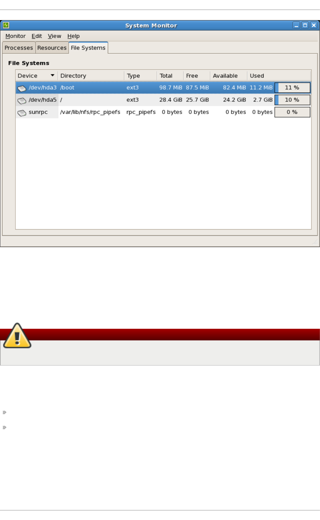
Fig ure 2.1. G N O ME Syst em Mo n it o r File Syst ems t ab
2.1 .1 .2 . T he /bo o t/ Direct o ry
The /bo o t/ directory contains static files required to boot the system, for example, the Linux kernel.
These files are essential for the system to boot properly.
Warning
Do not remove the /bo o t/ directory. Doing so renders the system unbootable.
2.1 .1 .3. T he /dev/ Direct o ry
The /dev/ directory contains device nodes that represent the following device types:
devices attached to the system;
virtual devices provided by the kernel.
These device nodes are essential for the system to function properly. The udevd daemon creates
and removes device nodes in /dev/ as needed.
Devices in the /dev/ directory and subdirectories are defined as either character (providing only a
serial stream of input and output, for example, mouse or keyboard) or block (accessible randomly,
such as a hard drive or a floppy drive). If GNOME or KDE is installed, some storage devices are
automatically detected when connected (such as with USB) or inserted (such as a CD or D VD drive),
St orage Administ rat ion G uide
10
and a pop-up window displaying the contents appears.
T able 2.1. Examp les of co mmo n f iles in t h e /dev direct o ry
File D escrip t io n
/dev/hda The master device on the primary IDE channel.
/dev/hdb The slave device on the primary IDE channel.
/dev/tty0 The first virtual console.
/dev/tty1 The second virtual console.
/dev/sda The first device on the primary SCSI or SATA
channel.
/dev/lp0 The first parallel port.
A valid block device can be one of two types of entries:
A map p ed d evice
A logical volume in a volume group, for example, /dev/mapper/VolGroup00-
LogVol02.
A st at ic d evice
A traditional storage volume, for example, /dev/sdbX, where sdb is a storage device name
and X is the partition number. /dev/sdbX can also be /dev/disk/by-id/WWID, or
/dev/disk/by-uuid/UUID, (see Section 25.7, “ Persistent Naming” for more information
on both these options).
2.1 .1 .4 . T he /etc/ Dire ct o ry
The /etc/ directory is reserved for configuration files that are local to the machine. It should contain
no binaries; any binaries should be moved to /usr/bin/ or /usr/sbin/.
For example, the /etc/skel/ directory stores "skeleton" user files, which are used to populate a
home directory when a user is first created. Applications also store their configuration files in this
directory and may reference them when executed. The /etc/exports file controls which file systems
export to remote hosts.
2.1 .1 .5 . T he /mnt/ Dire ct o ry
The /mnt/ directory is reserved for temporarily mounted file systems, such as NFS file system
mounts. For all removable storage media, use the /media/ directory. Automatically detected
removable media will be mounted in the /media directory.
Important
The /mnt directory must not be used by installation programs.
2.1 .1 .6 . T he /opt/ Dire ct o ry
The /opt/ directory is normally reserved for software and add-on packages that are not part of the
default installation. A package that installs to /opt/ creates a directory bearing its name, for
example, /opt/packagename/. In most cases, such packages follow a predictable subdirectory
structure; most store their binaries in /opt/packagename/bin/ and their man pages in
Chapt er 2 . File Syst em St ruct ure and Maint enance
11

/opt/packagename/man/.
2.1 .1 .7 . T he /proc/ Dire ct o ry
The /proc/ directory contains special files that either extract information from the kernel or send
information to it. Examples of such information include system memory, CPU information, and
hardware configuration. For more information about /proc/, refer to Section 2.3, “ The /proc Virtual
File System” .
2.1 .1 .8 . T he /srv/ Dire ct o ry
The /srv/ directory contains site-specific data served by a Red Hat Enterprise Linux system. This
directory gives users the location of data files for a particular service, such as FTP, WWW, or CVS.
Data that only pertains to a specific user should go in the /home/ directory.
2.1 .1 .9 . T he /sys/ Direct o ry
The /sys/ directory utilizes the new sysfs virtual file system specific to the kernel. With the
increased support for hot plug hardware devices in the kernel, the /sys/ directory contains
information similar to that held by /proc/, but displays a hierarchical view of device information
specific to hot plug devices.
2.1 .1 .1 0 . T he /usr/ Dire ct o ry
The /usr/ directory is for files that can be shared across multiple machines. The /usr/ directory is
often on its own partition and is mounted read-only. At a minimum, /usr/ should contain the
following subdirectories:
/usr/bin
This directory is used for binaries.
/usr/etc
This directory is used for system-wide configuration files.
/usr/games
This directory stores games.
/usr/include
This directory is used for C header files.
/usr/kerberos
This directory is used for Kerberos-related binaries and files.
/usr/l i b
This directory is used for object files and libraries that are not designed to be directly
utilized by shell scripts or users.
As of Red Hat Enterprise Linux 7.0, the /lib/ directory has been merged with /usr/lib. It
now also contains libraries needed to execute the binaries in /usr/bin/ and
/usr/sbin/. These shared library images are used to boot the system or execute
commands within the root file system.
St orage Administ rat ion G uide
12

/usr/libexec
This directory contains small helper programs called by other programs.
/usr/sbin
As of Red Hat Enterprise Linux 7.0, /sbin has been moved to /usr/sbin. This means that
it contains all system administration binaries, including those essential for booting,
restoring, recovering, or repairing the system. The binaries in /usr/sbin/ require root
privileges to use.
/usr/share
This directory stores files that are not architecture-specific.
/usr/src
This directory stores source code.
/usr/tmp lin ked to /var/tmp
This directory stores temporary files.
The /usr/ directory should also contain a /local/ subdirectory. As per the FHS, this subdirectory
is used by the system administrator when installing software locally, and should be safe from being
overwritten during system updates. The /usr/local directory has a structure similar to /usr/, and
contains the following subdirectories:
/usr/local/bin
/usr/local/etc
/usr/local/games
/usr/local/include
/usr/l o cal /l i b
/usr/local/libexec
/usr/local/sbin
/usr/local/share
/usr/local/src
Red Hat Enterprise Linux's usage of /usr/local/ differs slightly from the FHS. The FHS states that
/usr/local/ should be used to store softwarethat should remain safe from system software
upgrades. Since the RPM Packag e Man ag er can perform software upgrades safely, it is not
necessary to protect files by storing them in /usr/local/.
Instead, Red Hat Enterprise Linux uses /usr/local/ for software local to the machine. For
instance, if the /usr/ directory is mounted as a read-only NFS share from a remote host, it is still
possible to install a package or program under the /usr/local/ directory.
2.1 .1 .1 1 . T he /var/ Dire ct o ry
Since the FHS requires Linux to mount /usr/ as read-only, any programs that write log files or need
spo o l / or lock/ directories should write them to the /var/ directory. The FHS states /var/ is for
variable data, which includes spool directories and files, logging data, transient and temporary files.
Chapt er 2 . File Syst em St ruct ure and Maint enance
13

Below are some of the directories found within the /var/ directory:
/var/account/
/var/arpwatch/
/var/cache/
/var/crash/
/var/db/
/var/empty/
/var/ftp/
/var/gdm/
/var/kerberos/
/var/lib/
/var/local/
/var/lock/
/var/l o g /
/var/mail linked to /var/spool/mail/
/var/mailman/
/var/named/
/var/nis/
/var/opt/
/var/preserve/
/var/run/
/var/spool/
/var/tmp/
/var/tux/
/var/www/
/var/yp/
Important
The /var/run/media/user directory contains subdirectories used as mount points for
removable media such as USB storage media, DVDs, CD -ROMs, and Z ip disks. Note that
previously, the /media/ directory was used for this purpose.
St orage Administ rat ion G uide
14

System log files, such as messages and lastlog, go in the /var/log/ directory. The
/var/lib/rpm/ directory contains RPM system databases. Lock files go in the /var/lock/
directory, usually in directories for the program using the file. The /var/spool/ directory has
subdirectories that store data files for some programs. These subdirectories include:
/var/spool/at/
/var/spool/clientmqueue/
/var/spool/cron/
/var/spool/cups/
/var/spool/exim/
/var/spool/lpd/
/var/spool/mail/
/var/spool/mailman/
/var/spool/mqueue/
/var/spool/news/
/var/spool/postfix/
/var/spool/repackage/
/var/spool/rwho/
/var/spool/samba/
/var/spool/squid/
/var/spo o l /sq ui rrel mai l /
/var/spool/up2date/
/var/spool/uucp/
/var/spool/uucppublic/
/var/spool/vbox/
2.2. Special Red Hat Ent erprise Linux File Locat ions
Red Hat Enterprise Linux extends the FHS structure slightly to accommodate special files.
Most files pertaining to RPM are kept in the /var/lib/rpm/ directory. For more information on RPM,
refer to man rpm.
The /var/cache/yum/ directory contains files used by the Packag e Up d at er, including RPM
header information for the system. This location may also be used to temporarily store RPMs
downloaded while updating the system. For more information about the Red Hat Network, refer to the
documentation online at https://rhn.redhat.com/.
Another location specific to Red Hat Enterprise Linux is the /etc/sysconfig/ directory. This
directory stores a variety of configuration information. Many scripts that run at boot time use the files
in this directory.
Chapt er 2 . File Syst em St ruct ure and Maint enance
15

2.3. The /proc Virt ual File Syst em
Unlike most file systems, /proc contains neither text nor binary files. Instead, it houses virtual files; as
such, /proc is normally referred to as a virtual file system. These virtual files are typically zero bytes
in size, even if they contain a large amount of information.
The /proc file system is not used for storage. Its main purpose is to provide a file-based interface to
hardware, memory, running processes, and other system components. Real-time information can be
retrieved on many system components by viewing the corresponding /proc file. Some of the files
within /proc can also be manipulated (by both users and applications) to configure the kernel.
The following /proc files are relevant in managing and monitoring system storage:
/p ro c/d evi ces
Displays various character and block devices that are currently configured.
/p ro c/f iles yst ems
Lists all file system types currently supported by the kernel.
/p ro c/md st a t
Contains current information on multiple-disk or RAID configurations on the system, if they
exist.
/p ro c/mo u n t s
Lists all mounts currently used by the system.
/p ro c/p art it io n s
Contains partition block allocation information.
For more information about the /proc file system, refer to the Red Hat Enterprise Linux 7 Deployment
Guide.
2.4. Discard unused blocks
Batch discard and online discard operations are features of mounted file systems that discard blocks
not in use by the file system. They are useful for both solid-state drives and thinly-provisioned
storage.
Batch discard operations are run explicitly by the user with the fstri m command. This command
discards all unused blocks in a file system that match the user's criteria. Both operation types are
supported for use with ext4 file systems as of Red Hat Enterprise Linux 6.2 and later so long as the
block device underlying the file system supports physical discard operations. This is also the case
with XFS file systems as of Red Hat Enterprise Linux 6.4 and later. Physical discard operations are
supported if the value of /sys/block/device/queue/discard_max_bytes is not zero.
Online discard operations are specified at mount time with the -o d iscard option (either in
/etc/fstab or as part of the mount command), and run in realtime without user intervention. Online
discard operations only discard blocks that are transitioning from used to free. Online discard
operations are supported on ext4 file systems as of Red Hat Enterprise Linux 6.2 and later, and on
XFS file systems as of Red Hat Enterprise Linux 6.4 and later.
Red Hat recommends batch discard operations unless the system's workload is such that batch
discard is not feasible, or online discard operations are necessary to maintain performance.
St orage Administ rat ion G uide
16
Chapter 3. Btrfs (Technology Preview)
Btrfs is a next generation Linux file system that offers advanced management, reliability, and
scalability features. It is unique in offering snapshots, compression, and integrated device
management.
Important
BTRFS is a Technology Preview in Red Hat Enterprise Linux 7.
3.1. Creat ing a bt rfs File Syst em
In order to make a basic btrfs file system, use the following command:
# mkfs.btrfs /dev/device
For more information on creating btrfs file systems with added devices and specifying multi-device
profiles for metadata and data, refer to Section 3.4, “Integrated Volume Management of Multiple
D evices” .
3.2. Mount ing a bt rfs file syst em
To mount any device in the btrfs file system use the following command:
# mount /dev/device /mount-point
Other useful mount options include:
d evic e= /dev/name
Appending this option to the mount command tells btrfs to scan the named device for a btrfs
volume. This is used to ensure the mount will succeed as attempting to mount devices that
are not btrfs will cause the mount to fail.
Note
This does not mean all devices will be added to the file system, it only scans them.
max_in lin e= number
Use this option to set the maximum amount of space (in bytes) that can be used to inline
data within a metadata B-tree leaf. The default is 8192 bytes. For 4k pages it is limited to
3900 bytes due to additional headers that need to fit into the leaf.
all o c_st art = number
Use this option to set where in the disk allocations start.
t h read _p o o l= number
Use this option to assign the number of worker threads allocated.
Chapt er 3. Bt rfs (T echnology Preview)
17

Use this option to assign the number of worker threads allocated.
d isc ard
Use this option to enable discard/TRIM on freed blocks.
n o acl
Use this option to disable the use of ACL's.
space_cache
Use this option to store the free space data on disk to make caching a block group faster.
This is a persistent change and is safe to boot into old kernels.
nospace_cache
Use this option to disable the above space_cache.
clear_cache
Use this option to clear all the free space caches during mount. This is a safe option but will
trigger the space cache to be rebuilt. As such, leave the file system mounted in order to let
the rebuild process finish. This mount option is intended to be used once and only after
problems are apparent with the free space.
en o sp c _d e b u g
This option is used to debug problems with "no space left".
reco very
Use this option to enable autorecovery upon mount.
3.3. Resizing a bt rfs file syst em
It is not possible to resize a btrfs file system but it is possible to resize each of the devices it uses. If
there is only one device in use then this works the same as resizing the file system. If there are
multiple devices in use then they must be manually resized to achieve the desired result.
Note
The unit size is not case specific; it accepts both G or g for GiB.
The command does not accept t for terabytes or p for petabytes. It only accepts k, m, and g.
Enlarging a bt rfs File Syst em
To enlarge the file system on a single device, use the command:
# btrfs filesystem resize amount /mount-point
For example:
St orage Administ rat ion G uide
18

# btrfs filesystem resize +200M /btrfssingle
Resize '/btrfssingle' of '+200M'
To enlarge a multi-device file system, the device to be enlarged must be specified. First, show all
devices that have a btrfs file system at a specified mount point:
# btrfs filesystem show /mount-point
For example:
# btrfs filesystem show /btrfstest
Label: none uuid: 755b41b7-7a20-4a24-abb3-45fdbed1ab39
Total devices 4 FS bytes used 192.00KiB
devid 1 size 1.00GiB used 224.75MiB path /dev/vdc
devid 2 size 524.00MiB used 204.75MiB path /dev/vdd
devid 3 size 1.00GiB used 8.00MiB path /dev/vde
devid 4 size 1.00GiB used 8.00MiB path /dev/vdf
Btrfs v3.16.2
Then, after identifying the devid of the device to be enlarged, use the following command:
# btrfs filesystem resize devid:amount /mount-point
For example:
# btrfs filesystem resize 2:+200M /btrfstest
Resize '/btrfstest/' of '2:+200M'
Note
The amount can also be max instead of a specified amount. This will use all remaining free
space on the device.
Shrinking a bt rfs File Syst em
To shrink the file system on a single device, use the command:
# btrfs filesystem resize amount /mount-point
For example:
# btrfs filesystem resize -200M /btrfssingle
Resize '/btrfssingle' of '-200M'
To shrink a multi-device file system, the device to be shrunk must be specified. First, show all devices
that have a btrfs file system at a specified mount point:
# btrfs filesystem show /mount-point
Chapt er 3. Bt rfs (T echnology Preview)
19
For example:
# btrfs filesystem show /btrfstest
Label: none uuid: 755b41b7-7a20-4a24-abb3-45fdbed1ab39
Total devices 4 FS bytes used 192.00KiB
devid 1 size 1.00GiB used 224.75MiB path /dev/vdc
devid 2 size 524.00MiB used 204.75MiB path /dev/vdd
devid 3 size 1.00GiB used 8.00MiB path /dev/vde
devid 4 size 1.00GiB used 8.00MiB path /dev/vdf
Btrfs v3.16.2
Then, after identifying the devid of the device to be shrunk, use the following command:
# btrfs filesystem resize devid:amount /mount-point
For example:
# btrfs filesystem resize 2:-200M /btrfstest
Resize '/btrfstest' of '2:-200M'
Set t he File Syst em Size
To set the file system to a specific size on a single device, use the command:
# btrfs filesystem resize amount /mount-point
For example:
# btrfs filesystem resize 700M /btrfssingle
Resize '/btrfssingle' of '700M'
To set the file system size of a multi-device file system, the device to be changed must be specified.
First, show all devices that have a btrfs file system at the specified mount point:
# btrfs filesystem show /mount-point
For example:
# btrfs filesystem show /btrfstest
Label: none uuid: 755b41b7-7a20-4a24-abb3-45fdbed1ab39
Total devices 4 FS bytes used 192.00KiB
devid 1 size 1.00GiB used 224.75MiB path /dev/vdc
devid 2 size 724.00MiB used 204.75MiB path /dev/vdd
devid 3 size 1.00GiB used 8.00MiB path /dev/vde
devid 4 size 1.00GiB used 8.00MiB path /dev/vdf
Btrfs v3.16.2
Then, after identifying the devid of the device to be changed, use the following command:
# btrfs filesystem resize devid:amount /mount-point
St orage Administ rat ion G uide
20
For example:
# btrfs filesystem resize 2:300M /btrfstest
Resize '/btrfstest' of '2:300M'
3.4. Int egrat ed Volume Management of Mult iple Devices
A btrfs file system can be created on top of many devices, and more devices can be added after the
file system has been created. By default, metadata will be mirrored across two devices and data will
be striped across all devices present, however if only one device is present, metadata will be
duplicated on that device.
3.4 .1. File Syst em Creat ion wit h Mult iple Devices
The mkfs.btrfs command, as detailed in Section 3.1, “Creating a btrfs File System” , accepts the
options -d for data, and -m for metadata. Valid specifications are:
rai d 0
rai d 1
rai d 10
d up
si ng l e
The -m single option instructs that no duplication of metadata is done. This may be desired when
using hardware raid.
Note
Raid10 requires at least four devices to run correctly.
Examp le 3.1. C reat ing a raid 10 b t rf s f ile syst em
Create a file system across four devices (metadata mirrored, data striped).
# mkfs.btrfs /dev/device1 /dev/device2 /dev/device3 /dev/device4
Stripe the metadata without mirroring.
# mkfs.btrfs -m raid0 /dev/device1 /dev/device2
Use raid10 for both data and metadata.
# mkfs.btrfs -m raid10 -d raid10 /dev/device1 /dev/device2 /dev/device3
/dev/device4
Do not duplicate metadata on a single drive.
Chapt er 3. Bt rfs (T echnology Preview)
21
# mkfs.btrfs -m single /dev/device
Use the si ng l e option to use the full capacity of each drive when the drives are different sizes.
# mkfs.btrfs -d single /dev/device1 /dev/device2 /dev/device3
To add a new device to an already created multi-device file system, use the following command:
# btrfs device add /dev/device1 /mount-point
After rebooting or reloading the btrfs module, use the btrfs device scan command to discover all
multi-device file systems. See Section 3.4.2, “ Device scanning btrfs multiple devices” for more
information.
3.4 .2. Device scanning bt rfs mult iple devices
Use btrfs device scan to scan all block devices under /dev and probe for btrfs volumes. This
must be performed after loading the btrfs module if running with more than one device in a file system.
To scan all devices, use the following command:
# btrfs device scan
To scan a single device, use the following command:
# btrfs device scan /dev/device
3.4 .3. Adding new devices t o a bt rfs file syst em
Use the btrfs filesystem show command to list all the btrfs file systems and which devices they
include.
The btrfs device add command is used to add new devices to a mounted file system.
The btrfs filesystem balance command balances (restripes) the allocated extents across all
existing devices.
An example of all these commands together to add a new device is as follows:
Examp le 3.2. Ad d a n ew d evice t o an b t rf s f ile syst em
First, create and mount a btrfs file system. Refer to Section 3.1, “Creating a btrfs File System” for
more information on how to create a btrfs file system, and to Section 3.2, “ Mounting a btrfs file
system” for more information on how to mount a btrfs file system.
# mkfs.btrfs /dev/device1
# mount /dev/device1
Next, add a second device to the mounted btrfs file system.
# btrfs device add /dev/device2 /mount-point
St orage Administ rat ion G uide
22

The metadata and data on these devices are still stored only on /dev/device1. It must now be
balanced to spread across all devices.
# btrfs filesystem balance /mount-point
Balancing a file system will take some time as it reads all of the file system's data and metadata and
rewrites it across the new device.
3.4 .4 . Convert ing a bt rfs file syst em
To convert a non-raid file system to a raid, add a device and run a balance filter that changes the
chunk allocation profile.
Examp le 3.3. C o n vert in g a b t rf s f ile syst em
To convert an existing single device system, /dev/sdb1 in this case, into a two device, raid1
system in order to protect against a single disk failure, use the following commands:
# mount /dev/sdb1 /mnt
# btrfs device add /dev/sdc1 /mnt
# btrfs balance start -dconvert=raid1 -mconvert=raid1 /mnt
Important
If the metadata is not converted from the single-device default, it remains as D UP. This does
not guarantee that copies of the block are on separate devices. If data is not converted it does
not have any redundant copies at all.
3.4 .5. Removing bt rfs devices
Use the btrfs device delete command to remove an online device. It redistributes any extents in
use to other devices in the file system in order to be safely removed.
Examp le 3.4 . Remo vin g a d evice o n a b t rf s f ile syst em
First create and mount a few btrfs file systems.
# mkfs.btrfs /dev/sdb /dev/sdc /dev/sdd /dev/sde
# mount /dev/sdb /mnt
Add some data to the file system.
Finally, remove the required device.
# btrfs device delete /dev/sdc /mnt
3.4 .6. Replacing failed devices on a bt rfs file syst em
Chapt er 3. Bt rfs (T echnology Preview)
23

Section 3.4.5, “ Removing btrfs devices” can be used to remove a failed device provided the super
block can still be read. However, if a device is missing or the super block corrupted, the file system
will need to be mounted in a degraded mode:
# mkfs.btrfs -m raid1 /dev/sdb /dev/sdc /dev/sdd /dev/sde
ssd is destroyed or removed, use -o degraded to force the mount
to ignore missing devices
# mount -o degraded /dev/sdb /mnt
'missing' is a special device name
# btrfs device delete missing /mnt
The command btrfs device delete missing removes the first device that is described by the
file system metadata but not present when the file system was mounted.
Important
It is impossible to go below the minimum number of devices required for the specific raid
layout, even including the missing one. It may be required to add a new device in order to
remove the failed one.
For example, for a raid1 layout with two devices, if a device fails it is required to:
1. mount in degraded mode,
2. add a new device,
3. and, remove the missing device.
3.4 .7. Regist ering a bt rfs file syst em in /etc/fstab
If you do not have an initrd or it does not perform a btrfs device scan, it is possible to mount a multi-
volume btrfs file system by passing all the devices in the file system explicitly to the mount command.
Examp le 3.5. Examp le /etc/fstab en t ry
An example of a suitable /etc/fstab entry would be:
/dev/sdb /mnt btrfs
device=/dev/sdb,device=/dev/sdc,device=/device/sdd,device=/dev/sde 0
Using UUID's will also work and be more stable than device paths.
3.5. SSD Opt imizat ion
St orage Administ rat ion G uide
24

Using the btrfs file system can optimize SSD. There are two ways this can be done.
The first way is mkfs.btrfs turns off metadata duplication on a single device when
/sys/block/device/queue/rotational is zero for the single specified device. This is
equivalent to specifying -m single on the command line. It can be overridden and duplicate
metadata forced by providing the -m dup option. Duplication is not required due to SSD firmware
potentially losing both copies. This wastes space and is a performance cost.
The second way is through a group of SSD mount options: ssd, nossd, and ssd_spread.
The ssd option does several things:
It allows larger metadata cluster allocation.
It allocates data more sequentially where possible.
It disables btree leaf rewriting to match key and block order.
It commits log fragments without batching multiple processes.
Note
The ssd mount option only enables the ssd option. Use the nossd option to disable it.
Some SSDs perform best when reusing block numbers often, while others perform much better when
clustering strictly allocates big chunks of unused space. By default, mount -o ssd will find
groupings of blocks where there are several free blocks that might have allocated blocks mixed in.
The command mount -o ssd_spread ensures there are no allocated blocks mixed in. This
improves performance on lower end SSDs.
Note
The ssd_spread option enables both the ssd and the ssd_spread options. Use the nossd
to disable both these options.
The ssd_spread option is never automatically set if none of the ssd options are provided
and any of the devices are non-rotational.
These options will all need to be tested with your specific build to see if their use improves or reduces
performance, as each combination of SSD firmware and application loads are different.
3.6. bt rfs references
The man page btrfs(8) covers all important management commands. In particular this includes:
All the subvolume commands for managing snapshots.
The device commands for managing devices.
The scrub, balance, and defragment commands.
The man page mkfs.btrfs(8) contains information on creating a btrfs file system including all the
options regarding it.
Chapt er 3. Bt rfs (T echnology Preview)
25

The man page btrfsck(8) for information regarding fsck on btrfs systems.
St orage Administ rat ion G uide
26
Chapter 4. The Ext3 File System
The ext3 file system is essentially an enhanced version of the ext2 file system. These improvements
provide the following advantages:
Availab i li t y
After an unexpected power failure or system crash (also called an unclean system shutdown),
each mounted ext2 file system on the machine must be checked for consistency by the
e2fsck program. This is a time-consuming process that can delay system boot time
significantly, especially with large volumes containing a large number of files. During this
time, any data on the volumes is unreachable.
It is possible to run fsck -n on a live filesystem. However, it will not make any changes
and may give misleading results if partially written metadata is encountered.
If LVM is used in the stack, another option is to take an LVM snapshot of the filesystem and
run fsck on it instead.
Finally, there is the option to remount the filesystem as read only. All pending metadata
updates (and writes) are then forced to the disk prior to the remount. This ensures the
filesystem is in a consistent state, provided there is no previous corruption. It is now
possible to run fsck -n.
The journaling provided by the ext3 file system means that this sort of file system check is
no longer necessary after an unclean system shutdown. The only time a consistency check
occurs using ext3 is in certain rare hardware failure cases, such as hard drive failures. The
time to recover an ext3 file system after an unclean system shutdown does not depend on
the size of the file system or the number of files; rather, it depends on the size of the journal
used to maintain consistency. The default journal size takes about a second to recover,
depending on the speed of the hardware.
Note
The only journaling mode in ext3 supported by Red Hat is d ata= o rd ered (default).
Dat a In t eg rit y
The ext3 file system prevents loss of data integrity in the event that an unclean system
shutdown occurs. The ext3 file system allows you to choose the type and level of protection
that your data receives. With regard to the state of the file system, ext3 volumes are
configured to keep a high level of data consistency by default.
Sp eed
Despite writing some data more than once, ext3 has a higher throughput in most cases
than ext2 because ext3's journaling optimizes hard drive head motion. You can choose
from three journaling modes to optimize speed, but doing so means trade-offs in regards to
data integrity if the system was to fail.
Note
The only journaling mode in ext3 supported by Red Hat is d ata= o rd ered (default).
Chapt er 4 . T he Ext 3 File Syst em
27

Easy Tran sit io n
It is easy to migrate from ext2 to ext3 and gain the benefits of a robust journaling file system
without reformatting. Refer to Section 4.2, “ Converting to an Ext3 File System” for more
information on how to perform this task.
Note
Red Hat Enterprise Linux 7 provides a unified extN driver. It does this by disabling the ext2 and
ext3 configurations and instead uses ext4 . ko for these on-disk formats. This means that
kernel messages will always refer to ext4 regardless of the ext file system used.
The following sections cover creating and tuning ext3 partitions. For ext2 partitions, skip the
partitioning and formatting sections below and go directly to Section 4.2, “ Converting to an Ext3 File
System” .
4.1. Creat ing an Ext 3 File Syst em
After installation, it is sometimes necessary to create a new ext3 file system. For example, if a new disk
drive is added to the system, you may want to partition the drive and use the ext3 file system.
The steps for creating an ext3 file system are as follows:
Pro ced u re 4 .1. Creat e an ext 3 f ile syst em
1. Format the partition or LVM volume with the ext3 file system using mkfs.
2. Label the file system using e2label.
It is also possible to add a specific UUID to a file system. For example, to add the UUID 7cd65de3-
e0be-41d9-b66d-96d749c02da7 to the file system /dev/sda8, use the following commands:
# mkfs -t ext3 -U 7cd65de3-e0be-41d9-b66d-96d749c02da7 /dev/sda8
# tune2fs -U 7cd65de3-e0be-41d9-b66d-96d749c02da7 /dev/sda8
Replace the ext3 with the file system type you are using (ext4, for example), followed by the -U option
with your chosen UUID, and replace the /dev/sda8 with the file system to have the UUID added to it.
4.2. Convert ing t o an Ext 3 File Syst em
The tune2fs command converts an ext2 file system to ext3.
Note
To convert ext2 to ext3, always use the e2fsck utility to check your file system before and after
using tune2fs. Before trying to convert ext2 to ext3, back up all file systems in case any
errors occur.
In addition, Red Hat recommends creating a new ext3 file system and migrating data to it,
instead of converting from ext2 to ext3 whenever possible.
St orage Administ rat ion G uide
28
To convert an ext2 file system to ext3, log in as root and type the following command in a terminal:
# tune2fs -j block_device
block_device contains the ext2 file system to be converted.
Issue the d f command to display mounted file systems.
4.3. Revert ing t o an Ext 2 File Syst em
In order to revert to an ext2 file system, use the following procedure.
For simplicity, the sample commands in this section use the following value for the block device:
/dev/mapper/VolGroup00-LogVol02
Pro ced u re 4 .2. Revert f ro m ext3 t o ext 2
1. Unmount the partition by logging in as root and typing:
# umount /dev/mapper/VolGroup00-LogVol02
2. Change the file system type to ext2 by typing the following command:
# tune2fs -O ^has_journal /dev/mapper/VolGroup00-LogVol02
3. Check the partition for errors by typing the following command:
# e2fsck -y /dev/mapper/VolGroup00-LogVol02
4. Then mount the partition again as ext2 file system by typing:
# mount -t ext2 /dev/mapper/VolGroup00-LogVol02 /mount/point
In the above command, replace /mount/point with the mount point of the partition.
Note
If a . jo urnal file exists at the root level of the partition, delete it.
To permanently change the partition to ext2, remember to update the /etc/fstab file, otherwise it
will revert back after booting.
Chapt er 4 . T he Ext 3 File Syst em
29
Chapter 5. The Ext4 File System
The ext4 file system is a scalable extension of the ext3 file system. With Red Hat Enterprise Linux 7, it
can support a maximum individual file size of 16 terabytes, and file systems to a maximum of 50
terabytes, unlike Red Hat Enterprise Linux 6 which only supported file systems up to 16 terabytes. It
also supports an unlimited number of sub-directories (the ext3 file system only supports up to
32,000), though once the link count exceeds 65,000 it resets to 1 and is no longer increased. The
bigalloc feature is not currently supported.
Note
As with ext3, an ext4 volume must be umounted in order to perform an fsck. For more
information, see Chapter 4, The Ext3 File System.
Main Feat u res
Ext4 uses extents (as opposed to the traditional block mapping scheme used by ext2 and
ext3), which improves performance when using large files and reduces metadata overhead
for large files. In addition, ext4 also labels unallocated block groups and inode table
sections accordingly, which allows them to be skipped during a file system check. This
makes for quicker file system checks, which becomes more beneficial as the file system
grows in size.
Allo cat io n Feat u res
The ext4 file system features the following allocation schemes:
Persistent pre-allocation
Delayed allocation
Multi-block allocation
Stripe-aware allocation
Because of delayed allocation and other performance optimizations, ext4's behavior of
writing files to disk is different from ext3. In ext4, when a program writes to the file system, it
is not guaranteed to be on-disk unless the program issues an fsync() call afterwards.
By default, ext3 automatically forces newly created files to disk almost immediately even
without fsync(). This behavior hid bugs in programs that did not use fsync() to ensure
that written data was on-disk. The ext4 file system, on the other hand, often waits several
seconds to write out changes to disk, allowing it to combine and reorder writes for better
disk performance than ext3.
Warning
Unlike ext3, the ext4 file system does not force data to disk on transaction commit. As
such, it takes longer for buffered writes to be flushed to disk. As with any file system,
use data integrity calls such as fsync() to ensure that data is written to permanent
storage.
O t h er Ext 4 Feat u res
St orage Administ rat ion G uide
30
The ext4 file system also supports the following:
Extended attributes (xattr) — This allows the system to associate several additional
name and value pairs per file.
Quota journaling — This avoids the need for lengthy quota consistency checks after a
crash.
Note
The only supported journaling mode in ext4 is d ata= o rd ered (default).
Subsecond timestamps — This gives timestamps to the subsecond.
5.1. Creat ing an Ext 4 File Syst em
To create an ext4 file system, use the mkfs.ext4 command. In general, the default options are
optimal for most usage scenarios:
# mkfs.ext4 /dev/device
Below is a sample output of this command, which displays the resulting file system geometry and
features:
Examp le 5.1. mkfs.ext4 co mman d o ut put
~]# mkfs.ext4 /dev/sdb1
mke2fs 1.41.12 (17-May-2010)
Filesystem label=
OS type: Linux
Block size=4096 (log=2)
Fragment size=4096 (log=2)
Stride=0 blocks, Stripe width=0 blocks
245280 inodes, 979456 blocks
48972 blocks (5.00%) reserved for the super user
First data block=0
Maximum filesystem blocks=1006632960
30 block groups
32768 blocks per group, 32768 fragments per group
8176 inodes per group
Superblock backups stored on blocks:
32768, 98304, 163840, 229376, 294912, 819200, 884736
Writing inode tables: done
Creating journal (16384 blocks): done
Writing superblocks and filesystem accounting information: done
For striped block devices (for example, RAID5 arrays), the stripe geometry can be specified at the time
of file system creation. Using proper stripe geometry greatly enhances the performance of an ext4 file
system.
Chapt er 5. T he Ext 4 File Syst em
31

When creating file systems on LVM or MD volumes, mkfs.ext4 chooses an optimal geometry. This
may also be true on some hardware RAIDs which export geometry information to the operating
system.
To specify stripe geometry, use the -E option of mkfs.ext4 (that is, extended file system options)
with the following sub-options:
st rid e= value
Specifies the RAID chunk size.
st rip e- wi d t h = value
Specifies the number of data disks in a RAID device, or the number of stripe units in the
stripe.
For both sub-options, value must be specified in file system block units. For example, to create a file
system with a 64k stride (that is, 16 x 4096) on a 4k-block file system, use the following command:
# mkfs.ext4 -E stride=16,stripe-width=64 /dev/device
For more information about creating file systems, refer to man mkfs.ext4.
Important
It is possible to use tune2fs to enable some ext4 features on ext3 file systems, and to use the
ext4 driver to mount an ext3 file system. These actions, however, are not supported in Red Hat
Enterprise Linux 7, as they have not been fully tested. Because of this, Red Hat cannot
guarantee consistent performance and predictable behavior for ext3 file systems converted or
mounted in this way.
It is also possible to add a specific UUID to the file system. See Section 4.1, “Creating an Ext3 File
System” for more information.
5.2. Mount ing an Ext 4 File Syst em
An ext4 file system can be mounted with no extra options. For example:
# mount /dev/device /mount/point
The ext4 file system also supports several mount options to influence behavior. For example, the acl
parameter enables access control lists, while the user_xattr parameter enables user extended
attributes. To enable both options, use their respective parameters with -o , as in:
# mount -o acl,user_xattr /dev/device /mount/point
As with ext3, the option d ata_err= abo rt can be used to abort the journal if an error occures in file
data.
# mount -o data_err=abort /dev/device /mount/point
The tune2fs utility also allows administrators to set default mount options in the file system
superblock. For more information on this, refer to man tune2fs.
St orage Administ rat ion G uide
32
Writ e Barriers
By default, ext4 uses write barriers to ensure file system integrity even when power is lost to a device
with write caches enabled. For devices without write caches, or with battery-backed write caches,
disable barriers using the no barri er option, as in:
# mount -o nobarrier /dev/device /mount/point
For more information about write barriers, refer to Chapter 22, Write Barriers.
5.3. Resizing an Ext 4 File Syst em
Before growing an ext4 file system, ensure that the underlying block device is of an appropriate size
to hold the file system later. Use the appropriate resizing methods for the affected block device.
An ext4 file system may be grown while mounted using the resize2fs command:
# resize2fs /mount/device size
The resize2fs command can also decrease the size of an unmounted ext4 file system:
# resize2fs /dev/device size
When resizing an ext4 file system, the resize2fs utility reads the size in units of file system block
size, unless a suffix indicating a specific unit is used. The following suffixes indicate specific units:
s — 512 byte sectors
K — kilobytes
M — megabytes
G — gigabytes
Note
The size parameter is optional (and often redundant) when expanding. The resize2fs
automatically expands to fill all available space of the container, usually a logical volume or
partition.
For more information about resizing an ext4 file system, refer to man resize2fs.
5.4. Backup ext 2/3/4 File Syst ems
Pro ced u re 5.1. Backu p ext2/3/4 File Syst ems Examp le
1. All data must be backed up before attempting any kind of restore operation. Data backups
should be made on a regular basis. In addition to data, there is configuration information
that should be saved, including /etc/fstab and the output of fdisk -l. Running an
sosreport/sysreport will capture this information and is strongly recommended.
# cat /etc/fstab
Chapt er 5. T he Ext 4 File Syst em
33

LABEL=/ / ext3 defaults 1 1
LABEL=/boot1 /boot ext3 defaults 1 2
LABEL=/data /data ext3 defaults 0 0
tmpfs /dev/shm tmpfs defaults 0 0
devpts /dev/pts devpts gid=5,mode=620 0 0
sysfs /sys sysfs defaults 0 0
proc /proc proc defaults 0 0
LABEL=SWAP-sda5 swap swap defaults 0 0
/dev/sda6 /backup-files ext3 defaults 0 0
# fdisk -l
Device Boot Start End Blocks Id System
/dev/sda1 * 1 13 104391 83 Linux
/dev/sda2 14 1925 15358140 83 Linux
/dev/sda3 1926 3200 10241437+ 83 Linux
/dev/sda4 3201 4864 13366080 5 Extended
/dev/sda5 3201 3391 1534176 82 Linux swap /
Solaris
/dev/sda6 3392 4864 11831841 83 Linux
In this example, we will use the /dev/sda6 partition to save backup files, and we assume
that /dev/sda6 is mounted on /backup-files.
2. If the partition being backed up is an operating system partition, bootup your system into
Single User Mode. This step is not necessary for normal data partitions.
3. Use dump to backup the contents of the partitions:
Note
If the system has been running for a long time, it is advisable to run e2fsck on the
partitions before backup.
dump should not be used on heavily loaded and mounted filesystem as it could
backup corrupted version of files. This problem has been mentioned on
dump.sourceforge.net.
Important
When backing up operating system partitions, the partition must be
unmounted.
While it is possible to back up an ordinary data partition while it is mounted,
it is adviseable to unmount it where possible. The results of attempting to
back up a mounted data partition can be unpredicteable.
# dump -0uf /backup-files/sda1.dump /dev/sda1
# dump -0uf /backup-files/sda2.dump /dev/sda2
# dump -0uf /backup-files/sda3.dump /dev/sda3
If you want to do a remote backup, you can use both ssh or configure a non-password login.
St orage Administ rat ion G uide
34

Note
If using standard redirection, the '-f' option must be passed separately.
# dump -0u -f - /dev/sda1 | ssh root@remoteserver.example.com dd
of=/tmp/sda1.dump
5.5. Rest ore an ext 2/3/4 File Syst em
Pro ced u re 5.2. Rest o re an ext2/3/4 File Syst em Examp le
1. If you are restoring an operating system partition, bootup your system into Rescue Mode.
This step is not required for ordinary data partitions.
2. Rebuild sda1/sda2/sda3/sda4/sda5 by using the fdisk command.
Note
If necessary, create the partitions to contain the restored file systems. The new
partitions must be large enough to contain the restored data. It is important to get the
start and end numbers right; these are the starting and ending sector numbers of the
partitions.
3. Format the destination partitions by using the mkfs command, as shown below.
Important
DO NOT format /dev/sda6 in the above example because it saves backup files.
# mkfs.ext3 /dev/sda1
# mkfs.ext3 /dev/sda2
# mkfs.ext3 /dev/sda3
4. If creating new partitions, re-label all the partitions so they match the fstab file. This step is
not required if the partitions are not being recreated.
# e2label /dev/sda1 /boot1
# e2label /dev/sda2 /
# e2label /dev/sda3 /data
# mkswap -L SWAP-sda5 /dev/sda5
5. Prepare the working directories.
# mkdir /mnt/sda1
# mount -t ext3 /dev/sda1 /mnt/sda1
# mkdir /mnt/sda2
# mount -t ext3 /dev/sda2 /mnt/sda2
Chapt er 5. T he Ext 4 File Syst em
35
# mkdir /mnt/sda3
# mount -t ext3 /dev/sda3 /mnt/sda3
# mkdir /backup-files
# mount -t ext3 /dev/sda6 /backup-files
6. Restore the data.
# cd /mnt/sda1
# restore -rf /backup-files/sda1.dump
# cd /mnt/sda2
# restore -rf /backup-files/sda2.dump
# cd /mnt/sda3
# restore -rf /backup-files/sda3.dump
If you want to restore from a remote host or restore from a backup file on a remote host you
can use either ssh or rsh. You will need to configure a password-less login for the following
examples:
Login into 10.0.0.87, and restore sda1 from local sda1.dump file:
# ssh 10.0.0.87 "cd /mnt/sda1 && cat /backup-files/sda1.dump |
restore -rf -"
Login into 10.0.0.87, and restore sda1 from a remote 10.66.0.124 sda1.dump file:
# ssh 10.0.0.87 "cd /mnt/sda1 && RSH=/usr/bin/ssh restore -r -f
10.66.0.124:/tmp/sda1.dump"
7. Reboot.
5.6. Ot her Ext 4 File Syst em Ut ilit ies
Red Hat Enterprise Linux 7 also features other utilities for managing ext4 file systems:
e2fsck
Used to repair an ext4 file system. This tool checks and repairs an ext4 file system more
efficiently than ext3, thanks to updates in the ext4 disk structure.
e2label
Changes the label on an ext4 file system. This tool also works on ext2 and ext3 file systems.
quota
Controls and reports on disk space (blocks) and file (inode) usage by users and groups on
an ext4 file system. For more information on using q uo ta, refer to man quota and
Section 16.1, “ Configuring D isk Quotas” .
f sf reez e
To suspend access to a file system, use the command # fsfreeze -f mount-point to
freeze it and # fsfreeze -u mount-point to unfreeze it. This halts access to the file
system and creates a stable image on disk.
St orage Administ rat ion G uide
36

Note
It is unnecessary to use fsfreeze for device-mapper drives.
For more information see the fsfreeze(8) manpage.
As demonstrated in Section 5.2, “ Mounting an Ext4 File System” , the tune2fs utility can also adjust
configurable file system parameters for ext2, ext3, and ext4 file systems. In addition, the following
tools are also useful in debugging and analyzing ext4 file systems:
debugfs
Debugs ext2, ext3, or ext4 file systems.
e2i mag e
Saves critical ext2, ext3, or ext4 file system metadata to a file.
For more information about these utilities, refer to their respective man pages.
Chapt er 5. T he Ext 4 File Syst em
37
Chapter 6. The XFS File System
XFS is a highly scalable, high-performance file system which was originally designed at Silicon
Graphics, Inc. XFS is the default file system for Red Hat Enterprise Linux 7.
Main Feat u res
XFS supports metadata journaling, which facilitates quicker crash recovery. The XFS file
system can also be defragmented and enlarged while mounted and active. In addition, Red
Hat Enterprise Linux 7 supports backup and restore utilities specific to XFS.
Allo cat io n Feat u res
XFS features the following allocation schemes:
Extent-based allocation
Stripe-aware allocation policies
Delayed allocation
Space pre-allocation
Delayed allocation and other performance optimizations affect XFS the same way that they
do ext4. Namely, a program's writes to an XFS file system are not guaranteed to be on-disk
unless the program issues an fsync() call afterwards.
For more information on the implications of delayed allocation on a file system (ext4 and
XFS), refer to Allocation Features in Chapter 5, The Ext4 File System.
Note
Creating or expanding files occasionally fails with an unexpected ENOSPC write
failure even though the disk space appears to be sufficient. This is due to XFS's
performance-oriented design. In practice, it does not become a problem since it only
occurs if remaining space is only a few blocks.
O t h er XFS Feat u res
The XFS file system also supports the following:
Extended attributes ( xattr)
This allows the system to associate several additional name/value pairs per file. It
is enabled by default.
Quota journaling
This avoids the need for lengthy quota consistency checks after a crash.
Project/directory quotas
This allows quota restrictions over a directory tree.
Subsecond timestamps
This allows timestamps to go to the subsecond.
St orage Administ rat ion G uide
38

Def au lt atime b ehavio r is rel ati me
R el ati me is on by default for XFS. It has almost no overhead compared to noatime while
still maintaining sane atime values.
6.1. Creat ing an XFS File Syst em
To create an XFS file system, use the mkfs.xfs /dev/device command. In general, the default
options are optimal for common use.
When using mkfs.xfs on a block device containing an existing file system, use the -f option to
force an overwrite of that file system.
Examp le 6 .1. mkfs.xfs co mman d o u t p u t
Below is a sample output of the mkfs.xfs command:
meta-data=/dev/device isize=256 agcount=4, agsize=3277258
blks
= sectsz=512 attr=2
data = bsize=4096 blocks=13109032,
imaxpct=25
= sunit=0 swidth=0 blks
naming =version 2 bsize=4096 ascii-ci=0
log =internal log bsize=4096 blocks=6400, version=2
= sectsz=512 sunit=0 blks, lazy-
count=1
realtime =none extsz=4096 blocks=0, rtextents=0
Note
After an XFS file system is created, its size cannot be reduced. However, it can still be enlarged
using the xfs_growfs command (refer to Section 6.4, “ Increasing the Size of an XFS File
System” ).
For striped block devices (for example, RAID5 arrays), the stripe geometry can be specified at the time
of file system creation. Using proper stripe geometry greatly enhances the performance of an XFS
filesystem.
When creating filesystems on LVM or MD volumes, mkfs.xfs chooses an optimal geometry. This
may also be true on some hardware RAIDs that export geometry information to the operating system.
If the device exports stripe geometry information, mkfs (for ext3, ext4, and xfs) will automatically use
this geometry. If stripe geometry is not detected by mkfs and even though the storage does, in fact,
have stripe geometry, it is possible to manually specify it at mkfs time using the following options:
su = value
Specifies a stripe unit or RAID chunk size. The value must be specified in bytes, with an
optional k, m, or g suffix.
sw= value
Chapt er 6 . T he XFS File Syst em
39
Specifies the number of data disks in a RAID device, or the number of stripe units in the
stripe.
The following example specifies a chunk size of 64k on a RAID device containing 4 stripe units:
# mkfs.xfs -d su=64k,sw=4 /dev/device
For more information about creating XFS file systems, refer to man mkfs.xfs and the Red Hat
Enterprise Linux Performance Tuning Guide, chapter Basic Tuning for XFS.
6.2. Mount ing an XFS File Syst em
An XFS file system can be mounted with no extra options, for example:
# mount /dev/device /mount/point
The default for Red Hat Enterprise Linux 7 is inode64.
Note
Unlike mke2fs, mkfs.xfs does not utilize a configuration file; they are all specified on the
command line.
Writ e Barriers
By default, XFS uses write barriers to ensure file system integrity even when power is lost to a device
with write caches enabled. For devices without write caches, or with battery-backed write caches,
disable the barriers by using the no barri er option:
# mount -o nobarrier /dev/device /mount/point
For more information about write barriers, refer to Chapter 22, Write Barriers.
6.3. XFS Quot a Management
The XFS quota subsystem manages limits on disk space (blocks) and file (inode) usage. XFS quotas
control or report on usage of these items on a user, group, or directory or project level. Also, note that
while user, group, and directory or project quotas are enabled independently, group and project
quotas are mutually exclusive.
When managing on a per-directory or per-project basis, XFS manages the disk usage of directory
hierarchies associated with a specific project. In doing so, XFS recognizes cross-organizational
"group" boundaries between projects. This provides a level of control that is broader than what is
available when managing quotas for users or groups.
XFS quotas are enabled at mount time, with specific mount options. Each mount option can also be
specified as noenforce; this will allow usage reporting without enforcing any limits. Valid quota
mount options are:
uq uo ta/uqnoenforce - User quotas
St orage Administ rat ion G uide
4 0

g q uo ta/gqnoenforce - Group quotas
pq uo ta/pqnoenforce - Project quota
Once quotas are enabled, the xfs_quota tool can be used to set limits and report on disk usage. By
default, xfs_quota is run interactively, and in basic mode. Basic mode sub-commands simply report
usage, and are available to all users. Basic xfs_quota sub-commands include:
q u o t a username/userID
Show usage and limits for the given username or numeric userID
d f
Shows free and used counts for blocks and inodes.
In contrast, xfs_quota also has an expert mode. The sub-commands of this mode allow actual
configuration of limits, and are available only to users with elevated privileges. To use expert mode
sub-commands interactively, run xfs_quota -x. Expert mode sub-commands include:
rep o rt /path
Reports quota information for a specific file system.
limit
Modify quota limits.
For a complete list of sub-commands for either basic or expert mode, use the sub-command help.
All sub-commands can also be run directly from a command line using the -c option, with -x for
expert sub-commands.
Examp le 6 .2. Disp lay a samp le q u o t a rep o rt
For example, to display a sample quota report for /home (on /dev/blockdevice), use the
command xfs_quota -x -c 'report -h' /home. This will display output similar to the
following:
User quota on /home (/dev/blockdevice)
Blocks
User ID Used Soft Hard Warn/Grace
---------- ---------------------------------
root 0 0 0 00 [------]
testuser 103.4G 0 0 00 [------]
...
To set a soft and hard inode count limit of 500 and 700 respectively for user john (whose home
directory is /home/john), use the following command:
# xfs_quota -x -c 'limit isoft=500 ihard=700 john' /home/
In this case, pass mount_point which is the mounted xfs file system.
By default, the limit sub-command recognizes targets as users. When configuring the limits for a
group, use the -g option (as in the previous example). Similarly, use -p for projects.
Chapt er 6 . T he XFS File Syst em
4 1

Soft and hard block limits can also be configured using bsoft or bhard instead of i so ft or
i hard .
Examp le 6 .3. Set a so f t an d h ard b lo ck limit
For example, to set a soft and hard block limit of 1000m and 1200m, respectively, to group
accounting on the /target/path file system, use the following command:
# xfs_quota -x -c 'limit -g bsoft=1000m bhard=1200m accounting'
/targ et/path
Note
The commands bsoft and bhard count by the byte.
Important
While real-time blocks (rtbhard /rtbso ft) are described in man xfs_quota as valid units
when setting quotas, the real-time sub-volume is not enabled in this release. As such, the
rtbhard and rtbso ft options are not applicable.
Set t ing Project Limit s
Before configuring limits for project-controlled directories, add them first to /etc/projects. Project
names can be added to /etc/projectid to map project IDs to project names. Once a project is
added to /etc/projects, initialize its project directory using the following command:
# xfs_quota -x -c 'project -s projectname' project_path
Quotas for projects with initialized directories can then be configured, with:
# xfs_quota -x -c 'limit -p bsoft=1000m bhard=1200m projectname'
Generic quota configuration tools (q uo ta, repq uo ta, and ed q uo ta for example) may also be used
to manipulate XFS quotas. However, these tools cannot be used with XFS project quotas.
Important
Red Hat recommends the use of xfs_quota over all other available tools.
For more information about setting XFS quotas, refer to man xfs_quota, man projid(5), and
man projects(5).
6.4. Increasing t he Size of an XFS File Syst em
St orage Administ rat ion G uide
4 2
An XFS file system may be grown while mounted using the xfs_growfs command:
# xfs_growfs /mount/point -D size
The -D size option grows the file system to the specified size (expressed in file system blocks).
Without the -D size option, xfs_growfs will grow the file system to the maximum size supported
by the device.
Before growing an XFS file system with -D size, ensure that the underlying block device is of an
appropriate size to hold the file system later. Use the appropriate resizing methods for the affected
block device.
Note
While XFS file systems can be grown while mounted, their size cannot be reduced at all.
For more information about growing a file system, refer to man xfs_growfs.
6.5. Repairing an XFS File Syst em
To repair an XFS file system, use xfs_repair:
# xfs_repair /dev/device
The xfs_repair utility is highly scalable and is designed to repair even very large file systems with
many inodes efficiently. Unlike other Linux file systems, xfs_repair does not run at boot time, even
when an XFS file system was not cleanly unmounted. In the event of an unclean unmount,
xfs_repair simply replays the log at mount time, ensuring a consistent file system.
Warning
The xfs_repair utility cannot repair an XFS file system with a dirty log. To clear the log,
mount and unmount the XFS file system. If the log is corrupt and cannot be replayed, use the -
L option ("force log zeroing") to clear the log, that is, xfs_repair -L /dev/device. Be
aware that this may result in further corruption or data loss.
For more information about repairing an XFS file system, refer to man xfs_repair.
6.6. Suspending an XFS File Syst em
To suspend or resume write activity to a file system, use xfs_freeze. Suspending write activity
allows hardware-based device snapshots to be used to capture the file system in a consistent state.
Note
The xfs_freeze utility is provided by the xfsprogs package, which is only available on
x86_64.
Chapt er 6 . T he XFS File Syst em
4 3

To suspend (that is, freeze) an XFS file system, use:
# xfs_freeze -f /mount/point
To unfreeze an XFS file system, use:
# xfs_freeze -u /mount/point
When taking an LVM snapshot, it is not necessary to use xfs_freeze to suspend the file system
first. Rather, the LVM management tools will automatically suspend the XFS file system before taking
the snapshot.
For more information about freezing and unfreezing an XFS file system, refer to man xfs_freeze.
6.7. Backup and Rest orat ion of XFS File Syst ems
XFS file system backup and restoration involves two utilities: xfsdump and xfsrestore.
To backup or dump an XFS file system, use the xfsdump utility. Red Hat Enterprise Linux 7 supports
backups to tape drives or regular file images, and also allows multiple dumps to be written to the
same tape. The xfsdump utility also allows a dump to span multiple tapes, although only one dump
can be written to a regular file. In addition, xfsdump supports incremental backups, and can exclude
files from a backup using size, subtree, or inode flags to filter them.
In order to support incremental backups, xfsdump uses dump levels to determine a base dump to
which a specific dump is relative. The -l option specifies a dump level (0-9). To perform a full
backup, perform a level 0 dump on the file system (that is, /path/to/filesystem), as in:
# xfsdump -l 0 -f /dev/device /path/to/filesystem
Note
The -f option specifies a destination for a backup. For example, the /dev/st0 destination is
normally used for tape drives. An xfsdump destination can be a tape drive, regular file, or
remote tape device.
In contrast, an incremental backup will only dump files that changed since the last level 0 dump. A
level 1 dump is the first incremental dump after a full dump; the next incremental dump would be level
2, and so on, to a maximum of level 9. So, to perform a level 1 dump to a tape drive:
# xfsdump -l 1 -f /dev/st0 /path/to/filesystem
Conversely, the xfsrestore utility restores file systems from dumps produced by xfsdump. The
xfsrestore utility has two modes: a default simple mode, and a cumulative mode. Specific dumps are
identified by session ID or session label. As such, restoring a dump requires its corresponding session
ID or label. To display the session ID and labels of all dumps (both full and incremental), use the -I
option:
# xfsrestore -I
This will provide output similar to the following:
St orage Administ rat ion G uide
4 4
Examp le 6 .4 . Sessio n ID an d labels o f all du mp s
file system 0:
fs id: 45e9af35-efd2-4244-87bc-4762e476cbab
session 0:
mount point: bear-05:/mnt/test
device: bear-05:/dev/sdb2
time: Fri Feb 26 16:55:21 2010
session label: "my_dump_session_label"
session id: b74a3586-e52e-4a4a-8775-c3334fa8ea2c
level: 0
resumed: NO
subtree: NO
streams: 1
stream 0:
pathname: /mnt/test2/backup
start: ino 0 offset 0
end: ino 1 offset 0
interrupted: NO
media files: 1
media file 0:
mfile index: 0
mfile type: data
mfile size: 21016
mfile start: ino 0 offset 0
mfile end: ino 1 offset 0
media label: "my_dump_media_label"
media id: 4a518062-2a8f-4f17-81fd-bb1eb2e3cb4f
xfsrestore: Restore Status: SUCCESS
Simple Mode for xfsresto re
The simple mode allows users to restore an entire file system from a level 0 dump. After identifying a
level 0 dump's session ID (that is, session-ID), restore it fully to /path/to/destination using:
# xfsrestore -f /dev/st0 -S session-ID /path/to/destination
Note
The -f option specifies the location of the dump, while the -S or -L option specifies which
specific dump to restore. The -S option is used to specify a session ID , while the -L option is
used for session labels. The -I option displays both session labels and IDs for each dump.
Cumulat ive Mode for xfsresto re
The cumulative mode of xfsrestore allows file system restoration from a specific incremental
backup, for example, level 1 to level 9. To restore a file system from an incremental backup, simply add
the -r option:
# xfsrestore -f /dev/st0 -S session-ID -r /path/to/destination
Chapt er 6 . T he XFS File Syst em
4 5

Int eract ive Operat ion
The xfsrestore utility also allows specific files from a dump to be extracted, added, or deleted. To
use xfsrestore interactively, use the -i option, as in:
xfsrestore -f /dev/st0 -i /destination/directory
The interactive dialogue will begin after xfsrestore finishes reading the specified device. Available
commands in this dialogue include cd , l s, add, d el ete, and extract; for a complete list of
commands, use help.
For more information about dumping and restoring XFS file systems, refer to man xfsdump and man
xfsrestore.
6.8. Ot her XFS File Syst em Ut ilit ies
Red Hat Enterprise Linux 7 also features other utilities for managing XFS file systems:
xf s_f sr
Used to defragment mounted XFS file systems. When invoked with no arguments, xfs_fsr
defragments all regular files in all mounted XFS file systems. This utility also allows users to
suspend a defragmentation at a specified time and resume from where it left off later.
In addition, xfs_fsr also allows the defragmentation of only one file, as in xfs_fsr
/path/to/file. Red Hat advises not to periodically defrag an entire file system because
XFS avoids fragmentation by default. System wide defragmentation could cause the side
effect of fragmentation in free space.
xf s_b map
Prints the map of disk blocks used by files in an XFS filesystem. This map lists each extent
used by a specified file, as well as regions in the file with no corresponding blocks (that is,
holes).
xf s_in f o
Prints XFS file system information.
xf s_a d min
Changes the parameters of an XFS file system. The xfs_admin utility can only modify
parameters of unmounted devices or file systems.
xf s_c o p y
Copies the contents of an entire XFS file system to one or more targets in parallel.
The following utilities are also useful in debugging and analyzing XFS file systems:
xf s_met ad u mp
Copies XFS file system metadata to a file. Red Hat only supports using the xfs_metadump
utility to copy unmounted file systems or read-only mounted file systems; otherwise,
generated dumps could be corrupted or inconsistent.
xf s_md re st o re
St orage Administ rat ion G uide
4 6
Restores an XFS metadump image (generated using xfs_metadump) to a file system
image.
xf s_d b
Debugs an XFS file system.
For more information about these utilities, refer to their respective man pages.
6.9. Migrat ing from ext 4 t o XFS
A major change in Red Hat Enterprise 7 is the switch from ext4 to XFS as the default filesystem. This
section highlights the differences which may be enountered when using or administering an XFS
filesystem.
Note
The ext4 file system is still fully supported in Red Hat Enterprise Linux 7 and may be selected at
installation if desired. While it is possible to migrate from ext4 to XFS it is not required.
6.9.1. Ext 3/4 commands and t ools and t heir XFS count erpart s
The following table shows common commands for ext3 and ext4, and their XFS-specific counterparts.
T able 6 .1. C ommo n Co mman d s f o r ext3/4 an d XFS
T ask ext 3/4 XFS
Create a file system mkfs.ext4 or mkfs.ext3 mkfs.xfs
File system check e2fsck xfs_repair
Resizing a file system resize2fs xfs_growfs
Save an image of a file system e2image xfs_metadump and
xfs_mdrestore
Label or tune a file system tune2fs xfs_admin
Backup a file system dump and restore xfsdump and xfsresto re
The following table shows generic tools that function on XFS file systems as well, but the XFS
versions have more specific functionality and as such are recommended.
T able 6 .2. G en eric t o o ls f or ext2 an d XFS
T ask ext 4 XFS
Quota q uo ta xfs_q uo ta
File mapping filefrag xfs_bmap
Every XFS administrative tool has a complete man page and many of these commands are explained
in further detail in Chapter 6, The XFS File System.
6.9.2. Behavioral and Administ rat ive Differences Bet ween Ext 3/4 and XFS
File syst em rep air
Chapt er 6 . T he XFS File Syst em
4 7

Ext3/4 runs e2fsck in userspace at boot time to recover the journal as needed. XFS, by
comparison, performs journal recovery in kernelspace at mount time. An fsck.xfs shell
script is provided but does not perform any useful action as it is only there to satisfy
initscript requirements.
When an XFS file system repair or check is requested, use the xfs_repair command. Use
the -n option for a read-only check.
The xfs_repair command will not operate on a file system with a dirty log. To repair such
a file system mount and unmount must first be performed to replay the log. If the log is
corrupt and cannot be replayed, the -L option can be used to zero out in the log.
For more information on file system repair of XFS file systems, refer to Section 11.2.2, “ XFS”
Met ad at a erro r b eh avior
The ext3/4 file system has configurable behavior when metadata errors are encountered,
with the default being to simply continue. When XFS encounters a metadata error that is not
recoverable it will shut down the file system and return a EFSCORRUPTED error. The system
logs will contain details of the error enountered and will recommend running xfs_repair if
necessary.
Q u o t a s
XFS quotas are not a remountable option. The -o q uo ta option must be specified on the
initial mount for quotas to be in effect.
While the standard tools in the quota package can perform basic quota administrative
tasks (tools such as se t q u o t a and rep q u o t a), the xf s_q u o t a tool can be used for XFS-
specific features, such as Project Quota administration.
The quotacheck command has no effect on an XFS file system. The first time quota
accounting is turned on XFS does an automatic quotacheck internally. Because XFS
quota metadata is a first-class, journaled metadata object, the quota system will always be
consistent until quotas are manually turned off.
File syst em resiz e
The XFS file system has no utility to shrink a file system. XFS file systems can be grown
online via the xfs_growfs command.
In o de n u mb ers
For file systems above 1T with 256 byte inodes, or above 2T with 512 byte inodes, XFS
inode numbers may exceed 2^32. These large inode numbers will cause 32-bit stat calls to
fail with EOVERFLOW. In general, applications should properly handle these larger inode
numbers but, if necessary XFS may be mounted with -o i no d e32 to enforce inode
numbers below 2^32.
Note
This will not affect inodes already allocated with 64-bit numbers.
This option changes allocation behavior and may lead to early ENOSPC if no space is
available to allocate inodes in the lower disk blocks. The inode32 option should not be
used unless required by a specific environment.
St orage Administ rat ion G uide
4 8
Sp eculat ive p reallo cat io n
XFS uses speculative preallocation to allocate blocks past EOF as files are written. This
avoids file fragmentation due to concurrent streaming write workloads on NFS servers. By
default, this preallocation increases with the size of the file and will be apparent in "du"
output. If a file with speculative preallocation is not dirtied for five minutes the preallocation
will be discarded. If the inode is cycled out of cache before that time, then the preallocation
will be discarded when the inode is reclaimed.
If premature ENOSPC problems are seen due to speculative preallocation, a fixed
preallocation amount may be specified with the -o allocsize=amount mount option.
Frag mentat io n - relat ed t o o ls
Fragmentation is rarely a significant issue on XFS file systems due to heuristics and
behaviors, such as delayed allocation and speculative preallocation. However, tools exist
for measuring file system fragmentation as well as defragmenting file systems. Their use is
not encouraged.
The xfs_db frag command attempts to distill all file system allocations into a single
fragmentation number, expressed as a percentage. The output of the comand requires
significant expertise to understand its meaning. For example, a fragmentation factor of 75%
means only an average of 4 extents per file. For this reason the output of xfs_db's frag is
not considered useful and more careful analysis of any fragmentation problems is
recommended.
Warning
The xfs_fsr command may be used to defragment individual files, or all files on a
file system. The later is especially not recommended as it may destroy locality of files
and may fragment freespace.
Chapt er 6 . T he XFS File Syst em
4 9

Chapter 7. Global File System 2
The Red Hat Global File System 2 (GFS2) is a native file system that interfaces directly with the Linux
kernel file system interface (VFS layer). When implemented as a cluster file system, GFS2 employs
distributed metadata and multiple journals.
GFS2 is based on 64-bit architecture, which can theoretically accommodate an 8 exabyte file system.
However, the current supported maximum size of a GFS2 file system is 100 TB. If a system requires
GFS2 file systems larger than 100 TB, contact your Red Hat service representative.
When determining the size of a file system, consider its recovery needs. Running the fsck command
on a very large file system can take a long time and consume a large amount of memory.
Additionally, in the event of a disk or disk-subsystem failure, recovery time is limited by the speed of
backup media.
When configured in a Red Hat Cluster Suite, Red Hat GFS2 nodes can be configured and managed
with Red Hat Cluster Suite configuration and management tools. Red Hat GFS2 then provides data
sharing among GFS2 nodes in a Red Hat cluster, with a single, consistent view of the file system
name space across the GFS2 nodes. This allows processes on different nodes to share GFS2 files in
the same way that processes on the same node can share files on a local file system, with no
discernible difference. For information about the Red Hat Cluster Suite, refer to Red Hat's Cluster
Administration guide.
A GFS2 must be built on a logical volume (created with LVM) that is a linear or mirrored volume.
Logical volumes created with LVM in a Red Hat Cluster suite are managed with CLVM (a cluster-wide
implementation of LVM), enabled by the CLVM daemon clvmd, and running in a Red Hat Cluster
Suite cluster. The daemon makes it possible to use LVM2 to manage logical volumes across a
cluster, allowing all nodes in the cluster to share the logical volumes. For information on the Logical
Volume Manager, see Red Hat's Logical Volume Manager Administration guide.
The gfs2.ko kernel module implements the GFS2 file system and is loaded on GFS2 cluster nodes.
For comprehensive information on the creation and configuration of GFS2 file systems in clustered
and non-clustered storage, refer to Red Hat's Global File System 2 guide.
St orage Administ rat ion G uide
50
Chapter 8. Network File System (NFS)
A Network File System (NFS) allows remote hosts to mount file systems over a network and interact
with those file systems as though they are mounted locally. This enables system administrators to
consolidate resources onto centralized servers on the network.
This chapter focuses on fundamental NFS concepts and supplemental information.
8.1. How NFS Works
Currently, there are two major versions of NFS included in Red Hat Enterprise Linux. NFS version 3
(NFSv3) supports safe asynchronous writes and is more robust at error handling than the previous
NFSv2; it also supports 64-bit file sizes and offsets, allowing clients to access more than 2 GB of file
data. NFSv4 works through firewalls and on the Internet, no longer requires an rpcbind service,
supports ACLs, and utilizes stateful operations.
Red Hat Enterprise Linux 7 adds support for NFS version 4.1 (NFSv4.1), which provides a number of
performance and security enhancements, including client-side support for Parallel NFS (pNFS).
NFSv4.1 no longer requires a separate TCP connection for callbacks, which allows an NFS server to
grant delegations even when it cannot contact the client (for example, when NAT or a firewall
interferes). Additionally, NFSv4.1 now provides true exactly-once semantics (except for reboot
operations), preventing a previous issue whereby certain operations could return an inaccurate
result if a reply was lost and the operation was sent twice.
Red Hat Enterprise Linux 7 supports NFSv3, NFSv4.0, and NVSv4.1 clients. NFS clients attempt to
mount using NFSv4.0 by default, and fall back to NFSv3 if the mount operation is not successful.
Note
NFS version 2 (NFSv2) is no longer supported by Red Hat.
All versions of NFS can use Transmission Control Protocol (TCP) running over an IP network, with
NFSv4 requiring it. NFSv3 can use the User Datagram Protocol (UDP) running over an IP network to
provide a stateless network connection between the client and server.
When using NFSv3 with UD P, the stateless UD P connection (under normal conditions) has less
protocol overhead than TCP. This can translate into better performance on very clean, non-
congested networks. However, because UDP is stateless, if the server goes down unexpectedly, UDP
clients continue to saturate the network with requests for the server. In addition, when a frame is lost
with UDP, the entire RPC request must be retransmitted; with TCP, only the lost frame needs to be
resent. For these reasons, TCP is the preferred protocol when connecting to an NFS server.
The mounting and locking protocols have been incorporated into the NFSv4 protocol. The server
also listens on the well-known TCP port 2049. As such, NFSv4 does not need to interact with
rpcbind , lockd, and rpc. statd daemons. The rpc. mo untd daemon is still required on the
NFS server to set up the exports, but is not involved in any over-the-wire operations.
[1]
Chapt er 8 . Net work File Syst em (NFS)
51

Note
TCP is the default transport protocol for NFS version 2 and 3 under Red Hat Enterprise Linux.
UDP can be used for compatibility purposes as needed, but is not recommended for wide
usage. NFSv4 requires TCP.
All the RPC/NFS daemons have a ' -p' command line option that can set the port, making
firewall configuration easier.
After TCP wrappers grant access to the client, the NFS server refers to the /etc/exports
configuration file to determine whether the client is allowed to access any exported file systems. Once
verified, all file and directory operations are available to the user.
Important
In order for NFS to work with a default installation of Red Hat Enterprise Linux with a firewall
enabled, configure IPTables with the default TCP port 2049. Without proper IPTables
configuration, NFS will not function properly.
The NFS initialization script and rpc.nfsd process now allow binding to any specified port
during system start up. However, this can be error-prone if the port is unavailable, or if it
conflicts with another daemon.
8.1.1. Required Services
Red Hat Enterprise Linux uses a combination of kernel-level support and daemon processes to
provide NFS file sharing. All NFS versions rely on Remote Procedure Calls (RPC) between clients and
servers. RPC services under Red Hat Enterprise Linux 7 are controlled by the rpcbind service. To
share or mount NFS file systems, the following services work together depending on which version of
NFS is implemented:
Note
The portmap service was used to map RPC program numbers to IP address port number
combinations in earlier versions of Red Hat Enterprise Linux. This service is now replaced by
rpcbind in Red Hat Enterprise Linux 7 to enable IPv6 support. For more information about
this change, refer to the following links:
TI-RPC / rpcbind support: http://nfsv4.bullopensource.org/doc/tirpc_rpcbind.php
IPv6 support in NFS: http://nfsv4.bullopensource.org/doc/nfs_ipv6.php
n f s
systemctl start nfs.service starts the NFS server and the appropriate RPC
processes to service requests for shared NFS file systems.
n f slo ck
systemctl start nfs-lock.service activates a mandatory service that starts the
St orage Administ rat ion G uide
52

systemctl start nfs-lock.service activates a mandatory service that starts the
appropriate RPC processes allowing NFS clients to lock files on the server.
rp cb in d
rpcbind accepts port reservations from local RPC services. These ports are then made
available (or advertised) so the corresponding remote RPC services can access them.
rpcbind responds to requests for RPC services and sets up connections to the requested
RPC service. This is not used with NFSv4.
The following RPC processes facilitate NFS services:
rp c.mo u n t d
This process is used by an NFS server to process MOUNT requests from NFSv3 clients. It
checks that the requested NFS share is currently exported by the NFS server, and that the
client is allowed to access it. If the mount request is allowed, the rpc.mountd server replies
with a Success status and provides the File-Handle for this NFS share back to the NFS
client.
rp c.n f sd
rpc.nfsd allows explicit NFS versions and protocols the server advertises to be defined. It
works with the Linux kernel to meet the dynamic demands of NFS clients, such as providing
server threads each time an NFS client connects. This process corresponds to the nfs
service.
lo ck d
lockd is a kernel thread which runs on both clients and servers. It implements the Network
Lock Manager (NLM) protocol, which allows NFSv3 clients to lock files on the server. It is
started automatically whenever the NFS server is run and whenever an NFS file system is
mounted.
rp c.st a t d
This process implements the Network Status Monitor (NSM) RPC protocol, which notifies NFS
clients when an NFS server is restarted without being gracefully brought down. rpc. statd
is started automatically by the nfslock service, and does not require user configuration.
This is not used with NFSv4.
rp c.rq u o t a d
This process provides user quota information for remote users. rpc. rq uo tad is started
automatically by the nfs service and does not require user configuration.
rp c.id map d
rpc. i d mapd provides NFSv4 client and server upcalls, which map between on-the-wire
NFSv4 names (strings in the form of user@domain) and local UIDs and GIDs. For i d mapd
to function with NFSv4, the /etc/idmapd.conf file must be configured. At a minimum, the
"Domain" parameter should be specified, which defines the NFSv4 mapping domain. If the
NFSv4 mapping domain is the same as the DNS domain name, this parameter can be
skipped. The client and server must agree on the NFSv4 mapping domain for ID mapping to
function properly.
Chapt er 8 . Net work File Syst em (NFS)
53

Note
In Red Hat Enterprise Linux 7, only the NFSv4 server uses rpc. i d mapd . The NFSv4
client uses the keyring-based idmapper nfsidmap. nfsidmap is a stand-alone
program that is called by the kernel on-demand to perform ID mapping; it is not a
daemon. If there is a problem with nfsidmap does the client fall back to using
rpc. i d mapd . More information regarding nfsidmap can be found on the nfsidmap
man page.
8.2. pNFS
Support for Parallel NFS (pNFS) as part of the NFS v4.1 standard is available as of Red Hat
Enterprise Linux 6.4. The pNFS architecture improves the scalability of NFS, with possible
improvements to performance. That is, when a server implements pNFS as well, a client is able to
access data through multiple servers concurrently. It supports three storage protocols or layouts:
files, objects, and blocks.
Note
The protocol allows for three possible pNFS layout types: files, objects, and blocks. While the
Red Hat Enterprise Linux 6.4 client only supported the files layout type, Red Hat
Enterprise Linux 7 supports the files layout type, with objects and blocks layout types being
included as a technology preview.
To enable this functionality, use the following mount option on mounts from a pNFS-enabled server:
-o v4 . 1
After the server is pNFS-enabled, the nfs_layout_nfsv41_files kernel is automatically loaded
on the first mount. The mount entry in the output should contain mi no rversi o n= 1. Use the
following command to verify the module was loaded:
$ lsmod | grep nfs_layout_nfsv41_files
For more information on pNFS, refer to: http://www.pnfs.com.
8.3. NFS Client Configurat ion
The mount command mounts NFS shares on the client side. Its format is as follows:
# mount -t nfs -o options server:/remote/export /local/directory
This command uses the following variables:
options
A comma-delimited list of mount options; refer to Section 8.5, “Common NFS Mount
Options” for details on valid NFS mount options.
St orage Administ rat ion G uide
54

server
The hostname, IP address, or fully qualified domain name of the server exporting the file
system you wish to mount
/remote/export
The file system or directory being exported from the server, that is, the directory you wish to
mount
/local/directory
The client location where /remote/export is mounted
The NFS protocol version used in Red Hat Enterprise Linux 7 is identified by the mount options
nfsvers or vers. By default, mount will use NFSv4 with mount -t nfs. If the server does not
support NFSv4, the client will automatically step down to a version supported by the server. If the
nfsvers/vers option is used to pass a particular version not supported by the server, the mount will
fail. The file system type nfs4 is also available for legacy reasons; this is equivalent to running mount
-t nfs -o nfsvers=4 host:/remote/export /local/directory.
Refer to man mount for more details.
If an NFS share was mounted manually, the share will not be automatically mounted upon reboot.
Red Hat Enterprise Linux offers two methods for mounting remote file systems automatically at boot
time: the /etc/fstab file and the autofs service. Refer to Section 8.3.1, “ Mounting NFS File
Systems using /etc/fstab” and Section 8.4, “autofs” for more information.
8.3.1. Mount ing NFS File Syst ems using /etc/fstab
An alternate way to mount an NFS share from another machine is to add a line to the /etc/fstab
file. The line must state the hostname of the NFS server, the directory on the server being exported,
and the directory on the local machine where the NFS share is to be mounted. You must be root to
modify the /etc/fstab file.
Examp le 8.1. Synt ax examp le
The general syntax for the line in /etc/fstab is as follows:
server:/usr/local/pub /pub nfs defaults 0 0
The mount point /pub must exist on the client machine before this command can be executed. After
adding this line to /etc/fstab on the client system, use the command mount /pub, and the mount
point /pub is mounted from the server.
A valid /etc/fstab entry to mount an NFS export should contain the following information:
server:/remote/export /local/directory nfs options 0 0
The variables server, /remote/export, /local/directory, and options are the same ones used when
manually mounting an NFS share. Refer to Section 8.3, “ NFS Client Configuration” for a definition of
each variable.
Chapt er 8 . Net work File Syst em (NFS)
55

Note
The mount point /local/directory must exist on the client before /etc/fstab is read. Otherwise,
the mount will fail.
For more information about /etc/fstab, refer to man fstab.
8.4. auto fs
One drawback to using /etc/fstab is that, regardless of how infrequently a user accesses the NFS
mounted file system, the system must dedicate resources to keep the mounted file system in place.
This is not a problem with one or two mounts, but when the system is maintaining mounts to many
systems at one time, overall system performance can be affected. An alternative to /etc/fstab is to
use the kernel-based automount utility. An automounter consists of two components:
a kernel module that implements a file system, and
a user-space daemon that performs all of the other functions.
The automount utility can mount and unmount NFS file systems automatically (on-demand
mounting), therefore saving system resources. It can be used to mount other file systems including
AFS, SMBFS, CIFS, and local file systems.
Important
The nfs-utils package is now a part of both the 'NFS file server' and the 'Network File System
Client' groups. As such, it is no longer installed by default with the Base group. Ensure that
nfs-utils is installed on the system first before attempting to automount an NFS share.
autofs is also part of the 'Network File System Client' group.
autofs uses /etc/auto.master (master map) as its default primary configuration file. This can be
changed to use another supported network source and name using the autofs configuration (in
/etc/sysconfig/autofs) in conjunction with the Name Service Switch (NSS) mechanism. An
instance of the autofs version 4 daemon was run for each mount point configured in the master
map and so it could be run manually from the command line for any given mount point. This is not
possible with autofs version 5, because it uses a single daemon to manage all configured mount
points; as such, all automounts must be configured in the master map. This is in line with the usual
requirements of other industry standard automounters. Mount point, hostname, exported directory,
and options can all be specified in a set of files (or other supported network sources) rather than
configuring them manually for each host.
8.4 .1. Improvement s in aut ofs Version 5 over Version 4
autofs version 5 features the following enhancements over version 4:
Direct map su p p o rt
St orage Administ rat ion G uide
56

Direct maps in autofs provide a mechanism to automatically mount file systems at
arbitrary points in the file system hierarchy. A direct map is denoted by a mount point of /-
in the master map. Entries in a direct map contain an absolute path name as a key (instead
of the relative path names used in indirect maps).
Laz y mo u nt an d u n mo u n t su p p o rt
Multi-mount map entries describe a hierarchy of mount points under a single key. A good
example of this is the -hosts map, commonly used for automounting all exports from a
host under /net/host as a multi-mount map entry. When using the -hosts map, an l s of
/net/host will mount autofs trigger mounts for each export from host. These will then
mount and expire them as they are accessed. This can greatly reduce the number of active
mounts needed when accessing a server with a large number of exports.
En h an ced LDAP su p p ort
The autofs configuration file (/etc/sysconfig/autofs) provides a mechanism to
specify the autofs schema that a site implements, thus precluding the need to determine
this via trial and error in the application itself. In addition, authenticated binds to the LDAP
server are now supported, using most mechanisms supported by the common LDAP server
implementations. A new configuration file has been added for this support:
/etc/autofs_ldap_auth.conf. The default configuration file is self-documenting, and
uses an XML format.
Pro p er u se o f t he N ame Service Swit ch ( nsswitch) co n f ig u rat io n .
The Name Service Switch configuration file exists to provide a means of determining from
where specific configuration data comes. The reason for this configuration is to allow
administrators the flexibility of using the back-end database of choice, while maintaining a
uniform software interface to access the data. While the version 4 automounter is becoming
increasingly better at handling the NSS configuration, it is still not complete. Autofs version
5, on the other hand, is a complete implementation.
Refer to man nsswitch.conf for more information on the supported syntax of this file. Not
all NSS databases are valid map sources and the parser will reject ones that are invalid.
Valid sources are files, yp, nis, nisplus, l d ap, and hesi o d .
Mult ip le mast er map en t ries per au t o f s mo u n t p o int
One thing that is frequently used but not yet mentioned is the handling of multiple master
map entries for the direct mount point /-. The map keys for each entry are merged and
behave as one map.
Examp le 8.2. Mu lt ip le mast er map en t ries p er au t o f s mount po in t
An example is seen in the connectathon test maps for the direct mounts below:
/- /tmp/auto_dcthon
/- /tmp/auto_test3_direct
/- /tmp/auto_test4_direct
8.4.2. autofs Configurat ion
The primary configuration file for the automounter is /etc/auto.master, also referred to as the
Chapt er 8 . Net work File Syst em (NFS)
57
master map which may be changed as described in the Section 8.4.1, “ Improvements in autofs
Version 5 over Version 4” . The master map lists autofs-controlled mount points on the system, and
their corresponding configuration files or network sources known as automount maps. The format of
the master map is as follows:
mount-point map-name options
The variables used in this format are:
mount-point
The autofs mount point, /home, for example.
map-name
The name of a map source which contains a list of mount points, and the file system
location from which those mount points should be mounted. The syntax for a map entry is
described below.
options
If supplied, these will apply to all entries in the given map provided they don't themselves
have options specified. This behavior is different from autofs version 4 where options were
cumulative. This has been changed to implement mixed environment compatibility.
Examp le 8.3. /etc/auto.master f ile
The following is a sample line from /etc/auto.master file (displayed with cat
/etc/auto.master):
/home /etc/auto.misc
The general format of maps is similar to the master map, however the "options" appear between
the mount point and the location instead of at the end of the entry as in the master map:
mount-point [options] location
The variables used in this format are:
mount-point
This refers to the autofs mount point. This can be a single directory name for an indirect
mount or the full path of the mount point for direct mounts. Each direct and indirect map
entry key (mount-point above) may be followed by a space separated list of offset
directories (sub directory names each beginning with a "/") making them what is known as
a multi-mount entry.
options
Whenever supplied, these are the mount options for the map entries that do not specify their
own options.
location
St orage Administ rat ion G uide
58
This refers to the file system location such as a local file system path (preceded with the
Sun map format escape character ":" for map names beginning with "/"), an NFS file system
or other valid file system location.
The following is a sample of contents from a map file (for example, /etc/auto.misc):
payroll -fstype=nfs personnel:/dev/hda3
sales -fstype=ext3 :/dev/hda4
The first column in a map file indicates the autofs mount point (sales and payro l l from the
server called personnel). The second column indicates the options for the autofs mount while the
third column indicates the source of the mount. Following the above configuration, the autofs mount
points will be /home/payroll and /home/sales. The -fstype= option is often omitted and is
generally not needed for correct operation.
The automounter will create the directories if they do not exist. If the directories exist before the
automounter was started, the automounter will not remove them when it exits. You can start or restart
the automount daemon by issuing either of the following two commands:
service autofs start (if the automount daemon has stopped)
service autofs restart
Using the above configuration, if a process requires access to an autofs unmounted directory such
as /home/payroll/2006/July.sxc, the automount daemon automatically mounts the directory.
If a timeout is specified, the directory will automatically be unmounted if the directory is not accessed
for the timeout period.
You can view the status of the automount daemon by issuing the following command:
# service autofs status
8.4 .3. Overriding or Augment ing Sit e Configurat ion Files
It can be useful to override site defaults for a specific mount point on a client system. For example,
consider the following conditions:
Automounter maps are stored in NIS and the /etc/nsswitch.conf file has the following
directive:
automount: files nis
The auto.master file contains the following
+auto.master
The NIS auto.master map file contains the following:
/home auto.home
The NIS auto.home map contains the following:
beth fileserver.example.com:/export/home/beth
joe fileserver.example.com:/export/home/joe
* fileserver.example.com:/export/home/&
Chapt er 8 . Net work File Syst em (NFS)
59
The file map /etc/auto.home does not exist.
Given these conditions, let's assume that the client system needs to override the NIS map
auto.home and mount home directories from a different server. In this case, the client will need to
use the following /etc/auto.master map:
/home /etc/auto.home
+auto.master
The /etc/auto.home map contains the entry:
* labserver.example.com:/export/home/&
Because the automounter only processes the first occurrence of a mount point, /home will contain
the contents of /etc/auto.home instead of the NIS auto.home map.
Alternatively, to augment the site-wide auto.home map with just a few entries, create an
/etc/auto.home file map, and in it put the new entries. At the end, include the NIS auto . ho me
map. Then the /etc/auto.home file map will look similar to:
mydir someserver:/export/mydir
+auto.home
Given the NIS auto.home map listed above, ls /home would now output:
beth joe mydir
This last example works as expected because autofs does not include the contents of a file map of
the same name as the one it is reading. As such, autofs moves on to the next map source in the
nsswitch configuration.
8.4 .4 . Using LDAP t o St ore Aut omount er Maps
LDAP client libraries must be installed on all systems configured to retrieve automounter maps from
LDAP. On Red Hat Enterprise Linux, the openldap package should be installed automatically as a
dependency of the automounter. To configure LDAP access, modify
/etc/openldap/ldap.conf. Ensure that BASE, URI, and schema are set appropriately for your
site.
The most recently established schema for storing automount maps in LDAP is described by
rfc2307bis. To use this schema it is necessary to set it in the autofs configuration
(/etc/sysconfig/autofs) by removing the comment characters from the schema definition. For
example:
Examp le 8.4 . Set t in g aut of s co n f ig u rat io n
DEFAULT_MAP_OBJECT_CLASS="automountMap"
DEFAULT_ENTRY_OBJECT_CLASS="automount"
DEFAULT_MAP_ATTRIBUTE="automountMapName"
DEFAULT_ENTRY_ATTRIBUTE="automountKey"
DEFAULT_VALUE_ATTRIBUTE="automountInformation"
St orage Administ rat ion G uide
60

Ensure that these are the only schema entries not commented in the configuration. The
automountKey replaces the cn attribute in the rfc2307bis schema. An LDIF of a sample
configuration is described below:
Examp le 8.5. LD F co n f ig u rat io n
# extended LDIF
#
# LDAPv3
# base <> with scope subtree
# filter: (&(objectclass=automountMap)(automountMapName=auto.master))
# requesting: ALL
#
# auto.master, example.com
dn: automountMapName=auto.master,dc=example,dc=com
objectClass: top
objectClass: automountMap
automountMapName: auto.master
# extended LDIF
#
# LDAPv3
# base <automountMapName=auto.master,dc=example,dc=com> with scope
subtree
# filter: (objectclass=automount)
# requesting: ALL
#
# /home, auto.master, example.com
dn: automountMapName=auto.master,dc=example,dc=com
objectClass: automount
cn: /home
automountKey: /home
automountInformation: auto.home
# extended LDIF
#
# LDAPv3
# base <> with scope subtree
# filter: (&(objectclass=automountMap)(automountMapName=auto.home))
# requesting: ALL
#
# auto.home, example.com
dn: automountMapName=auto.home,dc=example,dc=com
objectClass: automountMap
automountMapName: auto.home
# extended LDIF
#
# LDAPv3
# base <automountMapName=auto.home,dc=example,dc=com> with scope
subtree
Chapt er 8 . Net work File Syst em (NFS)
61

# filter: (objectclass=automount)
# requesting: ALL
#
# foo, auto.home, example.com
dn: automountKey=foo,automountMapName=auto.home,dc=example,dc=com
objectClass: automount
automountKey: foo
automountInformation: filer.example.com:/export/foo
# /, auto.home, example.com
dn: automountKey=/,automountMapName=auto.home,dc=example,dc=com
objectClass: automount
automountKey: /
automountInformation: filer.example.com:/export/&
8.5. Common NFS Mount Opt ions
Beyond mounting a file system with NFS on a remote host, it is also possible to specify other options
at mount time to make the mounted share easier to use. These options can be used with manual
mount commands, /etc/fstab settings, and autofs.
The following are options commonly used for NFS mounts:
in t r
Allows NFS requests to be interrupted if the server goes down or cannot be reached.
lo o ku p c ach e= mode
Specifies how the kernel should manage its cache of directory entries for a given mount
point. Valid arguments for mode are all, none, or pos/po si ti ve.
n f svers= version
Specifies which version of the NFS protocol to use, where version is 2, 3, or 4. This is useful
for hosts that run multiple NFS servers. If no version is specified, NFS uses the highest
version supported by the kernel and mount command.
The option vers is identical to nfsvers, and is included in this release for compatibility
reasons.
n o acl
Turns off all ACL processing. This may be needed when interfacing with older versions of
Red Hat Enterprise Linux, Red Hat Linux, or Solaris, since the most recent ACL technology
is not compatible with older systems.
n o lo ck
Disables file locking. This setting is occasionally required when connecting to older NFS
servers.
n o exec
Prevents execution of binaries on mounted file systems. This is useful if the system is
mounting a non-Linux file system containing incompatible binaries.
St orage Administ rat ion G uide
62

n o su id
Disables set-user-identifier or set-g ro up-i d enti fi er bits. This prevents remote
users from gaining higher privileges by running a setui d program.
p o rt = num
po rt= num — Specifies the numeric value of the NFS server port. If num is 0 (the default),
then mount queries the remote host's rpcbind service for the port number to use. If the
remote host's NFS daemon is not registered with its rpcbind service, the standard NFS
port number of TCP 2049 is used instead.
rsiz e= num an d wsiz e= num
These settings speed up NFS communication for reads (rsize) and writes (wsize) by
setting a larger data block size (num, in bytes), to be transferred at one time. Be careful
when changing these values; some older Linux kernels and network cards do not work well
with larger block sizes. For NFSv3, the default values for both parameters is set to 8192.
For NFSv4, the default values for both parameters is set to 32768.
sec=mode
Its default setting is sec=sys, which uses local UNIX UIDs and GID s. These use AUTH_SYS
to authenticate NFS operations."
sec=krb5 uses Kerberos V5 instead of local UNIX UIDs and GIDs to authenticate users.
sec=krb5i uses Kerberos V5 for user authentication and performs integrity checking of
NFS operations using secure checksums to prevent data tampering.
sec=krb5p uses Kerberos V5 for user authentication, integrity checking, and encrypts NFS
traffic to prevent traffic sniffing. This is the most secure setting, but it also involves the most
performance overhead.
t cp
Instructs the NFS mount to use the TCP protocol.
udp
Instructs the NFS mount to use the UD P protocol.
For a complete list of options and more detailed information on each one, refer to man mount and
man nfs.
8.6. St art ing and St opping NFS
To run an NFS server, the rpcbind[1] service must be running. To verify that rpcbind is active, use
the following command:
# systemctl status rpcbind
If the rpcbind service is running, then the nfs service can be started. To start an NFS server, use
the following command:
# systemctl start nfs
Chapt er 8 . Net work File Syst em (NFS)
63
To enable NFS to start at boot, use the following command:
# systemctl enable nfs-server.service
Note
For NFSv3, if NFS is set to start at boot ensure that nfslock also starts by running
systemctl status nfs-lock. If nfslock is not set to enabled, this implies that you will
need to manually run the systemctl start nfs-lock each time the computer starts. To set
nfs-lock to automatically start on boot, use systemctl enable nfs-lock.
To stop the server, use:
# systemctl stop nfs
The restart option is a shorthand way of stopping and then starting NFS. This is the most efficient
way to make configuration changes take effect after editing the configuration file for NFS. To restart
the server type:
# systectl restart nfs
The try-restart command only starts nfs if it is currently running. This command is the equivalent
of co nd restart (conditional restart) in Red Hat init scripts and is useful because it does not start the
daemon if NFS is not running.
To conditionally restart the server type:
# systemctl try-restart nfs
To reload the NFS server configuration file without restarting the service type:
# systemctl reload nfs
8.7. NFS Server Configurat ion
There are two ways to configure an NFS server:
Manually editing the NFS configuration file, that is, /etc/exports, and
through the command line, that is, by using the command expo rtfs
8.7.1. T he /etc/exports Configurat ion File
The /etc/exports file controls which file systems are exported to remote hosts and specifies
options. It follows the following syntax rules:
Blank lines are ignored.
To add a comment, start a line with the hash mark (#).
You can wrap long lines with a backslash (\).
St orage Administ rat ion G uide
64
Each exported file system should be on its own individual line.
Any lists of authorized hosts placed after an exported file system must be separated by space
characters.
Options for each of the hosts must be placed in parentheses directly after the host identifier,
without any spaces separating the host and the first parenthesis.
Each entry for an exported file system has the following structure:
export host(options)
The aforementioned structure uses the following variables:
export
The directory being exported
host
The host or network to which the export is being shared
options
The options to be used for host
It is possible to specify multiple hosts, along with specific options for each host. To do so, list them
on the same line as a space-delimited list, with each hostname followed by its respective options (in
parentheses), as in:
export host1(options1) host2(options2) host3(options3)
For information on different methods for specifying hostnames, refer to Section 8.7.4, “Hostname
Formats” .
In its simplest form, the /etc/exports file only specifies the exported directory and the hosts
permitted to access it, as in the following example:
Examp le 8.6 . T h e /etc/exports f ile
/exported/directory bob.example.com
Here, bob.example.com can mount /expo rted /d i recto ry/ from the NFS server. Because no
options are specified in this example, NFS will use default settings.
The default settings are:
ro
The exported file system is read-only. Remote hosts cannot change the data shared on the
file system. To allow hosts to make changes to the file system (that is, read/write), specify the
rw option.
syn c
The NFS server will not reply to requests before changes made by previous requests are
written to disk. To enable asynchronous writes instead, specify the option async.
Chapt er 8 . Net work File Syst em (NFS)
65

wd e lay
The NFS server will delay writing to the disk if it suspects another write request is imminent.
This can improve performance as it reduces the number of times the disk must be accesses
by separate write commands, thereby reducing write overhead. To disable this, specify the
no_wdelay. no_wdelay is only available if the default sync option is also specified.
ro o t _sq u ash
This prevents root users connected remotely (as opposed to locally) from having root
privileges; instead, the NFS server will assign them the user ID nfsnobody. This effectively
"squashes" the power of the remote root user to the lowest local user, preventing possible
unauthorized writes on the remote server. To disable root squashing, specify
no_root_squash.
To squash every remote user (including root), use all_squash. To specify the user and group IDs
that the NFS server should assign to remote users from a particular host, use the anonuid and
anongid options, respectively, as in:
export host(anonuid=uid,anongid=gid)
Here, uid and gid are user ID number and group ID number, respectively. The anonuid and
anongid options allow you to create a special user and group account for remote NFS users to
share.
By default, access control lists (ACLs) are supported by NFS under Red Hat Enterprise Linux. To
disable this feature, specify the no_acl option when exporting the file system.
Each default for every exported file system must be explicitly overridden. For example, if the rw option
is not specified, then the exported file system is shared as read-only. The following is a sample line
from /etc/exports which overrides two default options:
/another/exported/directory 192.168.0.3(rw,async)
In this example 192.168.0.3 can mount /another/exported/directory/ read/write and all
writes to disk are asynchronous. For more information on exporting options, refer to man exportfs.
Other options are available where no default value is specified. These include the ability to disable
sub-tree checking, allow access from insecure ports, and allow insecure file locks (necessary for
certain early NFS client implementations). Refer to man exports for details on these less-used
options.
St orage Administ rat ion G uide
66

Important
The format of the /etc/exports file is very precise, particularly in regards to use of the space
character. Remember to always separate exported file systems from hosts and hosts from one
another with a space character. However, there should be no other space characters in the file
except on comment lines.
For example, the following two lines do not mean the same thing:
/home bob.example.com(rw)
/home bob.example.com (rw)
The first line allows only users from bob.example.com read/write access to the /home
directory. The second line allows users from bob.example.com to mount the directory as
read-only (the default), while the rest of the world can mount it read/write.
8.7.2. T he exportfs Command
Every file system being exported to remote users with NFS, as well as the access level for those file
systems, are listed in the /etc/exports file. When the nfs service starts, the
/usr/sbin/exportfs command launches and reads this file, passes control to rpc. mo untd (if
NFSv2 or NFSv3) for the actual mounting process, then to rpc.nfsd where the file systems are then
available to remote users.
When issued manually, the /usr/sbin/exportfs command allows the root user to selectively
export or unexport directories without restarting the NFS service. When given the proper options, the
/usr/sbin/exportfs command writes the exported file systems to /var/lib/nfs/xtab. Since
rpc. mo untd refers to the xtab file when deciding access privileges to a file system, changes to the
list of exported file systems take effect immediately.
The following is a list of commonly-used options available for /usr/sbin/exportfs:
- r
Causes all directories listed in /etc/exports to be exported by constructing a new export
list in /etc/lib/nfs/xtab. This option effectively refreshes the export list with any
changes made to /etc/exports.
- a
Causes all directories to be exported or unexported, depending on what other options are
passed to /usr/sbin/exportfs. If no other options are specified,
/usr/sbin/exportfs exports all file systems specified in /etc/exports.
- o file-systems
Specifies directories to be exported that are not listed in /etc/exports. Replace file-
systems with additional file systems to be exported. These file systems must be formatted in
the same way they are specified in /etc/exports. This option is often used to test an
exported file system before adding it permanently to the list of file systems to be exported.
Refer to Section 8.7.1, “ The /etc/exports Configuration File” for more information on
/etc/exports syntax.
- i
Chapt er 8 . Net work File Syst em (NFS)
67

Ignores /etc/exports; only options given from the command line are used to define
exported file systems.
- u
Unexports all shared directories. The command /usr/sbin/exportfs -ua suspends
NFS file sharing while keeping all NFS daemons up. To re-enable NFS sharing, use
exportfs -r.
- v
Verbose operation, where the file systems being exported or unexported are displayed in
greater detail when the exportfs command is executed.
If no options are passed to the exportfs command, it displays a list of currently exported file
systems. For more information about the exportfs command, refer to man exportfs.
8.7 .2 .1 . Using exportfs wit h NFSv4
In Red Hat Enterprise Linux 7, no extra steps are required to configure NFSv4 exports as any
filesystems mentioned are automatically available to NFSv3 and NFSv4 clients using the same path.
This was not the case in previous versions.
To prevent clients from using NFSv4, turn it off by setting RPCNFSDARGS= -N 4 in
/etc/sysconfig/nfs.
8.7.3. Running NFS Behind a Firewall
NFS requires rpcbind, which dynamically assigns ports for RPC services and can cause problems
for configuring firewall rules. To allow clients to access NFS shares behind a firewall, there are two
files that must be edited to control which ports the RPC services run on: /etc/sysconfig/nfs and
/etc/sysctl.conf.
The /etc/sysconfig/nfs may not exist by default on all systems. If it does not exist, create it and
add the following variable, replacing port with an unused port number (alternatively, if the file exists,
un-comment and change the default entries as required):
RPC MO UNT D O PT S= "- p port"
This will add "-p port to be added to rpc.mound's command line (that is, rpc.mount -p
port).
LO C K D_T C PPO R T = port
This will set the TCP port for nlockmgr.
LO CK D_U DPPO RT = port
This will set the UD P port for nlockmgr.
If NFS fails to start, check /var/log/messages. Normally, NFS will fail to start if you specify a port
number that is already in use. After editing /etc/sysconfig/nfs and /etc/sysctl.conf, restart
the NFS services.
systemctl restart nfs-config
systemctl restart nfs
Run rpcinfo -p to confirm the changes have taken effect.
St orage Administ rat ion G uide
68

Note
To allow NFSv4.0 callbacks to pass through firewalls set
/proc/sys/fs/nfs/nfs_callback_tcpport and allow the server to connect to that port
on the client.
This process is not needed for NFSv4.1 or higher, and the other ports for mo untd , statd , and
lockd are not required in a pure NFSv4 environment.
8.7 .3.1 . Disco vering NFS expo rt s
There are two ways to discover which file systems an NFS server exports.
First, on any server that supports NFSv2 or NFSv3, use the showmount command:
$ showmount -e myserver
Export list for mysever
/exports/foo
/exports/bar
Second, on any server that supports NFSv4, mount / and look around.
# mount myserver:/ /mnt/
#cd /mnt/
exports
# ls exports
foo
bar
On servers that support both NFSv4 and either NFSv2 or NFSv3, both methods will work and give the
same results.
Note
Before Red Hat Enterprise Linux 6 on older NFS servers, depending on how they are
configured, it is possible to export filesystems to NFSv4 clients at different paths. Because
these servers do not enable NFSv4 by default this should not normally be a problem.
8.7.4 . Host name Format s
The host(s) can be in the following forms:
Sin g le mach in e
A fully-qualified domain name (that can be resolved by the server), hostname (that can be
resolved by the server), or an IP address.
Series of mach in es sp ecif ied wit h wild card s
Use the * or ? character to specify a string match. Wildcards are not to be used with IP
addresses; however, they may accidentally work if reverse DNS lookups fail. When
Chapt er 8 . Net work File Syst em (NFS)
69

specifying wildcards in fully qualified domain names, dots (.) are not included in the
wildcard. For example, *.example.com includes one.example.com but does not
include one.two.example.com.
IP n et wo rks
Use a.b.c.d/z, where a.b.c.d is the network and z is the number of bits in the netmask (for
example 192.168.0.0/24). Another acceptable format is a.b.c.d/netmask, where a.b.c.d is the
network and netmask is the netmask (for example, 192.168.100.8/255.255.255.0).
N et g ro u p s
Use the format @group-name, where group-name is the NIS netgroup name.
8.7.5. NFS over RDMA
With Red Hat Enterprise Linux 7 the RDMA service is automatic so long as there is RDMA capable
hardware present in the machine. As such the following procedure only needs to be followed if the
RDMA package was not installed during machine installation.
Pro ced u re 8.1. En ab le RDMA fro m clien t
1. Install the RDMA package:
# yum install rdma
2. Remake the initramfs:
# dracut -f
3. Reboot.
8.8. Securing NFS
NFS is well-suited for sharing entire file systems with a large number of known hosts in a transparent
manner. However, with ease-of-use comes a variety of potential security problems. Consider the
following sections when exporting NFS file systems on a server or mounting them on a client. Doing
so minimizes NFS security risks and better protects data on the server.
8.8.1. NFS Securit y wit h AUT H_SYS and export cont rols
Traditionally, NFS has given two options in order to control access to exported files.
First, the server restricts which hosts are allowed to mount which filesystems either by IP address or
by host name.
Second, the server enforces file system permissions for users on NFS clients in the same way it does
local users. Traditionally it does this using AUTH_SYS (also called AUTH_UNIX) which relies on the
client to state the UID and GID's of the user. Be aware that this means a malicious or misconfigured
client can easily get this wrong and allow a user access to files that it should not.
To limit the potential risks, administrators often allow read-only access or squash user permissions
to a common user and group ID. Unfortunately, these solutions prevent the NFS share from being
used in the way it was originally intended.
St orage Administ rat ion G uide
70

Additionally, if an attacker gains control of the DNS server used by the system exporting the NFS file
system, the system associated with a particular hostname or fully qualified domain name can be
pointed to an unauthorized machine. At this point, the unauthorized machine is the system permitted
to mount the NFS share, since no username or password information is exchanged to provide
additional security for the NFS mount.
Wildcards should be used sparingly when exporting directories through NFS, as it is possible for the
scope of the wildcard to encompass more systems than intended.
It is also possible to restrict access to the rpcbind[1] service with TCP wrappers. Creating rules with
iptables can also limit access to ports used by rpcbind, rpc. mo untd , and rpc.nfsd.
For more information on securing NFS and rpcbind, refer to man iptables.
8.8.2. NFS securit y wit h AUTH_GSS
The release of NFSv4 brought a revolution to NFS security by mandating the implementation of
RPCSEC_GSS and the Kerberos version 5 GSS-API mechanism. However, RPCSEC_GSS and the
Kerberos mechanism are also available for all versions of NFS.
With the RPCSEC_GSS Kerberos mechanism, the server no longer depends on the client to correctly
represent which user is accessing the file, as is the case with AUTH_SYS. Instead, it uses
cryptography to authenticate users to the server, preventing a malicious client from impersonating a
user without having that user's kerberos credentials. This is also the easiest way to secure mounts
as, after the Kerberos configuration has been done, it just works without any further alteration.
Note
It is assumed that a Kerberos ticket-granting server (KDC) is installed and configured correctly,
prior to configuring an NFSv4 server. Kerberos is a network authentication system which
allows clients and servers to authenticate to each other through use of symmetric encryption
and a trusted third party, the KDC. For more information on Kerberos see Red Hat's Identity
Management Guide.
To set up RPCSEC_GSS, use the following procedure:
Pro ced u re 8.2. Set u p RPC SEC_G SS
1. Create nfs/client.mydomain@MYREALM and nfs/server.mydomain@MYREALM
principals.
2. Add the corresponding keys to keytabs for the client and server.
3. On the server side, add sec=krb5:krb5i:krb5p to the export. To continue allowing
AUTH_SYS, add sec=sys:krb5:krb5i:krb5p instead.
4. On the client side, add sec=krb5 (or sec=krb5i, or sec=krb5p depending on the setup) to
the mount options.
For more information, such as the difference between krb5, krb5i, and krb5p, refer to the expo rts
and nfs man pages or to Section 8.5, “ Common NFS Mount Options” .
For more information on the R P C SEC _G SS framework, including how rpc.svcgssd and rpc. g ssd
inter-operate, refer to http://www.citi.umich.edu/projects/nfsv4/gssd/.
Chapt er 8 . Net work File Syst em (NFS)
71
8.8 .2 .1 . NFS se curit y wit h NFSv4
NFSv4 includes ACL support based on the Microsoft Windows NT model, not the POSIX model,
because of the former's features and wide deployment.
Another important security feature of NFSv4 is the removal of the use of the MOUNT protocol for
mounting file systems. This protocol presented possible security holes because of the way that it
processed file handles.
8.8.3. File Permissions
Once the NFS file system is mounted read/write by a remote host, the only protection each shared file
has is its permissions. If two users that share the same user ID value mount the same NFS file system,
they can modify each others' files. Additionally, anyone logged in as root on the client system can
use the su - command to access any files with the NFS share.
By default, access control lists (ACLs) are supported by NFS under Red Hat Enterprise Linux. Red
Hat recommends that this feature is kept enabled.
By default, NFS uses root squashing when exporting a file system. This sets the user ID of anyone
accessing the NFS share as the root user on their local machine to no bo d y. Root squashing is
controlled by the default option root_squash; for more information about this option, refer to
Section 8.7.1, “ The /etc/exports Configuration File” . If possible, never disable root squashing.
When exporting an NFS share as read-only, consider using the all_squash option. This option
makes every user accessing the exported file system take the user ID of the nfsnobody user.
8.9. NFS and rpcbind
Note
The following section only applies to NFSv3 implementations that require the rpcbind service
for backward compatibility.
The rpcbind[1] utility maps RPC services to the ports on which they listen. RPC processes notify
rpcbind when they start, registering the ports they are listening on and the RPC program numbers
they expect to serve. The client system then contacts rpcbind on the server with a particular RPC
program number. The rpcbind service redirects the client to the proper port number so it can
communicate with the requested service.
Because RPC-based services rely on rpcbind to make all connections with incoming client
requests, rpcbind must be available before any of these services start.
The rpcbind service uses TCP wrappers for access control, and access control rules for rpcbind
affect all RPC-based services. Alternatively, it is possible to specify access control rules for each of
the NFS RPC daemons. The man pages for rpc. mo untd and rpc. statd contain information
regarding the precise syntax for these rules.
8.9.1. T roubleshoot ing NFS and rpcbind
St orage Administ rat ion G uide
72
Because rpcbind[1] provides coordination between RPC services and the port numbers used to
communicate with them, it is useful to view the status of current RPC services using rpcbind when
troubleshooting. The rpcinfo command shows each RPC-based service with port numbers, an
RPC program number, a version number, and an IP protocol type (TCP or UDP).
To make sure the proper NFS RPC-based services are enabled for rpcbind, issue the following
command:
# rpcinfo -p
Examp le 8.7. rpcinfo -p co mman d o ut put
The following is sample output from this command:
program vers proto port service
100021 1 udp 32774 nlockmgr
100021 3 udp 32774 nlockmgr
100021 4 udp 32774 nlockmgr
100021 1 tcp 34437 nlockmgr
100021 3 tcp 34437 nlockmgr
100021 4 tcp 34437 nlockmgr
100011 1 udp 819 rquotad
100011 2 udp 819 rquotad
100011 1 tcp 822 rquotad
100011 2 tcp 822 rquotad
100003 2 udp 2049 nfs
100003 3 udp 2049 nfs
100003 2 tcp 2049 nfs
100003 3 tcp 2049 nfs
100005 1 udp 836 mountd
100005 1 tcp 839 mountd
100005 2 udp 836 mountd
100005 2 tcp 839 mountd
100005 3 udp 836 mountd
100005 3 tcp 839 mountd
If one of the NFS services does not start up correctly, rpcbind will be unable to map RPC requests
from clients for that service to the correct port. In many cases, if NFS is not present in rpcinfo
output, restarting NFS causes the service to correctly register with rpcbind and begin working.
For more information and a list of options on rpcinfo, refer to its man page.
8.10. References
Administering an NFS server can be a challenge. Many options, including quite a few not mentioned
in this chapter, are available for exporting or mounting NFS shares. Consult the following sources for
more information.
Inst alled Document at ion
man mount — Contains a comprehensive look at mount options for both NFS server and client
configurations.
Chapt er 8 . Net work File Syst em (NFS)
73

man fstab — Gives details for the format of the /etc/fstab file used to mount file systems at
boot-time.
man nfs — Provides details on NFS-specific file system export and mount options.
man exports — Shows common options used in the /etc/exports file when exporting NFS file
systems.
Useful Websit es
http://linux-nfs.org — The current site for developers where project status updates can be viewed.
http://nfs.sourceforge.net/ — The old home for developers which still contains a lot of useful
information.
http://www.citi.umich.edu/projects/nfsv4/linux/ — An NFSv4 for Linux 2.6 kernel resource.
http://www.vanemery.com/Linux/NFSv4/NFSv4-no-rpcsec.html — Describes the details of NFSv4
with Fedora Core 2, which includes the 2.6 kernel.
http://citeseer.ist.psu.edu/viewdoc/summary?doi=10.1.1.111.4086 — An excellent whitepaper on
the features and enhancements of the NFS Version 4 protocol.
Relat ed Books
Managing NFS and NIS by Hal Stern, Mike Eisler, and Ricardo Labiaga; O'Reilly & Associates —
Makes an excellent reference guide for the many different NFS export and mount options
available.
NFS Illustrated by Brent Callaghan; Addison-Wesley Publishing Company — Provides
comparisons of NFS to other network file systems and shows, in detail, how NFS communication
occurs.
[1] The rpcbind s ervice rep lac es portmap, whic h was used in p revio us vers io ns o f Red Hat
Enterp rise Linux to map RPC p ro g ram numb ers to IP ad d ress p o rt numb er co mb inatio ns . Fo r mo re
info rmatio n, refer to Sec tio n 8 .1.1, “ Req uired Servic es” .
St orage Administ rat ion G uide
74
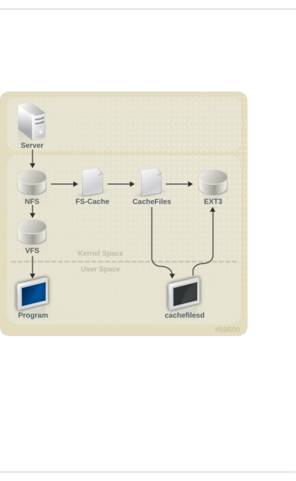
Chapter 9. FS-Cache
FS-Cache is a persistent local cache that can be used by file systems to take data retrieved from over
the network and cache it on local disk. This helps minimize network traffic for users accessing data
from a file system mounted over the network (for example, NFS).
The following diagram is a high-level illustration of how FS-Cache works:
Fig ure 9 .1. FS- Cach e O verview
FS-Cache is designed to be as transparent as possible to the users and administrators of a system.
Unlike cachefs on Solaris, FS-Cache allows a file system on a server to interact directly with a
client's local cache without creating an overmounted file system. With NFS, a mount option instructs
the client to mount the NFS share with FS-cache enabled.
FS-Cache does not alter the basic operation of a file system that works over the network - it merely
provides that file system with a persistent place in which it can cache data. For instance, a client can
still mount an NFS share whether or not FS-Cache is enabled. In addition, cached NFS can handle
files that won't fit into the cache (whether individually or collectively) as files can be partially cached
and do not have to be read completely up front. FS-Cache also hides all I/O errors that occur in the
cache from the client file system driver.
Chapt er 9 . FS- Cache
75
To provide caching services, FS-Cache needs a cache back-end. A cache back-end is a storage
driver configured to provide caching services (i.e. cachefiles). In this case, FS-Cache requires a
mounted block-based file system that supports bmap and extended attributes (e.g. ext3) as its cache
back-end.
FS-Cache cannot arbitrarily cache any file system, whether through the network or otherwise: the
shared file system's driver must be altered to allow interaction with FS-Cache, data storage/retrieval,
and metadata setup and validation. FS-Cache needs indexing keys and coherency data from the
cached file system to support persistence: indexing keys to match file system objects to cache
objects, and coherency data to determine whether the cache objects are still valid.
Note
In Red Hat Enterprise Linux 7, cachefilesd is not installed by default and will need to be
installed manually.
9.1. Performance Guarant ee
FS-Cache does not guarantee increased performance, however it ensures consistent performance by
avoiding network congestion. Using a cache back-end incurs a performance penalty: for example,
cached NFS shares add disk accesses to cross-network lookups. While FS-Cache tries to be as
asynchronous as possible, there are synchronous paths (e.g. reads) where this isn't possible.
For example, using FS-Cache to cache an NFS share between two computers over an otherwise
unladen GigE network will not demonstrate any performance improvements on file access. Rather,
NFS requests would be satisfied faster from server memory rather than from local disk.
The use of FS-Cache, therefore, is a compromise between various factors. If FS-Cache is being used
to cache NFS traffic, for instance, it may slow the client down a little, but massively reduce the network
and server loading by satisfying read requests locally without consuming network bandwidth.
9.2. Set t ing Up a Cache
Currently, Red Hat Enterprise Linux 7 only provides the cachefiles caching back-end. The
cachefilesd daemon initiates and manages cachefiles. The /etc/cachefilesd.conf file
controls how cachefiles provides caching services. To configure a cache back-end of this type,
the cachefilesd package must be installed.
The first setting to configure in a cache back-end is which directory to use as a cache. To configure
this, use the following parameter:
$ d i r /path/to/cache
Typically, the cache back-end directory is set in /etc/cachefilesd.conf as
/var/cache/fscache, as in:
$ dir /var/cache/fscache
FS-Cache will store the cache in the file system that hosts /path/to/cache. On a laptop, it is
advisable to use the root file system (/) as the host file system, but for a desktop machine it would be
more prudent to mount a disk partition specifically for the cache.
St orage Administ rat ion G uide
76

File systems that support functionalities required by FS-Cache cache back-end include the Red Hat
Enterprise Linux 7 implementations of the following file systems:
ext3 (with extended attributes enabled)
ext4
BTRFS
XFS
The host file system must support user-defined extended attributes; FS-Cache uses these attributes to
store coherency maintenance information. To enable user-defined extended attributes for ext3 file
systems (i.e. device), use:
# tune2fs -o user_xattr /dev/device
Alternatively, extended attributes for a file system can be enabled at mount time, as in:
# mount /dev/device /path/to/cache -o user_xattr
The cache back-end works by maintaining a certain amount of free space on the partition hosting the
cache. It grows and shrinks the cache in response to other elements of the system using up free
space, making it safe to use on the root file system (for example, on a laptop). FS-Cache sets defaults
on this behavior, which can be configured via cache cull limits. For more information about
configuring cache cull limits, refer to Section 9.4, “ Setting Cache Cull Limits” .
Once the configuration file is in place, start up the cachefilesd daemon:
# service cachefilesd start
To configure cachefilesd to start at boot time, execute the following command as root:
# chkconfig cachefilesd on
9.3. Using t he Cache Wit h NFS
NFS will not use the cache unless explicitly instructed. To configure an NFS mount to use FS-Cache,
include the -o fsc option to the mount command:
# mount nfs-share:/ /mount/point -o fsc
All access to files under /mount/point will go through the cache, unless the file is opened for direct
I/O or writing (refer to Section 9.3.2, “Cache Limitations With NFS” for more information). NFS indexes
cache contents using NFS file handle, not the file name; this means that hard-linked files share the
cache correctly.
Caching is supported in version 2, 3, and 4 of NFS. However, each version uses different branches
for caching.
9.3.1. Cache Sharing
There are several potential issues to do with NFS cache sharing. Because the cache is persistent,
blocks of data in the cache are indexed on a sequence of four keys:
Chapt er 9 . FS- Cache
77

Level 1: Server details
Level 2: Some mount options; security type; FSID; uniquifier
Level 3: File Handle
Level 4: Page number in file
To avoid coherency management problems between superblocks, all NFS superblocks that wish to
cache data have unique Level 2 keys. Normally, two NFS mounts with same source volume and
options will share a superblock, and thus share the caching, even if they mount different directories
within that volume.
Examp le 9 .1. Cach e sh arin g
Take the following two mount commands:
mount home0:/disk0/fred /home/fred -o fsc
mount home0:/disk0/jim /home/jim -o fsc
Here, /home/fred and /home/jim will likely share the superblock as they have the same
options, especially if they come from the same volume/partition on the NFS server (home0). Now,
consider the next two subsequent mount commands:
mount home0:/disk0/fred /home/fred -o fsc,rsize=230
mount home0:/disk0/jim /home/jim -o fsc,rsize=231
In this case, /home/fred and /home/jim will not share the superblock as they have different
network access parameters, which are part of the Level 2 key. The same goes for the following
mount sequence:
mount home0:/disk0/fred /home/fred1 -o fsc,rsize=230
mount home0:/disk0/fred /home/fred2 -o fsc,rsize=231
Here, the contents of the two subtrees (/home/fred1 and /home/fred2) will be cached twice.
Another way to avoid superblock sharing is to suppress it explicitly with the nosharecache
parameter. Using the same example:
mount home0:/disk0/fred /home/fred -o nosharecache,fsc
mount home0:/disk0/jim /home/jim -o nosharecache,fsc
However, in this case only one of the superblocks will be permitted to use cache since there is
nothing to distinguish the Level 2 keys of home0:/disk0/fred and home0:/disk0/jim. To
address this, add a unique identifier on at least one of the mounts, i.e. fsc=unique-identifier.
For example:
mount home0:/disk0/fred /home/fred -o nosharecache,fsc
mount home0:/disk0/jim /home/jim -o nosharecache,fsc=jim
Here, the unique identifier jim will be added to the Level 2 key used in the cache for /home/jim.
9.3.2. Cache Limit at ions Wit h NFS
St orage Administ rat ion G uide
78

Opening a file from a shared file system for direct I/O will automatically bypass the cache. This is
because this type of access must be direct to the server.
Opening a file from a shared file system for writing will not work on NFS version 2 and 3. The
protocols of these versions do not provide sufficient coherency management information for the client
to detect a concurrent write to the same file from another client.
As such, opening a file from a shared file system for either direct I/O or writing will flush the cached
copy of the file. FS-Cache will not cache the file again until it is no longer opened for direct I/O or
writing.
Furthermore, this release of FS-Cache only caches regular NFS files. FS-Cache will not cache
directories, symlinks, device files, FIFOs and sockets.
9.4. Set t ing Cache Cull Limit s
The cachefilesd daemon works by caching remote data from shared file systems to free space on
the disk. This could potentially consume all available free space, which could be bad if the disk also
housed the root partition. To control this, cachefilesd tries to maintain a certain amount of free
space by discarding old objects (i.e. accessed less recently) from the cache. This behavior is known
as cache culling.
Cache culling is done on the basis of the percentage of blocks and the percentage of files available
in the underlying file system. There are six limits controlled by settings in
/etc/cachefilesd.conf:
brun N% ( p ercen t ag e of b lo cks) , fru n N% ( p ercen t ag e of files)
If the amount of free space and the number of available files in the cache rises above both
these limits, then culling is turned off.
b cull N% ( p ercen t age o f b lo cks) , f cu ll N% (percen t ag e o f f iles)
If the amount of available space or the number of files in the cache falls below either of
these limits, then culling is started.
b st op N% ( p ercen t ag e o f b lo cks) , f st o p N% ( p ercent ag e o f f iles)
If the amount of available space or the number of available files in the cache falls below
either of these limits, then no further allocation of disk space or files is permitted until culling
has raised things above these limits again.
The default value of N for each setting is as follows:
brun/frun - 10%
bcull/fcull - 7%
bstop/fstop - 3%
When configuring these settings, the following must hold true:
0 <= bstop < bcull < brun < 100
0 <= fstop < fcull < frun < 100
These are the percentages of available space and available files and do not appear as 100 minus
the percentage displayed by the d f program.
Chapt er 9 . FS- Cache
79

Important
Culling depends on both bxxx and fxxx pairs simultaneously; they can not be treated
separately.
9.5. St at ist ical Informat ion
FS-Cache also keeps track of general statistical information. To view this information, use:
cat /proc/fs/fscache/stats
FS-Cache statistics includes information on decision points and object counters. For more details on
the statistics provided by FS-Cache, refer to the following kernel document:
/usr/share/doc/kernel-
d o c-version/Documentation/filesystems/caching/fscache.txt
9.6. References
For more information on cachefilesd and how to configure it, refer to man cachefilesd and
man cachefilesd.conf. The following kernel documents also provide additional information:
/usr/share/doc/cachefilesd-version-number/README
/usr/share/man/man5/cachefilesd.conf.5.gz
/usr/share/man/man8/cachefilesd.8.gz
For general information about FS-Cache, including details on its design constraints, available
statistics, and capabilities, refer to the following kernel document:
/usr/share/doc/kernel-
d o c-version/Documentation/filesystems/caching/fscache.txt
St orage Administ rat ion G uide
80

Part II. Storage Administration
The Storage Administration section starts with storage considerations for Red Hat Enterprise Linux 7.
Instructions regarding partitions, logical volume management, and swap partitions follow this. Disk
Quotas, RAID systems are next, followed by the functions of mount command, volume_key, and acls.
SSD tuning, write barriers, I/O limits and diskless systems follow this. The large chapter of Online
Storage is next, and finally device mapper multipathing and virtual storage to finish.
Use the following Table of Contents to explore these Storage Administration tasks.
Part II. St orage Administ rat io n
81

Chapter 10. Storage Considerations During Installation
Many storage device and file system settings can only be configured at install time. Other settings,
such as file system type, can only be modified up to a certain point without requiring a reformat. As
such, it is prudent that you plan your storage configuration accordingly before installing Red Hat
Enterprise Linux 7.
This chapter discusses several considerations when planning a storage configuration for your
system. For actual installation instructions (including storage configuration during installation), refer
to the Installation Guide provided by Red Hat.
For information on what Red Hat officially supports with regards to size and storage limits, refer to the
article http://www.redhat.com/resourcelibrary/articles/articles-red-hat-enterprise-linux-6-technology-
capabilities-and-limits.
10.1. Special Considerat ions
This section enumerates several issues and factors to consider for specific storage configurations.
Separat e Part it ions for /home, /opt , /usr/local
If it is likely that you will upgrade your system in the future, place /home, /o pt, and /usr/local on
a separate device. This will allow you to reformat the devices/file systems containing the operating
system while preserving your user and application data.
DASD and z FCP Devices on IBM Syst em Z
On the IBM System Z platform, DASD and zFCP devices are configured via the Channel Command
Word (CCW) mechanism. CCW paths must be explicitly added to the system and then brought online.
For DASD devices, this is simply means listing the device numbers (or device number ranges) as the
DASD= parameter at the boot command line or in a CMS configuration file.
For zFCP devices, you must list the device number, logical unit number (LUN), and world wide port name
(WWPN). Once the zFCP device is initialized, it is mapped to a CCW path. The FC P _x= lines on the
boot command line (or in a CMS configuration file) allow you to specify this information for the
installer.
Encrypt ing Block Devices Using LUKS
Formatting a block device for encryption using LUKS/dm-crypt will destroy any existing formatting
on that device. As such, you should decide which devices to encrypt (if any) before the new system's
storage configuration is activated as part of the installation process.
St ale BIOS RAID Met adat a
Moving a disk from a system configured for firmware RAID without removing the RAID metadata from
the disk can prevent An a co n d a from correctly detecting the disk.
St orage Administ rat ion G uide
82
Warning
Removing/deleting RAID metadata from disk could potentially destroy any stored data. Red
Hat recommends that you back up your data before proceeding.
To delete RAID metadata from the disk, use the following command:
dmraid -r -E /device/
For more information about managing RAID devices, refer to man dmraid and Chapter 17,
Redundant Array of Independent Disks (RAID).
iSCSI Det ect ion and Configurat ion
For plug and play detection of iSCSI drives, configure them in the firmware of an iBFT boot-capable
network interface card (NIC). CHAP authentication of iSCSI targets is supported during installation.
However, iSNS discovery is not supported during installation.
FCoE Det ect ion and Configurat ion
For plug and play detection of Fibre Channel over Ethernet (FCoE) drives, configure them in the
firmware of an EDD boot-capable NIC.
DASD
Direct-access storage devices (DASD) cannot be added/configured during installation. Such devices
are specified in the CMS configuration file.
Block Devices wit h DIF/DIX Enabled
DIF/DIX is a hardware checksum feature provided by certain SCSI host bus adapters and block
devices. When DIF/DIX is enabled, errors will occur if the block device is used as a general-purpose
block device. Buffered I/O or mmap(2)-based I/O will not work reliably, as there are no interlocks in
the buffered write path to prevent buffered data from being overwritten after the DIF/DIX checksum has
been calculated.
This will cause the I/O to later fail with a checksum error. This problem is common to all block device
(or file system-based) buffered I/O or mmap(2) I/O, so it is not possible to work around these errors
caused by overwrites.
As such, block devices with DIF/DIX enabled should only be used with applications that use
O_DIRECT. Such applications should use the raw block device. Alternatively, it is also safe to use
the XFS file system on a DIF/D IX enabled block device, as long as only O_DIRECT I/O is issued
through the file system. XFS is the only file system that does not fall back to buffered I/O when doing
certain allocation operations.
The responsibility for ensuring that the I/O data does not change after the DIF/DIX checksum has
been computed always lies with the application, so only applications designed for use with
O_DIRECT I/O and DIF/DIX hardware should use DIF/D IX.
Chapt er 1 0 . St orage Considerat ions During Inst allat ion
83

Chapter 11. File System Check
Filesystems may be checked for consistency, and optionally repaired, with filesystem-specific
userspace tools. These tools are often referred to as fsck tools, where fsck is a shortened version
of file system check.
Note
These filesystem checkers only guarantee metadata consistency across the filesystem; they
have no awareness of the actual data contained within the filesystem and are not data
recovery tools.
Filesystem inconsistencies can occur for various reasons, including but not limited to hardware
errors, storage administration errors, and software bugs.
Before modern metadata-journaling filesystems became common, a filesystem check was required
any time a system crashed or lost power. This was because a filesystem update could have been
interrupted, leading to an inconsistent state. As a result, a filesystem check is traditionally run on
each filesystem listed in /etc/fstab at boot-time. For journaling filesystems, this is usually a very
short operation, because the filesystem's metadata journaling ensures consistence even after a
crash.
However, there are times when a filesystem inconsistency or corruption may occur, even for
journaling filesystems. When this happens, the filesystem checker must be used to repair the
filesystem. The following will provide best practices and other useful information when performing
this procedure.
Important
Red Hat does not recommended this unless the machine does not boot, the file system is
extremely large, or the file system is on remote storage. It is possible to disable file system
check at boot by setting the sixth field in /etc/fstab to 0.
11.1. Best Pract ices for fsck
Generally, running the filesystem check and repair tool can be expected to automatically repair at
least some of the inconsistencies it finds. In some cases, severely damaged inodes or directories may
be discarded if they cannot be repaired. Significant changes to the filesystem may occur. To ensure
that unexpected or undesirable changes are not permanently made, perform the following
precautionary steps:
Dry ru n
Most filesystem checkers have a mode of operation which checks but does not repair the
filesystem. In this mode, the checker will print any errors that it finds and actions that it
would have taken, without actually modifying the filesystem.
St orage Administ rat ion G uide
84

Note
Later phases of consistency checking may print extra errors as it discovers
inconsistencies which would have been fixed in early phases if it were running in
repair mode.
O p erat e f irst o n a f ilesyst em imag e
Most filesystems support the creation of a metadata image, a sparse copy of the filesystem
which contains only metadata. Because filesystem checkers operate only on metadata,
such an image can be used to perform a dry run of an actual filesystem repair, to evaluate
what changes would actually be made. If the changes are acceptable, the repair can then
be performed on the filesystem itself.
Note
Severely damaged filesystems may cause problems with metadata image creation.
Save a f ilesyst em imag e f o r su p p o rt in vest ig at io n s
A pre-repair filesystem metadata image can often be useful for support investigations if
there is a possibility that the corruption was due to a software bug. Patterns of corruption
present in the pre-repair image may aid in root-cause analysis.
O p erat e o n ly on u n mo u n t ed f ilesyst ems
A filesystem repair must be run only on unmounted filesystems. The tool must have sole
access to the filesystem or further damage may result. Most filesystem tools enforce this
requirement in repair mode, although some only support check-only mode on a mounted
filesystem. If check-only mode is run on a mounted filesystem, it may find spurious errors
that would not be found when run on an unmounted filesystem.
Disk erro rs
Filesystem check tools cannot repair hardware problems. A filesystem must be fully
readable and writable if repair is to operate successfully. If a filesystem was corrupted due
to a hardware error, the filesystem must first be moved to a good disk, for example with the
dd(8) utility.
11.2. Filesyst em-Specific Informat ion for fsck
11.2.1. ext 2, ext 3, and ext 4
All of these filesytems use the e2fsck binary to perform filesystem checks and repairs. The filenames
fsck.ext2, fsck.ext3, and fsck.ext4 are hardlinks to this same binary. These binaries are run
automatically at boot time and their behavior differs based on the filesystem being checked and the
state of the filesystem.
A full filesystem check and repair is invoked for ext2, which is not a metadata journaling filesystem,
and for ext4 filesystems without a journal.
For ext3 and ext4 filesystems with metadata journaling, the journal is replayed in userspace and the
binary exited. This is the default action as journal replay ensures a consistent filesystem after a
Chapt er 1 1 . File Syst em Check
85

crash.
If these filesystems encounter metadata inconsistencies while mounted, they will record this fact in the
filesystem super block. If e2fsck finds that a filesystem is marked with such an error e2fsck will
perform a full check after replaying the journal (if present).
e2fsck may ask for user input during the run if the -p option is not specified. The -p option tells
e2fsck to automatically do all repairs that may be done safely. If user intervention is required,
e2fsck will indicate the unfixed problem in its output and reflect this status in the exit code.
Commonly used e2fsck run-time options include:
-n
No-modify mode. Check-only operation.
-b su p erb lo ck
Specify block number of an alternate suprerblock if the primary one is damaged.
-f
Force full check even if the superblock has no recorded errors.
-j journ al- dev
Specify the external journal device, if any.
-p
Automatically repair or "preen" the filesystem with no user input.
-y
Assume an answer of "yes" to all questions.
All options for e2fsck are specified in the e2fsck(8) manual page.
The following five basic phases are performed by e2fsck while running:
1. Inode, block, and size checks.
2. Directory structure checks.
3. Directory connectivity checks.
4. Reference count checks.
5. Group summary info checks.
The e2image(8) utility can be used to create a metadata image prior to repair for diagnostic or
testing purposes. The -r option should be used for testing purposes in order to create a sparse file
of the same size as the filesystem itself. e2fsck can then operate directly on the resulting file. The -Q
option should be specified if the image is to be archived or provided for diagnostic. This creates a
more compact file format suitable for transfer.
11.2.2. XFS
No repair is performed automatically at boot time. To initiate a filesystem check or repair, the
xfs_repair tool is used.
St orage Administ rat ion G uide
86

Note
Although an fsck.xfs binary is present in the xfsprogs package, this is present only to
satisfy initscripts that look for an fsck.filesystem binary at boot time. fsck.xfs
immediately exits with an exit code of 0.
Another thing to be aware of is that older xfsprogs packages contain an xfs_check tool. This
tool is very slow and does not scale well for large filesystems. As such, it has been depreciated
in favor of xfs_repair -n.
A clean log on a filesystem is required for xfs_repair to operate. If the filesystem was not cleanly
unmounted, it should be mounted and unmounted prior to using xfs_repair. If the log is corrupt
and cannot be replayed, the -L option may be used to zero the log.
Important
The -L option must only be used if the log cannot be replayed. The option discards all
metadata updates in the log and will result in further inconsistencies.
It is possible to run xfs_repair in a dry run, check-only mode by using the -n option. No changes
will be made to the filesystem when this option is specified.
xfs_repair takes very few options. Commonly used options include:
-n
No modify mode. Check-only operation.
-L
Z ero metadata log. Use only if log cannot be replayed with mount.
-m maxmem
Limit memory used during run to maxmem MB. 0 can be specified to obtain a rough estimate
of the minimum memory required.
-l lo g d ev
Specify the external log device, if present.
All options for xfs_repair are specified in the xfs_repair(8) manual page.
The following eight basic phases are performed by xfs_repair while running:
1. Inode and inode blockmap (addressing) checks.
2. Inode allocation map checks.
3. Inode size checks.
4. Directory checks.
5. Pathname checks.
Chapt er 1 1 . File Syst em Check
87

6. Link count checks.
7. Freemap checks.
8. Super block checks.
These phases, as well as messages printed during operation, are documented in depth in the
xfs_repair(8) manual page.
xfs_repair is not interactive. All operations are performed automatically with no input from the
user.
If it is desired to create a metadata image prior to repair for diagnostic or testing purposes, the
xfs_metadump(8) and xfs_mdrestore(8) utilities may be used.
11.2.3. Bt rfs
The btrfsck tool is used to check and repair btrfs filesystems. This tool is still in early development
and may not detect or repair all types of filesystem corruption.
By default, btrfsck does not make changes to the filesystem; that is, it runs check-only mode by
default. If repairs are desired the --repair option must be specified.
The following three basic phases are performed by btrfsck while running:
1. Extent checks.
2. Filesystem root checks.
3. Root reference count checks.
The btrfs-image(8) utility can be used to create a metadata image prior to repair for diagnostic or
testing purposes.
St orage Administ rat ion G uide
88
Chapter 12. Partitions
The utility parted allows users to:
View the existing partition table
Change the size of existing partitions
Add partitions from free space or additional hard drives
By default, the parted package is included when installing Red Hat Enterprise Linux. To start
parted , log in as root and type the command parted /dev/sda at a shell prompt (where
/dev/sda is the device name for the drive you want to configure).
If you want to remove or resize a partition, the device on which that partition resides must not be in
use. Creating a new partition on a device which is in use—while possible—is not recommended.
For a device to not be in use, none of the partitions on the device can be mounted, and any swap
space on the device must not be enabled.
As well, the partition table should not be modified while it is in use because the kernel may not
properly recognize the changes. If the partition table does not match the actual state of the mounted
partitions, information could be written to the wrong partition, resulting in lost and overwritten data.
The easiest way to achieve this it to boot your system in rescue mode. When prompted to mount the
file system, select Skip.
Alternately, if the drive does not contain any partitions in use (system processes that use or lock the
file system from being unmounted), you can unmount them with the umount command and turn off all
the swap space on the hard drive with the swapoff command.
Table 12.1, “ parted commands” contains a list of commonly used parted commands. The sections
that follow explain some of these commands and arguments in more detail.
T able 12.1. parted comman d s
C o mman d D escrip t io n
check minor-num Perform a simple check of the file system
cp from to Copy file system from one partition to another;
from and to are the minor numbers of the
partitions
hel p Display list of available commands
mklabel label Create a disk label for the partition table
mkfs minor-num file-system-type Create a file system of type file-system-type
mkpart part-type fs-type start-mb
end-mb
Make a partition without creating a new file
system
mkpartfs part-type fs-type start-mb
end-mb
Make a partition and create the specified file
system
move minor-num start-mb end-mb Move the partition
name minor-num name Name the partition for Mac and PC98 disklabels
only
pri nt Display the partition table
q ui t Quit parted
rescue start-mb end-mb Rescue a lost partition from start-mb to end-mb
resize minor-num start-mb end-mb Resize the partition from start-mb to end-mb
Chapt er 1 2 . Part it ion s
89
rm minor-num Remove the partition
select device Select a different device to configure
set minor-num flag state Set the flag on a partition; state is either on or off
to gg l e [NUMBER [FLAG]Toggle the state of FLAG on partition NUMBER
unit UNIT Set the default unit to UNIT
C o mman d D escrip t io n
12.1. Viewing t he Part it ion T able
After starting parted , use the command pri nt to view the partition table. A table similar to the
following appears:
Examp le 12.1. Part it io n t ab le
Model: ATA ST3160812AS (scsi)
Disk /dev/sda: 160GB
Sector size (logical/physical): 512B/512B
Partition Table: msdos
Number Start End Size Type File system Flags
1 32.3kB 107MB 107MB primary ext3 boot
2 107MB 105GB 105GB primary ext3
3 105GB 107GB 2147MB primary linux-swap
4 107GB 160GB 52.9GB extended root
5 107GB 133GB 26.2GB logical ext3
6 133GB 133GB 107MB logical ext3
7 133GB 160GB 26.6GB logical lvm
The first line contains the disk type, manufacturer, model number and interface, and the second
line displays the disk label type. The remaining output below the fourth line shows the partition
table.
In the partition table, the Minor number is the partition number. For example, the partition with minor
number 1 corresponds to /dev/sda1. The Start and End values are in megabytes. Valid Type are
metadata, free, primary, extended, or logical. The Filesystem is the file system type, which can be
any of the following:
ext2
ext3
fat16
fat32
hfs
jfs
linux-swap
ntfs
reiserfs
St orage Administ rat ion G uide
90

hp-ufs
sun-ufs
xfs
If a Filesystem of a device shows no value, this means that its file system type is unknown.
The Flags column lists the flags set for the partition. Available flags are boot, root, swap, hidden,
raid, lvm, or lba.
Note
To select a different device without having to restart parted , use the select command
followed by the device name (for example, /dev/sda). Doing so allows you to view or
configure the partition table of a device.
12.2. Creat ing a Part it ion
Warning
Do not attempt to create a partition on a device that is in use.
Pro ced u re 12.1. Creat in g a p art it io n
1. Before creating a partition, boot into rescue mode (or unmount any partitions on the device
and turn off any swap space on the device).
2. Start parted , where /dev/sda is the device on which to create the partition:
# parted /dev/sda
3. View the current partition table to determine if there is enough free space:
# print
If there is not enough free space, you can resize an existing partition. Refer to Section 12.4, “ Resizing
a Partition” for details.
12.2.1. Making t he Part it ion
From the partition table, determine the start and end points of the new partition and what partition
type it should be. You can only have four primary partitions (with no extended partition) on a device.
If you need more than four partitions, you can have three primary partitions, one extended partition,
and multiple logical partitions within the extended. For an overview of disk partitions, refer to the
appendix An Introduction to Disk Partitions in the Red Hat Enterprise Linux 7 Installation Guide.
For example, to create a primary partition with an ext3 file system from 1024 megabytes until 2048
megabytes on a hard drive type the following command:
Chapt er 1 2 . Part it ion s
91

# mkpart primary ext3 1024 2048
Note
If you use the mkpartfs command instead, the file system is created after the partition is
created. However, parted does not support creating an ext3 file system. Thus, if you wish to
create an ext3 file system, use mkpart and create the file system with the mkfs command as
described later.
The changes start taking place as soon as you press Enter, so review the command before
executing to it.
After creating the partition, use the pri nt command to confirm that it is in the partition table with the
correct partition type, file system type, and size. Also remember the minor number of the new partition
so that you can label any file systems on it. You should also view the output of cat
/pro c/parti ti o ns after parted is closed to make sure the kernel recognizes the new partition.
The maximum number of partitions parted will create is 128. While the GUID Partition Table (GPT)
specification allows for more partitions by growing the area reserved for the partition table, common
practice used by parted is to limit it to enough area for 128 partitions.
12.2.2. Format t ing and Labeling t he Part it ion
To format and label the partition use the following procedure:
Pro ced u re 12.2. Fo rmat an d lab el t h e part it io n
1. The partition still does not have a file system. To create one use the following command:
# /usr/sbin/mkfs -t ext3 /dev/sda6
Warning
Formatting the partition permanently destroys any data that currently exists on the
partition.
2. Next, give the file system on the partition a label. For example, if the file system on the new
partition is /dev/sda6 and you want to label it /work, use:
# e2label /dev/sda6 /work
By default, the installation program uses the mount point of the partition as the label to make sure the
label is unique. You can use any label you want.
Afterwards, create a mount point (e.g. /work) as root.
12.2.3. Add t o /etc/fstab
As root, edit the /etc/fstab file to include the new partition using the partition's UUID. Use the
command bl ki d -o l i st for a complete list of the partition's UUID, or blkid device for
individual device details.
St orage Administ rat ion G uide
92
The first column should contain UUID= followed by the file system's UUID. The second column
should contain the mount point for the new partition, and the next column should be the file system
type (for example, ext3 or swap). If you need more information about the format, read the man page
with the command man fstab.
If the fourth column is the word defaults, the partition is mounted at boot time. To mount the
partition without rebooting, as root, type the command:
mount /work
12.3. Removing a Part it ion
Warning
Do not attempt to remove a partition on a device that is in use.
Pro ced u re 12.3. Remo ve a p art it io n
1. Before removing a partition, boot into rescue mode (or unmount any partitions on the device
and turn off any swap space on the device).
2. Start parted , where /dev/sda is the device on which to remove the partition:
# parted /dev/sda
3. View the current partition table to determine the minor number of the partition to remove:
# print
4. Remove the partition with the command rm. For example, to remove the partition with minor
number 3:
# rm 3
The changes start taking place as soon as you press Enter, so review the command before
committing to it.
5. After removing the partition, use the pri nt command to confirm that it is removed from the
partition table. You should also view the output of /pro c/parti ti o ns to make sure the
kernel knows the partition is removed.
# cat /proc/partitions
6. The last step is to remove it from the /etc/fstab file. Find the line that declares the removed
partition, and remove it from the file.
12.4. Resizing a Part it ion
Before resizing a partition, back up the information on the file system.
Pro ced u re 12.4 . Resiz e a part it ion
Chapt er 1 2 . Part it ion s
93

1. Unmount the device.
~]# umount /dev/vda
2. Run fdisk device_name.
~]# fdisk /dev/vda
Welcome to fdisk (util-linux 2.23.2).
Changes will remain in memory only, until you decide to write
them. Be careful before using the write command.
Command (m for help):
3. Check the partition number to be deleted with the p option. The partitions are listed under the
heading 'Device'.
Command (m for help): p
Disk /dev/vda: 16.1 GB, 16106127360 bytes, 31457280 sectors
Units = sectors of 1 * 512 = 512 bytes
Sector size (logical/physical): 512 bytes / 512 bytes
I/O size (minimum/optimal): 512 bytes / 512 bytes
Disk label type: dos
Disk identifier: 0x0006d09a
Device Boot Start End Blocks Id System
/dev/vda1 * 2048 1026047 512000 83 Linux
/dev/vda2 1026048 31457279 15215616 8e Linux LVM
Important
Red Hat only supports the extension or resizing of LVM partitions.
4. Use the d option to delete a partition. If there is more than one partition available, fdisk will
prompt for which one to delete.
Command (m for help): d
Partition number (1,2, default 2): 2
Partition 2 is deleted
5. Use the n option to create a new partition. Follow the prompts and ensure enough space is
allowed for any future resizing that is needed. It is possible to specify a set, human-readable
size instead of using sectors if this is preferred.
Note
It is recommended to follow fdisk's default options for the default values and
partition sizes (for example, the first partition sectors).
Command (m for help): n
St orage Administ rat ion G uide
94
Partition type:
p primary (1 primary, 0 extended, 3 free)
e extended
Select (default p): *Enter*
Using default response p
Partition number (2-4, default 2): *Enter*
First sector (1026048-31457279, default 1026048): *Enter*
Using default value 1026048
Last sector, +sectors or +size{K,M,G} (1026048-31457279, default
31457279): +500M
Partition 2 of type Linux and of size 500 MiB is set
6. Set the partition type to LVM.
Command (m for help): t
Partition number (1,2, default 2): *Enter*
Hex code (type L to list all codes): 8e
Changed type of partition 'Linux' to 'Linux LVM'
7. Write the changes with the w option when certain they are correct.
Important
Errors in this process that are written could cause instability with the selected partition.
8. Run e2fsck on the device to check for consistency.
~]# e2fsck /dev/vda
e2fsck 1.41.12 (17-May-2010)
Pass 1:Checking inodes, blocks, and sizes
Pass 2:Checking directory structure
Pass 3:Checking directory connectivity
Pass 4:Checking reference counts
Pass 5:Checking group summary information
ext4-1:11/131072 files (0.0% non-contiguous),27050/524128 blocks
9. Mount the device.
~]# mount /dev/vda
For more information refer to the following references:
man fdisk
The man page for fdisk. It has basic information about what fdisk is and what it
supports.
T h e m o p t io n wit h in fd i sk
This option lists all available commands within fdisk.
Chapt er 1 2 . Part it ion s
95
Chapter 13. Creating and Maintaining Snapshots with Snapper
A snapshot volume is a point in time copy of a target volume that provides a way to revert a file
system back to an earlier state. Snapper is a command-line tool to create and maintain snapshots for
btrfs and thinly-provisioned LVM file systems. It provides snapshot functionality as the file system
specific tools, with some useful extras, such as comparing changes between two snapshots.
Note
The btrfs tools and file system are provided as a Technology Preview and should not be used
on production systems.
13.1. Init ial Snapper Set up
Snapper requires discrete configuration files for each volume it operates on. These must be set up
manually. By default, only the root user is allowed to perform snapper commands. To allow a user or
group access to snapper features requiring root privilege, please refer to Section 13.2, “ Allow Users
and Groups to Execute Snapper Commands” . To create a configuration file, use the following
procedure.
Note
The btrfs tools and file system are provided as a Technology Preview and should not be used
on production systems.
Pro ced u re 13.1. Creat e a Sn ap p er Co n f ig u rat io n File
1. Create or choose either:
A thinly-provisioned logical volume with a Red Hat supported file system on top of it, or
A btrfs subvolume.
2. Mount the file system.
3. Create the configuration file that defines this volume.
For LVM2:
# snapper -c config_name create-config -f "lvm(fs_type)" /mount-
point
For btrfs:
~]# snapper -c config_name create-config -f btrfs /mount-point
The -c config_name option specifies the name of the configuration file.
The create-config tells snapper to create a configuration file.
St orage Administ rat ion G uide
96
The -f file_system tells snapper what file system to use; if this is omitted snapper will
attempt to detect the file system.
The /mount-point is where the subvolume or thinly-provisioned LVM2 file system is
mounted.
For example, to create a configuration file called lvm_config on an LVM2 subvolume with
an ext4 file system, mounted at /lvm_mount, use:
# snapper -c lvm_config create-config -f "lvm(ext4)" /lvm_mount
Alternatively, to create a configuration file called btrfs_config, on a btrfs subvolume that
is mounted at /btrfs_mount, use the following command:
# snapper -c btrfs_config create-config -f btrfs /btrfs_mount
These configuration files are stored in /etc/snapper/configs/.
13.2. Allow Users and Groups t o Execut e Snapper Commands
To allow a user or group other than root to use some snapper commands, changes can be made in
the configuration file (created in Section 13.1, “Initial Snapper Setup” ).
Important
Although it is possible to add elevated permissions to otherwise unprivileged users or groups
it is not recommended. Such a configuration bypasses SELinux and could pose a security
risk. You should review these capabilities with your Security Team and consider using a sud o
infrastructure instead.
To allow a user or group snapper permissions, add the ALLOW_USERS= and ALLOW_GROUPS=
lines to the configuration file. The commands that this will allow are:
mount
umount
status
create
delete
list
modify
cleanup
For example, to allow the user user1 and the group snapper_group privileged access, the
configuration file will look like this:
# cat /etc/snapper/configs/lvm_config
Chapt er 1 3. Creat in g and Maint aining Snapsh ot s wit h Snapper
97
# subvolume to snapshot
SUBVOLUME="/lvmmount"
# filesystem type
FSTYPE="lvm(ext4)"
# users and groups allowed to work with config
ALLOW_USERS="user1"
ALLOW_GROUPS="snapper_group"
...
13.3. Creat ing a Snapper Snapshot
There are three kinds of snapshots that snapper can create: pre, post, and single.
Pre Sn ap sh o t
A pre snapshot serves as a point of origin for a post snapshot. The two are closely tied and
designed to track file system modification between the two points. The pre snapshot must be
created before the post snapshot.
Po st Sn ap sh o t
A post snapshot serves as the end point to the pre snapshot. The coupled pre and post
snapshots define a range for comparison. By default, every new snapper volume is
configured to create a background comparison after a related post snapshot is created
successfully.
Sin g le Snap sh o t
A single snapshot is a standalone snapshot created at a specific moment. These can be
used to track a timeline of modifications and have a general point to return to at a later
date.
13.3.1. Creat e a Pre and Post Snapshot Pair
To create a pre and post snapshot pair with snapper, the first step is to create the pre snapshot.
13.3.1 .1 . Creat e a Pre Snapsho t
To create a pre snapshot, use the following command:
# snapper -c config_name create -t pre
The -c config_name option creates a snapshot according to the specifications in the named
configuration file. If the configuration file does not yet exist, refer to Section 13.1, “Initial Snapper
Setup ” .
The create -t option specifies what type of snapshot to create. Accepted entries are pre, post, or
single.
For example, to create a pre snapshot using the lvm_config configuration file, as created in
Section 13.1, “ Initial Snapper Setup” , use the following command:
St orage Administ rat ion G uide
98

# snapper -c SnapperExample create -t pre -p
1
Note
For the purposes of this example, the option -p is used to print the number of the snapshot
created but it is safe to not include this option.
13.3.1 .2 . Creat e a Po st Snapsho t
A post snapshot is the end point of the snapshot and should be created after the parent pre
snapshot by following the instructions in Section 13.3.1.1, “ Create a Pre Snapshot” .
Pro ced u re 13.2. Creat e a Po st Sn apsh o t wit h Sn apper
1. To create a post snapshot, first find the number of the pre snapshot it will be linked to with the
l i st command.
# snapper -c config_name list
For example, to display the list of snapshots created using the configuration file
btrfs_config, use the following:
# snapper -c btrfs_config list
Type | # | Pre # | Date | User | Cleanup |
Description | Userdata
-------+---+-------+-------------------+------+----------+--------
-----+---------
single | 0 | | | root | | current
|
pre | 1 | | Mon 06<...> | root | | |
The output above shows that the pre snapshot is number 1.
2. Next, use the following command to create a post snapshot that is linked to a previously
created pre snapshot:
# snapper -c config_file create -t post --pre-num
pre_snapshot_number
Here, the create -t option specifies post to create a post snapshot.
The --pre-num option specifies the corresponding pre snapshot.
For example, to create a post snapshot using the btrfs_config configuration file and is
linked to pre snapshot number 1, use the following command:
# snapper -c btrfs_config create -t post --pre-num 1 -p
2
Chapt er 1 3. Creat in g and Maint aining Snapsh ot s wit h Snapper
99
Note
For the purposes of this example, the option -p is used to print the number of the
snapshot created. This can usually be left off but its use will make the example easier
to follow.
3. Now the pre and post snapshots 1 and 2 are created and paired. Verify this with another
l i st command. For example:
# snapper -c btrfs_config list
Type | # | Pre # | Date | User | Cleanup |
Description | Userdata
-------+---+-------+-------------------+------+----------+--------
-----+---------
single | 0 | | | root | | current
|
pre | 1 | | Mon 06<...> | root | | |
post | 2 | 1 | Mon 06<...> | root | | |
It is also possible to wrap a command within a pre and post snapshot which can be useful when
testing.
Pro ced u re 13.3. Wrap a Co mmand in Pre an d Po st Sn ap shots
1. To wrap a command in pre and post snapshots, use the following command:
# snapper -c btrfs_config create --command "command_to_be_tracked"
For example, to track the creation of the file /btrfs_mount/hello_file use the following
command:
# snapper -c btrfs_config create --command "echo Hello >
/btrfs/hello_file"
2. To verify this, use the status.
# snapper -c config_file status
first_snapshot_number..second_snapshot_number
For example, to track the changes made in the first step use the following command:
# snapper -c btrfs_config status 3..4
+..... /btrfs_mount/hello_file
Remember, the l i st command can be used to verify what a snapshot's number is.
For more information on the status command, refer to Section 13.4, “ Track Changes
Between Snapper Snapshots”
There is no guarantee that the command in the above example is the only thing the snapshots
capture; snapper will also record anything that is modified by the system, not just what a user
modifies.
St orage Administ rat ion G uide
100
13.3.2. Creat e a Single Snapper Snapshot
Creating a single snapper snapshot is similar to creating a pre or post snapshot, only the create -
t option specifies single. The single snapshot is used to create a single snapshot in time without
having it relate to any others.
Use the following command to create a single snapshot:
# snapper -c config_name create -t single
For example, the following command will create a single snapshot using the btrfs_config
configuration file.
# snapper -c SnapperExample create -t single
Note
Despite the fact that single snapshots are not specifically designed to track changes, snapper
is able to create a comparison between any two snapshots by explicit demand of the user (that
is, by snapper diff, xadiff, or status command). For more information on these
commands, refer to Section 13.4, “ Track Changes Between Snapper Snapshots” .
13.4 . Track Changes Bet ween Snapper Snapshot s
There are three commands used to track the changes made to a subvolume between snapshots.
These are status, d i ff, and xadiff.
st at u s
The status command shows a list of files and directories that have been created, modified,
or deleted between two snapshots.
Refer to Section 13.4.1, “ Comparing Changes with the status Command” for more
information.
d if f
The d i ff command shows a diff of modified files and directories between two snapshots.
Refer to Section 13.4.2, “ Comparing changes with the d i ff command” for more
information.
xad i f f
The xadiff command compares how the extended attributes of a file or directory have
changed between two snapshots.
Refer to Section 13.4.3, “ Comparing changes with the xadiff command” for more
information.
13.4 .1. Comparing Changes wit h t he status Command
Chapt er 1 3. Creat in g and Maint aining Snapsh ot s wit h Snapper
101

The status command shows a list of files and directories that have been created, modified, or
deleted between two snapshots.
Use the following command to display the status of files between two snapshots:
# snapper -c config_file status
first_snapshot_number..second_snapshot_number
Remember, the number of snapshots can be found with the l i st command.
For example, the following command displays the changes made between snapshot 1 and 2, using
the configuration file btrfs_config.
snapper -c btrfs_config status 1..2
tp.... /btrfs_mount/dir1
-..... /btrfs_mount/dir1/file_a
c.ug.. /btrfs_mount/file2
+..... /btrfs_mount/file3
....x. /btrfs_mount/file4
cp..xa /btrfs_mount/file5
The letters and dots in the first part of the output should be read as columns.
+..... /btrfs_mount/file3
||||||
123456
Column 1, as shown below, indicates any modification in the file's (directory entry) type. Possible
values are:
Co lu mn 1
O u t p u t Mea n in g
. Nothing has changed.
+ File created.
- File deleted.
c Content changed.
t Type of directory entry has changed (for
example, a former symbolic link has changed to
a regular file with the same file name).
Column 2, as shown below, indicates any changes in the file's permissions. Possible values are:
Co lu mn 2
O u t p u t Mea n in g
. No permissions changed.
p Permissions changed.
Column 3, as shown below, indicates any changes in the user ownership. Possible values are:
Co lu mn 3
St orage Administ rat ion G uide
102
O u t p u t Mea n in g
. No user ownership changed.
u User ownership has changed.
Column 4, as shown below, indicates any changes in the group ownership. Possible values are:
Co lu mn 4
O u t p u t Mea n in g
. No group ownership changed.
g Group ownership has changed.
Column 5, as shown below, indicates any changes in the extended attributes. Possible values are:
Co lu mn 5
O u t p u t Mea n in g
. No extended attributes changed.
x Extended attributes changed.
Column 6, as shown below, indicates any changes in the access control lists (ACLs). Possible
values are:
Co lu mn 6
O u t p u t Mea n in g
. No ACLs changed.
a ACLs modified.
13.4 .2. Comparing changes wit h t he d i ff command
The d i ff command shows the changes of modified files and directories between two snapshots.
The following command demostrates:
# snapper -c config_name diff
first_snapshot_number..second_snapshot_number
Remember, the number of snapshots can be found with the l i st command.
For example, to compare the changes made in files between snapshot 1 and snapshot 2 that were
made using the btrfs_config configuration file, use the following command:
# snapper -c btrfs_config diff 1..2
--- /btrfs_mount/.snapshots/13/snapshot/file4 19<...>
+++ /btrfs_mount/.snapshots/14/snapshot/file4 20<...>
@@ -0,0 +1 @@
+words
The above output shows that file4 had been modified to add "words" into the file.
13.4 .3. Comparing changes wit h t he xadiff command
Chapt er 1 3. Creat in g and Maint aining Snapsh ot s wit h Snapper
103

The xadiff command compares how the extended attributes of a file or directory have changed
between two snapshots. To do so, use the following command:
# snapper -c config_name xadiff
first_snapshot_number..second_snapshot_number
Remember, the number of snapshots can be found with the l i st command.
For example, to show the xadiff output between snapshot number 1 and snapshot number 2 that were
made using the btrfs_config configuration file, the command would be:
# snapper -c btrfs_config xadiff 1..2
13.5. Reverse Changes in Bet ween Snapshot s
To reverse changes made between two existing snapper snapshots, the undochange command is
used in the following format: snapper -c config_name undochange 1..2 where the 1 is the
first snapshot and 2 is the second snapshot.
Important
This will not revert the snapper volume back to its original state and does not provide data
consistency. Any file modification that occurs outside of the specified range (for example, after
snapshot 2) will remain unchanged after reverting back (for example, to the state of snapshot
1). For example, should the undochange be run to undo the creation of a user, any files
owned by that user may still remain.
There is also no mechanism to ensure file consistency as a snapshot is made, so any
inconsistencies that already exist can be transfered back to the snapshot when the
undochange command is used.
To understand how the undochange command works, consider the following diagram:
St orage Administ rat ion G uide
104
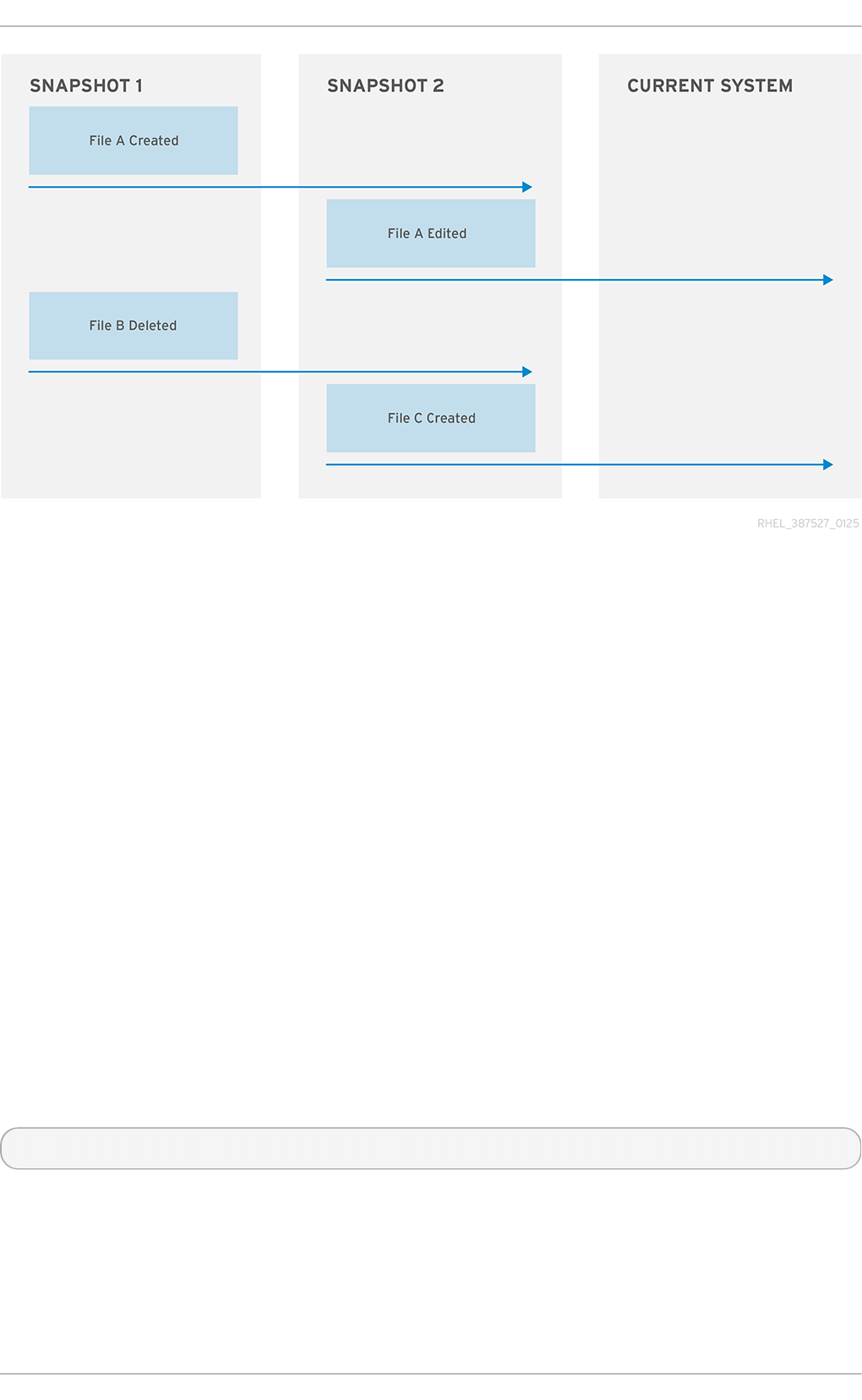
Fig ure 13.1. Sn ap p er St at u s O ver T ime
In the above diagram it shows the point in time where snapshot_1 is created, file_a is created,
then file_b deleted. Snapshot_2 is then created, after which file_a is edited and file_c is
created. This is now the current state of the system. The current system has an edited version of
file_a, no file_b, and a newly created fi l e_c
When the undochange is called, snapper generates a list of modified files between the first listed
snapshot and the second. In the above diagram, should the command be snapper -c
SnapperExample undochange 1..2, snapper will create a list of modified files (that is, fi l e_a
is created; file_b is deleted) and apply them to the current system. Therefore, the current system will
not have file_a (as it has yet to be created when snapshot_1 was created), file_b will exist
(copied from snapshot_1 into the current system), and file_c will exist, as its creation was outside
the specified time. Be aware that, should file_b and file_c conflict, the system could become
corrupted.
It is also possible for the command to be snapper -c SnapperExample undochange 2..1. In
this case the current system will replace the edited version of file_a with one copied from
snapshot_1, thus undoing the editing that took place on that file after snapshot_2 was created.
13.6. Delet e a Snapshot
To delete a snapshot, use the following command:
~]# snapper -c config_name delete snapshot_number
This can then be verified with the l i st command.
Chapt er 1 3. Creat in g and Maint aining Snapsh ot s wit h Snapper
105
Chapter 14. Swap Space
Swap space in Linux is used when the amount of physical memory (RAM) is full. If the system needs
more memory resources and the RAM is full, inactive pages in memory are moved to the swap space.
While swap space can help machines with a small amount of RAM, it should not be considered a
replacement for more RAM. Swap space is located on hard drives, which have a slower access time
than physical memory. Swap space can be a dedicated swap partition (recommended), a swap file,
or a combination of swap partitions and swap files. Note that Btrfs does not support swap space.
In years past, the recommended amount of swap space increased linearly with the amount of RAM in
the system. However, modern systems often include hundreds of gigabytes of RAM. As a
consequence, recommended swap space is considered a function of system memory workload, not
system memory.
Table 14.1, “ Recommended System Swap Space” provides the recommended size of a swap partition
depending on the amount of RAM in your system and whether you want sufficient memory for your
system to hibernate. The recommended swap partition size is established automatically during
installation. To allow for hibernation, however, you need to edit the swap space in the custom
partitioning stage.
Recommendations in Table 14.1, “ Recommended System Swap Space” are especially important on
systems with low memory (1 GB and less). Failure to allocate sufficient swap space on these systems
can cause issues such as instability or even render the installed system unbootable.
T able 14 .1. Reco mmen d ed Syst em Swap Sp ace
Amo u n t o f RAM in t h e
syst em
Reco mmen d ed swap sp ace Reco mmen d ed swap sp ace
if allo win g f or h ibern at io n
⩽ 2 GB 2 times the amount of RAM 3 times the amount of RAM
> 2 GB – 8 GB Equal to the amount of RAM 2 times the amount of RAM
> 8 GB – 64 GB At least 4 GB 1.5 times the amount of RAM
> 64 GB At least 4 GB Hibernation not recommended
At the border between each range listed in Table 14.1, “Recommended System Swap Space” , for
example a system with 2 GB, 8 GB, or 64 GB of system RAM, discretion can be exercised with regard
to chosen swap space and hibernation support. If your system resources allow for it, increasing the
swap space may lead to better performance. A swap space of at least 100 GB is recommended for
systems with over 140 logical processors or over 3 TB of RAM.
Note that distributing swap space over multiple storage devices also improves swap space
performance, particularly on systems with fast drives, controllers, and interfaces.
Important
File systems and LVM2 volumes assigned as swap space should not be in use when being
modified. Any attempts to modify swap fail if a system process or the kernel is using swap
space. Use the free and cat /proc/swaps commands to verify how much and where swap
is in use.
You should modify swap space while the system is booted in rescue mode, see Booting Your
Computer in Rescue Mode in the Red Hat Enterprise Linux 7 Installation Guide. When prompted to
mount the file system, select Skip.
St orage Administ rat ion G uide
106
14 .1. Adding Swap Space
Sometimes it is necessary to add more swap space after installation. For example, you may upgrade
the amount of RAM in your system from 1 GB to 2 GB, but there is only 2 GB of swap space. It might
be advantageous to increase the amount of swap space to 4 GB if you perform memory-intense
operations or run applications that require a large amount of memory.
You have three options: create a new swap partition, create a new swap file, or extend swap on an
existing LVM2 logical volume. It is recommended that you extend an existing logical volume.
14 .1.1. Extending Swap on an LVM2 Logical Volume
By default, Red Hat Enterprise Linux 7 uses all available space during installation. If this is the case
with your system, then you must first add a new physical volume to the volume group used by the
swap space.
After adding additional storage to the swap space's volume group, it is now possible to extend it. To
do so, perform the following procedure (assuming /d ev/Vo l G ro up0 0 /Lo g Vo l 0 1 is the volume
you want to extend by 2 GB):
Pro ced u re 14 .1. Exten d in g Swap on an LVM2 Logical Volu me
1. Disable swapping for the associated logical volume:
# swapoff -v /dev/VolGroup00/LogVol01
2. Resize the LVM2 logical volume by 2 GB:
# lvresize /dev/VolGroup00/LogVol01 -L +2G
3. Format the new swap space:
# mkswap /dev/VolGroup00/LogVol01
4. Enable the extended logical volume:
# swapon -v /dev/VolGroup00/LogVol01
To test if the logical volume was successfully extended, use cat /proc/swaps or free to inspect
the swap space.
14 .1.2. Creat ing an LVM2 Logical Volume for Swap
To add a swap volume group (assuming /d ev/Vo l G ro up0 0 /Lo g Vo l 0 2 is the swap volume you
want to add):
1. Create the LVM2 logical volume of size 2 GB:
# lvcreate VolGroup00 -n LogVol02 -L 2G
2. Format the new swap space:
# mkswap /dev/VolGroup00/LogVol02
Chapt er 1 4 . Swap Space
107
3. Add the following entry to the /etc/fstab file:
# /dev/VolGroup00/LogVol02 swap swap defaults 0 0
4. Enable the extended logical volume:
# swapon -v /dev/VolGroup00/LogVol02
To test if the logical volume was successfully created, use cat /proc/swaps or free to inspect the
swap space.
14 .1.3. Creat ing a Swap File
To add a swap file:
Pro ced u re 14 .2. Ad d a swap file
1. Determine the size of the new swap file in megabytes and multiply by 1024 to determine the
number of blocks. For example, the block size of a 64 MB swap file is 65536.
2. At a shell, type the following command with count being equal to the desired block size:
# dd if=/dev/zero of=/swapfile bs=1024 count=65536
3. Setup the swap file with the command:
# mkswap /swapfile
4. Change the security of the swapfile so it is not world readable.
# chmod 0600 /swapfile
5. To enable the swap file immediately but not automatically at boot time:
# swapon /swapfile
6. To enable it at boot time, edit /etc/fstab to include the following entry:
/swapfile swap swap defaults 0 0
The next time the system boots, it enables the new swap file.
To test if the new swap file was successfully created, use cat /proc/swaps or free to inspect the
swap space.
14 .2. Removing Swap Space
Sometimes it can be prudent to reduce swap space after installation. For example, say you
downgraded the amount of RAM in your system from 1 GB to 512 MB, but there is 2 GB of swap
space still assigned. It might be advantageous to reduce the amount of swap space to 1 GB, since
the larger 2 GB could be wasting disk space.
St orage Administ rat ion G uide
108
You have three options: remove an entire LVM2 logical volume used for swap, remove a swap file, or
reduce swap space on an existing LVM2 logical volume.
14 .2.1. Reducing Swap on an LVM2 Logical Volume
To reduce an LVM2 swap logical volume (assuming /d ev/Vo l G ro up0 0 /Lo g Vo l 0 1 is the volume
you want to reduce):
Pro ced u re 14 .3. Red u cin g an LVM2 swap lo gical vo lume
1. Disable swapping for the associated logical volume:
# swapoff -v /dev/VolGroup00/LogVol01
2. Reduce the LVM2 logical volume by 512 MB:
# lvreduce /dev/VolGroup00/LogVol01 -L -512M
3. Format the new swap space:
# mkswap /dev/VolGroup00/LogVol01
4. Enable the extended logical volume:
# swapon -v /dev/VolGroup00/LogVol01
To test if the swap's logical volume size was successfully reduced, use cat /proc/swaps or free
to inspect the swap space.
14 .2.2. Removing an LVM2 Logical Volume for Swap
To remove a swap volume group (assuming /d ev/Vo l G ro up0 0 /Lo g Vo l 0 2 is the swap volume
you want to remove):
Pro ced u re 14 .4 . Remo ve a swap volu me g ro u p
1. Disable swapping for the associated logical volume:
# swapoff -v /dev/VolGroup00/LogVol02
2. Remove the LVM2 logical volume of size 512 MB:
# l vremo ve /d ev/Vo l G ro up0 0 /Lo gVo l 02
3. Remove the following entry from the /etc/fstab file:
/dev/VolGroup00/LogVol02 swap swap defaults 0 0
To test if the logical volume size was successfully removed, use cat /proc/swaps or free to
inspect the swap space.
14 .2.3. Removing a Swap File
Chapt er 1 4 . Swap Space
109

To remove a swap file:
Pro ced u re 14 .5. Remove a swap f ile
1. At a shell prompt, execute the following command to disable the swap file (where /swapfile
is the swap file):
# swapoff -v /swapfile
2. Remove its entry from the /etc/fstab file.
3. Remove the actual file:
# rm /swapfile
14 .3. Moving Swap Space
To move swap space from one location to another, follow the steps for removing swap space, and
then follow the steps for adding swap space.
St orage Administ rat ion G uide
110

Chapter 15. System Storage Manager (SSM)
System Storage Manager (SSM) provides a command line interface to manage storage in various
technologies. Storage systems are becoming increasingly complicated through the use of Device
Mappers (D M), Logical Volume Managers (LVM), and Multiple Devices (MD). This creates a system
that is not user friendly and makes it easier for errors and problems to arise. SSM alleviates this by
creating a unified user interface. This interface allows users to run complicated systems in a simple
manner. For example, to create and mount a new file system without SSM, there are five commands
that must be used. With SSM only one is needed.
This chapter will explain how SSM interacts with various back ends, then detail some common use
cases.
15.1. SSM Backends
SSM uses a core abstraction layer in ssmlib/main.py which complies with the device, pool, and
volume abstraction, ignoring the specifics of the underlying technology. Backends can be registered
in ssmlib/main.py to handle specific storage technology methods, such as create, snapshot,
or to remove volumes and pools.
There are already several backends registered in SSM. The following sections will give basic
information on them as well as definitions on how they handle pools, volumes, snapshots, and
devices.
15.1.1. BT RFS Backend
BTRFS, a file system with many advanced features, is used as a volume management backend in
SSM. Pools, volumes, and snapshots can be created with the BTRFS backend.
15.1 .1 .1 . BT RFS Po o l
The BTRFS file system itself is the pool. It can be extended by adding more devices or shrunk by
removing devices. SSM creates a BTRFS file system when a BTRFS pool is created. This means that
every new BTRFS pool has one volume of the same name as the pool which cannot be removed
without removing the entire pool. The default BTRFS pool name is btrfs_po o l .
The name of the pool is used as the file system label. If there is already an existing BTRFS file system
in the system without a label, the BTRFS pool will generate a name for internal use in the format of
btrfs_device_base_name.
15.1 .1 .2 . BT RFS Vo lum e
Volumes created after the first volume in a pool are the same as sub-volumes. SSM will temporarily
mount the BTRFS file system if it is unmounted in order to create a sub-volume.
The name of a volume is used as the subvolume path in the BTRFS file system. For example, a
subvolume displays as /dev/lvm_pool/lvol001. Every object in this path must exist in order for
the volume to be created. Volumes can also be referenced with its mount point.
15.1 .1 .3. BT RFS Snapsho t
Snapshots can be taken of any BTRFS volume in the system with SSM. Be aware that BTRFS does
not distinguish between subvolumes and snapshots. While this means that SSM cannot recognize
the BTRFS snapshot destination, it will try to recognize special name formats. If the name specified
Chapt er 1 5. Syst em St orage Manager (SSM)
111

when creating the snapshot does the specific pattern, the snapshot will not be recognized and
instead be listed as a regular BTRFS volume.
15.1 .1 .4 . BT RFS De vice
BTRFS does not require any special device to be created on.
15.1.2. LVM Backend
Pools, volumes, and snapshots can be created with LVM. The following definitions are from an LVM
point of view.
15.1 .2 .1 . LVM Po o l
LVM pool is the same as an LVM volume group. This means that grouping devices and new logical
volumes can be created out of the LVM pool. The default LVM pool name is l vm_po o l .
15.1 .2 .2 . LVM Vo lum e
An LVM volume is the same as an ordinary logical volume.
15.1 .2 .3. LVM Snapsho t
When a snapshot is created from the LVM volume a new snapshot volume is created which can then
be handled just like any other LVM volume. Unlike BTRFS, LVM is able to distinguish snapshots from
regular volumes so there is no need for a snapshot name to match a particular pattern.
15.1 .2 .4 . LVM De vice
SSM makes the need for an LVM backend to be created on a physical device transparent for the user.
15.1.3. Crypt
The crypt backend in SSM uses cryptsetup and dm-crypt target to manage encrypted volumes.
Crypt backends can be used as a regular backend for creating encrypted volumes on top of regular
block devices (or on other volumes such as LVM or MD volumes), or to create encrypted LVM
volumes in a single steps.
Only volumes can be created with a crypt backend; pooling is not supported and it does not require
special devices.
The following sections define volumes and snapshots from the crypt point of view.
15.1 .3.1 . Crypt Vo lum e
Crypt volumes are created by dm-crypt and represent the data on the original encrypted device in
an unencrypted form. It does not support RAID or any device concatenation.
Two modes, or extensions, are supported: luks and plain. Luks is used by default. For more
information on the extensions, refer to man cryptsetup.
15.1 .3.2 . Crypt Snapsho t
While the crypt backend does not support snapshotting, if the encrypted volume is created on top of
an LVM volume, the volume itself can be snapshotted. The snapshot can then be opened by using
St orage Administ rat ion G uide
112

cryptsetup.
15.1.4 . Mult iple Devices (MD)
MD backend is currently limited to only gathering the information about MD volumes in the system.
15.2. Common SSM T asks
The following sections will go through basic use cases covering how to install SSM then display
information about all detected devices, pools, and volumes. Next, a pool will be created with two
volumes and an XFS file system. The file system will then be checked for consistency, then a volume
will be increased in size. Then a snapshot will be created. Finally one of the volumes will be removed.
15.2.1. SSM Inst allat ion
To install SSM use the following command:
# yum install system-storage-manager
There are several backends that are enabled only if the supporting packages are installed:
The LVM backend requires the lvm2 package.
The BTRFS backend requires the btrfs-progs package.
The Crypt backend requires the device-mapper and cryptsetup packages.
15.2.2. Show informat ion about all det ect ed devices
Displaying information about all detected devices, pools, volumes, and snapshots is done with the
l i st command. Running the ssm list with no options will display the following output:
~]# ssm list
----------------------------------------------------------
Device Free Used Total Pool Mount point
----------------------------------------------------------
/dev/sda 2.00 GB PARTITIONED
/dev/sda1 47.83 MB /test
/dev/vda 15.00 GB PARTITIONED
/dev/vda1 500.00 MB /boot
/dev/vda2 0.00 KB 14.51 GB 14.51 GB rhel
----------------------------------------------------------
------------------------------------------------
Pool Type Devices Free Used Total
------------------------------------------------
rhel lvm 1 0.00 KB 14.51 GB 14.51 GB
------------------------------------------------
------------------------------------------------------------------------
---------
Volume Pool Volume size FS FS size Free Type
Mount point
------------------------------------------------------------------------
---------
/dev/rhel/root rhel 13.53 GB xfs 13.52 GB 9.64 GB linear /
Chapt er 1 5. Syst em St orage Manager (SSM)
113
/dev/rhel/swap rhel 1000.00 MB linear
/dev/sda1 47.83 MB xfs 44.50 MB 44.41 MB part
/test
/dev/vda1 500.00 MB xfs 496.67 MB 403.56 MB part
/boot
------------------------------------------------------------------------
---------
This display can be further narrowed down by using arguments to specify what should be displayed.
The list of available options can be found with the ssm list --help command.
Note
Depending on the argument given, SSM may not display everything.
Running the devices or dev argument will omit some devices. CD Roms and DM/MD
devices, for example, are intentionally hidden as they are listed as volumes.
Some backends do not support snapshots and cannot distinguish between a snapshot
and a regular volume. Running the snapshot argument on one of these backends will
cause SSM to attempt to recognize the volume name in order to identify a snapshot. If the
SSM regular expression does not match the snapshot pattern then the snapshot will not be
recognized.
With the exception of the main BTRFS volume (the file system itself), any unmounted
BTRFS volumes will not be shown.
15.2.3. Creat e a new pool, logical volume, and file syst em
In this section, a new pool will be created with a default name. It will have the devices /dev/vdb and
/dev/vdc, a logical volume of 1G, and an XFS file system.
The command to create this scenario is ssm create --fs xfs -s 1G /dev/vdb /dev/vdc.
The following options are used:
The --fs option specifies the required file system type. Current supported file system types are:
ext3
ext4
xfs
btrfs
The -s specifies the size of the logical volume. The following suffixes are supported to define
units:
K or k for kilobytes
M or m for megabytes
G or g for gigabytes
T or t for terabytes
P or p for petabytes
St orage Administ rat ion G uide
114
E or e for exabytes
The two listed devices, /dev/vdb and /dev/vdc, are the two devices I wish to create.
~]# ssm create --fs xfs -s 1G /dev/vdb /dev/vdc
Physical volume "/dev/vdb" successfully created
Physical volume "/dev/vdc" successfully created
Volume group "lvm_pool" successfully created
Logical volume "lvol001" created
There are two other options for the ssm command that may be useful. The first is the -p pool
command. This specifies the pool the volume is to be created on. If it does not yet exist, then SSM will
create it. This was omitted in the above example which caused SSM to use the default name
l vm_po o l . However, to use a specific name to fit in with any existing naming conventions, the -p
option should be used.
The second useful option is the -n name command. This names the newly created logical volume.
As with the -p, this is needed in order to use a specific name to fit in with any existing naming
conventions.
An example of these two options being used follows:
~]# ssm create --fs xfs -p new_pool -n XFS_Volume /dev/vdd
Volume group "new_pool" successfully created
Logical volume "XFS_Volume" created
SSM has now created two physical volumes, a pool, and a logical volume with the ease of only one
command.
15.2.4 . Check a file syst em's consist ency
The ssm check command checks the file system consistency on the volume. It is possible to specify
multiple volumes to check. If there is no file system on the volume, then the volume will be skipped.
To check all devices in the volume lvol001, run the command ssm check
/dev/lvm_pool/lvol001.
~]# ssm check /dev/lvm_pool/lvol001
Checking xfs file system on '/dev/mapper/lvm_pool-lvol001'.
Phase 1 - find and verify superblock...
Phase 2 - using internal log
- scan filesystem freespace and inode maps...
- found root inode chunk
Phase 3 - for each AG...
- scan (but don't clear) agi unlinked lists...
- process known inodes and perform inode discovery...
- agno = 0
- agno = 1
- agno = 2
- agno = 3
- agno = 4
- agno = 5
- agno = 6
- process newly discovered inodes...
Phase 4 - check for duplicate blocks...
- setting up duplicate extent list...
Chapt er 1 5. Syst em St orage Manager (SSM)
115

- check for inodes claiming duplicate blocks...
- agno = 0
- agno = 1
- agno = 2
- agno = 3
- agno = 4
- agno = 5
- agno = 6
No modify flag set, skipping phase 5
Phase 6 - check inode connectivity...
- traversing filesystem ...
- traversal finished ...
- moving disconnected inodes to lost+found ...
Phase 7 - verify link counts...
No modify flag set, skipping filesystem flush and exiting.
15.2.5. Increase a volume's siz e
The ssm resize command changes the size of the specified volume and file system. If there is no
file system then only the volume itself will be resized.
For this example, we currently have one logical volume on /dev/vdb that is 900MB called
lvol001.
~]# ssm list
-----------------------------------------------------------------
Device Free Used Total Pool Mount point
-----------------------------------------------------------------
/dev/vda 15.00 GB PARTITIONED
/dev/vda1 500.00 MB /boot
/dev/vda2 0.00 KB 14.51 GB 14.51 GB rhel
/dev/vdb 120.00 MB 900.00 MB 1.00 GB lvm_pool
/dev/vdc 1.00 GB
-----------------------------------------------------------------
---------------------------------------------------------
Pool Type Devices Free Used Total
---------------------------------------------------------
lvm_pool lvm 1 120.00 MB 900.00 MB 1020.00 MB
rhel lvm 1 0.00 KB 14.51 GB 14.51 GB
---------------------------------------------------------
------------------------------------------------------------------------
--------------------
Volume Pool Volume size FS FS size Free
Type Mount point
------------------------------------------------------------------------
--------------------
/dev/rhel/root rhel 13.53 GB xfs 13.52 GB 9.64 GB
linear /
/dev/rhel/swap rhel 1000.00 MB
linear
/dev/lvm_pool/lvol001 lvm_pool 900.00 MB xfs 896.67 MB 896.54 MB
linear
St orage Administ rat ion G uide
116

/dev/vda1 500.00 MB xfs 496.67 MB 403.56 MB
part /boot
------------------------------------------------------------------------
--------------------
The logical volume needs to be increased by another 500MB. To do so we will need to add an extra
device to the pool:
~]# ssm resize -s +500M /dev/lvm_pool/lvol001 /dev/vdc
Physical volume "/dev/vdc" successfully created
Volume group "lvm_pool" successfully extended
Phase 1 - find and verify superblock...
Phase 2 - using internal log
- scan filesystem freespace and inode maps...
- found root inode chunk
Phase 3 - for each AG...
- scan (but don't clear) agi unlinked lists...
- process known inodes and perform inode discovery...
- agno = 0
- agno = 1
- agno = 2
- agno = 3
- process newly discovered inodes...
Phase 4 - check for duplicate blocks...
- setting up duplicate extent list...
- check for inodes claiming duplicate blocks...
- agno = 0
- agno = 1
- agno = 2
- agno = 3
No modify flag set, skipping phase 5
Phase 6 - check inode connectivity...
- traversing filesystem ...
- traversal finished ...
- moving disconnected inodes to lost+found ...
Phase 7 - verify link counts...
No modify flag set, skipping filesystem flush and exiting.
Extending logical volume lvol001 to 1.37 GiB
Logical volume lvol001 successfully resized
meta-data=/dev/mapper/lvm_pool-lvol001 isize=256 agcount=4,
agsize=57600 blks
= sectsz=512 attr=2, projid32bit=1
= crc=0
data = bsize=4096 blocks=230400, imaxpct=25
= sunit=0 swidth=0 blks
naming =version 2 bsize=4096 ascii-ci=0 ftype=0
log =internal bsize=4096 blocks=853, version=2
= sectsz=512 sunit=0 blks, lazy-count=1
realtime =none extsz=4096 blocks=0, rtextents=0
data blocks changed from 230400 to 358400
SSM runs a check on the device and then extends the volume by the specified amount. This can be
verified with the ssm list command.
Chapt er 1 5. Syst em St orage Manager (SSM)
117

~]# ssm list
------------------------------------------------------------------
Device Free Used Total Pool Mount point
------------------------------------------------------------------
/dev/vda 15.00 GB PARTITIONED
/dev/vda1 500.00 MB /boot
/dev/vda2 0.00 KB 14.51 GB 14.51 GB rhel
/dev/vdb 0.00 KB 1020.00 MB 1.00 GB lvm_pool
/dev/vdc 640.00 MB 380.00 MB 1.00 GB lvm_pool
------------------------------------------------------------------
------------------------------------------------------
Pool Type Devices Free Used Total
------------------------------------------------------
lvm_pool lvm 2 640.00 MB 1.37 GB 1.99 GB
rhel lvm 1 0.00 KB 14.51 GB 14.51 GB
------------------------------------------------------
------------------------------------------------------------------------
----------------------
Volume Pool Volume size FS FS size
Free Type Mount point
------------------------------------------------------------------------
----------------------
/dev/rhel/root rhel 13.53 GB xfs 13.52 GB 9.64 GB
linear /
/dev/rhel/swap rhel 1000.00 MB
linear
/dev/lvm_pool/lvol001 lvm_pool 1.37 GB xfs 1.36 GB 1.36 GB
linear
/dev/vda1 500.00 MB xfs 496.67 MB 403.56 MB
part /boot
------------------------------------------------------------------------
----------------------
Note
It is only possible to decrease an LVM volume's size; it is not supported with other volume
types. This is done by using a - instead of a +. For example, to decrease the size of an LVM
volume by 50M the command would be:
~]# ssm resize -s-50M /dev/lvm_pool/lvol002
Rounding size to boundary between physical extents: 972.00 MiB
WARNING: Reducing active logical volume to 972.00 MiB
THIS MAY DESTROY YOUR DATA (filesystem etc.)
Do you really want to reduce lvol002? [y/n]: y
Reducing logical volume lvol002 to 972.00 MiB
Logical volume lvol002 successfully resized
Without either the + or -, the value is taken as absolute.
15.2.6. Snapshot
St orage Administ rat ion G uide
118

To take a snapshot of an existing volume, use the ssm snapshot command.
Note
This operation will fail if the back end the volume belongs to does not support snapshotting.
To create a snapshot of the lvol001, use the following command:
~]# ssm snapshot /dev/lvm_pool/lvol001
Logical volume "snap20150519T130900" created
To verify this, use the ssm list, and note the extra snapshot section.
~]# ssm list
----------------------------------------------------------------
Device Free Used Total Pool Mount point
----------------------------------------------------------------
/dev/vda 15.00 GB PARTITIONED
/dev/vda1 500.00 MB /boot
/dev/vda2 0.00 KB 14.51 GB 14.51 GB rhel
/dev/vdb 0.00 KB 1020.00 MB 1.00 GB lvm_pool
/dev/vdc 1.00 GB
----------------------------------------------------------------
--------------------------------------------------------
Pool Type Devices Free Used Total
--------------------------------------------------------
lvm_pool lvm 1 0.00 KB 1020.00 MB 1020.00 MB
rhel lvm 1 0.00 KB 14.51 GB 14.51 GB
--------------------------------------------------------
------------------------------------------------------------------------
----------------------
Volume Pool Volume size FS FS size
Free Type Mount point
------------------------------------------------------------------------
----------------------
/dev/rhel/root rhel 13.53 GB xfs 13.52 GB 9.64 GB
linear /
/dev/rhel/swap rhel 1000.00 MB
linear
/dev/lvm_pool/lvol001 lvm_pool 900.00 MB xfs 896.67 MB 896.54 MB
linear
/dev/vda1 500.00 MB xfs 496.67 MB 403.56 MB
part /boot
------------------------------------------------------------------------
----------------------
------------------------------------------------------------------------
----------
Snapshot Origin Pool Volume size
Size Type
------------------------------------------------------------------------
----------
Chapt er 1 5. Syst em St orage Manager (SSM)
119
/dev/lvm_pool/snap20150519T130900 lvol001 lvm_pool 120.00 MB 0.00
KB linear
------------------------------------------------------------------------
----------
15.2.7. Remove an it em
The ssm remove is used to remove an item, either a device, pool, or volume.
Note
If a device is being used by a pool when removed, it will fail. This can be forced using the -f
argument.
If the volume is mounted when removed, it will fail. Unlike the device, it cannot be forced with
the -f argument.
To remove the l vm_po o l and everything within it use the following command:
~]# ssm remove lvm_pool
Do you really want to remove volume group "lvm_pool" containing 2
logical volumes? [y/n]: y
Do you really want to remove active logical volume snap20150519T130900?
[y/n]: y
Logical volume "snap20150519T130900" successfully removed
Do you really want to remove active logical volume lvol001? [y/n]: y
Logical volume "lvol001" successfully removed
Volume group "lvm_pool" successfully removed
15.3. SSM Resources
Further reading on SSM can be found with the following resources:
The man ssm page provides good descriptions and examples, as well as details on all of the
commands and options too specific to be documented here.
Local documentation for SSM is stored in the d o c/ directory.
The SSM wiki can be accessed at http://storagemanager.sourceforge.net/index.html.
The mailing list can be subscribed to from
https://lists.sourceforge.net/lists/listinfo/storagemanager-devel and mailing list archives from
http://sourceforge.net/mailarchive/forum.php?forum_name=storagemanager-devel. The mailing list
is where developers communicate. There is currently no user mailing list so feel free to post
questions there as well.
St orage Administ rat ion G uide
120

Chapter 16. Disk Quotas
Disk space can be restricted by implementing disk quotas which alert a system administrator before a
user consumes too much disk space or a partition becomes full.
Disk quotas can be configured for individual users as well as user groups. This makes it possible to
manage the space allocated for user-specific files (such as email) separately from the space
allocated to the projects a user works on (assuming the projects are given their own groups).
In addition, quotas can be set not just to control the number of disk blocks consumed but to control
the number of inodes (data structures that contain information about files in UNIX file systems).
Because inodes are used to contain file-related information, this allows control over the number of
files that can be created.
The q uo ta RPM must be installed to implement disk quotas.
Note
This chapter is for all file systems, however some file systems have their own quota
management tools. Refer to the corresponding description for the applicable file systems.
For XFS file systems, refer to Section 6.3, “XFS Quota Management” .
Btrfs does not have disk quotas so is not covered.
16.1. Configuring Disk Quot as
To implement disk quotas, use the following steps:
1. Enable quotas per file system by modifying the /etc/fstab file.
2. Remount the file system(s).
3. Create the quota database files and generate the disk usage table.
4. Assign quota policies.
Each of these steps is discussed in detail in the following sections.
16.1.1. Enabling Quot as
As root, using a text editor, edit the /etc/fstab file.
Examp le 16 .1. Ed it /etc/fstab
For example, to use the text editor vim type the following:
# vim /etc/fstab
Add the usrq uo ta and/or g rpq uo ta options to the file systems that require quotas:
Chapt er 1 6 . Disk Q uot as
121
Examp le 16 .2. Ad d q u o t as
/dev/VolGroup00/LogVol00 / ext3 defaults 1 1
LABEL=/boot /boot ext3 defaults 1 2
none /dev/pts devpts gid=5,mode=620 0 0
none /dev/shm tmpfs defaults 0 0
none /proc proc defaults 0 0
none /sys sysfs defaults 0 0
/dev/VolGroup00/LogVol02 /home ext3 defaults,usrquota,grpquota
1 2
/dev/VolGroup00/LogVol01 swap swap defaults 0 0 . . .
In this example, the /home file system has both user and group quotas enabled.
Note
The following examples assume that a separate /home partition was created during the
installation of Red Hat Enterprise Linux. The root (/) partition can be used for setting quota
policies in the /etc/fstab file.
16.1.2. Remount ing t he File Syst ems
After adding the usrq uo ta and/or g rpq uo ta options, remount each file system whose fstab entry
has been modified. If the file system is not in use by any process, use one of the following methods:
Issue the umount command followed by the mount command to remount the file system. Refer to
the man page for both umount and mount for the specific syntax for mounting and unmounting
various file system types.
Issue the mount -o remount file-system command (where file-system is the name of the
file system) to remount the file system. For example, to remount the /home file system, the
command to issue is mount -o remount /home.
If the file system is currently in use, the easiest method for remounting the file system is to reboot the
system.
16.1.3. Creat ing t he Quot a Dat abase Files
After each quota-enabled file system is remounted run the quotacheck command.
The quotacheck command examines quota-enabled file systems and builds a table of the current
disk usage per file system. The table is then used to update the operating system's copy of disk
usage. In addition, the file system's disk quota files are updated.
Note
The quotacheck command has no effect on XFS as the table of disk usage is completed
automatically at mount time. Refer to the man page xfs_quota(8) for more information.
St orage Administ rat ion G uide
122
To create the quota files (aquota.user and aq uo ta. g ro up) on the file system, use the -c option
of the quotacheck command.
Examp le 16 .3. Creat e q u o t a files
For example, if user and group quotas are enabled for the /home file system, create the files in the
/home directory:
# quotacheck -cug /home
The -c option specifies that the quota files should be created for each file system with quotas
enabled, the -u option specifies to check for user quotas, and the -g option specifies to check for
group quotas.
If neither the -u or -g options are specified, only the user quota file is created. If only -g is specified,
only the group quota file is created.
After the files are created, run the following command to generate the table of current disk usage per
file system with quotas enabled:
# quotacheck -avug
The options used are as follows:
a
Check all quota-enabled, locally-mounted file systems
v
Display verbose status information as the quota check proceeds
u
Check user disk quota information
g
Check group disk quota information
After quotacheck has finished running, the quota files corresponding to the enabled quotas (user
and/or group) are populated with data for each quota-enabled locally-mounted file system such as
/home.
16.1.4 . Assigning Quot as per User
The last step is assigning the disk quotas with the ed q uo ta command.
To configure the quota for a user, as root in a shell prompt, execute the command:
# ed q uo ta username
Perform this step for each user who needs a quota. For example, if a quota is enabled in
/etc/fstab for the /home partition (/d ev/Vo l G ro up0 0 /Lo g Vo l 0 2 in the example below) and
the command edquota testuser is executed, the following is shown in the editor configured as the
default for the system:
Chapt er 1 6 . Disk Q uot as
123

Disk quotas for user testuser (uid 501):
Filesystem blocks soft hard inodes soft
hard
/dev/VolGroup00/LogVol02 440436 0 0 37418 0
0
Note
The text editor defined by the EDITOR environment variable is used by ed q uo ta. To change
the editor, set the EDITOR environment variable in your ~/.bash_profile file to the full
path of the editor of your choice.
The first column is the name of the file system that has a quota enabled for it. The second column
shows how many blocks the user is currently using. The next two columns are used to set soft and
hard block limits for the user on the file system. The i no d es column shows how many inodes the
user is currently using. The last two columns are used to set the soft and hard inode limits for the
user on the file system.
The hard block limit is the absolute maximum amount of disk space that a user or group can use.
Once this limit is reached, no further disk space can be used.
The soft block limit defines the maximum amount of disk space that can be used. However, unlike the
hard limit, the soft limit can be exceeded for a certain amount of time. That time is known as the grace
period. The grace period can be expressed in seconds, minutes, hours, days, weeks, or months.
If any of the values are set to 0, that limit is not set. In the text editor, change the desired limits.
Examp le 16 .4 . Ch an ge d esired limit s
For example:
Disk quotas for user testuser (uid 501):
Filesystem blocks soft hard inodes soft
hard
/dev/VolGroup00/LogVol02 440436 500000 550000 37418 0
0
To verify that the quota for the user has been set, use the command:
# quota username
Disk quotas for user username (uid 501):
Filesystem blocks quota limit grace files quota limit
grace
/dev/sdb 1000* 1000 1000 0 0 0
16.1.5. Assigning Quot as per Group
Quotas can also be assigned on a per-group basis. For example, to set a group quota for the devel
group (the group must exist prior to setting the group quota), use the command:
St orage Administ rat ion G uide
124

# edquota -g devel
This command displays the existing quota for the group in the text editor:
Disk quotas for group devel (gid 505):
Filesystem blocks soft hard inodes soft
hard
/dev/VolGroup00/LogVol02 440400 0 0 37418 0
0
Modify the limits, then save the file.
To verify that the group quota has been set, use the command:
# quota -g devel
16.1.6. Set t ing t he Grace Period for Soft Limit s
If a given quota has soft limits, you can edit the grace period (i.e. the amount of time a soft limit can
be exceeded) with the following command:
# ed q uo ta -t
This command works on quotas for inodes or blocks, for either users or groups.
Important
While other ed q uo ta commands operate on quotas for a particular user or group, the -t
option operates on every file system with quotas enabled.
16.2. Managing Disk Quot as
If quotas are implemented, they need some maintenance — mostly in the form of watching to see if the
quotas are exceeded and making sure the quotas are accurate.
Of course, if users repeatedly exceed their quotas or consistently reach their soft limits, a system
administrator has a few choices to make depending on what type of users they are and how much
disk space impacts their work. The administrator can either help the user determine how to use less
disk space or increase the user's disk quota.
16.2.1. Enabling and Disabling
It is possible to disable quotas without setting them to 0. To turn all user and group quotas off, use
the following command:
# quotaoff -vaug
If neither the -u or -g options are specified, only the user quotas are disabled. If only -g is specified,
only group quotas are disabled. The -v switch causes verbose status information to display as the
command executes.
Chapt er 1 6 . Disk Q uot as
125
To enable quotas again, use the q uo tao n command with the same options.
For example, to enable user and group quotas for all file systems, use the following command:
# quotaon -vaug
To enable quotas for a specific file system, such as /home, use the following command:
# quotaon -vug /home
If neither the -u or -g options are specified, only the user quotas are enabled. If only -g is specified,
only group quotas are enabled.
Note
The q uo tao n command is not always needed for XFS because it is performed automatically
at mount time. Refer to the man page quotaon(8) for more information.
16.2.2. Report ing on Disk Quot as
Creating a disk usage report entails running the repq uo ta utility.
Examp le 16 .5. O u t p u t o f repq uo ta co mman d
For example, the command repquota /home produces this output:
*** Report for user quotas on device /dev/mapper/VolGroup00-LogVol02
Block grace time: 7days; Inode grace time: 7days
Block limits File limits
User used soft hard grace used soft hard grace
----------------------------------------------------------------------
root -- 36 0 0 4 0 0
kristin -- 540 0 0 125 0 0
testuser -- 440400 500000 550000 37418 0 0
To view the disk usage report for all (option -a) quota-enabled file systems, use the command:
# repquota -a
While the report is easy to read, a few points should be explained. The -- displayed after each user
is a quick way to determine whether the block or inode limits have been exceeded. If either soft limit is
exceeded, a + appears in place of the corresponding -; the first - represents the block limit, and the
second represents the inode limit.
The grace columns are normally blank. If a soft limit has been exceeded, the column contains a time
specification equal to the amount of time remaining on the grace period. If the grace period has
expired, none appears in its place.
16.2.3. Keeping Quot as Accurat e
St orage Administ rat ion G uide
126
When a file system fails to unmount cleanly (due to a system crash, for example), it is necessary to
run quotacheck. However, quotacheck can be run on a regular basis, even if the system has not
crashed. Safe methods for periodically running quotacheck include:
En su rin g q u ot ach eck ru n s o n n ext reb o o t
Note
This method works best for (busy) multiuser systems which are periodically rebooted.
As root, place a shell script into the /etc/cron.daily/ or /etc/cron.weekly/
directory—or schedule one using the crontab -e command—that contains the to uch
/forcequotacheck command. This creates an empty forcequotacheck file in the root
directory, which the system init script looks for at boot time. If it is found, the init script runs
quotacheck. Afterward, the init script removes the /forcequotacheck file; thus,
scheduling this file to be created periodically with cro n ensures that quotacheck is run
during the next reboot.
For more information about cro n, refer to man cron.
Ru n n in g q u ot ach eck in sin g le user mo d e
An alternative way to safely run quotacheck is to boot the system into single-user mode to
prevent the possibility of data corruption in quota files and run the following commands:
# quotaoff -vug /file_system
# quotacheck -vug /file_system
# quotaon -vug /file_system
Ru n n in g q u ot ach eck on a ru n n in g syst em
If necessary, it is possible to run quotacheck on a machine during a time when no users
are logged in, and thus have no open files on the file system being checked. Run the
command quotacheck -vug file_system; this command will fail if quotacheck
cannot remount the given file_system as read-only. Note that, following the check, the file
system will be remounted read-write.
Warning
Running quotacheck on a live file system mounted read-write is not recommended
due to the possibility of quota file corruption.
Refer to man cron for more information about configuring cro n.
16.3. Disk Quot a References
For more information on disk quotas, refer to the man pages of the following commands:
quotacheck
Chapt er 1 6 . Disk Q uot as
127

ed q uo ta
repq uo ta
q uo ta
q uo tao n
q uo tao ff
St orage Administ rat ion G uide
128

Chapter 17. Redundant Array of Independent Disks (RAID)
The basic idea behind RAID is to combine multiple small, inexpensive disk drives into an array to
accomplish performance or redundancy goals not attainable with one large and expensive drive.
This array of drives appears to the computer as a single logical storage unit or drive.
RAID allows information to be spread across several disks. RAID uses techniques such as disk
striping (RAID Level 0), disk mirroring (RAID Level 1), and disk striping with parity (RAID Level 5) to
achieve redundancy, lower latency, increased bandwidth, and maximized ability to recover from hard
disk crashes.
RAID distributes data across each drive in the array by breaking it down into consistently-sized
chunks (commonly 256K or 512k, although other values are acceptable). Each chunk is then written
to a hard drive in the RAID array according to the RAID level employed. When the data is read, the
process is reversed, giving the illusion that the multiple drives in the array are actually one large
drive.
System Administrators and others who manage large amounts of data would benefit from using RAID
technology. Primary reasons to deploy RAID include:
Enhances speed
Increases storage capacity using a single virtual disk
Minimizes data loss from disk failure
17.1. RAID T ypes
There are three possible RAID approaches: Firmware RAID, Hardware RAID and Software RAID .
Firmware RAID
Firmware RAID (also known as ATARAID) is a type of software RAID where the RAID sets can be
configured using a firmware-based menu. The firmware used by this type of RAID also hooks into the
BIOS, allowing you to boot from its RAID sets. Different vendors use different on-disk metadata
formats to mark the RAID set members. The Intel Matrix RAID is a good example of a firmware RAID
system.
Hardware RAID
The hardware-based array manages the RAID subsystem independently from the host. It presents a
single disk per RAID array to the host.
A Hardware RAID device may be internal or external to the system, with internal devices commonly
consisting of a specialized controller card that handles the RAID tasks transparently to the operating
system and with external devices commonly connecting to the system via SCSI, Fibre Channel, iSCSI,
InfiniBand, or other high speed network interconnect and presenting logical volumes to the system.
RAID controller cards function like a SCSI controller to the operating system, and handle all the
actual drive communications. The user plugs the drives into the RAID controller (just like a normal
SCSI controller) and then adds them to the RAID controllers configuration. The operating system will
not be able to tell the difference.
Soft ware RAID
Chapt er 1 7 . Redundant Array of In dependent Disks (RAID)
129

Software RAID implements the various RAID levels in the kernel disk (block device) code. It offers the
cheapest possible solution, as expensive disk controller cards or hot-swap chassis are not
required. Software RAID also works with cheaper IDE disks as well as SCSI disks. With today's faster
CPUs, Software RAID also generally outperforms Hardware RAID.
The Linux kernel contains a multi-disk (MD) driver that allows the RAID solution to be completely
hardware independent. The performance of a software-based array depends on the server CPU
performance and load.
Here are some of the key features of the Linux software RAID stack:
Multi-threaded design
Portability of arrays between Linux machines without reconstruction
Backgrounded array reconstruction using idle system resources
Hot-swappable drive support
Automatic CPU detection to take advantage of certain CPU features such as streaming SIMD
support
Automatic correction of bad sectors on disks in an array
Regular consistency checks of RAID data to ensure the health of the array
Proactive monitoring of arrays with email alerts sent to a designated email address on important
events
Write-intent bitmaps which drastically increase the speed of resync events by allowing the kernel
to know precisely which portions of a disk need to be resynced instead of having to resync the
entire array
Resync checkpointing so that if you reboot your computer during a resync, at startup the resync
will pick up where it left off and not start all over again
The ability to change parameters of the array after installation. For example, you can grow a 4-
disk RAID5 array to a 5-disk RAID 5 array when you have a new disk to add. This grow operation
is done live and does not require you to reinstall on the new array.
17.2. RAID Levels and Linear Support
RAID supports various configurations, including levels 0, 1, 4, 5, 6, 10, and linear. These RAID types
are defined as follows:
Level 0
RAID level 0, often called " striping," is a performance-oriented striped data mapping
technique. This means the data being written to the array is broken down into strips and
written across the member disks of the array, allowing high I/O performance at low inherent
cost but provides no redundancy.
Many RAID level 0 implementations will only stripe the data across the member devices up
to the size of the smallest device in the array. This means that if you have multiple devices
with slightly different sizes, each device will get treated as though it is the same size as the
smallest drive. Therefore, the common storage capacity of a level 0 array is equal to the
[2]
St orage Administ rat ion G uide
130

capacity of the smallest member disk in a Hardware RAID or the capacity of smallest
member partition in a Software RAID multiplied by the number of disks or partitions in the
array.
Level 1
RAID level 1, or "mirroring," has been used longer than any other form of RAID. Level 1
provides redundancy by writing identical data to each member disk of the array, leaving a
"mirrored" copy on each disk. Mirroring remains popular due to its simplicity and high level
of data availability. Level 1 operates with two or more disks, and provides very good data
reliability and improves performance for read-intensive applications but at a relatively high
cost.
The storage capacity of the level 1 array is equal to the capacity of the smallest mirrored
hard disk in a Hardware RAID or the smallest mirrored partition in a Software RAID. Level 1
redundancy is the highest possible among all RAID types, with the array being able to
operate with only a single disk present.
Level 4
Level 4 uses parity concentrated on a single disk drive to protect data. Because the
dedicated parity disk represents an inherent bottleneck on all write transactions to the RAID
array, level 4 is seldom used without accompanying technologies such as write-back
caching, or in specific circumstances where the system administrator is intentionally
designing the software RAID device with this bottleneck in mind (such as an array that will
have little to no write transactions once the array is populated with data). RAID level 4 is so
rarely used that it is not available as an option in Anaconda. However, it could be created
manually by the user if truly needed.
The storage capacity of Hardware RAID level 4 is equal to the capacity of the smallest
member partition multiplied by the number of partitions minus one. Performance of a RAID
level 4 array will always be asymmetrical, meaning reads will outperform writes. This is
because writes consume extra CPU and main memory bandwidth when generating parity,
and then also consume extra bus bandwidth when writing the actual data to disks because
you are writing not only the data, but also the parity. Reads need only read the data and
not the parity unless the array is in a degraded state. As a result, reads generate less traffic
to the drives and across the busses of the computer for the same amount of data transfer
under normal operating conditions.
Level 5
This is the most common type of RAID. By distributing parity across all of an array's
member disk drives, RAID level 5 eliminates the write bottleneck inherent in level 4. The only
performance bottleneck is the parity calculation process itself. With modern CPUs and
Software RAID , that is usually not a bottleneck at all since modern CPUs can generate
parity very fast. However, if you have a sufficiently large number of member devices in a
software RAID5 array such that the combined aggregate data transfer speed across all
devices is high enough, then this bottleneck can start to come into play.
As with level 4, level 5 has asymmetrical performance, with reads substantially
outperforming writes. The storage capacity of RAID level 5 is calculated the same way as
with level 4.
Level 6
This is a common level of RAID when data redundancy and preservation, and not
performance, are the paramount concerns, but where the space inefficiency of level 1 is not
acceptable. Level 6 uses a complex parity scheme to be able to recover from the loss of any
[3]
[4]
Chapt er 1 7 . Redundant Array of In dependent Disks (RAID)
131

two drives in the array. This complex parity scheme creates a significantly higher CPU
burden on software RAID devices and also imposes an increased burden during write
transactions. As such, level 6 is considerably more asymmetrical in performance than levels
4 and 5.
The total capacity of a RAID level 6 array is calculated similarly to RAID level 5 and 4,
except that you must subtract 2 devices (instead of 1) from the device count for the extra
parity storage space.
Level 10
This RAID level attempts to combine the performance advantages of level 0 with the
redundancy of level 1. It also helps to alleviate some of the space wasted in level 1 arrays
with more than 2 devices. With level 10, it is possible to create a 3-drive array configured to
store only 2 copies of each piece of data, which then allows the overall array size to be 1.5
times the size of the smallest devices instead of only equal to the smallest device (like it
would be with a 3-device, level 1 array).
The number of options available when creating level 10 arrays (as well as the complexity of
selecting the right options for a specific use case) make it impractical to create during
installation. It is possible to create one manually using the command line mdadm tool. For
details on the options and their respective performance trade-offs, refer to man md.
Lin ear RAID
Linear RAID is a simple grouping of drives to create a larger virtual drive. In linear RAID, the
chunks are allocated sequentially from one member drive, going to the next drive only when
the first is completely filled. This grouping provides no performance benefit, as it is unlikely
that any I/O operations will be split between member drives. Linear RAID also offers no
redundancy and, in fact, decreases reliability — if any one member drive fails, the entire
array cannot be used. The capacity is the total of all member disks.
17.3. Linux RAID Subsyst ems
RAID in Linux is composed of the following subsystems:
Linux Hardware RAID cont roller drivers
Hardware RAID controllers have no specific RAID subsystem in Linux. Because they use special
RAID chipsets, hardware RAID controllers come with their own drivers; these drivers allow the system
to detect the RAID sets as regular disks.
mdraid
The md rai d subsystem was designed as a software RAID solution for Linux; it is also the preferred
solution for software RAID under Linux. This subsystem uses its own metadata format, generally
referred to as native md rai d metadata.
md rai d also supports other metadata formats, known as external metadata. Red Hat Enterprise
Linux 7 uses md rai d with external metadata to access ISW / IMSM (Intel firmware RAID) sets.
md rai d sets are configured and controlled through the mdadm utility.
dmraid
Device-mapper RAID or d mrai d refers to device-mapper kernel code that offers the mechanism to
piece disks together into a RAID set. This same kernel code does not provide any RAID configuration
St orage Administ rat ion G uide
132

mechanism.
d mrai d is configured entirely in user-space, making it easy to support various on-disk metadata
formats. As such, d mrai d is used on a wide variety of firmware RAID implementations. d mrai d also
supports Intel firmware RAID, although Red Hat Enterprise Linux 7 uses md rai d to access Intel
firmware RAID sets.
17.4. RAID Support in t he Inst aller
The An ac o n d a installer will automatically detect any hardware and firmware RAID sets on a system,
making them available for installation. An aco n d a also supports software RAID using md rai d , and
can recognize existing md rai d sets.
An aco n d a provides utilities for creating RAID sets during installation; however, these utilities only
allow partitions (as opposed to entire disks) to be members of new sets. To use an entire disk for a
set, simply create a partition on it spanning the entire disk, and use that partition as the RAID set
member.
When the root file system uses a RAID set, An aco n d a will add special kernel command-line options
to the bootloader configuration telling the i ni trd which RAID set(s) to activate before searching for
the root file system.
For instructions on configuring RAID during installation, refer to the Red Hat Enterprise Linux 7
Installation Guide.
17.5. Configuring RAID Set s
Most RAID sets are configured during creation, typically through the firmware menu or from the
installer. In some cases, you may need to create or modify RAID sets after installing the system,
preferably without having to reboot the machine and enter the firmware menu to do so.
Some hardware RAID controllers allow you to configure RAID sets on-the-fly or even define
completely new sets after adding extra disks. This requires the use of driver-specific utilities, as there
is no standard API for this. Refer to your hardware RAID controller's driver documentation for
information on this.
mdadm
The mdadm command-line tool is used to manage software RAID in Linux, i.e. md rai d . For
information on the different mdadm modes and options, refer to man mdadm. The man page also
contains useful examples for common operations like creating, monitoring, and assembling software
RAID arrays.
dmraid
As the name suggests, d mrai d is used to manage device-mapper RAID sets. The d mrai d tool finds
ATARAID devices using multiple metadata format handlers, each supporting various formats. For a
complete list of supported formats, run d mrai d -l .
As mentioned earlier in Section 17.3, “Linux RAID Subsystems” , the d mrai d tool cannot configure
RAID sets after creation. For more information about using d mrai d , refer to man dmraid.
17.6. Advanced RAID Device Creat ion
Chapt er 1 7 . Redundant Array of In dependent Disks (RAID)
133

In some cases, you may wish to install the operating system on an array that can't be created after
the installation completes. Usually, this means setting up the /bo o t or root file system arrays on a
complex RAID device; in such cases, you may need to use array options that are not supported by
An aco n d a. To work around this, perform the following procedure:
Pro ced u re 17.1. Ad van ced R AID d evice creat io n
1. Insert the install disk as you normally would.
2. During the initial boot up, select Rescue Mo d e instead of In st a ll or U p g ra d e. When the
system fully boots into Rescue mode, the user will be presented with a command line terminal.
3. From this terminal, use parted to create RAID partitions on the target hard drives. Then, use
mdadm to manually create raid arrays from those partitions using any and all settings and
options available. For more information on how to do these, refer to Chapter 12, Partitions,
man parted, and man mdadm.
4. Once the arrays are created, you can optionally create file systems on the arrays as well.
5. Reboot the computer and this time select In s t al l or U p g ra d e to install as normal. As
An aco n d a searches the disks in the system, it will find the pre-existing RAID devices.
6. When asked about how to use the disks in the system, select Cu st o m Layo u t and click
Next. In the device listing, the pre-existing MD RAID devices will be listed.
7. Select a RAID device, click Ed i t and configure its mount point and (optionally) the type of
file system it should use (if you did not create one earlier) then click D o ne. An aco n d a will
perform the install to this pre-existing RAID device, preserving the custom options you
selected when you created it in Rescue Mode.
Note
The limited Rescue Mode of the installer does not include man pages. Both the man mdadm
and man md contain useful information for creating custom RAID arrays, and may be needed
throughout the workaround. As such, it can be helpful to either have access to a machine with
these man pages present, or to print them out prior to booting into Rescue Mode and creating
your custom arrays.
[2] A ho t-swap chass is allo ws yo u to remo ve a hard d rive witho ut having to p o wer-d o wn yo ur system.
[3] RAID level 1 co mes at a hig h c o st b ecause yo u write the s ame info rmatio n to all o f the d isks in the
array, p ro vid es d ata reliab ility, b ut in a much less sp ace-efficient manner than p arity b ased RAID levels
suc h as level 5. Ho wever, this sp ace ineffic iency co mes with a p erfo rmanc e b enefit: p arity-b ased RAID
levels co ns ume c o ns id erab ly mo re CPU p o wer in o rd er to g enerate the p arity while RAID level 1 simp ly
writes the s ame d ata mo re than o nce to the multip le RAID memb ers with very little CPU o verhead . As
suc h, RAID level 1 c an o utp erfo rm the p arity-b ased RAID levels o n machines where so ftware RAID is
emp lo yed and CPU reso urces o n the mac hine are co nsistently taxed with o p eratio ns o ther than RAID
ac tivities.
[4] Parity info rmatio n is calculated b ased o n the co ntents o f the rest o f the memb er d is ks in the array.
This info rmatio n c an then b e used to reco nstruc t d ata when o ne d isk in the array fails. T he
rec o nstruc ted d ata can then b e used to satisfy I/O req ues ts to the failed d isk b efo re it is rep lac ed and
to rep o p ulate the failed d isk after it has b een rep lac ed .
St orage Administ rat ion G uide
134

Chapter 18. Using the mount Command
On Linux, UNIX, and similar operating systems, file systems on different partitions and removable
devices (CD s, DVDs, or USB flash drives for example) can be attached to a certain point (the mount
point) in the directory tree, and then detached again. To attach or detach a file system, use the mount
or umount command respectively. This chapter describes the basic use of these commands, as well
as some advanced topics, such as moving a mount point or creating shared subtrees.
18.1. List ing Current ly Mount ed File Syst ems
To display all currently attached file systems, run the mount command with no additional arguments:
mount
This command displays the list of known mount points. Each line provides important information
about the device name, the file system type, the directory in which it is mounted, and relevant mount
options in the following form:
device on directory type type (options)
The findmnt utility, which allows users to list mounted file systems in a tree-like form, is also
available from Red Hat Enterprise Linux 6.1. To display all currently attached file systems, run the
findmnt command with no additional arguments:
findmnt
18.1.1. Specifying t he File Syst em T ype
By default, the output of the mount command includes various virtual file systems such as sysfs
and tmpfs. To display only the devices with a certain file system type, supply the -t option on the
command line:
mount -t type
Similarly, to display only the devices with a certain file system type by using the findmnt command,
type:
findmnt -t type
For a list of common file system types, refer to Table 18.1, “ Common File System Types” . For an
example usage, see Example 18.1, “ Listing Currently Mounted ext4 File Systems” .
Examp le 18.1. List in g Cu rren t ly Mo u n t ed ext4 File Syst ems
Usually, both / and /bo o t partitions are formatted to use ext4 . To display only the mount points
that use this file system, type the following at a shell prompt:
~]$ mount -t ext4
/dev/sda2 on / type ext4 (rw)
/dev/sda1 on /boot type ext4 (rw)
Chapt er 1 8 . Using t he mount Command
135
To list such mount points using the findmnt command, type:
~]$ findmnt -t ext4
TARGET SOURCE FSTYPE OPTIONS
/ /dev/sda2 ext4 rw,realtime,seclabel,barrier=1,data=ordered
/boot /dev/sda1 ext4 rw,realtime,seclabel,barrier=1,data=ordered
18.2. Mount ing a File Syst em
To attach a certain file system, use the mount command in the following form:
mount [option…] device directory
The device can be identified by a full path to a block device (for example, “ /dev/sda3” ), a universally
unique identifier (UUID ; for example, “UUID=34795a28-ca6d-4fd8-a347-73671d0c19cb” ), or a volume
label (for example, “ LABEL=home” ). Note that while a file system is mounted, the original content of the
directory is not accessible.
Important
Linux does not prevent a user from mounting a file system to a directory with a file system
already attached to it. To determine whether a particular directory serves as a mount point, run
the findmnt utility with the directory as its argument and verify the exit code:
findmnt directory; echo $?
If no file system is attached to the directory, the above command returns 1.
When the mount command is run without all required information (that is, without the device name,
the target directory, or the file system type), it reads the content of the /etc/fstab configuration file
to see if the given file system is listed. This file contains a list of device names and the directories in
which the selected file systems should be mounted, as well as the file system type and mount options.
Because of this, when mounting a file system that is specified in this file, you can use one of the
following variants of the command:
mount [option…] directory
mount [option…] device
Note that permissions are required to mount the file systems unless the command is run as ro o t (see
Section 18.2.2, “Specifying the Mount Options” ).
St orage Administ rat ion G uide
136

Note
To determine the UUID and—if the device uses it—the label of a particular device, use the
blkid command in the following form:
blkid device
For example, to display information about /dev/sda3, type:
~]# blkid /dev/sda3
/dev/sda3: LABEL="home" UUID="34795a28-ca6d-4fd8-a347-73671d0c19cb"
TYPE="ext3"
18.2.1. Specifying t he File Syst em T ype
In most cases, mount detects the file system automatically. However, there are certain file systems,
such as NFS (Network File System) or CIFS (Common Internet File System), that are not recognized,
and need to be specified manually. To specify the file system type, use the mount command in the
following form:
mount -t type device directory
Table 18.1, “ Common File System Types” provides a list of common file system types that can be
used with the mount command. For a complete list of all available file system types, consult the
relevant manual page as referred to in Section 18.4.1, “Manual Page Documentation” .
T able 18.1. C o mmo n File Syst em T ypes
T yp e D escrip t io n
ext2 The ext2 file system.
ext3 The ext3 file system.
ext4 The ext4 file system.
btrfs The btrfs file system.
xfs The xfs file system.
iso9660 The ISO 9660 file system. It is commonly used by optical media, typically
CDs.
jfs The JFS file system created by IBM.
nfs The NFS file system. It is commonly used to access files over the network.
nfs4 The NFSv4 file system. It is commonly used to access files over the network.
ntfs The NTFS file system. It is commonly used on machines that are running the
Windows operating system.
ud f The UDF file system. It is commonly used by optical media, typically DVDs.
vfat The FAT file system. It is commonly used on machines that are running the
Windows operating system, and on certain digital media such as USB flash
drives or floppy disks.
See Example 18.2, “ Mounting a USB Flash D rive” for an example usage.
Chapt er 1 8 . Using t he mount Command
137
Examp le 18.2. Mo u n t in g a U SB Flash Drive
Older USB flash drives often use the FAT file system. Assuming that such drive uses the
/dev/sdc1 device and that the /media/flashdisk/ directory exists, mount it to this directory
by typing the following at a shell prompt as ro o t:
~]# mount -t vfat /dev/sdc1 /media/flashdisk
18.2.2. Specifying t he Mount Opt ions
To specify additional mount options, use the command in the following form:
mount -o options device directory
When supplying multiple options, do not insert a space after a comma, or mount will incorrectly
interpret the values following spaces as additional parameters.
Table 18.2, “ Common Mount Options” provides a list of common mount options. For a complete list
of all available options, consult the relevant manual page as referred to in Section 18.4.1, “ Manual
Page Documentation” .
T able 18.2. C o mmo n Mo u n t O p t io n s
O p t i o n D escrip t io n
async Allows the asynchronous input/output operations on the file system.
auto Allows the file system to be mounted automatically using the mount -a
command.
d efaul ts Provides an alias for async,auto,dev,exec,nouser,rw,suid.
exec Allows the execution of binary files on the particular file system.
loop Mounts an image as a loop device.
no auto Default behavior disallows the automatic mount of the file system using the
mount -a command.
noexec Disallows the execution of binary files on the particular file system.
nouser Disallows an ordinary user (that is, other than ro o t) to mount and unmount
the file system.
remount Remounts the file system in case it is already mounted.
ro Mounts the file system for reading only.
rw Mounts the file system for both reading and writing.
user Allows an ordinary user (that is, other than ro o t) to mount and unmount the
file system.
See Example 18.3, “ Mounting an ISO Image” for an example usage.
Examp le 18.3. Mo u n t in g an ISO Imag e
An ISO image (or a disk image in general) can be mounted by using the loop device. Assuming
that the ISO image of the Fedora 14 installation disc is present in the current working directory and
that the /media/cdrom/ directory exists, mount the image to this directory by running the
following command as ro o t:
St orage Administ rat ion G uide
138
~]# mount -o ro,loop Fedora-14-x86_64-Live-Desktop.iso /media/cdrom
Note that ISO 9660 is by design a read-only file system.
18.2.3. Sharing Mount s
Occasionally, certain system administration tasks require access to the same file system from more
than one place in the directory tree (for example, when preparing a chroot environment). This is
possible, and Linux allows you to mount the same file system to as many directories as necessary.
Additionally, the mount command implements the --bind option that provides a means for
duplicating certain mounts. Its usage is as follows:
mount --bind old_directory new_directory
Although this command allows a user to access the file system from both places, it does not apply on
the file systems that are mounted within the original directory. To include these mounts as well, type:
mount --rbind old_directory new_directory
Additionally, to provide as much flexibility as possible, Red Hat Enterprise Linux 7 implements the
functionality known as shared subtrees. This feature allows the use of the following four mount types:
Sh ared Mo u n t
A shared mount allows the creation of an exact replica of a given mount point. When a
mount point is marked as a shared mount, any mount within the original mount point is
reflected in it, and vice versa. To change the type of a mount point to a shared mount, type
the following at a shell prompt:
mount --make-shared mount_point
Alternatively, to change the mount type for the selected mount point and all mount points
under it, type:
mount --make-rshared mount_point
See Example 18.4, “ Creating a Shared Mount Point” for an example usage.
Examp le 18.4 . Creat in g a Sh ared Mo u n t Po in t
There are two places where other file systems are commonly mounted: the /med i a
directory for removable media, and the /mnt directory for temporarily mounted file
systems. By using a shared mount, you can make these two directories share the same
content. To do so, as ro o t, mark the /media directory as “ shared” :
~]# mount --bind /media /media
~]# mount --make-shared /media
Then create its duplicate in /mnt by using the following command:
~]# mount --bind /media /mnt
Chapt er 1 8 . Using t he mount Command
139

It is now possible to verify that a mount within /media also appears in /mnt. For
example, if the CD-ROM drive contains non-empty media and the /media/cdrom/
directory exists, run the following commands:
~]# mount /dev/cdrom /media/cdrom
~]# ls /media/cdrom
EFI GPL isolinux LiveOS
~]# ls /mnt/cdrom
EFI GPL isolinux LiveOS
Similarly, it is possible to verify that any file system mounted in the /mnt directory is
reflected in /media. For instance, if a non-empty USB flash drive that uses the
/dev/sdc1 device is plugged in and the /mnt/flashdisk/ directory is present, type:
~]# mount /dev/sdc1 /mnt/flashdisk
~]# ls /media/flashdisk
en-US publican.cfg
~]# ls /mnt/flashdisk
en-US publican.cfg
Slave Mo u n t
A slave mount allows the creation of a limited duplicate of a given mount point. When a
mount point is marked as a slave mount, any mount within the original mount point is
reflected in it, but no mount within a slave mount is reflected in its original. To change the
type of a mount point to a slave mount, type the following at a shell prompt:
mount --make-slave mount_point
Alternatively, it is possible to change the mount type for the selected mount point and all
mount points under it by typing:
mount --make-rslave mount_point
See Example 18.5, “ Creating a Slave Mount Point” for an example usage.
Examp le 18.5. Creat in g a Slave Mo u n t Po in t
This example shows how to get the content of the /media directory to appear in /mnt as
well, but without any mounts in the /mnt directory to be reflected in /media. As ro o t,
first mark the /media directory as “ shared” :
~]# mount --bind /media /media
~]# mount --make-shared /media
Then create its duplicate in /mnt, but mark it as “ slave” :
~]# mount --bind /media /mnt
~]# mount --make-slave /mnt
Now verify that a mount within /media also appears in /mnt. For example, if the CD-
ROM drive contains non-empty media and the /media/cdrom/ directory exists, run the
following commands:
St orage Administ rat ion G uide
14 0

~]# mount /dev/cdrom /media/cdrom
~]# ls /media/cdrom
EFI GPL isolinux LiveOS
~]# ls /mnt/cdrom
EFI GPL isolinux LiveOS
Also verify that file systems mounted in the /mnt directory are not reflected in /media.
For instance, if a non-empty USB flash drive that uses the /dev/sdc1 device is plugged
in and the /mnt/flashdisk/ directory is present, type:
~]# mount /dev/sdc1 /mnt/flashdisk
~]# ls /media/flashdisk
~]# ls /mnt/flashdisk
en-US publican.cfg
Privat e Mo u n t
A private mount is the default type of mount, and unlike a shared or slave mount, it does not
receive or forward any propagation events. To explicitly mark a mount point as a private
mount, type the following at a shell prompt:
mount --make-private mount_point
Alternatively, it is possible to change the mount type for the selected mount point and all
mount points under it:
mount --make-rprivate mount_point
See Example 18.6, “ Creating a Private Mount Point” for an example usage.
Examp le 18.6 . Creat in g a Privat e Mo u n t Po in t
Taking into account the scenario in Example 18.4, “ Creating a Shared Mount Point” ,
assume that a shared mount point has been previously created by using the following
commands as ro o t:
~]# mount --bind /media /media
~]# mount --make-shared /media
~]# mount --bind /media /mnt
To mark the /mnt directory as “ private” , type:
~]# mount --make-private /mnt
It is now possible to verify that none of the mounts within /media appears in /mnt. For
example, if the CD-ROM drives contains non-empty media and the /media/cdrom/
directory exists, run the following commands:
~]# mount /dev/cdrom /media/cdrom
~]# ls /media/cdrom
EFI GPL isolinux LiveOS
~]# ls /mnt/cdrom
~]#
Chapt er 1 8 . Using t he mount Command
14 1
It is also possible to verify that file systems mounted in the /mnt directory are not
reflected in /media. For instance, if a non-empty USB flash drive that uses the
/dev/sdc1 device is plugged in and the /mnt/flashdisk/ directory is present, type:
~]# mount /dev/sdc1 /mnt/flashdisk
~]# ls /media/flashdisk
~]# ls /mnt/flashdisk
en-US publican.cfg
Un b in d ab le Mo u n t
In order to prevent a given mount point from being duplicated whatsoever, an unbindable
mount is used. To change the type of a mount point to an unbindable mount, type the
following at a shell prompt:
mount --make-unbindable mount_point
Alternatively, it is possible to change the mount type for the selected mount point and all
mount points under it:
mount --make-runbindable mount_point
See Example 18.7, “ Creating an Unbindable Mount Point” for an example usage.
Examp le 18.7. Creat in g an Un b in d ab le Mo u n t Po in t
To prevent the /media directory from being shared, as ro o t, type the following at a
shell prompt:
~]# mount --bind /media /media
~]# mount --make-unbindable /media
This way, any subsequent attempt to make a duplicate of this mount will fail with an error:
~]# mount --bind /media /mnt
mount: wrong fs type, bad option, bad superblock on /media,
missing codepage or helper program, or other error
In some cases useful info is found in syslog - try
dmesg | tail or so
18.2.4 . Moving a Mount Point
To change the directory in which a file system is mounted, use the following command:
mount --move old_directory new_directory
See Example 18.8, “ Moving an Existing NFS Mount Point” for an example usage.
Examp le 18.8. Mo ving an Exist in g NFS Mo u n t Po in t
St orage Administ rat ion G uide
14 2

An NFS storage contains user directories and is already mounted in /mnt/userdirs/. As ro o t,
move this mount point to /home by using the following command:
~]# mount --move /mnt/userdirs /home
To verify the mount point has been moved, list the content of both directories:
~]# ls /mnt/userdirs
~]# ls /home
jill joe
18.3. Unmount ing a File Syst em
To detach a previously mounted file system, use either of the following variants of the umount
command:
umount directory
umount device
Note that unless this is performed while logged in as ro o t, the correct permissions must be available
to unmount the file system (see Section 18.2.2, “ Specifying the Mount Options” ). See Example 18.9,
“ Unmounting a CD ” for an example usage.
Important
When a file system is in use (for example, when a process is reading a file on this file system,
or when it is used by the kernel), running the umount command will fail with an error. To
determine which processes are accessing the file system, use the fuser command in the
following form:
fuser -m directory
For example, to list the processes that are accessing a file system mounted to the
/media/cdrom/ directory, type:
~]$ fuser -m /media/cdrom
/media/cdrom: 1793 2013 2022 2435 10532c 10672c
Examp le 18.9 . Un mo u n t in g a C D
To unmount a CD that was previously mounted to the /media/cdrom/ directory, type the
following at a shell prompt:
~]$ umount /media/cdrom
18.4. mount Command References
Chapt er 1 8 . Using t he mount Command
14 3

The following resources provide an in-depth documentation on the subject.
18.4 .1. Manual Page Document at ion
man 8 mount — The manual page for the mount command that provides a full documentation
on its usage.
man 8 umount — The manual page for the umount command that provides a full documentation
on its usage.
man 8 findmnt — The manual page for the findmnt command that provides a full
documentation on its usage.
man 5 fstab — The manual page providing a thorough description of the /etc/fstab file
format.
18.4 .2. Useful Websit es
Shared subtrees — An LWN article covering the concept of shared subtrees.
St orage Administ rat ion G uide
14 4

Chapter 19. The volume_key Function
The volume_key function provides two tools, libvolume_key and volume_key. libvolume_key is a
library for manipulating storage volume encryption keys and storing them separately from volumes.
volume_key is an associated command line tool used to extract keys and passphrases in order to
restore access to an encrypted hard drive.
This is useful for when the primary user forgets their keys and passwords, after an employee leaves
abruptly, or in order to extract data after a hardware or software failure corrupts the header of the
encrypted volume. In a corporate setting, the IT help desk can use volume_key to back up the
encryption keys before handing over the computer to the end user.
Currently, volume_key only supports the LUKS volume encryption format.
Note
volume_key is not included in a standard install of Red Hat Enterprise Linux 7 server. For
information on installing it, refer to
http://fedoraproject.org/wiki/Disk_encryption_key_escrow_use_cases.
19.1. volume_key Commands
The format for volume_key is:
volume_key [OPTION]... OPERAND
The operands and mode of operation for volume_key are determined by specifying one of the
following options:
--save
This command expects the operand volume [packet]. If a packet is provided then
volume_key will extract the keys and passphrases from it. If packet is not provided, then
volume_key will extract the keys and passphrases from the volume, prompting the user
where necessary. These keys and passphrases will then be stored in one or more output
packets.
--resto re
This command expects the operands volume packet. It then opens the volume and uses the
keys and passphrases in the packet to make the volume accessible again, prompting the
user where necessary, such as allowing the user to enter a new passphrase, for example.
--setup-volume
This command expects the operands volume packet name. It then opens the volume and uses
the keys and passphrases in the packet to set up the volume for use of the decrypted data as
name.
Name is the name of a dm-crypt volume. This operation makes the decrypted volume
available as /dev/mapper/name.
This operation does not permanently alter the volume by adding a new passphrase, for
example. The user can access and modify the decrypted volume, modifying volume in the
Chapt er 1 9 . T he volume_key Funct ion
14 5

process.
--reencrypt, --secrets, an d --dump
These three commands perform similar functions with varying output methods. They each
require the operand packet, and each opens the packet, decrypting it where necessary. --
reencrypt then stores the information in one or more new output packets. --secrets
outputs the keys and passphrases contained in the packet. --dump outputs the content of
the packet, though the keys and passphrases are not output by default. This can be
changed by appending --with-secrets to the command. It is also possible to only dump
the unencrypted parts of the packet, if any, by using the --unencrypted command. This
does not require any passphrase or private key access.
Each of these can be appended with the following options:
-o , --output packet
This command writes the default key or passphrase to the packet. The default key or
passphrase depends on the volume format. Ensure it is one that is unlikely to expire, and
will allow --restore to restore access to the volume.
--output-format format
This command uses the specified format for all output packets. Currently, format can be one
of the following:
asymmetric: uses CMS to encrypt the whole packet, and requires a certificate
asymmetric_wrap_secret_only: wraps only the secret, or keys and passphrases,
and requires a certificate
passphrase: uses GPG to encrypt the whole packet, and requires a passphrase
--create-random-passphrase packet
This command generates a random alphanumeric passphrase, adds it to the volume
(without affecting other passphrases), and then stores this random passphrase into the
packet.
19.2. Using volume_key as an individual user
As an individual user, volume_key can be used to save encryption keys by using the following
procedure.
Note
For all examples in this file, /path/to/volume is a LUKS device, not the plaintext device
contained within. blkid -s type /path/to/volume should report
type="crypto_LUKS".
Pro ced u re 19 .1. Usin g volume_key st an d - alo n e
1. Run:
volume_key --save /path/to/volume -o escrow-packet
St orage Administ rat ion G uide
14 6
A prompt will then appear requiring an escrow packet passphrase to protect the key.
2. Save the generated escrow-packet file, ensuring that the passphrase is not forgotten.
If the volume passphrase is forgotten, use the saved escrow packet to restore access to the data.
Pro ced u re 19 .2. Rest ore access t o d at a wit h escro w p acket
1. Boot the system in an environment where volume_key can be run and the escrow packet is
available (a rescue mode, for example).
2. Run:
volume_key --restore /path/to/volume escrow-packet
A prompt will appear for the escrow packet passphrase that was used when creating the
escrow packet, and for the new passphrase for the volume.
3. Mount the volume using the chosen passphrase.
To free up the passphrase slot in the LUKS header of the encrypted volume, remove the old, forgotten
passphrase by using the command cryptsetup luksKillSlot.
19.3. Using volume_key in a larger organizat ion
In a larger organization, using a single password known by every system administrator and keeping
track of a separate password for each system is impractical and a security risk. To counter this,
volume_key can use asymmetric cryptography to minimize the number of people who know the
password required to access encrypted data on any computer.
This section will cover the procedures required for preparation before saving encryption keys, how to
save encryption keys, restoring access to a volume, and setting up emergency passphrases.
19.3.1. Preparat ion for saving encrypt ion keys
In order to begin saving encryption keys, some preparation is required.
Pro ced u re 19 .3. Prep arat io n
1. Create an X509 certificate/private pair.
2. Designate trusted users who are trusted not to compromise the private key. These users will
be able to decrypt the escrow packets.
3. Choose which systems will be used to decrypt the escrow packets. On these systems, set up
an NSS database that contains the private key.
If the private key was not created in an NSS database, follow these steps:
A. Store the certificate and private key in an PKCS#12 file.
B. Run:
certuti l -d /the/nss/directory -N
Chapt er 1 9 . T he volume_key Funct ion
14 7
At this point it is possible to choose an NSS database password. Each NSS database can
have a different password so the designated users do not need to share a single
password if a separate NSS database is used by each user.
C. Run:
pk12util -d /the/nss/directory -i the-pkcs12-file
4. Distribute the certificate to anyone installing systems or saving keys on existing systems.
5. For saved private keys, prepare storage that allows them to be looked up by machine and
volume. For example, this can be a simple directory with one subdirectory per machine, or a
database used for other system management tasks as well.
19.3.2. Saving encrypt ion keys
After completing the required preparation (see Section 19.3.1, “Preparation for saving encryption
keys”) it is now possible to save the encryption keys using the following procedure.
Note
For all examples in this file, /path/to/volume is a LUKS device, not the plaintext device
contained within; blkid -s type /path/to/volume should report
type="crypto_LUKS".
Pro ced u re 19 .4 . Savin g en cryp t io n keys
1. Run:
volume_key --save /path/to/volume -c /path/to/cert escrow-packet
2. Save the generated escrow-packet file in the prepared storage, associating it with the
system and the volume.
These steps can be performed manually, or scripted as part of system installation.
19.3.3. Rest oring access t o a volume
After the encryption keys have been saved (see Section 19.3.1, “Preparation for saving encryption
keys” and Section 19.3.2, “ Saving encryption keys” ), access can be restored to a driver where
needed.
Pro ced u re 19 .5. Rest orin g access t o a vo lume
1. Get the escrow packet for the volume from the packet storage and send it to one of the
designated users for decryption.
2. The designated user runs:
volume_key --reencrypt -d /the/nss/directory escrow-packet-in -o
escrow-packet-out
St orage Administ rat ion G uide
14 8
After providing the NSS database password, the designated user chooses a passphrase for
encrypting escrow-packet-out. This passphrase can be different every time and only
protects the encryption keys while they are moved from the designated user to the target
system.
3. Obtain the escrow-packet-out file and the passphrase from the designated user.
4. Boot the target system in an environment that can run volume_key and have the escrow-
packet-out file available, such as in a rescue mode.
5. Run:
volume_key --restore /path/to/volume escrow-packet-out
A prompt will appear for the packet passphrase chosen by the designated user, and for a new
passphrase for the volume.
6. Mount the volume using the chosen volume passphrase.
It is possible to remove the old passphrase that was forgotten by using cryptsetup
l uksKi l l Sl o t, for example, to free up the passphrase slot in the LUKS header of the encrypted
volume. This is done with the command cryptsetup luksKillSlot device key-slot. For
more information and examples see cryptsetup --help.
19.3.4 . Set t ing up emergency passphrases
In some circumstances (such as traveling for business) it is impractical for system administrators to
work directly with the affected systems, but users still need access to their data. In this case,
volume_key can work with passphrases as well as encryption keys.
During the system installation, run:
volume_key --save /path/to/volume -c /path/to/ert --create-random-
passphrase passphrase-packet
This generates a random passphrase, adds it to the specified volume, and stores it to passphrase-
packet. It is also possible to combine the --create-random-passphrase and -o options to
generate both packets at the same time.
If a user forgets the password, the designated user runs:
volume_key --secrets -d /your/nss/directory passphrase-packet
This shows the random passphrase. Give this passphrase to the end user.
19.4. volume_key References
More information on volume_key can be found:
in the readme file located at /usr/share/doc/volume_key-*/README
on volume_key's manpage using man volume_key
online at http://fedoraproject.org/wiki/D isk_encryption_key_escrow_use_cases
Chapt er 1 9 . T he volume_key Funct ion
14 9

Chapter 20. Access Control Lists
Files and directories have permission sets for the owner of the file, the group associated with the file,
and all other users for the system. However, these permission sets have limitations. For example,
different permissions cannot be configured for different users. Thus, Access Control Lists (ACLs) were
implemented.
The Red Hat Enterprise Linux kernel provides ACL support for the ext3 file system and NFS-exported
file systems. ACLs are also recognized on ext3 file systems accessed via Samba.
Along with support in the kernel, the acl package is required to implement ACLs. It contains the
utilities used to add, modify, remove, and retrieve ACL information.
The cp and mv commands copy or move any ACLs associated with files and directories.
20.1. Mount ing File Syst ems
Before using ACLs for a file or directory, the partition for the file or directory must be mounted with
ACL support. If it is a local ext3 file system, it can mounted with the following command:
mount -t ext3 -o acl device-name partition
For example:
mount -t ext3 -o acl /dev/VolGroup00/LogVol02 /work
Alternatively, if the partition is listed in the /etc/fstab file, the entry for the partition can include the
acl option:
LABEL=/work /work ext3 acl 1 2
If an ext3 file system is accessed via Samba and ACLs have been enabled for it, the ACLs are
recognized because Samba has been compiled with the --with-acl-support option. No special
flags are required when accessing or mounting a Samba share.
20.1.1. NFS
By default, if the file system being exported by an NFS server supports ACLs and the NFS client can
read ACLs, ACLs are utilized by the client system.
To disable ACLs on NFS shares when configuring the server, include the no_acl option in the
/etc/exports file. To disable ACLs on an NFS share when mounting it on a client, mount it with the
no_acl option via the command line or the /etc/fstab file.
20.2. Set t ing Access ACLs
There are two types of ACLs: access ACLs and default ACLs. An access ACL is the access control list
for a specific file or directory. A default ACL can only be associated with a directory; if a file within the
directory does not have an access ACL, it uses the rules of the default ACL for the directory. Default
ACLs are optional.
ACLs can be configured:
1. Per user
St orage Administ rat ion G uide
150
2. Per group
3. Via the effective rights mask
4. For users not in the user group for the file
The setfacl utility sets ACLs for files and directories. Use the -m option to add or modify the ACL of
a file or directory:
# setfacl -m rules files
Rules (rules) must be specified in the following formats. Multiple rules can be specified in the same
command if they are separated by commas.
u: uid:perms
Sets the access ACL for a user. The user name or UID may be specified. The user may be
any valid user on the system.
g:gid:perms
Sets the access ACL for a group. The group name or GID may be specified. The group may
be any valid group on the system.
m: perms
Sets the effective rights mask. The mask is the union of all permissions of the owning group
and all of the user and group entries.
o:perms
Sets the access ACL for users other than the ones in the group for the file.
Permissions (perms) must be a combination of the characters r, w, and x for read, write, and execute.
If a file or directory already has an ACL, and the setfacl command is used, the additional rules are
added to the existing ACL or the existing rule is modified.
Examp le 20.1. G ive read an d writ e p ermissio n s
For example, to give read and write permissions to user andrius:
# setfacl -m u:andrius:rw /project/somefile
To remove all the permissions for a user, group, or others, use the -x option and do not specify any
permissions:
# setfacl -x rules files
Examp le 20.2. Remo ve all p ermissio ns
For example, to remove all permissions from the user with UID 500:
# setfacl -x u:500 /project/somefile
Chapt er 2 0 . Access Cont rol List s
151
20.3. Set t ing Default ACLs
To set a default ACL, add d: before the rule and specify a directory instead of a file name.
Examp le 20.3. Set t in g d ef au lt ACLs
For example, to set the default ACL for the /share/ directory to read and execute for users not in
the user group (an access ACL for an individual file can override it):
# setfacl -m d:o:rx /share
20.4. Ret rieving ACLs
To determine the existing ACLs for a file or directory, use the getfacl command. In the example
below, the getfacl is used to determine the existing ACLs for a file.
Examp le 20.4 . Ret rievin g ACLs
# getfacl home/john/picture.png
The above command returns the following output:
# file: home/john/picture.png
# owner: john
# group: john
user::rw-
group::r--
other::r--
If a directory with a default ACL is specified, the default ACL is also displayed as illustrated below.
For example, getfacl home/sales/ will display similar output:
# file: home/sales/
# owner: john
# group: john
user::rw-
user:barryg:r--
group::r--
mask::r--
other::r--
default:user::rwx
default:user:john:rwx
default:group::r-x
default:mask::rwx
default:other::r-x
20.5. Archiving File Syst ems Wit h ACLs
St orage Administ rat ion G uide
152

By default, the dump command now preserves ACLs during a backup operation. When archiving a
file or file system with tar, use the --acls option to preserve ACLs. Similarly, when using cp to copy
files with ACLs, include the --preserve=mode option to ensure that ACLs are copied across too. In
addition, the -a option (equivalent to -dR --preserve=all) of cp also preserves ACLs during a
backup along with other information such as timestamps, SELinux contexts, and the like. For more
information about dump, tar, or cp, refer to their respective man pages.
The star utility is similar to the tar utility in that it can be used to generate archives of files; however,
some of its options are different. Refer to Table 20.1, “ Command Line Options for star” for a listing of
more commonly used options. For all available options, refer to man star. The star package is
required to use this utility.
T able 20.1. C o mman d Lin e O p t io n s for star
O p t i o n D escrip t io n
-c Creates an archive file.
-n Do not extract the files; use in conjunction with -x to show
what extracting the files does.
-r Replaces files in the archive. The files are written to the
end of the archive file, replacing any files with the same
path and file name.
-t Displays the contents of the archive file.
-u Updates the archive file. The files are written to the end of
the archive if they do not exist in the archive, or if the files
are newer than the files of the same name in the archive.
This option only works if the archive is a file or an
unblocked tape that may backspace.
-x Extracts the files from the archive. If used with -U and a file
in the archive is older than the corresponding file on the
file system, the file is not extracted.
-help Displays the most important options.
-xhelp Displays the least important options.
-/ Do not strip leading slashes from file names when
extracting the files from an archive. By default, they are
stripped when files are extracted.
-acl When creating or extracting, archives or restores any ACLs
associated with the files and directories.
20.6. Compat ibilit y wit h Older Syst ems
If an ACL has been set on any file on a given file system, that file system has the ext_attr attribute.
This attribute can be seen using the following command:
# tune2fs -l filesystem-device
A file system that has acquired the ext_attr attribute can be mounted with older kernels, but those
kernels do not enforce any ACLs which have been set.
Versions of the e2fsck utility included in version 1.22 and higher of the e2fsprogs package
(including the versions in Red Hat Enterprise Linux 2.1 and 4) can check a file system with the
ext_attr attribute. Older versions refuse to check it.
20.7. ACL References
Chapt er 2 0 . Access Cont rol List s
153

20.7. ACL References
Refer to the following man pages for more information.
man acl — Description of ACLs
man getfacl — Discusses how to get file access control lists
man setfacl — Explains how to set file access control lists
man star — Explains more about the star utility and its many options
St orage Administ rat ion G uide
154
Chapter 21. Solid-State Disk Deployment Guidelines
Solid-state disks (SSD ) are storage devices that use NAND flash chips to persistently store data. This
sets them apart from previous generations of disks, which store data in rotating, magnetic platters. In
an SSD, the access time for data across the full Logical Block Address (LBA) range is constant;
whereas with older disks that use rotating media, access patterns that span large address ranges
incur seek costs. As such, SSD devices have better latency and throughput.
Performance degrades as the number of used blocks approaches the disk capacity. The degree of
performance impact varies greatly by vendor. However, all devices experience some degradation.
To address the degradation issue, the host system (for example, the Linux kernel) may use discard
requests to inform the storage that a given range of blocks is no longer in use. An SSD can use this
information to free up space internally, using the free blocks for wear-leveling. Discards will only be
issued if the storage advertises support in terms of its storage protocol (be it ATA or SCSI). Discard
requests are issued to the storage using the negotiated discard command specific to the storage
protocol (T R IM command for ATA, and WRITE SAME with UNMAP set, or UNMAP command for SCSI).
Enabling d i scard support is most useful when the following two points are true:
Free space is still available on the file system.
Most logical blocks on the underlying storage device have already been written to.
For more information about T R IM, refer to its Data Set Management T13 Specifications from the
following link:
http://t13.org/Documents/UploadedD ocuments/docs2008/e07154r6-
Data_Set_Management_Proposal_for_ATA-ACS2.doc
For more information about UNMAP, refer to section 4.7.3.4 of the SCSI Block Commands 3 T10
Specification from the following link:
http://www.t10.org/cgi-bin/ac.pl?t=f&f=sbc3r26.pdf
Note
Not all solid-state devices in the market have d i scard support. To determine if your solid-
state device has d i scard support check for
/sys/block/sda/queue/discard_granularity.
21.1. Deployment Considerat ions
Because of the internal layout and operation of SSDs, it is best to partition devices on an internal
erase block boundary. Partitioning utilities in Red Hat Enterprise Linux 7 chooses sane defaults if the
SSD exports topology information.
However, if the device does not export topology information, Red Hat recommends that the first
partition be created at a 1MB boundary.
The Logical Volume Manager (LVM), the device-mapper (DM) targets, and MD (software raid) targets
that LVM uses support discards. The only DM targets that do not support discards are dm-snapshot,
dm-crypt, and dm-raid45. D iscard support for the dm-mirror was added in Red Hat
Enterprise Linux 6.1 and as of 7.0 MD supports discards.
Chapt er 2 1 . Solid- St at e Disk Deployment G uidelines
155

Red Hat also warns that software RAID levels 1, 4, 5, and 6 are not recommended for use on SSD s.
During the initialization stage of these RAID levels, some RAID management utilities (such as mdadm)
write to all of the blocks on the storage device to ensure that checksums operate properly. This will
cause the performance of the SSD to degrade quickly.
As of Red Hat Enterprise Linux 6.4, ext4 and XFS are the only fully-supported file systems that
support d i scard . Previous versions of Red Hat Enterprise Linux 6 only ext4 fully supported
d i scard . To enable d i scard commands on a device, use the mount option d i scard . For
example, to mount /dev/sda2 to /mnt with d i scard enabled, run:
# mount -t ext4 -o discard /dev/sda2 /mnt
By default, ext4 does not issue the d i scard command. This is mostly to avoid problems on devices
which may not properly implement the d i scard command. The Linux swap code will issue d i scard
commands to d i scard -enabled devices, and there is no option to control this behavior.
21.2. Tuning Considerat ions
This section describes several factors to consider when configuring settings that may affect SSD
performance.
I/O Scheduler
Any I/O scheduler should perform well with most SSD s. However, as with any other storage type, Red
Hat recommends benchmarking to determine the optimal configuration for a given workload.
When using SSDs, Red Hat advises changing the I/O scheduler only for benchmarking particular
workloads. For more information about the different types of I/O schedulers, refer to the I/O Tuning
Guide (also provided by Red Hat). The following kernel document also contains instructions on how
to switch between I/O schedulers:
/usr/share/doc/kernel-version/Documentation/block/switching-sched.txt
As of Red Hat Enterprise Linux 7.0, the default I/O scheduler is now Deadline, except for use with
SATA drives. In the case of SATA drives, CFQ is the default I/O scheduler. For faster storage, deadline
can outperform CFQ leading to better I/O performance without the need for specific tuning. It is
possible, however, that default is not right for some disks (such as SAS rotational disks). In this case
the I/O scheduler will need to be changed to CFQ.
Virt ual Memory
Like the I/O scheduler, virtual memory (VM) subsystem requires no special tuning. Given the fast
nature of I/O on SSD, it should be possible to turn down the vm_dirty_background_ratio and
vm_d i rty_rati o settings, as increased write-out activity should not negatively impact the latency
of other operations on the disk. However, this can generate more overall I/O and so is not generally
recommended without workload-specific testing.
Swap
An SSD can also be used as a swap device, and is likely to produce good page-out/page-in
performance.
St orage Administ rat ion G uide
156

Chapter 22. Write Barriers
A write barrier is a kernel mechanism used to ensure that file system metadata is correctly written and
ordered on persistent storage, even when storage devices with volatile write caches lose power. File
systems with write barriers enabled also ensure that data transmitted via fsync() is persistent
throughout a power loss.
Enabling write barriers incurs a substantial performance penalty for some applications. Specifically,
applications that use fsync() heavily or create and delete many small files will likely run much
slower.
22.1. Import ance of Writ e Barriers
File systems take great care to safely update metadata, ensuring consistency. Journalled file systems
bundle metadata updates into transactions and send them to persistent storage in the following
manner:
1. First, the file system sends the body of the transaction to the storage device.
2. Then, the file system sends a commit block.
3. If the transaction and its corresponding commit block are written to disk, the file system
assumes that the transaction will survive any power failure.
However, file system integrity during power failure becomes more complex for storage devices with
extra caches. Storage target devices like local S-ATA or SAS drives may have write caches ranging
from 32MB to 64MB in size (with modern drives). Hardware RAID controllers often contain internal
write caches. Further, high end arrays, like those from NetApp, IBM, Hitachi and EMC (among others),
also have large caches.
Storage devices with write caches report I/O as "complete" when the data is in cache; if the cache
loses power, it loses its data as well. Worse, as the cache de-stages to persistent storage, it may
change the original metadata ordering. When this occurs, the commit block may be present on disk
without having the complete, associated transaction in place. As a result, the journal may replay
these uninitialized transaction blocks into the file system during post-power-loss recovery; this will
cause data inconsistency and corruption.
How Writ e Barriers Work
Write barriers are implemented in the Linux kernel via storage write cache flushes before and after the
I/O, which is order-critical. After the transaction is written, the storage cache is flushed, the commit
block is written, and the cache is flushed again. This ensures that:
The disk contains all the data.
No re-ordering has occurred.
With barriers enabled, an fsync() call will also issue a storage cache flush. This guarantees that
file data is persistent on disk even if power loss occurs shortly after fsync() returns.
22.2. Enabling/Disabling Writ e Barriers
Chapt er 2 2 . Writ e Barriers
157
To mitigate the risk of data corruption during power loss, some storage devices use battery-backed
write caches. Generally, high-end arrays and some hardware controllers use battery-backed write
caches. However, because the cache's volatility is not visible to the kernel, Red Hat Enterprise Linux 7
enables write barriers by default on all supported journaling file systems.
Note
Write caches are designed to increase I/O performance. However, enabling write barriers
means constantly flushing these caches, which can significantly reduce performance.
For devices with non-volatile, battery-backed write caches and those with write-caching disabled,
you can safely disable write barriers at mount time using the -o no barri er option for mount.
However, some devices do not support write barriers; such devices will log an error message to
/var/log/messages (refer to Table 22.1, “Write barrier error messages per file system”).
T able 22.1. Writ e barrier erro r messages p er f ile syst em
File Syst em Error Messag e
ext3/ext4 JBD: barrier-based sync failed on
device - disabling barriers
XFS Filesystem device - Disabling
barri ers, tri al barri er wri te fai l ed
btrfs btrfs: disabling barriers on dev
device
22.3. Writ e Barrier Considerat ions
Some system configurations do not need write barriers to protect data. In most cases, other methods
are preferable to write barriers, since enabling write barriers causes a significant performance
penalty.
Disabling Writ e Caches
One way to alternatively avoid data integrity issues is to ensure that no write caches lose data on
power failures. When possible, the best way to configure this is to simply disable the write cache. On
a simple server or desktop with one or more SATA drives (off a local SATA controller Intel AHCI part),
you can disable the write cache on the target SATA drives with the hdparm command, as in:
# hdparm -W0 /device/
Bat t ery-Backed Writ e Caches
Write barriers are also unnecessary whenever the system uses hardware RAID controllers with
battery-backed write cache. If the system is equipped with such controllers and if its component
drives have write caches disabled, the controller will advertise itself as a write-through cache; this will
inform the kernel that the write cache data will survive a power loss.
Most controllers use vendor-specific tools to query and manipulate target drives. For example, the
LSI Megaraid SAS controller uses a battery-backed write cache; this type of controller requires the
MegaCli64 tool to manage target drives. To show the state of all back-end drives for LSI Megaraid
SAS, use:
St orage Administ rat ion G uide
158

# MegaCli64 -LDGetProp -DskCache -LAll -aALL
To disable the write cache of all back-end drives for LSI Megaraid SAS, use:
# MegaCli64 -LDSetProp -DisDskCache -Lall -aALL
Note
Hardware RAID cards recharge their batteries while the system is operational. If a system is
powered off for an extended period of time, the batteries will lose their charge, leaving stored
data vulnerable during a power failure.
High-End Arrays
High-end arrays have various ways of protecting data in the event of a power failure. As such, there
is no need to verify the state of the internal drives in external RAID storage.
NFS
NFS clients do not need to enable write barriers, since data integrity is handled by the NFS server
side. As such, NFS servers should be configured to ensure data persistence throughout a power loss
(whether through write barriers or other means).
Chapt er 2 2 . Writ e Barriers
159

Chapter 23. Storage I/O Alignment and Size
Recent enhancements to the SCSI and ATA standards allow storage devices to indicate their
preferred (and in some cases, required) I/O alignment and I/O size. This information is particularly
useful with newer disk drives that increase the physical sector size from 512 bytes to 4k bytes. This
information may also be beneficial for RAID devices, where the chunk size and stripe size may impact
performance.
The Linux I/O stack has been enhanced to process vendor-provided I/O alignment and I/O size
information, allowing storage management tools (parted , lvm, mkfs.*, and the like) to optimize
data placement and access. If a legacy device does not export I/O alignment and size data, then
storage management tools in Red Hat Enterprise Linux 7 will conservatively align I/O on a 4k (or
larger power of 2) boundary. This will ensure that 4k-sector devices operate correctly even if they do
not indicate any required/preferred I/O alignment and size.
Refer to Section 23.2, “ Userspace Access” to learn how to determine the information that the
operating system obtained from the device. This data is subsequently used by the storage
management tools to determine data placement.
The IO scheduler has changed for Red Hat Enterprise Linux 7. Default IO Scheduler is now Deadline,
except for SATA drives. CFQ is the default IO scheduler for SATA drives. For faster storage, Deadline
outperforms CFQ and when it is used there is a performance increase without the need of special
tuning.
If default is not right for some disks (for example, SAS rotational disks), then change the IO scheduler
to CFQ. This instance will depend on the workload.
23.1. Paramet ers for St orage Access
The operating system uses the following information to determine I/O alignment and size:
p h ysi cal_b lo ck _s iz e
Smallest internal unit on which the device can operate
lo g ica l_b lo ck_s iz e
Used externally to address a location on the device
ali g n me n t _o f f s et
The number of bytes that the beginning of the Linux block device (partition/MD/LVM device)
is offset from the underlying physical alignment
min imu m_io _siz e
The device’s preferred minimum unit for random I/O
o p t imal _io _siz e
The device’s preferred unit for streaming I/O
For example, certain 4K sector devices may use a 4K physical_block_size internally but expose
a more granular 512-byte logical_block_size to Linux. This discrepancy introduces potential
for misaligned I/O. To address this, the Red Hat Enterprise Linux 7 I/O stack will attempt to start all
data areas on a naturally-aligned boundary (physical_block_size) by making sure it accounts
for any alignment_offset if the beginning of the block device is offset from the underlying physical
alignment.
St orage Administ rat ion G uide
160

Storage vendors can also supply I/O hints about the preferred minimum unit for random I/O
(minimum_io_size) and streaming I/O (optimal_io_size) of a device. For example,
minimum_io_size and optimal_io_size may correspond to a RAID device's chunk size and
stripe size respectively.
23.2. Userspace Access
Always take care to use properly aligned and sized I/O. This is especially important for Direct I/O
access. Direct I/O should be aligned on a logical_block_size boundary, and in multiples of
the logical_block_size.
With native 4K devices (i.e. logical_block_size is 4K) it is now critical that applications perform
direct I/O in multiples of the device's logical_block_size. This means that applications will fail
with native 4k devices that perform 512-byte aligned I/O rather than 4k-aligned I/O.
To avoid this, an application should consult the I/O parameters of a device to ensure it is using the
proper I/O alignment and size. As mentioned earlier, I/O parameters are exposed through the both
sysfs and block device ioctl interfaces.
For more details, refer to man libblkid. This man page is provided by the l i bbl ki d -d evel
package.
sysfs Int erface
/sys/block/disk/alignment_offset
or
/sys/block/disk/partition/alignment_offset
Note
The file location depends on whether the disk is a physical disk (be that a local disk, local
RAID, or a multipath LUN) or a virutal disk. The first file location is applicable to physical
disks while the second file location is applicable to virtual disks. The reason for this is
because virtio-blk will always report an alignment value for the partition. Physical disks
may or may not report an alignment value.
/sys/block/disk/queue/physical_block_size
/sys/block/disk/queue/logical_block_size
/sys/block/disk/queue/minimum_io_size
/sys/block/disk/queue/optimal_io_size
The kernel will still export these sysfs attributes for " legacy" devices that do not provide I/O
parameters information, for example:
Examp le 23.1. sysfs in t erf ace
alignment_offset: 0
physical_block_size: 512
Chapt er 2 3. St orage I/O Alignment and Siz e
161

logical_block_size: 512
minimum_io_size: 512
optimal_io_size: 0
Block Device ioct ls
BLKALIGNOFF: alignment_offset
BLKPBSZGET: physical_block_size
BLKSSZGET: l o g i cal _bl o ck_si ze
BLKIOMIN: minimum_io_size
BLKIO O P T : o pti mal _i o _si ze
23.3. St andards
This section describes I/O standards used by ATA and SCSI devices.
AT A
ATA devices must report appropriate information via the IDENTIFY DEVICE command. ATA devices
only report I/O parameters for physical_block_size, logical_block_size, and
alignment_offset. The additional I/O hints are outside the scope of the ATA Command Set.
SCSI
I/O parameters support in Red Hat Enterprise Linux 7 requires at least version 3 of the SCSI Primary
Commands (SPC-3) protocol. The kernel will only send an extended inquiry (which gains access to the
BLOCK LIMITS VPD page) and READ CAPACITY(16) command to devices which claim
compliance with SPC-3.
The READ CAPACITY(16) command provides the block sizes and alignment offset:
LOGICAL BLOCK LENGTH IN BYTES is used to derive
/sys/block/disk/queue/physical_block_size
LOGICAL BLOCKS PER PHYSICAL BLOCK EXPONENT is used to derive
/sys/block/disk/queue/logical_block_size
LOWEST ALIGNED LOGICAL BLOCK ADDRESS is used to derive:
/sys/block/disk/alignment_offset
/sys/block/disk/partition/alignment_offset
The BLOCK LIMITS VPD page (0 xb0 ) provides the I/O hints. It also uses OPTIMAL TRANSFER
LENGTH GRANULARITY and OPTIMAL TRANSFER LENGTH to derive:
/sys/block/disk/queue/minimum_io_size
/sys/block/disk/queue/optimal_io_size
The sg 3_uti l s package provides the sg _i nq utility, which can be used to access the BLO C K
LIMITS VPD page. To do so, run:
St orage Administ rat ion G uide
162

# sg_inq -p 0xb0 disk
23.4 . St acking I/O Paramet ers
All layers of the Linux I/O stack have been engineered to propagate the various I/O parameters up the
stack. When a layer consumes an attribute or aggregates many devices, the layer must expose
appropriate I/O parameters so that upper-layer devices or tools will have an accurate view of the
storage as it transformed. Some practical examples are:
Only one layer in the I/O stack should adjust for a non-zero alignment_offset; once a layer
adjusts accordingly, it will export a device with an alignment_offset of zero.
A striped Device Mapper (DM) device created with LVM must export a minimum_io_size and
optimal_io_size relative to the stripe count (number of disks) and user-provided chunk size.
In Red Hat Enterprise Linux 7, Device Mapper and Software Raid (MD) device drivers can be used to
arbitrarily combine devices with different I/O parameters. The kernel's block layer will attempt to
reasonably combine the I/O parameters of the individual devices. The kernel will not prevent
combining heterogeneous devices; however, be aware of the risks associated with doing so.
For instance, a 512-byte device and a 4K device may be combined into a single logical DM device,
which would have a logical_block_size of 4K. File systems layered on such a hybrid device
assume that 4K will be written atomically, but in reality it will span 8 logical block addresses when
issued to the 512-byte device. Using a 4K logical_block_size for the higher-level D M device
increases potential for a partial write to the 512-byte device if there is a system crash.
If combining the I/O parameters of multiple devices results in a conflict, the block layer may issue a
warning that the device is susceptible to partial writes and/or is misaligned.
23.5. Logical Volume Manager
LVM provides userspace tools that are used to manage the kernel's DM devices. LVM will shift the
start of the data area (that a given DM device will use) to account for a non-zero
alignment_offset associated with any device managed by LVM. This means logical volumes will
be properly aligned (alignment_offset=0).
By default, LVM will adjust for any alignment_offset, but this behavior can be disabled by setting
data_alignment_offset_detection to 0 in /etc/lvm/lvm.conf. Disabling this is not
recommended.
LVM will also detect the I/O hints for a device. The start of a device's data area will be a multiple of the
minimum_io_size or optimal_io_size exposed in sysfs. LVM will use the minimum_io_size
if optimal_io_size is undefined (i.e. 0).
By default, LVM will automatically determine these I/O hints, but this behavior can be disabled by
setting data_alignment_detection to 0 in /etc/lvm/lvm.conf. D isabling this is not
recommended.
23.6. Part it ion and File Syst em T ools
This section describes how different partition and file system management tools interact with a
device's I/O parameters.
ut il-linux-ng's libblkid and fdisk
Chapt er 2 3. St orage I/O Alignment and Siz e
163

The libblkid library provided with the util-linux-ng package includes a programmatic API to
access a device's I/O parameters. libblkid allows applications, especially those that use Direct
I/O, to properly size their I/O requests. The fdisk utility from util-linux-ng uses libblkid to
determine the I/O parameters of a device for optimal placement of all partitions. The fdisk utility will
align all partitions on a 1MB boundary.
part ed and libpart ed
The l i bparted library from parted also uses the I/O parameters API of libblkid. The Red Hat
Enterprise Linux 7 installer (An aco n d a) uses l i bparted , which means that all partitions created by
either the installer or parted will be properly aligned. For all partitions created on a device that does
not appear to provide I/O parameters, the default alignment will be 1MB.
The heuristics parted uses are as follows:
Always use the reported alignment_offset as the offset for the start of the first primary
partition.
If optimal_io_size is defined (i.e. not 0), align all partitions on an o pti mal _i o _si ze
boundary.
If optimal_io_size is undefined (i.e. 0), alignment_offset is 0, and minimum_io_size
is a power of 2, use a 1MB default alignment.
This is the catch-all for "legacy" devices which don't appear to provide I/O hints. As such, by
default all partitions will be aligned on a 1MB boundary.
Note
Red Hat Enterprise Linux 7 cannot distinguish between devices that don't provide I/O hints
and those that do so with alignment_offset=0 and o pti mal _i o _si ze= 0 . Such a
device might be a single SAS 4K device; as such, at worst 1MB of space is lost at the start
of the disk.
File Syst em t ools
The different mkfs.filesystem utilities have also been enhanced to consume a device's I/O
parameters. These utilities will not allow a file system to be formatted to use a block size smaller than
the logical_block_size of the underlying storage device.
Except for mkfs.gfs2, all other mkfs.filesystem utilities also use the I/O hints to layout on-disk
data structure and data areas relative to the minimum_io_size and optimal_io_size of the
underlying storage device. This allows file systems to be optimally formatted for various RAID
(striped) layouts.
St orage Administ rat ion G uide
164

Chapter 24. Setting Up A Remote Diskless System
To set up a basic remote diskless system booted over PXE, you need the following packages:
tftp-server
xi netd
d hcp
syslinux
d racut-netwo rk
Note
After installing the dracut-network package, add the following line to
/etc/dracut.conf:
add_dracutmodules+="nfs"
Remote diskless system booting requires both a tftp service (provided by tftp-server) and a
DHCP service (provided by dhcp). The tftp service is used to retrieve kernel image and i ni trd
over the network via the PXE loader.
Note
SELinux is only supported over NFSv4.2. To use SELinux, NFS must be explicitly enabled in
/etc/sysconfig/nfs by adding the line:
R P C NFSD AR G S= "-V 4 . 2"
Then, in /var/lib/tftpboot/pxelinux.cfg/default, change ro o t= nfs: server-
i p: /expo rted /ro o t/d i recto ry to ro o t= nfs: server-
i p: /expo rted /ro o t/d i recto ry,vers= 4 . 2.
Finally, reboot the NFS server.
The following sections outline the necessary procedures for deploying remote diskless systems in a
network environment.
Important
Some RPM packages have started using file capabilities (such as setcap and getcap).
However, NFS does not currently support these so attempting to install or update any
packages that use file capabilities will fail.
24 .1. Configuring a t ft p Service for Diskless Client s
Chapt er 2 4 . Set t in g Up A Remot e Diskless Syst em
165

24 .1. Configuring a t ft p Service for Diskless Client s
The tftp service is disabled by default. To enable it and allow PXE booting via the network, set the
D i sabl ed option in /etc/xinetd.d/tftp to no . To configure tftp, perform the following steps:
Pro ced u re 24 .1. To co n f ig u re tftp
1. The tftp root directory (chro o t) is located in /var/lib/tftpboot. Copy
/usr/share/syslinux/pxelinux.0 to /var/lib/tftpboot/, as in:
cp /usr/share/syslinux/pxelinux.0 /var/lib/tftpboot/
2. Create a pxelinux.cfg directory inside the tftp root directory:
mkdir -p /var/lib/tftpboot/pxelinux.cfg/
You will also need to configure firewall rules properly to allow tftp traffic; as tftp supports TCP
wrappers, you can configure host access to tftp via /etc/hosts.allow. For more information on
configuring TCP wrappers and the /etc/hosts.allow configuration file, refer to the Red Hat
Enterprise Linux 7 Security Guide; man hosts_access also provides information about
/etc/hosts.allow.
After configuring tftp for diskless clients, configure DHCP, NFS, and the exported file system
accordingly. Refer to Section 24.2, “Configuring DHCP for Diskless Clients” and Section 24.3,
“ Configuring an Exported File System for Diskless Clients” for instructions on how to do so.
24 .2. Configuring DHCP for Diskless Client s
After configuring a tftp server, you need to set up a DHCP service on the same host machine. Refer
to the Red Hat Enterprise Linux 7 Deployment Guide for instructions on how to set up a DHCP server.
In addition, you should enable PXE booting on the DHCP server; to do this, add the following
configuration to /etc/dhcp/dhcp.conf:
allow booting;
allow bootp;
class "pxeclients" {
match if substring(option vendor-class-identifier, 0, 9) =
"PXEClient";
next-server server-ip;
filename "pxelinux.0";
}
Replace server-ip with the IP address of the host machine on which the tftp and DHCP services
reside. Now that tftp and DHCP are configured, all that remains is to configure NFS and the
exported file system; refer to Section 24.3, “ Configuring an Exported File System for Diskless Clients”
for instructions.
Note
When l i bvi rt virtual machines are used as the diskless client, l i bvi rt provides the DHCP
service and the stand alone DHCP server is not used. In this situation, network booting must
be enablied with the bo o tp fi l e= ' filename' option in the l i bvi rt network
configuration, virsh net-edit.
St orage Administ rat ion G uide
166
24 .3. Configuring an Export ed File Syst em for Diskless Client s
The root directory of the exported file system (used by diskless clients in the network) is shared via
NFS. Configure the NFS service to export the root directory by adding it to /etc/exports. For
instructions on how to do so, refer to Section 8.7.1, “ The /etc/exports Configuration File” .
To accommodate completely diskless clients, the root directory should contain a complete Red Hat
Enterprise Linux installation. You can synchronize this with a running system via rsync, as in:
# rsync -a -e ssh --exclude='/proc/*' --exclude='/sys/*' hostname.com:/
/exported/root/directory
Replace hostname.com with the hostname of the running system with which to synchronize via
rsync. The /exported/root/directory is the path to the exported file system.
Alternatively, you can also use yum with the --i nstal l ro o t option to install Red Hat Enterprise
Linux to a specific location. For example:
yum groupinstall Base --installroot=/exported/root/directory --
releasever=/
The file system to be exported still needs to be configured further before it can be used by diskless
clients. To do this, perform the following procedure:
Pro ced u re 24 .2. Co n f ig u re f ile syst em
1. Configure the exported file system's /etc/fstab to contain (at least) the following
configuration:
none /tmp tmpfs defaults 0 0
tmpfs /dev/shm tmpfs defaults 0 0
sysfs /sys sysfs defaults 0 0
proc /proc proc defaults 0 0
2. Select the kernel that diskless clients should use (vmlinuz-kernel-version) and copy it
to the tftp boot directory:
# cp /boot/vmlinuz-kernel-version /var/lib/tftpboot/
3. Create the i ni trd (that is, initramfs-kernel-version.img) with network support:
# dracut initramfs-kernel-version.img kernel-version
4. The initrd's file permissions need to be changed to 600 or the pxelinux.0 boot loader will
fail with a "file not found" error. Do this with the following command:
# chmod go-r initramfs-kernel-version.img
5. Copy the resulting initramfs-kernel-version.img into the tftp boot directory as well.
Chapt er 2 4 . Set t in g Up A Remot e Diskless Syst em
167

6. Edit the default boot configuration to use the i ni trd and kernel inside
/var/lib/tftpboot. This configuration should instruct the diskless client's root to mount
the exported file system (/exported/root/directory) as read-write. To do this, configure
/var/lib/tftpboot/pxelinux.cfg/default with the following:
default rhel7
label rhel7
kernel vmlinuz-kernel-version
append initrd=initramfs-kernel-version.img root=nfs:server-
ip:/exported/root/directory rw
Replace server-ip with the IP address of the host machine on which the tftp and DHCP
services reside.
The NFS share is now ready for exporting to diskless clients. These clients can boot over the network
via PXE.
St orage Administ rat ion G uide
168
Chapter 25. Online Storage Management
It is often desirable to add, remove or re-size storage devices while the operating system is running,
and without rebooting. This chapter outlines the procedures that may be used to reconfigure storage
devices on Red Hat Enterprise Linux 7 host systems while the system is running. It covers iSCSI and
Fibre Channel storage interconnects; other interconnect types may be added it the future.
This chapter focuses on adding, removing, modifying, and monitoring storage devices. It does not
discuss the Fibre Channel or iSCSI protocols in detail. For more information about these protocols,
refer to other documentation.
This chapter makes reference to various sysfs objects. Red Hat advises that the sysfs object
names and directory structure are subject to change in major Red Hat Enterprise Linux releases. This
is because the upstream Linux kernel does not provide a stable internal API. For guidelines on how
to reference sysfs objects in a transportable way, refer to the document
/usr/share/doc/kernel-doc-version/Documentation/sysfs-rules.txt in the kernel
source tree for guidelines.
Warning
Online storage reconfiguration must be done carefully. System failures or interruptions during
the process can lead to unexpected results. Red Hat advises that you reduce system load to
the maximum extent possible during the change operations. This will reduce the chance of I/O
errors, out-of-memory errors, or similar errors occurring in the midst of a configuration change.
The following sections provide more specific guidelines regarding this.
In addition, Red Hat recommends that you back up all data before reconfiguring online
storage.
25.1. Target Set up
Red Hat Enterprise Linux 7 uses targ etcl i as a front-end for viewing, editing, and saving the
configuration of the Linux-IO Target without the need to manipulate the kernel target's configuration
files directly. targ etcl i is a command line interface that allows an administrator to export local
storage resources (backed by either files, volumes, local SCSI devices, or RAM disks) to remote
systems. It has a tree-based layout, includes built-in tab-completion, and provides full auto-complete
support and inline documentation.
Note
targ etcl i 's hierachy does not always match up to the kernel interface. This is because it is
designed to be simplified where possible.
Chapt er 2 5. O nline St orag e Manag ement
169

Important
To ensure that the changes made in targ etcl i are persistent, start and enable the target
service:
~]# systemctl start target
~]# systemctl enable target
25.1.1. Inst all and run targ etcl i
To install targ etcl i , run:
# yum install targetcli
Start the target service:
# systemctl start target
Configure target to persistantly start at boot time:
# systemctl enable target
To start using targ etcl i , run targ etcl i and to get a layout of the tree interface, run l s:
# targetcli
:
/> ls
o- /........................................[...]
o- backstores.............................[...]
| o- block.................[Storage Objects: 0]
| o- fileio................[Storage Objects: 0]
| o- pscsi.................[Storage Objects: 0]
| o- ramdisk...............[Storage Ojbects: 0]
o- iscsi...........................[Targets: 0]
o- loopback........................[Targets: 0]
Note
In Red Hat Enterprise Linux 7.0, running a targ etcl i command from bash (for example,
targetcli iscsi/ create) would not work, but would also give no error code. This has
been fixed in Red Hat Enterprise Linux 7.1 to provide an error status code, thus making it more
useful to use with shell scripts.
25.1.2. Creat e a Backst ore
Backstores enable support for different methods of storing an exported LUN's data on the local
machine. Creating a storage object defines the resources the backstore will use.
St orage Administ rat ion G uide
170

Note
In Red Hat Enterprise Linux 6 the term 'backing-store' is used to refer to the mappings created.
However, to avoid confusion between the various ways 'backstores' can be used, in Red Hat
Enterprise Linux 7 the term 'storage objects' refers to the mappings created and 'backstores' is
used to describe the different types of backing devices.
The backstore devices that LIO supports are:
FILEIO ( Lin u x f ile- b acked st o rag e)
FILEIO storage objects can support either write_back or wri te_thru operation. The
write_back enables the local file system cache. This improves performance but increases
the risk of data loss. It is recommended to use write_back=false to disable
write_back in favor of wri te_thru.
To create a fileio storage object, run the command /backstores/fileio create
file_name file_location file_size write_back=false. For example:
/> /backstores/fileio create file1 /tmp/disk1.img 200M
write_back=false
Created fileio file1 with size 209715200
BLO CK ( Lin u x BLO C K d evices)
The block driver allows the use of any block device that appears in the /sys/block to be
used with LIO. This includes physical devices (for example, HDD s, SSDs, CDs, DVDs) and
logical devices (for example, software or hardware RAID volumes, or LVM volumes).
Note
BLOCK backstores usually provide the best performance.
To create a BLOCK backstore using the /dev/sdb block device, use the following
command:
/> /backstores/block create name=block_backend dev=/dev/sdb
Generating a wwn serial.
Created block storage object block_backend using /dev/sdb.
PSCSI ( Lin u x p ass- t hrough SCSI d evices)
Any storage object that supports direct pass-through of SCSI commands without SCSI
emulation, and with an underlying SCSI device that appears with lsscsi in
/proc/scsi/scsi (such as a SAS hard drive) can be configured as a backstore. SCSI-3
and higher is supported with this subsystem.
Chapt er 2 5. O nline St orag e Manag ement
171
Warning
PSCSI should only be used by advanced users. Advanced SCSI commands such as
for Aysmmetric Logical Unit Assignment (ALUAs) or Persistent Reservations (for
example, those used by VMware ESX, and vSphere) are usually not implemented in
the device firmware and can cause malfunctions or crashes. When in doubt, use
BLOCK for production setups instead.
To create a PSCSI backstore for a physical SCSI device, a TYPE_ROM device using
/dev/sr0 in this example, use:
/> backstores/pscsi/ create name=pscsi_backend dev=/dev/sr0
Generating a wwn serial.
Created pscsi storage object pscsi_backend using /dev/sr0
Memo ry Cop y RAM disk ( Lin u x RAMDISK _MC P)
Memory Copy RAM disks (ramdisk) provide RAM disks with full SCSI emulation and
separate memory mappings using memory copy for initiators. This provides capability for
multi-sessions and is particularly useful for fast, volatile mass storage for production
purposes.
To create a 1GB RAM disk backstore, use the following command:
/> backstores/ramdisk/ create name=rd_backend size=1GB
Generating a wwn serial.
Created rd_mcp ramdisk rd_backend with size 1GB.
25.1.3. Creat e an iSCSI T arget
To create an iSCSI target:
Pro ced u re 25.1. Creat e an iSCSI t arg et
1. Run targ etcl i .
2. Move into the iSCSI configuration path:
/> iscsi/
Note
The cd command is also accepted to change directories, as well as simply listing the
path to move into.
3. Create an iSCSI target using a default target name.
St orage Administ rat ion G uide
172

/iscsi> create
Created target
iqn.2003-01.org.linux-iscsi.hostname.x8664:sn.78b473f296ff
Created TPG1
Or create an iSCSI target using a specified name.
/iscsi > create iqn.2006-04.com.example:444
Created target iqn.2006-04.com.example:444
Created TPG1
4. Verify that the newly created target is visible when targets are listed with l s.
/iscsi > ls
o- iscsi.......................................[1 Target]
o- iqn.2006-04.com.example:444................[1 TPG]
o- tpg1...........................[enabled, auth]
o- acls...............................[0 ACL]
o- luns...............................[0 LUN]
o- portals.........................[0 Portal]
Note
As of Red Hat Enterprise Linux 7.1, whenever a target is created, a default portal is also
created.
25.1.4 . Configure an iSCSI Port al
To configure an iSCSI portal, an iSCSI target must first be created and associated with a TPG. For
instructions on how to do this, refer to Section 25.1.3, “ Create an iSCSI Target”.
Note
As of Red Hat Enterprise Linux 7.1 when an iSCSI target is created, a default portal is created
as well. This portal is set to listen on all IP addresses with the default port number (that is,
0.0.0.0:3260). To remove this and add only specified portals, use /iscsi/iqn-
name/tpg 1/po rtal s d el ete i p_ad d ress= 0 . 0 . 0 . 0 i p_po rt= 326 0 then create a
new portal with the required information.
Pro ced u re 25.2. Creat e an iSCSI Po rt al
1. Move into the TPG.
/iscsi> iqn.2006-04.example:444/tpg1/
2. There are two ways to create a portal: create a default portal, or create a portal specifying
what IP address to listen to.
Chapt er 2 5. O nline St orag e Manag ement
173
Creating a default portal uses the default iSCSI port 3260 and allows the target to listen on
all IP addresses on that port.
/iscsi/iqn.20...mple:444/tpg1> portals/ create
Using default IP port 3260
Binding to INADDR_Any (0.0.0.0)
Created network portal 0.0.0.0:3260
To create a portal specifying what IP address to listen to, use the following command.
/iscsi/iqn.20...mple:444/tpg1> portals/ create 192.168.122.137
Using default IP port 3260
Created network portal 192.168.122.137:3260
3. Verify that the newly created portal is visible with the l s command.
/iscsi/iqn.20...mple:444/tpg1> ls
o- tpg.................................. [enambled, auth]
o- acls ......................................[0 ACL]
o- luns ......................................[0 LUN]
o- portals ................................[1 Portal]
o- 192.168.122.137:3260......................[OK]
25.1.5. Configure LUNs
To configure LUNs, first create storage objects. See Section 25.1.2, “ Create a Backstore” for more
information.
Pro ced u re 25.3. Co n f ig u re LUN s
1. Create LUNs of already created storage objects.
/iscsi/iqn.20...mple:444/tpg1> luns/ create
/backstores/ramdisk/ramdisk1
Created LUN 0.
/iscsi/iqn.20...mple:444/tpg1> luns/ create /backstores/block/block1
Created LUN 1.
/iscsi/iqn.20...mple:444/tpg1> luns/ create /backstores/fileio/file1
Created LUN 2.
2. Show the changes.
/iscsi/iqn.20...mple:444/tpg1> ls
o- tpg.................................. [enambled, auth]
o- acls ......................................[0 ACL]
o- luns .....................................[3 LUNs]
| o- lun0.........................[ramdisk/ramdisk1]
| o- lun1.................[block/block1 (/dev/vdb1)]
| o- lun2...................[fileio/file1 (/foo.img)]
o- portals ................................[1 Portal]
o- 192.168.122.137:3260......................[OK]
St orage Administ rat ion G uide
174

Note
Be aware that the default LUN name starts at 0, as opposed to 1 as was the case when
using tg td in Red Hat Enterprise Linux 6.
Important
By default, LUNs are created with read-write permissions. In the event that a new LUN is added
after ACLs have been created that LUN will be automatically mapped to all available ACLs.
This can cause a security risk. Use the following procedure to create a LUN as read-only.
Pro ced u re 25.4 . Creat e a read - o n ly LUN
1. To create a LUN with read-only permissions, first use the following command:
/> set global auto_add_mapped_luns=false
Parameter auto_add_mapped_luns is now 'false'.
This prevents the auto mapping of LUNs to existing ACLs allowing the manual mapping of
LUNs.
2. Next, manually create the LUN with the command
iscsi/target_iqn_name/tpg1/acls/initiator_iqn_name/ create
mapped_lun=next_sequential_LUN_number tpg_lun_or_backstore=backstore
wri te_pro tect= 1.
/> iscsi/iqn.2015-06.com.redhat:target/tpg1/acls/iqn.2015-
06.com.redhat:initiator/ create mapped_lun=1
tpg_lun_or_backstore=/backstores/block/block2 write_protect=1
Created LUN 1.
Created Mapped LUN 1.
/> ls
o- / ...................................................... [...]
o- backstores ........................................... [...]
<snip>
o- iscsi ......................................... [Targets: 1]
| o- iqn.2015-06.com.redhat:target .................. [TPGs: 1]
| o- tpg1 ............................ [no-gen-acls, no-auth]
| o- acls ....................................... [ACLs: 2]
| | o- iqn.2015-06.com.redhat:initiator .. [Mapped LUNs: 2]
| | | o- mapped_lun0 .............. [lun0 block/disk1 (rw)]
| | | o- mapped_lun1 .............. [lun1 block/disk2 (ro)]
| o- luns ....................................... [LUNs: 2]
| | o- lun0 ...................... [block/disk1 (/dev/vdb)]
| | o- lun1 ...................... [block/disk2 (/dev/vdc)]
<snip>
The mapped_lun1 line now has (ro) at the end (unlike mapped_lun0's (rw)) stating that it is
read-only.
25.1.6. Configure ACLs
Chapt er 2 5. O nline St orag e Manag ement
175

Create an ACL for each initiator that will be connecting. This enforces authentication when that
initiator connects, allowing only LUNs to be exposed to each initiator. Usually each initator has
exclusive access to a LUN. Both targets and initiators have unique identifying names. The initiator's
unique name must be known to configure ACLs. For open-iscsi initiators, this can be found in
/etc/iscsi/initiatorname.iscsi.
Pro ced u re 25.5. Co n f ig u re AC Ls
1. Move into the acls directory.
/iscsi/iqn.20...mple:444/tpg1> acls/
2. Create an ACL. Either use the initiator name found in
/etc/iscsi/initiatorname.iscsi on the initiator, or if using a name that is easier to
remember, refer to Section 25.2, “ Create an iSCSI Initiator” to ensure ACL matches the
initiator. For example:
/iscsi/iqn.20...444/tpg1/acls> create iqn.2006-
04.com.example.foo:888
Created Node ACL for iqn.2006-04.com.example.foo:888
Created mapped LUN 2.
Created mapped LUN 1.
Created mapped LUN 0.
Note
The above example's behavior depends on the setting used. In this case, the global
setting auto_add_mapped_luns is used. This automatically maps LUNs to any
created ACL.
3. Show the changes.
/iscsi/iqn.20...444/tpg1/acls> ls
o- acls .................................................[1 ACL]
o- iqn.2006-04.com.example.foo:888 ....[3 Mapped LUNs, auth]
o- mapped_lun0 .............[lun0 ramdisk/ramdisk1 (rw)]
o- mapped_lun1 .................[lun1 block/block1 (rw)]
o- mapped_lun2 .................[lun2 fileio/file1 (rw)]
25.1.7. Fibre Channel over Et hernet (FCoE) T arget Set up
In addition to mounting LUNs over FCoE, as described in Section 25.4, “ Configuring a Fibre Channel
over Ethernet Interface” , exporting LUNs to other machines over FCoE is also supported with the aid
of targ etcl i .
Important
Before proceeding, refer to Section 25.4, “Configuring a Fibre Channel over Ethernet Interface”
and verify that basic FCoE setup is completed, and that fcoeadm -i displays configured
FCoE interfaces.
St orage Administ rat ion G uide
176
Pro ced u re 25.6 . Co n f ig u re FCo E t arg et
1. Setting up an FCoE target requires the installation of the targ etcl i package, along with its
dependencies. Refer to Section 25.1, “Target Setup” for more information on targ etcl i
basics and set up.
2. Create an FCoE target instance on an FCoE interface.
/> tcm_fc/ create 00:11:22:33:44:55:66:77
If FCoE interfaces are present on the system, tab-completing after create will list available
interfaces. If not, ensure fcoeadm -i shows active interfaces.
3. Map a backstore to the target instance.
Examp le 25.1. Examp le of map p in g a backst o re t o t h e t arg et in st an ce
/> tcm_fc/00:11:22:33:44:55:66:77
/> luns/ create /backstores/fileio/example2
4. Allow access to the LUN from an FCoE initiator.
/> acls/ create 00:99:88:77:66:55:44:33
The LUN should now be accessible to that initiator.
5. To make the changes persistant across reboots, use the saveconfig command and type
yes when prompted. If this is not done the configuration will be lost after rebooting.
6. Exit targ etcl i by typing exi t or entering ctrl +D.
25.1.8. Remove object s wit h targ etcl i
To remove an backstore use the command:
/> /backstores/backstore-type/backstore-name
To remove parts of an iSCSI target, such as an ACL, use the following command:
/> /iscsi/iqn-name/tpg/acls/ delete iqn-name
To remove the entire target, including all ACLs, LUNs, and portals, use the following command:
/> /iscsi delete iqn-name
25.1.9. targ etcl i References
For more information on targ etcl i , refer to the following resources:
man targetcli
Chapt er 2 5. O nline St orag e Manag ement
177

The targ etcl i man page. It includes an example walk through.
T h e Lin u x SCSI Target Wiki
http://linux-iscsi.org/wiki/Targetcli
Screen cast b y An d y G ro ver
https://www.youtube.com/watch?v=BkBGTBadOO8
Note
This was uploaded on February 28, 2012. As such, the service name has changed
from targ etcl i to targ et.
25.2. Creat e an iSCSI Init iat or
After creating a target with targ etcl i as in Section 25.1, “ Target Setup” use the iscsiadm utility to
set up an initiator.
Note
In Red Hat Enterprise Linux 7, the iSCSI service is lazily started by default. That is, should an
iscsiadm command be issued the service will start.
Pro ced u re 25.7. Creat e an iSCSI In it iat o r
1. Install i scsi -i ni ti ato r-uti l s.
~]$ sudo yum install iscsi-initiator-utils
2. If a custom name was given to the ACL in Section 25.1.6, “ Configure ACLs” , then change the
/etc/iscsi/initiatorname.isci file to match.
~]$ sudo vim /etc/iscsi/initiatorname.iscsi
~]$ cat /etc/iscsi/initiatorname.iscsi
InitiatorName=iqn.2006-04.com.example.foo
3. Discover the target.
~]$ sudo iscsiadm -m discovery -t st -p target-ip-address
10.64.24.179:3260,1 iqn.2006-04.com.example:3260
4. Log in to the target with the target iqn name found in the above step.
~]$ sudo iscsiadm -m node -T iqn.2006-04.com.example:3260 -l
Logging in to [iface: default, target: iqn.2006-
04.com.example:3260, portal: 10.64.24.179,3260] (multiple)
Login to [iface: default, target: iqn.2006-04.com.example:3260,
portal: 10.64.24.179,3260] successful.
St orage Administ rat ion G uide
178
This procedure can be followed for any number of initators connected to the same LUN so long as
their specific initiator names are added to the ACL as described in Section 25.1.6, “ Configure ACLs” .
25.3. Fibre Channel
This section discusses the Fibre Channel API, native Red Hat Enterprise Linux 7 Fibre Channel
drivers, and the Fibre Channel capabilities of these drivers.
25.3.1. Fibre Channel API
Below is a list of /sys/class/ directories that contain files used to provide the userspace API. In
each item, host numbers are designated by H, bus numbers are B, targets are T, logical unit numbers
(LUNs) are L, and remote port numbers are R.
Important
If your system is using multipath software, Red Hat recommends that you consult your
hardware vendor before changing any of the values described in this section.
T ran sport : /sys/class/fc_transport/targetH:B:T/
po rt_i d — 24-bit port ID/address
node_name — 64-bit node name
port_name — 64-bit port name
Remo t e Po rt : /sys/class/fc_remote_ports/rport-H:B-R/
po rt_i d
node_name
port_name
dev_loss_tmo — number of seconds to wait before marking a link as "bad". Once a
link is marked bad, I/O running on its corresponding path (along with any new I/O on
that path) will be failed.
The default dev_loss_tmo value varies, depending on which driver/device is used. If a
Qlogic adapter is used, the default is 35 seconds, while if an Emulex adapter is used, it
is 30 seconds. The dev_loss_tmo value can be changed via the
scsi_transport_fc module parameter dev_loss_tmo, although the driver can
override this timeout value.
The maximum dev_loss_tmo value is 600 seconds. If dev_loss_tmo is set to zero or
any value greater than 600, the driver's internal timeouts will be used instead.
fast_io_fail_tmo — length of time to wait before failing I/O executed when a link
problem is detected. I/O that reaches the driver will fail. If I/O is in a blocked queue, it will
not be failed until dev_loss_tmo expires and the queue is unblocked.
Ho st : /sys/class/fc_host/hostH/
po rt_i d
Chapt er 2 5. O nline St orag e Manag ement
179
issue_lip — instructs the driver to rediscover remote ports.
25.3.2. Nat ive Fibre Channel Drivers and Capabilit ies
Red Hat Enterprise Linux 7 ships with the following native Fibre Channel drivers:
l pfc
qla2xxx
zfcp
bfa
Table 25.1, “ Fibre Channel API Capabilities” describes the different Fibre Channel API capabilities of
each native Red Hat Enterprise Linux 7 driver. X denotes support for the capability.
T able 25.1. Fib re Chan n el API Cap ab ilit ies
lpfc qla2xxx zfcp bfa
Transport
po rt_i d
XXXX
Transport
node_name
XXXX
Transport
port_name
XXXX
Remote Port
dev_loss_tmo
XXXX
Remote Port
fast_io_fail_
tmo
X X X X
Host po rt_i d XXXX
Host issue_lip X X X
25.4. Configuring a Fibre Channel over Et hernet Int erface
Setting up and deploying a Fibre Channel over Ethernet (FCoE) interface requires two packages:
fco e-uti l s
l l d pad
Once these packages are installed, perform the following procedure to enable FCoE over a virtual
LAN (VLAN):
Pro ced u re 25.8. Co n f ig u rin g an Et h ern et in t erf ace t o u se FCo E
1. Configure a new VLAN by copying an existing network script (e.g. /etc/fcoe/cfg-eth0) to
the name of the Ethernet device that supports FCoE. This will provide you with a default file to
configure. Given that the FCoE device is ethX, run:
# cp /etc/fcoe/cfg-eth0 /etc/fcoe/cfg-ethX
[a] [b ]
[a] Sup p o rted as o f Red Hat Enterp rise Linux 5.4
[b ] Sup p o rted as o f Red Hat Enterp rise Linux 6 .0
St orage Administ rat ion G uide
180

Modify the contents of cfg-ethX as necessary. Of note, D C B_R EQ UIR ED should be set to
no for networking interfaces that implement a hardware DCBX client.
2. If you want the device to automatically load during boot time, set O NBO O T = yes in the
corresponding /etc/sysconfig/network-scripts/ifcfg-ethX file. For example, if the
FCoE device is eth2, then edit /etc/sysconfig/network-scripts/ifcfg-eth2
accordingly.
3. Start the data center bridging daemon (d cbd ) using the following command:
# /etc/init.d/lldpad start
4. For networking interfaces that implement a hardware DCBX client, skip this step and move on
to the next.
For interfaces that require a software DCBX client, enable data center bridging on the
Ethernet interface using the following commands:
# dcbtool sc ethX dcb on
Then, enable FCoE on the Ethernet interface by running:
# dcbtool sc ethX app:fcoe e:1
Note
These commands will only work if the d cbd settings for the Ethernet interface were not
changed.
5. Load the FCoE device now using:
# ifconfig ethX up
6. Start FCoE using:
# service fcoe start
The FCoE device should appear shortly, assuming all other settings on the fabric are correct.
To view configured FCoE devices, run:
# fcoeadm -i
After correctly configuring the Ethernet interface to use FCoE, Red Hat recommends that you set FCoE
and lldpad to run at startup. To do so, use chkconfig, as in:
# chkconfig lldpad on
# chkconfig fcoe on
Chapt er 2 5. O nline St orag e Manag ement
181

Note
Using systemctl stop fcoe.service will stop the daemon but will not deconfigure FCoE
interfaces. To do so, a superuser will need to use the systemctl -s SIGHUP kill
fcoe.service command.
As of Red Hat Enterprise Linux 7, Network Manager has the ability to query and set the DCB settings
of a DCB capable Ethernet interface.
25.5. Configuring an FCoE Int erface t o Aut omat ically Mount at Boot
Note
The instructions in this section are available in /usr/share/doc/fcoe-
uti l s-version/README as of Red Hat Enterprise Linux 6.1. Refer to that document for any
possible changes throughout minor releases.
You can mount newly discovered disks via udev rules, autofs, and other similar methods.
Sometimes, however, a specific service might require the FCoE disk to be mounted at boot-time. In
such cases, the FCoE disk should be mounted as soon as the fcoe service runs and before the
initiation of any service that requires the FCoE disk.
To configure an FCoE disk to automatically mount at boot, add proper FCoE mounting code to the
startup script for the fcoe service. The fcoe startup script is /etc/init.d/fcoe.
The FCoE mounting code is different per system configuration, whether you are using a simple
formatted FCoE disk, LVM, or multipathed device node.
Examp le 25.2. FCoE mo u n t in g co d e
The following is a sample FCoE mounting code for mounting file systems specified via wild cards
in /etc/fstab:
mount_fcoe_disks_from_fstab()
{
local timeout=20
local done=1
local fcoe_disks=($(egrep 'by-path\/fc-.*_netdev' /etc/fstab | cut
-d ' ' -f1))
test -z $fcoe_disks && return 0
echo -n "Waiting for fcoe disks . "
while [ $timeout -gt 0 ]; do
for disk in ${fcoe_disks[*]}; do
if ! test -b $disk; then
done=0
break
fi
done
St orage Administ rat ion G uide
182

test $done -eq 1 && break;
sleep 1
echo -n ". "
done=1
let timeout--
done
if test $timeout -eq 0; then
echo "timeout!"
else
echo "done!"
fi
# mount any newly discovered disk
mount -a 2>/dev/null
}
The mount_fcoe_disks_from_fstab function should be invoked after the fcoe service script
starts the fcoemon daemon. This will mount FCoE disks specified by the following paths in
/etc/fstab:
/dev/disk/by-path/fc-0xXX:0xXX /mnt/fcoe-disk1 ext3 defaults,_netdev
0 0
/dev/disk/by-path/fc-0xYY:0xYY /mnt/fcoe-disk2 ext3 defaults,_netdev
0 0
Entries with fc- and _netdev sub-strings enable the mount_fcoe_disks_from_fstab function
to identify FCoE disk mount entries. For more information on /etc/fstab entries, refer to man 5
fstab.
Note
The fcoe service does not implement a timeout for FCoE disk discovery. As such, the FCoE
mounting code should implement its own timeout period.
25.6. iSCSI
This section describes the iSCSI API and the iscsiadm utility. Before using the iscsiadm utility,
install the i scsi -i ni ti ato r-uti l s package first by running yum install iscsi-
i ni ti ato r-uti l s.
In Red Hat Enterprise Linux 7, the iSCSI service is lazily started by default. If root is not on an iSCSI
device or there are no nodes marked with node.startup = automatic then the iSCSI service will
not start until an iscsiadm command is run that requires iscsid or the iscsi kernel modules to be
started. For example, running the discovery command iscsiadm -m discovery -t st -p
i p: po rt will cause iscsiadmin to start the iSCSI service.
To force the iscsid daemon to run and iSCSI kernel modules to load, run service iscsid
force-start.
25.6.1. iSCSI API
Chapt er 2 5. O nline St orag e Manag ement
183
To get information about running sessions, run:
# iscsiadm -m session -P 3
This command displays the session/device state, session ID (sid), some negotiated parameters, and
the SCSI devices accessible through the session.
For shorter output (for example, to display only the sid-to-node mapping), run:
# iscsiadm -m session -P 0
or
# iscsiadm -m session
These commands print the list of running sessions with the format:
driver [sid] target_ip:port,target_portal_group_tag proper_target_name
Examp le 25.3. O ut p u t o f t h e iscisadm -m session co mman d
For example:
# iscsiadm -m session
tcp [2] 10.15.84.19:3260,2 iqn.1992-08.com.netapp:sn.33615311
tcp [3] 10.15.85.19:3260,3 iqn.1992-08.com.netapp:sn.33615311
For more information about the iSCSI API, refer to /usr/share/doc/iscsi-initiator-
uti l s-version/README.
25.7. Persist ent Naming
Red Hat Enterprise Linux provides a number of ways to identify storage devices. It is important to use
the correct option to identify each device when used in order to avoid inadvertently accessing the
wrong device, particularly when installing to or reformatting drives.
25.7.1. /dev/sd* and t heir Major and Minor Numbers
Storage devices managed by the sd driver are identified internally by a collection of major device
numbers and their associated minor numbers. The major device numbers used for this purpose are
not in a contiguous range. Each storage device is represented by a major number and a range of
minor numbers, which are used to identify either the entire device or a partition within the device.
There is a direct association between the major and minor numbers allocated to a device and
numbers in the form of sd <letter(s)><optional number(s)>. Whenever the sd driver detects a
new device, an available major number and minor number range is allocated. Whenever a device is
removed from the operating system, the major number and minor number range is freed for later
reuse.
The major and minor number range and associated sd names are allocated for each device when it
is detected. This means that the association between the major and minor number range and
St orage Administ rat ion G uide
184

associated sd names can change if the order of device detection changes. Although this is unusual
with some hardware configurations (for example, with an internal SCSI controller and disks that have
thier SCSI target ID assigned by their physical location within a chassis), it can nevertheless occur.
Examples of situations where this can happen are as follows:
A disk may fail to power up or respond to the SCSI controller. This will result in it not being
detected by the normal device proble. The disk will not be accessible to the system and
subsequent devices will have their major and minor number range, including the associated sd
names shifted down. For example, should a disk normally referred to as sdb is not detected, a
disk that is normally referred to as sdc would instead appear as sdb.
A SCSI controller (host bus adapter, or HBA) may fail to initialize, causing all disks connected to
that HBA to not be detected. Any disks connected to subsequently probed HBAs would be
assigned different major and minor number ranges, and different associated sd names.
The order of driver initialization could change if different types of HBAs are present in the system.
This would cause the disks connected to those HBAs to be detected in a different order. This can
also occur if HBAs are moved to different PCI slots on the system.
Disks connected to the system with Fibre Channel, iSCSI, or FCoE adapters might be inaccessible
at the time the storage devices are probed, due to a storage array or intervening switch being
powered off, for example. This could occur when a system reboots after a power failure, if the
storage array takes longer to come online than the system take to boot. Although some Fibre
Channel drivers support a mechanism to specify a persistent SCSI target ID to WWPN mapping,
this will not cause the major and minor number ranges, and the associated sd names to be
reserved, it will only provide consistent SCSI target ID numbers.
These reasons make it undesireable to use the major and minor number range or the associated sd
names when referring to devices, such as in the /etc/fstab file. There is the possibility that the
wrong device will be mounted and data corruption could result.
Occassionally, however, it is still necessary to refer to the sd names even when another mechanism
is used (such as when errors are reported by a device). This is because the Linux kernel uses sd
names (and also SCSI host/channel/target/LUN tuples) in kernel messages regarding the device.
25.7.2. WWID
The World Wide Identifier (WWID) can be used in reliably identifying devices. It is a persistent, system-
independent ID that the SCSI Standard requires from all SCSI devices. The WWID identifier is
guaranteed to be unique for every storage device, and independent of the path that is used to access
the device.
This identifier can be obtained by issuing a SCSI Inquiry to retrieve the Device Identification Vital
Product Data (page 0 x83) or Unit Serial Number (page 0 x80 ). The mappings from these WWIDs to the
current /dev/sd names can be seen in the symlinks maintained in the /dev/disk/by-id/
directory.
Examp le 25.4 . WWID
For example, a device with a page 0 x83 identifier would have:
scsi-3600508b400105e210000900000490000 -> ../../sda
Or, a device with a page 0 x80 identifier would have:
scsi-SSEAGATE_ST373453LW_3HW1RHM6 -> ../../sda
Chapt er 2 5. O nline St orag e Manag ement
185

Red Hat Enterprise Linux automatically maintains the proper mapping from the WWID-based device
name to a current /dev/sd name on that system. Applications can use the /dev/disk/by-id/
name to reference the data on the disk, even if the path to the device changes, and even when
accessing the device from different systems.
If there are multiple paths from a system to a device, d evic e- map p er- mu lt ip at h uses the WWID to
detect this. Devic e- map p er- mu lt ip at h then presents a single "pseudo-device" in
/dev/mapper/wwid, such as /dev/mapper/3600508b400105df70000e00000ac0000.
The command multipath -l shows the mapping to the non-persistent identifiers:
Host:Channel:Target:LUN, /dev/sd name, and the majo r: mi no r number.
3600508b400105df70000e00000ac0000 dm-2 vendor,product
[size=20G][features=1 queue_if_no_path][hwhandler=0][rw]
\_ round-robin 0 [prio=0][active]
\_ 5:0:1:1 sdc 8:32 [active][undef]
\_ 6:0:1:1 sdg 8:96 [active][undef]
\_ round-robin 0 [prio=0][enabled]
\_ 5:0:0:1 sdb 8:16 [active][undef]
\_ 6:0:0:1 sdf 8:80 [active][undef]
D evice - ma p p er- mu l t ip at h automatically maintains the proper mapping of each WWID-based
device name to its corresponding /dev/sd name on the system. These names are persistent across
path changes, and they are consistent when accessing the device from different systems.
When the user_friendly_names feature (of d evice - map p er- mu l t ip at h ) is used, the WWID is
mapped to a name of the form /dev/mapper/mpathn. By default, this mapping is maintained in the
file /etc/multipath/bindings. These mpathn names are persistent as long as that file is
maintained.
Important
If you use user_friendly_names, then additional steps are required to obtain consistent
names in a cluster. Refer to the Consistent Multipath Device Names in a Cluster section in the
Using DM Multipath Configuration and Administration book.
In addition to these persistent names provided by the system, you can also use udev rules to
implement persistent names of your own, mapped to the WWID of the storage.
25.7.3. Device Names Managed by t he udev mechanism (/dev/disk/by-*)
The udev mechanism consists of three major components:
T h e kern el
Generates events taht are sent to userspace when devices are added, removed or changed.
T h e udevd d aemo n
Receives the events.
T h e udev rules
St orage Administ rat ion G uide
186
Specifies the action to take when the udev daemon receives the kernel events.
This mechanism is used for all types of devices in Linux, not just for storage devices. In the case of
storage devices, Red Linux Enterprise Linux contains udev rules that create symbolic links in the
/dev/disk directory allowing storage devices to be referred to by their contents, a unique identifier,
their serial number, or the hardware path used to access the device.
/dev/disk/by-label
Entries in this directory provide a symbolic name that refers to the storage device by a label
in the contents (that is, the data) stored on the device. The blkid program is used to read
data from the device and determine a name (that is, a label) for the device. For example:
/dev/disk/by-label/Boot
Note
The information is obtained from the contents (that is, the data) on the device so if
the contents are copied to another device, the label will remain the same.
The label can also be used to refer to the device in /etc/fstab using the following syntax:
LABEL=Boot
/dev/disk/by-uuid
Entries in this directory provide a symbolic name that refers to the storage device by a
unique identifier in the contents (that is, the data) stored on the device. The blkid program
is used to read data from the device and obtain a unique identifier (that is, the uuid) for the
device. For example:
UUID=3e6be9de-8139-11d1-9106-a43f08d823a6
/dev/disk/by-id
Entries in this directory provide a symbolic name that refers to the storage device by a
unique identifier (different from all other storage devices). The identifier is a property of the
device but is not stored in the contents (that is, the data) on the devices. For example:
/dev/disk/by-id/scsi-3600508e000000000ce506dc50ab0ad05
/dev/disk/by-id/wwn-0x600508e000000000ce506dc50ab0ad05
The id is obtained from the world-wide ID of the device, or the device serial number. The
/dev/disk/by-id entries may also include a partition number. For example:
/dev/disk/by-id/scsi-3600508e000000000ce506dc50ab0ad05-part1
/dev/disk/by-id/wwn-0x600508e000000000ce506dc50ab0ad05-part1
/dev/disk/by-path
Chapt er 2 5. O nline St orag e Manag ement
187

Entries in this directory provide a symbolic name that refers to the storage device by the
hardware path used to access the device, beginning with a reference to the storage
controller in the PCI hierachy, and including the SCSI host, channel, target, and LUN
numbers and, optionally, the partition number. Although these names are preferable to
using major and minor numbers or sd names, caution must be used to ensure that the
target numbers do not change in a Fibre Channel SAN environment (for example, through
the use of persistent binding) and that the use of the names is updated if a host adapter is
moved to a different PCI slot. In addition, there is the possibility that the SCSI host numbers
could change if a HBA fails to probe, if drivers are loaded in a different order, or if a new
HBA is installed on the system. An example of by-path listing is:
/dev/disk/by-path/pci-0000:03:00.0-scsi-0:1:0:0
The /dev/disk/by-path entries may also include a partition number, such as:
/dev/disk/by-path/pci-0000:03:00.0-scsi-0:1:0:0-part1
25.7 .3.1 . Lim it at io ns o f t he udev Device Nam ing Co nvent io n
The following are some limitations of the udev naming convention.
It is possible that the device may not be accessible at the time the query is performed because the
udev mechanism may rely on the ability to query the storage device when the udev rules are
processed for a udev event. This is more likely to occur with Fibre Channel, iSCSI or FCoE
storage devices when the device is not located in the server chassis.
The kernel may also send udev events at any time, causing the rules to be processed and
possibly causing the /dev/disk/by-* links to be removed if the device is not accessible.
There can be a delay between when the udev event is generated and when it is processed (such
as when a large number of devices are detected and the user-space udevd daemon takes some
amount of time to process the rules for each one). This could cause a delay between when the
kernel detects the device and when the /dev/disk/by-* names are available.
External programs such as blkid invoked by the rules may open the device for a brief period of
time, making the device inaccessible for other uses.
25.8. Removing a St orage Device
Before removing access to the storage device itself, it is advisable to back up data from the device
first. Afterwards, flush I/O and remove all operating system references to the device (as described
below). If the device uses multipathing, then do this for the multipath "pseudo device"
(Section 25.7.2, “WWID” ) and each of the identifiers that represent a path to the device. If you are
only removing a path to a multipath device, and other paths will remain, then the procedure is
simpler, as described in Section 25.10, “ Adding a Storage Device or Path” .
Removal of a storage device is not recommended when the system is under memory pressure, since
the I/O flush will add to the load. To determine the level of memory pressure, run the command
vmstat 1 100; device removal is not recommended if:
Free memory is less than 5% of the total memory in more than 10 samples per 100 (the command
free can also be used to display the total memory).
Swapping is active (non-zero si and so columns in the vmstat output).
The general procedure for removing all access to a device is as follows:
St orage Administ rat ion G uide
188

Pro ced u re 25.9 . En su rin g a C lean Device Removal
1. Close all users of the device and backup device data as needed.
2. Use umount to unmount any file systems that mounted the device.
3. Remove the device from any md and LVM volume using it. If the device is a member of an LVM
Volume group, then it may be necessary to move data off the device using the pvmove
command, then use the vgreduce command to remove the physical volume, and (optionally)
pvremove to remove the LVM metadata from the disk.
4. If the device uses multipathing, run multipath -l and note all the paths to the device.
Afterwards, remove the multipathed device using multipath -f device.
5. Run blockdev --flushbufs device to flush any outstanding I/O to all paths to the
device. This is particularly important for raw devices, where there is no umount or vg red uce
operation to cause an I/O flush.
6. Remove any reference to the device's path-based name, like /dev/sd, /dev/disk/by-
path or the majo r: mi no r number, in applications, scripts, or utilities on the system. This is
important in ensuring that different devices added in the future will not be mistaken for the
current device.
7. Finally, remove each path to the device from the SCSI subsystem. To do so, use the command
echo 1 > /sys/block/device-name/device/delete where device-name may be
sde, for example.
Another variation of this operation is echo 1 >
/sys/class/scsi_device/h:c:t:l/device/delete, where h is the HBA number, c is
the channel on the HBA, t is the SCSI target ID, and l is the LUN.
Note
The older form of these commands, echo "scsi remove-single-device 0 0 0
0" > /proc/scsi/scsi, is deprecated.
You can determine the device-name, HBA number, HBA channel, SCSI target ID and LUN for a
device from various commands, such as lsscsi, scsi_id, multipath -l, and l s -l
/dev/disk/by-*.
After performing Procedure 25.9, “Ensuring a Clean Device Removal” , a device can be physically
removed safely from a running system. It is not necessary to stop I/O to other devices while doing so.
Other procedures, such as the physical removal of the device, followed by a rescan of the SCSI bus
(as described in Section 25.11, “ Scanning Storage Interconnects” ) to cause the operating system
state to be updated to reflect the change, are not recommended. This will cause delays due to I/O
timeouts, and devices may be removed unexpectedly. If it is necessary to perform a rescan of an
interconnect, it must be done while I/O is paused, as described in Section 25.11, “ Scanning Storage
Interconnects” .
25.9. Removing a Pat h t o a St orage Device
If you are removing a path to a device that uses multipathing (without affecting other paths to the
device), then the general procedure is as follows:
Chapt er 2 5. O nline St orag e Manag ement
189

Pro ced u re 25.10. Remo vin g a Pat h t o a St o rag e Device
1. Remove any reference to the device's path-based name, like /dev/sd or /dev/disk/by-
path or the majo r: mi no r number, in applications, scripts, or utilities on the system. This is
important in ensuring that different devices added in the future will not be mistaken for the
current device.
2. Take the path offline using echo offline > /sys/block/sda/device/state.
This will cause any subsequent I/O sent to the device on this path to be failed immediately.
D evice - ma p p er- mu l t ip at h will continue to use the remaining paths to the device.
3. Remove the path from the SCSI subsystem. To do so, use the command echo 1 >
/sys/block/device-name/device/delete where device-name may be sde, for
example (as described in Procedure 25.9, “ Ensuring a Clean Device Removal” ).
After performing Procedure 25.10, “ Removing a Path to a Storage Device” , the path can be safely
removed from the running system. It is not necessary to stop I/O while this is done, as d evic e-
map p e r- mu l t ip at h will re-route I/O to remaining paths according to the configured path grouping
and failover policies.
Other procedures, such as the physical removal of the cable, followed by a rescan of the SCSI bus to
cause the operating system state to be updated to reflect the change, are not recommended. This will
cause delays due to I/O timeouts, and devices may be removed unexpectedly. If it is necessary to
perform a rescan of an interconnect, it must be done while I/O is paused, as described in
Section 25.11, “Scanning Storage Interconnects” .
25.10. Adding a St orage Device or Pat h
When adding a device, be aware that the path-based device name (/dev/sd name, majo r: mi no r
number, and /dev/disk/by-path name, for example) the system assigns to the new device may
have been previously in use by a device that has since been removed. As such, ensure that all old
references to the path-based device name have been removed. Otherwise, the new device may be
mistaken for the old device.
Pro ced u re 25.11. Ad d a st o rage d evice o r p at h
1. The first step in adding a storage device or path is to physically enable access to the new
storage device, or a new path to an existing device. This is done using vendor-specific
commands at the Fibre Channel or iSCSI storage server. When doing so, note the LUN value
for the new storage that will be presented to your host. If the storage server is Fibre Channel,
also take note of the World Wide Node Name (WWNN) of the storage server, and determine
whether there is a single WWNN for all ports on the storage server. If this is not the case, note
the World Wide Port Name (WWPN) for each port that will be used to access the new LUN.
2. Next, make the operating system aware of the new storage device, or path to an existing
device. The recommended command to use is:
$ echo "c t l" > /sys/class/scsi_host/hosth/scan
In the previous command, h is the HBA number, c is the channel on the HBA, t is the SCSI
target ID, and l is the LUN.
St orage Administ rat ion G uide
190

Note
The older form of this command, echo "scsi add-single-device 0 0 0 0" >
/proc/scsi/scsi, is deprecated.
a. In some Fibre Channel hardware, a newly created LUN on the RAID array may not be
visible to the operating system until a Loop Initialization Protocol (LIP) operation is
performed. Refer to Section 25.11, “ Scanning Storage Interconnects” for instructions
on how to do this.
Important
It will be necessary to stop I/O while this operation is executed if an LIP is
required.
b. If a new LUN has been added on the RAID array but is still not being configured by
the operating system, confirm the list of LUNs being exported by the array using the
sg_luns command, part of the sg3_utils package. This will issue the SC SI R EP O R T
LUNS command to the RAID array and return a list of LUNs that are present.
For Fibre Channel storage servers that implement a single WWNN for all ports, you can
determine the correct h,c,and t values (i.e. HBA number, HBA channel, and SCSI target ID)
by searching for the WWNN in sysfs.
Examp le 25.5. Det ermin co rrect h, c, and t values
For example, if the WWNN of the storage server is 0x5006016090203181, use:
$ grep 5006016090203181 /sys/class/fc_transport/*/node_name
This should display output similar to the following:
/sys/class/fc_transport/target5:0:2/node_name:0x5006016090203181
/sys/class/fc_transport/target5:0:3/node_name:0x5006016090203181
/sys/class/fc_transport/target6:0:2/node_name:0x5006016090203181
/sys/class/fc_transport/target6:0:3/node_name:0x5006016090203181
This indicates there are four Fibre Channel routes to this target (two single-channel HBAs,
each leading to two storage ports). Assuming a LUN value is 56 , then the following
command will configure the first path:
$ echo "0 2 56" > /sys/class/scsi_host/host5/scan
This must be done for each path to the new device.
For Fibre Channel storage servers that do not implement a single WWNN for all ports, you
can determine the correct HBA number, HBA channel, and SCSI target ID by searching for
each of the WWPNs in sysfs.
Another way to determine the HBA number, HBA channel, and SCSI target ID is to refer to
Chapt er 2 5. O nline St orag e Manag ement
191

another device that is already configured on the same path as the new device. This can be
done with various commands, such as lsscsi, scsi_id, multipath -l, and l s -l
/dev/disk/by-*. This information, plus the LUN number of the new device, can be used as
shown above to probe and configure that path to the new device.
3. After adding all the SCSI paths to the device, execute the multipath command, and check to
see that the device has been properly configured. At this point, the device can be added to
md , LVM, mkfs, or mount, for example.
If the steps above are followed, then a device can safely be added to a running system. It is not
necessary to stop I/O to other devices while this is done. Other procedures involving a rescan (or a
reset) of the SCSI bus, which cause the operating system to update its state to reflect the current
device connectivity, are not recommended while storage I/O is in progress.
25.11. Scanning St orage Int erconnect s
There are several commands available that allow you to reset and/or scan one or more
interconnects, potentially adding and removing multiple devices in one operation. This type of scan
can be disruptive, as it can cause delays while I/O operations timeout, and remove devices
unexpectedly. As such, Red Hat recommends that this type of scan be used only when necessary. In
addition, the following restrictions must be observed when scanning storage interconnects:
1. All I/O on the effected interconnects must be paused and flushed before executing the
procedure, and the results of the scan checked before I/O is resumed.
2. As with removing a device, interconnect scanning is not recommended when the system is
under memory pressure. To determine the level of memory pressure, run the command vmstat
1 100; interconnect scanning is not recommended if free memory is less than 5% of the total
memory in more than 10 samples per 100. It is also not recommended if swapping is active
(non-zero si and so columns in the vmstat output). The command free can also display
the total memory.
The following commands can be used to scan storage interconnects.
echo "1" > /sys/class/fc_host/host/issue_lip
This operation performs a Loop Initialization Protocol (LIP) and then scans the interconnect
and causes the SCSI layer to be updated to reflect the devices currently on the bus. A LIP is,
essentially, a bus reset, and will cause device addition and removal. This procedure is
necessary to configure a new SCSI target on a Fibre Channel interconnect.
Bear in mind that issue_lip is an asynchronous operation. The command may complete
before the entire scan has completed. You must monitor /var/log/messages to
determine when it is done.
The lpfc, qla2xxx, and bnx2fc drivers support issue_lip. For more information
about the API capabilities supported by each driver in Red Hat Enterprise Linux, refer to
Table 25.1, “ Fibre Channel API Capabilities” .
/usr/bin/rescan-scsi-bus.sh
This script scans all the SCSI buses on the system by default, updating the SCSI layer to
reflect new devices on the bus. The script provides additional options to allow device
removal and the issuing of LIPs. For more information about this script (including known
issues), refer to Section 25.17, “ Adding/Removing a Logical Unit Through rescan-scsi-
bus.sh” .
echo "- - -" > /sys/class/scsi_host/hosth/scan
St orage Administ rat ion G uide
192
This is the same command described in Section 25.10, “ Adding a Storage Device or Path”
to add a storage device or path. In this case, however, the channel number, SCSI target ID,
and LUN values are replaced by wildcards. Any combination of identifiers and wildcards is
allowed, allowing you to make the command as specific or broad as needed. This
procedure will add LUNs, but not remove them.
rmmod driver-name or modprobe driver-name
These commands completely re-initialize the state of all interconnects controlled by the
driver. Although this is extreme, it may be appropriate in some situations. This may be used,
for example, to re-start the driver with a different module parameter value.
25.12. iSCSI Discovery Configurat ion
The default iSCSI configuration file is /etc/iscsi/iscsid.conf. This file contains iSCSI
settings used by i scsi d and iscsiadm.
During target discovery, the iscsiadm tool uses the settings in /etc/iscsi/iscsid.conf to
create two types of records:
No d e reco rd s in /var/lib/iscsi/nodes
When logging into a target, iscsiadm uses the settings in this file.
Disco very reco rd s in /var/lib/iscsi/discovery_type
When performing discovery to the same destination, iscsiadm uses the settings in this file.
Before using different settings for discovery, delete the current discovery records (i.e.
/var/lib/iscsi/discovery_type) first. To do this, use the following command:
# iscsiadm -m discovery -t discovery_type -p target_IP:port -o delete
Here, discovery_type can be either sendtargets, isns, or fw.
For details on different types of discovery, refer to the DISCOVERY TYPES section of man iscsiadm.
There are two ways to reconfigure discovery record settings:
Edit the /etc/iscsi/iscsid.conf file directly prior to performing a discovery. Discovery
settings use the prefix discovery; to view them, run:
# iscsiadm -m discovery -t discovery_type -p target_IP:port
Alternatively, iscsiadm can also be used to directly change discovery record settings, as in:
# iscsiadm -m discovery -t discovery_type -p target_IP:port -o update
-n setting -v %value
Refer to man iscsiadm for more information on available settings and valid values for each.
After configuring discovery settings, any subsequent attempts to discover new targets will use the
new settings. Refer to Section 25.14, “ Scanning iSCSI Interconnects” for details on how to scan for
new iSCSI targets.
[5]
Chapt er 2 5. O nline St orag e Manag ement
193
For more information on configuring iSCSI target discovery, refer to the man pages of iscsiadm and
i scsi d . The /etc/iscsi/iscsid.conf file also contains examples on proper configuration
syntax.
25.13. Configuring iSCSI Offload and Int erface Binding
This chapter describes how to set up iSCSI interfaces in order to bind a session to a NIC port when
using software iSCSI. It also describes how to set up interfaces for use with network devices that
support offloading.
The network subsystem can be configured to determine the path/NIC that iSCSI interfaces should use
for binding. For example, if portals and NICs are set up on different subnets, then it is not necessary
to manually configure iSCSI interfaces for binding.
Before attempting to configure an iSCSI interface for binding, run the following command first:
$ ping -I ethX target_IP
If pi ng fails, then you will not be able to bind a session to a NIC. If this is the case, check the network
settings first.
25.13.1. Viewing Available iface Configurat ions
iSCSI offload and interface binding is supported for the following iSCSI initiator implementations:
So f t ware iSC SI
This stack allocates an iSCSI host instance (that is, scsi_host) per session, with a single
connection per session. As a result, /sys/class_scsi_host and /proc/scsi will
report a scsi_host for each connection/session you are logged into.
O f f lo ad iSCSI
This stack allocates a scsi_host for each PCI device. As such, each port on a host bus
adapter will show up as a different PCI device, withh a different scsi_host per HBA port.
To manage both types of initiator implementations, iscsiadm uses the iface structure. With this
structure, an iface configuration must be entered in /var/lib/iscsi/ifaces for each HBA port,
software iSCSI, or network device (ethX) used to bind sessions.
To view available iface configurations, run iscsiadm -m iface. This will display iface
information in the following format:
iface_name
transport_name,hardware_address,ip_address,net_ifacename,initiator_name
Refer to the following table for an explanation of each value/setting.
T able 25.2. if ace Set t in gs
Set t in g D escrip t io n
iface_name iface configuration name.
transport_name Name of driver
hardware_address MAC address
i p_ad d ress IP address to use for this port
St orage Administ rat ion G uide
194

net_iface_name Name used for the vlan or alias binding of a
software iSCSI session. For iSCSI offloads,
net_iface_name will be <empty> because this
value is not persistent across reboots.
i ni ti ato r_name This setting is used to override a default name
for the initiator, which is defined in
/etc/iscsi/initiatorname.iscsi
Set t in g D escrip t io n
Examp le 25.6 . Samp le o u t p u t o f t h e iscsiadm -m iface co mman d
The following is a sample output of the iscsiadm -m iface command:
iface0 qla4xxx,00:c0:dd:08:63:e8,20.15.0.7,default,iqn.2005-
06.com.redhat:madmax
iface1 qla4xxx,00:c0:dd:08:63:ea,20.15.0.9,default,iqn.2005-
06.com.redhat:madmax
For software iSCSI, each iface configuration must have a unique name (with less than 65
characters). The iface_name for network devices that support offloading appears in the format
transport_name.hardware_name.
Examp le 25.7. iscsiadm -m iface o u t p u t wit h a Ch elsio n et wo rk card
For example, the sample output of iscsiadm -m iface on a system using a Chelsio network
card might appear as:
default tcp,<empty>,<empty>,<empty>,<empty>
iser iser,<empty>,<empty>,<empty>,<empty>
cxgb3i.00:07:43:05:97:07 cxgb3i,00:07:43:05:97:07,<empty>,<empty>,
<empty>
It is also possible to display the settings of a specific iface configuration in a more friendly way. To
do so, use the option -I iface_name. This will display the settings in the following format:
iface.setting = value
Examp le 25.8. Usin g iface set t ings wit h a C h elsio co n verged n et wo rk ad ap t er
Using the previous example, the iface settings of the same Chelsio converged network adapter
(i.e. iscsiadm -m iface -I cxgb3i.00:07:43:05:97:07) would appear as:
# BEGIN RECORD 2.0-871
iface.iscsi_ifacename = cxgb3i.00:07:43:05:97:07
iface.net_ifacename = <empty>
iface.ipaddress = <empty>
iface.hwaddress = 00:07:43:05:97:07
iface.transport_name = cxgb3i
iface.initiatorname = <empty>
# END RECORD
Chapt er 2 5. O nline St orag e Manag ement
195
25.13.2. Configuring an iface for Soft ware iSCSI
As mentioned earlier, an iface configuration is required for each network object that will be used to
bind a session.
Before
To create an iface configuration for software iSCSI, run the following command:
# iscsiadm -m iface -I iface_name --op=new
This will create a new empty iface configuration with a specified iface_name. If an existing iface
configuration already has the same iface_name, then it will be overwritten with a new, empty one.
To configure a specific setting of an iface configuration, use the following command:
# iscsiadm -m iface -I iface_name --op=update -n iface.setting -v
hw_address
Examp le 25.9 . Set MAC ad d ress of iface0
For example, to set the MAC address (hardware_address) of iface0 to
00:0F:1F:92:6B:BF, run:
# iscsiadm -m iface -I iface0 --op=update -n iface.hwaddress -v
00:0F:1F:92:6B:BF
Warning
Do not use default or i ser as iface names. Both strings are special values used by
iscsiadm for backward compatibility. Any manually-created iface configurations named
default or i ser will disable backwards compatibility.
25.13.3. Configuring an iface for iSCSI Offload
By default iscsiadm will create an iface configuration for each port. To view available iface
configurations, use the same command for doing so in software iSCSI, i.e. iscsiadm -m iface.
Before using the iface of a network card for iSCSI offload, first set the IP address (target_IP[5])
that the device should use. For devices that use the be2iscsi driver, the IP address is configured in
the BIOS setup screen. For all other devices, to configure the IP address of the iface use:
# iscsiadm -m iface -I iface_name -o update -n iface.ipaddress -v
target_IP
Examp le 25.10. Set t h e iface IP ad d ress o f a Ch elsio card
St orage Administ rat ion G uide
196

For example, to set the iface IP address to 20.15.0.66 when using a card with the iface name
of cxgb3i.00:07:43:05:97:07, use:
# iscsiadm -m iface -I cxgb3i.00:07:43:05:97:07 -o update -n
iface.ipaddress -v 20.15.0.66
25.13.4 . Binding/Unbinding an iface t o a Port al
Whenever iscsiadm is used to scan for interconnects, it will first check the iface.transport
settings of each iface configuration in /var/lib/iscsi/ifaces. The iscsiadm utility will then
bind discovered portals to any iface whose iface.transport is tcp.
This behavior was implemented for compatibility reasons. To override this, use the -I iface_name
to specify which portal to bind to an iface, as in:
# iscsiadm -m discovery -t st -p target_IP:port -I iface_name -P 1
[5]
By default, the iscsiadm utility will not automatically bind any portals to iface configurations that
use offloading. This is because such iface configurations will not have iface.transport set to
tcp. As such, the iface configurations need to be manually bound to discovered portals.
It is also possible to prevent a portal from binding to any existing iface. To do so, use default as
the iface_name, as in:
# iscsiadm -m discovery -t st -p IP:port -I default -P 1
To remove the binding between a target and iface, use:
# iscsiadm -m node -targetname proper_target_name -I iface0 --op=delete
To delete all bindings for a specific iface, use:
# iscsiadm -m node -I iface_name --op=delete
To delete bindings for a specific portal (e.g. for Equalogic targets), use:
# iscsiadm -m node -p IP:port -I iface_name --op=delete
Note
If there are no iface configurations defined in /var/lib/iscsi/iface and the -I option
is not used, iscsiadm will allow the network subsystem to decide which device a specific
portal should use.
25.14 . Scanning iSCSI Int erconnect s
[6]
Chapt er 2 5. O nline St orag e Manag ement
197
For iSCSI, if the targets send an iSCSI async event indicating new storage is added, then the scan is
done automatically.
However, if the targets do not send an iSCSI async event, you need to manually scan them using the
iscsiadm utility. Before doing so, however, you need to first retrieve the proper --targetname and
the --po rtal values. If your device model supports only a single logical unit and portal per target,
use iscsiadm to issue a sendtargets command to the host, as in:
# iscsiadm -m discovery -t sendtargets -p target_IP:port
[5]
The output will appear in the following format:
target_IP:port,target_portal_group_tag proper_target_name
Examp le 25.11. Usin g iscsiadm t o issu e a sendtargets co mman d
For example, on a target with a proper_target_name of iqn.1992-
08.com.netapp:sn.33615311 and a target_IP:port of 10 . 15. 85. 19 : 326 0 , the output
may appear as:
10.15.84.19:3260,2 iqn.1992-08.com.netapp:sn.33615311
10.15.85.19:3260,3 iqn.1992-08.com.netapp:sn.33615311
In this example, the target has two portals, each using target_ip:ports of
10.15.84.19:3260 and 10 . 15. 85. 19 : 326 0 .
To see which iface configuration will be used for each session, add the -P 1 option. This option
will print also session information in tree format, as in:
Target: proper_target_name
Portal: target_IP:port,target_portal_group_tag
Iface Name: iface_name
Examp le 25.12. View iface co n f ig u rat io n
For example, with iscsiadm -m discovery -t sendtargets -p 10.15.85.19:3260 -
P 1, the output may appear as:
Target: iqn.1992-08.com.netapp:sn.33615311
Portal: 10.15.84.19:3260,2
Iface Name: iface2
Portal: 10.15.85.19:3260,3
Iface Name: iface2
This means that the target iqn.1992-08.com.netapp:sn.33615311 will use iface2 as its
iface configuration.
St orage Administ rat ion G uide
198
With some device models a single target may have multiple logical units and portals. In this case,
issue a sendtargets command to the host first to find new portals on the target. Then, rescan the
existing sessions using:
# iscsiadm -m session --rescan
You can also rescan a specific session by specifying the session's SID value, as in:
# iscsiadm -m session -r SID --rescan
If your device supports multiple targets, you will need to issue a sendtargets command to the hosts
to find new portals for each target. Rescan existing sessions to discover new logical units on existing
sessions using the --rescan option.
Important
The sendtargets command used to retrieve --targetname and --po rtal values
overwrites the contents of the /var/lib/iscsi/nodes database. This database will then
be repopulated using the settings in /etc/iscsi/iscsid.conf. However, this will not
occur if a session is currently logged in and in use.
To safely add new targets/portals or delete old ones, use the -o new or -o delete options,
respectively. For example, to add new targets/portals without overwriting
/var/lib/iscsi/nodes, use the following command:
iscsiadm -m discovery -t st -p target_IP -o new
To delete /var/lib/iscsi/nodes entries that the target did not display during discovery,
use:
iscsiadm -m discovery -t st -p target_IP -o delete
You can also perform both tasks simultaneously, as in:
iscsiadm -m discovery -t st -p target_IP -o delete -o new
The sendtargets command will yield the following output:
ip:port,target_portal_group_tag proper_target_name
Examp le 25.13. O u t p u t o f t h e sendtargets co mman d
For example, given a device with a single target, logical unit, and portal, with equallogic-
iscsi1 as your target_name, the output should appear similar to the following:
10.16.41.155:3260,0 iqn.2001-05.com.equallogic:6-8a0900-ac3fe0101-
63aff113e344a4a2-dl585-03-1
[7]
Chapt er 2 5. O nline St orag e Manag ement
199
Note that proper_target_name and ip:port,target_portal_group_tag are identical to the
values of the same name in Section 25.6.1, “iSCSI API” .
At this point, you now have the proper --targetname and --po rtal values needed to manually
scan for iSCSI devices. To do so, run the following command:
# iscsiadm --mode node --targetname proper_target_name --portal
ip:port,target_portal_group_tag \ --login
Examp le 25.14 . Fu ll iscsiadm co mman d
Using our previous example (where proper_target_name is equallogic-iscsi1), the full
command would be:
# iscsiadm --mode node --targetname \ iqn.2001-05.com.equallogic:6-
8a0900-ac3fe0101-63aff113e344a4a2-dl585-03-1 \ --portal
10.16.41.155:3260,0 --login[8]
25.15. Logging in t o an iSCSI T arget
As mentioned in Section 25.6, “iSCSI” , the iSCSI service must be running in order to discover or log
into targets. To start the iSCSI service, run:
# service iscsi start
When this command is executed, the iSCSI i ni t scripts will automatically log into targets where the
no d e. startup setting is configured as automatic. This is the default value of no d e. startup for
all targets.
To prevent automatic login to a target, set no d e. startup to manual. To do this, run the following
command:
# iscsiadm -m node --targetname proper_target_name -p target_IP:port -o
update -n node.startup -v manual
Deleting the entire record will also prevent automatic login. To do this, run:
# iscsiadm -m node --targetname proper_target_name -p target_IP:port -o
delete
To automatically mount a file system from an iSCSI device on the network, add a partition entry for
the mount in /etc/fstab with the _netdev option. For example, to automatically mount the iSCSI
device sdb to /mount/iscsi during startup, add the following line to /etc/fstab:
/dev/sdb /mnt/iscsi ext3 _netdev 0 0
To manually log in to an iSCSI target, use the following command:
[8]
St orage Administ rat ion G uide
200
# iscsiadm -m node --targetname proper_target_name -p target_IP:port -l
Note
The proper_target_name and target_IP:port refer to the full name and IP address/port
combination of a target. For more information, refer to Section 25.6.1, “ iSCSI API” and
Section 25.14, “Scanning iSCSI Interconnects” .
25.16. Resizing an Online Logical Unit
In most cases, fully resizing an online logical unit involves two things: resizing the logical unit itself
and reflecting the size change in the corresponding multipath device (if multipathing is enabled on
the system).
To resize the online logical unit, start by modifying the logical unit size through the array
management interface of your storage device. This procedure differs with each array; as such,
consult your storage array vendor documentation for more information on this.
Note
In order to resize an online file system, the file system must not reside on a partitioned device.
25.16.1. Resizing Fibre Channel Logical Unit s
After modifying the online logical unit size, re-scan the logical unit to ensure that the system detects
the updated size. To do this for Fibre Channel logical units, use the following command:
$ echo 1 > /sys/block/sdX/device/rescan
Important
To re-scan Fibre Channel logical units on a system that uses multipathing, execute the
aforementioned command for each sd device (i.e. sd1, sd2, and so on) that represents a path
for the multipathed logical unit. To determine which devices are paths for a multipath logical
unit, use multipath -ll; then, find the entry that matches the logical unit being resized. It is
advisable that you refer to the WWID of each entry to make it easier to find which one matches
the logical unit being resized.
25.16.2. Resizing an iSCSI Logical Unit
After modifying the online logical unit size, re-scan the logical unit to ensure that the system detects
the updated size. To do this for iSCSI devices, use the following command:
# iscsiadm -m node --targetname target_name -R
[5]
Chapt er 2 5. O nline St orag e Manag ement
201

Replace target_name with the name of the target where the device is located.
Note
You can also re-scan iSCSI logical units using the following command:
# iscsiadm -m node -R -I interface
Replace interface with the corresponding interface name of the resized logical unit (for
example, iface0). This command performs two operations:
It scans for new devices in the same way that the command echo "- - -" >
/sys/class/scsi_host/host/scan does (refer to Section 25.14, “ Scanning iSCSI
Interconnects” ).
It re-scans for new/modified logical units the same way that the command echo 1 >
/sys/block/sdX/device/rescan does. Note that this command is the same one used
for re-scanning Fibre Channel logical units.
25.16.3. Updat ing t he Siz e of Your Mult ipat h Device
If multipathing is enabled on your system, you will also need to reflect the change in logical unit size
to the logical unit's corresponding multipath device (after resizing the logical unit). This can be done
through mul ti pathd . To do so, first ensure that mul ti pathd is running using service
multipathd status. Once you've verified that mul ti pathd is operational, run the following
command:
# multipathd -k"resize map multipath_device"
The multipath_device variable is the corresponding multipath entry of your device in
/dev/mapper. Depending on how multipathing is set up on your system, multipath_device can
be either of two formats:
mpathX, where X is the corresponding entry of your device (for example, mpath0)
a WWID ; for example, 3600508b400105e210000900000490000
To determine which multipath entry corresponds to your resized logical unit, run multipath -ll.
This displays a list of all existing multipath entries in the system, along with the major and minor
numbers of their corresponding devices.
Important
Do not use multipathd -k"resize map multipath_device" if there are any commands
queued to multipath_device. That is, do not use this command when the no_path_retry
parameter (in /etc/multipath.conf) is set to "queue", and there are no active paths to
the device.
For more information about multipathing, refer to the Red Hat Enterprise Linux 7 DM Multipath guide.
25.16.4 . Changing t he Read/Writ e St at e of an Online Logical Unit
St orage Administ rat ion G uide
202
Certain storage devices provide the user with the ability to change the state of the device from
Read/Write (R/W) to Read-Only (RO), and from RO to R/W. This is typically done through a
management interface on the storage device. The operating system will not automatically update its
view of the state of the device when a change is made. Follow the procedures described in this
chapter to make the operating system aware of the change.
Run the following command, replacing XYZ with the desired device designator, to determine the
operating system's current view of the R/W state of a device:
# blockdev --getro /dev/sdXYZ
The following command is also available for Red Hat Enterprise Linux 7:
# cat /sys/block/sdXYZ/ro 1 = read-only 0 = read-write
When using multipath, refer to the ro or rw field in the second line of output from the multipath -ll
command. For example:
36001438005deb4710000500000640000 dm-8 GZ,GZ500
[size=20G][features=0][hwhandler=0][ro]
\_ round-robin 0 [prio=200][active]
\_ 6:0:4:1 sdax 67:16 [active][ready]
\_ 6:0:5:1 sday 67:32 [active][ready]
\_ round-robin 0 [prio=40][enabled]
\_ 6:0:6:1 sdaz 67:48 [active][ready]
\_ 6:0:7:1 sdba 67:64 [active][ready]
To change the R/W state, use the following procedure:
Pro ced u re 25.12. Ch an g e the R/W st at e
1. To move the device from RO to R/W, see step 2.
To move the device from R/W to RO, ensure no further writes will be issued. Do this by
stopping the application, or through the use of an appropriate, application-specific action.
Ensure that all outstanding write I/Os are complete with the following command:
# blockdev --flushbufs /dev/device
Replace device with the desired designator; for a device mapper multipath, this is the entry for
your device in dev/mapper. For example, /dev/mapper/mpath3.
2. Use the management interface of the storage device to change the state of the logical unit
from R/W to RO, or from RO to R/W. The procedure for this differs with each array. Consult
applicable storage array vendor documentation for more information.
3. Perform a re-scan of the device to update the operating system's view of the R/W state of the
device. If using a device mapper multipath, perform this re-scan for each path to the device
before issuing the command telling multipath to reload its device maps.
This process is explained in further detail in Section 25.16.4.1, “ Rescanning logical units” .
25.1 6 .4 .1 . Rescanning lo gical unit s
Chapt er 2 5. O nline St orag e Manag ement
203
After modifying the online logical unit Read/Write state, as described in Section 25.16.4, “ Changing
the Read/Write State of an Online Logical Unit” , re-scan the logical unit to ensure the system detects
the updated state with the following command:
# echo 1 > /sys/block/sdX/device/rescan
To re-scan logical units on a system that uses multipathing, execute the above command for each sd
device that represents a path for the multipathed logical unit. For example, run the command on sd1,
sd2 and all other sd devices. To determine which devices are paths for a multipath unit, use
multipath -11, then find the entry that matches the logical unit to be changed.
Examp le 25.15. Use o f t h e multipath -11 co mman d
For example, the multipath -11 above shows the path for the LUN with WWID
36001438005deb4710000500000640000. In this case, enter:
# echo 1 > /sys/block/sdax/device/rescan
# echo 1 > /sys/block/sday/device/rescan
# echo 1 > /sys/block/sdaz/device/rescan
# echo 1 > /sys/block/sdba/device/rescan
25.1 6 .4 .2 . Updat ing t he R/W st at e o f a m ult ipat h de vice
If multipathing is enabled, after rescanning the logical unit, the change in its state will need to be
reflected in the logical unit's corresponding multipath drive. Do this by reloading the multipath device
maps with the following command:
# multipath -r
The multipath -11 command can then be used to confirm the change.
25.1 6 .4 .3. Do cument at io n
Further information can be found in the Red Hat Knowledgebase. To access this, navigate to
https://www.redhat.com/wapps/sso/login.html?redirect=https://access.redhat.com/knowledge/ and log
in. Then access the article at https://access.redhat.com/kb/docs/DOC-32850.
25.17. Adding/Removing a Logical Unit T hrough rescan-scsi-bus.sh
The sg 3_uti l s package provides the rescan-scsi-bus.sh script, which can automatically
update the logical unit configuration of the host as needed (after a device has been added to the
system). The rescan-scsi-bus.sh script can also perform an issue_lip on supported devices.
For more information about how to use this script, refer to rescan-scsi-bus.sh --help.
To install the sg 3_uti l s package, run yum install sg3_utils.
Known Issues Wit h rescan-scsi-bus.sh
When using the rescan-scsi-bus.sh script, take note of the following known issues:
St orage Administ rat ion G uide
204
In order for rescan-scsi-bus.sh to work properly, LUN0 must be the first mapped logical unit.
The rescan-scsi-bus.sh can only detect the first mapped logical unit if it is LUN0. The
rescan-scsi-bus.sh will not be able to scan any other logical unit unless it detects the first
mapped logical unit even if you use the --nooptscan option.
A race condition requires that rescan-scsi-bus.sh be run twice if logical units are mapped for
the first time. During the first scan, rescan-scsi-bus.sh only adds LUN0; all other logical units
are added in the second scan.
A bug in the rescan-scsi-bus.sh script incorrectly executes the functionality for recognizing a
change in logical unit size when the --remove option is used.
The rescan-scsi-bus.sh script does not recognize ISCSI logical unit removals.
25.18. Modifying Link Loss Behavior
This section describes how to modify the link loss behavior of devices that use either Fibre Channel
or iSCSI protocols.
25.18.1. Fibre Channel
If a driver implements the Transport dev_loss_tmo callback, access attempts to a device through a
link will be blocked when a transport problem is detected. To verify if a device is blocked, run the
following command:
$ cat /sys/block/device/device/state
This command will return blocked if the device is blocked. If the device is operating normally, this
command will return running.
Pro ced u re 25.13. Det ermin in g The St at e o f a Remo t e Po rt
1. To determine the state of a remote port, run the following command:
$ cat
/sys/class/fc_remote_port/rport-H:B:R/port_state
2. This command will return Blocked when the remote port (along with devices accessed
through it) are blocked. If the remote port is operating normally, the command will return
O nl i ne.
3. If the problem is not resolved within dev_loss_tmo seconds, the rport and devices will be
unblocked and all I/O running on that device (along with any new I/O sent to that device) will
be failed.
Pro ced u re 25.14 . C h an g in g dev_loss_tmo
To change the dev_loss_tmo value, echo in the desired value to the file. For example, to set
dev_loss_tmo to 30 seconds, run:
$ echo 30 >
/sys/class/fc_remote_port/rport-H:B:R/dev_loss_tmo
For more information about dev_loss_tmo, refer to Section 25.3.1, “ Fibre Channel API” .
Chapt er 2 5. O nline St orag e Manag ement
205
When a link loss exceeds dev_loss_tmo, the scsi_device and sd N devices are removed.
Typically, the Fibre Channel class will leave the device as is; i.e. /dev/sdx will remain /dev/sdx.
This is because the target binding is saved by the Fibre Channel driver so when the target port
returns, the SCSI addresses are recreated faithfully. However, this cannot be guaranteed; the sd x will
be restored only if no additional change on in-storage box configuration of LUNs is made.
25.18.2. iSCSI Set t ings Wit h d m-mul ti path
If dm-multipath is implemented, it is advisable to set iSCSI timers to immediately defer commands
to the multipath layer. To configure this, nest the following line under device { in
/etc/multipath.conf:
features "1 queue_if_no_path"
This ensures that I/O errors are retried and queued if all paths are failed in the dm-multipath layer.
You may need to adjust iSCSI timers further to better monitor your SAN for problems. Available iSCSI
timers you can configure are NOP-Out Interval/Timeouts and replacement_timeout, which are
discussed in the following sections.
25.1 8 .2 .1 . NOP-Out Int e rval/T im eo ut
To help monitor problems the SAN, the iSCSI layer sends a NOP-Out request to each target. If a NOP-
Out request times out, the iSCSI layer responds by failing any running commands and instructing the
SCSI layer to requeue those commands when possible.
When dm-multipath is being used, the SCSI layer will fail those running commands and defer them
to the multipath layer. The multipath layer then retries those commands on another path. If d m-
multipath is not being used, those commands are retried five times before failing altogether.
Intervals between NOP-Out requests are 10 seconds by default. To adjust this, open
/etc/iscsi/iscsid.conf and edit the following line:
node.conn[0].timeo.noop_out_interval = [interval value]
Once set, the iSCSI layer will send a NOP-Out request to each target every [interval value] seconds.
By default, NOP-Out requests time out in 10 seconds . To adjust this, open
/etc/iscsi/iscsid.conf and edit the following line:
node.conn[0].timeo.noop_out_timeout = [timeout value]
This sets the iSCSI layer to timeout a NOP-Out request after [timeout value] seconds.
SCSI Erro r H an d ler
If the SCSI Error Handler is running, running commands on a path will not be failed immediately
when a NOP-Out request times out on that path. Instead, those commands will be failed after
replacement_timeout seconds. For more information about replacement_timeout, refer to
Section 25.18.2.2, “ replacement_timeout”.
To verify if the SCSI Error Handler is running, run:
# iscsiadm -m session -P 3
[9 ]
St orage Administ rat ion G uide
206
25.18.2.2. replacement_timeout
replacement_timeout controls how long the iSCSI layer should wait for a timed-out path/session
to reestablish itself before failing any commands on it. The default replacement_timeout value is
120 seconds.
To adjust replacement_timeout, open /etc/iscsi/iscsid.conf and edit the following line:
node.session.timeo.replacement_timeout = [replacement_timeout]
The 1 queue_if_no_path option in /etc/multipath.conf sets iSCSI timers to immediately
defer commands to the multipath layer (refer to Section 25.18.2, “ iSCSI Settings With d m-
multipath”). This setting prevents I/O errors from propagating to the application; because of this,
you can set replacement_timeout to 15-20 seconds.
By configuring a lower replacement_timeout, I/O is quickly sent to a new path and executed (in
the event of a NOP-Out timeout) while the iSCSI layer attempts to re-establish the failed path/session.
If all paths time out, then the multipath and device mapper layer will internally queue I/O based on the
settings in /etc/multipath.conf instead of /etc/iscsi/iscsid.conf.
Important
Whether your considerations are failover speed or security, the recommended value for
replacement_timeout will depend on other factors. These factors include the network,
target, and system workload. As such, it is recommended that you thoroughly test any new
configurations to replacements_timeout before applying it to a mission-critical system.
25.18.3. iSCSI Root
When accessing the root partition directly through an iSCSI disk, the iSCSI timers should be set so
that iSCSI layer has several chances to try to reestablish a path/session. In addition, commands
should not be quickly re-queued to the SCSI layer. This is the opposite of what should be done when
dm-multipath is implemented.
To start with, NOP-Outs should be disabled. You can do this by setting both NOP-Out interval and
timeout to zero. To set this, open /etc/iscsi/iscsid.conf and edit as follows:
node.conn[0].timeo.noop_out_interval = 0
node.conn[0].timeo.noop_out_timeout = 0
In line with this, replacement_timeout should be set to a high number. This will instruct the
system to wait a long time for a path/session to reestablish itself. To adjust replacement_timeout,
open /etc/iscsi/iscsid.conf and edit the following line:
node.session.timeo.replacement_timeout = replacement_timeout
After configuring /etc/iscsi/iscsid.conf, you must perform a re-discovery of the affected
storage. This will allow the system to load and use any new values in /etc/iscsi/iscsid.conf.
For more information on how to discover iSCSI devices, refer to Section 25.14, “Scanning iSCSI
Interconnects” .
Co nfiguring T im eo ut s fo r a Specific Sessio n
Chapt er 2 5. O nline St orag e Manag ement
207
You can also configure timeouts for a specific session and make them non-persistent (instead of
using /etc/iscsi/iscsid.conf). To do so, run the following command (replace the variables
accordingly):
# iscsiadm -m node -T target_name -p target_IP:port -o update -n
node.session.timeo.replacement_timeout -v $timeout_value
Important
The configuration described here is recommended for iSCSI sessions involving root partition
access. For iSCSI sessions involving access to other types of storage (namely, in systems that
use dm-multipath), refer to Section 25.18.2, “ iSCSI Settings With dm-multipath”.
25.19. Cont rolling t he SCSI Command T imer and Device St at us
The Linux SCSI layer sets a timer on each command. When this timer expires, the SCSI layer will
quiesce the host bus adapter (HBA) and wait for all outstanding commands to either time out or
complete. Afterwards, the SCSI layer will activate the driver's error handler.
When the error handler is triggered, it attempts the following operations in order (until one
successfully executes):
1. Abort the command.
2. Reset the device.
3. Reset the bus.
4. Reset the host.
If all of these operations fail, the device will be set to the offline state. When this occurs, all I/O to
that device will be failed, until the problem is corrected and the user sets the device to running.
The process is different, however, if a device uses the Fibre Channel protocol and the rpo rt is
blocked. In such cases, the drivers wait for several seconds for the rpo rt to become online again
before activating the error handler. This prevents devices from becoming offline due to temporary
transport problems.
Device St at es
To display the state of a device, use:
$ cat /sys/block/device-name/device/state
To set a device to running state, use:
$ echo running > /sys/block/device-name/device/state
Command T imer
To control the command timer, you can write to /sys/block/device-name/device/timeout. To
do so, run:
St orage Administ rat ion G uide
208

echo value /sys/block/device-name/device/timeout
Here, value is the timeout value (in seconds) you want to implement.
25.20. Online St orage Configurat ion T roubleshoot ing
This section provides solution to common problems users experience during online storage
reconfiguration.
Lo g ical u n it remo val st at u s is n o t ref lect ed on t h e h o st .
When a logical unit is deleted on a configured filer, the change is not reflected on the host.
In such cases, lvm commands will hang indefinitely when dm-multipath is used, as the
logical unit has now become stale.
To work around this, perform the following procedure:
Pro ced u re 25.15. Wo rkin g Aro und St ale Lo g ical U n it s
1. Determine which mpath link entries in /etc/lvm/cache/.cache are specific to
the stale logical unit. To do this, run the following command:
$ ls -l /dev/mpath | grep stale-logical-unit
Examp le 25.16 . Det ermin e sp ecif ic mpath link en t ries
For example, if stale-logical-unit is
3600d0230003414f30000203a7bc41a00, the following results may appear:
lrwxrwxrwx 1 root root 7 Aug 2 10:33
/3600d0230003414f30000203a7bc41a00 -> ../dm-4
lrwxrwxrwx 1 root root 7 Aug 2 10:33
/3600d0230003414f30000203a7bc41a00p1 -> ../dm-5
This means that 3600d0230003414f30000203a7bc41a00 is mapped to two
mpath links: d m-4 and dm-5.
2. Next, open /etc/lvm/cache/.cache. Delete all lines containing stale-
logical-unit and the mpath links that stale-logical-unit maps to.
Examp le 25.17. Delet e relevan t lin es
Using the same example in the previous step, the lines you need to delete are:
/dev/dm-4
/dev/dm-5
/dev/mapper/3600d0230003414f30000203a7bc41a00
/dev/mapper/3600d0230003414f30000203a7bc41a00p1
/dev/mpath/3600d0230003414f30000203a7bc41a00
/dev/mpath/3600d0230003414f30000203a7bc41a00p1
Chapt er 2 5. O nline St orag e Manag ement
209

[5] T he target_IP and port variab les refer to the IP ad d res s and p o rt co mb inatio n o f a targ et/p o rtal,
res p ectively. Fo r mo re info rmatio n, refer to Sec tio n 25.6 .1, “ iSCSI API” and Sec tio n 25.14, “ Scanning
iSCSI Interco nnec ts ” .
[6 ] Refer to Sectio n 25.14, “ Scanning iSCSI Interc o nnects” fo r info rmatio n o n proper_target_name.
[7] Fo r info rmatio n o n ho w to retrieve a sessio n's SID value, refer to Sectio n 25.6 .1, “ iSCSI API” .
[8 ] T his is a sing le co mmand sp lit into multip le lines, to acco mmo d ate p rinted and PDF versio ns o f this
d o c ument. All co ncatenated lines — p reced ed b y the b ac kslash (\) — sho uld b e treated as o ne
co mmand , sans b acks las hes .
[9 ] Prio r to Red Hat Enterp rise Linux 5.4, the d efault NO P-O ut req ues ts time o ut was 15 seco nd s .
St orage Administ rat ion G uide
210

Chapter 26. Device Mapper Multipathing and Virtual Storage
Red Hat Enterprise Linux 7 supports DM-Multipath and virtual storage. Both features are documented in
detail in the Red Hat books DM Multipath and Virtualization Deployment and Administration Guide.
26.1. Virt ual St orage
Red Hat Enterprise Linux 7 supports the following file systems/online storage methods for virtual
storage:
Fibre Channel
iSCSI
NFS
GFS2
Virtualization in Red Hat Enterprise Linux 7 uses l i bvi rt to manage virtual instances. The
l i bvi rt utility uses the concept of storage pools to manage storage for virtualized guests. A storage
pool is storage that can be divided up into smaller volumes or allocated directly to a guest. Volumes
of a storage pool can be allocated to virtualized guests. There are two categories of storage pools
available:
Lo cal st o rag e p o o ls
Local storage covers storage devices, files or directories directly attached to a host. Local
storage includes local directories, directly attached disks, and LVM Volume Groups.
Net wo rked ( sh ared ) st o rag e po o ls
Networked storage covers storage devices shared over a network using standard
protocols. It includes shared storage devices using Fibre Channel, iSCSI, NFS, GFS2, and
SCSI RDMA protocols, and is a requirement for migrating guest virtualized guests between
hosts.
Important
For comprehensive information on the deployment and configuration of virtual storage
instances in your environment, refer to the Virtualization Deployment and Administration Guide
provided by Red Hat.
26.2. DM-Mult ipat h
Device Mapper Multipathing (D M-Multipath) is a feature that allows you to configure multiple I/O
paths between server nodes and storage arrays into a single device. These I/O paths are physical
SAN connections that can include separate cables, switches, and controllers. Multipathing
aggregates the I/O paths, creating a new device that consists of the aggregated paths.
DM-Multipath are used primarily for the following reasons:
R ed u n d an cy
DM-Multipath can provide failover in an active/passive configuration. In an active/passive
configuration, only half the paths are used at any time for I/O. If any element of an I/O path
Chapt er 2 6 . Device Mapper Mult ipat hing and Virt ual St orage
211

(the cable, switch, or controller) fails, DM-Multipath switches to an alternate path.
Impro ved Perf ormance
DM-Multipath can be configured in active/active mode, where I/O is spread over the paths in
a round-robin fashion. In some configurations, DM-Multipath can detect loading on the I/O
paths and dynamically re-balance the load.
Important
For comprehensive information on the deployment and configuration of DM-Multipath in your
environment, refer to the Using DM-Multipath guide provided by Red Hat.
St orage Administ rat ion G uide
212
Chapter 27. External Array Management (l i bSto rag eMg mt)
Red Hat Enterprise Linux 7 ships with a new external array management package called
l i bSto rag eMg mt.
27.1. What is l i bSto rag eMg mt
The l i bSto rag eMg mt package is a storage array independent Application Programming Interface
(API). It provides a stable and consistent API that allows developers the ability to programmatically
manage different storage arrays and leverage the hardware accelerated features provided.
This library is used as a building block for other higher level management tools and applications.
End system administrators can also use it as a tool to manually manage storage and automate
storage management tasks with the use of scripts.
The l i bSto rag eMg mt package allows operations such as:
List storage pools, volumes, access groups, or file systems.
Create and delete volumes, access groups, file systems, or NFS exports.
Grant and remove access to volumes, access groups, or initiators.
Replicate volumes with snapshots, clones, and copies.
Create and delete access groups and edit members of a group.
Server resources such as CPU and interconnect bandwidth are not utilized because the operations
are all done on the array.
The package provides:
A stable C and Python API for client application and plug-in developers.
A commandl line interface that utilizes the library (l smcl i ).
A daemon that executes the plug-in (l smd ).
A simulator plug-in that allows the testing of client applications (sim).
Plug-in architecture for interfacing with arrays.
Warning
This library and its associated tool have the ability to destroy any and all data located on the
arrays it manages. It is highly recommended to develop and test applications and scripts
against the storage simulator pulug-in to remove any logic errors before working with
production systems. Testing applications and scripts on actual non-production hardware
before deploying to production is also strongly encouraged if possible.
The l i bSto rag eMg mt package in Red Hat Enterprise Linux 7 adds a default udev rule to handle the
REPORTED LUNS DATA HAS CHANGED unit attention.
When a storage configuration change has taken place, one of several Unit Attention ASC/ASCQ
codes reports the change. A uevent is then generated and is rescanned automatically with sysfs.
Chapt er 2 7 . Ext ernal Array Management (libSt orageMgmt )
213

The file /lib/udev/rules.d/90-scsi-ua.rules contains example rules to enumerate other
events that the kernel can generate.
The l i bSto rag eMg mt library uses a plug-in architecture to accommodate differences in storage
arrays. For more information on l i bSto rag eMg mt plug-ins and how to write them, refer to Red Hat's
Developer Guide.
27.2. Terminology from l i bSto rag eMg mt
Different array vendors and storage standards use different terminology to refer to similar
functionality. This library uses the following terminology.
St o rag e array
Any storage system that provides block access (FC, FCoE, iSCSI) or file access through
Network Attached Storage (NAS).
Vo l u me
Storage Area Network (SAN) Storage Arrays can expose a volume to the Host Bus Adapter
(HBA) over different transports, such as FC, iSCSI, or FCoE. The host OS treats it as block
devices. One volume can be exposed to many disks if multipath[2] is enabled).
This is also known as the Logical Unit Number (LUN), StorageVolume with SNIA
terminology, or virtual disk.
Po o l
A group of storage spaces. File systems or volumes can be created from a pool. Pools can
be created from disks, volumes, and other pools. A pool may also hold RAID settings or thin
provisioning settings.
This is also known as a StoragePool with SNIA Terminology.
Sn ap sh o t
A point in time, read only, space efficent copy of data.
This is also known as a read only snapshot.
C lo n e
A point in time, read writeable, space efficent copy of data.
This is also known as a read writeable snapshot.
C o p y
A full bitwise copy of the data. It occupies the full space.
Mirro r
A continuously updated copy (synchronous and asynchronous).
Access g ro u p
Collections of iSCSI, FC, and FCoE initiators which are granted access to one or more
storage volumes. This ensures that only storage volumes are accessibly by the specified
initiators.
St orage Administ rat ion G uide
214

This is also known as an initiator group.
Access G ran t
Exposing a volume to a specified access group or initiator. The l i bSto rag eMg mt library
currently does not support LUN mapping with the ability to choose a specific logical unit
number. The l i bSto rag eMg mt library allows the storage array to select the next available
LUN for assignment. If configuring a boot from SAN or masking more than 256 volumes be
sure to read the OS, Storage Array, or HBA documents.
Access grant is also known as LUN Masking.
Syst em
Represents a storage array or a direct attached storage RAID.
File syst em
A Network Attached Storage (NAS) storage array can expose a file system to host an OS
through an IP network, using either NFS or CIFS protocol. The host OS treats it as a mount
point or a folder containing files depending on the client operating system.
Disk
The physical disk holding the data. This is normally used when creating a pool with RAID
settings.
This is also known as a DiskDrive using SNIA Terminology.
In it iat o r
In Fibre Channel (FC) or Fibre Channel over Ethernet (FCoE), the intiator is the World Wide
Port Name (WWPN) or World Wide Node Name (WWNN). In iSCSI, the initiator is the iSCSI
Qualified Name (IQN). In NFS or CIFS, the initiator is the host name or the IP address of the
host.
Ch ild d epen d en cy
Some arrays have an implicit relationship between the origin (parent volume or file system)
and the child (such as a snapshot or a clone). For example, it is impossible to delete the
parent if it has one or more depend children. The API provides methods to determine if any
such relationship exists and a method to remove the dependency by replicating the
required blocks.
27.3. Inst allat ion
To install l i bSto rag eMg mt for use of the command line, required run-time libraries and simulator
plug-ins use the following command:
$ sudo yum install libstoragemgmt libstoragemgmt-python
To develop C applications that utilize the library, install the l i bsto rag emg mt-d evel and,
optionally, the l i bsto rag e-d ebug i nfo packages with the following command:
$ sudo yum install libstoragemgmt-devel libstoragemgmt-debuginfo
Chapt er 2 7 . Ext ernal Array Management (libSt orageMgmt )
215
To install l i bSto rag eMg mt for use with hardware arrays, select one or more of the appropriate
plug-in packages with the following command:
$ sudo yum install libstoragemgmt-name-plugin
The following plug-ins that are available include:
lib st o rag emg mt - s mi s- p lu g in
Generic SMI-S array support.
lib st o rag emg mt - n e t ap p - p l u g in
Specific support for NetApp files.
lib st o rag emg mt - n s t o r- p lu g in
Specific support for NexentaStor.
lib st o rag emg mt - t a rg et d - p lu g i n
Specific support for targetd.
The daemon is then installed and configured to run at start up but will not do so until the next reboot.
To use it immediately without rebooting, start the daemon manually.
To manage an array requires support through a plug-in. The base install package includes open
source plug-ins for a number of different vendors. Additional plug-in packages will be available
separately as array support improves. Currently supported hardware is constantly changing and
improving. The project web page has the latest information about which arrays and which specific
features of each array are supported, and can be accessed at
http://libstoragemgmt.sourceforge.net/supported_hardware.html.
The libStorageMgmt daemon (l smd ) behaves like any standard service for the system.
To check on the status of libStorageMgmt use:
$ sudo systemctl status libstoragemgmt.service
To stop the service use:
$ sudo systemctl stop libstoragemgmt.service
To start the service use:
$ sudo systemctl start libstoragemgmt.service
27.4. Use of t he l i bSto rag eMg mt
To use l i bSto rag eMg mt interactively, use the l smcl i command.
The l smcl i tool requires two things to run:
A Uniform Resource Identifier (URI) which is used to identify the plug-in to connect to the array
and any configurable options the array requires.
St orage Administ rat ion G uide
216
A valid username and password for the array.
URI has the following form:
plugin+optional-transport://username@host:port/?query-string-parameters
Each plug-in has different requirements for what is needed.
Examp le 27.1. Examp les o f d if f eren t p lu g - in req uiremen t s
Simu lat o r p lug - in t h at req u ires n o user n ame o r p asswo rd
si m: //
Net Ap p p lu g - in o ver SSL wit h u ser n ame root
o ntap+ ssl : //ro o t@ filer.company. co m/
SMI- S p lu g- in over SSL for EMC array
smis+ssl://admin@provider.com:5989/?namespace=root/emc
For more examples refer to https://sourceforge.net/p/libstoragemgmt/wiki/URISyntax/.
There are three options to use the URI:
1. Pass the URI as part of the command.
$ lsmcli -u sim://...
2. Store the URI in an environmental vairable.
$ export LSMCLI_URI=sim:// && lsmcli ...
3. Place the URI in the file ~/.lsmcli, which contains name-value pairs separated by " =". The
only currently supported configuration is 'uri'.
Determining which URI to use needs to be done in this order. If all three are supplied, only the first
one on the command line will be used.
Supply the password by specifying -P on the command line or by placing it in an environmental
variable LSMCLI_PASSWORD .
Examp le 27.2. Examp les o f l smcl i
An example for using the command line to create a new volume and making it visible to an
initiator.
List arrays that are serviced by this connection.
$ lsmcli list --type SYSTEMS
ID | Name | Status
-------+-------------------------------+--------
sim-01 | LSM simulated storage plug-in | OK
Chapt er 2 7 . Ext ernal Array Management (libSt orageMgmt )
217

List storage pools.
$ lsmcli list --type POOLS -H
ID | Name | Total space | Free space |
System ID
-----+---------------+----------------------+----------------------+--
---------
POO2 | Pool 2 | 18446744073709551616 | 18446744073709551616 |
sim-01
POO3 | Pool 3 | 18446744073709551616 | 18446744073709551616 |
sim-01
POO1 | Pool 1 | 18446744073709551616 | 18446744073709551616 |
sim-01
POO4 | lsm_test_aggr | 18446744073709551616 | 18446744073709551616 |
sim-01
Create a volume.
$ lsmcli volume-create --name volume_name --size 20G --pool POO1 -H
ID | Name | vpd83 | bs | #blocks
| status | ...
-----+-------------+----------------------------------+-----+---------
-+--------+----
Vol1 | volume_name | F7DDF7CA945C66238F593BC38137BD2F | 512 | 41943040
| OK | ...
Create an access group with an iSCSI initiator in it.
$ lsmcli --create-access-group example_ag --id iqn.1994-
05.com.domain:01.89bd01 --type ISCSI --system sim-01
ID | Name | Initiator ID
|SystemID
---------------------------------+------------+-----------------------
-----------+--------
782d00c8ac63819d6cca7069282e03a0 | example_ag | iqn.1994-
05.com.domain:01.89bd01 |sim-01
Create an access group with an iSCSI intiator in it:
$ lsmcli access-group-create --name example_ag --init iqn.1994-
05.com.domain:01.89bd01 --init-type ISCSI --sys sim-01
ID | Name | Initiator IDs
| System ID
---------------------------------+------------+-----------------------
-----------+-----------
782d00c8ac63819d6cca7069282e03a0 | example_ag | iqn.1994-
05.com.domain:01.89bd01 | sim-01
Allow the access group visibility to the newly created volume:
$ lsmcli access-group-grant --ag 782d00c8ac63819d6cca7069282e03a0 --vol
Vol1 --access RW
St orage Administ rat ion G uide
218
The design of the library provides for a process separation between the client and the plug-in by
means of inter-process communication (IPC). This prevents bugs in the plug-in from crashing the client
application. It also provides a means for plug-in writers to write plug-ins with a license of their own
choosing. When a client opens the library passing a URI, the client library looks at the URI to
determine which plug-in should be used.
The plug-ins are technically stand alone applications but they are designed to have a file descriptor
passed to them on the command line. The client library then opens the appropriate Unix domain
socket which causes the daemon to fork and execute the plug-in. This gives the client library a point
to point communcation channel with the plug-in. The daemon can be restarted without affecting
existing clients. While the client has the library open for that plug-in, the plug-in process is running.
After one or more commands are sent and the plug-in is closed, the plug-in process cleans up and
then exits.
For a sequence diagram on this process see
https://sourceforge.net/p/libstoragemgmt/wiki/Architecture/.
The default behavior of lsmcli is to wait until the operation is completee. Depending on the requested
operations, this could potentially could take many hours. To allow a return to normal usage, it is
possible to use the -b option on the command line. If the exit code is 0 the command is completed. If
the exit code is 7 the command is in progress and a job identifier is written to standard output. The
user or script can then take the job ID and query the status of the command as needed by using
lsmcli --jobstatus JobID. If the job is now completed, the exit value will be 0 and the results
printed to standard output. If the command is still in progress, the return value will be 7 and the
percentage complete will be printed to the standard output.
Examp le 27.3. An asyn chro n o u s examp le
Create a volume passing the -b option so that the command returns immediately.
$ lsmcli volume-create --name async_created --size 20G --pool POO1 -b
JOB_3
Check to see what the exit value was, remembering that 7 indicates the job is still in progress.
$ echo $?
7
Check to see if the job is completed.
$ lsmcli job-status --job JOB_3
33
Check to see what the exit value was, remembering that 7 indicates the job is still in progress so
the standard output is the percentage done or 33% based on the above screen.
$ echo $?
7
Wait some more and check it again, remembering that exit 0 means success and standard out
displays the new volume.
$ lsmcli job-status --job JOB_3
ID | Name | vpd83 | Block Size
Chapt er 2 7 . Ext ernal Array Management (libSt orageMgmt )
219

| ...
-----+---------------+----------------------------------+-------------
+-----
Vol2 | async_created | 855C9BA51991B0CC122A3791996F6B15 | 512 |
...
For scripting, pass the -t SeparatorCharacters option. This will make it easier to parse the
output.
Examp le 27.4 . Scrip t in g examp les
$ lsmcli list --type volumes -t#
Vol1#volume_name#049167B5D09EC0A173E92A63F6C3EA2A#512#41943040#21474836
480#OK#sim-01#POO1
Vol2#async_created#3E771A2E807F68A32FA5E15C235B60CC#512#41943040#214748
36480#OK#sim-01#POO1
$ lsmcli list --type volumes -t " | "
Vol1 | volume_name | 049167B5D09EC0A173E92A63F6C3EA2A | 512 | 41943040
| 21474836480 | OK | 21474836480 | sim-01 | POO1
Vol2 | async_created | 3E771A2E807F68A32FA5E15C235B60CC | 512 |
41943040 | 21474836480 | OK | sim-01 | POO1
$ lsmcli list --type volumes -s
---------------------------------------------
ID | Vol1
Name | volume_name
VPD83 | 049167B5D09EC0A173E92A63F6C3EA2A
Block Size | 512
#blocks | 41943040
Size | 21474836480
Status | OK
System ID | sim-01
Pool ID | POO1
---------------------------------------------
ID | Vol2
Name | async_created
VPD83 | 3E771A2E807F68A32FA5E15C235B60CC
Block Size | 512
#blocks | 41943040
Size | 21474836480
Status | OK
System ID | sim-01
Pool ID | POO1
---------------------------------------------
It is recommended to use the Python library for non-trivial scripting.
For more information on l smcl i , refer to the man pages or the command lsmcli --help.
27.5. l i bSto rag eMg mt Document at ion
St orage Administ rat ion G uide
220

Appendix A. Revision History
Revisio n 3- 6 6 Fri Ap r 15 2016 Milan Navrat il
An asynchronous update.
Revisio n 3- 6 4 Wed No v 11 2015 Jan a Heves
Version for 7.2 GA release.
Revisio n 3- 33 Wed Feb 18 2015 Jacq u elynn East
Version for 7.1 GA
Revisio n 3- 26 Wed Jan 21 2015 Jacq u elynn East
Added overview of Ceph
Revisio n 3- 22 T h u Dec 4 2014 Jacq u elyn n East
7.1 Beta
Revisio n 3- 4 T h u Ju l 17 2014 Jacq u elynn East
Added new chapter on targetcli
Revisio n 3- 1 T u e Ju n 3 2014 Jacq u elynn East
Version for 7.0 GA release
Index
Symbols
/b oot/ direct o ry, T h e /boot / Direct o ry
/d ev/sh m, G at h erin g File Syst em Inf ormat io n
/et c/f st ab , Co n vert ing to an Ext 3 File Syst em, Mo u n t in g NFS File Syst ems u sin g
/et c /f st ab , Mo u n t in g a File Syst em
/et c/f st ab f ile
- enabling disk quotas with, Enabling Quotas
/local/d irect o ry ( clien t co n f ig u rat io n , mo u n t in g )
- NFS, NFS Client Configuration
/p ro c
- /proc/devices, The /proc Virtual File System
- /proc/filesystems, The /proc Virtual File System
- /proc/mdstat, The /proc Virtual File System
- /proc/mounts, The /proc Virtual File System
- /proc/mounts/, The /proc Virtual File System
- /proc/partitions, The /proc Virtual File System
/p ro c/d evi ces
- virtual file system (/proc), The /proc Virtual File System
/p ro c/f iles yst ems
- virtual file system (/proc), The /proc Virtual File System
St orage Administ rat ion G uide
222

/p ro c/md st a t
- virtual file system (/proc), The /proc Virtual File System
/p ro c/mo u n t s
- virtual file system (/proc), The /proc Virtual File System
/p ro c/mo u n t s/
- virtual file system (/proc), The /proc Virtual File System
/p ro c/p art it io n s
- virtual file system (/proc), The /proc Virtual File System
/remo t e/exp o rt ( clien t co n f ig u rat io n , mo u n t in g)
- NFS, NFS Client Configuration
A
Access Co n t ro l List s ( see ACLs)
ACLs
- access ACLs, Setting Access ACLs
- additional resources, ACL References
- archiving with, Archiving File Systems With ACLs
- default ACLs, Setting Default ACLs
- getfacl , Retrieving ACLs
- mounting file systems with, Mounting File Systems
- mounting NFS shares with, NFS
- on ext3 file systems, Access Control Lists
- retrieving, Retrieving ACLs
- setfacl , Setting Access ACLs
- setting
- access ACLs, Setting Access ACLs
- with Samba, Access Control Lists
addin g p at h s t o a st o rag e d evice, Ad d in g a St o rag e Device o r Pat h
ad d in g /remo vi n g
- LUN (logical unit number), Adding/Removing a Logical Unit Through rescan-scsi-
bus.sh
advan ced RAID device creat io n
- RAID, Advanced RAID Device Creation
allo cat io n f eat u res
- ext4, The Ext4 File System
- XFS, The XFS File System
An aco n da su p p o rt
- RAID, RAID Support in the Installer
API, Fib re Ch an n el, Fib re C h an n el API
API, iSCSI, iSCSI API
AT A st an d ard s
- I/O alignment and size, ATA
Appendix A. Revision Hist ory
223

aut of s , au t o f s, autofs C onfig u rat io n
- (see also NFS)
aut of s versio n 5
- NFS, Improvements in autofs Version 5 over Version 4
B
b ack u p /re st o ra t io n
- XFS, Backup and Restoration of XFS File Systems
b at t ery- backed writ e caches
- write barriers, Battery-Backed Write Caches
b cull ( cach e cu ll limit s set t in g s)
- FS-Cache, Setting Cache Cull Limits
b in din g /u n b in d in g an if ace t o a p o rt al
- offload and interface binding
- iSCSI, Binding/Unbinding an iface to a Portal
b lo ck d evice io ct ls (usersp ace access)
- I/O alignment and size, Block Device ioctls
b lo cked d evice, verif yin g
- Fibre Channel
- modifying link loss behavior, Fibre Channel
b ru n ( cach e cu ll limit s set tin g s)
- FS-Cache, Setting Cache Cull Limits
b st op ( cach e cu ll limit s set t in g s)
- FS-Cache, Setting Cache Cull Limits
B t rf s
- File System, Btrfs (Technology Preview)
C
cache back-end
- FS-Cache, FS-Cache
cach e cu ll limit s
- FS-Cache, Setting Cache Cull Limits
cach e limit at io n s wit h NFS
- FS-Cache, Cache Limitations With NFS
cache setup
- FS-Cache, Setting Up a Cache
cach e sh arin g
- FS-Cache, Cache Sharing
cac h ef i les
St orage Administ rat ion G uide
224

- FS-Cache, FS-Cache
cachefilesd
- FS-Cache, Setting Up a Cache
CCW, chan n el co mman d wo rd
- storage considerations during installation, DASD and zFCP Devices on IBM System
Z
chan g in g d ev_lo ss_t mo
- Fibre Channel
- modifying link loss behavior, Fibre Channel
Ch an g in g the read /writ e st at e
- Online logical units, Changing the Read/Write State of an Online Logical Unit
chan n el co mman d wo rd ( CCW)
- storage considerations during installation, DASD and zFCP Devices on IBM System
Z
coheren cy d at a
- FS-Cache, FS-Cache
comman d t imer ( SCSI)
- Linux SCSI layer, Command Timer
co mma n d s
- volume_key, volume_key Commands
co n f ig u rat io n
- discovery
- iSCSI, iSCSI D iscovery Configuration
conf ig u rin g a t f t p service f o r d iskless clien t s
- diskless systems, Configuring a tftp Service for Diskless Clients
conf ig u rin g an Et h ern et in t erf ace t o u se FCo E
- FCoE, Configuring a Fibre Channel over Ethernet Interface
conf ig u rin g DH CP f o r diskless clien t s
- diskless systems, Configuring DHCP for Diskless Clients
conf ig u rin g RAID set s
- RAID, Configuring RAID Sets
cont ro llin g SCSI co mman d t imer an d d evice st at u s
- Linux SCSI layer, Controlling the SCSI Command Timer and Device Status
creat in g
- ext4, Creating an Ext4 File System
- XFS, Creating an XFS File System
cumu lat ive mo d e ( xf srest o re)
- XFS, Cumulative Mode for xfsrestore
Appendix A. Revision Hist ory
225

D
DASD an d z FCP devices o n IBM Syst em z
- storage considerations during installation, DASD and zFCP Devices on IBM System
Z
d ebu g f s ( o t h er ext 4 f ile syst em u t ilit ies)
- ext4, Other Ext4 File System Utilities
d ep lo ymen t
- solid-state disks, Deployment Considerations
d eplo ymen t g u idelin es
- solid-state disks, Solid-State Disk Deployment Guidelines
d et ermin in g remo t e p o rt st at es
- Fibre Channel
- modifying link loss behavior, Fibre Channel
d ev direct o ry, T h e /dev/ Direct o ry
d evice st at u s
- Linux SCSI layer, Device States
d evice- mapper mu lt ip at h in g , DM- Mu lt i p at h
d evices, remo vin g , Remo ving a St o rag e Device
d ev_lo ss_t mo
- Fibre Channel
- modifying link loss behavior, Fibre Channel
- Fibre Channel API, Fibre Channel API
d ev_lo ss_tmo , ch an g ing
- Fibre Channel
- modifying link loss behavior, Fibre Channel
d f , G at h erin g File Syst em Inf ormat ion
DHCP, co n f igurin g
- diskless systems, Configuring DHCP for Diskless Clients
DIF/DIX-en ab led blo ck d evices
- storage considerations during installation, Block Devices with DIF/D IX Enabled
d irect map su p p o rt ( au t o f s versio n 5)
- NFS, Improvements in autofs Version 5 over Version 4
d irect o ries
- /boot/, The /boot/ Directory
- /dev/, The /dev/ Directory
- /etc/, The /etc/ Directory
- /mnt/, The /mnt/ Directory
- /opt/, The /opt/ Directory
- /proc/, The /proc/ Directory
- /srv/, The /srv/ D irectory
- /sys/, The /sys/ Directory
St orage Administ rat ion G uide
226

- /usr/, The /usr/ Directory
- /var/, The /var/ Directory
d irt y logs ( rep airin g XFS f ile syst ems)
- XFS, Repairing an XFS File System
d isab lin g NO P- O u t s
- iSCSI configuration, iSCSI Root
d isab lin g writ e cach es
- write barriers, Disabling Write Caches
d isc o very
- iSCSI, iSCSI D iscovery Configuration
d isk q u o t as, Disk Q uo t as
- additional resources, Disk Quota References
- assigning per file system, Setting the Grace Period for Soft Limits
- assigning per group, Assigning Quotas per Group
- assigning per user, Assigning Quotas per User
- disabling, Enabling and Disabling
- enabling, Configuring Disk Quotas, Enabling and Disabling
- /etc/fstab, modifying, Enabling Quotas
- creating quota files, Creating the Quota Database Files
- quotacheck, running, Creating the Quota D atabase Files
- grace period, Assigning Quotas per User
- hard limit, Assigning Quotas per User
- management of, Managing Disk Quotas
- quotacheck command, using to check, Keeping Quotas Accurate
- reporting, Reporting on Disk Quotas
- soft limit, Assigning Quotas per User
d isk st o rag e ( see d isk qu o t as)
- parted (see parted)
d iskless syst ems
- DHCP, configuring, Configuring D HCP for D iskless Clients
- exported file systems, Configuring an Exported File System for Diskless Clients
- network booting service, Setting Up A Remote Diskless System
- remote diskless systems, Setting Up A Remote Diskless System
- required packages, Setting Up A Remote Diskless System
- tftp service, configuring, Configuring a tftp Service for Diskless Clients
d m- mu lt ip at h
- iSCSI configuration, iSCSI Settings With dm-multipath
d mraid
- RAID, dmraid
d mraid (co n f ig u rin g RAID set s)
- RAID, dmraid
d rivers ( nat ive) , Fib re Ch an n el, N at ive Fib re Ch an n el Drivers an d C ap ab ilit ies
Appendix A. Revision Hist ory
227

d u , G at h erin g File Syst em In f o rmat io n
d u mp levels
- XFS, Backup and Restoration of XFS File Systems
E
e2fsck, R evert ing t o an Ext 2 File Syst em
e2imag e ( o t h er ext 4 f ile syst em ut ilit ies)
- ext4, Other Ext4 File System Utilities
e2label
- ext4, Other Ext4 File System Utilities
e2lab el ( o t h er ext4 f ile syst em utilit ies)
- ext4, Other Ext4 File System Utilities
en ab l in d /d i sab lin g
- write barriers, Enabling/Disabling Write Barriers
enhan ced LDAP su p p o rt (au t o f s versio n 5)
- NFS, Improvements in autofs Version 5 over Version 4
erro r messag es
- write barriers, Enabling/Disabling Write Barriers
et c d irect o ry, T h e /et c/ Direct o ry
expert mo d e ( xfs_q u o t a)
- XFS, XFS Quota Management
expo rt ed f ile syst ems
- diskless systems, Configuring an Exported File System for Diskless Clients
ext 2
- reverting from ext3, Reverting to an Ext2 File System
ext 3
- converting from ext2, Converting to an Ext3 File System
- creating, Creating an Ext3 File System
- features, The Ext3 File System
ext 4
- allocation features, The Ext4 File System
- creating, Creating an Ext4 File System
- debugfs (other ext4 file system utilities), Other Ext4 File System Utilities
- e2image (other ext4 file system utilities), Other Ext4 File System Utilities
- e2label, Other Ext4 File System Utilities
- e2label (other ext4 file system utilities), Other Ext4 File System Utilities
- file system types, The Ext4 File System
- fsync(), The Ext4 File System
- main features, The Ext4 File System
- mkfs.ext4, Creating an Ext4 File System
- mounting, Mounting an Ext4 File System
- nobarrier mount option, Mounting an Ext4 File System
- other file system utilities, Other Ext4 File System Utilities
St orage Administ rat ion G uide
228

- quota (other ext4 file system utilities), Other Ext4 File System Utilities
- resize2fs (resizing ext4), Resizing an Ext4 File System
- resizing, Resizing an Ext4 File System
- stride (specifying stripe geometry), Creating an Ext4 File System
- stripe geometry, Creating an Ext4 File System
- stripe-width (specifying stripe geometry), Creating an Ext4 File System
- tune2fs (mounting), Mounting an Ext4 File System
- write barriers, Mounting an Ext4 File System
F
f ast _io _f ail _t mo
- Fibre Channel API, Fibre Channel API
FC o E
- configuring an Ethernet interface to use FCoE, Configuring a Fibre Channel over
Ethernet Interface
- Fibre Channel over Ethernet, Configuring a Fibre Channel over Ethernet Interface
- required packages, Configuring a Fibre Channel over Ethernet Interface
FHS, O verview o f Filesyst em Hierarch y St an d ard ( FHS) , FHS O rg an iz at io n
- (see also file system)
Fib re Ch an n el
- online storage, Fibre Channel
Fib re Ch an n el API, Fibre Ch an nel API
Fib re Ch an n el d rivers ( n at ive) , Nat ive Fib re Ch an n el D rivers an d Cap ab ilit ies
Fib re Ch an n el o ver Et h ern et
- FCoE, Configuring a Fibre Channel over Ethernet Interface
f ile syst em
- FHS standard, FHS Organization
- hierarchy, Overview of Filesystem Hierarchy Standard (FHS)
- organization, FHS Organization
- structure, File System Structure and Maintenance
File Syst em
- Btrfs, Btrfs (Technology Preview)
f ile syst em t yp es
- ext4, The Ext4 File System
- GFS2, Global File System 2
- XFS, The XFS File System
f ile syst ems, G at h erin g File Syst em In f o rmat io n
- ext2 (see ext2)
- ext3 (see ext3)
f in d mn t ( co mman d )
- listing mounts, Listing Currently Mounted File Systems
FS- C ac h e
- bcull (cache cull limits settings), Setting Cache Cull Limits
- brun (cache cull limits settings), Setting Cache Cull Limits
Appendix A. Revision Hist ory
229

- bstop (cache cull limits settings), Setting Cache Cull Limits
- cache back-end, FS-Cache
- cache cull limits, Setting Cache Cull Limits
- cache sharing, Cache Sharing
- cachefiles, FS-Cache
- cachefilesd, Setting Up a Cache
- coherency data, FS-Cache
- indexing keys, FS-Cache
- NFS (cache limitations with), Cache Limitations With NFS
- NFS (using with), Using the Cache With NFS
- performance guarantee, Performance Guarantee
- setting up a cache, Setting Up a Cache
- statistical information (tracking), Statistical Information
- tune2fs (setting up a cache), Setting Up a Cache
f syn c( )
- ext4, The Ext4 File System
- XFS, The XFS File System
G
g et f acl , Ret rievin g ACLs
G FS2
- file system types, Global File System 2
- gfs2.ko, Global File System 2
- maximum size, Global File System 2
G FS2 f ile syst em maximu m siz e, G lo b al File Syst em 2
g f s2. ko
- GFS2, Global File System 2
G lo b al File Syst em 2
- file system types, Global File System 2
- gfs2.ko, Global File System 2
- maximum size, Global File System 2
gquota/gqnoenforce
- XFS, XFS Quota Management
H
Hard ware RAID ( see RAID)
h ard ware RAID co n t ro ller d rivers
- RAID, Linux Hardware RAID controller drivers
h ierarch y, f ile syst em, O verview o f Filesyst em Hierarch y St an d ard ( FHS)
h ig h- en d arrays
- write barriers, High-End Arrays
h o st
- Fibre Channel API, Fibre Channel API
h o w writ e b arriers wo rk
- write barriers, How Write Barriers Work
St orage Administ rat ion G uide
230

I
I/O alignmen t an d siz e, St orag e I/O Alig n men t an d Siz e
- ATA standards, ATA
- block device ioctls (userspace access), Block D evice ioctls
- Linux I/O stack, Storage I/O Alignment and Size
- logical_block_size, Userspace Access
- LVM, Logical Volume Manager
- READ CAPACITY(16), SCSI
- SCSI standards, SCSI
- stacking I/O parameters, Stacking I/O Parameters
- storage access parameters, Parameters for Storage Access
- sysfs interface (userspace access), sysfs Interface
- tools (for partitioning and other file system functions), Partition and File System
Tools
- userspace access, Userspace Access
I/O p aramet ers st ackin g
- I/O alignment and size, Stacking I/O Parameters
I/O sched u ler ( t u n in g )
- solid-state disks, I/O Scheduler
if ace ( co n f ig u rin g f o r iSCSI of f lo ad )
- offload and interface binding
- iSCSI, Configuring an iface for iSCSI Offload
if ace b in d in g /unb in d in g
- offload and interface binding
- iSCSI, Binding/Unbinding an iface to a Portal
if ace co n f ig u rat io n s, viewin g
- offload and interface binding
- iSCSI, Viewing Available iface Configurations
if ace f o r so f t ware iSCSI
- offload and interface binding
- iSCSI, Configuring an iface for Software iSCSI
if ace set t in g s
- offload and interface binding
- iSCSI, Viewing Available iface Configurations
import an ce o f writ e b arriers
- write barriers, Importance of Write Barriers
in creasin g f ile syst em siz e
- XFS, Increasing the Size of an XFS File System
in d exin g keys
- FS-Cache, FS-Cache
in d ivid u al u ser
- volume_key, Using volume_key as an individual user
Appendix A. Revision Hist ory
231

in it iat o r imp lemen t at io n s
- offload and interface binding
- iSCSI, Viewing Available iface Configurations
in st allat io n st orag e co n f ig u rat io n s
- channel command word (CCW), DASD and zFCP Devices on IBM System Z
- DASD and zFCP devices on IBM System z, DASD and zFCP Devices on IBM System
Z
- DIF/DIX-enabled block devices, Block Devices with DIF/DIX Enabled
- iSCSI detection and configuration, iSCSI D etection and Configuration
- LUKS/dm-crypt, encrypting block devices using, Encrypting Block D evices Using
LUKS
- separate partitions (for /home, /opt, /usr/local), Separate Partitions for /home, /opt,
/usr/local
- stale BIOS RAID metadata, Stale BIOS RAID Metadata
- updates, Storage Considerations D uring Installation
- what's new, Storage Considerations During Installation
in st aller su p p o rt
- RAID, RAID Support in the Installer
in t eract ive o p erat io n (xfsrest o re)
- XFS, Interactive Operation
in t erconnect s ( scan n in g )
- iSCSI, Scanning iSCSI Interconnects
in t ro d u ct ion, O verview
iSCSI
- discovery, iSCSI Discovery Configuration
- configuration, iSCSI Discovery Configuration
- record types, iSCSI Discovery Configuration
- offload and interface binding, Configuring iSCSI Offload and Interface Binding
- binding/unbinding an iface to a portal, Binding/Unbinding an iface to a
Portal
- iface (configuring for iSCSI offload), Configuring an iface for iSCSI Offload
- iface configurations, viewing, Viewing Available iface Configurations
- iface for software iSCSI, Configuring an iface for Software iSCSI
- iface settings, Viewing Available iface Configurations
- initiator implementations, Viewing Available iface Configurations
- software iSCSI, Configuring an iface for Software iSCSI
- viewing available iface configurations, Viewing Available iface
Configurations
- scanning interconnects, Scanning iSCSI Interconnects
- software iSCSI, Configuring an iface for Software iSCSI
- targets, Logging in to an iSCSI Target
- logging in, Logging in to an iSCSI Target
iSCSI API, iSCSI API
iSCSI d et ect io n an d co n f ig u rat io n
- storage considerations during installation, iSCSI Detection and Configuration
iSCSI lo g ical un it , resiz in g , Resiz in g an iSCSI Lo g ical Un it
St orage Administ rat ion G uide
232

iSCSI root
- iSCSI configuration, iSCSI Root
iss u e_lip
- Fibre Channel API, Fibre Channel API
K
known issu es
- adding/removing
- LUN (logical unit number), Known Issues With rescan-scsi-bus.sh
L
laz y mo u n t /u n mo u n t su p p o rt ( au t o f s versio n 5)
- NFS, Improvements in autofs Version 5 over Version 4
levels
- RAID, RAID Levels and Linear Support
limit ( xf s_q u o t a exp ert mo d e)
- XFS, XFS Quota Management
linear R AID
- RAID, RAID Levels and Linear Support
Lin ux I/O st ack
- I/O alignment and size, Storage I/O Alignment and Size
lo g gin g in
- iSCSI targets, Logging in to an iSCSI Target
lo g ica l_b lo ck_s iz e
- I/O alignment and size, Userspace Access
LUKS/dm- crypt , en cryp t in g blo ck d evices u sin g
- storage considerations during installation, Encrypting Block Devices Using LUKS
LUN (lo g ical u nit n u mb er)
- adding/removing, Adding/Removing a Logical Unit Through rescan-scsi-bus.sh
- known issues, Known Issues With rescan-scsi-bus.sh
- required packages, Adding/Removing a Logical Unit Through rescan-scsi-
bus.sh
- rescan-scsi-bus.sh, Adding/Removing a Logical Unit Through rescan-scsi-
bus.sh
LVM
- I/O alignment and size, Logical Volume Manager
M
main f eat u res
- ext4, The Ext4 File System
- XFS, The XFS File System
maximu m siz e
- GFS2, Global File System 2
Appendix A. Revision Hist ory
233

maximu m siz e, G FS2 f ile syst em, G lo b al File Syst em 2
md ad m ( co n f ig u rin g RAID set s)
- RAID, mdadm
md raid
- RAID, mdraid
mirro ri n g
- RAID, RAID Levels and Linear Support
mkf s , Fo rmat t in g and Lab elin g t h e Part it ion
mkf s .ext 4
- ext4, Creating an Ext4 File System
mkf s .xf s
- XFS, Creating an XFS File System
mkp art , Making th e Part it io n
mn t direct o ry, T h e /mn t / Direct o ry
mo dif yin g lin k lo ss b eh avio r, Mo d if ying Lin k Lo ss Behavio r
- Fibre Channel, Fibre Channel
mo unt (clien t co nf igurat ion)
- NFS, NFS Client Configuration
mo unt (co mman d ) , Usin g the mo u n t Co mman d
- listing mounts, Listing Currently Mounted File Systems
- mounting a file system, Mounting a File System
- moving a mount point, Moving a Mount Point
- options, Specifying the Mount Options
- shared subtrees, Sharing Mounts
- private mount, Sharing Mounts
- shared mount, Sharing Mounts
- slave mount, Sharing Mounts
- unbindable mount, Sharing Mounts
mo untin g , Mo u n t in g a File Syst em
- ext4, Mounting an Ext4 File System
- XFS, Mounting an XFS File System
mo vin g a mo u nt po in t , Mo ving a Mo u n t Po in t
mu lt ip le mast er map en t ries per au t o f s mo u n t p o in t ( au t o f s versio n 5)
- NFS, Improvements in autofs Version 5 over Version 4
N
n at ive Fib re Ch an n el drivers, N at ive Fib re Ch an n el Drivers an d C ap ab ilit ies
n et wo rk b o o t in g service
- diskless systems, Setting Up A Remote Diskless System
Net wo rk File Syst em (see NFS)
NFS
- /etc/fstab , Mounting NFS File Systems using /etc/fstab
St orage Administ rat ion G uide
234

- /local/directory (client configuration, mounting), NFS Client Configuration
- /remote/export (client configuration, mounting), NFS Client Configuration
- additional resources, References
- installed documentation, Installed Documentation
- related books, Related Books
- useful websites, Useful Websites
- autofs
- augmenting, Overriding or Augmenting Site Configuration Files
- configuration, autofs Configuration
- LDAP, Using LDAP to Store Automounter Maps
- autofs version 5, Improvements in autofs Version 5 over Version 4
- client
- autofs , autofs
- configuration, NFS Client Configuration
- mount options, Common NFS Mount Options
- condrestart, Starting and Stopping NFS
- configuration with firewall, Running NFS Behind a Firewall
- direct map support (autofs version 5), Improvements in autofs Version 5 over Version
4
- enhanced LDAP support (autofs version 5), Improvements in autofs Version 5 over
Version 4
- FS-Cache, Using the Cache With NFS
- hostname formats, Hostname Formats
- how it works, How NFS Works
- introducing, Network File System (NFS)
- lazy mount/unmount support (autofs version 5), Improvements in autofs Version 5
over Version 4
- mount (client configuration), NFS Client Configuration
- multiple master map entries per autofs mount point (autofs version 5), Improvements
in autofs Version 5 over Version 4
- options (client configuration, mounting), NFS Client Configuration
- overriding/augmenting site configuration files (autofs), autofs Configuration
- proper nsswitch configuration (autofs version 5), use of, Improvements in autofs
Version 5 over Version 4
- RDMA, NFS over RD MA
- reloading, Starting and Stopping NFS
- required services, Required Services
- restarting, Starting and Stopping NFS
- rfc2307bis (autofs), Using LDAP to Store Automounter Maps
- rpcbind , NFS and rpcbind
- security, Securing NFS
- file permissions, File Permissions
- NFSv3 host access, NFS Security with AUTH_SYS and export controls
- NFSv4 host access, NFS security with AUTH_GSS
- server (client configuration, mounting), NFS Client Configuration
- server configuration, NFS Server Configuration
- /etc/exports , The /etc/exports Configuration File
- exportfs command, The exportfs Command
- exportfs command with NFSv4, Using exportfs with NFSv4
- starting, Starting and Stopping NFS
- status, Starting and Stopping NFS
- stopping, Starting and Stopping NFS
Appendix A. Revision Hist ory
235

- storing automounter maps, using LDAP to store (autofs), Overriding or Augmenting
Site Configuration Files
- TCP, How NFS Works
- troubleshooting NFS and rpcbind, Troubleshooting NFS and rpcbind
- UDP, How NFS Works
- write barriers, NFS
NFS ( cach e limit at io n s wit h )
- FS-Cache, Cache Limitations With NFS
NFS ( u sin g wit h )
- FS-Cache, Using the Cache With NFS
n o b arrier mo u n t o pt io n
- ext4, Mounting an Ext4 File System
- XFS, Write Barriers
NO P- O u t req uest s
- modifying link loss
- iSCSI configuration, NOP-Out Interval/Timeout
NO P- O u t s ( d isab lin g )
- iSCSI configuration, iSCSI Root
O
o f f lin e st at u s
- Linux SCSI layer, Controlling the SCSI Command Timer and Device Status
o f f lo ad an d in t erf ace b in d in g
- iSCSI, Configuring iSCSI Offload and Interface Binding
O n lin e logical u n it s
- Changing the read/write state, Changing the Read/Write State of an Online Logical
Unit
o n lin e st o rag e
- Fibre Channel, Fibre Channel
- overview, Online Storage Management
- sysfs, Online Storage Management
- troubleshooting, Online Storage Configuration Troubleshooting
o p t direct o ry, T h e /o p t / Direct o ry
o p t io ns ( clien t co n f ig u rat io n , mo u n t in g )
- NFS, NFS Client Configuration
o t h er f ile syst em u t ilit ies
- ext4, Other Ext4 File System Utilities
o verrid in g /au g men t in g sit e co n f ig u rat io n f iles ( au t o f s)
- NFS, autofs Configuration
o verview, O verview
- online storage, Online Storage Management
St orage Administ rat ion G uide
236

P
Parallel N FS
- pNFS, pNFS
p aramet ers f o r st o rag e access
- I/O alignment and size, Parameters for Storage Access
p arit y
- RAID, RAID Levels and Linear Support
p art ed , Part it io n s
- creating partitions, Creating a Partition
- overview, Partitions
- removing partitions, Removing a Partition
- resizing partitions, Resizing a Partition
- selecting device, Viewing the Partition Table
- table of commands, Partitions
- viewing partition table, Viewing the Partition Table
p art it io n t ab le
- viewing, Viewing the Partition Table
p art it io n s
- creating, Creating a Partition
- formatting
- mkfs , Formatting and Labeling the Partition
- making
- mkpart , Making the Partition
- removing, Removing a Partition
- resizing, Resizing a Partition
- viewing list, Viewing the Partition Table
p at h to st o rag e d evices, ad d in g , Ad d in g a St o rag e Device o r Pat h
p at h to st o rag e d evices, remo vin g , Remo vin g a Pat h t o a St o rag e Device
p erf o rman ce g u aran t ee
- FS-Cache, Performance Guarantee
p ersist en t n amin g , Persist en t Namin g
p N FS
- Parallel NFS, pNFS
p o rt st at es ( remo t e) , d et ermin ing
- Fibre Channel
- modifying link loss behavior, Fibre Channel
pquota/pqnoenforce
- XFS, XFS Quota Management
p rivat e mo u n t , Sh arin g Mo unts
p ro c d irect ory, T h e /p ro c/ Direct o ry
p ro ject limit s ( set t in g )
Appendix A. Revision Hist ory
237

- XFS, Setting Project Limits
p ro p er n sswit ch conf ig u rat io n ( au t o f s versio n 5) , u se o f
- NFS, Improvements in autofs Version 5 over Version 4
Q
q u eu e_i f _n o _p at h
- iSCSI configuration, iSCSI Settings With dm-multipath
- modifying link loss
- iSCSI configuration, replacement_timeout
q u o t a ( o t h er ext 4 f ile syst em u t ilit ies)
- ext4, Other Ext4 File System Utilities
q u o t a man ag emen t
- XFS, XFS Quota Management
q u o t ach eck , C reat in g th e Q uo t a Dat ab ase Files
q u o t ach eck co mman d
- checking quota accuracy with, Keeping Quotas Accurate
q u o t ao f f , En ab lin g an d Disab lin g
q u o t ao n , En ab lin g an d Disab lin g
R
RAID
- advanced RAID device creation, Advanced RAID D evice Creation
- Anaconda support, RAID Support in the Installer
- configuring RAID sets, Configuring RAID Sets
- dmraid, dmraid
- dmraid (configuring RAID sets), dmraid
- Hardware RAID, RAID Types
- hardware RAID controller drivers, Linux Hardware RAID controller drivers
- installer support, RAID Support in the Installer
- level 0, RAID Levels and Linear Support
- level 1, RAID Levels and Linear Support
- level 4, RAID Levels and Linear Support
- level 5, RAID Levels and Linear Support
- levels, RAID Levels and Linear Support
- linear RAID, RAID Levels and Linear Support
- mdadm (configuring RAID sets), mdadm
- mdraid, mdraid
- mirroring, RAID Levels and Linear Support
- parity, RAID Levels and Linear Support
- reasons to use, Redundant Array of Independent Disks (RAID )
- Software RAID , RAID Types
- striping, RAID Levels and Linear Support
- subsystems of RAID , Linux RAID Subsystems
RDMA
- NFS, NFS over RDMA
READ CAPAC ITY( 16 )
- I/O alignment and size, SCSI
St orage Administ rat ion G uide
238

reco rd t yp es
- discovery
- iSCSI, iSCSI D iscovery Configuration
Red Hat En t erp rise Lin u x- sp ecif ic f ile lo cat io ns
- /etc/sysconfig/, Special Red Hat Enterprise Linux File Locations
- (see also sysconfig directory)
- /var/cache/yum, Special Red Hat Enterprise Linux File Locations
- /var/lib/rpm/, Special Red Hat Enterprise Linux File Locations
remo t e diskless syst ems
- diskless systems, Setting Up A Remote Diskless System
remo t e po rt
- Fibre Channel API, Fibre Channel API
remo t e po rt st at es, det ermin in g
- Fibre Channel
- modifying link loss behavior, Fibre Channel
remo vin g d evices, Remo vin g a St o rag e Device
remo vin g p at h s t o a st o rag e d evice, Remo ving a Pat h t o a St o rag e Device
rep airin g f ile syst em
- XFS, Repairing an XFS File System
rep airin g XFS f ile syst ems wit h d irt y lo g s
- XFS, Repairing an XFS File System
rep lace men t _t imeo u t
- modifying link loss
- iSCSI configuration, SCSI Error Handler, replacement_timeout
rep lace men t _t imeo u t M
- iSCSI configuration, iSCSI Root
rep o rt ( xf s_quo t a exp ert mo d e)
- XFS, XFS Quota Management
req u ired p ackag es
- adding/removing
- LUN (logical unit number), Adding/Removing a Logical Unit Through
rescan-scsi-bus.sh
- diskless systems, Setting Up A Remote Diskless System
- FCoE, Configuring a Fibre Channel over Ethernet Interface
resca n - sc si- b u s.sh
- adding/removing
- LUN (logical unit number), Adding/Removing a Logical Unit Through
rescan-scsi-bus.sh
resiz e2f s, Revert ing t o an Ext 2 File Syst em
resiz e2f s ( resiz in g ext 4 )
Appendix A. Revision Hist ory
239

- ext4, Resizing an Ext4 File System
resiz ed lo g ical u n it s, resiz ing, R esiz in g an O n lin e Lo g ical Un it
resiz i n g
- ext4, Resizing an Ext4 File System
resiz in g an iSCSI lo g ical u n it , Resiz in g an iSCSI Lo g ical Un it
resiz in g resiz ed lo g ical u n it s, Resiz in g an O n lin e Lo g ical Un it
rest o rin g a backu p
- XFS, Backup and Restoration of XFS File Systems
rf c2307b is ( au t o f s)
- NFS, Using LDAP to Store Automounter Maps
rp cb in d , N FS and rp cb in d
- (see also NFS)
- NFS, Troubleshooting NFS and rpcbind
- rpcinfo , Troubleshooting NFS and rpcbind
- status, Starting and Stopping NFS
rp cin f o , T ro ublesh o o t in g NFS an d rp cb in d
ru n n in g sessio n s, ret rievin g in f o rmat io n ab o u t
- iSCSI API, iSCSI API
ru n n in g st at u s
- Linux SCSI layer, Controlling the SCSI Command Timer and Device Status
S
scan n in g in t erco nnect s
- iSCSI, Scanning iSCSI Interconnects
scan n in g st o rag e in t erco n n ect s, Scan n in g St o rag e In t erco n nect s
SCSI co mman d timer
- Linux SCSI layer, Command Timer
SCSI Erro r H an d ler
- modifying link loss
- iSCSI configuration, SCSI Error Handler
SCSI st an d ard s
- I/O alignment and size, SCSI
sep arat e p art it io n s ( f o r /h o me, /o p t , /u sr/lo cal)
- storage considerations during installation, Separate Partitions for /home, /opt,
/usr/local
server (clien t co n f igurat ion, mo u n t in g )
- NFS, NFS Client Configuration
set f acl , Set t in g Access AC Ls
set t in g u p a cach e
- FS-Cache, Setting Up a Cache
St orage Administ rat ion G uide
24 0

shared mo u n t , Sh arin g Mo unts
shared su b t rees, Sh arin g Mo u n t s
- private mount, Sharing Mounts
- shared mount, Sharing Mounts
- slave mount, Sharing Mounts
- unbindable mount, Sharing Mounts
simp le mo d e (xfsrest o re)
- XFS, Simple Mode for xfsrestore
slave mo u nt , Sharing Mo u n t s
sof t ware iSCSI
- iSCSI, Configuring an iface for Software iSCSI
- offload and interface binding
- iSCSI, Configuring an iface for Software iSCSI
So f t ware R AID ( see RAID )
solid - st at e d isks
- deployment, Deployment Considerations
- deployment guidelines, Solid-State Disk Deployment Guidelines
- I/O scheduler (tuning), I/O Scheduler
- SSD, Solid-State Disk Deployment Guidelines
- swap (tuning), Swap
- throughput classes, Solid-State Disk Deployment Guidelines
- TRIM command, Solid-State Disk Deployment Guidelines
- tuning, Tuning Considerations
- virtual memory (tuning), Virtual Memory
specif ic sessio n t imeo u t s, co n f ig urin g
- iSCSI configuration, Configuring Timeouts for a Specific Session
srv direct o ry, T h e /srv/ Direct o ry
SSD
- solid-state disks, Solid-State Disk Deployment Guidelines
SSM
- System Storage Manager, System Storage Manager (SSM)
- Backends, SSM Backends
- Installation, SSM Installation
- list command, Show information about all detected devices
- resize command, Increase a volume's size
- snapshot command, Snapshot
st ackin g I/O p aramet ers
- I/O alignment and size, Stacking I/O Parameters
st ale BIO S RAID met ad at a
- storage considerations during installation, Stale BIOS RAID Metadata
st ar , Arch ivin g File Syst ems Wit h AC Ls
st at ist ical informat io n ( t rackin g )
- FS-Cache, Statistical Information
Appendix A. Revision Hist ory
24 1

storage access parameters
- I/O alignment and size, Parameters for Storage Access
st o rag e co n sid erat io ns d u rin g in st allat io n
- channel command word (CCW), DASD and zFCP Devices on IBM System Z
- DASD and zFCP devices on IBM System z, DASD and zFCP Devices on IBM System
Z
- DIF/DIX-enabled block devices, Block Devices with DIF/DIX Enabled
- iSCSI detection and configuration, iSCSI D etection and Configuration
- LUKS/dm-crypt, encrypting block devices using, Encrypting Block D evices Using
LUKS
- separate partitions (for /home, /opt, /usr/local), Separate Partitions for /home, /opt,
/usr/local
- stale BIOS RAID metadata, Stale BIOS RAID Metadata
- updates, Storage Considerations D uring Installation
- what's new, Storage Considerations During Installation
st o rag e in t erco n n ect s, scan n ing, Scan n in g St o rag e In t erconnect s
st o rin g au t o mo u n t er map s, usin g LDAP t o st ore ( au t o f s)
- NFS, Overriding or Augmenting Site Configuration Files
st rid e (sp ecif yin g st rip e g eo met ry)
- ext4, Creating an Ext4 File System
st rip e geo met ry
- ext4, Creating an Ext4 File System
st rip e- wid t h ( sp ecif yin g st rip e geo met ry)
- ext4, Creating an Ext4 File System
st rip in g
- RAID, RAID Levels and Linear Support
- RAID fundamentals, Redundant Array of Independent Disks (RAID )
su (mkf s.xf s su b - o p t io n s)
- XFS, Creating an XFS File System
subsyst ems o f R AID
- RAID, Linux RAID Subsystems
su sp e n d in g
- XFS, Suspending an XFS File System
sw ( mkf s.xf s su b - o p t io n s)
- XFS, Creating an XFS File System
swap ( t u n in g)
- solid-state disks, Swap
swap space, Swap Sp ace
- creating, Adding Swap Space
- expanding, Adding Swap Space
- file
- creating, Creating a Swap File, Removing a Swap File
St orage Administ rat ion G uide
24 2

- LVM2
- creating, Creating an LVM2 Logical Volume for Swap
- extending, Extending Swap on an LVM2 Logical Volume
- reducing, Reducing Swap on an LVM2 Logical Volume
- removing, Removing an LVM2 Logical Volume for Swap
- moving, Moving Swap Space
- recommended size, Swap Space
- removing, Removing Swap Space
sys d irect o ry, T h e /sys/ Direct o ry
sysco n f ig d irect ory, Sp ecial Red Hat En t erp rise Lin ux File Lo cat io n s
sysf s
- overview
- online storage, Online Storage Management
sysfs interface (userspace access)
- I/O alignment and size, sysfs Interface
syst em in f o rmat io n
- file systems, Gathering File System Information
- /dev/shm, Gathering File System Information
Syst em St o rage Man ager
- SSM, System Storage Manager (SSM)
- Backends, SSM Backends
- Installation, SSM Installation
- list command, Show information about all detected devices
- resize command, Increase a volume's size
- snapshot command, Snapshot
T
t arg et s
- iSCSI, Logging in to an iSCSI Target
t f t p service, co nf igurin g
- diskless systems, Configuring a tftp Service for Diskless Clients
t h ro u g h p u t classes
- solid-state disks, Solid-State Disk Deployment Guidelines
t imeo u t s f o r a sp ecif ic sessio n , co n f igurin g
- iSCSI configuration, Configuring Timeouts for a Specific Session
t o o ls ( f o r part it ionin g an d o t h er f ile syst em fun ct io n s)
- I/O alignment and size, Partition and File System Tools
t rackin g st at ist ical in f o rmat io n
- FS-Cache, Statistical Information
t ran sp o rt
- Fibre Channel API, Fibre Channel API
T RIM co mman d
Appendix A. Revision Hist ory
24 3

- solid-state disks, Solid-State Disk Deployment Guidelines
t ro u b l esh o o t in g
- online storage, Online Storage Configuration Troubleshooting
t ro u b lesh o o t in g NFS an d rp cb in d
- NFS, Troubleshooting NFS and rpcbind
t u n e2f s
- converting to ext3 with, Converting to an Ext3 File System
- reverting to ext2 with, Reverting to an Ext2 File System
t u n e2f s ( mo u n t in g )
- ext4, Mounting an Ext4 File System
t u n e2f s ( set t in g up a cache)
- FS-Cache, Setting Up a Cache
t u n in g
- solid-state disks, Tuning Considerations
U
u d ev ru le ( t imeo u t )
- command timer (SCSI), Command Timer
u mount , Un mo u n t in g a File Syst em
u n b ind ab le mo u n t , Sh arin g Mo u n t s
unmounting, Un mo u nt ing a File Syst em
u p d at es
- storage considerations during installation, Storage Considerations During
Installation
uquota/uqnoenforce
- XFS, XFS Quota Management
userspace access
- I/O alignment and size, Userspace Access
u sersp ace API f iles
- Fibre Channel API, Fibre Channel API
u sr d irect ory, Th e /u sr/ Direct o ry
V
var direct o ry, T h e /var/ Direct o ry
var/lib /rpm/ d irect o ry, Sp ecial Red Hat En t erprise Lin u x File Lo cat io n s
var/sp o o l/u p 2d at e/ d irect o ry, Sp ecial Red Hat En t erp rise Lin u x File Lo cat io n s
verif yin g if a d evice is b lo cked
- Fibre Channel
- modifying link loss behavior, Fibre Channel
versi o n
St orage Administ rat ion G uide
24 4

- what is new
- autofs, Improvements in autofs Version 5 over Version 4
viewin g availab le if ace co n f ig u rat io n s
- offload and interface binding
- iSCSI, Viewing Available iface Configurations
virt u al f ile syst em ( /p ro c)
- /proc/devices, The /proc Virtual File System
- /proc/filesystems, The /proc Virtual File System
- /proc/mdstat, The /proc Virtual File System
- /proc/mounts, The /proc Virtual File System
- /proc/mounts/, The /proc Virtual File System
- /proc/partitions, The /proc Virtual File System
virt u al memo ry ( t u n in g )
- solid-state disks, Virtual Memory
virt u al st o rag e, Virt u al St o rag e
vo lu me _k ey
- commands, volume_key Commands
- individual user, Using volume_key as an individual user
W
wh at ' s n ew
- storage considerations during installation, Storage Considerations During
Installation
Wo rld Wid e Id en t if ier ( WWID)
- persistent naming, WWID
writ e b arriers
- battery-backed write caches, Battery-Backed Write Caches
- definition, Write Barriers
- disabling write caches, Disabling Write Caches
- enablind/disabling, Enabling/Disabling Write Barriers
- error messages, Enabling/Disabling Write Barriers
- ext4, Mounting an Ext4 File System
- high-end arrays, High-End Arrays
- how write barriers work, How Write Barriers Work
- importance of write barriers, Importance of Write Barriers
- NFS, NFS
- XFS, Write Barriers
writ e cach es, d isab lin g
- write barriers, Disabling Write Caches
WWID
- persistent naming, WWID
X
XFS
- allocation features, The XFS File System
- backup/restoration, Backup and Restoration of XFS File Systems
Appendix A. Revision Hist ory
24 5

- creating, Creating an XFS File System
- cumulative mode (xfsrestore), Cumulative Mode for xfsrestore
- dump levels, Backup and Restoration of XFS File Systems
- expert mode (xfs_quota), XFS Quota Management
- file system types, The XFS File System
- fsync(), The XFS File System
- gquota/gqnoenforce, XFS Quota Management
- increasing file system size, Increasing the Size of an XFS File System
- interactive operation (xfsrestore), Interactive Operation
- limit (xfs_quota expert mode), XFS Quota Management
- main features, The XFS File System
- mkfs.xfs, Creating an XFS File System
- mounting, Mounting an XFS File System
- nobarrier mount option, Write Barriers
- pquota/pqnoenforce, XFS Quota Management
- project limits (setting), Setting Project Limits
- quota management, XFS Quota Management
- repairing file system, Repairing an XFS File System
- repairing XFS file systems with dirty logs, Repairing an XFS File System
- report (xfs_quota expert mode), XFS Quota Management
- simple mode (xfsrestore), Simple Mode for xfsrestore
- su (mkfs.xfs sub-options), Creating an XFS File System
- suspending, Suspending an XFS File System
- sw (mkfs.xfs sub-options), Creating an XFS File System
- uquota/uqnoenforce, XFS Quota Management
- write barriers, Write Barriers
- xfsdump, Backup and Restoration of XFS File Systems
- xfsprogs, Suspending an XFS File System
- xfsrestore, Backup and Restoration of XFS File Systems
- xfs_admin, Other XFS File System Utilities
- xfs_bmap, Other XFS File System Utilities
- xfs_copy, Other XFS File System Utilities
- xfs_db, Other XFS File System Utilities
- xfs_freeze, Suspending an XFS File System
- xfs_fsr, Other XFS File System Utilities
- xfs_growfs, Increasing the Size of an XFS File System
- xfs_info, Other XFS File System Utilities
- xfs_mdrestore, Other XFS File System Utilities
- xfs_metadump, Other XFS File System Utilities
- xfs_quota, XFS Quota Management
- xfs_repair, Repairing an XFS File System
xf sd u mp
- XFS, Backup and Restoration of XFS File Systems
xf sp ro g s
- XFS, Suspending an XFS File System
xf sres t o re
- XFS, Backup and Restoration of XFS File Systems
xf s_a d min
- XFS, Other XFS File System Utilities
xf s_b map
- XFS, Other XFS File System Utilities
St orage Administ rat ion G uide
24 6

xf s_c o p y
- XFS, Other XFS File System Utilities
xf s_d b
- XFS, Other XFS File System Utilities
xf s_f re ez e
- XFS, Suspending an XFS File System
xf s_f sr
- XFS, Other XFS File System Utilities
xf s_g ro wf s
- XFS, Increasing the Size of an XFS File System
xf s_in f o
- XFS, Other XFS File System Utilities
xf s_md re st o re
- XFS, Other XFS File System Utilities
xf s_met ad u mp
- XFS, Other XFS File System Utilities
xf s_q u o t a
- XFS, XFS Quota Management
xf s_rep a ir
- XFS, Repairing an XFS File System
Appendix A. Revision Hist ory
24 7
