Virtualization Deployment And Administration Guide Red Hat Enterprise Linux 7 En US
Red_Hat_Enterprise_Linux-7-Virtualization_Deployment_and_Administration_Guide-en-US
User Manual:
Open the PDF directly: View PDF ![]() .
.
Page Count: 582 [warning: Documents this large are best viewed by clicking the View PDF Link!]
- Table of Contents
- Part I. Deployment
- Chapter 1. System requirements
- Chapter 2. Installing the virtualization packages
- Chapter 3. Installing a virtual machine
- Chapter 4. Virtualizing Red Hat Enterprise Linux on Other Platforms
- Chapter 5. Installing a fully-virtualized Windows guest
- Chapter 6. KVM Para-virtualized (virtio) Drivers
- Chapter 7. Network configuration
- Chapter 8. Overcommitting with KVM
- Chapter 9. KVM guest timing management
- Chapter 10. Network booting with libvirt
- Chapter 11. Enhancing virtualization with the QEMU guest agent and SPICE agent
- Chapter 12. Nested Virtualization
- Part II. Administration
- Chapter 13. Securing the host physical machine and improving performance
- Chapter 14. Storage pools
- Chapter 15. Storage Volumes
- Chapter 16. Using qemu-img
- 16.1. Checking the disk image
- 16.2. Committing changes to an image
- 16.3. Converting an existing image to another format
- 16.4. Creating and formatting new images or devices
- 16.5. Displaying image information
- 16.6. Re-basing a backing file of an image
- 16.7. Re-sizing the disk image
- 16.8. Listing, creating, applying, and deleting a snapshot
- 16.9. Supported qemu-img formats
- Chapter 17. KVM live migration
- Chapter 18. Guest virtual machine device configuration
- 18.1. PCI devices
- 18.1.1. Assigning a PCI device with virsh
- 18.1.2. Assigning a PCI device with virt-manager
- 18.1.3. PCI device assignment with virt-install
- 18.1.4. Detaching an assigned PCI device
- 18.1.5. Creating PCI bridges
- 18.1.6. PCI passthrough
- 18.1.7. Configuring PCI assignment (passthrough) with SR-IOV devices
- 18.1.8. Setting PCI device assignment from a pool of SR-IOV virtual functions
- 18.2. USB devices
- 18.3. Configuring device controllers
- 18.4. Setting addresses for devices
- 18.5. Random number generator device
- 18.6. Assigning GPU devices
- 18.1. PCI devices
- Chapter 19. SR-IOV
- Chapter 20. Virtual Networking
- 20.1. Virtual network switches
- 20.2. Bridge Mode
- 20.3. Network Address Translation
- 20.4. DNS and DHCP
- 20.5. Routed mode
- 20.6. Isolated mode
- 20.7. The default configuration
- 20.8. Examples of common scenarios
- 20.9. Managing a virtual network
- 20.10. Creating a virtual network
- 20.11. Attaching a virtual network to a guest
- 20.12. Directly attaching to physical interface
- 20.13. Dynamically changing a host physical machine or a network bridge that is attached to a virtual NIC
- 20.14. Applying network filtering
- 20.14.1. Introduction
- 20.14.2. Filtering chains
- 20.14.3. Filtering chain priorities
- 20.14.4. Usage of variables in filters
- 20.14.5. Automatic IP address detection and DHCP snooping
- 20.14.6. Reserved Variables
- 20.14.7. Element and attribute overview
- 20.14.8. References to other filters
- 20.14.9. Filter rules
- 20.14.10. Supported protocols
- 20.14.10.1. MAC (Ethernet)
- 20.14.10.2. VLAN (802.1Q)
- 20.14.10.3. STP (Spanning Tree Protocol)
- 20.14.10.4. ARP/RARP
- 20.14.10.5. IPv4
- 20.14.10.6. IPv6
- 20.14.10.7. TCP/UDP/SCTP
- 20.14.10.8. ICMP
- 20.14.10.9. IGMP, ESP, AH, UDPLITE, 'ALL'
- 20.14.10.10. TCP/UDP/SCTP over IPV6
- 20.14.10.11. ICMPv6
- 20.14.10.12. IGMP, ESP, AH, UDPLITE, 'ALL' over IPv6
- 20.14.11. Advanced Filter Configuration Topics
- 20.14.12. Limitations
- 20.15. Creating Tunnels
- 20.16. Setting vLAN tags
- 20.17. Applying QoS to your virtual network
- Chapter 21. Remote management of guests
- Chapter 22. Managing guests with the Virtual Machine Manager (virt-manager)
- 22.1. Starting virt-manager
- 22.2. The Virtual Machine Manager main window
- 22.3. The virtual hardware details window
- 22.4. Virtual Machine graphical console
- 22.5. Adding a remote connection
- 22.6. Displaying guest details
- 22.7. Performance monitoring
- 22.8. Displaying CPU usage for guests
- 22.9. Displaying CPU usage for hosts
- 22.10. Displaying Disk I/O
- 22.11. Displaying Network I/O
- Chapter 23. Managing guest virtual machines with virsh
- 23.1. Guest virtual machine states
- 23.2. Running the virsh program
- 23.3. Interactive mode commands
- 23.4. Displaying the virsh version
- 23.5. Getting help
- 23.6. Sending commands with echo
- 23.7. Connecting to the hypervisor with virsh connect
- 23.8. Displaying information about guest virtual machine
- 23.9. Guest virtual machine basic commands
- 23.9.1. Starting a virtual machine
- 23.9.2. Configuring a virtual machine to be started automatically at boot
- 23.9.3. Suspending a guest virtual machine
- 23.9.4. Suspending a running guest virtual machine
- 23.9.5. Waking up a guest virtual machine from pmsuspend state
- 23.9.6. Undefining a domain
- 23.9.7. Resuming a guest virtual machine
- 23.9.8. Saving a guest virtual machine
- 23.9.9. Updating the domain XML file that will be used for restoring a guest virtual machine
- 23.9.10. Extracting the domain XML file
- 23.9.11. Editing the guest virtual machine configuration files
- 23.9.12. Restoring a guest virtual machine
- 23.10. Shutting down, rebooting, and forcing a shutdown of a guest virtual machine
- 23.10.1. Shutting down a guest virtual machine
- 23.10.2. Shutting down Red Hat Enterprise Linux 6 guests on a Red Hat Enterprise Linux 7 host
- 23.10.3. Manipulating the libvirt-guests configuration settings
- 23.10.4. Rebooting a guest virtual machine
- 23.10.5. Forcing a guest virtual machine to stop
- 23.10.6. Resetting a virtual machine
- 23.10.7. Connecting the serial console for the guest virtual machine
- 23.10.8. Defining a guest virtual machine with an XML file
- 23.10.9. Injecting NMI
- 23.10.10. Displaying device block statistics
- 23.10.11. Retrieving network statistics
- 23.10.12. Modifying the link state of a guest virtual machine's virtual interface
- 23.10.13. Listing the link state of a guest virtual machine's virtual interface
- 23.10.14. Setting network interface bandwidth parameters
- 23.10.15. Retrieving memory statistics for a running guest virtual machine
- 23.10.16. Displaying errors on block devices
- 23.10.17. Displaying the block device size
- 23.10.18. Displaying the block devices associated with a domain
- 23.10.19. Displaying virtual interfaces associated with a guest virtual machine
- 23.10.20. Using blockcommit to shorten a backing chain
- 23.10.21. Using blockpull to shorten a backing chain
- 23.10.22. Using blockresize to change the size of a guest virtual machine path
- 23.10.23. Disk image management with live block copy
- 23.10.24. Displaying a URI for connection to a graphical display
- 23.10.25. Discarding blocks not in use
- 23.10.26. Guest virtual machine retrieval commands
- 23.10.27. Converting QEMU arguments to domain XML
- 23.10.28. Creating a dump file of a guest virtual machine's core
- 23.10.29. Creating a virtual machine XML dump (configuration file)
- 23.10.30. Creating a guest virtual machine from a configuration file
- 23.11. Editing a guest virtual machine's configuration file
- 23.11.1. Adding multifunction PCI devices to KVM guest virtual machines
- 23.11.2. Stopping a running guest virtual machine in order to restart it later
- 23.11.3. Displaying CPU statistics for a specified guest virtual machine
- 23.11.4. Saving a screenshot
- 23.11.5. Sending a keystroke combination to a specified guest virtual machine
- 23.11.6. Sending process signal names to virtual processes
- 23.11.7. Displaying the IP address and port number for the VNC display
- 23.12. NUMA node management
- 23.12.1. Displaying node information
- 23.12.2. Setting NUMA parameters
- 23.12.3. Displaying the amount of free memory in a NUMA cell
- 23.12.4. Displaying a CPU list
- 23.12.5. Displaying CPU statistics
- 23.12.6. Managing devices
- 23.12.7. Suspending the host physical machine
- 23.12.8. Setting and displaying the node memory parameters
- 23.12.9. Creating devices on host nodes
- 23.12.10. Detaching a node device
- 23.12.11. Dump a Device
- 23.12.12. List devices on a node
- 23.12.13. Triggering a reset for a node
- 23.13. Retrieving guest virtual machine information
- 23.14. Storage pool commands
- 23.15. Storage Volume Commands
- 23.16. Displaying per-guest virtual machine information
- 23.16.1. Displaying the guest virtual machines
- 23.16.2. Displaying virtual CPU information
- 23.16.3. Pinning vCPU to a host physical machine's CPU
- 23.16.4. Displaying information about the virtual CPU counts of a given domian
- 23.16.5. Configuring virtual CPU affinity
- 23.16.6. Configuring virtual CPU count
- 23.16.7. Configuring memory allocation
- 23.16.8. Changing the memory allocation for the domain
- 23.16.9. Displaying guest virtual machine block device information
- 23.16.10. Displaying guest virtual machine network device information
- 23.17. Managing virtual networks
- 23.17.1. Autostarting a virtual network
- 23.17.2. Creating a virtual network from an XML file
- 23.17.3. Defining a virtual network from an XML file
- 23.17.4. Stopping a virtual network
- 23.17.5. Creating a dump file
- 23.17.6. Eding a virtual network's XML configuration file
- 23.17.7. Getting information about a virtual network
- 23.17.8. Listing information about a virtual network
- 23.17.9. Converting a network UUID to network name
- 23.17.10. Starting a (previously defined) inactive network
- 23.17.11. Undefining the configuration for an inactive network
- 23.17.12. Converting a network name to network UUID
- 23.17.13. Updating an existing network definition file
- 23.17.14. Migrating guest virtual machines with virsh
- 23.17.15. Setting a static IP address for the guest virtual machine
- 23.18. Interface Commands
- 23.18.1. Defining and starting a host physical machine interface via an XML file
- 23.18.2. Editing the XML configuration file for the host interface
- 23.18.3. Listing active host interfaces
- 23.18.4. Converting a MAC address into an interface name
- 23.18.5. Stopping a specific host physical machine interface
- 23.18.6. Displaying the host configuration file
- 23.18.7. Creating bridge devices
- 23.18.8. Tearing down a bridge device
- 23.18.9. Manipulating interface snapshots
- 23.19. Managing snapshots
- 23.19.1. Creating Snapshots
- 23.19.2. Creating a snapshot for the current guest virtual machine
- 23.19.3. Taking a snapshot of the current guest virtual machine
- 23.19.4. snapshot-edit-domain
- 23.19.5. snapshot-info-domain
- 23.19.6. snapshot-list-domain
- 23.19.7. snapshot-dumpxml domain snapshot
- 23.19.8. snapshot-parent guest virtual machine
- 23.19.9. snapshot-revert guest virtual machine
- 23.19.10. snapshot-delete domain
- 23.20. Guest virtual machine CPU model configuration
- 23.21. Configuring the guest virtual machine CPU model
- 23.22. Managing resources for guest virtual machines
- 23.23. Setting schedule parameters
- 23.24. Disk I/O throttling
- 23.25. Display or set block I/O parameters
- 23.26. Configuring memory Tuning
- Chapter 24. Guest virtual machine disk access with offline tools
- 24.1. Introduction
- 24.2. Terminology
- 24.3. Installation
- 24.4. The guestfish shell
- 24.5. Other commands
- 24.6. virt-rescue: The rescue shell
- 24.7. virt-df: Monitoring disk usage
- 24.8. virt-resize: resizing guest virtual machines offline
- 24.9. virt-inspector: inspecting guest virtual machines
- 24.10. virt-win-reg: Reading and editing the Windows Registry
- 24.11. Using the API from Programming Languages
- 24.12. virt-sysprep: resetting virtual machine settings
- Chapter 25. Graphic User Interface tools for guest virtual machine management
- Chapter 26. Manipulating the domain XML
- 26.1. General information and meta-data
- 26.2. Operating system booting
- 26.3. SMBIOS system information
- 26.4. CPU allocation
- 26.5. CPU tuning
- 26.6. Memory backing
- 26.7. Memory tuning
- 26.8. Memory allocation
- 26.9. NUMA node tuning
- 26.10. Block I/O tuning
- 26.11. Resource partitioning
- 26.12. CPU models and topology
- 26.13. Events configuration
- 26.14. Power Management
- 26.15. Hypervisor features
- 26.16. Time keeping
- 26.17. Timer element attributes
- 26.18. Devices
- 26.18.1. Hard drives, floppy disks, CD-ROMs
- 26.18.2. Files ystems
- 26.18.3. Device addresses
- 26.18.4. Controllers
- 26.18.5. Device leases
- 26.18.6. Host physical machine device assignment
- 26.18.7. Redirected devices
- 26.18.8. Smartcard devices
- 26.18.9. Network interfaces
- 26.18.9.1. Virtual networks
- 26.18.9.2. Bridge to LAN
- 26.18.9.3. Setting a port masquerading range
- 26.18.9.4. User space SLIRP stack
- 26.18.9.5. Generic Ethernet connection
- 26.18.9.6. Direct attachment to physical interfaces
- 26.18.9.7. PCI passthrough
- 26.18.9.8. Multicast tunnel
- 26.18.9.9. TCP tunnel
- 26.18.9.10. Setting NIC driver-specific options
- 26.18.9.11. Overriding the target element
- 26.18.9.12. Specifying boot order
- 26.18.9.13. Interface ROM BIOS configuration
- 26.18.9.14. Quality of service (QoS)
- 26.18.9.15. Setting VLAN tag (on supported network types only)
- 26.18.9.16. Modifying virtual link state
- 26.18.10. Input devices
- 26.18.11. Hub devices
- 26.18.12. Graphical framebuffers
- 26.18.13. Video devices
- 26.18.14. Consoles, serial, and channel devices
- 26.18.15. Guest virtual machine interfaces
- 26.18.16. Channel
- 26.18.17. Host physical machine interface
- 26.18.18. Sound devices
- 26.18.19. Watchdog device
- 26.18.20. Setting a panic device
- 26.18.21. Memory balloon device
- 26.18.22. TPM devices
- 26.19. Storage pools
- 26.20. Storage Volumes
- 26.21. Security label
- 26.22. A Sample configuration file
- Part III. Appendices
- Appendix A. Troubleshooting
- A.1. Debugging and troubleshooting tools
- A.2. Preparing for disaster recovery
- A.3. Creating virsh dump files
- A.4. Capturing trace data on a constant basis using the Systemtap flight recorder
- A.5. kvm_stat
- A.6. Troubleshooting with serial consoles
- A.7. Virtualization log files
- A.8. Loop device errors
- A.9. Live Migration Errors
- A.10. Enabling Intel VT-x and AMD-V virtualization hardware extensions in BIOS
- A.11. Generating a new unique MAC address
- A.12. KVM networking performance
- A.13. Workaround for creating external snapshots with libvirt
- A.14. Missing characters on guest console with Japanese keyboard
- A.15. Guest virtual machine fails to shutdown
- A.16. Disable SMART disk monitoring for guest virtual machines
- A.17. libguestfs troubleshooting
- A.18. Common libvirt errors and troubleshooting
- A.18.1. libvirtd failed to start
- A.18.2. The URI failed to connect to the hypervisor
- A.18.3. The guest virtual machine cannot be started: internal error guest CPU is not compatible with host CPU
- A.18.4. Guest starting fails with error: monitor socket did not show up
- A.18.5. Internal error cannot find character device (null)
- A.18.6. Guest virtual machine booting stalls with error: No boot device
- A.18.7. Virtual network default has not been started
- A.18.8. PXE boot (or DHCP) on guest failed
- A.18.9. Guest can reach outside network, but cannot reach host when using macvtap interface
- A.18.10. Could not add rule to fixup DHCP response checksums on network 'default'
- A.18.11. Unable to add bridge br0 port vnet0: No such device
- A.18.12. Guest is unable to start with error: warning: could not open /dev/net/tun
- A.18.13. Migration fails with Error: unable to resolve address
- A.18.14. Migration fails with Unable to allow access for disk path: No such file or directory
- A.18.15. No guest virtual machines are present when libvirtd is started
- A.18.16. Unable to connect to server at 'host:16509': Connection refused ... error: failed to connect to the hypervisor
- A.18.17. Common XML errors
- Appendix B. Virtualization restrictions
- Appendix C. Additional resources
- Appendix D. Working with IOMMU Groups [1]
- Appendix E. NetKVM Driver Parameters
- Appendix F. Revision History

Laura Novich Dayle Parker Scott Radvan
Tahlia Richardson
Red Hat Enterprise Linux 7
Virtualization Deployment and
Administration Guide
Installing, configuring, and managing virtual machines on a Red Hat
Enterprise Linux physical machine

Red Hat Enterprise Linux 7 Virtualization Deployment and Administration
Guide
Installing, configuring, and managing virtual machines on a Red Hat
Enterprise Linux physical machine
Laura Novich
Red Hat Customer Content Services
lno vich@redhat.co m
Dayle Parker
Red Hat Customer Content Services
dayleparker@redhat.com
Sco tt Radvan
Red Hat Customer Content Services
sradvan@redhat.co m
Tahlia Richardson
Red Hat Customer Content Services
trichard@redhat.com

Legal Notice
Co pyright © 2015 Red Hat, Inc.
This do cument is licensed by Red Hat under the Creative Commons Attribution-ShareAlike 3.0
Unpo rted License. If yo u distribute this do cument, or a mo dified version of it, you must pro vide
attributio n to Red Hat, Inc. and provide a link to the original. If the document is mo dified, all Red
Hat trademarks must be remo ved.
Red Hat, as the licenso r o f this document, waives the right to enforce, and agrees not to assert,
Sectio n 4d of CC-BY-SA to the fullest extent permitted by applicable law.
Red Hat, Red Hat Enterprise Linux, the Shadowman lo go, JBoss, MetaMatrix, Fedora, the Infinity
Logo , and RHCE are trademarks of Red Hat, Inc., registered in the United States and other
countries.
Linux ® is the registered trademark of Linus To rvalds in the United States and other co untries.
Java ® is a registered trademark of Oracle and/or its affiliates.
XFS ® is a trademark of Silicon Graphics Internatio nal Corp. o r its subsidiaries in the United
States and/o r o ther countries.
MySQL ® is a registered trademark of MySQL AB in the United States, the Euro pean Unio n and
other countries.
No de.js ® is an official trademark of Jo yent. Red Hat So ftware Collections is no t fo rmally
related to or endo rsed by the official Jo yent No de.js o pen source or co mmercial project.
The OpenStack ® Word Mark and OpenStack Logo are either registered trademarks/service
marks or trademarks/service marks o f the OpenStack Foundatio n, in the United States and o ther
countries and are used with the OpenStack Foundatio n's permissio n. We are no t affiliated with,
endo rsed or spo nsored by the OpenStack Foundatio n, o r the OpenStack community.
All other trademarks are the property o f their respective o wners.
Abstract
This guide covers ho w to co nfigure a Red Hat Enterprise Linux 7 ho st physical machine and
how to install and configure guest virtual machines using the KVM hyperviso r. Other to pics
include PCI device configuration, SR-IOV, networking, sto rage, device and guest virtual machine
management, as well as troubleshooting, co mpatibility and restrictions. To expand your
expertise, you might also be interested in the Red Hat Enterprise Virtualizatio n (RH318) training
course.

. . . . . . . . . . . . . . . . . . . . . . . . . . . . . . . . . . . . . . . . . . . . . . . . . . . . . . . . . . . . . . . . . . . . . . . . . . . . . . . . . . . . . . . . . . . . . . . . . . . . . . . . . . . . . . . . . . . . . . . . . . . . . . . . . . . . . . . . . . . . . . . . . . . . . . . . . . . . . . . . . . . . . . . . . . . . . . . . . . . . . . . . . . . . . . . . . . . . . . . . . . . . . . . . . . . . . . . . . . . . . . . . . . . . . . . . . . . . . . . . . . . . . . . . . . . . . . . . . . . . . . . . . . . . . . . . . . . . . . . .
. . . . . . . . . . . . . . . . . . . . . . . . . . . . . . . . . . . . . . . . . . . . . . . . . . . . . . . . . . . . . . . . . . . . . . . . . . . . . . . . . . . . . . . . . . . . . . . . . . . . . . . . . . . . . . . . . . . . . . . . . . . . . . . . . . . . . . . . . . . . . . . . . . . . . . . . . . . . . . . . . . . . . . . . . . . . . . . . . . . . . . . . . . . . . . . . . . . . . . . . . . . . . . . . . . . . . . . . . . . . . . . . . . . . . . . . . . . . . . . . . . . . . . . . . . . . . . . . . . . . . . . . . . . . . . . . . . . . . . . .
. . . . . . . . . . . . . . . . . . . . . . . . . . . . . . . . . . . . . . . . . . . . . . . . . . . . . . . . . . . . . . . . . . . . . . . . . . . . . . . . . . . . . . . . . . . . . . . . . . . . . . . . . . . . . . . . . . . . . . . . . . . . . . . . . . . . . . . . . . . . . . . . . . . . . . . . . . . . . . . . . . . . . . . . . . . . . . . . . . . . . . . . . . . . . . . . . . . . . . . . . . . . . . . . . . . . . . . . . . . . . . . . . . . . . . . . . . . . . . . . . . . . . . . . . . . . . . . . . . . . . . . . . . . . . . . . . . . . . . . .
. . . . . . . . . . . . . . . . . . . . . . . . . . . . . . . . . . . . . . . . . . . . . . . . . . . . . . . . . . . . . . . . . . . . . . . . . . . . . . . . . . . . . . . . . . . . . . . . . . . . . . . . . . . . . . . . . . . . . . . . . . . . . . . . . . . . . . . . . . . . . . . . . . . . . . . . . . . . . . . . . . . . . . . . . . . . . . . . . . . . . . . . . . . . . . . . . . . . . . . . . . . . . . . . . . . . . . . . . . . . . . . . . . . . . . . . . . . . . . . . . . . . . . . . . . . . . . . . . . . . . . . . . . . . . . . . . . . . . . . .
. . . . . . . . . . . . . . . . . . . . . . . . . . . . . . . . . . . . . . . . . . . . . . . . . . . . . . . . . . . . . . . . . . . . . . . . . . . . . . . . . . . . . . . . . . . . . . . . . . . . . . . . . . . . . . . . . . . . . . . . . . . . . . . . . . . . . . . . . . . . . . . . . . . . . . . . . . . . . . . . . . . . . . . . . . . . . . . . . . . . . . . . . . . . . . . . . . . . . . . . . . . . . . . . . . . . . . . . . . . . . . . . . . . . . . . . . . . . . . . . . . . . . . . . . . . . . . . . . . . . . . . . . . . . . . . . . . . . . . . .
. . . . . . . . . . . . . . . . . . . . . . . . . . . . . . . . . . . . . . . . . . . . . . . . . . . . . . . . . . . . . . . . . . . . . . . . . . . . . . . . . . . . . . . . . . . . . . . . . . . . . . . . . . . . . . . . . . . . . . . . . . . . . . . . . . . . . . . . . . . . . . . . . . . . . . . . . . . . . . . . . . . . . . . . . . . . . . . . . . . . . . . . . . . . . . . . . . . . . . . . . . . . . . . . . . . . . . . . . . . . . . . . . . . . . . . . . . . . . . . . . . . . . . . . . . . . . . . . . . . . . . . . . . . . . . . . . . . . . . . .
. . . . . . . . . . . . . . . . . . . . . . . . . . . . . . . . . . . . . . . . . . . . . . . . . . . . . . . . . . . . . . . . . . . . . . . . . . . . . . . . . . . . . . . . . . . . . . . . . . . . . . . . . . . . . . . . . . . . . . . . . . . . . . . . . . . . . . . . . . . . . . . . . . . . . . . . . . . . . . . . . . . . . . . . . . . . . . . . . . . . . . . . . . . . . . . . . . . . . . . . . . . . . . . . . . . . . . . . . . . . . . . . . . . . . . . . . . . . . . . . . . . . . . . . . . . . . . . . . . . . . . . . . . . . . . . . . . . . . . . .
. . . . . . . . . . . . . . . . . . . . . . . . . . . . . . . . . . . . . . . . . . . . . . . . . . . . . . . . . . . . . . . . . . . . . . . . . . . . . . . . . . . . . . . . . . . . . . . . . . . . . . . . . . . . . . . . . . . . . . . . . . . . . . . . . . . . . . . . . . . . . . . . . . . . . . . . . . . . . . . . . . . . . . . . . . . . . . . . . . . . . . . . . . . . . . . . . . . . . . . . . . . . . . . . . . . . . . . . . . . . . . . . . . . . . . . . . . . . . . . . . . . . . . . . . . . . . . . . . . . . . . . . . . . . . . . . . . . . . . . .
. . . . . . . . . . . . . . . . . . . . . . . . . . . . . . . . . . . . . . . . . . . . . . . . . . . . . . . . . . . . . . . . . . . . . . . . . . . . . . . . . . . . . . . . . . . . . . . . . . . . . . . . . . . . . . . . . . . . . . . . . . . . . . . . . . . . . . . . . . . . . . . . . . . . . . . . . . . . . . . . . . . . . . . . . . . . . . . . . . . . . . . . . . . . . . . . . . . . . . . . . . . . . . . . . . . . . . . . . . . . . . . . . . . . . . . . . . . . . . . . . . . . . . . . . . . . . . . . . . . . . . . . . . . . . . . . . . . . . . . .
. . . . . . . . . . . . . . . . . . . . . . . . . . . . . . . . . . . . . . . . . . . . . . . . . . . . . . . . . . . . . . . . . . . . . . . . . . . . . . . . . . . . . . . . . . . . . . . . . . . . . . . . . . . . . . . . . . . . . . . . . . . . . . . . . . . . . . . . . . . . . . . . . . . . . . . . . . . . . . . . . . . . . . . . . . . . . . . . . . . . . . . . . . . . . . . . . . . . . . . . . . . . . . . . . . . . . . . . . . . . . . . . . . . . . . . . . . . . . . . . . . . . . . . . . . . . . . . . . . . . . . . . . . . . . . . . . . . . . . . .
. . . . . . . . . . . . . . . . . . . . . . . . . . . . . . . . . . . . . . . . . . . . . . . . . . . . . . . . . . . . . . . . . . . . . . . . . . . . . . . . . . . . . . . . . . . . . . . . . . . . . . . . . . . . . . . . . . . . . . . . . . . . . . . . . . . . . . . . . . . . . . . . . . . . . . . . . . . . . . . . . . . . . . . . . . . . . . . . . . . . . . . . . . . . . . . . . . . . . . . . . . . . . . . . . . . . . . . . . . . . . . . . . . . . . . . . . . . . . . . . . . . . . . . . . . . . . . . . . . . . . . . . . . . . . . . . . . . . . . . .
. . . . . . . . . . . . . . . . . . . . . . . . . . . . . . . . . . . . . . . . . . . . . . . . . . . . . . . . . . . . . . . . . . . . . . . . . . . . . . . . . . . . . . . . . . . . . . . . . . . . . . . . . . . . . . . . . . . . . . . . . . . . . . . . . . . . . . . . . . . . . . . . . . . . . . . . . . . . . . . . . . . . . . . . . . . . . . . . . . . . . . . . . . . . . . . . . . . . . . . . . . . . . . . . . . . . . . . . . . . . . . . . . . . . . . . . . . . . . . . . . . . . . . . . . . . . . . . . . . . . . . . . . . . . . . . . . . . . . . . .
Table of Contents
Part I. Deployment
Chapt er 1 . Syst em requirement s
1.1. Ho st sys tem req uirements
1.2. KVM hyp erviso r req uirements
1.3. KVM g ues t virtual machine co mp atib ility
1.4. Sup p o rted g ues t CPU mo d els
Chapt er 2 . Inst alling t he virt ualiz at ion packages
2.1. Co nfig uring a virtualizatio n ho st d uring a new Red Hat Enterp rise Linux 7 installatio n
2.2. Installing virtualizatio n p ac kag es o n an exis ting Red Hat Enterp rise Linux system
2.3. Reg istering the hyp erviso r and virtual mac hine
Chapt er 3. Inst alling a virt ual machine
3.1. G ues t virtual machine p rereq uisites and c o ns id eratio ns
3.2. Creating g uests with virt-ins tall
3.3. Creating g uests with virt-manag er
3.4. Co mp aris o n o f virt-install and virt-manag er installatio n o p tio ns
Chapt er 4 . Virt ualiz ing Red Hat Ent erprise Linux o n O t her Plat forms
4.1. O n VMware ESX
4.2. O n Hyp er-V
Chapt er 5. Inst alling a fully- virt ualized Windows guest
5.1. Using virt-ins tall to c reate a g ues t
5.2. Tip s fo r mo re effic iency with Wind o ws g ues t virtual machines
Chapt er 6 . KVM Para- virt ualiz ed (virt io) Drivers
6 .1. Installing the KVM Wind o ws virtio d rivers
6 .2. Installing the d rivers o n an ins talled Wind o ws g uest virtual mac hine
6 .3. Installing d rivers d uring the Wind o ws installatio n
6 .4. Us ing KVM virtio d rivers fo r existing d evices
6 .5. Us ing KVM virtio d rivers fo r new d evic es
Chapt er 7 . Net work configurat ion
7.1. Netwo rk Ad d res s T rans latio n (NAT) with lib virt
7.2. Disab ling vho s t-net
7.3. Enab ling vho s t-net zero -co p y
7.4. Brid g ed netwo rking
Chapt er 8 . O vercommit t ing wit h KVM
8 .1. Intro d uctio n
8 .2. O verco mmitting Memo ry
8 .3. O verco mmitting virtualiz ed CPUs (vCPUs)
Chapt er 9 . KVM guest t iming management
9 .1. Req uired p arameters fo r Red Hat Enterp ris e Linux g ues ts
9 .2. Steal time ac co unting
Chapt er 1 0 . Net work boot in g wit h libvirt
10 .1. Prep aring the b o o t server
10 .2. Bo o ting a g ues t us ing PXE
Chapt er 1 1 . Enhancin g virt ualiz at ion wit h t he Q EMU guest agen t and SPICE agent
11.1. Q EMU g uest ag ent
6
7
7
8
9
9
1 1
11
15
16
2 2
22
22
26
36
38
38
38
4 0
40
41
4 3
44
45
54
6 3
6 4
6 9
6 9
70
71
71
7 6
76
76
77
7 9
8 0
8 2
8 3
8 3
8 4
8 6
8 6
T able of Cont ent s
1

. . . . . . . . . . . . . . . . . . . . . . . . . . . . . . . . . . . . . . . . . . . . . . . . . . . . . . . . . . . . . . . . . . . . . . . . . . . . . . . . . . . . . . . . . . . . . . . . . . . . . . . . . . . . . . . . . . . . . . . . . . . . . . . . . . . . . . . . . . . . . . . . . . . . . . . . . . . . . . . . . . . . . . . . . . . . . . . . . . . . . . . . . . . . . . . . . . . . . . . . . . . . . . . . . . . . . . . . . . . . . . . . . . . . . . . . . . . . . . . . . . . . . . . . . . . . . . . . . . . . . . . . . . . . . . . . . . . . . . . .
. . . . . . . . . . . . . . . . . . . . . . . . . . . . . . . . . . . . . . . . . . . . . . . . . . . . . . . . . . . . . . . . . . . . . . . . . . . . . . . . . . . . . . . . . . . . . . . . . . . . . . . . . . . . . . . . . . . . . . . . . . . . . . . . . . . . . . . . . . . . . . . . . . . . . . . . . . . . . . . . . . . . . . . . . . . . . . . . . . . . . . . . . . . . . . . . . . . . . . . . . . . . . . . . . . . . . . . . . . . . . . . . . . . . . . . . . . . . . . . . . . . . . . . . . . . . . . . . . . . . . . . . . . . . . . . . . . . . . . . .
. . . . . . . . . . . . . . . . . . . . . . . . . . . . . . . . . . . . . . . . . . . . . . . . . . . . . . . . . . . . . . . . . . . . . . . . . . . . . . . . . . . . . . . . . . . . . . . . . . . . . . . . . . . . . . . . . . . . . . . . . . . . . . . . . . . . . . . . . . . . . . . . . . . . . . . . . . . . . . . . . . . . . . . . . . . . . . . . . . . . . . . . . . . . . . . . . . . . . . . . . . . . . . . . . . . . . . . . . . . . . . . . . . . . . . . . . . . . . . . . . . . . . . . . . . . . . . . . . . . . . . . . . . . . . . . . . . . . . . . .
. . . . . . . . . . . . . . . . . . . . . . . . . . . . . . . . . . . . . . . . . . . . . . . . . . . . . . . . . . . . . . . . . . . . . . . . . . . . . . . . . . . . . . . . . . . . . . . . . . . . . . . . . . . . . . . . . . . . . . . . . . . . . . . . . . . . . . . . . . . . . . . . . . . . . . . . . . . . . . . . . . . . . . . . . . . . . . . . . . . . . . . . . . . . . . . . . . . . . . . . . . . . . . . . . . . . . . . . . . . . . . . . . . . . . . . . . . . . . . . . . . . . . . . . . . . . . . . . . . . . . . . . . . . . . . . . . . . . . . . .
. . . . . . . . . . . . . . . . . . . . . . . . . . . . . . . . . . . . . . . . . . . . . . . . . . . . . . . . . . . . . . . . . . . . . . . . . . . . . . . . . . . . . . . . . . . . . . . . . . . . . . . . . . . . . . . . . . . . . . . . . . . . . . . . . . . . . . . . . . . . . . . . . . . . . . . . . . . . . . . . . . . . . . . . . . . . . . . . . . . . . . . . . . . . . . . . . . . . . . . . . . . . . . . . . . . . . . . . . . . . . . . . . . . . . . . . . . . . . . . . . . . . . . . . . . . . . . . . . . . . . . . . . . . . . . . . . . . . . . . .
. . . . . . . . . . . . . . . . . . . . . . . . . . . . . . . . . . . . . . . . . . . . . . . . . . . . . . . . . . . . . . . . . . . . . . . . . . . . . . . . . . . . . . . . . . . . . . . . . . . . . . . . . . . . . . . . . . . . . . . . . . . . . . . . . . . . . . . . . . . . . . . . . . . . . . . . . . . . . . . . . . . . . . . . . . . . . . . . . . . . . . . . . . . . . . . . . . . . . . . . . . . . . . . . . . . . . . . . . . . . . . . . . . . . . . . . . . . . . . . . . . . . . . . . . . . . . . . . . . . . . . . . . . . . . . . . . . . . . . . .
. . . . . . . . . . . . . . . . . . . . . . . . . . . . . . . . . . . . . . . . . . . . . . . . . . . . . . . . . . . . . . . . . . . . . . . . . . . . . . . . . . . . . . . . . . . . . . . . . . . . . . . . . . . . . . . . . . . . . . . . . . . . . . . . . . . . . . . . . . . . . . . . . . . . . . . . . . . . . . . . . . . . . . . . . . . . . . . . . . . . . . . . . . . . . . . . . . . . . . . . . . . . . . . . . . . . . . . . . . . . . . . . . . . . . . . . . . . . . . . . . . . . . . . . . . . . . . . . . . . . . . . . . . . . . . . . . . . . . . . .
. . . . . . . . . . . . . . . . . . . . . . . . . . . . . . . . . . . . . . . . . . . . . . . . . . . . . . . . . . . . . . . . . . . . . . . . . . . . . . . . . . . . . . . . . . . . . . . . . . . . . . . . . . . . . . . . . . . . . . . . . . . . . . . . . . . . . . . . . . . . . . . . . . . . . . . . . . . . . . . . . . . . . . . . . . . . . . . . . . . . . . . . . . . . . . . . . . . . . . . . . . . . . . . . . . . . . . . . . . . . . . . . . . . . . . . . . . . . . . . . . . . . . . . . . . . . . . . . . . . . . . . . . . . . . . . . . . . . . . . .
11.2. Us ing the Q EMU g ues t ag ent with lib virt
11.3. SPICE ag ent
Chapt er 1 2 . Nest ed Virt ualizat ion
12.1. O verview
12.2. Setup
12.3. Restrictio ns and Limitatio ns
Part II. Administ rat ion
Chapt er 1 3. Securing t he host physical machin e and improving performance
13.1. Sec urity Dep lo yment Plan
13.2. Client access c o ntro l
Chapt er 1 4 . St orag e po ols
14.1. Disk-b as ed sto rag e p o o ls
14.2. Partitio n-b ased s to rag e p o o ls
14.3. Directo ry-b ased sto rag e p o o ls
14.4. LVM-b ased sto rag e p o o ls
14.5. iSCSI-b ased sto rag e p o o ls
14.6 . NFS-b ased s to rag e p o o ls
14.7. Us ing a NPIV virtual ad ap ter (vHBA) with SCSI d evices
Chapt er 1 5. St orage Volu mes
15.1. Intro d uctio n
15.2. Creating vo lumes
15.3. Clo ning vo lumes
15.4. Deleting and remo ving vo lumes
15.5. Ad d ing sto rag e d evices to g uests
Chapt er 1 6 . Usin g qemu- img
16 .1. Chec king the d isk imag e
16 .2. Co mmitting chang es to an imag e
16 .3. Co nverting an exis ting imag e to ano ther fo rmat
16 .4. Creating and fo rmatting new imag es o r d evices
16 .5. Dis p laying imag e info rmatio n
16 .6 . Re-b asing a b acking file o f an imag e
16 .7. Re-sizing the d isk imag e
16 .8 . Listing , creating , ap p lying , and d eleting a s nap s ho t
16 .9 . Sup p o rted q emu-img fo rmats
Chapt er 1 7 . KVM live migrat io n
17.1. Live mig ratio n req uirements
17.2. Live mig ratio n and Red Hat Enterp rise Linux vers io n co mp atib ility
17.3. Shared sto rag e examp le: NFS fo r a s imp le mig ratio n
17.4. Live KVM mig ratio n with virsh
17.5. Mig rating with virt-manag er
Chapt er 1 8 . G uest virt ual machine device configurat ion
18 .1. PCI d evices
18 .2. USB d evic es
18 .3. Co nfig uring d evic e co ntro llers
18 .4. Setting ad d ress es fo r d evices
18 .5. Rand o m numb er g enerato r d evic e
18 .6 . Ass ig ning G PU d evic es
9 3
9 5
9 9
9 9
9 9
10 1
102
103
10 3
10 4
106
10 8
111
118
124
133
146
150
1 56
156
157
158
159
159
170
170
170
170
171
171
171
172
172
173
174
174
176
177
178
18 3
190
19 0
20 8
20 9
213
214
217
Virt ualizat ion Deployment and Administ rat ion G uide
2

. . . . . . . . . . . . . . . . . . . . . . . . . . . . . . . . . . . . . . . . . . . . . . . . . . . . . . . . . . . . . . . . . . . . . . . . . . . . . . . . . . . . . . . . . . . . . . . . . . . . . . . . . . . . . . . . . . . . . . . . . . . . . . . . . . . . . . . . . . . . . . . . . . . . . . . . . . . . . . . . . . . . . . . . . . . . . . . . . . . . . . . . . . . . . . . . . . . . . . . . . . . . . . . . . . . . . . . . . . . . . . . . . . . . . . . . . . . . . . . . . . . . . . . . . . . . . . . . . . . . . . . . . . . . . . . . . . . . . . . .
. . . . . . . . . . . . . . . . . . . . . . . . . . . . . . . . . . . . . . . . . . . . . . . . . . . . . . . . . . . . . . . . . . . . . . . . . . . . . . . . . . . . . . . . . . . . . . . . . . . . . . . . . . . . . . . . . . . . . . . . . . . . . . . . . . . . . . . . . . . . . . . . . . . . . . . . . . . . . . . . . . . . . . . . . . . . . . . . . . . . . . . . . . . . . . . . . . . . . . . . . . . . . . . . . . . . . . . . . . . . . . . . . . . . . . . . . . . . . . . . . . . . . . . . . . . . . . . . . . . . . . . . . . . . . . . . . . . . . . . .
. . . . . . . . . . . . . . . . . . . . . . . . . . . . . . . . . . . . . . . . . . . . . . . . . . . . . . . . . . . . . . . . . . . . . . . . . . . . . . . . . . . . . . . . . . . . . . . . . . . . . . . . . . . . . . . . . . . . . . . . . . . . . . . . . . . . . . . . . . . . . . . . . . . . . . . . . . . . . . . . . . . . . . . . . . . . . . . . . . . . . . . . . . . . . . . . . . . . . . . . . . . . . . . . . . . . . . . . . . . . . . . . . . . . . . . . . . . . . . . . . . . . . . . . . . . . . . . . . . . . . . . . . . . . . . . . . . . . . . . .
. . . . . . . . . . . . . . . . . . . . . . . . . . . . . . . . . . . . . . . . . . . . . . . . . . . . . . . . . . . . . . . . . . . . . . . . . . . . . . . . . . . . . . . . . . . . . . . . . . . . . . . . . . . . . . . . . . . . . . . . . . . . . . . . . . . . . . . . . . . . . . . . . . . . . . . . . . . . . . . . . . . . . . . . . . . . . . . . . . . . . . . . . . . . . . . . . . . . . . . . . . . . . . . . . . . . . . . . . . . . . . . . . . . . . . . . . . . . . . . . . . . . . . . . . . . . . . . . . . . . . . . . . . . . . . . . . . . . . . . .
. . . . . . . . . . . . . . . . . . . . . . . . . . . . . . . . . . . . . . . . . . . . . . . . . . . . . . . . . . . . . . . . . . . . . . . . . . . . . . . . . . . . . . . . . . . . . . . . . . . . . . . . . . . . . . . . . . . . . . . . . . . . . . . . . . . . . . . . . . . . . . . . . . . . . . . . . . . . . . . . . . . . . . . . . . . . . . . . . . . . . . . . . . . . . . . . . . . . . . . . . . . . . . . . . . . . . . . . . . . . . . . . . . . . . . . . . . . . . . . . . . . . . . . . . . . . . . . . . . . . . . . . . . . . . . . . . . . . . . . .
Chapt er 1 9 . SR- IO V
19 .1. Ad vantag es o f SR-IO V
19 .2. Using SR-IO V
19 .3. Tro ub les ho o ting SR-IO V
Chapt er 2 0 . Virt ual Net working
20 .1. Virtual netwo rk switches
20 .2. Brid g e Mo d e
20 .3. Netwo rk Ad d ress Trans latio n
20 .4. DNS and DHCP
20 .5. Ro uted mo d e
20 .6 . Iso lated mo d e
20 .7. The d efault co nfig uratio n
20 .8 . Examp les o f co mmo n scenario s
20 .9 . Manag ing a virtual netwo rk
20 .10 . Creating a virtual netwo rk
20 .11. Attaching a virtual netwo rk to a g uest
20 .12. Direc tly attaching to p hysical interface
20 .13. Dynamically chang ing a ho st p hysical machine o r a netwo rk b rid g e that is attached to a virtual
NIC
20 .14. Ap p lying netwo rk filtering
20 .15. Creating Tunnels
20 .16 . Setting vLAN tag s
20 .17. Ap p lying Q o S to yo ur virtual netwo rk
Chapt er 2 1 . Remot e management of g uest s
21.1. Remo te manag ement with SSH
21.2. Remo te manag ement o ver TLS and SSL
21.3. Transp o rt mo d es
21.4. Co nfig uring a VNC Server
Chapt er 2 2 . Managing g u est s wit h t he Virt ual Mach ine Manager (virt - manag er)
22.1. Starting virt-manag er
22.2. The Virtual Machine Manag er main wind o w
22.3. The virtual hard ware d etails wind o w
22.4. Virtual Mac hine g rap hic al c o ns o le
22.5. Ad d ing a remo te c o nnectio n
22.6 . Dis p laying g uest d etails
22.7. Perfo rmance mo nito ring
22.8 . Dis p laying CPU usag e fo r g uests
22.9 . Dis p laying CPU usag e fo r ho s ts
22.10 . Disp laying Dis k I/O
22.11. Disp laying Netwo rk I/O
Chapt er 2 3. Managing g u est virt u al machines wit h virsh
23.1. G uest virtual mac hine s tates
23.2. Running the virs h p ro g ram
23.3. Interactive mo d e co mmand s
23.4. Disp laying the virsh versio n
23.5. G etting help
23.6 . Send ing co mmand s with echo
23.7. Co nnecting to the hyp erviso r with virsh co nnect
23.8 . Dis p laying info rmatio n ab o ut g uest virtual machine
23.9 . G uest virtual mac hine b as ic co mmand s
23.10 . Shutting d o wn, reb o o ting , and fo rc ing a s hutd o wn o f a g uest virtual mac hine
221
222
222
228
229
229
230
231
232
232
233
234
235
238
239
246
250
252
253
28 0
28 1
28 2
283
28 3
28 6
28 8
29 2
293
29 3
29 4
29 5
30 2
30 3
30 5
312
314
316
318
321
32 5
325
325
326
326
327
328
328
328
329
333
T able of Cont ent s
3

. . . . . . . . . . . . . . . . . . . . . . . . . . . . . . . . . . . . . . . . . . . . . . . . . . . . . . . . . . . . . . . . . . . . . . . . . . . . . . . . . . . . . . . . . . . . . . . . . . . . . . . . . . . . . . . . . . . . . . . . . . . . . . . . . . . . . . . . . . . . . . . . . . . . . . . . . . . . . . . . . . . . . . . . . . . . . . . . . . . . . . . . . . . . . . . . . . . . . . . . . . . . . . . . . . . . . . . . . . . . . . . . . . . . . . . . . . . . . . . . . . . . . . . . . . . . . . . . . . . . . . . . . . . . . . . . . . . . . . . .
. . . . . . . . . . . . . . . . . . . . . . . . . . . . . . . . . . . . . . . . . . . . . . . . . . . . . . . . . . . . . . . . . . . . . . . . . . . . . . . . . . . . . . . . . . . . . . . . . . . . . . . . . . . . . . . . . . . . . . . . . . . . . . . . . . . . . . . . . . . . . . . . . . . . . . . . . . . . . . . . . . . . . . . . . . . . . . . . . . . . . . . . . . . . . . . . . . . . . . . . . . . . . . . . . . . . . . . . . . . . . . . . . . . . . . . . . . . . . . . . . . . . . . . . . . . . . . . . . . . . . . . . . . . . . . . . . . . . . . . .
. . . . . . . . . . . . . . . . . . . . . . . . . . . . . . . . . . . . . . . . . . . . . . . . . . . . . . . . . . . . . . . . . . . . . . . . . . . . . . . . . . . . . . . . . . . . . . . . . . . . . . . . . . . . . . . . . . . . . . . . . . . . . . . . . . . . . . . . . . . . . . . . . . . . . . . . . . . . . . . . . . . . . . . . . . . . . . . . . . . . . . . . . . . . . . . . . . . . . . . . . . . . . . . . . . . . . . . . . . . . . . . . . . . . . . . . . . . . . . . . . . . . . . . . . . . . . . . . . . . . . . . . . . . . . . . . . . . . . . . .
23.10 . Shutting d o wn, reb o o ting , and fo rc ing a s hutd o wn o f a g uest virtual mac hine
23.11. Ed iting a g ues t virtual machine' s co nfig uratio n file
23.12. NUMA no d e manag ement
23.13. Retrieving g ues t virtual mac hine info rmatio n
23.14. Sto rag e p o o l c o mmand s
23.15. Sto rag e Vo lume Co mmand s
23.16 . Disp laying p er-g uest virtual mac hine info rmatio n
23.17. Manag ing virtual netwo rks
23.18 . Interfac e Co mmand s
23.19 . Manag ing snap sho ts
23.20 . G uest virtual mac hine CPU mo d el c o nfig uratio n
23.21. Co nfig uring the g uest virtual mac hine CPU mo d el
23.22. Manag ing reso urc es fo r g ues t virtual machines
23.23. Setting s ched ule p arameters
23.24. Disk I/O thro ttling
23.25. Disp lay o r set b lo ck I/O p arameters
23.26 . Co nfig uring memo ry Tuning
Chapt er 2 4 . G uest virt ual machine disk access wit h offline t ools
24.1. Intro d uc tio n
24.2. Termino lo g y
24.3. Installatio n
24.4. The g ues tfis h shell
24.5. O ther co mmand s
24.6 . virt-res cue: The resc ue shell
24.7. virt-d f: Mo nito ring d isk usag e
24.8 . virt-res ize: res izing g uest virtual mac hines o ffline
24.9 . virt-insp ecto r: ins p ec ting g uest virtual mac hines
24.10 . virt-win-reg : Read ing and ed iting the Wind o ws Reg istry
24.11. Using the API fro m Pro g ramming Lang uag es
24.12. virt-sysp rep : res etting virtual mac hine setting s
Chapt er 2 5. G raphic User Int erface t ools for guest virt ual machine manag ement
25.1. Using virt-viewer co mmand line
25.2. remo te-viewer
25.3. G NO ME Bo xes
Chapt er 2 6 . Manipulat ing t he domain XML
26 .1. G eneral info rmatio n and meta-d ata
26 .2. O p erating s ystem b o o ting
26 .3. SMBIO S s ystem info rmatio n
26 .4. CPU allo catio n
26 .5. CPU tuning
26 .6 . Memo ry b acking
26 .7. Memo ry tuning
26 .8 . Memo ry allo catio n
26 .9 . NUMA no d e tuning
26 .10 . Blo c k I/O tuning
26 .11. Reso urc e p artitio ning
26 .12. CPU mo d els and to p o lo g y
26 .13. Events co nfig uratio n
26 .14. Po wer Manag ement
26 .15. Hyp erviso r features
26 .16 . Time keep ing
26 .17. Timer element attrib utes
333
352
356
36 1
36 2
36 4
36 7
372
377
379
38 5
38 8
38 9
39 0
39 1
39 1
39 1
39 3
39 3
39 4
39 5
39 5
40 1
40 1
40 2
40 4
40 5
40 7
40 9
414
417
417
418
419
425
425
426
430
430
431
433
433
434
435
436
437
437
443
445
446
447
450
Virt ualizat ion Deployment and Administ rat ion G uide
4

. . . . . . . . . . . . . . . . . . . . . . . . . . . . . . . . . . . . . . . . . . . . . . . . . . . . . . . . . . . . . . . . . . . . . . . . . . . . . . . . . . . . . . . . . . . . . . . . . . . . . . . . . . . . . . . . . . . . . . . . . . . . . . . . . . . . . . . . . . . . . . . . . . . . . . . . . . . . . . . . . . . . . . . . . . . . . . . . . . . . . . . . . . . . . . . . . . . . . . . . . . . . . . . . . . . . . . . . . . . . . . . . . . . . . . . . . . . . . . . . . . . . . . . . . . . . . . . . . . . . . . . . . . . . . . . . . . . . . . . .
. . . . . . . . . . . . . . . . . . . . . . . . . . . . . . . . . . . . . . . . . . . . . . . . . . . . . . . . . . . . . . . . . . . . . . . . . . . . . . . . . . . . . . . . . . . . . . . . . . . . . . . . . . . . . . . . . . . . . . . . . . . . . . . . . . . . . . . . . . . . . . . . . . . . . . . . . . . . . . . . . . . . . . . . . . . . . . . . . . . . . . . . . . . . . . . . . . . . . . . . . . . . . . . . . . . . . . . . . . . . . . . . . . . . . . . . . . . . . . . . . . . . . . . . . . . . . . . . . . . . . . . . . . . . . . . . . . . . . . . .
. . . . . . . . . . . . . . . . . . . . . . . . . . . . . . . . . . . . . . . . . . . . . . . . . . . . . . . . . . . . . . . . . . . . . . . . . . . . . . . . . . . . . . . . . . . . . . . . . . . . . . . . . . . . . . . . . . . . . . . . . . . . . . . . . . . . . . . . . . . . . . . . . . . . . . . . . . . . . . . . . . . . . . . . . . . . . . . . . . . . . . . . . . . . . . . . . . . . . . . . . . . . . . . . . . . . . . . . . . . . . . . . . . . . . . . . . . . . . . . . . . . . . . . . . . . . . . . . . . . . . . . . . . . . . . . . . . . . . . . .
. . . . . . . . . . . . . . . . . . . . . . . . . . . . . . . . . . . . . . . . . . . . . . . . . . . . . . . . . . . . . . . . . . . . . . . . . . . . . . . . . . . . . . . . . . . . . . . . . . . . . . . . . . . . . . . . . . . . . . . . . . . . . . . . . . . . . . . . . . . . . . . . . . . . . . . . . . . . . . . . . . . . . . . . . . . . . . . . . . . . . . . . . . . . . . . . . . . . . . . . . . . . . . . . . . . . . . . . . . . . . . . . . . . . . . . . . . . . . . . . . . . . . . . . . . . . . . . . . . . . . . . . . . . . . . . . . . . . . . . .
. . . . . . . . . . . . . . . . . . . . . . . . . . . . . . . . . . . . . . . . . . . . . . . . . . . . . . . . . . . . . . . . . . . . . . . . . . . . . . . . . . . . . . . . . . . . . . . . . . . . . . . . . . . . . . . . . . . . . . . . . . . . . . . . . . . . . . . . . . . . . . . . . . . . . . . . . . . . . . . . . . . . . . . . . . . . . . . . . . . . . . . . . . . . . . . . . . . . . . . . . . . . . . . . . . . . . . . . . . . . . . . . . . . . . . . . . . . . . . . . . . . . . . . . . . . . . . . . . . . . . . . . . . . . . . . . . . . . . . . .
. . . . . . . . . . . . . . . . . . . . . . . . . . . . . . . . . . . . . . . . . . . . . . . . . . . . . . . . . . . . . . . . . . . . . . . . . . . . . . . . . . . . . . . . . . . . . . . . . . . . . . . . . . . . . . . . . . . . . . . . . . . . . . . . . . . . . . . . . . . . . . . . . . . . . . . . . . . . . . . . . . . . . . . . . . . . . . . . . . . . . . . . . . . . . . . . . . . . . . . . . . . . . . . . . . . . . . . . . . . . . . . . . . . . . . . . . . . . . . . . . . . . . . . . . . . . . . . . . . . . . . . . . . . . . . . . . . . . . . . .
. . . . . . . . . . . . . . . . . . . . . . . . . . . . . . . . . . . . . . . . . . . . . . . . . . . . . . . . . . . . . . . . . . . . . . . . . . . . . . . . . . . . . . . . . . . . . . . . . . . . . . . . . . . . . . . . . . . . . . . . . . . . . . . . . . . . . . . . . . . . . . . . . . . . . . . . . . . . . . . . . . . . . . . . . . . . . . . . . . . . . . . . . . . . . . . . . . . . . . . . . . . . . . . . . . . . . . . . . . . . . . . . . . . . . . . . . . . . . . . . . . . . . . . . . . . . . . . . . . . . . . . . . . . . . . . . . . . . . . . .
26 .17. Timer element attrib utes
26 .18 . Devices
26 .19 . Sto rag e p o o ls
26 .20 . Sto rag e Vo lumes
26 .21. Security lab el
26 .22. A Samp le co nfig uratio n file
Part III. Appendices
Appendix A. T roublesh o o t ing
A.1. Deb ug g ing and tro ub les ho o ting to o ls
A.2. Prep aring fo r d isaster reco very
A.3. Creating virsh d ump files
A.4. Cap turing trac e d ata o n a co nstant b asis us ing the Sys temtap flig ht rec o rd er
A.5. kvm_s tat
A.6 . Tro ub les ho o ting with serial c o nso les
A.7. Virtualiz atio n lo g files
A.8 . Lo o p d evic e erro rs
A.9 . Live Mig ratio n Erro rs
A.10 . Enab ling Intel VT-x and AMD-V virtualizatio n hard ware extensio ns in BIO S
A.11. G enerating a new uniq ue MAC ad d res s
A.12. KVM netwo rking p erfo rmance
A.13. Wo rkaro und fo r creating external snap s ho ts with lib virt
A.14. Mis sing characters o n g uest co nso le with Jap anese keyb o ard
A.15. G ues t virtual machine fails to s hutd o wn
A.16 . Dis ab le SMART d isk mo nito ring fo r g ues t virtual machines
A.17. lib g ues tfs tro ub les ho o ting
A.18 . Co mmo n lib virt erro rs and tro ub les ho o ting
Appendix B. Virt ualizat io n rest rict ions
B.1. KVM restrictio ns
B.2. Ap p licatio n res trictio ns
B.3. O ther restrictio ns
B.4. Sto rag e sup p o rt
B.5. USB 3 / xHCI Sup p o rt
Appendix C. Addit ion al resources
C.1. O nline res o urces
C.2. Ins talled d o cumentatio n
Appendix D. Working wit h IO MMU G roups [1 ]
D.1. IO MMU O verview
D.2. A d eep -d ive into IO MMU g ro up s
D.3. Ho w to id entify and ass ig n IO MMU G ro up s
D.4. IO MMU strateg ies and case uses
Appendix E. Net KVM Driver Paramet ers
E.1. Co nfig urab le p arameters fo r NetKVM
Appendix F. Revision Hist ory
450
451
50 2
50 8
512
514
51 5
51 6
516
517
518
519
521
526
527
527
527
528
529
530
531
531
532
533
533
533
56 2
56 2
56 5
56 5
56 5
56 6
56 7
56 7
56 7
56 8
56 8
56 9
570
572
57 4
574
57 8
T able of Cont ent s
5

Part I. Deployment
Virt ualizat ion Deployment and Administ rat ion G uide
6

Chapter 1. System requirements
Virtualization is available with the KVM hypervisor for Red Hat Enterprise Linux 7 on the Intel 64 and
AMD64 architectures. This chapter lists system requirements for running virtual machines, also
referred to as VMs.
For information on installing the virtualization packages, see Chapter 2, Installing the virtualization
packages.
1.1. Host syst em requirement s
Min imu m h o st syst em req u iremen t s
6 GB free disk space.
2 GB RAM.
Reco mmen d ed syst em req uiremen t s
One core or thread for each virtualized CPU and one for the host.
2 GB of RAM, plus additional RAM for virtual machines.
6 GB disk space for the host, plus the required disk space for the virtual machine(s).
Most guest operating systems require at least 6 GB of disk space. Additional storage space for
each guest depends on their workload.
Swap sp ace
Swap space in Linux is used when the amount of physical memory (RAM) is full. If the system
needs more memory resources and the RAM is full, inactive pages in memory are moved to the
swap space. While swap space can help machines with a small amount of RAM, it should not be
considered a replacement for more RAM. Swap space is located on hard drives, which have a
slower access time than physical memory. The size of your swap partition can be calculated from
the physical RAM of the host. The Red Hat Customer Portal contains an article on safely and
efficiently determining the size of the swap partition:
https://access.redhat.com/site/solutions/15244.
When using raw image files, the total disk space required is equal to or greater than the sum of
the space required by the image files, the 6 GB of space required by the host operating system,
and the swap space for the guest.
Eq u at io n 1.1. C alcu lat in g req uired sp ace f o r gu est virt u al mach in es u sin g raw
imag es
total for raw format = images + hostspace + swap
For qcow images, you must also calculate the expected maximum storage requirements of the
guest (total for qcow format), as qcow and qcow2 images are able to grow as
required. To allow for this expansion, first multiply the expected maximum storage
Chapt er 1 . Syst em requirement s
7

requirements of the guest (expected maximum guest storage) by 1.01, and add to this
the space required by the host (host), and the necessary swap space (swap).
Eq u at io n 1.2. C alcu lat in g req uired sp ace f o r gu est virt u al mach in es u sin g
q co w imag es
total for qcow format = (expected maximum guest storage * 1.01) + host + swap
Guest virtual machine requirements are further outlined in Chapter 8, Overcommitting with KVM.
1.2. KVM hypervisor requirement s
The KVM hypervisor requires:
an Intel processor with the Intel VT-x and Intel 64 virtualization extensions for x86-based systems;
or
an AMD processor with the AMD-V and the AMD64 virtualization extensions.
Virtualization extensions (Intel VT-x or AMD-V) are required for full virtualization. Run the following
commands to determine whether your system has the hardware virtualization extensions, and that
they are enabled.
Pro ced ure 1.1. Verif yin g virt ualiz at io n ext en sio ns
1. Verif y th e CPU virt u aliz at io n ext en sio n s are availab le
Run the following command to verify the CPU virtualization extensions are available:
$ grep -E 'svm|vmx' /proc/cpuinfo
2. An alyz e t he o u t put
The following example output contains a vmx entry, indicating an Intel processor with the
Intel VT-x extension:
flags : fpu tsc msr pae mce cx8 vmx apic mtrr mca cmov pat
pse36 clflush
dts acpi mmx fxsr sse sse2 ss ht tm syscall lm constant_tsc pni
monitor ds_cpl
vmx est tm2 cx16 xtpr lahf_lm
The following example output contains an svm entry, indicating an AMD processor with
the AMD-V extensions:
flags : fpu tsc msr pae mce cx8 apic mtrr mca cmov pat pse36
clflush
mmx fxsr sse sse2 ht syscall nx mmxext svm fxsr_opt lm 3dnowext
3dnow pni cx16
lahf_lm cmp_legacy svm cr8legacy ts fid vid ttp tm stc
If the grep -E 'svm|vmx' /proc/cpuinfo command returns any output, the processor
contains the hardware virtualization extensions. In some circumstances, manufacturers
Virt ualizat ion Deployment and Administ rat ion G uide
8

disable the virtualization extensions in the BIOS. If the extensions do not appear, or full
virtualization does not work, see Procedure A.4, “ Enabling virtualization extensions in BIOS”
for instructions on enabling the extensions in your BIOS configuration utility.
3. En su re t h e K VM kern el mo d u les are lo ad ed
As an additional check, verify that the kvm modules are loaded in the kernel with the following
command:
# lsmod | grep kvm
If the output includes kvm_intel or kvm_amd, the kvm hardware virtualization modules are
loaded.
Note
The virsh utility (provided by the libvirt-client package) can output a full list of your system's
virtualization capabilities with the following command:
# virsh capabilities
1.3. KVM guest virt ual machine compat ibilit y
Red Hat Enterprise Linux 7 servers have certain support limits.
The following URLs explain the processor and memory amount limitations for Red Hat Enterprise
Linux:
For host systems: https://access.redhat.com/articles/rhel-limits
For the KVM hypervisor: https://access.redhat.com/articles/rhel-kvm-limits
The following URL lists guest operating systems certified to run on a Red Hat Enterprise Linux KVM
host:
https://access.redhat.com/articles/973133
Note
For additional information on the KVM hypervisor's restrictions and support limits, see
Appendix B, Virtualization restrictions.
1.4. Support ed guest CPU models
Every hypervisor has its own policy for which CPU features the guest will see by default. The set of
CPU features presented to the guest by the hypervisor depends on the CPU model chosen in the
guest virtual machine configuration.
Chapt er 1 . Syst em requirement s
9

1.4 .1. List ing t he guest CPU models
To view a full list of the CPU models supported for an architecture type, run the virsh cpu-models
<arch> command. For example:
$ virsh cpu-models x86_64
486
pentium
pentium2
pentium3
pentiumpro
coreduo
n270
core2duo
qemu32
kvm32
cpu64-rhel5
cpu64-rhel6
kvm64
qemu64
Conroe
Penryn
Nehalem
Westmere
SandyBridge
Haswell
athlon
phenom
Opteron_G1
Opteron_G2
Opteron_G3
Opteron_G4
Opteron_G5
$ virsh cpu-models ppc64
POWER7
POWER7_v2.1
POWER7_v2.3
POWER7+_v2.1
POWER8_v1.0
The full list of supported CPU models and features is contained in the cpu_map.xml file, located in
/usr/share/libvirt/:
# cat /usr/share/libvirt/cpu_map.xml
A guest's CPU model and features can be changed in the <cpu> section of the domain XML file. See
Section 26.12, “CPU models and topology” for more information.
The host model can be configured to use a specified feature set as needed. For more information, see
Section 26.12.1, “Changing the feature set for a specified CPU” .
Virt ualizat ion Deployment and Administ rat ion G uide
10

Chapter 2. Installing the virtualization packages
To use virtualization, the virtualization packages must be installed on your computer. Virtualization
packages can be installed either during the host installation sequence or after host installation using
the yum command and Subscription Manager.
The KVM hypervisor uses the default Red Hat Enterprise Linux kernel with the kvm kernel module.
2.1. Configuring a virt ualizat ion host during a new Red Hat Ent erprise
Linux 7 inst allat ion
This section covers installing virtualization tools and virtualization packages as part of a fresh Red
Hat Enterprise Linux installation.
Note
The Red Hat Enterprise Linux 7 Installation Guide covers installing Red Hat Enterprise Linux in
detail.
Pro ced ure 2.1. In st alling th e virt u aliz at io n p ackag e g ro u p
1. Lau n ch t he Red Hat En t erp rise Lin u x 7 in st allat io n pro g ram
Start an interactive Red Hat Enterprise Linux 7 installation from the Red Hat Enterprise Linux
Installation CD-ROM, DVD or PXE.
2. Co n t in ue in st allat io n up to so f tware select io n
Complete the other steps up to the software selection step. The Installation Summary
screen prompts the user to complete any steps still requiring attention.
Chapt er 2 . Inst alling t he virt ualiz at ion packages
11
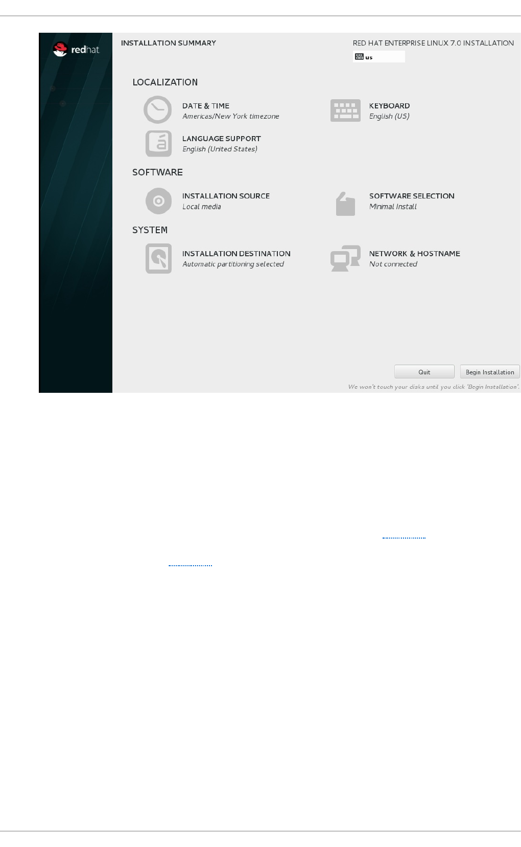
Fig u re 2.1. T h e In st allat io n Su mmary screen
Software Selection defaults to Minimal Install. Open the Software Selection screen
to select the virtualization packages instead.
3. Select t h e server t ype an d packag e g ro u p s
Red Hat Enterprise Linux 7 has two available options for installing a virtualization host: a
minimal virtualization host with only the basic packages installed (Step 3.a), or a
virtualization host with packages installed to allow management of guests through a
graphical user interface (Step 3.b).
a.
Select in g a min imal virt u aliz at io n h o st
Select the Vi rtual i zati o n Ho st radio button under Base Environment, and
the Vi rtual i zati o n P l atfo rm checkbox under Add-Ons for Selected
Environment. This installs a basic virtualization environment which can be run with
virsh, or remotely over the network.
Virt ualizat ion Deployment and Administ rat ion G uide
12

Fig u re 2.2. Virt u aliz at io n Ho st select ed in th e so f t ware select ion screen
b.
Select in g a virt u aliz at io n h o st wit h a g rap h ical u ser in terf ace
Select the Server with GUI radio button under Base Environment, and the
checkboxes for Vi rtual i zati o n C l i ent, Virtualization Hypervisor, and
Vi rtual i zati o n T o o l s under Add-Ons for Selected Environment. This
installs a virtualization environment along with graphical tools for installing and
managing guest virtual machines.
Chapt er 2 . Inst alling t he virt ualiz at ion packages
13

Fig u re 2.3. Server wit h G UI select ed in t h e so f tware select io n screen
4. Fin aliz e in st allat io n
On the Installation Summary screen, complete the steps as necessary and click Beg i n
Instal l ati o n.
When the installation is complete, reboot the system.
Important
You require a valid virtualization entitlement to receive updates for the virtualization packages.
2.1.1. Inst alling KVM packages wit h Kickst art files
Kickstart files allow for large, automated installations without a user manually installing each
individual host system.
To use a Kickstart file to install Red Hat Enterprise Linux with the virtualization packages, append the
following package groups in the %packages section of your Kickstart file:
@virtualization-hypervisor
@virtualization-client
@virtualization-platform
@virtualization-tools
For more information about installing with Kickstart files, see the Red Hat Enterprise Linux 7
Installation Guide.
Virt ualizat ion Deployment and Administ rat ion G uide
14

2.2. Inst alling virt ualizat ion packages on an exist ing Red Hat
Ent erprise Linux syst em
This section describes the steps for installing the KVM hypervisor on an existing Red Hat Enterprise
Linux 7 system.
To install the packages, your machine must be registered and subscribed to the Red Hat Customer
Portal. To register via Red Hat Subscription Manager, run the subscription-manager register
command and follow the prompts. Alternatively, run the Red Hat Subscription Manager application
from Ap p licat io n s → Syst em T o o ls on the desktop to register.
If you do not have a valid Red Hat subscription, visit the Red Hat online store to obtain one. For more
information on registering and subscribing a system to the Red Hat Customer Portal, see
https://access.redhat.com/solutions/253273.
2.2.1. Inst alling t he virt ualiz at ion packages wit h yum
To use virtualization on Red Hat Enterprise Linux, you require at minimum the qemu-kvm, qemu-img,
and libvirt packages. These packages provide the user-level KVM emulator, disk image manager, and
virtualization management tools on the host Red Hat Enterprise Linux system.
The libvirt package provides the server and host-side libraries for interacting with hypervisors and
host systems, and the l i bvi rtd daemon that handles the library calls, manages virtual machines
and controls the hypervisor.
To install these packages, run the following command:
# yum install qemu-kvm qemu-img libvirt
Several additional virtualization management packages are also available and are recommended
when using virtualization:
Reco mmen d ed virt u aliz at io n p ackag es
virt-install
This package provides the vi rt-i nstal l command for creating virtual machines from the
command line.
libvirt-python
The libvirt-python package contains a module that permits applications written in the Python
programming language to use the interface supplied by the libvirt API.
virt-manager
virt-manager, also known as Virt u al Mach in e Man ag er, provides a graphical tool for
administering virtual machines. It uses the libvirt-client library as the management API.
libvirt-client
The libvirt-client package provides the client-side APIs and libraries for accessing libvirt
servers. The libvirt-client package includes the virsh command line tool to manage and
control virtual machines and hypervisors from the command line or a special virtualization
shell.
Chapt er 2 . Inst alling t he virt ualiz at ion packages
15

Install all of these recommended virtualization packages with the following command:
# yum install virt-install libvirt-python virt-manager python-virtinst
libvirt-client
2.2.2. Inst alling virt ualiz at ion package groups
The virtualization packages can also be installed from package groups. The following table
describes the virtualization package groups and what they provide.
Note
Note that the qemu-img package is installed as a dependency of the Vi rtual i zati o n
package group if it is not already installed on the system. It can also be installed manually
with the yum install qemu-img command as described previously.
T ab le 2.1. Virt u aliz at io n Packag e G ro u p s
Packag e G ro u p Descrip t io n Man d at o ry
Packages
O p t io n al Packag es
Vi rtual i zati o n
Hypervisor
Smallest possible
virtualization host
installation
libvirt, qemu-kvm qemu-kvm-tools
Vi rtual i zati o n
C l i ent
Clients for installing
and managing
virtualization
instances
gnome-boxes, virt-
install, virt-manager,
virt-viewer
virt-top, libguestfs-
tools, libguestfs-tools-c
Vi rtual i zati o n
P l atfo rm
Provides an interface
for accessing and
controlling virtual
machines and
containers
libvirt, libvirt-client, virt-
who
fence-virtd-libvirt,
fence-virtd-multicast,
fence-virtd-serial,
libvirt-cim, libvirt-java,
libvirt-snmp, perl-Sys-
Virt
Vi rtual i zati o n
Tools
Tools for offline virtual
image management
libguestfs libguestfs-java,
libguestfs-tools,
libguestfs-tools-c
To install a package group, run the yum groupinstall <package group> command. For
instance, to install the Vi rtual i zati o n T o o l s package group, run:
# yum groupinstall "Virtualization Tools"
2.3. Regist ering t he hypervisor and virt ual machine
Red Hat Enterprise Linux 6 and 7 require that every guest virtual machine is mapped to a specific
hypervisor in order to ensure that every guest is allocated the same level of subscription service. To
do this you need to install a subscription agent that automatically detects all guest Virtual Machines
(VMs) on each KVM hypervisor that is installed and registered, which in turn will create a mapping file
that sits on the host. This mapping file ensures that all guest VMs receive the following benefits:
Subscriptions specific to virtual systems are readily available and can be applied to all of the
Virt ualizat ion Deployment and Administ rat ion G uide
16

associated guest VMs
All subscription benefits that can be inherited from the hypervisor are readily available and can
be applied to all of the associated guest VMs.
Note
The information provided in this chapter is specific to Red Hat Enterprise Linux subscriptions
only. If you also have a Red Hat Enterprise Virtualization subscription, or a Red Hat Satellite
subscription, you should also consult the virt-who information provided with those
subscriptions.
2.3.1. Inst alling virt -who on t he host physical machine
1. Reg ist er t h e KVM h yp erviso r
Register the KVM Hypervisor by running the subscription-manager register
[options] command in a terminal as the root user on the host physical machine. More
options are available using the # subscription-manager register --help menu. In
cases where you are using a username and password, use the credentials that are known to
the subscription manager. If this is your very first time subscribing and you do not have a
user account, contact customer support. For example to register the VM as 'admin' with
'secret' as a password, you would send the following command:
[root@rhel-server ~]# subscription-manager register --
username=admin --password=secret --auto-attach --type=hypervisor
2. In st all the virt - wh o p ackag es
Install the virt-who packages, by running the following command in a terminal as root on the
host physical machine:
[root@rhel-server ~]# yum install virt-who
3. Creat e a virt - wh o co n f igurat io n f ile
Add a configuration file in the /etc/virt-who.d/ directory. It does not matter what the
name of the file is, but you should give it a name that makes sense and the file must be
located in the /etc/virt-who.d/ directory. Inside that file add the following snippet and
remember to save the file before closing it.
[libvirt]
type=libvirt
4. St art t h e virt - wh o service
Start the virt-who service by running the following command in a terminal as root on the host
physical machine:
[root@virt-who ~]# systemctl start virt-who.service
[root@virt-who ~]# systemctl enable virt-who.service
Chapt er 2 . Inst alling t he virt ualiz at ion packages
17

5. Co n f irm virt - wh o service is receivin g g u est in f ormat io n
At this point, the virt-who service will start collecting a list of domains from the host. Check the
/var/log/rhsm/rhsm.log file on the host physical machine to confirm that the the file
contains a list of the guest VMs. For example:
2015-05-28 12:33:31,424 DEBUG: Libvirt domains found: [{'guestId':
'58d59128-cfbb-4f2c-93de-230307db2ce0', 'attributes': {'active': 0,
'virtWhoType': 'libvirt', 'hypervisorType': 'QEMU'}, 'state': 5}]
Pro ced ure 2.2. Man ag in g t h e su b scrip t io n on the cu st o mer p o rt al
1. Su b scrib in g t h e h yp erviso r
As the virtual machines will be receiving the same subscription benefits as the hypervisor, it is
important that the hypervisor has a valid subscription and that the subscription is available
for the VMs to use.
a. Lo g in t o t he cu st omer p o rt al
Login to the Red Hat customer portal https://access.redhat.com/ and click the
Subscriptions button at the top of the page.
b. Click t h e Syst ems lin k
In the Subscriber Inventory section (towards the bottom of the page), click
Systems link.
c. Select the h yp erviso r
On the Systems page, there is a table of all subscribed systems. Click on the name of
the hypervisor (localhost.localdomain for example). In the details page that opens,
click Attach a subscription and select all the subscriptions listed. Click Attach
Selected. This will attach the host's physical subscription to the hypervisor so that
the guests can benefit from the subscription.
2. Su b scrib ing t h e g u est virt u al mach in es - f irst t ime u se
This step is for those who have a new subscription and have never subscribed a guest virtual
machine before. If you are adding virtual machines, skip this step. To consume the
subscription assigned to the hypervisor profile on the machine running the virt-who service,
auto subscribe by running the following command in a terminal, on the guest virtual machine
as root.
[root@virt-who ~]# subscription-manager attach --auto
3. Su b scrib ing ad d it io n al g u est virt ual mach in es
If you just subscribed a for the first time, skip this step. If you are adding additional virtual
machines, it should be noted that running this command will not necessarily re-attach the
same pools to the hypervisor. This is because removing all subscriptions then allowing auto
attach to resolve what is necessary for a given guest virtual machine may result in different
subscriptions consumed than before. This may not have any effect on your system, but it is
something you should be aware about. If you used a manual attachment procedure to attach
the virtual machine, which is not described below, you will need to re-attach those virtual
machines manually as the auto-attach will not work. Use the following command as root in a
Virt ualizat ion Deployment and Administ rat ion G uide
18

terminal to first remove the subscriptions for the old guests and then use the auto-attach to
attach subscriptions to all the guests. Run these commands on the guest virtual machine.
[root@virt-who ~]# subscription-manager remove --all
[root@virt-who ~]# subscription-manager attach --auto
4. Co n f irm su bscrip t io ns are at tach ed
Confirm that the subscription is attached to the hypervisor by running the following command
as root in a terminal on the guest virtual machine:
[root@virt-who ~]# subscription-manager list --consumed
Output similar to the following will be displayed. Pay attention to the Subscription Details. It
should say 'Subscription is current'.
[root@virt-who ~]# subscription-manager list --consumed
+-------------------------------------------+
Consumed Subscriptions
+-------------------------------------------+
Subscription Name: Awesome OS with unlimited virtual guests
Provides: Awesome OS Server Bits
SKU: awesomeos-virt-unlimited
Contract: 0
Account: 12331131231
Serial: 7171985151317840309
Pool ID: 2c91808451873d3501518742f556143d
Provides Management: No
Active: True
Quantity Used: 1
Service Level:
Service Type:
Status Details: Subscription is current
Subscription Type:
Starts: 01/01/2015
Ends: 12/31/2015
System Type: Virtual
Indicates if your subscription is current. If your subscription is not current, an error
message appears. One example is Guest has not been reported on any host and is
using a temporary unmapped guest subscription. In this case the guest needs to be
subscribed. In other cases, use the information as indicated in Section 2.3.4.2, “ I have
subscription status errors, what do I do?” .
5. Reg ist er ad d it io n al g u est s
When you install new guest VMs on the hypervisor, you must register the new VM and use the
subscription attached to the hypervisor, by running the following commands in a terminal as
root on the guest virtual machine:
[root@server1 ~]# subscription-manager register
[root@server1 ~]# subscription-manager attach --auto
[root@server1 ~]# subscription-manager list --consumed
Chapt er 2 . Inst alling t he virt ualiz at ion packages
19

2.3.2. Regist ering a new guest virt ual machine
In cases where a new guest virtual machine is to be created on a host that is already registered and
running, the virt-who service must also be running. This ensures that the virt-who service maps the
guest to a hypervisor, so the system is properly registered as a virtual system. To register the virtual
machine, run the following command as root in a terminal:
[root@virt-server ~]# subscription-manager register --username=admin --
password=secret --auto-attach
2.3.3. Removing a guest virt ual machine ent ry
If the guest virtual machine is running, unregister the system, by running the following command in a
terminal window as root:
[root@virt-guest ~]# subscription-manager unregister
If the system has been deleted, however, the virtual service cannot tell whether the service is deleted
or paused. In that case, you must manually remove the system from the server side, using the
following steps:
1. Lo g in to the Su b script io n Man ag er
The Subscription Manager is located on the Red Hat Customer Portal. Login to the Customer
Portal using your username and password, by clicking the login icon at the top of the screen.
2. Click t h e Su b scrip t io n s t ab
Click the Subscriptions tab.
3. Click t h e Syst ems lin k
Scroll down the page and click the Systems link.
4. Delet e t h e syst em
To delete the system profile, locate the specified system's profile in the table, select the check
box beside its name and click D el ete.
2.3.4 . T roubleshoot ing virt -who
2.3.4 .1 . Why is t he hyperviso r st at us re d?
Scenario: On the server side, you deploy a guest on a hypervisor that does not have a subscription.
24 hours later, the hypervisor displays its status as red. To remedy this situation you must get a
subscription for that hypervisor. Or, permanently migrate the guest to a hypervisor with a
subscription.
2.3.4 .2 . I have subscript io n st at us erro rs, what do I do ?
Scenario: Any of the following error messages display:
System not properly subscribed
Status unknown
Virt ualizat ion Deployment and Administ rat ion G uide
20

Late binding of a guest to a hypervisor through virt-who (host/guest mapping)
To find the reason for the error open the virt-who log file, named rhsm. l o g , located in the
/var/log/rhsm/ directory.
Chapt er 2 . Inst alling t he virt ualiz at ion packages
21

Chapter 3. Installing a virtual machine
After you have installed the virtualization packages on your Red Hat Enterprise Linux 7 host system,
you can create guest operating systems. You can create guest virtual machines using the New button
in vi rt - ma n ag er or use the vi rt-i nstal l command line interface to install virtual machines by a
list of parameters or with a script. Both methods are covered by this chapter.
Detailed installation instructions are available in the following chapters for specific versions of Red
Hat Enterprise Linux and Microsoft Windows.
3.1. Guest virt ual machine prerequisit es and considerat ions
Various factors should be considered before creating any guest virtual machines. Not only should
the role of a virtual machine be considered before deployment, but regular ongoing monitoring and
assessment based on variable factors (load, amount of clients) should be performed. Some factors
include:
Perf o rman ce
Guest virtual machines should be deployed and configured based on their intended tasks.
Some guest systems (for instance, guests running a database server) may require special
performance considerations. Guests may require more assigned CPUs or memory based on
their role and projected system load.
In p u t /O ut p u t req uiremen t s an d t yp es o f In p u t/O u t p u t
Some guest virtual machines may have a particularly high I/O requirement or may require
further considerations or projections based on the type of I/O (for instance, typical disk
block size access, or the amount of clients).
St o ra g e
Some guest virtual machines may require higher priority access to storage or faster disk
types, or may require exclusive access to areas of storage. The amount of storage used by
guests should also be regularly monitored and taken into account when deploying and
maintaining storage. Make sure to read all the considerations outlined in Chapter 13,
Securing the host physical machine and improving performance. It is also important to
understand that your physical storage may limit your options in your virtual storage.
Net wo rkin g an d n et wo rk in f rast ru ct u re
Depending upon your environment, some guest virtual machines could require faster
network links than other guests. Bandwidth or latency are often factors when deploying and
maintaining guests, especially as requirements or load changes.
Req u est req u iremen t s
SCSI requests can only be issued to guest virtual machines on virtio drives if the virtio
drives are backed by whole disks, and the disk device parameter is set to lun, as shown in
the following example:
<devices>
<emulator>/usr/libexec/qemu-kvm</emulator>
<disk type='block' device='lun'>
3.2. Creat ing guest s wit h virt -inst all
Virt ualizat ion Deployment and Administ rat ion G uide
22

3.2. Creat ing guest s wit h virt -inst all
You can use the vi rt-i nstal l command to create virtual machines from the command line. vi rt-
i nstal l is used either interactively (with a graphical application such as virt - vie wer) or as part of
a script to automate the creation of virtual machines. Using vi rt-i nstal l with kickstart files allows
for unattended installation of virtual machines.
Note that you need root privileges in order for vi rt-i nstal l commands to complete successfully.
The vi rt-i nstal l tool provides a number of options that can be passed on the command line.
Most vi rt-i nstal l options are not required. Minimum requirements are --name, --ram, guest
storage (--disk, --filesystem or --nodisks), and an install option. To see a complete list of
options, run the following command:
# virt-install --help
The vi rt-i nstal l man page also documents each command option, important variables, and
examples.
Prior to running vi rt-i nstal l , qemu-img is a related command which can be used to configure
storage options. See refer to Chapter 16, Using qemu-img for instructions on using qemu-img.
3.2.1. Net work inst allat ion wit h virt -inst all
The following examples use a network bridge (named br0 in these examples), which must be created
separately, prior to running virt-install. See Section 7.4.1, “Configuring bridged networking on a Red
Hat Enterprise Linux 7 host” for details on creating a network bridge.
Examp le 3.1. Using virt - in st all t o in st all a R ed Hat En t erp rise Lin u x 6 virt ual mach in e
This example creates a Red Hat Enterprise Linux 6 guest:
# virt-install \
--name=guest1-rhel6-64 \
--disk path=/var/lib/libvirt/images/guest1-rhel6-
64.dsk,size=8,sparse=false,cache=none \
--graphics spice \
--vcpus=2 --ram=2048 \
--location=http://example1.com/installation_tree/RHEL6.4-Server-
x86_64/os \
--network bridge=br0 \
--os-type=linux \
--os-variant=rhel6
The options used in this example are as follows:
--name
The name of the virtual machine.
--d i sk
Specifies storage configuration details for the virtual machine.
--graphics
An important option which allows graphical installation of a virtual machine. It specifies the
Chapt er 3. Inst alling a virt ual machine
23

An important option which allows graphical installation of a virtual machine. It specifies the
type of graphical tool to use for interactive installation, or can be set to none for a fully
automated installation by script.
--vcpus
The number of vCPUs to allocate to the guest.
--ram
The amount of memory (RAM) to allocate to the guest, in MiB.
--l o cati o n
The location of the installation media. The above example uses an http:// network
installation, but several other protocols can be used.
--netwo rk bri d g e
Specifies the network bridge to use for installation, which must be configured before
running vi rt-i nstal l . See Section 7.4.1, “ Configuring bridged networking on a Red Hat
Enterprise Linux 7 host” for details on creating a network bridge.
--os-type
The guest operating system type.
--os-variant
Another important option in virt-install, used to further optimize the guest configuration.
Using this option can reduce installation time and improve performance.
Running the osinfo-query os command returns a complete list of operating system
variants identified by a short ID to use with the --os-variant option. For example, --os-
variant=rhel7.0 configures a Red Hat Enterprise Linux 7.0 virtual machine.
In Red Hat Enterprise Linux 7, the virtio-scsi controller is available for use in guests. If both the host
and guest support virtio-scsi, you can use it as follows:
Examp le 3.2. Using virt - in st all t o in st all a g u est virt ual mach in e wit h t he virt io - scsi
co n t ro l ler
The items in bold are required on top of a standard installation in order to use the virtio-scsi
controller.
# virt-install \
--name=guest1-rhel7 \
--co ntro l l er type= scsi ,mo d el = vi rti o -scsi \
--disk path=/var/lib/libvirt/images/guest1-
rhel7.dsk,size=8,sparse=false,cache=none,bus=scsi \
--graphics spice \
--vcpus=2 --ram=2048 \
--location=http://example1.com/installation_tree/RHEL7.1-Server-
x86_64/os \
--network bridge=br0 \
--os-type=linux \
--os-variant=rhel7
Virt ualizat ion Deployment and Administ rat ion G uide
24

Note
Ensure that you select the correct --os-type for your operating system when running this
command. This option prevents the installation disk from disconnecting when rebooting
during the installation procedure. The --os-variant option further optimizes the
configuration for a specific guest operating system.
3.2.2. PXE inst allat ion wit h virt -inst all
vi rt-i nstal l PXE installations require both the --network=bridge:bridge_name parameter,
where bridge_name is the name of the bridge, and the --pxe parameter.
By default, if no network is found, the guest virtual machine will attempt to boot from alternative
bootable devices. If there is no other bootable device found, the guest virtual machine will pause.
You can use the q emu - kvm boot parameter reboot-timeout to allow the guest to retry booting if
no bootable device is found, like so:
# qemu-kvm -boot reboot-timeout=1000
Examp le 3.3. Fu lly- virt ualiz ed PXE in st allat io n wit h virt - in st all
# virt-install --hvm --connect qemu:///system \
--network=bridge:br0 --pxe --graphics spice \
--name=rhel6-machine --ram=756 --vcpus=4 \
--os-type=linux --os-variant=rhel6 \
--disk path=/var/lib/libvirt/images/rhel6-machine.img,size=10
Note that the command above cannot be executed in a text-only environment. A fully-virtualized (-
-hvm) guest can only be installed in a text-only environment if the --location and --extra-
args "console=console_type" are provided instead of the --graphics spice parameter.
3.2.3. Kickst art inst allat ion wit h virt -inst all
The following example shows using a kickstart file with virt-install:
Examp le 3.4 . Kickst art in st allat io n wit h virt -in st all
# virt-install -n rhel7ks-guest -r 1024 --
file=/var/lib/libvirt/images/rhel7ks-guest.img --file-size=10 \
--location /var/lib/libvirt/images/rhel-server-7.1-x86_64-dvd.iso --
nographics \
--extra-args="ks=http://192.168.122.1/ks.cfg ip=dhcp \
console=tty0 console=ttyS0,115200n8” --os-variant=rhel7.0
3.2.4 . Guest inst allat ion wit h virt -inst all and t ext-based Anaconda
The following example shows using virt-install with text-based Anaconda installation:
Chapt er 3. Inst alling a virt ual machine
25

Examp le 3.5. G u est in st allat io n wit h virt - in st all an d t ext - b ased An aco n d a
# virt-install -n rhel6anaconda-guest -r 1024 --
disk=path=/path/to/rhel6anaconda-guest.img,size=10 \
--location /mnt/RHEL6DVD --nographics \
--extra-args=”console=tty0 console=ttyS0,115200n8” \
--disk=path=/path/to/rhel6-dvd.iso,device=cdrom
3.3. Creat ing guest s wit h virt -manager
virt-manager, also known as Virtual Machine Manager, is a graphical tool for creating and
managing guest virtual machines.
This section covers how to install a Red Hat Enterprise Linux 7 guest virtual machine on a Red Hat
Enterprise Linux 7 host using virt - man ag er.
These procedures assume that the KVM hypervisor and all other required packages are installed and
the host is configured for virtualization. For more information on installing the virtualization
packages, refer to Chapter 2, Installing the virtualization packages.
3.3.1. virt -manager inst allat ion overview
The New VM wizard breaks down the virtual machine creation process into five steps:
1. Choosing the hypervisor and installation type
2. Locating and configuring the installation media
3. Configuring memory and CPU options
4. Configuring the virtual machine's storage
5. Configuring virtual machine name, networking, architecture, and other hardware settings
Ensure that virt-manager can access the installation media (whether locally or over the network)
before you continue.
3.3.2. Creat ing a Red Hat Ent erprise Linux 7 guest wit h virt -manager
This procedure covers creating a Red Hat Enterprise Linux 7 guest virtual machine with a locally
stored installation DVD or DVD image. Red Hat Enterprise Linux 7 DVD images are available from the
Red Hat Customer Portal.
Pro ced ure 3.1. Creat in g a Red Hat En t erp rise Lin u x 7 g u est virt u al mach in e wit h virt -
man ag er u sin g lo cal in st allat io n med ia
1. O p t io n al: Prep arat io n
Prepare the storage environment for the virtual machine. For more information on preparing
storage, refer to Chapter 14, Storage pools.
Virt ualizat ion Deployment and Administ rat ion G uide
26
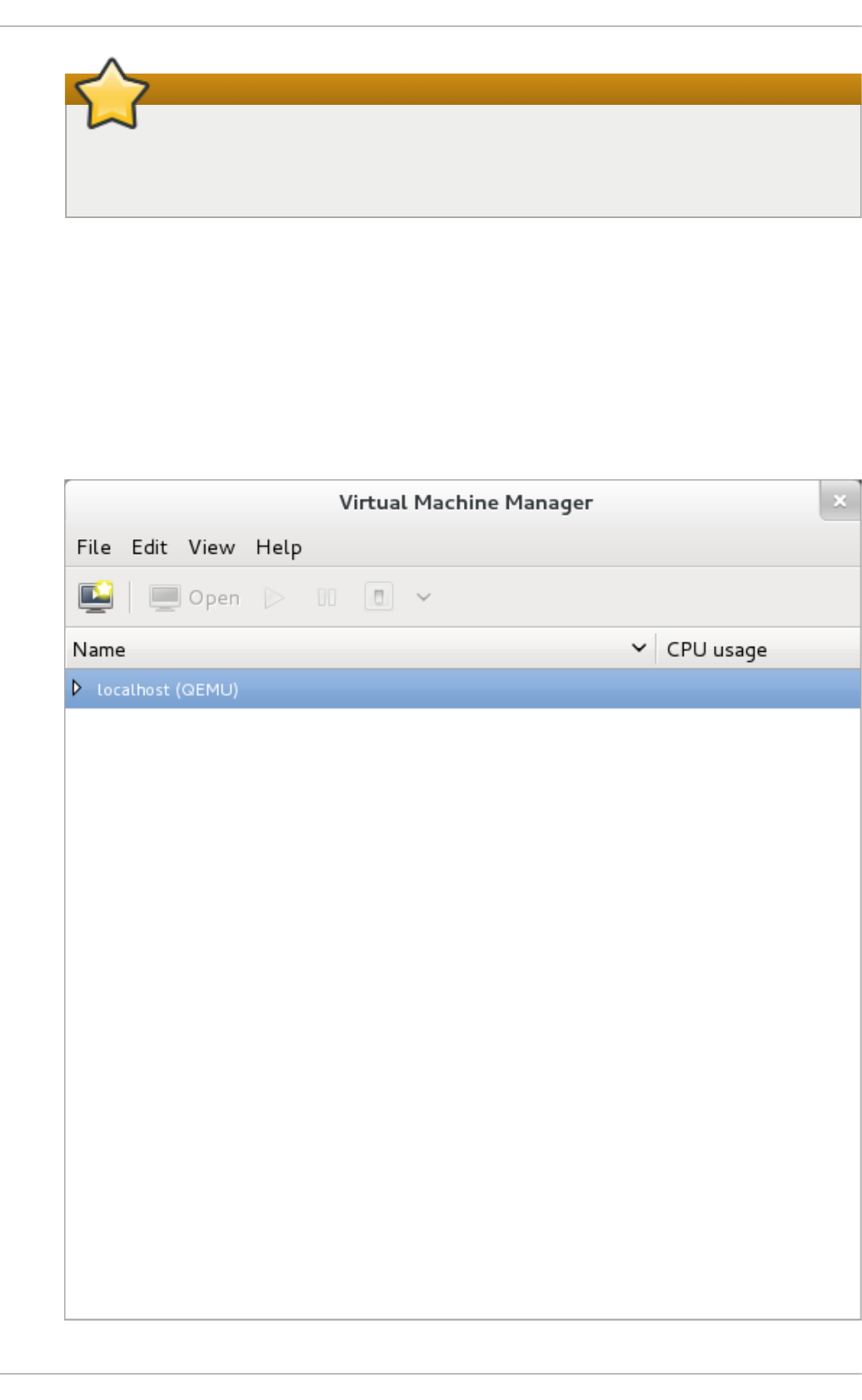
Important
Various storage types may be used for storing guest virtual machines. However, for a
virtual machine to be able to use migration features, the virtual machine must be
created on networked storage.
Red Hat Enterprise Linux 7 requires at least 1 GB of storage space. However, Red Hat
recommends at least 5 GB of storage space for a Red Hat Enterprise Linux 7 installation and
for the procedures in this guide.
2. O p en virt -man ag er an d st art t he wiz ard
Open virt-manager by executing the virt-manager command as root or opening
Applications → System Tools → Virtual Machine Manager. Alternatively, run the
virt-manager command as root.
Chapt er 3. Inst alling a virt ual machine
27

Fig u re 3.1. T h e Virt u al Mach in e Man ag er win d ow
Optionally, open a remote hypervisor by selecting the hypervisor and clicking the Connect
button.
Click on the Create a new virtual machine button to start the new virtualized guest
wizard.
Fig u re 3.2. T h e Creat e a n ew virt u al mach in e b u t ton
The New VM window opens.
3. Sp ecif y in st allat io n typ e
Select an installation type:
Lo cal in st all med ia ( ISO imag e o r CD RO M)
This method uses a CD-ROM, DVD, or image of an installation disk (for example,
.iso).
Net wo rk In st all ( HT T P, FT P, o r NFS)
This method involves the use of a mirrored Red Hat Enterprise Linux or Fedora
installation tree to install a guest. The installation tree must be accessible through
either HTTP, FTP, or NFS.
If you select Network Install, provide the installation URL, and the Kickstart URL
and Kernel options (if required) and continue to Step 5.
Net wo rk Bo o t ( PXE)
This method uses a Preboot eXecution Environment (PXE) server to install the guest
virtual machine. Setting up a PXE server is covered in the Deployment Guide. To
install via network boot, the guest must have a routable IP address or shared
network device.
If you select Netwo rk Bo o t, continue to Step 5. After all steps are completed, a
DHCP request is sent and if a valid PXE server is found the guest virtual machine's
installation processes will start.
Imp o rt exist ing disk imag e
This method allows you to create a new guest virtual machine and import a disk
image (containing a pre-installed, bootable operating system) to it.
Virt ualizat ion Deployment and Administ rat ion G uide
28
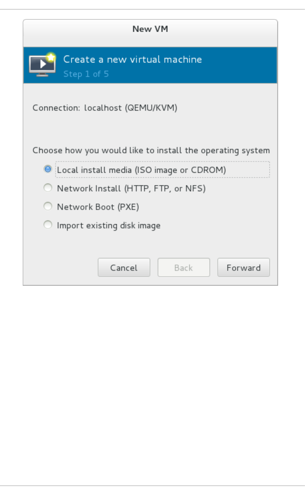
Fig u re 3.3. Virt u al mach in e in st allat io n met h od
Click Fo rward to continue.
4. Select the lo cal in st allat ion med ia
If you selected Local install media (ISO image or CDROM), specify your desired
local installation media.
Chapt er 3. Inst alling a virt ual machine
29
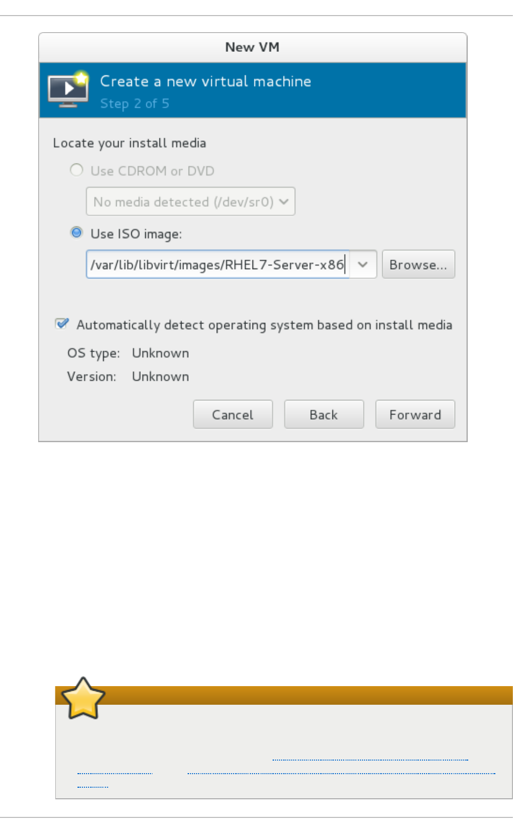
Fig u re 3.4 . Lo cal ISO imag e in st allat io n
A. If you wish to install from a CD-ROM or DVD , select the Use C D R O M o r D VD radio
button, and select the appropriate disk drive from the drop-down list of drives available.
B. If you wish to install from an ISO image, select Use ISO image, and then click the
Bro wse. . . button to open the Locate media volume window.
Select the installation image you wish to use, and click Choose Volume.
If no images are displayed in the Locate media volume window, click on the Browse
Local button to browse the host machine for the installation image or DVD drive
containing the installation disk. Select the installation image or DVD drive containing the
installation disk and click Open; the volume is selected for use and you are returned to the
Create a new virtual machine wizard.
Important
For ISO image files and guest storage images, the recommended location to use is
/var/lib/libvirt/images/. Any other location may require additional
configuration by SELinux. Refer to the Red Hat Enterprise Linux Virtualization
Security Guide or the Red Hat Enterprise Linux SELinux User's and Administrator's
Guide for more details on configuring SELinux.
Virt ualizat ion Deployment and Administ rat ion G uide
30
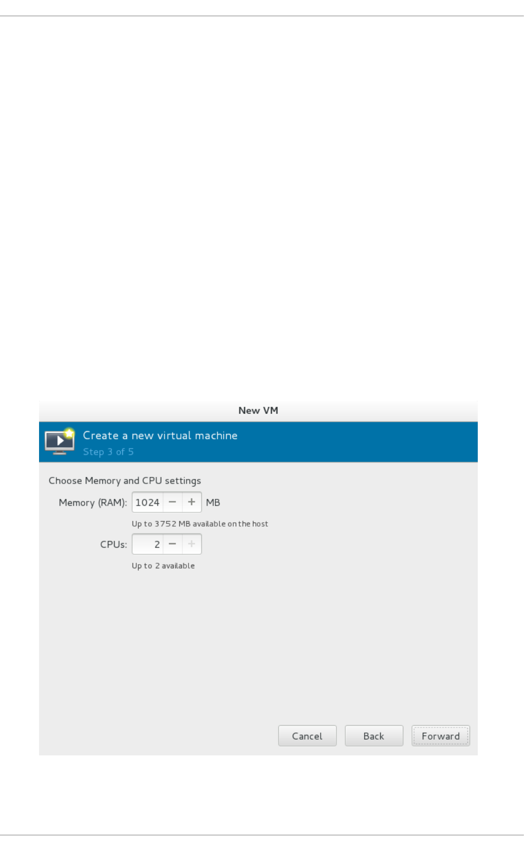
Next, configure the O S t ype and Versio n of the installation. Ensure that you select the
appropriate operating system type for your virtual machine. This can be specified manually
or by selecting the Automatically detect operating system based on install
media check box.
Click Fo rward to continue.
5.
Co n f ig ure memo ry ( RAM) an d virt u al CPUs
Specify the number of CPUs and amount of memory (RAM) to allocate to the virtual machine.
The wizard shows the number of CPUs and amount of memory you can allocate; these values
affect the host's and guest's performance.
Virtual machines require sufficient physical memory (RAM) to run efficiently and effectively.
Red Hat supports a minimum of 512MB of RAM for a virtual machine. Red Hat recommends at
least 1024MB of RAM for each logical core.
Assign sufficient virtual CPUs for the virtual machine. If the virtual machine runs a multi-
threaded application, assign the number of virtual CPUs the guest virtual machine will require
to run efficiently.
You cannot assign more virtual CPUs than there are physical processors (or hyper-threads)
available on the host system. The number of virtual CPUs available is noted in the Up to X
available field.
Fig u re 3.5. C o n f ig u rin g Memo ry an d CPU
Chapt er 3. Inst alling a virt ual machine
31
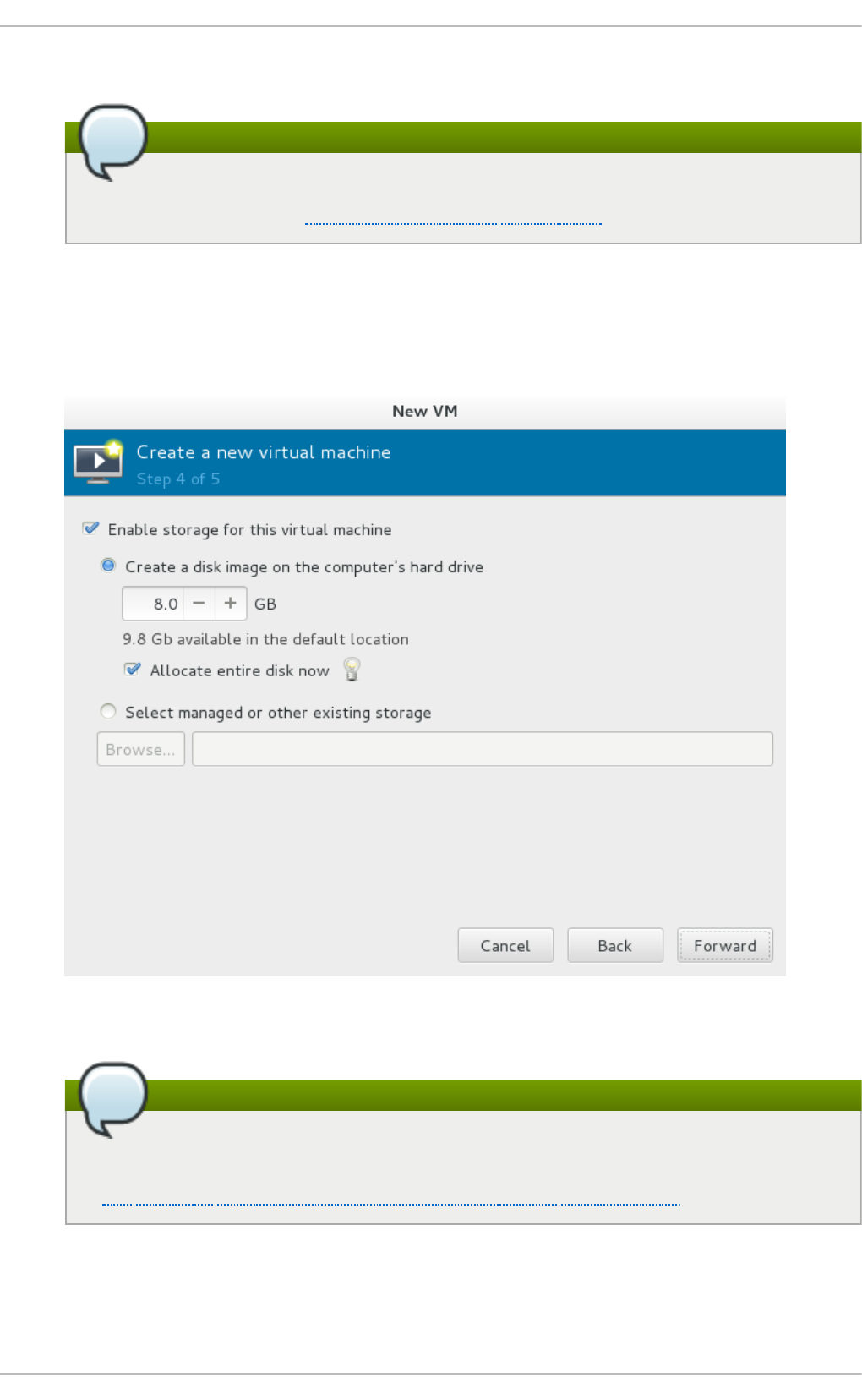
After you have configured the memory and CPU settings, click Fo rward to continue.
Note
Memory and virtual CPUs can be overcommitted. For more information on
overcommitting, refer to Chapter 8, Overcommitting with KVM.
6. Co n f ig ure st o rag e
Enable and assign sufficient space for your virtual machine and any applications it requires.
Assign at least 5 GB for a desktop installation or at least 1 GB for a minimal installation.
Fig u re 3.6 . Co nf ig urin g virt u al st o rag e
Note
Live and offline migrations require virtual machines to be installed on shared network
storage. For information on setting up shared storage for virtual machines, refer to
Section 17.3, “ Shared storage example: NFS for a simple migration” .
a. Wit h the d ef au lt lo cal st o rag e
Select the Create a disk image on the computer's hard drive radio
button to create a file-based image in the default storage pool, the
Virt ualizat ion Deployment and Administ rat ion G uide
32
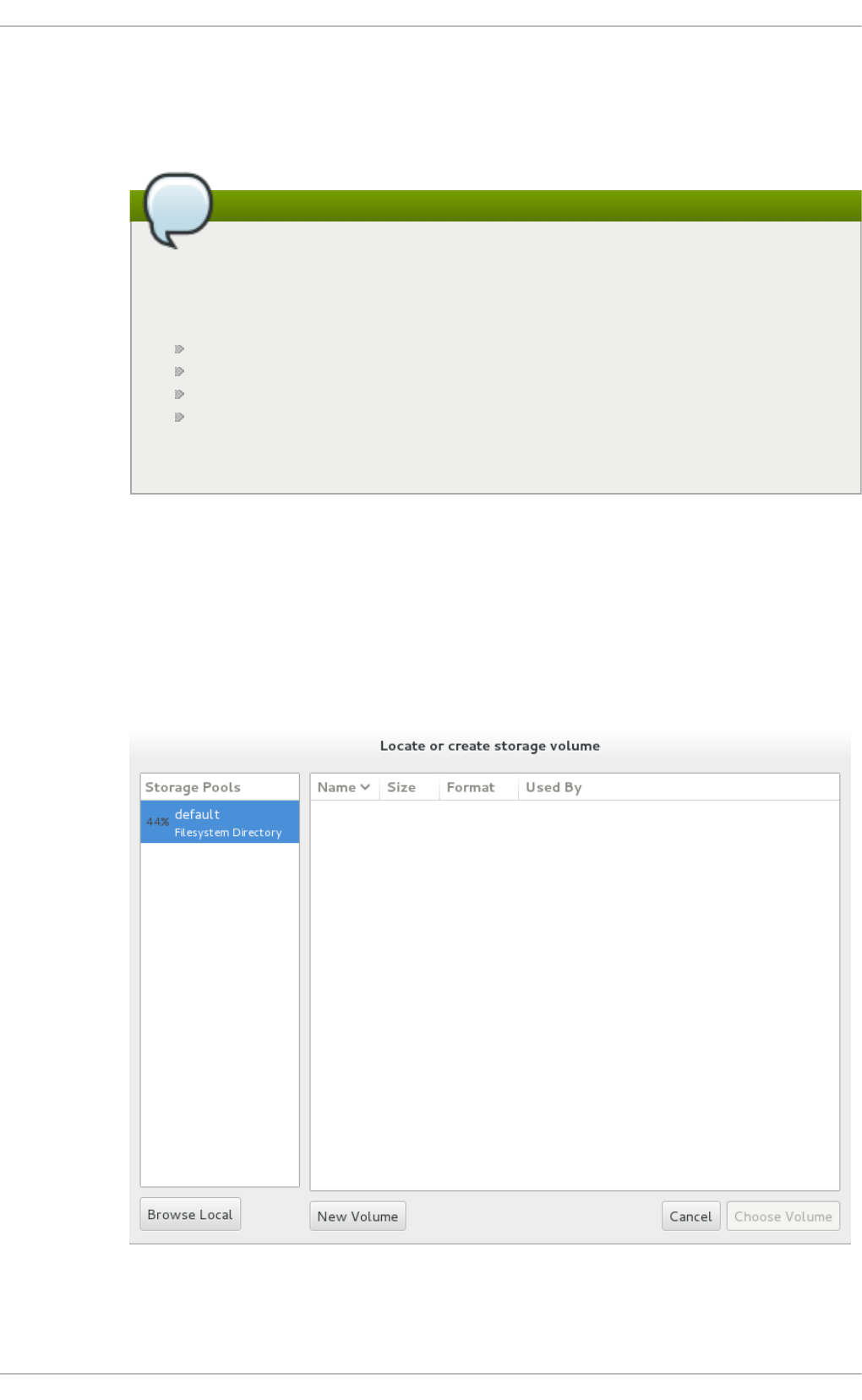
/var/lib/libvirt/images/ directory. Enter the size of the disk image to be
created. If the Allocate entire disk now check box is selected, a disk image of
the size specified will be created immediately. If not, the disk image will grow as it
becomes filled.
Note
Although the storage pool is a virtual container it is limited by two factors:
maximum size allowed to it by qemu-kvm and the size of the disk on the host
physical machine. Storage pools may not exceed the size of the disk on the
host physical machine. The maximum sizes are as follows:
virtio-blk = 2^63 bytes or 8 Exabytes(using raw files or disk)
Ext4 = ~ 16 TB (using 4 KB block size)
XFS = ~8 Exabytes
qcow2 and host file systems keep their own metadata and scalability
should be evaluated/tuned when trying very large image sizes. Using raw
disks means fewer layers that could affect scalability or max size.
Click Fo rward to create a disk image on the local hard drive. Alternatively, select
Select managed or other existing storage, then select Browse to
configure managed storage.
b. Wit h a st o rag e p o o l
If you select Select managed or other existing storage to use a storage
pool, click Browse to open the Locate or create storage volume window.
Fig u re 3.7. T h e Lo cat e o r creat e st o rag e volu me win d o w
Chapt er 3. Inst alling a virt ual machine
33
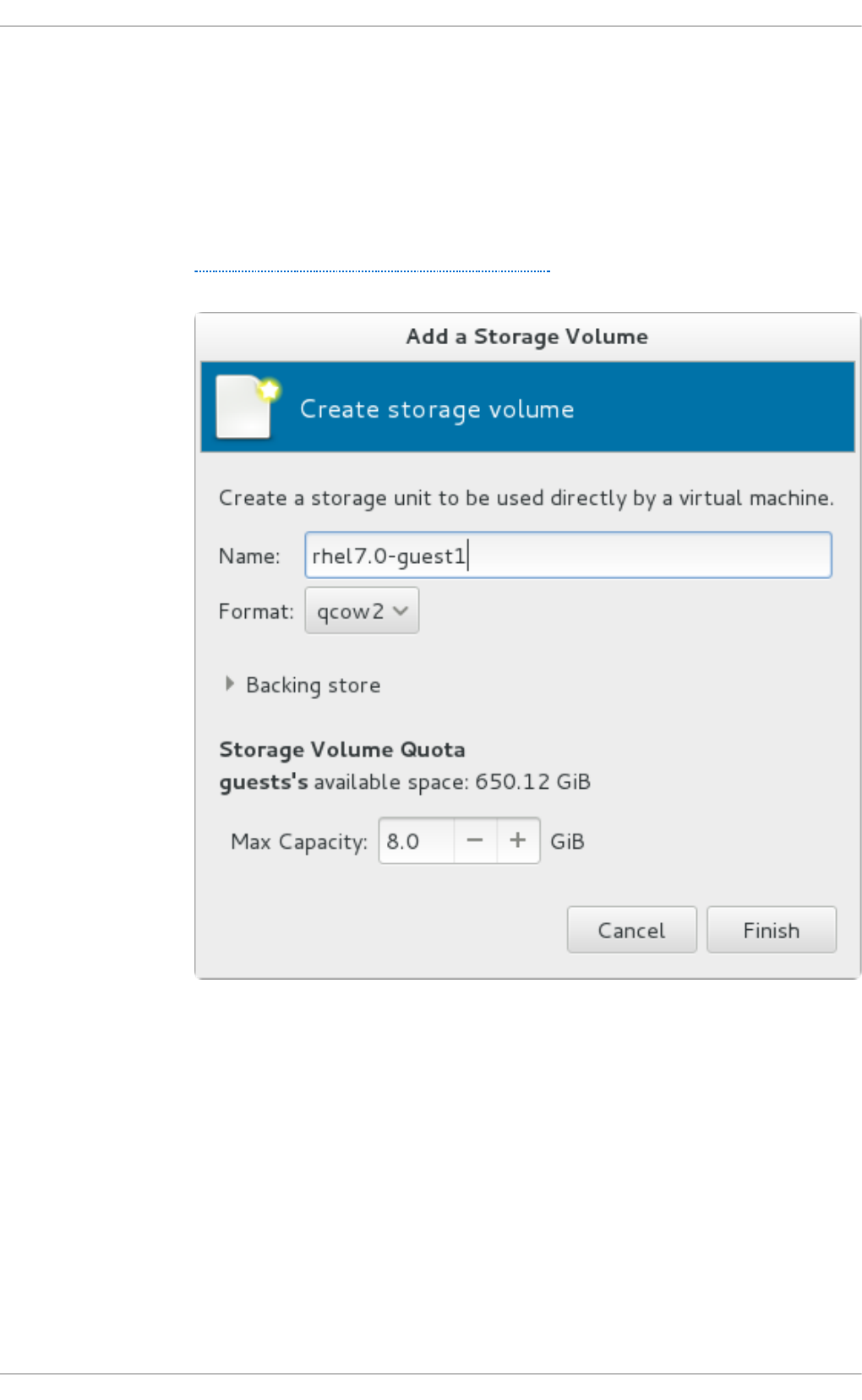
i. Select a storage pool from the Sto rag e P oo l s list.
ii. Optional: Click on the New Volume button to create a new storage volume.
The Add a Storage Volume screen will appear. Enter the name of the new
storage volume.
Choose a format option from the Fo rmat dropdown menu. Format options
include raw, qcow2, and qed. Adjust other fields as desired. Note that the
qcow2 version used here is version 3. To change the qcow version refer to
Section 26.20.2, “ Setting target elements”
Fig u re 3.8. T h e Ad d a St orag e Volu me win d o w
Select the new volume and click Choose volume. Next, click Finish to return to the New
VM wizard. Click Fo rward to continue.
7. Name an d fin al co n f ig u rat io n
Name the virtual machine. Virtual machine names can contain letters, numbers and the
following characters: underscores (_), periods (.), and hyphens (-). Virtual machine names
must be unique for migration and cannot consist only of numbers.
Verify the settings of the virtual machine and click Finish when you are satisfied; this will
create the virtual machine with default networking settings, virtualization type, and
architecture.
Virt ualizat ion Deployment and Administ rat ion G uide
34
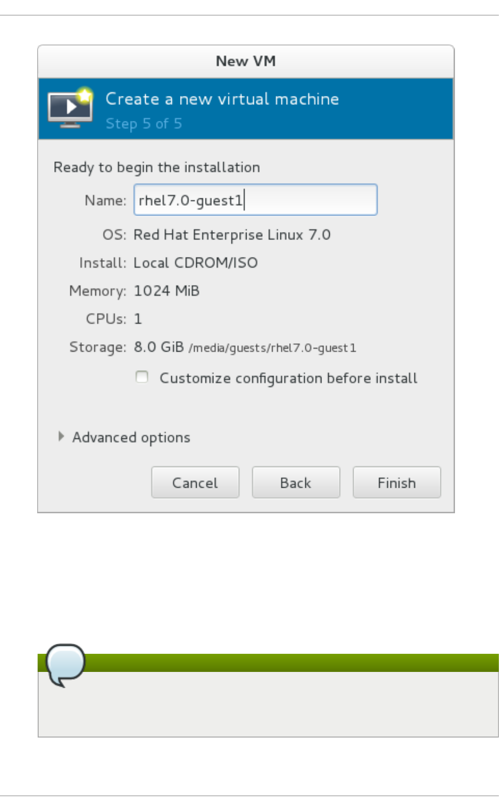
Fig u re 3.9 . Verif yin g t h e co n f igurat io n
Or, to further configure the virtual machine's hardware, check the Cu st o mi z e
co n f ig u rat io n b ef ore in st all check box to change the guest's storage or network devices,
to use the para-virtualized (virtio) drivers or to add additional devices. This opens another
wizard that will allow you to add, remove, and configure the virtual machine's hardware
settings.
Note
Red Hat Enterprise Linux 4 or Red Hat Enterprise Linux 5 guest virtual machines
cannot be installed using graphical mode. As such, you must select "Cirrus" instead of
"QXL" as a video card.
After configuring the virtual machine's hardware, click Apply. virt-manager will then create
the virtual machine with your specified hardware settings.
Chapt er 3. Inst alling a virt ual machine
35

Click on the Advanced options down arrow to inspect and modify advanced options. For
a standard Red Hat Enterprise Linux 7 installation, none of these options require
modification.
Click Finish to continue into the Red Hat Enterprise Linux installation sequence. For more
information on installing Red Hat Enterprise Linux 7, refer to the Red Hat Enterprise Linux 7
Installation Guide.
A Red Hat Enterprise Linux 7 guest virtual machine is now created from an ISO installation disk
image.
3.4. Comparison of virt -inst all and virt -manager inst allat ion opt ions
This table provides a quick reference to compare equivalent vi rt-i nstal l and vi rt - ma n ag er
installation options for when installing a virtual machine.
Most vi rt-i nstal l options are not required. Minimum requirements are --name, --ram, guest
storage (--disk, --filesystem or --nodisks), and an install option. These options are further
specified with arguments; to see a complete list of command options and related arguments, run the
following command:
# virt-install --help
In virt - man ag er, at minimum, a name, installation method, memory (RAM), vCPUs, storage are
required.
T ab le 3.1. virt - in st all an d virt - man ag er co nfig u rat ion co mp ariso n f o r g u est
in st allat i o n s
Co n f ig urat io n o n virt u al
mach in e
vi rt-i nstal l o p t io n virt - man ag er in st allat io n
wiz ard lab el an d st ep
n u mb er
Virtual machine name --name, -n Name (step 5)
RAM to allocate (MiB) --ram, -r Memory (RAM) (step 3)
Storage - specify storage
media
--disk Enable storage for this virtual
machine → Create a disk image
on the computer's hard drive,
or Select managed or other
existing storage (step 4)
Storage - export a host
directory to the guest
--filesystem Enable storage for this virtual
machine → Select managed or
other existing storage (step 4)
Storage - configure no local
disk storage on the guest
--nodisks Deselect the Enable storage for
this virtual machine checkbox
(step 4)
Installation media location
(local install)
--file Local install media → Locate
your install media (steps 1-2)
Installation via distribution tree
(network install)
--location Network install → URL (steps 1-
2)
Install guest with PXE --pxe Network boot (step 1)
Number of vCPUs --vcpus CPUs (step 3)
Host network --network Advanced options dropdown
menu (step 5)
Virt ualizat ion Deployment and Administ rat ion G uide
36

Operating system --os-type OS type (step 2)
Operating system
variant/version
--os-variant Version (step 2)
Graphical display method --graphics, --nographics * virt-manager provides GUI
installation only
Co n f ig urat io n o n virt u al
mach in e
vi rt-i nstal l o p t io n virt - man ag er in st allat io n
wiz ard lab el an d st ep
n u mb er
Chapt er 3. Inst alling a virt ual machine
37

Chapter 4. Virtualizing Red Hat Enterprise Linux on Other
Platforms
This chapter contains reference material for customers running Red Hat Enterprise Linux 7 as a
virtualized operating system on other virtualization hosts.
4.1. On VMware ESX
Red Hat Enterprise Linux 7 provides the following drivers:
vmw_balloon - a para-virtualized memory ballooning driver used when running Red Hat
Enterprise Linux on VMware hosts. For further information about this driver, refer to
http://kb.VMware.com/selfservice/microsites/search.do?
cmd=displayKC&docType=kc&externalId=1002586.
vmmouse_drv - a para-virtualized mouse driver used when running Red Hat Enterprise Linux on
VMware hosts. For further information about this driver, refer to
http://kb.VMware.com/selfservice/microsites/search.do?
cmd=displayKC&docType=kc&externalId=5739104.
vmware_drv - a para-virtualized video driver used when running Red Hat Enterprise Linux on
VMware hosts. For further information about this driver, refer to
http://kb.VMware.com/selfservice/microsites/search.do?
cmd=displayKC&docType=kc&externalId=1033557.
vmxnet3 - a para-virtualized network adapter used when running Red Hat Enterprise Linux on
VMware hosts. For further information about this driver, refer to
http://kb.VMware.com/selfservice/microsites/search.do?
language=en_US&cmd=displayKC&externalId=1001805.
vmw_pvscsi - a para-virtualized SCSI adapter used when running Red Hat Enterprise Linux on
VMware hosts. For further information about this driver, refer to
http://kb.VMware.com/selfservice/microsites/search.do?
language=en_US&cmd=displayKC&externalId=1010398.
4.2. On Hyper-V
Red Hat Enterprise Linux 7 ships with Microsoft's Linux Integration Services, a set of drivers that
enable synthetic device support in supported virtualized operating systems. Red Hat Enterprise Linux
7 provides the following drivers:
hv_vmbus - a main para-virtualized driver for communicating with the Hyper-V host
hv_netvsc - a para-virtualized network driver
hv_storvsc - a para-virtualized storage (SCSI) driver
hyperv_fb - a para-virtualized framebuffer device
hyperv_keyboard - a para-virtualized keyboard driver
hid_hyperv - a para-virtualized mouse driver
hv_balloon -a memory hotplug and ballooning driver
hv_utils - a guest integration services driver
Virt ualizat ion Deployment and Administ rat ion G uide
38

For more information about the drivers provided refer to Microsoft's website and the Linux and
FreeBSD Virtual Machines on Hyper-V article in particular. More information on the Hyper-V feature
set, is located in Feature Descriptions for Linux and FreeBSD virtual machines on Hyper-V.
Another article which may be helpful is: Enabling Linux Support on Windows Server 2012 R2 Hyper-
V. Access to this article may require a Microsoft account.
Note
The Hyper-V manager supports shrinking a GUID Partition Table (GPT) partitioned disk if
there is free space after the last partition, by allowing the user to drop the unused last part of
the disk. However, this operation will silently delete the secondary GPT header on the disk,
which may trigger error messages when guest examines the partition table (for example, when
printing the partition table with parted ). This is a known limit of Hyper-V. As a workaround, it
is possible to manually restore the secondary GPT header with the gdisk expert command
"e", after shrinking the GPT disk. This also occurs when using Hyper-V's Expand option, but
can also be fixed with the parted tool. Information about these commands can be viewed in
the parted(8) and gdisk(8) man pages.
For more information, see the following article: Best Practices for running Linux on Hyper-V.
Chapt er 4 . Virt ualiz ing Red Hat Ent erprise Linux o n O t her Plat forms
39

Chapter 5. Installing a fully-virtualized Windows guest
This chapter describes how to create a fully-virtualized Windows guest using the command-line
(vi rt-i nstal l ), launch the operating system's installer inside the guest, and access the installer
through virt-viewer.
Important
Red Hat Enterprise Linux 7 Windows guests are only supported under specific subscription
programs such as Advanced Mission Critical (AMC). If you are unsure whether your
subscription model includes support for Windows guests, please contact customer support.
To install a Windows operating system on the guest, use the virt-viewer tool. This tool allows you
to display the graphical console of a virtual machine (via the VNC protocol). In doing so, vi rt-
viewer allows you to install a fully-virtualized guest's operating system with that operating system's
installer (for example, the Windows 8 installer).
Installing a Windows operating system involves two major steps:
1. Creating the guest virtual machine, using either vi rt-i nstal l or virt-manager.
2. Installing the Windows operating system on the guest virtual machine, using virt-viewer.
Refer to Chapter 3, Installing a virtual machine for details about creating a guest virtual machine with
vi rt-i nstal l or virt-manager.
Note that this chapter does not describe how to install a Windows operating system on a fully-
virtualized guest. Rather, it only covers how to create the guest and launch the installer within the
guest. For information on how to install a Windows operating system, refer to the relevant Microsoft
installation documentation.
5.1. Using virt -inst all t o creat e a guest
The vi rt-i nstal l command allows you to create a fully-virtualized guest from a terminal, for
example, without a GUI.
Important
Before creating the guest, consider first if the guest needs to use KVM Windows para-
virtualized (virtio) drivers. If it does, keep in mind that you can do so during or after installing
the Windows operating system on the guest. For more information about virtio drivers, refer to
Chapter 6, KVM Para-virtualized (virtio) Drivers.
For instructions on how to install KVM virtio drivers, refer to Section 6.1, “Installing the KVM
Windows virtio drivers” .
It is possible to create a fully-virtualized guest with only a single command. To do so, run the
following program (replace the values accordingly):
# virt-install \
Virt ualizat ion Deployment and Administ rat ion G uide
4 0

--name=guest-name \
--os-type=windows \
--network network=default \
--disk path=path-to-disk,size=disk-size \
--cdrom=path-to-install-disk \
--graphics spice --ram=1024
The path-to-disk must be a device (e.g. /dev/sda3) or image file
(/var/lib/libvirt/images/name.img). It must also have enough free space to support the
disk-size.
The path-to-install-disk must be a path to an ISO image, or a URL from which to access a minimal boot
ISO image.
Important
All image files are stored in /var/lib/libvirt/images/ by default. Other directory
locations for file-based images are possible, but may require SELinux configuration. If you run
SELinux in enforcing mode, refer to the Red Hat Enterprise Linux SELinux User's and
Administrator's Guide for more information on SELinux.
Once the fully-virtualized guest is created, virt-viewer will launch the guest and run the operating
system's installer. Refer to the relevant Microsoft installation documentation for instructions on how
to install the operating system.
5.2. Tips for more efficiency wit h Windows guest virt ual machines
The following flags should be set with libvirt to make sure the Windows guest virual machine works
efficiently:
hv_relaxed
hv_spinlocks=0x1fff
hv_vapic
hv_time
5.2.1. Set t ing t he Hyper-V clock flag
To set the Hyper-V clock flag, augment the Windows guest virtual machine XML to contain:
<domain type='kvm'>
...
<clock offset='utc'>
<timer name='hypervclock' present='yes'/>
</clock>
...
</domain>
Chapt er 5. Inst alling a fully- virt ualized Windows guest
4 1

Fig u re 5.1. C lo ck elemen t XML
This action should not be done while the guest virtual machine is running. Shutdown the guest
virtual machine, change the XML file and then re-start the guest virtual machine.
Virt ualizat ion Deployment and Administ rat ion G uide
4 2

Chapter 6. KVM Para-virtualized (virtio) Drivers
Para-virtualized drivers enhance the performance of guests, decreasing guest I/O latency and
increasing throughput to near bare-metal levels. It is recommended to use the para-virtualized drivers
for fully virtualized guests running I/O heavy tasks and applications.
Virtio drivers are KVM's para-virtualized device drivers, available for Windows guest virtual machines
running on KVM hosts. These drivers are included in the virtio package. The virtio package supports
block (storage) devices and network interface controllers.
Important
Red Hat Enterprise Linux 7 Windows guests are only supported under specific subscription
programs such as Advanced Mission Critical (AMC). If you are unsure whether your
subscription model includes support for Windows guests, please contact customer support.
The KVM virtio drivers are automatically loaded and installed on the following:
Red Hat Enterprise Linux 4.8 and newer
Red Hat Enterprise Linux 5.3 and newer
Red Hat Enterprise Linux 6 and newer
Red Hat Enterprise Linux 7 and newer
Some versions of Linux based on the 2.6.27 kernel or newer kernel versions.
Versions of Red Hat Enterprise Linux in the list above detect and install the drivers; additional
installation steps are not required.
In Red Hat Enterprise Linux 3 (3.9 and above), manual installation is required.
Note
PCI devices are limited by the virtualized system architecture. Refer to Chapter 18, Guest virtual
machine device configuration for additional limitations when using assigned devices.
Using KVM virtio drivers, the following Microsoft Windows versions are expected to run similarly to
bare-metal-based systems.
Windows Server 2003 (32-bit and 64-bit versions)
Windows Server 2008 (32-bit and 64-bit versions)
Windows Server 2008 R2 (64-bit only)
Windows 7 (32-bit and 64-bit versions)
Windows Server 2012 (64-bit only)
Windows Server 2012 R2 (64-bit only)
Windows 8 (32-bit and 64-bit versions)
Chapt er 6 . KVM Para- virt ualiz ed (virt io) Drivers
4 3

Windows 8.1 (32-bit and 64-bit versions)
Note
Network connectivity issues sometimes arise when attempting to use older virtio drivers with
newer versions of QEMU. Keeping the drivers up to date is therefore recommended.
6.1. Inst alling t he KVM Windows virt io drivers
This section covers the installation process for the KVM Windows virtio drivers. The KVM virtio drivers
can be loaded during the Windows installation or installed after the guest's installation.
You can install the virtio drivers on a guest virtual machine using one of the following methods:
hosting the installation files on a network accessible to the virtual machine
using a virtualized CD-ROM device of the driver installation disk .iso file
using a USB drive, by mounting the same (provided) .ISO file that you would use for the CD -ROM
using a virtualized floppy device to install the drivers during boot time (required and
recommended only for Windows Server 2003)
This guide describes installation from the para-virtualized installer disk as a virtualized CD -ROM
device.
1.
Do wn lo ad t he d rivers
The virtio-win package contains the virtio block and network drivers for all supported
Windows guest virtual machines.
Note
The virtio-win package can be found here:
https://access.redhat.com/downloads/content/rhel---7/x86_64/2476/virtio-win/1.7.1-
1.el7/noarch/fd431d51/package. It requires access to one of the following channels:
RHEL Client Supplementary (v. 7)
RHEL Server Supplementary (v. 7)
RHEL Workstation Supplementary (v. 7)
Download and install the virtio-win package on the host with the yum command.
# yum install virtio-win
The list of virtio-win packages that are supported on Windows operating systems, and the
current certified package version, can be found at the following URL:
windowsservercatalog.com.
Virt ualizat ion Deployment and Administ rat ion G uide
4 4

Note that the Red Hat Enterprise Virtualization Hypervisor and Red Hat Enterprise Linux are
created on the same code base so the drivers for the same version (for example, Red Hat
Enterprise Virtualization Hypervisor 3.3 and Red Hat Enterprise Linux 6.5) are supported for
both environments.
The virtio-win package installs a CD -ROM image, vi rti o -wi n. i so , in the
/usr/share/virtio-win/ directory.
2.
In st all t h e virt io d rivers
When booting a Windows guest that uses virtio-win devices, the relevant virtio-win device
drivers must already be installed on this guest. The virtio-win drivers are not provided as
inbox drivers in Microsoft's Windows installation kit, so installation of a Windows guest on a
virtio-win storage device (viostor/virtio-scsi) requires that you provide the appropriate driver
during the installation, either directly from the vi rti o -wi n. i so or from the supplied Virtual
Floppy image vi rti o -wi n<version>. vfd .
6.2. Inst alling t he drivers on an inst alled Windows guest virt ual
machine
This procedure covers installing the virtio drivers with a virtualized CD-ROM after Windows is
installed.
Follow this procedure to add a CD-ROM image with virt-manager and then install the drivers.
Pro ced ure 6 .1. In st alling f ro m t h e d river CD- RO M imag e wit h virt - man ag er
1. O p en virt - man ag er an d t h e g u est virt u al mach in e
Open virt-manager, then open the guest virtual machine from the list by double-clicking
the guest name.
2. O p en t h e h ard ware win do w
Click the lightbulb icon on the toolbar at the top of the window to view virtual hardware
details.
Fig u re 6 .1. T h e virt u al hard ware d et ails b u t ton
Then click the Add Hardware button at the bottom of the new view that appears.
Chapt er 6 . KVM Para- virt ualiz ed (virt io) Drivers
4 5
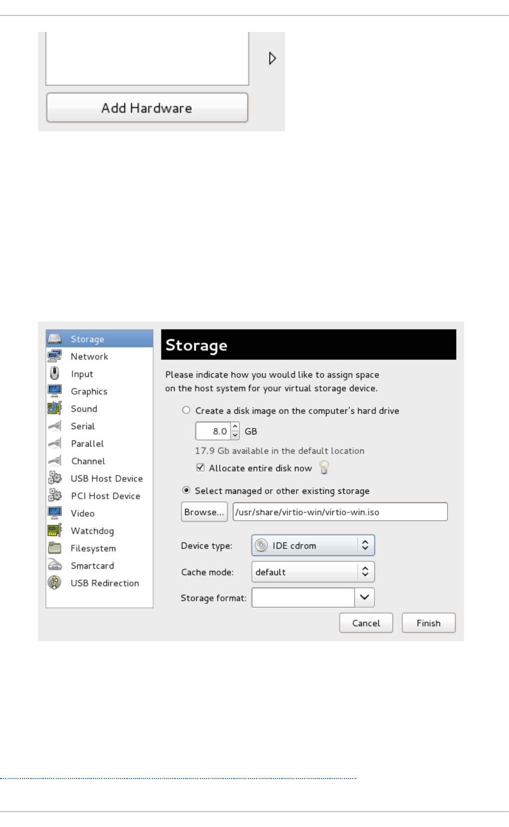
Fig u re 6 .2. T h e virt u al mach in e h ard ware in f o rmat io n win d o w
This opens a wizard for adding the new device.
3. Select t h e ISO f ile
Ensure that the Select managed or other existing storage radio button is
selected, and browse to the virtio driver's .iso image file. The default location for the latest
version of the drivers is /usr/share/virtio-win/virtio-win.iso.
Change the Device type to IDE cdrom and click the Fo rward button to proceed.
Fig u re 6 .3. T h e Ad d n ew virt u al h ard ware wiz ard
4. Reb o o t
Reboot or start the virtual machine to begin using the driver disc. Virtualized IDE devices
require a restart to for the virtual machine to recognize the new device.
Once the CD-ROM with the drivers is attached and the virtual machine has started, proceed with
Procedure 6.2, “ Windows installation on a Windows 7 virtual machine” .
Virt ualizat ion Deployment and Administ rat ion G uide
4 6
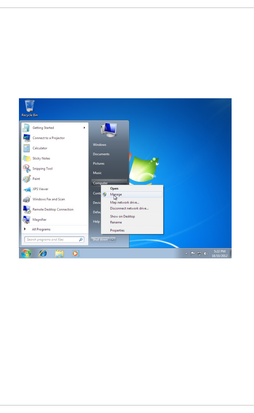
Pro ced ure 6 .2. Win d o ws in st allat io n on a Win d ows 7 virt u al mach in e
This procedure installs the drivers on a Windows 7 virtual machine as an example. Adapt the
Windows installation instructions to your guest's version of Windows.
1. O p en t h e Comp uter Man ag emen t win d o w
On the desktop of the Windows virtual machine, click the Windows icon at the bottom corner
of the screen to open the Start menu.
Right-click on C o mputer and select Manage from the pop-up menu.
Fig u re 6 .4 . The C o mp u t er Man ag emen t win d o w
2. O p en t h e D evice Man ag er
Select the Device Manager from the left-most pane. This can be found under C o mputer
Management > System Tools.
Chapt er 6 . KVM Para- virt ualiz ed (virt io) Drivers
4 7
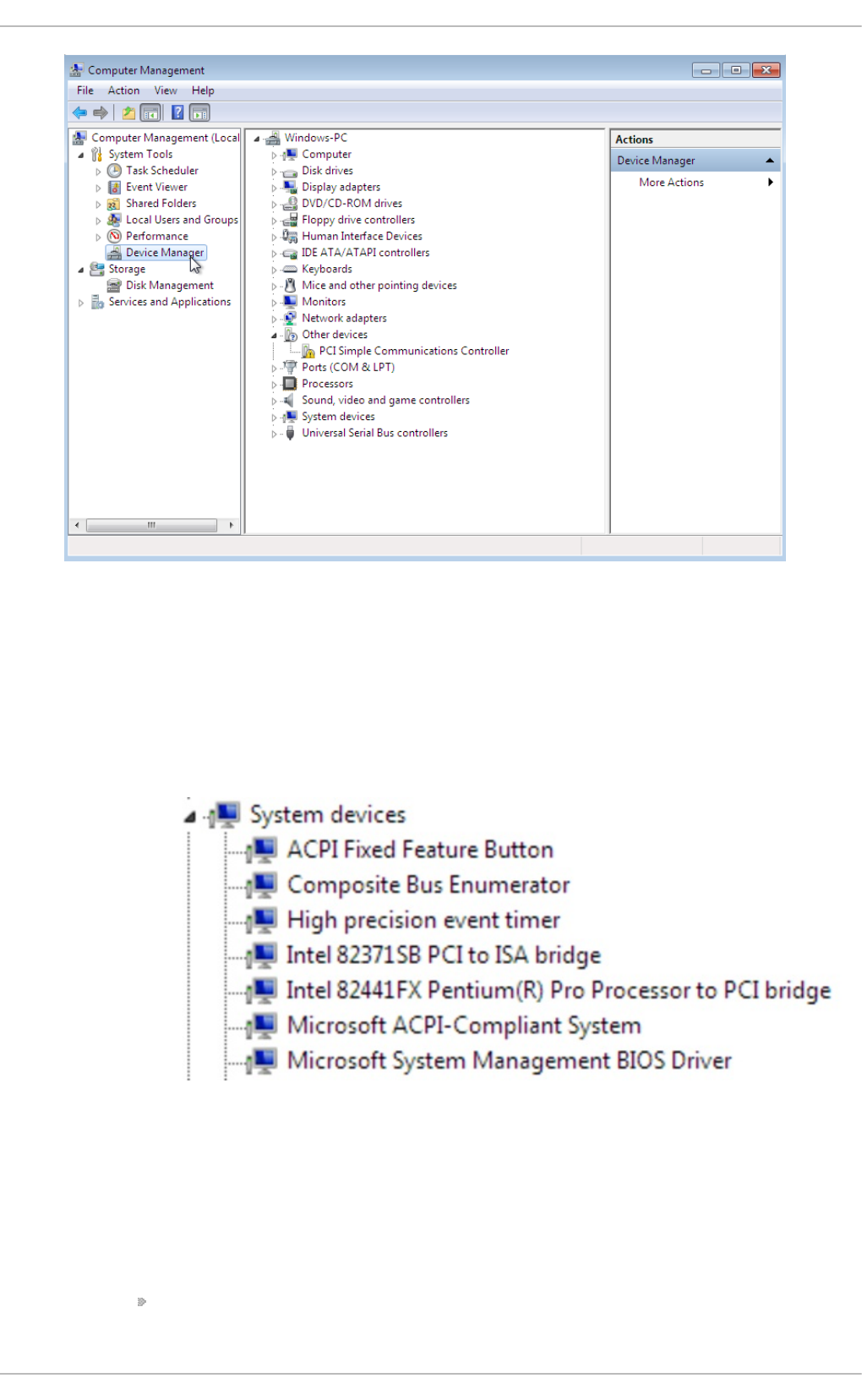
Fig u re 6 .5. T h e Comp u ter Man ag emen t windo w
3. St art t he d river u p d at e wiz ard
a. View availab le syst em d evices
Expand System devices by clicking on the arrow to its left.
Fig u re 6 .6 . Viewin g availab le syst em d evices in t h e Compu t er Man ag emen t
wi n d o w
b. Lo cat e t h e ap p ro p riat e d evice
There are up to four drivers available: the balloon driver, the serial driver, the network
driver, and the block driver.
Balloon, the balloon driver, affects the P C I stand ard R AM C o ntro l l er in
the System devices group.
Virt ualizat ion Deployment and Administ rat ion G uide
4 8
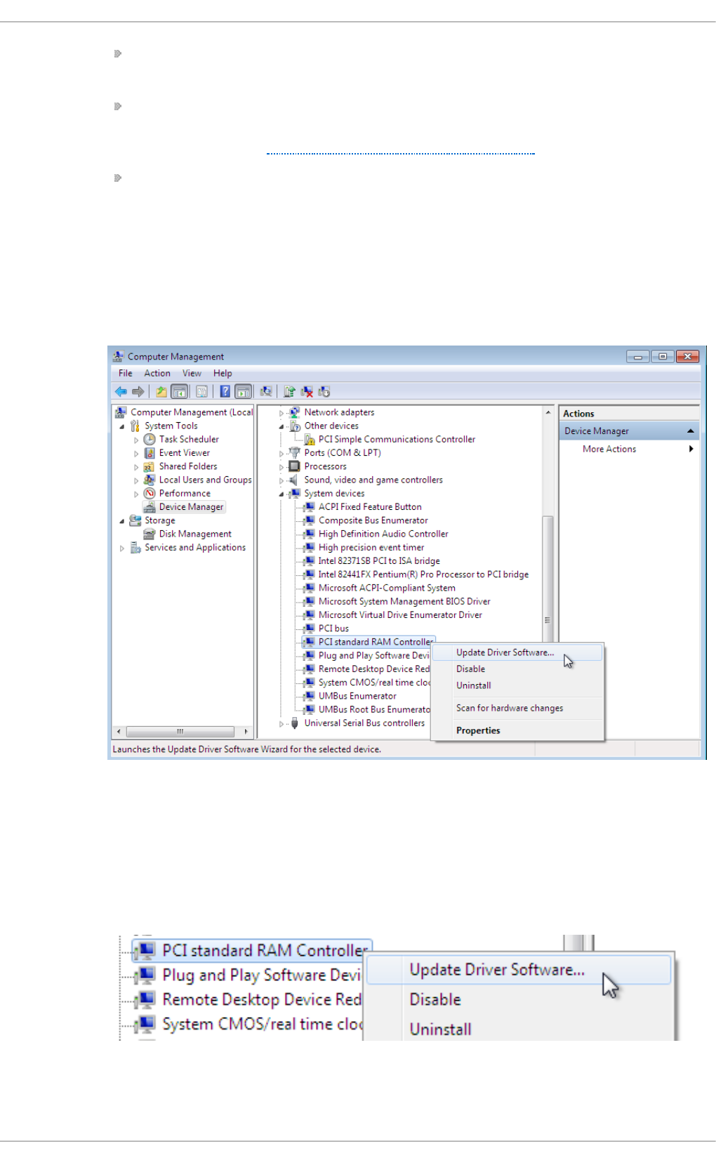
vi o seri al , the serial driver, affects the PCI Simple Communication
C o ntro l l er in the System devices group.
NetKVM, the network driver, affects the Network adapters group. This driver is
only available if a virtio NIC is configured. Configurable parameters for this driver
are documented in Appendix E, NetKVM Driver Parameters.
vi o sto r, the block driver, affects the Disk drives group. This driver is only
available if a virtio disk is configured.
Right-click on the device whose driver you wish to update, and select Update
Driver... from the pop-up menu.
This example installs the balloon driver, so right-click on PCI standard RAM
C o ntro l l er.
Fig u re 6 .7. T h e Comp u ter Man ag emen t windo w
c. O pen t he d river u p d at e wiz ard
From the drop-down menu, select Update Driver Software... to access the
driver update wizard.
Fig u re 6 .8. O p en in g t he d river u p d at e wiz ard
Chapt er 6 . KVM Para- virt ualiz ed (virt io) Drivers
4 9
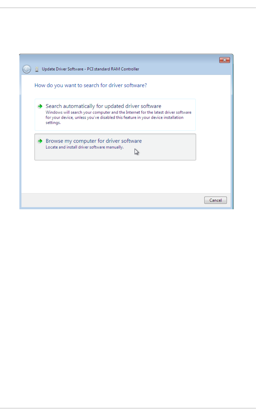
4. Sp ecify ho w t o f in d t h e d river
The first page of the driver update wizard asks how you want to search for driver software.
Click on the second option, Browse my computer for driver software.
Fig u re 6 .9 . The d river u p d at e wiz ard
5. Select t h e d river t o in st all
a. O p en a f ile b ro wser
Click on Bro wse. . .
Virt ualizat ion Deployment and Administ rat ion G uide
50
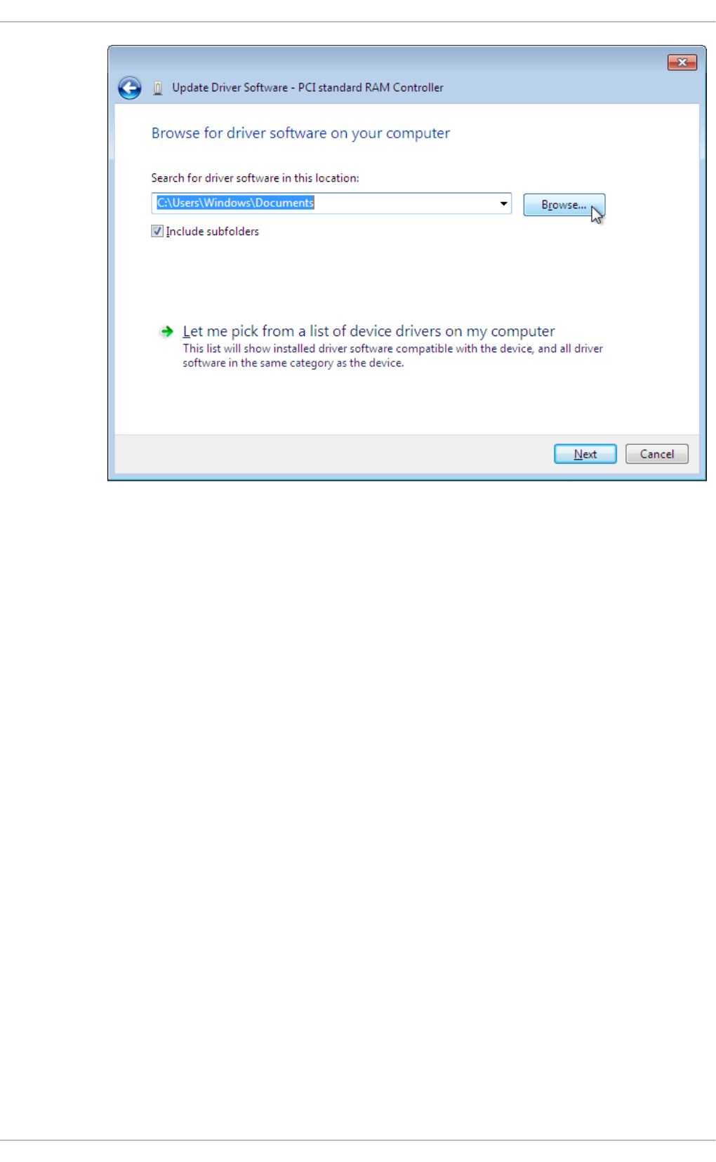
Fig u re 6 .10. T h e d river u p dat e wiz ard
b. Bro wse t o t h e lo cat ion of t h e d river
A separate driver is provided for each combination of operating systems and
architectures. The drivers are arranged hierarchically according to their driver type,
the operating system, and the architecture on which they will be installed:
driver_type/os/arch/. For example, the Balloon driver for a Windows 7
operating system with an x86 (32-bit) architecture, resides in the Balloon/w7/x86
directory.
Chapt er 6 . KVM Para- virt ualiz ed (virt io) Drivers
51
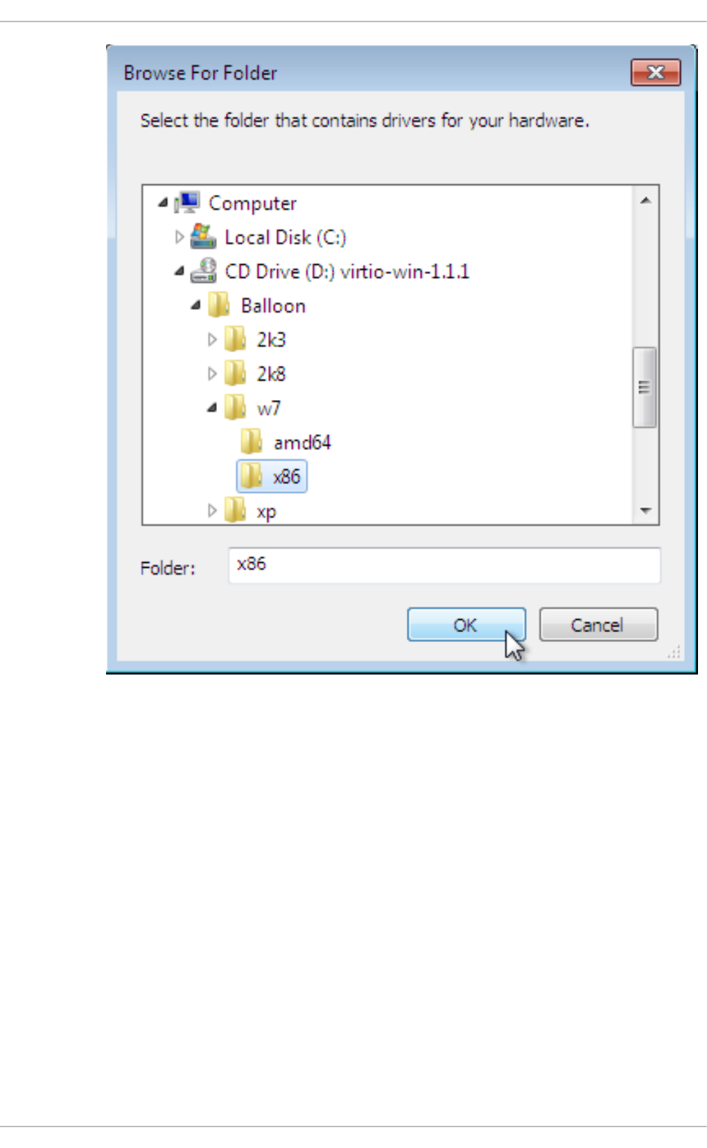
Fig u re 6 .11. T h e Bro wse f o r d river so f tware p o p -up win d o w
Once you have navigated to the correct location, click O K.
c. Click Next t o co n t in u e
Virt ualizat ion Deployment and Administ rat ion G uide
52
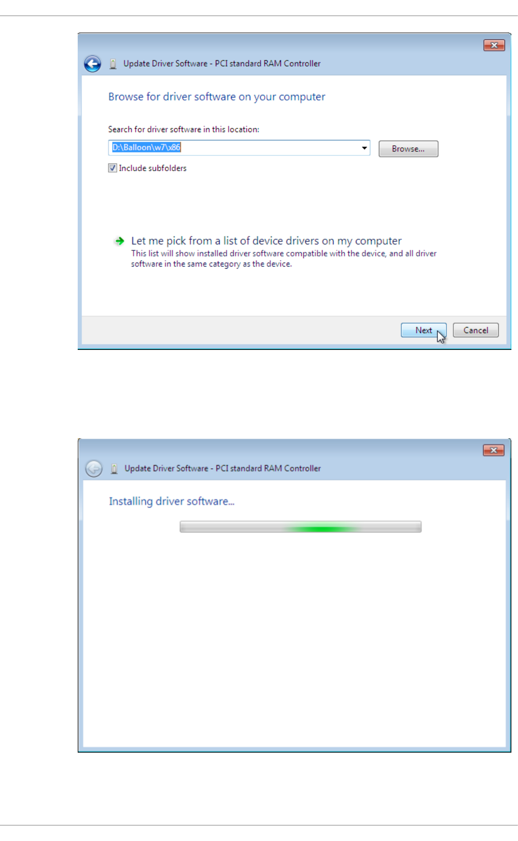
Fig u re 6 .12. T h e Updat e D river So f t ware wiz ard
The following screen is displayed while the driver installs:
Fig u re 6 .13. T h e Updat e D river So f t ware wiz ard
Chapt er 6 . KVM Para- virt ualiz ed (virt io) Drivers
53
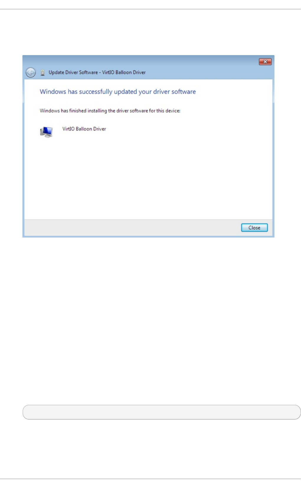
6. Clo se t h e in st aller
The following screen is displayed when installation is complete:
Fig u re 6 .14 . The U p d at e Driver So f tware wiz ard
Click Close to close the installer.
7. Reb o o t
Reboot the virtual machine to complete the driver installation.
6.3. Inst alling drivers during t he Windows inst allat ion
This procedure covers installing the virtio drivers during a Windows installation.
This method allows a Windows guest virtual machine to use the virtio drivers for the default storage
device.
Pro ced ure 6 .3. In st alling virt io d rivers d u ring th e Windows in st allat io n
1. Install the virtio-win package:
# yum install virtio-win
Virt ualizat ion Deployment and Administ rat ion G uide
54

Note
The virtio-win package can be found here:
https://access.redhat.com/downloads/content/rhel---7/x86_64/2476/virtio-win/1.7.1-
1.el7/noarch/fd431d51/package. It requires access to one of the following channels:
RHEL Client Supplementary (v. 7)
RHEL Server Supplementary (v. 7)
RHEL Workstation Supplementary (v. 7)
2. Creat in g th e g u est virt ual mach in e
Important
Create the virtual machine, as normal, without starting the virtual machine. Follow one
of the procedures below.
Select one of the following guest-creation methods, and follow the instructions.
a. Creat in g th e g u est virt ual mach in e wit h virsh
This method attaches the virtio driver floppy disk to a Windows guest before the
installation.
If the virtual machine is created from an XML definition file with virsh, use the vi rsh
define command not the virsh create command.
i. Create, but do not start, the virtual machine. Refer to the Red Hat Enterprise
Linux Virtualization Administration Guide for details on creating virtual machines
with the virsh command.
ii. Add the driver disk as a virtualized floppy disk with the virsh command. This
example can be copied and used if there are no other virtualized floppy
devices attached to the guest virtual machine. Note that vm_name should be
replaced with the name of the virtual machine.
# virsh attach-disk vm_name /usr/share/virtio-
win/virtio-win.vfd fda --type floppy
You can now continue with Step 3.
b. Creat in g th e g u est virt ual mach in e wit h virt - man ag er an d ch an gin g t he
d isk t yp e
i. At the final step of the virt-manager guest creation wizard, check the
Customize configuration before install checkbox.
Chapt er 6 . KVM Para- virt ualiz ed (virt io) Drivers
55
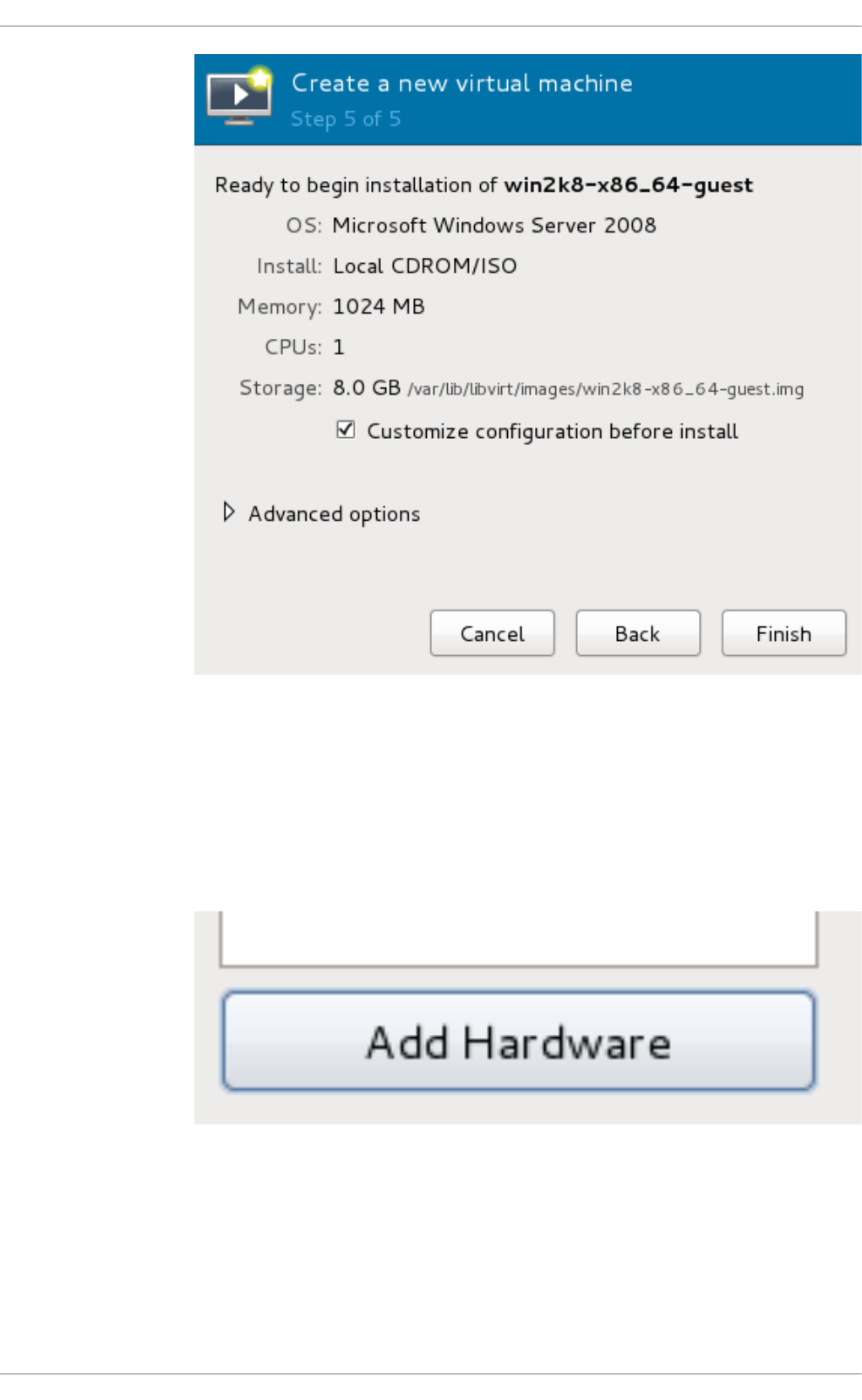
Fig u re 6 .15. T h e virt - man ag er g u est creat io n wiz ard
Click on the Finish button to continue.
ii. O pen t he Add Hard ware wiz ard
Click the Add Hardware button in the bottom left of the new panel.
Fig u re 6 .16 . The Ad d Hard ware b u t t o n
iii. Select st o rag e d evice
Sto rag e is the default selection in the Hardware type list.
Virt ualizat ion Deployment and Administ rat ion G uide
56
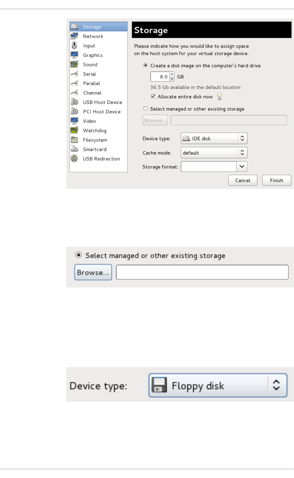
Fig u re 6 .17. T h e Ad d n ew virt u al h ard ware wiz ard
Ensure the Select managed or other existing storage radio button
is selected. Click Bro wse. . . .
Fig u re 6 .18. Select man ag ed o r exist in g st o rag e
In the new window that opens, click Browse Local. Navigate to
/usr/share/virtio-win/virtio-win.vfd, and click Select to
confirm.
Change Device type to Floppy disk, and click Finish to continue.
Fig u re 6 .19 . Ch an g e t h e D evice t ype
iv. Co nfirm set t in g s
Review the device settings.
Chapt er 6 . KVM Para- virt ualiz ed (virt io) Drivers
57
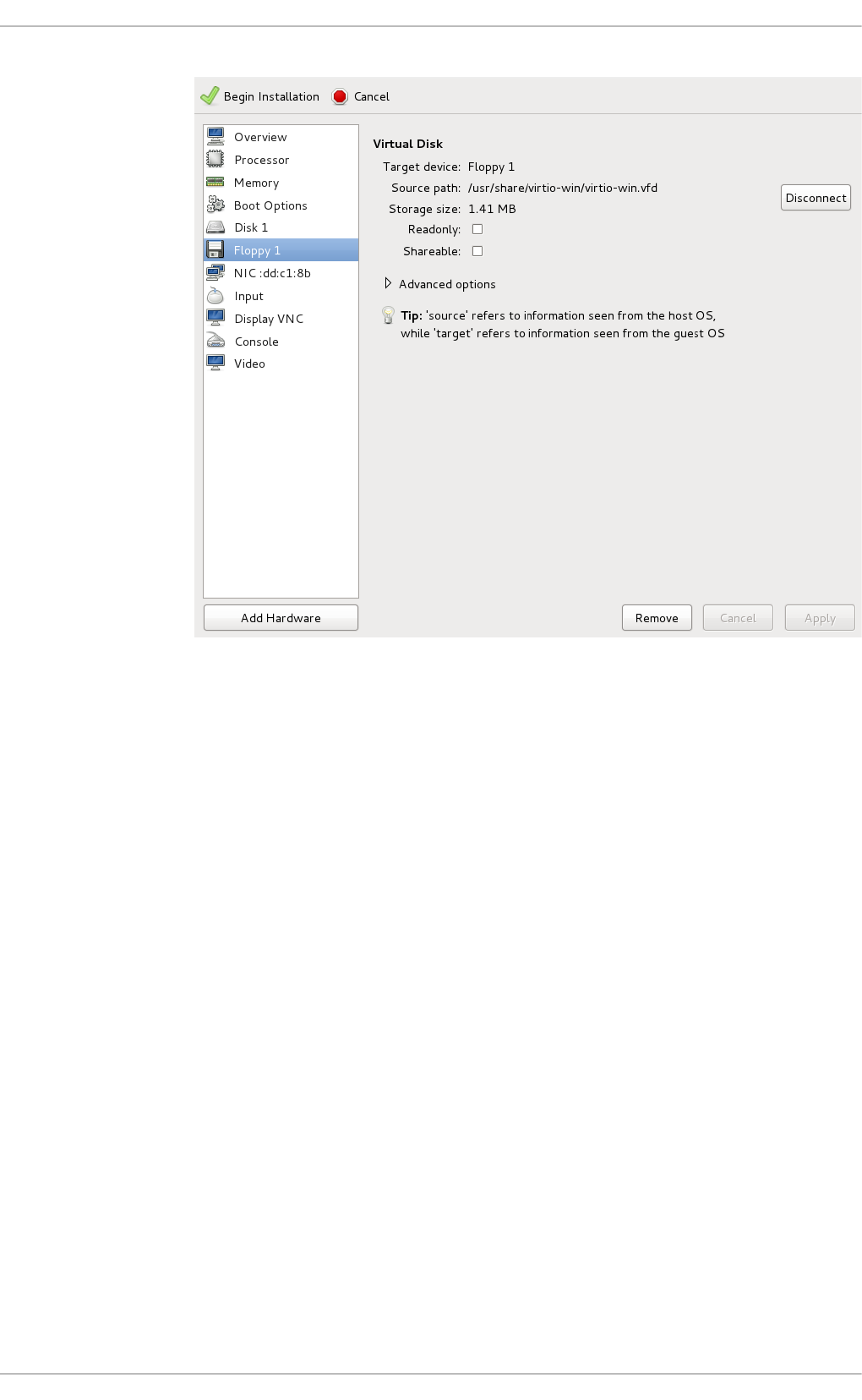
Fig u re 6 .20. T h e virt u al mach in e h ard ware in f o rmat io n win d o w
You have now created a removable device accessible by your virtual machine.
v. Chan ge t h e h ard d isk t yp e
To change the hard disk type from IDE Disk to Virtio Disk, we must first remove
the existing hard disk, Disk 1. Select the disk and click on the Remove button.
Virt ualizat ion Deployment and Administ rat ion G uide
58
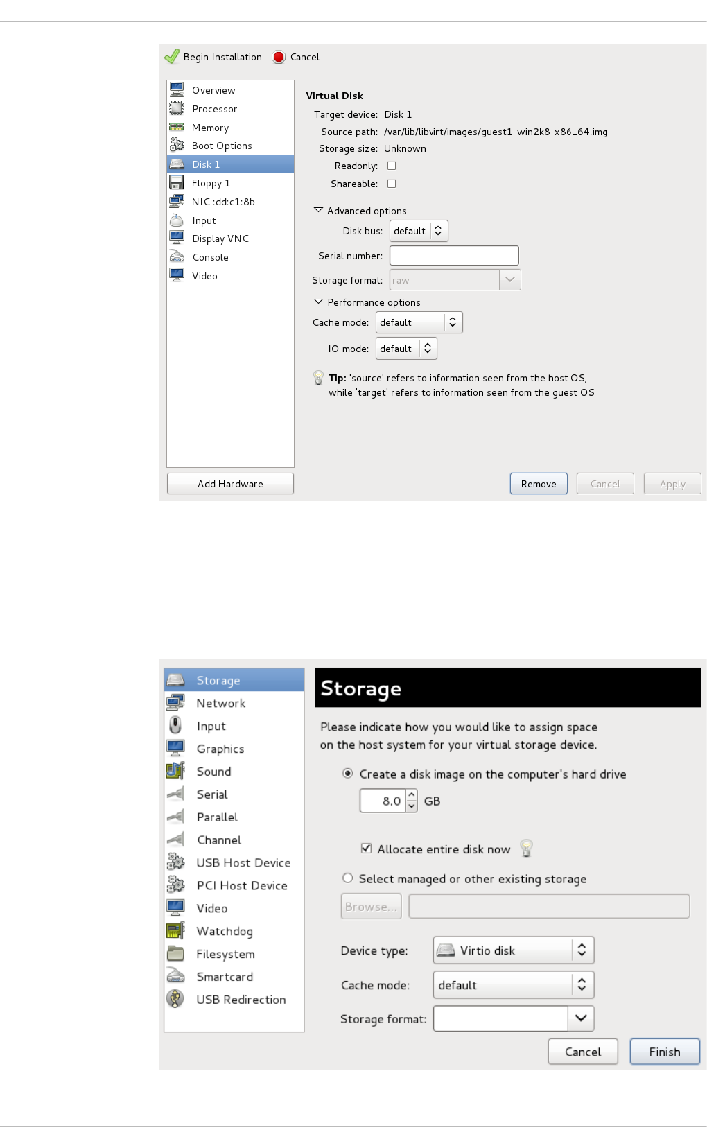
Fig u re 6 .21. T h e virt u al mach in e h ard ware in f o rmat io n win d o w
Add a new virtual storage device by clicking Add Hardware. Then, change
the Device type from IDE disk to Virtio Disk. Click Finish to confirm the
operation.
Chapt er 6 . KVM Para- virt ualiz ed (virt io) Drivers
59
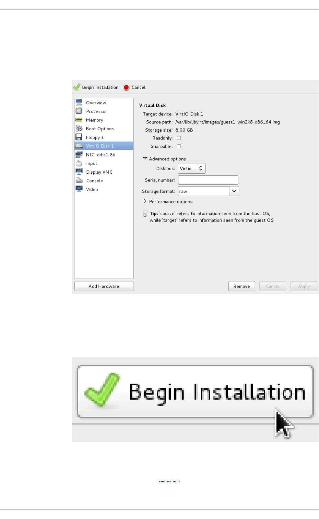
Fig u re 6 .22. T h e virt u al mach in e h ard ware in f o rmat io n win d o w
vi. En su re set t in g s are co rrect
Review the settings for VirtIO Disk 1.
Fig u re 6 .23. T h e virt u al mach in e h ard ware in f o rmat io n win d o w
When you are satisfied with the configuration details, click the Beg i n
Instal l ati o n button.
Fig u re 6 .24 . The B eg in In st allat io n bu t to n
You can now continue with Step 3.
c. Creat in g t h e g u est virt u al mach in e wit h virt -in st all
Virt ualizat ion Deployment and Administ rat ion G uide
60

c. Creat in g t h e g u est virt u al mach in e wit h virt -in st all
Append the following parameter exactly as listed below to add the driver disk to the
installation with the vi rt-i nstal l command:
--disk path=/usr/share/virtio-win/virtio-
win.vfd,device=floppy
Important
If the device you wish to add is a d i sk (that is, not a floppy or a cd ro m), you
will also need to add the bus= vi rti o option to the end of the --disk
parameter, like so:
--disk path=/usr/share/virtio-win/virtio-
win.vfd,device=disk,bus=virtio
According to the version of Windows you are installing, append one of the following
options to the vi rt-i nstal l command:
--os-variant win2k3
--os-variant win7
You can now continue with Step 3.
3.
Ad d it io n al st ep s f or d river in st allat io n
During the installation, additional steps are required to install drivers, depending on the type
of Windows guest.
a.
Windo ws Server 2003
Before the installation blue screen repeatedly press F6 for third party drivers.
Chapt er 6 . KVM Para- virt ualiz ed (virt io) Drivers
61
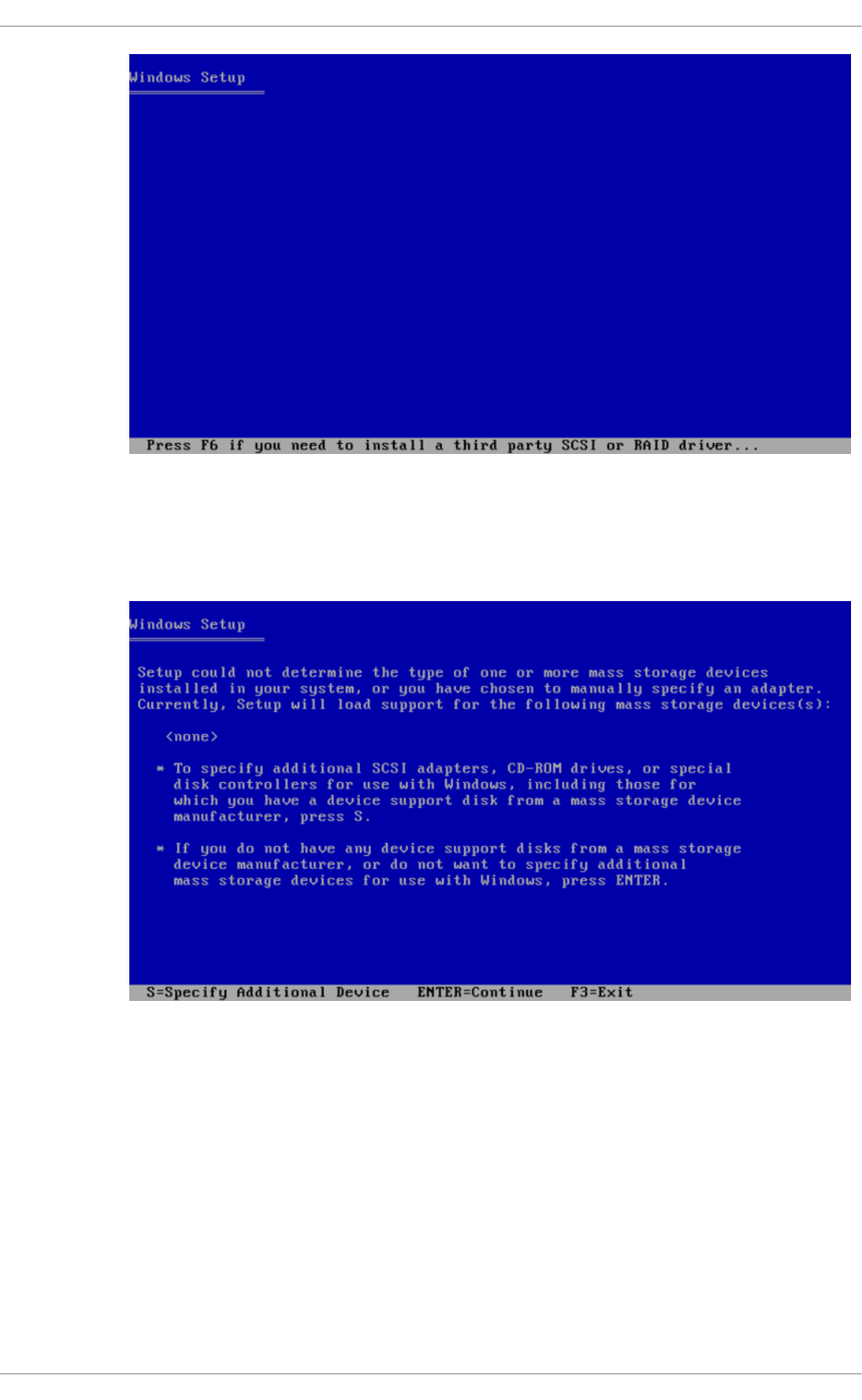
Fig u re 6 .25. T h e Win d o ws Set u p screen
Press S to install additional device drivers.
Fig u re 6 .26 . The Win dows Set u p screen
Virt ualizat ion Deployment and Administ rat ion G uide
62
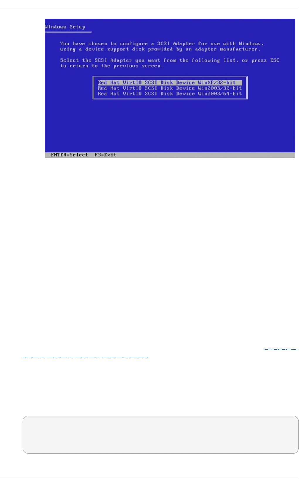
Fig u re 6 .27. T h e Win d o ws Set u p screen
Press Enter to continue the installation.
b.
Windo ws Server 2008
Follow the same procedure for Windows Server 2003, but when the installer prompts
you for the driver, click on Lo ad D ri ver, point the installer to D ri ve A: and pick
the driver that suits your guest operating system and architecture.
6.4. Using KVM virt io drivers for exist ing devices
You can modify an existing hard disk device attached to the guest to use the vi rti o driver instead
of the virtualized IDE driver. The example shown in this section edits libvirt configuration files. Note
that the guest virtual machine does not need to be shut down to perform these steps, however the
change will not be applied until the guest is completely shut down and rebooted.
Pro ced ure 6 .4 . Using KVM virt io d rivers f o r exist in g d evices
1. Ensure that you have installed the appropriate driver (vi o sto r), as described in Section 6.1,
“ Installing the KVM Windows virtio drivers” , before continuing with this procedure.
2. Run the virsh edit <guestname> command as root to edit the XML configuration file for
your device. For example, virsh edit guest1. The configuration files are located in
/etc/libvirt/qemu.
3. Below is a file-based block device using the virtualized IDE driver. This is a typical entry for a
virtual machine not using the virtio drivers.
<disk type='file' device='disk'>
<source file='/var/lib/libvirt/images/disk1.img'/>
<target dev='hda' bus='ide'/>
</disk>
Chapt er 6 . KVM Para- virt ualiz ed (virt io) Drivers
63

4. Change the entry to use the virtio device by modifying the b u s= entry to vi rti o . Note that if
the disk was previously IDE it will have a target similar to hda, hdb, or hdc and so on. When
changing to b u s = virt i o the target needs to be changed to vda, vdb, or vdc accordingly.
<disk type='file' device='disk'>
<source file='/var/lib/libvirt/images/disk1.img'/>
<target dev='vda' bus= ' vi rti o ' />
</disk>
5. Remove the address tag inside the d is k tags. This must be done for this procedure to work.
Libvirt will regenerate the address tag appropriately the next time the virtual machine is
started.
Alternatively, virt-manager, virsh attach-disk or virsh attach-interface can add a new
device using the virtio drivers.
Refer to the libvirt website for more details on using Virtio: http://www.linux-kvm.org/page/Virtio
6.5. Using KVM virt io drivers for new devices
This procedure covers creating new devices using the KVM virtio drivers with virt-manager.
Alternatively, the virsh attach-disk or virsh attach-interface commands can be used to
attach devices using the virtio drivers.
Important
Ensure the drivers have been installed on the Windows guest before proceeding to install new
devices. If the drivers are unavailable the device will not be recognized and will not work.
Pro ced ure 6 .5. Ad d in g a st o rag e d evice usin g t h e virt io st orag e d river
1. Open the guest virtual machine by double clicking on the name of the guest in vi rt-
manager.
2. Open the Show virtual hardware details tab by clicking the l i g htbul b button.
Fig u re 6 .28. T h e Sh o w virt u al hard ware d et ails t ab
3. In the Show virtual hardware details tab, click on the Add Hardware button.
4. Select hard ware t yp e
Select Sto rag e as the Hardware type.
Virt ualizat ion Deployment and Administ rat ion G uide
64
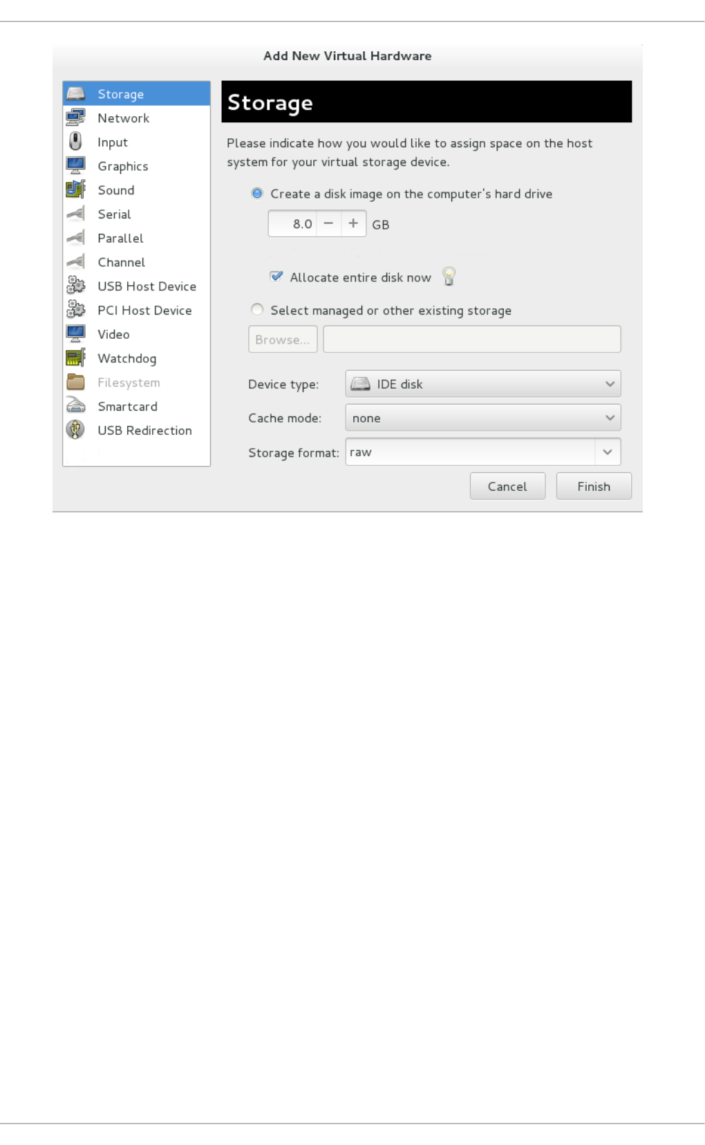
Fig u re 6 .29 . The Ad d n ew virt u al h ard ware wiz ard
5. Select t h e st o rag e d evice an d d river
Create a new disk image or select a storage pool volume.
Set the Device type to Vi rti o d i sk to use the virtio drivers.
Chapt er 6 . KVM Para- virt ualiz ed (virt io) Drivers
65
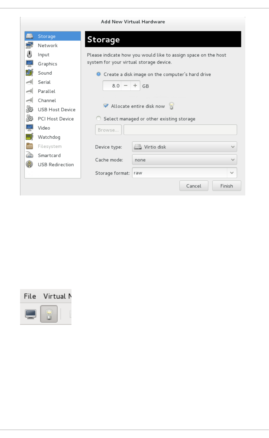
Fig u re 6 .30. T h e Ad d n ew virt u al h ard ware wiz ard
Click Finish to complete the procedure.
Pro ced ure 6 .6 . Ad d ing a n et wo rk d evice u sin g t he virt io net wo rk d river
1. Open the guest virtual machine by double clicking on the name of the guest in vi rt-
manager.
2. Open the Show virtual hardware details tab by clicking the l i g htbul b button.
Fig u re 6 .31. T h e Sh o w virt u al hard ware d et ails t ab
3. In the Show virtual hardware details tab, click on the Add Hardware button.
4. Select hard ware t yp e
Select Network as the Hardware type.
Virt ualizat ion Deployment and Administ rat ion G uide
66
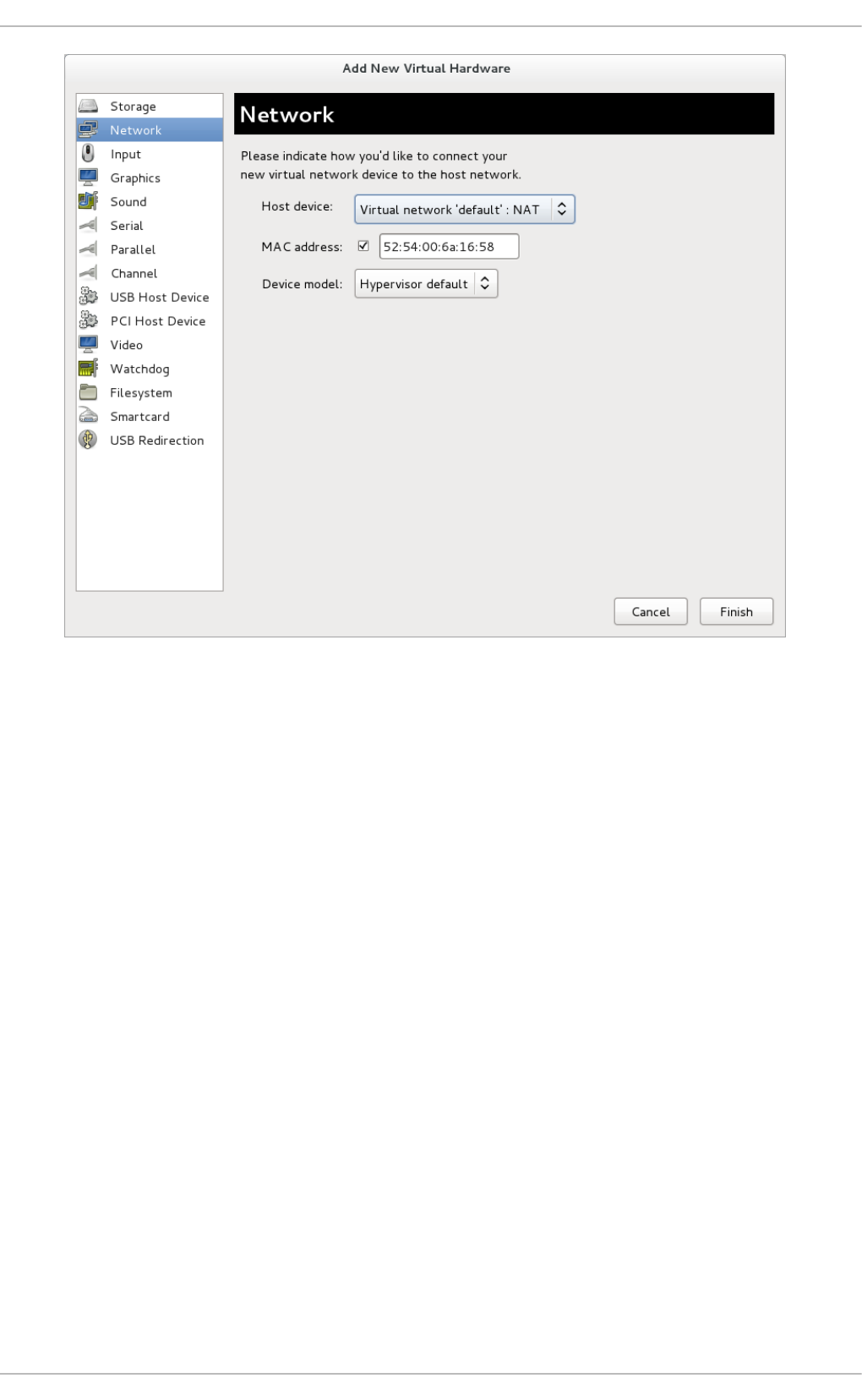
Fig u re 6 .32. T h e Ad d n ew virt u al h ard ware wiz ard
5. Select t h e n et wo rk d evice an d d river
Set the Device model to vi rti o to use the virtio drivers. Choose the desired Ho st
device.
Chapt er 6 . KVM Para- virt ualiz ed (virt io) Drivers
67

Fig u re 6 .33. T h e Ad d n ew virt u al h ard ware wiz ard
Click Finish to complete the procedure.
Once all new devices are added, reboot the virtual machine. Windows virtual machines may not
recognize the devices until the guest is rebooted.
Virt ualizat ion Deployment and Administ rat ion G uide
68

Chapter 7. Network configuration
This chapter provides an introduction to the common networking configurations used by libvirt
based guest virtual machines. For additional information, consult the libvirt network architecture
documentation: http://libvirt.org/archnetwork.html.
Red Hat Enterprise Linux 7 supports the following networking setups for virtualization:
virtual networks using Network Address Translation (NAT)
directly allocated physical devices using PCI device assignment
directly allocated virtual functions using PCIe SR-IOV
bridged networks
You must enable NAT, network bridging or directly assign a PCI device to allow external hosts
access to network services on guest virtual machines.
7.1. Net work Address T ranslat ion (NAT ) wit h libvirt
One of the most common methods for sharing network connections is to use Network Address
Translation (NAT) forwarding (also known as virtual networks).
Ho st co n f ig u rat io n
Every standard l i bvi rt installation provides NAT-based connectivity to virtual machines as the
default virtual network. Verify that it is available with the virsh net-list --all command.
# virsh net-list --all
Name State Autostart
-----------------------------------------
default active yes
If it is missing the following could be used in the XML configuration file (such as
/etc/libvirtd/qemu/myguest.xml) for the guest:
# ll /etc/libvirt/qemu/
total 12
drwx------. 3 root root 4096 Nov 7 23:02 networks
-rw-------. 1 root root 2205 Nov 20 01:20 r6.4.xml
-rw-------. 1 root root 2208 Nov 8 03:19 r6.xml
The default network is defined from /etc/libvirt/qemu/networks/default.xml
Mark the default network to automatically start:
# virsh net-autostart default
Network default marked as autostarted
Start the default network:
Chapt er 7 . Net work configurat ion
69

# virsh net-start default
Network default started
Once the l i bvi rt default network is running, you will see an isolated bridge device. This device
does not have any physical interfaces added. The new device uses NAT and IP forwarding to connect
to the physical network. Do not add new interfaces.
# brctl show
bridge name bridge id STP enabled interfaces
virbr0 8000.000000000000 yes
l i bvi rt adds iptables rules which allow traffic to and from guest virtual machines attached to
the vi rbr0 device in the INPUT, FORWARD, OUTPUT and POSTROUTING chains. l i bvi rt then
attempts to enable the i p_fo rward parameter. Some other applications may disable i p_fo rward ,
so the best option is to add the following to /etc/sysctl.conf.
net.ipv4.ip_forward = 1
G u est virt ual mach in e co n fig u rat io n
Once the host configuration is complete, a guest virtual machine can be connected to the virtual
network based on its name. To connect a guest to the 'default' virtual network, the following could be
used in the XML configuration file (such as /etc/libvirtd/qemu/myguest.xml) for the guest:
<interface type='network'>
<source network='default'/>
</interface>
Note
Defining a MAC address is optional. If you do not define one, a MAC address is automatically
generated and used as the MAC address of the bridge device used by the network. Manually
setting the MAC address may be useful to maintain consistency or easy reference throughout
your environment, or to avoid the very small chance of a conflict.
<interface type='network'>
<source network='default'/>
<mac address='00:16:3e:1a:b3:4a'/>
</interface>
7.2. Disabling vhost -net
The vhost-net module is a kernel-level back end for virtio networking that reduces virtualization
overhead by moving virtio packet processing tasks out of user space (the QEMU process) and into
the kernel (the vhost-net driver). vhost-net is only available for virtio network interfaces. If the
vhost-net kernel module is loaded, it is enabled by default for all virtio interfaces, but can be disabled
Virt ualizat ion Deployment and Administ rat ion G uide
70

in the interface configuration in the case that a particular workload experiences a degradation in
performance when vhost-net is in use.
Specifically, when UD P traffic is sent from a host machine to a guest virtual machine on that host,
performance degradation can occur if the guest virtual machine processes incoming data at a rate
slower than the host machine sends it. In this situation, enabling vhost-net causes the UDP
socket's receive buffer to overflow more quickly, which results in greater packet loss. It is therefore
better to disable vhost-net in this situation to slow the traffic, and improve overall performance.
To disable vhost-net, edit the <interface> sub-element in the guest virtual machine's XML
configuration file and define the network as follows:
<interface type="network">
...
<model type="virtio"/>
<driver name="qemu"/>
...
</interface>
Setting the driver name to qemu forces packet processing into QEMU user space, effectively disabling
vhost-net for that interface.
7.3. Enabling vhost -net zero-copy
In Red Hat Enterprise Linux 7, vhost-net zero-copy is disabled by default. To enable this action on a
permanent basis, add a new file vhost-net.conf to /etc/modprobe.d with the following
content:
options vhost_net experimental_zcopytx=1
If you want to disable this again, you can run the following:
modprobe -r vhost_net
modprobe vhost_net experimental_zcopytx=0
The first command removes the old file, the second one makes a new file (like above) and disables
zero-copy. You can use this to enable as well but the change will not be permanent.
To confirm that this has taken effect, check the output of cat
/sys/module/vhost_net/parameters/experimental_zcopytx. It should show:
$ cat /sys/module/vhost_net/parameters/experimental_zcopytx
0
7.4. Bridged net working
Bridged networking (also known as virtual network switching) is used to place virtual machine
network interfaces on the same network as the physical interface. Bridges require minimal
configuration and make a virtual machine appear on an existing network, which reduces
management overhead and network complexity. As bridges contain few components and
Chapt er 7 . Net work configurat ion
71

configuration variables, they provide a transparent set-up which is straightforward to understand
and troubleshoot, if required.
Bridging can be configured in a virtualized environment using standard Red Hat Enterprise Linux
tools, virt-manager, or libvirt, and is described in the following sections.
However, even in a virtualized environment, bridges may be more easily created using the host
operating system's networking tools. More information about this bridge creation method can be
found in the Red Hat Enterprise Linux 7 Networking Guide.
7.4 .1. Configuring bridged net working on a Red Hat Ent erprise Linux 7 host
Bridged networking can be configured for virtual machines on a Red Hat Enterprise Linux host,
independent to the virtualization management tools. This configuration may be more appropriate
when the virtualization bridge is the host's only network interface, or is the host's management
network interface.
The Red Hat Enterprise Linux 7 Networking Guide contains detailed instructions on configuring bridged
networking. See the Red Hat Enterprise Linux 7 Networking Guide - Configure Network Bridging for
instructions on configuring network bridging outside of the virtualization tools.
7.4 .2. Bridged net working wit h Virt ual Machine Manager
This section provides instructions on creating a bridge from a host machine's interface to a guest
virtual machine using virt-manager.
Note
Depending on your environment, setting up a bridge with libvirt tools in Red Hat Enterprise
Linux 7 may require disabling Network Manager, which is not recommended by Red Hat. A
bridge created with libvirt also requires libvirtd to be running for the bridge to maintain network
connectivity.
It is recommended to configure bridged networking on the physical Red Hat Enterprise Linux
host as described in the Red Hat Enterprise Linux 7 Networking Guide, while using libvirt after
bridge creation to add virtual machine interfaces to the bridges.
Pro ced ure 7.1. Creat in g a b rid g e with virt - man ag er
1. From the virt-manager main menu, click Ed it > C o n n ect io n D et ails to open the
C o nnecti o n D etai l s window.
2. Click the Net wo rk In t erf aces tab.
3. Click the + at the bottom of the window to configure a new network interface.
4. In the In terf ace t yp e drop-down menu, select B rid g e, and then click Fo rward to continue.
Virt ualizat ion Deployment and Administ rat ion G uide
72
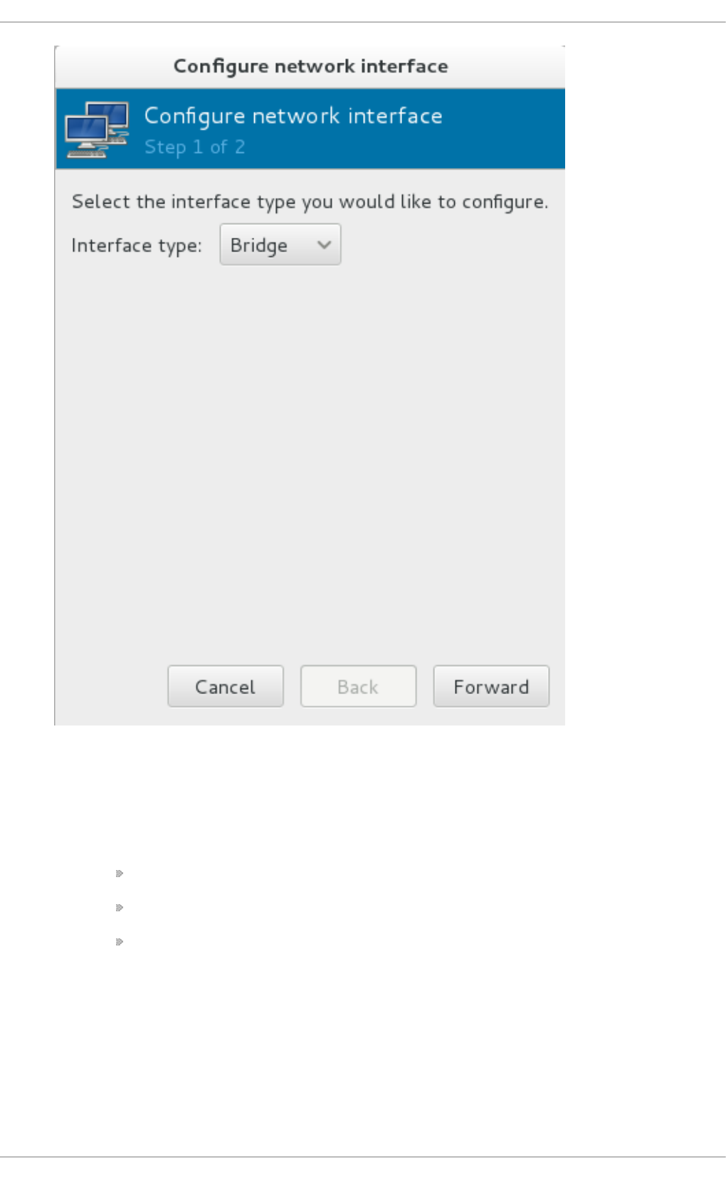
Fig u re 7.1. Ad d in g a b ridge
5. a. In the Name field, enter a name for the bridge, such as br0.
b. Select a St art mo d e from the drop-down menu. Choose from one of the following:
none - deactivates the bridge
onboot - activates the bridge on the next guest virtual machine reboot
hotplug - activates the bridge even if the guest virtual machine is running
c. Check the Act ivat e n o w check box to activate the bridge immediately.
d. To configure either the IP set t in g s or Brid g e set t in g s, click the appropriate
C o n f ig u re button. A separate window will open to specify the desired settings. Make
any necessary changes and click O K when done.
e. Select the physical interface to connect to your virtual machines. If the interface is
currently in use by another guest virtual machine, you will receive a warning
message.
Chapt er 7 . Net work configurat ion
73
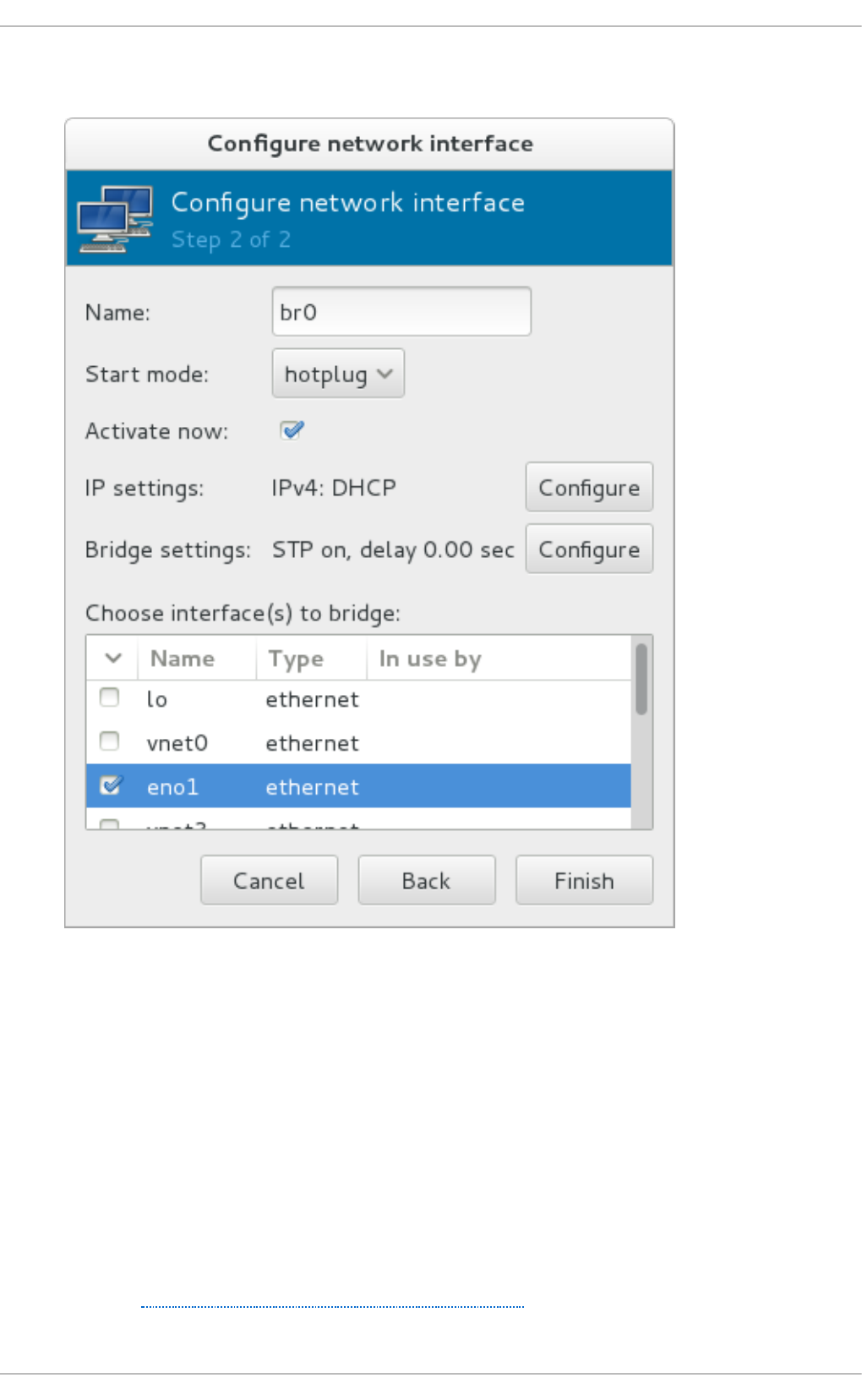
6. Click Fin ish and the wizard closes, taking you back to the Co n n ect io n s menu.
Fig u re 7.2. Ad d in g a b ridge
Select the bridge to use, and click Apply to exit the wizard.
To stop the interface, click the Stop Interface key. Once the bridge is stopped, to delete the
interface, click the Delete Interface key.
7.4 .3. Bridged net working wit h libvirt
Depending on your environment, setting up a bridge with libvirt in Red Hat Enterprise Linux 7 may
require disabling Network Manager, which is not recommended by Red Hat. This also requires
libvirtd to be running for the bridge to operate.
It is recommended to configure bridged networking on the physical Red Hat Enterprise Linux host as
described in the Red Hat Enterprise Linux 7 Networking Guide.
Virt ualizat ion Deployment and Administ rat ion G uide
74

Important
libvirt is now able to take advantage of new kernel tunable parameters to manage host bridge
forwarding database (FDB) entries, thus potentially improving system network performance
when bridging multiple virtual machines. Set the macTableManager attribute of a network's
<bridge> element to 'libvirt' in the host's XML configuration file:
<bridge name='br0' macTableManager='libvirt'/>
This will turn off learning (flood) mode on all bridge ports, and libvirt will add or remove entries
to the FDB as necessary. Along with removing the overhead of learning the proper forwarding
ports for MAC addresses, this also allows the kernel to disable promiscuous mode on the
physical device that connects the bridge to the network, which further reduces overhead.
Chapt er 7 . Net work configurat ion
75

Chapter 8. Overcommitting with KVM
8.1. Int roduct ion
The KVM hypervisor supports overcommitting CPUs and overcommitting memory. Overcommitting is
allocating more virtualized CPUs (vCPUs) or memory than there are physical resources on the
system. With CPU overcommit, under-utilized virtualized servers or desktops can run on fewer servers
which saves a number of system resources, with the net effect of less power, cooling, and investment
in server hardware.
As most processes do not access 100% of their allocated memory all the time, KVM can use this
behavior to its advantage and allocate more memory for guest virtual machines than the host
machine actually has available, in a process called overcommiting of resources.
8.2. Overcommit t ing Memory
Important
Overcommitting is not an ideal solution for all memory issues, as the recommended methods to
deal with memory shortage are to allocate less memory per guest, add more physical memory
to the host, or utilize swap space. If you decide to overcommit memory, ensure sufficient testing
is performed. Contact Red Hat support for assistance with overcommitting.
Virtual machines running on a KVM hypervisor do not have dedicated blocks of physical RAM
assigned to them. Instead, each guest functions as a Linux process where the host machine's Linux
kernel allocates memory only when requested. In addition, the host's memory manager can move the
guest's memory between its own physical memory and swap space. This is why overcommitting
requires allotting sufficient swap space on the host physical machine to accommodate all guests, as
well as enough memory for the host's processes. As a basic rule, the host's operating system
requires a maximum of 4GB of memory along with a minimum of 4GB of swap space. Refer to
Example 8.1, “Memory overcommit example” for more information.
Red Hat Knowledgebase has an article on safely and efficiently determining the size of the swap
partition.
Note
The example below is provided as a guide for configuring swap only. The settings listed may
not be appropriate for your environment.
Examp le 8.1. Memo ry o verco mmit examp le
ExampleServer1 has 32GB of physical RAM. The system is being configured to run 50 guest
virtual machines, each requiring 1GB of virtualized memory. As mentioned above, the host
machine's system itself needs a maximum of 4GB (apart from the guests) as well as an additional
4GB as a swap space minimum.
The swap space is calculated as follows:
Virt ualizat ion Deployment and Administ rat ion G uide
76

Calculate the amount of memory needed for the sum of all the virtual machines - In this
example: (50 virtual machines * 1GB of memory per virtual machine) = 50GB
Add the virtual machine's memory amount to the amount needed for the host's operating
system and for the host machine's minimum swap space - In this example: 50GB guest memory
+ 4GB host's OS + 4GB minimal swap = 58GB
Subtract this amount from the amount of physical RAM there is on the system - In this example
58GB - 32GB = 26GB
The answer is the amount of swap space that needs to be allocated - In this example 26GB.
Note
Overcommitting does not work with all virtual machines, but has been found to work in a
desktop virtualization setup with minimal intensive usage or running several identical guests
with KSM. Proceed with caution before changing these settings.
For more information on KSM and overcommitting, see the Red Hat Enterprise Linux 7
Virtualization Tuning and Optimization Guide.
8.3. Overcommit t ing virt ualized CPUs (vCPUs)
The KVM hypervisor supports overcommitting virtualized CPUs (vCPUs). Virtualized CPUs can be
overcommitted as far as load limits of guest virtual machines allow. Use caution when overcommitting
vCPUs, as loads near 100% may cause dropped requests or unusable response times.
In Red Hat Enterprise Linux 7, it is possible to overcommit guests with more than one vCPU (known
as symmetric multiprocessing virtual machines), however, you may experience performance
deterioration when running more cores on the virtual machine than are present on your physical
CPU. For example, a virtual machine with four vCPUs should not be run on a host machine with a
dual core processor. Overcommitting symmetric multiprocessing (SMP) virtual machines beyond the
physical number of processing cores will cause significant performance degradation, due to
programs getting less CPU time than required.
With SMP guests, some processing overhead is inherent. CPU overcommitting can increase the SMP
overhead, because time-slicing guests can make inter-CPU communication inside a guest slower.
This overhead increases with guests that have a larger number of vCPUs, or a larger overcommit
ratio.
Virtualized CPUs are overcommitted best when when a single host has multiple guests, and each
guest has a small number of vCPUs, compared to the number of host CPUs. The Linux scheduler is
very efficient with this type of load. KVM should safely support guests with loads under 100% at a
ratio of five vCPUs (on 5 virtual machines) to one physical CPU on one single host. The KVM
hypervisor will switch between all of the virtual machines, making sure that the load is balanced.
For best performance, Red Hat recommends assigning guests only as many vCPUs as are required
to run the programs that are inside each guest.
Chapt er 8 . O vercommit t ing wit h KVM
77

Important
Applications which use 100% of memory or processing resources may become unstable in
overcommitted environments. Do not overcommit memory or CPUs in a production
environment without extensive testing, as the amount of SMP and the CPU overcommit ratio is
workload dependent.
Virt ualizat ion Deployment and Administ rat ion G uide
78

Chapter 9. KVM guest timing management
Virtualization involves several intrinsic challenges for time keeping in guest virtual machines.
Interrupts cannot always be delivered simultaneously and instantaneously to all guest virtual
machines, because interrupts in virtual machines are not true interrupts; they are injected into the
guest virtual machine by the host machine. The host may be running another guest virtual machine,
or a different process, meaning that the precise timing typically required by interrupts may not always
be possible.
Guest virtual machines without accurate time keeping may experience issues with network
applications and processes, as session validity, migration, and other network activities rely on
timestamps to remain correct.
KVM avoids these issues by providing guest virtual machines with a para-virtualized clock (kvm-
clock). However, it is still vital to test timing before attempting activities that may be affected by time
keeping inaccuracies.
Note
Red Hat Enterprise Linux 5.5 and newer, Red Hat Enterprise Linux 6.0 and newer, and Red Hat
Enterprise Linux 7 use kvm- clo ck as their default clock source. Running without kvm- clo ck
requires special configuration, and is not recommended.
Important
The Network Time Protocol (NTP) daemon should be running on the host and the guest virtual
machines. Make sure to install ntp and enable the ntpd service:
Enable the ntpd service and add it to the default startup sequence:
# systemctl enable ntpd
Start the service:
# systemctl start ntpd
The ntpd service will correct the effects of clock skew as long as the clock runs no more than
0.05% faster or slower than the reference time source. The ntp startup script adjusts the clock
offset from the reference time by adjusting the system clock at startup time, if required.
Co n st an t Time St amp Co u n ter ( T SC )
Modern Intel and AMD CPUs provide a constant Time Stamp Counter (TSC). The count frequency of
the constant TSC does not vary when the CPU core itself changes frequency, for example, to comply
with a power saving policy. A CPU with a constant TSC frequency is necessary in order to use the
TSC as a clock source for KVM guests.
Chapt er 9 . KVM guest t iming management
79

Your CPU has a constant Time Stamp Counter if the constant_tsc flag is present. To determine if
your CPU has the constant_tsc flag run the following command:
$ cat /proc/cpuinfo | grep constant_tsc
If any output is given your CPU has the constant_tsc bit. If no output is given follow the
instructions below.
Co n f ig urin g h o st s wit h o u t a co n st an t Time St amp Co u nt er
Systems without a constant TSC frequency cannot use the TSC as a clock source for virtual
machines, and require additional configuration. Power management features interfere with accurate
time keeping and must be disabled for guest virtual machines to accurately keep time with KVM.
Important
These instructions are for AMD revision F CPUs only.
If the CPU lacks the constant_tsc bit, disable all power management features (BZ #51313 8). Each
system has several timers it uses to keep time. The TSC is not stable on the host, which is sometimes
caused by cpufreq changes, deep C state, or migration to a host with a faster TSC. Deep C sleep
states can stop the TSC. To prevent the kernel using deep C states append
processor.max_cstate=1 to the kernel boot. To make this change persistent, edit values of the
GRUB_CMDLINE_LINUX key in the /etc/default/grubfile. For example. if you want to enable
emergency mode for each boot, edit the entry as follows:
GRUB_CMDLINE_LINUX="emergency"
Note that you can specify multiple parameters for the GRUB_CMDLINE_LINUX key, similarly to adding
the parameters in the GRUB 2 boot menu.
To disnable cpufreq (only necessary on hosts without the constant_tsc), install kernel-tools and
enable the cpupower.service (systemctl disable cpupower.service). If you want to
disable this service every time the guest virtual machine boots, change the configuration file in
/etc/sysconfig/cpupower and change the CPUPOWER_START_OPTS and
CPUPOWER_STOP_OPTS. Valid limits can be found in the
/sys/devices/system/cpu/[cpuid]/cpufreq/scaling_available_governors files. For
more information on this package or on power management and governors, refer to the Red Hat
Enterprise Linux 7 Power Management Guide.
9.1. Required paramet ers for Red Hat Ent erprise Linux guest s
For certain Red Hat Enterprise Linux guest virtual machines, additional kernel parameters are
required. These parameters can be set by appending them to the end of the /kernel line in the
/boot/grub2/grub.cfg file of the guest virtual machine.
The table below lists versions of Red Hat Enterprise Linux and the parameters required on the
specified systems.
T ab le 9 .1. K ern el p aramet er req u iremen t s
Virt ualizat ion Deployment and Administ rat ion G uide
80

Red H at En t erp rise Lin ux versio n Ad d it io n al g u est kern el p aramet ers
7.0 AMD64/Intel 64 with the para-virtualized
clock
Additional parameters are not required
6.1 and higher AMD64/Intel 64 with the para-
virtualized clock
Additional parameters are not required
6.0 AMD64/Intel 64 with the para-virtualized
clock
Additional parameters are not required
6.0 AMD64/Intel 64 without the para-virtualized
clock
notsc lpj=n
5.5 AMD64/Intel 64 with the para-virtualized
clock
Additional parameters are not required
5.5 AMD64/Intel 64 without the para-virtualized
clock
notsc lpj=n
5.5 x86 with the para-virtualized clock Additional parameters are not required
5.5 x86 without the para-virtualized clock clocksource=acpi_pm lpj=n
5.4 AMD64/Intel 64 notsc
5.4 x86 clocksource=acpi_pm
5.3 AMD64/Intel 64 notsc
5.3 x86 clocksource=acpi_pm
4.8 AMD64/Intel 64 notsc
4.8 x86 clock=pmtmr
3.9 AMD64/Intel 64 Additional parameters are not required
Note
The lpj parameter requires a numeric value equal to the loops per jiffy value of the specific
CPU on which the guest virtual machine runs. If you do not know this value, do not set the lpj
parameter.
Chapt er 9 . KVM guest t iming management
81

Warning
The divider kernel parameter was previously recommended for Red Hat Enterprise Linux 4
and 5 guest virtual machines that did not have high responsiveness requirements, or exist on
systems with high guest density. It is no longer recommended for use with guests running Red
Hat Enterprise Linux 4, or Red Hat Enterprise Linux 5 versions prior to version 5.8.
divider can improve throughput on Red Hat Enterprise Linux 5 versions equal to or later
than 5.8 by lowering the frequency of timer interrupts. For example, if HZ=1000, and divider
is set to 10 (that is, divider=10), the number of timer interrupts per period changes from the
default value (1000) to 100 (the default value, 1000, divided by the divider value, 10).
BZ#698842 details a bug in the way that the divider parameter interacts with interrupt and
tick recording. This bug is fixed as of Red Hat Enterprise Linux 5.8. However, the divider
parameter can still cause kernel panic in guests using Red Hat Enterprise Linux 4, or Red Hat
Enterprise Linux 5 versions prior to version 5.8.
Red Hat Enterprise Linux 6 and newer does not have a fixed-frequency clock interrupt; it
operates in tickless mode and uses the timer dynamically as required. The divider parameter
is therefore not useful for Red Hat Enterprise Linux 6 and Red Hat Enterprise Linux 7, and
guests on these systems are not affected by this bug.
9.2. St eal t ime account ing
Steal time is the amount of CPU time desired by a guest virtual machine that is not provided by the
host. Steal time occurs when the host allocates these resources elsewhere: for example, to another
guest.
Steal time is reported in the CPU time fields in /proc/stat. It is automatically reported by utilities
such as to p and vmstat. It is displayed as "%st", or in the "st" column. Note that it cannot be
switched off.
Large amounts of steal time indicate CPU contention, which can reduce guest performance. To
relieve CPU contention, increase the guest's CPU priority or CPU quota, or run fewer guests on the
host.
Virt ualizat ion Deployment and Administ rat ion G uide
82

Chapter 10. Network booting with libvirt
Guest virtual machines can be booted with PXE enabled. PXE allows guest virtual machines to boot
and load their configuration off the network itself. This section demonstrates some basic
configuration steps to configure PXE guests with libvirt.
This section does not cover the creation of boot images or PXE servers. It is used to explain how to
configure libvirt, in a private or bridged network, to boot a guest virtual machine with PXE booting
enabled.
Warning
These procedures are provided only as an example. Ensure that you have sufficient backups
before proceeding.
10.1. Preparing t he boot server
To perform the steps in this chapter you will need:
A PXE Server (DHCP and TFTP) - This can be a libvirt internal server, manually-configured dhcpd
and tftpd, dnsmasq, a server configured by Cobbler, or some other server.
Boot images - for example, PXELINUX configured manually or by Cobbler.
10.1.1. Set t ing up a PXE boot server on a privat e libvirt net work
This example uses the default network. Perform the following steps:
Pro ced ure 10.1. Co n fig u rin g t he PXE b o o t server
1. Place the PXE boot images and configuration in /var/lib/tftp.
2. Run the following commands:
# virsh net-destroy default
# virsh net-edit default
3. Edit the <ip> element in the configuration file for the default network to include the
appropriate address, network mask, DHCP address range, and boot file, where
BOOT_FILENAME represents the file name you are using to boot the guest virtual machine.
<ip address='192.168.122.1' netmask='255.255.255.0'>
<tftp root='/var/lib/tftp' />
<dhcp>
<range start='192.168.122.2' end='192.168.122.254' />
<bootp file='BOOT_FILENAME' />
</dhcp>
</ip>
4. Run:
# virsh net-start default
Chapt er 1 0 . Net work boot in g wit h libvirt
83

5. Boot the guest using PXE (refer to Section 10.2, “ Booting a guest using PXE” ).
10.2. Boot ing a guest using PXE
This section demonstrates how to boot a guest virtual machine with PXE.
10.2.1. Using bridged net working
Pro ced ure 10.2. Bo o tin g a g u est u sin g PXE an d b rid g ed n et wo rkin g
1. Ensure bridging is enabled such that the PXE boot server is available on the network.
2. Boot a guest virtual machine with PXE booting enabled. You can use the vi rt-i nstal l
command to create a new virtual machine with PXE booting enabled, as shown in the
following example command:
virt-install --pxe --network bridge=breth0 --prompt
Alternatively, ensure that the guest network is configured to use your bridged network, and
that the XML guest configuration file has a <boot dev='network'/> element inside the
<os> element, as shown in the following example:
<os>
<type arch='x86_64' machine='rhel6.2.0'>hvm</type>
<boot dev='network'/>
<boot dev='hd'/>
</os>
<interface type='bridge'>
<mac address='52:54:00:5a:ad:cb'/>
<source bridge='breth0'/>
<target dev='vnet0'/>
<alias name='net0'/>
<address type='pci' domain='0x0000' bus='0x00' slot='0x03'
function='0x0'/>
</interface>
10.2.2. Using a privat e libvirt net work
Pro ced ure 10.3. Usin g a p rivat e lib virt n et wo rk
1. Configure PXE booting on libvirt as shown in Section 10.1.1, “Setting up a PXE boot server
on a private libvirt network” .
2. Boot a guest virtual machine using libvirt with PXE booting enabled. You can use the vi rt-
i nstal l command to create/install a new virtual machine using PXE:
virt-install --pxe --network network=default --prompt
Alternatively, ensure that the guest network is configured to use your bridged network, and that the
XML guest configuration file has a <boot dev='network'/> element inside the <os> element, as
shown in the following example:
Virt ualizat ion Deployment and Administ rat ion G uide
84

<os>
<type arch='x86_64' machine='rhel6.2.0'>hvm</type>
<boot dev='network'/>
<boot dev='hd'/>
</os>
Also ensure that the guest virtual machine is connected to the private network:
<interface type='network'>
<mac address='52:54:00:66:79:14'/>
<source network='default'/>
<target dev='vnet0'/>
<alias name='net0'/>
<address type='pci' domain='0x0000' bus='0x00' slot='0x03'
function='0x0'/>
</interface>
Chapt er 1 0 . Net work boot in g wit h libvirt
85

Chapter 11. Enhancing virtualization with the QEMU guest agent
and SPICE agent
Agents in Red Hat Enterprise Linux such as the QEMU guest agent and the SPICE agent can be
deployed to help the virtualization tools run more optimally on your system. These agents are
described in this chapter.
Note
To further optimize and tune host and guest performance, see the Red Hat Enterprise Linux 7
Virtualization Tuning and Optimization Guide.
11.1. QEMU guest agent
The QEMU guest agent runs inside the guest and allows the host machine to issue commands to the
guest operating system using libvirt, helping with functions such as freezing and thawing filesystems.
The guest operating system then responds to those commands asynchronously. The QEMU guest
agent package, qemu-guest-agent, is installed by default in Red Hat Enterprise Linux 7.
CPU hotplugging and hot-unplugging are supported with the help of the QEMU guest agent on Linux
guests; CPUs can be enabled or disabled while the guest is running, thus implementing the hotplug
feature and mimicking the unplug feature. Refer to Section 23.16.6, “ Configuring virtual CPU count”
for more information.
This section covers the libvirt commands and options available to the guest agent.
Important
Note that it is only safe to rely on the QEMU guest agent when run by trusted guests. An
untrusted guest may maliciously ignore or abuse the guest agent protocol, and although built-
in safeguards exist to prevent a denial of service attack on the host, the host requires guest
co-operation for operations to run as expected.
11.1.1. Set t ing up communicat ion bet ween t he QEMU guest agent and host
The host machine communicates with the QEMU guest agent through a VirtIO serial connection
between the host and guest machines. A VirtIO serial channel is connected to the host via a character
device driver (typically a Unix socket), and the guest listens on this serial channel.
Virt ualizat ion Deployment and Administ rat ion G uide
86

Note
The qemu-guest-agent does not detect if the host is listening to the VirtIO serial channel.
However, as the current use for this channel is to listen for host-to-guest events, the probability
of a guest virtual machine running into problems by writing to the channel with no listener is
very low. Additionally, the qemu-guest-agent protocol includes synchronization markers which
allow the host physical machine to force a guest virtual machine back into sync when issuing
a command, and libvirt already uses these markers, so that guest virtual machines are able to
safely discard any earlier pending undelivered responses.
11 .1 .1 .1 . Co nfiguring t he QEMU gue st age nt o n a Linux gue st
The QEMU guest agent can be configured on a running or shut down virtual machine. If configured
on a running guest, the guest will start using the guest agent immediately. If the guest is shut down,
the QEMU guest agent will be enabled at next boot.
Either virsh or virt - man ag er can be used to configure communication between the guest and the
QEMU guest agent. The following instructions describe how to configure the QEMU guest agent on a
Linux guest.
Pro ced ure 11.1. Set t ing up co mmu nicat io n bet ween g u est ag en t an d h o st wit h vi rsh
o n a sh u t d o wn Lin u x g u est
1. Sh u t down t h e virt ual mach in e
Ensure the virtual machine (named rhel7 in this example) is shut down before configuring the
QEMU guest agent:
# virsh shutdown rhel7
2. Ad d t h e Q EMU g u est ag en t ch an n el t o th e g u est XML co n f ig u rat io n
Edit the guest's XML file to add the QEMU guest agent details:
# virsh edit rhel7
Add the following to the guest's XML file and save the changes:
<channel type='unix'>
<target type='virtio' name='org.qemu.guest_agent.0'/>
</channel>
3. St art t he virt ual mach in e
# virsh start rhel7
4. In st all t he Q EMU g u est ag en t on the g u est
Install the QEMU guest agent if not yet installed in the guest virtual machine:
# yum install qemu-guest-agent
Chapt er 1 1 . Enhancin g virt ualiz at ion wit h t he Q EMU guest agen t and SPICE agent
87

5. St art t he Q EMU g u est ag en t in t h e g u est
Start the QEMU guest agent service in the guest:
# systemctl start qemu-guest-agent
Alternatively, the QEMU guest agent can be configured on a running guest with the following steps:
Pro ced ure 11.2. Set t ing up co mmu nicat io n bet ween g u est ag en t an d h o st on a ru n n in g
Lin u x g u est
1. Creat e an XML f ile f o r t h e Q EMU g u est ag en t
# cat agent.xml
<channel type='unix'>
<target type='virtio' name='org.qemu.guest_agent.0'/>
</channel>
2. At t ach t h e Q EMU gu est ag en t to t h e virt u al mach in e
Attach the QEMU guest agent to the running virtual machine (named rhel7 in this example)
with this command:
# virsh attach-device rhel7 agent.xml
3. In st all the Q EMU g u est ag en t o n t he g u est
Install the QEMU guest agent if not yet installed in the guest virtual machine:
# yum install qemu-guest-agent
4. St art t h e Q EMU g u est ag en t in t he g u est
Start the QEMU guest agent service in the guest:
# systemctl start qemu-guest-agent
Pro ced ure 11.3. Set t ing up co mmu nicat io n bet ween t h e Q EMU g u est ag en t an d ho st
wit h virt-manager
1. Sh u t down t h e virt ual mach in e
Ensure the virtual machine is shut down before configuring the QEMU guest agent.
To shut down the virtual machine, select it from the list of virtual machines in Virt u a l
Mach in e Man ag er, then click the light switch icon from the menu bar.
2. Ad d t h e Q EMU g u est ag en t ch an n el t o th e g u est
Open the virtual machine's hardware details by clicking the lightbulb icon at the top of the
guest window.
Click the Add Hardware button to open the Add New Virtual Hardware window, and
select Channel.
Virt ualizat ion Deployment and Administ rat ion G uide
88
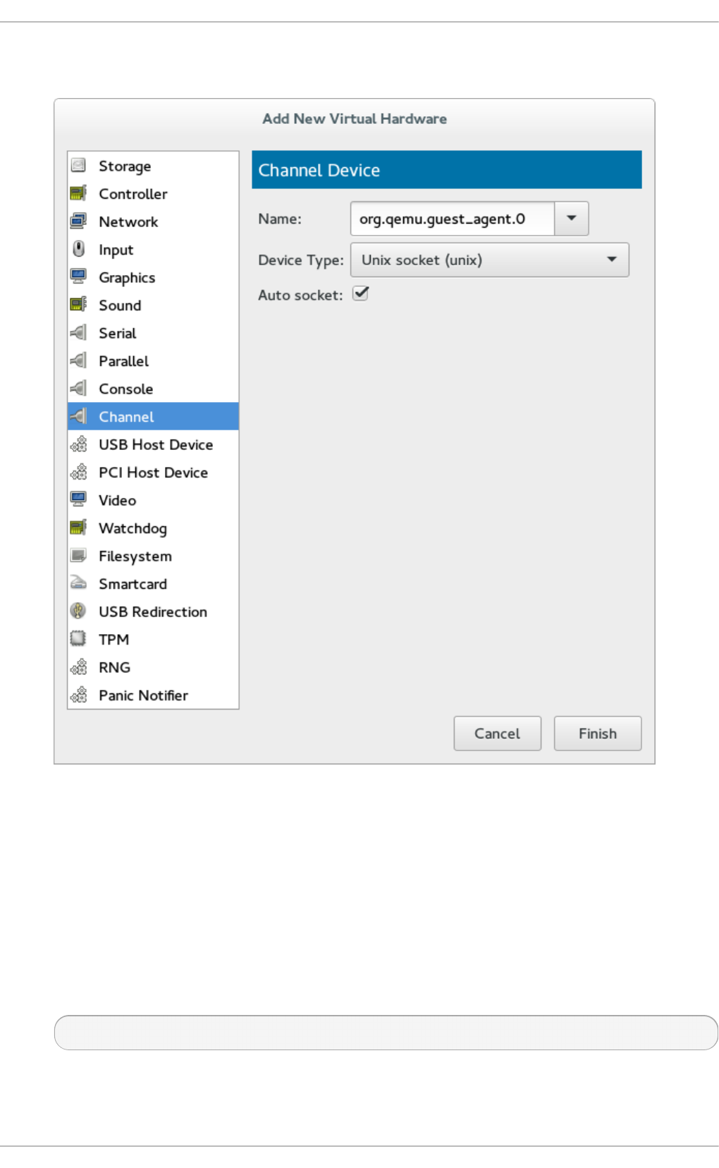
Select the QEMU guest agent from the Name drop-down list and click Finish:
Fig u re 11.1. Select in g t h e Q EMU g u est ag en t ch an nel d evice
3. St art t he virt ual mach in e
To start the virtual machine, select it from the list of virtual machines in Virt u al Mach in e
Man ag er, then click the triangle (play) icon from the menu bar.
4. In st all t he Q EMU g u est ag en t on the g u est
Open the guest with virt - man ag er and install the QEMU guest agent if not yet installed in the
guest virtual machine:
# yum install qemu-guest-agent
5. St art t he Q EMU g u est ag en t in t h e g u est
Chapt er 1 1 . Enhancin g virt ualiz at ion wit h t he Q EMU guest agen t and SPICE agent
89

Start the QEMU guest agent service in the guest:
# systemctl start qemu-guest-agent
The QEMU guest agent is now configured on the rhel7 virtual machine.
11.1.2. Configuring t he QEMU guest agent on a Windows guest
The following instructions describe how to configure the QEMU guest agent on a Windows guest
running on a Red Hat Enterprise Linux host.
Note
Windows guest virtual machines require the QEMU guest agent package for Windows, qemu-
guest-agent-win. This agent is required for VSS (Volume Shadow Copy Service) support for
Windows guest virtual machines running on Red Hat Enterprise Linux. More information can
be found here.
Pro ced ure 11.4 . Co n f ig u rin g t h e Q EMU g u est ag en t o n a Win d o ws g u est
1. (O p t io n al) Prep are t h e R ed Hat En t erp rise Lin u x ho st mach in e
While the virtio-win package is not required to run the QEMU guest agent, these drivers
improve performance.
a. Ch eck f o r t h e virtio-win p ackag e o n t h e h o st
Verify the following packages are installed on the Red Hat Enterprise Linux host
machine:
virtio-win, located in /usr/share/virtio-win/
b. Creat e an *.iso f ile t o co p y t h e d rivers t o t h e Win d o ws g u est
To copy the drivers to the Windows guest, make an *.iso file for the virt i o - wi n
drivers using the following command:
# mkisofs -o /var/lib/libvirt/images/virtiowin.iso
/usr/share/virtio-win/drivers
c. In st all t he d rivers o n t h e Win dows g u est
Install the virtio-serial drivers in the guest by mounting the *.iso to the Windows
guest to update the driver. Start the guest (in this example, the guest's name is
win7x86), then attach the driver .iso file to the guest as shown:
# virsh attach-disk win7x86
/var/l i b/l i bvi rt/i mag es/vi rti o wi n. i so hd b
To install the drivers using the Windows Cont ro l Pan el, navigate to the following
menus:
To install the virtio-win driver - Select Hard ware an d So un d > Device man ag er
Virt ualizat ion Deployment and Administ rat ion G uide
90

> virt io - serial d river.
2. Sh u t d o wn t h e g u est virt u al mach in e
Gracefully shutdown the guest virtual machine by running the
# virsh shutdown win7x86
command.
3. Ad d t h e Q EMU g u est ag en t ch an n el t o th e g u est fro m t h e h o st
Add the following elements to the guest's XML file using the # virsh edit win7x86
command and save the changes. The source socket name must be unique in the host, named
win7x86.agent in this example:
<channel type='unix'>
<source mode='bind'
path='/var/lib/libvirt/qemu/win7x86.agent'/>
<target type='virtio' name='org.qemu.guest_agent.0'/>
</channel>
Alternatively, this step can be completed with virt - ma n ag er:
To add the QEMU guest agent channel to the guest with virt - ma n ag er, click the lightbulb
icon at the top of the guest window to show the virtual machine hardware details.
Click the Add Hardware button to open the Add New Virtual Hardware window and
select Channel.
Select the QEMU guest agent from the Name drop-down list and click Finish:
Chapt er 1 1 . Enhancin g virt ualiz at ion wit h t he Q EMU guest agen t and SPICE agent
91
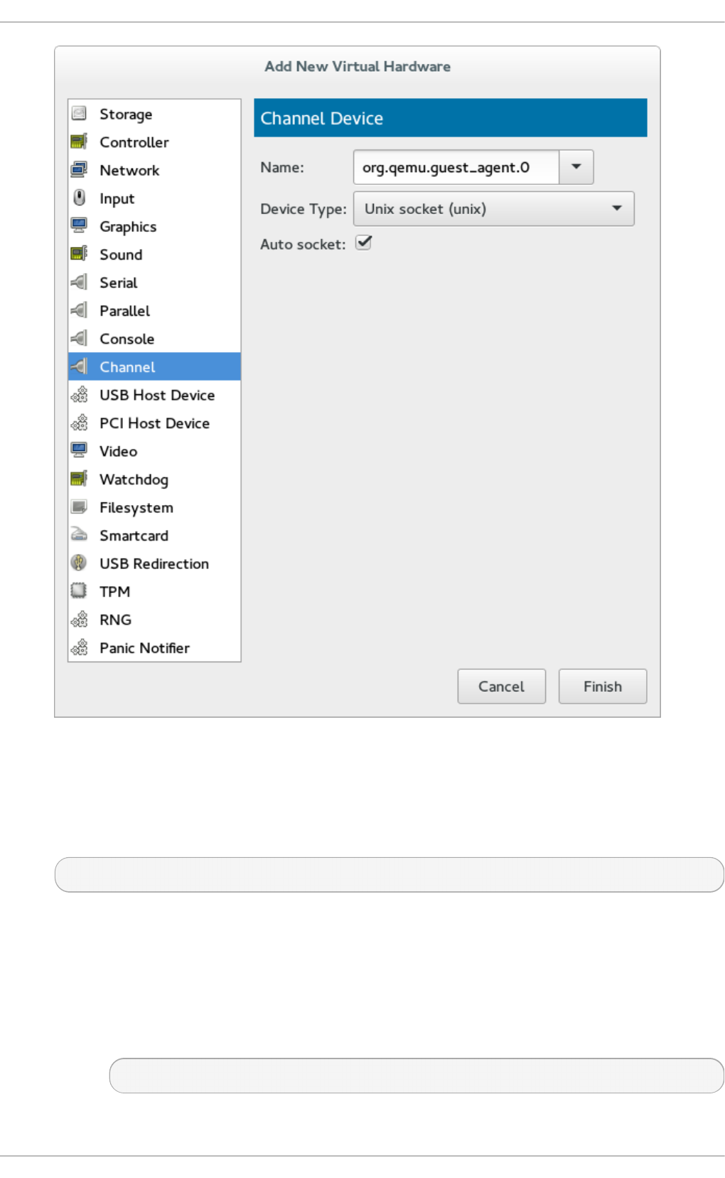
Fig u re 11.2. Select in g t h e Q EMU g u est ag en t ch an nel d evice
4. Bo o t t h e Win d ows g u est
Boot the Windows guest from the host machine to apply the changes:
# virsh start win7x86
5. Prep arin g t h e Q EMU g u est ag en t in t he Win d ows g u est
To prepare the guest agent in the Windows guest:
a. In st all the lat est virtio-win p ackag e
Run the following command on the host to install the virtio-win package:
# yum install virtio-win
Virt ualizat ion Deployment and Administ rat ion G uide
92

b. Co n f irm t h e in st allat ion co mp let ed
After the virtio-win package finishes installing, check the /usr/share/virtio-
win/guest-agent/ folder and you will find an file named qemu-ga-x64.msi or
qemu-ga-x86.msi as shown:
# ls -l /usr/share/virtio-win/guest-agent/
total 1544
-rw-r--r--. 1 root root 856064 Oct 23 04:58 qemu-ga-x64.msi
-rw-r--r--. 1 root root 724992 Oct 23 04:58 qemu-ga-x86.msi
c. In st all t he .msi f ile
From the Windows guest, install the qemu-ga-x64.msi or qemu-ga-x86.msi file by
double clicking on the file. Once installed, it will be shown as a qemu-guest-agent
service in the Windows guest within the Syst em Man ag er. This same manager can
be used to monitor the status of the service.
11.2. Using t he QEMU guest agent wit h libvirt
Installing the QEMU guest agent allows various libvirt commands to become more powerful. The
guest agent enhances the following virsh commands:
virsh shutdown --mode=agent - This shutdown method is more reliable than vi rsh
shutdown --mode=acpi, as virsh shutdown used with the QEMU guest agent is
guaranteed to shut down a cooperative guest in a clean state. If the agent is not present, libvirt
must instead rely on injecting an ACPI shutdown event, but some guests ignore that event and
thus will not shut down.
Can be used with the same syntax for vi rsh rebo o t.
virsh snapshot-create --quiesce - Allows the guest to flush its I/O into a stable state
before the snapshot is created, which allows use of the snapshot without having to perform a fsck
or losing partial database transactions. The guest agent allows a high level of disk contents
stability by providing guest co-operation.
virsh domfsfreeze and virsh domfsthaw - Quiesces the guest filesystem in isolation.
virsh domfstrim - Instructs the guest to trim its filesystem.
virsh domtime - Queries or sets the guest's clock.
virsh setvcpus --guest - Instructs the guest to take CPUs offline.
virsh domifaddr --source agent - Queries the guest operating system's IP address via
the guest agent.
virsh domfsinfo - Shows a list of mounted filesystems within the running guest.
virsh set-user-password - Sets the password for a user account in the guest.
11.2.1. Creat ing a guest disk backup
Chapt er 1 1 . Enhancin g virt ualiz at ion wit h t he Q EMU guest agen t and SPICE agent
93

libvirt can communicate with qemu-guest-agent to ensure that snapshots of guest virtual machine file
systems are consistent internally and ready to use as needed. Guest system administrators can write
and install application-specific freeze/thaw hook scripts. Before freezing the filesystems, the qemu-
guest-agent invokes the main hook script (included in the qemu-guest-agent package). The freezing
process temporarily deactivates all guest virtual machine applications.
The snapshot process is comprised of the following steps:
File system applications / databases flush working buffers to the virtual disk and stop accepting
client connections
Applications bring their data files into a consistent state
Main hook script returns
qemu-guest-agent freezes the filesystems and the management stack takes a snapshot
Snapshot is confirmed
Filesystem function resumes
Thawing happens in reverse order.
To create a snapshot of the guest's file system, run the virsh snapshot-create --quiesce --
disk-only command (alternatively, run virsh snapshot-create-as guest_name --
quiesce --disk-only, explained in further detail in Section 23.19.2, “Creating a snapshot for
the current guest virtual machine” ).
Note
An application-specific hook script might need various SELinux permissions in order to run
correctly, as is done when the script needs to connect to a socket in order to talk to a
database. In general, local SELinux policies should be developed and installed for such
purposes. Accessing file system nodes should work out of the box, after issuing the
restorecon -FvvR command listed in Table 11.1, “QEMU guest agent package contents” in
the table row labeled /etc/qemu-ga/fsfreeze-hook.d/.
The qemu-guest-agent binary RPM includes the following files:
T ab le 11.1. Q EMU g u est ag en t packag e co n ten t s
File n ame Descrip t io n
/usr/lib/systemd/system/qemu-guest-
agent.service
Service control script (start/stop) for the QEMU
guest agent.
/etc/sysconfig/qemu-ga Configuration file for the QEMU guest agent, as
it is read by the
/usr/lib/systemd/system/qemu-guest-
agent.service control script. The settings are
documented in the file with shell script
comments.
/usr/bin/qemu-ga QEMU guest agent binary file.
/etc/qemu-ga Root directory for hook scripts.
/etc/qemu-ga/fsfreeze-hook Main hook script. No modifications are needed
here.
Virt ualizat ion Deployment and Administ rat ion G uide
94

/etc/qemu-ga/fsfreeze-hook.d Directory for individual, application-specific
hook scripts. The guest system administrator
should copy hook scripts manually into this
directory, ensure proper file mode bits for them,
and then run restorecon -FvvR on this
directory.
/usr/share/qemu-kvm/qemu-ga/ Directory with sample scripts (for example
purposes only). The scripts contained here are
not executed.
File n ame Descrip t io n
The main hook script, /etc/qemu-ga/fsfreeze-hook logs its own messages, as well as the
application-specific script's standard output and error messages, in the following log file:
/var/log/qemu-ga/fsfreeze-hook.log. For more information, refer to the qemu-guest-agent
wiki page at wiki.qemu.org or libvirt.org.
11.3. SPICE agent
The SPICE agent helps run graphical applications such as virt - ma n ag er more smoothly, by
helping integrate the guest operating system with the SPICE client.
For example, when resizing a window in virt - ma n ag er, the SPICE agent allows for automatic X
session resolution adjustment to the client resolution. The SPICE agent also provides support for
copy and paste between the host and guest, and prevents mouse cursor lag.
For system-specific information on the SPICE agent's capabilities, see the spice-vdagent package's
README file.
11.3.1. Set t ing up communicat ion bet ween t he SPICE agent and host
The SPICE agent can be configured on a running or shut down virtual machine. If configured on a
running guest, the guest will start using the guest agent immediately. If the guest is shut down, the
SPICE agent will be enabled at next boot.
Either virsh or virt - man ag er can be used to configure communication between the guest and the
SPICE agent. The following instructions describe how to configure the SPICE agent on a Linux guest.
Pro ced ure 11.5. Set t ing up co mmu nicat io n bet ween g u est ag en t an d h o st wit h vi rsh
o n a Lin u x g u est
1. Sh u t down t h e virt ual mach in e
Ensure the virtual machine (named rhel7 in this example) is shut down before configuring the
SPICE agent:
# virsh shutdown rhel7
2. Ad d t h e SPICE ag en t ch an n el t o t he g u est XML co n f ig u rat io n
Edit the guest's XML file to add the SPICE agent details:
# virsh edit rhel7
Add the following to the guest's XML file and save the changes:
Chapt er 1 1 . Enhancin g virt ualiz at ion wit h t he Q EMU guest agen t and SPICE agent
95

<channel type='spicevmc'>
<target type='virtio' name='com.redhat.spice.0'/>
</channel>
3. St art t he virt ual mach in e
# virsh start rhel7
4. In st all t he SPICE ag en t o n t h e g u est
Install the SPICE agent if not yet installed in the guest virtual machine:
# yum install spice-vdagent
5. St art t he SPICE ag en t in t h e g u est
Start the SPICE agent service in the guest:
# systemctl start spice-vdagent
Alternatively, the SPICE agent can be configured on a running guest with the following steps:
Pro ced ure 11.6 . Set tin g u p co mmu n icat io n b et ween SPICE ag en t an d h o st on a ru n nin g
Lin u x g u est
1. Creat e an XML f ile f o r t h e SPIC E ag en t
# cat agent.xml
<channel type='spicevmc'>
<target type='virtio' name='com.redhat.spice.0'/>
</channel>
2. At t ach t h e SPICE ag en t t o t h e virt u al mach in e
Attach the SPICE agent to the running virtual machine (named rhel7 in this example) with this
command:
# virsh attach-device rhel7 agent.xml
3. In st all the SPICE ag en t o n t h e g u est
Install the SPICE agent if not yet installed in the guest virtual machine:
# yum install spice-vdagent
4. St art t h e SPICE ag en t in t h e g u est
Start the SPICE agent service in the guest:
# systemctl start spice-vdagent
Virt ualizat ion Deployment and Administ rat ion G uide
96
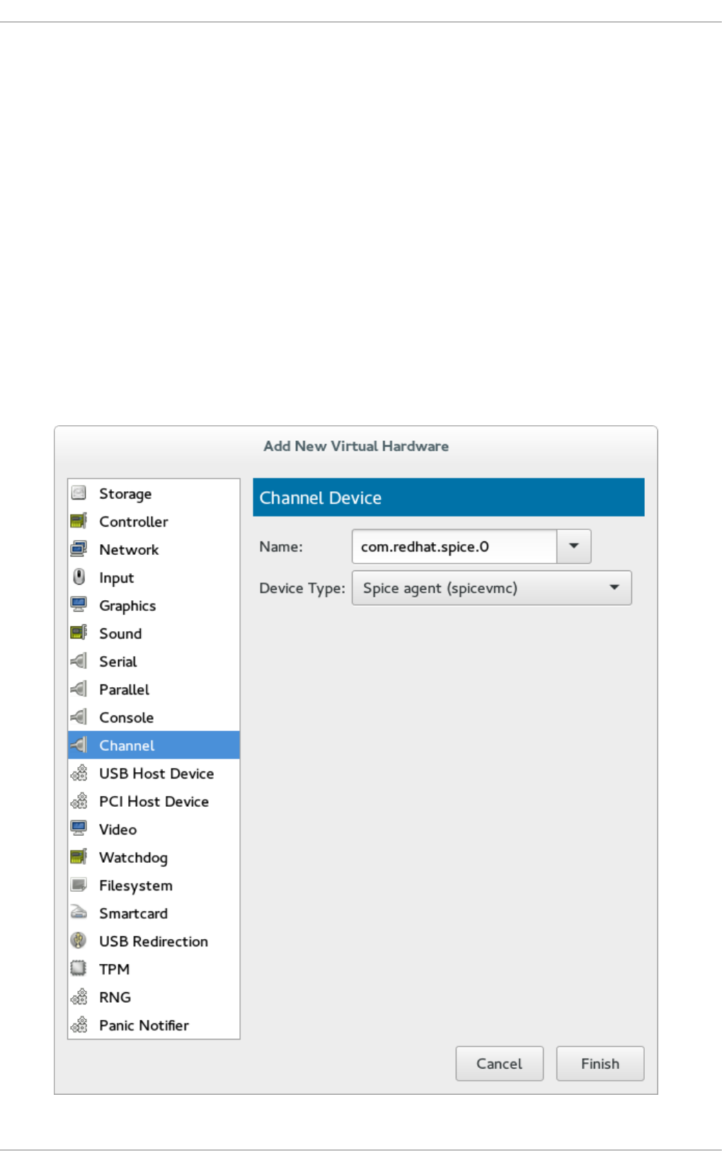
Pro ced ure 11.7. Set t ing up co mmu nicat io n bet ween t h e SPICE ag en t an d h o st wit h
virt-manager
1. Sh u t down t h e virt ual mach in e
Ensure the virtual machine is shut down before configuring the SPICE agent.
To shut down the virtual machine, select it from the list of virtual machines in Virt u a l
Mach in e Man ag er, then click the light switch icon from the menu bar.
2. Ad d t h e SPICE ag en t ch an n el t o t he g u est
Open the virtual machine's hardware details by clicking the lightbulb icon at the top of the
guest window.
Click the Add Hardware button to open the Add New Virtual Hardware window, and
select Channel.
Select the SPICE agent from the Name drop-down list and click Finish:
Chapt er 1 1 . Enhancin g virt ualiz at ion wit h t he Q EMU guest agen t and SPICE agent
97

Fig u re 11.3. Select in g t h e SPICE ag en t ch an n el d evice
3. St art t he virt ual mach in e
To start the virtual machine, select it from the list of virtual machines in Virt u al Mach in e
Man ag er, then click the triangle (play) icon from the menu bar.
4. In st all t he SPICE ag en t o n t h e g u est
Open the guest with virt - man ag er and install the SPICE agent if not yet installed in the guest
virtual machine:
# yum install spice-vdagent
5. St art t he SPICE ag en t in t h e g u est
Start the SPICE agent service in the guest:
# systemctl start spice-vdagent
The SPICE agent is now configured on the rhel7 virtual machine.
Virt ualizat ion Deployment and Administ rat ion G uide
98

Chapter 12. Nested Virtualization
12.1. Overview
As of Red Hat Enterprise Linux 7.2, nested virtualization is available as a Technology Preview for KVM
guest virtual machines. With this feature, a guest virtual machine (also referred to as level 1 or L1)
running on a physical host (level 0 or L0) can act as a hypervisor, and create its own (L2) guest
virtual machines.
Nested virtualization is useful in a variety of scenarios, such as debugging hypervisors in a
constrained environment and testing larger virtual deployments on a limited amount of physical
resources.
Nested virtualization is supported on Intel and AMD processors.
12.2. Set up
Follow these steps to enable, configure, and start using nested virtualization:
1. The feature is disabled by default. To e n ab le it, use the following procedure on the L0 host
physical machine.
Fo r In t el:
a. Check whether nested virtualization is available on your system.
$ cat /sys/module/kvm_intel/parameters/nested
If this command returns Y or 1, the feature is enabled.
If the command returns 0 or N, use steps 2 and 3.
b. Unload the kvm_intel module:
# modprobe -r kvm_intel
c. Activate the nesting feature:
# modprobe kvm_intel nested=1
d. The nesting feature is now enabled only until the next reboot of the L0 host. To enable
it permanently, add the following line to the /etc/modprobe.d/kvm.conf file:
options kvm_intel nested=1
Fo r AMD :
a. Check whether nested virtualization is available on your system:
$catq /sys/module/kvm_amd/parameters/nested
If this command returns "Y" or "1", the feature is enabled.
If the command returns " 0" or "N", use steps 2 and 3.
Chapt er 1 2 . Nest ed Virt ualizat ion
99
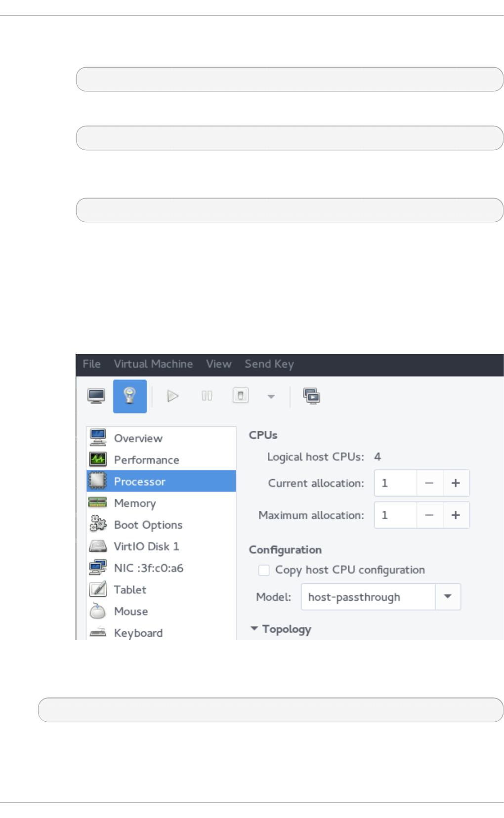
b. Unload the kvm_amd module
# modprobe -r kvm_amd
c. Activate the nesting feature
# modprobe kvm_amd nested=1
d. The nesting feature is now enabled only until the next reboot of the L0 host. To enable
it permanently, add the following line to the /etc/modprobe.d/kvm.conf file:
options kvm_amd nested=1
2. Afterwards, co n f ig u re your L1 virtual machine for nested virtualization using one of the
following methods:
virt - man ag er
a. Open the GUI of the desired guest and click the Show Virtual Hardware Details icon.
b. Select the Processor menu, and in the Configuration section, type host-passthrough
in the Model field (do not use the drop-down selection), and click Apply.
Do main XML
Add the following line to the domain XML file of the guest:
<cpu mode='host-passthrough'/>
If the XML file already contains a <cpu> element, rewrite it.
Virt ualizat ion Deployment and Administ rat ion G uide
100

3. To st art u sin g nested virtualization, install an L2 guest within the L1 guest. To do this,
follow the same procedure as when installing the L1 guest - see Chapter 3, Installing a virtual
machine for more information.
12.3. Rest rict ions and Limit at ions
As of Red Hat Enterprise Linux 7.2, it is strongly recommended to run Red Hat Enterprise Linux 7.2 or
later in the L0 host and the L1 guests. L2 guests can contain any of the supported systems.
It is not supported to migrate L2 guests.
Use of L2 guests as hypervisors and creating L3 guests is not supported.
Not all features available on the host are available to be utilized by the L1 hypervisor. For instance,
IOMMU/VT-d or APICv cannot be used by the L1 hypervisor.
It is not possible to use nested virtualization or a subset of it if the host CPU is missing the necessary
feature flags. For example, if the host CPU does not support Extended Page Tables (EPT), then the L1
hypervisor will not be able to use it.
To determine if the L0 and L1 hypervisors are set up correctly, use the $ cat /proc/cpuinfo
command on both L0 and L1, and make sure that the following flags are listed for the respective
CPUs on both hypervisors:
For Intel - vmx (Hardware Virtualization)
For AMD - svm (equivalent to vmx)
Chapt er 1 2 . Nest ed Virt ualizat ion
101

Part II. Administration
Virt ualizat ion Deployment and Administ rat ion G uide
102

Chapter 13. Securing the host physical machine and improving
performance
The following tasks and tips can assist you with increasing the performance of your Red Hat
Enterprise Linux host.
Run SELinux in enforcing mode. Set SELinux to run in enforcing mode with the setenforce
command.
# setenforce 1
Remove or disable any unnecessary services such as AutoFS, NFS, FTP, HTTP, NIS, tel netd ,
sendmail and so on.
Only add the minimum number of user accounts needed for platform management on the server
and remove unnecessary user accounts.
Avoid running any unessential applications on your host. Running applications on the host may
impact virtual machine performance and can affect server stability. Any application which may
crash the server will also cause all virtual machines on the server to go down.
Use a central location for virtual machine installations and images. Virtual machine images
should be stored under /var/lib/libvirt/images/. If you are using a different directory for
your virtual machine images make sure you add the directory to your SELinux policy and relabel
it before starting the installation. Use of shareable, network storage in a central location is highly
recommended.
Note
Additional performance tips can be found in the Red Hat Enterprise Linux Virtualization Tuning and
Optimization Guide.
Additional security tips can be found in the Red Hat Enterprise Linux Virtualization Security Guide.
Both of these guides can be found at https://access.redhat.com/site/documentation/.
13.1. Securit y Deployment Plan
When deploying virtualization technologies, you must ensure that the host physical machine and its
operating system cannot be compromised. In this case the host physical machine is a Red Hat
Enterprise Linux system that manages the system, devices, memory and networks as well as all guest
virtual machines. If the host physical machine is insecure, all guest virtual machines in the system
are vulnerable. There are several ways to enhance security on systems using virtualization. You or
your organization should create a Deployment Plan. This plan needs to contain the following:
Operating specifications
Specifies which services are needed on your guest virtual machines
Specifies the host physical servers as well as what support is required for these services
Here are a few security issues to consider while developing a deployment plan:
Chapt er 1 3. Securing t he host physical machin e and improving performance
103

Run only necessary services on host physical machines. The fewer processes and services
running on the host physical machine, the higher the level of security and performance.
Enable SELinux on the hypervisor. Refer to the Red Hat Enterprise Linux Virtualization Security Guide
for more information on using SELinux and virtualization.
Use a firewall to restrict traffic to the host physical machine. You can setup a firewall with default-
reject rules that will help secure the host physical machine from attacks. It is also important to limit
network-facing services.
Do not allow normal users to access the host operating system. If the host operating system is
privileged, granting access to unprivileged accounts may compromise the level of security.
13.2. Client access cont rol
libvirt's client access control framework allows system administrators to setup fine grained permission
rules across client users, managed objects, and API operations. This allows client connections to be
locked down to a minimal set of privileges.
In a default configuration, the libvirtd daemon has three levels of access control. All connections start
off in an unauthenticated state, where the only API operations allowed are those required to complete
authentication. After successful authentication, a connection either has full, unrestricted access to all
libvirt API calls, or is locked down to only "read only" operations, according to what socket the client
connection originated on. The access control framework allows authenticated connections to have
fine grained permission rules to be defined by the administrator. Every API call in libvirt has a set of
permissions that will be validated against the object being used. Further permissions will also be
checked if certain flags are set in the API call. In addition to checks on the object passed in to an API
call, some methods will filter their results.
13.2.1. Access cont rol drivers
The access control framework is designed as a pluggable system to enable future integration with
arbitrary access control technologies. By default, the none driver is used, which does no access
control checks at all. At this time, libvirt ships with support for using polkit as a real access control
driver. To learn how to use the polkit access driver refer to the configuration documentation.
The access driver is configured in the libvirtd.conf configuration file, using the access_drivers
parameter. This parameter accepts an array of access control driver names. If more than one access
driver is requested, then all must succeed in order for access to be granted. To enable 'polkit' as the
driver run the command:
# augtool -s set '/files/etc/libvirt/libvirtd.conf/access_drivers[1]'
po l ki t
To set the driver back to the default (no access control), run the following command:
# augtool -s rm /files/etc/libvirt/libvirtd.conf/access_drivers
It should be noted that changes made to libvirtd.conf require that the libvirtd daemon be restarted.
13.2.2. Object s and permissions
Virt ualizat ion Deployment and Administ rat ion G uide
104

libvirt applies access control to all the main object types in its API. Each object type, in turn, has a set
of permissions defined. To determine what permissions are checked for specific API call, consult the
API reference manual documentation for the API in question. For the complete list of objects and
permissions, refer to libvirt.org.
Chapt er 1 3. Securing t he host physical machin e and improving performance
105

Chapter 14. Storage pools
This chapter includes instructions on creating storage pools of assorted types. A storage pool is a
quantity of storage set aside by an administrator, often a dedicated storage administrator, for use by
guest virtual machines. Storage pools are divided into storage volumes either by the storage
administrator or the system administrator, and the volumes are then assigned to guest virtual
machines as block devices.
For example, the storage administrator responsible for an NFS server creates a shared disk to store
all of the guest virtual machines' data. The system administrator would define a storage pool on the
virtualization host using the details of the shared disk. In this example, the administrator may want
nfs.example.com:/path/to/share to be mounted on /vm_data). When the storage pool is
started, libvirt mounts the share on the specified directory, just as if the system administrator logged in
and executed mount nfs.example.com:/path/to/share /vmdata. If the storage pool is
configured to autostart, libvirt ensures that the NFS shared disk is mounted on the directory specified
when libvirt is started.
Once the storage pool is started, the files in the NFS shared disk are reported as storage volumes,
and the storage volumes' paths may be queried using the libvirt APIs. The storage volumes' paths
can then be copied into the section of a guest virtual machine's XML definition describing the source
storage for the guest virtual machine's block devices.In the case of NFS, an application using the
libvirt APIs can create and delete storage volumes in the storage pool (files in the NFS share) up to
the limit of the size of the pool (the storage capacity of the share). Not all storage pool types support
creating and deleting volumes. Stopping the storage pool (pool-destroy) undoes the start operation,
in this case, unmounting the NFS share. The data on the share is not modified by the destroy
operation, despite what the name of the command suggests. See man virsh for more details.
A second example is an iSCSI storage pool. A storage administrator provisions an iSCSI target to
present a set of LUNs to the host running the virtual machines. When libvirt is configured to manage
that iSCSI target as a storage pool, libvirt will ensure that the host logs into the iSCSI target and libvirt
can then report the available LUNs as storage volumes. The storage volumes' paths can be queried
and used in virtual machines' XML definitions as in the NFS example. In this case, the LUNs are
defined on the iSCSI server, and libvirt cannot create and delete volumes.
Storage pools and volumes are not required for the proper operation of guest virtual machines.
Storage pools and volumes provide a way for libvirt to ensure that a particular piece of storage will be
available for a guest virtual machine. On systems that do not use storage pools, system
administrators must ensure the availability of the guest virtual machine's storage, for example,
adding the NFS share to the host physical machine's fstab so that the share is mounted at boot
time.
One of the advantages of using libvirt to manage storage pools and volumes is libvirt's remote
protocol, so it is possible to manage all aspects of a guest virtual machine's life cycle, as well as the
configuration of the resources required by the guest virtual machine. These operations can be
performed on a remote host entirely within the libvirt API. As a result, a management application using
libvirt can enable a user to perform all the required tasks for configuring the host physical machine for
a guest virtual machine such as: allocating resources, running the guest virtual machine, shutting it
down and de-allocating the resources, without requiring shell access or any other control channel.
Although the storage pool is a virtual container it is limited by two factors: maximum size allowed to it
by qemu-kvm and the size of the disk on the host machine. Storage pools may not exceed the size of
the disk on the host machine. The maximum sizes are as follows:
virtio-blk = 2^63 bytes or 8 Exabytes(using raw files or disk)
Ext4 = ~ 16 TB (using 4 KB block size)
Virt ualizat ion Deployment and Administ rat ion G uide
106

XFS = ~8 Exabytes
qcow2 and host file systems keep their own metadata and scalability should be evaluated/tuned
when trying very large image sizes. Using raw disks means fewer layers that could affect
scalability or max size.
libvirt uses a directory-based storage pool, the /var/lib/libvirt/images/ directory, as the
default storage pool. The default storage pool can be changed to another storage pool.
Lo cal st o rag e p o o ls - Local storage pools are directly attached to the host physical machine
server. Local storage pools include: local directories, directly attached disks, physical partitions,
and LVM volume groups. These storage volumes store guest virtual machine images or are
attached to guest virtual machines as additional storage. As local storage pools are directly
attached to the host physical machine server, they are useful for development, testing and small
deployments that do not require migration or large numbers of guest virtual machines. Local
storage pools are not suitable for many production environments as local storage pools do not
support live migration.
Net wo rked ( sh ared ) st o rag e p o o ls - Networked storage pools include storage devices
shared over a network using standard protocols. Networked storage is required when migrating
virtual machines between host physical machines with virt-manager, but is optional when
migrating with virsh. Networked storage pools are managed by libvirt. Supported protocols for
networked storage pools include:
Fibre Channel-based LUNs
iSCSI
NFS
GFS2
SCSI RDMA protocols (SCSI RCP), the block export protocol used in InfiniBand and 10GbE
iWARP adapters.
Note
Multi-path storage pools should not be created or used as they are not fully supported.
Examp le 14 .1. NFS st o rag e p o o l
Suppose a storage administrator responsible for an NFS server creates a share to store guest
virtual machines' data. The system administrator defines a pool on the host physical machine with
the details of the share (nfs.example.com:/path/to/share should be mounted on /vm_data).
When the pool is started, libvirt mounts the share on the specified directory, just as if the system
administrator logged in and executed mount nfs.example.com:/path/to/share /vmdata.
If the pool is configured to autostart, libvirt ensures that the NFS share is mounted on the directory
specified when libvirt is started.
Once the pool starts, the files that the NFS share, are reported as volumes, and the storage
volumes' paths are then queried using the libvirt APIs. The volumes' paths can then be copied into
the section of a guest virtual machine's XML definition file describing the source storage for the
guest virtual machine's block devices. With NFS, applications using the libvirt APIs can create and
delete volumes in the pool (files within the NFS share) up to the limit of the size of the pool (the
Chapt er 1 4 . St orag e po ols
107

maximum storage capacity of the share). Not all pool types support creating and deleting volumes.
Stopping the pool negates the start operation, in this case, unmounts the NFS share. The data on
the share is not modified by the destroy operation, despite the name. See man virsh for more
details.
Note
Storage pools and volumes are not required for the proper operation of guest virtual
machines. Pools and volumes provide a way for libvirt to ensure that a particular piece of
storage will be available for a guest virtual machine, but some administrators will prefer to
manage their own storage and guest virtual machines will operate properly without any pools
or volumes defined. On systems that do not use pools, system administrators must ensure the
availability of the guest virtual machines' storage using whatever tools they prefer, for
example, adding the NFS share to the host physical machine's fstab so that the share is
mounted at boot time.
14 .1. Disk-based st orage pools
This section covers creating disk based storage devices for guest virtual machines.
Warning
Guests should not be given write access to whole disks or block devices (for example,
/dev/sdb). Use partitions (for example, /dev/sdb1) or LVM volumes.
If you pass an entire block device to the guest, the guest will likely partition it or create its own
LVM groups on it. This can cause the host physical machine to detect these partitions or LVM
groups and cause errors.
14 .1.1. Creat ing a disk based st orage pool using virsh
This procedure creates a new storage pool using a disk device with the virsh command.
Warning
Dedicating a disk to a storage pool will reformat and erase all data presently stored on the
disk device. It is strongly recommended to back up the data on the storage device before
commencing with the following procedure:
1. Creat e a G PT d isk lab el o n t h e d isk
The disk must be relabeled with a GUID Partition Table (GPT) disk label. GPT disk labels allow
for creating a large numbers of partitions, up to 128 partitions, on each device. GPT partition
tables can store partition data for far more partitions than the MS-DOS partition table.
# parted /dev/sdb
Virt ualizat ion Deployment and Administ rat ion G uide
108

GNU Parted 2.1
Using /dev/sdb
Welcome to GNU Parted! Type 'help' to view a list of commands.
(parted) mklabel
New disk label type? gpt
(parted) quit
Information: You may need to update /etc/fstab.
#
2. Creat e t h e st orag e p o o l co n f ig u rat io n f ile
Create a temporary XML text file containing the storage pool information required for the new
device.
The file must be in the format shown below, and contain the following fields:
<n ame>g u est _imag e s_d isk</n ame>
The name parameter determines the name of the storage pool. This example uses
the name guest_images_disk in the example below.
<d evice p at h = ' /dev/sdb' />
The device parameter with the path attribute specifies the device path of the
storage device. This example uses the device /dev/sdb.
<t arg et > <p at h >/dev</p at h ></t a rg e t >
The file system target parameter with the path sub-parameter determines the
location on the host physical machine file system to attach volumes created with
this storage pool.
For example, sdb1, sdb2, sdb3. Using /dev/, as in the example below, means
volumes created from this storage pool can be accessed as /dev/sdb1, /dev/sdb2,
/dev/sdb3.
<f o rmat typ e= ' gpt' />
The format parameter specifies the partition table type. This example uses the gpt
in the example below, to match the GPT disk label type created in the previous step.
Create the XML file for the storage pool device with a text editor.
Examp le 14 .2. Disk b ased st o rag e d evice st o rag e p o o l
<pool type='disk'>
<name>guest_images_disk</name>
<source>
<device path='/dev/sdb'/>
<format type='gpt'/>
</source>
<target>
<path>/dev</path>
</target>
</pool>
Chapt er 1 4 . St orag e po ols
109

3. At t ach t h e d evice
Add the storage pool definition using the virsh pool-define command with the XML
configuration file created in the previous step.
# virsh pool-define ~/guest_images_disk.xml
Pool guest_images_disk defined from /root/guest_images_disk.xml
# virsh pool-list --all
Name State Autostart
-----------------------------------------
default active yes
guest_images_disk inactive no
4. St art t h e st o rag e p o o l
Start the storage pool with the vi rsh po o l -start command. Verify the pool is started with
the virsh pool-list --all command.
# virsh pool-start guest_images_disk
Pool guest_images_disk started
# virsh pool-list --all
Name State Autostart
-----------------------------------------
default active yes
guest_images_disk active no
5. Turn o n au t o st art
Turn on autostart for the storage pool. Autostart configures the l i bvi rtd service to start
the storage pool when the service starts.
# virsh pool-autostart guest_images_disk
Pool guest_images_disk marked as autostarted
# virsh pool-list --all
Name State Autostart
-----------------------------------------
default active yes
guest_images_disk active yes
6. Verif y t h e st o rag e p o o l co n f ig u rat io n
Verify the storage pool was created correctly, the sizes reported correctly, and the state
reports as running.
# virsh pool-info guest_images_disk
Name: guest_images_disk
UUID: 551a67c8-5f2a-012c-3844-df29b167431c
State: running
Capacity: 465.76 GB
Allocation: 0.00
Available: 465.76 GB
# ls -la /dev/sdb
Virt ualizat ion Deployment and Administ rat ion G uide
110

brw-rw----. 1 root disk 8, 16 May 30 14:08 /dev/sdb
# virsh vol-list guest_images_disk
Name Path
-----------------------------------------
7. O p t io n al: Remo ve t h e t emp o rary co n f ig u rat io n f ile
Remove the temporary storage pool XML configuration file if it is not needed anymore.
# rm ~/guest_images_disk.xml
A disk based storage pool is now available.
14 .1.2. Delet ing a st orage pool using virsh
The following demonstrates how to delete a storage pool using virsh:
1. To avoid any issues with other guest virtual machines using the same pool, it is best to stop
the storage pool and release any resources in use by it.
# virsh pool-destroy guest_images_disk
2. Remove the storage pool's definition
# virsh pool-undefine guest_images_disk
14 .2. Part it ion-based st orage pools
This section covers using a pre-formatted block device, a partition, as a storage pool.
For the following examples, a host physical machine has a 500GB hard drive (/dev/sdc)
partitioned into one 500GB, ext4 formatted partition (/dev/sdc1). We set up a storage pool for it
using the procedure below.
14 .2.1. Creat ing a part it ion-based st orage pool using virt -manager
This procedure creates a new storage pool using a partition of a storage device.
Pro ced ure 14 .1. Creat ing a p art it ion- b ased st o rag e po o l wit h virt - man ag er
1. O p en t h e st o rag e p o o l set t ings
a. In the virt-manager graphical interface, select the host physical machine from the
main window.
Open the Ed i t menu and select C o nnecti o n D etai l s
Chapt er 1 4 . St orag e po ols
111
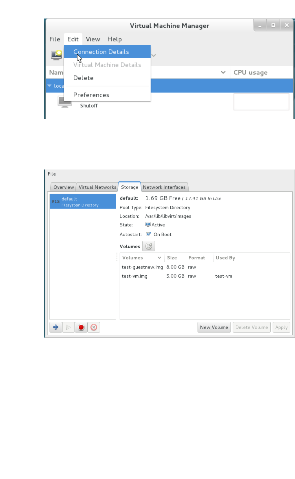
Fig u re 14 .1. Co nn ect ion Det ails
b. Click on the Sto rag e tab of the C o nnecti on D etai l s window.
Fig u re 14 .2. St o rag e t ab
2. Creat e t h e n ew st o rag e p o o l
a. Ad d a n ew p o o l (part 1)
Press the + button (the add pool button). The Add a New Storage Pool wizard
appears.
Choose a Name for the storage pool. This example uses the name guest_images_fs.
Change the Type to fs: Pre-Formatted Block Device.
Virt ualizat ion Deployment and Administ rat ion G uide
112
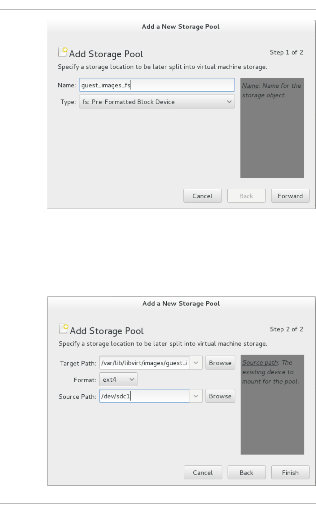
Fig u re 14 .3. St o rag e p o o l n ame an d t yp e
Press the Fo rward button to continue.
b. Ad d a n ew p o o l (part 2)
Change the T arg et P ath, Fo rmat, and Source Path fields.
Chapt er 1 4 . St orag e po ols
113
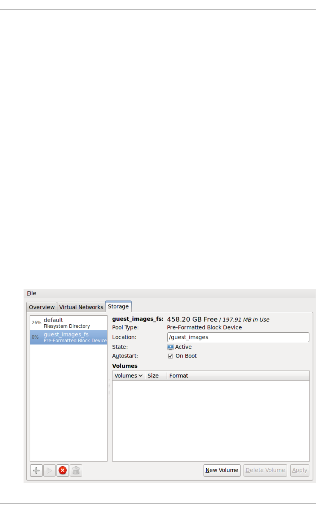
Fig u re 14 .4 . St orag e p o o l p at h an d f o rmat
T arg et Pat h
Enter the location to mount the source device for the storage pool in the
T arg et P ath field. If the location does not already exist, virt-manager
will create the directory.
Fo rmat
Select a format from the Fo rmat list. The device is formatted with the selected
format.
This example uses the ext4 file system, the default Red Hat Enterprise Linux
file system.
So u rce Pat h
Enter the device in the Source Path field.
This example uses the /dev/sdc1 device.
Verify the details and press the Finish button to create the storage pool.
3. Verif y t h e n ew st orag e p o o l
The new storage pool appears in the storage list on the left after a few seconds. Verify the size
is reported as expected, 458.20 GB Free in this example. Verify the State field reports the new
storage pool as Active.
Select the storage pool. In the Auto start field, click the O n Bo o t checkbox. This will make
sure the storage device starts whenever the l i bvi rtd service starts.
Virt ualizat ion Deployment and Administ rat ion G uide
114
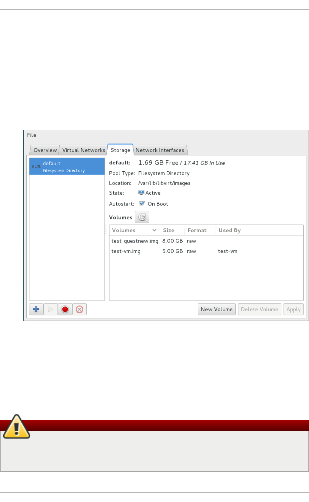
Fig u re 14 .5. St o rag e list co n f irmat io n
The storage pool is now created, close the C o nnecti o n D etai l s window.
14 .2.2. Delet ing a st orage pool using virt -manager
This procedure demonstrates how to delete a storage pool.
1. To avoid any issues with other guest virtual machines using the same pool, it is best to stop
the storage pool and release any resources in use by it. To do this, select the storage pool
you want to stop and click the red X icon at the bottom of the Storage window.
Fig u re 14 .6 . St op Ico n
2. Delete the storage pool by clicking the Trash can icon. This icon is only enabled if you stop
the storage pool first.
14 .2.3. Creat ing a part it ion-based st orage pool using virsh
This section covers creating a partition-based storage pool with the virsh command.
Warning
Do not use this procedure to assign an entire disk as a storage pool (for example,
/dev/sdb). Guests should not be given write access to whole disks or block devices. Only
use this method to assign partitions (for example, /dev/sdb1) to storage pools.
Pro ced ure 14 .2. Creat ing pre- f o rmat t ed b lo ck d evice st o rag e p o o ls u sin g virsh
Chapt er 1 4 . St orag e po ols
115

Pro ced ure 14 .2. Creat ing pre- f o rmat t ed b lo ck d evice st o rag e p o o ls u sin g virsh
1. Creat e t h e st o rag e p o o l d ef init io n
Use the virsh pool-define-as command to create a new storage pool definition. There are
three options that must be provided to define a pre-formatted disk as a storage pool:
Part it io n name
The name parameter determines the name of the storage pool. This example uses
the name guest_images_fs in the example below.
d evice
The device parameter with the path attribute specifies the device path of the
storage device. This example uses the partition /dev/sdc1.
mountpoint
The mountpoint on the local file system where the formatted device will be
mounted. If the mount point directory does not exist, the virsh command can create
the directory.
The directory /guest_images is used in this example.
# virsh pool-define-as guest_images_fs fs - - /dev/sdc1 -
"/guest_images"
Pool guest_images_fs defined
The new pool is now created.
2. Verif y t h e n ew p o ol
List the present storage pools.
# virsh pool-list --all
Name State Autostart
-----------------------------------------
default active yes
guest_images_fs inactive no
3. Creat e t h e mo u n t poin t
Use the vi rsh po o l -bui l d command to create a mount point for a pre-formatted file
system storage pool.
# virsh pool-build guest_images_fs
Pool guest_images_fs built
# ls -la /guest_images
total 8
drwx------. 2 root root 4096 May 31 19:38 .
dr-xr-xr-x. 25 root root 4096 May 31 19:38 ..
# virsh pool-list --all
Name State Autostart
-----------------------------------------
default active yes
guest_images_fs inactive no
Virt ualizat ion Deployment and Administ rat ion G uide
116

4. St art t h e st o rag e p o o l
Use the vi rsh po o l -start command to mount the file system onto the mount point and
make the pool available for use.
# virsh pool-start guest_images_fs
Pool guest_images_fs started
# virsh pool-list --all
Name State Autostart
-----------------------------------------
default active yes
guest_images_fs active no
5. Turn o n au t o st art
By default, a storage pool is defined with virsh is not set to automatically start each time
l i bvi rtd starts. Turn on automatic start with the vi rsh po o l -auto start command. The
storage pool is now automatically started each time l i bvi rtd starts.
# virsh pool-autostart guest_images_fs
Pool guest_images_fs marked as autostarted
# virsh pool-list --all
Name State Autostart
-----------------------------------------
default active yes
guest_images_fs active yes
6. Verif y t h e st o rag e p o o l
Verify the storage pool was created correctly, the sizes reported are as expected, and the state
is reported as running. Verify there is a " lost+found" directory in the mount point on the file
system, indicating the device is mounted.
# virsh pool-info guest_images_fs
Name: guest_images_fs
UUID: c7466869-e82a-a66c-2187-dc9d6f0877d0
State: running
Persistent: yes
Autostart: yes
Capacity: 458.39 GB
Allocation: 197.91 MB
Available: 458.20 GB
# mount | grep /guest_images
/dev/sdc1 on /guest_images type ext4 (rw)
# ls -la /guest_images
total 24
drwxr-xr-x. 3 root root 4096 May 31 19:47 .
dr-xr-xr-x. 25 root root 4096 May 31 19:38 ..
drwx------. 2 root root 16384 May 31 14:18 lost+found
14 .2.4 . Delet ing a st orage pool using virsh
Chapt er 1 4 . St orag e po ols
117

1. To avoid any issues with other guest virtual machines using the same pool, it is best to stop
the storage pool and release any resources in use by it.
# virsh pool-destroy guest_images_disk
2. Optionally, if you want to remove the directory where the storage pool resides use the
following command:
# virsh pool-delete guest_images_disk
3. Remove the storage pool's definition
# virsh pool-undefine guest_images_disk
14 .3. Direct ory-based st orage pools
This section covers storing guest virtual machines in a directory on the host physical machine.
Directory-based storage pools can be created with virt-manager or the virsh command line
tools.
14 .3.1. Creat ing a direct ory-based st orage pool wit h virt -manager
1. Creat e t h e lo cal d irect o ry
a. O p t io n al: C reat e a n ew d irect ory f o r t h e st o rag e p o o l
Create the directory on the host physical machine for the storage pool. This example
uses a directory named /guest virtual machine_images.
# mkdir /guest_images
b. Set d irect ory own ersh ip
Change the user and group ownership of the directory. The directory must be owned
by the root user.
# chown root:root /guest_images
c. Set d irect o ry permissio n s
Change the file permissions of the directory.
# chmod 700 /guest_images
d. Verif y t h e ch an g es
Verify the permissions were modified. The output shows a correctly configured empty
directory.
Virt ualizat ion Deployment and Administ rat ion G uide
118
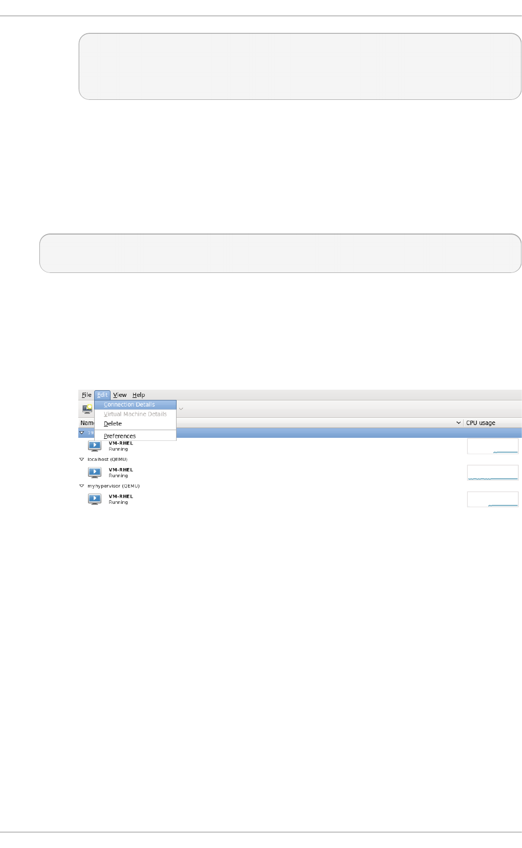
# ls -la /guest_images
total 8
drwx------. 2 root root 4096 May 28 13:57 .
dr-xr-xr-x. 26 root root 4096 May 28 13:57 ..
2. Co n f ig ure SELin u x file co n text s
Configure the correct SELinux context for the new directory. Note that the name of the pool
and the directory do not have to match. However, when you shutdown the guest virtual
machine, libvirt has to set the context back to a default value. The context of the directory
determines what this default value is. It is worth explicitly labeling the directory virt_image_t,
so that when the guest virtual machine is shutdown, the images get labeled 'virt_image_t' and
are thus isolated from other processes running on the host physical machine.
# semanage fcontext -a -t virt_image_t '/guest_images(/.*)?'
# restorecon -R /guest_images
3. O p en t h e st o rag e p o o l set t in gs
a. In the virt-manager graphical interface, select the host physical machine from the
main window.
Open the Ed i t menu and select C o nnecti o n D etai l s
Fig u re 14 .7. Co nn ect ion det ails window
b. Click on the Sto rag e tab of the C o nnecti on D etai l s window.
Chapt er 1 4 . St orag e po ols
119
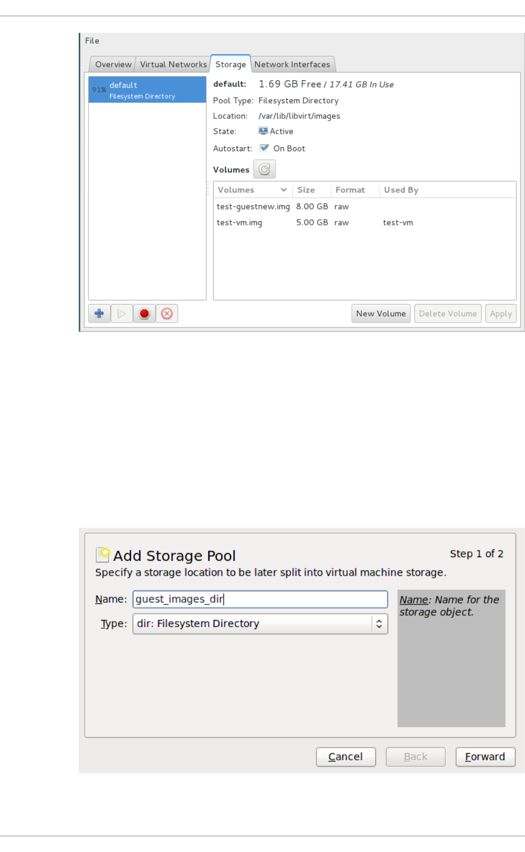
Fig u re 14 .8. St o rag e t ab
4. Creat e t h e n ew st o rag e p o ol
a. Ad d a n ew p o o l (part 1)
Press the + button (the add pool button). The Add a New Storage Pool wizard
appears.
Choose a Name for the storage pool. This example uses the name guest_images.
Change the Type to d i r: Fi l esystem D i recto ry.
Fig u re 14 .9 . Name t h e st o rag e p o o l
Virt ualizat ion Deployment and Administ rat ion G uide
120
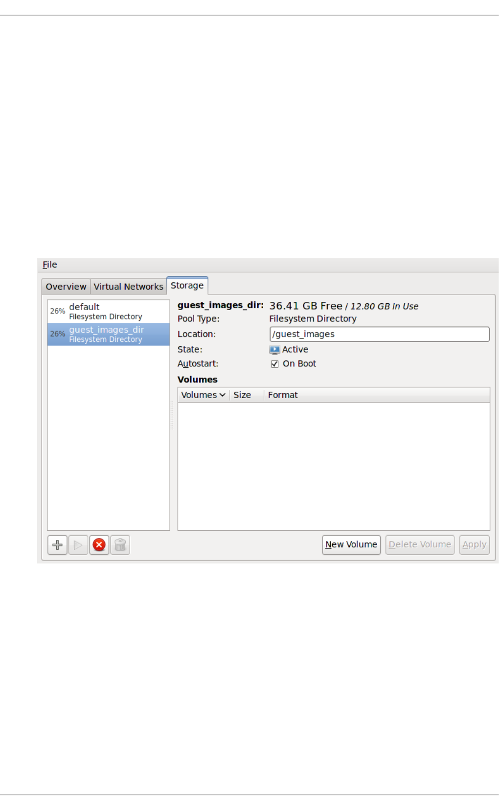
Press the Fo rward button to continue.
b. Ad d a n ew p o o l (part 2)
Change the T arg et P ath field. For example, /guest_images.
Verify the details and press the Finish button to create the storage pool.
5. Verif y t h e n ew st orag e p o o l
The new storage pool appears in the storage list on the left after a few seconds. Verify the size
is reported as expected, 36.41 GB Free in this example. Verify the State field reports the new
storage pool as Active.
Select the storage pool. In the Auto start field, confirm that the O n Bo o t checkbox is
checked. This will make sure the storage pool starts whenever the l i bvi rtd service starts.
Fig u re 14 .10. Verif y th e st orag e p o o l in f o rmat io n
The storage pool is now created, close the C o nnecti o n D etai l s window.
14 .3.2. Delet ing a st orage pool using virt -manager
This procedure demonstrates how to delete a storage pool.
1. To avoid any issues with other guest virtual machines using the same pool, it is best to stop
the storage pool and release any resources in use by it. To do this, select the storage pool
you want to stop and click the red X icon at the bottom of the Storage window.
Chapt er 1 4 . St orag e po ols
121
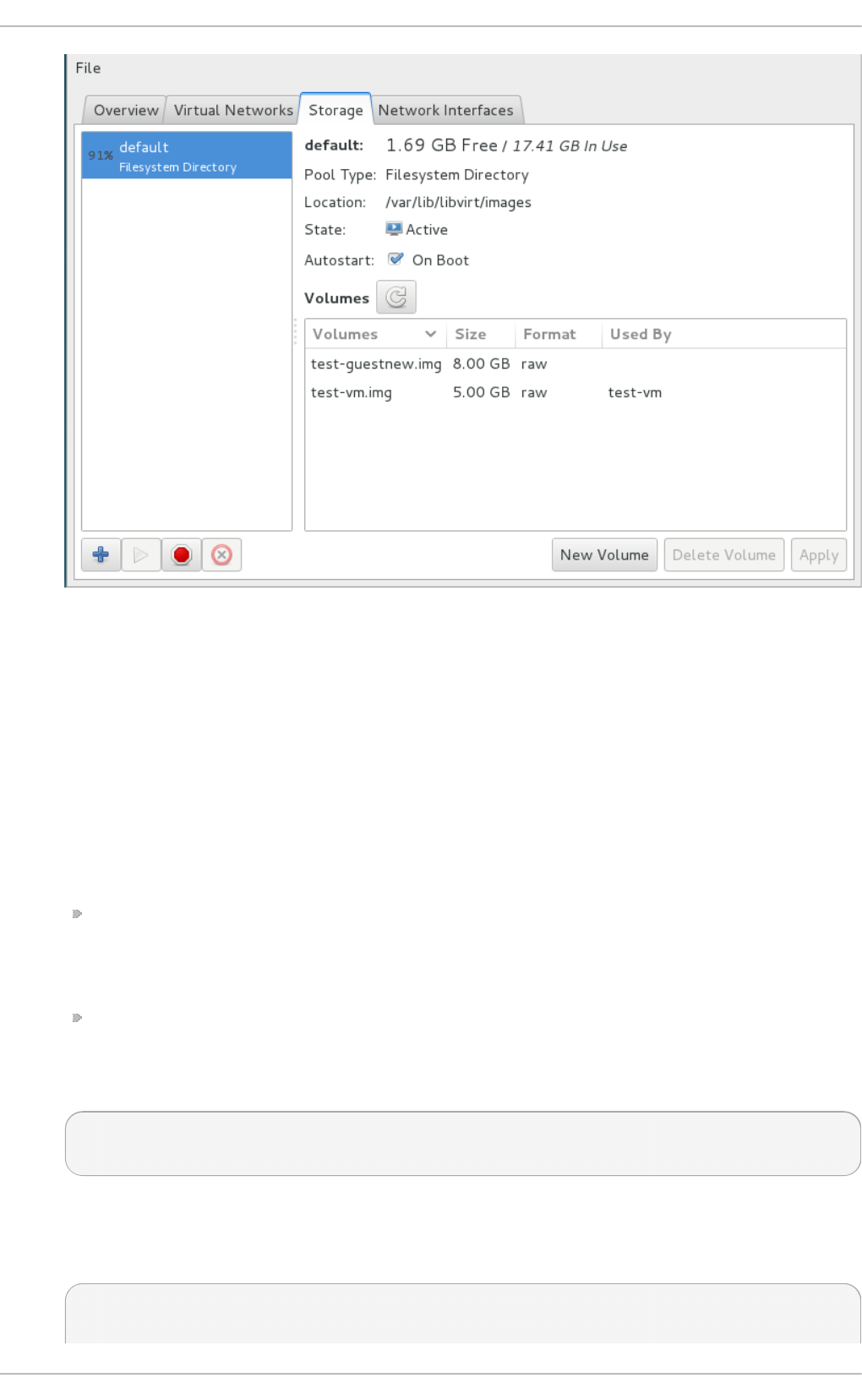
Fig u re 14 .11. St o p Ico n
2. Delete the storage pool by clicking the Trash can icon. This icon is only enabled if you stop
the storage pool first.
14 .3.3. Creat ing a direct ory-based st orage pool wit h virsh
1. Creat e t h e st o rag e p o o l d ef init io n
Use the virsh pool-define-as command to define a new storage pool. There are two
options required for creating directory-based storage pools:
The name of the storage pool.
This example uses the name guest_images. All further virsh commands used in this
example use this name.
The path to a file system directory for storing guest image files. If this directory does not
exist, virsh will create it.
This example uses the /guest_images directory.
# virsh pool-define-as guest_images dir - - - - "/guest_images"
Pool guest_images defined
2. Verif y t h e st o rag e p o o l is list ed
Verify the storage pool object is created correctly and the state reports it as inactive.
# virsh pool-list --all
Name State Autostart
Virt ualizat ion Deployment and Administ rat ion G uide
122

-----------------------------------------
default active yes
guest_images inactive no
3. Creat e t h e lo cal d irect o ry
Use the vi rsh po o l -bui l d command to build the directory-based storage pool for the
directory guest_images (for example), as shown:
# virsh pool-build guest_images
Pool guest_images built
# ls -la /guest_images
total 8
drwx------. 2 root root 4096 May 30 02:44 .
dr-xr-xr-x. 26 root root 4096 May 30 02:44 ..
# virsh pool-list --all
Name State Autostart
-----------------------------------------
default active yes
guest_images inactive no
4. St art t h e st o rag e p o o l
Use the virsh command po o l -start to enable a directory storage pool, thereby allowing
allowing volumes of the pool to be used as guest disk images.
# virsh pool-start guest_images
Pool guest_images started
# virsh pool-list --all
Name State Autostart
-----------------------------------------
default active yes
guest_images active no
5. Turn o n au t o st art
Turn on autostart for the storage pool. Autostart configures the l i bvi rtd service to start
the storage pool when the service starts.
# virsh pool-autostart guest_images
Pool guest_images marked as autostarted
# virsh pool-list --all
Name State Autostart
-----------------------------------------
default active yes
guest_images active yes
6. Verif y t h e st o rag e p o o l co n f ig u rat io n
Verify the storage pool was created correctly, the size is reported correctly, and the state is
reported as running. If you want the pool to be accessible even if the guest virtual machine
is not running, make sure that P ersi stent is reported as yes. If you want the pool to start
automatically when the service starts, make sure that Auto start is reported as yes.
Chapt er 1 4 . St orag e po ols
123

# virsh pool-info guest_images
Name: guest_images
UUID: 779081bf-7a82-107b-2874-a19a9c51d24c
State: running
Persistent: yes
Autostart: yes
Capacity: 49.22 GB
Allocation: 12.80 GB
Available: 36.41 GB
# ls -la /guest_images
total 8
drwx------. 2 root root 4096 May 30 02:44 .
dr-xr-xr-x. 26 root root 4096 May 30 02:44 ..
#
A directory-based storage pool is now available.
14 .3.4 . Delet ing a st orage pool using virsh
The following demonstrates how to delete a storage pool using virsh:
1. To avoid any issues with other guest virtual machines using the same pool, it is best to stop
the storage pool and release any resources in use by it.
# virsh pool-destroy guest_images_disk
2. Optionally, if you want to remove the directory where the storage pool resides use the
following command:
# virsh pool-delete guest_images_disk
3. Remove the storage pool's definition
# virsh pool-undefine guest_images_disk
14 .4. LVM-based st orage pools
This chapter covers using LVM volume groups as storage pools.
LVM-based storage groups provide the full flexibility of LVM.
Note
Thin provisioning is currently not possible with LVM based storage pools.
Virt ualizat ion Deployment and Administ rat ion G uide
124
Note
Please refer to the Red Hat Enterprise Linux Storage Administration Guide for more details on LVM.
Warning
LVM-based storage pools require a full disk partition. If activating a new partition/device with
these procedures, the partition will be formatted and all data will be erased. If using the host's
existing Volume Group (VG) nothing will be erased. It is recommended to back up the storage
device before commencing the following procedure.
14 .4 .1. Creat ing an LVM-based st orage pool wit h virt -manager
LVM-based storage pools can use existing LVM volume groups or create new LVM volume groups on
a blank partition.
1. O p t io n al: Creat e n ew p art it io n f or LVM volu mes
These steps describe how to create a new partition and LVM volume group on a new hard
disk drive.
Warning
This procedure will remove all data from the selected storage device.
a. Creat e a n ew p art it io n
Use the fdisk command to create a new disk partition from the command line. The
following example creates a new partition that uses the entire disk on the storage
device /dev/sdb.
# fdisk /dev/sdb
Command (m for help):
Press n for a new partition.
b. Press p for a primary partition.
Command action
e extended
p primary partition (1-4)
c. Choose an available partition number. In this example the first partition is chosen by
entering 1.
Partition number (1-4): 1
d. Enter the default first cylinder by pressing Enter.
Chapt er 1 4 . St orag e po ols
125

First cylinder (1-400, default 1):
e. Select the size of the partition. In this example the entire disk is allocated by pressing
Enter.
Last cylinder or +size or +sizeM or +sizeK (2-400, default
400):
f. Set the type of partition by pressing t.
Command (m for help): t
g. Choose the partition you created in the previous steps. In this example, the partition
number is 1.
Partition number (1-4): 1
h. Enter 8e for a Linux LVM partition.
Hex code (type L to list codes): 8e
i. write changes to disk and quit.
Command (m for help): w
Command (m for help): q
j. Creat e a n ew LVM vo lu me g ro u p
Create a new LVM volume group with the vgcreate command. This example creates
a volume group named guest_images_lvm.
# vgcreate guest_images_lvm /dev/sdb1
Physical volume "/dev/vdb1" successfully created
Volume group "guest_images_lvm" successfully created
The new LVM volume group, guest_images_lvm, can now be used for an LVM-based storage
pool.
2. O p en t h e st o rag e p o o l set t in gs
a. In the virt-manager graphical interface, select the host from the main window.
Open the Ed i t menu and select C o nnecti o n D etai l s
Virt ualizat ion Deployment and Administ rat ion G uide
126

Fig u re 14 .12. Co nn ect ion det ails
b. Click on the Sto rag e tab.
Fig u re 14 .13. St o rag e t ab
3. Creat e t h e n ew st o rag e p o o l
a. St art t he Wiz ard
Press the + button (the add pool button). The Add a New Storage Pool wizard
appears.
Choose a Name for the storage pool. We use guest_images_lvm for this example. Then
change the Type to logical: LVM Volume Group, and
Chapt er 1 4 . St orag e po ols
127
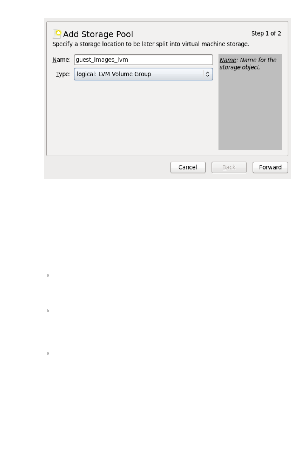
Fig u re 14 .14 . Ad d LVM st o rag e p o ol
Press the Fo rward button to continue.
b. Ad d a n ew p o o l (part 2)
Change the T arg et P ath field. This example uses /guest_images.
Now fill in the T arg et P ath and Source Path fields, then tick the Build Pool
check box.
Use the T arg et P ath field to either select an existing LVM volume group or as the
name for a new volume group. The default format is /dev/storage_pool_name.
This example uses a new volume group named /dev/guest_images_lvm.
The Source Path field is optional if an existing LVM volume group is used in the
T arg et P ath.
For new LVM volume groups, input the location of a storage device in the Source
P ath field. This example uses a blank partition /dev/sdc.
The Build Pool checkbox instructs virt-manager to create a new LVM
volume group. If you are using an existing volume group you should not select the
Build Pool checkbox.
This example is using a blank partition to create a new volume group so the
Build Pool checkbox must be selected.
Virt ualizat ion Deployment and Administ rat ion G uide
128
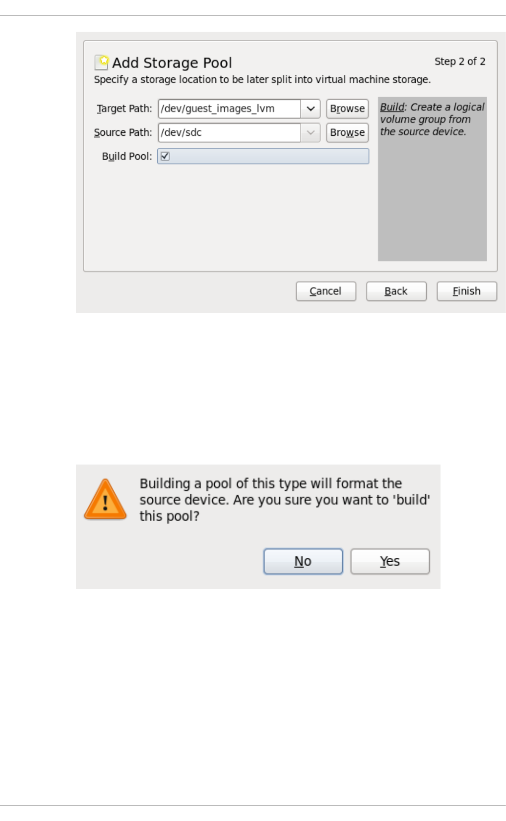
Fig u re 14 .15. Ad d t arg et an d so u rce
Verify the details and press the Finish button format the LVM volume group and
create the storage pool.
c. Conf irm t h e d evice t o b e f ormat t ed
A warning message appears.
Fig u re 14 .16 . Warn in g messag e
Press the Yes button to proceed to erase all data on the storage device and create
the storage pool.
4. Verif y th e n ew st o rag e p o ol
The new storage pool will appear in the list on the left after a few seconds. Verify the details
are what you expect, 465.76 GB Free in our example. Also verify the State field reports the
new storage pool as Active.
It is generally a good idea to have the Auto start check box enabled, to ensure the storage
pool starts automatically with libvirtd.
Chapt er 1 4 . St orag e po ols
129
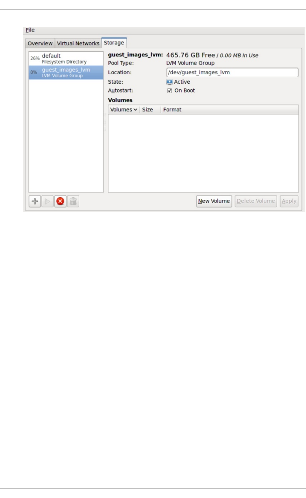
Fig u re 14 .17. Co nf irm LVM st orag e p o o l d et ails
Close the Host Details dialog, as the task is now complete.
14 .4 .2. Delet ing a st orage pool using virt -manager
This procedure demonstrates how to delete a storage pool.
1. To avoid any issues with other guest virtual machines using the same pool, it is best to stop
the storage pool and release any resources in use by it. To do this, select the storage pool
you want to stop and click the red X icon at the bottom of the Storage window.
Virt ualizat ion Deployment and Administ rat ion G uide
130
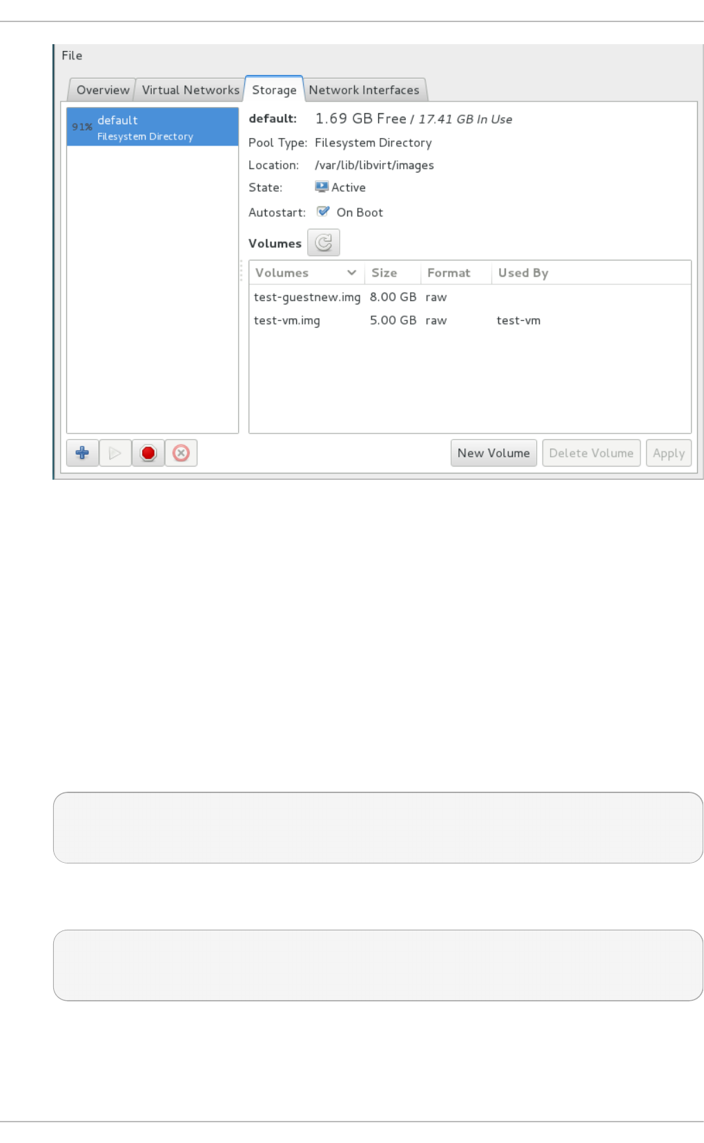
Fig u re 14 .18. St o p Ico n
2. Delete the storage pool by clicking the Trash can icon. This icon is only enabled if you stop
the storage pool first.
14 .4 .3. Creat ing an LVM-based st orage pool wit h virsh
This section outlines the steps required to create an LVM-based storage pool with the vi rsh
command. It uses the example of a pool named g u e st _imag es_lvm from a single drive
(/dev/sdc). This is only an example and your settings should be substituted as appropriate.
Pro ced ure 14 .3. Creat ing an LVM- b ased st o rag e p o o l wit h virsh
1. Define the pool name g u es t _imag es_lvm.
# virsh pool-define-as guest_images_lvm logical - - /dev/sdc
libvirt_lvm \ /dev/libvirt_lvm
Pool guest_images_lvm defined
2. Build the pool according to the specified name. If you are using an already existing volume
group, skip this step.
# virsh pool-build guest_images_lvm
Pool guest_images_lvm built
3. Initialize the new pool.
Chapt er 1 4 . St orag e po ols
131

# virsh pool-start guest_images_lvm
Pool guest_images_lvm started
4. Show the volume group information with the vgs command.
# vgs
VG #PV #LV #SN Attr VSize VFree
libvirt_lvm 1 0 0 wz--n- 465.76g 465.76g
5. Set the pool to start automatically.
# virsh pool-autostart guest_images_lvm
Pool guest_images_lvm marked as autostarted
6. List the available pools with the virsh command.
# virsh pool-list --all
Name State Autostart
-----------------------------------------
default active yes
guest_images_lvm active yes
7. The following commands demonstrate the creation of three volumes (volume1, volume2 and
volume3) within this pool.
# virsh vol-create-as guest_images_lvm volume1 8G
Vol volume1 created
# virsh vol-create-as guest_images_lvm volume2 8G
Vol volume2 created
# virsh vol-create-as guest_images_lvm volume3 8G
Vol volume3 created
8. List the available volumes in this pool with the virsh command.
# virsh vol-list guest_images_lvm
Name Path
-----------------------------------------
volume1 /dev/libvirt_lvm/volume1
volume2 /dev/libvirt_lvm/volume2
volume3 /dev/libvirt_lvm/volume3
9. The following two commands (lvscan and lvs) display further information about the newly
created volumes.
# lvscan
ACTIVE '/dev/libvirt_lvm/volume1' [8.00 GiB] inherit
ACTIVE '/dev/libvirt_lvm/volume2' [8.00 GiB] inherit
ACTIVE '/dev/libvirt_lvm/volume3' [8.00 GiB] inherit
# lvs
Virt ualizat ion Deployment and Administ rat ion G uide
132

LV VG Attr LSize Pool Origin Data% Move Log
Copy% Convert
volume1 libvirt_lvm -wi-a- 8.00g
volume2 libvirt_lvm -wi-a- 8.00g
volume3 libvirt_lvm -wi-a- 8.00g
14 .4 .4 . Delet ing a st orage pool using virsh
The following demonstrates how to delete a storage pool using virsh:
1. To avoid any issues with other guests using the same pool, it is best to stop the storage pool
and release any resources in use by it.
# virsh pool-destroy guest_images_disk
2. Optionally, if you want to remove the directory where the storage pool resides use the
following command:
# virsh pool-delete guest_images_disk
3. Remove the storage pool's definition
# virsh pool-undefine guest_images_disk
14 .5. iSCSI-based st orage pools
This section covers using iSCSI-based devices to store guest virtual machines. This allows for more
flexible storage options such as using iSCSI as a block storage device. The iSCSI devices use an
LIO target, which is a multi-protocol SCSI target for Linux. In addition to iSCSI, LIO also supports
Fibre Channel and Fibre Channel over Ethernet (FCoE).
iSCSI (Internet Small Computer System Interface) is a network protocol for sharing storage devices.
iSCSI connects initiators (storage clients) to targets (storage servers) using SCSI instructions over
the IP layer.
14 .5.1. Configuring a soft ware iSCSI t arget
Introduced in Red Hat Enterprise Linux 7, iSCSI targets are created with the targetcli package, which
provides a command set for creating software-backed iSCSI targets.
Pro ced ure 14 .4 . Creat in g an iSCSI t arg et
1. In st all t he req u ired p ackag e
Install the targetcli package and all dependencies:
# yum install targetcli
2. Lau n ch targ etcl i
Launch the targ etcl i command set:
Chapt er 1 4 . St orag e po ols
133

# targetcli
3.
Creat e st o rag e o b ject s
Create three storage objects as follows, using the device created in Section 14.4, “LVM-based
storage pools” :
a. Create a block storage object, by changing into the /backstores/block directory
and running the following command:
# create [block-name][filepath]
For example:
# create block1 dev=/dev/vdb1
b. Create a fileio object, by changing into the fileio directory and running the
following command:
# create [fileioname] [imagename] [image-size]
For example:
# create fileio1 /foo.img 50M
c. Create a ramdisk object by changing into the ramdisk directory, and running the
following command:
# create [ramdiskname] [size]
For example:
# create ramdisk1 1M
d. Remember the names of the disks you created in this step, as you will need them later.
4. Navig at e t o t h e /iscsi direct o ry
Change into the iscsi directory:
#cd /iscsi
5. Creat e iSCSI targ et
Create an iSCSI target in one of two ways:
a. create with no additional parameters, automatically generates the IQN.
b. create iqn.2010-05.com.example.server1:iscsirhel7guest creates a
specific IQN on a specific server.
6.
Virt ualizat ion Deployment and Administ rat ion G uide
134

Def in e t h e t arg et p o rt al g ro u p (TPG )
Each iSCSI target needs to have a target portal group (TPG) defined. In this example, the
default tpg 1 will be used, but you can add additional tpgs as well. As this is the most
common configuration, the example will configure tpg 1. To do this, make sure you are still in
the /iscsi directory and change to the /tpg1 directory.
# /i scsi >i q n. i q n. 20 10 -
05.com.example.server1:iscsirhel7guest/tpg1
7. Def in e t h e p o rt al IP ad d ress
In order to export the block storage over iSCSI, the portals, LUNs, and ACLs must all be
configured first.
The portal includes the IP address and TCP port that the target will listen on, and the
initiators will connect to. iSCSI uses port 3260, which is the port that will be configured by
default. To connect to this port, run the following command from the /tpg directory:
# portals/ create
This command will have all available IP addresses listening to this port. To specify that only
one specific IP address will listen on the port, run portals/ create [ipaddress], and
the specified IP address will be configured to listen to port 3260.
8. Co n f ig ure t h e LUN s an d assig n t h e st o rag e o b ject s t o t h e f ab ric
This step uses the storage devices created in Step 3. Make sure you change into the l uns
directory for the TPG you created in Step 6, or iscsi>iqn.iqn.2010-
05.com.example.server1:iscsirhel7guest, for example.
a. Assign the first LUN to the ramdisk as follows:
# create /backstores/ramdisk/ramdisk1
b. Assign the second LUN to the block disk as follows:
# create /backstores/block/block1
c. Assign the third LUN to the fileio disk as follows:
# create /backstores/fileio/file1
d. Listing the resulting LUNs should resemble this screen output:
/iscsi/iqn.20...csirhel7guest/tpg1 ls
o- tgp1
.............................................................
...............[enabled, auth]
o-
acls.........................................................
.........................[0 ACL]
Chapt er 1 4 . St orag e po ols
135

o-
luns.........................................................
........................[3 LUNs]
| o-
lun0.........................................................
............[ramdisk/ramdisk1]
| o-
lun1.........................................................
.....[block/block1 (dev/vdb1)]
| o-
lun2.........................................................
......[fileio/file1 (foo.img)]
o-
portals......................................................
......................[1 Portal]
o- IP-
ADDRESS:3260.................................................
.......................[OK]
9.
Creat in g ACLs f o r each in it iat o r
This step allows for the creation of authentication when the initiator connects, and it also
allows for restriction of specified LUNs to specified initiators. Both targets and initiators have
unique names. iSCSI initiators use an IQN.
a. To find the IQN of the iSCSI initiator, run the following command, replacing the name
of the initiator:
# cat /etc/iscsi/initiatorname.iscsi
Use this IQN to create the ACLs.
b. Change to the acls directory.
c. Run the command create [iqn], or to create specific ACLs, refer to the following
example:
# create iqn.2010-05.com.example.foo:888
Alternatively, to configure the kernel target to use a single user ID and password for
all initiators, and allow all initiators to log in with that user ID and password, use the
following commands (replacing userid and password):
# set auth userid=redhat
# set auth password=password123
# set attribute authentication=1
# set attribute generate_node_acls=1
10. Make the configuration persistent with the saveconfig command. This will overwrite the
previous boot settings. Alternatively, running exi t from the t arg et cli saves the target
configuration by default.
11. Enable the service with systemctl enable target.service to apply the saved settings
on next boot.
Virt ualizat ion Deployment and Administ rat ion G uide
136

Pro ced ure 14 .5. O p t io n al st ep s
1. Creat e LVM vo lu mes
LVM volumes are useful for iSCSI backing images. LVM snapshots and re-sizing can be
beneficial for guest virtual machines. This example creates an LVM image named virtimage1
on a new volume group named virtstore on a RAID5 array for hosting guest virtual machines
with iSCSI.
a. Creat e t h e R AID array
Creating software RAID5 arrays is covered by the Red Hat Enterprise Linux Deployment
Guide.
b. Creat e t h e LVM vo lu me g ro u p
Create a logical volume group named virtstore with the vgcreate command.
# vgcreate virtstore /dev/md1
c. Creat e a LVM lo g ical vo lu me
Create a logical volume group named virtimage1 on the virtstore volume group with a
size of 20GB using the lvcreate command.
# lvcreate **size 20G -n virtimage1 virtstore
The new logical volume, virtimage1, is ready to use for iSCSI.
Important
Using LVM volumes for kernel target backstores can cause issues if the initiator
also partitions the exported volume with LVM. This can be solved by adding
g l o bal _fi l ter = ["r| ^/d ev/vg 0 | "] to /etc/lvm/lvm.conf
2. O p t io n al: T est disco very
Test whether the new iSCSI device is discoverable.
# iscsiadm --mode discovery --type sendtargets --portal
server1.example.com
127.0.0.1:3260,1 iqn.2010-05.com.example.server1:iscsirhel7guest
3. O p t io n al: T est at t ach in g the d evice
Attach the new device (iqn.2010-05.com.example.server1:iscsirhel7guest) to determine whether
the device can be attached.
# iscsiadm -d2 -m node --login
scsiadm: Max file limits 1024 1024
Logging in to [iface: default, target: iqn.2010-
Chapt er 1 4 . St orag e po ols
137
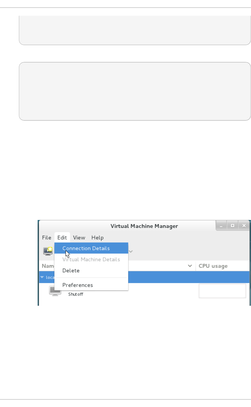
05.com.example.server1:iscsirhel7guest, portal: 10.0.0.1,3260]
Login to [iface: default, target: iqn.2010-
05.com.example.server1:iscsirhel7guest, portal: 10.0.0.1,3260]
successful.
4. Detach the device.
# iscsiadm -d2 -m node --logout
scsiadm: Max file limits 1024 1024
Logging out of session [sid: 2, target: iqn.2010-
05.com.example.server1:iscsirhel7guest, portal: 10.0.0.1,3260
Logout of [sid: 2, target: iqn.2010-
05.com.example.server1:iscsirhel7guest, portal: 10.0.0.1,3260]
successful.
An iSCSI device is now ready to use for virtualization.
14 .5.2. Creat ing an iSCSI st orage pool in virt -manager
This procedure covers creating a storage pool with an iSCSI target in virt-manager.
Pro ced ure 14 .6 . Ad d ing an iSCSI d evice t o virt - man ag er
1. O p en t h e h o st mach in e' s st orag e d et ails
a. In virt - ma n ag er, click the Ed i t and select C o nnecti o n D etai l s from the
dropdown menu.
Fig u re 14 .19 . Co n n ect ion det ails
b. Click on the Sto rag e tab.
Virt ualizat ion Deployment and Administ rat ion G uide
138
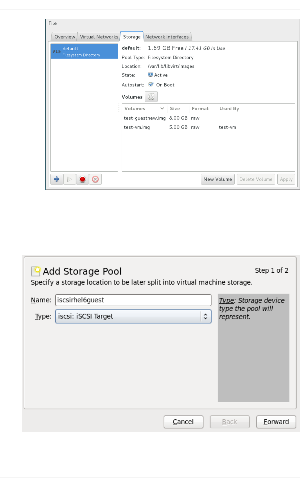
Fig u re 14 .20. St o rag e men u
2. Ad d a n ew p o o l (St ep 1 o f 2)
Press the + button (the add pool button). The Add a New Storage Pool wizard appears.
Fig u re 14 .21. Ad d an iSCSI st o rag e p o ol n ame an d t yp e
Chapt er 1 4 . St orag e po ols
139
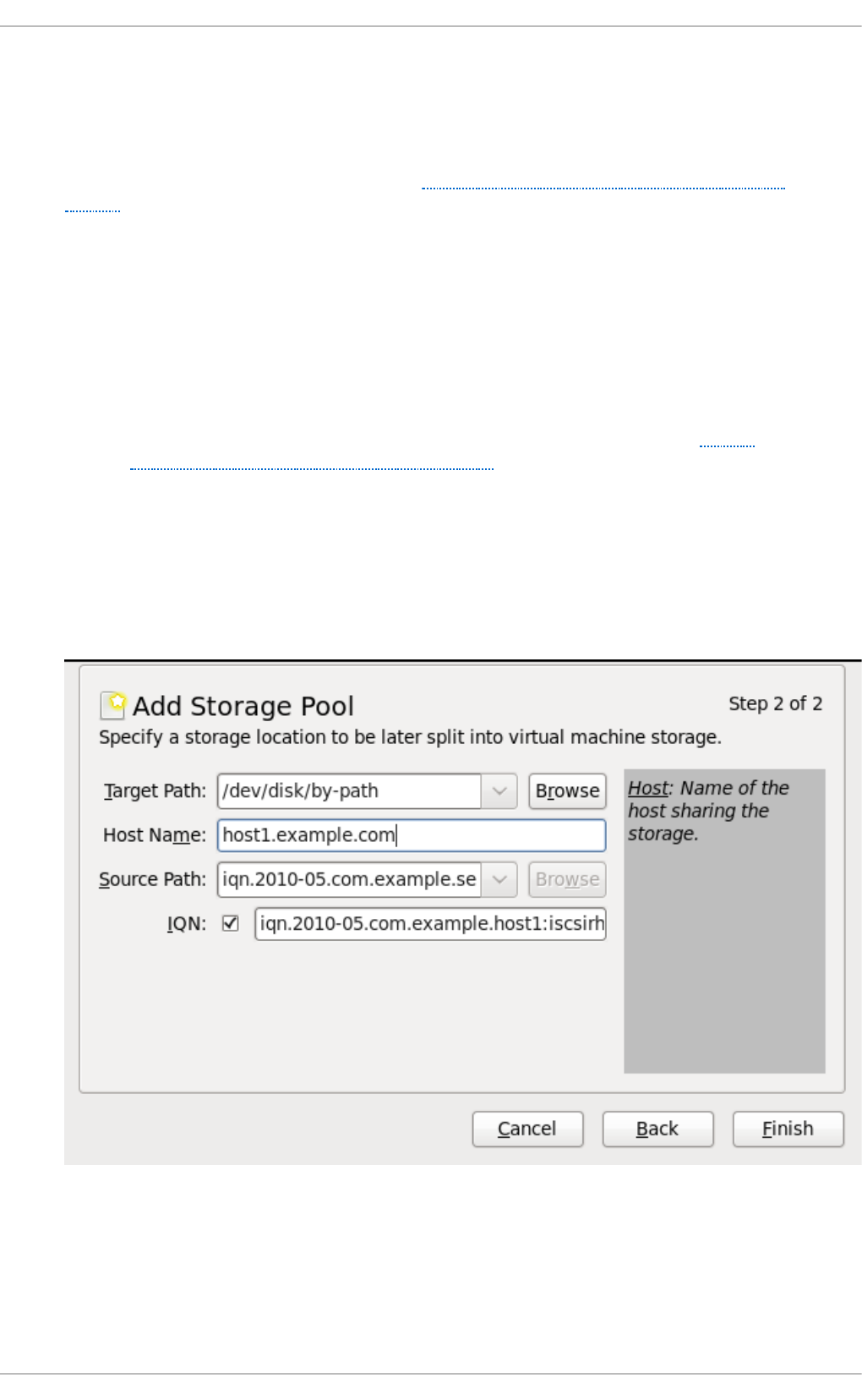
Choose a name for the storage pool, change the Type to iSCSI, and press Fo rward to
continue.
3. Ad d a n ew p o o l (St ep 2 o f 2)
You will need the information you used in Section 14.5, “ iSCSI-based storage pools” and
Step 6 to complete the fields in this menu.
a. Enter the iSCSI source and target. The Fo rmat option is not available as formatting is
handled by the guest virtual machines. It is not advised to edit the T arg et P ath. The
default target path value, /dev/disk/by-path/, adds the drive path to that
directory. The target path should be the same on all host physical machines for
migration.
b. Enter the hostname or IP address of the iSCSI target. This example uses
host1.example.com.
c. In the Source Path field, enter the iSCSI target IQN. If you look at Step 6 in
Section 14.5, “ iSCSI-based storage pools” , this is the information you added in the
/etc/target/targets.conf file. This example uses iqn.2010-
05.com.example.server1:iscsirhel7guest.
d. Check the IQN checkbox to enter the IQN for the initiator. This example uses
iqn.2010-05.com.example.host1:iscsirhel7.
e. Click Finish to create the new storage pool.
Fig u re 14 .22. Creat e an iSC SI st o rag e p o o l
14 .5.3. Delet ing a st orage pool using virt -manager
This procedure demonstrates how to delete a storage pool.
Virt ualizat ion Deployment and Administ rat ion G uide
14 0
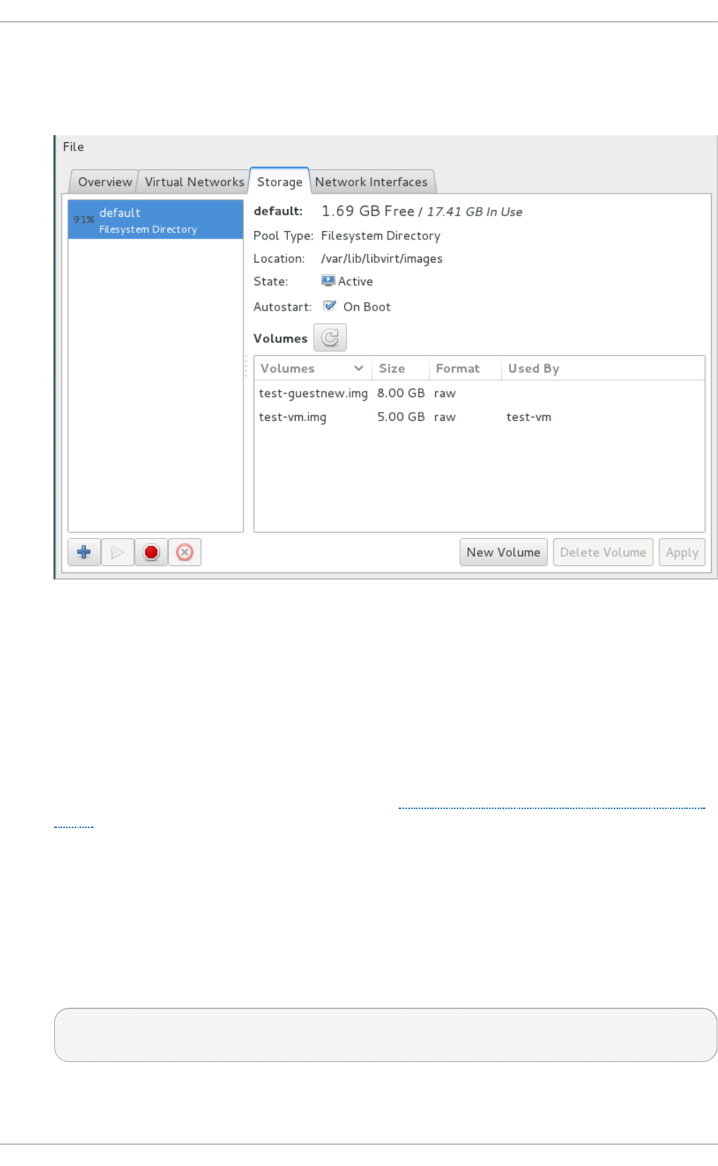
1. To avoid any issues with other guest virtual machines using the same pool, it is best to stop
the storage pool and release any resources in use by it. To do this, select the storage pool
you want to stop and click the red X icon at the bottom of the Storage window.
Fig u re 14 .23. St o p Ico n
2. Delete the storage pool by clicking the Trash can icon. This icon is only enabled if you stop
the storage pool first.
14 .5.4 . Creat ing an iSCSI-based st orage pool wit h virsh
1. O p t io n al: Secu re t h e st o rag e p o o l
If desired, set up authentication with the steps in Section 14.5.5, “ Securing an iSCSI storage
pool”.
2. Def in e t h e st o rag e p o o l
Storage pool definitions can be created with the virsh command line tool. Creating storage
pools with virsh is useful for system administrators using scripts to create multiple storage
pools.
The virsh pool-define-as command has several parameters which are accepted in the
following format:
virsh pool-define-as name type source-host source-path source-dev
source-name target
The parameters are explained as follows:
Chapt er 1 4 . St orag e po ols
14 1

t yp e
defines this pool as a particular type, iSCSI for example
n ame
sets the name for the storage pool; must be unique
so u rce- h ost an d so u rce- p at h
the hostname and iSCSI IQN respectively
so u rce- d ev an d so u rce- n ame
these parameters are not required for iSCSI-based pools; use a - character to leave
the field blank.
t arg e t
defines the location for mounting the iSCSI device on the host machine
The example below creates the same iSCSI-based storage pool as the vi rsh po o l -
define-as example above:
# virsh pool-define-as --name iscsirhel7pool --type iscsi \
--source-host server1.example.com \
--source-dev iqn.2010-05.com.example.server1:iscsirhel7guest \
--target /dev/disk/by-path
Pool iscsirhel7pool defined
3. Verif y t h e st o rag e p o o l is list ed
Verify the storage pool object is created correctly and the state is inactive.
# virsh pool-list --all
Name State Autostart
-----------------------------------------
default active yes
iscsirhel7pool inactive no
4. O p t io n al: Est ab lish a d irect co n n ect ion t o t h e iSC SI st o rag e p o o l
This step is optional, but it allows you to establish a direct connection to the iSCSI storage
pool. By default this is enabled, but if the connection is to the host machine (and not direct to
the network) you can change it back by editing the domain XML for the virtual machine to
reflect this example:
...
<disk type='volume' device='disk'>
<driver name='qemu'/>
<source pool='iscsi' volume='unit:0:0:1' mode='direct'/>
<target dev='vda' bus='virtio'/>
<address type='pci' domain='0x0000' bus='0x00' slot='0x06'
Virt ualizat ion Deployment and Administ rat ion G uide
14 2

function='0x0'/>
</disk>
...
Fig u re 14 .24 . Disk t yp e elemen t XML examp le
Note
The same iSCSI storage pool can be used for a LUN or a disk, by specifying the d i sk
device as either a d i sk or lun. See Section 15.5.3, “ Adding SCSI LUN-based
storage to a guest” for XML configuration examples for adding SCSI LUN-based
storage to a guest.
Additionally, the source mode can be specified as mode='host' for a connection
to the host machine.
If you have configured authentication on the iSCSI server as detailed in Step 9, then the
following XML used as a <disk> sub-element will provide the authentication credentials for
the disk. Section 14.5.5, “ Securing an iSCSI storage pool” describes how to configure the
libvirt secret.
<auth type='chap' username='redhat'>
<secret usage='iscsirhel7secret'/>
</auth>
5. St art t he st o rag e p o o l
Use the vi rsh po o l -start to enable a directory storage pool. This allows the storage pool
to be used for volumes and guest virtual machines.
# virsh pool-start iscsirhel7pool
Pool iscsirhel7pool started
# virsh pool-list --all
Name State Autostart
-----------------------------------------
default active yes
iscsirhel7pool active no
6. Turn o n au t o st art
Turn on autostart for the storage pool. Autostart configures the l i bvi rtd service to start
the storage pool when the service starts.
# virsh pool-autostart iscsirhel7pool
Pool iscsirhel7pool marked as autostarted
Verify that the iscsirhel7pool pool has autostart enabled:
# virsh pool-list --all
Name State Autostart
Chapt er 1 4 . St orag e po ols
14 3

-----------------------------------------
default active yes
iscsirhel7pool active yes
7. Verif y th e st o rag e p o o l co n f igurat io n
Verify the storage pool was created correctly, the sizes report correctly, and the state reports
as running.
# virsh pool-info iscsirhel7pool
Name: iscsirhel7pool
UUID: afcc5367-6770-e151-bcb3-847bc36c5e28
State: running
Persistent: unknown
Autostart: yes
Capacity: 100.31 GB
Allocation: 0.00
Available: 100.31 GB
An iSCSI-based storage pool called iscsirhel7pool is now available.
14 .5.5. Securing an iSCSI st orage pool
Username and password parameters can be configured with virsh to secure an iSCSI storage pool.
This can be configured before or after the pool is defined, but the pool must be started for the
authentication settings to take effect.
Pro ced ure 14 .7. Co n f ig u rin g au t h en t icat io n f or a st orag e p o o l wit h virsh
1. Creat e a lib virt secret f ile
Create a libvirt secret XML file called secret.xml, using the following example:
# cat secret.xml
<secret ephemeral='no' private='yes'>
<description>Passphrase for the iSCSI example.com
server</description>
<auth type='chap' username='redhat'/>
<usage type='iscsi'>
<target>iscsirhel7secret</target>
</usage>
</secret>
2. Def in e t h e secret f ile
Define the secret.xml file with virsh:
# virsh secret-define secret.xml
3. Verif y t h e secret f ile' s U UID
Verify the UUID in secret.xml:
# virsh secret-list
Virt ualizat ion Deployment and Administ rat ion G uide
14 4

UUID Usage
------------------------------------------------------------------
--------------
2d7891af-20be-4e5e-af83-190e8a922360 iscsi iscsirhel7secret
4. Assign a secret t o t h e U UID
Assign a secret to that UUID, using the following command syntax as an example:
# MYSECRET=`printf %s "password123" | base64`
# virsh secret-set-value 2d7891af-20be-4e5e-af83-190e8a922360
$MYSECRET
This ensures the CHAP username and password are set in a libvirt-controlled secret list.
5. Ad d an au t h en t icat io n en t ry t o t h e st o rag e p o o l
Modify the <source> entry in the storage pool's XML file using vi rsh ed i t and add an
<auth> element, specifying authentication type, username, and secret usage.
The following shows an example of a storage pool XML definition with authentication
configured:
# cat iscsirhel7pool.xml
<pool type='iscsi'>
<name>iscsirhel7pool</name>
<source>
<host name='192.168.122.1'/>
<device path='iqn.2010-
05.com.example.server1:iscsirhel7guest'/>
<auth type='chap' username='redhat'>
<secret usage='iscsirhel7secret'/>
</auth>
</source>
<target>
<path>/dev/disk/by-path</path>
</target>
</pool>
Note
The <auth> sub-element exists in different locations within the guest XML's <pool>
and <disk> elements. For a <pool>, <auth> is specified within the <source>
element, as this describes where to find the pool sources, since authentication is a
property of some pool sources (iSCSI and RBD). For a <disk>, which is a sub-
element of a domain, the authentication to the iSCSI or RBD disk is a property of the
disk. See Section 14.5.4, “ Creating an iSCSI-based storage pool with virsh” Creating
an iSCSI-based storage pool with virsh for an example of <disk> configured in the
guest XML.
6. Act ivat e t h e ch an g es in t he st o rag e p o o l
Chapt er 1 4 . St orag e po ols
14 5
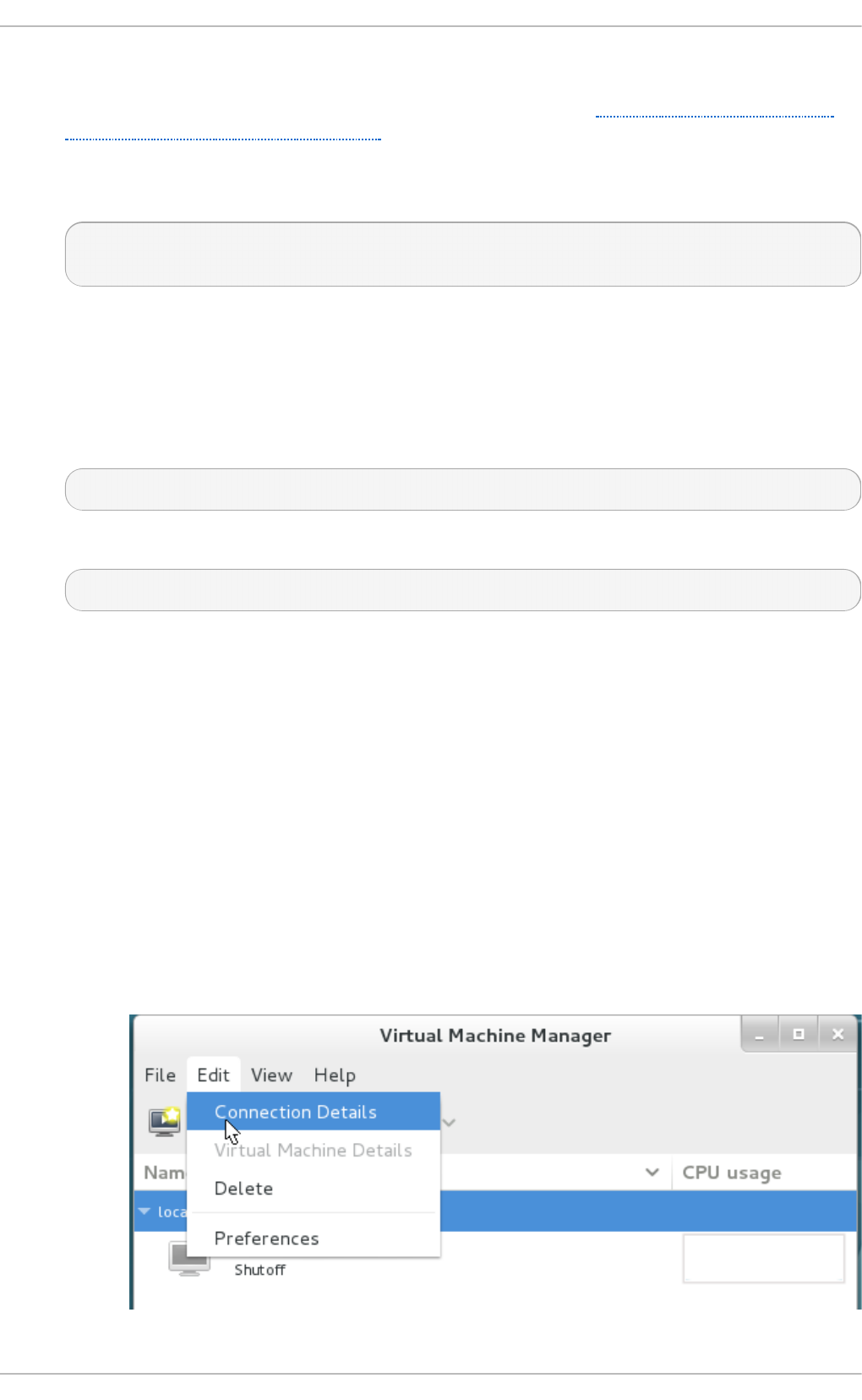
The storage pool must be started to activate these changes.
If the storage pool has not yet been started, follow the steps in Section 14.5.4, “Creating an
iSCSI-based storage pool with virsh” to define and start the storage pool.
If the pool has already been started, run the following commands to stop and restart the
storage pool:
# virsh pool-destroy iscsirhel7pool
# virsh pool-start iscsirhel7pool
14 .5.6. Delet ing a st orage pool using virsh
The following demonstrates how to delete a storage pool using virsh:
1. To avoid any issues with other guest virtual machines using the same pool, it is best to stop
the storage pool and release any resources in use by it.
# virsh pool-destroy iscsirhel7pool
2. Remove the storage pool's definition
# virsh pool-undefine iscsirhel7pool
14 .6. NFS-based st orage pools
This procedure covers creating a storage pool with a NFS mount point in virt-manager.
14 .6.1. Creat ing a NFS-based st orage pool wit h virt -manager
1. O p en t h e h o st p h ysical mach in e' s st o rag e t ab
Open the Sto rag e tab in the Ho st D etai l s window.
a. Open virt-manager.
b. Select a host physical machine from the main virt-manager window. Click Ed i t
menu and select C o nnecti o n D etai l s.
Virt ualizat ion Deployment and Administ rat ion G uide
14 6
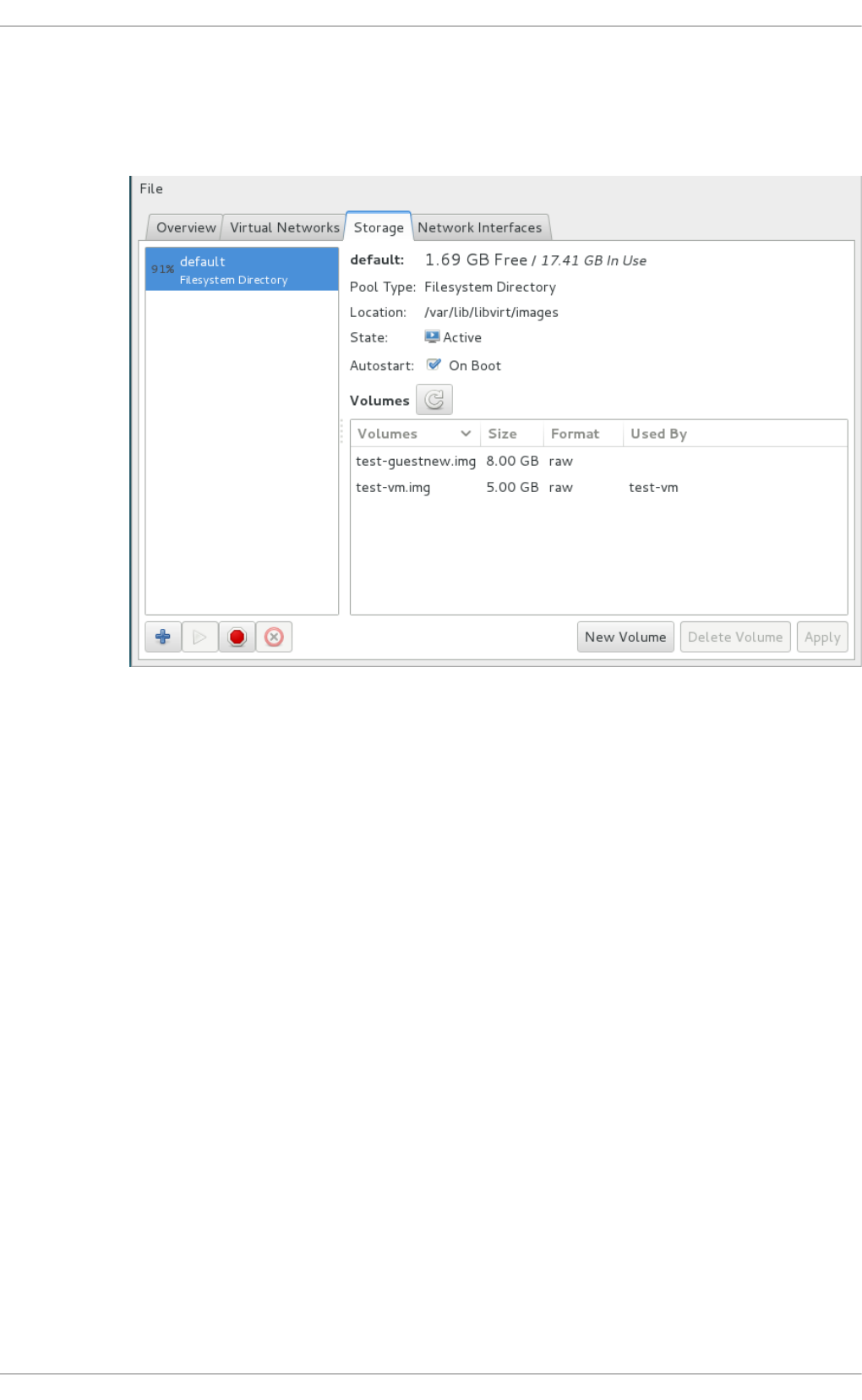
Fig u re 14 .25. Co nn ect ion det ails
c. Click on the Storage tab.
Fig u re 14 .26 . St orag e t ab
2. Creat e a n ew p o o l ( p art 1)
Press the + button (the add pool button). The Add a New Storage Pool wizard appears.
Chapt er 1 4 . St orag e po ols
14 7
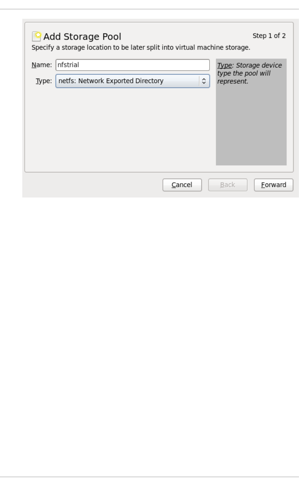
Fig u re 14 .27. Ad d an N FS n ame an d t yp e
Choose a name for the storage pool and press Fo rward to continue.
3. Creat e a n ew p o o l ( p art 2)
Enter the target path for the device, the hostname and the NFS share path. Set the Fo rmat
option to NFS or auto (to detect the type). The target path must be identical on all host
physical machines for migration.
Enter the hostname or IP address of the NFS server. This example uses
server1.example.com.
Enter the NFS path. This example uses /nfstrial.
Virt ualizat ion Deployment and Administ rat ion G uide
14 8
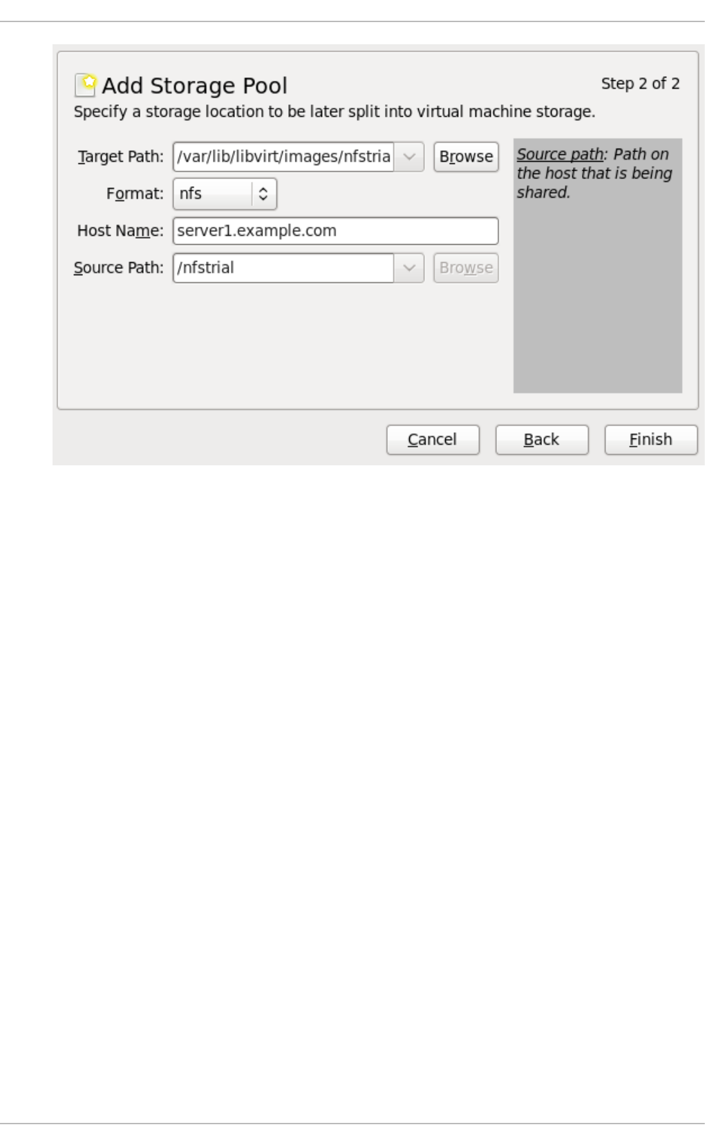
Fig u re 14 .28. Creat e an NFS st o rag e p o ol
Press Finish to create the new storage pool.
14 .6.2. Delet ing a st orage pool using virt -manager
This procedure demonstrates how to delete a storage pool.
1. To avoid any issues with other guests using the same pool, it is best to stop the storage pool
and release any resources in use by it. To do this, select the storage pool you want to stop
and click the red X icon at the bottom of the Storage window.
Chapt er 1 4 . St orag e po ols
14 9
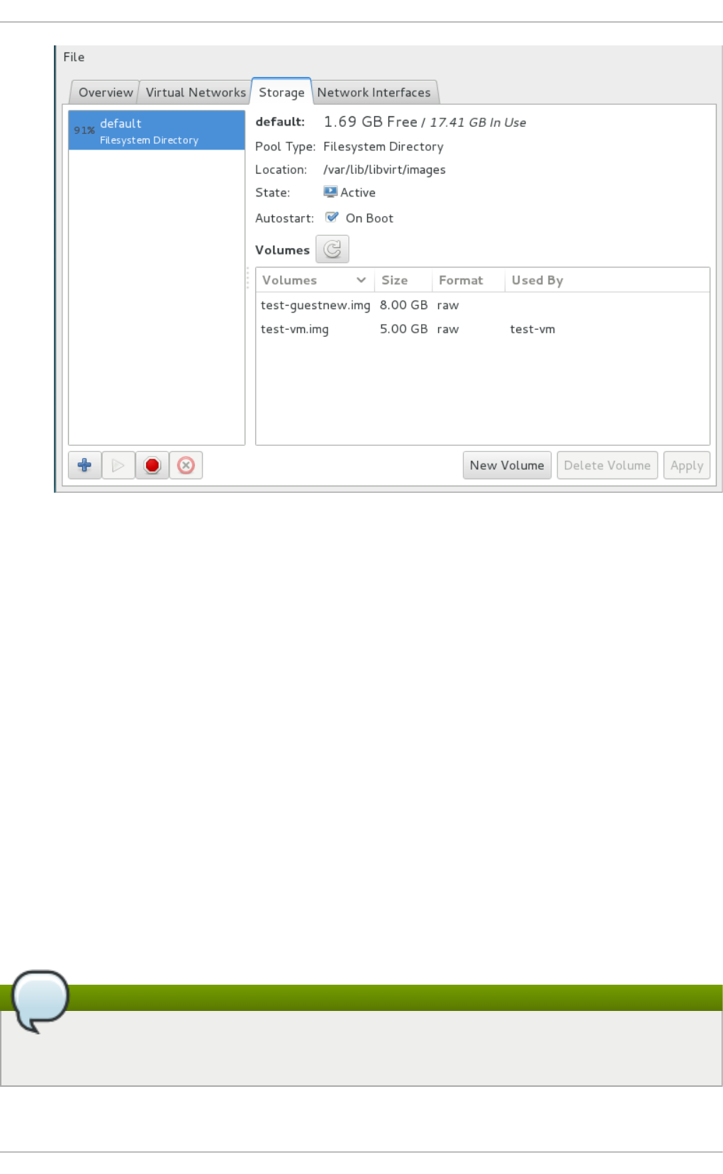
Fig u re 14 .29 . St op Ico n
2. Delete the storage pool by clicking the Trash can icon. This icon is only enabled if you stop
the storage pool first.
14 .7. Using a NPIV virt ual adapt er (vHBA) wit h SCSI devices
NPIV (N_Port ID Virtualization) is a software technology that allows sharing of a single physical
Fibre Channel host bus adapter (HBA).
This allows multiple guests to see the same storage from multiple physical hosts, and thus allows for
easier migration paths for the storage. As a result, there is no need for the migration to create or copy
storage, as long as the correct storage path is specified.
In virtualization, the virtual host bus adapter, or vHBA, controls the LUNs for virtual machines. For a
host to share one Fibre Channel device path between multiple KVM guests, a vHBA must be created
for each virtual machine. A single vHBA must not be used by multiple KVM guests.
Each vHBA is identified by its own WWNN (World Wide Node Name) and WWPN (World Wide Port
Name). The path to the storage is determined by the WWNN and WWPN values.
This section provides instructions for configuring a vHBA persistently on a virtual machine.
Note
Before creating a vHBA, it is recommended to configure storage array (SAN)-side zoning in the
host LUN to provide isolation between guests and prevent the possibility of data corruption.
Virt ualizat ion Deployment and Administ rat ion G uide
150

14 .7.1. Creat ing a vHBA
Pro ced ure 14 .8. Creat ing a vHBA
1. Lo cat e H BAs o n t h e h o st syst em
To locate the HBAs on your host system, use the virsh nodedev-list --cap vports
command.
For example, the following output shows a host that has two HBAs that support vHBA:
# virsh nodedev-list --cap vports
scsi_host3
scsi_host4
2. Ch eck t h e HBA' s d et ails
Use the virsh nodedev-dumpxml HBA_device command to see the HBA's details.
The XML output from the virsh nodedev-dumpxml command will list the fields <name>,
<wwnn>, and <wwpn>, which are used to create a vHBA. The <max_vports> value shows the
maximum number of supported vHBAs.
# virsh nodedev-dumpxml scsi_host3
<device>
<name>scsi_host3</name>
<path>/sys/devices/pci0000:00/0000:00:04.0/0000:10:00.0/host3</path
>
<parent>pci_0000_10_00_0</parent>
<capability type='scsi_host'>
<host>3</host>
<unique_id>0</unique_id>
<capability type='fc_host'>
<wwnn>20000000c9848140</wwnn>
<wwpn>10000000c9848140</wwpn>
<fabric_wwn>2002000573de9a81</fabric_wwn>
</capability>
<capability type='vport_ops'>
<max_vports>127</max_vports>
<vports>0</vports>
</capability>
</capability>
</device>
In this example, the <max_vports> value shows there are a total 127 virtual ports available
for use in the HBA configuration. The <vports> value shows the number of virtual ports
currently being used. These values update after creating a vHBA.
3. Creat e a vHB A h o st d evice
Create an XML file similar to the following (in this example, named vhba_host3.xml) for the
vHBA host.
# cat vhba_host3.xml
Chapt er 1 4 . St orag e po ols
151

<device>
<parent>scsi_host3</parent>
<capability type='scsi_host'>
<capability type='fc_host'>
</capability>
</capability>
</device>
The <parent> field specifies the HBA device to associate with this vHBA device. The details
in the <device> tag are used in the next step to create a new vHBA device for the host. See
http://libvirt.org/formatnode.html for more information on the nodedev XML format.
4. Creat e a n ew vHBA o n t h e vHB A h o st device
To create a vHBA on vhba_host3, use the virsh nodedev-create command:
# virsh nodedev-create vhba_host3.xml
Node device scsi_host5 created from vhba_host3.xml
5. Verif y t h e vHB A
Verify the new vHBA's details (scsi_host5) with the virsh nodedev-dumpxml command:
# virsh nodedev-dumpxml scsi_host5
<device>
<name>scsi_host5</name>
<path>/sys/devices/pci0000:00/0000:00:04.0/0000:10:00.0/host3/vport
-3:0-0/host5</path>
<parent>scsi_host3</parent>
<capability type='scsi_host'>
<host>5</host>
<unique_id>2</unique_id>
<capability type='fc_host'>
<wwnn>5001a4a93526d0a1</wwnn>
<wwpn>5001a4ace3ee047d</wwpn>
<fabric_wwn>2002000573de9a81</fabric_wwn>
</capability>
</capability>
</device>
14 .7.2. Creat ing a st orage pool using t he vHBA
It is recommended to define a libvirt storage pool based on the vHBA in order to preserve the vHBA
configuration.
Using a storage pool has two primary advantages:
the libvirt code can easily find the LUN's path via virsh command output, and
virtual machine migration requires only defining and starting a storage pool with the same vHBA
name on the target machine. To do this, the vHBA LUN, libvirt storage pool and volume name must
be specified in the virtual machine's XML configuration. Refer to Section 14.7.3, “ Configuring the
virtual machine to use a vHBA LUN” for an example.
Virt ualizat ion Deployment and Administ rat ion G uide
152

1. Creat e a SC SI st o rag e p o o l
To create a persistent vHBA configuration, first create a libvirt ' scsi ' storage pool XML file
using the format below. It is recommended to use a stable location for the <path> value, such
as one of the /dev/disk/by-{path|id|uuid|label} locations on your system. More
information on <path> and the elements within <targ et> can be found at
http://libvirt.org/formatstorage.html.
In this example, the ' scsi ' storage pool is named vhbapool_host3.xml:
<pool type='scsi'>
<name>vhbapool_host3</name>
<source>
<adapter type='fc_host' wwnn='5001a4a93526d0a1'
wwpn='5001a4ace3ee047d'/>
</source>
<target>
<path>/dev/disk/by-path</path>
<permissions>
<mode>0700</mode>
<owner>0</owner>
<group>0</group>
</permissions>
</target>
</pool>
Important
The pool must be type='scsi' and the source adapter type must be 'fc_host'.
For a persistent configuration across host reboots, the wwnn and wwpn attributes must
be the values assigned to the vHBA (scsi_host5 in this example) by libvirt.
Optionally, the ' parent' attribute can be used in the <adapter> field to identify the parent
scsi_host device as the vHBA. Note, the value is not the scsi_host of the vHBA created by
virsh nodedev-create, but it is the parent of that vHBA.
Providing the ' parent' attribute is also useful for duplicate pool definition checks. This is
more important in environments where both the 'fc_host' and 'scsi_host' source
adapter pools are being used, to ensure a new definition does not duplicate using the same
scsi_host of another existing storage pool.
The following example shows the optional ' parent' attribute used in the <adapter> field in
a storage pool configuration:
<adapter type='fc_host' parent='scsi_host3' wwnn='5001a4a93526d0a1'
wwpn='5001a4ace3ee047d'/>
2. Def in e t h e p o o l
To define the storage pool (named vhbapool_host3 in this example) persistently, use the
virsh pool-define command:
# virsh pool-define vhbapool_host3.xml
Pool vhbapool_host3 defined from vhbapool_host3.xml
Chapt er 1 4 . St orag e po ols
153

3. St art t he p o o l
Start the storage pool with the following command:
# virsh pool-start vhbapool_host3
Pool vhbapool_host3 started
Note
When starting the pool, libvirt will check if the vHBA with same wwpn:wwnn already
exists. If it does not yet exist, a new vHBA with the provided wwpn:wwnn will be created
and the configuration will not be persistent. Correspondingly, when destroying the
pool, libvirt will destroy the vHBA using the same wwpn:wwnn values as well.
4. En ab le au t o st art
Finally, to ensure that subsequent host reboots will automatically define vHBAs for use in
virtual machines, set the storage pool autostart feature (in this example, for a pool named
vhbapool_host3):
# virsh pool-autostart vhbapool_host3
14 .7.3. Configuring t he virt ual machine t o use a vHBA LUN
After a storage pool is created for a vHBA, add the vHBA LUN to the virtual machine configuration.
1. Fin d availab le LU Ns
First, use the vi rsh vo l -l i st command in order to generate a list of available LUNs on
the vHBA. For example:
# virsh vol-list vhbapool_host3
Name Path
------------------------------------------------------------------
------------
unit:0:4:0 /dev/disk/by-path/pci-0000:10:00.0-fc-
0x5006016844602198-lun-0
unit:0:5:0 /dev/disk/by-path/pci-0000:10:00.0-fc-
0x5006016044602198-lun-0
The list of LUN names displayed will be available for use as disk volumes in virtual machine
configurations.
2. Ad d t h e vHB A LUN t o t h e virt ual mach in e
Add the vHBA LUN to the virtual machine by creating a disk volume on the virtual machine in
the virtual machine's XML. Specify the storage pool and the volume in the <source>
parameter, using the following as an example:
<disk type='volume' device='disk'>
Virt ualizat ion Deployment and Administ rat ion G uide
154

<driver name='qemu' type='raw'/>
<source pool='vhbapool_host3' volume='unit:0:4:0'/>
<target dev='hda' bus='ide'/>
</disk>
To specify a lun device instead of a d i sk, refer to the following example:
<disk type='volume' device='lun' sgio='unfiltered'>
<driver name='qemu' type='raw'/>
<source pool='vhbapool_host3' volume='unit:0:4:0'
mode='host'/>
<target dev='sda' bus='scsi'/>
<shareable />
</disk>
See Section 15.5.3, “ Adding SCSI LUN-based storage to a guest” for XML configuration
examples for adding SCSI LUN-based storage to a guest.
14 .7.4 . Dest roying t he vHBA st orage pool
A vHBA created by the storage pool can be destroyed by the vi rsh po o l -d estro y command:
# virsh pool-destroy vhbapool_host3
Note that executing the vi rsh po o l -d estro y command will also remove the vHBA that was
created in Section 14.7.1, “ Creating a vHBA” .
To verify the pool and vHBA have been destroyed, run:
# virsh nodedev-list --cap scsi_host
scsi_host5 will no longer appear in the list of results.
Chapt er 1 4 . St orag e po ols
155

Chapter 15. Storage Volumes
15.1. Int roduct ion
Storage pools are divided into storage volumes. Storage volumes are an abstraction of physical
partitions, LVM logical volumes, file-based disk images and other storage types handled by libvirt.
Storage volumes are presented to guest virtual machines as local storage devices regardless of the
underlying hardware. Note the sections below do not contain all of the possible commands and
arguments that virsh allows, for more information refer to Section 23.15, “ Storage Volume
Comman ds” .
15.1.1. Referencing volumes
For more additional parameters and arguments, refer to Section 23.15.4, “ Listing volume
in formatio n” .
To reference a specific volume, three approaches are possible:
T h e n ame o f t h e vo lu me an d t h e st o rag e p o o l
A volume may be referred to by name, along with an identifier for the storage pool it belongs
in. On the virsh command line, this takes the form --pool storage_pool volume_name.
For example, a volume named firstimage in the guest_images pool.
# virsh vol-info --pool guest_images firstimage
Name: firstimage
Type: block
Capacity: 20.00 GB
Allocation: 20.00 GB
virsh #
T h e f u ll p at h to th e st orag e o n t h e h o st ph ysical mach in e syst em
A volume may also be referred to by its full path on the file system. When using this
approach, a pool identifier does not need to be included.
For example, a volume named secondimage.img, visible to the host physical machine system
as /images/secondimage.img. The image can be referred to as /images/secondimage.img.
# virsh vol-info /images/secondimage.img
Name: secondimage.img
Type: file
Capacity: 20.00 GB
Allocation: 136.00 kB
T h e u n iq u e vo lu me key
When a volume is first created in the virtualization system, a unique identifier is generated
and assigned to it. The unique identifier is termed the volume key. The format of this volume
key varies upon the storage used.
When used with block based storage such as LVM, the volume key may follow this format:
Virt ualizat ion Deployment and Administ rat ion G uide
156

c3pKz4-qPVc-Xf7M-7WNM-WJc8-qSiz-mtvpGn
When used with file based storage, the volume key may instead be a copy of the full path to
the volume storage.
/images/secondimage.img
For example, a volume with the volume key of Wlvnf7-a4a3-Tlje-lJDa-9eak-PZBv-LoZuUr:
# virsh vol-info Wlvnf7-a4a3-Tlje-lJDa-9eak-PZBv-LoZuUr
Name: firstimage
Type: block
Capacity: 20.00 GB
Allocation: 20.00 GB
virsh provides commands for converting between a volume name, volume path, or volume key:
vol- n ame
Returns the volume name when provided with a volume path or volume key.
# virsh vol-name /dev/guest_images/firstimage
firstimage
# virsh vol-name Wlvnf7-a4a3-Tlje-lJDa-9eak-PZBv-LoZuUr
vo l- p at h
Returns the volume path when provided with a volume key, or a storage pool identifier and
volume name.
# virsh vol-path Wlvnf7-a4a3-Tlje-lJDa-9eak-PZBv-LoZuUr
/dev/guest_images/firstimage
# virsh vol-path --pool guest_images firstimage
/dev/guest_images/firstimage
T h e vol- key co mman d
Returns the volume key when provided with a volume path, or a storage pool identifier and
volume name.
# virsh vol-key /dev/guest_images/firstimage
Wlvnf7-a4a3-Tlje-lJDa-9eak-PZBv-LoZuUr
# virsh vol-key --pool guest_images firstimage
Wlvnf7-a4a3-Tlje-lJDa-9eak-PZBv-LoZuUr
For more information refer to Section 23.15.4, “Listing volume information” .
15.2. Creat ing volumes
This section shows how to create disk volumes inside a block based storage pool. In the example
below, the virsh vol-create-as command will create a storage volume with a specific size in GB
within the guest_images_disk storage pool. As this command is repeated per volume needed, three
volumes are created as shown in the example. For additional parameters and arguments refer to
Chapt er 1 5. St orage Volu mes
157

Section 23.15.1, “Creating storage volumes”
# virsh vol-create-as guest_images_disk volume1 8G
Vol volume1 created
# virsh vol-create-as guest_images_disk volume2 8G
Vol volume2 created
# virsh vol-create-as guest_images_disk volume3 8G
Vol volume3 created
# virsh vol-list guest_images_disk
Name Path
-----------------------------------------
volume1 /dev/sdb1
volume2 /dev/sdb2
volume3 /dev/sdb3
# parted -s /dev/sdb pri nt
Model: ATA ST3500418AS (scsi)
Disk /dev/sdb: 500GB
Sector size (logical/physical): 512B/512B
Partition Table: gpt
Number Start End Size File system Name Flags
2 17.4kB 8590MB 8590MB primary
3 8590MB 17.2GB 8590MB primary
1 21.5GB 30.1GB 8590MB primary
15.3. Cloning volumes
The new volume will be allocated from storage in the same storage pool as the volume being cloned.
The virsh vol-clone must have the --po o l argument which dictates the name of the storage
pool that contains the volume to be cloned. The rest of the command names the volume to be cloned
(volume3) and the name of the new volume that was cloned (clone1). The vi rsh vo l -l i st
command lists the volumes that are present in the storage pool (guest_images_disk). For additional
commands and arguments refer to Section 23.15.1.2, “ Cloning a storage volume”
# virsh vol-clone --pool guest_images_disk volume3 clone1
Vol clone1 cloned from volume3
# virsh vol-list guest_images_disk
Name Path
-----------------------------------------
volume1 /dev/sdb1
volume2 /dev/sdb2
volume3 /dev/sdb3
clone1 /dev/sdb4
# parted -s /dev/sdb pri nt
Model: ATA ST3500418AS (scsi)
Disk /dev/sdb: 500GB
Virt ualizat ion Deployment and Administ rat ion G uide
158

Sector size (logical/physical): 512B/512B
Partition Table: msdos
Number Start End Size File system Name Flags
1 4211MB 12.8GB 8595MB primary
2 12.8GB 21.4GB 8595MB primary
3 21.4GB 30.0GB 8595MB primary
4 30.0GB 38.6GB 8595MB primary
15.4 . Delet ing and removing volumes
For the virsh commands you need to delete and remove a volume, refer to Section 23.15.2, “Deleting
storage volumes” .
15.5. Adding st orage devices t o guest s
This section covers adding storage devices to a guest. Additional storage can only be added as
needed. The following types of storage is discussed in this section:
File based storage. Refer to Section 15.5.1, “ Adding file based storage to a guest” .
Block devices - including CD-ROM, DVD and floppy devices. Refer to Section 15.5.2, “ Adding
hard drives and other block devices to a guest” .
SCSI controllers and devices. If your host physical machine can accommodate it, up to 100 SCSI
controllers can be added to any guest virtual machine. Refer to Section 15.5.4, “Managing
storage controllers in a guest virtual machine” .
15.5.1. Adding file based st orage t o a guest
File-based storage is a collection of files that are stored on the host physical machines file system
that act as virtualized hard drives for guests. To add file-based storage, perform the following steps:
Pro ced ure 15.1. Ad d in g file- b ased st o rag e
1. Create a storage file or use an existing file (such as an IMG file). Note that both of the
following commands create a 4GB file which can be used as additional storage for a guest:
Pre-allocated files are recommended for file-based storage images. Create a pre-allocated
file using the following dd command as shown:
# dd if=/dev/zero of=/var/lib/libvirt/images/FileName.img bs=1G
count=4
Alternatively, create a sparse file instead of a pre-allocated file. Sparse files are created
much faster and can be used for testing, but are not recommended for production
environments due to data integrity and performance issues.
# dd if=/dev/zero of=/var/lib/libvirt/images/FileName.img bs=1G
seek=4096 count=4
Chapt er 1 5. St orage Volu mes
159

2. Create the additional storage by writing a <disk> element in a new file. In this example, this file
will be known as NewStorage.xml.
A <disk> element describes the source of the disk, and a device name for the virtual block
device. The device name should be unique across all devices in the guest, and identifies the
bus on which the guest will find the virtual block device. The following example defines a
virtio block device whose source is a file-based storage container named FileName.img:
<disk type='file' device='disk'>
<driver name='qemu' type='raw' cache='none'/>
<source file='/var/lib/libvirt/images/FileName.img'/>
<target dev='vdb'/>
</disk>
Device names can also start with "hd" or "sd", identifying respectively an IDE and a SCSI
disk. The configuration file can also contain an <address> sub-element that specifies the
position on the bus for the new device. In the case of virtio block devices, this should be a
PCI address. Omitting the <address> sub-element lets libvirt locate and assign the next
available PCI slot.
3. Attach the CD -ROM as follows:
<disk type='file' device='cdrom'>
<driver name='qemu' type='raw' cache='none'/>
<source file='/var/lib/libvirt/images/FileName.img'/>
<readonly/>
<target dev='hdc'/>
</disk >
4. Add the device defined in NewStorage.xml with your guest (Guest1):
# virsh attach-device --config Guest1 ~/NewStorage.xml
Note
This change will only apply after the guest has been destroyed and restarted. In
addition, persistent devices can only be added to a persistent domain, that is a
domain whose configuration has been saved with virsh define command.
If the guest is running, and you want the new device to be added temporarily until the guest is
destroyed, omit the --config option:
# virsh attach-device Guest1 ~/NewStorage.xml
Virt ualizat ion Deployment and Administ rat ion G uide
160

Note
The virsh command allows for an attach-disk command that can set a limited
number of parameters with a simpler syntax and without the need to create an XML file.
The attach-disk command is used in a similar manner to the attach-device
command mentioned previously, as shown:
# virsh attach-disk Guest1
/var/lib/libvirt/images/FileName.img vdb --cache none
Note that the virsh attach-disk command also accepts the --config option.
5. Start the guest machine (if it is currently not running):
# virsh start Guest1
Note
The following steps are Linux guest specific. Other operating systems handle new
storage devices in different ways. For other systems, refer to that operating system's
documentation.
6.
Part it io n in g t he d isk d rive
The guest now has a hard disk device called /dev/vdb. If required, partition this disk drive
and format the partitions. If you do not see the device that you added, then it indicates that
there is an issue with the disk hotplug in your guest's operating system.
a. Start fdisk for the new device:
# fdisk /dev/vdb
Command (m for help):
b. Type n for a new partition.
c. The following appears:
Command action
e extended
p primary partition (1-4)
Type p for a primary partition.
d. Choose an available partition number. In this example, the first partition is chosen by
entering 1.
Partition number (1-4): 1
Chapt er 1 5. St orage Volu mes
161

e. Enter the default first cylinder by pressing Enter.
First cylinder (1-400, default 1):
f. Select the size of the partition. In this example the entire disk is allocated by pressing
Enter.
Last cylinder or +size or +sizeM or +sizeK (2-400, default
400):
g. Enter t to configure the partition type.
Command (m for help): t
h. Select the partition you created in the previous steps. In this example, the partition
number is 1 as there was only one partition created and fdisk automatically selected
partition 1.
Partition number (1-4): 1
i. Enter 83 for a Linux partition.
Hex code (type L to list codes): 83
j. Enter w to write changes and quit.
Command (m for help): w
k. Format the new partition with the ext3 file system.
# mke2fs -j /dev/vdb1
7. Create a mount directory, and mount the disk on the guest. In this example, the directory is
located in myfiles.
# mkdir /myfiles
# mount /dev/vdb1 /myfiles
The guest now has an additional virtualized file-based storage device. Note however, that
this storage will not mount persistently across reboot unless defined in the guest's
/etc/fstab file:
/dev/vdb1 /myfiles ext3 defaults 0 0
15.5.2. Adding hard drives and ot her block devices t o a guest
System administrators have the option to use additional hard drives to provide increased storage
space for a guest, or to separate system data from user data.
Pro ced ure 15.2. Ad d in g physical b lo ck d evices t o g u est s
Virt ualizat ion Deployment and Administ rat ion G uide
162

1. This procedure describes how to add a hard drive on the host physical machine to a guest. It
applies to all physical block devices, including CD-ROM, DVD and floppy devices.
Physically attach the hard disk device to the host physical machine. Configure the host
physical machine if the drive is not accessible by default.
2. Do one of the following:
a. Create the additional storage by writing a d i sk element in a new file. In this example,
this file will be known as NewStorage.xml. The following example is a configuration
file section which contains an additional device-based storage container for the host
physical machine partition /dev/sr0:
<disk type='block' device='disk'>
<driver name='qemu' type='raw' cache='none'/>
<source dev='/dev/sr0'/>
<target dev='vdc' bus='virtio'/>
</disk>
b. Follow the instruction in the previous section to attach the device to the guest virtual
machine. Alternatively, you can use the virsh attach-disk command, as shown:
# virsh attach-disk Guest1 /dev/sr0 vdc
Note that the following options are available:
The virsh attach-disk command also accepts the --config, --type, and -
-mode options, as shown:
# virsh attach-disk Guest1 /dev/sr0 vdc --config --type
cdrom --mode readonly
Additionally, --type also accepts --type disk in cases where the device is a
hard drive.
3. The guest virtual machine now has a new hard disk device called /dev/vdc on Linux (or
something similar, depending on what the guest virtual machine OS chooses) . You can now
initialize the disk from the guest virtual machine, following the standard procedures for the
guest virtual machine's operating system. Refer to Procedure 15.1, “Adding file-based
stora ge” and Step 6 for an example.
Chapt er 1 5. St orage Volu mes
163

Warning
The host physical machine should not use filesystem labels to identify file systems in
the fstab file, the i ni trd file or on the kernel command line. Doing so presents a
security risk if less guest virtual machines, have write access to whole partitions or LVM
volumes, because a guest virtual machine could potentially write a filesystem label
belonging to the host physical machine, to its own block device storage. Upon reboot
of the host physical machine, the host physical machine could then mistakenly use the
guest virtual machine's disk as a system disk, which would compromise the host
physical machine system.
It is preferable to use the UUID of a device to identify it in the fstab file, the i ni trd file
or on the kernel command line. While using UUIDs is still not completely secure on
certain file systems, a similar compromise with UUID is significantly less feasible.
Warning
Guest virtual machines should not be given write access to whole disks or block
devices (for example, /dev/sdb). Guest virtual machines with access to whole block
devices may be able to modify volume labels, which can be used to compromise the
host physical machine system. Use partitions (for example, /dev/sdb1) or LVM
volumes to prevent this issue. Refer to https://access.redhat.com/documentation/en-
US/Red_Hat_Enterprise_Linux/7/html/Logical_Volume_Manager_Administration/LVM_C
LI.html, or https://access.redhat.com/documentation/en-
US/Red_Hat_Enterprise_Linux/7/html/Logical_Volume_Manager_Administration/LVM_e
xamples.html for information on LVM administration and configuration examples. If you
are using raw access to partitions, for example, /dev/sdb1 or raw disks such as
/dev/sdb, you should configure LVM to only scan disks that are safe, using the
g l o bal _fi l ter setting. Refer to https://access.redhat.com/documentation/en-
US/Red_Hat_Enterprise_Linux/7/html/Logical_Volume_Manager_Administration/lvmcon
f_file.html for an example of an LVM configuration script using the g l o bal _fi l ter
command.
15.5.3. Adding SCSI LUN-based st orage t o a guest
A host SCSI LUN device can be exposed entirely to the guest using three mechanisms, depending on
your host configuration. Exposing the SCSI LUN device in this way allows for SCSI commands to be
executed directly to the LUN on the guest. This is useful as a means to share a LUN between guests,
as well as to share Fibre Channel storage between hosts.
Virt ualizat ion Deployment and Administ rat ion G uide
164

Important
The optional sgio attribute controls whether unprivileged SCSI Generical I/O (SG_IO)
commands are filtered for a d evi ce= ' l un' disk. The sgio attribute can be specified as
' fi l tered ' or ' unfi l tered ' , but must be set to ' unfi l tered ' to allow SG_IO i o ctl
commands to be passed through on the guest in a persistent reservation.
In addition to setting sgio='unfiltered', the <shareable> element must be set to share
a LUN between guests. The sgio attribute defaults to ' fi l tered ' if not specified.
The <disk> XML attribute d evi ce= ' l un' is valid for the following guest disk configurations:
type= ' bl o ck' for <source dev='/dev/sdX'... />
<disk type='block' device='lun' sgio='unfiltered'>
<driver name='qemu' type='raw'/>
<source dev='/dev/disk/by-path/pci-0000\:04\:00.1-fc-
0x203400a0b85ad1d7-lun-0'/>
<target dev='sda' bus='scsi'/>
<shareable />
</disk>
Note
The backslashes prior to the colons in the <source> device name are required.
type= ' netwo rk' for <so urce pro to co l = ' i scsi ' . . . />
<disk type='network' device='disk' sgio='unfiltered'>
<driver name='qemu' type='raw'/>
<source protocol='iscsi' name='iqn.2013-07.com.example:iscsi-net-
pool/1'>
<host name='example.com' port='3260'/>
</source>
<auth username='myuser'>
<secret type='iscsi' usage='libvirtiscsi'/>
</auth>
<target dev='sda' bus='scsi'/>
<shareable />
</disk>
type='volume' when using an iSCSI or a NPIV/vHBA source pool as the SCSI source pool.
The following example XML shows a guest using an iSCSI source pool (named iscsi-net-pool) as
the SCSI source pool:
<disk type='volume' device='lun' sgio='unfiltered'>
<driver name='qemu' type='raw'/>
<source pool='iscsi-net-pool' volume='unit:0:0:1' mode='host'/>
<target dev='sda' bus='scsi'/>
Chapt er 1 5. St orage Volu mes
165

<shareable />
</disk>
Note
The mode= option within the <source> tag is optional, but if used, it must be set to
' ho st' and not ' d i rect' . When set to ' ho st' , libvirt will find the path to the device on
the local host. When set to ' d i rect' , libvirt will generate the path to the device using the
source pool's source host data.
The iSCSI pool (iscsi-net-pool) in the example above will have a similar configuration to the
following:
# virsh pool-dumpxml iscsi-net-pool
<pool type='iscsi'>
<name>iscsi-net-pool</name>
<capacity unit='bytes'>11274289152</capacity>
<allocation unit='bytes'>11274289152</allocation>
<available unit='bytes'>0</available>
<source>
<host name='192.168.122.1' port='3260'/>
<device path='iqn.2013-12.com.example:iscsi-chap-netpool'/>
<auth type='chap' username='redhat'>
<secret usage='libvirtiscsi'/>
</auth>
</source>
<target>
<path>/dev/disk/by-path</path>
<permissions>
<mode>0755</mode>
</permissions>
</target>
</pool>
To verify the details of the available LUNs in the iSCSI source pool, run the following command:
# virsh vol-list iscsi-net-pool
Name Path
----------------------------------------------------------------------
--------
unit:0:0:1 /dev/disk/by-path/ip-192.168.122.1:3260-iscsi-
iqn.2013-12.com.example:iscsi-chap-netpool-lun-1
unit:0:0:2 /dev/disk/by-path/ip-192.168.122.1:3260-iscsi-
iqn.2013-12.com.example:iscsi-chap-netpool-lun-2
type='volume' when using a NPIV/vHBA source pool as the SCSI source pool.
The following example XML shows a guest using a NPIV/vHBA source pool (named
vhbapool_host3) as the SCSI source pool:
<disk type='volume' device='lun' sgio='unfiltered'>
<driver name='qemu' type='raw'/>
<source pool='vhbapool_host3' volume='unit:0:1:0'/>
Virt ualizat ion Deployment and Administ rat ion G uide
166

<target dev='sda' bus='scsi'/>
<shareable />
</disk>
The NPIV/vHBA pool (vhbapool_host3) in the example above will have a similar configuration to:
# virsh pool-dumpxml vhbapool_host3
<pool type='scsi'>
<name>vhbapool_host3</name>
<capacity unit='bytes'>0</capacity>
<allocation unit='bytes'>0</allocation>
<available unit='bytes'>0</available>
<source>
<adapter type='fc_host' parent='scsi_host3' managed='yes'
wwnn='5001a4a93526d0a1' wwpn='5001a4ace3ee045d'/>
</source>
<target>
<path>/dev/disk/by-path</path>
<permissions>
<mode>0700</mode>
<owner>0</owner>
<group>0</group>
</permissions>
</target>
</pool>
To verify the details of the available LUNs on the vHBA, run the following command:
# virsh vol-list vhbapool_host3
Name Path
----------------------------------------------------------------------
--------
unit:0:0:0 /dev/disk/by-path/pci-0000:10:00.0-fc-
0x5006016044602198-lun-0
unit:0:1:0 /dev/disk/by-path/pci-0000:10:00.0-fc-
0x5006016844602198-lun-0
For more information on using a NPIV vHBA with SCSI devices, see Section 14.7.3, “ Configuring
the virtual machine to use a vHBA LUN” .
The following procedure shows an example of adding a SCSI LUN-based storage device to a guest.
Any of the above <disk device='lun'> guest disk configurations can be attached with this
method. Substitute configurations according to your environment.
Pro ced ure 15.3. At t ach in g SCSI LUN - b ased st o rag e t o a g u est
1. Create the device file by writing a <disk> element in a new file, and save this file with an XML
extension (in this example, sda.xml):
# cat sda.xml
<disk type='volume' device='lun' sgio='unfiltered'>
<driver name='qemu' type='raw'/>
<source pool='vhbapool_host3' volume='unit:0:1:0'/>
Chapt er 1 5. St orage Volu mes
167
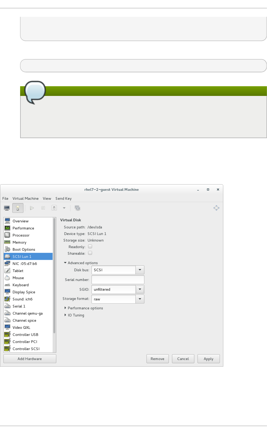
<target dev='sda' bus='scsi'/>
<shareable />
</disk>
2. Associate the device created in sda.xml with your guest virtual machine (Guest1, for example):
# virsh attach-device --config Guest1 ~/sda.xml
Note
Running the virsh attach-device command with the --config option requires a
guest reboot to add the device permanently to the guest. Alternatively, the --
persistent option can be used instead of --config, which can also be used to
hotplug the device to a guest.
Alternatively, the SCSI LUN-based storage can be attached or configured on the guest using virt -
man ag er. To configure this using virt - man ag er, click the Add Hardware button and add a virtual
disk with the desired parameters, or change the settings of an existing SCSI LUN device from this
window. In Red Hat Enterprise Linux 7.2, the SGIO value can also be configured in vi rt - ma n ag er:
Fig u re 15.1. C o n f ig u rin g SCSI LUN st o rag e wit h virt -man ag er
15.5.4 . Managing st orage cont rollers in a guest virt ual machine
Virt ualizat ion Deployment and Administ rat ion G uide
168

Unlike virtio disks, SCSI devices require the presence of a controller in the guest virtual machine.
This section details the necessary steps to create a virtual SCSI controller (also known as "Host Bus
Adapter" , or HBA), and to add SCSI storage to the guest virtual machine.
Pro ced ure 15.4 . Creat ing a virt u al SC SI co n t ro ller
1. Display the configuration of the guest virtual machine (Guest1) and look for a pre-existing
SCSI controller:
# virsh dumpxml Guest1 | grep controller.*scsi
If a device controller is present, the command will output one or more lines similar to the
following:
<controller type='scsi' model='virtio-scsi' index='0'/>
2. If the previous step did not show a device controller, create the description for one in a new
file and add it to the virtual machine, using the following steps:
a. Create the device controller by writing a <co ntro l l er> element in a new file and
save this file with an XML extension. vi rti o -scsi -co ntro l l er. xml , for example.
<controller type='scsi' model='virtio-scsi'/>
b. Associate the device controller you just created in vi rti o -scsi -co ntro l l er. xml
with your guest virtual machine (Guest1, for example):
# virsh attach-device --config Guest1 ~/virtio-scsi-
controller.xml
In this example the --config option behaves the same as it does for disks. Refer to
Procedure 15.2, “ Adding physical block devices to guests” for more information.
3. Add a new SCSI disk or CD-ROM. The new disk can be added using the methods in sections
Section 15.5.1, “Adding file based storage to a guest” and Section 15.5.2, “ Adding hard
drives and other block devices to a guest” . In order to create a SCSI disk, specify a target
device name that starts with sd. The supported limit for each controller is 1024 virtio-scsi
disks, but it is possible that other available resources in the host (such as file descriptors) are
exhausted with fewer disks.
For more information refer to the following Red Hat Enterprise Linux 6 whitepaper: The next-
generation storage interface for the Red Hat Enterprise Linux Kernel Virtual Machine: virtio-
scsi.
# virsh attach-disk Guest1 /var/lib/libvirt/images/FileName.img sdb
--cache none
Depending on the version of the driver in the guest virtual machine, the new disk may not be
detected immediately by a running guest virtual machine. Follow the steps in the Red Hat
Enterprise Linux Storage Administration Guide.
Chapt er 1 5. St orage Volu mes
169

Chapter 16. Using qemu-img
The qemu-img command line tool is used for formatting, modifying, and verifying various file systems
used by KVM. qemu-img options and usages are highlighted in the sections that follow.
16.1. Checking t he disk image
To perform a consistency check on a disk image with the file name imgname.
# qemu-img check [-f format] imgname
Note
Only the qcow2, qcow2 version3, and vdi formats support consistency checks.
16.2. Commit t ing changes t o an image
Commit any changes recorded in the specified image file (imgname) to the file's base image with the
qemu-img commit command. Optionally, specify the file's format type (fmt).
# qemu-img commit [-f qcow2] [-t cache] imgname
16.3. Convert ing an exist ing image t o anot her format
The convert option is used to convert one recognized image format to another image format. Refer
to Section 16.9, “ Supported qemu-img formats” for a list of accepted formats.
# qemu-img convert [-c] [-p] [-f fmt] [-t cache] [-O output_fmt] [-o
options] [-S sparse_size] filename output_filename
The -p parameter shows the progress of the command (optional and not for every command) and -S
flag allows for the creation of a sparse file, which is included within the disk image. Sparse files in all
purposes function like a standard file, except that the physical blocks that only contain zeros (i.e.,
nothing). When the Operating System sees this file, it treats it as it exists and takes up actual disk
space, even though in reality it doesn't take any. This is particularly helpful when creating a disk for
a guest virtual machine as this gives the appearance that the disk has taken much more disk space
than it has. For example, if you set -S to 50Gb on a disk image that is 10Gb, then your 10Gb of disk
space will appear to be 60Gb in size even though only 10Gb is actually being used.
Convert the disk image filename to disk image output_filename using format output_format.
The disk image can be optionally compressed with the -c option, or encrypted with the -o option by
setting -o encryption. Note that the options available with the -o parameter differ with the selected
format.
Only the qcow2 and qcow2 format supports encryption or compression. qcow2 encryption uses the
AES format with secure 128-bit keys. qcow2 compression is read-only, so if a compressed sector is
converted from qcow2 format, it is written to the new format as uncompressed data.
Virt ualizat ion Deployment and Administ rat ion G uide
170

Image conversion is also useful to get a smaller image when using a format which can grow, such as
q co w or cow. The empty sectors are detected and suppressed from the destination image.
16.4 . Creat ing and format t ing new images or devices
Create the new disk image filename of size size and format format.
# qemu-img create [-f format] [-o options] filename [size]
If a base image is specified with -o backing_file=filename, the image will only record
differences between itself and the base image. The backing file will not be modified unless you use
the co mmi t command. No size needs to be specified in this case.
16.5. Displaying image informat ion
The i nfo parameter displays information about a disk image filename. The format for the i nfo
option is as follows:
# qemu-img info [-f format] filename
This command is often used to discover the size reserved on disk which can be different from the
displayed size. If snapshots are stored in the disk image, they are displayed also. This command will
show for example, how much space is being taken by a qcow2 image on a block device. This is done
by running the qemu-img. You can check that the image in use is the one that matches the output of
the qemu-img info command with the qemu-img check command.
# qemu-img info /dev/vg-90.100-sluo/lv-90-100-sluo
image: /dev/vg-90.100-sluo/lv-90-100-sluo
file format: qcow2
virtual size: 20G (21474836480 bytes)
disk size: 0
cluster_size: 65536
16.6. Re-basing a backing file of an image
The qemu-img rebase changes the backing file of an image.
# qemu-img rebase [-f fmt] [-t cache] [-p] [-u] -b backing_file [-F
backing_fmt] filename
The backing file is changed to backing_file and (if the format of filename supports the feature), the
backing file format is changed to backing_format.
Note
Only the qcow2 format supports changing the backing file (rebase).
There are two different modes in which rebase can operate: safe and unsafe.
Chapt er 1 6 . Usin g qemu- img
171

safe mode is used by default and performs a real rebase operation. The new backing file may differ
from the old one and the qemu-img rebase command will take care of keeping the guest virtual
machine-visible content of filename unchanged. In order to achieve this, any clusters that differ
between backing_file and old backing file of filename are merged into filename before making any
changes to the backing file.
Note that safe mode is an expensive operation, comparable to converting an image. The old
backing file is required for it to complete successfully.
unsafe mode is used if the -u option is passed to qemu-img rebase. In this mode, only the
backing file name and format of filename is changed, without any checks taking place on the file
contents. Make sure the new backing file is specified correctly or the guest-visible content of the
image will be corrupted.
This mode is useful for renaming or moving the backing file. It can be used without an accessible old
backing file. For instance, it can be used to fix an image whose backing file has already been moved
or renamed.
16.7. Re-sizing t he disk image
Change the disk image filename as if it had been created with size size. Only images in raw format can
be re-sized in both directions, whereas qcow2 version 2 or qcow2 version 3 images can be grown
but cannot be shrunk.
Use the following to set the size of the disk image filename to size bytes:
# qemu-img resize filename size
You can also re-size relative to the current size of the disk image. To give a size relative to the current
size, prefix the number of bytes with + to grow, or - to reduce the size of the disk image by that
number of bytes. Adding a unit suffix allows you to set the image size in kilobytes (K), megabytes (M),
gigabytes (G) or terabytes (T).
# qemu-img resize filename [+|-]size[K|M|G|T]
Warning
Before using this command to shrink a disk image, you must use file system and partitioning
tools inside the VM itself to reduce allocated file systems and partition sizes accordingly.
Failure to do so will result in data loss.
After using this command to grow a disk image, you must use file system and partitioning tools
inside the VM to actually begin using the new space on the device.
16.8. List ing, creat ing, applying, and delet ing a snapshot
Using different parameters from the qemu-img snapshot command you can list, apply, create, or
delete an existing snapshot (snapshot) of specified image (filename).
# qemu-img snapshot [ -l | -a snapshot | -c snapshot | -d snapshot ]
filename
Virt ualizat ion Deployment and Administ rat ion G uide
172

The accepted arguments are as follows:
-l lists all snapshots associated with the specified disk image.
The apply option, -a, reverts the disk image (filename) to the state of a previously saved snapshot.
-c creates a snapshot (snapshot) of an image (filename).
-d deletes the specified snapshot.
16.9. Support ed qemu-img format s
When a format is specified in any of the q emu - img commands, the following format types may be
used:
raw - Raw disk image format (default). This can be the fastest file-based format. If your file system
supports holes (for example in ext2 or ext3 ), then only the written sectors will reserve space. Use
qemu-img info to obtain the real size used by the image or ls -ls on Unix/Linux. Although
Raw images give optimal performance, only very basic features are available with a Raw image
(no snapshots etc.).
qcow2 - QEMU image format, the most versatile format with the best feature set. Use it to have
optional AES encryption, zlib-based compression, support of multiple VM snapshots, and smaller
images, which are useful on file systems that do not support holes . Note that this expansive
feature set comes at the cost of performance.
Although only the formats above can be used to run on a guest virtual machine or host physical
machine machine, q emu - i mg also recognizes and supports the following formats in order to
convert from them into either raw , or qcow2 format. The format of an image is usually detected
automatically. In addition to converting these formats into raw or qcow2 , they can be converted
back from raw or qcow2 to the original format. Note that the qcow2 version supplied with Red Hat
Enterprise Linux 7 is 1.1. The format that is supplied with previous versions of Red Hat
Enterprise Linux will be 0.10. You can revert image files to previous versions of qcow2. To know
which version you are using, run qemu-img info qcow2 [imagefilename.img] command.
To change the qcow version refer to Section 26.20.2, “ Setting target elements” .
bochs - Bochs disk image format.
cloop - Linux Compressed Loop image, useful only to reuse directly compressed CD-ROM
images present for example in the Knoppix CD-ROMs.
cow - User Mode Linux Copy On Write image format. The cow format is included only for
compatibility with previous versions.
dmg - Mac disk image format.
nbd - Network block device.
parallels - Parallels virtualization disk image format.
q co w - Old QEMU image format. Only included for compatibility with older versions.
vdi - Oracle VM VirtualBox hard disk image format.
vmdk - VMware 3 and 4 compatible image format.
vvfat - Virtual VFAT disk image format.
Chapt er 1 6 . Usin g qemu- img
173

Chapter 17. KVM live migration
This chapter covers migrating guest virtual machines running on one host physical machine to
another. In both instances, the host physical machines are running the KVM hypervisor.
Migration describes the process of moving a guest virtual machine from one host physical machine
to another. This is possible because guest virtual machines are running in a virtualized environment
instead of directly on the hardware. Migration is useful for:
Load balancing - guest virtual machines can be moved to host physical machines with lower
usage when their host physical machine becomes overloaded, or another host physical machine
is under-utilized.
Hardware independence - when we need to upgrade, add, or remove hardware devices on the
host physical machine, we can safely relocate guest virtual machines to other host physical
machines. This means that guest virtual machines do not experience any downtime for hardware
improvements.
Energy saving - guest virtual machines can be redistributed to other host physical machines and
can thus be powered off to save energy and cut costs in low usage periods.
Geographic migration - guest virtual machines can be moved to another location for lower latency
or in serious circumstances.
Migration works by sending the state of the guest virtual machine's memory and any virtualized
devices to a destination host physical machine. It is recommended to use shared, networked storage
to store the guest virtual machine's images to be migrated. It is also recommended to use libvirt-
managed storage pools for shared storage when migrating virtual machines.
Migrations can be performed live or not.
In a live migration, the guest virtual machine continues to run on the source host physical machine,
while its memory pages are transferred to the destination host physical machine. During migration,
KVM monitors the source for any changes in pages it has already transferred, and begins to transfer
these changes when all of the initial pages have been transferred. KVM also estimates transfer speed
during migration, so when the remaining amount of data to transfer will take a certain configurable
period of time (10ms by default), KVM suspends the original guest virtual machine, transfers the
remaining data, and resumes the same guest virtual machine on the destination host physical
machine.
In contrast, a non-live migration (offline migration) suspends the guest virtual machine and then
copies the guest virtual machine's memory to the destination host physical machine. The guest
virtual machine is then resumed on the destination host physical machine and the memory the guest
virtual machine used on the source host physical machine is freed. The time it takes to complete such
a migration only depends on network bandwidth and latency. If the network is experiencing heavy
use or low bandwidth, the migration will take much longer. It should be noted that if the original guest
virtual machine modifies pages faster than KVM can transfer them to the destination host physical
machine, offline migration must be used, as live migration would never complete.
Note
If you are migrating a guest virtual machine that has virtio devices on it please adhere to the
warning explained in Important
17.1. Live migrat ion requirement s
Virt ualizat ion Deployment and Administ rat ion G uide
174

17.1. Live migrat ion requirement s
Migrating guest virtual machines requires the following:
Mig rat ion req u iremen ts
A guest virtual machine installed on shared storage using one of the following protocols:
Fibre Channel-based LUNs
iSCSI
FCoE
NFS
GFS2
SCSI RDMA protocols (SCSI RCP): the block export protocol used in Infiniband and 10GbE
iWARP adapters
Make sure that the libvirtd service is enabled.
# systemctl enable libvirtd
Make sure that the libvirtd service is running.
# systemctl restart libvirtd
. It is also important to note that the ability to migrate effectively is dependent on the parameter
settings in the /etc/l i bvi rt/l i bvi rtd . co nf configuration file.
The migration platforms and versions should be checked against table Table 17.1, “Live Migration
Compatibility”
Both systems must have the appropriate TCP/IP ports open. In cases where a firewall is used refer
to the Red Hat Enterprise Linux Virtualization Security Guide for detailed port information.
A separate system exporting the shared storage medium. Storage should not reside on either of
the two host physical machines being used for migration.
Shared storage must mount at the same location on source and destination systems. The
mounted directory names must be identical. Although it is possible to keep the images using
different paths, it is not recommended. Note that, if you are intending to use virt-manager to
perform the migration, the path names must be identical. If however you intend to use virsh to
perform the migration, different network configurations and mount directories can be used with the
help of --xml option or pre-hooks when doing migrations (refer to Live Migration Limitations). For
more information on prehooks, refer to libvirt.org, and for more information on the XML option,
refer to Chapter 26, Manipulating the domain XML.
When migration is attempted on an existing guest virtual machine in a public bridge+tap network,
the source and destination host physical machines must be located in the same network.
Otherwise, the guest virtual machine network will not operate after migration.
Chapt er 1 7 . KVM live migrat io n
175

Note
Guest virtual machine migration has the following limitations when used on Red Hat Enterprise
Linux with virtualization technology based on KVM:
Point to point migration – must be done manually to designate destination hypervisor from
originating hypervisor
No validation or roll-back is available
Determination of target may only be done manually
Storage migration cannot be performed live on Red Hat Enterprise Linux 7, but you can
migrate storage while the guest virtual machine is powered down. Live storage migration is
available on Red Hat Enterprise Virtualization . Call your service representative for details.
Pro ced ure 17.1. Co n fig u rin g libvirt d .co n f
1. Opening the l i bvi rtd . co nf requires running the command as root:
# vim /etc/libvirt/libvirtd.conf
2. Change the parameters as needed and save the file.
3. Restart the l i bvi rtd service:
# systemctl restart libvirtd
17.2. Live migrat ion and Red Hat Ent erprise Linux version compat ibilit y
Live Migration is supported as shown in table Table 17.1, “Live Migration Compatibility” :
T ab le 17.1. Live Mig rat io n C o mp at ib ilit y
Mig ra t io n
Met h o d
Release T yp e Examp le Live Mig rat io n
Support
N o t es
Forward Major release 6.5+ → 7.x Fully supported Any issues
should be
reported
Backward Major release 7.x → 6.y Not supported
Forward Minor release 7.x → 7.y (7.0 →
7.1)
Fully supported Any issues
should be
reported
Backward Minor release 7.y → 7.x (7.1 →
7.0)
Fully supported Any issues
should be
reported
T ro u b lesh o otin g p ro b lems wit h mig rat io n
Issu es wit h the migrat io n p ro t o co l — If backward migration ends with "unknown section
error", repeating the migration process can repair the issue as it may be a transient error. If not,
please report the problem.
Virt ualizat ion Deployment and Administ rat ion G uide
176

Co n f ig urin g n et wo rk st o rag e
Configure shared storage and install a guest virtual machine on the shared storage.
Alternatively, use the NFS example in Section 17.3, “ Shared storage example: NFS for a simple
migration”
17.3. Shared st orage example: NFS for a simple migrat ion
Important
This example uses NFS to share guest virtual machine images with other KVM host physical
machines. Although not practical for large installations, it is presented to demonstrate
migration techniques only. Do not use this example for migrating or running more than a few
guest virtual machines. In addition, it is required that the synch parameter is enabled. This is
required for proper export of the NFS storage.
iSCSI storage is a better choice for large deployments. Refer to Section 14.5, “ iSCSI-based
storage pools” for configuration details.
Also note, that the instructions provided herin are not meant to replace the detailed instructions
found in Red Hat Linux Storage Administration Guide. Refer to this guide for information on configuring
NFS, opening IP tables, and configuring the firewall.
Make sure that NFS file locking is not used as it is not supported in KVM.
1. Exp o rt yo u r lib virt imag e d irect ory
Migration requires storage to reside on a system that is separate to the migration target
systems. On this separate system, export the storage by adding the default image directory to
the /etc/exports file:
/var/lib/libvirt/images *.example.com(rw,no_root_squash,sync)
Change the hostname parameter as required for your environment.
2. St art N FS
a. Install the NFS packages if they are not yet installed:
# yum install nfs-utils
b. Make sure that the ports for NFS in iptables (2049, for example) are opened and
add NFS to the /etc/hosts.allow file.
c. Start the NFS service:
# systemctl restart nfs-server
3. Mo u n t the sh ared st o rag e o n th e d est inat io n
Chapt er 1 7 . KVM live migrat io n
177

On the migration destination system, mount the /var/lib/libvirt/images directory:
# mount storage_host:/var/lib/libvirt/images
/var/lib/libvirt/images
Warning
Whichever directory is chosen for the source host physical machine must be exactly
the same as that on the destination host physical machine. This applies to all types of
shared storage. The directory must be the same or the migration with virt-manager will
fail.
17.4 . Live KVM migrat ion wit h virsh
A guest virtual machine can be migrated to another host physical machine with the virsh command.
The mi g rate command accepts parameters in the following format:
# virsh migrate --live GuestName DestinationURL
Note that the --live option may be eliminated when live migration is not desired. Additional options are
listed in Section 17.4.2, “ Additional options for the virsh migrate command” .
The GuestName parameter represents the name of the guest virtual machine which you want to
migrate.
The DestinationURL parameter is the connection URL of the destination host physical machine.
The destination system must run the same version of Red Hat Enterprise Linux, be using the same
hypervisor and have l i bvi rt running.
Note
The DestinationURL parameter for normal migration and peer2peer migration has different
semantics:
normal migration: the DestinationURL is the URL of the target host physical machine as
seen from the source guest virtual machine.
peer2peer migration: DestinationURL is the URL of the target host physical machine as
seen from the source host physical machine.
Once the command is entered, you will be prompted for the root password of the destination system.
Important
Name resolution must be working on both sides (source and destination) in order for
migration to succeed. Each side must be able to find the other. Make sure that you can ping
one side to the other to check that the name resolution is working.
Virt ualizat ion Deployment and Administ rat ion G uide
178

Examp le: live mig rat ion wit h virsh
This example migrates from host1.example.com to host2.example.com. Change the host
physical machine names for your environment. This example migrates a virtual machine named
guest1-rhel6-64.
This example assumes you have fully configured shared storage and meet all the prerequisites
(listed here: Migration requirements).
1.
Verif y t h e g u est virt ual mach in e is ru n n in g
From the source system, host1.example.com, verify guest1-rhel6-64 is running:
[root@host1 ~]# virsh list
Id Name State
----------------------------------
10 guest1-rhel6-64 running
2.
Mig rat e t he g u est virt ual mach in e
Execute the following command to live migrate the guest virtual machine to the destination,
host2.example.com. Append /system to the end of the destination URL to tell libvirt that
you need full access.
# virsh migrate --live guest1-rhel7-64
qemu+ssh://host2.example.com/system
Once the command is entered you will be prompted for the root password of the destination
system.
3.
Wait
The migration may take some time depending on load and the size of the guest virtual
machine. virsh only reports errors. The guest virtual machine continues to run on the
source host physical machine until fully migrated.
4.
Verif y t h e g u est virt ual mach in e h as arrived at t h e d est in at io n host
From the destination system, host2.example.com, verify guest1-rhel7-64 is running:
[root@host2 ~]# virsh list
Id Name State
----------------------------------
10 guest1-rhel7-64 running
The live migration is now complete.
Chapt er 1 7 . KVM live migrat io n
179

Note
libvirt supports a variety of networking methods including TLS/SSL, UNIX sockets, SSH, and
unencrypted TCP. Refer to Chapter 21, Remote management of guests for more information on
using other methods.
Note
Non-running guest virtual machines cannot be migrated with the virsh migrate command.
To migrate a non-running guest virtual machine, the following script should be used:
virsh -c qemu+ssh://<target-system-FQDN> migrate --offline --
persistent
17.4 .1. Addit ional t ips for migrat ion wit h virsh
It is possible to perform multiple, concurrent live migrations where each migration runs in a separate
command shell. However, this should be done with caution and should involve careful calculations
as each migration instance uses one MAX_CLIENT from each side (source and target). As the default
setting is 20, there is enough to run 10 instances without changing the settings. Should you need to
change the settings, refer to the procedure Procedure 17.1, “Configuring libvirtd.conf” .
1. Open the libvirtd.conf file as described in Procedure 17.1, “Configuring libvirtd.conf” .
2. Look for the Processing controls section.
#################################################################
#
# Processing controls
#
# The maximum number of concurrent client connections to allow
# over all sockets combined.
#max_clients = 20
# The minimum limit sets the number of workers to start up
# initially. If the number of active clients exceeds this,
# then more threads are spawned, upto max_workers limit.
# Typically you'd want max_workers to equal maximum number
# of clients allowed
#min_workers = 5
#max_workers = 20
# The number of priority workers. If all workers from above
# pool will stuck, some calls marked as high priority
# (notably domainDestroy) can be executed in this pool.
#prio_workers = 5
Virt ualizat ion Deployment and Administ rat ion G uide
180

# Total global limit on concurrent RPC calls. Should be
# at least as large as max_workers. Beyond this, RPC requests
# will be read into memory and queued. This directly impact
# memory usage, currently each request requires 256 KB of
# memory. So by default upto 5 MB of memory is used
#
# XXX this isn't actually enforced yet, only the per-client
# limit is used so far
#max_requests = 20
# Limit on concurrent requests from a single client
# connection. To avoid one client monopolizing the server
# this should be a small fraction of the global max_requests
# and max_workers parameter
#max_client_requests = 5
#################################################################
3. Change the max_clients and max_workers parameters settings. It is recommended that
the number be the same in both parameters. The max_clients will use 2 clients per
migration (one per side) and max_workers will use 1 worker on the source and 0 workers on
the destination during the perform phase and 1 worker on the destination during the finish
phase.
Important
The max_clients and max_workers parameters settings are effected by all guest
virtual machine connections to the libvirtd service. This means that any user that is
using the same guest virtual machine and is performing a migration at the same time
will also beholden to the limits set in the the max_clients and max_workers
parameters settings. This is why the maximum value needs to be considered carefully
before performing a concurrent live migration.
Important
The max_clients parameter controls how many clients are allowed to connect to
libvirt. When a large number of containers are started at once, this limit can be easily
reached and exceeded. The value of the max_clients parameter could be increased
to avoid this, but doing so can leave the system more vulnerable to denial of service
(DoS) attacks against instances. To alleviate this problem, a new
max_anonymous_clients setting has been introduced in Red Hat Enterprise Linux
7.0 that specifies a limit of connections which are accepted but not yet authenticated.
You can implement a combination of max_clients and max_anonymous_clients
to suit your workload.
4. Save the file and restart the service.
Chapt er 1 7 . KVM live migrat io n
181

Note
There may be cases where a migration connection drops because there are too many
ssh sessions that have been started, but not yet authenticated. By default, sshd allows
only 10 sessions to be in a "pre-authenticated state" at any time. This setting is
controlled by the MaxStartups parameter in the sshd configuration file (located here:
/etc/ssh/sshd_config), which may require some adjustment. Adjusting this
parameter should be done with caution as the limitation is put in place to prevent DoS
attacks (and over-use of resources in general). Setting this value too high will negate
its purpose. To change this parameter, edit the file /etc/ssh/sshd_config, remove
the # from the beginning of the MaxStartups line, and change the 10 (default value)
to a higher number. Remember to save the file and restart the sshd service. For more
information, refer to the sshd_config man page.
17.4 .2. Addit ional opt ions for t he virsh migrat e command
In addition to --live, virsh migrate accepts the following options:
--d i rect - used for direct migration
--p2p - used for peer-2-peer migration
--tunneled - used for tunneled migration
--offline - migrates domain definition without starting the domain on destination and without
stopping it on source host. Offline migration may be used with inactive domains and it must be
used with the --persistent option.
--persistent - leaves the domain persistent on destination host physical machine
--undefinesource - undefines the domain on the source host physical machine
--suspend - leaves the domain paused on the destination host physical machine
--change-protection - enforces that no incompatible configuration changes will be made to
the domain while the migration is underway; this flag is implicitly enabled when supported by the
hypervisor, but can be explicitly used to reject the migration if the hypervisor lacks change
protection support.
--unsafe - forces the migration to occur, ignoring all safety procedures.
--verbose - displays the progress of migration as it is occurring
--compressed - activates compression of memory pages that have to be transferred repeatedly
during live migration.
--abo rt-o n-erro r - cancels the migration if a soft error (for example I/O error) happens during
the migration.
--domain name - sets the domain name, id or uuid.
--desturi uri - connection URI of the destination host as seen from the client (normal
migration) or source (p2p migration).
--migrateuri uri - the migration URI, which can usually be omitted.
--graphicsuri uri - graphics URI to be used for seamless graphics migration.
Virt ualizat ion Deployment and Administ rat ion G uide
182

--listen-address address - sets the listen address that the hypervisor on the destination
side should bind to for incoming migration.
--timeout seconds - forces a guest virtual machine to suspend when the live migration
counter exceeds N seconds. It can only be used with a live migration. Once the timeout is initiated,
the migration continues on the suspended guest virtual machine.
--dname newname - is used for renaming the domain during migration, which also usually can
be omitted
--xml filename - the filename indicated can be used to supply an alternative XML file for use
on the destination to supply a larger set of changes to any host-specific portions of the domain
XML, such as accounting for naming differences between source and destination in accessing
underlying storage. This option is usually omitted.
In addtion the following commands may help as well:
virsh migrate-setmaxdowntime domain downtime - will set a maximum tolerable
downtime for a domain which is being live-migrated to another host. The specified downtime is in
milliseconds. The domain specified must be the same domain that is being migrated.
virsh migrate-compcache domain --size - will set and or get the size of the cache in
bytes which is used for compressing repeatedly transferred memory pages during a live migration.
When the --size is not used the command displays the current size of the compression cache.
When --size is used, and specified in bytes, the hypervisor is asked to change compression to
match the indicated size, following which the current size is displayed. The --size argument is
supposed to be used while the domain is being live migrated as a reaction to the migration
progress and increasing number of compression cache misses obtained from the
domjobingfo.
virsh migrate-setspeed domain bandwidth - sets the migration bandwidth in Mib/sec for
the specified domain which is being migrated to another host.
virsh migrate-getspeed domain - gets the maximum migration bandwidth that is available
in Mib/sec for the specified domain.
Refer to Live Migration Limitations or the virsh man page for more information.
17.5. Migrat ing wit h virt -manager
This section covers migrating a KVM guest virtual machine with virt-manager from one host
physical machine to another.
1. O p en virt - man ag er
Open virt-manager. Choose Ap p l ic at io n s → Syst em T o o ls → Virt u al Mach in e
Man ag er from the main menu bar to launch virt-manager.
Chapt er 1 7 . KVM live migrat io n
183
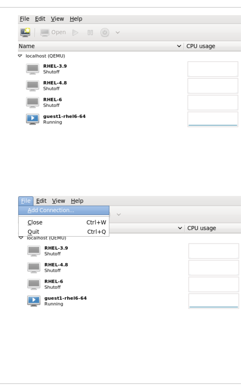
Fig u re 17.1. Virt - Man ag er main men u
2. Co n n ect t o the t arg et h o st p h ysical mach in e
Connect to the target host physical machine by clicking on the File menu, then click Ad d
C o n n ect i o n .
Fig u re 17.2. O p en Ad d C o n n ect io n win d o w
3. Ad d co n n ect io n
The Ad d C o nnecti o n window appears.
Virt ualizat ion Deployment and Administ rat ion G uide
184
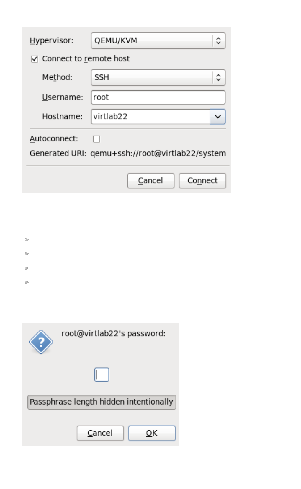
Fig u re 17.3. Ad d in g a co n n ect ion t o t h e t arg et h o st physical mach in e
Enter the following details:
Hypervisor: Select Q EMU/KVM.
Metho d : Select the connection method.
Username: Enter the username for the remote host physical machine.
Hostname: Enter the hostname for the remote host physical machine.
Click the Connect button. An SSH connection is used in this example, so the specified user's
password must be entered in the next step.
Fig u re 17.4 . En t er p asswo rd
Chapt er 1 7 . KVM live migrat io n
185
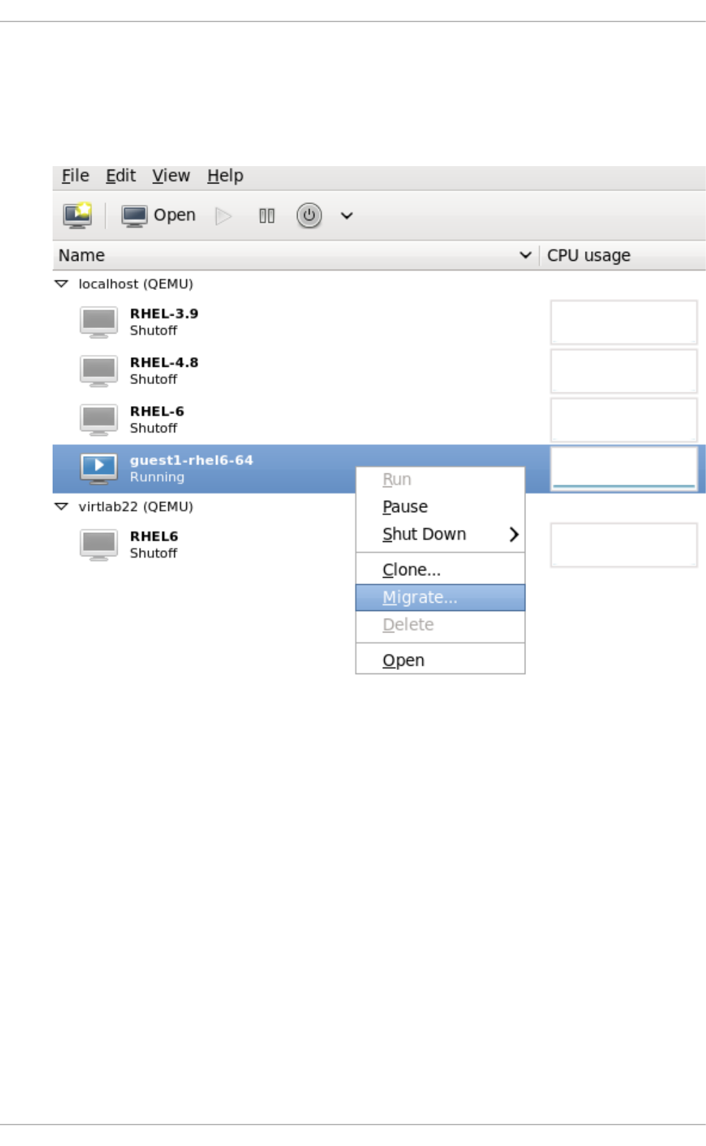
4. Mig rat e g u est virt ual mach in es
Open the list of guests inside the source host physical machine (click the small triangle on
the left of the host name) and right click on the guest that is to be migrated (g u e st 1 - rh e l6 -
64 in this example) and click Mig ra t e.
Fig u re 17.5. C h o o sin g t h e g u est to be mig rat ed
In the New Ho st field, use the drop-down list to select the host physical machine you wish to
migrate the guest virtual machine to and click Mi g ra t e.
Virt ualizat ion Deployment and Administ rat ion G uide
186
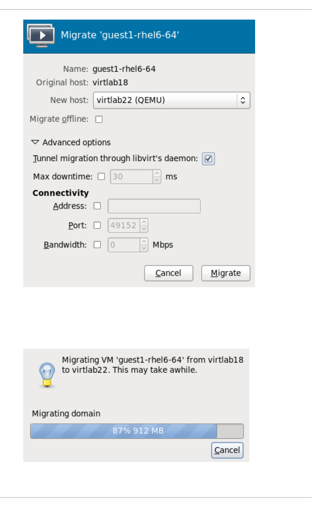
Fig u re 17.6 . Ch oo sin g the d est in at io n ho st p h ysical mach in e an d st art in g t h e
mig rat io n pro cess
A progress window will appear.
Fig u re 17.7. Pro g ress win d ow
Chapt er 1 7 . KVM live migrat io n
187
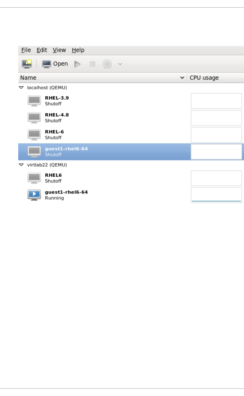
virt - man ag er now displays the newly migrated guest virtual machine running in the
destination host. The guest virtual machine that was running in the source host physical
machine is now listed inthe Shutoff state.
Fig u re 17.8. Mig rat ed g u est virt ual mach in e ru nnin g in t h e d est in at io n h o st
p h ysical mach in e
5. O p t io n al - View t h e st o rag e d et ails f or t h e h o st p h ysical mach in e
In the Ed i t menu, click Conn ect io n Det ails, the Connection Details window appears.
Click the Sto rag e tab. The iSCSI target details for the destination host physical machine is
shown. Note that the migrated guest virtual machine is listed as using the storage
Virt ualizat ion Deployment and Administ rat ion G uide
188
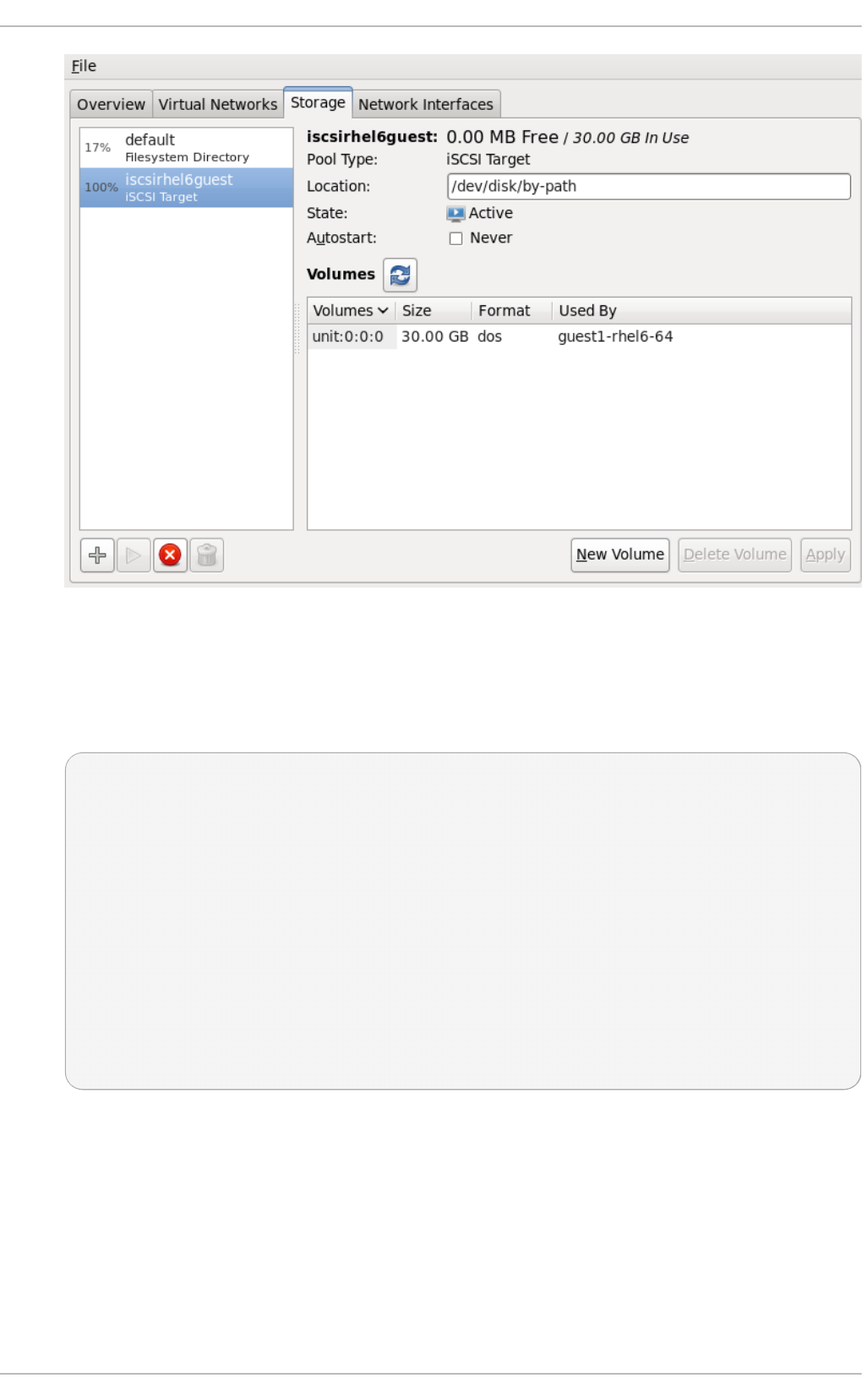
Fig u re 17.9 . St o rag e d et ails
This host was defined by the following XML configuration:
<pool type='iscsi'>
<name>iscsirhel6guest</name>
<source>
<host name='virtlab22.example.com.'/>
<device path='iqn.2001-05.com.iscsivendor:0-8a0906-
fbab74a06-a700000017a4cc89-rhevh'/>
</source>
<target>
<path>/dev/disk/by-path</path>
</target>
</pool>
...
Fig u re 17.10. XML co n f ig urat io n f o r t h e d est in at io n ho st p h ysical mach in e
Chapt er 1 7 . KVM live migrat io n
189

Chapter 18. Guest virtual machine device configuration
Red Hat Enterprise Linux 7 supports three classes of devices for guest virtual machines:
Emulated devices are purely virtual devices that mimic real hardware, allowing unmodified guest
operating systems to work with them using their standard in-box drivers. Red Hat Enterprise Linux
7 supports up to 216 virtio devices.
Virtio devices are purely virtual devices designed to work optimally in a virtual machine. Virtio
devices are similar to emulated devices, however, non-Linux virtual machines do not include the
drivers they require by default. Virtualization management software like the Virtual Machine
Manager (virt - man ag er) and the Red Hat Enterprise Virtualization Hypervisor install these
drivers automatically for supported non-Linux guest operating systems. Red Hat Enterprise Linux
7 supports up to 700 scsi disks.
Assigned devices are physical devices that are exposed to the virtual machine. This method is also
known as 'passthrough'. Device assignment allows virtual machines exclusive access to PCI
devices for a range of tasks, and allows PCI devices to appear and behave as if they were
physically attached to the guest operating system. Red Hat Enterprise Linux 7 supports up to 32
assigned devices per virtual machine.
Device assignment is supported on PCIe devices, including select graphics devices. Nvidia K-
series Quadro, GRID, and Tesla graphics card GPU functions are now supported with device
assignment in Red Hat Enterprise Linux 7. Parallel PCI devices may be supported as assigned
devices, but they have severe limitations due to security and system configuration conflicts. Refer
to the sections within this chapter for more details regarding specific series and versions that are
supported.
Red Hat Enterprise Linux 7 supports PCI hotplug of devices exposed as single function slots to the
virtual machine. Single function host devices and individual functions of multi-function host devices
may be configured to enable this. Configurations exposing devices as multi-function PCI slots to the
virtual machine are recommended only for non-hotplug applications.
For more information on specific devices and for limitations refer to Section 26.18, “ D evices” .
Note
Platform support for interrupt remapping is required to fully isolate a guest with assigned
devices from the host. Without such support, the host may be vulnerable to interrupt injection
attacks from a malicious guest. In an environment where guests are trusted, the admin may
opt-in to still allow PCI device assignment using the allow_unsafe_interrupts option to
the vfio_iommu_type1 module. This may either be done persistently by adding a .conf file
(e.g. l o cal . co nf) to /etc/modprobe.d containing the following:
options vfio_iommu_type1 allow_unsafe_interrupts=1
or dynamically using the sysfs entry to do the same:
# echo 1 >
/sys/module/vfio_iommu_type1/parameters/allow_unsafe_interrupts
18.1. PCI devices
Virt ualizat ion Deployment and Administ rat ion G uide
190

PCI device assignment is only available on hardware platforms supporting either Intel VT-d or AMD
IOMMU. These Intel VT-d or AMD IOMMU specifications must be enabled in BIOS for PCI device
assignment to function.
Pro ced ure 18.1. Prep arin g an In t el syst em f o r PCI d evice assig n men t
1. En ab le t h e In tel VT - d sp ecificat io n s
The Intel VT-d specifications provide hardware support for directly assigning a physical
device to a virtual machine. These specifications are required to use PCI device assignment
with Red Hat Enterprise Linux.
The Intel VT-d specifications must be enabled in the BIOS. Some system manufacturers
disable these specifications by default. The terms used to refer to these specifications can
differ between manufacturers; consult your system manufacturer's documentation for the
appropriate terms.
2. Act ivat e In t el VT- d in t h e kern el
Activate Intel VT-d in the kernel by adding the intel_iommu=pt parameter to the end of the
GRUB_CMDLINX_LINUX line, within the quotes, in the /etc/sysconfig/grub file.
Note
Instead of using the *_iommu=pt parameter for device assignment, which puts IOMMU
into passthrough mode, it is also possible to use *_iommu=on. However, iommu=on
should be used with caution, as it enables IOMMU for all devices, including those not
used for device assignment by KVM, which may have a negative impact on guest
performance.
The example below is a modified g rub file with Intel VT-d activated.
GRUB_CMDLINE_LINUX="rd.lvm.lv=vg_VolGroup00/LogVol01
vconsole.font=latarcyrheb-sun16 rd.lvm.lv=vg_VolGroup_1/root
vconsole.keymap=us $([ -x /usr/sbin/rhcrashkernel-param ] &&
/usr/sbin/
rhcrashkernel-param || :) rhgb quiet i ntel _i o mmu= pt"
3. Reg en erat e co n f ig f ile
Regenerate /boot/grub2/grub.cfg by running:
grub2-mkconfig -o /boot/grub2/grub.cfg
4. Read y t o u se
Reboot the system to enable the changes. Your system is now capable of PCI device
assignment.
Pro ced ure 18.2. Prep arin g an AMD syst em f o r PCI device assig n men t
1. En ab le t h e AMD IO MMU sp ecif icat io n s
Chapt er 1 8 . G uest virt ual machine device configurat ion
191

The AMD IOMMU specifications are required to use PCI device assignment in Red Hat
Enterprise Linux. These specifications must be enabled in the BIOS. Some system
manufacturers disable these specifications by default.
2. En ab le IO MMU kern el su p p o rt
Append amd_iommu=pt to the end of the GRUB_CMDLINX_LINUX line, within the quotes, in
/etc/sysconfig/grub so that AMD IOMMU specifications are enabled at boot.
3. Reg en erat e co n f ig f ile
Regenerate /boot/grub2/grub.cfg by running:
grub2-mkconfig -o /boot/grub2/grub.cfg
4. Read y t o u se
Reboot the system to enable the changes. Your system is now capable of PCI device
assignment.
Note
For further information on IOMMU, see Appendix D, Working with IOMMU Groups.
18.1.1. Assigning a PCI device wit h virsh
These steps cover assigning a PCI device to a virtual machine on a KVM hypervisor.
This example uses a PCIe network controller with the PCI identifier code, pci_0000_01_00_0, and
a fully virtualized guest machine named guest1-rhel7-64.
Pro ced ure 18.3. Assig n ing a PCI d evice t o a g u est virt ual mach in e wit h virsh
1. Id en t if y th e d evice
First, identify the PCI device designated for device assignment to the virtual machine. Use the
lspci command to list the available PCI devices. You can refine the output of lspci with
g rep.
This example uses the Ethernet controller highlighted in the following output:
# lspci | grep Ethernet
0 0 : 19 . 0 Ethernet co ntro l l er: Intel C o rpo rati o n 8256 7LM-2 G i g abi t
Netwo rk C o nnecti o n
01:00.0 Ethernet controller: Intel Corporation 82576 Gigabit
Network Connection (rev 01)
01:00.1 Ethernet controller: Intel Corporation 82576 Gigabit
Network Connection (rev 01)
This Ethernet controller is shown with the short identifier 00:19.0. We need to find out the
full identifier used by virsh in order to assign this PCI device to a virtual machine.
Virt ualizat ion Deployment and Administ rat ion G uide
192

To do so, use the virsh nodedev-list command to list all devices of a particular type
(pci) that are attached to the host machine. Then look at the output for the string that maps
to the short identifier of the device you wish to use.
This example shows the string that maps to the Ethernet controller with the short identifier
00:19.0. Note that the : and . characters are replaced with underscores in the full
identifier.
# virsh nodedev-list --cap pci
pci_0000_00_00_0
pci_0000_00_01_0
pci_0000_00_03_0
pci_0000_00_07_0
pci_0000_00_10_0
pci_0000_00_10_1
pci_0000_00_14_0
pci_0000_00_14_1
pci_0000_00_14_2
pci_0000_00_14_3
pci_0000_0 0 _19 _0
pci_0000_00_1a_0
pci_0000_00_1a_1
pci_0000_00_1a_2
pci_0000_00_1a_7
pci_0000_00_1b_0
pci_0000_00_1c_0
pci_0000_00_1c_1
pci_0000_00_1c_4
pci_0000_00_1d_0
pci_0000_00_1d_1
pci_0000_00_1d_2
pci_0000_00_1d_7
pci_0000_00_1e_0
pci_0000_00_1f_0
pci_0000_00_1f_2
pci_0000_00_1f_3
pci_0000_01_00_0
pci_0000_01_00_1
pci_0000_02_00_0
pci_0000_02_00_1
pci_0000_06_00_0
pci_0000_07_02_0
pci_0000_07_03_0
Record the PCI device number that maps to the device you want to use; this is required in
other steps.
2. Review d evice in f ormat io n
Information on the domain, bus, and function are available from output of the vi rsh
nodedev-dumpxml command:
# virsh nodedev-dumpxml pci_0000_00_19_0
Chapt er 1 8 . G uest virt ual machine device configurat ion
193

<device>
<name>pci_0000_00_19_0</name>
<parent>computer</parent>
<driver>
<name>e1000e</name>
</driver>
<capability type='pci'>
<domain>0</domain>
<bus>0</bus>
<slot>25</slot>
<function>0</function>
<product id='0x1502'>82579LM Gigabit Network
Connection</product>
<vendor id='0x8086'>Intel Corporation</vendor>
<iommuGroup number='7'>
<address domain='0x0000' bus='0x00' slot='0x19'
function='0x0'/>
</iommuGroup>
</capability>
</device>
Fig u re 18.1. D u mp co n t en t s
Note
An IOMMU group is determined based on the visibility and isolation of devices from the
perspective of the IOMMU. Each IOMMU group may contain one or more devices. When
multiple devices are present, all endpoints within the IOMMU group must be claimed for
any device within the group to be assigned to a guest. This can be accomplished
either by also assigning the extra endpoints to the guest or by detaching them from the
host driver using virsh nodedev-detach. Devices contained within a single group
may not be split between multiple guests or split between host and guest. Non-
endpoint devices such as PCIe root ports, switch ports, and bridges should not be
detached from the host drivers and will not interfere with assignment of endpoints.
Devices within an IOMMU group can be determined using the iommuGroup section of
the virsh nodedev-dumpxml output. Each member of the group is provided via a
separate "address" field. This information may also be found in sysfs using the
following:
$ ls /sys/bus/pci/devices/0000:01:00.0/iommu_group/devices/
An example of the output from this would be:
0000:01:00.0 0000:01:00.1
To assign only 0000.01.00.0 to the guest, the unused endpoint should be detached
from the host before starting the guest:
$ virsh nodedev-detach pci_0000_01_00_1
Virt ualizat ion Deployment and Administ rat ion G uide
194

3. Det ermin e req u ired co n f ig u rat io n d et ails
Refer to the output from the virsh nodedev-dumpxml pci_0000_00_19_0 command
for the values required for the configuration file.
The example device has the following values: bus = 0, slot = 25 and function = 0. The decimal
configuration uses those three values:
bus='0'
slot='25'
function='0'
4. Add co n f ig u rat io n d et ails
Run vi rsh ed it, specifying the virtual machine name, and add a device entry in the
<source> section to assign the PCI device to the guest virtual machine.
# virsh edit guest1-rhel7-64
<hostdev mode='subsystem' type='pci' managed='yes'>
<source>
<address domain='0' bus='0' slot='25' function='0'/>
</source>
</hostdev>
Fig u re 18.2. Ad d PCI device
Alternately, run virsh attach-device, specifying the virtual machine name and the
guest's XML file:
virsh attach-device guest1-rhel7-64 fi l e. xml
5. St art t he virt ual mach in e
# virsh start guest1-rhel7-64
The PCI device should now be successfully assigned to the virtual machine, and accessible to the
guest operating system.
18.1.2. Assigning a PCI device wit h virt -manager
PCI devices can be added to guest virtual machines using the graphical virt-manager tool. The
following procedure adds a Gigabit Ethernet controller to a guest virtual machine.
Pro ced ure 18.4 . Assig n in g a PC I d evice t o a g u est virt u al mach in e u sin g virt - man ag er
1. O p en t h e h ard ware set tin g s
Open the guest virtual machine and click the Add Hardware button to add a new device to
the virtual machine.
Chapt er 1 8 . G uest virt ual machine device configurat ion
195
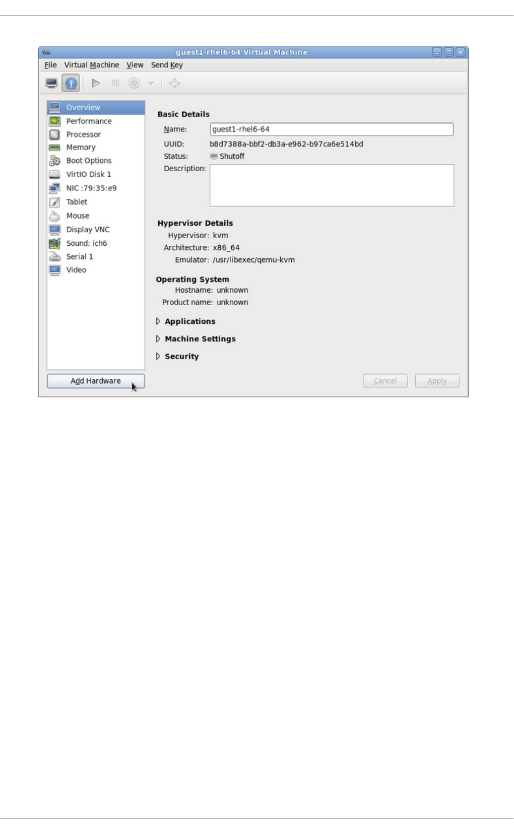
Fig u re 18.3. T h e virt ual mach in e h ard ware in f o rmat io n win d o w
2. Select a PCI device
Select PCI Ho st D evice from the Hardware list on the left.
Select an unused PCI device. Note that selecting PCI devices presently in use by another
guest causes errors. In this example, a spare 82576 network device is used. Click Finish to
complete setup.
Virt ualizat ion Deployment and Administ rat ion G uide
196
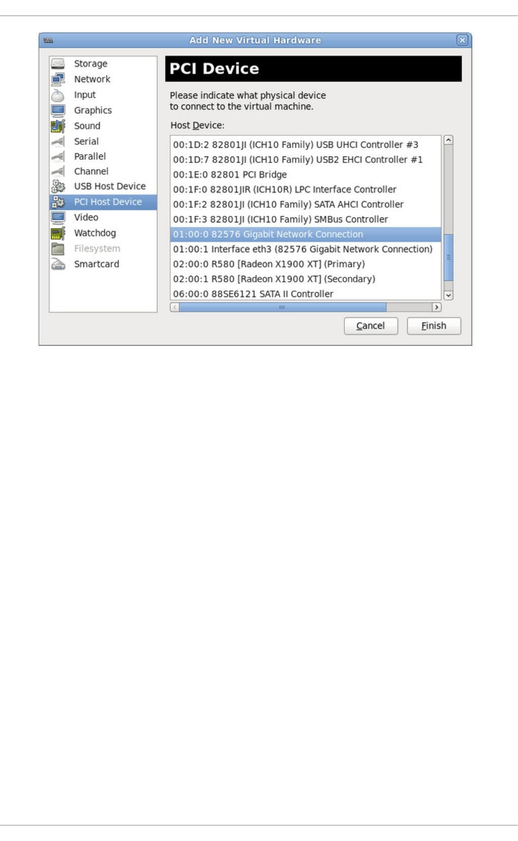
Fig u re 18.4 . T h e Ad d n ew virt u al h ard ware wiz ard
3. Ad d t h e n ew d evice
The setup is complete and the guest virtual machine now has direct access to the PCI device.
Chapt er 1 8 . G uest virt ual machine device configurat ion
197
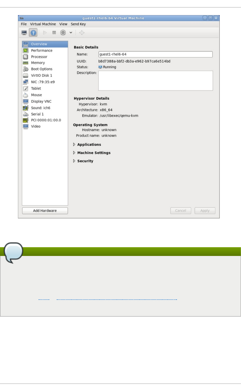
Fig u re 18.5. T h e virt ual mach in e h ard ware in f o rmat io n win d o w
Note
If device assignment fails, there may be other endpoints in the same IOMMU group that are still
attached to the host. There is no way to retrieve group information using virt-manager, but
virsh commands can be used to analyze the bounds of the IOMMU group and if necessary
sequester devices.
Refer to the Note in Section 18.1.1, “ Assigning a PCI device with virsh” for more information on
IOMMU groups and how to detach endpoint devices using virsh.
18.1.3. PCI device assignment wit h virt -inst all
To use virt - i nst al l to assign a PCI device, use the --host-device parameter.
Pro ced ure 18.5. Assig n ing a PCI d evice t o a virt u al mach in e with virt - in st all
1. Id en t if y th e d evice
Virt ualizat ion Deployment and Administ rat ion G uide
198

Identify the PCI device designated for device assignment to the guest virtual machine.
# lspci | grep Ethernet
00:19.0 Ethernet controller: Intel Corporation 82567LM-2 Gigabit
Network Connection
01:00.0 Ethernet controller: Intel Corporation 82576 Gigabit
Network Connection (rev 01)
01:00.1 Ethernet controller: Intel Corporation 82576 Gigabit
Network Connection (rev 01)
The virsh nodedev-list command lists all devices attached to the system, and identifies
each PCI device with a string. To limit output to only PCI devices, run the following command:
# virsh nodedev-list --cap pci
pci_0000_00_00_0
pci_0000_00_01_0
pci_0000_00_03_0
pci_0000_00_07_0
pci_0000_00_10_0
pci_0000_00_10_1
pci_0000_00_14_0
pci_0000_00_14_1
pci_0000_00_14_2
pci_0000_00_14_3
pci_0000_00_19_0
pci_0000_00_1a_0
pci_0000_00_1a_1
pci_0000_00_1a_2
pci_0000_00_1a_7
pci_0000_00_1b_0
pci_0000_00_1c_0
pci_0000_00_1c_1
pci_0000_00_1c_4
pci_0000_00_1d_0
pci_0000_00_1d_1
pci_0000_00_1d_2
pci_0000_00_1d_7
pci_0000_00_1e_0
pci_0000_00_1f_0
pci_0000_00_1f_2
pci_0000_00_1f_3
pci_0000_01_00_0
pci_0000_01_00_1
pci_0000_02_00_0
pci_0000_02_00_1
pci_0000_06_00_0
pci_0000_07_02_0
pci_0000_07_03_0
Record the PCI device number; the number is needed in other steps.
Information on the domain, bus and function are available from output of the vi rsh
nodedev-dumpxml command:
# virsh nodedev-dumpxml pci_0000_01_00_0
Chapt er 1 8 . G uest virt ual machine device configurat ion
199

<device>
<name>pci_0000_01_00_0</name>
<parent>pci_0000_00_01_0</parent>
<driver>
<name>igb</name>
</driver>
<capability type='pci'>
<domain>0</domain>
<bus>1</bus>
<slot>0</slot>
<function>0</function>
<product id='0x10c9'>82576 Gigabit Network Connection</product>
<vendor id='0x8086'>Intel Corporation</vendor>
<iommuGroup number='7'>
<address domain='0x0000' bus='0x00' slot='0x19'
function='0x0'/>
</iommuGroup>
</capability>
</device>
Fig u re 18.6 . PCI d evice f ile co n ten t s
Note
If there are multiple endpoints in the IOMMU group and not all of them are assigned to
the guest, you will need to manually detach the other endpoint(s) from the host by
running the following command before you start the guest:
$ virsh nodedev-detach pci_0000_00_19_1
Refer to the Note in Section 18.1.1, “ Assigning a PCI device with virsh” for more
information on IOMMU groups.
2. Ad d t h e d evice
Use the PCI identifier output from the virsh nodedev command as the value for the --
host-device parameter.
virt-install \
--name=guest1-rhel7-64 \
--disk path=/var/lib/libvirt/images/guest1-rhel7-64.img,size=8 \
--nonsparse --graphics spice \
--vcpus=2 --ram=2048 \
--location=http://example1.com/installation_tree/RHEL7.0-Server-
x86_64/os \
Virt ualizat ion Deployment and Administ rat ion G uide
200

--nonetworks \
--os-type=linux \
--os-variant=rhel7
--host-device=pci_0000_01_00_0
3. Co mp let e t h e in st allat io n
Complete the guest installation. The PCI device should be attached to the guest.
18.1.4 . Det aching an assigned PCI device
When a host PCI device has been assigned to a guest machine, the host can no longer use the
device. Read this section to learn how to detach the device from the guest with virsh or virt -
man ag er so it is available for host use.
Pro ced ure 18.6 . Det ach in g a PCI d evice f ro m a gu est wit h virsh
1. Det ach t h e d evice
Use the following command to detach the PCI device from the guest by removing it in the
guest's XML file:
# virsh detach-device name_of_guest file.xml
2. Re- at t ach t h e d evice t o t h e h o st (op t io n al)
If the device is in managed mode, skip this step. The device will be returned to the host
automatically.
If the device is not using managed mode, use the following command to re-attach the PCI
device to the host machine:
# virsh nodedev-reattach device
For example, to re-attach the pci_0000_01_00_0 device to the host:
virsh nodedev-reattach pci_0000_01_00_0
The device is now available for host use.
Pro ced ure 18.7. Det ach in g a PC I Device f ro m a g u est with virt - man ag er
1. O p en t h e virt ual hard ware d et ails screen
In virt - man ag er, double-click on the virtual machine that contains the device. Select the
Show virtual hardware details button to display a list of virtual hardware.
Chapt er 1 8 . G uest virt ual machine device configurat ion
201
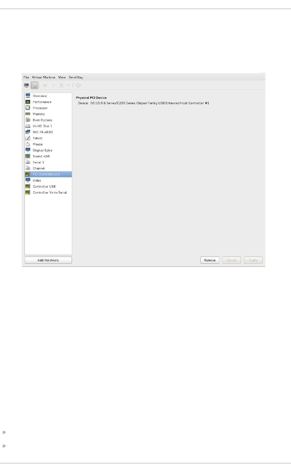
Fig u re 18.7. T h e virt ual h ard ware d et ails b u tt o n
2. Select an d remo ve t h e d evice
Select the PCI device to be detached from the list of virtual devices in the left panel.
Fig u re 18.8. Select in g t h e PC I d evice t o b e d et ach ed
Click the Remove button to confirm. The device is now available for host use.
18.1.5. Creat ing PCI bridges
Peripheral Component Interconnects (PCI) bridges are used to attach to devices such as network
cards, modems and sound cards. Just like their physical counterparts, virtual devices can also be
attached to a PCI Bridge. In the past, only 31 PCI devices could be added to any guest virtual
machine. Now, when a 31st PCI device is added, a PCI bridge is automatically placed in the 31st slot
moving the additional PCI device to the PCI bridge. Each PCI bridge has 31 slots for 31 additional
devices, all of which can be bridges. In this manner, over 900 devices can be available for guest
virtual machines. Note that this action cannot be performed when the guest virtual machine is
running. You must add the PCI device on a guest virtual machine that is shutdown.
18 .1 .5 .1 . PCI Bridge ho t plug/unho t plug suppo rt
PCI Bridge hotplug/unhotplug is supported on the following device types:
virtio-net-pci
virtio-scsi-pci
Virt ualizat ion Deployment and Administ rat ion G uide
202

e1000
rtl8139
virtio-serial-pci
virtio-balloon-pci
18.1.6. PCI passt hrough
A PCI network device (specified by the <source> element) is directly assigned to the guest using
generic device passthrough, after first optionally setting the device's MAC address to the configured
value, and associating the device with an 802.1Qbh capable switch using an optionally specified
<vi rtual po rt> element (see the examples of virtualport given above for type='direct' network
devices). Note that - due to limitations in standard single-port PCI ethernet card driver design - only
SR-IOV (Single Root I/O Virtualization) virtual function (VF) devices can be assigned in this manner;
to assign a standard single-port PCI or PCIe Ethernet card to a guest, use the traditional <hostdev>
device definition.
To use VFIO device assignment rather than traditional/legacy KVM device assignment (VFIO is a new
method of device assignment that is compatible with UEFI Secure Boot), a <type= ' ho std ev' >
interface can have an optional driver sub-element with a name attribute set to "vfio". To use legacy
KVM device assignment you can set name to "kvm" (or simply omit the <d ri ver> element, since
<d ri ver= ' kvm' > is currently the default).
Note that this "intelligent passthrough" of network devices is very similar to the functionality of a
standard <hostdev> device, the difference being that this method allows specifying a MAC address
and <vi rtual po rt> for the passed-through device. If these capabilities are not required, if you
have a standard single-port PCI, PCIe, or USB network card that does not support SR-IOV (and
hence would anyway lose the configured MAC address during reset after being assigned to the guest
domain), or if you are using a version of libvirt older than 0.9.11, you should use standard
<hostdev> to assign the device to the guest instead of <interface type='hostdev'/>.
<devices>
<interface type='hostdev'>
<driver name='vfio'/>
<source>
<address type='pci' domain='0x0000' bus='0x00' slot='0x07'
function='0x0'/>
</source>
<mac address='52:54:00:6d:90:02'>
<virtualport type='802.1Qbh'>
<parameters profileid='finance'/>
</virtualport>
</interface>
</devices>
Fig u re 18.9 . XML examp le f o r PCI device assig n men t
18.1.7. Configuring PCI assignment (passt hrough) wit h SR-IOV devices
This section is for SR-IOV devices only. SR-IOV network cards provide multiple Virtual Functions (VFs)
that can each be individually assigned to a guest virtual machines using PCI device assignment.
Chapt er 1 8 . G uest virt ual machine device configurat ion
203

Once assigned, each will behave as a full physical network device. This permits many guest virtual
machines to gain the performance advantage of direct PCI device assignment, while only using a
single slot on the host physical machine.
These VFs can be assigned to guest virtual machines in the traditional manner using the element
<hostdev>, but as SR-IOV VF network devices do not have permanent unique MAC addresses, it
causes issues where the guest virtual machine's network settings would have to be re-configured
each time the host physical machine is rebooted. To remedy this, you would need to set the MAC
address prior to assigning the VF to the host physical machine and you would need to set this each
and every time the guest virtual machine boots. In order to assign this MAC address as well as other
options, refert to the procedure described in Procedure 18.8, “Configuring MAC addresses, vLAN,
and virtual ports for assigning PCI devices on SR-IOV”.
Pro ced ure 18.8. Co n fig u rin g MAC ad d resses, vLAN, an d virt ual p o rt s f o r assig ning PCI
d evices o n SR-IO V
It is important to note that the <hostdev> element cannot be used for function-specific items like
MAC address assignment, vLAN tag ID assignment, or virtual port assignment because the <mac>,
<vlan>, and <vi rtual po rt> elements are not valid children for <hostdev>. As they are valid for
<interface>, support for a new interface type was added (<interface type='hostdev'>).
This new interface device type behaves as a hybrid of an <interface> and <hostdev>. Thus,
before assigning the PCI device to the guest virtual machine, libvirt initializes the network-specific
hardware/switch that is indicated (such as setting the MAC address, setting a vLAN tag, and/or
associating with an 802.1Qbh switch) in the guest virtual machine's XML configuration file. For
information on setting the vLAN tag, refer to Section 20.16, “ Setting vLAN tags” .
1. Sh u tdown t h e g u est virt u al mach in e
Using virsh shutdown command (refer to Section 23.10.2, “ Shutting down Red Hat
Enterprise Linux 6 guests on a Red Hat Enterprise Linux 7 host” ), shutdown the guest virtual
machine named guestVM.
# virsh shutdown guestVM
2. G at h er in f o rmat io n
In order to use <interface type='hostdev'>, you must have an SR-IOV-capable
network card, host physical machine hardware that supports either the Intel VT-d or AMD
IOMMU extensions, and you must know the PCI address of the VF that you wish to assign.
3. O p en t h e XML f ile f o r ed it in g
Run the # virsh save-image-edit command to open the XML file for editing (refer to
Section 23.9.11, “Editing the guest virtual machine configuration files” for more information).
As you would want to restore the guest virtual machine to its former running state, the --
running would be used in this case. The name of the configuration file in this example is
guestVM.xml, as the name of the guest virtual machine is guestVM.
# virsh save-image-edit guestVM.xml --running
The guestVM.xml opens in your default editor.
4. Ed it t h e XML f ile
Update the configuration file (guestVM.xml) to have a <devices> entry similar to the
following:
Virt ualizat ion Deployment and Administ rat ion G uide
204

<devices>
...
<interface type='hostdev' managed='yes'>
<source>
<address type='pci' domain='0x0' bus='0x00' slot='0x07'
function='0x0'/> <!--these values can be decimal as well-->
</source>
<mac address='52:54:00:6d:90:02'/>
<!--sets the mac address-->
<virtualport type='802.1Qbh'>
<!--sets the virtual port for the 802.1Qbh switch-->
<parameters profileid='finance'/>
</virtualport>
<vlan>
<!--sets the vlan tag-->
<tag id='42'/>
</vlan>
</interface>
...
</devices>
Fig u re 18.10. Samp le d o main XML f o r h o st d ev in t erf ace t yp e
Note that if you do not provide a MAC address, one will be automatically generated, just as
with any other type of interface device. Also, the <vi rtual po rt> element is only used if you
are connecting to an 802.11Qgh hardware switch (802.11Qbg (a.k.a. "VEPA") switches are
currently not supported.
5. Re- st art t h e g u est virt u al mach in e
Run the virsh start command to restart the guest virtual machine you shutdown in the first
step (example uses guestVM as the guest virtual machine's domain name). Refer to
Section 23.9.1, “Starting a virtual machine” for more information.
# virsh start guestVM
When the guest virtual machine starts, it sees the network device provided to it by the physical
host machine's adapter, with the configured MAC address. This MAC address will remain
unchanged across guest virtual machine and host physical machine reboots.
18.1.8. Set t ing PCI device assignment from a pool of SR-IOV virt ual funct ions
Hard coding the PCI addresses of a particular Virtual Functions (VFs) into a guest's configuration has
two serious limitations:
The specified VF must be available any time the guest virtual machine is started, implying that the
administrator must permanently assign each VF to a single guest virtual machine (or modify the
configuration file for every guest virtual machine to specify a currently unused VF's PCI address
each time every guest virtual machine is started).
If the guest vitual machine is moved to another host physical machine, that host physical machine
Chapt er 1 8 . G uest virt ual machine device configurat ion
205

must have exactly the same hardware in the same location on the PCI bus (or, again, the guest
vitual machine configuration must be modified prior to start).
It is possible to avoid both of these problems by creating a libvirt network with a device pool
containing all the VFs of an SR-IOV device. Once that is done you would configure the guest virtual
machine to reference this network. Each time the guest is started, a single VF will be allocated from
the pool and assigned to the guest virtual machine. When the guest virtual machine is stopped, the
VF will be returned to the pool for use by another guest virtual machine.
Pro ced ure 18.9 . Creat ing a d evice p o o l
1. Sh u tdown t h e g u est virt u al mach in e
Using virsh shutdown command (refer to Section 23.10.2, “ Shutting down Red Hat
Enterprise Linux 6 guests on a Red Hat Enterprise Linux 7 host” ), shutdown the guest virtual
machine named guestVM.
# virsh shutdown guestVM
2. Creat e a co n f igurat io n f ile
Using your editor of chocice create an XML file (named passthrough.xml, for example) in the
/tmp directory. Make sure to replace pf dev='eth3' with the netdev name of your own SR-
IOV device's PF
The following is an example network definition that will make available a pool of all VFs for
the SR-IOV adapter with its physical function (PF) at "eth3' on the host physical machine:
<network>
<name>passthrough</name> <!-- This is the name of the file you
created -->
<forward mode='hostdev' managed='yes'>
<pf dev='myNetDevName'/> <!-- Use the netdev name of your
SR-IOV devices PF here -->
</forward>
</network>
Fig u re 18.11. Samp le n et wo rk d ef in it io n d o main XML
3. Lo ad the n ew XML f ile
Run the following command, replacing /tmp/passthrough.xml, with the name and location of
your XML file you created in the previous step:
# virsh net-define /tmp/passthrough.xml
4. Rest art in g th e g u est
Run the following replacing passthrough.xml, with the name of your XML file you created in the
previous step:
Virt ualizat ion Deployment and Administ rat ion G uide
206

# virsh net-autostart passthrough # virsh net-start passthrough
5. Re- st art t h e g u est virt u al mach in e
Run the virsh start command to restart the guest virtual machine you shutdown in the first
step (example uses guestVM as the guest virtual machine's domain name). Refer to
Section 23.9.1, “Starting a virtual machine” for more information.
# virsh start guestVM
6. In it iat in g passt hro u g h f o r d evices
Although only a single device is shown, libvirt will automatically derive the list of all VFs
associated with that PF the first time a guest virtual machine is started with an interface
definition in its domain XML like the following:
<interface type='network'>
<source network='passthrough'>
</interface>
Fig u re 18.12. Samp le d o main XML f o r in terf ace n et wo rk d ef in itio n
7. Veri f icat i on
You can verify this by running virsh net-dumpxml passthrough command after starting
the first guest that uses the network; you will get output similar to the following:
<network connections='1'>
<name>passthrough</name>
<uuid>a6b49429-d353-d7ad-3185-4451cc786437</uuid>
<forward mode='hostdev' managed='yes'>
<pf dev='eth3'/>
<address type='pci' domain='0x0000' bus='0x02' slot='0x10'
function='0x1'/>
<address type='pci' domain='0x0000' bus='0x02' slot='0x10'
function='0x3'/>
<address type='pci' domain='0x0000' bus='0x02' slot='0x10'
function='0x5'/>
<address type='pci' domain='0x0000' bus='0x02' slot='0x10'
function='0x7'/>
<address type='pci' domain='0x0000' bus='0x02' slot='0x11'
function='0x1'/>
<address type='pci' domain='0x0000' bus='0x02' slot='0x11'
function='0x3'/>
<address type='pci' domain='0x0000' bus='0x02' slot='0x11'
function='0x5'/>
Chapt er 1 8 . G uest virt ual machine device configurat ion
207

</forward>
</network>
Fig u re 18.13. XML d u mp f ile passthrough co n t en t s
18.2. USB devices
This section gives the commands required for handling USB devices.
18.2.1. Assigning USB devices t o guest virt ual machines
Most devices such as web cameras, card readers, disk drives, keyboards, mice, etc are connected to
a computer using a USB port and cable. There are two ways to pass such devices to a guest virtual
machine:
Using USB passthrough - this requires the device to be physically connected to the host physical
machine that is hosting the guest virtual machine. SPICE is not needed in this case. USB devices
on the host can be passed to the guest via the command line or virt - man ag er. Refer to
Section 22.3.2, “ Attaching USB devices to a guest virtual machine” for virt man ag er directions.
Note that the virt - ma n ag er directions are not suitable for hot plugging or hot unplugging
devices. If you want to hot plug/or hot unplug a USB device, refer to Procedure 23.5,
“ Hotplugging USB devices for use by the guest virtual machine” .
Using USB re-direction - USB re-direction is best used in cases where there is a host physical
machine that is running in a data center. The user connects to his/her guest virtual machine from
a local machine or thin client. On this local machine there is a SPICE client. The user can attach
any USB device to the thin client and the SPICE client will redirect the device to the host physical
machine on the data center so it can be used by the guest virtual machine that is running on the
thin client. For instructions via the virt-manager refer to Section 22.3.3, “ USB redirection” .
18.2.2. Set t ing a limit on USB device redirect ion
To filter out certain devices from redirection, pass the filter property to -device usb-redir. The
filter property takes a string consisting of filter rules, the format for a rule is:
<class>:<vendor>:<product>:<version>:<allow>
Use the value -1 to designate it to accept any value for a particular field. You may use multiple rules
on the same command line using | as a separator. Note that if a device matches none of the passed
in rules, redirecting it will not be allowed!
Examp le 18.1. An examp le o f limit in g red irect io n wit h a windo ws g u est virt ual
mach in e
1. Prepare a Windows 7 guest virtual machine.
2. Add the following code excerpt to the guest virtual machine's' domain xml file:
<redirdev bus='usb' type='spicevmc'>
<alias name='redir0'/>
<address type='usb' bus='0' port='3'/>
Virt ualizat ion Deployment and Administ rat ion G uide
208

</redirdev>
<redirfilter>
<usbdev class='0x08' vendor='0x1234' product='0xBEEF'
version='2.0' allow='yes'/>
<usbdev class='-1' vendor='-1' product='-1' version='-1'
allow='no'/>
</redirfilter>
3. Start the guest virtual machine and confirm the setting changes by running the following:
#ps -ef | grep $guest_name
-device usb-redir,chardev=charredir0,id=redir0,/
fi l ter= 0 x0 8: 0 x1234 : 0 xBEEF: 0 x0 20 0 : 1| -1: -1: -1: -
1: 0 ,bus= usb. 0 ,po rt= 3
4. Plug a USB device into a host physical machine, and use virt - man ag er to connect to the
guest virtual machine.
5. Click USB d evice select ion in the menu, which will produce the following message:
"Some USB devices are blocked by host policy". Click O K to confirm and continue.
The filter takes effect.
6. To make sure that the filter captures properly check the USB device vendor and product,
then make the following changes in the host physical machine's domain XML to allow for
USB redirection.
<redirfilter>
<usbdev class='0x08' vendor='0x0951' product='0x1625'
version='2.0' allow='yes'/>
<usbdev allow='no'/>
</redirfilter>
7. Restart the guest virtual machine, then use virt - viewer to connect to the guest virtual
machine. The USB device will now redirect traffic to the guest virtual machine.
18.3. Configuring device cont rollers
Depending on the guest virtual machine architecture, some device buses can appear more than
once, with a group of virtual devices tied to a virtual controller. Normally, libvirt can automatically
infer such controllers without requiring explicit XML markup, but in some cases it is better to explicitly
set a virtual controller element.
...
<devices>
<controller type='ide' index='0'/>
<controller type='virtio-serial' index='0' ports='16' vectors='4'/>
<controller type='virtio-serial' index='1'>
<address type='pci' domain='0x0000' bus='0x00' slot='0x0a'
Chapt er 1 8 . G uest virt ual machine device configurat ion
209

function='0x0'/>
</controller>
...
</devices>
...
Fig u re 18.14 . Do main XML examp le f o r virt u al co n t ro llers
Each controller has a mandatory attribute <controller type>, which must be one of:
ide
fdc
scsi
sata
usb
ccid
virtio-serial
pci
The <co ntro l l er> element has a mandatory attribute <co ntro l l er i nd ex> which is the decimal
integer describing in which order the bus controller is encountered (for use in controller attributes of
<address> elements). When <co ntro l l er type = ' vi rti o -seri al ' > there are two additional
optional attributes (named po rts and vectors), which control how many devices can be connected
through the controller.
When <controller type ='scsi'>, there is an optional attribute model model, which can have
the following values:
auto
buslogic
ibmvscsi
lsilogic
lsisas1068
lsisas1078
virtio-scsi
vmpvscsi
When <controller type ='usb'>, there is an optional attribute model model, which can have
the following values:
piix3-uhci
piix4-uhci
ehci
Virt ualizat ion Deployment and Administ rat ion G uide
210

ich9-ehci1
ich9-uhci1
ich9-uhci2
ich9-uhci3
vt82c686b-uhci
pci-ohci
nec-xhci
Note that if the USB bus needs to be explicitly disabled for the guest virtual machine,
<mo d el = ' no ne' > may be used. .
For controllers that are themselves devices on a PCI or USB bus, an optional sub-element
<address> can specify the exact relationship of the controller to its master bus, with semantics as
shown in Section 18.4, “ Setting addresses for devices” .
An optional sub-element <d ri ver> can specify the driver specific options. Currently it only supports
attribute queues, which specifies the number of queues for the controller. For best performance, it's
recommended to specify a value matching the number of vCPUs.
USB companion controllers have an optional sub-element <master> to specify the exact
relationship of the companion to its master controller. A companion controller is on the same bus as
its master, so the companion index value should be equal.
An example XML which can be used is as follows:
...
<devices>
<controller type='usb' index='0' model='ich9-ehci1'>
<address type='pci' domain='0' bus='0' slot='4' function='7'/>
</controller>
<controller type='usb' index='0' model='ich9-uhci1'>
<master startport='0'/>
<address type='pci' domain='0' bus='0' slot='4' function='0'
multifunction='on'/>
</controller>
...
</devices>
...
Fig u re 18.15. D o main XML example f o r USB co n tro llers
PCI controllers have an optional model attribute with the following possible values:
pci-root
pcie-root
Chapt er 1 8 . G uest virt ual machine device configurat ion
211

pci-bridge
dmi-to-pci-bridge
For machine types which provide an implicit PCI bus, the pci-root controller with index='0' is
auto-added and required to use PCI devices. pci-root has no address. PCI bridges are auto-added if
there are too many devices to fit on the one bus provided by model='pci-root', or a PCI bus
number greater than zero was specified. PCI bridges can also be specified manually, but their
addresses should only refer to PCI buses provided by already specified PCI controllers. Leaving
gaps in the PCI controller indexes might lead to an invalid configuration. The following XML example
can be added to the <devices> section:
...
<devices>
<controller type='pci' index='0' model='pci-root'/>
<controller type='pci' index='1' model='pci-bridge'>
<address type='pci' domain='0' bus='0' slot='5' function='0'
multifunction='off'/>
</controller>
</devices>
...
Fig u re 18.16 . Do main XML examp le f o r PCI brid g e
For machine types which provide an implicit PCI Express (PCIe) bus (for example, the machine types
based on the Q35 chipset), the pcie-root controller with index='0' is auto-added to the domain's
configuration. pcie-root has also no address, but provides 31 slots (numbered 1-31) and can only be
used to attach PCIe devices. In order to connect standard PCI devices on a system which has a pcie-
root controller, a pci controller with model='dmi-to-pci-bridge' is automatically added. A
dmi-to-pci-bridge controller plugs into a PCIe slot (as provided by pcie-root), and itself provides 31
standard PCI slots (which are not hot-pluggable). In order to have hot-pluggable PCI slots in the
guest system, a pci-bridge controller will also be automatically created and connected to one of the
slots of the auto-created dmi-to-pci-bridge controller; all guest devices with PCI addresses that are
auto-determined by libvirt will be placed on this pci-bridge device.
...
<devices>
<controller type='pci' index='0' model='pcie-root'/>
<controller type='pci' index='1' model='dmi-to-pci-bridge'>
<address type='pci' domain='0' bus='0' slot='0xe' function='0'/>
</controller>
<controller type='pci' index='2' model='pci-bridge'>
<address type='pci' domain='0' bus='1' slot='1' function='0'/>
</controller>
</devices>
...
Virt ualizat ion Deployment and Administ rat ion G uide
212

Fig u re 18.17. D o main XML example f o r PC Ie ( PC I exp ress)
The following XML configuration is used for USB 3.0 / xHCI emulation:
...
<devices>
<controller type='usb' index='3' model='nec-xhci'>
<address type='pci' domain='0x0000' bus='0x00' slot='0x0f'
function='0x0'/>
</controller>
</devices>
...
Fig u re 18.18. D o main XML example f o r USB3/xHCI d evices
18.4 . Set t ing addresses for devices
Many devices have an optional <address> sub-element which is used to describe where the device
is placed on the virtual bus presented to the guest virtual machine. If an address (or any optional
attribute within an address) is omitted on input, libvirt will generate an appropriate address; but an
explicit address is required if more control over layout is required. See Figure 18.9, “ XML example for
PCI device assignment” for domain XML device examples including an <address> element.
Every address has a mandatory attribute type that describes which bus the device is on. The choice
of which address to use for a given device is constrained in part by the device and the architecture of
the guest virtual machine. For example, a <disk> device uses type= ' d ri ve' , while a <console>
device would use type= ' pci ' on i686 or x86_64 guest virtual machine architectures. Each
address type has further optional attributes that control where on the bus the device will be placed as
described in the table:
T ab le 18.1. Su p p ort ed d evice ad d ress t ypes
Ad d ress t yp e Descrip t io n
type='pci' PCI addresses have the following additional
attributes:
domain (a 2-byte hex integer, not currently
used by qemu)
bus (a hex value between 0 and 0xff,
inclusive)
slot (a hex value between 0x0 and 0x1f,
inclusive)
function (a value between 0 and 7, inclusive)
multifunction controls turning on the
multifunction bit for a particular slot/function
in the PCI control register By default it is set
to 'off', but should be set to 'on' for function 0
of a slot that will have multiple functions
used.
Chapt er 1 8 . G uest virt ual machine device configurat ion
213

type='drive' Drive addresses have the following additional
attributes:
controller (a 2-digit controller number)
bus (a 2-digit bus number
target (a 2-digit bus number)
unit (a 2-digit unit number on the bus)
type='virtio-serial' Each virtio-serial address has the following
additional attributes:
controller (a 2-digit controller number)
bus (a 2-digit bus number)
slot (a 2-digit slot within the bus)
type='ccid' A CCID address, for smart-cards, has the
following additional attributes:
bus (a 2-digit bus number)
slot attribute (a 2-digit slot within the bus)
type='usb' USB addresses have the following additional
attributes:
bus (a hex value between 0 and 0xfff,
inclusive)
port (a dotted notation of up to four octets,
such as 1.2 or 2.1.3.1)
type='isa' ISA addresses have the following additional
attributes:
iobase
irq
Ad d ress t yp e Descrip t io n
18.5. Random number generat or device
virtio-rng is a virtual hardware random number generator device that can provide the guest with fresh
entropy upon request. The driver feeds the data back to the guest virtual machine's OS.
On the host physical machine, the hardware rng interface creates a chardev at /dev/hwrng, which
can be opened and then read to fetch entropy from the host physical machine. Coupled with the rngd
daemon, the entropy from the host physical machine can be routed to the guest virtual machine's
/dev/random, which is the primary source of randomness.
Using a random number generator is particularly useful when a device such as a keyboard, mouse
and other inputs are not enough to generate sufficient entropy on the guest virtual machine.The
virtual random number generator device allows the host physical machine to pass through entropy
to guest virtual machine operating systems. This procedure can be done either via the command line
or via virt-manager. For virt-manager instructions refer to Procedure 18.10, “ Implementing virtio-rng via
Virtualzation Manager” and for command line instructions, refer to Procedure 18.11, “ Implementing
virtio-rng via command line tools” .
Pro ced ure 18.10. Imp lemen t in g virt io - rn g via Virt u alz at io n Man ag er
Virt ualizat ion Deployment and Administ rat ion G uide
214
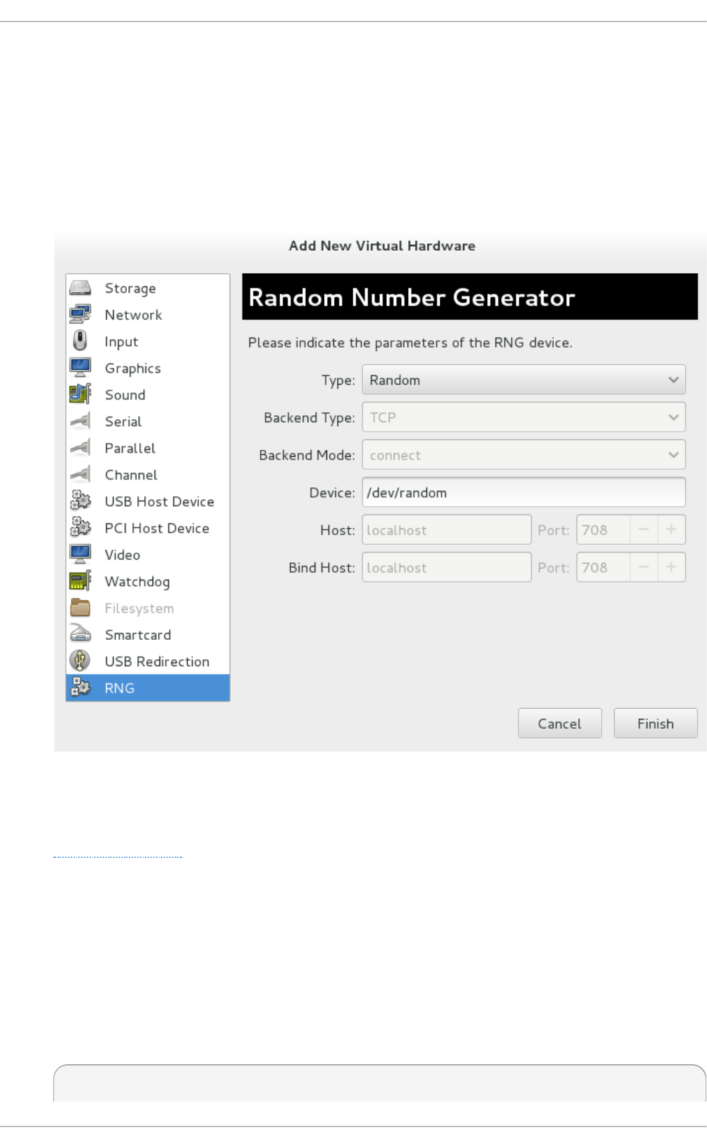
1. Shutdown the guest virtual machine.
2. Select the guest virtual machine and from the Ed it menu, select Virt u al Mach in e D et ails, to
open the Details window for the specified guest virtual machine.
3. Click the Add Hardware button.
4. In the Ad d New Virt u al Hard ware window, select RNG to open the Ran d om N u mb er
G e n era t o r window.
Fig u re 18.19 . Ran do m Nu mber G en erat o r win d o w
Enter the desired parameters and click Fin ish when done. The parameters are explained in
virtio-rng elements.
Pro ced ure 18.11. Imp lemen t in g virt io - rn g via co mman d line t ools
1. Shutdown the guest virtual machine.
2. Using virsh edit domain-name command, open the XML file for the desired guest virtual
machine.
3. Edit the <devices> element to include the following:
Chapt er 1 8 . G uest virt ual machine device configurat ion
215

...
<devices>
<rng model='virtio'>
<rate period="2000" bytes="1234"/>
<backend model='random'>/dev/random</backend>
<!-- OR -->
<backend model='egd' type='udp'>
<source mode='bind' service='1234'>
<source mode='connect' host physical machine='1.2.3.4'
service='1234'>
</backend>
</rng>
</devices>
...
Fig u re 18.20. R an d o m n u mb er g en erat o r d evice
The random number generator device allows the following attributes/elements:
virt io - rn g elemen t s
model - The required model attribute specifies what type of RNG device is provided.
' vi rti o '
<backend> - The <backend> element specifies the source of entropy to be used for the
domain. The source model is configured using the model attribute. Supported source
models include ' rand o m' — /dev/random (default setting) or similar device as source
and 'egd' which sets a EGD protocol backend.
backend type='random' - This <backend> type expects a non-blocking character
device as input. Examples of such devices are /dev/random and /dev/urandom. The
file name is specified as contents of the <backend> element. When no file name is
specified the hypervisor default is used.
<backend type='egd'> - This backend connects to a source using the EGD protocol.
The source is specified as a character device. Refer to character device host physical
machine interface for more information.
18.6. Assigning GPU devices
Red Hat Enterprise Linux 7 supports PCI device assignment of NVIDIA K-Series Quadro (model 2000
series or higher), GRID, and Tesla as non-VGA graphics devices. Currently up to two GPUs may be
attached to the virtual machine in addition to one of the standard, emulated VGA interfaces. The
emulated VGA is used for pre-boot and installation and the NVIDIA GPU takes over when the NVIDIA
graphics drivers are loaded. Note that the NVID IA Quadro 2000 is not supported, nor is the Quadro
K420 card.
This procedure will, in short, identify the device from lspci, detach it from host physical machine and
then attach it to the guest virtual machine.
1. En ab le IO MMU su p p o rt in t h e h o st p h ysical mach in e kern el
Virt ualizat ion Deployment and Administ rat ion G uide
216

For an Intel VT-d system this is done by adding the intel_iommu=pt parameter to the kernel
command line. For an AMD-Vi system, the option is amd_iommu=pt. To enable this option
you will need to edit or add the GRUB_CMDLINX_LINUX line to the /etc/sysconfig/grub
configuration file as follows:
GRUB_CMDLINE_LINUX="rd.lvm.lv=vg_VolGroup00/LogVol01
vconsole.font=latarcyrheb-sun16 rd.lvm.lv=vg_VolGroup_1/root
vconsole.keymap=us $([ -x /usr/sbin/rhcrashkernel-param ] &&
/usr/sbin/rhcrashkernel-param || :) rhgb quiet intel_iommu=pt"
Note
For further information on IOMMU, see Appendix D, Working with IOMMU Groups.
2. Reg en erat e t h e b o o t lo ad er co n f ig u rat io n
Regenerate the bootloader configuration using the grub2-mkconfig to include this option, by
running the following command:
# grub2-mkconfig -o /etc/grub2.cfg
Note that if you are using a UEFI-based host, the target file will be /etc/grub2-efi.cfg.
3. Reb o o t t he h o st ph ysical mach in e
In order for this option to take effect, reboot the host physical machine with the following
command:
# reboot
Pro ced ure 18.12. Exclu d in g t he G PU d evice f ro m b in d in g t o the h o st physical mach in e
d ri ve r
For GPU assignment it is recommended to exclude the device from binding to host drivers as these
drivers often do not support dynamic unbinding of the device.
1. Id en t if y th e PCI b u s ad d ress
To identify the PCI bus address and IDs of the device, run the following lspci command. In
this example, a VGA controller such as a Quadro or GRID card is used as follows:
# lspci -Dnn | grep VGA
0000:02:00.0 VGA compatible controller [0300]: NVIDIA Corporation
GK106GL [Quadro K4000] [10de:11fa] (rev a1)
The resulting search reveals that the PCI bus address of this device is 0000:02:00.0 and the
PCI IDs for the device are 10de:11fa.
2. Preven t t h e n at ive h o st p h ysical mach in e d river f ro m u sin g t he G PU d evice
Chapt er 1 8 . G uest virt ual machine device configurat ion
217

To prevent the native host physical machine driver from using the GPU device you can use a
PCI ID with the pci-stub driver. To do this, append the following additional option to the
GRUB_CMDLINX_LINUX configuration file located in /etc/sysconfig/grub as follows:
pci-stub.ids=10de:11fa
To add additional PCI IDs for pci-stub, separate them with a comma.
3. Reg en erat e t h e b o o t lo ad er co n f ig u rat io n
Regenerate the bootloader configuration using the grub2-mkconfig to include this option, by
running the following command:
# grub2-mkconfig -o /etc/grub2.cfg
Note that if you are using a UEFI-based host, the target file will be /etc/grub2-efi.cfg.
4. Reb o o t t h e h o st physical mach in e
In order for this option to take effect, reboot the host physical machine with the following
command:
# reboot
The virsh commands can be used to further evaluate the device, however in order to use virsh with
the devices you need to convert the PCI bus address to libvirt compatible format by appending pci_
and converting delimiters to underscores. In this example the libvirt address of PCI device
0000:02:00.0 becomes pci_0000_02_00_0. The nodedev-dumpxml option provides additional
information for the device as shown:
# virsh nodedev-dumpxml pci_0000_02_00_0
<device>
<name>pci_0000_02_00_0</name>
<path>/sys/devices/pci0000:00/0000:00:03.0/0000:02:00.0</path>
<parent>pci_0000_00_03_0</parent>
<driver>
<name>pci-stub</name>
</driver>
<capability type='pci'>
<domain>0</domain>
<bus>2</bus>
<slot>0</slot>
<function>0</function>
<product id='0x11fa'>GK106GL [Quadro K4000]</product>
<vendor id='0x10de'>NVIDIA Corporation</vendor>
<!-- pay attention to this part -->
<iommuGroup number='13'>
<address domain='0x0000' bus='0x02' slot='0x00' function='0x0'/>
<address domain='0x0000' bus='0x02' slot='0x00' function='0x1'/>
</iommuGroup>
Virt ualizat ion Deployment and Administ rat ion G uide
218

<pci-express>
<link validity='cap' port='0' speed='8' width='16'/>
<link validity='sta' speed='2.5' width='16'/>
</pci-express>
</capability>
</device>
Fig u re 18.21. XML f ile ad ap tat io n for G PU - Examp le
Particularly important in this output is the <iommuGroup> element. The iommuGroup indicates the
set of devices which are considered isolated from other devices due to IOMMU capabilities and PCI
bus topologies. All of the endpoint devices within the iommuGroup (ie. devices that are not PCIe root
ports, bridges, or switch ports) need to be unbound from the native host drivers in order to be
assigned to a guest. In the example above, the group is composed of the GPU device (0000:02:00.0)
as well as the companion audio device (0000:02:00.1). For more information, refer to Appendix D,
Working with IOMMU Groups.
Note
Assignment of Nvidia audio functions is not supported due to hardware issues with legacy
interrupt support. In order to assign the GPU to a guest, the audio function must first be
detached from native host drivers. This can either be done by using lspci to find the PCI IDs
for the device and appending it to the pci-stub.ids option or dynamically using the nodedev-
detach option of virsh. For example:
# virsh nodedev-detach pci_0000_02_00_1
Device pci_0000_02_00_1 detached
The GPU audio function is generally not useful without the GPU itself, so it’s generally recommended
to use the pci-stub.ids option instead.
The GPU can be attached to the VM using virt-manager or using virsh, either by directly editing the
VM XML ( virsh edit [domain]) or attaching the GPU to the domain with virsh attach-
device. If you are using the virsh attach-device command, an XML fragment first needs to be
created for the device, such as the following:
<hostdev mode='subsystem' type='pci' managed='yes'>
<driver name='vfio'/>
<source>
<address domain='0x0000' bus='0x02' slot='0x00' function='0x0'/>
</source>
</hostdev>
Fig u re 18.22. XML f ile f or at t ach in g G PU - Examp le
Save this to a file and run virsh attach-device [domain] [file] --persistent to
include the XML in the VM configuration. Note that the assigned GPU is added in addition to the
Chapt er 1 8 . G uest virt ual machine device configurat ion
219

existing emulated graphics device in the guest virtual machine. The assigned GPU is handled as a
secondary graphics device in the VM. Assignment as a primary graphics device is not supported and
emulated graphics devices in the VM's XML should not be removed.
Note
When using an assigned Nvidia GPU in the guest, only the Nvidia drivers are supported.
Other drivers may not work and may generate errors. For a Red Hat Enterprise Linux 7 guest,
the nouveau driver can be blacklisted using the option modprobe.blacklist=nouveau on
the kernel command line during install. For information on other guest virtual machines refer to
the operating system's specific documentation.
When configuring Xorg for use with an assigned GPU in a KVM guest, the BusID option must be
added to xorg.conf to specify the guest address of the GPU. For example, within the guest determine
the PCI bus address of the GPU (this will be different than the host address):
# lspci | grep VGA
00:02.0 VGA compatible controller: Device 1234:1111
00:09.0 VGA compatible controller: NVIDIA Corporation GK106GL [Quadro
K4000] (rev a1)
In this example the address is 00:09.0. The file /etc/X11/xorg.conf is then modified to add the
highlighted entry below.
Section "Device"
Identifier "Device0"
Driver "nvidia"
VendorName "NVIDIA Corporation"
BusID "PCI:0:9:0"
EndSection
Depending on the guest operating system, with the Nvidia drivers loaded, the guest may support
using both the emulated graphics and assigned graphics simultaneously or may disable the
emulated graphics. Note that access to the assigned graphics framebuffer is not provided by tools
such as virt-manager. If the assigned GPU is not connected to a physical display, guest-based
remoting solutions may be necessary to access the GPU desktop. As with all PCI device assignment,
migration of a guest with an assigned GPU is not supported and each GPU is owned exclusively by
a single guest. Depending on the guest operating system, hotplug support of GPUs may be
available.
Virt ualizat ion Deployment and Administ rat ion G uide
220
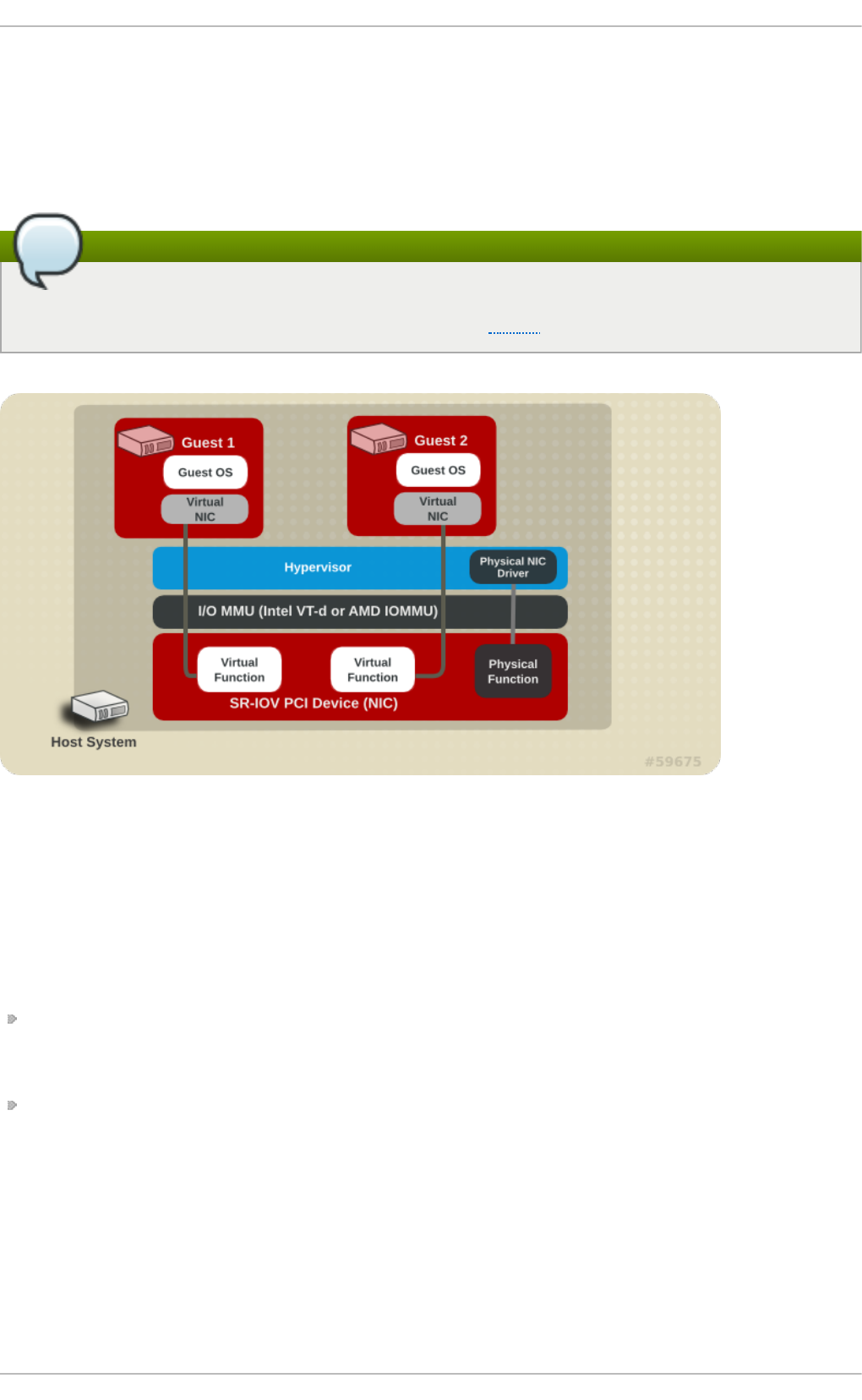
Chapter 19. SR-IOV
Developed by the PCI-SIG (PCI Special Interest Group), the Single Root I/O Virtualization (SR-IOV)
specification is a standard for a type of PCI device assignment that can share a single device to
multiple virtual machines. SR-IOV improves device performance for virtual machines.
Note
Virtual machines that use the Xeon E3-1200 series chip set, do not support SR-IOV. More
information can be found on Intel's website or in this article.
Fig u re 19 .1. Ho w SR-IO V wo rks
SR-IOV enables a Single Root Function (for example, a single Ethernet port), to appear as multiple,
separate, physical devices. A physical device with SR-IOV capabilities can be configured to appear
in the PCI configuration space as multiple functions. Each device has its own configuration space
complete with Base Address Registers (BARs).
SR-IOV uses two PCI functions:
Physical Functions (PFs) are full PCIe devices that include the SR-IOV capabilities. Physical
Functions are discovered, managed, and configured as normal PCI devices. Physical Functions
configure and manage the SR-IOV functionality by assigning Virtual Functions.
Virtual Functions (VFs) are simple PCIe functions that only process I/O. Each Virtual Function is
derived from a Physical Function. The number of Virtual Functions a device may have is limited
by the device hardware. A single Ethernet port, the Physical Device, may map to many Virtual
Functions that can be shared to virtual machines.
The hypervisor can map one or more Virtual Functions to a virtual machine. The Virtual Function's
configuration space is then mapped to the configuration space presented to the guest.
Chapt er 1 9 . SR- IO V
221

Each Virtual Function can only be mapped to a single guest at a time, as Virtual Functions require
real hardware resources. A virtual machine can have multiple Virtual Functions. A Virtual Function
appears as a network card in the same way as a normal network card would appear to an operating
system.
The SR-IOV drivers are implemented in the kernel. The core implementation is contained in the PCI
subsystem, but there must also be driver support for both the Physical Function (PF) and Virtual
Function (VF) devices. An SR-IOV capable device can allocate VFs from a PF. The VFs appear as
PCI devices which are backed on the physical PCI device by resources such as queues and register
sets.
19.1. Advant ages of SR-IOV
SR-IOV devices can share a single physical port with multiple virtual machines.
Virtual Functions have near-native performance and provide better performance than para-
virtualized drivers and emulated access. Virtual Functions provide data protection between virtual
machines on the same physical server as the data is managed and controlled by the hardware.
These features allow for increased virtual machine density on hosts within a data center.
SR-IOV is better able to utilize the bandwidth of devices with multiple guests.
19.2. Using SR-IOV
This section covers the use of PCI passthrough to assign a Virtual Function of an SR-IOV capable
multiport network card to a virtual machine as a network device.
SR-IOV Virtual Functions (VFs) can be assigned to virtual machines by adding a device entry in
<hostdev> with the vi rsh ed i t or virsh attach-device command. However, this can be
problematic because unlike a regular network device, an SR-IOV VF network device does not have a
permanent unique MAC address, and is assigned a new MAC address each time the host is rebooted.
Because of this, even if the guest is assigned the same VF after a reboot, when the host is rebooted
the guest determines its network adapter to have a new MAC address. As a result, the guest believes
there is new hardware connected each time, and will usually require re-configuration of the guest's
network settings.
libvirt-0.9.10 and newer contains the <interface type='hostdev'> interface device. Using this
interface device, li b virt will first perform any network-specific hardware/switch initialization indicated
(such as setting the MAC address, VLAN tag, or 802.1Qbh virtualport parameters), then perform the
PCI device assignment to the guest.
Using the <interface type='hostdev'> interface device requires:
an SR-IOV-capable network card,
host hardware that supports either the Intel VT-d or the AMD IOMMU extensions, and
the PCI address of the VF to be assigned.
Important
Assignment of an SR-IOV device to a virtual machine requires that the host hardware supports
the Intel VT-d or the AMD IOMMU specification.
Virt ualizat ion Deployment and Administ rat ion G uide
222

To attach an SR-IOV network device on an Intel or an AMD system, follow this procedure:
Pro ced ure 19 .1. At t ach an SR - IO V n et wo rk device o n an In t el or AMD syst em
1. En ab le In t el VT-d o r t h e AMD IO MMU sp ecificat io n s in t h e B IO S an d kern el
On an Intel system, enable Intel VT-d in the BIOS if it is not enabled already. Refer to
Procedure 18.1, “ Preparing an Intel system for PCI device assignment” for procedural help on
enabling Intel VT-d in the BIOS and kernel.
Skip this step if Intel VT-d is already enabled and working.
On an AMD system, enable the AMD IOMMU specifications in the BIOS if they are not enabled
already. Refer to Procedure 18.2, “ Preparing an AMD system for PCI device assignment” for
procedural help on enabling IOMMU in the BIOS.
2. Verif y su p p o rt
Verify if the PCI device with SR-IOV capabilities is detected. This example lists an Intel 82576
network interface card which supports SR-IOV. Use the lspci command to verify whether the
device was detected.
# lspci
03:00.0 Ethernet controller: Intel Corporation 82576 Gigabit
Network Connection (rev 01)
03:00.1 Ethernet controller: Intel Corporation 82576 Gigabit
Network Connection (rev 01)
Note that the output has been modified to remove all other devices.
3. St art t he SR - IO V kern el mo d u les
If the device is supported the driver kernel module should be loaded automatically by the
kernel. Optional parameters can be passed to the module using the mo d pro be command.
The Intel 82576 network interface card uses the igb driver kernel module.
# modprobe igb [<option>=<VAL1>,<VAL2>,]
# lsmod |grep igb
igb 87592 0
dca 6708 1 igb
4. Act ivat e Virt u al Fu n ct io n s
The max_vfs parameter of the igb module allocates the maximum number of Virtual
Functions. The max_vfs parameter causes the driver to spawn, up to the value of the
parameter in, Virtual Functions. For this particular card the valid range is 0 to 7.
Remove the module to change the variable.
# modprobe -r igb
Restart the module with the max_vfs set to 7 or any number of Virtual Functions up to the
maximum supported by your device.
# modprobe igb max_vfs=7
Chapt er 1 9 . SR- IO V
223

5. Make t h e Virt u al Fu n ct io ns p ersist en t
To make the Virtual Functions persistent across reboots, add the following to the
/etc/rc. d /rc. l o cal file. Specify the number of VFs desired (in this example, 2), up to the
limit supported by the network interface card, and replace enp14s0f0 with the PF network
device name(s):
# echo 2 > /sys/class/net/enp14s0f0/device/sriov_numvfs
This will ensure the feature is enabled at boot-time.
Note
If the /etc/rc. d /rc. l o cal file does not already exist on your system, first create the
file, then make it executable with this command:
# chmod +x /etc/rc.d/rc.local
6. In sp ect t he n ew Virt ual Fu n ct io ns
Using the lspci command, list the newly added Virtual Functions attached to the Intel 82576
network device. (Alternatively, use g rep to search for Virtual Function, to search for
devices that support Virtual Functions.)
# lspci | grep 82576
0b:00.0 Ethernet controller: Intel Corporation 82576 Gigabit
Network Connection (rev 01)
0b:00.1 Ethernet controller: Intel Corporation 82576 Gigabit
Network Connection (rev 01)
0b:10.0 Ethernet controller: Intel Corporation 82576 Virtual
Function (rev 01)
0b:10.1 Ethernet controller: Intel Corporation 82576 Virtual
Function (rev 01)
0b:10.2 Ethernet controller: Intel Corporation 82576 Virtual
Function (rev 01)
0b:10.3 Ethernet controller: Intel Corporation 82576 Virtual
Function (rev 01)
0b:10.4 Ethernet controller: Intel Corporation 82576 Virtual
Function (rev 01)
0b:10.5 Ethernet controller: Intel Corporation 82576 Virtual
Function (rev 01)
0b:10.6 Ethernet controller: Intel Corporation 82576 Virtual
Function (rev 01)
0b:10.7 Ethernet controller: Intel Corporation 82576 Virtual
Function (rev 01)
0b:11.0 Ethernet controller: Intel Corporation 82576 Virtual
Function (rev 01)
0b:11.1 Ethernet controller: Intel Corporation 82576 Virtual
Function (rev 01)
0b:11.2 Ethernet controller: Intel Corporation 82576 Virtual
Function (rev 01)
0b:11.3 Ethernet controller: Intel Corporation 82576 Virtual
Virt ualizat ion Deployment and Administ rat ion G uide
224

Function (rev 01)
0b:11.4 Ethernet controller: Intel Corporation 82576 Virtual
Function (rev 01)
0b:11.5 Ethernet controller: Intel Corporation 82576 Virtual
Function (rev 01)
The identifier for the PCI device is found with the -n parameter of the lspci command. The
Physical Functions correspond to 0b:00.0 and 0b:00.1. All Virtual Functions have
Virtual Function in the description.
7. Verif y devices exist wit h virsh
The l i bvi rt service must recognize the device before adding a device to a virtual machine.
l i bvi rt uses a similar notation to the lspci output. All punctuation characters, ; and ., in
lspci output are changed to underscores (_).
Use the virsh nodedev-list command and the g rep command to filter the Intel 82576
network device from the list of available host devices. 0b is the filter for the Intel 82576
network devices in this example. This may vary for your system and may result in additional
devices.
# virsh nodedev-list | grep 0b
pci_0000_0b_00_0
pci_0000_0b_00_1
pci_0000_0b_10_0
pci_0000_0b_10_1
pci_0000_0b_10_2
pci_0000_0b_10_3
pci_0000_0b_10_4
pci_0000_0b_10_5
pci_0000_0b_10_6
pci_0000_0b_11_7
pci_0000_0b_11_1
pci_0000_0b_11_2
pci_0000_0b_11_3
pci_0000_0b_11_4
pci_0000_0b_11_5
The serial numbers for the Virtual Functions and Physical Functions should be in the list.
8. G et d evice d et ails wit h virsh
The pci_0000_0b_00_0 is one of the Physical Functions and pci _0 0 0 0 _0 b_10 _0 is
the first corresponding Virtual Function for that Physical Function. Use the vi rsh
nodedev-dumpxml command to get advanced output for both devices.
# virsh nodedev-dumpxml pci_0000_0b_00_0
<device>
<name>pci_0000_0b_00_0</name>
<parent>pci_0000_00_01_0</parent>
<driver>
<name>igb</name>
</driver>
<capability type='pci'>
<domain>0</domain>
<bus>11</bus>
Chapt er 1 9 . SR- IO V
225

<slot>0</slot>
<function>0</function>
<product id='0x10c9'>Intel Corporation</product>
<vendor id='0x8086'>82576 Gigabit Network Connection</vendor>
</capability>
</device>
# virsh nodedev-dumpxml pci_0000_0b_10_0
<device>
<name>pci_0000_0b_10_0</name>
<parent>pci_0000_00_01_0</parent>
<driver>
<name>igbvf</name>
</driver>
<capability type='pci'>
<domain>0</domain>
<bus>11</bus>
<slot>16</slot>
<function>0</function>
<product id='0x10ca'>Intel Corporation</product>
<vendor id='0x8086'>82576 Virtual Function</vendor>
</capability>
</device>
This example adds the Virtual Function pci _0 0 0 0 _0 b_10 _0 to the virtual machine in Step
9. Note the bus, sl o t and function parameters of the Virtual Function: these are required
for adding the device.
Copy these parameters into a temporary XML file, such as /tmp/new-interface.xml for
example.
<interface type='hostdev' managed='yes'>
<source>
<address type='pci' domain='0' bus='11' slot='16'
function='0'/>
</source>
</interface>
Virt ualizat ion Deployment and Administ rat ion G uide
226

Note
If you do not specify a MAC address, one will be automatically generated. The
<virtualport> element is only used when connecting to an 802.11Qbh hardware
switch. The <vlan> element will transparently put the guest's device on the VLAN
tagged 42.
When the virtual machine starts, it should see a network device of the type provided by
the physical adapter, with the configured MAC address. This MAC address will remain
unchanged across host and guest reboots.
The following <interface> example shows the syntax for the optional <mac
address>, <virtualport>, and <vlan> elements. In practice, use either the <vlan>
or <virtualport> element, not both simultaneously as shown in the example:
...
<devices>
...
<interface type='hostdev' managed='yes'>
<source>
<address type='pci' domain='0' bus='11' slot='16'
function='0'/>
</source>
<mac address='52:54:00:6d:90:02'>
<vlan>
<tag id='42'/>
</vlan>
<virtualport type='802.1Qbh'>
<parameters profileid='finance'/>
</virtualport>
</interface>
...
</devices>
9.
Ad d t h e Virt u al Fu n ct io n t o the virt u al mach in e
Add the Virtual Function to the virtual machine using the following command with the
temporary file created in the previous step. This attaches the new device immediately and
saves it for subsequent guest restarts.
virsh attach-device MyGuest /tmp/new-interface.xml --live --config
Specifying the --live option with virsh attach-device attaches the new device to the
running guest. Using the --config option ensures the new device is available after future
guest restarts.
Chapt er 1 9 . SR- IO V
227

Note
The --live option is only accepted when the guest is running. virsh will return an
error if the --live option is used on a non-running guest.
The virtual machine detects a new network interface card. This new card is the Virtual Function of the
SR-IOV device.
19.3. T roubleshoot ing SR-IOV
This section contains solutions for problems which may affect SR-IOV. If you need additional help,
refer to Appendix A, Troubleshooting as well as Section 18.1.8, “ Setting PCI device assignment from a
pool of SR-IOV virtual functions” .
Erro r st art in g t h e g u est
When starting a configured virtual machine, an error occurs as follows:
# virsh start test
error: Failed to start domain test
error: Requested operation is not valid: PCI device 0000:03:10.1
is in use by domain rhel7
This error is often caused by a device that is already assigned to another guest or to the
host itself.
Erro r mig rat in g , savin g , o r d u mp in g t h e g u est
Attempts to migrate and dump the virtual machine cause an error similar to the following:
# virsh dump rhel7/tmp/rhel7.dump
error: Failed to core dump domain rhel7 to /tmp/rhel7.dump
error: internal error: unable to execute QEMU command 'migrate':
State blocked by non-migratable device '0000:00:03.0/vfio-pci'
Because device assignment uses hardware on the specific host where the virtual machine
was started, guest migration and save are not supported when device assignment is in use.
Currently, the same limitation also applies to core-dumping a guest; this may change in the
future. It is important to note that QEMU does not currently support migrate, save, and dump
operations on guest virtual machines with PCI devices attached. Currently it only can
support these actions with USB devices. Work is currently being done to improve this in the
future.
Virt ualizat ion Deployment and Administ rat ion G uide
228
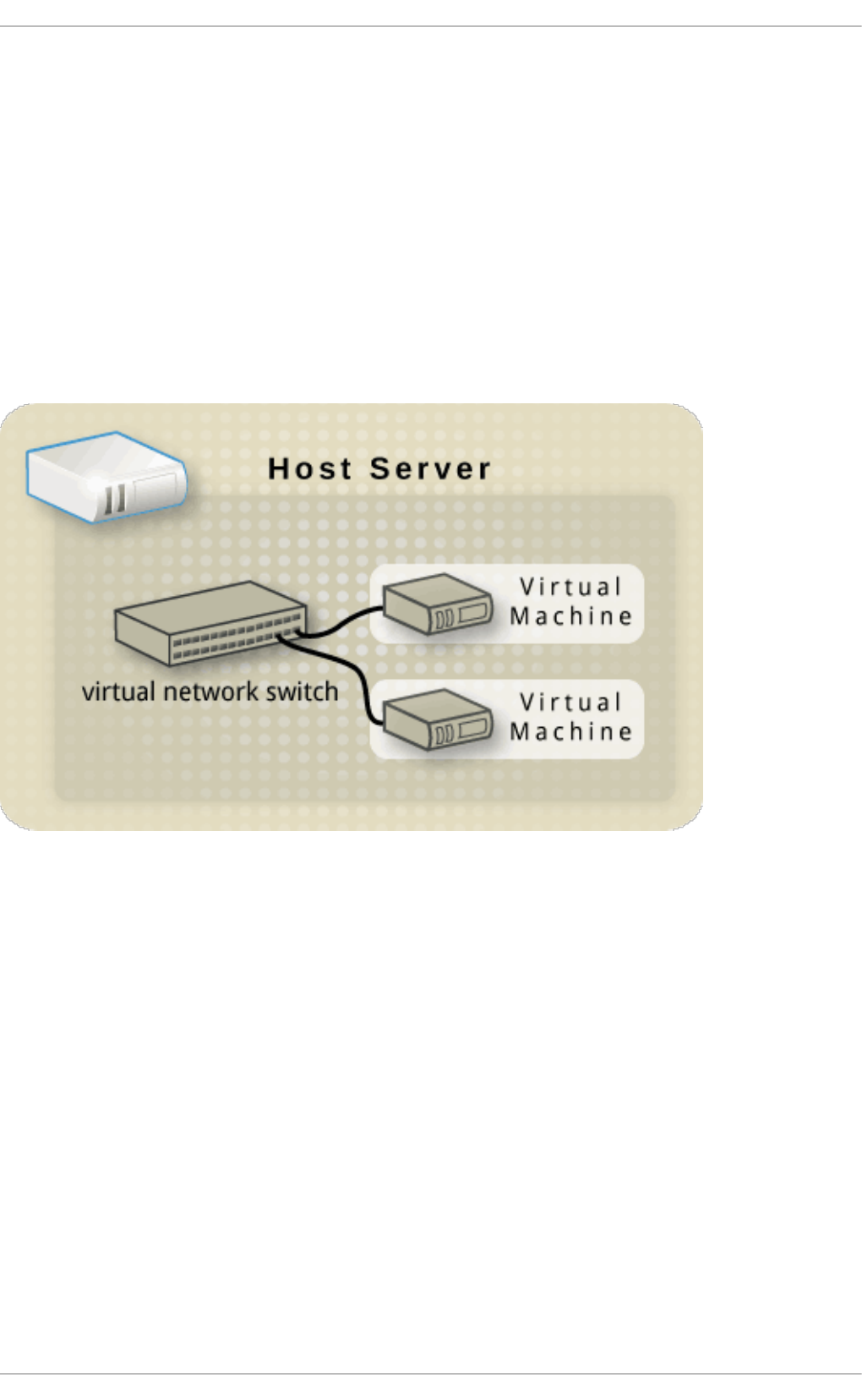
Chapter 20. Virtual Networking
This chapter introduces the concepts needed to create, start, stop, remove, and modify virtual
networks with libvirt.
Additional information can be found in the libvirt reference chapter
20.1. Virt ual net work swit ches
Libvirt virtual networking uses the concept of a virtual network switch. A virtual network switch is a
software construct that operates on a host physical machine server, to which virtual machines
(guests) connect. The network traffic for a guest is directed through this switch:
Fig u re 20.1. Virt u al n et wo rk swit ch wit h t wo g u est s
Linux host physical machine servers represent a virtual network switch as a network interface. When
the libvirtd daemon (l i bvi rtd ) is first installed and started, the default network interface
representing the virtual network switch is vi rbr0 .
Chapt er 2 0 . Virt ual Net working
229

Fig u re 20.2. Lin ux ho st ph ysical mach in e wit h an in t erf ace t o a virt ual n et wo rk swit ch
This vi rbr0 interface can be viewed with the i fco nfi g and i p commands like any other interface:
$ ifconfig virbr0
virbr0 Link encap:Ethernet HWaddr 1B:C4:94:CF:FD:17
inet addr:192.168.122.1 Bcast:192.168.122.255
Mask:255.255.255.0
UP BROADCAST RUNNING MULTICAST MTU:1500 Metric:1
RX packets:0 errors:0 dropped:0 overruns:0 frame:0
TX packets:11 errors:0 dropped:0 overruns:0 carrier:0
collisions:0 txqueuelen:0
RX bytes:0 (0.0 b) TX bytes:3097 (3.0 KiB)
$ ip addr show virbr0
3: virbr0: <BROADCAST,MULTICAST,UP,LOWER_UP> mtu 1500 qdisc noqueue
state UNKNOWN
link/ether 1b:c4:94:cf:fd:17 brd ff:ff:ff:ff:ff:ff
inet 192.168.122.1/24 brd 192.168.122.255 scope global virbr0
20.2. Bridge Mode
When using Bridge mode, all of the guest virtual machines appear within the same subnet as the host
physical machine. All other physical machines on the same physical network are aware of the virtual
machines, and can access the virtual machines. Bridging operates on Layer 2 of the OSI networking
model.
It is possible to use multiple physical interfaces on the hypervisor by joining them together with a
bond. The bond is then added to a bridge and then guest virtual machines are added onto the
bridge as well. However, the bonding driver has several modes of operation, and only a few of these
modes work with a bridge where virtual guest machines are in use.
Virt ualizat ion Deployment and Administ rat ion G uide
230
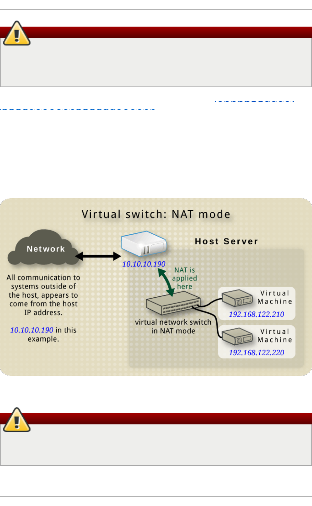
Warning
The only bonding modes that should be used with a guest virtual machine are Mode 1, Mode
2, and Mode 4. Under no circumstances should Modes 0, 3, 5, or 6 be used. It should also be
noted that mii-monitoring should be used to monitor bonding modes as arp-monitoring does
not work.
For more information on bonding modes, refer to the knowledge base article on bonding modes, or
The Red Hat Enterprise Linux 7 Deployment Guide.
20.3. Net work Address T ranslat ion
By default, virtual network switches operate in NAT mode. They use IP masquerading rather than
SNAT (Source-NAT) or DNAT (Destination-NAT). IP masquerading enables connected guests to use
the host physical machine IP address for communication to any external network. By default,
computers that are placed externally to the host physical machine cannot communicate to the guests
inside when the virtual network switch is operating in NAT mode, as shown in the following diagram:
Fig u re 20.3. Virt u al n et wo rk swit ch u sin g NAT wit h t wo g u est s
Warning
Virtual network switches use NAT configured by iptables rules. Editing these rules while the
switch is running is not recommended, as incorrect rules may result in the switch being unable
to communicate.
Chapt er 2 0 . Virt ual Net working
231
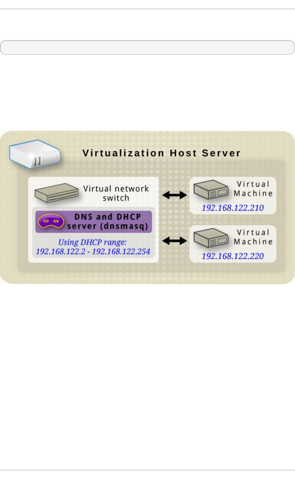
If the switch is not running, you can set th public IP range for foward mode NAT in order to create a
port masquerading range by running:
# iptables -j SNAT --to-source [start]-[end]
20.4 . DNS and DHCP
IP information can be assigned to guests via D HCP. A pool of addresses can be assigned to a
virtual network switch for this purpose. Libvirt uses the dnsmasq program for this. An instance of
dnsmasq is automatically configured and started by libvirt for each virtual network switch that needs
it.
Fig u re 20.4 . Virt ual n et wo rk swit ch ru n n in g d n smasq
20.5. Rout ed mode
When using Routed mode, the virtual switch connects to the physical LAN connected to the host
physical machine, passing traffic back and forth without the use of NAT. The virtual switch can
examine all traffic and use the information contained within the network packets to make routing
decisions. When using this mode, all of the virtual machines are in their own subnet, routed through
a virtual switch. This situation is not always ideal as no other host physical machines on the
physical network are aware of the virtual machines without manual physical router configuration,
and cannot access the virtual machines. Routed mode operates at Layer 3 of the OSI networking
model.
Virt ualizat ion Deployment and Administ rat ion G uide
232
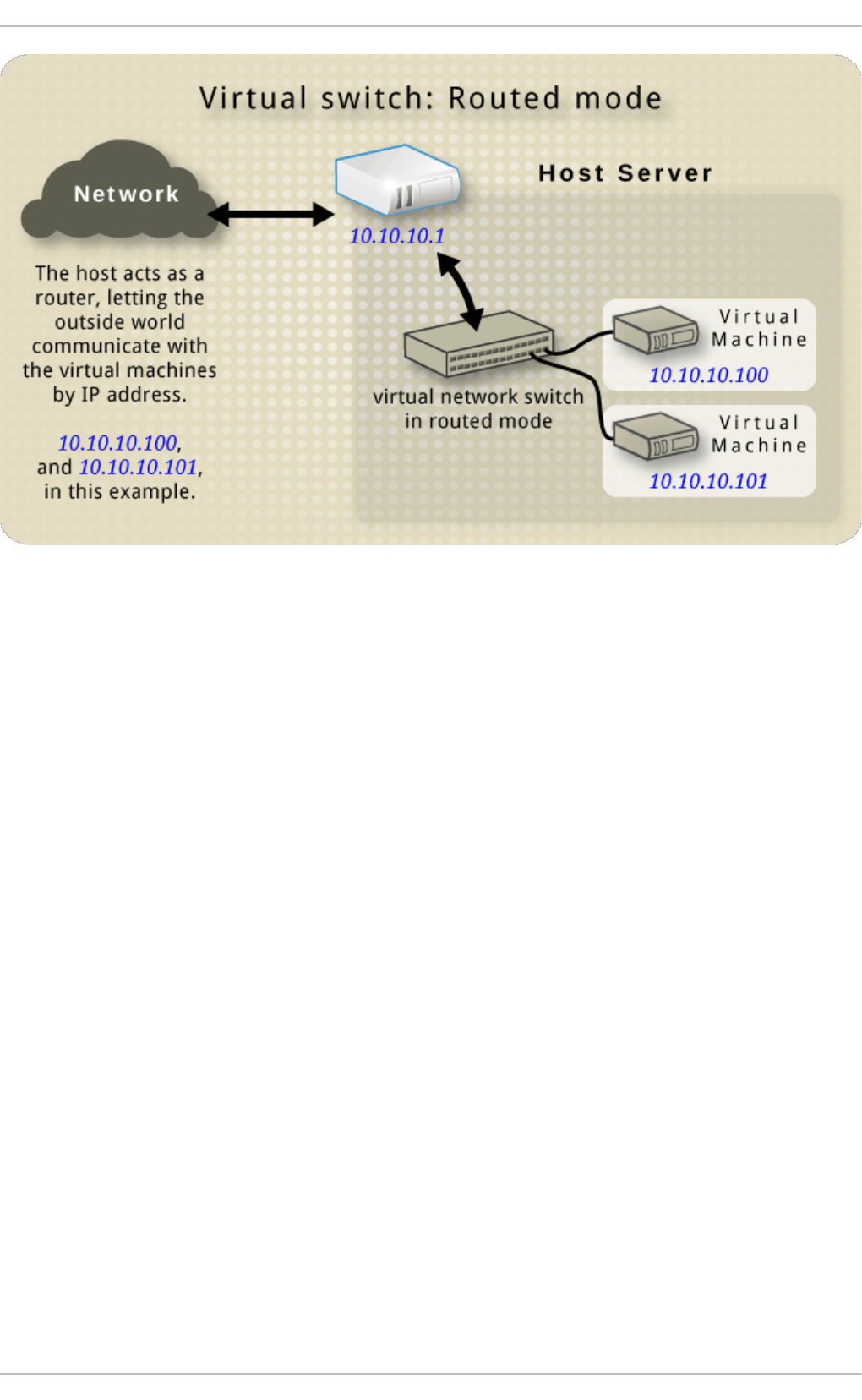
Fig u re 20.5. Virt u al n et wo rk swit ch in ro u t ed mo d e
20.6. Isolat ed mode
When using Isolated mode, guests connected to the virtual switch can communicate with each other,
and with the host physical machine, but their traffic will not pass outside of the host physical
machine, nor can they receive traffic from outside the host physical machine. Using dnsmasq in this
mode is required for basic functionality such as D HCP. However, even if this network is isolated from
any physical network, DNS names are still resolved. Therefore a situation can arise when DNS
names resolve but ICMP echo request (ping) commands fail.
Chapt er 2 0 . Virt ual Net working
233
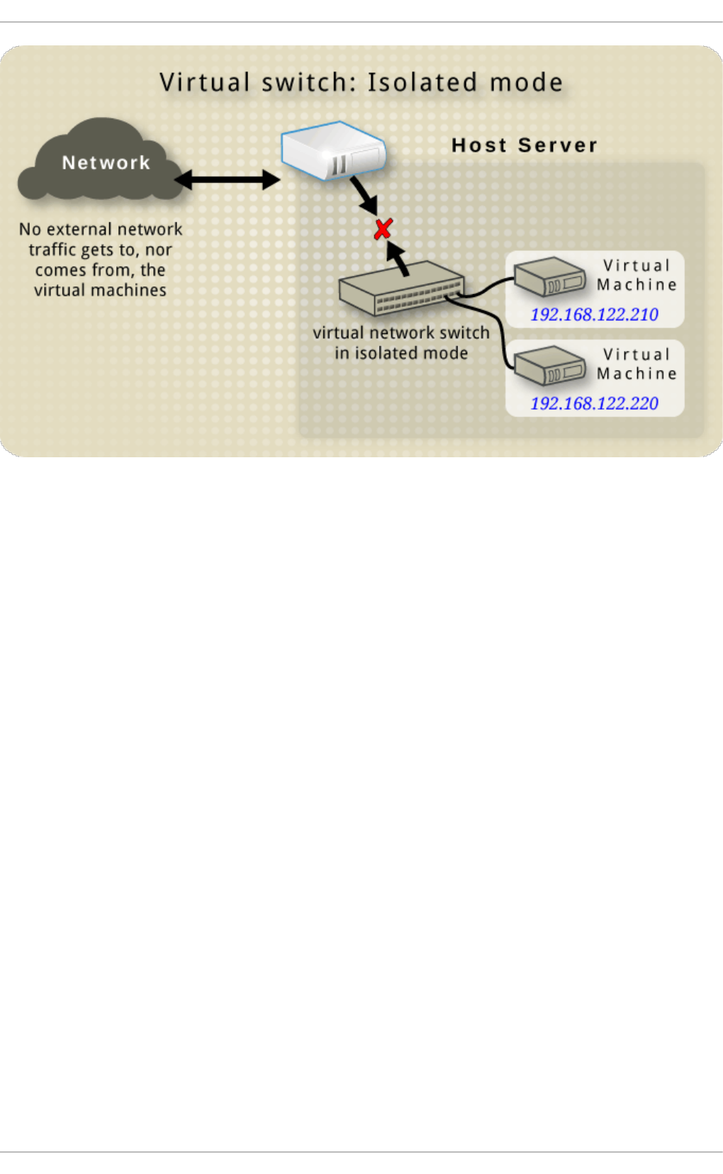
Fig u re 20.6 . Virt ual n et wo rk swit ch in iso lat ed mo d e
20.7. T he default configurat ion
When the libvirtd daemon (l i bvi rtd ) is first installed, it contains an initial virtual network switch
configuration in NAT mode. This configuration is used so that installed guests can communicate to
the external network, through the host physical machine. The following image demonstrates this
default configuration for l i bvi rtd :
Virt ualizat ion Deployment and Administ rat ion G uide
234
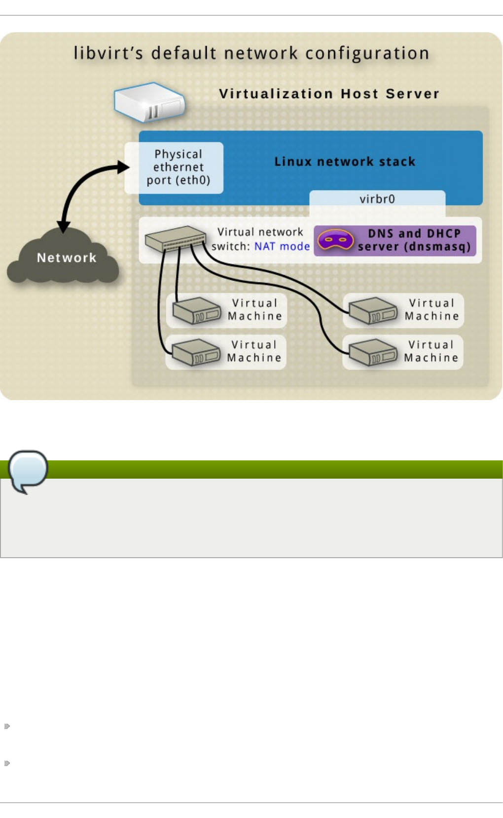
Fig u re 20.7. D ef au lt libvirt n et wo rk co n f ig u rat io n
Note
A virtual network can be restricted to a specific physical interface. This may be useful on a
physical system that has several interfaces (for example, eth0 , eth1 and eth2). This is only
useful in routed and NAT modes, and can be defined in the dev=<interface> option, or in
virt-manager when creating a new virtual network.
20.8. Examples of common scenarios
This section demonstrates different virtual networking modes and provides some example scenarios.
20.8.1. Bridged mode
Bridged mode operates on Layer 2 of the OSI model. When used, all of the guest virtual machines will
appear on the same subnet as the host physical machine. The most common use cases for bridged
mode include:
Deploying guest virtual machines in an existing network alongside host physical machines
making the difference between virtual and physical machines transparent to the end user.
Deploying guest virtual machines without making any changes to existing physical network
configuration settings.
Chapt er 2 0 . Virt ual Net working
235
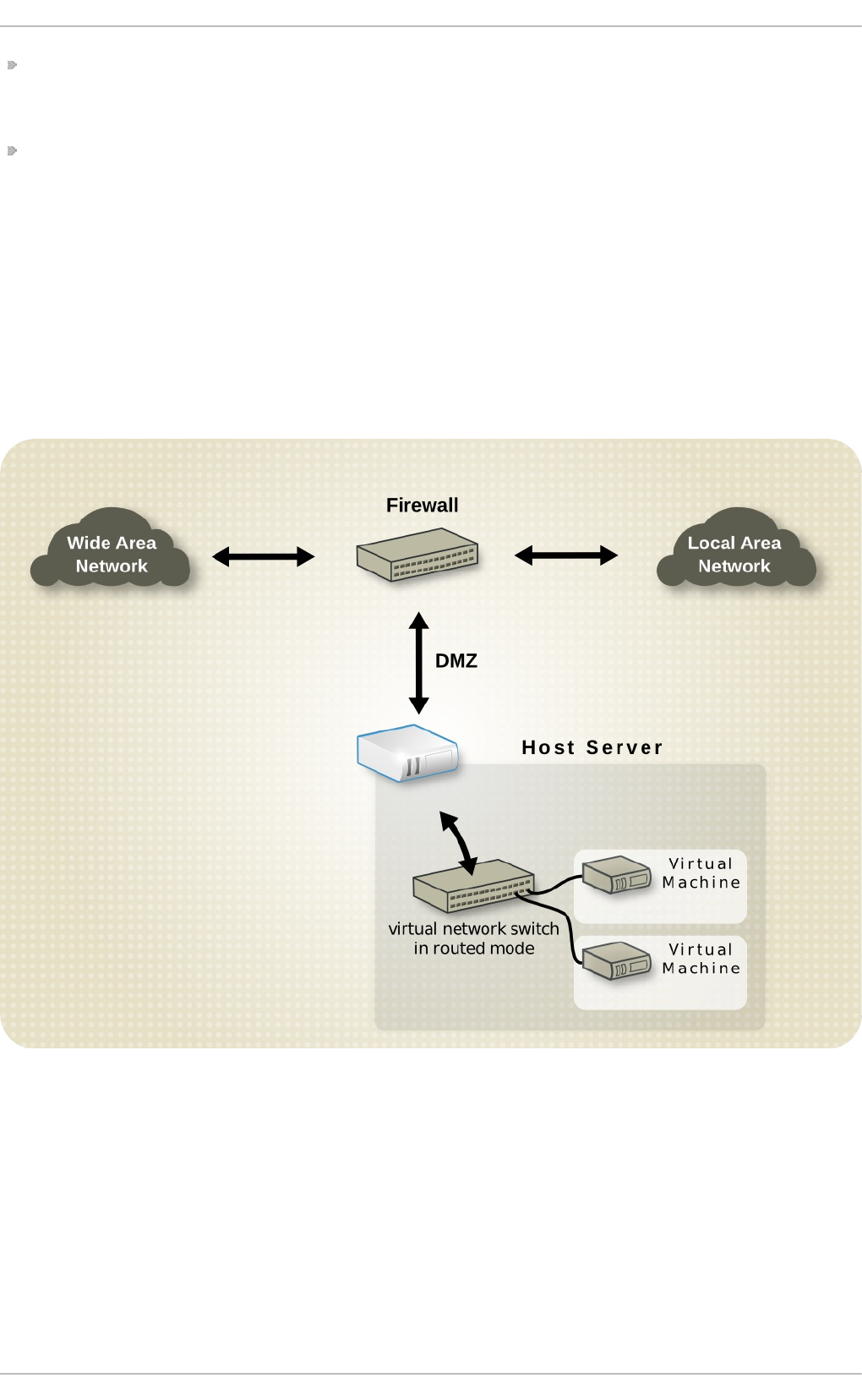
Deploying guest virtual machines which must be easily accessible to an existing physical
network. Placing guest virtual machines on a physical network where they must access services
within an existing broadcast domain, such as DHCP.
Connecting guest virtual machines to an exsting network where VLANs are used.
20.8.2. Rout ed mode
DMZ
Consider a network where one or more nodes are placed in a controlled sub-network for security
reasons. The deployment of a special sub-network such as this is a common practice, and the sub-
network is known as a D MZ. Refer to the following diagram for more details on this layout:
Fig u re 20.8. Samp le DMZ co n f ig urat io n
Host physical machines in a DMZ typically provide services to WAN (external) host physical
machines as well as LAN (internal) host physical machines. As this requires them to be accessible
from multiple locations, and considering that these locations are controlled and operated in different
ways based on their security and trust level, routed mode is the best configuration for this
environment.
Virt u al Server h o st ing
Virt ualizat ion Deployment and Administ rat ion G uide
236
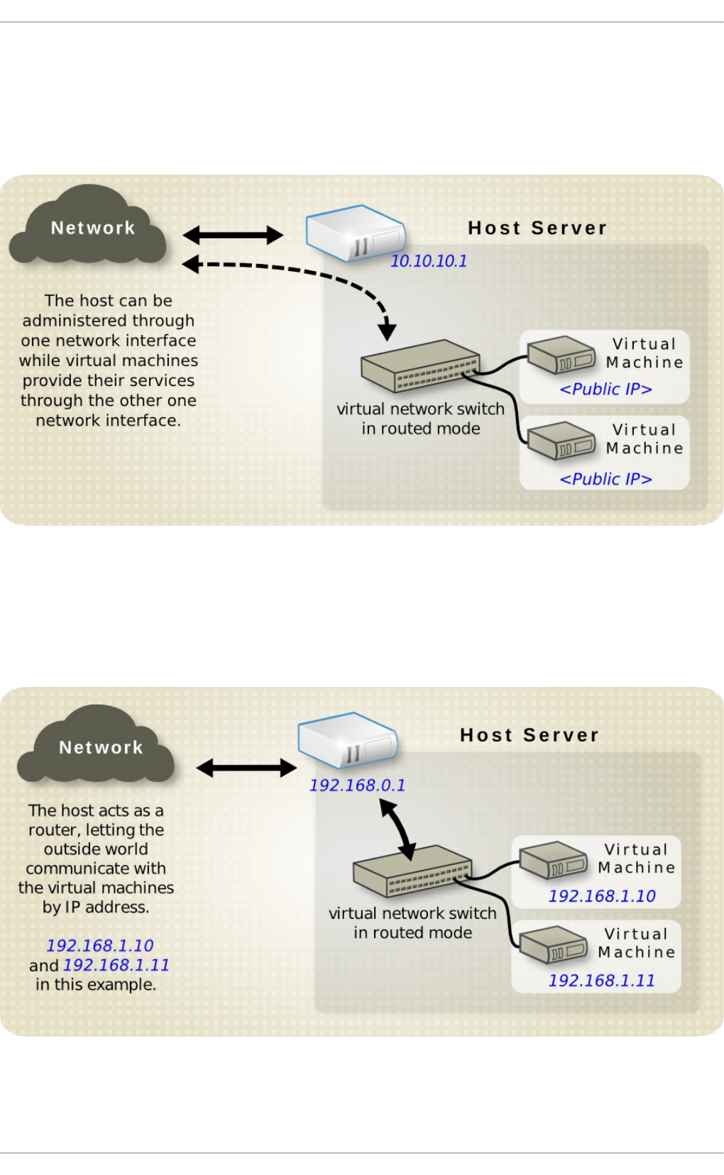
Consider a virtual server hosting company that has several host physical machines, each with two
physical network connections. One interface is used for management and accounting, the other is for
the virtual machines to connect through. Each guest has its own public IP address, but the host
physical machines use private IP address as management of the guests can only be performed by
internal administrators. Refer to the following diagram to understand this scenario:
Fig u re 20.9 . Virt ual server h o st in g samp le co n f igurat io n
When the host physical machine has a public IP address and the virtual machines have static public
IP addresses, bridged networking cannot be used, as the provider only accepts packets from the
MAC address of the public host physical machine. The following diagram demonstrates this:
Fig u re 20.10. Virt u al server u sin g st at ic IP ad dresses
20.8.3. NAT mode
Chapt er 2 0 . Virt ual Net working
237
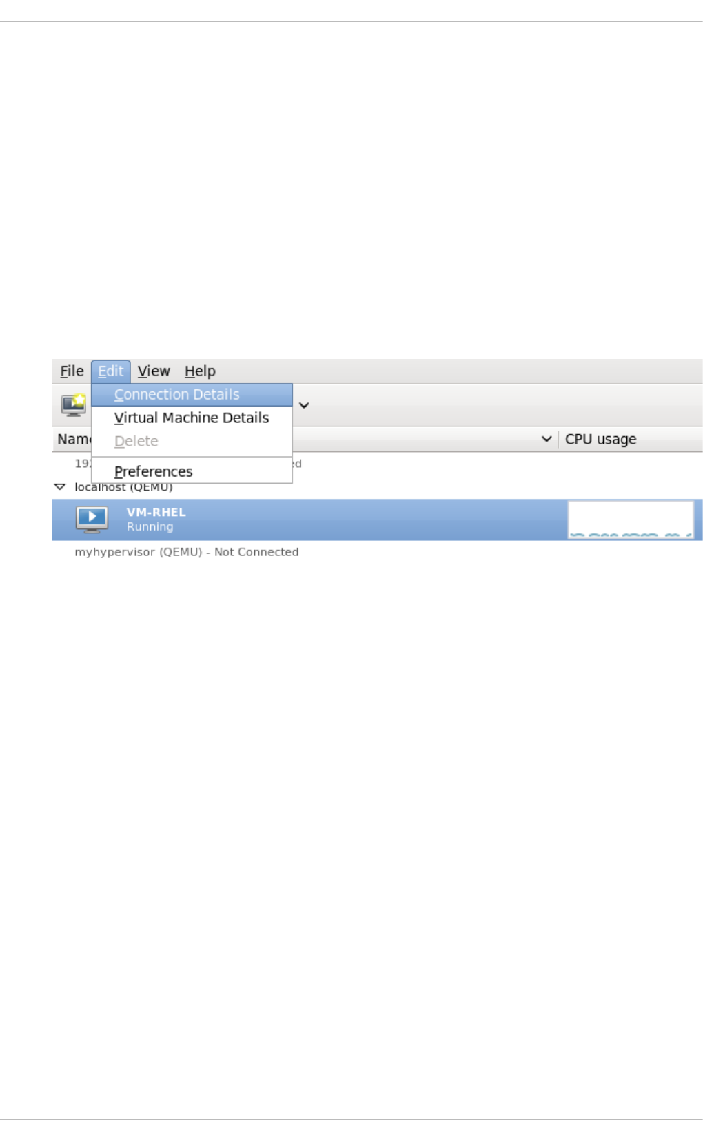
NAT (Network Address Translation) mode is the default mode. It can be used for testing when there is
no need for direct network visibility.
20.8.4 . Isolat ed mode
Isolated mode allows virtual machines to communicate with each other only. They are unable to
interact with the physical network.
20.9. Managing a virt ual net work
To configure a virtual network on your system:
1. From the Ed i t menu, select C o nnecti o n D etai l s.
Fig u re 20.11. Select in g a h o st ph ysical mach in e' s d et ails
2. This will open the Connect io n Det ails menu. Click the Virtual Networks tab.
Virt ualizat ion Deployment and Administ rat ion G uide
238

Fig u re 20.12. Virt u al n et wo rk co n f ig u rat io n
3. All available virtual networks are listed on the left-hand box of the menu. You can edit the
configuration of a virtual network by selecting it from this box and editing as you see fit.
20.10. Creat ing a virt ual net work
To create a virtual network on your system using the Virtual Manager (virt-manager):
1. Open the Virtual Networks tab from within the C o nnecti o n D etai l s menu. Click the
Add Network button, identified by a plus sign (+) icon. For more information, refer to
Section 20.9, “ Managing a virtual network” .
Chapt er 2 0 . Virt ual Net working
239
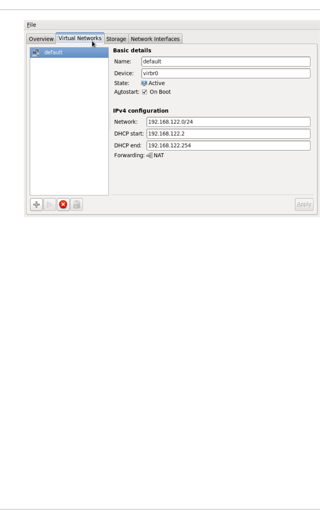
Fig u re 20.13. Virt u al n et wo rk co n f ig u rat io n
This will open the Creat e a n ew virt u al n et wo rk window. Click Fo rward to continue.
Virt ualizat ion Deployment and Administ rat ion G uide
24 0
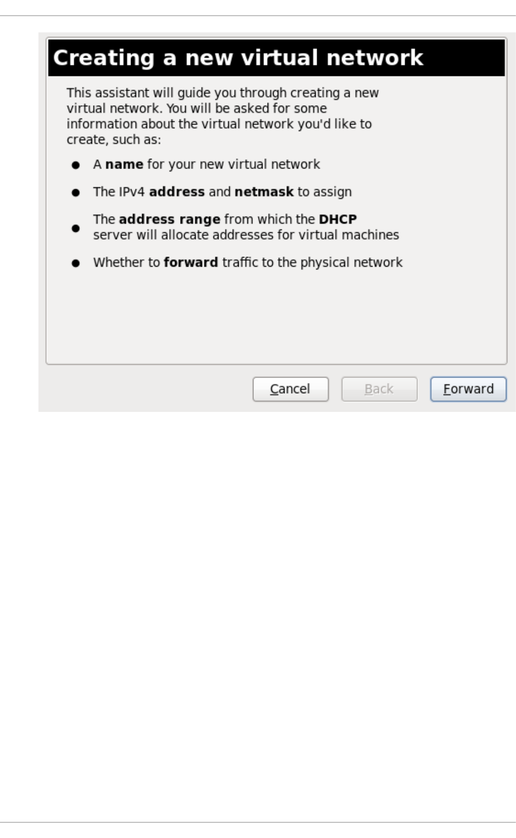
Fig u re 20.14 . Creat in g a n ew virt u al n et wo rk
2. Enter an appropriate name for your virtual network and click Fo rward .
Chapt er 2 0 . Virt ual Net working
24 1
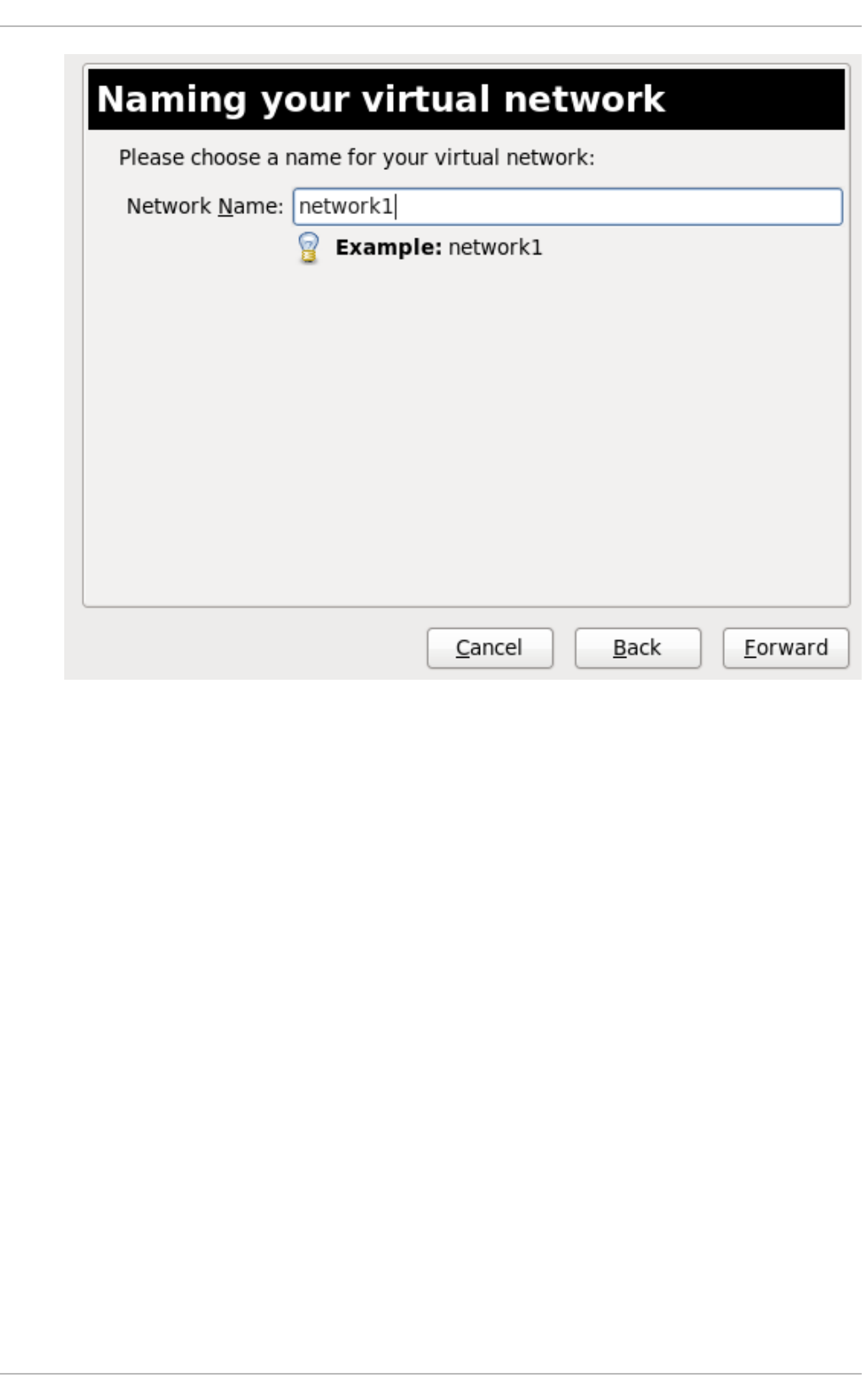
Fig u re 20.15. N amin g yo u r virt ual net wo rk
3. Enter an IPv4 address space for your virtual network and click Fo rward .
Virt ualizat ion Deployment and Administ rat ion G uide
24 2
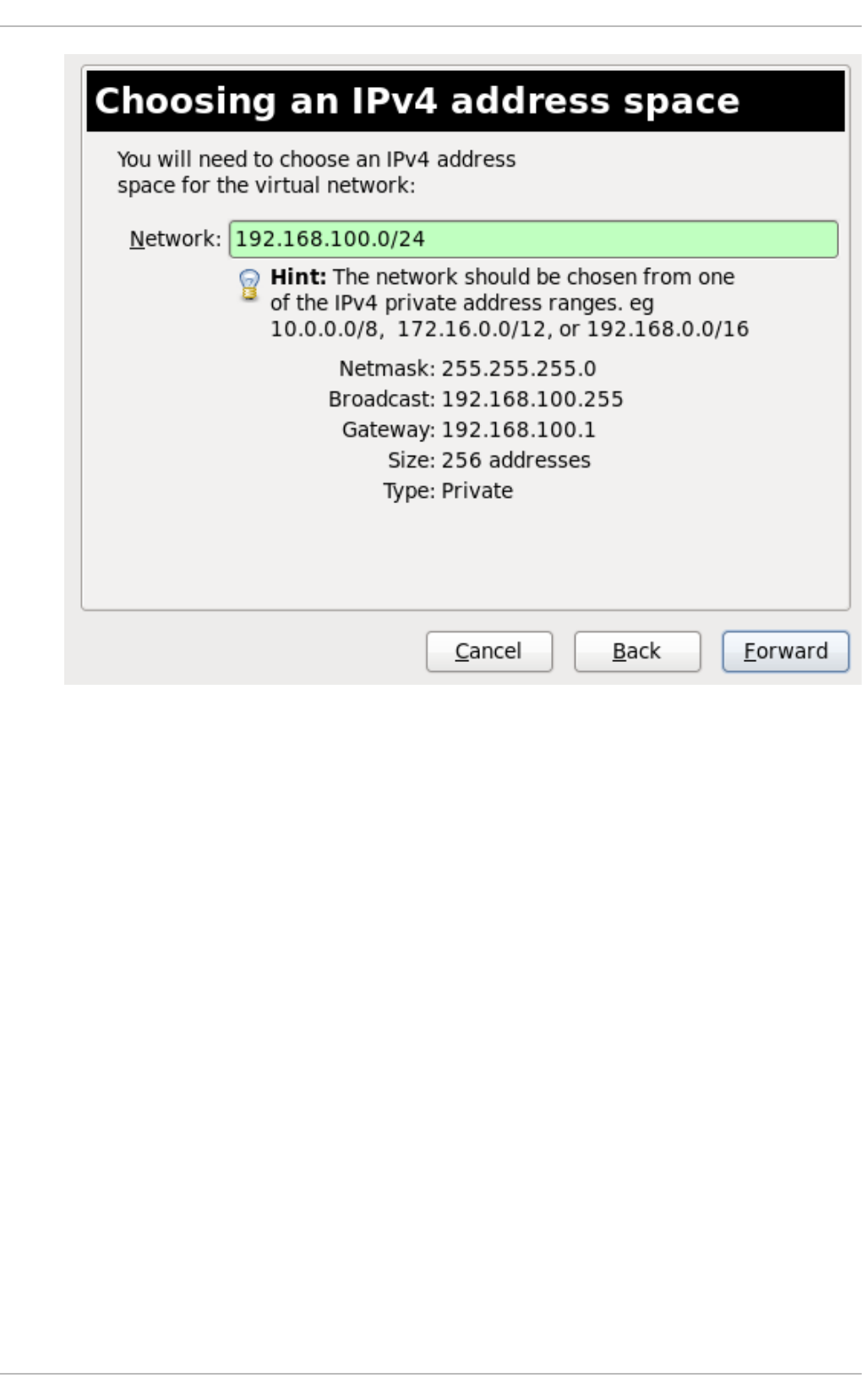
Fig u re 20.16 . Ch oo sin g an IPv4 ad d ress sp ace
4. Define the DHCP range for your virtual network by specifying a Start and End range of IP
addresses. Click Fo rward to continue.
Chapt er 2 0 . Virt ual Net working
24 3
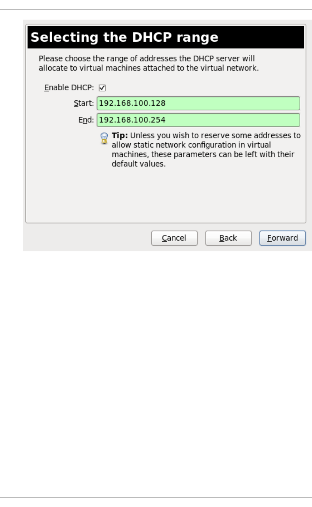
Fig u re 20.17. Select in g t h e DHCP ran g e
5. Select how the virtual network should connect to the physical network.
Virt ualizat ion Deployment and Administ rat ion G uide
24 4
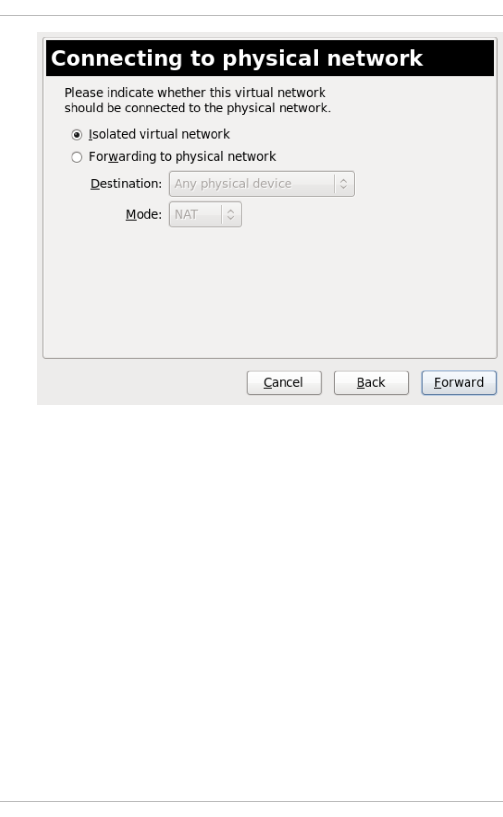
Fig u re 20.18. C o n n ect in g t o physical n et wo rk
If you select Forwarding to physical network, choose whether the D esti nati o n
should be Any physical device or a specific physical device. Also select whether the
Mo d e should be NAT or R o uted .
Click Fo rward to continue.
6. You are now ready to create the network. Check the configuration of your network and click
Finish.
Chapt er 2 0 . Virt ual Net working
24 5
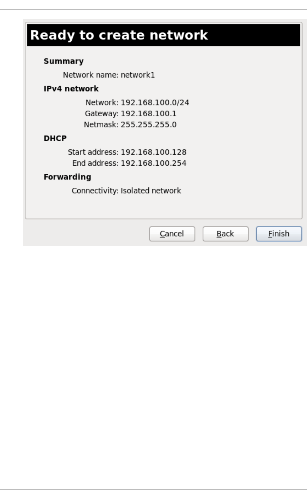
Fig u re 20.19 . Read y to creat e n et wo rk
7. The new virtual network is now available in the Virtual Networks tab of the C o nnecti o n
D etai l s window.
20.11. At t aching a virt ual net work t o a guest
To attach a virtual network to a guest:
1. In the Virtual Machine Manager window, highlight the guest that will have the network
assigned.
Virt ualizat ion Deployment and Administ rat ion G uide
24 6
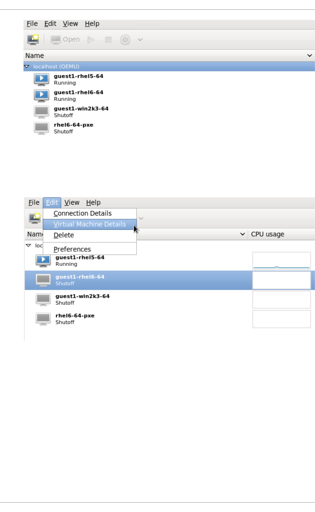
Fig u re 20.20. Select in g a virt ual mach in e t o d isp lay
2. From the Virtual Machine Manager Ed i t menu, select Virtual Machine Details.
Fig u re 20.21. D isp layin g t h e virt u al mach in e d et ails
3. Click the Add Hardware button on the Virtual Machine Details window.
Chapt er 2 0 . Virt ual Net working
24 7
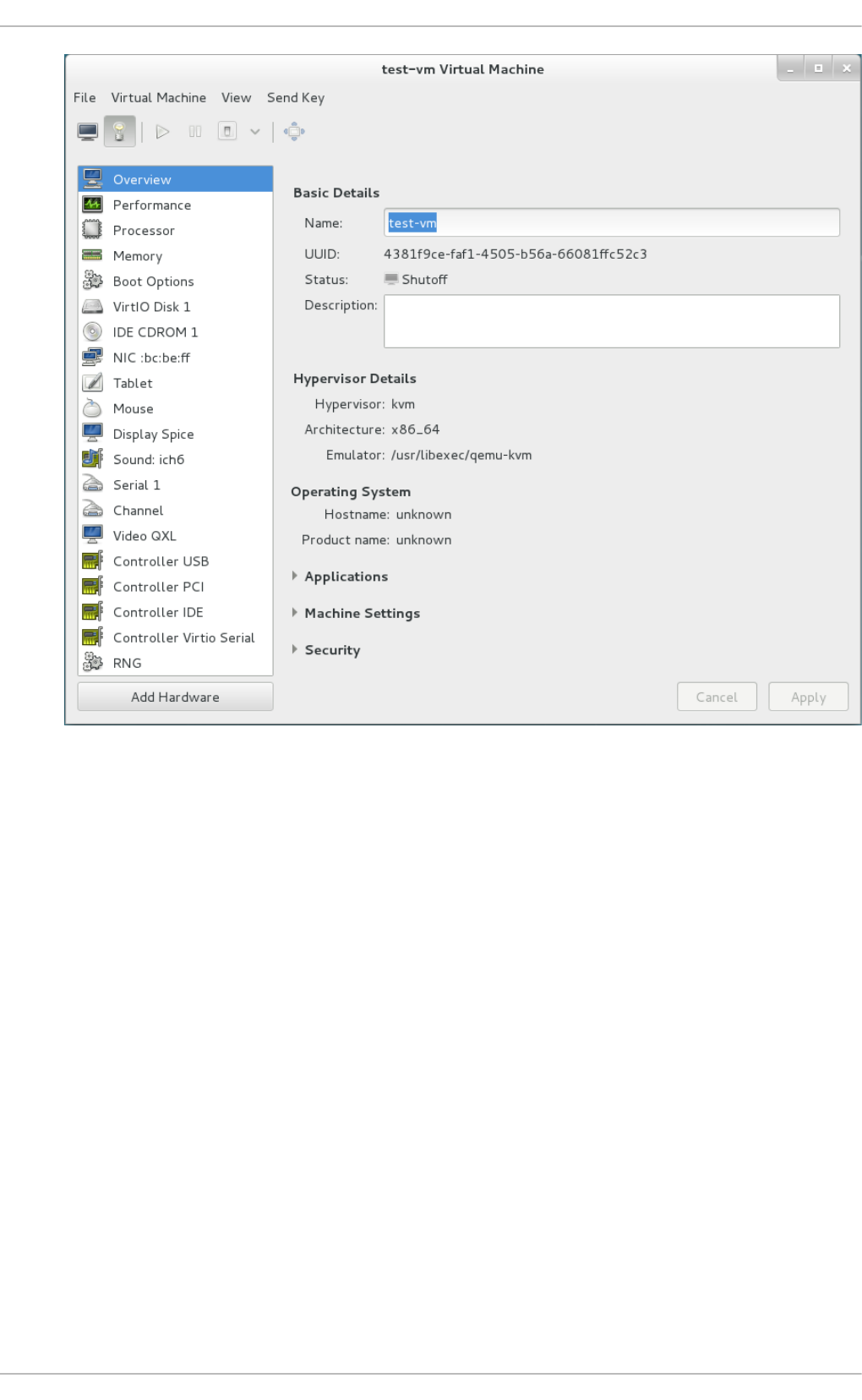
Fig u re 20.22. T h e Virt u al Mach in e Det ails windo w
4. In the Add new virtual hardware window, select Network from the left pane, and select
your network name (network1 in this example) from the Host device menu and click
Finish.
Virt ualizat ion Deployment and Administ rat ion G uide
24 8

Fig u re 20.23. Select yo u r n et wo rk f ro m t h e Ad d n ew virt ual hard ware win d o w
5. The new network is now displayed as a virtual network interface that will be presented to the
guest upon launch.
Chapt er 2 0 . Virt ual Net working
24 9
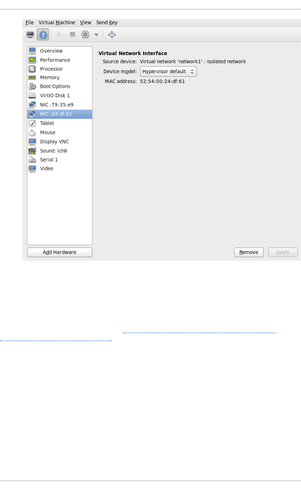
Fig u re 20.24 . New n et wo rk sh o wn in g u est hard ware list
20.12. Direct ly at t aching t o physical int erface
The instructions provided in this chapter will assist in the direct attachment of the virtual machine's
NIC to the given physical interface of the host physical machine. If you want to use an assignment
method (known as passthrough), refer to Chapter 18, Guest virtual machine device configuration and
Section 23.18, “Interface Commands” . This setup requires the Linux macvtap driver to be available.
There are four modes that you can choose for the operation mode of the macvtap device, with 'vepa'
being the default mode. Their behavior is as follows:
Ph ysical in t erf ace d elivery mo d es
vep a
All VMs' packets are sent to the external bridge. Packets whose destination is a VM on the
same host physical machine as where the packet originates from are sent back to the host
physical machine by the VEPA capable bridge (today's bridges are typically not VEPA
capable).
b ri d g e
Packets whose destination is on the same host physical machine as where they originate
from are directly delivered to the target macvtap device. Both origin and destination devices
Virt ualizat ion Deployment and Administ rat ion G uide
250

from are directly delivered to the target macvtap device. Both origin and destination devices
need to be in bridge mode for direct delivery. If either one of them is in vepa mode, a VEPA
capable bridge is required.
p ri va t e
All packets are sent to the external bridge and will only be delivered to a target VM on the
same host physical machine if they are sent through an external router or gateway and that
device sends them back to the host physical machine. This procedure is followed if either
the source or destination device is in private mode.
p asst h ro u g h
This feature attaches a virtual function of a SRIOV capable NIC directly to a VM without
losing the migration capability. All packets are sent to the VF/IF of the configured network
device. Depending on the capabilities of the device additional prerequisites or limitations
may apply; for example, on Linux this requires kernel 2.6.38 or newer.
Each of the four modes is configured by changing the domain xml file. Once this file is opened,
change the mode setting as shown:
<devices>
...
<interface type='direct'>
<source dev='eth0' mode='vepa'/>
</interface>
</devices>
The network access of direct attached guest virtual machines can be managed by the hardware
switch to which the physical interface of the host physical machine is connected to.
The interface can have additional parameters as shown below, if the switch is conforming to the IEEE
802.1Qbg standard. The parameters of the virtualport element are documented in more detail in the
IEEE 802.1Qbg standard. The values are network specific and should be provided by the network
administrator. In 802.1Qbg terms, the Virtual Station Interface (VSI) represents the virtual interface of
a virtual machine.
Note that IEEE 802.1Qbg requires a non-zero value for the VLAN ID. Also if the switch is conforming
to the IEEE 802.1Qbh standard, the values are network specific and should be provided by the
network administrator.
Virt u al St at io n In t erf ace t yp es
man ag erid
The VSI Manager ID identifies the database containing the VSI type and instance
definitions. This is an integer value and the value 0 is reserved.
t yp eid
The VSI Type ID identifies a VSI type characterizing the network access. VSI types are
typically managed by network administrator. This is an integer value.
t yp eid versio n
The VSI Type Version allows multiple versions of a VSI Type. This is an integer value.
Chapt er 2 0 . Virt ual Net working
251

in st an ceid
The VSI Instance ID Identifier is generated when a VSI instance (i.e. a virtual interface of a
virtual machine) is created. This is a globally unique identifier.
p ro f i lei d
The profile ID contains the name of the port profile that is to be applied onto this interface.
This name is resolved by the port profile database into the network parameters from the port
profile, and those network parameters will be applied to this interface.
Each of the four types is configured by changing the domain xml file. Once this file is opened,
change the mode setting as shown:
<devices>
...
<interface type='direct'>
<source dev='eth0.2' mode='vepa'/>
<virtualport type="802.1Qbg">
<parameters managerid="11" typeid="1193047" typeidversion="2"
instanceid="09b11c53-8b5c-4eeb-8f00-d84eaa0aaa4f"/>
</virtualport>
</interface>
</devices>
The profile ID is shown here:
<devices>
...
<interface type='direct'>
<source dev='eth0' mode='private'/>
<virtualport type='802.1Qbh'>
<parameters profileid='finance'/>
</virtualport>
</interface>
</devices>
...
20.13. Dynamically changing a host physical machine or a net work
bridge t hat is at t ached t o a virt ual NIC
This section demonstrates how to move the vNIC of a guest virtual machine from one bridge to
another while the guest virtual machine is running without compromising the guest virtual machine
1. Prepare guest virtual machine with a configuration similar to the following:
<interface type='bridge'>
<mac address='52:54:00:4a:c9:5e'/>
<source bridge='virbr0'/>
<model type='virtio'/>
</interface>
2. Prepare an XML file for interface update:
Virt ualizat ion Deployment and Administ rat ion G uide
252

# cat br1.xml
<interface type='bridge'>
<mac address='52:54:00:4a:c9:5e'/>
<source bridge='virbr1'/>
<model type='virtio'/>
</interface>
3. Start the guest virtual machine, confirm the guest virtual machine's network functionality, and
check that the guest virtual machine's vnetX is connected to the bridge you indicated.
# brctl show
bridge name bridge id STP enabled interfaces
virbr0 8000.5254007da9f2 yes
virbr0-nic
vnet0
virbr1 8000.525400682996 yes
virbr1-nic
4. Update the guest virtual machine's network with the new interface parameters with the
following command:
# virsh update-device test1 br1.xml
Device updated successfully
5. On the guest virtual machine, run service network restart. The guest virtual machine
gets a new IP address for virbr1. Check the guest virtual machine's vnet0 is connected to the
new bridge(virbr1)
# brctl sho w
bridge name bridge id STP enabled interfaces
virbr0 8000.5254007da9f2 yes virbr0-nic
virbr1 8000.525400682996 yes virbr1-nic
vnet0
20.14 . Applying net work filt ering
This section provides an introduction to libvirt's network filters, their goals, concepts and XML format.
20.14 .1. Int roduct ion
The goal of the network filtering, is to enable administrators of a virtualized system to configure and
enforce network traffic filtering rules on virtual machines and manage the parameters of network
traffic that virtual machines are allowed to send or receive. The network traffic filtering rules are
applied on the host physical machine when a virtual machine is started. Since the filtering rules
cannot be circumvented from within the virtual machine, it makes them mandatory from the point of
view of a virtual machine user.
From the point of view of the guest virtual machine, the network filtering system allows each virtual
Chapt er 2 0 . Virt ual Net working
253

machine's network traffic filtering rules to be configured individually on a per interface basis. These
rules are applied on the host physical machine when the virtual machine is started and can be
modified while the virtual machine is running. The latter can be achieved by modifying the XML
description of a network filter.
Multiple virtual machines can make use of the same generic network filter. When such a filter is
modified, the network traffic filtering rules of all running virtual machines that reference this filter are
updated. The machines that are not running will update on start.
As previously mentioned, applying network traffic filtering rules can be done on individual network
interfaces that are configured for certain types of network configurations. Supported network types
include:
network
ethernet -- must be used in bridging mode
bridge
Examp le 20.1. An examp le o f n et wo rk f ilt erin g
The interface XML is used to reference a top-level filter. In the following example, the interface
description references the filter clean-traffic.
<devices>
<interface type='bridge'>
<mac address='00:16:3e:5d:c7:9e'/>
<filterref filter='clean-traffic'/>
</interface>
</devices>
Network filters are written in XML and may either contain: references to other filters, rules for traffic
filtering, or hold a combination of both. The above referenced filter clean-traffic is a filter that only
contains references to other filters and no actual filtering rules. Since references to other filters can
be used, a tree of filters can be built. The clean-traffic filter can be viewed using the command: #
virsh nwfilter-dumpxml clean-traffic.
As previously mentioned, a single network filter can be referenced by multiple virtual machines.
Since interfaces will typically have individual parameters associated with their respective traffic
filtering rules, the rules described in a filter's XML can be generalized using variables. In this case,
the variable name is used in the filter XML and the name and value are provided at the place where
the filter is referenced.
Examp le 20.2. Descrip t io n ext en d ed
In the following example, the interface description has been extended with the parameter IP and a
dotted IP address as a value.
<devices>
<interface type='bridge'>
<mac address='00:16:3e:5d:c7:9e'/>
<filterref filter='clean-traffic'>
Virt ualizat ion Deployment and Administ rat ion G uide
254

<parameter name='IP' value='10.0.0.1'/>
</filterref>
</interface>
</devices>
In this particular example, the clean-traffic network traffic filter will be represented with the IP
address parameter 10.0.0.1 and as per the rule dictates that all traffic from this interface will always
be using 10.0.0.1 as the source IP address, which is one of the purpose of this particular filter.
20.14 .2. Filt ering chains
Filtering rules are organized in filter chains. These chains can be thought of as having a tree
structure with packet filtering rules as entries in individual chains (branches).
Packets start their filter evaluation in the root chain and can then continue their evaluation in other
chains, return from those chains back into the root chain or be dropped or accepted by a filtering
rule in one of the traversed chains.
Libvirt's network filtering system automatically creates individual root chains for every virtual
machine's network interface on which the user chooses to activate traffic filtering. The user may write
filtering rules that are either directly instantiated in the root chain or may create protocol-specific
filtering chains for efficient evaluation of protocol-specific rules.
The following chains exist:
root
mac
stp (spanning tree protocol)
vlan
arp and rarp
ipv4
ipv6
Multiple chains evaluating the mac, stp, vlan, arp, rarp, ipv4, or ipv6 protocol can be created using
the protocol name only as a prefix in the chain's name.
Examp le 20.3. AR P t raf fic f ilt erin g
This example allows chains with names arp-xyz or arp-test to be specified and have their ARP
protocol packets evaluated in those chains.
The following filter XML shows an example of filtering ARP traffic in the arp chain.
<filter name='no-arp-spoofing' chain='arp' priority='-500'>
<uuid>f88f1932-debf-4aa1-9fbe-f10d3aa4bc95</uuid>
<rule action='drop' direction='out' priority='300'>
<mac match='no' srcmacaddr='$MAC'/>
</rule>
<rule action='drop' direction='out' priority='350'>
<arp match='no' arpsrcmacaddr='$MAC'/>
Chapt er 2 0 . Virt ual Net working
255

</rule>
<rule action='drop' direction='out' priority='400'>
<arp match='no' arpsrcipaddr='$IP'/>
</rule>
<rule action='drop' direction='in' priority='450'>
<arp opcode='Reply'/>
<arp match='no' arpdstmacaddr='$MAC'/>
</rule>
<rule action='drop' direction='in' priority='500'>
<arp match='no' arpdstipaddr='$IP'/>
</rule>
<rule action='accept' direction='inout' priority='600'>
<arp opcode='Request'/>
</rule>
<rule action='accept' direction='inout' priority='650'>
<arp opcode='Reply'/>
</rule>
<rule action='drop' direction='inout' priority='1000'/>
</filter>
The consequence of putting ARP-specific rules in the arp chain, rather than for example in the root
chain, is that packets protocols other than ARP do not need to be evaluated by ARP protocol-
specific rules. This improves the efficiency of the traffic filtering. However, one must then pay
attention to only putting filtering rules for the given protocol into the chain since other rules will not
be evaluated. For example, an IPv4 rule will not be evaluated in the ARP chain since IPv4 protocol
packets will not traverse the ARP chain.
20.14 .3. Filt ering chain priorit ies
As previously mentioned, when creating a filtering rule, all chains are connected to the root chain.
The order in which those chains are accessed is influenced by the priority of the chain. The following
table shows the chains that can be assigned a priority and their default priorities.
T ab le 20.1. Filt erin g ch ain d ef au lt prio rit ies valu es
Ch ain (pref ix) Def au lt prio rity
stp -810
mac -800
vlan -750
ipv4 -700
ipv6 -600
arp -500
rarp -400
Virt ualizat ion Deployment and Administ rat ion G uide
256

Note
A chain with a lower priority value is accessed before one with a higher value.
The chains listed in Table 20.1, “Filtering chain default priorities values” can be also be
assigned custom priorities by writing a value in the range [-1000 to 1000] into the priority
(XML) attribute in the filter node. Section 20.14.2, “ Filtering chains” filter shows the default
priority of -500 for arp chains, for example.
20.14 .4 . Usage of variables in filt ers
There are two variables that have been reserved for usage by the network traffic filtering subsystem:
MAC and IP.
MAC is designated for the MAC address of the network interface. A filtering rule that references this
variable will automatically be replaced with the MAC address of the interface. This works without the
user having to explicitly provide the MAC parameter. Even though it is possible to specify the MAC
parameter similar to the IP parameter above, it is discouraged since libvirt knows what MAC address
an interface will be using.
The parameter IP represents the IP address that the operating system inside the virtual machine is
expected to use on the given interface. The IP parameter is special in so far as the libvirt daemon will
try to determine the IP address (and thus the IP parameter's value) that is being used on an interface
if the parameter is not explicitly provided but referenced. For current limitations on IP address
detection, consult the section on limitations Section 20.14.12, “ Limitations” on how to use this feature
and what to expect when using it. The XML file shown in Section 20.14.2, “Filtering chains” contains
the filter no-arp-spoofing, which is an example of using a network filter XML to reference the MAC
and IP variables.
Note that referenced variables are always prefixed with the character $. The format of the value of a
variable must be of the type expected by the filter attribute identified in the XML. In the above example,
the IP parameter must hold a legal IP address in standard format. Failure to provide the correct
structure will result in the filter variable not being replaced with a value and will prevent a virtual
machine from starting or will prevent an interface from attaching when hotplugging is being used.
Some of the types that are expected for each XML attribute are shown in the example Example 20.4,
“ Sample variable types” .
Examp le 20.4 . Sample variab le t yp es
As variables can contain lists of elements, (the variable IP can contain multiple IP addresses that
are valid on a particular interface, for example), the notation for providing multiple elements for the
IP variable is:
<devices>
<interface type='bridge'>
<mac address='00:16:3e:5d:c7:9e'/>
<filterref filter='clean-traffic'>
<parameter name='IP' value='10.0.0.1'/>
<parameter name='IP' value='10.0.0.2'/>
<parameter name='IP' value='10.0.0.3'/>
</filterref>
</interface>
</devices>
Chapt er 2 0 . Virt ual Net working
257

This XML file creates filters to enable multiple IP addresses per interface. Each of the IP addresses
will result in a separate filtering rule. Therefore using the XML above and the the following rule,
three individual filtering rules (one for each IP address) will be created:
<rule action='accept' direction='in' priority='500'>
<tcp srpipaddr='$IP'/>
</rule>
As it is possible to access individual elements of a variable holding a list of elements, a filtering
rule like the following accesses the 2nd element of the variable DSTPORTS.
<rule action='accept' direction='in' priority='500'>
<udp dstportstart='$DSTPORTS[1]'/>
</rule>
Examp le 20.5. Using a variet y of variab les
As it is possible to create filtering rules that represent all of the permissible rules from different lists
using the notation $VARIABLE[@<iterator id="x">]. The following rule allows a virtual
machine to receive traffic on a set of ports, which are specified in DSTPORTS, from the set of
source IP address specified in SRCIPADDRESSES. The rule generates all combinations of
elements of the variable DSTPORTS with those of SRCIPADDRESSES by using two independent
iterators to access their elements.
<rule action='accept' direction='in' priority='500'>
<ip srcipaddr='$SRCIPADDRESSES[@1]' dstportstart='$DSTPORTS[@2]'/>
</rule>
Assign concrete values to SRCIPADDRESSES and DSTPORTS as shown:
SRCIPADDRESSES = [ 10.0.0.1, 11.1.2.3 ]
DSTPORTS = [ 80, 8080 ]
Assigning values to the variables using $SRCIPADDRESSES[@1] and $DSTPORTS[@2] would
then result in all variants of addresses and ports being created as shown:
10.0.0.1, 80
10.0.0.1, 8080
11.1.2.3, 80
11.1.2.3, 8080
Accessing the same variables using a single iterator, for example by using the notation
$SRCIPADDRESSES[@1] and $DSTPORTS[@1], would result in parallel access to both lists
and result in the following combination:
10.0.0.1, 80
11.1.2.3, 8080
Virt ualizat ion Deployment and Administ rat ion G uide
258

Note
$VARIABLE is short-hand for $VARIABLE[@0]. The former notation always assumes the role
of iterator with i terato r i d = "0 " added as shown in the opening paragraph at the top of
this section.
20.14 .5. Aut omat ic IP address det ect ion and DHCP snooping
20 .1 4.5.1 . Int ro duct io n
The detection of IP addresses used on a virtual machine's interface is automatically activated if the
variable IP is referenced but no value has been assigned to it. The variable CTRL_IP_LEARNING
can be used to specify the IP address learning method to use. Valid values include: any, dhcp, or
none.
The value any instructs libvirt to use any packet to determine the address in use by a virtual machine,
which is the default setting if the variable TRL_IP_LEARNING is not set. This method will only detect
a single IP address per interface. Once a guest virtual machine's IP address has been detected, its IP
network traffic will be locked to that address, if for example, IP address spoofing is prevented by one
of its filters. In that case, the user of the VM will not be able to change the IP address on the interface
inside the guest virtual machine, which would be considered IP address spoofing. When a guest
virtual machine is migrated to another host physical machine or resumed after a suspend operation,
the first packet sent by the guest virtual machine will again determine the IP address that the guest
virtual machine can use on a particular interface.
The value of dhcp instructs libvirt to only honor DHCP server-assigned addresses with valid leases.
This method supports the detection and usage of multiple IP address per interface. When a guest
virtual machine resumes after a suspend operation, any valid IP address leases are applied to its
filters. Otherwise the guest virtual machine is expected to use DHCP to obtain a new IP addresses.
When a guest virtual machine migrates to another physical host physical machine, the guest virtual
machine is required to re-run the DHCP protocol.
If CTRL_IP_LEARNING is set to none, libvirt does not do IP address learning and referencing IP
without assigning it an explicit value is an error.
20 .1 4.5.2 . DHCP sno o ping
CTRL_IP_LEARNING=dhcp (DHCP snooping) provides additional anti-spoofing security,
especially when combined with a filter allowing only trusted DHCP servers to assign IP addresses.
To enable this, set the variable DHCPSERVER to the IP address of a valid DHCP server and provide
filters that use this variable to filter incoming DHCP responses.
When DHCP snooping is enabled and the DHCP lease expires, the guest virtual machine will no
longer be able to use the IP address until it acquires a new, valid lease from a DHCP server. If the
guest virtual machine is migrated, it must get a new valid DHCP lease to use an IP address (e.g., by
bringing the VM interface down and up again).
Chapt er 2 0 . Virt ual Net working
259

Note
Automatic DHCP detection listens to the DHCP traffic the guest virtual machine exchanges with
the DHCP server of the infrastructure. To avoid denial-of-service attacks on libvirt, the
evaluation of those packets is rate-limited, meaning that a guest virtual machine sending an
excessive number of DHCP packets per second on an interface will not have all of those
packets evaluated and thus filters may not get adapted. Normal DHCP client behavior is
assumed to send a low number of DHCP packets per second. Further, it is important to setup
appropriate filters on all guest virtual machines in the infrastructure to avoid them being able
to send DHCP packets. Therefore guest virtual machines must either be prevented from
sending UDP and TCP traffic from port 67 to port 68 or the DHCPSERVER variable should be
used on all guest virtual machines to restrict DHCP server messages to only be allowed to
originate from trusted DHCP servers. At the same time anti-spoofing prevention must be
enabled on all guest virtual machines in the subnet.
Examp le 20.6 . Act ivat in g IPs f o r DHCP sn o o p in g
The following XML provides an example for the activation of IP address learning using the DHCP
snooping method:
<interface type='bridge'>
<source bridge='virbr0'/>
<filterref filter='clean-traffic'>
<parameter name='CTRL_IP_LEARNING' value='dhcp'/>
</filterref>
</interface>
20.14 .6. Reserved Variables
Table 20.2, “ Reserved variables” shows the variables that are considered reserved and are used by
libvirt:
T ab le 20.2. Reserved variab les
Variab le N ame Def in it io n
MAC The MAC address of the interface
IP The list of IP addresses in use by an interface
IPV6 Not currently implemented: the list of IPV6
addresses in use by an interface
DHCPSERVER The list of IP addresses of trusted DHCP servers
DHCPSERVERV6 Not currently implemented: The list of IPv6
addresses of trusted D HCP servers
CTRL_IP_LEARNING The choice of the IP address detection mode
20.14 .7. Element and at t ribut e overview
The root element required for all network filters is named <fi l ter> with two possible attributes. The
name attribute provides a unique name of the given filter. The chain attribute is optional but allows
certain filters to be better organized for more efficient processing by the firewall subsystem of the
underlying host physical machine. Currently the system only supports the following chains: ro o t,
Virt ualizat ion Deployment and Administ rat ion G uide
260

i pv4 , i pv6 , arp and rarp.
20.14 .8. References t o ot her filt ers
Any filter may hold references to other filters. Individual filters may be referenced multiple times in a
filter tree but references between filters must not introduce loops.
Examp le 20.7. An Examp le o f a clean t raf f ic f ilter
The following shows the XML of the clean-traffic network filter referencing several other filters.
<filter name='clean-traffic'>
<uuid>6ef53069-ba34-94a0-d33d-17751b9b8cb1</uuid>
<filterref filter='no-mac-spoofing'/>
<filterref filter='no-ip-spoofing'/>
<filterref filter='allow-incoming-ipv4'/>
<filterref filter='no-arp-spoofing'/>
<filterref filter='no-other-l2-traffic'/>
<filterref filter='qemu-announce-self'/>
</filter>
To reference another filter, the XML node <filterref> needs to be provided inside a filter node.
This node must have the attribute filter whose value contains the name of the filter to be referenced.
New network filters can be defined at any time and may contain references to network filters that are
not known to libvirt, yet. However, once a virtual machine is started or a network interface referencing
a filter is to be hotplugged, all network filters in the filter tree must be available. Otherwise the virtual
machine will not start or the network interface cannot be attached.
20.14 .9. Filt er rules
The following XML shows a simple example of a network traffic filter implementing a rule to drop traffic
if the IP address (provided through the value of the variable IP) in an outgoing IP packet is not the
expected one, thus preventing IP address spoofing by the VM.
Examp le 20.8. Examp le o f n et wo rk t raf f ic f ilt erin g
<filter name='no-ip-spoofing' chain='ipv4'>
<uuid>fce8ae33-e69e-83bf-262e-30786c1f8072</uuid>
<rule action='drop' direction='out' priority='500'>
<ip match='no' srcipaddr='$IP'/>
</rule>
</filter>
The traffic filtering rule starts with the rule node. This node may contain up to three of the following
attributes:
action is mandatory can have the following values:
drop (matching the rule silently discards the packet with no further analysis)
reject (matching the rule generates an ICMP reject message with no further analysis)
Chapt er 2 0 . Virt ual Net working
261

accept (matching the rule accepts the packet with no further analysis)
return (matching the rule passes this filter, but returns control to the calling filter for further
analysis)
continue (matching the rule goes on to the next rule for further analysis)
direction is mandatory can have the following values:
in for incomming traffic
out for outgoing traffic
inout for incoming and outgoing traffic
priority is optional. The priority of the rule controls the order in which the rule will be instantiated
relative to other rules. Rules with lower values will be instantiated before rules with higher values.
Valid values are in the range of -1000 to 1000. If this attribute is not provided, priority 500 will be
assigned by default. Note that filtering rules in the root chain are sorted with filters connected to
the root chain following their priorities. This allows to interleave filtering rules with access to filter
chains. Refer to Section 20.14.3, “ Filtering chain priorities” for more information.
statematch is optional. Possible values are '0' or 'false' to turn the underlying connection state
matching off. The default setting is 'true' or 1
For more information see Section 20.14.11, “ Advanced Filter Configuration Topics” .
The above example Example 20.7, “ An Example of a clean traffic filter” indicates that the traffic of type
ip will be associated with the chain ipv4 and the rule will have pri o ri ty= 500. If for example another
filter is referenced whose traffic of type ip is also associated with the chain ipv4 then that filter's rules
will be ordered relative to the pri o ri ty= 500 of the shown rule.
A rule may contain a single rule for filtering of traffic. The above example shows that traffic of type ip
is to be filtered.
20.14 .10. Support ed prot ocols
The following sections list and give some details about the protocols that are supported by the
network filtering subsystem. This type of traffic rule is provided in the rule node as a nested node.
Depending on the traffic type a rule is filtering, the attributes are different. The above example showed
the single attribute srcipaddr that is valid inside the ip traffic filtering node. The following sections
show what attributes are valid and what type of data they are expecting. The following datatypes are
available:
UINT8 : 8 bit integer; range 0-255
UINT16: 16 bit integer; range 0-65535
MAC_ADDR: MAC address in dotted decimal format, i.e., 00:11:22:33:44:55
MAC_MASK: MAC address mask in MAC address format, i.e., FF:FF:FF:FC:00:00
IP_AD DR: IP address in dotted decimal format, i.e., 10.1.2.3
IP_MASK: IP address mask in either dotted decimal format (255.255.248.0) or CIDR mask (0-32)
IPV6_ADD R: IPv6 address in numbers format, i.e., FFFF::1
IPV6_MASK: IPv6 mask in numbers format (FFFF:FFFF:FC00::) or CIDR mask (0-128)
Virt ualizat ion Deployment and Administ rat ion G uide
262

STRING: A string
BOOLEAN: 'true', 'yes', '1' or 'false', 'no', '0'
IPSETFLAGS: The source and destination flags of the ipset described by up to 6 'src' or 'dst'
elements selecting features from either the source or destination part of the packet header;
example: src,src,dst. The number of 'selectors' to provide here depends on the type of ipset that is
referenced
Every attribute except for those of type IP_MASK or IPV6_MASK can be negated using the match
attribute with value no. Multiple negated attributes may be grouped together. The following XML
fragment shows such an example using abstract attributes.
[...]
<rule action='drop' direction='in'>
<protocol match='no' attribute1='value1' attribute2='value2'/>
<protocol attribute3='value3'/>
</rule>
[...]
Rules behave evaluate the rule as well as look at it logically within the boundaries of the given
protocol attributes. Thus, if a single attribute's value does not match the one given in the rule, the
whole rule will be skipped during the evaluation process. Therefore, in the above example incoming
traffic will only be dropped if: the protocol property attribute1 does not match both value1 and
the protocol property attribute2 does not match value2 and the protocol property attribute3
matches value3.
20 .1 4.10 .1 . MAC (Et he rnet )
Protocol ID: mac
Rules of this type should go into the root chain.
T ab le 20.3. MAC p ro t o co l t yp es
At t rib u t e N ame Dat at ype Def in itio n
srcmacaddr MAC_ADDR MAC address of sender
srcmacmask MAC_MASK Mask applied to MAC address
of sender
dstmacaddr MAC_ADDR MAC address of destination
dstmacmask MAC_MASK Mask applied to MAC address
of destination
protocolid UINT16 (0x600-0xffff), STRING Layer 3 protocol ID. Valid
strings include [arp, rarp, ipv4,
ipv6]
comment STRING text string up to 256 characters
The filter can be written as such:
[...]
<mac match='no' srcmacaddr='$MAC'/>
[...]
20 .1 4.10 .2 . VLAN (80 2 .1Q)
Chapt er 2 0 . Virt ual Net working
263

Protocol ID: vlan
Rules of this type should go either into the root or vlan chain.
T ab le 20.4 . VLAN p ro t o co l types
At t rib u t e N ame Dat at ype Def in itio n
srcmacaddr MAC_ADDR MAC address of sender
srcmacmask MAC_MASK Mask applied to MAC address
of sender
dstmacaddr MAC_ADDR MAC address of destination
dstmacmask MAC_MASK Mask applied to MAC address
of destination
vlan-id UINT16 (0x0-0xfff, 0 - 4095) VLAN ID
encap-protocol UINT16 (0x03c-0xfff), String Encapsulated layer 3 protocol
ID, valid strings are arp, ipv4,
ipv6
comment STRING text string up to 256 characters
20 .1 4.10 .3. ST P (Spanning T ree Pro t o co l)
Protocol ID: stp
Rules of this type should go either into the root or stp chain.
T ab le 20.5. ST P p ro t o co l t yp es
At t rib u t e N ame Dat at ype Def in itio n
srcmacaddr MAC_ADDR MAC address of sender
srcmacmask MAC_MASK Mask applied to MAC address
of sender
type UINT8 Bridge Protocol D ata Unit
(BPD U) type
flags UINT8 BPD U flagdstmacmask
root-priority UINT16 Root priority range start
root-priority-hi UINT16 (0x0-0xfff, 0 - 4095) Root priority range end
root-address MAC _ADDRESS root MAC Address
root-address-mask MAC _MASK root MAC Address mask
roor-cost UINT32 Root path cost (range start)
root-cost-hi UINT32 Root path cost range end
sender-priority-hi UINT16 Sender prioriry range end
sender-address MAC_ADDRESS BPD U sender MAC address
sender-address-mask MAC_MASK BPD U sender MAC address
mask
port UINT16 Port identifier (range start)
port_hi UINT16 Port identifier range end
msg-age UINT16 Message age timer (range start)
msg-age-hi UINT16 Message age timer range end
max-age-hi UINT16 Maximum age time range end
hello-time UINT16 Hello time timer (range start)
hello-time-hi UINT16 Hello time timer range end
forward-delay UINT16 Forward delay (range start)
Virt ualizat ion Deployment and Administ rat ion G uide
264

forward-delay-hi UINT16 Forward delay range end
comment STRING text string up to 256 characters
At t rib u t e N ame Dat at ype Def in itio n
20 .1 4.10 .4 . ARP/RARP
Protocol ID: arp or rarp
Rules of this type should either go into the root or arp/rarp chain.
T ab le 20.6 . ARP an d RARP p ro t o co l types
At t rib u t e N ame Dat at ype Def in itio n
srcmacaddr MAC_ADDR MAC address of sender
srcmacmask MAC_MASK Mask applied to MAC address
of sender
dstmacaddr MAC_ADDR MAC address of destination
dstmacmask MAC_MASK Mask applied to MAC address
of destination
hwtype UINT16 Hardware type
protocoltype UINT16 Protocol type
opcode UINT16, STRING Opcode valid strings are:
Request, Reply,
Request_Reverse,
Reply_Reverse,
DRARP_Request,
DRARP_Reply, DRARP_Error,
InARP_Request, ARP_NAK
arpsrcmacaddr MAC_ADDR Source MAC address in
ARP/RARP packet
arpdstmacaddr MAC _ADDR Destination MAC address in
ARP/RARP packet
arpsrcipaddr IP_AD DR Source IP address in
ARP/RARP packet
arpdstipaddr IP_ADD R Destination IP address in
ARP/RARP packet
gratututous BOOLEAN Boolean indiating whether to
check for a gratuitous ARP
packet
comment STRING text string up to 256 characters
20 .1 4.10 .5 . IPv4
Protocol ID: ip
Rules of this type should either go into the root or ipv4 chain.
T ab le 20.7. IPv4 pro t o co l types
At t rib u t e N ame Dat at ype Def in itio n
srcmacaddr MAC_ADDR MAC address of sender
Chapt er 2 0 . Virt ual Net working
265

srcmacmask MAC_MASK Mask applied to MAC address
of sender
dstmacaddr MAC_ADDR MAC address of destination
dstmacmask MAC_MASK Mask applied to MAC address
of destination
srcipaddr IP_AD DR Source IP address
srcipmask IP_MASK Mask applied to source IP
address
dstipaddr IP_ADD R Destination IP address
dstipmask IP_MASK Mask applied to destination IP
address
protocol UINT8, STRING Layer 4 protocol identifier. Valid
strings for protocol are: tcp,
udp, udplite, esp, ah, icmp,
igmp, sctp
srcportstart UINT16 Start of range of valid source
ports; requires protocol
srcportend UINT16 End of range of valid source
ports; requires protocol
dstportstart UNIT16 Start of range of valid
destination ports; requires
protocol
dstportend UNIT16 End of range of valid
destination ports; requires
protocol
comment STRING text string up to 256 characters
At t rib u t e N ame Dat at ype Def in itio n
20 .1 4.10 .6 . IPv6
Protocol ID: ipv6
Rules of this type should either go into the root or ipv6 chain.
T ab le 20.8. IPv6 pro t o co l types
At t rib u t e N ame Dat at ype Def in itio n
srcmacaddr MAC_ADDR MAC address of sender
srcmacmask MAC_MASK Mask applied to MAC address
of sender
dstmacaddr MAC_ADDR MAC address of destination
dstmacmask MAC_MASK Mask applied to MAC address
of destination
srcipaddr IP_AD DR Source IP address
srcipmask IP_MASK Mask applied to source IP
address
dstipaddr IP_ADD R Destination IP address
dstipmask IP_MASK Mask applied to destination IP
address
Virt ualizat ion Deployment and Administ rat ion G uide
266

protocol UINT8, STRING Layer 4 protocol identifier. Valid
strings for protocol are: tcp,
udp, udplite, esp, ah, icmpv6,
sctp
scrportstart UNIT16 Start of range of valid source
ports; requires protocol
srcportend UINT16 End of range of valid source
ports; requires protocol
dstportstart UNIT16 Start of range of valid
destination ports; requires
protocol
dstportend UNIT16 End of range of valid
destination ports; requires
protocol
comment STRING text string up to 256 characters
At t rib u t e N ame Dat at ype Def in itio n
20 .1 4.10 .7 . T CP/UDP/SCT P
Protocol ID: tcp, udp, sctp
The chain parameter is ignored for this type of traffic and should either be omitted or set to root. .
T ab le 20.9 . T C P/UDP/SCT P p ro t o co l t yp es
At t rib u t e N ame Dat at ype Def in itio n
srcmacaddr MAC_ADDR MAC address of sender
srcipaddr IP_AD DR Source IP address
srcipmask IP_MASK Mask applied to source IP
address
dstipaddr IP_ADD R Destination IP address
dstipmask IP_MASK Mask applied to destination IP
address
scripto IP_AD DR Start of range of source IP
address
srcipfrom IP_AD DR End of range of source IP
address
dstipfrom IP_ADD R Start of range of destination IP
address
dstipto IP_ADD R End of range of destination IP
address
scrportstart UNIT16 Start of range of valid source
ports; requires protocol
srcportend UINT16 End of range of valid source
ports; requires protocol
dstportstart UNIT16 Start of range of valid
destination ports; requires
protocol
dstportend UNIT16 End of range of valid
destination ports; requires
protocol
comment STRING text string up to 256 characters
Chapt er 2 0 . Virt ual Net working
267

state STRING comma separated list of
NEW,ESTABLISHED,RELATED,I
NVALID or NONE
flags STRING TCP-only: format of mask/flags
with mask and flags each being
a comma separated list of
SYN,ACK,URG,PSH,FIN,RST or
NONE or ALL
ipset STRING The name of an IPSet managed
outside of libvirt
ipsetflags IPSETFLAGS flags for the IPSet; requires
ipset attribute
At t rib u t e N ame Dat at ype Def in itio n
20 .1 4.10 .8 . ICMP
Protocol ID: icmp
Note: The chain parameter is ignored for this type of traffic and should either be omitted or set to root.
T ab le 20.10. ICMP p ro t o co l t ypes
At t rib u t e N ame Dat at ype Def in itio n
srcmacaddr MAC_ADDR MAC address of sender
srcmacmask MAC_MASK Mask applied to the MAC
address of the sender
dstmacaddr MAD _AD DR MAC address of the destination
dstmacmask MAC_MASK Mask applied to the MAC
address of the destination
srcipaddr IP_AD DR Source IP address
srcipmask IP_MASK Mask applied to source IP
address
dstipaddr IP_ADD R Destination IP address
dstipmask IP_MASK Mask applied to destination IP
address
srcipfrom IP_AD DR start of range of source IP
address
scripto IP_AD DR end of range of source IP
address
dstipfrom IP_ADD R Start of range of destination IP
address
dstipto IP_ADD R End of range of destination IP
address
type UNIT16 ICMP type
code UNIT16 ICMP code
comment STRING text string up to 256 characters
state STRING comma separated list of
NEW,ESTABLISHED,RELATED,I
NVALID or NONE
ipset STRING The name of an IPSet managed
outside of libvirt
Virt ualizat ion Deployment and Administ rat ion G uide
268

ipsetflags IPSETFLAGS flags for the IPSet; requires
ipset attribute
At t rib u t e N ame Dat at ype Def in itio n
20 .1 4.10 .9 . IGMP, ESP, AH, UDPLIT E, 'ALL'
Protocol ID: igmp, esp, ah, udplite, all
The chain parameter is ignored for this type of traffic and should either be omitted or set to root.
T ab le 20.11. IG MP, ESP, AH, UDPLIT E, ' ALL'
At t rib u t e N ame Dat at ype Def in itio n
srcmacaddr MAC_ADDR MAC address of sender
srcmacmask MAC_MASK Mask applied to the MAC
address of the sender
dstmacaddr MAD _AD DR MAC address of the destination
dstmacmask MAC_MASK Mask applied to the MAC
address of the destination
srcipaddr IP_AD DR Source IP address
srcipmask IP_MASK Mask applied to source IP
address
dstipaddr IP_ADD R Destination IP address
dstipmask IP_MASK Mask applied to destination IP
address
srcipfrom IP_AD DR start of range of source IP
address
scripto IP_AD DR end of range of source IP
address
dstipfrom IP_ADD R Start of range of destination IP
address
dstipto IP_ADD R End of range of destination IP
address
comment STRING text string up to 256 characters
state STRING comma separated list of
NEW,ESTABLISHED,RELATED,I
NVALID or NONE
ipset STRING The name of an IPSet managed
outside of libvirt
ipsetflags IPSETFLAGS flags for the IPSet; requires
ipset attribute
20 .1 4.10 .1 0. T CP/UDP/SCT P o ver IPV6
Protocol ID: tcp-ipv6, udp-ipv6, sctp-ipv6
The chain parameter is ignored for this type of traffic and should either be omitted or set to root.
T ab le 20.12. T CP, UD P, SC T P o ver IPv6 p ro t o co l t yp es
At t rib u t e N ame Dat at ype Def in itio n
srcmacaddr MAC_ADDR MAC address of sender
Chapt er 2 0 . Virt ual Net working
269

srcipaddr IP_AD DR Source IP address
srcipmask IP_MASK Mask applied to source IP
address
dstipaddr IP_ADD R Destination IP address
dstipmask IP_MASK Mask applied to destination IP
address
srcipfrom IP_AD DR start of range of source IP
address
scripto IP_AD DR end of range of source IP
address
dstipfrom IP_ADD R Start of range of destination IP
address
dstipto IP_ADD R End of range of destination IP
address
srcportstart UINT16 Start of range of valid source
ports
srcportend UINT16 End of range of valid source
ports
dstportstart UINT16 Start of range of valid
destination ports
dstportend UINT16 End of range of valid
destination ports
comment STRING text string up to 256 characters
state STRING comma separated list of
NEW,ESTABLISHED,RELATED,I
NVALID or NONE
ipset STRING The name of an IPSet managed
outside of libvirt
ipsetflags IPSETFLAGS flags for the IPSet; requires
ipset attribute
At t rib u t e N ame Dat at ype Def in itio n
20 .1 4.10 .1 1. ICMPv6
Protocol ID: icmpv6
The chain parameter is ignored for this type of traffic and should either be omitted or set to root.
T ab le 20.13. ICMPv6 p ro t o co l t yp es
At t rib u t e N ame Dat at ype Def in itio n
srcmacaddr MAC_ADDR MAC address of sender
srcipaddr IP_AD DR Source IP address
srcipmask IP_MASK Mask applied to source IP
address
dstipaddr IP_ADD R Destination IP address
dstipmask IP_MASK Mask applied to destination IP
address
srcipfrom IP_AD DR start of range of source IP
address
scripto IP_AD DR end of range of source IP
address
Virt ualizat ion Deployment and Administ rat ion G uide
270

dstipfrom IP_ADD R Start of range of destination IP
address
dstipto IP_ADD R End of range of destination IP
address
type UINT16 ICMPv6 type
code UINT16 ICMPv6 code
comment STRING text string up to 256 characters
state STRING comma separated list of
NEW,ESTABLISHED,RELATED,I
NVALID or NONE
ipset STRING The name of an IPSet managed
outside of libvirt
ipsetflags IPSETFLAGS flags for the IPSet; requires
ipset attribute
At t rib u t e N ame Dat at ype Def in itio n
20 .1 4.10 .1 2. IGMP, ESP, AH, UDPLIT E, 'ALL' o ver IPv6
Protocol ID: igmp-ipv6, esp-ipv6, ah-ipv6, udplite-ipv6, all-ipv6
The chain parameter is ignored for this type of traffic and should either be omitted or set to root.
T ab le 20.14 . IG MP, ESP, AH , UD PLIT E, ' ALL' over IPv pro t o co l t yp es
At t rib u t e N ame Dat at ype Def in itio n
srcmacaddr MAC_ADDR MAC address of sender
srcipaddr IP_AD DR Source IP address
srcipmask IP_MASK Mask applied to source IP
address
dstipaddr IP_ADD R Destination IP address
dstipmask IP_MASK Mask applied to destination IP
address
srcipfrom IP_AD DR start of range of source IP
address
scripto IP_AD DR end of range of source IP
address
dstipfrom IP_ADD R Start of range of destination IP
address
dstipto IP_ADD R End of range of destination IP
address
comment STRING text string up to 256 characters
state STRING comma separated list of
NEW,ESTABLISHED,RELATED,I
NVALID or NONE
ipset STRING The name of an IPSet managed
outside of libvirt
ipsetflags IPSETFLAGS flags for the IPSet; requires
ipset attribute
20.14 .11. Advanced Filt er Configurat ion T opics
The following sections discuss advanced filter configuration topics.
Chapt er 2 0 . Virt ual Net working
271

20 .1 4.11 .1 . Co nne ct io n t racking
The network filtering subsystem (on Linux) makes use of the connection tracking support of IP tables.
This helps in enforcing the direction of the network traffic (state match) as well as counting and
limiting the number of simultaneous connections towards a guest virtual machine. As an example, if a
guest virtual machine has TCP port 8080 open as a server, clients may connect to the guest virtual
machine on port 8080. Connection tracking and enforcement of the direction and then prevents the
guest virtual machine from initiating a connection from (TCP client) port 8080 to the host physical
machine back to a remote host physical machine. More importantly, tracking helps to prevent remote
attackers from establishing a connection back to a guest virtual machine. For example, if the user
inside the guest virtual machine established a connection to port 80 on an attacker site, then the
attacker will not be able to initiate a connection from TCP port 80 back towards the guest virtual
machine. By default the connection state match that enables connection tracking and then
enforcement of the direction of traffic is turned on.
Examp le 20.9 . XML examp le f o r t urn in g o f f co n n ect io n s t o t h e T CP p o rt
The following shows an example XML fragment where this feature has been turned off for incoming
connections to TCP port 12345.
[...]
<rule direction='in' action='accept' statematch='false'>
<cp dstportstart='12345'/>
</rule>
[...]
This now allows incoming traffic to TCP port 12345, but would also enable the initiation from
(client) TCP port 12345 within the VM, which may or may not be desirable.
20 .1 4.11 .2 . Lim it ing Num be r o f Co nne ct io ns
To limit the number of connections a guest virtual machine may establish, a rule must be provided
that sets a limit of connections for a given type of traffic. If for example a VM is supposed to be
allowed to only ping one other IP address at a time and is supposed to have only one active
incoming ssh connection at a time.
Examp le 20.10. XML samp le f ile t h at set s limit s t o co n nect io ns
The following XML fragment can be used to limit connections
[...]
<rule action='drop' direction='in' priority='400'>
<tcp connlimit-above='1'/>
</rule>
<rule action='accept' direction='in' priority='500'>
<tcp dstportstart='22'/>
</rule>
<rule action='drop' direction='out' priority='400'>
<icmp connlimit-above='1'/>
</rule>
<rule action='accept' direction='out' priority='500'>
<icmp/>
</rule>
Virt ualizat ion Deployment and Administ rat ion G uide
272

<rule action='accept' direction='out' priority='500'>
<udp dstportstart='53'/>
</rule>
<rule action='drop' direction='inout' priority='1000'>
<all/>
</rule>
[...]
Note
Limitation rules must be listed in the XML prior to the rules for accepting traffic. According to
the XML file in Example 20.10, “ XML sample file that sets limits to connections” , an additional
rule for allowing DNS traffic sent to port 22 go out the guest virtual machine, has been added
to avoid ssh sessions not getting established for reasons related to DNS lookup failures by
the ssh daemon. Leaving this rule out may result in the ssh client hanging unexpectedly as it
tries to connect. Additional caution should be used in regards to handling timeouts related to
tracking of traffic. An ICMP ping that the user may have terminated inside the guest virtual
machine may have a long timeout in the host physical machine's connection tracking system
and will therefore not allow another ICMP ping to go through.
The best solution is to tune the timeout in the host physical machine's sysfs with the
following command:# echo 3 >
/proc/sys/net/netfilter/nf_conntrack_icmp_timeout. This command sets the
ICMP connection tracking timeout to 3 seconds. The effect of this is that once one ping is
terminated, another one can start after 3 seconds.
If for any reason the guest virtual machine has not properly closed its TCP connection, the
connection to be held open for a longer period of time, especially if the TCP timeout value was
set for a large amount of time on the host physical machine. In addition, any idle connection
may result in a time out in the connection tracking system which can be re-activated once
packets are exchanged.
However, if the limit is set too low, newly initiated connections may force an idle connection
into TCP backoff. Therefore, the limit of connections should be set rather high so that
fluctuations in new TCP connections don't cause odd traffic behavior in relation to idle
connections.
20 .1 4.11 .3. Co m m and line t o o ls
virsh has been extended with life-cycle support for network filters. All commands related to the
network filtering subsystem start with the prefix nwfilter. The following commands are available:
nwfi l ter-l i st : lists UUIDs and names of all network filters
nwfilter-define : defines a new network filter or updates an existing one (must supply a
name)
nwfilter-undefine : deletes a specified network filter (must supply a name). Do not delete a
network filter currently in use.
nwfilter-dumpxml : displays a specified network filter (must supply a name)
nwfi l ter-ed i t : edits a specified network filter (must supply a name)
Chapt er 2 0 . Virt ual Net working
273

20 .1 4.11 .4 . Pre -e xist ing ne t wo rk filt ers
The following is a list of example network filters that are automatically installed with libvirt:
T ab le 20.15. ICMPv6 p ro t o co l t yp es
Co mman d N ame Descrip t io n
no-arp-spoofing Prevents a guest virtual machine from spoofing
ARP traffic; this filter only allows ARP request
and reply messages and enforces that those
packets contain the MAC and IP addresses of
the guest virtual machine.
allow-dhcp Allows a guest virtual machine to request an IP
address via DHCP (from any DHCP server)
allow-dhcp-server Allows a guest virtual machine to request an IP
address from a specified DHCP server. The
dotted decimal IP address of the DHCP server
must be provided in a reference to this filter. The
name of the variable must be DHCPSERVER.
no-ip-spoofing Prevents a guest virtual machine from sending
IP packets with a source IP address different
from the one inside the packet.
no-ip-multicast Prevents a guest virtual machine from sending
IP multicast packets.
clean-traffic Prevents MAC, IP and ARP spoofing. This filter
references several other filters as building
blocks.
These filters are only building blocks and require a combination with other filters to provide useful
network traffic filtering. The most used one in the above list is the clean-traffic filter. This filter itself can
for example be combined with the no-ip-multicast filter to prevent virtual machines from sending IP
multicast traffic on top of the prevention of packet spoofing.
20 .1 4.11 .5 . Writ ing yo ur o wn filt e rs
Since libvirt only provides a couple of example networking filters, you may consider writing your own.
When planning on doing so there are a couple of things you may need to know regarding the
network filtering subsystem and how it works internally. Certainly you also have to know and
understand the protocols very well that you want to be filtering on so that no further traffic than what
you want can pass and that in fact the traffic you want to allow does pass.
The network filtering subsystem is currently only available on Linux host physical machines and only
works for QEMU and KVM type of virtual machines. On Linux, it builds upon the support for ebtables,
iptables and ip6tables and makes use of their features. Considering the list found in
Section 20.14.10, “ Supported protocols” the following protocols can be implemented using ebtables:
mac
stp (spanning tree protocol)
vlan (802.1Q)
arp, rarp
ipv4
ipv6
Virt ualizat ion Deployment and Administ rat ion G uide
274

Any protocol that runs over IPv4 is supported using iptables, those over IPv6 are implemented using
ip6tables.
Using a Linux host physical machine, all traffic filtering rules created by libvirt's network filtering
subsystem first passes through the filtering support implemented by ebtables and only afterwards
through iptables or ip6tables filters. If a filter tree has rules with the protocols including: mac, stp,
vlan arp, rarp, ipv4, or ipv6; the ebtable rules and values listed will automatically be used first.
Multiple chains for the same protocol can be created. The name of the chain must have a prefix of
one of the previously enumerated protocols. To create an additional chain for handling of ARP
traffic, a chain with name arp-test, can for example be specified.
As an example, it is possible to filter on UDP traffic by source and destination ports using the ip
protocol filter and specifying attributes for the protocol, source and destination IP addresses and
ports of UD P packets that are to be accepted. This allows early filtering of UDP traffic with ebtables.
However, once an IP or IPv6 packet, such as a UDP packet, has passed the ebtables layer and there
is at least one rule in a filter tree that instantiates iptables or ip6tables rules, a rule to let the UDP
packet pass will also be necessary to be provided for those filtering layers. This can be achieved with
a rule containing an appropriate udp or udp-ipv6 traffic filtering node.
Examp le 20.11. Creat in g a cu st o m f ilter
Suppose a filter is needed to fulfill the following list of requirements:
prevents a VM's interface from MAC, IP and ARP spoofing
opens only TCP ports 22 and 80 of a VM's interface
allows the VM to send ping traffic from an interface but not let the VM be pinged on the interface
allows the VM to do DNS lookups (UDP towards port 53)
The requirement to prevent spoofing is fulfilled by the existing clean-traffic network filter, thus
the way to do this is to reference it from a custom filter.
To enable traffic for TCP ports 22 and 80, two rules are added to enable this type of traffic. To
allow the guest virtual machine to send ping traffic a rule is added for ICMP traffic. For simplicity
reasons, general ICMP traffic will be allowed to be initiated from the guest virtual machine, and will
not be specified to ICMP echo request and response messages. All other traffic will be prevented to
reach or be initiated by the guest virtual machine. To do this a rule will be added that drops all
other traffic. Assuming the guest virtual machine is called test and the interface to associate our
filter with is called eth0 , a filter is created named test-eth0.
The result of these considerations is the following network filter XML:
<filter name='test-eth0'>
<!- - This rule references the clean traffic filter to prevent MAC,
IP and ARP spoofing. By not providing an IP address parameter, libvirt
will detect the IP address the guest virtual machine is using. - ->
<filterref filter='clean-traffic'/>
<!- - This rule enables TCP ports 22 (ssh) and 80 (http) to be
reachable - ->
<rule action='accept' direction='in'>
<tcp dstportstart='22'/>
</rule>
Chapt er 2 0 . Virt ual Net working
275

<rule action='accept' direction='in'>
<tcp dstportstart='80'/>
</rule>
<!- - This rule enables general ICMP traffic to be initiated by the
guest virtual machine including ping traffic - ->
<rule action='accept' direction='out'>
<icmp/>
</rule>>
<!- - This rule enables outgoing DNS lookups using UDP - ->
<rule action='accept' direction='out'>
<udp dstportstart='53'/>
</rule>
<!- - This rule drops all other traffic - ->
<rule action='drop' direction='inout'>
<all/>
</rule>
</filter>
20 .1 4.11 .6 . Sam ple cust o m filt er
Although one of the rules in the above XML contains the IP address of the guest virtual machine as
either a source or a destination address, the filtering of the traffic works correctly. The reason is that
whereas the rule's evaluation occurs internally on a per-interface basis, the rules are additionally
evaluated based on which (tap) interface has sent or will receive the packet, rather than what their
source or destination IP address may be.
Examp le 20.12. Samp le XML f o r n et wo rk in t erf ace d escrip t io n s
An XML fragment for a possible network interface description inside the domain XML of the test
guest virtual machine could then look like this:
[...]
<interface type='bridge'>
<source bridge='mybridge'/>
<filterref filter='test-eth0'/>
</interface>
[...]
To more strictly control the ICMP traffic and enforce that only ICMP echo requests can be sent from
the guest virtual machine and only ICMP echo responses be received by the guest virtual machine,
the above ICMP rule can be replaced with the following two rules:
<!- - enable outgoing ICMP echo requests- ->
<rule action='accept' direction='out'>
<icmp type='8'/>
</rule>
Virt ualizat ion Deployment and Administ rat ion G uide
276

<!- - enable incoming ICMP echo replies- ->
<rule action='accept' direction='in'>
<icmp type='0'/>
</rule>
Examp le 20.13. Seco n d examp le cu st o m f ilt er
This example demonstrates how to build a similar filter as in the example above, but extends the
list of requirements with an ftp server located inside the guest virtual machine. The requirements for
this filter are:
prevents a guest virtual machine's interface from MAC, IP, and ARP spoofing
opens only TCP ports 22 and 80 in a guest virtual machine's interface
allows the guest virtual machine to send ping traffic from an interface but does not allow the
guest virtual machine to be pinged on the interface
allows the guest virtual machine to do DNS lookups (UDP towards port 53)
enables the ftp server (in active mode) so it can run inside the guest virtual machine
The additional requirement of allowing an FTP server to be run inside the guest virtual machine
maps into the requirement of allowing port 21 to be reachable for FTP control traffic as well as
enabling the guest virtual machine to establish an outgoing TCP connection originating from the
guest virtual machine's TCP port 20 back to the FTP client (FTP active mode). There are several
ways of how this filter can be written and two possible solutions are included in this example.
The first solution makes use of the state attribute of the TCP protocol that provides a hook into the
connection tracking framework of the Linux host physical machine. For the guest virtual machine-
initiated FTP data connection (FTP active mode) the RELATED state is used to enable detection
that the guest virtual machine-initiated FTP data connection is a consequence of ( or 'has a
relationship with' ) an existing FTP control connection, thereby allowing it to pass packets
through the firewall. The RELATED state, however, is only valid for the very first packet of the
outgoing TCP connection for the FTP data path. Afterwards, the state is ESTABLISHED, which
then applies equally to the incoming and outgoing direction. All this is related to the FTP data
traffic originating from TCP port 20 of the guest virtual machine. This then leads to the following
solution:
<filter name='test-eth0'>
<!- - This filter (eth0) references the clean traffic filter to
prevent MAC, IP, and ARP spoofing. By not providing an IP address
parameter, libvirt will detect the IP address the guest virtual
machine is using. - ->
<filterref filter='clean-traffic'/>
<!- - This rule enables TCP port 21 (FTP-control) to be reachable -
->
<rule action='accept' direction='in'>
<tcp dstportstart='21'/>
</rule>
<!- - This rule enables TCP port 20 for guest virtual machine-
initiated FTP data connection related to an existing FTP control
connection - ->
<rule action='accept' direction='out'>
Chapt er 2 0 . Virt ual Net working
277

<tcp srcportstart='20' state='RELATED,ESTABLISHED'/>
</rule>
<!- - This rule accepts all packets from a client on the FTP data
connection - ->
<rule action='accept' direction='in'>
<tcp dstportstart='20' state='ESTABLISHED'/>
</rule>
<!- - This rule enables TCP port 22 (SSH) to be reachable - ->
<rule action='accept' direction='in'>
<tcp dstportstart='22'/>
</rule>
<!- -This rule enables TCP port 80 (HTTP) to be reachable - ->
<rule action='accept' direction='in'>
<tcp dstportstart='80'/>
</rule>
<!- - This rule enables general ICMP traffic to be initiated by the
guest virtual machine, including ping traffic - ->
<rule action='accept' direction='out'>
<icmp/>
</rule>
<!- - This rule enables outgoing DNS lookups using UDP - ->
<rule action='accept' direction='out'>
<udp dstportstart='53'/>
</rule>
<!- - This rule drops all other traffic - ->
<rule action='drop' direction='inout'>
<all/>
</rule>
</filter>
Before trying out a filter using the RELATED state, you have to make sure that the appropriate
connection tracking module has been loaded into the host physical machine's kernel. Depending
on the version of the kernel, you must run either one of the following two commands before the FTP
connection with the guest virtual machine is established:
#modprobe nf_conntrack_ftp - where available OR
#modprobe ip_conntrack_ftp if above is not available
If protocols other than FTP are used in conjunction with the RELATED state, their corresponding
module must be loaded. Modules are available for the protocols: ftp, tftp, irc, sip, sctp, and
amanda.
The second solution makes use of the state flags of connections more than the previous solution
did. This solution takes advantage of the fact that the NEW state of a connection is valid when the
very first packet of a traffic flow is detected. Subsequently, if the very first packet of a flow is
accepted, the flow becomes a connection and thus enters into the ESTABLISHED state. Therefore
a general rule can be written for allowing packets of ESTABLISHED connections to reach the guest
Virt ualizat ion Deployment and Administ rat ion G uide
278

virtual machine or be sent by the guest virtual machine. This is done writing specific rules for the
very first packets identified by the NEW state and dictates the ports that the data is acceptable. All
packets meant for ports that are not explicitly accepted are dropped, thus not reaching an
ESTABLISHED state. Any subsequent packets sent from that port are dropped as well.
<filter name='test-eth0'>
<!- - This filter references the clean traffic filter to prevent MAC,
IP and ARP spoofing. By not providing and IP address parameter, libvirt
will detect the IP address the VM is using. - ->
<filterref filter='clean-traffic'/>
<!- - This rule allows the packets of all previously accepted
connections to reach the guest virtual machine - ->
<rule action='accept' direction='in'>
<all state='ESTABLISHED'/>
</rule>
<!- - This rule allows the packets of all previously accepted and
related connections be sent from the guest virtual machine - ->
<rule action='accept' direction='out'>
<all state='ESTABLISHED,RELATED'/>
</rule>
<!- - This rule enables traffic towards port 21 (FTP) and port 22
(SSH)- ->
<rule action='accept' direction='in'>
<tcp dstportstart='21' dstportend='22' state='NEW'/>
</rule>
<!- - This rule enables traffic towards port 80 (HTTP) - ->
<rule action='accept' direction='in'>
<tcp dstportstart='80' state='NEW'/>
</rule>
<!- - This rule enables general ICMP traffic to be initiated by the
guest virtual machine, including ping traffic - ->
<rule action='accept' direction='out'>
<icmp state='NEW'/>
</rule>
<!- - This rule enables outgoing DNS lookups using UDP - ->
<rule action='accept' direction='out'>
<udp dstportstart='53' state='NEW'/>
</rule>
<!- - This rule drops all other traffic - ->
<rule action='drop' direction='inout'>
<all/>
</rule>
</filter>
20.14 .12. Limit at ions
Chapt er 2 0 . Virt ual Net working
279

The following is a list of the currently known limitations of the network filtering subsystem.
VM migration is only supported if the whole filter tree that is referenced by a guest virtual
machine's top level filter is also available on the target host physical machine. The network filter
clean-traffic for example should be available on all libvirt installations and thus enable
migration of guest virtual machines that reference this filter. To assure version compatibility is not
a problem make sure you are using the most current version of libvirt by updating the package
regularly.
Migration must occur between libvirt insallations of version 0.8.1 or later in order not to lose the
network traffic filters associated with an interface.
VLAN (802.1Q) packets, if sent by a guest virtual machine, cannot be filtered with rules for
protocol IDs arp, rarp, ipv4 and ipv6. They can only be filtered with protocol IDs, MAC and VLAN.
Therefore, the example filter clean-traffic Example 20.1, “An example of network filtering” will not
work as expected.
20.15. Creat ing T unnels
This section will demonstrate how to implement different tunneling scenarios.
20.15.1. Creat ing Mult icast t unnels
A multicast group is setup to represent a virtual network. Any guest virtual machines whose network
devices are in the same multicast group can talk to each other even across host physical machines.
This mode is also available to unprivileged users. There is no default DNS or DHCP support and no
outgoing network access. To provide outgoing network access, one of the guest virtual machines
should have a second NIC which is connected to one of the first four network types thus providing
appropriate routing. The multicast protocol is compatible the guest virtual machine user mode. Note
that the source address that you provide must be from the address used fot the multicast address
block.
To create a multicast tunnel place the following XML details into the <devices> element:
...
<devices>
<interface type='mcast'>
<mac address='52:54:00:6d:90:01'>
<source address='230.0.0.1' port='5558'/>
</interface>
</devices>
...
Fig u re 20.25. Mu lticast t u n n el d o main XMl examp le
20.15.2. Creat ing T CP t unnels
A TCP client/server architecture provides a virtual network. In this configuration, one guest virtual
machine provides the server end of the network while all other guest virtual machines are configured
as clients. All network traffic is routed between the guest virtual machine clients via the guest virtual
Virt ualizat ion Deployment and Administ rat ion G uide
280

machine server. This mode is also available for unprivileged users. Note that this mode does not
provide default DNS or DHCP support nor does it provide outgoing network access. To provide
outgoing network access, one of the guest virtual machines should have a second NIC which is
connected to one of the first four network types thus providing appropriate routing.
To create a TCP tunnel place the following XML details into the <devices> element:
...
<devices>
<interface type='server'>
<mac address='52:54:00:22:c9:42'>
<source address='192.168.0.1' port='5558'/>
</interface>
...
<interface type='client'>
<mac address='52:54:00:8b:c9:51'>
<source address='192.168.0.1' port='5558'/>
</interface>
</devices>
...
Fig u re 20.26 . T CP t u n n el d o main XMl examp le
20.16. Set t ing vLAN t ags
virtual local area network (vLAN) tags are added using the virsh net-edit command. This tag can
also be used with PCI device assignment with SR-IOV devices. For more information, refer to
Section 18.1.7, “Configuring PCI assignment (passthrough) with SR-IOV devices” .
<network>
<name>ovs-net</name>
<forward mode='bridge'/>
<bridge name='ovsbr0'/>
<virtualport type='openvswitch'>
<parameters interfaceid='09b11c53-8b5c-4eeb-8f00-d84eaa0aaa4f'/>
</virtualport>
<vlan trunk='yes'>
<tag id='42' nativeMode='untagged'/>
<tag id='47'/>
</vlan>
<portgroup name='dontpanic'>
<vlan>
<tag id='42'/>
</vlan>
</portgroup>
</network>
Chapt er 2 0 . Virt ual Net working
281

Fig u re 20.27. vSet tin g VLAN t ag ( o n su p p o rt ed n et wo rk t ypes on ly)
If (and only if) the network type supports vlan tagging transparent to the guest, an optional <vlan>
element can specify one or more vlan tags to apply to the traffic of all guests using this network.
(openvswitch and type='hostdev' SR-IOV networks do support transparent vlan tagging of guest
traffic; everything else, including standard linux bridges and libvirt's own virtual networks, do not
support it. 802.1Qbh (vn-link) and 802.1Qbg (VEPA) switches provide their own way (outside of
libvirt) to tag guest traffic onto specific vlans.) As expected, the tag attribute specifies which vlan tag
to use. If a network has more than one <vlan> element defined, it is assumed that the user wants to
do VLAN trunking using all the specified tags. In the case that vlan trunking with a single tag is
desired, the optional attribute trunk='yes' can be added to the vlan element.
For network connections using openvswitch it is possible to configure the 'native-tagged' and
'native-untagged' vlan modes. This uses the optional nativeMode attribute on the <tag> element:
nativeMode may be set to 'tagged' or 'untagged'. The id attribute of the element sets the native vlan.
<vlan> elements can also be specified in a <po rtg ro up> element, as well as directly in a domain's
<interface> element. In the case that a vlan tag is specified in multiple locations, the setting in
<interface> takes precedence, followed by the setting in the <po rtg ro up> selected by the
interface config. The <vlan> in <network> will be selected only if none is given in <po rtg ro up> or
<interface>.
20.17. Applying QoS t o your virt ual net work
Quality of Service (QoS) refers to the resource control systems that guarantees an optimal experience
for all users on a network, making sure that there is no delay, jitter, or packet loss. QoS can be
application specific or user / group specific. Refer to Section 26.18.9.14, “Quality of service (QoS)”
for more information.
Virt ualizat ion Deployment and Administ rat ion G uide
282

Chapter 21. Remote management of guests
This section explains how to remotely manage your guests using ssh or TLS and SSL. More
information on SSH can be found in the Red Hat Enterprise Linux Deployment Guide
21.1. Remot e management wit h SSH
The ssh package provides an encrypted network protocol which can securely send management
functions to remote virtualization servers. The method described uses the l i bvi rt management
connection securely tunneled over an SSH connection to manage the remote machines. All the
authentication is done using SSH public key cryptography and passwords or passphrases gathered
by your local SSH agent. In addition the VNC console for each guest is tunneled over SSH.
Be aware of the issues with using SSH for remotely managing your virtual machines, including:
you require root log in access to the remote machine for managing virtual machines,
the initial connection setup process may be slow,
there is no standard or trivial way to revoke a user's key on all hosts or guests, and
ssh does not scale well with larger numbers of remote machines.
Note
Red Hat Enterprise Virtualization enables remote management of large numbers of virtual
machines. Refer to the Red Hat Enterprise Virtualization documentation for further details.
The following packages are required for ssh access:
openssh
openssh-askpass
openssh-clients
openssh-server
Co n f ig urin g p asswo rd less o r p asswo rd man ag ed SSH access f o r virt-manager
The following instructions assume you are starting from scratch and do not already have SSH keys
set up. If you have SSH keys set up and copied to the other systems you can skip this procedure.
Chapt er 2 1 . Remot e management of g uest s
283

Important
SSH keys are user dependent and may only be used by their owners. A key's owner is the one
who generated it. Keys may not be shared.
virt-manager must be run by the user who owns the keys to connect to the remote host. That
means, if the remote systems are managed by a non-root user virt-manager must be run in
unprivileged mode. If the remote systems are managed by the local root user then the SSH
keys must be owned and created by root.
You cannot manage the local host as an unprivileged user with virt-manager.
1. O p t io n al: Ch an g ing user
Change user, if required. This example uses the local root user for remotely managing the
other hosts and the local host.
$ su -
2. G en erat in g the SSH key p air
Generate a public key pair on the machine virt-manager is used. This example uses the
default key location, in the ~/.ssh/ directory.
# ssh-keygen -t rsa
3. Co p yin g t h e keys t o t h e remo t e h o st s
Remote login without a password, or with a pass-phrase, requires an SSH key to be
distributed to the systems being managed. Use the ssh-copy-id command to copy the key
to root user at the system address provided (in the example, root@host2.example.com).
# ssh-copy-id -i ~/.ssh/id_rsa.pub root@host2.example.com
root@host2.example.com's password:
Now try logging into the machine, with the ssh root@host2.example.com command and
check in the .ssh/authorized_keys file to make sure unexpected keys have not been
added.
Repeat for other systems, as required.
4. O p t io n al: Ad d t h e p assp h rase t o t h e ssh - ag en t
The instructions below describe how to add a passphrase to an existing ssh-agent. It will fail
to run if the ssh-agent is not running. To avoid errors or conflicts make sure that your SSH
parameters are set correctly. Refer to the Red Hat Enterprise Linux Deployment Guide for more
information.
Add the pass-phrase for the SSH key to the ssh-agent, if required. On the local host, use the
following command to add the pass-phrase (if there was one) to enable password-less login.
# ssh-add ~/.ssh/id_rsa
Virt ualizat ion Deployment and Administ rat ion G uide
284
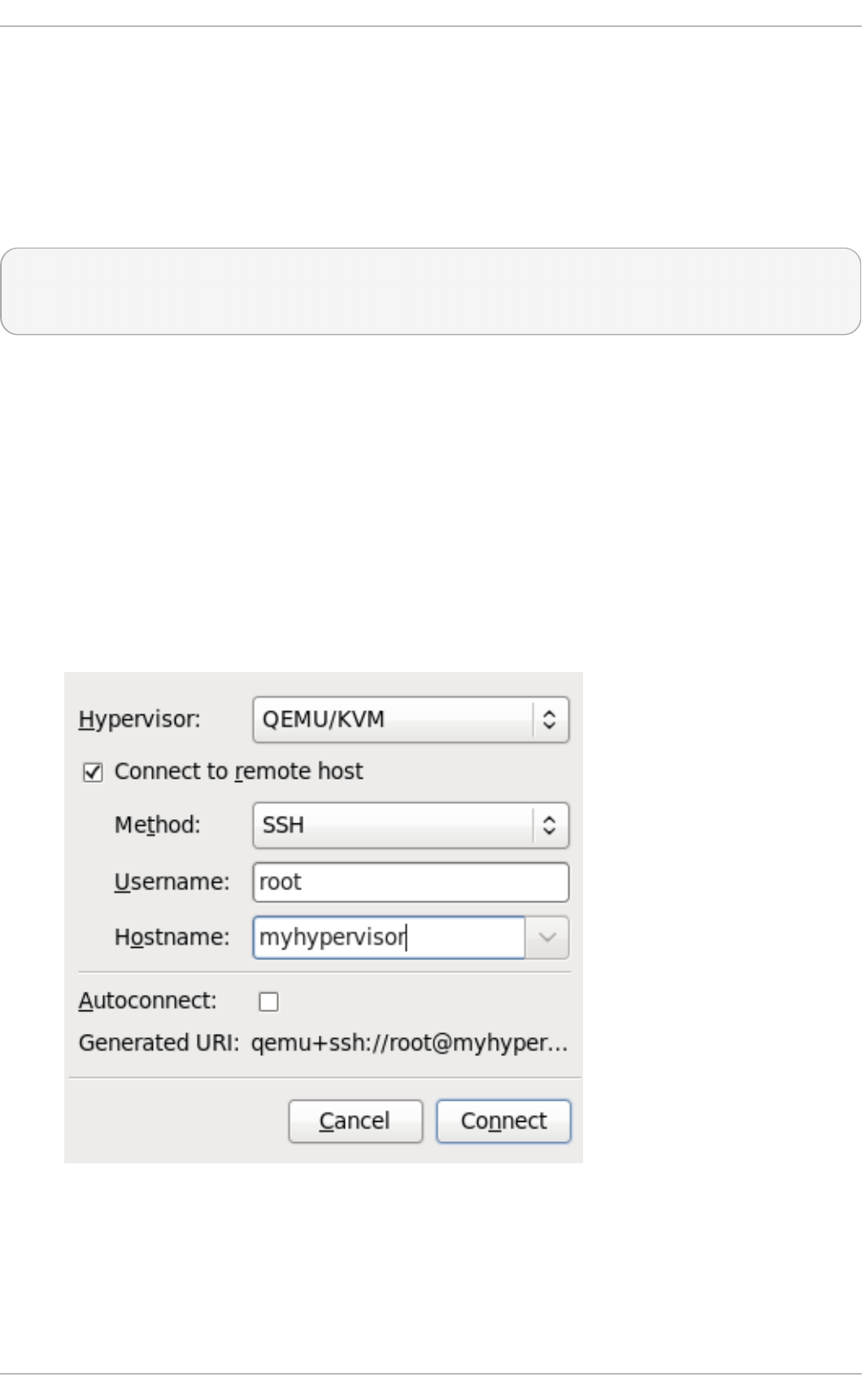
The SSH key is added to the remote system.
T h e l i bvi rt daemon ( l i bvi rtd )
The l i bvi rt daemon provides an interface for managing virtual machines. You must have the
l i bvi rtd daemon installed and running on every remote host that needs managing.
$ ssh ro o t@ somehost
# systemctl enable libvirtd.service
# systemctl start libvirtd
After l i bvi rtd and SSH are configured you should be able to remotely access and manage your
virtual machines. You should also be able to access your guests with VNC at this point.
Accessin g remo t e h o st s wit h virt -man ag er
Remote hosts can be managed with the virt-manager GUI tool. SSH keys must belong to the user
executing virt-manager for password-less login to work.
1. Start virt-manager.
2. Open the File->Ad d Co nn ect ion menu.
Fig u re 21.1. Ad d co n n ect io n men u
3. Use the drop down menu to select hypervisor type, and click the Co n n ect t o remot e h o st
check box to open the Connection Me t h o d (in this case Remote tunnel over SSH), and enter
the desired U ser n ame and H o st n a me, then click C o n n ec t .
Chapt er 2 1 . Remot e management of g uest s
285

21.2. Remot e management over T LS and SSL
You can manage virtual machines using TLS and SSL. TLS and SSL provides greater scalability but
is more complicated than ssh (refer to Section 21.1, “Remote management with SSH” ). TLS and SSL
is the same technology used by web browsers for secure connections. The l i bvi rt management
connection opens a TCP port for incoming connections, which is securely encrypted and
authenticated based on x509 certificates. The procedures that follow provide instructions on creating
and deploying authentication certificates for TLS and SSL management.
Pro ced ure 21.1. Creat in g a cert if icat e au t horit y ( CA) key f o r T LS man ag emen t
1. Before you begin, confirm that certto o l is installed. If not:
# yum install certtool
2. Generate a private key, using the following command:
# certtool --generate-privkey > cakey.pem
3. Once the key generates, the next step is to create a signature file so the key can be self-
signed. To do this, create a file with signature details and name it ca.info. This file should
contain the following:
# vim ca.info
cn = Name of your organization
ca
cert_signing_key
4. Generate the self-signed key with the following command:
# certtool --generate-self-signed --load-privkey cakey.pem --
template ca.info --outfile cacert.pem
Once the file generates, the ca.info file may be deleted using the rm command. The file that
results from the generation process is named cacert.pem. This file is the public key
(certificate). The loaded file cakey.pem is the private key. This file should not be kept in a
shared space. Keep this key private.
5. Install the cacert.pem Certificate Authority Certificate file on all clients and servers in the
/etc/pki/CA/cacert.pem directory to let them know that the certificate issued by your CA
can be trusted. To view the contents of this file, run:
# certtool -i --infile cacert.pem
This is all that is required to set up your CA. Keep the CA's private key safe as you will need it
in order to issue certificates for your clients and servers.
Pro ced ure 21.2. Issu in g a server cert if icat e
Virt ualizat ion Deployment and Administ rat ion G uide
286

This procedure demonstrates how to issue a certificate with the X.509 CommonName (CN)field set to
the hostname of the server. The CN must match the hostname which clients will be using to connect to
the server. In this example, clients will be connecting to the server using the URI:
qemu://mycommonname/system, so the CN field should be identical, ie mycommoname.
1. Create a private key for the server.
# certtool --generate-privkey > serverkey.pem
2. Generate a signature for the CA's private key by first creating a template file called
server.info . Make sure that the CN is set to be the same as the server's hostname:
organization = Name of your organization
cn = mycommonname
tls_www_server
encryption_key
signing_key
3. Create the certificate with the following command:
# certtool --generate-certificate --load-privkey serverkey.pem --
load-ca-certificate cacert.pem --load-ca-privkey cakey.pem \ --
template server.info --outfile servercert.pem
4. This results in two files being generated:
serverkey.pem - The server's private key
servercert.pem - The server's public key
Make sure to keep the location of the private key secret. To view the contents of the file,
perform the following command:
# certtool -i --inifile servercert.pem
When opening this file the CN= parameter should be the same as the CN that you set earlier.
For example, mycommonname.
5. Install the two files in the following locations:
serverkey.pem - the server's private key. Place this file in the following location:
/etc/pki/libvirt/private/serverkey.pem
servercert.pem - the server's certificate. Install it in the following location on the server:
/etc/pki/libvirt/servercert.pem
Pro ced ure 21.3. Issu in g a clien t cert if icat e
1. For every client (ie. any program linked with libvirt, such as virt-manager), you need to issue
a certificate with the X.509 Distinguished Name (DN) set to a suitable name. This needs to be
decided on a corporate level.
For example purposes the following information will be used:
C=USA,ST=North Carolina,L=Raleigh,O=Red Hat,CN=name_of_client
Chapt er 2 1 . Remot e management of g uest s
287

This process is quite similar to Procedure 21.2, “ Issuing a server certificate”, with the
following exceptions noted.
2. Make a private key with the following command:
# certtool --generate-privkey > clientkey.pem
3. Generate a signature for the CA's private key by first creating a template file called
cl ient. i nfo . The file should contain the following (fields should be customized to reflect
your region/location):
country = USA
state = North Carolina
locality = Raleigh
organization = Red Hat
cn = client1
tls_www_client
encryption_key
signing_key
4. Sign the certificate with the following command:
# certtool --generate-certificate --load-privkey clientkey.pem --
load-ca-certificate cacert.pem \ --load-ca-privkey cakey.pem --
template client.info --outfile clientcert.pem
5. Install the certificates on the client machine:
# cp clientkey.pem /etc/pki/libvirt/private/clientkey.pem
# cp clientcert.pem /etc/pki/libvirt/clientcert.pem
21.3. T ransport modes
For remote management, l i bvi rt supports the following transport modes:
T ran sp o rt Layer Secu rit y ( T LS)
Transport Layer Security TLS 1.0 (SSL 3.1) authenticated and encrypted TCP/IP socket, usually
listening on a public port number. To use this you will need to generate client and server certificates.
The standard port is 16514.
UN IX so cket s
UNIX domain sockets are only accessible on the local machine. Sockets are not encrypted, and use
UNIX permissions or SELinux for authentication. The standard socket names are
/var/run/libvirt/libvirt-sock and /var/run/libvirt/libvirt-sock-ro (for read-only
connections).
Virt ualizat ion Deployment and Administ rat ion G uide
288

SSH
Transported over a Secure Shell protocol (SSH) connection. Requires Netcat (the nc package)
installed. The libvirt daemon (l i bvi rtd ) must be running on the remote machine. Port 22 must be
open for SSH access. You should use some sort of SSH key management (for example, the ssh-
agent utility) or you will be prompted for a password.
ext
The ext parameter is used for any external program which can make a connection to the remote
machine by means outside the scope of libvirt. This parameter is unsupported.
T C P
Unencrypted TCP/IP socket. Not recommended for production use, this is normally disabled, but an
administrator can enable it for testing or use over a trusted network. The default port is 16509.
The default transport, if no other is specified, is TLS.
Remo t e U RIs
A Uniform Resource Identifier (URI) is used by virsh and libvirt to connect to a remote host. URIs can
also be used with the --connect parameter for the virsh command to execute single commands or
migrations on remote hosts. Remote URIs are formed by taking ordinary local URIs and adding a
hostname and/or transport name. As a special case, using a URI scheme of 'remote', will tell the
remote libvirtd server to probe for the optimal hypervisor driver. This is equivalent to passing a NULL
URI for a local connection
libvirt URIs take the general form (content in square brackets, "[]", represents optional functions):
driver[+transport]://[username@][hostname][:port]/path[?extraparameters]
Note that if the hypervisor(driver) is QEMU, the path is mandatory. If it is XEN, it is optional.
The following are examples of valid remote URIs:
qemu://hostname/
xen://hostname/
xen+ssh://hostname/
The transport method or the hostname must be provided to target an external location. For more
information refer to http://libvirt.org/guide/html/Application_Development_Guide-Architecture-
Remote_URIs.html.
Examp les o f remo t e man ag emen t p aramet ers
Chapt er 2 1 . Remot e management of g uest s
289

Connect to a remote KVM host named host2, using SSH transport and the SSH username
vi rtuser.The connect command for each is connect [<name>] [--readonly], where
<name> is a valid URI as explained here. For more information about the virsh connect
command refer to Section 23.7, “ Connecting to the hypervisor with virsh connect”
qemu+ssh://virtuser@host2/
Connect to a remote KVM hypervisor on the host named host2 using TLS.
qemu://host2/
T est in g examp les
Connect to the local KVM hypervisor with a non-standard UNIX socket. The full path to the UNIX
socket is supplied explicitly in this case.
qemu+unix:///system?socket=/opt/libvirt/run/libvirt/libvirt-sock
Connect to the libvirt daemon with an non-encrypted TCP/IP connection to the server with the IP
address 10.1.1.10 on port 5000. This uses the test driver with default settings.
test+ tcp: //10 . 1. 1. 10 : 50 0 0 /d efaul t
Ext ra U RI p aramet ers
Extra parameters can be appended to remote URIs. The table below Table 21.1, “Extra URI
parameters” covers the recognized parameters. All other parameters are ignored. Note that parameter
values must be URI-escaped (that is, a question mark (?) is appended before the parameter and
special characters are converted into the URI format).
T ab le 21.1. Ext ra UR I p aramet ers
Name T ran sp o rt mo d e Descrip t io n Examp le u sag e
name all modes The name passed to
the remote
vi rC o nnectO pen
function. The name is
normally formed by
removing transport,
hostname, port
number, username,
and extra parameters
from the remote URI,
but in certain very
complex cases it may
be better to supply the
name explicitly.
name=qemu:///system
Virt ualizat ion Deployment and Administ rat ion G uide
290

command ssh and ext The external command.
For ext transport this is
required. For ssh the
default is ssh. The
PATH is searched for
the command.
command=/opt/openss
h/bin/ssh
socket unix and ssh The path to the UNIX
domain socket, which
overrides the default.
For ssh transport, this
is passed to the remote
netcat command (see
netcat).
socket=/opt/libvirt/run/li
bvirt/libvirt-sock
netcat ssh The netcat command
can be used to connect
to remote systems. The
default netcat
parameter uses the nc
command. For SSH
transport, libvirt
constructs an SSH
command using the
form below:
command -p port [-l
username] hostname
netcat -U socket
The port, username
and hostname
parameters can be
specified as part of the
remote URI. The
command, netcat and
socket come from
other extra parameters.
netcat=/opt/netcat/bin/n
c
no_verify tls If set to a non-zero
value, this disables
client checks of the
server's certificate.
Note that to disable
server checks of the
client's certificate or IP
address you must
change the libvirtd
configuration.
no_verify=1
Name T ran sp o rt mo d e Descrip t io n Examp le u sag e
Chapt er 2 1 . Remot e management of g uest s
291

no_tty ssh If set to a non-zero
value, this stops ssh
from asking for a
password if it cannot
log in to the remote
machine automatically
. Use this when you do
not have access to a
terminal .
no_tty=1
Name T ran sp o rt mo d e Descrip t io n Examp le u sag e
21.4 . Configuring a VNC Server
To configure a VNC server, use the Remo t e D eskt o p application in Syst em > Preferences.
Alternatively, you can run the vino-preferences command.
Use the following step set up a dedicated VNC server session:
If needed, Create and then Edit the ~/.vnc/xstartup file to start a GNOME session whenever
vn cs erve r is started. The first time you run the vn cserver script it will ask you for a password you
want to use for your VNC session. For more information on vnc server files refer to the Red Hat
Enterprise Linux Installation Guide.
Virt ualizat ion Deployment and Administ rat ion G uide
292

Chapter 22. Managing guests with the Virtual Machine Manager
(virt-manager)
This section describes the Virtual Machine Manager (virt-manager) windows, dialog boxes, and
various GUI controls.
virt-manager provides a graphical view of hypervisors and guests on your host system and on
remote host systems. virt-manager can perform virtualization management tasks, including:
defining and creating guests,
assigning memory,
assigning virtual CPUs,
monitoring operational performance,
saving and restoring, pausing and resuming, and shutting down and starting guests,
links to the textual and graphical consoles, and
live and offline migrations.
22.1. St art ing virt -manager
To start virt-manager session open the Ap p licat i o n s menu, then the Syst em T o o ls menu and
select Virt u al Mach in e Man ag er (virt-manager).
The virt-manager main window appears.
Chapt er 2 2 . Managing g u est s wit h t he Virt ual Mach ine Manager (virt - manag er)
293
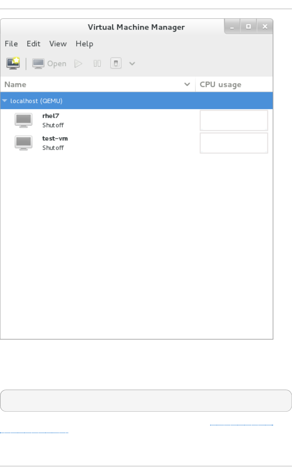
Fig u re 22.1. St art in g virt-manager
Alternatively, virt-manager can be started remotely using ssh as demonstrated in the following
command:
ssh -X host's address
[remotehost]# virt-manager
Using ssh to manage virtual machines and hosts is discussed further in Section 21.1, “Remote
management with SSH” .
22.2. T he Virt ual Machine Manager main window
Virt ualizat ion Deployment and Administ rat ion G uide
294

This main window displays all the running guests and resources used by guests. Select a guest by
double clicking the guest's name.
Fig u re 22.2. Virt u al Mach in e Man ag er main win d o w
22.3. T he virt ual hardware det ails window
The virtual hardware details window displays information about the virtual hardware configured for
the guest. Virtual hardware resources can be added, removed and modified in this window. To
access the virtual hardware details window, click on the icon in the toolbar.
Chapt er 2 2 . Managing g u est s wit h t he Virt ual Mach ine Manager (virt - manag er)
295
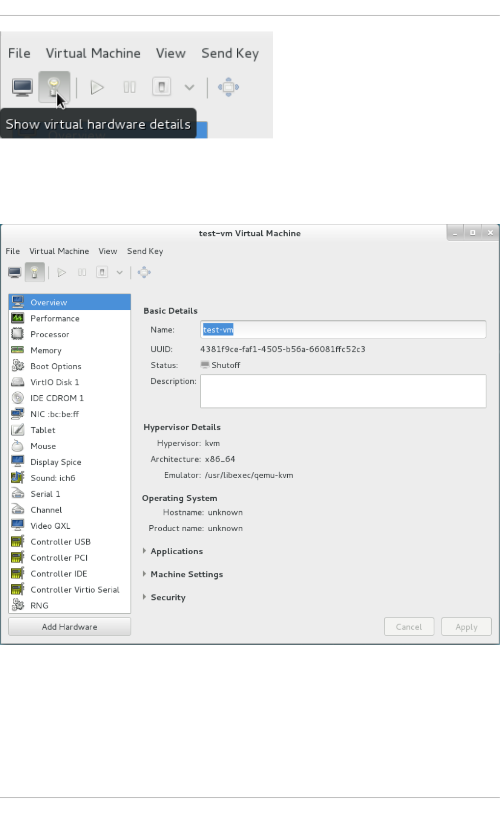
Fig u re 22.3. T h e virt ual h ard ware d et ails ico n
Clicking the icon displays the virtual hardware details window.
Fig u re 22.4 . T h e virt u al hard ware d et ails win d o w
22.3.1. Applying boot opt ions t o guest virt ual machines
Using virt-manager you can select how the guest virtual machine will act on boot. The boot options
will not take effect until the guest virtual machine reboots. You can either power down the virtual
machine before making any changes, or you can reboot the machine afterwards. If you do not do
either of these options, the changes will happen the next time the guest reboots.
Virt ualizat ion Deployment and Administ rat ion G uide
296
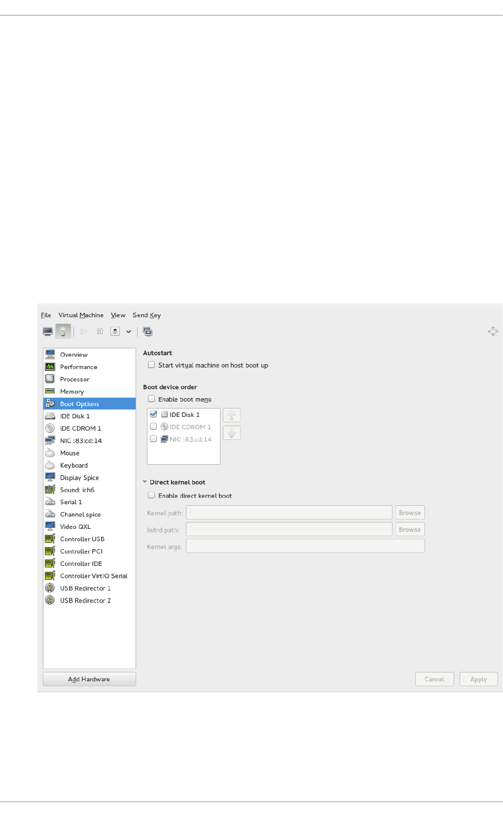
Pro ced ure 22.1. Co n fig u rin g b o ot opt io n s
1. From the Virtual Machine Manager Ed it menu, select Virt u al Mach in e D et ails.
2. From the side panel, select Bo o t O p t io n s and then complete any or all of the following
optional steps:
a. To indicate that this guest virtual machine should start each time the host physical
machine boots, select the Au t o st art check box.
b. To indicate the order in which guest virtual machine should boot, click the En a b le
boot menu check box. After this is checked, you can then check the devices you
want to boot from and using the arrow keys change the order that the guest virtual
machine will use when booting.
c. If you want to boot directly from the Linux kernel, expand the Direct kern el b o o t
menu. Fill in the Kern el p at h , In it rd p at h , and the Kern el arg u men t s that you
want to use.
3. Click Ap p l y.
Fig u re 22.5. C o n f ig u rin g b o o t o p t io n s
22.3.2. At t aching USB devices t o a guest virt ual machine
Chapt er 2 2 . Managing g u est s wit h t he Virt ual Mach ine Manager (virt - manag er)
297
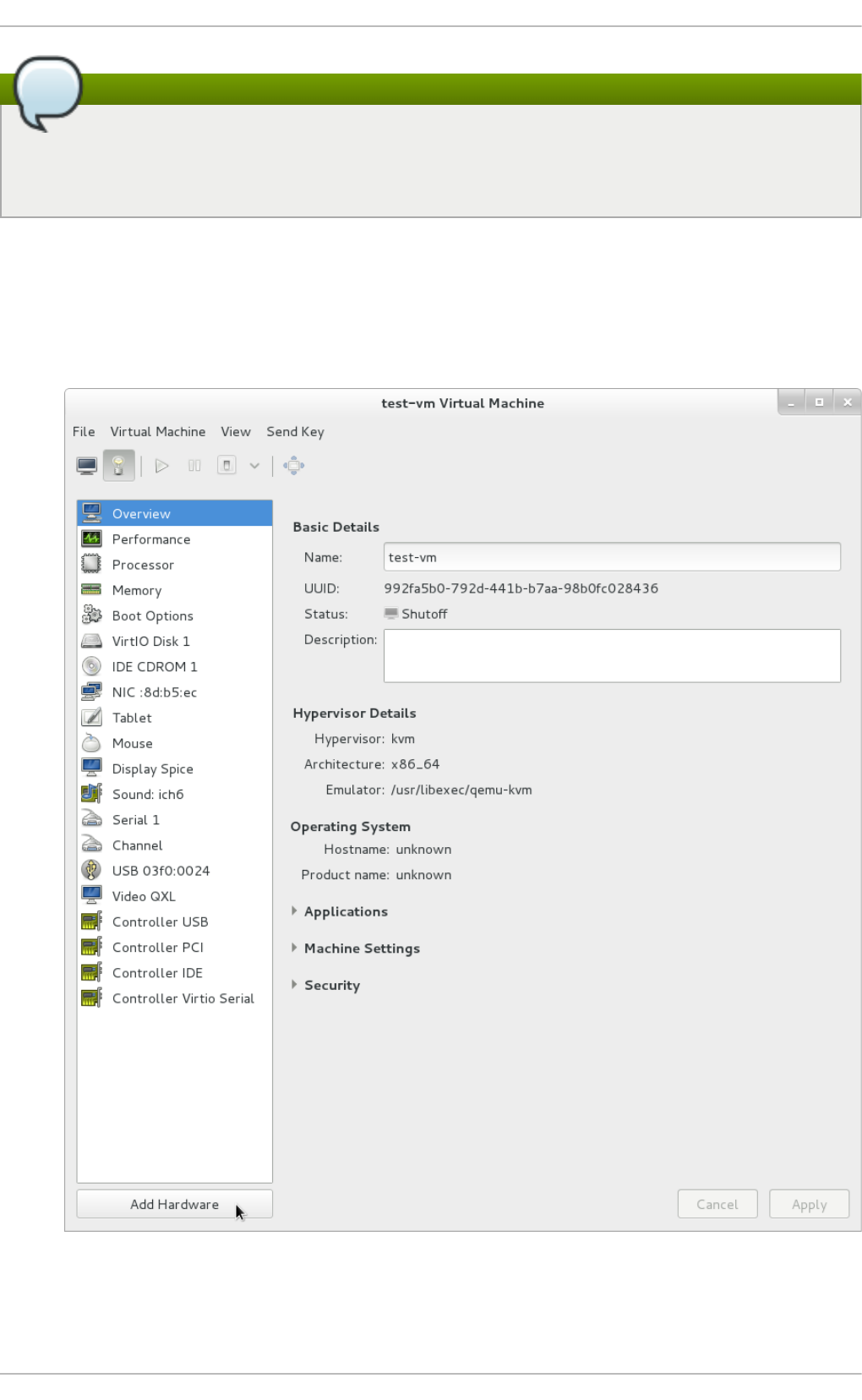
Note
In order to attach the USB device to the guest virtual machine, you first must attach it to the
host physical machine and confirm that the device is working. If the guest is running, you need
to shut it down before proceeding.
Pro ced ure 22.2. At t ach in g U SB devices u sin g Virt - Man ag er
1. Open the guest virtual machine's Virtual Machine Details screen.
2. Click Ad d Hard ware
Fig u re 22.6 . Ad d H ard ware Bu t t o n
Virt ualizat ion Deployment and Administ rat ion G uide
298
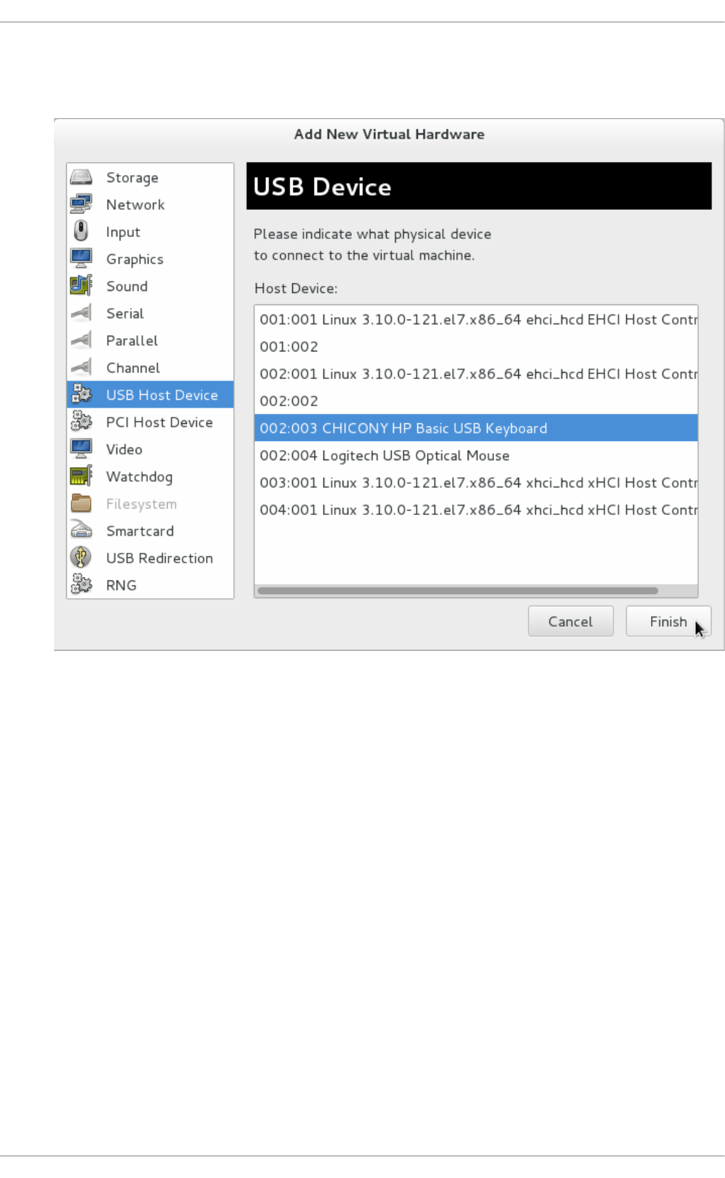
3. In the Ad d New Virt u al Hard ware popup, select USB H o st Device, select the device you
want to attach from the list and Click Finish.
Fig u re 22.7. Ad d USB D evice
4. To use the USB device in the guest virtual machine, start the guest virtual machine.
22.3.3. USB redirect ion
USB re-direction is best used in cases where there is a host physical machine that is running in a
data center. The user connects to his/her guest virtual machine from a local machine or thin client.
On this local machine there is a SPICE client. The user can attach any USB device to the thin client
and the SPICE client will redirect the device to the host physical machine on the data center so it can
be used by the VM that is running on the thin client.
Pro ced ure 22.3. Red irect in g U SB devices
1. Open the guest virtual machine's Virtual Machine Details screen.
2. Click Ad d Hard ware
Chapt er 2 2 . Managing g u est s wit h t he Virt ual Mach ine Manager (virt - manag er)
299
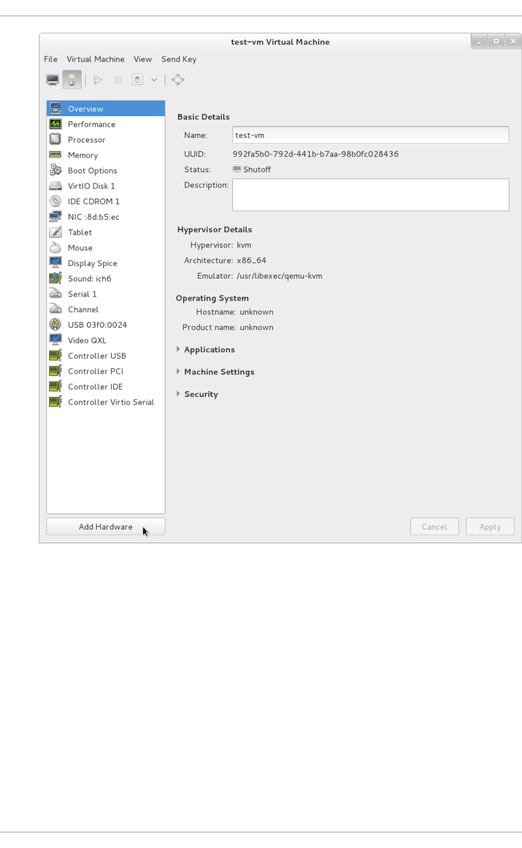
Fig u re 22.8. Ad d Hard ware Bu tt o n
3. In the Ad d New Virt u al Hard ware popup, select USB R ed irect io n . Make sure to select
Sp ice ch an n el the T yp e drop-down menu and click Finish.
Virt ualizat ion Deployment and Administ rat ion G uide
300
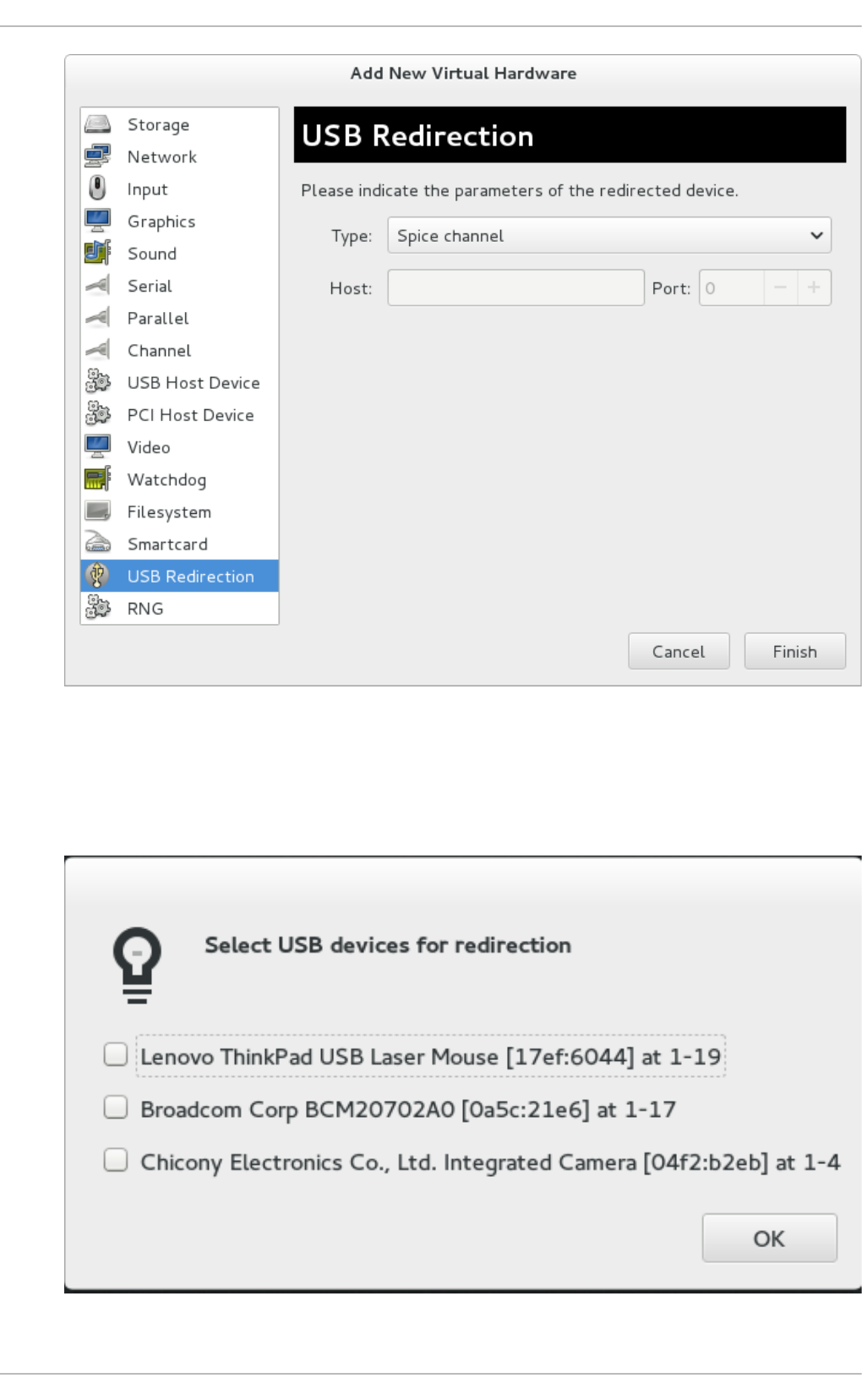
Fig u re 22.9 . Ad d N ew Virt u al Hard ware windo w
4. A pop-up menu opens with a list of devices to choose from. Select a device by clicking the
check box and click O K.
Fig u re 22.10. Select a USB d evice
Chapt er 2 2 . Managing g u est s wit h t he Virt ual Mach ine Manager (virt - manag er)
301

22.4 . Virt ual Machine graphical console
This window displays a guest's graphical console. Guests can use several different protocols to
export their graphical frame buffers: virt-manager supports VNC and SPICE. If your virtual
machine is set to require authentication, the Virtual Machine graphical console prompts you for a
password before the display appears.
Fig u re 22.11. G rap h ical co n so le win d o w
Virt ualizat ion Deployment and Administ rat ion G uide
302

Note
VNC is considered insecure by many security experts, however, several changes have been
made to enable the secure usage of VNC for virtualization on Red Hat enterprise Linux. The
guest machines only listen to the local host's loopback address (127.0.0.1). This ensures
only those with shell privileges on the host can access virt-manager and the virtual machine
through VNC. Although virt-manager is configured to listen to other public network interfaces
and alternative methods can be configured, it is not recommended.
Remote administration can be performed by tunneling over SSH which encrypts the traffic.
Although VNC can be configured to access remotely without tunneling over SSH, for security
reasons, it is not recommended. To remotely administer the guest follow the instructions in:
Chapter 21, Remote management of guests. TLS can provide enterprise level security for
managing guest and host systems.
Your local desktop can intercept key combinations (for example, Ctrl+Alt+F1) to prevent them from
being sent to the guest machine. You can use the Sen d key menu option to send these sequences.
From the guest machine window, click the Sen d key menu and select the key sequence to send. In
addition, from this menu you can also capture the screen output.
SPICE is an alternative to VNC available for Red Hat Enterprise Linux.
22.5. Adding a remot e connect ion
This procedure covers how to set up a connection to a remote system using virt-manager.
1. To create a new connection open the Fi l e menu and select the Ad d C o nnecti o n. . .
menu item.
2. The Ad d C o nnecti o n wizard appears. Select the hypervisor. For Red Hat Enterprise Linux
7 systems select QEMU/KVM. Select Local for the local system or one of the remote connection
options and click Connect. This example uses Remote tunnel over SSH which works on
default installations. For more information on configuring remote connections refer to
Chapter 21, Remote management of guests
Chapt er 2 2 . Managing g u est s wit h t he Virt ual Mach ine Manager (virt - manag er)
303
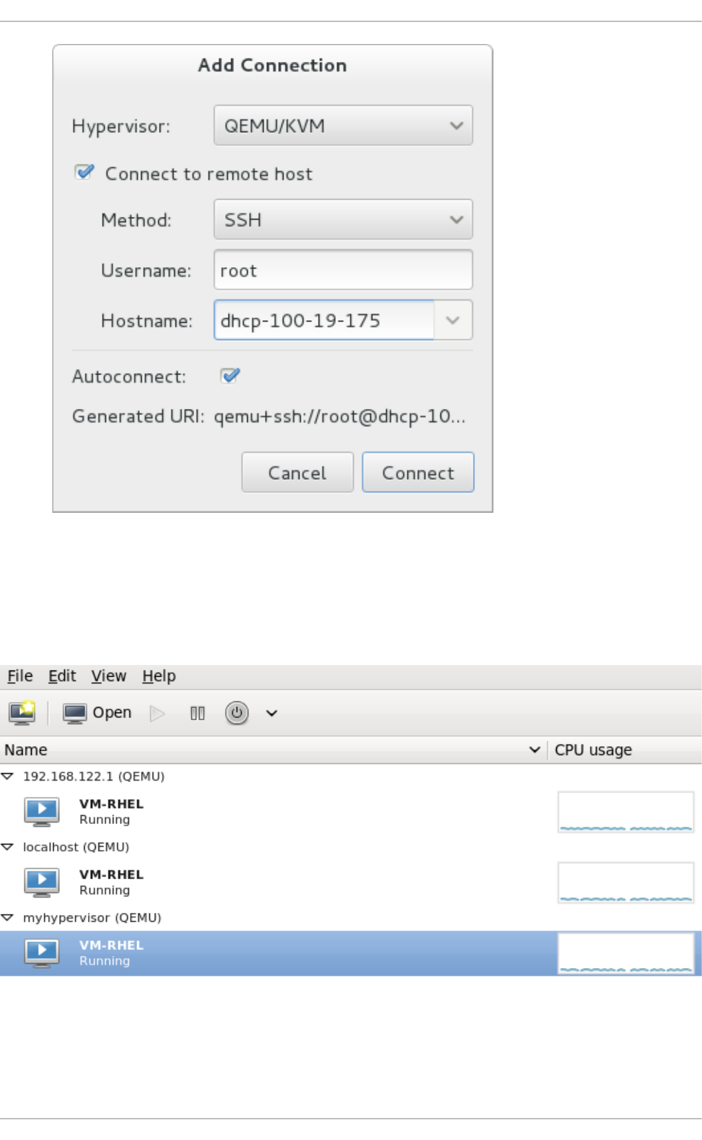
Fig u re 22.12. Ad d Co nn ect ion
3. Enter the root password for the selected host when prompted.
A remote host is now connected and appears in the main virt-manager window.
Fig u re 22.13. R emo t e h o st in t h e main virt -man ag er win d o w
Virt ualizat ion Deployment and Administ rat ion G uide
304
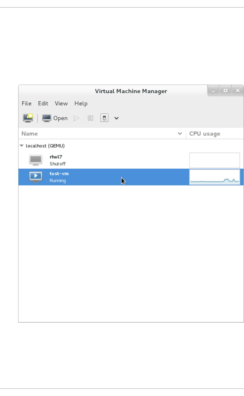
22.6. Displaying guest det ails
You can use the Virtual Machine Monitor to view activity information for any virtual machines on your
system.
To view a virtual system's details:
1. In the Virtual Machine Manager main window, highlight the virtual machine that you want to
view.
Fig u re 22.14 . Select ing a virt u al mach in e t o d isp lay
2. From the Virtual Machine Manager Ed i t menu, select Virtual Machine Details.
Chapt er 2 2 . Managing g u est s wit h t he Virt ual Mach ine Manager (virt - manag er)
305

Fig u re 22.15. D isp layin g t h e virt u al mach in e d et ails
When the Virtual Machine details window opens, there may be a console displayed. Should
this happen, click View and then select D etai l s. The Overview window opens first by
default. To go back to this window, select Overview from the navigation pane on the left
hand side.
The Overview view shows a summary of configuration details for the guest.
Virt ualizat ion Deployment and Administ rat ion G uide
306
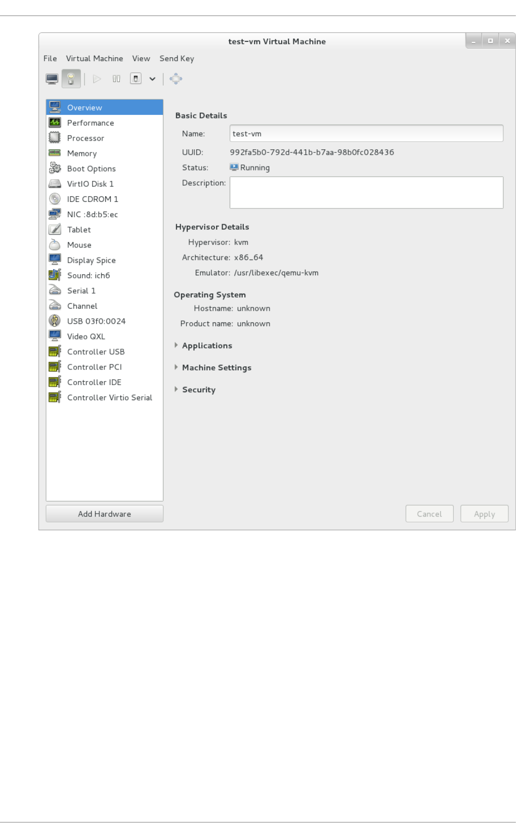
Fig u re 22.16 . Disp layin g g u est det ails o verview
3. Select Performance from the navigation pane on the left hand side.
The Performance view shows a summary of guest performance, including CPU and Memory
usage.
Chapt er 2 2 . Managing g u est s wit h t he Virt ual Mach ine Manager (virt - manag er)
307
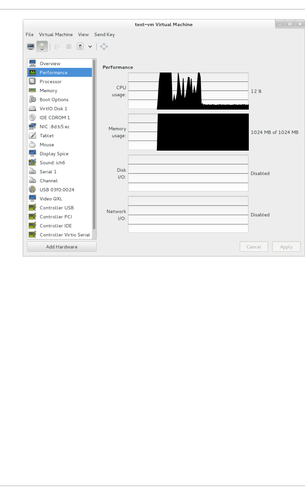
Fig u re 22.17. D isp layin g g u est p erf o rman ce d et ails
4. Select P ro cesso r from the navigation pane on the left hand side. The P ro cesso r view
allows you to view or change the current processor allocation.
Virt ualizat ion Deployment and Administ rat ion G uide
308
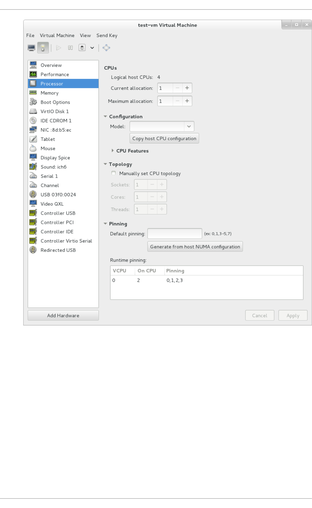
Fig u re 22.18. Pro cesso r allo cat io n p an el
5. Select Memory from the navigation pane on the left hand side. The Memory view allows you
to view or change the current memory allocation.
Chapt er 2 2 . Managing g u est s wit h t he Virt ual Mach ine Manager (virt - manag er)
309
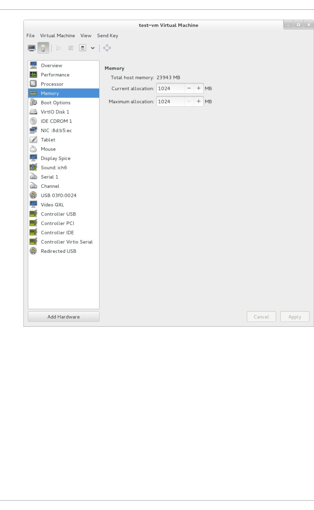
Fig u re 22.19 . Disp layin g memo ry allo cat io n
6. Each virtual disk attached to the virtual machine is displayed in the navigation pane. Click on
a virtual disk to modify or remove it.
Virt ualizat ion Deployment and Administ rat ion G uide
310
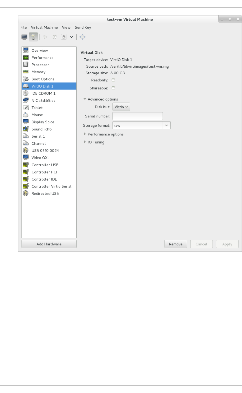
Fig u re 22.20. D isp layin g d isk co n f ig u rat io n
7. Each virtual network interface attached to the virtual machine is displayed in the navigation
pane. Click on a virtual network interface to modify or remove it.
Chapt er 2 2 . Managing g u est s wit h t he Virt ual Mach ine Manager (virt - manag er)
311
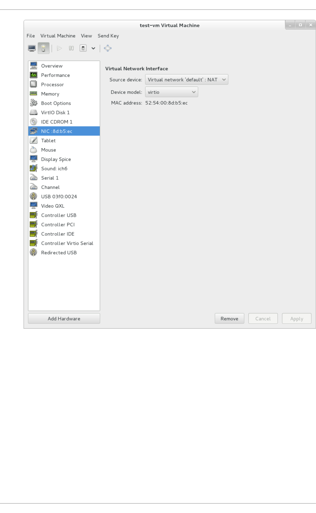
Fig u re 22.21. D isp layin g n et wo rk co nf ig urat io n
22.7. Performance monit oring
Performance monitoring preferences can be modified with virt-manager's preferences window.
To configure performance monitoring:
1. From the Ed i t menu, select Preferences.
Virt ualizat ion Deployment and Administ rat ion G uide
312
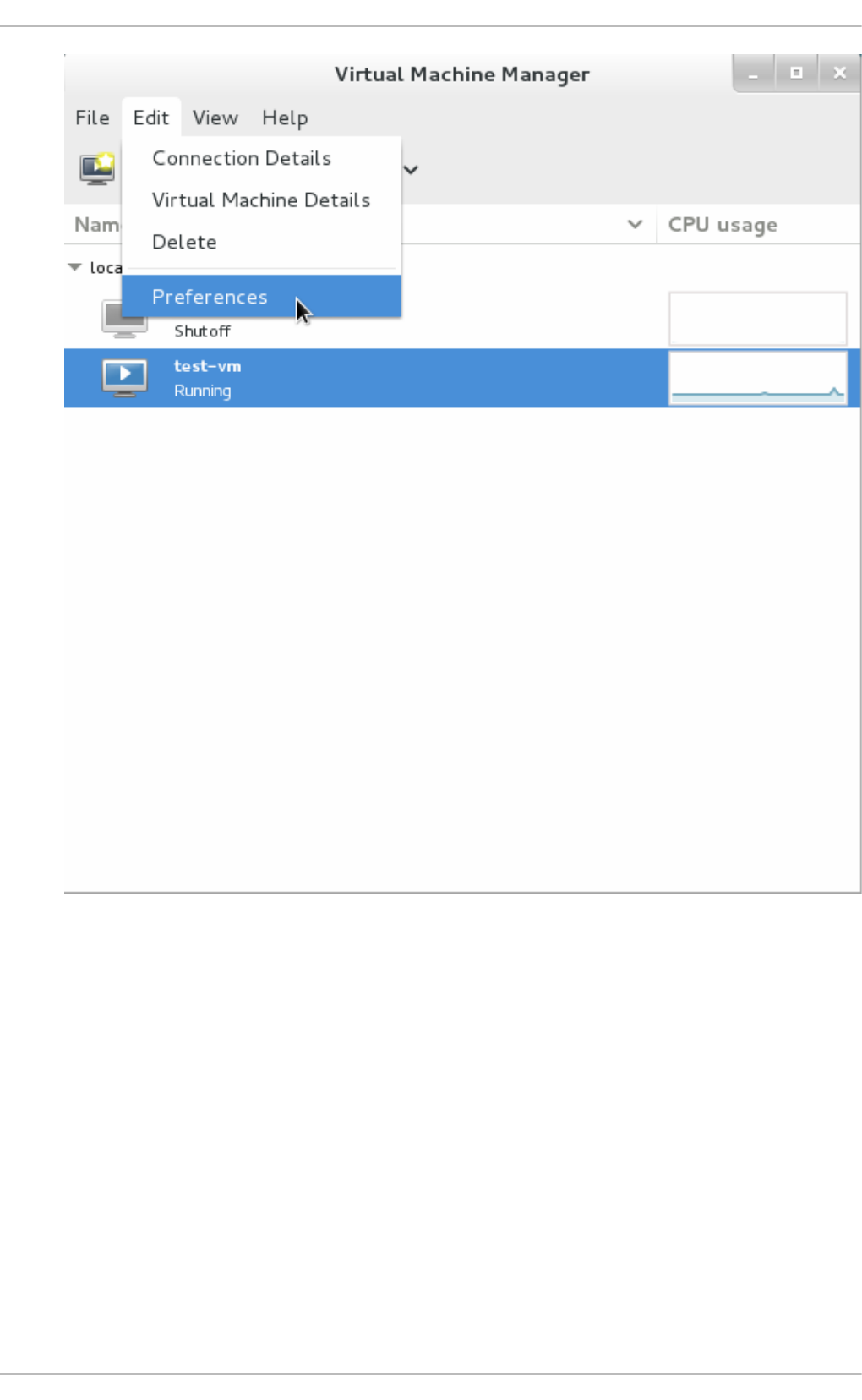
Fig u re 22.22. Mo d if yin g gu est p ref eren ces
The Preferences window appears.
2. From the Stats tab specify the time in seconds or stats polling options.
Chapt er 2 2 . Managing g u est s wit h t he Virt ual Mach ine Manager (virt - manag er)
313
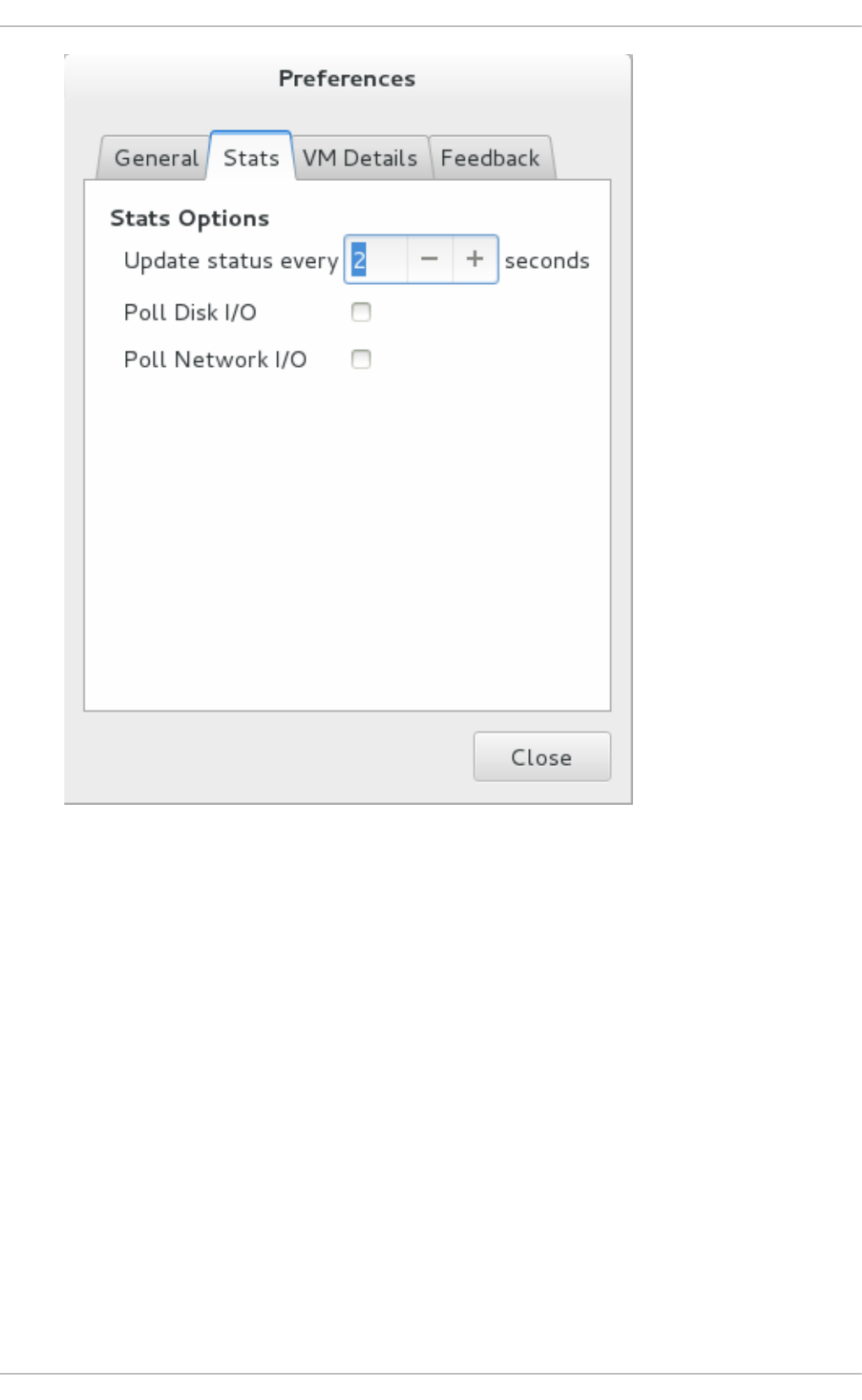
Fig u re 22.23. C o n f ig u rin g p erf orman ce mo n it o rin g
22.8. Displaying CPU usage for guest s
To view the CPU usage for all guests on your system:
1. From the View menu, select Graph, then the Guest CPU Usage check box.
Virt ualizat ion Deployment and Administ rat ion G uide
314
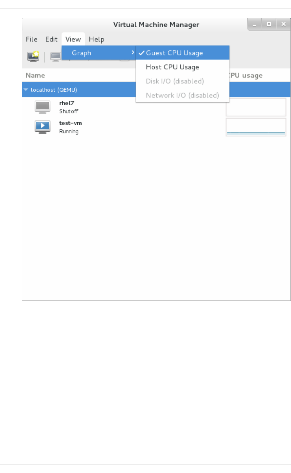
Fig u re 22.24 . En ab ling guest CPU u sag e st at ist ics g rap h in g
2. The Virtual Machine Manager shows a graph of CPU usage for all virtual machines on your
system.
Chapt er 2 2 . Managing g u est s wit h t he Virt ual Mach ine Manager (virt - manag er)
315
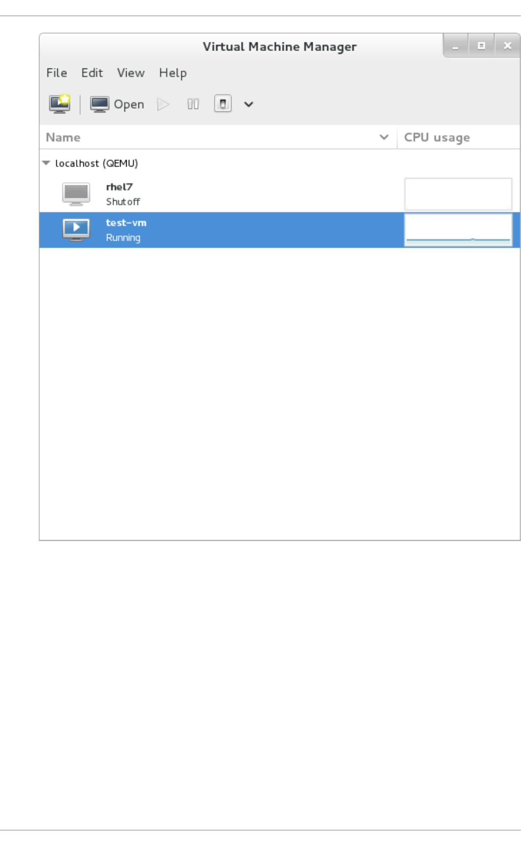
Fig u re 22.25. G u est CPU u sag e g rap h
22.9. Displaying CPU usage for host s
To view the CPU usage for all hosts on your system:
1. From the View menu, select Graph, then the Host CPU Usage check box.
Virt ualizat ion Deployment and Administ rat ion G uide
316
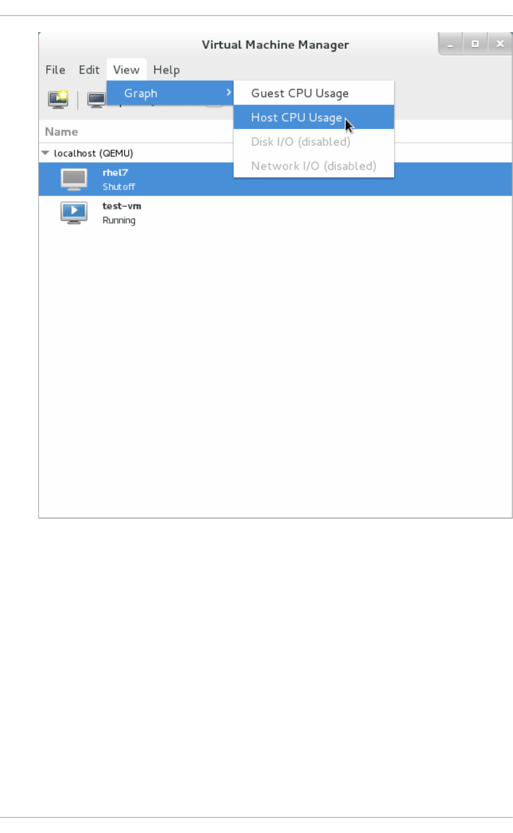
Fig u re 22.26 . En ab ling host CPU u sag e st at ist ics g rap h in g
2. The Virtual Machine Manager shows a graph of host CPU usage on your system.
Chapt er 2 2 . Managing g u est s wit h t he Virt ual Mach ine Manager (virt - manag er)
317
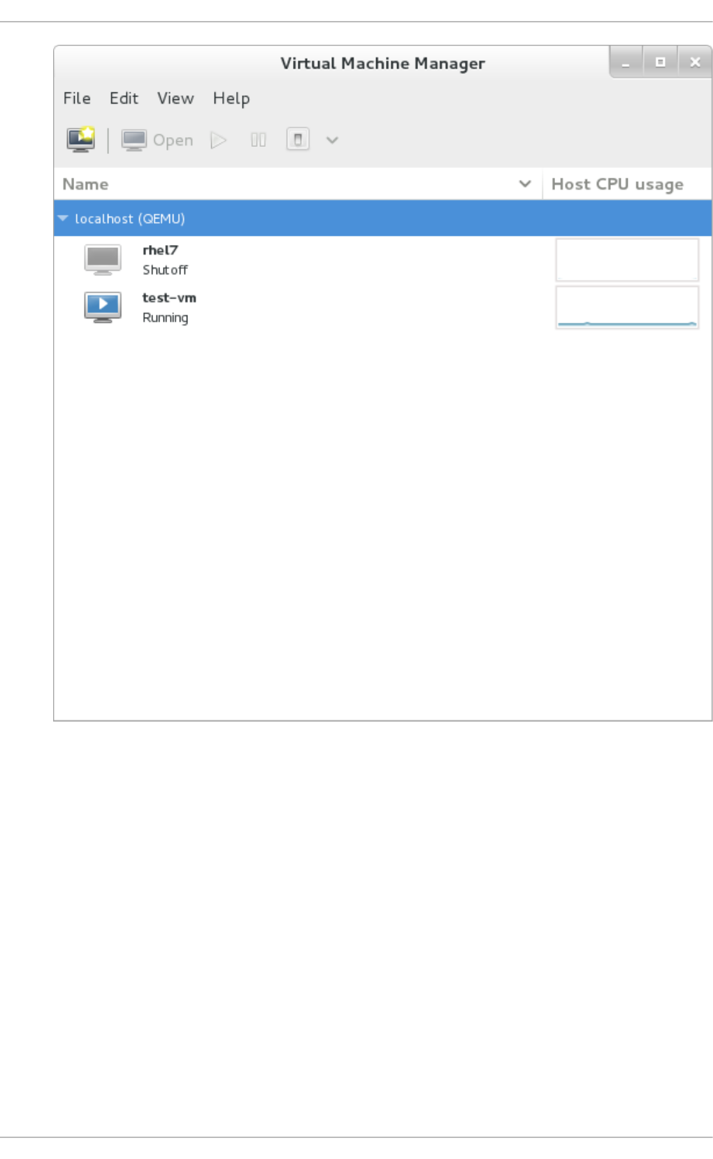
Fig u re 22.27. H o st CPU u sag e g rap h
22.10. Displaying Disk I/O
To view the disk I/O for all virtual machines on your system:
1. Make sure that the Disk I/O statistics collection is enabled. To do this, from the Ed i t menu,
select Preferences and click the Stats tab.
2. Select the Disk I/O checkbox.
Virt ualizat ion Deployment and Administ rat ion G uide
318
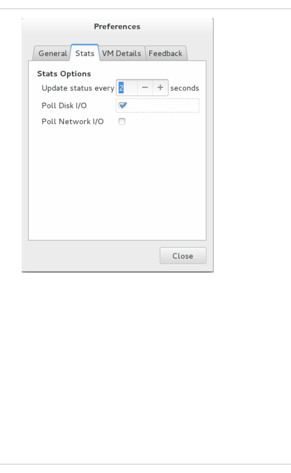
Fig u re 22.28. En ab lin g D isk I/O
3. To enable the Disk I/O display, from the View menu, select Graph, then the Disk I/O check
box.
Chapt er 2 2 . Managing g u est s wit h t he Virt ual Mach ine Manager (virt - manag er)
319
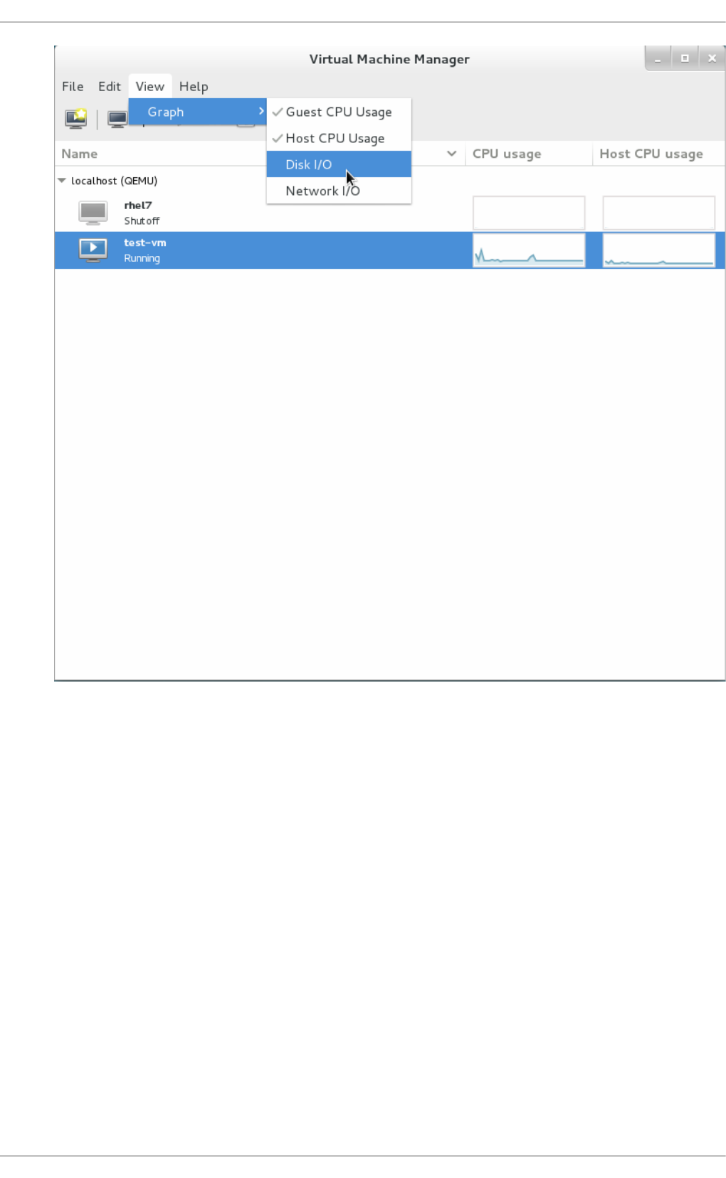
Fig u re 22.29 . Select ing Disk I/O
4. The Virtual Machine Manager shows a graph of Disk I/O for all virtual machines on your
system.
Virt ualizat ion Deployment and Administ rat ion G uide
320
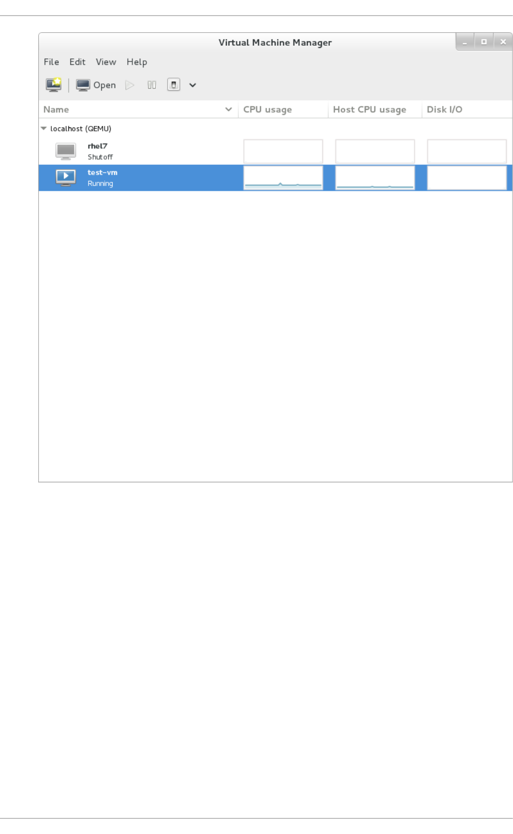
Fig u re 22.30. D isp layin g Disk I/O
22.11. Displaying Net work I/O
To view the network I/O for all virtual machines on your system:
1. Make sure that the Network I/O statistics collection is enabled. To do this, from the Ed i t
menu, select Preferences and click the Statstab.
2. Select the Network I/O checkbox.
Chapt er 2 2 . Managing g u est s wit h t he Virt ual Mach ine Manager (virt - manag er)
321

Fig u re 22.31. En ab lin g N et wo rk I/O
3. To display the Network I/O statistics, from the View menu, select Graph, then the Netwo rk
I/O check box.
Virt ualizat ion Deployment and Administ rat ion G uide
322
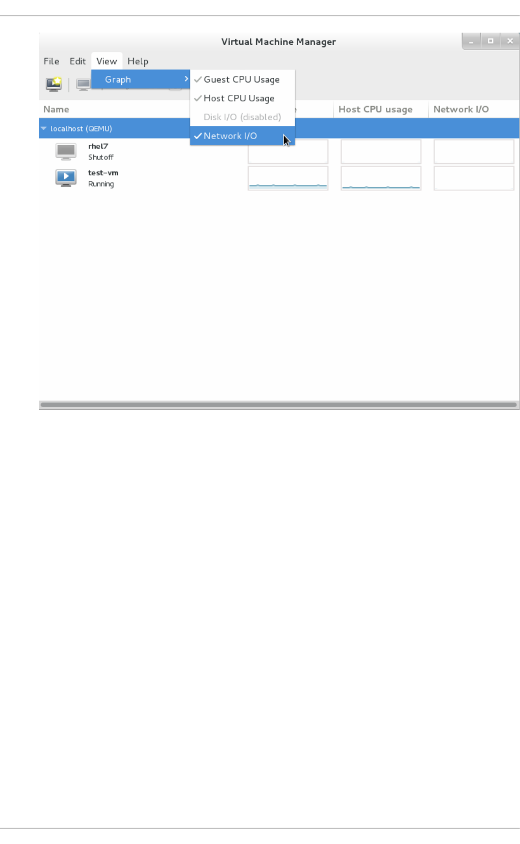
Fig u re 22.32. Select in g N et wo rk I/O
4. The Virtual Machine Manager shows a graph of Network I/O for all virtual machines on your
system.
Chapt er 2 2 . Managing g u est s wit h t he Virt ual Mach ine Manager (virt - manag er)
323

Fig u re 22.33. D isp layin g Net wo rk I/O
Virt ualizat ion Deployment and Administ rat ion G uide
324

Chapter 23. Managing guest virtual machines with virsh
virsh is a command line interface tool for managing guest virtual machines. It can be used to create,
deploy, and manage guest virtual machines. The virsh command-line tool is built on the libvirt
management API and operates as an alternative to the qemu-kvm command and the graphical virt -
man ag er application. The virsh program can be used in read-only mode by unprivileged users or,
with root access, full administration mode. The virsh program is ideal for scripting virtualization
administration. The virsh package is installed with yum as part of the libvirt-client package. For
installation instructions refer to libvirt-client. The remaining sections of this chapter cover the virsh
command set in a logical order based on usage.
Note
Note that when using the help or when reading the MAN pages, the term 'domain' will be used
instead of the term guest virtual machine. This is the term used by libvirt. In cases where the
screen output is displayed and the word 'domain' is used, it will not be switched to guest or
guest virtual machine. In all examples, the guest virtual machine 'guest1' will be used. You
should replace this with the name of your guest virtual machine in all cases.
23.1. Guest virt ual machine st at es
During the life cycle of a virtual machine, libvirt will classify the VM as any of the following states:
Undefined - This is a guest virtual machine that has not been defined or created. As such libvirt is
unaware of any guest in this state and will not report about guest virtual machines in this state.
Defined / Stopped - This is a guest virtual machine which is defined, but is not running. Only
persistent guests can be in this state. When a transient guest virtual machine is put into this state
it ceases to exist.
Running - The guest virtual machine in this state has been defined and is currently working. This
state can be used with both persistent and transient guest virtual machines.
Paused - The guest virtual machine's execution on the hypervisor has been suspended, or its
state has been temporarily stored until it is resumed. Guest virtual machines in this state are not
aware they have been suspended and do not notice that time has passed when they are resumed.
Saved - This state is similar to the paused state, however the guest virtual machine's
configuration is saved to persistent storage. Any guest virtual machine in this state is not aware it
is paused and does not notice that time has passed once it has been restored.
23.2. Running t he virsh program
There are two ways to run virsh. One way is line by line and the other is inside an interactive terminal.
The commands presented in this guide are shown in a line by line format. The same commands may
be used in the interactive terminal, but the prefix 'virsh' is not needed, and the interactive terminal
automatically registers the user as root. To enter the interactive terminal run $ virsh and click enter.
The following prompt appears: virsh #.
Examp le 23.1. Lau n ch in g t he virsh in t eract ive t ermin al
Chapt er 2 3. Managing g u est virt u al machines wit h virsh
325

In the following output, you can see the virsh welcome screen for the interactive terminal.
[~]$ vi rsh
Welcome to virsh, the virtualization interactive terminal.
Type: 'help' for help with commands
'quit' to quit
virsh #
23.3. Int eract ive mode commands
The following commands are best used in the virsh interactive mode, or interactive terminal as
explained in Example 23.1, “ Launching the virsh interactive terminal” . They can be used in batch
mode, but may behave differently as indicated.
23.3.1. Quit t ing and exit ing from t he virsh int eract ive t erminal
The vi rsh q ui t command and the virsh exit command will close the interactive terminal. For
example:
virsh # exi t
virsh # q ui t
The q ui t and exi t commands are mainly useful in the interactive terminal. Note that these
commands may also be used in bash mode from the command line as well. In that case, the
command virsh exit exits automatically.
23.3.2. Changing and displaying direct ories in a virt ual machine
The virsh cd command works just like the standard bash cd command. To change to a different
directory in virsh, either enter cd within the interactive terminal or virsh cd from a command line as
root. Likewise the command pwd or virsh pwd, functions just like the bash command pwd, and
displays the working directory you are currently in. This is particularly helpful when inside the guest.
23.4 . Displaying t he virsh version
The virsh version command displays the current libvirt version and displays information about
the local virsh client. For example:
$ virsh version
Compiled against library: libvirt 1.2.8
Using library: libvirt 1.2.8
Using API: QEMU 1.2.8
Running hypervisor: QEMU 1.5.3
The virsh version --daemon is useful for getting information about the libvirtd version and
package information, including information about the libvirt daemon that is running on the host.
Virt ualizat ion Deployment and Administ rat ion G uide
326

$ virsh version --daemon
Compiled against library: libvirt 1.2.8
Using library: libvirt 1.2.8
Using API: QEMU 1.2.8
Running hypervisor: QEMU 1.5.3
Running against daemon: 1.2.8
23.5. Get t ing help
The virsh help command can be used with or without options. When used without options, all
commands are listed, one per line. When used with an option, it is grouped into categories,
displaying the keyword for each group.
Examp le 23.2. virsh h elp g ro u p examp le
To display the commands that are only for a specific option, you need to give the keyword for that
group as an option. In the following output you can see the help information for the general
search for all commands which contain the keyword 'pool'.
$ virsh help pool
Storage Pool (help keyword 'pool'):
find-storage-pool-sources-as find potential storage pool sources
find-storage-pool-sources discover potential storage pool
sources
pool-autostart autostart a pool
pool-build build a pool
pool-create-as create a pool from a set of args
pool-create create a pool from an XML file
pool-define-as define a pool from a set of args
pool-define define (but don't start) a pool from
an XML file
pool-delete delete a pool
pool-destroy destroy (stop) a pool
pool-dumpxml pool information in XML
pool-edit edit XML configuration for a storage
pool
pool-info storage pool information
pool-list list pools
pool-name convert a pool UUID to pool name
pool-refresh refresh a pool
pool-start start a (previously defined)
inactive pool
pool-undefine undefine an inactive pool
pool-uuid convert a pool name to pool UUID
Examp le 23.3. virsh h elp examp le wit h co mman d o p t io n
Using the same command with a command option, gives the help information on that one specific
command. In the following output you can see the help information for the virsh vol-path
command.
Chapt er 2 3. Managing g u est virt u al machines wit h virsh
327

$ virsh help vol-path
NAME
vol-path - returns the volume path for a given volume name or key
SYNOPSIS
vol-path <vol> [--pool <string>]
OPTIONS
[--vol] <string> volume name or key
--pool <string> pool name or uuid
23.6. Sending commands wit h echo
The virsh echo [--shell][--xml] <args> command displays the specified argument in the
specified format. The formats you can use are --shell and --xml. Each argument queried is
displayed separated by a space. Tthe --shell option generates output that is formatted in single
quotes where needed, so it is suitable for copying and pasting into the bash mode as a command. If
the --xml argument is used, the output is formatted for use in an XML file, which can then be saved
or used for guest's configuration.
23.7. Connect ing t o t he hypervisor wit h virsh connect
The virsh connect [<name>] [--readonly] command begins a local hypervisor session
using virsh. After the first time you run this command it will run automatically each time the virsh shell
runs. The hypervisor connection URI specifies how to connect to the hypervisor. The most commonly
used URIs are:
qemu:///system - connects locally as the root user to the daemon supervising guest virtual
machines on the KVM hypervisor.
xen:///session - connects locally as a user to the user's set of guest local machines using the
KVM hypervisor.
lxc:/// - connects to a local Linux container.
xen:/// - connects to the local Xen hypervisor.
The command can be run as follows, where [name] is the machine name (hostname) or URL (the
output of the virsh uri command) of the hypervisor as shown:
$ virsh uri
qemu:///session
For example, to establish a session to connect to my set of guest virtual machines, with me as the
local user:
$ virsh connect qemu:///session
To initiate a read-only connection, append the above command with --readonly. For more
information on URIs, refer to Remote URIs. If you are unsure of the URI, the virsh uri command will
display it:
23.8. Displaying informat ion about guest virt ual machine
Virt ualizat ion Deployment and Administ rat ion G uide
328

23.8. Displaying informat ion about guest virt ual machine
The vi rsh l i st command will list all guest virtual machines which fit the search parameter
requested. Note that the information you enter in this command does not in any way change the
guest configuration setting.
There are many parameters you can use to filter the list you receive. These options are available in
the MAN page, by running man virsh or by running the virsh list --help command.
Examp le 23.4 . Ho w t o list all lo cally co n n ect ed virt ual mach in es
In this example, you will see a list of all the virtual machines that have been created. Note that if a
virtual machine was installed using virt-manager and you did not complete the installation
process, the guest virtual machine will not be displayed. The output you will see has 3 columns in
a table. Each guest virtual machine is listed with its ID, name, and state. There are five states that a
guest can have in libvirt. For more information, refer to Section 23.1, “Guest virtual machine states” .
# virsh list --all
Id Name State
------------------------------------------------
14 guest1 running
22 guest2 paused
35 guest3 stopped
In addition, the following commands can also be used to display basic information about the
hypervisor:
$ virsh hostname - displays the hypervisor's hostname.
$ virsh sysinfo - displays the XML representation of the hypervisor's system information, if
available.
23.9. Guest virt ual machine basic commands
The guest virtual machine name is required for almost every command you will run. libvirt refers to
this name as a domain or domain name. It is required for most of these commands as they
manipulate the specified virtual machine directly. The name may be given as a short integer (0,1,2...),
a text string name, or a full UUID . For the sake of simplicity, all virtual machines used in this section
will have the domain set as 'guest1'.
23.9.1. St art ing a virt ual machine
The virsh start <domain> [--console] [--paused] [--autodestroy] [--bypass-
cache] [--force-boot] [--pass-fds <string>] command starts a inactive virtual machine
that was already defined but whose state is inactive since its last managed save state or a fresh boot.
The command can take the following arguments:
--console - will boot the guest virtual machine in console mode
--paused - If this is supported by the driver it will boot the guest virtual machine and then put it
into a paused state
--autodestroy - the guest virtual machine is automatically destroyed when virsh disconnects
Chapt er 2 3. Managing g u est virt u al machines wit h virsh
329

--bypass-cache - used if the guest virtual machine is in the managedsave
--force-boot - discards any managedsave options and causes a fresh boot to occur
--pass-fds <string> - is a list of additional arguments separated by commas, which are
passed onto the guest virtual machine.
23.9.2. Configuring a virt ual machine t o be st art ed aut omat ically at boot
The $ virsh autostart [--disable] domain command will automatically start the guest
virtual machine when the host machine boots. Adding the --disable argument to this command
will cause the guest not to start automatically when the host physical machine boots. For example:
# virsh autostart guest1
23.9.3. Suspending a guest virt ual machine
The virsh suspend <domain> command suspends a guest virtual machine. For example:
# virsh suspend guest1
When a guest virtual machine is in a suspended state, it consumes system RAM but not processor
resources. D isk and network I/O does not occur while the guest virtual machine is suspended. This
operation is immediate and the guest virtual machine can be restarted with the resume
(Section 23.9.7, “Resuming a guest virtual machine” ) option.
23.9.4 . Suspending a running guest virt ual machine
The virsh dompmsuspend <domain> [--duration <number>] [--target <string>]
command will take a running guest virtual machine and suspended it so it can be placed into one of
three possible states (S3, S4, or a hybrid of the two).
This command can take the following arguments:
--d urati o n - sets the duration for the state change in seconds
--targ et - can be either mem (suspend to RAM (S3))disk (suspend to disk (S4)),
or hybrid (hybrid suspend)
For example:
# virsh dompmsuspend guest1 --duration 100 --target mem
In this example, the guest1 virtual machine is suspended and placed into a mem (suspend to RAM
(S3) state for 100 seconds.
23.9.5. Waking up a guest virt ual machine from pmsuspend st at e
The dompmwakeup <domain> command will inject a wake-up alert to a guest that was suspended
using the virsh dompmsuspend command, rather than waiting for the duration time set in the
command to expire. This operation will fail if the guest virtual machine is shutdown. For example:
# dompmwakeup guest1
Virt ualizat ion Deployment and Administ rat ion G uide
330

23.9.6. Undefining a domain
The virsh undefine <domain> [--managed-save] [<storage>] [--remove-all-
storage] [--wipe-storage] [--snapshots-metadata] [--nvram] command undefines
an inactive guest virtual machine. Once undefined, the configuration is removed. If the command is
run on a running guest virtual machine it will convert the running guest virtual machine into a
transient guest virtual machine without stopping it.
This command can take the following arguments:
--managed-save - this argument guarantees that any managed save image is also cleaned up.
Without using this argument, attempts to undefine a guest virtual machine with a managed save
will fail.
--snapshots-metadata - this argument guarantees that any snapshots (as shown with
snapshot-list) are also cleaned up when undefining an inactive guest virtual machine. Note
that any attempts to undefine an inactive guest virtual machine with snapshot metadata will fail. If
this argument is used and the guest virtual machine is active, it is ignored.
--storage - using this argument requires a comma separated list of volume target names or
source paths of storage volumes to be removed along with the undefined domain. This action will
undefine the storage volume before it is removed. Note that this can only be done with inactive
guest virtual machines. Note too that this will only work with storage volumes that are managed by
libvirt.
--remove-all-storage - in addition to undefining the guest virtual machine, all associated
storage volumes are deleted.
--wipe-storage - in addition to deleting the storage volume, the contents are wiped.
To undefine the guest virtual machine guest1 and remove all associated storage volumes for
example:
# virsh undefine guest1 --remove-all-storage
23.9.7. Resuming a guest virt ual machine
The virsh resume <domain> command restores a suspended guest virtual machine. For example
to restore the guest1 virtual machine:
# virsh resume guest1
This operation is immediate. The guest virtual machine parameters and configuration files are
preserved when suspend and resume operations are performed. Note that this action will not
resume a guest virtual machine that has been undefined.
23.9.8. Saving a guest virt ual machine
The virsh save [--bypass-cache] <domain> <file> [--xml <string>] [--
running] [--paused] [--verbose] command saves the current state of a guest virtual
machine to a specified file. This stops the guest virtual machine you specify and saves the data to a
file, which may take some time given the amount of memory in use by your guest virtual machine. You
can restore the state of the guest virtual machine with the virsh restore (Section 23.9.12,
“ Restoring a guest virtual machine” ) command. Save is similar to pause, but instead of just pausing
a guest virtual machine the present state of the guest virtual machine is saved as well. You can revert
Chapt er 2 3. Managing g u est virt u al machines wit h virsh
331

back to this saved state should you need to. If you want to restore the guest virtual machine directly
from the XML file that you saved, run the the virsh restore command. You can monitor the
process with the virsh domjobinfo command and cancel it with the virsh domjobabort
command.
The virsh save command can take the following arguments:
--bypass-cache - causes the restore to avoid the file system cache but note that using this flag
may slow down the restore operation.
--xml - this argument must be used with an XML file name. Although this argument is usually
omitted, it can be used to supply an alternative XML file for use on a restored guest virtual
machine with changes only in the host-specific portions of the domain XML. For example, it can
be used to account for the file naming differences in underlying storage due to disk snapshots
taken after the guest was saved.
--running - overrides the state recorded in the save image to start the guest virtual machine as
running.
--paused- overrides the state recorded in the save image to start the guest virtual machine as
paused.
--verbose - displays the progress of the save.
For example, to save the guest1 running configuration state:
# virsh save guest1 guest1-config.xml --running
23.9.9. Updat ing t he domain XML file t hat will be used for rest oring a guest
virt ual machine
The virsh save-image-define <file> [--xml <string>] [--running] [--paused]
command will update the domain XML file that will be used when the specified file is later used during
the virsh restore command. The --xml argument must be an XML file name containing the
alternative XML with changes only in the host physical machine specific portions of the domain XML.
For example, it can be used to account for the file naming differences resulting from creating disk
snapshots of underlying storage after the guest was saved. The save image records if the guest
virtual machine should be restored to a running or paused state. Using the arguments --running
or --paused dictates the state that is to be used. For example to update the domain XML file for
guest1's running state run the following command:
# virsh save-image-define guest1-config.xml --running
23.9.10. Ext ract ing t he domain XML file
save-image-dumpxml file --security-info command will extract the domain XML file that
was in effect at the time the saved state file (used in the virsh save command) was referenced.
Using the --security-info argument includes security sensitive information in the file.
23.9.11. Edit ing t he guest virt ual machine configurat ion files
save-image-edit <file> [--running] [--paused] command edits the XML configuration
file that was created by the virsh save command. Refer to Section 23.9.8, “ Saving a guest virtual
machine” for information on the virsh save command.
Virt ualizat ion Deployment and Administ rat ion G uide
332

Note that the save image records whether the guest virtual machine should be restored to a --
running or --paused state. Without using these arguments the state is determined by the file itself.
By selecting --running or --paused you can overwrite the state that virsh restore should use.
For example, to edit the guest1 file running configuration file:
# virsh save-image-edit guest1-config.xml --running
23.9.12. Rest oring a guest virt ual machine
The virsh restore <file> [--bypass-cache] [--xml <string>] [--running] [--
paused] command restores a guest virtual machine previously saved with the virsh save
command. Refer to Section 23.9.8, “ Saving a guest virtual machine” for information on the vi rsh
save command. The restore action restarts the saved guest virtual machine, which may take some
time. The guest virtual machine's name and UUID are preserved but are allocated for a new UUID.
The virsh restore command can take the following arguments:
--bypass-cache - causes the restore to avoid the file system cache but note that using this flag
may slow down the restore operation.
--xml - this argument must be used with an XML file name. Although this argument is usually
omitted, it can be used to supply an alternative XML file for use on a restored guest virtual
machine with changes only in the host-specific portions of the domain XML. For example, it can
be used to account for the file naming differences in underlying storage due to disk snapshots
taken after the guest was saved.
--running - overrides the state recorded in the save image to start the guest virtual machine as
running.
--paused- overrides the state recorded in the save image to start the guest virtual machine as
paused.
For example, to restore the guest1 guest virtual machine and its running configuration file:
# virsh restore guest1-config.xml --running
23.10. Shut t ing down, reboot ing, and forcing a shut down of a guest
virt ual machine
23.10.1. Shut t ing down a guest virt ual machine
The virsh shutdown <domain> [--mode <string>] command shuts down a guest virtual
machine. You can control the behavior of how the guest virtual machine reboots by modifying the
<on_shutdown> parameter in the guest virtual machine's configuration file.
The virsh shutdown command command can take the following optional argument:
--mode chooses the shutdown mode. This can be either acpi, agent, initctl, signal, or paravirt
For example, to shutdown the guest1 virtual machine in acpi mode:
# virsh shutdown guest1 --mode acpi
23.10.2. Shut t ing down Red Hat Ent erprise Linux 6 guest s on a Red Hat
Ent erprise Linux 7 host
Chapt er 2 3. Managing g u est virt u al machines wit h virsh
333

Ent erprise Linux 7 host
Installing Red Hat Enterprise Linux 6 guest virtual machines with the Mi ni mal i nstal l ati o n
option does not install the acpid (acpi daemon). Red Hat Enterprise Linux 7 no longer requires this
package, as it has been taken over by systemd. However, Red Hat Enterprise Linux 6 guest virtual
machines running on a Red Hat Enterprise Linux 7 host still require it.
Without the acpid package, the Red Hat Enterprise Linux 6 guest virtual machine does not shut down
when the virsh shutdown command is executed. The virsh shutdown command is designed to
gracefully shut down guest virtual machines.
Using the virsh shutdown command is easier and safer for system administration. Without
graceful shut down with the virsh shutdown command a system administrator must log into a
guest virtual machine manually or send the C trl -Al t-Del key combination to each guest virtual
machine.
Note
Other virtualized operating systems may be affected by this issue. The virsh shutdown
command requires that the guest virtual machine operating system is configured to handle
ACPI shut down requests. Many operating systems require additional configurations on the
guest virtual machine operating system to accept ACPI shut down requests.
Pro ced ure 23.1. Wo rkaro u n d f o r Red Hat En t erp rise Lin u x 6 gu est s
1. In st all t he acp id packag e
The acpid service listens and processes ACPI requests.
Log into the guest virtual machine and install the acpid package on the guest virtual machine:
# yum install acpid
2. En ab le t h e acp id service o n the g u est
Set the acpid service to start during the guest virtual machine boot sequence and start the
service:
# enable acpid service
# service acpid start
3. Prep are gu est d o main xml
Edit the domain XML file to include the following element. Replace the virtio serial port with
o rg . q emu. g uest_ag ent. 0 and use your guest's name instead of the one shown. In this
example, the guest is guest1. Remember to save the file.
<channel type='unix'>
<source mode='bind' path='/var/lib/libvirt/qemu/guest1.agent'/>
<target type='virtio' name='org.qemu.guest_agent.0'/>
Virt ualizat ion Deployment and Administ rat ion G uide
334

</channel>
Fig u re 23.1. G u est XML rep lacemen t
4. In st all t he Q EMU g u est ag en t
Install the QEMU guest agent (QEMU-GA) and start the service as directed in the
Red Hat Enterprise Linux 6 Virtualization Administration Guide..
5. Sh u t d o wn t h e g u est
a. List the known guest virtual machines so you can retrieve the name of the one you
want to shutdown.
# virsh list --all
Id Name State
----------------------------------
14 guest1 running
b. Shut down the guest virtual machine.
# virsh shutdown guest1
guest virtual machine guest1 is being shutdown
c. Wait a few seconds for the guest virtual machine to shut down. Verify it is shutdown.
# virsh list --all
Id Name State
----------------------------------
14 guest1 shut off
d. Start the guest virtual machine named guest1, with the XML file you edited.
# virsh start guest1
e. Shut down the acpi in the guest1 guest virtual machine.
# virsh shutdown --mode acpi guest1
f. List all the guest virtual machines again, guest1 should still be on the list, and it
should indicate it is shut off.
# virsh list --all
Id Name State
----------------------------------
14 guest1 shut off
g. Start the guest virtual machine named guest1, with the XML file you edited.
# virsh start guest1
Chapt er 2 3. Managing g u est virt u al machines wit h virsh
335

h. Shut down the guest1 guest virtual machine guest agent.
# virsh shutdown --mode agent guest1
i. List the guest virtual machines. guest1 should still be on the list, and it should indicate
it is shut off.
# virsh list --all
Id Name State
----------------------------------
guest1 shut off
The guest virtual machine will shut down using the virsh shutdown command for the consecutive
shutdowns, without using the workaround described above.
In addition to the method described above, a guest can be automatically shutdown, by stopping the
libvirt-guest service. Refer to Section 23.10.3, “ Manipulating the libvirt-guests configuration settings”
for more information on this method.
23.10.3. Manipulat ing t he libvirt -guest s configurat ion set t ings
The libvirt-guests service has parameter settings that can be configured to assure that the guest is
shutdown properly. It is a package that is a part of the libvirt installation and is installed by default.
This service automatically saves guests to the disk when the host shuts down, and restores them to
their pre-shutdown state when the host reboots. By default, this setting is set to suspend the guest. If
you want the guest to be gracefully shutdown, you will need to change one of the parameters of the
libvirt-guests configuration file.
Pro ced ure 23.2. Ch an gin g t he lib virt -g u est s service p aramet ers t o allo w f o r t h e
g racef u l sh u t down o f g u est s
The procedure described here allows for the graceful shutdown of guest virtual machines when the
host physical machine is stuck, powered off, or needs to be restarted.
1. O p en t h e co n f igurat io n f ile
The configuration file is located in /etc/sysconfig/libvirt-guests. Edit the file,
remove the comment mark (#) and change the ON_SHUTDOWN=suspend to
ON_SHUTDOWN=shutdown. Remember to save the change.
$ vi /etc/sysconfig/libvirt-guests
# URIs to check for running guests
# example: URIS='default xen:/// vbox+tcp://host/system lxc:///'
#URIS=default
# action taken on host boot
# - start all guests which were running on shutdown are started
on boot
# regardless on their autostart settings
# - ignore libvirt-guests init script won't start any guest on
Virt ualizat ion Deployment and Administ rat ion G uide
336

boot, however,
# guests marked as autostart will still be automatically
started by
# libvirtd
#ON_BOOT=start
# Number of seconds to wait between each guest start. Set to 0 to
allow
# parallel startup.
#START_DELAY=0
# action taken on host shutdown
# - suspend all running guests are suspended using virsh
managedsave
# - shutdown all running guests are asked to shutdown. Please be
careful with
# this settings since there is no way to distinguish
between a
# guest which is stuck or ignores shutdown requests and
a guest
# which just needs a long time to shutdown. When
setting
# ON_SHUTDOWN=shutdown, you must also set
SHUTDOWN_TIMEOUT to a
# value suitable for your guests.
ON_SHUTDOWN=shutdown
# If set to non-zero, shutdown will suspend guests concurrently.
Number of
# guests on shutdown at any time will not exceed number set in this
variable.
#PARALLEL_SHUTDOWN=0
# Number of seconds we're willing to wait for a guest to shut down.
If parallel
# shutdown is enabled, this timeout applies as a timeout for
shutting down all
# guests on a single URI defined in the variable URIS. If this is
0, then there
# is no time out (use with caution, as guests might not respond to
a shutdown
# request). The default value is 300 seconds (5 minutes).
#SHUTDOWN_TIMEOUT=300
# If non-zero, try to bypass the file system cache when saving and
# restoring guests, even though this may give slower operation for
# some file systems.
#BYPASS_CACHE=0
Chapt er 2 3. Managing g u est virt u al machines wit h virsh
337

URIS - checks the specified connections for a running guest. The Default setting
functions in the same manner as virsh does when no explicit URI is set In addition, one
can explicitly set the URI from /etc/l i bvi rt/l i bvi rt. co nf. It should be noted
that when using the libvirt configuration file default setting, no probing will be used.
ON_BOOT - specifies the action to be done to / on the guests when the host boots. The
start option starts all guests that were running prior to shutdown regardless on their
autostart settings. The ignore option will not start the formally running guest on boot,
however, any guest marked as autostart will still be automatically started by libvirtd.
The START_DELAY - sets a delay interval in between starting up the guests. This time
period is set in seconds. Use the 0 time setting to make sure there is no delay and that
all guests are started simultaneously.
ON_SHUTDOWN - specifies the action taken when a host shuts down. Options that can
be set include: suspend which suspends all running guests using vi rsh
managedsave and shutdown which shuts down all running guests. It is best to be
careful with using the shutdown option as there is no way to distinguish between a
guest which is stuck or ignores shutdown requests and a guest that just needs a
longer time to shutdown. When setting the ON_SHUTDOWN=shutdown, you must also
set SHUTDOWN_TIMEOUT to a value suitable for the guests.
PARALLEL_SHUTDOWN Dictates that the number of guests on shutdown at any time will
not exceed number set in this variable and the guests will be suspended concurrently.
If set to 0, then guests are not shutdown concurrently.
Number of seconds to wait for a guest to shut down. If SHUTDOWN_TIMEOUT is enabled,
this timeout applies as a timeout for shutting down all guests on a single URI defined in
the variable URIS. If SHUTDOWN_TIMEOUT is set to 0, then there is no time out (use with
caution, as guests might not respond to a shutdown request). The default value is 300
seconds (5 minutes).
BYPASS_CACHE can have 2 values, 0 to disable and 1 to enable. If enabled it will by-
pass the file system cache when guests are restored. Note that setting this may effect
performance and may cause slower operation for some file systems.
2. St art libvirt - g u est s service
If you have not started the service, start the libvirt-guests service. Do not restart the service as
this will cause all running guest virtual machines to shutdown.
23.10.4 . Reboot ing a guest virt ual machine
Reboot a guest virtual machine using vi rsh rebo o t command. Remember that this action will
return once it has executed the reboot, but there may be a time lapse from that point until the guest
virtual machine actually reboots.
#virsh reboot {domain-id, domain-name or domain-uuid} [--mode method]
You can control the behavior of the rebooting guest virtual machine by modifying the o n_rebo o t
element in the guest virtual machine's configuration file.
By default, the hypervisor will try to pick a suitable shutdown method. To specify an alternative
method, the --mode argument can specify a comma separated list which includes i ni tctl , acpi,
agent, si g nal . The order in which drivers will try each mode is undefined, and not related to the
order specified in virsh. For strict control over ordering, use a single mode at a time and repeat the
command.
23.10.5. Forcing a guest virt ual machine t o st op
Virt ualizat ion Deployment and Administ rat ion G uide
338

Force a guest virtual machine to stop with the virsh destroy command:
# virsh destroy {domain-id, domain-name or domain-uuid} [--graceful]
This command does an immediate ungraceful shutdown and stops the specified guest virtual
machine. Using virsh destroy can corrupt guest virtual machine file systems. Use the d estro y
option only when the guest virtual machine is unresponsive. If you want to initiate a graceful
shutdown, use the virsh destroy --graceful command.
23.10.6. Reset t ing a virt ual machine
virsh reset domain resets the guest virtual machine immediately without any guest shutdown. A
reset emulates the power reset button on a machine, where all guest hardware sees the RST line and
re-initializes the internal state. Note that without any guest virtual machine OS shutdown, there are
risks for data loss.
23.10.7. Connect ing t he serial console for t he guest virt ual machine
The $ virsh console <domain> [--devname <string>] [--force] [--safe]
command connects the virtual serial console for the guest virtual machine. The optional --devname
<string> parameter refers to the device alias of an alternate console, serial, or parallel device
configured for the guest virtual machine. If this parameter is omitted, the primary console will be
opened. The --force argument will force the console connection or when used with disconnect, will
disconnect connections. Using the --safe argument will only allow the guest to connect if safe
console handling is supported.
$ virsh console guest1 --safe
23.10.8. Defining a guest virt ual machine wit h an XML file
The virsh define <FILE> command defines a guest virtual machine from an XML file. The guest
virtual machine definition in this case is registered but not started. If the guest virtual machine is
already running, the changes will take effect on the next boot.
$ virsh define --file guest1.xml
23.10.9. Inject ing NMI
The $ virsh inject-nmi [domain] injects NMI (non-maskable interrupt) message to the guest
virtual machine. This is used when response time is critical, such as non-recoverable hardware
errors. To run this command:
$ virsh inject-nmi guest1
23.10.10. Displaying device block st at ist ics
This command will display the block statistics for a running guest virtual machine. You need to have
both the guest virtual machine name and the device name (use the vi rsh d o mbl kl i st to list the
devices.)In this case a block device is the unique target name (<target dev='name'/>) or a source file
(< source file ='name'/>). Note that not every hypervisor can display every field. To make sure that the
output is presented in its most legible form use the --human argument, as shown:
Chapt er 2 3. Managing g u est virt u al machines wit h virsh
339

# virsh domblklist guest1
Target Source
------------------------------------------------
vda /VirtualMachines/guest1.img
hdc -
# virsh domblkstat --human guest1 vda
Device: vda
number of read operations: 174670
number of bytes read: 3219440128
number of write operations: 23897
number of bytes written: 164849664
number of flush operations: 11577
total duration of reads (ns): 1005410244506
total duration of writes (ns): 1085306686457
total duration of flushes (ns): 340645193294
23.10.11. Ret rieving net work st at ist ics
The virsh domnetstat [domain][interface-device] command displays the network
interface statistics for the specified device running on a given guest virtual machine (domain).
# virsh domifstat guest1 eth0
23.10.12. Modifying t he link st at e of a guest virt ual machine's virt ual int erface
The virsh domif-setlink command can either configure a specified interface as up or down.
The virsh domif-setlink <domain> <interface> <state> [--config] modifies the
status of the specified interface for the specified guest virtual machine. Note that if you only want the
persistent configuration of the guest virtual machine to be modified, you need to use the --
co nfi g argument. It should also be noted that for compatibility reasons, --persistent is an alias
of --config. The "interface device" can be the interface's target name or the MAC address.
# virsh domif-setlink guest1 eth0 up
23.10.13. List ing t he link st at e of a guest virt ual machine's virt ual int erface
The virsh domif-getlink command can be used to query the state of a specified interface on a
given guest virtual machine. Note that if you only want the persistent configuration of the guest to be
modified, you need to use the --configargument. It should also be noted that for compatibility
reasons, --persistent is an alias of --config. The "interface device" can be the interface's
target name or the MAC address.
# virsh domif-getlink guest1 eth0 up
23.10.14 . Set t ing net work int erface bandwidt h paramet ers
The virsh domiftune sets the guest virtual machine's network interface bandwidth parameters.
The following format should be used:
#virsh domiftune [domain] interface-device [[--config] [--live] | [--
current]] [--inbound average,peak,burst] [--outbound average,peak,burst]
Virt ualizat ion Deployment and Administ rat ion G uide
34 0

The only required parameter is the guest's name and interface device of the guest virtual machine,
the --config, --live, and --current functions the same as in Section 23.23, “ Setting schedule
parameters” . If no limit is specified, it will query current network interface setting. Otherwise, alter the
limits with the following flags:
<interface-device> This is mandatory and it will set or query the guest virtual machine’s network
interface’s bandwidth parameters. interface-device can be the interface’s target name
(<target dev=’name’/>), or the MAC address.
If no --inbound or --outbound is specified, this command will query and show the bandwidth
settings. Otherwise, it will set the inbound or outbound bandwidth. average,peak,burst is the same
as in attach-interface command. Refer to Section 23.12.6.2, “ Attaching interface devices”
23.10.15. Ret rieving memory st at ist ics for a running guest virt ual machine
This command may return varied results depending on the hypervisor you are using.
The dommemstat [domain] [--period (sec)][[--config][--live]|[--current]]
displays the memory statistics for a running guest virtual machine. Using the --peri o d argument
requires a time period in seconds. Setting this argument to a value larger than 0 will allow the
balloon driver to return additional statistics which will be displayed by subsequent domemstat
commands. Setting the --peri o d argument to 0, will stop the balloon driver collection but does not
clear the statistics in the balloon driver. You cannot use the --live, --config, or --current
arguments without also setting the --peri o d option in order to also set the collection period for the
balloon driver. If the --live argument is specified, only the running guest's collection period is
affected. If the --configargument is used, it will affect the next boot of a persistent guest. If --
current argument is used, it will affect the current guest state
Both the --live and --config arguments may be used but --current is exclusive. If no flag is
specified, the behavior will be different depending on the guest's state.
#virsh domemstat guest1--current
23.10.16. Displaying errors on block devices
This command is best used following a d o mstate that reports that a guest virtual machine is paused
due to an I/O error. The d o mbl kerro r domain command shows all block devices that are in error
state on a given guest virtual machine and it displays the error message that the device is reporting.
# vi rsh d o mbl kerro r guest1
23.10.17. Displaying t he block device siz e
In this case a block device is the unique target name (<target dev='name'/>) or a source file (< source
file ='name'/>). To retrieve a list you can run d o mbl kl i st. This d o mbl ki nfo requires a domain
name.
# virsh domblkinfo guest1
23.10.18. Displaying t he block devices associat ed wit h a domain
The d o mbl kl i st domain --inactive--details displays a table of all block devices that are
associated with the specified guest virtual machine.
Chapt er 2 3. Managing g u est virt u al machines wit h virsh
34 1

If --inactive is specified, the result will show the devices that are to be used at the next boot and
will not show those that are currently running in use by the running guest virtual machine. If --
d etai l s is specified, the disk type and device value will be included in the table. The information
displayed in this table can be used with the d o mbl ki nfo and snapshot-create.
#d o mbl kl i st guest1 --d etai l s
23.10.19. Displaying virt ual int erfaces associat ed wit h a guest virt ual machine
Running the domiflist command results in a table that displays information of all the virtual
interfaces that are associated with a specified domain. The domiflist requires a domain name and
optionally can take the --inactive argument.
If --inactive is specified, the result will show the devices that are to be used at the next boot and
will not show those that are currently running in use by the running guest virtual machine.
Commands that require a MAC address of a virtual interface (such as detach-interface or
domif-setlink) will accept the output displayed by this command.
23.10.20. Using blockcommit t o short en a backing chain
This section demonstrates how to use blockcommit to shorten a backing chain. For more
background on backing chains, see Section 23.10.23, “ Disk image management with live block
co py” .
blockcommit copies data from one part of the chain down into a backing file, allowing you to pivot
the rest of the chain in order to bypass the committed portions. For example, suppose this is the
current state:
base ← snap1 ← snap2 ← active.
Using blockcommit moves the contents of snap2 into snap1, allowing you to delete snap2 from the
chain, making backups much quicker.
Pro ced ure 23.3. virsh b lo ckco mmit
Run the following command:
# virsh blockcommit $dom $disk -base snap1 -top snap2 -wait -verbose
The contents of snap2 are moved into snap1, resulting in:
base ← snap1 ← active. Snap2 is no longer valid and can be deleted
Warning
blockcommit will corrupt any file that depends on the -base argument (other than files
that depended on the -top argument, as those files now point to the base). To prevent this,
do not commit changes into files shared by more than one guest. The -verbose option will
allow the progress to be printed on the screen.
23.10.21. Using blockpull t o short en a backing chain
Virt ualizat ion Deployment and Administ rat ion G uide
34 2

blockpull can be used in in the following applications:
Flattens an image by populating it with data from its backing image chain. This makes the image
file self-contained so that it no longer depends on backing images and looks like this:
Before: base.img ← Active
After: base.img is no longer used by the guest and Active contains all of the data.
Flattens part of the backing image chain. This can be used to flatten snapshots into the top-level
image and looks like this:
Before: base ← sn1 ←sn2 ← active
After: base.img ← active. Note that active now contains all data from sn1 and sn2 and neither
sn1 nor sn2 are used by the guest.
Moves the disk image to a new file system on the host. This is allows image files to be moved while
the guest is running and looks like this:
Before (The original image file): /fs1/base.vm.img
After: /fs2/active.vm.qcow2 is now the new file system and /fs1/base.vm.img is no
longer used.
Useful in live migration with post-copy storage migration. The disk image is copied from the
source host to the destination host after live migration completes.
In short this is what happens: Before:/source-host/base.vm.img After:/d esti nati o n-
host/active.vm.qcow2./source-host/base.vm.img is no longer used.
Pro ced ure 23.4 . Usin g b lo ckp u ll t o sh o rt en a b ackin g ch ain
1. It may be helpful to run this command prior to running blockpull:
# virsh snapshot-create-as $dom $name - disk-only
2. If the chain looks like this: base ← snap1 ← snap2 ← active run the following:
# virsh blockpull $dom $disk snap1
This command makes 'snap1' the backing file of active, by pulling data from snap2 into
active resulting in: base ← snap1 ← active.
3. Once the blockpull is complete, the lib virt tracking of the snapshot that created the extra
image in the chain is no longer useful. Delete the tracking on the outdated snapshot with this
command:
# virsh snapshot-delete $dom $name - metadata
Additional applications of blockpull can be done as follows:
To flatten a single image and populate it with data from its backing image chain:# virsh
blockpull example-domain vda - wait
To flatten part of the backing image chain:# virsh blockpull example-domain vda -
base /path/to/base.img - wait
Chapt er 2 3. Managing g u est virt u al machines wit h virsh
34 3

To move the disk image to a new file system on the host:# virsh snapshot-create
example-domain - xmlfile /path/to/new.xml - disk-only followed by # virsh
blockpull example-domain vda - wait
To use live migration with post-copy storage migration:
On the destination run:
# qemu-img create -f qcow2 -o backing_file=/source-host/vm.img
/destination-host/vm.qcow2
On the source run:
# virsh migrate example-domain
On the destination run:
# virsh blockpull example-domain vda - wait
23.10.22. Using blockresiz e t o change t he siz e of a guest virt ual machine
pat h
blockresize can be used to resize a block device of a guest virtual machine while the guest virtual
machine is running, using the absolute path of the block device which also corresponds to a unique
target name (<target dev="name"/>) or source file (<source file="name"/>). This can be
applied to one of the disk devices attached to guest virtual machine (you can use the command
d o mbl kl i st to print a table showing the brief information of all block devices associated with a
given guest virtual machine).
Note
Live image resizing will always resize the image, but may not immediately be picked up by
guests. With recent guest kernels, the size of virtio-blk devices is automatically updated (older
kernels require a guest reboot). With SCSI devices, it is required to manually trigger a re-scan
in the guest with the command, echo >
/sys/class/scsi_device/0:0:0:0/device/rescan. In addition, with IDE it is
required to reboot the guest before it picks up the new size.
Run the following command: blockresize [domain] [path size] where:
Domain is the unique target name or source file of the guest virtual machine whose size you
want to change
Path size is a scaled integer which defaults to KiB (blocks of 1024 bytes) if there is no suffix.
You must use a suffix of "B" to for bytes.
23.10.23. Disk image management wit h live block copy
Virt ualizat ion Deployment and Administ rat ion G uide
34 4

Note
Live block copy is a feature that is not supported with the version of KVM that is supplied with
Red Hat Enterprise Linux. Live block copy is available with the version of KVM that is supplied
with Red Hat Virtualization. This version of KVM must be running on your physical host
machine in order for the feature to be supported. Contact your representative at Red Hat for
more details.
Live block copy allows you to copy an in use guest disk image to a destination image and switches
the guest disk image to the destination guest image while the guest is running. Whilst live migration
moves the memory and registry state of the host, the guest is kept in shared storage. Live block copy
allows you to move the entire guest contents to another host on the fly while the guest is running. Live
block copy may also be used for live migration without requiring permanent share storage. In this
method the disk image is copied to the destination host after migration, but while the guest is
running.
Live block copy is especially useful for the following applications:
moving the guest image from local storage to a central location
when maintenance is required, guests can be transferred to another location, with no loss of
performance
allows for management of guest images for speed and efficiency
image format conversions can be done without having to shut down the guest
Examp le 23.5. Examp le ( live b lo ck co p y)
This example shows what happens when live block copy is performed. The example has a
backing file (base) that is shared between a source and destination. It also has two overlays (sn1
and sn2) that are only present on the source and must be copied.
1. The backing file chain at the beginning looks like this:
base ← sn1 ← sn2
The components are as follows:
base - the original disk image
sn1 - the first snapshot that was taken of the base disk image
sn2 - the most current snapshot
active - the copy of the disk
2. When a copy of the image is created as a new image on top of sn2 the result is this:
base ← sn1 ← sn2 ← active
3. At this point the read permissions are all in the correct order and are set automatically. To
make sure write permissions are set properly, a mirror mechanism redirects all writes to
both sn2 and active, so that sn2 and active read the same at any time (and this mirror
mechanism is the essential difference between live block copy and image streaming).
Chapt er 2 3. Managing g u est virt u al machines wit h virsh
34 5

4. A background task that loops over all disk clusters is executed. For each cluster, there are
the following possible cases and actions:
The cluster is already allocated in active and there is nothing to do.
Use bdrv_is_allocated() to follow the backing file chain. If the cluster is read from
base (which is shared) there is nothing to do.
If bdrv_is_allocated() variant is not feasible, rebase the image and compare the
read data with write data in base in order to decide if a copy is needed.
In all other cases, copy the cluster into acti ve
5. When the copy has completed, the backing file of active is switched to base (similar to
rebase)
To reduce the length of a backing chain after a series of snapshots, the following commands are
helpful: blockcommit and blockpull. See Section 23.10.20, “ Using blockcommit to shorten a
backing chain” for more information.
23.10.24 . Displaying a URI for connect ion t o a graphical display
Running the virsh domdisplay command will output a URI which can then be used to connect to
the graphical display of the guest virtual machine via VNC, SPICE, or RDP. If the argument --
include-password is used, the SPICE channel password will be included in the URI.
23.10.25. Discarding blocks not in use
The virsh domfstrim doman --minium --mountpoint command will issue a fstrim on all
mounted files ystems within a running specified guest virtual machine. It will discard the blocks not in
use by the file system. if the argument --minimum is used, an amount in bytes must be specified.
This amount will be sent to the guest kernel as its length of contiguous free range. Values smaller
than this amount may be ignored. Increasing this value will create competition with file systems with
badly fragmented free space. Note that not all blocks in this case are discarded. The default minimum
is zero which means that every free block is discarded. If a user only wants to trim one mount point,
the --mountpoint argument should be used and a mount point should be specified.
23.10.26. Guest virt ual machine ret rieval commands
The following commands will display different information about a given guest virtual machine
virsh domhostname <domain> displays the hostname of the specified guest virtual machine
provided the hypervisor can publish it. This command may also be used with the option [--
domain] <string> where the name of the guest is included as the <string>. For example:
virsh domhostname guest1
or
virsh domhostname --domainguest1
.
Virt ualizat ion Deployment and Administ rat ion G uide
34 6

virsh dominfo <domain> displays basic information about a specified guest virtual machine.
This command may also be used with the option [--domain] <string> where the name of the
guest is included as the <string>. For example:
virsh dominfoguest1
or
virsh dominfo --domainguest1
.
vi rsh d o mi d <domain>|<ID> converts a given guest virtual machine name or UUID into an
ID. If the ID given is valid and the guest virtual machine is shut off, the machine name will be
displayed as a series of dashes ('-----'). This command may also be used with the option [--
domain] <string> where the name of the guest is included as the <string>. For example:
vi rsh d o mi d guest1
or
virsh domid --domainguest1
.
virsh domjobabort <domain> aborts the currently running job on the specified guest virtual
machine. This command may also be used with the option [--domain] <string> where the
name of the guest is included as the <string>. For example:
virsh domjobabortguest1
or
virsh domjobabort --domainguest1
.
virsh domjobinfo <domain> displays information about jobs running on the specified guest
virtual machine, including migration statistics. This command may also be used with the option
[--domain] <string> where the name of the guest is included as the <string> as well as --
completed to return information on the statistics of a recently completed job. For example:
virsh domjobabortguest1
or
virsh domjobabort --domainguest1 --completed
.
virsh domname <domain><domain ID>|<UUID> converts a given guest virtual machine ID
or UUID into a guest virtual machine name. This command may also be used with the option [--
domain] <string> where the name of the guest is included as the <string>. For example:
Chapt er 2 3. Managing g u est virt u al machines wit h virsh
34 7

virsh domnameguest1
or
virsh domname --domainguest1
.
virsh domstate <domain> displays the state of the given guest virtual machine. Using the --
reason argument will also display the reason for the displayed state.This command may also be
used with the option [--domain] <string> where the name of the guest is included as the
<string> as well as the option --reason, which displays the reason for the state. For example:
virsh domnameguest1
or
virsh domname --domainguest1 --reason
.
vi rsh d o mco ntro l <domain> displays the state of an interface to VMM that were used to
control a guest virtual machine. For states that are not OK or Error, it will also print the number of
seconds that have elapsed since the control interface entered the displayed state. This command
may also be used with the option [--domain] <string> where the name of the guest is
included as the <string>. For example:
vi rsh d o mco ntro l guest1
or
virsh domcontrol --domainguest1
.
Examp le 23.6 . Examp le o f st at ist ical f eed back
In order to get information about the guest virtual machine, run the following command:
# virsh domjobinfo guest1
Job type: Unbounded
Time elapsed: 1603 ms
Data processed: 47.004 MiB
Data remaining: 658.633 MiB
Data total: 1.125 GiB
Memory processed: 47.004 MiB
Memory remaining: 658.633 MiB
Memory total: 1.125 GiB
Constant pages: 114382
Normal pages: 12005
Normal data: 46.895 MiB
Expected downtime: 0 ms
Compression cache: 64.000 MiB
Virt ualizat ion Deployment and Administ rat ion G uide
34 8

Compressed data: 0.000 B
Compressed pages: 0
Compression cache misses: 12005
Compression overflows: 0
23.10.27. Convert ing QEMU argument s t o domain XML
The virsh domxml-from-native provides a way to convert an existing set of QEMU arguments
into a guest description using libvirt Domain XML that can then be used by libvirt. Please note that
this command is intended to be used only to convert existing qemu guests previously started from the
command line in order to allow them to be managed through libvirt. The method described here
should not be used to create new guests from scratch. New guests should be created using either
virsh or virt-manager. Additional information can be found here.
Suppose you have a QEMU guest with the following args file:
$ cat demo.args
LC_ALL=C
PATH=/bin
HOME=/home/test
USER=test
LOGNAME=test /usr/bin/qemu -S -M pc -m 214 -smp 1 -nographic -monitor pty
-no-acpi -boot c -hda /dev/HostVG/QEMUGuest1 -net none -serial none -
parallel none -usb
To convert this to a domain XML file so that the guest can be managed by libvirt, run:
$ virsh domxml-from-native qemu-argv demo.args
This command turns the args file above, into this domain XML file:
<domain type='qemu'>
<uuid>00000000-0000-0000-0000-000000000000</uuid>
<memory>219136</memory>
<currentMemory>219136</currentMemory>
<vcpu>1</vcpu>
<os>
<type arch='i686' machine='pc'>hvm</type>
<boot dev='hd'/>
</os>
<clock offset='utc'/>
<on_poweroff>destroy</on_poweroff>
<on_reboot>restart</on_reboot>
<on_crash>destroy</on_crash>
<devices>
<emulator>/usr/bin/qemu</emulator>
<disk type='block' device='disk'>
<source dev='/dev/HostVG/QEMUGuest1'/>
<target dev='hda' bus='ide'/>
</disk>
</devices>
</domain>
Chapt er 2 3. Managing g u est virt u al machines wit h virsh
34 9

23.10.28. Creat ing a dump file of a guest virt ual machine's core
Sometimes it is necessary (especially in the cases of troubleshooting), to create a dump file
containing the core of the guest virtual machine so that it can be analyzed. In this case, running
virsh dump domain corefilepath --bypass-cache --live |--crash |--reset --
verbose --memory-only dumps the guest virtual machine core to a file specified by the
corefilepath. Note that some hypervisors may gave restrictions on this action and may require the user
to manually ensure proper permissions on the file and path specified in the corefilepath parameter.
This command is supported with SR-IOV devices as well as other passthrough devices. The
following arguments are supported and have the following effect:
--bypass-cache the file saved will not contain the file system cache. Note that selecting this
option may slow down dump operation.
--live will save the file as the guest virtual machine continues to run and will not pause or stop
the guest virtual machine.
--crash puts the guest virtual machine in a crashed status rather than leaving it in a paused
state while the dump file is saved.
--reset once the dump file is successfully saved, the guest virtual machine will reset.
--verbose displays the progress of the dump process
--memory-only running a dump using this option will create a dump file where the contents of
the dump file will only contain the guest virtual machine's memory and CPU common register file.
This option should be used in cases where running a full dump will fail. This may happen when a
guest virtual machine cannot be live migrated (due to a passthrough PCI device).
Note that the entire process can be monitored using the d o mjo bi nfo command and can be
canceled using the d o mjo babo rt command.
23.10.29. Creat ing a virt ual machine XML dump (configurat ion file)
Output a guest virtual machine's XML configuration file with virsh:
# virsh dumpxml {guest-id, guestname or uuid}
This command outputs the guest virtual machine's XML configuration file to standard out (std o ut).
You can save the data by piping the output to a file. An example of piping the output to a file called
guest.xml:
# virsh dumpxml GuestID > guest.xml
This file guest.xml can recreate the guest virtual machine (refer to Section 23.11, “ Editing a guest
virtual machine's configuration file” . You can edit this XML configuration file to configure additional
devices or to deploy additional guest virtual machines.
An example of virsh dumpxml output:
# virsh dumpxml guest1
<domain type='kvm'>
<name>guest1-rhel6-64</name>
<uuid>b8d7388a-bbf2-db3a-e962-b97ca6e514bd</uuid>
<memory>2097152</memory>
<currentMemory>2097152</currentMemory>
Virt ualizat ion Deployment and Administ rat ion G uide
350

<vcpu>2</vcpu>
<os>
<type arch='x86_64' machine='rhel6.2.0'>hvm</type>
<boot dev='hd'/>
</os>
<features>
<acpi/>
<apic/>
<pae/>
</features>
<clock offset='utc'/>
<on_poweroff>destroy</on_poweroff>
<on_reboot>restart</on_reboot>
<on_crash>restart</on_crash>
<devices>
<emulator>/usr/libexec/qemu-kvm</emulator>
<disk type='file' device='disk'>
<driver name='qemu' type='raw' cache='none' io='threads'/>
<source file='/home/guest-images/guest1-rhel6-64.img'/>
<target dev='vda' bus='virtio'/>
<shareable/<
<address type='pci' domain='0x0000' bus='0x00' slot='0x05'
function='0x0'/>
</disk>
<interface type='bridge'>
<mac address='52:54:00:b9:35:a9'/>
<source bridge='br0'/>
<model type='virtio'/>
<address type='pci' domain='0x0000' bus='0x00' slot='0x03'
function='0x0'/>
</interface>
<serial type='pty'>
<target port='0'/>
</serial>
<console type='pty'>
<target type='serial' port='0'/>
</console>
<input type='tablet' bus='usb'/>
<input type='mouse' bus='ps2'/>
<graphics type='vnc' port='-1' autoport='yes'/>
<sound model='ich6'>
<address type='pci' domain='0x0000' bus='0x00' slot='0x04'
function='0x0'/>
</sound>
<video>
<model type='cirrus' vram='9216' heads='1'/>
<address type='pci' domain='0x0000' bus='0x00' slot='0x02'
function='0x0'/>
</video>
<memballoon model='virtio'>
<address type='pci' domain='0x0000' bus='0x00' slot='0x06'
function='0x0'/>
</memballoon>
</devices>
</domain>
Chapt er 2 3. Managing g u est virt u al machines wit h virsh
351

Note that the <shareable/> flag is set. This indicates the device is expected to be shared between
guest virtual machines (assuming the hypervisor and OS support this), which means that caching
should be deactivated for that device.
23.10.30. Creat ing a guest virt ual machine from a configurat ion file
Guest virtual machines can be created from XML configuration files. You can copy existing XML from
previously created guest virtual machines or use the dumpxml option (refer to Section 23.10.29,
“ Creating a virtual machine XML dump (configuration file)” ). To create a guest virtual machine with
virsh from an XML file:
# virsh create configuration_file.xml
23.11. Edit ing a guest virt ual machine's configurat ion file
Instead of using the dumpxml option (refer to Section 23.10.29, “ Creating a virtual machine XML
dump (configuration file)” ) guest virtual machines can be edited either while they run or while they
are offline. The vi rsh ed i t command provides this functionality. For example, to edit the guest
virtual machine named guest1:
# virsh edit guest1
This opens a text editor. The default text editor is the $EDITOR shell parameter (set to vi by default).
23.11.1. Adding mult ifunct ion PCI devices t o KVM guest virt ual machines
This section will demonstrate how to add multi-function PCI devices to KVM guest virtual machines.
1. Run the virsh edit [guestname] command to edit the XML configuration file for the
guest virtual machine.
2. In the address type tag, add a mul ti functi o n= ' o n' entry for functi o n= ' 0 x0 ' .
This enables the guest virtual machine to use the multifunction PCI devices.
<disk type='file' device='disk'>
<driver name='qemu' type='raw' cache='none'/>
<source file='/var/lib/libvirt/images/rhel62-1.img'/>
<target dev='vda' bus='virtio'/>
<address type='pci' domain='0x0000' bus='0x00' slot='0x05'
function='0x0' multifunction='on'/
</disk>
For a PCI device with two functions, amend the XML configuration file to include a second
device with the same slot number as the first device and a different function number, such as
functi o n= ' 0 x1' .
For Example:
<disk type='file' device='disk'>
<driver name='qemu' type='raw' cache='none'/>
<source file='/var/lib/libvirt/images/rhel62-1.img'/>
<target dev='vda' bus='virtio'/>
<address type='pci' domain='0x0000' bus='0x00' slot='0x05'
Virt ualizat ion Deployment and Administ rat ion G uide
352

function='0x0' multifunction='on'/>
</disk>
<disk type='file' device='disk'>
<driver name='qemu' type='raw' cache='none'/>
<source file='/var/lib/libvirt/images/rhel62-2.img'/>
<target dev='vdb' bus='virtio'/>
<address type='pci' domain='0x0000' bus='0x00' slot='0x05'
function='0x1'/>
</disk>
3. lspci output from the KVM guest virtual machine shows:
$ lspci
00:05.0 SCSI storage controller: Red Hat, Inc Virtio block device
00:05.1 SCSI storage controller: Red Hat, Inc Virtio block device
Note
The SeaBIOS application runs in real mode for compatibility with BIOS interfaces. This
limits the amount of memory available. As a consequence, SeaBIOS is only able to
handle a limited number of disks. Currently, the supported number of disks is:
virtio-scsi — 64
virtio-blk — 4
ahci/sata — 24 (4 controllers with all 6 ports connected)
usb-storage — 4
As a workaround for this problem, when attaching a large number of disks to your
virtual machine, make sure that your system disk has a small pci slot number, so
SeaBIOS sees it first when scanning the pci bus. It is also recommended to use the
virtio-scsi device instead of virtio-blk as the per-disk memory overhead is smaller.
23.11.2. St opping a running guest virt ual machine in order t o rest art it lat er
virsh managedsave domain --bypass-cache --running | --paused | --verbose
saves and destroys (stops) a running guest virtual machine so that it can be restarted from the same
state at a later time. When used with a virsh start command it is automatically started from this
save point. If it is used with the --bypass-cache argument the save will avoid the filesystem cache.
Note that this option may slow down the save process speed.
--verbose displays the progress of the dump process
Under normal conditions, the managed save will decide between using the running or paused state
as determined by the state the guest virtual machine is in when the save is done. However, this can
be overridden by using the --running argument to indicate that it must be left in a running state or
by using --paused argument which indicates it is to be left in a paused state.
To remove the managed save state, use the virsh managedsave-remove command which will
force the guest virtual machine to do a full boot the next time it is started.
Note that the entire managed save process can be monitored using the d o mjo bi nfo command and
can also be canceled using the d o mjo babo rt command.
Chapt er 2 3. Managing g u est virt u al machines wit h virsh
353

23.11.3. Displaying CPU st at ist ics for a specified guest virt ual machine
The virsh cpu-stats domain --total start count command provides the CPU statistical
information on the specified guest virtual machine. By default it shows the statistics for all CPUs, as
well as a total. The --to tal argument will only display the total statistics.
23.11.4 . Saving a screenshot
The virsh screenshot command takes a screenshot of a current guest virtual machine console
and stores it into a file. If however the hypervisor supports more displays for a guest virtual machine,
using the --screen and giving a screen ID will specify which screen to capture. In the case where
there are multiple graphics cards, where the heads are numerated before their devices, screen ID 5
addresses the second head on the second card.
23.11.5. Sending a keyst roke combinat ion t o a specified guest virt ual
machine
Using the virsh send-key domain --codeset --holdtime keycode command you can
send a sequence as a keycode to a specific guest virtual machine.
Each keycode can either be a numeric value or a symbolic name from the corresponding codeset. If
multiple keycodes are specified, thay are all sent simultaneously to the guest virtual machine and as
such may be received in random order. If you need distinct keycodes, you must send the send-key
command multiple times.
# virsh send-key guest1 --holdtime 1000 0xf
If a --ho l d ti me is given, each keystroke will be held for the specified amount in milliseconds. The -
-codeset allows you to specify a code set, the default being Linux, but the following options are
permitted:
linux - choosing this option causes the symbolic names to match the corresponding Linux key
constant macro names and the numeric values are those offered by the Linux generic input event
subsystems.
xt- this will send a value that is defined by the XT keyboard controller. No symbolic names are
provided.
atset1 - the numeric values are those that are defined by the AT keyboard controller, set1 (XT
compatible set). Extended keycodes from the atset1 may differ from extended keycodes in the XT
codeset. No symbolic names are provided.
atset2 - The numeric values are those defined by the AT keyboard controller, set 2. No symbolic
names are provided.
atset3 - The numeric values are those defined by the AT keyboard controller, set 3 (PS/2
compatible). No symbolic names are provided.
os_x - The numeric values are those defined by the OS-X keyboard input subsystem. The
symbolic names match the corresponding OS-X key constant macro names.
xt_kbd - The numeric values are those defined by the Linux KBD device. These are a variant on
the original XT codeset, but often with different encoding for extended keycodes. No symbolic
names are provided.
win32 - The numeric values are those defined by the Win32 keyboard input subsystem. The
symbolic names match the corresponding Win32 key constant macro names.
Virt ualizat ion Deployment and Administ rat ion G uide
354

usb - The numeric values are those defined by the USB HID specification for keyboard input. No
symbolic names are provided.
rfb - The numeric values are those defined by the RFB extension for sending raw keycodes.
These are a variant on the XT codeset, but extended keycodes have the low bit of the second bite
set, instead of the high bit of the first byte. No symbolic names are provided.
23.11.6. Sending process signal names t o virt ual processes
Using the virsh send-process-signal domain-ID PID signame you can send a signal
signame to a specified virtual process (as identified by its Process ID or PID) within a running guest
virtual machine given it's domain-ID. In addition to an integer signal constant number, one or more of
the following signames can be sent:
nop , stkfl t
hup, co nt
i nt, chl d
q ui t, sto p
ill, tstp
trap, tti n
abrt, tto u
bus, urg
fpe, xcpu
kill, xfsz
usr1, vtal rm
segv, pro f
usr2, winch
pipe, po l l
al rm, pwr
term, sys
More options are on the Virsh MAN page. Note that these sumbols may also be prefixed with
sigor si g _ and it is not case sensitive.
# virsh send-process-signal guest1 187 kill
23.11.7. Displaying t he IP address and port number for t he VNC display
The virsh vncdisplay will print the IP address and port number of the VNC display for the
specified guest virtual machine. If the information is unavailable the exit code 1 will be displayed.
# virsh vncdisplay guest1
127.0.0.1:0
Chapt er 2 3. Managing g u est virt u al machines wit h virsh
355

23.12. NUMA node management
This section contains the commands needed for NUMA node management.
23.12.1. Displaying node informat ion
The no d ei nfo command displays basic information about the node, including the model number,
number of CPUs, type of CPU, and size of the physical memory. The output corresponds to
virNodeInfo structure. Specifically, the "CPU socket(s)" field indicates the number of CPU sockets
per NUMA cell.
$ virsh nodeinfo
CPU model: x86_64
CPU(s): 4
CPU frequency: 1199 MHz
CPU socket(s): 1
Core(s) per socket: 2
Thread(s) per core: 2
NUMA cell(s): 1
Memory size: 3715908 KiB
23.12.2. Set t ing NUMA paramet ers
The virsh numatune can either set or retrieve the NUMA parameters for a specified guest virtual
machine. Within the Domain XML file these parameters are nested within the <numatune> element.
Without using flags, only the current settings are displayed. The numatune domain command
requires a specified guest virtual machine and can take the following arguments:
--mode - The mode can be set to either stri ct, interleave, or preferred. Running domains
cannot have their mode changed while live unless the guest virtual machine was started within
stri ct mode.
--nodeset contains a list of NUMA nodes that are used by the host physical machine for
running the guest virtual machine. The list contains nodes, each separated by a comma, with a
dash - used for node ranges and a caret ^ used for excluding a node.
Only one of the three following flags can be used per instance
--config will effect the next boot of a persistent guest virtual machine
--live will set the scheduler information of a running guest virtual machine.
--current will effect the current state of the guest virtual machine.
23.12.3. Displaying t he amount of free memory in a NUMA cell
The virsh freecell displays the available amount of memory on the machine within a specified
NUMA cell. This command can provide one of three different displays of available memory on the
machine depending on the options specified. If no options are used, the total free memory on the
machine is displayed. Using the --all option, it displays the free memory in each cell and the total
free memory on the machine. By using a numeric argument or with --cellno along with a cell
number it will display the free memory for the specified cell.
23.12.4 . Displaying a CPU list
Virt ualizat ion Deployment and Administ rat ion G uide
356

The nodecpumap command displays the number of CPUs that are available to the node, whether
they are online or not and it also lists the number that are currently online.
$ virsh nodecpumap
CPUs present: 4
CPUs online: 1
CPU map: y
23.12.5. Displaying CPU st at ist ics
The nodecpustats command displays statistical information about the specified CPU, if the CPU is
given. If not, it will display the CPU status of the node. If a percent is specified, it will display the
percentage of each type of CPU statistics that were recorded over an one (1) second interval.
This example shows no CPU specified:
$ virsh nodecpustats
user: 1056442260000000
system: 401675280000000
idle: 7549613380000000
iowait: 94593570000000
This example shows the statistical percentages for CPU number 2:
$ virsh nodecpustats 2 --percent
usage: 2.0%
user: 1.0%
system: 1.0%
idle: 98.0%
iowait: 0.0%
23.12.6. Managing devices
23.1 2 .6 .1. At t aching and updat ing a de vice wit h virsh
For information on attaching storage devices, refer to Section 15.5.1, “Adding file based storage to a
guest” .
Pro ced ure 23.5. Ho t plu g g in g USB d evices f o r u se b y t h e g u est virt ual mach in e
USB devices can be either attached to the virtual machine is running by hotplugging, or while the
guest is shut off. The device you want to emulate needs to be attached to the host machine.
1. Locate the USB device you want to attach with the following command:
# lsusb -v
idVendor 0x17ef Lenovo
idProduct 0x480f Integrated Webcam [R5U877]
2. Create an XML file and give it a logical name (usb_device.xml, for example). Copy the
vendor and product IDs exactly as was displayed in your search.
Chapt er 2 3. Managing g u est virt u al machines wit h virsh
357

<hostdev mode='subsystem' type='usb' managed='yes'>
<source>
<vendor id='0x17ef'/>
<product id='0x480f'/>
</source>
</hostdev>
Fig u re 23.2. U SB devices XML sn ip p et
3. Attach the device with the following command:
# virsh attach-device guest1 --file usb_device.xml --config
In this example, guest1 is the name of the virtual machine and usb_device.xml is the file you
created in the previous step.
For the change take effect at the next reboot, use the --config. For the change to take effect
on the current guest virtual machine, use the --current argument. See the virsh MAN page
for additional arguments.
To detach the device (hot unplug), use the following command, where guest1 is the name of the
virtual machine and usb_device.xml is the device file:
# virsh detach-device guest1 --file usb_device.xml
23.1 2 .6 .2. At t aching int erface de vice s
The virsh attach-interface guest type source command can take the following
arguments:
--live - get value from running guest virtual machine
--config - take effect at next boot
--current - get value according to current guest virtual machine state
--targ et - indicates the target device in the guest virtual machine.
--mac - use this to specify the MAC address of the network interface
--script - use this to specify a path to a script file handling a bridge instead of the default one.
--model - use this to specify the model type.
--inbound - controls the inbound bandwidth of the interface. Acceptable values are average,
peak, and burst.
--outbound - controls the outbound bandwidth of the interface. Acceptable values are
average, peak, and burst.
The type can be either network to indicate a physical network device, or bri d g e to indicate a
bridge to a device. source is the source of the device. To remove the attached device, use the vi rsh
detach-device.
Virt ualizat ion Deployment and Administ rat ion G uide
358

23.1 2 .6 .3. Changing t he me dia o f a CDROM
Changing the media of a CDROM to another source or format
# virsh change-media domain path source --eject --insert --update --
current --live --config --force
--path - A string containing a fully-qualified path or target of disk device
--source - A string containing the source of the media
--eject - Eject the media
--insert - Insert the media
--update - Update the media
--current - can be either or both of --live and --config, depends on implementation of
hypervisor driver
--live - alter live configuration of running guest virtual machine
--config - alter persistent configuration, effect observed on next boot
--force - force media changing
23.12.7. Suspending t he host physical machine
The nodesuspend command puts the host physical machine into a system-wide sleep state similar
to that of Suspend-to-RAM (s3), Suspend-to-Disk (s4), or Hybrid-Suspend and sets up a Real-Time-
Clock to wake up the node after the duration that is set has past. The --targ et argument can be set
to either mem,disk, or hybrid. These options indicate to set the memory, disk, or combination of the
two to suspend. Setting the --d urati o n instructs the host physical machine to wake up after the set
duration time has run out. It is set in seconds. It is recommended that the duration time be longer than
60 seconds.
$ virsh nodesuspend disk 60
23.12.8. Set t ing and displaying t he node memory paramet ers
The node-memory-tune [shm-pages-to-scan] [shm-sleep-milisecs] [shm-merge-
across-nodes] command displays and allows you to set the node memory parameters. There are
three parameters that may be set with this command:
shm-pages-to-scan - sets the number of pages to scan before the shared memory service goes
to sleep.
shm-sleep-milisecs - sets the number of miliseconds that the shared memory service will
sleep before the next scan
shm-merge-across-nodes - specifies if pages from different NUMA nodes can be merged.
Values allowed are 0 and 1. When set to 0, the only pages that can be merged are those that are
physically residing in the memory area of the same NUMA node. When set to 1, pages from all of
the NUMA nodes can be merged. The default setting is 1.
23.12.9. Creat ing devices on host nodes
Chapt er 2 3. Managing g u est virt u al machines wit h virsh
359

The virsh nodedev-create file command allows you to create a device on a host node and
then assign it to a guest virtual machine. lib virt normally detects which host nodes are available for
use automatically, but this command allows for the registration of host hardware that lib virt did not
detect. The file should contain the XML for the top level <device> description of the node device.
To stop this device, use the nodedev-destroy device command.
23.12.10. Det aching a node device
The virsh nodedev-detach detaches the nodedev from the host so it can be safely used by
guests via <hostdev> passthrough. This action can be reversed with the nodedev-reattach
command but it is done automatically for managed services. This command also accepts no d ed ev-
dettach.
Note that different drivers expect the device to be bound to different dummy devices. Using the --
d ri ver argument allows you to specify the desired backend driver.
23.12.11. Dump a Device
The virsh nodedev-dumpxml device dumps the <device> XML representation for the given
node device, including information such as the device name, which BUS owns the device, the
vendor, and product ID as well as any capabilities of the device as is usable by libvirt, where it may
specify what is supported. The argument device can either be a device name or WWN pair in WWNN,
WWPN format (HBA only).
23.12.12. List devices on a node
The virsh nodedev-list cap --tree command lists all the devices available on the node that
are known by li b vi rt . cap is used to filter the list by capability types, each separated by a comma and
cannot be used with --tree. Using the argument --tree, puts the output into a tree structure as
shown:
# virsh nodedev-list --tree
computer
|
+- net_lo_00_00_00_00_00_00
+- net_macvtap0_52_54_00_12_fe_50
+- net_tun0
+- net_virbr0_nic_52_54_00_03_7d_cb
+- pci_0000_00_00_0
+- pci_0000_00_02_0
+- pci_0000_00_16_0
+- pci_0000_00_19_0
| |
| +- net_eth0_f0_de_f1_3a_35_4f
(this is a partial screen)
23.12.13. T riggering a reset for a node
The nodedev-reset nodedev command triggers a device reset for the specified nodedev. Running
this command is useful prior to transferring a node device between guest virtual machine pass
through or the host physical machine. libvirt will do this action implicitly when required, but this
command allows an explicit reset when needed.
Virt ualizat ion Deployment and Administ rat ion G uide
360

23.13. Ret rieving guest virt ual machine informat ion
23.13.1. Get t ing t he domain ID of a guest virt ual machine
To get the domain ID of a guest virtual machine:
# virsh domid {domain-name or domain-uuid}
Note, domid returns '-' for domains that are in shut off state.
23.13.2. Get t ing t he domain name of a guest virt ual machine
To get the domain name of a guest virtual machine:
# virsh domname {domain-id or domain-uuid}
23.13.3. Get t ing t he UUID of a guest virt ual machine
To get the Universally Unique Identifier (UUID) for a guest virtual machine:
# virsh domuuid {domain-id or domain-name}
An example of virsh domuuid output:
# virsh domuuid r5b2-mySQL01
4a4c59a7-ee3f-c781-96e4-288f2862f011
23.13.4 . Displaying guest virt ual machine informat ion
Use virsh dominfo with a guest virtual machine's domain ID, domain name or UUID to display
information on that guest virtual machine:
# virsh dominfo {domain-id, domain-name or domain-uuid}
This is an example of virsh dominfo output:
# virsh dominfo vr-rhel6u1-x86_64-kvm
Id: 9
Name: vr-rhel6u1-x86_64-kvm
UUID: a03093a1-5da6-a2a2-3baf-a845db2f10b9
OS Type: hvm
State: running
CPU(s): 1
CPU time: 21.6s
Max memory: 2097152 kB
Used memory: 1025000 kB
Persistent: yes
Autostart: disable
Security model: selinux
Security DOI: 0
Security label: system_u:system_r:svirt_t:s0:c612,c921 (permissive)
Chapt er 2 3. Managing g u est virt u al machines wit h virsh
361

23.14. St orage pool commands
Using libvirt, you can manage various storage solutions, including files, raw partitions, and domain-
specific formats, used to provide the storage volumes visible as devices within virtual machines. For
more detailed information, see libvirt.org. Many of the commands for administering storage pools are
similar to the ones used for domains.
23.14 .1. Searching for a st orage pool XML
The find-storage-pool-sources type srcSpec command displays the XML describing all
storage pools of a given type that could be found. If srcSpec is provided, it is a file that contains XML
to further restrict the query for pools.
The find-storage-pool-sources-as type host port initiator displays the XML
describing all storage pools of a given type that could be found. If host, port, or initiator are provided,
they control where the query is performed.
The po o l -i nfo pool-or-uuid command will list the basic information about the specified
storage pool object. This command requires the name or UUID of the storage pool. To retrieve this
information, use the pool-list
The pool-list --inactive --all --persistent --transient --autostart --no-
autostart --details<type> command lists all storage pool objects known to libvirt. By default,
only active pools are listed; but using the --inactive argument lists just the inactive pools, and
using the --all argument lists all of the storage pools.
In addition to those arguments there are several sets of filtering flags that can be used to filter the
content of the list. --persistent restricts the list to persistent pools, --transient restricts the list
to transient pools, --autostart restricts the list to autostarting pools and finally --no-autostart
restricts the list to the storage pools that have autostarting disabled.
For all storage pool commands which require a type, the pool types must be separated by comma.
The valid pool types include: dir, fs, netfs, logical, d i sk, iscsi, scsi, mpath, rbd ,
sheepdog and g l uster.
The --details option instructs virsh to additionally display pool persistence and capacity related
information where available.
Note
When this command is used with older servers, it is forced to use a series of API calls with an
inherent race, where a pool might not be listed or might appear more than once if it changed
its state between calls while the list was being collected. Newer servers however, do not have
this problem.
The pool-refresh pool-or-uuid refreshes the list of volumes contained in pool.
23.14 .2. Creat ing, defining, and st art ing st orage pools
23.1 4 .2 .1. Building a st o rage po o l
The pool-build pool-or-uuid --overwrite --no-overwrite command builds a pool with
a specified pool name or UUID. The arguments --overwrite and --no-overwrite can only be
used for a pool whose type is file system.
Virt ualizat ion Deployment and Administ rat ion G uide
362

If --no-overwrite is specified, it probes to determine if a file system already exists on the target
device, returning an error if it exists, or using mkfs to format the target device if it does not. If --
o verwri te is specified, then the mkfs command is executed and any existing data on the target
device is overwritten.
23.1 4 .2 .2. Cre at ing and de fining a st o rage po o l fro m an XML file
The pool-create file command creates and starts a storage pool from its associated XML file.
The pool-define file command creates, but does not start, a storage pool object from the XML
file.
23.1 4 .2 .3. Cre at ing and st art ing a st o rage po o l fro m raw param et ers
The pool-create-as name --print-xml type source-host source-path source-dev
source-name <target> --source-format <format> command creates and starts a pool
object name from the raw parameters given.
The pool-define-as name --print-xml type source-host source-path source-dev
source-name <target> --source-format <format> command creates, but does not start, a
pool object name from the raw parameters given.
If --print-xml is specified, then it prints the XML of the pool object without creating or defining the
pool. Otherwise, the pool requires a specified type to be built. For all storage pool commands which
require a type, the pool types must be separated by comma. The valid pool types include: dir, fs,
netfs, logical, d i sk, iscsi, scsi, mpath, rbd , sheepdog, and g l uster.
The po o l -start pool-or-uuid starts the specified storage pool, which was previously defined
but inactive.
23.1 4 .2 .4. Aut o -st art ing a st o rage po o l
The po o l -auto start pool-or-uuid --enable command enables a storage pool to
automatically start at boot. This command requires the pool name or UUID. To disable the pool-
auto start command use the --disable argument instead.
23.14 .3. St opping and delet ing st orage pools
The po o l -d estro y pool-or-uuid command stops a storage pool. Once stopped, libvirt will no
longer manage the pool but the raw data contained in the pool is not changed, and can be later
recovered with the pool-create command.
The po o l -d el ete pool-or-uuid command destroys the resources used by the specified storage
pool. It is important to note that this operation is non-recoverable and non-reversible. However, the
pool structure will still exist after this command, ready to accept the creation of new storage volumes.
The pool-undefine pool-or-uuid command undefines the configuration for an inactive pool.
23.14 .4 . Creat ing an XML dump file for a pool
The pool-dumpxml --inactive pool-or-uuid command returns the XML information about
the specified storage pool object. Using --inactive dumps the configuration that will be used on
next start of the pool instead of the current pool configuration.
23.14 .5. Edit ing t he st orage pool's configurat ion file
Chapt er 2 3. Managing g u est virt u al machines wit h virsh
363

The po o l -ed i t pool-or-uuid opens the specified storage pool's XML configuration file for
editing.
This method is the only method that should be used to edit an XML configuration file as it does error
checking before applying.
23.15. St orage Volume Commands
This section covers commands for creating, deleting, and managing storage volumes. It is best to do
this once you have created a storage pool as the storage pool name or UUID will be required. For
information on storage pools refer to Chapter 14, Storage pools. For information on storage volumes
refer to, Chapter 15, Storage Volumes .
23.15.1. Creat ing st orage volumes
The virsh vol-create-from pool-or-uuid FILE [--inputpool pool-or-uuid] vol-
name-or-key-or-path [--prealloc-metadata] [--reflink] creates a volume, using
another volume as input. This command requires a pool-or-uuid which is the name or UUID of the
storage pool to create the volume in.
The file argument is the path to the file containing the volume definition. The --inputpool pool-
or-uuid argument specifies the name or UUID of the storage pool the source volume is in. The vol-
name-or-key-or-path argument specifies the name or key or path of the source volume. For examples,
refer to Section 15.2, “ Creating volumes” .
The vol-create-as command creates a volume from a set of arguments. The pool-or-uuid argument
contains the name or UUID of the storage pool to create the volume in.
vol-create-as pool-or-uuid name capacity --allocation <size> --format
<string> --backing-vol <vol-name-or-key-or-path> --backing-vol-format
<string> [--prealloc-metadata]
name is the name of the new volume. capacity is the size of the volume to be created, as a scaled
integer, defaulting to bytes if there is no suffix. --allocation <size> is the initial size to be
allocated in the volume, also as a scaled integer defaulting to bytes. --format <string>is used in
file based storage pools to specify the volume file format. Acceptable formats include raw, bochs,
q co w, qcow2, vmdk, and qed. --backing-vol vol-name-or-key-or-path is the source
backing volume to be used if taking a snapshot of an existing volume. --backing-vol-format
string is the format of the snapshot backing volume. Accepted values include: raw, bochs, q co w,
qcow2, qed, vmdk, and host_device. These are, however, only meant for file based storage
pools. By default the qcow version that is used is version 3. If you want to change the version, refer to
Section 26.20.2, “ Setting target elements” .
23.1 5 .1 .1. Cre at ing a st o rage vo lum e fro m an XML file
The vol-create pool-or-uuid file [--prealloc-metadata] creates a storage volume
from an XML file. This command also requires the pool-or-uuid, which is the name or UUID of the
storage pool to create the volume in. The file argument contains the path with the volume definition's
XML file. An easy way to create the XML file is to use the vol-dumpxml command to obtain the
definition of a pre-existing volume.
virsh vol-dumpxml --pool storagepool1 appvolume1 > newvolume.xml
virsh edit newvolume.xml
virsh vol-create differentstoragepool newvolume.xml
Virt ualizat ion Deployment and Administ rat ion G uide
364

23.1 5 .1 .2. Clo ning a st o rage vo lum e
The vol-clone --pool pool-or-uuid vol-name-or-key-or-path name [--
prealloc-metadata] [--reflink] command clones an existing storage volume. Although the
vol-create-from may also be used, it is not the recommended way to clone a storage volume. The
--pool pool-or-uuid argument is the name or UUID of the storage pool to create the volume in.
The vol-name-or-key-or-path argument is the name or key or path of the source volume. Using a name
argument refers to the name of the new volume. For additional examples, refer to Section 15.3,
“ Cloning volumes” .
23.15.2. Delet ing st orage volumes
The vol-delete --pool pool-or-uuid vol-name-or-key-or-path command deletes a
given volume. The command requires a specific --pool pool-or-uuid which is the name or UUID
of the storage pool the volume is in. The option vol-name-or-key-or-path is the name or key or path of
the volume to delete.
The vol-wipe --pool pool-or-uuid --algorithm algorithm vol-name-or-key-or-
pathcommand wipes a volume, to ensure data previously on the volume is not accessible to future
reads. The command requires a --pool pool-or-uuid which is the name or UUID of the storage
pool the volume is in. The vol-name-or-key-or-path contains the name or key or path of the volume to
wipe. Note that it is possible to choose different wiping algorithms instead of re-writing volume with
zeroes, via the argument --al g o ri thm and using one of the following supported algorithm types:
Note
The availability of algorithms may be limited by the version of the "scrub" binary installed on
the host.
zero - 1-pass all zeroes
nnsa - 4-pass NNSA Policy Letter NAP-14.1-C (XVI-8) for sanitizing removable and non-removable
hard disks: random x2, 0x00, verify.
dod - 4-pass DoD 5220.22-M section 8-306 procedure for sanitizing removeable and non-
removeable rigid disks: random, 0x00, 0xff, verify.
bsi - 9-pass method recommended by the German Center of Security in Information
Technologies (http://www.bsi.bund.de): 0xff, 0xfe, 0xfd, 0xfb, 0xf7, 0xef, 0xdf, 0xbf, 0x7f.
gutmann - The canonical 35-pass sequence described in Gutmann’s paper.
schneier - 7-pass method described by Bruce Schneier in "Applied Cryptography" (1996):
0x00, 0xff, random x5.
pfitzner7 - Roy Pfitzner’s 7-random-pass method: random x7
pfi tzner33 - Roy Pfitzner’s 33-random-pass method: random x33.
rand o m - 1-pass pattern: random.
23.15.3. Dumping st orage volume informat ion t o an XML file
vol-dumpxml --pool pool-or-uuid vol-name-or-key-or-path command takes the
volume information as an XML dump to a specified file.
Chapt er 2 3. Managing g u est virt u al machines wit h virsh
365

This command requires a --pool pool-or-uuid, which is the name or UUID of the storage pool
the volume is in. vol-name-or-key-or-path is the name or key or path of the volume to place the
resulting XML file.
23.15.4 . List ing volume informat ion
The vol-info --pool pool-or-uuid vol-name-or-key-or-path command lists basic
information about the given storage volume --po o l , where pool-or-uuid is the name or UUID of the
storage pool the volume is in. vol-name-or-key-or-path is the name or key or path of the volume to
return information for.
The vo l -l i st--po o l pool-or-uuid --details lists all of volumes in the specified storage
pool. This command requires --pool pool-or-uuid which is the name or UUID of the storage
pool. The --details option instructs virsh to additionally display volume type and capacity related
information where available.
23.15.5. Ret rieving st orage volume informat ion
The vol-pool --uuid vol-key-or-path command returns the pool name or UUID for a given
volume. By default, the pool name is returned. If the --uuid option is given, the pool UUID is
returned instead. The command requires the vol-key-or-path which is the key or path of the volume for
which to return the requested information.
The vol-path --pool pool-or-uuid vol-name-or-key command returns the path for a
given volume. The command requires --pool pool-or-uuid, which is the name or UUID of the
storage pool the volume is in. It also requires vol-name-or-key which is the name or key of the volume
for which the path has been requested.
The vol-name vol-key-or-path command returns the name for a given volume, where vol-key-
or-path is the key or path of the volume to return the name for.
The vol-key --pool pool-or-uuid vol-name-or-path command returns the volume key for
a given volume where --pool pool-or-uuid is the name or UUID of the storage pool the volume
is in and vol-name-or-path is the name or path of the volume to return the volume key for.
23.15.6. Uploading and downloading st orage volumes
The vol-upload --pool pool-or-uuid --offset bytes --length bytes vol-name-
or-key-or-path local-file command uploads the contents of specified local-file to a storage
volume. The command requires --pool pool-or-uuid, which is the name or UUID of the storage
pool the volume is in. It also requires vol-name-or-key-or-path which is the name or key or path of the
volume to upload. The --offset argument is the position in the storage volume at which to start
writing the data. --length length dictates an upper limit for the amount of data to be uploaded.
An error will occur if the local-file is greater than the specified --length.
The vo l -d o wnl o ad --po o l pool-or-uuid --offset bytes -length bytes vol-name-
or-key-or-path local-file command downloads the contents of local-file from a storage
volume.
The command requires a --pool pool-or-uuid which is the name or UUID of the storage pool
that the volume is in. It also requires vol-name-or-key-or-path which is the name or key or path of the
volume to download. Using the argument --offset dictates the position in the storage volume at
which to start reading the data. --length length dictates an upper limit for the amount of data to
be downloaded.
23.15.7. Resiz ing st orage volumes
Virt ualizat ion Deployment and Administ rat ion G uide
366

The vol-resize --pool pool-or-uuid vol-name-or-path pool-or-uuid capacity -
-allocate --delta --shrink command resizes the capacity of the given volume, in bytes.The
command requires --pool pool-or-uuid which is the name or UUID of the storage pool the
volume is in. This command also requires vol-name-or-key-or-path is the name or key or path of the
volume to resize.
The new capacity might be sparse unless --allocate is specified. Normally, capacity is the new
size, but if --delta is present, then it is added to the existing size. Attempts to shrink the volume will
fail unless --shrink is present.
Note that capacity cannot be negative unless --shrink is provided and a negative sign is not
necessary. capacity is a scaled integer which defaults to bytes if there is no suffix. Note too that this
command is only safe for storage volumes not in use by an active guest. Refer to Section 23.10.22,
“ Using blockresize to change the size of a guest virtual machine path” for live resizing.
23.16. Displaying per-guest virt ual machine informat ion
23.16.1. Displaying t he guest virt ual machines
To display the guest virtual machine list and their current states with virsh:
# virsh list
Other options available include:
--inactive option lists the inactive guest virtual machines (that is, guest virtual machines that
have been defined but are not currently active)
--all option lists all guest virtual machines. For example:
# virsh list --all
Id Name State
----------------------------------
0 Domain-0 running
1 Domain202 paused
2 Domain010 inactive
3 Domain9600 crashed
There are seven states that can be visible using this command:
Running - The running state refers to guest virtual machines which are currently active on a
CPU.
Idle - The idle state indicates that the guest virtual machine is idle, and may not be running
or able to run. This can be caused because the guest virtual machine is waiting on IO (a
traditional wait state) or has gone to sleep because there was nothing else for it to do.
Paused - The paused state lists domains that are paused. This occurs if an administrator
uses the paused button in virt-manager or virsh suspend. When a guest virtual machine
is paused it consumes memory and other resources but it is ineligible for scheduling and CPU
resources from the hypervisor.
Shutdown - The shutdown state is for guest virtual machines in the process of shutting down.
The guest virtual machine is sent a shutdown signal and should be in the process of stopping
its operations gracefully. This may not work with all guest virtual machine operating systems;
some operating systems do not respond to these signals.
Chapt er 2 3. Managing g u est virt u al machines wit h virsh
367

Shut off - The shut off state indicates that the guest virtual machine is not running. This can
be caused when a guest virtual machine completely shuts down or has not been started.
Crashed - The crashed state indicates that the guest virtual machine has crashed and can
only occur if the guest virtual machine has been configured not to restart on crash.
Dying - Domains in the dying state are in is in process of dying, which is a state where the
guest virtual machine has not completely shut-down or crashed.
--managed-save Although this flag alone does not filter the domains, it will list the domains that
have managed save state enabled. In order to actually list the domains seperately you will need to
use the --inactive flag as well.
--name is specified guest virtual machine names are printed in a list. If --uuid is specified the
donain's UUID is printed instead. Using the flag --table specifies that a table style output
should be used. All three commands are mutually exclusive
--ti tl e This command must be used with --table output. --ti tl ewill cause an extra column
to be created in the table with the short guest virtual machine description (title).
--persistentincludes persistent domains in a list. Use the --transient argument.
--with-managed-save lists the domains that have been configured with managed save. To list
the commands without it, use the command --without-managed-save
--state-running filters out for the domains that are running, --state-paused for paused
domains, --state-shutoff for domains that are turned off, and --state-other lists all states
as a fallback.
--autostart this argument will cause the auto-starting domains to be listed. To list domains with
this feature disabled, use the argument --no-autostart.
--with-snapshot will list the domains whose snapshot images can be listed. To filter for the
domains without a snapshot, use the argument --without-snapshot
$ virsh list --title --name
Id Name State
Title
0 Domain-0 running
Mailserver1
2 rhelvm paused
23.16.2. Displaying virt ual CPU informat ion
To display virtual CPU information from a guest virtual machine with virsh:
# virsh vcpuinfo {domain-id, domain-name or domain-uuid}
An example of virsh vcpuinfo output:
# virsh vcpuinfo guest1
VCPU: 0
CPU: 2
State: running
CPU time: 7152.4s
CPU Affinity: yyyy
Virt ualizat ion Deployment and Administ rat ion G uide
368

VCPU: 1
CPU: 2
State: running
CPU time: 10889.1s
CPU Affinity: yyyy
23.16.3. Pinning vCPU t o a host physical machine's CPU
The virsh vcpupin assigns a virtual CPU to a physical one.
# virsh vcpupin guest1
VCPU: CPU Affinity
----------------------------------
0: 0-3
1: 0-3
The vcpupin can take the following arguments:
--vcpu requires the vcpu number
[--cpulist] >string< lists the host physical machine's CPU number(s) to set, or omit option
to query
--config affects next boot
--live affects the running guest virtual machine
--current affects the current guest virtual machine
23.16.4 . Displaying informat ion about t he virt ual CPU count s of a given
domian
virsh vcpucount requires a domain name or a domain ID
# virsh vcpucount guest1
maximum config 2
maximum live 2
current config 2
current live 2
The vcpucount can take the following arguments:
--maximum get maximum cap on vcpus
--active get number of currently active vcpus
--live get value from running guest virtual machine
--config get value to be used on next boot
--current get value according to current guest virtual machine state
--guest count that is returned is from the perspective of the guest
23.16.5. Configuring virt ual CPU affinit y
Chapt er 2 3. Managing g u est virt u al machines wit h virsh
369

To configure the affinity of virtual CPUs with physical CPUs:
# virsh vcpupin domain-id vcpu cpulist
The domain-id parameter is the guest virtual machine's ID number or name.
The vcpu parameter denotes the number of virtualized CPUs allocated to the guest virtual
machine.The vcpu parameter must be provided.
The cpulist parameter is a list of physical CPU identifier numbers separated by commas. The
cpulist parameter determines which physical CPUs the VCPUs can run on.
Additional parameters such as --config effect the next boot, whereas --live effects the running
guest virtual machine and --currenteffects the current guest virtual machine
23.16.6. Configuring virt ual CPU count
Use this command to change the number of virtual CPUs active in a guest guest virtual machine. By
default, this command works on active guest virtual machines. To change the settings for an inactive
guest virtual machine, use the --config flag.To modify the number of CPUs assigned to a guest
virtual machine with virsh:
# virsh setvcpus {domain-name, domain-id or domain-uuid} count [[--
config] [--live] | [--current]]
For example:
virsh setvcpus guestVM1 2 --live
will increase the number of vCPUs to guestVM1 by two and this action will be performed while the
guestVM1 is running.
Likewise, to hot unplug the same CPU run the following:
virsh setvcpus guestVM1 1 --live
The count value may be limited by host, hypervisor, or a limit coming from the original description of
the guest virtual machine. For Xen, you can only adjust the virtual CPUs of a running guest virtual
machine if the guest virtual machine is paravirtualized.
If the --config flag is specified, the change is made to the stored XML configuration for the guest
virtual machine, and will only take effect when the guest is started.
If --live is specified, the guest virtual machine must be active, and the change takes place
immediately. This option will allow hotplugging of a vCPU. Both the --config and --live flags
may be specified together if supported by the hypervisor.
If --current is specified, the flag affects the current guest virtual machine state. When no flags are
given, the --live flag is assumed which will fail if the guest virtual machine is not active. In this
situation it is up to the hypervisor whether the --config flag is also assumed, and therefore
whether the XML configuration is adjusted to make the change persistent.
The --maximum flag controls the maximum number of virtual cpus that can be hot-plugged the next
time the guest virtual machine is booted. As such, it must only be used with the --config flag, and
not with the --live flag.
Virt ualizat ion Deployment and Administ rat ion G uide
370

It is important to note that the count value cannot exceed the number of CPUs that were assigned to
the guest virtual machine when it was created.
23.16.7. Configuring memory allocat ion
To modify a guest virtual machine's memory allocation with virsh:
# virsh setmem {domain-id or domain-name} count
# virsh setmem vr-rhel6u1-x86_64-kvm --kilobytes 1025000
You must specify the count in kilobytes. The new count value cannot exceed the amount you
specified when you created the guest virtual machine. Values lower than 64 MB are unlikely to work
with most guest virtual machine operating systems. A higher maximum memory value does not affect
active guest virtual machines. If the new value is lower than the available memory, it will shrink
possibly causing the guest virtual machine to crash.
This command has the following options
[--domain] <string> domain name, id or uuid
[--size] <number> new memory size, as scaled integer (default KiB)
Valid memory units include:
b or bytes for bytes
KB for kilobytes (103 or blocks of 1,000 bytes)
k or KiB for kibibytes (210 or blocks of 1024 bytes)
MB for megabytes (106 or blocks of 1,000,000 bytes)
M or MiB for mebibytes (220 or blocks of 1,048,576 bytes)
GB for gigabytes (109 or blocks of 1,000,000,000 bytes)
G or GiB for gibibytes (230 or blocks of 1,073,741,824 bytes)
TB for terabytes (1012 or blocks of 1,000,000,000,000 bytes)
T or TiB for tebibytes (240 or blocks of 1,099,511,627,776 bytes)
Note that all values will be rounded up to the nearest kibibyte by libvirt, and may be further
rounded to the granularity supported by the hypervisor. Some hypervisors also enforce a
minimum, such as 4000KiB (or 4000 x 210 or 4,096,000 bytes). The units for this value are
determined by the optional attribute memory unit, which defaults to the kibibytes (KiB) as a unit
of measure where the value given is multiplied by 210 or blocks of 1024 bytes.
--config takes affect next boot
--live controls the memory of the running guest virtual machine
--current controls the memory on the current guest virtual machine
23.16.8. Changing t he memory allocat ion for t he domain
Chapt er 2 3. Managing g u est virt u al machines wit h virsh
371

23.16.8. Changing t he memory allocat ion for t he domain
The virsh setmaxmem domain size --config --live --current allows the setting of the
maximum memory allocation for a guest virtual machine as shown:
virsh setmaxmem guest1 1024 --current
The size that can be given for the maximum memory is a scaled integer that by default is expressed in
kibibytes, unless a supported suffix is provided. The following arguments can be used with this
command:
--config - takes affect next boot
--live - controls the memory of the running guest virtual machine, providing the hypervisor
supports this action as not all hypervisors allow live changes of the maximum memory limit.
--current - controls the memory on the current guest virtual machine
23.16.9. Displaying guest virt ual machine block device informat ion
Use virsh domblkstat to display block device statistics for a running guest virtual machine.
# virsh domblkstat GuestName block-device
23.16.10. Displaying guest virt ual machine net work device informat ion
Use virsh domifstat to display network interface statistics for a running guest virtual machine.
# virsh domifstat GuestName interface-device
23.17. Managing virt ual net works
This section covers managing virtual networks with the virsh command. To list virtual networks:
# virsh net-list
This command generates output similar to:
# virsh net-list
Name State Autostart
-----------------------------------------
default active yes
vnet1 active yes
vnet2 active yes
To view network information for a specific virtual network:
# virsh net-dumpxml NetworkName
This displays information about a specified virtual network in XML format:
# virsh net-dumpxml vnet1
Virt ualizat ion Deployment and Administ rat ion G uide
372

<network>
<name>vnet1</name>
<uuid>98361b46-1581-acb7-1643-85a412626e70</uuid>
<forward dev='eth0'/>
<bridge name='vnet0' stp='on' forwardDelay='0' />
<ip address='192.168.100.1' netmask='255.255.255.0'>
<dhcp>
<range start='192.168.100.128' end='192.168.100.254' />
</dhcp>
</ip>
</network>
Other virsh commands used in managing virtual networks are:
virsh net-autostart network-name — Autostart a network specified as network-name.
virsh net-create XMLfile — generates and starts a new network using an existing XML
file.
virsh net-define XMLfile — generates a new network device from an existing XML file
without starting it.
virsh net-destroy network-name — destroy a network specified as network-name.
virsh net-name networkUUID — convert a specified networkUUID to a network name.
virsh net-uuid network-name — convert a specified network-name to a network UUID.
virsh net-start nameOfInactiveNetwork — starts an inactive network.
virsh net-undefine nameOfInactiveNetwork — removes the definition of an inactive
network.
libvirt has the capability to define virtual networks which can then be used by domains and linked to
actual network devices. For more detailed information about this feature see the documentation at
libvirt's website . Many of the commands for virtual networks are similar to the ones used for domains,
but the way to name a virtual network is either by its name or UUID.
23.17.1. Aut ost art ing a virt ual net work
This command will configure a virtual network to be started automatically when the guest virtual
machine boots. To run this command:
# virsh net-autostart network [--disable]
This command accepts the --disable option which disables the autostart command.
23.17.2. Creat ing a virt ual net work from an XML file
This command creates a virtual network from an XML file. Refer to libvirt's website to get a description
of the XML network format used by libvirt. In this command file is the path to the XML file. To create the
virtual network from an XML file, run:
# virsh net-create file
23.17.3. Defining a virt ual net work from an XML file
Chapt er 2 3. Managing g u est virt u al machines wit h virsh
373

This command defines a virtual network from an XML file, the network is just defined but not
instantiated. To define the virtual network, run:
# net-define file
23.17.4 . St opping a virt ual net work
This command destroys (stops) a given virtual network specified by its name or UUID. This takes
effect immediately. To stop the specified network network is required.
# net-destroy network
23.17.5. Creat ing a dump file
This command outputs the virtual network information as an XML dump to stdout for the specified
virtual network. If --inactive is specified, then physical functions are not expanded into their
associated virtual functions. To create the dump file, run:
# virsh net-dumpxml network [--inactive]
23.17.6. Eding a virt ual net work's XML configurat ion file
This command edits the XML configuration file for a network. This is equivalent to:
#virsh net-dumpxml --inactive network > network.xml
vi network.xml (or make changes with your other text editor)
virsh net-define network.xml
except that it does some error checking. The editor used can be supplied by the $VISUAL or
$EDITOR environment variables, and defaults to "vi". To edit the network, run:
#virsh net-edit network
23.17.7. Get t ing informat ion about a virt ual net work
This command returns basic information about the network object. To get the network information,
run:
# virsh net-info network
23.17.8. List ing informat ion about a virt ual net work
Returns the list of active networks, if --all is specified this will also include defined but inactive
networks, if --inactive is specified only the inactive ones will be listed. You may also want to filter
the returned networks by --persistent to list the persitent ones, --transient to list the transient
ones, --autostart to list the ones with autostart enabled, and --no-autostart to list the ones
with autostart disabled.
Note: When talking to older servers, this command is forced to use a series of API calls with an
inherent race, where a pool might not be listed or might appear more than once if it changed state
between calls while the list was being collected. Newer servers do not have this problem.
Virt ualizat ion Deployment and Administ rat ion G uide
374

To list the virtual networks, run:
# net-list [--inactive | --all] [--persistent] [<--transient>] [--
autostart] [<--no-autostart>]
23.17.9. Convert ing a net work UUID t o net work name
This command converts a network UUID to network name. To do this run:
# virsh net-name network-UUID
23.17.10. St art ing a (previously defined) inact ive net work
This command starts a (previously defined) inactive network. To do this, run:
# virsh net-start network
23.17.11. Undefining t he configurat ion for an inact ive net work
This command undefines the configuration for an inactive network. To do this, run:
# net-undefine network
23.17.12. Convert ing a net work name t o net work UUID
This command converts a network name to network UUID. To do this, run:
# virsh net-uuid network-name
23.17.13. Updat ing an exist ing net work definit ion file
This command updates the given section of an existing network definition, taking effect immediately,
without needing to destroy and re-start the network. This command is one of "add-first", "add-last",
"add" (a synonym for add-last), "delete", or "modify". section is one of "" bridge", "domain", "ip", "ip-
dhcp-host", "ip-dhcp-range", "forward", " forward-interface" , "forward-pf", "portgroup", "dns-host",
"dns-txt", or "dns-srv", each section being named by a concatenation of the xml element hierarchy
leading to the element being changed. For example, "ip-dhcp-host" will change a <host> element
that is contained inside a <dhcp> element inside an <ip> element of the network. xml is either the
text of a complete xml element of the type being changed (e.g. "<host mac="00:11:22:33:44:55’
ip=’1.2.3.4’/>", or the name of a file that contains a complete xml element. Disambiguation is done by
looking at the first character of the provided text - if the first character is "<", it is xml text, if the first
character is not ">" , it is the name of a file that contains the xml text to be used. The **parent-index
option is used to specify which of several parent elements the requested element is in (0-based). For
example, a dhcp <host> element could be in any one of multiple <ip> elements in the network; if a
parent-index isn’t provided, the "most appropriate" <ip> element will be selected (usually the only
one that already has a <dhcp> element), but if --parent-index is given, that particular instance of
<ip> will get the modification. If --live is specified, affect a running network. If --config is
specified, affect the next startup of a persistent network. If -- current is specified, affect the current
network state. Both --live and --config flags may be given, but --current is exclusive. Not
specifying any flag is the same as specifying --current.
Chapt er 2 3. Managing g u est virt u al machines wit h virsh
375

To update the configuration file, run:
# virsh net-update network command section xml [--parent-index index]
[[--live] [--config] | [--current]]
23.17.14 . Migrat ing guest virt ual machines wit h virsh
Information on migration using virsh is located in the section entitled Live KVM Migration with virsh
Refer to Section 17.4, “ Live KVM migration with virsh”
23.17.15. Set t ing a st at ic IP address for t he guest virt ual machine
In cases where a guest virtual machine is configured to acquire its IP address from DHCP, but you
still need it to have a predictable static IP address, you can use the following procedure to modify the
DHCP server configuration used by libvirt. This procedure requires that you know the MAC address of
the guest interface in order to make this change. Therefore you will need to perform the operation
after the guest has been created, or decide on a MAC address for the guest prior to creating it, and
then set this same address manually when creating the guest virtual machine.
In addition, you should note that this procedure only works for guest interfaces that are connected to
a libvirt virtual network with a forwarding mode of "nat", "ro ute", or no forwarding mode at all. This
procedure will not work if the network has been configured with fo rward mo de= "bri d g e" or
"ho std ev" . In those cases, the DCHP server is located elsewhere on the network, and is therefore
not under control of libvirt. In this case the static IP entry would need to be made on the remote DHCP
server. To do that refer to the documentation that is supplied with the server.
Pro ced ure 23.6 . Set tin g a st at ic IP ad d ress
This procedure is performed on the host physical machine.
1. Ch eck t h e g u est XML co n f igurat io n file
Display the guest's network configuration settings by running the vi rsh d o mi fl i st
guest1 command. Substitute the name of your virtual machine in place of guest1. A table is
displayed. Look in the Source column. That is the name of your network. In this example the
network is called default. This name will be used for the rest of the procedure as well as the
MAC address.
# virsh domiflist guest1
Interface Type Source Model MAC
-------------------------------------------------------
vnet4 network default virtio 52:54:00:48:27:1D
2. Verif y t h e DH CP ran g e
The IP address that you set must be within the dhcp range that is specified for the network. In
addition it must also not conflict with any other existing static IP addresses on the network.
To check the range of addresses available as well as addresses used, run the following
command as root in a terminal on the host physical machine:
Virt ualizat ion Deployment and Administ rat ion G uide
376

# virsh net-dumpxml default | egrep 'range|host\ mac'
<range start='198.51.100.2' end='198.51.100.254'/>
<host mac='52:54:00:48:27:1C:1D' ip='198.51.100.2'/>
The output you see will differ from the example and you may see more lines and multiple host
mac lines. Each guest static IP address will have one line.
3. Set a st at ic IP ad d ress
Run the following command as root in a terminal on the host physical machine. default is
the name of the network. Substitute the name of your network in its place. The --live option
allows this change to immediately take place and the --config option makes the change
persistent. This command will also work for guest virtual machines that you have not yet
created as long as you use a valid IP and MAC address. The MAC address should be a valid
unicast MAC address (6 hexadecimal digit pairs separated by ":" , with the first digit pair being
an even number); when libvirt creates a new random MAC address, it uses "52:54:00" for the
first three digit pairs, and it's recommended (but not required) to follow this convention.
# virsh net-update default add ip-dhcp-host '<host
mac= ' 52: 54 : 0 0 : 4 8: 27: 1D ' i p= ' 19 8. 51. 10 0 . 3"/>' --l i ve --co nfi g
4. Rest art the in t erf ace ( o p t ional)
If the guest virtual machine is currently running you will need to force the guest virtual
machine to re-request a D HCP address. If the guest is not running, the new IP address will be
implemented the next time you start it. To restart the interface, run the following commands as
root in a terminal on the host physical machine:
# virsh domif-setlink guest1 52:54:00:48:27:1D down
# sleep 10
# virsh domif-setlink guest1 52:54:00:48:27:1D up
This command makes the guest virtual machine's operating system think that the Ethernet
cable has been unplugged, and then re-plugged after ten seconds. The sleep command is
important because many DHCP clients allow for a short disconnect of the cable without re-
requesting the IP address. Ten seconds is long enough so that the DHCP client forgets the
old IP address and will request a new one once the up command is executed. If for some
reason this command fails, you will have to reset the guest's interface from the guest
operating system's management interface.
23.18. Int erface Commands
The following commands manipulate host interfaces and as such should not be run from the guest
virtual machine. These commands should be run from a terminal on the host physical machine.
Warning
The commands in this section are only supported if the machine has the NetworkManager
service disabled, and is using the network service instead.
Often, these host interfaces can then be used by name within guest virtual machine <interface>
Chapt er 2 3. Managing g u est virt u al machines wit h virsh
377

elements (such as a system-created bridge interface), but there is no requirement that host interfaces
be tied to any particular guest configuration XML at all. Many of the commands for host interfaces are
similar to the ones used for guest virtual machines, and the way to name an interface is either by its
name or its MAC address. However, using a MAC address for an iface argument only works when
that address is unique (if an interface and a bridge share the same MAC address, which is often the
case, then using that MAC address results in an error due to ambiguity, and you must resort to a
name instead).
23.18.1. Defining and st art ing a host physical machine int erface via an XML
file
The virsh iface-define file command define a host interface from an XML file. This command
will only define the interface and will not start it.
virsh iface-define iface.xml
To start an interface which has already been defined, run iface-start interface, where interface
is the interface name.
23.18.2. Edit ing t he XML configurat ion file for t he host int erface
The command iface-edit interface edits the XML configuration file for a host interface. This is
the o n ly recommended way to edit the XML configuration file. (Refer to Chapter 26, Manipulating the
domain XML for more information about these files.)
23.18.3. List ing act ive host int erfaces
The iface-list --inactive --all displays a list of active host interfaces. If --all is
specified, this list will also include interfaces that are defined but are inactive. If --inactive is
specified only the inactive interfaces will be listed.
23.18.4 . Convert ing a MAC address int o an int erface name
The iface-name interface command converts a host interface MAC to an interface name,
provided the MAC address is unique among the host’s interfaces. This command requires interface
which is the interface's MAC address.
The iface-mac interface command will convert a host's interface name to MAC address where
in this case interface, is the interface name.
23.18.5. St opping a specific host physical machine int erface
The virsh iface-destroy interface command destroys (stops) a given host interface, which
is the same as running if-down on the host. This command will disable that interface from active
use and takes effect immediately.
To undefine the interface, use the iface-undefine interface command along with the interface
name.
23.18.6. Displaying t he host configurat ion file
virsh iface-dumpxml interface --inactive displays the host interface information as an
XML dump to stdout. If the --inactive argument is specified, then the output reflects the persistent
state of the interface that will be used the next time it is started.
Virt ualizat ion Deployment and Administ rat ion G uide
378

23.18.7. Creat ing bridge devices
The iface-bridge creates a bridge device named bridge, and attaches the existing network device
interface to the new bridge, which starts working immediately, with STP enabled and a delay of 0.
# virsh iface-bridge interface bridge --no-stp delay --no-start
Note that these settings can be altered with --no-stp, --no-start, and an integer number of seconds for
delay. All IP address configuration of interface will be moved to the new bridge device. Refer to
Section 23.18.8, “Tearing down a bridge device” for information on tearing down the bridge.
23.18.8. T earing down a bridge device
The iface-unbridge bridge --no-start command tears down a specified bridge device
named bridge, releases its underlying interface back to normal usage, and moves all IP address
configuration from the bridge device to the underlying device. The underlying interface is restarted
unless --no-start argument is used, but keep in mind not restarting is generally not recommended.
Refer to Section 23.18.7, “ Creating bridge devices” for the command to use to create a bridge.
23.18.9. Manipulat ing int erface snapshot s
The iface-begin command creates a snapshot of current host interface settings, which can later
be committed (with iface-commit) or restored (iface-rollback). If a snapshot already exists,
then this command will fail until the previous snapshot has been committed or restored. Undefined
behavior will result if any external changes are made to host interfaces outside of the libvirt API
between the time of the creation of a snapshot and its eventual commit or rollback.
Use the iface-commit command to declare all changes made since the last iface-begin as
working, and then delete the rollback point. If no interface snapshot has already been started via
iface-begin, then this command will fail.
Use the iface-rollback to revert all host interface settings back to the state that recorded the last
time the iface-begin command was executed. If iface-begin command had not been
previously executed, then iface-rollback will fail. Note that if the host physical machine is
rebooted before virsh iface-commit is run, an automatic rollback will be performed which will
restore the host's configuration to the state it was at the time that the virsh iface-begin was
executed. This is useful in cases where an improper change to the network configuration renders the
host unreachable for purposes of undoing the change, but the host is either power-cycled or
otherwise forced to reboot.
23.19. Managing snapshot s
The sections that follow describe actions that can be done in order to manipulate guest virtual
machine snapshots. Snapshots take the disk, memory, and device state of a guest virtual machine at
a specified point-in-time, and save it for future use. Snapshots have many uses, from saving a
"clean" copy of an OS image to saving a guest virtual machine’s state before what may be a
potentially destructive operation. Snapshots are identified with a unique name. See the libvirt website
for documentation of the XML format used to represent properties of snapshots.
Chapt er 2 3. Managing g u est virt u al machines wit h virsh
379

Important
In all cases where --live is listed take note that live snapshots are not supported with
Red Hat Enterprise Linux 7 but you can create a snapshot while the guest virtual machine is
powered down. Live snapshot creation is available on Red Hat Enterprise Virtualization . Call
your service representative for details.
23.19.1. Creat ing Snapshot s
The virsh snapshot create command creates a snapshot for guest virtual machine with the
properties specified in the guest virtual machine's XML file (such as <name> and <description>
elements, as well as <disks>). To create a snapshot run:
#snapshot-create <domain> <xmlfile> [--redefine [--current] [--no-
metadata] [--halt] [--disk-only] [--reuse-external] [--quiesce] [--
atomic] [--live]
The guest virtual machine name, id, or uid may be used as the guest virtual machine requirement.
The XML requirement is a string that must in the very least contain the <name>, <description> and
<disks> elements.
The remaining optional arguments are as follows:
--disk-only - causes the rest of the fields to be ignored, and automatically filled in by libvirt.
If the XML file string is completely omitted, then libvirt will choose a value for all fields. The new
snapshot will become current, as listed by snapshot-current. In addition the snapshot will only
include the disk state rather than the usual system checkpoint with guest virtual machine state.
Disk snapshots are faster than full system checkpoints, but reverting to a disk snapshot may
require fsck or journal replays, since it is like the disk state at the point when the power cord is
abruptly pulled. Note that mixing --halt and --disk-only loses any data that was not flushed
to disk at the time.
--halt - causes the guest virtual machine to be left in an inactive state after the snapshot is
created. Mixing --halt and --disk-only loses any data that was not flushed to disk at the
time
--redefine specifies that if all XML elements produced by snapshot-dumpxml are valid; it can
be used to migrate snapshot hierarchy from one machine to another, to recreate hierarchy for the
case of a transient guest virtual machine that goes away and is later recreated with the same
name and UUID, or to make slight alterations in the snapshot metadata (such as host-specific
aspects of the guest virtual machine XML embedded in the snapshot). When this flag is supplied,
the xmlfile argument is mandatory, and the guest virtual machine’s current snapshot will not
be altered unless the --current flag is also given.
--no-metadata creates the snapshot, but any metadata is immediately discarded (that is, libvirt
does not treat the snapshot as current, and cannot revert to the snapshot unless --redefine is
later used to teach libvirt about the metadata again).
--reuse-external, if used and snapshot XML requests an external snapshot with a destination
of an existing file, then the destination must exist, and is reused; otherwise, a snapshot is refused
to avoid losing contents of the existing files.
Virt ualizat ion Deployment and Administ rat ion G uide
380

--quiesce libvirt will try to to freeze and unfreeze the guest virtual machine’s mounted file
system(s), using the guest agent. However, if the guest virtual machine doesn't have a guest
agent, snapshot creation will fail. Currently, this requires --disk-only to be passed as well.
--atomic causes libvirt to guarantee that the snapshot either succeeds, or fails with no
changes. Note that not all hypervisors support this. If this flag is not specified, then some
hypervisors may fail after partially performing the action, and dumpxml must be used to see
whether any partial changes occurred.
--live Refer to live snapshots. This option causes libvirt to take the snapshot while the guest is
running. This increases the size of the memory image of the external checkpoint. This is currently
supported only for external checkpoints. Existence of snapshot metadata will prevent attempts to
undefine a persistent guest virtual machine. However, for transient guest virtual machines,
snapshot metadata is silently lost when the guest virtual machine quits running (whether by
command such as destroy or by internal guest action).
23.19.2. Creat ing a snapshot for t he current guest virt ual machine
The virsh snapshot-create-as command creates a snapshot for guest virtual machine with the
properties specified in the domain XML file (such as <name> and <description> elements). If these
values are not included in the XML string, libvirt will choose a value. To create a snapshot run:
# snapshot-create-as domain {[--print-xml] | [--no-metadata] [--halt] [-
-reuse-external]} [name] [description] [--disk-only [--quiesce]] [--
atomic] [[--live] [--memspec memspec]] [--diskspec] diskspec]
The remaining optional arguments are as follows:
--print-xmlcreates appropriate XML for snapshot-create as output, rather than actually
creating a snapshot.
--halt keeps the guest virtual machine in an inactive state after the snapshot is created.
--disk-only creates a snapshot that does not include the guest virtual machine state.
--memspec can be used to control whether a checkpoint is internal or external. The flag is
mandatory, followed by a memspec of the form [file=]name[,snapshot=type], where type
can be none, internal, or external. To include a literal comma in file=name, escape it with a second
comma.
--diskspec option can be used to control how --disk-only and external checkpoints create
external files. This option can occur multiple times, according to the number of <disk> elements in
the domain XML. Each <diskspec> is in the form disk[,snapshot=type][,driver=type]
[,file=name]. To include a literal comma in disk or in file=name, escape it with a second
comma. A literal --diskspec must precede each diskspec unless all three of <domain>,
<name>, and <description> are also present. For example, a diskspec of
vda,snapshot=external,file=/path/to,,new results in the following XML:
<disk name=’vda’ snapshot=’external’>
<source file=’/path/to,new’/>
</disk>
--reuse-external is specified, and the domain XML or diskspec option requests an external
snapshot with a destination of an existing file, then the destination must exist, and is reused;
otherwise, a snapshot is refused to avoid losing contents of the existing files.
Chapt er 2 3. Managing g u est virt u al machines wit h virsh
381

--quiesce is specified, libvirt will try to use guest agent to freeze and unfreeze guest virtual
machine’s mounted file systems. However, if domain has no guest agent, snapshot creation will
fail. Currently, this requires --disk-only to be passed as well.
--no-metadata creates snapshot data but any metadata is immediately discarded (that is,libirt
does not treat the snapshot as current, and cannot revert to the snapshot unless snapshot-create
is later used to teach libvirt about the metadata again). This flag is incompatible with --pri nt-
xml
--atomicwill cause libvirt to guarantee that the snapshot either succeeds, or fails with no
changes. It should be noted that not all hypervisors support this. If this flag is not specified, then
some hypervisors may fail after partially performing the action, and dumpxml must be used to see
whether any partial changes occurred.
--live Refer to live snapshots. This option causes libvirt to take the snapshot while the guest
virtual machine is running. This increases the size of the memory image of the external
checkpoint. This is currently supported only for external checkpoints.
23.19.3. T aking a snapshot of t he current guest virt ual machine
This command is used to query which snapshot is currently in use. To use, run:
# virsh snapshot-current domain {[--name] | [--security-info] |
[snapshotname]}
If snapshotname is not used, snapshot XML for the guest virtual machine’s current snapshot (if there
is one) will be displayed as output. If --name is specified, just the current snapshot name instead of
the full XML will be sent as output. If --security-info is supplied security sensitive information
will be included in the XML. Using snapshotname, generates a request to make the existing named
snapshot become the current snapshot, without reverting it to the guest virtual machine.
23.19.4 . snapshot -edit -domain
This command is used to edit the snapshot that is currently in use. To use, run:
#virsh snapshot-edit domain [snapshotname] [--current] {[--rename] [--
clone]}
If both snapshotname and --current are specified, it forces the edited snapshot to become the
current snapshot. If snapshotname is omitted, then --current must be supplied, in order to edit the
current snapshot.
This is equivalent to the following command sequence below, but it also includes some error
checking:
# virsh snapshot-dumpxml dom name > snapshot.xml
# vi snapshot.xml [note - this can be any editor]
# virsh snapshot-create dom snapshot.xml --redefine [--current]
If --rename is specified, then the resulting edited file gets saved in a different file name. If --clone
is specified, then changing the snapshot name will create a clone of the snapshot metadata. If neither
is specified, then the edits will not change the snapshot name. Note that changing a snapshot name
must be done with care, since the contents of some snapshots, such as internal snapshots within a
single qcow2 file, are accessible only from the original snapshot filename.
Virt ualizat ion Deployment and Administ rat ion G uide
382

23.19.5. snapshot -info-domain
snapshot-info-domain displays information about the snapshots. To use, run:
# snapshot-info domain {snapshot | --current}
Outputs basic information about a specified snapshot , or the current snapshot with --current.
23.19.6. snapshot -list -domain
List all of the available snapshots for the given guest virtual machine, defaulting to show columns for
the snapshot name, creation time, and guest virtual machine state. To use, run:
#virsh snapshot-list domain [{--parent | --roots | --tree}] [{[--from]
snapshot | --current} [--descendants]] [--metadata] [--no-metadata] [--
leaves] [--no-leaves] [--inactive] [--active] [--disk-only] [--
internal] [--external]
The remaining optional arguments are as follows:
--parent adds a column to the output table giving the name of the parent of each snapshot. This
option may not be used with --ro o ts or --tree.
--ro o ts filters the list to show only the snapshots that have no parents. This option may not be
used with --parent or --tree.
--tree displays output in a tree format, listing just snapshot names. These three options are
mutually exclusive. This option may not be used with --ro o ts or --parent.
--from filters the list to snapshots which are children of the given snapshot; or if --current is
provided, will cause the list to start at the current snapshot. When used in isolation or with --
parent, the list is limited to direct children unless --descendants is also present. When used
with --tree, the use of --descendants is implied. This option is not compatible with --ro o ts.
Note that the starting point of --from or --current is not included in the list unless the --tree
option is also present.
--leaves is specified, the list will be filtered to just snapshots that have no children. Likewise, if -
-no-leaves is specified, the list will be filtered to just snapshots with children. (Note that omitting
both options does no filtering, while providing both options will either produce the same list or
error out depending on whether the server recognizes the flags) Filtering options are not
compatible with --tree..
--metadata is specified, the list will be filtered to just snapshots that involve libvirt metadata, and
thus would prevent the undefining of a persistent guest virtual machine, or be lost on destroy of a
transient guest virtual machine. Likewise, if --no-metadata is specified, the list will be filtered to
just snapshots that exist without the need for libvirt metadata.
--inactive is specified, the list will be filtered to snapshots that were taken when the guest
virtual machine was shut off. If --active is specified, the list will be filtered to snapshots that
were taken when the guest virtual machine was running, and where the snapshot includes the
memory state to revert to that running state. If --disk-only is specified, the list will be filtered to
snapshots that were taken when the guest virtual machine was running, but where the snapshot
includes only disk state.
--internal is specified, the list will be filtered to snapshots that use internal storage of existing
disk images. If --external is specified, the list will be filtered to snapshots that use external files for
disk images or memory state.
Chapt er 2 3. Managing g u est virt u al machines wit h virsh
383

23.19.7. snapshot -dumpxml domain snapshot
virsh snapshot-dumpxml domain snapshot outputs the snapshot XML for the guest virtual
machine’s snapshot named snapshot. To use, run:
# virsh snapshot-dumpxml domain snapshot [--security-info]
The --security-info option will also include security sensitive information. Use snapshot-
current to easily access the XML of the current snapshot.
23.19.8. snapshot -parent guest virt ual machine
Outputs the name of the parent snapshot, if any, for the given snapshot, or for the current snapshot
with --current. To use, run:
#virsh snapshot-parent domain {snapshot | --current}
23.19.9. snapshot -revert guest virt ual machine
Reverts the given domain to the snapshot specified by snapshot, or to the current snapshot with --
current.
Warning
Be aware that this is a destructive action; any changes in the domain since the last snapshot
was taken will be lost. Also note that the state of the domain after snapshot-revert is
complete will be the state of the domain at the time the original snapshot was taken.
To revert the snapshot, run
# snapshot-revert domain {snapshot | --current} [{--running | --paused}]
[--force]
Normally, reverting to a snapshot leaves the domain in the state it was at the time the snapshot was
created, except that a disk snapshot with no guest virtual machine state leaves the domain in an
inactive state. Passing either the --running or --paused flag will perform additional state changes
(such as booting an inactive domain, or pausing a running domain). Since transient domains
cannot be inactive, it is required to use one of these flags when reverting to a disk snapshot of a
transient domain.
There are two cases where a snapshot revert involves extra risk, which requires the use of --
force to proceed. One is the case of a snapshot that lacks full domain information for reverting
configuration; since libvirt cannot prove that the current configuration matches what was in use at
the time of the snapshot, supplying --force assures libvirt that the snapshot is compatible with the
current configuration (and if it is not, the domain will likely fail to run). The other is the case of
reverting from a running domain to an active state where a new hypervisor has to be created rather
than reusing the existing hypervisor, because it implies drawbacks such as breaking any existing
VNC or Spice connections; this condition happens with an active snapshot that uses a provably
incompatible configuration, as well as with an inactive snapshot that is combined with the --start
or --pause flag.
Virt ualizat ion Deployment and Administ rat ion G uide
384

23.19.10. snapshot -delet e domain
snapshot-delete domain deletes the snapshot for the specified domain. To do this, run:
# virsh snapshot-delete domain {snapshot | --current} [--metadata] [{--
children | --children-only}]
This command Deletes the snapshot for the domain named snapshot, or the current snapshot with
--current. If this snapshot has child snapshots, changes from this snapshot will be merged into the
children. If the option --children is used, then it will delete this snapshot and any children of this
snapshot. If --children-only is used, then it will delete any children of this snapshot, but leave
this snapshot intact. These two flags are mutually exclusive.
The --metadata is used it will delete the snapshot's metadata maintained by libvirt, while leaving the
snapshot contents intact for access by external tools; otherwise deleting a snapshot also removes its
data contents from that point in time.
23.20. Guest virt ual machine CPU model configurat ion
23.20.1. Int roduct ion
Every hypervisor has its own policy for what a guest virtual machine will see for its CPUs by default.
Whereas some hypervisors decide which CPU host physical machine features will be available for
the guest virtual machine, QEMU/KVM presents the guest virtual machine with a generic model named
qemu32 or q emu6 4 . These hypervisors perform more advanced filtering, classifying all physical
CPUs into a handful of groups and have one baseline CPU model for each group that is presented to
the guest virtual machine. Such behavior enables the safe migration of guest virtual machines
between host physical machines, provided they all have physical CPUs that classify into the same
group. libvirt does not typically enforce policy itself, rather it provides the mechanism on which the
higher layers define their own desired policy. Understanding how to obtain CPU model information
and define a suitable guest virtual machine CPU model is critical to ensure guest virtual machine
migration is successful between host physical machines. Note that a hypervisor can only emulate
features that it is aware of and features that were created after the hypervisor was released may not
be emulated.
23.20.2. Learning about t he host physical machine CPU model
The virsh capabilities command displays an XML document describing the capabilities of the
hypervisor connection and host physical machine. The XML schema displayed has been extended to
provide information about the host physical machine CPU model. One of the big challenges in
describing a CPU model is that every architecture has a different approach to exposing their
capabilities. On x86, the capabilities of a modern CPU are exposed via the CPUID instruction.
Essentially this comes down to a set of 32-bit integers with each bit given a specific meaning.
Fortunately AMD and Intel agree on common semantics for these bits. Other hypervisors expose the
notion of CPUID masks directly in their guest virtual machine configuration format. However,
QEMU/KVM supports far more than just the x86 architecture, so CPUID is clearly not suitable as the
canonical configuration format. QEMU ended up using a scheme which combines a CPU model
name string, with a set of named flags. On x86, the CPU model maps to a baseline CPUID mask, and
the flags can be used to then toggle bits in the mask on or off. libvirt decided to follow this lead and
uses a combination of a model name and flags.
It is not practical to have a database listing all known CPU models, so libvirt has a small list of
baseline CPU model names. It chooses the one that shares the greatest number of CPUID bits with
the actual host physical machine CPU and then lists the remaining bits as named features. Notice
Chapt er 2 3. Managing g u est virt u al machines wit h virsh
385

that libvirt does not display which features the baseline CPU contains. This might seem like a flaw at
first, but as will be explained in this section, it is not actually necessary to know this information.
23.20.3. Det ermining support for VFIO IOMMU devices
Use the virsh domcapabilities command to determine support for VFIO. See the following
example output:
# virsh domcapabilities
[...output truncated...]
<enum name='pciBackend'>
<value>default</value>
<value>vfio</value>
[...output truncated...]
Fig u re 23.3. D et ermin in g su p port f o r VFIO
23.20.4 . Det ermining a compat ible CPU model t o suit a pool of host physical
machines
Now that it is possible to find out what CPU capabilities a single host physical machine has, the next
step is to determine what CPU capabilities are best to expose to the guest virtual machine. If it is
known that the guest virtual machine will never need to be migrated to another host physical
machine, the host physical machine CPU model can be passed straight through unmodified. A
virtualized data center may have a set of configurations that can guarantee all servers will have
100% identical CPUs. Again the host physical machine CPU model can be passed straight through
unmodified. The more common case, though, is where there is variation in CPUs between host
physical machines. In this mixed CPU environment, the lowest common denominator CPU must be
determined. This is not entirely straightforward, so libvirt provides an API for exactly this task. If libvirt
is provided a list of XML documents, each describing a CPU model for a host physical machine,
libvirt will internally convert these to CPUID masks, calculate their intersection, and convert the
CPUID mask result back into an XML CPU description.
Here is an example of what libvirt reports as the capabilities on a basic workstation, when the vi rsh
capabilitiesis executed:
<capabilities>
<host>
<cpu>
<arch>i686</arch>
<model>pentium3</model>
<topology sockets='1' cores='2' threads='1'/>
<feature name='lahf_lm'/>
<feature name='lm'/>
<feature name='xtpr'/>
<feature name='cx16'/>
Virt ualizat ion Deployment and Administ rat ion G uide
386

<feature name='ssse3'/>
<feature name='tm2'/>
<feature name='est'/>
<feature name='vmx'/>
<feature name='ds_cpl'/>
<feature name='monitor'/>
<feature name='pni'/>
<feature name='pbe'/>
<feature name='tm'/>
<feature name='ht'/>
<feature name='ss'/>
<feature name='sse2'/>
<feature name='acpi'/>
<feature name='ds'/>
<feature name='clflush'/>
<feature name='apic'/>
</cpu>
</host>
</capabilities>
Fig u re 23.4 . Pu lling host p h ysical mach in e' s CPU mo d el in format io n
Now compare that to any random server, with the same virsh capabilities command:
<capabilities>
<host>
<cpu>
<arch>x86_64</arch>
<model>phenom</model>
<topology sockets='2' cores='4' threads='1'/>
<feature name='osvw'/>
<feature name='3dnowprefetch'/>
<feature name='misalignsse'/>
<feature name='sse4a'/>
<feature name='abm'/>
<feature name='cr8legacy'/>
<feature name='extapic'/>
<feature name='cmp_legacy'/>
<feature name='lahf_lm'/>
<feature name='rdtscp'/>
<feature name='pdpe1gb'/>
<feature name='popcnt'/>
<feature name='cx16'/>
<feature name='ht'/>
<feature name='vme'/>
</cpu>
...snip...
Fig u re 23.5. G en erat e C PU descrip t io n fro m a ran d o m server
Chapt er 2 3. Managing g u est virt u al machines wit h virsh
387

To see if this CPU description is compatible with the previous workstation CPU description, use the
virsh cpu-compare command.
The reduced content was stored in a file named virsh-caps-workstation-cpu-only.xml and
the virsh cpu-compare command can be executed on this file:
# virsh cpu-compare virsh-caps-workstation-cpu-only.xml
Host physical machine CPU is a superset of CPU described in virsh-caps-
workstation-cpu-only.xml
As seen in this output, libvirt is correctly reporting that the CPUs are not strictly compatible. This is
because there are several features in the server CPU that are missing in the client CPU. To be able to
migrate between the client and the server, it will be necessary to open the XML file and comment out
some features. To determine which features need to be removed, run the virsh cpu-baseline
command, on the both-cpus.xml which contains the CPU information for both machines. Running
# virsh cpu-baseline both-cpus.xml, results in:
<cpu match='exact'>
<model>pentium3</model>
<feature policy='require' name='lahf_lm'/>
<feature policy='require' name='lm'/>
<feature policy='require' name='cx16'/>
<feature policy='require' name='monitor'/>
<feature policy='require' name='pni'/>
<feature policy='require' name='ht'/>
<feature policy='require' name='sse2'/>
<feature policy='require' name='clflush'/>
<feature policy='require' name='apic'/>
</cpu>
Fig u re 23.6 . Co mp o sit e C PU baseline
This composite file shows which elements are in common. Everything that is not in common should
be commented out.
23.21. Configuring t he guest virt ual machine CPU model
For simple defaults, the guest virtual machine CPU configuration accepts the same basic XML
representation as the host physical machine capabilities XML exposes. In other words, the XML from
the cpu-baseline virsh command can now be copied directly into the guest virtual machine XML at
the top level under the <domain> element. In the previous XML snippet, there are a few extra attributes
available when describing a CPU in the guest virtual machine XML. These can mostly be ignored, but
for the curious here is a quick description of what they do. The top level <cpu> element has an
attribute called match with possible values of:
match='minimum' - the host physical machine CPU must have at least the CPU features described
in the guest virtual machine XML. If the host physical machine has additional features beyond the
guest virtual machine configuration, these will also be exposed to the guest virtual machine.
Virt ualizat ion Deployment and Administ rat ion G uide
388

match='exact' - the host physical machine CPU must have at least the CPU features described in
the guest virtual machine XML. If the host physical machine has additional features beyond the
guest virtual machine configuration, these will be masked out from the guest virtual machine.
match='strict' - the host physical machine CPU must have exactly the same CPU features
described in the guest virtual machine XML.
The next enhancement is that the <feature> elements can each have an extra 'policy' attribute with
possible values of:
policy='force' - expose the feature to the guest virtual machine even if the host physical machine
does not have it. This is usually only useful in the case of software emulation.
policy='require' - expose the feature to the guest virtual machine and fail if the host physical
machine does not have it. This is the sensible default.
policy='optional' - expose the feature to the guest virtual machine if it happens to support it.
policy='disable' - if the host physical machine has this feature, then hide it from the guest virtual
machine.
policy='forbid' - if the host physical machine has this feature, then fail and refuse to start the guest
virtual machine.
The 'forbid' policy is for a niche scenario where an incorrectly functioning application will try to use a
feature even if it is not in the CPUID mask, and you wish to prevent accidentally running the guest
virtual machine on a host physical machine with that feature. The 'optional' policy has special
behavior with respect to migration. When the guest virtual machine is initially started the flag is
optional, but when the guest virtual machine is live migrated, this policy turns into 'require', since you
cannot have features disappearing across migration.
23.22. Managing resources for guest virt ual machines
virsh allows the grouping and allocation of resources on a per guest virtual machine basis. This is
managed by the libvirt daemon which creates cgroups and manages them on behalf of the guest virtual
machine. The only thing that is left for the system administrator to do is to either query or set tunables
against specified guest virtual machines. The following tunables may used:
memory - The memory controller allows for setting limits on RAM and swap usage and querying
cumulative usage of all processes in the group
cpuset - The CPU set controller binds processes within a group to a set of CPUs and controls
migration between CPUs.
cpuacct - The CPU accounting controller provides information about CPU usage for a group of
processes.
cpu -The CPU scheduler controller controls the prioritization of processes in the group. This is
similar to granting nice level privileges.
devices - The devices controller grants access control lists on character and block devices.
freezer - The freezer controller pauses and resumes execution of processes in the group. This is
similar to SIGSTOP for the whole group.
net_cls - The network class controller manages network utilization by associating processes
with a tc network class.
Chapt er 2 3. Managing g u est virt u al machines wit h virsh
389

In creating a group hierarchy cgroup will leave mount point and directory setup entirely to the
administrators’ discretion and is more complex than just adding some mount points to /etc/fstab.
It is necessary to setup the directory hierarchy and decide how processes get placed within it. This
can be done with the following virsh commands:
schedinfo - described in Section 23.23, “ Setting schedule parameters”
blkdeviotune - described in Section 23.24, “ Disk I/O throttling”
blkiotune- described in Section 23.25, “Display or set block I/O parameters”
domiftune- described in Section 23.10.14, “ Setting network interface bandwidth parameters”
memtune - described in Section 23.26, “Configuring memory Tuning”
23.23. Set t ing schedule paramet ers
schedinfo allows scheduler parameters to be passed to guest virtual machines. The following
command format should be used:
#virsh schedinfo domain --set --weight --cap --current --config --live
Each parameter is explained below:
d o mai n - this is the guest virtual machine domain
--set - the string placed here is the controller or action that is to be called. Additional parameters
or values if required should be added as well.
--current - when used with --set, will use the specified set string as the current scheduler
information. When used without will display the current scheduler information.
--config - - when used with --set, will use the specified set string on the next reboot. When
used without will display the scheduler information that is saved in the configuration file.
--live - when used with --set, will use the specified set string on a guest virtual machine that
is currently running. When used without will display the configuration setting currently used by
the running virtual machine
The scheduler can be set with any of the following parameters: cpu_shares, vcpu_period and
vcpu_quota.
Examp le 23.7. sch ed in f o sh o w
This example shows the shell guest virtual machine's schedule information
# virsh schedinfo shell
Scheduler : posix
cpu_shares : 1024
vcpu_period : 100000
vcpu_quota : -1
Examp le 23.8. sch ed in f o set
Virt ualizat ion Deployment and Administ rat ion G uide
390

In this example, the cpu_shares is changed to 2046. This effects the current state and not the
configuration file.
# virsh schedinfo --set cpu_shares=2046 shell
Scheduler : posix
cpu_shares : 2046
vcpu_period : 100000
vcpu_quota : -1
23.24. Disk I/O t hrot t ling
virsh blkdeviotune sets disk I/O throttling for a specified guest virtual machine. This can
prevent a guest virtual machine from over utilizing shared resources and thus impacting the
performance of other guest virtual machines. The following format should be used:
# virsh blkdeviotune <domain> <device> [[--config] [--live] | [--
current]] [[total-bytes-sec] | [read-bytes-sec] [write-bytes-sec]]
[[total-iops-sec] [read-iops-sec] [write-iops-sec]]
The only required parameter is the domain name of the guest virtual machine. To list the domain
name, run the d o mbl kl i st command. The --config, --live, and --current arguments
function the same as in Section 23.23, “ Setting schedule parameters” . If no limit is specified, it will
query current I/O limits setting. Otherwise, alter the limits with the following flags:
--total-bytes-sec - specifies total throughput limit in bytes per second.
--read-bytes-sec - specifies read throughput limit in bytes per second.
--write-bytes-sec - specifies write throughput limit in bytes per second.
--total-iops-sec - specifies total I/O operations limit per second.
--read-iops-sec - specifies read I/O operations limit per second.
--write-iops-sec - specifies write I/O operations limit per second.
For more information refer to the blkdeviotune section of the virsh MAN page. For an example domain
XML refer to Figure 26.27, “Devices - Hard drives, floppy disks, CD -ROMs” .
23.25. Display or set block I/O paramet ers
blkiotune sets and or displays the I/O parameters for a specified guest virtual machine. The
following format should be used:
# virsh blkiotune domain [--weight weight] [--device-weights device-
weights] [[--config] [--live] | [--current]]
More information on this command can be found in the Virtualization Tuning and Optimization Guide
23.26. Configuring memory Tuning
Chapt er 2 3. Managing g u est virt u al machines wit h virsh
391

The virsh memtune virtual_machine --parameter size is covered in the Virtualization
Tuning and Opitimization Guide.
Virt ualizat ion Deployment and Administ rat ion G uide
392

Chapter 24. Guest virtual machine disk access with offline tools
24 .1. Int roduct ion
Red Hat Enterprise Linux 7 comes with tools to access, edit and create guest virtual machine disks or
other disk images. There are several uses for these tools, including:
Viewing or downloading files located on a guest virtual machine disk.
Editing or uploading files onto a guest virtual machine disk.
Reading or writing guest virtual machine configuration.
Preparing new disk images containing files, directories, file systems, partitions, logical volumes
and other options.
Rescuing and repairing guest virtual machines that fail to boot or those that need boot
configuration changes.
Monitoring disk usage of guest virtual machines.
Auditing compliance of guest virtual machines, for example to organizational security standards.
Deploying guest virtual machines by cloning and modifying templates.
Reading CD and DVD ISO and floppy disk images.
Warning
You must n ever use these tools to write to a guest virtual machine or disk image which is
attached to a running virtual machine, not even to open such a disk image in write mode.
Doing so will result in disk corruption of the guest virtual machine. The tools try to prevent you
from doing this, however do not catch all cases. If there is any suspicion that a guest virtual
machine might be running, it is strongly recommended that the tools not be used, or at least
always use the tools in read-only mode.
Note
The primary source for documentation for libguestfs and the tools are the Unix man pages. The
API is documented in guestfs(3). guestfish is documented in guestfish(1). The virt tools are
documented in their own man pages (eg. virt-df(1)). For troubleshooting information, refer to
Section A.17, “libguestfs troubleshooting”
24 .1.1. Caut ion about using remot e connect ions
Some virt commands in Red Hat Enterprise Linux 7 allow you to specify a remote libvirt connection.
For example:
# virt-df -c qemu://remote/system -d Guest
Chapt er 2 4 . G uest virt ual machine disk access wit h offline t ools
393

libguestfs in Red Hat Enterprise Linux 7 cannot access the disks of remote libvirt guests, and
commands using remote URLs like this do not work as expected.
However beginning with Red Hat Enterprise Linux 7, libguestfs can access remote disk sources over
NBD . You can export a disk image from a remote machine using the qemu-nbd command, and
access it using a nbd:// URL,. You may need to open a port on your firewall (port 10809) as
shown here:
(on remote system) qemu-nbd -t disk.img
(on local system) virt-df -a nbd://remote
The following libguestfs commands are affected:
- guestfish
- guestmount
- virt-alignment-scan
- virt-cat
- virt-copy-in
- virt-copy-out
- virt-df
- virt-edit
- virt-filesystems
- virt-inspector
- virt-ls
- virt-rescue
- virt-sysprep
- virt-tar-in
- virt-tar-out
- virt-win-reg
24 .2. Terminology
This section explains the terms used throughout this chapter.
lib g u est f s ( G UEST FileSyst em LIB rary) - the underlying C library that provides the basic
functionality for opening disk images, reading and writing files and so on. You can write C
programs directly to this API, but it is quite low level.
g u est f ish ( G UEST Filesyst em In t eract ive SHell) is an interactive shell that you can use
from the command line or from shell scripts. It exposes all of the functionality of the libguestfs API.
Various virt tools are built on top of libguestfs, and these provide a way to perform specific single
tasks from the command line. Tools include virt - d f , virt - rescu e, virt - re siz e and vi rt - ed it .
Virt ualizat ion Deployment and Administ rat ion G uide
394

h ivex and augeas are libraries for editing the Windows Registry and Linux configuration files
respectively. Although these are separate from libguestfs, much of the value of libguestfs comes
from the combination of these tools.
g u est mo u n t is an interface between libguestfs and FUSE. It is primarily used to mount file
systems from disk images on your host physical machine. This functionality is not necessary, but
can be useful.
24 .3. Inst allat ion
To install libguestfs, guestfish, the libguestfs tools, guestmount and support for Windows guest
virtual machines, subscribe to the RHEL V2WIN channel, go to the Red Hat Website and run the
following command:
# yum install libguestfs guestfish libguestfs-tools libguestfs-mount
libguestfs-winsupport
Important
Red Hat Enterprise Linux 7 Windows guests are only supported under specific subscription
programs such as Advanced Mission Critical (AMC). If you are unsure whether your
subscription model includes support for Windows guests, please contact customer support.
To install every libguestfs-related package including the language bindings, run the following
command:
# yum install '*guestf*'
24 .4. T he guest fish shell
g u est f ish is an interactive shell that you can use from the command line or from shell scripts to
access guest virtual machine file systems. All of the functionality of the libguestfs API is available
from the shell.
To begin viewing or editing a virtual machine disk image, run the following command, substituting
the path to your desired disk image:
$ guestfish --ro -a /path/to/disk/image
- - ro means that the disk image is opened read-only. This mode is always safe but does not allow
write access. Only omit this option when you are ce rt ain that the guest virtual machine is not
running, or the disk image is not attached to a live guest virtual machine. It is not possible to use
libguestfs to edit a live guest virtual machine, and attempting to will result in irreversible disk
corruption.
/p at h /t o /d isk/imag e is the path to the disk. This can be a file, a host physical machine logical
volume (such as /dev/VG/LV), a host physical machine device (/dev/cdrom) or a SAN LUN (/dev/sdf3).
Chapt er 2 4 . G uest virt ual machine disk access wit h offline t ools
395

Note
libguestfs and guestfish do not require root privileges. You only need to run them as root if the
disk image being accessed needs root to read and/or write.
When you start guestfish interactively, it will display this prompt:
$ guestfish --ro -a /path/to/disk/image
Welcome to guestfish, the libguestfs filesystem interactive shell for
editing virtual machine filesystems.
Type: 'help' for help on commands
'man' to read the manual
'quit' to quit the shell
><fs>
At the prompt, type run to initiate the library and attach the disk image. This can take up to 30
seconds the first time it is done. Subsequent starts will complete much faster.
Note
libguestfs will use hardware virtualization acceleration such as KVM (if available) to speed up
this process.
Once the run command has been entered, other commands can be used, as the following section
demonstrates.
24 .4 .1. Viewing file syst ems wit h guest fish
24 .4 .1 .1 . Manual list ing and viewing
The list-filesystems command will list file systems found by libguestfs. This output shows a
Red Hat Enterprise Linux 4 disk image:
><fs> run
><fs> list-filesystems
/dev/vda1: ext3
/dev/VolGroup00/LogVol00: ext3
/dev/VolGroup00/LogVol01: swap
This output shows a Windows disk image:
><fs> run
><fs> list-filesystems
/dev/vda1: ntfs
/dev/vda2: ntfs
Virt ualizat ion Deployment and Administ rat ion G uide
396

Other useful commands are list-devices, l i st-parti ti o ns, lvs, pvs, vfs-type and fi l e.
You can get more information and help on any command by typing help command, as shown in the
following output:
><fs> help vfs-type
NAME
vfs-type - get the Linux VFS type corresponding to a mounted device
SYNOPSIS
vfs-type device
DESCRIPTION
This command gets the filesystem type corresponding to the filesystem
on
"device".
For most filesystems, the result is the name of the Linux VFS module
which would be used to mount this filesystem if you mounted it
without
specifying the filesystem type. For example a string such as "ext3"
or
"ntfs".
To view the actual contents of a file system, it must first be mounted. This example uses one of the
Windows partitions shown in the previous output (/dev/vda2), which in this case is known to
correspond to the C:\ drive:
><fs> mount-ro /dev/vda2 /
><fs> ll /
total 1834753
drwxrwxrwx 1 root root 4096 Nov 1 11:40 .
drwxr-xr-x 21 root root 4096 Nov 16 21:45 ..
lrwxrwxrwx 2 root root 60 Jul 14 2009 Documents and Settings
drwxrwxrwx 1 root root 4096 Nov 15 18:00 Program Files
drwxrwxrwx 1 root root 4096 Sep 19 10:34 Users
drwxrwxrwx 1 root root 16384 Sep 19 10:34 Windows
You can use guestfish commands such as l s, ll, cat, mo re, download and tar-o ut to view and
download files and directories.
Note
There is no concept of a current working directory in this shell. Unlike ordinary shells, you
cannot for example use the cd command to change directories. All paths must be fully
qualified starting at the top with a forward slash (/) character. Use the Tab key to complete
paths.
To exit from the guestfish shell, type exi t or enter Ctrl+d.
24 .4 .1 .2 . Via guest fish inspect io n
Chapt er 2 4 . G uest virt ual machine disk access wit h offline t ools
397

Instead of listing and mounting file systems by hand, it is possible to let guestfish itself inspect the
image and mount the file systems as they would be in the guest virtual machine. To do this, add the - i
option on the command line:
$ guestfish --ro -a /path/to/disk/image -i
Welcome to guestfish, the libguestfs filesystem interactive shell for
editing virtual machine filesystems.
Type: 'help' for help on commands
'man' to read the manual
'quit' to quit the shell
Operating system: Red Hat Enterprise Linux AS release 4 (Nahant Update
8)
/dev/VolGroup00/LogVol00 mounted on /
/dev/vda1 mounted on /boot
><fs> ll /
total 210
drwxr-xr-x. 24 root root 4096 Oct 28 09:09 .
drwxr-xr-x 21 root root 4096 Nov 17 15:10 ..
drwxr-xr-x. 2 root root 4096 Oct 27 22:37 bin
drwxr-xr-x. 4 root root 1024 Oct 27 21:52 boot
drwxr-xr-x. 4 root root 4096 Oct 27 21:21 dev
drwxr-xr-x. 86 root root 12288 Oct 28 09:09 etc
[etc]
Because guestfish needs to start up the libguestfs back end in order to perform the inspection and
mounting, the run command is not necessary when using the -i option. The -i option works for
many common Linux and Windows guest virtual machines.
24 .4 .1 .3. Acce ssing a gue st virt ual machine by nam e
A guest virtual machine can be accessed from the command line when you specify its name as
known to libvirt (in other words, as it appears in virsh list --all). Use the -d option to access
a guest virtual machine by its name, with or without the -i option:
$ guestfish --ro -d GuestName -i
24 .4 .2. Adding files wit h guest fish
To add a file with guestfish you need to have the complete URI. Once you have the URI, use the
following command:
# guestfish -a ssh://root@example.com/disk.img
The format used for the URI should be like any of these examples where the file is named disk.img,
use /// when the file is local:
guestfish -a disk.img
guestfish -a file:///path/to/disk.img
guestfish -a ftp://[user@]example.com[:port]/disk.img
Virt ualizat ion Deployment and Administ rat ion G uide
398

guestfish -a ftps://[user@]example.com[:port]/disk.img
guestfish -a http://[user@]example.com[:port]/disk.img
guestfish -a https://[user@]example.com[:port]/disk.img
guestfish -a tftp://[user@]example.com[:port]/disk.img
24 .4 .3. Modifying files wit h guest fish
To modify files, create directories or make other changes to a guest virtual machine, first heed the
warning at the beginning of this section: your guest virtual machine must be shut down. Editing or
changing a running disk with guestfish will result in disk corruption. This section gives an example
of editing the /boot/grub/grub.conf file. When you are sure the guest virtual machine is shut
down you can omit the --ro flag in order to get write access via a command such as:
$ guestfish -d RHEL3 -i
Welcome to guestfish, the libguestfs filesystem interactive shell for
editing virtual machine filesystems.
Type: 'help' for help on commands
'man' to read the manual
'quit' to quit the shell
Operating system: Red Hat Enterprise Linux AS release 3 (Taroon Update
9)
/dev/vda2 mounted on /
/dev/vda1 mounted on /boot
><fs> edit /boot/grub/grub.conf
Commands to edit files include ed i t, vi and emacs. Many commands also exist for creating files
and directories, such as wri te, mkd i r, upl o ad and tar-i n.
24 .4 .4 . Ot her act ions wit h guest fish
You can also format file systems, create partitions, create and resize LVM logical volumes and much
more, with commands such as mkfs, part-ad d , lvresize, lvcreate, vgcreate and pvcreate.
24 .4 .5. Shell script ing wit h guest fish
Once you are familiar with using guestfish interactively, according to your needs, writing shell scripts
with it may be useful. The following is a simple shell script to add a new MOTD (message of the day)
to a guest:
#!/bin/bash -
set -e
guestname="$1"
guestfish -d "$guestname" -i <<'EOF'
write /etc/motd "Welcome to Acme Incorporated."
chmod 0644 /etc/motd
EOF
Chapt er 2 4 . G uest virt ual machine disk access wit h offline t ools
399

24 .4 .6. Augeas and libguest fs script ing
Combining libguestfs with Augeas can help when writing scripts to manipulate Linux guest virtual
machine configuration. For example, the following script uses Augeas to parse the keyboard
configuration of a guest virtual machine, and to print out the layout. Note that this example only
works with guest virtual machines running Red Hat Enterprise Linux:
#!/bin/bash -
set -e
guestname="$1"
guestfish -d "$1" -i --ro <<'EOF'
aug-init / 0
aug-get /files/etc/sysconfig/keyboard/LAYOUT
EOF
Augeas can also be used to modify configuration files. You can modify the above script to change
the keyboard layout:
#!/bin/bash -
set -e
guestname="$1"
guestfish -d "$1" -i <<'EOF'
aug-init / 0
aug-set /files/etc/sysconfig/keyboard/LAYOUT '"gb"'
aug-save
EOF
Note the three changes between the two scripts:
1. The --ro option has been removed in the second example, giving the ability to write to the
guest virtual machine.
2. The aug-get command has been changed to aug-set to modify the value instead of
fetching it. The new value will be "g b" (including the quotes).
3. The aug-save command is used here so Augeas will write the changes out to disk.
Note
More information about Augeas can be found on the website http://augeas.net.
guestfish can do much more than we can cover in this introductory document. For example, creating
disk images from scratch:
guestfish -N fs
Or copying out whole directories from a disk image:
><fs> copy-out /home /tmp/home
For more information see the man page guestfish(1).
Virt ualizat ion Deployment and Administ rat ion G uide
4 00

24 .5. Ot her commands
This section describes tools that are simpler equivalents to using guestfish to view and edit guest
virtual machine disk images.
vi rt-cat is similar to the guestfish download command. It downloads and displays a single
file to the guest virtual machine. For example:
# virt-cat RHEL3 /etc/ntp.conf | grep ^server
server 127.127.1.0 # local clock
vi rt-ed i t is similar to the guestfish ed i t command. It can be used to interactively edit a single
file within a guest virtual machine. For example, you may need to edit the grub.conf file in a
Linux-based guest virtual machine that will not boot:
# virt-edit LinuxGuest /boot/grub/grub.conf
vi rt-ed i t has another mode where it can be used to make simple non-interactive changes to a
single file. For this, the - e option is used. This command, for example, changes the root password
in a Linux guest virtual machine to having no password:
# virt-edit LinuxGuest /etc/passwd -e 's/^root:.*?:/root::/'
vi rt-l s is similar to the guestfish l s, ll and fi nd commands. It is used to list a directory or
directories (recursively). For example, the following command would recursively list files and
directories under /home in a Linux guest virtual machine:
# virt-ls -R LinuxGuest /home/ | less
24 .6. virt -rescue: T he rescue shell
24 .6.1. Int roduct ion
This section describes virt-rescue, which can be considered analogous to a rescue CD for virtual
machines. It boots a guest virtual machine into a rescue shell so that maintenance can be performed
to correct errors and the guest virtual machine can be repaired.
There is some overlap between virt-rescue and guestfish. It is important to distinguish their differing
uses. virt-rescue is for making interactive, ad-hoc changes using ordinary Linux file system tools. It is
particularly suited to rescuing a guest virtual machine that has failed . virt-rescue cannot be scripted.
In contrast, guestfish is particularly useful for making scripted, structured changes through a formal
set of commands (the libguestfs API), although it can also be used interactively.
24 .6.2. Running virt -rescue
Before you use virt-rescue on a guest virtual machine, make sure the guest virtual machine is not
running, otherwise disk corruption will occur. When you are sure the guest virtual machine is not live,
enter:
$ virt-rescue -d GuestName
Chapt er 2 4 . G uest virt ual machine disk access wit h offline t ools
4 01

(where GuestName is the guest name as known to libvirt), or:
$ virt-rescue -a /path/to/disk/image
(where the path can be any file, any logical volume, LUN, or so on) containing a guest virtual
machine disk.
You will first see output scroll past, as virt-rescue boots the rescue VM. In the end you will see:
Welcome to virt-rescue, the libguestfs rescue shell.
Note: The contents of / are the rescue appliance.
You have to mount the guest virtual machine's partitions under /sysroot
before you can examine them.
bash: cannot set terminal process group (-1): Inappropriate ioctl for
device
bash: no job control in this shell
><rescue>
The shell prompt here is an ordinary bash shell, and a reduced set of ordinary Red Hat Enterprise
Linux commands is available. For example, you can enter:
><rescue> fdisk -l /dev/vda
The previous command will list disk partitions. To mount a file system, it is suggested that you mount
it under /sysro o t, which is an empty directory in the rescue machine for the user to mount anything
you like. Note that the files under / are files from the rescue VM itself:
><rescue> mount /dev/vda1 /sysroot/
EXT4-fs (vda1): mounted filesystem with ordered data mode. Opts: (null)
><rescue> ls -l /sysroot/grub/
total 324
-rw-r--r--. 1 root root 63 Sep 16 18:14 device.map
-rw-r--r--. 1 root root 13200 Sep 16 18:14 e2fs_stage1_5
-rw-r--r--. 1 root root 12512 Sep 16 18:14 fat_stage1_5
-rw-r--r--. 1 root root 11744 Sep 16 18:14 ffs_stage1_5
-rw-------. 1 root root 1503 Oct 15 11:19 grub.conf
[...]
When you are finished rescuing the guest virtual machine, exit the shell by entering exi t or Ctrl+d.
virt-rescue has many command line options. The options most often used are:
- - ro : Operate in read-only mode on the guest virtual machine. No changes will be saved. You can
use this to experiment with the guest virtual machine. As soon as you exit from the shell, all of your
changes are discarded.
- - n et wo rk : Enable network access from the rescue shell. Use this if you need to, for example,
download RPM or other files into the guest virtual machine.
24 .7. virt -df: Monit oring disk usage
24 .7.1. Int roduct ion
Virt ualizat ion Deployment and Administ rat ion G uide
4 02

This section describes vi rt-d f, which displays file system usage from a disk image or a guest
virtual machine. It is similar to the Linux d f command, but for virtual machines.
24 .7.2. Running virt -df
To display file system usage for all file systems found in a disk image, enter the following:
# virt-df -a /dev/vg_guests/RHEL7
Filesystem 1K-blocks Used Available Use%
RHEL6:/dev/sda1 101086 10233 85634 11%
RHEL6:/dev/VolGroup00/LogVol00 7127864 2272744 4493036 32%
(Where /dev/vg_guests/RHEL7 is a Red Hat Enterprise Linux 7 guest virtual machine disk image.
The path in this case is the host physical machine logical volume where this disk image is located.)
You can also use vi rt-d f on its own to list information about all of your guest virtual machines (ie.
those known to libvirt). The vi rt-d f command recognizes some of the same options as the
standard d f such as -h (human-readable) and -i (show inodes instead of blocks).
vi rt-d f also works on Windows guest virtual machines:
# virt-df -h -d domname
Filesystem Size Used Available Use%
F14x64:/dev/sda1 484.2M 66.3M 392.9M 14%
F14x64:/dev/vg_f14x64/lv_root 7.4G 3.0G 4.4G 41%
RHEL6brewx64:/dev/sda1 484.2M 52.6M 406.6M 11%
RHEL6brewx64:/dev/vg_rhel6brewx64/lv_root
13.3G 3.4G 9.2G 26%
Win7x32:/dev/sda1 100.0M 24.1M 75.9M 25%
Win7x32:/dev/sda2 19.9G 7.4G 12.5G 38%
Note
You can use vi rt-d f safely on live guest virtual machines, since it only needs read-only
access. However, you should not expect the numbers to be precisely the same as those from a
d f command running inside the guest virtual machine. This is because what is on disk will be
slightly out of synch with the state of the live guest virtual machine. Nevertheless it should be a
good enough approximation for analysis and monitoring purposes.
virt-df is designed to allow you to integrate the statistics into monitoring tools, databases and so on.
This allows system administrators to generate reports on trends in disk usage, and alerts if a guest
virtual machine is about to run out of disk space. To do this you should use the --csv option to
generate machine-readable Comma-Separated-Values (CSV) output. CSV output is readable by most
databases, spreadsheet software and a variety of other tools and programming languages. The raw
CSV looks like the following:
# virt-df --csv -d WindowsGuest
Virtual Machine,Filesystem,1K-blocks,Used,Available,Use%
Win7x32,/dev/sda1,102396,24712,77684,24.1%
Win7x32,/dev/sda2,20866940,7786652,13080288,37.3%
For resources and ideas on how to process this output to produce trends and alerts, refer to the
following URL: http://virt-tools.org/learning/advanced-virt-df/.
Chapt er 2 4 . G uest virt ual machine disk access wit h offline t ools
4 03

24 .8. virt -resize: resizing guest virt ual machines offline
24 .8.1. Int roduct ion
This section describes virt-resize, a tool for expanding or shrinking guest virtual machines. It
only works for guest virtual machines which are offline (shut down). It works by copying the guest
virtual machine image and leaving the original disk image untouched. This is ideal because you can
use the original image as a backup, however there is a trade-off as you need twice the amount of disk
space.
24 .8.2. Expanding a disk image
This section demonstrates a simple case of expanding a disk image:
1. Locate the disk image to be resized. You can use the command virsh dumpxml
GuestName for a libvirt guest virtual machine.
2. Decide on how you wish to expand the guest virtual machine. Run virt-df -h and vi rt-
filesystems on the guest virtual machine disk, as shown in the following output:
# virt-df -h -a /dev/vg_guests/RHEL6
Filesystem Size Used Available Use%
RHEL6:/dev/sda1 98.7M 10.0M 83.6M 11%
RHEL6:/dev/VolGroup00/LogVol00 6.8G 2.2G 4.3G 32%
# virt-filesystems -a disk.img --all --long -h
/dev/sda1 ext3 101.9M
/dev/sda2 pv 7.9G
This example will demonstrate how to:
Increase the size of the first (boot) partition, from approximately 100MB to 500MB.
Increase the total disk size from 8GB to 16GB.
Expand the second partition to fill the remaining space.
Expand /dev/VolGroup00/LogVol00 to fill the new space in the second partition.
1. Make sure the guest virtual machine is shut down.
2. Rename the original disk as the backup. How you do this depends on the host physical
machine storage environment for the original disk. If it is stored as a file, use the mv
command. For logical volumes (as demonstrated in this example), use lvrename:
# lvrename /dev/vg_guests/RHEL6 /dev/vg_guests/RHEL6.backup
3. Create the new disk. The requirements in this example are to expand the total disk size up to
16GB. Since logical volumes are used here, the following command is used:
# lvcreate -L 16G -n RHEL6 /dev/vg_guests
Logical volume "RHEL6" created
4. The requirements from step 2 are expressed by this command:
Virt ualizat ion Deployment and Administ rat ion G uide
4 04

# virt-resize \
/dev/vg_guests/RHEL6.backup /dev/vg_guests/RHEL6 \
--resize /dev/sda1=500M \
--expand /dev/sda2 \
--LV-expand /dev/VolGroup00/LogVol00
The first two arguments are the input disk and output disk. --resize /dev/sda1=500M
resizes the first partition up to 500MB. --expand /dev/sda2 expands the second partition
to fill all remaining space. --LV-expand /dev/VolGroup00/LogVol00 expands the
guest virtual machine logical volume to fill the extra space in the second partition.
virt-resize describes what it is doing in the output:
Summary of changes:
/dev/sda1: partition will be resized from 101.9M to 500.0M
/dev/sda1: content will be expanded using the 'resize2fs' method
/dev/sda2: partition will be resized from 7.9G to 15.5G
/dev/sda2: content will be expanded using the 'pvresize' method
/dev/VolGroup00/LogVol00: LV will be expanded to maximum size
/dev/VolGroup00/LogVol00: content will be expanded using the
'resize2fs' method
Copying /dev/sda1 ...
[#####################################################]
Copying /dev/sda2 ...
[#####################################################]
Expanding /dev/sda1 using the 'resize2fs' method
Expanding /dev/sda2 using the 'pvresize' method
Expanding /dev/VolGroup00/LogVol00 using the 'resize2fs' method
5. Try to boot the virtual machine. If it works (and after testing it thoroughly) you can delete the
backup disk. If it fails, shut down the virtual machine, delete the new disk, and rename the
backup disk back to its original name.
6. Use vi rt-d f and/or virt-filesystems to show the new size:
# virt-df -h -a /dev/vg_pin/RHEL6
Filesystem Size Used Available Use%
RHEL6:/dev/sda1 484.4M 10.8M 448.6M 3%
RHEL6:/dev/VolGroup00/LogVol00 14.3G 2.2G 11.4G 16%
Resizing guest virtual machines is not an exact science. If virt-resize fails, there are a number of
tips that you can review and attempt in the virt-resize(1) man page. For some older Red Hat Enterprise
Linux guest virtual machines, you may need to pay particular attention to the tip regarding GRUB.
24 .9. virt -inspect or: inspect ing guest virt ual machines
24 .9.1. Int roduct ion
vi rt-i nspecto r is a tool for inspecting a disk image to find out what operating system it contains.
24 .9.2. Inst allat ion
To install virt-inspector and the documentation, enter the following command:
Chapt er 2 4 . G uest virt ual machine disk access wit h offline t ools
4 05

# yum install libguestfs-tools libguestfs-devel
To process Windows guest virtual machines you must also install libguestfs-winsupport. Refer to
Section 24.10.2, “ Installation” for details. The documentation, including example XML output and a
Relax-NG schema for the output, will be installed in /usr/share/doc/libguestfs-devel-*/
where "*" is replaced by the version number of libguestfs.
24 .9.3. Running virt -inspect or
You can run vi rt-i nspecto r against any disk image or libvirt guest virtual machine as shown in
the following example:
$ virt-inspector --xml -a disk.img > report.xml
Or as shown here:
$ virt-inspector --xml -d GuestName > report.xml
The result will be an XML report (repo rt. xml ). The main components of the XML file are a top-level
<operatingsytems> element containing usually a single <operatingsystem> element, similar to the
following:
<operatingsystems>
<operatingsystem>
<!-- the type of operating system and Linux distribution -->
<name>linux</name>
<distro>rhel</distro>
<!-- the name, version and architecture -->
<product_name>Red Hat Enterprise Linux Server release 6.4
</product_name>
<major_version>6</major_version>
<minor_version>4</minor_version>
<package_format>rpm</package_format>
<package_management>yum</package_management>
<root>/dev/VolGroup/lv_root</root>
<!-- how the filesystems would be mounted when live -->
<mountpoints>
<mountpoint dev="/dev/VolGroup/lv_root">/</mountpoint>
<mountpoint dev="/dev/sda1">/boot</mountpoint>
<mountpoint dev="/dev/VolGroup/lv_swap">swap</mountpoint>
</mountpoints>
< !-- filesystems-->
<filesystem dev="/dev/VolGroup/lv_root">
<label></label>
<uuid>b24d9161-5613-4ab8-8649-f27a8a8068d3</uuid>
<type>ext4</type>
<content>linux-root</content>
<spec>/dev/mapper/VolGroup-lv_root</spec>
</filesystem>
<filesystem dev="/dev/VolGroup/lv_swap">
<type>swap</type>
<spec>/dev/mapper/VolGroup-lv_swap</spec>
Virt ualizat ion Deployment and Administ rat ion G uide
4 06

</filesystem>
<!-- packages installed -->
<applications>
<application>
<name>firefox</name>
<version>3.5.5</version>
<release>1.fc12</release>
</application>
</applications>
</operatingsystem>
</operatingsystems>
Processing these reports is best done using W3C standard XPath queries. Red Hat Enterprise Linux
7 comes with a command line program (xpath) which can be used for simple instances; however, for
long-term and advanced usage, you should consider using an XPath library along with your favorite
programming language.
As an example, you can list out all file system devices using the following XPath query:
$ virt-inspector --xml GuestName | xpath //filesystem/@dev
Found 3 nodes:
-- NODE --
dev="/dev/sda1"
-- NODE --
dev="/dev/vg_f12x64/lv_root"
-- NODE --
dev="/dev/vg_f12x64/lv_swap"
Or list the names of all applications installed by entering:
$ virt-inspector --xml GuestName | xpath //application/name
[...long list...]
24 .10. virt -win-reg: Reading and edit ing t he Windows Regist ry
24 .10.1. Int roduct ion
vi rt-wi n-reg is a tool that manipulates the Registry in Windows guest virtual machines. It can be
used to read and change registry keys in Windows guest virtual machines.
Important
Red Hat Enterprise Linux 7 Windows guests are only supported under specific subscription
programs such as Advanced Mission Critical (AMC). If you are unsure whether your
subscription model includes support for Windows guests, please contact customer support.
Chapt er 2 4 . G uest virt ual machine disk access wit h offline t ools
4 07

Warning
Never merge or write changes into live/running guest virtual machines with vi rt-wi n-reg , as
it will result in disk corruption. Always stop the guest first.
24 .10.2. Inst allat ion
To install vi rt-wi n-reg , run the following yum command as the ro o t user:
# yum install libguestfs-tools libguestfs-winsupport
24 .10.3. Using virt -win-reg
To read Registry keys, you must specify the name of the guest to be changed. This guest can be local
or remote, or you can specify its disk image file. Also specify the full path to the desired Registry key.
You must use single quotes to surround the name of the desired Registry key. See the following
example commands for guests (local and remote) and a guest image file, used against the example
HKEY_LOCAL_MACHINE\Software\Microsoft\Windows\CurrentVersion\Uninstall key, and with output
(optionally) piped to the less pager.
# virt-win-reg WindowsGuest \
'HKEY_LOCAL_MACHINE\Software\Microsoft\Windows\CurrentVersion\Uninstall'
| less
# virt-win-reg -c qemu+ssh://host_ip/system WindowsGuest \
'HKEY_LOCAL_MACHINE\Software\Microsoft\Windows\CurrentVersion\Uninstall'
| less
# virt-win-reg WindowsGuest.qcow2 \
'HKEY_LOCAL_MACHINE\Software\Microsoft\Windows\CurrentVersion\Uninstall'
| less
The output is in the same text-based format used by . reg files on Windows.
Virt ualizat ion Deployment and Administ rat ion G uide
4 08

Note
Hex-quoting is used for strings because the format does not properly define a portable
encoding method for strings. This is the only way to ensure fidelity when transporting . reg
files from one machine to another.
You can make hex-quoted strings printable by piping the output of vi rt-wi n-reg through
this simple Perl script:
perl -MEncode -pe's?hex\((\d+)\):(\S+)?
$t=$1;$_=$2;s,\,,,g;"str($t):\"".decode(utf16le=>pack("H*",$_))."\""
?eg'
Warning
Modifying the Windows Registry is inherently risky. Ensure that the target guest is offline, and
that you have reliable backups.
To merge changes into the Windows Registry of an o f f l in e guest virtual machine, you must first
prepare a suitable . reg file that contains your changes. See this Microsoft KB article for detailed
information on this file format. When you have prepared a . reg file, use a command similar to the
following examples, which show local, remote, and local image file options:
# virt-win-reg --merge WindowsGuest changes.reg
# virt-win-reg -c qemu+ssh://host_ip/system WindowsGuest --merge
changes.reg
# virt-win-reg --merge WindowsGuest.qcow2 changes.reg
24 .11. Using t he API from Programming Languages
The libguestfs API can be used directly from the following languages in Red Hat Enterprise Linux 7:
C, C++, Perl, Python, Java, Ruby and OCaml.
To install C and C++ bindings, enter the following command:
# yum install libguestfs-devel
To install Perl bindings:
# yum install 'perl(Sys::Guestfs)'
To install Python bindings:
# yum install python-libguestfs
Chapt er 2 4 . G uest virt ual machine disk access wit h offline t ools
4 09

To install Java bindings:
# yum install libguestfs-java libguestfs-java-devel libguestfs-javadoc
To install Ruby bindings:
# yum install ruby-libguestfs
To install OCaml bindings:
# yum install ocaml-libguestfs ocaml-libguestfs-devel
The binding for each language is essentially the same, but with minor syntactic changes. A C
statement:
guestfs_launch (g);
Would appear like the following in Perl:
$g->launch ()
Or like the following in OCaml:
g#launch ()
Only the API from C is detailed in this section.
In the C and C++ bindings, you must manually check for errors. In the other bindings, errors are
converted into exceptions; the additional error checks shown in the examples below are not
necessary for other languages, but conversely you may wish to add code to catch exceptions. Refer
to the following list for some points of interest regarding the architecture of the libguestfs API:
The libguestfs API is synchronous. Each call blocks until it has completed. If you want to make
calls asynchronously, you have to create a thread.
The libguestfs API is not thread safe: each handle should be used only from a single thread, or if
you want to share a handle between threads you should implement your own mutex to ensure that
two threads cannot execute commands on one handle at the same time.
You should not open multiple handles on the same disk image. It is permissible if all the handles
are read-only, but still not recommended.
You should not add a disk image for writing if anything else could be using that disk image (eg. a
live VM). Doing this will cause disk corruption.
Opening a read-only handle on a disk image which is currently in use (eg. by a live VM) is
possible; however, the results may be unpredictable or inconsistent particularly if the disk image
is being heavily written to at the time you are reading it.
24 .11.1. Int eract ion wit h t he API via a C program
Your C program should start by including the <guestfs.h> header file, and creating a handle:
#include <stdio.h>
Virt ualizat ion Deployment and Administ rat ion G uide
4 10

#include <stdlib.h>
#include <guestfs.h>
int
main (int argc, char *argv[])
{
guestfs_h *g;
g = guestfs_create ();
if (g == NULL) {
perror ("failed to create libguestfs handle");
exit (EXIT_FAILURE);
}
/* ... */
guestfs_close (g);
exit (EXIT_SUCCESS);
}
Save this program to a file (test. c). Compile this program and run it with the following two
commands:
gcc -Wall test.c -o test -lguestfs
./test
At this stage it should print no output. The rest of this section demonstrates an example showing how
to extend this program to create a new disk image, partition it, format it with an ext4 file system, and
create some files in the file system. The disk image will be called disk.img and be created in the
current directory.
The outline of the program is:
Create the handle.
Add disk(s) to the handle.
Launch the libguestfs back end.
Create the partition, file system and files.
Close the handle and exit.
Here is the modified program:
#include <stdio.h>
#include <stdlib.h>
#include <string.h>
#include <fcntl.h>
#include <unistd.h>
#include <guestfs.h>
int
main (int argc, char *argv[])
{
guestfs_h *g;
Chapt er 2 4 . G uest virt ual machine disk access wit h offline t ools
4 11

size_t i;
g = guestfs_create ();
if (g == NULL) {
perror ("failed to create libguestfs handle");
exit (EXIT_FAILURE);
}
/* Create a raw-format sparse disk image, 512 MB in size. */
int fd = open ("disk.img", O_CREAT|O_WRONLY|O_TRUNC|O_NOCTTY, 0666);
if (fd == -1) {
perror ("disk.img");
exit (EXIT_FAILURE);
}
if (ftruncate (fd, 512 * 1024 * 1024) == -1) {
perror ("disk.img: truncate");
exit (EXIT_FAILURE);
}
if (close (fd) == -1) {
perror ("disk.img: close");
exit (EXIT_FAILURE);
}
/* Set the trace flag so that we can see each libguestfs call. */
guestfs_set_trace (g, 1);
/* Set the autosync flag so that the disk will be synchronized
* automatically when the libguestfs handle is closed.
*/
guestfs_set_autosync (g, 1);
/* Add the disk image to libguestfs. */
if (guestfs_add_drive_opts (g, "disk.img",
GUESTFS_ADD_DRIVE_OPTS_FORMAT, "raw", /* raw format */
GUESTFS_ADD_DRIVE_OPTS_READONLY, 0, /* for write */
-1 /* this marks end of optional arguments */ )
== -1)
exit (EXIT_FAILURE);
/* Run the libguestfs back-end. */
if (guestfs_launch (g) == -1)
exit (EXIT_FAILURE);
/* Get the list of devices. Because we only added one drive
* above, we expect that this list should contain a single
* element.
*/
char **devices = guestfs_list_devices (g);
if (devices == NULL)
exit (EXIT_FAILURE);
if (devices[0] == NULL || devices[1] != NULL) {
fprintf (stderr,
"error: expected a single device from list-devices\n");
exit (EXIT_FAILURE);
}
Virt ualizat ion Deployment and Administ rat ion G uide
4 12

/* Partition the disk as one single MBR partition. */
if (guestfs_part_disk (g, devices[0], "mbr") == -1)
exit (EXIT_FAILURE);
/* Get the list of partitions. We expect a single element, which
* is the partition we have just created.
*/
char **partitions = guestfs_list_partitions (g);
if (partitions == NULL)
exit (EXIT_FAILURE);
if (partitions[0] == NULL || partitions[1] != NULL) {
fprintf (stderr,
"error: expected a single partition from list-
partitions\n");
exit (EXIT_FAILURE);
}
/* Create an ext4 filesystem on the partition. */
if (guestfs_mkfs (g, "ext4", partitions[0]) == -1)
exit (EXIT_FAILURE);
/* Now mount the filesystem so that we can add files. */
if (guestfs_mount_options (g, "", partitions[0], "/") == -1)
exit (EXIT_FAILURE);
/* Create some files and directories. */
if (guestfs_touch (g, "/empty") == -1)
exit (EXIT_FAILURE);
const char *message = "Hello, world\n";
if (guestfs_write (g, "/hello", message, strlen (message)) == -1)
exit (EXIT_FAILURE);
if (guestfs_mkdir (g, "/foo") == -1)
exit (EXIT_FAILURE);
/* This uploads the local file /etc/resolv.conf into the disk image.
*/
if (guestfs_upload (g, "/etc/resolv.conf", "/foo/resolv.conf") == -1)
exit (EXIT_FAILURE);
/* Because 'autosync' was set (above) we can just close the handle
* and the disk contents will be synchronized. You can also do
* this manually by calling guestfs_umount_all and guestfs_sync.
*/
guestfs_close (g);
/* Free up the lists. */
for (i = 0; devices[i] != NULL; ++i)
free (devices[i]);
free (devices);
for (i = 0; partitions[i] != NULL; ++i)
free (partitions[i]);
Chapt er 2 4 . G uest virt ual machine disk access wit h offline t ools
4 13

free (partitions);
exit (EXIT_SUCCESS);
}
Compile and run this program with the following two commands:
gcc -Wall test.c -o test -lguestfs
./test
If the program runs to completion successfully then you should be left with a disk image called
disk.img, which you can examine with guestfish:
guestfish --ro -a disk.img -m /dev/sda1
><fs> ll /
><fs> cat /foo/resolv.conf
By default (for C and C++ bindings only), libguestfs prints errors to stderr. You can change this
behavior by setting an error handler. The guestfs(3) man page discusses this in detail.
24 .12. virt -sysprep: reset t ing virt ual machine set t ings
The virt-sysprep command line tool can be used to reset or unconfigure a guest virtual machine so
that clones can be made from it. This process involves removing SSH host keys, removing persistent
network MAC configuration, and removing user accounts. Virt-sysprep can also customize a virtual
machine, for instance by adding SSH keys, users or logos. Each step can be enabled or disabled as
required.
virt-sysprep modifies the guest or disk image in place. To use virt-sysprep, the guest virtual machine
must be offline, so you must shut it down before running the commands. If you want to preserve the
existing contents of the guest virtual machine, you must snapshot, copy or clone the disk first. Refer
to libguestfs.org for more information on copying and cloning disks.
You do not need to run virt-sysprep as root, and it is recommended that you do not. The only time
where you might want to run it as root is when you need root in order to access the disk image, but
even in this case, it is better to change the permissions on the disk image to be writable by the non-
root user running virt-sysprep.
To install virt-sysprep, run the following command:
$ sudo yum install virt-sysprep
The following commands are available to use with virt-sysprep:
T ab le 24 .1. virt-sysprep co mman d s
C o mman d D escri p t io n Examp le
--help Displays a brief help entry
about a particular command or
about the whole package. For
additional help, see the virt-
sysprep man page.
$ virt-sysprep --help
Virt ualizat ion Deployment and Administ rat ion G uide
4 14

-a [file] or --add [file] Adds the specified file which
should be a disk image from a
guest virtual machine. The
format of the disk image is
auto-detected. To override this
and force a particular format,
use the --format option.
$ virt-sysprep --add
/dev/vms/disk.img
-a [URI] or --add [URI] Adds a remote disk. The URI
format is compatible with
guestfish. Refer to
Section 24.4.2, “ Adding files
with guestfish” for more
information.
$ virt-sysprep -a
http://[user@]example.c
o m[: po rt]/d i sk. i mg
-c [URI] or --connect [URI] Connects to the given URI, if
using libvirt. If omitted, then it
connects via the KVM
hypervisor. If you specify guest
block devices directly (vi rt-
sysprep -a), then libvirt is not
used at all.
$ virt-sysprep -c
qemu:///system
-d [guest] or --domain [guest] Adds all the disks from the
specified guest virtual machine.
Domain UUIDs can be used
instead of domain names.
$ virt-sysprep --domain
90df2f3f-8857-5ba9-
2714-7d95907b1c9e
-n or --dry-run Performs a read-only "dry run"
sysprep operation on the guest
virtual machine. This runs the
sysprep operation, but throws
away any changes to the disk
at the end.
$ virt-sysprep -n
--enable [operations] Enables the specified
operations. To list the possible
operations, use the --list
command.
$ virt-sysprep --enable
ssh-hotkeys,udev-
persistent-net
--operation or --operations Chooses which sysprep
operations to perform. To
disable an operation, use the -
before the operation name.
$ virt-sysprep --
operations ssh-
hotkeys,udev-persistent-
net would enable both
operations, while $ vi rt-
sysprep --operations
firewall-rules,-tmp-
files would enable the
firewall-rules operation and
disable the tmp-files operation.
Refer to libguestfs.org for a list
of valid operations.
C o mman d D escri p t io n Examp le
Chapt er 2 4 . G uest virt ual machine disk access wit h offline t ools
4 15

--format [raw|qcow2|auto ] The default for the -a option is
to auto-detect the format of the
disk image. Using this forces
the disk format for -a options
which follow on the command
line. Using --format auto
switches back to auto-detection
for subsequent -a options (see
the -a command above).
$ virt-sysprep --format
raw -a disk.img forces raw
format (no auto-detection) for
disk.img, but virt-sysprep -
-format raw -a disk.img
--format auto -a
ano ther. i mg forces raw
format (no auto-detection) for
disk.img and reverts to auto-
detection for ano ther. i mg . If
you have untrusted raw-format
guest disk images, you should
use this option to specify the
disk format. This avoids a
possible security problem with
malicious guests.
--list-operations List the operations supported
by the virt-sysprep program.
These are listed one per line,
with one or more single-space-
separated fields. The first field
in the output is the operation
name, which can be supplied to
the --enable flag. The second
field is a * character if the
operation is enabled by default,
or is blank if not. Additional
fields on the same line include
a description of the operation.
$ virt-sysprep --
l i st-o perati o ns
bash-history *
Remove the bash
history in the guest
cron-spool * Remove
user at-jobs and
cron-jobs
dhcp-client-state *
Remove DHCP client
leases
dhcp-server-state *
Remove DHCP server
leases
...
--mount-options Sets the mount options for each
mount point in the guest virtual
machine. Use a semicolon-
separated list of
mountpoint:options pairs. You
may need to place quotes
around this list to protect it from
the shell.
$ virt-sysprep --mount-
o pti o ns "/: no ti me" will
mount the root directory with
the no ti me operation.
-q or --quiet Prevents the printing of log
messages.
$ virt-sysprep -q
-v or --verbose Enables verbose messages for
debugging purposes.
$ virt-sysprep -v
-V or --version Displays the virt-sysprep
version number and exits.
$ virt-sysprep -V
C o mman d D escri p t io n Examp le
For more information, refer to the libguestfs documentation.
Virt ualizat ion Deployment and Administ rat ion G uide
4 16

Chapter 25. Graphic User Interface tools for guest virtual
machine management
In addition to virt-manager, there are other tools that can allow you to have access to your guest
virtual machine's console. The sections that follow describe and explain these tools.
25.1. Using virt -viewer command line
virt-viewer is a minimal, limited in feature tool for displaying the graphical console of a guest virtual
machine. The console is accessed using the VNC or SPICE protocol. The guest can be referred to
based on its name, ID, or UUID . If the guest is not already running, then the viewer can be told to wait
until is starts before attempting to connect to the console. The viewer can connect to remote hosts to
get the console information and then also connect to the remote console using the same network
transport.
To install the virt-viewer tool, run:
# sudo yum install virt-viewer
The basic virt viewer commands are as follows:
# virt-viewer [OPTIONS] {domain-name|id|uuid}
The following options may be used with virt-viewer
-h, or --help - Displays the command line help summary.
-V, or --version - Displays the virt-viewer version number.
-v, or --verbose - Displays information about the connection to the guest virtual machine.
-c URI, or --connect=URI - Specifies the hypervisor connection URI.
-w, or --wait - Causes the domain to start up before attempting to connect to the console.
-r, or --reconnect - Automatically reconnects to the domain if it shuts down and restarts.
-z PCT, or --zoom=PCT - Adjusts the zoom level of the display window in the specified
percentage. Accepted range 10-200%.
-a, or --attach - Uses libvirt to directly attach to a local display, instead of making a TCP/UNIX
socket connection. This avoids the need to authenticate with the remote display, if authentication
with libvirt is already allowed. This option does not work with remote displays.
-f, or --full-screen - Starts with the windows maximized to fullscreen.
-h hotkeys, or --hotkeys hotkeys - Overrides the default hotkey settings with the new
specified hotkey. Refer to Example 25.5, “ Setting hot keys” .
--debug - Prints debugging information.
Examp le 25.1. Co nnect in g to a g u est virt ual mach in e
If using a XEN hypervisor:
Chapt er 2 5. G raphic User Int erface t ools for guest virt ual machine manag ement
4 17

# virt-viewer guest-name
If using a KVM-QEMU hypervisor:
# virt-viewer --connect qemu:///system 7
Examp le 25.2. T o wait f o r a sp ef ic g u est to st art b ef o re co nnect in g
Enter the following command:
# virt-viewer --reconnect --wait 66ab33c0-6919-a3f7-e659-16c82d248521
Examp le 25.3. T o co n n ect t o a remo t e co n so le u sin g TLS
Enter the following command:
# virt-viewer --connect xen://example.org/ demo
Examp le 25.4 . To co n nect to a remo t e h o st u sin g SSH
Look up the guest configuration and then make a direct non-tunneled connection to the console:
# virt-viewer --direct --connect xen+ssh://root@example.org/ demo
Examp le 25.5. Set t in g h o t keys
To create a customized hotkey, run the following command:
# virt-viewer --hotkeys=action1=key-combination1, action2=key-
combination2
The following actions can be assigned to a hotkey:
toggle-fullscreen
release-cursor
smartcard-insert
smartcard-remove
Key name combination hotkeys are case insensitive. Each hotkey setting should have a unique
key combination.
For example, to create a hotkey to change to full screen mode:
# virt-viewer --hotkeys=toggle-fullscreen=shift+f11 qemu:///system 7
25.2. remot e-viewer
Virt ualizat ion Deployment and Administ rat ion G uide
4 18

25.2. remot e-viewer
The remote-viewer is a simple remote desktop display client that supports SPICE and VNC.
To install the remote-viewer tool, run:
# sudo yum install remote-viewer
The basic remote viewer commands are as follows:
remote-viewer [OPTIONS] -- URI
The following options may be used with remote-viewer:
-h, or --help - Displays the command line help summary.
-V, or --version - Displays the remote-viewer version number.
-v, or --verbose - Displays information about the connection to the guest virtual machine.
-z PCT, or --zoom=PCT - Adjusts the zoom level of the display window in the specified
percentage. Accepted range 10-200%.
-f, or --full-screen=auto-conf - Starts with the windows maximized to its full screen size. If
the optional argument 'auto-conf' is given, the remote display will be reconfigured to match at best
the client physical monitor configuration on initialization, by enabling or disabling extra monitors
as necessary. This is currently implemented by the Spice backend only.
-t title, or --ti tl e title - Sets the window title to the string given.
--spice-controller - Uses the SPICE controller to initialize the connection with the SPICE
server. This option is used by the SPICE browser plug-ins to allow web page to start a client.
--debug - Prints debugging information.
For more information see the MAN page for the remote-viewer.
25.3. GNOME Boxes
B o xes is a lightweight graphical desktop virtualization tool used to view and access virtual
machines and remote systems. Boxes provides a way to test different operating systems and
applications from the desktop with minimal configuration.
To install Boxes, run:
# sudo yum install gnome-boxes
Open Boxes through Applications > System Tools.
The main screen shows the available guest virtual machines. The right-hand side of the screen has
two buttons:
the search button, to search for guest virtual machines by name, and
Chapt er 2 5. G raphic User Int erface t ools for guest virt ual machine manag ement
4 19

the selection button.
Clicking on the selection button allows you to select one or more guest virtual machines in order to
perform operations individually or as a group. The available operations are shown at the bottom of
the screen on the operations bar:
Fig u re 25.1. T h e O perat io n s B ar
There are four operations that can be performed:
Favo ri te: Adds a heart to selected guest virtual machines and moves them to the top of the list of
guests. This becomes increasingly helpful as the number of guests grows.
Pause: The selected guest virtual machines will stop running.
D el ete: Removes selected guest virtual machines.
P ro perti es: Shows the properties of the selected guest virtual machine.
Create new guest virtual machines using the New button on the left-hand side of the main screen.
Pro ced ure 25.1. Creat in g a n ew g u est virt ual mach in e wit h Boxes
1. Click New
This opens the In t ro d u ct io n screen. Click C o nti nue.
Virt ualizat ion Deployment and Administ rat ion G uide
4 20

Fig u re 25.2. In tro d u ct ion screen
2. Select so u rce
The So u rce Select io n screen has three options:
Available media: Any immediately available installation media will be shown here. Clicking
on any of these will take you directly to the Review screen.
Enter a URL: Type in a URL to specify a local URI or path to an ISO file. This can also
be used to access a remote machine. The address should follow the pattern of
protocol://IPaddress?port;, for example:
spice://192.168.122.1?port=5906;
Protocols can be spice://, qemu://, or vnc://.
Select a file: Open a file directory to search for installation media manually.
Chapt er 2 5. G raphic User Int erface t ools for guest virt ual machine manag ement
4 21

Fig u re 25.3. So u rce Select io n screen
3. Review t h e d et ails
The Review screen shows the details of the guest virtual machine.
Virt ualizat ion Deployment and Administ rat ion G uide
4 22

Fig u re 25.4 . Review screen
These details can be left as is, in which case proceed to the final step, or:
4. O p t io n al: cu st o miz e t h e d et ails
Clicking on Customize allows you to adjust the configuration of the guest virtual machine,
such as the memory and disk size.
Chapt er 2 5. G raphic User Int erface t ools for guest virt ual machine manag ement
4 23

Fig u re 25.5. C u st o miz at io n screen
5. Cre at e
Click C reate. The new guest virtual machine will open.
Virt ualizat ion Deployment and Administ rat ion G uide
4 24

Chapter 26. Manipulating the domain XML
This chapter explains in detail the components of the domain.xml configuration file. In this chapter,
the term domain refers to the root <domain> element required for all guest virtual machines. The
domain XML has two attributes: type and id. type specifies the hypervisor used for running the
domain. The allowed values are driver specific, but include KVM and others. id is a unique integer
identifier for the running guest virtual machine. Inactive machines have no id value. The sections in
this chapter will describe the components of the domain XML. Additional chapters in this manual may
refer to this chapter when manipulation of the domain XML is required.
Important
Use only supported management interfaces (such as virsh) and commands (such as vi rsh
ed i t) to edit the components of the domain XML file. Do not open and edit the domain XML file
directly with a text editor such as vim or g e d it .
26.1. General informat ion and met a-dat a
This information is in this part of the domain XML:
<domain type='kvm' id='3'>
<name>fv0</name>
<uuid>4dea22b31d52d8f32516782e98ab3fa0</uuid>
<title>A short description - title - of the domain</title>
<description>A human readable description</description>
<metadata>
<app1:foo xmlns:app1="http://app1.org/app1/">..</app1:foo>
<app2:bar xmlns:app2="http://app1.org/app2/">..</app2:bar>
</metadata>
...
</domain>
Fig u re 26 .1. Do main XML met a- d at a
The components of this section of the domain XML are as follows:
T ab le 26 .1. G en eral met a- dat a elemen t s
Elemen t D escri p t io n
<name> Assigns a name for the virtual machine. This
name should consist only of alpha-numeric
characters and is required to be unique within
the scope of a single host physical machine. It is
often used to form the file name for storing the
persistent configuration files.
Chapt er 2 6 . Manipulat ing t he domain XML
4 25

<uui d > Assigns a globally unique identifier for the
virtual machine. The format must be RFC 4122
compliant, for example, 3e3fce45-4f53-
4fa7-bb32-11f34168b82b. If omitted when
defining or creating a new machine, a random
UUID is generated. It is also possible to provide
the UUID via a sysinfo specification.
<ti tl e> Creates space for a short description of the
domain. The title should not contain any new
lines.
<d escri pti o n> Different from the title, this data is not used by
libvirt. It can contain any information the user
chooses to display.
<metadata> Can be used by applications to store custom
meta-data in the form of XML nodes/trees.
Applications must use custom name spaces on
XML nodes/trees, with only one top-level element
per name space (if the application needs
structure, they should have sub-elements to their
name space element).
Elemen t D escri p t io n
26.2. Operat ing syst em boot ing
There are a number of different ways to boot virtual machines, including BIOS boot loader, host
physical machine boot loader, direct kernel boot, and container boot.
26.2.1. BIOS boot loader
Booting via the BIOS is available for hypervisors supporting full virtualization. In this case, the BIOS
has a boot order priority (floppy, hard disk, CD-ROM, network) determining where to locate the boot
image. The <os> section of the domain XML contains the following information:
...
<os>
<type>hvm</type>
<loader>/usr/lib/kvm/boot/hvmloader</loader>
<boot dev='hd'/>
<boot dev='cdrom'/>
<bootmenu enable='yes'/>
<smbios mode='sysinfo'/>
<bios useserial='yes' rebootTimeout='0'/>
</os>
...
Fig u re 26 .2. BIO S b o o t lo ad er do main XML
The components of this section of the domain XML are as follows:
Virt ualizat ion Deployment and Administ rat ion G uide
4 26

T ab le 26 .2. B IO S b o ot lo ad er elemen t s
Elemen t D escri p t io n
<type> Specifies the type of operating system to be
booted on the guest virtual machine. hvm
indicates that the operating system is designed
to run on bare metal and requires full
virtualization. linux refers to an operating
system that supports the KVM hypervisor guest
ABI. There are also two optional attributes: arch
specifies the CPU architecture to virtualization,
and machine refers to the machine type. Refer
to Driver Capabilities for more information.
<l o ad er> Refers to a piece of firmware that is used to
assist the domain creation process. It is only
needed for using KVM fully virtualized domains.
<bo o t> Specifies the next boot device to consider with
one of the following values:fd , hd , cd ro m or
network. The boot element can be repeated
multiple times to set up a priority list of boot
devices to try in turn. Multiple devices of the
same type are sorted according to their targets
while preserving the order of buses. After
defining the domain, its XML configuration
returned by libvirt (through
virDomainGetXMLDesc) lists devices in the
sorted order. Once sorted, the first device is
marked as bootable. For more information, see
BIOS boot loader.
<bootmenu> D etermines whether or not to enable an
interactive boot menu prompt on guest virtual
machine start up. The enable attribute can be
either yes or no . If not specified, the hypervisor
default is used.
<smbios> determines how SMBIOS information is made
visible in the guest virtual machine. The mo d e
attribute must be specified, as either emulate
(allows the hypervisor generate all values),
ho st (copies all of Block 0 and Block 1, except
for the UUID, from the host physical machine's
SMBIOS values; the virConnectGetSysinfo
call can be used to see what values are copied),
or sysinfo (uses the values in the sysinfo
element). If not specified, the hypervisor's default
setting is used.
Chapt er 2 6 . Manipulat ing t he domain XML
4 27

<bi o s> This element has attribute useserial with
possible values yes or no . The attribute
enables or disables the Serial Graphics Adapter
which allows users to see BIOS messages on a
serial port. Therefore, one needs to have serial
port defined. The rebo o tT i meo ut attribute
controls whether and after how long the guest
virtual machine should start booting again in
case the boot fails (according to the BIOS). The
value is set in milliseconds with a maximum of
65535; setting -1 disables the reboot.
Elemen t D escri p t io n
26.2.2. Host physical machine boot loader
Hypervisors using para-virtualization do not usually emulate a BIOS, but instead the host physical
machine is responsible for the operating system boot. This may use a pseudo-boot loader in the host
physical machine to provide an interface to choose a kernel for the guest virtual machine. An
example is P yG rub with KVM:
...
<bootloader>/usr/bin/pygrub</bootloader>
<bootloader_args>--append single</bootloader_args>
...
Fig u re 26 .3. Ho st p h ysical mach in e b o o t lo ad er d o main XML
The components of this section of the domain XML are as follows:
T ab le 26 .3. B IO S b o ot lo ad er elemen t s
Elemen t D escri p t io n
<bo o tl o ad er> Provides a fully qualified path to the boot loader
executable in the host physical machine OS.
This boot loader will choose which kernel to
boot. The required output of the boot loader is
dependent on the hypervisor in use.
<bo o tl o ad er_arg s> Allows command line arguments to be passed to
the boot loader (optional command).
26.2.3. Direct kernel boot
When installing a new guest virtual machine operating system, it is often useful to boot directly from a
kernel and i ni trd stored in the host physical machine operating system, allowing command line
arguments to be passed directly to the installer. This capability is usually available for both fully
virtualized and para-virtualized guest virtual machines.
...
Virt ualizat ion Deployment and Administ rat ion G uide
4 28

<os>
<type>hvm</type>
<loader>/usr/lib/kvm/boot/hvmloader</loader>
<kernel>/root/f8-i386-vmlinuz</kernel>
<initrd>/root/f8-i386-initrd</initrd>
<cmdline>console=ttyS0 ks=http://example.com/f8-i386/os/</cmdline>
<dtb>/root/ppc.dtb</dtb>
</os>
...
Fig u re 26 .4 . Direct kern el b o o t
The components of this section of the domain XML are as follows:
T ab le 26 .4 . Direct kern el b o ot elemen t s
Elemen t D escri p t io n
<type> Same as described in the BIOS boot section.
<l o ad er> Same as described in the BIOS boot section.
<kernel> Specifies the fully-qualified path to the kernel
image in the host physical machine operating
system.
<i ni trd > Specifies the fully-qualified path to the
(optional) ramdisk image in the host physical
machine operating system.
<cmdline> Specifies arguments to be passed to the kernel
(or installer) at boot time. This is often used to
specify an alternate primary console (such as a
serial port), or the installation media source or
kickstart file.
26.2.4 . Cont ainer boot
When booting a domain using container-based virtualization, instead of a kernel or boot image, a
path to the i ni t binary is required, using the i ni t element. By default this will be launched with no
arguments. To specify the initial arg v, use the i ni targ element, repeated as many times as
required. The cmdline element provides an equivalent to /proc/cmdline but will not affect
<i ni targ >.
...
<os>
<type>hvm</type>
<loader>/usr/lib/kvm/boot/hvmloader</loader>
<kernel>/root/f8-i386-vmlinuz</kernel>
<initrd>/root/f8-i386-initrd</initrd>
<cmdline>console=ttyS0 ks=http://example.com/f8-i386/os/</cmdline>
<dtb>/root/ppc.dtb</dtb>
</os>
...
Chapt er 2 6 . Manipulat ing t he domain XML
4 29

Fig u re 26 .5. Co nt ain er b o o t
26.3. SMBIOS syst em informat ion
Some hypervisors allow control over what system information is presented to the guest virtual
machine (for example, SMBIOS fields can be populated by a hypervisor and inspected via the
dmidecode command in the guest virtual machine). The optional sysinfo element covers all such
categories of information.
...
<os>
<smbios mode='sysinfo'/>
...
</os>
<sysinfo type='smbios'>
<bios>
<entry name='vendor'>LENOVO</entry>
</bios>
<system>
<entry name='manufacturer'>Fedora</entry>
<entry name='vendor'>Virt-Manager</entry>
</system>
</sysinfo>
...
Fig u re 26 .6 . SMB IO S syst em in f ormat io n
The <sysinfo> element has a mandatory attribute type that determines the layout of sub-elements,
and may be defined as follows:
<smbios> - Sub-elements call out specific SMBIOS values, which will affect the guest virtual
machine if used in conjunction with the smbios sub-element of the <os> element. Each sub-
element of <sysinfo> names a SMBIOS block, and within those elements can be a list of entry
elements that describe a field within the block. The following blocks and entries are recognized:
<bios> - This is block 0 of SMBIOS, with entry names drawn from vend o r, version, d ate,
and release.
<system> - This is block 1 of SMBIOS, with entry names drawn from manufacturer,
pro d uct, version, seri al , uui d , sku, and family. If a uui d entry is provided alongside
a top-level uui d element, the two values must match.
26.4 . CPU allocat ion
<domain>
...
<vcpu placement='static' cpuset="1-4,^3,6" current="1">2</vcpu>
Virt ualizat ion Deployment and Administ rat ion G uide
4 30

...
</domain>
Fig u re 26 .7. CPU allocat io n
The <cpu> element defines the maximum number of virtual CPUs allocated for the guest virtual
machine operating system, which must be between 1 and the maximum number supported by the
hypervisor. This element can contain an optional cpuset attribute, which is a comma-separated list
of physical CPU numbers that the domain process and virtual CPUs can be pinned to by default.
Note that the pinning policy of the domain process and virtual CPUs can be specified separately by
using the cputune attribute. If the emulatorpin attribute is specified in <cputune>, cpuset
specified by <vcpu> will be ignored.
Similarly, virtual CPUs that have set a value for vcpupin cause cpuset settings to be ignored. For
virtual CPUs where vcpupin is not specified, it will be pinned to the physical CPUs specified by
cpuset. Each element in the cpuset list is either a single CPU number, a range of CPU numbers, or
a caret (^) followed by a CPU number to be excluded from a previous range. The attribute current
can be used to specify whether fewer than the maximum number of virtual CPUs should be enabled.
The optional attribute placement can be used to indicate the CPU placement mode for domain
process. Its value can be either stati c or auto , which defaults to placement, or numatune, or
stati c if cpuset is specified. auto indicates the domain process will be pinned to the advisory
nodeset from querying numad, and the value of attribute cpuset will be ignored if it is specified. If
both cpuset and placement are not specified, or if placement is stati c, but no cpuset is
specified, the domain process will be pinned to all the available physical CPUs.
26.5. CPU t uning
<domain>
...
<cputune>
<vcpupin vcpu="0" cpuset="1-4,^2"/>
<vcpupin vcpu="1" cpuset="0,1"/>
<vcpupin vcpu="2" cpuset="2,3"/>
<vcpupin vcpu="3" cpuset="0,4"/>
<emulatorpin cpuset="1-3"/>
<shares>2048</shares>
<period>1000000</period>
<quota>-1</quota>
<emulator_period>1000000</emulator_period>
<emulator_quota>-1</emulator_quota>
</cputune>
...
</domain>
Fig u re 26 .8. CPU t u nin g
Although all are optional, the components of this section of the domain XML are as follows:
Chapt er 2 6 . Manipulat ing t he domain XML
4 31

T ab le 26 .5. C PU tu n in g elemen t s
Elemen t D escri p t io n
<cputune> Provides details regarding the CPU tunable
parameters for the domain. This is optional.
<vcpupin> Specifies which of host physical machine's
physical CPUs the domain vCPU will be pinned
to. If this is omitted, and the cpuset attribute of
the <vcpu> element is not specified, the vCPU is
pinned to all the physical CPUs by default. It
contains two required attributes: the <vcpu>
attribute specifies id, and the cpuset attribute
is same as the cpuset attribute in the <vcpu>
element.
<emulatorpin> Specifies which of the host physical machine
CPUs the "emulator" (a subset of a domains not
including <vcpu>) will be pinned to. If this is
omitted, and the cpuset attribute in the <vcpu>
element is not specified, the "emulator" is pinned
to all the physical CPUs by default. It contains
one required cpuset attribute specifying which
physical CPUs to pin to. emulatorpin is not
allowed if the placement attribute in the
<vcpu> element is set as auto .
<shares> Specifies the proportional weighted share for the
domain. If this is omitted, it defaults to the
operating system provided defaults. If there is no
unit for the value, it is calculated relative to the
setting of the other guest virtual machine. For
example, a guest virtual machine configured
with a <shares> value of 2048 will get twice as
much CPU time as a guest virtual machine
configured with a <shares> value of 1024.
<peri o d > Specifies the enforcement interval in
microseconds. By using <peri o d >, each of the
domain's vCPUs will not be allowed to consume
more than its allotted quota worth of run time.
This value should be within the following range:
1000-1000000. A <peri o d > with a value of
0 means no value.
<q uo ta> Specifies the maximum allowed bandwidth in
microseconds. A domain with <quota> as any
negative value indicates that the domain has
infinite bandwidth, which means that it is not
bandwidth controlled. The value should be
within the following range: 10 0 0 -
184 4 6 74 4 0 7370 9 551 or less than 0. A q uo ta
with value of 0 means no value. You can use
this feature to ensure that all vCPUs run at the
same speed.
Virt ualizat ion Deployment and Administ rat ion G uide
4 32

<emul ato r_peri o d > Specifies the enforcement interval in
microseconds. Within an
<emulator_period>, emulator threads (those
excluding vCPUs) of the domain will not be
allowed to consume more than the
<emulator_quota> worth of run time. The
<emulator_period> value should be in the
following range: 1000 - 1000000. An
<emulator_period> with value of 0 means
no value.
<emul ato r_q uo ta> Specifies the maximum allowed bandwidth in
microseconds for the domain's emulator threads
(those excluding vCPUs). A domain with an
<emulator_quota> as a negative value
indicates that the domain has infinite bandwidth
for emulator threads (those excluding vCPUs),
which means that it is not bandwidth controlled.
The value should be in the following range:
10 00 - 184 4 6 74 4 0 7370 9 551, or less than
0. An <emulator_quota> with value 0 means
no value.
Elemen t D escri p t io n
26.6. Memory backing
Memory backing allows the hypervisor to properly manage large pages within the guest virtual
machine.
<domain>
...
<memoryBacking>
<hugepages/>
</memoryBacking>
...
</domain>
Fig u re 26 .9 . Memo ry backin g
The optional <memoryBacking> element may have an <hugepages> element set within it. This tells
the hypervisor that the guest virtual machine should have its memory allocated using hugepages
instead of using the default native page size.
26.7. Memory t uning
<domain>
...
Chapt er 2 6 . Manipulat ing t he domain XML
4 33

<memtune>
<hard_limit unit='G'>1</hard_limit>
<soft_limit unit='M'>128</soft_limit>
<swap_hard_limit unit='G'>2</swap_hard_limit>
<min_guarantee unit='bytes'>67108864</min_guarantee>
</memtune>
...
</domain>
Fig u re 26 .10. Memo ry t u n in g
Although <memtune> is optional, the components of this section of the domain XML are as follows:
T ab le 26 .6 . Memo ry t u n in g elemen t s
Elemen t D escri p t io n
<memtune> Provides details regarding the memory tunable
parameters for the domain. If this is omitted, it
defaults to the operating system provided
defaults. As parameters are applied to the
process as a whole, when setting limits,
determine values by adding the guest virtual
machine RAM to the guest virtual machine video
RAM, allowing for some memory overhead. For
each tunable, it is possible to designate which
unit the number is in on input, using the same
values as for <memory>. For backwards
compatibility, output is always in kibibytes (KiB).
<hard _l i mi t> The maximum memory the guest virtual machine
can use. This value is expressed in kibibytes
(blocks of 1024 bytes).
<so ft_l i mi t> The memory limit to enforce during memory
contention. This value is expressed in kibibytes
(blocks of 1024 bytes).
<swap_hard_limit> The maximum memory plus swap the guest
virtual machine can use. This value is
expressed in kibibytes (blocks of 1024 bytes).
This must be more than <hard _l i mi t> value.
<min_guarantee> The guaranteed minimum memory allocation for
the guest virtual machine. This value is
expressed in kibibytes (blocks of 1024 bytes).
26.8. Memory allocat ion
In cases where the guest virtual machine crashes, the optional attribute dumpCore can be used to
control whether the guest virtual machine's memory should be included in the generated coredump
(dumpCore='on') or not included (dumpCore='off'). Note that the default setting is on, so unless
the parameter is set to off, the guest virtual machine memory will be included in the coredump file.
The currentMemory attribute determines the actual memory allocation for a guest virtual machine.
This value can be less than the maximum allocation, to allow for the guest virtual machine memory to
balloon as needed. If omitted, this defaults to the same value as the memory element. The unit
attribute behaves the same as for memory.
Virt ualizat ion Deployment and Administ rat ion G uide
4 34

<domain>
<memory unit='KiB' dumpCore='off'>524288</memory>
<!-- changes the memory unit to KiB and does not allow the guest
virtual machine's memory to be included in the generated coredump file -
->
<currentMemory unit='KiB>524288</currentMemory>
<!-- makes the current memory unit 524288 KiB -->
...
</domain>
Fig u re 26 .11. Memo ry u n it
26.9. NUMA node t uning
After NUMA node tuning is done using vi rsh ed i t, the following domain XML parameters are
affected:
<domain>
...
<numatune>
<memory mode="strict" nodeset="1-4,^3"/>
</numatune>
...
</domain>
Fig u re 26 .12. NU MA n o d e t u nin g
Although all are optional, the components of this section of the domain XML are as follows:
T ab le 26 .7. N UMA n o d e t u n in g elemen t s
Elemen t D escri p t io n
<numatune> Provides details of how to tune the performance
of a NUMA host physical machine by controlling
NUMA policy for domain processes.
Chapt er 2 6 . Manipulat ing t he domain XML
4 35

<memory> Specifies how to allocate memory for the domain
processes on a NUMA host physical machine. It
contains several optional attributes. The mo d e
attribute can be set to interleave, stri ct, or
preferred. If no value is given it defaults to
stri ct. The nodeset attribute specifies the
NUMA nodes, using the same syntax as the
cpuset attribute of the <vcpu> element.
Attribute placement can be used to indicate the
memory placement mode for the domain
process. Its value can be either stati c or auto .
If the <nodeset> attribute is specified it defaults
to the <placement> of <vcpu>, or stati c.
auto indicates the domain process will only
allocate memory from the advisory nodeset
returned from querying numad and the value of
the nodeset attribute will be ignored if it is
specified. If the <placement> attribute in vcpu
is set to auto , and the <numatune> attribute is
not specified, a default <numatune> with
<placement> auto and stri ct mode will be
added implicitly.
Elemen t D escri p t io n
26.10. Block I/O t uning
<domain>
...
<blkiotune>
<weight>800</weight>
<device>
<path>/dev/sda</path>
<weight>1000</weight>
</device>
<device>
<path>/dev/sdb</path>
<weight>500</weight>
</device>
</blkiotune>
...
</domain>
Fig u re 26 .13. Block I/O t u n in g
Although all are optional, the components of this section of the domain XML are as follows:
T ab le 26 .8. B lo ck I/O tunin g elemen t s
Elemen t D escri p t io n
Virt ualizat ion Deployment and Administ rat ion G uide
4 36

<blkiotune> This optional element provides the ability to tune
blkio cgroup tunable parameters for the
domain. If this is omitted, it defaults to the
operating system provided defaults.
<wei g ht> This optional weight element is the overall I/O
weight of the guest virtual machine. The value
should be within the range 100 - 1000.
<device> The domain may have multiple <device>
elements that further tune the weights for each
host physical machine block device in use by
the domain. Note that multiple guest virtual
machine disks can share a single host physical
machine block device. In addition, as they are
backed by files within the same host physical
machine file system, this tuning parameter is at
the global domain level, rather than being
associated with each guest virtual machine disk
device (contrast this to the <iotune> element
which can be applied to a single <disk>). Each
device element has two mandatory sub-
elements, <path> describing the absolute path
of the device, and <weight> giving the relative
weight of that device, which has an acceptable
range of 100 - 1000.
Elemen t D escri p t io n
26.11. Resource part it ioning
Hypervisors may allow for virtual machines to be placed into resource partitions, potentially with
nesting of said partitions. The <resource> element groups together configurations related to
resource partitioning. It currently supports a child element partition whose content defines the path of
the resource partition in which to place the domain. If no partition is listed, then the domain will be
placed in a default partition. The partition must be created prior to starting the guest virtual machine.
Only the (hypervisor specific) default partition can be assumed to exist by default.
<resource>
<partition>/virtualmachines/production</partition>
</resource>
Fig u re 26 .14 . Reso u rce part it ionin g
Resource partitions are currently supported by the KVM and LXC drivers, which map partition paths
to cgroups directories in all mounted controllers.
26.12. CPU models and t opology
This section covers the requirements for CPU models. Note that every hypervisor has its own policy
for which CPU features guest will see by default. The set of CPU features presented to the guest by
KVM depends on the CPU model chosen in the guest virtual machine configuration. qemu32 and
q emu6 4 are basic CPU models, but there are other models (with additional features) available. Each
Chapt er 2 6 . Manipulat ing t he domain XML
4 37

model and its topology is specified using the following elements from the domain XML:
<cpu match='exact'>
<model fallback='allow'>core2duo</model>
<vendor>Intel</vendor>
<topology sockets='1' cores='2' threads='1'/>
<feature policy='disable' name='lahf_lm'/>
</cpu>
Fig u re 26 .15. CPU mo d el an d topolo g y examp le 1
<cpu mode='host-model'>
<model fallback='forbid'/>
<topology sockets='1' cores='2' threads='1'/>
</cpu>
Fig u re 26 .16 . CPU mo del an d t opolo g y examp le 2
<cpu mode='host-passthrough'/>
Fig u re 26 .17. CPU mo d el an d topolo g y examp le 3
In cases where no restrictions are to be put on the CPU model or its features, a simpler <cpu>
element such as the following may be used:
<cpu>
<topology sockets='1' cores='2' threads='1'/>
</cpu>
Fig u re 26 .18. CPU mo d el an d topolo g y examp le 4
The components of this section of the domain XML are as follows:
T ab le 26 .9 . CPU mo d el an d to polo g y elemen t s
Elemen t D escri p t io n
<cpu> This is the main container for describing guest
virtual machine CPU requirements.
Virt ualizat ion Deployment and Administ rat ion G uide
4 38

<match> Specifies how the virtual CPU is provided to the
guest virtual machine must match these
requirements. The match attribute can be
omitted if topology is the only element within
<cpu>. Possible values for the match attribute
are:
minimum - the specified CPU model and
features describes the minimum requested
CPU.
exact - the virtual CPU provided to the guest
virtual machine will exactly match the
specification.
stri ct - the guest virtual machine will not be
created unless the host physical machine
CPU exactly matches the specification.
Note that the match attribute can be omitted and
will default to exact.
Elemen t D escri p t io n
Chapt er 2 6 . Manipulat ing t he domain XML
4 39

<mo d e> This optional attribute may be used to make it
easier to configure a guest virtual machine CPU
to be as close to the host physical machine CPU
as possible. Possible values for the mo d e
attribute are:
custom - Describes how the CPU is
presented to the guest virtual machine. This
is the default setting when the mo d e attribute
is not specified. This mode makes it so that a
persistent guest virtual machine will see the
same hardware no matter what host physical
machine the guest virtual machine is booted
on.
ho st-mo d el - This is essentially a shortcut
to copying host physical machine CPU
definition from the capabilities XML into the
domain XML. As the CPU definition is copied
just before starting a domain, the same XML
can be used on different host physical
machines while still providing the best guest
virtual machine CPU each host physical
machine supports. Neither the match
attribute nor any feature elements can be
used in this mode. For more information see
libvirt domain XML CPU models.
host-passthrough With this mode, the
CPU visible to the guest virtual machine is
exactly the same as the host physical
machine CPU, including elements that cause
errors within libvirt. The obvious the
downside of this mode is that the guest
virtual machine environment cannot be
reproduced on different hardware and
therefore this mode is recommended with
great caution. Neither model nor feature
elements are allowed in this mode.
Note that in both ho st-mo d el and ho st-
passthrough mode, the real (approximate
in host-passthrough mode) CPU
definition which would be used on current
host physical machine can be determined by
specifying
VIR_DOMAIN_XML_UPDATE_CPU flag when
calling the virD o main G et XMLD esc API.
When running a guest virtual machine that
might be prone to operating system
reactivation when presented with different
hardware, and which will be migrated
between host physical machines with
different capabilities, you can use this output
to rewrite XML to the custom mode for more
robust migration.
Elemen t D escri p t io n
Virt ualizat ion Deployment and Administ rat ion G uide
440

<mo d el > Specifies the CPU model requested by the guest
virtual machine. The list of available CPU
models and their definition can be found in the
cpu_map.xml file installed in libvirt's data
directory. If a hypervisor is unable to use the
exact CPU model, libvirt automatically falls back
to a closest model supported by the hypervisor
while maintaining the list of CPU features. An
optional fallback attribute can be used to
forbid this behavior, in which case an attempt to
start a domain requesting an unsupported CPU
model will fail. Supported values for fallback
attribute are: allow (the default), and fo rbi d .
The optional vend o r_i d attribute can be used
to set the vendor ID seen by the guest virtual
machine. It must be exactly 12 characters long. If
not set, the vendor iID of the host physical
machine is used. Typical possible values are
AuthenticAMD and GenuineIntel.
<vend o r> Specifies the CPU vendor requested by the
guest virtual machine. If this element is missing,
the guest virtual machine runs on a CPU
matching given features regardless of its
vendor. The list of supported vendors can be
found in cpu_map.xml.
<to po l o g y> Specifies the requested topology of the virtual
CPU provided to the guest virtual machine.
Three non-zero values must be given for
sockets, cores, and threads: the total number of
CPU sockets, number of cores per socket, and
number of threads per core, respectively.
<feature> Can contain zero or more elements used to fine-
tune features provided by the selected CPU
model. The list of known feature names can be
found in the cpu_map.xml file. The meaning of
each feature element depends on its policy
attribute, which has to be set to one of the
following values:
force - forces the virtual to be supported,
regardless of whether it is actually supported
by host physical machine CPU.
req ui re - dictates that guest virtual
machine creation will fail unless the feature is
supported by host physical machine CPU.
This is the default setting,
o pti o nal - this feature is supported by
virtual CPU but only if it is supported by host
physical machine CPU.
disable - this is not supported by virtual
CPU.
fo rbi d - guest virtual machine creation will
fail if the feature is supported by host
physical machine CPU.
Elemen t D escri p t io n
Chapt er 2 6 . Manipulat ing t he domain XML
441

26.12.1. Changing t he feat ure set for a specified CPU
Although CPU models have an inherent feature set, the individual feature components can either be
allowed or forbidden on a feature by feature basis, allowing for a more individualized configuration
for the CPU.
Pro ced ure 26 .1. En ab ling an d disab ling CPU f eat u res
1. To begin, shut down the guest virtual machine.
2. Open the guest virtual machine's configuration file by running the virsh edit [domain]
command.
3. Change the parameters within the <feature> or <model> to include the attribute value
'allow' to force the feature to be allowed, or 'forbid' to deny support for the feature.
<!-- original feature set -->
<cpu mode='host-model'>
<model fallback='allow'/>
<topology sockets='1' cores='2' threads='1'/>
</cpu>
<!--changed feature set-->
<cpu mode='host-model'>
<model fallback='forbid'/>
<topology sockets='1' cores='2' threads='1'/>
</cpu>
Fig u re 26 .19 . Examp le f o r en ab ling or d isab lin g CPU feat u res
<!--original feature set-->
<cpu match='exact'>
<model fallback='allow'>core2duo</model>
<vendor>Intel</vendor>
<topology sockets='1' cores='2' threads='1'/>
<feature policy='disable' name='lahf_lm'/>
</cpu>
<!--changed feature set-->
<cpu match='exact'>
<model fallback='allow'>core2duo</model>
<vendor>Intel</vendor>
<topology sockets='1' cores='2' threads='1'/>
<feature policy='enable' name='lahf_lm'/>
</cpu>
Fig u re 26 .20. Examp le 2 f o r en ab lin g o r d isab lin g CPU feat ures
Virt ualizat ion Deployment and Administ rat ion G uide
442

4. When you have completed the changes, save the configuration file and start the guest virtual
machine.
26.12.2. Guest virt ual machine NUMA t opology
Guest virtual machine NUMA topology can be specified using the <numa> element in the domain
XML:
<cpu>
<numa>
<cell cpus='0-3' memory='512000'/>
<cell cpus='4-7' memory='512000'/>
</numa>
</cpu>
...
Fig u re 26 .21. G u est virt u al mach in e NUMA t o polo g y
Each cell element specifies a NUMA cell or a NUMA node. cpus specifies the CPU or range of CPUs
that are part of the node. memory specifies the node memory in kibibytes (blocks of 1024 bytes). Each
cell or node is assigned a cellid or nodeid in increasing order starting from 0.
26.13. Event s configurat ion
Using the following sections of domain XML it is possible to override the default actions for various
events:
<on_poweroff>destroy</on_poweroff>
<on_reboot>restart</on_reboot>
<on_crash>restart</on_crash>
<on_lockfailure>poweroff</on_lockfailure>
Fig u re 26 .22. Even t s Con f ig u rat io n
The following collections of elements allow the actions to be specified when a guest virtual machine
operating system triggers a life cycle operation. A common use case is to force a reboot to be treated
as a power off when doing the initial operating system installation. This allows the VM to be re-
configured for the first post-install boot up.
The components of this section of the domain XML are as follows:
T ab le 26 .10. Even t co n f ig urat io n elemen t s
St at e D escri p t io n
Chapt er 2 6 . Manipulat ing t he domain XML
443

<on_poweroff> Specifies the action that is to be executed when
the guest virtual machine requests a power off.
Four arguments are possible:
d estro y - This action terminates the domain
completely and releases all resources.
restart - This action terminates the domain
completely and restarts it with the same
configuration.
preserve - This action terminates the
domain completely but and its resources are
preserved to allow for future analysis.
rename-restart - This action terminates the
domain completely and then restarts it with a
new name.
<o n_rebo o t> Specifies the action to be executed when the
guest virtual machine requests a reboot. Four
arguments are possible:
d estro y - This action terminates the domain
completely and releases all resources.
restart - This action terminates the domain
completely and restarts it with the same
configuration.
preserve - This action terminates the
domain completely but and its resources are
preserved to allow for future analysis.
rename-restart - This action terminates the
domain completely and then restarts it with a
new name.
St at e D escri p t io n
Virt ualizat ion Deployment and Administ rat ion G uide
444

<on_crash> Specifies the action that is to be executed when
the guest virtual machine crashes. In addition, it
supports these additional actions:
coredump-destroy - The crashed
domain's core is dumped, the domain is
terminated completely, and all resources are
released.
coredump-restart - The crashed domain's
core is dumped, and the domain is restarted
with the same configuration settings.
Four arguments are possible:
d estro y - This action terminates the domain
completely and releases all resources.
restart - This action terminates the domain
completely and restarts it with the same
configuration.
preserve - This action terminates the
domain completely but and its resources are
preserved to allow for future analysis.
rename-restart - This action terminates the
domain completely and then restarts it with a
new name.
<on_lockfailure> Specifies the action to take when a lock
manager loses resource locks. The following
actions are recognized by libvirt, although not
all of them need to be supported by individual
lock managers. When no action is specified,
each lock manager will take its default action.
The following arguments are possible:
poweroff - Forcefully powers off the
domain.
restart - Restarts the domain to reacquire
its locks.
pause - Pauses the domain so that it can be
manually resumed when lock issues are
solved.
i g no re - Keeps the domain running as if
nothing happened.
St at e D escri p t io n
26.14 . Power Management
It is possible to forcibly enable or disable BIOS advertisements to the guest virtual machine operating
system using conventional management tools which affects the following section of the domain XML:
Chapt er 2 6 . Manipulat ing t he domain XML
445

...
<pm>
<suspend-to-disk enabled='no'/>
<suspend-to-mem enabled='yes'/>
</pm>
...
Fig u re 26 .23. Po wer Man ag emen t
The <pm> element can be enabled using the argument yes or disabled using the argument no . BIOS
support can be implemented for S3 using the suspend-to-disk argument and S4 using the
suspend-to-mem argument for ACPI sleep states. If nothing is specified, the hypervisor will be left
with its default value.
26.15. Hypervisor feat ures
Hypervisors may allow certain CPU or machine features to be enabled (state= ' o n' ) or disabled
(state= ' o ff' ).
...
<features>
<pae/>
<acpi/>
<apic/>
<hap/>
<privnet/>
<hyperv>
<relaxed state='on'/>
</hyperv>
</features>
...
Fig u re 26 .24 . Hyp erviso r f eat u res
All features are listed within the <features> element, if a <state> is not specified it is disabled. The
available features can be found by calling the capabilities XML, but a common set for fully
virtualized domains are:
T ab le 26 .11. H yp erviso r f eat u res elemen t s
St at e D escri p t io n
<pae> Physical address extension mode allows 32-bit
guest virtual machines to address more than 4
GB of memory.
Virt ualizat ion Deployment and Administ rat ion G uide
446

<acpi> Useful for power management, for example, with
KVM guest virtual machines it is required for
graceful shutdown to work.
<apic> Allows the use of programmable IRQ
management. This element has an optional
attribute eoi with values o n and off, which
sets the availability of EOI (End of Interrupt) for
the guest virtual machine.
<hap> Enables the use of hardware assisted paging if
it is available in the hardware.
St at e D escri p t io n
26.16. T ime keeping
The guest virtual machine clock is typically initialized from the host physical machine clock. Most
operating systems expect the hardware clock to be kept in UTC, which is the default setting.
Accurate timekeeping on guest virtual machines is a key challenge for virtualization platforms.
Different hypervisors attempt to handle the problem of timekeeping in a variety of ways. lib virt
provides hypervisor-independent configuration settings for time management, using the <clock> and
<timer> elements in the domain XML. The domain XML can be edited using the vi rsh ed i t
command. See Section 23.11, “Editing a guest virtual machine's configuration file” for details.
...
<clock offset='localtime'>
<timer name='rtc' tickpolicy='catchup' track='guest'>
<catchup threshold='123' slew='120' limit='10000'/>
</timer>
<timer name='pit' tickpolicy='delay'/>
</clock>
...
Fig u re 26 .25. T imekeep in g
The components of this section of the domain XML are as follows:
T ab le 26 .12. T imekeep ing elemen t s
St at e D escri p t io n
Chapt er 2 6 . Manipulat ing t he domain XML
447

<clock> The <clock> element is used to determine how
the guest virtual machine clock is synchronized
with the host physical machine clock. The
offset attribute takes four possible values,
allowing for fine grained control over how the
guest virtual machine clock is synchronized to
the host physical machine. Note that
hypervisors are not required to support all
policies across all time sources
utc - Synchronizes the clock to UTC when
booted. utc mode can be converted to
variable mode, which can be controlled by
using the adjustment attribute. If the value is
reset, the conversion is not done. A numeric
value forces the conversion to vari abl e
mode using the value as the initial
adjustment. The default adjustment is
hypervisor specific.
l o cal ti me - Synchronizes the guest virtual
machine clock with the host physical
machine's configured timezone when booted.
The adjustment attribute behaves the same
as in utc mode.
timezone - Synchronizes the guest virtual
machine clock to the requested time zone.
variable - Gives the guest virtual machine
clock an arbitrary offset applied relative to
UTC or l o cal ti me, depending on the basis
attribute. The delta relative to UTC (or
l o cal ti me) is specified in seconds, using
the adjustment attribute. The guest virtual
machine is free to adjust the RTC over time
and expect that it will be honored at next
reboot. This is in contrast to utc and
l o cal ti me mode (with the optional attribute
adjustment='reset'), where the RTC
adjustments are lost at each reboot. In
addition the basis attribute can be either
utc (default) or l o cal ti me. The cl o ck
element may have zero or more <ti mer>
elements.
<ti mer> See Note
<present> Specifies whether a particular timer is available
to the guest virtual machine. Can be set to yes
or no .
St at e D escri p t io n
Virt ualizat ion Deployment and Administ rat ion G uide
448

Note
A <clock> element can have zero or more <timer> elements as children. The <ti mer>
element specifies a time source used for guest virtual machine clock synchronization.
In each <timer> element only the name is required, and all other attributes are optional:
name - Selects which ti mer is being modified. The following values are acceptable:
kvmclock, pi t, or rtc.
track - Specifies the timer track. The following values are acceptable: bo o t, guest, or
wal l . track is only valid for name= "rtc".
ti ckpo l i cy - Determines what happens when the deadline for injecting a tick to the guest
virtual machine is missed. The following values can be assigned:
delay - Continues to deliver ticks at the normal rate. The guest virtual machine time will
be delayed due to the late tick.
catchup - Delivers ticks at a higher rate in order to catch up with the missed tick. The
guest virtual machine time is not displayed once catch up is complete. In addition, there
can be three optional attributes, each a positive integer: threshold, slew, and limit.
merge - Merges the missed tick(s) into one tick and injects them. The guest virtual
machine time may be delayed, depending on how the merge is done.
d i scard - Throws away the missed tick(s) and continues with future injection at its
default interval setting. The guest virtual machine time may be delayed, unless there is
an explicit statement for handling lost ticks.
Note
The value u t c is set as the clock offset in a virtual machine by default. However, if the guest
virtual machine clock is run with the lo calt ime value, the clock offset needs to be changed to
a different value in order to have the guest virtual machine clock synchronized with the host
physical machine clock.
Examp le 26 .1. Always syn ch ro n iz e t o UT C
<clock offset="utc" />
Examp le 26 .2. Always syn ch ro n iz e t o t h e h o st p h ysical mach in e t imez o n e
<clock offset="localtime" />
Examp le 26 .3. Synch ro n iz e t o an arb it rary t ime z on e
<clock offset="timezone" timezone="Europe/Paris" />
Examp le 26 .4 . Syn ch ro n iz e t o UT C + arb itrary o f f set
Chapt er 2 6 . Manipulat ing t he domain XML
449

<clock offset="variable" adjustment="123456" />
26.17. T imer element at t ribut es
The name element contains the name of the time source to be used. It can have any of the following
values:
T ab le 26 .13. N ame at t ribut e valu es
Valu e D escri p t io n
pit Programmable Interval Timer - a timer with
periodic interrupts. When using this attribute, the
ti ckpo l i cy delay becomes the default setting.
rtc Real Time Clock - a continuously running timer
with periodic interrupts. This attribute supports
the ti ckpo l i cy catchup sub-element.
kvmclock KVM clock - the recommended clock source for
KVM guest virtual machines. KVM pvclock, or
kvm-clock allows guest virtual machines to read
the host physical machine’s wall clock time.
The track attribute specifies what is tracked by the timer, and is only valid for a name value of rtc.
T ab le 26 .14 . t rack at trib u t e valu es
Valu e D escri p t io n
boot Corresponds to old host physical machine option,
this is an unsupported tracking option.
guest RTC always tracks the guest virtual machine
time.
wall RTC always tracks the host time.
The ti ckpo l i cy attribute and the values dictate the policy that is used to pass ticks on to the guest
virtual machine.
T ab le 26 .15. t ickp o licy at t rib u t e valu es
Valu e D escri p t io n
delay Continue to deliver at normal rate (ticks are
delayed).
catchup Deliver at a higher rate to catch up.
merge Ticks merged into one single tick.
discard All missed ticks are discarded.
The present attribute is used to override the default set of timers visible to the guest virtual machine.
The present attribute can take the following values:
T ab le 26 .16 . p resen t at t rib u t e valu es
Valu e D escri p t io n
Virt ualizat ion Deployment and Administ rat ion G uide
4 50

yes Force this timer to be visible to the guest virtual
machine.
no Force this timer to not be visible to the guest
virtual machine.
Valu e D escri p t io n
26.18. Devices
This set of XML elements are all used to describe devices provided to the guest virtual machine
domain. All of the devices below are indicated as children of the main <devices> element.
The following virtual devices are supported:
virtio-scsi-pci - PCI bus storage device
virtio-9p-pci - PCI bus storage device
virtio-blk-pci - PCI bus storage device
virtio-net-pci - PCI bus network device also known as virtio-net
virtio-serial-pci - PCI bus input device
virtio-balloon-pci - PCI bus memory balloon device
virtio-rng-pci - PCI bus virtual random number generator device
Important
If a virtio device is created where the number of vectors is set to a value higher than 32, the
device behaves as if it was set to a zero value on Red Hat Enterprise Linux 6, but not on
Enterprise Linux 7. The resulting vector setting mismatch causes a migration error if the
number of vectors on any virtio device on either platform is set to 33 or higher. It is therefore
not reccomended to set the vector value to be greater than 32. All virtio devices with the
exception of virtio-balloon-pci and virtio-rng-pci will accept a vecto r argument.
...
<devices>
<emulator>/usr/lib/kvm/bin/kvm-dm</emulator>
</devices>
...
Fig u re 26 .26 . Devices - ch ild elemen t s
The contents of the <emulator> element specify the fully qualified path to the device model emulator
binary. The capabilities XML specifies the recommended default emulator to use for each particular
domain type or architecture combination.
Chapt er 2 6 . Manipulat ing t he domain XML
4 51

26.18.1. Hard drives, floppy disks, CD-ROMs
This section of the domain XML specifies any device that looks like a disk, including any floppy disk,
hard disk, CD-ROM, or para-virtualized driver that is specified in the <disk> element.
...
<devices>
<disk type='file' snapshot='external'>
<driver name="tap" type="aio" cache="default"/>
<source file='/var/lib/xen/images/fv0' startupPolicy='optional'>
<seclabel relabel='no'/>
</source>
<target dev='hda' bus='ide'/>
<iotune>
<total_bytes_sec>10000000</total_bytes_sec>
<read_iops_sec>400000</read_iops_sec>
<write_iops_sec>100000</write_iops_sec>
</iotune>
<boot order='2'/>
<encryption type='...'>
...
</encryption>
<shareable/>
<serial>
...
</serial>
</disk>
Fig u re 26 .27. Devices - H ard d rives, f lo p p y d isks, CD- R O Ms
<disk type='network'>
<driver name="qemu" type="raw" io="threads" ioeventfd="on"
event_idx="off"/>
<source protocol="sheepdog" name="image_name">
<host name="hostname" port="7000"/>
</source>
<target dev="hdb" bus="ide"/>
<boot order='1'/>
<transient/>
<address type='drive' controller='0' bus='1' unit='0'/>
</disk>
Fig u re 26 .28. Devices - H ard d rives, f lo p p y d isks, CD- R O Ms Examp le 2
Virt ualizat ion Deployment and Administ rat ion G uide
4 52

<disk type='network'>
<driver name="qemu" type="raw"/>
<source protocol="rbd" name="image_name2">
<host name="hostname" port="7000"/>
</source>
<target dev="hdd" bus="ide"/>
<auth username='myuser'>
<secret type='ceph' usage='mypassid'/>
</auth>
</disk>
Fig u re 26 .29 . Devices - Hard d rives, f lopp y disks, CD-RO Ms Examp le 3
<disk type='block' device='cdrom'>
<driver name='qemu' type='raw'/>
<target dev='hdc' bus='ide' tray='open'/>
<readonly/>
</disk>
<disk type='network' device='cdrom'>
<driver name='qemu' type='raw'/>
<source protocol="http" name="url_path">
<host name="hostname" port="80"/>
</source>
<target dev='hdc' bus='ide' tray='open'/>
<readonly/>
</disk>
Fig u re 26 .30. Devices - H ard d rives, f lo p p y d isks, CD- R O Ms Examp le 4
<disk type='network' device='cdrom'>
<driver name='qemu' type='raw'/>
<source protocol="https" name="url_path">
<host name="hostname" port="443"/>
</source>
<target dev='hdc' bus='ide' tray='open'/>
<readonly/>
</disk>
<disk type='network' device='cdrom'>
<driver name='qemu' type='raw'/>
<source protocol="ftp" name="url_path">
<host name="hostname" port="21"/>
</source>
<target dev='hdc' bus='ide' tray='open'/>
<readonly/>
</disk>
Chapt er 2 6 . Manipulat ing t he domain XML
4 53

Fig u re 26 .31. Devices - H ard d rives, f lo p p y d isks, CD- R O Ms Examp le 5
<disk type='network' device='cdrom'>
<driver name='qemu' type='raw'/>
<source protocol="ftps" name="url_path">
<host name="hostname" port="990"/>
</source>
<target dev='hdc' bus='ide' tray='open'/>
<readonly/>
</disk>
<disk type='network' device='cdrom'>
<driver name='qemu' type='raw'/>
<source protocol="tftp" name="url_path">
<host name="hostname" port="69"/>
</source>
<target dev='hdc' bus='ide' tray='open'/>
<readonly/>
</disk>
<disk type='block' device='lun'>
<driver name='qemu' type='raw'/>
<source dev='/dev/sda'/>
<target dev='sda' bus='scsi'/>
<address type='drive' controller='0' bus='0' target='3' unit='0'/>
</disk>
Fig u re 26 .32. Devices - H ard d rives, f lo p p y d isks, CD- R O Ms Examp le 6
<disk type='block' device='disk'>
<driver name='qemu' type='raw'/>
<source dev='/dev/sda'/>
<geometry cyls='16383' heads='16' secs='63' trans='lba'/>
<blockio logical_block_size='512' physical_block_size='4096'/>
<target dev='hda' bus='ide'/>
</disk>
<disk type='volume' device='disk'>
<driver name='qemu' type='raw'/>
<source pool='blk-pool0' volume='blk-pool0-vol0'/>
<target dev='hda' bus='ide'/>
</disk>
<disk type='network' device='disk'>
<driver name='qemu' type='raw'/>
<source protocol='iscsi' name='iqn.2013-07.com.example:iscsi-
nopool/2'>
<host name='example.com' port='3260'/>
</source>
<auth username='myuser'>
Virt ualizat ion Deployment and Administ rat ion G uide
4 54

<secret type='chap' usage='libvirtiscsi'/>
</auth>
<target dev='vda' bus='virtio'/>
</disk>
Fig u re 26 .33. Devices - H ard d rives, f lo p p y d isks, CD- R O Ms Examp le 7
<disk type='network' device='lun'>
<driver name='qemu' type='raw'/>
<source protocol='iscsi' name='iqn.2013-07.com.example:iscsi-
nopool/1'>
iqn.2013-07.com.example:iscsi-pool
<host name='example.com' port='3260'/>
</source>
<auth username='myuser'>
<secret type='chap' usage='libvirtiscsi'/>
</auth>
<target dev='sda' bus='scsi'/>
</disk>
<disk type='volume' device='disk'>
<driver name='qemu' type='raw'/>
<source pool='iscsi-pool' volume='unit:0:0:1' mode='host'/>
<auth username='myuser'>
<secret type='chap' usage='libvirtiscsi'/>
</auth>
<target dev='vda' bus='virtio'/>
</disk>
Fig u re 26 .34 . Devices - Hard d rives, f lopp y disks, CD-RO Ms Examp le 8
<disk type='volume' device='disk'>
<driver name='qemu' type='raw'/>
<source pool='iscsi-pool' volume='unit:0:0:2' mode='direct'/>
<auth username='myuser'>
<secret type='chap' usage='libvirtiscsi'/>
</auth>
<target dev='vda' bus='virtio'/>
</disk>
<disk type='file' device='disk'>
<driver name='qemu' type='raw' cache='none'/>
<source file='/tmp/test.img' startupPolicy='optional'/>
<target dev='sdb' bus='scsi'/>
<readonly/>
</disk>
<disk type='file' device='disk'>
<driver name='qemu' type='raw' discard='unmap'/>
<source file='/var/lib/libvirt/images/discard1.img'/>
<target dev='vdb' bus='virtio'/>
Chapt er 2 6 . Manipulat ing t he domain XML
4 55

<alias name='virtio-disk1'/>
<address type='pci' domain='0x0000' bus='0x00' slot='0x09'
function='0x0'/>
</disk>
</devices>
...
Fig u re 26 .35. Devices - H ard d rives, f lo p p y d isks, CD- R O Ms Examp le 9
26 .1 8.1.1 . Disk ele ment
The <disk> element is the main container for describing disks. The attribute type can be used with
the <disk> element. The following types are allowed:
fi l e
bl o ck
dir
netwo rk
For more information, see Disk Elements.
26 .1 8.1.2 . So urce ele m e nt
If <disk type='file'>, then the fi l e attribute specifies the fully-qualified path to the file
holding the disk. If <disk type='block'>, then the dev attribute specifies the path to the host
physical machine device to serve as the disk. With both fi l e and block, one or more optional sub-
elements seclabel, described below, can be used to override the domain security labeling policy
for just that source file. If the disk type is dir, then the dir attribute specifies the fully-qualified path
to the directory to use as the disk. If the disk type is network, then the protocol attribute specifies the
protocol to access to the requested image; possible values are nbd, rbd , sheepdog or g l uster.
If the protocol attribute is rbd , sheepdog or g l uster, an additional attribute name is mandatory to
specify which volume and or image will be used. When the disk type is network, the source may
have zero or more ho st sub-elements used to specify the host physical machines to connect,
including: type= ' d i r' and type= ' netwo rk' . For a fi l e disk type which represents a CD -ROM
or floppy (the device attribute), it is possible to define the policy for what to do with the disk if the
source file is not accessible. This is done by setting the startupP o l i cy attribute with one of the
following values:
mandatory causes a failure if missing for any reason. This is the default setting.
req ui si te causes a failure if missing on boot up, drops if missing on migrate, restore, or revert.
o pti o nal drops if missing at any start attempt.
26 .1 8.1.3. Mirro r ele m ent
This element is present if the hypervisor has started a BlockCopy operation, where the <mi rro r>
location in the attribute file will eventually have the same contents as the source, and with the file
format in attribute format (which might differ from the format of the source). If an attribute ready is
present, then it is known the disk is ready to pivot; otherwise, the disk is probably still copying. For
now, this element only valid in output; it is ignored on input.
Virt ualizat ion Deployment and Administ rat ion G uide
4 56

26 .1 8.1.4 . T arge t elem e nt
The <targ et> element controls the bus or device under which the disk is exposed to the guest virtual
machine operating system. The dev attribute indicates the logical device name. The actual device
name specified is not guaranteed to map to the device name in the guest virtual machine operating
system. The optional bus attribute specifies the type of disk device to emulate; possible values are
driver specific, with typical values being ide, scsi, vi rti o , kvm, usb or sata. If omitted, the bus
type is inferred from the style of the device name. For example, a device named 'sda' will typically
be exported using a SCSI bus. The optional attribute tray indicates the tray status of the removable
disks (for example, CD -ROM or Floppy disk), where the value can be either open or cl o sed . The
default setting is cl o sed . For more information, see Target Elements.
26 .1 8.1.5 . io t une elem e nt
The optional <iotune> element provides the ability to provide additional per-device I/O tuning, with
values that can vary for each device (contrast this to the blkiotune element, which applies globally
to the domain). This element has the following optional sub-elements (note that any sub-element not
specified or at all or specified with a value of 0 implies no limit):
<total_bytes_sec> - The total throughput limit in bytes per second. This element cannot be
used with <read_bytes_sec> or <write_bytes_sec>.
<read_bytes_sec> - The read throughput limit in bytes per second.
<write_bytes_sec> - The write throughput limit in bytes per second.
<total_iops_sec> - The total I/O operations per second. This element cannot be used with
<read_iops_sec> or <write_iops_sec>.
<read_iops_sec> - The read I/O operations per second.
<write_iops_sec> - The write I/O operations per second.
26 .1 8.1.6 . Drive r ele m e nt
The optional <d ri ver> element allows specifying further details related to the hypervisor driver that
is used to provide the disk. The following options may be used:
If the hypervisor supports multiple back-end drivers, the name attribute selects the primary back-
end driver name, while the optional type attribute provides the sub-type. For a list of possible
types, refer to Driver Elements.
The optional cache attribute controls the cache mechanism. Possible values are: default,
none, wri tethro ug h, writeback, directsync (similar to wri tethro ug h, but it bypasses the
host physical machine page cache) and unsafe (host physical machine may cache all disk I/O,
and sync requests from guest virtual machines are ignored).
The optional erro r_po l i cy attribute controls how the hypervisor behaves on a disk read or
write error. Possible values are sto p, repo rt, i g no re, and enospace. The default setting of
erro r_po l i cy is repo rt. There is also an optional rerro r_po l i cy that controls behavior for
read errors only. If no rerro r_po l i cy is given, erro r_po l i cy is used for both read and write
errors. If rerro r_po l i cy is given, it overrides the erro r_po l i cy for read errors. Also note that
enospace is not a valid policy for read errors, so if erro r_po l i cy is set to enospace and no
rerro r_po l i cy is given, the read error default setting, repo rt will be used.
The optional io attribute controls specific policies on I/O; kvm guest virtual machines support
threads and native. The optional ioeventfd attribute allows users to set domain I/O
asynchronous handling for disk devices. The default is determined by the hypervisor. Accepted
Chapt er 2 6 . Manipulat ing t he domain XML
4 57

values are o n and off. Enabling this allows the guest virtual machine to be executed while a
separate thread handles I/O. Typically, guest virtual machines experiencing high system CPU
utilization during I/O will benefit from this. On the other hand, an overloaded host physical
machine can increase guest virtual machine I/O latency. However, it is recommended that you do
not change the default setting, and allow the hypervisor to determine the setting.
Note
The ioeventfd attribute is included in the <d ri ver> element of the d i sk XML section
and also of the of the device XML section. In the former case, it influences the virtIO disk,
and in the latter case the SCSI disk.
The optional event_idx attribute controls some aspects of device event processing and can be
set to either o n or off. If set to o n, it will reduce the number of interrupts and exits for the guest
virtual machine. The default is determined by the hypervisor and the default setting is o n. When
this behavior is not desired, setting off forces the feature off. However, it is highly recommended
that you not change the default setting, and allow the hypervisor to dictate the setting.
The optional copy_on_read attribute controls whether to copy the read backing file into the
image file. The accepted values can be either o n or <off>. copy-on-read avoids accessing the
same backing file sectors repeatedly, and is useful when the backing file is over a slow network.
By default copy-on-read is off.
The discard='unmap' can be set to enable discard support. The same line can be replaced
with discard='ignore' to disable. discard='ignore' is the default setting.
26 .1 8.1.7 . Addit io nal De vice Ele ment s
The following attributes may be used within the device element:
<bo o t> - Specifies that the disk is bootable.
Ad d it io n al b o o t valu es
<o rd er> - Determines the order in which devices will be tried during boot sequence.
<per-device> Boot elements cannot be used together with general boot elements in the
BIOS boot loader section.
<encryption> - Specifies how the volume is encrypted.
<readonly> - Indicates the device cannot be modified by the guest virtual machine virtual
machine. This setting is the default for disks with attri bute <d evi ce= ' cd ro m' >.
<shareable> Indicates the device is expected to be shared between domains (as long as
hypervisor and operating system support this). If shareable is used, cache='no' should be
used for that device.
<transient> - Indicates that changes to the device contents should be reverted automatically
when the guest virtual machine exits. With some hypervisors, marking a disk transient prevents
the domain from participating in migration or snapshots.
<serial>- Specifies the serial number of guest virtual machine's hard drive. For example,
<serial>WD-WMAP9A966149</serial>.
Virt ualizat ion Deployment and Administ rat ion G uide
4 58

<wwn> - Specifies the WWN (World Wide Name) of a virtual hard disk or CD-ROM drive. It must be
composed of 16 hexadecimal digits.
<vendor> - Specifies the vendor of a virtual hard disk or CD -ROM device. It must not be longer
than 8 printable characters.
<product> - Specifies the product of a virtual hard disk or CD-ROM device. It must not be longer
than 16 printable characters
<host> - Supports 4 attributes: viz, name, po rt, transpo rt and socket, which specify the host
name, the port number, transport type, and path to socket, respectively. The meaning of this
element and the number of the elements depend on the pro to co l attribute as shown here:
Ad d it io n al h o st at t rib u t es
nbd - Specifies a server running nbd-server and may only be used for only one host
physical machine.
rbd - Monitors servers of RBD type and may be used for one or more host physical machines.
sheepdog - Specifies one of the sheepdog servers (default is localhost:7000) and can be
used with one or none of the host physical machines.
g l uster - Specifies a server running a g l u st erd daemon and may be used for only only one
host physical machine. The valid values for transport attribute are tcp, rd ma or unix. If
nothing is specified, tcp is assumed. If transport is unix, the socket attribute specifies path
to unix socket.
<address> - Ties the disk to a given slot of a controller. The actual <co ntro l l er> device can
often be inferred but it can also be explicitly specified. The type attribute is mandatory, and is
typically pci or d ri ve. For a pci controller, additional attributes for bus, sl o t, and functi o n
must be present, as well as optional d o mai n and multifunction. multifunction defaults to
off. For a d ri ve controller, additional attributes co ntro l l er, bus, targ et, and uni t are
available, each with a default setting of 0.
auth - Provides the authentication credentials needed to access the source. It includes a
mandatory attribute username, which identifies the user name to use during authentication, as
well as a sub-element secret with mandatory attribute type. More information can be found here
at Device Elements.
g eo metry - Provides the ability to override geometry settings. This mostly useful for S390 DASD -
disks or older DOS-disks.
cyls - Specifies the number of cylinders.
heads - Specifies the number of heads.
secs - Specifies the number of sectors per track.
trans - Specifies the BIOS-Translation-Modes and can have the following values: none, lba or
auto .
blockio - Allows the block device to be overridden with any of the block device properties listed
below:
b lo ckio o p t ions
Chapt er 2 6 . Manipulat ing t he domain XML
4 59

logical_block_size - Reports to the guest virtual machine operating system and
describes the smallest units for disk I/O.
physical_block_size - Reports to the guest virtual machine operating system and
describes the disk's hardware sector size, which can be relevant for the alignment of disk data.
26.18.2. Files yst ems
The file systems directory on the host physical machine can be accessed directly from the guest
virtual machine.
...
<devices>
<filesystem type='template'>
<source name='my-vm-template'/>
<target dir='/'/>
</filesystem>
<filesystem type='mount' accessmode='passthrough'>
<driver type='path' wrpolicy='immediate'/>
<source dir='/export/to/guest'/>
<target dir='/import/from/host'/>
<readonly/>
</filesystem>
...
</devices>
...
Fig u re 26 .36 . Devices - f iles yst ems
The filesystem attribute has the following possible values:
type= ' mo unt' - Specifies the host physical machine directory to mount in the guest virtual
machine. This is the default type if one is not specified. This mode also has an optional sub-
element d ri ver, with an attribute type='path' or type='handle'. The driver block has an
optional attribute wrpo l i cy that further controls interaction with the host physical machine page
cache; omitting the attribute reverts to the default setting, while specifying a value i mmed i ate
means that a host physical machine write back is immediately triggered for all pages touched
during a guest virtual machine file write operation.
type='template' - Specifies the OpenVZ file system template and is only used by OpenVZ
driver.
type= ' fi l e' - Specifies that a host physical machine file will be treated as an image and
mounted in the guest virtual machine. This file system format will be auto-detected and is only
used by LXC driver.
type= ' bl o ck' - Specifies the host physical machine block device to mount in the guest virtual
machine. The file system format will be auto-detected and is only used by the LXC driver.
Virt ualizat ion Deployment and Administ rat ion G uide
4 60

type= ' ram' - Specifies that an in-memory file system, using memory from the host physical
machine operating system will be used. The source element has a single attribute usage, which
gives the memory usage limit in kibibytes and is only used by LXC driver.
type= ' bi nd ' - Specifies a directory inside the guest virtual machine which will be bound to
another directory inside the guest virtual machine. This element is only used by LXC driver.
accessmode - Specifies the security mode for accessing the source. Currently this only works
with type= ' mo unt' for the KVM driver. The possible values are:
passthrough - Specifies that the source is accessed with the user's permission settings that
are set from inside the guest virtual machine. This is the default accessmode if one is not
specified.
mapped - Specifies that the source is accessed with the permission settings of the hypervisor.
squash - Similar to 'passthrough', the exception is that failure of privileged operations like
chown are ignored. This makes a passthrough-like mode usable for people who run the
hypervisor as non-root.
source - Specifies that the resource on the host physical machine that is being accessed in the
guest virtual machine. The name attribute must be used with <type='template'>, and the dir
attribute must be used with <type='mount'>. The usage attribute is used with <type= ' ram' >
to set the memory limit in KB.
targ et - D ictates where the source drivers can be accessed in the guest virtual machine. For
most drivers, this is an automatic mount point, but for KVM this is merely an arbitrary string tag
that is exported to the guest virtual machine as a hint for where to mount.
read o nl y - Enables exporting the file system as a read-only mount for a guest virtual machine.
By default read -wri te access is given.
space_hard_limit - Specifies the maximum space available to this guest virtual machine's file
system.
space_soft_limit - Specifies the maximum space available to this guest virtual machine's file
system. The container is permitted to exceed its soft limits for a grace period of time. Afterwards the
hard limit is enforced.
26.18.3. Device addresses
Many devices have an optional <address> sub-element to describe where the device placed on the
virtual bus is presented to the guest virtual machine. If an address (or any optional attribute within an
address) is omitted on input, libvirt will generate an appropriate address; but an explicit address is
required if more control over layout is required. See below for device examples including an address
element.
Every address has a mandatory attribute type that describes which bus the device is on. The choice
of which address to use for a given device is constrained in part by the device and the architecture of
the guest virtual machine. For example, a disk device uses type= ' d i sk' , while a console device
would use type= ' pci ' on i686 or x86_64 guest virtual machines, or type='spapr-vio' on
PowerPC64 pseries guest virtual machines. Each address <type> has additional optional attributes
that control where on the bus the device will be placed. The additional attributes are as follows:
type= ' pci ' - PCI addresses have the following additional attributes:
d o mai n (a 2-byte hex integer, not currently used by KVM)
bus (a hex value between 0 and 0xff, inclusive)
Chapt er 2 6 . Manipulat ing t he domain XML
4 61

sl o t (a hex value between 0x0 and 0x1f, inclusive)
function (a value between 0 and 7, inclusive)
Also available is the multi-function attribute, which controls turning on the multi-function
bit for a particular slot or function in the PCI control register. This multi-function attribute
defaults to 'off', but should be set to 'on' for function 0 of a slot that will have multiple
functions used.
type= ' d ri ve' - d ri ve addresses have the following additional attributes:
co ntro l l er- (a 2-digit controller number)
bus - (a 2-digit bus number)
targ et - (a 2-digit bus number)
uni t - (a 2-digit unit number on the bus)
type= ' vi rti o -seri al ' - Each vi rti o -seri al address has the following additional
attributes:
co ntro l l er - (a 2-digit controller number)
bus - (a 2-digit bus number)
sl o t - (a 2-digit slot within the bus)
type= ' cci d ' - A CCID address, used for smart-cards, has the following additional attributes:
bus - (a 2-digit bus number)
sl o t - (a 2-digit slot within the bus)
type='usb' - USB addresses have the following additional attributes:
bus - (a hex value between 0 and 0xfff, inclusive)
po rt - (a dotted notation of up to four octets, such as 1.2 or 2.1.3.1)
type='spapr-vio - On PowerPC pseries guest virtual machines, devices can be assigned to
the SPAPR-VIO bus. It has a flat 64-bit address space; by convention, devices are generally
assigned at a non-zero multiple of 0x1000, but other addresses are valid and permitted by libvirt.
The additional attribute: reg (the hex value address of the starting register) can be assigned to
this attribute.
26.18.4 . Cont rollers
Depending on the guest virtual machine architecture, it is possible to assign many virtual devices to
a single bus. Under normal circumstances libvirt can automatically infer which controller to use for the
bus. However, it may be necessary to provide an explicit <co ntro l l er> element in the guest virtual
machine XML:
...
<devices>
<controller type='ide' index='0'/>
<controller type='virtio-serial' index='0' ports='16' vectors='4'/>
Virt ualizat ion Deployment and Administ rat ion G uide
4 62

<controller type='virtio-serial' index='1'>
<address type='pci' domain='0x0000' bus='0x00' slot='0x0a'
function='0x0'/>
<controller type='scsi' index='0' model='virtio-scsi'
num_queues='8'/>
</controller>
...
</devices>
...
Fig u re 26 .37. Co nt ro ller Elemen t s
Each controller has a mandatory attribute type, which must be one of "i d e", "fd c", "scsi ",
"sata", "usb", "cci d ", o r "vi rti o -seri al ", and a mandatory attribute index which is the
decimal integer describing in which order the bus controller is encountered (for use in controller
attributes of address elements). The "vi rti o -seri al " controller has two additional optional
attributes, po rts and vectors, which control how many devices can be connected through the
controller.
A <co ntro l l er type= ' scsi ' > has an optional attribute model, which is one of "auto ",
"busl o g i c", "i bmvscsi ", "l si l o g i c", "l si as10 6 8", "vi rti o -scsi o r
"vmpvscsi". The <co ntro l l er type= ' scsi ' > also has an attribute num_queues which
enables multi-queue support for the number of queues specified.
A "usb" controller has an optional attribute model, which is one of "pi i x3-uhci ", "pi i x4 -
uhci", "ehci", "ich9-ehci1", "ich9-uhci1", "ich9-uhci2", "ich9-uhci3",
"vt82c686b-uhci", "pci-ohci" or "nec-xhci". Additionally, if the USB bus needs to be
explicitly disabled for the guest virtual machine, model='none' may be used. The PowerPC64
"spapr-vio" addresses do not have an associated controller.
For controllers that are themselves devices on a PCI or USB bus, an optional sub-element ad d ress
can specify the exact relationship of the controller to its master bus, with semantics given above.
USB companion controllers have an optional sub-element master to specify the exact relationship of
the companion to its master controller. A companion controller is on the same bus as its master, so
the companion index value should be equal.
...
<devices>
<controller type='usb' index='0' model='ich9-ehci1'>
<address type='pci' domain='0' bus='0' slot='4' function='7'/>
</controller>
<controller type='usb' index='0' model='ich9-uhci1'>
<master startport='0'/>
<address type='pci' domain='0' bus='0' slot='4' function='0'
multifunction='on'/>
</controller>
...
</devices>
...
Chapt er 2 6 . Manipulat ing t he domain XML
4 63

Fig u re 26 .38. Devices - co n t ro llers - USB
26.18.5. Device leases
When using a lock manager, you have the option to record device leases against a guest virtual
machine. The lock manager will ensure that the guest virtual machine does not start unless the
leases can be acquired. When configured using conventional management tools, the following
section of the domain XML is affected:
...
<devices>
...
<lease>
<lockspace>somearea</lockspace>
<key>somekey</key>
<target path='/some/lease/path' offset='1024'/>
</lease>
...
</devices>
...
Fig u re 26 .39 . Devices - d evice leases
The lease section can have the following arguments:
lockspace - An arbitrary string that identifies lockspace within which the key is held. Lock
managers may impose extra restrictions on the format, or length of the lockspace name.
key - An arbitrary string that uniquely identifies the lease to be acquired. Lock managers may
impose extra restrictions on the format, or length of the key.
targ et - The fully qualified path of the file associated with the lockspace. The offset specifies
where the lease is stored within the file. If the lock manager does not require a offset, set this value
to 0.
26.18.6. Host physical machine device assignment
26 .1 8.6.1 . USB / PCI de vice s
The host physical machine's USB and PCI devices can be passed through to the guest virtual
machine using the hostdev element, by modifying the host physical machine using a management
tool, configure the following section of the domain XML file:
...
<devices>
<hostdev mode='subsystem' type='usb'>
<source startupPolicy='optional'>
Virt ualizat ion Deployment and Administ rat ion G uide
4 64

<vendor id='0x1234'/>
<product id='0xbeef'/>
</source>
<boot order='2'/>
</hostdev>
</devices>
...
Fig u re 26 .4 0. Devices - Ho st physical mach in e d evice assig n men t
Alternatively the following can also be done:
...
<devices>
<hostdev mode='subsystem' type='pci' managed='yes'>
<source>
<address bus='0x06' slot='0x02' function='0x0'/>
</source>
<boot order='1'/>
<rom bar='on' file='/etc/fake/boot.bin'/>
</hostdev>
</devices>
...
Fig u re 26 .4 1. Devices - Ho st physical mach in e d evice assig n men t alt ern at ive
Alternatively the following can also be done:
...
<devices>
<hostdev mode='subsystem' type='scsi'>
<source>
<adapter name='scsi_host0'/>
<address type='scsi' bus='0' target='0' unit='0'/>
</source>
<readonly/>
<address type='drive' controller='0' bus='0' target='0' unit='0'/>
</hostdev>
</devices>
..
Fig u re 26 .4 2. Devices - h o st p h ysical mach in e scsi d evice assig n men t
Chapt er 2 6 . Manipulat ing t he domain XML
4 65

The components of this section of the domain XML are as follows:
T ab le 26 .17. H o st p h ysical mach in e d evice assig n men t elemen t s
Para met e r D escri p t io n
ho std ev This is the main container for describing host
physical machine devices. For USB device
passthrough mo d e is always subsystem and
type is usb for a USB device and pci for a PCI
device. When managed is yes for a PCI device,
it is detached from the host physical machine
before being passed on to the guest virtual
machine, and reattached to the host physical
machine after the guest virtual machine exits. If
managed is omitted or no for PCI and for USB
devices, the user is responsible to use the
argument virNodeDeviceDettach (or vi rsh
nodedev-dettach) before starting the guest
virtual machine or hot-plugging the device, and
virNodeDeviceReAttach (or vi rsh
nodedev-reattach) after hot-unplug or
stopping the guest virtual machine.
so urce Describes the device as seen from the host
physical machine. The USB device can be
addressed by vendor or product ID using the
vend o r and pro d uct elements or by the
device's address on the host physical machines
using the address element. PCI devices on the
other hand can only be described by their
address. Note that the source element of USB
devices may contain a startupP o l i cy
attribute which can be used to define a rule for
what to do if the specified host physical machine
USB device is not found. The attribute accepts
the following values:
mandatory - Fails if missing for any reason
(the default).
req ui si te - Fails if missing on boot up,
drops if missing on migrate/restore/revert.
o pti o nal - Drops if missing at any start
attempt.
vendor, product These elements each have an id attribute that
specifies the USB vendor and product ID. The
IDs can be given in decimal, hexadecimal
(starting with 0x) or octal (starting with 0) form.
bo o t Specifies that the device is bootable. The
attribute's order determines the order in which
devices will be tried during boot sequence. The
per-device boot elements cannot be used
together with general boot elements in BIOS
boot loader section.
Virt ualizat ion Deployment and Administ rat ion G uide
4 66

ro m Used to change how a PCI device's ROM is
presented to the guest virtual machine. The
optional bar attribute can be set to o n or off,
and determines whether or not the device's ROM
will be visible in the guest virtual machine's
memory map. (In PCI documentation, the ro m
bar setting controls the presence of the Base
Address Register for the ROM). If no rom bar is
specified, the default setting will be used. The
optional fi l e attribute is used to point to a
binary file to be presented to the guest virtual
machine as the device's ROM BIOS. This can be
useful, for example, to provide a PXE boot ROM
for a virtual function of an SR-IOV capable
ethernet device (which has no boot ROMs for the
VFs).
ad d ress Also has a bus and device attribute to specify
the USB bus and device number the device
appears at on the host physical machine. The
values of these attributes can be given in
decimal, hexadecimal (starting with 0x) or octal
(starting with 0) form. For PCI devices, the
element carries 3 attributes allowing to
designate the device as can be found with
lspci or with virsh nodedev-list.
Para met e r D escri p t io n
26 .1 8.6.2 . Blo ck / charact e r de vice s
The host physical machine's block / character devices can be passed through to the guest virtual
machine by using management tools to modify the domain XML hostdev element. Note that this is
only possible with container based virtualization.
...
<hostdev mode='capabilities' type='storage'>
<source>
<block>/dev/sdf1</block>
</source>
</hostdev>
...
Fig u re 26 .4 3. Devices - Ho st physical mach in e d evice assig n men t b lock ch aract er
d evices
An alternative approach is this:
Chapt er 2 6 . Manipulat ing t he domain XML
4 67

...
<hostdev mode='capabilities' type='misc'>
<source>
<char>/dev/input/event3</char>
</source>
</hostdev>
...
Fig u re 26 .4 4 . Devices - Ho st p h ysical mach in e d evice assig n men t b lo ck ch aract er
d evices alt ern at ive 1
Another alternative approach is this:
...
<hostdev mode='capabilities' type='net'>
<source>
<interface>eth0</interface>
</source>
</hostdev>
...
Fig u re 26 .4 5. Devices - Ho st physical mach in e d evice assig n men t b lock ch aract er
d evices alt ern at ive 2
The components of this section of the domain XML are as follows:
T ab le 26 .18. B lo ck / ch aract er d evice elemen t s
Para met e r D escri p t io n
ho std ev This is the main container for describing host
physical machine devices. For block/character
devices, passthrough mo d e is always
capabilities, and type is block for a block
device and char for a character device.
so urce This describes the device as seen from the host
physical machine. For block devices, the path to
the block device in the host physical machine
operating system is provided in the nested
block element, while for character devices, the
char element is used.
26.18.7. Redirect ed devices
USB device redirection through a character device is configured by modifying the following section
of the domain XML:
Virt ualizat ion Deployment and Administ rat ion G uide
4 68

...
<devices>
<redirdev bus='usb' type='tcp'>
<source mode='connect' host='localhost' service='4000'/>
<boot order='1'/>
</redirdev>
<redirfilter>
<usbdev class='0x08' vendor='0x1234' product='0xbeef'
version='2.00' allow='yes'/>
<usbdev allow='no'/>
</redirfilter>
</devices>
...
Fig u re 26 .4 6 . Devices - red irect ed devices
The components of this section of the domain XML are as follows:
T ab le 26 .19 . Red irect ed d evice elemen t s
Para met e r D escri p t io n
red i rd ev This is the main container for describing
redirected devices. bus must be usb for a USB
device. An additional attribute type is required,
matching one of the supported serial device
types, to describe the host physical machine
side of the tunnel: type= ' tcp' or
type='spicevmc' (which uses the usbredir
channel of a SPICE graphics device) are typical.
The red i rd ev element has an optional sub-
element, address, which can tie the device to a
particular controller. Further sub-elements, such
as source, may be required according to the
given type, although a targ et sub-element is
not required (since the consumer of the
character device is the hypervisor itself, rather
than a device visible in the guest virtual
machine).
bo o t Specifies that the device is bootable. The o rd er
attribute determines the order in which devices
will be tried during boot sequence. The per-
device boot elements cannot be used together
with general boot elements in BIOS boot loader
section.
red i rfi l ter This is used for creating the filter rule to filter out
certain devices from redirection. It uses sub-
element usbdev to define each filter rule. The
class attribute is the USB Class code.
26.18.8. Smart card devices
Chapt er 2 6 . Manipulat ing t he domain XML
4 69

A virtual smartcard device can be supplied to the guest virtual machine via the smartcard element. A
USB smartcard reader device on the host physical machine cannot be used on a guest virtual
machine with device passthrough. This is because it cannot be made available to both the host
physical machine and guest virtual machine, and can lock the host physical machine computer
when it is removed from the guest virtual machine. Therefore, some hypervisors provide a specialized
virtual device that can present a smartcard interface to the guest virtual machine, with several modes
for describing how the credentials are obtained from the host physical machine or even a from a
channel created to a third-party smartcard provider.
Configure USB device redirection through a character device with management tools to modify the
following section of the domain XML:
...
<devices>
<smartcard mode='host'/>
<smartcard mode='host-certificates'>
<certificate>cert1</certificate>
<certificate>cert2</certificate>
<certificate>cert3</certificate>
<database>/etc/pki/nssdb/</database>
</smartcard>
<smartcard mode='passthrough' type='tcp'>
<source mode='bind' host='127.0.0.1' service='2001'/>
<protocol type='raw'/>
<address type='ccid' controller='0' slot='0'/>
</smartcard>
<smartcard mode='passthrough' type='spicevmc'/>
</devices>
...
Fig u re 26 .4 7. Devices - smart card d evices
The smartcard element has a mandatory attribute mo d e. In each mode, the guest virtual machine
sees a device on its USB bus that behaves like a physical USB CCID (Chip/Smart Card Interface
Device) card.
The mode attributes are as follows:
T ab le 26 .20. Smart card mod e elemen t s
Para met e r D escri p t io n
mo d e= ' ho st' In this mode, the hypervisor relays all requests
from the guest virtual machine into direct access
to the host physical machine's smartcard via
NSS. No other attributes or sub-elements are
required. See below about the use of an
optional address sub-element.
Virt ualizat ion Deployment and Administ rat ion G uide
4 70

mo d e= ' ho st-certi fi cates' This mode allows you to provide three NSS
certificate names residing in a database on the
host physical machine, rather than requiring a
smartcard to be plugged into the host physical
machine. These certificates can be generated
via the command certuti l -d
/etc/pki/nssdb -x -t CT,CT,CT -S -s
CN=cert1 -n cert1, and the resulting three
certificate names must be supplied as the
content of each of three certificate sub-
elements. An additional sub-element database
can specify the absolute path to an alternate
directory (matching the -d flag of the certuti l
command when creating the certificates); if not
present, it defaults to /etc/pki/nssdb.
mo d e= ' passthro ug h' Using this mode allows you to tunnel all
requests through a secondary character device
to a third-party provider (which may in turn be
communicating to a smartcard or using three
certificate files, rather than having the
hypervisor directly communicate with the host
physical machine. In this mode of operation, an
additional attribute type is required, matching
one of the supported serial device types, to
describe the host physical machine side of the
tunnel; type= ' tcp' or type='spicevmc'
(which uses the smartcard channel of a SPICE
graphics device) are typical. Further sub-
elements, such as source, may be required
according to the given type, although a targ et
sub-element is not required (since the consumer
of the character device is the hypervisor itself,
rather than a device visible in the guest virtual
machine).
Para met e r D escri p t io n
Each mode supports an optional sub-element address, which fine-tunes the correlation between the
smartcard and a ccid bus controller (Refer to Section 26.18.3, “ Device addresses” ).
26.18.9. Net work int erfaces
Modify the network interface devices using management tools to configure the following part of the
domain XML:
...
<devices>
<interface type='direct' trustGuestRxFilters='yes'>
<source dev='eth0'/>
<mac address='52:54:00:5d:c7:9e'/>
<boot order='1'/>
<rom bar='off'/>
Chapt er 2 6 . Manipulat ing t he domain XML
4 71

</interface>
</devices>
...
Fig u re 26 .4 8. Devices - n et wo rk in t erf aces
There are several possibilities for configuring the network interface for the guest virtual machine. This
is done by setting a value to the interface element's type attribute. The following values may be used:
"d i rect" - Attaches the guest virtual machine's NIC to the physical NIC on the host physical
machine. Refer to Section 26.18.9.6, “ Direct attachment to physical interfaces” for more details
and an example.
"netwo rk" - This is the recommended configuration for general guest virtual machine
connectivity on host physical machines with dynamic or wireless networking configurations. Refer
to Section 26.18.9.1, “ Virtual networks” for more details and an example.
"bri d g e" - This is the recommended configuration setting for guest virtual machine connectivity
on host physical machines with static wired networking configurations. Refer to Section 26.18.9.2,
“ Bridge to LAN” for more details and an example.
"ethernet" - Provides a means for the administrator to execute an arbitrary script to connect the
guest virtual machine's network to the LAN. Refer to Section 26.18.9.5, “ Generic Ethernet
co nnection” for more details and an example.
"ho std ev" - Allows a PCI network device to be directly assigned to the guest virtual machine
using generic device passthrough. Refer to Section 26.18.9.7, “ PCI passthrough” for more details
and an example.
"mcast" - A multicast group can be used to represent a virtual network. Refer to
Section 26.18.9.8, “ Multicast tunnel” for more details and an example.
"user" - Using the user option sets the user space SLIRP stack parameters provides a virtual LAN
with NAT to the outside world. Refer to Section 26.18.9.4, “ User space SLIRP stack” for more
details and an example.
"server" - Using the server option creates a TCP client/server architecture in order to provide a
virtual network where one guest virtual machine provides the server end of the network and all
other guest virtual machines are configured as clients. Refer to Section 26.18.9.9, “ TCP tunnel”
for more details and an example.
Each of these options has a link to give more details. Additionally, each <interface> element can
be defined with an optional <trustGuestRxFilters> attribute which allows host physical machine
to detect and trust reports received from the guest virtual machine. These reports are sent each time
the interface receives changes to the filter. This includes changes to the primary MAC address, the
device address filter, or the vlan configuration. The <trustGuestRxFilters> attribute is disabled
by default for security reasons. It should also be noted that support for this attribute depends on the
guest network device model as well as on the host physical machine's connection type. Currently it is
only supported for the virtio device models and for macvtap connections on the host physical
machine. OA simple case use where it is recommended to set the optional parameter
<trustGuestRxFilters> is if you want to give your guest virtual machines the permission to
control host physical machine side filters, as any filters that are set by the guest will also be mirrored
on the host.
Virt ualizat ion Deployment and Administ rat ion G uide
4 72

In addition to the attributes listed above, each <interface> element can take an optional
<address> sub-element that can tie the interface to a particular PCI slot, with attribute
type= ' pci ' . Refer to Section 26.18.3, “ Device addresses” for more information.
26 .1 8.9.1 . Virt ual ne t wo rks
This is the recommended configuration for general guest virtual machine connectivity on host
physical machines with dynamic or wireless networking configurations (or multi-host physical
machine environments where the host physical machine hardware details, which are described
separately in a <network> definition). In addition, it provides a connection with details that are
described by the named network definition. Depending on the virtual network's fo rward mo d e
configuration, the network may be totally isolated (no <forward> element given), using NAT to
connect to an explicit network device or to the default route (fo rward mo d e= ' nat' ), routed with no
NAT (fo rward mo d e= ' ro ute' ), or connected directly to one of the host physical machine's
network interfaces (using macvtap) or bridge devices (fo rward
mo d e= ' bri d g e| pri vate| vepa| passthro ug h' )
For networks with a forward mode of bri d g e, private, vepa, and passthrough, it is assumed that
the host physical machine has any necessary DNS and DHCP services already set up outside the
scope of libvirt. In the case of isolated, nat, and routed networks, DHCP and DNS are provided on
the virtual network by libvirt, and the IP range can be determined by examining the virtual network
configuration with virsh net-dumpxml [networkname]. The 'default' virtual network, which is
set up out of the box, uses NAT to connect to the default route and has an IP range of
192.168.122.0/255.255.255.0. Each guest virtual machine will have an associated tun device
created with a name of vnetN, which can also be overridden with the <targ et> element (refer to
Section 26.18.9.11, “ Overriding the target element” ).
When the source of an interface is a network, a port group can be specified along with the name of
the network; one network may have multiple portgroups defined, with each portgroup containing
slightly different configuration information for different classes of network connections. Also, similar
to <d i rect> network connections (described below), a connection of type network may specify a
<vi rtual po rt> element, with configuration data to be forwarded to a 802.1Qbg or 802.1Qbh
compliant Virtual Ethernet Port Aggregator (VEPA)switch, or to an Open vSwitch virtual switch.
Since the type of switch is dependent on the configuration setting in the <network> element on the
host physical machine, it is acceptable to omit the <virtualport type> attribute. You will need to
specify the <virtualport type> either once or many times. When the domain starts up a complete
<vi rtual po rt> element is constructed by merging together the type and attributes defined. This
results in a newly-constructed virtual port. Note that the attributes from lower virtual ports cannot
make changes on the attributes defined in higher virtual ports. Interfaces take the highest priority,
while port group is lowest priority.
For example, in order to work properly with both an 802.1Qbh switch and an Open vSwitch switch,
you may choose to specify no type, but both a profileid (in case the switch is 802.1Qbh) and an
interfaceid (in case the switch is Open vSwitch) You may also omit the other attributes, such as
managerid, typei d , or profileid, to be filled in from the network's vi rtual po rt. If you want to
limit a guest virtual machine to connect only to certain types of switches, you can specify the virtual
port type, but still omit some or all of the parameters. In this case, if the host physical machine's
network has a different type of virtual port, connection of the interface will fail. Define the virtual
network parameters using management tools that modify the following part of the domain XML:
...
<devices>
<interface type='network'>
Chapt er 2 6 . Manipulat ing t he domain XML
4 73

<source network='default'/>
</interface>
...
<interface type='network'>
<source network='default' portgroup='engineering'/>
<target dev='vnet7'/>
<mac address="00:11:22:33:44:55"/>
<virtualport>
<parameters instanceid='09b11c53-8b5c-4eeb-8f00-d84eaa0aaa4f'/>
</virtualport>
</interface>
</devices>
...
Fig u re 26 .4 9 . Devices - n et wo rk in t erf aces- virt u al n et wo rks
26 .1 8.9.2 . Bridge t o LAN
As mentioned in, Section 26.18.9, “Network interfaces” , this is the recommended configuration setting
for guest virtual machine connectivity on host physical machines with static wired networking
configurations.
Bridge to LAN provides a bridge from the guest virtual machine directly onto the LAN. This assumes
there is a bridge device on the host physical machine which has one or more of the host physical
machines physical NICs enslaved. The guest virtual machine will have an associated tun device
created with a name of <vnetN>, which can also be overridden with the <targ et> element (refer to
Section 26.18.9.11, “ Overriding the target element” ). The <tun> device will be enslaved to the bridge.
The IP range or network configuration is the same as what is used on the LAN. This provides the
guest virtual machine full incoming and outgoing network access, just like a physical machine.
On Linux systems, the bridge device is normally a standard Linux host physical machine bridge. On
host physical machines that support Open vSwitch, it is also possible to connect to an Open vSwitch
bridge device by adding virtualport type='openvswitch'/ to the interface definition. The
Open vSwitch type vi rtual po rt accepts two parameters in its parameters element: an
interfaceid which is a standard UUID used to uniquely identify this particular interface to Open
vSwitch (if you do no specify one, a random interfaceid will be generated when first defining the
interface), and an optional profileid which is sent to Open vSwitch as the interfaces <po rt-
pro fi l e>. To set the bridge to LAN settings, use a management tool that will configure the following
part of the domain XML:
...
<devices>
...
<interface type='bridge'>
<source bridge='br0'/>
</interface>
<interface type='bridge'>
<source bridge='br1'/>
<target dev='vnet7'/>
<mac address="00:11:22:33:44:55"/>
</interface>
Virt ualizat ion Deployment and Administ rat ion G uide
4 74

<interface type='bridge'>
<source bridge='ovsbr'/>
<virtualport type='openvswitch'>
<parameters profileid='menial' interfaceid='09b11c53-8b5c-4eeb-
8f00-d84eaa0aaa4f'/>
</virtualport>
</interface>
...
</devices>
Fig u re 26 .50. Devices - n et wo rk in t erf aces- b rid g e t o LAN
26 .1 8.9.3. Se t t ing a po rt m asque rading range
In cases where you want to set the port masquerading range, set the port as follows:
<forward mode='nat'>
<address start='1.2.3.4' end='1.2.3.10'/>
</forward> ...
Fig u re 26 .51. Po rt Masq u erad ing Ran g e
These values should be set using the iptables commands as shown in Section 20.3, “ Network
Address Translation”
26 .1 8.9.4 . Use r space SLIRP st ack
Setting the user space SLIRP stack parameters provides a virtual LAN with NAT to the outside world.
The virtual network has DHCP and DNS services and will give the guest virtual machine an IP
addresses starting from 10.0.2.15. The default router is 10.0.2.2 and the DNS server is 10.0.2.3. This
networking is the only option for unprivileged users who need their guest virtual machines to have
outgoing access.
The user space SLIRP stack parameters are defined in the following part of the domain XML:
...
<devices>
<interface type='user'/>
...
<interface type='user'>
<mac address="00:11:22:33:44:55"/>
</interface>
</devices>
...
Chapt er 2 6 . Manipulat ing t he domain XML
4 75

Fig u re 26 .52. Devices - n et wo rk in t erf aces- User sp ace SLIRP st ack
26 .1 8.9.5 . Gene ric Et herne t co nne ct io n
This provides a means for the administrator to execute an arbitrary script to connect the guest virtual
machine's network to the LAN. The guest virtual machine will have a <tun> device created with a
name of vnetN, which can also be overridden with the <targ et> element. After creating the tun
device a shell script will be run and complete the required host physical machine network integration.
By default, this script is called /etc/kvm-ifup but can be overridden (refer to Section 26.18.9.11,
“ Overriding the target element” ).
The generic ethernet connection parameters are defined in the following part of the domain XML:
...
<devices>
<interface type='ethernet'/>
...
<interface type='ethernet'>
<target dev='vnet7'/>
<script path='/etc/kvm-ifup-mynet'/>
</interface>
</devices>
...
Fig u re 26 .53. Devices - n et wo rk in t erf aces- g en eric et h ern et co n n ect io n
26 .1 8.9.6 . Dire ct at t achm ent t o physical int e rface s
This directly attaches the guest virtual machine's NIC to the physical interface of the host physical
machine, if the physical interface is specified.
This requires the Linux macvtap driver to be available. One of the following mo d e attribute values
vepa ( 'Virtual Ethernet Port Aggregator'), bri d g e or private can be chosen for the operation
mode of the macvtap device. vepa is the default mode.
Manipulating direct attachment to physical interfaces involves setting the following parameters in this
section of the domain XML:
...
<devices>
...
<interface type='direct'>
<source dev='eth0' mode='vepa'/>
</interface>
</devices>
...
Virt ualizat ion Deployment and Administ rat ion G uide
4 76

Fig u re 26 .54 . Devices - n et wo rk in t erf aces- d irect at t ach men t t o ph ysical in t erf aces
The individual modes cause the delivery of packets to behave as shown in Table 26.21, “ Direct
attachment to physical interface elements” :
T ab le 26 .21. D irect at t ach men t to ph ysical in t erf ace elemen t s
Elemen t D escri p t io n
vepa All of the guest virtual machines' packets are
sent to the external bridge. Packets whose
destination is a guest virtual machine on the
same host physical machine as where the
packet originates from are sent back to the host
physical machine by the VEPA capable bridge
(today's bridges are typically not VEPA
capable).
bri d g e Packets whose destination is on the same host
physical machine as where they originate from
are directly delivered to the target macvtap
device. Both origin and destination devices
need to be in bridge mode for direct delivery. If
either one of them is in vepa mode, a VEPA
capable bridge is required.
pri vate All packets are sent to the external bridge and
will only be delivered to a target virtual machine
on the same host physical machine if they are
sent through an external router or gateway and
that device sends them back to the host physical
machine. This procedure is followed if either the
source or destination device is in private mode.
passthrough This feature attaches a virtual function of a SR-
IOV capable NIC directly to a guest virtual
machine without losing the migration capability.
All packets are sent to the VF/IF of the
configured network device. Depending on the
capabilities of the device, additional
prerequisites or limitations may apply; for
example, this requires kernel 2.6.38 or later.
The network access of directly attached virtual machines can be managed by the hardware switch to
which the physical interface of the host physical machine is connected to.
The interface can have additional parameters as shown below, if the switch conforms to the IEEE
802.1Qbg standard. The parameters of the virtualport element are documented in more detail in the
IEEE 802.1Qbg standard. The values are network specific and should be provided by the network
administrator. In 802.1Qbg terms, the Virtual Station Interface (VSI) represents the virtual interface of
a virtual machine.
Note that IEEE 802.1Qbg requires a non-zero value for the VLAN ID.
Additional elements that can be manipulated are described in Table 26.22, “Direct attachment to
physical interface additional elements” :
T ab le 26 .22. D irect at t ach men t to ph ysical in t erf ace ad d it io n al elemen t s
Chapt er 2 6 . Manipulat ing t he domain XML
4 77

Elemen t D escri p t io n
managerid The VSI Manager ID identifies the database
containing the VSI type and instance definitions.
This is an integer value and the value 0 is
reserved.
typei d The VSI Type ID identifies a VSI type
characterizing the network access. VSI types are
typically managed by network administrator.
This is an integer value.
typei d versi o n The VSI Type Version allows multiple versions of
a VSI Type. This is an integer value.
instanceid The VSI Instance ID Identifier is generated when
a VSI instance (i.e. a virtual interface of a virtual
machine) is created. This is a globally unique
identifier.
pro fi l ei d The profile ID contains the name of the port
profile that is to be applied onto this interface.
This name is resolved by the port profile
database into the network parameters from the
port profile, and those network parameters will
be applied to this interface.
Additional parameters in the domain XML include:
...
<devices>
...
<interface type='direct'>
<source dev='eth0.2' mode='vepa'/>
<virtualport type="802.1Qbg">
<parameters managerid="11" typeid="1193047" typeidversion="2"
instanceid="09b11c53-8b5c-4eeb-8f00-d84eaa0aaa4f"/>
</virtualport>
</interface>
</devices>
...
Fig u re 26 .55. Devices - n et wo rk in t erf aces- d irect at t ach men t t o physical in t erf aces
ad d it io n al paramet ers
The interface can have additional parameters as shown below if the switch conforms to the IEEE
802.1Qbh standard. The values are network specific and should be provided by the network
administrator.
Additional parameters in the domain XML include:
...
Virt ualizat ion Deployment and Administ rat ion G uide
4 78

<devices>
...
<interface type='direct'>
<source dev='eth0' mode='private'/>
<virtualport type='802.1Qbh'>
<parameters profileid='finance'/>
</virtualport>
</interface>
</devices>
...
Fig u re 26 .56 . Devices - n et wo rk in t erf aces - d irect at t ach men t to ph ysical in t erf aces
mo re ad d it ional p aramet ers
The profileid attribute contains the name of the port profile to be applied to this interface. This
name is resolved by the port profile database into the network parameters from the port profile, and
those network parameters will be applied to this interface.
26 .1 8.9.7 . PCI passt hro ugh
A PCI network device (specified by the source element) is directly assigned to the guest virtual
machine using generic device passthrough, after first optionally setting the device's MAC address to
the configured value, and associating the device with an 802.1Qbh capable switch using an
optionally specified vi rtual po rt element (see the examples of virtualport given above for
type= ' d i rect' network devices). Note that due to limitations in standard single-port PCI ethernet
card driver design, only SR-IOV (Single Root I/O Virtualization) virtual function (VF) devices can be
assigned in this manner. To assign a standard single-port PCI or PCIe ethernet card to a guest
virtual machine, use the traditional hostdev device definition.
Note that this "intelligent passthrough" of network devices is very similar to the functionality of a
standard hostdev device, the difference being that this method allows specifying a MAC address
and vi rtual po rt for the passed-through device. If these capabilities are not required, if you have a
standard single-port PCI, PCIe, or USB network card that does not support SR-IOV (and hence
would anyway lose the configured MAC address during reset after being assigned to the guest virtual
machine domain), or if you are using libvirt version older than 0.9.11, use standard ho std ev
definition to assign the device to the guest virtual machine instead of interface
type= ' ho std ev' .
...
<devices>
<interface type='hostdev'>
<driver name='vfio'/>
<source>
<address type='pci' domain='0x0000' bus='0x00' slot='0x07'
function='0x0'/>
</source>
<mac address='52:54:00:6d:90:02'>
<virtualport type='802.1Qbh'>
<parameters profileid='finance'/>
</virtualport>
Chapt er 2 6 . Manipulat ing t he domain XML
4 79

</interface>
</devices>
...
Fig u re 26 .57. Devices - n et wo rk in t erf aces- PC I p asst h ro u g h
26 .1 8.9.8 . Mult icast t unne l
A multicast group can be used to represent a virtual network. Any guest virtual machine with network
devices within the same multicast group will communicate with each other, even if they reside across
multiple physical host physical machines. This mode may be used as an unprivileged user. There is
no default DNS or DHCP support and no outgoing network access. To provide outgoing network
access, one of the guest virtual machines should have a second NIC which is connected to one of
the first 4 network types in order to provide appropriate routing. The multicast protocol is compatible
with protocols used by user mode Linux guest virtual machines as well. Note that the source
address used must be from the multicast address block. A multicast tunnel is created by manipulating
the interface type using a management tool and setting it to mcast, and providing a mac
address and source address, for example:
...
<devices>
<interface type='mcast'>
<mac address='52:54:00:6d:90:01'>
<source address='230.0.0.1' port='5558'/>
</interface>
</devices>
...
Fig u re 26 .58. Devices - n et wo rk in t erf aces- mu lt icast tun n el
26 .1 8.9.9 . T CP t unne l
Creating a TCP client/server architecture is another way to provide a virtual network where one guest
virtual machine provides the server end of the network and all other guest virtual machines are
configured as clients. All network traffic between the guest virtual machines is routed through the
guest virtual machine that is configured as the server. This model is also available for use to
unprivileged users. There is no default DNS or DHCP support and no outgoing network access. To
provide outgoing network access, one of the guest virtual machines should have a second NIC
which is connected to one of the first 4 network types thereby providing the appropriate routing. A
TCP tunnel is created by manipulating the interface type using a management tool and setting it
to mcast, and providing a mac address and source address, for example:
...
<devices>
<interface type='server'>
<mac address='52:54:00:22:c9:42'>
Virt ualizat ion Deployment and Administ rat ion G uide
4 80

<source address='192.168.0.1' port='5558'/>
</interface>
...
<interface type='client'>
<mac address='52:54:00:8b:c9:51'>
<source address='192.168.0.1' port='5558'/>
</interface>
</devices>
...
Fig u re 26 .59 . Devices - n et wo rk in t erf aces- T CP t u n n el
26 .1 8.9.1 0 . Se t t ing NIC drive r-spe cific o pt io ns
Some NICs may have tunable driver-specific options. These options are set as attributes of the
d ri ver sub-element of the interface definition. These options are set by using management tools to
configure the following sections of the domain XML:
<devices>
<interface type='network'>
<source network='default'/>
<target dev='vnet1'/>
<model type='virtio'/>
<driver name='vhost' txmode='iothread' ioeventfd='on'
event_idx='off'/>
</interface>
</devices>
...
Fig u re 26 .6 0. Devices - n et wo rk in t erf aces- set t in g NIC driver- sp ecif ic o p tio ns
The following attributes are available for the "virtio" NIC driver:
T ab le 26 .23. virt io NIC d river elemen t s
Para met e r D escri p t io n
name The optional name attribute forces which type of
back-end driver to use. The value can be either
kvm (a user-space back-end) or vhost (a kernel
back-end, which requires the vhost module to be
provided by the kernel); an attempt to require the
vhost driver without kernel support will be
rejected. The default setting is vhost if the vhost
driver is present, but will silently fall back to kvm
if not.
Chapt er 2 6 . Manipulat ing t he domain XML
4 81

txmo d e Specifies how to handle transmission of packets
when the transmit buffer is full. The value can be
either i o thread or ti mer. If set to i o thread ,
packet tx is all done in an iothread in the bottom
half of the driver (this option translates into
adding "tx= bh" to the kvm commandline -
device virtio-net-pci option). If set to ti mer, tx
work is done in KVM, and if there is more tx data
than can be sent at the present time, a timer is
set before KVM moves on to do other things;
when the timer fires, another attempt is made to
send more data. It is not recommended to
change this value.
ioeventfd Sets domain I/O asynchronous handling for the
interface device. The default is left to the
discretion of the hypervisor. Accepted values are
o n and off . Enabling this option allows KVM
to execute a guest virtual machine while a
separate thread handles I/O. Typically, guest
virtual machines experiencing high system CPU
utilization during I/O will benefit from this. On the
other hand, overloading the physical host
machine may also increase guest virtual
machine I/O latency. It is not recommended to
change this value.
event_idx The event_idx attribute controls some aspects
of device event processing. The value can be
either o n or off. o n is the default, which
reduces the number of interrupts and exits for
the guest virtual machine. In situations where
this behavior is sub-optimal, this attribute
provides a way to force the feature off. It is not
recommended to change this value.
Para met e r D escri p t io n
26 .1 8.9.1 1 . Ove rriding t he t arget e le ment
To override the target element, use a management tool to make the following changes to the domain
XML:
...
<devices>
<interface type='network'>
<source network='default'/>
<target dev='vnet1'/>
</interface>
</devices>
...
Fig u re 26 .6 1. Devices - n et wo rk in t erf aces- o verrid in g t h e t arg et elemen t
Virt ualizat ion Deployment and Administ rat ion G uide
4 82

If no target is specified, certain hypervisors will automatically generate a name for the created tun
device. This name can be manually specified, however the name must not start with either vnet or
vif, which are prefixes reserved by libvirt and certain hypervisors. Manually-specified targets using
these prefixes will be ignored.
26 .1 8.9.1 2 . Spe cifying bo o t o rder
To specify the boot order, use a management tool to make the following changes to the domain XML:
...
<devices>
<interface type='network'>
<source network='default'/>
<target dev='vnet1'/>
<boot order='1'/>
</interface>
</devices>
...
Fig u re 26 .6 2. Sp ecif yin g b o o t ord er
In hypervisors which support it, you can set a specific NIC to be used for the network boot. The order
of attributes determine the order in which devices will be tried during boot sequence. Note that the
per-device boot elements cannot be used together with general boot elements in BIOS bootloader
section.
26 .1 8.9.1 3. Int e rface ROM BIOS co nfigurat io n
To specify the ROM BIOS configuration settings, use a management tool to make the following
changes to the domain XML:
...
<devices>
<interface type='network'>
<source network='default'/>
<target dev='vnet1'/>
<rom bar='on' file='/etc/fake/boot.bin'/>
</interface>
</devices>
...
Fig u re 26 .6 3. In t erf ace RO M BIO S co n f ig u rat io n
For hypervisors which support it, you can change how a PCI Network device's ROM is presented to
the guest virtual machine. The bar attribute can be set to o n or off, and determines whether or not
the device's ROM will be visible in the guest virtual machine's memory map. (In PCI documentation,
the rom bar setting controls the presence of the Base Address Register for the ROM). If no ro m
Chapt er 2 6 . Manipulat ing t he domain XML
4 83

baris specified, the KVM default will be used (older versions of KVM used off for the default, while
newer KVM hypervisors default to o n). The optional fi l e attribute is used to point to a binary file to
be presented to the guest virtual machine as the device's ROM BIOS. This can be useful to provide
an alternative boot ROM for a network device.
26 .1 8.9.1 4 . Qualit y o f se rvice (Qo S)
Incoming and outgoing traffic can be shaped independently to set Quality of Service (QoS). The
bandwidth element can have at most one inbound and one outbound child elements. Leaving any
of these child elements out results in no QoS being applied on that traffic direction. Therefore, to
shape only a domain's incoming traffic, use inbound only, and vice versa.
Each of these elements has one mandatory attribute average (or floor as described below).
Average specifies the average bit rate on the interface being shaped. Then there are two optional
attributes: peak, This attribute specifies the maximum rate at which the bridge can send data, in
kilobytes a second. A limitation of this implementation is this attribute in the outbound element is
ignored, as Linux ingress filters don't know it yet. burst, specifies the amount of bytes that can be
burst at peak speed. Accepted values for attributes are integer numbers.
The units for average and peak attributes are kilobytes per second, whereas burst is only set in
kilobytes. In addition, inbound traffic can optionally have a floor attribute. This guarantees
minimal throughput for shaped interfaces. Using the floor requires that all traffic goes through one
point where QoS decisions can take place. As such, it may only be used in cases where the
interface type='network'/ with a fo rward type of ro ute, nat, or no forward at all). It should
be noted that within a virtual network, all connected interfaces are required to have at least the
inbound QoS set (average at least) but the floor attribute does not require specifying average.
However, peak and burst attributes still require average. At the present time, ingress qdiscs may
not have any classes, and therefore floor may only be applied only on inbound and not outbound
traffic.
To specify the QoS configuration settings, use a management tool to make the following changes to
the domain XML:
...
<devices>
<interface type='network'>
<source network='default'/>
<target dev='vnet0'/>
<bandwidth>
<inbound average='1000' peak='5000' floor='200' burst='1024'/>
<outbound average='128' peak='256' burst='256'/>
</bandwidth>
</interface>
<devices>
...
Fig u re 26 .6 4 . Q uality of service
26 .1 8.9.1 5 . Se t t ing VLAN t ag (o n suppo rt ed ne t wo rk t ype s o nly)
To specify the VLAN tag configuration settings, use a management tool to make the following
changes to the domain XML:
Virt ualizat ion Deployment and Administ rat ion G uide
4 84

...
<devices>
<interface type='bridge'>
<vlan>
<tag id='42'/>
</vlan>
<source bridge='ovsbr0'/>
<virtualport type='openvswitch'>
<parameters interfaceid='09b11c53-8b5c-4eeb-8f00-d84eaa0aaa4f'/>
</virtualport>
</interface>
<devices>
...
Fig u re 26 .6 5. Set tin g VLAN t ag ( o n su p p o rt ed n et wo rk t yp es o n ly)
If the network connection used by the guest virtual machine supports VLAN tagging transparent to
the guest virtual machine, an optional vlan element can specify one or more VLAN tags to apply to
the guest virtual machine's network traffic. Only OpenvSwitch and type= ' ho std ev' SR-IOV
interfaces support transparent VLAN tagging of guest virtual machine traffic; other interfaces,
including standard Linux bridges and libvirt's own virtual networks, do not support it. 802.1Qbh (vn-
link) and 802.1Qbg (VEPA) switches provide their own methods (outside of libvirt) to tag guest virtual
machine traffic onto specific VLANs. To allow for specification of multiple tags (in the case of VLAN
trunking), the tag subelement specifies which VLAN tag to use (for example, tag id='42'/). If an
interface has more than one vlan element defined, it is assumed that the user wants to do VLAN
trunking using all the specified tags. In the case that VLAN trunking with a single tag is desired, the
optional attribute trunk='yes' can be added to the top-level vlan element.
26 .1 8.9.1 6 . Mo difying virt ual link st at e
This element sets the virtual network link state. Possible values for attribute state are up and d o wn.
If d o wn is specified as the value, the interface behaves as the network cable is disconnected. Default
behavior if this element is unspecified is up.
To specify the virtual link state configuration settings, use a management tool to make the following
changes to the domain XML:
...
<devices>
<interface type='network'>
<source network='default'/>
<target dev='vnet0'/>
<link state='down'/>
</interface>
<devices>
...
Fig u re 26 .6 6 . Mo d if yin g virt u al lin k st at e
Chapt er 2 6 . Manipulat ing t he domain XML
4 85

26.18.10. Input devices
Input devices allow interaction with the graphical framebuffer in the guest virtual machine. When
enabling the framebuffer, an input device is automatically provided. It may be possible to add
additional devices explicitly, for example, to provide a graphics tablet for absolute cursor movement.
To specify the input device configuration settings, use a management tool to make the following
changes to the domain XML:
...
<devices>
<input type='mouse' bus='usb'/>
</devices>
...
Fig u re 26 .6 7. In p ut devices
The <input> element has one mandatory attribute: type, which can be set to mouse or tabl et.
tabl et provides absolute cursor movement, while mouse uses relative movement. The optional bus
attribute can be used to refine the exact device type and can be set to kvm (para-virtualized), ps2,
and usb.
The input element has an optional sub-element <address>, which can tie the device to a particular
PCI slot, as documented above.
26.18.11. Hub devices
A hub is a device that expands a single port into several so that there are more ports available to
connect devices to a host physical machine system.
To specify the hub device configuration settings, use a management tool to make the following
changes to the domain XML:
...
<devices>
<hub type='usb'/>
</devices>
...
Fig u re 26 .6 8. Hu b d evices
The hub element has one mandatory attribute, type, which can only be set to usb. The hub element
has an optional sub-element, address, with type='usb', which can tie the device to a particular
controller.
26.18.12. Graphical framebuffers
Virt ualizat ion Deployment and Administ rat ion G uide
4 86

A graphics device allows for graphical interaction with the guest virtual machine operating system. A
guest virtual machine will typically have either a framebuffer or a text console configured to allow
interaction with the admin.
To specify the graphical framebuffer device configuration settings, use a management tool to make
the following changes to the domain XML:
...
<devices>
<graphics type='sdl' display=':0.0'/>
<graphics type='vnc' port='5904'>
<listen type='address' address='1.2.3.4'/>
</graphics>
<graphics type='rdp' autoport='yes' multiUser='yes' />
<graphics type='desktop' fullscreen='yes'/>
<graphics type='spice'>
<listen type='network' network='rednet'/>
</graphics>
</devices>
...
Fig u re 26 .6 9 . G rap h ical f rameb uff ers
The graphics element has a mandatory type attribute which takes the value sdl, vnc, rd p or
desktop as explained below:
T ab le 26 .24 . G rap h ical f rameb u f f er elemen t s
Para met e r D escri p t io n
sd l This displays a window on the host physical
machine desktop. It accepts 3 optional
arguments: a display attribute for the display
to use, an xauth attribute for the authentication
identifier, and an optional fullscreen
attribute accepting values yes or no .
Chapt er 2 6 . Manipulat ing t he domain XML
4 87

vnc Starts a VNC server. The po rt attribute specifies
the TCP port number (with -1 as legacy syntax
indicating that it should be auto-allocated). The
auto po rt attribute is the preferred syntax for
indicating auto-allocation of the TCP port to
use. The l i sten attribute is an IP address for
the server to listen on. The passwd attribute
provides a VNC password in clear text. The
keymap attribute specifies the keymap to use. It
is possible to set a limit on the validity of the
password be giving an timestamp
passwdValidTo='2010-04-
09T15:51:00' assumed to be in UTC. The
connected attribute allows control of
connected client during password changes.
VNC accepts the keep value only; note that it
may not be supported by all hypervisors. Rather
than using listen/port, KVM supports a socket
attribute for listening on a UNIX domain socket
path.
spice Starts a SPICE server. The po rt attribute
specifies the TCP port number (with -1 as legacy
syntax indicating that it should be auto-
allocated), while tl sP o rt gives an alternative
secure port number. The auto po rt attribute is
the new preferred syntax for indicating auto-
allocation of both port numbers. The l i sten
attribute is an IP address for the server to listen
on. The passwd attribute provides a SPICE
password in clear text. The keymap attribute
specifies the keymap to use. It is possible to set
a limit on the validity of the password be giving
an timestamp passwdValidTo='2010-
04-09T15:51:00' assumed to be in UTC.
The connected attribute allows control of a
connected client during password changes.
SPICE accepts keep to keep a client connected,
disconnect to disconnect the client and fai l
to fail changing password. Note, this is not
supported by all hypervisors. The
defaultMode attribute sets the default channel
security policy; valid values are secure,
insecure and the default any (which is
secure if possible, but falls back to insecure
rather than erroring out if no secure path is
available).
Para met e r D escri p t io n
When SPICE has both a normal and TLS secured TCP port configured, it may be desirable to restrict
what channels can be run on each port. This is achieved by adding one or more channel elements
inside the main graphics element. Valid channel names include main, display, inputs, curso r,
playback, reco rd , smartcard, and usbred i r.
To specify the SPICE configuration settings, use a mangement tool to make the following changes to
the domain XML:
Virt ualizat ion Deployment and Administ rat ion G uide
4 88

<graphics type='spice' port='-1' tlsPort='-1' autoport='yes'>
<channel name='main' mode='secure'/>
<channel name='record' mode='insecure'/>
<image compression='auto_glz'/>
<streaming mode='filter'/>
<clipboard copypaste='no'/>
<mouse mode='client'/>
</graphics>
Fig u re 26 .70. SPICE co n f ig u rat io n
SPICE supports variable compression settings for audio, images and streaming. These settings are
configured using the compression attribute in all following elements: image to set image
compression (accepts auto _g l z, auto_lz, q ui c, glz, l z, off), jpeg for JPEG compression for
images over WAN (accepts auto , never, always), zl i b for configuring WAN image compression
(accepts auto , never, always) and playback for enabling audio stream compression (accepts o n
or off).
The streaming element sets streaming mode. The mo d e attribute can be set to fi l ter, all or off.
In addition, copy and paste functionality (through the SPICE agent) is set by the cl i pbo ard
element. It is enabled by default, and can be disabled by setting the copypaste property to no .
The mouse element sets mouse mode. The mo d e attribute can be set to server or cl i ent. If no
mode is specified, the KVM default will be used (cl i ent mode).
Additional elements include:
T ab le 26 .25. Ad d it io n al g rap h ical f rameb u f f er elemen t s
Para met e r D escri p t io n
rd p Starts a RDP server. The po rt attribute specifies
the TCP port number (with -1 as legacy syntax
indicating that it should be auto-allocated). The
auto po rt attribute is the preferred syntax for
indicating auto-allocation of the TCP port to
use. The replaceUser attribute is a boolean
deciding whether multiple simultaneous
connections to the virtual machine are permitted.
The multiUser decides whether the existing
connection must be dropped and a new
connection must be established by the VRDP
server, when a new client connects in single
connection mode.
d eskto p This value is reserved for VirtualBox domains
for the moment. It displays a window on the host
physical machine desktop, similarly to "sdl", but
uses the VirtualBox viewer. Just like "sdl", it
accepts the optional attributes display and
fullscreen.
Chapt er 2 6 . Manipulat ing t he domain XML
4 89

l i sten Rather than putting the address information
used to set up the listening socket for graphics
types vnc and spice in the graphics, the
l i sten attribute, a separate sub-element of
graphics, can be specified (see the examples
above). l i sten accepts the following attributes:
type - Set to either address or network.
This tells whether this listen element is
specifying the address to be used directly, or
by naming a network (which will then be
used to determine an appropriate address for
listening).
address - This attribute will contain either
an IP address or hostname (which will be
resolved to an IP address via a DNS query)
to listen on. In the "live" XML of a running
domain, this attribute will be set to the IP
address used for listening, even if
type= ' netwo rk' .
network - If type= ' netwo rk' , the network
attribute will contain the name of a network in
libvirt's list of configured networks. The
named network configuration will be
examined to determine an appropriate listen
address. For example, if the network has an
IPv4 address in its configuration (for
example, if it has a forward type of route,
NAT, or an isolated type), the first IPv4
address listed in the network's configuration
will be used. If the network is describing a
host physical machine bridge, the first IPv4
address associated with that bridge device
will be used. If the network is describing one
of the 'direct' (macvtap) modes, the first IPv4
address of the first forward dev will be used.
Para met e r D escri p t io n
26.18.13. Video devices
To specify the video device configuration settings, use a management tool to make the following
changes to the domain XML:
...
<devices>
<video>
<model type='vga' vram='8192' heads='1'>
<acceleration accel3d='yes' accel2d='yes'/>
Virt ualizat ion Deployment and Administ rat ion G uide
4 90

</model>
</video>
</devices>
...
Fig u re 26 .71. Vid eo d evices
The graphics element has a mandatory type attribute which takes the value "sdl", "vnc", "rdp" or
"desktop" as explained below:
T ab le 26 .26 . G rap h ical f rameb u f f er elemen t s
Para met e r D escri p t io n
vi d eo The video element is the container for
describing video devices. For backwards
compatibility, if no video is set but there is a
graphics element in the domain XML, then
libvirt will add a default video according to the
guest virtual machine type. If "ram" or "vram"
are not supplied, a default value is used.
mo d el This has a mandatory type attribute which
takes the value vga, ci rrus, vmvga, kvm,
vbox, or qxl depending on the hypervisor
features available. You can also provide the
amount of video memory in kibibytes (blocks of
1024 bytes) using vram and the number of figure
with heads.
acceleration If acceleration is supported it should be enabled
using the accel3d and accel2d attributes in
the acceleration element.
ad d ress The optional address sub-element can be used
to tie the video device to a particular PCI slot.
26.18.14 . Consoles, serial, and channel devices
A character device provides a way to interact with the virtual machine. Para-virtualized consoles,
serial ports, and channels are all classed as character devices and are represented using the same
syntax.
To specify the consoles, channel and other device configuration settings, use a management tool to
make the following changes to the domain XML:
...
<devices>
<serial type='pty'>
<source path='/dev/pts/3'/>
<target port='0'/>
</serial>
<console type='pty'>
<source path='/dev/pts/4'/>
<target port='0'/>
Chapt er 2 6 . Manipulat ing t he domain XML
4 91

</console>
<channel type='unix'>
<source mode='bind' path='/tmp/guestfwd'/>
<target type='guestfwd' address='10.0.2.1' port='4600'/>
</channel>
</devices>
...
Fig u re 26 .72. Co nso les, serial, an d ch an n el devices
In each of these directives, the top-level element name (seri al , console, channel) describes how
the device is presented to the guest virtual machine. The guest virtual machine interface is configured
by the targ et element. The interface presented to the host physical machine is given in the type
attribute of the top-level element. The host physical machine interface is configured by the source
element. The source element may contain an optional seclabel to override the way that labeling is
done on the socket path. If this element is not present, the security label is inherited from the per-
domain setting. Each character device element has an optional sub-element address which can tie
the device to a particular controller or PCI slot.
Note
Parallel ports, as well as the isa-parallel device, are no longer supported.
26.18.15. Guest virt ual machine int erfaces
A character device presents itself to the guest virtual machine as one of the following types.
To set the serial port, use a management tool to make the following change to the domain XML:
...
<devices>
<serial type='pty'>
<source path='/dev/pts/3'/>
<target port='0'/>
</serial>
</devices>
...
Fig u re 26 .73. G u est virt u al mach in e in t erf ace serial port
<targ et> can have a po rt attribute, which specifies the port number. Ports are numbered starting
from 0. There are usually 0, 1 or 2 serial ports. There is also an optional type attribute, which has
two choices for its value, isa-serial or usb-serial. If type is missing, isa-serial will be
used by default. For usb-serial, an optional sub-element <address> with type='usb' can tie
the device to a particular controller, documented above.
The <console> element is used to represent interactive consoles. Depending on the type of guest
virtual machine in use, the consoles might be para-virtualized devices, or they might be a clone of a
serial device, according to the following rules:
Virt ualizat ion Deployment and Administ rat ion G uide
4 92

If no targ etT ype attribute is set, then the default device type is according to the hypervisor's
rules. The default type will be added when re-querying the XML fed into libvirt. For fully virtualized
guest virtual machines, the default device type will usually be a serial port.
If the targ etT ype attribute is seri al , and if no <serial> element exists, the console element
will be copied to the <serial> element. If a <serial> element does already exist, the console
element will be ignored.
If the targ etT ype attribute is not seri al , it will be treated normally.
Only the first <console> element may use a targ etT ype of seri al . Secondary consoles must
all be para-virtualized.
On s390, the console element may use a targ etT ype of sclp or sclplm (line mode). SCLP is
the native console type for s390. There is no controller associated to SCLP consoles.
In the example below, a virtio console device is exposed in the guest virtual machine as
/dev/hvc[0-7] (for more information, see the Fedora project's virtio-serial page):
...
<devices>
<console type='pty'>
<source path='/dev/pts/4'/>
<target port='0'/>
</console>
<!-- KVM virtio console -->
<console type='pty'>
<source path='/dev/pts/5'/>
<target type='virtio' port='0'/>
</console>
</devices>
...
...
<devices>
<!-- KVM s390 sclp console -->
<console type='pty'>
<source path='/dev/pts/1'/>
<target type='sclp' port='0'/>
</console>
</devices>
...
Fig u re 26 .74 . G u est virt ual mach in e in t erf ace - virt io co n so le d evice
If the console is presented as a serial port, the <targ et> element has the same attributes as for a
serial port. There is usually only one console.
26.18.16. Channel
Chapt er 2 6 . Manipulat ing t he domain XML
4 93

This represents a private communication channel between the host physical machine and the guest
virtual machine. It is manipulated by making changes to a guest virtual machine using a
management tool to edit following section of the domain XML:
...
<devices>
<channel type='unix'>
<source mode='bind' path='/tmp/guestfwd'/>
<target type='guestfwd' address='10.0.2.1' port='4600'/>
</channel>
<!-- KVM virtio channel -->
<channel type='pty'>
<target type='virtio' name='arbitrary.virtio.serial.port.name'/>
</channel>
<channel type='unix'>
<source mode='bind' path='/var/lib/libvirt/kvm/f16x86_64.agent'/>
<target type='virtio' name='org.kvm.guest_agent.0'/>
</channel>
<channel type='spicevmc'>
<target type='virtio' name='com.redhat.spice.0'/>
</channel>
</devices>
...
Fig u re 26 .75. Ch an n el
This can be implemented in a variety of ways. The specific type of <channel> is given in the type
attribute of the <targ et> element. Different channel types have different target attributes as follows:
guestfwd - D ictates that TCP traffic sent by the guest virtual machine to a given IP address and
port is forwarded to the channel device on the host physical machine. The targ et element must
have address and port attributes.
vi rti o - para-virtualized virtio channel. <channel> is exposed in the guest virtual machine
under /dev/vport*, and if the optional element name is specified, /d ev/vi rti o -
ports/$name (for more information, see the Fedora project's virtio-serial page). The optional
element address can tie the channel to a particular type= ' vi rti o -seri al ' controller,
documented above. With KVM, if name is "org.kvm.guest_agent.0", then libvirt can interact with a
guest agent installed in the guest virtual machine, for actions such as guest virtual machine
shutdown or file system quiescing.
spicevmc - Para-virtualized SPICE channel. The domain must also have a SPICE server as a
graphics device, at which point the host physical machine piggy-backs messages across the
main channel. The targ et element must be present, with attribute type= ' vi rti o ' ; an optional
attribute name controls how the guest virtual machine will have access to the channel, and
defaults to name='com.redhat.spice.0'. The optional <address> element can tie the
channel to a particular type= ' vi rti o -seri al ' controller.
26.18.17. Host physical machine int erface
A character device presents itself to the host physical machine as one of the following types:
Virt ualizat ion Deployment and Administ rat ion G uide
4 94

T ab le 26 .27. C h aract er device elemen t s
Paramet er Descrip t io n XML sn ip p et
Domain logfile Disables all input on the
character device, and sends
output into the virtual
machine's logfile.
<devices>
<console
type= ' std i o ' >
<targ et
po rt= ' 1' />
</console>
</devices>
Device logfile A file is opened and all data
sent to the character device is
written to the file.
<devices>
<seri al
type= "fi l e">
<source
path="/var/log/vm/vm
-seri al . l o g "/>
<targ et
po rt= "1"/>
</serial>
</devices>
Virtual console Connects the character device
to the graphical framebuffer in
a virtual console. This is
typically accessed via a special
hotkey sequence such as
"ctrl+alt+3".
<devices>
<seri al
type= ' vc' >
<targ et
po rt= "1"/>
</serial>
</devices>
Null device Connects the character device
to the void. No data is ever
provided to the input. All data
written is discarded.
<devices>
<seri al
type= ' nul l ' >
<targ et
po rt= "1"/>
</serial>
</devices>
Pseudo TTY A Pseudo TTY is allocated
using /dev/ptmx. A suitable
client such as vi rsh
console can connect to
interact with the serial port
locally.
<devices>
<seri al
type= "pty">
<source
path="/dev/pts/3"/>
<targ et
po rt= "1"/>
</serial>
</devices>
Chapt er 2 6 . Manipulat ing t he domain XML
4 95

NB Special case NB special case if <console
type='pty'>, then the TTY
path is also duplicated as an
attribute tty= ' /d ev/pts/3'
on the top level <console>
tag. This provides compat with
existing syntax for <console>
tags.
Host physical machine device
proxy
The character device is passed
through to the underlying
physical character device. The
device types must match, eg the
emulated serial port should
only be connected to a host
physical machine serial port -
don't connect a serial port to a
parallel port.
<devices>
<seri al
type= "d ev">
<source
path="/dev/ttyS0"/>
<targ et
po rt= "1"/>
</serial>
</devices>
Named pipe The character device writes
output to a named pipe. See the
pipe(7) man page for more info.
<devices>
<seri al
type= "pi pe">
<source
path="/tmp/mypipe"/>
<targ et
po rt= "1"/>
</serial>
</devices>
TCP client/server The character device acts as a
TCP client connecting to a
remote server.
<devices>
<seri al
type= "tcp">
<source
mo de= "co nnect"
host="0.0.0.0"
servi ce= "24 4 5"/>
<pro to co l
type= "raw"/>
<targ et
po rt= "1"/>
</serial>
</devices>
Or as a TCP server waiting for
a client connection.
<devices>
<seri al
type= "tcp">
<source
mo de= "bi nd "
Paramet er Descrip t io n XML sn ip p et
Virt ualizat ion Deployment and Administ rat ion G uide
4 96

ho st= "127. 0 . 0 . 1"
servi ce= "24 4 5"/>
<pro to co l
type= "raw"/>
<targ et
po rt= "1"/>
</serial>
</devices>
Alternatively you can use telnet
instead of raw TCP. In addition,
you can also use telnets
(secure telnet) and tls.
<devices>
<seri al
type= "tcp">
<source
mo de= "co nnect"
host="0.0.0.0"
servi ce= "24 4 5"/>
<pro to co l
type= "tel net"/>
<targ et
po rt= "1"/>
</serial>
<seri al
type= "tcp">
<source
mo de= "bi nd "
ho st= "127. 0 . 0 . 1"
servi ce= "24 4 5"/>
<pro to co l
type= "tel net"/>
<targ et
po rt= "1"/>
</serial>
</devices>
Paramet er Descrip t io n XML sn ip p et
Chapt er 2 6 . Manipulat ing t he domain XML
4 97

UDP network console The character device acts as a
UDP netconsole service,
sending and receiving packets.
This is a lossy service.
<devices>
<seri al
type= "ud p">
<source
mo de= "bi nd "
host="0.0.0.0"
servi ce= "24 4 5"/>
<source
mo de= "co nnect"
host="0.0.0.0"
servi ce= "24 4 5"/>
<targ et
po rt= "1"/>
</serial>
</devices>
UNIX domain socket
client/server
The character device acts as a
UNIX domain socket server,
accepting connections from
local clients.
<devices>
<seri al
type= "uni x">
<source
mo de= "bi nd "
path="/tmp/foo"/>
<targ et
po rt= "1"/>
</serial>
</devices>
Paramet er Descrip t io n XML sn ip p et
26.18.18. Sound devices
A virtual sound card can be attached to the host physical machine via the sound element.
...
<devices>
<sound model='sb16'/>
</devices>
...
Fig u re 26 .76 . Virt u al so u n d card
The sound element has one mandatory attribute, model, which specifies what real sound device is
emulated. Valid values are specific to the underlying hypervisor, though typical choices are ' sb16 ' ,
' ac9 7' , and 'ich6'. In addition, a sound element with 'ich6' model set can have optional
codec sub-elements to attach various audio codecs to the audio device. If not specified, a default
codec will be attached to allow playback and recording. Valid values are ' d upl ex' (advertises a
line-in and a line-out) and 'micro' (advertises a speaker and a microphone).
Virt ualizat ion Deployment and Administ rat ion G uide
4 98

...
<devices>
<sound model='ich6'>
<codec type='micro'/>
<sound/>
</devices>
...
Fig u re 26 .77. So u n d d evices
Each sound element has an optional sub-element <address> which can tie the device to a
particular PCI slot, documented above.
26.18.19. Wat chdog device
A virtual hardware watchdog device can be added to the guest virtual machine using the
<watchdog> element. The watchdog device requires an additional driver and management daemon
in the guest virtual machine. Currently there is no support notification when the watchdog fires.
...
<devices>
<watchdog model='i6300esb'/>
</devices>
...
...
<devices>
<watchdog model='i6300esb' action='poweroff'/>
</devices>
...
Fig u re 26 .78. Wat ch d o g d evice
The following attributes are declared in this XML:
model - The required model attribute specifies what real watchdog device is emulated. Valid
values are specific to the underlying hypervisor.
The model attribute may take the following values:
i 6 30 0 esb — the recommended device, emulating a PCI Intel 6300ESB
ib700 — emulates an ISA iBase IB700
acti o n - The optional acti o n attribute describes what action to take when the watchdog
expires. Valid values are specific to the underlying hypervisor. The acti o n attribute can have the
following values:
reset — default setting, forcefully resets the guest virtual machine
Chapt er 2 6 . Manipulat ing t he domain XML
4 99

shutdown — gracefully shuts down the guest virtual machine (not recommended)
poweroff — forcefully powers off the guest virtual machine
pause — pauses the guest virtual machine
none — does nothing
dump — automatically dumps the guest virtual machine.
Note that the 'shutdown' action requires that the guest virtual machine is responsive to ACPI signals.
In the sort of situations where the watchdog has expired, guest virtual machines are usually unable
to respond to ACPI signals. Therefore using 'shutdown' is not recommended. In addition, the
directory to save dump files can be configured by auto_dump_path in file /etc/libvirt/kvm.conf.
26.18.20. Set t ing a panic device
Red Hat Enterpise Linux now has a way to detect Linux guest virtual machine kernel panics . To do
so, you need to have a pvpanic device enabled, and then to add a <panic> element as a child of
the <device> parent element. libvirt exposes the device to the guest virtual machine, and if it is
running a new enough Linux kernel that knows how to drive the device, will use the device to inform
libvirt any time the guest kernel panics. This panic is fed to libvirt as an event, and the <on_crash>
element of the domain XML determines what libvirt will do as a result of the crash, which includes the
possibility of capturing a guest virtual machine core dump, rebooting the guest virtual machine, or
merely halting the guest virtual machine to await further action.
To configure the panic mechanism, place the following snippet into the domain XML devices
element, by running vi rsh ed i t to open and edit the XML:
<devices>
<panic>
<address type='isa' iobase='0x505'/>
</panic>
</devices>
Fig u re 26 .79 . Pan ic elemen t co n t en ts
The element <address> specifies the address of panic. The default ioport is 0x505. In most cases
specifying an address is not needed.
26.18.21. Memory balloon device
A virtual memory balloon device is added to all KVM guest virtual machines. It will be seen as
<memballoon> element. It will be automatically added when appropriate, so there is no need to
explicitly add this element in the guest virtual machine XML unless a specific PCI slot needs to be
assigned. Note that if the <memballoon> device needs to be explicitly disabled, mo d el = ' no ne'
may be used.
In the following example, KVM has automatically added the memballoon device:
Virt ualizat ion Deployment and Administ rat ion G uide
500

...
<devices>
<memballoon model='virtio'/>
</devices>
...
Fig u re 26 .80. Memo ry b allo o n d evice
The following example shows the device has been added manually with static PCI slot 2 requested:
...
<devices>
<memballoon model='virtio'>
<address type='pci' domain='0x0000' bus='0x00' slot='0x02'
function='0x0'/>
</memballoon>
</devices>
...
Fig u re 26 .81. Memo ry b allo o n d evice ad d ed man u ally
The required model attribute specifies what type of balloon device is provided. Valid values are
specific to the virtualization platform; in the KVM hypervisor, 'virtio' is the default setting.
26.18.22. T PM devices
The TPM device enables the guest virtual machine to have access to TPM functionality. The TPM
passthrough device type provides access to the host physical machine's TPM for one guest virtual
machine. No other software may use the TPM device (typically /dev/tpm0) at the time the guest
virtual machine is started. The following domain XML example shows the usage of the TPM
passthrough device:
...
<devices>
<tpm model='tpm-tis'>
<backend type='passthrough'>
<backend path='/dev/tpm0'/>
</backend>
</tpm>
</devices>
...
Fig u re 26 .82. T PM d evices
The model attribute specifies what device model KVM provides to the guest virtual machine. If no
Chapt er 2 6 . Manipulat ing t he domain XML
501

model name is provided, tpm-tis will automatically be chosen. The <backend> element specifies
the type of TPM device. The following types are supported: 'passthrough' — uses the host
physical machine's TPM device and 'passthrough'. This backend type requires exclusive access
to a TPM device on the host physical machine. An example for such a device is /dev/tpm0. The
filename is specified as path attribute of the source element. If no file name is specified, /dev/tpm0
is automatically used.
26.19. St orage pools
Although all storage pool back-ends share the same public APIs and XML format, they have varying
levels of capabilities. Some may allow creation of volumes, others may only allow use of pre-existing
volumes. Some may have constraints on volume size, or placement.
The top level element for a storage pool document is <po o l >. It has a single attribute type, which
can take the following values: dir, fs, netfs, disk, iscsi, logical, scsi, mpath,
rbd, sheepdog, or g l uster.
26.19.1. Providing met adat a for t he st orage pool
The following XML example, shows the metadata tags that can be added to a storage pool. In this
example, the pool is an iSCSI storage pool.
<pool type="iscsi">
<name>virtimages</name>
<uuid>3e3fce45-4f53-4fa7-bb32-11f34168b82b</uuid>
<allocation>10000000</allocation>
<capacity>50000000</capacity>
<available>40000000</available>
...
</pool>
Fig u re 26 .83. G en eral met ad at a t ag s
The elements that are used in this example are explained in the Table 26.28, “ virt-sysprep
co mmands” .
T ab le 26 .28. virt-sysprep co mman d s
Elemen t D escri p t io n
<name> Provides a name for the storage pool which
must be unique to the host physical machine.
This is mandatory when defining a storage pool.
<uui d > Provides an identifier for the storage pool which
must be globally unique. Although supplying
the UUID is optional, if the UUID is not provided
at the time the storage pool is created, a UUID
will be automatically generated.
Virt ualizat ion Deployment and Administ rat ion G uide
502

<al l o cati o n> Provides the total storage allocation for the
storage pool. This may be larger than the sum of
the total allocation across all storage volumes
due to the metadata overhead. This value is
expressed in bytes. This element is read-only
and the value should not be changed.
<capacity> Provides the total storage capacity for the pool.
Due to underlying device constraints it may not
be possible to use the full capacity for storage
volumes. This value is in bytes. This element is
read-only and the value should not be changed.
<available> Provides the free space available for allocating
new storage volumes in the storage pool. Due to
underlying device constraints it may not be
possible to allocate the entire free space to a
single storage volume. This value is in bytes.
This element is read-only and the value should
not be changed.
Elemen t D escri p t io n
26.19.2. Source element s
Within the <po o l > element there can be a single <source> element defined (only one). The child
elements of <source> depend on the storage pool type. Some examples of the XML that can be used
are as follows:
...
<source>
<host name="iscsi.example.com"/>
<device path="demo-target"/>
<auth type='chap' username='myname'>
<secret type='iscsi' usage='mycluster_myname'/>
</auth>
<vendor name="Acme"/>
<product name="model"/>
</source>
...
Fig u re 26 .84 . So urce elemen t o p t io n 1
...
<source>
<adapter type='fc_host' parent='scsi_host5'
wwnn='20000000c9831b4b' wwpn='10000000c9831b4b'/>
Chapt er 2 6 . Manipulat ing t he domain XML
503

</source>
...
Fig u re 26 .85. So u rce elemen t o p t io n 2
The child elements that are accepted by <source> are explained in Table 26.29, “ Source child
elements commands” .
T ab le 26 .29 . Source child elements co mman ds
Elemen t D escri p t io n
<device> Provides the source for storage pools backed
by host physical machine devices (based on
<pool type=> (as shown in Section 26.19,
“ Storage pools” )). May be repeated multiple
times depending on backend driver. Contains a
single attribute path which is the fully qualified
path to the block device node.
<d i r> Provides the source for storage pools backed
by directories (<po o l type= ' d i r' >), or
optionally to select a subdirectory within a
storage pool that is based on a filesystem
(<po o l type= ' g l uster' >). This element
may only occur once per (<po o l >). This
element accepts a single attribute (<path>)
which is the full path to the backing directory.
<adapter> Provides the source for storage pools backed
by SCSI adapters (<pool type='scsi'>).
This element may only occur once per
(<po o l >). Attribute name is the SCSI adapter
name (ex. "scsi_host1". Although " host1" is still
supported for backwards compatibility, it is not
recommended. Attribute type specifies the
adapter type. Valid values are ' fc_ho st' |
'scsi_host'. If omitted and the name attribute
is specified, then it defaults to
type='scsi_host'. To keep backwards
compatibility, the attribute type is optional for
the type='scsi_host' adapter, but
mandatory for the type='fc_host' adapter.
Attributes wwnn (Word Wide Node Name) and
wwpn (Word Wide Port Name) are used by the
type='fc_host' adapter to uniquely identify
the device in the Fibre Channel storage fabric
(the device can be either a HBA or vHBA). Both
wwnn and wwpn should be specified (Refer to
Section 23.12.11, “D ump a Device” for
instructions on how to get wwnn/wwpn of a
(v)HBA). The optional attribute parent specifies
the parent device for the type='fc_host'
adapter.
Virt ualizat ion Deployment and Administ rat ion G uide
504

<ho st> Provides the source for storage pools backed
by storage from a remote server
(type= ' netfs' | ' i scsi ' | ' rbd ' | ' sheepd
og'|'gluster'). This element should be
used in combination with a <d i recto ry> or
<device> element. Contains an attribute name
which is the hostname or IP address of the
server. May optionally contain a po rt attribute
for the protocol specific port number.
<auth> If present, the <auth> element provides the
authentication credentials needed to access the
source by the setting of the type attribute (pool
type= ' i scsi ' | ' rbd ' ). The type must be
either type='chap' or type='ceph'. Use
"ceph" for Ceph RBD (Rados Block Device)
network sources and use "iscsi" for CHAP
(Challenge-Handshake Authentication Protocol)
iSCSI targets. Additionally a mandatory attribute
username identifies the username to use during
authentication as well as a sub-element secret
with a mandatory attribute type, to tie back to a
libvirt secret object that holds the actual
password or other credentials. The domain XML
intentionally does not expose the password,
only the reference to the object that manages the
password. The secret element requires either a
uuid attribute with the UUID of the secret object
or a usage attribute matching the key that was
specified in the secret object. Refer to ceph for
more information.
<name> Provides the source for storage pools backed
by a storage device from a named element
<type> which can take the values:
(type='logical'|'rbd'|'sheepdog','
g l uster' ).
<fo rmat> Provides information about the format of the
storage pool <type> which can take the
following values:
type='logical'|'disk'|'fs'|'netfs'
). It should be noted that this value is backend
specific. This is typically used to indicate a
filesystem type, or a network filesystem type, or a
partition table type, or an LVM metadata type. As
all drivers are required to have a default value
for this, the element is optional.
<vend o r> Provides optional information about the vendor
of the storage device. This contains a single
attribute <name> whose value is backend
specific.
<pro d uct> Provides optional information about the product
name of the storage device. This contains a
single attribute <name> whose value is back-
end specific.
Elemen t D escri p t io n
Chapt er 2 6 . Manipulat ing t he domain XML
505

Important
In all cases where type='ceph' is listed take note that ceph is not supported with Red Hat
Enterprise Linux 7 but you can create storage pools with type='chap'. type='ceph' is
available on Red Hat Enterprise Virtualization . Call your service representative for details.
26.19.3. Creat ing t arget element s
A single <targ et> element is contained within the top level <po o l > element for the following types:
(type='dir'|'fs'|'netfs'|'logical'|'disk'|'iscsi'|'scsi'|'mpath'). This tag
is used to describe the mapping of the storage pool into the host filesystem. It can contain the
following child elements:
<pool>
...
<target>
<path>/dev/disk/by-path</path>
<permissions>
<owner>107</owner>
<group>107</group>
<mode>0744</mode>
<label>virt_image_t</label>
</permissions>
<timestamps>
<atime>1341933637.273190990</atime>
<mtime>1341930622.047245868</mtime>
<ctime>1341930622.047245868</ctime>
</timestamps>
<encryption type='...'>
...
</encryption>
</target>
</pool>
Fig u re 26 .86 . Targ et elemen t s XML examp le
The table (Table 26.30, “ Target child elements” ) explains the child elements that are valid for the
parent <targ et> element:
T ab le 26 .30. T arg et ch ild elemen t s
Elemen t D escri p t io n
Virt ualizat ion Deployment and Administ rat ion G uide
506

<path> Provides the location at which the storage pool
will be mapped into the local filesystem
namespace. For a filesystem/directory based
storage pool it will be the name of the directory
in which storage volumes will be created. For
device based storage pools it will be the name of
the directory in which the device's nodes exist.
For the latter, /dev/may seem like the logical
choice, however, the device's nodes there are
not guaranteed to be stable across reboots,
since they are allocated on demand. It is
preferable to use a stable location such as one
of the /dev/disk/by-
{path,id,uuid,label} locations.
<permissions> This is currently only useful for directory or
filesystem based storage pools, which are
mapped as a directory into the local filesystem
namespace. It provides information about the
permissions to use for the final directory when
the storage pool is built. The <mode> element
contains the octal permission set. The <owner>
element contains the numeric user ID. The
<group> element contains the numeric group
ID. The <label> element contains the MAC (for
example, SELinux) label string.
<timestamps> Provides timing information about the storage
volume. Up to four sub-elements are present,
where
ti mestamps= ' ati me' | ' bti me| ' cti me' | '
mti me' holds the access, birth, change, and
modification time of the storage volume, where
known. The used time format is
<seconds>.<nanoseconds> since the
beginning of the epoch (1 Jan 1970). If
nanosecond resolution is 0 or otherwise
unsupported by the host operating system or
filesystem, then the nanoseconds part is omitted.
This is a read-only attribute and is ignored
when creating a storage volume.
<encryption> If present, specifies how the storage volume is
encrypted. Refer to Storage Encryption page for
more information.
Elemen t D escri p t io n
26.19.4 . Set t ing device ext ent s
If a storage pool exposes information about its underlying placement or allocation scheme, the
<device> element within the <source> element may contain information about its available extents.
Some storage pools have a constraint that a storage volume must be allocated entirely within a
single constraint (such as disk partition pools). Thus, the extent information allows an application to
determine the maximum possible size for a new storage volume.
For storage pools supporting extent information, within each <device> element there will be zero or
more <freeExtent> elements. Each of these elements contains two attributes, <start> and <end>
which provide the boundaries of the extent on the device, measured in bytes.
Chapt er 2 6 . Manipulat ing t he domain XML
507

26.20. St orage Volumes
A storage volume will generally be either a file or a device node; since 1.2.0, an optional output-only
attribute type lists the actual type (file, block, dir, network, or netdir),
26.20.1. General met adat a
The top section of the <volume> element contains information known as metadata as shown in this
XML example:
...
<volume type='file'>
<name>sparse.img</name>
<key>/var/lib/xen/images/sparse.img</key>
<allocation>0</allocation>
<capacity unit="T">1</capacity>
...
</volume>
Fig u re 26 .87. G en eral met ad at a f o r st o rag e volu mes
The table (Table 26.31, “ Volume child elements” ) explains the child elements that are valid for the
parent <volume> element:
T ab le 26 .31. Volu me ch ild elemen t s
Elemen t D escri p t io n
<name> Provides a name for the storage volume which is
unique to the storage pool. This is mandatory
when defining a storage volume.
<key> Provides an identifier for the storage volume
which identifies a single storage volume. In
some cases it's possible to have two distinct
keys identifying a single storage volume. This
field cannot be set when creating a storage
volume as it is always generated.
Virt ualizat ion Deployment and Administ rat ion G uide
508

<al l o cati o n> Provides the total storage allocation for the
storage volume. This may be smaller than the
logical capacity if the storage volume is
sparsely allocated. It may also be larger than
the logical capacity if the storage volume has
substantial metadata overhead. This value is in
bytes. If omitted when creating a storage volume,
the storage volume will be fully allocated at time
of creation. If set to a value smaller than the
capacity, the storage pool has the option of
deciding to sparsely allocate a storage volume
or not. Different types of storage pools may treat
sparse storage volumes differently. For example,
a logical pool will not automatically expand a
storage volume's allocation when it gets full; the
user is responsible for configuring it or
configuring dmeventd to do so automatically.
By default this is specified in bytes. Refer to A
note about uni t
<capacity> Provides the logical capacity for the storage
volume. This value is in bytes by default, but a
<unit> attribute can be specified with the same
semantics as for <al l o cati o n> described in A
note about uni t. This is compulsory when
creating a storage volume.
<source> Provides information about the underlying
storage allocation of the storage volume. This
may not be available for some storage pool
types.
<targ et> Provides information about the representation of
the storage volume on the local host physical
machine.
Elemen t D escri p t io n
Chapt er 2 6 . Manipulat ing t he domain XML
509

Note
When necessary, an optional attribute uni t can be specified to adjust the passed value. This
attribute can be used with the elements <al l o cati o n> and <capacity>. Accepted values
for the attribute uni t include:
B or bytes for bytes
KB for kilobytes
K or KiB for kibibytes
MB for megabytes
M or MiB for mebibytes
G B for gigabytes
G or GiB for gibibytes
T B for terabytes
T or TiB for tebibytes
P B for petabytes
P or PiB for pebibytes
EB for exabytes
E or EiB for exbibytes
26.20.2. Set t ing t arget element s
The <targ et> element can be placed in the <volume> top level element. It is used to describe the
mapping that is done on the storage volume into the host physical machine filesystem. This element
can take the following child elements:
<target>
<path>/var/lib/virt/images/sparse.img</path>
<format type='qcow2'/>
<permissions>
<owner>107</owner>
<group>107</group>
<mode>0744</mode>
<label>virt_image_t</label>
</permissions>
<compat>1.1</compat>
<features>
<lazy_refcounts/>
</features>
</target>
Fig u re 26 .88. T arg et ch ild elemen t s
The specific child elements for <targ et> are explained in Table 26.32, “ Target child elements” :
T ab le 26 .32. T arg et ch ild elemen t s
Virt ualizat ion Deployment and Administ rat ion G uide
510

Elemen t D escri p t io n
<path> Provides the location at which the storage
volume can be accessed on the local filesystem,
as an absolute path. This is a read-only
attribute, and should not be specified when
creating a volume.
<fo rmat> Provides information about the pool specific
volume format. For disk based storage pools, it
will provide the partition type. For filesystem or
directory based storage pools, it will provide the
file format type, (such as cow, qcow, vmdk, raw).
If omitted when creating a storage volume, the
storage pool's default format will be used. The
actual format is specified via the type attribute.
Refer to the sections on the specific storage
pools in Chapter 14, Storage pools for the list of
valid values.
<permissions> Provides information about the default
permissions to use when creating storage
volumes. This is currently only useful for
directory or filesystem based storage pools,
where the storage volumes allocated are simple
files. For storage pools where the storage
volumes are device nodes, the hotplug scripts
determine permissions. It contains four child
elements. The <mode> element contains the
octal permission set. The <owner> element
contains the numeric user ID. The <g ro up>
element contains the numeric group ID. The
<label> element contains the MAC (for
example, SELinux) label string.
<compat> Specify compatibility level. So far, this is only
used for <type='qcow2'> volumes. Valid
values are <compat>0.10</compat> for qcow2
(version 2) and <compat>1.1</compat> for
qcow2 (version 3) so far for specifying the
QEMU version the images should be compatible
with. If the <feature> element is present,
<compat>1.1</compat> is used. If omitted,
qemu-img default is used.
<features> Format-specific features. Presently is only used
with <format type='qcow2'/> (version 3).
Valid sub-elements include
<lazy_refcounts/>. This reduces the amount
of metadata writes and flushes, and therefore
improves initial write performance. This
improvement is seen especially for writethrough
cache modes, at the cost of having to repair the
image after a crash, and allows delayed
reference counter updates. It is recommended to
use this feature with qcow2 (version 3), as it is
faster when this is implemented.
26.20.3. Set t ing backing st ore element s
Chapt er 2 6 . Manipulat ing t he domain XML
511

A single <backingStore> element is contained within the top level <volume> element. This tag is
used to describe the optional copy-on-write backing store for the storage volume. It can contain the
following child elements:
<backingStore>
<path>/var/lib/virt/images/master.img</path>
<format type='raw'/>
<permissions>
<owner>107</owner>
<group>107</group>
<mode>0744</mode>
<label>virt_image_t</label>
</permissions>
</backingStore>
Fig u re 26 .89 . Backin g st o re ch ild elemen t s
T ab le 26 .33. B ackin g st o re ch ild elemen t s
Elemen t D escri p t io n
<path> Provides the location at which the backing store
can be accessed on the local filesystem, as an
absolute path. If omitted, there is no backing
store for this storage volume.
<fo rmat> Provides information about the pool specific
backing store format. For disk based storage
pools it will provide the partition type. For
filesystem or directory based storage pools it will
provide the file format type (such as cow, qcow,
vmdk, raw). The actual format is specified via the
<type> attribute. Consult the pool-specific docs
for the list of valid values. Most file formats
require a backing store of the same format,
however, the qcow2 format allows a different
backing store format.
<permissions> Provides information about the permissions of
the backing file. It contains four child elements.
The <owner> element contains the numeric user
ID. The <group> element contains the numeric
group ID. The <label> element contains the
MAC (for example, SELinux) label string.
26.21. Securit y label
The <seclabel> element allows control over the operation of the security drivers. There are three
basic modes of operation, 'dynamic' where libvirt automatically generates a unique security label,
' stati c' where the application/administrator chooses the labels, or ' no ne' where confinement is
disabled. With dynamic label generation, libvirt will always automatically relabel any resources
Virt ualizat ion Deployment and Administ rat ion G uide
512

associated with the virtual machine. With static label assignment, by default, the administrator or
application must ensure labels are set correctly on any resources, however, automatic relabeling can
be enabled if desired.
If more than one security driver is used by libvirt, multiple seclabel tags can be used, one for each
driver and the security driver referenced by each tag can be defined using the attribute model. Valid
input XML configurations for the top-level security label are:
<seclabel type='dynamic' model='selinux'/>
<seclabel type='dynamic' model='selinux'>
<baselabel>system_u:system_r:my_svirt_t:s0</baselabel>
</seclabel>
<seclabel type='static' model='selinux' relabel='no'>
<label>system_u:system_r:svirt_t:s0:c392,c662</label>
</seclabel>
<seclabel type='static' model='selinux' relabel='yes'>
<label>system_u:system_r:svirt_t:s0:c392,c662</label>
</seclabel>
<seclabel type='none'/>
Fig u re 26 .9 0. Secu rit y lab el
If no ' type' attribute is provided in the input XML, then the security driver default setting will be
used, which may be either ' no ne' or 'dynamic'. If a <baselabel> is set but no ' type' is set,
then the type is presumed to be 'dynamic'. When viewing the XML for a running guest virtual
machine with automatic resource relabeling active, an additional XML element, imagelabel, will be
included. This is an output-only element, so will be ignored in user supplied XML documents.
The following elements can be manipulated with the following values:
type - Either stati c, dynamic or none to determine whether libvirt automatically generates a
unique security label or not.
model - A valid security model name, matching the currently activated security model.
relabel - Either yes or no . This must always be yes if dynamic label assignment is used. With
static label assignment it will default to no .
<label> - If static labelling is used, this must specify the full security label to assign to the virtual
domain. The format of the content depends on the security driver in use:
SELinux: a SELinux context.
AppArmor: an AppArmor profile.
DAC: owner and group separated by colon. They can be defined both as user/group names or
UID/GID. The driver will first try to parse these values as names, but a leading plus sign can
used to force the driver to parse them as UID or GID .
Chapt er 2 6 . Manipulat ing t he domain XML
513

<baselabel> - If dynamic labelling is used, this can optionally be used to specify the base
security label. The format of the content depends on the security driver in use.
<imagelabel> - This is an output only element, which shows the security label used on
resources associated with the virtual domain. The format of the content depends on the security
driver in use. When relabeling is in effect, it is also possible to fine-tune the labeling done for
specific source file names, by either disabling the labeling (useful if the file exists on NFS or other
file system that lacks security labeling) or requesting an alternate label (useful when a
management application creates a special label to allow sharing of some, but not all, resources
between domains). When a seclabel element is attached to a specific path rather than the top-level
domain assignment, only the attribute relabel or the sub-element label are supported.
26.22. A Sample configurat ion file
KVM hardware accelerated guest virtual machine on i686:
<domain type='kvm'>
<name>demo2</name>
<uuid>4dea24b3-1d52-d8f3-2516-782e98a23fa0</uuid>
<memory>131072</memory>
<vcpu>1</vcpu>
<os>
<type arch="i686">hvm</type>
</os>
<clock sync="localtime"/>
<devices>
<emulator>/usr/bin/kvm-kvm</emulator>
<disk type='file' device='disk'>
<source file='/var/lib/libvirt/images/demo2.img'/>
<target dev='hda'/>
</disk>
<interface type='network'>
<source network='default'/>
<mac address='24:42:53:21:52:45'/>
</interface>
<graphics type='vnc' port='-1' keymap='de'/>
</devices>
</domain>
Fig u re 26 .9 1. Examp le d o main XML co n f ig u rat io n
Virt ualizat ion Deployment and Administ rat ion G uide
514

Part III. Appendices
Part III. Appendices
515

Appendix A. Troubleshooting
This chapter covers common problems and solutions for Red Hat Enterprise Linux 7 virtualization
issues.
Read this chapter to develop an understanding of some of the common problems associated with
virtualization technologies. It is recommended that you experiment and test virtualization on Red Hat
Enterprise Linux 7 to develop your troubleshooting skills.
If you cannot find the answer in this document, there may be an answer online from the virtualization
community. Refer to Section C.1, “ Online resources” for a list of Linux virtualization websites.
A.1. Debugging and t roubleshoot ing t ools
This section summarizes the system administrator applications, the networking utilities, and
debugging tools. You can use these standard system administration tools and logs to assist with
troubleshooting:
kvm_stat - refer to Section A.5, “kvm_stat”
trace-cmd
ftrace - Refer to the Red Hat Enterprise Linux Developer Guide.
vmstat
i o stat
l so f
systemtap
crash
sysrq
sysrq t
sysrq w
These networking tools can assist with troubleshooting virtualization networking problems:
i fco nfi g
tcpdump
The tcpdump command 'sniffs' network packets. tcpdump is useful for finding network
abnormalities and problems with network authentication. There is a graphical version of tcpdump
named wireshark.
brctl
brctl is a networking tool that inspects and configures the Ethernet bridge configuration in the
Linux kernel. You must have root access before performing these example commands:
# brctl show
bridge-name bridge-id STP enabled interfaces
----------------------------------------------------------------------
Virt ualizat ion Deployment and Administ rat ion G uide
516

-------
virtbr0 8000.feffffff yes eth0
# brctl showmacs virtbr0
port-no mac-addr local? aging timer
1 fe:ff:ff:ff:ff: yes 0.00
2 fe:ff:ff:fe:ff: yes 0.00
# brctl showstp virtbr0
virtbr0
bridge-id 8000.fefffffffff
designated-root 8000.fefffffffff
root-port 0 path-cost 0
max-age 20.00 bridge-max-age 20.00
hello-time 2.00 bridge-hello-time 2.00
forward-delay 0.00 bridge-forward-delay 0.00
aging-time 300.01
hello-timer 1.43 tcn-timer 0.00
topology-change-timer 0.00 gc-timer 0.02
Listed below are some other useful commands for troubleshooting virtualization:
strace is a command which traces system calls and events received and used by another
process.
vn cvi ewer connects to a VNC server running on your server or a virtual machine. Install
vn cvi ewer using the yum install vnc command.
vn cs erve r starts a remote desktop on your server. Gives you the ability to run graphical user
interfaces such as virt-manager via a remote session. Install vn cserve r using the yum install
vnc-server command.
In addition to all the commands listed above, examining the following log files can be quite helpful:
/var/log/messages (From Red Hat Enterprise Linux 7, the libvirtd log is recorded here by
default.)
/var/l o g /aud i t/aud i t. l o g
A.2. Preparing for disast er recovery
If at all possible, it is best to prepare for situations where your equipment will be compromised due to
weather, or other reasons. It is highly recommended that you perform a backup of the following files
and directories on your host physical machine:
From the /etc/l i bvi rt directory, all files.
From the /var/l i b/l i bvi rt directory, back up the following items:
The current dnsmasq DHCP leases found in /var/lib/libvirt/dnsmasq
The running virtual network configuration files found in /var/l i b/l i bvi rt/netwo rk
The guest virtual machine core dump files found in /var/lib/libvirt/qemu/dump
The saved guest virtual machine files (using the virsh save command save or similar),
found in /var/lib/libvirt/qemu/save
Appendix A. T roublesh o o t ing
517

The guest virtual machine snapshot files which are found in
*/var/lib/libvirt/qemu/snapsho*
The guest virtual machine disk images can be found in the /var/lib/libvirt/images
directory. For instructions on how to back up the guest image files, use the steps described in
Procedure A.1, “ Creating a backup of the guest virtual machine's disk image for disaster
recovery purposes” .
If you are using bridges, you will also need to back up the files located in
/etc/sysconfig/network-scripts/ifcfg-<bridge_name>
Pro ced ure A.1. Creat in g a b acku p o f t h e g u est virt ual mach in e' s d isk imag e f o r d isast er
reco very p u rp o ses
This procedure will cover how to back up several different disk image types.
1. To back up only the guest virtual machine disk image, back up the files located in
/var/lib/libvirt/images. To back up guest virtual machine disk images with LVM
logical volumes, run the following command:
# lvcreate --snapshot --name snap --size 8G /dev/vg0/data
This command creates a snapshot volume named snap with a size of 8G as part of a 64G
volume.
2. Create a file for the snapshots using a command similar to this one:
# mkdir /mnt/virt.snapshot
3. Mount the directory you created and the snapshot volume using the following command:
# mount /dev/vg0/snap /mnt/virt.snapshot
4. Use one of the following commands to back up the volume:
a. # tar -pzc -f /mnt/backup/virt-snapshot-MM-DD-YYYY.tgz
/mnt/virt.snapshot++++++++++++
b. # rsync -a /mnt/virt.snapshot/ /mnt/backup/virt-snapshot.MM-
DD-YYYY/
A.3. Creat ing virsh dump files
Executing a virsh dump command sends a request to dump the core of a guest virtual machine to a
file so errors in the virtual machine can be diagnosed. Running this command may require you to
manually ensure proper permissions on file and path specified by the argument corefilepath. The
virsh dump command is similar to a coredump (or the crash utility). To create the virsh dump
file, run:
#virsh dump <domain> <corefilepath> [--bypass-cache] { [--live] | [--
crash] | [--reset] } [--verbose] [--memory-only]
Virt ualizat ion Deployment and Administ rat ion G uide
518

While the domain (guest virtual machine domain name) and corefilepath (location of the newly
created core dump file) are mandatory, the following arguments are optional:
--live creates a dump file on a running machine and doesn't pause it.
--crash stops the guest virtual machine and generates the dump file. The guest virtual machine
will be listed as Shut off, with the reason as Crashed. Note that in virt - ma n ag er the status will be
listed as Shut off also.
--reset will reset the guest virtual machine following a successful dump. Note, these three
switches are mutually exclusive.
--bypass-cache uses O_DIRECT to bypass the file system cache.
--memory-only the dump file will be saved as an elf file, and will only include domain’s memory
and cpu common register value. This option is very useful if the domain uses host devices
directly.
--verbose displays the progress of the dump
The entire dump process may be monitored using virsh domjobinfo command and can be
canceled by running virsh domjobabort.
A.4 . Capt uring t race dat a on a const ant basis using t he Syst emt ap
flight recorder
You can capture QEMU trace data all the time using a systemtap initscript provided in the qemu-kvm
package. This package uses SystemTap's flight recorder mode to trace all running guest virtual
machines and to save the results to a fixed-size buffer on the host. Old trace entries are overwritten
by new entries when the buffer is filled.
Pro ced ure A.2. Co n f ig u rin g an d ru nn in g syst emt ap
1. In st all t he p ackag e
Install the systemtap-initscript package by running the following command:
# yum install systemtap-initscript
2. Co p y t h e co n f igurat io n f ile
Copy the systemtap scripts and the configuration files to the systemtap directory by running
the following commands:
# cp /usr/share/qemu-kvm/systemtap/script.d/qemu_kvm.stp
/etc/systemtap/script.d/
# cp /usr/share/qemu-kvm/systemtap/conf.d/qemu_kvm.conf
/etc/systemtap/conf.d/
The set of trace events to enable is given in qemu_kvm.stp. This SystemTap script can be
customized to add or remove trace events provided in
/usr/share/systemtap/tapset/qemu-kvm-simpletrace.stp.
SystemTap customizations can be made to qemu_kvm.conf to control the flight recorder buffer
size and whether to store traces in memory only or in the disk as well.
Appendix A. T roublesh o o t ing
519

3. St art t he service
Start the systemtap service by runnuing the following command:
# systemctl start systemtap qemu_kvm
4. Make syst emt ap en ab led t o ru n at b o o t time
Enable the systemtap service to run at bootime by running the following command:
# systemctl enable systemtap qemu_kvm
5. Co n f irmat io n t h e service is ru n n in g
Confirm that the service is working by running the following command:
# systemctl status systemtap qemu_kvm
qemu_kvm is running...
Pro ced ure A.3. In sp ect in g t he t race b u f f er
1. Creat e a t race b u f f er d u mp f ile
Create a trace buffer dump file called trace.log and place it in the tmp directory by running the
following command:
# staprun -A qemu_kvm >/tmp/trace.log
You can change the file name and location to something else.
2. St art t he service
As the previous step stops the service, start it again by running the following command:
# systemctl start systemtap qemu_kvm
3. Co n vert the t race co n t en t s in t o a read ab le f o rmat
To convert the trace file contents into a more readable format, run the following command:
# /usr/share/qemu-kvm/simpletrace.py --no-header /usr/share/qemu-
kvm/trace-events /tmp/trace.log
Virt ualizat ion Deployment and Administ rat ion G uide
520

Note
The following notes and limitations should be noted:
The systemtap service is disabled by default.
There is a small performance penalty when this service is enabled, but it depends on which
events are enabled in total.
There is a README file located in /usr/share/doc/qemu-kvm-*/README.systemtap.
A.5. kvm_st at
The kvm_stat command is a python script which retrieves runtime statistics from the kvm kernel
module. The kvm_stat command can be used to diagnose guest behavior visible to kvm. In
particular, performance related issues with guests. Currently, the reported statistics are for the entire
system; the behavior of all running guests is reported. To run this script you need to install the qemu-
kvm-tools package. Refer to Section 2.2, “ Installing virtualization packages on an existing Red Hat
Enterprise Linux system” .
The kvm_stat command requires that the kvm kernel module is loaded and debugfs is mounted. If
either of these features are not enabled, the command will output the required steps to enable
debugfs or the kvm module. For example:
# kvm_stat
Please mount debugfs ('mount -t debugfs debugfs /sys/kernel/debug')
and ensure the kvm modules are loaded
Mount debugfs if required:
# mount -t debugfs debugfs /sys/kernel/debug
kvm_st at ou tput
The kvm_stat command outputs statistics for all guests and the host. The output is updated until the
command is terminated (using C trl +c or the q key). Note that the output you see on your screen
may differ. For an explanation of the output elements, click on any of the terms to link to the defintion.
#kvm_stat -l
kvm_ack_irq 0 0
kvm_age_page 0 0
kvm_apic 44 44
kvm_apic_accept_irq 12 12
kvm_apic_ipi 4 4
kvm_async_pf_completed 0 0
kvm_async_pf_doublefault 0 0
kvm_async_pf_not_present 0 0
kvm_async_pf_ready 0 0
kvm_cpuid 0 0
kvm_cr 0 0
Appendix A. T roublesh o o t ing
521

kvm_emulate_insn 2 2
kvm_entry 56 56
kvm_eoi 12 12
kvm_exit 56 56
Individual exit reasons follow, refer to kvm_exit (NAME) for more
information.
kvm_exit(CLGI) 0 0
kvm_exit(CPUID) 0 0
kvm_exit(CR0_SEL_WRITE) 0 0
kvm_exit(EXCP_BASE) 0 0
kvm_exit(FERR_FREEZE) 0 0
kvm_exit(GDTR_READ) 0 0
kvm_exit(GDTR_WRITE) 0 0
kvm_exit(HLT) 11 11
kvm_exit(ICEBP) 0 0
kvm_exit(IDTR_READ) 0 0
kvm_exit(IDTR_WRITE) 0 0
kvm_exit(INIT) 0 0
kvm_exit(INTR) 0 0
kvm_exit(INVD) 0 0
kvm_exit(INVLPG) 0 0
kvm_exit(INVLPGA) 0 0
kvm_exit(IOIO) 0 0
kvm_exit(IRET) 0 0
kvm_exit(LDTR_READ) 0 0
kvm_exit(LDTR_WRITE) 0 0
kvm_exit(MONITOR) 0 0
kvm_exit(MSR) 40 40
kvm_exit(MWAIT) 0 0
kvm_exit(MWAIT_COND) 0 0
kvm_exit(NMI) 0 0
kvm_exit(NPF) 0 0
kvm_exit(PAUSE) 0 0
kvm_exit(POPF) 0 0
kvm_exit(PUSHF) 0 0
kvm_exit(RDPMC) 0 0
kvm_exit(RDTSC) 0 0
kvm_exit(RDTSCP) 0 0
kvm_exit(READ_CR0) 0 0
kvm_exit(READ_CR3) 0 0
kvm_exit(READ_CR4) 0 0
kvm_exit(READ_CR8) 0 0
kvm_exit(READ_DR0) 0 0
kvm_exit(READ_DR1) 0 0
kvm_exit(READ_DR2) 0 0
kvm_exit(READ_DR3) 0 0
kvm_exit(READ_DR4) 0 0
kvm_exit(READ_DR5) 0 0
kvm_exit(READ_DR6) 0 0
kvm_exit(READ_DR7) 0 0
kvm_exit(RSM) 0 0
kvm_exit(SHUTDOWN) 0 0
kvm_exit(SKINIT) 0 0
kvm_exit(SMI) 0 0
kvm_exit(STGI) 0 0
kvm_exit(SWINT) 0 0
Virt ualizat ion Deployment and Administ rat ion G uide
522

kvm_exit(TASK_SWITCH) 0 0
kvm_exit(TR_READ) 0 0
kvm_exit(TR_WRITE) 0 0
kvm_exit(VINTR) 1 1
kvm_exit(VMLOAD) 0 0
kvm_exit(VMMCALL) 0 0
kvm_exit(VMRUN) 0 0
kvm_exit(VMSAVE) 0 0
kvm_exit(WBINVD) 0 0
kvm_exit(WRITE_CR0) 2 2
kvm_exit(WRITE_CR3) 0 0
kvm_exit(WRITE_CR4) 0 0
kvm_exit(WRITE_CR8) 0 0
kvm_exit(WRITE_DR0) 0 0
kvm_exit(WRITE_DR1) 0 0
kvm_exit(WRITE_DR2) 0 0
kvm_exit(WRITE_DR3) 0 0
kvm_exit(WRITE_DR4) 0 0
kvm_exit(WRITE_DR5) 0 0
kvm_exit(WRITE_DR6) 0 0
kvm_exit(WRITE_DR7) 0 0
kvm_fpu 4 4
kvm_hv_hypercall 0 0
kvm_hypercall 0 0
kvm_inj_exception 0 0
kvm_inj_virq 12 12
kvm_invlpga 0 0
kvm_ioapic_set_irq 0 0
kvm_mmio 0 0
kvm_msi_set_irq 0 0
kvm_msr 40 40
kvm_nested_intercepts 0 0
kvm_nested_intr_vmexit 0 0
kvm_nested_vmexit 0 0
kvm_nested_vmexit_inject 0 0
kvm_nested_vmrun 0 0
kvm_page_fault 0 0
kvm_pic_set_irq 0 0
kvm_pio 0 0
kvm_pv_eoi 12 12
kvm_set_irq 0 0
kvm_skinit 0 0
kvm_track_tsc 0 0
kvm_try_async_get_page 0 0
kvm_update_master_clock 0 0
kvm_userspace_exit 0 0
kvm_write_tsc_offset 0 0
vcpu_match_mmio 0 0
Exp lan at io n of variab les:
kvm_ack_irq
Number of interrupt controller (PIC/IOAPIC) interrupt acknowledgements.
Appendix A. T roublesh o o t ing
523

kvm_a g e_p ag e
Number of page age iterations by MMU notifiers.
kvm_a p ic
Number of APIC register accesses.
kvm_a p ic_accep t _irq
Number of interrupts accepted into local APIC.
kvm_a p ic_ip i
Number of inter processor interrupts.
kvm_a syn c_p f _co mp l et ed
Number of completions of asynchronous page faults.
kvm_a syn c_p f _d o u b le f au l t
Number of asynchronous page fault halts.
kvm_a syn c_p f _n o t _p re se n t
Number of initializations of asynchronous page faults.
kvm_a syn c_p f _read y
Number of completions of asynchronous page faults.
kvm_c p u id
Number of CPUID instructions executed.
kvm_cr
Number of trapped and emulated CR register accesses (CR0, CR3, CR4, CR8).
kvm_e mu lat e_in sn
Number of emulated instructions.
kvm_e n t ry
Number of emulated instructions.
kvm_e o i
Number of APIC EOI's (end of interrupt) notifications.
kvm_exit
Number of VM-exits.
kvm_exit ( N AME)
Individual exits which are processor specific. Please refer to your processor's
documentation for more specific information.
kvm_f p u
Virt ualizat ion Deployment and Administ rat ion G uide
524

Number of KVM FPU reloads.
kvm_h v_h yp ercall
Number of Hyper-V hypercalls.
kvm_h yp erc al l
Number of non-Hyper-V hypercalls.
kvm_i n j_excep t io n
Number of exceptions injected into guest.
kvm_i n j_virq
Number of interrupts injected into guest.
kvm_i n vlp g a
Number of INVLPGA instructions intercepted.
kvm_i o ap ic_set _irq
Number of interrupts level changes to the virtual IOAPIC controller.
kvm_mmio
Number of emulated MMIO operations.
kvm_msi_set _irq
Number of MSI interrupts.
kvm_msr
Number of MSR accesses.
kvm_n e st ed _in t erc ep t s
Number of L1 -> L2 nested SVM switches.
kvm_n e st ed _vmru n
Number of L1 -> L2 nested SVM switches.
kvm_n e st ed _in t r_vmexit
Number of nested VM-exit injections due to interrupt window.
kvm_n e st ed _vme xit
Exits to hypervisor while executing nested (L2) guest.
kvm_n e st ed _vme xit _in ject
Number of L2 -> L1 nested switches.
kvm_p a g e_f au lt
Number of page faults handled by hypervisor.
kvm_p i c_set _irq
Appendix A. T roublesh o o t ing
525

Number of interrupts level changes to the virtual PIC controller.
kvm_p i o
Number of emulated PIO operations.
kvm_p v_eo i
Number of para-virtual EOI events.
kvm_set _irq
Number of interrupt level changes at the generic IRQ controller level (counts PIC, IOAPIC
and MSI).
kvm_s kin it
Number of SVM SKINIT exits.
kvm_t rack_t sc
Number of TSC writes.
kvm_t ry_as yn c _g et _p ag e
Number of asynchronous page fault attempts.
kvm_u p d a t e_mast er_clo ck
Number of pvclock masterclock updates.
kvm_u s ers p ace_exit
Number of exits to userspace.
kvm_wri t e_t sc_o f f se t
Number of TSC offset writes.
vcp u _mat c h _mmi o
Number of SPTE cached MMIO hits.
The output information from the kvm_stat command is exported by the KVM hypervisor as pseudo
files which are located in the /sys/kernel/debug/tracing/events/kvm/ directory.
A.6. T roubleshoot ing wit h serial consoles
Linux kernels can output information to serial ports. This is useful for debugging kernel panics and
hardware issues with video devices or headless servers. The subsections in this section cover setting
up serial console output for host physical machines using the KVM hypervisor.
This section covers how to enable serial console output for fully virtualized guests.
Fully virtualized guest serial console output can be viewed with the virsh console command.
Be aware fully virtualized guest serial consoles have some limitations. Present limitations include:
output data may be dropped or scrambled.
The serial port is called ttyS0 on Linux .
Virt ualizat ion Deployment and Administ rat ion G uide
526

You must configure the virtualized operating system to output information to the virtual serial port.
To output kernel information from a fully virtualized Linux guest into the domain, modify the
etc/default/grub file. Append the following to the kernel line: console=tty0
console=ttyS0,115200.
title Red Hat Enterprise Linux Server (2.6.32-36.x86-64)
root (hd0,0)
kernel /vmlinuz-2.6.32-36.x86-64 ro root=/dev/volgroup00/logvol00 \
console=tty0 console=ttyS0,115200
initrd /initrd-2.6.32-36.x86-64.img
Run the following command in the guest:
# grub2-mkconfig -o /boot/grub2/grub.cfg
Reboot the guest.
On the host, access the serial console with the following command:
# virsh console
You can also use virt-manager to display the virtual text console. In the guest console window,
select Serial 1 in Text Consoles from the View menu.
A.7. Virt ualizat ion log files
Each fully virtualized guest log is in the /var/log/libvirt/qemu/ directory. Each guest log is
named as GuestName.log and will be periodically compressed once a size limit is reached.
If you encounter any errors with the Virtual Machine Manager, you can review the generated data in
the vi rt-manag er. l o g file that resides in the $HOME/.virt-manager directory.
A.8. Loop device errors
If file-based guest images are used you may have to increase the number of configured loop devices.
The default configuration allows up to eight active loop devices. If more than eight file-based guests
or loop devices are needed the number of loop devices configured can be adjusted in the
/etc/modprobe.d/directory. Add the following line:
options loop max_loop=64
This example uses 64 but you can specify another number to set the maximum loop value. You may
also have to implement loop device backed guests on your system. To use a loop device backed
guests for a full virtualized system, use the phy: device or fi l e: fi l e commands.
A.9. Live Migrat ion Errors
There may be cases where a guest changes memory too fast, and the live migration process has to
transfer it over and over again, and fails to finish (converge). This issue is not scheduled to be
resolved at the moment for Red Hat Enterprise Linux 6, and is scheduled to be fixed in Red Hat
Enterprise Linux 7.1.
Appendix A. T roublesh o o t ing
527

The current live-migration implementation has a default migration time configured to 30ms. This
value determines the guest pause time at the end of the migration in order to transfer the leftovers.
Higher values increase the odds that live migration will converge
A.10. Enabling Int el VT -x and AMD-V virt ualizat ion hardware ext ensions
in BIOS
Note
To expand your expertise, you might also be interested in the Red Hat Enterprise Virtualization
(RH318) training course.
This section describes how to identify hardware virtualization extensions and enable them in your
BIOS if they are disabled.
The Intel VT-x extensions can be disabled in the BIOS. Certain laptop vendors have disabled the
Intel VT-x extensions by default in their CPUs.
The virtualization extensions cannot be disabled in the BIOS for AMD-V.
Refer to the following section for instructions on enabling disabled virtualization extensions.
Verify the virtualization extensions are enabled in BIOS. The BIOS settings for Intel VT or AMD-V are
usually in the C h ip s et or Pro cesso r menus. The menu names may vary from this guide, the
virtualization extension settings may be found in Security Settings or other non standard menu
names.
Pro ced ure A.4 . En ab lin g virt u aliz at io n ext en sio n s in BIO S
1. Reboot the computer and open the system's BIOS menu. This can usually be done by
pressing the d el ete key, the F1 key or Al t and F4 keys depending on the system.
2. En ab lin g t h e virt u aliz at io n ext en sio n s in B IO S
Note
Many of the steps below may vary depending on your motherboard, processor type,
chipset and OEM. Refer to your system's accompanying documentation for the correct
information on configuring your system.
a. Open the P ro cesso r submenu The processor settings menu may be hidden in the
Chipset, Advanced CPU Configuration or No rthbri d g e.
b. Enable Intel Virtualization Technology (also known as Intel VT-x). AMD-V
extensions cannot be disabled in the BIOS and should already be enabled. The
virtualization extensions may be labeled Virtualization Extensions,
Vand erpo o l or various other names depending on the OEM and system BIOS.
c. Enable Intel VT-d or AMD IOMMU, if the options are available. Intel VT-d and AMD
IOMMU are used for PCI device assignment.
d. Select Save & Exit.
Virt ualizat ion Deployment and Administ rat ion G uide
528

3. Reboot the machine.
4. When the machine has booted, run grep -E "vmx|svm" /proc/cpuinfo. Specifying --
color is optional, but useful if you want the search term highlighted. If the command outputs,
the virtualization extensions are now enabled. If there is no output your system may not have
the virtualization extensions or the correct BIOS setting enabled.
A.11. Generat ing a new unique MAC address
In some cases you will need to generate a new and unique MAC address for a guest virtual machine.
There is no command line tool available to generate a new MAC address at the time of writing. The
script provided below can generate a new MAC address for your guest virtual machines. Save the
script on your guest virtual machine as macgen.py. Now from that directory you can run the script
using ./macgen.py and it will generate a new MAC address. A sample output would look like the
following:
$ ./macgen.py
00:16:3e:20:b0:11
#!/usr/bin/python
# macgen.py script to generate a MAC address for guest virtual machines
#
import random
#
def randomMAC():
mac = [ 0x00, 0x16, 0x3e,
random.randint(0x00, 0x7f),
random.randint(0x00, 0xff),
random.randint(0x00, 0xff) ]
return ':'.join(map(lambda x: "%02x" % x, mac))
#
print randomMAC()
An o t h er met hod t o g en erat e a n ew MAC f or your g u est virt ual mach in e
You can also use the built-in modules of python-virtinst to generate a new MAC address and
UUID for use in a guest virtual machine configuration file:
# echo 'import virtinst.util ; print\
virtinst.util.uuidToString(virtinst.util.randomUUID())' | python
# echo 'import virtinst.util ; print virtinst.util.randomMAC()' |
python
The script above can also be implemented as a script file as seen below.
#!/usr/bin/env python
# -*- mode: python; -*-
print ""
print "New UUID:"
import virtinst.util ; print
Appendix A. T roublesh o o t ing
529

virtinst.util.uuidToString(virtinst.util.randomUUID())
print "New MAC:"
import virtinst.util ; print virtinst.util.randomMAC()
print ""
A.12. KVM net working performance
By default, KVM virtual machines are assigned a virtual Realtek 8139 (rtl8139) NIC (network interface
controller).
The rtl8139 virtualized NIC works fine in most environments,but this device can suffer from
performance degradation problems on some networks, such as a 10 Gigabit Ethernet.
To improve performance, you can switch to the para-virtualized network driver.
Note
Note that the virtualized Intel PRO/1000 (e1000) driver is also supported as an emulated
driver choice. To use the e1000 driver, replace vi rti o in the procedure below with e1000.
For the best performance it is recommended to use the vi rti o driver.
Pro ced ure A.5. Swit ch in g t o the virt io d river
1. Shutdown the guest operating system.
2. Edit the guest's configuration file with the virsh command (where GUEST is the guest's
name):
# virsh edit GUEST
The vi rsh ed i t command uses the $EDITOR shell variable to determine which editor to
use.
3. Find the network interface section of the configuration. This section resembles the snippet
below:
<interface type='network'>
[output truncated]
<model type='rtl8139' />
</interface>
4. Change the type attribute of the model element from 'rtl8139' to 'virtio'. This will
change the driver from the rtl8139 driver to the e1000 driver.
<interface type='network'>
[output truncated]
<model type='virtio' />
</interface>
5. Save the changes and exit the text editor
6. Restart the guest operating system.
Virt ualizat ion Deployment and Administ rat ion G uide
530

Creat in g n ew g u est s u sin g o t her n et wo rk d rivers
Alternatively, new guests can be created with a different network driver. This may be required if you
are having difficulty installing guests over a network connection. This method requires you to have at
least one guest already created (possibly installed from CD or D VD) to use as a template.
1. Create an XML template from an existing guest (in this example, named Guest1):
# virsh dumpxml Guest1 > /tmp/guest-template.xml
2. Copy and edit the XML file and update the unique fields: virtual machine name, UUID, disk
image, MAC address, and any other unique parameters. Note that you can delete the UUID
and MAC address lines and virsh will generate a UUID and MAC address.
# cp /tmp/guest-template.xml /tmp/new-guest.xml
# vi /tmp/new-guest.xml
Add the model line in the network interface section:
<interface type='network'>
[output truncated]
<model type='virtio' />
</interface>
3. Create the new virtual machine:
# virsh define /tmp/new-guest.xml
# virsh start new-guest
A.13. Workaround for creat ing ext ernal snapshot s wit h libvirt
There are two classes of snapshots for QEMU guests. Internal snapshots are contained completely
within a qcow2 file, and fully supported by libvirt, allowing for creating, deleting, and reverting of
snapshots. This is the default setting used by libvirt when creating a snapshot, especially when no
option is specified. Although this file type takes a bit longer than others in creating the the snapshot,
it is required by libvirt to use qcow2 disks. Another drawback to this file type is that qcow2 disks are
not subject to receive improvements from QEMU.
External snapshots, on the other hand work with any type of original disk image, can be taken with
no guest downtime, and are able to receive active improvements from QEMU. In libvirt, they are created
when using the --disk-only or --memspec option to snapshot-create-as (or when specifying
an explicit XML file to snapshot-create that does the same). At the moment external snapshots are
a one-way operation as libvirt can create them but can't do anything further with them. A workaround
is described here.
A.14 . Missing charact ers on guest console wit h Japanese keyboard
On a Red Hat Enterprise Linux 7 host, connecting a Japanese keyboard locally to a machine may
result in typed characters such as the underscore (the _ character) not being displayed correctly in
guest consoles. This occurs because the required keymap is not set correctly by default.
Appendix A. T roublesh o o t ing
531

With Red Hat Enterprise Linux 6 and Red Hat Enterprise Linux 7 guests, there is usually no error
message produced when pressing the associated key. However, Red Hat Enterprise Linux 4 and
Red Hat Enterprise Linux 5 guests may display an error similar to the following:
atkdb.c: Unknown key pressed (translated set 2, code 0x0 on
isa0060/serio0).
atkbd.c: Use 'setkeycodes 00 <keycode>' to make it known.
To fix this issue in virt-manager, perform the following steps:
Open the affected guest in virt-manager.
Click View → D et ail s.
Select Display VNC in the list.
Change Au t o to ja in the Keymap pull-down menu.
Click the Apply button.
Alternatively, to fix this issue using the vi rsh ed i t command on the target guest:
Run virsh edit <target guest>
Add the following attribute to the <graphics> tag: keymap = ' j a' . For example:
<graphics type='vnc' port='-1' autoport='yes' keymap='ja'/>
A.15. Guest virt ual machine fails t o shut down
Traditionally, executing a virsh shutdown command causes a power button ACPI event to be sent,
thus copying the same action as when someone presses a power button on a physical machine.
Within every physical machine, it is up to the OS to handle this event. In the past operating systems
would just silently shutdown. Today, the most usual action is to show a dialog asking what should
be done. Some operating systems even ignore this event completely, especially when no users are
logged in. When such operating systems are installed on a guest virtual machine, running vi rsh
shutdown just does not work (it is either ignored or a dialog is shown on a virtual display). However,
if a qemu-guest-agent channel is added to a guest virtual machine and this agent is running inside
the guest virtual machine's OS, the virsh shutdown command will ask the agent to shutdown the
guest OS instead of sending the ACPI event. The agent will call for a shutdown from inside the guest
virtual machine OS and everything works as expected.
Pro ced ure A.6 . Co n f ig u rin g t h e g u est ag en t ch an n el in a g u est virt ual mach in e
1. Stop the guest virtual machine.
2. Open the Domain XML for the guest virtual machine and add the following snippet:
<channel type='unix'>
<source mode='bind'/>
<target type='virtio' name='org.qemu.guest_agent.0'/>
</channel>
Virt ualizat ion Deployment and Administ rat ion G uide
532

Fig u re A.1. Co n fig urin g t h e g u est ag en t ch an nel
3. Start the guest virtual machine, by running virsh start [domain].
4. Install qemu-guest-agent on the guest virtual machine (yum install qemu-guest-agent)
and make it run automatically at every boot as a service (qemu-guest-agent.service).
A.16. Disable SMART disk monit oring for guest virt ual machines
SMART disk monitoring can be safely disabled as virtual disks and the physical storage devices are
managed by the host physical machine.
# service smartd stop
# systemctl --del smartd
A.17. libguest fs t roubleshoot ing
A test tool is available to check that libguestfs is working. Run the following command after installing
libguestfs (root access not required) to test for normal operation:
$ libguestfs-test-tool
This tool prints a large amount of text to test the operation of libguestfs. If the test is successful, the
following text will appear near the end of the output:
===== TEST FINISHED OK =====
A.18. Common libvirt errors and t roubleshoot ing
This appendix documents common l ib virt -related problems and errors along with instructions for
dealing with them.
Locate the error on the table below and follow the corresponding link under So l uti o n for detailed
troubleshooting information.
T ab le A.1. C o mmo n lib virt erro rs
Erro r Descrip t io n o f pro b lem So lu t ion
l i bvi rtd fai l ed to
start
The li b virt daemon failed to
start. However, there is no
information about this error in
/var/log/messages.
Section A.18.1, “li b virt d failed
to start”
Cannot read CA
certi fi cate
This is one of several errors
that occur when the URI fails to
connect to the hypervisor.
Section A.18.2, “The URI failed
to connect to the hypervisor”
Failed to connect
so cket . . . :
Permission denied
This is one of several errors
that occur when the URI fails to
connect to the hypervisor.
Section A.18.2, “The URI failed
to connect to the hypervisor”
Appendix A. T roublesh o o t ing
533

Other connectivity errors These are other errors that
occur when the URI fails to
connect to the hypervisor.
Section A.18.2, “The URI failed
to connect to the hypervisor”
Internal error guest
CPU is not compatible
wi th ho st C P U
The guest virtual machine
cannot be started because the
host and guest processors are
different.
Section A.18.3, “The guest
virtual machine cannot be
started: i nternal erro r
guest CPU is not
compatible with host
CPU”
Failed to create domain
fro m vm. xml erro r:
mo ni to r so cket d i d no t
show up.: Connection
refused
The guest virtual machine (or
domain) starting fails and
returns this error or similar.
Section A.18.4, “Guest starting
fails with error: mo ni to r
socket did not show up”
Internal error cannot
find character device
(nul l )
This error can occur when
attempting to connect a guest's
console. It reports that there is
no serial console configured
for the guest virtual machine.
Section A.18.5, “Internal
erro r canno t fi nd
character device (null)”
No bo o t d evi ce After building a guest virtual
machine from an existing disk
image, the guest booting stalls.
However, the guest can start
successfully using the Q EMU
command directly.
Section A.18.6, “Guest virtual
machine booting stalls with
error: No boot device”
The virtual network
"default" has not been
started
If the default network (or other
locally-created network) is
unable to start, any virtual
machine configured to use that
network for its connectivity will
also fail to start.
Section A.18.7, “Virtual network
default has not been started”
PXE boot (or DHCP) on guest
failed
A guest virtual machine starts
successfully, but is unable to
acquire an IP address from
DHCP, boot using the PXE
protocol, or both. This is often
a result of a long forward delay
time set for the bridge, or when
the iptables package and kernel
do not support checksum
mangling rules.
Section A.18.8, “PXE boot (or
DHCP) on guest failed”
Guest can reach outside
network, but cannot reach host
when using macvtap interface
A guest can communicate with
other guests, but cannot
connect to the host machine
after being configured to use a
macvtap (or type='direct')
network interface.
This is actually not an error —
it is the defined behavior of
macvtap.
Section A.18.9, “Guest can
reach outside network, but
cannot reach host when using
macvtap interface”
Erro r Descrip t io n o f pro b lem So lu t ion
Virt ualizat ion Deployment and Administ rat ion G uide
534

C o ul d no t ad d rul e to
fixup DHCP response
checksums on network
'default'
This warning message is
almost always harmless, but is
often mistakenly seen as
evidence of a problem.
Section A.18.10, “ Could not
add rule to fixup DHCP
response checksums on
network 'default'”
Unable to add bridge
br0 port vnet0: No such
d evi ce
This error message or the
similar Fai l ed to ad d tap
i nterface to bri dg e
'br0': No such device
reveal that the bridge device
specified in the guest's (or
domain's) <interface>
definition does not exist.
Section A.18.11, “Unable to add
bridge br0 port vnet0: No such
device”
Warni ng : co ul d no t
open /dev/net/tun: no
vi rtual netwo rk
emulation qemu-kvm: -
netdev
tap,script=/etc/my-
qemu-ifup,id=hostnet0:
Device 'tap' could not
be i ni ti al i zed
The guest virtual machine does
not start after configuring a
type='ethernet' (or 'generic
ethernet') interface in the host
system. This error or similar
appears either in
libvirtd.log,
/var/log/libvirt/qemu/n
ame_of_guest.log, or in
both.
Section A.18.12, “ Guest is
unable to start with error:
warning: could not open
/dev/net/tun”
Unable to resolve
address name_of_host
service '49155': Name
or service not known
Q EMU guest migration fails
and this error message
appears with an unfamiliar
hostname.
Section A.18.13, “ Migration
fails with Erro r: unabl e to
resolve address”
Unable to allow access
for disk path
/var/lib/libvirt/images
/qemu.img: No such
fi le o r d i recto ry
A guest virtual machine cannot
be migrated because li b virt
cannot access the disk
image(s).
Section A.18.14, “Migration fails
with Unable to allow
access for disk path:
No such file or
d i recto ry”
No guest virtual machines are
present when lib virt d is
started
The li b virt daemon is
successfully started, but no
guest virtual machines appear
to be present when running
virsh list --all.
Section A.18.15, “ No guest
virtual machines are present
when lib virt d is started”
Unable to connect to
server at ' ho st: 16 50 9 ' :
Connection refused ...
erro r: fai l ed to
connect to the
hypervisor
While lib virt d should listen on
TCP ports for connections, the
connection to the hypervisor
fails.
Section A.18.16, “ Unable to
connect to server at
'host:16509': Connection
refused ... error: failed to
connect to the hypervisor”
Common XML errors lib virt uses XML documents to
store structured data. Several
common errors occur with XML
documents when they are
passed to lib virt through the
API. This entry provides
instructions for editing guest
XML definitions, and details
common errors in XML syntax
and configuration.
Section A.18.17, “Common XML
errors”
Erro r Descrip t io n o f pro b lem So lu t ion
Appendix A. T roublesh o o t ing
535

A.18.1. libvirt d failed t o st art
Symp t o m
The li b virt daemon does not start automatically. Starting the lib virt daemon manually
fails as well:
# /etc/init.d/libvirtd start
* Caching service dependencies ...
[ ok ]
* Starting libvirtd ...
/usr/sbin/libvirtd: error: Unable to initialize network sockets.
Check /var/log/messages or run without --daemon for more info.
* start-stop-daemon: failed to start `/usr/sbin/libvirtd'
[ !! ]
* ERROR: libvirtd failed to start
Moreover, there is not ' mo re i nfo ' about this error in /var/log/messages.
In vest ig at io n
Change l ib vi rt ' s logging in /etc/l i bvi rt/l i bvi rtd . co nf by enabling the line
below. To enable the setting the line, open the /etc/l i bvi rt/l i bvi rtd . co nf file in a
text editor, remove the hash (or #) symbol from the beginning of the following line, and save
the change:
log_outputs="3:syslog:libvirtd"
Note
This line is commented out by default to prevent lib virt from producing excessive
log messages. After diagnosing the problem, it is recommended to comment this line
again in the /etc/l i bvi rt/l i bvi rtd . co nf file.
Restart l ib virt to determine if this has solved the problem.
If l i bvi rtd still does not start successfully, an error similar to the following will be shown
in the /var/log/messages file:
Feb 6 17:22:09 bart libvirtd: 17576: info : libvirt version:
0.9.9
Feb 6 17:22:09 bart libvirtd: 17576: error :
virNetTLSContextCheckCertFile:92: Cannot read CA certificate
'/etc/pki/CA/cacert.pem': No such file or directory
Feb 6 17:22:09 bart /etc/init.d/libvirtd[17573]: start-stop-
daemon: failed to start `/usr/sbin/libvirtd'
Feb 6 17:22:09 bart /etc/init.d/libvirtd[17565]: ERROR: libvirtd
failed to start
The li b virt d man page shows that the missing cacert.pem file is used as TLS authority
when lib virt is run in Listen for TCP/IP connections mode. This means the --
listen parameter is being passed.
So lu t i o n
Virt ualizat ion Deployment and Administ rat ion G uide
536

Configure the l ib virt daemon's settings with one of the following methods:
Install a CA certificate.
Note
For more information on CA certificates and configuring system authentication,
refer to the Configuring Authentication chapter in the Red Hat Enterprise Linux 7
Deployment Guide.
Do not use TLS; use bare TCP instead. In /etc/l i bvi rt/l i bvi rtd . co nf set
l i sten_tl s = 0 and listen_tcp = 1. The default values are l i sten_tl s = 1
and listen_tcp = 0.
Do not pass the --listen parameter. In /etc/sysconfig/libvirtd.conf change
the LIBVIRTD_ARGS variable.
A.18.2. T he URI failed t o connect t o t he hypervisor
Several different errors can occur when connecting to the server (for example, when running virsh).
A.1 8 .2 .1 . Canno t re ad CA ce rt ificat e
Symp t o m
When running a command, the following error (or similar) appears:
$ virsh -c name_of_uri list
error: Cannot read CA certificate '/etc/pki/CA/cacert.pem': No
such file or directory
error: failed to connect to the hypervisor
In vest ig at io n
The error message is misleading about the actual cause. This error can be caused by a
variety of factors, such as an incorrectly specified URI, or a connection that is not
configured.
So lu t i o n
In co rrect ly sp ecif ied U RI
When specifying qemu://system or qemu://session as a connection URI,
virsh attempts to connect to hostnames system or session respectively. This is
because virsh recognizes the text after the second forward slash as the host.
Use three forward slashes to connect to the local host. For example, specifying
qemu:///system instructs virsh connect to the system instance of lib virt d on
the local host.
When a host name is specified, the Q EMU transport defaults to TLS. This results
in certificates.
Co n n ect ion is not co n f ig u red
Appendix A. T roublesh o o t ing
537

The URI is correct (for example, qemu[+tls]://server/system) but the
certificates are not set up properly on your machine. For information on
configuring TLS, see Setting up l ib virt for TLS available from the l ib virt website.
A.1 8 .2 .2 . Faile d t o co nne ct so cket ... : Perm issio n de nie d
Symp t o m
When running a virsh command, the following error (or similar) appears:
$ virsh -c qemu:///system list
error: Failed to connect socket to '/var/run/libvirt/libvirt-
sock': Permission denied
error: failed to connect to the hypervisor
In vest ig at io n
Without any hostname specified, the connection to Q EMU uses UNIX sockets by default. If
there is no error running this command as root, the UNIX socket options in
/etc/l i bvi rt/l i bvi rtd . co nf are likely misconfigured.
So lu t i o n
To connect as a non-root user using UNIX sockets, configure the following options in
/etc/l i bvi rt/l i bvi rtd . co nf:
unix_sock_group = <g ro up>
unix_sock_ro_perms = <perms>
unix_sock_rw_perms = <perms>
Note
The user running virsh must be a member of the g ro up specified in the
unix_sock_group option.
A.1 8 .2 .3. Ot he r co nne ct ivit y e rro rs
Un ab le t o co n n ect to server at server: po rt: Con n ect io n ref u sed
The daemon is not running on the server or is configured not to listen, using configuration
option listen_tcp or l i sten_tl s.
En d o f f ile wh ile read in g d at a: n c: u sing st ream so cket : In put/ou t p u t erro r
If you specified ssh transport, the daemon is likely not running on the server. Solve this
error by verifying that the daemon is running on the server.
A.18.3. T he guest virt ual machine cannot be st art ed: i nternal erro r g uest C P U
is not compatible with host CPU
Symp t o m
Virt ualizat ion Deployment and Administ rat ion G uide
538

Running on an Intel Core i7 processor (which virt - man ag er refers to as Nehalem, or the
older Core 2 Duo, referred to as Penryn), a KVM guest (or domain) is created using virt -
man ag er. After installation, the guest's processor is changed to match the host's CPU. The
guest is then unable to start and reports this error:
2012-02-06 17:49:15.985+0000: 20757: error :
qemuBuildCpuArgStr:3565 : internal error guest CPU is not
compatible with host CPU
Additionally, clicking Copy host CPU configuration in virt - ma n ag er shows
Pentium III instead of Nehalem or Penryn.
In vest ig at io n
The /usr/share/libvirt/cpu_map.xml file lists the flags that define each CPU model.
The Nehalem and Penryn definitions contain this:
<feature name='nx'/>
As a result, the NX (or No eXecute) flag needs to be presented to identify the CPU as
Nehalem or Penryn. However, in /proc/cpuinfo, this flag is missing.
So lu t i o n
Nearly all new BIOSes allow enabling or disabling of the No eXecute bit. However, if
disabled, some CPUs do not report this flag and thus li b vi rt detects a different CPU.
Enabling this functionality instructs lib virt to report the correct CPU. Refer to your
hardware documentation for further instructions on this subject.
A.18.4 . Guest st art ing fails wit h error: monitor socket did not show up
Symp t o m
The guest virtual machine (or domain) starting fails with this error (or similar):
# virsh -c qemu:///system create name_of_guest.xml error: Failed
to create domain from name_of_guest.xml error: monitor socket did
not show up.: Connection refused
In vest ig at io n
This error message shows:
1. li b virt is working;
2. The Q EMU process failed to start up; and
3. li b virt quits when trying to connect Q EMU or the QEMU agent monitor socket.
To understand the error details, examine the guest log:
# cat /var/log/libvirt/qemu/name_of_guest.log
LC_ALL=C PATH=/sbin:/usr/sbin:/bin:/usr/bin QEMU_AUDIO_DRV=none
/usr/bin/qemu-kvm -S -M pc -enable-kvm -m 768 -smp
1,sockets=1,cores=1,threads=1 -name name_of_guest -uuid ebfaadbe-
e908-ba92-fdb8-3fa2db557a42 -nodefaults -chardev
Appendix A. T roublesh o o t ing
539

socket,id=monitor,path=/var/lib/libvirt/qemu/name_of_guest.monito
r,server,nowait -mon chardev=monitor,mode=readline -no-reboot -
boot c -kernel /var/lib/libvirt/boot/vmlinuz -initrd
/var/lib/libvirt/boot/initrd.img -append
method=http://www.example.com/pub/product/release/version/x86_64/
os/ -drive
file=/var/lib/libvirt/images/name_of_guest.img,if=none,id=drive-
ide0-0-0,boot=on -device ide-drive,bus=ide.0,unit=0,drive=drive-
ide0-0-0,id=ide0-0-0 -device virtio-net-
pci,vlan=0,id=net0,mac=52:40:00:f4:f1:0a,bus=pci.0,addr=0x4 -net
tap,fd=42,vlan=0,name=hostnet0 -chardev pty,id=serial0 -device
isa-serial,chardev=serial0 -usb -vnc 127.0.0.1:0 -k en-gb -vga
cirrus -device virtio-balloon-pci,id=balloon0,bus=pci.0,
addr=0x3
char device redirected to /dev/pts/1
qemu: could not load kernel '/var/lib/libvirt/boot/vmlinuz':
Permission denied
So lu t i o n
The guest log contains the details needed to fix the error.
If a host physical machine is shut down while the guest is still running a lib virt version
prior to 0.9.5, the libvirt-guest's init script attempts to perform a managed save of the guest.
If the managed save was incomplete (for example, due to loss of power before the managed
save image was flushed to disk), the save image is corrupted and will not be loaded by
Q EMU. The older version of l ib virt does not recognize the corruption, making the problem
perpetual. In this case, the guest log will show an attempt to use -incoming as one of its
arguments, meaning that lib virt is trying to start Q EMU by migrating in the saved state file.
This problem can be fixed by running virsh managedsave-remove name_of_guest to
remove the corrupted managed save image. Newer versions of li b vi rt take steps to avoid
the corruption in the first place, as well as adding virsh start --force-boot
name_of_guest to bypass any managed save image.
A.18.5. Internal error cannot find character device (null)
Symp t o m
This error message appears when attempting to connect to a guest virtual machine's
console:
# virsh console test2 Connected to domain test2 Escape character
is ^] error: internal error cannot find character device (null)
In vest ig at io n
This error message shows that there is no serial console configured for the guest virtual
machine.
So lu t i o n
Set up a serial console in the guest's XML file.
Pro ced ure A.7. Set tin g u p a serial co n so le in t h e g u est ' s XML
1. Add the following XML to the guest virtual machine's XML using virsh ed it :
Virt ualizat ion Deployment and Administ rat ion G uide
54 0

<serial type='pty'>
<target port='0'/>
</serial>
<console type='pty'>
<target type='serial' port='0'/>
</console>
2. Set up the console in the guest kernel command line.
To do this, either log in to the guest virtual machine to edit the
/boot/grub/grub.conf file directly, or use the virt - e d it command line tool. Add
the following to the guest kernel command line:
console=ttyS0,115200
3. Run the followings command:
# virsh start vm && virsh console vm
A.18.6. Guest virt ual machine boot ing st alls wit h error: No bo o t d evi ce
Symp t o m
After building a guest virtual machine from an existing disk image, the guest booting stalls
with the error message No boot device. However, the guest virtual machine can start
successfully using the QEMU command directly.
In vest ig at io n
The disk's bus type is not specified in the command for importing the existing disk image:
# virt-install \
--connect qemu:///system \
--ram 2048 -n rhel_64 \
--os-type=linux --os-variant=rhel5 \
--disk path=/root/RHEL-Server-5.8-64-
virtio.qcow2,device=disk,format=qcow2 \
--vcpus=2 --graphics spice --noautoconsole --import
However, the command line used to boot up the guest virtual machine using Q EMU directly
shows that it uses vi rti o for its bus type:
# ps -ef | grep qemu
/usr/libexec/qemu-kvm -monitor stdio -drive file=/root/RHEL-
Server-5.8-32-
virtio.qcow2,index=0,if=virtio,media=disk,cache=none,format=qcow2
-net nic,vlan=0,model=rtl8139,macaddr=00:30:91:aa:04:74 -net
tap,vlan=0,script=/etc/qemu-ifup,downscript=no -m 2048 -smp
2,cores=1,threads=1,sockets=2 -cpu qemu64,+sse2 -soundhw ac97 -
rtc-td-hack -M rhel5.6.0 -usbdevice tablet -vnc :10 -boot c -no-
kvm-pit-reinjection
Note the bus= in the guest's XML generated by l ib virt for the imported guest:
Appendix A. T roublesh o o t ing
54 1

<domain type='qemu'>
<name>rhel_64</name>
<uuid>6cd34d52-59e3-5a42-29e4-1d173759f3e7</uuid>
<memory>2097152</memory>
<currentMemory>2097152</currentMemory>
<vcpu>2</vcpu>
<os>
<type arch='x86_64' machine='rhel5.4.0'>hvm</type>
<boot dev='hd'/>
</os>
<features>
<acpi/>
<apic/>
<pae/>
</features>
<clock offset='utc'>
<timer name='pit' tickpolicy='delay'/>
</clock>
<on_poweroff>destroy</on_poweroff>
<on_reboot>restart</on_reboot>
<on_crash>restart</on_crash>
<devices>
<emulator>/usr/libexec/qemu-kvm</emulator>
<disk type='file' device='disk'>
<driver name='qemu' type='qcow2' cache='none'/>
<source file='/root/RHEL-Server-5.8-64-virtio.qcow2'/>
<emphasis role="bold"><target dev='hda' bus='ide'/>
</emphasis>
<address type='drive' controller='0' bus='0' unit='0'/>
</disk>
<controller type='ide' index='0'/>
<interface type='bridge'>
<mac address='54:52:00:08:3e:8c'/>
<source bridge='br0'/>
</interface>
<serial type='pty'>
<target port='0'/>
</serial>
<console type='pty'>
<target port='0'/>
</console>
<input type='mouse' bus='ps2'/>
<graphics type='vnc' port='-1' autoport='yes' keymap='en-us'/>
<video>
<model type='cirrus' vram='9216' heads='1'/>
</video>
</devices>
</domain>
The bus type for the disk is set as ide, which is the default value set by li b vi rt . This is the
incorrect bus type, and has caused the unsuccessful boot for the imported guest.
So lu t i o n
Pro ced ure A.8. Co rrect in g t h e d isk b u s t ype
Virt ualizat ion Deployment and Administ rat ion G uide
54 2

1. Undefine the imported guest virtual machine, then re-import it with bus=virtio and
the following:
# virsh destroy rhel_64
# virsh undefine rhel_64
# virt-install \
--connect qemu:///system \
--ram 1024 -n rhel_64 -r 2048 \
--os-type=linux --os-variant=rhel5 \
--disk path=/root/RHEL-Server-5.8-64-
virtio.qcow2,device=disk,bus= vi rti o ,format=qcow2 \
--vcpus=2 --graphics spice --noautoconsole --import
2. Edit the imported guest's XML using vi rsh ed i t and correct the disk bus type.
A.18.7. Virt ual net work default has not been st art ed
Symp t o m
Normally, the configuration for a virtual network named default is installed as part of the
libvirt package, and is configured to autostart when l ib virt d is started.
If the default network (or any other locally-created network) is unable to start, any virtual
machine configured to use that network for its connectivity will also fail to start, resulting in
this error message:
Virtual network default has not been started
In vest ig at io n
One of the most common reasons for a lib virt virtual network's failure to start is that the
dnsmasq instance required to serve DHCP and DNS requests from clients on that network
has failed to start.
To determine if this is the cause, run virsh net-start default from a root shell to start
the default virtual network.
If this action does not successfully start the virtual network, open
/var/l o g /l i bvi rt/l i bvi rtd . l o g to view the complete error log message.
If a message similar to the following appears, the problem is likely a systemwide dnsmasq
instance that is already listening on lib virt 's bridge, and is preventing lib virt 's own
dnsmasq instance from doing so. The most important parts to note in the error message are
dnsmasq and exit status 2:
Could not start virtual network default: internal error
Child process (/usr/sbin/dnsmasq --strict-order --bind-interfaces
--pid-file=/var/run/libvirt/network/default.pid --conf-file=
--except-interface lo --listen-address 192.168.122.1
--dhcp-range 192.168.122.2,192.168.122.254
--dhcp-leasefile=/var/lib/libvirt/dnsmasq/default.leases
--dhcp-lease-max=253 --dhcp-no-override) status unexpected: exit
status 2
So lu t i o n
Appendix A. T roublesh o o t ing
54 3

If the machine is not using dnsmasq to serve DHCP for the physical network, disable
dnsmasq completely.
If it is necessary to run dnsmasq to serve DHCP for the physical network, edit the
/etc/dnsmasq.conf file. Add or remove the comment mark the first line, as well as one of
the two lines following that line. Do not add or remove the comment from all three lines:
bind-interfaces
interface=name_of_physical_interface
listen-address=chosen_IP_address
After making this change and saving the file, restart the system wide dnsmasq service.
Next, start the default network with the virsh net-start default command.
Start the virtual machines.
A.18.8. PXE boot (or DHCP) on guest failed
Symp t o m
A guest virtual machine starts successfully, but is then either unable to acquire an IP
address from DHCP or boot using the PXE protocol, or both. There are two common causes
of this error: having a long forward delay time set for the bridge, and when the iptables
package and kernel do not support checksum mangling rules.
Lo n g f o rward d elay t ime on b rid g e
In vest ig at io n
This is the most common cause of this error. If the guest network
interface is connecting to a bridge device that has STP (Spanning Tree
Protocol) enabled, as well as a long forward delay set, the bridge will
not forward network packets from the guest virtual machine onto the
bridge until at least that number of forward delay seconds have elapsed
since the guest connected to the bridge. This delay allows the bridge
time to watch traffic from the interface and determine the MAC addresses
behind it, and prevent forwarding loops in the network topology.
If the forward delay is longer than the timeout of the guest's PXE or
DHCP client, then the client's operation will fail, and the guest will either
fail to boot (in the case of PXE) or fail to acquire an IP address (in the
case of DHCP).
So lu t i o n
If this is the case, change the forward delay on the bridge to 0, disable
STP on the bridge, or both.
Note
This solution applies only if the bridge is not used to connect
multiple networks, but just to connect multiple endpoints to a
single network (the most common use case for bridges used by
lib virt ).
Virt ualizat ion Deployment and Administ rat ion G uide
54 4

If the guest has interfaces connecting to a lib virt -managed virtual
network, edit the definition for the network, and restart it. For example,
edit the default network with the following command:
# virsh net-edit default
Add the following attributes to the <bri d g e> element:
<name_of_bridge='virbr0' delay='0' stp='on'/>
Note
delay='0' and stp= ' o n' are the default settings for virtual
networks, so this step is only necessary if the configuration has
been modified from the default.
If the guest interface is connected to a host bridge that was configured
outside of lib virt , change the delay setting.
Add or edit the following lines in the /etc/sysconfig/network-
scripts/ifcfg-name_of_bridge file to turn STP on with a 0 second
delay:
STP=on
DELAY=0
After changing the configuration file, restart the bridge device:
/usr/sbin/ifdown name_of_bridge
/usr/sbin/ifup name_of_bridge
Note
If name_of_bridge is not the root bridge in the network, that
bridge's delay will eventually reset to the delay time configured for
the root bridge. In this case, the only solution is to disable STP
completely on name_of_bridge.
T h e iptables p ackag e an d kern el d o no t su p p ort ch ecksu m man g lin g ru les
In vest ig at io n
This message is only a problem if all four of the following conditions are
true:
The guest is using virt io network devices.
If so, the configuration file will contain mo d el type= ' vi rti o '
The host has the vhost-net module loaded.
This is true if ls /dev/vhost-net does not return an empty result.
Appendix A. T roublesh o o t ing
54 5

The guest is attempting to get an IP address from a DHCP server that
is running directly on the host.
The iptables version on the host is older than 1.4.10.
iptables 1.4.10 was the first version to add the libxt_CHECKSUM
extension. This is the case if the following message appears in the
lib virt d logs:
warning: Could not add rule to fixup DHCP
response checksums on network default
warning: May need to update iptables package and
kernel to support CHECKSUM rule.
Important
Unless all of the other three conditions in this list are also true,
the above warning message can be disregarded, and is not
an indicator of any other problems.
When these conditions occur, UDP packets sent from the host to the
guest have uncomputed checksums. This makes the host's UD P packets
seem invalid to the guest's network stack.
So lu t i o n
To solve this problem, invalidate any of the four points above. The best
solution is to update the host iptables and kernel to iptables-1.4.10 or
newer where possible. Otherwise, the most specific fix is to disable the
vhost-net driver for this particular guest. To do this, edit the guest
configuration with this command:
virsh edit name_of_guest
Change or add a <d ri ver> line to the <interface> section:
<interface type='network'>
<model type='virtio'/>
<driver name='qemu'/>
...
</interface>
Save the changes, shut down the guest, and then restart it.
If this problem is still not resolved, the issue may be due to a conflict
between f i re walld and the default lib virt network.
To fix this, stop f ire wal ld with the service firewalld stop
command, then restart lib virt with the servi ce l i bvi rtd restart
command.
A.18.9. Guest can reach out side net work, but cannot reach host when using
macvt ap int erface
Virt ualizat ion Deployment and Administ rat ion G uide
54 6

Symp t o m
A guest virtual machine can communicate with other guests, but cannot connect to the host
machine after being configured to use a macvtap (also known as type='direct')
network interface.
In vest ig at io n
Even when not connecting to a Virtual Ethernet Port Aggregator (VEPA) or VN-Link capable
switch, macvtap interfaces can be useful. Setting the mode of such an interface to bri d g e
allows the guest to be directly connected to the physical network in a very simple manner
without the setup issues (or NetworkManager incompatibility) that can accompany the use of
a traditional host bridge device.
However, when a guest virtual machine is configured to use a type= ' d i rect' network
interface such as macvtap, despite having the ability to communicate with other guests and
other external hosts on the network, the guest cannot communicate with its own host.
This situation is actually not an error — it is the defined behavior of macvtap. Due to the
way in which the host's physical Ethernet is attached to the macvtap bridge, traffic into that
bridge from the guests that is forwarded to the physical interface cannot be bounced back
up to the host's IP stack. Additionally, traffic from the host's IP stack that is sent to the
physical interface cannot be bounced back up to the macvtap bridge for forwarding to the
guests.
So lu t i o n
Use lib virt to create an isolated network, and create a second interface for each guest
virtual machine that is connected to this network. The host and guests can then directly
communicate over this isolated network, while also maintaining compatibility with
NetworkManager.
Pro ced ure A.9 . Creat in g an iso lat ed n et wo rk wit h lib virt
1. Add and save the following XML in the /tmp/isolated.xml file. If the
192.168.254.0/24 network is already in use elsewhere on your network, you can
choose a different network.
...
<network>
<name>isolated</name>
<ip address='192.168.254.1' netmask='255.255.255.0'>
<dhcp>
<range start='192.168.254.2' end='192.168.254.254'/>
</dhcp>
</ip>
</network>
...
Fig u re A.2. Iso lat ed N et wo rk XML
2. Create the network with this command: virsh net-define
/tmp/isolated.xml
Appendix A. T roublesh o o t ing
54 7

3. Set the network to autostart with the virsh net-autostart isolated
command.
4. Start the network with the virsh net-start isolated command.
5. Using virsh edit name_of_guest, edit the configuration of each guest that
uses macvtap for its network connection and add a new <interface> in the
<devices> section similar to the following (note the <mo d el type= ' vi rti o ' />
line is optional to include):
...
<interface type='network' trustGuestRxFilters='yes'>
<source network='isolated'/>
<model type='virtio'/>
</interface>
Fig u re A.3. In t erf ace Device XML
6. Shut down, then restart each of these guests.
The guests are now able to reach the host at the address 192.168.254.1, and the host will
be able to reach the guests at the IP address they acquired from DHCP (alternatively, you
can manually configure the IP addresses for the guests). Since this new network is isolated
to only the host and guests, all other communication from the guests will use the macvtap
interface. Refer to Section 26.18.9, “ Network interfaces” for more information.
A.18.10. Could not add rule t o fixup DHCP response checksums on net work
'default'
Symp t o m
This message appears:
Could not add rule to fixup DHCP response checksums on network
'default'
In vest ig at io n
Although this message appears to be evidence of an error, it is almost always harmless.
So lu t i o n
Unless the problem you are experiencing is that the guest virtual machines are unable to
acquire IP addresses through DHCP, this message can be ignored.
If this is the case, refer to Section A.18.8, “ PXE boot (or DHCP) on guest failed” for further
details on this situation.
A.18.11. Unable t o add bridge br0 port vnet 0: No such device
Symp t o m
The following error message appears:
Virt ualizat ion Deployment and Administ rat ion G uide
54 8

Unable to add bridge name_of_bridge port vnet0: No such device
For example, if the bridge name is br0, the error message will appear as:
Unable to add bridge br0 port vnet0: No such device
In lib virt versions 0.9.6 and earlier, the same error appears as:
Failed to add tap interface to bridge name_of_bridge: No such
device
Or for example, if the bridge is named br0:
Failed to add tap interface to bridge 'br0': No such device
In vest ig at io n
Both error messages reveal that the bridge device specified in the guest's (or domain's)
<interface> definition does not exist.
To verify the bridge device listed in the error message does not exist, use the shell
command ifconfig br0.
A message similar to this confirms the host has no bridge by that name:
br0: error fetching interface information: Device not found
If this is the case, continue to the solution.
However, if the resulting message is similar to the following, the issue exists elsewhere:
br0 Link encap:Ethernet HWaddr 00:00:5A:11:70:48
inet addr:10.22.1.5 Bcast:10.255.255.255
Mask:255.0.0.0
UP BROADCAST RUNNING MULTICAST MTU:1500 Metric:1
RX packets:249841 errors:0 dropped:0 overruns:0 frame:0
TX packets:281948 errors:0 dropped:0 overruns:0
carrier:0
collisions:0 txqueuelen:0
RX bytes:106327234 (101.4 MiB) TX bytes:21182634 (20.2 MiB)
So lu t i o n
Ed it t h e exist in g brid g e o r creat e a n ew b rid g e wit h vi rsh
Use virsh to either edit the settings of an existing bridge or network, or to add the
bridge device to the host system configuration.
Ed it t h e exist in g brid g e set t ings u sing vi rsh
Use virsh edit name_of_guest to change the <interface>
definition to use a bridge or network that already exists.
For example, change type= ' bri d g e' to type= ' netwo rk' , and
<so urce bri d g e= ' br0 ' /> to <source network='default'/>.
Appendix A. T roublesh o o t ing
54 9

Creat e a h o st b rid g e u sin g vi rsh
For lib virt version 0.9.8 and later, a bridge device can be created with
the virsh iface-bridge command. This will create a bridge device
br0 with eth0 , the physical network interface which is set as part of a
bridge, attached:
virsh iface-bridge eth0 br0
Optional: If desired, remove this bridge and restore the original eth0
configuration with this command:
virsh iface-unbridge br0
Creat e a h o st b rid g e man u ally
For older versions of lib virt , it is possible to manually create a bridge device on
the host. Refer to Section 7.4.3, “ Bridged networking with libvirt” for instructions.
A.18.12. Guest is unable t o st art wit h error: warning: could not open
/dev/net/tun
Symp t o m
The guest virtual machine does not start after configuring a type='ethernet' (also
known as 'generic ethernet') interface in the host system. An error appears either in
libvirtd.log, /var/log/libvirt/qemu/name_of_guest.log, or in both, similar
to the below message:
warning: could not open /dev/net/tun: no virtual network
emulation qemu-kvm: -netdev tap,script=/etc/my-qemu-
ifup,id=hostnet0: Device 'tap' could not be initialized
In vest ig at io n
Use of the generic ethernet interface type (<interface type='ethernet'>) is
discouraged, because using it requires lowering the level of host protection against
potential security flaws in Q EMU and its guests. However, it is sometimes necessary to use
this type of interface to take advantage of some other facility that is not yet supported
directly in l ib virt . For example, o p en vswi t ch was not supported in lib virt until libvirt-
0.9.11, so in older versions of lib virt , <interface type='ethernet'> was the only way
to connect a guest to an o p e n vs wit ch bridge.
However, if you configure a <interface type='ethernet'> interface without making
any other changes to the host system, the guest virtual machine will not start successfully.
The reason for this failure is that for this type of interface, a script called by Q EMU needs to
manipulate the tap device. However, with type='ethernet' configured, in an attempt to
lock down Q EMU , lib virt and SELinux have put in place several checks to prevent this.
(Normally, l ib virt performs all of the tap device creation and manipulation, and passes an
open file descriptor for the tap device to Q EMU .)
So lu t i o n
Reconfigure the host system to be compatible with the generic ethernet interface.
Virt ualizat ion Deployment and Administ rat ion G uide
550

Pro ced ure A.10. Reco n f ig u rin g t h e h o st syst em t o u se t h e g en eric et h ern et
in t erf ace
1. Set SELinux to permissive by configuring SELINUX=permissive in
/etc/selinux/config:
# This file controls the state of SELinux on the system.
# SELINUX= can take one of these three values:
# enforcing - SELinux security policy is enforced.
# permissive - SELinux prints warnings instead of
enforcing.
# disabled - No SELinux policy is loaded.
SELINUX=permissive
# SELINUXTYPE= can take one of these two values:
# targeted - Targeted processes are protected,
# mls - Multi Level Security protection.
SELINUXTYPE=targeted
2. From a root shell, run the command setenforce permissive.
3. In /etc/libvirt/qemu.conf add or edit the following lines:
clear_emulator_capabilities = 0
user = "root"
group = "root"
cgroup_device_acl = [
"/dev/null", "/dev/full", "/dev/zero",
"/dev/random", "/dev/urandom",
"/dev/ptmx", "/dev/kvm", "/dev/kqemu",
"/dev/rtc", "/dev/hpet", "/dev/net/tun",
4. Restart l i bvi rtd .
Important
Since each of these steps significantly decreases the host's security protections
against Q EMU guest domains, this configuration should only be used if there is no
alternative to using <interface type='ethernet'>.
Note
For more information on SELinux, refer to the Red Hat Enterprise Linux 7 Security-Enhanced Linux
User Guide.
A.18.13. Migrat ion fails wit h Error: unable to resolve address
Appendix A. T roublesh o o t ing
551

Symp t o m
Q EMU guest migration fails and this error message appears:
# virsh migrate qemu qemu+tcp://192.168.122.12/system
error: Unable to resolve address name_of_host service '49155':
Name or service not known
For example, if the destination hostname is "newyork", the error message will appear as:
# virsh migrate qemu qemu+tcp://192.168.122.12/system
error: Unable to resolve address 'newyork' service '49155': Name
or service not known
However, this error looks strange as we did not use "newyork" hostname anywhere.
In vest ig at io n
During migration, li b virt d running on the destination host creates a URI from an address
and port where it expects to receive migration data and sends it back to l ib virt d running
on the source host.
In this case, the destination host (192.168.122.12) has its name set to 'newyork'. For
some reason, l ib virt d running on that host is unable to resolve the name to an IP address
that could be sent back and still be useful. For this reason, it returned the 'newyork'
hostname hoping the source li b vi rt d would be more successful with resolving the name.
This can happen if DNS is not properly configured or /etc/hosts has the hostname
associated with local loopback address (127.0.0.1).
Note that the address used for migration data cannot be automatically determined from the
address used for connecting to destination lib virt d (for example, from
qemu+tcp://192.168.122.12/system). This is because to communicate with the
destination lib virt d , the source lib virt d may need to use network infrastructure different
from that which virsh (possibly running on a separate machine) requires.
So lu t i o n
The best solution is to configure DNS correctly so that all hosts involved in migration are
able to resolve all host names.
If DNS cannot be configured to do this, a list of every host used for migration can be added
manually to the /etc/hosts file on each of the hosts. However, it is difficult to keep such
lists consistent in a dynamic environment.
If the host names cannot be made resolvable by any means, virsh migrate supports
specifying the migration host:
# virsh migrate qemu qemu+tcp://192.168.122.12/system
tcp://192.168.122.12
Destination l ib virt d will take the tcp://192.168.122.12 URI and append an
automatically generated port number. If this is not desirable (because of firewall
configuration, for example), the port number can be specified in this command:
# virsh migrate qemu qemu+tcp://192.168.122.12/system
tcp://192.168.122.12:12345
Virt ualizat ion Deployment and Administ rat ion G uide
552

Another option is to use tunneled migration. Tunneled migration does not create a separate
connection for migration data, but instead tunnels the data through the connection used for
communication with destination lib virt d (for example,
qemu+tcp://192.168.122.12/system):
# virsh migrate qemu qemu+tcp://192.168.122.12/system --p2p --
tunnelled
A.18.14 . Migrat ion fails wit h Unable to allow access for disk path: No such
fi le o r d i recto ry
Symp t o m
A guest virtual machine (or domain) cannot be migrated because lib virt cannot access the
disk image(s):
# virsh migrate qemu qemu+tcp://name_of_host/system
error: Unable to allow access for disk path
/var/lib/libvirt/images/qemu.img: No such file or directory
For example, if the destination hostname is "newyork", the error message will appear as:
# virsh migrate qemu qemu+tcp://newyork/system
error: Unable to allow access for disk path
/var/lib/libvirt/images/qemu.img: No such file or directory
In vest ig at io n
By default, migration only transfers the in-memory state of a running guest (such as
memory or CPU state). Although disk images are not transferred during migration, they
need to remain accessible at the same path by both hosts.
So lu t i o n
Set up and mount shared storage at the same location on both hosts. The simplest way to
do this is to use NFS:
Pro ced ure A.11. Set tin g u p sh ared st orag e
1. Set up an NFS server on a host serving as shared storage. The NFS server can be
one of the hosts involved in the migration, as long as all hosts involved are
accessing the shared storage through NFS.
# mkdir -p /exports/images
# cat >>/etc/exports <<EOF
/exports/images 192.168.122.0/24(rw,no_root_squash)
EOF
2. Mount the exported directory at a common location on all hosts running lib virt . For
example, if the IP address of the NFS server is 192.168.122.1, mount the directory
with the following commands:
# cat >>/etc/fstab <<EOF
192.168.122.1:/exports/images /var/lib/libvirt/images nfs
Appendix A. T roublesh o o t ing
553

auto 0 0
EOF
# mount /var/lib/libvirt/images
Note
It is not possible to export a local directory from one host using NFS and mount it at
the same path on another host — the directory used for storing disk images must be
mounted from shared storage on both hosts. If this is not configured correctly, the
guest virtual machine may lose access to its disk images during migration, because
the source host's lib virt daemon may change the owner, permissions, and SELinux
labels on the disk images after it successfully migrates the guest to its destination.
If li b virt detects that the disk images are mounted from a shared storage location, it
will not make these changes.
A.18.15. No guest virt ual machines are present when libvirt d is st art ed
Symp t o m
The li b virt daemon is successfully started, but no guest virtual machines appear to be
present.
# virsh list --all
Id Name State
----------------------------------------------------
#
In vest ig at io n
There are various possible causes of this problem. Performing these tests will help to
determine the cause of this situation:
Verif y KVM kern el mo d u les
Verify that KVM kernel modules are inserted in the kernel:
# lsmod | grep kvm
kvm_intel 121346 0
kvm 328927 1 kvm_intel
If you are using an AMD machine, verify the kvm_amd kernel modules are inserted
in the kernel instead, using the similar command lsmod | grep kvm_amd in
the root shell.
If the modules are not present, insert them using the modprobe <modulename>
command.
Virt ualizat ion Deployment and Administ rat ion G uide
554

Note
Although it is uncommon, KVM virtualization support may be compiled into
the kernel. In this case, modules are not needed.
Verif y virt ualiz at io n ext en sions
Verify that virtualization extensions are supported and enabled on the host:
# egrep "(vmx|svm)" /proc/cpuinfo
flags : fpu vme de pse tsc ... svm ... skinit wdt npt lbrv
svm_lock nrip_save
flags : fpu vme de pse tsc ... svm ... skinit wdt npt lbrv
svm_lock nrip_save
Enable virtualization extensions in your hardware's firmware configuration within
the BIOS setup. Refer to your hardware documentation for further details on this.
Verif y clien t URI co n f ig u rat io n
Verify that the URI of the client is configured as desired:
# virsh uri
vbox:///system
For example, this message shows the URI is connected to the Vi rt u a lB o x
hypervisor, not Q EMU , and reveals a configuration error for a URI that is
otherwise set to connect to a Q EMU hypervisor. If the URI was correctly
connecting to Q EMU , the same message would appear instead as:
# virsh uri
qemu:///system
This situation occurs when there are other hypervisors present, which lib virt may
speak to by default.
So lu t i o n
After performing these tests, use the following command to view a list of guest virtual
machines:
# virsh list --all
A.18.16. Unable t o connect t o server at 'host :16509': Connect ion refused ...
error: failed t o connect t o t he hypervisor
Symp t o m
While lib virt d should listen on TCP ports for connections, the connections fail:
Appendix A. T roublesh o o t ing
555

# virsh -c qemu+tcp://host/system
error: unable to connect to server at 'host:16509': Connection
refused
error: failed to connect to the hypervisor
The li b virt daemon is not listening on TCP ports even after changing configuration in
/etc/l i bvi rt/l i bvi rtd . co nf:
# grep listen_ /etc/libvirt/libvirtd.conf
listen_tls = 1
listen_tcp = 1
listen_addr = "0.0.0.0"
However, the TCP ports for l ib virt are still not open after changing configuration:
# netstat -lntp | grep libvirtd
#
In vest ig at io n
The li b virt daemon was started without the --listen option. Verify this by running this
command:
# ps aux | grep libvirtd
root 27314 0.0 0.0 1000920 18304 ? Sl Feb16 1:19
libvirtd --daemon
The output does not contain the --listen option.
So lu t i o n
Start the daemon with the --listen option.
To do this, modify the /etc/sysconfig/libvirtd file and uncomment the following
line:
#LIBVIRTD_ARGS="--listen"
Then restart the li b virt d service with this command:
# /etc/init.d/libvirtd restart
A.18.17. Common XML errors
The li b virt tool uses XML documents to store structured data. A variety of common errors occur with
XML documents when they are passed to lib virt through the API. Several common XML errors —
including erroneous XML tags, inappropriate values, and missing elements — are detailed below.
A.1 8 .1 7.1. Edit ing do m ain de finit io n
Although it is not recommended, it is sometimes necessary to edit a guest virtual machine's (or a
domain's) XML file manually. To access the guest's XML for editing, use the following command:
Virt ualizat ion Deployment and Administ rat ion G uide
556

# virsh edit name_of_guest.xml
This command opens the file in a text editor with the current definition of the guest virtual machine.
After finishing the edits and saving the changes, the XML is reloaded and parsed by li b vi rt . If the
XML is correct, the following message is displayed:
# virsh edit name_of_guest.xml
Domain name_of_guest.xml XML configuration edited.
Important
When using the ed i t command in virs h to edit an XML document, save all changes before
exiting the editor.
After saving the XML file, use the xml l i nt command to validate that the XML is well-formed, or the
virt-xml-validate command to check for usage problems:
# xmllint --noout config.xml
# virt-xml-validate config.xml
If no errors are returned, the XML description is well-formed and matches the lib virt schema. While
the schema does not catch all constraints, fixing any reported errors will further troubleshooting.
XML do cu men t s st o red b y libvirt
These documents contain definitions of states and configurations for the guests. These
documents are automatically generated and should not be edited manually. Errors in these
documents contain the file name of the broken document. The file name is valid only on the
host machine defined by the URI, which may refer to the machine the command was run on.
Errors in files created by li b vi rt are rare. However, one possible source of these errors is a
downgrade of l ib vi rt — while newer versions of lib virt can always read XML generated by
older versions, older versions of li b vi rt may be confused by XML elements added in a
newer version.
A.1 8 .1 7.2. XML synt ax erro rs
Syntax errors are caught by the XML parser. The error message contains information for identifying
the problem.
This example error message from the XML parser consists of three lines — the first line denotes the
error message, and the two following lines contain the context and location of the XML code
containing the error. The third line contains an indicator showing approximately where the error lies
on the line above it:
error: (name_of_guest.xml):6: StartTag: invalid element name
<vcpu>2</vcpu><
-----------------^
In f o rmat io n co n t ain ed in t h is messag e:
Appendix A. T roublesh o o t ing
557

(name_of_guest.xml)
This is the file name of the document that contains the error. File names in
parentheses are symbolic names to describe XML documents parsed from
memory, and do not directly correspond to files on disk. File names that are not
contained in parentheses are local files that reside on the target of the connection.
6
This is the line number in the XML file that contains the error.
St art T ag : in valid elemen t name
This is the error message from the lib xml2 parser, which describes the specific
XML error.
A.18.17.2.1. St ray < in t h e d o cu men t
Symp t o m
The following error occurs:
error: (name_of_guest.xml):6: StartTag: invalid element name
<vcpu>2</vcpu><
-----------------^
In vest ig at io n
This error message shows that the parser expects a new element name after the < symbol
on line 6 of a guest's XML file.
Ensure line number display is enabled in your text editor. Open the XML file, and locate the
text on line 6:
<domain type='kvm'>
<name>name_of_guest</name>
<memory>524288</memory>
<vcpu>2</vcpu><
This snippet of a guest's XML file contains an extra < in the document:
So lu t i o n
Remove the extra < or finish the new element.
A.18.17.2.2. U n t ermin at ed at trib u t e
Symp t o m
The following error occurs:
error: (name_of_guest.xml):2: Unescaped '<' not allowed in
attributes values
<name>name_of_guest</name>
--^
In vest ig at io n
Virt ualizat ion Deployment and Administ rat ion G uide
558

This snippet of a guest's XML file contains an unterminated element attribute value:
<domain type='kvm>
<name>name_of_guest</name>
In this case, 'kvm' is missing a second quotation mark. Strings of attribute values, such
as quotation marks and apostrophes, must be opened and closed, similar to XML start and
end tags.
So lu t i o n
Correctly open and close all attribute value strings.
A.18.17.2.3. O p en in g an d en d in g tag mismat ch
Symp t o m
The following error occurs:
error: (name_of_guest.xml):61: Opening and ending tag mismatch:
clock line 16 and domain
</domain>
---------^
In vest ig at io n
The error message above contains three clues to identify the offending tag:
The message following the last colon, clock line 16 and domain, reveals that
<clock> contains a mismatched tag on line 16 of the document. The last hint is the pointer
in the context part of the message, which identifies the second offending tag.
Unpaired tags must be closed with />. The following snippet does not follow this rule and
has produced the error message shown above:
<domain type='kvm'>
...
<clock offset='utc'>
This error is caused by mismatched XML tags in the file. Every XML tag must have a
matching start and end tag.
O t her examples o f mismat ch ed XML t ag s
The following examples produce similar error messages and show variations of
mismatched XML tags.
This snippet contains an mismatch error for <features> because there is no end
tag (</name>):
<domain type='kvm'>
...
<features>
<acpi/>
<pae/>
...
</domain>
Appendix A. T roublesh o o t ing
559

This snippet contains an end tag (</name>) without a corresponding start tag:
<domain type='kvm'>
</name>
...
</domain>
So lu t i o n
Ensure all XML tags start and end correctly.
A.18.17.2.4 . T yp o g rap h ical erro rs in t ag s
Symp t o m
The following error message appears:
error: (name_of_guest.xml):1: Specification mandate value for
attribute ty
<domain ty pe='kvm'>
-----------^
In vest ig at io n
XML errors are easily caused by a simple typographical error. This error message
highlights the XML error — in this case, an extra white space within the word type — with a
pointer.
<domain ty pe='kvm'>
These XML examples will not parse correctly because of typographical errors such as a
missing special character, or an additional character:
<domain type 'kvm'>
<dom#ain type='kvm'>
So lu t i o n
To identify the problematic tag, read the error message for the context of the file, and locate
the error with the pointer. Correct the XML and save the changes.
A.1 8 .1 7.3. Lo gic and co nfigurat io n erro rs
A well-formatted XML document can contain errors that are correct in syntax but lib virt cannot parse.
Many of these errors exist, with two of the most common cases outlined below.
A.18.17.3.1. Van ish ing part s
Symp t o m
Parts of the change you have made do not show up and have no effect after editing or
defining the domain. The define or ed i t command works, but when dumping the XML
once again, the change disappears.
Virt ualizat ion Deployment and Administ rat ion G uide
560

In vest ig at io n
This error likely results from a broken construct or syntax that libvirt does not parse. The
lib virt tool will generally only look for constructs it knows but ignore everything else,
resulting in some of the XML changes vanishing after lib virt parses the input.
So lu t i o n
Validate the XML input before passing it to the ed i t or define commands. The lib virt
developers maintain a set of XML schemas bundled with lib virt which define the majority of
the constructs allowed in XML documents used by l ib virt .
Validate lib virt XML files using the following command:
# virt-xml-validate libvirt.xml
If this command passes, li b virt will likely understand all constructs from your XML, except if
the schemas cannot detect options which are valid only for a given hypervisor. Any XML
generated by l ib vi rt as a result of a virsh dump command, for example, should validate
without error.
A.18.17.3.2. In co rrect d rive device t ype
Symp t o m
The definition of the source image for the CD-ROM virtual drive is not present, despite being
added:
# virsh dumpxml domain
<domain type='kvm'>
...
<disk type='block' device='cdrom'>
<driver name='qemu' type='raw'/>
<target dev='hdc' bus='ide'/>
<readonly/>
</disk>
...
</domain>
So lu t i o n
Correct the XML by adding the missing <source> parameter as follows:
<disk type='block' device='cdrom'>
<driver name='qemu' type='raw'/>
<source file='/path/to/image.iso'/>
<target dev='hdc' bus='ide'/>
<readonly/>
</disk>
A type= ' bl o ck' disk device expects that the source is a physical device. To use the disk
with an image file, use type= ' fi l e' instead.
Appendix A. T roublesh o o t ing
561

Appendix B. Virtualization restrictions
This appendix covers additional support and product restrictions of the virtualization packages in
Red Hat Enterprise Linux 7.
B.1. KVM rest rict ions
The following restrictions apply to the KVM hypervisor:
Maximu m vCPUs p er g u est
Red Hat Enterprise Linux 7.1 and above supports 240 vCPUs per guest, up from 160 in
Red Hat Enterprise Linux 7.0.
Nest ed virt ualiz at io n
Nested virtualization is available as a Technology Preview in Red Hat Enterprise Linux 7.2.
This feature enables KVM to launch guests that can act as hypervisors and create their own
guests.
Co n st an t TSC b it
Systems without a Constant Time Stamp Counter require additional configuration. Refer to
Chapter 9, KVM guest timing management for details on determining whether you have a
Constant Time Stamp Counter and configuration steps for fixing any related issues.
Memory o verco mmit
KVM supports memory overcommit and can store the memory of guest virtual machines in
swap. A virtual machine will run slower if it is swapped frequently. See the following Red Hat
Customer Portal article on safely and efficiently determining the size of the swap partition
https://access.redhat.com/site/solutions/15244. When KSM is used for memory
overcommitting, make sure that the swap size follows the recommendations described in
this article.
Important
When device assignment is in use, all guest virtual machine memory must be
statically pre-allocated to enable DMA with the assigned device. Memory overcommit
is therefore not supported on guest virtual machines that are making use of device
assignment.
CPU o verco mmit
It is not recommended to have more than 10 virtual CPUs per physical processor core.
Customers are encouraged to use a capacity planning tool in order to determine the vCPU
overcommit ratio. Estimating an ideal ratio is difficult as it is highly dependent on each
workload. For instance, a guest virtual machine may consume 100% CPU in one use case,
and multiple guests may be completely idle on another.
Refer to Section 8.3, “ Overcommitting virtualized CPUs (vCPUs)” for recommendations on
overcommitting vCPUs.
Emu lat ed SCSI ad ap t ers
SCSI device emulation is only supported with the virtio-scsi para-virtualized host bus
Virt ualizat ion Deployment and Administ rat ion G uide
562

SCSI device emulation is only supported with the virtio-scsi para-virtualized host bus
adapter (HBA). Emulated SCSI HBAs are not supported with KVM in Red Hat Enterprise
Linux.
Emu lat ed ID E d evices
KVM is limited to a maximum of four virtualized (emulated) IDE devices per virtual machine.
Para- virt u aliz ed devices
Para-virtualized devices are also known as VirtIO devices. They are purely virtual devices
designed to work optimally in a virtual machine.
Red Hat Enterprise Linux 7 supports 32 PCI device slots per virtual machine bus, and 8 PCI
functions per device slot. This gives a theoretical maximum of 256 PCI functions per bus
when multi-function capabilities are enabled in the virtual machine, and PCI bridges are
used. Each PCI bridge adds a new bus, potentially enabling another 256 device
addresses. However, some buses do not make all 256 device addresses available for the
user; for example, the root bus has several built-in devices occupying slots.
Refer to Chapter 18, Guest virtual machine device configuration for more information on
devices and Section 18.1.5, “Creating PCI bridges” for more information on PCI bridges.
PCI d evice assig n men t
PCI device assignment (attaching PCI devices to virtual machines) requires host systems to
have AMD IOMMU or Intel VT-d support to enable device assignment of PCI-e devices.
Red Hat Enterprise Linux 7 has limited PCI configuration space access by guest device
drivers. This limitation could cause drivers that are dependent on device capabilities or
features present in the extended PCI configuration space, to fail configuration.
There is a limit of 32 total assigned devices per Red Hat Enterprise Linux 7 virtual machine.
This translates to 32 total PCI functions, regardless of the number of PCI bridges present in
the virtual machine or how those functions are combined to create multi-function slots.
Platform support for interrupt remapping is required to fully isolate a guest with assigned
devices from the host. Without such support, the host may be vulnerable to interrupt
injection attacks from a malicious guest. In an environment where guests are trusted, the
administrator may opt-in to still allow PCI device assignment using the
allow_unsafe_interrupts option to the vfio_iommu_type1 module. This may either
be done persistently by adding a .conf file (e.g. l o cal . co nf) to /etc/modprobe.d
containing the following:
options vfio_iommu_type1 allow_unsafe_interrupts=1
or dynamically using the sysfs entry to do the same:
# echo 1 >
/sys/module/vfio_iommu_type1/parameters/allow_unsafe_interrupts
Mig rat ion rest rict io n s
Device assignment refers to physical devices that have been exposed to a virtual machine,
for the exclusive use of that virtual machine. Because device assignment uses hardware on
the specific host where the virtual machine runs, migration and save/restore are not
supported when device assignment is in use. If the guest operating system supports hot-
Appendix B. Virt ualizat io n rest rict ions
563
plugging, assigned devices can be removed prior to the migration or save/restore operation
to enable this feature.
Live migration is only possible between hosts with the same CPU type (that is, Intel to Intel
or AMD to AMD only).
For live migration, both hosts must have the same value set for the No eXecution (NX) bit,
either o n or off.
For migration to work, cache=none must be specified for all block devices opened in write
mode.
Warning
Failing to include the cache=none option can result in disk corruption.
St o rag e rest rict io n s
There are risks associated with giving guest virtual machines write access to entire disks or
block devices (such as /dev/sdb). If a guest virtual machine has access to an entire block
device, it can share any volume label or partition table with the host machine. If bugs exist
in the host system's partition recognition code, this can create a security risk. Avoid this risk
by configuring the host machine to ignore devices assigned to a guest virtual machine.
Warning
Failing to adhere to storage restrictions can result in risks to security.
SR-IO V rest rict ions
SR-IOV is only thoroughly tested with the following devices (other SR-IOV devices may work
but have not been tested at the time of release):
Intel® 82576NS Gigabit Ethernet Controller (igb driver)
Intel® 82576EB Gigabit Ethernet Controller (igb driver)
Intel® 82599ES 10 Gigabit Ethernet Controller (ixgbe driver)
Intel® 82599EB 10 Gigabit Ethernet Controller (ixgbe driver)
Co re d u mp in g rest rict io n s
Because core dumping is currently implemented on top of migration, it is not supported
when device assignment is in use.
Realt ime kern el
KVM currently does not support the realtime kernel, and thus cannot be used on Red Hat
Enterprise Linux for Real Time.
IBM Po wer Syst ems
Virt ualizat ion Deployment and Administ rat ion G uide
564

Red Hat Enterprise Linux with KVM is supported on AMD64 and Intel 64 systems, but not on
IBM Power Systems. Red Hat currently provides a POWER8-based solution with Red Hat
Enterprise Virtualization for IBM Power Systems.
Note
More information on version support and installation procedures can be found in the
related Knowledge Base article.
B.2. Applicat ion rest rict ions
There are aspects of virtualization which make it unsuitable for certain types of applications.
Applications with high I/O throughput requirements should use KVM's para-virtualized drivers (virtio
drivers) for fully-virtualized guests. Without the virtio drivers certain applications may be
unpredictable under heavy I/O loads.
The following applications should be avoided due to high I/O requirements:
kdump server
netdump server
You should carefully evaluate applications and tools that heavily utilize I/O or those that require real-
time performance. Consider the virtio drivers or PCI device assignment for increased I/O performance.
Refer to Chapter 6, KVM Para-virtualized (virtio) Drivers for more information on the virtio drivers for fully
virtualized guests. Refer to Chapter 18, Guest virtual machine device configuration for more information
on PCI device assignment.
Applications suffer a small performance loss from running in virtualized environments. The
performance benefits of virtualization through consolidating to newer and faster hardware should be
evaluated against the potential application performance issues associated with using virtualization.
B.3. Ot her rest rict ions
For the list of all other restrictions and issues affecting virtualization read the Red Hat Enterprise Linux
7 Release Notes. The Red Hat Enterprise Linux 7 Release Notes cover the present new features, known
issues and restrictions as they are updated or discovered.
B.4 . St orage support
The supported storage methods for virtual machines are:
files on local storage,
physical disk partitions,
locally connected physical LUNs,
LVM partitions,
NFS shared file systems,
iSCSI,
Appendix B. Virt ualizat io n rest rict ions
565

GFS2 clustered file systems,
Fibre Channel-based LUNs, and
Fibre Channel over Ethernet (FCoE).
B.5. USB 3 / xHCI Support
USB 3 (xHCI) USB host adapter emulation is supported in Red Hat Enterprise Linux 7.2. All USB
speeds are available, meaning any generation of USB device can be plugged into a xHCI bus.
Additionally, no companion controllers (for USB 1 devices) are required. It should be noted however,
that USB 3 bulk streams are not supported.
Advantages of xHCI:
Virtualization-compatible hardware design, meaning xHCI emulation requires less CPU resources
than previous versions due to reduced polling overhead.
USB passthrough of USB 3 devices is available.
Limitations of xHCI:
Not supported for Red Hat Enterprise Linux 5 guests.
See Figure 18.18, “ D omain XML example for USB3/xHCI devices” for a domain XML device example
for xHCI devices.
Virt ualizat ion Deployment and Administ rat ion G uide
566

Appendix C. Additional resources
To learn more about virtualization and Red Hat Enterprise Linux, refer to the following resources.
C.1. Online resources
http://www.libvirt.org/ is the official website for the l i bvi rt virtualization API.
http://virt-manager.et.redhat.com/ is the project website for the Virt u al Mach in e Man ag er (virt-
manager), the graphical application for managing virtual machines.
Red Hat Enterprise Virtualization
http://www.redhat.com/products/cloud-computing/virtualization/
Red Hat Documentation
https://access.redhat.com/site/documentation/
Virtualization technologies overview
http://virt.kernelnewbies.org
Red Hat Emerging Technologies group
http://et.redhat.com
C.2. Inst alled document at ion
man virsh and /usr/share/doc/libvirt-<version-number> — Contains sub commands
and options for the virsh virtual machine management utility as well as comprehensive
information about the l i bvi rt virtualization library API.
/usr/share/doc/gnome-applet-vm-<version-number> — Documentation for the GNOME
graphical panel applet that monitors and manages locally-running virtual machines.
/usr/share/doc/libvirt-python-<version-number> — Provides details on the Python
bindings for the l i bvi rt library. The l i bvi rt-pytho n package allows python developers to
create programs that interface with the l i bvi rt virtualization management library.
/usr/share/doc/python-virtinst-<version-number> — Provides documentation on the
vi rt-i nstal l command that helps in starting installations of Fedora and Red Hat Enterprise
Linux related distributions inside of virtual machines.
/usr/share/doc/virt-manager-<version-number> — Provides documentation on the
Virtual Machine Manager, which provides a graphical tool for administering virtual machines.
Appendix C. Addit ion al resources
567

Appendix D. Working with IOMMU Groups
Introduced in Red Hat Enterprise Linux 7, VFIO, or Virtual Function I/O, is a set of Linux kernel
modules that provide a user-space driver framework. This framework enables secure, IOMMU
protected, device access for user-space drivers. VFIO enables user-space drivers such as the DPDK
(Data Plane Development Kit) as well as the more common PCI device assignment. One of the
features of VFIO is its use of the IOMMU (Input–output memory management unit). IOMMU groups
isolate devices and prevent unintentional DMA (Direct Memory Access) between two devices running
on the same host physical machine, which would impact on host and guest functionality. IOMMU
groups are now available in Red Hat Enterprise Linux 7, which is a big improvement over the legacy
KVM device assignment that is available in Red Hat Enterprise Linux 6. This appendix highlights the
following:
An overview of IOMMU groups
The importance of device isolation
VFIO benefits
D.1. IOMMU Overview
An IOMMU creates a virtual address space for the device, where each I/O Virtual Address (IOVA) may
translate to different addresses in the physical system memory. When the translation is completed the
devices are connected to a different address within the physical system's memory. Without an
IOMMU, all devices have a shared, flat view of the physical memory because they lack memory
address translation. With an IOMMU, devices receive a new address space, the IOVA space, which is
useful for device assignment.
Different IOMMUs have different levels of functionality. In the past, IOMMUs were limited providing
only translation, and often only for a small window of the address space. For example, the IOMMU
would only reserve a small window (1GB or less) of IOVA space in low memory, which was shared by
multiple devices. The AMD GART (graphics address remapping table), when used as a general
purpose IOMMU, is an example of this model. These classic IOMMUs mostly provided two
capabilities: bounce buffers and address coalescing.
Bounce buffers are necessary when the addressing capabilities of the device are less than that of the
platform. For example, if a device's address space is limited to 4GB (32 bits) of memory and the driver
was to allocate to a buffer above 4GB, the device would not be able to directly access the buffer.
Such a situation necessitates using a bounce buffer; a buffer space located in lower memory, where
the device can perform a DMA operation. The data in the buffer is only copied to the driver's
allocated buffer on completion of the operation. In other words, the buffer is bounced from a lower
memory address to a higher memory address. IOMMUs avoid bounce buffering by providing an IOVA
translation within the device's address space. This allows the device to perform a DMA operation
directly into the buffer, even when the buffer extends beyond the physical address space of the
device. Historically, this IOMMU feature was often the exclusive use case for the IOMMU, but with the
adoption of PCI-Express (PCIe), the ability to support addressing above 4GB is required for all non-
legacy endpoints.
In traditional memory allocation, blocks of memory are assigned and freed based on the needs of the
application. Using this method creates memory gaps scattered throughout the physical address
space. It would be better if the memory gaps were coalesced so they can be used more efficiently, or
in basic terms it would be better if the memory gaps were gathered together. The IOMMU coalesces
these scattered memory lists through the IOVA space, sometimes referred to as scatter-gather lists. In
doing so the IOMMU creates contiguous DMA operations and ultimately increases the efficiency of
the I/O performance. In the simplest example, a driver may allocate two 4KB buffers that are not
contiguous in the physical memory space. The IOMMU can allocate a contiguous range for these
[1 ]
Virt ualizat ion Deployment and Administ rat ion G uide
568

buffers allowing the I/O device to do a single 8KB DMA rather than two separate 4KB DMAs.
Although memory coalescing and bounce buffering are important for high performance I/O on the
host, the IOMMU feature that is essential for a virtualization environment is the isolation capabilities
of modern IOMMUs. Isolation was not possible on a wide scale prior to PCI-Express because
conventional PCI does not tag transactions with an ID of the requesting device (requester ID). Even
though PCI-X included some degree of a requester ID,the rules for interconnecting devices taking
ownership of the transaction did not provide complete support for device isolation. With PCIe, each
device’s transaction is tagged with a requester ID unique to the device (the PCI bus/device/function
number, often abbreviated as BD F), which is used to reference a unique IOVA table for that device.
Now that isolation is possible, the IOVA space can not only be used for translation operations such
as offloading unreachable memory and coalescing memory, but it can also be used to restrict DMA
access from the device. This allows devices to be isolated from each other preventing duplicate
assignment of memory spaces, which is essential for proper guest virtual machine device
management. Using these features on a guest virtual machine, involves populating the IOVA space
for the assigned device with the guest physical to host physical memory mappings for the virtual
machine. Once this is done, the device transparently performs DMA operations in the guest virtual
machine’s address space.
D.2. A deep-dive int o IOMMU groups
An IOMMU group is defined as the smallest set of devices which can be considered isolated from the
IOMMU’s perspective. The first step to achieve isolation is granularity. If the IOMMU cannot
differentiate devices into separate IOVA spaces, they are not isolated. For example, if multiple devices
were to alias to the same IOVA space, then the IOMMU would not be able to distinguish between them.
This is the reason why a typical x86 PC will group all conventional-PCI devices together, with all of
them aliased to the same requester ID, the PCIe-to-PCI bridge. Legacy KVM device assignment allows
a user to assign these conventional-PCI devices separately, but the configuration fails because the
IOMMU cannot distinguish between the devices. As VFIO is governed by IOMMU groups, it prevents
any configuration which violates this most basic requirement of IOMMU granularity.
The next step is to determine whether the transactions from the device actually reach the IOMMU. The
PCIe specification allows for transactions to be re-routed within the interconnect fabric. A PCIe
downstream port can re-route a transaction from one downstream device to another. The downstream
ports of a PCIe switch may be interconnected to allow re-routing from one port to another. Even within
a multifunction endpoint device, a transaction from one function may be delivered directly to another
function. These transactions from one device to another are called peer-to-peer transactions and can
destroy the isolation of devices operating in separate IOVA spaces. Imagine for instance, if the
network interface card assigned to a guest virtual machine, attempts a DMA write operation to a
virtual address within its own IOVA space. However in the physical space, that same address
belongs to a peer disk controller owned by the host. As the IOVA to physical translation for the device
is only performed at the IOMMU, any interconnect attempting to optimize the data path of that
transaction could mistakenly redirect the DMA write operation to the disk controller before it gets to
the IOMMU for translation.
To solve this problem, the PCI Express specification includes support for PCIe Access Control
Services, or ACS, which provides visibility and control of these redirects. This is an essential
component for isolating devices from one another, which is often missing in interconnects and
multifunction endpoints. Without ACS support at every level from the device to the IOMMU, it must be
assumed that redirection is possible. This will therefore break the isolation of all devices below the
point lacking ACS support in the PCI topology. IOMMU groups in a PCI environment take this
isolation into account, grouping together devices which are capable of untranslated peer-to-peer
DMA.
In summary, the IOMMU group represents the smallest set of devices for which the IOMMU has
visibility and which is isolated from other groups. VFIO uses this information to enforce safe
Appendix D. Working wit h IO MMU G roups [1 ]
569

ownership of devices for userspace. With the exception of bridges, root ports, and switches (all
examples of interconnect fabric), all devices within an IOMMU group must be bound to a VFIO device
driver or known safe stub driver. For PCI, these drivers are vfio-pci and pci-stub. pci-stub is allowed
simply because it is known that the host does not interact with devices via this driver . If an error
occurs indicating the group is not viable when using VFIO, it means that all of the devices in the
group need to be bound to an appropriate host driver. Using virsh nodedev-dumpxml to explore
the composition of an IOMMU group and virsh nodedev-detach to bind devices to VFIO
compatible drivers, will help resolve such problems.
D.3. How t o ident ify and assign IOMMU Groups
This example demonstrates how to identify and assign the PCI devices that are present on the target
system. For additional examples and information, refer to Section 18.6, “ Assigning GPU devices” .
Pro ced ure D.1. IO MMU g ro u p s
1. List t he d evices
Identify the devices in your system by running the virsh nodev-list [device-type]
command as root in a terminal. This example demonstrates how to locate the PCI devices.
The output has been amended for brevity.
# virsh nodedev-list pci
pci_0000_00_00_0
pci_0000_00_01_0
pci_0000_00_03_0
pci_0000_00_07_0
...
pci_0000_00_1c_0
pci_0000_00_1c_4
…
pci_0000_01_00_0
pci_0000_01_00_1
...
pci_0000_03_00_0
pci_0000_03_00_1
pci_0000_04_00_0
pci_0000_05_00_0
pci_0000_06_0d_0
2. Lo cat e t h e IO MMU g ro u p ing of a d evice
For each device listed, further information about the device, including the IOMMU grouping,
can be found using the virsh nodedev-dumpxml [name-of-device] command. For
example, to find the IOMMU grouping for the PCI device named pci_0000_04_00_0 (PCI
address 0000:04:00.0), run the following command as root in a terminal:
# virsh nodedev-dumpxml pci_0000_04_00_0
This command generates a XML dump similar to the one shown.
[2]
Virt ualizat ion Deployment and Administ rat ion G uide
570

<device>
<name>pci_0000_04_00_0</name>
<path>/sys/devices/pci0000:00/0000:00:1c.0/0000:04:00.0</path>
<parent>pci_0000_00_1c_0</parent>
<capability type='pci'>
<domain>0</domain>
<bus>4</bus>
<slot>0</slot>
<function>0</function>
<product id='0x10d3'>82574L Gigabit Network
Connection</product>
<vendor id='0x8086'>Intel Corporation</vendor>
<iommuGroup number='8'> <!--This is the element block you
will need to use-->
<address domain='0x0000' bus='0x00' slot='0x1c'
function='0x0'/>
<address domain='0x0000' bus='0x00' slot='0x1c'
function='0x4'/>
<address domain='0x0000' bus='0x04' slot='0x00'
function='0x0'/>
<address domain='0x0000' bus='0x05' slot='0x00'
function='0x0'/>
</iommuGroup>
<pci-express>
<link validity='cap' port='0' speed='2.5' width='1'/>
<link validity='sta' speed='2.5' width='1'/>
</pci-express>
</capability>
</device>
Fig u re D .1. IO MMU G ro u p XML
3. View t h e PC I d at a
In the output collected above, there is one IOMMU group with 4 devices. This is an example of
a multi-function PCIe root port without ACS support. The two functions in slot 0x1c are PCIe
root ports, which can be identified by running the lspci command (from the pciutils package)
in a terminal as root:
# lspci -s 1c
00:1c.0 PCI bridge: Intel Corporation 82801JI (ICH10 Family) PCI
Express Root Port 1
00:1c.4 PCI bridge: Intel Corporation 82801JI (ICH10 Family) PCI
Express Root Port 5
Repeat this step for the two PCIe devices on buses 0x04 and 0x05, which are endpoint
devices.
# lspci -s 4
04:00.0 Ethernet controller: Intel Corporation 82574L Gigabit
Appendix D. Working wit h IO MMU G roups [1 ]
571

Network Connection This is used in the next step and is called
04:00.0
# lspci -s 5 This is used in the next step and is called 05:00.0
05:00.0 Ethernet controller: Broadcom Corporation NetXtreme
BCM5755 Gigabit Ethernet PCI Express (rev 02)
4. Assign t h e en d p o in t s t o the g u est virt u al mach in e
In order to assign either one of the endpoints to a virtual machine, the endpoint which you
are not assigning at the moment, must be bound to a VFIO compatible driver so that the
IOMMU group is not split between user and host drivers. If for example, using the output
received above, you were to configuring a virtual machine with only 04:00.0, the virtual
machine will fail to start unless 05:00.0 is detached from host drivers. To detach 05:00.0, run
the virsh nodedev-detach command as root:
# virsh nodedev-detach pci_0000_05_00_0
Device pci_0000_05_00_0 detached
Assigning both endpoints to the virtual machine is another option for resolving this issue.
Note that libvirt will automatically perform this operation for the attached devices when using
the yes value for the managed attribute within the <hostdev> element. For example:
<hostdev mode='subsystem' type='pci' managed='yes'>. Refer to the Note for
more information.
Note
libvirt has two ways to handle PCI devices. They can be either managed or unmanaged. This is
determined by the value given to the managed attribute within the <hostdev> element. When
the device is managed, libvirt automatically detaches the device from the existing driver and
then assigns it to the virtual machine by binding it to vfio-pci on boot (for the virtual machine).
When the virtual machine is shutdown or deleted or the PCI device is detached from the virtual
machine, libvirt unbinds the device from vfio-pci and rebinds it to the original driver. If the
device is unmanaged, libvirt will not automate the process and you will have to ensure all of
these management aspects as described are done before assigning the device to a virtual
machine, and after the device is no longer used by the virtual machine you will have to
reassign the devices as well. Failure to do these actions in an unmanaged device will cause
the virtual machine to fail. Therefore, it may be easier to make sure that libvirt manages the
device.
D.4 . IOMMU st rat egies and case uses
There are many ways to handle IOMMU groups that contain more devices than desired. For a plug-in
card, the first option would be to determine whether installing the card into a different slot produces
the desired grouping. On a typical Intel chipset, PCIe root ports are provided via both the processor
and the PCH (Platform Controller Hub). The capabilities of these root ports can be very different. Red
Hat Enterprise Linux 7 has support for exposing the isolation of numerous PCH root ports, even
though many of them do not have native PCIe ACS support. Therefore, these root ports are good
targets for creating smaller IOMMU groups. With Intel® Xeon® class processors (E5 series and
above) and “ High End Desktop Processors” , the processor-based PCIe root ports typically provide
native support for PCIe ACS, however the lower-end client processors, such as the Core™ i3, i5, and
i7 and Xeon® E3 processors do not. For these systems, the PCH root ports generally provide the
most flexible isolation configurations.
Virt ualizat ion Deployment and Administ rat ion G uide
572

Another option is to work with the hardware vendors to determine whether isolation is present and
quirk the kernel to recognize this isolation. This is generally a matter of determining whether internal
peer-to-peer between functions is possible, or in the case of downstream ports, also determining
whether redirection is possible. The Red Hat Enterprise Linux 7 kernel includes numerous quirks for
such devices and Red Hat Customer Support can help you work with hardware vendors to determine
if ACS-equivalent isolation is available and how best to incorporate similar quirks into the kernel to
expose this isolation. For hardware vendors, please note that multifunction endpoints that do not
support peer-to-peer can expose this using a single static ACS table in configuration space,
exposing no capabilities. Adding such a capability to the hardware will allow the kernel to
automatically detect the functions as isolated and eliminate this issue for all users of your hardware.
In cases where the above suggestions are not available, a common reaction is that the kernel should
provide an option to disable these isolation checks for certain devices or certain types of devices,
specified by the user. Often the argument is made that previous technologies did not enforce
isolation to this extent and everything “ worked fine” . Unfortunately, bypassing these isolation
features leads to an unsupportable environment. Not knowing that isolation exists, means not
knowing whether the devices are actually isolated and it is best to find out before disaster strikes.
Gaps in the isolation capabilities of devices may be extremely hard to trigger and even more difficult
to trace back to device isolation as the cause. VFIO’s job is first and foremost to protect the host
kernel from user owned devices and IOMMU groups are the mechanism used by VFIO to ensure that
isolation.
In summary, by being built on top of IOMMU groups, VFIO is able to provide an increased degree of
security and isolation between devices than was possible using legacy KVM device assignment. This
isolation is now enforced at the Linux kernel level, allowing the kernel to protect itself and prevent
dangerous configurations for the user. Additionally, hardware vendors should be encouraged to
support PCIe ACS support, not only in multifunction endpoint devices, but also in chip sets and
interconnect devices. For existing devices lacking this support, Red Hat may be able to work with
hardware vendors to determine whether isolation is available and add Linux kernel support to
expose this isolation.
[1] Co ntent fo r this ap p end ix was p ro vid ed b y Alex Williamso n, Princip al So ftware Eng ineer.
[2] The excep tio n is leg acy KVM d evice ass ig nment, which o ften interacts with the d evice while b o und to
the p ci-stub d river. Red Hat Enterp rise Linux 7 d o es no t includ e leg acy KVM d evice ass ig nment,
avo id ing this interactio n and p o tential co nflict. Therefo re mixing the use o f VFIO and leg acy KVM d evice
ass ig nment within the same IO MMU g ro up is no t reco mmend ed .
Appendix D. Working wit h IO MMU G roups [1 ]
573

Appendix E. NetKVM Driver Parameters
Important
Red Hat Enterprise Linux 7 Windows guests are only supported under specific subscription
programs such as Advanced Mission Critical (AMC). If you are unsure whether your
subscription model includes support for Windows guests, please contact customer support.
After the NetKVM driver is installed, you can configure it to better suit your environment. The
parameters listed in this section can be configured in the Windows Device Manager
(devmgmt.msc).
Important
Modifying the driver's parameters causes Windows to re-load that driver. This interrupts
existing network activity.
Pro ced ure E.1. Con f ig u rin g Net KVM Paramet ers
1. O p en Device Manager
Click on the Start button. In the right-hand pane, right-click on C o mputer, and click
Manage. If prompted, click C o nti nue on the User Account Control window. This opens
the Computer Management window.
In the left-hand pane of the Computer Management window, click Device Manager.
2. Lo cat e t h e co rrect d evice
In the central pane of the Computer Management window, click on the + symbol beside
Network adapters.
Under the list of Red Hat VirtIO Ethernet Adapter devices, double-click on NetKVM.
This opens the P ro perti es window for that device.
3. View d evice p aramet ers
In the P ro perti es window, click on the Advanced tab.
4. Mo d if y device p aramet ers
Click on the parameter you wish to modify to display the options for that parameter.
Modify the options as appropriate, then click on O K to save your changes.
E.1. Configurable paramet ers for Net KVM
Lo g g in g p aramet ers
Virt ualizat ion Deployment and Administ rat ion G uide
574

Lo g g in g .En a b le
A Boolean value that determines whether logging is enabled. The default value is 1
(enabled).
Lo g g in g .Level
An integer that defines the logging level. As the integer increases, so does the verbosity of
the log. The default value is 0 (errors only). 1-2 adds configuration messages. 3-4 adds
packet flow information. 5-6 adds interrupt and DPC level trace information.
Important
High logging levels will slow down your guest virtual machine.
Lo g g in g .St a t is t ics( s ec)
An integer that defines whether log statistics are printed, and the time in seconds between
each periodical statistics printout. The default value is 0 (no logging statistics).
In it ial p aramet ers
Assig n MAC
A string that defines the locally-administered MAC address for the para-virtualized NIC. This
is not set by default.
In it .C o n n ec t io n R at e( Mb )
An integer that represents the connection rate in megabytes. The default value for Windows
2008 and later is 10000.
In it .D o 80 2. 1PQ
A Boolean value that enables Priority/VLAN tag population and removal support. The
default value is 1 (enabled).
In it .U se Merg e d Bu f f ers
A Boolean value that enables merge-able RX buffers. The default value is 1 (enabled).
In it .U se Pu b l is h Even t s
A Boolean value that enables published event use. The default value is 1 (enabled).
In it .MT U Siz e
An integer that defines the maximum transmission unit (MTU). The default value is 150 0 .
Any value from 500 to 65500 is acceptable.
In it .I n d ire ct T x
Controls whether indirect ring descriptors are in use. The default value is Disable, which
disables use of indirect ring descriptors. Other valid values are Enable, which enables
indirect ring descriptor usage; and Enable*, which enables conditional use of indirect ring
descriptors.
Appendix E. Net KVM Driver Paramet ers
575

In it .MaxT xB u f f ers
An integer that represents the amount of TX ring descriptors that will be allocated. The
default value is 10 24 . Valid values are: 16, 32, 64, 128, 256, 512, or 1024.
In it .MaxR xB u f f ers
An integer that represents the amount of RX ring descriptors that will be allocated. The
default value is 256. Valid values are: 16, 32, 64, 128, 256, 512, or 1024.
O f f l o ad . T x.C h ec ksu m
Specifies the TX checksum offloading mode.
In Red Hat Enterprise Linux 7, the valid values for this parameter are All (the default),
which enables IP, TCP and UD P checksum offloading for both IPv4 and IPv6;
T C P /UD P (v4 ,v6 ), which enables TCP and UDP checksum offloading for both IPv4 and
IPv6; TCP/UDP(v4), which enables TCP and UDP checksum offloading for IPv4 only;
and TCP(v4), which enables only TCP checksum offloading for IPv4 only.
O f f l o ad . T x.LSO
A Boolean value that enables TX TCP Large Segment Offload (LSO). The default value is 1
(enabled).
O f f l o ad . Rx.C h ecksu m
Specifies the RX checksum offloading mode.
In Red Hat Enterprise Linux 7, the valid values for this parameter are All (the default),
which enables IP, TCP and UD P checksum offloading for both IPv4 and IPv6;
T C P /UD P (v4 ,v6 ), which enables TCP and UDP checksum offloading for both IPv4 and
IPv6; TCP/UDP(v4), which enables TCP and UDP checksum offloading for IPv4 only;
and TCP(v4), which enables only TCP checksum offloading for IPv4 only.
T est an d d eb u g p aramet ers
Important
Test and debug parameters should only be used for testing or debugging; they should not be
used in production.
T est O n l y.D el ayC o n n ec t ( ms)
The period for which to delay connection upon startup, in milliseconds. The default value is
0.
T est O n l y.D PC Ch eckin g
Sets the DPC checking mode. 0 (the default) disables DPC checking. 1 enables DPC
checking; each hang test verifies DPC activity and acts as if the DPC was spawned. 2
clears the device interrupt status and is otherwise identical to 1.
T est O n ly.Scat t er- G at h er
A Boolean value that determines whether scatter-gather functionality is enabled. The default
value is 1 (enabled). Setting this value to 0 disables scatter-gather functionality and all
Virt ualizat ion Deployment and Administ rat ion G uide
576

value is 1 (enabled). Setting this value to 0 disables scatter-gather functionality and all
dependent capabilities.
T est O n l y.In t e rru p t R ec o ve ry
A Boolean value that determines whether interrupt recovery is enabled. The default value is
1 (enabled).
T est O n ly.Packet Fi lt er
A Boolean value that determines whether packet filtering is enabled. The default value is 1
(enabled).
T est O n l y.B at c h Receive
A Boolean value that determines whether packets are received in batches, or singularly.
The default value is 1, which enables batched packet receipt.
T est O n l y.Pro miscu o u s
A Boolean value that determines whether promiscuous mode is enabled. The default value
is 0 (disabled).
T est O n l y.An a lyz eI PPacket s
A Boolean value that determines whether the checksum fields of outgoing IP packets are
tested and verified for debugging purposes. The default value is 0 (no checking).
T est O n l y.R XT h ro t t le
An integer that determines the number of receive packets handled in a single DPC. The
default value is 1000.
T est O n l y.U se SwT xC h ecksu m
A Boolean value that determines whether hardware checksum is enabled. The default value
is 0 (disabled).
Appendix E. Net KVM Driver Paramet ers
577

Appendix F. Revision History
Revisio n 2- 24 Thu Dec 17 2015 Lau ra N o vich
Republished guide and fixed multiple issues (BZ #1286552)
Revisio n 2- 23 Su n No v 22 2015 Lau ra N o vich
Republished guide
Revisio n 2- 21 Thu No v 12 2015 Lau ra No vich
Edited and Revised Domain XML chapter (BZ #1097365)
Removed vmhostmd Appendix(BZ #1277548)
Added IOMMU Appendix (BZ #1179072)
Added Warning message for Windows guests (BZ#1262007)
Edited Virsh chapter (BZ #1206207)
Moved KSM Chapter to Virtualization Tuning and Optimization Guide (BZ#1272286)
Backported Bonding Modes information to Networking Chapter
Revisio n 2- 19 Thu O ct 08 2015 Jiri H errman n
Cleaned up the Revision History
Revisio n 2- 17 Thu Au g 27 2015 Dayle Parker
Updates for the 7.2 beta release
Virt ualizat ion Deployment and Administ rat ion G uide
578
