HexView Reference Manual Hex View
User Manual:
Open the PDF directly: View PDF ![]() .
.
Page Count: 115 [warning: Documents this large are best viewed by clicking the View PDF Link!]
- 1 Introduction
- 2 User Interface
- 2.1 With a Double Click to the Main Menu
- 2.2 Menu
- 2.2.1 Menu: “File”
- 2.2.1.1 New
- 2.2.1.2 Open
- 2.2.1.3 Merge
- 2.2.1.4 Compare
- 2.2.1.5 Save
- 2.2.1.6 Save as
- 2.2.1.7 Log Commands
- 2.2.1.8 Import
- 2.2.1.9 Export
- 2.2.1.9.1 Export as S-Record
- 2.2.1.9.2 Export as Intel-HEX
- 2.2.1.9.3 Export as HEX-ASCII
- 2.2.1.9.4 Export as CCP Flashkernel
- 2.2.1.9.5 Export as C-Array
- 2.2.1.9.6 Export Mime coded data
- 2.2.1.9.7 Export Binary data
- 2.2.1.9.8 Export binary block data
- 2.2.1.9.9 Export Fiat Binary File
- 2.2.1.9.10 Export Ford Ihex data container
- 2.2.1.9.11 Export Ford VBF data container
- 2.2.1.9.12 Export GM data
- 2.2.1.9.13 Export GM-FBL header info
- 2.2.1.9.14 Export VAG data container
- 2.2.1.9.15 Export GAC binary files
- 2.2.1.10 Print / Print Preview / Printer Setup
- 2.2.1.11 Exit
- 2.2.2 Edit
- 2.2.2.1 Undo
- 2.2.2.2 Cut / Copy / Paste
- 2.2.2.3 Copy dsPIC like data
- 2.2.2.4 Data Alignment
- 2.2.2.5 Fill block data
- 2.2.2.6 Create Checksum
- 2.2.2.7 Run Data Processing
- 2.2.2.8 Edit/Create OEM Container-Info
- 2.2.2.9 Remap S12 Phys->Lin
- 2.2.2.10 Remap S12x Phys->Lin
- 2.2.2.11 General Remapping
- 2.2.2.12 Generate file validation structure
- 2.2.2.13 Run Postbuild
- 2.2.3 View
- 2.2.4 Flash Programming
- 2.2.5 Info operation (?)
- 2.2.1 Menu: “File”
- 2.3 Accelerator Keys (short-cut keys)
- 3 Command line arguments description
- 3.1 Command line options summary
- 3.2 General command line operation order
- 3.2.1 Align Data (/ADxx or /AD:yy)
- 3.2.2 Align length (/AL[:length])
- 3.2.3 Specify erase alignment value (/AE:xxx)
- 3.2.4 Specify fill character (/AF:xx, /AFxx)
- 3.2.5 Address range reduction (/AR:’range’)
- 3.2.6 Cut out data from loaded file (/CR:’range1[:’range2’:…]
- 3.2.7 Checksum calculation method (/CS[R]x[:target[;!Forced-range[#fill pattern]][;limited_range][/no_range])
- 3.2.8 Run Data Processing interface (/DPn:param[,section,key][;outfilename])
- 3.2.9 Specify an alternative data processing DLL (/expdat:<path-to-expdatproc.dll>)
- 3.2.10 Create error log file (/E:errorfile.err)
- 3.2.11 Create single region file (/FA)
- 3.2.12 Fill region (/FR:’range1’:’range2’:…)
- 3.2.13 Specify fill pattern (/FP:xxyyzz…)
- 3.2.14 Import HEX-ASCII data (/IA:filename[;AddressOffset])
- 3.2.15 Import Binary data (/IN:filename[;AddressOffset])
- 3.2.16 Execute logfile (/L:logfile)
- 3.2.17 Merging files (/MO, /MT)
- 3.2.18 Run postbuild operation (/pb=postbuild-file)
- 3.2.19 Specify output filename (-o outfilename)
- 3.2.20 Run in silent mode (/s)
- 3.2.21 Split blocks (/sb:maxblocksize)
- 3.2.22 Specify an INI-file for additional parameters (/P:ini-file)
- 3.2.23 Remapping address information (/remap)
- 3.2.24 Write version string to error log file (/v)
- 3.2.25 Create validation structure (/vs)
- 3.3 Output-control command line options (/Xx)
- 3.3.1 Output of HEX ASCII data (/XA[:linelen[:separator]])
- 3.3.2 Output a Fiat specific data file (/XB)
- 3.3.3 Output data into C-Code array (/XC)
- 3.3.4 Output a Ford specific data file (/XF, /XVBF)
- 3.3.5 Output a GM-specific data file
- 3.3.5.1 Manipulating Checksum and address/Length field within an existing header (/XG)
- 3.3.5.2 Creating the GM file header for the operating software (/XGC[:address])
- 3.3.5.3 Creating the GM file header for the calibration software (/XGCC[:address])
- 3.3.5.4 Creating the GM file header with 1-byte HFI (/XGCS[:address])
- 3.3.5.5 Specify the SWMI data (/SWMI=xxxx)
- 3.3.5.6 Adding the part number to the header (/PN)
- 3.3.5.7 Specify the DLS values (/DLS=xx)
- 3.3.5.8 Specify the Module-ID parameter (/MODID=value)
- 3.3.5.9 Specify the DCID-field (/DCID=value)
- 3.3.5.10 Specify the MPFH field (/MPFH[=file1+file2+…]
- 3.3.5.11 Signature version (/sigver=value)
- 3.3.5.12 Signature Key ID (/sigkeyid=value)
- 3.3.5.13 Generate Routine header (/XGCR[:header-address])
- 3.3.5.14 Generate key exchange header (/XGCK)
- 3.3.6 Output a VAG specific data file (/XV)
- 3.3.7 Output data as Intel-HEX (/XI[:reclinelen[:rectype]])
- 3.3.8 Output data as Motorola S-Record (/XS[:reclinelen[:rectype]])
- 3.3.9 Outputs to a CCP/XCP kernel file (/XK)
- 3.3.10 Output to a GAC binary file (/XGAC, /XGACSWIL)
- 4 EXPDATPROC
- 5 Glossary and Abbreviations
- 6 Contact

Reference Manual HexView
© 2016 Vector Informatik GmbH Version 1.10.01 1
based on template version 5.1.0
HexView
Reference Manual
Version 1.10.01
Authors
Armin Happel
Status
Released

Reference Manual HexView
© 2016 Vector Informatik GmbH Version 1.10.01 2
based on template version 5.1.0
Document Information
History
Author
Date
Version
Remarks
Vishp
2006-02-21
1.0
> Creation
Vishp
2006-07-14
1.1
> Description of new features for V1.2.0
> Main features are:
> Support for Ford-VBF and Ford-IHex in
dialogs
> Compare-Feature
> Auto-detect file format on file open/save
Vishp
2006-09-27
1.2
> Description of new features for V1.3.0
> Merge and compare uses now the auto-
filetype detection
> Merge operation available from
commandline
> Address calculation from banked to linear
addresses from commandline
> Checksum calculation feature from
commandline places results into file or data.
Vishp
2006-12-07
1.3
> Description of new features for V1.4.0
> Commandline: Checksum operates on
selected section. Multiple checksum areas
can be specified from the commandline.
> Postbuild operation added
> Fixing Ford IHex configuration problem for
flashindicator and File-Browse in the dialog
> Option /CR (cut-section) added to the
commandline
> Delete and Cut&paste with internal
clipboard added.
> Description of the commandline processing
order added to the document
> Program returns a value depending on the
status of operation
> New option combination /XG with /MPFH to
re-position existing NOAM to adjusted
NOAR-fields
> Goto start of a block (double-click to block
descriptor)
> Find ASCII string in data was added
Vishp
2007-07-09
1.31
> Description of new features for V1.4.6
> Support part number in GM-files (option /pn)

Reference Manual HexView
© 2016 Vector Informatik GmbH Version 1.10.01 3
based on template version 5.1.0
from the commandline and reading the file
Vishp
2007-09-19
1.4
> Description of new features for V1.5
> Start CANflash from within Hexview
> Create partial datafiles for Fiat-export
> Support VBF V2.4 for Ford
> Support Align Erase (/AE)
> Use ranges instead of start and end address
> Creation of a validation structure
> New About-dialog with personalized license
info
Vishp
2008-01-31
1.5
> Fixing wrong description of checksum
calculation for method 8 (see Table 3-3,
index 8)
Vishp
2009-05-19
1.6
> Description of new features for V1.6
> Fixing problem when HEX-file contain
addresses until 0xFFFF.FFFF
> Extend expdatproc interface to allow
insertion of data processing results into
HEX-file
> Now browse for data processing parameter
file
> Intel-HEX record length now adjustable
> This document can now be opened from
Help menu
> Allow to select multiple post build files
> Generate structured hex file from Eeprom
data set
> C-array generation supports structured list,
Ansi-C and memmap.
Vishp
2009-11-27
1.06.01
> Fixing problems with path names using a
colon, e.g. “D:”
> Minor corrections in the documentation
(CRC calculation algorithms)
Vishp
2010-10-11
1.06.04
> AccessParameter for Fiat export now
editable.
> Export binary blocks from commandline
interface
Vishp
2011-12-05
1.07.00
> Fixing Windows7 problems in dialogs.
> Faster HEX read operation
> Support dsPIC copy and ghost byte
clearance
> Export splitted binary data files per segment
> Add checksum to last data bytes (@end)

Reference Manual HexView
© 2016 Vector Informatik GmbH Version 1.10.01 4
based on template version 5.1.0
> Further support for compress+sign
> Padding for data encryption
> Scanning memory for EepM data (for
development)
> S5 records are now tolerated.
> Swapping words or longwords
Vishp
2012-09-15
1.08.00
> Solving further Win7 problems in dialogs.
> Adding SHA256 in checksum and data
processing DLL
> Record type specifier in the commandline for
Intel-HEX and Motorola S-Records.
> Add import and Export for HEX ASCII data
through commandline
> Generate signature header for GM
> Support for VBF V2.5 (Volvo)
Vishp
2014-03-11
1.08.04
> Correcting padding mode for AES
> Add support for IV-Vector w/ AES-CBC
> Support for VBF V3.0 (Ford)
> Improvements for the GM-header signature
generation for cyber security.
> Corrections on address range definition for
data processing.
> Ford-VBF allows now to omit the erase
table. Editable now in the GUI.
> Call to CANflash removed.
> Description for validation structure
generation added.
> Support multiple part numbers for VBF
> Merging files over commandline supports
now wildcards.
> Order of identifiers for VBF corrected.
> Expdatproc V1.08.04 added
> RSA encryption/decryption byte order
corrected.
> Padding mode for AES corrected
> IV can be specified explicitly for AES
CBC in the parameter
Vishp
2014-04-07
1.08.05
> Commandline option to export MIME coded
files
Vishp
2014-05-19
1.08.06
> Export/Import of GAC binary files
Vishp
2014-01-16
1.09.00
> Import and Export of MIME coded files
(BASE64)
> Correct description of /remap in the

Reference Manual HexView
© 2016 Vector Informatik GmbH Version 1.10.01 5
based on template version 5.1.0
commandline overview
> New expdatproc included, rework RSA
encryption/decryption, crypto-library
replaced with Vector crypto-lib..
> ARLE compression/decompression added.
> Support GM compressed envelope
> Incorrect length of imported MIME data
> Wrong update of erase information in ini file
for VBF
> Message "out of memory" displayed when
opening BIN-files
> File type recognition failure with files that
have no extensions
> Checksum calculation over a fixed range,
even if there are wholes in the internal data
Commandline: /cs<csum-method-
number>:@<address>;!<range>|<fillpattern>
Example: /cs9:@0x8000;!0x9000-
0xBFFF|CAFÉ
Vishp
2015-04-13
1.09.01
> Validation struct inserted as separate block.
> Support for VBF V4.0
> Support splitting big block into smaller junks
Vishp
2015-07-25
1.09.02
> Limited RSA operation with private key
> Importing binary data over commandline
> Improved ASCII import.
> Hexview version reported in logfile.
> Unknown commandline options reported in
logfile.
> Referencing alternative expdatproc.dll
Vishp
2015-08-28
1.09.03
> Allow sw_version in VBF V2.5 with no char.
> RSA operation with public key only fails.
> 16-Bit Intel import doesn’t allow segment
wrapping.
Vishp
2016-01-21
1.09.04
> Correcting data processing operations.
Vishp
2016-03-18
1.10.00
> MISRA and strict ANSI for C-File generation
improved.
> Extensions to expdatproc (RSA-PSS, RSA-
OAEP)
> Hexview returned error codes even if no
error was detected.
> Checksum calculation over holes revised.
> Support PKCS#1, PKCS#8 and X.509
certificates as file input for RSA operations

Reference Manual HexView
© 2016 Vector Informatik GmbH Version 1.10.01 6
based on template version 5.1.0
(without passwords).
Vishp
2016-09-05
1.10.01
> Fixing dialog problem with HEX export
> Allow long lines for HEX exports
> Introduce /CSR for reverse csum output
> Multiple modules for GM SLP4 export
> DataTypes can be specified for GM cmpr.
Sign. (envelope 3)
> Value input with leading 0 no longer leads to
interpretation of octal values.
Reference Documents
No.
Title
[1]
Fiat-Specification 07284-01, dated 2003-05-15
[2]
Ford/Volvo: Versatile Binary Format V2.2, V2.3, V2.4, V3.0, V4.0
[3]
Ford: Module programming and Design specification, V2003.0
[4]
GM: GMW3110, V1.5, chapter 11
Caution
We have configured the programs in accordance with your specifications in the
questionnaire. Whereas the programs do support other configurations than the one
specified in your questionnaire, Vector´s release of the programs delivered to your
company is expressly restricted to the configuration you have specified in the
questionnaire.

Reference Manual HexView
© 2016 Vector Informatik GmbH Version 1.10.01 7
based on template version 5.1.0
Contents
1 Introduction .................................................................................................................. 13
1.1 Important notes ...................................................................................................... 13
1.2 Terminology ............................................................................................................ 14
2 User Interface ............................................................................................................... 15
2.1 With a Double Click to the Main Menu .................................................................... 16
2.1.1 Edit a HEX data line ...................................................................................... 16
2.1.2 Change the base address of a data block, erase it or jump directly to the
beginning of the block data............................................................................ 16
2.2 Menu ...................................................................................................................... 17
2.2.1 Menu: “File” ................................................................................................... 17
2.2.1.1 New ........................................................................................................ 17
2.2.1.2 Open ...................................................................................................... 17
2.2.1.2.1 Auto-file format analysing process ................................................... 17
2.2.1.3 Merge ..................................................................................................... 18
2.2.1.4 Compare ................................................................................................ 19
2.2.1.5 Save ....................................................................................................... 20
2.2.1.6 Save as .................................................................................................. 20
2.2.1.7 Log Commands ...................................................................................... 20
2.2.1.8 Import ..................................................................................................... 20
2.2.1.8.1 Import Intel-Hex/Motorola S-Record ................................................ 21
2.2.1.8.2 Read 16-Bit Intel Hex....................................................................... 21
2.2.1.8.3 Import binary data ............................................................................ 21
2.2.1.8.4 Import HEX ASCII ............................................................................ 21
2.2.1.8.5 Import GM data................................................................................ 21
2.2.1.8.6 Import Fiat data ............................................................................... 21
2.2.1.8.7 Import Ford Ihex data ...................................................................... 21
2.2.1.8.8 Import Ford VBF data ...................................................................... 21
2.2.1.8.9 Import GAC binary file ..................................................................... 21
2.2.1.9 Export ..................................................................................................... 22
2.2.1.9.1 Export as S-Record ......................................................................... 22
2.2.1.9.2 Export as Intel-HEX ......................................................................... 23
2.2.1.9.3 Export as HEX-ASCII....................................................................... 23
2.2.1.9.4 Export as CCP Flashkernel .............................................................. 24
2.2.1.9.5 Export as C-Array ............................................................................ 26
2.2.1.9.6 Export Mime coded data .................................................................. 29
2.2.1.9.7 Export Binary data ........................................................................... 29
2.2.1.9.8 Export binary block data .................................................................. 30
2.2.1.9.9 Export Fiat Binary File ..................................................................... 30

Reference Manual HexView
© 2016 Vector Informatik GmbH Version 1.10.01 8
based on template version 5.1.0
2.2.1.9.10 Export Ford Ihex data container ....................................................... 31
2.2.1.9.11 Export Ford VBF data container ...................................................... 32
2.2.1.9.12 Export GM data ............................................................................... 33
2.2.1.9.13 Export GM-FBL header info ............................................................. 34
2.2.1.9.14 Export VAG data container .............................................................. 35
2.2.1.9.15 Export GAC binary files ................................................................... 38
2.2.1.10 Print / Print Preview / Printer Setup ........................................................ 38
2.2.1.11 Exit ......................................................................................................... 38
2.2.2 Edit ................................................................................................................ 38
2.2.2.1 Undo ...................................................................................................... 38
2.2.2.2 Cut / Copy / Paste .................................................................................. 39
2.2.2.3 Copy dsPIC like data .............................................................................. 41
2.2.2.4 Data Alignment ....................................................................................... 42
2.2.2.5 Fill block data ......................................................................................... 43
2.2.2.6 Create Checksum ................................................................................... 44
2.2.2.7 Run Data Processing.............................................................................. 45
2.2.2.8 Edit/Create OEM Container-Info ............................................................. 46
2.2.2.9 Remap S12 Phys->Lin ........................................................................... 46
2.2.2.10 Remap S12x Phys->Lin .......................................................................... 46
2.2.2.11 General Remapping ............................................................................... 47
2.2.2.12 Generate file validation structure ............................................................ 47
2.2.2.13 Run Postbuild ......................................................................................... 50
2.2.3 View .............................................................................................................. 51
2.2.3.1 Goto address… ...................................................................................... 51
2.2.3.2 Find record ............................................................................................. 51
2.2.3.3 Repeat last find ...................................................................................... 51
2.2.3.4 View OEM container info ........................................................................ 52
2.2.4 Flash Programming ....................................................................................... 52
2.2.4.1 Scan CANoe trace log ............................................................................ 52
2.2.4.2 Build ID based EEP download file. ......................................................... 53
2.2.4.3 Scan EepM data section ......................................................................... 54
2.2.5 Info operation (?) ........................................................................................... 56
2.3 Accelerator Keys (short-cut keys) ........................................................................... 57
3 Command line arguments description ....................................................................... 58
3.1 Command line options summary ............................................................................ 58
3.2 General command line operation order .................................................................. 64
3.2.1 Align Data (/ADxx or /AD:yy) ......................................................................... 65
3.2.2 Align length (/AL[:length]) .............................................................................. 65
3.2.3 Specify erase alignment value (/AE:xxx) ....................................................... 65
3.2.4 Specify fill character (/AF:xx, /AFxx) .............................................................. 66

Reference Manual HexView
© 2016 Vector Informatik GmbH Version 1.10.01 9
based on template version 5.1.0
3.2.5 Address range reduction (/AR:’range’) .......................................................... 66
3.2.6 Cut out data from loaded file (/CR:’range1[:’range2’:…] ................................ 66
3.2.7 Checksum calculation method (/CS[R]x[:target[;!Forced-range[#fill
pattern]][;limited_range][/no_range]) .............................................................. 67
3.2.8 Run Data Processing interface (/DPn:param[,section,key][;outfilename]) ...... 72
3.2.9 Specify an alternative data processing DLL (/expdat:<path-to-
expdatproc.dll>) ............................................................................................ 79
3.2.10 Create error log file (/E:errorfile.err) ............................................................... 79
3.2.11 Create single region file (/FA) ........................................................................ 79
3.2.12 Fill region (/FR:’range1’:’range2’:…) .............................................................. 80
3.2.13 Specify fill pattern (/FP:xxyyzz…) .................................................................. 80
3.2.14 Import HEX-ASCII data (/IA:filename[;AddressOffset]) .................................. 80
3.2.15 Import Binary data (/IN:filename[;AddressOffset]) ......................................... 80
3.2.16 Execute logfile (/L:logfile) .............................................................................. 80
3.2.17 Merging files (/MO, /MT) ................................................................................ 80
3.2.18 Run postbuild operation (/pb=postbuild-file) .................................................. 82
3.2.18.1 OpenPBFile ............................................................................................ 82
3.2.18.2 ClosePBFile ........................................................................................... 83
3.2.18.3 ClosePBFile ........................................................................................... 83
3.2.18.4 GetPBData ............................................................................................. 84
3.2.19 Specify output filename (-o outfilename) ....................................................... 84
3.2.20 Run in silent mode (/s) .................................................................................. 84
3.2.21 Split blocks (/sb:maxblocksize) ...................................................................... 84
3.2.22 Specify an INI-file for additional parameters (/P:ini-file) ................................. 85
3.2.23 Remapping address information (/remap) ..................................................... 85
3.2.24 Write version string to error log file (/v) .......................................................... 87
3.2.25 Create validation structure (/vs) ..................................................................... 87
3.3 Output-control command line options (/Xx) ............................................................. 88
3.3.1 Output of HEX ASCII data (/XA[:linelen[:separator]]) ..................................... 88
3.3.2 Output a Fiat specific data file (/XB) .............................................................. 89
3.3.3 Output data into C-Code array (/XC) ............................................................. 90
3.3.4 Output a Ford specific data file (/XF, /XVBF) ................................................. 91
3.3.4.1 Output Ford files in Intel-HEX format ...................................................... 91
3.3.4.2 Output Ford files in VBF format .............................................................. 95
3.3.5 Output a GM-specific data file ..................................................................... 101
3.3.5.1 Manipulating Checksum and address/Length field within an existing
header (/XG) ........................................................................................ 102
3.3.5.2 Creating the GM file header for the operating software
(/XGC[:address]) .................................................................................. 103
3.3.5.3 Creating the GM file header for the calibration software
(/XGCC[:address]) ................................................................................ 104
3.3.5.4 Creating the GM file header with 1-byte HFI (/XGCS[:address]) ........... 105

Reference Manual HexView
© 2016 Vector Informatik GmbH Version 1.10.01 10
based on template version 5.1.0
3.3.5.5 Specify the SWMI data (/SWMI=xxxx) .................................................. 105
3.3.5.6 Adding the part number to the header (/PN) ......................................... 105
3.3.5.7 Specify the DLS values (/DLS=xx) ........................................................ 106
3.3.5.8 Specify the Module-ID parameter (/MODID=value)............................... 106
3.3.5.9 Specify the DCID-field (/DCID=value) ................................................... 106
3.3.5.10 Specify the MPFH field (/MPFH[=file1+file2+…] ................................... 106
3.3.5.11 Signature version (/sigver=value) ......................................................... 107
3.3.5.12 Signature Key ID (/sigkeyid=value) ....................................................... 107
3.3.5.13 Generate Routine header (/XGCR[:header-address]) ........................... 107
3.3.5.14 Generate key exchange header (/XGCK) ............................................. 108
3.3.6 Output a VAG specific data file (/XV) ........................................................... 108
3.3.7 Output data as Intel-HEX (/XI[:reclinelen[:rectype]]) .................................... 108
3.3.8 Output data as Motorola S-Record (/XS[:reclinelen[:rectype]]) .................... 108
3.3.9 Outputs to a CCP/XCP kernel file (/XK) ....................................................... 109
3.3.10 Output to a GAC binary file (/XGAC, /XGACSWIL) ...................................... 109
4 EXPDATPROC ............................................................................................................. 111
4.1 Interface function for checksum calculation ........................................................... 111
4.2 Interface function for data processing ................................................................... 112
5 Glossary and Abbreviations ...................................................................................... 114
5.1 Glossary ............................................................................................................... 114
5.2 Abbreviations ....................................................................................................... 114
6 Contact........................................................................................................................ 115

Reference Manual HexView
© 2016 Vector Informatik GmbH Version 1.10.01 11
based on template version 5.1.0
Illustrations
Figure 2-1 Main Menu of HexView ............................................................................. 15
Figure 2-2 Edit-Line dialog ......................................................................................... 16
Figure 2-3 Change the base address of a segment ................................................... 16
Figure 2-4: Customizing merge data in the merge dialog ............................................ 18
Figure 2-5 Overlapping data when merging a file ....................................................... 18
Figure 2-6 Compare Info dialog ................................................................................. 19
Figure 2-7 Export data in the Motorola S-Record format ............................................ 22
Figure 2-8 Export dialog for the Intel-Hex output ........................................................ 23
Figure 2-9 Export HEX ASCII data ............................................................................. 24
Figure 2-10 Export flashkernel data for CCP/XCP ....................................................... 24
Figure 2-11 Export data into a C-Array ........................................................................ 26
Figure 2-12 Export binary block data ........................................................................... 30
Figure 2-13: Export dialog for the FIAT binary file ......................................................... 30
Figure 2-14: Export dialog for Ford I-Hex output file...................................................... 32
Figure 2-15: Export dialog for the Ford/VolvoCars-VBF data file format ........................ 33
Figure 2-16: The output information for the GM data export .......................................... 34
Figure 2-17: Export dialog to generate the GM-FBL header information for GENy ........ 34
Figure 2-18 Exports data into a VAG-compatible data container .................................. 35
Figure 2-19 Example of ‘Copy window’ when Ctrl-C or “Paste” pressed using start-
and end-address ....................................................................................... 40
Figure 2-20 Example of cut-data using start-address and length as a parameter ......... 40
Figure 2-21: Pasting the clipboard data into the document specifying the target
address ..................................................................................................... 41
Figure 2-22: Copy dsPIC like data ................................................................................ 42
Figure 2-23 Data alignment option ............................................................................... 43
Figure 2-24 Dialog that allows to fill data ..................................................................... 44
Figure 2-25 Dialog to operate the checksum calculation .............................................. 45
Figure 2-26 Dialog for Data Processing ....................................................................... 45
Figure 2-27: Configuration window for general remapping ............................................ 47
Figure 2-28 Figure 2-29 Generate the validation structure for your target memory. ...... 48
Figure 2-30: Jump to a specific address in the display window ..................................... 51
Figure 2-31: Find a string or pattern within the document ............................................. 51
Figure 2-32: Dialog to run a CANoe trace ..................................................................... 52
Figure 2-33: Example output for building ID based download files. ............................... 54
Figure 2-34: Scan EepM dialog and example ............................................................... 55
Figure 3-1 Order of commandline operations within Hexview. .................................... 64
Figure 3-2 Example on how to select the checksum calculation methods in the
“Create Checksum” operation ................................................................... 67
Figure 3-3: Calling sequence of the post-build functions ............................................ 82
Figure 3-4: Mapping pysical to linear address spaces ................................................. 86
Figure 4-1 Build the list box entries for the GUI ......................................................... 111
Figure 4-2 Function calls when running checksum calculation ................................. 112
Tables
Table 1-1 Terminology .............................................................................................. 14
Table 2-1 Auto-file format detection .......................................................................... 18
Table 2-2 Currently available commands in the log-file ............................................. 20
Table 2-3 Description of the elements for the VAG SGML output container .............. 37
Table 2-4 Accelerator keys (short-cut keys) available in Hexview ............................ 57
Table 3-1 Command line options summary ............................................................... 63

Reference Manual HexView
© 2016 Vector Informatik GmbH Version 1.10.01 12
based on template version 5.1.0
Table 3-2 Checksum location operators used in the commandline ........................... 69
Table 3-3: Functional overview of checksum calculation methods in “expdatproc.dll” 72
Table 3-4 Functional overview of data processing methods in “expdatproc.dll” ......... 78
Table 3-5 OpenPBFile .............................................................................................. 83
Table 3-6 OpenPBFile .............................................................................................. 83
Table 3-7 ClosePBFile .............................................................................................. 84
Table 3-8 GetPBData ............................................................................................... 84
Table 3-9 INI-file information fort he Fiat file container generation ............................ 90
Table 3-10 INI-File definition fort he C-Code array export function ............................. 91
Table 3-11 INI-file description for Ford I-Hex file generation ....................................... 93
Table 3-12 INI-File description for Ford VBF export configuration ............................... 97

Reference Manual HexView
© 2016 Vector Informatik GmbH Version 1.10.01 13
based on template version 5.1.0
1 Introduction
This document describes the usage of the PC-Tool “HexView”. Originally a study of the
usage of the MFC library to display the contents of Intel-HEX or Motorola S-Record files, it
has been enhanced to create data containers for some OEMs used for flash download.
Another purpose is to manipulate this data or file contents to adapt it to the specific needs
for a flash download.
An open interface has been designed to allow data processing and checksum calculation.
Some of the features of Hexview can be used by the graphical user interface. But there
are also powerful features available via a command line interface. Some features are even
just accessible via the command lines.
1.1 Important notes
Caution
The application of this product can be dangerous. Please use it with care.
Note that this tool may be used to alter the program or data intended to be downloaded
into an ECU for series production. The results of this data manipulation must be observed
very carefully and thoroughly tested.
Vector Informatik GmbH is furnishing this item “as is” and free of charge. Vector Informatik
GmbH does not provide any warranty of the item whatsoever, whether express, implied, or
statutory, including, but not limited to, any warranty of merchantability or fitness for a
particular purpose or any warranty that the contents of the item will be error-free.
In no respect shall Vector Informatik GmbH incur any liability for any damages,
including, but limited to, direct, indirect, special, or consequential damages arising
out of, resulting from, or any way connected to the use of the item, whether or not
based upon warranty, contract, tort, or otherwise; whether or not injury was
sustained by persons or property or otherwise; and whether or not loss was
sustained from, or arose out of, the results of, the item, or any services that may be
provided by Vector Informatik GmbH.

Reference Manual HexView
© 2016 Vector Informatik GmbH Version 1.10.01 14
based on template version 5.1.0
1.2 Terminology
Item
Description
> Address Region
> PMA
> Section
> Block
> Segment
Area of coherent data that can be described
by a start address and length of data.
Table 1-1 Terminology
Reference Manual HexView
© 2016 Vector Informatik GmbH Version 1.10.01 15
based on template version 5.1.0
2 User Interface
This chapter describes the user interface and menu items of the program.
To understand the user interface, some basics of file contents need to be clarified.
First, an Intel-HEX or Motorola S-Record consists of data assigned to specific addresses.
The data can be continuous from a specific start address. A continuous data block is
named as a section or segment. Such files can contain one or more data sections.
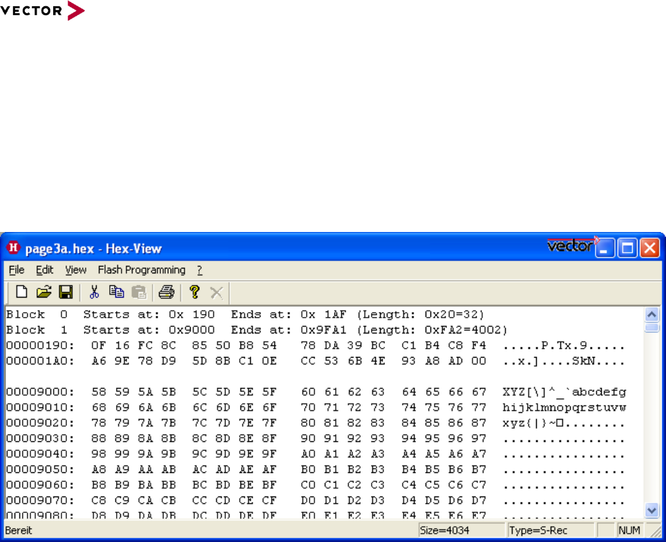
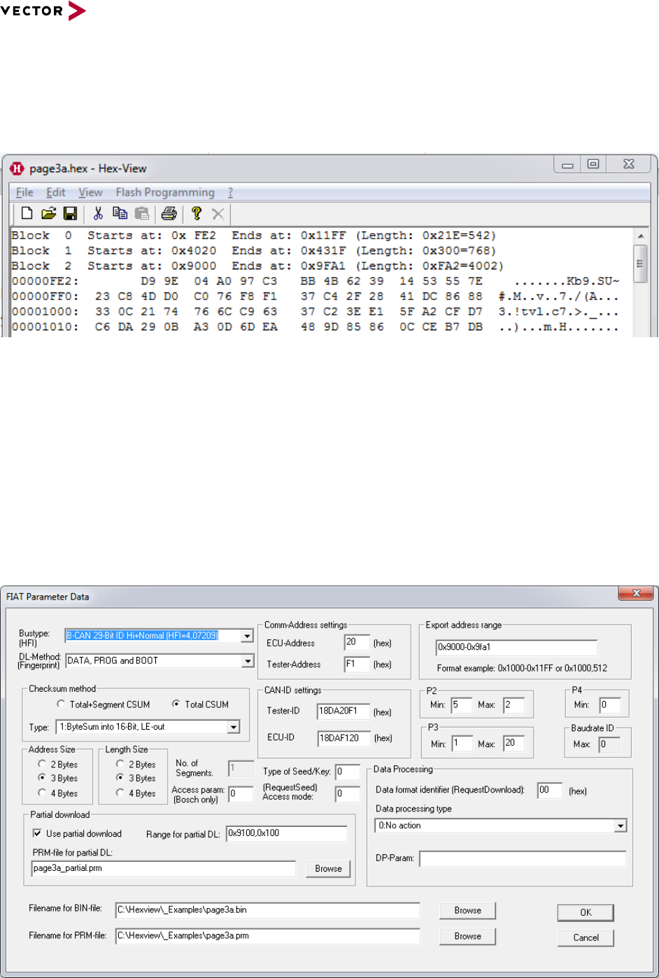
Figure 2-1 Main Menu of HexView
The figure above shows the main menu of HexView after a HEX-.File has been loaded. In
the upper part of the tool the sections of the file are listed. In the example above, the file
consists of 2 section2, named “Block 0..1”. For each block the start and end address is
given, as well as the length in hexadecimal and decimal value.
After the block section description, the data itself are displayed. Two adjacent blocks are
separated by a blank line (between 00000190 and 0009000).
A HEX-display line consists of the start address and its data. On the right side, the data is
partly interpreted as characters if possible (if the data is lower 32, the character is shown
as a ‘.’).
Any mouse click with the left button restores the display in the window.
On the bottom of the window some status information is displayed.
From left to right:
Information about the selected menu option
Total number of bytes (decimal)
15
ndian currently loaded file (Size=Xxxxx)
The file format
15
ndian data file that is currently loaded (see section 2.2.1.2.1 for
possible values).
Reference Manual HexView
© 2016 Vector Informatik GmbH Version 1.10.01 16
based on template version 5.1.0
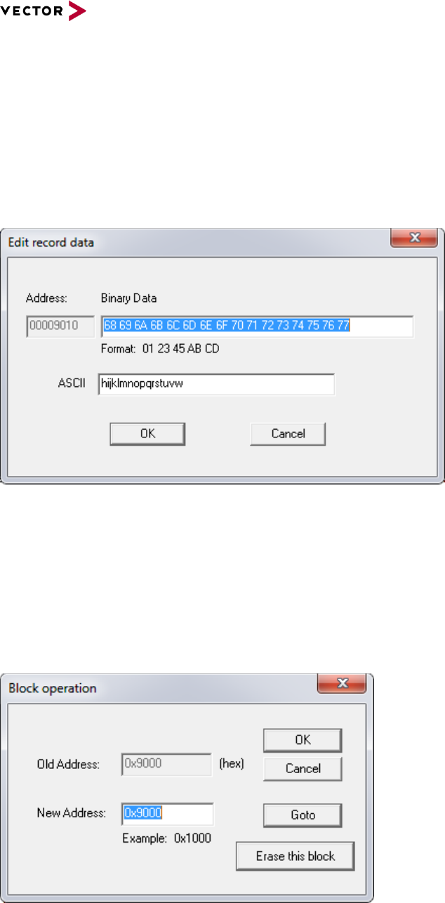
2.1 With a Double Click to the Main Menu
To edit a hex-line, make a double click on the corresponding line you want to edit. This will
open the Edit-Line dialog.
2.1.1 Edit a HEX data line
You can edit the line in two different modes. In the upper line the data can be entered in
hexadecimal mode. In the lower line, the data can be entered as ASCII-characters. The left
field shows which base address the line is assigned to.
Figure 2-2 Edit-Line dialog
If only a few characters or hex values are entered, HexView will only change these lines.
All others will remain.
2.1.2 Change the base address of a data block, erase it or jump directly to the
beginning of the block data
It is also possible to make a double click onto the block info which is on top of the main
menu. This opens the block shift address menu:
Figure 2-3 Change the base address of a segment
This dialog allows you to change the address of a block. Simply enter the new base
address.

Reference Manual HexView
© 2016 Vector Informatik GmbH Version 1.10.01 17
based on template version 5.1.0
You can also jump to the beginning of the specified block to display the data by selecting
the “Goto”-button (Note that it may also shift the address if another value in “New Address
will be specified).
It is also possible to delete the whole block from the list by pushing the button “Erase
entire block” button.
2.2 Menu
The main menu is grouped into the categories
File
Edit
View
Flash Programming
The file menu operates directly on complete files. The view menu allows searching for
options and the Edit menu can operate on the data.
Each of the elements of the menu will be described now.
2.2.1 Menu: “File”
2.2.1.1 New
Closes the current file and restarts a new session
2.2.1.2 Open
This dialog allows to open a data file. Hexview analyses the data container and checks for
a known format. The resulting data format is displayed in the status line in the bottom area.
2.2.1.2.1 Auto-file format analysing process
The format analyse process uses the following method and order:
File-format detection
Scan process and order during file-read operation
> Fiat File
Check the filename extension if it is a “.prm” – file, and try to read it as a
Fiat parameter and BIN-File combination.
> GM binary files
(GBF)
Check the filename extension if it is a “.gbf” – or “.bin” – file, and try to
load it in the GM-binary file format.
> Binary file, if no
ASCII is found
Read the first line with non-zero length and check if it contains non-
ASCII characters. If so, read the file as a binary block
> I-Hex if the line
begins with ‘:’
If the first 25 lines of the file corresponds to an ASCII string and starts
with a ‘:’, the data are read as Intel-HEX.
> S-Rec if the line
begins with ‘S’
If the ASCII-string starts with the character ‘S’ it will be read as Motorola
S-Record
> Ford VBF-File
Check, if the contains the string “vbf_version”. Load it as VBF-file in that
case.
> Ford I-Hex
Check if the file contains one of the Ford’s Intel-HEX header information
and read it as Ford-Ihex file.
> Binary file in all
In all other cases, read the file as a binary data input with the base
Reference Manual HexView
© 2016 Vector Informatik GmbH Version 1.10.01 18
based on template version 5.1.0
File-format detection
Scan process and order during file-read operation
other cases
address of 0.
Table 2-1 Auto-file format detection
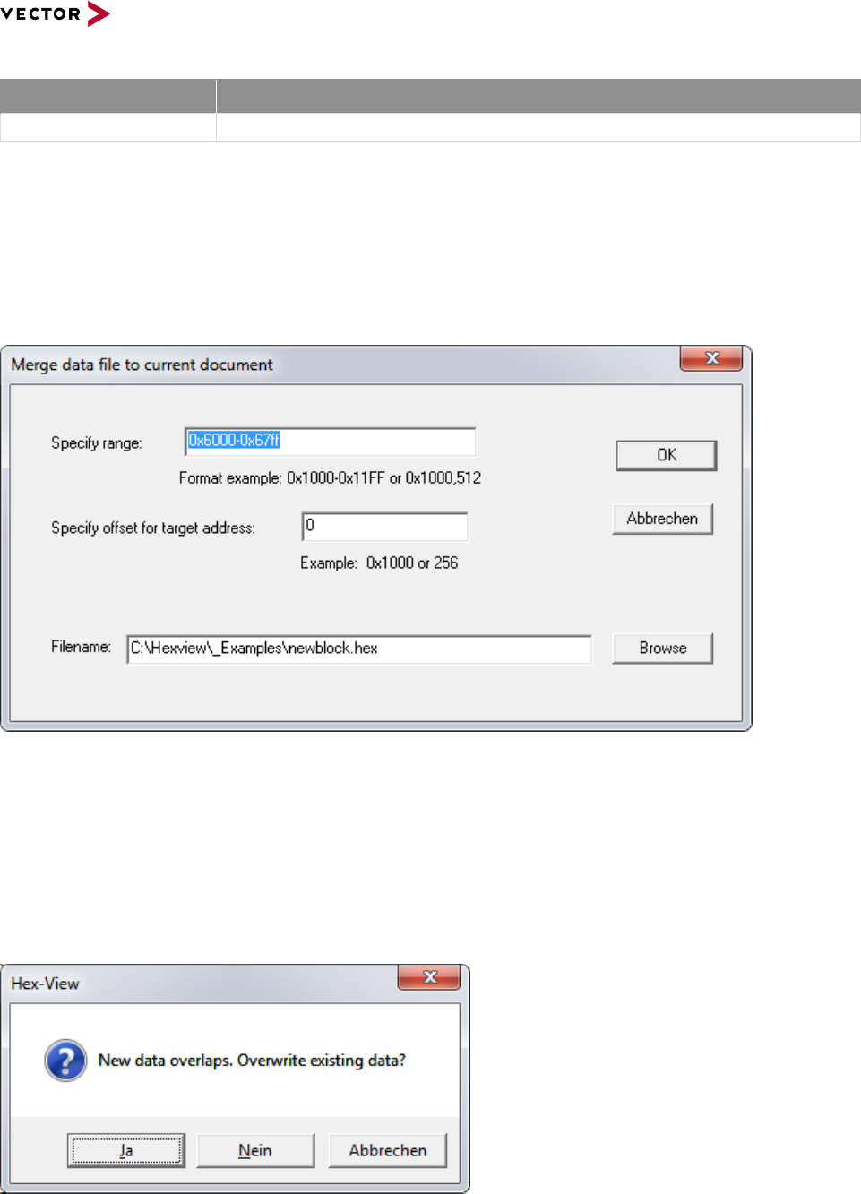
2.2.1.3 Merge
This item reads a file and adds the data to the current document data. After selecting this
item, a file-select dialog will open. You can select any of the files in the format of the
autofile-type selections (see section 2.2.1.2.1). After selsecting the file and pressing OK,
the following dialog will appear:
Figure 2-4: Customizing merge data in the merge dialog
The specified range shows the area of data from the merge file. A smaller range can be
selected that shall be merged to the current document. An offset can be specified that will
be applied to each segment that will be merged. The offset can be positive or negative and
will be added or subtracted. Use a minus-sign to subtract the offset from the base address
of each segment.
If the data of the merged file overlaps with the file data, a warning will be displayed.
Figure 2-5 Overlapping data when merging a file

Reference Manual HexView
© 2016 Vector Informatik GmbH Version 1.10.01 19
based on template version 5.1.0
If “Overwriting existing data” is accepted, the newly read data will overwrite the data that is
internally present. If this is not accepted, the internal data is kept and just the surrounding
data is read into the internal memory.
All filetypes can be merged that are also supported with the automatic filetype detection
method.
2.2.1.4 Compare
This item provides the means to compare the internal data against the data in an external
file. The compare option can load the same filetypes as supported with “File open”.
After selecting this item, a file select dialog will open. Select the file that contains the data
you want to compare. Afterwards, the file compare dialog will be opened.
Figure 2-6 Compare Info dialog
The left window displays the internal data, whereas the right window displays the data
from the external file. All differences are marked in colors. Data sections that are not
present in the internal or external document are marked with ‘-‘.
The green up- and down arrows in the upper middle can be used to search for further
differences in the file. The next/previous search procedure starts always from the first line
displayed in the window.
As mentioned above, the next/prev search algorithm starts from the top line of the window.
It uses the next/previous line and searches for the next equal data. If equal data found, it
searches for the next difference or non-presence of data. If this is found, the first
appearance will be displayed on top of the window.
Reference Manual HexView
© 2016 Vector Informatik GmbH Version 1.10.01 20
based on template version 5.1.0
2.2.1.5 Save
After any modification of the data (e.g. modifying a hexline or the base address of a block),
the save option will be enabled. This indicates, that the file has been modified. In that
case, the “Save” option enables you to store the data to the current file name. Hexview
writes the data in the current file format. The current file format is displayed in the status
line.
2.2.1.6 Save as
Enables you to store the internal data to a file with a different filename. Hexview uses the
current file format displayed in the status line. If a file format cannot be stored (e.g. the
Intel-Hex/Motorola S-Record “Mixed” file type), a warning will be shown and no data can
be saved. Use the export function of Hexview to store the data in a different format.
2.2.1.7 Log Commands
This option is reserved for future use. It is intended as a certain kind of macro recorder. If
selected, the “save as” dialog will open. Within it, a log file can be selected. HexView will
create a new file or delete the contents of an existing file. Once this has been selected,
some commands will be stored within it.
The following commands are implemented at the moment:
Command name
Command option
Description
FileOpen
filename
Opens a file.
FileClose
-
Close the file
FileNew
-
Deletes the current file and creates a new
object
Table 2-2 Currently available commands in the log-file
This might be extended in the future.
The LOG-File commands can be executed through the command line options.
2.2.1.8 Import
The Import option allows to read files in different other file formats. The following file
formats are supported:
Motorola S-Record or Intel-Hex data
Binary data
GM data
Fiat data
Ford Intel-HEX data
Ford VBF-Data

Reference Manual HexView
© 2016 Vector Informatik GmbH Version 1.10.01 21
based on template version 5.1.0
2.2.1.8.1 Import Intel-Hex/Motorola S-Record
This item is used to provide backward compatibility to the File->Open function available in
previous versions of Hexview (V1.1.2 or lower). It scans a textfile and analyses each line if
it is an Intel-HEX or a Motorola S-Record line and reads the data.
The resulting file type will be displayed in the filetype-area of the status line (‘S-Record’,
‘Intel-Hex’ or ‘Mixed’)
2.2.1.8.2 Read 16-Bit Intel Hex
This option reads an Intel-hex file and treats the address and data as 16-bit values. Every
address information is multiplied by two. Then the data is read into the buffer.
2.2.1.8.3 Import binary data
Reads a data file content as a binary. The data is treated as one binary block starting at
address 0. The base address can be changed by a double click to the block info line at the
top of the file.
2.2.1.8.4 Import HEX ASCII
This option provides the ability to read text information in HEX ASCII format. Every byte
will be represented as a pair or single HEX characters, e.g. 34, 5, F3. All non-HEX-ASCII
characters like spaces or carriage returns will be dropped and treated as separators.
The base address of the read operation is always set to 0.
Note: The current file in the editor is not deleted. So, the HEX ASCII is rather merged to
the existing one. Use “File -> New” to read in only the ASCII data.
2.2.1.8.5 Import GM data
Reads a binary file that contains the GM header information. Since the header should
contain address and length information, all sections can be restored from the file. Note that
this option can only be used if the file actually contains a GM binary header.
2.2.1.8.6 Import Fiat data
This option reads the file in the Fiat binary format. The Fiat files are split into two files, the
parameter file (*.prm) and the binary file (*.bin). The parameter file contains section
information, the checksum, etc. The binary file contains the actual data. HexView reads the
PRM file and interprets the section information. Then it reads the actual data from the
binary file.
2.2.1.8.7 Import Ford Ihex data
Reads the header container information used by Ford and the following Intel-HEX
information from the file.
All information from the Ford header will be stored in an INI-file.
2.2.1.8.8 Import Ford VBF data
Reads the Ford VBF data file. This version of Hexview manages the vbf-version V2.2.
All information from the header will be stored in an INI-File.
2.2.1.8.9 Import GAC binary file
Allows to read in GAC binary files. The header information like DCID, S/W version etc. are
stored in an internal buffer and are hidden from the user. The address and length
information from the binary will be taken to re-construct the memory representation of the
Reference Manual HexView
© 2016 Vector Informatik GmbH Version 1.10.01 22
based on template version 5.1.0
binary data. Hence, the GAC binary files without address information (e.g. for the SWIL)
will not displayed as GAC files and must be handled like binaries.
2.2.1.9 Export
This item groups a number of different options to store the internal data into different file
formats. Each export can contain some options to adjust the output information.
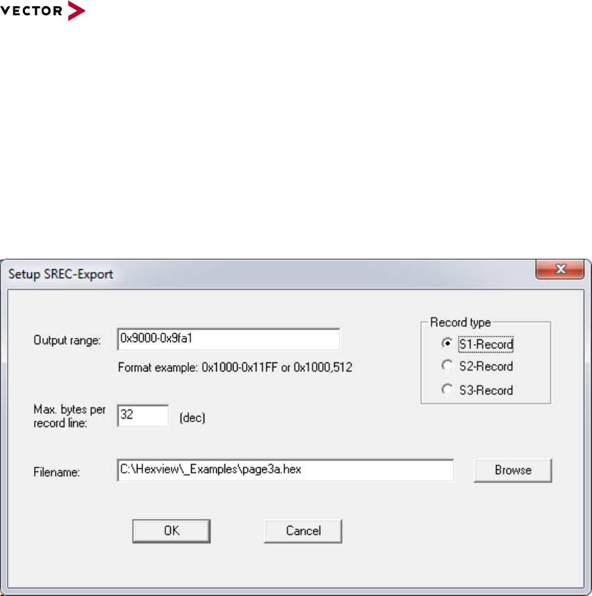
2.2.1.9.1 Export as S-Record
This item exports the data in the Motorola S-Record format.
Figure 2-7 Export data in the Motorola S-Record format
The record type will be selected automatically depending on the length of the highest
address information.
The default values for start and end address will be the lowest respectively the highest
address of the file. The Output range specifier can be used if just a portion of the internal
data shall be exported. The range can be specified using the start and end address
separated by a ‘-‘, or can be specified using the start address and length separated by a
comma. Several ranges can be separated by a colon ‘:’. Address and length can be
specified in hexadecimal with a preceding ‘0x’. Otherwise it is treated as a decimal value.
Examples: 0x190,0x20:0x9020-0x903f
The option “Max. bytes per record line” specifies the number of bytes per block for the S-
Record file. The [Browse] option allows to locate the file with the file dialog.
Reference Manual HexView
© 2016 Vector Informatik GmbH Version 1.10.01 23
based on template version 5.1.0
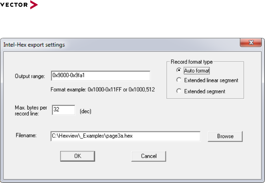
2.2.1.9.2 Export as Intel-HEX
Figure 2-8 Export dialog for the Intel-Hex output
Exports the data in Intel-HEX record format. This opens the following dialog for the export:
The address range of the output can be limited (see 2.2.1.9.1 for a description on the
format and how to use the range specifier).
Hexview supports two different types of output on the Intel-HEX file format, the extended
linear segment and the extended segment. The extended linear segment can store data
with address ranges up to 20 bits, whereas the extended linear segment format can
support address ranges with up to 32 bits (address ranges with up to 16 bit length of
addresses are not using any extended segments).
In the auto-mode, the used segment mode depends on the address length of each line. If
the address length of a line that shall be written exceeds 16 bits, but is lower or equal than
20 bits, the extended segment will be used. If the size of the address is larger than 20 bits,
the extended linear segment type will be used.
Sometimes it is necessary to restrict the number of bytes per record line in the output file.
This can be adjusted with the “Max bytes per record line” parameter.
2.2.1.9.3 Export as HEX-ASCII
The internal data will be exported as HEX-ASCII. Each byte will be written as a pair of
characters. A separator between bytes can be specified as well as the number of bytes
that shall be written per line before a newline will be inserted.
The number of characters per line can be entered in decimal or hexadecimal value. To use
hexadecimal values, the value must start with ‘0x’, e.g. 0x20 will output 32 bytes per line.
Reference Manual HexView
© 2016 Vector Informatik GmbH Version 1.10.01 24
based on template version 5.1.0
Figure 2-9 Export HEX ASCII data
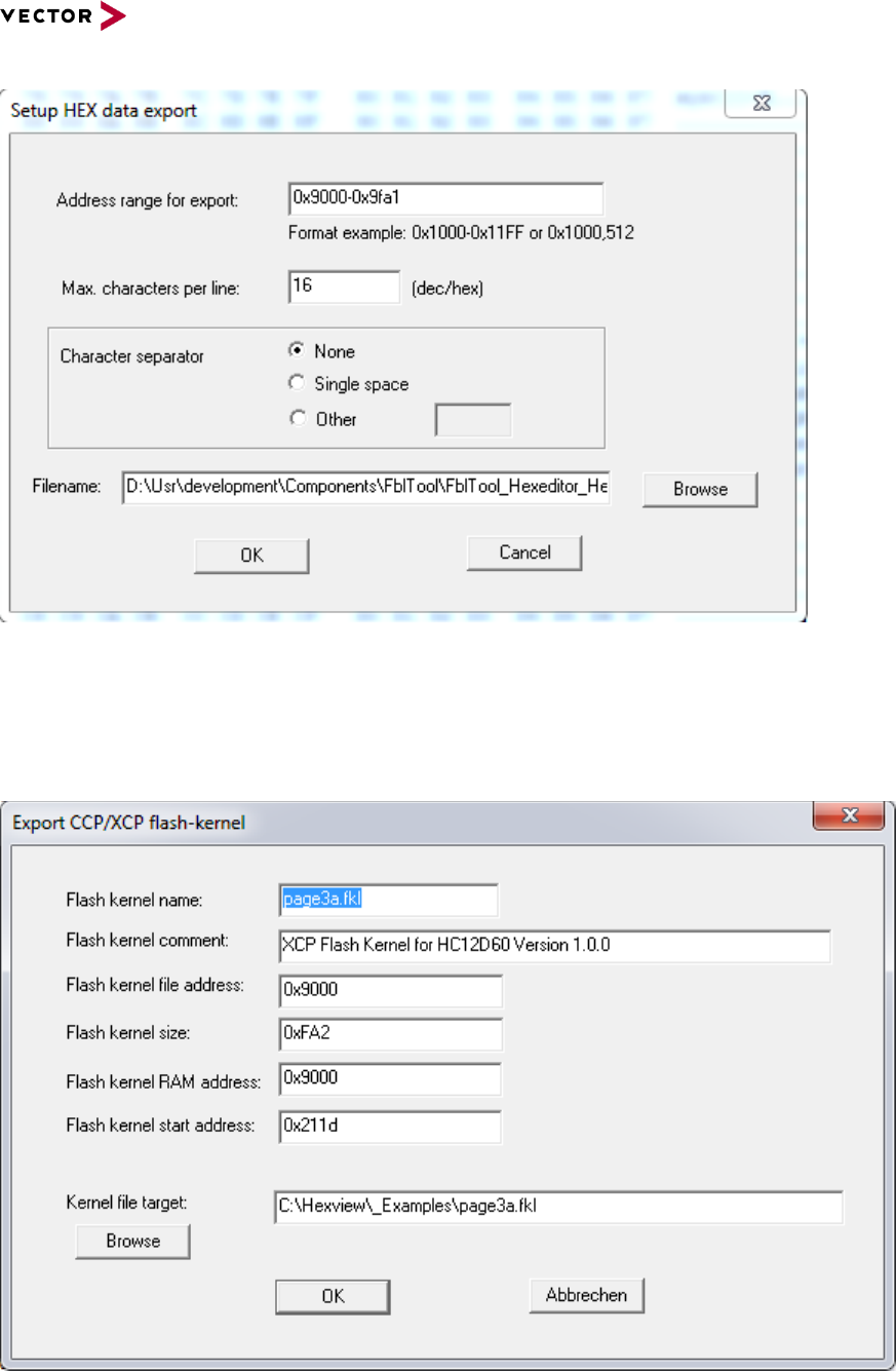
2.2.1.9.4 Export as CCP Flashkernel
This option generates the internal data into an Intel-HEX file, including the data section
necessary for the CCP/XCP flash kernel.
Figure 2-10 Export flashkernel data for CCP/XCP
The section information is directly copied into the FKL-header section.

Reference Manual HexView
© 2016 Vector Informatik GmbH Version 1.10.01 25
based on template version 5.1.0
The kernel header contains a few information about the kernel file name, both the
addresses of the RAM and the start address of the main application in the flash kernel.
Note
The main application of each flash kernel starts with the function:
ccpBootLoaderStartup(), ensure FLASH_KERNEL_RAM_START has got the right
function address. Sometimes the flash kernel location is at the same address like a
vector interrupt table, to prove this, the developer must add the size of the kernel to the
FLASH_KERNEL_RAM_START address. For Example here
FLASH_KERNEL_RAM_START + FLASH_KERNEL_SIZE = 1533. That mean the
RAM area from 0x1000 – 0x1533 must be clear.
FLASH_KERNEL_NAME=”xxxxx.fkl”
FLASH_KERNEL_COMMENT=”Flash Kernel for xxxxxx”
FLASH_KERNEL_FILE_ADDR=0x1000
FLASH_KERNEL_SIZE=0x0533
FLASH_KERNEL_RAM_ADDR=0x1000
FLASH_KERNEL_RAM_START=0x1000
The parameters of the flash kernel reflect directly the input of the dialog.
These parameters are also written to an INI-file, so that it can be retrieved the next time
when this dialog will be opened. An example of the INI-file is shown below:
[FLASH_KERNEL_CONFIG]
;FLASH_KERNEL_NAME=”S12D64kernel.fkl”
FLASH_KERNEL_COMMENT=”CCP Flash Kernel for Star12D64@16Mhz Version
1.0.0”
;FLASH_KERNEL_FILE_ADDR=0x039A
;FLASH_KERNEL_SIZE=0x0426
;FLASH_KERNEL_RAM_ADDR=0x039A
FLASH_KERNEL_RAM_START=0x039A
; or: FLASH_KERNEL_RAM_START=@S12D64Kernel.map:
ccpBootLoaderStartup %lx
Note
FLASH_KERNEL_NAME: If omitted, HexView will use the filename of the loaded file.
FLASH_KERNEL_ADDR: If omitted, HexView will use the lowest address of the block
FLASH_KERNEL_SIZE: If omitted, HexView will use the total size of the block
FLASH_KERNEL_RAM_START: If omitted, HexView will use the lowest address of the
block. See also description below.
Usually, the value of FLASH_KERNEL_RAM_START must specify the address location of
the function ccpBootLoaderStartup() in the flash kernel. Since this value can change
after changing the CCP-kernel files, a special feature has been added to extract the
address information from a MAP-file. Even though the implementation is very basic, it can
be very helpful. A special syntax enables this feature. The line must start with the ‘@’
followed by the MAP-file. A ‘:’ separates this information from the following line. This line is
used for a scan process of the MAP-file. HexView reads every line and tries to interpret the
Reference Manual HexView
© 2016 Vector Informatik GmbH Version 1.10.01 26
based on template version 5.1.0
MAP-file line by using the remaining parameter in an SSCANF function call. The
parameter “%lx” must represent the address value of the function ccpBootLoaderStartup.
If the scan process was not successful, HexView will add the complete line to the
parameter.
The example above extracts successfully the information from the following map-file
(extract of a Metrowerks compiler output):
MODULE: -- boot_ccp.obj –
- PROCEDURES:
ccpBootLoaderStartup 38EB 1E
30 0 .text
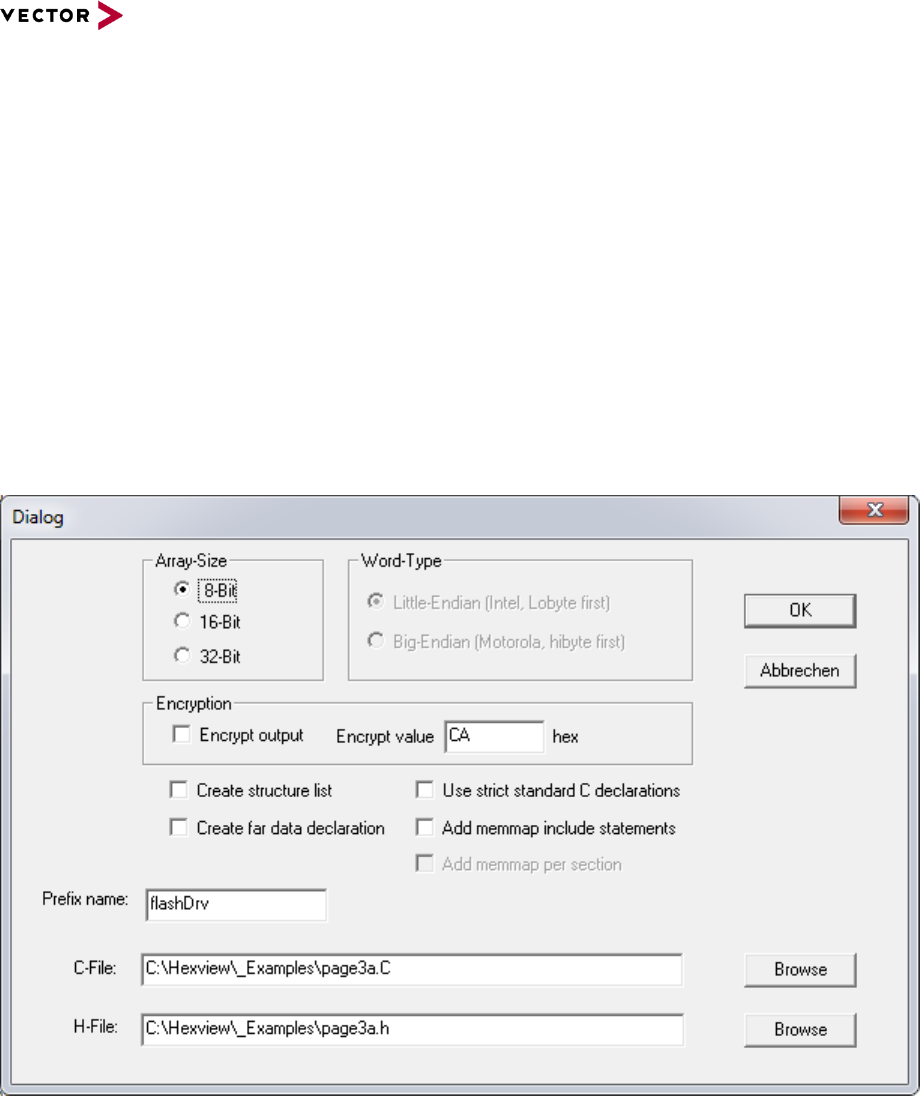
2.2.1.9.5 Export as C-Array
This option writes the data into a C-style file format:
Figure 2-11 Export data into a C-Array
The array size can be either 8-, 16- or 32-bit. If 16-bit or 32-bit is selected, the output can
be chosen as either Motorola (big-endian) or Intel (little-endian) style.
The array can be exported as plain C-data. But it is also possible to encrypt it. The
encryption will be an XOR operation with the specified parameter. The decryption
parameter is also given in C-style.
The data is written into a C-array. The array name will use the prefix given from the dialog.
If the block contains several blocks, the data will be written into several C-Arrays. Each
block will contain the block number as a postfix.

Reference Manual HexView
© 2016 Vector Informatik GmbH Version 1.10.01 27
based on template version 5.1.0
Example for the C-File
/****************************************************************
* Filename: D:\Usr\Armin\VC\HexView\_page4a.C
* Project: C-Array of Flash-Driver
* File created: Sun Jan 15 20:59:35 2006
****************************************************************/
#include <fbl_inc.h>
#include <_page4a.h>
#if (FLASHDRV_GEN_RAND!=1739)
# error “Generated header and C-File inconsistent!!”
#endif
V_MEMROM0 MEMORY_ROM unsigned char flashDrvBlk0[FLASHDRV_BLOCK0_LENGTH] = {
0x00, 0x01, 0x02, 0x03, 0x04, 0x05, 0x06, 0x07, 0x08, 0x09, 0x0A, 0x0B, 0x0C, 0x0D,
0x0E, 0x0F,
0x10, 0x11, 0x12, 0x13, 0x14, 0x15, 0x16, 0x17, 0x18, 0x19, 0x1A, 0x1B, 0x1C, 0x1D,
0x1E, 0x1F,
0x20, 0x21, 0x22, 0x23, 0x24, 0x25, 0x26, 0x27, 0x28, 0x29, 0x2A, 0x2B, 0x2C, 0x2D,
0x2E, 0x2F,
0x30, 0x31, 0x32, 0x33, 0x34, 0x35, 0x36, 0x37, 0x38, 0x39, 0x3A, 0x3B, 0x3C, 0x3D,
0x3E, 0x3F,
0x40, 0x41, 0x42, 0x43, 0x44, 0x45, 0x46, 0x47, 0x48, 0x49, 0x4A, 0x4B, 0x4C, 0x4D,
0x4E, 0x4F,
0x50, 0x51, 0x52, 0x53, 0x54, 0x55, 0x56, 0x57, 0x58, 0x59, 0x5A, 0x5B, 0x5C, 0x5D,
0x5E, 0x5F,
0x60, 0x61, 0x62, 0x63, 0x64, 0x65, 0x66, 0x67, 0x68, 0x69, 0x6A, 0x6B, 0x6C, 0x6D,
0x6E, 0x6F,
0x70, 0x71, 0x72, 0x73, 0x74, 0x75, 0x76, 0x77, 0x78, 0x79, 0x7A, 0x7B, 0x7C, 0x7D,
0x7E, 0x7F,
0x80, 0x81, 0x82, 0x83, 0x84, 0x85, 0x86, 0x87, 0x88, 0x89, 0x8A, 0x8B, 0x8C, 0x8D,
0x8E, 0x8F,
0x90, 0x91, 0x92, 0x93, 0x94, 0x95, 0x96, 0x97, 0x98, 0x99, 0x9A, 0x9B, 0x9C, 0x9D,
0x9E, 0x9F,
0xA0, 0xA1, 0xA2, 0xA3, 0xA4, 0xA5, 0xA6, 0xA7, 0xA8, 0xA9, 0xAA, 0xAB, 0xAC, 0xAD,
0xAE, 0xAF,
0xB0, 0xB1, 0xB2, 0xB3, 0xB4, 0xB5, 0xB6, 0xB7, 0xB8, 0xB9, 0xBA, 0xBB, 0xBC, 0xBD,
0xBE, 0xBF,
0xC0, 0xC1, 0xC2, 0xC3, 0xC4, 0xC5, 0xC6, 0xC7, 0xC8, 0xC9, 0xCA, 0xCB, 0xCC, 0xCD,
0xCE, 0xCF,
0xD0, 0xD1, 0xD2, 0xD3, 0xD4, 0xD5, 0xD6, 0xD7, 0xD8, 0xD9, 0xDA, 0xDB, 0xDC, 0xDD,
0xDE, 0xDF,
0xE0, 0xE1, 0xE2, 0xE3, 0xE4, 0xE5, 0xE6, 0xE7, 0xE8, 0xE9, 0xEA, 0xEB, 0xEC, 0xED,
0xEE, 0xEF,
0xF0, 0xF1, 0xF2, 0xF3, 0xF4, 0xF5, 0xF6, 0xF7, 0xF8, 0xF9, 0xFA, 0xFB, 0xFC, 0xFD,
0xFE, 0xFF
};
Example of the Header-File:
/****************************************************************
*
* Filename: D:\Usr\Armin\VC\HexView\_page4a.h
* Project: Exported definition of C-Array Flash-Driver
* File created: Sun Jan 15 20:59:35 2006
*
****************************************************************/
#define FLASHDRV_GEN_RAND 1739
#define FLASHDRV_DECRYPTDATA(a) (unsigned char)a
#define FLASHDRV_BLOCK0_ADDRESS 0x9000
#define FLASHDRV_BLOCK0_LENGTH 0x100
#define FLASHDRV_BLOCK0_CHECKSUM 0x7F80u
extern V_MEMROM0 MEMORY_ROM unsigned char flashDrvBlk0[FLASHDRV_BLOCK0_LENGTH];

Reference Manual HexView
© 2016 Vector Informatik GmbH Version 1.10.01 28
based on template version 5.1.0
Example for the C-File
/****************************************************************
* Filename: D:\Usr\Armin\VC\HexView\_page4a.C
* Project: C-Array of Flash-Driver
* File created: Sun Jan 15 20:59:35 2006
****************************************************************/
#include <fbl_inc.h>
#include <_page4a.h>
#if (FLASHDRV_GEN_RAND!=1739)
# error “Generated header and C-File inconsistent!!”
#endif
V_MEMROM0 MEMORY_ROM unsigned char flashDrvBlk0[FLASHDRV_BLOCK0_LENGTH] = {
0x00, 0x01, 0x02, 0x03, 0x04, 0x05, 0x06, 0x07, 0x08, 0x09, 0x0A, 0x0B, 0x0C, 0x0D,
0x0E, 0x0F,
0x10, 0x11, 0x12, 0x13, 0x14, 0x15, 0x16, 0x17, 0x18, 0x19, 0x1A, 0x1B, 0x1C, 0x1D,
0x1E, 0x1F,
0x20, 0x21, 0x22, 0x23, 0x24, 0x25, 0x26, 0x27, 0x28, 0x29, 0x2A, 0x2B, 0x2C, 0x2D,
0x2E, 0x2F,
0x30, 0x31, 0x32, 0x33, 0x34, 0x35, 0x36, 0x37, 0x38, 0x39, 0x3A, 0x3B, 0x3C, 0x3D,
0x3E, 0x3F,
0x40, 0x41, 0x42, 0x43, 0x44, 0x45, 0x46, 0x47, 0x48, 0x49, 0x4A, 0x4B, 0x4C, 0x4D,
0x4E, 0x4F,
0x50, 0x51, 0x52, 0x53, 0x54, 0x55, 0x56, 0x57, 0x58, 0x59, 0x5A, 0x5B, 0x5C, 0x5D,
0x5E, 0x5F,
0x60, 0x61, 0x62, 0x63, 0x64, 0x65, 0x66, 0x67, 0x68, 0x69, 0x6A, 0x6B, 0x6C, 0x6D,
0x6E, 0x6F,
0x70, 0x71, 0x72, 0x73, 0x74, 0x75, 0x76, 0x77, 0x78, 0x79, 0x7A, 0x7B, 0x7C, 0x7D,
0x7E, 0x7F,
0x80, 0x81, 0x82, 0x83, 0x84, 0x85, 0x86, 0x87, 0x88, 0x89, 0x8A, 0x8B, 0x8C, 0x8D,
0x8E, 0x8F,
0x90, 0x91, 0x92, 0x93, 0x94, 0x95, 0x96, 0x97, 0x98, 0x99, 0x9A, 0x9B, 0x9C, 0x9D,
0x9E, 0x9F,
0xA0, 0xA1, 0xA2, 0xA3, 0xA4, 0xA5, 0xA6, 0xA7, 0xA8, 0xA9, 0xAA, 0xAB, 0xAC, 0xAD,
0xAE, 0xAF,
0xB0, 0xB1, 0xB2, 0xB3, 0xB4, 0xB5, 0xB6, 0xB7, 0xB8, 0xB9, 0xBA, 0xBB, 0xBC, 0xBD,
0xBE, 0xBF,
0xC0, 0xC1, 0xC2, 0xC3, 0xC4, 0xC5, 0xC6, 0xC7, 0xC8, 0xC9, 0xCA, 0xCB, 0xCC, 0xCD,
0xCE, 0xCF,
0xD0, 0xD1, 0xD2, 0xD3, 0xD4, 0xD5, 0xD6, 0xD7, 0xD8, 0xD9, 0xDA, 0xDB, 0xDC, 0xDD,
0xDE, 0xDF,
0xE0, 0xE1, 0xE2, 0xE3, 0xE4, 0xE5, 0xE6, 0xE7, 0xE8, 0xE9, 0xEA, 0xEB, 0xEC, 0xED,
0xEE, 0xEF,
0xF0, 0xF1, 0xF2, 0xF3, 0xF4, 0xF5, 0xF6, 0xF7, 0xF8, 0xF9, 0xFA, 0xFB, 0xFC, 0xFD,
0xFE, 0xFF
};

Reference Manual HexView
© 2016 Vector Informatik GmbH Version 1.10.01 29
based on template version 5.1.0
Example of the Header-File
/****************************************************************
*
* Filename: D:\Usr\Armin\VC\HexView\_page4a.h
* Project: Exported definition of C-Array Flash-Driver
* File created: Sun Jan 15 20:59:35 2006
*
****************************************************************/
#define FLASHDRV_GEN_RAND 1739
#define FLASHDRV_DECRYPTDATA(a) (unsigned char)a
#define FLASHDRV_BLOCK0_ADDRESS 0x9000
#define FLASHDRV_BLOCK0_LENGTH 0x100
#define FLASHDRV_BLOCK0_CHECKSUM 0x7F80u
extern V_MEMROM0 MEMORY_ROM unsigned char flashDrvBlk0[FLASHDRV_BLOCK0_LENGTH];
The macro [Prefix-name]_DECRYPTDATA() can be used to extract and encrypt the data. It
will be generated according to the encryption option and value.
The output can also generated via the command line. Refer to section 3.3.3 for further
information.
The declaration of the C-arrays are dedicated to the Vector
29
ootloader. In some cases, it
might be necessary to use these structures in a pure C-environment without compiler
abstraction used by Vector’s naming convention. Use the “Use strict Ansi-C declaration” in
this case.
Another option is to use so-called memmap-statements. Hexview will generate statements
to delare a define and then include the file memmap.h:
Example
Memmap declarations generated by Hexview:
#define FLASHDRV_START_SEC_CONST
#include “memmap.h”
The file memmap.h may look like this:
#ifdef FLASHDRV_START_SEC_CONST
#undef FLASHDRV_START_SEC_CONST
#pragma section .flashdrv
#endif
2.2.1.9.6 Export Mime coded data
This item exports the data file in MIME-coded format with BASE64 coding.
2.2.1.9.7 Export Binary data
This item will write all data contents in the order of their appearance into a binary file.
All segments will be written linear into the data block
Reference Manual HexView
© 2016 Vector Informatik GmbH Version 1.10.01 30
based on template version 5.1.0
2.2.1.9.8 Export binary block data
This item will export the data into a binary file. However, if the internal data file contains
several blocks, the data is written to different files. Each filename will have the base
address as a postfix.
Figure 2-12 Export binary block data
File output names:
_page3_overlap_fe2.bin
_page3_overlap_4020.bin
_page3_overlap_9000.bin
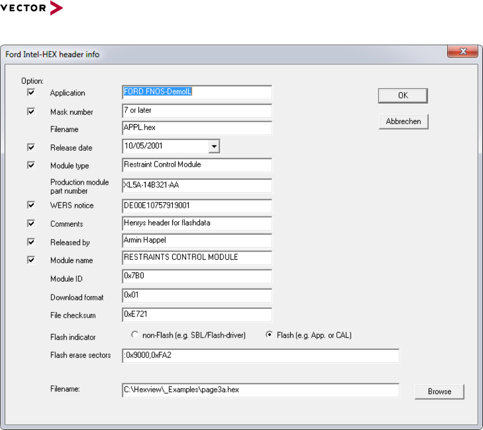
2.2.1.9.9 Export Fiat Binary File
This exports data in the FIAT file format.
Figure 2-13: Export dialog for the FIAT binary file

Reference Manual HexView
© 2016 Vector Informatik GmbH Version 1.10.01 31
based on template version 5.1.0
The dialog shown above can only be understood if the Fiat file format is known. This
document does not intend to explain this file format. Refer to 0728401.pdf for further
explanation.
During the export, an INI-file will be updated or generated. If the INI-File was specified by
the commandline, this file will be used. Otherwise, an existing file will be updated or new
file will be generated with the same name and location as the export filename. For the INI-
file format, refer to section 3.3.2, “Output a Fiat specific data file (/XB)”.
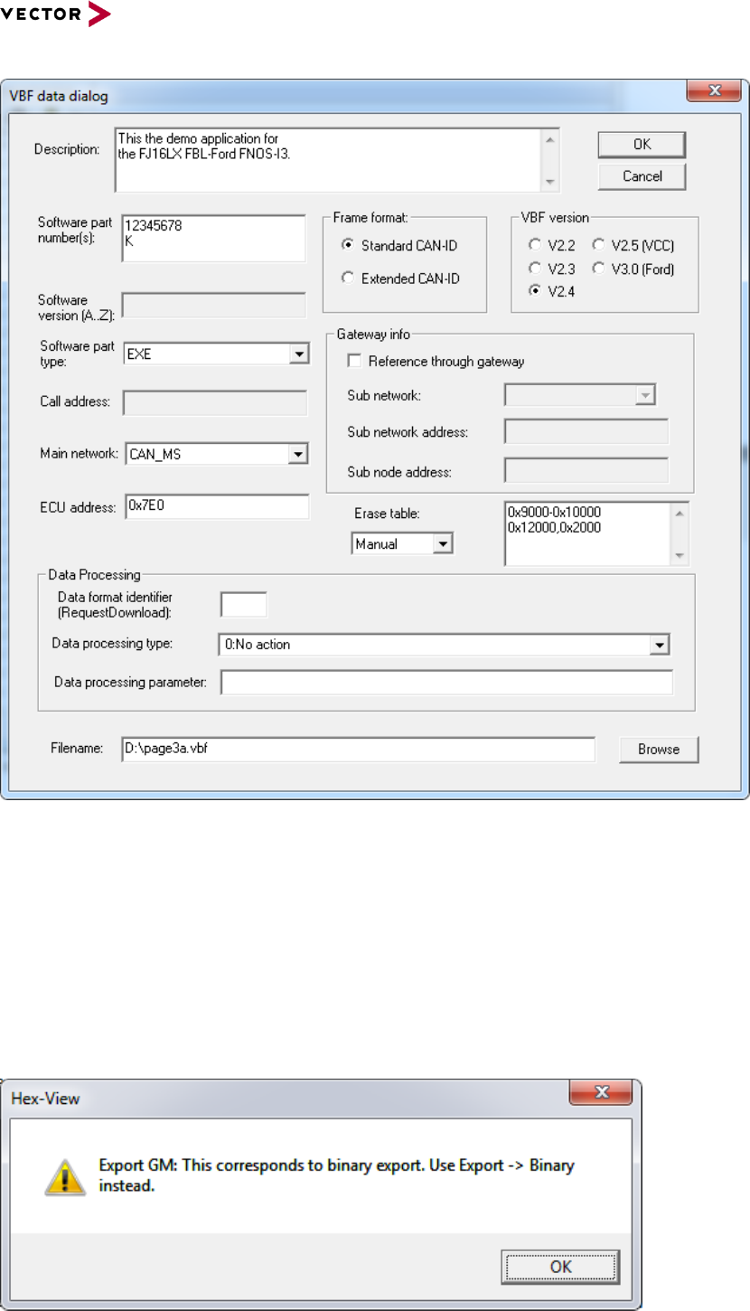
2.2.1.9.10 Export Ford Ihex data container
The file format generated with this output is based on the Ford-specification “Module
Programming & Configuration Design Specification”, V 2003.0, dated: 25 April 2005,
Annex C.
Besides the download data itself, there are some optional and mandatory values added to
the output file. The optional fields can be selected/unselected with the option checkbox.
All values entered in the dialog below will be written to the INI-File. The INI-file can also be
used for the command line option to generate the output without the needs of a user input.
For detailed description of each item of the data fields, refer to the document mentioned
above. Further information can be found in section 3.3.4.1, “Output Ford files in Intel-HEX
format”.
Information: The file format has been replaced by VBF.
Reference Manual HexView
© 2016 Vector Informatik GmbH Version 1.10.01 32
based on template version 5.1.0
Figure 2-14: Export dialog for Ford I-Hex output file
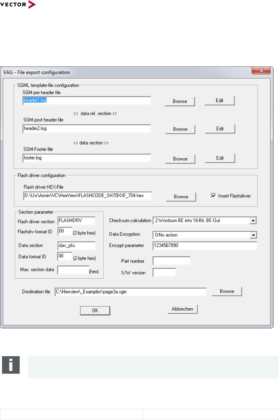
2.2.1.9.11 Export Ford VBF data container
The VBF file format is the Versatile Binary Format used by Ford and VolvoCars. The
output of this file is based on the specification “Versatile Binary Format”, V2.2 until V2.5.
All values entered in the dialog below will be written to the INI-File. The INI-file can also be
used for the command line option to generate the output without the needs of a user input.
Refer to section 3.3.4.2, “Output Ford files in VBF format” for further information.
Reference Manual HexView
© 2016 Vector Informatik GmbH Version 1.10.01 33
based on template version 5.1.0
Figure 2-15: Export dialog for the Ford/VolvoCars-VBF data file format
2.2.1.9.12 Export GM data
This item is just present to indicate, that the tool also supports GM-data export. In fact, the
GM data preparation must be done through the commandline option. More information can
be found in section 3.3.5ff,”Output a GM-specific data file”.
The GM data container is simply a binary file stream. It can be exported through the binary
export.

Reference Manual HexView
© 2016 Vector Informatik GmbH Version 1.10.01 34
based on template version 5.1.0
Figure 2-16: The output information for the GM data export
2.2.1.9.13 Export GM-FBL header info
This option provides the possibility to export the address and length information of each
segment into an XML-File. Also, the number of segments and the checksum value will be
written into the XML-file. If the checksum target address is located within the segment
array, the tool will automatically split this region into two to spare the location of the
checksum. Thus, the checksum can be re-calculated.
The purpose of this output is to read the XML-file into the configuration and generation tool
“Geny”. It is used to generate the GM-header info for the GM flash Bootloader. It allows the
Bootloader to calculate the checksum on its own data.
It may require two rounds (generate the configuration, compile and link the Bootloader,
generate the XML-file with Hexview) for a valid header.
Figure 2-17: Export dialog to generate the GM-FBL header information for GENy
The XML-file has the following format:
<!—Created by HexView v2006 (Vector Informatik GmbH)
<ECU xmlns:xsi=”http://www.w3.org/2001/XMLSchema-instance”
xsi:noNamespaceSchemaLocation=”FBLConfiguration.xsd”>
<FBLConfiguration>
<PMA ID=”1”>
<Checksum Value=”51434”/>
<NumberOfPMA Value=”2”/>
<PMAField>
<Address Value=”8380416”/>
<Length Value=”1932”/>
</PMAField>
<PMAField>
<Address Value=”8388368”/>
<Length Value=”240”/>
</PMAField>
</PMA>
Reference Manual HexView
© 2016 Vector Informatik GmbH Version 1.10.01 35
based on template version 5.1.0
</FBLConfiguration>
</ECU>
2.2.1.9.14 Export VAG data container
This item exports the data into a VAG-compatible data container format.
Figure 2-18 Exports data into a VAG-compatible data container
Note
The generated VAG data file is NOT compatible with the ODX-F format used for UDS.
The VAG data container is a SGML-file that can be divided into five sections. Three
sections are merged from external files, two others are generated.
Section 1:
<!DOCTYPE SW-CNT PUBLIC “-//Volkswagen AG//DTD
Datencontainer fuer die SG-Programmierung

Reference Manual HexView
© 2016 Vector Informatik GmbH Version 1.10.01 36
based on template version 5.1.0
“SGM pre-header file”.
HexView parses this file and checks, if the fields
in [1], [2] or [3] are blank. If not blank, it will copy
the contents as is from the file. But if the fields
are left blank, it will be filled with parameters
from the dialog box:
[1] = filename from “destination file” without the
path
[2] = the value from “S/W version”
[3] = the value from “Part number”
V00.80:MiniDC08.DTD//GE” “minidc08.dtd”>
<SW-CNT>
<IDENT>
<CNT-DATEI> [1] </CNT-DATEI>
<CNT-VERSION-TYP>cvt_pfu_01</CNT-VERSION-
TYP>
<CNT-VERSION-INHALT>0.80</CNT-VERSION-
INHALT>
<CNT-IDENT-TEXT>MyProject</CNT-IDENT-TEXT>
<SW-VERSION-KURZ> [2] </SW-VERSION-KURZ>
<SW-VERSION-LANG> [3] </SW-VERSION-LANG>
</IDENT>
<INFO>
<ADRESSEN>
<ADRESSE>
<FIRMENNAME>S/W-Development
GmbH</FIRMENNAME>
<ROLLE>Entwicklung VAG-Software</ROLLE>
<ABTEILUNG>ESVG</ABTEILUNG>
<PERSON>Klaus Mustermann</PERSON>
<ANSCHRIFT>Gewerbestrasse 40, D-03421
Ingolsheim</ANSCHRIFT>
<TELEFON>+49-6234-123-456</TELEFON>
<FAX>+49-6234-123-200</FAX>
<EMAIL>Klaus.Mustermann@sw-
develop.de</EMAIL>
</ADRESSE>
</ADRESSEN>
<REVISIONEN>
<REVISION>
<WANN></WANN>
<WER></WER>
<WAS></WAS>
<WARUM></WARUM>
<VERSION></VERSION>
</REVISION>
</REVISIONEN>
</INFO>
<ABLAEUFE>
<ABLAUF>
<ABLAUF-NAME>abn_pfu</ABLAUF-NAME>
<KWP-2000>
<KWP-2000-TGT>0x62</KWP-2000-TGT>
<KWP-2000-REI>
<KWP-2000-PSTAT-BIT0>255</KWP-2000-
PSTAT-BIT0>
<KWP-2000-PSTAT-BIT1>6</KWP-2000-
PSTAT-BIT1>
<KWP-2000-PSTAT-BIT2>10</KWP-2000-
PSTAT-BIT2>
<KWP-2000-PSTAT-BIT3>0</KWP-2000-
PSTAT-BIT3>
<KWP-2000-PSTAT-BIT4>0</KWP-2000-
PSTAT-BIT4>
<KWP-2000-PSTAT-BIT5>0</KWP-2000-
PSTAT-BIT5>
<KWP-2000-PSTAT-BIT6>0</KWP-2000-
PSTAT-BIT6>
<KWP-2000-PSTAT-BIT7>0</KWP-2000-
PSTAT-BIT7>
</KWP-2000-REI>
<KWP-2000-ACP>
<KWP-2000-P2MIN>0xFF</KWP-2000-P2MIN>
<KWP-2000-P2MAX>0xFF</KWP-2000-P2MAX>
<KWP-2000-P3MIN>0xFF</KWP-2000-P3MIN>
<KWP-2000-P3MAX>0xFF</KWP-2000-P3MAX>
<KWP-2000-P4MIN>0xFF</KWP-2000-P4MIN>
</KWP-2000-ACP>
<KWP-2000-
SA2>0x12,0x23,0x23,0x34,0x45,0x56C</KWP-2000-
SA2>
</KWP-2000>
Section 2:
<DATEN-VERWEISE>
<DATEN-VERWEIS>FLASHDRV</DATEN-VERWEIS>
<DATEN-VERWEIS>dav_pfu_01</DATEN-

Reference Manual HexView
© 2016 Vector Informatik GmbH Version 1.10.01 37
based on template version 5.1.0
Generated “Data Reference section”
The reference section contains a reference to
each segment or block. An external Hex-file can
be added for reference, e.g. a HIS-flash driver. It
is necessary that this hex field contains only one
segment or block.
VERWEIS>
</DATEN-VERWEISE>
Section 3:
“SGM post-header file”.
</ABLAUF>
</ABLAEUFE>
Section 4:
Generated “data section”.
This section contains the current data. On the
right side an example of the output is shown.
Start and end address is taken from the block
information. The checksum is calculated with the
given checksum method (see section 2.2.2.6 or
3.2.7 for further details on checksum
calculation). The erase section is calculated out
of the section length. The value of
<DATENBLOCK-FORMAT> is taken from the
“Data Format ID” field in the dialog box.
The <DATENBLOCK-DATEN> contains the data
of the block or segment in a MIME-coded format.
<DATENBLOCK-
NAME>dav_pfu_01</DATENBLOCK-NAME>
<DATENBLOCK-FORMAT-
NAME>dfn_mime</DATENBLOCK-FORMAT-NAME>
<START-ADR>0x9000</START-ADR>
<DATENBLOCK-FORMAT>0x00</DATENBLOCK-
FORMAT>
<GROESSE-DEKOMPRIMIERT>0xFA2</GROESSE-
DEKOMPRIMIERT>
<LOESCH-BEREICH>
<START-ADR>0x9000</START-ADR>
<END-ADR>0x9FA1</END-ADR>
</LOESCH-BEREICH>
<DATENBLOCK-CHECK>
<START-ADR>0x9000</START-ADR>
<END-ADR>0x9FA1</END-ADR>
<CHECKSUMME>0xA866</CHECKSUMME>
</DATENBLOCK-CHECK>
<DATENBLOCK-DATEN>
MIME-Version: 1.0
WflaW1xdXl9gYWJjZGVmZ2hpamtsbW5vcHFyc3R1dnd4eXp
7fH1+f4CbgoOE
hYaHiImKi4yNjo+QkZKTlJWWl5iZmpucnZ6foKGio6Slpqe
oqaqrrK2ur7Cx
srO0tba3uLm6u7y9vr/AwcLDxMXGx8jJysvMzc7P0NHS09T
V1tfY2drb3N3e
</DATENBLOCK-DATEN>
</DATENBLOCK>
</DATENBLOECKE>
</DATEN>
Section 5:
Appending file contents from „SGM footer file“
</SW-CNT>
Table 2-3 Description of the elements for the VAG SGML output container
It should be noted, that the filename is automatically generated out of the part number and
the S/W-version fields whenever the fields are changed. You can overwrite the name if the
filename is changed at last. When editing the filename or [Browse] for a file, the name will
not automatically adapted.
It is also possible to preprocess the data before it is MIME-coded. This process is done
after the checksum calculation. It is intended to be used for e.g. Data Encryption.
It uses the standard interface functions from the EXPDATPROC.DLL (refer to section 4.2,
2.2.2.7 and 3.2.8 for further details).
INI-File info for VAG export
The dialog information is stored in an INI-file. This file has the same name as the HEX-file,
but with the file extension INI. Every time this dialog will be opened, CANflash checks for
such an INI-file and retrieves the information from there. This allows to store project

Reference Manual HexView
© 2016 Vector Informatik GmbH Version 1.10.01 38
based on template version 5.1.0
information in separate files. It is a prerequisite that the INI-file resides in the same folder
as the HEX-file.
This INI-File can then also be used in the command line option.
The following list file shows an example of the INI-file:
[SGMDATA]
DATENBLOCKNAME=dav_pfu
FLASHDRVSECTION=FLASHDRV
FLASHDRV=D:\Usr\Armin\VC\HexView\FLASHCODE_SH70XXF_704.hex
SGMHEADERPRE=header1.txt
SGMHEADERPOST=header2.txt
SGMFOOTER=footer.txt
CHECKSUMTYPE=2
DATAPROCESSINGTYPE=0
DATAPROCESSINGPARAMETER=1234567890
PARTNUMBER=123456789ab
SW_VERSION=cdef
FLASHDRV_DLID=12
DATA_DLID=24
MAXBLOCKLEN=0x400
Note
This INI-file is automatically created when executing this dialog.
2.2.1.9.15 Export GAC binary files
This option allows to write the internal data from Hexview to a GAC binary file.
The header information will be taken from the INI-file info section and written to the binary.
With this option it is only possible to write GAC files with address information.
If you want to generate GAC files without address info, use the commandline option
“/xgacswil”.
2.2.1.10 Print / Print Preview / Printer Setup
There is no special support for printer output other than that from the MFC. Thus, the view
output will directly sent to the printer.
2.2.1.11 Exit
Leaves the program.
2.2.2 Edit
This menu item collects some options that can be used to manipulate data in HexView.
2.2.2.1 Undo
This option is currently not supported by HexView.

Reference Manual HexView
© 2016 Vector Informatik GmbH Version 1.10.01 39
based on template version 5.1.0
2.2.2.2 Cut / Copy / Paste
Hexview uses an internal clipboard (not the Windows clipboard). Cut and Copy can put
data into this clipboard. Even if files are closed and others are opened, the data remain in
clipboard.
It allows, to cut or copy data regions and put it into the data section. As a new challenge,
another syntax to specify range has been introduced. Different from the other regions,
where start and end address must be specified as HEX-values, the range can now
specified in one single string. The range can be specified in two ways: Using start- and
end address or with startaddress and length.
Start and end address is separated with a ‘-‘ sign. Startaddress and length are separated
with a ‘,’.
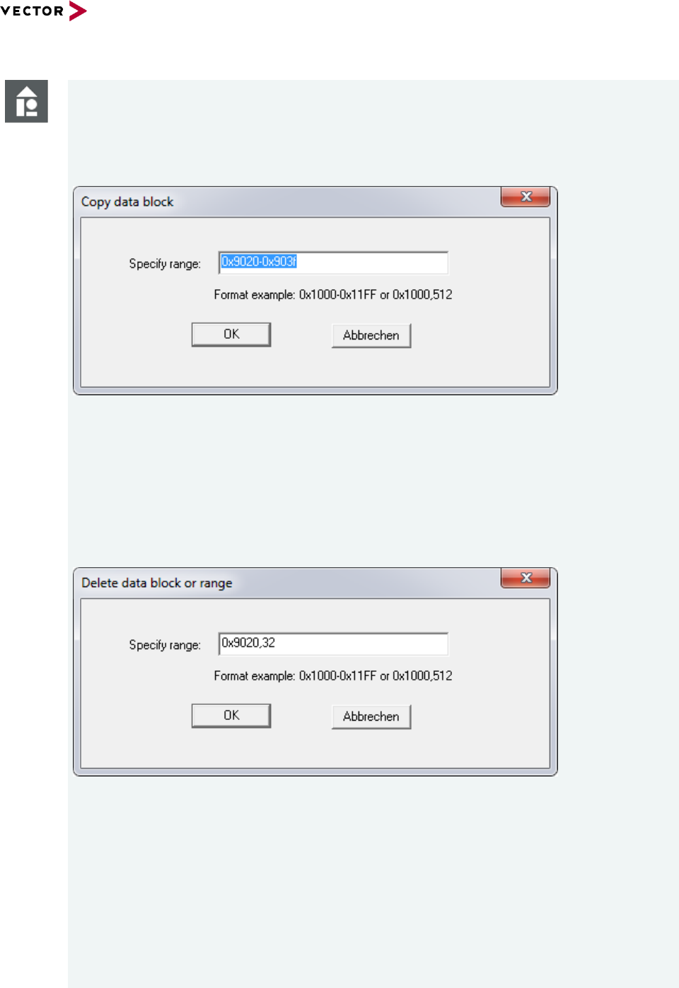
Reference Manual HexView
© 2016 Vector Informatik GmbH Version 1.10.01 40
based on template version 5.1.0
Example
Address range with start and end address: 0x9020-0x903f
This specifies start- and end-address in hexadecimal value. A ‘0x’ is required to
preceed. If ‘0x‘ is omitted, the value is treated as a decimal value. This allows to use
the parameters in both hexadecimal or decimal values.
Figure 2-19 Example of ‘Copy window’ when Ctrl-C or “Paste” pressed using start- and end-address
Address range with start address and length: 0x9020,32
This specifies a range from 0x9020 with length of 32 bytes (0x20 bytes). It is the
range of 0x9020-0x903f.
The standard short-cuts (acceleration keys) for delete (del or Ctrl-x), copy (Ctrl-
c) and paste (Ctrl-V) are supported by Hexview.
Figure 2-20 Example of cut-data using start-address and length as a parameter
Cut or paste can only be used if data are present inside Hexview.
The paste-operation is activated when something is present in Hexview’s
internal clipboard.
When ‘Paste’ (Ctrl-V) is entered, a window will open where the target paste
address can be specified. By default, the clipboard’s start address will be shown
as a default value. This can be overwritten. An address offset will be applied to
the pasting range from the clipboard.

Reference Manual HexView
© 2016 Vector Informatik GmbH Version 1.10.01 41
based on template version 5.1.0
Figure 2-21: Pasting the clipboard data into the document specifying the target address
2.2.2.3 Copy dsPIC like data
The dsPIC24/33 has a 24-bit addressing format. The flash memory only contains 3 bytes
per 4 words. Direct data access can be accomplished by addressing the lower 2 bytes,
disregarding the the upper byte. The 4th byte is also known as the ghost byte and is always
read as 0. Since the machine is a 16-bit machine, its internal words are normally
addressed 16-bit wise, Thus, address 0x1000 specifies e.g. 0xABCD, whereas 0x1001
then specifies 0x00EF and so on. Intel-HEX or Motorola S-records uses byte addresses.
The Microchip toolchain generates therefore hexfiles with double address. The values from
the example above is then represented on address 0x2000 with bytes 00 EF CD AB.
In somve cases it can be helpful to change the representation in a HEX file from “outer” to
“inner” addresses and vice versa. The copy procedure of Hexview allows to copy any
section from outer addressed (doubled address) to inner (word) address (Shrink option in
dialog) and vice versa (Expand option in the dialog).
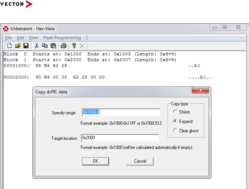
Reference Manual HexView
© 2016 Vector Informatik GmbH Version 1.10.01 42
based on template version 5.1.0
Figure 2-22: Copy dsPIC like data
When expanding data, Hexview will add 2 zero bytes to the expanded location, one for the
ghost byte and one for the remaining byte. After flashing these data into dsPIC memory,
the data can be access using a byte pointer to data. The correct data will be read now.
When shrink operation is used, the upper two high bytes will not copied, only the lower two
bytes are copied to the new location.
When selecting the “Clear ghost byte” Copy type, no data will be copied, but the highest of
the four bytes will be set to 0. This allows to calculate a correct checksum over the data,
since internally of the dsPIC the ghost byte is always read with 0.
A target location is only required if the shrink or expand address is not double or half of the
specified source address. This option is also available through commandline.
2.2.2.4 Data Alignment
Data Alignment operates on the block start address and its length. This can be used to
adjust the start address and length on all blocks/segments.
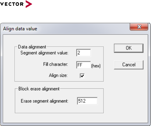
Reference Manual HexView
© 2016 Vector Informatik GmbH Version 1.10.01 43
based on template version 5.1.0
Figure 2-23 Data alignment option
This option ensures, that the start address of all blocks is a multiple of the segment size
alignment value. E.g., if this parameter is 2, then HexView ensures that all addresses are
even (dividable by 2 without remainder). If an odd address is detected, HexView fills bytes
with the “Fill character” at the beginning of a block until the address is even.
If “Align size” is selected, too, the size of all blocks is a multiple of the given segment
alignment value. If a length of a block is not a multiple of the segment align value, a fill
pattern will be added until the size meets this condition.
Some export file formats contain separate address and length information used to specify
the erasable ranges of a flash memory. These address ranges require different alignment
definition. This align value can be specified in the “Erase segment alignment”. It is mainly
used with Ford-VBF and Fiat binary/parameter files. This value can also be specified
through the commandline option /AE.
2.2.2.5 Fill block data
This option provides the ability to fill data regions. This is possible with either random data
or with a pattern that will be added repetitively.
Within the dialog, one or more block ranges must be given. This parameter is used to
generate the block base address and its size.
The overwrite method specifies how to treat the fill data with the existing data. If the new
data overlaps, the new data may overwrite it or will be weaved into the existing data as a
fill pattern.
The data pattern can either be a random data value or can be filled with a given pattern.
Here, you can even specify several ranges, each one separated by ‘:’.
If you push the “Get fill all region” button, the Fill address range will be filled in with the
smallest and largest address of the currently loaded hey data to create a single region file.
With the button “Get Geny block config” you can read the .gny file from geny. Hexview
then tries to load the Flash block configuration for the address ranges. That can be used to
create a test file that fills all known flash blocks for a download.
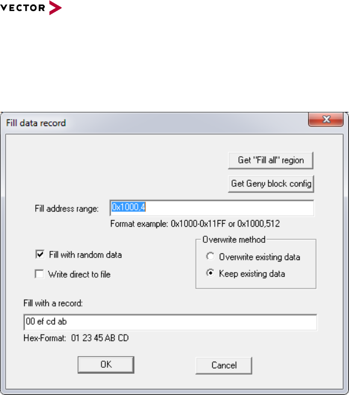
Reference Manual HexView
© 2016 Vector Informatik GmbH Version 1.10.01 44
based on template version 5.1.0
You may have to generate a Document from the GENy-component
“GenTool_GenyPluginConfigDocumentor”. Make sure you have selected the checkbox
(Ignore Default Values).
Figure 2-24 Dialog that allows to fill data
2.2.2.6 Create Checksum
There are two different methods to allow to operate on the data set of the loaded file info:
data processing
checksum calculation.
Data processing operates directly on the data set and change it. The checksum calculation
operates on the data without changing them. The resulting value can be added to the data
set.
The dialog above shows the method to operate on the data. The checksum range can
limit the data section where the checksum calculation operates on. Please note, that you
can specify only one range. If several ranges are specified using the colon separator, only
the first one will be used to limit the data area.
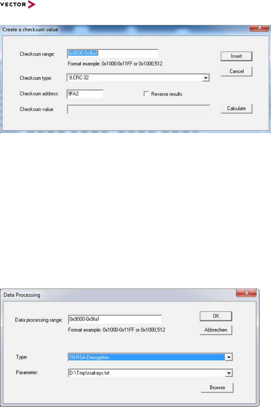
Reference Manual HexView
© 2016 Vector Informatik GmbH Version 1.10.01 45
based on template version 5.1.0
Figure 2-25 Dialog to operate the checksum calculation
The checksum type depends on the capability of the underlying checksum DLL. For the
interfaces, refer to section 4.1. Also, section “Checksum calculation method
(/CS[R]x[:target[;!Forced-range[#fill pattern]][;limited_range][/no_range])” provides further
details on checksum calculation.
The button [Calculate] will run the calculation and shows the result in the field checksum
value. If [Insert] is selected, the checksum calculation will be performed and the result will
be added to the internal data blocks on the given address.
When the checkbox “Reverse results” is selected, the checksum will be inserted in reverse
order, with lowest byte first (“little endianness”).
2.2.2.7 Run Data Processing
The second method that uses the EXPDATPROC.DLL functions is the data processing
field. As already mentioned in the Checksum calculation section, the data processing
directly operates on the internal data. Most of these operations requires a parameter for
this operation. Typically, the resulting data is the manipulated data. Therefore, no result of
the data processing can be inserted or added to the data sections.
Figure 2-26 Dialog for Data Processing

Reference Manual HexView
© 2016 Vector Informatik GmbH Version 1.10.01 46
based on template version 5.1.0
The data processing allows to operate on the data. Typical applications are data
decryption/encryption or compression/decompression.
The string value given in the Parameter field is passed to the routines for the data
processing.
The Data processing range can limit the data range, where the data processing will
operate on. The parameter will be stored in the registry, to retrieve the information the next
time this option is activated. Please note, that you can specify only one range. If several
ranges are specified using the colon separator, only the first one will be used to limit the
data area.
See also section 4.2 for further details on the DLL-interface. Please, read also section
“Run Data Processing interface (/DPn:param[,section,key][;outfilename])” for more details
on available data processing functions.
Some data processing options allow to use a file that contains the parameter. You can
browse for the specific file using the “Browse” button.
Please note that all file references within the data processing operation are relative to the
location of the data file that is currently loaded. So use either full path or use relative paths
related to the location of your input file!
2.2.2.8 Edit/Create OEM Container-Info
This option is currently not available.
2.2.2.9 Remap S12 Phys->Lin
This option is used to remap all blocks from physical paged addressing to the linear
address mode. It is dedicated to be used with HEX-files with paged address information for
the Motorola Star12 (MC9S12 family). The Star12 paged addressing mode uses 24-bit
addresses, where the upper 8-bit specifies the bank address in the range from 0x30 to
0x3F. The lower 16-bit address is the physical bank address in the range from 0x8000-
0xBFFF. These address ranges are shifted to the linear addresses starting from
0x0C.0000 for Bank 0x30 up to the highest address 0xF.FFFF.
The non-banked addresses from 0x4000-0x7FFF and 0xC000-0xFFFF are mapped to the
linear address range of the corresponding pages (0x4000-0x7FFF mapped to 0x0F.8000-
0x0F.BFFF [Bank 0x3E] and 0xC000-0xFFFF mapped to 0x0F.C000-0x0F.FFFF (Bank
0x3F]). See also chapter 3.2.23 for further explanations.
2.2.2.10 Remap S12x Phys->Lin
This option is used to remap all blocks from physical paged addressing to the linear
address mode. It is dedicated to be used with HEX-files with paged address information for
the Motorola Star12X (MC9S12X family). The Star12X paged addressing mode uses 24-
bit addresses, where the upper 8-bit specifies the bank address in the range from 0xE0 to
0xFF. The lower 16-bit address is the physical bank address in the range from 0x8000-
0xBFFF. These address ranges are shifted to the linear addresses starting from 0x78.0000
for Bank 0xE0 up to the highest address 0x7F.FFFF.
The non-banked addresses from 0x4000-0x7FFF and 0xC000-0xFFFF are mapped to the
linear address range of the corresponding pages (0x4000-0x7FFF mapped to 0x7F.4000-
0x7F.7FFF [Bank 0xFD] and 0xC000-0xFFFF mapped to 0x7F.C000-0x7F.FFFF (Bank
0xFF]). See also chapter 3.2.23 for further explanations.
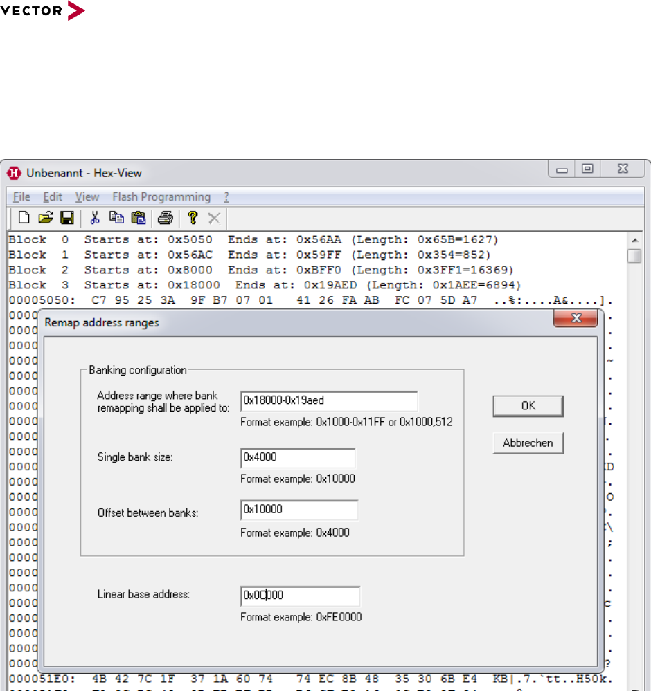
Reference Manual HexView
© 2016 Vector Informatik GmbH Version 1.10.01 47
based on template version 5.1.0
2.2.2.11 General Remapping
This option can be used to remap any banked address information into a linear address
range, e.g. for the Motorola MCS08 or NEC 78k0.
Detailed information about banked and linear addresses can be found in chapter 3.2.23.
Figure 2-27: Configuration window for general remapping
2.2.2.12 Generate file validation structure
This menu item provides a powerful way to generate a validation structure over the
complete download data. The purpose is to generate a list of target address and length
information that can be located at a specific address within the flash memory. The target
location can be used to verify the complete that all download information is available in
your target memory. This validation information must be spared out from this range.
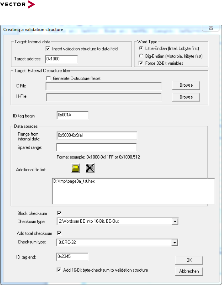
Reference Manual HexView
© 2016 Vector Informatik GmbH Version 1.10.01 48
based on template version 5.1.0
Figure 2-28 Figure 2-29 Generate the validation structure for your target memory.
The following options are available:
Target address:
The fixed address where the validation structure shall be placed into the currently
open file.
External C-structure
A C-file and header will be generated that helps you to access all the individual
elements of the generated structure

Reference Manual HexView
© 2016 Vector Informatik GmbH Version 1.10.01 49
based on template version 5.1.0
Example
Below is an example of the generated C and H-file:
_page3a.h:
/***************************************************************
* Filename: D:\uti\_page3a.h
* Project: Header-File for validation structure
* File created: Tue Mar 11 19:59:54 2014
****************************************************************/
#ifndef ___PAGE3A_H__
#define ___PAGE3A_H__
/* Structure describing a single block info */
typedef struct tVsBlockInfo {
unsigned short blockAddress;
unsigned short blockLength;
unsigned short blockChecksum;
} tVsBlockInfo;
typedef struct tValidateInfo {
unsigned short tagBegin;
unsigned char blockCount;
tVsBlockInfo blockInfo[1];
unsigned long fileChecksum;
unsigned short tagEnd;
unsigned short validateSum;
} tValidateInfo;
/* Extern definition of the data generated structure */
#define VALIDATEINFO_START_SEC_CONST_EXPORT
#include “memmap.h”
extern const tValidateInfo ValidateInfo;
#define VALIDATEINFO_STOP_SEC_CONST_EXPORT
#include “memmap.h”
#endif
_page3a.c:
/****************************************************************
* Filename: D:\uti\_page3a.c
* Project: C-File for validation structure
* File created: Tue Mar 11 19:59:54 2014
****************************************************************/
#include “_page3a.h”
#define VALIDATEINFO_START_SEC_CONST
#include “memmap.h”
const tValidateInfo ValidateInfo = {
0x1234u, /* Magic Tag begin */
2 /* Number of block elements */
,0x9000u, 0xFA2u, 0xE321
,0xA893AF42ul /* Total file checksum*/
,0x4321u /* Magic Tag end */
,0x2F0u /* 16-bit byte-sum on validation area. */};

Reference Manual HexView
© 2016 Vector Informatik GmbH Version 1.10.01 50
based on template version 5.1.0
#define VALIDATEINFO_STOP_SEC_CONST
#include “memmap.h”
Word type:
This specifies the endianness for 16- and 32-bit fields of the generated data
structure.
Force 32-bit variables
If not checked, Hexview will use either 16-bit or 32-bit values, depending on the
length of the largest address in the hex file. When checked, the address and length
values of the validation table will always use 32-bit types.
ID tag begin:
Will be placed at the beginning of the address/length list. This can be used to
uniquely identify if the address/length field is actually present there.
Data source:.
For sure, the internal data of Hexview will be used. A limited range of the data can
be specified. In addition, a range can be specified if an address range shall be
spared out. It could be useful to add also address/length information from other
files. These files can be specified In the file list as well. Hexview will scan the
address/length information and will add it to the list, and also calculate its checksum
if soecified.
Block Checksum:
If checked, Hexview will calculate and add the specified checksum to each
address/length field.
Total checksum:
if checked, a checksum/CRC will be calculated over the complete set of data. This
checksum can be calculated in addition or instead to the block checksum values.
ID tag end:
Here you can specify a magic number that indicates the end of the list. It can be
used to verify if the complete validation list is present.
16-bit byte checksum:
This is a checksum that is generated over the complete validation array. It can be
used in addition to check if the complete validation structure is present.
When generating the data, all parameters will be written to the INI-file. This INI-file can be
used for the commandline option.
2.2.2.13 Run Postbuild
This option allows to scan for postbuild files. Typically, a postbuild file contains address
and length information as well as data information which shall be used to overwrite the
current contents within a hexfile. With Hexview V1.6 and higher it is even possible to
create segment blocks based on the information in a postbuild file.
Note, that the postbuild option is only available if the pbuild.dll is available. After selecting
the item Edit -> Run postbuild, you can select one or more XML files that follows the data
scheme for postbuild. Normally, the postbuild files will be generated by Geny. If you need
further information about the postbuild options, please contact Vector.
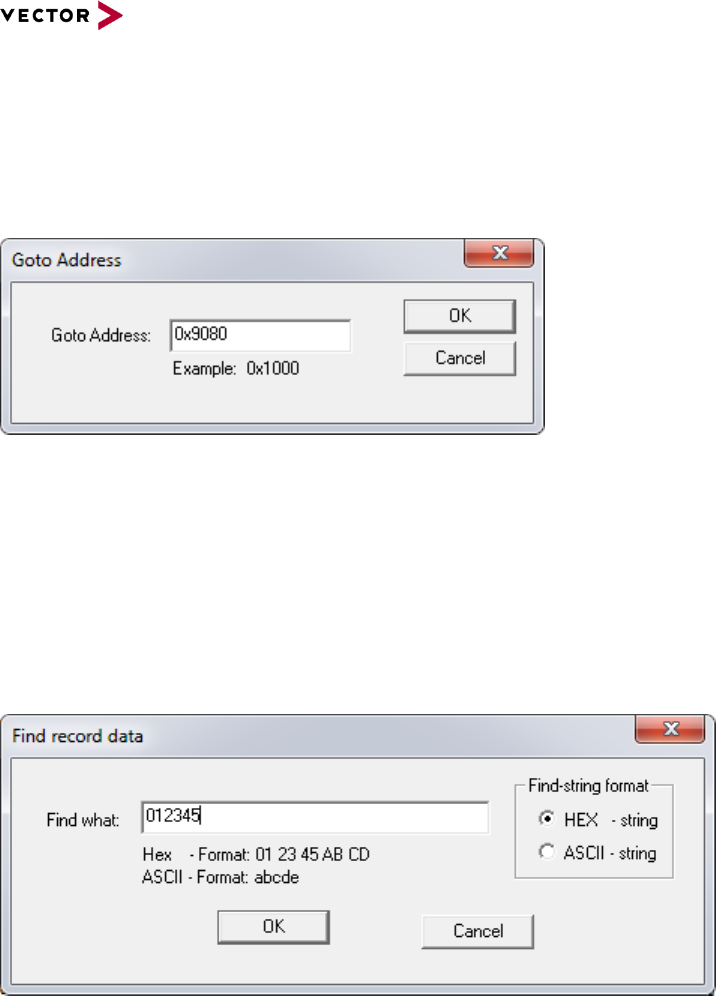
Reference Manual HexView
© 2016 Vector Informatik GmbH Version 1.10.01 51
based on template version 5.1.0
2.2.3 View
This menu item provides some features to control the view.
2.2.3.1 Goto address…
This item allows to jump to a specific address within the view.
Figure 2-30: Jump to a specific address in the display window
If the address is valid, the slider will be moved to the beginning of the address. Thus, the
address information will be shown on the top of the display. The line is not highlighted.
A way to jump to the beginning of an address block can be done by jump to the beginning
of the file (press POS1 or Ctrl-Pageup button)
2.2.3.2 Find record
This option allows to search for a pattern within the file.
Figure 2-31: Find a string or pattern within the document
The format of the pattern can be selected on the right side of the window. By default, the
data pattern is given as a hexadecimal data byte stream. The search algorithm searches
from the beginning until the presence of this pattern is found. HexView tries to display the
value on the top of the screen. If a pattern has been found, the search can be repeated
from the last position where the pattern has been found.
If the “Find-string format” is changed to “ASCII-string”, the pattern entered in “Find what”
will be treated as an ASCII pattern and will search for the ASCII values.
2.2.3.3 Repeat last find
This option is only present after a successful search operation. This item will continue the
search given from “View -> Find record”.
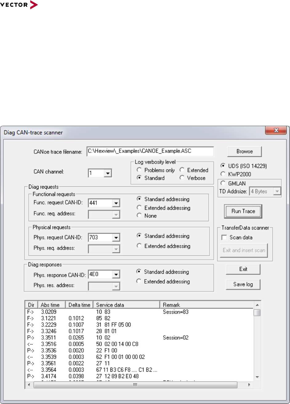
Reference Manual HexView
© 2016 Vector Informatik GmbH Version 1.10.01 52
based on template version 5.1.0
2.2.3.4 View OEM container info
This option was implemented to present some OEM-specific information available in the
file. However, at the moment only the GM header information will be shown.
This may be extended in the future.
2.2.4 Flash Programming
This menu item is directly related to the flash process.
2.2.4.1 Scan CANoe trace log
This menu allows you to backtrace a download of CAN data. You need an ASCII-based log
file from CANoe.
Figure 2-32: Dialog to run a CANoe trace
You need to go through the menu step-by-step. First, you need browse for the CANoe
trace file, which normally has the file extension “.ASC”. Then, select the channel. Hexview

Reference Manual HexView
© 2016 Vector Informatik GmbH Version 1.10.01 53
based on template version 5.1.0
will show the available channel numbers in the list box. Then select the functional and
physical CAN identifier. Also here, Hexview will show you all available CAN IDs found in
the trace file.
Not only UDS downloads are supported, but also KWP2000 and GMLAN. Pre-select the
desired option before running the scan.
Select the checkbox “Scan Data” if the resulting data information shall be scanned and
placed into the memory buffer. Now you can run the trace by clicking on the “Run Trace”
button. An output window like shown above can be seen. Depending on the “log verbosity
level”, more or less information per trace can be seen. The internal Transport layer
analyser will analyse the timing of each service and indicated in the list box. The
information can be stored into a CSV file through the “Save log” button, to further process
this with a spreadsheet.
After finishing the trace you can exit through the “Exit” button. But if you have selected the
“Scan data” checkbox and the trace ran successfully, you can also leave using the “Exit
and insert scan” button. Then, all scanned data will be placed into the memory buffer with
the specified addresses, length and data found in the RequestDownload/TransferData
services.
2.2.4.2 Build ID based EEP download file.
This option is intended to be used to create an address based data file with EEPROM
information. Each segment in the memory represents one entry of an EEPROM block. The
virtual address space shall address a special driver that extracts the block number and
data from each record and writes the data to an EEPROM emulation.
Hexview takes the information from an XML-file with the following format:
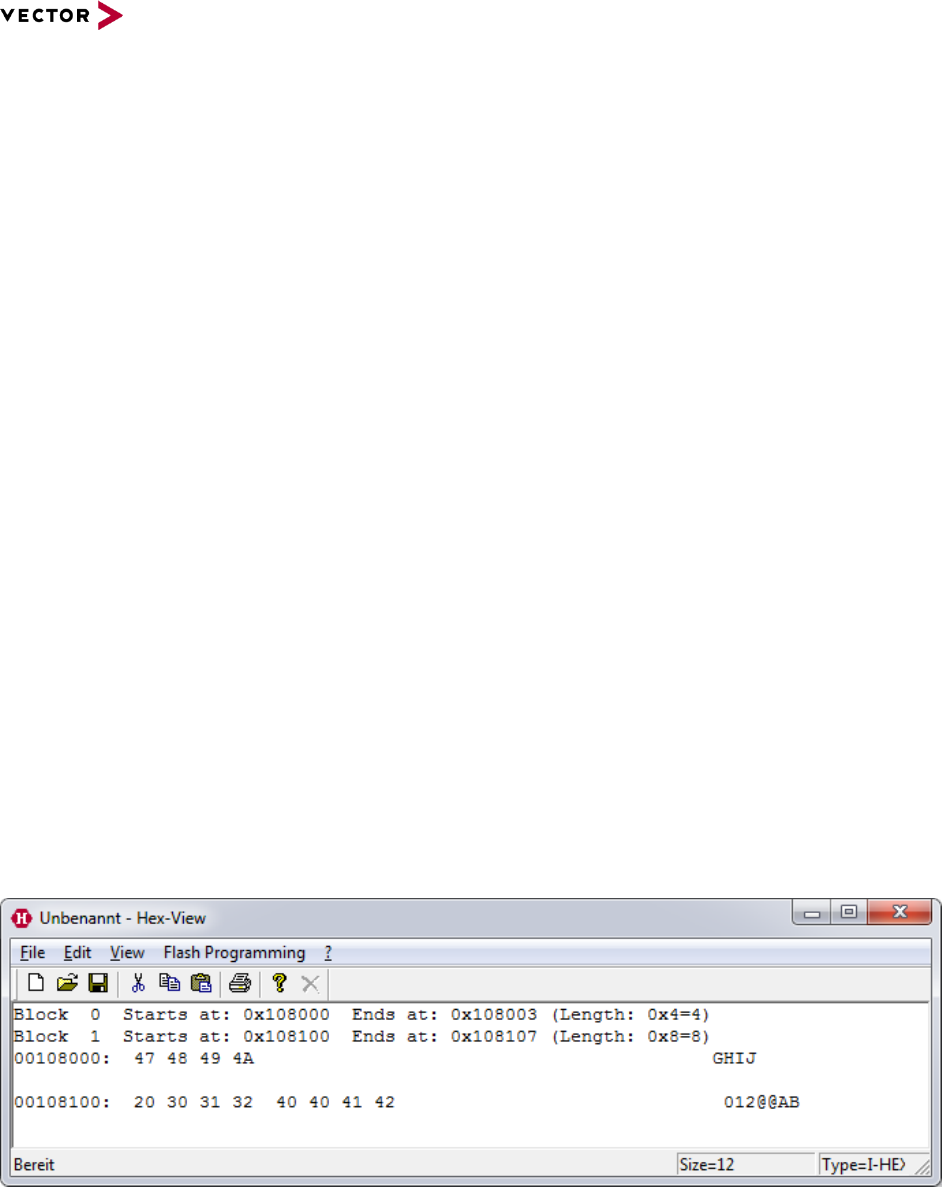
Reference Manual HexView
© 2016 Vector Informatik GmbH Version 1.10.01 54
based on template version 5.1.0
<?xml version=”1.0”?>
<DataFlash>
<AdministrativeSection>
<SectionSize>0x0800</SectionSize>
<Offset>0x0000</Offset>
<VirtualBaseAddress>0x100000</VirtualBaseAddress>
<IdMultiplier>256</IdMultiplier>
</AdministrativeSection>
<Record>
<ID>0x80</ID>
<Length>4</Length>
<Data>
0x47, 0x48, 0x49, 0x4a
</Data>
</Record>
<Record>
<ID>0x81</ID>
<Length>8</Length>
<Data>
0x20, 0x30, 0x31, 0x32,
0x40, 0x40, 0x41, 0x42
</Data>
</Record>
</DataFlash>
Each record consists of its ID, length and data. The block address of a segment will be
created by the formula:
<VirtualBaseAddress> + <IdMultipler> * <ID>
The above example generates the following output:
Figure 2-33: Example output for building ID based download files.
The offset and SectionSize information is not used and just present for compatibility.
2.2.4.3 Scan EepM data section
The EepM is a software component from Vector to emulate EEPROM in data or program
flash. If EepM has written data into a flash memory, it is often difficult to re-trace the block
information. This option is used to provide the possibility to upload the memory contents of
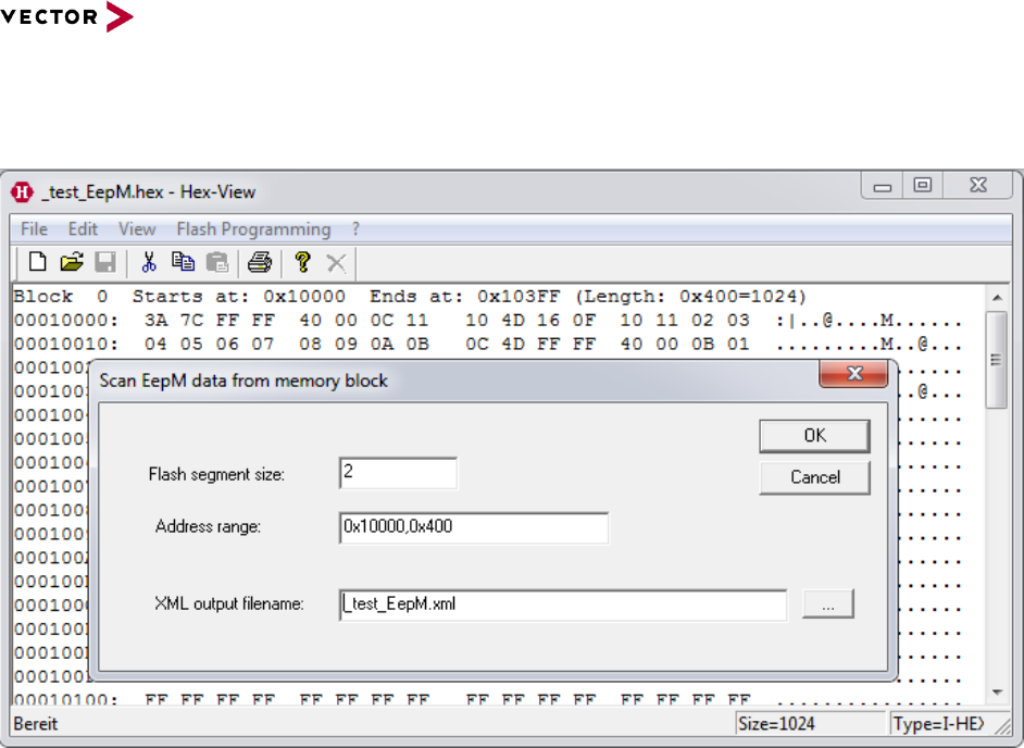
Reference Manual HexView
© 2016 Vector Informatik GmbH Version 1.10.01 55
based on template version 5.1.0
the flash memory into a HEX file and then let Hexview trace back the block number, length
and information and put the results into an XML file.
Figure 2-34: Scan EepM dialog and example
The above picture shows the flash memory data in the background and the dialog for scan
in the foreground. You need to specify the flash segment size (flash sector size, the
minimum write unit of the flash memory), but also specify the range of data and the XML
output file.
If the scan could be executed successfully, an output fiel as shown below can be seen:

Reference Manual HexView
© 2016 Vector Informatik GmbH Version 1.10.01 56
based on template version 5.1.0
<?xml version=”1.0”?>
<DataFlash>
<AdministrativeSection>
<SectionSize>0x2</SectionSize>
<Offset>0x0000</Offset>
<VirtualBaseAddress>0x400</VirtualBaseAddress>
<IdMultiplier>1</IdMultiplier>
</AdministrativeSection>
<Record>
<ID>12</ID>
<Length>17</Length>
<Data>
0x10, 0x4D, 0x16, 0x0F,
0x10, 0x11, 0x02, 0x03,
0x04, 0x05, 0x06, 0x07,
0x08, 0x09, 0x0A, 0x0B,
0x0C
</Data>
</Record>
<Record>
<ID>13</ID>
<Length>17</Length>
<Data>
0x10, 0x4E, 0x17, 0x0D,
0x0E, 0x0F, 0x10, 0x11,
0x02, 0x03, 0x04, 0x05,
0x06, 0x07, 0x08, 0x09,
0x0A
</Data>
</Record>
<Record>
<ID>11</ID>
<Length>1</Length>
<Data>
0xFD
</Data>
</Record>
</DataFlash>
2.2.5 Info operation (?)
This option contains the About information of HexView. It shows the version of the tool and
displays also the copyright information.

Reference Manual HexView
© 2016 Vector Informatik GmbH Version 1.10.01 57
based on template version 5.1.0
2.3 Accelerator Keys (short-cut keys)
Some of the menu items mentioned above can be entered by hotkeys or accelerator keys.
This can be helpful to activate functions from the keyboard without using the menu and the
mouse.
The following table provides a list of available accelerator keys:
Accelerator key
Description
Ctrl+A
Align data
Ctrl+B
Run postbuild configuration
Ctrl+C
Copy data to the internal clipboard
Ctrl+D
Data Processing
Ctrl+F
Find record
Ctrl+G
Goto address
Ctrl+K
Open checksum calculation dialog
Ctrl+L
Opens the fill data dialog
Ctrl+N
File new
Ctrl+O
Open file
Ctrl+P
Print file
Ctrl+S
Save current file
Ctrl+T
Generate validation structure information
Ctrl+V
Paste data into current document
Ctrl+X
Remove data from current document and put
them into the internal clipboard
Alt+A
Export as HEX-ASCII
Alt+B
Export Fiat binary
Alt+C
Export C-Array
Alt+E
Export Ford Intel-HEX format
Alt+F
Export Ford VBF format
Alt+G
Export GM file format
Alt+I
Export Intel-HEX
Alt+L
Export GM-FBL data
Alt+M
Export MIME-Data
Alt+N
Export Binary data
Alt+S
Export S-Record
Alt+V
Export VAG-Data
Alt+Y
Export splitted binary file.
F3
Repeat last find
Alt+F4
Exit application
DEL
Delete a range from the current document
Table 2-4 Accelerator keys (short-cut keys) available in Hexview

Reference Manual HexView
© 2016 Vector Informatik GmbH Version 1.10.01 58
based on template version 5.1.0
3 Command line arguments description
HexView cannot only be used as a PC-program with a GUI to display information. It is also
possible to manipulate the data via command line. There are even some options only
available through command lines.
The following section describes the usage of the command line.
The command line can be grouped roughly into two groups: general options that operates
generally and OEM-related command line options. The OEM command line options control
the generation of files in OEM specific file formats.
3.1 Command line options summary
This section provides a summary of all command line options. An option must start either
with a ‘/’ or a ‘-‘. In this description, a slash is used. The switches are not case-sensitive.
Some options require additional parameter information. Some parameters are followed
directly by the option, some others require a separator. The separator can either be the
equal-sign or a colon.
Hexview infile [options] [-o outfile]
Command line option
Description
Infile
This is the input filename either in Intel-HEX or
Motorola S-Record format
/Ad:xx
/Adyy
Align data. Xx is specified in standard-C
notation, e.g. 0xFF, whereas yy are only hex-
digits. Format is distinguished by the
separator ‘:’ or ‘=’.
/AE:zzzz
Specify AlignErase section size, e.g. for VBF
or Fiat Erase sections aligned to a multiple of
this value.
/AL
Align length.
/Afxx
Specifies the fill character for /AL, /AD and /FA
as hexadecimal value
/Af:xx
Same as above: specifies the fill character for
/AL, /AD, but xx can either be specified as
decimal (no suffix), hex value (0x-suffix) or
binary (b-suffix)
/AR:’range’1
Load a limited range of data.
The ‘range’ is an address range, that can be
specified in two ways: either with start address
and length, separated by a comma, or with
start address and end address, separated by
a minus-sign.
/cdspx:range[;target][:range[;target]]
Expand dsPIC like data from range (0x1000-
0x103ff/0x1000,0x400) to the target address.

Reference Manual HexView
© 2016 Vector Informatik GmbH Version 1.10.01 59
based on template version 5.1.0
Command line option
Description
If target is not specified, the doubled address
(0x2000) will be used (see section “Copy
dsPIC like data”).
/cdsps:range[;target][:range[;target]]…
Same as /cdspx, but it’s the shrink operation
(see section “Copy dsPIC like data”)
/cdspg:range[:range]…
Clear ghost byte in the specified range.
/CR:’range1’:’range2’:…
Cut out data ranges from the loaded file
/CS[R]xx:target[;!forced range[#Fill-pattern]]
[;limited_range]
[/exclude_range1]
[/exclude_range2]
[:target[;limited_range]
[/exclude_range1]
[/exclude_range2]]…
This option specifies the checksum calculation
method. If the optional location parameter is
added, the checksum value is written into this
file. The result can also be placed into the file
using the @ operator.
Note: ‘location’ is a pre-requisit in most cases.
If /CSR is used instead of /CS, the generated
checksum will be inverted (low byte first).
/DLS=AA or /DLS=ABC
This option is used in combination with the
/XG group option to specify the DLS code and
length.
The DLS code can be 2 or 3 characters. A ‘=’
is required between the option and the
characters itself.
Do not use this option for GM cyber security
files.
/DCID=0x8000
/DCID:32238
This option is used in combination with the
/XG group option to specify the DCID code.
The value can be represented in integer or
hexadecimal. In the latter case, a ‘0x’ must
preceed the value. The value is treaded as a
16-bit value and will be added to the header
when creating the GM-header.
Do not use this option for GM cyber security
files.
/DPn:param
Run the data processing interface from
expdatproc.dll. The value ‘n’ specifies the
method, ‘param’ is used as the string
parameter to the DoDataProcessing function
(see section 3.2.8 for parameter details).
/E=errorfile
/e:errorfile
This specifies an error log file. HexView can
run in silent mode. In that case, no error will
be displayed to the GUI. However, error
messages are also suppressed. This option
allows an error report to the file in the silent
mode.
/expdat:<path-to-expdatproc.dll>
/expdat=<path-to-expdatproc.dll>
Specify an alternative path to expdatproc.dll,
e.g. if you want to use your own DLL.
Note: The standard expdatproc.dll functions

Reference Manual HexView
© 2016 Vector Informatik GmbH Version 1.10.01 60
based on template version 5.1.0
Command line option
Description
are then not usable in this session.
/FA
Create a single region file (fill all)
/FR:’range1’:’range2’:… 1
Fill regions.
/FP:11223344
Fill pattern in hex. Used by the /FR parameter
/II2=filename.hex
Special import for 16-bit addressed Intel-HEX
files
/IA:filename[;startAddress]
/IA=filename[;startAddress]
Read Hex data from a file. Startaddress
specifies the address of the block.Cannot be
combined with infile.
/IN:filename[;startAddress]
/IN=filename[;startAddress]
Explicit read of a binary file, no file
interpretation. Cannot be combined with infile.
/L:logfile.log
Load and execute a commandfile
/M:path-to-licensefile
Specify a path to the license.liz file (if not
specified, hexview looks in its own folder).
/MPFH[=cal1.hex+cal2.hex+…]
Special option for /XG. Sets the MPFH flag
and optionally adds the address, length and
DCID-info to the GM-header.
/MPFH must be specified if an existing NOAM-
field shall be re-positioned adjacent to the new
NOAR-field.
Do not use this option for GM cyber security
files.
/MODID:value
Special option for GM-header creation. Sets
the Module-ID for this header.
Do not use this option for GM cyber security
files.
/MO:file1[;offset]
[+file2][;offset]
Merges the file(s) from the filelist into the
memory in Opaque mode (existing data will be
overwritten). The optional offset may be added
to all addresses of the file that is merged.
File names can have wildcards such as ? or *.
/MT:file1
[;offset][:range1]
[+file2][;offset][:range1]
Merges the file(s) or portions of it from the
filelist into the memory in transparent mode
(existing data not overwritten). The optional
offset will be applied to all addresses of the file
that is merged. The range limits the before
the offset
File names can have wildcards such as ? or *.
-o outfilename
Specifies the output filename. The filename
must follow directly the –o option separated
with a blank character.
/P:ini-file
Specifies the path and file for the INI-
information partly used by some conversion
routines.
/PB:”PostbuildXML-file1”;”XML-File2”;…
Applies Postbuild operation to the specified

Reference Manual HexView
© 2016 Vector Informatik GmbH Version 1.10.01 61
based on template version 5.1.0
Command line option
Description
file.
/PN
Add part number to the GM-header. This
option is only useful in combination with /XGC
or /XGCC. The part number must not be
specified and will be taken from the SWMI
value.
Do not use this option for GM cyber security
files.
/remap:BankStartAddress-
BankEndAddress,LinearBaseAddress,BankSize,
BankIncrement
This option was intended to be used for
controllers using a memory banked
addressing scheme. The option calculates
from physical banked addressing to a linear
addressing scheme.
One of the most popular controllers using
banked method, the Star12 and Star12x, is
directly supported with the special option
/s12map resp. /s12xmap (see below).
/swmi:value
Specifies the SWMI parameter when creating
the GM-header
Do not use this option for GM cyber security
files.
/s
Run HexView in silent mode.
/s08map
Re-maps the physical address spaces of the
Freescale Star08 to its linear address spaces,
e.g. maps segments in the range of 0x4000-
0x7FFF to 0x104.000 or from 0x02.8000-
0x02.BFFF to 0x10.8000-0x10.BFFF and so
on.
/s12map
Re-maps the physical address space to the
linear address space of the Freescale Star12
to its linear address spaces, e.g. maps
segments in the range of 0x4000-0x7FFF to
0xF8000 or from 0x308000-0x30BFFF to
0xC0000-0xC3FFF and so on.
/s12xmap
Re-maps the physical address space to the
linear address space of the Freescale Star12x
to its linear address spaces, e.g. maps
segments in the range of 0x4000-0x7FFF to
0x7F4000-0x7F7FFF or from 0xE08000-
0xE0BFFF to 0x780000-0x783FFF and so on.
/sb:maxblocksize
Splits a block into pieces if the size exceeds
maxblocksize.
/swapword
Swaps the byte on an even address with its
successor. AA BB becomes BB AA.
/swaplong
Swaps 4 bytes on longword addresses. AA BB
CC DD becomes DD CC BB AA
/tms570-parity
Generates the parity data for the TMS570

Reference Manual HexView
© 2016 Vector Informatik GmbH Version 1.10.01 62
based on template version 5.1.0
Command line option
Description
flash file
/tms570-ECC
Generates the ECC data for the TMS570 flash
file.
/v
Writes the Hexview version string into the
error log file.
/vs
Create validation structure. All necessary
information are provided through an INI-file.
See section 3.2.24 for further details.
/XA[:Linelen[:ExportSeparator]]
Exports the data as HEX ASCII data. Use
doublequotes if separator shall contain
spaces.
Since 1.10.01 the linelen can also be entered
in HEX. Long values are also accepted. To
use single line outputs, a very long linelen can
be used, e.g. 0xffffffff.
/XB
Outputs the data in the Fiat binary format
including the PRM- and BIN-file .
/XC
Outputs the data into a C-like array. All
configuration options are provided through an
INI-file.
/XF
Exports data in the Ford-HEX specific file
format. Adds the Ford header information and
data in an Intel-HEX like file format.
/XGAC
Exports data into a GAC binary file format.
The data information will be taken from an INI-
file. Address and length information will be
added accordingly.
/XGACSWIL
Like the /XGAC export option, but the
address/length information will not be added.
Typical use-case for the SWIL (software
interlock).
/XG[:header-address]
Completes the information in an existing GM-
header
/XGC[:header-address]
Generates the GM-file header and completes
the information.
/XGCC[:header-address]
Generates the header information for a single-
region calibration file.
/XGCS
Generates the header, but with a 1-byte HFI
information (backward compatibility with
previous “SAAB”-specific header).
/XGC_APP_PLAIN
/XGC_APP_SIGN
/XGC_CAL_PLAIN
/XGC_CAL_SIGN
/XGC_SIGN_CMPR[:DataType[:DictCoding]]
Generate the GM file header applicable for
GM Cyber security.
/XML:xml-file
Specifies an XML file used for some additional

Reference Manual HexView
© 2016 Vector Informatik GmbH Version 1.10.01 63
based on template version 5.1.0
Command line option
Description
command options (mainly for the new GM
header generation)
/XGMFBL
Exports the GM-FBL XML-data file
/XI[:reclinelen[:rectype]]
Exports in Intel-HEX format
/XK
Outputs the data into an FKL-file for CCP/XCP
kernel
/XN
Exports data into the binary file format
/XP
Exports data into a single region binary file
and appends a checksum. Typically used by a
Porsche download (KWP2000).
/XS[:reclinelen[:rectype]]
Exports in Motorola S-Record format
/XSB
Export each section of a hex file into a binary
file. The start address of the block is used as a
postfix for the binary name.
/XV
Outputs the VAG-compatible SGML file
format.
/XVBF
Generates the Ford-specific VBF file format.
All parameters are specified through an INI-
file.
Table 3-1 Command line options summary
1 A range defines a section area. It can be entered in two ways, either with start address
and length or with start address and end address. Examples are: “0x1000,0x200” or
“0x1000-0x11FF”. Both parameters span the same range and will be treated the same
way. Note that the end address must be higher than the start address. Values are
accepted as binaries, integer, hex or octal with C-like pre- or postfixes.
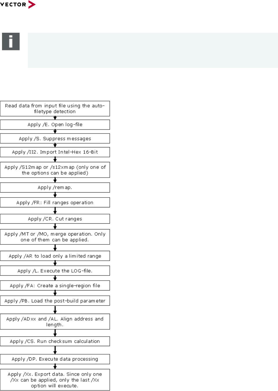
Reference Manual HexView
© 2016 Vector Informatik GmbH Version 1.10.01 64
based on template version 5.1.0
Note
Parameter /Xx cannot be combined. /Xx can be specified only once in the parameter
list.
/Mt and /MO cannot be combined as well.
3.2 General command line operation order
Figure 3-1 Order of commandline operations within Hexview.

Reference Manual HexView
© 2016 Vector Informatik GmbH Version 1.10.01 65
based on template version 5.1.0
The commandlines can be specified in any order. Hexview will first summarize the
commandline operations and will then execute them. Since some operations may have
influences to subsequent operations, the commandline operation sequence within hexview
is important to know. The following commandline sequence will be applied (if specified):
This section describes command line options of HexView, that can be used in general.
There is no restriction or limitation in the combination of the options (as long as they are
useful).
3.2.1 Align Data (/ADxx or /AD:yy)
The start address of each block will be aligned to multiples of the given parameter xx. If
the separator ‘:’ or ‘=’ is omitted, the parameter xx is a hexadecimal value. If the separator
is used, the value xx is interpreted in C-style, e.g. /AD:0xFF is the same as /AD:255 or
/AD:11111111b. This value can only be an unsigned char value.
Example
/AD2
Aligns address to be a multiple of 2.
If a block starts at 0xFE01 a fill byte will be inserted at 0xFE00. The inserted character
will be 0xFF by default. The default character can be overwritten with the /AF
parameter.
An address starting at 0xE000 will be left unchanged. No characters are inserted.
/AD:0x80
Align the addresses of all sections to a multiple of 128
If an address starts at e.g. 0xE730, the address will be aligned to 0xE700.
3.2.2 Align length (/AL[:length])
This option is useful in combination with the /AD parameter. It aligns also the length of all
blocks to be a multiple of the parameter given in the /Adxx option. The option corresponds
to the “Align size” option in section 2.2.2.4: “Data Alignment”.
Example
/AD4 /AL
A block 0xE432-0xE47E will be aligned to 0xE430-0xE47F. All characters will be filled
with 0xFF or the value specified by /Afxx.
3.2.3 Specify erase alignment value (/AE:xxx)
This parameter specifies the erase alignment parameter. This value is used to align data
blocks that specifies erase blocks for certain output file formats for Ford and Fiat.

Reference Manual HexView
© 2016 Vector Informatik GmbH Version 1.10.01 66
based on template version 5.1.0
Example
/AE:0x200
Erase blocks are always aligned to multiples of 0x200
3.2.4 Specify fill character (/AF:xx, /AFxx)
This option specifies the fill character used for the align options (/AL, /AD or /FA). If the fill
parameter is located directly after the option, it is treaded as a hex-string. If the parameter
is separated by a colon, the parameter must use the C-convention for characters, e.g.
0xCC for hexadecimal values.
Important: Distinguish if a colon or equal-sign is in-between the option field or not. If the fill
value follows directly the /AF option, then xx is always treated as HEX value. If you put a
colon or equal in-between, it can be either dec, hex or binary like “128dec”, “0xAAhex” or
“b01001100bin”. Thus, /AFdd is the same as /AF:0xdd or /AF:221,.
This option corresponds to the “Fill character” in section 2.2.2.4: “Data Alignment”.
Example
/AF:0xEF
Fill character is 0xEF
/AFCD
Fill character is 0xCD
3.2.5 Address range reduction (/AR:’range’)
This option can limit the range of data to be loaded into the memory. This is useful if only a
reduced range of data shall be processed within HexView.
An address range is specified by its block start address and its length. Address and length
are separated by a comma. You can also specify the range with the start and end
address. Then, the two values must be separated by ‘-‘.
Example
/AR:0x1000,0x200
Only the data between 0x1000 and 0x11FF are loaded to the memory and then further
processed.
/AR:0x7000-0x7FFF
This loads the data from 0x7000 to 0x7FFF
3.2.6 Cut out data from loaded file (/CR:’range1[:’range2’:…]
The parameter option /CR is used to cut out a range from the loaded data file. It removes
any data within the specified ranges. More than one range can be specified. Each range
must be separated by a colon ‘:’.
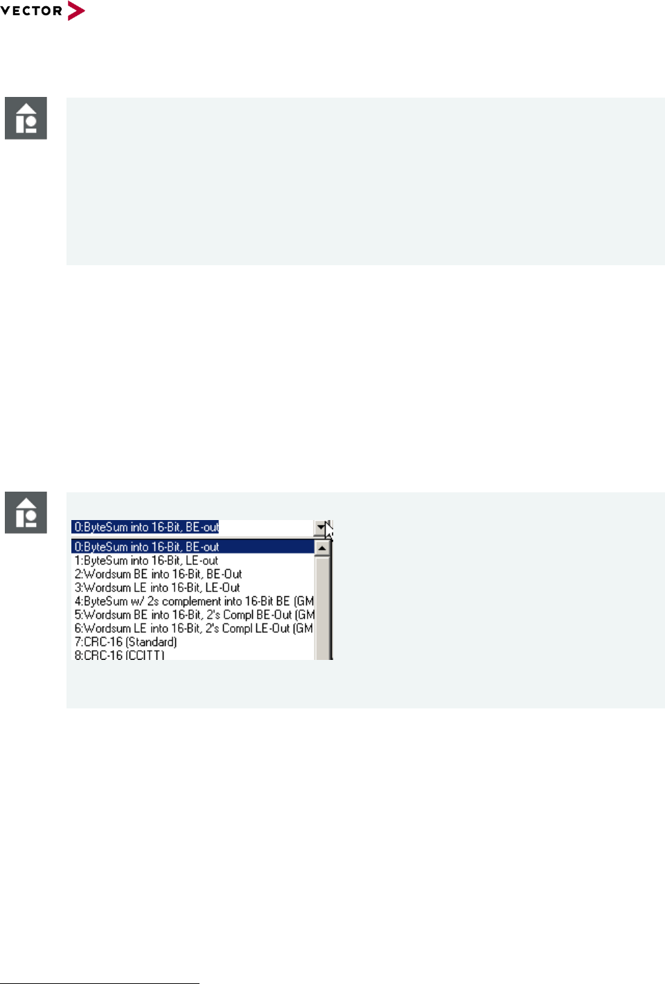
Reference Manual HexView
© 2016 Vector Informatik GmbH Version 1.10.01 67
based on template version 5.1.0
Example
/CR:0x1000,0x200
If a data section in the range from 0x1000-0x11FF exist, the data will be removed from
the file. All successive operations will operate on data that don’t include this section. All
other sections remain unchanged. If this section is located within a segment or block, it
will be splitted into two.
/CR:0x7000-0x7FFF
This removes the data from 0x7000 to 0x7FFF if present.
3.2.7 Checksum calculation method (/CS[R]x[:target[;!Forced-range[#fill
pattern]][;limited_range][/no_range])
This option is used to specify the checksum calculation method provided by the checksum
calculation feature. The checksum calculation
When using, The parameter x in the option /CSx denotes the index to the checksum
calculation algorithm. The function in the EXPDATPROC.DLL will be called that
corresponds to this parameter value. The index can be calculated by counting the list of
checksum methods in the checksum dialog starting with index 0
1
.
Example
Figure 3-2 Example on how to select the checksum calculation methods in the “Create Checksum” operation
1
Newer versions of expdatproc.dll (V1.3 and higher) shows the function index in the dialog.

Reference Manual HexView
© 2016 Vector Informatik GmbH Version 1.10.01 68
based on template version 5.1.0
Example
/CS6:csum.txt
Runs the checksum calculation method “Wordsum LE into 16-Bit, 2’s Compl LE-Out
(GM new style)” and writes the results into the file CSUM.TXT.
This example uses the checksum method “Wordsum LE into 16-Bit, 2’s Compl LE-Out
(GM new style)”, as this is the 7th option in the checksum dialog menu shown above.
/CS1:@append;0x1000-0x7FFF or /CS1:@append;0x1000,0x7000
Runs the checksum calculation method “Bytesum into a 16-Bit LE-out” and appends
the checksum at the very end of the internal file. The checksum is calculated over the
limited range from 0x1000-0x7FFF as specified.
A range within the checksum range can be excluded, if for example a data array shall
not be used for checksum calculation, Such an excluded range can be specified with a
preceding ‘/’.
/CS7:@upfront;0x2000-0x3fff/0x2800-0x29ff/0x3000,0x200
The option above calculates the checksum using method 7 (the 8th) on data within the
range from 0x2000-0x3ffff. The range from 0x2800-0x29ff and 0x3000-0x31ff will be
excluded for the checksum calculation. The exclude has no effect to the real data. The
result of the checksum calculation will be written before the very beginning of the file
data (Note: it will be written not upfront to 0x2000, but to the very beginning of the
loaded file. This applies to all other labelled address specifier, such as ‘upfront’, ‘begin’
and ‘append’).
/CS4:@0xFFFC;!0x01000-0xFFFFF#FF
It might be useful to calculate the checksum over a range of pre-filled data that do not
exist in the internal data representation. A command can be given to calculate the
checksum also over this range. This feature is only available through the commandline
interface. For example, if the checksum shall be calculated over the range of 0x0.1000-
0xF.FFFF which is pre-filled with the pattern FF, a checksum can be calculated over the
existing data including the specified range.
With HexView version V1.2.0 and higher, the results of the checksum can now also be
written into an output file or placed into a location within the internal data. The location is
separated by a ‘:’ or ‘=’ sign, followed by the target where the resulting checksum value
shall be placed in. The example above shows how to write the results of the checksum
calculation into the file “csum.txt”.
The following target IDs can be used:
Filename (e.g. csum.txt)
Writes the result into a file. The value is
written from high to low byte in hexadecimal
form. Each byte is separated by a comma.
@append
The results of the checksum will be added at
the very end of the file.

Reference Manual HexView
© 2016 Vector Informatik GmbH Version 1.10.01 69
based on template version 5.1.0
@begin
Writes the contents at the very beginning of
the file.
Important Note: It will overwrite the first bytes
of your data. The number of bytes that will be
overwritten depends on the checksum
method.
@upfront
Write the checksum results prior to the
beginning of the first block. No data will be
overwritten.
@end
Places the checksum on the last bytes of the
last section of the file. The address is
automatically calculated.
Important Note: It will overwrite the last bytes
of your data. The number of bytes that will be
overwritten depends on the checksum
method.
@0x1234
Writes the checksum result into the address
location given after the @ operator.
Caution
Whenever using the @ operator to write the results into the file, make sure that the
checksum is at the proper location and is not overwriting accidentally any imported
data!
Table 3-2 Checksum location operators used in the commandline
Since Hexview V1.10.01 the parameter /CSR can be used which accepts the parameter in
the same way as /CS does. The only difference is, that /CSR reverses the output to ‘little
endian’ instead of ‘big endian’.
The available checksum methods depends on the expdatproc.dll. Version 1.05.00 of the
DLL provides the following methods:
0
ByteSum into 16-Bit, BE-out
Sums the bytes of all segments into a
16-bit value. The result is a 16-Bit
value in Big-Endian order (high byte
first).
1
ByteSum into 16-Bit, LE-out
Sums the bytes of all segments into a
16-bit value. The result is a 16-Bit
value in Little-Endian order (low-byte
first)
2
Wordsum BE into 16-Bit, BE-Out
Sums the data of every segment as
16-bit words. The result is a 16-bit
value.
The input stream is treaded as big-
endians (high-byte first), the 16-bit
checksum result is given in big-

Reference Manual HexView
© 2016 Vector Informatik GmbH Version 1.10.01 70
based on template version 5.1.0
endian format (high-byte first).
Note that this routine requires aligned
data. The number of bytes per
segment and the start address of
each segment must be a multiple of
two. If not, Hexview/expdatproc will
generate the errors “Base address
mis-alignment” or “Data length mis-
alignment”
3
Wordsum LE into 16-Bit, LE-Out
Same as above, but the data are
treaded as 16-bit values with low byte
first. The 16-bit result is also stored
with low-byte first
4
ByteSum w/ 2s complement into 16-Bit BE (GM
old-style)
Each byte of the segments are
complemented with its 2’s
complement and then added to a 16-
bit sum value. The result is stored in
big-endian format (high-byte first).
5
Wordsum BE into 16-Bit, 2's Compl BE-Out (GM
new style)
Sums the data of every segment as
16-bit words. The result is the 2’s
complement of the 16-bit sum.
The input stream is treaded as big-
endians (high-byte first), the 16-bit
checksum result is given in big-
endian format (high-byte first).
Note that this routine requires aligned
data. The number of bytes per
segment and the start address of
each segment must be a multiple of
two. If not, Hexview/expdatproc will
generate the errors “Base address
mis-alignment” or “Data length mis-
alignment”
6
Wordsum LE into 16-Bit, 2's Compl LE-Out (GM
new style)
Same as above, but the input data is
managed in little-endian format. The
result is also given as 16-bit little-
endian.
7
CRC-16 (Standard)
Calculation of a CRC-16 using the
polynomial:
215+214+27+26+20 ($C0C1)
8
CRC-16 (non-standard)
This is a 16-bit checksum algorithm
that can easily implemented in a
microcontroller. The used algorithm is
as follows:
CS = 0xffff; // pre-initialize CS
Foreach 8-bit data byte do
Swap(CS) // swap upper and lower
bytes

Reference Manual HexView
© 2016 Vector Informatik GmbH Version 1.10.01 71
based on template version 5.1.0
CS = CS XOR data-byte
CS = CS XOR ((CS AND 0xFF) SHR
4)
CS = CS XOR ((CS SHL 8) SHL 4)
CS = CS XOR (((CS AND 0xFF) SHL
4) SHL 1)
Endeach
CS = NOT CS // Inverse CS after
operation
9
CRC-32
Calculation of the CRC-32 according
to IEEE, using the polynomial:
0x04C11DB7. The start value is
0xFFFFFFFF.
The result is inverted.
10
SHA-1 Hash Algorithm
Creating a 20-byte hash value based
on the SHA-1 algorithm.
11
RIPEMD-160 Hash Algorithm
Dto for RIPE-MD 160
12
Wordsum LE into 16-Bit, 2's Compl BE-Out (GM
new style)
Same as method 6, but the resulting
16-bit value will be represented as
16-bit big-endian.
13
CRC-16 (CCITT) LE out
16-Bit CRC using the non-reflected
CCITT polynomial with start value
0xFFFF:
212 + 25 + 20 ($1021)
The function returns the 16-bit
checksum in Little-Endian format
(low-byte first)
The start value is 0xFFFF.
The result is inverted.
14
CRC-16 (CCITT) BE out
Same as method 13, but result is in
Big-Endian format.
15
MD5 Hash algorithm
The MD5 has value.
16
Constant expression
Doesn’t calculate a checksum but
places a constant string to the
specified location. The constant is
taken from an INI-file with the name
“expdatproc.ini” located in the same
folder as the HEX file. The INI-file
must have the following format:
[constant]
NumBytes=8
HexDataString=0123456789ABCDEF
17
CRC16 CCITT LE-Out
Sames as method 13, but with start
value 0.
18
CRC16 CCITT BE-Out
Same as method 17, but in big-

Reference Manual HexView
© 2016 Vector Informatik GmbH Version 1.10.01 72
based on template version 5.1.0
endian output format.
19
SHA-256 Hash Algorithm on Address, length and
data
This method builds the hash value
with SHA-256 including the block
address and length.
Note: RIPEMD-128 is discontinued
since V2.0 of this DLL.
20
SHA-256 Hash Algorithm
Build the Hash value on the data
using SHA-256.
Table 3-3: Functional overview of checksum calculation methods in “expdatproc.dll”
3.2.8 Run Data Processing interface (/DPn:param[,section,key][;outfilename])
This option will run the data processing interface. This method is called right before the
data export commands are executed.
The parameter ‘n’ specifies the method. The value ‘n’ can be calculated in a similar way to
the checksum calculation method. The number can be found from the list box in the Edit-
>Run Data processing” option dialog. Count the number of entries in this dialog starting
from 0. The number of processing methods depends on the EXPDATPROC.DLL.
Some of the data processing interface functions may take over useful (optional)
parameters. This parameter is separated by a colon directly after the command line option.
The RSA operation also accepts PKCS#1 and PKCS#8 files without password. Public keys
can also be extracted from common X.509 certificates.
Examples
HexView testfile.dat /DP1:CC
This option runs the second data processing method in the list. It passes the parameter
string “CC” to the function.
Hexview testfile.dat /dp11:00112233445566778899aabbccddeeff;RFC1321#IV=0
This command encrypts a file using AES128 in CBC-mode. The initialization vector is 0
and the padding mode according to RFC1321 is applied.
The EXPDATPROC that comes with this delivery of Hexview can manage the following
data processing methods:
ID
Name
Description
Parameter
0
No action
Does no modification on
the data
-
1
XOR data with byte
parameter
Runs XOR operation on
the data
If no parameter is given, all data
will be inverted (XOR by 0xFF).
Otherwise, it will run a byte-wise
operation with a HEX-string
passed as parameter.
2
AES-ECB encryption
Encrypts the data with the
AES standard encryption
A 16/24 or 32 byte hex string
00112233445566778899aabbcc

Reference Manual HexView
© 2016 Vector Informatik GmbH Version 1.10.01 73
based on template version 5.1.0
ID
Name
Description
Parameter
method.
(This represents the HIS
security class AAA).
Selection of AES-128/AES-
196 or AES-256 selected
by the key length.
ddeeff[;padding method]
Padding at the end of the block
is optional. The following
padding methods are accepted:
- PKCS7
- RFC1321
- ANSIX.923
Example: /DP2:
00112233445566778899
aabbccddeeff;PKCS7
3
AES-ECB decryption
Decrypts data with the
AES-ECB method
A 16/24 or 32 byte hex string
00112233445566778899aabbcc
ddeeff[;padding method]
Use the same padding method
for decryption to reconstruct the
original size of the block.
4
HMAC (ANSI-X9.71)
with SHA-1
Creates a signature based
on Runs the HMAC using
SHA-1.
By default, the signature is
written to a file
signd_sha1.txt.
The key-parameter as HEX-
string or an ASN-formatted string
The ASN-string must be
preceeded by the tag bytes
FF59 or FF5B.
Example: /dp:mykeyfile[;outfile]
/dp:647262756473[;outputfile]
5
HMAC /w SHA-1 on
addr+len+data
Creates a signature based
on HMAC using SHA-1
including the address and
length information for each
segment
By default, the signature is
written to the file
signdal_sha1.txt.
This is security class C.
The key-parameter as HEX-
string or an ASN-formatted
string.
The ASN-string must be
preceeded by the tag bytes
FF59 or FF5B
Example: /dp:mykeyfile[;outfile]
/dp:647262756473[;outputfile]
6
HMAC (ANSI-X9.71)
with RIPEMD-160
Creates a signature based
on HMAC using
RIPEMD160 including the
address and length
information for each
segment.
By default, the signature is
written to the file
SignD_Ripemd160.HMAC.
The key-parameter as HEX-
string or an ASN-formatted
string.
The ASN-string must be
preceeded by the tag bytes
FF59 or FF5B
Example: /dp:mykeyfile[;outfile]
/dp:647262756473[;outputfile]
7
HMAC /w RIPEMD-160
on addr+len+data
Creates a signature based
on HMAC using
RIPEMD160.
By default, the signature is
written to the file
SignDAL_Ripemd160.HMA
C
The key-parameter as HEX-
string or an ASN-formatted
string.
The ASN-string must be
preceeded by the tag bytes
FF59 or FF5B
Example: /dp:mykeyfile[;outfile]

Reference Manual HexView
© 2016 Vector Informatik GmbH Version 1.10.01 74
based on template version 5.1.0
ID
Name
Description
Parameter
This is security class C..
/dp:647262756473[;outputfile]
8
RSA-Signature /w SHA-
1 on data
Creating the hash-value
using the SHA-1 algorithm
the data (only) for every
segment and encrypt the
result with the RSA
algorithm. By default, the
output is written to
SignD_SHA1.RSA.
The private key as an ASN
formatted string. The string must
be preceeded by the tag FF49 or
FF4B. The tag for the exponent
is 0x91 and the tag for the
modulo is 0x81.
Example: /dp:mykeyfile[;outfile]
Note: Signature follows the
EMSA-PKCS1-v1_5 format.
9
RSA-Signature /w
RIPEMD160 on
Addr+Len+Data
Creating the hash-value
using the RIPEMD160
algorithm on address,
length and data for every
segment and encrypt the
result with the RSA
algorithm. By default, the
output is written to
SignDAL_RIPEMD160.RS
A.
This is security class CCC.
The private key as an ASN
formatted string. The string must
be preceeded by the tag FF49 or
FF4B. The tag for the exponent
is 0x91 and the tag for the
modulo is 0x81.
Example: /dp:mykeyfile[;outfile
Note: Signature follows the
EMSA-PKCS1-v1_5 format.
10
RSA-Signature /w SHA-
1 on Addr+Len+data
Creating the hash-value
using the RIPEMD160
algorithm on address,
length and data for every
segment and encrypt the
result with the RSA
algorithm. By default, the
output is written to
SignDAL_SHA1.RSA
This is security class CCC.
The private key as an ASN
formatted string. The string must
be preceeded by the tag FF49 or
FF4B. The tag for the exponent
is 0x91 and the tag for the
modulo is 0x81.
Example: /dp:mykeyfile[;outfile]
Note: Signature follows the
EMSA-PKCS1-v1_5 format.
11
AES-CBC Encryption
Encrypts the data with AES
in CBC-mode using an
initialisation vector (IV).
The IV will be taken from the first
16 bytes of the data stream. The
data for the IV will be skipped for
encryption operation.
The IV can also be defined
explicitly in the parameter field
separated by the Hash sign.
Example:
“/dp11:00112233445566778899a
abbccddeeff;RFC1321#IV=ABC
D”
IV=0 sets the IV explicitly to 0.
remaining values will be set to 0
by default. Use a 32 char hex
string if you want to define a
complete and explicit vector.
See option 2 for further
description.

Reference Manual HexView
© 2016 Vector Informatik GmbH Version 1.10.01 75
based on template version 5.1.0
ID
Name
Description
Parameter
12
AES-CBC Decryption
Counter operation of AES-
CBC Encryption.
See operation #11 for further
description.
13
HMAC (ANSI-X9.71)
with MD-5"
Calculating the Hash-MAC
based on MD5
The key-parameter as HEX-
string or an ASN-formatted string
The ASN-string must be
preceeded by the tag bytes
FF59 or FF5B.
Examples:
/dp:mykeyfile[;outputfile]
/dp:6472A275D73[;outputfile]
14
HMAC /w MD-5 on
addr+len+data
Same as #13, but also
including address and
length of each block to the
hash value.
The key-parameter as HEX-
string or an ASN-formatted string
The ASN-string must be
preceeded by the tag bytes
FF59 or FF5B.
Example:
/dp:mykeyfile[;outfile]
/dp:647262756473[;outputfile]
15
RSA-Signature /w MD5
on data
Creating the hash-value
using the MD5 algorithm
the data (only) for every
segment and encrypt the
result with the RSA
algorithm. By default, the
output is written to
SignD_MD5.RSA.
The private key as an ASN
formatted string. The string must
be preceeded by the tag FF49 or
FF4B. The tag for the exponent
is 0x91 and the tag for the
modulo is 0x81.
Example: /dp:mykeyfile[;outfile]
Note: Signature follows the
EMSA-PKCS1-v1_5 format.
16
RSA-Signature /w MD5
on Addr+Len+data
Creating the hash-value
using the MD5 algorithm on
address, length and data
for every segment and
encrypt the result with the
RSA algorithm. By default,
the output is written to
SignDAL_MD5.RSA
The private key as an ASN
formatted string. The string must
be preceeded by the tag FF49 or
FF4B. The tag for the exponent
is 0x91 and the tag for the
modulo is 0x81.
Example: /dp:mykeyfile[;outfile]
Note: Signature follows the
EMSA-PKCS1-v1_5 format.
17
RSA Encryption (Public
key operation)
Encrypt data using the
public RSA key.
Example: /dp:mykeyfile.
Note: The type of operation
depends on the length of input
data. If the length is not a
multiple of the keylength, data
will padded as block type 02
according to PKCS#1, V1.5. If
the length is a multiple of
keylength, a plain RSA operation
will be performed.
RSA-512/1024/1536 and 2048
are supported. Operation

Reference Manual HexView
© 2016 Vector Informatik GmbH Version 1.10.01 76
based on template version 5.1.0
ID
Name
Description
Parameter
derived from length of modulo.
Do not encrypt files longer than
RSA-bit size.
18
RSA Decryption (Private
key operation)
Decrypt data using the
private RSA key.
Example: /dp:mykeyfile.
Note: Data length is expevted to
be a multiple of keylength. First,
decryption of PKCS#1, V1.5 BT
02 is tried. If this fails, a plain
decryption is performed.
19
LZ Vector data
compression (0)
LZSS with Vector specific
coding of compressed
data.
This is the default and
preferred algorithm!
Uses 8 bits for sliding window
and 4 bits for repeated
characters
20
LZ Vector data
compression (1)
LZSS with Vector specific
coding of compressed
data.
Uses 9 bits for sliding window
and 4 bits for repeated
characters
21
LZ Vector data
compression (2)
LZSS with Vector specific
coding of compressed
data.
Uses 12 bits for sliding window
and 6 bits for repeated
characters
22
LZ Vector data
decompression (0)
LZSS decompression of
Vector specific method
Counter operation of #19
23
LZ Vector data
decompression (1)
LZSS decompression of
Vector specific method
Counter operation of #20
24
LZ Vector data
decompression (2)
LZSS decompression of
Vector specific method
Counter operation of #21
25
RSA-RIPEMD sign.
A+L+D /w Vector data
compression (0)
Calculates the hash with
RIPEMD-160 with address
and uncompressed length
over compressed data,
encrypts the signature
using RSA-1024 and writes
the result to the signature
file. Outputs compressed
data. Thus, signature and
compression is done in one
step.
This is the only way to add
address and uncompressed
length to the signature while
compressing the file at the same
time. The uncompressed
memory size is transferred in
RequestDownload and added to
the hash value. Input parameter
like in operation #9.
It can fulfull Security class CCC
w/ compression.
This method is not needed when
using “LifeCompression”
26
LZSS data compression
(10Bit/4Bit acc. Ford-
SWDL005)
This is a pure LZSS
compression with bit coded
value of plain text or
repeated data.
Sliding window is 10 bit length,
repeat character is 4 bits.
27
LZSS data
decompression
(10Bit/4Bit acc. Ford-
SWDL005)
The LZSS decompression
algorithm
Counter operation of #26.

Reference Manual HexView
© 2016 Vector Informatik GmbH Version 1.10.01 77
based on template version 5.1.0
ID
Name
Description
Parameter
28
RSA-Signature /w
RIPEMD160 on Data
RSA signature without
address and length info.
Like e.g. in operation #9.
29
HMAC-RIPEMD sign.
A+L+D /w Vector
compression (0)
Calculates the hash with
RIPEMD-160 with address
and uncompressed length
over compressed data,
encrypts the signature
using RSA-1024 and writes
the result to the signature
file. Outputs compressed
data. Thus, signature and
compression is done in one
step.
This is the only way to add
address and uncompressed
length to the signature while
compressing the file at the same
time. The uncompressed
memory size is transferred in
RequestDownload and added to
the has value. Input parameter
like in operation #9. It can fulfull
Security class C w/
compression.
This method is not needed when
using “LifeCompression”
30
HMAC-SHA256
Calculate the Hash MAC
with SHA256
Segment address and length is
not added to the hash value.
A symmetric key as parameter is
required.
31
HMAC-SHA256 on
segment-
address+segment-
length+data
Calculate the Hash-MAC
with SHA256, hashing also
start address and length
per segment.
A symmetric key as parameter is
required.
32
RSA-Signature on data
using SHA256.
Builds the signature on the
data
The private key as an ASN
formatted string. The string must
be preceeded by the tag FF49 or
FF4B. The tag for the exponent
is 0x91 and the tag for the
modulo is 0x81.
Example: /dp:mykeyfile[;outfile]
Note: Signature follows the
EMSA-PKCS1-v1_5 format.
33
RSA-Signature using
SHA256 on
address+length+data.
Builds the signature on the
segment start
address+segment
length+segmentdata (per
all segments)
The private key as an ASN
formatted string. The string must
be preceeded by the tag FF49 or
FF4B. The tag for the exponent
is 0x91 and the tag for the
modulo is 0x81.
Example: /dp:mykeyfile[;outfile]
Note: Signature follows the
EMSA-PKCS1-v1_5 format.
34
Ford compression with
AES-CBC encryption
Performs the Ford
compression (LZSS 10/4)
followed by AES CBC
encryption.
Parameter like for AES CBC
compression (see #11)
35
AES-CBC decryption
with Ford
decompression
Performs first the
decryption of the data with
AES-CBC followed by the
Parameter like for AES CBC
compression (see #11)

Reference Manual HexView
© 2016 Vector Informatik GmbH Version 1.10.01 78
based on template version 5.1.0
ID
Name
Description
Parameter
Ford decompression with
LZSS (10/4).
36
ARLE compression
Compresses a file with
ARLE
ARLE format:
00LL.LLLL: Plain bytes
01LL.LLLL: Repeated byte
10LL.LLLL: Repeated WORD
11LL.LLLL: Repeated LWORD
LLLLLL specifies the number of
repetitions or plain data bytes.
Good compression for multiple
repetitive bytes or words.
37
ARLE decompression
Decompresses a file with
ARLE
See above.
38
Code signing with RSA-
PSS SHA-256
Hashes the data with SHA-
256 and signs it with RSA-
PSS.
Note that the salt is generated
with srand()/rand().
Parameters like above.
39
Code signing with RSA-
PSS SHA-256
Same as 38, but also
hashes address and length
before hashing the data.
See above.
40
RSA encryption with
RSA-OAEP with SHA-1
Encrypts the data with the
public key
See above
41
RSA decryption with
RSA-OAEP with SHA-1
Decrypts the data with the
private key
See above
42
RSA encryption with
RSA-OAEP with SHA-
256
Encrypts the data with the
public key
See above
43
RSA decryption with
RSA-OAEP with SHA-
256
Decrypts the data with the
public key
See above
Table 3-4 Functional overview of data processing methods in “expdatproc.dll”
With EXPDATPROC.DLL, V1.02, it is also possible to pass the parameters not only
directly but through a file or an INI-file. The parameter must be passed as follows:
Passing the parameter through a file:
/DP:input-filename[;output-filename]
Passing the parameter through an INI-file:
/DP:input-filename,sectionname, keyname[;out-filename]
The INI-file has the format:
[sectionname]
keyname=’0011223344’
In every case, an output-filename can be optionally entered, preceeded by a “;”. This
output-filename will overwrite the default output filename.

Reference Manual HexView
© 2016 Vector Informatik GmbH Version 1.10.01 79
based on template version 5.1.0
Please note that all file references within the data processing operation are relative to the
location of the data file that is currently loaded. So use either full path or use relative paths
related to the location of your input file!
The output is always written relative to the location of the Hex-File loaded by HexView.
Expert Knowledge
Methods 17 and 18 for RSA operation are different in behavior depending on the length
of input data and thus somewhat tricky for use. That is to pack several use-cases into
this method.
17 RSA Encryption: If the input data are a multiple of the modulo length, a public key
operation will be applied on each of it. If the data length is not equal to the public key
length, Encryption with the public key will be applied according to PKCS#1, V1.5. That
is, a maximum of <RSA-Length> - 12 bytes are taken, 00 02 is added, then filled with
(non-zero) random values, a ‘0’ is added followed by the data. This package is
encrypted with the public key.
18 RSA Decryption: If the input data are a multiple of the modulo length, the RSA
operation will be applied on a try-and-error method. First, PKCS#1, V1.5 decryption
with the public key is applied. If the result does not start with 00 02, then the RSA
operation will be applied without interpretation using the private key.
If the length is not a multiple of the modulo, then the encryption according to PKCS#1,
V1.5 will be applied. Thus, 00 01 will be set, followed by a number of FF and one 00
until the fill value and data provides a multiple of the RSA key length. This data is then
encrypted with the private key.
3.2.9 Specify an alternative data processing DLL (/expdat:<path-to-
expdatproc.dll>)
By default, Hexview searches and loads the DLL EXPDATPROC.DLL for daa processing
and checksum calculation methods. This default value can be overwritten by this
commandline interface. An alternative path and name for the DLL can be specified, so that
these methods are used for the options /CS or /DP.
Note
Only one DLL can be active at a time. Thus, if you specify your own DLL, the default
methods are not available.
3.2.10 Create error log file (/E:errorfile.err)
This specifies an error log file. HexView can run in silent mode (see 3.2.20). In that case,
no error will be displayed to the GUI. However, error messages are important to know. This
option allows to re-direct the output to a file.
3.2.11 Create single region file (/FA)
This option can be used to create a single block file. In that case, HexView will use the
start address of the first block and the end address of the last block and will fill all
remaining holes in-between with the fill character given with the /AFxx parameter.

Reference Manual HexView
© 2016 Vector Informatik GmbH Version 1.10.01 80
based on template version 5.1.0
Note that some files should be a single region file, e.g. the flashdrivers are not allowed to
have more than 1 region. This option can ensure that the file is a single region file.
3.2.12 Fill region (/FR:’range1’:’range2’:…)
This option is used to create and fill memory regions. If the /FP parameter is not provided,
HexView will create random data to fill the blocks or regions. Otherwise, the value given by
the /FP parameter will be used repetitively. The fill-operation does not touch existing data.
Thus, it can even be used to fill data between segments. Ranges are either specified by its
start and length, separated by a coma, or by start and end address, separated by the
minus sign (e.g. /FR:0x1000,0x200:0x2000-0x2FFF).
3.2.13 Specify fill pattern (/FP:xxyyzz…)
This option can be used to specify a fill pattern that’s been used to fill regions. This option
is only useful in combination with the /FR parameter. The parameter for /FP is a list of
(see /FR option). The parameter will be treaded as a data stream in hexadecimal format.
3.2.14 Import HEX-ASCII data (/IA:filename[;AddressOffset])
This option is used to instruct Hexview to read in HEX-ASCII data values to the internal
data memory. Since HEX-ASCII files are not detected automatically, it cannot be read in as
a normal input file. However, if you want to use this option, you cannot read in a normal
HEX file while you are also want to read in HEX-ASCII data. The accepted format is as
follows:
23456789
0x12, 0x23, 0x34, …
All data are expected to be in HEX data format. No integers will be recognized.
Typically, the input data will be located at start address 0. An offset can be specified with
the parameter, e.g. /IA:myhexstring.asc;0x1000, which will place the string at address
0x1000. No data overlapping is allowed with data from the input file! If data overlaps, a
warning is generated and the HEX input is completely ignored.
Hint: Set the filename in double quotes if spaces or other untypical characters are used for
the filename itself.
3.2.15 Import Binary data (/IN:filename[;AddressOffset])
This option can be used to import explicitly a binary data file. This option is used to avoid
the file interpretation algorithm. It corresponds to the “File -> Import -> Import Binary”
option from the GUI.
3.2.16 Execute logfile (/L:logfile)
This option is intended to load a logfile command. Similar to a macro recorder, actions in
the GUI can be logged and later on re-executed using this command line option. Refer to
section 2.2.1.7 for further description).
3.2.17 Merging files (/MO, /MT)
One or more files can be merged into the internal data memory of the program. The files
are read using the auto-detect filetype mechanism described in chapter 2.2.1.2.1. The
commandline operation has some optional parameters to control the merge operation.

Reference Manual HexView
© 2016 Vector Informatik GmbH Version 1.10.01 81
based on template version 5.1.0
First, the type of merge operation need to be chosen. The merge can done in a
transparent (/MT) or opaque (/MO) mode. Both cannot be mixed. Only one can be chosen
in one commandline operation.
In the transparent mode, the loaded filedata will not overwrite data in the internal memory.
The opaque mode does not check if data already exist and will load the data from the
merged file unconditionally. Already existing data may be overwritten.
Option extensions: file1[;offset][:’range’][+file2;offset][:’range’]
The filename must be followed directly to the option, separated by either a ‘: or the ‘=’ sign
(/Mx:file or /Mx=file). An optional offset parameter can be added. The offset can be positive
or negative, specified in hexadecimal or integer. In addition, a data range that’s been
loaded from the merge-file can be specified. This can be given with or without the offset.
Note, that the range will be applied on the unshifted data, then the address shift operation
will be applied.
Further files to merge can be added using the ‘+’ character to separate the next file to load.
Example
HexView will merge the file “cal1.hex” with address offset -0x1000, then loads
“cal2.s19” with address offset 128. Existing address information in the internal memory
will not be overwritten.
Example
/MT:cal1.hex;-0x1000+cal2.s19;128
/MO:testfile.hex;0x2000-0x3FFF
Simply reads the address range from 0x2000-0x3FFF from the file “testfile.hex” into the
memory. No offset will be added or subtracted. Existing data on the same address will
be overwritten.
/MT:testfile1.hex;0x2000:0x1000,0x4000+cal2.s19;-0x3000:0x1000-0x1FFF
Merges the address range 0x1000-0x4FFF of testfile1.hex and shifts all block
addresses of these ranges by the offset 0x2000. Afterwards, merges the address range
0x1000-0x1FFF of file cal2.s19 and changes the block start addresses by -0x3000.
Note: /MT and /MO cannot be combined in one commandline. Only the last in the
commandline-list will be used, in that case.
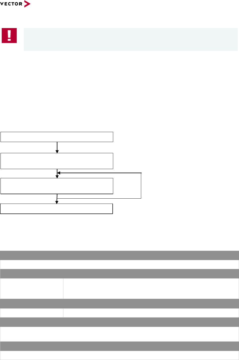
Reference Manual HexView
© 2016 Vector Informatik GmbH Version 1.10.01 82
based on template version 5.1.0
Caution
Since this operation can manipulate data in a post process, make sure HexView
creates the resulting file containing the desired data and applies the correct changes.
3.2.18 Run postbuild operation (/pb=postbuild-file)
This option applies the postbuild operation. This option requires a valid PBUILD.DLL to
read the data from a postbuild file. The results will be applied to the internal document.
Originally, it is used to read the generated postbuild XML-file using the PBUILD.DLL that
comes along with Hexview. However, it can also be used to apply your own postbuild
configuration or to apply data changes to the currently loaded document.
The only pre-requisite is that the DLL provides the correct interface functions.
The DLL interface functions will be called in the following sequence:
Figure 3-3: Calling sequence of the post-build functions
The following function interface will be applied:
3.2.18.1 OpenPBFile
Prototype
Long __declspec(dllexport) __cdecl OpenPBFile ( LPCSTR filename )
Parameter
Filename
Pointer to the location of the file that shall be opened. This is the full-path of
the file that has been selected in the file dialog when slecting the “Apply
postbuild options”.
Return code
Long
Number of segments found in the postbuild file and shall be applied to.
Functional Description
Requests to open a file used for the postbuild operation process. Typically, it is the XML file generated by
GENy to apply the postbuild configuration data.
Particularities and Limitations
> The function must return the number of segments that shall be applied to the postbuild operation
OpenPBFile(Filename)
GetPBSegmentInfo(Address[], Length[],
maxNoOfSegments)
GetPBData(srcAddress, dstAddress,
length)
ClosePBFile( )

Reference Manual HexView
© 2016 Vector Informatik GmbH Version 1.10.01 83
based on template version 5.1.0
Call context
> -
Table 3-5 OpenPBFile
3.2.18.2 ClosePBFile
Prototype
Void __declspec(dllexport) __cdecl ClosePBFile ( void )
Parameter
-
-
Return code
-
-
Functional Description
Closes the previously opened file. Concludes all operations within the DLL.
Particularities and Limitations
> -
Call context
> -
Table 3-6 OpenPBFile
3.2.18.3 ClosePBFile
Prototype
Long __declspec(dllexport) __cdecl GetPBSegmentInfo ( DWORD address[], DWORD
length[], long maxSegments )
Parameter
Address
Length
Long maxSegments
Pointer to a list of addresses. Will be filled by the operation.
Pointer to a list of length values. Each field for one segment. The index
corresponds to the address field.
Size of the fields where Address and Length points to. The interface function
shall not place more address and length information into the list as specified
by maxSegments (will exceeds internal data structures within Hexview).
Return code
Long
Number of segments found in the postbuild file and loaded to the segment
arrays of Address[] and Length[]..
Functional Description
Provides all segments from the postbuild file that shall be loaded.-

Reference Manual HexView
© 2016 Vector Informatik GmbH Version 1.10.01 84
based on template version 5.1.0
Particularities and Limitations
> The function must return the number of segments that has been loaded to the arrays.
> Segments provided in the list of address[] and length[] shall not overlap, length shall be greater than 0 in
all cases (otherwise, the element in the list should be omitted).
Call context
> -
Table 3-7 ClosePBFile
3.2.18.4 GetPBData
Prototype
Long __declspec(dllexport) __cdecl GetPBData ( DWORD srcAddress, char
*dstBuffer, DWORD length)
Parameter
srcAddress
Length
Long maxSegments
Pointer to the segment that shall be read. Corresponds to at least one of
the Addresses of addresses. Will be filled by the operation.
Pointer to a list of length values. Each field for one segment. The index
corresponds to the address field.
Size of the fields where Address and Length points to. The interface function
shall not place more address and length information into the list as specified
by maxSegments (will exceeds internal data structures within Hexview).
Return code
Long
Number of bytes read for post-building.
Functional Description
Reads the segment data from the postbuild file and applies it to the current document.
Particularities and Limitations
> The function must return the number of bytes read from the segment.
> The number of bytes read from the segment must correspond to the size previously specified for the
segment that belongs to the address given in the parameter.
Call context
> -
Table 3-8 GetPBData
3.2.19 Specify output filename (-o outfilename)
This option is used to overwrite the default output filename when exporting data to a file.
3.2.20 Run in silent mode (/s)
This option is used to suppress any output to the GUI. After executing all commands given
in the command line options, HexView will be closed.
3.2.21 Split blocks (/sb:maxblocksize)
This option allows to split a large block into pieces when the original block is too large. Thus, one
block can be splitted into several blocks. This can be helpful if RequestDownload-TransferData-
Reference Manual HexView
© 2016 Vector Informatik GmbH Version 1.10.01 85
based on template version 5.1.0
TransferExit for a large block exceeds the timing constrains (e.g. checksum calculation in
TransferExit for some OEMs).
<maxblocksize> can be given in decimal or hexadecimal with preceeding ‘0x’.
3.2.22 Specify an INI-file for additional parameters (/P:ini-file)
Some output control functions require complex parameters that cannot be passed on by
command lines. These output controls reads parameters from the INI-file. By default, if the
/P parameter is not given, HexView will extract the path and file information from the input
file and will search for the same file and location, but with the INI-extension. It will read the
contents from there. However, it could be useful to specify the INI-file explicitly. This is for
example useful, if several output controls shall be used with the same parameters.
Note
Some export functions from the GUI automatically generates an INI-file with the same
name and path location as the output file, to write these parameters into it. These
values will then automatically taken when reading or converting the file through
commandline.
The path and filename for the INI-file must follow directly the /P parameter, but separated
either with a colon or an Equal sign. No blank character is allowed for separation or within
the file and path name (or use double quotes to specify such file and path names).
Example
/P:testfile.ini
HexView will read the data from the path of the input file. If no explicit path is used for
the input file, HexView will search for the file in its current path.
/P=c:\testpath\testfile.ini
HexView reads the INI-file from the specified path and filename.
3.2.23 Remapping address information (/remap)
The remap option is used to shift the start address of block. This can be useful to remap
several address blocks from physical to logical addresses. A use-case for that is the re-
mapping of address spaces in banked mode to a contiguous linear address space
2
.
2
Such linear address spaces are also called „virtual“ addresses, because the address itself does cannot
directly used for a read operation on the micro. An address calculation of the virtual address is necessary to
split it to a banked and a physical address.
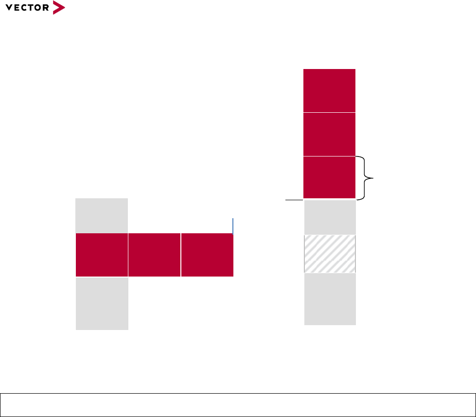
Reference Manual HexView
© 2016 Vector Informatik GmbH Version 1.10.01 86
based on template version 5.1.0
Figure 3-4: Mapping pysical to linear address spaces
The parameters to this option are as follows:
/remap:BankStartAddress-BankEndAddress,LinearBaseAddress,BankSize,BankIncrement
Figure 3-4 gives a reference to the parameters of the memory map. The BankStartAddress
and BankEndAddress spans a range of the memory region, where the remap shall be
applied to. The LinearBaseAddress is the base address, where the first BankStartAddress
shall be mapped to. The BankSize is the maximum size of a block that shall be remapped
and the BankIncrement is the difference of address between two banks, e.g. the difference
between BankStartAddress of bank #1 and BankStartAddress of bank #2.
Please note, that just blocks can be remapped, that fits within the BankStartAddress and
BankEndAddress or multiples of BankIncrement. That is to say, only blocks with maximum
size of BankSize can be remapped. A continuous block section cannot be splitted and
remapped into linear addresses (this is not necessary. In that case, only the whole base
address of a block may be shifted).
The following example shows, how address shift operations are applied:
Assuming, the input file contains the following data sections:
Non-Banked addresses from 0x0000 – 0x7FFF.
Banked addresses: 0x018000-0x01BFFF; 0x028000-0x02BFFF.
In this example, the address mapping consists of a non-banked section and two bank
sections. The bank numbers are 0x01 and 0x02. The physical bank addresses are from
0x8000-0xBFFF. The bank size is 0x4000.
Bank no.
#1
Bank start
address
Bank end
address
Bank no.
#2
Bank no.
#3
Physical address space Virtual, linear address space
Non-
banked
section #1
Non-
banked
section #2
Bank no.
#1
Bank no.
#2
Bank no.
#3
„Peep-
Hole“
Linear base
address
Bank size
Non-
banked
section #2
Non-
banked
section #1

Reference Manual HexView
© 2016 Vector Informatik GmbH Version 1.10.01 87
based on template version 5.1.0
The following option will remap the addresses to a linear address space:
/remap:0x018000-0x02BFFF,0x008000,0x4000,0x010000
This remaps the address space in the example above to 0x0000-0xFFFF.
3.2.24 Write version string to error log file (/v)
The Hexview version string is written to the error log file.
Note that you also need to specify the /E:<filename> option in combination to see the
string in this file.
Version string: “Hexview V1.09.02”
3.2.25 Create validation structure (/vs)
This item is used to create an information structure intended to be used for application
validation. It is typically used for flash download systems where it is difficult or impossible
to determine if all elements necessary for a download are available and complete.
There are some flash download procedures, where it is impossible to verify if the download
is completed. For example, if partial download is used without an information in the
download procedure, where the complete download can be verified, or where a download
can be interrupted at a certain state that appears like a completed download.
For a successful usage of the validation structure, it is necessary, some important
precautions must be considered. To use the structure it is necessary to be able to re-
program it with every download, even if it is just a partial download. Before the validation
structure itself can be used, it is necessary to determine if the validation structure is
present and complete. There are three options that can be used in combination to verify if
the structure is complete. A magic value at the beginning and the end can be added to the
structure In addition, a simple byte checksum can be inserted that is added at the very end
to the structure.
The key information for the validation is the block structure containing the segment start
address and length for each segment or block. The data information is not only (and not
necessarily) taken from the internal data but also from external files. A list of files can be
provided in the list box. An optional checksum per block can be added. The checksum
method can be chosen from the available checksum methods from EXPDATPROC.DLL.
Instead or in addition to the block checksum a total checksum that is calculated over all
segment and block data can be added. The total checksum method can be different from
the block checksum.
The resulting data structure can now generated in two ways, or even in both if wanted.
First, a C-structure can be generated that can be compiled and linked together with your
program data. If the data don’t change, the resulting HEX-files should be the same just
with the additional structure added to the HEX-file. A header-file may helps you to access
the data structure during the validation method.
A second method is to insert the data directly into the HEX-data file. Since 16-bit or 32-Bit
values are generated, it is important to select if the CPU uses little- or big-endian format.
The 16- and 32-Bit values will be generated according to the selected option.
When using this commandline option, all parameters will be taken from the INI-file (see
section 3.2.22). The contents of the INI-file has the following parameters:
[VALIDATION]

Reference Manual HexView
© 2016 Vector Informatik GmbH Version 1.10.01 88
based on template version 5.1.0
GenerateCFiles=1 ; 0=no, 1=yes
InsertData=1
CFilename=D:\uti\_page3a.c
HFilename=D:\uti\_page3a.h
BlockChecksumType=0
FileChecksumType=9
ValidateChecksum=1
IdTagBegin=0x1234
IdTagEnd=0x4321
BaseAddress=0x10000
SpareRange=
EndianType=0
Force32BitFormat=0 ; 0=Not force, 1=force.
See section 2.2.2.12: “Generate file validation structure” for further information.
Note
Some changes were made to Hexview V1.10.
The validation structure is added as a separate block into the block chain list of the
hexfiles. Before that, it was merged into the file. Thus, the validation structure always
appears as a separate block even if the preceeding block ends at the start address of
the validation structure. Re-Reading the file will merge the blocks.
IDtags are added as is, e.g. a value of 001A will be added as 2-byte value.
Address/length values can be forced as 4-byte values.
3.3 Output-control command line options (/Xx)
The following chapter describes the options used to control the output generator of
HexView. Note that only one output can be generated per execution. That is, you cannot
combine several output generator options (/X..) in one command line call of HexView.
The output control is used to generate a file in a specific output format. Some of the
formats correspond to a file format used for flash download in the OEM specific download
process. Therefore, the output control is named in combination with a car manufacturer’s
brand name.
3.3.1 Output of HEX ASCII data (/XA[:linelen[:separator]])
This option provides the possibility to output the data into a file as HEX ASCII.
There are two optional parameters to control the output. The first option is the length of the
output line. The second option is the separator between bytes within a line. Each option
will be separated by a semicolon. The line number always comes first, followed by the
separator. If you want to use spaces for the separator, you need to use doublequotes. The
separator is only placed between two HEX values within a line, not at the beginning or end
of it.

Reference Manual HexView
© 2016 Vector Informatik GmbH Version 1.10.01 89
based on template version 5.1.0
Example #1
Output HEX ASCII as a number of HEX strings
. /XA:32
0102030405060708090A0B0C0D0E0F10
1112131415161718191A1B1C1D1E1F20
Example #2
Output HEX ASCII in a formatted string using the separator.
/XA:32:”, “
01, 02, 03, 04, 05, 06, 07, 08, 09, 0A, 0B, 0C, 0D, 0E, 0F, 10
11, 12, 13, 14, 15, 16, 17, 18, 19, 1A, 1B, 1C, 1D, 1E, 1F, 20
3.3.2 Output a Fiat specific data file (/XB)
This option commands to create the BIN- and PRM file used for the Fiat specific download.
The format of the file will not described here, but can be found in the Fiat specific
documentations (07284-01). Refer also to section 2.2.1.9.9.
The Fiat file contains a number of parameters. These parameters are too complex to pass
them all through command line options. Therefore, HexView reads this information from an
INI-file. This INI-file can either be specified explicitly with the command line option /P (see
section 3.2.22) or will use the filename of the input file, but with the file extension ‘.INI’
(same location of INI as the HEX-file).
The base address and length of the erase sections within the parameter file fields will be
aligned with the erase alignment value. See sections 2.2.2.4 and 3.2.3 on how to specify
this value.
The following table shows the options for the INI-File used with the Fiat output.
HFIType=4
HFIType: Header Format Identifier. Should be
4 for 07209 or 2 for 07274
DownloadMethod=0
DownloadMethod or Fingerprint (FPM):
0=all Fingerprints,
1=Prog+Data,
2=Prog-only
ChecksumMethod=1
ChecksumMethod:
0=Files and Segments,
1=File only
ChecksumType=1
ChecksumType=Type of Checksum
calculation. Same paramter value as in
section 3.2.7 resp. 2.2.2.6.
ECUAddress=0x20

Reference Manual HexView
© 2016 Vector Informatik GmbH Version 1.10.01 90
based on template version 5.1.0
TesterAddress=0xf1
TesterCanID=0x18DA20F1
EcuCanID=0x18DAF120
TypeOfSeedKey=0
AccessMethod=0
AccessParameter=0
ReqDLMethod=0
ReqDLType=0
P2Min=5
P2Max=2
P3Min=1
P3Max=20
P4=0
AddressLengthSize
The size for the used addresses and length of
the segment information in the parameter file.
The default value is 0x33, which denotes, that
3-bytes will be used for address and length
values.
ReqDLParam
The parameter to the data processing
algorithm. See “Data Processing” chapter for
more information.
UseParialDownload
This flag is set to 1 if a partial download
parameter file shall be generated. The partial
download is used if the binary data file
consists of the application and data file. In this
case, the partial download extracts the
parameter file info for the data section only. A
data range must be specified for the data field.
PartialRange
This is the range for the data field if the binary
download is used for application and data. It’ll
be used to generate a separate parameter file
that specifies only the data section within the
combined binary section.
PartialPrmFile
Specifies the separate parameterfile that will
be generated if partial download is used.
Table 3-9 INI-file information fort he Fiat file container generation
3.3.3 Output data into C-Code array (/XC)
This option allows to create arrays in a C-language. This allows to compile and link
complex data packets with a program. This option directly reflects the GUI-option in
section 2.2.1.9.4.
The parameter for this output can also controlled by an INI-file (for INI-file rule, refer to
section 3.2.22).

Reference Manual HexView
© 2016 Vector Informatik GmbH Version 1.10.01 91
based on template version 5.1.0
The following list shows the options of the INI-file for this output:
Decryption=0
Option:
0=Off,
1=On
Decryptvalue=0xCC
Value for encryption using XOR with each
uchar/ushort/ulong
Prefix=flashDrv
WordSize=0
0=uchar,
1=ushort,
2=ulong
WordType=0
Only used if WordSize > 0.
0=Intel,
1=Motorola
Table 3-10 INI-File definition fort he C-Code array export function
Example
HexView test.dat /XC
Reads data from test.dat as Intel-HEX or S-Record and outputs to test.c/test.h. Tries to
read the INI-Info from test.ini in the same folder where test.dat is located.
HexView /XC test.dat /P:myini.ini –o outfile.c
Reads the data from test.dat and the parameter from myini.ini and outputs the file
outfile.c/outfile.h.
3.3.4 Output a Ford specific data file (/XF, /XVBF)
The Ford data container comes along in two resp. three different formats. One is the Intel-
HEX format with additional information at the beginning of the file and the other is the VBF-
format.
This section describes the two different formats:
3.3.4.1 Output Ford files in Intel-HEX format
The Ford files in Intel-HEX format consist of a header information with some Ford specific
information and the data itself in Intel-HEX format. The header has the following format:

Reference Manual HexView
© 2016 Vector Informatik GmbH Version 1.10.01 92
based on template version 5.1.0
APPLICATION>FORD FNOS-DemoIL
MASK NUMBER>7 or later
FILE NAME>APPL.hex
RELEASE DATE>10/05/2001
MODULE TYPE>Restraint Control Module
PRODUCTION MODULE PART NUMBER>XL5A-14B321-AA
WERS NOTICE>DE00E10757919001
COMMENTS>Any comments can be entered here.
RELEASED BY>Armin Happel
MODULE NAME>RESTRAINTS CONTROL MODULE
MODULE ID>0x7B0
DOWNLOAD FORMAT>0x01
FILE CHECKSUM>0xBF76
FLASH INDICATOR>1
FLASH ERASE
SECTORS>:0xFC0002,0x5716:0xFF9D00,0xC:0xFF9F54,0x8C:0xFF9F54,0x8C
$
:0200000400FCFE
:2000020011AA0001230000BC614E4141000AFFFFFFFFFFFFFFFFFFFFFFFFFFFFF
FFFFFFF1A
…
The whole file format can be written by HexView. The only information that HexView needs
in addition to the data itself are the parameters for the header shown above.
Some information can be generated automatically by the tool. Further information is
necessary and will be given by the INI-file parameter. The parameters from the INI-file are
controlled according to the INI parameter rule (see section 3.2.22).
The base address and length of the erase sections in the “flash erase sections” field will be
aligned with the erase alignment value. See sections 2.2.2.4 and 3.2.3 on how to specify
this value.
The following table shows the INI-information:
[FORDHEADER]
APPLICATION=FORD FNOS-DemoIL
Mandatory text field
MASK NUMBER=7 or later
Mandatory text field
FILE NAME=APPL.hex
Optional If omitted, the file-output name will be
used. Otherwise, the text field paramter is
used.
RELEASE DATE=10/05/2001
If omitted, the current PC-date will be used.
Otherwise, if specified, the textfield will be
used.
MODULE TYPE=Restraint Control Module
Mandatory text field
PRODUCTION MODULE PART
NUMBER=XL5A-14B321-AA
Mandatory text field
WERS NOTICE=DE00E10757919001
Mandatory text field
COMMENTS=Henrys header for flashdata
Mandatory text field
RELEASED BY=Armin Happel
Mandatory text field
Reference Manual HexView
© 2016 Vector Informatik GmbH Version 1.10.01 93
based on template version 5.1.0
[FORDHEADER]
MODULE NAME=RESTRAINTS CONTROL
MODULE
Mandatory text field
MODULE ID=0x7B0
Mandatory text field
DOWNLOAD FORMAT=0x01
Specifies the download method:
0: Download Application file
1: Download SBL
;FILE CHECKSUM=0x0A33
Will be generated by HexView. This is a byte
sum of the data in the datafield.
FLASH INDICATOR=1
0: for Flashdriver aka. SBL,
1: for normal file download
Note: Writes 0 if paramter is omitted.
;FLASH ERASE
SECTORS=:0xF0000,0x4000:0xF4000,0x4000:0
xF8000,0x4000:0xFC000,0x4000:0xFD800,0x04
00
Can be given as a textual information. If
omitted, the block sections will be listed. This
can be used with GGDS and I3 to specify the
erase values (Note: for I3 und GGDS, usually
the VBF-format is used).
In 14230/KWP2000, the Erase indicator must
be given here.
0: Erase all
1: Any erase section numbers
1,3,5: erase section number as a list.
Table 3-11 INI-file description for Ford I-Hex file generation

Reference Manual HexView
© 2016 Vector Informatik GmbH Version 1.10.01 94
based on template version 5.1.0
Example 1
Output an application file for FNOS 101 (KWP2000 based):
HexView /FR:0x4000,0x200 /XF /P:test.ini /AD2 /AL –o demo_fill1.hex
INI File contents of test.ini:
[FORDHEADER]
APPLICATION=FORD FNOS-Demo DemoAppl, adapted for
Bootloader
MASK NUMBER=Must be adapted by TIER I
;FILE NAME=appl.hex ; Will be filled out automatically
if not present.
;RELEASE DATE=02/18/2005 ; dto.
MODULE TYPE=Demo Software
PRODUCTION MODULE PART NUMBER=XL5A-14B321-AA
WERS NOTICE=DE00E10757919001
COMMENTS=This is just an example software
RELEASED BY=Armin Happel
MODULE NAME=Test software
MODULE ID=0x7B0
DOWNLOAD FORMAT=0x00
;FILE CHECKSUM=0x0A33 ; dto.
FLASH INDICATOR=1
FLASH ERASE SECTORS=0
HEX file output:
APPLICATION>FORD FNOS-Demo DemoAppl, adapted for
Bootloader
MASK NUMBER>Must be adapted by TIER I
FILE NAME>Demo_Fill1_f.hex
RELEASE DATE=17/02/2004
MODULE TYPE>Demo Software
PRODUCTION MODULE PART NUMBER>XL5A-14B321-AA
WERS NOTICE>DE00E10757919001
COMMENTS>This is just an example software
RELEASED BY>Armin Happel
MODULE NAME>Test software
MODULE ID>0x7B0
DOWNLOAD FORMAT>0x00
FILE CHECKSUM>0x1BFB
FLASH INDICATOR>1
FLASH ERASE SECTORS>0
$
:02000004000EEC
:20000000E25C9D40D6874BEAFAF1C7824BF70FE1CAE157397509A05577408C2
29C6D716FD1

Reference Manual HexView
© 2016 Vector Informatik GmbH Version 1.10.01 95
based on template version 5.1.0
Example 2
Output an SBL aka. Flashdriver file:
HexView flash_s12.hex /XF /P:flashdrv.ini /FA
INI File contents of flashdrv.ini:
[FORDHEADER]
APPLICATION=FORD FNOS-Secondary Bootloader
MASK NUMBER=Must be adapted by TIER I
;FILE NAME=Flash_S12.hex ; Will be filled out
automatically if not present.
;RELEASE DATE=02/18/2005
MODULE TYPE=Restraint Control Module
PRODUCTION MODULE PART NUMBER=XL5A-14B321-AA
WERS NOTICE=DE00E10757919001
COMMENTS=Henrys header for flashdata
RELEASED BY=Armin Happel
MODULE NAME=RESTRAINTS CONTROL MODULE
MODULE ID=0x7B0
DOWNLOAD FORMAT=0x01
;FILE CHECKSUM=0x0A33
;FLASH INDICATOR=1 Set to 0 if not present
FLASH ERASE SECTORS=
HEX file output:
APPLICATION>FORD FNOS-Secondary Bootloader
MASK NUMBER>Must be adapted by TIER I
FILE NAME>Flash_S12_f.hex
RELEASE DATE=17/02/2004
MODULE TYPE>Restraint Control Module
PRODUCTION MODULE PART NUMBER>XL5A-14B321-AA
WERS NOTICE>DE00E10757919001
COMMENTS>Henrys header for flashdata
RELEASED BY>Armin Happel
MODULE NAME>RESTRAINTS CONTROL MODULE
MODULE ID>0x7B0
DOWNLOAD FORMAT>0x01
FILE CHECKSUM>0x0A01
FLASH INDICATOR>0
FLASH ERASE SECTORS>:0x0,0x480
$
:200000000B00021202DF02D8036E02976CADB745EEE018B746EDE81AC60E15F
A04306B8211
3.3.4.2 Output Ford files in VBF format
Another output format used by Ford, especially in the FNOS I3 and GGDS projects, is the
VBF format. This file format is typically generated during the export of a VBF-file using the

Reference Manual HexView
© 2016 Vector Informatik GmbH Version 1.10.01 96
based on template version 5.1.0
Ford VBF-export function of Hexview. The INI-file is necessary to generate the VBF-file
from the command line. It is also used to adjust the dialog options for a specific file.
The values for ERASE_ADDRESS and ERASE_LENGTH will be aligned with the erase
alignment value in a way that erase address and length are a multiple of this parameter.
See sections 2.2.2.4 and 3.2.3 on how to specify this value.
Options and data generation is also controlled by an INI-file. The following INI-file
parameters are used to control the output:
[VBFHEADER]
SW_PART_NUMBER=12345678
Part-number. Any arbitrary text string.
SW_PART_TYPE=EXE
Software part type can be:
EXE, DATA, GBL, CAFCFG, CUSTOM,
SIGCFG, TEST
SW_CALL_ADDRESS
Only used if SW_PART_TYPE=SBL or TEST.
When SW_PART_TYPE is SBL, the call
address is mandatory.
SW_VERSION
The software version. Only used for VBF V2.5.
FRAME_FORMAT=CAN_STANDARD
FRAME Format can be:
CAN_STANDARD, CAN_EXTENDED
DESCRIPTION1=This is the demo application
for
Description field, part #1.
DESCRIPTION2=the FJ16LX FBL-Ford FNOS-
I3. *)
Description field, part #2
NETWORK=CAN_MS *)
Network parameter. Can be:
CAN_HS, CAN_MS, SUB_MOST,
SUB_CAN1, SUB_CAN2, SUB_LIN1,
SUB_LIN2, SUB_OTHER
ECU_ADDRESS=0x7E0 *)
ECU-Address
ERASE_LIST_GEN_MODE
This specifies how the erase table shall be
generated:
0 = Generate no erase table
1 = AUTO. Each segment of the input file will
correspond to an address range. The values
can be aligned to a multiple of a factor given
with the /AE parameter. This is useful to let
Hexview generate automatically the erase
table.
2 = Manual: You must specify erase address
and length value in this INI file (see below)!
ERASE_ADDRESS *)
Erase address and length information. This
paramter is not allowed if
SW_PART_TYPE=SBL.
ERASE_LENGTH *)
DATA_FORMAT_ID
Data format identifier for VBF 2.4 and higher

Reference Manual HexView
© 2016 Vector Informatik GmbH Version 1.10.01 97
based on template version 5.1.0
[VBFHEADER]
DATPROC_PARAM
Data processing parameter. Normally empty if
no data processing or just data compression is
used.
DATPROC_METHOD
ID of the data processing method (see chapter
3.2.8).
Table 3-12 INI-File description for Ford VBF export configuration
*) The parameters marked with *) can be specified as a single parameter or in a list format.
In the list format, a continuous counter number is added at the end of the parameter starts
with ‘1’, e.g. NETWORK1, NETWORK2, etc. If the iterator is used, the non-iterator name
will be ignored (e.g. NETWORK will not be used). It is much more convenient to generate
this file during an export through the GUI than writing this INI-file by hand. Make
modifications after it has been generated.

Reference Manual HexView
© 2016 Vector Informatik GmbH Version 1.10.01 98
based on template version 5.1.0
Example1
Convert an SBL resp. flashdriver
HexView.exe flashdrv.mhx /FA /s /e:flashdrv.err /xvbf /P:flashdrv.ini
flashdrv.ini-File:
[VBFHEADER]
SW_PART_NUMBER=12345678
SW_PART_TYPE=SBL
SW_CALL_ADDRESS=0x1000
FRAME_FORMAT=CAN_STANDARD
DESCRIPTION1=This is the flashdriver (SBL) for
DESCRIPTION2=the FJ16LX microcontroller.
NETWORK=CAN_MS
ECU_ADDRESS=0x7E0
Output of flashdrv.vbf:
vbf_version = 2.2;
header {
//**************************************************
********
//*
//* Vector Informatik GmbH
//*
//* This file was created by HEXVIEW V1.01
//*
//**************************************************
********
//Description
description = {"This is the flashdriver (SBL) for",
"the FJ16LX microcontroller."
};
//Software part number
sw_part_number = "12345678";
//Software part type
sw_part_type = SBL;
//Network type or list
network = CAN_MS;
//ecu_address or list
ecu_address = 0x7E0;
//Format frame
frame_format = CAN_STANDARD;
//call address
call = 0x1000;

Reference Manual HexView
© 2016 Vector Informatik GmbH Version 1.10.01 99
based on template version 5.1.0
//file checksum
file_checksum = 0xab8650b7;
}.

Reference Manual HexView
© 2016 Vector Informatik GmbH Version 1.10.01 100
based on template version 5.1.0
Example2
Convert an application file
HexView.exe testsuit.mhx /AD2 /AL /s /e:testsuit.err /xvbf
testsuit.ini-File:
[VBFHEADER]
SW_PART_NUMBER=12345678
SW_PART_TYPE=EXE
FRAME_FORMAT=CAN_EXTENDED
DESCRIPTION1=This the demo application for
DESCRIPTION2=the FJ16LX FBL-Ford FNOS-I3.
NETWORK1=CAN_MS
NETWORK2=SUB_CAN1
//ERASE_LIST_GEN_MODE:
// 0=Off (generate no erase list);
// 1=Auto (generate erase list from segment list and,
if given, from the erase alignment parameter /AE) ;
// 2=Manual (the erase list is specified in this INI-
file)!
ERASE_LIST_GEN_MODE=1
;ERASE_ADDRESS1=0xff0000
;ERASE_LENGTH1=0x10000
ECU_ADDRESS1=0x00
ECU_ADDRESS2=0x06
ECU_ADDRESS3=0x65
testsuit.vbf-File:
vbf_version = 2.2;
header {
//**************************************************
********
//*
//* Vector Informatik GmbH
//*
//* This file was created by HEXVIEW V1.01
//*
//**************************************************
********
//Description
description = {"This the demo application for",
"the FJ16LX FBL-Ford FNOS-I3."
};
//Software part number
sw_part_number = "12345678";
//Software part type

Reference Manual HexView
© 2016 Vector Informatik GmbH Version 1.10.01 101
based on template version 5.1.0
sw_part_type = EXE;
//Network type or list
network = { CAN_MS, SUB_CAN1};
//ecu_address or list
ecu_address = { 0x00, 0x06, 0x65};
//Format frame
frame_format = CAN_EXTENDED;
//erase block
erase = { { 0x00ff0002, 0x00007764},
{ 0x00ff7f00, 0x0000008c}
};
//file checksum
file_checksum = 0x73940915;
}.
3.3.5 Output a GM-specific data file
A file used for a flash download within GM contains important information necessary for its
download at the very beginning. This is the so-called GM file-header. It contains a
description of the download data and also some version information. A detailed description
of this file-header can be found in GMW3110, V1.5, section 11.
Roughly, the header can be divided up into two groups, the header for the operational
respectively executable software and the calibration file. The main difference is, that the
operational software contains the address information of both the operational and the
calibration software. The calibration software therefore doesn’t contain any address
information, even not about itself.
The file header can roughly be divided up into two parts, a static part and a dynamic part.
The static part contains information that changes only the version management and
contains, e.g. version information and other file descriptions like module-id, DLS-code and
DCID. The information is static in respect to the compile and link process.
The dynamic data part contains the address and length of all sections of a file and also the
total checksum over all sections. Thus, the dynamic data contents is changing by the
compile and link process and must therefore be adapted after every link process.
The command line options of HexView are therefore adapted to these two stages and can
roughly be divided up into two groups: manipulating the dynamic part within an existing
header of the hex-file or to create the complete header information including the static and
dynamic parts, without the existence of any predefined data.

Reference Manual HexView
© 2016 Vector Informatik GmbH Version 1.10.01 102
based on template version 5.1.0
If only the dynamic part is inserted, the static part must already be present in the loaded
file. In that case, HexView analyzes the static part and checks if enough placeholder has
been reserved to insert the dynamic part. To avoid the risk that HexView accidentally
overwrites important software part data, a unique ID must be written at the very beginning
of the header block. This ID has the value 0x11AA.
If it’s commanded to HexView to create also the static part, the whole header will be
generated. This also implies, that the information of the static part must be given by the
command line options. These options are the /DLS, /SWMI, /DCID and the /MPFH.
This document does not describe completely the format and meaning of the header. You
must refer to GMW3110 for further details.
3.3.5.1 Manipulating Checksum and address/Length field within an existing
header (/XG)
The option /XG is used to command HexView to change the checksum, address and
length information (the dynamic part) within the existing header data fields of the hex-file. It
is a prerequisite, that the header is at the very beginning of a block or a section. The
header must contain all static information like Module-ID, SWMI, DLS and HFI. There must
also already be data as a placeholder for the PMA and the checksum. The placeholder for
the checksum must have the value 0x11AA, the placeholder data for the address and
length information can be of any value.
Note
HexView will overwrite these data during the conversion process. Make sure that no
important data is overwritten. Test the output results carefully!!.
By default, HexView checks the presence of the header on the lowest address of the
block. However, if the header is at the beginning of another block, the address information
of this block can be specified in this command line, separated by the colon.
Example
/XG /CS5 test.dat
Reads in the file test.dat as Intel-HEX or S-Record file and tries to fill in the header
information into the lowest address. The value 0x11AA must be specified there.
Outputs the data into test.bin (GM-binary format) and test.hex (Intel-HEX).
/XG:0x1000 /CS6
HexView searches for the block at address 0x1000. If this is not the first block in the
internal list (e.g. it’s not the lowest address of the block), the block will be moved to the
front. The specified address must be the beginning of a segment or block.
moduleId01.hex /XG /CS6 /MPFH –o myGMfile.bin
The hex-file “moduleId01” contains a header with placeholder 0x11aa for the
checksum, SWMI, DLS, the HFI and a NOAR with dummy address/length information
and optional DCID. It also contains values for the additional modules (NOAM-fields).
Hexview will fill the placeholder 0x11AA with the calculated checksum, will adjust the
NOAR and address/length information from the address fields of “moduleId01.hex” and
then copies the NOAM fields to the end of the last address/length information.

Reference Manual HexView
© 2016 Vector Informatik GmbH Version 1.10.01 103
based on template version 5.1.0
Note
The parameter /CSx must be given when manipulating the header to specify the
checksum method for the checksum value.
If the existing header already contains data for the additional modules (NOAM-data),
the option /MPFH can be specified to let Hexview copy the contents of the NOAM field
adjacent to the end of the new address region. Extensive checks are done internally to
avoid overwriting existing data. Do not use the /MPFH option if you don’t use
calibration information within the GM file.
Besides the presence of the value 0x11AA, the parameter NOAR in the static part must be
equal or greater than the number of sections available in the hex-file. If the NOAR in the
static part is lower, HexView generates an error and does not write the output.
After the NOAR parameter, there must be at least 8*NOAR data bytes within the header,
reserved for the address and length information.
Note
HexView will overwrite these reserved data bytes with the address and length
information of the sections. Also, the value 0x11AA for the checksum will be overwritten
with the result of the checksum calculation value.
The output file format of HexView is a BIN-file.
If the –o parameter is not given, HexView will use the input filename and will replace the
file extension of the input file with “.bin” to specify the output filename.
In addition, HexView will create an Intel-HEX file with the extension “.hex”.
If the output filename already contains the extension .hex, HexView will create a Motorola
S-record file with the extension “.s19”.
3.3.5.2 Creating the GM file header for the operating software (/XGC[:address])
This option is used to create the header for the operational software respectively the
executable.
Without any address information in the parameter, the header will be added at the very
beginning of the first section (lowest address of the file). The address information will be
adapted according to the necessary size of the header (the size can vary depending on
the information in the header). If the header doesn’t fit to the lowest address, an error will
be generated and the output file will not be written.
Using the /XGC parameter, the HFI will always be a two byte value. If the parameter /DCID
and /MPFH are given, the corresponding bits in the HFI field will be set and the values
from the parameters will be added. If the parameters /SWMI and /DLS are not given, the
default values will be used.

Reference Manual HexView
© 2016 Vector Informatik GmbH Version 1.10.01 104
based on template version 5.1.0
Example
myHexFile.hex /XGC /CS5 /DCID=0x8000 /DLS=AA /SWMI=12345678
/MODID=1 /AL /AD4 /MPFH=cal1.hex+cal2.hex –o myGmFile.bin
This will create a full header with all options passed through command line. It
will put the header data upfront to the first block data on the lowest address.
The base address of the header will be shifted down to match the header size.
The data will be filled in to the block. The DCID-field will be added and the flag
in the HFI as well. The NOAM-field will be 2 followed either with the placeholder
or the real data of cal1.hex and cal2.hex. If placeholder or real data are used
depends on if HexView can read the contents of the data from cal1.hex and/or
cal2.hex.
Please note, that a GM-binary file cannot be used as an input file of CAL-files,
as this file doesn’t contain address information.
myHexFile.hex /XGC:0x1000 /CS5 /DCID=0x8000 /DLS=AA
/SWMI=12345678 /MODID=1 /MPFH=cal1.hex+cal2.hex /AL /AD4 –o
myGmFile.bin
This will create the file header at the address 0x1000. The created section will be
located at the very beginning of the data. Thus, the header will be the first data in the
output file, regardless if there are any sections with lower addresses.
3.3.5.3 Creating the GM file header for the calibration software (/XGCC[:address])
The option /XGCC is used to create the header for the calibration software. The major
difference is, that the calibration file does not contain the PMA-field for address information
and the NOAR-field. The corresponding PMA-bitfield is not set in the HFI (typically 0x22).
The parameters /DCID, /SWMI, /DLS and /CS are also accepted. The /MPFH parameter
must not be added to the command line.

Reference Manual HexView
© 2016 Vector Informatik GmbH Version 1.10.01 105
based on template version 5.1.0
Example
myCalHexFile.hex /XGCC /CS5 /DCID=0x8000 /DLS=AA /SWMI=12345678
/MODID=2 /FA /AL /AD4 –o myCalFile.bin
This will create a full header with all options passed through command line. It
will put the header data upfront to the first block data on the lowest address.
The base address of the header will be shifted down to match the header size.
The data will be filled in to the block. The DCID-field will be added and the flag
in the HFI as well. A NOAM-field is not allowed in CAL-files. Therefore, the
/MPFH option is not allowed to be used.
Please note, that a GM-binary file cannot be used as an input file of CAL-files,
as this file doesn’t contain address information. However, Hexview will
automatically generate a myCalFile.hex in parallel to the bin-file. Make sure,
that your input file has not the same name as the output file as this will overwrite
your origin.
Note: The option /FA should be used for CAL-files, because CALs are always
single-region files!
myHexFile.hex /XGCC:0x1000 /CS5 /DCID=0x8000 /DLS=AA
/SWMI=12345678 /MODID=2 /FA /AL /AD4 –o myGmFile.bin
This will create the file header at the address 0x1000. The created section will be
located at the very beginning of the data. Thus, the header will be the first data in the
output file, regardless if there are any sections with lower addresses.
3.3.5.4 Creating the GM file header with 1-byte HFI (/XGCS[:address])
For backward compatibility, it is also possible to create the header with one-byte HFI.
In that case, the parameters /DCID and /MPFH shall not be given as an option.
All other information are in accordance with the other options described above.
3.3.5.5 Specify the SWMI data (/SWMI=xxxx)
The parameter /SWMI is used to specify the value within the SWMI field. The parameter in
the command line option is used to add it to the field. The parameter is treaded as a
integer value and added to a 4-byte field in the SWMI-field of the header. The data can be
represented in decimal or in hex by a leading ‘0x’.
If the /SWMI parameter is omitted, HexView will use the default value 0x12345678.
This parameter is only useful in combination with /XGC, /XGCC or /XGCS.
3.3.5.6 Adding the part number to the header (/PN)
In some cases, the part number needs to be added to the GM-header. The part number is
an ASCII representation of the SWMI value. If the option /PN is added in combination with
any /XGC option, the ASCII representation of the part number will be added to the header.
The corresponding bit of the 2nd byte of the HFI-field will be set if the option is given.
This parameter is only useful in combination with the option /XGC or /XGCC.

Reference Manual HexView
© 2016 Vector Informatik GmbH Version 1.10.01 106
based on template version 5.1.0
3.3.5.7 Specify the DLS values (/DLS=xx)
The DLS parameter is used to specify the DLS field information in the header. The
parameter is interpreted as ASCII characters and added to the DLS-field. The number of
characters in the DLS-field can either be two or three characters. The HFI-field will be
adapted according to the number of characters given in the parameters.
This parameter is only useful in combination with /XGC, /XGCC or /XGCS.
Example
/ DLS=AA
The DLS is AA. The HFI field specifies a two-byte DLS field.
/DLS=ABC
The DLS is ABC. The HFI field is set to be a three-byte field.
3.3.5.8 Specify the Module-ID parameter (/MODID=value)
The /MODID parameter specifies the module id of the header. The parameter specifies the
number. The parameter can be either a decimal or a hexadecimal value if a ‘0x’ is added
upfront.
This parameter is only useful in combination with /XGC, /XGCC or /XGCS.
Example
/modid=1
The module-ID is 0001 in the module-id field
/MODID:0x0051
The Module-ID is set to 81dez resp. 51hex.
3.3.5.9 Specify the DCID-field (/DCID=value)
The /DCID parameter specifies the DCID-value in the GM-header. This option can only be
used for a 2-byte HFI. Thus, it can only combined with the options /XGC or /XGCC (not
with /XGCS or /XG).
The value can either a decimal or a hexadecimal value if it precedes with ‘0x’.
Example
/XGC /DCID:32238
/XGCC /DCID=0x8000
3.3.5.10 Specify the MPFH field (/MPFH[=file1+file2+…]
The /MPFH option is added to specify the MPFH data. In combination with /XGC the
header will be extended to store the NOAM, DCID and address/length information from the
files specified in the options field. The value of NOAM is taken from the number of files
specified in the parameter field. Each file is separated by the ‘+’ sign.

Reference Manual HexView
© 2016 Vector Informatik GmbH Version 1.10.01 107
based on template version 5.1.0
In combination with the /XG or /XGC parameter, HexView will scan the files listed in the
parameter field. If they could be found, the address, length and DCID-fields will be
extracted and added to the header information.
Note that the files listed in the MPFH parameter must be single region files. If they contain
multiple sections, an error will be generated and the address/length information will not be
added.
File format: HexView first tries to read the files as Intel-Hex or Motorola-S-Record files. If
this is not possible, that means, if it results in a zero data container, it will try to read it as a
GM-binary file.
In combination with the /XGC option, HexView will create sufficient data information to
store the information for the calibration files.
If this option is added with /XG, Hexview will analyse for existing data of additional
modules and will copy this field to the end of the address- and length field.
3.3.5.11 Signature version (/sigver=value)
With Global Bootloader specification V2.2, GM introduces signature verification within the
Bootloader. The GM-header requires to contain signature information that the Bootloader
will use for signature verification. These values are the signature version, the signature key
ID and the signature itself. With Hexview V1.08.00, it is possible to generate this
information in the header file.
One essential parameter for hexview is the signature version. This value is placed into the
header at the required position and is passed to Hexview with this option. The value can
either be an integer or a HEX-number. Example #1 (integer value): /sigver=12345678.
Example #2 (hex value): /sigver=0x12345678.
The signature version is a 4 byte value in the header.
Note, that the parameter /DP must be used in conjunction with this parameter to instruct
Hexview to calculate the correct signature. Normally, the /DP parameter outputs the
signature value into a file. But here with this option, Hexview will place the results into the
corresponding position of the header within the data.
If this option is given, Hexview outputs a concatenated file without the signature. It is the
exact same output, but without the signature itself. So, this file can be given to GM to let
them generate and insert the signature with real keys.
3.3.5.12 Signature Key ID (/sigkeyid=value)
This option is also required for the signature header generation. It provides the key ID
information used for the signature calculation. It identifies uniquely the private/public key
combination for the signature. The value can be given in HEX or integer format, similar to
the sigver option. The value will be placed as a 2-byte value into the corresponding
location of the header.
3.3.5.13 Generate Routine header (/XGCR[:header-address])
This option is similar to the /XGC, but generates a header suitable for the routines, e.g.
flashdriver, etc. The major difference is, that the start address will not decrease while the

Reference Manual HexView
© 2016 Vector Informatik GmbH Version 1.10.01 108
based on template version 5.1.0
header is placed upfront. Instead, the header is placed at the same start address where
the routines itself are placed to . This is because the Vector bootloader does use the start
address of the header as the start address for the code itself and will use the header
information only for internal processes but will not locate this into the memory (typically
RAM).
3.3.5.14 Generate key exchange header (/XGCK)
This option is used to generate a key exchange file. It contains only the header and
signature information. The data after the header contains the new public key information
for proceeding signature values.
Note, that the signature must be built from the previous keys, not the new key!
3.3.6 Output a VAG specific data file (/XV)
This option generates an SGM-file that can be used for the VAS-tester. The file is
generated as described in section 2.2.1.9.14.
The VAG-export also requires parameters from an INI-file as described in section 0.
Example
HexView testappl.mhx /XV /P:vagparam.ini –o demoappl.sgm
3.3.7 Output data as Intel-HEX (/XI[:reclinelen[:rectype]])
This option generates the data in the Intel-HEX file format.
The output can be either as Extended Segment or Extended Linear Segment. Hexview
selects the appropriate format automatically, depending on the highest address of the data
file. If you want to force Hexview to use a specific output file format, use the rectype
selector. The following selection is possible:
Rectype = 0: Auto selection (same as omitting the parameter)
Rectype = 1: Extended Linear Segment
Rectype = 2: Extended Segment
Also, the number of data bytes in the output line can be specified using the reclinelen
parameter.
Example
HexView anyfile.hex /XI:32 –o intelhex.hex
Hexview myhexfile.S19 /s /xi:16:2 –o myihex.hex
3.3.8 Output data as Motorola S-Record (/XS[:reclinelen[:rectype]])
This option generates the data in the Motorola S-Record format.
The format (S1, S2 or S3) is automatically detected by HexView according to the size of
the highest address. If this address is 16-bit, the S1-record format is used. If it is up to 24-
bit, the S2-record type is used. If it is up to 32 bit long, the S3-record format is used.

Reference Manual HexView
© 2016 Vector Informatik GmbH Version 1.10.01 109
based on template version 5.1.0
However, it could be useful to select the record type, e.g. when S2 or S3 is desired even
though the highest address is below its threshold. In that case, the “rectype” parameter
can be selected. Use the following settings:
Rectype = 0: S1-Record
Rectype = 1: S2-Record
Rectype = 2: S3-Record.
Note that Hexview will throw an error if you select a rectype lower than the address ranges
can handle. No data will be generated. “Reclinelen” must be specified when usrecord type
shall be selected.
The number of data bytes per S-Record line can be specified in the reclinelen parameter.
The parameter is separated by a colon. It can be specified in integer or hexadecimal
format.
Example
HexView intelfile.hex /XS:32 –o srecord.s19
Hexview myhexfile.S19 /s /xs:16:2 –o mysrecord.s3
3.3.9 Outputs to a CCP/XCP kernel file (/XK)
This option generates the flash kernel data file according to the file format necessary for
CANape to read the file. This file format specifies a header and the data itself as Intel-HEX
record format.
For detailed description refer to section 2.2.1.9.4.
3.3.10 Output to a GAC binary file (/XGAC, /XGACSWIL)
The GAC binary file can be generated in two ways. The standard file format contains a
header information with some container information such as DCIDs, software version, part
numbers, etc. A complete list of supported IDs are listed in the example for the INI-file.
Example
The following is an example of the INI-file information for the GAC header
[GACHEADERINFO]
DCID_0=0x00
DCID_1=0x01
DCID_2=0x00
SoftwareVersion="123"
SoftwarePartNumber="1234567890ABCD"
AppOrCalVersion="123"
EcuCodeAndSupplierId="123456789"
The required information will take the tool from an INI-file. The corresponding format and
item is listed in the example above.

Reference Manual HexView
© 2016 Vector Informatik GmbH Version 1.10.01 110
based on template version 5.1.0
Besides this information, the GAC header also includes the address and length information
and the number of address/length info. Thus, the GAC binary file header contains three
sections:
The GAC software information
The number of address/length, the address and length itself
The data of the file.
We distinguish two file formats, the GAC file with complete information of all three
sections, which is typically for the program and calibration files, and the file for the
software interlock (SWIL, sometimes also called as the “flash driver”).
The flash driver itself has no GAC software information and consists only of the two parts,
the address/length info and the binary data itself. Note that the SWIL should have just one
region, so it should start with the binary value ‘01’ as the first byte.
The SWIL file can only be generated through the commandline with the option /xgacswil,
whereas the standard GAC file can be generated through the commandline or with “File ->
Export -> GAC Binary File”. For the latter one it is required, that the corresponding INI-file
contains the valid entries (see example in this section).
Reference Manual HexView
© 2016 Vector Informatik GmbH Version 1.10.01 111
based on template version 5.1.0
4 EXPDATPROC
HexView provides an open interface for data processing and checksum calculation. The
interface is realized by a DLL, called EXPDATPROC.DLL (EXPorted DATa PROCessing).
This item describes how HexView calls these functions.
4.1 Interface function for checksum calculation
The checksum calculation is called whenever the /CSn parameter is used in the command
line or when “Edit ->Checksum calculation” is used in the GUI.
The checksum calculation is also called during the export of Fiat-binary, GM-header and
the VAG-export.
The following diagram shows the collaboration of function calls between HexView and
Expdatproc.dll.
To run the checksum calculation via the GUI, HexView first reads all available checksum
calculation methods from the DLL. It first reads the number of available methods by calling
the GetChecksumFunctionCount(), then reads the corresponding name by an iterate
call to GetChecksumFunctionName(). This builds the list box entries in the dialog.
Figure 4-1 Build the list box entries for the GUI
After the method has been selected, HexView runs the calculation in three steps. First, it
initializes the calculation, runs the calculation by passing the data block wise to the DLL
and then concludes the calculation.
Init and Deinit has the purpose to construct and destruct a context sensitive data section.
This section is passed to the calculation together with the data.
The function GetChecksumSizeOfResult() has been introduced to check the length of
the results of the checksum calculation. This allows HexView to prepare the data
container. It also allows HexView to spare the address section where the checksum
calculation shall be placed to.
The following diagram shows the message flow when processing the checksum
calculation method:
sd Build GUI entry
Hexv iew Expdatproc
GetChecksumFunctionCount()
GetChecksumFunctionName()
Reference Manual HexView
© 2016 Vector Informatik GmbH Version 1.10.01 112
based on template version 5.1.0
An error code can be passed to HexView during the calculation. HexView asks for the text
description in a separate function. This error text description is then shown in the error
report.
Figure 4-2 Function calls when running checksum calculation
The diagram above shows the function interface and the message sequence chart. The
function DoCalculateChecksum with the parameter CSumActionDoData is called
several times. Typically, once per section. The segInData contains the pointer to the
section data, dataInLength specifies the length of the data, and dataInAddress contains
the base address of the section.
Note
segInData is a pointer to the internal data buffer of HexView. The function can therefore
operate and destroy the data. Be careful not to write to any location where segInData
or segOutData points to in the DoCalculateChecksum() function.
After the calculation has been completed, the DoCalculateChecksum function is called
the last time, but with the parameter CSumActionEnd. The segOutData must contain
pointer to the data buffer, that holds the checksum. The segOutLength specifies the
number of bytes in segOutData. The segOutAddress parameter is not used and ignored
here.
4.2 Interface function for data processing
The data processing interface is similar to the interface of the checksum calculation. It’s
the same way how HexView gets the available methods by calling the functions
GetDataProcessingFunctionCount() that returns the number of available methods,
sd Run Checksum calculation
Hexv iew Expdatproc
GetChecksumSizeOfResult(methodIndex)
InitChecksum(TExportDataInfo)
DoCalculateChecksum(TExportDataInfo,CSumActionBegin)
RepeatPerSection
DoCalculateChecksum(TExportDataInfo,CSumActionDoData)
DoCalculateChecksum(TExportDataInfo,CSumActionEnd)

Reference Manual HexView
© 2016 Vector Informatik GmbH Version 1.10.01 113
based on template version 5.1.0
and then repetitively the function GetDataProcessingFunctionName() until one name
per method has been read.
It also runs first the function InitDataProcessing(TExportDataInfo*) before
running the DoDataProcessing(). But with the difference, that the DoDataProcessing is
called only once. HexView does not distinguish between the Begin, DoData and End
function, but calls the DoDataProcessing once. But the TExportDataInfo structure also
contains the segInData, segInLength and segInAddress information. It also contains the
structure segOutData, segoutLength and segOutAddress. Before HexView calls
DoDataProcessing, it initializes segOutData and segOutLength with the values and pointer
of segInData and segInLength. Thus, if the data remains the same, HexView will use the
same data set.
However, if the DoDataProcessing() function wants to manipulate the data, it can overwrite
the default output. HexView will then replace the returned data with the new contents. The
memory buffer where segOutBuffer points to will be used instead. The former segInBuffer
will be released If segOutLength is different, the segment length will be adapted. The
operation is done for every segment or block.
It is also possible to manipulate the data in segInData without restructuring the data buffer
(only possible if the resulting data is not larger than the input data). The manipulation can
operate directly on the segInData buffer which is the internal data buffer of HexView. This
allows to run data encryption, decryption, compression and decompression with this
method.
Since most of these data processing operation requires a parameter, the TExportDataInfo-
>generalParam contains a pointer to a parameter string. The parameter typically points to
the data buffer from the ‘parameter’ field of the dialog (see section: “Run Data
Processing”), or it points to the buffer of the command line if the command line option is
used (option ‘param’ in section 3.2.8: “Run Data Processing interface
(/DPn:param[,section,key][;outfilename])”).
Reference Manual HexView
© 2016 Vector Informatik GmbH Version 1.10.01 114
based on template version 5.1.0
5 Glossary and Abbreviations
5.1 Glossary
Term
Description
5.2 Abbreviations
Abbreviation
Description

Reference Manual HexView
© 2016 Vector Informatik GmbH Version 1.10.01 115
based on template version 5.1.0
6 Contact
Visit our website for more information on
News
Products
Demo software
Support
Training data
Addresses
www.vector.com
Send feedback to: mailto:fblsupport@vector-informatik.de
