Regulator
User Manual: Regulator PCTI
Open the PDF directly: View PDF ![]() .
.
Page Count: 1
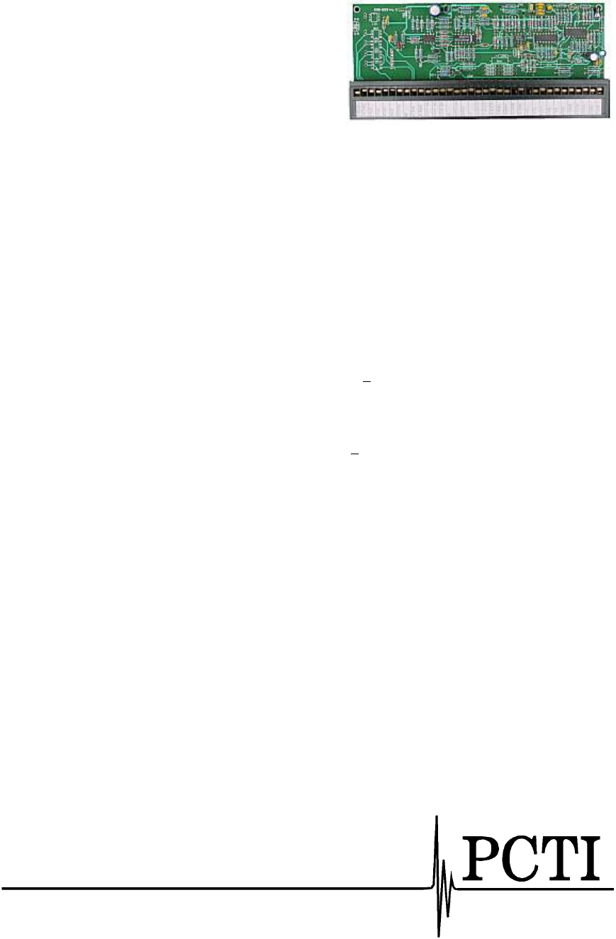
OEM Regulator Board
The ALR02 regulator board was designed to be adaptable
to a variety of requirements imposed by different
applications from power supply regulation and protection
to AC controllers or soft-start motor starters.
Part No. 60.003
Functions of the Regulator Board
• The regulator board contains 2 independently configurable regulators and a very stable internal
reference.
• The feedback current value input can be switched from shunt to current transformer.
• Prescribed value ramp-up/ramp-down circuitry with independently adjustable for the up and down
ranges. The standard control circuit integrator prevents transformer saturation for step function signal
changes and provides stable operation when using any of the optional regulator features.
• Contains shutdown protection in case of overvoltage and overcurrent (electronic fuse), both adjustable.
• Accepts the output from any conventional instrument (e.g. temperature controller) in a integrated
system: 1-5mA, 2-10mA, and 4-20mA, all at an input resistance which results in approximately a 5Vdc
signal. A 0-10VDC input into 1Kohms is also available for use with either a process control signal or
a manual control potentiometer.
• Reference supply - a 10VDC reference source regulated to +0.5% is available for use in energizing a
manual control potentiometer.
Specific Features
1. BIAS SUPPLY Present - Two green LEDs. Indicate the + 15 volt presence.
2. RAMP UP adjustment potentiometer. Adjusting the potentiometer clockwise will increase the
response of the power supply to an upward adjustment of the voltage regulation control.
3. RAMP DOWN adjustment potentiometer. Adjusting the potentiometer clockwise will increase the
time it takes the power supply to react to a downward adjustment of the voltage regulation control.
4. VOLTAGE FEEDBACK POTENTIOMETER. It is used to set the maximum desired voltage and the
sensitivity of the power supply to the voltage regulation control. Clockwise adjustment decreases
voltage.
5. CURRENT FEEDBACK POTENTIOMETER. This sets the maximum current output. Clockwise
adjustment decreases current.
6. OVERTEMPERATURE Indicator - Yellow LED (leftmost). It is lit in the event of temperature
exceeding design specifications. It will light for SCR, or transformer overtemperature conditions.
7. OVERVOLTAGE Indicator - Yellow LED (second from the left ) In the event the output exceeds the
limit set by the potentiometer to the right, it will turn on. Adjusting the potentiometer can set the
sensitivity to overcurrent. Clockwise decreases the threshold for a trip.
8. OVERVOLTAGE SHUTDOWN Indicator - Yellow LED (third from the left). This is activated in the
event the output voltage exceeds the preset limit. The limit is set by the potentiometer to the right of
the LED. Turning the potentiometer clockwise decreases the threshold for a trip.
9. UNDERVOLTAGE Indicator - Yellow LED (fourth from the left). This is illuminated in the event the
output voltage is under the preset limit. The limit is set by the pot to the right of the LED. Turning the
pot clockwise decreases the threshold for trip.
Contact the factory for pricing and further information.
152 Nickle Road
Harmony PA 16037
Phone (724) 452-5787
Fax: (724) 452-4791
www.gopcti.com
