Technical Information Ti.b. Rematic 2945 C3K Control
User Manual: Rematic 2945 C3K - Control Technical Information
Open the PDF directly: View PDF ![]() .
.
Page Count: 56
- PREFACE
- 1 Safety notice
- 2 General information
- 3 Controls and displays
- 4 Specialist adjustments
- 5 level 3 adjustments
- 5.1 Heating curve (adjustments 3-0 and 3-2)
- 5.2 Maximum common flow / boiler flow temperature (adjustment 3-1)
- 5.3 Summertime limits
- 5.4 Optimised start - pre-heat time (adjustment 3-5)
- 5.5 Room temperature compensation (adjustment 3-6)
- 5.6 Number of slaves and their addressing (adjustment 3-7) NOT AVAILABLE IN UK
- 5.7 Nature of the controller (adjustment 3-8)
- 5.8 Minimum modulation percentage (output) (adjustment 3-9)
- 6 level 4 adjustments
- 6.1 Domestic hot water operation modes
- 6.2 Flow water temperature for D.H.W. heating (adjustment 4-2)
- 6.3 Run-on time of domestic hot water pump (adjustment 4-3)
- 6.4 Legionnaires’ disease protection temperature (adjustment 4-4)
- 6.5 Legionnaires’ disease protection mode (adjustment 4-5)
- 6.6 Adaptive heating curve (adjustment 4-6)
- 6.7 Minimum boiler temperature (adjustment 4-7)
- 6.8 Flow temperature excess in °C in relation to the heating curve(s) (adjustment 4-8)
- 6.9 Adapting to the heating circuit (adjustment 4-9)
- 7 level 5 adjustments
- 7.1 Boiler output at full load (adjustment 5-0)
- 7.2 Grouping boilers (adjustment 5-1)
- 7.3 Cut-in output of the follow-up boiler (adjustment 5-2)
- 7.4 Minimum boiler return temperature TBR MIN (adjustment 5-3)
- 7.5 Minimum fan speed with boiler switched off (adjustment 5-4)
- 7.6 Return temperature control selection (adjustment 5-5) (NOT USED IN THE UK)
- 7.7 Allocation of boiler relay outputs for on/off or high/low boilers (adjustment 5-6) (NOT USED IN THE UK)
- 7.8 Sequence changeover of boilers in groups 1 and 3 (adjustment 5-7)
- 7.9 P-band (proportional band) (adjustment 5-8)
- 7.10 I-band (integral proportion) (adjustment 5-9)
- 8 level 6 adjustments
- 8.1 Maximum common flow temperature (adjustment 6-0)
- 8.2 Run-on time of the D.H.W. pump dependent on time or temperature (adjustment 6-1)
- 8.3 Boiler safety modes (adjustment 6-2)
- 8.4 Delayed cut-in of boiler stages
- 8.5 Blocking of boiler groups dependent on outside temperature
- 8.6 Neutral zone for the internal Pl-behaviour of the controller (adjustment 6-7)
- 8.7 Ramp mode to limit the speed of changes in output
- 9 pump functions
- 10 Remote control operation
- 11 Connector pinouts
- 12 Functional tests and checks
- 13 control of modulating boilers
- 14 Error messages
- 15 Explanation of terms
- 16 Technical data
- 17 Dimensions and fitting instructions
- 18 Adjustment keys, boiler data and system data
- 18.1 level 3 controls
- 18.2 level 4 controls
- 18.3 level 5 controls
- 18.4 level 6 controls
- 18.5 Data for Remeha modulating boilers in a single-boiler installation
- 18.6 Data for Remeha modulating boilers in a multiple boiler installation
- 18.7 Installations with slave controllers rematic 2940 C3 S and/or 2945 C3 S

1
rematic® 2945 C3 K
• rematic® 2945 C3 K
Technical information
rematic® 2945 C3 K

rematic® 2945 C3 K
2
3
TABLE OF CONTENT
Preface 6
1 Safety notice 7
1.1 Intended use 7
1.2 Safety 7
1.3 Danger 7
2 General information 8
2.1 Installation notes and preparing for operation 8
3 Controls and displays 9
4 Specialist adjustments 10
4.1 Documenting the adjustments 10
4.2 General procedures 10
4.2.1 Performing 3rd -level adjustments 10
4.2.2 Performing 4th, 5th and 6th -level adjustments 11
5 Level 3 adjustments 13
5.1 Heating curve (adjustments 3-0 and 3-2) 13
5.1.1 Adjusting the heating curve slope and base point 13
5.1.2 Fine-adjusting the heating curve 15
5.1.3 Compensating differences between set and current room
temperature 15
5.2 Maximum common flow / boiler flow temperature (adjustment 3-1) 15
5.3 Summertime limits 16
5.3.1 Summertime limit in heating mode (adjustment 3-3) 16
5.3.2 Summertime limit in night setback mode (adjustment 3-4) 16
5.3.3 Frost protection 16
5.4 Optimised start - pre-heat time (adjustment 3-5) 16
5.4.1 Calculation formula for pre-heat time based on outside
temperature 17
5.4.2 Calculation formula for pre-heat time with room temperature
correction 17
5.4.3 Correcting the basic value 17
5.5 Room temperature compensation (adjustment 3-6) 18
5.5.1 Calculation formula for room temperature compensation 19
5.6 Number of slaves and their addressing (adjustment 3-7)
NOT AVAILABLE IN UK 19

rematic® 2945 C3 K
2
3
5.7 Nature of the controller (adjustment 3-8) 19
5.7.1 Procedure for performing adjustment 3-8: 20
5.8 Minimum modulation percentage (output) (adjustment 3-9) 20
5.8.1 Procedure for performing adjustment 3-9: 21
6 Level 4 adjustments 21
6.1 Domestic hot water operation modes 21
6.1.1 Simultaneous or priority D.H.W. heating (adjustment 4-0) 21
6.1.2 D.H.W. heating using a pump or a diverter valve (adjustment 4-1) 22
6.2 Flow water temperature for D.H.W. heating (adjustment 4-2) 22
6.3 Run-on time of domestic hot water pump (adjustment 4-3) 22
6.4 Legionnaires’ disease protection temperature (adjustment 4-4) 22
6.5 Legionnaires’ disease protection mode (adjustment 4-5) 22
6.6 Adaptive heating curve (adjustment 4-6) 23
6.7 Minimum boiler temperature (adjustment 4-7) 23
6.8 Flow temperature excess in °C in relation to the heating curve(s)
(adjustment 4-8) 23
6.9 Adapting to the heating circuit (adjustment 4-9) 23
7 Level 5 adjustments 24
7.1 Boiler output at full load (adjustment 5-0) 24
7.2 Grouping boilers (adjustment 5-1) 24
7.3 Cut-in output of the follow-up boiler (adjustment 5-2) 25
7.4 Minimum boiler return temperature TBR MIN (adjustment 5-3) 25
7.5 Minimum fan speed with boiler switched off (adjustment 5-4) 25
7.6 Return temperature control selection (adjustment 5-5)
(NOT USED IN THE UK) 25
7.7 Allocation of boiler relay outputs for on/off or high/low boilers
(adjustment 5-6) (NOT USED IN THE UK) 26
7.8 Sequence changeover of boilers in groups 1 and 3 (adjustment 5-7) 26
7.9 P-band (proportional band) (adjustment 5-8) 26
7.10 I-band (integral proportion) (adjustment 5-9) 27
8 Level 6 adjustments 27
8.1 Maximum common flow temperature (adjustment 6-0) 27
8.2 Run-on time of the D.H.W. pump dependent on time or temperature
(adjustment 6-1) 27
8.3 Boiler safety modes (adjustment 6-2) 27
8.4 Delayed cut-in of boiler stages 28
8.4.1 Delayed cut-in of 1st boiler (adjustment 6-3) 28
8.4.2 Delayed cut-in of subsequent boilers (adjustment 6-4) 29

rematic® 2945 C3 K
4
5
8.5 Blocking of boiler groups dependent on outside temperature 29
8.5.1 Blocking of boiler groups 3 and 4 dependent on outside
temperature (adjustment 6-5) 29
8.5.2 Blocking of boiler groups 1 and 2 dependent on outside
temperature (adjustment 6-6) 29
8.6 Neutral zone for the internal Pl-behaviour of the controller
(adjustment 6-7) 29
8.7 Ramp mode to limit the speed of changes in output 29
9 Pump functions 30
10 Remote control operation 31
10.1 Remote control FS 3611 31
10.1.1 Connecting the FS 3611 remote control
(RED CIRCUIT NOT USED IN THE UK) 31
10.1.2 Operation with the FS 3611 remote control 31
10.2 Remote control FB 5240 (NOT USED IN THE UK) 32
10.2.1 Connecting the FB 5240 remote control 32
10.2.2 Operation with the FB 5240 remote control 32
11 Connector pinouts 33
11.1 Boiler control interface (in the UK the interface is supplied with the
relevant controls package kit) 33
11.2 Connector layout (rear of controller) 34
11.3 Connector terminal pinouts 34
11.3.1 Live connections (230 Vac) 34
12 Functional tests and checks 37
12.1 Service program 37
12.1.1 Starting the service program 37
12.1.2 Terminating the service program 37
12.2 Test mode for controller output signals 37
12.2.1 Operation 37
12.2.2 Display 38
12.2.3 Closing the test mode 38
12.2.4 Meaning of keys and allocation to modes 38
12.3 Checking the temperature sensors 39
12.4 Checking temperature settings 39
12.4.1 Displayed symbols and their meanings 40
12.5 Temperature sensor resistance values 41

rematic® 2945 C3 K
4
5
13 Control of modulating boilers 42
14 Error messages 43
15 Explanation of terms 44
16 Technical data 45
17 Dimensions and fitting instructions 45
17.1 Dimensions 45
17.2 Panel cut-out 46
17.3 Fitting instructions (For UK see seperate fitting instructions) 46
18 Adjustment keys, boiler data and system data 47
18.1 level 3 controls 47
18.2 level 4 controls 49
18.3 level 5 controls 51
18.4 level 6 controls 52
18.5 Data for Remeha modulating boilers in a single-boiler installation 54
18.6 Data for Remeha modulating boilers in a multiple boiler installation 54
18.7 Installations with slave controllers rematic 2940 C3 S and/or 2945 C3 S 55

rematic® 2945 C3 K
6
7
PREFACE
This rematic® controller is a modern electronic device with numerous functions for
operating a heating system at maximum efficiency. Most adjustments and set points
are performed just once by the installation specialists.
These technical instructions contain useful and important information for the correct
operation and commissioning of the rematic® optimising / weather compensator
- rematic® 2945 C3K-m. This controller is capable of controlling from 1- 8 boilers
using direct modulation or 1 boiler on high/low control, with independant time and
temperature control over domestic hot water production
- rematic® 2945 C3-s This rematic® weather compensator is available as an optional
extra for the Remeha Quinta 45/65 and Gas 210 ECO series of boilers only. The
2945 Slave can control 2 mixing circuits a calorifyer and 1 high/low boiler.
- rematic® 2940 C3-s: the 2940 C3 Slave can control 1 mixing circuit and a calorifyer.
With the maximum lay-out of one Master and 4 Slaves, 5 high/low boilers can be
controlled (leaving space for 3 modulating boilers to be controlled additionally) and
up to 10 independent heating circuits. These rematic® weather compensators are
prepared for the modulating control of the Remeha Quinta 45/65 and Gas 210 ECO
boilers.
Read these instructions carefully before putting the controller into operation, familiarise
yourself with it’s control functions and operation, strictly observing the instructions
given. Instructions in the text that are marked by a warning symbol must be
observed under all circumstances. Failure to do so may unnecessarily raise energy
consumption, invalidate warranty or prevent the installation from operating properly. For
User Guidelines see the separate booklet with details on the programming of the time
clock and use of the 1st & 2nd level controls.
The installation and commissioning of the controller must be carried out by a
competent Engineer, with the relevant product training and general certification i.e.:
CORGI, ACOPS, IEE regs. etc.
If you have any questions, or if you need more information about specific subjects
relating to this controller, or it’s installation please do not hesitate to contact us. The
data published in these technical instructions is based on the latest information (at date
of publication) and may be subject to revisions.
We reserve the right to continuous development in both design and manufacture,
therefore any changes to the technology employed may not be retrospective nor may
we be obliged to adjust earlier supplies accordingly.
Please read the Safety Notice in section 1 before commencing the work.

rematic® 2945 C3 K
6
7
1 SAFETY NOTICE
1.1 Intended use
The controller is an electronic device for use in conjunction with a hydraulic circuit in
accordance with the manufacturer’s specifications. The device is not to be used for
any other purpose.
The controller complies with the following EU guidelines:
- 72/23/EWG “Low Voltage Guidelines”
- 89/336/EWG “EMC Guidelines”, including amendment guideline 92/31/EWG
1.2 Safety
Power supply to the boiler must be isolated before carrying out any modifications to
the wiring of the controller.
This device uses the latest technology and complies with applicable safety regulations.
1.3 Danger
The controller and associated connection panel has a 230V power supply taken
from the boiler. Unauthorised repairs or installation by unqualified persons may result
in a life-threatening electric shock hazard. Installation and commissioning must be
performed by adequately qualified specialist personnel. This unit is factory sealed and
unauthorised access and repairs will invalidate any warranty therefore any repairs to
the unit must be carried out by manufacturer.
Instructions in the text that are marked by a warning symbol must be
observed under all circumstances.

rematic® 2945 C3 K
8
9
2 GENERAL INFORMATION
2.1 Installation notes and preparing for operation
The installation and commissioning of the controller must be carried out by a
competent Engineer, with the relevant product training and general certification i.e.:
CORGI, ACOPS, IEE regs. etc.
It is strongly recommended to leave the controller under power, even during the
summer season. (For further installation details, see section 11 onwards and the
separate fitting instructions.)
Warning: Power supply to the boiler must be isolated before carrying out any
modifications to the wiring of the controller.
Once the controller is completely installed and ready for operation re-establish the
power supply. The normal display (unlit) should appear on the control. If the normal
display fails to appear , press the reset button using a fine pointed object (recessed
to the right of the 2nd-level controls), set the time and day of week, if necessary.
This operation will start the controller, without affecting existing settings or the clock
programme. If the normal display does not appear please check the following:
- Are all the required cables and connectors plugged together?
- Are the electrical fuses in order?
- Is the power supply on?
Note 1: The controller should reset itself automatically when power supply is
established, exchanging data with the boiler control(s). The display may show the DHW
sensor temperature as 99 °C until this process is completed.
Note 2: All references to the red zone and mixing valve zones are not applicable
in UK.
Only one heating and one DHW timed zone is supported in UK
rematic® 2945 C3 K
8
9
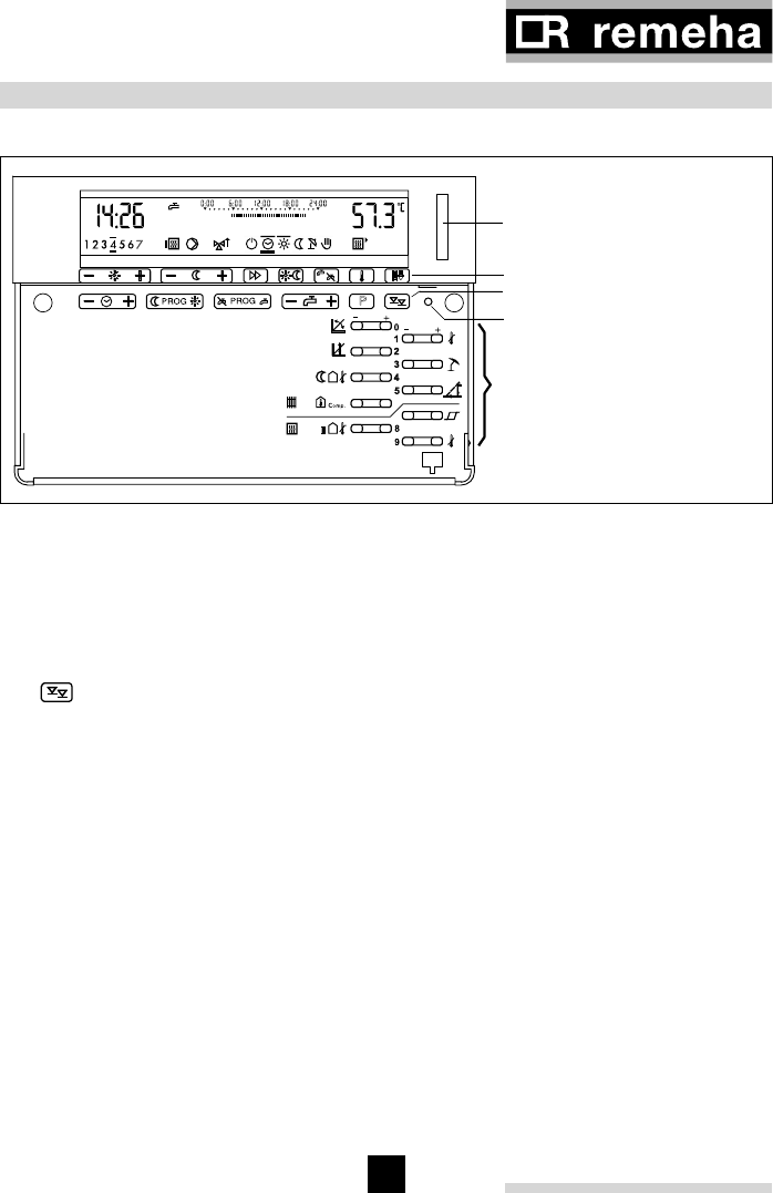
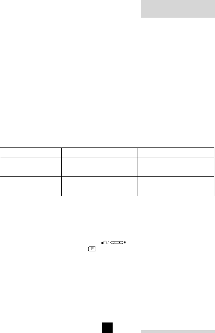
3 CONTROLS AND DISPLAYS
P
Heating circuit toggle key
(dual circuit controller only)
1st -level controls
2nd -level controls
Reset button (recessed)
3rd till 6th -level controls
(specialist levels)
Fig. 01
The 1st and 2nd -level controls are explained in chapter “2.3 User controls and display”
of the User Guidelines.
The specialist-level controls have multiple functions, i.e. the same key may have
different functions at the 3rd, 4th, 5th and 6th levels.
The key selects between the 3rd till 6th specialist levels; the procedure is described
under chapter “3 Specialists adjustments”. The 5th and 6th specialist levels are
protected by a code.
Adjustments are numbered using the operating level (3, 4, 5 or 6), plus the number
to the right or left of the key.
Dual circuit controllers (not applicable to the UK) include certain adjustments that apply
to specific heating circuits (identified by the display background colour). The desired
circuit must be set using the toggle key (see Fig. 01).
rematic® 2945 C3 K
10
11
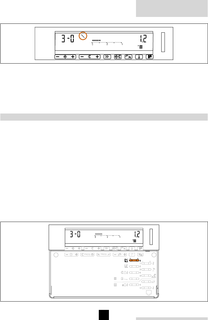
Fig. 02
From level 3 onwards, the manufacturer, or system installers acting on manufacturer’s
instructions, may restrict access to individual adjustments or entire operating levels.
The symbol “\” appears in the display, together with the set value, when ever a
protected key is pressed.
4 SPECIALIST ADJUSTMENTS
4.1 Documenting the adjustments
Record all initial settings and subsequent adjustments in the tables contained in the
section “18 Adjustment keys, boiler data and system data”. These tables provide a full
overview of 3rd till 6th level adjustment options.
Note: Some adjustments (ie heating slope and parallel shift) do not show an immediate
response. Therefore it is unwise to make more than one adjustment at a time – waiting
to see the reaction before making another.
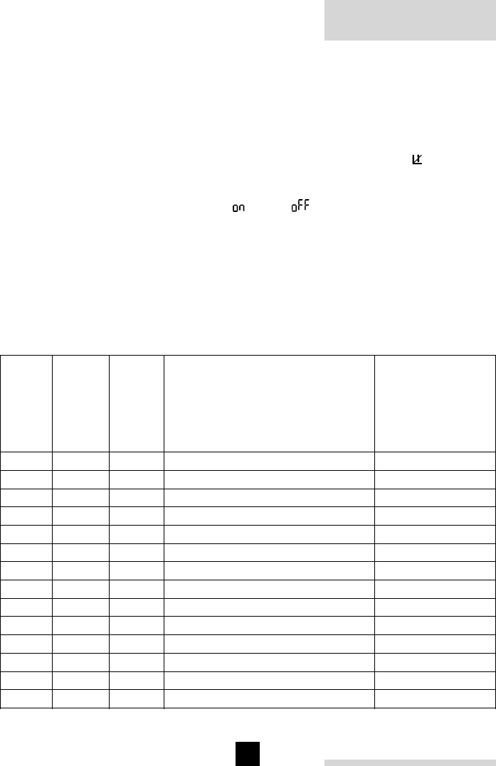
4.2 General procedures
The basic procedure for performing a specialist adjustment is always the same. The
example below demonstrates the principle.
4.2.1 Performing 3rd -level adjustments
P
t
Fig. 03
rematic® 2945 C3 K
10
11
- Remove the cover (press down on the arrow marks on the bottom edge in the
centre), and press once on the key corresponding to the desired adjustment, for
example the key .
The present setting appears in the display.
- Adjust by pressing the “–” or “+” side of the key.
Changes take effect immediately. The display returns to normal after 1 minute, or you
can press the key to restore the normal display.
You can make further 3rd -level adjustments without returning to the normal display.
Simply press another 3rd-level key and perform the adjustment.
To proceed to the 4th, 5th or 6th level, press the key one or more times (each action
move to the next level)
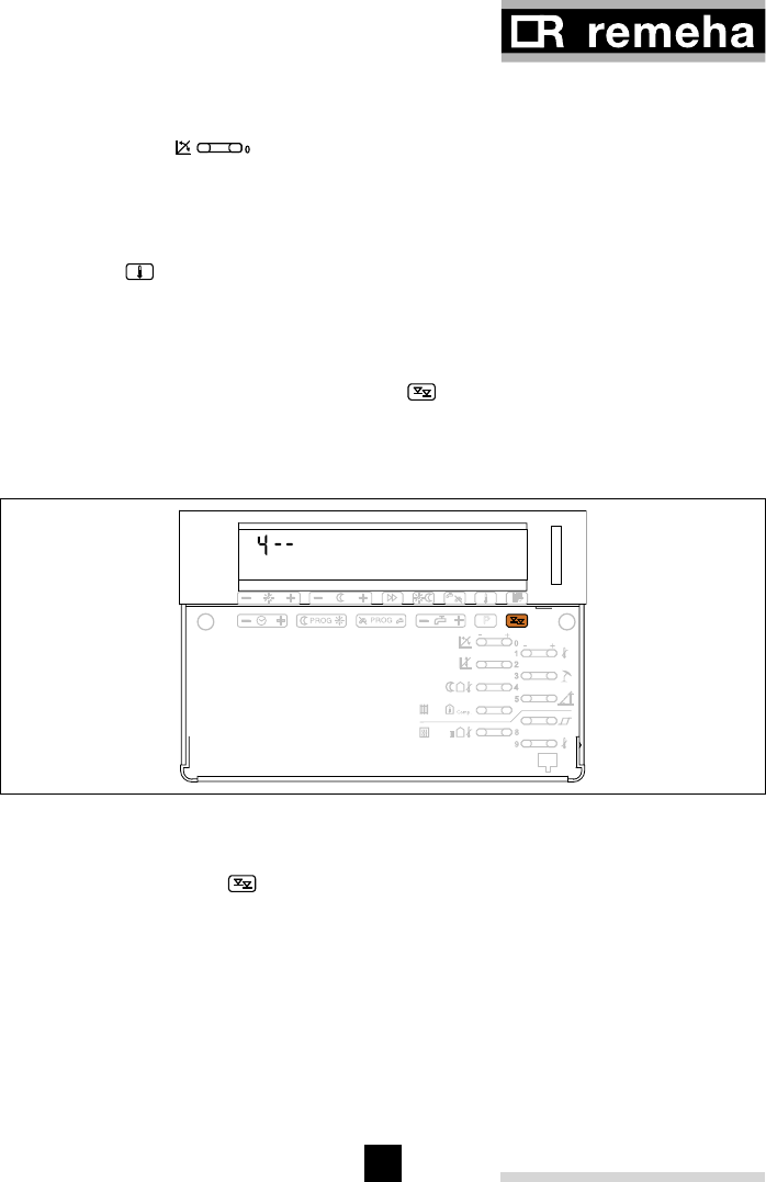
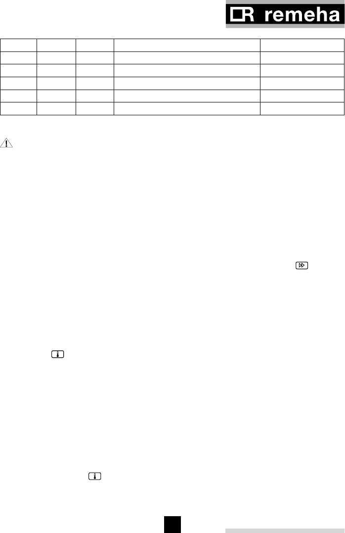
4.2.2 Performing 4th, 5th and 6th -level adjustments
P
t
Fig. 04
- Remove the cover (press down on the arrow marks on the bottom edge in the
centre), and press key to access the specialist levels. The first time you press
this key, “3 - -” shows in the display. You can now perform 3rd -level adjustments
(see the previous section).
Press the key again and “4 - -” appears in the display meaning that you are now at
the 4th operating level.
The next time you press the key, the word “out” is displayed. This is the test level,
where outputs may be switched on and off for testing purposes (see section “12.2
Test mode for controller output signals”).
The next time you press the key, the word “codE” is displayed. The 5th operating
level is protected by a code, which means that in order to be able to perform
adjustments in this level you must enter the correct code (see section “18.3 level 5
rematic® 2945 C3 K
12
13
controls”) and press key again.
If you press the key without entering the code, the word “not” is displayed, pressing
the key again returns you back to the 3rd operating level, and so on.
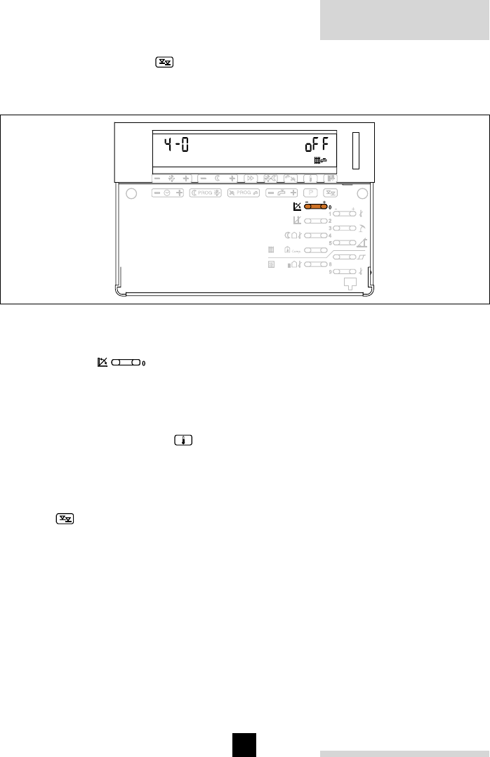
P
t
Fig. 05
- Press once on the key corresponding to the desired adjustment, for example in
level 4 on key
The present setting appears in the display.
- Adjust by pressing the “–” or “+” side of the key (ON/OFF toggle in this example).
Changes take effect immediately. The display will return to normal after 1 minute of
inactivity, or you can press the key to restore the normal display right away. You
can make further adjustments in the present level without returning to the normal
display. To do so, press another key in the current operating level and perform your
adjustments.
To switch to the 4th, 5th or 6th operating levels before returning to the normal display,
press the key the required number of times. Press the key repeatedly to cycle
through the various operating levels.
rematic® 2945 C3 K
12
13
5 LEVEL 3 ADJUSTMENTS
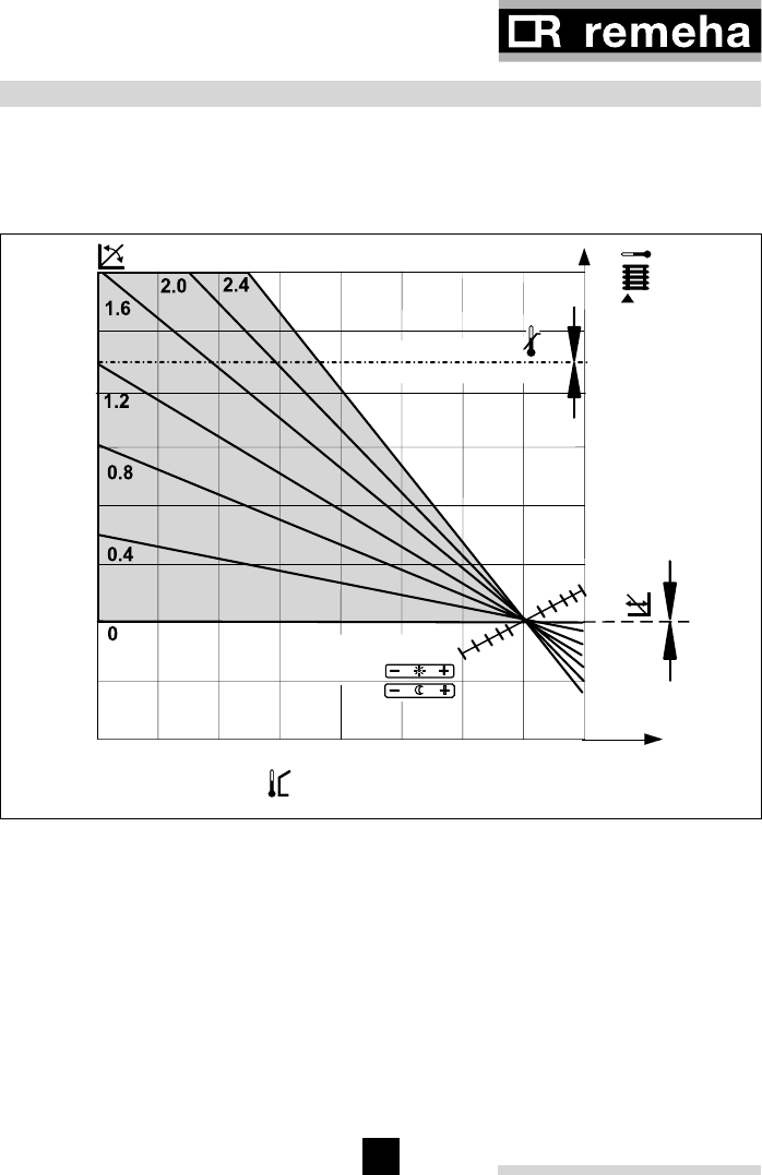
5.1 Heating curve (adjustments 3-0 and 3-2)
The heating curve indicates the relationship between the flow water and the outside
temperature, ∆TF/∆TO.
Set point room
temperature
-20 -15 -10-5
0
5
10
15
20
10
20
30
40
50
60
70
80
90
Outside temperature
°C
Slope
°C
TO
°C
15 °C
25 °C
Set point
maximum flow / boiler
Slope
Base point flow temperature (TF)
Fig. 06
NOTE: Because of the building’s thermal inertia, it is recommended to perform
no more than one adjustment step per day. Remember to record each change
and reaction to the change.
5.1.1 Adjusting the heating curve slope and base point
The heating curve is governed by the following adjustments:
rematic® 2945 C3 K
14
15
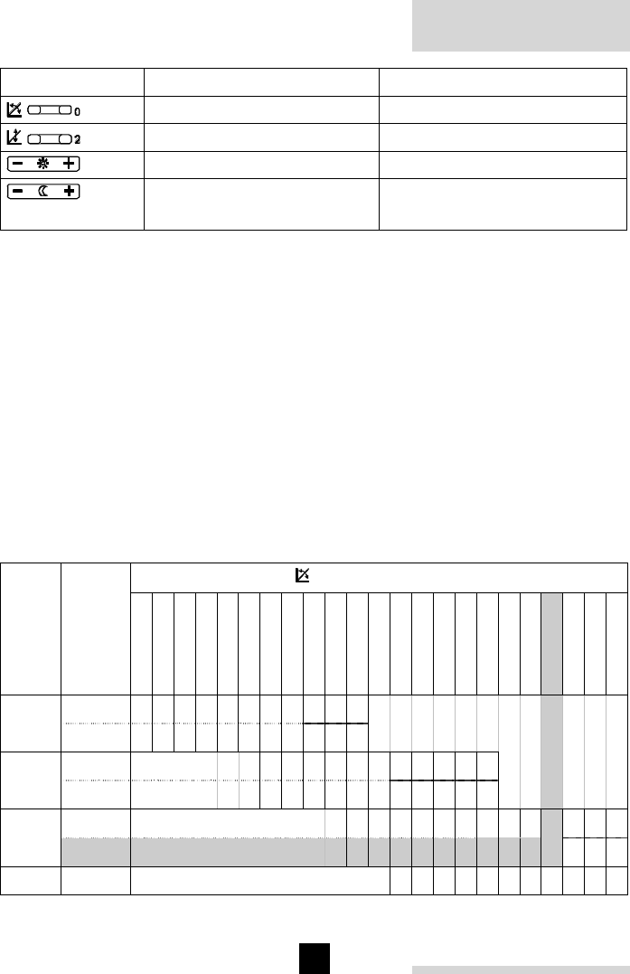
Adjuster button Function Basic setting performed by:
Slope Specialists
Flow temperature base point Specialists
Desired heating temperature User
Desired night setback
temperature
User
Table 01
The table below will assist in determining the heating curve appropriate to a given
heating system. You will need to know the type of heating system, and the climatic
zone in which it will operate.
High-temperature 90/70 Radiator heating
Standard-temperature 81/70 Radiator heating
Low-temperature 70/50 Radiator heating
Ultra-low temperature 50/35 Underfloor heating
Climatic zone where the building is located:
- 10°C = A
- 8°C = B
- 6°C = C
- 4°C = D
- 2°C = E
Heat curve rate rise = ∆TF/∆TO
Heating
system
base
point
TF at
TO = +
15°C
0.8
0.9
1.0
1.1
1.2
1.3
1.4
1.5
1.6
1.7
1.8
1.9
2.0
2.1
2.2
2.3
2.4
2.5
2.6
2.7
2.8
2.9
3.0
20°C A B C D E
50/35
25°C A B C D E
30°C A B C D E
70/50
35°C A B C D E
30°C A B C D E
81/70
35°C ABCDE
90/70 39°C A B C D E
Table 02
rematic® 2945 C3 K
14
15
Example:
Heating system class = 81/70
Base point at TO 15°C = 35°C
Climatic zone - 2°C = E
Resulting slope = 2.7
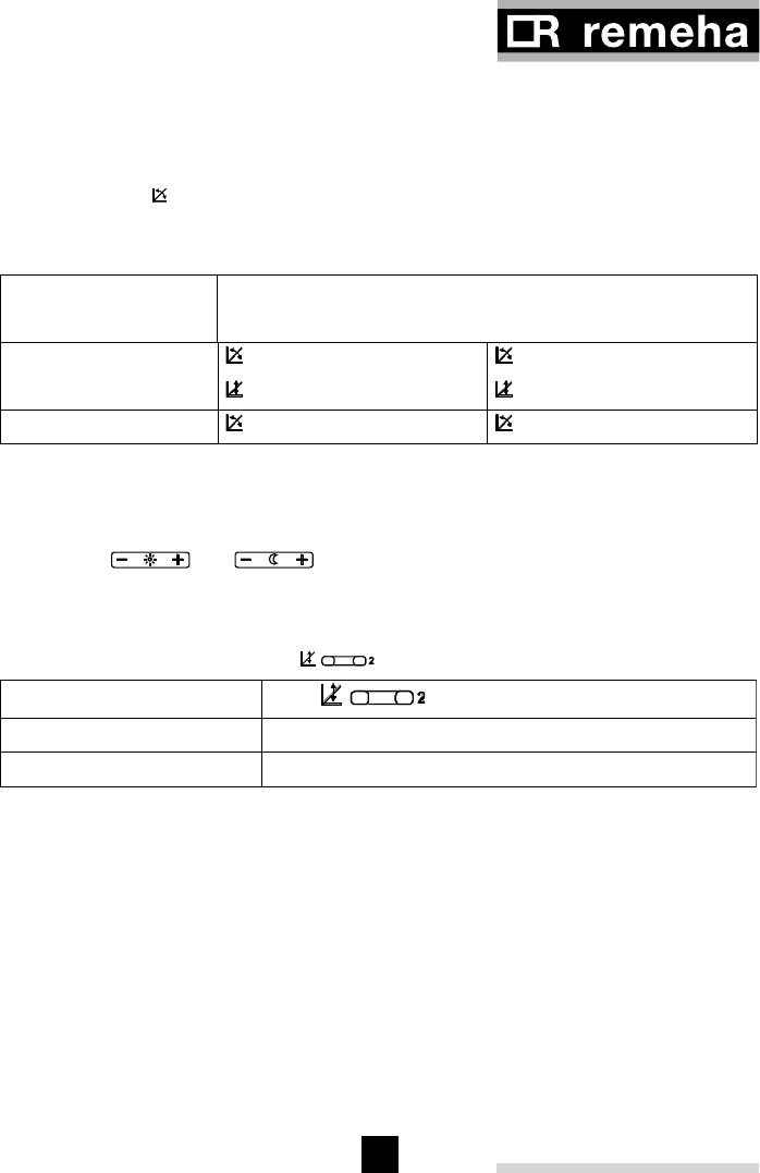
5.1.2 Fine-adjusting the heating curve
room temperature
At day time outside
temp. between too cold too warm
+5°C and +15°C set 0,2 lower and
set 5ºC higher
set 0,2 higher and
set 5ºC lower
-20°C and +5°C set 0,2 higher set 0,2 lower
Table 03
5.1.3 Compensating differences between set and current room temperature
The end user programs temperature set points in terms of a room temperature (oC)
with buttons and . Even if the heating curve slope is correctly
adjusted, depending on the heating system there may still be a difference between
the room temperature measured by a thermometer (actual temperature) and the
temperature defined in the controller (set temperature). This may be adjusted by
moving the base point with button .
Room temperature Key
too low Increase by pressing [ + ]
too high Decrease by pressing [ - ] )
Table 04
Increasing or decreasing the set point influences the room temperature.
A 5°C change in flow temperature set point alters the calculated room temperature as
follows:
- Underfloor heating: approx. 2°C
- Radiator heating: approx. 1°C
5.2 Maximum common flow / boiler flow temperature (adjustment 3-1)
The flow water temperature is limited to the pre-set value (Note: this cannot override
the boilers flow temp set point).
This limiting value applies to the selected heating circuit or to the cascade temperature,
depending on usage.

rematic® 2945 C3 K
16
17
This adjustment is not intended as a safety device! Underfloor heating may
require an additional control to prevent overheating.
5.3 Summertime limits
This set point read with the outside sensor will, if exceeded, hold the heating in the
off position
5.3.1 Summertime limit in heating mode (adjustment 3-3)
Heating ceases once the average outside temperature exceeds the set temperature.
Domestic hot water keeps on operating. Heating resumes once the average outside
temperature drops more than 2°C below the set temperature.
5.3.2 Summertime limit in night setback mode (adjustment 3-4)
This adjustment defines the maximum outside temperature in order for the flow
temperature to be controlled according to the night setback heating curve. Heating
ceases at outside temperatures above the set temperature. Once the outside
temperature drops more than 2°C below the set temperature, the flow water
temperature is controlled according to the night setback heating curve.
Setting a value below 2°C activates frost protection at outside temperatures between
2°C and the set temperature, see section “5.3.3 Frost protection”.
5.3.3 Frost protection
The circulation pump is switched on cyclically below an outside temperature of
2°C (frost protection limit). In each cycle it runs for 6 minutes, then switches off for
54 minutes. If the adjustment 3-4 is set above 2°C, the “frost protection mode” is
overruled by the “summertime limit in night setback mode” as described under section
“5.3.2 Summertime limit in night setback mode (adjustment 3-4)”.
5.4 Optimised start - pre-heat time (adjustment 3-5)
Pre-heat time gives the heating system a “warm up time” in order to attain operating
temperature at set occupancy time. A basic value for the pre-heat time, based on the
type of heating system, has to be programmed so that the controller is able to calculate
the actual start time to achieve room temperature set point at set occupancy time.
The controller takes the following factors into account:
- measured outside temperature
- measured room temperature, assuming that a room sensor or remote control is
fitted.
Recommended basic value:
- Underfloor heating: 210 (minutes)
- Radiator heating 150 (minutes)
rematic® 2945 C3 K
16
17
The basic value is the pre-heat time, valid for an outside temperature of -10°C (= the
so called standard climatic zone). The higher the outside temperature, the shorter the
pre-heat time, which decreases to 0 minutes at 20°C.
5.4.1 Calculation formula for pre-heat time based on outside temperature:
The controller calculates according the following formula:
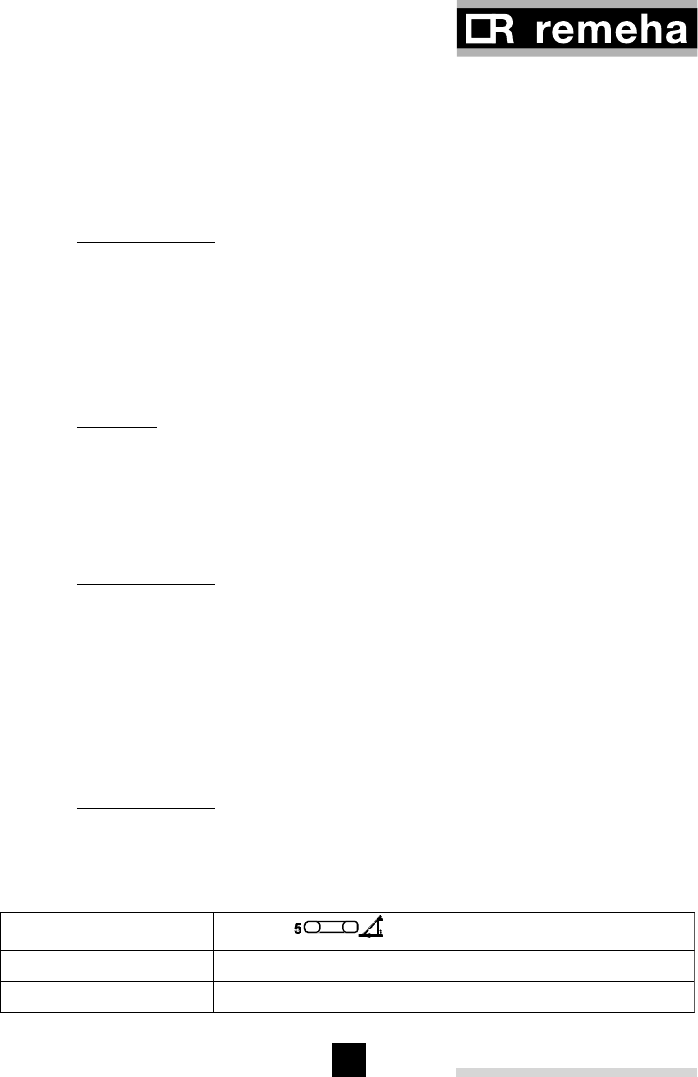
TR SET is reached: Button
too early reduce basic value (press [ - ] side)
too late increase basic value (press [ + ] side)
PHT COR = corrected pre-heat time
PHT CAL = calculated pre-heat time prior to occupancy time
TR SET = set room temperature
TR MES = measured room temperature
Example: TR SET = 20°C
TR MES = 18°C
PHTCAL= 20-TOMES x basic value
20-climate point
PHT CAL = calculated pre-heat time prior to occupancy time
TO MES = measured outside temperature
Example: basic value = 150 minutes
Outside temperature = 5°C
PHTCAL= 20 - 5 x 150 = 75 minutes
20 - - 10
5.4.2 Calculation formula for pre-heat time with room temperature correction
If a room sensor or remote control is connected, the measured ambient room
temperature is included in the pre-heat time calculation. The pre-heat time calculated
earlier is shortened by a factor that is calculated as follows:
PHTCOR = TRSET - TRMES x PHTCAL
5
PHTCOR = 20 - 18 x 75 = 30 minutes
5
5.4.3 Correcting the basic value
Should the design temperature be reached before or after occupancy time, correct the
basic value as follows:
Table 05

rematic® 2945 C3 K
18
19
It is recommended that modifications of the basic value be no shorter than the
following:
- Underfloor heating 30 minutes
- Radiator heating 20 minutes
If the heating system start-up does not need to be optimised in this way, set the basic
value to 0. The heating system then commences operation at the programmed time.
5.5 Room temperature compensation (adjustment 3-6)
This adjustment is relevant only if a room sensor or remote control is
connected.
If the temperature measured by a room sensor or remote control deviates from the set
point (e.g. as a result of external heating such as solar gain), the controller corrects
the water flow temperature according to the compensation value. This specifies the
increase or decrease in water flow temperature (in °C) per °C room temperature
deviation.
- Room over-temperature = reduced flow temperature
- Room under-temperature = increased flow temperature
The effect of the setting is shown in Fig. 07.
Recommended settings:
No room compensation 0
Underfloor heating 1 - 4
Radiator heating
• Mild compensation 1 - 3
• Medium compensation 4 - 6
• Strong compensation 7 – 9
Einstellwert
-4 +4
3
6
9
-3 -2 -1 +1 +2 +3
0
∆TF (°C)
∆TR (°C)
Setpoint 3-6
∆TF = Change in flow water temperature
∆TR = Change in room temperature
Fig. 07

rematic® 2945 C3 K
18
19
5.5.1 Calculation formula for room temperature compensation
Deviation of the room temperature from the set point causes a change in the flow
water temperature. The resulting flow water temperature set point is calculated as
follows:
TF CAL “NEW” = TF CAL + ((TR SET – TR MES) x K)
TF CAL = calculated flow temperature
TR SET = set room temperature
TR MES = measured room temperature
K = compensation factor (adjustment 3-6)
Example:
Desired room temperature (TR set) 20°C
Current room temperature (TR MES)(elevation due to e.g. incoming sunshine) 22°C
Room temperature compensation K (adjustment 3-6) 4 °C/°C
Flow water temperature setting (TF CAL)(according to heating curve) 45°C
TF CAL “NEW” = 45 + ((20 - 22) x 4) = 37°C
5.6 Number of slaves and their addressing (adjustment 3-7) NOT AVAILABLE IN
UK
This adjustment determines whether the controller at hand is used as a master or
as a slave controller and simultaneously the number and sequence of the slaves are
indicated.
- Master controller: By entering one of the codes 0, 1, 2, 3 or 4, the number of
connected slaves is programmed. With only one controller in the installation,
adjustment 3-7 should be set at 0.
- Slave controller: The slave controller is assigned an address by entering one of
the codes F1, F2, F3 or F4.(F= follower controller).
When adjustment 3-7 is incorrectly programmed, the master controller can
communicate neither with the slave controllers, nor with the boiler(s).
5.7 Nature of the controller (adjustment 3-8)
This sets the controller to the number of boilers and method of control (Modulation or
High / Low)
One master controller can operate up to 8 modulating boilers. With one master - and
4 slave controllers 5 on/off or high low boilers can be handled. As long as the total
number of boilers does not exceed 8 and the number of on/off - or high/low boilers
does not exceed 5, any combination of modulating -, on/off - or high/low boilers can be
controlled.(NOT AVAILABLE IN THE UK)
rematic® 2945 C3 K
20
21
The settings which may be chosen are as follows:
Master controller: (adjustment 3-7 is set to 0, 1, 2, 3, or 4)
Adjustment 3-8 must be set for each boiler in the installation.
b1 = setting for an on/off boiler
b2 = setting for a high/low boiler
FA. = setting for communication with a modulating boiler control
-- = setting for those boiler positions (of 8) which are not in use
Slave controller: (adjustment 3-7 is set to F1, F2, F3, or F4) NOT AVAILABLE IN THE
UK
-- = setting for the slave that only controls supplementary mixing circuits
b1 = setting for the slave that controls a supplementary on/off boiler
b2 = setting for the slave that controls a supplementary high low boiler
If the controller has been programmed with the FA.- - setting, it detects whether the
sensors are connected at the controller or at the boiler control and the controller itself
supplements the FA. setting with a number as follows (If an error occurs it might help
to program the correct FA setting directly by hand):
Adjustment 3-8 D.H.W. sensor at: Flow sensor at:
FA1 Compensator Compensator
FA2 Boiler control Compensator
FA3 Compensator Boiler control
FA4 Boiler control Boiler control
Table 06
The outside sensor packed in the rematic® kit must be connected to the controller
adapter plate. (See also the relevant fitting and wiring diagrams)
5.7.1 Procedure for performing adjustment 3-8:
- Select adjustment 3-8 by pushing key one time.
- If boilers are connected, use the
P
key to invoke the boiler for which the
adjustments are to apply.
Instead of the time bar, the points in the display indicate how many boilers are
programmed. The point of the invoked boiler flashes. You can now perform the
required adjustment or ad more boilers.
5.8 Minimum modulation percentage (output) (adjustment 3-9)
The minimum output of the boiler may be entered as a percentage of the nominal
output of the boiler. The minimum modulation percentage must be set for each boiler.

rematic® 2945 C3 K
20
21
5.8.1 Procedure for performing adjustment 3-9:
- Select adjustment 3-9 by pushing key one time.
- If multiple boilers are connected, use the
P
key to invoke the boiler for which the
adjustments are to apply.
Instead of the time bar, the points in the display indicate how many boilers are
programmed. The point of the invoked boiler flashes. You can now perform the
required adjustment.
6 LEVEL 4 ADJUSTMENTS
6.1 Domestic hot water operation modes
NOTE: In a cascade installation if the DHW is controlled by the rematic® controller all
boilers connected to the control will be made available to satisfy the demand.
Domestic hot water heating is activated when the DHW time channel is in the on
position and the connected DHW sensor shows that the water temperature in the
calorifier is 5 °C below the set point. When the D.H.W. set point is reached the demand
is deactivated.
6.1.1 Simultaneous or priority D.H.W. heating (adjustment 4-0)
The domestic hot water may be heated simultaneously with the heating circuits, or
be given priority.
Setting adjustment 4-0 to “OFF”: D.H.W. heating has priority over the heating
circuits
The heating circuits are switched off while the domestic hot water is heated. (i.e.
system pumps “OFF)
The heating circuits are enabled once the domestic hot water has reached the set
temperature. The D.H.W. pump continues to operate for a period set by adjustment 4-3.
If a heating circuit demands a higher flow temperature, the controller immediately shuts
off the domestic hot water pump. A diverting valve can be used In place of a D.H.W.
primary pump (see section 6.1.2).
Setting adjustment 4-0 to”ON”: Simultaneous operation of D.H.W. heating
(Requires the use of a D.H.W. primary pump and is not possible with a diverting
valve).
The controller will boost the flow temperature from the compensated level to the DHW
flow temp set point which will mean that the heating flow temperature may also be
elevated

rematic® 2945 C3 K
22
23
6.1.2 D.H.W. heating using a pump or a diverter valve (adjustment 4-1)
Depending on the heating system, it is possible to select a pump or a diverter valve
for D.H.W. heating.
Setting of adjustment 4-1 to “OFF” : Domestic hot water heating using a pump
See section 6.1.1 for explanation
Setting of adjustment 4-1 to “ON” : Domestic hot water heating using a diverting
valve
Together with the diverting valve, the system pump feeds flow water to the
calorifyer heat exchanger. The pump therefore continues to run during D.H.W. heating.
Simultaneous D.H.W. and heating is not possible with this setting. (see also section
“6.1.1 Simultaneous or priority D.H.W. heating (adjustment 4-0)”).
6.2 Flow water temperature for D.H.W. heating (adjustment 4-2)
The D.H.W. temperature set point, increased by the value set here, gives the set flow
temperature of the boiler(s) for D.H.W. heating.
6.3 Run-on time of domestic hot water pump (adjustment 4-3)
The value set here determines how long, after attaining the set D.H.W. temperature,
the domestic hot water pump continues to run and the diverting valve is in the DHW
mode.
6.4 Legionnaires’ disease protection temperature (adjustment 4-4)
The domestic hot water temperature programmed here (minimum setting is 60 °C)
is initiated on the day set in adjustment 3-4 (see section “6.5 Legionnaires’ disease
protection mode (adjustment 4-5)”). Adjustment 4-4 is set higher than the normal
domestic hot water temperature, set with button and is used to protect against
Legionnaires’ disease.
6.5 Legionnaires’ disease protection mode (adjustment 4-5)
In accordance with the code set here, the Legionnaires’ disease protection
temperature, set with adjustment 4-4 (see section 6.4 “Legionnaires’ disease protection
temperature (adjustment 4-4)” is enabled for two hours during the first D.H.W. heating
on each day in question.
The set codes are as follows:
1 = Mondays
2 = Tuesdays
3 = Wednesdays
4 = Thursdays
5 = Fridays
6 = Saturdays
7 = Sundays
8 = daily
9 = continuously at the temperature set with adjustment 4-4
0 = no Legionnaires’ disease protection mode

rematic® 2945 C3 K
22
23
6.6 Adaptive heating curve (adjustment 4-6)
If a remote control or room sensor (supplied as standard in the UK) is connected to the
controller, it can automatically correct the heating curve to suit the buildings properties.
Adjustment 4-6 can be set for each heating circuit separately.
Adaptive heating curve “inactive” (“OFF” setting)
The operator-defined heating curve is not automatically modified (useful if there is
another heat source such as an open fireplace).
Adaptive heating curve “active” (“ON” setting)
The controller automatically determines the optimal heating curve. It might take more
than a week before the optimal curve is reached.
6.7 Minimum boiler temperature (adjustment 4-7)
The controller maintains a minimum flow temperature for the boiler(s) in heating and
night set back mode. This adjustment is used to prevent the compensator lowering
the flow temp below the min required for heat emitters used in the system (ie fan
convectors may have a min flow requirement of 55 oC).
Note : This set point should not be set below to the boiler manufacturer’s specifications.
6.8 Flow temperature excess in °C in relation to the heating curve(s)
(adjustment 4-8)
During the heating season, the set flow temperature for the boiler(s) is higher, by the
value set here, than the highest flow temperature, requested by one of the heating
circuits. This adjustment must be set for each heating circuit.
Recommended settings:
0 = for direct heating circuits
5 = for mixed heating circuits
6.9 Adapting to the heating circuit (adjustment 4-9)
Before performing this adjustment, the required heating circuit must be selected! (Only
setting 2 for UK)
Setting 0 = 3-point output for mixer drives with 230 V motor with 2 directions
of rotation
The direction of rotation of the mixer is controlled by energising the “ON” or the “OFF”
relay in the controller.
Setting 1 = 2-point output for mixer drives with automatic return, e.g. 230 V
thermal mixer drives
The mixer drive opens the valve on energising the “ON” relay in the controller. It closes
automatically if the controller de-energises the “ON” relay. The controller maintains a
certain valve position by intermittently energising the “ON” relay.
Setting 2 = setting for a direct heating circuit with no output for a mixer drive
The system pump for this circuit runs continuously during the heating season. (The
mixer symbol is not displayed.)

rematic® 2945 C3 K
24
25
7 LEVEL 5 ADJUSTMENTS
The adjustments in the 5th operating level make it possible to adapt the controller
adjustments to the features and allocation of each boiler in a multiple boiler installation.
Access to this operating level is coded.
Improper changes in this operating level may impair the functioning of the
boiler(s).
The adjustments 5-0 to 5-6 described below must be individually adjusted for each
boiler. The number of boilers has been programmed with adjustment 3-8. Select the
adjustment, e.g. 5-3, then use the
P
key to select the relevant boiler. The display
shows a row of points instead of the time bar. The flashing point indicates which boiler
has been selected. You can now adjust the value of the selected boiler.
7.1 Boiler output at full load (adjustment 5-0)
The full load output of the selected boiler must be entered in the controller in kW. This
setting is essential for modulating boilers. The nominal output specification on the data
badge of the boiler is definitive.
It is not compulsory to enter this value for connected on/off or high/low boilers
(controlled by relay contacts in the controller).
7.2 Grouping boilers (adjustment 5-1)
Each boiler in a multiple boiler installation is assigned to a group. There are 4 groups to
be selected. The following group features should be noted when assigning boilers:
- Groups 1 and 3 have automatic sequence changeover (see section “7.8 Sequence
changeover of boilers in groups 1 and 3 (adjustment 5-7)”).
- Groups 3 and 4 are switched off when the outside temperature rises above the set
heating limit value (see section “8.5.1 Blocking of boiler groups 3 and 4 dependent
on outside temperature (adjustment 6-5)”).
- Groups 1 and 2 are switched off when the outside temperature drops below the set
heating limit value (see section “8.5.2 Blocking of boiler groups 1 and 2 dependent
on outside temperature (adjustment 6-6)”).
Normally all modulating condensing boilers are programmed in group 1. The sequence
of the groups is as follows: With increasing heat demand, the boilers in group 2 will not
be started before all boilers in group 1 are in service at full load. The same principle
applies for groups 3 and 4. The allocation of boilers to groups allows the energy saving
operation of installations with condensing boilers and standard boilers. It also allows
the bivalent operation of installations with heating boilers and heat pumps. It permits
automatic output limitation as a function of outside temperature. Automatic sequence
changeover allows you to programme a load compensation for the boilers.

rematic® 2945 C3 K
24
25
7.3 Cut-in output of the follow-up boiler (adjustment 5-2)
This set value determines the percentage output of the selected boiler with which the
following boiler is to be switched on.
The first boiler is switched on immediately after the time, set with adjustment 6-3,
is elapsed.
7.4 Minimum boiler return temperature TBR MIN (adjustment 5-3)
The boiler return control is active for the selected boiler if the set value of TBR MIN is
greater than 0. Heating circuits are enabled when the return temperature of the boiler
rises above the set point. This adjuster is not active for stages programmed with FA.
7.5 Minimum fan speed with boiler switched off (adjustment 5-4)
The minimum speed of the boiler fan is adjustable for modulating burners as a
percentage of the maximum fan speed. 0 = OFF, which means the fan is not required
with burner switched off. This adjustment might be of use when ventilation problems
occur.
7.6 Return temperature control selection (adjustment 5-5) (NOT USED IN THE
UK)
The return temperature of the boiler(s) can be controlled in several ways, which can
be separately set for each boiler.
The settings have the following meaning:
0 = U0...U5 corresponding to the boiler safety modes.(see section “8.3 Boiler safety
modes (adjustment 6-2)”)
1 = Return temperature control by the heating circuit mixer(s). The boiler circuit pump
Uw operates continuously during the heating season.
2 = Return temperature control by the heating circuit mixer(s) without boiler circuit
pump Uw. The controller calculates a variable minimum boiler flow temperature based
on the set value for the minimum boiler return temperature (adjustment 5-3). The
lower the measured return temperature, the higher the required minimum boiler flow
temperature TF MIN.
3 = The “green” heating circuit mixer is used as return temperature control. The mixer
Mr itself, as well as the boiler circuit pump Uw are mounted in the return pipework of
the boiler. Operation and display for the green circuit are blocked, with the exception
of the temperature display.

rematic® 2945 C3 K
26
27
4 = The “green” heating circuit mixer is used as return temperature control without the
assistance of a boiler circuit pump. The mixer Mr itself is mounted in the flow pipework
of the boiler. Operation and display for the green circuit are blocked, with the exception
of the temperature display. The controller calculates a variable minimum boiler
flow temperature based on the set value for the minimum boiler return temperature
(adjustment 5-3). The lower the measured return temperature, the higher the required
minimum boiler flow temperature TF MIN.
5 = Return temperature control only with boiler circuit pump Uw. The pump Uw
switches off on reaching the minimum return temperature TBR MIN. No mixer Mr is
used. No heating circuit mixer is influenced by the set min. boiler return temperature
TBR MIN.
6 = The “green” heating circuit mixer is used as return temperature control for all boilers
in a multiple boiler installation. The mixer Mr itself is mounted in the common return
pipework of the boilers. Each boiler has its own boiler circuit pump Uw. Operation and
display for the green circuit are blocked, with the exception of the temperature display.
The sequence changeover (adjustment 5-7) does not influence this mode.
7.7 Allocation of boiler relay outputs for on/off or high/low boilers (adjustment
5-6) (NOT USED IN THE UK)
If relay contacts are used to control on/off and/or high/low boiler(s), they
must be allocated to a controller.
The settings are as follows:
--- = no boiler relay function (there is no on/off or high/low boiler in the installation)
M = boiler relay function at the master (the 1rst boiler is an on/off or high/ low boiler)
F1 = boiler relay function at slave 1(the 2nd boiler is an on/off or high/ low boiler)
F2 = relay function at slave 2 (the 3rd boiler is an on/off or high/ low boiler)
F3 = relay function at slave 3 (the 4th boiler is an on/off or high/ low boiler)
F4 = relay function at slave 4 (the 5th boiler is an on/off or high/ low boiler)
7.8 Sequence changeover of boilers in groups 1 and 3 (adjustment 5-7)
OFF = continuous forward operation
ON = continuous backward operation
10 ... 999 = sequence changeover after the set number of running hours of the first
boiler.
7.9 P-band (proportional band) (adjustment 5-8)
The P-band indicates the deviation between the actual flow temperature and flow
temperature set point at which 100% boiler output (for all boilers) is required (setting
band 0 to 30 °C). With increasing deviation, a low set value produces a large change
in output. The heat production reacts quickly on changes in heat demand. With

rematic® 2945 C3 K
26
27
increasing deviation, a high set value produces a small change in output. The heat
production reacts slowly on changes in heat demand. The factory setting rarely needs
modification.
7.10 I-band (integral proportion) (adjustment 5-9)
The I-proportion indicates, at a constant deviation between the actual flow temperature
and flow temperature set point, how long (minutes) the controller takes to double the
output needed according to the P-band. A low set value produces a rapid change in
output where there is a deviation. The heat production reacts quickly, even where
there is only a short term temperature deviation. A high set value produces a slowly
increasing change in output where there is a deviation. The heat production reacts
slowly on an existing temperature deviation.
The factory settings rarely needs modification.
8 LEVEL 6 ADJUSTMENTS
8.1 Maximum common flow temperature (adjustment 6-0)
To prevent the common flow temperature exceeding the setpoint, the controller will
throttle the output of the boiler(s) or switch them off. This adjustment has priority over
all other requirements.
8.2 Run-on time of the D.H.W. pump dependent on time or temperature
(adjustment 6-1)
With adjustment 6-1 the run-on time of the D.H.W. pump can be programmed
dependent on time or dependent on temperature.
Setting “off”: time-dependent run-on time
After domestic hot water heating is completed, the D.H.W. pump continues to operate
for the period set with adjustment 4-3 (see section “6.3 Run-on time of domestic hot
water pump (adjustment 4-3)”).
Setting “on”: temperature-dependent run-on time
After domestic hot water heating is completed, the D.H.W. pump continues to operate
until the differential between the flow temperature and the domestic hot water
temperatures reaches 3 °C. However, the run-on time is limited to the time period
set in adjustment 4-3 (see section “6.3 Run-on time of domestic hot water pump
(adjustment 4-3)”).
8.3 Boiler safety modes (adjustment 6-2)
Depending on the safety mode selected here, given a sudden heat demand (from the
heating circuits and/or domestic hot water heating) the heating load is immediately
switched on or only after the flow temperature of the boiler (or the common flow
temperature of the boilers) has reached the set minimum flow temperature TF MIN (see
section “6.7 Minimum boiler temperature (adjustment 4-7)”).

rematic® 2945 C3 K
28
29
In selecting the boiler safety mode, the functioning of the boiler circuit pump is
determined at the same time as follows:
Setting Safety mode Function of the boiler circuit pump Uw
0
1
2
U0
U1
U3
Uw operates continuously during the heating
season.
3
4
5
U0
U1
U3
After the master boiler is switched off, Uw
continues to operate for 15 minutes or (for
communicating boilers) for the period set in the
boiler control.
Table 07
Safety mode U0 (settings 0 and 3)
This mode ensures that the set minimum boiler temperature TF MIN (adjustment 4-7) is
not undershot by using the maximum output of the boiler or boilers. If this set value is
undershot, no heat load is switched off.
Safety mode U1 (settings 1 and 4)
This mode ensures that the minimum boiler temperature TF MIN (adjustment 4-7) is not
undershot by using the maximum output of the boiler or boilers. Additionally, however,
heat load is switched off if this set value is undershot.
Safety mode U3 (settings 2 and 5)
This mode ensures that, if the flow temperature of the boiler(s) drops below the
set minimum return temperature TBR MIN (see section “7.4 Minimum boiler return
temperature TBR MIN (adjustment 5-3)”), no heat load is switched off and no boilers are
switched on. It is not before the flow temperature of the boiler(s) has dropped to the set
point (according to the heating curve or external requirement) and heat production is
necessary that the mixers are closed, the circuit pumps are switched off and the boilers
are switched on with the required output. The heating circuits are enabled again once
the flow temperature of the boiler(s) reaches the minimum temperature range.
8.4 Delayed cut-in of boiler stages
8.4.1 Delayed cut-in of 1st boiler (adjustment 6-3)
A delayed cut-in may be programmed for the 1st boiler. The count down starts when
the controller requests the first boiler, based on his internal PI calculation.

rematic® 2945 C3 K
28
29
8.4.2 Delayed cut-in of subsequent boilers (adjustment 6-4)
A second delayed cut-in may be programmed for the following boilers. The count down
starts when the controller requests the next boiler. The programmed time is the same
for all subsequent boilers. This time delay can prevent short-term switching on of
boilers.
8.5 Blocking of boiler groups dependent on outside temperature
Since a normal boiler installation does not need these adjustments, the adjustments
6-5 and 6-6 are ceased to be operative by the factory settings.
8.5.1 Blocking of boiler groups 3 and 4 dependent on outside temperature
(adjustment 6-5)
If the outside temperature exceeds the set value, the boilers associated with groups 3
and 4 are blocked. If the outside temperature drops by more than 2 °C below this value,
the boilers in these groups are enabled again.
8.5.2 Blocking of boiler groups 1 and 2 dependent on outside temperature
(adjustment 6-6)
If the outside temperature undershoots the set value, the boilers associated with
groups 1 and 2 are blocked. If the outside temperature rises by more than 2 °C above
this value, the boilers in these groups are enabled again.
This adjustment is important if air/water heat pumps are used in combination with
boilers.
8.6 Neutral zone for the internal Pl-behaviour of the controller (adjustment 6-7)
Variations in the (common) flow temperature within the neutral zone around the flow
temperature set point, will not cause changes in the output of the boiler(s).
8.7 Ramp mode to limit the speed of changes in output
If there are jumps in the set point (e.g. night/day changeover) or changes in load, this
adjustment allows the speed of change in output to be limited. The ramp function may
be adjusted separately for set temperature / /measured temperature deviations both
outside and inside the proportional band. The maximum allowed change in output per
minute is set as a percentage of the total boiler output. The higher the set value, the
quicker the response in boiler output to a flow temperature change. The factory settings
apply to 99% of the installations.
- Adjustment 6-8: Ramp function outside the P-band
- Adjustment 6-9: Ramp function inside the P-band
For installation personnel only

rematic® 2945 C3 K
30
31
9 PUMP FUNCTIONS
The system pumps run when:
- heating is enabled and the outside temperature lies below the heating limit (see
section “5.3.1 Summertime limit in heating mode (adjustment 3-3)”);
- night set back is enabled and the outside temperature lies below the corresponding
heating limit (see section “5.3.2 Summertime limit in night setback mode
(adjustment 3-4)”);
- frost protection is activated (outside temperature lies below 2°C) (see section “5.3.3
Frost protection”);
- the heating program “manual operation” is selected.
The 30-minute pump run-on time is effective when:
- heating is enabled and the outside temperature rises above the heating limit (see
section “5.3.1 Summertime limit in heating mode (adjustment 3-3)”);
- night set back is enabled and the outside temperature rises above 4°C, or above
the night set back heating limit (see section “5.3.2 Summertime limit in night setback
mode (adjustment 3-4)”);
- power is restored after an interruption (causes a reset) or following installation.
The 5-second pump seizure protection operates:
- daily at 24 hour intervals following the last time the power was switched on
The boiler pump Uw runs:
- during heating operation ( or ) according to the selected protection mode (see
section “8.3 Boiler safety modes (adjustment 6-2)”)
For installation personnel only
rematic® 2945 C3 K
30
31
10 REMOTE CONTROL OPERATION
Each heating circuit can be operated by its own remote control. See the corresponding
instruction manual for more information. (ONLY ONE IN THE UK)
The information in this chapter references the terminal numbers as they are
marked on the controller. These numbers will not necessarily be the same if the
controller has been built into a boiler control panel, control rack, etc. In this case,
refer to the appropriate documentation.
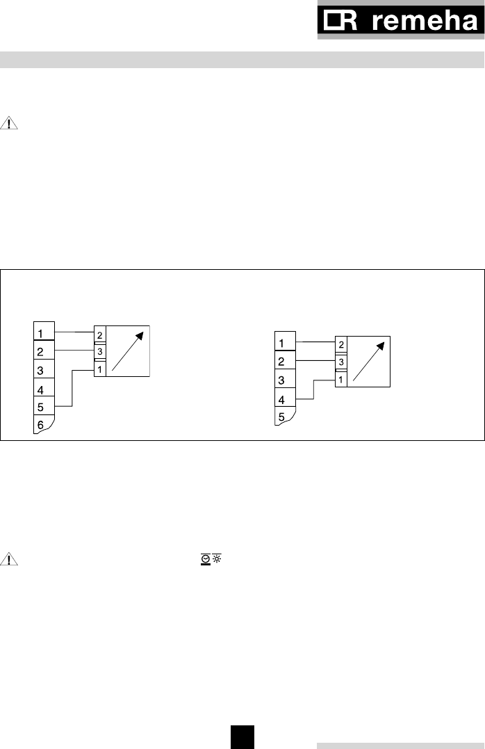
10.1 Remote control FS 3611
10.1.1 Connecting the FS 3611 remote control (RED CIRCUIT NOT USED IN THE
UK)
Heating circuit “green” Heating circuit “red”
Connector P11 of rematic 2945 Connector P12 of rematic 2945
Terminal numbers of FS 3611 Terminal numbers of FS 3611
Fig. 08
10.1.2 Operation with the FS 3611 remote control
The controller display indicates whether a FS 3611 remote control is connected
when the heating program “automatic operation” is selected. The remote control is
automatically deactivated when the controller is not in the automatic time controlled
mode.
Select “Automatic operation” after the work has been completed. This
reactivates the remote control.
The heating program and temperature adjustment set on the remote control become
visible in the controller display.
rematic® 2945 C3 K
32
33
10.2 Remote control FB 5240 (NOT USED IN THE UK)
10.2.1 Connecting the FB 5240 remote control
Heating circuit “green” Heating circuit “red”
Connector P11 Terminal numbers of FB 5240 Terminal numbers of FB 5240
of rematic 2945
FB
56
FB 2
56
Fig. 09
FB 5240 remote controls may only be used for controllers which are
programmed (with adjuster 3-7) as masters (and not as slaves). Also, when
slaves are connected to a master, remote control FB 5240 can not be used.
Allocation of the remote control FB 5240 to the “red” or “green” heating circuit is
programmable on the rear of the remote control (see the remote control operating
instructions). RED CIRCUIT NOT USED IN THE UK
Dipswitch position
Allocation of FB 5240:
Dipswitch 1 Dipswitch 2
to the “green” heating circuit (and to
the rematic®2940 C3-s)
OFF OFF
to the “red” heating circuit ON OFF
Table 08
10.2.2 Operation with the FB 5240 remote control
The FB 5240 remote control connects to the controller data bus. Any change made
on the remote control is mirrored at the controller, and vice versa. The program and
settings on the remote control and the controller stay synchronised. The remote control
must be assigned to the “red” or “green” heating circuit when the system is first put into
operation (see the FB 5240 remote control operating instructions).
rematic® 2945 C3 K
32
33
11 CONNECTOR PINOUTS
The information in this chapter references the terminal numbers as they
are marked on the controller. These numbers will not necessarily be the same if
the controller has been built into a boiler control panel, control rack, etc. In this
case, refer to the appropriate wiring diagrams.
Unused sensor and signal inputs and outputs must not be connected. The associated
symbols and temperatures are not displayed when checking the sensors. An unused
heating circuit must have its heating curve set to 0, and its heating program must be
set to “OFF” .
It may be advisable to suppress inductive loads (circuit breakers, relays, mixer drives,
etc.) by connecting RC snubber networks across the coils. (0.047µF, 100 W, rated 250
VAC recommended).
For installation personnel only
Warning: Before starting to wire up the system, ensure that all the
conductors are disconnected from the electrical supply. Electricity must also be
disconnected before plugging or unplugging the connectors. Never touch the
controller wires or connections.
Connections to sensors, remote controls, the data bus, etc. must be routed separately
from high-power wiring.
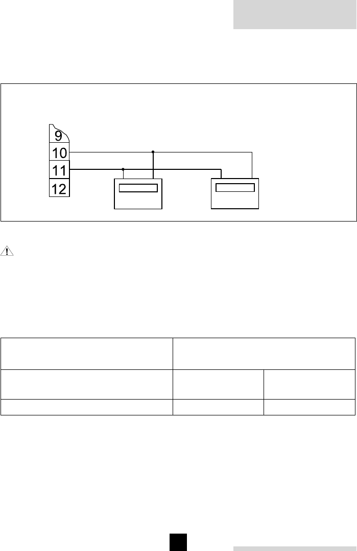
11.1 Boiler control interface (in the UK the interface is supplied with the relevant
controls package kit)
An interface is required to exchange data with the boiler control. Depending on boiler
execution, an interface might already be present in the boiler. The wiring of the
interface, of the boiler control and of the sensors (outside -, DHW - and common flow
-) must be carried out in accordance with the appropriate wiring diagrams, that come
with the controls package kit.
9
10
11
12
Interface
Feuerungs-
automat
Anschluss-
stecker P11
Connector P11 Interface Boiler control
Fig. 10
rematic® 2945 C3 K
34
35
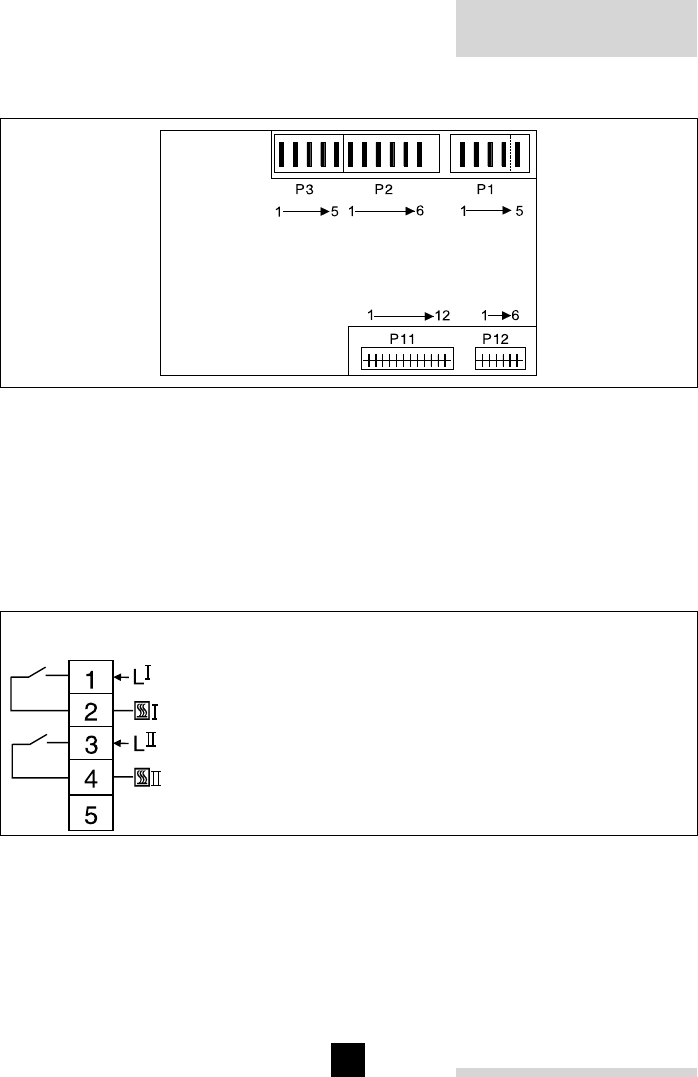
11.2 Connector layout (rear of controller)
Fig. 11
11.3 Connector terminal pinouts
The following diagrams show the full range of input and output connections. Depending
on the controller version and application, not all of these may necessarily be in use.
Always refer to the appropriate assembly instructions and for the correct terminal
identification refer to the wiring diagrams, that come with the controller kits.
11.3.1 Live connections (230 Vac)
Connector P1
Boiler
Boiler 1 (on/off boiler) or Step 1 (high/low boiler)
Boiler 2 (on/off boiler) or Step 2 (high/low boiler)
not used
Fig. 12
rematic® 2945 C3 K
34
35
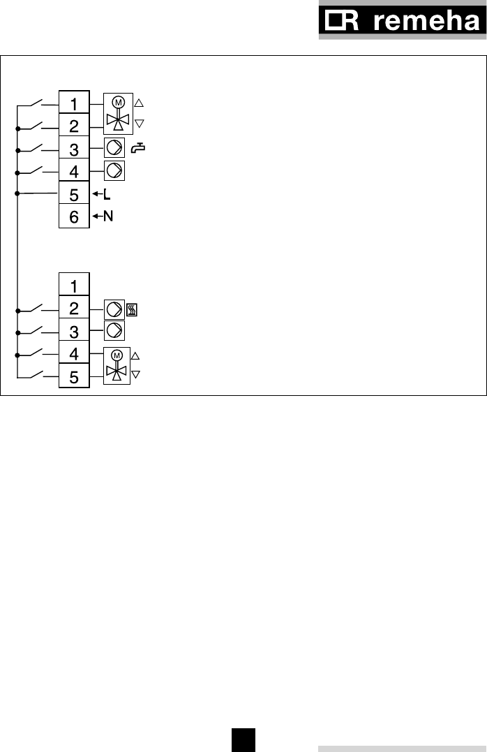
Connector P2
Mains supply, “green” heating circuit, D.H.W. production
Mixer OPEN
Mixer CLOSED
D.H.W pump / diverter valve
Circulation pump
Live
Neutral
Connector P3
“Red” heating circuit, boiler circulation
not used
Boiler circulation pump
Circulation pump
Mixer OPEN
Mixer CLOSED
Fig. 13
rematic® 2945 C3 K
36
37
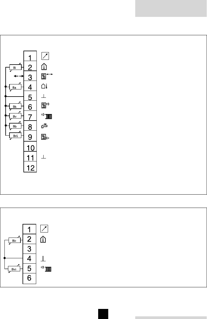
11.3.2 Sensor connections
Connector P11
“Green” heating circuit, boiler, domestic hot water
“Green” analogue remote control (on pins 1, 2 and 5)
“Green” room sensor
Set point input / output
Outside sensor
Sensor and set point ground
Common flow sensor*
“Green” mixer circuit flow sensor
Domestic hot water sensor
Return temperature sensor**
Data bus signal
Data bus ground
not used
* (or boiler sensor for on/off-high/low boilers)
** (see section “7.4 Minimum boiler return temperature TBR MIN (adjustment 5-3)”)
Fig. 14
Connector P12 (RED CIRCUIT NOT USED IN THE UK)
“Red” heating circuit
“Red” analogue remote control (on pins 1, 2 and 4)
“Red” room sensor
not used
Sensor ground
“Red” mixer circuit flow sensor
not used
Fig. 15
rematic® 2945 C3 K
36
37
12 FUNCTIONAL TESTS AND CHECKS
12.1 Service program
The service program permits maintenance personnel to establish boiler conditions
necessary for performing required measurements, without disturbing the controller’s
normal operational parameters. The controller sets all boilers to full load and
commands the installation load (i.e. mixing valves) in a way to reach a (boiler or
common) flow temperature of 60°C as quick as possible and maintain this temperature
as long as possible. To avoid overheating of the installation it may be necessary to
manually switch off all boilers but the one that is measured.
In on/off or high/low boilers with little water content the high limit thermostat
may trigger, as well as in an installation where the boiler sensor is not fitted in
the boiler but in the flow pipe work. However the Remeha communicating boilers
will not be affected with this problem.
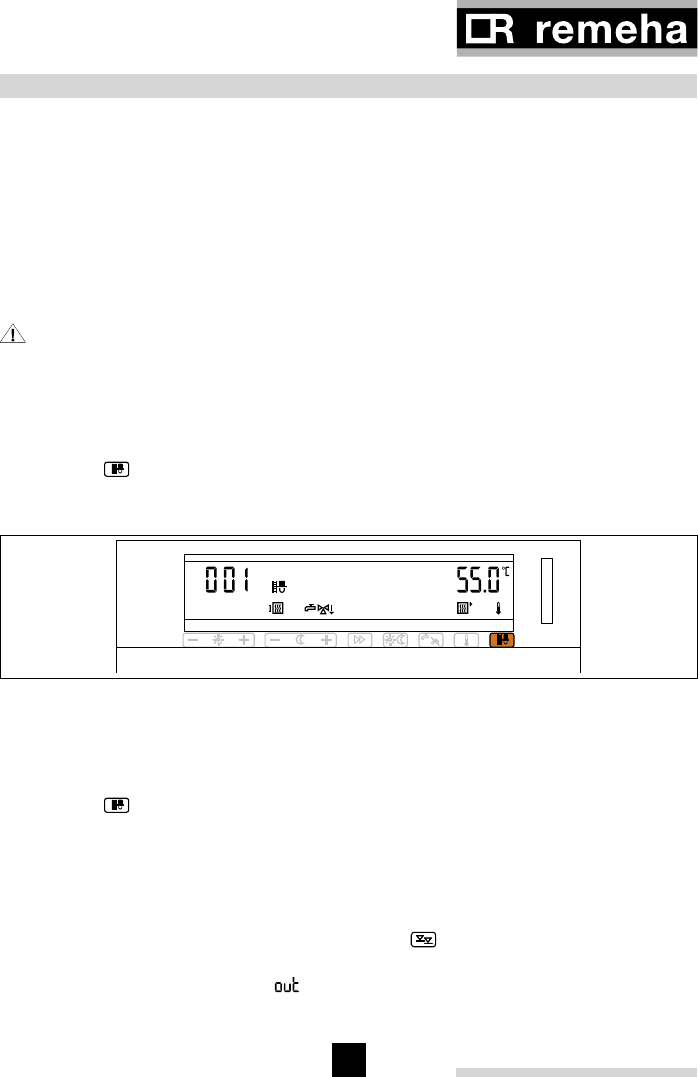
12.1.1 Starting the service program
- Press the key.
Instead of the current time, the display shows the elapsed time since the service
program was started.
P
Fig. 16
12.1.2 Terminating the service program
The service program terminates automatically when no controller key has been
pressed for 30 minutes. The service program can also be terminated earlier by
pressing the key again.
The controller returns to normal programmed operation.
12.2 Test mode for controller output signals
12.2.1 Operation
If the specialist levels are scrolled through with the key, after the 4th level and
before the code-protected 5th level you will reach the test level for output signals. It
is indicated on the display with “ “ (see also section “4.2.2 Performing 4th, 5th
and 6th -level adjustments”). In this test level, the specialist may switch the outputs
rematic® 2945 C3 K
38
39
on and off. With each push on one side of the key in the 3rd level, the status of the
corresponding output signal toggles between “ON” and “OFF”.
12.2.2 Display
The modes which are switched on or off are indicated in the display.
- The modes which are allocated to the keys on the left-hand side (even numbers) are
indicated with the corresponding symbol and the output number, e.g. and A-4.
- The modes which are allocated to the keys on the right-hand side (odd numbers)
are shown with the output number only, e.g. F-5.
For each function the status indicator “ ” or “ ” also appears.
12.2.3 Closing the test mode
The test mode is automatically interrupted if no key is pressed for 20 minutes. The
display returns to normal. The functioning of the controller outputs is then determined
once again by the controller. When switching to another specialist level, all output
functions are switched off.
12.2.4 Meaning of keys and allocation to modes
Adjust-
ment
key
Push at
– or +
side of
adjust-
ment
key
Display Function Connection pinouts
at back of controller
0 - A-1 Boiler step 1 (on/off) P1-1
0 + A-2 Boiler step 2 (high/low) P1-3
1 - F-1 Communication Boiler 1 P11-10
1 + F-2 Communication Boiler 2 P11-10
2 - A-3 Mixer "opens", Green heating circuit P2-1
2 + A-4 Mixer "closes", Green heating circuit P2-2
3 - F-3 Communication Boiler 3 P11-10
3 + F-4 Communication Boiler 4 P11-10
4 - A-5 D.H.W. pump or diverter valve P2-3
4 + A-6 Circulation pump, Green heating circuit P2-3
5 - F-5 Communication Boiler 5 P11-10
5 + F-6 Communication Boiler 6 P11-10
6 - A-7 Mixer "opens", Red heating circuit P3-4
6 + A-8 Mixer "closes", Red heating circuit P3-5
7 - F-7 Communication Boiler 7 P11-10
7 + F-8 Communication Boiler 8 P11-10
8 - A-9 Circulation pump, Red heating circuit P3-3
8 + A-10 Boiler circulation pump P3-2
9 - --- Not used
9 + --- Not used
rematic® 2945 C3 K
38
39
Adjust-
ment
key
Push at
– or +
side of
adjust-
ment
key
Display Function Connection pinouts
at back of controller
0 - A-1 Boiler step 1 (on/off) P1-1
0 + A-2 Boiler step 2 (high/low) P1-3
1 - F-1 Communication Boiler 1 P11-10
1 + F-2 Communication Boiler 2 P11-10
2 - A-3 Mixer "opens", Green heating circuit P2-1
2 + A-4 Mixer "closes", Green heating circuit P2-2
3 - F-3 Communication Boiler 3 P11-10
3 + F-4 Communication Boiler 4 P11-10
4 - A-5 D.H.W. pump or diverter valve P2-3
4 + A-6 Circulation pump, Green heating circuit P2-3
5 - F-5 Communication Boiler 5 P11-10
5 + F-6 Communication Boiler 6 P11-10
6 - A-7 Mixer "opens", Red heating circuit P3-4
6 + A-8 Mixer "closes", Red heating circuit P3-5
7 - F-7 Communication Boiler 7 P11-10
7 + F-8 Communication Boiler 8 P11-10
8 - A-9 Circulation pump, Red heating circuit P3-3
8 + A-10 Boiler circulation pump P3-2
9 - --- Not used
9 + --- Not used
Table 09
The test mode allows the specialist to test parts of the system for
correct functioning. If proper procedures are not followed, this can lead
to output statuses being enabled which place an abnormal load on the
heating equipment (example: both directions of a mixer motor energised
simultaneously). Modes which are switched on are only switched off if
no key is pressed for 20 minutes or if the operating level is changed.
Please, therefore, note the following:
- after the function test, deactivate each output order.
- never simultaneously enable an “ON” and an “OFF” order on the same mixer
drive.
- before leaving the system, ensure that the controller is no longer at the test
level (change operating level or return to normal display using the key).
12.3 Checking the temperature sensors
The temperature sensors can be checked without disconnecting the controller, or
using special measurement or test equipment. (See section “12.5 Temperature sensor
resistance values”)
- Select the desired heating circuit using the toggle key.
- Press the key.
The measured temperatures appear in the display. If a temperature is displayed, this
means that the corresponding sensor is properly connected and functional.
Failure to display a temperature can have one of the following reasons:
- The sensor is unnecessary for the heating system
- Sensor or connection open-circuit
- Sensor or connection short-circuit
12.4 Checking temperature settings
For dual circuit controllers select the desired heating circuit using the toggle key.
- Press and hold the key. The controller shows the measured temperature
values in succession.
After cycling through all the measured values, the controller shows the temperature
settings in place of the regular display.
rematic® 2945 C3 K
40
41
- Release the key. Single presses of this key display the Setpoints and sensor
readings.
- Press the key to return to the normal display. This also happens automatically if
1 minute elapses without pressing a key.
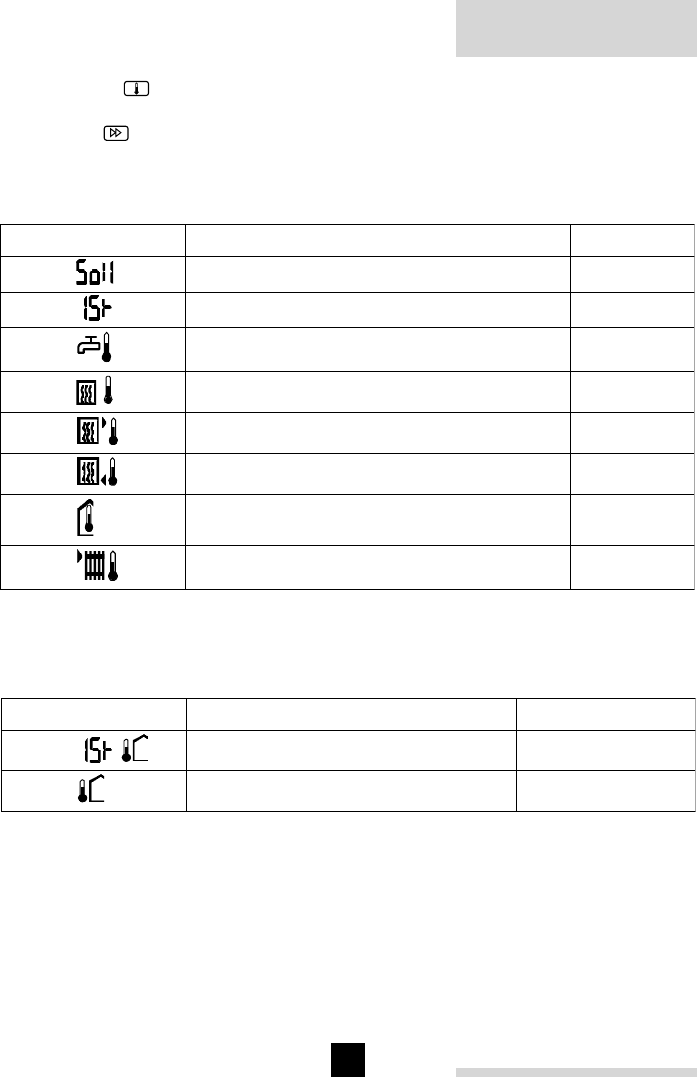
12.4.1 Displayed symbols and their meanings
Symbol Display Unit
Display shows set value °C
Display shows measured value °C
D.H.W. temperature (hot water) °C
Common flow temperature °C
Boiler flow temperature °C
Boiler return temperature °C
Room temperature °C
Circuit flow water temperature °C
Table 10
The outside temperature can be read as average temperature and as current
temperature as follows:
Symbol Display Unit
Actual outside temperature °C
Average outside temperature °C
Table 11
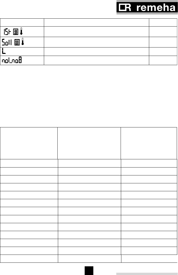
On the master controller’s display, the total output and the output required by the
individual boilers may be interrogated as well as the common flow set temperature.
rematic® 2945 C3 K
40
41
Table 12
The set output of the installation is understood to be the total output of all the required
boilers in kW. The output of the individual boilers is shown as % of the nominal output
of the boiler.
12.5 Temperature sensor resistance values
The temperature sensors connected to the controller and those connected to the boiler
control do have different characteristics. Resistance values are shown in the following
table.
Temperature
°C
Controller
Resistance
Ω
Boilercontrol
Resistance
Ω
-20 48.535 98.820
-15 36.475 75.940
-10 27.665 58.820
-5 21.165 45.910
0 16.325 36.100
5 12.695 28.590
10 9.950 22.790
15 7.855 18.290
20 6.245 14.770
25 5.000 12.000
30 4.029 9.805
40 2.663 6.653
50 1.802 4.609
60 1.244 3.253
70 876 2.337
80 628 1.707
90 458 1.266
100 339 952
Symbol Display Unit
Common flow temperature measured °C
Common flow temperature set °C
Total load of all boilers kW
Load per boiler %

rematic® 2945 C3 K
42
43
Table 13
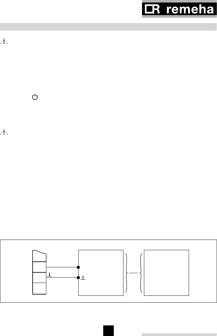
13 CONTROL OF MODULATING BOILERS
The rematic® controller communicates with all connected boilers over a two-wire
bus. Each boiler needs an interface for addressing and translation of the messages.
Messages are send every 10 - 15 seconds.
The rematic® controller calculates a boiler flow temperature (or a common flow
temperature in a multiple boiler installation) based on outside temperature, heating
curve, programmed over-temperature, room temperature etc.
- Without a common flow sensor connected (i.e. in a single boiler installation), this
flow temperature setpoint is sent to the boiler control, which in turn calculates the
necessary output to obtain the setpoint temperature.
- With a common flow sensor connected (i.e. in a multiple boiler installation), the
controller itself calculates the number of boilers and the output percentage per
boiler, necessary to obtain the setpoint temperature.
- With the DHW sensor and -pump connected to the controller (is standard
configuration for single - and multiple boiler installations), the boilers
are controlled as described above. (also during DHW production code
3 is displayed on the boiler(s))
DHW temperature, flow-over temperature and time program are as set in the
controller.
- In a multiple boiler installation, a DHW sensor and DHW pump or diverter valve
can be connected to one or more boilers in which the rematic® controller is not
mounted. The controller DHW-time program acts on all boilers. DHW temperature
and over temperature are to be set in each boiler.
Temperature
°C
Controller
Resistance
Ω
Boilercontrol
Resistance
Ω
-20 48.535 98.820
-15 36.475 75.940
-10 27.665 58.820
-5 21.165 45.910
0 16.325 36.100
5 12.695 28.590
10 9.950 22.790
15 7.855 18.290
20 6.245 14.770
25 5.000 12.000
30 4.029 9.805
40 2.663 6.653
50 1.802 4.609
60 1.244 3.253
70 876 2.337
80 628 1.707
90 458 1.266
100 339 952

rematic® 2945 C3 K
42
43
14 ERROR MESSAGES
Display Description of error
Left side Right side
--- Communication error with boiler control 1….8 1)
--- Communication error with slave 1…4 2)
xxx* Lock-out of boiler 1…8 with error code 3)
Table 14
1) See also section “5.7 Nature of the controller (adjustment 3-8)”. Er1 can also mean:
inverted or short-circuited bus wiring
2) See also section “5.6 Number of slaves and their addressing (adjustment 3-7) NOT
AVAILABLE IN UK”
3) See the boiler documentation for the meaning of the displayed boiler error code.
With more than one error , the sequence of the messages is as follows:
- The message of a boiler control is displayed before that of a slave controller.
- The message of the boiler control or slave with the lowest address comes first.
Note 1: With the wires of the bus short circuited or connections crossed (boiler 1-
terminal 1 connected to boiler 2-terminal 2 etc) the message Er 1 will occur. Only one
LED will blink on the boiler interface(s). With one interface disconnected or damaged,
the corresponding message will be displayed, but the communication with other boilers
and /or slaves will remain.
Note 2: Every time the power to the controller is switched on, the microprocessor will
initialise. During initialisation, the controller is exchanging date with the boiler control
and a DHW temperature of 99 °C might be displayed.

rematic® 2945 C3 K
44
45
15 EXPLANATION OF TERMS
Start of occupancy time:
The start of occupancy time is the moment from which on the room temperature must
be at comfort level.
Occupancy time:
The period of the day the room temperature must be at comfort level.
Specialist levels:
Adjustment levels controlled by engineers. They contain adjustment variables for
matching the regulator to the heating system design parameters.
Adaptive heating curve:
Automatic modification of the heating curve to match the building characteristics.
Measured value ( is displayed at the left):
The present, measured temperature. The symbol underneath the displayed value
indicates which sensor is read.
Set point ( is displayed at the left):
A temperature value calculated by the controller or specified by the specialist or end
user. The controller regulates the measured value to match the set point.
Pre-heat time:
Automatic advancement of the heating start-up time according to the heating
requirement, in order to obtain comfort temperature at start of occupancy time.
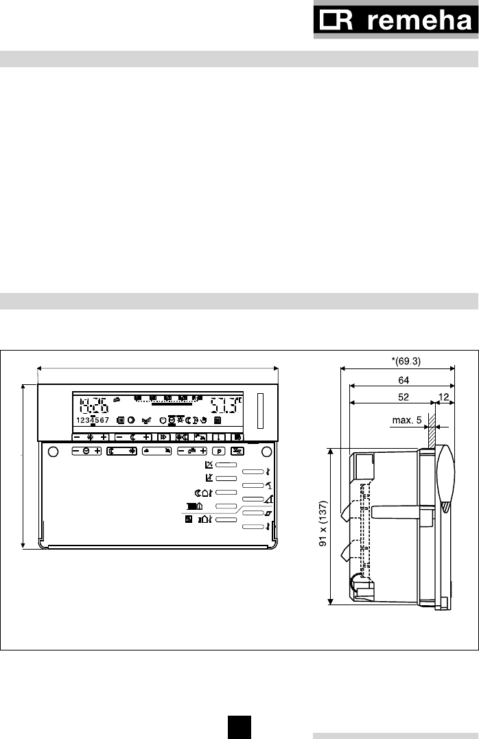
rematic® 2945 C3 K
44
45
17 DIMENSIONS AND FITTING INSTRUCTIONS
+-
4
8
3
5
2
t
PROG
PROG
144
96
+
-
Comp.
BB
1
0
9
B = securing latches
* (69.3) Dimension when fitted with ZLS 203 or ZLS 204 sensor PCB
Fig. 17
17.1 Dimensions
16 TECHNICAL DATA
Supply voltage 230 VAC ± 10%, 50 Hz
Power consumption 7W
Operational ambient temperature 0°C … 50°C
Sensor and Bus cable length and max. 100 m
“ cross sectional area min. 0.75 mm2
Bus 2 wire Bus
Output switching capability 230V 6 (2) A, 50 Hz
Certification CE-compliant
Protection category II EN 60730
Protection level IP 40 EN 60529
EMC EN 50082-1
EMC-emission EN 50081-1
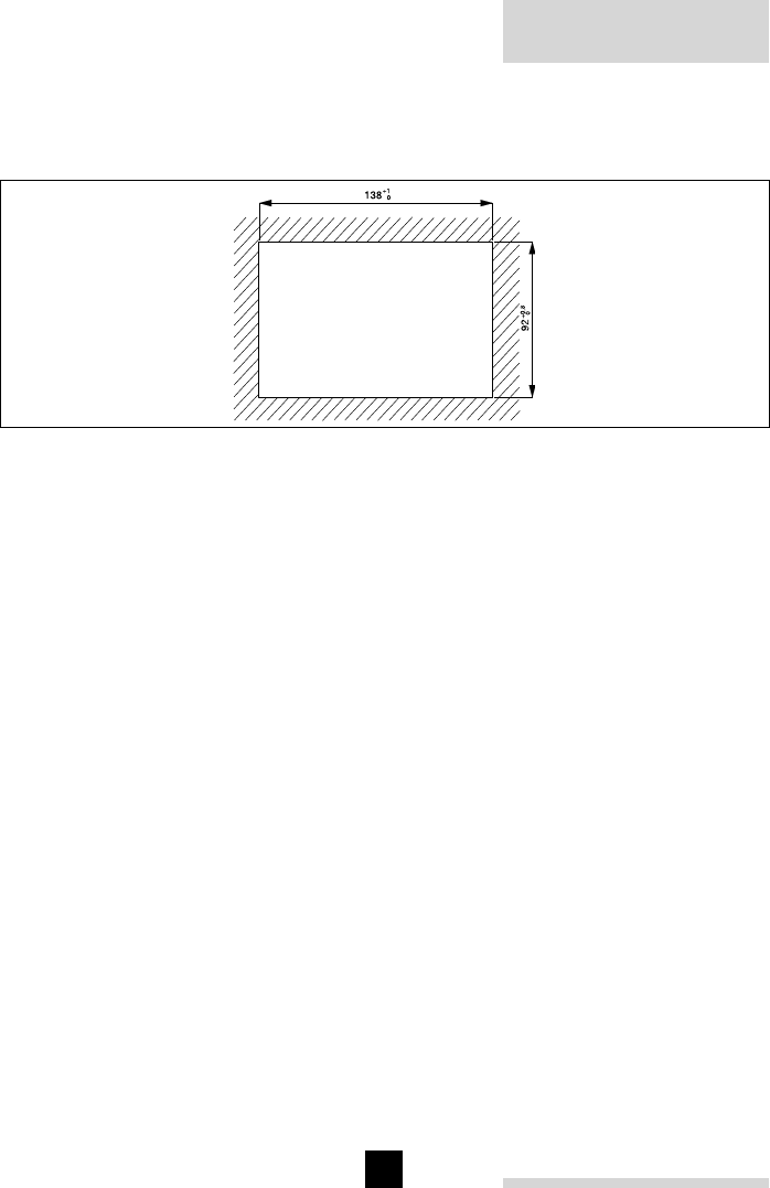
rematic® 2945 C3 K
46
47
17.2 Panel cut-out
The panel cut-out is 92 x 138 mm according to DIN 43700.
Panel thickness <5 mm
Fig. 18
17.3 Fitting instructions (For UK see seperate fitting instructions)
The recessed securing assemblies B to the left and right of the 2 nd -level keys are
visible with the front cover removed (see Fig. 17).
- After the electrical connectors have been plugged in, fit the controller into the panel
cut-out.
- 2. Use a screwdriver to push the securing latches gently inwards, then give them a
quarter turn clockwise to secure the controller to the panel.
Releasing the controller: turn both securing latches counter-clockwise to their end-
stops.
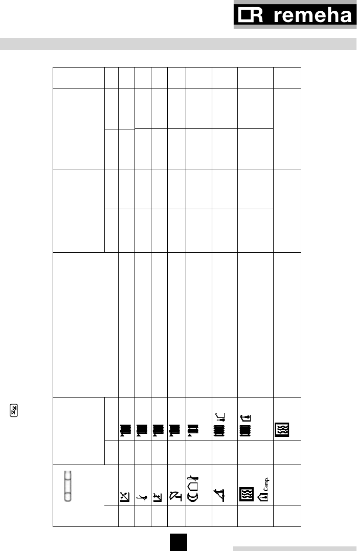
rematic® 2945 C3 K
46
47
18 ADJUSTMENT KEYS, BOILER DATA AND SYSTEM DATA
18.1 level 3 controls
Push several times on the button until “3--“ appears in the display. For adjustments 3-0 to 3-6 the heating
circuit must be selected first with the toggle key in dual circuit systems (observe the display colour). The
function(s) can be selected from the following table and set to the desired value if not protected (\).
Adjustment
key
-
+
Display Factory settings
Heating circuit
Commissioning
settings
Heating circuit
No. Symbol No. Symbol
Description
Red Green Red Green
03-0 Compensation slope 1,2 1,2
13-1 Max. flow temp. 75 75 °C
23-2 Parallel shift of slope base point 30 30 °C
33-3 Summertime limit in heating mode 20 20 °C
43-4 Summertime limit in night set back
mode 5 5 °C
53-5 Setting of time to reach design
temp. 180 180 Min
63-6 Room temp. compensation
0,0 0,0
°C
/°C
7 M/S 3-7 Master: number of slaves (0…4)
Slave: position of slave (F1…F4) 0
Table 15
Use of adjustment 3-6 requires a remote control or a room sensor.
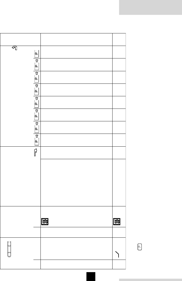
rematic® 2945 C3 K
48
49
Adjustment
key
-
+
Display Description
1 2 3 4 5 6 7 8
No Symbol No Symbol Factory settings
8typ 3-8 Nature of the
controller :
-- = mixing circuit
controller without
boiler control
b1 = controller for
on/of boiler
b2 = controller for
high/low boiler
FA = controller for
communicating boiler
Fa
9 P 3-9 Minimum modulation
percentage of boiler 30 %
Table 16
With the
P
button the boiler can be selected, for which parameters must be set.

rematic® 2945 C3 K
48
49
18.2 level 4 controls
Push several times on the button until “4--“ appears in the display. For adjustments 4-6, 4-8 and 4-9 the heating
circuit must be selected first with the toggle key in dual circuit systems (observe the display colour). The function(s) can
be selected from the following table and set to the desired value if not protected (\).
Adjustment key
-
+
Display Factory settings
Heating circuit
Commissioning
settings
Heating circuit
No. Symbol No. Symbol
Description
Red Green Red Green
04-0 DHW production
priority
simultaneous
14-1 DHW production
pump
diverter valve
24-2 Overtemperature of flow for
DHW production 20,0 °C
34-3 Run-on time of DHW pump 8,0 Min.
44-4 Legionnaires' disease
protection temperature 60,0 °C
54-5 Legionnaires' disease
protection mode
1 = Mondays
2 = Tuesdays
7 = Sundays
8 = daily
9 = continuously at 60 °C
0 = no Legionnaires' disease
protection mode
0
64-6 Adaptive heating curve
inactive
active, automatic
7 M/S 4-7 Minimum boiler temperature 0,0 °C
8typ 4-8 Overtemp. of common flow for
heating
- direct circuit = 0 (4-9=2)
- mixing circuit = 5
5,0 5,0
°C
9 P 4-9 Adapting to the heating circuit
0=3 point mixer motor
1=2 point mixer motor
(spring return)
2=direct heating circuit
(no mixer displayed)
0 0
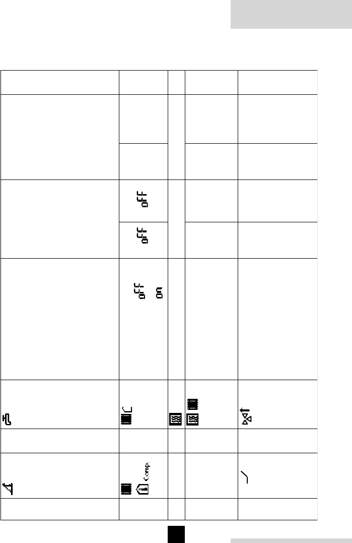
rematic® 2945 C3 K
50
51
Adjustment key
-
+
Display Factory settings
Heating circuit
Commissioning
settings
Heating circuit
No. Symbol No. Symbol
Description
Red Green Red Green
04-0 DHW production
priority
simultaneous
14-1 DHW production
pump
diverter valve
24-2 Overtemperature of flow for
DHW production 20,0 °C
34-3 Run-on time of DHW pump 8,0 Min.
44-4 Legionnaires' disease
protection temperature 60,0 °C
54-5 Legionnaires' disease
protection mode
1 = Mondays
2 = Tuesdays
7 = Sundays
8 = daily
9 = continuously at 60 °C
0 = no Legionnaires' disease
protection mode
0
64-6 Adaptive heating curve
inactive
active, automatic
7 M/S 4-7 Minimum boiler temperature 0,0 °C
8typ 4-8 Overtemp. of common flow for
heating
- direct circuit = 0 (4-9=2)
- mixing circuit = 5
5,0 5,0
°C
9 P 4-9 Adapting to the heating circuit
0=3 point mixer motor
1=2 point mixer motor
(spring return)
2=direct heating circuit
(no mixer displayed)
0 0
Table 17
Use of adjustment 4-6 requires a remote control or a room sensor.
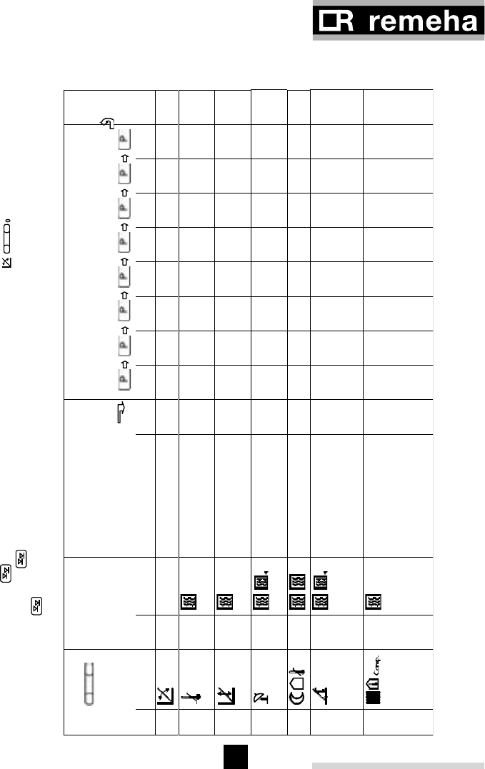
rematic® 2945 C3 K
50
51
18.3 level 5 controls
Push several times on the button until “codE” appears in the display. Use the button to enter the standard
access code (000). Push the button once and the controller will display “Acc” for acceptance of the code. Now push
several times on the button until “5--” appears in the display. The function(s) can be selected from the following
table and set to the desired value if not protected (\).
Adjustment
key
-
+
Display Description
1 2 3 4 5 6 7 8
No Symbol No Symbol Factory settings
05-0 Boiler output full load 60,0 kW
15-1 Grouping boilers
(groups 1 till 4) 1
25-2 Cut-in output for next
boiler in % 80,0 %
35-3 Min. boiler return
temperature 0,0 °C
45-4 Min. fan speed in % 0,0 %
55-5 Return control
selection (option 0 till
6, see section 7.6)
0
65-6 Allocation of boiler-
relay outputs:
(options: ---, M, F1 till
F4)
---
Table 18
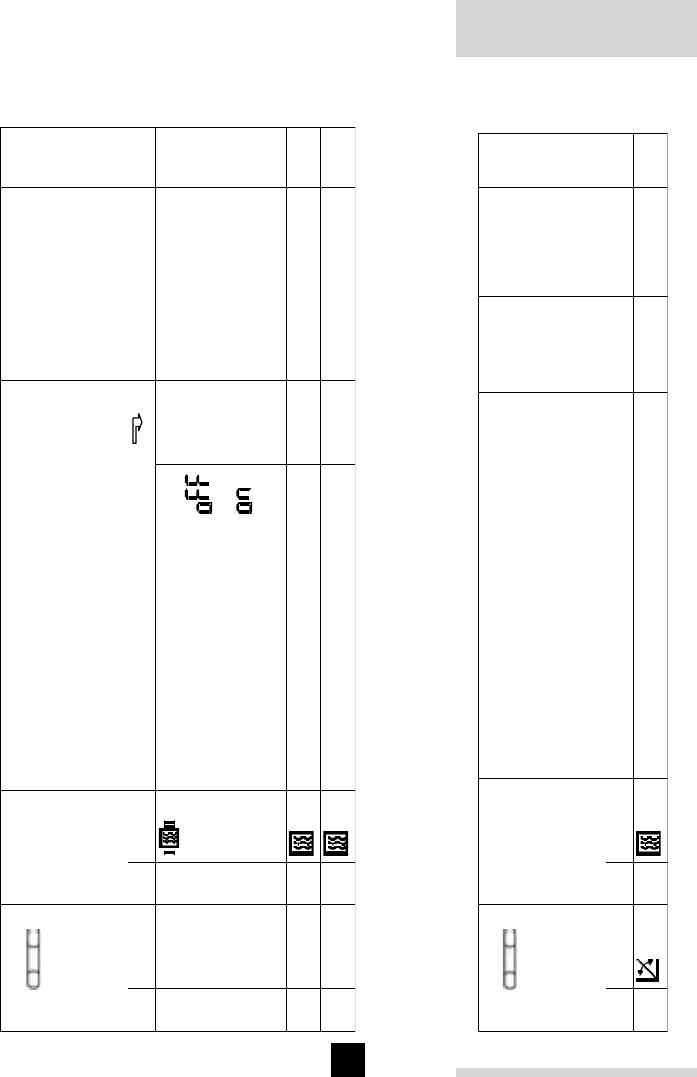
rematic® 2945 C3 K
52
53
Adjustment
key
-
+
Display Description
No. Symbol No. Symbol Factory settings
Commissioning settings
7 M/S 5-7 Sequence changeover
continuous forward operation
continuous backward operation
changeover after 10 - 990 run hours
100
on/off
h
8typ 5-8 Proportional band 6,0 °C
9 P 5-9 Integral proportion 6,0 Min.
Table 19
18.4 level 6 controls
Enter the acces code as described in section 18.3. Push several times on the (94) button until “6--” appears in the
display. The function(s) can be selected from the following table and set to the desired value if not protected (\).
Adjustment
key
-
+
Display Description Factory
settings
Commission
-ing settings
No. Symbol No. Symbol
06-0 Max common flow temperature 95,0 °C
16-1 Run-on time of DHW pump
0=time controlled
1=temperature controlled
0
26-2 Boiler safety modes
0=U0
1=U1 Uw energised during heating season
2=U3
3=U0
4=U1 Uw with run-on time
5=U3
0
36-3 Delayed cut-in of 1rst boiler 2,0 Min.
46-4 Delayed cut-in of subsequent boilers 3,0 Min.
56-5 Blocking of boiler groups 3 and 4 at outside
temperatures over 40,0 °C
66-6 Blocking of boiler groups 1 and 2 at outside
temperatures below -40,0 °C
7 M/S 6-7 Neutral zone with PI behaviour 1,0 °C
8typ 6-8 Ramp mode outsite P-band 5,0 %/
Min.
9 P 6-9 Ramp mode inside P-band 1,0 %/
Min.
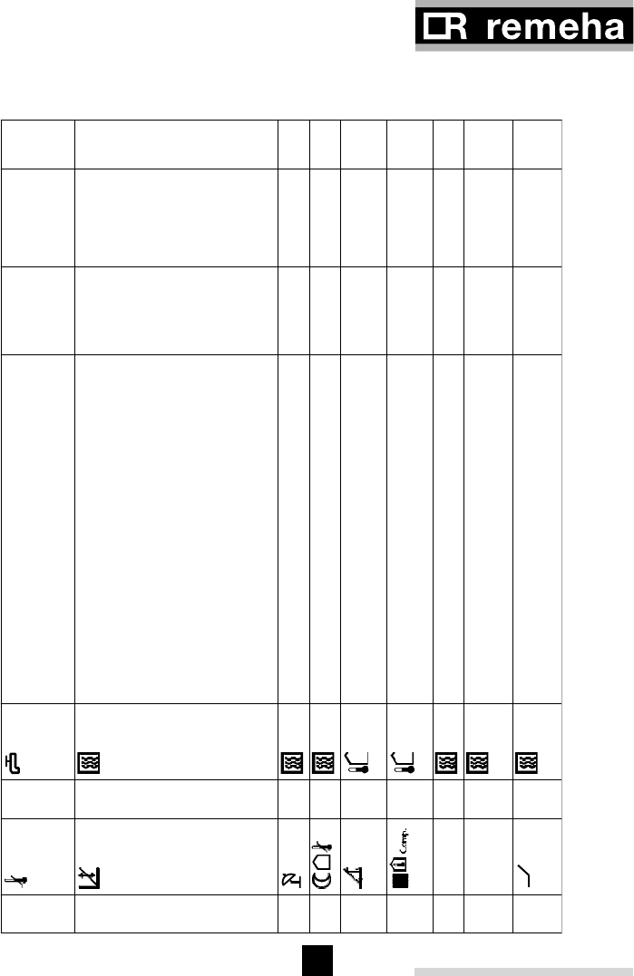
rematic® 2945 C3 K
52
53
Adjustment
key
-
+
Display Description Factory
settings
Commission
-ing settings
No. Symbol No. Symbol
06-0 Max common flow temperature 95,0 °C
16-1 Run-on time of DHW pump
0=time controlled
1=temperature controlled
0
26-2 Boiler safety modes
0=U0
1=U1 Uw energised during heating season
2=U3
3=U0
4=U1 Uw with run-on time
5=U3
0
36-3 Delayed cut-in of 1rst boiler 2,0 Min.
46-4 Delayed cut-in of subsequent boilers 3,0 Min.
56-5 Blocking of boiler groups 3 and 4 at outside
temperatures over 40,0 °C
66-6 Blocking of boiler groups 1 and 2 at outside
temperatures below -40,0 °C
7 M/S 6-7 Neutral zone with PI behaviour 1,0 °C
8typ 6-8 Ramp mode outsite P-band 5,0 %/
Min.
9 P 6-9 Ramp mode inside P-band 1,0 %/
Min.
Table 20
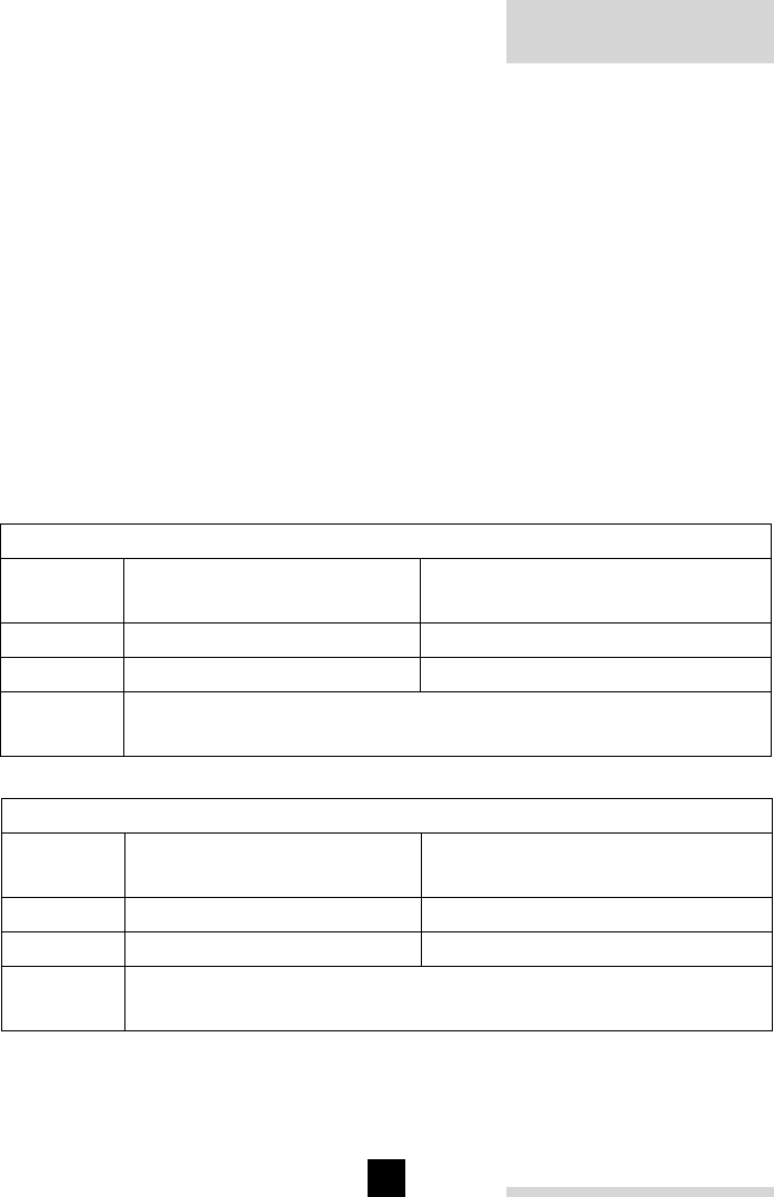
rematic® 2945 C3 K
54
55
18.5 Data for Remeha modulating boilers in a single-boiler installation
Remeha W 10/21/28 series, Quinta series, Gas 210 ECO series:
For these applications the factory settings of the adjustments are adequate, except for
those adjustments that are necessary to adapt the controller to the installation, such as
heating curve, time program, D.H.W. temperature etc.
18.6 Data for Remeha modulating boilers in a multiple boiler installation
In order to achieve proper operation of the boilers in a multiple boiler installation, the
relevant adjustments must be set according to the tables below.
Procedure for performing the adjustments in the table:
- Select the adjustment.
- If more than one boilers are connected, use the P key to invoke the boiler for which
the adjustments are to apply.
- Instead of the time bar, the points in the display indicate how many boilers are
programmed. The point of the invoked boiler flashes. You can now perform the
required adjustment. With adjustment 3-8 the number of boilers can be programmed
by replacing on each position the given --- code by the correct FA code.
Remeha Quinta
Adjustment Setting for a single boiler
installation
Setting for a multiple boiler
installation (for all boilers up to 8)
3-8 FA 3 FA 1
3-9 18 18
5-0 The correct output of the boiler (in kW) can be read from the boiler
identification plate.
Table 21 Remeha Quinta series
Table 22 Remeha Gas 210 ECO series
Remeha Gas 210 ECO
Adjustment Setting for a single boiler
installation
Setting for a multiple boiler
installation (for all boilers up to 8)
3-8 FA 3 FA 1
3-9 10 10
5-0 The correct output of the boiler (in kW) can be read from the boiler
identification plate.
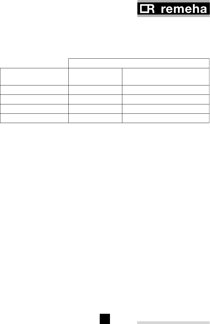
rematic® 2945 C3 K
54
55
Adjustment 3-7
Number of slave
controllers
Setting in master
controller
Setting in slave controllers
1 1 F1
2 2 F1, F2
3 3 F1, F2, F3
4 4 F1, F2, F3, F4
Table 23
18.7 Installations with slave controllers rematic 2940 C3 S and/or 2945 C3 S
In order to achieve communication between the master and the slave controllers, they
must both correctly be programmed. In the master controller the number of slaves
must be programmed. In each slave controller its address must be programmed
according to the table below.

56
© Copyright
All technical information and drawings contained within this document are the
property of Broag - Remeha and shall not be copied without our prior consent
in writing.
Subject to alterations
56302/1000/0402/Ips.
rematic® 2945 C3 K
Broag Ltd.
Head office
Remeha house
Molly Millars Lane,
Workingham,
Berkshire RG 41 2QP.
Tel: 0118 976977
Fax: 0118 9783434
E-mail: boilers@broag.ltd.uk
Internet: http://www.broag.ltd.uk
