Rescuvator 5 Manual
User Manual: Rescuvator 5 Manual
Open the PDF directly: View PDF ![]() .
.
Page Count: 11
Doc. No.:S-F85-18.doc 1
G.A.L. Manufacturing Corporation
50 East 153rd Street, Bronx, N.Y. 10451
Phone (718) 292-9000 Fax (718) 292-2034 May 7, 1999
G.A.L. RESCUVATOR SURVEY AND DATA FORM
(Model 5)
I. RESCUVATOR DATA:
1. The Rescuvator main line phase monitor is available for any one of the following main line
voltages.
a) 120, 208 - 240/3/60 and 120, 208 - 240/1/60
b) 440 - 480/3/60
c) 575 - 600/3/6
2. The Rescuvator has the following output voltages: (Total output 500 watts ).
a) 120 volts, 1∅ (single phase) AC or 240 volts, 1∅ (single phase) AC.
b) 130 volts DC or 260 volts DC.
3. The Rescuvator is mounted in a metal enclosure and includes a non spillable sealed
maintenance free battery which never requires watering.
4. A normally open electrical interlock is to be supplied by the customer and installed in the
elevator main line disconnect switch to de-activate the Rescuvator when the main line
disconnect switch is opened.
5. The elevator logic controller must have a low oil return feature which when activated will bring
the elevator down to the lowest level and open the door.
6. The door operator voltage must be either DC or single phase AC.
The Rescuvator cannot provide 3∅
∅∅
∅ (3 phase) power.
II. ENGINEERING INFORMATION REQUIRED ON EXISTING INSTALLATIONS:
Included with the Rescuvator are standard wiring diagrams and instructions which explain all
interconnection requirements. If desired, G.A.L. engineering can be provided at an additional cost,
including marked-up wiring diagrams and any additional parts that may be required. Please include
a copy of the existing controller wiring diagrams noting main line voltage and transformer secondary
voltages. If the existing controller is not relay logic, customer must determine the required input
points that would activate low oil return to bottom floor.
III. HOW TO ORDER A MODEL 5 RESCUVATOR:
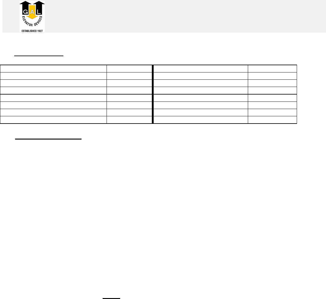
Select Rescuvator model number from table below:
MAIN LINE
VOLTAGE RESCUVATOR
MODEL NUMBER
120 volt or 208 to 240 volt RSCV-0006N
single or three phase
440 to 480 volt, three phase RSCV-0007N
575 to 600 volt, three phase RSCV-0008N
If G.A.L. engineering is requested, send a copy of the existing
controller wiring diagrams noting main line voltage and
transformer secondary voltages.
.
Doc. No.:S-F85-19.doc 1
G.A.L. Manufacturing Corporation
50 East 153rd Street, Bronx, N.Y. 10451
Phone (718) 292-9000 Fax (718) 292-2034 May 7, 1999
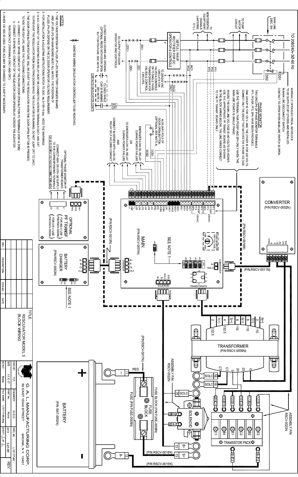
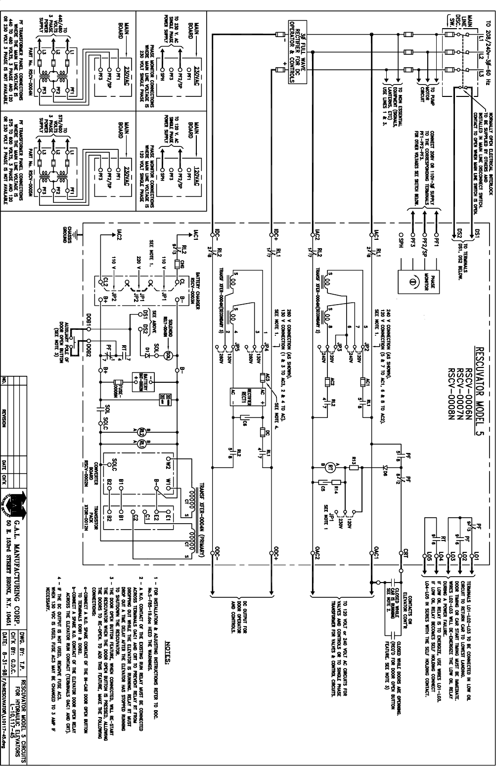
RESCUVATOR INSTRUCTIONS
REFER TO DWG. (L-1O,117-45)
When Installing This Device Check With Local Enforcing Authorities For Any Special
Requirements That The Elevator Operation Must Comply With.
When a Rescuvator is to be included with a hydraulic elevator, the elevator must be equipped with a
low oil feature and control circuits arranged as per schematic diagram L-10,117- 45. When
activated, the low oil feature should bring the elevator to the lowest landing and open and then
close the doors.
The elevator disconnect switch must be in the closed position when a power failure occurs for
rescue to take place (return to lowest landing) . With the disconnect switch closed, any power failure
will automatically transfer the control circuits, valves and door operator circuits from their normal
supplies to the Rescuvator emergency supplies of the same voltage. The elevator will then be
placed on low oil rescue operation, returning the car to the lowest landing and opening and closing
the doors.
A normally open electrical interlock, supplied by others, is to be installed in the elevator disconnect
switch to prevent rescue when the disconnect switch is opened.
WARNING!
Warning notices in this manual call attention to
situations that would cause damage to the equipment.
These notices are repeated below :
The red battery cable must connect to the + battery post (See Fig. 8).
Jumper JP1 on the main board and jumpers JP1-JP2 on the battery charger
board must match the position of jumpers JP2-JP3 on the main board (See Figs. 1, 2, 3).
Jumpers JP4, JP5 can be in either position depending on the DC voltage required.
Never apply over 130 volts across the 120VAC terminals PF1- PF2- PF3 or over 270 volts
across the 230VAC terminals PF1- PF2- PF3 (See Figs. 4, 5).
Never connect wires to terminal PF1 or PF3 when terminal SPH is used (See Figs. 4, 5).
The Rescuvator must never turn on when the main line disconnect switch is open.
The Rescuvator should never emit a high pitch sound. A high pitch sound is an indication of
a short circuited output, damage can occur within seconds. Immediately shutdown the
Rescuvator by opening the main line switch or by pulling out the RT relay (See Fig. 6) and
call G.A.L..
The Rescuvator must be allowed to automatically shut down after lowest landing rescue has
been completed. Running the Rescuvator continuously for more than 10 minutes can cause
it to overheat and become damaged.
Doc. No.:S-F85-19.doc 2
G.A.L. Manufacturing Corporation
50 East 153rd Street, Bronx, N.Y. 10451
Phone (718) 292-9000 Fax (718) 292-2034 May 7, 1999
I. Part numbers:
Main board RSCV-0001N Transistor pack assembly RSCV-0023N
Converter board RSCV-0002N Battery BAT-0002N
Battery charger board RSCV-0003N Solenoid assembly RSCV-0022N
460 volt PF transformer board RSCV-0004N Power transformer w/connectors RSCV-0009N
575 volt PF transformer board RSCV-0005N Power fuse FUSE-0008N
Rescuvator RSCV-0006N Power fuse block FUSE-0009N
Rescuvator w/460v PF board RSCV-0007N
Rescuvator w/575v PF board RSCV-0008N
II. Initial connections:
1. Disconnect power from the main line disconnect switch.
2. Install the n.o. electrical interlock (auxiliary contact) in the main line disconnect switch. The
contact must open when the main line disconnect switch is opened.
3. Install the Rescuvator in a convenient location close to the elevator logic controller.
4. Make all connections to the elevator logic controller (16 wires) and to the auxiliary contact in the
main line disconnect switch (2 wires) as per wiring diagram L-10117-45. Note that 2 groups of
phase monitor terminals PF1, PF2/SP, PF3, SPH have been provided. One is for 120 volts and
the other is for 230 volts. Connect only the group that matches the 3 phase voltage. In some
rare installations the main line power is 1 phase, in that event, connect the single phase power
to the matching PF2/SP, SPH terminal pair .
WARNING! Never connect wires to terminals PF1 or PF3 when terminal SPH is used
(See Figs. 4, 5).
5. If the DC output connections are not used, remove fuse AC3.
6. Remove the 60 amp battery power fuse.
7. Place the battery within the enclosure with the + post on the left. Attach the battery to the back
plate with the bracket provided.
8. Connect the battery cables.
WARNING! The red cable must connect to the + battery post (See Fig. 8).
9. Proceed to section III.

G.A.L. Manufacturing Corporation May 7, 1999
Doc. No.: S-F85-19.doc 3
III. Pre-rescue checks.
It is strongly suggested that, before power is turned on, all connections and control changes
are tested as follows:
1. Open the main line disconnect switch and check that the circuit to terminals DS1-DS2 is open.
With the circuit to DS1-DS2 open, the elevator will not and must not operate under any mode.
2. Remove the large 60 amp power fuse.
3. Check that the voltage that will be applied to the wires connected to terminals PFl-PF2-PF3
corresponds to the voltage indicated on these terminals, otherwise the phase monitor circuits
may be damaged. Where the main line voltage is 440-600 volts and 120 volts or 230 volts
3 phase power is not available, a separate high voltage PF transformer board should have been
provided (refer to section IV).
4. Check that the power transformer secondary jumpers JP2-JP3 and JP4-JP5 on the main board
are connected for the required output voltages. (120 or 240 VAC and 130 or 260 VDC) and that
this is the same voltage that is present during normal power.
5. Check that the position of jumper JP1 on the main board corresponds with the position of
jumpers JP2-JP3. Also, the position of jumpers JP1-JP2 on the battery charger board must
correspond with the position of jumpers JP2-JP3 on the main board (See Fig.1, Fig.2, Fig.3).
6. Check that the optional door open button feature has been wired correctly to terminals DOB1-
DOB2 and OAC1-CRT and that the door open button contact in the car station is isolated and
has only the DOB1-DOB2 wires and no other wires connected to it.
7. With the 60 amp power fuse removed, turn main power on.
8. Place a dc voltmeter across terminals B+ and B-. It should read approx. 13.7 volts. Otherwise
recheck the battery charger connections.
9. Park the car at the top floor with the door closed.
10. Simulate a low oil condition as follows (see Fig.9):
a) If the Rescuvator terminals L02-L03 are used, remove the control wire from terminal L02.
b) If the Rescuvator terminals LOl-L03 are used connect a jumper across LO1-L03.
11. If all wiring changes are correct, the elevator will return to the bottom floor and open and then
close its doors while under normal power. The Rescuvator will not turn on.
12. Once you have verified that the circuits are operating correctly under simulated low oil, then
undo step 10a or 10b above and once again open the main line disconnect switch.
13. Measure the voltage at the battery posts, if the battery voltage is under 12 volts then reinsert the
large 60 amp power fuse into the fuse holder and let the battery charge up for 48 hours.
14. Proceed to the section IV.

G.A.L. Manufacturing Corporation May 7, 1999
Doc. No.: S-F85-19.doc 4
IV. PF transformer board (See Fig.10):
(If the main line voltage is 110-250 volts, skip this section).
1. If the main line voltage is 440 – 600 volts, a PF transformer board may have been provided.
The board is used to provide 230 volts 3 phase to the PF phase monitor.
There are two PF transformer boards, depending on the main line voltage.
Board no. RSCV-0004N is for converting 440-480 volts 3 phase to 230 volts 3 phase.
Board no. RSCV-0005N is for converting 575-600 volts 3 phase to 230 volts 3 phase.
2. Connect the 440-600 volts 3 phase power to the board terminals L1-L2-L3. Connect one end of
the 3 wire plug into the PF1-PF2-PF3 socket and the other end into the 230VAC terminals (PF1-
PF2/SP-PF3) on the main board as shown on diagram L-10,117-45.
3. For PF relay adjusting instructions refer to the section VIII.
V. Rescue test procedure:
1. It is best to let the battery charge up for 48 hours before continuing with the test procedure.
2. First open the main line disconnect switch and check that the Rescuvator will not turn on. If the
Rescuvator does turn on, check the connections to the auxiliary contact in the main line switch.
The auxiliary contact must interrupt the circuit to terminals DS1-DS2 when the main line switch is
opened. WARNING! : The Rescuvator must never turn on when the main line disconnect
switch is open.
3. To test for rescue, close the main line disconnect switch and either simulate a power loss or
momentarily press the white button on relay RL1. In either case, the Rescuvator should turn on
emitting a soft 60 cycle hum and the elevator should return to the lowest landing opening and
closing its doors. Approximately 15 seconds after the elevator has stopped moving, the
Rescuvator should shutdown.
WARNING! : The Rescuvator should never emit a high pitch sound. A high pitch sound is
an indication of a short circuited output, damage can occur within seconds. Immediately
shutdown the Rescuvator by opening the main line switch or by pulling out the RT relay
and call G.A.L..
WARNING! : The Rescuvator must be allowed to automatically shut down after lowest
landing rescue has been completed. Running the Rescuvator continuously for more than
10 minutes can cause it to overheat and become damaged.
4. Elevators that park with the doors closed after the lowest floor return, require a door open button
feature. Pressing the door open button inside the car will re-activate a timed-out Rescuvator and
re-open the doors. Refer to drawing L-10117-45 for circuit connections.

G.A.L. Manufacturing Corporation May 7, 1999
Doc. No.: S-F85-19.doc 5
VI. Sequence of operation:
During normal power, relays PF and RT are energized. AC control circuit power flows in through
terminals IAC1-IAC2 and flows out through terminals OAC1, OAC2. Conversely DC door operator
power flows in thru terminals IDC+, IDC- and flows out thru terminals ODC+, ODC-.
When a power failure, or single phase failure, or phase reversal occurs, relay PF drops out. Relay
RT is delayed dropping by means of the R-C network around the RT coil. The elevator “run” relay
must energize before RT drops out.
Contacts of PF, RT and the auxiliary contact of the main line disconnect switch, energize the
solenoid.
The solenoid contacts connects the battery to the electronic converter circuit and to the coils of
relays RL1 and RL2. These relays pick-up to connect the Rescuvator power transformer
secondaries to the output terminals OAC1, OAC2 and ODC+, ODC-.
Contacts at terminals LO1—LO5 signal the elevator controller that it is now operating under
Rescuvator power and rescue will take place.
A n.o. contact of the existing “run” relay prevents relay RT from dropping out while the elevator is
running. Relay RT will drop out a time delay after the elevator has stopped running shutting down
the Rescuvator.
VII. Relay energization chart
The relay energization chart can be used for testing and trouble shooting. After rescue (return to
lowest landing) takes place, or if rescue doesn't occur, the RT relay will drop and turn off the
Rescuvator emergency power.
*To restart the Rescuvator, during a power failure, push the button on the RT relay. The Rescuvator
will remain turned on as long as the button on RT is depressed or the “run” switch is in.
**To restart the Rescuvator, while the main line switch and power is on and relay RT is energized,
momentarily press the white button on relay RL1.
RELAY PF RT RL1 &
RL2 SOL Rescue
Occurs
Coil Voltage 110VDC 110 VDC 12VDC 12VDC
Normal Power** E E D D NO
Power Loss D ETR E E YES
Open Disconnect Switch D ETR D D NO
After Rescue, After RT Time*
(Power Failure still exists)
D
D
D
D
NO
E - Energized
D - De-energized
ETR - Remains energized for a time period after the elevator “run” switch drops out.

G.A.L. Manufacturing Corporation May 7, 1999
Doc. No.: S-F85-19.doc 6
VIII. Adjusting the PF relay
Warning! : Never apply over 130 volts across the 120VAC terminals PF1- PF2- PF3 or over
270 volts across the 230VAC terminals PF1- PF2- PF3 (See Figs. 4, 5).
To avoid rescue operation while setting the reverse phase failure relay, PF, open the emergency
stop switch on the controller, also, unplug relay RT. Turn potentiometer P2 on the main board to
MAX . If the phases are correct the PF relay will energize.
If the phases are incorrect and a PF transformer board has been provided, interchange wires on
terminals L1 and L2 on the transformer board..
If the phases are incorrect and a PF transformer board has not been provided, interchange wires on
terminals PF1 and PF2.
When PF is energized the potentiometer should be turned toward MIN until PF drops out, and then
back again towards MAX until PF energizes.
CAUTION: Setting the potentiometer to close to MIN may cause unwanted rescues.
IX. Battery charger:
Battery Charging rate is fixed at the factory. The charging current with the battery connected will be
approximately 0.6 AMPS and will taper down as battery reaches full charge. Battery voltage at full
charge will be between 13.4 and 13.7 volts. It takes at least 48 hours to charge up a discharged
battery.
To check the charger, remove the 60 amp power fuse and measure the DC voltage across
terminals B+ and B-. It should read approx. 14 volts otherwise, recheck the battery charger
connections.
X. The battery:
The battery supplied with the Rescuvator is completely sealed maintenance free design, non
spillable and never requires watering. The pressure regulated safety vents are not removable and
must not be tampered with.
Specifications: Shipping weight: 35.3 Lb. Nominal volts: 12 volts
Overall dim.: 8.61”x5.29”x8.79” Type: Sealed lead acid.
Term.: stud with wing nut. Operating temp.: - lO0F to + 1600F.
XI. Replacing boards:
All four circuit boards (including the optional PF transformer board) have pluggable terminals and
connectors for easy board replacement. Simply unplug the terminals and/or connectors and remove
the board mounting screws.
The Main circuit board (part no. RSCV-0001N) has convenient jumper plugs which simplify
removing the board and allow normal elevator use.
How to remove the Main circuit board:
1. Note which PF terminals are being used, the 230VAC or the 120VAC and unplug them.
2. Note the position of jumpers JP1 to JP5.
3. Note which LO1 to LO5 terminals are being used and unplug them.
4. When terminals LO2 and LO3 are used, they must be connected together. The male JMP
terminal plug has been provided as a convenient way of connecting wire LO2 to LO3. Simply
unplug JMP and plug it into the LO2, LO3 female plug.
5. The 4-terminal female plug IAC1, IAC2, IDC+, IDC- and the 4-terminal male plug OAC1, OAC2,
ODC+, ODC- are mates, unplug them from the circuit board and plug them into each other.
6. Unplug the remaining terminals and connectors.
7. Remove the board. When replacing the board be sure to insert the plugs into their respective
terminals.

G.A.L. Manufacturing Corporation May 7, 1999
Doc. No.: S-F85-19.doc 7
XII. TROUBLESHOOTING GUIDE:
PROBLEM IMMEDIATE CAUSE PRIM. FAULT
Phase monitor relay PF does not pick-up Incorrect voltage or phases P1
Relays RL1 and RL2 pick-up but there is no AC voltage
across terminals OAC1 and OAC2 Power transistor, Conv. Board.
P2
a) Voltage across terminals OAC1 and OAC2 does not
match the required voltage.
b) Voltage across terminals ODC+ and ODC- does not
match the required voltage
Incorrect trans. connections.
Low battery
Bad power transistor.
P3
P4
P2
The fully charged battery has less than 13 volts Bad battery charger. P4
Relays RL1 and RL2 do not pick-up Bad solenoid P5
The Rescuvator shuts down while the car is running. Run relay contact not wired. P6
The Rescuvator does not shut down after rescue. Jumper across OAC1 & CRT P7
Rescuvator output voltages are ok, but controller doesn’t
work. Controller does not recognize
output wave form. P8
Output voltage is too high No load at output P9
List of primary faults:
P1. Check voltage across terminals PF1-PF2-PF3. Swap wires PF1 and PF2 . See Section III line 3 and
section VIII.
P2. For transistor testing instructions, refer to document number S10117-33.1.doc. Also, visually inspect
Converter board RSCV-0002N for damaged capacitors or broken traces.
P3. The voltage across terminals OAC1 and OAC2 and across terminals ODC+ and ODC- should be
approximately the same as during normal power. If the voltage is approximately ½ or twice the normal
voltage then check that jumpers JP1---JP3 and JP4---JP5 are in the correct voltage position.
P4. Check that the battery voltage at the battery terminals is at least 11 volts, otherwise the battery needs to
be charged. It takes at least 48 hours to charge up a discharged battery. Remove the battery fuse and check
that current flow to the battery is approximately 0.6 amps DC. Battery voltage at full charge should be
between 13.4 and 13.7 volts. Refer to battery charger instructions section IX.
P5. Check for battery voltage across the solenoid coil terminals SOL and B- (approx. 12 volts dc). If there is
voltage there but there is no voltage across terminals SOLC and B- and the large battery power fuse is good,
then the solenoid must be defective.
P6. Elevator “run” contact across terminals OAC1 and CRT is not wired in. See WD. L-10,117-45. The “run”
contact will keep the Rescuvator from shutting down while the elevator is in the run mode.
P7. Terminals OAC1 and CRT must not be jumped, otherwise the Rescuvator will not shutdown after rescue
is completed and may become damaged. A spare elevator “run” contact must be connected across
terminals OAC1 and CRT. The “run” contact must close and stay closed while the elevator is in the “run”
mode and open once the elevator has stopped, permitting the Rescuvator to automatically shut down.
P8. Some logic controllers may not function properly with the Rescuvator output wave form. Try adjusting
potentiometer P1 on converter board to see if it will help. Otherwise call G.A.L.
P9. A high output voltage at no load is normal. The voltage will come down to a normal level once load has
been applied. The voltage under load can be reduced somewhat by turning potentiometer P1 clockwise.
G.A.L. Manufacturing Corporation May 7, 1999
Doc. No.: S-F85-19.doc 8
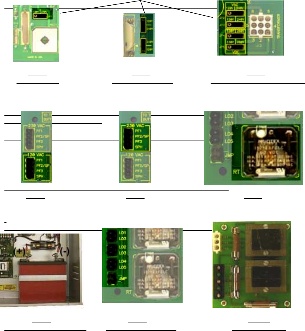
The voltage positions of these jumpers must match (except for JP4 & JP5).
Fig. 1 Fig. 2 Fig. 3
JP1 Jumper JP1, JP2 Jumpers JP2, JP3, JP4, JP5 Jumpers
(Main Board – RSCV-0001N) (Charger Board – RSCV-0003N) (Main Board – RSCV-0001N)
Fig. 4 Fig. 5 Fig. 6
120 VAC Phase Monitor 230 VAC Phase Monitor RT Relay
(Main Board – RSCV-0001N) (Main Board – RSCV-0001N) (Main Board – RSCV-0001N)
Fig. 8 Fig. 9 Fig. 10
Battery and 60 amp fuse LO1—LO5 Terminals PF Trans. board
(Main Board – RSCV-0001N) (480V RSCV-0004N, 575V RSCV-0005N)