Riggers2005_200404_PDF_200406.qxp Riggers PDF 200406
User Manual: RiggersPDF-200406 Igor's of metalworking and electrical manuals
Open the PDF directly: View PDF ![]() .
.
Page Count: 148 [warning: Documents this large are best viewed by clicking the View PDF Link!]


This Rigger’s Handbook is dedicated to Theodore C. Hanes, the founder of Hanes Supply.
Ted left us on August 11, 1997. We Know it is appropriate that the history of Hanes Supply
should be told by Ted. His hard work, common sense and dedication enabled Hanes Supply
to move forward into the next millennium.
"It all started when Tex McLaughlin taught me how to splice cable in order to obtain
my Federal A and E Aircraft Mechanics License #8867 on May 1, 1930. After leaving
American Airways August 20, 1936 to become a Professional Firefighter, I soon
learned that splicing cable for local contractor friends like Herb Darling and
Howard Stimm put extra bread on the table.
Soon we had to take operations into larger quarters at 23 Poplar Avenue. In 1962 we
moved to the warehouse at 1294 Seneca Street, giving us the space for a larger Sling
Shop and also the ability to be an Allied Products Supply House with more products
and quicker, better service.
Our new 55,000 square feet warehouse at 55 James E. Casey Drive enables us to
stock even more products to better service our customers. The increasing number
of Hanes Supply customers in Central New York State convinced us to open our
new Rochester Warehouse. Hanes Supply is committed to making the moves to give
the best possible service to all of our customers.
On October 1, 1975 I retired as a Battalion Chief from the Buffalo Fire Department
enabling me to devote more time to the company until my son Bill could take the
wheel. Bill graduated in June 1980 as a Civil Engineer from the State University at
Buffalo and is now President of Hanes Supply, Inc. Having been around watching
Dad since he was 9 years old, he thoroughly knows the wire rope business.
In association with his friends Dennis St. Germain and Jim Boyco, Bill and the
Hanes Supply Crew have learned many modern improvements in sling productions.
Many thanks to our hard working staff led by our Operations Manager and
son-in-law Dave Learn, Retired Office Manager Hermine Bruno, my other son
Ted Hanes, II and my late wife Nellie C. Hanes who have all been very valuable
assets to our business."
Ted Hanes, 1996
Ted had many other accomplishments including being a Buffalo Firefighter for 39 years,
retiring as Battalion Chief in 1975. During WWII, Ted served in the Coast Guard Reserve. Ted
was Commodore of the Buffalo Yacht Club in 1957 and Master of his Masonic Lodge in 1950.
Ted and Nellie had five children in the 1950’s. When most couples would be thinking of
retirement, they were busy providing the best home and education for their children.
Work was never a four letter word to Ted. Long days and nights of working at Hanes Marine
and Cable and the Buffalo Fire Department were common. He spent countless hours making
slings by walking around the rigger’s vise. His strength and determination built Hanes Supply
into what it is today. He also had the strength to pass the company to the next generation.
Your memory and leadership will never leave us. Special thanks to a great man who we are
proud to have had as our father. God bless you.
Thank you,
Bill Hanes/ Dave Learn / Ted Hanes II
1
Table of Contents
Aircraft Cable...............................................123
Adjustable Slings ..............................3,11-12,46
Angles...................................................133-134
Blocks, General ....................................136-138
Blocks, Snatch.............................................121
Boom Pendants ...........................................120
Boom Pendant Fittings .........................104-107
Bridles, Chain .................................43,45,48-49
Bridles,Twin-Path®................................3-4,9,11
Bridles, Wire Rope ...................................38-41
Buttons, Swage ...........................................108
Cable-Laid Wire Rope Slings ........................35
Chain .............................................................41
Chain Hoist, Hand (manual).....................60-62
Chain Hoist, Electric (power).........................63
Chain Hooks ..................................................94
Chain Load Binders .......................................50
Chain Saddle Rings....................................5,46
Chain Slings .............................................42-49
Chain Slings, Inspection ................................44
Clamps, Lifting (Plate)...........................116-117
Clevises .........................................................92
Clips, Wire Rope .....................................78-79
Common Conversions Chart .......................141
Crane Hand Signals (USA Std.) ..................144
Crane Scales............................................74-75
Definitions.............................................139-140
Dynamometers .........................................74-75
Environmental Considerations ............18-20,56
Eye Bolts...............................................109-113
Eye Hooks ................................................90-91
Fiber Characteristics.................................20,73
Fittings ...........................................................41
G-LinksTM....................................................4,15
Gator-Flex®Grommets.............................31-32
Gator-Flex®Slings, Wire Rope..............5,29-30
Gator-Laid®Slings, Wire Rope..............5,27-28
Gator-Max®Slings, Wire Rope...................5,27
General Information..............................133-144
Griphoist Electronic Weight Instruments .......75
Grommets, Wire Rope.........................31-32,36
Hand Spliced, Wire Rope Slings ...................33
Hilman Rollers ...............................................76
Hoist, Hand (manual) Chain.....................60-62
Hoist, Electric (power) Chain.........................63
Hoist Rings............................................114-115
Hooks, Chain .................................................94
Hooks, Eye ...............................................90-91
Hooks, Hoist .............................................87-91
Hooks, Replacement .....................................93
Hooks, Shank ...........................................88-89
Hooks, Sliding Choker ...................................93
Hooks, Sling .............................................87-91
Hooks, Snap ..................................................93
Hooks, Sorting ...............................................93
Hooks, Swivel ..................................93,118-119
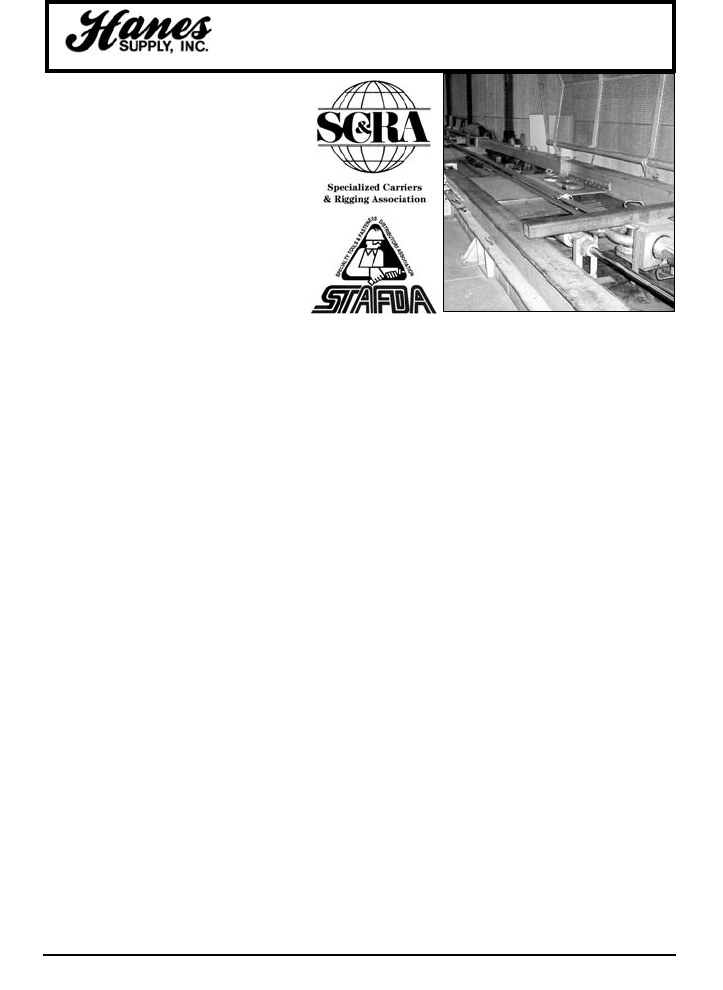
HANES SUPPLY HAS COMPLETE TESTING
FACILITIES for tension and cycling of wire rope,
chain, nylon, high-performance fiber slings, and related
items including spreader beams and other types of
rigging gear.
Specifications: 225' clear test bed with complete length
adjustment to suit any test item.
Capacity: 225 ton maximum pull test and 200 ton
maximum break test. Now available up to 3 Million
pounds.
Ram Stroke: 8' Ram
Gauges: Digital readout
Holding Load: Up to 225 tons can be held in tension for
an indefinite period which can be predetermined by the
customer.
Calibration: In accordance with ASTM E4-94 + / -1%,
and complies to MIL-STD-45662A and traceable to the
National Institute of Standards and Technology.
Recalibrated each 12 months or as otherwise deemed
necessary.
Hanes Supply Test Bed
TABLE OF CONTENTS
HEADQUARTERS: 55 James E. Casey Drive • Buffalo, NY 14206 PHONE: 716.826.2636 FAX: 716.826.4412 www.hanessupply.com
YOUR SLING AND RIGGING SPECIALIST

Table of Contents
2
HEADQUARTERS: 55 James E. Casey Drive • Buffalo, NY 14206 PHONE: 716.826.2636 FAX: 716.826.4412 www.hanessupply.com
Hooks, Synthetic Sling...................................86
K-Spec®Core Yarn .............................7,9-11,20
Lifting Beams.................................................77
Lifting Clamps .......................................116-117
Lifting Enginering...........................133-134,142
Links, Master Oblong.....................................80
Load Binders, Chain.................................50-52
Load Binders, Web...................................58-59
Master Link ....................................................80
Mechanical Splice Flemish Eye Slings ..........34
Metric Conversion........................................141
MSI Electronic Weight Instruments ...............74
Nylon Slings .............................................53-57
Polyester Slings ..................................3,8,11,22
Ratchet Assembly, Polyester....................58-59
Rings................................................80,114-115
Rope Slings, Manila.......................................66
Rope Slings, Synthetic ............................66-67
Rope Specifications ............................20,68,73
Round Slings, Endless Polyester Single Path..22
Shackles ...................................................81-85
Shank Hooks ............................................88-89
Sling Connector ..........................................4,15
Slings, Chain ............................................42-49
Slings, Nylon ............................................53-57
Slings, Polyester Single Path Endless Round ..22
Slings, Twin-Path®Sparkeater....................4,13
Slings, Tri-Flex®..................................4-5,23-26
Slings, Twin-Path®.....................3-4,6-13,16-21
Slings, Wire Mesh.....................................64,65
Slings, Wire Rope ..............................4-5,23-41
Sling Guard Protectors ...............................4,14
Snatch Blocks..............................................121
Sockets, Spelter ............................104-105,108
Sockets, Swage.............................106-108,120
Sockets, Wedge .......................................95-96
Spreader Beams ............................................77
Swivels ..................................................118,119
Synthetic Armor Wear Pads .......................4,14
Synthetic Sling Saver Shackles.....................85
T&D Ultra Flex Wire Rope Slings..................30
Tension Measurement ..............................74-75
Thimbles ...............................................102-103
Tri-Flex®Slings...................................4-5,23-26
Tri-Flex®Wire Rope.........................................4
Turnbuckles ...........................................97-101
Twin Flex™ Wire Rope Slings..................31-32
Twin-Path®Bridles ..............................3,9,11-12
Twin-Path®Chemical Considerations ......18-20
Twin-Path®Covermax Slings ......................3,8
Twin-Path®Extra Covermax Slings ..............3,7
Twin-Path®Extra Slings................................3,7
Twin-Path®Eye and Eye Slings .................3,10
Twin-Path®Inspection .............................4,8,21
Twin-Path®Mechanical Operation ...........17-18
Twin-Path®Optical Tell-Tail......................4,8,21
Twin Path®Slings ......................3-4,6-13,16-21
Twin-Path®Sparkeater Slings.....................4,13
Utility Rope, Synthetic .........................20,69-73
Wear Pads, Synthetic Armor ......................4,14
Web Slings, Nylon ....................................53-57
Web Sling Chemical Properties.....................56
Web Sling Inspection.....................................57
Web Sling Load Binders...........................58-59
Web Sling, Mechanical Considerations.........55
Wedge Sockets ........................................95-96
Weights of Material......................................143
Winch Lines, Synthetic .............................69-73
Wire Mesh Slings .....................................64-65
Wire Rope .....................................122-132,135
Wire Rope Abuse .................................128-129
Wire Rope Breaking Strength ...............124,130
Wire Rope Clips........................................78,79
Wire Rope Cross Sections ..........................125
Wire Rope, Aircraft Cable ............................123
Wire Rope, General.......................130-131,135
Wire Rope, High Performance ....................123
Wire Rope Inspection ...........................126-127
Wire Rope Rotation Resistant .....................122
Wire Rope Slings ...............................4-5,23-41
Wire Rope, 6x19 Classification ...................124
Wire Rope, 6x36 Classification ...................124
Wire Rope Slings, Bridles ........................38-41
Wire Rope Slings, Cable-Laid Grommet .......36
Wire Rope Slings, Strand-Laid Grommet ......37
Wire Rope Thimbles.............................102-103
YOUR SLING AND RIGGING SPECIALIST
anes Supply specializes in lifting
solutions for a wide variety of
applications. As a manufacturer of Slingmax®
slings we are proud to provide riggers with
innovative products that increase productivity
and safetyi The following product inventions
provide benefits that make a rigger's work
easier, safer or more cost effective.
3
HEADQUARTERS: 55 James E. Casey Drive • Buffalo, NY 14206 PHONE: 716.826.2636 FAX: 716.826.4412 www.hanessupply.com
Innovative Lifting Solutions
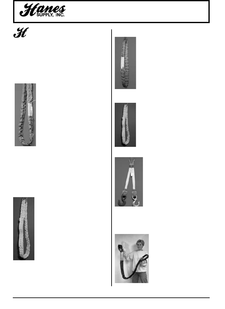
TWIN-PATH®EXTRA SLINGS
WITH COVERMAX AND
K-SPEC™ CORE YARN
US Patent #4,850,629; CN #1,280,458
TPXC The best synthetic sling. Made with
K-Spec™ high performance fibers and a
bulked nylon outer cover (Covermax) that is
very abrasion resistant. For vertical rated
capacities up to 300,000 lbs. This sling
features overload tell-tails, fiber optic
inspection system, red inner cover, and are
used worldwide in place of chain and wire
rope slings for heavy lifts. They are also
repairable. The Twin-Path®patented design
provides the rigger with redundant
protection in the event that one path is cut. These slings
have 1% stretch at rated capacity and are made in matched
lengths. If head room is critical, then these are the slings for
the job. Conforms to ASME B30.9 Chapter six and US Navy
NAVFAC P-307 Section 14. Developed by a team of
professional riggers to overcome shortfalls found in single
path roundslings. See page 7.
TWIN-PATH®EXTRA SLINGS
WITH K-SPEC™
US Patent #4,850,629; CN #1,280,458
TPX Same as the slings above, but they
have polyester outer covers which are less
abrasion resistant than the Covermax.
Complete with overload tell-tails, fiber optic
inspection system, red inner cover, orange
outer cover, and are repairable. These slings
have 1% stretch at rated capacity and are
made in matched lengths. If you are
interested in safety, ergonomics, increased
productivity and saving money, then this is
the product.
See page 7.
TWIN-PATH®POLYESTER SLINGS
WITH COVERMAX
US Patent #4,850,629; CN #1,280,458
TPC slings are made in capacities up to
60,000 lbs. vertical. They have the
abrasion resistant Covermax cover with a
polyester inner cover over polyester fiber
cores. Complete with overload tell-tails
and are repairable. Like all Twin-Path®
slings, they can be fitted with fiber optics
for inspection. These slings have up to 3%
stretch at rated capacity. See page 8.
TWIN-PATH®POLYESTER SLINGS
US Patent #4,850,629; CN #1,280,458
TP slings are the same as the TPC slings
except their outer covers are polyester and
less abrasion resistant than Covermax. See
page 8.
TWIN-PATH®TWO LEG BRIDLES
US Patent #5,727,833 & 4,850,629
TL Simply the lightest and strongest
synthetic bridles in the world today.
Replaces existing chain and wire rope
bridles. The Twin-Path®synthetic bridle
with K-Spec™ core yarn is less than half
the weight of any steel assembly and is
the ergonomic bridle of the future, here
today. The loop at the top goes on the
crane hook and there is no heavy steel
ring to deal with. If you need a four leg
bridle, just use two Twin-Path®Two Leg bridles. Capacities
to 200,000 lbs. See page 9.
TWIN-PATH®EYE & EYE
SYNTHETIC SLING
US Patent #5,727,833 & 4,850,629
EE This product is made to be an
eye and eye sling only, with all of the
Twin-Path®features. This sling is
light, strong and less expensive than
a round sling with a sleeve. It can be
manufactured using either K-Spec™
core yarn or polyester. See page 10.
YOUR SLING AND RIGGING SPECIALIST
4
HEADQUARTERS: 55 James E. Casey Drive • Buffalo, NY 14206 PHONE: 716.826.2636 FAX: 716.826.4412 www.hanessupply.com
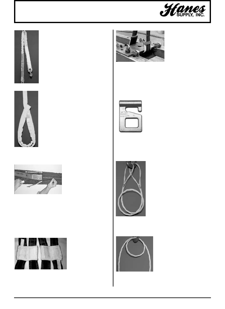
Innovative Lifting Solutions
SPARKEATER®SYNTHETIC SLINGS
US Patent #4,850,629
SE For hot environments up to 300°F, the
Sparkeater®lifts the load without marring
the surface of the lifted piece. Excellent for
stage rigging, this product offers protection
from exposure to fire, heat, sparks and
pyrotechnics. Made from Nomex®for the
cover and Aramid high performance core
yarns. Rated capacities of 2,000 lbs. to
30,000 lbs. Fire exposure testing was
performed by London Scientific and the
product was identified as being as good as
wire rope or chain for use in off shore
applications in the oil industry. See page 13.
FIBER OPTIC
INSPECTION OPTION
US Patent #5,651,572
FO All of the Twin-Path®
slings have the Fiber Optic
inspection system. The fiber
optic cable will conduct light
using natural, overhead or flashlight sources. The condition
of the internal core yarn can be inspected by checking the
continuity of the fiber optic cable. If heat, chemicals,
crushing or cutting has occurred, the damage to the fiber
optic cable will destroy its ability to transmit light from one
end to the other. This gives the inspector a reason to
remove the sling from service and send it for repair
evaluation. See page 8.
SYNTHETIC ARMOR
WEAR PADS
For extra protection for
synthetic, wire rope, and
chain slings, we have
available an assortment of
materials that we
incorporate in our Synthetic
Armor Wear Pads. These are primarily for abrasion or wear
protection but can be used for cut protection in many cases.
Not only will these wear pads keep the load from damaging
the slings, but they will also protect the load from being
scratched by the slings. See page 14.
CORNERMAX™
US Patent #5,651,573
& Patents Pending
The Cornermax™ cut
protection device prevents
a sharp edge on the load
from touching the sling.
In fact, the sharp edge
doesn't even touch the Cornermax™ protector! This protector
will handle the most extreme circumstances lifting steel and
concrete. See page 14.
G-LINK™ CONNECTORS
US Patent #5,651,573 & Patents Pending
This is the only universal coupler
designed to fulfill all the needs of riggers
in the field! You can use it on Twin-
Path®, Web and Single Path Round
Slings for attaching hooks, rings, two
slings together, as a sliding choker
connection, as an adjustable sling, or as
a choke lock connection. No parts, bolts, nuts, cotters, pins,
or anything to look for. The G-Link™ connector keeps
hardware such as hooks or rings in the same plane as the
sling. See page 15.
TRI-FLEX®WIRE ROPE SLING
US Patent #4,043,581
This is a three-part wire rope sling
developed for strength combined with
greater flexibility. Replaces large
diameter single-part wire rope slings
which are awkward and stiff. Tri-Flex®
Slings are manufactured in sizes from 1
ton to 150 ton capacity. Steel erectors,
millwrights and riggers use Tri-Flex®
slings for everything from steel erection
and machinery moving to heavy lifts of
200 tons or more. These slings are
made in matching lengths.
See page 24.
TRI-FLEX®WIRE ROPE
US Patent #4,043,581
Tri-Flex®Wire Rope is a three-part
wire rope made in lengths up to
200' installed on winches for
barges, tugs and car pullers. It
wraps snugly around the winch
hub because it has greater
flexibility than standard wire rope.
Order by specifying rated capacity or finished diameter, and
required end attachment.
TWIN-PATH®ADJUSTABLE
BRIDLE SLING
US Patent #4,850,629 & #5,651,573
TPXA or TPA This tool is an aid to finding
the center of gravity when lifting objects
with uneven geometric proportions or off-
center balance points. When the load is
lifted, the ring moves over the COG to
balance and level the object. The Twin-
Path®may be permanently attached to the
ring, or use a G-Link™ for the connection.
See page 11.
YOUR SLING AND RIGGING SPECIALIST
5
HEADQUARTERS: 55 James E. Casey Drive • Buffalo, NY 14206 PHONE: 716.826.2636 FAX: 716.826.4412 www.hanessupply.com
Innovative Lifting Solutions
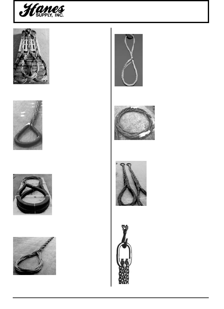
TRI-FLEX® SLING SYSTEM
US Patent #4,240,659
CN Patent #1,082,755
British Patent #2,029,796
This product is a combination of
three Tri-Flex®Wire Rope slings
wrapped together to form a nine-
part finished body sling. After a
heavy lift is done, the product can
be taken apart to form three
individual Tri-Flex®slings for
smaller lifting work. There are
twelve parts of wire rope in the loop
for greater strength than traditional
nine part wire rope slings. See page 26.
GATOR-MAX®
US Patent #5,561,973
& Patents Pending
Tests have proven this sling to be the
strongest Multi-Part wire rope sling
when attached to small pins because it
has twelve parts of wire rope in the loop
in a parallel construction. It will develop
its full strength on small pins with a D/d
ratio of 1/1 where D is the pin and d is
the sling body. (4/1 D/d when
comparing the pin to the component
parts.) The Gator-Max® sling was developed to meet
conditions specified by the US Navy and the Wire Rope
Technical Board Sling Manual. See page 27.
GATOR-LAID®
WIRE ROPE SLING
US Patent #4,240,659
Identical to the Gator-Max®sling
except it has metal sleeves for
the splice connection. The ideal
sling for big lifts but when a
shorter sling is required. The
Gator-Flex®and Gator-Laid®
products were developed in
conjunction with the off shore oil industry to provide the best
heavy lift wire rope slings. See page 27.
GATOR-FLEX®
WIRE ROPE SLING
US Patent #5,561,973
This sling has a nine-part body
style but the eyes are crossed
or interwoven so that no
wrapping is necessary. This
allows for visual inspection of
the sling. Used for heavy lifts
and offers the highest flexibility in a Multi-Part wire rope
sling. See page 30.
T & D ULTRA-FLEX
WIRE ROPE SLING
US Patent #5,561,973
Developed by a committee composed of
utility company workers and members of
the Slingmax®design team, this wire
rope sling is an extremely flexible
product with great applications for
general rigging purposes in the utility
industry. It makes a fantastic choker
sling especially when lifting poles.
See page 30.
GATOR-FLEX®NINE PART
GROMMETS
US Patent #5,561,973
Ultra flexible slings for short
heavy lift connection. These
slings can be made shorter than
standard Multi-Part slings but
maintain all of the advantages.
See page 32.
TWIN-FLEX®
WIRE ROPE SLINGS
US Patent #5,561,973
Another model of a grommet type
sling which is formed into an eye and
eye design. It consists of 18 body
parts with a loop at each end. It is
extremely flexible and is used where
heavy lift, short slings are required.
See page 32.
CHAIN SLING SADDLE RING
US Patent #4,241,575;
CN Patent #1,086,510;
British Patent #2,029,370
This product gives a chain bridle length
adjustment capabilities in each chain leg. It
aids the rigger in placing the lifting point over
the center of gravity so the load will lift in a
level manner. Different length chains or
chains with different attachments can be
interchanged in the Saddle Ring for added
utility. The Saddle Ring has found favor with
millwrights for moving machinery in factories.
See page 46.
YOUR SLING AND RIGGING SPECIALIST

6
HEADQUARTERS: 55 James E. Casey Drive • Buffalo, NY 14206 PHONE: 716.826.2636 FAX: 716.826.4412 www.hanessupply.com
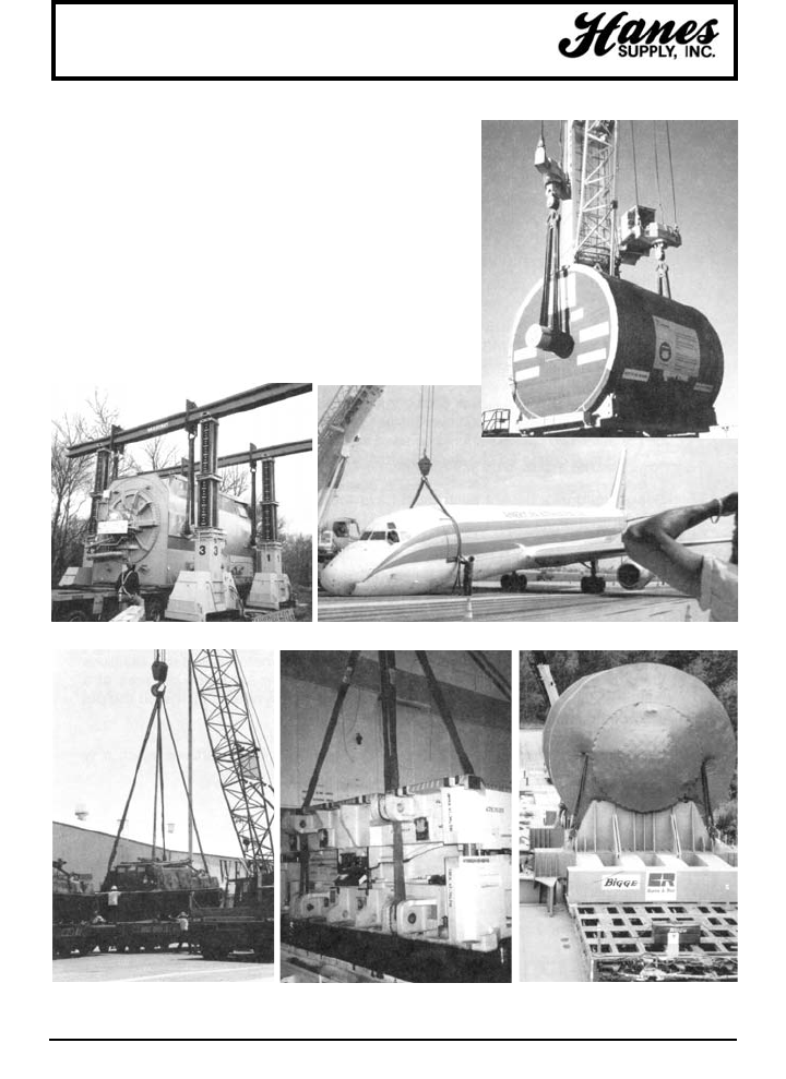
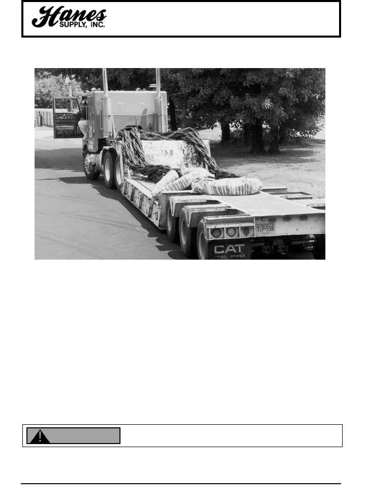
Twin-Path®Slings
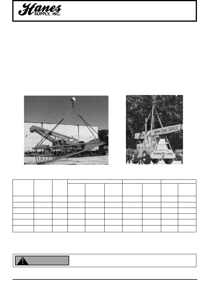
TWIN-PATH®
SLINGS IN
CONSTRUCTION
517 ton Bridge Retrofit
440 ton Gas Plant Vessel
80 ton Concrete Pilings
100 ton Airport Walkway Section
YOUR SLING AND RIGGING SPECIALIST
7
HEADQUARTERS: 55 James E. Casey Drive • Buffalo, NY 14206 PHONE: 716.826.2636 FAX: 716.826.4412 www.hanessupply.com
RATED CAPACITIES (LBS.) 5-1 D/F
CHOKER VERTICAL BASKET HITCHES APPROXIMATE
TWIN-PATH®WEIGHT APPROXIMATE
EXTRA COVERMAX (LBS. PER FT.) BODY WIDTH
STOCK NO. (BEARING-BEARING) (IN.)
TPXC 1000 8,000 10,000 20,000 17,320 14,140 .31 3"
TPXC 1500 12,000 15,000 30,000 25,980 21,210 .40 3"
TPXC 2000 16,000 20,000 40,000 34,640 28,280 .55 3"
TPXC 2500 20,000 25,000 50,000 43,300 35,350 .65 4"
TPXC 3000 24,000 30,000 60,000 51,960 42,420 .80 4"
TPXC 4000 32,000 40,000 80,000 69,280 56,560 1.12 5"
TPXC 5000 40,000 50,000 100,000 86,139 70,700 1.50 5"
TPXC 6000 48,000 60,000 120,000 103,920 84,840 1.60 6"
TPXC 7000 56,000 70,000 140,000 121,240 98,980 1.68 6"
TPXC 8500 68,000 85,000 170,000 147,220 120,190 1.85 6"
TPXC 10000 80,000 100,000 200,000 173,200 141,400 2.20 6"
TPXC 12500 100,000 125,000 250,000 216,500 176,750 3.00 8"
TPXC 15000 120,000 150,000 300,000 259,800 212,100 3.36 8"
TPXC 17500 140,000 175,000 350,000 303,100 247,450 4.00 10"
TPXC 20000 160,000 200,000 400,000 346,400 282,800 4.37 10"
TPXC 25000 200,000 250,000 500,000 433,000 353,500 5.50 11"
TPXC 27500 220,000 275,000 550,000 476,300 388,850 6.90 11"
TPXC 30000 240,000 300,000 600,000 519,600 424,200 7.50 12"
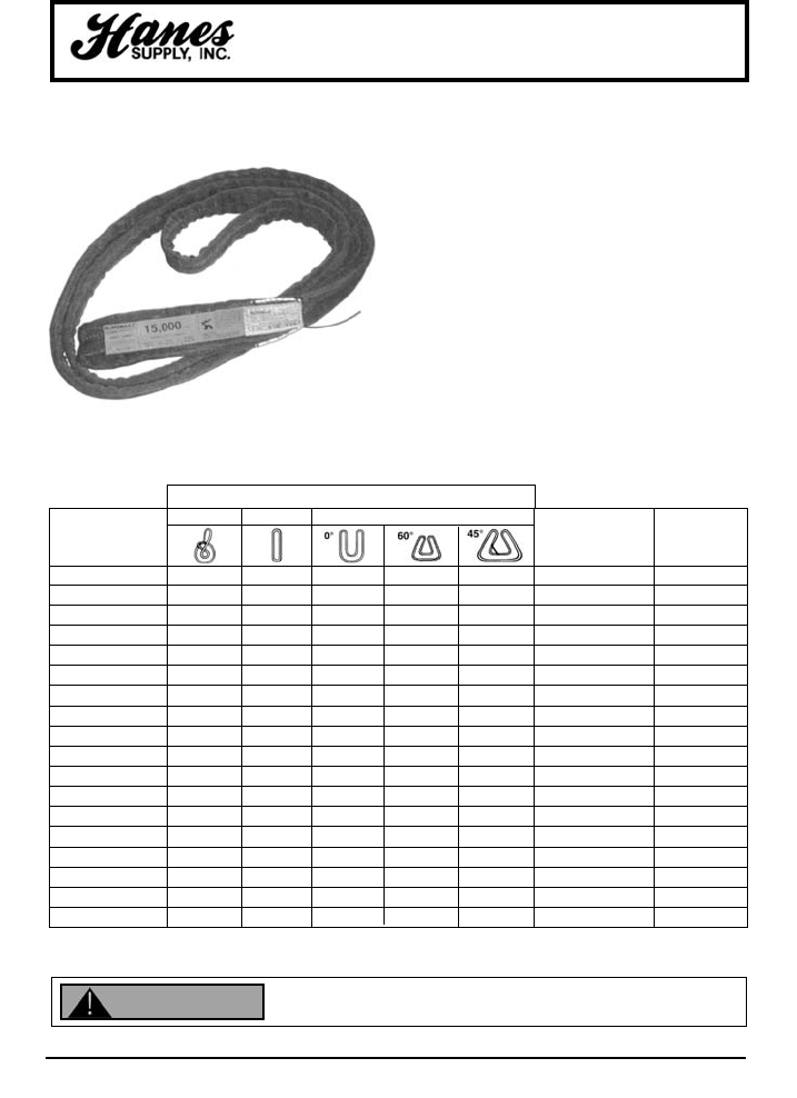
TPXC This is the world's first truly ergonomic sling. It has
a bulked nylon outer cover for superior abrasion
resistance. These are made in sizes up to 300,000 lbs.
vertical rated capacity. Larger capacity slings are
available on special order. Extra Heavy Duty Covermax
is standard on 70,000 lb. vertical capacity and higher.
These slings have overload tell-tails, inner red cover,
and are used worldwide in place of wire rope slings for
heavy lifts. They are about 10% of the weight of a steel
sling. These products are repairable. The Twin-Path®
patented design provides the rigger with two connections
between the hook and the load for redundant back-up
protection. These slings have 1% stretch at rated capacity compared
to braided polyester round slings which can stretch up to 9%. If
ergonomics, productivity and safety are important, then these slings are the only
choice. This is the lightest and strongest sling on the market today with K-Spec®, the
longest lasting load bearing core yarn, backed by independent testing. All slings have fiber optic internal
inspection system.
Twin Path®Extra Covermax Slings
PLEASE NOTE: Capacities shown include both paths and are for one complete sling. Ratings based on straight pin diameter one-half
the sling width. DO NOT EXCEED RATED CAPACITY
TWIN-PATH®EXTRA COVERMAX SPECIFICATIONS
Can fail if damaged, misused or overloaded. Inspect before use. Use only if trained.
Observe rated capacity. Avoid sharp edges and exposure to acid, alkali, sunlight and
temperature over 180°F. DEATH or INJURY can occur from improper use or maintenance.
WARNING
United States
Patent #4,850,629
Canadian
Patent #1,280,458
TWIN-PATH®EXTRA SLING WITH COVERMAX
AND K-SPEC®CORE YARN
YOUR SLING AND RIGGING SPECIALIST
8
HEADQUARTERS: 55 James E. Casey Drive • Buffalo, NY 14206 PHONE: 716.826.2636 FAX: 716.826.4412 www.hanessupply.com
Can fail if damaged, misused or overloaded. Inspect before use. Use only if trained.
Observe rated capacity. Avoid sharp edges and exposure to acid, alkali, sunlight and
temperature over 180°F. DEATH or INJURY can occur from improper use or maintenance. WARNING
Rated Capacities (lbs.) 5-1 D/F
Twin-Path®Covermax Slings (Polyester)
Fiber Optic Inspection (All Slings)
TWIN-PATH®POLYESTER SLINGS WITH COVERMAX SPECIFICATIONS
CHOKER VERTICAL BASKET HITCHES APPROXIMATE
TWIN-PATH®WEIGHT APPROXIMATE
EXTRA COVERMAX (LBS. PER FT.) BODY WIDTH
STOCK NO. (BEARING-BEARING) (IN.)
TPC 200 1,600 2,000 4,000 3,464 2,828 .28 2"
TPC 300 2,400 3,000 6,000 5,196 4,242 .30 2"
TPC 450 3,600 4,500 9,000 7,794 6,383 .45 2"
TPC 600 4,800 6,000 12,000 10,392 8,484 .48 3"
TPC 750 6,000 7,500 15,000 12,990 10,605 .65 3"
TPC 900 7,200 9,000 18,000 15,588 12,726 .70 3"
TPC 1200 9,600 12,000 24,000 20,784 16,968 .90 4"
TPC 1400 11,200 14,000 28,000 24,248 19,798 .95 4"
TPC 1700 13,600 17,000 34,000 29,440 24,038 1.20 4"
TPC 2200 17,800 22,000 44,000 38,104 31,108 1.40 5"
TPC 2600 20,800 26,000 52,000 45,032 36,784 1.70 5"
TPC 3200 25,600 32,000 64,000 55,424 45,248 1.90 5"
TPC 5000 40,000 50,000 100,000 86,600 70,700 2.70 6"
TPC 6000 48,000 60,000 120,000 103,920 84,840 3.00 6"
PLEASE NOTE: Capacities shown include both paths and are for one complete sling. Ratings based on straight pin diameter
one-half the sling width.
DO NOT EXCEED RATED CAPACITY
United States
Patent #4,850,629
Canadian
Patent #1,280,458
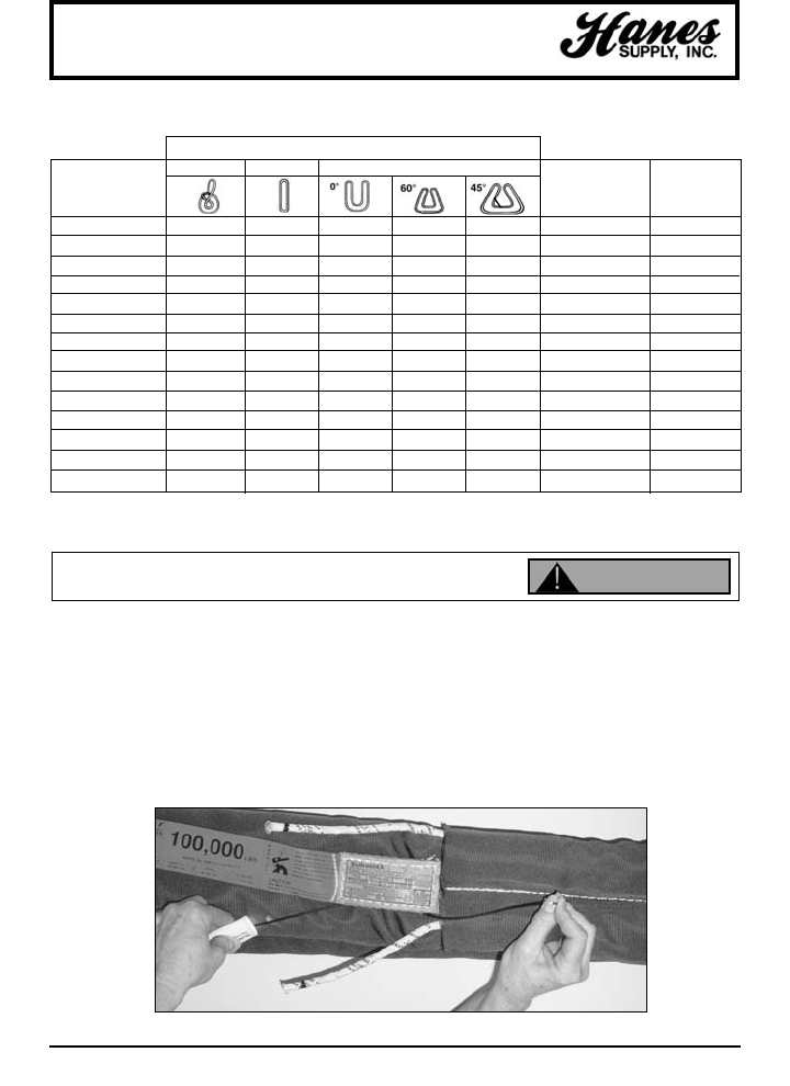
Twin-Path®slings have the Fiber Optic inspection system. The condition of the internal core yarn can be inspected
just by checking the continuity of the fiber optic cable. If crushing or cutting, heat or chemical damage, has
occurred, then the damage to the fiber optic cable will destroy its ability to transmit light from one end to the other
giving the inspector a reason to remove the sling from service and send it in for repair evaluation. The fiber optic
cable will conduct light using natural, overhead or flashlight sources. The inspector simply covers and removes
his finger from one end and watches the other end for blinking which indicates that the sling is OK to use for
another lift.
FIBER OPTIC INSPECTION
FOR ALL TWIN-PATH®SLINGS
United States Patent #5,561,972 & Patents Pending
YOUR SLING AND RIGGING SPECIALIST
9
HEADQUARTERS: 55 James E. Casey Drive • Buffalo, NY 14206 PHONE: 716.826.2636 FAX: 716.826.4412 www.hanessupply.com
Can fail if damaged, misused or overloaded. Inspect before use. Use only if trained.
Observe rated capacity. Avoid sharp edges and exposure to acid, alkali, sunlight and
temperature over 180°F. DEATH or INJURY can occur from improper use or maintenance.
WARNING
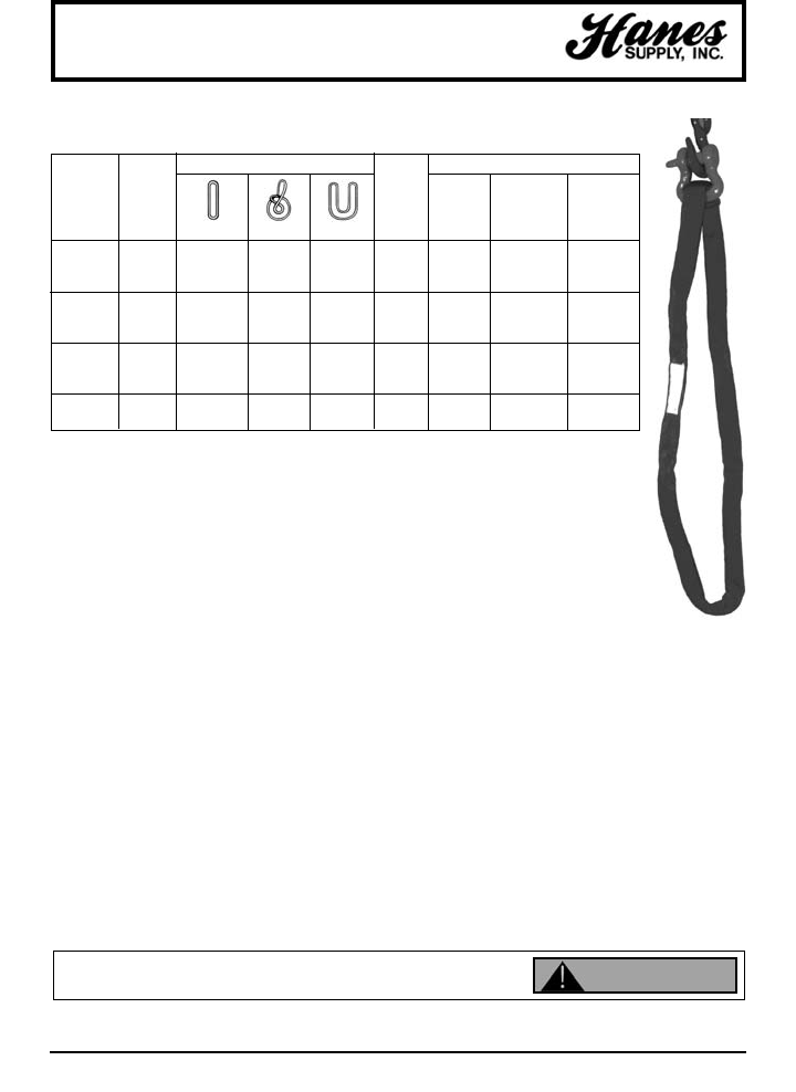
Twin-Path®Two Leg Bridles
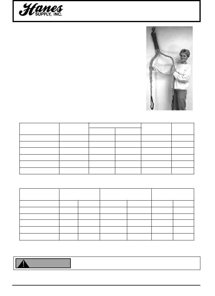
TWIN-PATH®TWO LEG BRIDLES
United States Patent #5,727,833 & #4,850,629
TL Simply the lightest and strongest synthetic bridles in the
world today. These are perfect to replace existing chain and
wire rope bridles. The Twin-Path®synthetic bridle with K-Spec®
core yarn is less than half the weight of any steel assembly and
is the ergonomic bridle of the future, here today. The loop at the
top goes on the crane hook and there is no heavy steel ring to
deal with. If you need a four leg bridle, just order two Twin-
Path®Two Leg Bridles. Capacities to 200,000 lbs. Please
specify the loop size at the top and the hardware such as hooks
required on the bottom of each leg. Hooks can be removable if
they are attached with G-Link™ connectors. This gives the
Twin-Path®Two Leg Bridle added versatility on the job.
HORIZONTAL ANGLES WT. PER FT. EYE
STOCK NUMBERS VERTICAL 60° 45° (LBS.) WIDTH
TPXCTL 1,000 10,000 8,500 7,000 .34 3"
TPXCTL 1,500 15,000 12,750 10,500 .44 3"
TPXCTL 2,000 20,000 17,000 14,000 .61 3"
TPXCTL 3,000 30,000 25,500 21,000 .88 4"
TPXCTL 4,000 40,000 34,000 28,000 1.23 5"
TPXCTL 5,000 50,000 42,500 35,000 1.65 5"
TWIN-PATH®TWO LEG BRIDLES
BOTTOM OF LEG SYNTHETIC SLING
G-LINK / WEIGHT / WEIGHT / WEIGHT
HARDWARE SHACKLE HOOK
TPXCTL 1,000 2" 2.0 2" 6.9 3T 3.9
TPXCTL 1,500 3" 3.5 2" 6.9 5T 7.3
TPXCTL 2,000 3" 3.5 2" 6.9 5T 7.3
TPXCTL 3,000 4" 7.0 3" 8.9 10T 17.0
TPXCTL 4,000 4" 7.0 3" 8.9 10T 17.0
TPXCTL 5,000 5" 15.0 3" 8.9 15T 33.0
S-253 S-320
YOUR SLING AND RIGGING SPECIALIST
10
HEADQUARTERS: 55 James E. Casey Drive • Buffalo, NY 14206 PHONE: 716.826.2636 FAX: 716.826.4412 www.hanessupply.com
Twin-Path®Eye and Eye Sling
TWIN-PATH®EYE & EYE
SYNTHETIC SLING
United States Patent #5,727,833 & #4,850,629
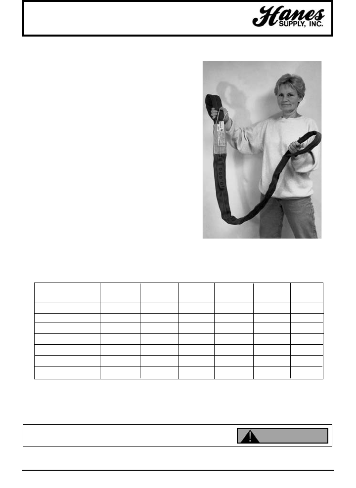
EE This product is made to be an eye and
eye sling only. Usually an eye and eye sling
is made from a round sling with a sleeve
over it to form the eyes at each end. This
sling is light, strong and less expensive than
a round sling with a sleeve. It can be
manufactured using either K-Spec®core
yarn or polyester. Riggers have told us that
they have some applications where they
want an eye and eye sling only and this is
the one with all of the Twin-Path®features in
a strictly eye and eye product.
BASKET VERTICAL WT. LBS.
STOCK NUMBERS CHOKER VERTICAL 60° BASKET PER FT. WIDTH
TPXCEE 1,000 8,000 10,000 17,320 20,000 .28 3"
TPXCEE 1,500 12,000 15,000 25,980 30,000 .36 3"
TPXCEE 2,000 16,000 20,000 36,640 40,000 .50 3"
TPXCEE 2,500 20,000 25,000 43,300 50,000 .60 4"
TPXCEE 3,000 24,000 30,000 51,960 60,000 .75 4"
TPXCEE 4,000 32,000 40,000 69,280 80,000 1.00 5"
TPXCEE 5,000 40,000 50,000 86,139 100,000 1.40 5"
TWIN-PATH®EYE AND EYE SLING
Can fail if damaged, misused or overloaded. Inspect before use. Use only if trained.
Observe rated capacity. Avoid sharp edges and exposure to acid, alkali, sunlight and
temperature over 180°F. DEATH or INJURY can occur from improper use or maintenance. WARNING
YOUR SLING AND RIGGING SPECIALIST
11
HEADQUARTERS: 55 James E. Casey Drive • Buffalo, NY 14206 PHONE: 716.826.2636 FAX: 716.826.4412 www.hanessupply.com
Can fail if damaged, misused or overloaded. Inspect before use. Use only if trained.
Observe rated capacity. Avoid sharp edges and exposure to acid, alkali, sunlight and
temperature over 180°F. DEATH or INJURY can occur from improper use or maintenance.
WARNING
TPXA (with K-Spec®), TPA (with polyester)
United States Patent #4,850,629 Canadian Patent #1,280,458
The Twin-Path®Adjustable Bridle is the ultimate multiple use rigging tool.
It can be used in applications where a standard two leg or four leg bridle
is used with the added advantage of self-adjustment to awkward loads.
The Twin-Path®Adjustable Bridle self-adjusts over the center of gravity to
find the lifting point. The Twin-Path®Adjustable Bridle can also be used as
a complete rigging tool for choker, vertical, or basket hitches. The use of
two or more Twin-Path®Adjustable Bridles facilitates lifts with multiple
lifting points.
SINGLE ADJUSTABLE RING DIMENSIONS SHACKLE DIMENSIONS SLING WEIGHT (LBS.)
TPA BRIDLE APPROX. RING MAIN HOOK RING NOMINAL TONNAGE APPROX. APPROX.
CODE CAPACITY SLING STOCK AREA AREA SHACKLE (W.L.L.) 3 FOOT ADDER
(LBS.) (WIDTH) DIAMETER (WIDTH) (LENGTH) SIZE BASE PER FOOT
TPA 6 6,000 2" 1/2" 2-1/2" 2-1/2" 5/8" 3-1/4T 4.40 1.35
TPXA 12 12,000 3" 3/4" 3" 3" 7/8" 6-1/2T 6.80 1.95
TPXA 20 20,000 4" 1" 4" 4" 1-1/4" 12T 13.60 2.70
TPXA 40 40,000 5" 1-1/2" 5-1/4" 5-1/4" 1-3/4" 25T 31.10 4.20
TPXA 60 60,000 5" 2" 7" 7" 2" 35T 60.00 5.70
TPXA 90 90,000 6" 2-1/4" 8" 8" 2-1/4" 55T 86.00 8.10
TWIN-PATH®ADJUSTABLE BRIDLE SPECIFICATIONS
Twin-Path®Adjustable Bridle
PLEASE NOTE: Capacities shown include both paths and are for one complete assembly.
DO NOT EXCEED RATED CAPACITY
YOUR SLING AND RIGGING SPECIALIST
12
HEADQUARTERS: 55 James E. Casey Drive • Buffalo, NY 14206 PHONE: 716.826.2636 FAX: 716.826.4412 www.hanessupply.com
Can fail if damaged, misused or overloaded. Inspect before use. Use only if trained.
Observe rated capacity. Avoid sharp edges and exposure to acid, alkali, sunlight and
temperature over 180°F. DEATH or INJURY can occur from improper use or maintenance. WARNING
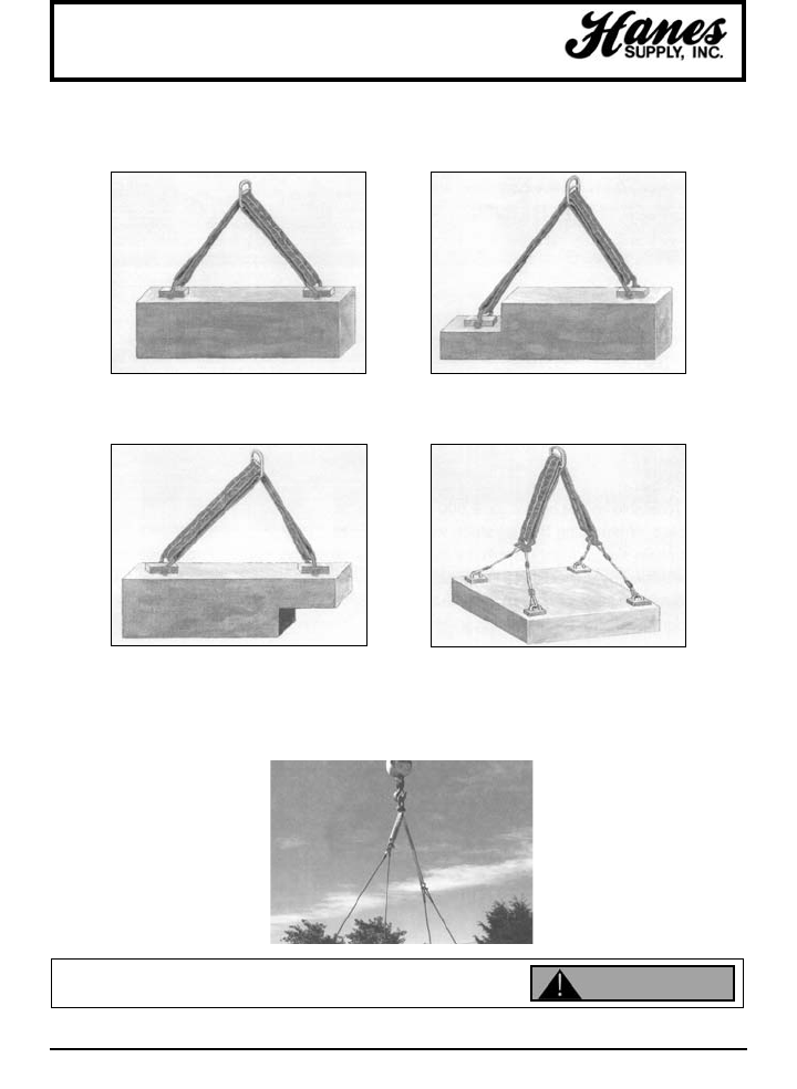
Twin-Path®Adjustable Bridle
The Twin-Path®Adjustable Bridle sling is a multi-purpose rigging tool and it's important that it is used
properly. The adjustment ring has a double sling on one side and a single sling on the other side.
If the lifting points are an equal distance from
the center of gravity, then the Twin-Path®
Adjustable can be hooked-up with the double
or single sling on either lifting point.
If the lifting points are an equal distance on
either side of the center of gravity but one is
higher, then the double sling should be
attached to the higher lifting point.
If one of the lifting points is closer to the
center of gravity, then attach the double sling
to this lifting point. It will have the highest
weight concentration. If the Twin-Path®
Adjustable is attached so that the single sling
is nearest the center of gravity, it will not
allow the lift to be made.
Never use the Twin-Path®Adjustable Bridle
in situations where the sling-to-hook angle is
greater than 45°. Always connect above the
center of gravity. If connections are made
below the center of gravity, then the load may
turn when lifted.
YOUR SLING AND RIGGING SPECIALIST
13
HEADQUARTERS: 55 James E. Casey Drive • Buffalo, NY 14206 PHONE: 716.826.2636 FAX: 716.826.4412 www.hanessupply.com
Can fail if damaged, misused or overloaded. Inspect before use. Use only if trained.
Observe rated capacity. Avoid sharp edges and exposure to acid, alkali, sunlight and
temperature over 180°F. DEATH or INJURY can occur from improper use or maintenance.
WARNING
Twin-Path®Sparkeater Slings
SPARKEATER®
SYNTHETIC SLINGS
U.S. Patent #4,850,629; CN Patent #1,280,458
SE When you have a hot environment up to
300°F, use a Sparkeater®to lift the load
without marring the surface of the lifted
piece. Also, when doing stage rigging order
this product for the protection it gives from
exposure to fire, heat, sparks and
pyrotechnics. Just specify black color for the
theater or yellow for all other applications.
These slings are made from Nomex®for the
cover and Aramid high-performance core
yarns. Available in capacities of 2,000 to
30,000 lbs. When lifting heated steel, wire
rope or chain slings might scratch the load
causing expensive rework. Fire exposure testing was performed by the Offshore
Certification Bureau and the product was identified as being as good as wire rope
or chain for use in off shore applications in the oil industry.
TWIN-PATH®SPARKEATER SPECIFICATIONS
RATED CAPACITIES
CHOKER VERTICAL BASKET APPROX.
STOCK NUMBER SLING WIDTH WEIGHT
LBS. PER FT.
(Bearing-Bearing)
TPSE 200 2.5" 1,600 2,000 4,000 .20
TPSE 400 2.5" 3,200 4,000 8,000 .24
TPSE 600 2.5" 4,800 6,000 12,000 .28
TPSE 1000 3" 8,000 10,000 20,000 .31
TPSE 2000 3" 16,000 20,000 40,000 .55
TPSE 3000 4" 20,000 30,000 60,000 .80
PLEASE NOTE: Capacities shown include both paths and are for one complete sling.
DO NOT EXCEED RATED CAPACITY
YOUR SLING AND RIGGING SPECIALIST
14
HEADQUARTERS: 55 James E. Casey Drive • Buffalo, NY 14206 PHONE: 716.826.2636 FAX: 716.826.4412 www.hanessupply.com
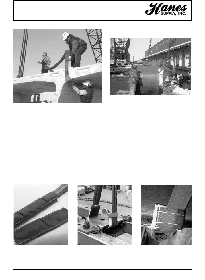
Wear Pads and Cut Protectors
Wear pads such as Cornermax™ and Synthetic Armor Wear Pads
protect loads and slings. These wear pads contain a variety of
synthetic and metallic materials, and can be made ready to use in any
length or width to fit wire rope, chain, nylon webbing, or any regular
rope or sling product. They can also be made in long lengths which the
customer can cut into suitable sizes on the job. Among all our wear
pads and corner protectors, you can find the appropriate materials to
provide cut resistance for the most severe conditions.
YOUR SLING AND RIGGING SPECIALIST
15
HEADQUARTERS: 55 James E. Casey Drive • Buffalo, NY 14206 PHONE: 716.826.2636 FAX: 716.826.4412 www.hanessupply.com
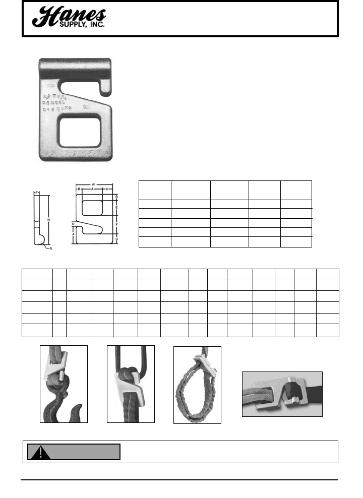
G-Link™ Synthetic Sling Connector
Patent #5,651,573
PRODUCT FEATURES:
9Couples web, round or Twin-Path®slings with
hardware (oblongs or hooks).
9Splices two slings into longer length.
9Connects two slings with oblong and two hooks
into bridle sling.
9Allows sling to be used as sliding choker sling.
9Two G-Link™ connectors used together will double
the rated capacity of one G-Link™ connector.
9Conforms with ASME B30.9 web and round sling
specifications.
VERTICAL CHOKER SLING
MODEL RATED RATED SIZE WGT.
NUMBER CAP. (TONS) CAP. (TONS) (IN.) (LBS.)
SC200L 2-1/2 2 2" 2
SC300L 5 3 3" 3-1/2
SC400L 7-1/2 4 4" 7
SC500L 15 8 5" 15
SC600L 25 12 6" 29
MODEL A B C D E F G H J O R T W
SC200L 2 5/8 1-1/8 5/8 1-1/8 1-15/16 1 5.00 1-13/16 1/2 .50 .50 3.50
SC300L 3 11/16 1-1/4 11/16 2-1/4 2-7/16 1-1/4 6.62 2-1/2 9/16 .75 .75 5.00
SC400L 4 13/16 1-3/8 13/16 2-1/2 2-7/8 1-3/8 7.50 2-3/4 3/4 .75 1.00 6.00
SC500L 5 1-1/16 2 1-1/16 3 3-3/4 2 9.75 3-3/4 1 1.00 1.25 8.00
SC600L 6 1-1/4 2-1/4 1-1/4 4 5 2-1/4 12.50 4-3/4 1-1/4 1.00 1.50 9.38
G-LINK™ SYNTHETIC SLING CONNECTOR DIMENSIONS
Can fail if damaged, misused or overloaded. Inspect before use. Use only if trained.
Observe rated capacity. DEATH or INJURY can occur from improper use or maintenance.
Connect Hook or Oblong to Sling Choker Sling Connect Two Slings
WARNING
YOUR SLING AND RIGGING SPECIALIST
16
HEADQUARTERS: 55 James E. Casey Drive • Buffalo, NY 14206 PHONE: 716.826.2636 FAX: 716.826.4412 www.hanessupply.com
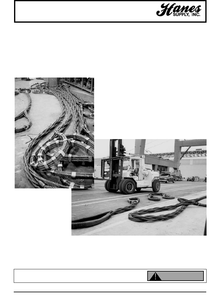
Twin-Path®Slings in Action
TWIN-PATH®
SLINGS IN ACTION
YOUR SLING AND RIGGING SPECIALIST

17
HEADQUARTERS: 55 James E. Casey Drive • Buffalo, NY 14206 PHONE: 716.826.2636 FAX: 716.826.4412 www.hanessupply.com
Twin-Path®Slings
7.0 - MECHANICAL CONSIDERATIONS
7.1 Determine the weight of the load. The weight of the load shall be within the rated capacity
of the sling.
7.2 Select a sling having suitable characteristics for the type of load, hitch and environment.
7.3 Slings shall not be loaded in excess of the rated capacity. Consideration shall be given to
angle of lift which may affect the lifting capacity. Diameters of pins and sharp edges also
may affect the capacity of the lifting sling.
7.4 Slings used in a choker shall not be forced to tighten around the load by pounding with
hammers or other objects. Choker hitches are the least effective way to use a sling based
on capacity. Two chokers should be used to balance the load. One choker in the center of
the load may create an unbalanced situation which could lead to an accident.
7.5 Slings used in a basket hitch must have the load balanced to prevent slippage and accidents.
7.6 Slings used with fittings shall be compatible with the fittings used. The lifting capacity shall
be rated at the lower of the fitting or sling. Fitting openings shall be of the proper shape and
size to assure that the sling will seat properly.
7.7 Slings shall be protected from cutting and sharp edges. All sharp protrusions and abrasive
surfaces will be kept from contact with the sling. Where unavoidable situations develop,
padding shall be placed between the sling and the load. The pin area of a shackle can
cause synthetic slings to cut and placing synthetic slings on the pin should be
avoided.
7.8 Slings shall not be dragged on the floor or drawn across other surfaces which may damage
the sling.
7.9 Slings shall not be twisted or tied in knots to shorten.
7.10 Slings shall not be pulled from under loads resting on the sling.
7.11 Do not drop objects on slings or run over them with vehicles.
7.12 Slings which are damaged shall not be used.
7.13 Sling hitches must provide control of the load.
YOUR SLING AND RIGGING SPECIALIST

18
HEADQUARTERS: 55 James E. Casey Drive • Buffalo, NY 14206 PHONE: 716.826.2636 FAX: 716.826.4412 www.hanessupply.com
Twin-Path®Slings
7.14 Portions of the human body shall be kept from between the sling and the load and from
between the sling and any attachment to lifting devices such as hooks.
7.15 Personnel shall stand clear of suspended loads.
7.16 Personnel shall not ride on the sling or suspended loads.
7.17 Avoid snatch or shock loading.
7.18 Twisting and kinking the legs of the sling shall be avoided.
7.19 Load applied to the hook should be centered in the bowl of the hooks. Do not point load
the hook.
7.20 During lifting with or without the load all personnel shall be alert for possible snagging.
7.21 The slings should contain or support the load from the sides above the center of gravity so
that the load will not tilt when the load is lifted.
7.22 Slings shall be of the proper length so that the angle of the sling to the load does not
reduce the rated capacity of the sling for a given angle.
7.23 Only legibly-marked or labeled slings should be used. If the tag is not legible, or missing,
the sling should not be used.
7.24 Keep labels or tags away from the load, the hook and the angle of choke.
7.25 Synthetic slings should be inspected each time before each lift.
8.0 - ENVIRONMENTAL CONSIDERATIONS
8.1 When not in use, synthetic slings should be stored in a clean, dry place. Heat sources and
non-ventilated places should be avoided.
8.2 Chemically active environments can affect the strength of synthetic lifting slings. Different
chemicals will react with different exposure to Covermax bulked nylon, polyester, aramids,
and Olefins. Please see the enclosed tables for reactions of specific chemicals.
YOUR SLING AND RIGGING SPECIALIST

19
HEADQUARTERS: 55 James E. Casey Drive • Buffalo, NY 14206 PHONE: 716.826.2636 FAX: 716.826.4412 www.hanessupply.com
Twin-Path®Slings
Aramids are resistant to most ketones, alcohols, dry cleaning solvents and many other organic
solvents. Its acid resistance is superior to that of nylon but is not as good as that of polyester.
Aramids show good resistance to alkalis at room temperature, but is degraded by strong alkalis at
higher temperatures.
Aramids are compatible with fluorine-containing elastomers, resins, and refrigerants at high
temperatures, and is resistant to fluorine compounds in concentrations usually encountered in
stack gases from metallurgical and rock-processing operations.
The resistance of aramids to oxides of sulphur at temperatures above the acid dew point is
superior to that of polyester. Below the dew point, concentrated sulphuric acid may condense on
the fiber and cause a progressive loss in strength.
In moderate-to-strong acid or alkali environments, evaluation of aramids should be made to ensure
that the yarn will perform acceptably before use.
Polyester and nylon are not significantly affected by most compounds of the following classes:
Alcohols
Dry Cleaning Solvents
Halogenated Hydrocarbons
Ketones
Soaps and Synthetic Detergents
Water (Including Sea Water)
Polyester also shows good-to-excellent resistance to:
• Aqueous solutions of most weak acids at the boil, and to most strong acids at room
temperature, but is disintegrated by concentrated (95%) sulphuric acid at room
temperature.
• Aqueous solutions of strong alkalis at room temperature, but is degraded at the boil.
• Oxidizing agents, and is not degraded by bleaching treatments ordinarily used for textiles.
Nylon is not significantly affected by most aldehydes, alkalis, ethers, or hydrocarbons, but is
deteriorated by dilute acids (e.g., hydrochloric acid and sulphuric acid in 10% concentrations at
room temperature cause a noticeable loss in breaking strength in 10 hours).
Solvents for nylon includes:
Concentrated formic acid
Phenolic compounds at room temperature
Calcium chloride in methanol at room temperature
Hot solutions of calcium chloride in:
Glacial Acetic Acid
Ethylene Chlorohydrin
Ethylene Glycol
Hot solutions of zinc chloride in methanol
Benzyl alcohol at the boil
Aramids are resistant to most weak acids and alkalis, ketones, alcohols, hydrocarbons, oils and
dry cleaning solvents. Strong acids and bases and sodium hypo-chlorite bleach attack aramids,
particularly at high temperatures of high concentrations.
YOUR SLING AND RIGGING SPECIALIST

20
HEADQUARTERS: 55 James E. Casey Drive • Buffalo, NY 14206 PHONE: 716.826.2636 FAX: 716.826.4412 www.hanessupply.com
Twin-Path®Slings
K-Spec™ core yarn strength retention is based on test results of components at
65°C/150°F (or less) for 6 months. K-Spec™ has a 100% strength retention when
exposed to: Age, 10% detergent solution, rot and mildew, sunlight and Toluene; 99%
strength retention when exposed to: acetic acid, gasoline, hydrochloric acid 1m,
hydraulic fluid, kerosene, and sea water; 98% retention when exposed to: 25%
ammonium hydroxide, 10% hypophosphite solution, and 40% phosphoric acid; 97%
retention when exposed to 5m sodium hydroxide; 95% retention when exposed to
Portland cement and sulfuric acid; and 88% retention when exposed to Clorox®, and
nitric acid.
9.0 - FIBER CHARACTERISTICS
(Using Nylon as a basis of 1.0)
GENERIC FIBER POLYPRO- HDPE
TYPE NYLON POLYESTER PYLENE OLEFIN ARAMID K-SPEC
Bulk Strength11.0 .9-1.1 .55 2.8 2.7 2.75
Weight 1.0 1.21 .80 .85 1.26 1.01
Working2Elastic 1.0 .60 .80 .10 .10 .10
Elongation
Co-efficient3of .10-.12 .12-.15 .15-.25 .08 .10-.12 .10
Friction
Chars at Chars at
Melting Point 460°F 480°F 330°F 297°F 800°F 297°F
Critical4Temperature 180°F 180°F 180°F 150°F 300°F 180°F
Specific Gravity 1.14 1.38 .91 .97 1.44 1.2
Cold-Flow (Creep) Negligible Negligible Negligible Negligible Negligible Negligible
to High to High
1Bulk Strength is defined as strength per circumference squared.
2Working is defined as rope actually in use under a cycling load.
3Co-efficient of friction is based on reluctance to slip or slide.
4Critical temperature is defined as the point at which degradation is caused by temperature alone.
Cold-Flow (Creep) is defined as fiber deformation (elongation) due to molecular
slippage under a constant steady static loading situation. Fibers that have this
inherent characteristic will display extremely low or negligible creep if minor
fluctuations occur in the rate and/or frequency of load levels. In rope form, this would
apply to polypropylene, polyethylene, and HDPE Olefin fibers.
YOUR SLING AND RIGGING SPECIALIST

21
HEADQUARTERS: 55 James E. Casey Drive • Buffalo, NY 14206 PHONE: 716.826.2636 FAX: 716.826.4412 www.hanessupply.com
Twin-Path®Slings
10.0 - INSPECTIONS OF TWIN-PATH®PRODUCTS
10.1 Tell-Tails should extend 1/2" past the tag area of each sling. If both Tell-Tails are not 1/2" long,
remove the sling from service. If the Tell-Tails show evidence of chemical degradation, remove the
sling from service. Send to the manufacturer for repair evaluation.
10.2 Slings should be inspected for evidence of cutting or tearing of the outer cover. Slings with cuts
should be removed from service and sent back to the manufacturer for repair evaluation. Damage
to the cover may indicate core damage.
10.3 Inspect slings for evidence of heat damage. Slings with polyester or Covermax covers should not
be exposed to temperature above 82°C/180°F. Aramid Sparkeater Slings should not be exposed to
temperatures above 149°C/300°F. K-spec Core Slings should not be exposed to temperatures
above 82°C/180°F. Cold temperature exposure down to minus 40°C/minus 40°F do not effect the
strength of the products. Other temperatures should be referred to the manufacturer.
10.4 Slings using aluminum fittings shall not be used where fumes, vapors, sprays, or mists of alkalis or
acids are present.
10.5 Twin-Path®Lifting Slings and any fittings attached should be the subject of frequent and regular
inspections. In addition to the initial inspection by a competent person and frequent written
inspections, the slings should be visually inspected before each use.
10.6 Written inspections should be performed as required and documents of such inspection by a compe-
tent person shall be kept on file in the safety department of the plant or site where used. Inspections
may be done more often based on frequency of use, severity of conditions and experience of past
service life.
10.7 Slings should be examined throughout their length for abrasion, cuts, heat damage, fitting distortion
or damage, tag legibility, and if any doubts are held by the inspector, the sling should be removed
from service. Core integrity is determined by fiber optic light transfer if this type of tell-tail is
installed in the sling. If a deterioration is found, the sling must be removed from service and
returned to the manufacturer for evaluation.
10.8 Slings removed from service that are not capable of repair should be destroyed and rendered
completely unfit for future use.
10.9 Abrasion, heat damage or cuts to the cover may indicate a loss of strength to the load core and
these slings should not be used until evaluated by the manufacturer. At area of damage, cover
should be opened and the core yarns counted and visually inspected.
11.0 - TEST PROCEDURES FOR COMPLETE TWIN-PATH®SLING PRODUCTS
11.1 For proof testing, the pins shall be 1" in diameter or larger.
11.2 Proof tests shall consist of pulling the slings to twice their rated capacity. Slings shall be held at the
proof test limit for a period of 15 seconds and then the tension may be released.
11.3 Testing of Twin-Path®Sling products and load yarn shall be on a certified and currently calibrated
testing machine, which meets or exceeds the standards as described in ASME E-4.
11.4 Break testing of slings shall be as above with results documented. Pin size for break testing should
be a diameter equal to half the sling width, or larger.
11.5 Proof testing is recommended for every sling.
11.6 After the sling is proof tested, the Tell-Tails should then be trimmed to length prior to shipment.
11.7 Repaired fittings or slings shall be proof-tested before they are returned to service.
THESE RECOMMENDED STANDARD SPECIFICATIONS HAVE BEEN FORMULATED AS A GUIDE TO USERS, INDUSTRY AND
GOVERNMENT TO INSURE THE PROPER USE, MAINTENANCE AND INSPECTION OF TWIN-PATH®LIFTING SLING PRODUCTS.
YOUR SLING AND RIGGING SPECIALIST
22
HEADQUARTERS: 55 James E. Casey Drive • Buffalo, NY 14206 PHONE: 716.826.2636 FAX: 716.826.4412 www.hanessupply.com
Can fail if damaged, misused or overloaded. Inspect before use. Use only if trained.
Observe rated capacity. Avoid sharp edges and exposure to acid, alkali, sunlight and
temperature over 180°F. DEATH or INJURY can occur from improper use or maintenance. WARNING
RATED CAPACITY (LBS) APPROX. MEASUREMENTS
MIN. BODY DIA. WIDTH
ITEM LGTH. WT. RELAXED @ LOAD
NO. COLOR VERTICAL CHOKER BASKET (FT) (LBS/FT) (IN) (IN)
SP260 Purple 2,600 2,100 5,200 1-1/2 .2 5/8 1-1/8
SP530 Green 5,300 4,200 10,600 1-1/2 .3 7/8 1-1/2
SP840 Yellow 8,400 6,700 16,800 3 .4 1-1/8 1-7/8
SP1060 Tan 10,600 8,500 21,200 3 .5 1-1/8 2-1/8
SP1320 Red 13,200 10,600 26,400 3 .7 1-3/8 2-1/4
SP1680 White 16,800 13,400 33,600 3 .8 1-3/8 2-1/2
SP2120 Blue 21,200 17,000 42,400 3 1.1 1-3/4 3
SP3100 Grey 31,000 24,800 62,000 3 1.6 2-1/4 3-3/4
SP5300 Brown 53,000 42,400 106,000 8 2.5 2-3/4 4-5/8
SP6600 Olive 66,000 52,800 132,000 8 3.1 3-1/8 5-1/4
SP9000 Black 90,000 72,000 180,000 8 4.0 3-5/8 6
Single-Path Round Slings
SINGLE PATH - ENDLESS POLYESTER ROUND SLINGS
PLEASE NOTE: Sling cover color can change to meet customer specifications.
DO NOT EXCEED RATED CAPACITY.
LIFTING FIBERS – Endless loops of polyester load bearing yarn.
COVER – Polyester contrasting color cover.
Aramid outer covers also available for heat protection.
LABEL – Plastic or leather available - Private labeling also.
CAPACITIES – 3000 pounds to 60,000 pounds vertical rated capacity.
DESIGN FACTOR – 5 to 1.
COLORS – Wide variety available (including BLACK for stage rigging).
CONFIGURATIONS – Roundsling or eye-and-eye.
APPLICATIONS – Vertical, basket or choker.
INSPECTION – Slings should be examined throughout their length for abrasion, cuts, heat
damage, fitting distortion or damage, and tag legibility. Abrasion, heat
damage, or cuts to the cover may indicate a loss of strength to the load core.
If any doubts are held by the inspector, the sling should be taken out of
service. Slings removed from service that are not capable of repair shall be
destroyed and rendered completely unfit for future use.
YOUR SLING AND RIGGING SPECIALIST

23
HEADQUARTERS: 55 James E. Casey Drive • Buffalo, NY 14206 PHONE: 716.826.2636 FAX: 716.826.4412 www.hanessupply.com
Tri-Flex®Slings
TRI-FLEX SLINGS IN ACTION
YOUR SLING AND RIGGING SPECIALIST
24
HEADQUARTERS: 55 James E. Casey Drive • Buffalo, NY 14206 PHONE: 716.826.2636 FAX: 716.826.4412 www.hanessupply.com
Tri-Flex®Sling Engineering
CERTIFIED PROOF TESTING
SLINGS – WIRE ROPE – CHAIN – NYLON – FITTINGS
TRI-FLEX®ENGINEERING INFORMATION
PIN SIZE EQUALS
D/d OF 4/1 USING
COMPONENT PARTS
BASKET HITCH EQUALS
D/d OF 5/1 USING
FINISHED DIAMETER
Patent #4,043,581
TRI-FLEX®WIRE ROPE SLINGS provide the best combination of strength and flexibility.
Because of the patented TRI-FLEX®SLING construction, there is a large savings in material and machine costs
in the larger sizes; this, combined with ease of use make TRI-FLEX®SLINGS the only sling for smart buyers.
Inspect before use. Follow OSHA, ANSI B30.9 or Manufacturers Guidelines. Use by untrained
persons is hazardous. Improper use will result in serious injury or death. Do not exceed rated
capacity. This product will fail if damaged, abused, misused, overused or improperly maintained.
EQUIVALENT TO COMPOSED OF PUBLISHED 5 TO 1 FINISHED WEIGHT
STANDARD SIZE 3 PARTS OF RATED LOAD TONS VERTICAL ACTUAL PER FT.
FLEMISH EYE SLING EIP ROPE VERTICAL CHOKER BASKET DIAMETER APPROX.
7/16" 1/4" 1.7 1.3 3.4 1/2" .44
9/16" 5/16" 2.6 1.9 5.2 5/8" .68
5/8" 3/8" 3.6 2.7 7.2 3/4" .99
3/4" 7/16" 4.9 3.7 9.8 7/8" 1.33
7/8" 1/2" 6.4 4.8 12.8 1" 1.75
1" 9/16" 8.0 6.0 16.0 1-1/8" 2.24
1-1/8" 5/8" 9.9 7.4 19.8 1-1/4" 2.73
1-1/4" 3/4" 14.0 10.5 28.0 1-1/2" 3.9
1-1/2" 7/8" 19.0 14.3 38.0 1-3/4" 5.4
1-3/4" 1" 24.8 18.6 49.6 2" 7.0
2" 1-1/8" 31.2 23.4 62.4 2-1/4" 8.9
2-1/4" 1-1/4" 38.4 28.8 76.8 2-1/2" 10.0
2-1/2" 1-3/8" 46.0 34.5 92.0 2-3/4" 13.3
2-3/4" 1-1/2" 55.0 41.2 110.0 3" 15.8
3" 1-5/8" 63.4 47.6 126.8 3-1/4" 18.5
3-1/4" 1-3/4" 73.0 54.8 146.0 3-1/2" 21.5
3-1/2" 2" 95.0 71.2 190.0 4" 28.0
4" 2-1/4" 118.0 88.5 236.0 4-1/2" 35.6
4-1/2" 2-1/2" 145.0 109.0 290.0 5" 44.0
WARNING
YOUR SLING AND RIGGING SPECIALIST
25
HEADQUARTERS: 55 James E. Casey Drive • Buffalo, NY 14206 PHONE: 716.826.2636 FAX: 716.826.4412 www.hanessupply.com
Tri-Flex®Sling System
TRI-FLEX®SLING SYSTEM
U.S. Patent #4,240,659; CN Patent #1,082,755; British #2,029,796
This product is a combination of three Tri-Flex®Wire Rope slings wrapped
together helically to form a nine-part finished body sling. After a heavy lift is
finished, the product can be taken apart to form three individual Tri-Flex®
slings for smaller lifting work. This product was developed for construction
projects where there are a few heavy lifts. A superior strength sling because it
has twelve parts of wire rope in the loop for greater strength than traditional
nine-part wire rope slings that have only ten parts of wire rope in the loops.
Inspect before use. Follow OSHA, ANSI B30.9 or Manufacturers Guidelines. Use by untrained
persons is hazardous. Improper use will result in serious injury or death. Do not exceed rated
capacity. This product will fail if damaged, abused, misused, overused or improperly maintained.
WARNING
YOUR SLING AND RIGGING SPECIALIST

26
HEADQUARTERS: 55 James E. Casey Drive • Buffalo, NY 14206 PHONE: 716.826.2636 FAX: 716.826.4412 www.hanessupply.com
Tri-Flex®Sling System Engineering
CERTIFIED PROOF TESTING
SLINGS – WIRE ROPE – CHAIN – NYLON – FITTINGS
ONE TRI-FLEX®SLING IS A
COMPLETE SLING WITH 3
PARTS FOR FLEXIBILITY.
9-PART TRI-FLEX®SLINGS
BREAK DOWN INTO THREE
3-PART STANDARD TRI-
FLEX®SLINGS.
27-PART TRI-FLEX®SLINGS
BREAK DOWN INTO THREE
9-PART SLINGS OR NINE 3-
PART SLINGS.
The TRI-FLEX®SYSTEM allows the purchase of multiple part slings for big lifts
which can easily be taken apart to provide slings for smaller lifts or for storage.
ONE TRI-FLEX®SLING THREE TRI-FLEX®SLINGS NINE TRI-FLEX® SLINGS
3 PARTS EIP 9 PARTS EIP 27 PARTS EIP
PIN DIAMETER = PIN DIAMETER = PIN DIAMETER =
4 X'S COMPONENT PART 4 X'S COMPONENT PART 8 X'S COMPONENT PART
Diameter of VERTICAL FINISHED VERTICAL FINISHED VERTICAL FINISHED
Component Parts RATED LOAD DIAMETER RATED LOAD DIAMETER RATED LOAD DIAMETER
1/4" 1.7 1/2" 4.6 1" 12.9 2"
5/16" 2.6 5/8" 7.0 1-1/4" 19.9 2-1/2"
3/8" 3.6 3/4" 10.0 1-1/2" 28.5 3"
7/16" 4.9 7/8" 13.8 1-3/4" 38.6 3-1/2"
1/2" 6.4 1" 18.0 2" 50.0 4"
9/16" 8.0 1-1/8" 22.7 2-1/4" 63.5 4-1/2"
5/8" 9.9 1-1/4" 27.8 2-1/2" 78.0 5"
3/4" 14.0 1-1/2" 39.7 3" 110.0 6"
7/8" 19.0 1-3/4" 53.7 3-1/2" 150.0 7"
1" 24.8 2" 69.8 4" 195.0 8"
1-1/8" 31.2 2-1/4" 87.7 4-1/2" 245.0 9"
1-1/4" 38.4 2-1/2" 108.0 5" 302.0 10"
1-3/8" 46.0 2-3/4" 130.0 5-1/2" 363.0 11"
1-1/2" 55.0 3" 154.0 6" 430.0 12"
1-5/8" 63.4 3-1/4" 178.0 6-1/2" 499.0 13"
1-3/4" 73.0 3-1/2" 206.0 7" 578.0 14"
2" 95.0 4" 267.0 8" 748.0 16"
2-1/4" 118.0 4-1/2" 333.0 9" 934.0 18"
2-1/2" 145.0 5" 408.0 10" 1140.0 20"
Inspect before use. Follow OSHA, ANSI B30.9 or Manufacturers Guidelines. Use by untrained
persons is hazardous. Improper use will result in serious injury or death. Do not exceed rated
capacity. This product will fail if damaged, abused, misused, overused or improperly maintained.
Rated Load with 5-1 Factor / Rated Load in Tons
WARNING
YOUR SLING AND RIGGING SPECIALIST
27
HEADQUARTERS: 55 James E. Casey Drive • Buffalo, NY 14206 PHONE: 716.826.2636 FAX: 716.826.4412 www.hanessupply.com
Gator-Max®Wire Rope Slings
GATOR-MAX®WIRE ROPE SLING
WITH PARALLEL EYES
U.S. Patent #5,561,973 & Patents Pending
This is the strongest multi-part sling with great flexibility. It will
develop its full strength on small pins with a D/d ratio of 1/1 where
D is the pin and d is the sling body. (4/1 D/d when comparing the
pin to the component parts.) For heavy lifting work this is the most
efficient wire rope sling that meets all of the standards. The eyes
have the wire ropes (12) laid in parallel so that there is no cross-
over and then they are wrapped with heavy duty material to keep
them in position. This sling was developed to meet conditions
specified by the US Navy and the Wire Rope Technical Board Sling
Manual. Testing has proven it to be the strongest multi-part wire rope sling when attached to small
pins because it has twelve parts of wire rope in the loop in a parallel construction.
FINISHED COMPONENT STD. VERTICAL CHOKER BASKET WGT.
DIAMETER PARTS EYE SIZE RC RC RC PER FT.
1/2" 1/8" 8" 1.4 .95 2.7 .26
5/8" 3/16" 10" 1.8 1.4 3.6 .40
3/4" 5/32" 12" 2.7 2.0 5.5 .59
7/8" 7/32" 14" 3.7 2.7 7.4 .77
1" 1/4" 16" 4.8 3.6 9.7 .99
1-1/4" 5/16" 18" 7.4 5.5 14.7 1.56
1-1/2" 3/8" 20" 10.5 7.9 21.0 2.19
1-3/4" 7/16" 22" 14.0 11.0 29.0 3.15
2" 1/2" 24" 19.0 14.0 38.0 4.14
2-1/4" 9/16" 26" 24.0 19.0 48.0 5.31
2-1/2" 5/8" 28" 29.0 22.0 58.0 6.48
3" 3/4" 30" 42.0 31.0 83.0 9.36
3-1/2" 7/8" 35" 56.0 42.0 112.0 12.78
4" 1" 40" 74.0 55.0 146.0 16.65
4-1/2" 1-1/8" 45" 92.0 69.0 184.0 21.06
5" 1-1/4" 50" 113.0 85.0 227.0 26.01
5-1/2" 1-3/8" 55" 137.0 102.0 273.0 31.50
6" 1-1/2" 60" 162.0 121.0 323.0 37.44
7" 1-3/4" 70" 216.0 162.0 432.0 51.03
8" 2" 80" 280.0 210.0 560.0 66.51
9" 2-1/4" 90" 350.0 261.0 700.0 84.24
10" 2-1/2" 100" 428.0 321.0 856.0 104.00
Inspect before use. Follow OSHA, ANSI B30.9 or Manufacturers Guidelines. Use by untrained
persons is hazardous. Improper use will result in serious injury or death. Do not exceed rated
capacity. This product will fail if damaged, abused, misused, overused or improperly maintained.
GATOR-MAX®AND GATOR-LAID®SLINGS
TECHNICAL CHART
Rated Capacity is based on 5-1 Design Factor.
WARNING
YOUR SLING AND RIGGING SPECIALIST
28
HEADQUARTERS: 55 James E. Casey Drive • Buffalo, NY 14206 PHONE: 716.826.2636 FAX: 716.826.4412 www.hanessupply.com
Gator-Laid®Cable-Laid Slings
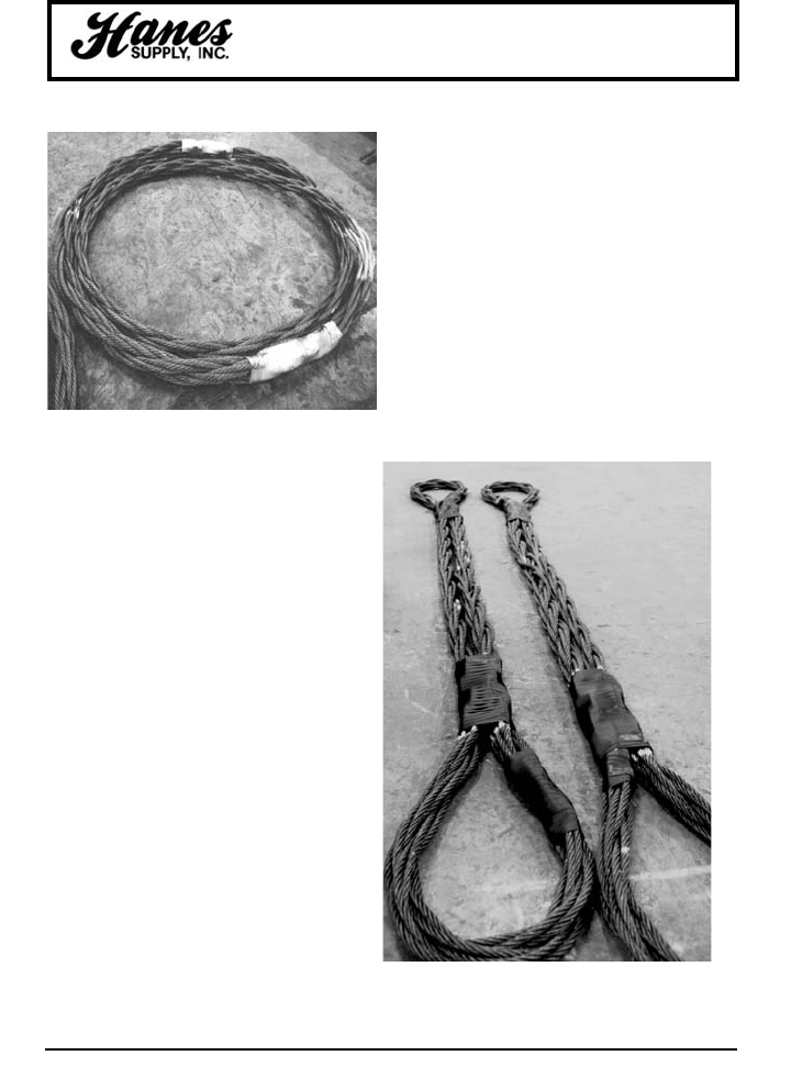
GATOR-LAID®WIRE ROPE SLING
U.S. Patent #4,240,659 & #5,561,973
This is identical to the Gator-Max™ sling
with the parallel eyes except it has metal
sleeves for the splice connection. This is
the product when a big lift but short sling is
required. It also has twelve parts of wire
rope in the loop. The Gator-Flex®and
Gator-Laid®products were developed in
conjunction with the off-shore oil industry to
provide the world's best heavy lift wire rope
slings.
Inspect before use. Follow OSHA, ANSI B30.9 or Manufacturers Guidelines. Use by untrained
persons is hazardous. Improper use will result in serious injury or death. Do not exceed rated
capacity. This product will fail if damaged, abused, misused, overused or improperly maintained. WARNING
YOUR SLING AND RIGGING SPECIALIST
29
HEADQUARTERS: 55 James E. Casey Drive • Buffalo, NY 14206 PHONE: 716.826.2636 FAX: 716.826.4412 www.hanessupply.com
Gator-Flex®Slings
T&D Ultra-Flex Slings
GATOR-FLEX®WIRE ROPE SLING
U.S. Patent #5,561,973
This sling has a nine-part body style with wires in the eyes that are
crossed or interwoven so no wrapping is necessary. This sling was
developed in conjunction with riggers who preferred a sling for heavy lifts
that could be visually inspected and have the highest flexibility possible in
a multi-part wire rope sling.
YOUR SLING AND RIGGING SPECIALIST
30
HEADQUARTERS: 55 James E. Casey Drive • Buffalo, NY 14206 PHONE: 716.826.2636 FAX: 716.826.4412 www.hanessupply.com
Gator-Flex®Slings
T&D Ultra-Flex Slings
T&D ULTRA-FLEX
WIRE ROPE SLING
U.S. Patent #5,561,973
This wire rope sling is an extremely flexible
product with great applications for general
rigging purposes in the utility industry. It makes
a fantastic choker sling especially when lifting
poles. Development was through a committee
composed of utility company workers and
members of the SLINGMAX®design team.
Actual field testing was used to determine
merits of the final product.
FINISHED COMPONENT STD. VERTICAL CHOKER BASKET WGT.
DIAMETER PARTS EYE SIZE RC RC RC PER FT.
1/2" 1/8" 8" 1.3 .9 2.6 .26
5/8" 5/32" 10" 1.7 1.3 3.4 .40
3/4" 3/16" 12" 2.6 1.9 5.2 .59
7/8" 7/32" 14" 3.5 2.6 7.0 .77
1" 1/4" 16" 4.6 3.4 9.2 .99
1-1/4" 5/16" 18" 7.0 5.2 14.0 1.56
1-1/2" 3/8" 20" 10.0 7.5 20.0 2.19
1-3/4" 7/16" 22" 13.8 10.3 27.6 3.15
2" 1/2" 24" 18.0 13.5 36.0 4.14
2-1/4" 9/16" 26" 22.7 18.1 45.4 5.31
2-1/2" 5/8" 28" 27.8 20.8 55.6 6.48
3" 3/4" 30" 39.7 29.8 79.4 9.36
3-1/2" 7/8" 35" 53.7 40.3 107.4 12.78
4" 1" 40" 69.8 52.3 139.6 16.65
4-1/2" 1-1/8" 45" 87.7 65.8 175.4 21.06
5" 1-1/4" 50" 108.8 81.0 216.0 26.01
5-1/2" 1-3/8" 55" 130.0 97.5 260.0 31.50
6" 1-1/2" 60" 154.0 115.5 308.0 37.44
7" 1-3/4" 70" 206.0 154.5 412.0 51.03
8" 2" 80" 267.0 200.2 534.0 66.51
9" 2-1/4" 90" 333.0 249.7 666.0 84.24
10" 2-1/2" 100" 408.0 306.0 816.0 104.00
Inspect before use. Follow OSHA, ANSI B30.9 or Manufacturers Guidelines. Use by untrained
persons is hazardous. Improper use will result in serious injury or death. Do not exceed rated
capacity. This product will fail if damaged, abused, misused, overused or improperly maintained.
Rated capacity is based on 5-1 Design Factor.
GATOR-FLEX®AND T&D ULTRA-FLEX SLINGS
TECHNICAL CHART
WARNING
YOUR SLING AND RIGGING SPECIALIST
31
HEADQUARTERS: 55 James E. Casey Drive • Buffalo, NY 14206 PHONE: 716.826.2636 FAX: 716.826.4412 www.hanessupply.com
Gator-Flex®/Twin-Flex™ Grommets
GATOR-FLEX®
NINE PART GROMMETS
U.S. Patent #5,561,973
Ultra flexible slings for that short
heavy lift connection. These slings
can be made shorter than standard
multi-part slings, but maintain all of
the advantages.
TWIN-FLEX™
WIRE ROPE SLINGS
U.S. Patent #5,561,973
This is another model of a grommet-
type sling which is formed into an
eye and eye design. It consists of
18 body parts with a loop at each
end. This is extremely flexible and is
used where short, heavy lift slings
are required.
YOUR SLING AND RIGGING SPECIALIST
32
HEADQUARTERS: 55 James E. Casey Drive • Buffalo, NY 14206 PHONE: 716.826.2636 FAX: 716.826.4412 www.hanessupply.com
Gator-Flex®/Twin-Flex®Grommets
TWIN-FLEX®SLINGS AND GATOR-FLEX®GROMMETS
ENGINEERING SPECIFICATIONS
TONS (2,000 LBS)
PIN SIZE 9 PARTS
5 X FD WIRE ROPE BASKET WT. PER
DIAMETER SIZE VERTICAL CHOKER VERTICAL FOOT LBS.
1" 1/4" 10 7 20 2
1-1/4" 5/16" 15 11 30 3
1-1/2" 3/8" 22 15 44 5
1-3/4" 7/16" 29 21 58 6
2" 1/2" 38 27 76 8
2-1/4" 9/16" 48 34 96 11
2-1/2" 5/8" 59 42 118 13
3" 3/4" 85 59 170 19
3-1/2" 7/8" 115 81 230 25
4" 1" 148 104 296 33
4-1/2" 1-1/8" 187 131 374 42
5" 1-1/4" 230 161 460 52
5-1/2" 1-3/8" 276 194 552 63
6" 1-1/2" 328 230 656 75
7" 1-3/4" 441 308 882 102
8" 2" 570 399 1140 133
9" 2-1/4" 711 498 1422 168
10" 2-1/2" 870 609 1740 209
11" 2-3/4" 1040 728 2080 250
12" 3" 1224 857 2448 300
CERTIFIED PROOF TESTING TO ANY STANDARD
YOU SPECIFY – WE COMPLY!
Rated Capacity at 5-1 D/F
D/d = 5/1
Inspect before use. Follow OSHA, ANSI B30.9 or Manufacturers Guidelines. Use by untrained
persons is hazardous. Improper use will result in serious injury or death. Do not exceed rated
capacity. This product will fail if damaged, abused, misused, overused or improperly maintained.
The Most Flexible Grommet in the World!
WARNING
YOUR SLING AND RIGGING SPECIALIST
33
HEADQUARTERS: 55 James E. Casey Drive • Buffalo, NY 14206 PHONE: 716.826.2636 FAX: 716.826.4412 www.hanessupply.com
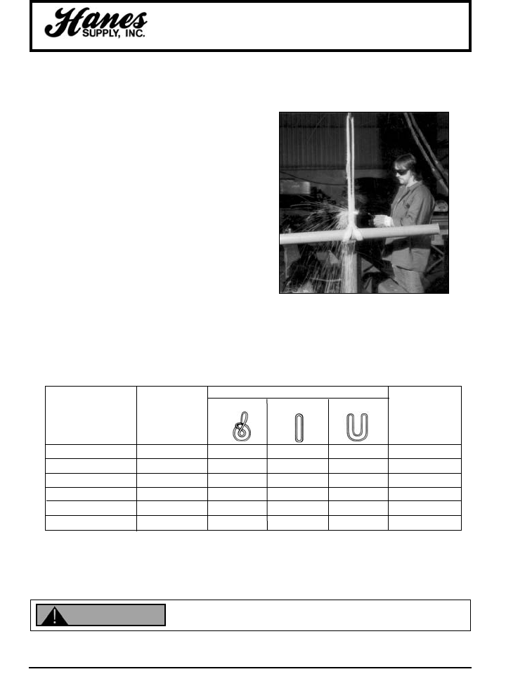
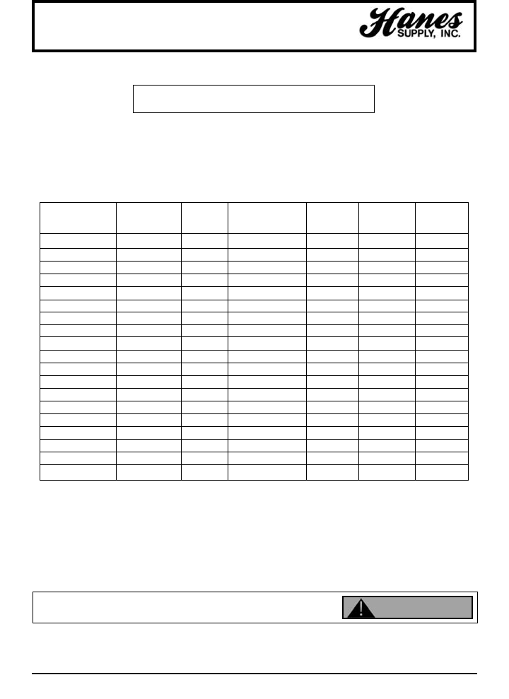
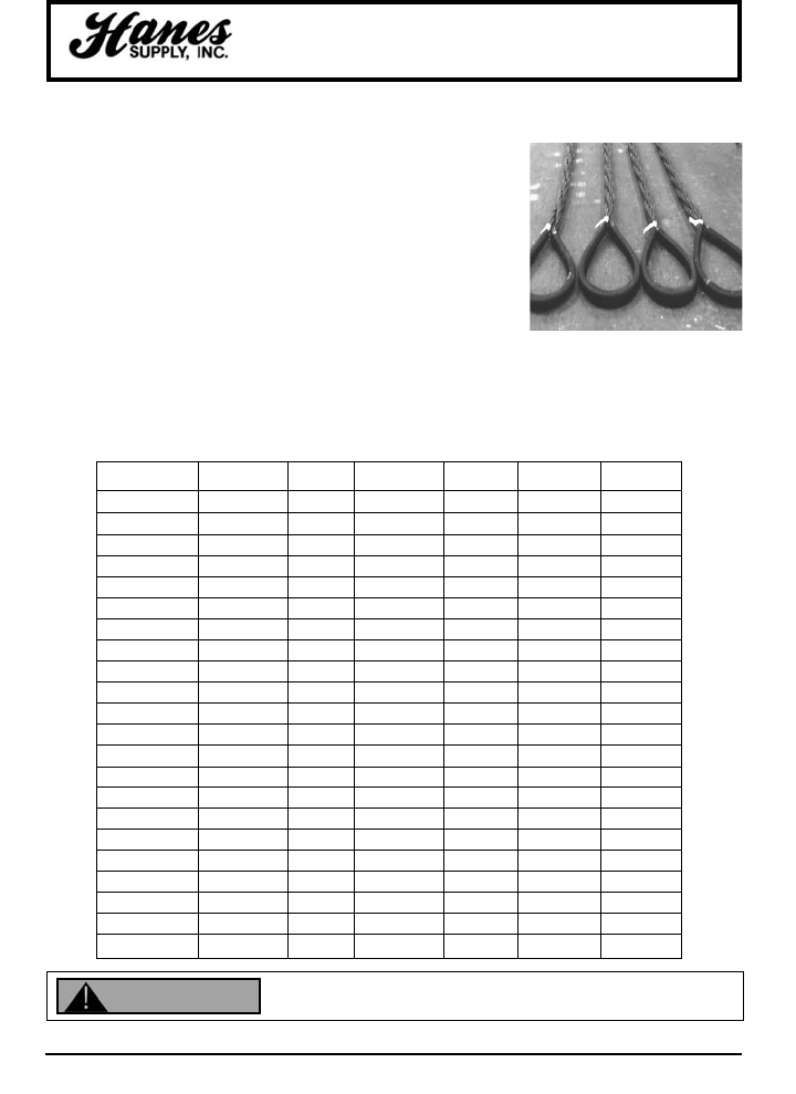
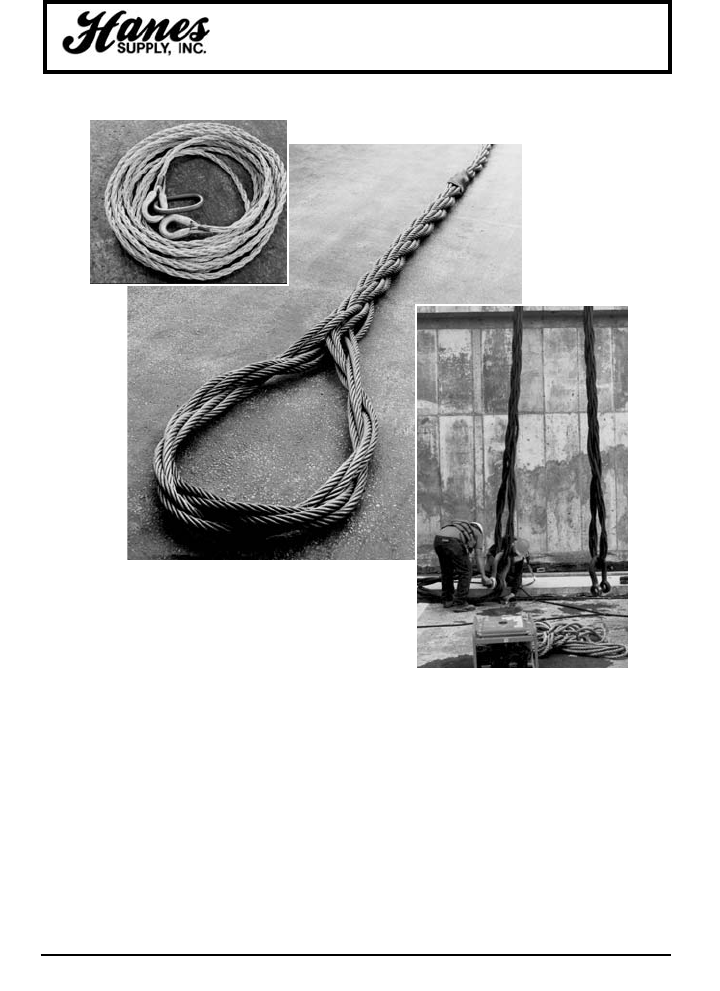
Hand-Spliced Slings
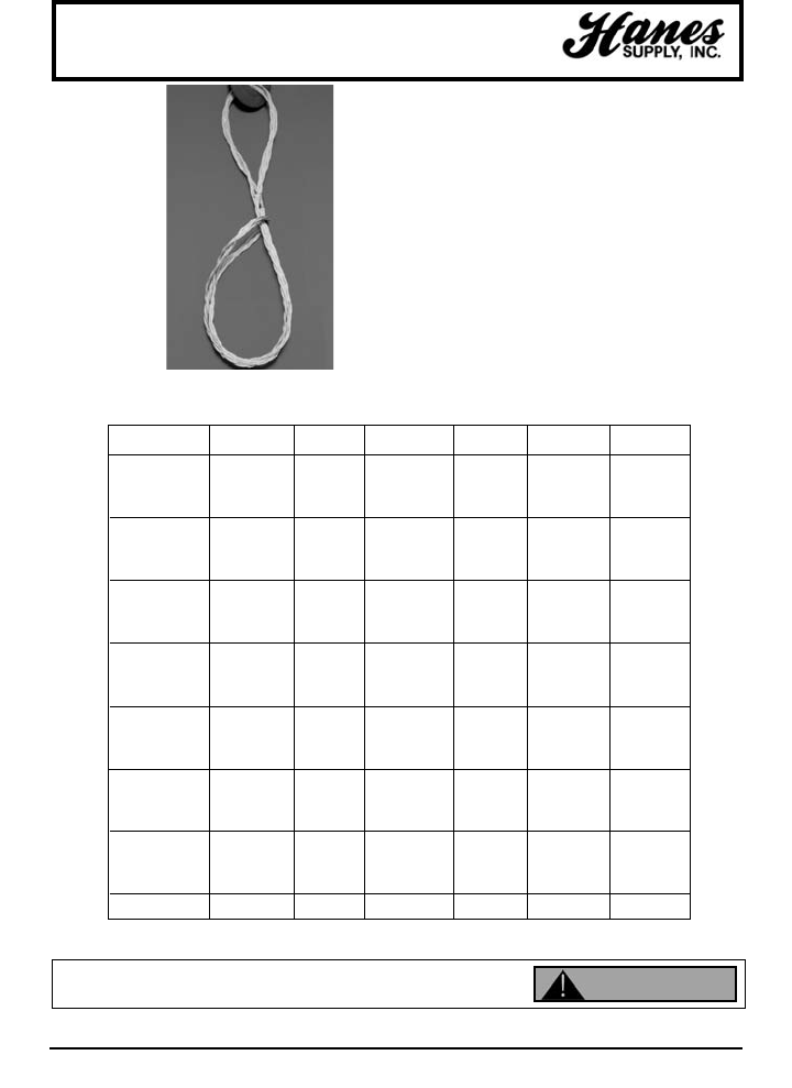
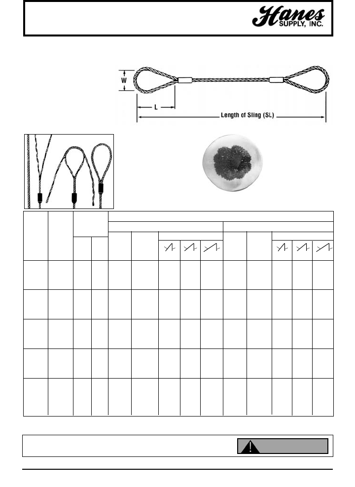
NO. 100 B
The end of a single wire rope is bent back
along the rope to form the eye, and strands
are hand-tucked into the body of the rope in
what is called a tapered and concealed
splice. This splice makes a sling that is easily
pulled through narrow spaces; there are no
rough ends to snag hands. Slings with rope
bodies larger than 1-1/2" diameter are made
only with Burnt End splices in which ends of
strands are left exposed and cut off with a
torch. These may also be cut shorter and
served, for smoothness. All have the same
rated capacity, size for size.
WARNING: Hand-spliced slings should not be used in lifts where the sling
may rotate and cause the wire rope to unlay.
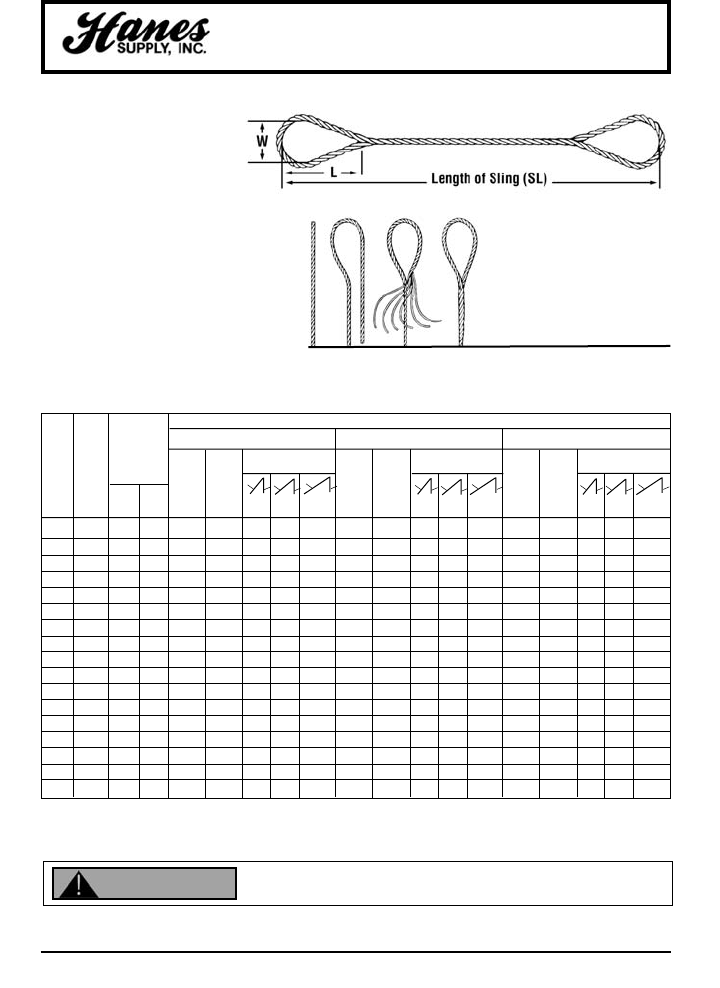
Hand Spliced Eye
The tapered and concealed splice
utilizes tension in the rope body to
secure strands where they are
tucked back into the rope. Needs
no metal sleeve to assure firm
anchoring. When “tapered and
concealed”, ends of strands are
tucked inward and concealed
inside the rope.
Rated capacities of choker hitches apply when the angle of choke is greater than 120°.
Rated capacities of basket hitches are based on a minimum diameter of curvature at the point of load contact of 25 times
the rope diameter.
RATED CAPACITIES IN TONS (2000 LBS.)
IPS ROPE - FIBER CORE IPS ROPE - IWRC EIPS ROPE - IWRC
Min.
Diam. Length Loop BASKET HITCH BASKET HITCH BASKET HITCH
of (SL) of Dimensions Single Single Single
Rope Sling W L Choker Leg Choker Leg Choker Leg
(in.) (ft.–in.) (in.) (in.) Hitch Vertical Hitch Vertical Hitch Vertical
30° 45° 60° 30° 45° 60° 30° 45° 60°
3/8 2–6 3 6 .085 1.1 1.9 1.6 1.1 0.92 1.2 2.1 1.7 1.2 1.1 1.3 2.3 1.8 1.3
7/16 2–9 3½ 7 1.2 1.4 2.4 2.0 1.4 1.2 1.5 2.6 2.1 1.5 1.4 1.8 3.1 2.5 1.8
1/2 3 4 8 1.5 1.8 3.1 2.5 1.8 1.6 2.0 3.5 2.8 2.0 1.9 2.3 4.0 3.3 2.3
9/16 3–6 4½ 9 1.9 2.3 4.0 3.3 2.3 2.0 2.5 4.3 3.5 2.5 2.4 2.9 5.0 4.1 2.9
5/8 4 5 10 2.3 2.8 4.8 4.0 2.8 2.5 3.0 5.2 4.2 3.0 2.9 3.5 6.1 4.9 3.5
3/4 4–6 6 12 3.3 3.9 6.8 5.5 3.9 3.6 4.2 7.3 5.9 4.2 4.1 4.8 8.3 6.8 4.8
7/8 5–6 7 14 4.5 5.2 9.0 7.4 5.2 4.8 5.5 9.5 7.8 5.5 5.6 6.4 11 9.0 6.4
1 6 8 16 5.9 6.7 12 9.5 6.7 6.3 7.2 12 10 7.2 7.2 8.3 14 12 8.3
1-1/8 6–6 9 18 7.4 8.4 15 12 8.4 7.9 9.0 16 13 9.0 9.1 10 17 14 10
1-1/4 7 10 20 9.0 10 17 14 10 9.7 11 19 16 11 11 13 23 18 13
1-3/8 7–6 11 22 11 12 21 17 12 12 13 23 18 13 13 15 26 21 15
1-1/2 8–6 12 24 13 15 26 21 15 14 16 28 23 16 16 18 31 25 18
1-5/8 9 13 26 15 17 29 24 17 16 18 31 25 18 18 21 36 30 21
1-3/4 9–6 14 28 17 20 35 28 20 19 21 36 30 21 21 24 42 34 24
2 11 163222 26 4537 26 24 28 4840 28 28 32 5545 32
2-1/4 12–6 18 36 28 32 55 45 32 30 34 59 48 34 35 40 69 57 40
2-1/2 14 20 40 34 39 68 55 39 37 42 73 59 42 42 48 83 68 48
Inspect before use. Follow OSHA, ANSI B30.9 or Manufacturers Guidelines. Use by untrained
persons is hazardous. Improper use will result in serious injury or death. Do not exceed rated
capacity. This product will fail if damaged, abused, misused, overused or improperly maintained.
WARNING
YOUR SLING AND RIGGING SPECIALIST
34
HEADQUARTERS: 55 James E. Casey Drive • Buffalo, NY 14206 PHONE: 716.826.2636 FAX: 716.826.4412 www.hanessupply.com
Mechanical Splice
Flemish Eye Slings
NO. 105B
Eyes are formed using the
flemish eye splice. Ends are
secured by pressing a metal
sleeve over the ends of the
strands of the splice. Pull is
directly along the centerline of
rope and eye. Gives most
efficient use of rope capacity and
is economical.
*Rated capacities of basket hitches are based on a minimum diameter of curvature at the point of load contact of 40 times
the rope diameter for slings 1/4" thru 1" diameter and 25 times the rope diameter for slings 1-1/4" diameter and larger.
Swaging Provides
Positive Grip
This cutaway of a metal
sleeve swaged onto a
splice shows how metal
“flows” into valleys
between strands to
positively prevent ends
from unlaying when sling
is used within its rated
capacity.
Flemish Eye Splice
In the standard flemish eye
mechanical splice, rope is
separated into two parts – 3
adjacent strands, and 3
adjacent strands and core.
These two parts are then re-
laid back in opposite directions
to form an eye, and ends are
secured with a pressed metal
sleeve.
RATED CAPACITIES (TONS)*
Min. Loop Dim. IPS ROPE - IWRC EIPS ROPE - IWRC
Dia. Length BASKET HITCH BASKET HITCH
of (SL) of Single Single
Rope Sling W L Choker Leg Choker Leg
(in) (ft - in) (in) (in) Hitch Vertical 30O45O60OHitch Vertical 30O45O60O
1/4 1 - 6 2 4 .41 .56 .97 .79 .56 .48 .65 1.1 .92 .65
3/8 2 3 6 .93 1.2 2.1 1.7 1.2 1.1 1.4 2.4 2.0 1.4
1/2 2 - 6 4 8 1.6 2.2 3.8 3.1 2.2 1.9 2.5 4.3 3.5 2.5
5/8 3 5 10 2.5 3.4 5.9 4.8 3.4 2.9 3.9 6.8 5.5 3.9
3/4 3 - 6 6 12 3.6 4.9 8.5 6.9 4.9 4.1 5.6 9.7 7.9 5.6
7/8 4 7 14 4.8 6.6 11 9.3 6.6 5.6 7.6 13 11 7.6
1 4 - 6 8 16 6.3 8.5 15 12 8.5 7.2 9.8 17 14 9.8
1-1/8 5 9 18 7.9 10 17 14 10 9.1 12 21 17 12
1-1/4 5 - 6 10 20 9.7 13 23 18 13 11 15 26 21 15
1-3/8 6 11 22 12 15 26 21 15 13 18 31 25 18
1-1/2 7 12 24 14 18 31 25 18 16 21 36 30 21
1-3/4 8 14 28 19 25 43 35 25 21 28 48 40 28
2 9 16 32 24 32 55 45 32 28 37 64 52 37
2-1/4 10 18 36 30 39 68 55 39 35 44 76 62 44
2-1/2 11 20 40 37 47 81 66 47 42 54 94 76 54
2-3/4 12 22 44 44 57 99 81 57 51 65 113 92 65
3 13 24 48 52 67 116 95 67 60 77 133 109 77
3-1/2 16 - 6 32 64 69 88 152 124 88 79 102 177 144 102
3-3/4 18 36 72 78 100 173 141 100 90 115 199 163 115
4 20 40 80 88 113 196 160 113 101 130 225 184 130
4-1/2 24 50 100 108 139 241 197 139 124 160 277 226 160
Inspect before use. Follow OSHA, ANSI B30.9 or Manufacturers Guidelines. Use by untrained
persons is hazardous. Improper use will result in serious injury or death. Do not exceed rated
capacity. This product will fail if damaged, abused, misused, overused or improperly maintained. WARNING
YOUR SLING AND RIGGING SPECIALIST
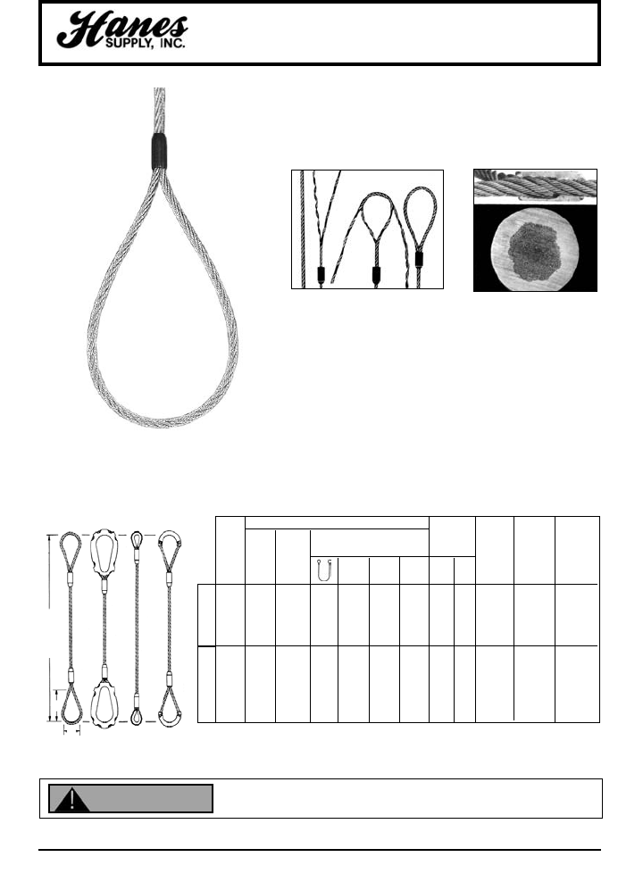
35
HEADQUARTERS: 55 James E. Casey Drive • Buffalo, NY 14206 PHONE: 716.826.2636 FAX: 716.826.4412 www.hanessupply.com
Cable-Laid Slings
NO. 108 C
These smooth and very flexible slings are made from cut
lengths of cable-laid fabric that is machine formed by
laying six wire ropes in a helical pattern around a core
rope. Flemish eye mechanical splices, secured by pressed
metal sleeves, provide centerline pull at the eyes. More
flexible than same capacity single-part slings.
Swaging Provides
Positive Grip
This cutaway of a metal
sleeve swaged onto a
splice shows how metal
"flows" into valleys
between strands to
positively prevent ends
from unlaying when
sling is used within its
rated capacity.
Flemish Eye Splice
In the standard flemish eye
mechanical splice, rope is
separated into two parts – 3
adjacent strands, and 3
adjacent strands and core.
These two parts are then re-
laid back in opposite
directions to form an eye, and
ends are secured with a
pressed metal sleeve.
Ideal for use as basket or choker hitches, where flexibility and ease of
handling are essential and cutting or abrasion is not a critical factor.
RATED CAPACITY - TONS
Eye Slip Heavy Slip-on
Body Basket Hitch Thru Thimble Thimble
Dia. Thimble
(in.) Vert. Choker 60° 45° 30° A B ST HT QT
1/4 .50 .34 1.0 .87 .71 .50 2 4 W-2 1/4 3/8
3/8 1.1 .74 2.2 1.9 1.5 1.1 3 6 W-2 3/8 3/8
1/2 1.9 1.3 3.7 3.2 2.6 1.9 4 8 W-3 1/2 1/2
5/8 2.8 1.9 5.5 4.8 3.9 2.8 5 10 W-4 5/8 5/8
3/4 4.1 2.8 8.1 7.0 5.8 4.1 6 12 W-4 3/4 3/4
7/8 5.4 3.7 11. 9.4 7.6 5.4 7 14 W-5 7/8 7/8
1 6.9 4.7 14. 12. 9.7 6.9 8 16 W-5 1 1
1-1/8 8.3 5.8 17. 14. 12. 8.3 9 18 W-6 1-1/8
1-1/4 9.9 7.0 20. 17. 14. 9.9 10 20 W-6 1-1/4
7x7x7
7x7x19
B
A
LENGTH
E-E ST-ST HT-HT OT-OT
Inspect before use. Follow OSHA, ANSI B30.9 or Manufacturers Guidelines. Use by untrained
persons is hazardous. Improper use will result in serious injury or death. Do not exceed rated
capacity. This product will fail if damaged, abused, misused, overused or improperly maintained.
WARNING
Sling Bodies
Are Made from
7 Individual
Wire Ropes
YOUR SLING AND RIGGING SPECIALIST
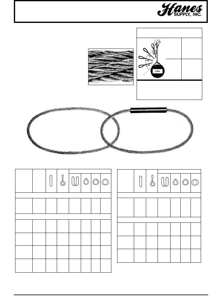
36
HEADQUARTERS: 55 James E. Casey Drive • Buffalo, NY 14206 PHONE: 716.826.2636 FAX: 716.826.4412 www.hanessupply.com
BASKET HITCHES
Finished
Sling
Body
Dia. (in.) Vert. Choker Vertical 30° 45° 60°
1/4 .83 .54 1.7 .83 1.2 1.4
3/8 1.8 1.2 3.6 1.8 2.5 3.1
1/2 3.0 2.0 6.1 3.0 4.3 5.3
5/8 4.6 3.0 9.1 4.6 6.4 7.9
3/4 6.2 4.1 12 6.2 8.8 11
7/8 8.3 5.4 17 8.3 12 14
1 11 6.8 21 11 15 18
1-1/8 13 8.4 26 13 18 22
1-1/4 16 10 31 16 22 27
1-3/8 18 12 37 18 26 32
1-1/2 22 14 43 22 31 38
1-5/8 25 16 50 25 36 44
1-3/4 28 18 56 28 40 49
Grommet Slings
BASKET HITCHES
EIP Finished
Component Sling
Rope Body
Dia. (in.) Dia. (in.) Vert. Choker Vertical 30° 45° 60°
1/8 3/8 1.6 1.0 3.2 1.6 2.2 12.8
3/16 9/16 3.5 2.3 6.9 3.5 4.9 6.0
7/32 5/8 4.5 2.9 9.0 4.5 6.4 7.8
1/4 3/4 5.6 3.6 11 5.6 7.9 9.7
5/16 15/16 8.7 5.6 17 8.7 12 15
3/8 1-1/8 12 8.0 25 12 17 21
7/16 1-5/16 17 11 33 17 23 29
1/2 1-1/2 21 14 43 21 30 37
9/16 1-11/16 27 17 53 27 38 46
5/8 1-7/8 33 21 66 33 46 57
3/4 2-1/4 46 30 92 46 65 80
7/8 2-5/8 62 40 123 62 87 107
1 3 79 51 158 79 112 137
1-1/8 3-3/8 98 64 196 98 138 170
1-1/4 3-3/4 119 77 237 119 168 205
Cable Laid Grommets have six wire
ropes laid helically around a wire rope
core, with ends joined either by a hand-
tucked or a mechanical splice to form an
endless body. Highly flexible, they resist
kinks and are easy to handle. Minimum
circumference of the sling is 96 times the
grommet body diameter.
CABLE LAID GROMMET
WIRE ROPE SLINGS
Rated Capacity Adjustment
For Choker Hitches
ANGLE
OF
CHOKE
IN
DEGREES
PERCENT
OF SLING
RATED
CAPACITY
APPLICABLE
120-180
90-119
60-89
30-59
0-29
100%
87%
74%
62%
49%
When a choke is drawn down tight against a
load, or a side pull is exerted resulting in an
angle of less than 120 degrees, an
adjustment must be made for further
reduction of the sling rated capacity.
Mechanical Splice
7 Parts of Wire Rope in the
Sling Body
Hand-Tucked
Continuous Construction
...made from one
continuous wire rope
7 x 7 x 7 GALVANIZED AIRCRAFT CABLE
7 X 6 X 9 AND 7 X 6 X 37 - EIP
7 x 7 x 19 CONSTRUCTION
7 x 6 x 19 AND 7 x 6 x 37 - EIP CONSTRUCTION
Rated Capacities Basket Hitch and vertical lift based on
D/d ratio of 5 when "d" is diameter of the finished grommet.
Rated Capacities based on pin diameter no smaller than
5 times the body diameter.
Rated capacities based on design factor of 5.
Sling angles of less than 30 degrees shall not be used.
No. 21 B Rated Capacity - Tons (2,000 Lbs.) No. 15 B Rated Capacity - Tons (2,000 Lbs.)
YOUR SLING AND RIGGING SPECIALIST
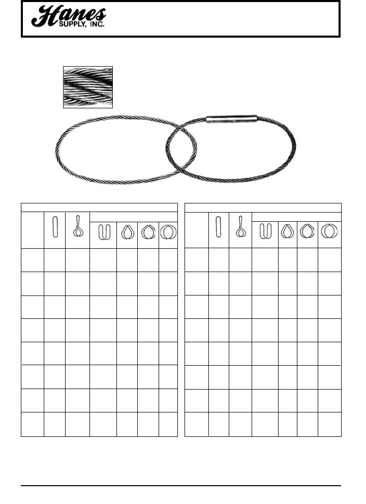
37
HEADQUARTERS: 55 James E. Casey Drive • Buffalo, NY 14206 PHONE: 716.826.2636 FAX: 716.826.4412 www.hanessupply.com
Grommet Slings
STRAND LAID GROMMET WIRE ROPE SLINGS
7 x 19 AND 7 x 37 CLASS - IPS
BASKET HITCHES
SLING
BODY
DIA. *
(IN) VERT. CHOKER VERTICAL 600450300
1/4 .85 .60 1.7 1.5 1.2 .85
5/16 1.3 .93 2.7 2.3 1.9 1.3
3/8 1.9 1.3 3.8 3.3 2.7 1.9
7/16 2.6 1.8 5.2 4.5 3.6 2.6
1/2 3.3 2.3 6.7 5.8 4.7 3.3
9/16 4.2 2.9 8.4 7.3 6.0 4.2
5/8 5.2 3.6 10. 9.0 7.4 5.2
3/4 7.4 5.2 15. 13. 10. 7.4
7/8 10. 7.0 20. 17. 14. 10.
1 13 9.1 26. 22. 18. 13.
1-1/8 16. 11. 32. 28. 23. 16.
1-1/4 20. 14. 39. 34. 28. 20.
1-3/8 23. 16. 46. 40. 33. 23.
1-1/2 27. 19. 54. 47. 38. 27.
1-5/8 31. 22. 62. 54. 44. 31.
1-3/4 36. 25. 72. 62. 51. 36.
1-7/8 41. 28. 81. 70. 57. 41.
2 46. 32. 92. 79. 65. 46.
2-1/8 51. 36. 102. 88. 72. 51.
2-1/4 56. 39. 113. 98. 80. 56.
2-3/8 62. 44. 124. 108. 88. 62.
2-1/2 68. 47. 136. 117. 96. 68.
2-3/4 81. 56. 161. 140. 114. 81.
3 94. 66. 189. 163. 133. 94.
No. 11B Rated Capacity - Tons (2,000 Lbs.)
6 x 19 AND 6 x 37 CLASS - IPS - IWRC
BASKET HITCHES
SLING
BODY
DIA. *
(IN) VERT. CHOKER VERTICAL 600450300
1/4 .92 .64 1.8 1.6 1.3 .92
5/16 1.4 1.0 2.9 2.5 2.0 1.4
3/8 2.0 1.4 4.1 3.5 2.9 2.0
7/16 2.8 1.9 5.5 4.8 3.9 2.8
1/2 3.6 2.5 7.2 6.2 5.1 3.6
9/16 4.5 3.2 9.0 7.8 6.4 4.5
5/8 5.6 3.9 11. 9.7 7.9 5.6
3/4 8. 5.6 16. 14. 11. 8.
7/8 11. 7.6 22. 19. 15. 11.
1 14. 9.8 28. 24. 20. 14.
1-1/8 18. 12. 35. 31. 25. 18.
1-1/4 22. 15. 43. 38. 31. 22.
1-3/8 26. 18. 52. 45. 37. 26.
1-1/2 31. 22. 62. 53. 44. 31.
1 -5/8 36. 25. 72. 62. 51. 36.
1-3/4 41. 29. 83. 72. 59. 41.
1-7/8 47. 33. 95. 82. 67. 47.
2 54. 38. 107. 93. 76. 54.
2-1/8 60. 42. 120. 104. 85. 60.
2-1/4 67. 47. 134. 116. 95. 67.
2-3/8 75. 52. 149. 129. 105. 75.
2-1/2 82. 57. 163. 142. 116. 82.
2-3/4 98. 69. 196. 170. 139. 98.
3 115. 81. 231. 200. 163. 115.
No. 14B Rated Capacity - Tons (2,000 Lbs.)
Hand Tucked
Continuous Construction
...made from one
continuous strand
Mechanical Splice
7 Parts of Wire Rope
in the Sling Body
Strand Laid Grommets have either a wire rope body, or
a body of six strands laid helically around a strand core,
with either a hand tucked or a mechanical splice to form
an endless sling body. Minimum circumference of the
sling is 96 times the grommet body diameter.
Rated Capacities Basket Hitch and vertical lift based on D/d ratio of 5 when "d" is
diameter of the finished grommet.
Rated Capacities based on pin diamter no smaller than 5 times the body diameter.
Sling angles of less than 30 degrees shall not be used.
*See Choker Hitch Rated Capacity Adjustment chart.
YOUR SLING AND RIGGING SPECIALIST
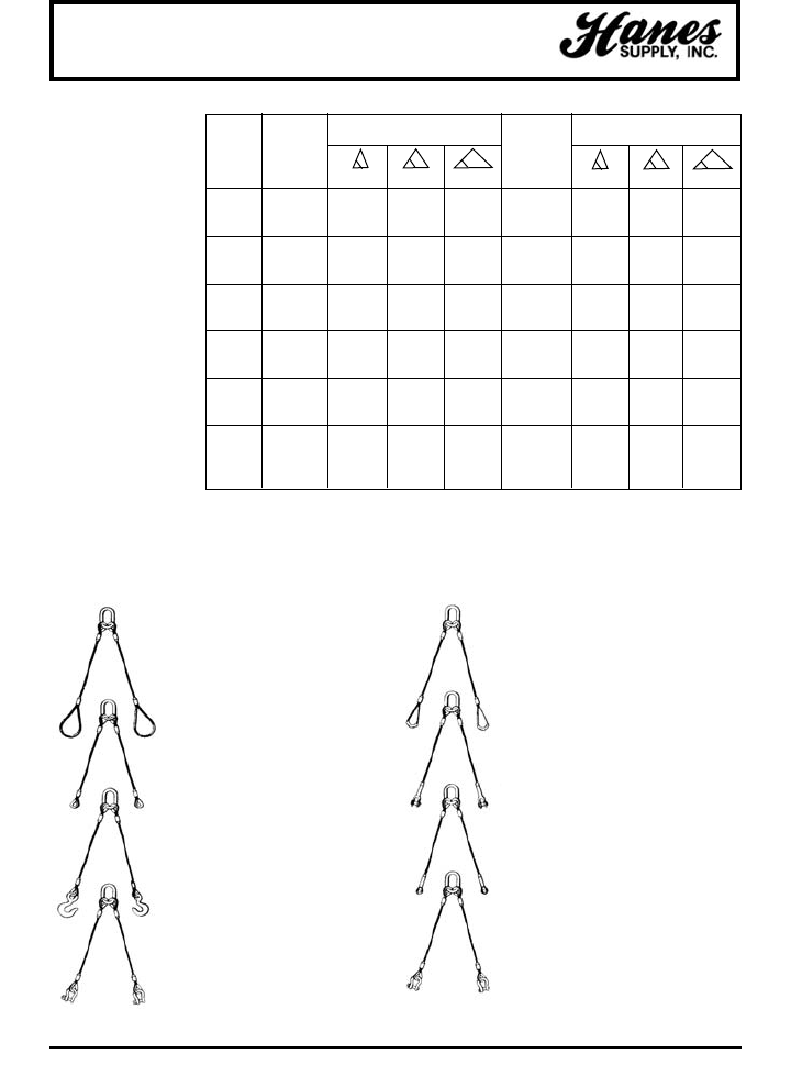
38
HEADQUARTERS: 55 James E. Casey Drive • Buffalo, NY 14206 PHONE: 716.826.2636 FAX: 716.826.4412 www.hanessupply.com
2 Leg Wire Rope Bridles
Dia. Min. Rated Capacities (tons) Alloy Rated Capacities (tons)
of Length IPS-IWRC Oblong EIPS-IWRC
Wire (SL) Of Links
Rope Sling Dia.
(in) (ft.- in.) 60° 45° 30° (in) 60° 45° 30°
1/4 1 - 3 .97 .79 .56 1/2 1.10 .91 .65
5/16 1 - 6 1.50 1.30 .87 1/2 1.70 1.50 1.00
3/8 1 - 8 2.10 1.80 1.20 3/4 2.50 2.00 1.40
7/16 1 - 10 3.00 2.50 1.70 3/4 3.50 2.80 2.00
1/2 2 - 0 3.80 3.10 2.20 3/4 4.40 3.60 2.50
9/16 2 - 2 4.90 4.00 2.70 1 5.60 4.60 3.10
5/8 2 - 4 5.90 4.80 3.40 1 6.80 5.50 3.90
3/4 2 - 9 8.40 6.90 4.90 1-1/4 9.70 7.90 5.60
7/8 3 - 3 11.00 9.30 6.60 1-1/4 13.00 11.00 7.60
1 3 - 6 15.00 12.00 8.50 1-1/2 17.00 14.00 9.80
1-1/8 4 - 0 18.00 15.00 10.00 1-3/4 21.00 17.00 12.00
1-1/4 4 - 6 22.00 18.00 13.00 1-3/4 26.00 21.00 15.00
1-3/8 5 - 0 27.00 22.00 15.00 2 31.00 25.00 18.00
1-1/2 5 - 6 32.00 26.00 18.00 2-1/4 36.00 30.00 21.00
1-5/8 6 - 0 38.00 31.00 20.00 2-1/2 43.00 35.00 23.00
1-3/4 6 - 6 43.00 35.00 25.00 2-1/2 49.00 40.00 28.00
2 8 - 0 55.00 45.00 32.00 2-3/4 63.00 52.00 37.00
2-1/4 8 - 9 69.00 56.00 40.00 3-1/4 79.00 65.00 46.00
2-1/2 10 - 0 84.00 68.00 48.00 3-3/4 97.00 79.00 56.00
For approximate capacities using Fibre Core IPS: deduct 10% from IPS-IWRC strengths.
For approximate capacities on Hand Braided Slings: deduct 15% from corresponding mechanically
swaged strengths.
For approximate capacities on Socket Attachments: add 5% to corresponding IWRC swaged
strengths.
200CT
2 leg – Oblong Link with Heavy
Duty Thimbles on Top and
Crescent Thimble on Bottom.
200OS
2 leg – Oblong Link with Heavy
Duty Thimbles on Top and Open
Swage Socket on Bottom.
200CS
2 leg – Oblong Link with Heavy
Duty Thimbles on Top and Closed
Swage Socket on Bottom.
200BAS
2 leg – Oblong Link with Heavy
Duty Thimbles on Top and Bolt
Anchor Shackle on Bottom.
200FL
2 leg – Oblong Link with Heavy
Duty Thimbles on Top and
Flemish Loops on Bottom.
200HT
2 leg – Oblong Link with Heavy
Duty Thimbles on Top and Heavy
Duty Thimbles on Bottom.
200EH
2 leg – Oblong Link with Heavy
Duty Thimbles on Top and Eye
Hoist Hooks Safety Latches on
Bottom.
200SPA
2 leg – Oblong Link with Heavy
Duty Thimbles on Top and Screw
Pin Anchor Shackle on Bottom.
No. 200 Series
Slings are 2-leg all-
purpose bridles,
designed for general
lifting purposes where
attachment may be
made directly to the
load, such as hooking
into lifing eyes or
placing loops over lugs.
YOUR SLING AND RIGGING SPECIALIST
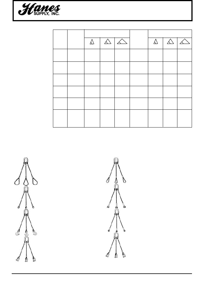
39
HEADQUARTERS: 55 James E. Casey Drive • Buffalo, NY 14206 PHONE: 716.826.2636 FAX: 716.826.4412 www.hanessupply.com
3 Leg Wire Rope Bridles
No. 300 Series
Slings are 3-leg all-
purpose bridles,
generally recommended
for handling unbalanced
loads.
300FL
3 leg – Oblong Link with Heavy
Duty Thimbles on Top and
Flemish Loops on Bottom.
300HT
3 leg – Oblong Link with Heavy
Duty Thimbles on Top and
Heavy Duty Thimbles on
Bottom.
300EH
3 leg – Oblong Link with Heavy
Duty Thimbles on Top and Eye
Hoist Hooks Safety Latches on
Bottom.
300SPA
3 leg – Oblong Link with Heavy
Duty Thimbles on Top and
Screw Pin Anchor Shackle on
Bottom.
300CT
3 leg – Oblong Link with Heavy
Duty Thimbles on Top and
Crescent Thimble on Bottom.
300OS
3 leg – Oblong Link with Heavy
Duty Thimbles on Top and Open
Swage Socket on Bottom.
300CS
3 leg – Oblong Link with Heavy
Duty Thimbles on Top and Closed
Swage Socket on Bottom.
300BAS
3 leg – Oblong Link with Heavy
Duty Thimbles on Top and Bolt
Anchor Shackle on Bottom.
Dia. Min. Rated Capacities (tons) Alloy Rated Capacities (tons)
of Length IPS-IWRC Oblong EIPS-IWRC
Wire (SL) Of Links
Rope Sling Dia.
(in) (ft.- in.) 60° 45° 30° (in) 60° 45° 30°
1/4 1 - 3 1.40 1.20 .84 1/2 1.60 1.40 .97
5/16 1 - 6 2.30 1.80 1.30 3/4 2.60 2.10 1.50
3/8 1 - 8 3.20 2.60 1.90 3/4 3.70 3.00 2.20
7/16 1 - 10 4.40 3.60 2.50 1 5.10 4.10 2.90
1/2 2 - 0 5.70 4.60 3.30 1 6.60 5.30 3.80
9/16 2 - 2 7.10 5.80 4.10 1 8.30 6.80 4.70
5/8 2 - 4 8.80 7.20 5.10 1-1/4 10.00 8.30 5.90
3/4 2 - 9 13.00 10.00 7.30 1-1/2 14.00 12.00 8.40
7/8 3 - 3 17.00 14.00 9.90 1-1/2 20.00 16.00 11.00
1 3 - 6 22.00 18.00 13.00 1-3/4 25.00 21.00 15.00
1-1/8 4 - 0 27.00 22.00 16.00 2 31.00 25.00 18.00
1-1/4 4 - 6 33.00 27.00 18.00 2-1/4 38.00 31.00 21.00
1-3/8 5 - 0 40.00 33.00 22.00 2-3/4 46.00 38.00 25.00
1-1/2 5 - 6 47.00 39.00 26.00 2-3/4 55.00 45.00 30.00
1-5/8 6 - 0 53.00 43.00 31.00 2-3/4 61.00 49.00 36.00
1-3/4 6 - 6 64.00 52.00 35.00 3 73.00 60.00 40.00
2 8 - 0 83.00 67.00 46.00 3-1/2 95.00 76.00 53.00
2-1/4 8 - 9 103.00 84.00 58.00 4 118.00 96.00 67.00
2-1/2 10 - 0 126.00 102.00 72.00 4-1/2 145.00 118.00 84.00
For approximate capacities using Fibre Core IPS: deduct 10% from IPS-IWRC strengths.
For approximate capacities on Hand Braided Slings: deduct 15% from corresponding
mechanically swaged strengths.
For approximate capacities on Socket Attachments: add 5% to corresponding IWRC swaged
strengths.
YOUR SLING AND RIGGING SPECIALIST
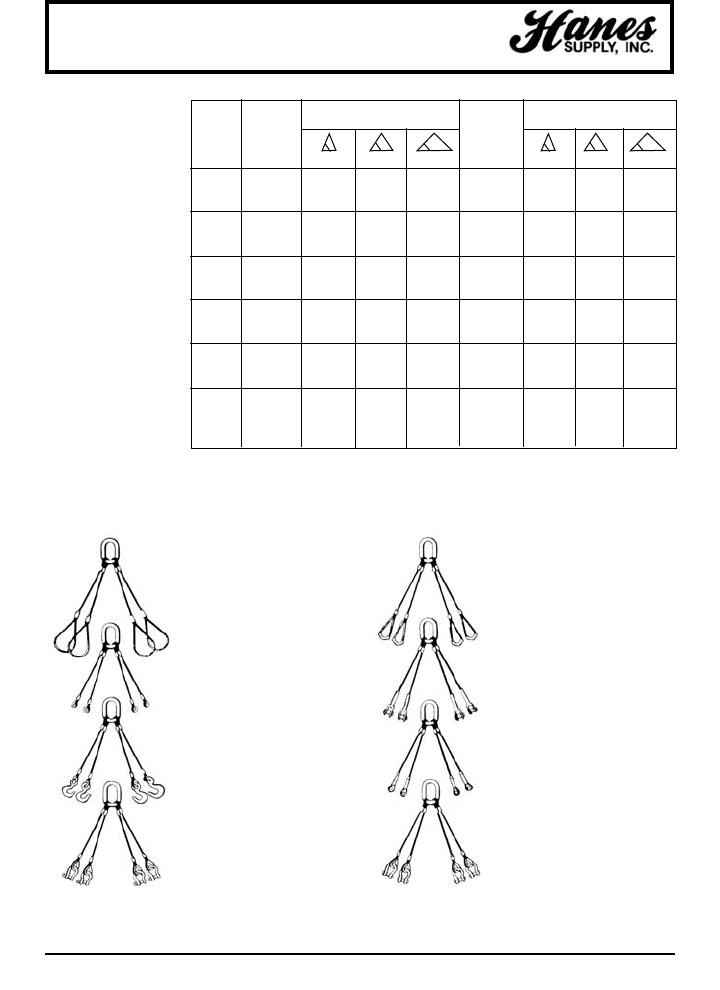
40
HEADQUARTERS: 55 James E. Casey Drive • Buffalo, NY 14206 PHONE: 716.826.2636 FAX: 716.826.4412 www.hanessupply.com
4 Leg Wire Rope Bridles
No. 400 Series
Slings are 4-leg all-
purpose bridles, used
both for balanced &
unbalanced loads and
for heavier loads where
design calls for more
distribution of weight by
the use of attachment at
four points.
Dia. Min. Rated Capacities (tons) Alloy Rated Capacities (tons)
of Length IPS-IWRC Oblong EIPS-IWRC
Wire (SL) Of Links
Rope Sling Dia.
(in) (ft.- in.) 60° 45° 30° (in) 60° 45° 30°
1/4 1 - 3 1.90 1.60 1.10 1/2 2.20 1.80 1.30
5/16 1 - 6 3.00 2.50 1.70 3/4 3.50 2.80 2.00
3/8 1 - 8 4.30 3.50 2.40 1. 5.00 4.00 2.80
7/16 1 - 10 5.80 4.80 3.40 1 6.70 5.50 4.00
1/2 2 - 0 7.60 6.20 4.40 1-1/4 8.70 7.10 5.00
9/16 2 - 2 9.50 7.80 5.40 1-1/4 11.00 9.00 6.20
5/8 2 - 4 12.00 9.60 6.80 1-1/4 13.00 11.00 7.80
3/4 2 - 9 17.00 14.00 9.80 1-3/4 18.00 16.00 11.00
7/8 3 - 3 23.00 18.00 13.00 1-3/4 26.00 21.00 15.00
1 3 - 6 29.00 24.00 17.00 2-1/4 34.00 28.00 20.00
1-1/8 4 - 0 36.00 29.00 20.00 2-3/4 42.00 34.00 24.00
1-1/4 4 - 6 44.00 26.00 26.00 2-3/4 51.00 42.00 30.00
1-3/8 5 - 0 53.00 44.00 30.00 3-1/4 61.00 50.00 36.00
1-1/2 5 - 6 63.00 52.00 36.00 3-3/4 73.00 60.00 42.00
1-5/8 6 - 0 74.00 61.00 40.00 3-3/4 85.00 70.00 46.00
1-3/4 6 - 6 85.00 69.00 50.00 4-1/2 98.00 80.00 56.00
2 8 - 0 110.00 90.00 64.00 4-1/2 126.00 104.00 74.00
2-1/4 8 - 9 138.00 112.00 80.00 Call 158.00 130.00 92.00
2-1/2 10 - 0 168.00 136.00 96.00 Call 194.00 158.00 112.00
For approximate capacities using Fibre Core IPS: deduct 10% from IPS-IWRC strengths.
For approximate capacities on Hand Braided Slings: deduct 15% from corresponding
mechanically swaged strengths.
For approximate capacities on Socket Attachments: add 5% to corresponding IWRC swaged
strengths.
400CT
4 leg – Oblong Link with Heavy
Duty Thimbles on Top and
Crescent Thimble on Bottom.
400OS
4 leg – Oblong Link with Heavy
Duty Thimbles on Top and Open
Swage Socket on Bottom.
400CS
4 leg – Oblong Link with Heavy
Duty Thimbles on Top and Closed
Swage Socket on Bottom.
400BAS
4 leg – Oblong Link with Heavy
Duty Thimbles on Top and Bolt
Anchor Shackle on Bottom.
400FL
4 leg – Oblong Link with Heavy
Duty Thimbles on Top and
Flemish Loops on Bottom.
400HT
4 leg – Oblong Link with Heavy
Duty Thimbles on Top and
Heavy Duty Thimbles on
Bottom.
400EH
4 leg – Oblong Link with Heavy
Duty Thimbles on Top and Eye
Hoist Hooks Safety Latches on
Bottom.
400SPA
4 leg – Oblong Link with Heavy
Duty Thimbles on Top and
Screw Pin Anchor Shackle on
Bottom.
YOUR SLING AND RIGGING SPECIALIST
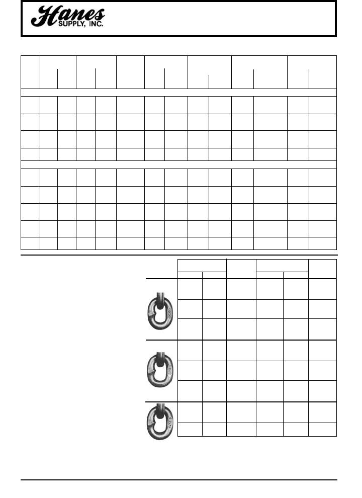
HEADQUARTERS: 55 James E. Casey Drive • Buffalo, NY 14206 PHONE: 716.826.2636 FAX: 716.826.4412 www.hanessupply.com
41
Diam. Standard Heavy Duty Alloy Carbon Half Thimble Open Closed
Of Loop Inside Thimble Inside Hook Shackle Size (in) Inside Loop Swage Socket Swage Socket
Wire Size Size (tons) Head
Rope W L W L (tons) For For W L Pin. Jaw Hole. Thickness
(in) (in) (in) (in) (in) IPS & EIPS IPS EIPS (in) (in) Dia. (in) Opening (in) Dia. (in) (in)
1/4 2 4 7/8 1-5/8 1 5/16 5/16 – – 11/16 11/16 3/4 1/2
5/16 2-1/2 5 1-1/16 1-7/8 1 3/8 3/8 – – 13/16 13/16 7/8 11/16
3/8 3 6 1-1/8 2-1/8 1-1/2 7/16 7/16 2 4 13/16 13/16 7/8 11/16
7/16 3-1/2 7 1-1/4 2-3/8 2 1/2 1/2 2-1/4 5 1 1 1-1/16 7/8
1/2 4 8 1-1/2 2-3/4 3 5/8 5/8 2-1/4 5-1/2 1 1 1-1/16 7/8
9/16 4-1/2 9 1-1/2 2-3/4 5 5/8 5/8 2-1/4 5-1/2 1-3/16 1-1/4 1-1/4 1-1/8
5/8 5 10 1-3/4 3-1/4 5 3/4 3/4 3-1/4 7 1-3/16 1-1/4 1-1/4 1-1/8
3/4 6 12 2 3-3/4 7 7/8 7/8 3-1/4 9 1-3/8 1-1/2 1-7/16 1-5/16
7/8 7 14 2-1/4 4-1/4 11 1 1 4-1/2 10-1/2 1-5/8 1-3/4 1-11/16 1-1/2
1 8 16 2-1/2 4-1/2 11 1-1/8 1-1/4 4-1/2 12 2 2 2-1/16 1-3/4
1-1/8 9 18 2-7/8 5-1/8 15 1-1/4 1-1/4 4-5/8 13-1/2 2-1/4 2-1/4 2-5/16 2
1-1/4 10 20 2-7/8 5-1/8 15 1-3/8 1-1/2 5-1/2 15 2-1/2 2-1/2 2-9/16 2-1/4
1-3/8 11 22 3-1/2 6-1/4 22 1-1/2 1-3/4 6 17 2-1/2 2-1/2 2-9/16 2-1/4
1-1/2 12 24 3-1/2 6-1/4 22 1-3/4 1-3/4 6-1/2 18 2-3/4 3 2-13/16 2-1/2
1-5/8 13 26 4 8 30 1-3/4 1-3/4 6-1/2 18 3-1/2 3-1/2 3-9/16 3
1-3/4 14 28 4-1/2 9 30 1-3/4 2 7 21-1/2 3-1/2 3-1/2 3-9/16 3
2 16 32 6 12 37 2 2-1/2 7 24-1/2 3-3/4 4 3-13/16 3-1/4
2-1/4 18 36 7 14 45 2-1/2 2-1/2 8-1/2 25-1/2 4-1/4 4-1/4 4-5/16 4
2-1/2 20 40 – – 60 2-1/2 3 8-1/2 26-1/2 4-1/4 4-1/4 4-5/16 4
2-3/4 22 44 – – – 3 3 10 30 – – – –
3 24 48 – – – 3 3 10 32 – – – –
3-1/4 – – – – – 3 3-1/2 – – – – – –
3-1/2 – – – – – 3-1/2 3-1/2 – – – – – –
3-3/4 – – – – – 3-1/2 4 – – – – – –
4–––– – 4 4 – – – – – –
PERTINENT DIMENSIONS FOR END FITTINGS FOR NO. 200, 300 & 400 SERIES SLINGS
6 x 19 WITH IWRC
6 x 37 WITH IWRC
Wire Rope Bridle End Fittings
Chain Specifications
WORKING NOMINAL INSIDE LINK WGT.
CHAIN SIZE LOAD LIMIT DIMENSIONS (IN.) PER 100 FT
INCHES DECIMAL (LBS)* LENGTH WIDTH (LBS)
3/16 .218 800 .95 .40 38
1/4 .276 1,300 1.00 .47 66
5/16 .327 1,900 1.10 .50 98
3/8 .390 2,650 1.23 .62 144
7/16 .468 3,700 1.37 .75 210
1/2 .531 4,500 1.50 .81 278
5/8 .656 6,900 1.87 1.00 422
3/4 .787 10,600 2.12 1.12 628
1 1.031 17,900 2.75 1.50 1,069
1/4 .281 2,600 1.00 .47 71
5/16 .327 3,900 1.10 .50 98
3/8 .390 5,400 1.23 .62 144
7/16 .468 7,200 1.37 .75 210
1/2 .531 9,200 1.50 .81 278
5/8 .656 13,000 1.87 1.00 422
3/4 .781 20,200 2.12 1.12 606
7/8 .875 24,500 2.25 1.14 776
1 1.000 34,100 2.75 1.50 1,050
1/4 .281 3,150 .84 .47 74
5/16 .327 4,700 .98 .46 100
3/8 .406 6,600 1.14 .54 156
7/16 .468 8,750 1.33 .62 204
1/2 .531 11,300 1.43 .72 259
CHAIN SPECIFICATIONS
CM GRADE 30 PROOF COIL CHAIN
Low carbon steel utility chain with a wide range of
general purpose uses. Self-colored finish. Links
embossed every 10 inches with date code and grade
appearing alternately. Also available in Hot
Galvanized or Bright Zinc finish.
CM GRADE 43 HIGH TEST CHAIN
CM GRADE GRADE 70
TRANSPORT (BINDING) CHAIN
*WARNING! DO NOT EXCEED WORKING LOAD LIMIT.
Made from a selected analysis carbon steel to provide
higher tensile strength and working load limits, as well
as better resistance to wear. Bright (polished) finish.
Links embossed every 10 inches with date code and
grade appearing alternately. Also available in Hot
Galvanized or Bright Zinc finish.
Significantly higher tensile strength for all load
binding and tie down applications, which permits you
to hold a given load with the next smaller size chain
than Grade 43. This increased strength-to-weight
ratio means lower costs and a lighter chain, for easier
storage and handling. Gold finish. Links embossed
every 10 inches with date code and grade appearing
alternately.
BINDER CHAIN ASSEMBLIES AVAILABLE IN GRADE 43, 70 & 80
AND A VARIETY OF SIZES AND LENGTHS
YOUR SLING AND RIGGING SPECIALIST
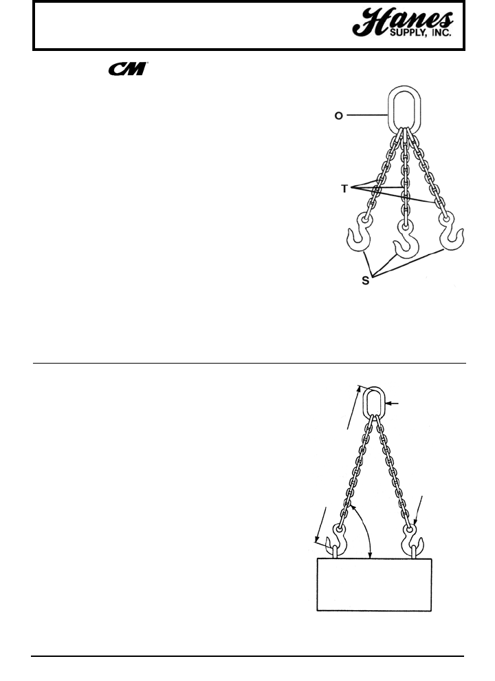
42
HEADQUARTERS: 55 James E. Casey Drive • Buffalo, NY 14206 PHONE: 716.826.2636 FAX: 716.826.4412 www.hanessupply.com
Chain Sling Assembly
BASIC TYPES OF CHAIN SLINGS
Basic types of chain slings are dsignated throughout the
industry by the following symbols:
First Symbol (basic type):
S - Single chain sling with master link and hook, or hook at each end.
C - Choker chain sling with master link on each end; no hooks.
D - Double chain sling with standard master link and hooks.
T - Triple chain sling with standard master link and hooks
Q - Quadruple chain sling with master link and hooks.
Second Symbol (type of master link or end link):
O - Oblong master link – Recommended standard for all types.
P - Pear shaped master link – Available on request.
Third Symbol (type of hook):
S - Sling hook G - Grab hook
F - Foundry hook L - Latchlok hook
Sling tags are coded with numerals 1 through 4 to reflect number of branches
in sling. Additional coding is defined as follows:
AS - Adjustable sling SB - Single Basket
ES - Endless single ED - Endless double
SAL - Single adjustable loop DAL - Double adjustable loop
AD - Adjustable double DB - Double basket
Type TOS
1. Determine the weight and configuration of the load(s) to be
lifted.
2. Determine the type of chain sling required, according to
weight and configuration. (refer to the following pages)
3. Determine the size of the body chain according to the
working load limits. Be sure to take into consideration the
effect of the required angle.
*Working load limit: The working load limit is the maximum
load in pounds which should ever be applied to chain, even
when chain is new, and when load is uniformly applied in
direct tension to a straight length of chain.
4. Determine the reach required to give the desired angle. The
reach is measured from the upper bearing surface of the
master link to the bearing surface of the lower attachment.
If chain slings are to be used in pairs and are to be matched
for reach, please indicate when ordering.
5. Be sure to specify type, size and reach when ordering chain
slings. For specifications on additional hooks, attachments
and accessories, refer to the following pages.
Note: Angle to the load on multiple leg slings will be 60° or
greater as long as the distance between lifting eyes of load
is NOT greater than reach shown on Identification Tag.
GRADE 80 CHAIN SLING ASSEMBLY
REACH AS REQUIRED
MASTER
OBLONG
LINK
SLING HOOK
ANGLE
LOAD
HOW TO SELECT & ORDER THE PROPER CHAIN SLING
YOUR SLING AND RIGGING SPECIALIST
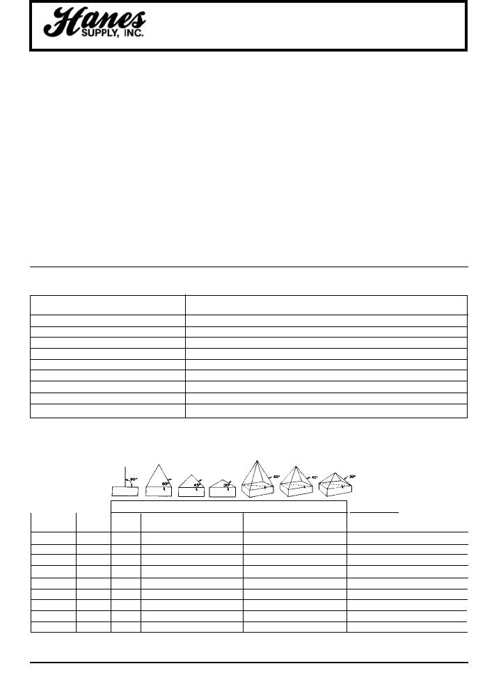
43
HEADQUARTERS: 55 James E. Casey Drive • Buffalo, NY 14206 PHONE: 716.826.2636 FAX: 716.826.4412 www.hanessupply.com
Alloy Chain Slings
A higher strength heat treated alloy steel chain, CM
grade 80 Herc-Alloy 800 chain is primarily used as a
sling component for overhead lifting, but can be used in
rigging and tie down applications where a lighter weight
high strength chain is desirable. Recommended for
overhead lifting by NACM, ANSI, & OSHA.
CM grade 80 Herc-Alloy 800 chain slings and
attachments are manufactured from special analysis
alloy steel, engineered for a superior combination of
strength, lightness and durability.
All Herc-Alloy 800 chain and attachments are black
finish and/or color coded orange for easy, permanent
identification. The chain is embossed with the grade
(HA-800) and trace code.
CHAIN SIZE HOOK SIZE DESIGNATION AND MARKINGS
Fraction (in) Decimal (in) Metric (mm) Sling Cradle Grab* Flat Grab Foundry Latchlok
7/32 .218 5.5 HA22 10 M 10M – –
9/32 .281 7.0 HA220 HA 9/32 HA1 HA498 9/32
3/8 .394 10.0 HA250 HA 3/8 HA3 HA499 3/8
1/2 .512 13.0 HA280 HA 1/2 HA5 HA500 1/2
5/8 .630 16.0 HA290 HA 5/8 HA6 HA501 5/8
3/4 .787 20.0 HA300 HA 3/4 HA7 HA502 3/4
7/8 .875 22.0 HA320 HA 7/8 HA8 HA503 –
1 1.024 26.0 HA330 HA 1 HA9 HA504 –
1-1/4 1.260 32.0 HA350 HA 1-1/4 HA11 HA505 –
HERC-ALLOY 800®CHAIN AND ATTACHMENTS CONVERSION TABLE
WORKING LOAD LIMITS (LBS)
CHAIN SIZE PRODUCT SINGLE DOUBLE TRIPLE & QUAD
(IN) (MM) CODE 90° 60° 45° 30° 60° 45° 30°
7/32 5.5 607020 2,100 3,600 3,000 2,100 5,450 4,450 3,150 .671 .296 17.9 44.7
9/32 7.0 607028 3,500 6,100 4,900 3,500 9,100 7,400 5,200 .868 .395 13.8 74.2
3/8 10.0 607037 7,100 12,300 10,000 7,100 18,400 15,100 10,600 1.222 .572 9.8 145.9
1/2 13.0 607050 12,000 20,800 17,000 12,000 31,200 25,500 18,000 1.101 .720 8.5 257.7
5/8 16.0 607062 18,100 31,300 25,600 18,100 47,000 38,400 27,100 1.733 .854 6.9 387.3
3/4 20.0 607075 28,300 49,000 40,000 28,300 73,500 60,000 42,400 2.160 1.052 5.5 622.0
7/8 22.0 607087 34,200 59,200 48,400 34,200 88,900 72,500 51,300 2.250 1.137 5.3 776.4
1 26.0 607101 47,700 82,600 67,400 47,700 123,900 101,200 71,500 2.664 1.348 4.5 995.4
1-1/4 32.0 607128 72,300 125,200 102,200 72,300 187,800 153,400 108,400 3.250 1.656 3.7 1,570.9
APPROX. APPROX.
NO. WEIGHT
LINKS PER 100FT.
PER FT. (LBS)
NOMINAL
DIMENSIONS
(IN)
INSIDE INSIDE
LENGTH WIDTH
CM HERC-ALLOY 800®CHAIN SIZES AND WORKING LOAD LIMITS
90° 60° 45° 30° 60° 45° 30°
Before shipment, all CM Herc-Alloy 800 chain slings
undergo a succession of demanding quality control
checks. Every sling is proof tested, registered and
guaranteed for one year to be free from defects in
materials and workmanship. A durable metal tag
attached to the sling permanently identifies the grade,
type, working load limit (at a specific angle of lift) and
registration number of the sling.
Chain slings are used primarily for overhead lifting and
are generally used in conjunction with a crane or some
type of lifting device. Standard sling configurations
consist of chain branches which are affixed on one end
to a master link or ring with some type of attachment,
usually a hook, affixed to the opposite end.
CM HERC-ALLOY 800®SINGLE CHAIN SLINGS
YOUR SLING AND RIGGING SPECIALIST
44
HEADQUARTERS: 55 James E. Casey Drive • Buffalo, NY 14206 PHONE: 716.826.2636 FAX: 716.826.4412 www.hanessupply.com
Chain Slings
CARE, USE AND INSPECTION
The life and strength of CM Herc-Alloy 800 chain slings depends
on proper inspection, maintenance and use. For additional
information, refer to ANSI B30.9 and OSHA 1920.184.
CARE
Chain requires careful storage and regular maintenance.
• Store chains on an A frame in a clean, dry place.
• To avoid corrosion, oil chaines before prolonged storage.
• Do not heat CM Herc-Alloy 800 chain; this will alter its thermal
treatment
• Do not plate or change surface finish of chain. Contact CM
for special requirements.
USE
To protect both operators and materials, observe these
precautions when using chain slings:
• Before use, inspect chain and attachments following the
instructions under "Inspection" below.
• Do not exceed working load limit. Any of the factors listed
here can reduce the load the chain will hold:
• Acceleration in rate of load to application – can produce
dangerous overloading.
• Variation in the angle of the load to the sling – as the
angle decreases, the working load of the sling will
increase.
• Twisting, knotting or kinking – subjects links to unusual
loading, decreasing the working load of the sling.
• Use for purposes other than those for which slings are
intended – can reduce the working load of the sling.
• Free chain of all twists, knots and kinks.
• Center load in hook(s); hook latches must not support load.
• Avoid sudden jerks when lifting and lowering.
• Balance all loads; avoid tipping of loads.
• Use pads around sharp corners.
• Do not drop load on chains.
• Match the size and working load limit of attachments such as
hooks or rings to the size and working load limit of the chain.
• For overhead lifting, use only alloy chain and attachments
(grade 80).
INSPECTION
It is important both to inspect chain slings regularly and to keep
a record of all chain inspections. Follow this guide for such an
inspection system.
• Before inspecting, clean chains with a non-acid/non-causic
solvent so that marks, nicks, wear and other defects are
visible.
• Inspect each link for these conditions:
• Twists or bends.
• Nicks or gouges.
• Excessive wear at bearing points.
• Stretch.
• Distorted or damaged master links, coupling links or
attachments, especially spread in throat opening of hooks.
• Mark plainly with paint each link or attachment showing any of
the conditions listed here to indicate rejection; remove from
service until properly repaired.
WEAR ALLOWANCES OF CM HERC-ALLOY 800 CHAIN
Measure cross section at link ends to determine wear. If chain
is worn to less than the minimum allowable thickness, remove
from service.
Maximum Minimum Thickness
Allowable Wear Allowable at
MM Inches (inches) Link Ends (inches)*
5.5 7/32 – – – – 11/64 (.171)
7.0 9/32 3/64 (.046) 13/64 (.203)
10.0 3/8 5/64 (.078) 18/64 (.281)
13.0 1/2 7/64 (.109) 22/64 (.343)
16.0 5/8 9/64 (.140) 27/64 (.421)
20.0 3/4 10/64 (.156) 34/64 (.531)
22.0 7/8 11/64 (.171) 40/64 (3625)
26.0 1 12/64 (.187) 47/64 (.734)
32.0 1-1/4 16/64 (.250) 58/64 (.906)
*Applies to CM Herc-Alloy 800 chain only.
USE OF CHAIN UNDER HEAT CONDITIONS
When the chain itself is heated to temperatures shown here,
working load limits should be reduced as indicated.
Reduction in Permanent
Temperature Working Load Limit1Reduction In
of Chain While Heated Working Load Limit2
500°F none none
600°F 10% none
700°F 20% none
800°F 30% none
900°F 40% 10%
1000°F 50% 15%
1While chain is at temperature shown in first column.
2When chain is used at room temperature after having
been heated to temperatures shown in first column.
CERTIFICATE OF TEST AND IDENTIFICATION
The identification tag found on the master coupling link of each
chain sling contains this information:
• Grade • Size
• Reach • Type
• Working load limit (at a specific angle of lift)
• Serial number
CM CHAIN INSPECTION PROGRAMS
CM provides chain users with a wide range of informative materials and instructive programs on chain and chain inspection. Our
coloful chain safety proster/chart and our fact-filled booklet. "CM Lifting, Pulling & Binding Products Manual PMC-10," are available on
request.
CM Chain Clinics on proper chain use, care and inspection are conducted at our headquarters in Amherst, New York, and in plants
across the country. Video cassette training programs, slide and film presentations and in-plant chain sling inspections are also
available.
CM education programs are designed to promote the proper use of all CM products, and to assist users in complying with OSHA
regulations.
YOUR SLING AND RIGGING SPECIALIST
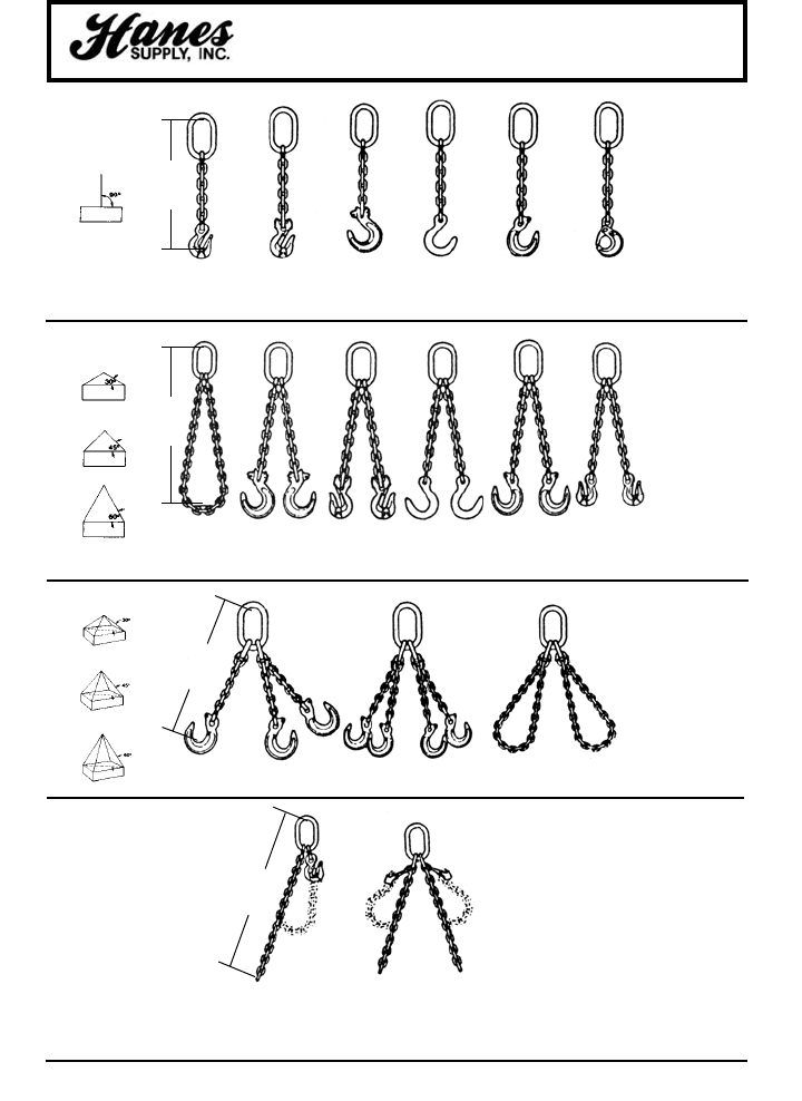
45
HEADQUARTERS: 55 James E. Casey Drive • Buffalo, NY 14206 PHONE: 716.826.2636 FAX: 716.826.4412 www.hanessupply.com
Chain Sling Specifications
DOUBLE
CHAIN
SLINGS
TYPE SOG
GRAB HOOK
TYPE SOG
CLEVLOCK
GRAB HOOK
TYPE SOS
CLEVLOCK
SLING HOOK
TYPE SOF
FOUNDRY
HOOK
TYPE SOS
SLING
HOOK
TYPE SOL
LATCHLOK
HOOK
SINGLE
BASKET
TYPE DOS
CLEVLOK
SLING HOOK
TYPE DOG
CLEVLOK
GRAB HOOK
TYPE DOF
FOUNDRY
HOOK
TYPE DOS TYPE DOG
GRAB HOOK
TYPE TOS TYPE OOS DOUBLE BASKET
SINGLE ADJUSTABLE
LOOP - STYLE A
DOUBLE ADJUSTABLE
LOOP - STYLE A
SINGLE
CHAIN
SLINGS
TRIPLE
& QUAD
CHAIN
SLINGS
SINGLE
ADJUSTABLE LOOP
CHAIN SLING
DOUBLE
ADJUSTABLE LOOP
CHAIN SLING
REACH
REACH
REACH
REACH
YOUR SLING AND RIGGING SPECIALIST
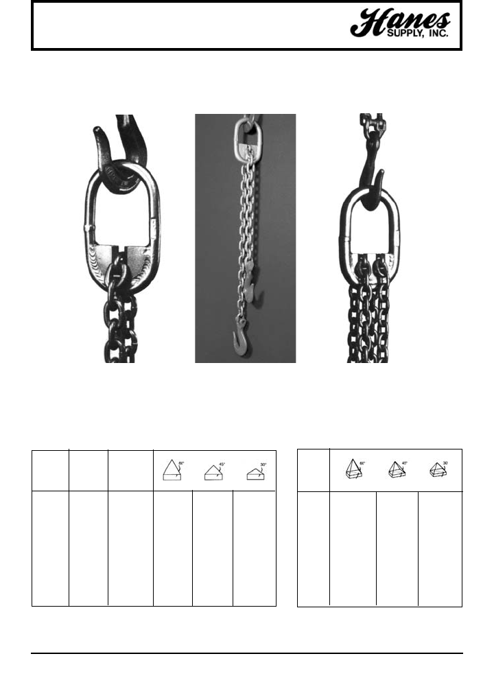
46
HEADQUARTERS: 55 James E. Casey Drive • Buffalo, NY 14206 PHONE: 716.826.2636 FAX: 716.826.4412 www.hanessupply.com
Chain Sling Saddle Rings
SINGLE DOUBLE SLING
BRANCH
CHAIN SLING
SIZE 90 DEGREE
SYSTEM INCHES LOADING 60° 45° 30°
10 9/32 4,300 7,500 6,100 4,300
10 3/8 8,800 15,200 12,400 8,800
10 1/2 15,000 26,000 21,200 15,000
10 5/8 22,600 39,000 32,000 22,000
10 3/4 35,300 61,100 49,900 35,300
10 7/8 42,700 74,000 60,400 42,700
8 1 47,700 82,600 67,400 47,700
8 1-1/4 72,300 125,200 102,200 72,300
8 1-1/2 80,000 138,600 113,100 80,000
ALLOWS ADJUSTMENT OF CHAIN REACH
TRIPLE AND QUADRUPLE SLING
CHAIN
SIZE
INCHES 60° 45° 30°
9/32 11,200 9,100 6,450
3/8 22,800 18,600 13,200
1/2 39,000 31,800 22,500
5/8 58,700 47,900 33,900
3/4 91,700 74,900 53,000
7/8 110,900 90,600 64,000
1 123,900 101,200 71,500
1-1/4 187,800 153,400 108,400
1-1/2 — — —
United States Patent #4,241,575
Canadian Patent #1,086,510 British Patent #2,029,370
SAME STRENGTH AS STANDARD CHAIN SLINGS,
ONLY MORE ECONOMICAL
YOUR SLING AND RIGGING SPECIALIST
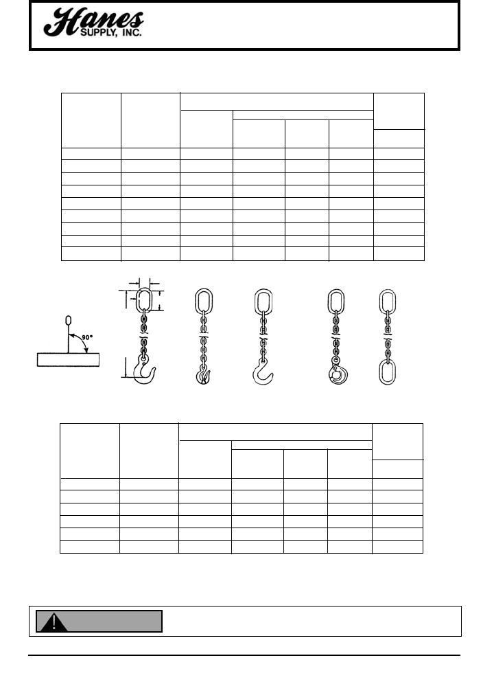
47
HEADQUARTERS: 55 James E. Casey Drive • Buffalo, NY 14206 PHONE: 716.826.2636 FAX: 716.826.4412 www.hanessupply.com
Chain Slings - Single
Types S & C
CM GRADE 80 SINGLE CHAIN SLING TYPE S & C
OBLONG MASTER LINK
DIMENSIONS (INCHES) APPROX. WT.
WORKING WORKING DIAMETER DIAMETER INSIDE INSIDE (LBS)
CHAIN SIZE LOAD LIMIT LINK MATERIAL WIDTH LENGTH TYPE SOS
(IN.) (MM) (LBS)* NUMBER A B C 5 FT. REACH
7/32 5.5 2,100 HA40 13/32 1-1/2 3 4
9/32 7 3,500 HA50 1/2 2-1/2 5 5
3/8 10 7,100 HA75 3/4 2-3/4 5-1/2 10
1/2 13 12,000 HA100 1 3-1/2 7 18
5/8 16 18,100 HA100 1 3-1/2 7 25
3/4 20 28,300 HA125 1-1/4 4-3/8 8-3/4 38
7/8 22 34,200 HA150 1-1/2 5-1/4 10-1/2 54
1 26 47,700 HA175 1-3/4 6 12 76
1-1/4 32 72,300 HA200 2 7 14 116
SOS
SLING
HOOK
SOG
GRAB
HOOK
SOF
FOUNDRY
HOOK
SOL
LATCHLOK
CO
CM GRADE 100 SINGLE CHAIN SLING TYPE S & C
OBLONG MASTER LINK
DIMENSIONS (INCHES) APPROX. WT.
WORKING WORKING DIAMETER DIAMETER INSIDE INSIDE (LBS)
CHAIN SIZE LOAD LIMIT LINK MATERIAL WIDTH LENGTH TYPE SOS
(IN.) (MM) (LBS)* NUMBER A B C 5 FT. REACH
7/32 5.5 2,700 HA40 13/32 1-1/2 3 4
9/32 7 4,300 HA50 1/2 2-1/2 5 5
3/8 10 8,800 HA75 3/4 2-3/4 5-1/2 10
1/2 13 15,000 HA100 1 3-1/2 7 18
5/8 16 22,600 HA100 1 3-1/2 7 25
3/4 20 35,300 HA125 1-1/4 4-3/8 8-3/4 38
Inspect before use. Follow OSHA, ANSI B30.9 or Manufacturers Guidelines. Use by untrained
persons is hazardous. Improper use will result in serious injury or death. Do not exceed rated
capacity. This product will fail if damaged, abused, misused, overused or improperly maintained.
AC
B
REACH
WARNING
YOUR SLING AND RIGGING SPECIALIST
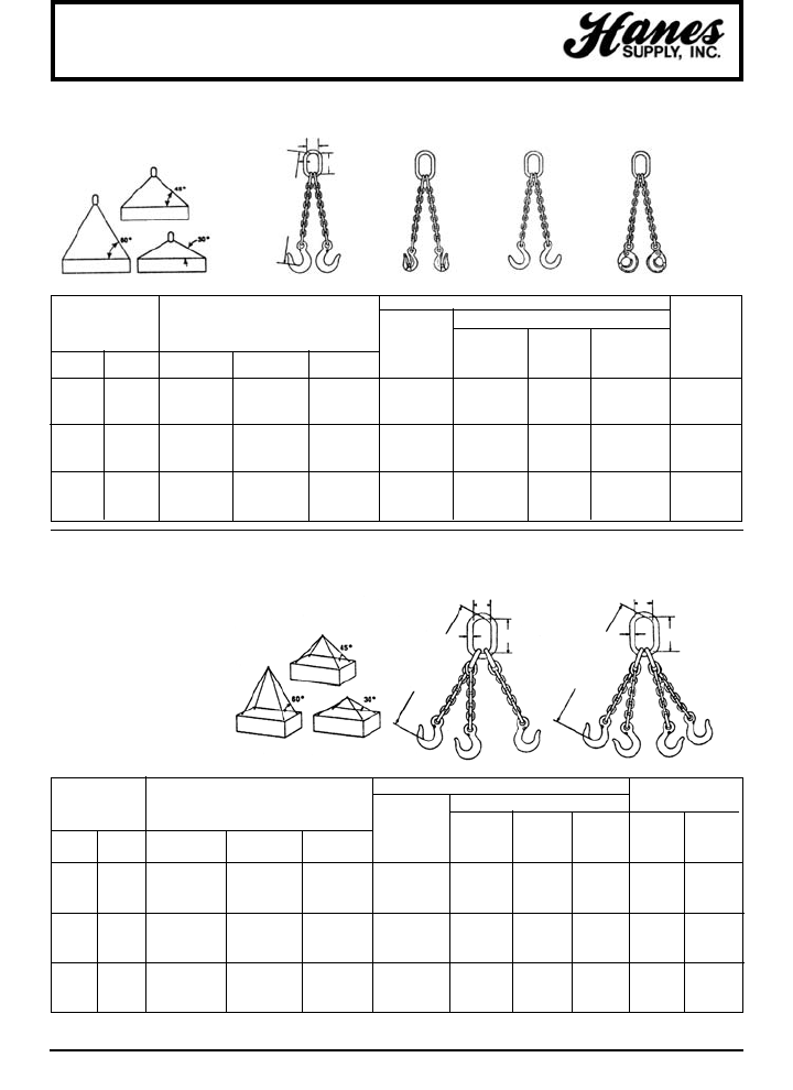
48
HEADQUARTERS: 55 James E. Casey Drive • Buffalo, NY 14206 PHONE: 716.826.2636 FAX: 716.826.4412 www.hanessupply.com
Chain Slings - Grade 80 Alloy
OBLONG MASTER LINK SUB-ASSEMBLY APPROX. WT.
MASTER DIMENSIONS (IN) (LBS)
CHAIN SIZE WLL (LBS)* LINK SUB DIA. INSIDE INSIDE TYPE TYPE
ASSEMBLY MATERIAL WIDTH LENGTH TOS QOS 5’
(IN) (MM) 60° 45° 30° NO. A B C REACH REACH
7/32 5.5 5,450 4,450 3,150 HA50-SA 1/2 2-1/2 5 12 16
9/32 7 9,100 7,400 5,200 HA75-SA 3/4 2-3/4 5-1/2 14 18
3/8 10 18,400 15,100 10,600 HA100-SA 1 3-1/2 7 28 36
1/2 13 31,200 25,500 18,000 HA125-SA 1-1/4 4-3/8 8-3/4 50 62
5/8 16 47,000 38,400 27,100 HA150-SA 1-1/2 5-1/4 10-1/2 79 97
3/4 20 73,500 60,000 42,400 HA175-SA 1-3/4 6 12 112 137
7/8 22 88,900 72,500 51,300 HA200-SA 2 7 14 155 188
1 26 123,900 101,200 71,500 HA225-SA 2-1/4 8 16 215 260
1-1/4 32 187,800 153,400 108,400 HA275-SA 2-3/4 9 16 348 421
Safety note: A quad branch
chain sling usually does not
sustain loads with even
distribution to its four
branches, especially when
loads are of rigid structure.
Therefore, maximum
working load limits are set
at the same values as for
triple branch chain slings of
equal quality and size and
used with branches at the
same angle of inclination.
DOG
GRAB
HOOKS
TOS
SLING
HOOKS
QOS
SLING
HOOKS
DOF
FOUNDRY
HOOKS
OBLONG MASTER LINK APPROX
DIMENSIONS (IN) WT.
(LBS.)
CHAIN SIZE WORKING LOAD LIMIT (LBS) MASTER DIA. INSIDE INSIDE TYPE
LINK MATERIAL WIDTH LENGTH DOS
(IN) (MM) 60° 45° 30° NO. A B C 5' REACH
7/32 5.5 3,600 3,000 2,100 HA40 13/32 1-1/2 3 8
9/32 7 6,100 4,900 3,500 HA50 1/2 2-1/2 5 9
3/8 10 12,300 10,000 7,100 HA75 3/4 2-3/4 5-1/2 18
1/2 13 20,800 17,000 12,000 HA100 1 3-1/2 7 31
5/8 16 31,300 25,600 18,100 HA125 1-1/4 4-3/8 8-3/4 49
3/4 20 49,000 40,000 28,300 HA150 1-1/2 5-1/4 10-1/2 71
7/8 22 59,200 48,400 34,200 HA175 1-3/4 6 12 98
1 26 82,600 67,400 47,700 HA200 2 7 14 132
1-1/4 32 125,200 102,200 72,300 HA225 2-1/4 8 16 221
DOUBLE CHAIN SLING TYPE D
TRIPLE & QUAD CHAIN SLING TYPE T & Q
DOL
LATCHLOK
HOOKS
DOS
SLING
HOOKS
AC
B
REACH
AC
B
REACH
AC
B
REACH
YOUR SLING AND RIGGING SPECIALIST
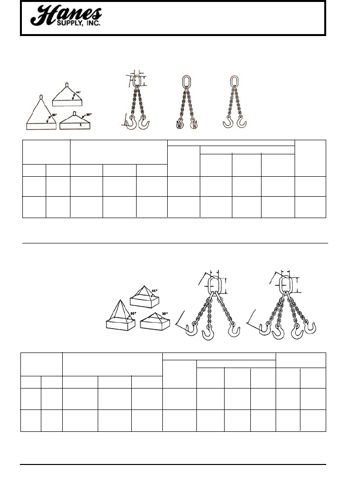
49
HEADQUARTERS: 55 James E. Casey Drive • Buffalo, NY 14206 PHONE: 716.826.2636 FAX: 716.826.4412 www.hanessupply.com
Chain Slings - Grade 100 Alloy
OBLONG MASTER LINK SUB-ASSEMBLY APPROX. WT.
MASTER DIMENSIONS (IN) (LBS)
CHAIN SIZE WLL (LBS)* LINK SUB DIA. INSIDE INSIDE TYPE TYPE
ASSEMBLY MATERIAL WIDTH LENGTH TOS 5' QOS 5’
(IN) (MM) 60° 45° 30° NO. A B C REACH REACH
7/32 5.5 7,000 5,700 4,000 HA50-SA 1/2 2-1/2 5 12 16
9/32 7 11,200 9,100 6,400 HA75-SA 3/4 2-3/4 5-1/2 14 18
3/8 10 22,900 18,700 13,200 HA100-SA 1 3-1/2 7 28 36
1/2 13 39,000 31,800 22,500 HA125-SA 1-1/4 4-3/8 8-3/4 50 62
5/8 16 58,700 47,900 33,900 HA150-SA 1-1/2 5-1/4 10-1/2 79 97
3/4 20 91,700 74,900 53,000 HA175-SA 1-3/4 6 12 112 137
Safety note: A quad branch
chain sling usually does not
sustain loads with even
distribution to its four
branches, especially when
loads are of rigid structure.
Therefore, maximum
working load limits are set at
the same values as for triple
branch chain slings of equal
quality and size and used
with branches at the same
angle of inclination.
OBLONG MASTER LINK APPROX
DIMENSIONS (IN) WT.
(LBS.)
CHAIN SIZE WORKING LOAD LIMIT (LBS) DIA. INSIDE INSIDE TYPE
PRODUCT MATERIAL WIDTH LENGTH DOS
(IN) (MM) 60° 45° 30° CODE A B C 5' REACH
7/32 5.5 4,700 3,800 2,700 555231 13/32 1-1/2 3 8
9/32 7 7,400 6,100 4,300 555232 1/2 2-1/2 5 9
3/8 10 15,200 12,400 8,800 555235 3/4 2-3/4 5-1/2 18
1/2 13 26,000 21,200 15,000 555238 1 3-1/2 7 31
5/8 16 39,100 32,000 22,600 555240 1-1/4 4-3/8 8-3/4 49
3/4 20 61,100 49,900 35,300 555243 1-1/2 5-1/4 10-1/2 71
DOUBLE CHAIN SLING TYPE D
TRIPLE & QUAD CHAIN SLING TYPE T & Q
DOG
GRAB
HOOKS
TOS
SLING
HOOKS
QOS
SLING
HOOKS
DOF
FOUNDRY
HOOKS
DOS
SLING
HOOKS
AC
B
REACH
AC
B
REACH
AC
B
REACH
YOUR SLING AND RIGGING SPECIALIST
50
HEADQUARTERS: 55 James E. Casey Drive • Buffalo, NY 14206 PHONE: 716.826.2636 FAX: 716.826.4412 www.hanessupply.com
• Failure to use this load binder properly may result in
serious injury or even death
• Do not operate load binder while standIng on the
load.
• Move handle with caution. It may whip – Keep body
clear.
• Keep yourself out of the path of the moving handle.
• You must be familiar with state and federal
regulations regarding size and number of chain
systems required for securing loads on trucks.
• Always consider the safety of nearby workers as well
as yourself when using load binder.
• While under tension, load binder must not bear
against any object.
• Do not thow these instructions away. Keep them
close at hand and share them with any others who
use this load binder.
Load Binders
INSTRUCTIONS - LEVER TYPE LOAD BINDERS
• Hook load binder to chain so you
can operate it while standing on the
ground. Position load binder so its
handle can be pulled downward to
tighten chain (see photo). Be aware
of ice, snow rain, oil, etc. that can
affect your footing. Make certain
your footing is secure.
• The Crosby Group, Inc. specifically
recommends AGAINST the use of a
handle extender (cheater pipe). If sufficient leverage cannot
be obtained using the lever type load binder by itself, a
ratchet type binder should be used.
• If the above recommendation is disregarded and a cheater
pipe is used, it must closely fit the handle and must slide
down the handle until the handle projections are contacted.
The pipe should be secured to the handle, for example, by a
pin, so that the pipe cannot fly off the handle if you lose
control and let go. The increased leverage, by using a
cheater pipe, can cause deformation and failure of the chain
and load binder.
• During and after tightening chain, check load binder handle
position. Be sure it is in the locked position and that its
bottom side touches the chain link.
• Chain tension may decrease due to load shifting during
transport. To be sure the load binder remains in proper
position: Secure handle to chain by wrapping the loose end
of chain around the handle and the tight chain, or tie handle
to chain with soft wire.
• When releasing load binder, remember there is a great deal
of energy in the stretched chain. This will cause the load
binder handle to move very quickly with great force when it
is unlatched. Move handle with caution. It may whip –
Keep body clear.
•Never use a cheater pipe or handle extender to release
handle. Use a steel bar and pry under the handle and stay
out of the path of handle as it moves upward.
• If you release the handle by hand, use an open hand under
the handle and push upward. Do not close your hand
around the handle. Always keep yourself out of the path
of the moving handle.
INSTRUCTIONS - RATCHET LOAD BINDERS
• Position ratchet binder so it can be operated from the ground.
•Make sure your footing is secure.
MAINTENANCE OF ALL LOAD BINDERS
• Routinely check load binders for wear, bending, cracks,
nicks, or gouges. If bending or cracks are present – Do
not use load binder.
• Routinely lubricate pivot and swivel points of Lever Binders,
and pawl part and screw threads of Ratchet Binders to
extend product life and reduce friction wear.
LOAD BINDER WARNINGS AND APPLICATION INSTRUCTIONS
RATCHET TYPE
LOAD BINDER WARNINGS AND
APPLICATION INSTRUCTIONS
LEVER TYPE
LEVER SNUBBING TYPE LEVER WALKING TYPE
LEVER RELEASING TYPE
Mechanical Advantage
Lever Type Binder = 25 : 1
Ratchet Type Binder = 50 : 1
Example: 100 pounds of effort
applied to the binder results in
the following force on the binder.
Lever Type:
2500 (100 lbs. x 25) lbs. of force
Ratchet Type:
5000 (100 lbs. x 50) lbs. of force
WARNING
YOUR SLING AND RIGGING SPECIALIST
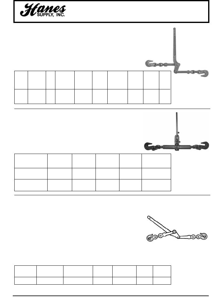
51
HEADQUARTERS: 55 James E. Casey Drive • Buffalo, NY 14206 PHONE: 716.826.2636 FAX: 716.826.4412 www.hanessupply.com
Load Binders - Crosby
STANDARD LEVER TYPE LOAD BINDERS
L-150
CM RATCHET TYPE LOAD BINDER
MIN-MAX
WORKING
MINIMUM
CHAIN LOAD PROOF ULTIMATE WEIGHT HANDLE TAKE
STOCK STD. SIZE LIMIT LOAD STRENGTH EACH LENGTH UP
MODEL NO. PKG. (IN.) (LBS.) (LBS.) (LBS.) (LBS.) (IN.) (IN.)
7-1 1048128 4 5/16-3/8 5400 10800 19000 7.02 16.00 4.50
A-1 1048146 4 3/8-1/2 9200 18400 33000 12.47 18.69 4.50
C-1 1048164 4 1/2-5/8 13000 26000 46000 19.68 21.00 4.75
• Forged Steel–Quenched & Tempered.
• Binder toggles away from the load.
WORKING APPROX.
MAX LOAD LIMIT PRODUCT UPC TAKE-UP WEIGHT
SIZE (IN.) (LBS.) CODE 43927- (IN.) EACH (LBS.)
3/8
G80, G43
7,100 D48360 81767- 8 13
5/8
G70
48360
1/2
G70
13,000 D48367 30008 8 14
5/8
G43
• Heavy duty, rigid, all steel construction.
• Short reach hooks for maximum take-up.
• Infinite adjustment.
• Continuous take-up.
• Meets DOT and CVSA specifications.
CHAIN SIZE CHAIN
WORKING LOAD
PRODUCT HANDLE TAKE-UP WEIGHT
(IN.) GRADE LIMIT (LBS.)* CODE
LENGTH (IN.)
(IN.) (LBS.)
3/8
30,43, 70, 80
7,100 D48769 16 4-7/8 8-1/4
CM 3/8" LEVER TYPE LOAD BINDER
YOUR SLING AND RIGGING SPECIALIST
• Provides more control in binding and releasing without extra tools.
• Handle closes down away from load with more leverage.
• Hooks are heat treated steel.
• Functionally superior to any other on the road.
• Handles are drop forged from special bar quality steel.
• Single welded links as in binder chain for better reliability.
• More take-up for binding greater loads. Smaller handle slot with
riveted nose to prevent spreading at the critical loading point.
• Meets DOT and CVSA requirements.
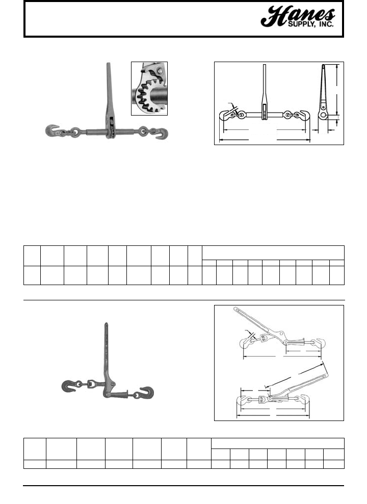
52
HEADQUARTERS: 55 James E. Casey Drive • Buffalo, NY 14206 PHONE: 716.826.2636 FAX: 716.826.4412 www.hanessupply.com
Lebus®Load Binders
MIN-MAX WORKING MINIMUM
DIMENSIONS (IN.)
CHAIN LOAD PROOF ULTIMATE
WEIGHT
HANDLE TAKE
SIZE LIMIT LOAD STRENGTH EACH LENGTH UP
MODEL STOCK NO. (IN.) (LBS.) (LBS.) (LBS.) (IN.) (IN.) (IN.) A B C D E E1 F F1 G
R-7 1048404 5/16-3/8 6600 13200 26000 11.23 14 10 8.0 14.00 1.38 2.75 22.94 30.94 25.13 33.13 .50
R-A 1048422 3/8 -1/2 9200 18400 33000 12.83 14 10 8.0 14.00 1.38 2.75 25.25 33.25 27.63 35.63 .63
R-C 1048440 1/2-5/8 13000 26000 46000 14.55 14 10 8.0 14.00 1.38 2.75 26.38 34.38 29.44 37.44 .72
MIN-MAX WORKING DIMENSIONS (IN.)
CHAIN LOAD ULTIMATE WEIGHT TAKE
L-130 SIZE LIMIT LOAD EACH UP
MODEL STOCK NO (IN.) (LBS.) (LBS.) (LBS.) (IN.) A B C D E F G
W-1 1048100 3/16-1/4 1450 5100 2.57 2.40 16.13 13.63 11.00 11.25 6.25 6.58 .34
L-140
STANDARD RATCHET TYPE LOAD BINDER
L-130 MIDGET LOAD BINDER
NOTE: Binders shown with Proof Load Pounds have been individually Proof Tested to these values shown, prior to shipment.
• Upgrade for use with Grade 7 Transport Chain - applies to R-7 only.
• Utilizes standard Crosby A-323 Alloy Eye Grab Hooks.
• New design "one piece" forged handle.
• Continuous take-up feature, infinite adjustment, gets the last half of chain.
• One piece assembly, no bolts or nuts to loosen.
• Ratchet spring rust proofed.
• All load bearing or holding parts forged.
• Easy operating positive ratchet.
• Meets or exceeds CVSA Cargo Securement Guidelines, August 1993.
• Forged handle, hooks and swivel link.
• Steel swivels and clevis.
• Meets or exceeds DOT and CVSA Cargo securement, August 1993.
G
E1 OPEN
E CLOSED C
A
YOUR SLING AND RIGGING SPECIALIST
A
B
C
D
E
F
G
B
F1 OPEN
F CLOSED
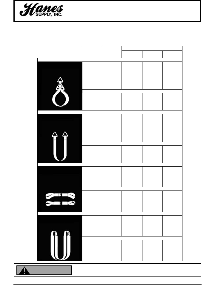
RATED CAPACITIES (LBS.)
WEB CODE
WIDTH NUMBER VERTICAL CHOKER BASKET
2" TC1-802 3,200 2,500 6,400
3" TC1-803 4,800 3,800 9,600
4" TC1-804 6,400 5,000 12,800
5" TC1-805 8,000 6,400 16,000
6" TC1-806 9,600 7,700 19,200
8" TC1-808 12,800 10,200 25,600
10" TC1-810 16,000 12,800 32,000
12" TC1-812 19,200 15,400 38,400
2" TC2-802 6,400 5,000 12,800
3" TC2-803 8,600 6,900 17,200
4" TC2-804 11,500 9,200 23,000
5" TC2-805 14,000 11,200 28,000
6" TC2-806 16,800 13,400 33,600
2" TT1-802 3,200 – 6,400
3" TT1-803 4,800 – 9,600
4" TT1-804 6,400 – 12,800
5" TT1-805 8,000 – 16,000
6" TT1-806 9,600 – 19,200
8" TT1-808 12,800 – 25,600
10" TT1-810 16,000 – 32,000
12" TT1-812 19,200 – 38,400
2" TT2-802 6,400 – 12,800
3" TT2-803 8,600 – 17,200
4" TT2-804 11,500 – 23,000
5" TT2-805 14,000 – 28,000
6" TT2-806 16,800 – 33,600
1" EE1-801 1,600 1,250 3,200
2" EE1-802 3,200 2,500 6,400
3" EE1-803 4,800 3,800 9,600
4" EE1-804 6,400 5,000 12,800
5" EE1-805 8,000 6,400 16,000
6" EE1-806 9,600 7,700 19,200
1" EE2-801 3,200 2,500 6,400
2" EE2-802 6,400 5,000 12,800
3" EE2-803 8,600 6,900 17,200
4" EE2-804 11,500 9,200 23,000
5" EE2-805 13,600 10,900 27,200
6" EE2-806 16,300 13,000 32,600
1" EN1-801 3,200 2,500 6,400
2" EN1-802 6,400 5,000 12,800
3" EN1-803 8,600 6,900 17,200
4" EN1-804 11,500 9,200 23,000
5" EN1-805 13,600 10,900 27,200
6" EN1-806 16,300 13,000 32,600
1" EN2-801 6,200 4,900 12,400
2" EN2-802 12,200 9,800 24,400
3" EN2-803 16,300 13,000 32,600
4" EN2-804 20,700 16,500 41,400
5" EN2-805 24,500 19,600 49,000
6" EN2-806 28,600 23,000 57,200
53
HEADQUARTERS: 55 James E. Casey Drive • Buffalo, NY 14206 PHONE: 716.826.2636 FAX: 716.826.4412 www.hanessupply.com
Nylon Web Sling Properties
Can fail if damaged, misused or overloaded. Inspect before use. Use only if trained.
Observe rated capacity. Avoid sharp edges and exposure to acid, alkali, sunlight and
temperature over 180°F. DEATH or INJURY can occur from improper use or maintenance.
SINGLE PLY SLINGS
SINGLE PLY SLINGS
TWO PLY SLINGS
SINGLE PLY SLINGS
TWO PLY SLINGS
SINGLE PLY SLINGS
TWO PLY SLINGS
TYPE 1 SLINGS
CHOKER & BASKET HITCH
TRIANGLE & CHOKER FITTINGS
TYPE 2 SLINGS
BASKET & VERTICAL
HITCHES ONLY
TWO TRIANGLE FITTINGS
TYPE 3 & 4 SLINGS
FLAT OR TWISTED EYES
VERTICAL, CHOKER, BASKET
HITCHES
TYPE 5 SLINGS
VERTICAL, CHOKER, BASKET
HITCHES
ENDLESS OR GROMMET TYPE
• Resistant to Alkalies
• Untreated – approx. 6% stretch; treated – approx. 10% stretch at rated capacity
• Temperature limit is 180°F
• Contains red warning yarns
• Subject to damage by sharp edges
Ratings based on straight pin diameter one-half the sling width.
WARNING
TWO PLY SLINGS
YOUR SLING AND RIGGING SPECIALIST
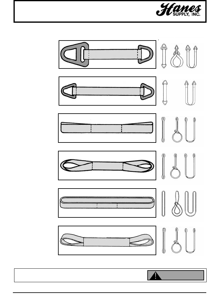
54
HEADQUARTERS: 55 James E. Casey Drive • Buffalo, NY 14206 PHONE: 716.826.2636 FAX: 716.826.4412 www.hanessupply.com
Nylon Web Slings
Can fail if damaged, misused or overloaded. Inspect before use. Use only if trained.
Observe rated capacity. Avoid sharp edges and exposure to acid, alkali, sunlight and
temperature over 180°F. DEATH or INJURY can occur from improper use or maintenance.
Type 1 TC Slings
Slings with a triangle on
one end and a slotted
triangle (the choker) on
the other end. Choice of
lightweight aluminum or
durable steel fittings.
Type 2 TT Slings
Slings with a triangle at
both ends. Used in vertical
and basket hitches only.
Choice of lightweight
aluminum or durable steel
fittings.
Type 3 EE Slings
Slings with an eye on both
ends. Choice of straight or
tapered eyes (tapered eye
are standard on 2" and
larger web-widths).
Type 4 EE Slings
Same basic type as Type
3 but eyes are twisted to a
right angle to the sling
body. (Tapered eye are
standard on 2" and larger
web-widths).
Type 5 EN Slings
Endless slings, sometimes
also referred to as
grommet slings. The most
versatile sling.
Type 6 RE Slings
Return eye sling, also
referred to as reversed
eye sling. Sling body is
formed by 2 parts of
webbing sewn side by side
using either a cordura
tube or web in the finished
width.
BASIC SLING TYPES HITCHES
Vertical Choker Basket
Vertical Cher Basket
Vertical Choker Basket
Vertical Choker Basket
Vertical Choker Basket
Vertical Choker Basket
WARNING
YOUR SLING AND RIGGING SPECIALIST

55
HEADQUARTERS: 55 James E. Casey Drive • Buffalo, NY 14206 PHONE: 716.826.2636 FAX: 716.826.4412 www.hanessupply.com
Nylon Web Slings
5.2 - MECHANICAL CONSIDERATIONS
5.2.1 Determine weight of the load. The weight of the load shall be within the rated capacity of
the sling.
5.2.2 Select the proper sling having suitable characteristics for the type of load, hitch and
environment.
5.2.3 Slings shall not be loaded in excess of the rated capacity. Consideration should be given
to the angle of lift (sling-to-load angle), which affects rated capacity.
5.2.4 Slings with fittings which are used in a choker hitch shall be of sufficient length to assure
that the choking action is on the webbing, and never on the other fitting.
5.2.5 Slings used in a basket hitch shall have the load balanced to prevent slippage.
5.2.6 The opening in fittings shall be the proper shape and size to insure that the fitting will seat
properly in the hook or other attachments.
5.2.7 Slings shall always be protected from being cut by sharp corners, sharp edges, protrusions
or abrasive surfaces.
5.2.8 Slings shall not be dragged on the floor or over an abrasive surface.
5.2.9 Slings shall not be twisted or tied into knots, or joined by knotting.
5.2.10 Slings shall not be pulled from under loads when the load is resting on the sling.
5.2.11 Do not drop slings equipped with metal fittings.
5.2.12 Slings that appear to be damaged shall not be used unless inspected and accepted as
usable under Section 5.2.
5.2.13 The sling shall be hitched in a manner providing control of the load.
5.2.14 Portions of the human body should be kept from between the sling and the load, and from
between the sling and the crane hook or hoist hook.
5.2.15 Personnel should stand clear of the suspended load.
5.2.16 Personnel shall not ride the sling.
5.2.17 Shock loading should be avoided.
5.2.18 Twisting the legs (branches) shall be avoided.
5.2.19 Load applied to the hook should be centered in the base (bowl) of hook to prevent point
loading on the hook.
5.2.20 During lifting, with or without the load, personnel shall be alert for possible snagging.
5.2.21 The slings' legs (branches) should contain or support the load from the sides above the
center of gravity when using a basket hitch.
5.2.22 Slings shall be long enough so that the rated load (rated capacity) is adequate when the
angle of the legs (branches) is taken into consideration.
YOUR SLING AND RIGGING SPECIALIST

56
HEADQUARTERS: 55 James E. Casey Drive • Buffalo, NY 14206 PHONE: 716.826.2636 FAX: 716.826.4412 www.hanessupply.com
5.3 - ENVIRONMENTAL CONSIDERATIONS
5.3.1 Slings should be stored in a cool, dry and dark place, and should not be exposed to
sunlight, to prevent mechanical or chemical damage when not in use.
5.3.2 Chemically active environments can affect the strength of synthetic web slings in varying
degrees ranging from none to total degradation. The sling manufacturer should be
consulted before slings are used in chemically active environments.
a. ACIDS
1. Nylon is subject to degradation in acids, ranging from none to total degradation.
2. Polyester is resistant to many acids, but is subject to degradation, ranging from none
to moderate in some acids.
3. Each application shall be evaluated, taking into consideration the following:
i Type of Acid
ii Exposure to conditions
iii Concentration
iv Temperature
b. ALKALIS
1. Polyester is subject to degradation in alkalis, ranging from none to total degradation.
2. Nylon is resistant to many alkalis, but is subject to degradation ranging from none to
moderate in some alkalis.
3. Each application shall be evaluated, taking into consideration the following:
i Type of Alkali
ii. Exposure to conditions
iii Concentration
iv Temperature
5.3.3 Nylon and polyester slings shall not be used at temperatures in excess of 180°F (85°C),
however, they may be used in temperatures as low as -40°F (-40°C).
5.3.4 Slings incorporating aluminum fittings shall not be used where fumes, vapors, sprays,
mists or liquids of alkalis and/or acids are present.
5.3.5 Environments in which synthetic webbing slings are continuously exposed to ultra-violet
light can affect the strength of synthetic webbing slings in varying degrees ranging from
slight to total degradation.
a. Factors which affect the degree of strength loss are:
1. Length of time of continuous exposure
2. Sling construction and design
3. Other environmental factors such as weather conditions and geographic location.
b. Suggested procedures to minimize the effects of ultra-violet light
1. Store slings in a cool, dry and dark place when not being used for prolonged periods
of time
2. Inspect slings weekly or more often depending on frequency of sling use
c. Visual indications of ultra-violet degradation are:
1. Bleaching out of sling color
2. Increased stiffness of sling material
3. Surface abrasion in areas not normally in contact with the load.
d. Proof-Testing – Slings used in environments where they are subject to continuous
exposure to ultra-violet light should be proof-tested to two times rated capacity annually,
or more frequently depending on severity of exposure.
Nylon Web Slings
YOUR SLING AND RIGGING SPECIALIST

57
HEADQUARTERS: 55 James E. Casey Drive • Buffalo, NY 14206 PHONE: 716.826.2636 FAX: 716.826.4412 www.hanessupply.com
Nylon Web Slings
5.4 - INSPECTION
5.4.1 TYPE OF INSPECTION
a. INITIAL INSPECTION – Before any new or repaired sling is placed in service, it shall
be inspected to insure that the correct sling is being used, as well as to determine that
the sling meets the requirements of this specification.
b. FREQUENT INSPECTION – This inspection should be made by the person handling the
sling each time the sling is used.
c. PERIODIC INSPECTION – This inspection shall be conducted by designated personnel.
Frequency of inspection should be based on:
1. Frequency of sling use
2. Severity of service conditions
3. Experience gained on the service life of slings used in similar applications
4. Periodic inspections should be conducted at least monthly
5.5 - POSSIBLE DEFECTS
5.5.1 A sling shall be removed from service if any defects such as the following are visible:
a. Acid or alkali burns
b. Melting, charring, or weld spatter of any part of the sling
c. Holes, tears, cuts, snags or embedded particles
d. Broken or worn stitching in load bearing splices
e. Excessive abrasive wear
f. Knots in any part of the sling
g. Distortion and excessive pitting or corrosion or broken fittings
h. Other apparent defects which cause doubt as to the strength of the sling
i. If sling rated capacity or sling material identification is missing or not readable
5.6 - INSPECTION RECORDS
5.6.1 Written inspection records, utilizing the identification for each sling as established by
the user, should be kept on file for all slings. These records should show a description
of the new sling and its condition on each subsequent inspection.
5.7 - REPAIR OF WEB SLINGS
5.7.1 Slings shall be repaired only by a sling manufacturer. When repaired by other than the
original manufacturer, the sling shall be permanently marked to identify the repair
agent.
5.7.2 All repaired slings shall be proof-tested to two (2) times its newly assigned rated
capacity, berfore being put back into service. Certification of proof-test should be
provided.
5.7.3 Temporary repairs of either webbing, fittings, or stitching shall not be permitted.
YOUR SLING AND RIGGING SPECIALIST
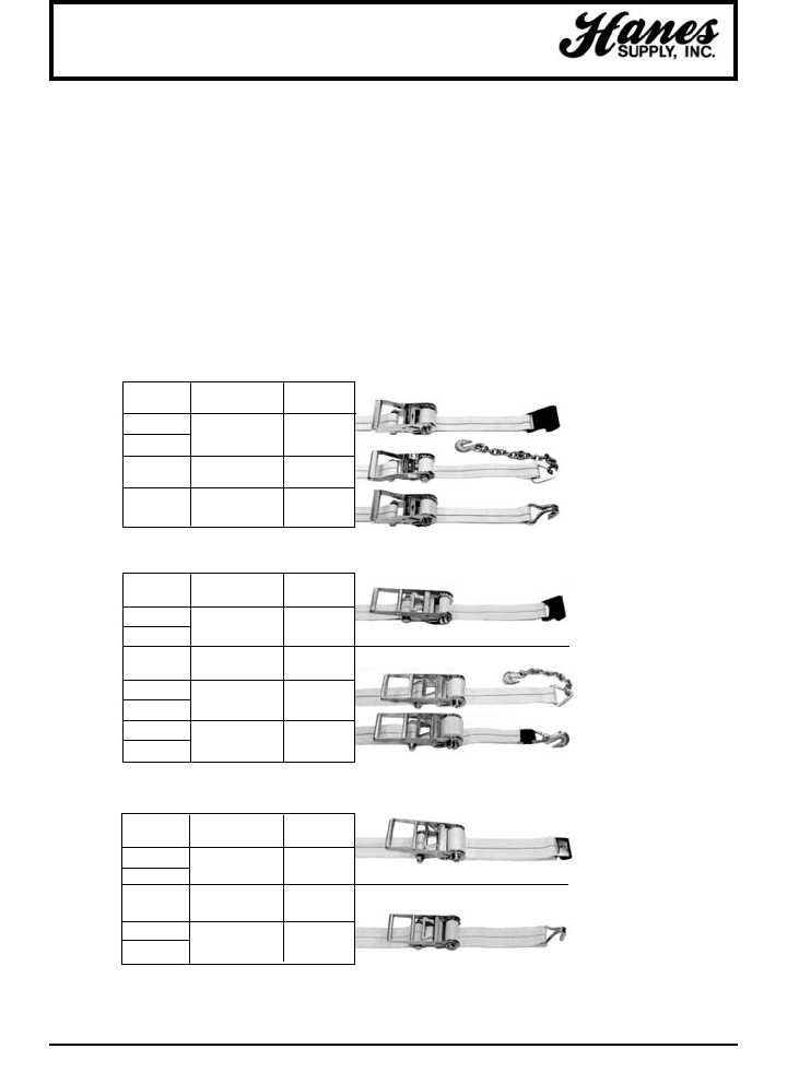
58
HEADQUARTERS: 55 James E. Casey Drive • Buffalo, NY 14206 PHONE: 716.826.2636 FAX: 716.826.4412 www.hanessupply.com
STRAP END
LENGTH HARDWARE WLL
27' 1015 3,335 lbs.
30' Flat Hook 1515 kgs.
27' 3705-2 3,335 lbs.
Chain Anchor 1515 kgs.
27' 1006 3,335 lbs.
Wire Hook 1515 kgs.
Polyester Ratchet Assembly
TRUCKER TIE DOWN AND LASHING EQUIPMENT
RATCHET STRAPS — Designed to handle most types of flatbed tie-down
requirements.
• All straps have an 18" fixed end as standard, except for straps with 3705-2
and 3705-3 chain anchors which have a fixed end of 30." Special length fixed
ends and alternate end hardware available through Hanes Supply.
Labeled to meet CVSA guidelines, DOT regulations and WSTDA
recommended standards.
2" RATCHET STRAP W/804 WIDE HANDLE AND 2004 WEBBING
3" RATCHET STRAP W/806 LONG HANDLE AND 3004 WEBBING
STRAP END
LENGTH HARDWARE WLL
27' 1021-3 5,000 lbs.
30' Flat Hook 2270 kgs.
STRAP END
LENGTH HARDWARE WLL
27' 3705-3 5,400 lbs.
30' Chain Anchor 2450 kgs.
27' 3704 5,400 lbs.
30' Grab Hook 2450 kgs.
15,000 LB. BREAKING STRENGTH
16,200 LB. BREAKING STRENGTH
STRAP END
LENGTH HARDWARE WLL
27' 1021-3 5,000 lbs.
30' Flat Hook 2270 kgs.
STRAP END
LENGTH HARDWARE WLL
27' 1016 6,600 lbs.
30' Wire Hook 2995 kgs.
15,000 LB. BREAKING STRENGTH
20,000 LB. BREAKING STRENGTH
4" RATCHET STRAP W/808 LONG HANDLE AND 4004 WEBBING
10,000 LB. BREAKING STRENGTH
YOUR SLING AND RIGGING SPECIALIST
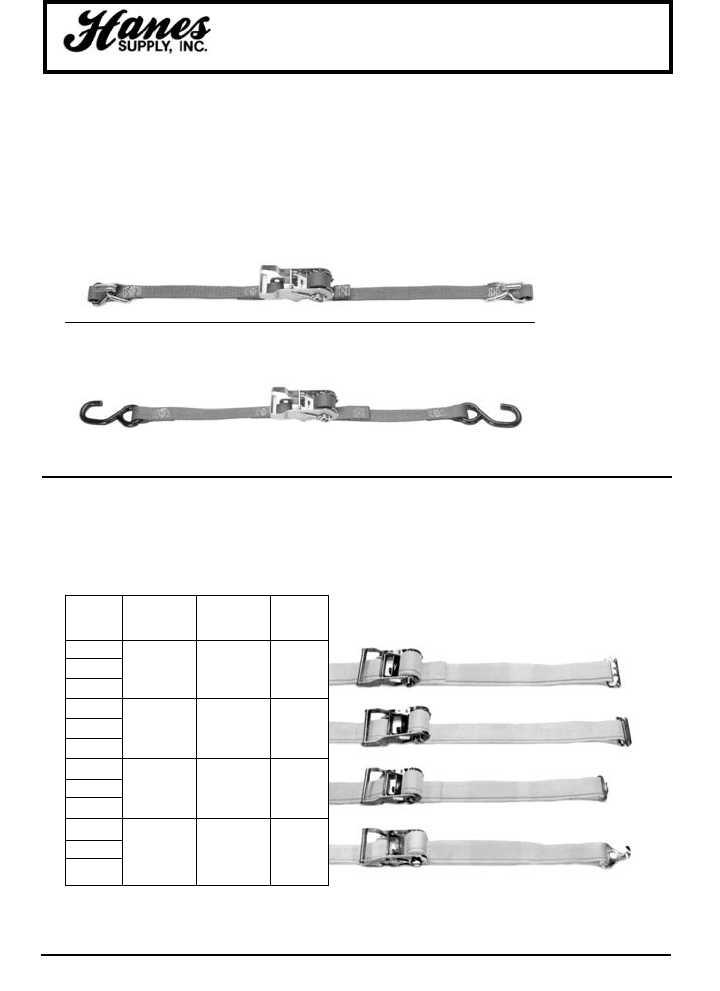
59
HEADQUARTERS: 55 James E. Casey Drive • Buffalo, NY 14206 PHONE: 716.826.2636 FAX: 716.826.4412 www.hanessupply.com
STRAP ASSY.
LENGTH END BREAKING
(FT) HARDWARE STRENGTH WLL
12 Series E, A
16 FE8306-1 3,000 lbs. 1,000 lbs.
20 Spring 1360 kgs. 455 kgs.
Fitting
12 Series E, A
16 43020-1 3,000 lbs. 1,000 lbs.
20 3-Piece 1360 kgs. 455 kgs.
Fitting
12 Series F
16 1831 1,250 lbs. 420 lbs.
20 Butterfly 570 kgs. 195 kgs.
Fitting
12 Series F
16 FE8427-1 2,200 lbs. 735 kgs.
20 Plate Trailer 1000 kgs. 335 kgs.
Hook
2" LOGISTIC STRAPS W / 811 RATCHET BUCKLE AND 4900 WEBBING
LOGISTIC STRAPS — Designed for interior van loading requirements.
• All straps have a 4' fixed end as standard.
• Adjustable ends are sewn captivated.
710987 - 9'
RATCHET STRAP WITH 800 RATCHET AND VINYL COATED S HOOKS
• Breaking Strength: 1,200 lbs. • WLL: 400 lbs.
STRAP-ALL™ STRAPS — Light duty tie-down
711681/45 - 16'
RATCHET STRAP WITH 800 RATCHET, WIRE HOOKS AND D RINGS
• Breaking Strength: 2,500 lbs./1135 kgs. • WLL: 835 lbs./380 kgs.
Polyester Ratchet Assembly
TRUCKER TIE DOWN AND LASHING EQUIPMENT
YOUR SLING AND RIGGING SPECIALIST
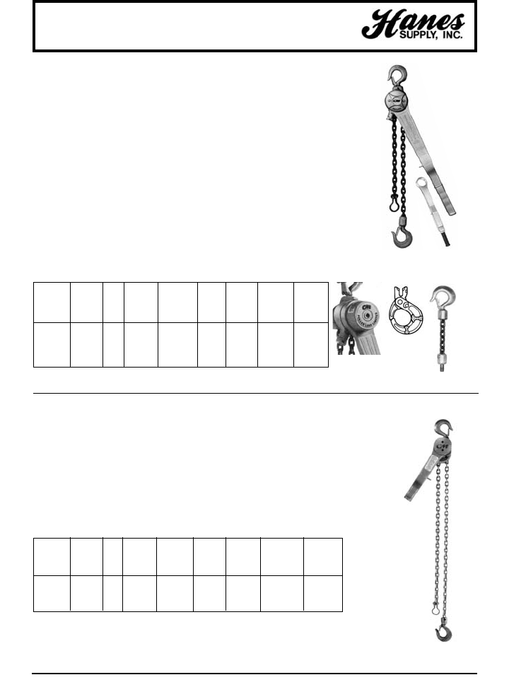
60
HEADQUARTERS: 55 James E. Casey Drive • Buffalo, NY 14206 PHONE: 716.826.2636 FAX: 716.826.4412 www.hanessupply.com
Manual Hoists - Puller
Optional Load
Security
3/4 ton Puller
Shown
Also available
in 1-1/2, 3 & 6
ton capacity
• Free wheeling for fast and easy
attachment to load.
• Upper and lower Latchlok hooks available
for all capacities.
• Optional Load Limiter protection device
stops transmission of lever forces
protecting against dangerous overload.
• Optional anchor sling simplifies attachment
to allow anchor hook to swivel in tight space
applications (3/4 & 1-1/2 ton units only).
• Optional Load Sentry warns of overload
condition.
• Optional shorter lever for 3/4 and 1-1/2 ton
units available.
• Optional zinc-plated chain available.
• Unlimited lift.
• Lifetime warranty.
• Made in U.S.A.
CM Puller is designed for heavy-duty
construction and industrial applications.
Used to pull, lift, drag or stretch, it features:
• Tough aluminum alloy construction and
powder coat finish.
• Weatherproof for outdoor service.
• Simple construction with fewer parts for
ease of maintenance.
• Hoistaloy hardened steel link type load
chain for strength, long wear life and
flexibility.
• Weatherized Weston-type automatic
braking system for positive load control.
• Easy, one-hand operation and control —
only 58 pounds of pull required for 3/4 ton
model capacity.
• Forged upper and lower hooks with
latches standard.
• Free chaining for fast, easy attachment to
load.
• Forged upper and lower hooks with latches.
• Simple construction with fewer parts for
ease of maintenance.
• Optional Load Limiter®device protects
against overload
• Lifetime warranty
• Made in U.S.A.
• Easy one-hand operation.
• Lever pull range is 45 to 62 pounds to lift
full load.
• Handle that rotates 360O, making it easy
to operate in any position and in small
spaces.
• Tough yet lightweight aluminum
construction and powder coat finish.
•CM
®Hoistaloy®hardened steel load chain
for strength, long wear life and flexibility.
CM PULLER
CM SHORT HANDLE PULLER
PULL TO MINIMUM HOOK APPROX.
RATED STD. LIFT FULL DISTANCE LEVER THROAT SHIPPING
CAPACITY PROD. LIFT † LOADS BETWEEN LENGTH OPENINGS WEIGHT
(TONS) CODE (FT) (LBS) HOOKS (IN) (IN) REEVING (IN) (LBS)
3/4 4043 5 58 10-3/4 21-1/4 1 1-1/32 16
1-1/2 4045 5 89 14-1/4 21-1/4 1 1-1/8 16
3 4047 5 95 16-15/16 21-1/4 2 1-7/32 38
6 4050 5 96 21-3/8 21-1/4 4 1-3/4 73
† Can be supplied with lifts longer than 5 feet
PULL TO HOOK MIN. APPROX.
RATED STD. LIFT FULL LEVER THROAT DISTANCE SHIPPING
CAPACITY PRODUCT LIFT LOAD LENGTH OPENING BETWEEN WT.
(TONS) CODE (FT) REEVING (LBS) (IN.) (IN) HOOKS (IN) (LBS)
3/4 7300P 5 1 45 12 1-1/32 12-1/4 16
1-1/2 7320P 5 1 55 16-3/4 1-1/8 14-3/4 27
3 7330P 5 2 62 16-3/4 1-3/16 17-5/8 40
Optional
Load Limiter
Latchlok
type
hook
Optional
anchor
sling
(3/4 &
1-1/2
ton)
3/4 ton Puller
Shown
Also available
in 1-1/2 & 3
ton capacity
Optional kits also available - Load Limiter, Anchor Sling & Latchlok®Hook.
Call Hanes Supply for complete details.
YOUR SLING AND RIGGING SPECIALIST
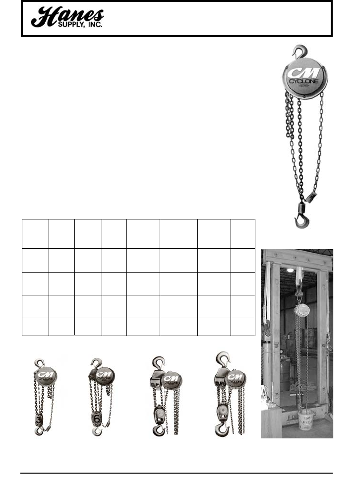
61
HEADQUARTERS: 55 James E. Casey Drive • Buffalo, NY 14206 PHONE: 716.826.2636 FAX: 716.826.4412 www.hanessupply.com
Manual Hoists - Cyclone
CM CYCLONE HAND CHAIN HOIST
One of the most popular and reliable hoists
ever designed, the CM Cyclone combines
superior engineering, efficiency and
durability. Available in a variety of
capacities from 1/4 ton to 10 tons, CM
Cyclone features:
• Most interchangeability of parts in the
industry.
• Standard Load Limiter for simple,
automatic overload protection.
• Enclosed contoured Weston-type
automatic brake for positive load control.
• High-efficiency spur gearing for greater
lift with minimum effort.
• Rugged CM Hoistaloy chain for added
strength and durability.
• Fully machined, forged liftwheel pickets
for easier lifting and smooth free
chaining.
MINIMUM CHAIN
RATED STANDARD DISTANCE OVERHAULED CHAIN PULL SHIPPING
CAPACITY PRODUCT LIFT † BETWEEN TO LIFT LOAD TO LIFT FULL WEIGHT
(TONS) CODE (FT.) REEVING HOOKS (IN.) ONE FOOT (FT.) (LBS.) (LBS.)
1/4 4621 8 1 12-7/8 22-1/2 23 37
1/2 4622 8 1 12-7/8 22-1/2 46 37
1 4624 8 1 14 30 69 40
1-1/2 4625 8 1 17-5/16 40-1/2 80 65
2 4626 8 1 17-5/16 52 83 64
3 4627 8 2 21-1/2 81 85 96
4 4628 8 3 21-1/2 104 88 96
5 4629 8 3 24-1/4 156 75 128
6 4630 8 3 25-1/4 156 90 132
8 4631 8 4 34-1/2 208 89 235
10 4632 8 5 35-1/2 260 95 249
† Can be supplied with longer lifts
• High-strength aluminum alloy castings in
frame and covers.
• Inspected over 75 times to meet or
exceed HMI and ASME/ANSI
performance and safety standards.
• Standard hand chain drop is 2 feet less
than lift, (example: 8 foot lift hoist has 6
foot hand chain drop).
• Chain containers, zinc-plated load and
hand chain, aluminum unwelded hand
chain, Latchlok hooks, bronze hooks,
eye-type suspension, bullard hooks and
units without Load Limiter optional,
depending on capacity.
• Lifetime warranty.
• Made in U.S.A.
3 and 4 Ton
Capacity
5 and 6 Ton
Capacity
8 Ton
Capacity
10 Ton
Capacity
1/4 to 2 Ton
Capacity
Hanes Supply 25 Ton
Capacity Test Stand
YOUR SLING AND RIGGING SPECIALIST
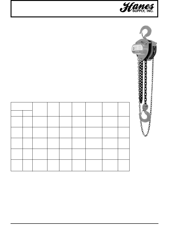
62
HEADQUARTERS: 55 James E. Casey Drive • Buffalo, NY 14206 PHONE: 716.826.2636 FAX: 716.826.4412 www.hanessupply.com
Manual Hoists - LHH
LHH HAND CHAIN HOIST
Coffing LHH Models - Stamped steel hand
chain hoists are an excellent low cost option
in the Coffing line. The compact, lighweight
design is ideal for construction and
contractor applications where portability and
easy rigging are critical.
• Capacities and Lift - Rated loads from 1/2
to 20 tons in stock with standard lifts of
10, 15 and 20 feet. Standard hand chain
drop is 2 feet less than lift. Other lifts and
hand chain drops, and 25 - 50 Ton
models available - Please contact Hanes
Supply for details.
• Compact and Light Weight - Designed for
portability and easy installation. Compact
gear housing provides low headroom.
• Easy to Operate - Lubricated bearings
and bushings, bearing mounted pinions,
*25, 30, 40 and 50 ton models available by special order - contact Hanes Supply for more details.
**Standard lifts shown. Other lifts available - contact Hanes Supply for more details.
† LHH-20 through LHH-50 models have two hand chains.
NOTE: Please contact Hanes Supply for complete dimensional data.
and heat-treated spur gearing ensure
smooth and efficient operation with
minimal effort.
• Safety and Load Control - Mechanical
load brake engages instantly for precise
load holding and positioning. 360 degree
swivel hooks with safety latches for
positive load engagement.
• Durable - Through-hardened load chain
provides added strength and wear
resistance for greater chain life.
Stamped steel housing withstands
rugged conditions.
• Easy to Maintain - Designed for easy
maintenance. Hoist can be dismantled
easily with simple hand tools.
• Lifetime Warranty.
1/4 to 50 Ton
Capacity
STRANDS MINIMUM AVG. NET PULL WT. FOR
CAPACITY OF HEAD- OVERHAUL TO LIFT 10 FT.
LIFTS LOAD ROOM FOR 1 FT. RATED LIFT
(LBS) (TONS) MODEL† (FT)** CHAIN (IN) LIFT (FT) LOAD (LBS) (LBS)
1,000 1/2 LHH-1/2 10/15/20 1 10-1/4 32 55 19
2,000 1 LHH-1 10/15/20 1 11-13/16 56 53 25
3,000 1-1/2 LHH-1-1/2 10/15/20 1 13-9/16 75 65 36
4,000 2 LHH-2 10/15/20 1 15 75 74 45
6,000 3 LHH-3 10/15/20 1 17-1/8 95 84 66
10,000 5 LHH-5 10/15/20 3 22-5/8 203 79 75
16,000 8 LHH-8 10/20 3 32-1/2 312.5 77 158
20,000 10 LHH-12 10/20 3 32-1/2 312.5 95 158
24,000 12 LHH-12 10/20 5 50-5/8 526 84 328
30,000 15 LHH-15 10/20 5 50-5/8 526 103 328
40,000 20 LHH-20 10 6 52-3/8 312.5 x 2 † 99 x 2 † 535
50,000 25* LHH-25 10 8 52-7/8 416.7 x 2 † 97 x 2 † 680
60,000 30* LHH-30 10 10 65 526.3 x 2 † 104 x 2 † 945
80,000 40* LHH-40 10 14 73-5/16 714.3 x 2 † 104 x 2 † 1,400
100,000 50* LHH-50 10 20 77-5/8 1000 x 2 † 104 x 2 † 1,840
YOUR SLING AND RIGGING SPECIALIST
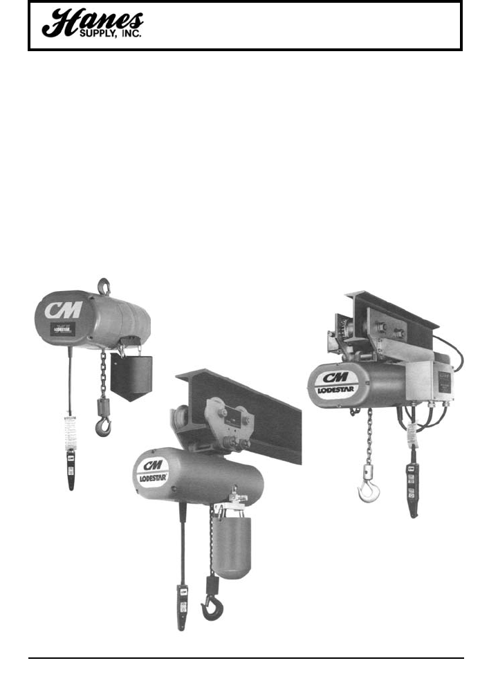
63
HEADQUARTERS: 55 James E. Casey Drive • Buffalo, NY 14206 PHONE: 716.826.2636 FAX: 716.826.4412 www.hanessupply.com
Powered Chain Hoists - Lodestar
The balanced, integrated, proven design of the Lodestar
has made it the most popular electric chain hoist in the
industry. Lodestar gives you more value for your money
including:
• Up to 3 ton capacities for heavy-duty industrial
applications.
• Gear train lifetime lubricated with non-oxidizing grease.
• Precision machined and hardened liftwheel with
hardened chain guides for precise chain liftwheel fit.
• Grearing designed for exceptionally long life and quiet
operation.
• H4 duty standard.
• Rugged control station (NEMA 4).
• Hoist duty motor, standard Protector overload device
and standard screw type limit switches.
• Hardened, forged steel, latch type hooks and Hoistaloy
load chain for long, dependable service.
• Easy to install and maintain.
CM LODESTAR ELECTRIC CHAIN HOIST
• No special tools required to disassemble.
• High reliability and long life.
• Designed for greater productivity, efficiency and
economy.
• Lifetime warranty.
• Each hoist thoroughly inspected and tested to over
125% of rated load prior to shipment.
• Meets ASME B30.16.
• Made in U.S.A.
Special Applications
• Harsh environment hoists available for severe duty of
plating, galvanizing and washdown applications.
• Hoists with climbing capability available for temporary
rigging of lifting applications – must be used in inverted
position only.
• Hoists with creep control allow precise positioning
through field adjustment within the range of
approximately 1/16" to 1/2".
Hook
Suspension
Motorized
Plain Trolley
YOUR SLING AND RIGGING SPECIALIST
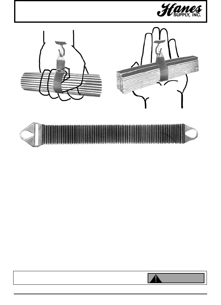
64
HEADQUARTERS: 55 James E. Casey Drive • Buffalo, NY 14206 PHONE: 716.826.2636 FAX: 716.826.4412 www.hanessupply.com
Wire Mesh Slings
Safer than wire rope, gentle as canvas, flexible as manila...that's only a part of the story of the Gripper Sling –
the ultimate in versatile materials handling tools. Like a giant hand, Gripper Slings grasp and hold the load in a
strong, gentle grip when used in a choke hitch... safely and gently cradle it on a broad, flat surface in a basket
hitch.
Whatever the size or shape of the load you handle – rounds, flats, hexes or squares--Gripper Slings can reduce
load damage in production or shipping, provide greater safety for load and operator, cut rigging and unhitching
time and eliminate the need for two-legged slings. Here's how –
NO LOAD DAMAGE – The unique woven wire construction of Gripper Slings consists of a series of smooth,
spiral wires joined together across the body of the sling. This gives the sling complete flexibility, enabling it to
bend easily around even irregularly shaped loads and eliminating the danger of gouging or marring edges of the
load members. For turned or ground surfaces, PVS or Neoprene-covered slings assure extremely delicate
handling.
SAFE – The wide bearing surface of the Gripper Sling provides better load balance and gripping power...less
crushing effect when handling hollow tubing or similar parts. Its instant gripping action means there's no slipping
of shifting when load is applied. All metal construction means there's no core to rot, nothing to tear suddenly.
Gripper Slings will not whip, kink or tangle, and there are no loose strands to snag load or operator. As for
rigging and hitching, a single man can easily do the job.
STRONG – Thousands of spiral wire loops in a transverse construction give Gripper Slings exceptionally long
life. Should a single wire break, the slack is absorbed by the rest of the sling. Gripper Slings are pretested and
guaranteed to meet load specifications. Standard lengths and widths with capacities up to 100,000 lbs. are
available. Special sizes and corrosion resistant alloys available on request.
Inspect before use. Follow OSHA, ANSI B30.9 or Manufacturers Guidelines. Use by untrained
persons is hazardous. Improper use will result in serious injury or death. Do not exceed rated
capacity. This product will fail if damaged, abused, misused, overused or improperly maintained.
LIKE
A GIANT
HAND...
STRONG, GENTLE GRIP – SAFE, SURE BALANCE MAKES
BEST FOR FAST, SAFE, EASY LIFTS
GRIPPER SLINGS
WOVEN
WIRE
WARNING
YOUR SLING AND RIGGING SPECIALIST
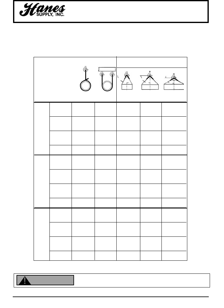
65
HEADQUARTERS: 55 James E. Casey Drive • Buffalo, NY 14206 PHONE: 716.826.2636 FAX: 716.826.4412 www.hanessupply.com
Wire Mesh Slings
EFFECT OF ANGLE ON RATED
CAPACITIES IN BASKET HITCH
NOMINAL
WIDTH OF
SLING VERTICAL 30° VERT. 45° VERT. 60° VERT.
(IN) CHOKER BASKET 60° HORZ. 45° HORZ. 30° HORZ.
2 1,600 3,200 2,700 2,000 1,600
3 3,000 6,000 5,100 3,800 2,800
4 4,400 8,800 7,480 5,600 4,400
G-35 6 6,600 13,200 11,225 8,400 6,600
HEAVY 8 8,800 17,600 15,000 11,250 8,800
DUTY 10 11,000 22,000 18,700 14,000 11,000
12 13,200 26,440 22,440 16,800 13,200
14 15,400 30,800 26,180 19,600 15,400
16 17,600 35,200 29,920 22,400 17,600
18 19,800 39,600 33,660 25,200 19,800
20 22,000 44,000 37,400 28,000 22,000
2 1,450 2,900 2,320 1,740 1,450
3 2,175 4,350 3,700 2,700 2,175
4 2,900 5,800 4,900 3,670 2,900
G-43 6 4,800 9,600 8,150 6,100 4,800
MED. 8 6,400 12,800 10,880 8,100 6,400
DUTY 10 8,000 16,000 13,600 10,200 8,000
12 9,600 19,200 16,300 12,000 9,600
14 11,200 22,400 19,000 14,000 11,200
16 12,800 25,600 21,700 16,200 12,800
18 13,500 27,000 22,900 17,000 13,500
20 15,000 30,000 25,500 19,000 15,000
2 900 1,800 1,600 1,300 900
3 1,400 2,800 2,400 2,000 1,400
4 2,000 4,000 3,500 2,800 2,000
G-59 6 3,000 6,000 5,200 4,200 3,000
LIGHT 8 4,000 8,000 6,900 5,700 4,000
DUTY 10 5,000 10,000 8,600 7,100 5,000
12 6,000 12,000 10,400 8,500 6,000
14 7,000 14,000 12,100 9,900 7,000
16 8,000 16,000 13,900 11,300 8,000
18 9,000 18,000 15,600 12,700 9,000
20 10,000 20,000 17,300 14,100 10,000
SAFETY FACTOR OF 5
HOW TO SELECT PROPER SLING WIDTH
First, determine the hitch you will use for the guage slected. Then read down the column under the selected hitch
and guage to the load weight you wish to lift. Then read across to the first column at left to find sling width
required. Example: You wish to use a G-43 sling in a choke hitch to lift 6,400 poiunds. Sling width required is 8".
Inspect before use. Follow OSHA, ANSI B30.9 or Manufacturers Guidelines. Use by untrained
persons is hazardous. Improper use will result in serious injury or death. Do not exceed rated
capacity. This product will fail if damaged, abused, misused, overused or improperly maintained.
60°
30°
45°
45°
30°
60°
WARNING
YOUR SLING AND RIGGING SPECIALIST
66
HEADQUARTERS: 55 James E. Casey Drive • Buffalo, NY 14206 PHONE: 716.826.2636 FAX: 716.826.4412 www.hanessupply.com
Rope Slings
RATED CAPACITY IN POUNDS (SAFETY FACTOR = 5)
EYE AND EYE SLING ENDLESS SLING
NOM. BASKET HITCH BASKET HITCH
ROPE WGT. MIN. ANGLE OF ROPE TO HORIZONTAL ANGLE OF ROPE TO HORIZONTAL
DIA. PER BREAK 90° 60° 45° 30° 90° 60° 45° 30°
NOM. 100 FT. STRENGTH VERT. CHOKER ANGLE OF ROPE TO VERTICAL VERT CHOKER ANGLE OF ROPE TO VERTICAL
(IN.) (LBS.) (LBS.) HITCH HITCH 0° 30° 45° 60° HITCH HITCH 0° 30° 45° 60°
1/2 7.5 2,650 550 250 1,100 900 750 550 950 500 1,900 1,700 1,400 950
9/16 10.4 3,450 700 350 1,400 1,200 1,000 700 1,200 600 2,500 2,200 1,800 1,200
5/8 13.3 4,400 900 450 1,800 1,500 1,200 900 1,600 800 3,200 2,700 2,200 1,600
3/4 16.7 5,400 1,100 550 2,200 1,900 1,500 1,100 2,000 950 3,900 3,400 2,800 2,000
13/16 19.5 6,500 1,300 650 2,600 2,300 1,800 1,300 2,300 1,200 4,700 4,100 3,300 2,300
7/8 22.5 7,700 1,500 750 3,100 2,700 2,200 1,500 2,800 1,400 5,600 4,800 3,900 2,800
1 27.0 9,000 1,800 900 3,600 3,100 2,600 1,800 3,200 1,600 6,500 5,600 4,600 3,200
1-1/16 31.3 10,500 2,100 1,100 4,200 3,600 3,000 2,100 3,800 1,900 7,600 6,600 5,400 3,800
1-1/8 36.0 12,000 2,400 1,200 4,800 4,200 3,400 2,400 4,300 2,200 8,600 7,500 6,100 4,300
1-1/4 41.7 13,500 2,700 1,400 5,400 4,700 3,800 2,700 4,900 2,400 9,700 8,400 6,900 4,900
1-5/16 47.9 15,000 3,000 1,500 6,000 5,200 4,300 3,000 5,400 2,700 11,000 9,400 7,700 5,400
1-1/2 59.9 18,500 3,700 1,850 7,400 6,400 5,200 3,700 6,700 3,300 13,500 11,500 9,400 6,700
1-5/8 74.6 22,500 4,500 2,300 9,000 7,800 6,400 4,500 8,100 4,100 16,000 14,000 11,500 8,000
1-3/4 89.3 36,500 5,300 2,700 10,500 9,200 7,500 5,300 9,500 4,800 19,000 16,500 13,500 9,500
2 107.5 31,000 6,200 3,100 12,500 10,500 8,800 6,200 11,000 5,600 22,500 19,500 16,000 11,000
2-1/3 125.0 36,000 7,200 3,600 14,500 12,500 10,000 7,200 13,000 6,500 26,000 22,500 18,500 13,000
2-1/4 146.0 41,000 8,200 4,100 16,500 14,000 11,500 8,200 15,000 7,400 29,500 25,500 21,000 15,000
2-1/2 166.7 46,500 9,300 4,700 18,500 16,000 13,000 9,300 16,500 8,400 33,500 29,000 23,500 16,500
2-5/8 190.8 52,000 10,500 5,200 21,000 18,000 14,500 10,500 18,500 9,500 37,500 32,500 26,500 18,500
MANILA ROPE SLINGS
Table H-15
NYLON ROPE SLINGS
Table H-16
RATED CAPACITY IN POUNDS (SAFETY FACTOR = 5)
EYE AND EYE SLING ENDLESS SLING
NOM. BASKET HITCH BASKET HITCH
ROPE WGT. MIN. ANGLE OF ROPE TO HORIZONTAL ANGLE OF ROPE TO HORIZONTAL
DIA. PER BREAK 90° 60° 45° 30° 90° 60° 45° 30°
NOM. 100 FT. STRENGTH VERT. CHOKER ANGLE OF ROPE TO VERTICAL VERT CHOKER ANGLE OF ROPE TO VERTICAL
(IN.) (LBS.) (LBS.) HITCH HITCH 0° 30° 45° 60° HITCH HITCH 0° 30° 45° 60°
1/2 6.5 6,080 700 350 1,400 1,200 950 700 1,200 600 2,400 2,100 1,700 1,200
9/16 8.3 7,600 850 400 1,700 1,500 1,200 850 1,500 750 3,000 2,600 2,200 1,500
5/8 10.5 9,800 1,100 550 2,200 1,900 1,600 1,100 2,000 1,000 4,000 3,400 2,800 2,000
3/4 14.5 13,490 1,500 750 3,000 2,600 2,100 1,500 2,700 1,400 5,400 4,700 3,800 2,700
13/16 17.0 16,150 1,800 900 3,600 3,100 2,600 1,800 3,200 1,600 6,400 5,600 4,600 3,200
7/8 20.0 19,000 2,100 1,100 4,200 3,700 3,000 2,100 3,800 1,900 7,600 6,600 5,400 3,800
1 26.0 23,750 2,600 1,300 5,300 4,600 3,700 2,600 4,800 2,400 9,500 8,200 6,700 4,800
1-1/16 29.0 27,360 3,000 1,500 6,100 5,300 4,300 3,000 5,500 2,700 11,000 9,500 7,700 5,500
1-1/8 34.0 31,350 3,500 1,700 7,000 6,000 5,000 3,500 6,300 3,100 12,500 11,000 8,900 6,300
1-1/4 40.0 35,625 4,000 2,000 7,900 6,900 5,600 4,000 7,100 3,600 14,500 12,500 10,000 7,100
1-5/16 45.0 40,850 4,500 2,300 9,100 7,900 6,400 4,500 8,200 4,100 16,500 14,000 12,000 8,200
1-1/2 55.0 50,530 5,600 2,800 11,000 9,700 7,900 5,600 10,000 5,000 20,000 17,500 14,000 10,000
1-5/8 68.0 61,750 6,900 3,400 13,500 12,000 9,700 6,900 12,500 6,200 24,500 21,500 17,500 12,500
1-3/4 83.0 74,100 8,200 4,100 16,500 14,500 11,500 8,200 15,000 7,400 29,500 27,500 21,000 15,000
2 95.0 87,400 9,700 4,900 19,500 17,000 13,500 9,700 17,500 8,700 35,000 30,500 24,500 17,500
2-1/8 109.0 100,700 11,000 5,600 22,500 19,500 16,000 11,000 20,000 10,000 40,500 35,000 28,500 20,000
2-1/4 129.0 118,750 13,000 6,600 26,500 23,000 18,500 13,000 24,000 12,000 47,500 41,000 33,500 24,000
2-1/2 149.0 133,000 15,000 7,400 29,500 25,500 21,000 15,000 26,500 13,500 53,000 46,000 37,500 26,500
2-5/8 168.0 153,900 17,100 8,600 34,000 29,500 24,000 17,000 31,000 15,500 61,500 53,500 43,500 31,000
YOUR SLING AND RIGGING SPECIALIST
67
HEADQUARTERS: 55 James E. Casey Drive • Buffalo, NY 14206 PHONE: 716.826.2636 FAX: 716.826.4412 www.hanessupply.com
Synthetic Rope Slings
RATED CAPACITY IN POUNDS (SAFETY FACTOR = 5)
EYE AND EYE SLING ENDLESS SLING
NOM. BASKET HITCH BASKET HITCH
ROPE WGT. MIN. ANGLE OF ROPE TO HORIZONTAL ANGLE OF ROPE TO HORIZONTAL
DIA. PER BREAK 90° 60° 45° 30° 90° 60° 45° 30°
NOM. 100 FT. STRENGTH VERT. CHOKER ANGLE OF ROPE TO VERTICAL VERT CHOKER ANGLE OF ROPE TO VERTICAL
(IN.) (LBS.) (LBS.) HITCH HITCH 0° 30° 45° 60° HITCH HITCH 0° 30° 45° 60°
1/2 8.0 6,080 700 350 1,400 1,200 950 700 1,200 600 2,400 2,100 1,700 1,200
9/16 10.2 7,600 850 400 1,700 1,500 1,200 850 1,500 600 2,400 2,100 1,700 1,200
5/8 13.0 9,500 1,100 550 2,100 1,800 1,500 1,100 1,900 950 3,800 3,300 2,700 1,900
3/4 17.5 11,875 1,300 650 2,600 2,300 1,900 1,300 2,400 1,200 4,800 4,100 3,400 2,400
13/16 21.0 14,725 1,600 800 3,300 2,800 2,300 1,600 2,900 1,500 5,900 5,100 4,200 2,900
7/8 25.0 17,100 1,900 950 3,800 3,300 2,700 1,900 3,400 1,700 6,800 5,900 4,800 3,400
1 30.5 20,900 2,300 1,200 4,600 4,000 3,300 2,300 4,200 2,100 8,400 7,200 5,900 4,200
1-1/16 34.5 24,225 2,700 1,300 5,400 4,700 3,800 2,700 4,800 2,400 9,700 8,400 6,900 4,800
1-1/8 40.0 28,025 3,100 1,600 6,200 5,400 4,400 3,100 5,600 2,800 11,000 9,700 7,900 5,600
1-1/4 46.3 31,540 3,500 1,800 7,000 6,100 5,000 3,500 6,300 3,200 12,500 11,000 8,900 6,300
1-5/16 52.5 35,625 4,000 2,000 7,900 6,900 5,600 4,000 7,100 3,600 14,500 12,500 10,000 7,100
1-1/2 66.8 44,460 4,900 2,500 9,900 8,600 7,000 4,900 8,900 4,400 18,000 15,500 12,500 8,900
1-5/8 82.0 54,150 6,000 3,000 12,000 10,400 8,500 6,000 11,000 5,400 21,500 19,000 15,500 11,000
1-3/4 82.0 64,410 7,200 3,600 14,500 12,500 10,000 7,200 13,000 6,400 26,000 22,500 18,000 13,000
2 118.0 76,000 8,400 4,200 17,000 14,500 12,000 8,400 15,000 7,600 30,500 26,500 21,500 15,000
2-1/8 135.0 87,400 9,700 4,900 19,500 17,000 13,500 9,700 17,500 8,700 35,000 30,500 24,500 17,500
2-1/4 157.0 101,650 11,500 5,700 22,500 19,500 16,000 11,500 20,500 10,000 40,500 35,000 29,000 20,500
2-1/2 181.0 115,900 13,000 6,400 26,000 22,500 18,000 13,000 23,000 11,500 46,500 40,000 33,000 23,000
2-5/8 205.0 130,150 14,500 7,200 29,000 25,000 20,500 14,500 26,000 13,000 52,000 45,000 37,000 26,000
POLYESTER ROPE SLINGS
Table H-17
POLYPROPYLENE ROPE SLINGS
Table H-18
RATED CAPACITY IN POUNDS (SAFETY FACTOR = 5)
EYE AND EYE SLING ENDLESS SLING
NOM. BASKET HITCH BASKET HITCH
ROPE WGT. MIN. ANGLE OF ROPE TO HORIZONTAL ANGLE OF ROPE TO HORIZONTAL
DIA. PER BREAK 90° 60° 45° 30° 90° 60° 45° 30°
NOM. 100 FT. STRENGTH VERT. CHOKER ANGLE OF ROPE TO VERTICAL VERT CHOKER ANGLE OF ROPE TO VERTICAL
(IN.) (LBS.) (LBS.) HITCH HITCH 0° 30° 45° 60° HITCH HITCH 0° 30° 45° 60°
1/2 4.7 3,900 650 350 1,300 1,200 950 650 1,200 600 2,400 2,100 1,700 1,200
9/16 6.1 4,845 800 400 1,600 1,400 1,100 650 1,200 600 2,400 2,100 1,700 1,200
5/8 7.5 5,890 1,000 500 2,000 1,700 1,400 1,000 1,800 900 3,500 3,100 2,500 1,800
3/4 10.7 8,075 1,300 700 2,700 2,300 1,900 1,300 2,400 1,200 4,900 4,200 3,400 2,400
13/16 12.7 9,405 1,600 800 3,100 2,700 2,200 1,600 2,800 1,400 5,600 4,900 4,000 2,800
7/8 15.0 10,925 1,800 900 3,600 3,200 2,600 1,800 3,300 1,600 6,600 5,700 4,600 3,300
1 18.0 13,300 2,200 1,100 4,400 3,800 3,100 2,200 4,000 2,000 8,000 6,900 5,600 4,000
1-1/16 20.4 15,200 2,500 1,300 5,100 4,400 3,600 2,500 4,600 2,300 9,100 7,900 6,500 4,600
1-1/8 23.7 17,385 2,900 1,500 5,800 5,000 4,100 2,900 5,200 2,600 10,500 9,000 7,400 5,200
1-1/4 27.0 19,950 3,300 1,700 6,700 5,800 4,700 3,300 6,000 3,000 12,000 10,500 8,500 6,000
1-5/16 30.5 22,325 3,700 1,900 7,400 6,400 5,300 3,700 6,700 3,400 13,500 11,500 9,500 6,700
1-1/2 38.5 28,215 4,700 2,400 9,400 8,100 6,700 4,700 8,500 4,200 17,000 14,500 12,000 8,500
1-5/8 47.5 34,200 5,700 2,900 11,500 9,900 8,100 5,700 10,500 5,100 20,500 18,000 14,500 10,500
1-3/4 57.0 40,850 6,800 3,400 13,500 12,000 9,600 6,800 12,500 6,100 24,500 21,000 17,500 12,500
2 69.0 49,400 8,200 4,100 16,500 14,500 11,500 8,200 15,000 7,400 29,500 25,500 21,500 15,000
2-1/8 80.0 57,950 9,700 4,800 19,500 16,500 13,500 9,700 17,500 8,700 35,000 30,100 24,500 17,500
2-1/4 92.0 65,550 11,000 5,500 22,000 19,000 15,500 11,000 19,500 9,900 39,500 34,000 28,000 19,500
2-1/2 107.0 76,000 12,500 6,300 25,500 22,000 18,000 12,500 23,000 11,500 45,500 39,500 32,500 23,000
2-5/8 120.0 85,500 14,500 7,100 28,500 24,500 20,000 14,500 25,500 13,000 51,500 44,500 36,500 25,500
YOUR SLING AND RIGGING SPECIALIST
68
HEADQUARTERS: 55 James E. Casey Drive • Buffalo, NY 14206 PHONE: 716.826.2636 FAX: 716.826.4412 www.hanessupply.com
Rope Specifications
POLYPRO NYLON POLYESTER MANILA
DIA. CIR. LBS. FEET BRK. LBS. FEET BRK. LBS. FEET BRK. LBS. FEET BRK.
(IN.) (IN.) PER PER STGTH. PER PER STGTH. PER PER STGET. PER PER STGTH.
100' LB. (LBS.) 100' LB. (LBS.) 100' LB. (LBS.) 100' LB. (LBS.)
3/16 5/8 .75 133.0 800 1.0 100.0 1,000 1.2 83.4 850 1.5 66.7 450
1/4 3/4 1.2 83.4 1,250 1.5 66.7 1,650 2.0 50.0 1,650 2.0 50.0 600
5/16 1 1.8 55.6 1,900 2.5 40.0 2,550 3.1 32.2 2,550 3.0 35.0 1,000
3/8 1-1/8 2.8 35.7 2,700 3.5 28.5 3,700 4.5 22.2 3,700 4.0 25.0 1,350
7/16 1-1/4 3.8 26.3 3,500 5.0 20.0 5,000 6.2 16.1 5,000 5.3 19.0 1,750
1/2 1-1/2 4.7 21.3 4,200 6.5 15.4 6,400 8.0 12.5 6,400 7.5 13.3 2.650
5/8 2 7.5 13.3 6,200 10.5 9.5 10,400 13.0 7.7 10,000 13.3 7.5 4,400
3/4 2-1/4 10.7 9.3 8,500 14.5 6.9 14,000 17.5 5.7 12,500 16.7 6.0 5,400
7/8 2-3/4 15.0 6.7 11,500 20.0 5.0 20,000 25.0 4.0 18,000 22.0 4.5 7,700
1 3 18.0 5.5 14,000 26.0 3.8 25,000 30.5 3.3 22,000 27.0 3.7 9,000
1-1/8 3-1/2 23.7 4.2 18,300 34.0 2.9 33,000 40.0 2.5 29,500 36.0 2.8 12,000
1-1/4 3-3/4 27.0 3.7 21,000 40.0 2.5 37,500 46.3 2.5 33,200 42.0 2.4 13,500
1-5/16 4 30.5 3.3 23,500 45.0 2.2 43,000 52.5 1.9 37,500 48.0 2.2 –
1-1/2 4-1/2 38.5 2.6 29,700 55.0 1.8 53,000 66.8 1.5 46,800 60.0 1.7 18,500
1-5/8 5 47.5 2.1 36,000 68.0 1.5 65,000 82.0 1.2 57,000 75.0 1.3 22,500
1-3/4 5-1/2 57.0 1.7 43,000 83.0 1.2 78,000 98.0 1.02 67,800 90.0 1.1 26,500
2 6 69.0 1.4 53,000 95.0 1.1 92,000 118.0 .85 75,000 108.0 .93 31,000
2-1/8 6-1/2 80.0 1.2 62,000 109.0 .92 105,000 135.0 .75 81,000 125.0 .79 36,000
2-1/4 7 92.0 1.1 70,000 129.0 .77 125,000 157.0 .64 96,000 146.0 .69 41,000
2-1/2 7-1/2 107.0 .93 80,500 150.0 .67 138,000 181.0 .55 110,000 167.0 .59 46,500
2-5/8 8 120.0 .83 90,000 168.0 .59 154,000 205.0 .49 125,000 191.0 .53 52,000
2-7/8 8-1/2 137.0 .73 100,000 189.0 .53 173,000 230.0 .43 140,000 213.0 .47 58,000
3 9 153.0 .65 116,000 210.0 .47 195,000 258.0 .39 158,000 242.0 .42 64,000
3-1/4 10 190.0 .52 137,000 263.0 .38 238,000 319.0 .31 190,000 299.0 .33 77,000
3-1/2 11 232.0 .43 162,000 316.0 .31 288,000 384.0 .26 230,000 367.0 .28 91,000
4 12 275.0 .36 190,000 379.0 .26 342,000 460.0 .21 275,000 436.0 .23 105,000
ROPE SPECIFICATIONS
THREE STRAND AND EIGHT STRAND – STANDARD LAY ROPES
YOUR SLING AND RIGGING SPECIALIST
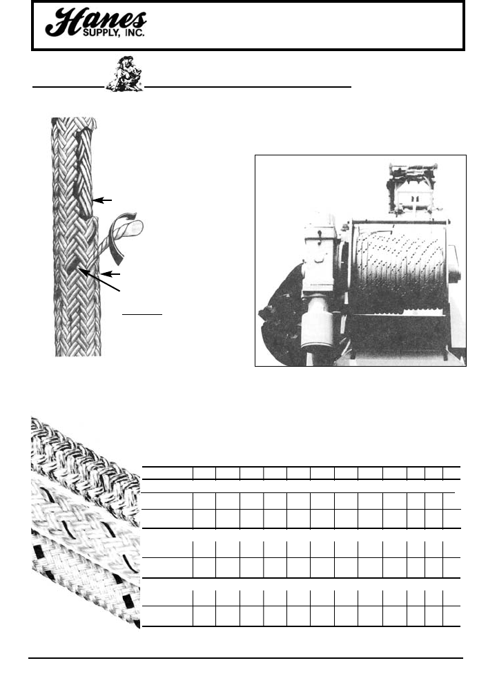
69
HEADQUARTERS: 55 James E. Casey Drive • Buffalo, NY 14206 PHONE: 716.826.2636 FAX: 716.826.4412 www.hanessupply.com
Winch Lines
USAGE / MAINTENANCE GUIDE
2-in-1®DOUBLE BRAIDED ROPE
Samson 2-IN1®Double Braided Rope is
actually two ropes in one. First the
braided core is constructed. A second
rope is then braided over it to form the
cover. You then have two ropes
performing as a single integrated
strength member. By altering the
construction of the core and/or cover, it
is possible to engineer a rope with
specific performance characteristics.
Braided Core Rope
Parallay®Design
is a twisting and braiding
process that orients all the
fibers parallel to the axis of
the rope.
Braided Cover Rope
Samson Product Identification
Tracer
SIZE (Dia.) 1/2" 9/16" 5/8" 3/4" 13/16" 7/8" 1" 1-1/8" 1-1/4" 10% 20% 30%
STABLE BRAID
Approx. Avg. 9,870 12,600 15,500 19,400 28,400 37,200 45,800 54,400 1.1 1.7 2.7
Tensile Lbs.
Approx. Wgt. 8.5 10.9 13.7 17.2 25.9 34.4 42.7 51.2
Per 100 Ft. Lbs.
NYSTROM
Approx. Avg. 10,500 13,200 16,300 23,000 30,800 40,400 49,800 59,100 3.7 5.3 6.9
Tensile Lbs.
Approx. Wgt. 7.7 10.0 12.6 17.3 23.7 31.5 39.2 46.9
Per 100 Ft. Lbs.
SPECTRON II
Approx. Avg. 15,500 22,000 27,000 35,000 40,000 50,000 57,000 72,900 81,000 .57 .76 .92
Tensile Lbs.
Approx. Wgt. 8.1 9.8 12.3 15.7 19.9 24.3 27.8 34.6 40.2
Per 100 Ft. Lbs.
WINCH LINE SELECTION GUIDE ELASTIC
ELONGATION*
STABLE BRAID
NYSTROM
SPECTRON II
*Elastic Elongation after 50 Cycles from 2000D2
For Example:
STABLE BRAID
•Balanced construction – core and
cover share the load equally
NYSTRON
•Fiber selection – different fiber
combinations in the core and cover
to meet specific performance
requirements
SPECTRON II
• Imbalanced construction – core and
cover have different load sharing
capabilities.
• Coatings may be applied to selected
sections or to continuous long
lengths.
YOUR SLING AND RIGGING SPECIALIST
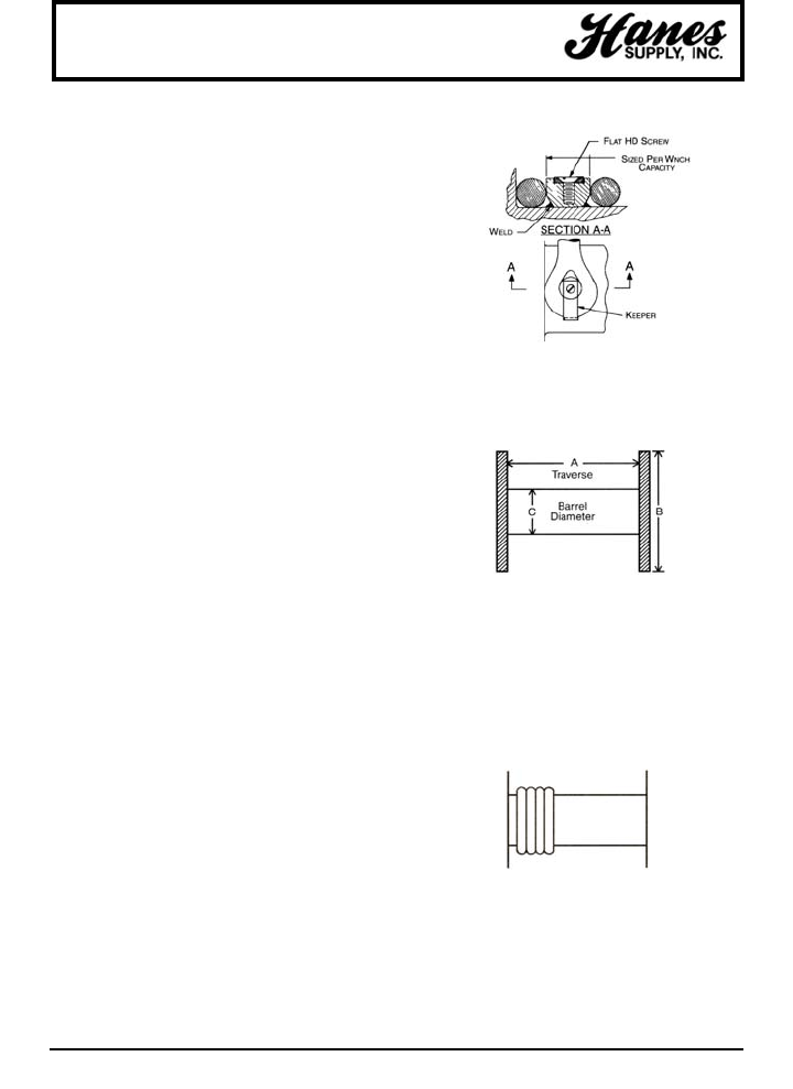
70
HEADQUARTERS: 55 James E. Casey Drive • Buffalo, NY 14206 PHONE: 716.826.2636 FAX: 716.826.4412 www.hanessupply.com
Do not attach end of line to drum by using core only.
DETERMINING LENGTH OF ROPE THAT CAN BE
PUT ON A WINCH
The formula for rope capacity on a winch drum is:
Length to be stored = A(B2 - C2)
15.3 x dia of rope 2
A, B, C, and diameter are in inches.
END-FOR-ENDING
It is recommended that every winch line be rotated End-forEnd
on a periodic basis. This will vary high stress and wear point and
extend useful life. Recommended period is six (6) months, at
which time visual inspection and washing can be programmed.
WINDING ROPE ON WINCH DRUM
The first layer (wrap) around winch drum should be put on
closely and tightly. Initial winding tension (load) should be
approximately 50 pounds. This will prevent subsequent wraps
from slipping down between turns when tension is applied.
Samson Winch Lines will tend to self-level themselves.
IMPORTANT: Recommend at least four wraps always be left on
winch drum.
ABRASION PROTECTION OF LINE
Stable Braid, Nyston, and Spectron II, with their outer jacket of
Polyester, have a relatively high degree of resistance to abrasion
and fusing. However, all synthetics are subject to fusing if
subjected to enough friction and heat, and therefore such
practices as surging on a Gypsy head winch, hard rendering
around poles or over cross-arms, etc. should be avoided
whenever possible.
GUIDELINES FOR THE USE
OF SAMSON WINCH LINES
ROPE STRENGTH
Note carefully the quoted breaking strengths of the various
Samson Braid sizes. These are approximate average breaking
strengths and are subject to a plus or minus 5% testing
tolerance. Advertised breaking strengths are determined by the
standard cordage testing and do not cover conditions such as
sustained loads or shock loading. These strengths are attained
under laboratory conditions. Remember also, that this is a
breaking strength--not a recommended working load capacity.
(See next paragraph for working load factors.)
ASSIGNED WORKING LOAD FACTORS
Will vary in accordance with varying safety practices and policies
of different utilities and industrial users. However, our
recommendation, and one that is fairly well accepted in the
industry, is a minimum 5:1 working load factor. Thus, your
maximum work load should be approximately 20% of the quoted
breaking strength. This factor will provide greater safety and
extended service life of the winch line. A low working load factor
is not only dangerous, but poor economy as it overworks the
fibers and shortens the life of the line.
DIELECTRIC PROPERTIES
Samson Stable Braid, Nystron, and Spectron II have been
described as a "non-conductor". It is our hope that it is never
turned over to a line crew on these terms. It is important to note
that most quoted Dielectric Properties are results obtained from
new, clean rope, and hold true only under such ideal conditions.
Dirt, grease, other foriegn matter and moisture, including
humidity, will all alter the non-conductivity/conductivity of this or
any other synthetic rope or material.
SHARP CUTTING EDGES
Samson winch lines should not be exposed to sharp edges and
surface such as metal burrs on Winch Drums, sheaves,
shackles, thimbles, wire slings, etc. Samson Winch Lines are
made from synthetic fibers, and as such, can be cut and
damaged by sharp edges. When installing winch lines on old
truck units, great care must be exercised to assure that the rope
is not coming in contact with hardware that has been scored and
chewed by previously used wire lines. Sheaves, shackles,
thimbles, etc. should, in most cases, be replaced. Other metal
surfaces should be carefully examined and dressed if necessary.
ATTACHING LINE TO WINCH DRUM
There are various methods of attaching a winch line to a winch
drum: the use of a wedge or plug and set screw in the main body
of the drum, or "U" bolt through the side of the flange. Another
method involves welding a round plug to the winch drum. The
soft eye at the bitter end of the winch line is placed over the plug
and held in place with a flat keeper which is screwed in flush with
the top of the plug. Be sure the attachment method does not
have a sharp edge that will cut the line under load. If possible, it
is advisable to have an eye splice in both ends of the Winch Line
so that it can be reversed in the event of damage to one end.
This is not always possible, depending on the method of
attachment to the winch drum, and whether or not a closed
thimble is spliced into the eye. If an eye is not used at the drum
end, then this end should be tightly whipped with a strong twine.
Important: The end connection is not designed to carry any load,
so at least four wraps should always be kept on the drum.
Winch Lines
Flange
Diameter
DO NOT WORK
BELOW 4 TURNS
ON A DRUM
YOUR SLING AND RIGGING SPECIALIST
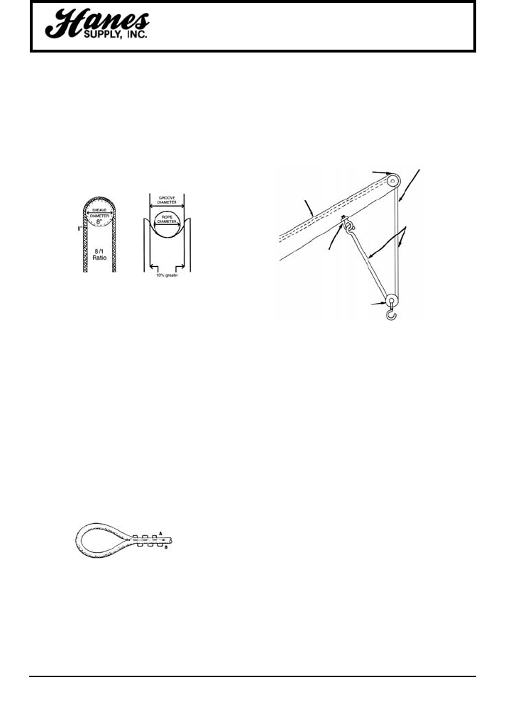
71
HEADQUARTERS: 55 James E. Casey Drive • Buffalo, NY 14206 PHONE: 716.826.2636 FAX: 716.826.4412 www.hanessupply.com
Winch Lines
"DOUBLE BLOCK" SYSTEM
For handling heavy loads (up to 14,880 lbs. – pad-mounted
transformers, etc.) using 1" diameter Stable Braid winch lines,
without exceeding R.W.L. of rope (7,440 lbs.), a Double Block
System is recommended.
The system avoids the use of 1-1/4" diameter Stable Braid,
which limits capacity of winch drum and/or sheave-size.
NOTE: Unless boom is equipped with "pole-grabber" claws –
this system does not work well – when handling and setting
poles – as pole can't be snubbed tightly against jaws at end of
boom.
The result is that 1" diameter Stable Braid can be used – with a
single leg, for most normal lifting operations – (up to 7,440 lbs.)
– and for heavy lifts up to 14,880 lbs.) using the double leg
system – in both cases, observing approximate recommended
work loads.
ULTRAVIOLET – STRENGTH DEGRADATION
Prolonged exposure of synthetic ropes to Ultraviolet Radiation of
sunlight causes varying degrees of strength degradation. Some
concern has been created by various reports published on this
subject (and by erroneous interpretations drawn from these
reports).
Polyester fibers are the least affected by ultraviolet exposure,
and resulting strength degradation of exposed fibers is
negligible.
Nylon is more susceptible to strength loss due to ultraviolet rays;
but, with both fibers, the degree of susceptibility to ultraviolet
damage is dependent upon the type of fiber, and the various
ultraviolet inhibitors with which they are treated by the fiber
manufacturer.
The important point to note here is that ultraviolet rays have low
penetration in synthetic fibers, thus it is only the outer surface
fibers that are affected.
HARMFUL CHEMICALS
Certain chemicals will break down synthetic fibers. To be
avoided are sulfuric acids, alkalies, or chlorinate hydrocarbons
over 160°F; strong cleaning agents or bleaches may be harmful.
Boom-tip winch drum
(or sheave-leading from
base-mounted-winch)
Derrick-boom-rated @ 14,520 lbs. max.
(bare drum) – elevated @ 70°
from horizontal.
1" dia. rope
(stable Braid)
7,440 lb. RWL
(one-leg)
2-legs = 14,880 RWL –
compatible with boom
max. capacity: ie., Rope
cannot be overloaded –
beyond rope RWL
Boom drilled for eye-bolt
(permanently installed) –
to accomodate standard
winch-line hook – as
needed.
Removable Nylite "Snatch-Block" –
stored in truck, for quick installation
and removal – as needed.
Note: While the 2-leg
system does allow use
of 1" dia. rope (vs 1-1/4"
dia.) – it does require a
greater length and
results in slower lifting
speeds.
THE USE OF SLINGS WITH A WINCH LINE
The winch line itself should not be used as a choker to pick up a
pole or other objects. The hook attached on the end of the wind
line can cut deeply into the rope itself. We recommend a
separate line, sling or strap be used as the choker and not the
basic winch line itself.
BOOM SHEAVE RECOMMENDATIONS
To assure maximum efficiency and safety, the boom sheave
diameter should be no less than eight (8) times the rope
diameter. The sheave groove diameter should be no less than
10% greater than the rope diameter, and the groove should be
round in shape – not V-shaped.
EYE SPLICING
Eye splices at the end of winch lines, (if not put in at the factory)
should be done in strict accordance with the steps and
procedures as outlined in the Samson Splicing Manual under
"Standard Eye Splice." This splice can be easily learned and
executed by line crews and shop personnel. Assistance in
splicing instruction is available through Hanes Supply. Training
Splicing Kits, manuals, and tools can be ordered through Hanes
Supply.
The Standard Eye Splice can't be pulled out under tension; it
can, however, be pulled out by hand when in a relaxed state. To
prevent such tampering, it is recommended that stich locking or
a tight seizing be applied to the base or throat of the splice.
When splicing used rope, be sure to refer to the "Special Tips for
Splicing Used Rope" in the Splicing Manual.
KNOTS
Splicing is, by far, the strongest and most efficient means of
attachment. Knots should never be tied in a winch line if it can in
any way be avoided, as knots can reduce the strength of any
rope (or wire) as much as 50%. Also, avoid sharp bends in the
line where possible as this will also greatly reduce strength.
STITCH LOCKING EYE SPLICES
Stitch locking may prove advantageous on some splices to
prevent no-load opening due to mishandling.
Material required – about one (1) fid length of Nylon Whipping
Twine approximately the same size as the strands in the size
rope you are stitch locking. The same strands cut from the rope
you are stitch locking may also be used, but whipping twine is
preferable. Instructions are in the Samson Splicing Manual.
YOUR SLING AND RIGGING SPECIALIST

72
HEADQUARTERS: 55 James E. Casey Drive • Buffalo, NY 14206 PHONE: 716.826.2636 FAX: 716.826.4412 www.hanessupply.com
Winch Lines
CLEANING
Sometimes utilities have adopted the very good practice of
carrying at all times, a spare (clean and dry) winch line enclosed
in a plastic bag, enabling crews in the field to quickly replace a
damaged, soiled or wet winch line. Samson winch lines can be
washed in a mild detergent and warm water, rinsed and air-dried.
The polyester fibers themselves actually absorb only a negligible
amount of water, but water trapped between the fibers should be
squeezed out (by placing the line under tension) and air-dried.
SHOCK LOADING
Shock loading of any line – synthetic, manila, or wire – produces
a drastically different set of physical properties and results as
compared with normal loading. Shock loading, most simply
described, is a "jerking" or "snatching" or a line. Or, a very
sudden change in tension – from a state of relaxation or low load
to one of high load. This results in accelerated wearing.
A typical shock load on a winch line occurs when an object is
lifted vertically with a sudden jerk, or when this load is suddenly
dropped. A 5,000 pound load, under these conditions, may then
"weigh" 30,000 pounds – and break a winch line rated in this
strength range.
A 4" sudden drop – as off a platform – can actually double the
load. Similarly, an over-wrap "falling off" the winch drum can
result in a 50% shock load.
Assume that you have seven identical ropes – each with a
30,000 lb. breaking strength – and you work these ropes daily –
each rope lifting a different load, as below – for example, in a
winch line application:
WORKING NO. OF LIFTS
BREAKING WORKING LOAD BEFORE
STRENGTH LOAD FACTOR FAILURE*
1. 30,000 lbs. 5,000 lbs. 6/1 1,000
2. 30,000 lbs. 6,000 lbs. 5/1 750
3. 30,000 lbs. 7,500 lbs. 4/1 500
4. 30,000 lbs. 10,000 lbs. 3/1 300
5. 30,000 lbs. 15,000 lbs. 2/1 100
6. 30,000 lbs. 20,000 lbs. 1.5/1 25
7. 30,000 lbs. 28,000 lbs. 1.1/1 5
*Relative values only
This illustration clearly shows the higher the Working Load
Factor the greater the Service Life, and the lower the
replacement factor. Thus, a Working Load Factor also related
directly as an "Economy Factor."
Your may turn this around and look at it another way: If you're
always lifting the same weight; then, the stronger the rope (and
higher the Working Load Factor) – the longer the rope will last.
FATIGUE
Synthetic fibers have a "memory." They function similar to metal
(wire) in that they remember and retain the effects of being
overloaded and shock loaded. This is an important reason to
stress winch line procedures which reduce danger of shock
loading... in order to prolong the life of the line and reduce
premature down grading. If there is reason to believe that a line
has been shock loaded above its recommended working load, it
should be logged; and if a number of these occur, the line should
be rotated and inspected.
VISUAL INSPECTION
The load-bearing capacity of Samson Stable Braid and Nystron
Ropes are divided equally between the inner core and the outer
cover – thus, despite damage to the outer cover strands, you
have an intact inner core capable of supporting approximately
50% of the applied load... an important reserve safety factor.
Spectron II has 100% of its load bearing capacity accomplished
by the core.
DISCARD POINT
Continued use and normal wear in the line gradually diminishes
the ultimate bearing strength and lowers the factor of safety. In
determining the proper discard time of Samson winch lines, the
following guides are suggested:
a. If as many as 1/2 of the cover strands are cut at a given
point, this damaged section should be cut out. If within 10 feet
of the eye, put in a new eye splice. If over 10 feet, rejoin the
rope with a Standard End-for-End Splice per the Splice
Manual. The rope can then be put back into normal operation.
A few damaged strands spaced out along the rope at intervals
is no real cause for immediate concern, but should be watched
and periodically examined.
b. If the individual cover strands have been worn down after
extended use to within 50% of their original bulk over an
extended area of the line, then the line should be discarded (or
assigned to a less critical task). This can best be determined
by an examination and comparison of the bulk of an individual
strand which is exposed and subject to wear with the same
strand where it crosses under other strands and is protected
(and therefore is full size).
c. Another guide for determining discard time is when the rope
has a residual strength of 50% of its original new rope
strength. This can be determined through laboratory tensile
strength break tests. This can be done by Hanes Supply. If
utilities wish to perform their own tests, they should contact
Hanes Supply to coordinate testing procedure, methods and
apparatus. Hanes Supply has instructions on technical
procedures for testing braided synthetic ropes.
TRAINING
A Preventative Maintenance and Safety Program in the use of
winch lines is strongly recommended. Hanes Supply will assist
in this.
Samson winch lines, used and cared for properly, will render
years of efficient, economical, and trouble-free service.
Winch line replacements, either in cut lengths or 600 ft. spools
are available through Hanes Supply.
Samson Ocean Systems guarantees its products against
manufacturing defects, but can't be held responsible for failure
or accident due to improper use or failure to observe prescribed
procedures for usage, as set forth above. Write to Samson for
Guidelines on Care, Usage & Inspection of Rope.
YOUR SLING AND RIGGING SPECIALIST
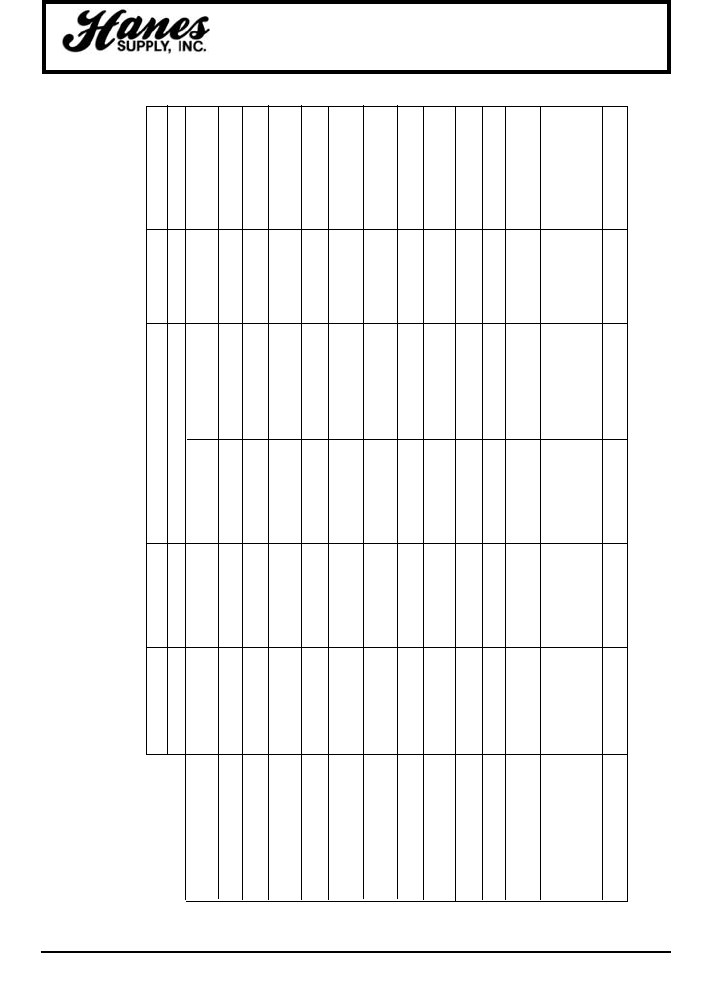
73
HEADQUARTERS: 55 James E. Casey Drive • Buffalo, NY 14206 PHONE: 716.826.2636 FAX: 716.826.4412 www.hanessupply.com
Fiber Characteristics
K-SPEC ARAMID NYLON POLYESTER HMWPE POLYPROPYLENE
FILAMENT TYPE MULTIFILIMENT
STRENGTH 27 23 8.0 - 9.0 6.5 - 9.0 27 6.5 - 8.0
(GRAMS PER DENIER)
SPECIFIC GRAVITY 1.2 1.44 1.14 1.38 .97 .92
ABILITY TO FLOAT SINKS SINKS SINKS SINKS FLOATS FLOATS
ELASTICITY AT 3.6% 3.6% 16% 10 - 12% 3.6% 22 - 28%
STRETCH BREAK
MOISTURE ABSORBENCY .2% OF WEIGHT .5% OF WEIGHT 9% OF WEIGHT 1% OF WEIGHT ZERO ZERO
DECOMPOSES 50% TENSILE AT 200°
EFFECT OF HEAT MELTS AT 300°F MELTS AT 482°F MELTS AT 482°F MELTS AT 297°F
AT 800°F MELTS AT 330°F
EFFECT OF SUNLIGHT TPX TP & SE WEB WEB TPX UP TO 50%
ON SLINGS NONE NONE UP TO 50% UP TO 50% NONE
EFFECT OF AGE NONE NONE NONE NONE NONE NEGLIGIBLE
RESISTANCE TO EXCELLENT GOOD FAIR VERY GOOD EXCELLENT EXCELLENT
CHEMICALS AND ACIDS
TO AKLALIS EXCELLENT GOOD EXCELLENT VERY GOOD EXCELLENT GOOD
TO SOLVENTS EXCELLENT GOOD GOOD VERY GOOD EXCELLENT GOOD
100% 100% 100% 100% 100% 100%
ROT AND MILDEW RESISTANT RESISTANT RESISTANT RESISTANT RESISTANT RESISTANT
MELTS BEFORE MELTS BEFORE FLOATS.
BURNING. BURNING. MELTS BEFORE MELTS BEFORE
IDENTIFICATION LIGHT DOES NOT FORMS HARD FORMS HARD BURNING. BURNING.
STRONG BURN BEAD. BEAD. HARD TO CUT. BURNING ASPHALT
CELERY ODOR. PUNGENT ODOR. ORDOR.
ABRASION RESISTANCE EXCELLENT GOOD GOOD GOOD EXCELLENT FAIR
CHARACTERISTICS OF NATURAL AND SYNTHETIC FIBERS
YOUR SLING AND RIGGING SPECIALIST
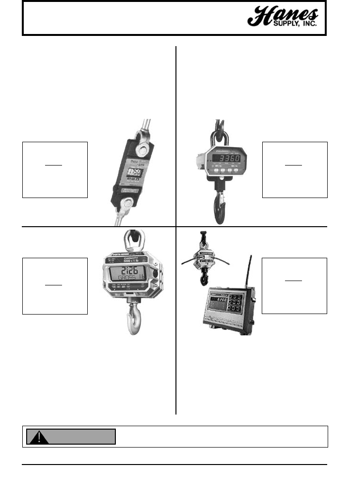
74
HEADQUARTERS: 55 James E. Casey Drive • Buffalo, NY 14206 PHONE: 716.826.2636 FAX: 716.826.4412 www.hanessupply.com
MSI Products
MSI-7200
DYNA-LINK
MSI-3360
CHALLENGER II
MSI-4300
"PORTA-WEIGH PLUS"
MSI-6260
TRANS-WEIGH
The MSI-7200 Dyna-Link is a versatile digital
force measurement and load-indicating
instrument for inside and outside use. Ask
about remote display options.
The MSI-3360 Challenger II DigitalCrane
Scale is an instrument for light-duty overhead
industrial weighing.
The MSI-4300 "Porta-Weigh Plus" Overhead
Crane Scale has served duty in aerospace,
chemical, marine, mining, petroleum, and
steel industry applications for heavy-duty use.
Ask about the MSI-4260 "Porta-Weigh" for
Intrinsically Safe and High Heat applications.
The MSI-6260 Trans-Weigh Radio Telemetry
Crane Scale provides trouble-free data
transmission from crane hook to digital
indicator.
TRANS-WEIGH
SPECIFICATIONS
500 LB.
TO 250 TON
RANGE
CHALLENGER
SPECIFICATIONS
250 LB.
TO 15,000 LB.
RANGE
DYNA-LINK
SPECIFICATIONS
500 LB.
TO 250 TON
RANGE
"PORTA-WEIGH
PLUS"
SPECIFICATIONS
500 LB.
TO 250 TON
RANGE
Do not use this product unless properly trained.
Inspect and use according to OSHA B30.9 or Manufacturers Instructions.
WARNING
YOUR SLING AND RIGGING SPECIALIST
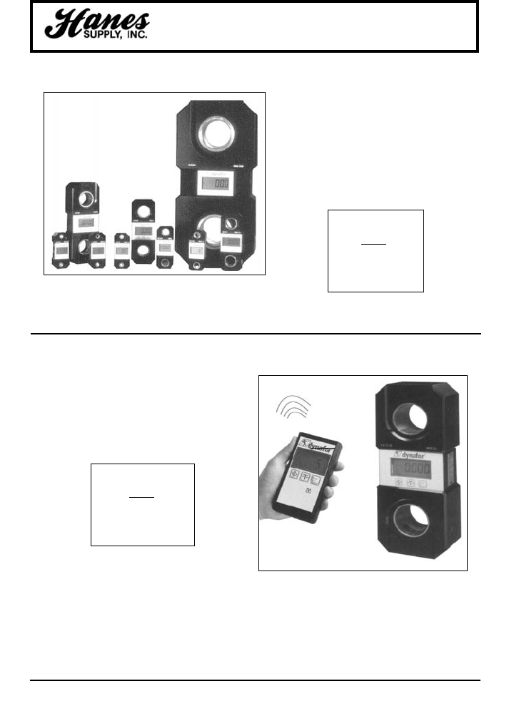
75
HEADQUARTERS: 55 James E. Casey Drive • Buffalo, NY 14206 PHONE: 716.826.2636 FAX: 716.826.4412 www.hanessupply.com
Griphoist Products
GRIPHOIST
DYNAFOR®LLX
The Griphoist Dynafor®LLX with
Microprocessor combines digital
technology with lightweight, durable
aluminum construction for state-of-the-art
load monitoring and check-weighing.
Output by cable to hand-held display,
computer or printer. Operates in extreme
atmospheric conditions.
DYNAFOR®LLX
SPECIFICATIONS
250 LB.
TO 500,000 LB.
RANGE
GRIPHOIST
DYNAFOR®LLX-TR
The Griphoist Wireless Dynafor®LLX-TR
sends radio signal up to 180 feet away to
hand-held display, or optional wall-
mounted display or printer.
DYNAFOR®LLX-TR
SPECIFICATIONS
250 LB.
TO 500,000 LB.
RANGE
YOUR SLING AND RIGGING SPECIALIST
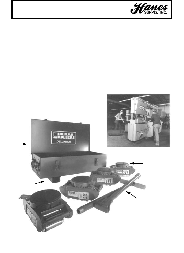
76
HEADQUARTERS: 55 James E. Casey Drive • Buffalo, NY 14206 PHONE: 716.826.2636 FAX: 716.826.4412 www.hanessupply.com
Hilman Rollers
1. How much does the load weigh?
2. How many contact points does the load have? The Hilman rollers are rated in metric tons. Divide the number of
contact points into the total load to determine the capacity of individual rollers. Determine if the load is equally
distributed or unbalanced. If unbalanced, some rollers may carry more load and some less.
3. What is the rolling surface and its condition? The rolling surface should be hard and level, and free of debris.
Where the surface is not hard such as asphalt or dirt, a track or steel plate can be used as the rolling surface.
If the surface is not level, there must be a hold-back system on the load to brake and control it. If the floor is
composed of a delicate surface, then specify Nyton rollers which are coated to soften the roller contact.
4. Are there turns involved or is it a straight line move? If there are turns, rollers with swivels or swivels with a
locking top are suggested. If no turns, then a rigid style top is fine.
Rollers are available in sizes ranging from 1/2 to 3,000 tons. Riggers kits which consist of four rollers, steering
handles and various tops are available if moving loads with rollers is a common task. The kit comes complete with
a locking steel box. A riggers set is the same as a kit without the steel box.
GUIDELINES FOR SELECTING THE PROPER MODEL
HILMAN DELUXE KITS
• Steel or Nyton Chain
Hilman Rollers
provide maximum
turning options
Two full-length steering
handles knock-down
for storage
Raised base
prevents corrosion
and provides
forklift loading
14 guage
steel
carrying
case
Move and position all types of heavy equipment
YOUR SLING AND RIGGING SPECIALIST
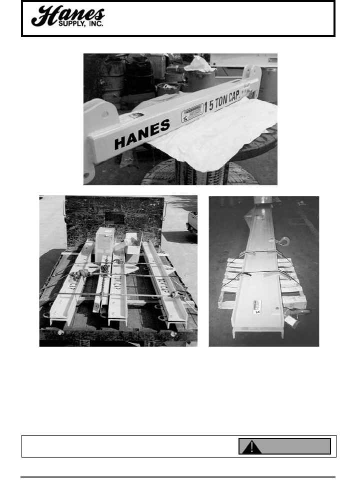
77
HEADQUARTERS: 55 James E. Casey Drive • Buffalo, NY 14206 PHONE: 716.826.2636 FAX: 716.826.4412 www.hanessupply.com
Lifting Attachments
LIFTER VS SPREADER – THE DIFFERENCE
Lifting beams are used when available headroom is not sufficient for top rigging. Lifting
beams must be designed structurally larger than spreader beams to adequately handle
load stress. Spreader beams with top rigging are smaller because most load stress is
absorbed by the rigging. This differentiation is critical in order to properly specify the
equipment required. Make sure you know the difference.
DO NOT EXCEED RATED CAPACITY
Can fail if damaged, misused or overloaded. Inspect before use. Use only if trained.
DEATH or INJURY can occur from improper use or maintenance. WARNING
YOUR SLING AND RIGGING SPECIALIST
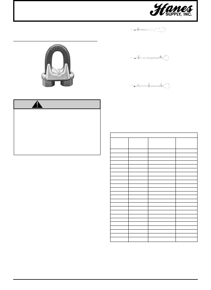
78
HEADQUARTERS: 55 James E. Casey Drive • Buffalo, NY 14206 PHONE: 716.826.2636 FAX: 716.826.4412 www.hanessupply.com
Wire Rope Clips
CROSBY CLIP WARNINGS AND
APPLICATION INSTRUCTIONS
• Failure to read, understand, and follow these
instructions may cause death or serious injury.
• Read and understand these instructions before
using clips.
• Prepare wire rope end termination only as
instructed.
• Do not use with plastic coated wire rope.
• Apply first load to test the assembly. This load
should be of equal or greater weight than loads
expected in use. Next, check and re-tighten nuts to
recommended torque. (See Table I, this page).
1.
Refer to Table I following these instructions. Turn back
specified amount of rope from thimble or loop. Apply first
clip one base width from dead end of rope. Apply U-Bolt
over dead end of wire rope – live end rests in saddle.
Tighten nuts evenly, alternate from one nut to the other
until reaching the recommended torque.
2.
When two clips are required, apply the second clip as near
the loop or thimble as possible. Tighten nuts evenly,
alternating until reaching the recommended torque. When
more than two clips are required, apply the second clip as
near the loop or thimble as possible, turn nuts on second
clip firmly, but do not tighten. Proceed to Step 3.
3.
When three or more clips are required, space additional
clips equally between first two – take up rope slack –
tighten nuts on each U-Bolt evenly, alternating from one
nut to the other until reaching recommended torque.
IMPORTANT
Apply first load to test the assembly. This load should be of
equal or greater weight than loads expected in use. Next,
check and retighten nuts to recommended torque. In
accordance with good rigging and maintenance practices,
the wire rope end termination should be inspected
periodically for wear, abuse, and general adequacy.
Efficiency ratings for wire rope end terminations are based
upon the catalog breaking strength of wire rope. The
efficiency rating of a properly prepared loop or thimble –
eye termination for clip sizes 1/8" through 7/8" is 80%, and
for sizes 1" through 3-1/2" is 90%.
The number of clips shown (see Table I) is based upon
using RRL or RLL wire rope, 6 x 19 or 6 x 37 Class, FC or
IWRC; IPS or XIP. If Seale construction or similar large
outer wire type construction in the 6 x 19 Class is to be
used for sizes 1" and larger, add one additional clip. If a
pulley (sheave) is used for turning back the wire rope, add
one additional clip.
The number of clips shown also applies to rotation-
resistant RRL wire rope, 8 x 19 Class, IPS, XIP, sizes 1-
1/2" and smaller; and to rotation-resistant RRL wire rope,
19 x 7 Class IPS, XIP, sizes 1-3/4" and smaller.
For elevator, personnel hoist, and scaffold applications,
refer to ANSI A17.1 and ANSI A10.4. These standards do
not recommend U-Bolt style wire rope clip terminations.
The style wire rope termination used for any application is
the obligation of the user.
For OSHA (Construction) applications, see OSHA
1926.251.
TABLE I
CLIP MINIMUM AMOUNT OF *TORQUE IN
SIZE NO. ROPE TO TURN FT.
(IN.) OF CLIPS BACK IN INCHES (LBS)
1/8 2 3-1/4 4.5
3/16 2 3-3/4 7.5
1/4 2 4-3/4 15
5/16 2 5-1/4 30
3/8 2 6-1/2 45
7/16 2 7 65
1/2 3 11-1/2 65
9/16 3 12 95
5/8 3 12 95
3/4 4 18 130
7/8 4 19 225
1 5 26 225
1-1/8 6 34 225
1-1/4 7 44 360
1-3/8 7 44 360
1-1/2 8 4 360
1-5/8 8 58 430
1-3/4 8 61 590
2 8 71 750
2-1/4 8 73 750
2-1/2 9 84 750
2-3/4 10 100 750
3 10 106 1200
3-1/2 12 149 1200
If a pulley (sheave) is used for turning back the wire rope, add
one additional clip.
If a greater number of clips are used than shown in the table, the
amount of turnback should be increased proportionately.
*The tightening torque values shown are based upon the threads
being clean, dry, and free of lubrication.
G-450
(Red-U-Bolt)
WARNING
YOUR SLING AND RIGGING SPECIALIST
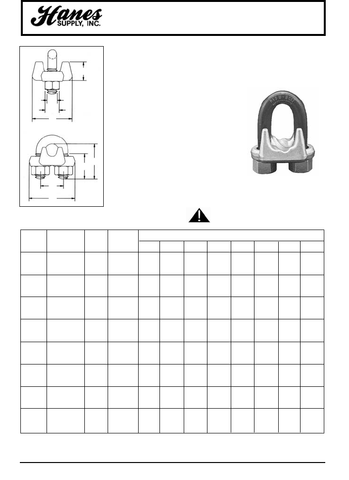
79
HEADQUARTERS: 55 James E. Casey Drive • Buffalo, NY 14206 PHONE: 716.826.2636 FAX: 716.826.4412 www.hanessupply.com
Wire Rope Clips
G-450
• Sizes 1/8" through 3" have
forged bases
• Entire clip – hot dip galvanized to
resist corrosive and rusting
action.
• Only genuine Crosby clips have
a red U-BOLT for instant
recognition.
• All clips are individually bagged
or tagged with proper application
instructions and warning
information.
• Clip sizes up through 1-1/2" have
rolled threads.
Look for the Red-U-Bolt®,
your assurance of
Crosby Clips.
CROSBY®CLIPS
SEE APPLICATION AND
WARNING INFORMATION
Crosby clips all sizes 1/4" and larger meet
Federal Specification FF-C-450 TYPE 1 CLASS 1.
ROPE G-450 STD. WT. PER DIMENSIONS (IN)
SIZE STOCK NO. PKG. 100
(IN) GALV. QTY. (LBS) A B C D E F G H
*1/8 1010015 100 6 .22 .72 .44 .47 .41 .38 .81 .94
*3/16 1010033 100 10 .25 .97 .56 .59 .50 .44 .94 1.16
1/4 1010051 100 20 .31 1.03 .50 .75 .66 .56 1.19 1.44
5/16 1010079 100 30 .38 1.38 .75 .88 .72 .69 1.31 1.69
3/8 1010097 100 47 .44 1.50 .75 1.00 .91 1.63 1.94 .75
7/16 1010113 50 76 .50 1.88 1.00 1.19 1.13 .88 1.81 2.28
1/2 1010131 50 80 .50 1.88 1.00 1.19 1.13 .88 1.91 2.28
9/16 1010159 50 104 .56 2.25 1.25 1.31 1.22 .94 2.06 2.50
5/8 1010177 50 106 .56 2.38 1.25 1.31 1.34 .94 2.06 2.50
3/4 1010195 25 142 .62 2.75 1.44 1.50 1.41 1.06 2.25 2.84
7/8 1010211 25 212 .75 3.12 1.62 1.75 1.59 1.25 2.44 3.16
1 1010239 10 252 .75 3.50 1.81 1.88 1.78 1.25 2.63 3.47
1-1/8 1010257 10 283 .75 3.88 2.00 2.00 1.91 1.25 2.81 3.59
1-1/4 1010275 10 438 .88 4.25 2.13 2.31 2.19 1.44 3.13 4.13
1-3/8 1010293 10 442 .88 4.63 2.31 2.38 2.31 1.44 3.13 4.19
1-1/2 1010319 10 544 .88 4.94 2.38 2.59 2.44 1.44 3.41 4.44
1-5/8 1010337 Bulk 704 1.00 5.31 2.62 2.75 2.66 1.63 3.63 4.75
1-3/4 1010355 Bulk 934 1.13 5.75 2.75 3.06 2.94 1.81 3.81 5.28
2 1010373 Bulk 1300 1.25 6.44 3.00 3.38 3.28 2.00 4.44 5.88
2-1/4 1010391 Bulk 1600 1.25 7.13 3.19 3.88 3.19 2.00 4.50 6.38
2-1/2 1010417 Bulk 1900 1.25 7.69 3.44 4.13 3.69 2.00 4.05 6.63
†2-3/4 1010435 Bulk 2300 1.25 8.31 3.56 4.38 4.88 2.00 5.00 6.88
3 1010453 Bulk 3100 1.50 9.19 3.88 4.75 4.69 2.38 5.88 7.63
†31/2 1010426 Bulk 4000 1.50 10.75 4.50 5.50 6.00 2.38 6.19 8.38
*Electro-plated U-Bolt and Nuts
†2-3/4" and 3-1/2" are made of cast steel.
A
F
G
E
D
B
C
H
YOUR SLING AND RIGGING SPECIALIST
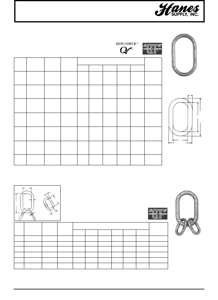
80
HEADQUARTERS: 55 James E. Casey Drive • Buffalo, NY 14206 PHONE: 716.826.2636 FAX: 716.826.4412 www.hanessupply.com
Master Link
MASTER LINK
MASTER LINK ASSEMBLY
• Alloy Steel - Quenched and Tempered.
• Individually proof tested at 2 times Working
Load Limit with certification.
• Proof test certification shipped with each link.
• Sizes from 1/2" to 2" are drop forged.
*Minimum Ultimate Load is 5 times Working Load Limit.
†Based on single leg sling (in-line load), or resultant load on muliple legs with an included angle less than or equal to 120°.
For use with chain slings.
††Welded Master Link.
A-342 WT. DIMENSIONS (IN) DEFOR-
SIZE STOCK WLL*† EACH MATION
(IN) NO. S.C. (LBS) (LBS) A B C D E INDICATOR
1/2 1014262 7000 .82 .50 2.50 5.00 3.50 6.00 3.00
5/8 1014280 9000 1.52 .63 3.00 6.00 4.25 7.25 3.50
3/4 1014306 12300 2.07 .75 2.75 5.50 4.25 7.00 3.50
1 1014324 24360 4.85 1.00 3.50 7.00 5.50 9.00 4.50
1-1/4 1014342 36000 9.57 1.25 4.38 8.75 6.88 11.25 5.50
1-1/2 1014360 54300 16.22 1.50 5.25 10.50 8.25 13.50 6.50
1-3/4 1014388 84900 25.22 1.75 6.00 12.00 9.50 15.50 7.50
2 1014404 102600 37.04 2.00 7.00 14.00 11.00 18.00 9.00
2-1/4†† 1014422 143100 54.10 2.25 8.00 16.00 12.50 20.50 –
2-1/2†† 1014468 147300 67.75 2.50 8.00 16.00 13.00 21.00 –
2-3/4†† 1014440 216900 87.70 2.75 9.50 16.00 15.00 21.50 –
3†† 1014486 228000 115.00 3.00 9.00 18.00 15.00 24.00 –
3-1/4†† 1014501 262200 145.00 3.25 10.00 20.00 16.50 26.50 –
3-1/2†† 1014529 279000 200.00 3.50 12.00 24.00 19.00 31.00 –
3-3/4†† 1015051 336000 198.00 3.75 10.00 20.00 17.50 27.50 –
4†† 1015060 373000 228.00 4.00 10.00 20.00 18.00 28.00 –
4-1/4†† 1015067 354000 302.00 4.25 12.00 24.00 20.50 32.50 –
4-1/2†† 1015079 360000 345.00 4.50 14.00 28.00 23.00 37.00 –
4-3/4†† 1015088 389000 436.00 4.75 14.00 28.00 23.50 37.50 –
5†† 1015094 395000 516.00 5.00 15.00 30.00 25.00 40.00 –
A-342
A-345 WT. DIMENSIONS (IN) DEFOR-
SIZE STOCK WLL*† EACH MATION
(IN) NO. S.C. (LBS) (LBS) A B C D E F INDICATOR
3/4 1014734 10500 2.60 .75 2.75 5.50 .56 3.55 1.57 3.50
1 1014752 24360 6.10 1.00 3.50 7.00 .69 3.94 2.36 4.50
1-1/4 1014770 36000 13.20 1.25 4.38 8.75 .88 3.94 2.36 5.50
1-1/2 1014798 54300 24.20 1.50 5.25 10.50 1.15 5.91 2.76 6.50
1-3/4 1014814 84900 35.60 1.75 6.00 12.00 1.25 6.30 3.54 7.50
2 1014832 102600 57.30 2.00 7.00 14.00 1.50 7.09 3.94 9.00
• Alloy Steel - Quenched and Tempered.
• Individually proof tested at 2 times Working
Load Limit with certification.
• Proof test certification shipped with each link.
*Working Load Limit with coupling links at 60° included angle.
†Ultimate Load is 4 times Working Load Limit.
A-345
E
A
B
C
D
F
E
D
C
B
A
G
YOUR SLING AND RIGGING SPECIALIST
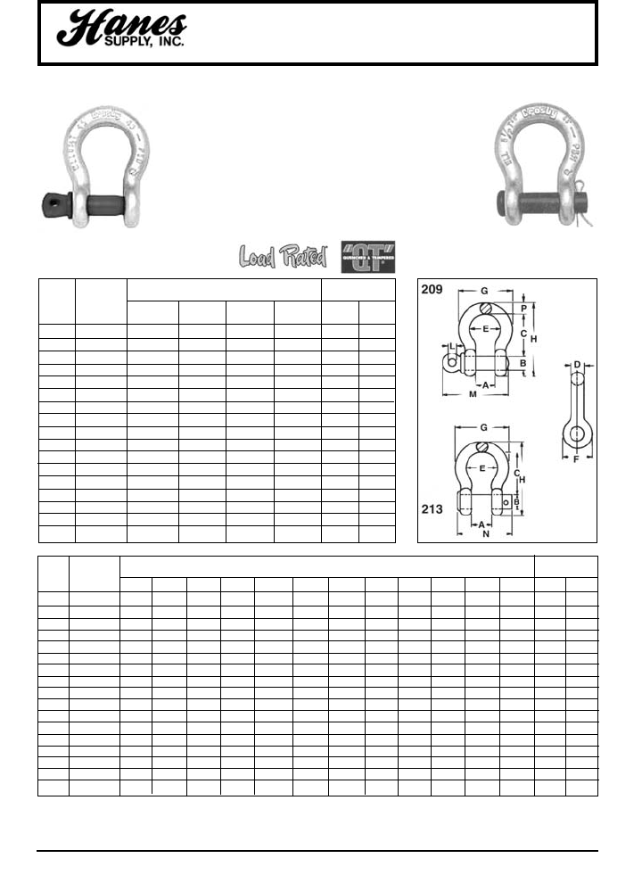
81
HEADQUARTERS: 55 James E. Casey Drive • Buffalo, NY 14206 PHONE: 716.826.2636 FAX: 716.826.4412 www.hanessupply.com
Forged Shackles
• Working load limit permanently shown on every shackle.
• Forged – Quenched and Tempered, with alloy pins.
• Capacities 1/3 through 55 tons.
• Look for the red pin...the mark of genuine Crosby quality.
• Shackles can be furnished proof tested with certificates
to designated standards such as ABS, DNV, Lloyds, or
other certification available when requested at the time of
order.
• Hot dip galvanized or self-colored.
• Fatigue rated.
G-209 S-209 G-213 S-213
WORKING DIMENSIONS (IN) TOLERANCE
NOM. LOAD + / -
SIZE LIMIT* A B C D E F G H L M N P C A
3/16 †1/3 .38 .25 .88 .19 .60 .56 .98 1.47 .16 1.12 – .19 .06 .06
1/4 1/2 .47 .31 1.13 .25 .78 .61 1.28 1.84 .19 1.38 1.34 .25 .06 .06
5/16 3/4 .53 .38 1.22 .31 .84 .75 1.47 2.09 .22 1.66 1.59 .31 .06 .06
3/8 1 .66 .44 1.44 .38 1.03 .91 1.78 2.49 .25 2.03 1.88 .38 .13 .06
7/16 1-1/2 .75 .50 1.69 .44 1.16 1.06 2.03 2.91 .31 2.38 2.13 .44 .13 .06
1/2 2 .81 .63 1.88 .50 1.31 1.19 2.31 3.28 .38 2.69 2.38 .50 .13 .06
5/8 3-1/4 1.06 .75 2.38 .63 1.69 1.50 2.94 4.19 .44 3.34 2.91 .69 .13 .06
3/4 4-3/4 1.25 .88 2.81 .75 2.00 1.81 3.50 4.97 .50 3.97 3.44 .81 .25 .06
7/8 6-1/2 1.44 1.00 3.31 .88 2.28 2.09 4.03 5.83 .50 4.50 3.81 .97 .25 .06
1 8-1/2 1.69 1.13 3.75 1.00 2.69 2.38 4.69 6.56 .56 5.07 4.53 1.06 .25 .06
1-1/8 9-1/2 1.81 1.25 4.25 1.16 2.91 2.69 5.16 7.47 .63 5.59 5.13 1.25 .25 .06
1-1/4 12 2.03 1.38 4.69 1.29 3.25 3.00 5.75 8.25 .69 6.16 5.50 1.38 .25 .06
1-3/8 13-1/2 2.25 1.50 5.25 1.42 3.63 3.31 6.38 9.16 .75 6.84 6.13 1.50 .25 .13
1-1/2 17 2.38 1.63 5.75 1.54 3.88 3.63 6.88 10.00 .81 7.35 6.50 1.62 .25 .13
1-3/4 25 2.88 2.00 7.00 1.84 5.00 4.19 8.86 12.34 1.00 9.08 7.75 2.25 .25 .13
2 35 3.25 2.25 7.75 2.08 5.75 4.71 9.97 13.68 1.22 10.34 8.75 2.40 .25 .13
2-1/2 †55 4.13 2.75 10.50 2.71 7.25 5.69 12.87 17.84 1.38 13.00 – 3.13 .25 .25
*NOTE: Maximum Proof Load is 2.0 times the Working Load Limit. Minimum Ultimate Strength is 6 times the Working Load Limit.
†Furnished in screw pin only.
WORKING STOCK NO. WEIGHT EACH
NOM. LOAD (LBS)
SIZE LIMIT* G-209 S-209 G-213 S-213 G-209 G-213
(IN.) (TONS) GALV. S.C. GALV. S.C. S-209 S-213
3/16 †1/3 1018357 – – – .06 –
1/4 1/2 1018375 1018384 1018017 1018026 .10 .13
5/16 3/4 1018393 1018400 1018035 1018044 .19 .18
3/8 1 1018419 1018428 1018053 1018062 .31 .29
7/16 1-1/2 1018437 1018446 1018071 1018080 .38 .38
1/2 2 1018455 1018464 1018099 1018106 .72 .71
5/8 3-1/4 1018473 1018482 1018115 1018124 1.37 1.50
3/4 4-3/4 1018491 1018507 1018133 1018142 2.35 2.32
7/8 6-1/2 1018516 1018525 1018151 1018160 3.62 3.49
1 8-1/2 1018534 1018543 1018179 1018188 5.03 5.00
1-1/8 9-1/2 1018552 1018561 1018197 1018204 7.41 6.97
1-1/4 12 1018570 1018589 1018213 1018222 9.50 9.75
1-3/8 13-1/2 1018598 1018605 1018231 1018240 13.53 13.25
1-1/2 17 1018614 1018623 1018259 1018268 17.20 17.25
1-3/4 25 1018632 1018641 1018277 1018286 27.75 29.46
2 35 1018650 1018669 1018295 1018302 45.00 45.75
2-1/2 †55 1018678 1018687 – – 85.75 –
Screw pin anchor shackles meet the
requirements of Federal Specification
RR-C-271D Type IVA, Grade A, Class 2.
SCREW PIN ROUND PIN
Round pin anchor shackles meet the
requirements of Federal Specification
RR-C-271D Type IVA, Grade A, Class 1.
YOUR SLING AND RIGGING SPECIALIST
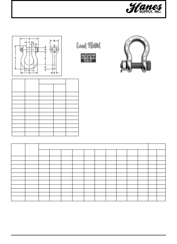
HEADQUARTERS: 55 James E. Casey Drive • Buffalo, NY 14206 PHONE: 716.826.2636 FAX: 716.826.4412 www.hanessupply.com
82
Alloy Bolt-Type Shackles
NOM. WORKING DIMENSIONS TOLERANCE
SHACKLE LOAD (IN) + / -
SIZE LIMIT* ABC DEFGHJKAE
(IN.) (TONS)
1-1/2 30 2.38 3.62 1.62 1.63 5.75 1.50 6.88 7.94 10.00 3.88 .13 .25
1-3/4 40 2.88 4.31 2.25 2.00 7.00 1.75 8.50 9.31 12.22 5.00 .13 .25
2 55 3.25 4.81 2.40 2.25 7.75 2.00 9.75 10.41 13.28 5.75 .13 .25
2-1/2 85 4.12 5.69 3.12 2.75 10.50 2.62 12.50 13.56 17.34 7.25 .25 .25
3 †120 5.00 6.50 3.62 3.25 12.98 3.00 14.50 16.50 21.50 7.88 .25 .25
3-1/2 †150 5.25 8.00 4.12 3.75 14.63 3.50 16.50 19.00 24.62 9.00 .25 .25
4 †175 5.50 9.00 4.56 4.25 14.50 4.00 18.38 19.75 25.69 10.00 .25 .25
4-3/4** †200 7.25 10.50 6.00 4.75 15.50 3.75 21.00 19.88 29.25 11.00 .25 .25
5** †250 8.25 12.00 6.50 5.00 20.00 4.00 24.50 21.12 35.00 13.00 .25 .25
6** †300 8.38 12.00 6.75 6.00 19.50 5.25 25.00 22.88 35.25 13.00 .25 .25
7** †400 8.25 14.00 7.25 7.00 22.50 6.50 26.00 26.12 40.25 13.00 .25 .25
*NOTE: Maximum Proof Load is 2.0 times the Working Load Limit. Minimum Ultimate Load is 4 times the Working Load Limit on 200
through 400 metric tons. For sizes 30 throught 175 metric tons, Minimum Ultimate Load is 5.4 times the Working Load Limit.
**Cast Alloy Steel.
†Furnished with Round Head Bolts with welded handle.
††Maximum Proof Load is 1000 tons and furnished with Round Head Bolts with welded handle.
NOM. WORKING STOCK NO.
SHACKLE LOAD WEIGHT
SIZE LIMIT* G-2140 S-2140 EACH
(IN.) (TONS) GALV S.C. (LBS.)
1-1/2 30 1021110 1021129 20.8
1-3/4 40 1021138 1021147 33.9
2 55 1021156 1021165 52.0
2-1/2 85 1021174 1021183 96.0
3 120 1021192 – 178.0
3-1/2 †150 1021218 – 265.0
4 †175 1021236 – 338.0
4-3/4** †200 1021414 – 450.0
5** †250 1021432 – 600.0
6** †300 1021450 – 775.0
7** †400 1021478 – 1102.0
• Working Load Limit is permanently
shown on every shackle.
• Alloy bows, alloy bolts.
• Quenched and tempered.
• Sizes 200 tons and larger are
individually proof tested.
• Forged Alloy Steel 30 through 175 metric
tons. Cast Alloy Steel 200 through 400
metric tons.
• Pins are galvanized and painted red.
BOLT-TYPE ANCHOR SHACKLE
G-2140 S-2140
YOUR SLING AND RIGGING SPECIALIST
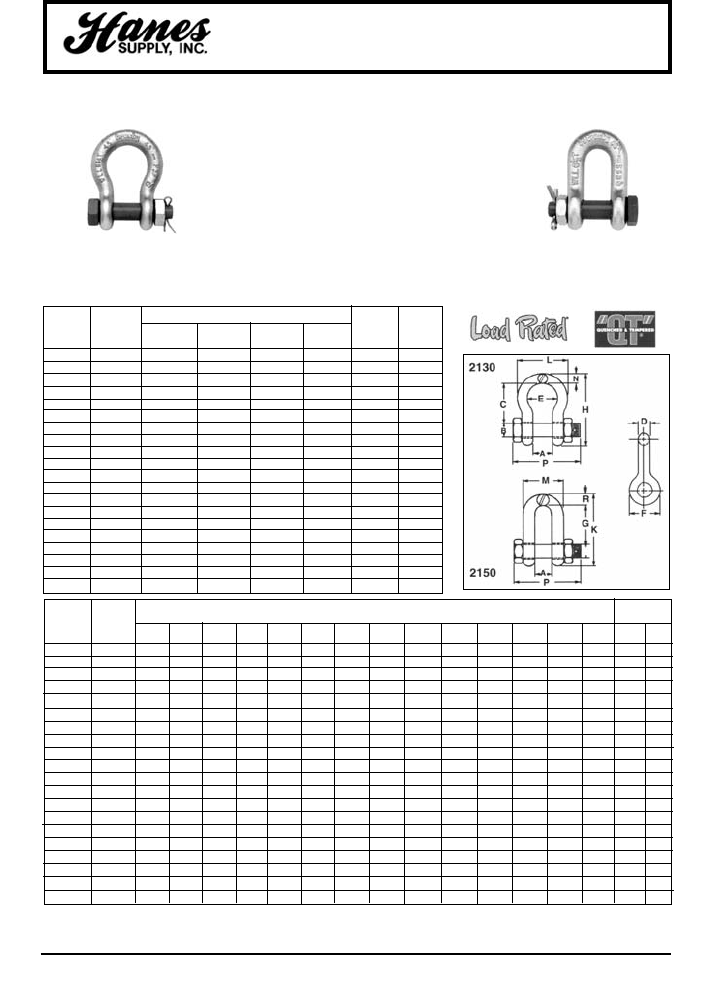
83
HEADQUARTERS: 55 James E. Casey Drive • Buffalo, NY 14206 PHONE: 716.826.2636 FAX: 716.826.4412 www.hanessupply.com
Bolt-Type Shackles
NOM. WORKING DIMENSIONS (IN) TOLERANCE
SHACKLE LOAD + / -
SIZE LIMIT* A B C D E F G H K L M N P R C&G A
(IN.) (TONS)
3/16 1/3 .38 .25 .88 .19 .60 .56 – 1.47 – .98 – .19 1.29 – .06 .06
1/4 1/2 .47 .31 1.13 .25 .78 .61 – 1.84 – 1.28 – .25 1.56 – .06 .06
5/16 3/4 .53 .38 1.22 .31 .84 .75 – 2.09 – 1.47 – .31 1.82 – .06 .06
3/8 1 .66 .44 1.44 .38 1.03 .91 – 2.49 – 1.78 – .38 2.17 – .13 .06
7/16 1-1/2 .75 .50 1.69 .44 1.16 1.06 – 2.91 – 2.03 – .44 2.51 – .13 .06
1/2 2 .81 .63 1.88 .50 1.31 1.19 1.63 3.28 3.03 2.31 1.81 .50 3.03 .50 .13 .06
5/8 3-1/4 1.06 .75 2.38 .63 1.69 1.50 2.00 4.22 3.75 2.94 2.31 .69 3.63 .63 .13 .06
3/4 4-3/4 1.25 .88 2.81 .75 2.00 1.81 2.38 4.97 4.53 3.50 2.75 .81 4.44 .81 .25 .06
7/8 6-1/2 1.44 1.00 3.31 .88 2.28 2.09 2.81 5.83 5.33 4.03 3.19 .97 5.00 .97 .25 .06
1 8-1/2 1.69 1.13 3.75 1.00 2.69 2.38 3.19 6.56 5.94 4.69 3.69 1.00 5.69 1.00 .25 .06
1-1/8 9-1/2 1.81 1.25 4.25 1.13 2.91 2.69 3.56 7.47 6.78 5.16 4.06 1.25 6.41 1.25 .25 .06
1-1/4 12 2.03 1.38 4.69 1.25 3.25 3.00 3.94 8.28 7.50 5.75 4.53 1.38 6.97 1.38 .25 .06
1-3/8 13-1/2 2.25 1.50 5.25 1.38 3.63 3.31 4.44 9.16 8.28 6.38 5.00 1.50 7.69 1.50 .25 .13
1-1/2 17 2.38 1.63 5.75 1.50 3.88 3.63 4.88 10.00 9.06 6.88 5.38 1.62 8.25 1.62 .25 .13
1-3/4 25 2.88 2.00 7.00 1.75 5.00 4.19 5.75 12.22 10.97 8.50 6.38 2.12 9.59 2.12 .25 .13
2 35 3.25 2.25 7.75 2.00 5.75 4.81 6.75 13.28 12.28 9.75 7.25 2.40 11.00 2.00 .25 .13
2-1/2 55 4.13 2.75 10.50 2.62 7.25 5.69 8.00 17.34 14.84 12.50 9.13 3.13 13.69 2.62 .25 .25
3 †85 5.00 3.25 13.00 3.00 7.88 6.50 8.50 21.50 16.88 14.50 11.00 3.62 16.50 3.50 .25 .25
3-1/2 †120 5.25 3.75 14.63 3.50 9.00 8.00 – 24.63 – 16.50 – 4.12 19.00 – .25 .25
4 †150 5.50 4.25 14.50 4.00 10.00 9.00 – 25.69 – 18.38 – 4.56 19.75 – .25 .25
BOLT-TYPE
ANCHOR SHACKLE
BOLT-TYPE
CHAIN SHACKLE
G-2130 S-2130 G-2150 S-2150
• Working Load Limit is permanently shown on
every shackle.
• Forged – quenched and tempered, with alloy
pins.
• Capacities 1/3 through 150 metric tons.
• Look for the red pin... the mark of genuine
Crosby quality.
• Shackles can be furnished proof tested with
certificates to designated standards, such as
ABS, DNV, Lloyds, or other certification.
Charges for proof testing and certification
available when requested at time of order.
• Hot dip galvanized or self colored.
• Fatigue rated.
NOM. WORKING 2130 2150
STOCK NO.
SHACKLE LOAD WEIGHT WEIGHT
SIZE LIMIT* G-2130 A-21E0 G-2150 A-2150 EACH EACH
(IN.) (TONS) GALV. S.C. GALV. S.C. (LBS.) (LBS.)
3/16 1/3 1019464 – – – .06 –
1/4 1/2 1019466 – 1019768 – .11 .13
5/16 3/4 1019468 – 1019770 – .22 .23
3/8 1 1019470 – 1019772 – .33 .33
7/16 1-1/2 1019471 – 1019774 – .49 .49
1/2 2 1019472 1019481 1019775 1019784 .79 .75
5/8 3-1/4 1019490 1019506 1019793 1019800 1.68 1.47
3/4 4-3/4 1019515 1019524 1019819 1019828 2.72 2.52
7/8 6-1/2 1019533 1019542 1019837 1019846 3.95 3.85
1 8-1/2 1019551 1019560 1019855 1019864 5.66 5.55
1-1/8 9-1/2 1019579 1019588 1019873 1019882 8.27 7.60
1-1/4 12 1019597 1019604 1019891 1019908 11.71 10.81
1-3/8 13-1/2 1019613 1019622 1019917 1019926 15.83 13.75
1-1/2 17 1019631 1019640 1019935 1019944 20.80 18.50
1-3/4 25 1019659 1019668 1019953 1019962 33.91 31.40
2 35 1019677 1019686 1019971 1019980 52.25 46.75
2-1/2 55 1019695 1019702 1019999 1020004 98.25 85.00
3 †85 1019711 – 1020013 – 154.00 124.25
3-1/2 †120 1019739 – – – 265.00 –
4 †150 1019757 – – – 338.00 –
Bolt Type Anchor shackles with thin
head bolt–nut with cotter pin, meets the
requirements of Federal Specification
RR-C-271D Type IVA, Grade A, Class 3.
Bolt Type Chain shackles with thin hex
head bolt–nut with cotter pin, meets the
requirements of Federal Specification
RR-C-271D Type IVB, Grade A, Class 3.
YOUR SLING AND RIGGING SPECIALIST
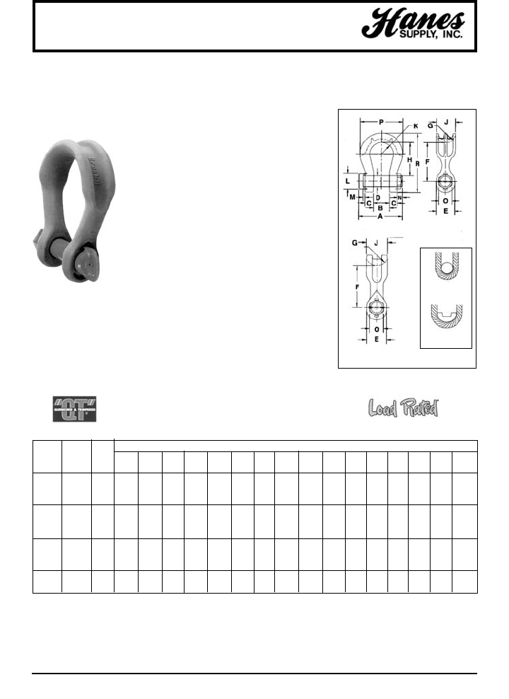
84
HEADQUARTERS: 55 James E. Casey Drive • Buffalo, NY 14206 PHONE: 716.826.2636 FAX: 716.826.4412 www.hanessupply.com
Alloy Shackles
"WIDE BODY" SLING SAVER SHACKLES INCREASE SLING LIFE
• Greatly improves wearability of wire rope slings.
• Increase in shackle bow radius provides minimum
58% gain in sling bearing surface and eliminates
need for a thimble.
• Increases usable sling strength minimum of 15%.
• Pin is non-rotating, with weld on handles for easier
use.
• All ratings are in metric tons, embossed on side of
bow.
• Sizes 400 tons and larger are tested to 1.33 times
Working Load Limit.
• Standard 2160 shackles 400 tons and larger are
individually proof tested with Crosby certification.
Shackles requiring ABS, DNV, Lloyds and other
certifications are available upon special request
and must be specified at time of order.
• Weighs no more than conventionally designed
shackles.
• All sizes quenched and tempered for maximum
strength.
• Forged alloy steel from 75 through 300 metric tons.
• Cast alloy steel from 400 through 1000 metric tons.
• All bows are furnished Dimetcoted. All pins are
Dimetcoted then painted red.
G-2160
Patented
WLL* G-2160 WT. DIMENSIONS (IN)
(METRIC STOCK EACH A B C D E F G H J K L M N O P R
TONS) NO. (LBS) +/-.25 +/-.02
75† 1021290 99 13.62 4.13 2.12 2.76 4.76 12.80 2.52 11.41 4.72 3.66 4.37 1.00 3.00 3.90 12.32 18.31
125† 1021307 161 15.75 5.12 2.56 3.15 5.71 15.94 3.15 14.37 5.90 4.33 5.12 1.06 2.95 4.64 14.96 22.68
200† 1021316 500 20.00 5.90 3.35 4.13 7.28 20.96 4.33 18.90 8.07 5.41 6.69 1.26 4.33 5.75 19.49 29.82
300† 1021325 811 23.27 7.28 4.00 5.25 9.25 26.25 5.51 23.62 10.43 6.31 8.07 1.50 4.42 6.89 23.64 37.39
400†† 1021334 1041 28.13 8.66 5.16 6.30 11.02 25.79 6.30 22.64 12.60 7.28 9.45 1.50 4.72 7.76 27.16 38.78
500†† 1021343 1378 31.87 9.84 5.59 7.09 12.52 28.35 6.69 24.80 13.39 8.86 10.43 1.61 4.92 8.74 31.10 42.72
600†† 1021352 1833 35.94 10.83 6.04 7.87 13.78 31.50 7.28 27.56 14.57 9.74 11.93 1.75 5.39 9.74 34.06 47.24
700†† 1021361 2446 39.07 11.81 6.59 8.46 14.80 33.17 7.87 28.94 15.75 10.63 12.62 1.89 5.94 10.75 37.01 50.18
800†† 1021254 3016 38.82 12.80 7.19 9.06 15.75 34.06 8.27 29.53 16.54 10.92 13.90 1.89 6.14 11.26 38.39 52.09
900†† 1021389 3436 41.34 13.78 7.78 9.84 16.93 34.74 8.66 29.80 17.32 11.52 15.20 2.01 6.08 12.50 40.35 54.04
1000†† 1021370 4022 46.30 14.96 8.33 10.63 17.72 35.24 9.06 29.92 18.11 12.11 16.00 2.01 5.98 12.99 42.32 55.31
*Ultimate Load is 5 times the Working Load Limit.
†Forged Alloy Steel. Proof Load is 2 times the Working Load Limit.
††Cast Alloy Steel. Proof Load is 1.33 times the Working Load Limit.
CONVENTIONAL
SHACKLE
"WIDE BODY"
SHACKLE
400 THROUGH 1000
METRIC TONS
75 THROUGH 300
METRIC TONS
YOUR SLING AND RIGGING SPECIALIST
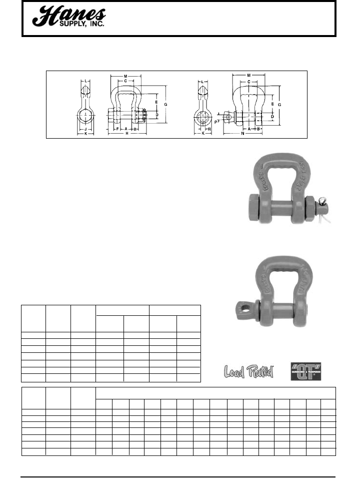
85
HEADQUARTERS: 55 James E. Casey Drive • Buffalo, NY 14206 PHONE: 716.826.2636 FAX: 716.826.4412 www.hanessupply.com
"Synthetic Sling Saver" Shackle
SLING SAVER SHACKLES INCREASE SLING LIFE
The Crosby "Synthetic Sling Saver" Shackle, designed for Round or Flat
Synthetic Slings, has the following features:
• Eliminates "bunching" effect caused by traditional shackles.
• Reduces sling tendency to slide.
Increased radius of bow gives wider sling bearing surface resulting in an
increased area for load distribution, thus:
• Increases Synthetic Sling efficiency by at least 15% as compared to a
standard anchor or chain shackle bow.
• Allowing better load distribution on internal fibers.
Both a Screw Pin and Bolt, nut and cotter pin configuration.
• Bolt (Pin) has a large diameter that provides better load distribution.
Each shackle has a Product Identification Code (PIC) for material
traceability along with a Working Load Limit and the name Crosby forged
into it.
• Available in sizes from 3-1/4 tons (1") to 50 tons (6").
• All Alloy construction.
• Design Factor of 5 to 1.
• Fatigue rated to 20,000 cycles at 1-1/2 times the Working Load Limit.
WEB S-252 S-253
ROUND SLING WORKING BOLT TYPE SCREW PIN
SLING NOMINAL LOAD WEIGHT WEIGHT
SIZE SIZE LIMIT* S-252 EACH S-253 EACH
(NUMBER) (IN.) (TONS) STOCK NO. (LBS.) STOCK NO. (LBS.)
1 & 2 1 3-1/4 1020485 1.4 1020575 1.4
3 & 4 1.5 6-1/2 1020496 2.4 1020575 2.2
5 & 6 2 8-3/4 1020507 4.1 1020593 3.8
7 & 8 3 12-1/2 1020518 8.0 1020602 7.3
9 & 10 4 20-1/2 1020529 16.9 1020611 15.2
11 & 12 5 35 1020540 35.0 1020620 30.8
13 6 50 1020551 57.5 1020629 52.0
ROUND WEB WORKING DIMENSIONS
SLING SLING LOAD (IN.)
SIZE NOMINAL LIMIT*
(NUMBER) SIZE (IN.) (TONS) A BCD E F G H J KLMNPR
1 & 2 1 3-1/4 .88 .62 1.38 .75 1.50 .44 3.38 3.68 1.12 1.50 .75 2.69 3.22 .44 1.00
3 & 4 1.5 6-1/2 1.25 .75 1.75 .88 1.88 .50 4.15 4.25 1.31 1.81 1.00 3.38 4.03 .50 1.19
5 & 6 2 8-3/4 1.38 .88 2.25 1.00 2.81 .56 5.50 4.72 1.50 2.09 1.12 4.19 4.50 .50 1.44
7 & 8 3 12-1/2 1.62 1.12 3.25 1.25 3.06 .75 6.34 5.88 1.88 2.62 1.38 5.62 5.59 .62 1.81
9 & 10 4 20-1/2 2.12 1.38 4.50 1.50 5.75 .88 9.75 7.19 2.25 3.12 1.75 7.50 6.88 .75 2.13
11 & 12 5 35 2.50 1.75 5.50 2.00 6.34 1.12 11.50 9.31 3.00 4.19 2.25 9.19 8.66 1.00 2.88
13 6 50 3.00 2.12 6.50 2.25 7.70 1.25 16.75 10.38 3.38 4.75 2.75 11.00 10.22 1.22 3.19
*Note: Maximum Proof Load is 2-1/2 times the Working Load Limit. Minimum Ultimate Strength is 5 times the Working Load Limit.
S-252 S-253
S-253
S-252
YOUR SLING AND RIGGING SPECIALIST
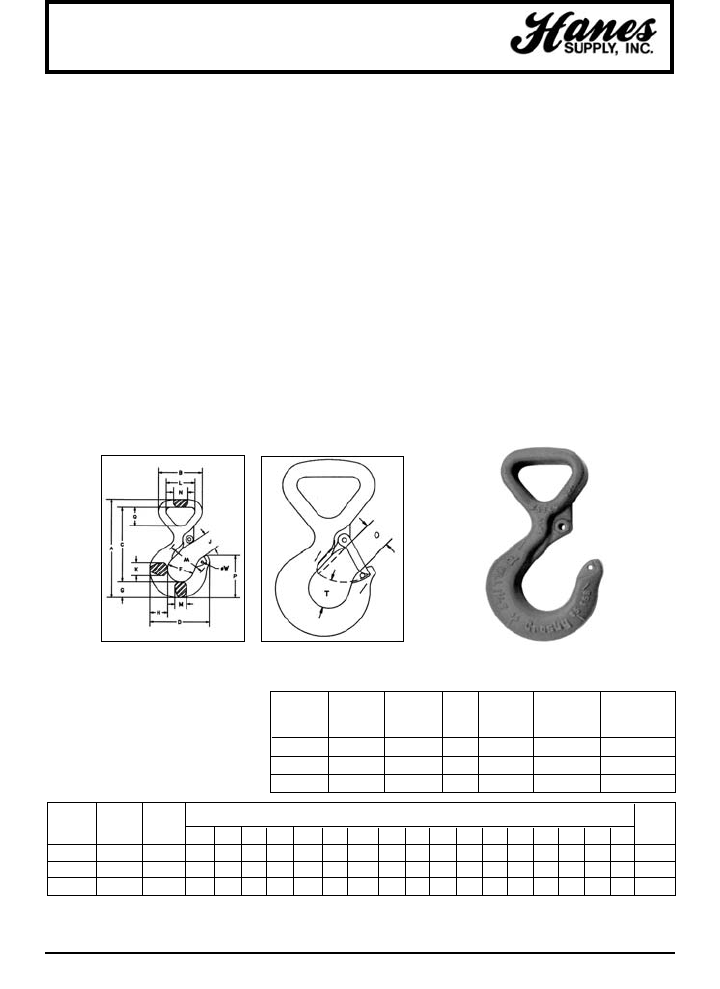
86
HEADQUARTERS: 55 James E. Casey Drive • Buffalo, NY 14206 PHONE: 716.826.2636 FAX: 716.826.4412 www.hanessupply.com
Synthetic Sling Hook
The Web Sling hook, originally designed for 2-Ply Web slings, can also be used
with Round Slings as long as the Working Load Limit ratings are compatible.
The new hook incorporates the following features:
99Eye is desigend with a wide beam surface which:
• Eliminates bunching effects
• Reduces sling tendency to slide.
• Allows a better load distribution on internal fibers.
99Each hook has a Product Identification Code (PIC) for material
traceability along with a working load limit.
99Hooks available in sizes 1-1/2 (1"), 3 (2"), and 5 (3") tons.
99All alloy construction.
99Design factor of 5 to 1.
99Fatigue rated to 20,000 cycles at 1-1/2 times the Working Load Limit.
WS-320 A
WEB SLING HOOK
WEB SLING ROUND WORKING S-4320
NOMINAL SLING LOAD HOOK WS-320 A WSL-320 A REPLACEMENT
SIZE SIZE LIMIT* I.D. S.C WITH LATCH LATCH KIT
(IN.) (NUMBER) (TONS) CODE STOCK NO. STOCK NO. STOCK NO.
1" 1 1-1/2 FA 1022701 1022706 1096374
2" 2 3 HA 1022712 1022717 1096468
3" 3 5 IA 1022723 1022728 1096515
WEB SLING ROUND WORKING DIMENSIONS
NOMINAL SLING LOAD (IN.) WEIGHT
SIZE SIZE LIMIT* EACH
(IN.) (NUMBER) (TONS) A B C D F G H J K L M N O P Q T AA (LBS.)
1" 1 1-1/2 5.25 2.26 3.98 3.11 1.38 .84 .94 .93 .71 1.50 .63 .75 .91 2.24 1.01 .98 2.00 1.10
2" 2 3 7.11 3.66 5.31 3.97 1.63 1.13 1.32 1.13 .94 2.50 .85 1.13 1.09 2.82 1.69 1.16 2.00 2.86
3" 3 5 9.33 5.13 7.06 4.81 2.00 1.44 1.63 1.47 1.31 3.75 1.13 1.63 1.36 3.51 2.59 1.53 2.50 6.60
*Note: Proof load is 2-1/2 times Working Load Limit. Average straightening load (ultimate load) is 5 time Working Load Limit.
WEB SLING HOOK
YOUR SLING AND RIGGING SPECIALIST
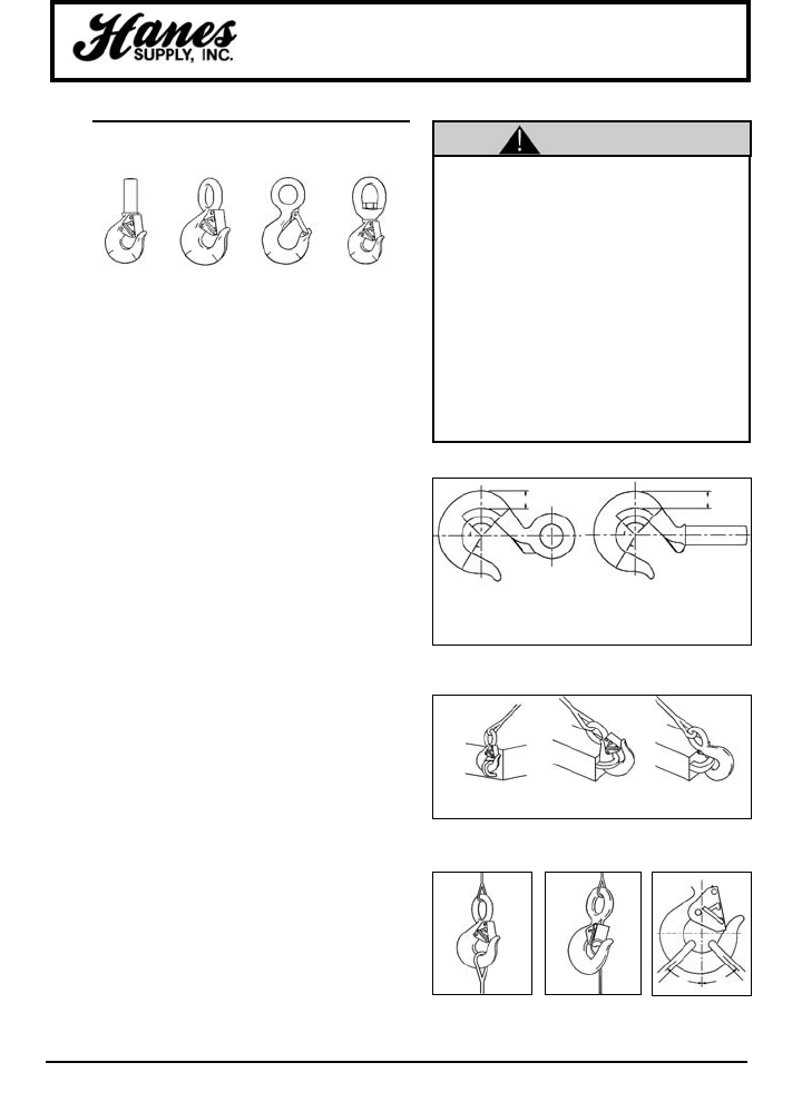
87
HEADQUARTERS: 55 James E. Casey Drive • Buffalo, NY 14206 PHONE: 716.826.2636 FAX: 716.826.4412 www.hanessupply.com
Sling and Hoist Hooks
Important Safety Information –
Read and Follow
• A visual periodic inspection for cracks, nicks, wear,
gouges and deformation as part of a comprehensive
documented inspection program, should be conducted by
trained personnel in compliance with the schedule in ANSI
B30.10.
• For hooks used in frequent load cycles or pulsating loads,
the hook and threads should be periodically inspected by
Magnetic Particle or Dye Penetrant. (Note: Some
disassembly may be required.)
• Never use a hook whose throat opening has been
increased, or whose tip has been bent more than 10
degrees out of plane from the hook body, or is in any other
way distorted or bent. Note: A latch will not work
properly on a hook with a bent or worn tip.
• Never use a hook that is worn beyond the limits shown in
Figure 1.
• Remove from service any hook with a crack, nick, or
gouge. Hooks with a crack, nick or gouge shall be repaired
by grinding lengthwise, following the contour of the hook,
provided that the reduced dimension is within the limits
shown in Figure 1.
• Never repair, alter, rework, or reshape a hook by welding,
heating, burning, or bending.
• Never side load, back load, or tip load a hook. (See Figure
2)
• Eye hooks, shank hooks and swivel hooks are designed to
be used with wire rope or chain. Efficiency of assembly
may be reduced when used with synthetic material.
• Do not swivel the S-322 swivel hook while it is supporting
a load.
• The use of a latch may be mandatory by regulations or
safety codes; e.g., OSHA, MSHA, ANSI/ASME B30,
Insurance, etc.
• Always make sure the hook supports the load. (See Figure
3) The latch must never support the load. (See Figure 4)
• When placing two (2) sling legs in hook, make sure the
angle from the vertical to the outermost leg is not greater
than 45 degrees, and the included angle between the legs
does not exceed 90 degrees.* (See Figure 5)
• See ANSI/ASME B30.10 "Hooks" for additional
information.
• Loads may disengage from hook if proper
procedures are not followed.
• A failing load may cause serious injury or
death.
• See OSHA Rule 1926.550(g) for personnel
hoisting by cranes or derricks. A 319, 320 or
322 hook with a PL Latch attached (when
secured with the bolt, nut and pin) may be
used for lifting personnel.
• Threads may corrode and/or strip and drop
the load.
• Hook must always support the load. The
load must never be supported by the latch.
• Never apply more force than the hook's
assigned Working Load Limit (WLL) rating.
• Read and understand these instructions
before using hook.
SLING AND HOIST HOOKS
WARNINGS AND APPLICATION
INSTRUCTIONS
*For two legged slings with angles greater than 90°, use an intermediate
link such as a master link or bolt type shackle to collect the legs of the
slings. The intermediate link can then be placed over the hook to provide
an in-line load on the hook. This approach must also be used when using
slings with three or more legs.
S-319 S-320 S-320N S-322
ZONE A: REPAIR NOT REQUIRED
ZONE B: 10% OF ORIGINAL DIMENSION
ZONE C: 5% OF ORIGINAL DIMENSION
ZONE D: SEE MINIMUM THREAD SIZE
Side Load Back Load Tip Load
WRONG
WRONG
RIGHT
Figure 2
Figure 3 Figure 4 Figure 5
Figure 1
ZONE A
ZONE B
ZONE C
2/3
45°
45°
60°
ZONE A
ZONE B
ZONE C
2/3
45°
45°
60°ZONE D
WARNING
YOUR SLING AND RIGGING SPECIALIST
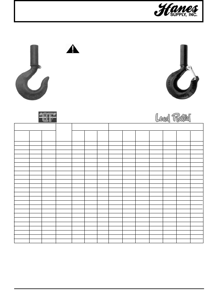
88
HEADQUARTERS: 55 James E. Casey Drive • Buffalo, NY 14206 PHONE: 716.826.2636 FAX: 716.826.4412 www.hanessupply.com
Hoist Hooks
• The most complete line of shank hoist hooks. Available 3/4
to 300 tons.
• Available in carbon steel, alloy steel, and bronze.
• Quenched and Tempered.
• Proper design, careful forging and precision controlled
quench and tempering give maximum strength without
excessive weight and bulk.
• Every Crosby Shank Hook has a pre-drilled cam which can
be equipped with a latch. Even years after purchase of the
original hook, latch assemblies can be added.
• Load Rating code stamped on each hook (Refer to Hook
Identification Code columns below).
SHANK HOOKS
SEE APPLICATION AND
WARNING INFORMATION
*NOTE: Proof load is 2 times Working Load Limit. All carbon hooks – average straightening load (ultimate load) is 5 times Working Load Limit. Alloy
eye hooks 1 ton thru 22 tons – average straightening load (ultimate load) is 5 times Working Load Limit. Alloy eye hooks 30 tons through 60 tons –
average straightening load (ultimate load) is 4.0 times the Working Load Limit. Alloy shank hooks 1 ton through 22 tons – average straightening load
(ultimate load) is 4.0 times the Working Load Limit. Alloy shank hooks 30 tons through 300 tons (ultimate load is All Bronze hooks – average
straightening load (ultimate load) is 4 times Working Load Limit.
WORKING LOAD LIMIT* HOOK IDENTIFICATION DIMENSIONS
(TONS) CODE (IN.)
SHANK‡ 319-C 319-A
LENGTH 320-C 320-A 319-B
CARBON ALLOY BRONZE TYPE 322-C 322-A A B C D F G H
3/4* 1 .5 Std. DC DA DB 4.42 1.47 3.34 2.86 1.25 .73 .81
1** 1-1/2 .6 Std. FC FA FB 5.05 1.75 3.80 3.15 1.38 .84 .94
1-1/2** 2 1.0 Std. GC GA GB 5.74 2.13 4.24 3.55 1.50 1.00 1.16
2** 3 1.4 Std. HC HA HB 6.53 2.41 4.82 3.97 1.63 1.13 1.32
3** 4-1/2 2.0 Std. IC IA IB 8.07 3.00 5.91 4.87 2.00 1.44 1.63
5** 7 3.5 Std. JC JA JB 10.19 3.81 7.47 6.27 2.50 1.81 2.06
7-1/2** 11 5.0 Std. KC KA KB 12.52 4.66 9.16 7.50 3.00 2.25 2.63
10** 15 6.5 Std. LC LA LB 14.05 5.38 10.19 8.37 3.25 2.59 2.94
15** 22 10.0 Std. NC NA NB 17.38 6.63 12.82 10.34 4.25 3.00 3.50
20 30 – Std. OC OA – 19.47 7.00 14.06 13.62 5.00 3.62 4.62
20 30 – Long OC OA – – – – 13.62 5.00 3.62 4.62
25 37 – Std. PC PA – 24.81 8.50 18.19 14.06 5.38 4.56 5.00
25 37 – Long PC PA – – – – 14.06 5.38 4.56 5.00
30 45 – Std. SC SA – 27.44 9.31 20.12 15.44 6.00 5.06 5.50
30 45 – Long SC SA – – – – 15.44 6.00 5.06 5.50
40 60 – Std TC TA – 32.31 10.75 23.72 18.50 7.00 6.00 6.50
40 60 – Long TC TA – – – – 18.50 7.00 6.00 6.50
50† 75† – Std. UC UA – – – – 20.62 7.75 6.69 7.25
50† 75† – Long UC UA – – – – 20.62 7.75 6.69 7.25
– 100† – Std. – WA – – – – 23.00 6.81 8.59 9.88
– 100† – Long – WA – – – – 23.00 6.81 8.59 9.88
– 150† – Std. – XA – – – – 24.38 6.75 9.12 10.94
– 200† – Std. – YA – – – – 26.69 7.50 9.75 11.81
– 300† – Std. – ZA – – – – 30.12 9.50 10.62 12.94
**Available hot dip galvanized. ‡See column "Y" for actual shank length.
†Cams on these hook sizes fit PL Latch only.
Hook I.D. Codes: A - Alloy Steel, B - Bronze, C - Carbon Steel.
S-319 S-319N
YOUR SLING AND RIGGING SPECIALIST
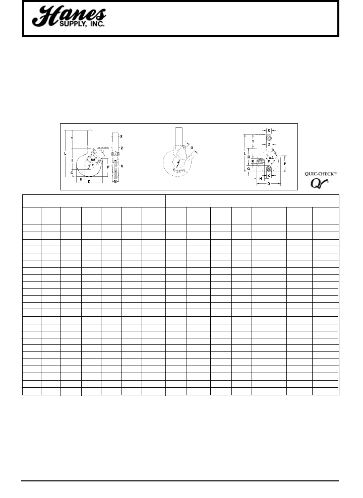
89
HEADQUARTERS: 55 James E. Casey Drive • Buffalo, NY 14206 PHONE: 716.826.2636 FAX: 716.826.4412 www.hanessupply.com
Hoist Hooks
*NOTE: Proof load is 2 times Working Load Limit. All carbon hooks – average straightening load (ultimate load) is 5 times Working Load Limit. Alloy
eye hooks 1 ton thru 22 tons – average straightening load (ultimate load) is 5 times Working Load Limit. Alloy eye hooks 30 tons through 60 tons –
average straightening load (ultimate load) is 4.0 times the Working Load Limit. Alloy shank hooks 1 ton through 22 tons – average straightening load
(ultimate load) is 4.0 times the Wroking Load Limit. Alloy shank hooks 30 tons through 300 tons (ultimate load is All Bronze hooks – average
straightening load (ultimate load) is 4 times Working Load Limit.
DIMENSIONS WEGHT EACH
(IN.) (LBS.)
DEFORMATION
INDICATOR
J K L O P Q R T†† X†† Y Z AA 319 320
.93 .63† 5.14 .89 2.00 .75 2.35 .87 .59 2.06 .69 1.50 .50 .61
.97 .71† 5.68 .91 2.24 .91 2.59 .98 .66 2.25 .78 2.00 .75 .75
1.06 .88† 6.35 1.00 2.45 1.13 2.76 1.03 .72 2.59 .88 2.00 1.00 1.00
1.19 .94† 4.14 1.09 2.82 1.25 3.16 1.16 .88 2.84 1.00 2.00 1.82 1.85
1.50 1.31 8.63 1.36 3.51 1.56 3.85 1.53 1.16 3.34 1.25 2.50 3.69 3.85
1.78 1.66 10.43 1.61 4.52 2.00 4.77 1.96 1.41 3.84 1.56 3.00 7.25 7.25
2.41 1.88 12.52 2.08 5.32 2.44 5.88 2.47 1.81 4.38 1.94 4.00 13.49 13.00
2.62 2.19 13.47 2.27 6.00 2.84 6.37 2.62 2.00 4.50 2.19 4.00 18.00 17.25
3.41 2.69 16.65 3.02 6.90 3.50 8.14 2.83 2.56 5.50 2.63 5.00 35.33 33.00
4.00 3.00 23.09 3.25 8.78 3.50 9.44 3.44 3.12 10.00 3.12 6.50 72.00 53.00
4.00 3.00 31.09 3.25 8.78 – 9.44 3.44 3.12 18.00 3.12 6.50 85.50 85.50
4.25 3.62 31.12 3.00 11.38 4.50 12.56 3.88 4.00 15.00 4.00 7.00 134.00 134.00
4.25 4.00 41.12 3.00 11.38 – 12.56 3.88 4.00 24.00 4.00 7.00 172.00 172.00
4.75 3.72 34.12 3.38 12.63 4.94 14.00 4.75 4.00 15.00 4.00 8.00 182.00 182.00
4.75 4.50 43.12 3.38 12.63 – 14.00 4.75 4.00 24.00 4.00 8.00 214.00 214.00
5.75 4.44 36.06 4.12 14.81 5.69 15.50 5.69 4.50 14.50 4.50 10.00 268.00 268.00
5.75 5.50 47.56 4.12 14.81 – 15.50 5.69 4.50 26.00 4.50 10.00 312.00 312.00
6.50 6.25 41.16 5.38 16.53 – 19.38 6.00 5.00 15.00 5.00 11.50 390.00 390.00
6.50 6.25 49.16 5.38 16.53 – 19.38 6.00 5.00 15.00 5.00 11.50 390.00 390.00
5.88 5.50 42.12 4.50 17.38 – 18.41 7.00 7.00 15.00 7.00 12.00 610.00 610.00
5.88 5.50 48.12 4.50 17.38 – 18.41 7.00 7.00 21.00 7.00 12.00 675.00 675.00
6.00 6.00 45.75 4.50 18.00 – 18.38 7.00 7.25 18.00 7.25 13.00 735.00 735.00
6.60 7.00 50.50 5.00 19.25 – 20.50 8.00 8.00 20.00 8.00 13.00 1020.00 1020.00
8.00 7.25 54.69 6.25 22.69 – 23.50 8.25 9.50 20.00 9.50 15.00 1390.00 1390.00
†Dimensions shown are for S-4320 latch kits. Dimensions for sizes 20 ton carbon and larger are for PL Latch Kits.
††Dimension before machining (as forged).
Shank Hook dimensions
with PL Latch Assembled
• Hoist hooks incorporate markings forged into the product which address two (2) QUIC-CHECK®
features.
• Deformation Indicators – Two strategically placed marks, one just below the shank or eye and the
other on the hook up, which allow for a QUIC-CHECK®measurement to determine if the throat
opening has changed, thus indicating abuse or overload.
• To check, use a measuring device (i.e. tape measure) to measure the distance between the
marks. The marks should align to either an inch or half-inch increment on the measuring device.
If the measurement does not meet this criteria, the hook should be inspected further for possible
damage.
• Angle Indicators – Indicates the maximum included angle which is allowed between two (2) sling
legs in the hook. These indicators also provide the opportunity to approximate other included
angles between two sling legs.
YOUR SLING AND RIGGING SPECIALIST
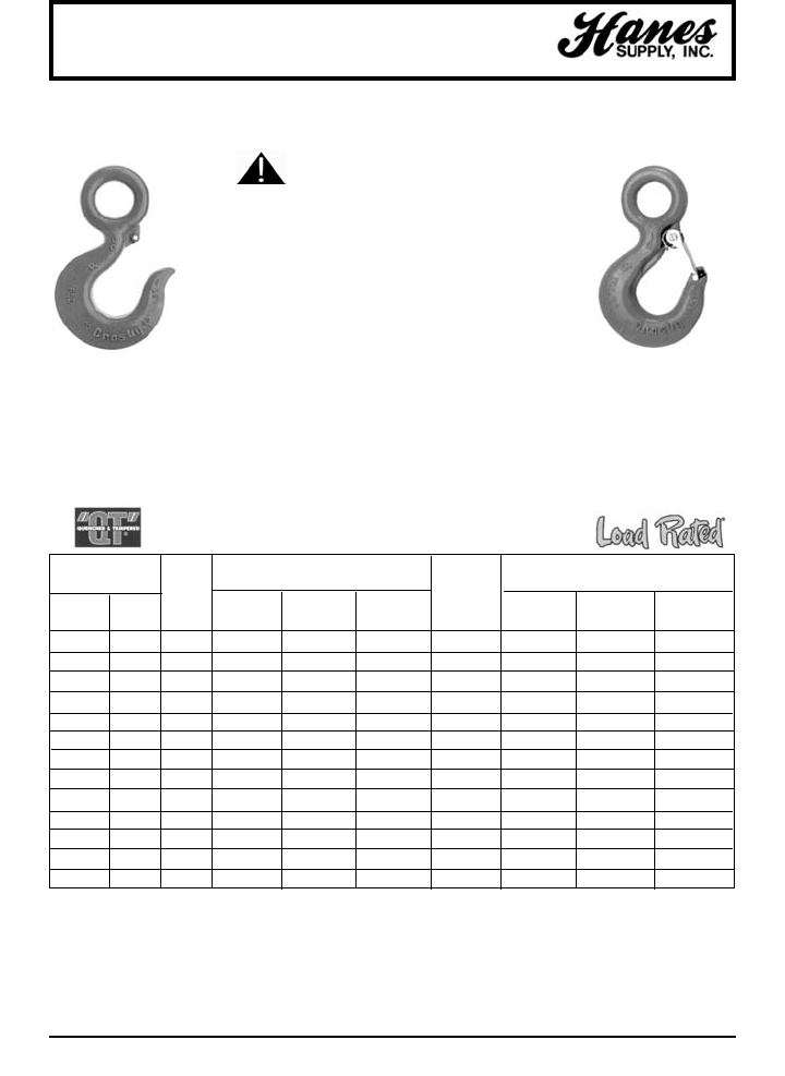
90
HEADQUARTERS: 55 James E. Casey Drive • Buffalo, NY 14206 PHONE: 716.826.2636 FAX: 716.826.4412 www.hanessupply.com
Sling and Hoist Hooks
All Crosby 320 Eye Hoist Hooks incorporate the following features:
• Designed with 5:1 Design Factor.
• Proper design, careful forging and precision controlled quenched
and tempering give maximum strength without excessive weight
and bulk.
• Pre-drilled cam which can be equipped with a latch.
• Eye hooks are load rated.
• Available in carbon steel and alloy steel.
• Strategically placed markings forged into the product which
address two (2) QUIC-CHECK®features. (See following page)
• Fatigue rated at 1-1/2 times the Working Load Limit at 20,000
cycles.
• Low profile hook tip.
• Integrated latch (S-4320) meets the World class standard for
lifting.
• Heavy duty stamped latch interlocks with the hook tip.
• High cycle, long life spring.
• When secured with proper cotter pin through the hole in the tip
of the hook, meets the intent of OSHA Rule 1926.550(g) for
personnel hoisting.
EYE HOOKS
SEE APPLICATION AND
WARNING INFORMATION
*Eye Hooks (3/4TC - 22TA), Proof load is 2.5 times Working Load Limit. Eye Hooks (20TC - 60TA), Proof Load is 2 times Working Load Limit.
All carbon hooks – average straightening loads (ultimate load) is 5 tiimes Working Load Limit. Alloy eye hooks 1 ton through 22 ton – average load)
is 4.5 times Working Load Limit.
†New 320N style hook.
WORKING
LOAD LIMITS* EYE HOOK REPLACEMENT
(TONS) STOCK NO. LATCH KITS
HOOK CARBON CARBON ALLOY WEIGHT
ID S-320C G-320C S320A EACH S-4320 PL SS-4055
CARBON ALLOY CODE S.C. GALV. S.C. (LBS.) STOCK NO. STOCK NO. STOCK NO.
3/4† 1† D 1022200 1022208 1022375 .61 1096325 – –
1† 1-1/2† F 1022211 1022219 1022386 .89 1096374 – –
1-1/2† 2† G 1022222 1022230 1022397 1.44 1096421 – –
2† 3† H 1022233 1022241 1022406 2.07 1096468 – –
3† 5† I 1022244 1022249 1022419 4.30 1096515 – –
5† 7† J 1022255 1022262 1022430 8.30 1096562 – –
7-1/2† 11† K 1022264 1022274 1022441 15.00 1096609 – –
10† 15† L 1022277 1022285 1022452 21.60 1096657 – –
15† 22† N 1022288 1022296 1022465 39.50 1096704 – –
20 30 O 1023289 – 1023546 60.00 – 1093716 1090161
25 37 P 1023305 – 1023564 105.00 – 1093717 1090189
30 45 S 1023323 – 1023582 148.00 – 1093718 1090189
40 60 T 1023341 – 1023608 228.00 – 1093719 1090205
S-320 S-320N / S-1320N
YOUR SLING AND RIGGING SPECIALIST
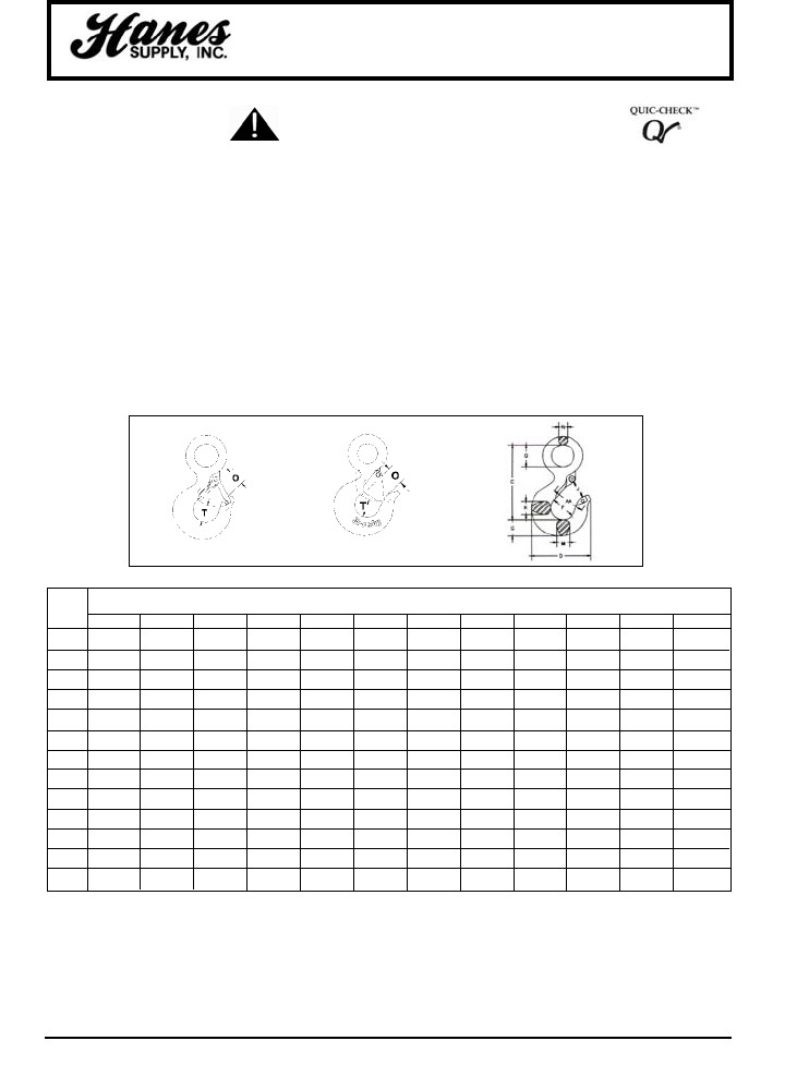
91
HEADQUARTERS: 55 James E. Casey Drive • Buffalo, NY 14206 PHONE: 716.826.2636 FAX: 716.826.4412 www.hanessupply.com
Sling and Hoist Hooks
HOOK DIMENSIONS
ID (IN.)
CODE C D F G J K M N O Q T AA
D 3.34 2.83 1.25 .73 .91 .63 .63 .36 .89 .75 .87 1.50
F 3.81 3.11 1.38 .84 .93 .71 .71 .42 .91 .91 .98 2.00
G 4.14 .353 1.50 1.00 1.00 .88 .88 .55 1.00 1.13 1.03 3.00
H 4.69 3.97 1.63 1.13 1.13 .94 .94 .58 1.09 1.25 1.16 2.00
I 5.77 4.81 2.00 1.44 1.47 1.31 1.31 .72 1.36 1.56 1.53 2.50
J 7.37 6.27 2.50 1.81 1.75 1.66 1.66 .90 1.61 2.00 1.96 3.00
K 9.07 7.45 3.00 2.25 2.29 1.88 1.63 1.11 2.08 2.44 2.47 4.00
L 10.08 8.30 3.25 2.59 2.50 2.19 1.94 4.27 2.27 2.84 2.62 4.00
N 12.53 10.30 4.25 3.00 3.30 2.69 2.38 1.56 3.02 3.50 2.83 5.00
O 14.06 13.62 5.00 3.62 4.00 3.00 3.00 1.75 3.25 3.50 3.44 6.50
P 18.19 14.06 5.38 4.56 4.25 4.00 3.19 2.00 3.00 4.50 3.88 7.00
S 20.12 15.44 6.00 5.06 4.75 4.50 3.25 2.18 3.38 4.94 4.75 8.00
T 23.72 18.50 7.00 6.00 5.75 5.50 3.91 2.53 4.12 5.69 5.69 10.00
Shank Hook dimensions
with PL Latch Assembled
• Hoist hooks incorporate markings forged into the product which address two (2) QUIC-
CHECK®features.
• Deformation Indicators – Two strategically placed marks, one just below the shank or
eye and the other on the hook up, which allow for a QUIC-CHECK®measurement to
determine if the throat opening has changed, thus indicating abuse or overload.
• To check, use a measuring device (i.e. tape measure) to measure the distance
between the marks. The marks should align to either an inch or half-inch increment
on the measuring device. If the measurement does not meet this criteria, the hook
should be inspected further for possible damage.
• Angle Indicators – Indicates the maximum included angle which is allowed between
two (2) sling legs in the hook. These indicators also provide the opportunity to
approimate other included angles between two sling legs.
*Eye Hooks (3/4TC - 22TA), Proof load is 2.5 times Working Load Limit. Eye Hooks (20TC - 60TA), Proof Load is 2 times Working Load Limit.
All carbon hooks – average straightening loads (ultimate load) is 5 tiimes Working Load Limit. Alloy eye hooks 1 ton through 22 ton – average load) is
4.5 times Working Load Limit.
SEE APPLICATION AND
WARNING INFORMATION
YOUR SLING AND RIGGING SPECIALIST
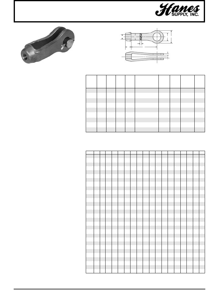
92
HEADQUARTERS: 55 James E. Casey Drive • Buffalo, NY 14206 PHONE: 716.826.2636 FAX: 716.826.4412 www.hanessupply.com
Material: C-1035 and SA-182-F-11 in stock
Threads: U.N.C. Class 2B, Right or Left Hand
Finish: Self-Colored, Galvanized, Plated
Options: Stainless Steel; Other Alloys;
Special Threading
Maximum working loads have been
established with a safety factor of 5:1 using
the maximum pin diameter, the resulting net
area of the eye at the pin hole, and the
expected ultimate tensile strength of C-1035
steel.
The maximum tap size (U dimension) shown
in Table I is for reference purposes only. It
should be used only to determine the largest
tap diameter the clevis can accommodate
without considering the pin diameter. Use
Table II to select the proper combination of tap
size and pin diameter for any given size of
clevis.
Clevis sizes in Table II for any given tap size
and pin diameter combination are based upon
the net area of the eye at the pin hole being
equal to or greater than 125% of the net area
at the minor diameter of a round rod without
upset ends, threaded Unified National Coarse
Series.
For any combination of tap size and pin
diameter shown, the pin in double shear will
develop the strength of the rod if both the rod
and pin are made from steel having the same
physical properties. The pin must be
investigated for bending, however; and if
inadequate, a larger diameter pin selected.
Pins supplied with clevises by Cleveland City
Forge are made from steel having a minimum
ultimate tensile strength of 58,000 pounds per
square inch, unless otherwise specified.
If the pin is made from steel with physical
properties lower in value than the steel used
for the rod, the pin may not develop the
strength of the rod in either shear or bending;
requiring a larger diameter pin.
Some combinations of tap size and pin
diameter shown will not develop the maximum
working load of the clevis shown in Table I.
Selection of the rod and pin, the material from
which both are made, as well as the clevis
size adequate to meet the required design
load is the responsibility of the purchaser or
user. Load imposed upon the clevis should not
exceed the maximum working load values
shown in Table I.
Clevises
DIAMETER OF TAP – Inches
A
U
T
N
WD
P
T
MAX.
WORKING WGT.
CLEVIS D N U W TOLERANCE A P LOAD EACH
NO. MAX. MAX. KIPS LBS.
2 1-7/16 5/8 5/8 1-1/16 5/16 + 1/32 - 0 3-9/16 3/4 3.5 1
2-1/2 2-1/2 1-1/8 7/8 1-1/4 5/16 + 1/32 - 0 4 1-1/2 7.5 2-1/2
3 3 1-1/4 1-3/8 1-1/2 1/2 + 1/32 - 1/32 5-1/16 1-3/7 15 4
3-1/2 3-1/2 1-1/2 1-1/2 1-3/4 1/2 + 1/16 - 1/16 6 2 18 6
4 4 1-3/4 1-3/4 2 1/2 + 1/16 - 1/16 5-15/16 2-1/4 21 8
5 5 2-1/4 2-1/8 2-1/2 5/8 + 3/32 - 0 7 2-1/2 37.5 16
6 6 2-3/4 2-1/2 3 3/4 + 3/32 - 0 8 3 54 26
7 7 3 3 3-1/2 7/8 + 1/8 - 1/16 9 3-3/4 68.5 36
8 8 4 4 4 1-1/2 + 1/8 - 1/16 10-1/8 4-1/4 135 90
TABLE I
STANDARD CLEVIS DIMENSIONS – Inches
1/2 5/8 3/4 7/8 1 1¼ 1½ 1¾ 2 2¼ 2½ 2¾ 3 3¼ 3½ 3¾ 4 4¼
3/8 2 2 2
1/2 2 2 2
5/8 2 2 2 2½2½ 2½2½
3/4 2½ 2½ 2½ 2½ 2½
7/8 2½ 2½ 2½ 3
13333
1-1/8 3 3 3 3 3½
1-1/4 3 3 3 3 3½
1-3/8 3 3 3½ 3½ 4
1-1/2 3½ 3½ 4 4 5
1-5/8 4 4 4 5 5 5
1-3/4 4 5 5 5 5
1-7/8 5 5 5 5 5
25555566
2-1/8 5 5 6 6 6 6
2-1/4 6 6 6 6 6 7 7
2-3/8 6 6 6 6 7 7 7 7
2-1/2 6 6 6 7 7 7 7 7
2-5/8 7 7 7 7 7 8
2-3/4 7 7 7 7 8 8
2-7/8 7 8 8 8 8 8 8 8
3 7 88 88 88 8
3-1/8 8 8 8 8 8 8 8
3-1/4 8 8 8 8 8 8 8
3-3/8 8 8 8 8 8 8 8
3-1/2 8 8 8 8 8 8
3-5/8 8 8 8 8 8
3-3/4 8 8 8 8
3-7/8 888
488
TABLE II
DIAMETER OF PIN – Inches
YOUR SLING AND RIGGING SPECIALIST
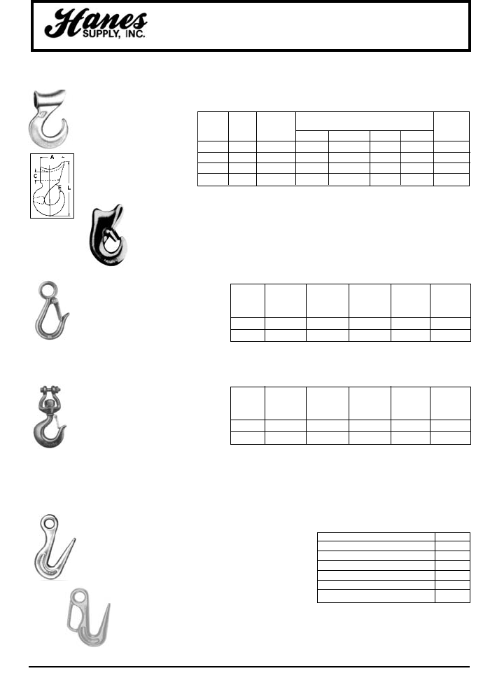
HEADQUARTERS: 55 James E. Casey Drive • Buffalo, NY 14206 PHONE: 716.826.2636 FAX: 716.826.4412 www.hanessupply.com
93
Hooks
HOOKS • SNAP • REPLACEMENT • SORTING
SINGLE EIGHT SAFE
PART PART WORKING DIMENSIONS (IN.) WEIGHT
ROPE ROPE LOAD* EACH
SIZE SIZE (LBS.) A C E L (LBS.)
3/8 – 2,500 2-1/16 5/8 5/8 4-9/32 .77
1/2 1/8 3,300 2-1/4 3/4 25/32 4-31/32 1.19
5/8† 3/16 5,000 3-1/16 3/4 OR 1 5/16 6-3/8 2.89
3/4† 1/4 8,000 3-3/8 1 OR 1-7/16 1-5/32 7-21/32 5.00
• FORGED ALLOY STEEL
through 3/4".
• Wide throat to take heavy
thimbles
*Ultimate Load is 5 times Safe
Working Load.
†When ordering, EYE diameter
("C") should be specified.
A-350
G-3315
S-3316
A-378
SAFE INSIDE
HOOK WORKING DIAM. THROAT LENGTH WEIGHT
SIZE LOAD OF EYE OPENING OVERALL POUNDS
(IN.) (LBS.) (IN.) (IN.) (IN.) PER 100
7/16 750 3/4 3/4 3-15/16 23.25
9/16 1,000 1-1/8 13/16 4-3/4 48.25
SLIDING CHOKER HOOKS Quenched & Tempered
SNAP HOOKS Forged Steel, Quenched & Tempered
• Pressed steel latches and stainless
steel springs, bolts and nuts.
• Safe Working Loads shown are
based on Ultimate Load that is 4
times the Safe Working Load.
WIDTH
SIZE BETWEEN DIAM. OVERALL THROAT WEIGHT
HOIST JAWS BOLT LENGTH OPENING EACH
(TON) (IN.) (IN.) (IN.) (IN.) (LBS.)
1/2 9/16 3/8 6-1/8 31/32 1.25
1 11/16 7/16 7-11/16 1-1/8 2.61
REPLACEMENT HOOKS Quenched & Tempered
• Easily attached to any hoist with
welded link load chain and roller
chain or wire rope with suitable end
fitting.
• Spring latch, latch bolt with self
locking nut – stainless steel. Nuts
cadmium plated brass.
• For chain and electric hoists with
swivel jaw-forged.
Forged Alloy Steel
SORTING HOOKS Quenched & Tempered
• Deep straight throat permits efficient handling of flat plates
or large cylindrical shapes.
• The long tapered point allow easy grab in rings, pear links,
eye bolts or lifting holes.
• Ultimate load is 5 times the Safe Working Load.
Safe Working Load at Tip 2 Ton
Safe Working Load at Bottom of Hook 7-1/2 Ton
Overall Length 9-11/16"
I.D. of Eye 1-3/8"
Opening at Top of Hook 2-13/16"
Radius at Bottom of Hook 5/8"
Weight Each 6.42 Lbs.
SORTING HOOK
with HANDLE
SLIDING CHOKER
HOOK with LATCH
YOUR SLING AND RIGGING SPECIALIST
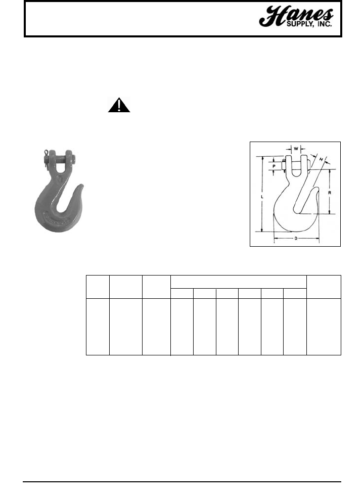
HEADQUARTERS: 55 James E. Casey Drive • Buffalo, NY 14206 PHONE: 716.826.2636 FAX: 716.826.4412 www.hanessupply.com
94
Chain Hooks
CM ALLOY CLEVIS TYPE GRAB HOOK – GRADE 80
• Attach directly to the chain – no connecting
links to buy.
• Heat treated pins.
• Extra deep throat.
• Painted orange.
• Hooks embossed with chain grade.
• "Alloy" forged on every hook.
• Grab hooks are compatible with grade 80 alloy
chain except M807A.
• Alloy clevis hooks develop the mechanical
properties of grade 80, as stated, but are not
recommended for overhead lifting sling
applications.
M806A
WORKING DIMENSIONS
CHAIN LOAD (IN.) APPROX
SIZE LIMIT† PROD. WEIGHT
(IN.) (LBS.) CODE W D H L P R EA. (LBS.)
1/4 3,500 M804A 5/16 1-15/16 3/8 3-1/4 21/64 1-7/8 .38
5/16 4,500 M805A 3/8 2-9/32 7/16 3-31/32 25/64 2-3/8 .62
3/8 7,100 M806A 29/64 2-5/8 1/2 4-1/2 1/2 2-5/8 .96
7/16 6,900 M807A** 1/2 3 9/16 5-1/32 1/2 3 1.46
1/2 12,000 M808A 19/32 3-7/16 21-32 5-23/32 19/32 3-5/16 2.02
5/8 18,100 M810A 3/4 4-5/16 23-32 6-7/8 3/4 3-15/16 3.75
SEE APPLICATION AND
WARNING INFORMATION
†Alloy clevis hooks develop the mechanical properties of grade 80, as stated, but are not recommended for
overhead lifting sling applications.
**Grade 63
YOUR SLING AND RIGGING SPECIALIST
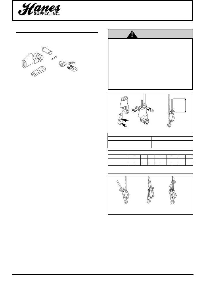
HEADQUARTERS: 55 James E. Casey Drive • Buffalo, NY 14206 PHONE: 716.826.2636 FAX: 716.826.4412 www.hanessupply.com
95
Wedge Sockets
S-421T
"THE TERMINATOR™"
NOTE: Existing Crosby S-421 Wedge Sockets can be
retrofitted with the New Terminator Wedge.
New QUIC-CHECK™ "Go" and "No-Go" features cast into
wedge. The proper size wire rope is determined when the
following criteria are met:
1. The wire rope shall pass thru the "Go" hole in the wedge.
2. The wire rope shall NOT pass thru the "No-Go" hole in the
wedge.
Important Safety Information –
Read and Follow
Inspection / Maintenance Safety
• Always inspect socket, wedge and pin before using.
• Do not use part showing cracks.
• Do not use modified or substitute parts.
• Repair minor nicks or gouges to socket or pin by lightly
grinding until surfaces are smooth. Do not reduce original
dimension more than 10%. Do not repair by welding.
• Inspect permanent assemblies annually, or more often in
severe operating conditions.
Assembly Safety
• Use only with standard 6 to 8 strand wire rope of designated
size. For intermediate size rope, use next larger size socket.
For example: When using 9/16" diameter wire rope use a 5/8"
size Wedge Socket Assembly. WElding of the tail on the
standard wire rope is not recommended. The tail length of the
dead end should be a minimum of 6 rope diameters but not
less than 6". (See Figure 1)
• To use with Rotation Resistant wire rope (special wire rope
constructions with 8 or more outer strands) ensure that the
dead end is welded, brazed or seized before inserting the
wire rope into the wedge socket to prevent core slippage or
loss of rope lay. The tail length of the dead end should be a
minimum of 20 rope diameters but not less than 6". (See
Figure 1)
• Properly match socket, wedge and clip (See Table I) to wire
rope size.
• Align live end of rope, with center line of pin. (See Figure 1)
• Secure dead end section of rope. (See Figure 1)
• Tighten nuts on clip to recommended torque. (Table I)
• Do not attach dead end to live end or install wedge
backwards. (See Figure 2)
•Use a hammer to seat Wedge and Rope as deep into
socket as possible before applying first load.
• Loads may slip and fall if the Wedge Socket
is not properly installed.
• A failing load can seriously injure or kill.
• Read and understand these instructions
before installing the Wedge Socket.
• Do not side load the Wedge Socket.
• Apply first load to fully seat the Wedge and
Wire Rope in the socket. This load should be
of equal or greater weight than loads
expected in use.
WEDGE SOCKET
WARNINGS AND APPLICATION
INSTRUCTIONS
Extended Wedge Socket Assembly
U.S. Patent No. 5,553,360
FIGURE 1
*TAIL
LENGTH
"Go"
"No-Go"
RIGHT
*Tail Length
Standard 6 to 8 strand wire rope Rotation Resistant Wire Rope
A minimum of 6 rope diameters, A minimum of 20 rope diameters,
but not less than 6". but not less than 6".
TABLE I
Rope Size 3/8 7/16 1/2 9/16 5/8 3/4 7/8 1 1-1/8 1-1/4
Clip Size 3/8 7/16 1/2 9/16 5/8 3/4 7/8 1 1-1/8 1-1/4
*Torque Ft./Lbs. 45 65 65 95 95 130 225 225 225 360
*The lightening torque values shown are based upon the threads
being clean, dry, and free of lubrication.
Operating Safety
• Apply first load to fully seat the Wedge and Wire Rope in
the socket. This load should be of equal or greater weight
than loads expected in use.
• Efficiency rating of the Wedge socket termination is based
upon the catalog breaking strength of Wire Rope. The
efficiency of a properly assembled Wedge Socket is 80%.
• During use, do not strike the dead end section with any
other elements of the rigging (Called two-blocking).
WRONG
Rope
Backward
WRONG
Wedge
Backward
WRONG
Tail Clipped
to live Line
FIGURE 2
WARNING
YOUR SLING AND RIGGING SPECIALIST
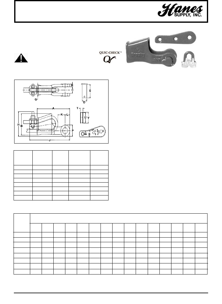
96
HEADQUARTERS: 55 James E. Casey Drive • Buffalo, NY 14206 PHONE: 716.826.2636 FAX: 716.826.4412 www.hanessupply.com
Wedge Sockets
• Basket is cast steel.
• Individually magnetic particle inspected.
• Pin diameter and jaw opening allows wedge and socket to
be used in conjunction with open swage and spelter
sockets.
• Secures the tail or "dead end" of the wire rope to the
wedge, thus eliminates loss or "Punch out" of the wedge.
• The TERMINATOR™ wedge eliminates the potential
breaking off of the tail due to fatigue.
• The tail, which is secured by the base of the clip and the
wedge, is left undeformed and available for reuse.
• Incorporates Crosby's patented QUIC-CHECK™ "Go"
and "No-Go" feature cast into the wedge. The proper size
rope is determined when the following criteria are met:
1. The wire rope should pass thru the "Go" hole in the
wedge.
2. The wire rope should NOT pass thru the "No-Go"
hole in the wedge.
• Utilizes standard Crosby Red-U-Bolt wire rope clip.
• Generates a minimum efficiency of 80% based on the
catalog breaking strength of the wire rope.
• Standard S-421 wedge socket can be retrofitted with the
new style TERMINATOR™ wedge.
• Available with Bolt, Nut and Cotter Pin.
U.S. Patent No. 5,553,360 and foreign equivalents
"THE TERMINATOR™"
Crosby's New & Improved Wedge Socket
SEE APPLICATION AND
WARNING INFORMATION
S-421T S-421T S-421TW
WIRE ROPE STOCK NO WEIGHT S-421TW WEIGHT
SIZE COMPLETE EACH STOCK NO. EACH
(IN.) ASSEMBLY* (LBS.) WEDGE ONLY (LBS.)
3/8 1035000 3.18 1035555 .50
1/2 1035009 6.15 1035564 1.05
5/8 1035018 9.70 1035573 1.79
3/4 1035027 14.50 1035582 2.60
7/8 1035036 21.50 1035591 4.02
1 1035045 30.75 1035600 5.37
1-1/8 1035051 45.30 1035609 7.84
1-1/4** 1040448 57.50 1040607 6.81
WIRE
ROPE DIMENSIONS (IN)
DIA.‡
(IN.) A B C D G H J† K† L P R S T U V
3/8 5.63 2.66 .81 .81 1.38 3.12 7.38 1.60 .88 1.56 .44 2.13 .44 1.25 1.38
1/2 6.81 3.53 1.00 1.00 1.62 3.85 8.75 1.21 1.06 1.94 .50 2.56 .53 1.75 1.88
5/8 8.16 4.25 1.25 1.19 2.12 4.58 10.34 1.64 1.22 2.25 .56 3.25 .69 2.00 2.19
3/4 9.78 4.96 1.50 1.38 2.44 5.37 12.03 2.17 1.40 2.62 .66 3.63 .78 2.34 2.56
7/8 11.16 5.66 1.75 1.63 2.69 6.28 14.00 2.22 1.66 3.12 .75 4.31 .88 2.69 2.94
1 12.75 6.31 2.00 2.00 2.56 7.02 15.86 2.71 2.00 3.75 .88 4.70 1.03 2.88 3.29
1-1/8 14.38 6.94 2.25 2.25 3.31 7.76 17.70 2.50 2.25 4.25 1.00 5.44 1.19 3.13 3.56
1-1/4 16.00 7.53 2.50 2.50 3.56 N/A N/A 3.39 2.50 4.75 1.12 6.13 1.31 3.38 3.81
*Terminator Assembly includes Socket, Wedge, Pin and Wire Rope Clip.
**1-1/4" not available in TERMINATOR™ style.
†Nominal
‡For intermediate wire rope sizes use next larger size socket.
S-421T
YOUR SLING AND RIGGING SPECIALIST
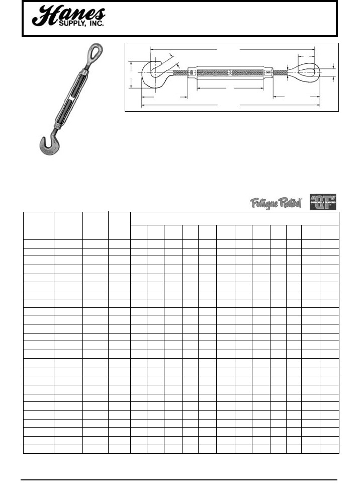
97
HEADQUARTERS: 55 James E. Casey Drive • Buffalo, NY 14206 PHONE: 716.826.2636 FAX: 716.826.4412 www.hanessupply.com
Hook & Eye Turnbuckles
HG-225
HOOK & EYE
Meets the performance requirements
of Federal Specification FF-T-79 lb.,
Type 1, Form 1 – CLASS 6, and
ASTM F-1145, except for those
provisions required of the contractor.
• Hot Dip galvanized steel.
• End fittings are Quenched and Tempered, bodies heat treated by
normalizing.
• Turnbuckle eyes are forged elongated, by design, to maximize easy
attachment in system and minimize stress in the eye. For turnbuckle sizes
1/4" through 2-1/2", a shackle one size smaller can be reeved through eye.
• Turnbuckle hooks are forged with a greater cross sectional area that results
in a stronger hook with better fatigue properties.
• TURNBUCKLES RECOMMENDED FOR STRAIGHT OR IN-LINE PULL ONLY.
• Modified UNJ thread on end fittings for improved fatigue properties. Body
has UNC threads.
• Lock Nuts available for all sizes.
THREAD WORKING
DIAMETER LOAD WEIGHT DIMENSIONS (IN)
& TAKE UP STOCK NO. LIMIT* EACH A D E F J K M N R S X BB
(IN.) GALV. (LBS.) (LBS.) CLOSED OPEN CLOSED OPEN CLOSED CLOSED
1/4 x 4 1030636 400 .29 .25 .45 1.59 1.27 11.46 7.46 12.09 8.09 .78 .34 1.75 4.00
5/16 x 4-1/2 1030654 700 .49 .31 .50 1.94 1.50 13.19 8.69 13.47 9.47 .94 .44 2.09 4.50
3/8 x 6 1030672 1000 .78 .38 .56 2.30 1.77 16.98 10.98 17.94 11.94 1.12 .53 2.52 6.00
1/2 x 6 1030690 1500 1.61 .50 .66 2.94 2.28 19.45 12.45 20.67 13.67 1.42 .72 3.23 6.00
1/2 x 9 1030716 1500 1.85 .50 .66 2.94 2.28 25.45 15.45 26.67 16.67 1.42 .72 3.23 9.00
1/2 x 12 1030734 1500 2.26 .50 .66 2.94 2.28 31.45 18.45 32.67 19.67 1.42 .72 3.23 12.00
5/8 x 6 1030752 2250 2.70 .63 .90 3.69 2.81 21.96 13.96 22.72 15.47 1.80 .88 3.90 6.00
5/8 x 9 1030770 2250 3.13 .63 .90 3.69 2.81 27.96 16.96 28.72 18.47 1.80 .88 3.90 9.00
5/8 x 12 1030798 2250 3.78 .63 .90 3.69 2.81 33.21 19.96 34.72 21.47 1.80 .88 3.90 12.00
3/4 x 6 1030814 3000 3.89 .75 .98 4.52 3.33 23.13 15.63 24.95 17.45 2.09 1.00 4.69 6.00
3/4 x 9 1030832 3000 4.61 .75 .98 4.52 3.33 29.13 18.63 30.95 20.45 2.09 1.00 4.69 9.00
3/4 x 12 1030850 3000 5.83 .75 .98 4.52 3.33 35.13 21.63 36.95 23.45 2.09 1.00 4.69 12.00
3/4 x 18 1030878 3000 6.33 .75 .98 4.52 3.33 47.13 27.63 48.95 29.45 2.09 1.00 4.69 18.00
7/8 x 12 1030896 4000 8.10 .88 1.13 5.19 3.78 36.53 22.78 38.66 24.91 2.38 1.25 5.10 12.00
7/8 x 18 1030912 4000 9.95 .88 1.13 5.19 3.78 48.53 28.78 50.66 30.91 2.38 1.25 5.10 18.00
1 x 6 1030930 5000 9.33 1.00 1.25 5.84 4.25 26.80 18.80 29.20 21.20 3.00 1.44 6.36 6.00
1 x 12 1030958 5000 11.93 1.00 1.25 5.84 4.25 38.80 24.80 41.20 27.20 3.00 1.44 6.36 12.00
1 x 18 1030976 5000 14.00 1.00 1.25 5.84 4.25 50.80 30.80 53.20 33.20 3.00 1.44 6.36 18.00
1 x 24 1030994 5000 17.25 1.00 1.25 5.84 4.25 62.80 36.80 65.20 39.20 3.00 1.44 6.36 24.00
1-1/4 x 12 1031010 6500 19.00 1.25 1.50 7.22 5.13 41.63 27.13 44.56 30.06 3.56 1.81 7.72 12.00
1-1/4 x 18 1031038 6500 23.00 1.25 1.50 7.22 5.13 53.63 33.13 56.56 36.06 3.56 1.81 7.72 18.00
1-1/4 x 24 1031056 6500 24.00 1.25 1.50 7.22 5.13 65.63 39.13 68.56 42.06 3.56 1.81 7.72 24.00
1-1/2 x 12 1031074 7500 27.50 1.50 1.88 8.34 5.75 44.72 29.72 47.72 32.72 4.06 2.12 8.62 12.00
1-1/2 x 18 1031092 7500 31.00 1.50 1.88 8.34 5.75 56.72 35.72 59.72 38.72 4.06 2.12 8.62 18.00
1-1/2 x 24 1031118 7500 37.50 1.50 1.88 8.34 5.75 68.72 41.72 71.72 44.72 4.06 2.12 8.62 24.00
*Proof Load is 2.5 times the Working Load Limit. Ultimate Load is 5 times Working Load Limit.
M OPEN
N CLOSED
X CLOSED
J OPEN
K CLOSED
A
R
S
BB
E CLOSED
F
D
YOUR SLING AND RIGGING SPECIALIST
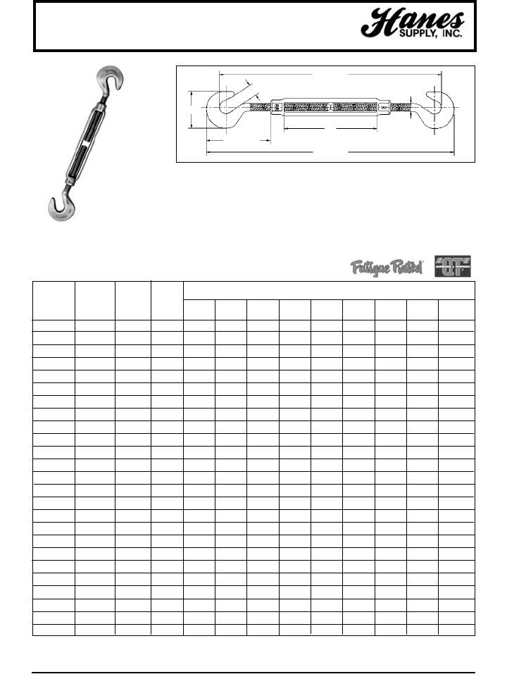
HEADQUARTERS: 55 James E. Casey Drive • Buffalo, NY 14206 PHONE: 716.826.2636 FAX: 716.826.4412 www.hanessupply.com
98
Hook & Hook Turnbuckles
HG-223
HOOK & HOOK
Meets the performance requirements
of Federal Specification FF-T-79 lb.,
Type 1, Form 1 – CLASS 5, and
ASTM F-1145, except for those
provisions required of the contractor.
• Hot Dip galvanized steel.
• End fittings are Quenched and Tempered, bodies heat treated by normalizing.
• Turnbuckle hooks are forged with a greater cross sectional area that results in a
stronger hook with better fatigue properties.
• TURNBUCKLES RECOMMENDED FOR STRAIGHT OR IN-LINE PULL ONLY.
• Modified UNJ thread on end fittings for improved fatigue properties. Body has
UNC threads.
• Lock Nuts available for all sizes.
• Fatigue Rated.
*Proof Load is 2.5 times the Working Load Limit. Ultimate Load is 5 times Working Load Limit.
THREAD WORKING
DIAMETER LOAD WEIGHT DIMENSIONS (IN)
& TAKE UP STOCK NO. LIMIT* EACH A D E F J K M N BB
(IN.) GALV. (LBS.) (LBS.) CLOSED OPEN CLOSED OPEN CLOSED
1/4 x 4 1030011 400 .30 .25 .45 1.59 1.27 11.12 7.12 11.94 7.94 4.00
5/16 x 4-1/2 1030039 700 .47 .31 .50 1.94 1.50 12.81 8.31 13.81 9.31 4.50
3/8 x 6 1030057 1000 .78 .38 .56 2.30 1.77 16.50 10.50 17.72 11.72 6.00
1/2 x 6 1030075 1500 1.60 .50 .66 2.94 2.28 18.82 11.82 20.38 13.38 6.00
1/2 x 9 1030093 1500 1.83 .50 .66 2.94 2.28 24.82 14.82 26.38 16.38 9.00
1/2 x 12 1030119 1500 2.28 .50 .66 2.94 2.28 30.82 17.82 32.38 19.38 12.00
5/8 x 6 1030137 2250 2.75 .63 .90 3.69 2.81 20.50 13.25 22.50 15.25 6.00
5/8 x 9 1030155 2250 3.38 .63 .90 3.69 2.81 26.50 16.25 28.50 18.25 9.00
5/8 x 12 1030173 2250 3.50 .63 .90 3.69 2.81 32.50 19.25 34.50 21.25 12.00
3/4 x 6 1030191 3000 3.89 .75 .98 4.52 3.33 22.38 14.88 24.78 17.28 6.00
3/4 x 9 1030217 3000 5.28 .75 .98 4.52 3.33 28.38 17.88 30.78 20.28 9.00
3/4 x 12 1030235 3000 5.43 .75 .98 4.52 3.33 34.38 20.88 36.78 23.28 12.00
3/4 x 18 1030253 3000 8.12 .75 .98 4.52 3.33 46.38 26.88 48.78 29.28 18.00
7/8 x 12 1030271 4000 8.10 .88 1.13 5.19 3.78 36.00 22.25 38.75 25.00 12.00
7/8 x 18 1030299 4000 9.95 .88 1.13 5.19 3.78 48.00 28.25 50.75 31.00 18.00
1 x 6 1030315 5000 9.33 1.00 1.25 5.84 4.25 25.63 17.63 28.69 20.69 6.00
1 x 12 1030333 5000 11.93 1.00 1.25 5.74 4.25 37.63 23.63 40.69 26.69 12.00
1 x 18 1030351 5000 14.00 1.00 1.25 5.84 4.25 49.63 29.63 52.69 32.69 18.00
1 x 24 1030379 5000 17.25 1.00 1.25 5.84 4.25 61.63 35.63 64.69 38.69 24.00
1-1/4 x 12 1030397 6500 20.58 1.25 1.50 7.22 5.13 40.44 25.94 44.06 29.56 12.00
1-1/4 x 18 1030413 6500 23.00 1.25 1.50 7.22 5.13 52.44 31.94 56.06 35.56 18.00
1-1/4 x 24 1030431 6500 27.00 1.25 1.50 7.22 5.13 64.44 37.94 68.06 41.56 24.00
1-1/2 x 12 1030459 7500 27.50 1.50 1.88 8.34 5.75 43.94 28.94 47.44 32.44 12.00
1-1/2 x 18 1030477 7500 31.00 1.50 1.88 8.34 5.75 55.96 34.94 59.44 38.44 18.00
1-1/2 x 24 1030495 7500 37.50 1.50 1.88 8.34 5.75 67.94 40.94 71.44 44.44 24.00
M OPEN
N CLOSED
J OPEN
K CLOSED
A
BB
E CLOSED
F
D
YOUR SLING AND RIGGING SPECIALIST
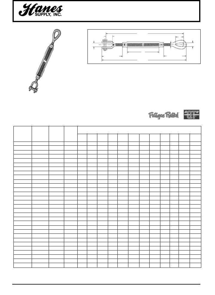
HEADQUARTERS: 55 James E. Casey Drive • Buffalo, NY 14206 PHONE: 716.826.2636 FAX: 716.826.4412 www.hanessupply.com
99
Jaw & Eye Turnbuckles
THREAD WORKING
DIAMETER LOAD WEIGHT DIMENSIONS (IN)
& TAKE UP STOCK NO. LIMIT* EACH A D E F J K M N R S X BB
(IN.) GALV. (LBS.) (LBS.) CLOSED OPEN CLOSED OPEN CLOSED CLOSED
1/4 x 4 1031877 500 .30 .25 .45 1.58 .62 11.35 7.35 12.07 8.17 .78 .34 1.75 4.00
5/16 x 4-1/2 1031895 800 .50 .31 .50 1.98 .87 13.71 8.71 14.01 9.51 .94 .44 2.09 4.50
3/8 x 6 1031911 1200 .80 .38 .54 2.12 .87 16.81 10.81 17.77 11.77 1.12 .53 2.52 6.00
1/2 x 6 1031939 2200 1.51 .50 .55 2.75 1.06 19.29 12.29 20.47 13.48 1.42 .72 3.23 6.00
1/2 x 9 1031957 2200 1.71 .50 .55 2.75 1.06 25.29 15.29 26.48 16.48 1.42 .72 3.23 9.00
1/2 x 12 1031975 2200 2.08 .50 .55 2.75 1.06 31.29 18.29 32.48 19.48 1.42 .72 3.23 12.00
5/8 x 6 1031993 3500 2.35 .63 .82 3.50 1.31 20.99 13.74 22.53 15.28 1.80 .88 3.90 6.00
5/8 x 9 1032019 3500 3.17 .63 .82 3.50 1.31 26.99 16.74 28.53 18.28 1.80 .88 3.90 9.00
5/8 x 12 1032037 3500 3.61 .63 .82 3.50 1.31 32.99 19.74 34.53 21.28 1.80 .88 3.90 12.00
3/4 x 6 1032055 5200 4.00 .75 1.03 4.18 1.50 22.69 15.19 24.61 17.11 2.09 1.00 4.69 6.00
3/4 x 9 1032073 5200 4.75 .75 1.03 4.18 1.50 28.69 18.19 30.61 20.11 2.09 1.00 4.69 9.00
3/4 x 12 1032091 5200 5.93 .75 1.03 4.18 1.50 34.69 21.19 36.61 23.11 2.09 1.00 4.69 12.00
3/4 x 18 1032117 5200 7.00 .75 1.03 4.18 1.50 46.69 27.19 48.61 29.11 2.09 1.00 4.69 18.00
7/8 x 12 1032135 7200 8.36 .88 1.23 4.85 1.75 36.09 22.34 38.32 24.57 2.38 1.25 5.10 12.00
7/8 x 18 1032153 7200 9.75 .88 1.23 4.85 1.75 48.09 28.34 50.32 30.57 2.38 1.25 5.10 18.00
1 x 6 1032171 10000 8.92 1.00 1.31 5.53 2.06 26.34 18.34 28.89 20.89 3.00 1.44 6.36 6.00
1 x 12 1032199 10000 11.20 1.00 1.31 5.53 2.06 38.34 24.34 40.89 26.89 3.00 1.44 6.36 12.00
1 x 18 1032215 10000 13.30 1.00 1.31 5.53 2.06 50.34 30.34 52.89 32.89 3.00 1.44 6.36 18.00
1 x 24 1032233 10000 17.00 1.00 1.31 5.53 2.06 62.34 36.34 64.89 38.89 3.00 1.44 6.36 24.00
1-1/4 x 12 1032251 15200 19.42 1.25 1.86 7.21 2.81 41.32 26.82 44.55 30.05 3.56 1.81 7.72 12.00
1-1/4 x 18 1032279 15200 24.18 1.25 1.86 7.21 2.81 53.32 32.82 56.05 36.05 3.56 1.81 7.72 18.00
1-1/4 x 24 1032297 15200 28.50 1.25 1.86 7.21 2.81 65.32 38.82 68.55 42.05 3.56 1.81 7.72 24.00
1-1/2 x 12 1032313 21400 28.99 1.50 2.25 7.88 2.81 43.50 28.50 47.25 32.25 4.06 2.12 8.62 12.00
1-1/2 x 18 1032331 21400 35.00 1.50 2.25 7.88 2.81 55.50 34.50 59.25 38.25 4.06 2.12 8.62 18.00
1-1/2 x 24 1032359 21400 39.18 1.50 2.25 7.88 2.81 67.50 40.50 71.25 44.25 4.06 2.12 8.62 24.00
1-3/4 x 18 1032395 28000 53.75 1.75 2.60 9.40 3.38 55.38 37.38 59.78 41.78 4.62 2.38 10.00 18.00
1-3/4 x 24 1032411 28000 60.68 1.75 2.60 9.40 3.38 67.38 43.38 71.78 47.78 4.62 2.38 10.00 24.00
2 x 24 1032439 37000 89.00 2.00 2.62 11.86 3.69 72.62 48.62 77.95 53.95 5.75 2.69 13.09 24.00
2-1/2 x 24 1032457 60000 150.00 2.50 3.06 13.56 4.44 75.80 51.80 82.40 58.40 6.50 3.12 13.78 24.00
2-3/4 x 24 1032475 75000 183.00 2.75 3.68 15.22 4.19 77.88 53.88 85.50 61.50 7.00 3.25 15.22 24.00
*Proof Load is 2.5 times the Working Load Limit. Ultimate Load is 5 times Working Load Limit.
HG-227
JAW & EYE
Meets the performance requirements
of Federal Specification FF-T-79 lb.,
Type 1, Form 1 – CLASS 8, and
ASTM F-1145, except for those
provisions required of the contractor.
• Hot Dip galvanized steel.
• End fittings are Quenched and Tempered, bodies heat treated by normalizing.
• Turnbuckle eyes are forged elongated, by design, to maximize easy
attachment in system and minimize stress in the eye. For turnbuckle sizes
1/4" through 2-1/2", a shackle one size smaller can be reeved through eye.
• Forged jaw ends are fitted with bolts and nuts for 1/4" through 5/8", and pins
and cotters on 3/4" through 2-3/4" sizes.
• TURNBUCKLES RECOMMENDED FOR STRAIGHT OR IN-LINE PULL ONLY.
• Modified UNJ thread on end fittings for improved fatigue properties. Body has
UNC threads.
• Lock Nuts available for all sizes.
M OPEN
N CLOSED
X CLOSED
J OPEN
K CLOSED
AR
BB
E CLOSED
B
G
S
YOUR SLING AND RIGGING SPECIALIST
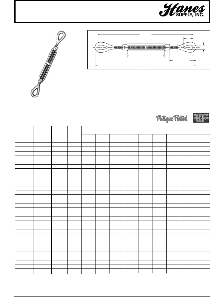
100
HEADQUARTERS: 55 James E. Casey Drive • Buffalo, NY 14206 PHONE: 716.826.2636 FAX: 716.826.4412 www.hanessupply.com
Eye & Eye Turnbuckles
THREAD WORKING
DIAMETER LOAD WEIGHT DIMENSIONS (IN)
& TAKE UP STOCK NO. LIMIT* EACH A J K M N R S X BB
(IN.) GALV. (LBS.) (LBS.) OPEN CLOSED OPEN CLOSED CLOSED
1/4 x 4 1031252 500 .26 .25 11.80 7.80 12.25 8.25 .78 .34 1.75 4.00
5/16 x 4-1/2 1031270 800 .45 .31 13.56 9.06 14.12 9.62 .94 .44 2.09 4.50
3/8 x 6 1031298 1200 .76 .38 17.47 11.47 18.16 12.16 1.12 .53 2.52 6.00
1/2 x 6 1031314 2200 1.54 .50 20.08 13.08 20.96 13.96 1.42 .72 3.23 6.00
1/2 x 9 1031332 2200 1.13 .50 26.08 16.08 26.96 16.96 1.42 .72 3.23 9.00
1/2 x 12 1031350 2200 2.14 .50 32.08 19.08 32.96 19.96 1.42 .72 3.23 12.00
5/8 x 6 1031378 3500 3.28 .63 21.93 14.68 22.93 15.68 1.80 .88 3.90 6.00
5/8 x 9 1031396 3500 2.83 .63 27.93 17.68 28.93 18.68 1.80 .88 3.90 9.00
5/8 x 12 1031412 3500 3.42 .63 33.93 20.68 34.93 21.68 1.80 .88 3.90 12.00
3/4 x 6 1031430 5200 3.79 .75 23.88 16.38 25.12 17.62 2.09 1.00 4.69 6.00
3/4 x 9 1031458 5200 4.61 .75 29.88 19.38 31.12 20.62 2.09 1.00 4.69 9.00
3/4 x 12 1031476 5200 5.48 .75 35.88 22.38 37.12 23.62 2.09 1.00 4.69 12.00
3/4 x 18 1031494 5200 7.19 .75 47.88 28.38 49.12 29.62 2.09 1.00 4.69 18.00
7/8 x 12 1031519 7200 7.22 .88 37.07 23.32 38.57 24.82 2.38 1.25 5.10 12.00
7/8 x 18 1031537 7200 9.95 .88 49.07 29.32 50.57 30.82 2.38 1.25 5.10 18.00
1 x 6 1031555 10000 9.04 1.00 27.97 19.97 29.72 21.72 3.00 1.44 6.36 6.00
1 x 12 1031573 10000 11.50 1.00 39.97 25.97 41.97 27.72 3.00 1.44 6.36 12.00
1 x 18 1031591 10000 14.00 1.00 51.97 31.97 53.72 33.72 3.00 1.44 6.36 18.00
1 x 24 1031617 10000 17.25 1.00 63.97 37.97 65.82 39.72 3.00 1.44 6.36 24.00
1-1/4 x 12 1031635 15200 19.00 1.25 42.81 28.31 45.06 30.56 3.56 1.81 7.72 12.00
1-1/4 x 18 1031653 15200 23.00 1.25 54.81 34.31 57.06 36.56 3.56 1.81 7.72 18.00
1-1/4 x 24 1031671 15200 27.00 1.25 66.81 40.31 69.06 42.56 3.56 1.81 7.72 24.00
1-1/2 x 12 1031699 21400 27.50 1.50 45.50 30.50 48.00 33.00 4.06 2.12 8.62 12.00
1-1/2 x 18 1031715 21400 31.00 1.50 57.50 36.50 60.00 39.00 4.06 2.12 8.62 18.00
1-1/2 x 24 1031733 21400 37.50 1.50 69.50 42.50 72.00 45.00 4.06 2.12 8.62 24.00
1-3/4 x 18 1031779 28000 52.50 1.75 57.38 39.38 60.38 42.38 4.62 2.38 10.00 18.00
1-3/4 x 24 1031797 28000 58.00 1.75 69.38 45.38 72.38 48.38 4.62 2.38 10.00 24.00
2 x 24 1031813 37000 85.25 2.00 75.69 51.69 79.19 55.19 5.75 2.69 13.09 24.00
2-1/2 x 24 1031831 60000 144.25 2.50 78.62 54.62 82.62 58.62 6.50 3.12 13.78 24.00
2-3/4 x 24 1031859 75000 194.00 2.75 81.00 57.00 85.50 61.50 7.00 3.25 15.22 24.00
HG-226
EYE & EYE
Meets the performance requirements
of Federal Specification FF-T-79 lb.,
Type 1, Form 1 – CLASS 4, and
ASTM F-1145, except for those
provisions required of the contractor.
• Hot Dip galvanized steel.
• End fittings are Quenched and Tempered, bodies heat treated by normalizing.
• Turnbuckle eyes are forged elongated, by design, to maximize easy attachment in
system and minimize stress in the eye. For turnbuckle sizes 1/4" through
2-1/2", a shackle one size smaller can be reeved through eye.
• TURNBUCKLES RECOMMENDED FOR STRAIGHT OR IN-LINE PULL ONLY.
• Modified UNJ thread on end fittings for improved fatigue properties. Body has
UNC threads.
• Lock Nuts available for all sizes.
• Fatigue Rated.
*Proof Load is 2.5 times the Working Load Limit. Ultimate Load is 5 times Working Load Limit.
M OPEN
N CLOSED
X CLOSED
J OPEN
K CLOSED
A
R
BB
S
YOUR SLING AND RIGGING SPECIALIST
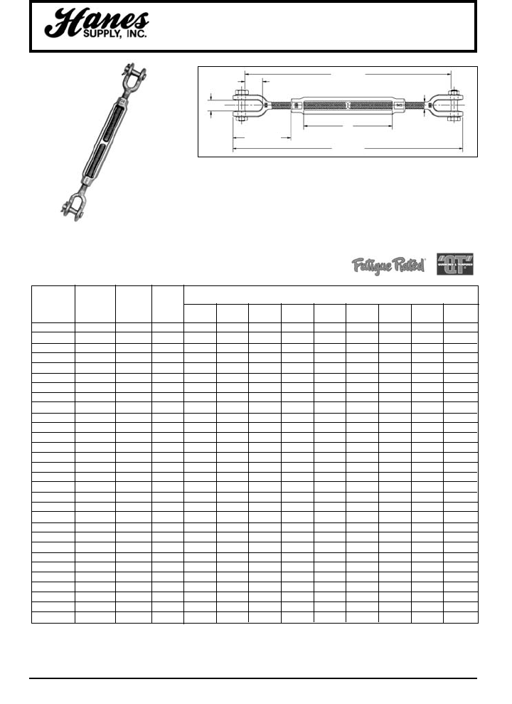
101
HEADQUARTERS: 55 James E. Casey Drive • Buffalo, NY 14206 PHONE: 716.826.2636 FAX: 716.826.4412 www.hanessupply.com
Jaw & Jaw Turnbuckles
THREAD WORKING
DIAMETER LOAD WEIGHT DIMENSIONS (IN)
& TAKE UP STOCK NO. LIMIT* EACH A B E G J K M N BB
(IN.) GALV. (LBS.) (LBS.) CLOSED OPEN CLOSED OPEN CLOSED
1/4 x 4 1032493 500 .36 .25 .45 1.58 .62 10.90 6.90 11.90 7.90 4.00
5/16 X 4-1/2 1032518 800 .52 .31 .50 1.98 .87 12.36 8.36 13.90 9.40 4.50
3/8 X 6 1032536 1200 .81 .38 .54 2.12 .87 16.14 10.14 17.38 11.38 6.00
1/2 X 6 1032554 2200 1.56 .50 .55 2.75 1.06 18.50 11.50 20.00 13.00 6.00
1/2 X 9 1032572 2200 1.74 .50 .55 2.75 1.06 24.50 14.50 26.00 16.00 9.00
1/2 X 12 1032590 2200 2.40 .50 .55 2.75 1.06 30.50 17.50 32.00 19.00 12.00
5/8 X 6 1032616 3500 2.72 .63 .82 3.50 1.31 20.05 12.80 22.13 14.88 6.00
5/8 X 9 1032634 3500 3.43 .63 .82 3.50 1.31 26.05 15.80 28.13 17.88 9.0
5/8 X 12 1032652 3500 3.91 .63 .82 3.50 1.31 32.05 18.80 34.13 20.88 12.00
3/4 X 6 1032670 5200 4.11 .75 1.03 4.18 1.50 21.50 14.00 24.10 16.60 6.00
3/4 X 9 1032698 5200 5.46 .75 1.03 4.18 1.50 27.50 17.00 30.10 19.60 9.00
3/4 X 12 1032714 5200 6.43 .75 1.03 4.18 1.50 33.50 20.00 36.10 22.60 12.00
3/4 X 18 1032732 5200 8.07 .75 1.03 4.18 1.50 45.50 26.00 48.10 28.60 18.00
7/8 X 12 1032750 7200 8.17 .88 1.23 4.85 1.75 35.11 21.36 38.07 24.32 12.00
7/8 X 18 1032778 7200 10.78 .88 1.23 4.85 1.75 47.00 27.36 50.07 30.32 18.00
1 X 6 1032796 10000 10.18 1.00 1.31 5.53 2.06 24.72 16.72 28.06 20.06 6.00
1 X 12 1032812 10000 12.52 1.00 1.31 5.53 2.06 36.72 22.72 40.06 26.06 12.00
1 X 18 1032830 10000 15.14 1.00 1.31 5.53 2.06 48.72 28.72 52.06 32.06 18.00
1 X 24 1032858 10000 18.08 1.00 1.31 5.53 2.06 60.72 34.72 64.06 38.06 24.00
1-1/4 X 12 1032876 15200 20.59 1.25 1.86 7.21 2.81 39.84 25.34 44.04 29.54 12.00
1-1/4 X 18 1032894 15200 24.68 1.25 1.86 7.21 2.81 51.84 31.34 56.04 35.54 18.00
1-1/4 X 24 1032910 15200 28.20 1.25 1.86 7.21 2.81 63.84 37.34 68.04 41.54 24.00
1-1/2 X 12 1032938 21400 30.69 1.50 2.25 7.88 2.81 51.50 26.50 46.50 31.50 12.00
1-1/2 X 18 1032956 21400 36.75 1.50 2.25 7.88 2.81 53.50 32.50 58.50 37.50 18.00
1-1/2 X 24 1032974 21400 40.67 1.50 2.25 7.88 2.81 65.50 38.50 70.50 43.50 24.00
1-3/4 X 18 1033018 28000 54.00 1.75 2.60 9.40 3.38 53.38 35.38 59.18 41.18 18.00
1-3/4 X 24 1033036 28000 63.36 1.75 2.60 9.40 3.38 65.38 41.38 71.18 47.18 24.00
2 X 24 1033054 37000 94.25 2.00 2.62 11.86 3.69 69.54 45.54 76.72 52.72 24.00
2-1/2 X 24 1033072 60000 165.00 2.50 3.06 13.56 4.44 72.98 48.98 82.18 58.18 24.00
2-3/4 X 24 1033090 75000 198.00 2.75 3.68 15.22 4.19 74.75 50.75 85.50 61.50 24.00
HG-228
JAW & JAW
Meets the performance requirements
of Federal Specification FF-T-79 lb.,
Type 1, Form 1 – CLASS 7, and
ASTM F-1145, except for those
provisions required of the contractor.
• Hot Dip galvanized steel.
• End fittings are Quenched and Tempered, bodies heat treated by normalizing.
• TURNBUCKLES RECOMMENDED FOR STRAIGHT OR IN-LINE PULL ONLY.
• Forged jaw ends are fitted with bolts and nuts for 1/4" through 5/8", and pins and
cotters on 3/4" through 2-3/4" sizes.
• Modified UNJ thread on end fittings for improved fatigue properties. Body has
UNC threads.
• Lock Nuts available for all sizes.
• Fatigue Rated.
*Proof Load is 2.5 times the Working Load Limit. Ultimate Load is 5 times Working Load Limit.
M OPEN
N CLOSED
J OPEN
K CLOSED
A
BB
E CLOSED
B
G
YOUR SLING AND RIGGING SPECIALIST
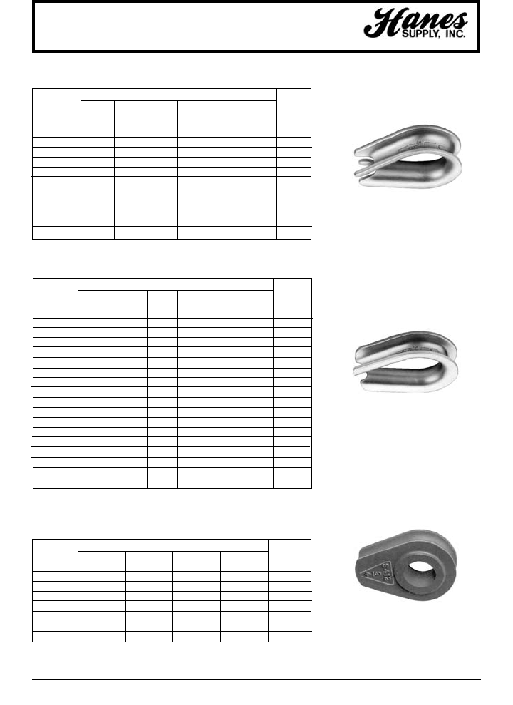
102
HEADQUARTERS: 55 James E. Casey Drive • Buffalo, NY 14206 PHONE: 716.826.2636 FAX: 716.826.4412 www.hanessupply.com
Wire Rope Thimbles
DIMENSIONS (IN)
ROPE INSIDE MAX. WEIGHT
DIAMETER OVERALL OVERALL LENGTH WIDTH WIDTH PIN POUNDS
(IN) LENGTH WIDTH INSIDE INSIDE OF SCORE DIAM. PER 100
1/8 1-15/16 1-1/16 1-5/16 11/16 5/32 5/8 3.30
3/16 1-15/16 1-1/16 1-5/16 11/16 7/32 5/8 3.30
1/4 1-15/16 1-1/16 1-5/16 11/16 9/32 5/8 3.30
5/16 2-1/8 1-1/4 1-1/2 13/16 3/8 3/4 4.00
3/8 2-3/8 1-15/32 1-5/8 15/16 7/16 7/8 7.50
1/2 2-3/4 1-3/4 1-7/8 1-1/8 9/16 1-1/16 18.80
5/8 3-1/2 2-3/8 2-1/4 1-3/8 11/16 1-1/4 36.00
3/4 3-3/4 2-11/16 2-1/2 1-5/8 13/16 1-1/2 60.00
7/8 5 3-3/16 3-1/2 1-7/8 15/16 1-3/4 90.00
1 5-11/16 3-3/4 4-1/4 2-1/2 1-1/16 2-3/8 105.00
1-1/8 - 1-1/4 6-1/4 4-5/16 4-1/2 2-3/4 1-5/16 2-5/8 166.00
G-411
STANDARD
Recommended for light duty
service. G-411 meets Federal
Specification FF-T-276b Type II.
STANDARD WIRE ROPE THIMBLES GALVANIZED STEEL
DIMENSIONS (IN)
ROPE OVERALL MAX. WEIGHT
DIAMETER OVERALL OVERALL LENGTH WIDTH THICK- PIN POUNDS
(IN) LENGTH WIDTH INSIDE INSIDE NESS DIAM. PER 100
*1/4 2-3/16 1-1/2 1-5/8 7/8 13/32 13/16 7.50
*5/16 2-1/2 1-13/16 1-7/8 1-1/16 1/2 15/16 14.00
*3/8 2-7/8 2-1/8 2-1/8 1-1/8 21/32 1-1/16 25.00
7/16 3-1/4 2-3/8 2-3/8 1-1/4 3/4 1-3/16 36.00
*1/2 3-5/8 2-3/4 2-3/4 1-1/2 27/32 1-7/16 51.00
9/16 3-5/8 2-11/16 2-3/4 1-1/2 29/32 1-7/16 51.00
*5/8 4-1/4 3-1/8 3-1/4 1-3/4 1 1-5/8 75.00
*3/4 5 3-3/16 3-3/4 2 1-1/4 1-7/8 147.00
7/8 5-1/2 4-1/4 4-1/4 2-1/4 1-3/8 2-1/8 185.00
1 6-1/8 4-15/16 4-1/2 2-1/2 1-9/16 2-3/8 291.66
1-1/8 - 1-1/4 7 5-7/8 5-1/8 2-7/8 1-7/8 2-3/4 383.33
1-1/4 - 1-3/8 9-1/16 6-13/16 6-1/2 3-1/2 2-1/4 3-1/4 816.66
1-3/8 - 1-1/2 9 7-1/8 6-1/4 3-1/2 2-5/8 3-3/8 1,166.66
1-5/8 11-1/4 8-1/8 8 4 2-3/4 3-7/8 1,625.00
1-3/4 12-3/16 8-1/2 9 4-1/2 2-7/8 4-3/8 1,837.50
1-7/8 - 2 15-1/8 10-3/8 12 6 3-1/8 5-7/8 2,575.00
2-1/4 17-1/8 11-7/8 14 7 3-5/8 6-7/8 3,850.00
EXTRA HEAVY WIRE ROPE THIMBLES GALVANIZED AND
STAINLESS STEEL
G-414 and SS-414
STAINLESS STEEL
*Sizes available in Stainless (304) Steel.
EXTRA HEAVY
Rugged rope thimbles recommended
for heavy duty service. Thimbles G-414
meet Federal Specification FF-T-276b
Type III.
S-412
SOLID
Fits open wire rope socket, boom
pendant clevis, as well as wedge
socket.
DIMENSIONS (IN)
ROPE WEIGHT
DIAMETER OVERALL OVERALL MAXIMUM POUNDS
(IN) LENGTH WIDTH THICKNESS PIN. DIAM. EACH
1/2 2-13/16 2-1/8 7/8 1 1.0
5/8 4-11/16 3-3/8 1-1/8 1-3/16 2.5
3/4 4-11/16 3-3/8 1-3/8 1-3/8 3.3
7/8 6-1/16 4-1/2 1-5/8 1-5/8 5.0
1 6-1/16 4-1/2 1-13/16 2 6.5
1-1/8 7-1/4 5-3/8 2-1/16 2-1/4 8.5
1-1/4 - 1-3/8 7-1/4 5-3/8 2-5/16 2-1/2 10.0
SOLID WIRE ROPE THIMBLES
*Sizes available in open pattern.
YOUR SLING AND RIGGING SPECIALIST
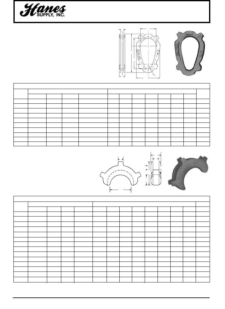
103
HEADQUARTERS: 55 James E. Casey Drive • Buffalo, NY 14206 PHONE: 716.826.2636 FAX: 716.826.4412 www.hanessupply.com
Thimbles
DIMENSIONS AND DATA
THIMBLE SLING SIZE DIMENSION (IN) WT.
CODE SINGLE 8 PTS. 6 PTS. 4 PTS. A B C D ERF G (LBS)
*W-2 5/16 - 3/8 3/32 - 1/8 3/32 - 1/8 1/8 - 3/16 2-1/8 4-1/8 7/16 13/16 9/16 3-1/4 5-1/4 1.3
W-3 1/2 - 9/16 3/16 3/16 1/4 2-3/8 4-3/8 5/8 1 5/8 4 6 1.15
W-4 5/8 - 3/4 1/4 1/4 - 5/16 5/16 - 1/8 3-3/8 6-5/8 13/16 1-5/16 5/8 5-3/8 8-1/2 3.11
W-5 7/8 - 1 5/16 3/8 7/16 - 1/2 3-3/4 7-1/8 1-1/8 1-5/8 7/8 6-1/4 9-3/8 5.6
W-6 1-1/8 - 1-1/4 3/8 7/16 9/16 - 5/8 4-3/8 8-3/8 1-3/8 1-7/8 1 7-1/8 11 8.6
W-7 1-3/8 - 1-1/2 7/16 - 1/2 1/2 3/4 5 9-1/2 1-5/8 2-1/8 1-1/4 8-1/8 12-1/2 11.1
W-8 1-5/8 - 1-3/4 9/16 5/8 7/8 6-3/4 11-3/4 1-13/16 2-9/16 1-7/16 9-3/8 14-3/4 17.6
W-9 1-7/8 - 2 5/8 3/4 1 8 14-1/2 2-1/8 3-1/4 1-7/8 13 19-1/4 53
W-10 2-1/8 - 2-1/4 1/4 7/8 - 1 1-1/8 - 1-1/4 8 15-1/2 2-1/2 3-3/4 2 13 20-1/8 66
W-11 2-1/2 - 3 7/8 - 1 1-1/8 1-1/4 - 1-3/8 - 1-1/2 9 18-1/2 3-3/16 4-11/16 2-1/2 15-3/4 24-3/4 126
SLIP-THRU THIMBLE
NEWCO SLIP-TRHU THIMBLES are designed to allow
passage of an identical thimble through its eye. This is
a necessity when a regular sling is used as a choker
sling. SLIP-THRU THIMBLES also prevent the eye of
the sling from mashing together and the top of the eye
wearing excessively. The generous inside dimensions
allow the thimbles to fit large crane hooks.
CRESCENT THIMBLE
Designed to protect the bearing surface of a loop
where a large dimension loop is necessary. The
ears are tapered so that they can be bent over.
Standard-Laid Rope Size 3/8" to 3".
*Made from High Tensile Malleable.
*Made from High Tensile Malleable.
DIMENSIONS AND DATA
THIMBLE ROPE SIZE DIMENSION (IN) WT.
CODE SINGLE 8 PTS. 6 PTS. 4 PTS. A B C D E F G H (LBS)
6C 3/8 - 7/16 3/32 - 1/8 1/8 1/8 - 3/16 2 1 27/32 15/32 2-1/16 3/8 1/2 3/8 .75
8C 1/2 - 9/16 3/16 3/16 1/4 2-1/4 1-1/8 1 5/8 2-1/2 1/2 1/2 1/2 1.0
9C 5/8 – 1/4 5/16 2-3/4 1-3/8 1-5/32 23/32 3 19/32 9/16 19/32 1.2
10C 3/4 1/4 5/16 3/8 3-1/4 1-5/8 1-5/16 13/16 3-1/2 5/8 5/8 5/8 2.0
14C 7/8 – – 7/16 4-1/2 2-1/4 1-7/16 15/16 4-5/16 3/4 11/16 3/4 3.3
16C 1 5/16 3/8 1/2 4-1/2 2-1/4 1-9/16 1-1/16 4-19/32 13/16 3/4 7/8 3.8
18C 1-1/8 3/8 7/16 9/16 4-7/8 2-7/16 1-13/16 1-1/4 5-1/32 7/8 7/8 1 5.0
20C 1-1/4 7/16 1/2 5/8 5-1/2 2-3/4 2-1/16 1-7/16 5-3/4 15/16 15/16 1-1/8 6.8
22C 1-3/8 - 1-1/2 1/2 9/16 3/4 6 3 2-1/4 1-5/8 6-1/4 1-1/16 1-1/8 1-3/16 9.0
24C 1-5/8 9/16 5/8 – 6-1/2 3-1/4 2-1/2 1-3/4 6-11/16 1-1/8 1-1/4 1-1/4 12.0
28C 1-3/4 - 1-7/8 – – 7/8 7 3-1/2 2-15/16 1-15/16 7-3/8 1-1/4 1-3/8 1-1/2 16.6
32C 2 5/8 3/4 1 7 3-1/2 3-3/16 2-3/16 7-13/16 1-1/2 1-1/2 1-5/8 21.8
40C 2-1/4 - 2-1/2 3/4 - 7/8 1 1-1/8 - 1-1/4 8-1/2 4-1/4 4-1/8 2-7/8 9-5/8 1-5/8 1-7/8 2 39.0
48C 2-3/4 - 3 1 1-1/8 – 10 5 4-7/8 3-3/8 11-1/4 1-3/4 2-1/4 2-1/2 67.0
DIMENSIONS ARE IN INCHES AND ARE APPROXIMATE.
C
D
A
G
B
F
D
C
N
FE
B
G
A
YOUR SLING AND RIGGING SPECIALIST
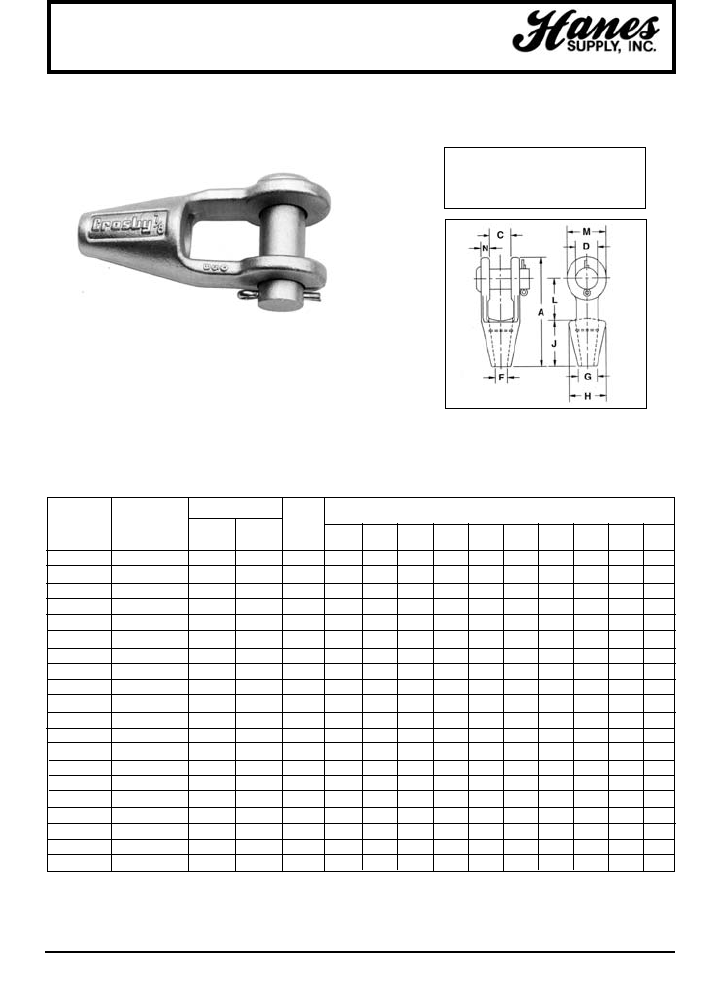
104
HEADQUARTERS: 55 James E. Casey Drive • Buffalo, NY 14206 PHONE: 716.826.2636 FAX: 716.826.4412 www.hanessupply.com
Spelter Sockets
GROOVED OPEN SPELTER SOCKETS
• Forged Steel Sockets thru 1-1/2", cast alloy steel 1-5/8" thru 4".
• Spelter socket terminations have an efficiency rating of 100%,
based on the catalog strength of wire rope. Ratings are based
on recommended use with 6 x 7, 6 x 19, or 6 x 37, IPS or XIP
(EIP), RRL, FC, or IWRC wire rope.
STRUCTURAL STOCK NO.
ROPE STRAND WEIGHT DIMENSIONS (IN)
DIAMETER DIAM. G-416 S-416 EACH
(IN.) (IN.) GALV. S.C. (LBS.) A C D F G H J L M N
1/4 – 1039619 1039628 1.10 4.56 .91 .69 .38 .69 1.56 2.25 1.56 1.31 .36
5/16 - 3/8 – 1039637 1039646 1.30 4.84 .81 .81 .50 .81 1.69 2.25 1.75 1.50 .44
7/16 - 1/2 – 1039655 1039664 2.25 5.56 1.00 1.00 .56 .94 1.88 2.50 2.00 1.88 .50
9/16 - 5/8 1/2 1039673 1039682 3.60 6.75 1.25 1.19 .69 1.13 2.25 3.00 2.50 2.25 .56
3/4 9/16 - 5/8 1039691 1039708 5.83 7.94 1.50 1.38 .81 1.25 2.62 3.50 3.00 2.62 .62
7/8 11/16 - 3/4 1039717 1039726 9.65 9.25 1.75 1.63 .94 1.50 3.25 4.00 3.50 3.13 .80
1 13/16 - 7/8 1039735 1039744 15.50 10.56 2.00 2.00 1.13 1.75 3.75 4.50 4.00 3.75 .88
1-1/8 15/16 - 1 1039753 1039762 21.50 11.81 2.25 2.25 1.25 2.00 4.12 5.00 4.62 4.12 1.00
1-1/4 - 1-3/8 1-1/16 - 1-1/8 1039771 1039780 31.00 13.19 2.50 2.50 1.50 2.25 4.75 5.50 5.00 4.75 1.13
1-1/2 1-3/16 - 1-1/4 1039799 1039806 47.25 15.12 3.00 2.75 1.63 2.75 5.25 6.00 6.00 5.38 1.19
1-5/8 1-5/16 - 1-3/8 1039815 1039824 55.00 16.25 3.00 3.00 1.75 3.00 5.50 6.50 6.50 5.75 1.31
1-3/4 - 1-7/8 1-7/16 - 1-5/8 1039833 1039842 82.00 18.25 3.50 3.50 2.00 3.13 6.38 7.50 7.00 6.50 1.56
2 - 2-1/8 1-11/16 - 1-3/4 1039851 1039860 129.00 21.50 4.00 3.75 2.25 3.75 7.38 8.50 9.00 7.00 1.81
2-1/4 - 2-3/8 1-13/16 - 1-7/8 1039879 1039888 167.00 23.50 4.50 4.25 2.50 4.00 8.25 9.00 10.00 7.75 2.13
2-1/2 - 2-5/8 1-15/16 - 2-1/8 1041633 1041642 252.00 25.50 5.00 4.75 2.88 4.50 9.25 9.75 10.75 8.50 2.38
2-3/4 - 2-7/8 2-3/16 - 2-7/16 1041651 1041660 315.00 27.25 5.25 5.00 3.12 4.88 10.50 11.00 11.00 9.00 2.88
3 - 3-1/8 2-1/2 - 2-5/8 1041679 1041688 380.00 29.00 5.75 5.25 3.38 5.25 11.12 12.00 11.25 9.50 3.00
3-1/4 - 3-3/8 2-3/4 - 2-7/8 1041697 1041704 434.00 30.88 6.25 5.50 3.62 5.75 11.88 13.00 11.75 10.00 3.12
3-1/2 - 3-5/8 3 - 3-1/8 1041713 1041722 563.00 33.25 6.75 6.00 3.88 6.50 12.38 14.00 12.50 10.75 3.25
3-3/4 - 4 – 1041731 1041740 783.00 35.25 7.50 7.00 4.25 7.25 13.62 15.00 13.50 12.50 3.50
Open Grooved Sockets meet the requirements of Federal Specifications RR-S-550D, Type A.
NOTICE: All cast steel sockets 1-5/8" and
larger are magnetic particle inspected and
ultrasonic inspected. Proof testing
available on special order.
Note: Above drawing illustrates one
groove used on sockets 1/4" thru 3/4".
Sizes 7/8" thru 1-1/2" use 2 grooves.
Sizes 1-5/8" and larger use 3 grooves.
G-416
YOUR SLING AND RIGGING SPECIALIST
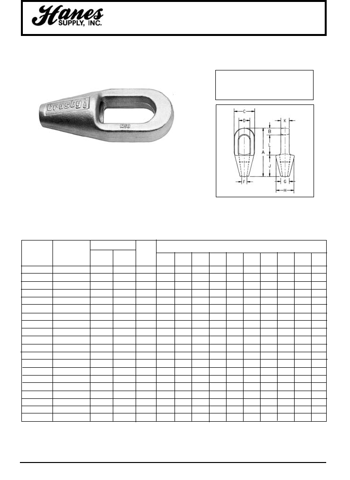
HEADQUARTERS: 55 James E. Casey Drive • Buffalo, NY 14206 PHONE: 716.826.2636 FAX: 716.826.4412 www.hanessupply.com
105
Spelter Sockets
GROOVED CLOSED SPELTER SOCKETS
• Forged Steel Sockets thru 1-1/2", cast alloy steel 1-5/8" thru 4".
• Spelter socket terminations have an efficiency rating of 100%,
based on the catalog strength of wire rope. Ratings are based
on recommended use with 6 x 7, 6 x 19, or 6 x 37, IPS or XIP
(EIP), RRL, FC, or IWRC wire rope.
STRUCTURAL STOCK NO.
ROPE STRAND WEIGHT DIMENSIONS (IN)
DIAMETER DIAM. G-417 S-417 EACH
(IN.) (IN.) GALV. S.C. (LBS.) A B C D F G H J K L
1/4 – 1039897 1039904 .50 4.50 .50 1.50 .88 .38 .69 1.56 2.25 .50 1.75
5/16 - 3/8 – 1039913 1039922 .75 4.88 .62 1.69 .97 .50 .81 1.69 2.25 .69 2.00
7/16 - 1/2 – 1039931 1039940 1.50 5.44 .69 2.00 1.16 .56 .94 1.88 2.50 .88 2.25
9/16 - 5/8 1/2 1039959 1039968 2.50 6.31 .81 2.63 1.41 .69 1.12 2.38 3.00 1.00 2.50
3/4 9/16 - 5/8 1039977 1039986 4.25 7.56 1.06 3.00 1.66 .81 1.25 2.75 3.50 1.25 3.00
7/8 11/16 - 3/4 1039995 1040000 7.25 8.75 1.25 3.63 1.88 .97 1.50 3.25 4.00 1.50 3.50
1 13/16 - 7/8 1040019 1040028 10.50 9.88 1.38 4.13 2.30 1.13 1.75 3.75 4.44 1.75 4.00
1-1/8 15/16 - 1 1040037 1040046 14.25 11.00 1.50 4.50 2.55 1.25 2.00 4.13 5.00 2.00 4.50
1-1/4 - 1-3/8 1-1/16 - 1-1/8 1040055 1040064 19.75 12.12 1.63 5.30 2.80 1.50 2.25 4.75 5.50 2.25 5.00
1-1/2 1-3/16 - 1-1/4 1040073 1040082 29.20 13.94 1.94 5.33 3.19 1.63 2.75 5.25 6.00 2.50 6.00
1-5/8 1-5/16 - 1-3/8 1040091 1040108 36.00 15.13 2.13 5.75 3.25 1.75 3.00 5.50 6.50 2.75 6.50
1-3/4 - 1-7/8 1-7/16 - 1-5/8 1040117 1040126 57.25 17.25 2.19 6.75 3.75 2.00 3.13 6.38 7.50 3.00 7.56
2 - 2-1/8 1-11/16 - 1-3/4 1040135 1040144 79.00 19.50 2.44 7.63 4.38 2.25 3.75 7.38 8.50 3.25 8.56
2-1/4 - 2-5/8 1-13/16 - 1-7/8 1040153 1040162 105.00 21.13 2.88 8.50 5.00 2.50 4.00 8.25 9.00 3.63 9.50
2-1/2 - 2-5/8 1-15/16 - 2-1/8 1041759 1041768 140.00 23.50 3.12 9.50 5.50 2.94 4.50 9.25 9.75 4.00 10.62
2-3/4 - 2-7/8 2-3/16 - 2-7/16 1041777 1041786 220.00 25.38 3.12 10.75 6.25 3.12 4.88 10.19 11.00 4.88 11.25
3 - 3-1/8 2-1/2 - 2-5/8 1041795 1041802 276.00 27.00 3.25 11.50 6.75 3.38 5.25 11.50 12.00 5.25 11.75
3-1/4 - 3-3/8 2-3/4 - 2-7/8 1041811 1041820 313.00 29.25 4.00 12.25 7.25 3.62 5.75 12.25 13.00 5.75 12.25
3-1/2 - 3-5/8 3 - 3-1/8 1041839 1041848 400.00 31.00 4.00 13.00 7.75 3.88 6.50 13.00 14.00 6.25 13.00
3-3/4 - 4 – 1041857 1041866 542.00 33.25 4.25 14.25 8.50 4.25 7.25 14.25 15.00 7.00 14.00
Closed Grooved Sockets meet the requirements of Federal Specifications RR-S-550D, Type B.
NOTICE: All cast steel sockets 1-5/8" and
larger are magnetic particle inspected and
ultrasonic inspected. Proof testing
available on special order.
Note: Above drawing illustrates one
groove used on sockets 1/4" thru 3/4".
Sizes 7/8" thru 1-1/2" use 2 grooves.
Sizes 1-5/8" and larger use 3 grooves.
G-417
YOUR SLING AND RIGGING SPECIALIST
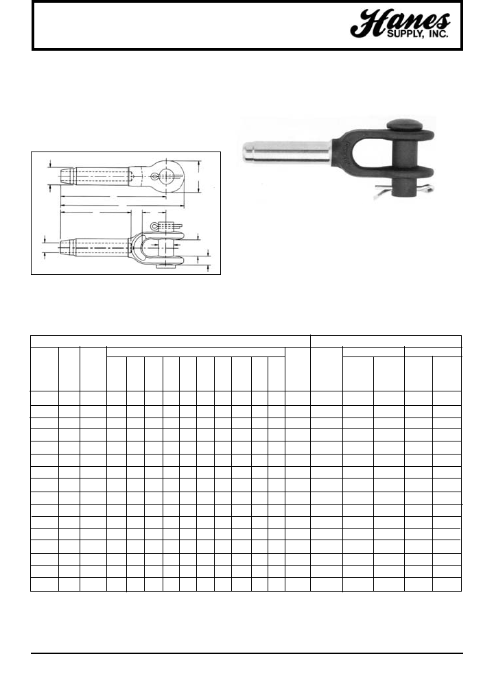
106
HEADQUARTERS: 55 James E. Casey Drive • Buffalo, NY 14206 PHONE: 716.826.2636 FAX: 716.826.4412 www.hanessupply.com
Open Swage Sockets
OPEN SWAGE SOCKET
• Forged from special bar quality carbon steel, suitable for cold
forming.
• Hardness controlled by spheriodize annealing.
• Swage Socket terminations have an efficiency rating of 100%
based on the catalog strength of wire rope.
NOTE: S-501 Swage Sockets are recommended for use with 6 x 19,
or 6 x 37, IPS or XIP (EIP), RRL, FC, or IWRC wire rope.
S-501 OPEN SOCKET SPECIFICATIONS PRESS / DIE DATA
BEFORE SWAGE DIMENSIONS MAX. STOCK NO. SIDE LOAD
AFTER 500 TON
ROPE WEIGHT SWAGE DIE 1000 TON 1500 TON 1500 3000
STOCK SIZE EACH DIM. DESCRIP. 1500 TON 3000TON TONS TONS
NO. (IN.) (LBS.) A B C D E F H L M N (IN.) (SOCKET) 5 X 7 6 X 12 6 X 12 6 X 12
1039021 1/4 .52 4.81 .50 1.38 .69 .27 2.13 .69 4.00 .38 1.50 .46 1/4 1192845 – – –
1039049 5/16 1.12 6.25 .77 1.62 .81 .34 3.19 .81 5.31 .47 1.75 .71 5/16 - 3/8 1192863 – – –
1039067 3/8 1.30 6.25 .77 1.62 .81 .41 3.19 .81 5.31 .47 1.75 .71 5/16 - 3/8 1192863 – – –
1039085 7/16 2.08 7.81 .98 2.00 1.00 .48 4.25 1.00 6.69 .56 2.00 .91 7/16 - 1/2 1192881 – – –
1039101 1/2 2.08 7.81 .98 2.00 1.00 .55 4.25 1.00 6.69 .56 2.00 .91 7/16 - 1/2 1192881 – – –
1039129 9/16 4.67 9.50 1.25 2.38 1.19 .61 5.31 1.25 8.13 .66 2.25 1.16 9/16 - 5/8 1192907 – – –
1039147 5/8 4.51 9.50 1.25 2.38 1.19 .67 5.31 1.25 8.13 .66 2.25 1.16 9/16 - 5/8 1192907 – – –
1039165 3/4 7.97 11.56 1.55 2.75 1.38 .80 6.38 1.50 10.00 .75 2.75 1.42 3/4 1192925 – – –
1039183 7/8 11.52 13.41 1.70 3.13 1.62 .94 7.44 1.75 11.63 .94 3.25 1.55 7/8 1192949 – – –
1039209 1 17.80 15.47 1.98 3.69 2.00 1.06 8.50 2.00 13.38 1.06 3.75 1.80 1 1192961 – – –
1039227 1-1/8 25.25 17.31 2.25 4.06 2.25 1.19 9.56 2.25 15.00 1.19 4.25 2.05 1-1/8 1192989 – – –
1039245 1-1/4 35.56 19.06 2.53 4.50 2.50 1.33 10.63 2.50 16.50 1.22 4.75 2.30 1-1/4 1193005 – – –
1039263 1-3/8 43.75 20.94 2.80 5.00 2.50 1.45 11.69 2.50 18.13 1.38 5.25 2.56 1-3/8 1193023 – – –
1039281 1-1/2 58.50 22.88 3.08 5.50 2.75 1.58 12.75 3.00 19.75 1.69 5.75 2.81 1-1/2 1193041 1191267 1195355 1195192
1039307 1-3/4 88.75 26.63 3.39 6.25 3.50 1.86 14.88 3.50 23.00 2.11 6.75 3.06 1-3/4 1193069 1191276 1195367 1195209
1042767 2 146.25 31.44 3.94 8.00 3.75 2.11 17.00 4.00 26.88 2.37 8.00 3.56 2 1193087 1191294 1195379 1195218
S-501
M
H
D
E
NF
A
L
C
B
YOUR SLING AND RIGGING SPECIALIST
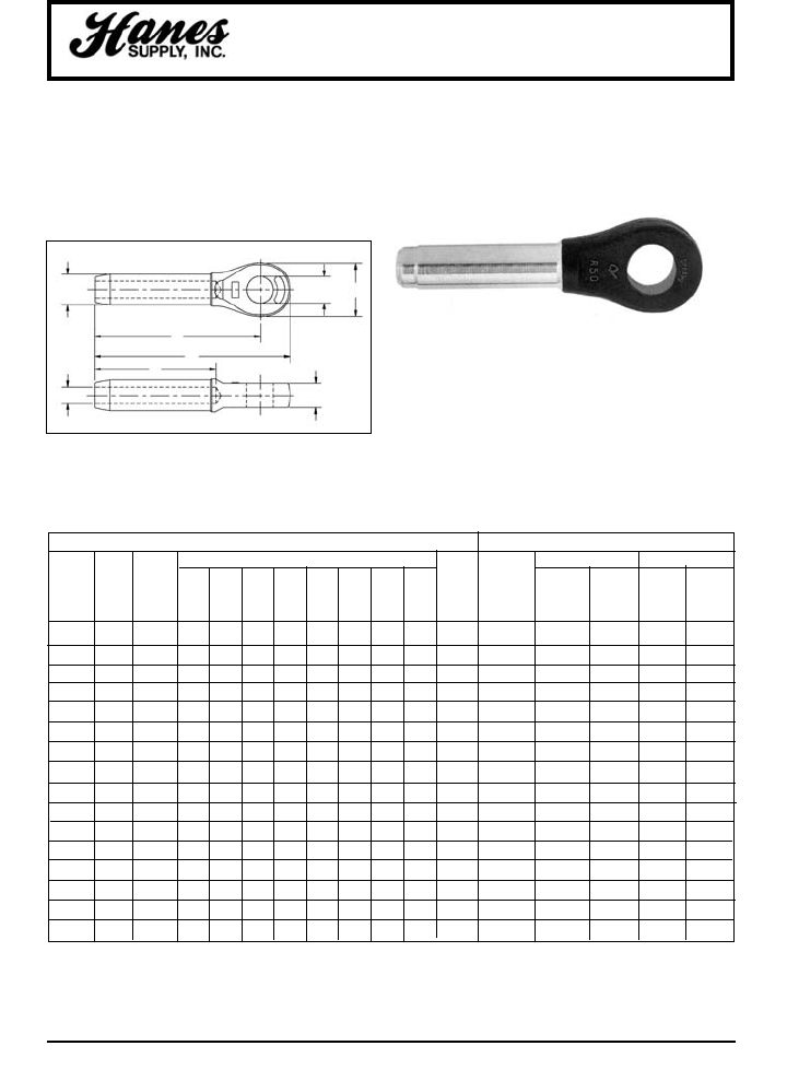
HEADQUARTERS: 55 James E. Casey Drive • Buffalo, NY 14206 PHONE: 716.826.2636 FAX: 716.826.4412 www.hanessupply.com
107
Spelter Sockets
CLOSED SWAGE SOCKET
• Forged from special bar quality carbon steel, suitable for
cold forming.
• Hardness controlled by spheriodize annealing.
• Swage Socket terminations have an efficiency rating of
100% based on the catalog strength of wire rope.
NOTE: S-502 Swage Sockets are recommended for use with
6 x 19, or 6 x 37, IPS or XIP (EIP), RRL, FC, or IWRC wire rope.
S-502 CLOSED SOCKET SPECIFICATIONS PRESS / DIE DATA
BEFORE SWAGE DIMENSIONS MAX. STOCK NO. SIDE LOAD
AFTER 500 TON
ROPE WEIGHT SWAGE DIE 1000 TON 1500 TON 1500 3000
STOCK SIZE EACH DIM. DESCRIP. 1500 TON 3000TON TONS TONS
NO. (IN.) (LBS.) A B C D E F H L (IN.) (SOCKET) 5 X 7 6 X 12 6 X 12 6 X 12
1039325 1/4 .33 4.31 .50 1.38 .75 .27 2.12 .50 3.50 .46 1/4 1192845 – – –
1039343 5/16 .75 5.44 .77 1.62 .88 .34 3.19 .67 4.50 .71 5/16 - 3/8 1192863 – – –
1039361 3/8 .72 5.44 .77 1.62 .88 .41 3.19 .67 4.50 .71 5/16 - 3/8 1192863 – –
1039389 7/16 1.42 6.91 .98 2.00 1.06 .48 4.25 .86 5.75 .91 7/16 - 1/2 1192881 – – –
1039405 1/2 1.42 6.91 .98 2.00 1.06 .55 4.25 .86 5.75 .91 7/16 - 1/2 1192881 – – –
1039423 9/16 2.92 8.66 1.25 2.38 1.25 .61 5.31 1.13 7.25 1.16 9/16 - 5/8 1192907 – – –
1039441 5/8 2.85 8.66 1.25 2.38 1.25 .67 5.31 1.13 7.25 1.16 9/16 - 5/8 1192907 – – –
1039469 3/4 5.00 10.28 1.55 2.88 1.44 .80 6.38 1.31 8.63 1.42 3/4 1192925 – – –
1039487 7/8 6.80 11.94 1.70 3.12 1.69 .94 7.44 1.50 10.13 1.55 7/8 1192949 – – –
1039502 1 10.40 13.56 1.98 3.63 2.06 1.06 8.50 1.75 11.50 1.80 1 1192961 – – –
1096520 1-1/8 14.82 15.03 2.25 4.00 2.31 1.19 9.56 2.00 12.75 2.05 1-1/8 1192989 – – –
1039548 1-1/4 21.57 16.94 2.53 4.50 2.56 1.33 10.63 2.25 14.38 2.30 1-1/4 1193005 – – –
1039566 1-3/8 28.54 18.63 2.80 5.00 2.56 1.45 11.69 2.25 15.75 2.56 1-3/8 1193023 – – –
1039584 1-1/2 38.06 20.12 3.08 5.50 2.81 1.58 12.75 2.50 17.00 2.81 1-1/2 1193041 1191267 1193355 1195192
1039600 1-3/4 51.00 23.56 3.39 6.25 3.56 1.86 14.88 3.00 20.00 3.06 1-3/4 1193069 1191276 1195367 1195209
1042589 2 89.25 27.62 3.94 7.25 3.81 2.11 17.00 3.25 23.00 3.56 2 1193087 1191294 1195379 1195218
S-502
H
E
F
A
L
C
D
B
YOUR SLING AND RIGGING SPECIALIST
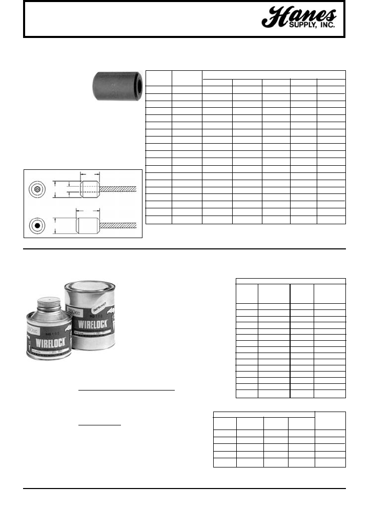
108
HEADQUARTERS: 55 James E. Casey Drive • Buffalo, NY 14206 PHONE: 716.826.2636 FAX: 716.826.4412 www.hanessupply.com
Swage Buttons / Socket Compound
DIMENSIONS (IN)
ROPE
ITEM DIAMETER A B C D E
1 SB 1/8 27/64 1/2 .141 3/8 39/64
2 SB 5/32 1/2 39/64 .172 7/16 23/32
3 SB 3/16 9/16 45/64 .203 1/2 27/32
4 SB 7/32 41/64 13/16 .234 9/16 31/32
5 SB 1/4 41/64 1-1/16 .296 9/16 1-13/64
6 SB 9/32 49/64 1-1/32 .313 11/16 1-13/64
7 SB 5/16 27/32 1-1/8 .358 3/4 1-21/64
8 SB 3/8 27/32 1-31/64 .421 3/4 1-11/16
9 SB 7/16 1-1/8 1-5/8 .484 1 1-15/16
10 SB 1/2 1-17/64 1-57/64 .547 1-1/8 2-11/64
11 SB 9/16 1-13/32 2-1/64 .609 1-1/4 2-13/32
12 SB 5/8 1-35/64 2-27/64 .672 1-3/8 2-57/64
13 SB 3/4 1-11/16 2-47/64 .796 1-1/2 3-1/4
14 SB 7/8 1-31/32 3-17/64 .936 1-3/4 3-55/64
15 SB 1 2-1/4 3-43/64 1.061 2 4-23/64
16 SB 1-1/8 2-17/32 4-3/64 1.188 2-1/4 4-23/64
17 SB 1-1/4 2-13/16 4-37/64 1.328 2-1/2 5-27/64
18 SB 1-3/8 3-3/32 5-5/64 1.453 2-3/4 6-1/32
19 SB 1-1/2 3-3/8 5-15/32 1.578 3 6-33/64
S-409 SWAGE BUTTONS
• Low carbon steel
• Spherodize annealed
• Quality controlled
• Economical to use
A multi-purpose fitting for many swaging
applications. Manufactured from a special
analysis high quality, low carbon steel,
and later heat treated. They are precision
made with constant quality control checks
throughout all stages of manufacturing to
assure the best in quality and
performance.
NOTE: Length is measured from outside end of terminal.
E
D
C
B
A
BEFORE SWAGE
AFTER SWAGE
AMOUNT OF WIRELOCK®REQUIRED
WIRE WIRE
ROPE WIRELOCK®ROPE WIRELOCK®
SIZE REQUIRED SIZE REQUIRED
(IN.) (CC) (IN.) (CC)
1/4 9 1-3/4 700
5/16 17 1-7/8 700
3/8 17 2 1265
7/16 35 2-1/8 1265
1/2 35 2-1/4 1410
9/16 52 2-3/8 1410
5/8 52 2-1/2 1830
3/4 86 2-5/8 1830
7/8 125 2-3/4 2250
1 160 3 3160
1-1/8 210 3-1/4 3795
1-1/4 350 3-1/2 4920
1-3/8 350 3-3/4 5980
1-1/2 420 4 7730
1-5/8 495
WIRELOCK®- RESIN FOR SPELTER SOCKETS
• Ideal for on-site applications
• Improved fatigue life
• For use on 416 & 417 Spelter
Sockets only
• 100% termination efficiency
• Temperature operating range
from -65°F to +240°F
• One Booster pack needed if
pouring temperature is 35°F to 48°F
• Two Booster packs needed if
pouring temperature is 27°F to 35°F
W416-7 KITS BOOSTER
KIT KITS STOCK WT. EACH PACK
SIZE PER CASE NO. (LBS.) STOCK NO.
100 CC 20 1039602 .62 1039603
250 CC 12 1039604 1.25 1039605
500 CC 12 1039606 2.54 1039607
1000 CC 12 1039608 4.59 1039609
2000 CC 12 1039610 9.00 1039611
APPROXIMATE U.S. MEASUREMENTS
250cc Kit 1 Cup
500cc Kit 1 Pint
1,000cc Kit 1 Quart
NATO NUMBERS
100cc 8030-21-902-1823
250cc 8030-21-902-1824
500cc 8030-21-902-1825
1,000cc 8030-21-902-1826
Witnessed and tested by American
Bureau of Shipping (ABS)
W416-7
YOUR SLING AND RIGGING SPECIALIST
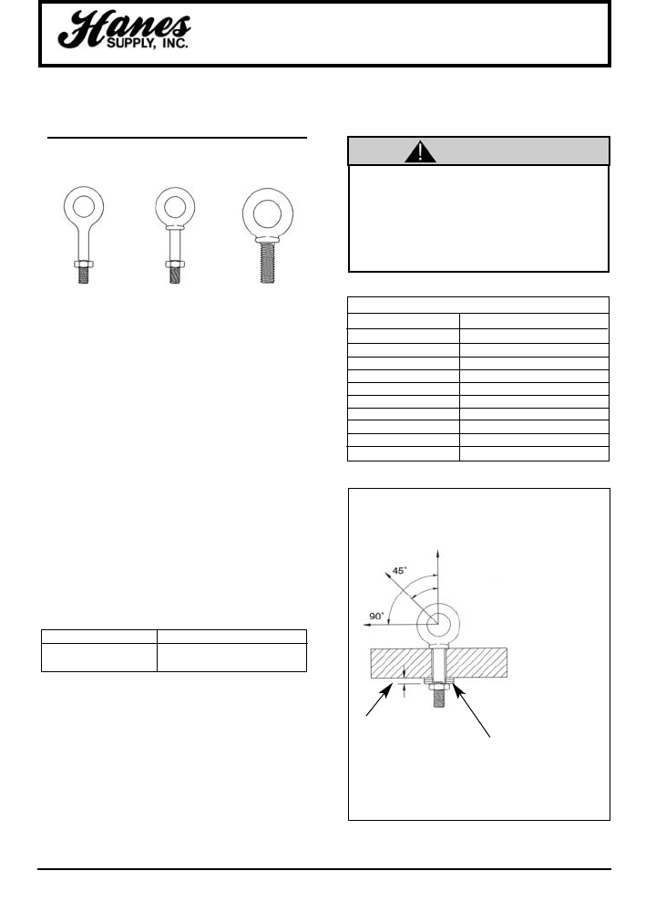
109
HEADQUARTERS: 55 James E. Casey Drive • Buffalo, NY 14206 PHONE: 716.826.2636 FAX: 716.826.4412 www.hanessupply.com
Eye Bolts
Important Safety Information –
Read and Follow
Inspection/Maintenance Safety
• Always inspect eye bolt before use.
• Never use eye bolt that shows signs of wear or
damage.
• Never use eye bolt if eye or shank is bent or elongated.
• Always be sure threads on shank and receiving holes
are clean.
• Never machine, grind, or cut eye bolt.
Assembly Safety
• Never exceed load limits specified in Table I.
• Never use regular nut eye bolts for angular lifts.
• Always use shoulder nut eye bolts (or machinery eye
bolts) for angular lifts.
• For angular lifts, adjust working load as follows:
• Never undercut eye bolt to seat shoulder against the
load.
• Always countersink receiving hole or use washers to
seat shoulder.
• Always screw eye bolt down completely for proper
seating.
• Always tighten nuts securely against the load.
• Loads may slip or fall if proper eye bolt
assembly and lifting procedures are not used.
• A falling load can seriously injure or kill.
• Read, understand and follow all eye bolt
safety information and diagrams presented
here.
FORGED EYE BOLT
WARNINGS AND APPLICATION
INSTRUCTIONS
Regular Nut
Eye Bolt
G-291
Shoulder Nut
Eye Bolt
G-277
Machinery
Eye Bolt
G-279
DIRECTION OF PULL ADJUSTED WORKING LOAD
45 degrees 30% of rated working load
90 degrees 25% of rated working load
TABLE I (IN-LINE LOAD)
Size (in.) Working Load Limit (lbs.)
1/4 650
5/16 1200
3/8 1550
1/2 2600
5/8 5200
3/4 7200
7/8 10600
1 13300
1-1/4 21000
1-1/2 24000
• Thickness of spacers
must exceed this
distance between the
bottom of the load and
the last thread of the eye
bolt.
• Place washers or
spacers between nut
and load so that when
the nut is tightened
securely, the shoulder is
secured flush against
the load surface.
• The threaded shank
must protrude
through the load
sufficiently to allow
full engagement of
the nut.
• If the eye bolt
protrudes so far
through the load
that the nut cannot
be tightened
securely against the
load, use properly
sized washers to
take up the excess
space BETWEEN
THE NUT AND THE
LOAD.
Shoulder Nut Eye Bolt –
Installation for Angular Loading
WARNING
YOUR SLING AND RIGGING SPECIALIST
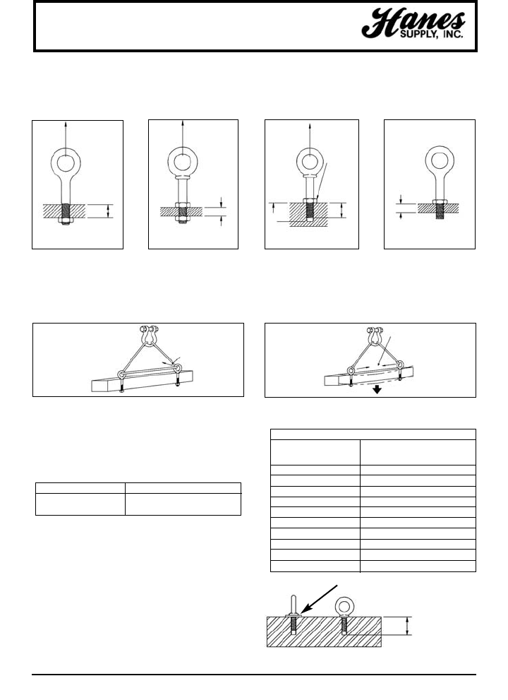
110
HEADQUARTERS: 55 James E. Casey Drive • Buffalo, NY 14206 PHONE: 716.826.2636 FAX: 716.826.4412 www.hanessupply.com
Eye Bolts
Right
More than
one eye
bolt dia. of
threads,
only (1) nut
required.
Do not reeve slings
from one eye bolt to
another. This will alter
the load & angle of
loading on the eye bolt.
After slings have been
properly attached to the eye
bolts, apply force slowly.
Watch the load carefully
& be prepared to stop
applying force
if the load
starts buckling.
Buckling may occur if
the load is not stiff
enough to resist the
compressive forces
which result
from the angular
loading.
Resultant Load
Wrong
Tighten hex nut securely
against load
One eye
bolt dia. of
threads or
less, use
two (2)
nuts.
Tighten hex nut securely
against load
Tighten
Hex Nut
Securely
Against
Load
One eye bolt dia. or less
2x Dia.
(Min.)
Tap Depth:
2.5 x Dia.
Right Right Wrong
IMPORTANT – READ AND UNDERSTAND THESE INSTRUCTIONS
BEFORE USING EYE BOLTS.
Regular Nut & Shoulder Nut Eye Bolt – Installation for In-Line Loading
Operating Safety
• Always inspect eye bolt before use.
• Always lift load with a steady, even pull – do not jerk.
• Always apply load to eye bolt in the plane of the eye,
not at an angle.
• Never exceed the capacity of the eyebolt – See Table I.
• When using lifting slings of two or more legs, make sure
the loads in the legs are calculated using the angle from
the vertical to the leg and properly size the shoulder nut
or machinery eye bolt for the angular load.
Machinery Eye Bolt – Installation for In-Line & Angular Loading
These eye bolts are primarily intended to be installed into
tapped holes.
1. After the loads on the eye bolts have been calculated,
select the proper size eye bolt for the job.
For angular lifts, adjust working load as follows:
2. Drill and tap the load to the correct sizes to a minimum
depth of one-half the eye bolt size beyond the shank
length of the machinery eye bolt.
3. Thread the eye bolt into the load until the shoulder is
flush and securely tightened against the load.
4. If the plane of the machinery eye bolt is not aligned
with the sling line, estimate the amount of unthreading
rotation necessary to align the plane of the eye
properly.
5. Remove the machinery eye bolt from the load and add
shims (washers) of proper thickness to adjust the angle
of the plane of the eye to match the sling line. Use
Table II to estimate the required shim thickness for the
amount of unthreading rotation required.
DIRECTION OF PULL ADJUSTED WORKING LOAD
45 degrees 30% of rated working load
90 degrees 25% of rated working load
Shim added to change eye alignment 90°
Min. tap depth is
basic shank length
plus one-half the
nominal eye bolt
diameter.
TABLE II
SHIM THICKNESS REQUIRED
EYE BOLT SIZE TO CHANGE ROTATION 90°
(IN.) (IN.)
1/4 .0125
5/16 .0139
3/8 .0156
1/2 .0192
5/8 .0227
3/4 .0250
7/8 .0278
1 .0312
1-1/4 .0357
1-1/2 .0417
YOUR SLING AND RIGGING SPECIALIST
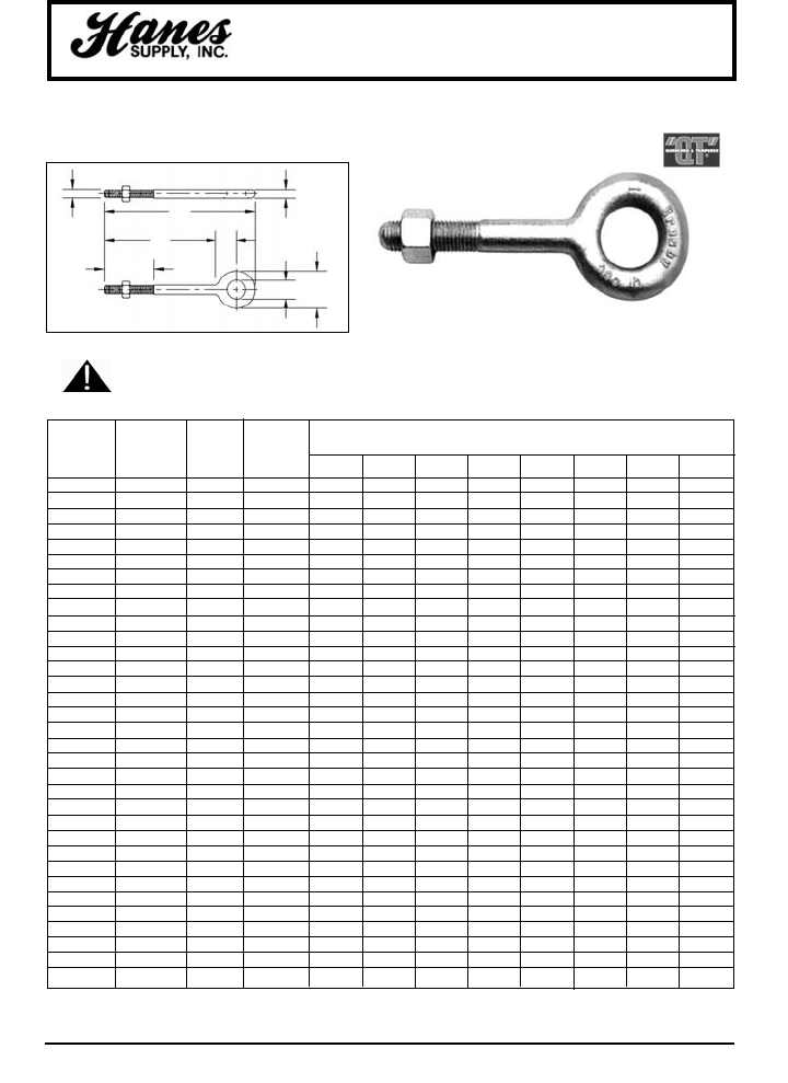
HEADQUARTERS: 55 James E. Casey Drive • Buffalo, NY 14206 PHONE: 716.826.2636 FAX: 716.826.4412 www.hanessupply.com
111
Eye Bolts
REGULAR NUT EYE BOLTS
• Recommended for straight line pull.
• All Bolts Hot Dip galvanized after threading.
• Furnished with standard Hot Dip galvanized hex nuts.
• Forged Steel – Quenched and Tempered.
G-291
SEE APPLICATION AND
WARNING INFORMATION
SHANK WORKING WEIGHT
DIAMETER G-291 LOAD PER DIMENSIONS (IN)
& LENGTH STOCK NO. LIMIT* 100
(IN.) GALV. (LBS.) (LBS.) A B C D E F G H
1/4 x 2 1043230 650 8.20 .25 .50 1.00 .25 1.50 2.00 3.06 .56
1/4 x 4 1043258 650 11.70 .25 .50 1.00 .25 2.50 4.00 5.06 .56
5/16 x 2-1/4 1043276 1200 13.30 .31 .62 1.25 .31 1.50 2.25 3.56 .69
5/16 x 4-1/4 1043294 1200 25.00 .31 .62 1.25 .31 2.50 4.25 5.56 .69
3/8 x 2-1/2 1043310 1550 23.30 .38 .75 1.50 .38 1.50 2.50 4.12 .88
3/8 x 4-1/2 1043338 1550 29.50 .38 .75 1.50 .38 2.50 4.50 6.12 .88
3/8 x 6 1043356 1550 35.20 .38 .75 1.50 .38 2.50 6.00 7.62 .88
1/2 x 3-1/4 1043374 2600 50.30 .50 1.00 2.00 .50 1.50 3.25 5.38 1.12
1/2 x 6 1043392 2600 66.10 .50 1.00 2.00 .50 3.00 6.00 8.12 1.12
1/2 x 8 1043418 2600 82.00 .50 1.00 2.00 .50 3.00 8.00 10.12 1.12
1/2 x 10 1043436 2600 88.00 .50 1.00 2.00 .50 3.00 10.00 12.12 1.12
1/2 x 12 1043454 2600 114.20 .50 1.00 2.00 .50 3.00 12.00 14.12 1.12
5/8 x 4 1043472 5200 103.10 .62 1.25 2.50 .62 2.00 4.00 6.69 1.44
5/8 x 6 1043490 5200 118.20 .62 1.25 2.50 .62 3.00 6.00 8.69 1.44
5/8 x 8 1043515 5200 135.10 .62 1.25 2.50 .62 3.00 8.00 10.69 1.44
5/8 x 10 1043533 5200 153.60 .62 1.25 2.50 .62 3.00 10.00 12.69 1.44
5/8 x 12 1043551 5200 167.10 .62 1.25 2.50 .62 4.00 12.00 14.69 1.44
3/4 x 4-1/2 1043579 7200 168.60 .75 1.50 3.00 .75 2.00 4.50 7.69 1.69
3/4 x 6 1043597 7200 184.50 .75 1.50 3.00 .75 3.00 6.00 9.19 1.69
3/4 x 8 1043613 7200 207.90 .75 1.50 3.00 .75 3.00 8.00 11.19 1.69
3/4 x 10 1043631 7200 235.00 .75 1.50 3.00 .75 3.00 10.00 13.19 1.69
3/4 x 12 1043659 7200 257.50 .75 1.50 3.00 .75 4.00 12.00 15.19 1.69
3/4 x 15 1043677 7200 298.00 .75 1.50 3.00 .75 5.00 15.00 18.19 1.69
7/8 x 5 1043695 10600 270.00 .88 1.75 3.50 .88 2.50 5.00 8.75 2.00
7/8 x 8 1043711 10600 308.00 .88 1.75 3.50 .88 4.00 8.00 11.75 2.00
7/8 x 12 1043739 10600 400.00 .88 1.75 3.50 .88 4.00 12.00 15.75 2.00
1 x 6 1043757 13300 421.00 1.00 2.00 4.00 1.00 3.00 6.00 10.31 2.31
1 x 9 1043775 13300 468.50 1.00 2.00 4.00 1.00 4.00 9.00 13.31 2.31
1 x 12 1043793 13300 540.00 1.00 2.00 4.00 1.00 4.00 12.00 16.31 2.31
1 x 18 1043819 13300 650.00 1.00 2.00 4.00 1.00 7.00 18.00 22.31 2.31
1-1/4 x 8 1043837 21000 750.00 1.25 2.50 5.00 1.25 4.00 8.00 13.38 2.88
1-1/4 x 12 1043855 21000 900.00 1.25 2.50 5.00 1.25 4.00 12.00 17.38 2.88
1-1/4 x 20 1043873 21000 1210.00 1.25 2.50 5.00 1.25 6.00 20.00 25.38 2.88
*Ultimate Load is 5 times Working Load Limit.
A
E
G
FH
D
BC
D
YOUR SLING AND RIGGING SPECIALIST
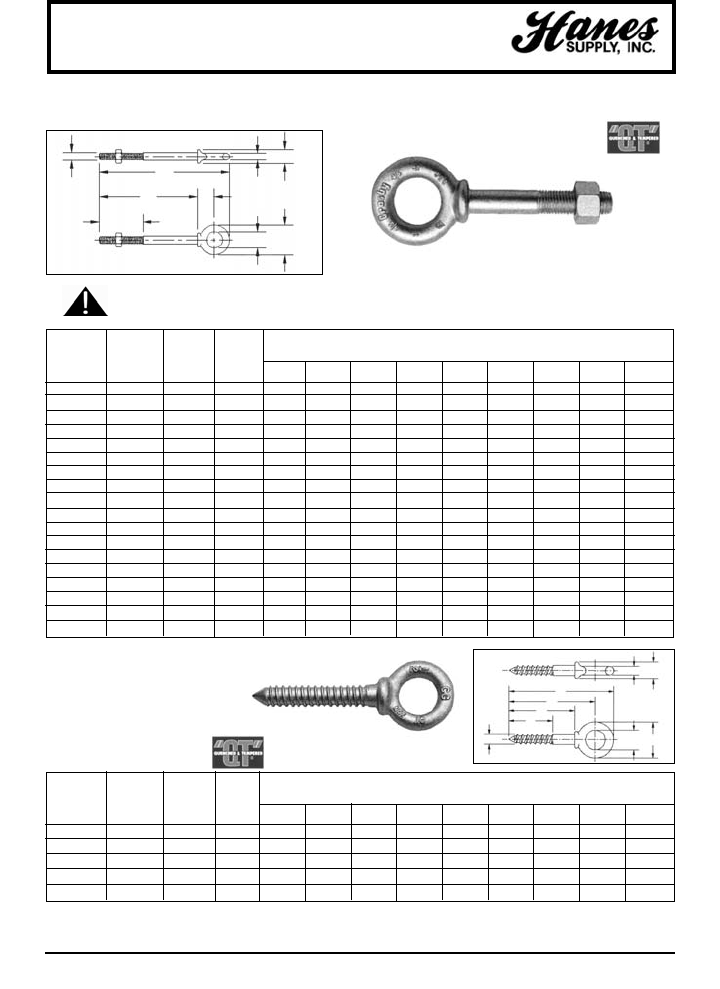
HEADQUARTERS: 55 James E. Casey Drive • Buffalo, NY 14206 PHONE: 716.826.2636 FAX: 716.826.4412 www.hanessupply.com
112
Eye Bolts
SHANK WORKING
DIAMETER G-277 LOAD WEIGHT DIMENSIONS (IN)
& LENGTH STOCK NO. LIMIT* PER 100
(IN.) GALV. (LBS.) (LBS.) A B C D E F G H J
1/4 x 2 1045014 650 6.60 .25 .50 .88 .19 1.50 2.00 2.94 .50 .47
1/4 x 4 1045032 650 9.10 .25 .50 .88 .19 2.50 4.00 4.94 .50 .47
5/16 x 2-1/4 1045050 1200 12.50 .31 .62 1.12 .25 1.50 2.25 3.50 .69 .56
5/16 x 4-1/4 1045078 1200 18.80 .31 .62 1.12 .25 2.50 4.25 5.50 .69 .56
3/8 x 2-1/2 1045096 1550 21.40 .38 .75 1.38 .31 1.50 2.50 3.97 .78 .66
3/8 x 4-1/2 1045112 1550 25.30 .38 .75 1.38 .31 2.50 4.50 5.97 .78 .66
1/2 x 3-1/4 1045130 2600 42.60 .50 1.00 1.75 .38 1.50 3.25 5.12 1.00 .91
1/2 x 6 1045158 2600 56.60 .50 1.00 1.75 .38 3.00 6.00 7.88 1.00 .91
5/8 x 4 1045176 5200 68.60 .62 1.25 2.25 .50 2.00 4.00 6.44 1.31 1.12
5/8 x 6 1045194 5200 102.40 .62 1.25 2.25 .50 3.00 6.00 8.44 1.31 1.12
3/4 x 4-1/2 1045210 7200 144.50 .75 1.50 2.75 .62 2.00 4.50 7.44 1.56 1.38
3/4 x 6 1045238 7200 167.50 .75 1.50 2.75 .62 3.00 6.00 8.94 1.56 1.38
7/8 x 5 1045256 10600 225.00 .88 1.75 3.25 .75 2.50 5.00 8.47 1.84 1.56
1 x 6 1045292 13300 366.60 1.00 2.00 3.75 .88 3.00 6.00 9.97 2.09 1.81
1 x 9 1045318 13300 422.50 1.00 2.00 3.75 .88 4.00 9.00 12.97 2.09 1.81
1-1/4 x 8 1045336 21000 650.00 1.25 2.50 4.50 1.00 4.00 8.00 12.72 2.47 2.28
1-1/4 x 12 1045354 21000 795.00 1.25 2.50 4.50 1.00 4.00 12.00 16.72 2.47 2.28
1-1/2 x 15 1045372 24000 1425.00 1.50 3.00 5.50 1.25 6.00 15.00 20.75 3.00 2.75
SHOULDER NUT EYE BOLTS
• Forged Steel
• Hot Dip galvanized
• Furnished with standard Hot Dip galvanized, heavy hex nuts
G-277
SEE APPLICATION AND
WARNING INFORMATION
SHANK WORKING
DIAMETER G-275 LOAD WEIGHT DIMENSIONS (IN)
& LENGTH STOCK NO. LIMIT* PER 100
(IN.) GALV. (LBS.) (LBS.) A B C D E F G H J
1/4 x 2 1046111 500 4.30 .25 1.50 2.00 2.50 2.94 .50 .88 .19 .47
5/16 x 2-1/4 1046139 800 12.50 .31 1.69 2.25 2.94 3.50 .63 1.13 .25 .56
3/8 x 2-1/2 1046157 1200 19.00 .38 1.88 2.50 3.28 3.97 .75 1.38 .31 .66
1/2 x 3-1/4 1046175 2200 37.50 .50 2.44 3.25 4.25 5.12 1.00 1.75 .38 .91
5/8 x 4 1046193 3500 75.00 .62 3.00 4.00 5.31 6.44 1.25 2.25 .50 1.12
*Ultimate Load is 5 times Working Load Limit.
• Forged Steel – Quenched and Tempered
• Hot Dip galvanized
SCREW EYE BOLTS
G-275
A
E
G
FH
D
BC
J
A
E
G
F
H
D
B
C
J
YOUR SLING AND RIGGING SPECIALIST
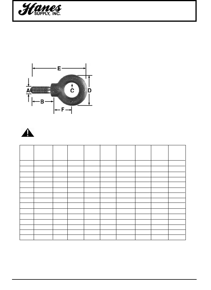
HEADQUARTERS: 55 James E. Casey Drive • Buffalo, NY 14206 PHONE: 716.826.2636 FAX: 716.826.4412 www.hanessupply.com
113
Eye Bolts
SHOULDER TYPE MACHINE EYE BOLTS
• Forged
• 1030 Carbon Steel
• Self-Colored
SEE APPLICATION AND
WARNING INFORMATION
THREAD CENTER APPROX.
SIZE SHANK I.D. O.D. OVERALL OF EYE TO WT. PER RATED
STOCK UNC-2A LENGTH EYE EYE LENGTH SHOULDER 100 PCS. CAP.
NO. A B C D E F BLANKS* (LBS.) (LBS.)
14611 1/4 - 20 1 3/4 1-3/16 2-3/8 3/4 R14611 5.0 500
14621 5/16 - 18 1-1/8 7/8 1-7/16 2-13/16 15/16 R14621 9.6 900
14631 3/8 - 16 1-1/4 1 1-11/16 3-1/4 1-1/8 R14631 16.0 1,300
14638 7/16 - 14 1-3/8 1-3/32 1-13/16 3-9/16 1-1/4 R14638 24.2 1,800
14641 1/2 - 13 1-1/2 1-3/16 2-1/8 3-31/32 1-3/8 R14641 34.8 2,400
14650 9/16 - 12 1-3/4 1-3/8 2-9/16 4-3/4 1-21/32 R14650 47.0 3,200
14661 5/8 - 11 1-3/4 1-3/8 2-9/16 4-3/4 1-21/32 R14661 67.0 4,000
14672 3/4 - 10 2 1-1/2 2-13/16 5-1/4 1-13/16 R14682 100.0 5,000
14682 7/8 - 9 2-1/4 1-11/16 3-3/16 6 2-1/8 R14682 163.0 7,000
14702 1 - 8 2-1/2 1-13/16 3-9/16 6-5/8 2-5/16 R14702 222.0 9,000
14712 1-1/8 - 7 2-3/4 2 4-1/16 7-17/32 2-11/16 R14712 340.0 12,000
14723 1-1/4 - 7 3 2-13/16 4-7/16 8-7/32 2-15/16 R14723 444.0 15,000
14753 1-1/2 - 6 3-1/2 2-1/2 5-3/16 9-15/32 3-5/16 R14753 736.0 21,000
14770 1-3/4 - 5 3-3/4 2-7/8 6 10-13/16 4 R14770 1135.0 28,000
14780 2 - 4-1/2 4 3-1/4 6-7/8 11-7/8 4-3/8 R14780 1670.0 38,000
*Blanks have no rated capacity.
YOUR SLING AND RIGGING SPECIALIST
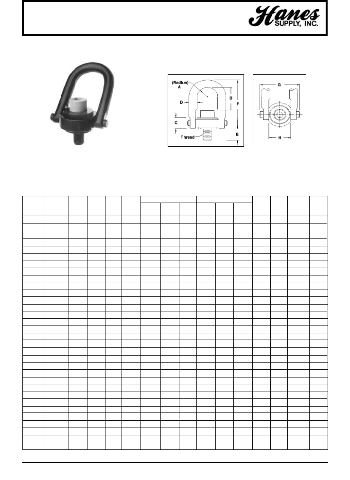
HEADQUARTERS: 55 James E. Casey Drive • Buffalo, NY 14206 PHONE: 716.826.2636 FAX: 716.826.4412 www.hanessupply.com
114
RATED THREAD STANDARD U-BAR LONG U-BAR
LOADS SIZE PART PART TORQUE WT.
(LBS.) (IN.) A C D E NO. B F NO. B F G H (FT/LB) (LBS)
600 1/4 - 20 0.43 0.71 3/8 0.54 46100 1.27 2.67 – – – 1.84 1.00 6 0.3
800 5/16 - 18 0.43 0.71 3/8 0.29 46102 1.27 2.67 – – – 1.84 1.00 7 0.3
800 5/16 - 18 0.43 0.71 3/8 0.54 46104 1.27 2.67 – – – 1.84 1.00 7 0.3
1,000 3/8 - 16 0.43 1.71 3/8 0.54 46106 1.27 2.67 – – – 1.84 1.00 12 0.3
2,000 7/16 - 14 0.70 0.93 1/2 1.07 46606 1.84 3.77 – – – 2.58 1.49 22 1.0
2,500 1/2 - 13 0.70 0.93 1/2 1.07 46602 1.84 3.77 – – – 2.58 1.49 28 1.0
2,000 7/16 - 14 0.88 1.22 3/4 0.78 46000 2.31 4.78 46638 4.25 6.72 3.52 1.99 22 2.6
2,500 1/2 - 13 0.88 1.22 3/4 0.78 46008 2.31 4.78 46644 4.25 6.72 3.52 1.99 28 2.6
2,500 1/2 - 13 0.88 1.22 3/4 1.03 46010 2.31 4.78 46646 4.25 6.72 3.52 1.99 28 2.6
2,500 1/2 - 13 0.88 1.22 3/4 1.28 46012 2.31 4.78 46648 4.25 6.72 3.52 1.99 28 2.6
4,000 5/8 - 11 0.88 1.22 3/4 0.78 46002 2.18 4.78 – – – 3.52 1.99 60 2.6
4,000 5/8 - 11 0.88 1.22 3/4 1.03 46004 2.18 4.78 46640 4.12 6.72 3.52 1.99 60 2.6
4,000 5/8 - 11 0.88 1.22 3/4 1.28 46006 2.18 4.78 46642 4.12 6.72 3.52 1.99 60 2.6
5,000 3/4 - 10 0.88 1.22 3/4 1.03 46014 2.06 4.78 46650 4.00 6.72 3.52 1.99 100 3.0
5,000 3/4 - 10 0.88 1.22 3/4 1.53 46018 2.06 4.78 46654 4.00 6.72 3.52 1.99 100 3.0
7,000 3/4 - 10 1.40 1.71 1 1.04 46204 3.06 6.52 46658 4.65 8.11 5.14 3.00 100 7.0
7,000 3/4 - 10 1.40 1.71 1 2.54 46206 3.06 6.52 46660 4.65 8.11 5.14 3.00 100 7.0
8,000 7/8 - 9 1.40 1.71 1 1.04 46202 2.93 6.52 46656 4.52 8.11 5.14 3.00 160 7.0
8,000 7/8 - 9 1.40 1.71 1 1.29 46203 2.93 6.52 46652 4.52 8.11 5.14 3.00 160 7.0
10,000 1 - 8 1.40 1.71 1 1.29 46210 2.81 6.52 46662 4.40 8.11 5.14 3.00 230 7.5
10,000 1 - 8 1.40 1.71 1 1.54 46212 2.81 6.52 46664 4.40 8.11 5.14 3.00 230 7.5
10,000 1 - 8 1.40 1.71 1 2.29 46214 2.81 6.52 46666 4.40 8.11 5.14 3.00 230 7.5
15,000 1-1/4 - 7 1.75 2.11 1-1/4 1.89 46802 4.12 8.73 – – – 6.50 3.76 470 14.0
20,000 1-3/8 - 6 2.00 2.36 1-1/2 2.64 46702 5.20 10.59 – – – 7.46 4.31 540 22.0
24,000 1-1/2 - 6 2.25 2.81 1-3/4 2.70 46404 6.41 12.47 – – – 8.55 4.87 800 34.0
24,000 1-3/4 - 5 2.25 2.81 1-3/4 2.70 46408 6.41 12.47 – – – 8.55 4.87 800 34.0
30,000 2 - 4-1/2 2.25 2.81 1-3/4 2.96 46400 5.91 12.47 – – – 8.55 4.87 800 36.0
50,000 2-1/2 - 8 3.00 4.09 2-1/4 4.00 47002 8.03 16.87 – – – 11.67 6.52 2100 88.0
50,000 2-1/2 - 4 3.00 4.09 2-1/4 4.00 47006 8.03 16.87 – – – 11.67 6.52 2100 88.0
75,000 3 - 4 3.75 5.27 2-3/4 4.20 47200 8.48 19.50 – – – 14.15 8.10 4300 166.0
100,000 3-1/2 - 4 4.00 6.06 3-1/4 7.00 47402 9.28 22.09 – – – 15.90 8.60 5100 265.0
250,000 6 - 4 6.00 14.00 5 9.00 47602 14.00 33.00 – – – 25.00 13.00 9900 790.0
Hoist Rings
ACTEK™ SWIVEL (SAFETY) HOIST RINGS
• Rated load from 400 lbs. to 125 tons.
• Pivots 180°/Swivels 360°
• Material: AISI 4140 aircraft quality
• Finish: Black oxide per mil spec cadmium plated
• Safety factor: 5:1
• 100% magnetic particle inspected
• Certified heat treatment
UNC THREADS METRIC THREADS
See following page
UNC THREADS
YOUR SLING AND RIGGING SPECIALIST
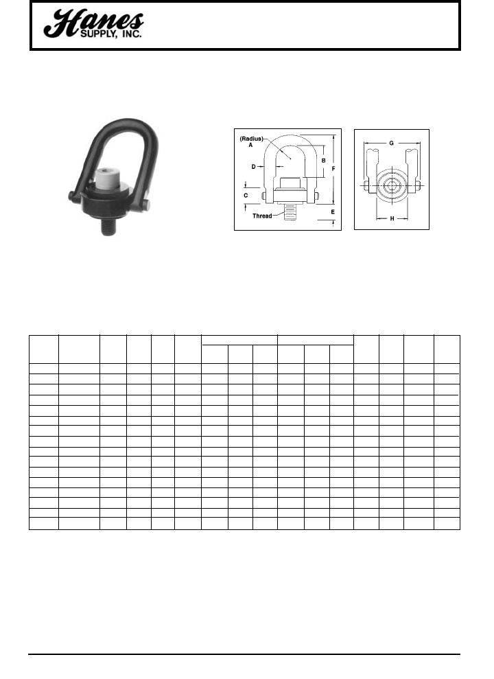
HEADQUARTERS: 55 James E. Casey Drive • Buffalo, NY 14206 PHONE: 716.826.2636 FAX: 716.826.4412 www.hanessupply.com
115
RATED STANDARD U-BAR LONG U-BAR
LOADS THREAD PART PART TORQUE WT.
(KGS.) SIZE A C D E NO. B F NO. B F G H (KGM.) (KGS.)
400 M8 x 1.25 11 18 10 13 46912 32 68 – – – 47 25 0.86 0.17
500 M10 x 1.50 11 18 10 18 46916 30 68 – – – 47 25 1.5 0.17
1,050 M12 x 1.75 22 30 19 19 46924 60 121 47124 110 171 89 51 3.7 1.08
1,900 M16 x 2.00 22 30 19 29 46930 56 121 47130 106 171 89 51 8.4 1.12
2,150 M20 x 2.50 22 30 19 34 46936 52 121 47136 102 171 89 51 14 1.19
3,000 M20 x 2.50 36 43 25 32 46942 78 166 47142 118 206 131 76 14 3.03
4,200 M24 x 3.00 36 43 25 37 46948 74 166 47148 114 206 131 76 14 3.10
4,200 M30 x 3.50 36 43 25 58 – – – 46950 108 206 131 76 60 3.10
7,000 M30 x 3.50 45 54 32 42 46956 106 222 – – – 165 95 60 6.30
7,000 M30 x 3.50 45 54 32 62 46958 106 222 – – – 165 95 60 6.40
11,000 M36 x 4.00 57 71 44 64 46966 166 317 – – – 217 124 100 15.50
12,500 M42 x 4.50 57 71 44 82 46968 160 317 – – – 217 124 100 16.00
13,500 M48 x 5.00 57 71 44 82 46970 154 317 – – – 217 124 100 16.80
22,300 M64 x 6.00 76 103 57 101 46972 204 428 – – – 296 165 273 39.00
31,500 M72 x 6.00 95 133 70 132 46988 220 495 – – – 359 206 559 74.00
51,000 M90 x 6.00 102 153 83 177 46990 235 561 – – – 404 218 663 118.00
Hoist Rings
ACTEK™ SWIVEL (SAFETY) HOIST RINGS
• Rated load from 400 lbs. to 125 tons.
• Pivots 180°/Swivels 360°
• Material: AISI 4140 aircraft quality
• Finish: Black oxide per mil spec cadmium plated
• Safety factor: 5:1
• 100% magnetic particle inspected
• Certified heat treatment
METRIC THREADS UNC THREADS
See previous page
METRIC THREADS
YOUR SLING AND RIGGING SPECIALIST
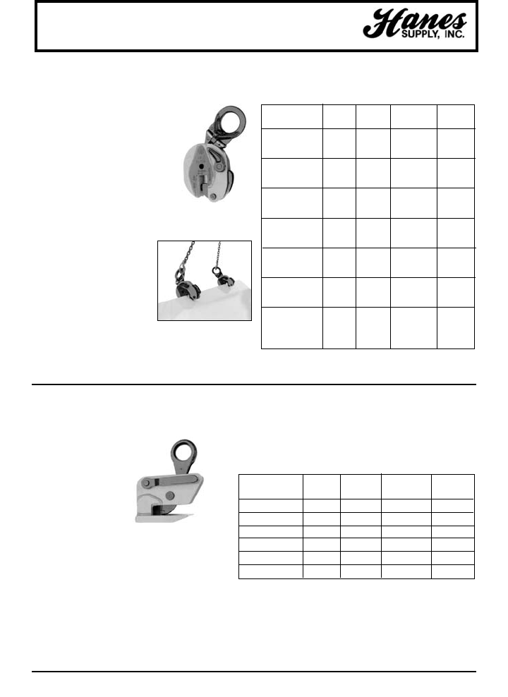
HEADQUARTERS: 55 James E. Casey Drive • Buffalo, NY 14206 PHONE: 716.826.2636 FAX: 716.826.4412 www.hanessupply.com
116
IPHGZ horizontal
lifting clamps are
designed for the lifting
and transfer in the
horizontal position of
steel plates, including
thin plates that sag.
• Clamps have a latch
which allows the
oprator to position the clamp and
move away from the load before the lift
begins.
• Suitable for working in conjunction
with an angle bench, guillotine, round
roller, etc.
Lifting Clamps
IPUZ / UNIVERSAL VERTICAL LIFTING CLAMP
IPUZ vertical lifting clamps are
used for lifting, turning (180°)
and vertical transfer of steel
plates & constructions.
• Hinged hoisting eye allows
the user to place and lift the
load from virtually any
direction.
• All IPUZ clamps have latches
that lock in both the open and
closed positions.
• IPUZ clamps with working
load limits greater than 12
tons have special built-in
hook-up devices to assist
in the placement of these
large-sized clamps.
IPHGZ / IPHGUZ HORIZONTAL LIFTING CLAMP
WLL JAW WT. PER
ORDER PER PCE. OPENING PIECE
MODEL NO. (TONS) (IN.) (LBS.)
0,75 - IPUZ 5051 0,75 0 - 5/8 4
0,75 - IPSUZ 5052 0,75 5/8 - 1-1/4 4
0,75 - IPWGUNZ 1601 0,75 0 - 3/4 4
1,5 - IPUZ 5053 1,5 0 - 3/4 17
1,5 - IPSUZ 5054 1,5 3/4 - 1-5/8 17
1,5 - IPWGUZ 5186 1,5 0 - 1-3/8 17
3 - IPUZ 5055 3,0 0 - 1 35
3 - IPSUZ 5056 3,0 1 - 2 36
4,5 - IPUZ 5057 4,5 0 - 1 35
4,5 - IPSUZ 5058 4,5 1 - 2 37
6 - IPUNZ 5139 6,0 0 - 1-1/4 50
6 - IPSUNZ 5140 6,0 1-1/4 - 2-1/2 51
9 - IPUNZ 5141 9,0 0 - 1-5/8 63
9 - IPSUNZ 5142 9,0 1-5/8 - 3-1/8 64
12 - IPUNZ 5078 12,0 0 - 2-1/8 126
12 - IPSUNZ 5079 12,0 2-1/8 - 4-1/4 130
16 - IPUNZ 5093 16,0 1/4 - 2-1/2 174
16 - IPSUNZ 5094 16,0 2-1/2 - 5 203
22,5 - IPUNZ 5098 22,5 1/4 - 3-1/8 281
22,5 - IPSUNZ 5099 22,5 3-1/8 - 6-1/8 288
30 - IPUNZ 5112 30,0 1/4 - 3-1/8 337
30 - IPSUNZ 5113 30,0 3-1/8 - 6-1/8 364
WLL JAW WT. PER
ORDER PER PCE. OPENING PIECE
MODEL NO. (TONS) (IN.) (LBS.)
0,75 - IPHGZ 5451 0,75 0 - 1 8
1,5 - IPHGZ 5452 1,5 0 - 1 16
3 - IPHGZ 5453 3,0 0 - 1-1/2 27
4,5 - IPHGZ 5454 4,5 0 - 1-1/2 46
4,5 - IPHGX1Z 3772 4,5 1/4 - 1-3/4 50
1,5 - IPHGUZ 5455 1,5 0 - 1 18
IPHGZ
Type IPHGZ has a fixed hoisting eye.
Type IPHGUZ has a universal hoisting eye.
Type IPURZ has a cam segment and pivot made of stainless
steel.
YOUR SLING AND RIGGING SPECIALIST
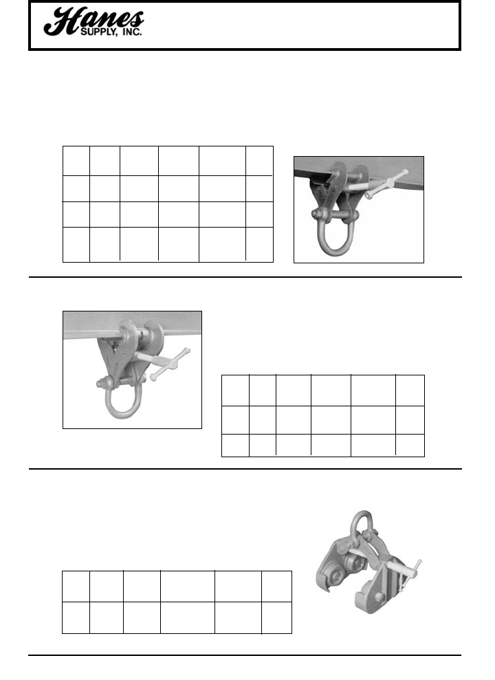
HEADQUARTERS: 55 James E. Casey Drive • Buffalo, NY 14206 PHONE: 716.826.2636 FAX: 716.826.4412 www.hanessupply.com
117
Lifting Clamps
WLL@ JAW GRIP INSIDE
0 - 15° ADJ. JAW SHACKLE AVG.
VERT. MIN-MAX APERTURE CROWN TO WT.
MODEL (LBS.) (IN.) (IN.) SPACER (IN.) (LBS.)
S5 6720 3-1/2 - 12 1 3-3/4 22.0
S5A 6720 3-1/2 - 12 1 4-1/8 30.4
S6 11200 3-1/2 - 12 1 4-1/8 30.4
S6A 11200 3-1/2 - 12 1 4-1/8 33.5
S11 22400 3-1/2 - 12 1 5-1/8 45.4
FIXED JAW ADJUSTABLE GIRDER CLAMPS
SWIVEL JAW ADJUSTABLE GIRDER CLAMPS
ADJUSTABLE RUNWAY BEAM TROLLEYS
Swivel Jaw Adjustable Girder Clamps incorporate the
additional benefit of horizontal jaw adjustment. This enables
the full length and maximum width of the swivel jaw to anchor
evenly on a considerable surface area of the beam flange.
Additional tools or width adjusting components are not
required.
WLL@ JAW GRIP INSIDE
0 - 15° ADJ. JAW SHACKLE AVG.
VERT. MIN-MAX APERTURE CROWN TO WT.
MODEL (LBS.) (IN.) (IN.) SPACER (IN.) (LBS.)
S1 4480 3 - 7-1/2 7/8 3-3/4 8.8
S2 6720 3 - 7-1/2 7/8 3-3/4 11.3
S2A 6720 3 - 7-1/2 7/8 3-3/4 16.3
S3 8960 6 - 10 7/8 3-9/10 22.9
S3X 11200 3 - 7-1/2 7/8 4-1/8 19.9
S3A 11200 6 - 12 1-5/8 4-1/8 32.8
S4S 13440 8 - 18 1-5/8 4-1/8 41.5
S4A 22400 8 - 18 1-5/8 5-1/8 60.2
S12 33600 8 - 18 2 5-7/8 118.4
S14 33600 16 - 24 2-1/2 5-7/8 126.1
These Fixed Jaw Adjustable Girder Clamps are truly versatile in
application and may be used for lifting, pulling or as an anchor point.
• Designed specifically to provide maximum JAW GRIP ADJUSTMENT.
• Engineered for practical use where mobility is essential.
• Easily applied and do not require additional tools or width adjusting
components such as spacing washers.
WLL@ WIDTH TO ACCOM- INSIDE
0° ADJ. MODATE BEAM SHACKLE AVG.
VERT. MIN-MAX FLANGE MAX. CROWN TO WT.
MODEL (LBS.) (IN.) THKNS. (IN.) SPACER (IN.) (LBS.)
B1 6720 3 - 8 1-1/8 4 60.6
B2 13440 4 - 12 1-1/4 4 107.2
B3 22400 4 - 12 1-1/2 5-1/8 158.7
"SUPERCLAMP" Adjustable Runway Beam Trolleys are of
acknowledged and experienced design. The unique quality features
of this new range of manual travelling gear are the Wheelguarding
Anti-drop Plates, which are incorporated into the practical design of
these transferable and mobile securing attachments. To complement
this range, reference is made to "SUPERCLAMP" Geared Runway
Beam Trolleys which allow additional ease of load conveyance.
YOUR SLING AND RIGGING SPECIALIST
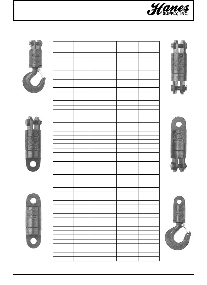
118
HEADQUARTERS: 55 James E. Casey Drive • Buffalo, NY 14206 PHONE: 716.826.2636 FAX: 716.826.4412 www.hanessupply.com
Swivels
SAFE WEIGHT
WORKING SWIVEL WIRE ROPE EACH
LOAD* TYPE NUMBER SIZE (LBS.)
3 S - 1 3 - S - 1 1/2 9.81
3 S - 2 3 - S - 2 1/2 9.63
3 S - 3 3 - S - 3 1/2 9.12
3 S - 4 3 - S - 4 1/2 9.00
3 S - 5 3 - S - 5 1/2 8.50
3 S - 6 3 - S - 6 1/2 9.32
5 S - 1 5 - S - 1 5/8 15.51
5 S - 2 5 - S - 2 5/8 13.69
5 S - 3 5 - S - 3 5/8 13.50
5 S - 4 5 - S - 4 5/8 12.33
5 S - 5 5 - S - 5 5/8 11.30
5 S - 6 5 - S - 6 5/8 14.24
8-1/2 S - 1 8-1/2 - S - 1 3/4 29.42
8-1/2 S - 2 8-1/2 - S - 2 3/4 26.16
8-1/2 S - 3 8-1/2 - S - 3 3/4 24.90
8-1/2 S - 4 8-1/2 - S - 4 3/4 29.00
8-1/2 S - 5 8-1/2 - S - 5 3/4 29.25
8-1/2 S - 6 8-1/2 - S - 6 3/4 32.00
10 S - 1 10 - S - 1 7/8 46.75
10 S - 2 10 - S - 2 7/8 45.75
10 S - 3 10 - S - 3 7/8 43.50
10 S - 4 10 - S - 4 7/8 44.00
10 S - 5 10 - S - 5 7/8 42.00
10 S - 6 10 - S - 6 7/8 45.50
15 S - 1 15 - S - 1 1 73.75
15 S - 2 15 - S - 2 1 62.75
15 S - 3 15 - S - 3 1 61.00
15 S - 4 15 - S - 4 1 61.00
15 S - 5 15 - S - 5 1 49.00
15 S - 6 15 - S - 6 1 63.00
25 S - 1 25 - S - 1 – 140.00
25 S - 2 25 - S - 2 – 140.00
25 S - 3 25 - S - 3 – 135.00
25 S - 4 25 - S - 4 – 135.00
25 S - 5 25 - S - 5 – 130.00
25 S - 6 25 - S - 6 – 135.00
35 S - 1 35 - S - 1 – 220.00
35 S - 2 35 - S - 2 – 155.00
35 S - 3 35 - S - 3 – 150.00
35 S - 4 35 - S - 4 – 150.00
35 S - 5 35 - S - 5 – 145.00
35 S - 6 35 - S - 6 – 215.00
45 S - 1 45 - S - 1 – 251.00
45 S - 2 45 - S - 2 – 235.00
45 S - 3 45 - S - 3 – 225.00
45 S - 4 45 - S - 4 – 225.00
45 S - 5 45 - S - 5 – 215.00
45 S - 6 45 - S - 6 – 270.00
SWIVELS
TIMKEN BEARING EQUIPPED
LOAD RATED
S-2
JAW & JAW
S-4
EYE & JAW
S-6
EYE & HOOK
S-1
JAW & HOOK
S-3
JAW & EYE
S-5
EYE & EYE
*Safe working load in metric tons.
YOUR SLING AND RIGGING SPECIALIST
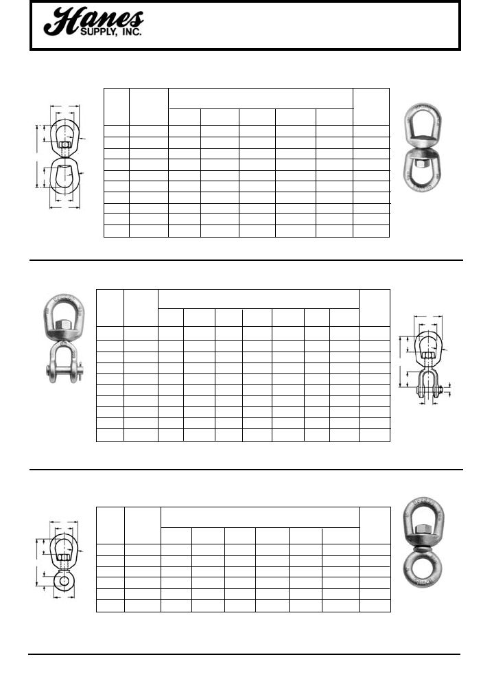
HEADQUARTERS: 55 James E. Casey Drive • Buffalo, NY 14206 PHONE: 716.826.2636 FAX: 716.826.4412 www.hanessupply.com
119
SAFE
WORKING DIMENSIONS (IN) WEIGHT
SIZE LOAD EACH
(IN.) (LBS)* A B C D E R (LBS.)
1/4 850 1-1/4 11/16 3/4 7/16 15/16 2-1/4 .13
5/16 1250 1-5/8 13/16 1 1/2 1-1/8 2-23/32 .25
3/8 2250 2 15/16 1-1/4 3/4 1-1/2 3-7/16 .54
1/2 3600 2-1/2 1-5/16 1-1/2 7/8 1-7/8 4-1/4 1.12
5/8 5200 3 1-9/16 1-3/4 1-1/16 2-3/16 5-1/8 2.09
3/4 7200 3-1/2 1-3/4 2 1-1/4 2-5/8 5-25/32 3.09
Swivels
REGULAR
SAFE
WORKING DIMENSIONS (IN) WEIGHT
SIZE LOAD EACH
(IN.) (LBS)* A B C K N P R (LBS.
1/4 850 1-1/4 11/16 3/4 15/32 7/8 1/4 2-5/8 .21
5/16 1250 1-5/8 13/16 1 1/2 7/8 5/16 2-15/16 .34
3/8 2250 2 15/16 1-1/4 5/8 1-1/16 3/8 3-5/8 .66
1/2 3600 2-1/2 1-5/16 1-1/2 3/4 1-5/16 1/2 4-1/2 1.34
5/8 5200 3 1-9/16 1-3/4 15/16 1-1/2 5/8 5-5/16 2.48
3/4 7200 3-1/2 1-3/4 2 1-1/8 1-3/4 3/4 6-1/16 3.88
7/8 10000 4 2-1/16 2-1/4 1-3/16 2-1/16 7/8 7 5.87
1 12500 4-1/2 2-5/16 2-1/2 1-3/4 2-13/16 1-1/8 8-9/16 9.84
1-1/4 18000 5-5/8 2-11/16 3-1/8 2-1/16 2-13/16 1-3/8 9-7/16 15.75
1-1/2 45200 7 4-3/16 4 2-7/8 4-7/16 2-1/4 14-3/4 54.75
*Ultimate Load is five times the Safe Working Load.
SAFE
WORKING DIMENSIONS (IN) WEIGHT
SIZE LOAD EACH
(IN.) (LBS)* A B C D R (LBS.)
1/4 850 1-1/4 11/16 3/4 1-1/16 2-15/16 .21
5/16 1250 1-5/8 13/16 1 1-1/4 3-9/16 .39
3/8 2250 2 15/16 1-1/4 1-1/2 4-5/16 .71
1/2 3600 2-1/2 1-5/16 1-1/2 2 5-7/16 1.32
5/8 5200 3 1-9/16 1-3/4 2-3/8 6-9/16 2.49
3/4 7200 3-1/2 1-3/4 2 2-5/8 7-3/16 4.02
7/8 10000 4 2-1/16 2-1/4 3-1/16 8-3/8 6.25
1 12500 4-1/2 2-5/16 2-1/2 3-1/2 9-5/8 8.95
1-1/4 18000 5-5/8 2-11/16 3-1/8 2-11/16 11-1/8 16.37
1-1/2 45200 7 4-3/16 4 4-3/16 17-1/8 45.79
JAW END
CHAIN
*Ultimate Load is five times the Safe Working Load.
*Ultimate Load is five times the Safe Working Load.
G-402
REGULAR
QUENCHED
& TEMPERED
G-403
JAW END
QUENCHED
& TEMPERED
G-401
CHAIN
QUENCHED &
TEMPERED
A
C
C
A
B
D
R
SIZE
SIZE
P
K
C
A
B
N
R
SIZE
E
C
A
B
D
R
SIZE
YOUR SLING AND RIGGING SPECIALIST
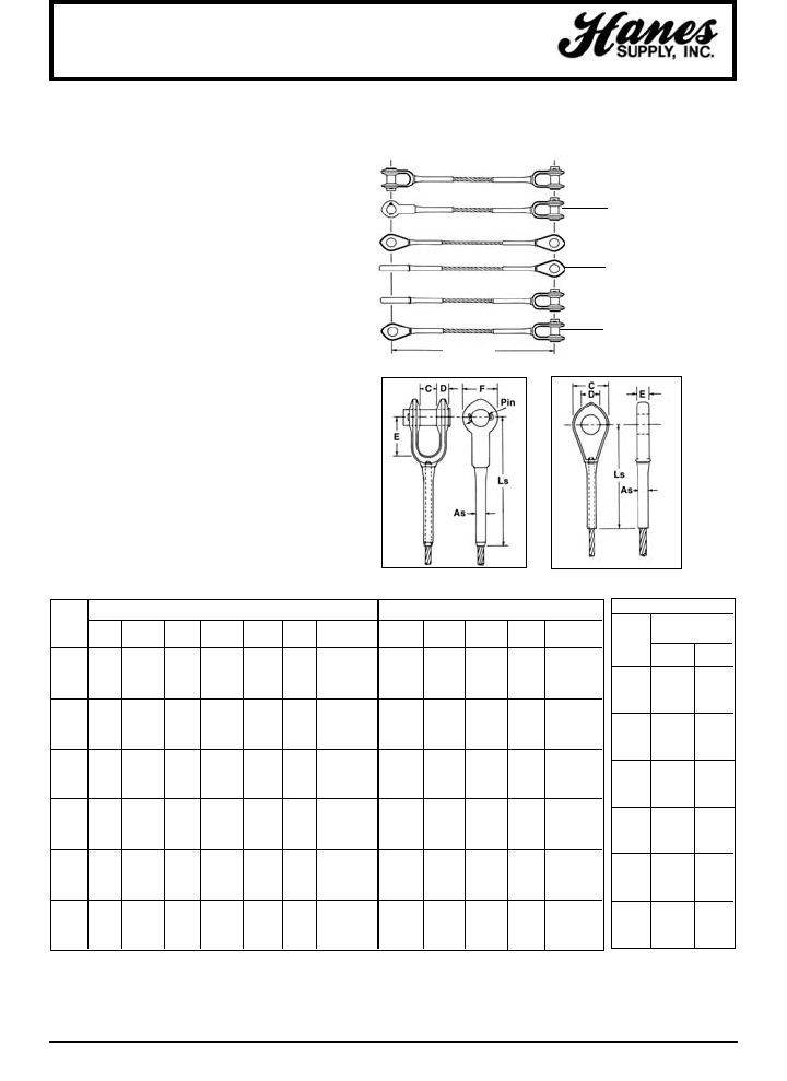
120
HEADQUARTERS: 55 James E. Casey Drive • Buffalo, NY 14206 PHONE: 716.826.2636 FAX: 716.826.4412 www.hanessupply.com
Swaged Sockets
SWAGED SOCKETS ASSEMBLIES
CAPACITY (TONS*)
6X 19 & 6 X 37
IWRC
ROPE
DIA. LPS XIP
1/4 .588 .69
5/16 .916 1.05
3/8 1.3 1.5
7/16 1.778 2.04
1/2 2.3 2.66
9/16 2.9 3.36
5/8 3.58 4.12
3/4 5.12 5.88
7/8 6.92 7.96
1 8.98 10.34
1-1/8 11.3 13.
1-1/4 13.88 15.98
1-3/8 16.7 19.2
1-1/2 19.78 22.8
1-3/4 26.6 30.6
2 34.4 39.6
2-1/4 43. 49.4
2-1/2 52.4 60.4
In mechanically swaged fittings, high
pressure presses and precision dies cause
metal of the socket to flow around wires
and strands to offer the ultimate in
compactness and strength with minimum
weight. Material is weldless, drop-forged
steel.
Normally, only regular lay rope is used.
Swaged assemblies are interchangeable
with *poured sockets up through 2" rope
diameters. Assembly length is measured
from centerline of pins for both open and
closed sockets.
When purchasing, indicate choice of end
fittings by the suffixes “OS” or “CS” after
the stock number, for open or closed type
fittings. Pins and cotters are supplied as
standard on open fittings, but assemblies
may be specified without pins. Fittings are
assembled in the same plane unless
specified otherwise when ordered.
* These sockets are not interchangeable with zinc
poured sockets.
OPEN SOCKET DIAMETER (IN) CLOSED SOCKET DIAMETER (IN)
ROPE LSLS
DIA. C D E F PIN AS(APPROX.) C D E AS(APPROX.)
1/4 11/16 5/16 1-1/2 1-3/8 .688 .438 4-7/16 1-7/16 .750 1/2 .438 3-15/16
5/16 13/16 13/32 1-3/4 1-5/8 .812 .688 5-15/16 1-11/16 .875 11/16 .688 5-1/8
3/8 13/16 13/32 1-3/4 1-5/8 .812 .688 5-15/16 1-11/16 .875 11/16 .688 5-1/8
7/16 1 1/2 2 2 1.00 .875 7-5/8 2 1.063 7/8 .875 6-5/8
1/2 1 1/2 2 2 1.00 .875 7-5/8 2 1.063 7/8 .875 6-5/8
9/16 1-1/4 5/8 2-1/4 2-1/2 1.19 1.125 9-3/16 2-1/2 1.250 1-1/8 1.125 8-5/16
5/8 1-1/4 5/8 2-1/4 2-1/2 1.19 1.125 9-3/16 2-1/2 1.250 1-1/8 1.125 8-5/16
3/4 1-1/2 3/4 2-3/4 3 1.38 1.375 11-1/4 3 1.438 1-5/16 1.375 9-15/16
7/8 1-3/4 15/16 3-1/4 3-3/8 1.63 1.50 13-1/8 3-1/2 1.688 1-1/2 1.50 11-5/8
1 2 1-1/32 3-3/4 4 2.00 1.75 15-1/16 4 2.063 1-3/4 1.75 13-3/16
1-1/8 2-1/4 1-3/16 4-1/4 4-1/2 2.25 2.00 16-15/16 4-1/2 2.313 2 2.00 14-11/16
1-1/4 2-1/2 1-3/16 4-3/4 5 2.50 2.25 18-5/8 5 2.563 2-1/4 2.25 16-1/2
1-3/8 2-1/2 1-5/16 5-1/4 5-1/4 2.50 2.50 20-1/2 5-1/4 2.563 2-1/4 2.50 18-1/8
1-1/2 3 1-7/16 5-3/4 5-3/4 2.75 2.75 22-5/16 5-1/2 2.813 2-1/2 2.75 19-9/16
1-3/4 3-1/2 1-11/16 6-3/4 7 3.50 3.00 26 6-3/4 3.563 3 3.00 23
2 4 1-13/16 8 8 3.75 3.50 30-1/8 7-3/4 3.813 3-1/4 3.50 26-7/16
2-1/4* 4-1/4 2-1/8 6-3/4 8-3/4 4.25 4.00 31-1/4 8-3/4 4.312 4 4.00 28-1/2
2-1/2* 4-1/4 2-1/8 6-3/4 8-3/4 4.25 4.40 33-3/8 8-3/4 4.312 4 4.40 30-1/4
Pins at
Right Angles
500-R
Pins at
Right Angles
502-R
Pins at
Right Angles
503-R
Pins
Parallel
500-P
Pins
Parallel
502-P
Pins
Parallel
503-P
os-os
cs-cs
os-cs
LENGTH
YOUR SLING AND RIGGING SPECIALIST
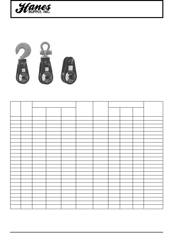
HEADQUARTERS: 55 James E. Casey Drive • Buffalo, NY 14206 PHONE: 716.826.2636 FAX: 716.826.4412 www.hanessupply.com
121
Snatch Blocks
NEW IMPROVED LIGHT CHAMPION by McKissick®
418
w/Hook
419
w/Shackle
404
Tail Board
• Forged alloy heat treated hooks.
• Forged steel swivel tees, yokes and shackles.
• Hook and shackle assemblies on 4-1/2” through 14”
sizes can be interchanged.
• Can be furnished with bronze bushings or roller
bearings.
• Opening feature permits insertion of rope while block is
suspended from gin-pole.
• 3” thru 18” 418 and 419 blocks have exclusive bolt
retaining spring to assure no lost bolts.
• Can be furnished with SS-4055 hook latch.
• Pressure lube fittings.
• Fatigue rated.
• 3” - 10” feature dual rated wireline sheaves.
STOCK NO. WEIGHT EACH
WIRE (LBS.) REPLACEMENT
SHEAVE 481 419 404 ROPE WORKING 418 419 404 SHEAVE
DIA. BEARING WITH WITH TAIL SIZE LOAD LIMIT* WITH WITH TAIL STOCK
(IN.) CODE HOOK SHACKLE BOARD (IN.)‡ (TONS) HOOK SHACKLE BOARD NO.
3** BB – 109091 – 5/16 - 3/8 2 – 5 – 460147
3** BB 108038 109037† 102016 5/16 - 3/8 2 5 4 3 460147
4-1/2** BB 108065 109064 102025 3/8 - 1/2 4 12 12 7 2000232
6 BB 108127 109126 102098 5/8 - 3/4 8 27 28 15 460815
6 RB 108154 109153 102114 5/8 - 3/4 8 27 28 15 472688
8 BB 108225 109224 102169 5/8 - 3/4 8 33 34 21 461164
8 RB 108252 109251 102187 5/8 - 3/4 8 33 34 21 473277
10 BB 108323 109322 102230 5/8 - 3/4 8 41 42 29 461805
10 RB 108350 109359 102258 5/8 - 3/4 8 41 42 29 473776
12 BB 169169 202961 178890 5/8 8 48 49 36 462270
12 RB 199911 169347 178934 5/8 8 48 49 36 474141
12 BB 108421 109420 102301 3/4 8 48 49 36 462289
12 RB 108458 109457 102329 3/4 8 48 49 36 474150
14 BB 194920 169356 – 5/8 8 55 56 – 463625
14 RB 199948 167857 – 5/8 8 55 56 – 474766
14 BB 108528 109527 – 3/4 8 55 56 – 463634
14 RB 108546 109545 – 3/4 8 55 56 – 474775
16 BB 199975 203041 – 3/4 15 130 135 – 4100056
16 RB 200008 203087 – 3/4 15 130 135 – 4200028
16 BB 108608 109607 – 7/8 15 130 135 – 4100065
16 RB 108626 109625 – 7/8 15 130 135 – 4200037
18 BB 200099 203130 – 7/8 15 150 155 – 464571
18 RB 200151 203176 – 7/8 15 150 155 – 475792
18 BB 108644 109643 – 1 15 150 155 – 4104640
18 RB 108662 109661 – 1 15 150 155 – 6000000
*Ultimate Load is 4 times the Working Load Limit.
**Available in Bronze Bushed only. 3" and 4-1/2" have self-lubricating Bronze Bushing.
†Fitted with 1-1/4" ID Swivel Eye.
‡May be furnished in other rope sizes.
YOUR SLING AND RIGGING SPECIALIST
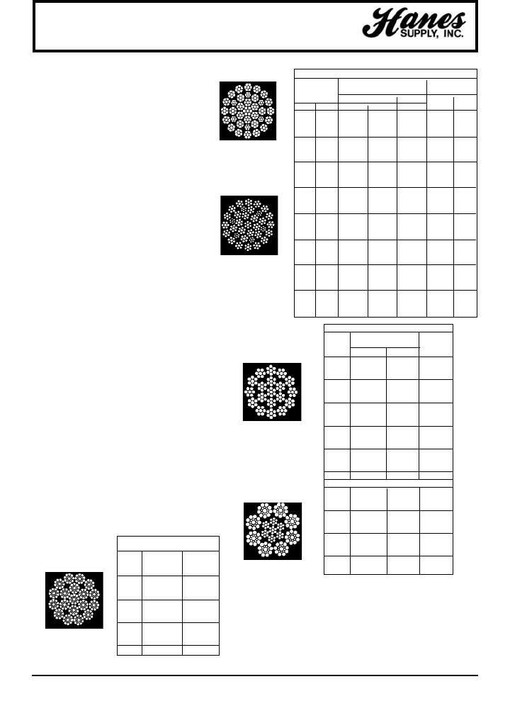
122
HEADQUARTERS: 55 James E. Casey Drive • Buffalo, NY 14206 PHONE: 716.826.2636 FAX: 716.826.4412 www.hanessupply.com
Wire Rope
In certain instances the use of rotation resistant
wire rope is necessary to provide rotational
stability to the lifted load. In general, the use of
these specialized wire ropes is limited to those
situations where it is impractical to:
1. Use a tag line.
2. Relocate rope dead end.
3. Increase sheave sizes.
4. Eliminate "odd-part" reeving.
5. Significantly reduce rope loading and rope
length.
Rotation resistant wire ropes have less of a
tendency to unlay when loaded than do
conventional wire ropes. This results in improved
rotational stability to the lifted load within a safe
working load range. Rotation resistant wire
ropes are designed in such a way that the
rotational force of the outer rope is partially
counteracted by the rotational force of the inner
rope when the rope is subjected to a load.
The rated strengths of rotation resistant ropes
are less than the conventional 6 x 19 and 6 x 36
Classification wire ropes, and larger sheaves
and drums are required in order to achieve
comparable fatigue life. Drum and sheave
diameters should be 34 to 36 times rope
diameter for the 19 x 7 and 35 x 7 rotation
resistant ropes and 21 to 27 times rope diameter
for 8 x 19 rotation resistant ropes.
Rotation Resistant Ropes are available in a full
range of sizes, grades and constructions:
• Standard constructions for single-part and
multi-part lifting.
• Special wire rope constructions for increased
service life in particularly demanding
applications – Dyform®-18 HSLR, Dyform®
34LR and 35LS.
NOTE:
1.Swivels are not recommended for use with
rotation resistant ropes.
2.Although B30 standards permit rotation
resistant ropes to be used under certain
conditions at design factors of 3.5:1, we
recommend a minimum design factor of 5:1
and a design factor of 7:1 for extended rope
life.
ROTATION RESISTANT
WIRE ROPES
DYFORM®-34LR & 35LS ROTATION RESISTANCE ROPE
MIN. BREAKING FORCE** APPROX.
(TONS) WT/FT (LBS)
DIAMETER 1960 2160
(MM) (IN.) 34LR 35LS 34LR 34LR 35LS
– 1/2 15.40 13.60 17.42 .54 .49
13 – 16.19 14.28 18.21 .57 .51
14 – 18.88 16.52 21.13 .65 .60
– 9/16 19.67 17.31 22.03 .69 .62
15 – 22.03 19.11 24.73 .77 .69
16 5/8 25.18 21.69 28.21 .87 .78
17 – 27.20 24.28 30.46 .94 .87
18 – 30.80 27.09 34.62 1.07 ..97
19 3/4 34.51 30.91 38.67 1.20 1.11
20 – 38.33 33.61 42.94 1.32 1.21
21 – 43.28 37.43 48.45 1.49 1.34
22 – 46.65 41.37 52.38 1.61 1.49
– 7/8 47.21 41.59 53.06 1.65 1.51
23 – 50.69 44.74 56.88 1.75 1.61
24 – 55.64 49.35 62.38 1.92 1.77
25 – 60.59 52.94 67.89 2.10 1.91
– 1 62.38 54.40 70.03 2.16 1.97
26 – 66.09 57.78 74.19 2.28 2.08
28 – 75.99 66.99 85.20 2.63 2.41
– 1-1/8 77.45 68.90 86.89 2.70 2.50
30 – 86.44 75.99 97.01 2.99 2.74
32 1-1/4 98.13 85.99 110.16 3.39 3.10
35 1-3/8 116.90 105.89 123.65 4.05 3.82
38 1-1/2 138.26 120.27 147.25 4.87 4.35
Not recommended for
multiple part lifting.
19 x 7
Rotation Resistant
Can be used for multiple
part lifting.
8 x 19
Rotation Resistant
35LS
19 X 7 ROTATION RESISTANT ROPE
NOMINAL STRENGTH* APPROX.
DIA. (TONS) WT/FT
(IN.) EIP IPS (LBS)
3/16 1.57 1.42 .064
1/4 2.77 2.51 .113
5/16 4.30 3.90 .177
3/8 6.15 5.59 .25
7/16 8.33 7.58 .35
1/2 10.8 9.85 .45
9/16 13.6 12.4 .58
5/8 16.8 15.3 .71
3/4 24.0 21.8 1.02
7/8 32.5 29.5 1.39
1 42.2 38.3 1.82
1-1/8 53.1 48.2 2.30
1-1/4 65.1 59.2 2.80
1-3/8 78.4 71.3 3.43
1-1/2 92.8 84.4 4.08
1-5/8 108.0 98.4 4.80
8 X 19 ROTATION RESISTANT ROPE
7/16 8.97 7.80 .36
1/2 11.7 10.2 .47
9/16 14.7 12.8 .60
5/8 18.1 15.7 .73
3/4 25.9 22.6 1.06
7/8 35.0 30.5 1.44
1 45.5 39.6 1.88
1-1/8 57.3 49.8 2.39
1-1/4 70.5 61.3 2.94
1-3/8 84.9 73.8 3.56
1-1/2 100.0 87.3 4.24
*Acceptance strength is not less than 2-1/2% below the nominal
breaking strengths listed.
NOTE: These strengths apply only when a test is conducted
with both ends fixed. When in use, the strength of
these ropes may be reduced if one end is free to rotate.
**Listed minimum breaking force is for 1960 & 2160 grade
bright (ungalvanized) ropes. Inquire for a minimum breaking
force of glavanized ropes.
†Other sizes available upon request.
Dyform®- 18HSLR
Rotation Resistant
Strongest, most rotation
resistant. For the most
demanding hoisting
applications.
Dyform®- 34LR
For multi-part lifting.
35% greater strength.
For demanding
applications where
highest strength is not
mandatory.
DYFORM®-18 HSLR
ROTATION RESISTANT ROPE
NOMINAL APPROX.
DIA. STRENGTH* WT/FT
(IN.)† (TONS) (LBS)
3/8 8.3 .27
7/16 11.2 .37
1/2 14.6 .51
9/16 18.5 .64
5/8 22.7 .79
3/4 32.4 1.1
7/8 43.8 1.5
1 57.5 2.0
1-1/8 71.5 2.5
1-1/4 87.9 3.1
YOUR SLING AND RIGGING SPECIALIST
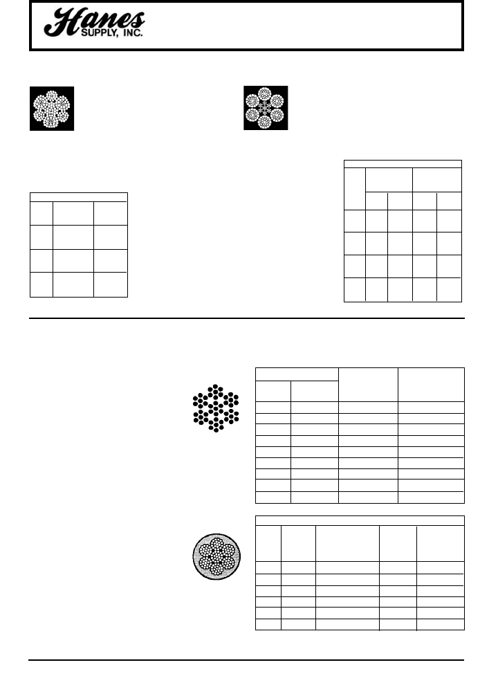
Dyform®-6 The Dyforming process produces high
density wire rope made with compacted strands.
Dyform®-6 is a six strand construction with an
Independent Wire Rope Core (IWRC). It meets or
exceeds strength requirements of EEIPS rope. The
compact strand construction provides better
flexibility, bending life and crush resistance than standard 6-strand
ropes. Compacting also produces a smooth surface for reduced
bearing pressure; and
increases the steel area by
100% for higher abrasion
resistance and less sheave
wear. Typical Applications
include: boom hoist, load
hoist and winch lines,
holding, closing, crowd and
retract lines, blast furnace
skip hoist and bell operating
ropes, ore bridges and ore
unloaders, stripper, soaking
pit, hot metal, scrap yard,
mobile and overhead
traveling cranes, hot bed
conveyors, car haulage, and
marine cargo falls.
DYFORM®-6
NOMINAL APPROX.
STRENGTH* WT/FT
(TONS) (LBS.)
DIA. FIBER FIBER
(IN.)† IWRC CORE IWRC CORE
3/8 8.8 – .31 –
7/16 11.9 – .39 –
1/2 15.3 – .49 –
9/16 19.3 – .63 –
5/8 22.7 20.0 .78 .71
3/4 32.4 28.6 1.13 1.03
7/8 43.8 38.6 1.54 1.40
1 57.5 50.0 2.00 1.82
1-1/8 71.5 63.0 2.54 2.31
1-1/4 87.9 77.5 3.14 2.85
1-3/8 106.0 93.0 3.80 3.45
1-1/2 125.0 111.0 4.50 4.10
Constructex®is made of three different
strand constructions: 7-wire, 24-wire and
40-wire strands. The nine strands are
closed in operation and lightly swaged to
postform the rope and give the strands a
triangular shape. Compacting increases
strength and resistance to crushing. The smooth outside
surface enhances abrasion and scrubbing resistance.
Constructex®can provide 1-1/2 to 2 times the service life
of other wire ropes in severely abusive applications.
Typical Applications include: tubing lines, logging lines,
winch lines, boom hoists, scrap yard, mobile and
overhead traveling
cranes, hot bed
conveyors, car haulage
and marine cargo falls.
HEADQUARTERS: 55 James E. Casey Drive • Buffalo, NY 14206 PHONE: 716.826.2636 FAX: 716.826.4412 www.hanessupply.com
123
Wire Rope
HIGH PERFORMANCE WIRE ROPE
AIR CRAFT CABLE
GALVANIZED STAINLESS STEEL
7 X 19 MIN. MIN.
DIA. APPROX. WT. BREAKING BREAKING
(IN.) 1000 FT/LBS. STRENGTH (LBS) STRENGTH (LBS.)
3/32 17. 1,000 920
1/8 29. 2,000 1,760
5/32 45. 2,800 2,400
3/16 65. 4,200 3,700
7/32 86. 5,600 5,000
1/4 110. 7,000 6,400
9/32 139. 8,000 7,800
5/16 173. 9,800 9,000
3/8 243. 14,400 12,000
7 x 19
CONSTRUCTEX®ROPE
NOMINAL APPROX
DIA. STRENGTH* WT/FT
(IN.)† (TONS) (LBS)
5/8 25.5 .86
3/4 36.5 1.1
7/8 48.5 1.5
1 62.5 2.0
1-1/8 79.5 2.6
1-1/4 97.6 3.2
1-3/8 118.0 3.8
1-1/2 139.0 4.6
1-5/8 162.0 5.3
*Acceptance strength is not
less than 2-1/2% below the
nominal breaking strengths
listed.
†Other sizes available upon
request.
7 x 19
VINYL COATED GALVANIZED AIRCRAFT CABLE
MIN.
COATED APPROX. BREAKING
DIA. TO WT/FT STRENGTH
(IN.) (IN.) CONSTRUCTION (LBS.) (LBS.)
3/32 3/16 7 x 7 28 920
1/8 3/16 7 x 7 39 1,700
1/8 3/16 7 x 19 39 2,000
3/16 1/4 7 x 19 78 4,200
1/4 5/16 7 x 19 125 7,000
3/8 7/16 7 x 19 272 14,400
Aircraft Cable is pre-formed and
made in accordance with commerical
specifications. GAC to military and
federal specifications is available.
CARBON STEEL AIRCRAFT
CABLE
Galvanized cable has the highest
strength and greatest fatigue life of
the materials offered. It has good to
fair corrosion resistance in rural to
industrial atmosphere enviornments.
This material is most widely used for
small diameter cable. Tin over
galvanized cable offers greater
corrosion resistance and reduced
friction over pulleys.
YOUR SLING AND RIGGING SPECIALIST
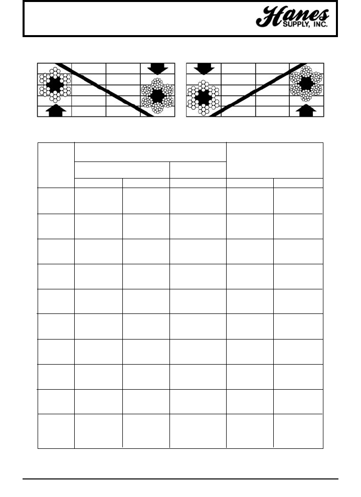
124
HEADQUARTERS: 55 James E. Casey Drive • Buffalo, NY 14206 PHONE: 716.826.2636 FAX: 716.826.4412 www.hanessupply.com
Wire Ropes
NOMINAL STRENGTH
IN TONS OF 2000 POUNDS APPROXIMATE WEIGHT
DIAMETER EXTRA IMPROVED PER FOOT (LBS.)
IMPROVED PLOW STEEL
(IN.) PLOW STEEL
FIBER CORE IWRC IWRC FIBER CORE IWRC
3/16 1.55 1.67 – .059 .065
1/4 2.74 2.94 3.40 .105 .116
5/16 4.26 4.58 5.27 .164 .18
3/8 6.10 6.56 7.55 .236 .26
7/16 8.27 8.89 10.2 .32 .35
1/2 10.7 11.5 13.3 .42 .46
9/16 13.5 14.5 16.8 .53 .59
5/8 16.7 17.9 20.6 .66 .72
3/4 23.8 25.6 29.4 .95 1.04
7/8 32.2 34.6 39.8 1.29 1.42
1 41.8 44.9 51.7 1.68 1.85
1-1/8 52.6 56.5 65.0 2.13 2.34
1-1/4 64.6 69.4 79.9 2.63 2.89
1-3/8 77.7 83.5 96. 3.18 3.50
1-1/2 92.0 98.9 114. 3.78 4.16
1-5/8 107. 115. 132. 4.44 4.88
1-3/4 124. 133. 153. 5.15 5.67
1-7/8 141. 152. 174. 5.91 6.50
2 160. 172. 198. 6.72 7.39
2-1/8 179. 192. 221. 7.59 8.35
2-1/4 200. 215. 247. 8.51 9.36
2-3/8 222. 239. 274. 9.48 10.4
2-1/2 244. 262. 302. 10.5 11.6
2-5/8 268. 288. 331. 11.6 12.8
2-3/4 292. 314. 361. 12.7 14.0
2-7/8 317. 341. 393. 13.9 15.3
3 – 370. 425. – 16.6
3-1/8 – 399. 458. – 18.0
3-1/4 – 429. 492. – 19.5
3-3/8 – 459. 529. – 21.0
3-1/2 – 491. 564. – 22.6
Available galvanized at 10% lower strengths, or in equivalent strengths on special request.
ABRASION RESISTANCE FATIGUE RESISTANCE
WIRE ROPE
NOMINAL STRENGTHS AND WEIGHTS – 6 X 19 CLASS – 6 X 36 CLASS
...DECREASES
with Smaller Wires
...DECREASES
with Fewer Wires
...INCREASES
with More Wires
...INCREASES
with Larger Wires
YOUR SLING AND RIGGING SPECIALIST
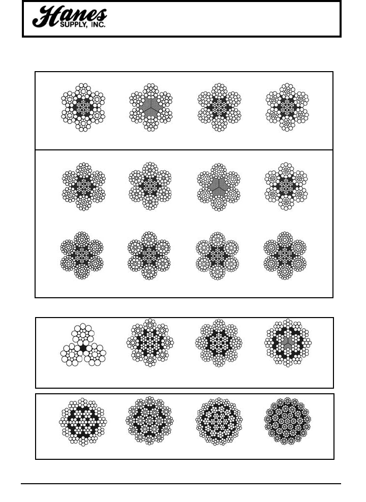
HEADQUARTERS: 55 James E. Casey Drive • Buffalo, NY 14206 PHONE: 716.826.2636 FAX: 716.826.4412 www.hanessupply.com
125
Wire Ropes
COMMONLY USED WIRE ROPE CROSS SECTIONS
6 x 19 Classification
6 x 36 Classification
Cross sections of rotation resistant rope constructions.
6 x 19 Seale
IWRC
6 x 21 Filler Wire
FC
6 x 25 Filler Wire
IWRC
6 x 26 Warrington Seale
IWRC
6 x 31 Warrington Seale
IWRC
6 x 36 Seale Filler Wire
IWRC
6 x 36 Warrington Seale
FC
6 x 31 Filler Wire Seale
IWRC
6 x 41 Warrington Seale
IWRC
6 x 41 Seale Filler Wire
IWRC
6 x 46 Seale Filler Wire
IWRC
6 x 49 Filler Wire Seale
IWRC
3 x 19 Seale 8 x 19 Seale
IWRC
8 x 25 Filler Wire
IWRC
8 x 17
FC
19 x 7 19 x 19 Seale 35 x 7 35 x 19 Seale
YOUR SLING AND RIGGING SPECIALIST
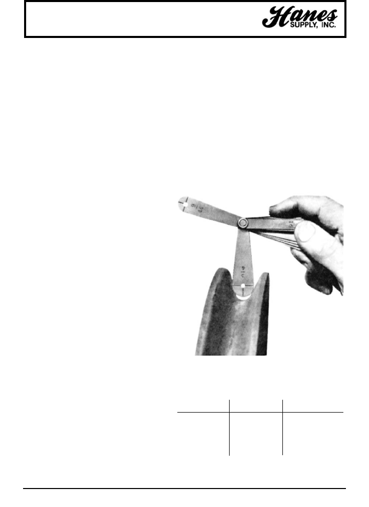
126
HEADQUARTERS: 55 James E. Casey Drive • Buffalo, NY 14206 PHONE: 716.826.2636 FAX: 716.826.4412 www.hanessupply.com
Wire Ropes
INSPECTION – THE KEY TO LONGER, SAFER WIRE ROPE USE
Any wire rope in use should be inspected on a
regular basis. You have too much at stake in
lives and equipment to ignore thorough
examination of the rope at prescribed
intervals.
The purpose of inspection is to accurately
estimate the service life and strength
remaining in a rope so that maximum service
can be had within the limits of safety. Results
of the inspection should be recorded to
provide a history of rope performance on a
particular job. On most jobs, wire rope must be
replaced before there is a risk of failure. A rope
broken in service can destroy machinery and
curtail production. It can also kill.
Because of the great responsibility involved in
ensuring safe rigging on equipment, the man
assigned to inspect should know wire rope and
its operation thoroughly. Inspections should be
made regularly and the results recorded.
When inspecting the rope, the condition of the
drum, sheaves, guards, cable clamps and
other end fittings should be noted. The
condition of these parts affects rope wear; any
defects detected should be repaired.
To ensure rope soundness between
inspections, all workers should participate.
The operation can be most helpful by watching
the ropes under his control. If any accident
involving the ropes occurs, the operator
should immediately shut down his equipment
and report the accident to his supervisor. The
equipment should be inspected before
resuming operation.
The Occupational Safety and Health Act has
made periodic inspection mandatory for most
wire rope applications.
Photo shows new gauge and worn sheave. This new gauge is
designed with one-half the allowable oversize (see table). Using
the new gauge, when you do not see light, the sheave is OK.
When you do see light under the new gauge, the sheave should
be replaced.
NOMINAL ROPE ALLOWABLE ROPE ONE-HALF ALLOWABLE
DIAMETER OVERSIZE ROPE OVERSIZE
0" - 3/4" +1/32" +1/64"
13/16" - 1-1/8" +3/64" +3/128"
1-3/16" - 1-1/2" +1/16" +1/32"
1-9/16" - 2-1/4" +3/32" +3/64"
2-5/16" - and larger +1/8" +1/16"
JUST LOOKING AT THE ROPE IS NOT ENOUGH
When an inspector takes a look at a rope, he may see
sections showing excessive wear. By flagging the rope, he
can quickly determine where the rope is rubbing or
contacting parts of the equipment, and then repair, replace
or modify the condition causing wear.
Inspections of sheaves is a relatively simple, yet very vital
task. A sheave groove gauge, usually obtainable from a
wire rope manufacturer, is used to check the grooves in a
sheave. Hold the gauge perpendicular to the surface of the
groove to observe properly the groove size and contour, as
in this illustration.
YOUR SLING AND RIGGING SPECIALIST
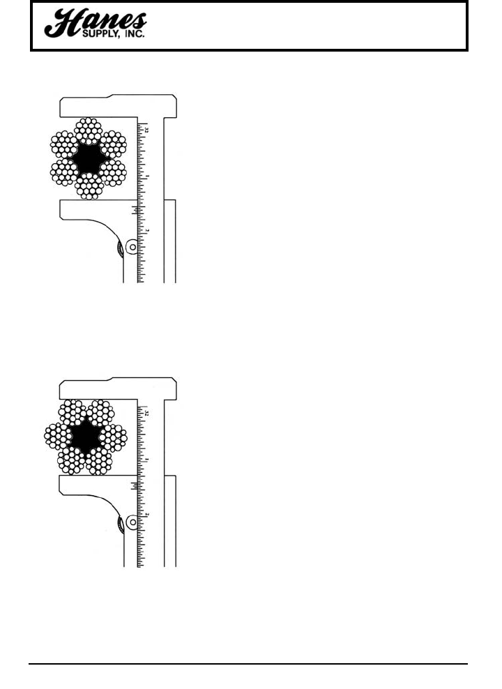
HEADQUARTERS: 55 James E. Casey Drive • Buffalo, NY 14206 PHONE: 716.826.2636 FAX: 716.826.4412 www.hanessupply.com
127
SHEAVES SHOULD BE CHECKED FOR:
1. Correct groove diameter
2. Roundness or contour to give proper support to the rope
3. Small holes, cracks, uneven surfaces, or other defects that
might be detrimental to the rope
4. Extreme deep wear
A sheave should also be checked to make sure it turns freely,
is properly aligned, has no broken or cracked flanges, and has
bearings that work properly.
Drums should also be inspected for signs of wear that could
damage rope. Plain-faced or smooth drums can develop
grooves or impressions that prevent rope from winding
properly. Repair by resurfacing the face or replacing the
lagging.
Scrubbing will occur if the rope tends to close wind. If the
tendency is to open winding, the rope will encounter abnormal
abuse as the second layer forces itself down between the
open wraps of the first layer on the drum.
Operating with a smooth drum calls for special care. Be sure
the rope is always tightly wound and thread laid on the first
layer. Any loosening of the line is easily observed as the
winding will be bad and the rope will be coming off with a
series of "bad spots."
Grooved drums should be examined for tight or corrugated
grooves and for differences in depth or pitch that could
damage the second and subsequent layers. Worn grooves
can develop extremely sharp edges that shave away small
particles of steel from the rope. Correct this condition by
grinding or filing a radius to replace the sharp edge.
Drum flanges, as well as the starter, filler and riser strips,
should be checked. Excessive wear here often causes
unnecessary rope abuse at the change of layers and cross-
over points.
Other places of contact such as rollers, scrub boards, guides
and end-attachments should also be inspected.
MEASURE THE WIDEST DIAMETER
Ropes and sheave grooves must be precisely fitted to each
other to get the most service out of your wire rope dollar.
Make measurement of rope diameter a normal part of your
inspection program.
There's only one right way to measure rope diameter: use
machinist's calipers and be sure to measure the widest
diameter. The drawings at the left compare the right way with
the wrong way.
This method is not only useful for measuring the diameter of
a new rope, but also for determining the amount of wear and
compression that has occurred while the rope has been in
use. Accurate recording of this information is essential in
helping to decide when to replace wire rope.
RIGHT WAY. Set the machinist's caliper to read the
widest diameter. Vernier scale reads to 1/128th of
an inch.
WRONG WAY. This is the wrong way to measure
wire rope diameter. Widest diameter is not being
read.
Wire Ropes
YOUR SLING AND RIGGING SPECIALIST
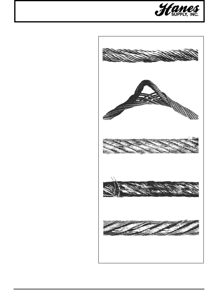
128
HEADQUARTERS: 55 James E. Casey Drive • Buffalo, NY 14206 PHONE: 716.826.2636 FAX: 716.826.4412 www.hanessupply.com
COMMON WIRE ROPE ABUSES
Neglect and abuse are the two chief enemies of
wire rope life. One costly form of neglect is lack of
proper field lubrication. Abuse takes many forms:
improper reeling or unreeling, wrong size or worn
sheaves, improper storage, and bad splicing are a
few.
CONDITION OF MACHINERY
Wire rope performance depends upon the
condition of the equipment on which it operates;
poorly maintained equipment will usually result in
reduced rope life.
EFFECTS OF SHOCK-LOADING AND
VIBRATION
The destructive effects of jerking or shock-loading
are visually noticeable. Vibration has somewhat
the same effect, and is equally destructive. An
individual shock may be slight, but many rapidly
repeated slight shocks can have the effect of
several large shocks.
Vibration which occurs directly above a load is
often unavoidable. "Whipping" of the section of
rope immediately above the load is also common.
In these cases, rapid wire fatigue is possible. For
reasons of safety, this section should be examined
regularly.
Wire rope failure is usually cumulative. Each
repeated overstress brings the rope nearer to
failure. Thus, a wire rope may become fatigued to
a point close to failure under a heavy load, and
actually fail under a much lighter load.
OVERSTRESSING
In any hoisting operation, there should be no slack
in the wire rope when the load is applied.
Otherwise, the resulting stress will be excessive.
Overstressing can also be the result of too-rapid
acceleration or deceleration. Wire rope will
withstand considerable stress if the load is applied
slowly. As with ordinary twine, a quick snap will
cause overstressing and breakage. This applies
both when starting to lift a load, and when bringing
it to a stop.
CORROSION
Corrosion can seriously shorten wire rope life, both
by metal loss and by formation of corrosion pits in
the wires. These pits act as stress-concentration
points in the wires in much the same manner as do
nicks.
CRUSHING. Because of loose winding on drum, rope was pulled
inbetween underlying wraps and crushed out of shape.
TOO SUDDEN LOAD RELEASE. The sudden release of a load
caused birdcaging. Here individual strands open away from each
other, displacing the core.
LACK OF LUBRICATION. Premature breakage of wires resulted from
"locking" of strands, which was caused by insufficient lubrication.
INFREQUENT INSPECTION. Neglect of periodical inspection left this
rope in service too long, resulting in considerable abrasion.
IMPROPER HANDLING. Kink or "dog leg" was caused by improper
handling and/or installation. A kink causes excessive localized or spot
abrasion.
Wire Ropes
continued...
YOUR SLING AND RIGGING SPECIALIST
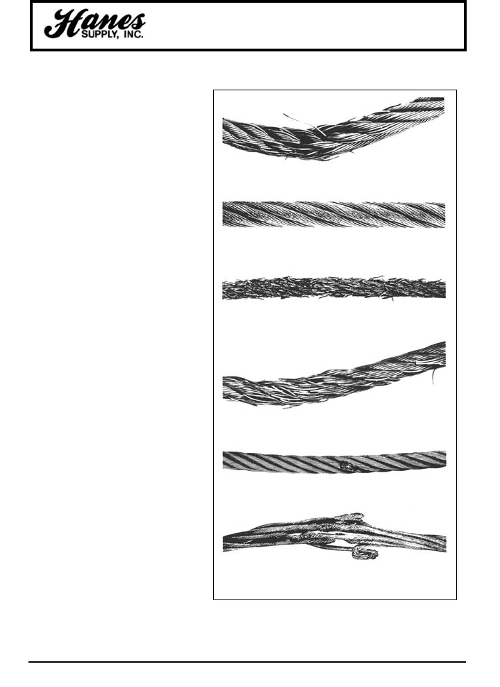
HEADQUARTERS: 55 James E. Casey Drive • Buffalo, NY 14206 PHONE: 716.826.2636 FAX: 716.826.4412 www.hanessupply.com
129
Wire Ropes
Wire rope left on machines shut down for
long periods of time deteriorates rapidly. To
preserve the rope for future sue, it should
be removed, cleaned and thoroughly
lubricated.
CAUSES OF CORROSION DAMAGE
Pitting, erosion and surface effects of many
different types can all result in corrosion
damage. Because they tend to increase
corrosion, the following conditions should
be considered and noted when applicable,
during the ordering of wire rope: acid and
alkaline solutions, gases, fumes, brine and
salt air, sulphurous compounds, and high
humidity and temperature. Lubricants are
readily available to reduce the severity of
attack of most of these conditions.
EFFECTS OF SEVERE HEAT
Where wire rope is subjected to severe heat
(e.g., foundry cranes) it will not give the
service expected because it will deteriorate
more quickly.
Wire ropes exposed to hot-metal handling
or other extreme heat sometimes require
independent wire rope cores.
SHIFTING ROPES FROM ONE JOB
TO ANOTHER
Sometimes an idle wire rope from one
operation is installed on another to keep the
rope in continuous service. This extremely
poor practice is an expensive "economy."
Because wire rope tends to "set" to the
conditions of its particular operating job, the
differing bends, abrasions and stresses of a
new operation can produce premature
failure. Therefore, for a maximum life and
efficiency, a rope should be used only on
the job for which it has been specified.
MACHINERY OPERATION
Some operators are harder on their
machinery than others and as a result they
get shorter rope life. In certain instances,
enough extra work is done to more than
offset the additional wear-and-tear on
equipment and wire rope. The operation
may be more efficient from the production
standpoint as a result, but those in charge
of rope purchases should be made aware of
the probable reduction in rope life and
increased rope costs.
REVERSE BENDING Running this rope over one sheave and under
another caused fatigue breaks in wires.
EXCESSIVE EXPOSURE TO ELEMENTS. Too much exposure
combined with surface wear and loss of lubrication caused corrosion
and pitting.
TOO LONG IN SERVICE. Repeated winding and overwinding of this
rope on a drum while it was under heavy stress caused the unusually
severe wear shown.
UNDERSIZE SHEAVE GROOVES. Sheaves were too small, causing
strands to pinch. Wires then fail in the valley between the strands.
LACK OF KNOWLEDGE. Here's what occurs when a loop which has
been "pulled through" and tightened remains in service.
POOR WORK PROCEDURES. Damage to strands and wires resulted
from electric arcing.
WIRE ROPE ABUSE continued
YOUR SLING AND RIGGING SPECIALIST
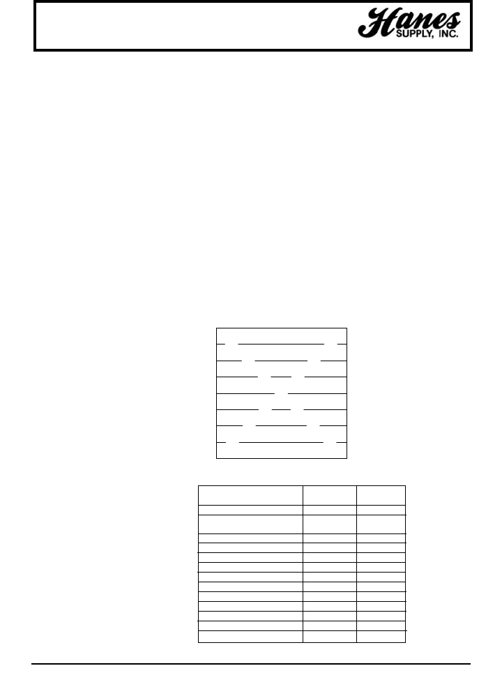
130
HEADQUARTERS: 55 James E. Casey Drive • Buffalo, NY 14206 PHONE: 716.826.2636 FAX: 716.826.4412 www.hanessupply.com
LEAST½½RESISTANCE TO ABRASION ¾¾GREATEST
LEAST½RESISTANCE TO BENDING FATIGUE ¾GREATEST
Wire Ropes
While there is a possibility, there is
likelihood that an application can be
found for which there is a precisely
suitable wire rope – one that can
satisfy every indicated requirement.
As with all engineering design
problems, feasible solutions demand
compromise to some degree. At times,
it becomes necessary to settle for less
than optimum resistance to abrasion
in order to obtain maximum flexibility;
the latter being a more important
requirement for the given job. A
typical example of this kind of trade-off
would be in selecting a highly flexible
rope on an overhead crane.
Conversely, in a haulage installation, a
rope with greater resistance to
abrasion would be chosen despite the
fact that such ropes are markedly less
flexible.
Two compelling factors that govern
most decisions as to the selection of a
wire rope are: abrasion resistance,
and resistance to bending fatigue.
Striking a proper balance with respect
to these two important characteristics
demands judgment of a very high
order. A graphic presentation of just
such comparison of qualities between
the most widely used rope
constructions and others is given by
means of X-chart.
Referring to this chart when selecting
a rope, the mid-point (at the X) comes
closest to an even balance between
abrasion resistance and resistance to
bending fatigue. Reading up or down
along either leg of the X, the inverse
relationship becomes more apparent
as one quality increases and the other
decreases.
EFFECT OF SHEAVE SIZE
Wire ropes are manufactured in a
great variety of constructions to meet
the varying demands of wire rope
usage. Where abrasion is an
important factor, the rope must be
made of a coarse construction
containing relatively large wires. In
other cases, the great amount of
bending to which the rope is subjected
is more important. Here, a more
flexible construction, containing many
relatively small wires, is required. In
either case, however, if the rope
operates over inadequate size
sheaves, the severe bending stresses
imposed will cause the wires to break
from fatigue, even though actual wear is
slight. The smaller the diameter of the
sheave, the sooner these fatigue breaks
will occur and the shorter rope life
becomes.
Another undesirable effect of small
sheaves is accelerated wear of both
rope and sheave groove. The pressure
per unit area of rope on sheave groove
for a given load is inversely proportional
to the size of the sheave. In other
words, the smaller the sheave the
greater the rope pressure per unit area
on the groove. Both sheaves and rope
life can obviously be prolonged by using
the proper diameter sheave for the size
and construction of rope.
Sheave diameter can also influence
rope strength. When a wire rope is
bent around a sheave, there is a loss
of effective strength due to the inability
of the individual strands and wire to
adjust themselves entirely to their
changed position. Tests show that rope
strength efficiency decreases to a
marked degree as the sheave diameter
is reduced with respect to the diameter
of the rope.
Therefore, it is evident that a definite
relationship exists between rope
service and sheave size. As a guide to
rope users, wire rope manufacturers
have established standards for various
rope constructions. To secure the most
economical service, it is important that
the suggested size of sheaves given
below be used.
NUMBER OF OUTSIDE WIRES PER STRAND
SUGGESTED MINIMUM
CONSTRUCTION D/d* RATIO D/d*RATIO
6 x 7 72 42
19 x 7 or 18 x 7
Rotation Resistant 51 34
6 x 19 Seale 51 34
6 x 27 H flattened strand 45 30
6 x 31 V flattened strand 45 30
6 x 21 filler wire 45 30
6 x 25 filler wire 39 26
6 x 31 Warrington Seale 39 26
6 x 36 Warrington Seale 35 23
8 x 19 Seale 41 27
8 x 25 filler wire 32 21
6 x 41 Warrington Seale 32 21
6 x 42 filler 21 14
The wire rope industry refers to this as the X-chart. It serves to illustrate the
inverse relationship between abrasion resistance and resistance to bending
fatigue in a representative number of the most widely used wire ropes.
6
9
10
12
12
12
14
16
18
6 X 7
6 X 19 S
6 X 21 FW
Flattened
Strand
6 X 25 FW
6 X 31 WS
6 X 36 WS
6 X 49 FWS
6 X 64 SFWS
PROPER SHEAVE AND DRUM SIZES
ABRASION AND BENDING
THE "X CHART": ABRASION RESISTANCE VS. BENDING-FATIGUE RESISTANCE
YOUR SLING AND RIGGING SPECIALIST
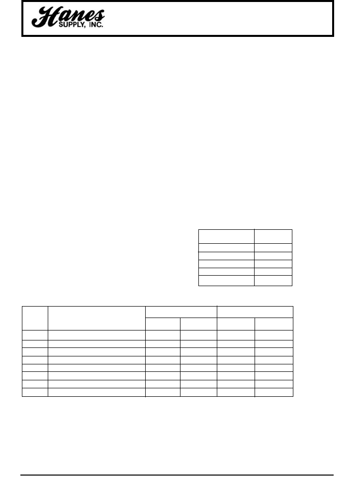
HEADQUARTERS: 55 James E. Casey Drive • Buffalo, NY 14206 PHONE: 716.826.2636 FAX: 716.826.4412 www.hanessupply.com
131
Wire Ropes
The rope strength design factor is the ratio of the
rated strength of the rope to its operating stress. If
a particular rope has a rated strength of 100,000
lbs. and is working under an operating stress of
20,000 lbs., it has a rope strength design factor of
5. It is operating at one-fifth or 20% of its rated
strength.
Many codes refer to this factor as the "Safety
Factor" which is a misleading term, since this ratio
obviously does not include the many facets of an
operation which must be considered in
determining safety.
NUMBER BROKEN WIRES NUMBER BROKEN WIRES
IN RUNNING ROPES IN STANDING ROPES
A.N.S.I. EQUIPMENT IN ONE IN ONE IN ONE IN ONE
NO. ROPE LAY STRAND ROPE LAY STRAND
B30.2 Overhead & Gantry Cranes 12 4 Not specified Not specified
B30.4 Portal, Tower & Pillar Cranes 6 3 3 2
B30.5 Crawler, Locomotive & Truck Cranes 6 3 3 2
B30.6 Derricks 6 3 3 2
B30.7 Base Mounted Drum Hoists 6 3 3 2
B30.8 Floating Cranes & Derricks 6 3 3 2
A10.4 Personnel Hoists 6* 3 2* 2
A10.5 Material Hoists 6* Not specified Not specified Not specified
NUMBER OF WIRE BREAKS
Wire rope is an expendable item – a replacement
part of a machine or installation. For economic and
other reasons, some installations require ropes to
operate at high stresses (low rope strength design
factors). On some installations where high risk is
involved, high rope strength design factors must
be maintained. However, operating and safety
codes exist for most applications and these codes
give specific factors for usage. When a machine is
working and large dynamic loadings (shock
loading) are imparted to the rope, the rope
strength design factor will be reduced which could
result in overstressing of the rope. Reduced rope
strength design factors frequently result in reduced
service life of wire rope.
O.S.H.A. (A.N.S.I.) Removal Criteria 5.
A.N.S.I. Safety Codes, Standards and
Requirements –
rope must be removed from service
when diameter loss or wire breakage
occurs as follows:
ORIGINAL LOSS
DIAMETER (IN.) (IN.)
5/16 & smaller 1/64
3/8 - 1/2 1/32
9/16 - 3/4 3/64
7/8 - 1-1/8 1/16
1-1/4 - 1-1/2 3/32
DIAMETER LOSS
*Also remove for 1 valley break. OSHA requires monthly record keeping of wire rope condition.
Note: Current industry recommendations and OSHA Standars are based upon the use of steel sheaves. The
manufacturer of plastic or synthetic sheaves or liners should be consulted for their recommendations on
the safe application of their product, and possible revision in rope inspection criteria when used with their
product.
ROPE STRENGTH AND DESIGN FACTORS
YOUR SLING AND RIGGING SPECIALIST
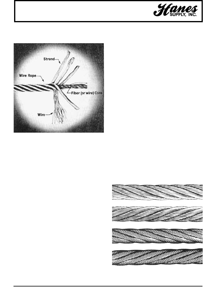
HEADQUARTERS: 55 James E. Casey Drive • Buffalo, NY 14206 PHONE: 716.826.2636 FAX: 716.826.4412 www.hanessupply.com
132
Wire Ropes
UNDERSTAND WHAT THE "LAYS" OF WIRE
ROPE MEAN
"Lay" of a wire rope is simply a description of the way
wires and strands are placed during construction.
Right lay and left lay refer to the direction of strands.
Right lay means that the strands pass from left to right
across the rope. Left lay means just the opposite;
strands pass from right to left.
Regular lay and lang lay describe the way wires are
placed within each strand. Regular lay means that
wires in the strands are laid opposite in direction to the
lay of the strands. Lang lay means that wires are laid
in the same direction as the lay of the strands.
Most of the wire rope used is right lay, regular lay. This
specification has the widest range of applications and
meets the requirements of most equipment. In fact,
other lay specifications are considered exceptions and
must be requested when ordering.
HERE ARE SOME EXCEPTIONS
Lang lay is recommended for many excavating,
construction, and mining applications, including
draglines, hoist lines, dredgelines and other similar
lines. Here's why. Lang lay ropes are more flexible
than regular lay ropes. They also have greater wearing
surface per wire than regular lay ropes.
Where properly recommended, installed and used,
lang lay ropes can be used to greater advantage than
regular lay ropes. However, lang lay ropes are more
ROPE STRENGTH AND DESIGN FACTORS
susceptible to the abuses of bending over small
diameter sheaves, pinching in undersize sheave
grooves, crushing when winding on drums, and failing
due to excessive rotation. Left lay rope has greatest
usage in oil fields on rod and tubing lines, blast hole
rigs, and spudders where rotation of right lay rope
would loosen couplings. The rotation of a left lay rope
tightens a standard coupling.
A wire rope is a piece of flexible, multi-wired, stranded
machinery made of many precision parts.
Usually a wire rope consists of a core member, around
which a number of multi-wired strands are "laid" or
helically bent. There are two general types of cores for
wire rope – fiber cores and wire cores. The fiber core
may be made from natural or synthetic fibers. The wire
core can be an Independent Wire Core (IWRC), or
Strand Core (SC).
The purpose of the core is to provide support and
maintain the position of the outer strands during
operation.
Any number of multi-wired strands may be laid around
the core. The most popular arrangement is six strands
around the core, as this combination gives the best
balance.
The number of wires per strand may vary from 3 to 91,
with the majority or wire ropes falling into the 7-wire,
19-wire, or 36 wire strand categories.
RIGHT LAY REGULAR LAY
LEFT LAY REGULAR LAY
RIGHT LAY LANG LAY
LEFT LAY LANG LAY
LENGTH OF SERVICE DEPENDS ON
HOW YOU TREAT YOUR WIRE ROPES.
YOUR SLING AND RIGGING SPECIALIST
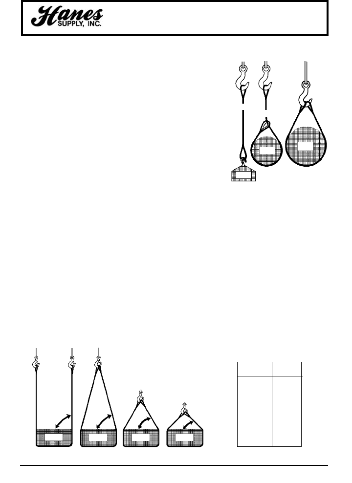
HEADQUARTERS: 55 James E. Casey Drive • Buffalo, NY 14206 PHONE: 716.826.2636 FAX: 716.826.4412 www.hanessupply.com
133
Basic Lift Engineering
STRAIGHT OR VERTICAL,
attachment, is simply using a sling to
connect a lifting hook to a load. Full
rated lifting capacity of the sling may
be utilized, but must not be exceeded.
Whenever a single sling is used in this
manner, a tagline should be used to
prevent load rotation which may cause
damage to the sling.
When two or more slings are attached
to the same lifting hook in straight or
vertical manner, the total hitch
becomes, in effect, a lifting bridle, and
the load is distributed among the
individual slings.
CHOKER hitches reduce lifting
capability of a sling, since this method
of rigging affects ability of the wire
rope components to adjust during the
lift. A choker is used when the load will
not be seriously damaged by the sling
body – or the sling damaged by the
load, and when the lift requires the
sling to snug up against the load.
The diameter of the bend where the
sling contacts the load should keep the
point of choke against the sling BODY –
never against a splice or the base of
the eye. When a choke is used, the
sling rated capacity must be adjusted
downward to compensate for loss of
capability.
A choker hitch should be pulled tight
before a lift is made – NOT PULLED
DOWN DURING THE LIFT. It is also
dangerous to use only one choker hitch
to lift a load which might shift or slide
out of the choke.
BASKET hitches distribute a load
between the two legs of a sling – within
limitations described below. Capacity of
a sling used in a basket is affected by
the bend, or curvature, where the sling
body comes in contact with the load –
just as any sling is affected and limited
by bending action, as over a sheave.
EVERY LIFT USES 1 OF 3 BASIC HITCHES
CALCULATING THE LOAD ON EACH LEG OF A SLING
As the horizontal angle between the
legs of a sling decreases, the load on
each leg increases. The effect is the
same whether a single sling is used as
a basket, or two slings are used with
each in a straight pull, as with a 2-
legged bridle.
Anytime pull is exerted at an angle on
a leg – or legs – of a sling, the load per
leg can be determined by using the
data in the table at right. Proceed as
follows to calculate this load – and
determine the rated capacity required
of the sling, or slings, needed for a lift.
1. First, divide the total load to be lifted by the number of legs to be used. This
provides the load per leg if the lift were being made with all legs lifting vertically.
2. Determine the angle.
3. Then MULTIPLY the load per leg (as computed in No. 1 above) by the Load
Factor for the leg angle being used (from the table below) – to compute the
ACTUAL LOAD on each leg for this lift and angle. THE ACTUAL LOAD MUST
NOT EXCEED THE RATED SLING CAPACITY.
Thus, in drawing three (sling angle at 60°):
1000 ÷ 2 = 500 (Load Per Leg if vertical lift)
500 x 1.154 = 577 lbs. = ACTUAL LOAD on each leg at the 60° HORIZ
angle being used.
In drawing four (sling angle of 45°):
1000 ÷ 2 = 500 (Load Per Leg if a vertical lift)
500 x 1.414 = 70 lbs. = ACTUAL LOAD on each leg at the 45° HORIZ angle
being used.
LEG ANGLE LOAD
(DEGREES) FACTOR
90° 1.000
85° 1.003
80° 1.015
75° 1.035
70° 1.064
65° 1.103
60° 1.154
55° 1.220
50° 1.305
45° 1.414
STRAIGHT
CHOKER
BASKET
LOAD
LOAD LOAD
1000 LBS
500 LBS.
500 LBS.
1000 LBS 1000 LBS 1000 LBS
1000 LBS
1000 LBS
1000 LBS
518 LBS
518 LBS
577 LBS
577 LBS
707 LBS
707 LBS
90° 75° 60° 45°
YOUR SLING AND RIGGING SPECIALIST

134
HEADQUARTERS: 55 James E. Casey Drive • Buffalo, NY 14206 PHONE: 716.826.2636 FAX: 716.826.4412 www.hanessupply.com
Basic Lift Engineering
EFFECT OF ANGLES
Various sling manufacturers refer in their
specification tables to leg angles of slings
during lifts – since these angles have a
direct relationship to lifting capability of a
sling. Regardless of how the sling angle
may be stated, or the method used to
compute stress in a sling leg, the sling is
the same. Capacity does not change –
but stresses on sling legs change with
rigging angles.
Much misunderstanding results because
the carrying capacity of a sling leg is
reduced by the rigging angle. What
happens is that the operator is lifting the
load straight up (vertical) while the legs
are pulling at an angle, thereby causing a
disadvantage.
For quick figuring in the shop, a 60-degree
leg angle causes a loss in lifting capacity
of 15%... a 45-degree angle reduces
capacity by 30%... and a 30-degree angle,
50%. This rule of thumb is not 100%
accurate, but is easy to remember and
slightly on the safe side.
It is always good practice, within limits, to
keep the sling leg angle as large as
possible. The length and width of the load
sling length, and available headroom are
determining factors in this sling angle.
It is neither economical nor good practice
to exceed a 45-degree sling leg angle.
Angles less than 45 degrees not only build
up tension in the sling legs out of all
proportion to the weight of the load, they
also create a much greater "in-pull" on the
ends of the load. This produces
eccentrically loaded column effect, as an
engineer would describe it – meaning
simply that long, slender objects have a
tendency to buckle. Angles less than 45
degrees indicate some thought should be
given to the use of a lifting beam or other
device in connection with the lift.
Studying typical sling charts readily reveals
that lifting capacities on slings are
misleading unless the sling angle is stated.
The same sling that will handle 10 tons at
an 85-degree leg angle will only handle 5
tons if this angle is decreased to 30
degrees.
GOOD SLING PRACTICE
Regardless of what type of sling may be
employed, there are accepted good
working rules which will help increase
useful sling life – as well as improve safety.
These include:
1. Use the proper sling for the lift. Whether
Twin-Path, Web, Chain, or Wire Rope,
the proper sling is the one with the best
combination of work and handling
feature – of the proper length and rated
capacity for the situation.
2. Start and stop slowly. Crane hooks
should be raised slowly until the sling
becomes taut and the load is
suspended. Lifting or lowering speed
should be increased or decreased
gradually. Sudden starts or stops place
heavier loads on a sling – comparable
to jamming the brakes on a speeding
automobile. A rule of thumb: Shock
loads can double the stress on a sling.
3. If possible, set the load on blocks.
Pulling a sling from under a load causes
abrasion and "curling" – making the
sling harder to handle on the next lift,
while reducing strength through loss of
metal.
4. Sharp corners cut slings. Use protector
arcs, Cornermax™ and Synthetic Armor
Wear Pads between sharp corners and
the sling body.
5. Store in a dry room. Moisture is a
natural enemy of wire rope – as are acid
fumes and other caustic gases.
6. Avoid handling hot material or objects in
direct contact with the sling. Strength
goes down as temperature goes up!
7. Dropping casting, tools or heavy objects
on slings, or running over them with
trucks, can cause damage. Always
hang slings when not in use.
8. Use hooks properly. "Point loading"
reduces hook capacity. Pull should be
straight in the line of lift.
SELECTING A SLING
The following is presented as a guide only
to help in selection of a sling for a lift.
1. Determine the Load: The weight of the
load must be known. This is always the
starting point.
2. Decide the Hitch: Shape and bulk of the
load must be accommodated as well as
weight. Determine whether a straight
attachment at some point on the load, a
choker around the load, or some form of
basket hitch will best control the load
during the lift.
3. Adequacy of Lifting Device: The lifting
device must have adequate capacity for
making the lift, and provide any
maneuverability required once the load
is hoisted.
4. Room to Lift: Make certain the lifting
device has sufficient headroom to raise
the load to the height required.
Headroom will affect the length of sling.
5. Length of Sling: By applying your
decision on the type of hitch to
knowledge of the headroom offered by
the lifting device, the length of sling can
be calculated.
6. Use Rated Capacity Chart: Always
double-check that the sling type and
capacity you choose, when rigged at
the angle determined by the length of
the sling, or the specific type of hitch,
will handle the load.
Attaching the sling and completing the lift
should be an orderly procedure without
"surprises" when these steps have been
followed. Two further precautions should be
noted, however.
First, plan to protect both load and sling
from damage at sharp corners, etc.
Cornermax™ and Synthetic Armor Wear
Pads should be provided at the lift site. A
protective pad should be used anytime a
sling passes around a sharp corner.
Last – by no means unimportant by being
last – every sling should be visually
examined from end to end BEFORE
EVERY LIFT. It must always be kept in
mind that the manufacturer's Rated
Capacity applies only to a new sling in
"unused" condition. A sling should be
carefully examined to determine that it is in
as nearly new condition as practicable
before each lift.
There are specific standards on the use
and care of slings in industries such as
shipping and construction, and these
provide some guidance for sling inspectors.
Consensus standards published as ANSI
B30.9 are particularly helpful.
ANSI Standard B30.9 specifies that a wire
rope sling should be removed form service
any time any of the following conditions
are detected:
1. Ten randomly distributed broken wires
in one rope lay, or five broken wires in
one strand in one rope lay.
2. Kinking, crushing, bird caging or any
other damage resulting in distortion of
the wire rope structure.
3. Evidence of heat damage.
4. End attachments that are cracked,
deformed, or worn.
5. Hooks that have been opened more
than 15% of the normal throat opening
measured at the narrowest point, or
twisted more than 10 degrees from the
plane of the unbent hook.
6. Corrosion of the rope or end
attachments.
It is apparent from the foregoing that
inspection of a wire rope sling to meet
these removal criteria requires more than
a casual understanding of wire rope
design and manufacture, and the
responsibility for daily inspections must be
in the hands of trained personnel.
Most of the foregoing applies equally to
any type of sling and careful inspection by
a trained inspector is necessary for safe
sling use. If you require training for any
type of sling inspection, contact Hanes
Supply for more information.
YOUR SLING AND RIGGING SPECIALIST
HEADQUARTERS: 55 James E. Casey Drive • Buffalo, NY 14206 PHONE: 716.826.2636 FAX: 716.826.4412 www.hanessupply.com
135
Wire Ropes
BLOCK TWISTING
Block twisting or "cabling" is one of the
most frequently encountered wire rope
problems in the construction field. When
this problem occurs, the wire rope is most
often blamed, and other equally important
factors in the operation are overlooked.
Personnel experienced with handling of
wire rope know that conventional wire
ropes will twist or unlay slightly, when a
load is applied. In a reeved hoisting
system, subjected to loading and
unloading such as a load hoisting line, this
results in block twisting and possibly
distortion of the wire rope. Cabling of the
block most frequently occurs as the load
in the wire rope is released, and the "falls"
are in a lowered position. Cabling may be
considered as the twisting of the block
beyond one-half of a revolution (180°
twisting) of the traveling block. When this
condition occurs, the operator shows good
judgment in not making additional lifts,
until the conditions causing the problem
are corrected.
The following machine and site conditions
should be investigated for possible
improvement in block twisting.
1. Reduced wire rope length. Longer rope
lengths cause more twisting than short
rope lengths. This applies particularly
to the amount of wire rope in the "falls."
2. Reduce the amount of load lifted.
Heavily loaded ropes have more torque
and twist than lightly loaded ropes.
This condition would also apply to the
speed of loading or "shock" loading,
since this condition also causes higher
wire rope loading.
3. Eliminate "odd-part" reeving, where the
wire rope "dead-end" is on the traveling
block. Wire rope torque, from the
application of load, is greatest at the
rope dead-end.
4. Relocate the rope dead-end at the boom,
in order to increase the separation
between the dead-end and the other
rope parts. This applies a stabilizing
load directly to the traveling block. The
original equipment manufacturer should
be consulted before making this
modification.
5. Increase sheave size. This increases the
amount of separation between wire rope
parts and may improve the situation by
applying stabilizing loads and reducing
the amount of rope torque transmitted to
the traveling block.
6. Restrain the twisting block with a "tag"
line. One or more of the foregoing
suggestions may eliminate the problem
without resorting to "specialized" wire
rope which may not only be difficult to
locate but expensive as well.
The use of special "rotation resistant" wire
ropes will not likely be required unless the
intended length of rope "falls" exceeds 100
feet, or the length of the load hoisting line
exceeds 600 feet. In the event these latter
conditions exist, the user should also
anticipate using a combination of the
"rotation resistant" wire rope and the
foregoing field suggestions for the more
severe problems.
PHYSICAL PROPERTIES
ELASTIC PROPERTIES OF WIRE
ROPE
The following discussion relates to
conventional 6- or 8-strand ropes that
have either fiber or steel cores; it is not
applicable to rotation-resistant ropes since
these constitute a separate case.
Wire rope is an elastic member; it
stretches or elongates under load. This
stretch derives from two sources:
1. constructional, and
2. elastic.
In actuality, there may be a third source of
stretch – a result of the rope rotating on its
own axis. Such elongation, which may
occur either as a result of using a swivel,
or from the effect of a free-turning load, is
brought about by the unlaying of the rope
strands. Because the third source is a
subject that is beyond the scope of this
publication, discussion will be directed to
constructional and elastic stretch.
CONSTRUCTIONAL STRETCH
When a load is applied to wire rope, the
helically-laid wires and strands act in a
constricting manner thereby compressing
the core and bringing all the rope
elements into closer contact. The result is
a slight reduction in diameter and an
accompanying lengthening of the rope.
Constructional stretch is influenced by the
following factors:
1. type of core (fiber or steel),
2. rope construction (6 x 7, 6 x 25 FW,
6 x 41 WS, 8 x 19 S, etc.),
3. length of lay
4. material.
Ropes with wire strand core (WSC) or
independent wire rope core (IWRC) have
less constructional stretch than those with
fiber core (FC). The reason for this is the
fact that the steel cannot compress as
much as the fiber core.
Usually, constructional stretch will cease
at an early stage in the rope's life.
However, some fiber core ropes, if lightly
loaded (as in the case of elevator ropes),
may display a degree of constructional
stretch over a considerable portion of their
life.
A definite value for determining
constructional stretch cannot be assigned
since it is influenced by several factors.
The following table gives some idea of the
approximate stretch as a percentage of
rope under load.
ROPE CONSTRUCTION APPROX. STRETCH*
6 strand FC 1/2% - 3/4%
6 strand IWRC 1/4% - 1/2%
8 strand FC 3/4% - 1%
*Varies with the magnitude of the loading.
ROPE ZERO THROUGH 20% 21 TO 65%
CLASSIFICATION LOADING LOADING*
6 x 7 with fiber core 11,700,000 13,000,000
6 x 19 with fiber core 10,800,000 12,000,000
6 x 36 with fiber core 9,900,000 11,000,000
8 x 19 with fiber core 8,100,000 9,000,000
6 x 19 with IWRC 13,500,000 15,000,000
6 x 36 with IWRC 12,600,000 14,000,000
*Applicable to new rope, i.e., not previously loaded.
ELASTIC STRETCH
Elastic stretch results from recoverable deformation of the metal itself. Here, again, a
quantity cannot be precisely calculated. However, the following equation can provide a
reasonable approximation for a good many situations.
Change in load (lb.) x Length (ft.)
Changes in length (ft.) = Area (in.2) x Modulus of Elasticity (psi)
The modulus of elasticity is given below.
APPROXIMATE MODULUS OF ELASTICITY
(POUNDS PER SQUARE INCH)
YOUR SLING AND RIGGING SPECIALIST
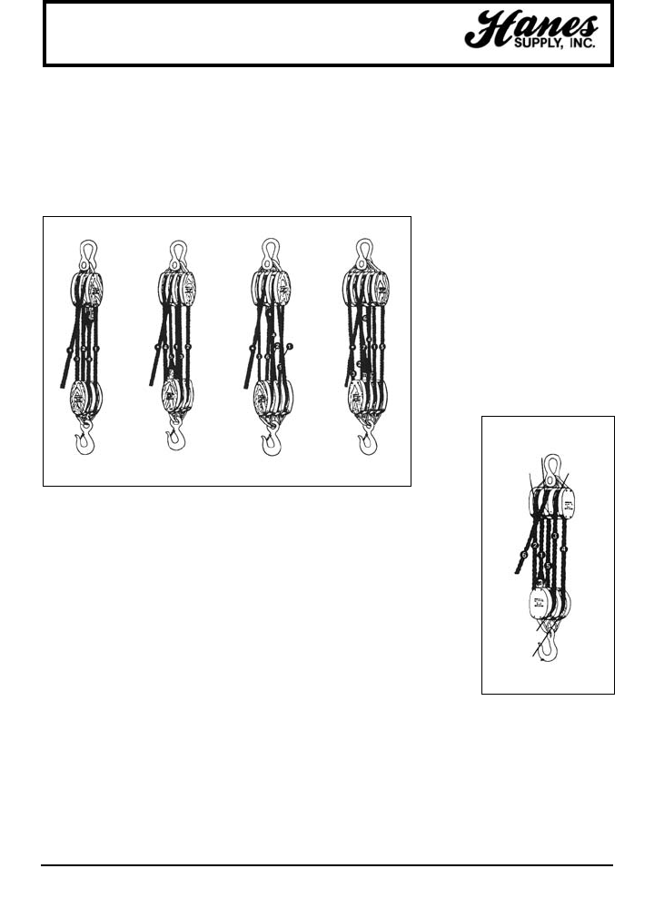
136
HEADQUARTERS: 55 James E. Casey Drive • Buffalo, NY 14206 PHONE: 716.826.2636 FAX: 716.826.4412 www.hanessupply.com
VARYING SHEAVE REVOLUTIONS IN A PAIR OF TACKLE BLOCKS
To raise a load one foot, the lower block must be raised one foot, and in accomplishing
this, each working rope must be shortened one foot.
In the example above, Ropes 1, 2, 3, etc., must be shortened one foot to raise the load
one foot. Assuming that the circumference of each sheave is one foot, Sheave No.1
must make one revolution to shorten Rope No. 1; Sheave No. 2 must make one
revolution to take up the one foot slack form Rope No. 1 and one additional revolution
to shorten Rope No. 2; Sheave No. 3 must make two revolutions to take up the two
feet of slack from Ropes 1 and 2 and one additional revolution to shorten Rope No. 3,
etc. for each succeeding sheave.
Viz: Rope No. 1 must travel one foot on Sheave No. 1.
Rope No. 2 must travel two feet on Sheave No. 2.
Rope No. 3 must travel three feet on Sheave No. 3.
Rope No. 4 must travel four feet on Sheave No. 4.
Rope No. 5 must travel five feet on Sheave No. 5.
Therefore, all the sheaves in a set of blocks revolve at different rates of speed. Sheave No. 2 rotates twice as fast
as No. 1, Sheave No. 3 rotates three times as fast as No.1, Sheave No. 4 four times as fast as No. 1, etc.
Consequently the sheaves nearest the lead line, rotating at higher rates of speed, wear out more rapidly.
All sheaves should be kept well lubricated when in operation to reduce friction and wear.
across the edges of the block shell.
To reeve by this method, the two blocks should be
placed so that the sheaves in the upper block are at
right angles to those in the lower one, as shown in the
following illustrations. Start reeving with the becket, or
standing end, of the rope.
It is good practice to use a shackle
block as the upper one of a pair and a
hook block as the lower one. A
shackle would prevent any accidental
disengagement of the block from its
attaching point in the event of an
unusual movement of the attaching
point or block. The lower block having
a hook is more readily attached or
detached from the load. See Figures 1
through 5.
General Information
In reeving a pair of tackle blocks, one of which has
more than two sheaves, the hoisting rope should lead
from one of the center sheaves of the upper block.
When so reeved, the hoisting strain comes on the
center of the blocks and they are prevented from
toppling, with consequent injury to the rope by cutting
THE REEVING OF TACKLE BLOCKS
FIGURE 1 FIGURE 2 FIGURE 3 FIGURE 4
FIGURE 5
DOUBLE AND
DOUBLE
TRIPLE AND
DOUBLE
TRIPLE AND
TRIPLE
QUADRUPLE
AND TRIPLE
SHEAVE
NO. 5
SHEAVE
NO. 1
SHEAVE
NO. 3
SHEAVE
NO. 4
SHEAVE
NO. 2
YOUR SLING AND RIGGING SPECIALIST
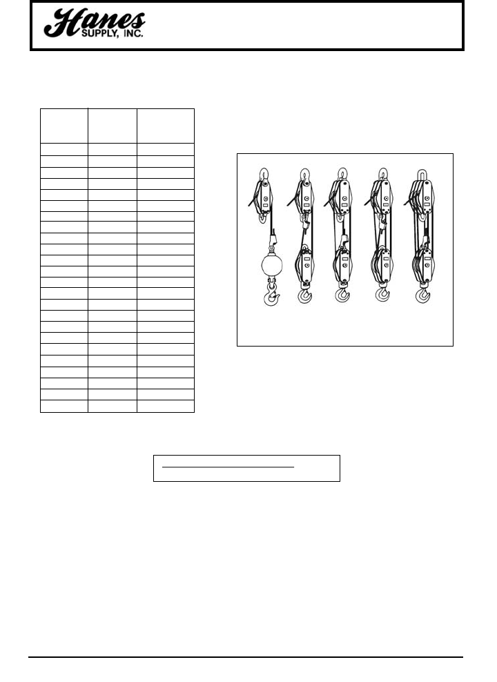
HEADQUARTERS: 55 James E. Casey Drive • Buffalo, NY 14206 PHONE: 716.826.2636 FAX: 716.826.4412 www.hanessupply.com
137
Wire Ropes
RATIO FOR RATIO FOR
NUMBER BRONZE ANTI-FRICTION
OF PARTS BUSHED BEARING
OF LINE SHEAVES SHEAVES
1 .96 .98
2 1.87 1.94
3 2.75 2.88
4 3.59 3.81
5 4.39 4.71
6 5.16 5.60
7 5.90 6.47
8 6.60 7.32
9 7.27 8.16
10 7.91 8.98
11 8.52 9.79
12 9.11 10.6
13 9.68 11.4
14 10.2 12.1
15 10.7 12.9
16 11.2 13.6
17 11.7 14.3
18 12.2 15.0
19 12.6 15.7
20 13.0 16.4
21 13.4 17.0
22 13.8 17.7
23 14.2 18.3
24 14.5 18.9
HOW TO FIGURE LINE PARTS
To help figure the number of parts of line to be used for
a given load or the line pull required for a given load, the
following ratio table is provided with examples of how to
use it:
1
PART
OF LINE
2
PARTS
OF LINE
3
PARTS
OF LINE
4
PARTS
OF LINE
5
PARTS
OF LINE
USING THE RATIO TABLE RATIO FORMULA
Example:
To find the number of parts of line needed
when weight of load and single line pull is
established.
Sample Problem:
72,480 lbs. (load to be lifted)
8,000 lbs. (single line pull) = 9.06 RATIO
Refer to ratio 9.06 in table or number nearest
to it, then check column under heading
"Number of Parts of Line"... 12 parts of line to
be used for this load.
Example:
To find single line pull needed when weight of
load and number of parts of line are
established.
Sample Problem:
68,000 lbs. (load to be lifted)
6.60 (ratio of 8 part line)
= 10,300 lbs. (single line pull)
10,300 lbs. single line pull required to lift this
load on 8 parts of line.
TOTAL LOAD TO BE LIFTED = RATIO
SINGLE LINE PULL IN POUNDS
YOUR SLING AND RIGGING SPECIALIST
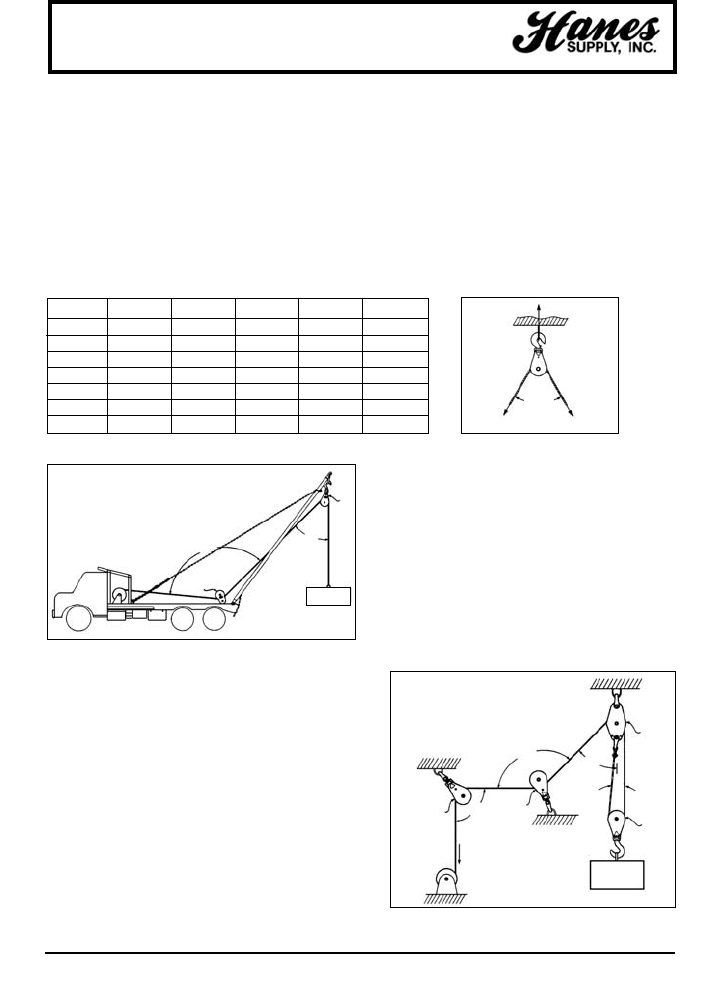
138
HEADQUARTERS: 55 James E. Casey Drive • Buffalo, NY 14206 PHONE: 716.826.2636 FAX: 716.826.4412 www.hanessupply.com
General Information
LOADS ON BLOCKS
The Rated Load Values for blocks shown in Crosby Group
literature are shown as "Working Loads," "Safe Working
Load" and "Resultant Safe Working Load"; and all these
terms are defined as the maximum amount of total load that
should be exerted on the block and its fitting, the fitting being
a hook, shackle, eye, loop, etc.
It must be recognized that this total load value MAY BE
DIFFERENT than the weight being lifted or pulled by a
hoisting or hauling system and, therefore, it is necessary to
determine the total load being imposed on each block in the
system in order to properly determine the rated capacity
block to be used.
A single sheave block that is used to change direction of a
load line can be subjected to total loads GREATLY
DIFFERENT than the weight being lifted or pulled. The
amount of total load changes with the angle between the
incoming and departing lines to the block.
The following chart indicates the factor that is multiplied by
the line pull to obtain the total load on the block:
ANGLE FACTOR ANGLE FACTOR ANGLE FACTOR
0° 2.00 60° 1.73 130° .84
10° 1.99 70° 1.64 135° .76
20° 1.97 80° 1.53 140° .68
30° 1.93 90° 1.41 150° .52
40° 1.87 100° 1.29 160° .35
45° 1.84 110° 1.15 170° .17
50° 1.81 120° 1.00 180° .00
Example: A gin pole truck being used to lift a weight of
1,000 lbs.
There is no mechanical advantage to a single part load line
system, so, whinch line pull is equal to 1,000 lbs. or the
weight being lifted.
Total load on snatch block shown as A equals 1,000 lbs.
times angle factor for 50°.
Total load on A = 1,000 x 1.81 = 1,1810 lbs.
Total load on toggle block shown as B equals 1,000 lbs.
times angle factor for 135°.
Total load on B = 1,000 x .76 = 760 lbs.
TOTAL LOAD
Example: Hoisting system using a traveling block to lift a
weight of 1,000 lbs.
The mechanical advantage at the traveling block C is 2
because 2 parts of a load line support the 1,000 lbs. weight; so,
the line pull equals the 1,000 lbs. divided by 2 or 500 lbs.
Total load on traveling block shown as C equals 500 lbs. times
angle factor for 0°.
Total Load on C = 500 x 2.00 = 1,000 lbs.
Total load on stationary block shown as D equals the dead end
load of 500 lbs. plus the line pull of 500 lbs. times the angle
factor for 40°.
Total Load on E = 500 x .84 = 420 lbs.
Total load on block shown as F equals 500 lbs. times the angle
factor for 90°.
Total Load on F = 500 x 1.41 = 705 lbs.
LINE PULL LINE PULL
ANGLE
WINCH
LINE
PULL
135°
50°
A
B
1000 LBS
1000 LBS
130°
50°
40°
E
FC
D
0°
YOUR SLING AND RIGGING SPECIALIST

HEADQUARTERS: 55 James E. Casey Drive • Buffalo, NY 14206 PHONE: 716.826.2636 FAX: 716.826.4412 www.hanessupply.com
139
General Information
DEFINITIONS OF TERMS
Abrasion: The mechanical wearing of surface resulting from frictional contact with materials or
objects.
Breaking Strength: That total force (lbs. or kg.) at which the sling fails. The total weight strain
which can be applied before failure. Usually at five times the rated capacity.
Competent Person: A person designated for inspection who is trained, qualified by knowledge
and practical experience and the necessary instructions to enable the required test or examination
to be carried out.
Twin-Path®Core: The load bering multiple fibers of polyester, aramids, or K-Spec™ which, when
wound into the seamless tubes, become the load bearing yarns of the sling. If other materials are
used, follow the manufacturers recommendations.
Twin-Path®Cover: The seamless tubes, usually at least two separate and contrasting colors for
easier inspection that contain the cores. Covers may be of polyester, Covermax nylon, or aramids
depending on the desired finished characteristics of the product.
Elongation: The measurement of stretch, expressed as a percentage of the finished length.
Fitting: A load bearing metal component which is fitted to the sling. Can be of steel, aluminum or
other material that will sustain the rated capacity of the sling.
Hitch/Vertical: A method of attachment whereby the sling extends from the crane hook to the
load in a straight connection.
Hitch/Choker: The sling is passed around the load and back through itself and is connected
to the crane hook. The sling then tightens around the load when it is strained.
Hitch/Basket: The sling is passed from the crane hook around the load and attached to the
crane hook.
Length: The distance between bearing points of the sling.
Proof Load Test: A non-destructive load test usually to twice the rated capacity of the sling.
Synthetic Fiber: Man-made material used for the cover, the core and the thread of the Twin-Path®
sling products.
Tattle-Tails: Tell-Tails which extend past the tag area of Twin-Path®slings. Extension of the load
core yarns. When the sling is stretched beyond its elastic limit, they shrink and eventually
disappear under the tag. Take out of service if less than 1/2" is exposed.
Thread: The synthetic yarn which is used to sew the sling covers and tag and to provide the stitch
which separates the individual load cores.
Twin-Path®:A patented and trademarked product which is composed of two separate load cores
and two contrasting color covers.
YOUR SLING AND RIGGING SPECIALIST

140
HEADQUARTERS: 55 James E. Casey Drive • Buffalo, NY 14206 PHONE: 716.826.2636 FAX: 716.826.4412 www.hanessupply.com
General Information
Rated Load The maximum recommended load that should be exerted on the item.
Value-Rated The following terms are also used for the term Rated Load: "SWL," "Safe
Capacity: Working Load," "Working Load," "Working Load Limit," and the "Resultant
Safe Working Load." All rated load values, unless noted otherwise, are for in-
line pull with respect to the centerline of the item.
Proof Load: The average load to which an item may be subjected before visual
deformation occurs or a load that is applied in the performance of a proof test.
Proof Test: A term designating a tensile test applied to the item for the sole purpose of
detecting injurious defects in the material or manufacture.
Ultimate Load: The average load at which the item is being tested fails or no longer supports
the load.
Shock Load: A resulting load from the rapid change of movement, such as impacting or
jerking, or a static load. A Shock Load is generally significantly greater than
the static load.
Design Factor: An industry term denoting theoretical reserve capability. Usually computed
dividing the catalog stated ultimate load by the catalog stated working load
limit and generally expressed as a ratio, for example: 5 to 1.
DEFINITIONS
CAUTIONS OR WARNINGS
All ratings shown in this literature are based upon the items being new or "in as new" condition.
Catalog ratings are considered to be the greatest load that should be applied to the item;
therefore, any shock loading must be considered when selecting the item for use in a system.
The products shown in this literature are subject to wear, misuse, overloading, corrosion,
deformation, intentional alteration and other usage factors which may necessitate a reduction in
the product's Rated Capacity or a reduction in its Design Factor. Therefore, it is recommended that
all products be regularly inspected to determine their condition as a basis for deciding if the
product may continue to be used at the catalog assigned WL, a reduced WL, a reduced design
factor, or removed from service.
YOUR SLING AND RIGGING SPECIALIST

HEADQUARTERS: 55 James E. Casey Drive • Buffalo, NY 14206 PHONE: 716.826.2636 FAX: 716.826.4412 www.hanessupply.com
141
Summary
IF YOU KNOW: MULTIPLY BY: TO FIND:
inches 25.4 millimeters (mm)
inches 2.54 centimeters (cm)
feet 0.30 meters (m)
yards 0.3711 meters (m)
miles 1.61 kilometers (km)
millimeters .0394 inches
centimeters .39 inches
meters 3.28 feet
meters 1.09 yards
kilometers .62 miles
metric tons 1.102 U.S. tons
U.S. tons .9072 metric tons
kilograms 2.204 pounds
pounds .453 kilograms
metric tons 2204.62 pounds
metric tons 1000.0 kilograms
Fahrenheit (temp.) 5/9 (after subtracting 32) Celsius (temp.)
Celsius (temp.) 9/5 (then add 32) Fahrenheit (temp.)
SUMMARY OF COMMON CONVERSIONS
FACTORS
FRACTION DECIMAL METRIC
(IN.) (IN.) (MM.)
1/16 .0625 1.588
1/8 .1250 3.175
3/16 .1875 4.762
1/4 .2500 6.350
5/16 .3125 7.938
3/8 .3750 9.525
7/16 .4375 11.112
1/2 .5000 12.700
9/16 .5625 14.288
5/8 .6250 15.875
11/16 .6875 17.462
3/4 .7500 19.050
13/16 .8125 20.638
7/8 .8750 22.225
15/16 .9375 23.812
1 1.0000 25.400
DECIMAL / METRIC EQUIVALENT TABLE
YOUR SLING AND RIGGING SPECIALIST
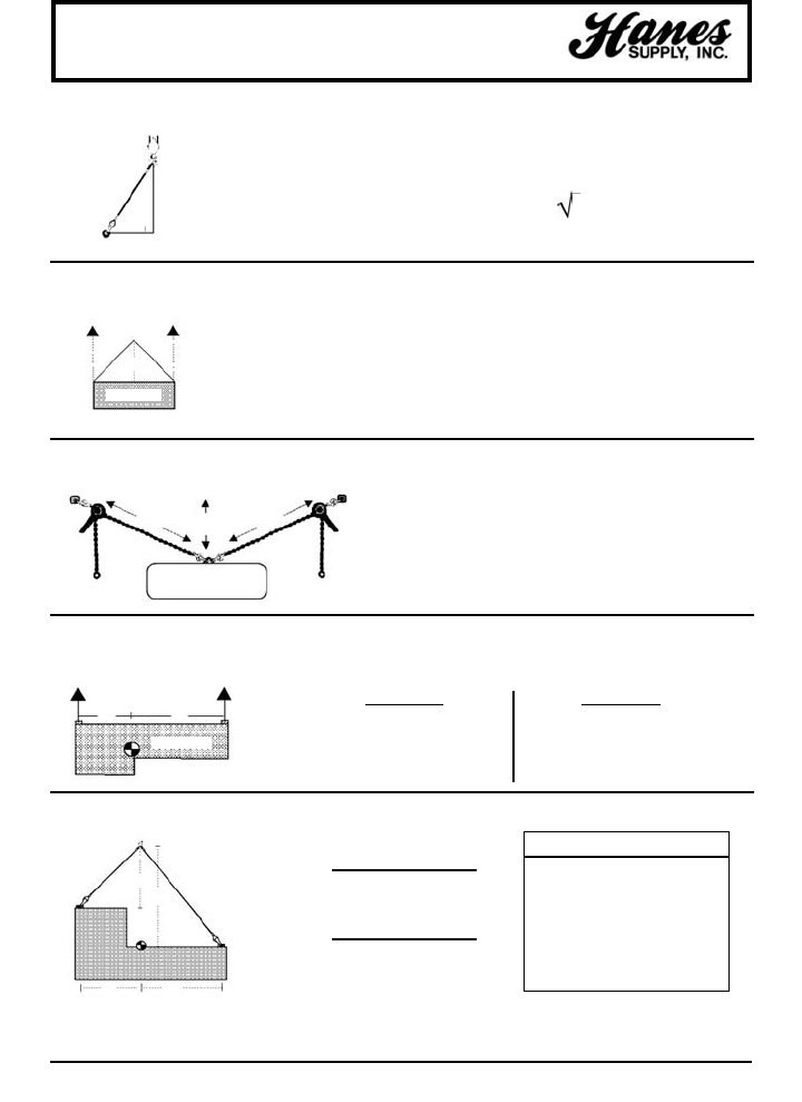
HEADQUARTERS: 55 James E. Casey Drive • Buffalo, NY 14206 PHONE: 716.826.2636 FAX: 716.826.4412 www.hanessupply.com
142
Lift Engineering
FINDING THE HYPOTENUSE
LOAD ANGLE FACTORS
TENSION IN OVERHEAD HOISTS
OFF-SET CENTER OF GRAVITY (SHARE OF THE LOAD)
OFF-LEVEL LIFT POINTS
To find c (hypotenuse)
Given: a2+ b2= c2
Example: 42+ 32= c2; 16 + 9 = c2; 25 = 5
L15
— = LAF (Load Angle Factor) Example: — = 1.5 (LAF)
H10
L
Tension in L = — x L's share of the load
H
15
Tension in L = — x 5,000; 1.5 x 5,000 Ten. = 7,500 lbs.
10
a
b
c
6
Ten. in A = — x 3,000 Ten. in A = 9,000 lbs.
2
(As load moves, tension changes)
Lift Point A
7 + 3 = 10, — = .70
10
.70 x 10,000 = 7,000 lbs.
Inverse Proportion To Distance
Lift Point B
7 + 3 = 10, — = .30
10
.30 x 10,000 = 3,000 lbs.
W x D2x L1
TL1=(D2x H1) +(D1x H2)
W x 1 x L2
TL2=(D2x H1) +(D1x H2)
LEGEND
W = Load Weight
L1= Length Leg 1
L2= Length Leg 2
H1= Vertical Height 1
H2= Vertical Height 2
D1= Horizontal Distance 1
D2= Horizontal Distance 2
5,000 lbs. 5,000 lbs.
L
H
10,000 lbs.
H = 10' L = 15'
AB
6'
6'
2'
6,000 lbs.
AB
3' 7'
10,000 lbs.
L1
L2
H1
H2
D1D2
YOUR SLING AND RIGGING SPECIALIST

FORMULAS AND INFORMATION
H= Height W= Width L= Length d= diameter r= radius (1/2 dia.)
π= 3.14 (rounded 3.15) [area of a square or rectangle = HW]
[Vol of cube = HWL] [Circumference of circle = πd] [area of a circle = πr2
or the approximate area of a circle = 80% of the dia2(dia x dia x .80)]
HEADQUARTERS: 55 James E. Casey Drive • Buffalo, NY 14206 PHONE: 716.826.2636 FAX: 716.826.4412 www.hanessupply.com
143
Weights of Material
MATERIALS AND LIQUIDS – POUNDS/CU. FT.
Aluminum 165 Granite 96
Asbestos 153 Iron Casting 450
Asphalt 81 Lead 710
Brass 524 Limestone 95
Brick, Soft 100 Lumber – Fir 32
Brick, Medium 115 Lumber – Oak 62
Brick, Hard 130 Lumber – RR Ties 50
Bronze 534 Marble 95
Coal 56 Oil, Motor 60
Concrete, Reinforced 150 Paper 58
Copper 556 Portland Cement, Loose 94
Crushed Rock 95 Portland Cement, Set 183
Diesel 52 River Sand 120
Dry Earth, Loose 75 Rubber 94
Dry Earth, Packed 95 Steel 490
Gasoline 45 Water, Fresh 63
Glass 16 Zinc 437
MATERIALS – POUNDS/SQ. FT.
Steel Plate Aluminum Plate
1/8" 5 1/8" 1.75
1/4" 10 1/4" 3.50
1/2" 20 1/2" 7.00
3/4" 30 3/4" 10.50
1" 40 1" 14.00
YOUR SLING AND RIGGING SPECIALIST
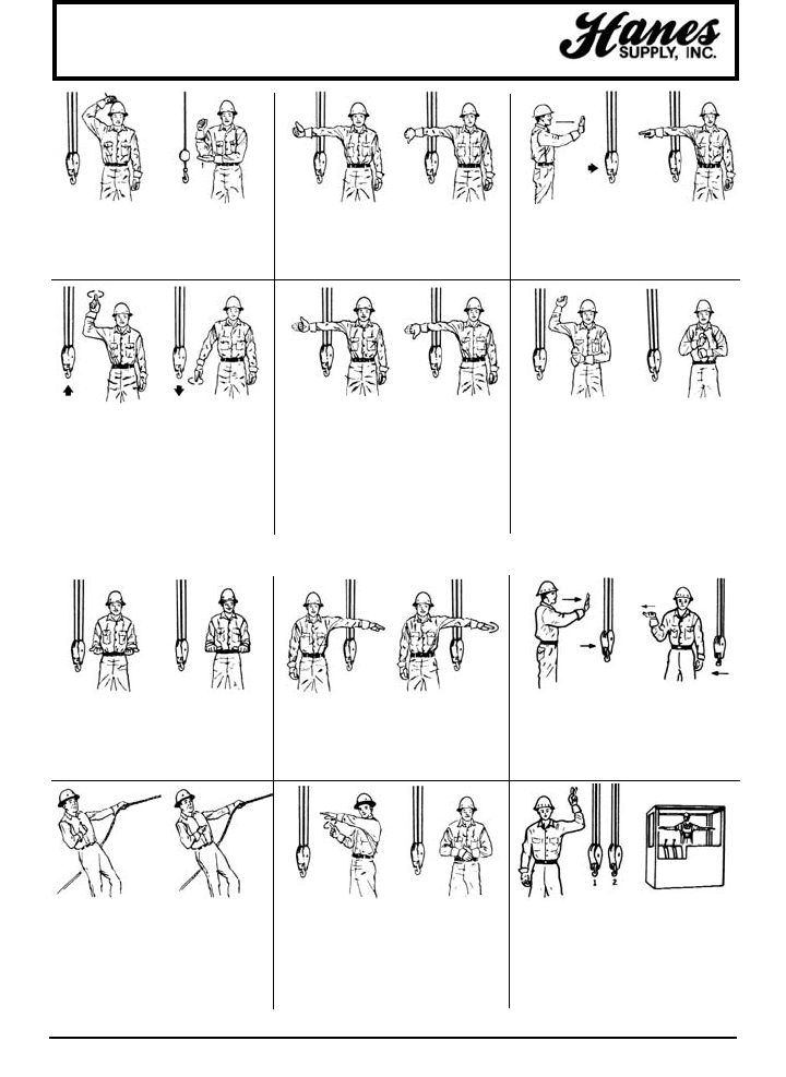
144
HEADQUARTERS: 55 James E. Casey Drive • Buffalo, NY 14206 PHONE: 716.826.2636 FAX: 716.826.4412 www.hanessupply.com
USA Standard
Crane Hand Signals
Use Main Hoist.
Tap fist on head;
then use regular
signals.
Use Whipline.
(Auxiliary Hoist).
Tap elbow with one
hand, then use
regular signals.
Raise Boom. Arm
extended, fingers
closed, thumb
pointing upward.
Lower Boom. Arm
extended, fingers
closed, thumb
pointing downward.
Travel. Arm extended
forward, hand open
and slightly raised,
make pushing motion
indirection of travel.
Swing. Arm
extended, point with
finger in direction of
swing of boom.
Hoist. With forearm
vertical, forefinger
pointing up, move
hand in small
horizontal circle.
Lower. With arm
extended downward,
forefinger pointing
down, move hand in
small horizontal
circles.
Raise the Boom and
Lower the Load.
With arm extended,
thumb pointing up,
flex fingers in and out
as long as load
movement is desired.
Lower the Boom
and Raise the Load.
With arm extended,
thumb pointing down,
flex fingers in and
out as load
movement is desired.
Travel. (One Track).
Lock the track on side
indicated by raised
fist. Travel opposite
track in direction
indicated by circular
motion of other fist,
rotated vertically in
front of body. (For
crawler cranes only).
Travel. (Both Tracks).
Use both fists in front
of body, making a
circular motion about
each other, indicating
direction of travel;
forward or backward.
(For crawler cranes
only.)
Extend Boom.
(Telescoping Booms).
Both fists in front of
body with thumbs
pointing outward
Retract Boom.
(Telescoping
Booms). Both fists in
front of body with
thumbs pointing
toward each other.
Stop. Arm extended,
palm down, hold
position rigidly.
Emergency Stop.
Arm extended, palm
down, move hand
rapidly right and left.
Bridge Travel. Arm
extended forward,
hand open and
slightly raised, make
pushing motion in
direction of travel.
Trolley Travel. Palm
up, fingers closed,
thumb pointing in
direction of motion,
jerk hand horizontally.
Extend Boom.
(Telescoping Boom).
One Hand Signal.
One fist in front of
chest with thumb
tapping chest.
Retract Boom.
(Telescoping Boom).
One Hand Signal.
One fist in front of
chest, thumb pointing
outward and heel of
fist tapping chest.
Move Slowly. Use
one hand to give any
motion signal and
place other hand
motionless in front of
hand giving the motion
signal. (Hoist slowly
shown as example.)
Dog Everything.
Clasp hands in front
of body.
Multiple Trolleys.
Hold up one finger for
block marked "1" and
two fingers for block
marked "2". Regular
signals follow.
Magnet is
Disconnected. Crane
Operator spreads
both hands apart
palms up.
Additional Signals for Bridge Cranes
YOUR SLING AND RIGGING SPECIALIST

FOUR LOCATIONS & THE WEB TO SERVICE YOUR NEEDS!
Our Headquarters is located in Buffalo, New York
BUFFALO/WESTERN NY/NORTHERN PA
55 James E. Casey Drive • Buffalo, NY 14206
PHONE 716-826-2636 FAX 716-826-4412
Our Newest Location is located near Albany, NY, opened June 2004
and is intended to help service the Albany & New England Regions
ALBANY/EASTERN NY/NEW ENGLAND
156 Railroad Avenue • Colonie, NY 12205
PHONE 518-438-0139 FAX 518-428-5343
Our Rochester Location was established in
June 1993 to accommodate our expanding cliental
ROCHESTER/CENTRAL NEW YORK
10 Cairn Street • Rochester, NY 14611
PHONE 585-235-0160 FAX 585-235-0229
CCISCO/Coastal Construction Industrial Supply Company,
was acquired in September 1996 to service the South
MYRTLE BEACH/SOUTH-EAST COAST
1020 Shine Avenue • Myrtle Beach, SC 29577
PHONE 843-238-1338 FAX 843-238-8337
Our web-site serves as a store and as an informative Rigging & Wire Rope resource
www.hanessupply.com
One of the foremost leaders in the industry
Specializing in Lifting Solutions
Manufacturer of Slingmax, Wire Rope, Chain & Nylon Slings
Complete Contractor & Industrial Supplier
55 James E. Casey Drive • Buffalo, New York 14206-2361 • U.S.A.
PHONE 716-826-2636 • FAX 716-826-4412
www.hanessupply.com $5.95 US Dollars
Printed in Canada
