River Flow2D Reference Manual
User Manual:
Open the PDF directly: View PDF ![]() .
.
Page Count: 45
Hydronia LLC
RIVERFLO-2D©
TWO-DIMENSIONAL FINITE-ELEMENT
RIVER DYNAMICS MODEL
INPUT AND OUTPUT FILES
REFERENCE MANUAL
RELEASE 2009

RiverFLO-2D Model Input/Output Reference Manual
2
Hydronia LLC
RiverFLO-2D© model and documentation produced by Hydronia LLC.
Pembroke Pines, FL. USA.
RiverFLO-2D© copyright by Hydronia LLC. 2011.
Argus ONE and MeshMaker are trademarks of Argus Holdings Ltd.
All other products or service names mentioned herein are trademarks of
their respective owners.
All rights reserved. No part of this publication may be reproduced, stored in
a retrieval system or transmitted in any form or by any means electronic,
mechanical, photocopying, recording or
otherwise, without the prior written permission of Hydronia LLC.
Last source code and document modification date: March, 2011
Technical Support: E-mail: support@hydronia.com

RiverFLO-2D Model Input/Output Reference Manual
3
Hydronia LLC
Contents
INTRODUCTION TO RIVERFLO-2D INPUT AND OUTPUT FILES ................................................................................. 5
INPUT DATA FILES .................................................................................................................................................. 6
FILE: *.EXP: ELEVATIONS DATA ...................................................................................................................................... 7
Example of a *.EXP Elevations data file ............................................................................................................... 7
Instructional Comments for the *.EXP Elevations Data File ................................................................................. 8
FILE: *.DAT: SYSTEM CONTROL VARIABLES .............................................................................................................. 9
Example of the *.DAT file ................................................................................................................................... 10
Variable Descriptions for the *.DAT File ............................................................................................................. 11
Instructional Comments for the *.DAT File ........................................................................................................ 13
FILE: *.FED: FINITE ELEMENT MESH DATA .............................................................................................................. 15
Example of a * .FED file ...................................................................................................................................... 15
Variable Descriptions for the * .FED File ............................................................................................................ 16
FILE: *.IFL: OPEN BOUNDARY CONDITIONS DATA .................................................................................................. 17
Example of the *.IFL file ..................................................................................................................................... 17
Variable Descriptions for the *.IFL File ............................................................................................................... 18
Instructional Comments for the *.IFL File ........................................................................................................... 19
FILE: *.PLT: GRAPHICAL OUTPUT CONTROL DATA .................................................................................................. 21
Example of the *.PLT file .................................................................................................................................... 21
Variable Descriptions for the *.PLT File .............................................................................................................. 22
Instructional Comments for the *.PLT File ......................................................................................................... 23
FILE: *.PRF: PROFILE CUT DATA FOR RESULT OUTPUT ........................................................................................... 24
Example of the *.PRF file .................................................................................................................................... 24
Variable Descriptions for the *.PRF File ............................................................................................................. 24
FILE: *.REP: CROSS SECTION DATA FOR RESULT OUTPUT ....................................................................................... 25
Example of the * .REP file ................................................................................................................................... 25
Variable Descriptions for the *.REP File ............................................................................................................. 25
FILE: *.RET: RAINFALL AND EVAPORATION DATA .................................................................................................. 26
Example of the *.RET file .................................................................................................................................... 26
Variable Descriptions for the *.RET File ............................................................................................................. 26
FILE: *.SED: SEDIMENT TRANSPORT DATA ............................................................................................................. 27
Example of the *.SED file .................................................................................................................................... 27
Variable Descriptions for the *.SED File ............................................................................................................. 27
FILE: *.TBA: MESH BOUNDARY DATA ..................................................................................................................... 28
Example of the *.TBA file ................................................................................................................................... 29
Variable Descriptions for the *.TBA File ............................................................................................................. 30
Instructional Comments for the *.TBA File ......................................................................................................... 30
BOUNDARY CONDITIONS DATA FILES ..................................................................................................................... 31
One variable boundary condition. ...................................................................................................................... 31
Example of a Boundary Condition file for one variable time series .................................................................... 31
Variable Descriptions of a Boundary Condition File ........................................................................................... 32
Two variables boundary condition. .................................................................................................................... 32
Example of a Two-Variable Boundary Condition file .......................................................................................... 32
Variable Descriptions of a Two-Variable Boundary Condition File ..................................................................... 33
Stage-discharge data file. .................................................................................................................................. 34
Example of a Stage-Discharge data file ............................................................................................................. 34

RiverFLO-2D Model Input/Output Reference Manual
4
Hydronia LLC
OUTPUT FILES ...................................................................................................................................................... 35
UVH AND UVHE OUTPUT FILES ..................................................................................................................................... 36
OUT AND OUTE OUTPUT FILES ..................................................................................................................................... 37
UVHB AND VTP OUTPUT FILES ..................................................................................................................................... 41
DXF FILES ................................................................................................................................................................. 41
ARGUS ONE ASCII FILES *.EXP ..................................................................................................................................... 42
GIF OUTPUT FILES ....................................................................................................................................................... 44
REFERENCES ......................................................................................................................................................... 45
RiverFLO-2D Model Input/Output Reference Manual
5
Hydronia LLC
Introduction to RiverFLO-2D input and output files
RiverFLO-2D is a hydrodynamic and mobile bed finite element model for rivers developed by
Hydronia LLC. This document describes the content and format of the data input files as well as
that of the output files generated by the model. The data input files are ASCII free format and
can be opened by any text editor or spreadsheet program.
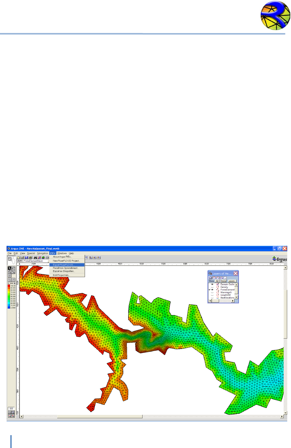
RiverFLO-2D uses the Argus ONE graphical software as a pre-processor to facilitate data input
and as a post-processor to display results (www.argusone.com). The Argus ONE software
provides a user friendly GIS environment for RiverFLO-2D, automatically linking the physical
data in GIS layers to mesh nodes and elements. It provides a variety of triangular mesh
generation options to optimize the mesh creation around complex river features enabling the
model to resolve difficult flow issues in a rapidly varied flow field. Regenerating the
computational mesh does not require re-entering bed elevations, roughness coefficients, nor
boundary conditions.
To conduct a basic RiverFLO-2D simulation, four data files must be created. These are identified
by their name extension: *.DAT, *.FED, *.TBA, and *.IFL. In addition, there are boundary
condition files that can have any extension. These files contain run control and numerical
stability data, bed elevations, roughness coefficients, finite element mesh system data, and
inflow and outflow conditions. The *.DAT and boundary condition files can be interactively
created with RiverFLO-2D tabbed user interface and the remaining files can be generated
with Argus ONE program. To use some of the RiverFLO-2D components, additional data
files need to be prepared using the RiverFLO-2D interface.
When the model is running, the user has the option of displaying the flow as velocity vector
plots, flow depths, etc. Upon completion of the RiverFLO-2D simulation, results can be
visualized in a number of graphic formats.
This document includes descriptions of all input and output files. Each description contains a
list of variables, their definitions and instructional comments and guidelines for data
organization range of data values and data limitations.
RiverFLO-2D Model Input/Output Reference Manual
6
Hydronia LLC
Input data files
Data files required to run the RiverFLO-2D model are automatically created by the RiverFLO-2D
software system through interactive dialog boxes and the Argus ONE program. In some
instances, it may be convenient to use a text editor program to quickly edit the data. Manually
editing the files may be occasionally expeditious, but it may also result in data errors. This
section explains the input data file content, format, and provides instructional comments on
how to set key parameters for each file.
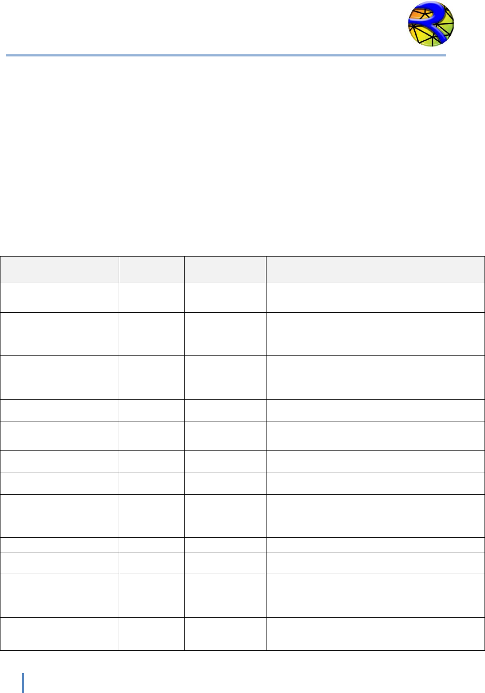
In the C:\Program Files (x86)\RiverFLO-2D\ExampleProjects folder there are several example
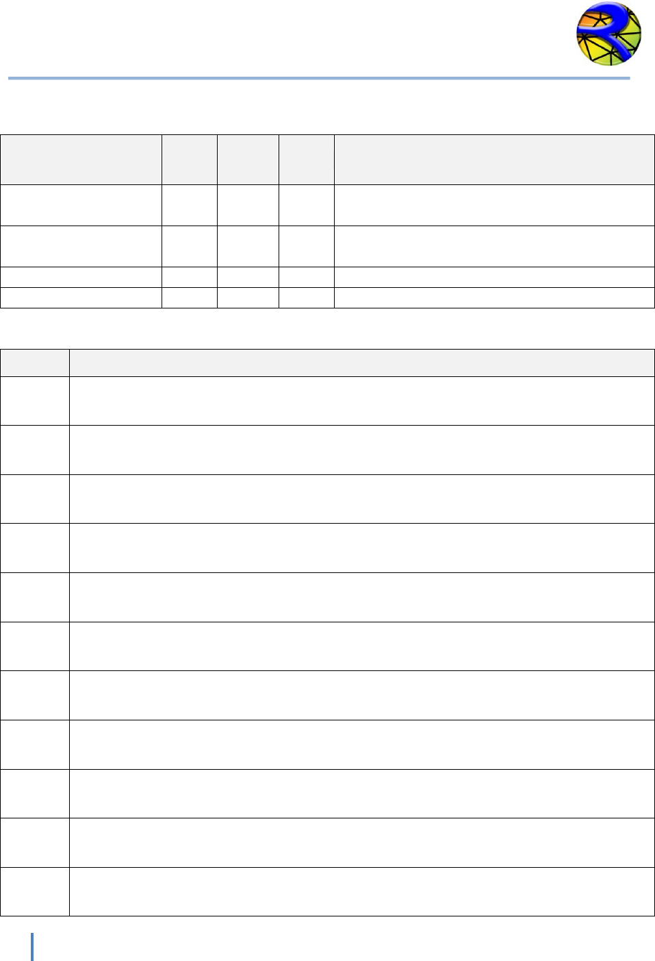
projects that can be used to review the data file format. The following table summarizes the
data files used by RiverFLO-2D model. For any RiverFLO-2D simulation, all files will share the
same name (e.g. Case1) and use the file extensions listed in the table. For example: Case1.DAT,
Case1.FED, Case1.TBA, Case1.IFL, etc.
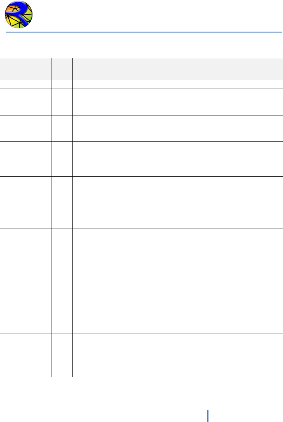
NAME
DATA FILE
EXTENSION
DEPENDENCIES
CONTENT
Elevations data file
EXP
Required
File containing scattered elevation data
points.
Run control data
DAT
Required
General options such as time step
parameters, metric or English units,
graphical output, and initial conditions.
Finite element mesh
data
FED
Required
Node coordinates and elevations, triangular
mesh topology, Manning’s n coefficients,
and other mesh related parameters.
Mesh boundary nodes
TBA
Required
List of external and island boundary nodes.
I/O boundary
conditions
IFL
Required
List of nodes where inflow or outflow
conditions are imposed.
Sediment data
SED
Optional
Sediment transport formula and data.
Rainfall/Evaporation
RET
Optional
Time series for rainfall and evaporation.
Cross section
coordinates for output
results
REP
Optional
List of cross sections where output is
required. Each cross section is defined by
coordinates of its two extreme points.
Plot results options
PLT
Optional
Graphical output options.
Profile output
PRF
Optional
Mesh profile cut where results are desired.
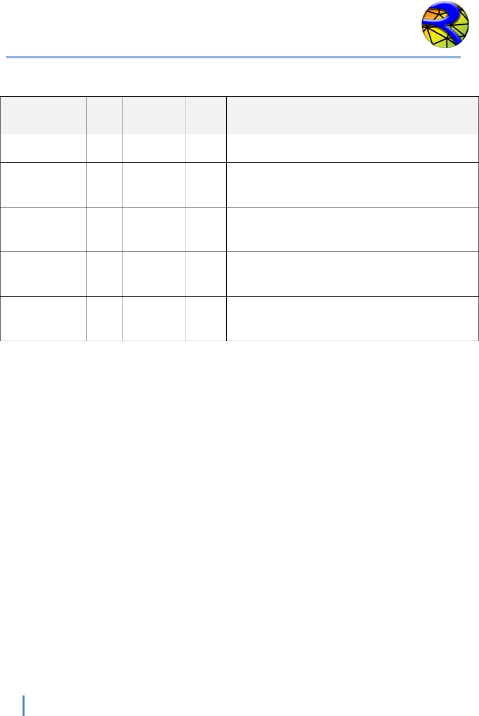
Time series files for
inflow or outflow
boundary conditions
User
defined
Required
Input hydrograph, outflow water surface
elevations vs. time, etc. There will be a file
for each open boundary condition.
Argus ONE project file
MMB
Required
This is the file where Argus ONE stores the
finite element mesh and related data.

RiverFLO-2D Model Input/Output Reference Manual
7
Hydronia LLC
FILE: *.EXP: Elevations Data
This file contains scattered elevation data and is imported in an ArgusONE BedElevations Data
layer. Each point is identified by its X and Y coordinates and the elevation value for that
coordinate.
Line 1 contains
1 NUMBER OF DATA POINTS, NUMBER OF PARAMETERS
Following “NUMBER OF DATA POINTS” lines with X, Y and Elevation data.
2 X(POINT), Y(POINT), ZB(POINT)
Example of a *.EXP Elevations data file
11086
1
798439.73
306063.87
160.00
798477.04
309506.95
201.10
798489.45
309522.30
200.93
798498.09
306222.29
162.00
798504.45
305915.63
160.00
798511.71
306075.55
161.00
798516.09
309412.73
201.74
798517.37
309592.42
163.14
.
.
.
In this example, there are 11086 elevation data points, one parameter per point (the elevation
for each point).
RiverFLO-2D Model Input/Output Reference Manual
8
Hydronia LLC
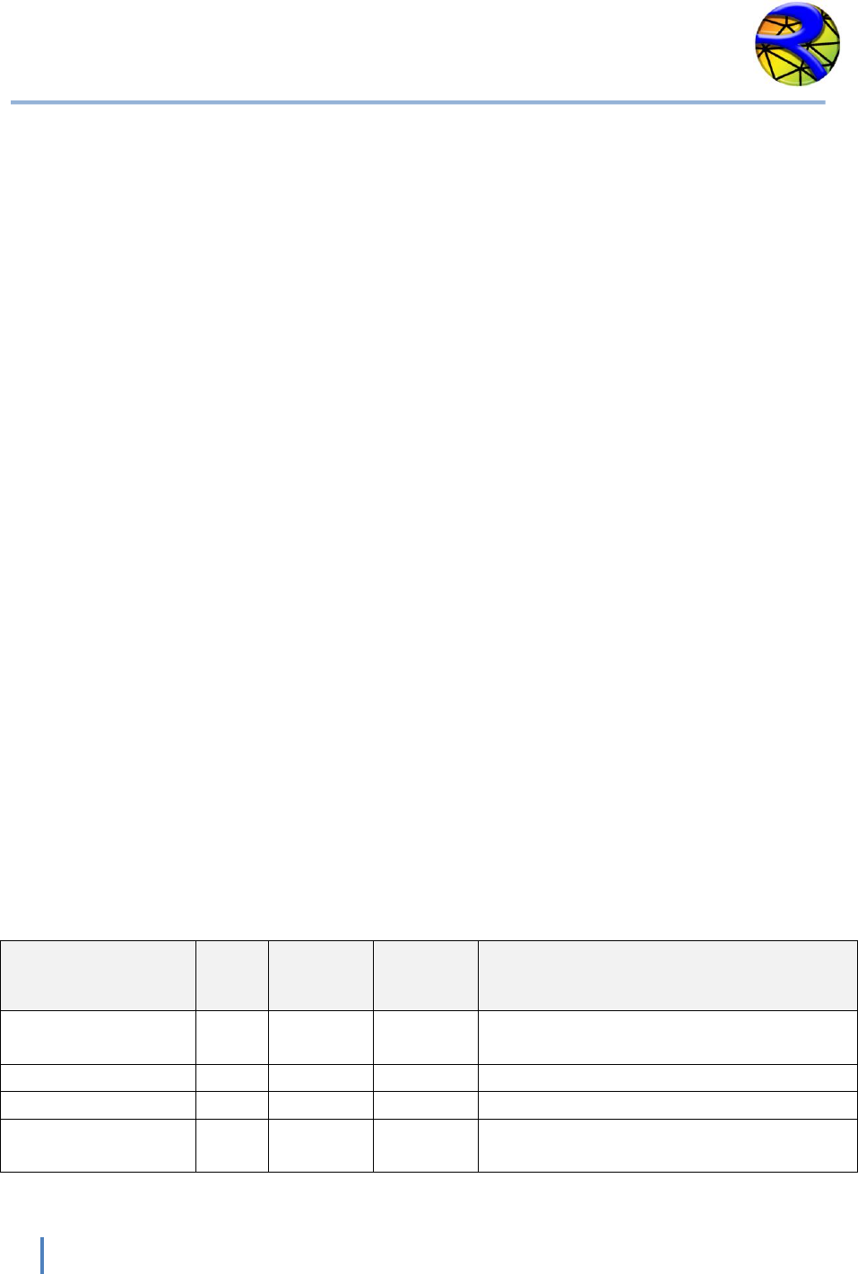
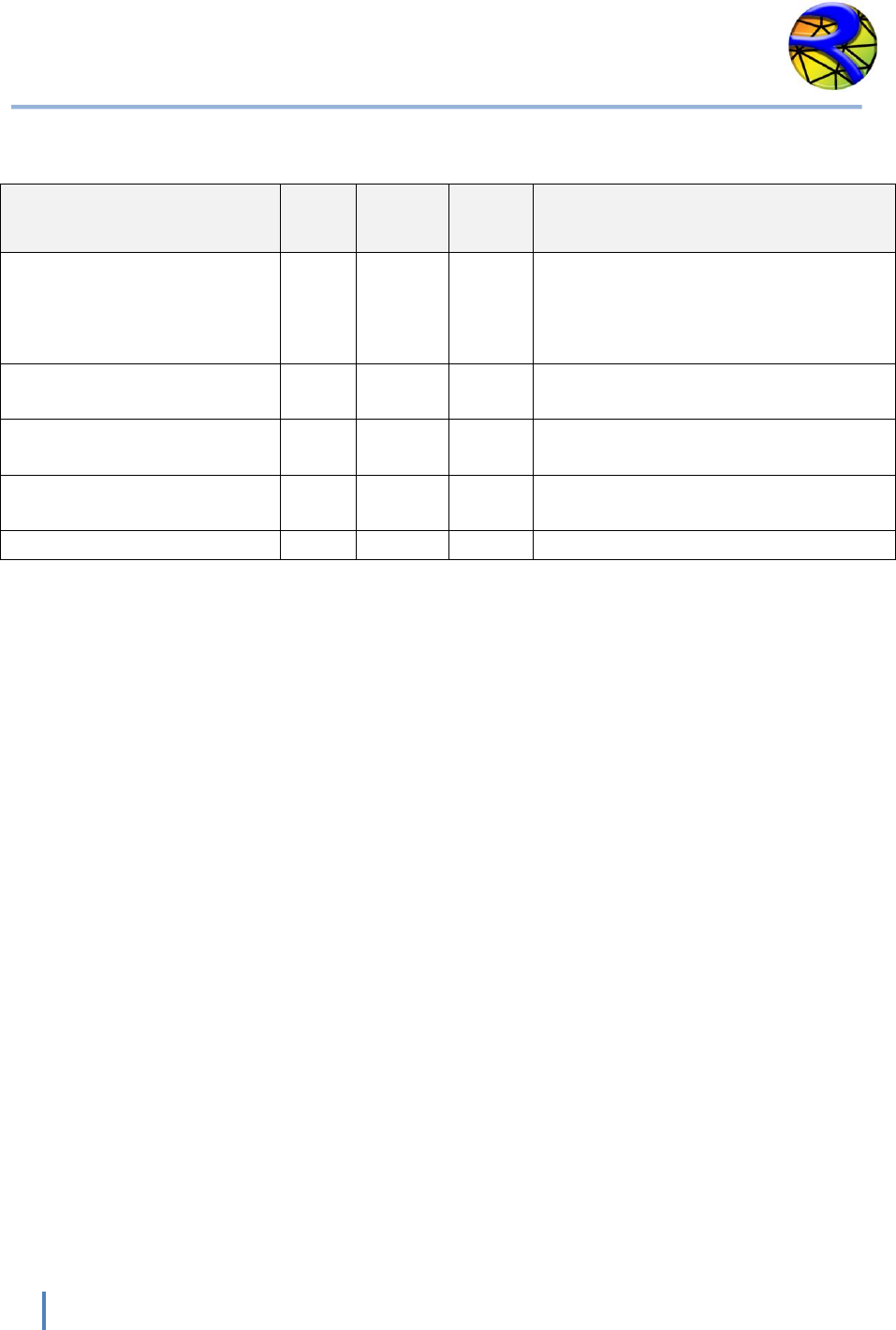
Variable Descriptions for the *.EXP Elevations Data File
VARIABLE
TYPE
RANGE
UNITS
DESCRIPTION
NUMBER OF
DATA POINTS
I
> 0
-
Number of elevation data points in the file.
NUMBER OF
PARAMETERS
I
>0
-
Number of parameters for each point. In the
case of the elevation data file this value is
normally equal to 1.
X
R
-
m.
or
ft.
X Coordinate of each elevation point See
comment 1.
Y
R
-
m.
or
ft.
Y Coordinate of each elevation point See
comment 1.
ZB
R
-
m.
or
ft.
Point elevation . See comments 2 and 3.
Note: I = Integer variable. R = Real variable
Instructional Comments for the *.EXP Elevations Data File
The following comments will assist in the developing of the *.EXP Elevations data file:
1. X and Y coordinates may be given in either meters or feet, depending on the units being
used in the project. Coordinate system should always correspond to plane projection.
RiverFLO-2D does not support geographical coordinates in Latitude/Longitude format. If
the available data is in Lat/Lon format, it will have to be converted to UTM or plane
Cartesian coordinates before importing them into Argus ONE. Presently RiverFLO-2D
does not provide tools to make this conversion.
2. Elevation values should be given in the same units as the corresponding coordinates.
NOTE: Each line must be delimited by the TAB or SPACE characters and should terminate with a
Carriage Return. Empty fields and sequential delimiters are not allowed. If the file does not fully
adhere to the above format, Argus ONE will fail to read the file and will notify you by presenting
a message box indicating that it encountered a problem trying to read the file.

RiverFLO-2D Model Input/Output Reference Manual
9
Hydronia LLC
FILE: *.DAT: SYSTEM CONTROL VARIABLES
This file contains control options such as timestep, metric or English units, physical process
switches, and graphical output and initial conditions options.
Line 1 contains program version number
1 RELEASE
Line 2 has system component switches.
2 IRAIN, ISED, IXSEC, IPROFILE, IVARDT, IINITIAL, IHOTSTART
Line 3 contains time control related data.
3 DT, DTMULT, TOUT, TLIMT
Line 4 contains the run time plot control variable.
4 NOGRAPH
Line 5 contains the Manning’s n value global multiplication factor.
5 XNMAN
Line 6 contains the finite element selective lumping parameter.
6 EPSILON
Line 7 is unit definition switch.
7 NUNITS
Line 8 is surface detention or minimum value of flow depth for dry areas.
8 HMIN
Line 8 is the number of nodes for time series output.
7 NN_OUTPUT
Line 9 contains the list of NN_OUTPUT node numbers for time series output.
9 INTS (1:NN_OUTPUT), TIMTEP

RiverFLO-2D Model Input/Output Reference Manual
10
Hydronia LLC
Example of the *.DAT file
200901
0 0 0 0 0 1 0
0.1 1 0.1 1
1
1
0.90
0
0.01
6
20
230
238
250
429
432
RiverFLO-2D Model Input/Output Reference Manual
11
Hydronia LLC
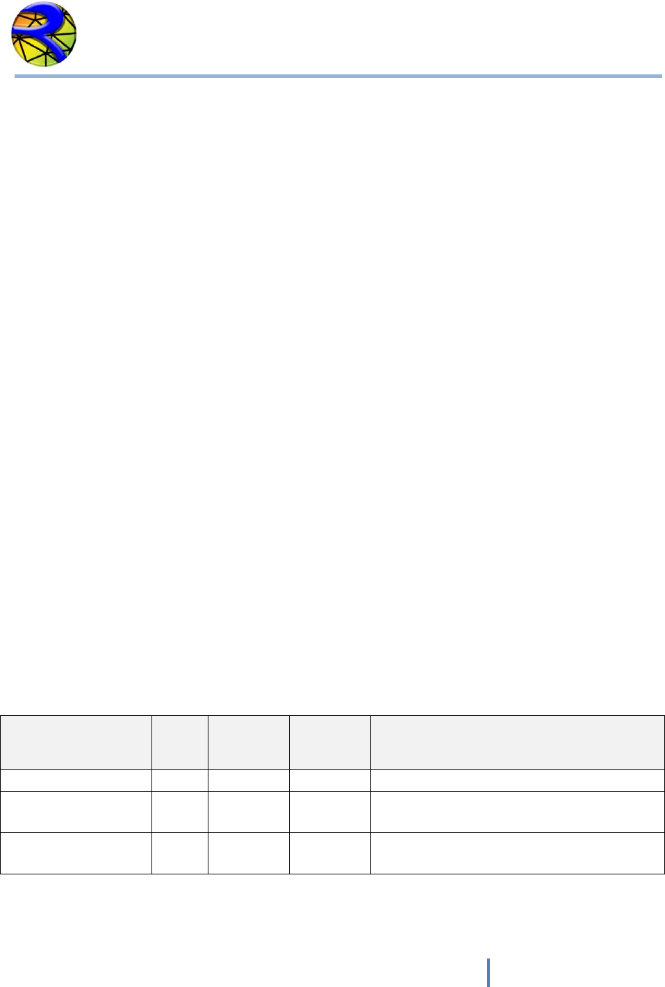
Variable Descriptions for the *.DAT File
VARIABLE
TYPE
RANGE
UNITS
DESCRIPTION
DT
R
> 0
sec.
Timestep. See comment 1.
DTMULT
R
>0
-
Timestep multiplier for variable time step option.
See comment 2.
EPSILON
R
0.80-0.99
-
Selective lumping parameter. See comment 3.
HMIN
R
>0
m.
or
ft.
Depth limit for dry-wet calculation. If depth is
less than HMIN, node will be considered dry.
IHOTSTART
I
0,1
-
Switch to start run from scratch or continue a
previous simulation.
0: start simulation from time=0.
1: start simulation from previous run.
IINITIAL
I
0,1,2
-
Switch to control initial conditions for water
surface elevations.
0: for flat horizontal water surface elevations.
1: for initial dry bed on whole mesh.
2: initial water surface elevations read from
*.FED file. See comment 4.
INTS
I
1 -
NNODES
-
List of node numbers where time series of results
is required.
IPROFILE
I
0,1
-
Switch to control profile section output.
0: No profile section results output.
1: Results will be output along a prescribed
profile. *.PRF file needs to be created. See
comment 5.
IRAIN
I
0,1
Switch to control rainfall and evaporation input.
0: no rainfall modeling.
1: rainfall/evaporation will be modeled. File
*.RET with time series of rainfall and evaporation
data needs to be created.
ISED
I
0,1
-
Sediment transport switch.
0: no sediment transport modeling.
1: sediment transport and mobile bed scour and
deposition will be simulated. File *.SED with time
sediment transport data needs to be created.
RiverFLO-2D Model Input/Output Reference Manual
12
Hydronia LLC
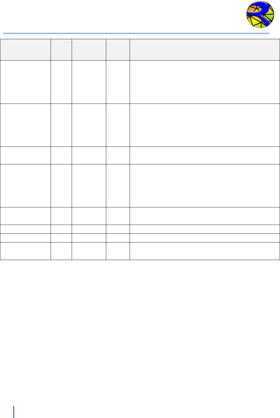
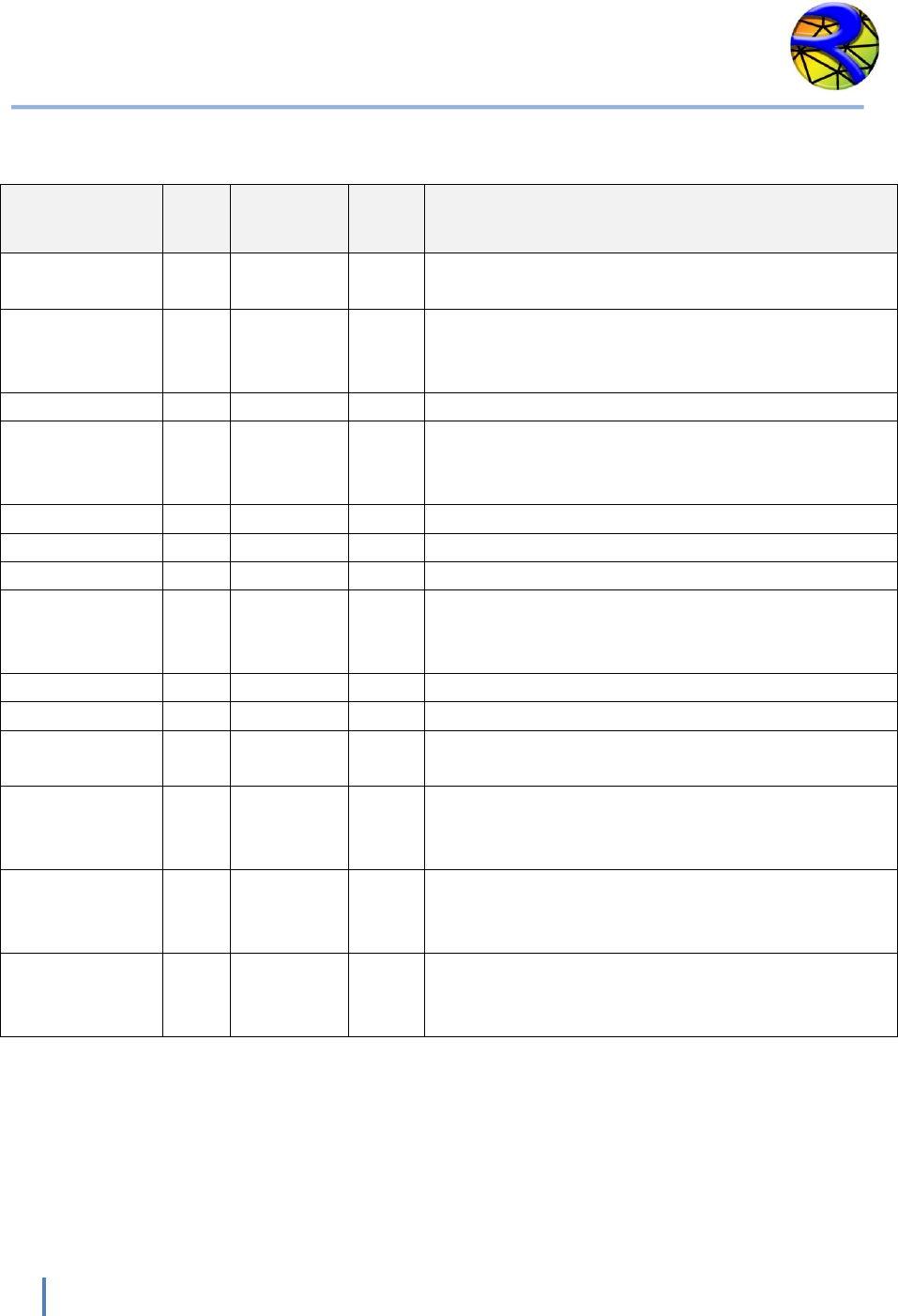
VARIABLE
TYPE
RANGE
UNITS
DESCRIPTION
IVARDT
I
0,1
-
Switch to control variable timestep option. See
comment 6.
0: DT constant time step will be used through the
simulation.
1: Variable time step will be used.
IXSEC
I
0,1
-
Cross section output switch.
0: No cross section result output.
1: Cross section results will be output to file.
<NAME.REP> needs to be created.
See comment 7.
NN_OUTPUT
I
1-100
-
Number of nodes where time series of results will
be output.
NOGRAPH
I
0,1
-
Variable to control screen output during
simulation.
0: only screen text output
1: text and graphic output during simulation. If
NOGRAPH =1, the *.PLT file needs to be created.
RELEASE
I
-
-
Release number used internally for reference.
Should not be changed.
TLIMT
R
>0
hours
Total simulation time.
TOUT
R
<TLIMT
hours
Output time interval for reporting results.
XNMAN
R
[0.1-2]
-
Manning’s n coefficient multiplier.
See comment 8.
Note: I = Integer variable. R = Real variable
RiverFLO-2D Model Input/Output Reference Manual
13
Hydronia LLC
Instructional Comments for the *.DAT File
The following comments will assist in the developing of the *.DAT file:
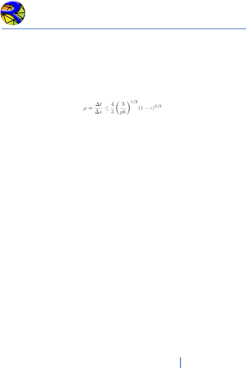
3. Setting the timestep DT is a critical issue for adequate stability and mass conservation.
RiverFLO-2D explicit time scheme is conditionally stable, meaning that there is a
maximum DT above which the simulations will become unstable. This threshold can be
theoretically approximated by the Courant-Frederick-Lewy condition defined as follows:
where Δt = DT is the timestep, Δx is a measure of the minimum triangle element size, g
is the acceleration of gravity, h is the flow depth and e is the selective lumping
parameter (EPSILON). It may occur that during the initial stages of a hydrograph,
velocities small and the selected the time step is adequate. During the simulation,
however, velocities and flow depth may increase causing the stability condition to be
exceeded. In those cases it will be necessary to rerun the model with a smaller timestep.
Alternatively, the variable timestep option may be used (see below).
4. For variable timestep simulations, RiverFLO-2D computes an estimate of the maximum
DT using the theoretical Courant-Frederick-Lewy (CFL) condition. Often this estimation is
high, leading to instabilities and you may use the DTMULT variable to adjust it. The
estimated CFL timestep can be multiple by the DTMULT factor to adjust the DT. Typical
DTMULT values range from 0.3 to 0.7, but may vary with the simulation.
5. The selective lumping parameter EPSILON is used to improve the model capabilities to
simulate abrupt change in depth or rapid flows. Lower values tend to smooth out depth
and velocity gradients and higher values steepen frontal waves and may lead to
instabilities. It is recommended to use an EPSILON = 0.9 for most applications.
6. There are three initial conditions options. If IINITIAL = 0, the initial water surface
elevation will be constant and arbitrarily set to an elevation equal to 0.5 m (1.5 ft)
higher than the highest bed elevation on the mesh. If IINITIAL = 1, the whole
computational mesh will be initially dry, except at open boundaries where discharge is
prescribed and depth > 0 is assumed for the first time step. If IINITIAL = 2, initial water
surface elevations are read from the *.FED data file for each node in the mesh. These
initial elevations can be set in the Argus ONE InitialConditions Layer, and can be
arbitrary. This last option allows modeling cases where part of the domain is flooded
(e.g. a reservoir) and other parts of the mesh are dry. The initial velocities are always
assumed equal to 0.

RiverFLO-2D Model Input/Output Reference Manual
14
Hydronia LLC
7. Use the IPROFILE option to allow RiverFLO-2D to generate results along a polyline. The
polyline and other required data should be given in file *.PRF which is defined later in
this document.
8. If IVARDT is = 0, a constant timestep equal to DT will be used through the computation.
This DT may potentially lead to instabilities if at some point during the simulation the
CFL condition is exceeded. In that case, it is necessary to reduce DT and restart the
simulation. If IVARDT = 1, for each time, RiverFLO-2D computes an estimate of the
maximum DT using the theoretical Courant-Frederick-Lewy (CFL) condition multiplied by
DTMULT. As the flow accelerates, the timestep will automatically decrease and when
the flow slows down the timestep may increase.
9. Use this option to allow RiverFLO-2D to generate results along prescribed cross sections.
The cross sections and other required data should be given in file *.REP which is defined
later in this document.
10. Use the XNMAN option to test the Manning’s n value sensitivity on the results. The
prescribed Manning’s coefficient assigned to each element will be multiplied by
XNMAN. By performing several simulations with various XNMAN values, the model
calibration can be improved.

RiverFLO-2D Model Input/Output Reference Manual
15
Hydronia LLC
FILE: *.FED: FINITE ELEMENT MESH DATA
NOTE: It is recommended to use the Argus ONE program to create this file. The templates for
RiverFLO-2D provided with Argus ONE assures that the file will be created error free and
consistent with the boundary conditions and other mesh parameters. Manually editing this file
may introduce errors.
Line 1 contains general mesh parameters
1 NELEM, NNODES, NPARAMEL, NPARAM
Following NNODES lines contain the node coordinates and node parameters.
2 IN, X(IN), Y(IN), ZB(IN), ETA(IN), (ARN(J), J=1, NPARAM-1)
Following NELEM lines contain element connectivity.
3 IE, NODE(IE,1), NODE(IE,2), NODE(IE,3), ZBED, MANNING(IE)
Example of a * .FED file
1231 682 2 5
1 799001.27 305583.22 162.12 0. 0.04 0 0
2 798948.74 305505.30 159.74 0. 0.04 0 0
3 799037.14 305459.39 156.96 0. 0.04 0 0
.
.
.
1 1 2 3 160.88 0.04
2 4 5 6 173.78 0.04
3 7 8 9 164.90 0.04
.
.
.
RiverFLO-2D Model Input/Output Reference Manual
16
Hydronia LLC
Variable Descriptions for the * .FED File
VARIABLE
TYPE
RANGE
UNITS
DESCRIPTION
ARN
R
-
-
Not used in this release.
ETA(IN)
R
-
m.
or
ft.
Initial water surface elevation for node IN.
IE
I
>0
-
Element index. Consecutively from 1 to NELEM.
IN
I
>0
m/s
or
ft/s
Node number. Consecutively from 1 to NNODES.
MANNING(IE)
R
>0
-
Manning n value for element IE.
NELEM
I
1-5
-
Number of triangular finite elements.
NNODES
I
>0
-
Number of finite element nodes.
NODE(IE,1),
NODE(IE,2),
NODE(IE,3)
I
>0
-
Node numbers for element IE given in counter
clockwise direction.
NPARAMEL
I
>0
-
Number of element parameters.
NPARAM
I
>0
-
Number of node parameters.
X(IN)
R
-
m.
ft.
X coordinate for node IN.
Y(IN)
R
-
m.
or
ft.
Y coordinate for node IN.
ZB (IN)
R
-
m.
or
ft.
Initial bed elevation for node IN.
ZBED(IE)
R
-
m.
or
ft.
Initial bed elevation for element IE.
Note: I = Integer variable. R = Real variable. All variables are separated by one or more spaces.

RiverFLO-2D Model Input/Output Reference Manual
17
Hydronia LLC
FILE: *.IFL: OPEN BOUNDARY CONDITIONS DATA
NOTE: It is recommended to use Argus ONE program to create this file. The templates for
RiverFLO-2D provided with Argus ONE assures that the file will be created error free and
consistent with the boundary conditions and other mesh parameters. Manually editing this file
may introduce errors.
Line 1 contains the number of parameters and number of nodes on external boundary
1 NPARAMB, NNODESBOUNDARY
The next NNODESBOUNDARY lines contain the boundary conditions data
IN, DUMMY1, DUMMY2, DUMMY3, BCTYPE, BCFILENAME
Example of the *.IFL file
5 131
1 162.22 0. 0.04 0 0
2 159.74 0. 0.04 0 0
3 156.96 0. 0.04 0 0
4 163.57 0. 0.04 6 qsec94.qvt
5 198.72 0. 0.04 6 qsec94.qvt
6 190.19 0. 0.04 0 0
18 171.54 0. 0.04 0 0
20 170.77 0. 0.04 6 qsec94.qvt
22 163.56 0. 0.04 6 qsec94.qvt
24 159.88 0. 0.04 6 qsec94.qvt
26 160.91 0. 0.04 6 qsec94.qvt
29 179.82 0. 0.04 0 0
33 168.77 0. 0.04 0 0
99 170.03 0. 0.04 0 0
.
.
.
167 157.14 0. 0.04 1 hsec52.hvt
169 155.55 0. 0.04 1 hsec52.hvt
171 153.06 0. 0.04 1 hsec52.hvt
173 154.98 0. 0.04 1 hsec52.hvt
RiverFLO-2D Model Input/Output Reference Manual
18
Hydronia LLC
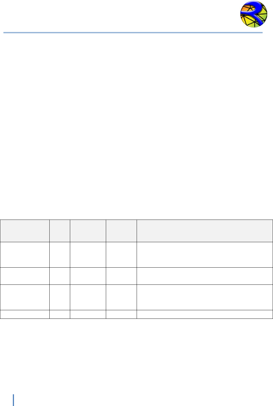
Variable Descriptions for the *.IFL File
VARIABLE
TYPE
RANGE
UNITS
DESCRIPTION
BCTYPE
I
0-10
-
Code to indicate type of open boundary. See
table below. See Comment 1.
BCFILENAME
S
-
-
Boundary condition file name. Can be any
valid file name. See comments 2 and 3.
NNODESBOUNDARY
I
1-5
-
Total number of nodes on boundary.
NPARAMB
I
1-5
-
Number of node parameters.
Note: I = Integer variable. R = Real variable. S=Text String.
BCTYPE
DESCRIPTION
0
Closed impermeable boundary. Slip boundary condition (no normal flow) is imposed.
See comment 5.
1
Imposes Water Surface Elevation. An associated boundary condition file must be
provided. See comments 2 and 4.
2
Imposes U velocity component. An associated boundary condition file must be
provided. See comment 2.
3
Imposes V velocity component. An associated boundary condition file must be
provided. See comment 2.
4
Imposes U and V velocity components. A two-variable boundarcondition file must be
provided. See comment 3.
5
Imposes water discharge and water surface elevation. A two-variable boundary
condition file must be provided. See comment 3.
6
Imposes water discharge. An associated boundary condition file must be provided.
See comment 2.
7
Imposes U velocity and water surface elevation. A two-variable boundary condition
file must be provided. See comment 3.
8
Imposes V velocity and water surface elevation. An associated boundary condition
file must be provided. See comment 3.
9
Imposes single-valued stage-discharge rating table. An associated boundary
condition file must be provided. See comment 6.
10
“Free” inflow or outflow condition. Velocities and water surface elevations are
calculated by the model. See comment 7.
RiverFLO-2D Model Input/Output Reference Manual
19
Hydronia LLC
Instructional Comments for the *.IFL File
The following comments will assist in the developing of the *.IFL file:
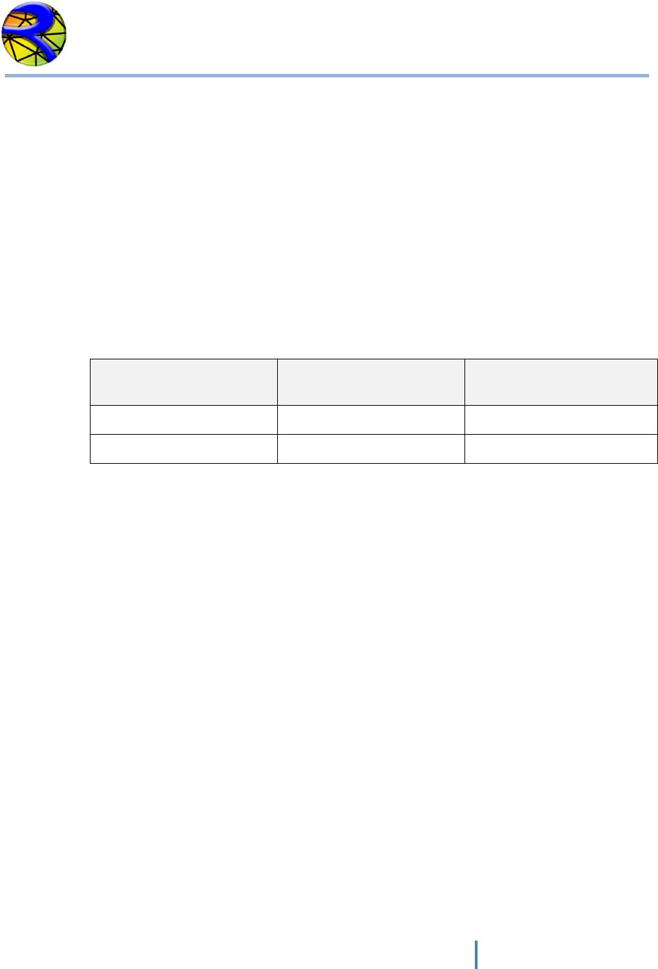
1. RiverFLO-2D allows having any number of inflow and outflow boundaries with
various combinations of imposed conditions. Proper use of these conditions is a
critical component of a successful RiverFLO-2D simulation. Theoretically, for
subcritical flow it is required to provide at least one condition at inflow
boundaries and one for outflow boundaries. For supercritical flow all conditions
must be imposed on the inflow boundaries and “none” on outflow boundaries.
The table below helps determining which conditions to use for most
applications.
Flow regime at boundary
Inflow boundary condition
Outflow boundary
condition
Subcritical
Q or Velocity
Water Surface Elevation
Supercritical
Q and WSE
“Free”
NOTE: It is recommended to have at least one boundary where WSE or stage-
discharge is prescribed. Having only discharge and no WSE may result in
instabilities due to violation of the theoretical boundary condition requirements
of the shallow water equations.
2. When imposing a single variable (water surface elevation, Q, U or V, it is required
to provide an ASCII file with the time series for the variable. See section
Boundary Conditions Data Files for details on the format for one-variable
boundary condition files.
3. When imposing two variables (water surface elevation and discharge, etc.), it is
required to provide an ASCII file with the time series for the variables. See
section Boundary Conditions Data Files for details on the format for two-variable
boundary condition files.
4. When imposing water surface elevation it is important to check that the imposed
value is higher than the bed elevation. Even though the RiverFLO-2D model may
run with that condition, it may lead to volume conservation errors.
5. When Argus ONE is used to create RiverFLO-2D data files a closed boundary
condition is imposed by default on all boundary nodes. In this case, the model
calculates velocities and water surface elevations for all nodes on the boundary

RiverFLO-2D Model Input/Output Reference Manual
20
Hydronia LLC
and then imposes zero-flow across the boundary. Tangential flow is free
corresponding to a slip condition. This condition can be overridden using any of
the other open inflow or outflow conditions described herein.
6. When using a single valued stage-discharge condition the model first computes
the discharge on the boundary then interpolates the corresponding water
surface elevation from the rating table and imposes that value for the next time
step. In case the boundary is dry, it functions as a “free” condition boundary
(see comment 7). Water surface elevations are imposed only on wet nodes. This
condition requires providing an ASCII file with the table values entries. See
section Boundary Conditions Data Files for details on the file format.
In general it is preferable to use stage hydrograph rather than stage-discharge
condition. Most small slope rivers, the stage-discharge relationship is affected by
hysteresis. In other words, the stage-discharge curve is looped with higher
discharges occurring on the rising limb than on the rescission limb of the
hydrograph. This is mainly caused by the depth gradient in the flow direction
that changes in sign throughout the hydrograph. In practice, this implies that
there can be two possible stages for the same discharge. If the stage-discharge
relationship is not well known or if it just computed assuming steady state
uniform flow, it may lead to considerable errors when used as downstream
boundary condition. That it is why it is often preferred to use the stage
hydrograph for that purpose. However, such hydrograph may not be available to
study changes in the river and evaluating proposed conditions. For those cases, it
is useful to use a stage-discharge relationship, preferably measured over an
extensive range of discharges.
When this relationship is not available, one option would be to assume steady
state flow to determine a single-value rating curve. Since this condition may
generate wave reflection that can propagate upstream, it is important to locate
the downstream boundary on a reach sufficiently far from the area of interest,
therefore minimizing artificial backwater effects. Unfortunately, there is no
general way to select such place, but numerical experimenting with the actual
model will be necessary to achieve a reasonable location.
NOTE: loop stage-discharge relationships are not allowed in this version.
7. On free condition boundary nodes, the model calculates velocities and water
surface elevations applying the full equations from the internal elements. No
condition is imposed per se on these nodes, which on the finite element context,
is equivalent to apply natural boundary conditions. In practice this should be
equivalent to assume that derivatives of water surface elevations and velocities
are 0. Use advisable to use this condition when there is at least another open
boundary where WSE or stage-discharge is imposed.

RiverFLO-2D Model Input/Output Reference Manual
21
Hydronia LLC
FILE: *.PLT: GRAPHICAL OUTPUT CONTROL DATA
Line 1 contains plot control variables
1 IGRAPHCODE, COLORSCHEME, IAXES, IDXF, IGRAPHFILES
Line 2 contains velocity vector scale multiplier.
2 SF_MULT
Line 3 contains coordinates for plot window.
3 XMING, XMAXG, YMING, YMAXG
Line 4 contains limits of plotted variable.
4 MINVARG, MAXVARG
Line 5 contains maximum velocity to plot.
5 MAXVELOC
Example of the *.PLT file
100 5 1 0 1
5
0 0 0 0
0 0
7
RiverFLO-2D Model Input/Output Reference Manual
22
Hydronia LLC
Variable Descriptions for the *.PLT File
VARIABLE
TYPE
RANGE
UNITS
DESCRIPTION
COLORSCHEME
I
1-5
-
Variable to select plot option. See comment 1.
IAXES
I
0,1
-
Switch to control weather to plot axes.
0: Do not plot X and Y axes.
1: Plot X and Y axes.
IDXF
I
0,1
-
Switch to control velocity field output in DXF CAD
format.
0: Do not output DXF velocity field.
1: Create velocity field DXF files for each output
time.
IGRAPHFILES
I
0,1
-
Variable to control weather to output graphic
files.
0: Do not output graphic files.
1: Output graphic files.
MAXVELOC
R
-
m/s
or
ft/s
Use this variable to control the maximum
velocity displayed in vector plots.
If MAXVELOC = 0, the whole velocity range will
be plotted.
If MAXVELOC > 0, it will define the maximum
velocity to be displayed.
MINVARG,
MAXVARG
R
-
-
These variables define the minimum and
maximum values to be displayed of the selected
variable. If equal to 0, the maximum range will
be displayed.
SF_MULT
R
>0
-
Variable to control velocity vector scale.
Use this variable to adjust velocity vectors.
Velocities will be scaled according to SF_MULT.
XMING,
XMAXG,
YMING,
YMAXG
R
-
m.
or
ft.
These variables indicate the coordinates of a
rectangle that define the plot window. If all
values are 0, the full extent of the modeling are
will be displayed.
Note: I = Integer variable. R = Real variable
RiverFLO-2D Model Input/Output Reference Manual
23
Hydronia LLC
Instructional Comments for the *.PLT File
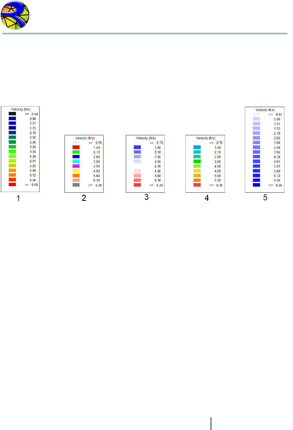
1. COLORSCHEME defines the color palette that will be used for all plots. The available
palettes are shown in this figure.
.
Color palettes.
RiverFLO-2D Model Input/Output Reference Manual
24
Hydronia LLC
FILE: *.PRF: PROFILE CUT DATA FOR RESULT OUTPUT
Use this file to provide profiles (polylines) along which results will be provided.
Line 1 Number of profiles and number of intervals to divide each profile.
1 NPROFILES, ND_PR
For each profile I, write number of vertices in profile I and list coordinates for each vertex in
polyline. There should be NPROFILES groups like this one:
NVERTICES_PR(I)
X_PRF(I), Y_PRF(I)
.
.
Example of the *.PRF file
2 200
2
800500.45 306895.63
799095.07 307457.34
3
800503.45 306896.63
799500.00 306900.00
799095.07 307457.34
This file indicates there is data for 2 profiles, each will be divided in 200 parts. The first profile is
defined by 2 vertices and the second profile is defined by 3 vertices.
Variable Descriptions for the *.PRF File
VARIABLE
TYPE
RANGE
UNITS
DESCRIPTION
ND_PR
I
>2
-
Intervals to divide each profile. Results
will be reported at each interval.
NPROFILES
I
>0
-
Number of cross sections.
NVERTICES_PR(I)
I
>1
-
Number of vertices in each profile.
X_PRF(I,J),Y_PRF(I,J)
R
-
m or ft
Coordinates of each vertex J in profile I.
Note: I = Integer variable. R = Real variable
RiverFLO-2D Model Input/Output Reference Manual
25
Hydronia LLC
FILE: *.REP: CROSS SECTION DATA FOR RESULT OUTPUT
Line 1 Number of cross sections and number of intervals to divide each section.
1 NCROSS_SECTIONS, ND_CS
For each cross section I, coordinates of initial and final point in cross section. There should be
NCROSS_SECTIONS lines like this one:
X1_CS(I), Y1_CS(I), X2_CS(I), Y2_CS(I)
Example of the * .REP file
12 40
800500.45 306895.63 799095.07 307457.34
800492.17 307163.36 799171.99 307594.56
800449.99 307404.31 799223.97 307690.20
800456.79 307736.80 799226.05 307729.70
800467.07 308012.96 799325.84 307856.52
800463.75 308460.92 799325.84 307896.03
800256.02 309010.15 799244.76 308051.96
800441.71 309664.04 7 99113.78 308284.81
800175.75 309705.15 799038.93 308528.06
800016.40 309821.89 798968.24 308918.92
799633.54 309854.50 798828.95 309112.27
800631.40 305589.90 798349.30 307285.18
.
.
Variable Descriptions for the *.REP File
VARIABLE
TYPE
RANGE
UNITS
DESCRIPTION
NCROSS_SECTIONS
I
>0
-
Number of cross sections.
ND_CS
I
>2
-
Intervals to divide each section. Results
will be reported at each interval.
X1_CS, Y1_CS,
X2_CS, Y2_CS
R
-
m or ft
Coordinates of initial and ending point of
each cross section.
Note: I = Integer variable. R = Real variable
RiverFLO-2D Model Input/Output Reference Manual
26
Hydronia LLC
FILE: *.RET: RAINFALL AND EVAPORATION DATA
Line 1 Number of points in time series of rainfall and evaporation
1 NPRE
Line 2 Time, Daily Rainfall, Daily Evaporation
2 TIME, RAINFALL, EVAP
Example of the *.RET file
10
0. 0.0 0.0
24. 4.0 0.0
48 12.0 0.0
.
.
.
Variable Descriptions for the *.RET File
VARIABLE
TYPE
RANGE
UNITS
DESCRIPTION
EVAPORATION
R
>=0
mm/day
or
in/day
Daily evaporation. Should be given for each 24
hour interval
NPRE
I
-
-
Number of times in rainfall and evaporation
time series.
RAINFALL
R
>=0
mm/day
or
in/day
Daily rainfall. Should be given for each 24 hour
interval.
TIME
R
>=0
hours
Time should be given for each 24 hour interval
Note: I = Integer variable. R = Real variable
RiverFLO-2D Model Input/Output Reference Manual
27
Hydronia LLC
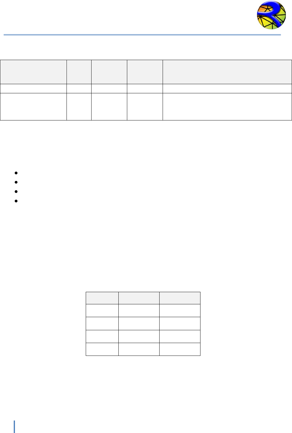
FILE: *.SED: SEDIMENT TRANSPORT DATA
Line 1 Sediment discharge formula.
1 ST_FORMULA
Line 2 Median sediment size in mm, sediment specific gravity and porosity
2 D50, GR, POROS
Example of the *.SED file
1
0.01 2.65 0.4
Variable Descriptions for the *.SED File
VARIABLE
TYPE
RANGE
UNITS
DESCRIPTION
D50
R
>0
mm
Sediment median size. 50% of the sediment is
finer than D50.
GR
R
2-2.7
-
Sediment particles specific gravity.
POROS
R
0.3-0.6
-
Sediment porosity.
ST_FORMULA
I
1-3
-
Code indicating the sediment transport rate to
use. The options available in this version are:
1: Meyer-Peter & Muller (1948),
2: Karim-Kennedy (1998),
3: Ackers-White (1975).
4: Yang (Sand),
5: Yang (Gravel),
6: Parker-Klingeman-Mclean (1982),
7: Van Rijn (1984a-c),
8: Engelund Hansen (1967).
Note: I = Integer variable. R = Real variable

RiverFLO-2D Model Input/Output Reference Manual
28
Hydronia LLC
FILE: *.TBA: MESH BOUNDARY DATA
NOTE: It is recommended to use Argus ONE program to create this file. The templates for
RiverFLO-2D provided with the Argus ONE program assures that the file will be created error
free and consistent with the boundary conditions and other mesh parameters. Manually editing
this file may introduce errors.
Line 1 contains new boundary parameter.
1 IBOUNDARYID
Line 2 contains the number of nodes in external boundary of mesh.
2 NNODESBOUNDARY
Next NNODESBOUNDARY lines contain the list of boundary nodes in counter clockwise
direction.
3 BOUNDARYNODE (1:NNODESBOUNDARY)
The next lines are only used if there are islands in the mesh. Repeat for each island.
Next line contains the new boundary parameter indicator for each island or internal closed
contour.
4 IBOUNDARYID
Line 2 contains the number of nodes in island external boundary.
2 NNODESISLANDBOUNDARY
Next NNODESISLANDBOUNDARY lines contain the list of boundary nodes in clockwise direction.
3 ISLANDBOUNDARYNODE (1: NNODESISLANDBOUNDARY)

RiverFLO-2D Model Input/Output Reference Manual
29
Hydronia LLC
Example of the *.TBA file
-9999
132
1
2
3
173
171
.
.
.
244
240
236
232
228
224
175
1
-9999
34
5
7
45
66
.
.
.
5
In this example the external boundary has 132 nodes and there is one island with 34 nodes.
RiverFLO-2D Model Input/Output Reference Manual
30
Hydronia LLC
Variable Descriptions for the *.TBA File
VARIABLE
TYPE
RANGE
UNITS
DESCRIPTION
IBOUNDARYID
I
-99999
-
Always = -99999. This is to indicate
the program that the following lines
contain a boundary.
NNODESBOUNDARY
I
>0
-
Number of nodes on external
boundary.
BOUNDARYNODE
I
>0
-
Node number on external boundary.
See comment 1.
NNODESISLANDBOUNDARY
I
>0
-
Number of nodes on island
boundary.
ISLANDBOUNDARYNODE
I
>0
-
Node number on island boundary.
Note: I = Integer variable. R = Real variable
Instructional Comments for the *.TBA File
1. There should be a single external boundary and any number of internal islands or closed
contours.

RiverFLO-2D Model Input/Output Reference Manual
31
Hydronia LLC
BOUNDARY CONDITIONS DATA FILES
One variable boundary condition.
This format applies to the following data files:
Time vs Water Surface Elevation (BCTYPE = 1)
Time vs Discharge (BCTYPE = 6)
Time vs U velocity component in x direction (BCTYPE = 2)
Time vs V velocity component in y direction (BCTYPE = 3)
Line 1 Number points in data series.
1 NDATA
For each time I
TIME(I) VARIABLE(I)
Where VARIABLE(I) is WSE, Q, U or V depending on the boundary condition
Example of a Boundary Condition file for one variable time series
The following example shows an inflow hydrograph where NDATA is 10 and there are 10 lines
with pairs of time and discharge:
10
0. 20.
1. 30.
1.3 50.
2 . 90.
4 . 120.
5. 200.
7. 250.
8.1 110.
10. 60.
20. 20.
RiverFLO-2D Model Input/Output Reference Manual
32
Hydronia LLC
Variable Descriptions of a Boundary Condition File
VARIABLE
TYPE
RANGE
UNITS
DESCRIPTION
NDATA
R
> 0
-
Number points in data series.
VARIABLE
R
-
-
Represents Water Surface Elevation,
Discharge, U or V velocity components
depending on the boundary condition.
Note: I = Integer variable. R = Real variable
Two variables boundary condition.
This format applies to the following data files:
Time vs U and V velocity components (BCTYPE = 4)
Time vs Discharge and Water Surface Elevation (BCTYPE = 5)
Time vs U velocity component and Water Surface Elevation (BCTYPE = 7)
Time vs V velocity component and Water Surface Elevation (BCTYPE = 8)
Line 1 Number points in data series.
2 NDATA
For each time I
TIME(I) VARIABLE1(I) VARIABLE2(I)
Where VARIABLE1(I) and VARIABLE(2) depend on the boundary condition type as follows:
BCTYPE
VARIABLE1
VARIABLE2
4
U
V
5
Q
WSE
7
U
WSE
8
V
WSE
Example of a Two-Variable Boundary Condition file
RiverFLO-2D Model Input/Output Reference Manual
33
Hydronia LLC
The following example shows a file for BCTYPE 5 where discharge and WSE are given, NDATA is
10 and there are 10 lines with pairs of time, discharge and WSE:
10
0. 20. 1420.
1. 30. 1421.5
1.3. 50. 1423.
2 . 90. 1425.
4 . 120. 1427.
5. 200. 1428.
7. 250. 1420.
8.1 110. 1426.
10. 60. 1423.5
20. 20. 1421.
Variable Descriptions of a Two-Variable Boundary Condition File
VARIABLE
TYPE
RANGE
UNITS
DESCRIPTION
NDATA
R
>0
-
Number points in data series.
VARIABLE1
R
-
-
Represents Water Surface Elevation,
Discharge, U or V velocity components
depending on the boundary condition.
VARIABLE2
R
-
-
Represents Water Surface Elevation,
Discharge, U or V velocity components
depending on the boundary condition.
Note: R = Real variable

RiverFLO-2D Model Input/Output Reference Manual
34
Hydronia LLC
Stage-discharge data file.
This format applies to the stage (water surface elevation) vs. discharge table used in BCTYPE =
9.
Line 1 Number points in data series.
NDATA
For each table entry
STAGE(I) Q(I)
Where STAGE(I) is Water Surface Elevation and Q(I) is the corresponding discharge.
Example of a Stage-Discharge data file
The following example shows an inflow hydrograph where NDATA is 10 and there are 10 lines
with pairs of time and discharge:
21
-1.00 0.00
-0.75 1.79
-0.50 5.20
-0.25 9.45
0.00 14.23
0.25 19.37
0.50 24.76
0.75 30.36
1.00 36.09
1.25 41.95
1.50 47.89
1.75 53.92
2.00 60.00
2.25 66.14
2.50 72.31
2.75 78.53
3.00 84.78
3.25 91.05
3.50 97.35
3.75 103.67
4.00 110.01
RiverFLO-2D Model Input/Output Reference Manual
35
Hydronia LLC
Output Files
RiverFLO-2D generates extensive output data into a series of ASCII files. These ASCII files can be
easily accessed with various text editor software and they can be import into the Argus ONE
program and other GIS software for visualization and analysis. RiverFLO-2D always creates
output ASCII files in both English and Metric units. The following sections describe the content
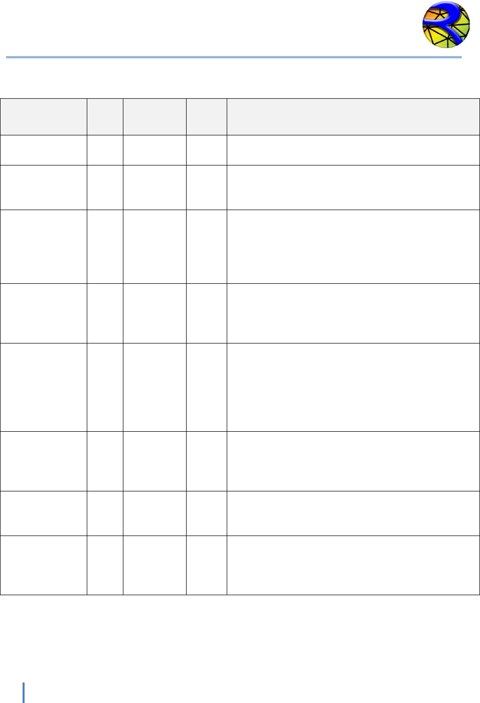
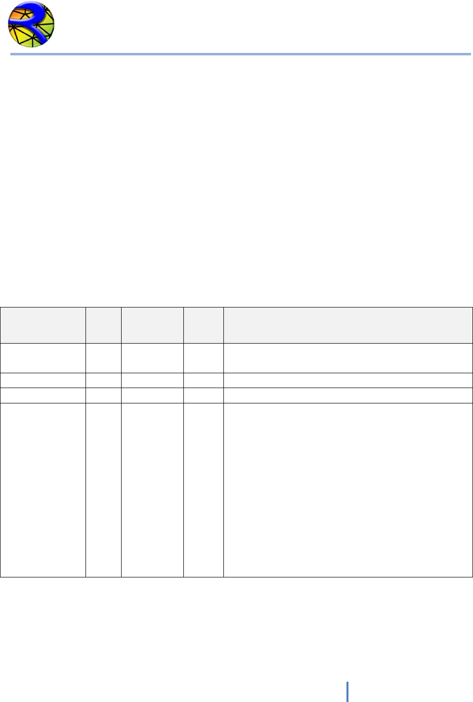
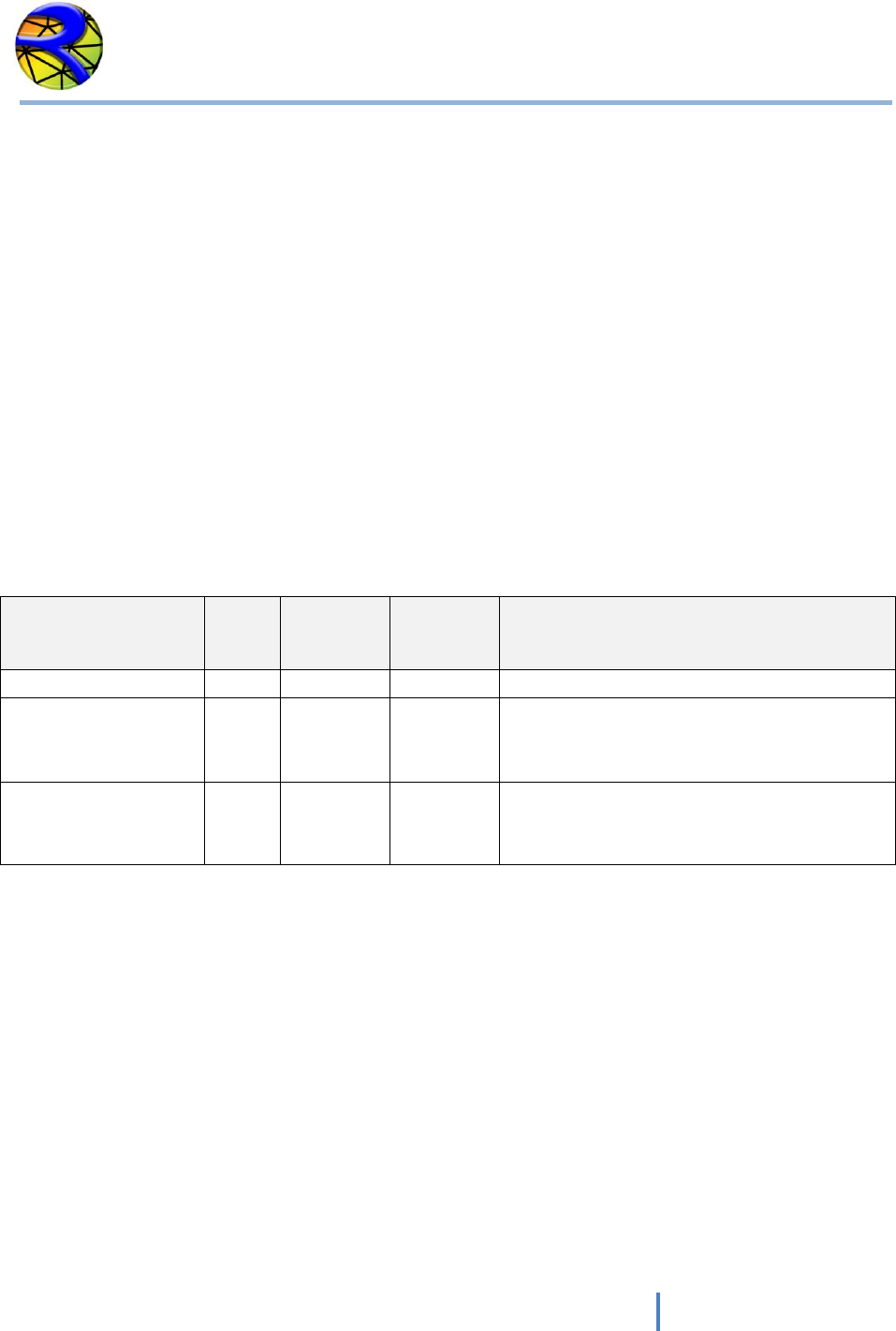
of each output file. The following table summarizes the output files generated by RiverFLO-2D:
Data File
Extension
Content
OUT
OUTE
Echoes input data read from files including modeling control parameters,
mesh data, boundary conditions, and for each report time interval inflow and
outflow discharges and velocities. OUT file is in metric units and OUTE file in
English units.
UVH
UVHE
For each output interval nodal velocities, depths, water surface and bed
elevations, bed elevation changes, wet-dry condition, Froude number are
written to file. UVH is in metric units and UVHE in English units.
Time Series
OUT FILES
For user selected nodes a time series of velocities, depths, water surface and
bed elevations, bed elevation changes, wet-dry condition, Froude number is
written to file. File name format is:
RESvsT_NODE_NODENUMBER.OUT for metric units and
RESvsT_NODE_ENG_NODENUMBER.OUT for English units.
EXP
For each output interval nodal velocities, depths, water surface and bed
elevations, bed elevation changes, wet-dry condition, Froude number are
written to file. These files can be directly imported into an Argus ONE data
layer for post processing. The file names are:
TIME_METRIC_DDDD_HH_MM_SS.EXP. for metric units and
TIME_ENG_DDDD_HH_MM_SS.EXP for English units.
PRFI
PRFE
For each output interval and for a number of points along user defined
polylines, these files provide bed elevation, depth, water surface elevation,
depth average velocity, and Froude number are written to file. PRFI is in
metric and PRFE in English units.
UVHB
VTP
Binary files that allow hot starts of previous simulations.
XSEC
XSECE
For output interval and user defined cross section, these files provide bed
elevation, depth, water surface elevation, depth average velocity, and Froude
number. XSEC is in metric and XSECE in English units.
DXF
Velocity field using colored vectors in AutoCAD DXF format. File name is in
this format: VelField_TIME_ DDDD_HH_MM_SS.DXF.
GIF
Raster file plot for each report time interval.
RiverFLO-2D Model Input/Output Reference Manual
36
Hydronia LLC
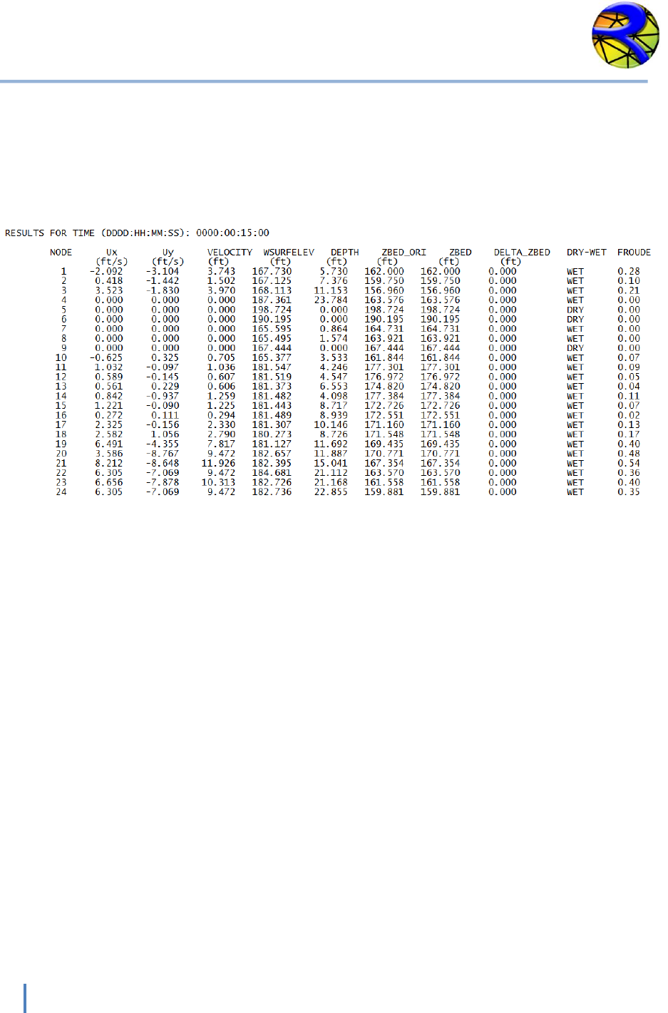
UVH and UVHE Output Files
These files report the output time interval nodal velocities, depths, water surface and bed
elevations, bed elevation changes, wet-dry condition, Froude number. UVH is in metric units
and UVHE in English units. A typical output UVHE file is shown below:
RiverFLO-2D Model Input/Output Reference Manual
37
Hydronia LLC
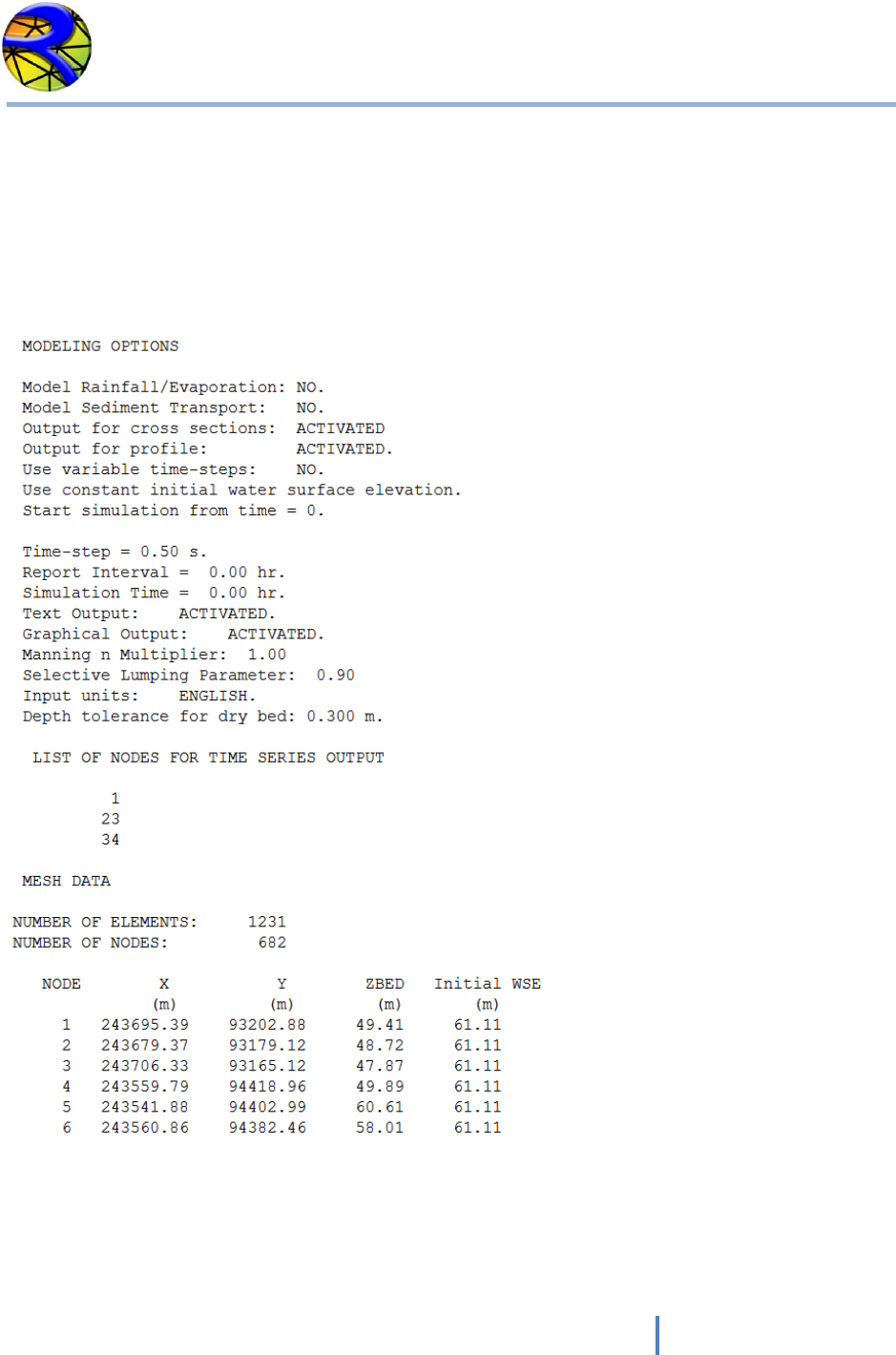
OUT and OUTE Output Files
These files replicate the input data read from files including modeling control parameters, mesh
data, boundary conditions, and inflow and outflow discharges and velocities for each output
interval. OUT is in metric units and OUTE in English units. Part of a typical OUT file format is
shown below:
RiverFLO-2D Model Input/Output Reference Manual
38
Hydronia LLC
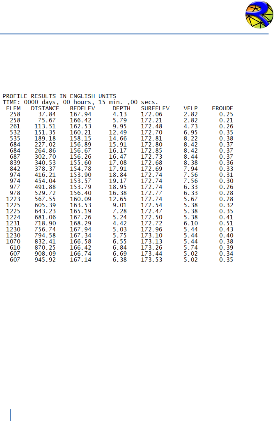
PRFI and PRFE Output Files
For each output interval and for the number of points along user defined polylines these files
list bed elevation, depth, water surface elevation, depth average velocity, and Froude number.
PRFI is in metric and PRFE in English units. An example output is shown below:
RiverFLO-2D Model Input/Output Reference Manual
39
Hydronia LLC
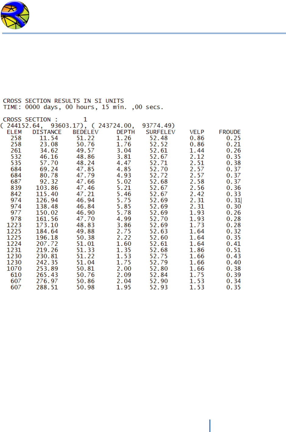
XSEC and XSECE Output Files
For output interval and for each user defined cross sections the bed elevation, depth, water
surface elevation, depth average velocity, and Froude number is written to file. XSEC is in
metric and XSECE in English units. A portion of a typical XSEC file is as follows:
RiverFLO-2D Model Input/Output Reference Manual
40
Hydronia LLC
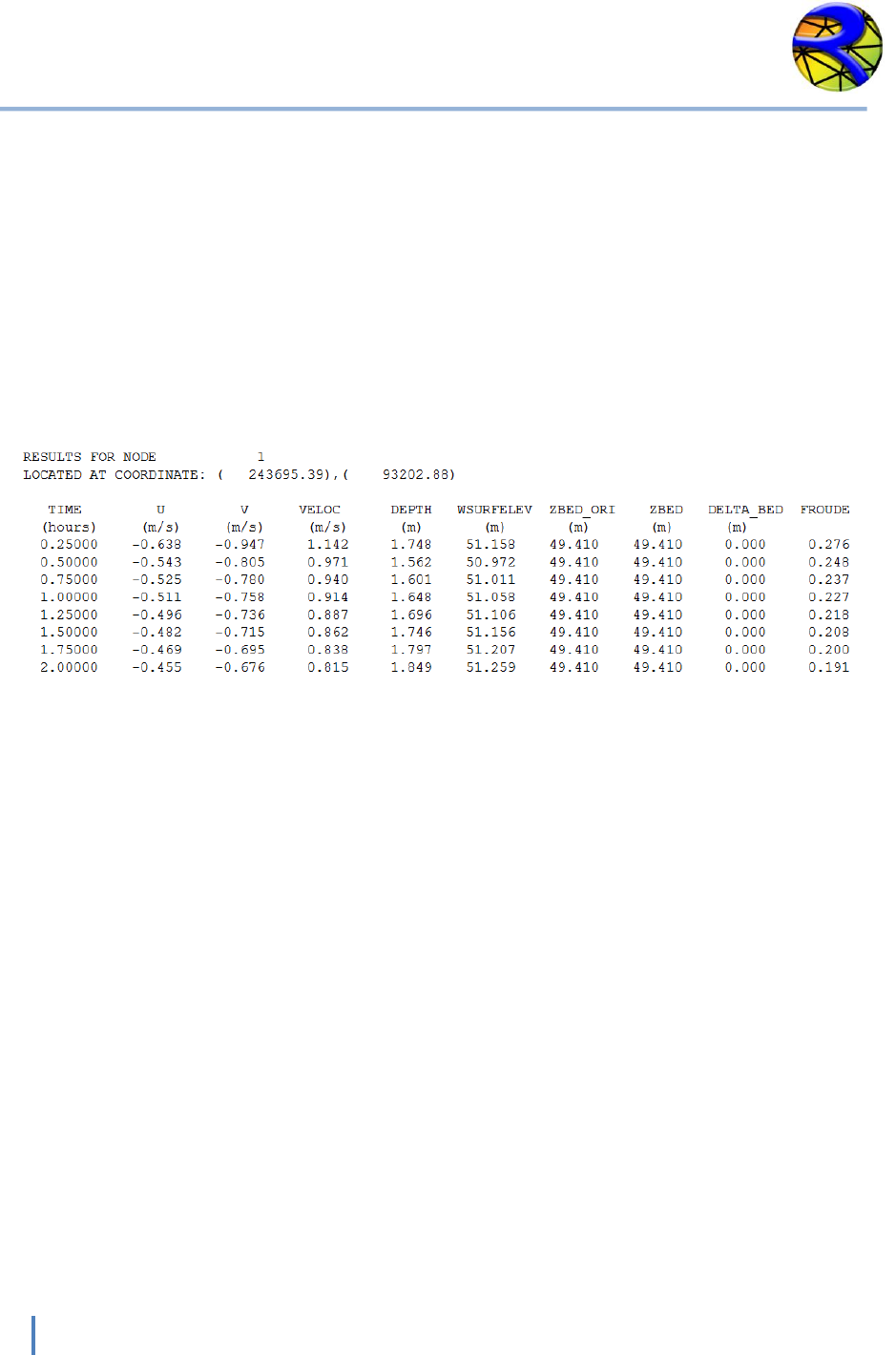
TIME SERIES OUT OUTPUT FILES
For user selected nodes (INTS variable in DAT file), these files report the time series of
velocities, depths, water surface and bed elevations, bed elevation changes, and Froude
number. The file name is:
RESvsT_NODE_NODENUMBER for metric units and,
RESvsT_NODE_ENG_NODENUMBER for English units.
An example is shown below.

RiverFLO-2D Model Input/Output Reference Manual
41
Hydronia LLC
UVHB and VTP Output Files
These are binary files for model internal use and contain the simulation results at the end of
each output interval. These files are then used to restart a simulation from the completion time
(hot start option). For example, the user stops the simulation at 4.25 hours to review results.
The RiverFLO-2D can then be restarted from the last report output time interval by reading the
last state from the VTP file. UVHB file also serves to save all model results for each report time
interval as redundancy storage.
NOTE: UVHB and VTP files are in binary format and are not readable by a text editor.
DXF FILES
These files contain the velocity field for each output interval using colored vectors in AutoCAD
DXF format. The file name is of this form: VelField_TIME_ DDDD_HH_MM_SS.
RiverFLO-2D Model Input/Output Reference Manual
42
Hydronia LLC
Argus ONE ASCII files *.EXP
The ASCII files allow seamless transfer to Argus ONE data layers. These files use the *.EXP
extension and are named as follows:
For English units: TIME_ENG_DDDD_HH_MM_SS.EXP
For Metric units: TIME_METRIC_ DDDD_HH_MM_SS.EXP
Where DDDD is days, HH is hours, MM is minutes and SS seconds. For example
TIME_ENG_0001_12_01_34.EXP corresponds to a file in English units for time: 1 day, 12 hours,
1 minute and 34 seconds.
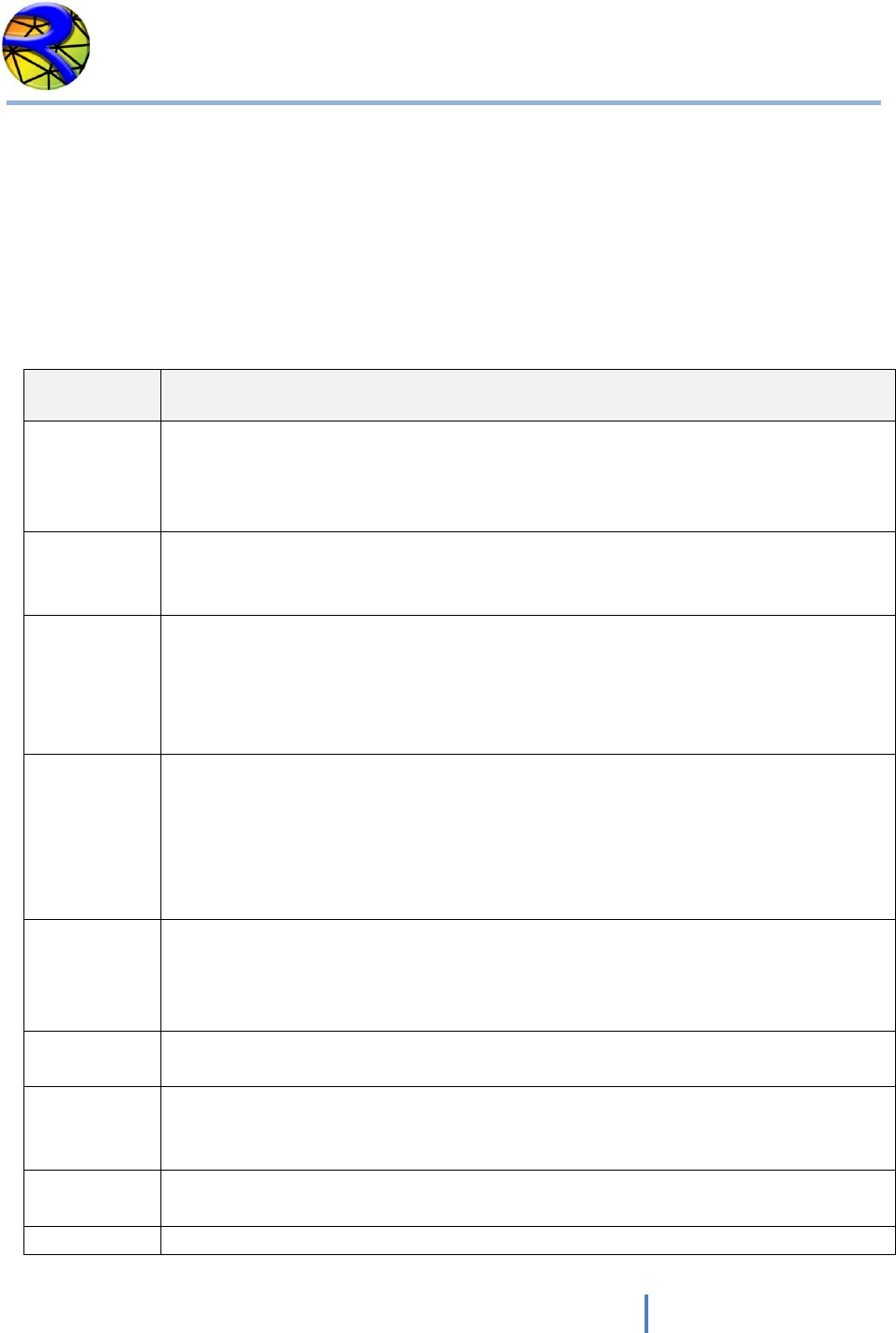
The format for these files is as follows. The first line indicates the number of node parameters
(10 by default). Following, there is a line with results for each node in the finite element mesh
as shown:
COLUMN
VALUE
ENGLISH UNITS
METRIC UNITS
1
Node number
-
-
2
Velocity component in x
direction U
ft/s
m/s
3
Velocity component in y
direction V
ft/s
m/s
4
Velocity magnitude
SQRT(U^2 + V^2)
ft/s
m/s
5
Water surface elevation
ft
m
6
Depth
ft
m
7
Initial bed elevation
ft
m
8
Bed elevation
ft
m
9
Variation in bed
elevation since time = 0
ft
m
10
Dry or wet
Dry=1 / Wet=0
Dry=1 / Wet=0
11
Froude number
-
-
An example of a typical Argus ONE ASCII EXP file is as follows:
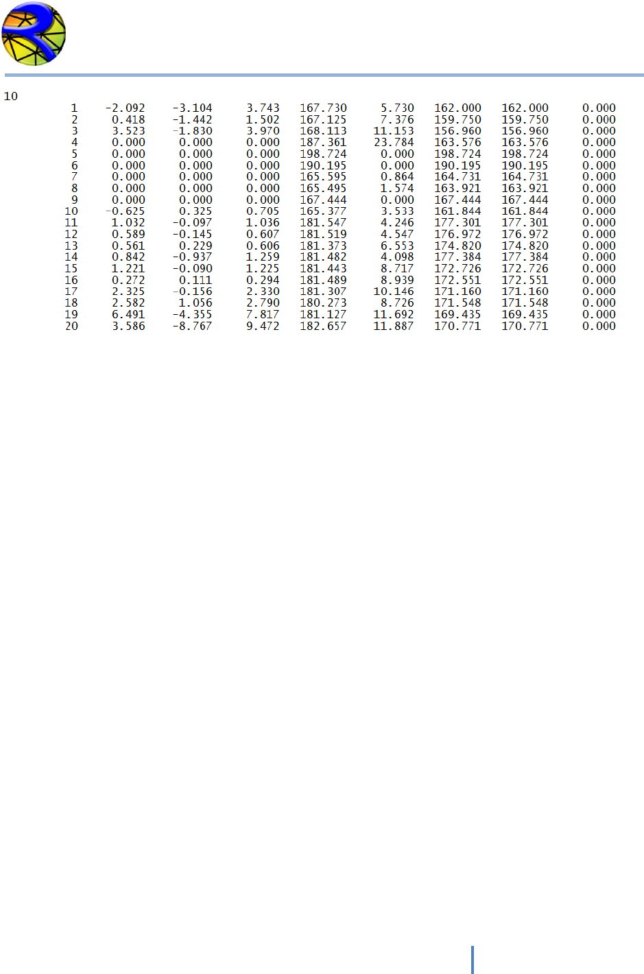
RiverFLO-2D Model Input/Output Reference Manual
43
Hydronia LLC
.
.
.
RiverFLO-2D Model Input/Output Reference Manual
44
Hydronia LLC
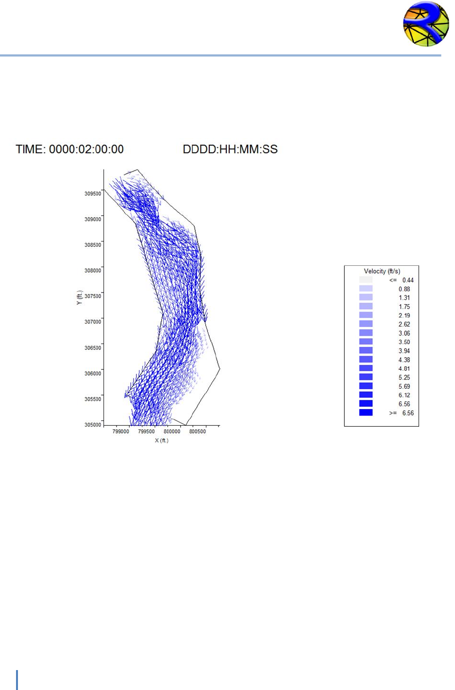
GIF Output Files
These are raster output files showing the plot for each output interval. They can be imported in
other word, spreadsheet or presentation programs.

RiverFLO-2D Model Input/Output Reference Manual
45
Hydronia LLC
References
Ackers, P., and W.R. White, Sediment transport, new approach and analysis, J. Hyd. Div.
ASCE, 99, HY 11, 1975
Engelund, F. and Hensen, E. A Monograph on Sediment Transport to Alluvial Streams.
Copenhagen: Teknique Vorlag, 1967.
Garcia, R., Espinoza, R., Valera, E., and Gonzalez, M. (2006). An explicit two-dimensional
finite element model to simulate short- and long-term bed evolution in alluvial rivers. J.
Hyd. Res. (44), No. 6, 755–766.
Karim, F. Bed material discharge prediction for non-uniform bed sediments. J. Hyd. Eng., 6,
1998.
Meyer-Peter, E. and Muller, R. Formulas for Bed-load Transport. Proc. of the Seconds
Meeting. IAHR, Stockholm, Sweden, pp. 39–64. 1948.
Parker, G.; Klingeman, P. C.; McLean, D. G. Bedload and size distribution in paved gravel bed
streams. Journal of Hydraulic Engineering. 108(4): 544-571. 1982.
Van Rijn, L.C., Sediment Transport, Part I: Bed load transport, J. Hyd. Eng., ASCE, no 10.
1984a
Van Rijn, L.C., Sediment Transport, Part II: Suspended load transport, J. Hyd. Eng., ASCE, no
11. 1984b
Van Rijn, L.C., Sediment pick-up functions, J. Hyd. Eng., ASCE, no 10. 1984c
Yang, C.T. Sediment Transport Theory and Practice. McGraw Hill, New York, 1996.
