Roadway Design Manual (RDW) TWLTL
User Manual:
Open the PDF directly: View PDF ![]() .
.
Page Count: 311 [warning: Documents this large are best viewed by clicking the View PDF Link!]
- Roadway Design Manual
- Manual Notice 2018-1
- Chapter 1 — Design General
- Section 1 — Overview
- Section 2 — Design Exceptions, Design Waivers, Design Variances, and Texas Highway Freight Network (THFN) Design Deviations
- Section 3 — Schematic Layouts
- Section 4 — Additional Access to the Interstate System
- Section 5 — Preliminary Design Submissions
- Section 6 — Maintenance Considerations in Design
- Chapter 2 — Basic Design Criteria
- Chapter 3 — New Location and Reconstruction (4R) Design Criteria
- Section 1 — Overview
- Section 2 — Urban Streets
- Section 3 — Suburban Roadways
- Section 4 — Two-Lane Rural Highways
- Section 5 — Multi-Lane Rural Highways
- Section 6 — Freeways
- Overview
- Basic Design Criteria
- Access Control
- General
- Mainlane Access
- Frontage Road Access
- Driveways and Side Streets
- Methods
- Designation
- Design
- Mainlanes
- Design Speed
- Level of Service
- Lane Width and Number
- Shoulders
- Medians
- Outer Separation
- Crossing Facilities
- Vertical and Horizontal Clearance at Structures
- Frontage Roads
- Function and Uses
- Planning
- Design Speed on Frontage Roads
- Capacity and Level of Service
- Frontage Road Design Criteria
- Conversion of Frontage Roads from Two-Way to One-Way Operation
- Interchanges
- Three Leg Interchanges
- Four Leg Interchanges
- Diamond Interchanges
- Cloverleaf Interchanges
- Directional Interchanges
- Ramps and Direct Connections
- General Information
- Design Speed
- Horizontal Geometrics
- Distance Between Successive Ramps
- Cross Section and Cross Slopes
- Sight Distance
- Grades and Profiles
- Metered Ramps
- Collector-Distributor Roads
- Frontage Road Turnarounds and Intersection Approaches
- Section 7 — Freeway Corridor Enhancements
- Section 8 — Texas Highway Freeway Network (THFN)
- Chapter 4 — Non-Freeway Rehabilitation (3R) Design Criteria
- Chapter 5 — Non-Freeway Resurfacing or Restoration Projects (2R)
- Chapter 6 — Special Facilities
- Chapter 7 — Miscellaneous Design Elements
- Chapter 8 — Mobility Corridor (5 R) Design Criteria
- Appendix A — Longitutinal Barriers
- Section 1 — Overview
- Section 2 — Barrier Need
- Section 3 — Structural Considerations of Guard Fence
- Section 4 — Placement of Guard Fence
- Section 5 — End Treatment of Guard Fence
- Section 6 — Determining Length of Need of Barrier
- Section 7 — Example Problems
- Section 8 — Median Barrier
- Section 9 — Emergency Crossovers
- Appendix B — Treatment of Pavement Drop-offs in Work Zones
- Appendix C — Driveway Design Guidelines

Roadway Design Manual
Revised April 2018
© 2018 by Texas Department of Transportation
(512) 463-8630 all rights reserved
Manual Notice 2018-1
From: Camille Thomason, P.E
Manual: Roadway Design Manual
Effective Date: April 26, 2018
Purpose
Roadway Design Manual updates to provide vertical clearance guidance for roadways on the Texas
Highway Freight Network (THFN):
To provide guidance for the THFN Design Deviation Process;
To provide an explanation and guidance for which projects on the THFN are affected by the
new policy;
To provide vertical clearance criteria for applicable projects on the THFN.
Contents
Table of Contents
The addition of the Texas Highway Freight Network (THFN) Design Deviation process to Chapter
1, Section 2. The new addition of Section 8 to Chapter 3.
Chapter 1
Contents: The addition of the Texas Highway Freight Network (THFN) Design Deviation process.
Section 2: The addition of a new subsection that defines the Texas Highway Freight Network
(THFN) Design Deviation process.
Chapter 3
Contents:
Addition of the Texas Highway Freight Network (THFN) to the Contents.
Section 1:
Addition of the Texas Highway Freight Network (THFN) to list of roadway classes, and cross
references to Chapter 3, Section 8, and Chapter 1.
Addition of reference to the THFN Design Deviation process.

Section 8: New Section that explains the application of the Texas Highway Freight Network
(THFN) policy. This includes the following:
The policy is effective for applicable bridge construction and reconstruction projects on the
THFN, Let on September 1, 2020 or later,
Designation of a roadway as being on the latest THFN map maintained by the Transportation
Planning and Programming Division (TP&P),
The specific vertical clearance design criteria:
-18.5’ for applicable bridge structures;
-19.5’ for pedestrian crossover structures;
-19.5’ for overhead signs;
-19’ for traffic signals on a designated THFN.
Chapter 4
Section 5: Addition of a cross reference to Chapter 3, Section 8.
Chapter 6
Section 1: Under the Project Conditions, Addition of a cross reference to Chapter 3, Section 8.
Chapter 8
Section 1: In the last paragraph, the addition of a reference to the THFN Design Deviation process.
Section 2: Under Vertical Clearance at Structures, the addition of a reference to Chapter 3, Section
8.
Contact
Contact the Roadway Design Section of the Design Division at (512) 416-2678 with any questions
or comments.
Archives
Past manual notices are available in a pdf archive.

Roadway Design Manual i TxDOT 04/2018
Table of Contents
Preface
Non-discrimination . . . . . . . . . . . . . . . . . . . . . . . . . . . . . . . . . . . . . . . . . . . . . . . . . . . . . . . 1-1
Overview . . . . . . . . . . . . . . . . . . . . . . . . . . . . . . . . . . . . . . . . . . . . . . . . . . . . . . . . . . . . . . . 1-1
Chapter 1 — Design General
Section 1 — Overview. . . . . . . . . . . . . . . . . . . . . . . . . . . . . . . . . . . . . . . . . . . . . . . . . . . . . . 1-2
Application of Design Guidelines . . . . . . . . . . . . . . . . . . . . . . . . . . . . . . . . . . . . . . . . . . . . 1-2
Roadway Design Manual Format . . . . . . . . . . . . . . . . . . . . . . . . . . . . . . . . . . . . . . . . . . . . 1-2
External Reference Documents . . . . . . . . . . . . . . . . . . . . . . . . . . . . . . . . . . . . . . . . . . . . . . 1-3
Section 2 — Design Exceptions, Design Waivers, Design Variances, and Texas Highway
Freight Network (THFN) Design Deviations . . . . . . . . . . . . . . . . . . . . 1-5
Overview . . . . . . . . . . . . . . . . . . . . . . . . . . . . . . . . . . . . . . . . . . . . . . . . . . . . . . . . . . . . . . . 1-5
Design Exceptions . . . . . . . . . . . . . . . . . . . . . . . . . . . . . . . . . . . . . . . . . . . . . . . . . . . . . . . . 1-5
Design Waivers . . . . . . . . . . . . . . . . . . . . . . . . . . . . . . . . . . . . . . . . . . . . . . . . . . . . . . . . . . 1-8
Design Variances. . . . . . . . . . . . . . . . . . . . . . . . . . . . . . . . . . . . . . . . . . . . . . . . . . . . . . . . . 1-9
Texas Highway Freight Network (THFN) Design Deviations . . . . . . 1-9
Section 3 — Schematic Layouts . . . . . . . . . . . . . . . . . . . . . . . . . . . . . . . . . . . . . . . . . . . . . 1-10
Overview . . . . . . . . . . . . . . . . . . . . . . . . . . . . . . . . . . . . . . . . . . . . . . . . . . . . . . . . . . . . . . 1-10
Section 4 — Additional Access to the Interstate System. . . . . . . . . . . . . . . . . . . . . . . . . . . 1-11
Requirements. . . . . . . . . . . . . . . . . . . . . . . . . . . . . . . . . . . . . . . . . . . . . . . . . . . . . . . . . . . 1-11
Section 5 — Preliminary Design Submissions . . . . . . . . . . . . . . . . . . . . . . . . . . . . . . . . . . 1-13
Submissions. . . . . . . . . . . . . . . . . . . . . . . . . . . . . . . . . . . . . . . . . . . . . . . . . . . . . . . . . . . . 1-13
Section 6 — Maintenance Considerations in Design. . . . . . . . . . . . . . . . . . . . . . . . . . . . . . 1-14
Maintenance. . . . . . . . . . . . . . . . . . . . . . . . . . . . . . . . . . . . . . . . . . . . . . . . . . . . . . . . . . . . 1-14
Chapter 2 — Basic Design Criteria
Section 1 — Functional Classifications. . . . . . . . . . . . . . . . . . . . . . . . . . . . . . . . . . . . . . . . . 2-2
Overview . . . . . . . . . . . . . . . . . . . . . . . . . . . . . . . . . . . . . . . . . . . . . . . . . . . . . . . . . . . . . . . 2-2
Section 2 — Traffic Characteristics. . . . . . . . . . . . . . . . . . . . . . . . . . . . . . . . . . . . . . . . . . . . 2-3
Overview . . . . . . . . . . . . . . . . . . . . . . . . . . . . . . . . . . . . . . . . . . . . . . . . . . . . . . . . . . . . . . . 2-3
Traffic Volume . . . . . . . . . . . . . . . . . . . . . . . . . . . . . . . . . . . . . . . . . . . . . . . . . . . . . . . . . . 2-3
Traffic Speed . . . . . . . . . . . . . . . . . . . . . . . . . . . . . . . . . . . . . . . . . . . . . . . . . . . . . . . . . . . . 2-5
Turning Roadways and Intersection Corner Radii . . . . . . . . . . . . . . . . . . . . . . . . . . . . . . . 2-5
Section 3 — Sight Distance . . . . . . . . . . . . . . . . . . . . . . . . . . . . . . . . . . . . . . . . . . . . . . . . . . 2-6
Overview . . . . . . . . . . . . . . . . . . . . . . . . . . . . . . . . . . . . . . . . . . . . . . . . . . . . . . . . . . . . . . . 2-6
Stopping Sight Distance . . . . . . . . . . . . . . . . . . . . . . . . . . . . . . . . . . . . . . . . . . . . . . . . . . . 2-6
Decision Sight Distance. . . . . . . . . . . . . . . . . . . . . . . . . . . . . . . . . . . . . . . . . . . . . . . . . . . . 2-7

Roadway Design Manual ii TxDOT 04/2018
Passing Sight Distance. . . . . . . . . . . . . . . . . . . . . . . . . . . . . . . . . . . . . . . . . . . . . . . . . . . . . 2-9
Intersection Sight Distance . . . . . . . . . . . . . . . . . . . . . . . . . . . . . . . . . . . . . . . . . . . . . . . . . 2-9
Section 4 — Horizontal Alignment . . . . . . . . . . . . . . . . . . . . . . . . . . . . . . . . . . . . . . . . . . . 2-10
Overview . . . . . . . . . . . . . . . . . . . . . . . . . . . . . . . . . . . . . . . . . . . . . . . . . . . . . . . . . . . . . . 2-10
General Considerations for Horizontal Alignment . . . . . . . . . . . . . . . . . . . . . . . . . . . . . . 2-10
Curve Radius . . . . . . . . . . . . . . . . . . . . . . . . . . . . . . . . . . . . . . . . . . . . . . . . . . . . . . . . . . . 2-11
Superelevation Rate. . . . . . . . . . . . . . . . . . . . . . . . . . . . . . . . . . . . . . . . . . . . . . . . . . . . . . 2-12
Sight Distance on Horizontal Curves . . . . . . . . . . . . . . . . . . . . . . . . . . . . . . . . . . . . . . . . 2-22
Section 5 — Vertical Alignment . . . . . . . . . . . . . . . . . . . . . . . . . . . . . . . . . . . . . . . . . . . . . 2-25
Overview . . . . . . . . . . . . . . . . . . . . . . . . . . . . . . . . . . . . . . . . . . . . . . . . . . . . . . . . . . . . . . 2-25
Grades . . . . . . . . . . . . . . . . . . . . . . . . . . . . . . . . . . . . . . . . . . . . . . . . . . . . . . . . . . . . . . . . 2-25
Vertical Curves . . . . . . . . . . . . . . . . . . . . . . . . . . . . . . . . . . . . . . . . . . . . . . . . . . . . . . . . . 2-28
Grade Change Without Vertical Curves . . . . . . . . . . . . . . . . . . . . . . . . . . . . . . . . . . . . . . 2-32
Combination of Vertical and Horizontal Alignment . . . . . . . . . . . . . . . . . . . . . . . . . . . . . 2-32
Section 6 — Cross Sectional Elements . . . . . . . . . . . . . . . . . . . . . . . . . . . . . . . . . . . . . . . . 2-33
Overview . . . . . . . . . . . . . . . . . . . . . . . . . . . . . . . . . . . . . . . . . . . . . . . . . . . . . . . . . . . . . . 2-33
Pavement Cross Slope . . . . . . . . . . . . . . . . . . . . . . . . . . . . . . . . . . . . . . . . . . . . . . . . . . . . 2-33
Median Design. . . . . . . . . . . . . . . . . . . . . . . . . . . . . . . . . . . . . . . . . . . . . . . . . . . . . . . . . . 2-34
Lane Widths. . . . . . . . . . . . . . . . . . . . . . . . . . . . . . . . . . . . . . . . . . . . . . . . . . . . . . . . . . . . 2-35
Shoulder Widths . . . . . . . . . . . . . . . . . . . . . . . . . . . . . . . . . . . . . . . . . . . . . . . . . . . . . . . . 2-35
Sidewalks and Pedestrian Elements. . . . . . . . . . . . . . . . . . . . . . . . . . . . . . . . . . . . . . . . . . 2-36
Curb and Curb and Gutters . . . . . . . . . . . . . . . . . . . . . . . . . . . . . . . . . . . . . . . . . . . . . . . . 2-42
Roadside Design . . . . . . . . . . . . . . . . . . . . . . . . . . . . . . . . . . . . . . . . . . . . . . . . . . . . . . . . 2-42
Slopes and Ditches. . . . . . . . . . . . . . . . . . . . . . . . . . . . . . . . . . . . . . . . . . . . . . . . . . . . . . . 2-43
Lateral Offset to Obstructions . . . . . . . . . . . . . . . . . . . . . . . . . . . . . . . . . . . . . . . . . . . . . . 2-44
Clear Zone . . . . . . . . . . . . . . . . . . . . . . . . . . . . . . . . . . . . . . . . . . . . . . . . . . . . . . . . . . . . . 2-45
Section 7 — Drainage Facility Placement. . . . . . . . . . . . . . . . . . . . . . . . . . . . . . . . . . . . . . 2-47
Overview . . . . . . . . . . . . . . . . . . . . . . . . . . . . . . . . . . . . . . . . . . . . . . . . . . . . . . . . . . . . . . 2-47
Introduction . . . . . . . . . . . . . . . . . . . . . . . . . . . . . . . . . . . . . . . . . . . . . . . . . . . . . . . . . . . . 2-47
Design Treatment of Cross Drainage Culvert Ends . . . . . . . . . . . . . . . . . . . . . . . . . . . . . 2-48
Parallel Drainage Culverts. . . . . . . . . . . . . . . . . . . . . . . . . . . . . . . . . . . . . . . . . . . . . . . . . 2-53
Side Ditches. . . . . . . . . . . . . . . . . . . . . . . . . . . . . . . . . . . . . . . . . . . . . . . . . . . . . . . . . . . . 2-55
Section 8 — Roadways Intersecting Department Projects . . . . . . . . . . . . . . . . . . . . . . . . . 2-56
Chapter 3 — New Location and Reconstruction (4R) Design Criteria
Section 1 — Overview. . . . . . . . . . . . . . . . . . . . . . . . . . . . . . . . . . . . . . . . . . . . . . . . . . . . . . 3-2
Introduction . . . . . . . . . . . . . . . . . . . . . . . . . . . . . . . . . . . . . . . . . . . . . . . . . . . . . . . . . . . . . 3-2
Section 2 — Urban Streets. . . . . . . . . . . . . . . . . . . . . . . . . . . . . . . . . . . . . . . . . . . . . . . . . . . 3-3
Overview . . . . . . . . . . . . . . . . . . . . . . . . . . . . . . . . . . . . . . . . . . . . . . . . . . . . . . . . . . . . . . . 3-3

Roadway Design Manual iii TxDOT 04/2018
Level of Service. . . . . . . . . . . . . . . . . . . . . . . . . . . . . . . . . . . . . . . . . . . . . . . . . . . . . . . . . . 3-3
Basic Design Features . . . . . . . . . . . . . . . . . . . . . . . . . . . . . . . . . . . . . . . . . . . . . . . . . . . . . 3-3
Medians . . . . . . . . . . . . . . . . . . . . . . . . . . . . . . . . . . . . . . . . . . . . . . . . . . . . . . . . . . . . . . . . 3-6
Median Openings. . . . . . . . . . . . . . . . . . . . . . . . . . . . . . . . . . . . . . . . . . . . . . . . . . . . . . . . . 3-8
Borders. . . . . . . . . . . . . . . . . . . . . . . . . . . . . . . . . . . . . . . . . . . . . . . . . . . . . . . . . . . . . . . . . 3-9
Berms. . . . . . . . . . . . . . . . . . . . . . . . . . . . . . . . . . . . . . . . . . . . . . . . . . . . . . . . . . . . . . . . . . 3-9
Grade Separations and Interchanges . . . . . . . . . . . . . . . . . . . . . . . . . . . . . . . . . . . . . . . . . 3-10
Right-of-Way Width . . . . . . . . . . . . . . . . . . . . . . . . . . . . . . . . . . . . . . . . . . . . . . . . . . . . . 3-10
Intersections. . . . . . . . . . . . . . . . . . . . . . . . . . . . . . . . . . . . . . . . . . . . . . . . . . . . . . . . . . . . 3-11
Speed Change Lanes . . . . . . . . . . . . . . . . . . . . . . . . . . . . . . . . . . . . . . . . . . . . . . . . . . . . . 3-12
Auxiliary Lanes on Crest Vertical Curves. . . . . . . . . . . . . . . . . . . . . . . . . . . . . . . . . . . . . 3-17
Horizontal Offsets . . . . . . . . . . . . . . . . . . . . . . . . . . . . . . . . . . . . . . . . . . . . . . . . . . . . . . . 3-17
Bus Facilities . . . . . . . . . . . . . . . . . . . . . . . . . . . . . . . . . . . . . . . . . . . . . . . . . . . . . . . . . . . 3-18
Bus Streets . . . . . . . . . . . . . . . . . . . . . . . . . . . . . . . . . . . . . . . . . . . . . . . . . . . . . . . . . . . . . 3-18
Section 3 — Suburban Roadways . . . . . . . . . . . . . . . . . . . . . . . . . . . . . . . . . . . . . . . . . . . . 3-19
Overview . . . . . . . . . . . . . . . . . . . . . . . . . . . . . . . . . . . . . . . . . . . . . . . . . . . . . . . . . . . . . . 3-19
Basic Design Features . . . . . . . . . . . . . . . . . . . . . . . . . . . . . . . . . . . . . . . . . . . . . . . . . . . . 3-19
Access Control. . . . . . . . . . . . . . . . . . . . . . . . . . . . . . . . . . . . . . . . . . . . . . . . . . . . . . . . . . 3-21
Medians . . . . . . . . . . . . . . . . . . . . . . . . . . . . . . . . . . . . . . . . . . . . . . . . . . . . . . . . . . . . . . . 3-22
Median Openings. . . . . . . . . . . . . . . . . . . . . . . . . . . . . . . . . . . . . . . . . . . . . . . . . . . . . . . . 3-23
Speed Change Lanes . . . . . . . . . . . . . . . . . . . . . . . . . . . . . . . . . . . . . . . . . . . . . . . . . . . . . 3-23
Right of Way Width. . . . . . . . . . . . . . . . . . . . . . . . . . . . . . . . . . . . . . . . . . . . . . . . . . . . . . 3-23
Horizontal Clearances . . . . . . . . . . . . . . . . . . . . . . . . . . . . . . . . . . . . . . . . . . . . . . . . . . . . 3-23
Borders. . . . . . . . . . . . . . . . . . . . . . . . . . . . . . . . . . . . . . . . . . . . . . . . . . . . . . . . . . . . . . . . 3-23
Grade Separations and Interchanges . . . . . . . . . . . . . . . . . . . . . . . . . . . . . . . . . . . . . . . . . 3-23
Intersections. . . . . . . . . . . . . . . . . . . . . . . . . . . . . . . . . . . . . . . . . . . . . . . . . . . . . . . . . . . . 3-23
Parking. . . . . . . . . . . . . . . . . . . . . . . . . . . . . . . . . . . . . . . . . . . . . . . . . . . . . . . . . . . . . . . . 3-24
Section 4 — Two-Lane Rural Highways. . . . . . . . . . . . . . . . . . . . . . . . . . . . . . . . . . . . . . . 3-25
Overview . . . . . . . . . . . . . . . . . . . . . . . . . . . . . . . . . . . . . . . . . . . . . . . . . . . . . . . . . . . . . . 3-25
Basic Design Features . . . . . . . . . . . . . . . . . . . . . . . . . . . . . . . . . . . . . . . . . . . . . . . . . . . . 3-29
Access Control. . . . . . . . . . . . . . . . . . . . . . . . . . . . . . . . . . . . . . . . . . . . . . . . . . . . . . . . . . 3-30
Transitions to Four-Lane Divided Highways . . . . . . . . . . . . . . . . . . . . . . . . . . . . . . . . . . 3-30
Passing Sight Distances. . . . . . . . . . . . . . . . . . . . . . . . . . . . . . . . . . . . . . . . . . . . . . . . . . . 3-30
Speed Change Lanes . . . . . . . . . . . . . . . . . . . . . . . . . . . . . . . . . . . . . . . . . . . . . . . . . . . . . 3-32
Intersections. . . . . . . . . . . . . . . . . . . . . . . . . . . . . . . . . . . . . . . . . . . . . . . . . . . . . . . . . . . . 3-36
Section 5 — Multi-Lane Rural Highways . . . . . . . . . . . . . . . . . . . . . . . . . . . . . . . . . . . . . . 3-37
Overview . . . . . . . . . . . . . . . . . . . . . . . . . . . . . . . . . . . . . . . . . . . . . . . . . . . . . . . . . . . . . . 3-37
Level of Service. . . . . . . . . . . . . . . . . . . . . . . . . . . . . . . . . . . . . . . . . . . . . . . . . . . . . . . . . 3-40
Basic Design Criteria. . . . . . . . . . . . . . . . . . . . . . . . . . . . . . . . . . . . . . . . . . . . . . . . . . . . . 3-41

Roadway Design Manual iv TxDOT 04/2018
Access Control. . . . . . . . . . . . . . . . . . . . . . . . . . . . . . . . . . . . . . . . . . . . . . . . . . . . . . . . . . 3-41
Medians . . . . . . . . . . . . . . . . . . . . . . . . . . . . . . . . . . . . . . . . . . . . . . . . . . . . . . . . . . . . . . . 3-41
Turn Lanes. . . . . . . . . . . . . . . . . . . . . . . . . . . . . . . . . . . . . . . . . . . . . . . . . . . . . . . . . . . . . 3-43
Travel Lanes and Shoulders. . . . . . . . . . . . . . . . . . . . . . . . . . . . . . . . . . . . . . . . . . . . . . . . 3-47
Intersections. . . . . . . . . . . . . . . . . . . . . . . . . . . . . . . . . . . . . . . . . . . . . . . . . . . . . . . . . . . . 3-48
Transitions to Four-Lane Divided Highways . . . . . . . . . . . . . . . . . . . . . . . . . . . . . . . . . . 3-49
Converting Existing Two-Lane Roadways to Four-Lane Divided Facilities . . . . . . . . . . 3-50
Grade Separations and Interchanges . . . . . . . . . . . . . . . . . . . . . . . . . . . . . . . . . . . . . . . . . 3-51
Section 6 — Freeways . . . . . . . . . . . . . . . . . . . . . . . . . . . . . . . . . . . . . . . . . . . . . . . . . . . . . 3-52
Overview . . . . . . . . . . . . . . . . . . . . . . . . . . . . . . . . . . . . . . . . . . . . . . . . . . . . . . . . . . . . . . 3-52
Basic Design Criteria. . . . . . . . . . . . . . . . . . . . . . . . . . . . . . . . . . . . . . . . . . . . . . . . . . . . . 3-52
Access Control. . . . . . . . . . . . . . . . . . . . . . . . . . . . . . . . . . . . . . . . . . . . . . . . . . . . . . . . . . 3-53
General. . . . . . . . . . . . . . . . . . . . . . . . . . . . . . . . . . . . . . . . . . . . . . . . . . . . . . . . . . . . . . . . 3-53
Mainlane Access . . . . . . . . . . . . . . . . . . . . . . . . . . . . . . . . . . . . . . . . . . . . . . . . . . . . . . . . 3-54
Frontage Road Access . . . . . . . . . . . . . . . . . . . . . . . . . . . . . . . . . . . . . . . . . . . . . . . . . . . . 3-54
Driveways and Side Streets . . . . . . . . . . . . . . . . . . . . . . . . . . . . . . . . . . . . . . . . . . . . . . . . 3-56
Methods . . . . . . . . . . . . . . . . . . . . . . . . . . . . . . . . . . . . . . . . . . . . . . . . . . . . . . . . . . . . . . . 3-58
Designation . . . . . . . . . . . . . . . . . . . . . . . . . . . . . . . . . . . . . . . . . . . . . . . . . . . . . . . . . . . . 3-58
Design . . . . . . . . . . . . . . . . . . . . . . . . . . . . . . . . . . . . . . . . . . . . . . . . . . . . . . . . . . . . . . . . 3-59
Mainlanes. . . . . . . . . . . . . . . . . . . . . . . . . . . . . . . . . . . . . . . . . . . . . . . . . . . . . . . . . . . . . . 3-60
Design Speed . . . . . . . . . . . . . . . . . . . . . . . . . . . . . . . . . . . . . . . . . . . . . . . . . . . . . . . . . . . 3-60
Level of Service. . . . . . . . . . . . . . . . . . . . . . . . . . . . . . . . . . . . . . . . . . . . . . . . . . . . . . . . . 3-60
Lane Width and Number . . . . . . . . . . . . . . . . . . . . . . . . . . . . . . . . . . . . . . . . . . . . . . . . . . 3-61
Shoulders . . . . . . . . . . . . . . . . . . . . . . . . . . . . . . . . . . . . . . . . . . . . . . . . . . . . . . . . . . . . . . 3-62
Medians . . . . . . . . . . . . . . . . . . . . . . . . . . . . . . . . . . . . . . . . . . . . . . . . . . . . . . . . . . . . . . . 3-62
Outer Separation . . . . . . . . . . . . . . . . . . . . . . . . . . . . . . . . . . . . . . . . . . . . . . . . . . . . . . . . 3-62
Crossing Facilities . . . . . . . . . . . . . . . . . . . . . . . . . . . . . . . . . . . . . . . . . . . . . . . . . . . . . . . 3-63
Vertical and Horizontal Clearance at Structures . . . . . . . . . . . . . . . . . . . . . . . . . . . . . . . . 3-63
Frontage Roads . . . . . . . . . . . . . . . . . . . . . . . . . . . . . . . . . . . . . . . . . . . . . . . . . . . . . . . . . 3-65
Function and Uses . . . . . . . . . . . . . . . . . . . . . . . . . . . . . . . . . . . . . . . . . . . . . . . . . . . . . . . 3-65
Planning. . . . . . . . . . . . . . . . . . . . . . . . . . . . . . . . . . . . . . . . . . . . . . . . . . . . . . . . . . . . . . . 3-66
Design Speed on Frontage Roads . . . . . . . . . . . . . . . . . . . . . . . . . . . . . . . . . . . . . . . . . . . 3-66
Capacity and Level of Service. . . . . . . . . . . . . . . . . . . . . . . . . . . . . . . . . . . . . . . . . . . . . . 3-67
Frontage Road Design Criteria . . . . . . . . . . . . . . . . . . . . . . . . . . . . . . . . . . . . . . . . . . . . . 3-67
Conversion of Frontage Roads from Two-Way to One-Way Operation. . . . . . . . . . . . . . 3-69
Interchanges. . . . . . . . . . . . . . . . . . . . . . . . . . . . . . . . . . . . . . . . . . . . . . . . . . . . . . . . . . . . 3-70
Three Leg Interchanges . . . . . . . . . . . . . . . . . . . . . . . . . . . . . . . . . . . . . . . . . . . . . . . . . . . 3-71
Four Leg Interchanges. . . . . . . . . . . . . . . . . . . . . . . . . . . . . . . . . . . . . . . . . . . . . . . . . . . . 3-72
Diamond Interchanges. . . . . . . . . . . . . . . . . . . . . . . . . . . . . . . . . . . . . . . . . . . . . . . . . . . . 3-72
Cloverleaf Interchanges. . . . . . . . . . . . . . . . . . . . . . . . . . . . . . . . . . . . . . . . . . . . . . . . . . . 3-78

Roadway Design Manual v TxDOT 04/2018
Directional Interchanges . . . . . . . . . . . . . . . . . . . . . . . . . . . . . . . . . . . . . . . . . . . . . . . . . . 3-80
Ramps and Direct Connections . . . . . . . . . . . . . . . . . . . . . . . . . . . . . . . . . . . . . . . . . . . . . 3-82
General Information. . . . . . . . . . . . . . . . . . . . . . . . . . . . . . . . . . . . . . . . . . . . . . . . . . . . . . 3-83
Design Speed . . . . . . . . . . . . . . . . . . . . . . . . . . . . . . . . . . . . . . . . . . . . . . . . . . . . . . . . . . . 3-90
Horizontal Geometrics. . . . . . . . . . . . . . . . . . . . . . . . . . . . . . . . . . . . . . . . . . . . . . . . . . . . 3-90
Distance Between Successive Ramps . . . . . . . . . . . . . . . . . . . . . . . . . . . . . . . . . . . . . . . . 3-91
Cross Section and Cross Slopes. . . . . . . . . . . . . . . . . . . . . . . . . . . . . . . . . . . . . . . . . . . . . 3-92
Sight Distance . . . . . . . . . . . . . . . . . . . . . . . . . . . . . . . . . . . . . . . . . . . . . . . . . . . . . . . . . . 3-94
Grades and Profiles . . . . . . . . . . . . . . . . . . . . . . . . . . . . . . . . . . . . . . . . . . . . . . . . . . . . . . 3-95
Metered Ramps . . . . . . . . . . . . . . . . . . . . . . . . . . . . . . . . . . . . . . . . . . . . . . . . . . . . . . . . . 3-95
Collector-Distributor Roads. . . . . . . . . . . . . . . . . . . . . . . . . . . . . . . . . . . . . . . . . . . . . . . . 3-95
Frontage Road Turnarounds and Intersection Approaches . . . . . . . . . . . . . . . . . . . . . . . . 3-95
Section 7 — Freeway Corridor Enhancements . . . . . . . . . . . . . . . . . . . . . . . . . . . . . . . . . . 3-97
Overview . . . . . . . . . . . . . . . . . . . . . . . . . . . . . . . . . . . . . . . . . . . . . . . . . . . . . . . . . . . . . . 3-97
Freeways With High Occupancy Vehicle Treatments. . . . . . . . . . . . . . . . . . . . . . . . . . . . 3-97
Light Rail Transit. . . . . . . . . . . . . . . . . . . . . . . . . . . . . . . . . . . . . . . . . . . . . . . . . . . . . . . . 3-97
Section 8 — Texas Highway Freeway Network (THFN) . . . . . . . . . . . . . . . . . 3-98
Overview . . . . . . . . . . . . . . . . . . . . . . . . . . . . . . . . . . . . . . . . . . . . . . . . . . . . . . . . . . . . 3-98
Basic Design Criteria. . . . . . . . . . . . . . . . . . . . . . . . . . . . . . . . . . . . . . . . . . . . . 3-99
Vertical Clearance at Structures . . . . . . . . . . . . . . . . . . . . . . . . . . . . . . . 3-99
Signs, Overhead Sign Bridges (OSB’s), Signals . . . . . . . . . . . . . . . . 3-99
Other Overhead Utilities . . . . . . . . . . . . . . . . . . . . . . . . . . . . . . . . . . . . . . . . . 3-99
Chapter 4 — Non-Freeway Rehabilitation (3R) Design Criteria
Section 1 — Purpose . . . . . . . . . . . . . . . . . . . . . . . . . . . . . . . . . . . . . . . . . . . . . . . . . . . . . . . 4-2
Overview . . . . . . . . . . . . . . . . . . . . . . . . . . . . . . . . . . . . . . . . . . . . . . . . . . . . . . . . . . . . . . . 4-2
Design Guidelines . . . . . . . . . . . . . . . . . . . . . . . . . . . . . . . . . . . . . . . . . . . . . . . . . . . . . . . . 4-2
Section 2 — Design Characteristics. . . . . . . . . . . . . . . . . . . . . . . . . . . . . . . . . . . . . . . . . . . . 4-3
Pavement Design . . . . . . . . . . . . . . . . . . . . . . . . . . . . . . . . . . . . . . . . . . . . . . . . . . . . . . . . . 4-3
Geometric Design . . . . . . . . . . . . . . . . . . . . . . . . . . . . . . . . . . . . . . . . . . . . . . . . . . . . . . . . 4-3
Design Values . . . . . . . . . . . . . . . . . . . . . . . . . . . . . . . . . . . . . . . . . . . . . . . . . . . . . . . . . . . 4-6
Alignment . . . . . . . . . . . . . . . . . . . . . . . . . . . . . . . . . . . . . . . . . . . . . . . . . . . . . . . . . . . . . . 4-6
Design Speed . . . . . . . . . . . . . . . . . . . . . . . . . . . . . . . . . . . . . . . . . . . . . . . . . . . . . . . . . . . . 4-7
Side and Backslopes . . . . . . . . . . . . . . . . . . . . . . . . . . . . . . . . . . . . . . . . . . . . . . . . . . . . . . 4-7
Lane Widths. . . . . . . . . . . . . . . . . . . . . . . . . . . . . . . . . . . . . . . . . . . . . . . . . . . . . . . . . . . . . 4-7
Section 3 — Safety Enhancements . . . . . . . . . . . . . . . . . . . . . . . . . . . . . . . . . . . . . . . . . . . . 4-8
Overview . . . . . . . . . . . . . . . . . . . . . . . . . . . . . . . . . . . . . . . . . . . . . . . . . . . . . . . . . . . . . . . 4-8
Safety Design. . . . . . . . . . . . . . . . . . . . . . . . . . . . . . . . . . . . . . . . . . . . . . . . . . . . . . . . . . . . 4-8
Project Specific Design Information . . . . . . . . . . . . . . . . . . . . . . . . . . . . . . . . . . . . . . . . . . 4-9

Roadway Design Manual vi TxDOT 04/2018
Basic Safety Improvements. . . . . . . . . . . . . . . . . . . . . . . . . . . . . . . . . . . . . . . . . . . . . . . . 4-10
Other Safety Enhancements. . . . . . . . . . . . . . . . . . . . . . . . . . . . . . . . . . . . . . . . . . . . . . . . 4-11
Section 4 — Frontage Roads . . . . . . . . . . . . . . . . . . . . . . . . . . . . . . . . . . . . . . . . . . . . . . . . 4-12
Overview . . . . . . . . . . . . . . . . . . . . . . . . . . . . . . . . . . . . . . . . . . . . . . . . . . . . . . . . . . . . . . 4-12
Section 5 — Bridges, Including Bridge-Classification Culverts. . . . . . . . . . . . . . . . . . . . . 4-14
Overview . . . . . . . . . . . . . . . . . . . . . . . . . . . . . . . . . . . . . . . . . . . . . . . . . . . . . . . . . . . . . . 4-14
Section 6 — Super 2 Highways . . . . . . . . . . . . . . . . . . . . . . . . . . . . . . . . . . . . . . . . . . . . . . 4-15
Overview . . . . . . . . . . . . . . . . . . . . . . . . . . . . . . . . . . . . . . . . . . . . . . . . . . . . . . . . . . . . . . 4-15
Basic Design Criteria. . . . . . . . . . . . . . . . . . . . . . . . . . . . . . . . . . . . . . . . . . . . . . . . . . . . . 4-16
Chapter 5 — Non-Freeway Resurfacing or Restoration Projects (2R)
Section 1 — Overview. . . . . . . . . . . . . . . . . . . . . . . . . . . . . . . . . . . . . . . . . . . . . . . . . . . . . . 5-2
Guidelines . . . . . . . . . . . . . . . . . . . . . . . . . . . . . . . . . . . . . . . . . . . . . . . . . . . . . . . . . . . . . . 5-2
Chapter 6 — Special Facilities
Section 1 — Off-System Bridge Replacement and Rehabilitation Projects . . . . . . . . . . . . . 6-2
Project Conditions . . . . . . . . . . . . . . . . . . . . . . . . . . . . . . . . . . . . . . . . . . . . . . . . . . . . . . . . 6-2
Design Values . . . . . . . . . . . . . . . . . . . . . . . . . . . . . . . . . . . . . . . . . . . . . . . . . . . . . . . . . . . 6-2
Section 2 — Historically Significant Bridge Projects . . . . . . . . . . . . . . . . . . . . . . . . . . . . . . 6-4
Reference for Procedures. . . . . . . . . . . . . . . . . . . . . . . . . . . . . . . . . . . . . . . . . . . . . . . . . . . 6-4
Section 3 — Texas Parks and Wildlife Department (Park Road) Projects . . . . . . . . . . . . . . 6-5
Working Agreements. . . . . . . . . . . . . . . . . . . . . . . . . . . . . . . . . . . . . . . . . . . . . . . . . . . . . . 6-5
Section 4 — Bicycle Facilities. . . . . . . . . . . . . . . . . . . . . . . . . . . . . . . . . . . . . . . . . . . . . . . . 6-6
Overview . . . . . . . . . . . . . . . . . . . . . . . . . . . . . . . . . . . . . . . . . . . . . . . . . . . . . . . . . . . . . . . 6-6
Guidance for Bicycle Facilities . . . . . . . . . . . . . . . . . . . . . . . . . . . . . . . . . . . . . . . . . . . . . . 6-6
Design Exceptions and Design Waivers for Bicycle Facilities . . . . . . . . . . . . . . . . . . . . . . 6-6
Chapter 7 — Miscellaneous Design Elements
Section 1 — Longitudinal Barriers . . . . . . . . . . . . . . . . . . . . . . . . . . . . . . . . . . . . . . . . . . . . 7-2
Overview . . . . . . . . . . . . . . . . . . . . . . . . . . . . . . . . . . . . . . . . . . . . . . . . . . . . . . . . . . . . . . . 7-2
Concrete Barriers (Median and Roadside) . . . . . . . . . . . . . . . . . . . . . . . . . . . . . . . . . . . . . 7-2
Guardrail . . . . . . . . . . . . . . . . . . . . . . . . . . . . . . . . . . . . . . . . . . . . . . . . . . . . . . . . . . . . . . . 7-3
Attenuators (Crash Cushions) . . . . . . . . . . . . . . . . . . . . . . . . . . . . . . . . . . . . . . . . . . . . . . . 7-3
Section 2 — Fencing . . . . . . . . . . . . . . . . . . . . . . . . . . . . . . . . . . . . . . . . . . . . . . . . . . . . . . . 7-5
Right-of-way . . . . . . . . . . . . . . . . . . . . . . . . . . . . . . . . . . . . . . . . . . . . . . . . . . . . . . . . . . . . 7-5
Control of Access Fencing on Freeways . . . . . . . . . . . . . . . . . . . . . . . . . . . . . . . . . . . . . . . 7-5
Section 3 — Pedestrian Separations and Ramps . . . . . . . . . . . . . . . . . . . . . . . . . . . . . . . . . . 7-6
General Requirements . . . . . . . . . . . . . . . . . . . . . . . . . . . . . . . . . . . . . . . . . . . . . . . . . . . . . 7-6
Overcrossings . . . . . . . . . . . . . . . . . . . . . . . . . . . . . . . . . . . . . . . . . . . . . . . . . . . . . . . . . . . 7-6

Roadway Design Manual vii TxDOT 04/2018
Undercrossings . . . . . . . . . . . . . . . . . . . . . . . . . . . . . . . . . . . . . . . . . . . . . . . . . . . . . . . . . . 7-6
Section 4 — Parking . . . . . . . . . . . . . . . . . . . . . . . . . . . . . . . . . . . . . . . . . . . . . . . . . . . . . . . 7-7
Overview . . . . . . . . . . . . . . . . . . . . . . . . . . . . . . . . . . . . . . . . . . . . . . . . . . . . . . . . . . . . . . . 7-7
Fringe Parking Lots . . . . . . . . . . . . . . . . . . . . . . . . . . . . . . . . . . . . . . . . . . . . . . . . . . . . . . . 7-7
Parking Along Highways and Arterial Streets. . . . . . . . . . . . . . . . . . . . . . . . . . . . . . . . . . . 7-9
Section 5 — Shoulder Texturing . . . . . . . . . . . . . . . . . . . . . . . . . . . . . . . . . . . . . . . . . . . . . 7-11
Definition. . . . . . . . . . . . . . . . . . . . . . . . . . . . . . . . . . . . . . . . . . . . . . . . . . . . . . . . . . . . . . 7-11
Types of Shoulder Texturing. . . . . . . . . . . . . . . . . . . . . . . . . . . . . . . . . . . . . . . . . . . . . . . 7-11
Roadway Applications of Shoulder Texturing . . . . . . . . . . . . . . . . . . . . . . . . . . . . . . . . . 7-12
Section 6 — Emergency Median Openings on Freeways . . . . . . . . . . . . . . . . . . . . . . . . . . 7-13
Overview . . . . . . . . . . . . . . . . . . . . . . . . . . . . . . . . . . . . . . . . . . . . . . . . . . . . . . . . . . . . . . 7-13
Conditions . . . . . . . . . . . . . . . . . . . . . . . . . . . . . . . . . . . . . . . . . . . . . . . . . . . . . . . . . . . . . 7-13
Spacing of Openings . . . . . . . . . . . . . . . . . . . . . . . . . . . . . . . . . . . . . . . . . . . . . . . . . . . . . 7-13
Construction. . . . . . . . . . . . . . . . . . . . . . . . . . . . . . . . . . . . . . . . . . . . . . . . . . . . . . . . . . . . 7-13
Section 7 — Minimum Designs for Truck and Bus Turns . . . . . . . . . . . . . . . . . . . . . . . . . 7-14
Overview . . . . . . . . . . . . . . . . . . . . . . . . . . . . . . . . . . . . . . . . . . . . . . . . . . . . . . . . . . . . . . 7-14
Application . . . . . . . . . . . . . . . . . . . . . . . . . . . . . . . . . . . . . . . . . . . . . . . . . . . . . . . . . . . . 7-14
Channelization. . . . . . . . . . . . . . . . . . . . . . . . . . . . . . . . . . . . . . . . . . . . . . . . . . . . . . . . . . 7-22
Alternatives to Simple Curvature . . . . . . . . . . . . . . . . . . . . . . . . . . . . . . . . . . . . . . . . . . . 7-23
Urban Intersections . . . . . . . . . . . . . . . . . . . . . . . . . . . . . . . . . . . . . . . . . . . . . . . . . . . . . . 7-25
Rural Intersections. . . . . . . . . . . . . . . . . . . . . . . . . . . . . . . . . . . . . . . . . . . . . . . . . . . . . . . 7-26
Chapter 8 — Mobility Corridor (5 R) Design Criteria
Section 1 — Overview. . . . . . . . . . . . . . . . . . . . . . . . . . . . . . . . . . . . . . . . . . . . . . . . . . . . . . 8-2
Introduction . . . . . . . . . . . . . . . . . . . . . . . . . . . . . . . . . . . . . . . . . . . . . . . . . . . . . . . . . . . . . 8-2
Section 2 — Roadway Design Criteria . . . . . . . . . . . . . . . . . . . . . . . . . . . . . . . . . . . . . . . . . 8-4
Lane Width and Number . . . . . . . . . . . . . . . . . . . . . . . . . . . . . . . . . . . . . . . . . . . . . . . . . . . 8-4
Shoulders . . . . . . . . . . . . . . . . . . . . . . . . . . . . . . . . . . . . . . . . . . . . . . . . . . . . . . . . . . . . . . . 8-4
Pavement Cross Slope . . . . . . . . . . . . . . . . . . . . . . . . . . . . . . . . . . . . . . . . . . . . . . . . . . . . . 8-4
Vertical Clearances at Structures. . . . . . . . . . . . . . . . . . . . . . . . . . . . . . . . . . . . . . . . . . . . . 8-4
Stopping Sight Distance . . . . . . . . . . . . . . . . . . . . . . . . . . . . . . . . . . . . . . . . . . . . . . . . . . . 8-4
Grades . . . . . . . . . . . . . . . . . . . . . . . . . . . . . . . . . . . . . . . . . . . . . . . . . . . . . . . . . . . . . . . . . 8-5
Curve Radii . . . . . . . . . . . . . . . . . . . . . . . . . . . . . . . . . . . . . . . . . . . . . . . . . . . . . . . . . . . . . 8-6
Superelevation . . . . . . . . . . . . . . . . . . . . . . . . . . . . . . . . . . . . . . . . . . . . . . . . . . . . . . . . . . . 8-8
Vertical Curves . . . . . . . . . . . . . . . . . . . . . . . . . . . . . . . . . . . . . . . . . . . . . . . . . . . . . . . . . 8-11
Section 3 — Roadside Design Criteria . . . . . . . . . . . . . . . . . . . . . . . . . . . . . . . . . . . . . . . . 8-13
Horizontal Clearance . . . . . . . . . . . . . . . . . . . . . . . . . . . . . . . . . . . . . . . . . . . . . . . . . . . . . 8-13
Slopes. . . . . . . . . . . . . . . . . . . . . . . . . . . . . . . . . . . . . . . . . . . . . . . . . . . . . . . . . . . . . . . . . 8-13
Medians . . . . . . . . . . . . . . . . . . . . . . . . . . . . . . . . . . . . . . . . . . . . . . . . . . . . . . . . . . . . . . . 8-14

Roadway Design Manual viii TxDOT 04/2018
Section 4 — Ramps and Direct Connections. . . . . . . . . . . . . . . . . . . . . . . . . . . . . . . . . . . . 8-15
Overview . . . . . . . . . . . . . . . . . . . . . . . . . . . . . . . . . . . . . . . . . . . . . . . . . . . . . . . . . . . . . . 8-15
Design Speed . . . . . . . . . . . . . . . . . . . . . . . . . . . . . . . . . . . . . . . . . . . . . . . . . . . . . . . . . . . 8-15
Lane and Shoulder Widths. . . . . . . . . . . . . . . . . . . . . . . . . . . . . . . . . . . . . . . . . . . . . . . . . 8-16
Acceleration and Deceleration Lengths. . . . . . . . . . . . . . . . . . . . . . . . . . . . . . . . . . . . . . . 8-16
Distance between Successive Ramps . . . . . . . . . . . . . . . . . . . . . . . . . . . . . . . . . . . . . . . . 8-20
Grades and Profiles . . . . . . . . . . . . . . . . . . . . . . . . . . . . . . . . . . . . . . . . . . . . . . . . . . . . . . 8-20
Cross Section and Cross Slopes. . . . . . . . . . . . . . . . . . . . . . . . . . . . . . . . . . . . . . . . . . . . . 8-20
Appendix A — Longitutinal Barriers
Section 1 — Overview. . . . . . . . . . . . . . . . . . . . . . . . . . . . . . . . . . . . . . . . . . . . . . . . . . . . . . A-2
Introduction . . . . . . . . . . . . . . . . . . . . . . . . . . . . . . . . . . . . . . . . . . . . . . . . . . . . . . . . . . . . . A-2
Section 2 — Barrier Need . . . . . . . . . . . . . . . . . . . . . . . . . . . . . . . . . . . . . . . . . . . . . . . . . . . A-3
Overview . . . . . . . . . . . . . . . . . . . . . . . . . . . . . . . . . . . . . . . . . . . . . . . . . . . . . . . . . . . . . . . A-3
Section 3 — Structural Considerations of Guard Fence . . . . . . . . . . . . . . . . . . . . . . . . . . . . A-6
Overview . . . . . . . . . . . . . . . . . . . . . . . . . . . . . . . . . . . . . . . . . . . . . . . . . . . . . . . . . . . . . . . A-6
Post Spacing, Embedment, and Lateral Support . . . . . . . . . . . . . . . . . . . . . . . . . . . . . . . . . A-6
Rail Element . . . . . . . . . . . . . . . . . . . . . . . . . . . . . . . . . . . . . . . . . . . . . . . . . . . . . . . . . . . . A-6
Blockouts. . . . . . . . . . . . . . . . . . . . . . . . . . . . . . . . . . . . . . . . . . . . . . . . . . . . . . . . . . . . . . . A-7
Deflection Considerations . . . . . . . . . . . . . . . . . . . . . . . . . . . . . . . . . . . . . . . . . . . . . . . . . . A-7
Section 4 — Placement of Guard Fence . . . . . . . . . . . . . . . . . . . . . . . . . . . . . . . . . . . . . . . . A-9
Overview . . . . . . . . . . . . . . . . . . . . . . . . . . . . . . . . . . . . . . . . . . . . . . . . . . . . . . . . . . . . . . . A-9
Lateral Placement at Shoulder Edge or Curb Face . . . . . . . . . . . . . . . . . . . . . . . . . . . . . . . A-9
Lateral Placement Away From the Shoulder Edge . . . . . . . . . . . . . . . . . . . . . . . . . . . . . . . A-9
Section 5 — End Treatment of Guard Fence. . . . . . . . . . . . . . . . . . . . . . . . . . . . . . . . . . . . A-11
Overview . . . . . . . . . . . . . . . . . . . . . . . . . . . . . . . . . . . . . . . . . . . . . . . . . . . . . . . . . . . . . . A-11
Section 6 — Determining Length of Need of Barrier . . . . . . . . . . . . . . . . . . . . . . . . . . . . . A-12
Overview . . . . . . . . . . . . . . . . . . . . . . . . . . . . . . . . . . . . . . . . . . . . . . . . . . . . . . . . . . . . . . A-12
Variables . . . . . . . . . . . . . . . . . . . . . . . . . . . . . . . . . . . . . . . . . . . . . . . . . . . . . . . . . . . . . . A-12
Design Equations. . . . . . . . . . . . . . . . . . . . . . . . . . . . . . . . . . . . . . . . . . . . . . . . . . . . . . . . A-13
Using Design Equations to Determine Length of Guard Fence . . . . . . . . . . . . . . . . . . . . A-15
Section 7 — Example Problems . . . . . . . . . . . . . . . . . . . . . . . . . . . . . . . . . . . . . . . . . . . . . A-17
Example Problem 1 . . . . . . . . . . . . . . . . . . . . . . . . . . . . . . . . . . . . . . . . . . . . . . . . . . . . . . A-17
Example Problem 2 . . . . . . . . . . . . . . . . . . . . . . . . . . . . . . . . . . . . . . . . . . . . . . . . . . . . . . A-18
Example Problem 3 . . . . . . . . . . . . . . . . . . . . . . . . . . . . . . . . . . . . . . . . . . . . . . . . . . . . . . A-20
Section 8 — Median Barrier . . . . . . . . . . . . . . . . . . . . . . . . . . . . . . . . . . . . . . . . . . . . . . . . A-23
Overview . . . . . . . . . . . . . . . . . . . . . . . . . . . . . . . . . . . . . . . . . . . . . . . . . . . . . . . . . . . . . . A-23
Application . . . . . . . . . . . . . . . . . . . . . . . . . . . . . . . . . . . . . . . . . . . . . . . . . . . . . . . . . . . . A-23
Placement. . . . . . . . . . . . . . . . . . . . . . . . . . . . . . . . . . . . . . . . . . . . . . . . . . . . . . . . . . . . . . A-25

Roadway Design Manual ix TxDOT 04/2018
Section 9 — Emergency Crossovers . . . . . . . . . . . . . . . . . . . . . . . . . . . . . . . . . . . . . . . . . . A-27
Overview . . . . . . . . . . . . . . . . . . . . . . . . . . . . . . . . . . . . . . . . . . . . . . . . . . . . . . . . . . . . . . A-27
Location. . . . . . . . . . . . . . . . . . . . . . . . . . . . . . . . . . . . . . . . . . . . . . . . . . . . . . . . . . . . . . . A-27
Construction. . . . . . . . . . . . . . . . . . . . . . . . . . . . . . . . . . . . . . . . . . . . . . . . . . . . . . . . . . . . A-27
Appendix B — Treatment of Pavement Drop-offs in Work Zones
Section 1 — Overview. . . . . . . . . . . . . . . . . . . . . . . . . . . . . . . . . . . . . . . . . . . . . . . . . . . . . . B-2
Scope . . . . . . . . . . . . . . . . . . . . . . . . . . . . . . . . . . . . . . . . . . . . . . . . . . . . . . . . . . . . . . . . . . B-2
Types of Treatment . . . . . . . . . . . . . . . . . . . . . . . . . . . . . . . . . . . . . . . . . . . . . . . . . . . . . . . B-2
Factors Affecting Treatment Choice . . . . . . . . . . . . . . . . . . . . . . . . . . . . . . . . . . . . . . . . . . B-2
Edge Condition . . . . . . . . . . . . . . . . . . . . . . . . . . . . . . . . . . . . . . . . . . . . . . . . . . . . . . . . . . B-4
Guidelines for Treatment. . . . . . . . . . . . . . . . . . . . . . . . . . . . . . . . . . . . . . . . . . . . . . . . . . . B-4
Use of Positive Barriers. . . . . . . . . . . . . . . . . . . . . . . . . . . . . . . . . . . . . . . . . . . . . . . . . . . . B-6
Appendix C — Driveway Design Guidelines
Section 1 — Purpose . . . . . . . . . . . . . . . . . . . . . . . . . . . . . . . . . . . . . . . . . . . . . . . . . . . . . . . C-2
Section 2 — Introduction. . . . . . . . . . . . . . . . . . . . . . . . . . . . . . . . . . . . . . . . . . . . . . . . . . . . C-3
General Guidelines . . . . . . . . . . . . . . . . . . . . . . . . . . . . . . . . . . . . . . . . . . . . . . . . . . . . . . . C-3
Definitions . . . . . . . . . . . . . . . . . . . . . . . . . . . . . . . . . . . . . . . . . . . . . . . . . . . . . . . . . . . . . . C-3
Section 3 — Driveway Design Principles . . . . . . . . . . . . . . . . . . . . . . . . . . . . . . . . . . . . . . . C-5
General Guidelines . . . . . . . . . . . . . . . . . . . . . . . . . . . . . . . . . . . . . . . . . . . . . . . . . . . . . . . C-5
Geometrics for Two-Way Driveways . . . . . . . . . . . . . . . . . . . . . . . . . . . . . . . . . . . . . . . . . C-6
Divided Driveways . . . . . . . . . . . . . . . . . . . . . . . . . . . . . . . . . . . . . . . . . . . . . . . . . . . . . . . C-9
Section 4 — Profiles . . . . . . . . . . . . . . . . . . . . . . . . . . . . . . . . . . . . . . . . . . . . . . . . . . . . . . C-11
Driveway Grades . . . . . . . . . . . . . . . . . . . . . . . . . . . . . . . . . . . . . . . . . . . . . . . . . . . . . . . . C-11
Profiles on Curb and Gutter Sections . . . . . . . . . . . . . . . . . . . . . . . . . . . . . . . . . . . . . . . . C-14
Profiles with Drainage Ditch . . . . . . . . . . . . . . . . . . . . . . . . . . . . . . . . . . . . . . . . . . . . . . . C-14
Section 5 — Driveway Angle . . . . . . . . . . . . . . . . . . . . . . . . . . . . . . . . . . . . . . . . . . . . . . . C-15
Section 6 — Pedestrian Considerations. . . . . . . . . . . . . . . . . . . . . . . . . . . . . . . . . . . . . . . . C-16
General Guidelines . . . . . . . . . . . . . . . . . . . . . . . . . . . . . . . . . . . . . . . . . . . . . . . . . . . . . . C-16
Sidewalk and Driveway Intersections . . . . . . . . . . . . . . . . . . . . . . . . . . . . . . . . . . . . . . . . C-17
Section 7 — Visibility . . . . . . . . . . . . . . . . . . . . . . . . . . . . . . . . . . . . . . . . . . . . . . . . . . . . . C-19
Section 8 — References. . . . . . . . . . . . . . . . . . . . . . . . . . . . . . . . . . . . . . . . . . . . . . . . . . . . C-20

Roadway Design Manual 1 TxDOT 04/2018
Preface
Non-discrimination
TxDOT policy is to ensure that no person in the United States of America shall on the grounds of
race, color, national origin, sex, age or disability be excluded from the participation in, be denied
the benefits of or otherwise be subjected to discrimination under any of our programs or activities.
Overview
The Roadway Design Manual was developed by the Texas Department of Transportation to provide
guidance in the geometric design of roadway facilities. It should be noted at the outset that this doc-
ument is a guide containing geometric design recommendations and does not represent an absolute
design requirement.
The Roadway Design Manual represents a synthesis of current information and operating practices
related to the geometric design of roadway facilities. The fact that updated design values are pre-
sented in this document does not imply that existing facilities are unsafe. Nor should the
publication of updated design guidelines mandate improvement projects. Infrastructure projects are
by their nature long lived facilities. While design methodologies are constantly being improved, the
implementation of these improvements typically occurs as projects are built, or rebuilt, in future
undertakings.
Traditional roadway project development is expanding to include consideration of the impact on
such stakeholders as non-facility users and the environment. This more complex approach must
take into account both the individual project priorities and the relative priorities of the entire road-
way system. Therefore, effective design needs to not only provide for beneficial design
components, but also ultimately provide the most beneficial total roadway system of which each
individual design project is only a part.
While much of the material in the Roadway Design Manual can be considered universal in most
geometric design applications, there are many areas that are subjective and may need varying
degrees of modification to fit local project conditions. The decision to use specific design guidance
at a particular location should be made on the basis of an engineering study of the location, opera-
tional experience, and objective analysis. Thus, while this document provides guidance for the
geometric design of highways and streets, it is not a substitute for engineering judgment. Further,
while it is the intent that this document provide geometric design guidance, the Roadway Design
Manual does not represent a legal requirement for roadway design.
Roadway design is a continually evolving process. As additional information becomes available
through experience, research, and/or in-service evaluation, this guide will be updated to reflect cur-
rent state-of-the-practice geometric design guidance for roadway facilities.

Roadway Design Manual 1-1 TxDOT 04/2018
Chapter 1 — Design General
Contents:
Section 1 — Overview
Section 2 — Design Exceptions, Design Waivers, Design Variances, and Texas Highway
Freight Network (THFN) Design Deviations
Section 3 — Schematic Layouts
Section 4 — Additional Access to the Interstate System
Section 5 — Preliminary Design Submissions
Section 6 — Maintenance Considerations in Design

Roadway Design Manual 1-2 TxDOT 04/2018
Chapter 1 — Design General Section 1 — Overview
Section 1 — Overview
Application of Design Guidelines
The criteria contained in this Roadway Design Manual (manual) are applicable to all classes of
highways from freeways to two-lane roads. This manual represents a synthesis of current informa-
tion and design practices related to highway design.
Since no document can be expected to cover every highway design situation, the guidelines may
require modification for local conditions. It is important that significant deviations from the manual
be documented and be based on an objective engineering analysis.
It should be noted that roadway design criteria and technology is a rapidly changing field of study.
The fact that new design values are presented or updated herein does not imply that existing high-
way conditions are less safe. Also, continually enhanced design practices do not mandate the need
for improvement projects. With a significant transportation infrastructure in place, the intention is
to use the most current design techniques on projects scheduled for future construction. The manual
is intended to result in projects, which provide user safety and operational efficiency while taking
into account environmental quality. Various environmental impacts can be mitigated or eliminated
by the use of appropriate design practices. To the extent practical, the selection of cost effective
design criteria can allow the finished project to be more consistent with surrounding terrain and/or
settings.
Roadway Design Manual Format
The manual is formatted to follow the traditional resurfacing, restoration, rehabilitation, and recon-
struction (the four R’s) of highway construction. The individual sections are briefly described in the
following paragraphs.
Chapter 2 presents basic design criteria. Portions of this section will have application to all projects
to varying degrees. The chapter discusses traffic characteristics, sight distance, horizontal and verti-
cal alignment, and cross sectional elements. The dimensions given in this chapter will be
referenced for most of the roadway classifications.
Chapter 3 describes new location and reconstruction (4R) project design criteria. These projects
usually represent the highest type design since these are either new roadways or almost totally
reconstructed roadway sections. This chapter of the manual is broken into roadway classifications
such as urban streets, suburban roadways, two-lane highways, multilane rural highways, and
freeways.
Chapter 4 describes non-freeway rehabilitation (3R) project design criteria. Rehabilitation projects
are intended to preserve and extend the service life of the existing roadway and to enhance safety.

Roadway Design Manual 1-3 TxDOT 04/2018
Chapter 1 — Design General Section 1 — Overview
The chapter presents criteria for improvements and enhancements within the context of acceptable
rehabilitation project design.
Chapter 5 describes nonfreeway restoration (2R) project design criteria. Restoration projects are
intended to restore the pavement structure, riding quality, or other necessary components to their
existing cross section configuration. The chapter makes a special note that the addition of through
travel lanes is not permitted under a restoration project.
Chapter 6 describes special facility design criteria. Special facilities may include off-system bridge
projects, historical roadways or structures, park roads, and bicycle facilities. For these projects, the
roadway may have preservation or economic considerations which have equal weight with the user
access and mobility characteristics of the roadway, bridge, or other facility.
Chapter 7 describes miscellaneous design elements. These elements may not be a part of all high-
way projects. Guidance is given concerning longitudinal barriers, attenuators, fencing, parking,
emergency median openings, and minimum turning designs. These individual design elements can
be selected as needed and incorporated into appropriate project designs.
Appendix A describes the components of guardrail installations and the methodology for determin-
ing appropriate lengths of need.
Appendix B describes the treatment of pavement drop-offs in work zones.
External Reference Documents
It is recommended that the following publications, in their current editions, be available for refer-
ence in conjunction with this manual. All these listed publications are produced by entities other
than the Texas Department of Transportation.
A Policy of Geometric Design of Highway and Streets (Green Book), American Association of
State Highway and Transportation Officials (AASHTO).
Roadside Design Guide, American Association of State Highway and Transportation Officials
(AASHTO).
Highway Capacity Manual, Transportation Research Board (TRB).
Guide for the Development of Bicycle Facilities, American Association of State Highway and
Transportation Officials (AASHTO).
Guide for the Design of High Occupancy Vehicle Facilities, American Association of State
Highway and Transportation Officials (AASHTO)
The American Association of State Highway and Transportation Officials (AASHTO) has estab-
lished various policies, standards, and guides relating to transportation design practices. These
documents are approved references to be used in conjunction with this manual. However, the

Roadway Design Manual 1-4 TxDOT 04/2018
Chapter 1 — Design General Section 1 — Overview
instructions given in this manual will take precedence over AASHTO documents unless specifi-
cally noted otherwise.

Roadway Design Manual 1-5 TxDOT 04/2018
Chapter 1 — Design General Section 2 — Design Exceptions, Design Waivers,
Design Variances, and Texas Highway
Section 2 — Design Exceptions, Design Waivers, Design Variances, and Texas
Highway Freight Network (THFN) Design Deviations
Overview
This subsection discusses the following topics:
design exceptions
design waivers
design variances
Texas Highway Freight Network (THFN) Design Deviations
Design Exceptions
A design exception is required whenever the criteria for certain controlling criteria specified for the
different categories of construction projects (i.e., 4R, 3R, 2R, Special Facilities, Off-System Histor-
ically Significant Bridge Projects, Park Road Projects, and on-street Bicycle Facilities) are not met.
The determination of whether a design exception exists rests with the district, unless the project is
subject to federal oversight or review. A design exception is not required when values exceed the
guidelines for the controlling criteria.
Design exceptions for plans, specifications and estimates, designated federal oversight under the
current Federal Oversight Agreement must be reviewed and approved by the FHWA. Design
exceptions for all schematics on the NHS with the exception of preventive maintenance, freeway
safety and 3R type projects must be reviewed and approved by the FHWA.
Design exceptions for all projects on the interstate system must also be reviewed and approved by
the FHWA.
Design exceptions involving the structural capacity or bridge width shall be sent to the Bridge Divi-
sion for their review and approval.
Final approval of a roadway design exception must be signed by the district engineer and this sig-
nature authority cannot be delegated. For flexibility and efficiency in meeting project design
schedules, the review of design exceptions and recommendations for approval/non-approval may
be established individually by each district. For example, a four person review committee might be
established which includes:
Director of Transportation Planning and Development,
Director of Construction,
Director of Operations/Traffic, and

Roadway Design Manual 1-6 TxDOT 04/2018
Chapter 1 — Design General Section 2 — Design Exceptions, Design Waivers,
Design Variances, and Texas Highway
Area Engineer (not responsible for project management).
The reviews of any three of the four member committee would constitute a quorum for recom-
mending signature action.
The complete documentation for a roadway exception should be retained permanently in the dis-
trict project files and a copy furnished to the Design Division. Since the construction plans are
sealed, the design exception documentation does not require an engineer’s seal.
The following project categories will have controlling criteria that dictate a design exception.
New Location and Reconstruction Projects (4R). The list below gives the controlling criteria that
will require a design exception.
Design Speed
Lane Width
Shoulder Width
Bridge Width (see Bridge Project Development Manual)
Structural Capacity (see Bridge Project Development Manual)
Horizontal Alignment
Vertical Alignment
Grades
Stopping Sight Distance
Cross Slope
Superelevation
Vertical Clearance
Lateral offset to obstructions
Resurfacing, Restoration or Rehabilitation (3R) Projects. The list below gives the controlling
criteria that will require a design exception. For 3R projects, high volume roadways are defined as
current ADT of 1500 and greater.
Deficient Bridge Rails (high volume roadways)
Design Speed (high volume roadways)
Horizontal Alignment (high volume roadways)
Vertical Alignment (high volume roadways)
Superelevation (high volume roadways)

Roadway Design Manual 1-7 TxDOT 04/2018
Chapter 1 — Design General Section 2 — Design Exceptions, Design Waivers,
Design Variances, and Texas Highway
Grades (high volume roadways)
Lane Width
Shoulder Width
Bridge Width (see Bridge Project Development Manual)
Structural Capacity (see Bridge Project Development Manual)
Resurfacing or Restoration Projects (2R). Design exceptions are required for 2R projects any
time the existing geometric or bridge features for the proposed project will be reduced.
Special Facilities. For off-system bridge replacement and rehabilitation projects with current ADT
of 400 or less, the following design elements must meet or improve conditions that are typical on
the remainder of the roadway or a design exception will be necessary:
Design Speed
Lane Width
Shoulder Width
Structural Capacity (see Bridge Project Development Manual)
Horizontal Alignment
Vertical Alignment
Grades
Cross Slope
Superelevation
Minimum Structure Width, Face to Face of Rail: 24 ft [7.2 m].
Off-System Historically Significant Bridge Projects. The list below gives the controlling criteria
that will require a design exception.
Roadway Width
Load Carrying Capacity (Operating Rating)
Park Road Projects. Design exceptions are not applicable to park road projects that are off the
state highway system. Design is based on the criteria and guidance given in the current publication
of the Texas Parks and Wildlife Department Design Standards for Roads and Parking, or as
approved by the Texas Parks and Wildlife Department.
On-system park road projects must meet the required design criteria for the appropriate roadway
classification including exception or waiver requirements.

Roadway Design Manual 1-8 TxDOT 04/2018
Chapter 1 — Design General Section 2 — Design Exceptions, Design Waivers,
Design Variances, and Texas Highway
Bicycle Facilities. Design exceptions are necessary when the minimum requirements given in the
AASHTO Guide for the Development of Bicycle Facilities for on-street bicycle lanes and increased
shared lane width cannot be met.
Design Waivers
When the criteria is not met in a noncontrolling category, a design exception is not required. How-
ever, variations from the criteria in these cases will be handled by design waivers at the district
level. Design waivers will be granted as the district authorizes. The complete documentation should
be retained permanently in the district project files and a copy furnished to the Design Division.
The following project categories will have noncontrolling criteria that dictate a design waiver.
New Location and Reconstruction Projects (4R). The list below gives the noncontrolling criteria
that will require a design waiver:
Curb Parking Lane Width
Speed Change (refuge) Lane Width
Length of Speed Change Lanes
Curb Offset
Median Opening Width
Horizontal Clearance (clear zone)
Railroad Overpass Geometrics
Guardrail Length (unless for access accommodation; see Appendix A, Metal Beam
Guardrails).
Resurfacing, Restoration or Rehabilitation (3R) Projects. The list below gives the noncon-
trolling criteria that will require a design waiver. For 3R projects, low volume roadways are
defined as current ADT of less than 1500.
Design Speed (low volume roadways)
Horizontal Alignment (low volume roadways)
Vertical Alignment (low volume roadways)
Superelevation (low volume roadways)
Grades (low volume roadways)
Deficient Bridge Rails (low volume roadways)

Roadway Design Manual 1-9 TxDOT 04/2018
Chapter 1 — Design General Section 2 — Design Exceptions, Design Waivers,
Design Variances, and Texas Highway
Obstruction Clearance (clear zone)
Turn Lane Width
Length of Speed Change Lanes
Parallel Parking Lane Width
Guardrail Length (unless for access accommodation; see Appendix A, Metal Beam
Guardrails).
Resurfacing or Restoration Projects (2R). Design waivers are not applicable to 2R projects.
Special Facilities. Design waivers are not applicable to special facility projects including (1) off-
system bridge replacement and rehabilitation projects, (2) off-system historically significant bridge
projects, or (3) park road projects.
Design waivers are necessary when the minimum requirements given in the AASHTO Guide for the
Development of Bicycle Facilities for separate bicycle paths cannot be met.
Design Variances
A design variance is required whenever the design guidelines specified in the Americans with Dis-
abilities Act Accessibility Guidelines (ADAAG) and the Texas Accessibility Standards are not met.
Design variances should be sent to the Design Division for forwarding to the Texas Department of
Licensing and Regulation for approval. Refer to Sidewalks and Pedestrian Elements in Chapter 2
for additional discussion.
Texas Highway Freight Network (THFN) Design Deviations
A Texas Highway Freight Network (THFN) Design Deviation may be
required for projects Letting September 1, 2020 or later that do
not meet specified Bridge Vertical Clearance Requirements. Chapter
3, Section 8 contains the specific requirements for the THFN. The
Deviation request is exclusive of (and in addition to) the Design
Exception that may be needed for Vertical Clearances not meeting
the specified requirements in Chapter 3 of the respective roadway
facility. The THFN Deviation requests will be submitted to the
respective Design Division Field Section, and will be reviewed by
the Design Deviation Committee.
A Draft Deviation request form, process flowchart, and other
information can be found on the Design Division – Roadway and
Hydraulics Design website.

Roadway Design Manual 1-10 TxDOT 04/2018
Chapter 1 — Design General Section 3 — Schematic Layouts
Section 3 — Schematic Layouts
Overview
The submission of schematic layouts should include the basic information necessary for the proper
review and evaluation of the proposed improvement:
General project information including project limits, design speed, and functional
classification.
The location of interchanges, mainlanes, grade separations, frontage roads, turnarounds, and
ramps.
Existing and proposed profiles and horizontal alignments of mainlanes, ramps, and crossroads
at proposed interchanges or grade separations. Frontage road alignment data need not be
shown on the schematic, however, it should be developed in sufficient detail to determine right
of way needs.
For freeways, the location and text of the proposed mainlane guide signs should be shown.
Lane lines and/or arrows indicating the number of lanes should be shown.
For freeway added capacity projects, a capacity analysis.
An explanation of the sequence and methods of stage construction including initial and ulti-
mate proposed treatment of crossovers and ramps.
The tentative right of way limits.
Bridges and bridge class culverts should be shown.
The geometrics (pavement cross slope, superelevation, lane and shoulder widths, slope ratio
for fills and cuts) of the typical sections of proposed highway mainlanes, ramps, frontage
roads, and cross roads.
Location of retaining walls and/or noise walls.
The existing and proposed traffic volumes and, as applicable, turning movement volumes.
If applicable, the existing and proposed control of access lines.
The direction of traffic flow on all roadways.
If applicable, location and width of median openings.
The geometrics of speed change and auxiliary lanes.
Design speed.
Existing roadways and structures to be closed or removed.

Roadway Design Manual 1-11 TxDOT 04/2018
Chapter 1 — Design General Section 4 — Additional Access to the Interstate
System
Section 4 — Additional Access to the Interstate System
Requirements
According to the Code of Federal Regulations, 23 CFR 630, proposals for new or revised access
points to the existing interstate system should meet the following requirements:
The existing interchanges and/or local roads and streets in the corridor can neither provide the
necessary access nor be improved to satisfactorily accommodate the design year traffic
demands while at the same time providing the access intended by the proposal.
All reasonable alternatives for design options, location and transportation system management
type improvements (such as ramp metering, mass transit, and HOV facilities) have been
assessed and provided for if currently justified, or provisions are included for accommodating
such facilities if a future need is identified.
The proposed access point does not have a significant adverse impact on the safety and opera-
tion of the interstate facility based on an analysis of current and future traffic. The operational
analysis for existing conditions shall, particularly in urbanized areas, include an analysis of
sections of interstate to and including at least the first adjacent existing or proposed inter-
change on either side. Crossroads and other roads and streets shall be included in the analysis
to the extent necessary to assure their ability to collect and distribute traffic to and from the
interchange with new or revised access points.
The proposed access connects to a public road only and will provide for all traffic movements.
Less than "full interchanges" for special purpose access for transit vehicles, for HOV's, or into
park and ride lots may be considered on a case by case basis. The proposed access will be
designed to meet or exceed current standards for federal aid projects on the interstate system.
The proposal considers and is consistent with local and regional land use and transportation
plans. Prior to final approval, all requests for new or revised access must be consistent with the
metropolitan and/or statewide transportation plan, as appropriate, the applicable provisions of
23 CFR part 450 and the transportation conformity requirements of 40 CFR parts 51 and 93.
In areas where the potential exists for future multiple interchange additions, all requests for
new or revised access are supported by a comprehensive interstate network study with recom-
mendations that address all proposed and desired access within the context of a long term plan.
The request for a new or revised access generated by new or expanded development demon-
strates appropriate coordination between the development and related or otherwise required
transportation system improvements.
The request for new or revised access contains information relative to the planning require-
ments and the status of the environmental processing of the proposal.
According to the federal regulations, the application of these requirements is as follows:

Roadway Design Manual 1-12 TxDOT 04/2018
Chapter 1 — Design General Section 4 — Additional Access to the Interstate
System
These requirements are applicable to new or revised access points to existing interstate facili-
ties regardless of the funding of the original construction or regardless of the funding for the
new access points. This includes routes incorporated into the interstate system under the provi-
sions of 23 U.S.C. 139(a) or other legislation. Routes approved as a future part of the interstate
system under 23 U.S.C. 139(b) represent a special case because they are not yet a part of the
interstate system and the requirements contained herein do not apply. However, since the inten-
tion to add the route to the interstate system has been formalized by agreement, any proposed
access points, regardless of funding, must be coordinated with the FHWA Division Office.
These requirements are not applicable to toll roads incorporated into the interstate system,
except for segments where federal funds have been expended, or where the toll road section
has been added to the interstate system under the provisions of 23 U.S.C. 139(a).
Each entrance or exit point, including "locked gate" access, to the mainlanes is considered to
be an access point. For example, a diamond interchange configuration has four access points.
Generally, revised access is considered to be a change in the interchange configuration even
though the number of actual points of access may not change. For example, replacing one of
the direct ramps of a diamond interchange with a loop, or changing a cloverleaf interchange
into a fully directional interchange would be considered revised access.
All requests for new or revised access points on completed interstate highways must be closely
coordinated with the planning and environmental processes. The FHWA approval constitutes a
federal action, and as such, requires that the National Environmental Policy Act (NEPA) pro-
cedures are followed. The NEPA procedures will be accomplished as part of the normal project
development process and as a condition of the access approval. This means the final approval
of access cannot precede the completion of the NEPA process. To offer maximum flexibility,
however, any proposed access points can be submitted in accordance with the delegation of
authority for a determination of engineering and operational acceptability prior to completion
of the NEPA process. In this manner, the state highway agency can determine if a proposal is
acceptable for inclusion as an alternative in the environmental process. These requirements in
no way alter the current implementing procedures as contained in 23 CFR part 771.
Although the justification and documentation procedures can be applied to access requests for
non-interstate freeways or other access controlled highways, they are not required. However,
applicable federal rules and regulations, including NEPA procedures, must be followed.
The request should contain sufficient information to independently evaluate the proposal and
ensure that all pertinent factors and alternatives have been appropriately considered. The
extent and format of the required documentation and justification should be consistent with the
complexity and expected impact of the proposal. No specific documentation format or content
is prescribed. The Design Division can provide assistance with documentation and examples
of proposals. The final documentation for these requests should be sent to the Design Division
for coordination with the FHWA Division Office.

Roadway Design Manual 1-13 TxDOT 04/2018
Chapter 1 — Design General Section 5 — Preliminary Design Submissions
Section 5 — Preliminary Design Submissions
Submissions
The preliminary submission should clearly establish the design criteria or guidelines under which
the project is being developed. The following table outlines preliminary design items that should be
submitted.
Preliminary Design Submission
Item Submission
Design Summary Report
Form 1002 with applicable design speed and
design criteria
Typical section
As soon after project authorization as practical, sub-
mit to DES, Field Coordination.
Pavement design With copy of typical sections to Pavement Design
Section, DES, as soon after project authorization as
practical.
Schematic layout Submit to DES, Field Coordination prior to initiating
detailed plan preparation.
Exhibit layouts for work on railroad rights of way for
railroad agreements Refer to Traffic Operations Manual, Railroad Opera-
tions Volume.
Bridge layouts Submit in accordance with the Bridge Project Devel-
opment Manual.
Hike/Bike facility schematic Submit to DES, Field Coordination prior to initiating
detailed plan preparation.

Roadway Design Manual 1-14 TxDOT 04/2018
Chapter 1 — Design General Section 6 — Maintenance Considerations in Design
Section 6 — Maintenance Considerations in Design
Maintenance
The future maintenance of a facility cannot be overemphasized in project design. Projects which
are difficult or costly to maintain, or those which require frequent maintenance activities, must be
considered poorly designed.
Different areas can be expected to have different maintenance considerations. Reduced or low
maintenance designs with limited worker exposure should be the ultimate goal. In addition to a
maintenance perspective review during project design, the development of a specific list of design
practices may be appropriate to address maintenance needs in a particular area. Such a list might
include the following:
Acquire drainage easements when necessary to grade outfalls and thus provide adequate drain-
age. Avoid instances where adjacent property elevation is well above the drainage outfall as
this may form a dam at the outfall to the structure.
Where practical, try to match the drainage structure to the natural grade of the drainage chan-
nel, and then profile the roadway over the structure. This practice may reduce siltation in the
structure and erosion at the outfall.
Avoid placing signs in the ditch. Such placement may impede drainage (making mowing more
difficult) and result in erosion or siltation around the sign support. Where practical, riprap mow
strips around sign supports may minimize the need for herbicidal treatment.
At exit gores, try to extend the riprap area to include any EXIT sign supports. Extending the
riprap will eliminate the need to mow or hand trim around the sign supports and keep mowers
further from traffic.
Address access control variations (perhaps due to changes in property ownership) at ramp
gores during design.
Avoid the use of roadside barriers if the fixed object (culvert, large sign, steep slope, etc.) can
be appropriately relocated or eliminated. The barrier itself represents a fixed object and should
only be used where alternatives are impractical.
When designing grade separations, consider extending riprap on the header banks of the over-
passes all the way to the cross road pavement. This eliminates the need to mow or maintain a
small strip of soil under the structure.
Consider the provision of a narrow mow strip at the bottom or top of retaining walls to sim-
plify mowing operations along the wall. Riprap considerations may also be appropriate in
other locations (sign structures, narrow borders, etc.).
Generally, designs should reduce the amount of hand trimming that would be required and
eliminate the places that are relatively difficult for mowers to access.

Roadway Design Manual 1-15 TxDOT 04/2018
Chapter 1 — Design General Section 6 — Maintenance Considerations in Design
Provide access to areas requiring maintenance (mowing, bridge inspection, etc.).
To the extent practical, utilization of desirable design criteria recommended herein regarding maxi-
mum roadway sideslope ratios and ditch profile grades will reduce maintenance and make required
maintenance operation easier to accomplish.

Roadway Design Manual 2-1 TxDOT 04/2018
Chapter 2 — Basic Design Criteria
Contents:
Section 1 — Functional Classifications
Section 2 — Traffic Characteristics
Section 3 — Sight Distance
Section 4 — Horizontal Alignment
Section 5 — Vertical Alignment
Section 6 — Cross Sectional Elements
Section 7 — Drainage Facility Placement
Section 8 — Roadways Intersecting Department Projects

Roadway Design Manual 2-2 TxDOT 04/2018
Chapter 2 — Basic Design Criteria Section 1 — Functional Classifications
Section 1 — Functional Classifications
Overview
The first step in the design process is to define the function that the facility is to serve. The two
major considerations in functionally classifying a roadway are access and mobility. Access and
mobility are inversely related - that is, as access is increased, mobility is decreased. Roadways are
functionally classified first as either urban or rural. The hierarchy of the functional highway system
within either the urban or rural area consists of the following:
Principal arterial - main movement (high mobility, limited access)
Minor arterial - interconnects principal arterials (moderate mobility, limited access)
Collectors - connects local roads to arterials (moderate mobility, moderate access)
Local roads and streets - permits access to abutting land (high access, limited mobility)

Roadway Design Manual 2-3 TxDOT 04/2018
Chapter 2 — Basic Design Criteria Section 2 — Traffic Characteristics
Section 2 — Traffic Characteristics
Overview
Information on traffic characteristics is vital in selecting the appropriate geometric features of a
roadway. Necessary traffic data includes traffic volume, traffic speed, and percentage of trucks or
other large vehicles.
Traffic Volume
Traffic volume is an important basis for determining what improvements, if any, are required on a
highway or street facility. Traffic volumes may be expressed in terms of average daily traffic or
design hourly volumes. These volumes may be used to calculate the service flow rate, which is typ-
ically used for evaluations of geometric design alternatives.
Average Daily Traffic. Average daily traffic (ADT) represents the total traffic for a year divided by
365, or the average traffic volume per day. Due to seasonal, weekly, daily, or hourly variations,
ADT is generally undesirable as a basis for design, particularly for high-volume facilities. ADT
should only be used as a design basis for low and moderate volume facilities, where more than two
lanes unquestionably are not justified.
Design Hourly Volume. The design hourly volume (DHV) is usually the 30th highest hourly vol-
ume for the design year, commonly 20 years from the time of construction completion. For
situations involving high seasonal fluctuations in ADT, some adjustment of DHV may be
appropriate.
For two-lane rural highways, the DHV is the total traffic in both directions of travel. On highways
with more than two lanes (or on two-lane roads where important intersections are encountered or
where additional lanes are to be provided later), knowledge of the directional distribution of traffic
during the design hour (DDHV) is essential for design. DHV and DDHV may be determined by the
application of conversion factors to ADT.
Computation of DHV and DDHV. The percent of ADT occurring in the design hour (K) may be
used to convert ADT to DHV as follows:
DHV = (ADT)(K)
The percentage of the design hourly volume that is in the predominant direction of travel (D) and K
are both considered in converting ADT to DDHV as shown in the following equation:
DDHV = (ADT)(K)(D)

Roadway Design Manual 2-4 TxDOT 04/2018
Chapter 2 — Basic Design Criteria Section 2 — Traffic Characteristics
Directional Distribution (D). Traffic tends to be more equally divided by direction near the center
of an urban area or on loop facilities. For other facilities, D factors of 60 to 70 percent frequently
occur.
K Factors. K is the percentage of ADT representing the 30th highest hourly volume in the design
year. For typical main rural highways, K-factors generally range from 12 to 18 percent. For urban
facilities, K factors are typically somewhat lower, ranging from 8 to 12 percent.
Projected Traffic Volumes. Projected traffic volumes are provided by the Transportation Planning
and Programming (TPP) Division upon request and serve as a basis for design of proposed
improvements. For high-volume facilities, a tabulation showing traffic converted to DHV or
DDHV will be provided by TPP if specifically requested. Generally, however, projected traffic vol-
ume is expressed as ADT with K and D factors provided.
NOTE: If the directional ADT is known for only one direction, total ADT may be computed by
multiplying the directional ADT by two for most cases.
Service Flow Rate. A facility should be designed to provide sufficient capacity to accommodate
the design traffic volumes (ADT, DHV, DDHV). The necessary capacity of a roadway is initially
based on a set of “ideal conditions.” These conditions are then adjusted for the “actual conditions”
that are predicted to exist on the roadway section. This adjusted capacity is termed service flow
rate (SF) and is defined as a measure of the maximum flow rate under prevailing conditions.
Adjusting for prevailing conditions involves adjusting for variations in the following factors:
lane width
lateral clearances
free-flow speed
terrain
distribution of vehicle type.
Service flow rate is the traffic parameter most commonly used in capacity and level-of-service
(LOS) evaluations. Knowledge of highway capacity and LOS is essential to properly fit a planned
highway or street to the requirements of traffic demand. Both capacity and LOS should be evalu-
ated in the following analyses:
selection of geometric design for an intersection
determining the appropriate type of facility and number of lanes warranted
performing ramp merge/diverge analysis
performing weaving analysis and subsequent determination of weaving section lengths
All roadway design should reflect proper consideration of capacity and level of service procedures
as detailed in the Transportation Research Board’s Highway Capacity Manual.

Roadway Design Manual 2-5 TxDOT 04/2018
Chapter 2 — Basic Design Criteria Section 2 — Traffic Characteristics
Traffic Speed
Traffic speed is influenced by volume, capacity, design, weather, traffic control devices, posted
speed limit, and individual driver preference. For design purposes, the following definitions apply:
Low-speed is 45 mph [70 km/h] and below
High-speed is 50 mph [80 km/h] and above
Several tables and figures for high-speed conditions will show values for 45 mph [70 km/h] to pro-
vide information for transitional roadway sections.
Design Speed. Design speed is a selected speed used to determine the various geometric design
features of the roadway. It is important to design facilities with all elements in balance, consistent
with an appropriate design speed. Design elements such as sight distance, vertical and horizontal
alignment, lane and shoulder widths, roadside clearances, superelevation, etc., are influenced by
design speed.
Selection of design speed for a given functionally classified roadway is influenced primarily by the
character of terrain, economic considerations, extent of roadside development (i.e., urban or rural),
and highway type. For example, the design speed chosen would usually be less for rough terrain, or
for an urban facility with frequent points of access, as opposed to a rural highway on level terrain.
Choice should be influenced by the expectations of drivers, which are closely related to traffic vol-
ume conditions, potential traffic conflicts, and topographic features.
Appropriate design speed values for the various highway classes are presented in subsequent sec-
tions. Whenever mountainous conditions are encountered, refer to AASHTO’s A Policy on
Geometric Design for Highways and Streets.
Posted Speed. Posted speed refers to the maximum speed limit posted on a section of highway.
TxDOT’s Procedure for Establishing Speed Zones states that the posted speed should be based pri-
marily upon the 85th percentile speed when adequate speed samples can be secured. Speed zoning
guidelines permit consideration of other factors such as roadside development, road and shoulder
surface characteristics, public input, and pedestrian and bicycle activity.
Turning Roadways and Intersection Corner Radii
Traffic volume and vehicle type influence the width and curvature of turning roadways and inter-
section corner radii. Minimum designs for turning roadways and turning templates for various
design vehicles are shown in Chapter 7, Section 7, “Minimum Designs for Truck and Bus Turns.”

Roadway Design Manual 2-6 TxDOT 04/2018
Chapter 2 — Basic Design Criteria Section 3 — Sight Distance
Section 3 — Sight Distance
Overview
This section provides descriptions and information on sight distance, one of several principal ele-
ments of design that are common to all types of highways and streets. Of utmost importance in
highway design is the arrangement of geometric elements so that there is adequate sight distance
for safe and efficient traffic operation assuming adequate light, clear atmospheric conditions, and
drivers' visual acuity. For design, the following four types of sight distance are considered:
“Stopping Sight Distance”
“Decision Sight Distance”
“Passing Sight Distance”
“Intersection Sight Distance”
Stopping Sight Distance
Sight distance is the length of roadway ahead that is visible to the driver. The available sight dis-
tance on a roadway should be sufficiently long to enable a vehicle traveling at or a near the design
speed to stop before reaching a stationary object in its path. Although greater lengths of visible
roadway are desirable, the sight distance at every point along a roadway should be at least that
needed for a below-average driver or vehicle to stop.
Stopping sight distance is the sum of two distances: (1) the distance traversed by the vehicle from
the instant the driver sights an object necessitating a stop to the instant the brakes are applied; and
(2) the distance needed to stop the vehicle from the instant brake application begins. These are
referred to as brake reaction distance and braking distance, respectively.
In computing and measuring stopping sight distances, the height of the driver’s eye is estimated to
be 3.5 ft [1080 mm] and the height of the object to be seen by the driver is 2.0 ft [600 mm], equiva-
lent to the taillight height of the passenger car.
The calculated and design stopping sight distances are shown in Table 2-1.
The values given in Table 2-1 represent stopping sight distances on level terrain. As a general rule,
the sight distance available on downgrades is larger than on upgrades, more or less automatically
providing the necessary corrections for grade. Therefore, corrections for grade are usually unneces-
sary. An example where correction for grade might come into play for stopping sight distance
would be a divided roadway with independent design profiles in extreme rolling or mountainous

Roadway Design Manual 2-7 TxDOT 04/2018
Chapter 2 — Basic Design Criteria Section 3 — Sight Distance
terrain. AASHTO’s A Policy on Geometric Design for Highways and Streets, provides additional
information and suggested values for grade corrections in these rare circumstances.
NOTE: Online users can view the metric version of this table in PDF format.
Decision Sight Distance
Decision sight distance is the distance required for a driver to detect an unexpected or otherwise
difficult-to-perceive information source, recognize the source, select an appropriate speed and path,
and initiate and complete the required maneuver safely and efficiently. Because decision sight dis-
tance gives drivers additional margin for error and affords them sufficient length to maneuver their
vehicles at the same or reduced speed rather than to just stop, its values are substantially greater
than stopping sight distance. Table 2-2 shows recommended decision sight distance values for vari-
ous avoidance maneuvers.
Table 2-1: Stopping Sight Distance
Stopping sight distance
Design
Speed
(mph)
Brake reaction
distance
(ft)
Braking distance
on level
(ft)
Calculated
(ft)
Design
(ft)
15 55.1 21.6 76.7 80
20 73.5 38.4 111.9 115
25 91.9 60.0 151.9 155
30 110.3 86.4 196.7 200
35 128.6 117.6 246.2 250
40 147.0 153.6 300.6 305
45 165.4 194.4 359.8 360
50 183.8 240.0 423.8 425
55 202.1 290.3 492.4 495
60 220.5 345.5 566.0 570
65 238.9 405.5 644.4 645
70 257.3 470.3 727.6 730
75 275.6 539.9 815.5 820
80 294.0 614.3 908.3 910
Note: brake reaction distance predicated on a time of 2.5s; deceleration rate 11.2 ft/sec²

Roadway Design Manual 2-8 TxDOT 04/2018
Chapter 2 — Basic Design Criteria Section 3 — Sight Distance
NOTE: Online users can view the metric version of this table in PDF format.
Examples of situations in which decision sight distance is preferred include the following:
Interchange and intersection locations where unusual or unexpected maneuvers are required
(such as exit ramp gore areas and left-hand exits)
Changes in cross section such as toll plazas and lane drops
Areas of concentrated demand where there is apt to be “visual noise” whenever sources of
information compete, as those from roadway elements, traffic, traffic control devices, and
advertising signs
Locations along the roadway where a driver has stopping sight distance but not the extra response
time provided by decision sight distance is identified as a reduce decision zone. During the design
process, the roadway engineer can avoid the location of intersections within a reduced decision
zone either by relocating the intersection or by changing the grades to reduce the size of the
reduced design zone.
Table 2-2: Recommended Decision Sight Distance Values
Decision sight distance (ft) Avoidance maneuver
Design speed
(mph) ABCDE
30 220 490 450 535 620
35 275 590 525 625 720
40 330 690 600 715 825
45 395 800 675 800 930
50 465 910 750 890 1030
55 535 1030 865 980 1135
60 610 1150 990 1125 1280
65 695 1275 1050 1220 1365
70 780 1410 1105 1275 1445
75 875 1545 1180 1365 1545
80 970 1685 1260 1455 1650
Avoidance Maneuver A: Stop on rural road – t = 3.0s
Avoidance Maneuver B: Stop on urban road – t = 9.1s
Avoidance Maneuver C: Speed/path/direction change on rural road – t varies between 10.2 and 11.2s
Avoidance Maneuver D: Speed/path/direction change on suburban road – t varies between 12.1 and 12.9s
Avoidance Maneuver E: Speed/path/direction change on urban road – t varies between 14.0 and 14.5s

Roadway Design Manual 2-9 TxDOT 04/2018
Chapter 2 — Basic Design Criteria Section 3 — Sight Distance
Passing Sight Distance
Passing sight distance is applicable only in the design of two-lane roadways (including two-way
frontage roads) and therefore is presented in Chapter 3, Section 4 under the discussion on “Two
Lane Rural Highways”, and Chapter 4, Section 6 under the discussion on “Super 2 Highways”,
Intersection Sight Distance
The operator of a vehicle approaching an intersection should have an unobstructed view of the
entire intersection and an adequate view of the intersecting highway to permit control of the vehicle
to avoid a collision. When designing an intersection, the following factors should be taken into
consideration:
Adequate sight distance should be provided along both highway approaches and across
corners.
Gradients of intersecting highways should be as flat as practical on sections that are to be used
for storage of stopped vehicles.
Combination of vertical and horizontal curvature should allow adequate sight distance of the
intersection.
Traffic lanes should be clearly visible at all times.
Lane markings and signs should be clearly visible and understandable from a desired distance.
Intersections should be free from the sudden appearance of potential conflicts.
Intersections should be evaluated for the effects of barriers, rails, and retaining walls on sight
distance.
For selecting appropriate intersection sight distance, refer to AASHTO’s A Policy on Geometric
Design for Highways and Streets. Sight distance criteria are provided for the following types of
intersection controls:
Intersections with no control
Intersections with stop control on the minor road
Intersections with yield control on the minor road
Intersections with traffic signal control
Intersections with all-way stop control
Left turns from the major road.

Roadway Design Manual 2-10 TxDOT 04/2018
Chapter 2 — Basic Design Criteria Section 4 — Horizontal Alignment
Section 4 — Horizontal Alignment
Overview
In the design of highway alignment, it is necessary to establish the proper relation between design
speed and curvature. The two basic elements of horizontal curves are “Curve Radius” and,
“Superelevation Rate”.
General Considerations for Horizontal Alignment
There are a number of general considerations which are important in attaining safe, smooth flow-
ing, and aesthetically pleasing facilities. These practices as outlined below are particularly
applicable to high-speed facilities.
Flatter than minimum curvature for a certain design speed should be used where possible,
retaining the minimum guidelines for the most critical conditions.
Compound curves should be used with caution and should be avoided on mainlanes where
conditions permit the use of flat simple curves. Where compound curves are used, the radius of
the flatter curve should not be more than 50 percent greater than the radius of the sharper curve
for rural and urban open highway conditions. For intersections or other turning roadways (such
as loops, connections, and ramps), this percentage may be increased to 100 percent.
Alignment consistency should be sought. Sharp curves should not follow tangents or a series
of flat curves. Sharp curves should be avoided on high, long fill areas.
Reverse curves on high-speed facilities should include an intervening tangent section of suffi-
cient length to provide adequate superelevation transition between the curves.
Broken-back curves (two curves in the same direction connected with a short tangent) should
normally not be used. This type of curve is unexpected by drivers and is not pleasing in
appearance.
Horizontal alignment and its associated design speed should be consistent with other design
features and topography. Coordination with vertical alignment is discussed in “Combination of
Vertical and Horizontal Alignment” in Section 5, Vertical Alignment.

Roadway Design Manual 2-11 TxDOT 04/2018
Chapter 2 — Basic Design Criteria Section 4 — Horizontal Alignment
Curve Radius
The minimum radii of curves are important control values in designing for safe operation. Design
guidance for curvature is shown in Table 2-3 and “Table 2-4: Horizontal Curvature of Highways
without Superelevation1.”
NOTE: Online users can view the metric version of this table in PDF format.
Table 2-3: Horizontal Curvature of High-Speed Highways and Connecting Roadways with
Superelevation
Design Speed (mph) Usual Min.1,2 Radius of Curve (ft) Absolute Min.1,3 Radius of Curve (ft)
[based on emax = 6%]
45 810 643
50 1050 833
55 1635 1060
60 2195 1330
65 2740 1660
70 3390 2040
75 3750 2500
80 4575 3050
[based on emax = 8%]
45 740 587
50 955 758
55 1480 960
60 1980 1200
65 2445 1480
70 3005 1810
75 3315 2210
80 4005 2670
1For other maximum superelevation rates refer to AASHTO’s A Policy on Geometric Design of Highways
and Streets.
2 Applies to new location construction. For 3R or reconstruction, existing curvature equal to or flatter than
absolute minimum values may be retained unless accident history indicates flattening curvature.
3 Absolute minimum values should be used only where unusual design circumstances dictate.

Roadway Design Manual 2-12 TxDOT 04/2018
Chapter 2 — Basic Design Criteria Section 4 — Horizontal Alignment
NOTE: Online users can view the metric version of this table in PDF format.
For high speed design conditions, the maximum deflection angle allowable without a horizontal
curve is fifteen (15) minutes. For low speed design conditions, the maximum deflection angle
allowable without a horizontal curve is thirty (30) minutes.
Superelevation Rate
As a vehicle traverses a horizontal curve, centrifugal force is counter-balanced by the vehicle
weight component due to roadway superelevation and by the side friction between tires and surfac-
ing as shown in the following equation:
e + f = V2/15R (US Customary)
Where:
e = superelevation rate, in decimal format
f = side friction factor
V = vehicle speed, mph
Table 2-4: Horizontal Curvature of Highways without Superelevation
Design Speed (mph)
6%
Min. Radius (ft)18%
Min. Radius (ft)1
15 868 932
20 1580 1640
25 2290 2370
30 3130 3240
35 4100 4260
40 5230 5410
45 6480 6710
50 7870 8150
55 9410 9720
60 11100 11500
65 12600 12900
70 14100 14500
75 15700 16100
80 17400 17800
1 Normal crown (2%) maintained

Roadway Design Manual 2-13 TxDOT 04/2018
Chapter 2 — Basic Design Criteria Section 4 — Horizontal Alignment
R = curve radius, feet
NOTE: Online users can view the metric version of this equation in PDF format.
There are practical limits to the rate of superelevation. High rates create steering problems for driv-
ers traveling at lower speeds, particularly during ice or snow conditions. On urban facilities, lower
maximum superelevation rates may be employed since adjacent buildings, lower design speeds,
and frequent intersections are limiting factors.
Although maximum superelevation is not commonly used on urban streets, if provided, maximum
superelevation rates of 4 percent should be used. For urban freeways and all types of rural high-
ways, maximum rates of 6 to 8 percent are generally used.
Superelevation on Low-Speed Facilities. Although superelevation is advantageous for traffic
operations, various factors often combine to make its use impractical in many built-up areas. These
factors include the following:
wide pavement areas
surface drainage considerations
frequency of cross streets and driveways
need to meet the grade of adjacent property
For these reasons, horizontal curves on low-speed streets in urban areas are frequently designed
without superelevation, and centrifugal force is counteracted solely with side friction.
Table 2-5 shows the relationship of radius, superelevation rate, and design speed for low-speed
urban street design. For example, for a curve with normal crown (2 percent cross slope each direc-
tion), the designer may enter Table 2-5 with a given curve radius of 400 ft [110 m] and determine
that through interpolation, the related design speed is approximately:
35 mph for positive crown condition
32 mph for negative crown condition
Table 2-5 should be used to evaluate existing conditions and may be used in design for constrained
conditions, such as detours.
When superelevation is used on low-speed streets, Table 2-5 should be used to determine design
superelevation rate for specific curvature and design speed conditions. Given a design speed of 35
mph and a 400 ft radius curve, Table 2-5 indicates an approximate superelevation rate of 2.4
percent.

Roadway Design Manual 2-14 TxDOT 04/2018
Chapter 2 — Basic Design Criteria Section 4 — Horizontal Alignment
NOTE: Online users can view the metric version of this table in PDF format.
Table 2-5: Minimum Radii and Superelevation for Low-Speed Urban Streets
e(%) V = 15
mph R (ft) V = 20 mph
R (ft) V = 25 mph
R (ft) V = 30 mph
R (ft) V = 35 mph
R (ft) V = 40 mph
R (ft) V = 45 mph
R (ft)
-4.0 54 116 219 375 583 889 1227
-3.0 52 111 208 353 544 821 1125
-2.8 51 110 206 349 537 808 1107
-2.6 51 109 204 345 530 796 1089
-2.4 51 108 202 341 524 784 1071
-2.2 50 108 200 337 517 773 1055
-2.0 50 107 198 333 510 762 1039
-1.5 49 105 194 324 495 736 1000
0 47 99 181 300 454 667 900
1.5 45 94 170 279 419 610 818
2.0 44 92 167 273 408 593 794
2.2 44 91 165 270 404 586 785
2.4 44 91 164 268 400 580 776
2.6 43 90 163 265 396 573 767
2.8 43 89 161 263 393 567 758
3.0 43 89 160 261 389 561 750
3.2 43 88 159 259 385 556 742
3.4 42 88 158 256 382 550 734
3.6 42 87 157 254 378 544 726
3.8 42 87 155 252 375 539 718
4.0 42 86 154 250 371 533 711
Notes:
1. Computed using Superelevation Distribution Method 2.
2. Superelevation may be optional on low-speed urban streets.
3. Negative superelevation values beyond -2.0% should be used for low type surfaces such as gravel,
crushed stone, and earth. However, areas with intense rainfall may use normal cross slopes on high
type surfaces of -2.5%.

Roadway Design Manual 2-15 TxDOT 04/2018
Chapter 2 — Basic Design Criteria Section 4 — Horizontal Alignment
Superelevation Rate on High-Speed Facilities. Tables 2-6 and 2-7 show superelevation rates
(maximum 6 and 8 percent, respectively) for various design speeds and radii. These tables should
be used for high-speed facilities such as rural highways and urban freeways.

Roadway Design Manual 2-16 TxDOT 04/2018
Chapter 2 — Basic Design Criteria Section 4 — Horizontal Alignment
NOTE: Online users can view the metric version of this table in PDF format.
Table 2-6: Minimum Radii for Design Superelevation Rates, Design Speeds,
and emax = 6%
e
(%)
15
mph
R (ft)
20
mph
R (ft)
25
mph
R (ft)
30
mph
R(ft)
35mp
h R
(ft)
40
mph
R (ft)
45
mph
R (ft)
50
mph
R (ft)
55
mph
R (ft)
60
mph
R (ft)
65mp
h R
(ft)
70
mph
R (ft)
75
mph
R (ft)
80
mph
R (ft)
2.0 614 1120 1630 2240 2950 3770 4680 5700 6820 8060 9130 10300 11500 12900
2.2 543 991 1450 2000 2630 3370 4190 5100 6110 7230 8200 9240 10400 11600
2.4 482 884 1300 1790 2360 3030 3770 4600 5520 6540 7430 8380 9420 10600
2.6 430 791 1170 1610 2130 2740 3420 4170 5020 5950 6770 7660 8620 9670
2.8 384 709 1050 1460 1930 2490 3110 3800 4580 5440 6200 7030 7930 8910
3.0 341 635 944 1320 1760 2270 2840 3480 4200 4990 5710 6490 7330 8260
3.2 300 566 850 1200 1600 2080 2600 3200 3860 4600 5280 6010 6810 7680
3.4 256 498 761 1080 1460 1900 2390 2940 3560 4250 4890 5580 6340 7180
3.6 209 422 673 972 1320 1740 2190 2710 3290 3940 4540 5210 5930 6720
3.8 176 358 583 864 1190 1590 2010 2490 3040 3650 4230 4860 5560 6320
4.0 151 309 511 766 1070 1440 1840 2300 2810 3390 3950 4550 5220 5950
4.2 131 270 452 684 960 1310 1680 2110 2590 3140 3680 4270 4910 5620
4.4 116 238 402 615 868 1190 1540 1940 2400 2920 3440 4010 4630 5320
4.6 102 212 360 555 788 1090 1410 1780 2210 2710 3220 3770 4380 5040
4.8 91 189 324 502 718 995 1300 1640 2050 2510 3000 3550 4140 4790
5.0 82 169 292 456 654 911 1190 1510 1890 2330 2800 3330 3910 4550
5.2 73 152 264 413 595 833 1090 1390 1750 2160 2610 3120 3690 4320
5.4 65 136 237 373 540 759 995 1280 1610 1990 2420 2910 3460 4090
5.6 58 121 212 335 487 687 903 1160 1470 1830 2230 2700 3230 3840
5.8 51 106 186 296 431 611 806 1040 1320 1650 2020 2460 2970 3560
6.0 39 81 144 231 340 485 643 833 1060 1330 1660 2040 2500 3050

Roadway Design Manual 2-17 TxDOT 04/2018
Chapter 2 — Basic Design Criteria Section 4 — Horizontal Alignment
Table 2-7: Minimum Radii for Design Superelevation Rates, Design Speeds, and emax = 8%
e
(%)
Vd=
15mp
h
R(ft)
Vd=
20mp
h
R(ft)
Vd=
25mp
h
R(ft)
Vd=
30mp
h
R(ft)
Vd=
35mp
h
R(ft)
Vd=
40mp
h
R(ft)
Vd=
45mp
h
R(ft)
Vd=
50mp
h
R(ft)
Vd=
55mp
h
R(ft)
Vd=
60mp
h
R(ft)
Vd=
65mp
h
R(ft)
Vd=
70mp
h
R(ft)
Vd=
75mp
h
R(ft)
Vd=
80mp
h
R(ft)
2.0 676 1190 1720 2370 3120 3970 4930 5990 7150 8440 9510 10700 12000 13300
2.2 605 1070 1550 2130 2800 3570 4440 5400 6450 7620 8600 9660 10800 12000
2.4 546 959 1400 1930 2540 3240 4030 4910 5870 6930 7830 8810 9850 11000
2.6 496 872 1280 1760 2320 2960 3690 4490 5370 6350 7180 8090 9050 10100
2.8 453 796 1170 1610 2130 2720 3390 4130 4950 5850 6630 7470 8370 9340
3.0 415 730 1070 1480 1960 2510 3130 3820 4580 5420 6140 6930 7780 8700
3.2 382 672 985 1370 1820 2330 2900 3550 4250 5040 5720 6460 7260 8130
3.4 352 620 911 1270 1690 2170 2700 3300 3970 4700 5350 6050 6800 7620
3.6 324 572 845 1180 1570 2020 2520 3090 3710 4400 5010 5680 6400 7180
3.8 300 530 784 1100 1470 1890 2360 2890 3480 4140 4710 5350 6030 6780
4.0 277 490 729 1030 1370 1770 2220 2720 3270 3890 4450 5050 5710 6420
4.2 255 453 678 955 1280 1660 2080 2560 3080 3670 4200 4780 5410 6090
4.4 235 418 630 893 1200 1560 1960 2410 2910 3470 3980 4540 5140 5800
4.6 215 384 585 834 1130 1470 1850 2280 2750 3290 3770 4310 4890 5530
4.8 193 349 542 779 1060 1390 1750 2160 2610 3120 3590 4100 4670 5280
5.0 172 314 499 727 991 1310 1650 2040 2470 2960 3410 3910 4460 5050
5.2 154 284 457 676 929 1230 1560 1930 2350 2820 3250 3740 4260 4840
5.4 139 258 420 627 870 1160 1480 1830 2230 2680 3110 3570 4090 4640
5.6 126 236 387 582 813 1090 1390 1740 2120 2550 2970 3420 3920 4460
5.8 115 216 358 542 761 1030 1320 1650 2010 2430 2840 3280 3760 4290
6.0 105 199 332 506 713 965 1250 1560 1920 2320 2710 3150 3620 4140
6.2 97 184 308 472 669 909 1180 1480 1820 2210 2600 3020 3480 3990
6.4 89 170 287 442 628 857 1110 1400 1730 2110 2490 2910 3360 3850
6.6 82 157 267 413 590 808 1050 1330 1650 2010 2380 2790 3240 3720
6.8 76 146 248 386 553 761 990 1260 1560 1910 2280 2690 3120 3600
7.0 70 135 231 360 518 716 933 1190 1480 1820 2180 2580 3010 3480
7.2 64 125 214 336 485 672 878 1120 1400 1720 2070 2470 2900 3370

Roadway Design Manual 2-18 TxDOT 04/2018
Chapter 2 — Basic Design Criteria Section 4 — Horizontal Alignment
NOTE: Online users can view the metric version of this table in PDF format
Superelevation Transition Length
Superelevation transition is the general term denoting the change in cross slope from a normal
crown section to the full superelevated section or vice versa. To meet the requirements of comfort
and safety, the superelevation transition should be effected over a length adequate for the usual
travel speeds.
Desirable design values for length of superelevation transition are based on using a given maxi-
mum relative gradient between profiles of the edge of traveled way and the axis of rotation. Table
2-8 shows recommended maximum relative gradient values. Transition length on this basis is
directly proportional to the total superelevation, which is the product of the lane width and the
change in cross slope.
7.4 59 115 198 312 451 628 822 1060 1320 1630 1970 2350 2780 3250
7.6 54 105 182 287 417 583 765 980 1230 1530 1850 2230 2650 3120
7.8 48 94 164 261 380 533 701 901 1140 1410 1720 2090 2500 2970
8.0 38 76 134 214 314 444 587 758 960 1200 1480 1810 2210 2670
Table 2-8: Maximum Relative Gradient for Superelevation Transition
Design Speed (mph) Maximum
Relative Gradient%1Equivalent Maximum
Relative Slope
15 0.78 1:128
20 0.74 1:135
25 0.70 1:143
30 0.66 1:152
35 0.62 1:161
40 0.58 1:172
45 0.54 1:185
1 Maximum relative gradient for profile between edge of traveled way and axis of
rotation.
Table 2-7: Minimum Radii for Design Superelevation Rates, Design Speeds, and emax = 8%
e
(%)
Vd=
15mp
h
R(ft)
Vd=
20mp
h
R(ft)
Vd=
25mp
h
R(ft)
Vd=
30mp
h
R(ft)
Vd=
35mp
h
R(ft)
Vd=
40mp
h
R(ft)
Vd=
45mp
h
R(ft)
Vd=
50mp
h
R(ft)
Vd=
55mp
h
R(ft)
Vd=
60mp
h
R(ft)
Vd=
65mp
h
R(ft)
Vd=
70mp
h
R(ft)
Vd=
75mp
h
R(ft)
Vd=
80mp
h
R(ft)

Roadway Design Manual 2-19 TxDOT 04/2018
Chapter 2 — Basic Design Criteria Section 4 — Horizontal Alignment
NOTE: Online users can view the metric version of this table in PDF format.
Transition length, L, for a multilane highway can be calculated using the following equation:
LCT = [(CS)(W)]/G (US Customary)
Where:
LCT = calculated transition length (ft)
CS = percent change in cross slope of superelevated pavement,
W = distance between the axis of rotation and the edge of traveled way (ft),
G = maximum relative gradient (“Table 2-8: Maximum Relative Gradient for Superelevation
Transition”).
NOTE: Online users can view the metric version of this equation in PDF format.
Example determinations of superelevation transition shown in Figure 2-1.
50 0.50 1:200
55 0.47 1:213
60 0.45 1:222
65 0.43 1:233
70 0.40 1:250
75 0.38 1:263
80 0.35 1:286
Table 2-8: Maximum Relative Gradient for Superelevation Transition
1 Maximum relative gradient for profile between edge of traveled way and axis of
rotation.
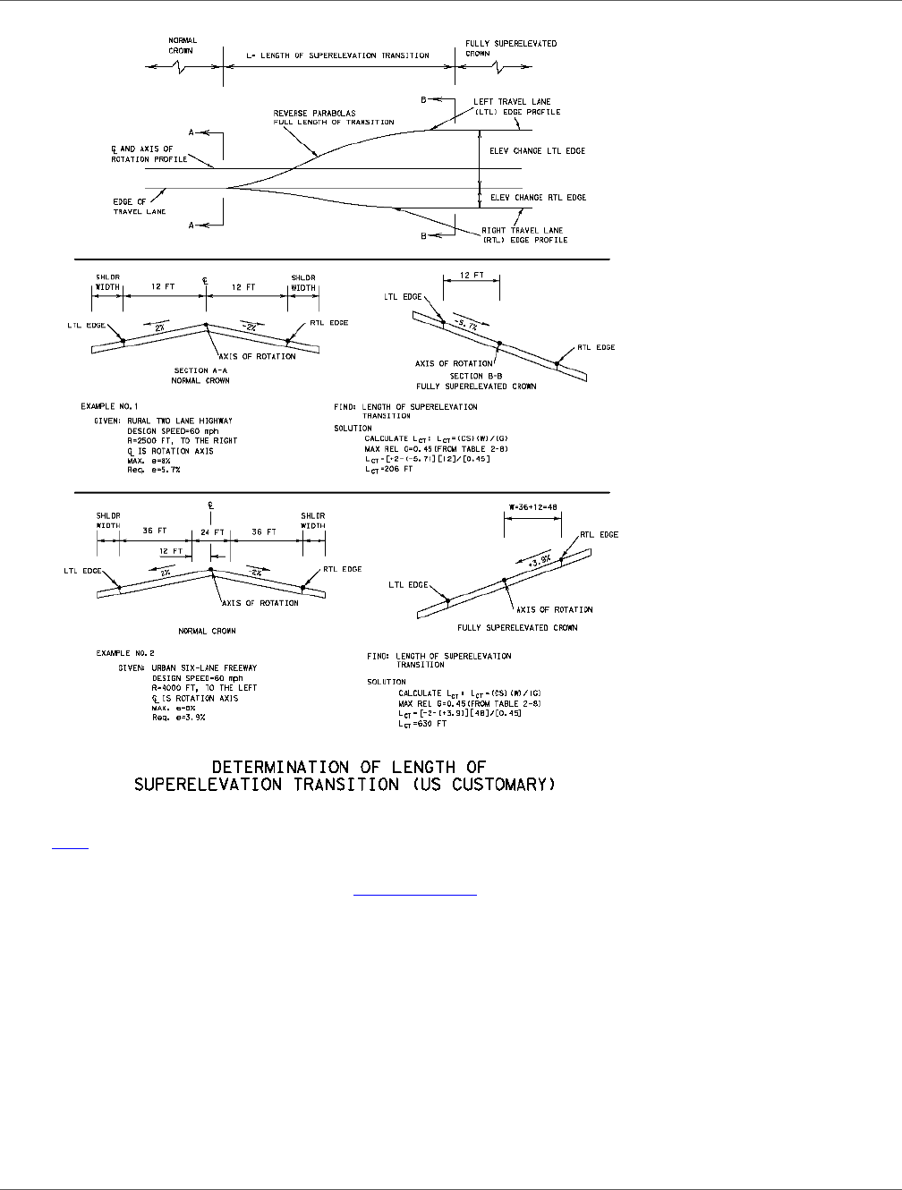
Roadway Design Manual 2-20 TxDOT 04/2018
Chapter 2 — Basic Design Criteria Section 4 — Horizontal Alignment
Figure 2-1. Determination of Length of Superelevation Transition. Click
here to see a PDF of the image.
NOTE: Online users can view the metric version of this figure in PDF format.
As the number of lanes to be transitioned increases, the length of superelevation transition increases
proportionately with the increased width. While strict adherence to the length (LCT) calculation is
desirable, the length for multilane highways may become impractical for design purposes (e.g.
drainage problems, avoiding bridges, accommodating merge/diverge condition). In such cases, an
adjustment factor may be used to avoid excessive lengths such that the transition length formula
becomes:
LCT = b[(CS)(W)]/G (US Customary and Metric)
Roadway Design Manual 2-21 TxDOT 04/2018
Chapter 2 — Basic Design Criteria Section 4 — Horizontal Alignment
where “b” is defined in Table 2-9
Superelevation Transition Placement
The location of the transition in respect to the termini of a simple (circular) curve should be placed
to minimize lateral acceleration and the vehicle's lateral motion. The appropriate allocation of
superelevation transition on the tangent, either preceding or following a curve, is provided on Table
2-10. When spiral curves are used, the transition usually is distributed over the length of the spiral
curve.
Care must be exercised in designing the length and location of the transition. Profiles of both gut-
ters or pavement edges should be plotted relative to the profile grade line to insure proper drainage,
especially where these sections occur within vertical curvature of the profile grade line. Special
care should be given to ensure that the zero cross slope in the superelevation transition does not
occur near the flat portion of the crest or sag vertical curve. A plot of roadway contours can identify
drainage problems in areas of superelevation transition. See "Minimum Transition Grades" section
of AASHTO's A Policy on Geometric Design of Highways and Streets for further discussion on
potential drainage problems and effective means to mitigate them.
Table 2-9: Multilane Adjustment Factor1
Number of Lanes Rotated Adjustment Factor (b)
1.5 0.83
20.75
2.5 0.70
30.67
3.5 0.64
1 These adjustment factors are directly applicable to undivided streets and highways. For divided highways where
the axis of rotation is not the edge of travel, see AASHTO’s A Policy on Geometric Design of Highways and Streets
discussion under “Axis of Rotation with a Median”.
Table 2-10: Portion of Superelevation Transition Located on the Tangent1
Design Speed
(mph) No. of Lanes Rotated
1.0 1.5 2.0 - 2.5 3.0 - 3.5
15 - 45 0.80 0.85 0.90 0.90
50 - 80 0.70 0.75 0.80 0.85
1 These values are desirable and should be followed as closely as possible when conditions allow. A
value between 0.6 and 0.9 for all speeds and rotated widths is considered acceptable. (AASHTO’s A
Policy on Geometric Design of Highways and Streets, 2011, pg. 3-67).

Roadway Design Manual 2-22 TxDOT 04/2018
Chapter 2 — Basic Design Criteria Section 4 — Horizontal Alignment
Whenever reverse curves are closely spaced and superelevation transition lengths overlap, L values
should be adjusted to prorate change in cross slope and to ensure that roadway cross slopes are in
the proper direction for each horizontal curve.
Superelevation Transition Type
Where appearance is a factor (e.g. curbed sections and retaining walls) use of reverse parabolas is
recommended for attaining superelevation as shown in Figure 2-1. This produces an outer edge
profile that is smooth, undistorted, and pleasing in appearance. Sufficient information needs to be
in the plans to ensure the parabolic design is properly constructed.
Figure 2-1 shows reverse parabolas over the full length of the transition. Alternative methods for
developing smooth-edge profiles over the length of the transition are given in the section "Design
of Smooth Profiles for Traveled Way Edges" of AASHTO's A Policy on Geometric Design of High-
ways and Streets.
Sight Distance on Horizontal Curves
Where an object off the pavement, such as a bridge pier, bridge railing, median barrier, retaining
wall, building, cut slope or natural growth restricts sight distance, the minimum radius of curvature
is determined by the stopping sight distance.
The following equation applies only to the circular curves longer than the stopping sight distance
for the pertinent design speed. For example, with a 50 mph [80 km/h] design speed and a curve
with a 1150 ft [350 m] radius, a clear sight area with a middle ordinate of a approximately 20 ft [6.0
m] is needed for stopping sight distance.
Where:
M = middle ordinate (ft)
S = stopping sight distance (ft) and,
R = radius (ft)
NOTE: Online users can view the metric version of this equation in PDF format.
Figure 2-2 provides a graph illustrating the required offset where stopping sight distance is less
than the length of curve (S<L).
MR1 28.65S
R
-----------------
cos–=
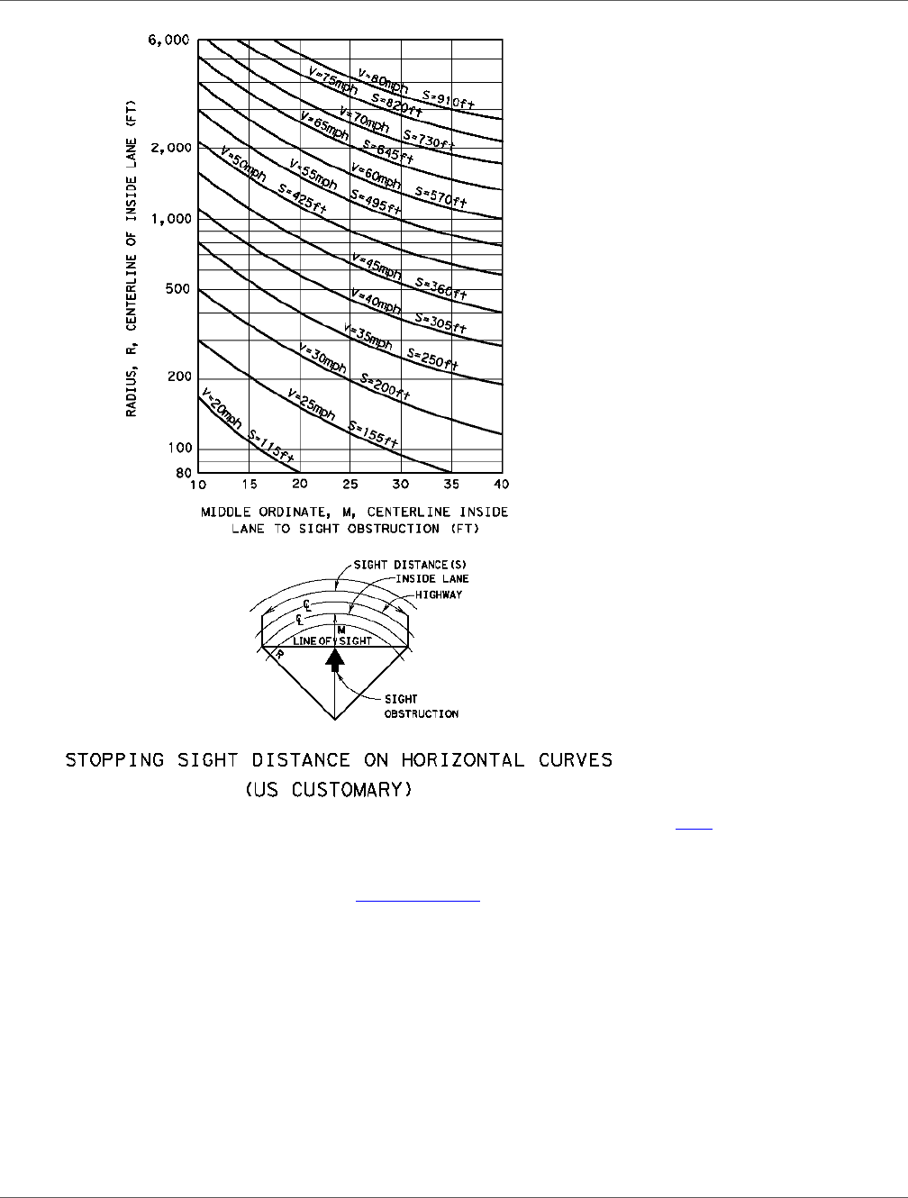
Roadway Design Manual 2-23 TxDOT 04/2018
Chapter 2 — Basic Design Criteria Section 4 — Horizontal Alignment
Figure 2-2. (US). Stopping Sight Distance on Horizontal Curves. Click here to see a PDF of the
image.
NOTE: Online users can view the metric version of this figure in PDF format.
In cases where complex geometries or discontinuous objects cause sight obstructions, graphical
methods may be useful in determining available sight distance and associated offset requirements.
Graphical methods may also be used when the circular curve is shorter than the stopping sight
distance.
To check horizontal sight distance on the inside of a curve graphically, sight lines equal to the
required sight distance on horizontal curves should be reviewed to ensure that obstructions such as
buildings, hedges, barrier railing, high ground, etc., do not restrict sight below that required in
either direction.

Roadway Design Manual 2-24 TxDOT 04/2018
Chapter 2 — Basic Design Criteria Section 4 — Horizontal Alignment
Where sufficient stopping sight distance is not available because a railing or a longitudinal barrier
constitutes a sight obstruction, alternative designs should be considered. The alternatives are: (1)
increase the offset to the obstruction, (2) increase the radius, or (3) reduce the design speed. How-
ever, the alternative selected should not incorporate shoulder widths on the inside of the curve in
excess of 12 ft [3.6 m] because of the concern that drivers will use wider shoulders as a passing or
travel lane.
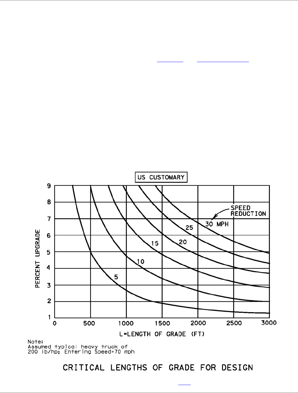
Roadway Design Manual 2-25 TxDOT 04/2018
Chapter 2 — Basic Design Criteria Section 5 — Vertical Alignment
Section 5 — Vertical Alignment
Overview
The two basic elements of vertical alignment are “Grades” and “Vertical Curves.”
Grades
The effects of rate and length of grade are more pronounced on the operating characteristics of
trucks than on passenger cars and thus may introduce undesirable speed differentials between the
vehicle types. The term “critical length of grade” is used to indicate the maximum length of a spec-
ified ascending gradient upon which a loaded truck can operate without an unreasonable reduction
in speed (commonly 10 mph [15 km/h]). Figure 2-3 shows the relationship of percent upgrade,
length of grade, and truck speed reduction. Where critical length of grade is exceeded for two-lane
highways, climbing lanes should be considered as discussed in the Transportation Research
Board’s Highway Capacity Manual.
Figure 2-3. Critical Lengths of Grade for Design. Click here to see a PDF of the image.


Roadway Design Manual 2-27 TxDOT 04/2018
Chapter 2 — Basic Design Criteria Section 5 — Vertical Alignment
Table 2-11 summarizes the maximum grade controls in terms of design speed. Generally, maximum
design grade should be used infrequently rather than as a value to be used in most cases. However,
for certain cases such as urban freeways, a maximum value may be applied in blanket fashion on
interchange and grade separated approaches.
Flat or level grades on uncurbed pavements are satisfactory when the pavement is adequately
crowned to drain the surface water laterally. When side ditches are required, the grade should sel-
dom be less than 0.5 percent for unpaved ditches and 0.25 percent for lined channels. With curbed
pavements, desirable minimum grades of 0.35 percent should be provided to facilitate surface
drainage. Joint analyses of rainfall frequency and duration, the longitudinal grade, cross slope, curb
inlet type and spacing of inlets or discharge points usually is required so that the width of water on
the pavement surface during likely storms does not unduly interfere with traffic. Criteria for water
Table 2-11: Maximum Grades
Functional
Classification Type of
Terrain 15 20 25 30 35 40 45 50 55 60 65 70 75 80
Urban and
Suburban: - --------------
- - --------------
Local1All <15 <15 <15 <15 <15 <15 <15 -- -- -- -- -- -- --
- - --------------
Collector Level 9999998776--------
- Rolling1212121110109 8 8 7 -- -- -- --
- - --------------
Arterial Level -- -- -- 8 7 7 6 6 5 5 -- -- -- --
- Rolling -- -- -- 9 8 8 7 7 6 6 -- -- -- --
- - --------------
Freeway Level -- -- -- -- -- -- -- 4 4 3 3 3 3 3
- Rolling--------------5544444
Rural: - --------------
Local Level 9877777665--------
- Rolling1211111010109 8 7 6 -- -- -- --
- - --------------
Collector Level - 777777665--------
- Rolling - 10 10 9 9 8 8 7 7 6 -- -- -- --
- - --------------
Arterial Level ----------5 5 4433333
- Rolling----------6 6 5544444
- - --------------
Freeway Level -- -- -- -- -- -- -- 4 4 3 3 3 3 3
- Rolling--------------5544444
1 8% maximum in commercial areas on local streets, desirably less than 5%. Flatter gradients should be used where practical.
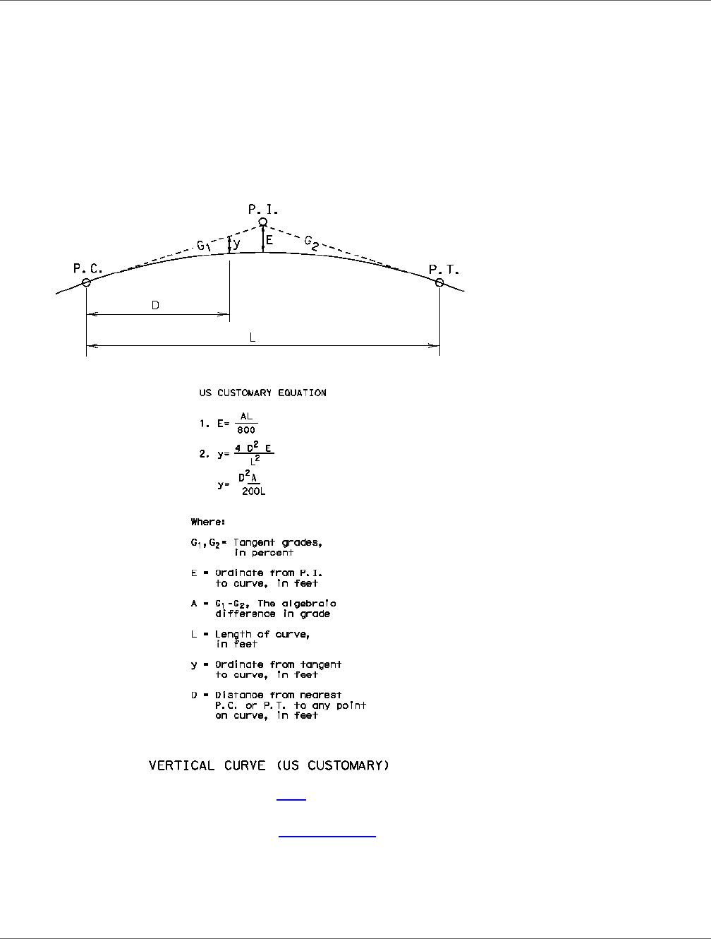
Roadway Design Manual 2-28 TxDOT 04/2018
Chapter 2 — Basic Design Criteria Section 5 — Vertical Alignment
ponding for various functionally classified roadways are contained in the Hydraulic Design
Manual.
Vertical Curves
Vertical curves provide gradual changes between tangents of different grades. The simple parabola
shown in Figure 2-4 is used in the highway profile design of vertical curves.
Figure 2-4. Vertical Curve. Click here to see a PDF of the image.
NOTE: Online users can view the metric version of this figure in PDF format.
For vertical curve discussion purposes, the following parameters are defined:
L = length of vertical curve;

Roadway Design Manual 2-29 TxDOT 04/2018
Chapter 2 — Basic Design Criteria Section 5 — Vertical Alignment
S = sight distance for crest vertical curves or headlight beam distance for sag vertical curves;
A = algebraic difference in grades, percent;
K = length of vertical curve per percent change in A (also known as the design control)
Crest Vertical Curves. The minimum lengths of crest vertical curves for different values of A to
provide the stopping sight distances for each design speed are shown in Figure 2-5. The solid lines
give the minimum vertical curve lengths on the basis of rounded values of K. These lengths repre-
sent minimum values based on design speed and longer curves are desired wherever practical.
A dashed curve crossing the solid lines indicates where S = L. Note that to the right of the S = L
line, the value of K is a simple and convenient expression of the design control. For each design
speed this single value is a positive number that is indicative of the rate of vertical curvature. The
design control in terms of K covers all combinations of A and L for any one design speed; thus A
and L need not be indicated separately in a tabulation of the design values. The selection of design
curves is facilitated because the length of curve is equal to K times the algebraic difference in
grades in percent, L = KA. Conversely, the checking of curve design is simplified by comparing all
curves with the design value for K.
Where S is greater than L, the values plot as a curve (as shown by the dashed curve extension for 45
mph [70 km/h]. Also, for small values of A, the vertical curve lengths are zero because the sight
line passes over the apex. Since this relationship does not represent desirable design practice except
in limited conditions (see discussion on Grade Change Without Vertical Curves), a minimum length
of vertical curve is shown. Attention should be given where there are successive vertical curves.
These minimum length of vertical curves (both crest and sag) are expressed as approximately three
times the design speed in miles per hour (Lmin = 3 V) or 0.6 times the design speed in kilometers
per hour (Lmin = 0.6 V). However, these minimum lengths are not considered a design control (i.e.,
a design exception would not be required for these minimum length values as long as the minimum
K value for the relevant design speed is met).
There is a level point on a vertical curve which can affect drainage; particularly on curbed facilities.
Typically, there is no difficulty with drainage on highways if the curve is sharp enough so that a
minimum grade of 0.30 percent is reached at a point about 50 ft [15 m] from the crest or sag. This
corresponds to a K value of 167 ft [51 m] per percent change in grade which is plotted in Figures 2-
5 and 2-6 as the drainage threshold. All combinations above or to the left of this line satisfy the
drainage criterion. The combinations below and to the right of this line involve flatter vertical
curves. Special attention is needed in these cases to ensure proper pavement drainage. It is not
intended that these values be considered a design maximum, but merely a value beyond which
drainage should be more carefully designed.
Sag Vertical Curves. At least four different criteria for establishing the lengths of sag vertical
curves are recognized to some extent. These are (1) headlight sight distance, (2) passenger comfort,
(3) drainage control, and (4) general appearance.
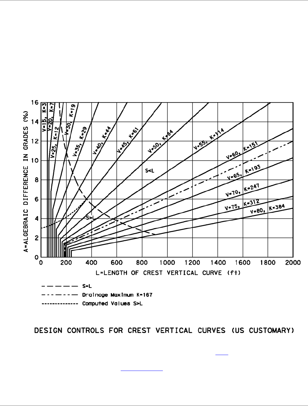
Roadway Design Manual 2-30 TxDOT 04/2018
Chapter 2 — Basic Design Criteria Section 5 — Vertical Alignment
Generally, a sag vertical curve should be long enough that the light beam distance is nearly the
same as the stopping sight distance. Accordingly, it is appropriate to use stopping sight distances
for different design speeds to establish sag vertical curve lengths. The resulting sag vertical curves
for the recommended stopping sight distances for each design speed are shown in Figure 2-6 with
the solid lines representing the rounded K values. As with crest vertical curves, these lengths are
minimum values based on design speed and longer curves are desired wherever practical. For sag
vertical curves, drainage criteria and minimum curve lengths are established similarly to crest verti-
cal curves.
Figure 2-5. (US). Design Controls for Crest Vertical Curves. Click here to see a PDF of the image.
NOTE: Online users can view the metric version of this figure in PDF format.
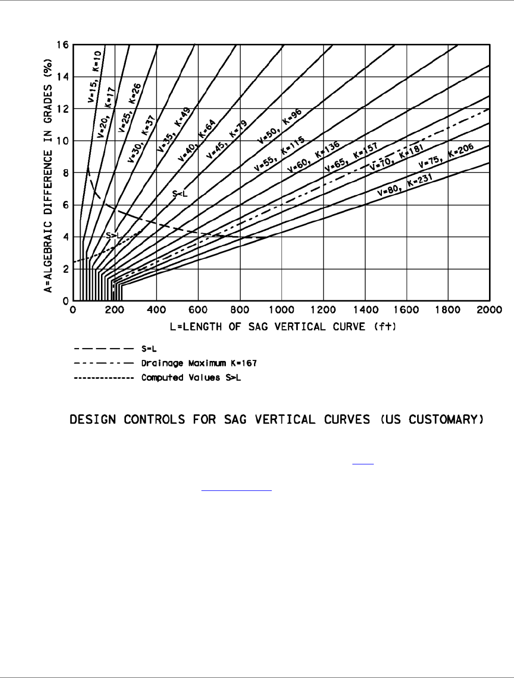
Roadway Design Manual 2-31 TxDOT 04/2018
Chapter 2 — Basic Design Criteria Section 5 — Vertical Alignment
Figure 2-6. (US). Design Controls for Sag Vertical Curves. Click here to see a PDF of the image.
NOTE: Online users can view the metric version of this figure in PDF format.
Because cost and energy conservation considerations are factors in operating continuous lighting
systems, headlight sight distance should be generally used in the design of sag vertical curves.
Comfort control criteria is about 50 percent of the sag vertical curve lengths required by headlight
distance and should be reserved for special use. Instances where the comfort control criteria may be
appropriately used include ramp profiles where safety lighting is provided and for economical rea-
sons in cases where an existing element, such as a structure not ready for replacement, controls the
vertical profile. Comfort control criteria should be used sparingly on continuously lighted facilities
since local, outside agencies often maintain and operate these systems and operations could be cur-
tailed in the event of energy shortages.

Roadway Design Manual 2-32 TxDOT 04/2018
Chapter 2 — Basic Design Criteria Section 5 — Vertical Alignment
Care should be exercised in sag vertical curve design to insure that overhead sight obstructions
such as structures for overpassing roadways, overhead sign bridges, tree crowns, etc., do not reduce
stopping sight distance below the appropriate minimum value.
Grade Change Without Vertical Curves
Designing a sag or crest vertical point of intersection without a vertical curve is generally accept-
able where the grade difference (A) is:
1.0 percent or less for design speeds equal to or less than 45 mph [70 km/h]
0.5 percent or less for design speeds greater than 45 mph [70 km/h].
When a grade change without vertical curve is specified, the construction process typically results
in a short vertical curve being built (i.e., the actual point of intersection is “smoothed” in the field).
Conditions where grade changes without vertical curves are not recommended include:
Bridges (including bridge ends)
Direct-traffic culverts
Other locations requiring carefully detailed grades.
Combination of Vertical and Horizontal Alignment
Due to the near permanent nature of roadway alignment once constructed, it is important that the
proper alignment be selected consistent with design speed, existing and future roadside develop-
ment, subsurface conditions, topography, etc. The following factors are general considerations in
obtaining a proper combination of horizontal and vertical alignment:
The design speed of both vertical and horizontal alignment should be compatible with longer
vertical curves and flatter horizontal curves than dictated by minimum values. Design speed
should be compatible with topography with the roadway fitting the terrain where feasible.
Alignment should be as flat as possible near intersections where sight distance is important.
For rural divided facilities, independent mainlane profiles are often more aesthetic and eco-
nomical. Where used on non-controlled access facilities with narrow medians, care should be
exercised in the location of median openings to minimize crossover grades and insure adequate
sight distance for vehicles stopped therein.
When designing independent vertical and horizontal profiles on divided facilities, consider-
ations should be given to the impact these profiles may have on future widening into the
median.
For two-lane rural highways and Super 2 Highways the need for safe passing sections at fre-
quent intervals should be carefully considered in developing horizontal and vertical
alignments.

Roadway Design Manual 2-33 TxDOT 04/2018
Chapter 2 — Basic Design Criteria Section 6 — Cross Sectional Elements
Section 6 — Cross Sectional Elements
Overview
This section includes information on the following cross sectional design elements:
“Pavement Cross Slope”
“Median Design”
“Lane Widths”
“Shoulder Widths”
“Sidewalks and Pedestrian Elements”
“Curb and Curb and Gutters”
“Roadside Design”
“Slopes and Ditches”
“Lateral Offset to Obstructions”
“Clear Zone”
Pavement design is covered in TxDOT’s Pavement Design Guide.
Pavement Cross Slope
The operating characteristics of vehicles on crowned pavements are such that on cross slopes up to
2 percent, the effect on steering is barely perceptible. A reasonably steep lateral slope is desirable to
minimize water ponding on flat sections of uncurbed pavements due to imperfections or unequal
settlement. With curbed pavements, a steep cross slope is desirable to contain the flow of water
adjacent to the curb. The recommended pavement cross slope for usual conditions is 2 percent. In
areas of high rainfall, steeper cross slopes may be used (see AASHTO’s A Policy on Geometric
Design of Highways and Streets).
On multilane divided highways, pavements with three or more lanes inclined in the same direction
desirably should have greater slope across the outside lane(s) than across the two interior lanes. The
increase in slope in the outer lane(s) should be at least 0.5 percent greater than the inside lanes (i.e.,
slope of 2.5 percent). In these cases, the inside lanes may be sloped flatter than normal, typically at
1.5 percent but not less than 1.0 percent.
For tangent sections on divided highways, each pavement should have a uniform cross slope with
the high point at the edge nearest the median. Although a uniform cross slope is preferable, on rural
sections with a wide median, the high point of the crown is sometimes placed at the centerline of

Roadway Design Manual 2-34 TxDOT 04/2018
Chapter 2 — Basic Design Criteria Section 6 — Cross Sectional Elements
the pavement with cross slopes from 1.5 to 2 percent. At intersections, interchange ramps or in
unusual situations, the high point of the crown position may vary depending upon drainage or other
controls.
For two lane roadways, cross slope should also be adequate to provide proper drainage. The cross
slope for two lane roadways for usual conditions is 2 percent and should not be less than 1.0
percent.
Shoulders should be sloped sufficiently to drain surface water but not to the extent that safety con-
cerns are created for vehicular use. The algebraic difference of cross slope between the traveled
way and shoulder grades should not exceed 6 to 7 percent. Maximum shoulder slope should not
exceed 10 percent. Following are recommended cross slopes for various types of shoulders:
Bituminous and concrete-surface shoulders should be sloped from 2 to 6 percent (often the
slope rate is identical to that used on the travel lanes).
Gravel or crushed rock shoulders should be sloped from 4 to 6 percent.
Turf shoulders should be sloped at about 8 percent.
Pavement cross slopes on all roadways, exclusive of superelevation transition sections, should not
be less than 1 percent.
Median Design
A median (i.e., the area between opposing travel lane edges) is provided primarily to separate
opposing traffic streams. The general range of median width is from 4 ft to 76 ft [1.2 m to 22.8 m],
with design width dependent on the type and location of the highway or street facility.
In rural areas, median sections are normally wider than in urban areas. For multi-lane rural high-
ways without access control, a median width of 76 ft [22.8 m] is desirable to provide complete
shelter for trucks at median openings (crossovers). These wide, depressed medians are also effec-
tive in reducing headlight glare and providing a horizontal clearance for run-off-the-road vehicle
encroachments.
Where economically feasible, freeways in rural areas should also desirably include a 76 ft [22.8 m]
median. Since freeways by design do not allow at-grade crossings, median widths need not be
sufficient to shelter crossing trucks. In this regard, where right-of-way costs are prohibitive,
reduced median widths (less than 76 ft [22.8 m]) may be appropriate for certain rural freeways.
Statistical studies have shown that over 90 percent of median encroachments involve lateral
distances traveled of 48 ft [14.4 m] or less. In this regard, depressed medians on rural freeways
sections should be 48 ft [14.4 m] or more in width.
Urban freeways generally include narrower, flush medians with continuous longitudinal barriers.
For urban freeways with flush median and six or more travel lanes, full (10 ft [3.0 m]) inside shoul-

Roadway Design Manual 2-35 TxDOT 04/2018
Chapter 2 — Basic Design Criteria Section 6 — Cross Sectional Elements
ders should be provided to provide space for emergency parking. Median widths vary up to 30 ft
[9.0 m], with 24 ft [7.2 m] commonly used. For projects involving the rehabilitation and expansion
of existing urban freeways, the provision of wide inside shoulders may not be feasible.
For low-speed urban arterial streets, flush or curbed medians are used. A width of 16 ft [4.8 m] will
effectively accommodate left-turning traffic for either raised or flush medians. Where the need for
dual left turns are anticipated at cross streets, the median width should be 28 ft [8.4 m]. The two-
way (continuous) left-turn lane design is appropriate where there exists (or is expected to exist) a
high frequency of mid-block left turns. Median types for urban arterials without access control are
further discussed in Chapter 3, Section 2, “Urban Streets”.
When flush median designs are selected, it should be expected that some crossing and turning
movements can occur in and around these medians. Full pavement structure designs will usually be
carried across flush medians to allow for traffic movements.
Lane Widths
For high-speed facilities such as all freeways and most rural arterials, lane widths should be 12 ft
[3.6 m] minimum. For low-speed urban streets, 11 ft or 12 ft [3.3 m or 3.6 m] lanes are generally
used. Subsequent sections of this manual identify appropriate lane widths for the various classes of
highway and street facilities.
Bicycle accomodations should be considered when a project is scoped. Bicycle consideration is
required on urban facilities. To accommodate bicycles, the outside curb lane should be 14 ft [4.2m]
from the lane stripe to the gutter joint or gutter lip on a monolithic curb. For a striped bicycle lane,
the clear width is 5 ft [1.5m] minimum. For additional guidance, refer to the AASHTO Guide for
the Development of Bicycle Facilities.
Shoulder Widths
Wide, surfaced shoulders provide a suitable, all-weather area for stopped vehicles to be clear of the
travel lanes. Shoulders are of considerable value on high-speed facilities such as freeways and rural
highways. Shoulders, in addition to serving as emergency parking areas, lend lateral support to
travel lane pavement structure, provide a maneuvering area, increase sight distance of horizontal
curves, and give drivers a sense of safe, open roadway. Design shoulder widths for the various
classes of highways are shown in the appropriate subsequent portions of this manual.
Shoulder widths should accomodate bicycle facilities and provide a 1 ft offset to barriers across
bridges being replaced or rehabilitated.
On urban collector and local streets, parking lanes may be provided instead of shoulders. On arte-
rial streets, parking lanes decrease capacity and generally are discouraged.

Roadway Design Manual 2-36 TxDOT 04/2018
Chapter 2 — Basic Design Criteria Section 6 — Cross Sectional Elements
Sidewalks and Pedestrian Elements
Walking is an important transportation mode that needs to be incorporated in transportation proj-
ects. Planning for pedestrian facilities should occur early and continuously throughout project
development. Sidewalks provide distinct separation of pedestrians and vehicles, serving to increase
pedestrian safety as well as to enhance vehicular capacity. When any of the following
factors are present, sidewalks should be included on a project
located in an urban setting where:
Construction is within existing right-of-way, and the scope of work involves pavement
widening;
Full reconstruction or new construction that requires new right-of-way.
In typical suburban development, there are initially few pedestrian trips because there are few
closely located pedestrian destinations. However, when pedestrian demand increases with addi-
tional development, it may be more difficult and more costly to go back and install pedestrian
facilities if they were not considered in the initial design. Early consideration of pedestrian facility
design during the project development process may also greatly simplify compliance with accessi-
bility requirements established by the Americans with Disabilities Act Public Accessibility
Guidelines for Pedestrian Facilities in the Public Right of Way (PROWAG) and the Texas Accessi-
bility Standards (TAS).
Sidewalk Location. For pedestrian comfort, especially adjacent to high speed traffic, it is desirable
to provide a buffer space between the traveled way and the sidewalk as shown in Figure 2-7(A). For
curb and gutter sections, a buffer space of 4 ft to 6 ft [1.2m to 1.8m] between the back of the curb
and the sidewalk is desirable. Roadways in urban and suburban areas without curb and gutter
require sidewalks , which should be placed between the ditch and the right of way line if practical.
Note that pedestrian street crossings must be ADA compliant. For roadways functionally classified
as rural, the shoulder may be used to accommodate pedestrian and bicycle traffic. Where a shoulder
serves as part of the pedestrian access route, it must meet ADA/TAS requirements.
Sidewalk Width. Sidewalks should be wide enough to accommodate the volume and type of
pedestrian traffic expected in the area. The minimum clear sidewalk width is 5 ft [1525 mm].
Where a sidewalk is placed immediately adjacent to the curb as shown in Figure 2-7(B), a sidewalk
width of 6 ft [1830 mm] is recommended to allow additional space for street and highway hardware
and allow for the proximity of moving traffic. Sidewalk widths of 8 ft [2440 mm] or more may be
appropriate in commercial areas, along school routes, and other areas with concentrated pedestrian
traffic.
Where necessary to cross a driveway while maintaining the maximum 2 percent cross slope, the
sidewalk width may be reduced to 4 ft [1220 mm] (Figure 2-8). Also,if insufficient space is avail-
able to locate street fixtures (elements such as sign supports, signal poles, fire hydrants, manhole
covers, and controller cabinets that are not intended for public use) outside the 5 ft [1525 mm] min-
imum clear width, the sidewalk width may be reduced to 4 ft [1220 mm] for short distances.

Roadway Design Manual 2-37 TxDOT 04/2018
Chapter 2 — Basic Design Criteria Section 6 — Cross Sectional Elements
Street Crossings. Intersections can present formidable barriers to pedestrian travel. Intersection
designs which incorporate properly placed curb ramps, sidewalks, crosswalks, pedestrian signal
heads and pedestrian refuge islands can make the environment more accommodating for pedestri-
ans. Desirably, drainage inlets should be located on the upstream side of crosswalks and sidewalk
ramps.
Refuge islands enhance pedestrian comfort by reducing effective walking distances and pedestrian
exposure to traffic. Islands should be a minimum of 6 ft [1.8m] wide to afford refuge to people in
wheelchairs. A minimum 5 ft [1.5m] wide by 6 ft [1.8m] long curb ramp should be cut through the
island for pedestrian passage. Install curb ramps with a minimum 5 ft x 5 ft [1525 mm x 1525 mm]
landing in the island if room allows, see Figure 2-9. Curb ramps and crosswalks must be aligned
behind the nose of the median island to provide adequate refuge.
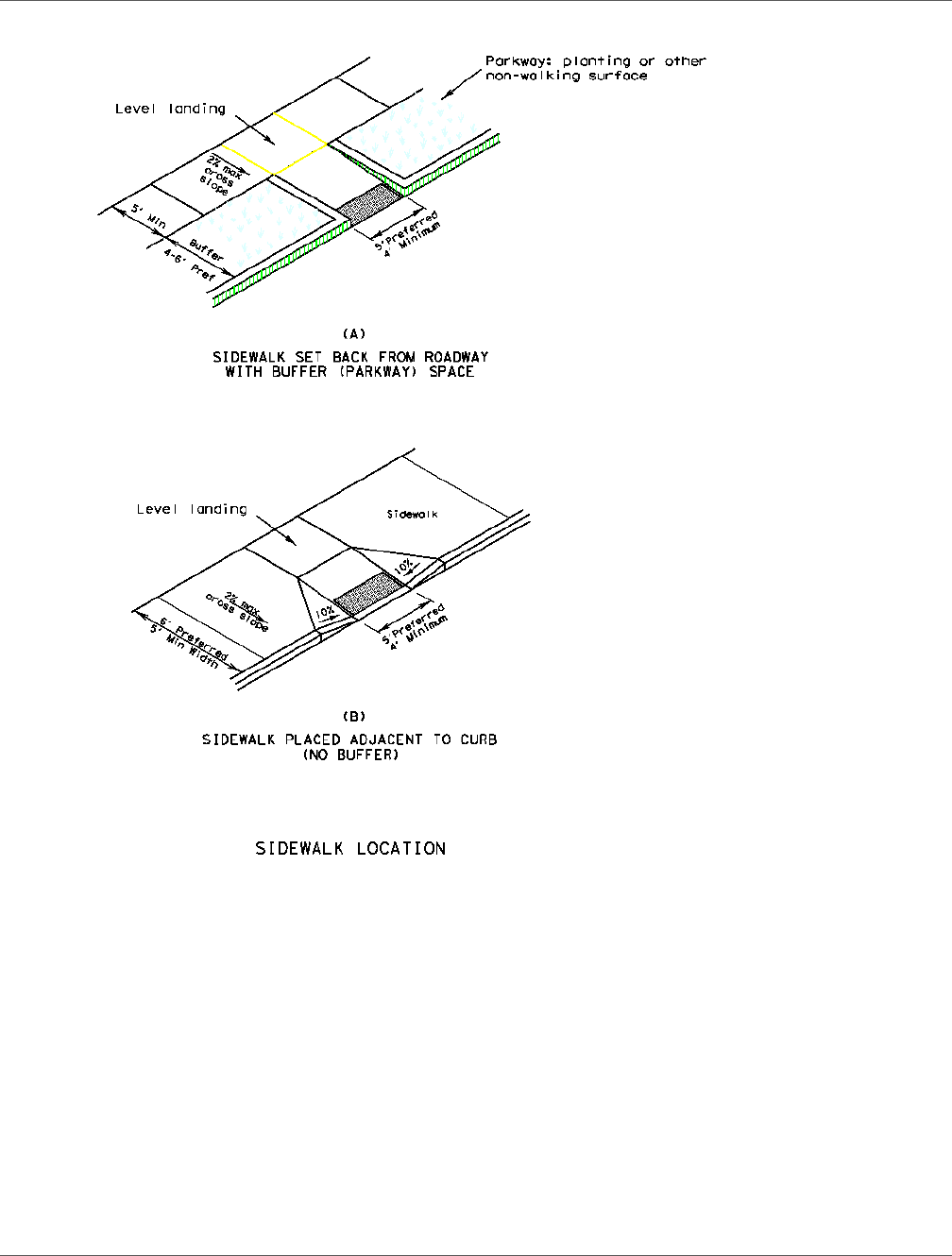
Roadway Design Manual 2-38 TxDOT 04/2018
Chapter 2 — Basic Design Criteria Section 6 — Cross Sectional Elements
Figure 2-7. Curb Ramps and Landings
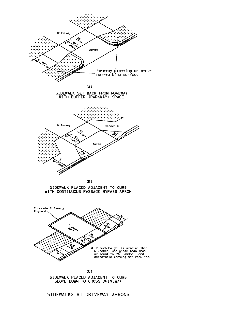
Roadway Design Manual 2-39 TxDOT 04/2018
Chapter 2 — Basic Design Criteria Section 6 — Cross Sectional Elements
Figure 2-8. Sidewalks at Driveway Aprons.
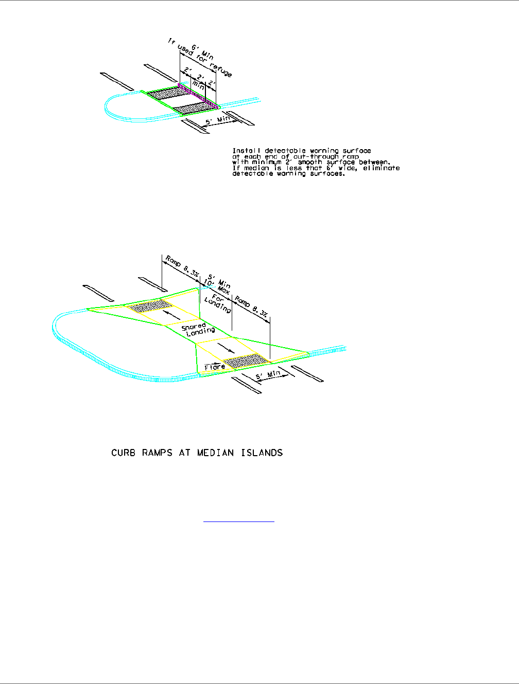
Roadway Design Manual 2-40 TxDOT 04/2018
Chapter 2 — Basic Design Criteria Section 6 — Cross Sectional Elements
Figure 2-9. Curb Ramps at Median Islands.
NOTE: Online users can view the metric version of this figure.
Curb Ramps and Landings. Curb ramps must be provided in conjunction with each project where
the following types of work will be performed:
reconstruction, rehabilitation and resurfacing projects, including overlays, where a barrier
exists to a sidewalk or a prepared surface for pedestrian use
construction of curbs, curb and gutter, and/or sidewalks
installation of traffic signals which include pedestrian signals
installation of pavement markings for pedestrian crosswalks

Roadway Design Manual 2-41 TxDOT 04/2018
Chapter 2 — Basic Design Criteria Section 6 — Cross Sectional Elements
A sidewalk curb ramp and level landing will be provided wherever a public sidewalk crosses a curb
or other change in level. The maximum grade for curb ramps is 8.3 percent. The maximum cross
slope for curb ramps is 2 percent. Flatter grades and slopes should be used where possible and to
allow for construction tolerances and to improve accessibility. The preferred width of curb ramps is
5 ft [1.5m] and the minimum width is 4 ft [1.2m], exclusive of flared sides. Where a side of a curb
ramp is contiguous with a public sidewalk or walking surface, it will be flared with a slope of 10
percent maximum, measured parallel to the curb.
Where a perpendicular or directional curb ramp is provided, a landing must be provided at the top
of the ramp run. The slope of the landing will not exceed 2 percent in any direction. The landing
should have a minimum clear dimension of 5 ft x 5 ft [1.5m x 1.5m] square or accomodate a 5 ft
[1.5m] diameter circle and will connect to the continuous passage in each direction of travel as
shown in Figure 2-7. Landings may overlap with other landings.
Where a parallel curb ramp is provided (i.e., the sidewalk ramps down to a landing at street level) a
minimum 5 ft x 5 ft [1.5m x 1.5m] landing should be provided at the entrance to the street.
The bottom of a curb ramp run should be wholly contained within the markings of the crosswalk.
There should be a minimum 4 ft x 4 ft [1.2m x 1.2m] maneuvering space wholly contained within
the crosswalk, whether marked or unmarked and outside the path of parallel vehicular traffic.
Manhole covers, grates, and obstructions should not be located within the curb ramp, maneuvering
area, or landing.
The standard sheet PED may be referenced for additional information on the configuration of curb
ramps.
Cross Slope. Sidewalk cross slope will not exceed 1:50 (2 percent). Due to construction tolerances,
it is recommended that sidewalk cross slopes be shown in the plans at 1.5 percent to avoid exceed-
ing the 2 percent limit when complete. Cross slope requirements also apply to the continuation of
the pedestrian route through the cross walk. Sidewalks immediately adjacent to the curb or roadway
may be offset to avoid a non-conforming cross slope at driveway aprons by diverting the sidewalk
around the apron as shown in Figure 2-8. Where the ramp sidewalk must be sloped to cross a drive-
way, the designer is encouraged to use a running slope of 5 percent or less on the sloping portions
of the sidewalk to avoid the need for handrails.
Street Furniture. Special consideration should be given to the location of street furniture (items
intended for use by the public such as benches, public telephones, bike racks, and parking meters).
A clear ground space at least 2.5 ft x 4 ft [760 mm x 1.2m] with a maximum slope of 2 percent must
be provided and positioned to allow for either forward or parallel approach to the element in com-
pliance with PROWAG/TAS. The clear ground space must have an accessible connection to the
sidewalk and must not encroach into the 5 ft [1.5m] minimum sidewalk width by more than 2 ft
[610 mm]. Pedestrian push buttons must also be within specified reach ranges of a ground space.

Roadway Design Manual 2-42 TxDOT 04/2018
Chapter 2 — Basic Design Criteria Section 6 — Cross Sectional Elements
PROWAG/TAS. Specific design requirements to accommodate the needs of persons with disabili-
ties are established by the PROWAG/TAS and related rulemaking. A request for a design variance
for any deviations from TAS requirements must be submitted to the Texas Department of Licensing
and Regulation (TDLR) for approval.
Curb and Curb and Gutters
Curb designs are classified as vertical or sloping. Vertical curbs are defined as those having a verti-
cal or nearly vertical traffic face 6 inches [150 mm] or higher. Vertical curbs are intended to
discourage motorists from deliberately leaving the roadway. Sloping curbs are defined as those
having a sloping traffic face 6 inches [150 mm] or less in height. Sloping curbs can be readily tra-
versed by a motorist when necessary. A preferable height for sloping curbs at some locations may
be 4 inches [100 mm] or less because higher curbs may drag the underside of some vehicles.
Curbs are used primarily on frontage roads, crossroads, and low-speed streets in urban areas. They
should not be used in connection with the through, high-speed traffic lanes or ramp areas except at
the outer edge of the shoulder where needed for drainage, in which case they should be of the slop-
ing type.
Roadside Design
Of particular concern to the design engineer is the number of single-vehicle, run-off-the-road acci-
dents which occur even on the safest facilities. About one-third of all highway fatalities are
associated with accidents of this nature. The configuration and condition of the roadside greatly
affect the extent of damages and injuries for these accidents.
Increased safety may be realized through application of the following principles, particularly on
high-speed facilities:
A “forgiving” roadside should be provided, free of unyielding obstacles including landscaping,
drainage facilities that create obstacles, steep slopes, utility poles, etc. For adequate safety, it is
desirable to provide an unencumbered roadside recovery area that is as wide as practicable for
the specific highway and traffic conditions.
For existing highways, treatment of obstacles should be considered in the following order:
-Eliminate the obstacle.
-Redesign the obstacle so that it can by safely traversed.
-Relocate the obstacle to a point where it is less likely to be struck.
-Make the obstacle breakaway.
-Apply a cost-effective device to provide for redirection (longitudinal barrier) or severity
reduction (impact attenuators). Barrier should only be used if the barrier is less of an

Roadway Design Manual 2-43 TxDOT 04/2018
Chapter 2 — Basic Design Criteria Section 6 — Cross Sectional Elements
obstacle than the obstacle it would protect, or if the cost of otherwise safety treating the
obstacle is prohibitive.
-Delineate the obstacle.
Use of higher than minimum design standards result in a driver environment which is funda-
mentally safer because it is more likely to compensate for driver errors. Frequently, a design,
including sight distances greater than minimum, flattened slopes, etc., costs little more over the
life of a project and increases safety and usefulness substantially.
For improved safety performance, highway geometry and traffic control devices should merely
confirm drivers' expectations. Unexpected situations, such as left side ramps on freeways,
sharp horizontal curvature introduced within a series of flat curves, etc., have demonstrated
adverse effects on traffic operations.
These principles have been incorporated as appropriate into the design guidelines included herein.
These principles should be examined for their applicability at an individual site based on its partic-
ular circumstances, including the aspects of social impact, environmental impact, economy, and
safety.
Slopes and Ditches
Sideslopes. Sideslopes refer to the slopes of areas adjacent to the shoulder and located between the
shoulder and the right-of-way line. For safety reasons, it is desirable to design relatively flat areas
adjacent to the travelway so that out-of-control vehicles are less likely to turn over, vault, or impact
the side of a drainage channel.
Slope Rates. The path that an out-of-control vehicle follows after it leaves the traveled portion of
the roadway is related to a number of factors such as driver capabilities, slope rates, and vehicular
speed. Accident data indicates that approximately 75 percent of reported encroachments do not
exceed a lateral distance of 30 ft [9 m] from the travel lane edge where roadside slopes are 1V:6H
or flatter - slope rates that afford drivers significant opportunity for recovery. Crash test data further
indicates that steeper slopes (up to 1V:3H) are negotiable by drivers; however, recovery of vehicu-
lar control on these steeper slopes is less likely. Recommended clear zone width associated with
these slopes are further discussed in “Clear Zone.”
Design Values. Particularly difficult terrain or restricted right-of-way width may require deviation
from these general guide values. Where conditions are favorable, it is desirable to use flatter slopes
to enhance roadside safety.
Front Slope. The slope adjacent to the shoulder is called the front slope. Ideally, the front
slope should be 1V:6H or flatter, although steeper slopes are acceptable in some locations.
Rates of 1V:4H (or flatter) facilitate efficient operation of construction and maintenance equip-
ment. Slope rates of 1V:3H may be used in constrained conditions. Slope rates of 1V:2H are

Roadway Design Manual 2-44 TxDOT 04/2018
Chapter 2 — Basic Design Criteria Section 6 — Cross Sectional Elements
normally only used on bridge header banks or ditch side slopes, both of which would likely
require rip-rap.
When the front slope is steeper than 1V:3H, a longitudinal barrier may be considered to keep
vehicles from traversing the slope. A longitudinal barrier should not be used solely for slope
protection for rates of 1V:3H or flatter since the barrier may be more of an obstacle than the
slope. Also, since recovery is less likely on 1V:3H and 1V:4H slopes, fixed objects should not
be present in the vicinity of the toe of these slopes. Particular care should be taken in the treat-
ment of man-made appurtenances such as culvert ends.
Back Slope. The back slope is typically at a slope of 1V:4H or flatter for mowing purposes.
Generally, if steep front slopes are provided, the back slopes are relatively flat. Conversely, if
flat front slopes are provided, the back slopes may be steeper. The slope ratio of the back slope
may vary depending upon the geologic formation encountered. For example, where the road-
way alignment traverses through a rock formation area, back slopes are typically much steeper
and may be close to vertical. Steep back slope designs should be examined for slope stability.
Design. The intersections of slope planes in the highway cross section should be well rounded for
added safety, increased stability, and improved aesthetics. Front slopes, back slopes, and ditches
should be sodded and/or seeded where feasible to promote stability and reduce erosion. In arid
regions, concrete or rock retards may be necessary to prevent ditch erosion.
Where guardrail is placed on side slopes, the area between the roadway and barrier should be
sloped at 1V:10H or flatter.
Roadside drainage ditches should be of sufficient width and depth to handle the design run-off and
should be at least 6 inches [150 mm] below the subgrade crown to insure stability of the base
course. For additional information, see “Drainage Facility Placement.”
Lateral Offset to Obstructions
It is generally desirable that there be uniform clearance between traffic and roadside features such
as bridge railings, parapets, retaining walls, and roadside barriers. In an urban environment, right of
way is often limited and is characterized by sidewalks, enclosed drainage, numerous fixed objects
(e.g., signs, utility poles, luminaire supports, fire hydrants, sidewalk furniture, etc.), and traffic
making frequent stops. Uniform alignment enhances highway safety by providing the driver with a
certain level of expectation, thus reducing driver concern for and reaction to those objects. The dis-
tance from the edge of the traveled way, beyond which a roadside object will not be perceived as an
obstacle and result in a motorist’s reducing speed or changing vehicle position on the roadway, is
called the lateral offset. This lateral offset to obstructions helps to:
Avoid impacts on vehicle lane position and encroachments into opposing or adjacent lanes
Improve driveway and horizontal sight distances
Reduce the travel lane encroachments from occasional parked and disabled vehicles

Roadway Design Manual 2-45 TxDOT 04/2018
Chapter 2 — Basic Design Criteria Section 6 — Cross Sectional Elements
Improve travel lane capacity
Minimize contact from vehicle mounted intrusions (e.g., large mirrors, car doors, and the over-
hang of turning trucks.
As a minimum, as long as the obstruction is located beyond the recommended paved shoulder of a
roadway, it will have minimum impact on driver speed or lane position and meet the lateral offset
requirement. Where a curb is present, the lateral offset is measured from the face of curb and shall
be a minimum of 1.5 ft [0.5 m]. A minimum of 1 ft [0.3 m] lateral offset should be provided from
the toe of barrier to the edge of traveled way.
Clear Zone
A clear recovery area, or clear zone, should be provided along high-speed rural highways. A clear
zone is the unobstructed, traversable area provided beyond the edge of the through traveled way for
the recovery of errant vehicles. The clear zone includes shoulders, bike lanes, and auxiliary lanes,
except those auxiliary lanes that function like through lanes. Such a recovery area should be clear
of unyielding objects where practical or shielded by crash cushions or barrier. Table 2-12 shows cri-
teria for clear zones.

Roadway Design Manual 2-46 TxDOT 04/2018
Chapter 2 — Basic Design Criteria Section 6 — Cross Sectional Elements
NOTE: Online users can view the metric version of this table in PDF format.
The clear zone values shown in Table 2-12 are measured from the edge of travel lane. These are
appropriate design values for all cut sections (see “Drainage Facility Placement”), for cross sec-
tional design of ditches within the clear zone area) and for all fill sections with side slopes 1V:4H or
flatter. It should be noted that, while a 1V:4H slope is acceptable, that a 1V:6H or flatter slope is
preferred for both errant vehicle performance and slope maintainability. For fill slopes steeper than
1V:4H, errant vehicles have a reduced chance of recovery and the lateral extent of each roadside
encroachment increases. It is therefore preferable to provide an obstacle-free area of 10 ft[3.0m]
beyond the toe of steep side slopes even when this area is outside the clear zone.
Table 2-12: Clear Zones
Location Functional
Classification Design Speed
(mph) Avg. Daily
Traffic Clear Zone Width (ft)3,4,5
----MinimumDesirable
Rural Freeways All All 30 (16 for ramps)
Rural Arterial All 0 - 750
750 - 1500
>1500
10
16
30
16
30
--
Rural Collector All Use above rural arterial criteria.
Rural Collector 45 All 10 --
Rural Local All All 10 --
Suburban All All <8,000 106106
Suburban All All 8,000 - 12,000 106206
Suburban All All 12,000 - 16,000 106256
Suburban All All >16,000 206306
Urban Freeways All All 30 (16 for ramps)
Urban All (Curbed) All Use above suburban criteria insofar
as available border width permits.
Urban All (Curbed) All 4 from curb face 6
Urban All (Uncurbed) All Use above suburban criteria.
Urban All (Uncurbed) All 10 --
1 Because of the need for specific placement to assist traffic operations, devices such as traffic signal supports,
railroad signal/warning device supports, and controller cabinets are excluded from clear zone requirements.
However, these devices should be located as far from the travel lanes as practical. Other non-breakaway
devices should be located outside the prescribed clear zone or these devices should be protected with barrier.
2Average ADT over project life, i.e., 0.5 (present ADT plus future ADT). Use total ADT on two-way road-
ways and directional ADT on one-way roadways.
3 Without barrier or other safety treatment of appurtenances.
4 Measured from edge of travel lane for all cut sections and for all fill sections where side slopes are 1V:4H or
flatter. Where fill slopes are steeper than 1V:4H it is desirable to provide a 10 ft area free of obstacles beyond
the toe of slope.
5 Desirable, rather than minimum, values should be used where feasible.
6 Purchase of 5 ft or less of additional right-of-way strictly for satisfying clear zone provisions is not required.

Roadway Design Manual 2-47 TxDOT 04/2018
Chapter 2 — Basic Design Criteria Section 7 — Drainage Facility Placement
Section 7 — Drainage Facility Placement
Overview
This section contains information on the following topics:
“Design Treatment of Cross Drainage Culvert Ends”
“Parallel Drainage Culverts”
“Side Ditches”
Introduction
In designing drainage systems, the primary objective is to properly accommodate surface run-off
along and across highway right-of-way through the application of sound hydraulic principles.
Consideration must also be given to incorporating safety into the design of drainage appurtenances.
The best design would efficiently accommodate drainage and be traversable by an out-of-control
vehicle without rollover or abrupt change in speed.
To meet safety needs, the designer may use one of the following treatments:
Design or treat drainage appurtenances so that they will be traversable by a vehicle without
rollover or abrupt change in speed.
Locate appurtenances a sufficient distance, consistent with traffic volume, from the travel
lanes so as to reduce the likelihood of accidental collision.
Protect the driver through installation of traffic barrier shielding appurtenances.
The following guidelines are intended to improve roadside safety with respect to facilities accom-
modating drainage parallel to and crossing under highways. The guidelines apply to all rural, high-
speed facilities and other facilities with posted speed limits of 50 mph [80 km/h] or more and with
rural type (uncurbed) cross sections. Where reference is made to clear zone requirements in these
guidelines, see “Table 2-12: Clear Zones” and the discussions regarding “Slopes and Ditches,”
“Roadside Design,” and “Clear Zone.” Desirable values for clear zone width should generally be
used and minimum clear zone widths applied where unusual conditions are encountered. Site visits
may be appropriate to ascertain terrain conditions and debris potential before arriving at design
decisions for .
Designers should address and resolve culvert end treatment issues with involved parties early in
project development. If there are doubts about the proper application of criteria on a given project
or group of projects, then arrangements should be made for a project concept conference with the
appropriate entities prior to in-depth development of Plans, Specifications, and Estimates
(P.S.&E.).

Roadway Design Manual 2-48 TxDOT 04/2018
Chapter 2 — Basic Design Criteria Section 7 — Drainage Facility Placement
Design Treatment of Cross Drainage Culvert Ends
Cross drainage culverts are defined as those handling drainage across and beneath the highway.
Selection of an appropriate end treatment is primarily related to culvert size, culvert end location,
side slope rate, terrain characteristics, drift conditions, right-of-way availability, and other consid-
erations that may influence treatment selection at individual sites.
Roadside safety performance is related to clear zone width and side slope rate. (For a discussion of
safety performance and design guidelines related to side slopes, see “Slopes and Ditches”) Where
right-of-way availability and economic conditions permit, flatter slopes may be used.
Design values for clear zones are shown in “Table 2-12: Clear Zones.” for new location and major
reconstruction projects. Within the clear zone, sideslopes should preferably be 1V:6H or flatter with
1V:4H as a maximum steepness in most cases.
Small Pipe Culverts. A small pipe culvert is defined as a single round pipe with 36 inches [900
mm] or less diameter, or multiple round pipes each with 30 inches [750 mm] or less diameter, each
oriented on normal skew. (Note: For arch pipes, use span dimension instead of diameter.)
When skews are involved, the definition of a small pipe culvert is modified as shown in Table 2-13:
NOTE: Click here to see the metric version of the table.
Small pipe culverts with sloping, open ends have been crash tested and proven to be safely travers-
able by vehicles for a range of speeds. Small pipe ends should be sloped at a rate of 1V:3H or flatter
and should match side slope rate thereby providing a flush, traversable safety treatment. Single box
culverts on normal skew with spans of 36 inches [900 mm] or less may be effectively safety treated
just as small pipes (open, match 1V:3H or flatter slope).
When vulnerable to run-off-the-road vehicles (i.e., unshielded by barrier), sloped ends should be
provided on small pipe culverts regardless of culvert end location with respect to clear zone dimen-
sions. For existing culverts, this often entails removing existing headwalls and may include
removing the barrier treatment if it is no longer needed to protect an obstacle other than a culvert
end. The resultant culvert with sloped end is both safe and inexpensive.
Table 2-13: Maximum Diameter of Small Pipe Culvert
Skew (degree) Single Pipe (in.) Multiple Pipe (in.)
15 30 30
30 24 24
45 24 21

Roadway Design Manual 2-49 TxDOT 04/2018
Chapter 2 — Basic Design Criteria Section 7 — Drainage Facility Placement
For new culverts or existing culverts that may need adjusting, culvert pipe length should be con-
trolled by the intercept of the small pipe and the side slope planes. Side slopes should not be
warped or flattened near culvert locations. Headwalls should not be used.
In summary, whether a small pipe culvert is new or existing, sloped open ends should normally be
used. Terrain in the vicinity of the culvert ends should be smooth and free of fixed objects.
Intermediate Size Single Box Culverts and (Single and Multiple) Pipe Culverts. An intermedi-
ate size pipe culvert is defined as a single round pipe with more than 36 inches [900 mm] diameter
or multiple round pipes each with more than 30 inches [750 mm] diameter but having maximum
diameter of 60 inches [1,500 mm]. (Note: For arch pipes, use span dimension instead of diameter.)
Intermediate size single box culverts are defined as those having only one barrel with maximum
height of 60 in. [1,500 mm]. Cross sectional area of the single box or individual pipe normally
should not exceed 25 ft2 [2.3 m2].
The openings of intermediate size single barrel box and pipe culverts are too large to be safely tra-
versable by a vehicle. Recommended safety treatment options are in the following priority:
1. Provide sloped ends with safety pipe runners.
2. Provide flat side slopes and locate the ends outside the clear zone, unless it is bridge class
culvert.
3. Use barrier to shield culvert ends.
Sloped end treatments with safety pipe runners are preferred from a safety standpoint and are gen-
erally cost effective for both new and existing intermediate size culverts, regardless of end location
with respect to clear zone criteria. These end treatments should be sloped at a rate of 1V:3H or flat-
ter and should match the side slope rate thereby providing a flush, traversable safety treatment.
Length of new culverts should be governed by the locations of the side slope plane/culvert inter-
cepts rather than by clear zone. Terrain in the vicinity of the culvert end should be smoothly shaped
and traversable, and headwalls should not be used.
For existing intermediate size single barrel box and pipe culverts, no treatment is warranted for cer-
tain culvert end offsets and traffic volumes as shown in “Table 2-12: Clear Zones.” Where an
improved design is warranted using Table 2-13, the removal of headwalls and installation of sloped
ends with safety pipe runners is the preferred safety treatment.
In certain situations (e.g., culvert skew exceeds 15 degrees, severe debris problems, etc.) treatment
with safety pipe runners may be impractical. For these conditions, locating intermediate size cul-
vert ends to meet desirable clear zone values (see “Table 2-12: Clear Zones”) is preferred over
shielding with barrier. Designs having flared wing walls with safety pipe runners oriented parallel
to the stream flow and spaced at 30 inches [750 mm] (maximum) center to center thereby can min-
imize debris problems.

Roadway Design Manual 2-50 TxDOT 04/2018
Chapter 2 — Basic Design Criteria Section 7 — Drainage Facility Placement
Multiple Box Culverts and Large Single Pipes or Boxes. Multiple box culverts are defined as
those with more than one barrel and a total opening (i.e., distance) of 20 ft [6.1 m] or less between
extreme inside faces as measured along the highway centerline. Large single pipes or single boxes
are defined as those with diameter or height exceeding 5 ft [1,500 mm] or cross sectional area
exceeding 25 ft2 [2.3 m2].
From a safety standpoint alone, treatment is in the following priority for both new and existing
installations:
1. Provide safety pipe runners
2. Meet or exceed desirable clear zone value, unless it is bridge class
3. Shield with barrier.
Designers should carefully consider several factors before opting to use safety pipe runners. First,
multiple box culverts accommodate significantly greater flow quantities than single box or pipe
culverts and often a defined channel crosses the highway right-of-way. Where a defined channel is
present, it may be impossible or impractical to shape the terrain near the culvert end to provide for
vehicular traversability. Such circumstances would dictate that a more suitable, but lower priority,
culvert end treatment be selected.
Meeting clear zone criteria does not eliminate the obstacle of the culvert end, rather the obstacle is
placed at a location where it is less likely to be struck. Although not as desirable as providing a tra-
versable culvert end, it is preferred over barrier treatment where there is sufficient right-of-way and
where the cost of providing the necessary culvert length is reasonable. Where the cost of added
length for new culverts or of extension of existing culverts is three or more times the cost of shield-
ing with barrier, treatment with barrier becomes an attractive alternative.
For low-volume (less than 750 current ADT) conditions, however, the treatment option that has the
lowest initial (construction) cost is generally the most cost effective design if an improved design is
warranted.
Bridge Class Drainage Culverts. Bridge class culverts are defined as those having an opening
(i.e., distance) of more than 20 ft [6.1 m] between the extreme inside faces as measured along the
highway centerline.
Bridge class culverts shall be, in order of preference, safety treated, shielded with guardrail and/or
bridge rail on the approach and across the culvert. Table 2-14 provides guidelines for installing
guardrails and barrier rails. Recommended treatment options are in the following priority:
1. Safety treat culvert ends.
2. Meet clear zone requirements, unless it is bridge class.

Roadway Design Manual 2-51 TxDOT 04/2018
Chapter 2 — Basic Design Criteria Section 7 — Drainage Facility Placement
3. Shield with appropriate barrier or attenuator.
NOTE: Online users can view the metric version of this table in PDF format
Where guardrail is carried across a bridge class culvert, steep side slopes should be positioned to
provide for lateral support of the guardrail, as shown in Figure 2-10.
Table 2-14: Treatment Barrier Rail for Bridge Class Culverts
Depth of Cover Treatment
Less than 9 in. Bridge Railing
9 in.
but less than 36 in. Steel post welded to base plate
and bolted to culvert ceiling
(Low-fill culvert post)
36 in. or more Guardrail
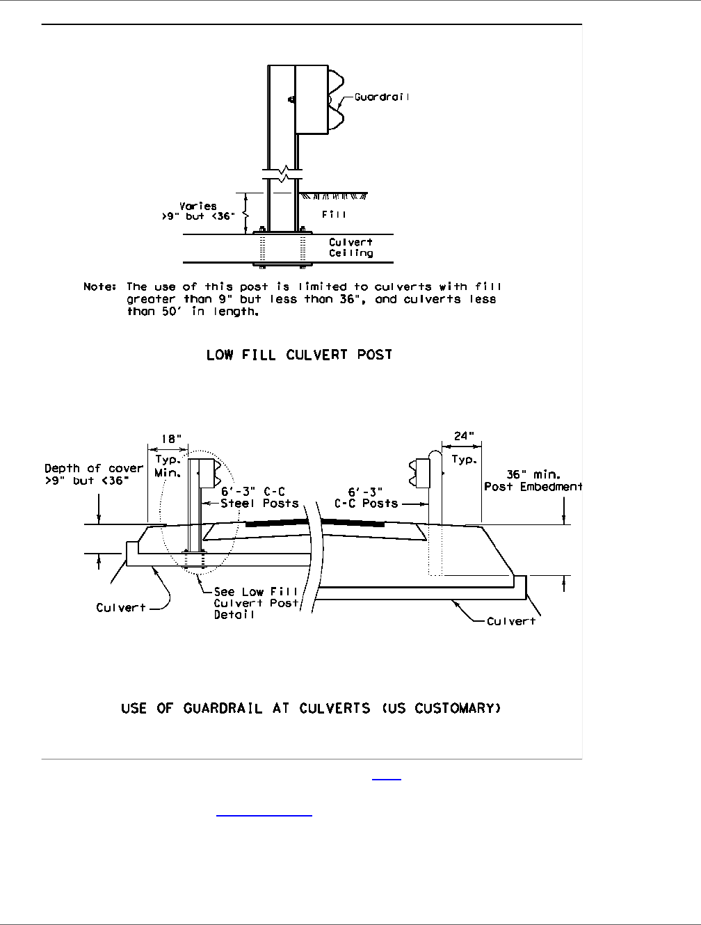

Roadway Design Manual 2-53 TxDOT 04/2018
Chapter 2 — Basic Design Criteria Section 7 — Drainage Facility Placement
Parallel Drainage Culverts
The inlet and outlet points of culverts handling drainage parallel to the travel lanes, such as at
driveways, side roads, and median crossovers, are concerns in providing a safe roadside environ-
ment. Flow quantities for parallel drainage situations are generally low with drainage typically
accommodated by a single pipe. The following guidelines apply to driveway, side road, and median
crossover drainage facilities:
Within the clear zone, there should be no culvert headwalls or vertical ends. Outside the clear
zone, single pipe ends preferably should be sloped although not required.
Where used, sloped pipe ends should be at a rate of 1V:6H or flatter. The sloping end may be
terminated and a vertical section introduced at the top and bottom of the partial pipe section as
shown in Figure 2-11.
Median crossover, side road, and driveway embankment slopes should be 1V:6H maximum
steepness, with 1V:8H preferred, within the clear zone dimensions.
Where greater than 30 in. [750 mm] in diameter pipe ends are located within the clear zone,
safety pipe runners should be provided with a maximum slope steepness of 1V:6H with 1V:8H
preferred. Typical details for a driveway, side road, or median crossover grate are shown in
Figure 2-12. Cross pipes are not required on single, small (30 in. [750 mm] or less diameter)
pipes regardless of end location with respect to clear zone requirements; however, the ends of
small pipes should be sloped as described above and appropriate measures taken to control ero-
sion and stabilize the pipe end. Multiple 30 in. pipes require cross pipes.
The use of paved dips, instead of pipes, is encouraged particularly at infrequently used drive-
ways such as those serving unimproved private property.
For unusual situations, such as driveways on high fills or where multiple pipes or box culverts
are necessary to accommodate side or median ditch drainage, the designer should consider the
alternatives available and select an appropriate design.
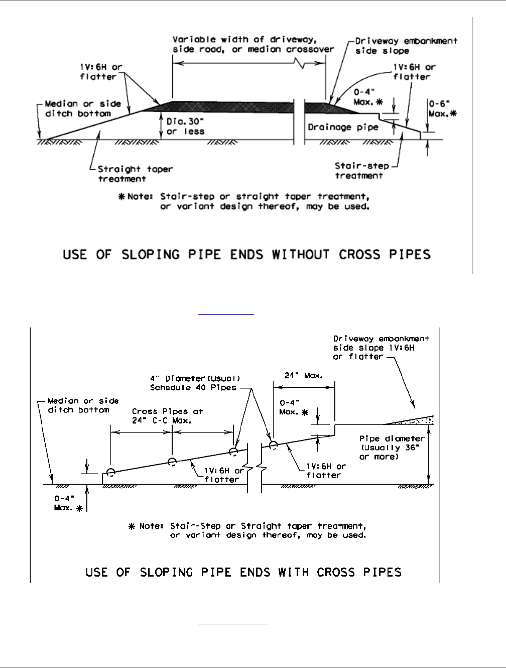
Roadway Design Manual 2-54 TxDOT 04/2018
Chapter 2 — Basic Design Criteria Section 7 — Drainage Facility Placement
Figure 2-11. Use of Sloping Pipe Ends Without Cross Pipes.
NOTE: Online users can view the metric PDF of this figure.
Figure 2-12. Use of Sloping Pipe Ends With Grates.
NOTE: Online users can view the metric version of this figure.

Roadway Design Manual 2-55 TxDOT 04/2018
Chapter 2 — Basic Design Criteria Section 7 — Drainage Facility Placement
Side Ditches
For side ditches, attention to cross section design can reduce the likelihood of serious injuries
during vehicular encroachments. Ditches with the cross sectional characteristics defined in Table 2-
15 are preferred and should especially be sought when ditch location is within the clear zone
requirements. Where conditions dictate, such as insufficient existing right-of-way to accommodate
the preferred ditch cross section or where ditches are located outside the horizontal clearance
requirements, other ditch configurations may be used. Typically, guardrail is not necessary where
the preferred ditch cross sections are provided.
Ditches that include retards to control erosion should be avoided inside the clear zone requirements
and should be located as far from the travel lanes as practical unless the retardant is a rock filter
dam with side slopes of 1V:6H or flatter. Non-traversable catch or stilling basins should also be
located outside the clear zone requirements.
Table 2-15: Preferred Ditch Cross Sections
- Preferred Maximum Back Slope (Vertical:Horizontal)
Given Front Slope
(Vertical:Horizontal) V-Shaped Trapezoidal-Shaped
1V:8H 1V:3.5H 1V:2.5H
1V:6H 1V:4H 1V:3H
1V:4H 1V:6H 1V:4H
1V:3H Level 1V:8H

Roadway Design Manual 2-56 TxDOT 04/2018
Chapter 2 — Basic Design Criteria Section 8 — Roadways Intersecting Department
Projects
Section 8 — Roadways Intersecting Department Projects
Roadways that intersect or tie into a facility which the department is constructing must improve or
retain the existing geometry of the intersecting roadway, or meet the design criteria for the roadway
classification of the intersecting road. If these conditions are not met, then a design exception or
design waiver for the intersecting roadway will be appropriate. Existing geometry will include all
cross sectional elements. The definition of intersecting roadways excludes driveways.

Roadway Design Manual 3-1 TxDOT 04/2018
Chapter 3 — New Location and Reconstruction (4R) Design
Criteria
Contents:
Section 1 — Overview
Section 2 — Urban Streets
Section 3 — Suburban Roadways
Section 4 — Two-Lane Rural Highways
Section 5 — Multi-Lane Rural Highways
Section 6 — Freeways
Section 7 — Freeway Corridor Enhancements
Section 8 — Texas Highway Freeway Network (THFN)

Roadway Design Manual 3-2 TxDOT 04/2018
Chapter 3 — New Location and Reconstruction (4R)
Design Criteria Section 1 — Overview
Section 1 — Overview
Introduction
This chapter presents guidelines that are applicable to all new location and reconstruction projects
for several different classes of roadways including the following:
urban streets
suburbanways
two-lane rural highways
multilane rural highways
freeways
Texas Highway Freight Network (THFN)
Note that additional vertical clearance requirements may apply to
projects on the Texas Highway Freight Network (THFN) as specified
in Chapter 3, Section 8.
Departures from these guidelines are governed in Design Exceptions, Design Waivers, Design Vari-
ances, and Texas Highway Freight Network (THFN) Design Deviations,
Chapter 1.

Roadway Design Manual 3-3 TxDOT 04/2018
Chapter 3 — New Location and Reconstruction (4R)
Design Criteria Section 2 — Urban Streets
Section 2 — Urban Streets
Overview
The term “Urban Street” as used in this chapter refers to roadways in developed areas that provide
access to abutting property as well as movement of vehicular traffic. Access for these facilities is
controlled only through driveway locations and medians.
Level of Service
Urban streets and their auxiliary facilities should be designed for level of service B as defined in the
Highway Capacity Manual. Heavily developed urban areas may necessitate the use of level of ser-
vice D. The class of urban facility should be carefully selected to provide the appropriate level of
service. For more information regarding level of service as it relates to facility design, see Service
Flow Rate under subhead Traffic Volume in Chapter 2.
Basic Design Features
This subsection includes information on the following basic design features for urban streets:
Table 3-1: Geometric Design Criteria for Urban Streets
Medians
Median Openings
Borders
Berms
Grade Separations and Interchanges
Right-of-Way Width
Intersections
Speed Change Lanes
Horizontal Offsets
Bus Facilities.
Table 3-1 shows tabulated basic geometric design criteria for urban arterial, collector, and local
streets. The basic design criteria shown in this table reflects minmum and desirable values applica-

Roadway Design Manual 3-4 TxDOT 04/2018
Chapter 3 — New Location and Reconstruction (4R)
Design Criteria Section 2 — Urban Streets
ble to new location, reconstruction or major improvement projects (such as widening to provide
additional lanes).
Table 3-1: Geometric Design Criteria for Urban Streets
(US Customary)
Item Functional Class Desirable Minimum
Design Speed (mph) All Up to 60 30
Minimum Horiz. Radius All See Tables 2-3 and 2-4, Figure 2-2
Maximum Gradient (%) All See Table 2-9
Stopping Sight Distance All See Table 2-1
Width of Travel Lanes (ft) Arterial
Collector
Local
12
12
11-12
111
102
102,3
Curb Parking Lane Width (ft) Arterial
Collector
Local
12
10
9
104
75
75
Shoulder Width6 (ft), Uncurbed Urban
Streets Arterial
Collector
Local
10
8
--
4
3
2
Width of Speed Change Lanes (ft) Arterial and Collector
Local
11-12
10-12
10
9
Offset to Face of Curb (ft) All 2 1
Median Width All See Medians
Border Width (ft) Arterial
Collector
20
20
15
15
Right-of-Way Width All Variable 7
Clear Sidewalk Width (ft)10 All 6-885
On-Street Bicycle Lane Width All See Chapter 6, Bicycle Facilities
Superelevation All See Chapter 2, Superelevation
Clear Zone Width All See Table 2-12
Vertical Clearance for New Structures (ft) All 16.5 16.59
Turning Radii - See Chapter 7, Minimum Designs for Truck and
Bus Turns

Roadway Design Manual 3-5 TxDOT 04/2018
Chapter 3 — New Location and Reconstruction (4R)
Design Criteria Section 2 — Urban Streets
1In highly restricted locations or locations with few trucks and speeds less than or equal to 40 mph, 10 ft permissible.
2 In industrial areas 12 ft usual, and 11 ft minimum for restricted R.O.W. conditions. In non-industrial areas, 10 ft
minimum.
3 In residential areas, 9 ft minimum.
4 Where there is no demand for use as a future through lane, 8 ft minimum.
5 In commercial and industrial areas, 8 ft minimum.
6 Where only minimum width is provided, it should be fully surfaced. Where desirable width is provided, partial (not less
than minimum width) surfacing or full width surfacing may be provided at the option of the designer.
7 Right-of-way width is a function of roadway elements as well as local conditions.
8 Applicable for commercial areas, school routes, or other areas with concentrated pedestrian traffic.
9 Exceptional cases near as practical to 16.5 ft but never less than 14.5 ft. Existing structures that provide at least 14 ft
may be retained.
10 Cross slopes, ramps, and sidewalks shall be in compliance with the Americans with Disabilities Act Accessibility
Guidelines and the Texas Accessibility Standards. See Chapter 2, Curb and Curb and Gutters and Sidewalks and Pedes-
trian Elements.
Table 3-1: Geometric Design Criteria for Urban Streets
(US Customary)
Table 3-1: Geometric Design Criteria for Urban Streets
(Metric)
Item Functional Class Desirable Minimum
Design Speed (km/h) All Up to 100 50
Minimum Horiz. Radius All See Tables 2-3 and 2-4, Figure 2-2
Maximum Gradient (%) All See Table 2-9
Stopping Sight Distance All See Table 2-1
Width of Travel Lanes (m) Arterial
Collector
Local
3.6
3.6
3.3-3.6
3.31
3.02
3.02,3
Curb Parking Lane Width (m) Arterial
Collector
Local
3.6
3.0
2.7
3.04
2.15
2.15
Shoulder Width 6 (m), Uncurbed Urban
Streets Arterial
Collector
Local
3.0
2.4
--
1.2
0.9
0.6
Width of Speed Change Lanes (m) Arterial and Collector
Local
3.3-3.6
3.0-3.6
3.0
2.7
Offset to Face of Curb (m) All 0.6 0.3
Median Width All See Medians
Border Width (m) Arterial
Collector
6.0
6.0
4.5
4.5
Right-of-Way Width All Variable 7
Clear Sidewalk Width (m)10 All 1.8-2.481.5

Roadway Design Manual 3-6 TxDOT 04/2018
Chapter 3 — New Location and Reconstruction (4R)
Design Criteria Section 2 — Urban Streets
For minor rehabilitation projects where no additional lanes are proposed, existing curbed cross sec-
tions should be compared with the design criteria in Table 3-1 to determine the practicality and
economic feasibility of minor widening to meet the prescribed standards. Where only minimal wid-
ening is required to conform with a standard design, it is often cost effective to retain the existing
street section, thereby sparing the cost of removing and replacing concrete curb and gutter and curb
inlets. For these type projects, Resurfacing, Restoration, and Rehabilitation (3R) guidelines are
usually applicable, see Chapter 4.
Medians
Medians are desirable for urban streets with four or more traffic lanes. The primary functions of
medians are to provide the following:
storage space for left-turning vehicles
separation of opposing traffic streams
access control to/from minor access drives and intersection.
Medians used on urban streets include the following types:
raised
On-Street Bicycle Lane Width All See Chapter 6, Bicycle Facilities
Superelevation All See Chapter 2 Superelevation
Horizontal Clearance Width All See Table 2-11
Vertical Clearance for New Structures (m) All 5.0 5.09
Turning Radii - See Chapter 7, Minimum Designs for Truck and
Bus Turns
1 In highly restricted locations or locations with few trucks and speeds less than or equal to 60 km/h 3.0 m permissible.
2 In industrial areas 3.6 m usual, and 3.3 m minimum for restricted R.O.W. conditions. In non-industrial areas, 3.0 m
minimum.
3 In residential areas, 2.7 m minimum.
4 Where there is no demand for use as a future through lane, 2.4 m minimum.
5 In commercial and industrial areas, 2.4 m minimum.
6 Where only minimum width is provided, it should be fully surfaced. Where desirable width is provided, partial (not less
than minimum width) surfacing or full width surfacing may be provided at the option of the designer.
7 Right-of-way width is a function of roadway elements as well as local conditions.
8 Applicable for commercial areas, school routes, or other areas with concentrated pedestrian traffic.
9 Exceptional cases near as practical to 5.0 m but never less than 4.4 m. Existing structures that provide at least 4.3 m may
be retained.
10 Cross slopes, ramps, and sidewalks shall be in compliance with the Americans with Disabilities Act Accessibility
Guidelines and the Texas Accessibility Standards. See Chapter 2, Curb and Curb and Gutters and Sidewalks and Pedes-
trian Elements.
Table 3-1: Geometric Design Criteria for Urban Streets
(Metric)

Roadway Design Manual 3-7 TxDOT 04/2018
Chapter 3 — New Location and Reconstruction (4R)
Design Criteria Section 2 — Urban Streets
flush
two-way left-turn lanes.
Raised Medians. A raised median is used on urban streets where it is desirable to control or
restrict mid-block left-turns and crossing maneuvers. Installing a raised median can result in
the following benefits:
restricting left-turn and crossing maneuvers to specific locations or certain movements
improving traffic safety
increasing throughput capacity and reducing delays
providing pedestrian refuge areas.
Where ADT exceeds 20,000 vehicles per day or where development is occurring, and volumes
are increasing and are anticipated to reach this level, and the demand for mid-block turns is
high, a raised median design should be considered. For these conditions, a raised median may
improve safety by separating traffic flows and controlling left-turn and crossing maneuvers.
The use of raised medians should be discouraged where the roadway cross-section is too nar-
row for U-turns.
For median left turn lanes at intersections, a median width of 16 ft [4.8 m] (12 ft [3.6 m] lane
plus a 4 ft [1.2 m] divider) is recommended to accommodate a single left turn lane. For mainte-
nance considerations in preventing recurring damage to the divider, the divider should be at
least 2 ft [0.6 m]. If pedestrians are expected to cross the divider, then the divider should be a
minimum of 5 ft [1.5 m] wide in order to accommodate a cut-though landing or refuge area
that is at least 5 ft x 5 ft [1.5 m x 1.5 m] cut-through landing or refuge area. See Dual Left-Turn
Lanes for additional median width discussion.
Flush Medians. Flush medians are medians that can be traversed. Although a flush median
does not permit left-turn and cross maneuvers, it does not prevent them because the median
can be easily crossed. Therefore, for urban arterials where access control is desirable, flush
medians should not be used.
A flush median design should include the following:
delineation from through lanes using double yellow stripes and possibly a contrasting surface
texture or color to provide visibility
flexibility to allow left turn bay storage if necessary.
Two-Way Left-Turn Lanes. Two-way left-turn lanes (TWLTL) are flush medians that may be
used for left turns by traffic from either direction on the street. The TWLTL is appropriate where
there is a high demand for mid-block left turns, such as areas with (or expected to experience) mod-
erate or intense strip development. Used appropriately, the TWLTL design has improved the safety
and operational characteristics of streets as demonstrated through reduced travel times and accident
rates. The TWLTL design also offers added flexibility since, during spot maintenance activities, a
travel lane may be barricaded with through traffic temporarily using the median lane.

Roadway Design Manual 3-8 TxDOT 04/2018
Chapter 3 — New Location and Reconstruction (4R)
Design Criteria Section 2 — Urban Streets
Recommended median lane widths for the TWLTL design are as shown in Table 3-2. In applying
these criteria on new location projects or on reconstruction projects where widening necessitates
the removal of exterior curbs, the median lane width should not be less than 12 ft [3.6 m], and pref-
erably the desirable value shown in Table 3-2. Minimum values shown in Table 3-2 are appropriate
for restrictive right-of-way projects and improvement projects where attaining the desirable width
would necessitate removing and replacing exterior curbing to gain only a small amount of roadway
width.
Criteria for the potential use of a TWLTL for urban streets are as follows:
future ADT volume of 3,000 vehicles per day for an existing two-lane urban street, 6,000 vehi-
cles per day for an existing four-lane urban street, or 10,000 vehicles per day for an existing
six-lane urban street
side road plus driveway density of 20 or more entrances per mile [12 or more entrances per
kilometer].
When the above two conditions are met, the site should be considered suitable for the use of a
TWLTL. For ADT volumes greater than 20,000 vehicle per day or where development is occurring,
and volumes are increasing and are anticipated to reach this level, a raised median design should be
considered. Seven-lane cross sections should be evaluated for pedestrian crossing capabilities.
Median Openings
Openings should only be provided for street intersections or at intervals for major developed areas.
Spacing between median openings must be adequate to allow for introduction of left-turn lanes and
signal detection loops to operate without false calls. A directional opening can be used to limit the
number and type of conflict. Figures 3-1 illustrates the different options for the design of a direc-
tional median opening.
Table 3-2: Median Lane Widths for Two-Way Left-Turn Lanes
(US Customary) (Metric)
Design Speed
Mph
Width of TWLTL - ft Design Speed
Km/h
Width of TWLTL – m
Desirable Minimum Desirable Minimum
Less than or
equal to 40 12 - 14 11 Less than or
equal to 60 3.6 - 4.2 3.3
45 - 50 14 12 70 - 80 4.2 3.6
Greater than 50 16 14 Greater than 80 4.8 4.2
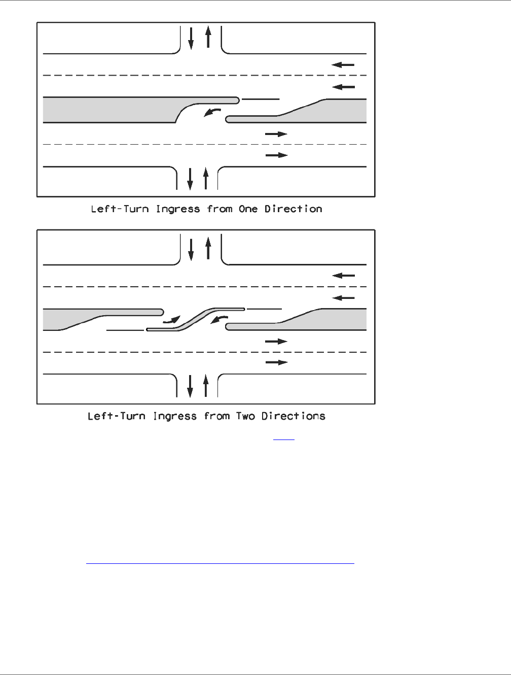
Roadway Design Manual 3-9 TxDOT 04/2018
Chapter 3 — New Location and Reconstruction (4R)
Design Criteria Section 2 — Urban Streets
Figure 3-1. Types of Directional Openings. Click here to see a PDF of the image.
Borders
The border, which accommodates sidewalks, provides sight distance, and utility accommodation,
and separates traffic from privately owned areas, is the area between the roadway and right-of-way
line. Every effort should be made to provide wide borders to serve functional needs, reduce traffic
nuisances to adjacent development, and for aesthetics. Minimum and desirable border widths are as
indicated inTable 3-1: Geometric Design Criteria for Urban Streets.
Berms
There are two different types of berms typically used on urban streets. One type of berm is con-
structed as a narrow shelf or path. This type is typically used to provide a flush grade behind a curb
to accommodate the possible future installation of sidewalks.

Roadway Design Manual 3-10 TxDOT 04/2018
Chapter 3 — New Location and Reconstruction (4R)
Design Criteria Section 2 — Urban Streets
Another type of berm is constructed as a raised mound to facilitate drainage or for landscaping pur-
poses. When this type of berm is constructed, it is desirable that the berm be placed outside of the
clear zone. If this is not practical, care should be taken to ensure that the slopes and configurations
used meet the horizontal clearance requirements as discussed in Slopes and Ditches in Chapter 2.
Grade Separations and Interchanges
Although grade separations and interchanges are not often provided on urban streets, they may be
the only means available for providing sufficient capacity at critical intersections. Normally, a
grade separation is part of an interchange (except grade separations with railroads); it is usually the
diamond type where there are four legs. Locations considered include high volume intersections
and where terrain conditions favor separation of grades.
The entire roadway width of the approach, including parking lanes or shoulders if applicable,
should be carried across or under the separation. Interchange design elements may have slightly
lower dimensional values as compared to freeways due to the lower speeds involved. For example,
diamond ramps may have lengths controlled by the minimum distance to overcome the elevation
difference at suitable gradients.
In some instances, it may be feasible to provide grade separations or interchanges at all major
crossings for a lengthy section of arterial street. In these cases, the street assumes the operating
characteristics and appearance of a freeway. In this regard, where right-of-way availability permits,
it may be appropriate to eliminate the relatively few crossings at-grade and control access by design
(i.e., provide continuous frontage roads) in the interest of safety. It is not desirable, however, to
intermix facility types by providing intermittent sections of fully controlled and non-controlled
access facilities.
Right-of-Way Width
The width of right-of-way for urban streets is influenced by the following factors:
traffic volume requirements
land use
availability and cost
extent of expansion.
Width is the summation of the various cross sectional elements, including widths of travel and turn-
ing lanes, shoulders or parking lanes, median, borders, and the area necessary to accommodate
slopes and provide ramps or connecting roadways where interchanges are involved.
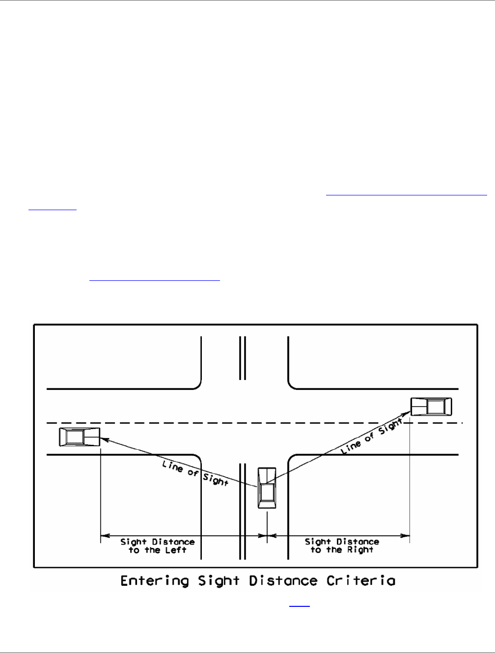
Roadway Design Manual 3-11 TxDOT 04/2018
Chapter 3 — New Location and Reconstruction (4R)
Design Criteria Section 2 — Urban Streets
Intersections
The number, design, and spacing of intersections influence the capacity, speed, and safety on urban
streets. Capacity analysis of signalized intersections is one of the most important considerations in
intersection design. Dimensional layout or geometric design considerations are closely influenced
by traffic volumes and operational characteristics and the type of traffic control measures used.
Because of the space limitations and lower operating speeds on urban streets, curve radii for turning
movements are less than for rural highway intersections. Curb radii of 15 ft [4.5 m] to 25 ft [7.5 m]
permit passenger cars to negotiate right turns with little or no encroachment on other lanes. Where
heavy volumes of trucks or buses are present, increased curb radii of 30 ft [9 m] to 50 ft [15 m]
expedite turns to and from through lanes. Where combination tractor-trailer units are anticipated in
significant volume, reference should be made to the material in Minimum Designs for Truck and
Bus Turns, Chapter 7.
In general, intersection design should be rather simple, and free of complicated channelization, to
minimize driver confusion. Sight distance is an important consideration even in the design of sig-
nalized intersections since, during the low volume hours, flashing operation may be used (see
discussion in Intersection Sight Distance, Chapter 2).
Figure 3-2 illustrates lines of sight for a vehicle entering an intersection.
Figure 3-2. Entering Intersection Lines of Sight. Click here to see a PDF of the image.

Roadway Design Manual 3-12 TxDOT 04/2018
Chapter 3 — New Location and Reconstruction (4R)
Design Criteria Section 2 — Urban Streets
Speed Change Lanes
On urban arterial streets, speed change lanes generally provide space for the deceleration and possi-
bly storage of turning vehicles. The length of speed change lanes for turning vehicles consists of the
following two components:
deceleration length
storage length
Left-Turn Deceleration Lanes. Figure 3-3 illustrates the use of left-turn lanes on urban streets. A
short symmetrical reverse curve taper or straight taper may be used. For median left-turn lanes, a
minimum median width of 16 ft [4.8 m] (12 ft [3.6 m] lane width plus a 4 ft [1.2 m] divider) is rec-
ommended to accommodate a single left-turn lane. The absolute minimum median width is 14 ft
[4.2 m]. Where dual left-turns are provided, a minimum median width of 28 ft. [8.5 m] is recom-
mended (two 12 ft. (3.6 m] lanes plus a 4 ft. [1.2 m] divider). Where pedestrians may be present,
the divider must be at least 5 ft. [1.5 m] wide, preferably at least 6 ft. [1.8 m]. Where a raised
divider extends into the pedestrian cross-walk, a cut-through that is a minimum of 5 ft. x 5 ft. [1.5
m x 1.5 m] must be provided.
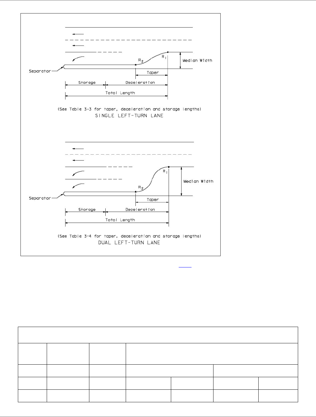
Roadway Design Manual 3-13 TxDOT 04/2018
Chapter 3 — New Location and Reconstruction (4R)
Design Criteria Section 2 — Urban Streets
Figure 3-3. Left-Turn Lanes on Urban Streets. Click here to see a PDF of the image.
Table 3-3 provides recommended taper lengths, deceleration lengths, and storage lengths for left-
turn lanes. These guidelines may also be applied to the design of right-turn lanes.
Table 3-3: Lengths of Single Left-Turn Lanes on Urban Streets1
(US Customary)
Speed
(mph)
Deceleration
Length2(ft) Taper
Length (ft) Storage Length (ft)
- Signalized Non-Signalized
- Calculated Minimum4Calculated5Minimum4
30 160 50 See footnote 3 100 See footnote 5 100

Roadway Design Manual 3-14 TxDOT 04/2018
Chapter 3 — New Location and Reconstruction (4R)
Design Criteria Section 2 — Urban Streets
Deceleration Length. Deceleration length assumes that moderate deceleration will occur in the
through traffic lane and the vehicle entering the left-turn lane will clear the through traffic lane at a
speed of 10 mph (15 km/h) slower than through traffic. Where providing this deceleration length is
35 215 50 See footnote 3 100 See footnote 5 100
40 275 50 See footnote 3 100 See footnote 5 100
45 345 100 See footnote 3 100 See footnote 5 100
50 425 100 See footnote 3 100 See footnote 5 100
55 510 100 See footnote 3 100 See footnote 5 100
(Metric)
Speed
(km/h)
Deceleration
Length2 (m) Taper
Length (m) Storage Length (m)
Signalized Non-Signalized
Calculated Minimum4Calculated Minimum4
50 50 15 See footnote 3 30 See footnote 5 30
60 65 15 See footnote 3 30 See footnote 5 30
70 85 30 See footnote 3 30 See footnote 5 30
80 105 30 See footnote 3 30 See footnote 5 30
90 130 30 See footnote 3 30 See footnote 5 30
1 The minimum length of a left-turn lane is the sum of the deceleration length plus queue storage. In order to
determine the design length, the deceleration plus storage length must be calculated for peak and off-peak
periods, the longest total length will be the minimum design length.
2 See Deceleration Length discussion immediately following Table 3-3.
3 See Storage Length Calculations discussion immediately following Table 3-3A.
4 The minimum storage length shall apply when: 1) the required queue storage length calculated is less than
the minimum length, or 2) there is no rational method for estimating the left-turn volume.
5 The calculated queue storage at unsignalized location using a traffic model or simulation model or by the
following:
L = (V/30)(2)(S)
where: (V/30) is the left-turn volume in a two-minute interval and other terms are as defined in the
Storage Length Calculations discussion immediately following Table 3-3A.
Table 3-3: Lengths of Single Left-Turn Lanes on Urban Streets1
(US Customary)

Roadway Design Manual 3-15 TxDOT 04/2018
Chapter 3 — New Location and Reconstruction (4R)
Design Criteria Section 2 — Urban Streets
impractical, it may be acceptable to allow turning vehicles to decelerate more than 10 mph (15km/
h) before clearing the through traffic lane. See Table 3-3A.
Storage Length Calculations. The required storage may be obtained using an acceptable traffic
model such as the latest version of the HCM software (HCS), SYNCHRO, or VISSIM or other
acceptable simulation models. Where such model results have not been applied, the following may
be used:
L = (V/N)(2)(S)
where:
L = storage length in feet (or meters)
V = left-turn volume per hour, vph
N = number of cycles
2 = a factor that provides for storage of all left-turning vehicles on most cycles; a value of 1.8
may be acceptable on collector streets
S = queue storage length, in feet (or meters), per vehicle
Table 3-3A Deceleration Lengths for Speed Differentials Greater than 10 mph (15km/h)
US Customary (ft) Metric (m)
Speed Speed Differential* Speed Speed Differential*
(mph) 15 mph 20 mph (km/h) 20 km/h 25km/h
3011075504035
35 160 110 60 60 50
40 215 160 70 75 65
45 275 215 80 95 85
50 345 275 90 115 105
55 425 345
* Speed differential = the difference between a turning vehicle when it clears the through traffic lane and
speed of following through traffic. Clearance is considered to have occurred when the turning vehicle has
moved laterally a sufficient distance (10 ft. [3m]) so that a following through vehicle can pass without
encroaching upon the adjacent through lane.
% of
trucks S (ft) S (m)
<5 25 7.6
5-9 30 9.1

Roadway Design Manual 3-16 TxDOT 04/2018
Chapter 3 — New Location and Reconstruction (4R)
Design Criteria Section 2 — Urban Streets
Dual Left-Turn Deceleration Lanes. For major signalized intersections where high peak hour
left-turn volumes are expected, dual left-turn lanes should be considered. As with single left-turn
lanes, dual left-turn lanes should desirably include length for deceleration, storage, and taper. Table
3-4 provides recommended lengths for dual left-turn lanes.
Right-Turn Acceleration Lanes. Acceleration lanes typically are not used on urban streets. See
Section 5, Figure 3-10, for acceleration distances and taper lengths if an acceleration lane may be
necessary.
Right-Turn Deceleration Lanes. Figure 3-4 illustrates a right-turn deceleration lane. The length of
a single right-turn deceleration lane is the same as that for a single left-turn lane (see Table 3-3).
10-14 35 10.7
15-19 40 12.2
Table 3-4: Lengths of Dual Left-Turn Lanes on Urban Streets 1
(US Customary)
Speed Deceleration Taper Storage Length (ft)
(mph) Length2(ft) Length (ft) Calculated 3Minimum4
30 160 100 See footnote 3 100
35 215 100 See footnote 3 100
40 275 100 See footnote 3 100
45 345 150 See footnote 3 100
50 425 150 See footnote 3 100
55 510 150 See footnote 3 100
Table 3-4: Lengths of Dual Left-Turn Lanes on Urban Streets
(Metric)
Speed Deceleration Taper Storage Length (m)
(km/h) Length2(m) Length (m) Calculated3Minimum4
50 50 30 See footnote 3 30
60 65 30 See footnote 3 30
70 85 45 See footnote 3 30
80 105 45 See footnote 3 30
90 130 45 See footnote 3 30
See Table 3-3 for footnotes.
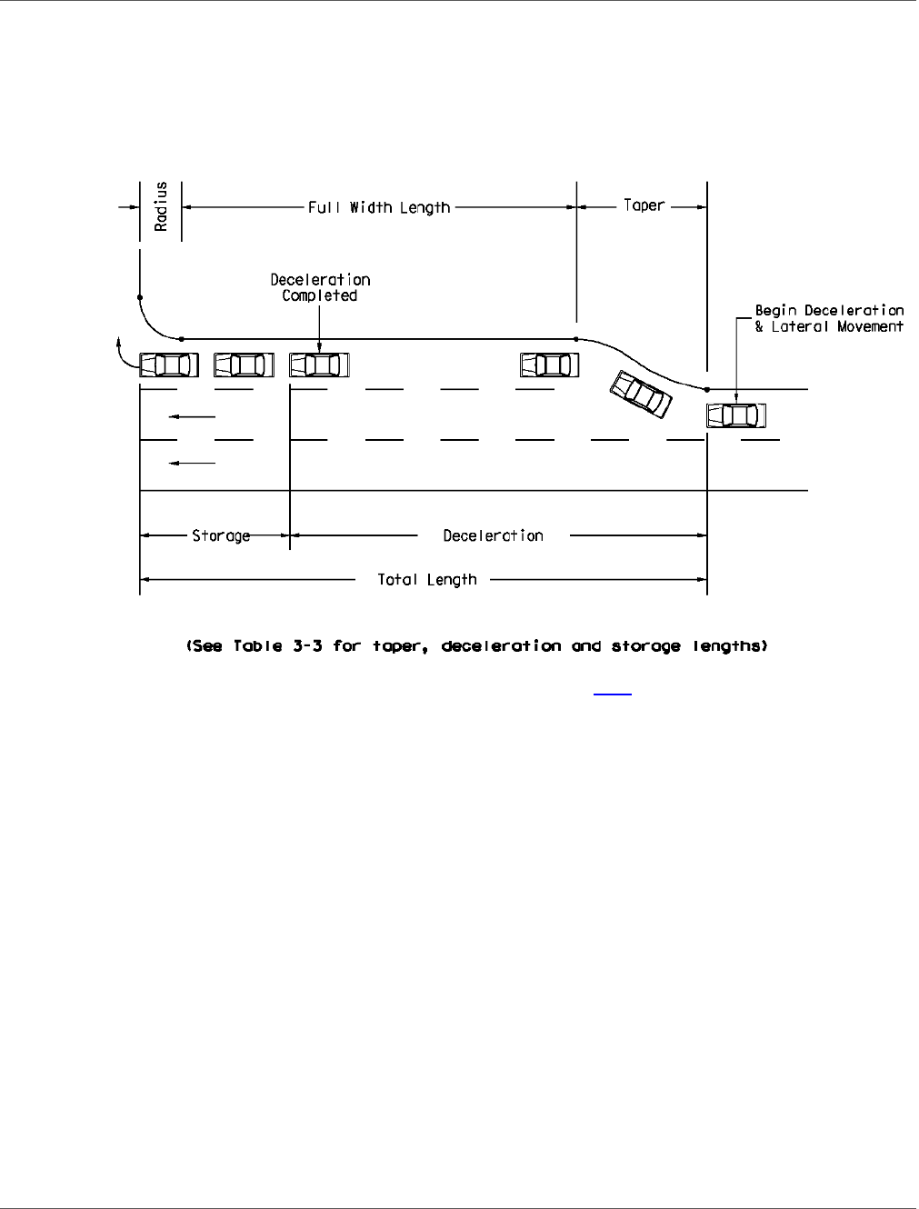
Roadway Design Manual 3-17 TxDOT 04/2018
Chapter 3 — New Location and Reconstruction (4R)
Design Criteria Section 2 — Urban Streets
However, the minimum queue storage is 30 ft for right-turn lanes. The length for a dual right-turn
lane is the same as for a dual left-turn lane (see Table 3-4). Refer to the TxDOT Access Manage-
ment Manual for guidelines as to when to consider a right-turn deceleration lane.
Figure 3-4. Lengths of Right-Turn Deceleration Lanes. Click here to see a PDF of the image.
Auxiliary Lanes on Crest Vertical Curves
When an intersection or driveway is located beyond the crest of a vertical curve, the designer
should check the driver’s view of the left-turn or right-turn lane as they approach the beginning of
the taper. It is suggested that this preview time be at least two seconds. An auxiliary lane that is lon-
ger than the deceleration distance plus queue storage length may be a consideration, if practical, in
these situations.
Horizontal Offsets
For low-speed streets, cross drainage culvert ends should be offset minimally 4 ft [1.2 m] from the
back of curb or 4 ft [1.2 m] from outside edge of shoulder. The designer, however, should make the
best use of available border width to obtain wide clearances. Sloped open ends may be used to
effectively safety treat small culverts. Consideration should be given to future sidewalk needs.

Roadway Design Manual 3-18 TxDOT 04/2018
Chapter 3 — New Location and Reconstruction (4R)
Design Criteria Section 2 — Urban Streets
Bus Facilities
Urban areas benefit from the effective bus utilization of downtown and radial arterial streets, and
from the effective coordination of transit and traffic improvements. To maintain and increase bus
patronage, bus priority treatments on arterial streets may be used to underscore the importance of
transit use. Possible bus priority treatments on non-controlled access facilities include measures
designed to separate car and bus movements and general traffic engineering improvements
designed to expedite overall traffic flow.
This subsection includes the following topics:
bus lanes
bus streets
Bus Lanes
Bus lanes are usually used exclusively by buses; however, in some instances carpools, taxis, or
turning vehicles may share the lane. They may be located along curbs or in street medians and may
operate with, or counter to, automobile flow. For more information on bus lanes, see St. Jacques,
Kevin and Herbert S. Levinson. Operational Analysis of Bus Lanes on Arterials, TCRP Report 26,
TRB, National Research Council, Washington, DC (1997).
Curb Bus Lanes (Normal Flow). Curb bus lanes in the normal direction flow are usually in effect
only during the peak periods. They are usually implemented in conjunction with removal of curb
parking so that there is little adverse effect on existing street capacity. This type of operation may
be difficult to enforce and may produce only marginal benefits to bus flow. In operation, right-turn-
ing vehicles conflict with buses.
Median Bus Lanes. Median bus lanes generally are in effect throughout the day. Wide medians are
required to provide refuge for bus patrons, and passengers are required to cross active street lanes to
reach bus stops. Additionally, left-turn traffic must be prohibited or controlled to minimize interfer-
ence between transportation modes.
Bus Streets
Reserving entire streets for the exclusive use of buses represents a major commitment to transit and
generally is not feasible due to adverse effects on abutting properties and businesses, including
parking garages or lots, drive-in banks, etc.

Roadway Design Manual 3-19 TxDOT 04/2018
Chapter 3 — New Location and Reconstruction (4R)
Design Criteria Section 3 — Suburban Roadways
Section 3 — Suburban Roadways
Overview
The term “suburban roadway” refers to high-speed roadways that serve as transitions between low-
speed urban streets and high-speed rural highways. Suburban roadways are typically 1 to 3 miles
[1.6 to 4.8 kilometers] in length and have light to moderate driveway densities (approximately 10 to
30 driveways per mile [5 to 20 driveways per kilometer]). Because of their location, suburban road-
ways have both rural and urban characteristics. For example, these sections typically maintain high
speeds (a rural characteristic) while utilizing curb and gutter to facilitate drainage (an urban charac-
teristic). Consequently, guidelines for suburban roadways typically fall between those for rural
highways and urban streets.
Basic Design Features
This subsection includes information on the following basic design features for suburban
roadways:
Access Control
Medians
Median Openings
Speed Change Lanes
Right of Way Width
Horizontal Clearances
Borders
Grade Separations and Interchanges
Intersections
Parking
Table 3-5 shows tabulated basic geometric design criteria for suburban roadways. The basic design
criteria shown in this table reflect minimum and desired values that are applicable to new location,
reconstruction or major improvement projects.
Table 3-5: Geometric Design Criteria for Suburban Roadways
(US Customary)
Item Functional Class Desirable Minimum

Roadway Design Manual 3-20 TxDOT 04/2018
Chapter 3 — New Location and Reconstruction (4R)
Design Criteria Section 3 — Suburban Roadways
Design Speed (mph) All 60 50
Minimum Horizontal Radius All See Tables 2-3 and 2-4
Maximum Gradient (%) All See Table 2-9
Stopping Sight Distance All See Table 2-1
Width of Travel Lanes (ft) Arterial
Collector
12
12
111
102
Curb Parking Lane Width (ft) All None
Shoulder Width (ft) All 10 4
Width of Speed Change Lanes3(ft) All 11-12 10
Offset to Face of Curb (ft) All 2 1
Median Width All See Medians, Urban Streets
Border Width (ft) Arterial
Collector
20
20
15
15
Right-of-Way Width (ft) All Variable4
Sidewalk Width (ft) All 6-855
Superelevation All See Chapter 2, Superelevation
Horizontal Clearance All See Table 2-11
Vertical Clearance for New Strs. (ft) All 16.5 16.56
Turning Radii All See Chapter 7, Minimum Designs for
Truck and Bus Turns
1 In highly restricted locations, 10 ft permissible.
2 In industrial areas 12 ft usual, and 11 ft minimum for restricted R.O.W. conditions. In non-industrial
areas, 10 ft minimum.
3 Applicable when right or left-turn lanes are provided.
4 Right-of-way width is a function of roadway elements as well as local conditions.
5 Applicable for commercial areas, school routes, or other areas with concentrated pedestrian traffic.
6 Exceptional cases near as practical to 16.5 ft but never less than 14.5 ft. Existing structures that provide
at least 14 ft may be retained.
Table 3-5: Geometric Design Criteria for Suburban Roadways
(Metric)
Item Functional Class Desirable Minimum
Design Speed (km/h) All 100 80
Table 3-5: Geometric Design Criteria for Suburban Roadways
(US Customary)

Roadway Design Manual 3-21 TxDOT 04/2018
Chapter 3 — New Location and Reconstruction (4R)
Design Criteria Section 3 — Suburban Roadways
Access Control
A major concern for suburban roadways is the large number of access points introduced due to
commercial development. These access points create conflicts between exiting/entering traffic and
through traffic. In addition, the potential for severe accidents is increased due to the high-speed dif-
ferentials. Driver expectancy is also violated because through traffic traveling at high speeds does
Minimum Horizontal Radius All See Tables 2-3 and 2-4
Maximum Gradient (%) All See Table 2-9
Stopping Sight Distance All See Table 2-1
Width of Travel Lanes (m) Arterial
Collector
3.6
3.6
3.31
3.02
Curb Parking Lane Width (m) All None
Shoulder Width (m) All 3.0 1.2
Width of Speed Change Lanes3 (m) All 3.3-3.6 3.0
Offset to Face of Curb (m) All 0.6 0.3
Median Width All See Medians, Urban Streets
Border Width (m) Arterial
Collector
6.0
6.0
4.5
4.5
Right-of-Way Width (m) All Variable4
Sidewalk Width (m) All 1.8-2.451.5
Superelevation All See Chapter 2, Superelevation
Horizontal Clearance All See Table 2-11
Vertical Clearance for New Strs. (m) All 5.0 5.06
Turning Radii All See Chapter 7, Minimum Designs for
Truck and Bus Turns
1 In highly restricted locations, 3.0 m permissible.
2 In industrial areas 3.6 m usual, and 3.3 m minimum for restricted R.O.W. conditions. In non-industrial
areas, 3.0 m minimum.
3 Applicable when right or left-turn lanes are provided.
4 Right-of-way width is a function of roadway elements as well as local conditions.
5 Applicable for commercial areas, school routes, or other areas with concentrated pedestrian traffic.
6 Exceptional cases near as practical to 5.0 m but never less than 4.4 m. Existing structures that provide at
least 4.3 m may be retained.
Table 3-5: Geometric Design Criteria for Suburban Roadways
(Metric)

Roadway Design Manual 3-22 TxDOT 04/2018
Chapter 3 — New Location and Reconstruction (4R)
Design Criteria Section 3 — Suburban Roadways
not expect to have to slow down or stop. Research has shown that reducing the number of access
points and increasing the amount of access control will reduce the potential for accidents. In addi-
tion, accident experience can be reduced by separating conflicting traffic movements with the use
of turn bays and/or turn lanes. Reference can be made to TxDOT Access Management Manual for
additional access discussion.
Medians
Medians are desirable for suburban roadways with four or more lanes primarily to provide storage
space for left-turning vehicles. The types of medians used on suburban roadways include raised
medians and two-way left-turn lanes.
Raised Medians. Raised medians with curbing are used on suburban arterials where it is desirable
to control left-turn movements. These medians should be delineated with curbs of the mountable
type. Raised medians are applicable on high-volume roadways with high demand for left turns. For
additional guidelines regarding the installation of raised medians, see Raised Medians, Urban
Streets.
Two-Way Left-Turn Lanes. The two-way left-turn lanes (TWLTL) is applicable on suburban
roadways with moderate traffic volumes and low to moderate demands for left turns. For suburban
roadways, TWLTL facilities should minimally be 14 ft [4.2 m] and desirably 16 ft [4.8 m] in width.
The desirable value of 16 ft [4.8 m] width should be used on new location projects or on recon-
struction projects where widening necessitates the removal of exterior curbs. The “minimum” value
of 14 ft [4.2 m] width is appropriate for restrictive right-of-way projects and improvement projects
where attaining “desirable” median lane width would necessitate removing and replacing exterior
curbing to gain only a small amount of roadway width.
Criteria for the potential use of a continuous TWLTL on a suburban roadway are as follows:
future ADT volume of 3,000 vehicles per day for an existing two-lane suburban roadway,
6,000 vehicles per day for an existing four-lane suburban roadway, or 10,000 vehicles per day
for an existing six-lane suburban roadway.
side road plus driveway density of 10 or more entrances per mile [6 or more entrances per
kilometer].
When both conditions are met, the use of a TWLTL should be considered. For ADT volumes
greater than 20,000 vehicle per day, or where development is occurring and volumes are increasing
and are anticipated to reach this level, a raised median design should be considered.
Seven-lane cross sections should be evaluated for pedestrian crossing capabilities.

Roadway Design Manual 3-23 TxDOT 04/2018
Chapter 3 — New Location and Reconstruction (4R)
Design Criteria Section 3 — Suburban Roadways
Median Openings
As the number of median openings along a suburban roadway increase, the interference between
through traffic and turning traffic increases. To reduce the interference between turning traffic and
through traffic, turn bays should be provided at all median openings. Recommended minimum
median opening spacings are based on the length of turn bay required. For additional information
regarding the design of median openings, see Section 2, Urban Streets, Medians.
Speed Change Lanes
Due to high operating speeds on suburban roadways, speed change lanes may be provided as space
for deceleration/acceleration to/from intersecting side streets with significant volumes. For infor-
mation regarding the design of left-turn (median) speed change lanes and right speed change lanes,
see Section 2, Urban Streets, Speed Change Lanes. (See Table 3-3 for lengths of single left-turn
lanes; Table 3-4 for lengths of dual left-turn lanes, Figure 3-4 for length of right-turn lanes.)
Right of Way Width
Similar to urban streets, the width of right-of-way for suburban roadways is influenced by traffic
volume requirements, lane use, cost, extent of ultimate expansion, and land availability. Width is
the summation of the various cross-sectional elements, including widths of travel and turning lanes,
shoulders, median, sidewalks, and borders.
Horizontal Clearances
Table 2-11: Horizontal Clearances presents the general horizontal clearance guidelines for subur-
ban roadways.
Borders
See Borders Urban Streets.
Grade Separations and Interchanges
See Grade Separations and Interchanges, Urban Streets.
Intersections
Due to high operating speeds (50 mph [80 km/h] or greater) on suburban roadways, curve radii for
turning movements should equal that of rural highway intersections. Space restrictions due to right-
of-way limitations in suburban areas, however, may necessitate reduction in the values given for

Roadway Design Manual 3-24 TxDOT 04/2018
Chapter 3 — New Location and Reconstruction (4R)
Design Criteria Section 3 — Suburban Roadways
rural highways. For additional information regarding intersection design, see Intersections Urban
Streets.
Parking
Desirably, parking adjacent to the curb on suburban roadways should not be allowed.

Roadway Design Manual 3-25 TxDOT 04/2018
Chapter 3 — New Location and Reconstruction (4R)
Design Criteria Section 4 — Two-Lane Rural Highways
Section 4 — Two-Lane Rural Highways
Overview
The general geometric features for two-lane rural highways are provided in this section and are
summarized in the following tables and figures:
Figure 3-5: Typical cross section
Table 3-6: Minimum Design Speed for Rural Two-lane Highways: Minimum design speed
Table 3-7. Geometric Design Criteria for Rural Two-Lane Highways: Basic design criteria and
cross sectional elements
Table 3-8: Width of Travel Lanes and Shoulders on Rural Two-lane Highways: Lane and
shoulder widths
Table 3-9: Minimum Structure Widths For Bridges to Remain in Place on Rural Two-lane
Highways: Minimum structure widths that may remain in place.
Additional information on structure widths may be obtained in the Bridge Design - LRFD and
the Bridge Project Development Manual.
Table 3-6: Minimum Design Speed for Rural Two-lane Highways
(US Customary)
Functional - Minimum Design Speed (mph) for future ADT of:
Class Terrain < 400 400-1500 1500-2000 > 2000
Arterial Level
Rolling
70
60
Collector Level
Rolling
501
40250
40
50
40
60
50
Local3Level
Rolling
402
30
50
40
50
40
50
40
(Metric)
Functional - Minimum Design Speed (km/h) for future ADT of:
Class Terrain < 400 400-1500 1500-2000 > 2000
Arterial Level
Rolling
110
100
Collector Level
Rolling
801
60280
60
80
60
100
80

Roadway Design Manual 3-26 TxDOT 04/2018
Chapter 3 — New Location and Reconstruction (4R)
Design Criteria Section 4 — Two-Lane Rural Highways
Local3Level
Rolling
602
50
80
60
80
60
80
60
1 A 40 mph [60 km/h] minimum design speed may be used where roadside environment or unusual design
considerations dictate.
2 A 30 mph [50 km/h] minimum design speed may be used where roadside environment or unusual design
considerations dictate.
3 Applicable only to off-system routes that are not functionally classified at a higher classification.
Table 3-7. Geometric Design Criteria for Rural Two-Lane Highways
(US Customary)
Geometric Design Element Functional Class Reference or Design Value
Design Speed All Table 3-6
Minimum Horizontal Radius All Table 2-3and Table 2-4
Max. Gradient All Table 2-9
Stopping Sight Distance All Table 2-1
Width of Travel Lanes All Table 3-8
Width of Shoulders All Table 3-8
Vertical Clearance, New Structures All 16.5 ft1
Horizontal Clearance All Table 2-11
Pavement Cross Slope All Chapter 2, Pavement Cross Slope
(Metric)
Geometric Design Element Functional Class Reference or Design Value
Design Speed All Table 3-6
Minimum Horizontal Radius All Table 2-3and Table 2-4
Max. Gradient All Table 2-9
Stopping Sight Distance All Table 2-1
Width of Travel Lanes All Table 3-8
Width of Shoulders All Table 3-8
Vertical Clearance, New Structures All 5.0 m1
Horizontal Clearance All Table 2-11
Table 3-6: Minimum Design Speed for Rural Two-lane Highways
(US Customary)

Roadway Design Manual 3-27 TxDOT 04/2018
Chapter 3 — New Location and Reconstruction (4R)
Design Criteria Section 4 — Two-Lane Rural Highways
Pavement Cross Slope All Chapter 2, Pavement Cross Slope
1 Exceptional cases near as practical to 16.5 ft [5.0 m] but never less than 14.5 ft [4.4 m].
Table 3-8: Width of Travel Lanes and Shoulders on Rural Two-lane Highways
(US Customary)
Functional Class Design Speed
(mph) Minimum Width 1,2(ft) for future ADT of:
- - < 400 400-1500 1500-2000 > 2000
Arterial LANES (ft)
-All12
- SHOULDERS (ft)
-All4
343 or 83838 - 103
Collector LANES (ft)
- 3010101112
- 3510101112
- 4010101112
- 4510101112
- 5010101212
- 5510101212
- 6011111212
- 6511111212
- 7011111212
- 7511121212
- 8011121212
- SHOULDERS (ft)
-All2
4,5 45858 - 105
Local6 LANES (ft)
- 3010101112
- 3510101112
- 4010101112
- 4510101112
- 5010101112
- SHOULDERS (ft)
- All2448
Table 3-7. Geometric Design Criteria for Rural Two-Lane Highways
(US Customary)

Roadway Design Manual 3-28 TxDOT 04/2018
Chapter 3 — New Location and Reconstruction (4R)
Design Criteria Section 4 — Two-Lane Rural Highways
1 Minimum surfacing width is 24 ft for all on-system state highway routes.
2 On high riprapped fills through reservoirs, a minimum of two 12 ft lanes with 8 ft shoulders should be pro-
vided for roadway sections. For arterials with 2,000 or more ADT in reservoir areas, two 12 ft lanes with 10 ft
shoulders should be used.
3On arterials, shoulders fully surfaced.
4On collectors, use minimum 4 ft shoulder width at locations where roadside barrier is utilized.
5For collectors, shoulders fully surfaced for 1,500 or more ADT. Shoulder surfacing not required but desirable
even if partial width for collectors with lower volumes and all local roads.
6 Applicable only to off-system routes that are not functionally classified at a higher classification.
Table 3-8: Width of Travel Lanes and Shoulders on Rural Two-lane Highways
(Metric)
Functional Class Design Speed
(km/h) Minimum Width 1,2(m) for future ADT of:
- - < 400 400-1500 1500-2000 > 2000
Arterial LANES (m)
- All 3.6
- SHOULDERS (m)
- All 1.231.23 or 2.432.432.4 - 3.03
Collector LANES (m)
- 50 3.0 3.0 3.3 3.6
- 60 3.0 3.0 3.3 3.6
- 70 3.0 3.0 3.3 3.6
- 80 3.0 3.0 3.6 3.6
- 90 3.0 3.0 3.6 3.6
- 100 3.3 3.3 3.6 3.6
- 110 3.3 3.3 3.6 3.6
- 120 3.3 3.6 3.6 3.6
- 130 3.3 3.6 3.6 3.6
- SHOULDERS (m)
- All 0.64,5 1.252.452.4-3.05
Local6LANES (m)
- 50 3.0 3.0 3.3 3.6
- 60 3.0 3.0 3.3 3.6
- 70 3.0 3.0 3.3 3.6
- 80 3.0 3.0 3.3 3.6
- SHOULDERS (m)
- All 0.6 1.2 1.2 2.4
Table 3-8: Width of Travel Lanes and Shoulders on Rural Two-lane Highways
(US Customary)

Roadway Design Manual 3-29 TxDOT 04/2018
Chapter 3 — New Location and Reconstruction (4R)
Design Criteria Section 4 — Two-Lane Rural Highways
The following notes apply to Table 3-8:
Minimum width of new or widened structures should accommodate the approach roadway
including shoulders.
See Table 3-9 for minimum structure widths that may remain in place.
Basic Design Features
This subsection includes information on the following basic design features for two-lane rural
highways:
Access Control
1 Minimum surfacing width is 7.2 m for all on-system state highway routes.
On high riprapped fills through reservoirs, a minimum of two 3.6 m lanes with 2.4 m shoulders should be
provided for roadway sections. For arterials with 2,000 or more ADT in reservoir areas, two 3.6 m lanes with
3.0 m shoulders should be used.
On arterials, shoulders fully surfaced.
4 On collectors, use minimum 1.2 m shoulder width at locations where roadside barrier is utilized.
5 For collectors, shoulders fully surfaced for 1,500 or more ADT. Shoulder surfacing not required but desirable
even if partial width for collectors with lower volumes and all local roads.
6 Applicable only to off-system routes that are not functionally classified at a higher classification.
Table 3-9: Minimum Structure Widths For Bridges to Remain in Place on Rural Two-lane Highways
(US Customary)
Functional Class Roadway Clear Width 1 (ft) for ADT of:
- < 400 400-1500 1500-2000 > 2000
Local 20 22 24 28
Collector 22 22 24 28
Arterial Traveled Way + 6 ft
(Metric)
Functional Class Roadway Clear Width 1 (m) for ADT of:
- < 400 400-1500 1500-2000 > 2000
Local 6.0 6.6 7.2 8.4
Collector 6.6 6.6 7.2 8.4
Arterial Traveled Way + 1.8 m
1 Clear width between curbs or rails, whichever is lesser, is considered to be at least the same as approach
roadway clear width. Approach roadway width includes shoulders.
Table 3-8: Width of Travel Lanes and Shoulders on Rural Two-lane Highways
(Metric)

Roadway Design Manual 3-30 TxDOT 04/2018
Chapter 3 — New Location and Reconstruction (4R)
Design Criteria Section 4 — Two-Lane Rural Highways
Transitions to Four-Lane Divided Highways
Passing Sight Distances
Speed Change Lanes
Intersections
Access Control
Frontage roads or parallel service roads to serve small rural business communities or other develop-
ments should not be permitted along two-lane rural highways. To a driver unfamiliar with the local
area, a frontage road takes on the appearance of a separate roadway of a multilane divided facility,
thus resulting in the assumption that the two-way, two-lane highway is a one-way roadway. Where
individual driveways are located within deep cut or high fill areas, driveways may be routed paral-
lel to the highway for short distances to provide for a safe, economical junction with the highway.
The installation of access driveways along two-lane rural highways shall be in accordance with the
TxDOT Access Management Manual.
Transitions to Four-Lane Divided Highways
Typical transitions from two-lane to four-lane divided highways are discussed in Transitions to
Four-Lane Divided Highways, Multi-Lane Rural Highways, and illustrated in Multi-Lane Rural
Highway Intersection.
Passing Sight Distances
Passing sight distance is the length of highway required by a driver to make a passing maneuver
without cutting off the passed vehicle and before meeting an opposing vehicle. Therefore, passing
sight distance is applicable to two-lane highways only (including two-way frontage roads).
Recommended passing sight distances are based on the following conditions:
3.5 ft [1,080 mm] driver eye height
3.5 ft [1,080 mm] object height
10 mph [15 km/h] speed differential between the passing vehicle and vehicle being passed
In the design of two-lane highways, minimum or greater passing sight distance should be provided
wherever practical, since less than minimum distances reduce capacity and adversely affect level of
service. For rolling terrain, provision of climbing lanes may be a more economical alternative than
achieving a vertical alignment with adequate passing sight distance.

Roadway Design Manual 3-31 TxDOT 04/2018
Chapter 3 — New Location and Reconstruction (4R)
Design Criteria Section 4 — Two-Lane Rural Highways
Minimum passing sight distance values for design of two-lane highways are shown in
Table 3-10. These distances are for design purposes only and should not be confused with other dis-
tances used as warrants for striping no-passing zones as shown in the Texas Manual on Uniform
Traffic Control Devices. For the design of typical two-lane rural highways, except for level terrain,
provision of near continuous passing sight distance (2,680 ft at 80 mph [815 m at 130 km/h]) is
impractical. However, the designer should attempt to increase the length and frequency of passing
sections where economically feasible.
Table 3-10: Passing Sight Distance
(US Customary)
K-Values for Determining Length of Crest Vertical Curve for Various Passing Sight Distances
Design Speed (mph) Minimum Passing Sight Distance
for Design (ft) K-Value1
20 710 180
25 900 289
30 1090 424
35 1280 585
40 1470 772
45 1625 943
50 1835 1203
55 1985 1407
60 2135 1628
65 2285 1865
70 2480 2197
75 2580 2377
80 2680 2565
(Metric)
K-Values for Determining Length of Crest Vertical Curve for Various Passing Sight Distances
Design Speed (km/h) Minimum Passing Sight Distance
for Design (m) K-Value1
30 200 46
40 270 84
50 345 138
60 410 195
70 485 272
80 540 338
90 615 438
100 670 520
110 730 617
120 775 695
130 815 769

Roadway Design Manual 3-32 TxDOT 04/2018
Chapter 3 — New Location and Reconstruction (4R)
Design Criteria Section 4 — Two-Lane Rural Highways
Speed Change Lanes
There are three kinds of speed change lanes: climbing lanes, left-turn lanes, and right-turn lanes.
Climbing Lanes. It is desirable to provide a climbing lane, as an extra lane on the upgrade side of a
two-lane highway where the grade, traffic volume, and heavy vehicle volume combine to degrade
traffic operations. A climbing lane should be considered when one of the following three conditions
exist:
10 mph [15 km/h] or greater speed reduction is expected for a typical heavy truck
level-of-service E or F exists on the upgrade
a reduction of two or more levels of service is experienced when moving from the approach
segment to the upgrade.
For low-volume roadways, only an occasional car is delayed, and a climbing lane may not be
justified economically. For this reason, a climbing lane should only be considered on roadways
with the following traffic conditions:
upgrade traffic flow rate in excess of 200 vehicles per hour or
upgrade truck flow rate in excess of 20 vehicles per hour.
The upgrade flow rate is predicted by multiplying the predicted or existing design hour volume by
the directional distribution factor for the upgrade direction and dividing the result by the peak hour
factor (see Traffic Characteristics, Chapter 2 and the Highway Capacity Manual for definitions of
these terms). The upgrade truck flow rate is obtained by multiplying the upgrade flow rate by the
percentage of trucks in the upgrade direction.
The beginning of a climbing lane should be introduced near the foot of the grade. The climbing
lane should be preceded by a tapered section desirably with a ratio of 25:1, but at least 150 ft [50 m]
long.
Attention should also be given to the location of the climbing lane terminal. Ideally, the climbing
lane should be extended to a point beyond the crest where a typical truck could attain a speed that is
within 10 mph [15 km/h] of the speed of other vehicles. In addition, climbing lanes should not end
just prior to an obstruction such as a restrictive width bridge. The climbing lane should be followed
by a tapered section desirably with a ratio of 50:1.
For projects on new location or where an existing highway will be regraded, the economics of pro-
viding an improved grade line in lieu of providing climbing lanes should be investigated. Refer to
1K = Length of Crest Vertical Curve ÷ Algebraic Difference in Grades
Table 3-10: Passing Sight Distance
(US Customary)
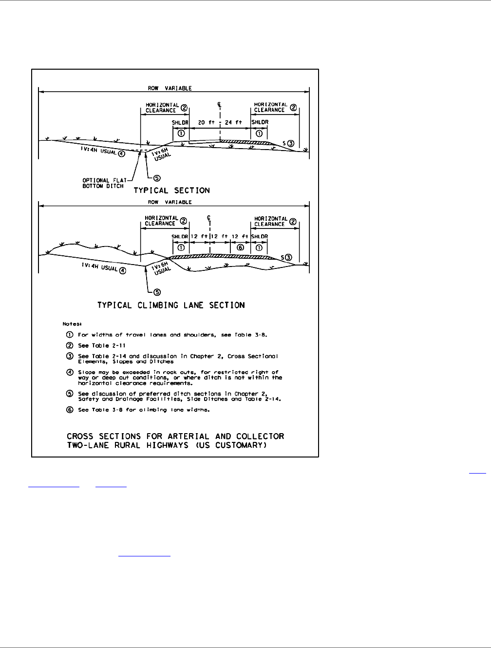
Roadway Design Manual 3-33 TxDOT 04/2018
Chapter 3 — New Location and Reconstruction (4R)
Design Criteria Section 4 — Two-Lane Rural Highways
Chapter 3 of AASHTO’s A Policy on Geometric Design of Highways and Streets for more informa-
tion regarding the design of climbing lanes. Figure 3-5 shows cross sections for climbing lanes on
rural highways.
Figure 3-5. (US). Cross Sections for Arterial and Collector Two-Lane Rural Highways. Click US
Customary or Metric to see a PDF of the image.
Left-Turn Deceleration Lanes. Left-turn lanes on two-lane highways at intersecting crossroads
generally are not economically justified. For certain moderate or high volume two-lane highways
with heavy left-turn movements, however, left-turn lanes may be justified in view of reduced road
user accident costs. Figure 3-6 provides recommendations for when left-turn lanes should be con-
sidered based on traffic volumes.
Example: Traffic northbound on a highway has 350 vph with 10 percent left turns included. The
southbound traffic volume is 200 vph. The design speed on the highway is 60 mph [100 km/h].
Beginning at the opposing volume (southbound in this case) of 200 vph, using the 10 percent left
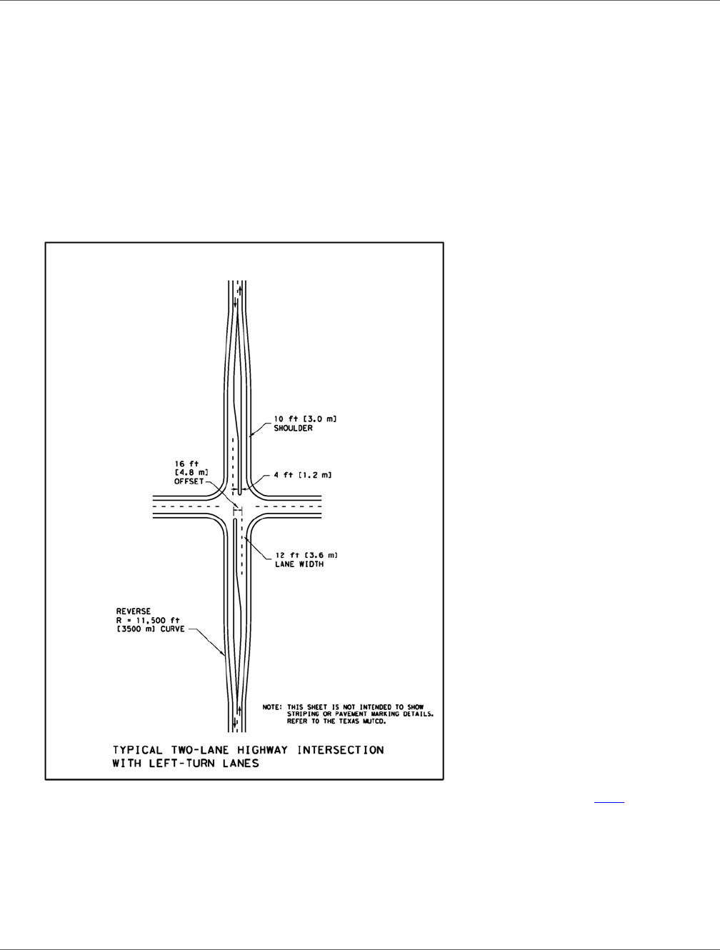
Roadway Design Manual 3-34 TxDOT 04/2018
Chapter 3 — New Location and Reconstruction (4R)
Design Criteria Section 4 — Two-Lane Rural Highways
turn column and 60 mph [100 km/h] design speed section, a value of 330 vph advancing volume
(northbound) is found in the table. Because the northbound volume of 350 vph exceeds the table
value of 330 vph, a left turn lane should be considered at the intersection.
Lengths of left-turn deceleration lanes are provided in Table 3-13.
Where used, left-turn lanes should be delineated with striping and pavement markers or jiggle bars.
Passing should be restricted in advance of the intersection, and horizontal alignment shifts of the
approaching travel lanes should be gradual. Figure 3-6 shows typical geometry for a rural two-lane
highway with left-turn bays at a crossroad intersection.
Figure 3-6. Typical Two-Lane Highway Intersection with Left-Turn Lanes. Click here to see a PDF
of the image.

Roadway Design Manual 3-35 TxDOT 04/2018
Chapter 3 — New Location and Reconstruction (4R)
Design Criteria Section 4 — Two-Lane Rural Highways
Right-Turn Deceleration Lanes. Shoulders 10 ft [3.0 m] wide alongside the traffic lanes generally
provide sufficient area for acceleration or deceleration of right-turning vehicles. Where the right
turn lane is being constructed in addition to the through lanes and shoulders, the minimum right
turn lane width is 10 ft [3.0 m] with a 2 ft [0.6 m] surfaced shoulder. Where speed change lanes are
used, they should be provided symmetrically along both sides of the highway for both directions of
traffic, thus presenting drivers with a balanced section.
A deceleration-acceleration lane on one side of a two-lane highway, such as at a “tee” intersection,
results in the appearance of a three-lane highway and may result in driver confusion. In this regard,
right-turn speed change lanes are generally inappropriate for “tee” intersection design except where
a four lane (2 through, 1 median left turn, 1 right acceleration/deceleration) section is provided.
Table 3-11: Guide for Left-Turn Lanes on Two-Lane Highways
Opposing Volume
(vph) Advancing Volume (vph)
- 5 % Left Turns 10 % Left Turns 20 % Left Turns 30 % Left Turns
40 mph [60 km/h] Design Speed
800 330 240 180 160
600 410 305 225 200
400 510 380 275 245
200 640 470 350 305
100 720 515 390 340
50 mph [80 km/h] Design Speed
800 280 210 165 135
600 350 260 195 170
400 430 320 240 210
200 550 400 300 270
100 615 445 335 295
60 mph [100 km/h] Design Speed
800 230 170 125 115
600 290 210 160 140
400 365 270 200 175
200 450 330 250 215
100 505 370 275 240

Roadway Design Manual 3-36 TxDOT 04/2018
Chapter 3 — New Location and Reconstruction (4R)
Design Criteria Section 4 — Two-Lane Rural Highways
Section 2, Figure 3-4 shows the lengths for right-turn deceleration lanes.
The length of a right-turn deceleration lane is the same as that for a left-turn lane (see Table 3-13).
Right turn lanes shorter than the lengths given in Table 3-13 may be acceptable on some low vol-
ume rural highways.
Right-Turn Acceleration Lanes. Right-turn acceleration lanes may be appropriate on some two-
lane rural highways – for example on high volume highways where significant truck percentages
are encountered. See Table 3-8 for acceleration distances and taper lengths.
Intersections
The provision of adequate sight distance is of utmost importance in the design of intersections
along two-lane rural highways. At intersections, consideration should be given to avoid steep pro-
file grades as well as areas with limited horizontal or vertical sight distance. An intersection should
not be situated just beyond a short crest vertical curve or a sharp horizontal curve. Where necessary,
backslopes should be flattened and horizontal and vertical curves lengthened to provide additional
sight distance. For more information on intersection sight distance, see Intersection Sight Distance
in Chapter 2.
Desirably, the roadways should cross at approximately right angles. Where crossroad skew is flatter
than 60 degrees to the highway, the crossroad should be re-aligned to provide for a near perpendic-
ular crossing. The higher the functional classification, the closer to right-angle the crossroad
intersection should be.
Minimum Designs for Truck and Bus Turns in Chapter 7 provides information regarding the
accommodation of various types of truck class vehicles in intersection design. Further information
on intersection design may also be found in AASHTO’s A Policy on Geometric Design of High-
ways and Streets.

Roadway Design Manual 3-37 TxDOT 04/2018
Chapter 3 — New Location and Reconstruction (4R)
Design Criteria Section 5 — Multi-Lane Rural Highways
Section 5 — Multi-Lane Rural Highways
Overview
This section includes guidelines on geometric features for multilane rural highways. The guidelines
are outlined in Table 3-12, and Figure 3-6 and Figure 3-7. The guidelines apply for all functional
classes of roadways.
Table 3-12: Design Criteria For Multilane Rural Highways
(Non-controlled Access) (All Functional Classes)
(US Customary)
Type of Facility Six-Lane Divided Four-Lane Divided Four-Lane
Undivided1
Design Speed (Arterials)2 (mph) Min. Min. Min.
Flat 703703703
Rolling 604604604
Lane Width (ft) 12
- Des. Min. Des. Min. Des. Min
Median Width (ft) Surfaced 16 4 16 4 Not Applicable
- Depressed76487648-
Shoulder Outside (ft) 10 8510 8510 85
Shoulder Inside (ft) for Depressed
Medians 10 4 4 4 Not applicable
Min. Structure Widths for
Bridges to Remain in
place (ft)
Depressed
Median -- 42 -- 30 -- 56
1 Undivided section may be used on two-lane highways to improve passing opportunities. Most appropriate
for use in rolling terrain and/or restricted right of way conditions.
2 For multilane collectors, minimum design speed values are 10 mph less than tabulated.
3 60 mph acceptable for heavy betterment under unusual circumstances. Otherwise, 70 mph should be
minimum.
4 50 mph acceptable for heavy betterment under unusual circumstances. Otherwise, 60 mph should be mini-
mum for rural design.
5 Applies to collector roads only. On four-lane undivided highways, outside surfaced shoulder width may be
decreased to 4 ft where flat (1V:10H), sodded front slopes are provided for a minimum distance of 4 ft from
the shoulder edge.

Roadway Design Manual 3-38 TxDOT 04/2018
Chapter 3 — New Location and Reconstruction (4R)
Design Criteria Section 5 — Multi-Lane Rural Highways
Table 3-12: Design Criteria For Multilane Rural Highways
(Non-controlled Access) (All Functional Classes)
(Metric)
Type of Facility
-
Six-Lane Divided Four-Lane Divided Four-Lane
Undivided1
Design Speed (Arterials)2 (km/h) Min. Min. Min.
Flat 110311031103
Rolling 100410041004
Lane Width (m) 3.6
- Des. Min. Des. Min. Des. Min.
-
Median Width (m)
Surfaced 4.8 1.2 4.8 1.2 Not applicable
- Depressed
-
22.8 14.4 22.8 14.4 -
Shoulder Outside (m) 3.0 2.453.0 2.453.0 2.45
Shoulder Inside (m) for Depressed
Medians 3.0 1.2 1.2 1.2 Not applicable
Min. Structure Widths for
Bridges to Remain in
place (m)
Depressed
Median -- 12.6 -- 9.0 -- 16.8
1 Undivided section may be used on two-lane highways to improve passing opportunities. Most appropriate
for use in rolling terrain and/or restricted right of way conditions.
2 For multilane collectors, minimum design speed values are 20 km/h less than tabulated.
3 100 km/h acceptable for heavy betterment under unusual circumstances. Otherwise, 110 km/h should be
minimum.
4 80 km/h acceptable for heavy betterment under unusual circumstances. Otherwise, 100 km/h should be min-
imum for rural design.
5 Applies to collector roads only. On four-lane undivided highways, outside surfaced shoulder width may be
decreased to 1.2 m where flat (1V:10H), sodded front slopes are provided for a minimum distance of 1.2 m
from the shoulder edge.
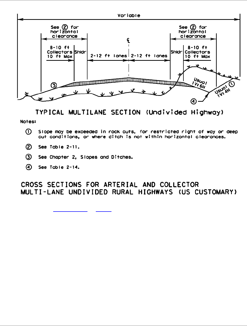
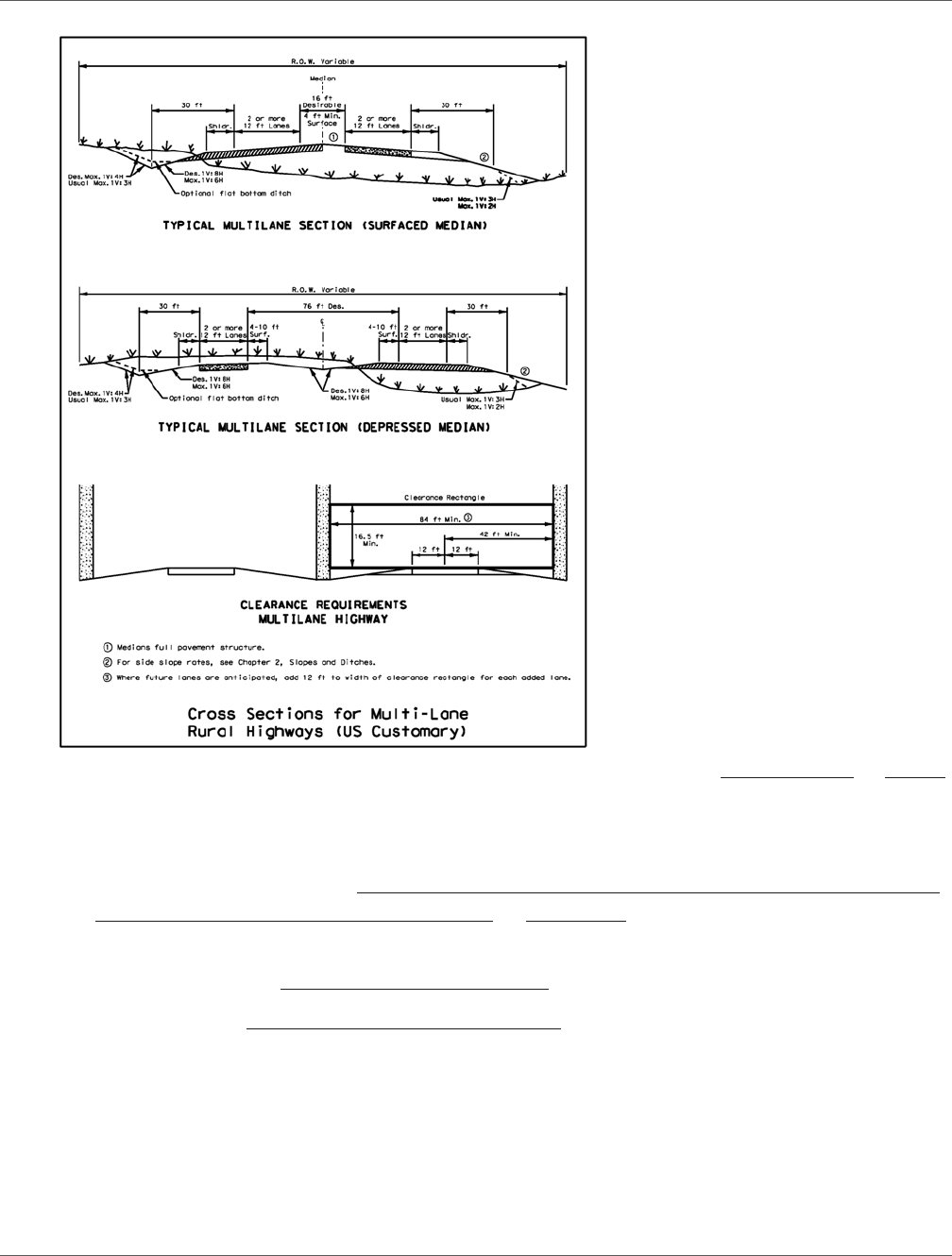
Roadway Design Manual 3-40 TxDOT 04/2018
Chapter 3 — New Location and Reconstruction (4R)
Design Criteria Section 5 — Multi-Lane Rural Highways
Figure 3-8. (US). Cross Sections For Multi-Lane Rural Highways. Click US Customary or Metric
to see a PDF of the image.
References to other applicable criteria are as follows:
Minimum Horizontal Radius: Table 2-3: Horizontal Curvature of High-Speed Highways and
Connecting Roadways with Superelevation and Figure 2-3, Determination of Length of
Superelevation Transition.
Maximum Gradient: Table 2-9: Maximum Grades
Fill Slope Rates: Table 2-10: Earth Fill Slope Rates.
Level of Service
Rural arterials and their auxiliary facilities should be desirably designed for level of service B in the
design year as defined in the Highway Capacity Manual.

Roadway Design Manual 3-41 TxDOT 04/2018
Chapter 3 — New Location and Reconstruction (4R)
Design Criteria Section 5 — Multi-Lane Rural Highways
Undivided four-lane roadways have generally been associated with higher accident rates than
divided roadways. This higher accident rate has frequently been attributed to the lack of protection
for left-turning vehicles. Therefore, if an undivided facility is selected for a location, the impact of
left-turning vehicles should be examined.
For more information regarding level of service as it relates to facility design, see Service Flow
Rate in the sub section titled Traffic Volume of Chapter 2.
Basic Design Criteria
This subsection includes information on the following basic design features for multi-lane rural
highways:
Access Control
Medians
Turn Lanes
Travel Lanes and Shoulders
Intersections
Transitions to Four-Lane Divided Highways
Grade Separations and Interchanges
Access Control
The installation of all access driveways along multilane facilities from adjacent property connect-
ing to the main lanes should be in accordance with the TxDOT Access Management Manual.
For multilane highways constructed in developed (or expected to be developed) areas, such as by-
passes in close proximity to urban areas, it may be desirable to control access to the main lanes by
either purchasing access rights as part of the right-of-way acquisition or by design (i.e., provision of
frontage roads). Where desired, control of access by design may be provided either solely in the
interchange areas or continuously throughout a section of highway, depending on traffic volumes,
the degree of roadside development, availability of right-of-way, economic conditions, etc.
All frontage road development must be in accordance with the rules contained in 43 Texas Admin-
istrative Code (TAC) §15.54. The Project Development Policy Manual can also be referenced for
additional information.
Medians
The width of the median is the distance between the inside edges of the travel lanes. Insofar as
practical, wide (desirably 76 ft [22.8 m]) medians should be used to provide sufficient storage

Roadway Design Manual 3-42 TxDOT 04/2018
Chapter 3 — New Location and Reconstruction (4R)
Design Criteria Section 5 — Multi-Lane Rural Highways
space for tractor-trailer combination vehicles at median openings, reduce headlight glare, provide a
pleasing appearance, and reduce the chances of head-on collisions. However, in areas that are likely
to become suburban or urban in nature, medians wider than 60 ft [18 m] should be avoided at inter-
sections except where necessary to accommodate turning and crossing maneuvers by larger
vehicles. Wide medians may be a disadvantage when signalization is required at intersections. The
increased time for vehicles to cross the median can lead to inefficient signal operation.
Four-Lane Undivided Highways. Improvement of an existing two-lane highway to a four-lane
highway facility preferably should include a median. Undivided highways may be constructed as
betterment projects for existing two-lane highways to improve passing opportunities and traffic
operations. Undivided highways are sometimes provided in rolling terrain, or where restricted
right-of-way conditions and moderate traffic volumes dictate. Table 3-12: Design Criteria For Mul-
tilane Rural Highways (Non-controlled Access) (All Functional Classes) and Figure 3-7 include the
general geometric features for four-lane undivided highways.
Surfaced Medians. Surfaced medians of 4 ft to 16 ft [1.2 m to 4.8 m] are classified as narrow
medians and are used in restricted conditions. Medians 4 ft [1.2 m] wide provide little separation of
opposing traffic and a minimal refuge area for pedestrians. Surfaced medians of 14 ft to 16 ft [4.2 m
to 4.8 m] offer space for use by exiting traffic turning left, but do not offer protection for crossing
vehicles. Surfaced median designs are most appropriate in areas with roadside development.
Wide Medians. Medians 76 ft [22.8 m] wide significantly reduce headlight glare, are pleasing in
appearance, reduce the chances of head-on collisions, and provide a sheltered storage area for
crossing vehicles, including tractor-trailer combinations. Wide medians should generally be used
whenever feasible but median widths greater than 60 ft [18 m] have been found to be undesirable
for intersections that are signalized or may be signalized in the design life of the project.
Median Openings. Median openings at close intervals on divided highways can cause interference
between high-speed through-traffic and turning vehicles. The frequency of median openings varies
with topographic restrictions and local requirements; however, as a general rule the minimum spac-
ing should not be less than one-quarter mile [400 m] in rural areas. Spacing often is selected to
provide openings at all public roads and at major traffic generators such as industrial sites or shop-
ping centers. Additional openings should be provided so as not to surpass a maximum one-half
mile [800 m] spacing.
Left-turn lanes should be provided at all median openings. At intersections with highways or other
major public roads, turn lanes for right-turning vehicles entering and exiting the highway are usu-
ally provided, as shown in Figure 3-9. For divided highways with independent main lane
alignment, particular care should be exercised at median openings to provide a satisfactory profile
along the crossover with flat, platform approaches to the main lanes.
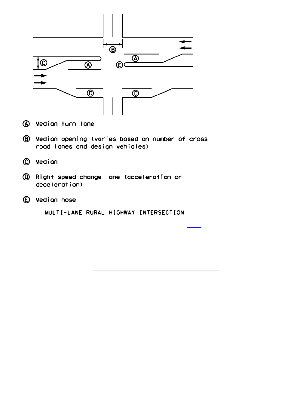
Roadway Design Manual 3-43 TxDOT 04/2018
Chapter 3 — New Location and Reconstruction (4R)
Design Criteria Section 5 — Multi-Lane Rural Highways
Figure 3-9. Multi-Lane Rural Highway Intersection. Click here to see a PDF of the image.
Median opening width should in no case be less than 40 ft [12 m] nor less than crossroad pavement
width plus 8 ft [2.4 m]. Turning templates for a selected control radius and design vehicle are often
used as the basis for minimum design of median openings, particularly for multilane crossroads and
skewed intersections. See Minimum Designs for Truck and Bus Turns for additional information.
Turn Lanes
Turn lanes, or speed change lanes, should generally be provided wherever vehicles must slow to
leave a facility or accelerate to merge onto a facility.
Median Turn Lane (Left-Turn Lane). Median turn lanes provide deceleration and storage area
for vehicles making left turns to leave a divided highway. Storage, taper, and deceleration lengths
for design are summarized in Table 3-13. Turn lanes shorter than the lengths given in Table 3-13

Roadway Design Manual 3-44 TxDOT 04/2018
Chapter 3 — New Location and Reconstruction (4R)
Design Criteria Section 5 — Multi-Lane Rural Highways
may be acceptable on some low volume rural highways. Also adjustments for grade are given in
Table 3-14.
Right Turn Deceleration Lane. Right (12 ft [3.6 m] lane with 4 ft [1.2 m] adjacent shoulders) turn
lanes provide deceleration or acceleration area for right-turning vehicles. The deceleration length
and taper lengths for right turn lanes are the same as for left-turn lanes (See Table 3-13). Adjust-
ment factors for grade effects are shown in Table 3-14.
Table 3-13: Lengths of Median Turn Lanes Multilane Rural Highways
(US Customary)
Mainlane Design
Speed (mph)
Taper Length
(ft)1Deceleration
Length (ft)2-Design Turning
ADT (vpd)
Minimum Storage
Length (ft)
30 50 160 - 150 50
35 50 215 - 300 100
40 50 275 - 500 175
45 100 345 - 750 250
50 100 425 - -- --
55 100 510 - -- --
60 150 615 - -- --
65 150 715 - -- --
70 150 830 - -- --
75 150 950 - -- --
80 150 1075 - -- --
(Metric)
Mainlane Design
Speed (km/h)
Taper Length
(m)1Deceleration
Length (m)2-Design Turning
ADT (vpd)
Minimum Storage
Length (m)
50 15 50 - 150 15
60 15 65 - 300 30
70 30 85 - 500 50
80 30 105 - 750 75
90 30 130 - - -
100 45 200 - - -
110 45 240 - - -
120 45 290 - - -
130 45 330 - - -
1 For low volume median openings, such as those serving private drives or U-turns, a taper length of 100 ft [30
m] may be used regardless of mainlane design speed.
2 Deceleration length assumes that moderate deceleration will occur in the through traffic lane and the vehicle
entering the left-turn lane will clear the through traffic lane at a speed of 10 mph (15 km/h) slower than
through traffic. Where providing this deceleration length is impractical, it may be acceptable to allow turning
vehicles to decelerate more than 10 mph (15km/h) before clearing the through traffic lane.
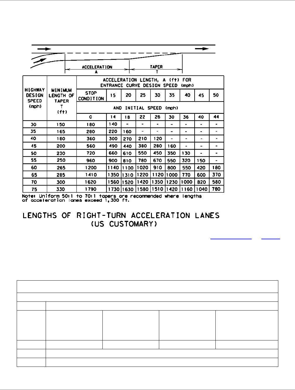
Roadway Design Manual 3-45 TxDOT 04/2018
Chapter 3 — New Location and Reconstruction (4R)
Design Criteria Section 5 — Multi-Lane Rural Highways
Acceleration Lanes. Acceleration lanes for right-turning and/or left-turning vehicles may be desir-
able on multi-lane rural highways. Acceleration distances and taper lengths are provided in Figure
3-10. Adjustments for grade are given in Table 3-14.
Figure 3-10. (US). Lengths of Right-Turn Acceleration Lanes. Click US Customary or Metric to
see a PDF of the image.
Table 3-14: Speed Change Lane Adjustment Factors as a Function of a Grade
(US Customary)
Deceleration Lanes
- Ratio of Length on Grade to Length on Level*
Design
Speed of
Roadway
(mph)
3 to 4 % Upgrade 3 to 4 % Downgrade 5 to 6% Upgrade 5 to 6% Downgrade
All 0.9 1.2 0.8 1.35
- Acceleration Lanes
- Ratio of Length on Grade to Length for Design Speed (mph) of Turning Roadway Curve*

Roadway Design Manual 3-46 TxDOT 04/2018
Chapter 3 — New Location and Reconstruction (4R)
Design Criteria Section 5 — Multi-Lane Rural Highways
Design
Speed of
Roadway
(mph)
20 25 30 35 40 45 50 All Speeds
- 3 to 4 % Upgrade 3 to 4%
Downgrade
30 ---- ---- ---- ---- ---- ---- ---- ----
35 ---- ---- ---- ---- ---- ---- ---- 0.7
40 1.3 1.3 1.3 1.3 ---- ---- ---- 0.7
45 1.3 1.3 1.35 1.35 ---- ---- ---- 0.675
50 1.3 1.35 1.4 1.4 1.4 ---- ---- 0.65
55 1.35 1.4 1.45 1.45 1.45 1.45 ---- 0.625
60 1.4 1.45 1.5 1.5 1.5 1.51.55 1.6 0.6
65 1.45 1.5 1.55 1.55 1.6 1..65 1.7 0.6
70 1.5 1.55 1.6 1.65 1.7 1.75 1.8 0.6
75 1.55 1.6 1.65 1.7 1.75 1.8 1.9 0.6
80 1.6 1.65 1.7 1.75 1.8 1.9 2.0 0.6
- 5 to 6% Upgrade 5 to 6%
Downgrade
30 ---- ---- ---- ---- ---- ---- ---- ----
35 ---- ---- ---- ---- ---- ---- ---- 0.6
40 1.5 1.5 1.5 1.6 ---- ---- ---- 0.6
45 1.5 1.55 1.6 1.6 ---- ---- ---- 0.575
50 1.5 1.6 1.7 1.8 1.9 2.0 ---- 0.55
55 1.6 1.7 1.8 1.9 2.05 2.1 ---- 0.525
60 1.7 1.8 1.9 2.05 2.2 2.4 2.5 0.5
65 1.85 1.95 2.05 2.2 2.4 2.6 2.75 0.5
70 2.0 2.1 2.2 2.4 2.6 2.8 3.0 0.5
75 2.2 2.3 2.4 2.65 2.9 3.2 3.5 0.5
80 2.4 2.5 2.6 2.9 2.9 3.6 4.0 0.5
*Ratio in this table multiplied by length of deceleration or acceleration distances in Table 3-13 and Figure 3-
10, gives length of deceleration/acceleration distance on grade.
Table 3-14: Speed Change Lane Adjustment Factors as a Function of a Grade
(Metric)
Deceleration Lanes
- Ration of Length on Grade to Length on Level*
Design
Speed of
Roadway
(mph)
3 to 4 % Upgrade 3 to 4 % Downgrade 5 to 6% Upgrade 5 to 6% Downgrade
Table 3-14: Speed Change Lane Adjustment Factors as a Function of a Grade
(US Customary)

Roadway Design Manual 3-47 TxDOT 04/2018
Chapter 3 — New Location and Reconstruction (4R)
Design Criteria Section 5 — Multi-Lane Rural Highways
Travel Lanes and Shoulders
Travel Lanes. Travel lanes should be 12 ft [3.6 m] minimum width on rural multilane highways.
The Highway Capacity Manual should be consulted to determine the number of lanes to be used in
the design.
Shoulders. Shoulders should be provided with widths as shown in Table 3-12: Design Criteria For
Multilane Rural Highways (Non-controlled Access) (All Functional Classes).
All 0.9 1.2 0.8 1.35
- Acceleration Lanes
- Ratio of Length on Grade to Length for Design Speed (km/h of Turning Roadway Curve)*
Design
Speed of
Roadway
(km/h)
40 50 60 70 80 All Speeds
- 3 to 4 % Upgrade 3 to 4%
Downgrade
50 ---- ---- ---- ---- ---- ----
60 1.3 1.4 1.4 ---- ---- 0.7
70 1.3 1.4 1.4 1.5 ---- 0.65
80 1.4 1.5 1.5 1.5 1.6 0.65
90 1.4 1.5 1.5 1.5 1.6 0.6
100 1.5 1.6 1.7 1.7 1.8 0.6
110 1.5 1.6 1.7 1.7 1.8 0.6
120 1.5 1.6 1.7 1.7 1.8 0.6
130 1.5 1.6 1.7 1.7 1.8 0.6
- 5 to 6% Upgrade 5 to 6%
Downgrade
50 ---- ---- ---- ---- ---- ----
60 1.5 1.5 ---- ---- ---- 0.6
70 1.5 1.6 1.7 ---- ---- 0.6
80 1.5 1.7 1.9 1.8 ---- 0.55
90 1.6 1.8 2.0 2.1 2.2 0.55
100 1.7 1.9 2.2 2.4 2.5 0.5
110 2.0 2.2 2.6 2.8 3.0 0.5
120 2.3 2.5 3.0 3.2 3.5 0.5
130 2.6 2.8 3.4 3.6 4.0 0.5
*Ratio in this table multiplied by length of deceleration or acceleration distances in Table 3-13 and Figure 3-
10, gives length of deceleration/acceleration distance on grade.
Table 3-14: Speed Change Lane Adjustment Factors as a Function of a Grade
(Metric)

Roadway Design Manual 3-48 TxDOT 04/2018
Chapter 3 — New Location and Reconstruction (4R)
Design Criteria Section 5 — Multi-Lane Rural Highways
Intersections
In the design of intersections, careful consideration should be given to the appearance of the inter-
section from the driver’s perspective. In this regard, design should be rather simple to avoid driver
confusion. In addition, adequate sight distance should be provided throughout, especially in maneu-
ver or conflict areas. See Stopping Sight Distance in Chapter 2 for further information regarding
sight distance.
Right angle crossings are preferred to skewed crossings, and where skew angles exceed 60 degrees,
alignment modifications are generally necessary. Turn Lanes may be provided in accordance with
previous discussions.
Chapter 7, Minimum Designs for Truck and Bus Turns provides information regarding the accom-
modation of various types of truck class vehicles in intersection design. AASHTO’s A Policy on
Geometric Design of Highways and Streets should be consulted for further information on intersec-
tion design and intersection sight distance.
Intersections formed at by-pass and existing route junctions should be designed so as not to mislead
drivers. Treatment of an old-new route connection is illustrated in Figure 3-11.
For intersections with narrow, depressed median sections, it may be necessary to effect supereleva-
tion across the entire cross section to provide for safer operation at median openings.
For more information on intersection design, See Stopping Sight Distance in Chapter 2.
For more information on border areas, see Borders.
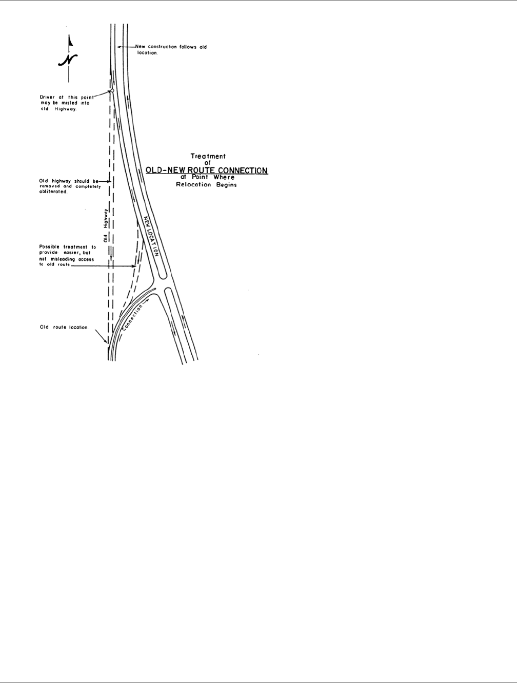
Roadway Design Manual 3-49 TxDOT 04/2018
Chapter 3 — New Location and Reconstruction (4R)
Design Criteria Section 5 — Multi-Lane Rural Highways
Figure 3-11. Treatment of Old-New Route Connection at Point Where Relocation Begins.
Transitions to Four-Lane Divided Highways
Typical transitions from a two-lane to a four-lane divided highway are shown in Figure 3-12. Tran-
sition geometrics should meet the design criteria based on the highest design speed of the two
roadways. The transition should be visible to the driver approaching from either direction and
median openings should not be permitted within one-quarter mile [400 m] of the transition area.
Transition areas should be located so that obstructions such as restrictive width bridges or under-
passes or other fixed objects are not within the no-passing zone of the two-lane highway approach.

Roadway Design Manual 3-50 TxDOT 04/2018
Chapter 3 — New Location and Reconstruction (4R)
Design Criteria Section 5 — Multi-Lane Rural Highways
Figure 3-12. (US). Typical Transitions From Two-Lane To Four-Lane Divided Highways. Click US
Customary or Metric to see a PDF of the image.
Converting Existing Two-Lane Roadways to Four-Lane Divided Facilities
The Federal Highway Administration will allow the existing alignments to remain in place when
existing two-lane roadways are converted to four-lane divided facilities. Specifically, the new road-
bed will be constructed to full current standards. When the existing lanes are converted to one-way
operations, no changes are required in the horizontal or vertical alignment of the existing road.
Other features such as signing, roadside hardware, safety end treatments, etc., should meet current
standards.
Existing structures with substandard width on the existing lanes may remain if that width meets
minimum rehabilitation (3R) requirements for multi-lane facilities.
An accident analysis of the existing two-lane roadway should be conducted. Any specific areas
involving high accident frequencies will be reviewed and corrective measures taken where
appropriate.

Roadway Design Manual 3-51 TxDOT 04/2018
Chapter 3 — New Location and Reconstruction (4R)
Design Criteria Section 5 — Multi-Lane Rural Highways
Grade Separations and Interchanges
Grade separations or interchanges on multilane rural highways may be provided at high-volume
highway or railroad crossings, or to increase safety at accident-prone crossings.
Further information on grade separations and interchanges may be found in Chapter 3, Freeways
and Chapter 10 of AASHTO’s A Policy on Geometric Design of Highways and Streets.

Roadway Design Manual 3-52 TxDOT 04/2018
Chapter 3 — New Location and Reconstruction (4R)
Design Criteria Section 6 — Freeways
Section 6 — Freeways
Overview
A freeway is defined as a controlled access multilane divided facility. Freeways are functionally
classified as arterials but have unique design characteristics that set them apart from non-access
controlled arterials. This section discusses the features and design criteria for freeways and includes
the following subsections:
Basic Design Criteria
Access Control
Mainlane Access
Vertical and Horizontal Clearance at Structures
Frontage Roads
Interchanges
Basic Design Criteria
Specific references to Freeway Geometric Design criteria are shown in Table 3-15:
Table 3-15: Freeway Geometric Design Criteria
Design Criteria Reference
General
Horizontal Clearance Table 2-11
Grades Table 2-9
Minimum Horizontal Radius Table 2-3 and 2-4
Superelevation Tables 2-6, 2-7 and 2-8
Vertical Curvature 2-7, 2-8 ,2-9, and 2-10
Pavement Cross Slope Chapter 2, Pavement Cross Slope
Freeways
Design Speed Mainlanes (urban and rural) Table 3-17
Design Speed Frontage Roads (urban and rural) Chapter 3, Frontage Roads
Capacity and LOS Analysis Highway Capacity Manual

Roadway Design Manual 3-53 TxDOT 04/2018
Chapter 3 — New Location and Reconstruction (4R)
Design Criteria Section 6 — Freeways
Access Control
This subsection discusses access control and includes the following topics:
General
Mainlane Access
Frontage Road Access
Driveways and Side Streets
Methods
General
The entire Interstate Highway System and portions of the State Highway System have been desig-
nated by the Commission as Controlled Access Highways, thereby making it necessary along
certain sections of said highways to either limit or completely deny the abutting owner’s access
rights, which include the right of ingress and egress and the right of direct access to and from said
owner’s abutting property to said highway facility. Such access may be controlled under the State’s
Police Power, which is an inherent right of a sovereignty. However, the existing right of access to
an existing public way is an increment of ownership and a part of the bundle of rights vested in the
owner of abutting property. It is a legal right, and though such right may be limited or completely
denied under the State’s Police Power, the owner is entitled to be paid whatever damages may be
suffered by reason of the loss of such access.
The abutting owners are denied access to any controlled access highway on new location, unless
there is a specific grant of access, and no damages may be claimed for the denial of access to the
new facility; the theory being that the owner cannot be damaged by the loss of something which the
owner never had.
If an existing road is converted into a controlled access facility, the design of which does not con-
template the initial construction of frontage roads, and the abutting owner is to be denied access to
such facility pending frontage road construction, there is a taking of the owner’s access rights. If an
existing road is converted into a controlled access facility, the design of which does contemplate
frontage road(s) in the initial construction, and the abutting owner is not to be denied access to such
frontage road(s), there is not taking or denial of access rights. Access to the frontage road(s) consti-
tutes access to the facility. Further control of movements, once upon the frontage road, such as one-
way traffic, no U-turns, no left or right turns, denial of direct access to the through lanes, and circu-
itous routes are all controlled under police power and inflict no more control over the abutting
owner than is inflicted upon the general public.
If an existing road is converted into a controlled access facility and no part of the abutting owner’s
property is taken for right of way, but access is to be denied to the controlled access facility, and by
reason of such denial of access it is found that such owner will suffer damages measured by the

Roadway Design Manual 3-54 TxDOT 04/2018
Chapter 3 — New Location and Reconstruction (4R)
Design Criteria Section 6 — Freeways
diminution of the market value of said abutting land, said owner should be requested to release and
relinquish said access rights for consideration equal to the State’s approved value for such damages.
If the owner is not willing to negotiate on these terms, then the access right may be acquired
through eminent domain proceedings. In some instances, the State’s appraisal and approved value
may indicate that there is no diminution in value by reason of the access denial, and in those cases
the abutting owner should be requested to release and relinquish access rights for no cash consider-
ation. If the owner refuses to do so, then the access rights should be acquired through eminent
domain proceedings with the State testifying to a zero value for such rights.
Mainlane Access
Freeway mainlane access, either to or from abutting property or cross streets, is only allowed to
occur through a ramp. This control of mainlane access may be achieved through one of the follow-
ing methods:
through access restrictions whereby the access to the highway from abutting property owners
is denied with ingress and egress to the mainlanes only at selected freeway or interchange
ramps
through construction of frontage roads permitting access to the mainlanes only at selected
ramps.
In either case, direct access from private property to the mainlanes is prohibited without excep-
tion.
Frontage Road Access
In the case where frontage roads are provided, access should be controlled for operational purposes
at ramp junctions with frontage roads through access restrictions or the use of the State’s police
powers to control driveway location and design. Figures 3-13 and 3-14 show recommended access
control strategies for planned exit and entrance ramps, respectively, and should be used where
practical.
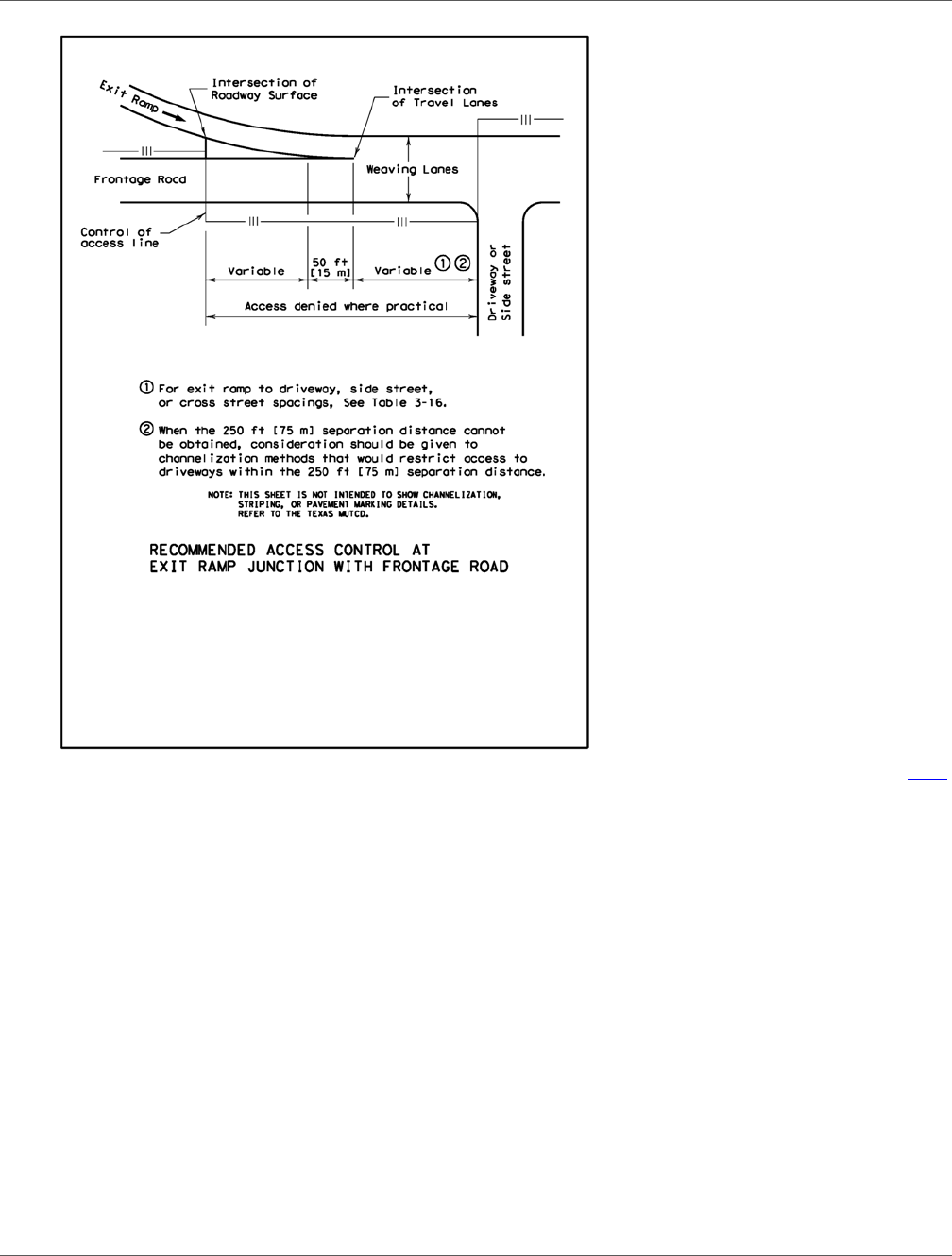
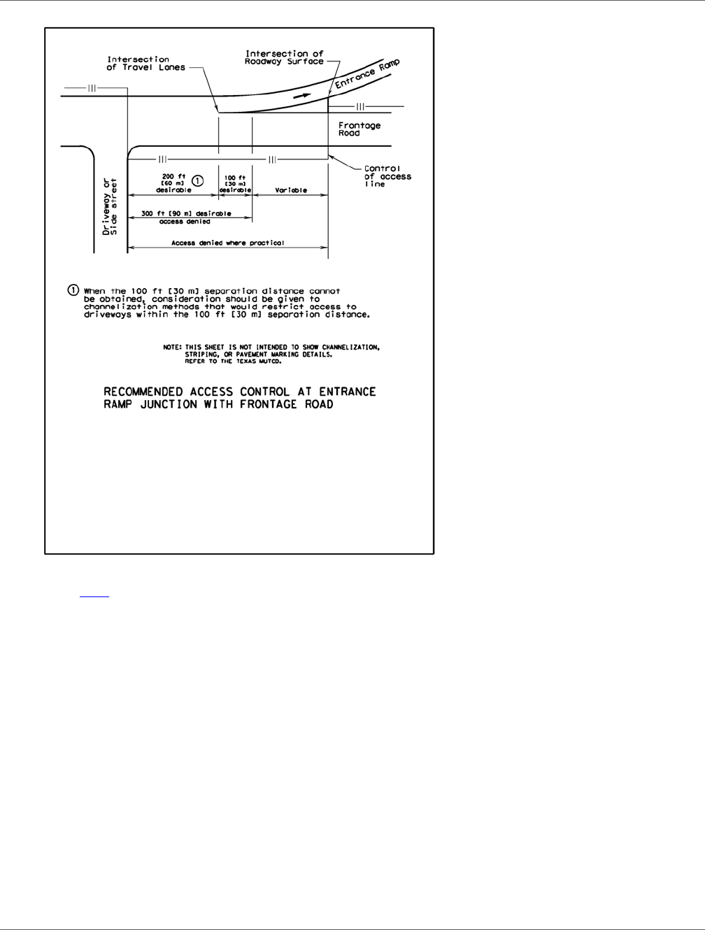
Roadway Design Manual 3-56 TxDOT 04/2018
Chapter 3 — New Location and Reconstruction (4R)
Design Criteria Section 6 — Freeways
Figure 3-14. Recommended Access Control At Entrance Ramp Junction With Frontage Road.
Click here to see a PDF of the image.
Driveways and Side Streets
The placement of streets and driveways in the vicinity of freeway ramp/frontage road intersections
should be carefully considered and permitted only after local traffic operations are considered.
Information on the driveway clearance from the cross street intersection is contained in the TxDOT
Access Management Manual and should be considered in the locating of any driveways on projects
involving the construction or reconstruction of ramps and/or frontage roads.

Roadway Design Manual 3-57 TxDOT 04/2018
Chapter 3 — New Location and Reconstruction (4R)
Design Criteria Section 6 — Freeways
Table 3-16 shows the spacing to be used between exit ramps and driveways, side streets, or cross
streets if practical. The number of weaving lanes is defined as the total number of lanes on the
frontage road downstream from the ramp.
Driveway or side street access on the frontage road in close downstream proximity to exit ramp ter-
minals increases the weaving that occurs on the frontage road and may lead to operational
problems. For this reason, it is important to maintain appropriate separation between the intersec-
tion of the exit ramp and frontage road travel lanes, and downstream driveways or side streets
where practical.
It is recognized that there are occasions when meeting these exit ramp separation distance values
may not be possible due to the nature of the existing development, such as a high number of closely
spaced driveways and/or side streets especially when in combination with closely spaced inter-
changes. In these cases, at least 250 ft [75 m] of separation should be provided between the
intersection of the exit ramp and frontage road travel lanes and the downstream driveway or side
street. Since the use of only 250 ft [75 m] of separation distance may negatively impact the opera-
tion of the frontage road, exit ramp, driveway and/or side street traffic, careful consideration should
be given to its use. When the 250 ft [75 m] separation distance cannot be obtained, consideration
should be given to channelization methods that would restrict access to driveways within this 250 ft
[75 m] distance. Refer to the Texas MUTCD for specific types of channelization.
There will be similar occasions when meeting the entrance ramp separation distance values may
not be possible due to the same existing development conditions associated with exit ramps. In
these cases, at least 100 ft [30 m] of separation distance should be provided between the intersec-
tion of the entrance ramp and frontage road travel lanes and the upstream driveway or side street.
Table 3-16: Desirable Spacing between Exit Ramps and Driveways, Side Streets, or Cross Streets
Total Volume
(Frtg rd +Ramp)
(vph)
Driveway or Side
Street Volume
(vph) Spacing
(ft [m])
-- -- Number of Weaving Lanes
-- -- 2 3 4
< 2500 < 250 460 [140] 460 [140] 560 [170]
-- > 250 520 [160] 460 [140] 560 [170]
-- > 750 790 [240] 460 [140] 560 [170]
-- > 1000 1000 [300] 460 [140] 560 [170]
> 2500 < 250 920 [280] 460 [140] 560 [170]
-- > 250 950 [290] 460 [140] 560 [170]
-- > 750 1000 [300] 600 [180] 690 [210]
-- > 1000 1000 [300] 1000 [300] 1000 [300]

Roadway Design Manual 3-58 TxDOT 04/2018
Chapter 3 — New Location and Reconstruction (4R)
Design Criteria Section 6 — Freeways
Since the use of only 100 ft [30 m] of entrance ramp separation distance may also negatively
impact the operation of the frontage road, entrance ramp, driveway, and/or side street traffic, care-
ful consideration should be given to its use. As with exit ramps, when the 100 ft [30 m] entrance
ramp separation distance cannot be obtained, consideration should be given to channelization meth-
ods that would restrict access to driveways within this 100 ft [30 m] distance. Refer to the Texas
MUTCD for specific types of channelization.
Relocating driveways. On reconstruction projects, it may be necessary to close or relocate drive-
ways in order to meet these guidelines. However, if the closure/relocation is not feasible, and
adjustment of the location of the ramp gore along the frontage road is not practical, then deviation
from these recommended guidelines may be necessary.
Ramp Location. In the preparation of schematic drawings, care should be exercised to develop
design in sufficient detail to accurately tie down the locations of ramp junctions with frontage roads
and thus the location of access control limits. These drawings are often displayed at meetings and
hearings and further become the basis for right-of-way instruments or, in some cases, the Depart-
ment's regulation of driveway location.
In some instances, ramps must be shifted to satisfy level of service considerations or geometric
design controls. When this is necessary, the access control limits should also be shifted if right-of-
way has not been previously purchased.
Methods
A controlled access highway may be developed in either of two ways:
Designation (Transportation Code §203.031 and access restrictions)
Design (continuous frontage road and State’s police power)
Designation
When the Texas Transportation Commission designates a freeway to be developed as a controlled
access facility under Transportation Code §203.031, the State is empowered to control access
through access restrictions. All Interstate Highways are designated as controlled access and certain
other routes have been or may be designated. These designated freeways may or may not have
frontage roads, whichever arrangement is determined to be appropriate as discussed in Planning
Development of freeways by designation, rather than solely by design, is the preferred design
approach especially for all new location freeways.
Under Transportation Code §203.031, Not Along An Existing Public Road. Whenever desig-
nated controlled access freeways include frontage roads and the planned location is not along an
existing public road, preferably access should be controlled through access restrictions at ramp
junctions with frontage roads as shown on Figure 3-13 and Figure 3-14.

Roadway Design Manual 3-59 TxDOT 04/2018
Chapter 3 — New Location and Reconstruction (4R)
Design Criteria Section 6 — Freeways
Where no frontage roads are provided, access is controlled to the mainlanes by access restriction.
Under Transportation Code §203.031, Along An Existing Public Road. Whenever a designated
controlled access freeway is to be provided along the location of an existing public road, generally
(subject to discussion in Planning) frontage roads are provided to retain or restore existing access.
Frontage road access should be controlled by imposing access restrictions in accordance with Fig-
ure 3-13 and Figure 3-14 whenever all of the following conditions prevail:
Right-of-way is being obtained from the abutting property owner(s).
A landlocked condition does not result.
Recommended control of access as shown in Figure 3-13 and Figure 3-14.
Access may be controlled by use of the State's police power to control driveway location and
design where any of the following conditions prevail:
No right of way is obtained from the abutting property owner(s).
Restricting access results in landlocking an abutting property.
Whenever the State's police powers are used, the denial of access zone should be free of driveways
insofar as practical.
Design
If an existing highway is to be developed as a controlled access facility solely by design (not desig-
nated by the Transportation Commission), the Texas Department of Transportation is not
empowered to purchase access rights but must achieve access control by construction of continuous
frontage roads and by the utilization of the State's police power to control driveways, particularly at
locations such as ramp junctions with frontage roads.
In the interest of providing for highway safety and utility, the State may regulate driveway location
and design through its police powers. Landlocking through complete denial of access is beyond the
State's regulatory power (without Commission designation under the Transportation Code). The
State, however, may effectively regulate driveway location in accordance with Statewide policy as
long as the following two conditions are met:
Reasonable access is provided.
Landlocking of an abutting property does not result.
The Departmental publication entitled TxDOT Access Management Manual governs design and
location of driveways.

Roadway Design Manual 3-60 TxDOT 04/2018
Chapter 3 — New Location and Reconstruction (4R)
Design Criteria Section 6 — Freeways
Whenever new or relocated ramps are to be provided along existing freeways, the design philoso-
phy shown in Frontage Roads applies. Access should therefore be controlled at frontage road
junctions through access restriction as illustrated in Figures 3-13 and 3-14 if practical and feasible.
Whenever access is to be controlled solely by provision of frontage roads, departmental power to
regulate driveway location and design should be used to control access near ramp junctions. How-
ever, where designation by the Transportation Commission is practical, it is preferred over
controlling access solely by design.
Mainlanes
This subsection discusses mainlanes and includes information on the following topics:
Design Speed
Level of Service
Lane Width and Number
Shoulders
Medians
Outer Separation
Crossing Facilities
Design Speed
The design speed of urban freeways should reflect the desired operating conditions during non-
peak hours. The design speed should not exceed the limits of prudent construction, right-of-way,
and socioeconomic costs because a large proportion of vehicles are accommodated during periods
of peak flows when lower speeds are tolerable. Design speeds for rural freeways should be high,
providing a design speed that is consistent with the overall quality and safety of the facility.
Table 3-17 provides minimum design speeds for freeways:
Level of Service
For acceptable degrees of congestion, urban freeways and their auxiliary facilities should generally
be designed for level of service C, as defined in the Highway Capacity Manual, in the design year.
Table 3-17: Design Speed for Controlled Access Facilities (mph [km/h])
Facility Minimum
Mainlanes - Urban 50 [80]
Mainlanes - Rural 70 [110]
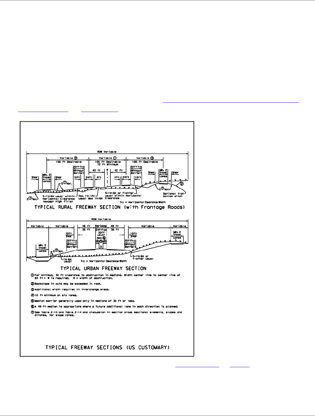
Roadway Design Manual 3-61 TxDOT 04/2018
Chapter 3 — New Location and Reconstruction (4R)
Design Criteria Section 6 — Freeways
In heavily developed urban areas, level of service D may be acceptable. In rural areas, level of ser-
vice B is desirable for freeway facilities; however, level of service C may be acceptable for
auxiliary facilities (i.e., ramps, direct connections and frontage roads) carrying unusually high
volumes.
Lane Width and Number
The minimum and usual mainlane width is 12 ft [3.6 m]. The number of lanes required to accom-
modate the anticipated traffic in the design year is determined by the level of service evaluation as
discussed in the Highway Capacity Manual. See Table 3-18: Roadway Widths for Controlled
Access Facilities and Figure 3-11 for further information.
Figure 3-15. (US). Typical Freeway Sections. Click US Customary or Metric to see a PDF of the
image.

Roadway Design Manual 3-62 TxDOT 04/2018
Chapter 3 — New Location and Reconstruction (4R)
Design Criteria Section 6 — Freeways
Shoulders
Continuous surfaced shoulders are provided on each side of the mainlane roadways, both rural and
urban, as shown in Figure 3-15. The minimum widths should be 10 ft [3.0 m] on the outside and 4
ft [1.2 m] on the median side of the pavement for four-lane freeways. On freeways of six lanes or
more, 10 ft [3.0 m] inside shoulders for emergency parking should be provided. A 10 ft [3.0 m] out-
side shoulder should be maintained along all speed change lanes with a 6 ft [1.8 m] shoulder
considered in those instances where light weaving movements take place. See Table 3-18: Road-
way Widths for Controlled Access Facilities and Figure 3-11 for further information.
Medians
The width of the median is the distance between the inside edges of the travel lanes. For depressed
freeway sections, medians 76 ft [22.8 m] in width are generally used. Where topography, right-of-
way, or other special considerations dictate, depressed freeway median width may be reduced from
76 ft [22.8 m] to a minimum of 48 ft [14.4 m]. A median width of 24 ft to 30 ft [7.2 m to 9.0 m] is
generally used on freeway sections with flush medians. On freeways including six or more travel
lanes and a flush 24 ft [7.2 m] median, the resulting section provides for 10 ft [3.0 m] inside shoul-
ders and a usual 2 ft [0.6 m] offset to barrier centerline. See Figure 3-11 for further information.
Because of high speed and volume traffic on urban freeways and the resulting adverse environment
for accomplishing construction improvements thereon, it is the usual practice to construct the ulti-
mate freeway section initially. Under those unusual circumstances where future additional lanes
will be provided in the median area, the usual median width of 24 ft [7.2 m] should be increased by
the appropriate multiple of 12 ft [3.6 m] in anticipation of need for additional lanes. Provisions
should be made, or retained, for any future high occupancy vehicle lanes in the median.
At horizontal curves on freeways with narrow medians, a check should be made to insure that the
median barrier does not restrict stopping sight distance to less than minimum values.
For information on freeway median crossings, refer to Chapter 7, Emergency Median Openings on
Freeways.
Outer Separation
The portion of the freeway between the mainlanes and frontage road, or right-of-way line where
frontage roads are not provided, should be wide enough to accommodate shoulders, speed change
lanes, side slopes and drainage, retaining walls and ramps, as well as the necessary signs and other
appurtenances necessary for traffic control. Because of right-of-way limitations in urban areas, the
outer separation may oftentimes be narrower than desired; however, in rural areas, where opposing
headlights along a two-way frontage road tend to reduce a driver’s comfort and perception on the
freeway, the outer separation should be as wide as possible.

Roadway Design Manual 3-63 TxDOT 04/2018
Chapter 3 — New Location and Reconstruction (4R)
Design Criteria Section 6 — Freeways
Crossing Facilities
The following exhibits show the appropriate widths for facilities crossing the freeway:
Urban Streets: Table 3-1: Geometric Design Criteria for Urban Streets
Suburban Roadways: Table 3-5: Geometric Design Criteria for Suburban Roadways
Rural Two-Lane Highways: Table 3-7. Geometric Design Criteria for Rural Two-Lane High-
ways and Table 3-8: Width of Travel Lanes and Shoulders on Rural Two-lane Highways
Multilane Rural Highways: Table 3-12: Design Criteria For Multilane Rural Highways (Non-
controlled Access) (All Functional Classes)
The Bridge Project Development Manual should also be referenced for appropriate structure
widths.
Vertical and Horizontal Clearance at Structures
Vertical. All controlled access highway grade separation structures, including railroad underpasses,
should provide 16.5 ft [5.0 m] minimum vertical clearance over the usable roadway.
Structures over the mainlanes of interstate or controlled access highways must meet the minimum
vertical clearance requirement except within cities where the 16.5 ft [5.0 m] vertical clearance is
provided on an interstate loop around the particular city. Less than 16 ft [4.9 m] vertical clearance
on rural interstate and single priority defense interstate routes, including ramps and collector-dis-
tributor roads, requires approval through the Design Division with the Federal Highway
Administration and/or the Military Traffic Management Command Transportation Engineering
Agency (MTMCTEA) of the Department of Defense (DOD).
Roadways under the mainlanes of interstate or controlled access highways must meet the minimum
vertical clearance requirements for the appropriate undercrossing roadway classification.
Vertical clearances for pedestrian crossover structures should be approximately 1 ft [0.3 m] greater
than that provided for other grade separation structures. This is due to the increased risk of personal
injury upon impact by over-height loads and the relative weakness of such structures to resist lat-
eral loads from vehicular impact.
The above-specified clearances apply over the entire width of roadway including usable shoulders
and include an allowance of 6 inches [150 mm] for future pavement overlays. It is recognized that
it is impractical to arrive at the exact clearance dimensions on the structure plans. However, the
above clearances should not generally be exceeded by more than approximately 3 inches [75 mm].
Vertical clearance for railroad overpasses is shown in Figure 3-16, and is discussed further in the
Bridge Project Development Manual.
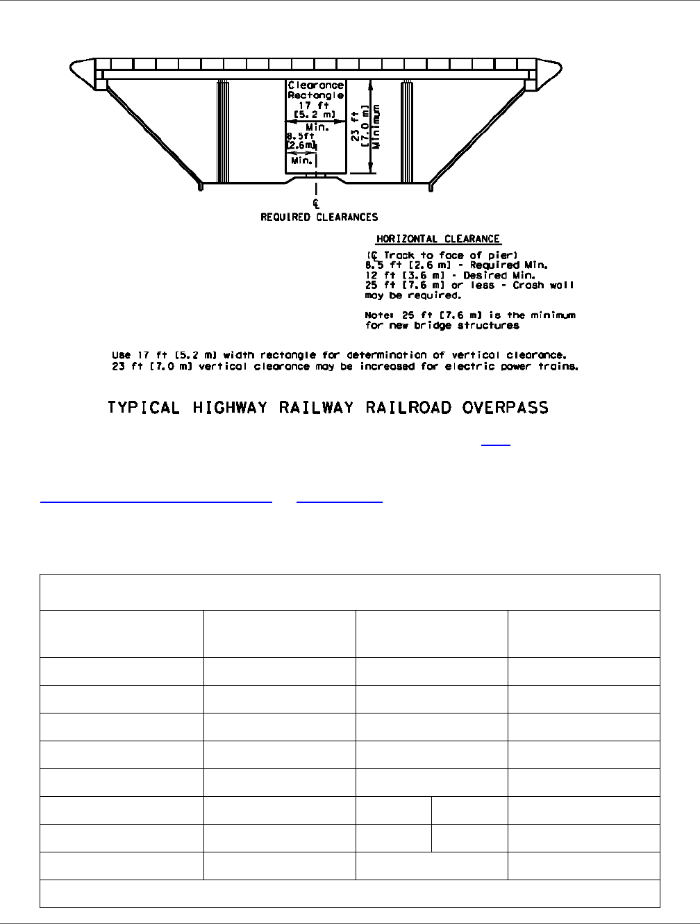
Roadway Design Manual 3-64 TxDOT 04/2018
Chapter 3 — New Location and Reconstruction (4R)
Design Criteria Section 6 — Freeways
Figure 3-16. Typical Highway Railway Railroad Overpass. Click here to see a PDF of the image.
Horizontal. The minimum horizontal clearance to bridge parapets and piers should be as shown in
Table 2-11: Horizontal Clearances and Figure 3-12.
Table 3-18: Roadway Widths for Controlled Access Facilities
(US Customary)
Type of Roadway Inside Shoulder Width
(ft) Outside Shoulder Width2
(ft) Traffic Lanes
(ft)
Mainlanes: - - -
4-Lane Divided 4 10 24
6-Lane or more Divided 10 10 361
1-Lane Direct Conn.2 2 Rdwy.; 4 Str. 8 14
2-Lane Direct Conn. 2 Rdwy.; 4 Str. 8 24
Ramps2 (uncurbed) 2 Rdwy.; 4 Str. Min. Des. 14
--68-
Ramps3 (curbed) — — 22
(Metric)

Roadway Design Manual 3-65 TxDOT 04/2018
Chapter 3 — New Location and Reconstruction (4R)
Design Criteria Section 6 — Freeways
Frontage Roads
This subsection discusses frontage roads and includes information on the following topics:
Function and Uses
Planning
Design Speed on Frontage Roads
Capacity and Level of Service
Function and Uses
Frontage roads serve a multitude of purposes in addition to controlling or providing access. Urban
frontage roads are multi-functional. They reduce the “barrier” effect of urban freeways since they
provide for some of the circulation of the local street system. They provide invaluable operational
flexibility, serving as detour routes when mainlane accidents occur, during mainlane maintenance
activity, for over-height loads, as bus routes, or during inclement weather. For freeways that include
freeway surveillance and control, continuous frontage roads provide the operational flexibility
required to manage saturation.
Type of Roadway Inside Shoulder Width
(m) Outside Shoulder Width2
(m) Traffic Lanes
(m)
Mainlanes: - - -
4-Lane Divided 1.2 3.0 7.2
6-Lane or more Divided 3.0 3.0 10.81
1-Lane Direct Conn.2 0.6 Rdwy.; 1.2 Str. 2.4 4.2
2-Lane Direct Conn. 0.6 Rdwy.; 1.2 Str. 2.4 7.2
Ramps2 (uncurbed) 0.6 Rdwy.; 1.2 Str. Min. Des. 4.2
--1.82.4-
Ramps3 (curbed) — — 6.6
1 For more than six lanes, add 12 ft [3.6 m] width per lane.
2 If sight distance restrictions are present due to horizontal curvature, the shoulder width on the inside of the
curve may be increased to 8 ft [2.4 m] and the shoulder width on the outside of the curve decreased to 2 ft [0.6
m] (Rdwy) or 4 ft [1.2 m] (Str).
3 The curb for a ramp lane will be mountable and limited to 4 inches [100 mm] or less in height. The width of
the curbed ramp lane is measured face to face of curb. Existing curb ramp lane widths of 19 ft [5.7 m] may be
retained.
Table 3-18: Roadway Widths for Controlled Access Facilities
(US Customary)

Roadway Design Manual 3-66 TxDOT 04/2018
Chapter 3 — New Location and Reconstruction (4R)
Design Criteria Section 6 — Freeways
In addition to the above-described purposes of frontage roads, many times they prove advantageous
when used as the first stage of construction for an ultimate freeway facility. By constructing front-
age roads prior to the mainlanes, interim traffic demands very often can be satisfied and a usable
section of highway can be opened to the traveling public at a greatly reduced cost.
Planning
Frontage roads may be incorporated into a project at various points during the project development,
however, later incorporation of frontage roads will be more difficult. Frontage roads may be
included:
during the planning stage
subsequent to the planning stage
after the freeway has been constructed.
Frontage road construction may be funded by TxDOT, a local government, or shared by both. The
Texas Transportation Commission has adopted rules governing the construction and funding of
frontage roads. All frontage road development must be in accordance with the rules contained in 43
Texas Administrative Code (TAC) §15.54. The Project Development Policy Manual can also be
referenced for additional information.
Changes in control of access must be in accordance with 43 TAC §15.54(d)(4).
As specified in the Right of Way Manual, Volume 1, subsequent changes in the control of access
will be as shown on approved construction plans or as provided in instruments conveying right-of-
way on authorized projects, or as may be authorized by Commission Minute Order. Where access is
permitted to adjacent properties, ingress and egress will be governed by the issuance of permits to
construct access driveway facilities as set forth in established Departmental policy which is
designed to provide reasonable access, to insure traffic safety, and preserve the utility of highways.
Design Speed on Frontage Roads
Design speeds for frontage roads are a factor in the design of the roadway. For consistency, design
speeds should be used that match values used for collector streets or highways. For urban frontage
roads, the desirable design speed is 50 mph [80 km/h] and the minimum design speed is 30 mph [50
km/h]. See Table 3-5: Geometric Design Criteria for Suburban Roadways for design speeds for
suburban frontage roads, and Table 3-6: Minimum Design Speed for Rural Two-lane Highways for
rural frontage roads.

Roadway Design Manual 3-67 TxDOT 04/2018
Chapter 3 — New Location and Reconstruction (4R)
Design Criteria Section 6 — Freeways
Capacity and Level of Service
Although techniques to estimate capacity and level of service on freeways and urban arterials are
detailed in the Highway Capacity Manual, these procedures should not be applied directly to front-
age roads, as frontage roads have features characteristic of both freeways (i.e., exit and entrance
ramps) and urban arterials (i.e., driveways, cross streets and signalized intersections). The follow-
ing report was developed to suggest techniques for estimating capacity and level of service on
frontage roads.
Kay Fitzpatrick, R. Lewis Nowlin, and Angelia H. Parham. Procedures to Determine Frontage
Road Level of Service and Ramp Spacing. Research Report 1393-4F, Texas Department of Trans-
portation, Texas Transportation Institute, 1996.
Research Report 1393-4F contains procedures for the following:
determining level of service on a continuous frontage road section
analyzing frontage road weaving sections
determining spacing requirements for ramp junctions.
Frontage Road Design Criteria
Design criteria for urban frontage roads are shown in Table 3-1: Geometric Design Criteria for
Urban Streets using the collector criteria. Design criteria for suburban frontage roads are shown in
Table 3-5: Geometric Design Criteria for Suburban Roadways using the collector criteria. Design
criteria for rural frontage roads are shown in Table 3-19: Design Criteria for Rural Frontage Roads.
Horizontal clearances are given in Table 2-11: Horizontal Clearances.
Any frontage road constructed will be designed to provide one-way operation initially. There may
be exceptions in certain isolated instances; however, such exceptions will be considered only
where, due to extraordinary circumstances, a one-way pattern would impose severe restrictions on
circulation within an area. In those cases where such exceptions are considered, they must be
approved by the Design Division at the schematic stage.
Table 3-19: Design Criteria for Rural Frontage Roads
(US Customary)
Design Speed2 (mph) Min. Width1 for Future Traffic Volume of
- 0-400 ADT 400-1,500 ADT 1,500-2,000 ADT 2,000 or more ADT
LANES (ft)
20 10 10 11 12
25 10 10 11 12
30 10 10 11 12
35 10 10 11 12
40 10 11 11 12

Roadway Design Manual 3-68 TxDOT 04/2018
Chapter 3 — New Location and Reconstruction (4R)
Design Criteria Section 6 — Freeways
45 10 11 11 12
50 10 11 12 12
55 10 11 12 12
60 11 11 12 12
65 11 11 12 12
70 11 11 12 12
75 11 12 12 12
80 11 12 12 12
SHOULDERS (ft)4
Each Shoulder
Two-Way Operation
234 8 8 – 10
Inside Shoulder
One-Way Operation
232344
4
Outside Shoulder
One-Way Operation
234 8 8 – 10
1May retain existing paved width on a reconstruction project if total paved width is 24 ft and operating
satisfactorily.
2Use rural collector criteria (Table 3-6) for determining minimum design speed.
3At locations where roadside barriers are provided, use minimum 4 ft offset from travel lane edge to barrier
face.
4If the one-way frontage road section contains three or more travel lanes, then minimum inside shoulder width
is 8 – 10 ft.
Table 3-19: Design Criteria for Rural Frontage Roads
(Metric)
Design Speed2 (km/h) Min. Width1 for Future Traffic Volume of
- 0-400 ADT 400-1,500 ADT 1,500-2,000 ADT 2,000 or more ADT
LANES (m)
30 3.0 3.0 3.3 3.6
40 3.0 3.0 3.3 3.6
50 3.0 3.0 3.3 3.6
60 3.0 3.3 3.3 3.6
70 3.0 3.3 3.3 3.6
80 3.0 3.3 3.6 3.6
90 3.0 3.3 3.6 3.6
Table 3-19: Design Criteria for Rural Frontage Roads
(US Customary)

Roadway Design Manual 3-69 TxDOT 04/2018
Chapter 3 — New Location and Reconstruction (4R)
Design Criteria Section 6 — Freeways
Conversion of Frontage Roads from Two-Way to One-Way Operation
Existing frontage roads in some areas are currently operating as two-way facilities. Such two-way
operation has the following disadvantages:
Higher crash rates are normally experienced when the frontage roads are two-way. In large
part, this is because of the risk of essentially head-on collisions at the ramp terminals.
Increased potential for wrong-way entry to the mainlanes.
The intersections of the frontage roads with the arterials are much more complicated. Left
turns from the arterial onto the frontage road must be accommodated from both directions.
Accordingly, the signal phasing and sequencing options normally available at signalized dia-
mond interchanges cannot be used.
The overall traffic-carrying capacity of the frontage roads is substantially less than if the same
facility were re-striped for one-way operation.
Existing two-way frontage roads should be converted to one-way operation when one or more
of the following conditions occur.
100 3.3 3.3 3.6 3.6
110 3.3 3.3 3.6 3.6
120 3.3 3.6 3.6 3.6
130 3.3 3.6 3.6 3.6
SHOULDERS (m)4
Each Shoulder
Two-Way Operation
0.631.2 2.4 2.4 – 3.0
Inside Shoulder
One-Way Operation
0.630.631.2 1.24
Outside Shoulder
One-Way Operation
0.631.2 2.4 2.4 – 3.0
1May retain existing paved width on a reconstruction project if total paved width is 7.2 m and operating
satisfactorily.
2Use rural collector criteria (Table 3-6) for determining minimum design speed.
3At locations where roadside barriers are provided, use minimum 1.2 m offset from travel lane edge to barrier
face.
4If the one-way frontage road section contains three or more travel lanes, then minimum inside shoulder width
is 2.4 – 3.0 m.
Table 3-19: Design Criteria for Rural Frontage Roads
(Metric)

Roadway Design Manual 3-70 TxDOT 04/2018
Chapter 3 — New Location and Reconstruction (4R)
Design Criteria Section 6 — Freeways
Queuing on the frontage road approach routinely backs up from the arterial intersection to
within 100 ft. of a freeway entrance or exit ramp gore.
The level-of-service of a signalized intersection of the frontage road and the arterial drops
below level-of-service C.
Queuing in the counter-flow direction (i.e. that which would not exist if the frontage road were
one-way) routinely backs up from the stop line at a freeway entrance or exit ramp to within 100
ft. of the arterial street.
Accident rate comparisons are above the statewide average accident rate for two-way frontage
roads.
Major freeway reconstruction or rehabilitation is occurring in a developed or developing area.
Conversion of two-way frontage roads located in urbanizing rural areas, where distances between
crossover interchanges are relatively long, will require consideration of additional crossovers to
minimize the distance traveled for adjacent residents and business patrons. The existence of an ade-
quate local street system in the area will also facilitate traffic circulation and minimize the travel
time impact of converting frontage roads from two-way to one-way operation.
The simple conversion of two-way to one-way frontage roads will be accomplished with ramp and
terminal design based on reconstruction criteria shown in Chapter 3, Section 6, Freeways, Frontage
Roads, while the balance of the existing frontage road lanes may retain dimensions that meet reha-
bilitation criteria shown in Chapter 4, Section 4, Frontage Roads. However, if the frontage roads are
being reconstructed, then reconstruction design criteria shown in Chapter 3, Section 6, Freeways,
will be applicable throughout the section.
Interchanges
The decision to develop a facility to freeway standards becomes the warrant for providing highway
grade separations or interchanges at the most important intersecting roadways (usually arterials and
some collectors) and railroads. A grade separation refers to the crossing of two roadways by a phys-
ical separation so that neither roadway interferes with the other. An interchange is a grade
separation with connecting roadways (ramps, loops, or connections) that move traffic between the
intersecting highways.
Effect on community. An interchange or series of interchanges on a freeway through a community
may affect large continuous areas or even the entire community. For this reason, interchanges must
be located and designed so that they will provide the best possible traffic service. Drivers who have
exited from a freeway expect to be able to re-enter in the same vicinity; therefore, partial inter-
changes that do not serve all desired traffic movements should be avoided.
Classifications. Interchanges are classified in a general way, according to the number of approach
roadways or intersection legs, as 3-leg, 4-leg and multi-leg interchanges. Through common usage,
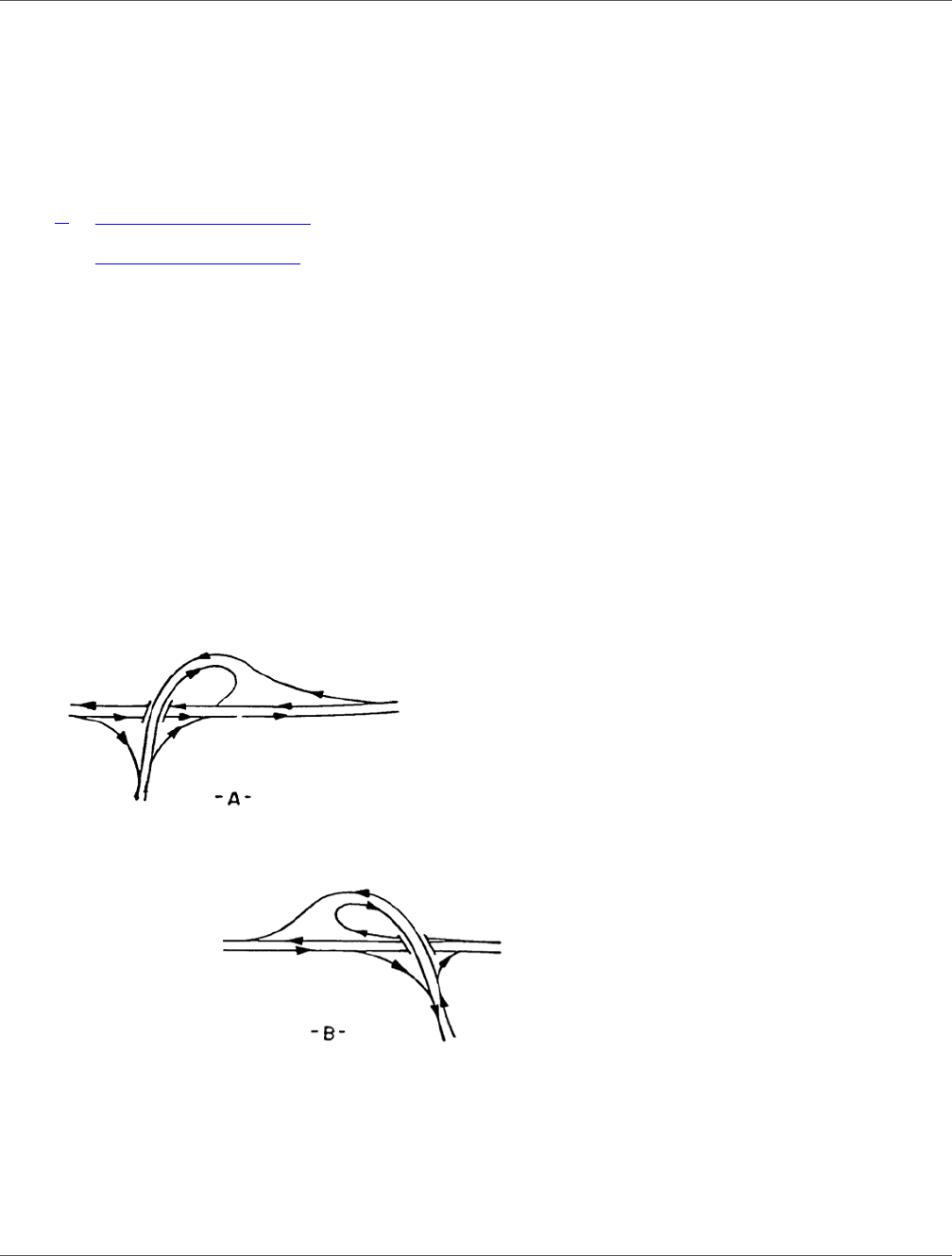
Roadway Design Manual 3-71 TxDOT 04/2018
Chapter 3 — New Location and Reconstruction (4R)
Design Criteria Section 6 — Freeways
interchanges are descriptively called “Tee” (or Trumpet) for 3-leg design. Cloverleaf (full or par-
tial) and Diamond for 4-leg, and Directional interchanges with three or more legs including direct
connectors.
The following subsections include a brief description and some of the advantages and disadvan-
tages of each of the following types of interchanges:
Three Leg Interchanges
Four Leg Interchanges
Three Leg Interchanges
Three-leg interchanges can take any of several forms, although all of the forms provide connections
for the three intersecting highways. Three-leg interchanges should be used only after careful con-
sideration because expansion to include a fourth leg is usually very difficult. If the potential exists
that a fourth leg will ultimately be included, another type of interchange may be appropriate.
Trumpet. The most widely used 3-leg interchange is the trumpet type, as shown in Figure 3-17.
This type of interchange is particularly suitable for the connection of a major facility and a freeway.
Preference should be given to the major turning movements so that the directional roadway handles
higher traffic volume and the loop the lower traffic volume.
Figure 3-17. Trumpet Three Leg Interchange.
Direct. High-type directional three-leg interchanges are those in which all movements are provided
without the use of loops. These interchanges should be used only where all movements are large.

Roadway Design Manual 3-72 TxDOT 04/2018
Chapter 3 — New Location and Reconstruction (4R)
Design Criteria Section 6 — Freeways
They contain more than one structure or, alternatively, a three-level structure. Both variations are
illustrated in Figure 3-18.
Figure 3-18. Directional Three Leg Interchange.
Four Leg Interchanges
Four-leg interchanges can take a wide variety of forms. The choice of interchange type is generally
established after careful consideration of dominant traffic patterns and volumes, ROW require-
ments, and system considerations. The three primary types of four-leg interchanges are as follows:
Diamond Interchanges
Cloverleaf Interchanges
Directional Interchanges
Diamond Interchanges
The diamond interchange is the most common interchange, especially in urban areas, since it
requires less area than any other type. The diamond interchange is used almost exclusively for
major-minor crossings since left-turn movements are made at-grade across conflicting traffic on the
minor road. Separation between frontage road intersections in diamond interchanges in urban or
suburban conditions should be 300 ft [90 m] as a minimum, as shown in Figure 3-19.

Roadway Design Manual 3-73 TxDOT 04/2018
Chapter 3 — New Location and Reconstruction (4R)
Design Criteria Section 6 — Freeways
Figure 3-19. Typical Interchange For At-Grade Portion Of Diamond Interchange In Urban Or
Suburban Areas. Click here to see a PDF of the image.
The diamond interchange may have several different configurations, as discussed in the following
paragraphs and shown in Figure 3-20:
Conventional diamond without frontage roads. The conventional diamond (Figure 3-20 A) is
the most common application of a diamond interchange. Traffic exits in advance of and near the
cross street. Entering vehicles quickly access the freeway beyond or past the cross street. Its disad-
vantages include exiting vehicles backing up onto the freeway when long queues form on the ramp.
Conventional diamond with frontage roads. The conventional diamond with frontage roads (Fig-
ure 3-20 B) is a common variation of a diamond interchange. Traffic exits in advance of and near
the cross street. Entering vehicles quickly access the freeway past the cross street. Its disadvantages
include 1) exiting vehicles backing up onto the freeway when long queues form on the ramp or
frontage road, and 2) most vehicles must go through the intersection to gain access to most frontage
road property.

Roadway Design Manual 3-74 TxDOT 04/2018
Chapter 3 — New Location and Reconstruction (4R)
Design Criteria Section 6 — Freeways
Reverse diamond or x- pattern. The reverse diamond or “X” interchange pattern (Figure 3-20 C)
has primary application to locations with significant development along the frontage road. It pro-
vides access between interchanges and exiting queues do not back up onto the freeway. However,
entering vehicles may have to accelerate on an upgrade and exiting maneuvers occur just beyond
the crest vertical curve where weaving also takes place. The “X" ramp pattern also encourages
frontage road traffic to bypass the frontage road signal and weave with the mainlane traffic. The
“X” ramp pattern may cause some drivers to miss an exit located well in advance of the cross street.
Spread diamond. The spread diamond (Figure 3-20 D) involves moving the frontage roads out-
ward to provide better intersection sight distance at the cross street and improved operational
characteristics with signalized intersections, due to the separation between intersections. However,
more additional right-of-way is required, which may limit its usage.
Stacked diamond. Sometimes access to and from the mainlanes is needed on two closely-spaced
cross streets. Insufficient distance for consecutive entrance and exit ramps can be resolved by using
grade separated ramps, resulting in a “stacked diamond” (Figure 3-20 E).
Split diamond. In some locations, it may be feasible and desirable to “split” the diamond by hav-
ing one-way streets for the arterial movement (Figure 3-20 F). (This is especially true near central
business districts where one-way street systems are common.) However, the split diamond can also
be used to accommodate two closely-spaced two-way arterial roadways crossing a freeway.
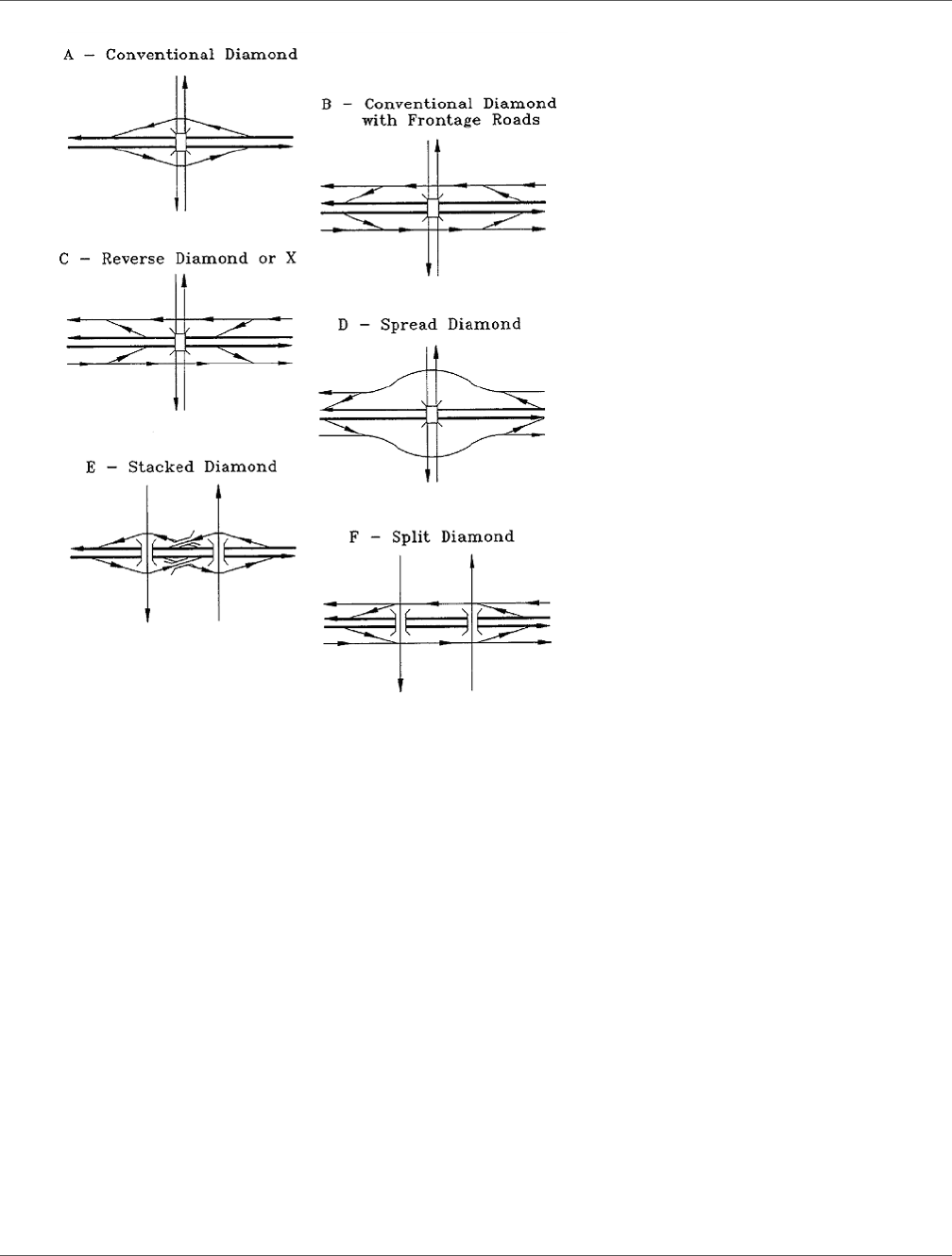
Roadway Design Manual 3-75 TxDOT 04/2018
Chapter 3 — New Location and Reconstruction (4R)
Design Criteria Section 6 — Freeways
Figure 3-20. Typical Diamond Interchanges.
Three level diamond. In urban areas, where the cross street carries a high volume of traffic, the
three-level diamond interchange, illustrated in Figure 3-21, may be warranted. The through move-
ments of both the controlled access facility and the cross street flow is uninterrupted with only the
turning movements requiring regulation by stop signs or traffic lights. This type interchange is not
usually recommended for use as the ultimate design at the crossing of two controlled access facili-
ties since it requires left-turn interchanging traffic to negotiate three traffic signals or stop controls.
However, as stage construction for a fully directional interchange between two controlled access
facilities, the three-level diamond can be effective.
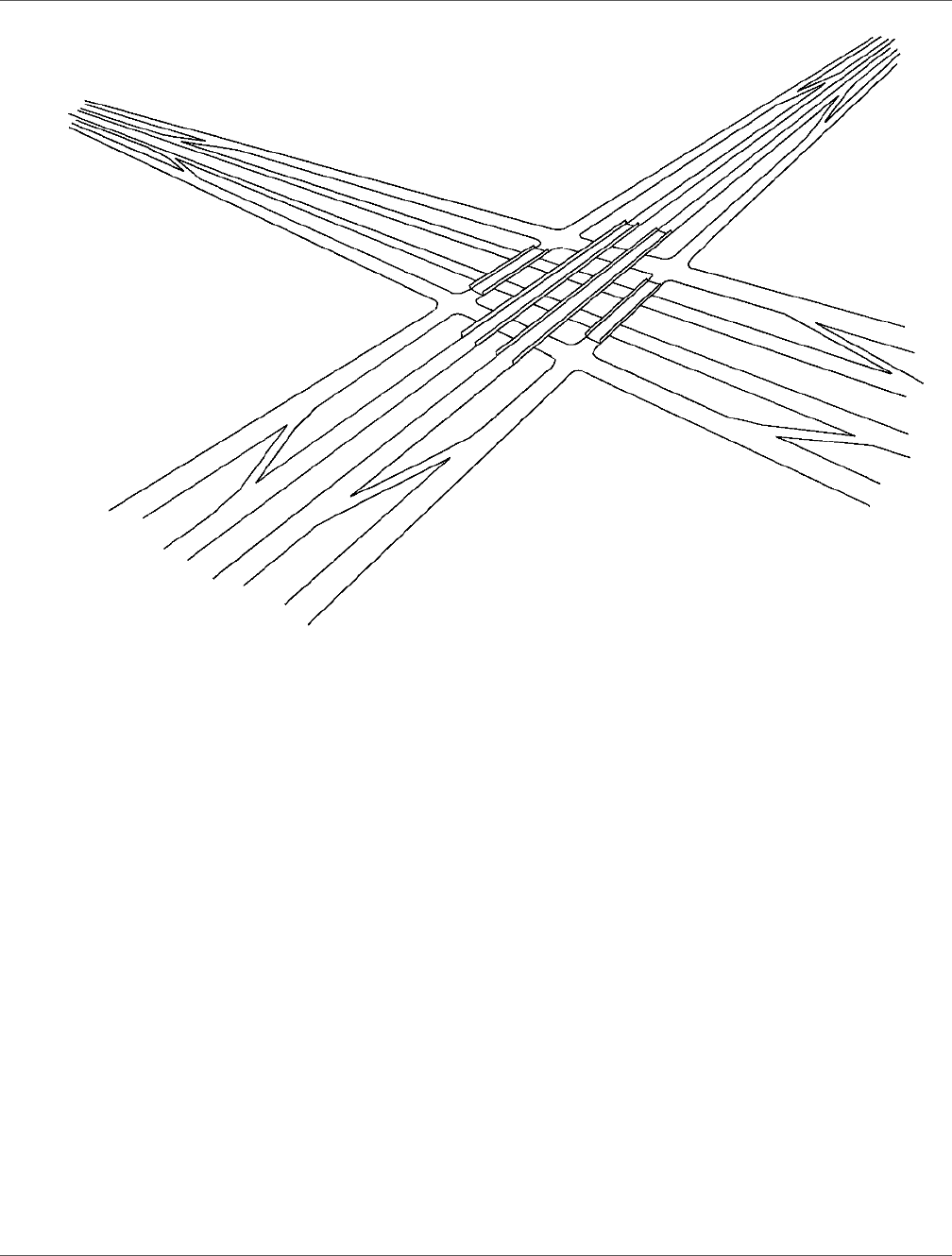
Roadway Design Manual 3-76 TxDOT 04/2018
Chapter 3 — New Location and Reconstruction (4R)
Design Criteria Section 6 — Freeways
Figure 3-21. Three Level Diamond Interchange.
Single point diamond. A special type of freeway-to-arterial interchange has received attention
during recent years and is worthy of discussion. AASHTO’s A Policy on Geometric Design of
Highways and Streets refers to it as a “single point diamond” or “single point urban” interchange.
In this type of interchange, the freeway mainlanes may go either over or under the crossing arterial
and the turn movements occur at-grade on the arterial, as illustrated in Figure 3-22. This type of
interchange has application only in specialized locations. Traffic operations and signalization must
be carefully modeled prior to final design selection of the single point urban interchange.
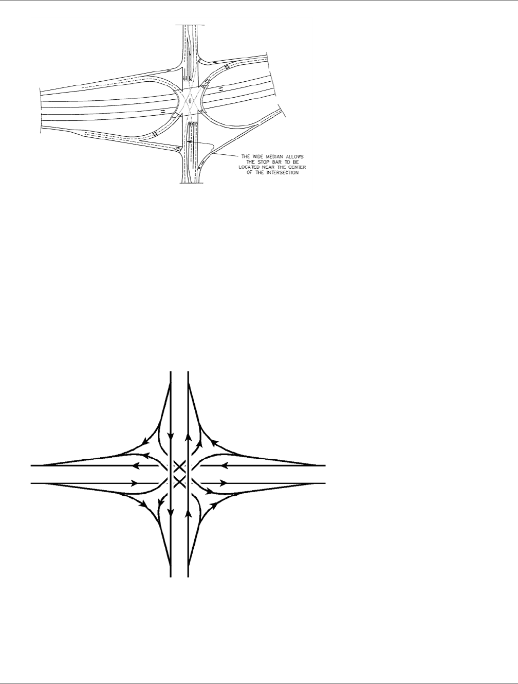
Roadway Design Manual 3-77 TxDOT 04/2018
Chapter 3 — New Location and Reconstruction (4R)
Design Criteria Section 6 — Freeways
Figure 3-22. Single Point Diamond Interchange.
Three level stacked diamond. The three-level stacked diamond interchange is also an interchange
requiring only one signalized intersection. In a sense, it is a three-level version of the “single point
diamond” configuration, as illustrated in Figure 3-23. This design grade separates both roadways,
and accommodates turning movements with signal operations requiring only one signalized inter-
section. The two-phase signal operation at the intersection typically provides a level of throughput
on the turning movements between a conventional diamond interchange and a fully directional
interchange. Furthermore, it works best at separating high arterial cross-street and freeway traffic.
It has the same shortcomings as the “single point diamond” in the way it brings the left turn move-
ments together.
Figure 3-23. Three Level Stacked Diamond Interchange (see Figure 3-24 for At-Grade Portions of
the Interchange).
As indicated in Figure 3-24, vehicles enter the intersection with oncoming vehicles to the right in
contrast to the left as is the case on conventional diamond interchange intersections. Also, the
design is less attractive with continuous frontage roads.
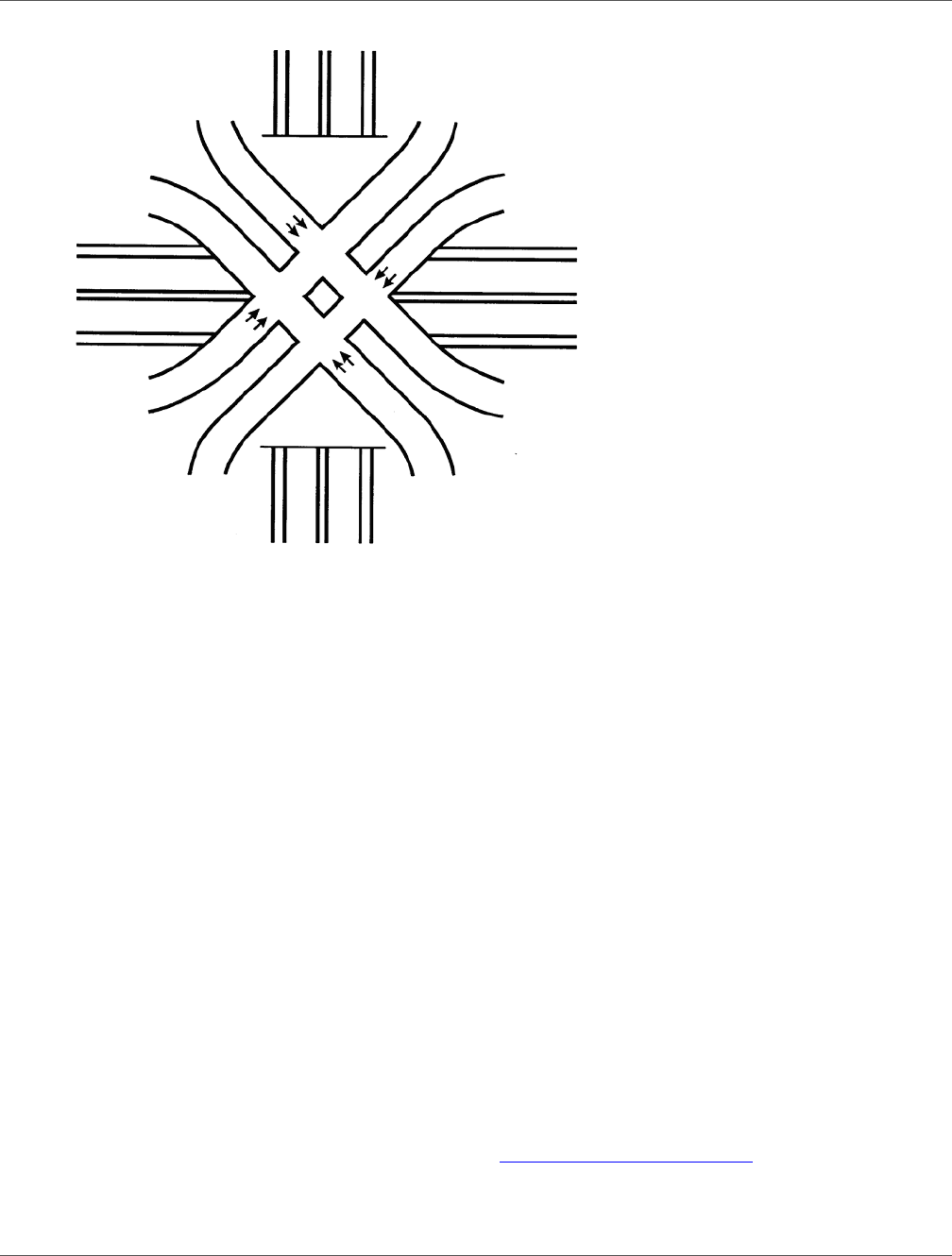
Roadway Design Manual 3-78 TxDOT 04/2018
Chapter 3 — New Location and Reconstruction (4R)
Design Criteria Section 6 — Freeways
Figure 3-24. Three Level Stacked Diamond At-Grade Interchange.
Cloverleaf Interchanges
Cloverleaf interchanges are very common in many states. These types of interchanges were popular
in the early era of freeway construction, but are usually no longer considered preferable for freeway
to freeway movement, especially when interchange volumes are high. However, in some instances
they may be appropriate when interchanging a freeway with a non-controlled access facility in a
location away from an urban or urbanizing area. Cloverleafs should not be used where left-turn vol-
umes are high (exceed 1200 pcph) since loop ramps are limited to one lane of operation and have
restricted operating speeds.
Primary disadvantages of the cloverleaf design include the following:
large right-of-way requirements
capacity restrictions of loops, especially if truck volumes are significant
short weaving length between loops
trucks have difficulty with weaves and acceleration
When used, cloverleaf designs should include collector-distributor roads to provide more satisfac-
tory operations as further noted in the section on Collector-Distributor Roads.
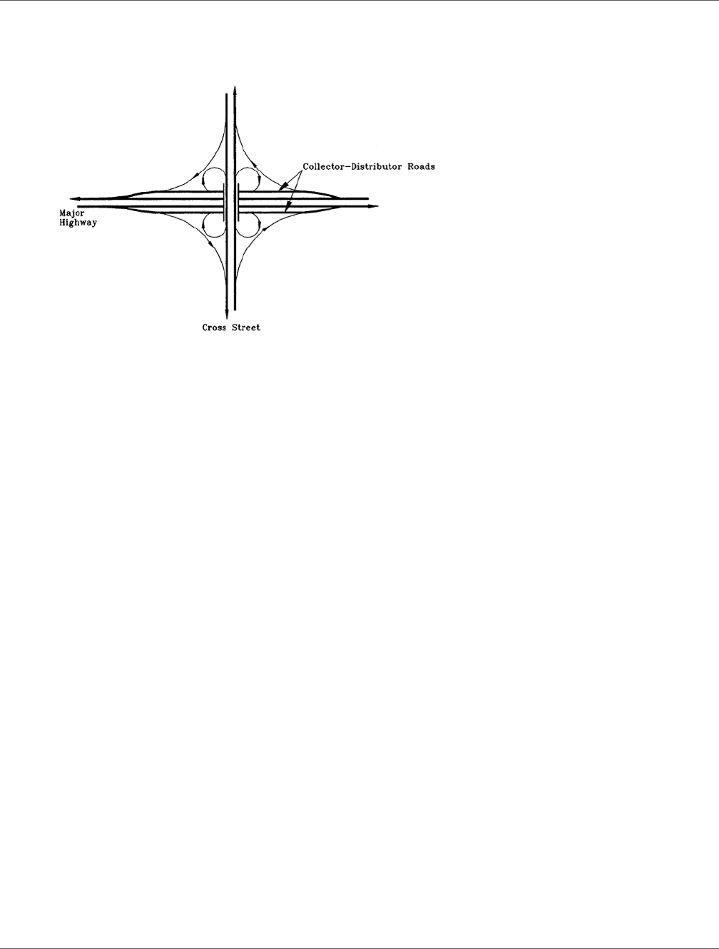
Roadway Design Manual 3-79 TxDOT 04/2018
Chapter 3 — New Location and Reconstruction (4R)
Design Criteria Section 6 — Freeways
Full cloverleaf. The four-quadrant, full cloverleaf, illustrated in Figure 3-25, eliminates all left-turn
conflicts through construction of a two-level interchange.
Figure 3-25. Full Cloverleaf Interchange.
Partial cloverleaf. A cloverleaf without ramps in all four quadrants, illustrated in Figure 3-26, is
sometimes used when site controls (such as railroads or streams running parallel to the crossroad)
limit the number of loops and/or the traffic pattern is such that the left-turn conflicts caused by the
absence of one or more loops are within tolerable limits. With such an arrangement, left-turn con-
flicts at the ramp intersections require that satisfactory approach sight distance be provided. Several
variations on partial cloverleafs are also discussed in the AASHTO’s A Policy on Geometric
Design of Highways and Streets.
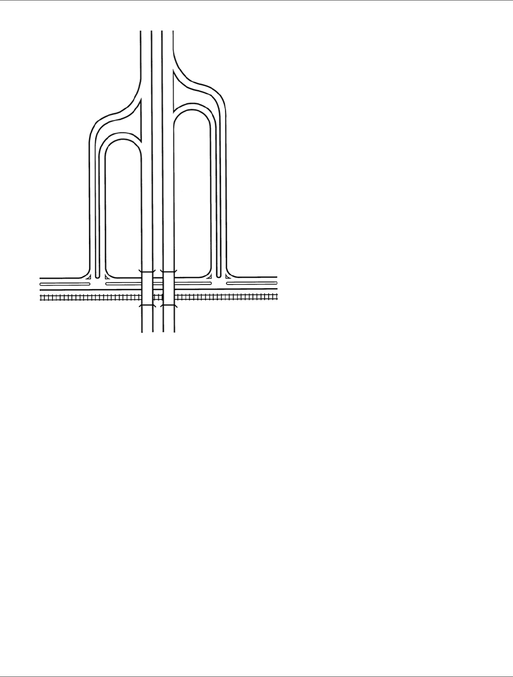
Roadway Design Manual 3-80 TxDOT 04/2018
Chapter 3 — New Location and Reconstruction (4R)
Design Criteria Section 6 — Freeways
Figure 3-26. Partial Cloverleaf Interchange.
Directional Interchanges
Interchanges that use direct or semi-direct connections for one or more left-turn movements are
called “directional” interchanges (Figure 3-27). When all turning movements travel on direct or
semi-direct ramps or direct connections, the interchange is referred to as “fully directional”. These
connections are used for important turning movements instead of loops to reduce travel distance,
increase speed and capacity, reduce weaving and avoid loss of direction in traversing a loop. “Fully
directional” interchanges are usually justified at the intersection of two freeways.
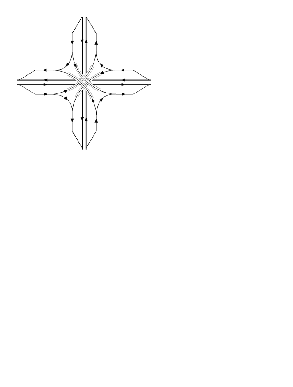
Roadway Design Manual 3-81 TxDOT 04/2018
Chapter 3 — New Location and Reconstruction (4R)
Design Criteria Section 6 — Freeways
Figure 3-27. Four Level Fully Directional Interchange Without Frontage Roads.
Four level without frontage roads. The four-level directional interchange as depicted in Figure 3-
27 includes direct connections for all freeway-to-freeway movements, without continuation of any
frontage roads through the interchange.
Five level with frontage roads. In some instances, it may be desirable to continue the frontage
roads through the interchange at the first or second level, producing a five-level directional inter-
change. Where frontage roads are made continuous through the interchange, the lower three levels
are a three-level diamond configuration. Where stage construction is desired, the three-level dia-
mond will adequately serve moderate traffic volumes until the upper two levels of direct
connections are constructed to complete the five-level interchange. Figure 3-28 depicts a five level
interchange with frontage roads.
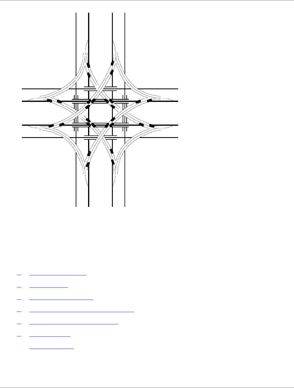
Roadway Design Manual 3-82 TxDOT 04/2018
Chapter 3 — New Location and Reconstruction (4R)
Design Criteria Section 6 — Freeways
Figure 3-28. Five Level Fully Directional Interchange with Frontage Roads.
Ramps and Direct Connections
This subsection discusses ramps and direct connections and includes information on the following
topics:
General Information
Design Speed
Horizontal Geometrics
Distance Between Successive Ramps
Cross Section and Cross Slopes
Sight Distance
Metered Ramps
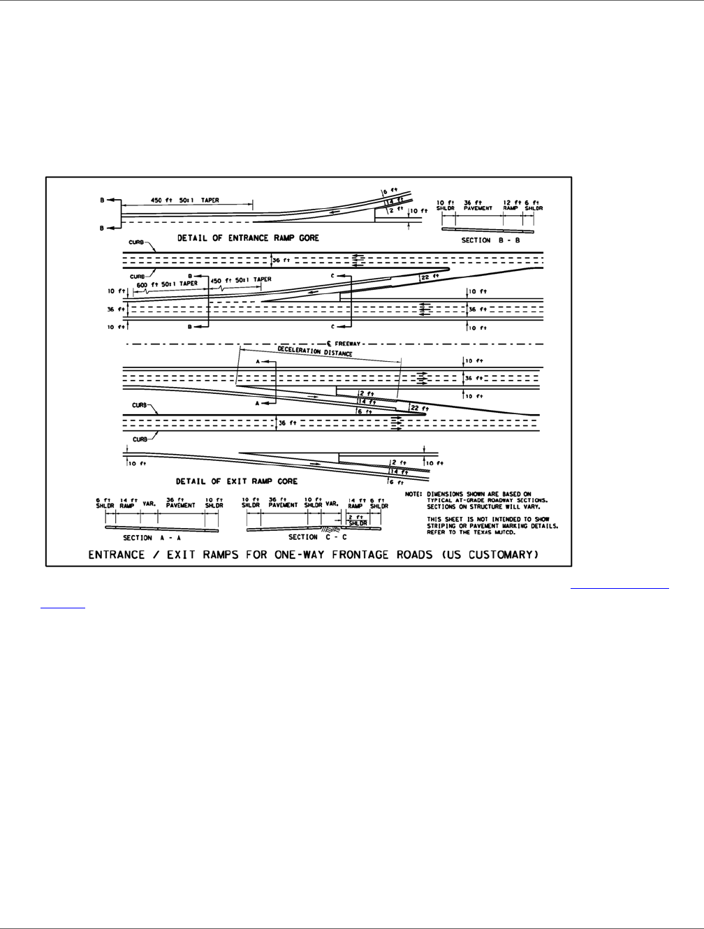
Roadway Design Manual 3-83 TxDOT 04/2018
Chapter 3 — New Location and Reconstruction (4R)
Design Criteria Section 6 — Freeways
General Information
All ramps and direct connections should be designed for one-lane operation with provision for
emergency parking; however, if the anticipated volume exceeds the capacity of one freeway lane,
two-lane operation may be provided with consideration given to merges and additional entry lanes
downstream. Several examples of ramps and connecting roadway arrangements are shown in Fig-
ures 3-29 through 3-35.
Figure 3-29. (US). Entrance/Exit Ramps For One-Way Frontage Roads. Click US Customary or
Metric to see a PDF of the image.
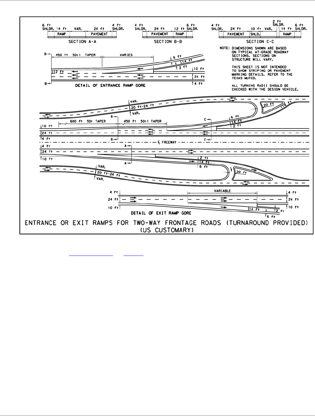
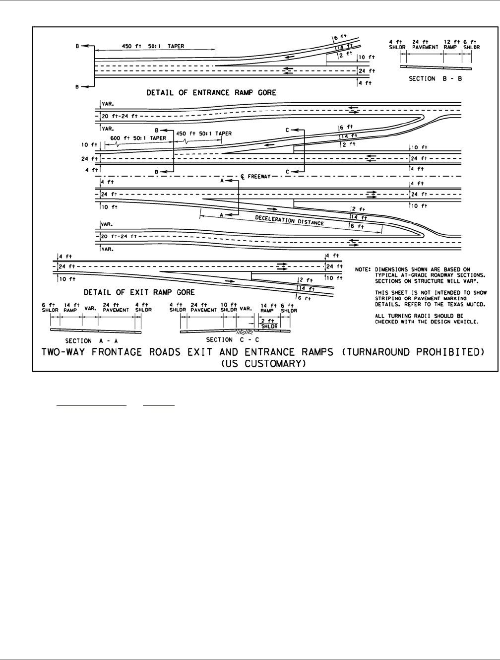
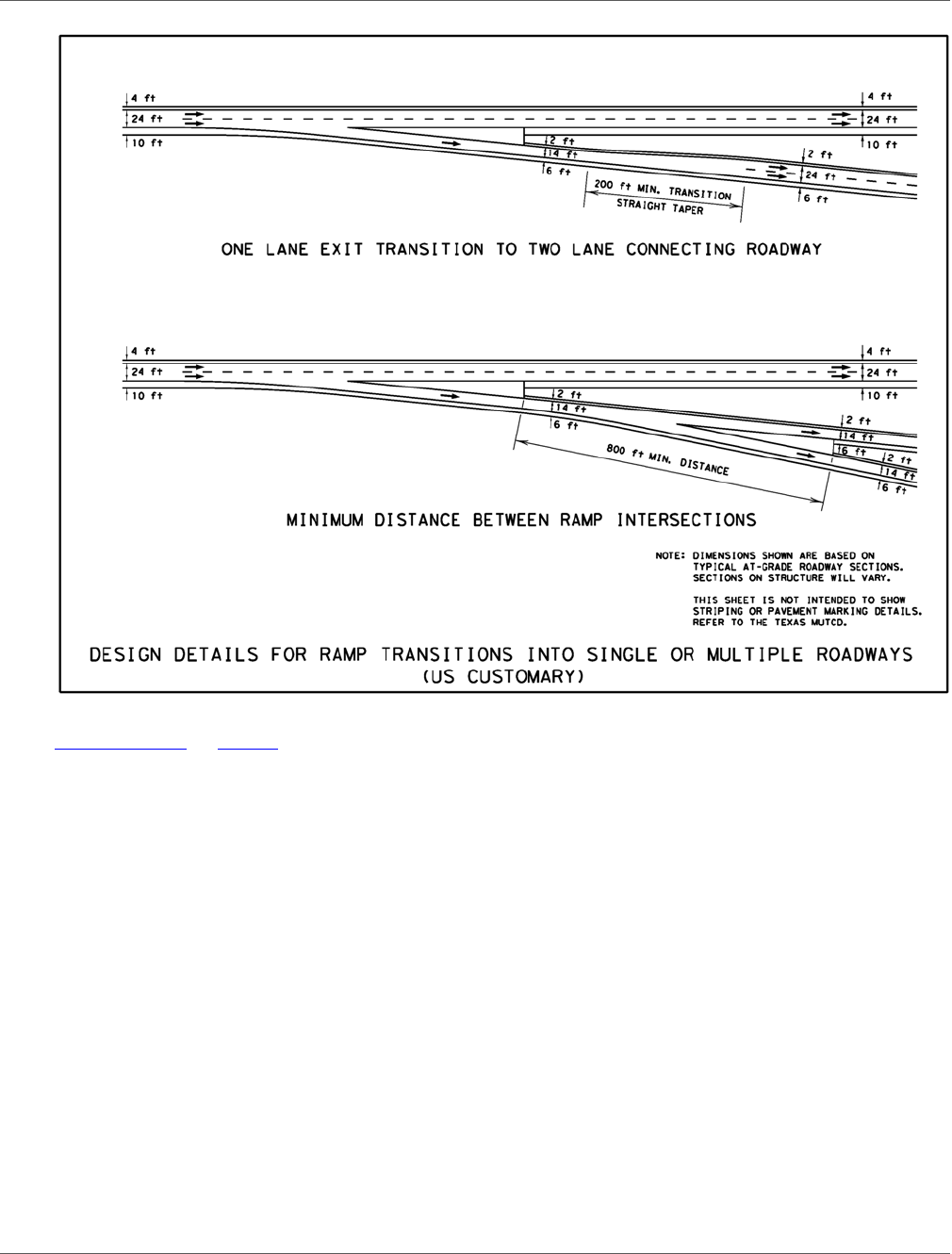
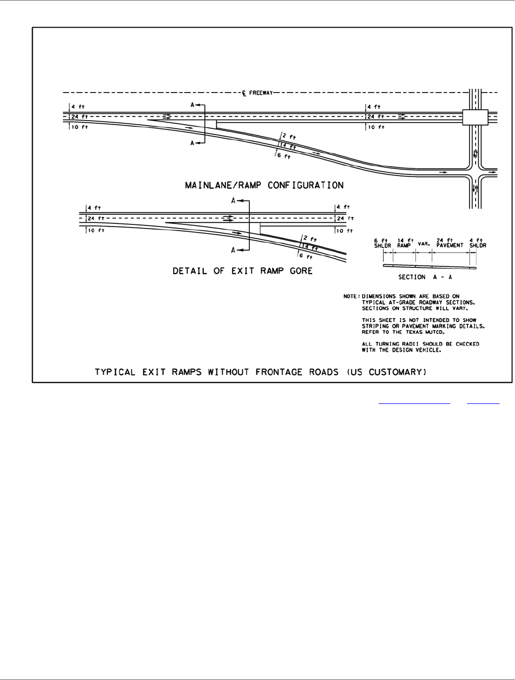
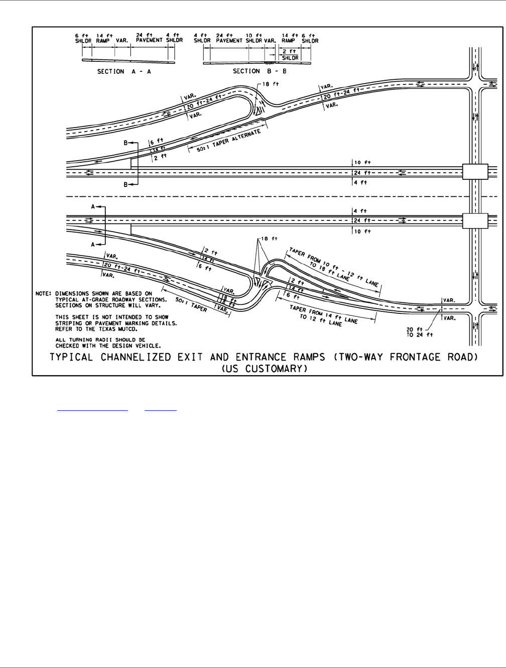
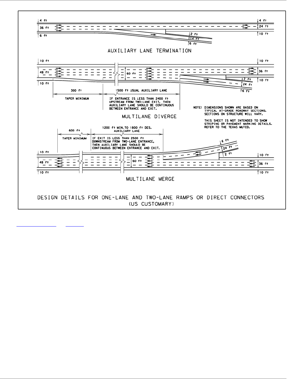
Roadway Design Manual 3-89 TxDOT 04/2018
Chapter 3 — New Location and Reconstruction (4R)
Design Criteria Section 6 — Freeways
Figure 3-35. (US). Design Details for One-Lane and Two-Lane Ramps or Direct Connectors. Click
US Customary or Metric to see a PDF of the image.
Once ramps have been located on a schematic layout and the same has been exhibited at a public
hearing or the design has otherwise become a matter of public record, extreme caution should be
exercised in making any subsequent changes in ramp location to better serve areas that may have
developed after the original design was determined. In all cases, proposed changes should be sub-
mitted to the Design Division, and another public hearing may be required.
Right-side ramps are markedly superior in their operational characteristics and safety to those that
leave or enter on the left. With right-side ramps, merging and diverging maneuvers are accom-
plished into or from the slower moving right travel lane. Since a high majority of ramps are right-
side, there is an inherent expectancy by drivers that all ramps will be right-side, and violations of
driver expectancy may adversely affect operation and safety characteristics.
Direct access to and from ramps or direct connections can seriously impair safety and traffic opera-
tions and, therefore, should not be permitted.

Roadway Design Manual 3-90 TxDOT 04/2018
Chapter 3 — New Location and Reconstruction (4R)
Design Criteria Section 6 — Freeways
Design Speed
There should be a definite relationship between the design speed on a ramp or direct connection
and the design speed on the intersecting highway or frontage road. All ramps and connections
should be designed to enable vehicles to leave and enter the traveled way of the freeway at no less
than 50 percent (70 percent usual, 85 percent desirable) of the freeway’s design speed. Table 3-20
shows guide values for ramp/connection design speed. The design speed for a ramp should not be
less than the design speed on the intersecting frontage roads. AASHTO’s A Policy on Geometric
Design of Highways and Streets provides additional guidance on the application of the ranges of
ramp design speed shown in Table 3-20:
Horizontal Geometrics
Lane and shoulder widths for ramps and direct connections are shown in Table 3-18.
Figure 3-36 provides design criteria for entrance and exit ramp acceleration, deceleration, and taper
lengths; adjustment factors for grade effects are shown in Table 3-14: Speed Change Lane Adjust-
ment Factors as a Function of a Grade
Table 3-20: Guide Values for Ramp/Connection Design Speed as Related to Highway Design Speed*
(US Customary)
Highway Design Speed (mph) 30 35 40 45 50 55 60 65 70 75 80
Ramp** Design Speed (mph): -
Upper Range (85%) 2530354045485055606570
Mid Range (70%) 2025303335404545505560
Lower Range (50%) 1518202325283030354045
(Metric)
Highway Design Speed (km/h) 50 60 70 80 90 100 110 120 130
Ramp** Design Speed (km/h): -
Upper Range (85%) 40 50 60 70 80 90 100 110 120
Mid Range (70%) 30 40506060708090100
Lower Range (50%) 203040405050607080
* For corresponding minimum radius, see Table 2-6.
**Loops: Upper and middle range values of design speed generally do not apply. The design speed on a loop
should be no less than 25 mph [40 km/h] (185 ft [55 m] minimum radius) based on an emax of 6%. Particular
attention should be given to controlling superelevation on loops due to the tight turning radii and speed
limitations.
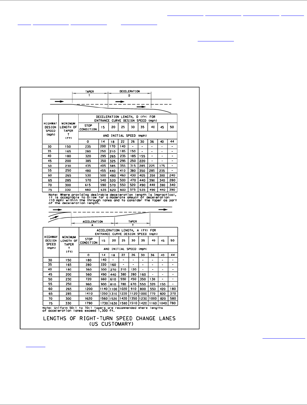
Roadway Design Manual 3-91 TxDOT 04/2018
Chapter 3 — New Location and Reconstruction (4R)
Design Criteria Section 6 — Freeways
Exit and entrance ramp typical details are shown in Figure 3-23, Figure 3-24, Figure 3-25, Figure
3-26, Figure 3-27, Figure 3-28, and Figure 3-29.
Channelized (braided) entrance and exit ramps, as typified in Figure 3-28, should be used only
where ramp volumes are considerably greater than frontage road traffic such as where stub frontage
roads occur. Where used, the exit ramp desirably should cross the frontage road at approximately
90 degrees to minimize wrong-way entry. Passing should be restricted between the crossroad and
the channelized area.
Figure 3-36. (US). Lengths of Exit and Entrance Ramp Speed Change Lanes. Click US Customary
or Metric to see a PDF of the image.
Distance Between Successive Ramps
The minimum acceptable distance between ramps is dependent upon the merge, diverge and weav-
ing operations that take place between ramps as well as distances required for signing. For analysis
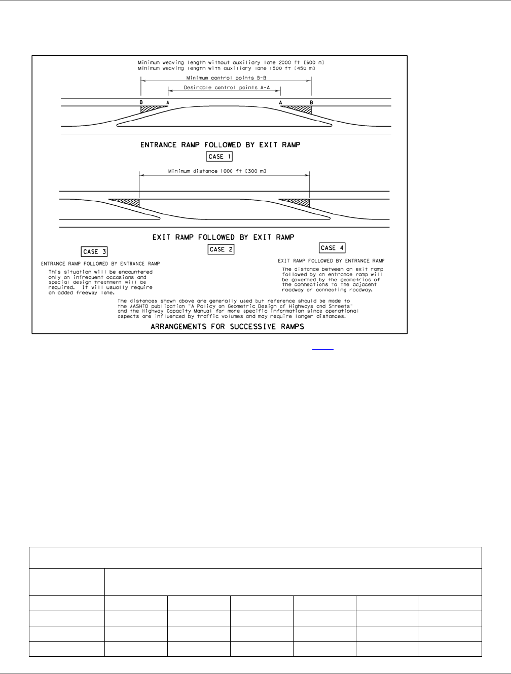
Roadway Design Manual 3-92 TxDOT 04/2018
Chapter 3 — New Location and Reconstruction (4R)
Design Criteria Section 6 — Freeways
of these requirements, see the Highway Capacity Manual. Figure 3-37 shows minimum distances
between ramps for various ramp configurations.
Figure 3-37. Arrangements For Successive Ramps. Click here to see a PDF of the image.
Cross Section and Cross Slopes
Superelevation rates, as related to curvature and design speed of the ramp or direct connector, are
given in Table 3-21. While connecting roadways represent highly variable conditions, as high a
superelevation rate as practicable should be used, preferably in the upper half or third of the indi-
cated range, particularly in descending grades. Superelevation rates above 8% are shown in Table
3-21 only to indicate the limits of the range. Superelevation rates above 8% are not recommended
and a larger radius is preferable.
Table 3-21: Superelevation Range for Curves on Connecting Roadways
(US Customary)
Radius (ft) Range in Superelevation Rate (percent) For Connecting Roadways With Design Speed,
mph, of:
- 202530354045
90 2-10 - - - - -
150 2-8 4-10 - - - -
230 2-6 3-8 6-10 - - -

Roadway Design Manual 3-93 TxDOT 04/2018
Chapter 3 — New Location and Reconstruction (4R)
Design Criteria Section 6 — Freeways
The cross slope on portions of connecting roadways or ramps on tangent normally is sloped one
way at a practical rate of 1.5% to 2%.
The change in pavement edge elevation per given length of connecting roadway or ramp should be
that as shown in Table 2-8: Maximum Relative Gradient for Superelevation Transition. The maxi-
310 2-5 3-6 5-9 8-10 - -
430 2-4 3-5 4-7 6-9 9-10 -
540 2-3 3-5 4-6 6-8 8-10 10-10
600 2-3 2-4 3-5 5-7 7-9 8-10
1000 2 2-3 3-4 4-5 5-6 7-9
1500 2 2 2-3 3-4 4-5 5-6
2000 2 2 2 2-3 3-4 4-5
3000 2 2 2 2 2-3 3-4
* See Tables 2-6 and 2-7 for design speeds greater than 45 mph.
(Metric)
Radius (m) Range in Superelevation Rate (percent) For Connecting Roadways With Design Speed, km/
h, of:
- 203040506070
15 2-10 - - - - -
25 2-9 2-10 - - - -
50 2-8 2-8 4-10 - - -
80 2-6 2-6 3-8 6-10 - -
100 2-5 2-4 3-6 5-8 - -
115 2-3 2-4 3-6 5-8 8-10 -
150 2-3 2-3 3-5 4-7 6-8 -
160 2-3 2-3 3-5 4-7 6-8 10-10
200 2 2-3 2-4 3-5 5-7 6-8
300 2 2-3 2-3 3-4 4-5 5-7
500 2222-33-44-5
700 2 2 2 2 2-3 3-4
1000 2 2 2 2 2 2-3
* See Tables 2-6 and 2-7 for design speeds greater than 70 km/h.
Table 3-21: Superelevation Range for Curves on Connecting Roadways
(US Customary)

Roadway Design Manual 3-94 TxDOT 04/2018
Chapter 3 — New Location and Reconstruction (4R)
Design Criteria Section 6 — Freeways
mum algebraic difference in pavement cross slope at connecting roadways or ramps should not
exceed that set forth in Table 3-22:
The cross section of a ramp or direct connector is a function of the following variables:
number of lanes determined by traffic volume
minimum lane and shoulder width
lane balance
where two lanes are required by volume, the provision of parallel merging two lanes onto the
mainlanes must be provided at the terminal
Sight Distance
On all ramps and direct connections, the combination of grade, vertical curves, alignments and
clearance of lateral and corner obstructions to vision shall be such as to provide sight distance along
such ramps and connections from terminal junctions along the freeway, consistent with the proba-
ble speeds of vehicle operation. Sight distance and sight lines are especially important at merge
points for ramps and mainlanes or between individual ramps. Table 2-1: Stopping Sight Distance
shows recommended stopping sight distances for ramps and direct connections.
The sight distance on a freeway preceding the approach nose of an exit ramp should exceed the
minimum stopping sight distance for the freeway design speed, preferably by 25 percent or more.
Decision sight distance, as discussed in Decision Sight Distance in Chapter 2, is a desirable goal.
Table 3-22: Maximum Algebraic Differences in Pavement Cross Slope
at Connecting Roadway Terminals
(US Customary) (Metric)
Design Speed of Exit or
Entrance Curve
(mph)
Maximum Algebraic Dif-
ference in Cross Slope at
Crossover Line
(%)
Design Speed of Exit or
Entrance Curve
(km/h)
Maximum Algebraic Dif-
ference in Cross Slope at
Crossover Line
(%)
Less than or equal to 20 5.0 to 8.0 Less than or equal to 30 5.0 to 8.0
25 to 30 5.0 to 6.0 40 to 50 5.0 to 6.0
Greater than or equal to
35 4.0 to 5.0 Greater than or equal to
60 4.0 to 5.0

Roadway Design Manual 3-95 TxDOT 04/2018
Chapter 3 — New Location and Reconstruction (4R)
Design Criteria Section 6 — Freeways
Grades and Profiles
Design controls for crest and sag vertical curves on ramps and direct connectors may be obtained
from Figures 2-7 through 2-10. Longer vertical curves with increased stopping sight distances
should be provided wherever possible.
The tangent or controlling grade on ramps and direct connectors should be as flat as possible, and
preferably should be limited to 4 percent or less. AASHTO’s A Policy on Geometric Design of
Streets and Highways has additional discussion on ramp gradients.
Metered Ramps
Where ramps are initially, or subsequently, expected to accommodate metering, the geometric
design features shown in Design Criteria for Ramp Metering may be considered. Ramp metering,
when properly designed and installed, has been shown to have potential benefits for the operation
of the mainlanes. However, since ramp meters are installed to control the number of vehicles that
are allowed to enter the mainlanes, an analysis of the entire roadway network area should be done
to determine any adverse operational impacts to other roadways. It is suggested that the analysis
specifically include both frontage road and adjacent cross street operations of through traffic, turn-
ing movements, and queue lengths.
Collector-Distributor Roads
A collector-distributor road may be warranted within an interchange, through two adjacent inter-
changes or continuous for some distance along the freeway through several interchanges.
Collector-distributor roads should be provided at all cloverleaf interchanges and particularly at such
interchanges on controlled access facilities. A collector-distributor road is designed to meet the fol-
lowing goals:
transfer weaving from the mainlanes
provide single-point exits from the main lanes
provide exit from the main lanes in advance of cross roads.
Where there is considerable demand for frequent ingress and egress, as in and near the business dis-
trict of large cities, a collector-distributor road, continuous for some distance, should be provided.
Frontage Road Turnarounds and Intersection Approaches
Turnaround lanes are to be provided at all interchanges with major arterials in urban and suburban
areas where the freeway lanes are flanked by one-way frontage roads. Turnaround lanes are not to
be provided where two-way frontage roads are used. In urban and suburban areas, overpasses
should be arranged so that turnarounds may be added in the future. This includes provisions for end
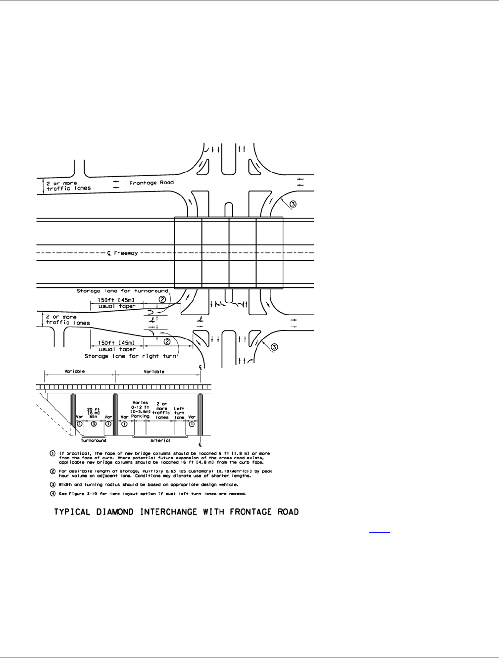
Roadway Design Manual 3-96 TxDOT 04/2018
Chapter 3 — New Location and Reconstruction (4R)
Design Criteria Section 6 — Freeways
spans and vertical clearance for future turnarounds at overpasses. Underpass situations should also
allow for vertical clearances on future elevated turnarounds.
Figure 3-38 shows a typical turnaround at a diamond interchange.
When the cross street overpasses the freeway, the resulting turnarounds will be on bridge struc-
tures. In these cases, sight lines and distances should be carefully evaluated with respect to any
bridge railing sight obstructions.
Figure 3-38. Typical Diamond Interchange With Frontage Road. Click here to see a PDF of the
image.

Roadway Design Manual 3-97 TxDOT 04/2018
Chapter 3 — New Location and Reconstruction (4R)
Design Criteria Section 7 — Freeway Corridor Enhancements
Section 7 — Freeway Corridor Enhancements
Overview
This section discusses other transportation modes and includes discussions on where to find infor-
mation on planning and design criteria for these modes.
Freeways With High Occupancy Vehicle Treatments
High Occupancy Vehicles (HOV) lanes are becoming common in urban freeway environment as an
approach to reducing congestion and travel times.
Guidelines for the planning and designs of HOV facilities are given in AASHTO’s Guide for the
Design of High Occupancy Vehicle Facilities and in the HOV Systems Manual, National Coopera-
tive Highway Research Program Report 414, Transportation Research Board, National Research
Council, Washington, D.C., 1998.
Light Rail Transit
Light Rail Transit systems are being considered in some urban environments as an approach to
reducing congestion and travel times.
Guidelines for the incorporation of light rail transit systems in the transportation network are given
in the Federal Transit Administration publication by Korve, Farran, Mansel, Levinson, Chira-Cha-
vala and Ragland, TCRP Report 17, Integration of Light Rail Transit into City Streets,
Transportation Research Board, National Academy Press, Washington, D.C., 1996.

Roadway Design Manual 3-98 TxDOT 04/2018
Chapter 3 — New Location and Reconstruction (4R)
Design Criteria Section 8 — Texas Highway Freeway
Network (THFN)
Section 8 — Texas Highway Freeway Network (THFN)
Overview
On September 28, 2017 a memorandum was distributed by Bill Hale,
P.E. (Chief Engineer) that provided general guidance for the TxDOT
Freight Vertical Clearance Policy. The purpose of the Freight Pol-
icy is to make Texas the leader in providing movement of Freight in
the Nation. This is a process that should be approached with a well
thought out long range vision and plan in place to provide a con-
tinuum of efficient Freight movement within the State. Additional
consideration and planning should also be given to existing
bridges that due to low vertical clearances act as Freight bottle-
necks; even if there are no immediate plans for new construction or
reconstruction of these bridges. Consideration for exchanging
overpasses for underpasses should be given as well.
This policy is applicable to projects that meet the following
criteria;
Let on September 1, 2020 or later.
Designated as being on the THFN as shown on the THFN map main-
tained by the Transportation Planning and Programming Division
(TP&P).
Bridge new construction or reconstruction; including bridge
widening. BMIP and maintenance projects may not be considered
bridge reconstruction, but this would need to be handled on a
case-by-case basis in consultation with the Bridge Division.
Redecking a bridge will also be handled on a case-by-case basis
in consultation with the Bridge Division.
Note, the policy does not apply to THFN overpasses, frontage roads,
direct connectors off of the THFN, and entrance and exit ramps that
include bridge underpasses. The THFN vertical clearance require-
ments should be considered for bridge and incidental vertical
obstruction to the Freight Network that support significant ori-
gin/destination locations.

Roadway Design Manual 3-99 TxDOT 04/2018
Chapter 3 — New Location and Reconstruction (4R)
Design Criteria Section 8 — Texas Highway Freeway
Network (THFN)
Basic Design Criteria
Vertical Clearance at Structures
Applicable structures on the THFN project must meet the minimum
vertical clearance requirement of 18.5 ft.
Minimum vertical clearances for pedestrian crossover structures is
19.5 ft; this is due to the increased risk of personal injury upon
impact by over-height loads and the relative weakness of such
structures to resist lateral loads from vehicular impact.
The above-specified clearances apply over the entire width of
roadway including usable shoulders and include an allowance of 6
inches for future pavement overlays.
Signs, Overhead Sign Bridges (OSB’s), Signals
For the designated Texas Highway Freight Network (THFN), overhead
signs shall provide a vertical clearance of not less than 19 feet 6
inches to the sign, light fixture, or sign bridge over the entire
width of the pavement and shoulders. For traffic signals on the
THFN, the bottom of the signal housing and any related attachments
to a vehicular signal face located over any portion of a highway
that can be used by motor vehicles shall be at least 19 feet above
the pavement. See the latest version of the TXMUTCD for additional
guidance.
Other Overhead Utilities
All overhead utilities over the designated THFN project must meet
the requirements specified in the TxDOT ROW Utility Manual, Chap-
ter 3.

Roadway Design Manual 4-1 TxDOT 04/2018
Chapter 4 — Non-Freeway Rehabilitation (3R) Design Criteria
Contents:
Section 1 — Purpose
Section 2 — Design Characteristics
Section 3 — Safety Enhancements
Section 4 — Frontage Roads
Section 5 — Bridges, Including Bridge-Classification Culverts
Section 6 — Super 2 Highways

Roadway Design Manual 4-2 TxDOT 04/2018
Chapter 4 — Non-Freeway Rehabilitation (3R)
Design Criteria Section 1 — Purpose
Section 1 — Purpose
Overview
The basic purposes of resurfacing, restoration or rehabilitation (3R) construction projects are to
preserve and extend the service life of existing highways and streets and to enhance safety. Because
of limited resources, individual rehabilitation projects may have to be limited in scope in an effort
to preserve the mobility function of the entire highway system. The scope of 3R projects varies
from thin overlays and minor safety upgrading to more complete rehabilitation.
3R projects are those which address pavement needs and/or deficiencies and which substantially
follow the existing horizontal and vertical alignment. They differ from reconstruction projects in
that reconstruction projects substantially deviate from the existing horizontal and/or vertical align-
ment and/or add capacity.
Design Guidelines
Design guidelines for 3R projects have been developed to allow greater design flexibility. At the
District’s option, design values above those presented in this chapter may be used.
These guidelines offer sufficient flexibility to ensure cost effective design and further compliance
with the program goals of preserving and extending the service life and enhancing safety. While
safety may not be the primary reason for initiating a 3R project, highway safety is an essential ele-
ment of all projects. These 3R projects are to be developed in a manner which identifies and
incorporates appropriate safety enhancements.
For the purpose of 3R projects, current average daily traffic (ADT) volumes of less than 1500 are
defined as low traffic volume roadways.

Roadway Design Manual 4-3 TxDOT 04/2018
Chapter 4 — Non-Freeway Rehabilitation (3R)
Design Criteria Section 2 — Design Characteristics
Section 2 — Design Characteristics
Pavement Design
Pavement rehabilitation includes all pavement-related work undertaken to extend the service life of
an existing facility. This includes placement of additional surfacing material and/or other work nec-
essary to return an existing roadway, including shoulders, to a condition of structural and/or
functional adequacy. The following are some examples of pavement rehabilitation work:
resurfacing to provide improved structural capacity and/or serviceability
removing and replacing deteriorated materials
replacing or restoring malfunctioning joints
reworking or strengthening of bases and subbases
recycling existing materials
adding underdrains.
The existing pavement condition and deficiencies should be identified for 3R projects. Design strat-
egies selected to correct deficiencies will vary from seal coats to overlays to complete pavement
structure reconstruction. Projects that consist only of seal coats or overlays, and do not evaluate the
project according to the additional guidelines presented in this chapter, are not eligible for rehabili-
tation funding.
Reference can be made to the Pavement Design Guide for additional information related to pave-
ment rehabilitation.
Geometric Design
Geometric design guidelines are provided for the following roadways in the tables indicated.
rural multilane highways, Table 4-1
rural two-lane highways, Table 4-2
urban streets, Table 4-3
rural frontage roads, Table 4-4
urban frontage roads, Table 4-5.

Roadway Design Manual 4-4 TxDOT 04/2018
Chapter 4 — Non-Freeway Rehabilitation (3R)
Design Criteria Section 2 — Design Characteristics
NOTE: Online users can view the metric version of this table in PDF format.
Table 4-1: 3R Design Guidelines for Rural Multilane Highways (Nonfreeway)a
(US Customary)
Design Element Highway Class
-6-Lane Divided 4-Lane Divided 4-Lane Undivided
Design Speedb50 mph 50 mph 50 mph
Lane Width 11 ft 11 ft 11 ft
Outside Shoulder 4 ft 4 ft 4 ft
Inside Shoulder 4 ft 2 ft N/A
Turn Lane Widthc10 ft 10 ft N/A
Horizontal Clearance 16 ft 16 ft 16 ft
Bridgesd: Width to be retained 42 ft 28 ft 52 ft
a These values are intended for use on rehabilitation projects. However, the designer may select higher values
to provide consistency with adjoining roadway sections, to provide consistency with prevailing conditions on
similar roadways in the area or to provide operational improvements at specific locations.
b Considerations in selecting design speeds for the project should include the roadway alignment characteris-
tics as discussed in this chapter.
c For two-way left turn lanes, 11 ft – 14 ft usual.
d Where structures are to be modified, bridges should meet approach roadway width as a minimum.
(Approach roadway width is the total width of the lanes and shoulders.) Greater bridge widths may be appro-
priate if the rehabilitation project increases roadway life significantly or if higher design values are selected
for the remainder of the project. Existing structure widths less than those shown may be retained if the total
lane width is not reduced across or in the vicinity of the structure.

Roadway Design Manual 4-5 TxDOT 04/2018
Chapter 4 — Non-Freeway Rehabilitation (3R)
Design Criteria Section 2 — Design Characteristics
NOTE: Online users can view the metric version of this table in PDF format.
Table 4-2: 3R Design Guidelines for Rural Two-Lane Highwaysa
(US Customary)
Design Element Current Average Daily Traffic
- 0 – 400 400 -1500 1500 or more
Design Speedb30 mph 30 mph 40 mph
Shoulder Width 0 ft 1 ft 3 ft
Lane Width 10 ft 11 ft 11 ft
Surfaced Roadway 20 ft 24 ft 28 ft
Turn Lane Widthc10 ft 10 ft 10 ft
Horizontal Clearance 7 ft 7 ft 16 ft
Bridgesd: Width to be retained 20 ft 24 ft 24 fte
a These values are intended for use on rehabilitation projects. However, the designer may select higher values
to provide consistency with adjoining roadway sections, to provide consistency with prevailing conditions on
similar roadways in the area or to provide operational improvements at specific locations.
b Considerations in selecting design speeds for the project should include the roadway alignment characteris-
tics as discussed in this chapter.
c For two-way left turn lanes, 11 ft – 14 ft usual.
d Where structures are to be modified, bridges should meet approach roadway width as a minimum.
(Approach roadway width is the total width of the lanes and shoulders.) Greater bridge widths may be appro-
priate if the rehabilitation project increases roadway life significantly or if higher design values are selected
for the remainder of the project. Existing structure widths less than those shown may be retained if the total
lane width is not reduced across or in the vicinity of the structure.
e For current ADT exceeding 2000, minimum width of bridge to be retained is 28 ft.

Roadway Design Manual 4-6 TxDOT 04/2018
Chapter 4 — Non-Freeway Rehabilitation (3R)
Design Criteria Section 2 — Design Characteristics
NOTE: Online users can view the metric version of this table in PDF format.
Design Values
Where the existing highway features comply with the design values given in this chapter, the
designer may choose not to modify these features. However, where the existing features do not
meet these values, upgrading should be to the values shown in this chapter. These values are
intended for use on typical rehabilitation projects. The designer may select higher values to provide
consistency with adjoining roadway sections, to provide consistency with prevailing conditions on
similar roadways in the area or to provide operational improvements at specific locations.
Alignment
Typically, 3R projects will involve minor or no change in either vertical or horizontal alignment.
However, flattening of curves or other improvements may be considered where suggested by acci-
dent history, or where existing curvature is inconsistent with prevailing conditions within the
Table 4-3: 3R Design Guidelines for Urban Streetsa All Functional Classes
(US Customary)
Design Element Guideline
Design Speedb30 mph
Lane Width 10 ft
Turn Lane Widthc10 ft
Parallel Parking Lane Width 7 ft
Curb Offset 0 ft
Shouldersd,e 2 ft
Horizontal Clearance To back of curb or outside edge of shoulder
Bridges: Width to be retained Approach roadway, not including shoulders
a These values are intended for use on rehabilitation projects. However, the designer may select higher values
to provide consistency with adjoining roadway sections, to provide consistency with prevailing conditions on
similar roadways in the area or to provide operational improvements at specific locations.
b Considerations in selecting design speeds for the project should include the roadway alignment characteris-
tics as discussed in this chapter.
c For two-way left turn lanes, 11 ft – 14 ft usual.
d Minimally 1 ft of shoulder surfaced where lane width is 10 ft thereby providing a 22 ft
surfacing width.
e Applicable to uncurbed streets.

Roadway Design Manual 4-7 TxDOT 04/2018
Chapter 4 — Non-Freeway Rehabilitation (3R)
Design Criteria Section 2 — Design Characteristics
project or on similar roadways in the area. Where appropriate, improvements in superelevation may
also be a consideration. Substantial changes in existing horizontal and/or vertical alignment are
considered reconstruction. These projects should be developed to reconstruction standards.
Design Speed
The reconstruction of horizontal and vertical alignments should be considered when the suggested
design speed of the particular roadway in question is not consistent with the existing geometrics.
For rehabilitation purposes, the suggested minimum design speed for rural multilane highways is
50 mph [80 km/h]. The suggested minimum design speed for high volume rural two-lane highways
and high volume rural frontage roads is 40 mph [60 km/h]. The suggested minimum design speed
for low volume rural two-lane highways, low volume rural frontage roads, urban streets, and urban
frontage roads is 30 mph [50 km/h].
This does not imply that roadways with alignments falling below these current design speed values
are unsafe. Rather, these roadways were usually designed to values considered current at the time
of construction or at a time when alignment criteria was nonexistent for that particular type of road-
way. These roadways may experience enhanced safety and improved traffic operations if the
proposed rehabilitation project can cost effectively make alignment improvements.
For roadways not meeting the suggested 3R design speeds, an evaluation should be done to exam-
ine high frequency accident locations and potential accident sites to determine whether cost
effective alignment revisions can be accomplished with the resources available.
Side and Backslopes
Existing side and backslopes usually should be retained except where crown widening or grade
changes create conditions that dictate otherwise.
Lane Widths
Consideration should be given to increasing lane widths to 12 ft [3.6 m] in conjunction with reha-
bilitation projects where the highway is a high volume route utilized extensively by large trucks.
This consideration should be factored in along with all of the other normal considerations that
determine the scope of a project, including expected service life of the proposed rehabilitation
work, long range plans for the route and the design standards of other nearby segments on the route.

Roadway Design Manual 4-8 TxDOT 04/2018
Chapter 4 — Non-Freeway Rehabilitation (3R)
Design Criteria Section 3 — Safety Enhancements
Section 3 — Safety Enhancements
Overview
Resurfacing, restoration, and rehabilitation projects are to be developed in a manner which identi-
fies and incorporates appropriate safety enhancements. Engineering judgement will have to play a
part in determining the extent to which safety improvements can reasonably be made with the lim-
ited resources available. Traffic volumes are an important factor to be considered when evaluating
cost-effectiveness of potential safety improvements. Typically, safety improvements are the most
cost effective on roadways with higher traffic volumes. This should not imply that safety enhance-
ments on lower traffic volume roadways are not to be considered. Even relatively low-cost
incremental safety enhancements can significantly reduce accident frequency and/or severity.
Safety Design
Transportation Research Board Special Report 214, Designing Safer Roads: Practices for Resurfac-
ing, Restoration, and Rehabilitation, describes a safety conscious design process for 3R projects as
follows:
“Significant improvements in safety are not automatic by-products of RRR projects; safety must be
systematically engineered into each project. To do this, highway designers must deliberately seek
safety opportunities specific to each project and apply sound safety and traffic engineering princi-
ples. Highway agencies must strengthen safety considerations at each major step in the design
process, treating safety as an integral part of design and not as a secondary objective. These actions
require that highway agencies devote greater resources to RRR project design. . .”
Special report 214 offers suggestions for considering project specifics very early in the 3R design
process. These suggestions are paraphrased as follows:
At the beginning of 3R project design, highway designers should assess existing physical and
operational conditions related to safety.
-Gather data to identify specific safety problems that might be corrected and compare this
data with the system-wide performance of similar highways.
-Conduct a site inspection using experienced personnel to recognize the opportunities for
safety improvements within the common operating conditions of that individual roadway.
-Determine and verify existing geometry such as roadway widths, horizontal and vertical
curvature, intersection layout, and other geometrics specific to the roadway section being
examined.
In addition to pavement repairs and geometric improvements, designers of 3R projects should
consider incorporating other intersection, roadside, and traffic control improvements that may
enhance safety.

Roadway Design Manual 4-9 TxDOT 04/2018
Chapter 4 — Non-Freeway Rehabilitation (3R)
Design Criteria Section 3 — Safety Enhancements
-At horizontal curves where reconstruction cannot be accomplished, designers should eval-
uate less costly safety measures such as widening narrow pavements, flattening steep side
slopes, removing or relocating roadside obstacles, or installing traffic control devices and
pavement markings.
-Whether or not bridge widening is necessary on a particular project, designers should rou-
tinely evaluate guardrail installations at the bridge approaches, existing bridge rails for
rehabilitation or replacement, and approach signing or delineation for inclusion in the
project if appropriate and cost effective.
Before developing construction plans and specifications, designers should document the proj-
ect evaluation and give the design criteria which will be used to produce the final rehabilitation
project.
Other methods have been successfully used to identify potential accident problems. These may be
used at the designer’s option to meet the particular needs of the project.
Maintenance personnel are normally more familiar with a particular route and can point out
problem areas to the designer based on their experiences. These individuals frequently “work”
accident locations and are called upon to perform corrective work necessitated by accidents.
A traffic accident analysis can be conducted from reports generated using the Traffic Accident
Information and Hazard Elimination Program volume of the Traffic Operations Manual. Addi-
tional information is available from the Traffic Operations Division or from District Traffic
personnel.
Accident locations can be hand plotted on a straight-line drawing of the roadway in question. If
a location or type-of-accident cluster is found, a more detailed review should be undertaken to
determine potential causes of the accidents. If similar causes appear frequently, corrective
measures should be designed into the 3R project.
A summary of the accident evaluation should accompany the submission. This evaluation should
document the presence, or absence, of any major deficiencies which may contribute to accident fre-
quency and/or severity. This evaluation should be initially considered when scoping work in order
that corrective measures may be taken where practicable.
Project Specific Design Information
The Project Specification Design Information has been developed to assist in the project evalua-
tion and provide one possible outline for file documentation.
For individual project evaluation:
Has an on-site evaluation of the project been conducted (date, time, personnel)?
What is the highway type (low volume two-lane, urban street, etc.)?
What are the design guidelines given in this chapter which are applicable to this project?

Roadway Design Manual 4-10 TxDOT 04/2018
Chapter 4 — Non-Freeway Rehabilitation (3R)
Design Criteria Section 3 — Safety Enhancements
What are the design values present on the existing roadway?
What are the expected design values of the roadway after project completion? Which design
elements require individual evaluation prior to final design?
What is the ADT and the character (truck %, recreational use, local traffic, etc.) of the traffic
using the roadway?
What is the accident history (type, severity, conditions, etc.) of the entire project and at any
specific locations which require the individual evaluation of design elements?
What is the compatibility of the proposed design with adjacent sections of the roadway?
For specific design elements which require individual evaluation prior to final project design:
What length and percentage of the project is affected by the design elements in question?
What is the comparative cost of the given design guideline versus the proposed design element
in terms of construction, right-of-way availability, project delay, environmental impacts, etc.?
What is the long term effect of using the design element selected in terms of capacity and level
of service?
If other design elements required individual evaluation, what is believed to be the cumulative
effect of these design elements on the safety and operation of the proposed facility?
Basic Safety Improvements
Basic safety improvements will be required for all 3R projects. Basic safety improvements are
defined as upgrading guardrail to current standards, providing signing and pavement markings in
accordance with the Texas Manual on Uniform Traffic Control Devices, providing a skid resistant
surface, and safety treating cross drainage pipe culverts 36 inches [0.9 m] in diameter or smaller
that are inside the horizontal clearances given in this chapter. Other safety improvements to con-
sider include treatment of nonstandard mailbox supports, nonstandard luminaire supports, and
nonstandard sign supports that are inside the suggested horizontal clearances. Consideration may
also be necessary for trees, utility poles or other obstacles where these features are indicated signifi-
cantly in an accident evaluation.
Guardrails. Guardrails shall be upgraded to current hardware standards. Connections to structures,
post spacing and end treatments shall meet current design practices. Where guardrail height is 3
inches [75 mm] or more too high or too low, corrections in height are required. Guardrail will gen-
erally be installed to length requirements given in Determining Length of Need of Barrier in
Appendix A.
All guardrail that is not needed should be removed. Guardrail also should be removed where obsta-
cles being shielded may be cost effectively design treated (removed, made yielding, etc.).

Roadway Design Manual 4-11 TxDOT 04/2018
Chapter 4 — Non-Freeway Rehabilitation (3R)
Design Criteria Section 3 — Safety Enhancements
Headwalls. Headwalls on small (36 inches [0.9 m] or less) cross drainage pipe culverts that are
inside the horizontal clearances given in this chapter should be removed and sloping (1V:3H or flat-
ter) culvert ends that blend with existing side slopes should be installed. Where located behind
guardrail, these culvert ends should be safety treated and guardrail removed where there are no
other obstructions involved. Where guardrail is required for shielding other obstacles, headwalls
behind guardrail need not be safety treated. Also, where other non-removable, non-treatable obsta-
cles are present near these culvert ends, culverts need not be treated.
Other Safety Enhancements
Cross drainage box and pipe culverts. Cross drainage box and pipe culverts greater than 36
inches [0.9 m] may remain as they exist where the horizontal clearances given in this chapter are
satisfied. Where the horizontal clearances given in this chapter are not met, safety treatment (grates,
extension, or guardrail) will be required. Where the culvert end creates a safety obstacle that is out
of context with the remaining portion of the project, even though it meets clearances, consideration
should be given to safety treatment. On the other hand, where other non-removable and non-treat-
able obstacles are located near culvert ends, treatment of culvert ends would be out of context with
the immediate area, and guardrail or non-treatment may be the only choices.
Culverts. For culvert spans from 3 ft [0.9 m] to 5 ft [1.5 m] and heights up to 5 ft [1.5 m] that need
to be safety treated, the pipe grated design is very effective from a safety standpoint and generally
cost effective from an economic standpoint. If sloping or grated inlet designs are utilized for these
low height and width culverts and their past performance has not been satisfactory, then inlet
restrictions (entrance loss coefficients) should be evaluated as to their effects on hydraulics. If nec-
essary, reference can be made to the Hydraulic Design Manual for entrance loss coefficients with
various configurations as well as other hydraulic design information.
Driveway embankments and pipes. Treatment of driveway embankments and pipes will be
required on 3R projects only where other design improvements necessitate their reconstruction or
when they are located inside the horizontal clearances given in this chapter.
The extent of the safety improvement selected for a particular project may be influenced by the
extent of other work. Where pavement improvements extend pavement life substantially, more sig-
nificant geometric and safety related improvements may be appropriate.

Roadway Design Manual 4-12 TxDOT 04/2018
Chapter 4 — Non-Freeway Rehabilitation (3R)
Design Criteria Section 4 — Frontage Roads
Section 4 — Frontage Roads
Overview
Table 4-4: 3R Design Guidelines for Rural Frontage Roads and Table 4-5: 3R Design Guidelines
for Urban Frontage Roads show geometric design guidelines for 3R projects on rural and urban
freeway frontage roads. These guidelines are acceptable for those projects involving either rehabil-
itation of only the frontage road or rehabilitation of the frontage road in conjunction with
rehabilitation of the freeway mainlanes. It is not the intent of these 3R frontage road design guide-
lines to be used when a freeway section is reconstructed from right of way line to right of way line
even though no additional frontage road lanes are added. Complete frontage road reconstruction
projects should reference the applicable reconstruction guidelines for the appropriate criteria.
Frontage roads are built in some locations initially in a phased construction sequence with the
mainlanes to be built when traffic conditions warrant. If the frontage road is serving as the principal
roadway pending future mainlane construction, the 3R design guidelines for rural multilane high-
ways would be applicable for rehabilitation work on these facilities.
Table 4-4: 3R Design Guidelines for Rural Frontage Roadsa
(US Customary)
Design Element Current Average Daily Traffic
- 0 - 1500 1500 or more
Design Speed 30 mph 40 mph
Lane Width 10 ft 11 ft
Shoulder Width
Two-Way Operation
1 ft 3 ft
Inside Shoulder Width
One-Way Operation
1 ft 2 ft
Outside Shoulder Width
One-Way Operation
1 ft 4 ft
Horizontal Clearance 7 ft 16 ft
Bridgesb: Width to be retained 22 ft 24 ftc

Roadway Design Manual 4-13 TxDOT 04/2018
Chapter 4 — Non-Freeway Rehabilitation (3R)
Design Criteria Section 4 — Frontage Roads
NOTE: Online users can view the metric version of this table in PDF format.
NOTE: Online users can view the metric version of this table in PDF format.
a These values are intended for use on rehabilitation projects. However, the designer may select higher values
to provide consistency with adjoining roadway sections, to provide consistency with prevailing conditions on
similar roadways in the area, or to provide operational improvements at specific locations.
b Where structures are to be modified, bridges should meet approach roadway width as a minimum.
(Approach roadway width is the total width of the lanes and shoulders.) Greater bridge widths may be appro-
priate if the rehabilitation project increases roadway life significantly or if higher design values are selected
for the remainder of the project. Existing structure widths less than those shown may be retained if the total
lane width is not reduced across or in the vicinity of the structure.
c For current ADT exceeding 2000, minimum width of bridge to be retained is 28 ft.
Table 4-5: 3R Design Guidelines for Urban Frontage Roadsa
(US Customary)
Design Element All Traffic Volumes
Design Speed 30 mph
Lane Width 10 ft
Shoulder Width 0 ft inside
2 ft outside
Horizontal Clearance Back of curb or edge of shoulder
Curb Offset 1 ft either side
Bridges: Width to be retained Approach roadway not including shoulders
a These values are intended for use on rehabilitation projects. However, the designer may select higher values
to provide consistency with adjoining roadway sections, to provide consistency with prevailing conditions on
similar roadways in the area, or to provide operational improvements at specific locations.
Table 4-4: 3R Design Guidelines for Rural Frontage Roadsa
(US Customary)

Roadway Design Manual 4-14 TxDOT 04/2018
Chapter 4 — Non-Freeway Rehabilitation (3R)
Design Criteria Section 5 — Bridges, Including Bridge-Classification
Culverts
Section 5 — Bridges, Including Bridge-Classification Culverts
Overview
Where minimum bridge widths exist, it is generally expected that no additional structural work will
be necessary. However, existing conditions such as deficient railing (pre-1964 rails are typically in
this category), deteriorated deck, or a structure which has an unsafe load carrying capability may
require additional structural work. In such cases, the Bridge Division should be consulted for
design recommendations. If structural modification is necessary, it may be appropriate to consider a
greater bridge width if future plans or traffic projections indicate additional roadway improvement
will be necessary in the foreseeable future.
To accomplish a complete and cost effective rehabilitation plan throughout a geographic area, road-
ways with low traffic volumes should have an accident evaluation conducted on structures with
railings which do not match current standard railing details. It is important that bridges with these
railings be evaluated on an individual basis. If the evaluation indicates continuing satisfactory per-
formance and the railing is in good repair, these railings may be retained on low volume roadways.
Addtitional information on bridge rehabilitation may be obtained by referencing the Bridge Project
Development Manual.
Note that additional vertical clearance requirements may apply to
bridge projects on the Texas Highway Freight Network (THFN) as
specified in Chapter 3, Section 8.

Roadway Design Manual 4-15 TxDOT 04/2018
Chapter 4 — Non-Freeway Rehabilitation (3R)
Design Criteria Section 6 — Super 2 Highways
Section 6 — Super 2 Highways
Overview
A Super 2 highway is where a periodic passing lane is added to a two-lane rural highway to allow
passing of slower vehicles and the dispersal of traffic platoons. The passing lane will alternate from
one direction of travel to the other within a section of roadway allowing passing opportunities in
both directions. A Super 2 project can be introduced on an existing two-lane roadway where there
is a significant amount of slow moving traffic, limited sight distance for passing, and/or the existing
traffic volume has exceeded the two-lane highway capacity, creating the need for vehicles to pass
on a more frequent basis.
Widening of the existing pavement can be symmetric about the centerline or on one side of the
roadway depending on right of way (ROW) availability and ease of construction.
Some issues to consider when designing a Super 2 project:
Existing ROW width considerations must be analyzed to determine feasibility of upgrading to
a Super 2.
Consider providing a left turn lane if a significant traffic generator falls within the limits of a
Super 2.
Consider providing full shoulders (8'-10') in areas with high driveway density.
The location of large drainage structures and bridges should be evaluated when considering the
placement of passing lanes.
Evaluate traffic operations including truck volumes if consideration is given to terminating
passing lanes on significant uphill grades. Coordinate passing lanes with climbing lane needs
to improve operating characteristics.
Avoid closing a passing lane over a hill or around a horizontal curve where the pavement sur-
face at the end of the taper isn't visible from the beginning of the taper.
When evaluating the termination of a passing lane at an intersection, consideration should be
given to traffic operations turning and weaving movements, and intersection geometrics. If
closure of the passing lane at the intersection would result in significant operational lane weav-
ing, then consideration should be given to extending the passing lane beyond the intersection.
Allow adequate distance (recommend stopping site distance) between the end of a lane closure
taper and a constraint such as metal beam guard fence, a narrow structure, or major traffic
generator.
Consider providing the passing lane in the direction leaving an incorporated area for potential
platoons generated in the urban area.

Roadway Design Manual 4-16 TxDOT 04/2018
Chapter 4 — Non-Freeway Rehabilitation (3R)
Design Criteria Section 6 — Super 2 Highways
Basic Design Criteria
Recommended design values are shown in Table 4-6.
The length for opening a passing lane (Figure 4-1) should be based on the following:
L = WS/2,
Where
L = Length of taper,
W = Lane width, and
S = Posted speed.
The taper length for closing a passing lane (Figure 4-1) should be based on:
L = WS,
Where
L = Length of taper,
W = Lane width, and
S = Posted speed.
Table 4-6: Design Criteria
Minimum Desirable
Design Speed See Table 4-2
Horizontal Clearance See Table 4-2
Lane Width 11 ft 12 ft
Shoulder Width 3 fta8 - 10 ft
Passing Lane Length 1 mi 1.5 - 2 mib
a. Where ROW is limited
b. Longer passing lanes are acceptable, but not recommended more than 4 miles. Consider switching the direction if
more than 4 miles.
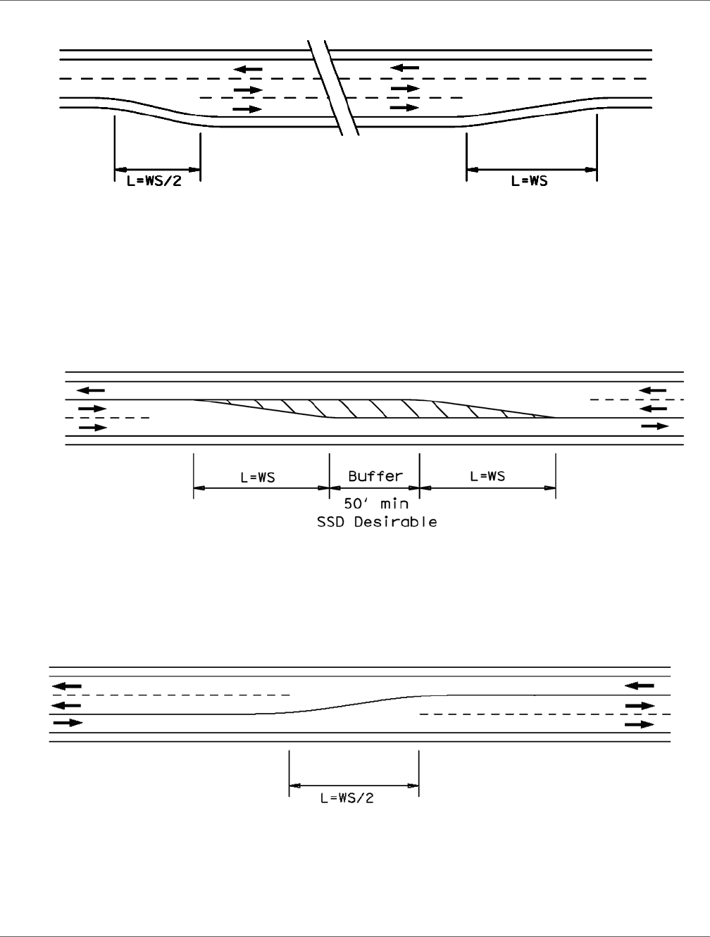
Roadway Design Manual 4-17 TxDOT 04/2018
Chapter 4 — Non-Freeway Rehabilitation (3R)
Design Criteria Section 6 — Super 2 Highways
Figure 4-1. Opening and Closing a Passing Lane
When switching the passing lane from one direction to another (closing the passing lane in each
direction), provide a taper length from each direction based on L = WS, with a minimum 50 ft buf-
fer (stopping sight distance (SSD) desirable) between them. (Figure 4-2).
Figure 4-2. Closing the Passing Lane from One Direction to Another
When opening a passing lane in each direction (Figure 4-3), provide a taper length based on L=
WS/2.
Figure 4-3. Opening the Passing Lane from One Direction to Another
When widening to the outside of the roadway to provide a passing lane opportunity (Figure 4-4),
provide an opening taper length based on L = WS/2 and a closing taper length based on L=WS.
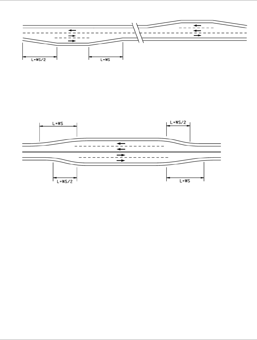
Roadway Design Manual 4-18 TxDOT 04/2018
Chapter 4 — Non-Freeway Rehabilitation (3R)
Design Criteria Section 6 — Super 2 Highways
Figure 4-4. Separated Passing Lanes with Widening to the Outside of Roadway
Passing lanes in each direction may overlap if ROW is sufficient (Figure 4-5).
Provide an opening taper length based on L = WS/2 and a closing taper length based on L=WS.
Figure 4-5. Side by Side Passing Lanes


Roadway Design Manual 5-2 TxDOT 04/2018
Chapter 5 — Non-Freeway Resurfacing or
Restoration Projects (2R) Section 1 — Overview
Section 1 — Overview
Guidelines
The following guidelines apply to non-freeway resurfacing or restoration (2R) projects which are
not on National Highway System (NHS) routes, and have current average daily traffic (ADT) vol-
umes of 2500 per lane and less. Projects with current average daily traffic (ADT) volumes greater
than 2500 per lane and projects which are on NHS system routes may not be designed to 2R
guidelines.
These guidelines should also be used in determining design scope and estimating cost for individ-
ual candidate projects whenever a restoration program is being developed. Preliminary structural
planning should be coordinated with the Bridge Division.
Definition. Restoration projects are defined as work performed to restore pavement structure, rid-
ing quality, or other necessary components, to their existing cross section configuration. The
principal purposes of these projects are surfacing and repair of the pavement structure. The addition
of through travel lanes is not permitted under a restoration project. The addition of continuous two-
way left-turn lanes, acceleration/deceleration lanes, turning lanes, and shoulders are acceptable as
restoration work as long as the existing through lane and shoulder widths are maintained as a mini-
mum. The restoration work may include upgrading roadway components as needed to maintain the
roadway in an acceptable condition.
Upgrading. Where the work is cost effective and funds are sufficient to upgrade to reconstruction
or rehabilitation design criteria without jeopardizing district priorities for other restoration work,
development of projects to higher criteria may be done at the district’s discretion.
Crash Analysis. A crash analysis should be conducted for 2R projects. Any specific areas involv-
ing high crash frequencies will be reviewed and corrective measures taken where appropriate. In
addition to a formal analysis of crash data, Chapter 4, Section 3 lists several methods that have been
used successfully to identify potential crash problems.


Roadway Design Manual 6-2 TxDOT 04/2018
Chapter 6 — Special Facilities Section 1 — Off-System Bridge Replacement and
Rehabilitation Projects
Section 1 — Off-System Bridge Replacement and Rehabilitation Projects
Project Conditions
This section provides design guidance for projects meeting all of the following conditions:
included in the off-system bridge replacement and rehabilitation program
facility not likely to be added to the designated state highway system
current ADT of 400 or less.
If all the above conditions are not met, then the design criteria for the appropriate class of highway
should be utilized. For off-system bridge projects, current ADT may be used with the appropriate
class of highway (i.e., enter tables, charts, or figures with current ADT substituted for future ADT).
Where significant traffic growth is expected or the roadway will be widened in the near future, the
use of future ADT for design purposes is encouraged.
For more information on the off-system bridge replacement and rehabilitation program, refer to the
Bridge Project Development Manual.
Note that additional vertical clearance requirements may apply to
bridge projects on the Texas Highway Freight Network (THFN) as
specified in Chapter 3, Section 8.
Design Values
Design values selected for a particular project should satisfy and preferably exceed the values
shown below. Selected design values should be consistent and compatible with the prevalent design
features on the existing off-system roadway. If the route has the potential for significant ADT
increases in the near future, or if the character of the traffic is not local, design requirements for the
appropriate class of highway should be used.
Minimum Design Speed: Meet or improve conditions that are typical on the remainder of the
roadway.
Vertical Curvature, Minimum K values: Meet or improve conditions that are typical on the
remainder of the roadway.
Horizontal Curvature: Meet or improve conditions that are typical on the remainder of the
roadway.
Minimum Superelevation: Meet or improve conditions that are typical on the remainder of the
roadway.

Roadway Design Manual 6-3 TxDOT 04/2018
Chapter 6 — Special Facilities Section 1 — Off-System Bridge Replacement and
Rehabilitation Projects
Maximum Grades: Meet or improve conditions that are typical on the remainder of the
roadway.
Minimum Structure Width, Face to Face of Rail: 24 ft [7.2 m].
Bridge End Guard Fence:
-Minimum Conditions – Transition section plus end treatment.
-If an intervening roadway or driveway prevents usual placement of guard fence, a guard
fence radius may be used provided the approach represents a low speed condition.
Approach Roadway:
-For minimum length of 50 feet [15 m] adjacent to the bridge end, the roadway crown
should match clear width across structure (24 feet [7.2 m]) plus additional width to accom-
modate approach guard fence.
-An appropriate transition (minimum length 50 feet [15 m]) to county road width should be
made in the sections of approach roadway located at the federal project extremities.
-If roadway surfacing is included, a minimum of 20 feet [6 m] surfacing width should be
used for the 50 feet [15 m] roadway section adjacent to the bridge.
Traffic Control:
-When provided, and to the extent practical, detours should match existing county road
design features. Design details for detours should be shown in the plans and on the prelim-
inary layouts.
-Traffic control devices should be in conformance with the Texas Manual on Uniform Traf-
fic Control Devices, and details should be included in the plans.

Roadway Design Manual 6-4 TxDOT 04/2018
Chapter 6 — Special Facilities Section 2 — Historically Significant Bridge Projects
Section 2 — Historically Significant Bridge Projects
Reference for Procedures
Historically significant bridges command importance and a place in the engineering and cultural
heritage of this nation. Federal law requires these bridges be given special consideration, where
practical and feasible, toward their preservation in the course of bridge replacement or bridge reha-
bilitation/improvement projects.
Reference can be made to the Historic Bridge Manual for procedures that should be used when
developing projects that involve historic bridges.

Roadway Design Manual 6-5 TxDOT 04/2018
Chapter 6 — Special Facilities Section 3 — Texas Parks and Wildlife Department
(Park Road) Projects
Section 3 — Texas Parks and Wildlife Department (Park Road) Projects
Working Agreements
According to Acts 1995, 74th Leg., Ch. 445, §1, the Texas Department of Transportation shall con-
struct, repair and maintain roads in and adjacent to state parks, state fish hatcheries, state wildlife
management areas, and support facilities for parks, fish hatcheries, and wildlife management areas.
In response to this legislation, a memorandum of agreement between Texas Department of Trans-
portation (TxDOT) and the Texas Parks and Wildlife Department (TPWD) was established. This
memorandum of agreement states that TPWD is to provide TxDOT with current design standards
for TPWD facilities. Accordingly, TPWD facilities are be designed based on the criteria and guid-
ance given in the current publication of the Texas Parks and Wildlife Department Design Standards
for Roads and Parking.

Roadway Design Manual 6-6 TxDOT 04/2018
Chapter 6 — Special Facilities Section 4 — Bicycle Facilities
Section 4 — Bicycle Facilities
Overview
The Texas Legislature has directed TxDOT, in Texas Transportation Code §201.902, to enhance the
use of the state highway system by bicyclists. Administrative rules adopted by the commission in
43 TAC §25.50–25.55 affirm TxDOT’s commitment to integrating this mode of travel into project
development.
Guidance for Bicycle Facilities
The AASHTO Guide for the Development of Bicycle Facilities is the guide for planning, design,
construction, maintenance, and operation of bicycle facilities. There are two types of bicycle facili-
ties described in the guide. These are bicycle lanes and bicycle paths. A bicycle lane is defined as a
portion of a roadway which has been designated by striping, signing and/or pavement markings for
the preferential or exclusive use of bicyclists. A bicycle path is defined as a bikeway that is physi-
cally separated from motorized vehicular traffic by an open space or barrier, either within the
highway right of way or within an independent right of way, that can also be used by pedestrians,
skaters, joggers, wheelchairs, and other non-motorized users.
Design Exceptions and Design Waivers for Bicycle Facilities
If the minimum requirements give in the AASHTO Guide for the Development of Bicycle Facilities
for bicycle lanes cannot be met, these variances will be submitted as design exceptions to the Road-
way Design Exception Committee. For new shared lanes on a signed, designated bicycle route, the
minimum lane width shall be 14 ft [4.2 m]. Proposed widths less than 14 ft [4.2 m] will require
approval by the Roadway Design Exception Committee.
If the minimum requirements given in the AASHTO Guide for the Development of Bicycle Facili-
ties for bicycle paths cannot be met, these variances will be handled by design waivers at the
district level.

Roadway Design Manual 7-1 TxDOT 04/2018
Chapter 7 — Miscellaneous Design Elements
Contents:
Section 1 — Longitudinal Barriers
Section 2 — Fencing
Section 3 — Pedestrian Separations and Ramps
Section 4 — Parking
Section 5 — Shoulder Texturing
Section 6 — Emergency Median Openings on Freeways
Section 7 — Minimum Designs for Truck and Bus Turns

Roadway Design Manual 7-2 TxDOT 04/2018
Chapter 7 — Miscellaneous Design Elements Section 1 — Longitudinal Barriers
Section 1 — Longitudinal Barriers
Overview
This section contains information regarding the following elements of longitudinal barriers:
Concrete Barriers (Median and Roadside)
Guardrail
Attenuators (Crash Cushions).
Concrete Barriers (Median and Roadside)
Application. Concrete barriers may be used to prevent the following:
unlawful turns
out-of-control vehicles from entering the opposing traffic lanes, and, in some cases
unlawful crossing of medians by pedestrians.
Concrete barriers, much like guardrail, may also be used as roadside barriers to prevent vehicles
from encountering steep slopes or obstacles.
Location. On controlled access highways, concrete barriers will generally be provided in medians
of 30 ft [9.0 m] or less. On non-controlled access highways, concrete barriers may be used on medi-
ans of 30 ft [9.0 m] or less; however, care should be exercised in their use in order to avoid the
creation of an obstacle or restriction in sight distance at median openings or on horizontal curves.
Generally, the use of concrete barriers on non-controlled access facilities should be restricted to
areas with potential safety concerns such as railroad separations or through areas where median
constriction occurs. Concrete barriers may be considered in medians wider than 30 ft [9.0 m] based
on an operational analysis.
Standard Installations. Medians for urban freeway sections generally are relatively narrow and
flush. For new construction, an urban freeway usually includes a flush median (see Medians in
Chapter 3) with concrete barrier.
In determining the type of barrier to be used for any project, the primary consideration is safety,
both for vehicular impacts and during any maintenance activities. Field experience with concrete
barriers indicates that, unlike the metal beam system, maintenance operations are not normally
required following accidental vehicular encroachment.

Roadway Design Manual 7-3 TxDOT 04/2018
Chapter 7 — Miscellaneous Design Elements Section 1 — Longitudinal Barriers
Reconstruction projects with median barriers should be considered on a project-by-project basis.
Often, the structural capability of existing bridges may make the use of concrete median barriers
infeasible due to increased dead load.
TxDOT’s design standards and standard construction specifications provide more information on
the design and construction details for concrete barriers.
Guardrail
Application. Guardrail is considered a protective device for the traveling public and is used at
points on the highway where vehicles inadvertently leaving the facility would be a significant
safety concern. Guardrail is designed to resist impact by deflecting the vehicle so that it continues
to move at a reduced velocity along the rail in the original direction of traffic. The limits of rail to
be installed are shown on the plans; however, they may be adjusted in the field after the grading is
completed.
Location. Guardrail should be installed in areas where the consequence of an errant vehicle leaving
the roadway is judged to be more severe than impacting the guardrail. Guardrail should be offset at
least 2.5 ft [750 mm] and desirably 5 ft [1,500 mm] from the nearest edge of fixed objects. At over-
passes, guardrail should be anchored securely to the structure.
Standard Installations. Guardrail should be installed in accordance with the current roadway
standards.
End Treatments. Providing appropriate end treatments is one of the most important considerations
in the design of guardrail. An untreated guardrail will stop a vehicle abruptly and can penetrate the
passenger compartment. For more information on the installation of various types of end treat-
ments, refer to TxDOT’s standard construction specifications and roadway standards.
Attenuators (Crash Cushions)
Application. Crash cushions or impact attenuators are protective devices that prevent errant vehi-
cles from impacting fixed objects. This is accomplished by gradually decelerating a vehicle to a
safe stop for head-on impacts or redirecting a vehicle away from the fixed object for side impacts.
Location. Attenuators are ideally suited for use at locations where fixed objects cannot be moved,
relocated, or made breakaway, and cannot be adequately shielded by a longitudinal barrier. A com-
mon application of a crash cushion is in an exit ramp gore where a bridge rail end requires
shielding. Crash cushions are also frequently used to shield bridge columns as well as roadside and
median barrier terminals.
Standard Installations. There are numerous types of attenuators that are in common use today.
When more than one system is under consideration, the designer should carefully evaluate the

Roadway Design Manual 7-4 TxDOT 04/2018
Chapter 7 — Miscellaneous Design Elements Section 1 — Longitudinal Barriers
structural, safety, and maintenance characteristics of each candidate system. Characteristics to be
considered include the following:
impact decelerations
redirection capabilities
anchorage and back-up structure requirements
debris produced by impact
ease and cost of maintenance.
For more detailed information on the installation of various types of attenuators, refer to TxDOT’s
standard specifications and roadway standards.

Roadway Design Manual 7-5 TxDOT 04/2018
Chapter 7 — Miscellaneous Design Elements Section 2 — Fencing
Section 2 — Fencing
Right-of-way
The procedures for fencing highway right-of-way are in Right of Way Manual Vol. 2 - Right of
Way Acquisition. Where additional right-of-way is not required for construction of improvements
of existing highways, right-of-way (property) fencing is the responsibility of the land owner.
Control of Access Fencing on Freeways
Control of access fence should be erected whenever it is necessary to prohibit unrestricted access to
the through lanes by pedestrians, animals and/or vehicles. The prohibition of access to the through
lanes should be from private property, intercepted local roads and unauthorized crossings from
frontage roads to the through lanes. Table 7-1 describes the types of fences that should be used for
various conditions.
Department standard designs should be used where applicable. Specially designed fences may be
necessary in certain areas where sandstorms and snowstorms occur and for other special conditions.
Table 7-1: Use of Control of Access Fencing on Freeways
Condition Type of Fence Usual Location
Urban and suburban areas Chain link fence of 4 ft [1.2 m] usual height or
6 ft [1.8 m] height where necessary for control
of pedestrians
Variable1
Rural conditions where both large
and small animals exist Wire mesh fence with one or more strands of
barbed wire ROW line
Rural conditions where only large
animals exist Barbed wire fence with height of 4 ft or 5 ft [1.2
or 1.5 m] ROW line
Control of Vehicles Post and cable fence with closely spaced posts Variable1
1Where frontage roads are provided, control of access fence, when used, should be placed in the outer separa-
tion approximately equidistant between the mainlanes and frontage roads and at least 30 ft [9.0 m] from the
edge of mainlane pavement. Where the control of access line is at the right-of-way line, the control of access
fence may be located at the right-of-way line and will serve a dual function as a right-of-way fence.

Roadway Design Manual 7-6 TxDOT 04/2018
Chapter 7 — Miscellaneous Design Elements Section 3 — Pedestrian Separations and Ramps
Section 3 — Pedestrian Separations and Ramps
General Requirements
Pedestrian separations are generally limited to controlled access facilities since it is necessary that
all at-grade pedestrian crossings be eliminated on those facilities. Control-of-access fences and
other means may be used to encourage pedestrians to cross at traffic separations. On highways
other than freeways, pedestrian separations will be considered only in unusual circumstances.
Pedestrian structures may used to provide for heavy pedestrian movements adjacent to factories,
schools, parks, athletic fields, etc. If the location of traffic separations is such that their use would
add an unreasonable pedestrian distance, a pedestrian structure may be considered for lower pedes-
trian volumes.
A pedestrian structure should be made as natural and convenient as possible. Either an overcrossing
or undercrossing may be provided. All separations must be accessible to the disabled unless alter-
nate safe means are provided to enable mobility-limited persons to cross the roadway at that
location, or unless it would be infeasible for mobility-limited persons to reach the structure because
of unusual topographical or architectural obstacles unrelated to the roadway facility.
Pedestrian ramps associated with roadway facilities such as pedestrian separations, parking lots,
rest areas, curb cuts at cross walks, etc., must be accessible to disabled persons and designed in
accordance with the Americans with Disabilities Act Accessibility Guidelines and the Texas Acces-
sibility Standards.
Overcrossings
All pedestrian overcrossings should be enclosed with wire fabric to discourage pedestrians from
throwing debris onto vehicles below the structure.
Undercrossings
Pedestrians avoid the use of undercrossings unless the underpass is in line with the approach side-
walk and has continuous vision through the underpass from the approaching sidewalk. Ample
lighting, both day and night, is essential.

Roadway Design Manual 7-7 TxDOT 04/2018
Chapter 7 — Miscellaneous Design Elements Section 4 — Parking
Section 4 — Parking
Overview
This section presents information on the following topics:
fringe parking lots
parking along highways and arterial streets
Fringe Parking Lots
Fringe parking lots are congestion mitigation and energy conservation measures which TxDOT uti-
lizes. Depending on the function which they are intended to serve, they maybe one of the following
types of facilities:
park and pool lots
park and ride lots, or
combination park and pool/park and ride lot.
Park and Pool Lots. Park and Pool lots are usually located on the fringe of an urban area along an
arterial roadway at a convenient point where a group of two or more drivers from a surrounding
area can gather, leave their individual vehicle and proceed to a common destination in one of the
group vehicles. The carpool may consist of two or more persons per vehicle. The lot may provide
space for a small to large number of vehicles and serve many carpools involving several
destinations.
Park and pool lots are located within the highway right-of-way except where they may be in combi-
nation with a park and ride lot as discussed below. They are eligible for Federal-aid participation.
The lots should be simply designed to accommodate the passenger vehicle with regard to parking
stall widths, drive through isles and turning movements.
Park and Ride Lots. Park and ride lots are generally constructed along express bus routes and are
designed to intercept automobiles from low density suburban development of outlying locations
along transitway corridors. The quality of transit service must be attractive. The time required to
reach the destination point by bus must be comparable to or better than driving one’s own car.
The facility should be located with regard to the following criteria:
along a corridor which experiences 20,000 vehicles per day per lane
in advance of the point where intense traffic congestion routinely occurs

Roadway Design Manual 7-8 TxDOT 04/2018
Chapter 7 — Miscellaneous Design Elements Section 4 — Parking
4 to 5 miles [6.4 to 8.0 kilometers] from the activity center (usually the Central Business Dis-
trict (CBD)) served by the transit way and at least 4 to 5 miles [6.4 to 8.0 kilometers] from
another park and ride facility
downstream from, but in the immediate area of, sufficient demand for travel to the activity cen-
ter being served
on the right hand side of the inbound roadway.
Other desirable general features include the following:
good accessibility to the adjoining street system
no parking fees
space for future expansion
fencing.
Typical park and ride layouts include the following design features:
bus travel area designed to accommodate the Bus or A-Bus for all turning movements
bus loading areas located to reduce conflict between buses and private vehicles
maximum walking distance of 650 ft [200 m]
separate bus access points from private vehicle access points if demand exceeds 500 all day
spaces
parking placed in the following order with respect to proximity of the bus loading area:
-disabled persons
-bicycles
-motorcycles
-kiss and ride
-private vehicular parking.
ingress and egress located near midblock on collector and local streets; direct access to arteri-
als and freeway ramps should only be used if projected queues do not interfere with functional
areas of nearby intersections; at least two ingress/egress points should be provided to the park
and ride facility; right and left turn lanes with adequate storage should be added to all ingress/
egress locations
parking lanes in the park and ride lot placed approximately 90 degrees to the bus loading area
to facilitate safe, convenient walking to buses
curbs depressed and wheelchair ramps provided where necessary; disabled parking spaces and
pedestrian facilities should be in accordance with the Americans with Disabilities Act Accessi-
bility Guidelines and the Texas Accessibility Standards.

Roadway Design Manual 7-9 TxDOT 04/2018
Chapter 7 — Miscellaneous Design Elements Section 4 — Parking
Combination Park and Pool/Park and Ride Lot. These combination type lots serve the purposes
and combine the features of each of the two types of facilities discussed above.
References. Further information on the planning and design of park and ride facilities may be
found in the following publications:
AASHTO Policy on Geometric Design of Streets and Highways
AASHTO Guide for the Design of Park and Ride Facilities
TxDOT Revised Manual for Planning, Designing and Operating Transitway Facilities in
Texas.
Authority and Funding. For fringe parking areas within highway right-of-way, projects are gener-
ally developed as any other multiple use project. Where parking lots are proposed that are located
outside of existing or proposed highway right-of-way, commission approval is required.
Park and pool lots are eligible for Federal-aid participation. Projects are usually located within or
adjacent to highway right-of-way outside the central business district, but inside the urbanized area,
and consistent with the urban transportation planning process. Operation and maintenance respon-
sibilities should be assigned to local transit or government or agencies by agreement.
Parking Along Highways and Arterial Streets
This section deals with parking as it pertains to the mainlanes of a controlled access highway, the
frontage roads for such a facility, and parking along urban and suburban arterials. Offstreet parking
facilities provided within highway right-of-way are discussed in the previous section (Fringe Park-
ing Lots) Rest areas as parking facilities are not considered in this section.
Emergency Parking. Parking on and adjacent to the mainlanes of a highway will not be permitted
except for emergency situations. It is of paramount importance, however, that provision be made
for emergency parking. Shoulders of adequate design provide for this required parking space.
Curb Parking. In general, curb parking on urban/suburban arterial streets and frontage roads
should be discouraged. Where speed is low and the traffic volumes are well below capacity, curb
parking may be permitted. However, at higher speeds and during periods of heavy traffic move-
ment, curb parking is incompatible with arterial street service and desirably should not be
permitted. Curb parking reduces capacity and interferes with free flow of adjacent traffic. Elimina-
tion of curb parking can increase the capacity of four-to-six lane arterials by 50 to 60 percent.
If curb parking is used on urban/suburban arterials or frontage roads under the conditions stated
above, the following design requirements should be met:
provide parking lanes only at locations where needed
parallel parking preferred

Roadway Design Manual 7-10 TxDOT 04/2018
Chapter 7 — Miscellaneous Design Elements Section 4 — Parking
confine parking lanes to outer side of street or frontage road
require that parking lane widths be 10 feet [3.0 meters]
restrict parking a minimum of 20 feet [6 meters] back from the radius of the intersection to
allow for sight distance, turning clearance and, if desired, a short right turn lane.

Roadway Design Manual 7-11 TxDOT 04/2018
Chapter 7 — Miscellaneous Design Elements Section 5 — Shoulder Texturing
Section 5 — Shoulder Texturing
Definition
Rumble strips are depressed or raised patterns used to provide auditory and tactile sensations to the
driver to call attention to an upcoming change in conditions. Specifically, shoulder texturing is the
use of rumble strips along the shoulder as a warning device to alert inattentive drivers that they are
leaving the travelway.
Types of Shoulder Texturing
Milled-in. Milled-in rumble strips are effective types of shoulder texturing at reducing the number
of single vehicle run-off-the-road accidents. Milled-in rumble strips are shallow depressions per-
pendicular to the edge line. Machinery specifically adapted for this type of work is required. A
minimum shoulder width of 8 ft [2.4 m] is required for the outside shoulder to be milled. A mini-
mum shoulder width of 4 ft [1.2 m] is required for the inside shoulder to be milled. Milled-in
texturing produces sufficient stimuli to alert inattentive drivers, but does not affect the maneuver-
ability capabilities of vehicles.
Rolled-in. Rolled-in strips may produce less noise and vibration than milled-in rumble stripes;
however, rolled-in rumble strips are also effective at reducing the number of single vehicle run-off-
the-road accidents. Rolled-in rumble strips are produced by half sections of pipe welded on a steel
wheel roller at the appropriate spacing and rolled-in during the placement of hot mix asphaltic con-
crete pavement. Considerations in evaluating rolled-in texturing include 1) placement must be in
coordination with other asphaltic concrete pavement construction, and 2) the temperature of the
asphaltic concrete pavement is critical for achieving the proper depth without affecting the remain-
ing surface. A minimum shoulder width of 8 ft [2.4 m] is required for the outside shoulder to be
treated. A minimum shoulder width or 4 ft [1.2 m] is required for the inside shoulder to be treated.
Traffic Buttons. Traffic buttons placed along the edge line may also be used as shoulder texturing
when milled-in or rolled-in texturing is not feasible. Buttons should be limited to roadways where
there is insufficient pavement structure or shoulder width to accommodate either of the depressed
texturing treatments and where the accident experience justifies the cost for placing and maintain-
ing buttons. Buttons, however, may be used to supplement other shoulder texturing treatments
when appropriate. Buttons may not be suitable where snow plows are used.
Raised Profile Thermoplastic Marking. Raised profile thermoplastic markings installed as the
edge line may be used as shoulder texturing when rolled-in or milled-in texturing is not feasible.
Raised profile thermoplastic markings used as the shoulder texturing treatment should be limited to
roadways where there is insufficient pavement structure or shoulder width to accommodate either

Roadway Design Manual 7-12 TxDOT 04/2018
Chapter 7 — Miscellaneous Design Elements Section 5 — Shoulder Texturing
of the depressed texturing treatments. Raised profile thermoplastic markings, however, may be
used to supplement other shoulder treatments, when appropriate.
Jiggle Bars. Jiggle bar tiles placed in a pattern perpendicular to the edge line may also be used as
shoulder texturing when rolled-in or milled-in texturing is not feasible. The use of jiggle bars as
shoulder texturing is not encouraged due to the level of auditory and tactile sensations caused by
the jiggle bars and the high cost of installing the jiggle bars. Also, jiggle bars may not be suitable
where snow plows are used. A minimum shoulder width of 8 ft [2.4 m] is required for the outside
shoulder to be treated. A minimum shoulder width of 4 ft [1.2 m] is required for the inside shoulder
to be treated.
Roadway Applications of Shoulder Texturing
For rural freeways and rural four-lane or more divided highways, the following guidelines are
recommended:
Asphaltic Concrete Shoulders: Rumble strips should be installed as part of new construction,
reconstruction, and overlay projects on rural four-lane or more controlled and partially con-
trolled access highways with asphaltic concrete shoulders.
Portland Cement Shoulders: Rumble strips should be installed as part of new construction
and reconstruction projects. If the concrete shoulder will be used in the near future as a perma-
nent travel lane or a travel lane in a work zone, shoulder texturing should not be considered.
For rural four-lane or more undivided and rural two-lane highways, shoulder texturing on asphaltic
concrete or portland cement shoulders is not recommended for these facilities except in special
cases where a significant number of accidents, by frequency and percentage of total accidents, are
run-off-the-road accidents and the installation of rumble strips is determined to be cost beneficial.
The accident history, along with consideration of shoulder use by traffic, mail carriers, bicyclists,
and/or farm equipment should be evaluated. If the concrete shoulder will be used in the near future
as a permanent travel lane or a travel lane in a work zone, shoulder texturing should not be
considered.
For urban highways, shoulder texturing on asphaltic concrete or portland cement shoulders is not
recommended.
Bicyclists. When installing shoulder treatments, appropriate riding space for bicyclists needs to be
a consideration. The standard details for shoulder texturing treatments provide appropriate riding
space.
Placement. Rumble strips shall not be placed across exit or entrance ramps, acceleration and decel-
eration lanes, crossovers, gore areas or intersections with other roadways. Depressed rumble strips
(i.e., milled-in or rolled-in) shall not be placed across bridge decks.

Roadway Design Manual 7-13 TxDOT 04/2018
Chapter 7 — Miscellaneous Design Elements Section 6 — Emergency Median Openings on
Freeways
Section 6 — Emergency Median Openings on Freeways
Overview
Median crossings between the mainlanes are sometimes necessary for proper law enforcement or
for performance of highway maintenance on rural freeways. The construction of such median
crossings is not encouraged since the necessary U-turns by such vehicles should be accomplished
by using ramps at interchanges to the maximum extent feasible.
Conditions
Median crossings, as turnarounds, interfere with through traffic and should be avoided. Normally,
the spacing of interchanges and layout of the highway provides for all necessary traffic movements,
including those of emergency vehicles.
In unusual situations, where the distance between interchanges is great, emergency crossings may
be provided with administrative approval.
Spacing of Openings
Due to the close spacing of interchanges on urban freeways, emergency median openings are not
needed for the operation of official vehicles and, in general, they should not be provided. In rural
areas where the spacing of interchanges is greater than approximately 3 miles [4.8 km], a U-turn
median opening may be considered at a favorable location about halfway between interchanges. In
no case should emergency median openings be spaced at less than 1 mile [1.6 km] intervals. All
emergency median openings should be at least 0.5 mile [0.8 km] from any structure that crosses
over a freeway and at least 1 mile [1.6 km] from any ramp terminal or other access connection,
such as those serving safety rest areas. Openings should be located where adequate stopping sight
distance is available and where the median is sufficiently wide to permit an official vehicle to turn
between the inner freeway lanes. Emergency median openings should also be as inconspicuous to
the traveling public as possible.
Construction
Location and type of emergency median openings should be made a part of the PS&E as a contract
item and should be installed as such.

Roadway Design Manual 7-14 TxDOT 04/2018
Chapter 7 — Miscellaneous Design Elements Section 7 — Minimum Designs for Truck and Bus
Turns
Section 7 — Minimum Designs for Truck and Bus Turns
Overview
This section contains the following information on minimum designs for truck and bus turns:
application
channelization
alternatives to simple curvature
urban Intersections
rural Intersections.
Application
There are no firm guidelines governing the selection of the type of large vehicle to be used as a
design vehicle. Factors that influence design vehicle selection are as follows:
the type and frequency of use by large vehicles
consequences of encroachment into other lanes or the roadside
availability of right-of-way
Functional class of intersecting routes and location (urban versus rural) affect this selection in
a general sense. Project-specific traffic data, specifically the frequency of use by the various
design vehicle classes, is often the most important consideration in the selection process. The
Transportation Planning and Programming Division (TPP) may be contacted to obtain volume
data for the various vehicle classes.
Minimum turning path templates for single unit trucks or buses, semi-trailer combinations with
wheelbases of 40, 50 and 62 ft [12.2, 15.24 and 18.9 m], and double-trailer combination with
wheelbase of 67 ft [20.43 m] are shown in Figures 7-1, 7-2, 7-3, 7-4, 7-5, and 7-6 respectively. The
AASHTO publication A Policy on Geometric Design of Highways and Streets provides additional
information on turning paths and turning radii of these and other vehicles.
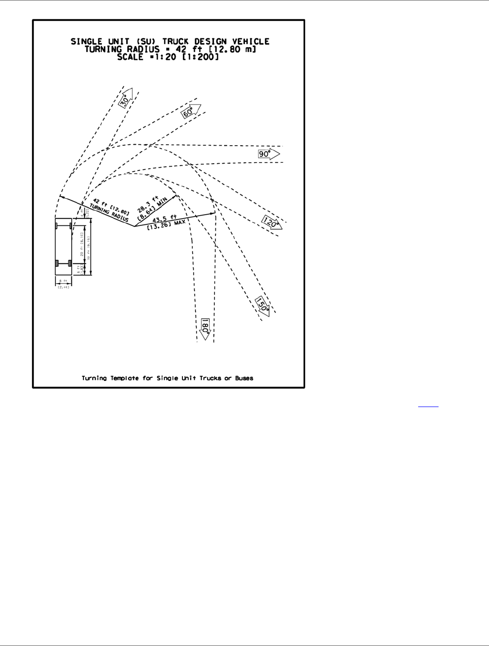
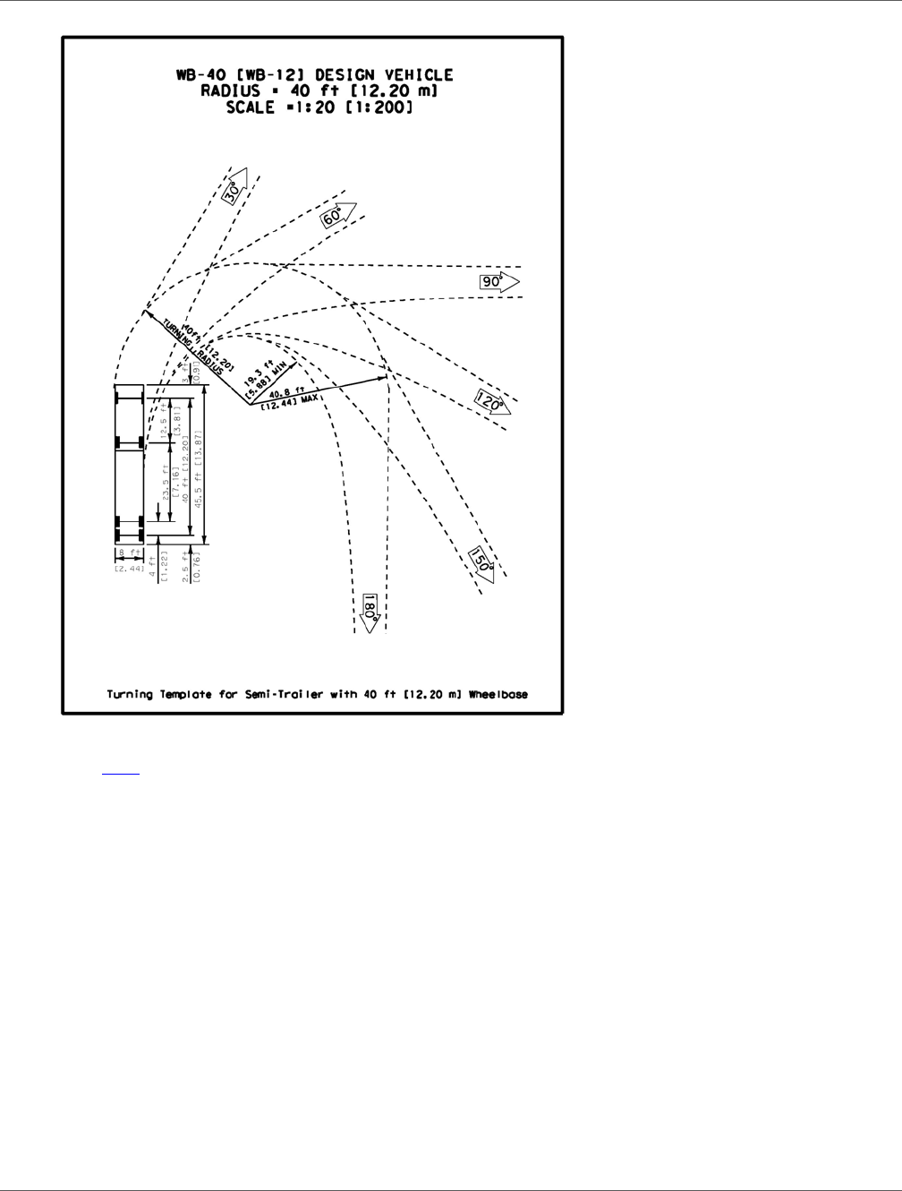
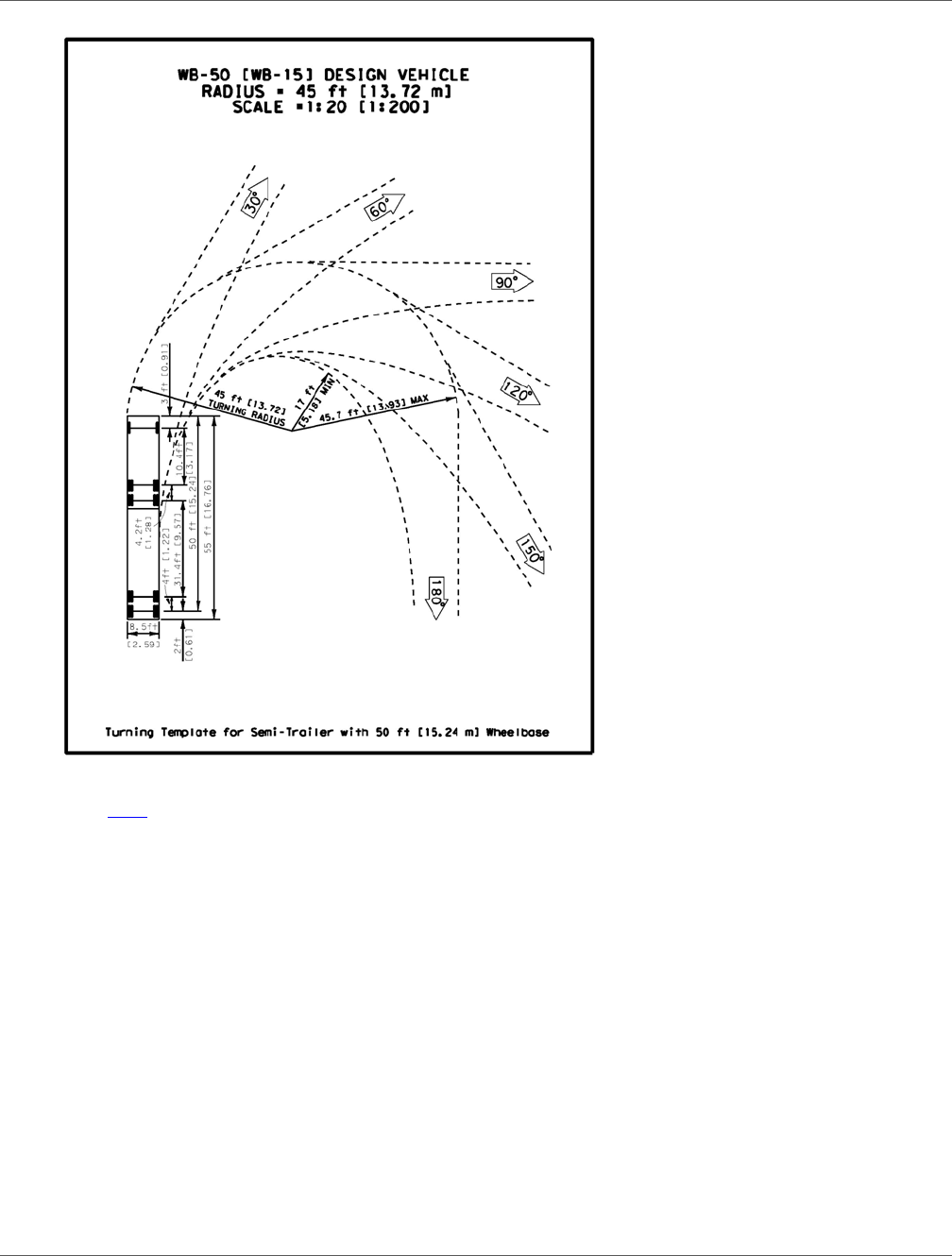
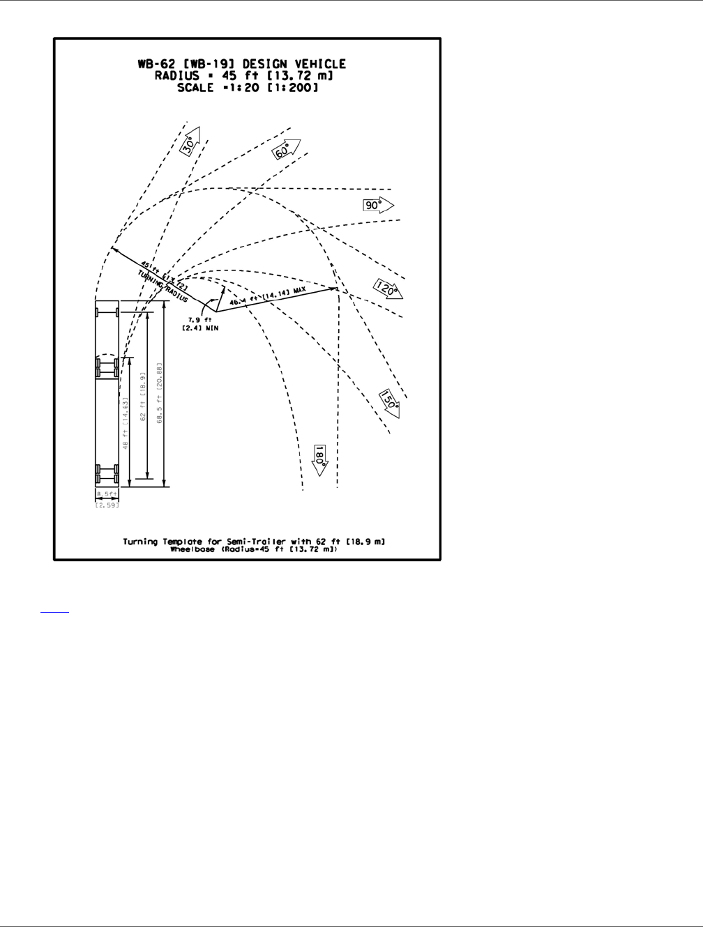
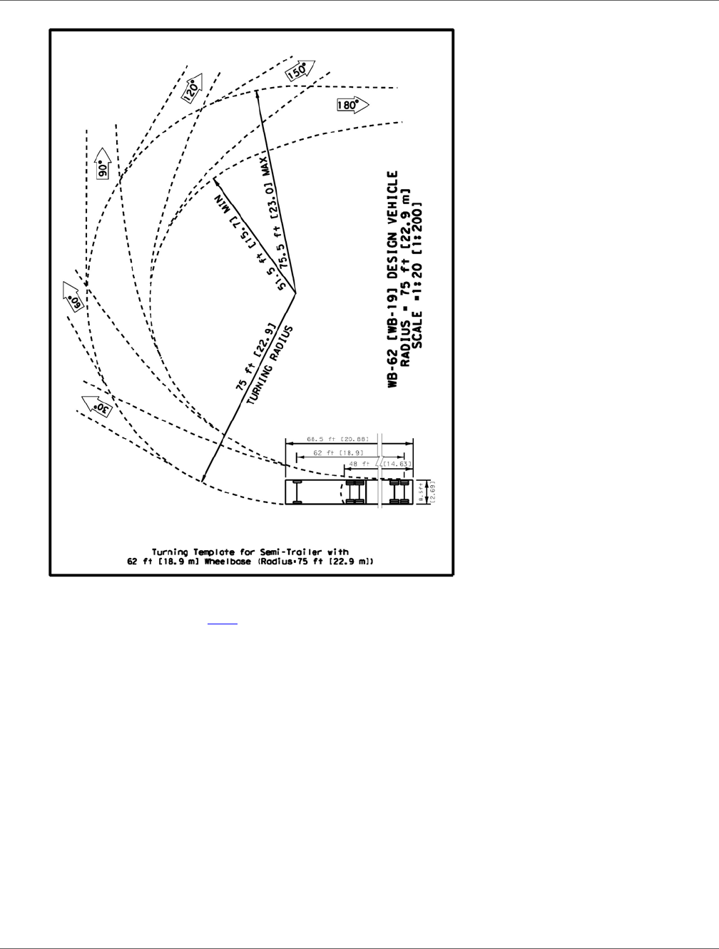

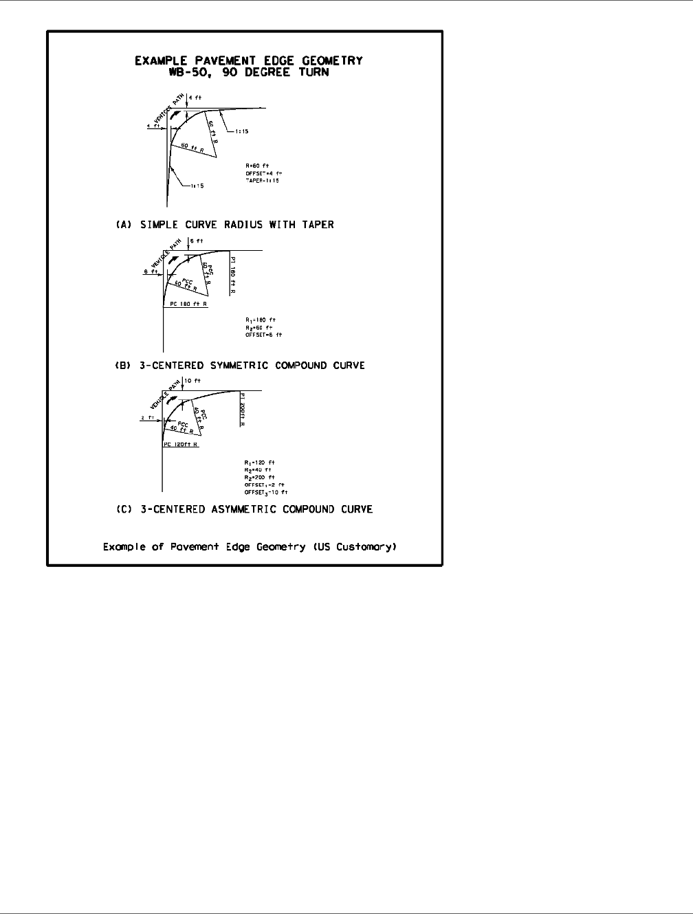
Roadway Design Manual 7-21 TxDOT 04/2018
Chapter 7 — Miscellaneous Design Elements Section 7 — Minimum Designs for Truck and Bus
Turns
Figure 7-7. (US). Example of Pavement Edge Geometry (US Customary).
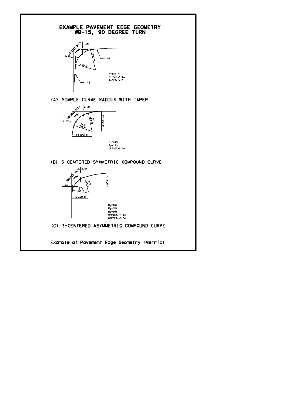
Roadway Design Manual 7-22 TxDOT 04/2018
Chapter 7 — Miscellaneous Design Elements Section 7 — Minimum Designs for Truck and Bus
Turns
Figure 7-8. (M). Example of Pavement Edge Geometry (Metric).
Channelization
Where the inner edges of pavement for right turns at intersections are designed to accommodate
semi-trailer combinations or where the design permits passenger vehicles to turn at 15 mph [20 km/
h] or more (i.e., 50 ft [15 m] or more radius), the pavement area at the intersection may become
excessively large for proper control of traffic. In these cases, channelizing islands should be used to
more effectively control, direct, and/or divide traffic paths. Physically, islands should be at least 50
ft2 [4.5 m2 ] in urban and 75 ft2 [7.0 m2] for rural conditions (100 ft2 [9.0 m2] preferable for both) in
size and may range from a painted to a curbed area.

Roadway Design Manual 7-23 TxDOT 04/2018
Chapter 7 — Miscellaneous Design Elements Section 7 — Minimum Designs for Truck and Bus
Turns
Alternatives to Simple Curvature
To accommodate the longest vehicles, off-tracking characteristics in combination with the large
(simple curve) radius that must be used results in a wide pavement area. In this regard, three-cen-
tered compound curves, or offset simple curves in combination with tapers, are preferred since they
more closely fit the paths of vehicles. Table 7-2 shows minimum edge of pavement designs for
right turns to accommodate various design vehicles for turn angles varying from 60 to 120 degrees.
(US Customary)
Angle of
Turn1
(degrees) Design
Vehicle
Simple
Curve
Radius Simple Curve Radius with Taper
3-Centered
Compound Curve,
Symmetric 3-Centered Compound
Curve, Asymmetric
- - (ft) Radius (ft) Offset (ft) Taper Radii (ft) Offset (ft) Radii (ft) Offset (ft)
60P40- ------
-SU60- ------
- WB-40 90 - - - - - - -
- WB-50 150 120 3.0 15:1 200-75-200 5.5 200-75-275 2.0-7.0
75 P 35 25 2.0 10:1 100-75-100 2.0 - -
- SU 55 45 2.0 10:1 120-45-120 2.0 - -
- WB-40 - 60 2.0 15:1 120-45-120 5.0 120-45-195 2.0-6.5
- WB-50 - 65 3.0 15:1 150-50-150 6.5 150-50-225 2.0-10.0
90 P 30 20 2.5 10:1 100-20-100 2.5 - -
- SU 50 40 2.0 10:1 120-40-120 2.0 - -
- WB-40 - 45 4.0 10:1 120-40-120 5.0 120-40-200 2.0-6.5
- WB-50 - 60 4.0 15:1 180-60-180 6.5 120-40-200 2.0-10.0
105 P - 20 2.5 - 100-20-100 2.5 - -
- SU - 35 3.0 - 100-35-100 3.0 - -
- WB-40 - 40 4.0 - 100-35-100 5.0 100-55-200 2.0-8.0
- WB-50 - 55 4.0 15:1 180-45-180 8.0 150-40-210 2.0-10.0
120 P - 20 2.0 - 100-20-100 2.0 - -
- SU - 30 3.0 - 100-30-100 3.0 - -
- WB-40 - 35 5.0 - 120-30-120 6.0 100-30-180 2.0-9.0
- WB-50 - 45 4.0 15:1 180-40-180 8.5 150-35-220 2.0-12.0

Roadway Design Manual 7-24 TxDOT 04/2018
Chapter 7 — Miscellaneous Design Elements Section 7 — Minimum Designs for Truck and Bus
Turns
1 “Angle of Turn” is the angle through which a vehicle travels in making a turn. It is measured from the extension of the tan-
gent on which a vehicle approaches to the corresponding tangent on the intersecting road to which a vehicle turns. It is the
same angle that is commonly called the delta angle in surveying terminology.
(US Customary)
Angle of
Turn1
(degrees) Design
Vehicle
Simple
Curve
Radius Simple Curve Radius with Taper
3-Centered
Compound Curve,
Symmetric 3-Centered Compound
Curve, Asymmetric
(Metric)
Angle of
Turn1
(degrees) Design
Vehicle
Simple
Curve
Radius Simple Curve Radius with Taper
3-Centered
Compound Curve,
Symmetric 3-Centered Compound
Curve, Asymmetric
- - (m) Radius (m) Offset (m) Taper Radii (m) Offset (m) Radii (m) Offset (m)
60P12- ------
-SU18- -------
- WB-12 28 - - - - - - -
- WB-15 45 29 1.0 15:1 60-23-60 1.7 60-23-84 0.6-2.0
75 P 11 8 0.6 10:1 30-8-30 0.6 - -
- SU 17 14 0.6 10:1 36-14-36 0.6 - -
- WB-12 - 18 0.6 15:1 36-14-36 1.5 36-14-60 0.6-2.0
- WB-15 - 20 1.0 15:1 45-15-45 2.0 45-15-69 0.6-3.0
90 P 9 6 0.8 10:1 30-6-30 0.8 - -
- SU 15 12 0.6 10:1 36-12-36 0.6 - -
- WB-12 - 14 1.2 10:1 36-12-36 1.5 36-12-60 0.6-2.0
- WB-15 - 18 1.2 15:1 55-18-55 2.0 36-12-60 0.6-3.0
105 P - 6 0.8 8:1 30-6-30 0.8 - -
- SU - 11 1.0 10:1 30-11-30 1.0 - -
- WB-12 - 12 1.2 10:1 30-11-30 1.5 30-17-60 0.6-2.5
- WB-15 - 17 1.2 15:1 55-14-55 2.5 45-12-64 0.6-3.0
120 P - 6 0.6 10:1 30-6-30 0.6 - -
- SU - 9 1.0 10:1 30-9-30 1.0 - -
- WB-12 - 11 1.5 8:1 36-9-36 2.0 30-9-55 0.6-2.7
- WB-15 - 14 1.2 15:1 55-12-55 2.6 45-11-67 0.6-3.6

Roadway Design Manual 7-25 TxDOT 04/2018
Chapter 7 — Miscellaneous Design Elements Section 7 — Minimum Designs for Truck and Bus
Turns
Figure 7-7 shows sample alternative (to simple curvature) edge of pavement geometry for a 90
degree turn using a WB 50 [WB-15] design vehicle. Although not shown in this figure, a radius of
80 ft [25 m] without channelizing island would be necessary to accommodate the wide, off-tracking
path of a WB-50 [WB-15] without undesirable encroachment. A geometric design of this sort is
undesirable, however, since there would be a confusing, wide expanse of surfaced area; further-
more, there is no convenient, effective location for traffic control devices.
Urban Intersections
Corner radii at intersections on arterial streets should satisfy the requirements of the drivers using
them to the extent practical and in consideration of the amount of right-of-way available, the angle
of the intersection, numbers of and space for pedestrians, width and number of lanes on the inter-
secting streets, and amounts of speed reductions. The following summary is offered as a guide:
Radii of 15 ft [4.5 m] to 25 ft [7.5 m] are adequate for passenger vehicles. These radii may be
provided at minor cross streets where there is little occasion for trucks to turn or at major inter-
sections where there are parking lanes. Where the street has sufficient capacity to retain the
curb lane as a parking lane for the foreseeable future, parking should be restricted for appropri-
ate distances from the crossing.
Radii of 25 ft [7.5 m] or more at minor cross streets should be provided on new construction
and on reconstruction where space permits.
Radii of 30 ft [9 m] or more at major cross streets should be provided where feasible so that an
occasional truck can turn without too much encroachment.
Radii of 40 ft [12 m] or more, and preferably three-centered compound curves or simple curves
with tapers to fit the paths of appropriate design vehicles, should be provided where large truck
combinations and buses turn frequently. Larger radii are also desirable where speed reductions
would cause problems.
Radii dimensions should be coordinated with crosswalk distances or special designs to make
crosswalks safe for all pedestrians.
For arterial-arterial urban intersections, turning radii of 75 ft [23 m] or more are desirable if fre-
quent use is anticipated by the WB-62 [WB-19] design vehicle. Where other types of truck
combinations are used as the design vehicle, pavement edge geometry as shown in Table 7-2: Min-
1“Angle of Turn” is the angle through which a vehicle travels in making a turn. It is measured from the extension of the tan-
gent on which a vehicle approaches to the corresponding tangent on the intersecting road to which a vehicle turns. It is the
same angle that is commonly called the delta angle in surveying terminology.
(Metric)
Angle of
Turn1
(degrees) Design
Vehicle
Simple
Curve
Radius Simple Curve Radius with Taper
3-Centered
Compound Curve,
Symmetric 3-Centered Compound
Curve, Asymmetric

Roadway Design Manual 7-26 TxDOT 04/2018
Chapter 7 — Miscellaneous Design Elements Section 7 — Minimum Designs for Truck and Bus
Turns
imum Edge of Pavement Designs at Intersections and Figure 7-7 permit the use of lesser radii. An
operational measure that appears promising is to provide guidance in the form of edge lines to
accommodate the turning paths of passenger cars, while providing sufficient paved area beyond the
edge lines to accommodate the turning path of an occasional large vehicle.
Rural Intersections
In rural areas space is generally more available and speeds higher. These factors suggest more lib-
eral designs for truck turning even when the frequency of long vehicles may not be as great as in
urban areas.
In the design of highway intersections with other (non-highway system) public roads, long vehicles
are generally infrequent users. Minimally, the SU, or on some occasions the WB –40 [WB-12],
design vehicle is appropriate for use unless special circumstances (location of a truck stop or termi-
nal) influence the frequency of use by certain vehicle classes.
For arterial intersections with collectors, the WB-40 [WB-12] design vehicle is generally appropri-
ate and the WB-50 [WB-15] should be used where specific circumstances warrant.
For arterial-arterial intersections, use by the WB-62 [WB-19] design vehicle should be anticipated
within project life. Two template layouts, Figure 7-4 and Figure 7-5, are shown with radii of 45 ft
[13.7 m] and 75 ft [ 23 m] respectively. For turning roadway widths to be reasonable in width, a
design radius of 75 ft [23 m] or more is required. Where circumstances at a particular rural arte-
rial-arterial intersection precludes the use of the WB-62 [WB-19] design vehicle, the WB-50 [WB-
15] should be used.


Roadway Design Manual 8-2 TxDOT 04/2018
Chapter 8 — Mobility Corridor (5 R) Design Criteria Section 1 — Overview
Section 1 — Overview
Introduction
Mobility corridors are intended to generate, or produce anew, very long term transportation oppor-
tunities. These transportation opportunities may include multiple modes such as rail, utilities,
freight and passenger characteristics. These modes may occur within a single corridor alignment or
the modes may be separated for some intervals. This chapter is intended to provide design guidance
on the roadway aspects of these mobility corridors. This guidance can be expected to be updated as
additional experience in gained in the planning, design, construction and operations of these trans-
portation facilities.
The primary focus of these corridors is mobility. The roadway portions of a mobility corridor facil-
ity are intended for long distance travel, and will therefore, be very controlled in terms of access.
The access will be limited to public roadways via ramp connections. Access will not be allowed
along these ramp connections.
Since these corridors are intended for mobility, the design speeds presented in this chapter are
between 85 mph to 100 mph [130 to 160 km/h]. Because mobility corridors may be generated or
regenerated, this design criteria may be applied when planning new facilities or reconstructing
existing corridors. While higher operating speeds may not be appropriate in all instances (such as
densely developed urban areas), these higher design speeds can be applied, and should be consid-
ered, whenever prudent.
With respect to facilities that one day could be part of a major corridor, particularly new location
routes, it is strongly recommended that these facilities be initially designed to accommodate a 100
mph design speed. Even though the facility may initially be posted for an 85 mph speed, the higher
design criteria will allow the greatest flexibility, both in the roadway portion as well as for other
transportation modes within the right of way, in terms of maximizing the future use of the corridor.
This does not mean that all projects should be over-designed. If, through the project development
process it is determined that substantial, adverse and unavoidable social, economic and environ-
mental impacts will occur, then different design criteria may be appropriate. Contact the
Environmental Affairs Division and the Right of Way Division as questions arise about environ-
mental and right of way impacts while planning for higher design speeds.
As always, the potential long-term use and growth of the system should be considered and appro-
priate planning and engineering principles should be applied. Again, these mobility corridors are
not primarily intended for local travel.
Section 2 discusses the features and design criteria for the roadway portion of mobility corridors
and includes the following subsections.

Roadway Design Manual 8-3 TxDOT 04/2018
Chapter 8 — Mobility Corridor (5 R) Design Criteria Section 1 — Overview
Lane Width and Number
Shoulders
Pavement Cross Slope
Vertical Clearances at Structures
Stopping Sight Distance
Grades
Curve Radii
Superelevation
Vertical Curves
Departures from these guidelines are governed in Design Exceptions, Design Waivers, Design Vari-
ances, and Texas Highway Freight Network (THFN) Design Deviations,
Chapter 1.

Roadway Design Manual 8-4 TxDOT 04/2018
Chapter 8 — Mobility Corridor (5 R) Design Criteria Section 2 — Roadway Design Criteria
Section 2 — Roadway Design Criteria
Lane Width and Number
The usual and minimum lane width is 13 ft [4 m]. The number of lanes required to accommodate
the anticipated traffic in the design year is determined by the level of service evaluation as dis-
cussed in the Highway Capacity Manual.
Shoulders
The minimum shoulder width is 12 ft [3.6 m]. This width applies to both inside and outside shoul-
ders, regardless of the number of main lanes of the facility. Shoulders should be continuously
surfaced and be maintained along all speed change lanes.
Pavement Cross Slope
Multilane divided pavements should be inclined in the same direction. The recommended pave-
ment cross slope is 2.0 percent. Shoulders should be sloped sufficiently to drain surface water but
not to an extent that safety concerns are created for vehicular use.
Vertical Clearances at Structures
The minimum vertical clearances at structures for the facility types are as
described below:
Texas Highway Freight Network (THFN) as specified in Chapter 3,
Section 8.
Other Facilities as specified in Chapter 3, Section 6.
Stopping Sight Distance
Stopping sight distance (SSD) for these facilities is calculated using the same methodology
described in Chapter 2, Section 3. The key variables that affect the calculation of SSD are brake
reaction time and deceleration rate.
The calculated and design stopping sight distances are shown in Table 8-1. Significant downgrades
may affect stopping sight distances.

Roadway Design Manual 8-5 TxDOT 04/2018
Chapter 8 — Mobility Corridor (5 R) Design Criteria Section 2 — Roadway Design Criteria
NOTE: Online users can click here to see the below table in PDF format.
Grades
Undesirable speed differentials that could occur between vehicle types on these facilities suggest
that limiting the rate and length of the grades be considered. Passenger vehicles are not signifi-
cantly affected by grades as steep as 3 percent, regardless of initial speed. Grades above 2 percent
may affect truck traffic depending on length of grade.
Table 8-2 summarizes the maximum grade controls in terms of design speed.
NOTE: Online users can click here to see the below table in PDF format.
Table 8-1: Stopping Sight Distance (US Customary)
Design Speed
(mph) Brake reaction
distance (ft) Braking distance
on level (ft) Stopping Sight Distance
--- Calculated (ft) Design (ft)
85 312.4 693.5 1005.8 1010
90 330.8 777.5 1108.2 1110
95 349.1 866.2 1215.4 1220
100 367.5 959.8 1327.3 1330
(Metric)
Design Speed (km/
h) Braking distance
on level (m) Brake reaction dis-
tance (m) Stopping Sight Distance
Calculated (m) Design (m)
140 97.3 224.8 322.1 325
150 104.3 258.1 362.3 365
160 111.2 293.6 404.8 405
NOTE: brake reaction distance predicated on a time of 2.5s; deceleration rate 11.2 ft/sec[3.4 m/sec]
Table 8-2: Maximum Grades (US Customary)
Type of Terrain Design Speed
-85 90 95 100
Level 2-3 2-3 2-3 2-3
Rolling 4444
(Metric)
- 140 150 160 --

Roadway Design Manual 8-6 TxDOT 04/2018
Chapter 8 — Mobility Corridor (5 R) Design Criteria Section 2 — Roadway Design Criteria
Curve Radii
The minimum curve radii for superelevation rates of 6 percent and 8 percent are shown in Table 8-
3. These radii were calculated using the horizontal curvature equation shown in Chapter 2, section
4, with the side friction values in Table 8-5 and the assumed maximum superelevation rates.
NOTE: Online users can click here to see the below tables in PDF format.
Level 2-3 2-3 2-3 --
Rolling 444--
Table 8-2: Maximum Grades (US Customary)
Type of Terrain Design Speed
Table 8-3: Horizontal Curvature Highways and Connecting Roadways with Superelevation
(US Customary [based on emax = 6%])
Design Speed
(mph) Usual Min. Radius of Curve (ft) Absolute Min.1 Radius of Curve
(ft)
85 5615 3710
90 6820 4500
95 8285 5470
100 10100 6670
(Metric [based on emax = 6%])
Design Speed
(km/h)
Usual Min. Radius of Curve (m) Absolute Min.1 Radius of Curve
(m)
140 1800 1190
150 2440 1615
160 3050 2020
1 Absolute minimum values should be used only where unusual design circumstances dictate.
Table 8-3: Horizontal Curvature Highways and Connecting Roadways with Superelevation
(US Customary [based on emax = 8%])
Design Speed
(mph) Usual Min. Radius of Curve (ft) Absolute Min.1 Radius of Curve
(ft)
85 4865 3215
90 5845 3860
95 7010 4630

Roadway Design Manual 8-7 TxDOT 04/2018
Chapter 8 — Mobility Corridor (5 R) Design Criteria Section 2 — Roadway Design Criteria
NOTE: Online users can click here to see the below table in PDF format.
Horizontal curvature without superelevation means maintaining a normal crown with a negative 2
percent superelevation for one direction, and the side friction is not excessive for that direction.
Table 85 shows the minimum curve radii without additional superelevation and an emax of 8
percent.
NOTE: Online users can click here to see the below table in PDF format.
100 8420 5560
(Metric [based on emax = 8%])
Design Speed
(km/h)
Usual Min. Radius of Curve (m) Absolute Min.1 Radius of Curve
(m)
140 1560 1030
150 2060 1365
160 2550 1680
1Absolute minimum values should be used only where unusual design circumstances dictate.
Table 8-4: Side Friction Factors and Running Speeds for Horizontal Curves
(US Customary) (Metric)
Design
Speed
(mph)
Side Friction
Factor Running Speed
(mph) Design Speed
(km/h) Side Friction
Factor Running Speed
(km/h)
85 0.07 67 140 0.07 110
90 0.06 70 150 0.05 1181
95 0.05 751160 0.04 1311
100 0.04 821
1Values adjusted to eliminate negative friction on curve.
Table 8-5: Horizontal Curvature of Highways without Superelevation1
(US Customary)
Design Speed (mph) Min. Radius (ft)
85 14700
90 16200
Table 8-3: Horizontal Curvature Highways and Connecting Roadways with Superelevation
(US Customary [based on emax = 8%])
Design Speed
(mph) Usual Min. Radius of Curve (ft) Absolute Min.1 Radius of Curve
(ft)

Roadway Design Manual 8-8 TxDOT 04/2018
Chapter 8 — Mobility Corridor (5 R) Design Criteria Section 2 — Roadway Design Criteria
Superelevation
The maximum superelevation rates of 6 to 8 percent are not varied based on design speed.
Tables 8-6 and 8-7 show superelevation rates (maximum 6 and 8 percent, respectively) for various
design speeds and radii.
NOTE: Online users can click here to see the below table in PDF format.
95 18800
100 22400
(Metric)
Design Speed (km/h) Min. Radius (m)
140 4680
150 5480
160 6750
1Normal crown (2%) maintained (emax = 8%)
Table 8-5: Horizontal Curvature of Highways without Superelevation1
(US Customary)
Design Speed (mph) Min. Radius (ft)
Table 8-6: Superelevation Rates for Horizontal Curves:
Superelevation Rate, e (6%), for Design Speed of
(US Customary)
Radius (ft) 85 mph 90 mph 95 mph 100 mph
23000 NC NC NC NC
20000 NC NC NC 2.2
17000 NC NC 2.2 2.6
14000 RC 2.3 2.6 3.2
12000 2.4 2.6 3.0 3.6
10000 2.8 3.1 3.6 4.3
8000 3.4 3.8 4.5 5.3
6000 4.5 5.0 5.8 Rmin = 6670 ft
5000 5.2 5.8 Rmin = 5470 ft -
4000 5.9 Rmin = 4500 ft - -

Roadway Design Manual 8-9 TxDOT 04/2018
Chapter 8 — Mobility Corridor (5 R) Design Criteria Section 2 — Roadway Design Criteria
NOTE: Online users can click here to see the below table in PDF format.
NOTE: Online users can click here to see the below table in PDF format.
3500 Rmin = 3710 ft - - -
NC = Normal Crown RC = Reverse Crown emax = 6%
Table 8-6: Superelevation Rates for Horizontal Curves:
Superelevation Rate, e (6%), for Design Speed of
(Metric)
Radius (m) 140 km/h 150 km/h 160 km/h
7000 NC NC NC
5000 NC 2.1 2.6
3000 3.0 3.5 4.3
2500 3.5 4.2 5.1
2000 4.3 5.2 Rmin = 2015 m
1500 5.5 Rmin = 1610 m -
1400 5.7 - -
1300 5.9 - -
1200 6.0 - -
1000 Rmin = 1190 m - -
NC = Normal Crown RC = Reverse Crown emax = 6%
Table 8-7: Superelevation Rates for Horizontal Curves:
Superelevation Rate, e (8%), for Design Speed of
(US Customary)
Radius (ft) 85 mph 90 mph 95 mph 100 mph
23000 NC NC NC NC
20000 NC NC NC 2.2
17000 NC NC 2.2 2.6
14000 2.1 2.3 2.7 3.2
12000 2.4 2.7 3.1 3.7
Table 8-6: Superelevation Rates for Horizontal Curves:
Superelevation Rate, e (6%), for Design Speed of
(US Customary)
Radius (ft) 85 mph 90 mph 95 mph 100 mph

Roadway Design Manual 8-10 TxDOT 04/2018
Chapter 8 — Mobility Corridor (5 R) Design Criteria Section 2 — Roadway Design Criteria
NOTE: Online users can click here to see the below table in PDF format.
Desirable design values for length of superelevation transition on these facilities are based on using
a given maximum relative gradient between profiles of the edge of traveled way and the axis of
rotation. Table 8-8 shows recommended maximum relative gradient values. Transition length on
this basis is directly proportional to the total superelevation, which is the product of the lane width
and the change in the cross slope.
10000 2.9 3.2 3.7 4.5
8000 3.6 4.0 4.7 5.6
6000 4.8 5.3 6.2 7.4
5000 5.7 6.4 7.5 Rmin = 5560 ft
4000 7.0 7.9 Rmin = 4630 ft -
3500 7.8 Rmin = 3860 ft - -
3000 Rmin = 3215 ft - - -
NC = Normal Crown RC = Reverse Crown emax = 8%
Table 8-7: Superelevation Rates for Horizontal Curves:
Superelevation Rate, e (8%), for Design Speed of
(Metric)
Radius (m) 140 km/h 150 km/h 160 km/h
7000 NC NC NC
5000 NC 2.2 2.7
3000 3.1 3.6 4.5
2500 3.7 4.4 5.4
2000 4.6 5.5 6.7
1500 6.0 7.3 Rmin = 1680 m
1400 6.4 7.8 -
1300 6.9 Rmin = 1365 m -
1200 7.4 - -
1000 Rmin = 1030 m - -
NC = Normal Crown RC = Reverse Crown - emax = 8%
Table 8-7: Superelevation Rates for Horizontal Curves:
Superelevation Rate, e (8%), for Design Speed of
(US Customary)
Radius (ft) 85 mph 90 mph 95 mph 100 mph

Roadway Design Manual 8-11 TxDOT 04/2018
Chapter 8 — Mobility Corridor (5 R) Design Criteria Section 2 — Roadway Design Criteria
NOTE: Online users can click here to see the below table in PDF format.
Vertical Curves
Vertical curves create a gradual transition between different grades which is essential for the safe
and efficient operation of a roadway. The lengths of both crest and sag vertical curves are con-
trolled by the available sight distance.
K Values are calculated using the same equations as in Chapter 3, Section 4.
Design Ks for both crest and sag vertical curves are shown on Table 8-9.
NOTE: Online users can click here to see the below table in PDF format.
Table 8-8: Maximum Relative Gradient for Superelevation Transition
(US Customary)(Metric)
Design Speed
(mph) Maximum
Relative
Gradient,%1
Equivalent
Maximum
Relative Slope
Design Speed
(km/h) Maximum
Relative
Gradient,%1
Equivalent
Maximum
Relative Slope
85 0.33 1:303 140 0.32 1:313
90 0.30 1:333 150 0.28 1:357
95 0.28 1:357 160 0.25 1:400
100 0.25 1:400 - - -
1Maximum relative gradient for profile between edge of traveled way and axis of rotation.
Table 8-9: Vertical Curves (US Customary)
Design Speed (mph) Stopping Sight Distance
(ft) Crest Vertical Curves Sag Vertical Curves
- - Design K Design K
85 1010 473 260
90 1110 571 288
95 1220 690 319
100 1330 820 350
(Metric)
Design Speed (km/h) Stopping Sight Distance
(m) Crest Vertical Curves Sag Vertical Curves
- - Design K Design K
140 325 161 84

Roadway Design Manual 8-12 TxDOT 04/2018
Chapter 8 — Mobility Corridor (5 R) Design Criteria Section 2 — Roadway Design Criteria
The length of a sag vertical curve that satisfies the driver comfort criteria is 60 percent of the sag
vertical curve lengths required by the sight distance control. The use of driver comfort control
should be reserved for special use and where continuous lighting systems are in place.
150 365 203 96
160 405 250 107
Table 8-9: Vertical Curves (US Customary)
Design Speed (mph) Stopping Sight Distance
(ft) Crest Vertical Curves Sag Vertical Curves

Roadway Design Manual 8-13 TxDOT 04/2018
Chapter 8 — Mobility Corridor (5 R) Design Criteria Section 3 — Roadside Design Criteria
Section 3 — Roadside Design Criteria
Horizontal Clearance
The horizontal clearance distances are shown in Table 8-10.
NOTE: Online users can click here to see the below table in PDF format.
Slopes
For safety reasons, it is desirable to design relatively flat areas adjacent to the travelway so that out-
of-control vehicles are more likely to recover or make a controlled deceleration. Design guide val-
ues for the selection of earth fill slope rates in relation to height of fill are shown in Table 8-11.
Particularly difficult terrain may require deviation from these general guide values. Where condi-
tions are favorable, it is desirable to use flatter slopes to enhance roadside safety.
NOTE: Online users can click here to see the below table in PDF format.
Table 8-10: Horizontal Clearance Distances (US Customary)
Design Speed (mph) Horizontal Clearance Distance (ft)
85 80
90 80
95 90
100 100
(Metric)
Design Speed (km/h) Horizontal Clearance Distance (m)
140 24
150 28
160 30
Table 8-11 Earth Fill Slope Rates
Height of Fill Usual Max1 Slope Rate, Vertical:Horizontal
-Type of Terrain
Flat or Gently Rolling Rolling
0 - 5 ft [0 - 1.5 m] 1V:8H 1V:6H
5 ft and over [1.5 m and over] 1V:6H 1V:6H
1 Deviation permitted for particularly difficult terrain conditions

Roadway Design Manual 8-14 TxDOT 04/2018
Chapter 8 — Mobility Corridor (5 R) Design Criteria Section 3 — Roadside Design Criteria
The slope adjacent to the shoulder is called the front slope. Ideally, the front slope should be 1V:8H
or flatter, although steeper slopes are acceptable in some locations.
The back slope should typically be 1V:6H or flatter. However, the slope ratio of the back slope may
vary depending upon the geologic formation encountered. For example, where the roadway align-
ment traverses through a rock formation area, back slopes are typically much steeper.
The intersections of slope planes in the highway cross section should be well rounded for added
safety and increased stability of out-of-control vehicles. Where barrier is placed on side slopes, the
area between the roadway and barrier should be sloped at 1V:10H or flatter.
Medians
The median width is the distance between the inside edge of travel lanes of opposing traffic.
Median barriers should be considered when the median widths are less than those shown in Table
8-10.

Roadway Design Manual 8-15 TxDOT 04/2018
Chapter 8 — Mobility Corridor (5 R) Design Criteria Section 4 — Ramps and Direct Connections
Section 4 — Ramps and Direct Connections
Overview
Ramps and direct connections are designed to the same criteria. Subsequent discussions referring to
ramps shall be construed to also include and apply to direct connections.
This subsection discusses ramps and direct connections and includes information on the following
topics:
Design Speed
Lane and Shoulder Widths
Acceleration and Deceleration Lengths
Distance Between Successive Ramps
Grades and Profiles
Cross Section and Cross Slopes
Design Speed
Similar to facilities with design speeds of 80 mph [130 km/h] or less, ramps on these facilities
should also have a relationship between the ramp design speed and the mainlane design speed. The
current relationship, in general, is for the ramp design speed to be 85 or 70 percent of the highway
design speed, rounded up to the nearest 5 mph [10 km/h] increment, and limiting the speed differ-
ential to 10 mph [20 km/h] on the upper range and 20 mph [30 km/h] for the mid range.
Table 8-12 shows the values for ramp/connector design speeds.
NOTE: Online users can click here to see the below table in PDF format.
Table 8-12: Guide Values for Ramp/Connection Design Speed as Related to Highway Design Speed1
(US Customary)
-Highway Design Speed (mph)
85 90 95 100
Ramp Design Speed (mph): -
Upper Range (85%) 75 80 85 90
Mid Range (70%) 65 70 75 80
(Metric)

Roadway Design Manual 8-16 TxDOT 04/2018
Chapter 8 — Mobility Corridor (5 R) Design Criteria Section 4 — Ramps and Direct Connections
Lane and Shoulder Widths
Ramp and Direct Connection shoulder widths (inside and outside) and lane widths are shown in
Table 8-13.
NOTE: Online users can click here to see the below table in PDF format.
Acceleration and Deceleration Lengths
Table 8-14 provides design criteria for exit ramp deceleration and taper lengths. Adjustment factors
for grade effects are independent of highway design speed, therefore use Table 3-14 for decelera-
tion length adjustment factors.
-Highway Design Speed (km/h)
140 150 160
Ramp Design Speed (km/h) -
Upper Range (85%) 120 130 140
Mid Range (70%) 110 120 130
1 Values determined by calculating the 85 or 70 % value of the highway design speed and rounding up to the
nearest 5 mph [10 km/h] increment and then adjusting if the rounded value is more than the cap amount from
the highway design speed (10 mph [20 km/h] for upper range and 20 mph [30 km/h]for mid range).
Table 8-12: Guide Values for Ramp/Connection Design Speed as Related to Highway Design Speed1
(US Customary)
Table 8-13: Ramp and Direct Connection Widths (US Customary)
-Inside Shoulder Width
(ft) Outside Shoulder
Width1 (ft) Traffic Lanes(ft)
1-lane 8 10 14
2-lane 4 10 26
(Metric)
-Inside Shoulder Width
(m) Outside Shoulder
Width1 (m) Traffic Lanes (m)
1-lane 2.4 3.0 4.3
2-lane 1.2 3.0 7.9
1If sight distance restrictions are present due to horizontal curvature, the shoulder width on the inside of the
curve may be increased to 10 ft [3.0 m] and the shoulder width on the outside of the curve decreased to 8 ft [2.4
m] (one lane) or 4 ft [1.2 m] (two lane).
Roadway Design Manual 8-17 TxDOT 04/2018
Chapter 8 — Mobility Corridor (5 R) Design Criteria Section 4 — Ramps and Direct Connections
Table 8-15 provides design criteria for entrance ramp acceleration and taper lengths; adjustment
factors for grade effects are shown in Table 8-16.
NOTE: Online users can click here to see the below table in PDF format.
NOTE: Online users can click here to see the below table in PDF format.
Table 8-14: Lengths of Exit Ramp Speed Change Lanes (US Customary)
Highway
Design
Speed
(mph)
Minimum
Length of
Taper, T
(ft)
Deceleration Length, D (ft) for Exit Curve Design Speed (mph)
Stop 15 20 25 30 35 40 45 50 55 60 65 70 75
Assumed Exit Curve Speed (mph)
0 14 1822 26303640 444852555861
30
35
40
45
50
55
60
65
70
75
Existing Criteria in Roadway Design Manual Figure 3-36 --
--
--
--
--
--
185
225
270
310
--
--
--
--
--
--
--
185
225
265
--
--
--
--
--
--
--
--
190
235
--
--
--
--
--
--
--
--
--
195
--
--
--
--
--
--
--
--
--
--
80 335 310 275 240 200
85
90
95
100
345
360
370
425
650
695
780
900
630
675
760
880
615
660
745
865
595
645
725
850
575
625
705
830
550
600
680
805
510
555
640
760
475
525
605
730
440
490
570
695
355
400
450
530
655
310
355
405
485
610
275
325
370
455
575
240
285
335
415
540
200
250
295
375
500
NOTE: Where providing desirable deceleration length is impractical, it is acceptable to allow for a moderate amount of
deceleration (10 mph) within the through lanes and to consider the taper as part of the deceleration length.
Table 8-14: Lengths of Exit Ramp Speed Change Lanes (Metric)
Highway
Design
Speed (km/
h
Minimum
Length of
Taper, T (m)
Deceleration Length, D (m) for Exit Curve Design Speed (km/h)
Stop 20 30 40 50 60 70 80 90 100 110 120
Assumed Exit Curve Speed (km/h)
0 2028354251637077859198

Roadway Design Manual 8-18 TxDOT 04/2018
Chapter 8 — Mobility Corridor (5 R) Design Criteria Section 4 — Ramps and Direct Connections
NOTE: Online users can click here to see the below table in PDF format.
50
60
70
80
90
100
110
120
Existing Criteria in Roadway Design Manual Figure 3-36 --
--
--
--
--
56
78
102
--
--
--
--
--
--
52
78
--
--
--
--
--
--
--
58
--
--
--
--
--
--
--
--
130 1169273--
140
150
160
110
115
130
248
271
309
241
264
303
234
258
297
226
250
290
217
241
282
202
227
268
178
204
248
162
189
233
144
172
216
121
150
196
103
132
180
80
110
159
NOTE: Where providing desirable deceleration length is impractical, it is acceptable to allow for a moderate
amount of deceleration (15 km/h) within the through lanes and to consider the taper as part of the decelera-
tion length.
Table 8-14: Lengths of Exit Ramp Speed Change Lanes (Metric)
Table 8-15: Lengths of Entrance Ramp Speed Change Lanes
(US Customary)
Highway
Design
Speed
(mph)
Minimum
Length of
Taper, T
(ft)
Acceleration Length, A (ft) for Entrance Curve Design Speed (mph)
Stop 15 20 25 30 35 40 45 50 55 60 65 70 75
Initial Speed (mph)
0 141822263036404448525558
30
35
40
45
50
55
60
65
70
75
Existing Criteria in
Roadway Design Manual Figure 3-36
--
--
--
--
--
--
--
132
331
545
--
--
--
--
--
--
--
--
70
287
--
--
--
--
--
--
--
--
--
74
--
--
--
--
--
--
--
--
--
--
--
--
--
--
--
--
--
--
--
--
80 771 516 306 79 --
85
90
95
100
345
360
370
425
2186
2403
2786
3372
2154
2379
2777
3385
2045
2266
2658
3256
2006
2233
2636
3250
1945
2179
2593
3225
1828
2065
2484
3123
1601
1840
2264
2910
1426
1668
2097
2751
1227
1472
1906
2568
1009
1259
1701
2375
757
1010
1459
2142
550
805
1258
1949
326
584
1042
1740
84
345
808
1514
NOTE: Uniform 50:1 to 70:1 tapers are recommended where lengths of acceleration lanes exceed 1,300 ft.
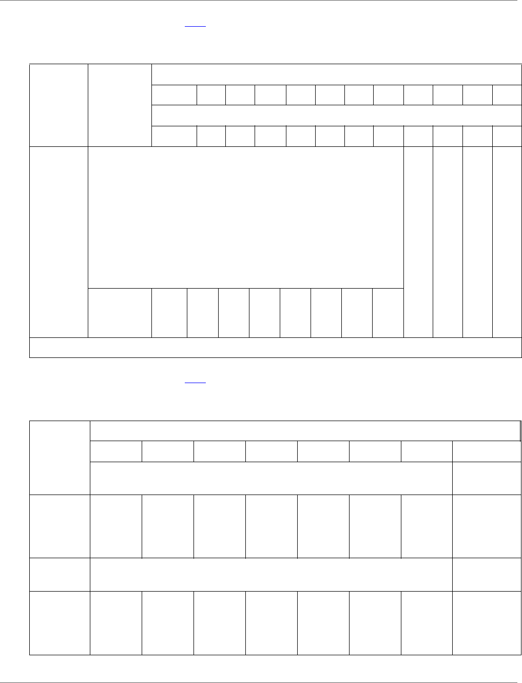
Roadway Design Manual 8-19 TxDOT 04/2018
Chapter 8 — Mobility Corridor (5 R) Design Criteria Section 4 — Ramps and Direct Connections
NOTE: Online users can click here to see the below table in PDF format.
NOTE: Online users can click here to see the below table in PDF format.
Table 8-15: Lengths of Entrance Ramp Speed Change Lanes
(Metric)
Highway
Design
Speed (km/
h
Minimum
Length of
Taper, T (m)
Acceleration Length, A (m) for Entrance Curve Design Speed (km/h)
Stop 20 30 40 50 60 70 80 90 100 110 120
Initial Speed (km/h)
0 203040 4755637077859198
50
60
70
80
90
100
110
120
Existing Criteria in Roadway Design Manual Figure 3-36 --
--
--
--
--
--
48
156
--
--
--
--
--
--
--
46
--
--
--
--
--
--
--
--
--
--
--
--
--
--
--
--
130 218 109 -- --
140
150
160
110
115
130
703
819
977
687
806
987
793
945
652
776
940
624
750
928
572
700
877
507
646
787
438
581
726
350
492
657
245
392
570
155
305
496
37
190
397
Note: Uniform 50:1 to 70:1 tapers are recommended where lengths of acceleration lanes exceed 400 m.
Table 8-16: Speed Change Lane Adjustment Factors as a Function of a Grade
(US Customary)
Design
Speed of
Roadway
(mph)
Ratio of Length on Grade to Length on Level1
20 25 30 35 40 45 50 All Speeds
3 to 4% Upgrade 3 to 4%
Downgrade
85
90
95
100
1.62
1.66
1.71
1.75
1.69
1.73
1.78
1.83
1.75
1.80
1.85
1.90
1.80
1.86
1.92
1.98
1.89
1.96
2.03
2.10
1.99
2.08
2.17
2.26
2.10
2.20
2.30
2.40
0.56
0.55
0.54
0.52
5 to 6 % Upgrade 5 to 6 %
Downgrade
85
90
95
100
2.39
2.50
2.62
2.74
2.51
2.64
2.76
2.89
2.64
2.77
2.91
3.04
2.94
3.10
3.27
3.43
3.15
3.33
3.51
3.69
3.73
4.00
4.26
4.53
4.28
4.65
5.03
5.40
0.46
0.45
0.44
0.42

Roadway Design Manual 8-20 TxDOT 04/2018
Chapter 8 — Mobility Corridor (5 R) Design Criteria Section 4 — Ramps and Direct Connections
Distance between Successive Ramps
The minimum acceptable distance between ramps is dependent upon the merge, diverge, and weav-
ing operations that take place between ramps and the Highway Capacity Manual should be used for
analysis of these requirements. Several iterations of the analysis may be required to determine these
lengths at the higher design speeds. The distances required for adequate signing should also be
considered.
Grades and Profiles
Grades and profiles are associated with design speed selected for the ramp. Design criteria for
design speeds less than 85 mph [140km/h] can be found in Chapter 2.
Cross Section and Cross Slopes
The cross slope for ramp tangent sections should be similar to the cross slope used on the main
lanes of the roadway. The cross slope on the ramp should be sloped in the same direction across the
entire ramp. The cross slope used will depend on the pavement used and other drainage
considerations.
(Metric)
Design Speed of
Roadway (km/
h)
Ratio of Length on Grade to Length on Level1
40 50 60 70 80 All Speeds
3 to 4% Upgrade 3 to 4%
Downgrade
140
150
160
1.57
1.60
1.63
1.67
1.70
1.73
1.81
1.86
1.90
1.79
1.83
1.86
1.90
1.94
1.99
0.55
0.53
0.52
5 to 6 % Upgrade 5 to 6 %
Downgrade
140
150
160
2.55
2.70
2.86
2.82
3.00
3.18
3.53
3.81
4.09
3.92
4.29
4.65
4.42
4.88
5.34
0.44
0.42
0.41
1 Ratio in this table multiplied by length of acceleration distances gives length of acceleration distance on grade.
Table 8-16: Speed Change Lane Adjustment Factors as a Function of a Grade
(US Customary)

Roadway Design Manual A-1 TxDOT 04/2018
Appendix A — Longitutinal Barriers
Contents:
Section 1 — Overview
Section 2 — Barrier Need
Section 3 — Structural Considerations of Guard Fence
Section 4 — Placement of Guard Fence
Section 5 — End Treatment of Guard Fence
Section 6 — Determining Length of Need of Barrier
Section 7 — Example Problems
Section 8 — Median Barrier
Section 9 — Emergency Crossovers

Roadway Design Manual A-2 TxDOT 04/2018
Appendix A — Longitutinal Barriers
Section 1 — Overview
Introduction
The objectives of this appendix are to make available data and guidelines for the use of roadside
and median traffic barriers in a consolidated and understandable form. These guidelines should be
supplemented by sound engineering judgment.
The area adjacent to the traveled way plays an important role in the safe operation of a high speed
facility. Accident statistics show that a significant portion of accidents on rural roads are the single
vehicle, run-off-the-road type. Provision of an obstacle free zone and the effective use of barriers to
shield obstacles that cannot otherwise be removed or safety treated are important considerations for
enhancing safety performance.
The Appendix also contains the following sections:
Section 2 - Barrier Need
Section 3 - Structural Consideration
Section 4 - Placement of Guard fence
Section 5 - End Treatment of Guard fence
Section 6 - Determining Length of Need of Barrier
Section 7 - Example Problems
Section 8 - Median Barrier
Section 9 - Emergency Crossovers

Roadway Design Manual A-3 TxDOT 04/2018
Appendix A — Longitutinal Barriers
Section 2 — Barrier Need
Overview
Traffic barriers are considered only when the obstacle is less forgiving than striking the barrier
itself.
Should a roadside obstacle exist, treatment should be considered in the following priority:
1. Eliminate the obstacle.
2. Redesign the obstacle so it can be safely traversed.
3. Relocate the obstacle outside the obstruction free zone to reduce the likelihood that it will be
struck.
4. Treat the obstacle to reduce accident severity, i.e., use flush or yielding designs.
5. Shield the obstacle with a barrier (median barrier, roadside barrier, or crash cushion).
6. Delineate the obstacle if the above alternatives are not appropriate.
The three basic types of obstacles that are commonly shielded using roadside barriers are as
follows:
slopes, lateral drop-offs, or terrain features
bridge ends and the areas alongside bridges
other roadside obstacles that cannot be eliminated, made breakaway or otherwise traversable,
or relocated.
Table A-1 shows a summary of roadside features that are commonly shielded with guard fence.
Table A-1: General Applications of Conditions for Roadside Barriers
Roadside Feature Applications
Terrain Features:
Steep Embankment Slope cza, See Figure A-1
Rough Rock Cut cz
Boulders cz, dia. Exceeds 6 in [150 mm]
Water Body cz, width exceeds 2 ft [600 mm], permanent
Lateral Drop-off cz & steeper than 1V:1H and depth exceeds 2 ft [600
mm]
Side Ditches cz & unsafe cross sectionb

Roadway Design Manual A-4 TxDOT 04/2018
Appendix A — Longitutinal Barriers
The combination of embankment height and side slope rate may indicate barrier protection consid-
eration as shown in Figure A-1. For low fill heights a more abrupt slope rate is tolerable than at
high fill heights. Because steeper than 1V:4H side slopes provide little opportunity for drivers to
redirect vehicles at high speeds, in the absence of guard fence, a 10 ft area free of obstructions
should be provided by the designer beyond the toe of slope.
-
Bridges:
Parapet Wall/Wingwall/Bridge Rail End approaching traffic
Area Alongside Bridges approaching traffic
-
Roadside Obstacles:
Trees cz & dia. Exceeds 6 in [150 mm]
Culvert Headwall cz & size of opening exceeds 3 ft [900 mm] (w.o.
safety grates only)
Wood Poles, Posts cz & cross section/area exceeds 50 in2 [32000 mm2]
Bridge Piers, Abutments at Underpasses cz
Retaining Walls cz & not parallel to travelway
a cz - Within clear zone for highway class and traffic volume conditions.
b For preferred ditch cross sections, see Side Ditches in Chapter 2
Table A-1: General Applications of Conditions for Roadside Barriers
Roadside Feature Applications
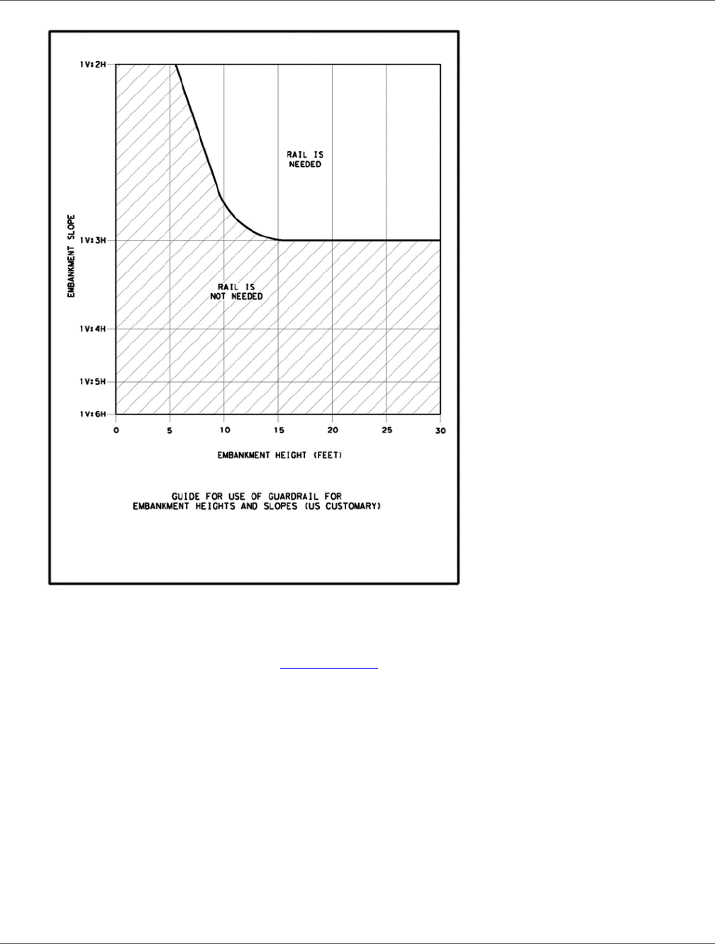
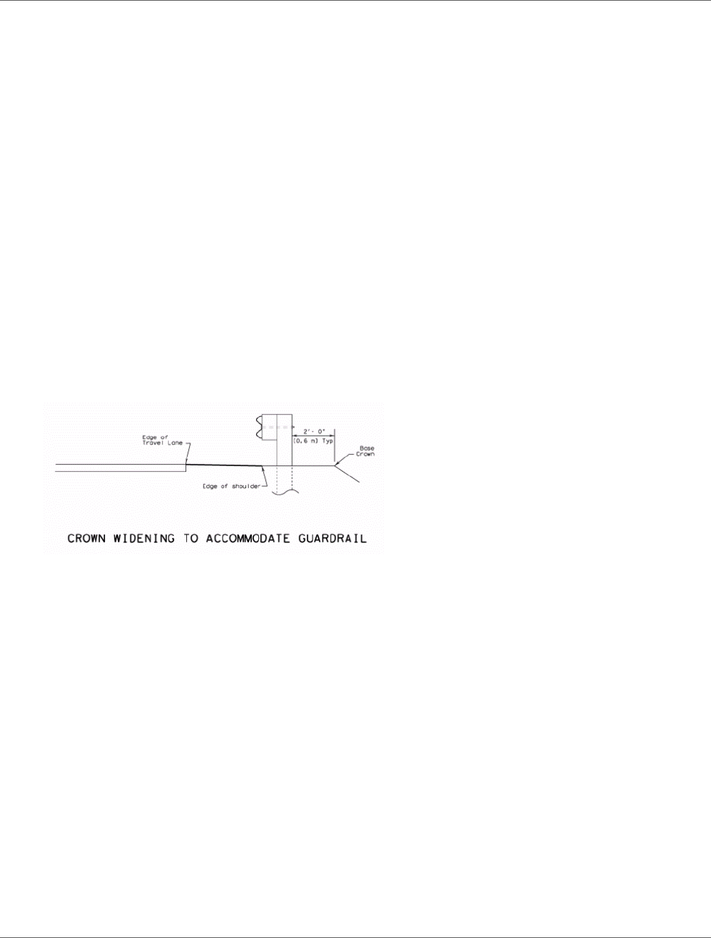
Roadway Design Manual A-6 TxDOT 04/2018
Appendix A — Longitutinal Barriers
Section 3 — Structural Considerations of Guard Fence
Overview
Post spacing, rail shape and thickness, splice strength and location, post embedment, and rail
anchorage are all important factors that influence the structural integrity of guard fence.
Post Spacing, Embedment, and Lateral Support
Typical post spacing is 6 ft- 3in [1905 mm] for guard fence. Where guard fence is to be placed at or
near the shoulder edge, it is desirable that the roadway crown be widened, typically 2 ft [600 mm]
from the back of the post location as shown in Figure A-2, to provide lateral support for the posts.
Locating the roadway crown/side slope hinge point behind the rail also provides a platform that
increases vehicular stability in the event of impacts that straddle the end section.
Embedment depth is shown on the standard detail sheet for both timber and steel posts.
Figure A-2. Crown Widening to Accommodate Guard fence
Rail Element
Guard fence is fabricated in a deep beam shape to provide for bending strength. Nominal thickness
of the rail is 10 or 12 gauge. End treatments, wingwalls, retaining walls, etc. provide firm rail
anchorage. With full splice connections, the anchored rail has sufficient tensile and flexural
strength to contain and redirect vehicles under nominal impact conditions.
To insure satisfactory performance for a range of vehicle sizes, rail should be mounted 25 in [635
mm] high as measured from shoulder surface, gutter pan, or widened crown to the center of the rail
at the bolt. The rail element shall be spliced midspan between the posts.
Pavement overlays effectively reduce existing rail height. When rail height varies more than 1 in
[25 mm] above and 3 in [75 mm] below the 31 in [787mm] top of rail standard height, steps should
be taken to restore the rail to the standard dimension to reduce the possibility of vehicular vaulting

Roadway Design Manual A-7 TxDOT 04/2018
Appendix A — Longitutinal Barriers
or post snagging. For existing 27 in [686 mm] rail systems, the rail height shall not vary by more
than 2 in [50 mm] above and 1/2 in [12 mm] below the 27 in [686 mm] top of rail.
When raising existing metal beam guard fence to the 31 in [787 mm] height, the railing will also
need to be adjusted horizontally and an additional post will be needed to obtain the mid-span splic-
ing location. Existing bridge transitions may need to be upgraded to current standards or adjusted
with a new transition section to obtain the 31 in [787 mm] height. The end treatments may require
new materials to adhere to the manufacturer’s specifications, such as the breakaway hole and angle
strut locations.
Blockouts
The guard fence is blocked out from the posts with routed timber or composite blockouts (6 in x 8
in [150 mm x 200 mm]). These blockouts minimize vehicle snagging on the posts and reduce the
likelihood of a vehicle vaulting over the barrier by maintaining the rail height during the initial
stages of post deflection.
It is acceptable to use double blockouts (up to 16 in. [406 mm]) to increase the post offset to avoid
obstacles such as curbs. There is no limit to the number of posts that can have double blockouts
installed, except terminals, unless approved by the manufacturer. Under special circumstances,
such as avoiding buried obstacles that are not relocated, it is also acceptable to install additional
blockouts to obtain up to 36 in [914 mm] of clearance for one or two posts in a section of guard
fence.
Deflection Considerations
Guard fence is a flexible barrier system. The amount of dynamic deflection varies primarily with
weight of impacting vehicle, its speed, and its encroachment angle. Guard fence should be laterally
positioned to provide a clear shoulder width while maintaining a distance from a fixed object that is
greater than the dynamic deflection of the rail. Based on crash test data, this barrier-to-object dis-
tance should be 2.5 ft [750 mm] or more as diagrammed in Figure A-3. Where conditions permit, a
barrier-to-obstacle distance of 5 ft [1500 mm] or more is desirable.
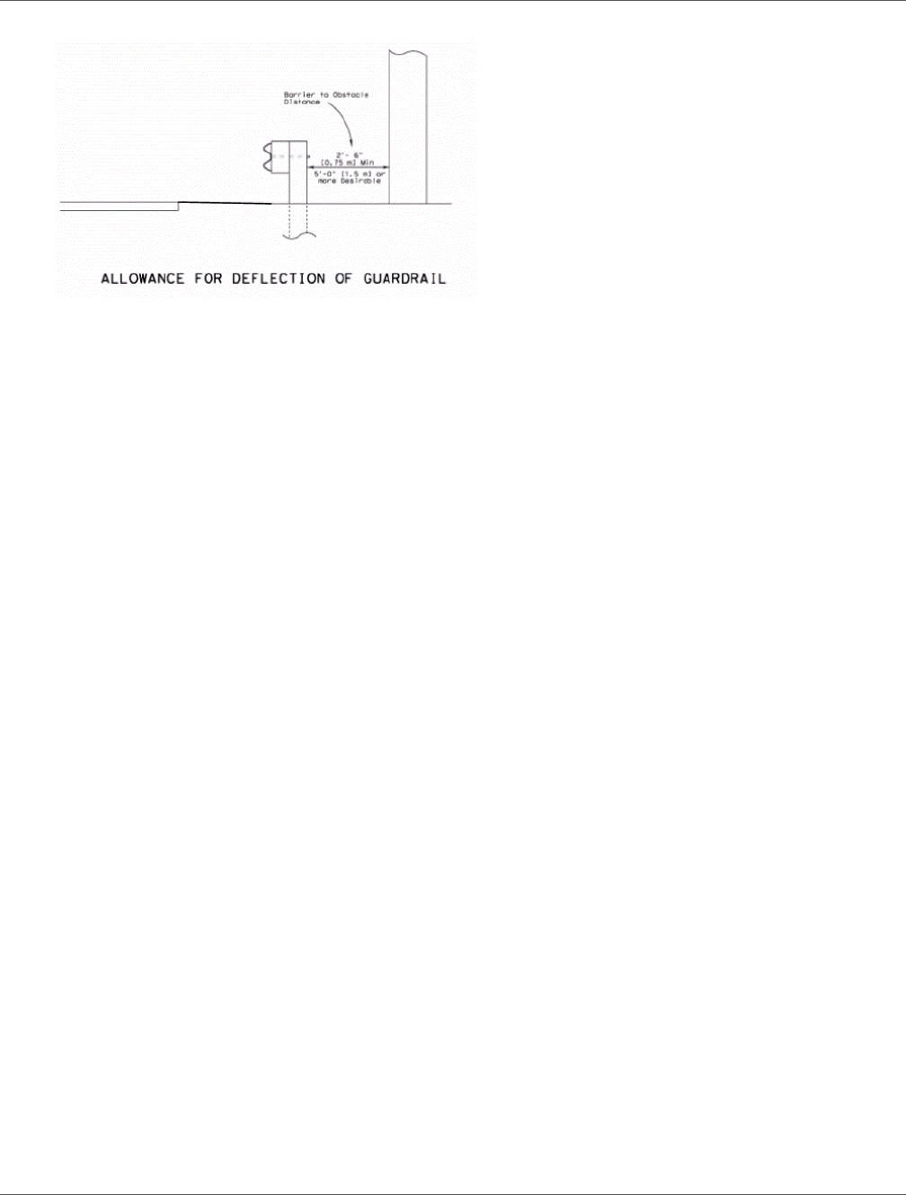
Roadway Design Manual A-8 TxDOT 04/2018
Appendix A — Longitutinal Barriers
Figure A-3. Allowance for Deflection of Guard fence
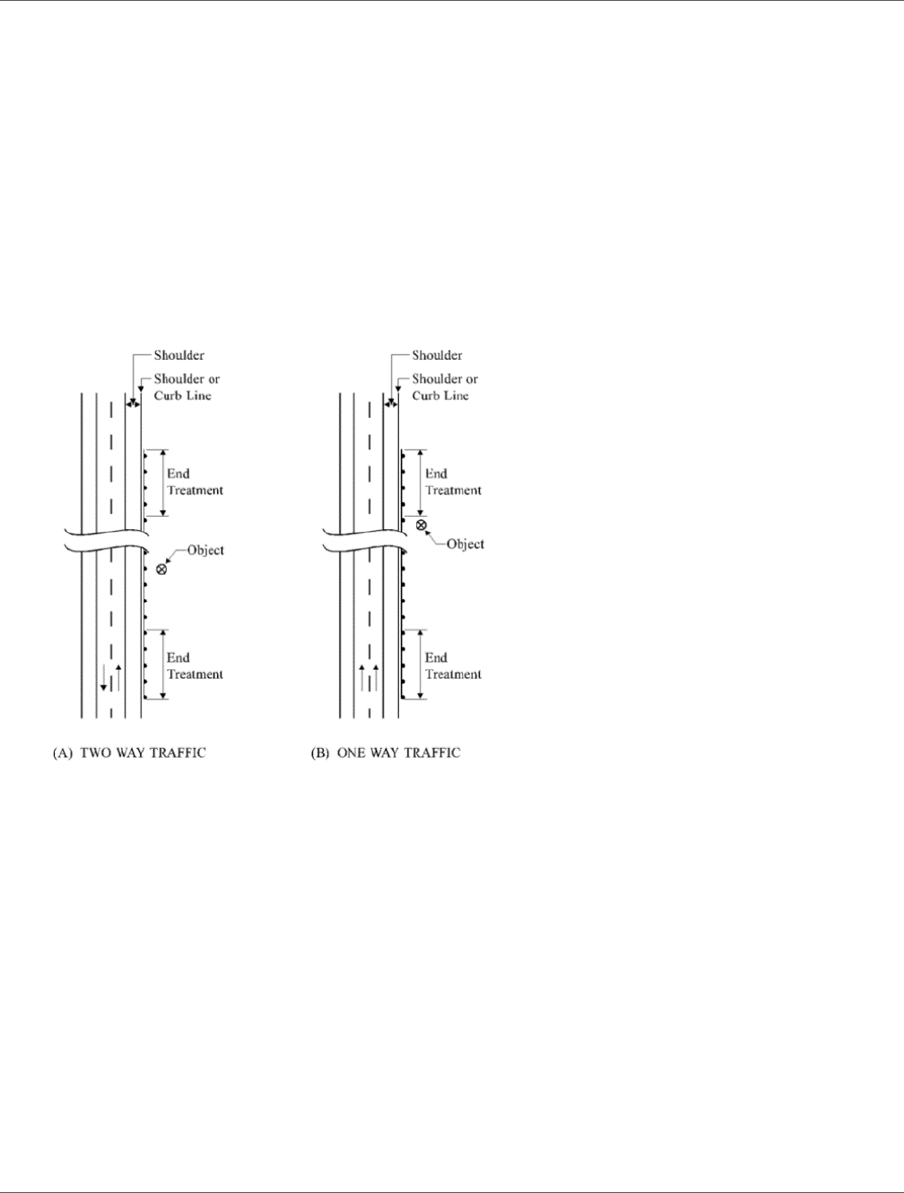
Roadway Design Manual A-9 TxDOT 04/2018
Appendix A — Longitutinal Barriers
Section 4 — Placement of Guard Fence
Overview
The placement of guard fence pertains to the lateral and longitudinal position.
Lateral Placement at Shoulder Edge or Curb Face
Typically the face of rail is placed at the shoulder edge or curb face throughout most of its length as
shown in Figure A-4.
Figure A-4. Placement at Shoulder Edge or Curb Face
Guard fence placed in the vicinity of curbs should be blocked out so that the face of curb is located
directly below or behind the face of rail. Rail placed over curbs should be installed so that the post
bolt is located 25 in [550 mm] above the gutter pan or roadway surface.
Lateral Placement Away From the Shoulder Edge
In certain instances it is desirable to place guard fence closer to the obstacle rather than at the shoul-
der edge or curb face as shown in Figure A-5. Placement in this manner can substantially reduce
the length of rail required to shield a given obstacle and minimize the probability of impact, but
undesirably, encroachment angles may increase. This manner of placement is most applicable to
small areas of concern—point type obstacles such as overhead sign bridge supports, bridge piers,
etc.
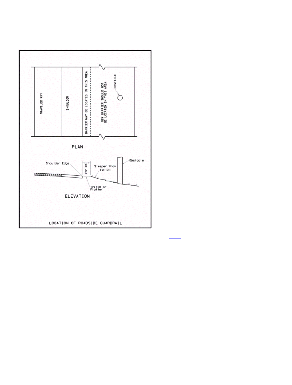
Roadway Design Manual A-10 TxDOT 04/2018
Appendix A — Longitutinal Barriers
To preclude vaulting or impacting at an undesirable position by errant vehicles; care should be
exercised in selecting placement location of guard fence with respect to slope conditions. Guard
fence may be placed at any lateral location on a side slope only if the slope rate between the edge of
the pavement and the face of the barrier is 1V:10H or flatter.
Figure A-5. Location of Roadside Guard fence. Click here to see a PDF of the image.

Roadway Design Manual A-11 TxDOT 04/2018
Appendix A — Longitutinal Barriers
Section 5 — End Treatment of Guard Fence
Overview
Guard fence systems must be anchored at both ends to acceptable end treatments, buried terminals,
wingwalls, concrete traffic barriers, etc., so that full tensile strength of the rail may be developed.
Approved end treatments have been developed and are recommended for the upstream end of a
guard fence system. These approved end treatments shall be used unless the guard fence terminal is
located on the downstream end [with respect to adjacent traffic—see Figure A-4] of the guard fence
and outside the clear zone for opposing traffic. In that case a Downstream Anchor Terminal (DAT)
section without offset is acceptable for use.
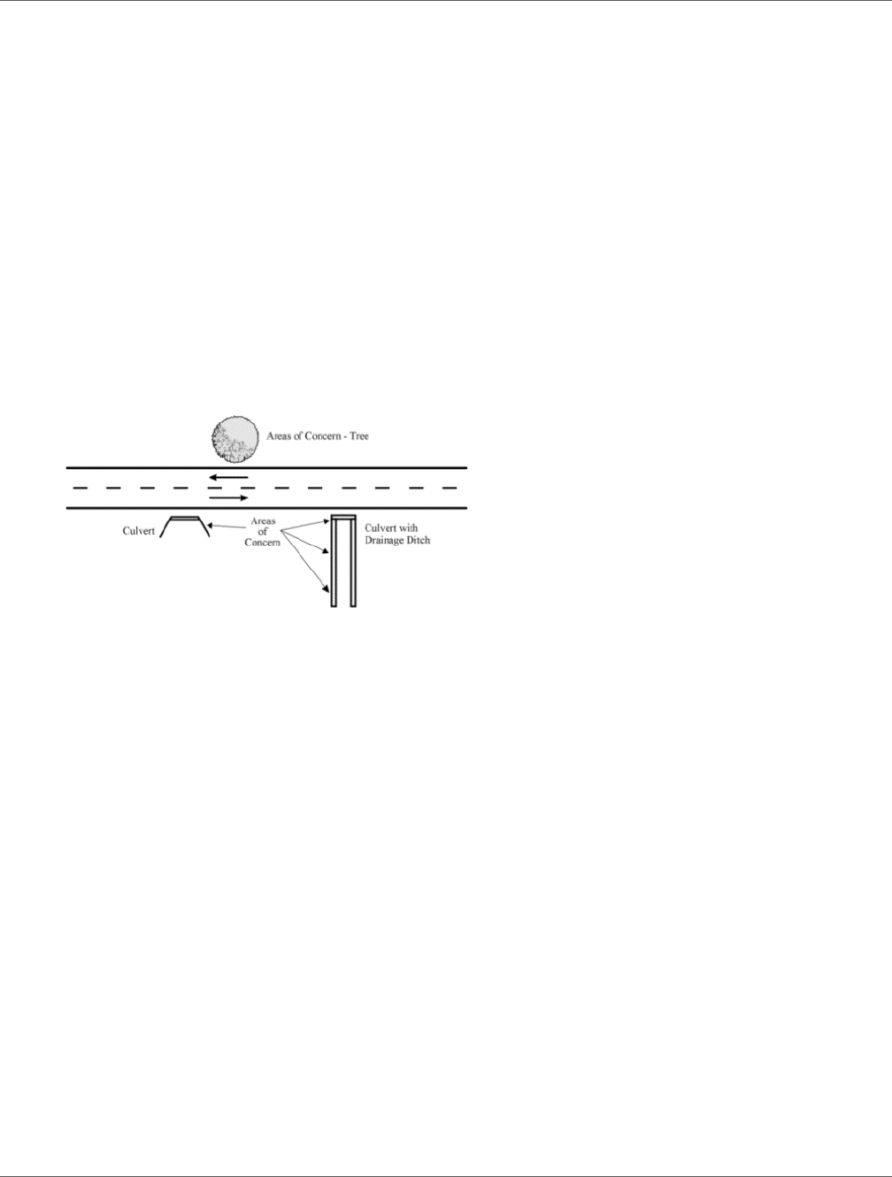
Roadway Design Manual A-12 TxDOT 04/2018
Appendix A — Longitutinal Barriers
Section 6 — Determining Length of Need of Barrier
Overview
The shape of the obstacle, its location with respect to travel lanes, the volume of traffic and its cor-
responding clear zone width are the primary variables influencing length of barrier need.
Variables
After all practical means to free the roadside of obstacles have been exhausted, certain areas may
remain which constitute an obstacle to errant vehicles. These areas, as illustrated in Figure A-6, will
be referred to an “area of concern.”
Figure A-6. Areas of Concern
Figure A-6 illustrates the variables of interest in the layout of approach barrier to shield an area of
concern. Length of need is equal to the sum of the following variables:
length of upstream barrier, Lu,
length of barrier parallel to the area of concern, Lp,
the length of downstream barrier, Ld.
Lu is the length of guard fence needed to protect traffic adjacent to proposed guard fence. Upstream
refers to the guard fence upstream of traffic adjacent to proposed guard fence. While Ld is the
length of guard fence needed to protect the opposing traffic. For roadways serving one-way traffic
operations, Ld = 0. Ld is greater than zero for two-way operations when the area of concern lies
within the clear zone of opposing (northbound in Figure A-6) traffic as measured from the center-
line pavement markings.
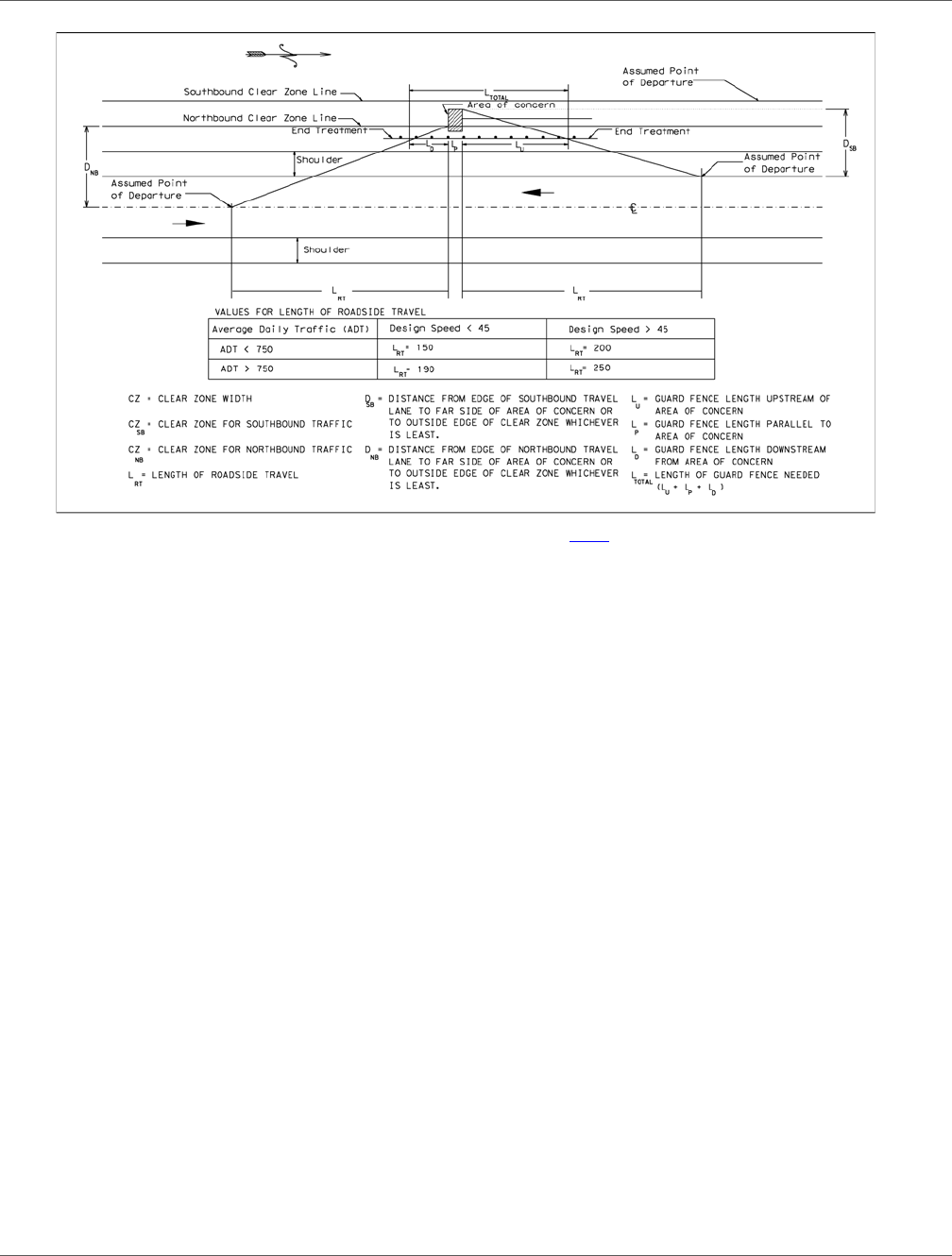
Roadway Design Manual A-13 TxDOT 04/2018
Appendix A — Longitutinal Barriers
Figure A-7. Variables Involved in Barrier Layout. Click here to see a PDF of the image.
In certain instances judgment should be exercised to supplement design chart solutions and provide
for public safety. For example, high severity fixed objects (e.g., bridge columns) may justify mini-
mum guard fence treatment where located slightly outside the clear zone if geometric conditions
(i.e., steep fill slope, outside of horizontal curvature, etc.) increase the likelihood of roadside
encroachments.
Design Equations
To determine needed length of guard fence for a given obstacle, design equations have been
formulated for low volume (ADT 750 or less) and higher volume (ADT more than 750) conditions.
A clear zone width of 16 ft [4.9 m] and length of roadside travel of 200 ft [61 m] are incorporated in
the low volume design equation (for use on roadways when the present ADT volume is 750 or
less). Also, if the clear zone required is less than 16 ft [4.9 m] and the present ADT is 750 or less,
use Equation A-1 for calculating the guard fence length of need.

Roadway Design Manual A-14 TxDOT 04/2018
Appendix A — Longitutinal Barriers
Where:
Lu = Length of guard fence needed (upstream of area of concern), ft
Ld = Length of guard fence needed (downstream of area of concern), ft
Du = Distance from edge of travel lane to far side of area of concern or to outside edge of clear
zone, whichever is least, ft (for upstream direction of traffic)
Dd = Distance from edge of travel lane to far side of area of concern or to outside edge of clear
zone, whichever is least, ft (for opposing direction of traffic)
Gu = Guard fence offset from edge of travel lane adjacent to proposed guard fence, ft
Gd = Guard fence offset from edge of opposing direction of travel lane (centerline)
Click here for Metric.
For low volume conditions, if the clear zone width (16 ft [4.9 m]) is met or exceeded, L=0.
For higher volumes, a clear zone width of 30 ft [9 m] and length of roadside travel of 250 ft [76 m]
are incorporated into the design equation (for use on roadways when the present ADT volume is
more than 750 or the recommended clear zone is greater than 16 ft [4.9 m]):
For high volume conditions, if the clear zone width (30 ft [9 m]) is met or exceeded, L=0.
Table A-2: Equations for Upstream and Downstream Length of Need
ADT < 750
Equation A-1.
Equation A-2.
ADT > 750
Equation A-3.
Equation A-4.
Lu200 200
Du
---------xGu
–=
Ld200 200
Dd
---------xGd
–=
Lu250 250
Du
---------xGu
–=
Ld250 250
Dd
---------xGd
–=

Roadway Design Manual A-15 TxDOT 04/2018
Appendix A — Longitutinal Barriers
The length of need for guard fence, as illustrated below in equation A-5, is equal to the sum of the
required upstream length (Lu), the guard fence length parallel to the area of concern Lp, and the
required downstream length.
Equation A-5.
Where:
Ltotal = Length of guard fence needed
Lu = Guard fence Length Upstream of Area of Concern
Lp = Guard fence Length Parallel to Area of Concern
Ld = Guard fence length Downstream from area of concern
Using Design Equations to Determine Length of Guard Fence
Before determining length of guard fence, the designer should assemble the following pertinent
data:
present ADT volume
clear zone (horizontal clearance)
traffic operations (one-way or two-way)
lateral and longitudinal dimension of the area of concern
shoulder width
offset distance of the area of concern from the edge of travel lane (including from the
centerline markings for two-way traffic operations)
design slope conditions, (i.e. will slopes be 1V:10H or flatter?)
placement location (alongside shoulder vs. near object, flared, etc.)
presence of other nearby areas of concern which should be considered simultaneously.
Once this design data has been assembled, the appropriate equation can be used.
Where the prescribed length of the guard fence cannot be installed at a bridge end due to an inter-
vening access point such as an intersecting roadway or driveway, the length of guard fence may be
interrupted or reduced. This change in length is acceptable only in locations where the Department
must meet the obligation to provide access and this access cannot be reasonably relocated. Alterna-
tive treatments in these situations include wrapping the guard fence around the radius of the access
location, terminating the guard fence prior to the access location with an appropriate end treatment
Ltotal LuLpLd
++=

Roadway Design Manual A-16 TxDOT 04/2018
Appendix A — Longitutinal Barriers
and continuing the guard fence beyond the access location if necessary or using an alternate bridge
end treatment. The selected treatment should consider potential sight line obstructions, cost and
maintenance associated with the selected treatment and any accident history at the site. Reduced
guard fence length to accommodate access points will not require a design exception or a design
waiver.
The Example Problems section provides example problems and solutions using the design equa-
tions. The guard fence lengths produced by the equations should be rounded up to an even length of
guard fence.

Roadway Design Manual A-17 TxDOT 04/2018
Appendix A — Longitutinal Barriers
Section 7 — Example Problems
Example Problem 1
Given: A rural two-lane collector highway containing 6 ft [1.8 m] wide shoulders and a current
ADT of 500 is illustrated in Figure A-8. The area of concern is a 16 ft [4.9 m] design clear zone that
includes 1V:2H side slopes on a 10 ft [3 m] high embankment section that is 125 ft [38 m] in length
alongside the highway.
Figure A-8. Example 1 Problem Layout Rural Low Volume. Click here to see a PDF of the image.
Solution: From the information above and referring to Figure A-1 it is determined that a “rail is
needed.” As shown in Equation A-5, the length of need is Ltotal = Lu+Lp+Ld. From the given infor-
mation, Lp = 125 ft [38 m]. Because the ADT is less than 750, Equations A-1 and A-2 are used to
solve for Lu and Ld , respectively (if necessary).
For the upstream direction, the area of concern is the full (16 ft [4.9 m]) clear zone width and the
guard fence offset (Gu) is 6 ft [1.8 m]. Substituting in Equation A-1.
(US Customary):

Roadway Design Manual A-18 TxDOT 04/2018
Appendix A — Longitutinal Barriers
Click here for metric.
A placement of guard fence alongside the 6 ft [1.8 m]-wide shoulder results in Lu = 125 ft [38 m].
Referring to figure A-8, the length of guard fence needed in the downstream is zero because the off-
set distance from the edge of the travel lane (centerline marking) to the area of concern is greater
than the design clear zone (17 ft [5.1 m] greater than 16 ft [4.9 m]). Therefore, Ld is zero.
The design placement is shown in Figure A-9 including 125 ft [38 m] of guard fence adjacent to the
obstacle plus 125 ft [38 m] shielding traffic adjacent to proposed guard fence upstream of the obsta-
cle. These lengths of need do not include end treatments.
Figure A-9. Example 1 Problem Solution Guard fence Layout
Example Problem 2
Given: A rural two-lane arterial highway containing a shoulder width of 8 ft [2.4 m] and a current
ADT of 3500 is illustrated in Figure A-10. The areas of concern are bridge bents located 5 ft [1.5
m] from the edge of shoulder. The side slopes are 1V:6H.
ft1256
16
200
200Lu
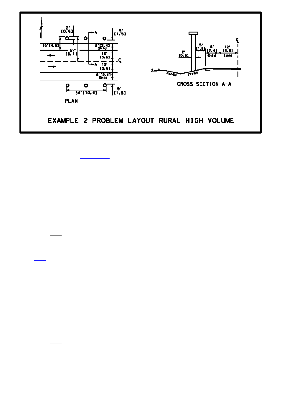
Roadway Design Manual A-19 TxDOT 04/2018
Appendix A — Longitutinal Barriers
Figure A-10. Example 2 Problem Layout Rural High Volume.
Solution: Referring to Table A-1: General Applications of Conditions for Roadside Barriers bridge
piers within the clear zone (30 ft [9 m] in this case) indicates guard fence placement for the north
side of the roadway displayed in Figure A-10. As shown in Equation A-5 the length of need is Ltotal
= Lu+Lp+Ld. Therefore, Lp is 34 ft [10.4 m] from the given (see Figure A-10) information. Because
the ADT is greater than 750, Equations A-3 and A-4 are used to find Lu and Ld (if necessary),
respectively:
(US Customary):
Click here for metric.
Substituting in the equation, the upstream length (Lu) is 116.5 ft [35.5 m] if placement is at the
shoulder edge.
The downstream (westbound traffic) length of guard fence is also determined by substituting into
Equation A-4:
(US Customary):
Click here for metric.
ft5.1168
15
250
250Lu
ft6520
27
250
250Ld
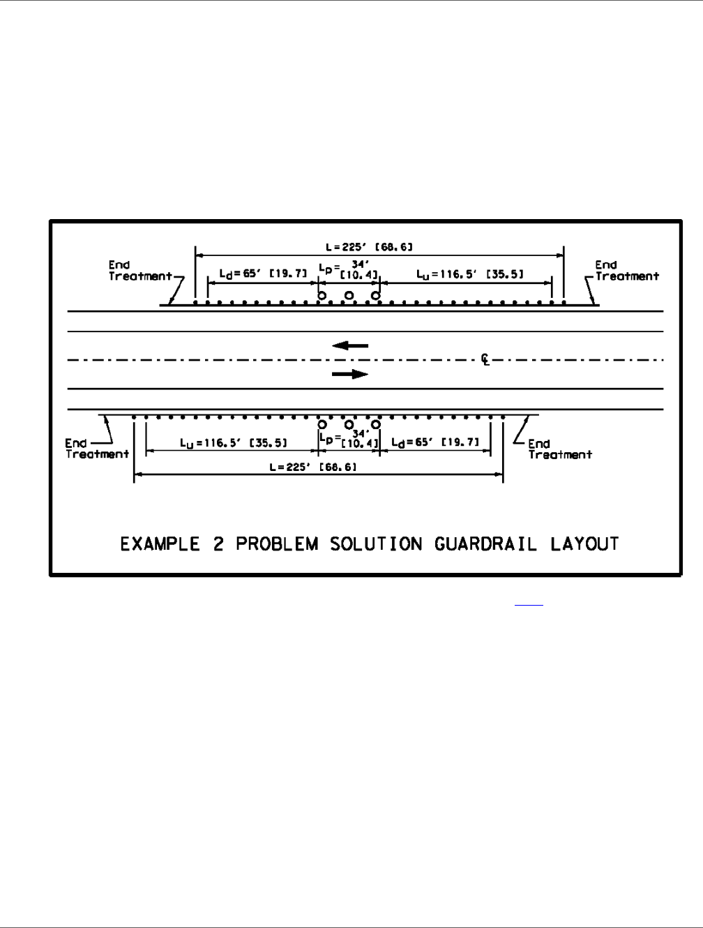
Roadway Design Manual A-20 TxDOT 04/2018
Appendix A — Longitutinal Barriers
Ld is 65 ft [19.7 m] as shown above, based on the shoulder edge placement. For westbound traffic,
the centerline is the edge of the travel lane and thus guard fence offset (G) is 20 ft [6 m] (12 ft [3.6
m] lane plus 8 ft [2.4 m] shoulder) from the edge of the travel lane.
Total length of guard fence, Lu+Lp+Ld, thus is 116.5 ft [35.5 m] + 34 ft [10.4 m] + 65 ft [19.7 m] or
215.5 ft [62.3 m]; or, rounded to an even length of guard fence, 225 ft [68.6m].
The solution for the south side of the roadway yields the same results, hence placement should be
as shown in Figure A-11.
Figure A-11. Example 2 Problem Solution Guard fence Layout. Click here to see a PDF of the
image.
Example Problem 3
Given: A divided (76 ft [22.8 m] median) highway with 4 ft [1.2 m] left and 10 ft [3.0 m] right
shoulder widths is illustrated in Figure A-12. The median slopes are 1V:10H, and the outside side
slopes are 1V:6H. The cross sectional design allows for the addition of a future lane on the median
side of the present lanes. The areas of concern are overhead sign bridge supports offset 25 ft [7.6 m]
left and 18 ft [5.5 m] right from edge of the travel lanes as shown below. The ADT is 10,000.
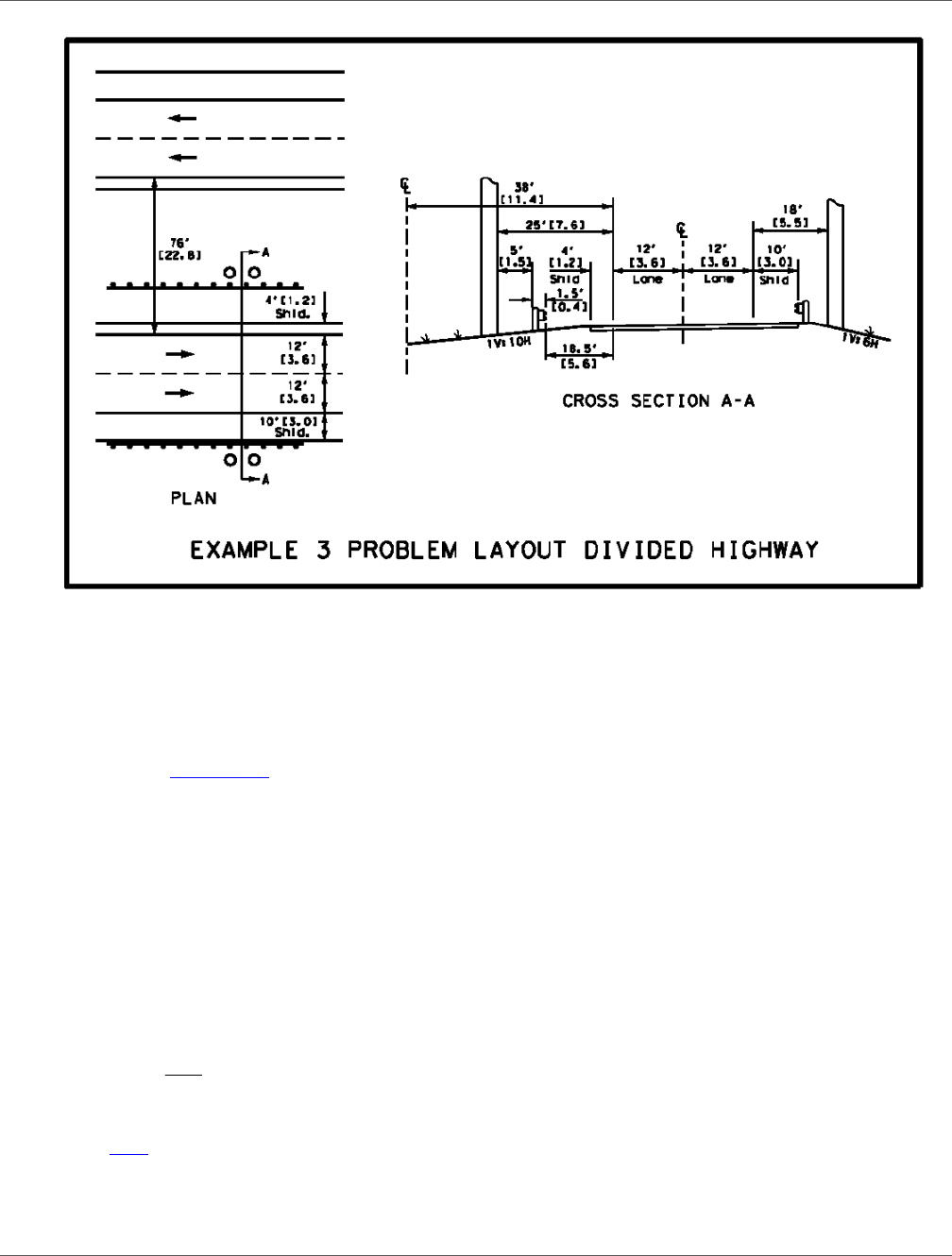
Roadway Design Manual A-21 TxDOT 04/2018
Appendix A — Longitutinal Barriers
Figure A-12. Example 3 Problem Layout Divided Highway.
Solution: Crash cushions in lieu of guard fence should be considered, particularly for facilities with
higher than 10,000 ADT. For this example problem assume crash cushions are not cost effective.
Because the median is sloped at 1V:10H, as shown in Figure A-12, guard fence may be placed
thereon (see Figure A-5,). Therefore place the guard fence such that the back of the posts are 5 ft
[1.5 m] in front of the median overhead sign bridge support to allow for deflection, i.e., 20 ft [6.0
m] from the edge of the travel lanes (including the 1.5 ft [0.5 m] from the back of the post to the
face of the rail).
Referring to Equation A-5, Ltotal = Lu+Lp+Ld. For one-way traffic operations, Ld=0; furthermore,
for the overhead sign bridge support Lp=0. Equation A-3 is used to find Lu because ADT is greater
than 750:
(US Customary):
Click here for metric.
Equation A-6
ft655.18
25
250
250Lu
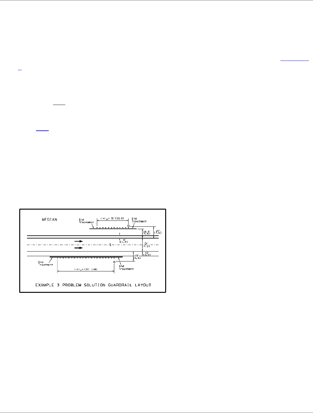
Roadway Design Manual A-22 TxDOT 04/2018
Appendix A — Longitutinal Barriers
For the median side, Lu = 65 ft [20 m] (rounded to 75 ft [22.9 m] to conform to even lengths of
guard fence) based on parallel placement for the full length of need, and placement on the 1V:10H
slope 5 ft [1.5 m] in front of the fixed object. In contrast, parallel placement at the shoulder edge
would have required over 200 ft [60 m] of guard fence.
For the right side of traffic, guard fence must be placed at the shoulder edge (Reference Figure A-
5). Substituting in Equation A-3 to determine Lu:
(US Customary):
Click here for metric.
Equation A-7
Using parallel placement for the entire length, Lu = 111 ft [34.5 m] (which should be rounded to
125 ft [38] to conform to even lengths of guard fence).
Using parallel placement for the entire length of guard fence for both the median and left side,
placement is as shown in Figure A-13.
Figure A-13. Example 3 Problem Solution Guard fence Layout.
ft11110
18
250
250Lu

Roadway Design Manual A-23 TxDOT 04/2018
Section 8 — Median Barrier
Section 8 — Median Barrier
Overview
Median barriers are used to reduce median crossover vehicle encroachments and to protect against
continuous longitudinal obstacles, and can generally be categorized as:
Concrete barriers (such as F-shape or single sloped), or
High-tension cable barrier systems.
The utilization of other median barriers, such as metal beam guard fence, may be appropriate based
on the need to protect point obstacles in the median, such as overhead sign supports, etc. (See Sec-
tions 1-7).
Application
On high-speed highways, median barriers should be considered based on the criteria shown in
Table 3. Flush medians or frequent crossovers may preclude the use of median barriers based on an
engineering analysis of individual locations.

Roadway Design Manual A-24 TxDOT 04/2018
Section 8 — Median Barrier
The criterion is divided into two different zones by various combinations of average annual daily
traffic and median width.
Barrier Recommended: Barrier should be installed.
Evaluate Need and Cost Effectiveness of Continuous Barriers. (Point obstacle protection
may be appropriate for specific locations): An engineering analysis should be performed to
determine if barrier is needed for reducing the occurrence of cross-median encroachments
(crashes). This analysis may consider the following:
-Type of median (flush, depressed [V-ditch or flat-bottom])
-Width of the median
-Traffic volumes, including estimated traffic growth and percent trucks
-Types and severity of crashes
-Posted speed limit
Table 3: Recommended Guidelines for Installing Median Barriers on High-Speed Highways

Roadway Design Manual A-25 TxDOT 04/2018
Section 8 — Median Barrier
-Type of facility, including controlled access or
non-controlled access with crossovers
-Roadway alignment
-Ramp locations
-Elimination of barrier gaps
Continuous barrier should be limited to areas where it is needed to reduce cross median incidents
and should not be used for point obstacles (i.e. overhead sign bridges, etc.), or in areas of lesser
concern (i.e. wider medians, forested areas, etc.).
Placement
As a general rule, a barrier should be placed as far from the traveled way as possible while main-
taining the proper operation and performance of the system. The more lateral offset afforded a
driver, the better the opportunity for the driver to regain control of the vehicle in a traversable
median and avoid a barrier impact. The placement of concrete barrier adjacent to narrow shoulders
is discouraged.
Slopes
Where possible, barriers should be installed on relatively flat, unobstructed terrain (1V:10H or
flatter). Barriers may also be placed on 1V:6H maximum slopes as shown in Figure A-14. The
centerline axis of the barrier shall be vertical.
From the perspective of barrier performance alone, it is acceptable placement practice to locate
the barrier at, or within 1 ft. [0.3m], of the bottom of the ditch line. If it is desirable to offset the
median barrier more than one foot from the bottom of the ditch line to avoid drainage issues
(potential for erosion, etc.), the barrier can be placed anywhere along the 1V:6H median slope,
provided it is located at least 8 ft. [2.4 m] from the bottom of the median ditch line. This offset
from the bottom of the ditch line reduces the potential for the vehicle to strike the barrier too
low for the barrier to function properly.
If the slopes in the median are steeper than 1V:6H and barrier is needed, consideration should be
given to regrading the slopes to meet the requirements or to filling in the median to place a split
level concrete barrier.
If regrading or other options are not feasible, placement of cable barrier on slopes up to 1V:4H
is an alternative to consider. Designers should contact the Design Division for assistance in
locating the cable barrier at the proper location along the steeper slopes. While not desirable,
some median configurations may require barrier placement on both sides of the median to pro-
vide the proper protection.
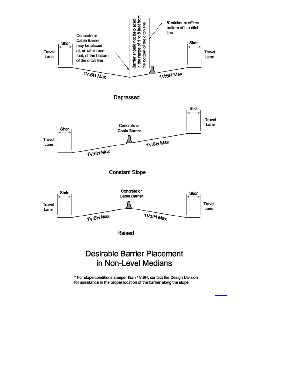

Roadway Design Manual A-27 TxDOT 04/2018
Section 9 — Emergency Crossovers
Section 9 — Emergency Crossovers
Overview
Emergency crossovers may be provided when needed to facilitate emergency and law enforcement
vehicles. Coordination with local and state law enforcement and emergency services personnel is
recommended to identify roadway sections where crossovers may be necessary.
Location
When selecting a location for a crossover, the following guidance should be used:
Do not install emergency crossovers in urban locations. Interchanges are closely spaced and
provide opportunities for making needed turn movements.
Emergency crossovers should be spaced at approximately 2 mile intervals, except where coor-
dination with local and state law enforcement has identified a need for spacing of crossovers of
less than 2 mi. [3.2 km] to address local issues.
Emergency crossovers should be placed at reasonable intervals based on engineering judgment
and safety, generally no closer than ½ mi. [0.8 km] between crossovers.
The emergency crossover is not to be located within 1500 ft. [457.2 m] from any ramp terminal
or other access connection.
The emergency crossover is not to be located within curves requiring superelevation, unless
field engineering determines the location is safe and reasonable for emergency use.
Emergency crossovers should be located where more than minimum stopping sight distance is
provided.
Construction
When ending a run of cable barrier, the cable barrier terminals should be located, when possible,
behind some protection such as the MBGF, leaving adequate distance to allow an emergency vehi-
cle to maneuver around if necessary. See Figure A-15.
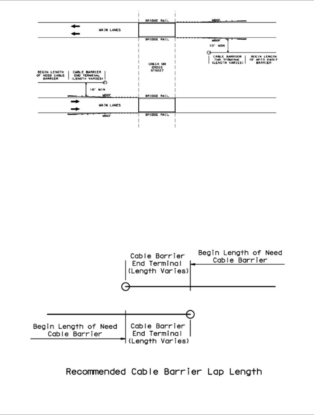
Roadway Design Manual A-28 TxDOT 04/2018
Section 9 — Emergency Crossovers
Figure A-15. Cable Terminals Behind Metal Beam Guard Fence
The terminals can be placed in locations with no protection, but since they provide the anchorage
for the cable barrier system, protecting them from possible hits is recommended. These terminals
are also gating (meaning they will not prevent a vehicle from going through).
When switching the cable barrier from one median side to the other and the terminals are not pro-
tected, overlapping the runs of cable barrier is recommended to provide adequate protection from
possible crossovers if the median is wide enough to allow emergency vehicles to utilize it as an
effective emergency crossover. (See Figures A-16 through A-17).
Figure A-16. Recommended Cable Barrier Lap Length
Another typical layout for emergency crossovers may be as shown below.
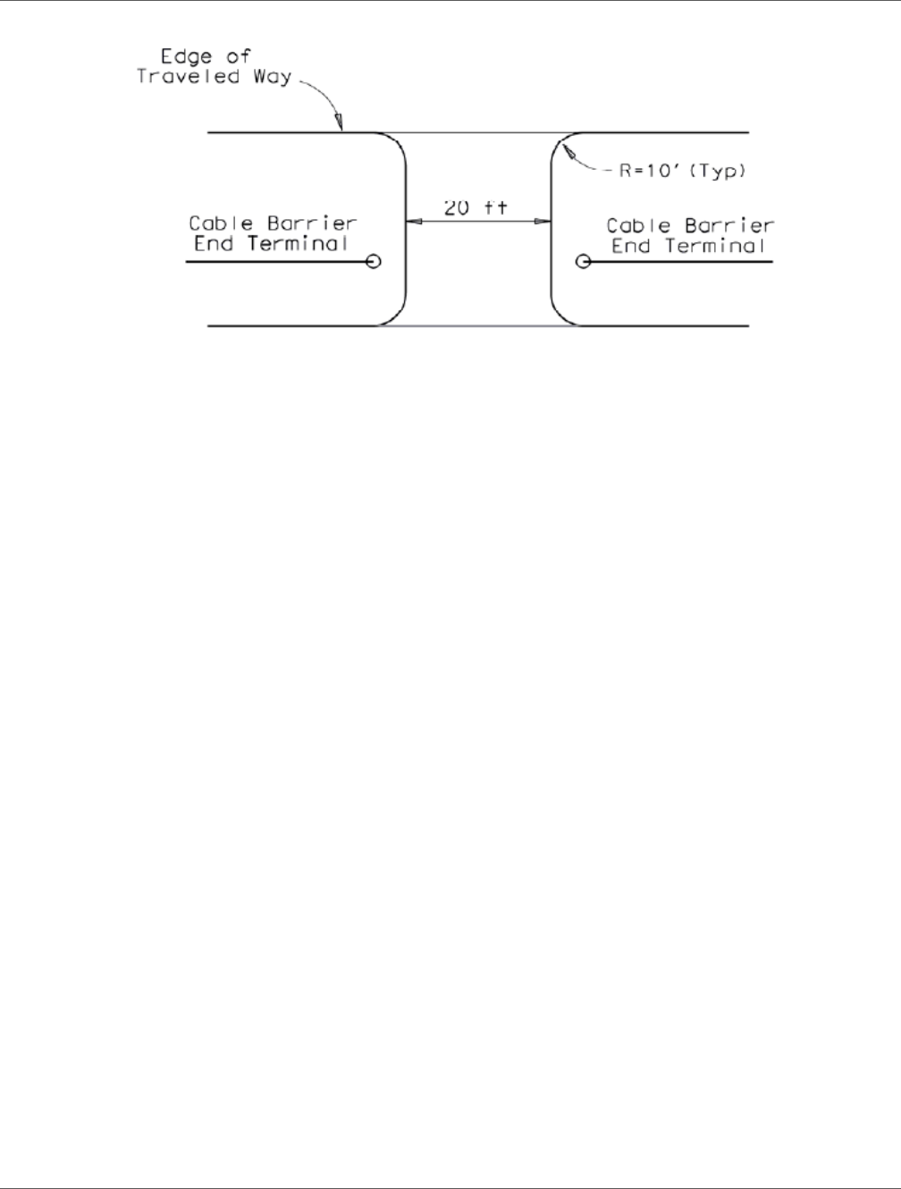
Roadway Design Manual A-29 TxDOT 04/2018
Section 9 — Emergency Crossovers
Figure A-17. Another Typical Layout for Emergency Crossovers
Emergency crossovers should be an all-weather surface. It is recommended that they be
constructed with a surface treatment that does not invite use. Grade 1 or 2 aggregate or bladed
recycled asphalt pavement (RAP) has provided an adequate low cost surface in some
applications.
Emergency crossovers should be approximately 20 ft. [6.1 m] with return radii of 10 ft. [3.0
m]. Wider crossovers invite non-emergency use and should only be constructed after an
engineering study of the site.
To be inconspicuous to main lane traffic, the surface should be depressed below the shoulder
level, if possible.


Roadway Design Manual B-2 TxDOT 04/2018
Appendix B — Treatment of Pavement Drop-offs in
Work Zones
Section 1 — Overview
Scope
These guidelines apply to construction zone work where continuous pavement edges or drop-offs
exist parallel and adjacent to a lane used for traffic. These guidelines do not apply to short term
operations. The Texas Manual on Uniform Traffic Control Devices (TMUTCD) defines short term
operations as daytime work from one to twelve hours.
These guidelines do not constitute a rigid standard or policy; rather, they are guidance to be used in
conjunction with engineering judgment.
Types of Treatment
Treatment may consist of either or both of the following:
warning devices (such as signs or channelizing devices)
protective barriers (such as concrete traffic barriers or metal beam guard fence).
Factors Affecting Treatment Choice
The type of treatment (warning device or protective barrier or both) selected depends on several
factors, including engineering judgement. These guidelines are based on the following factors:
Factors Considered in the Guidelines
Factor Definition Notes
edge condition slope of the drop-off For more information, see “Edge Condition” subhead-
ing below.
Lateral
clearance distance from the edge of the
travel lane to the edge condition See Figure B-1 for description.
edge height depth of the drop-off See Figure B-1 for description.
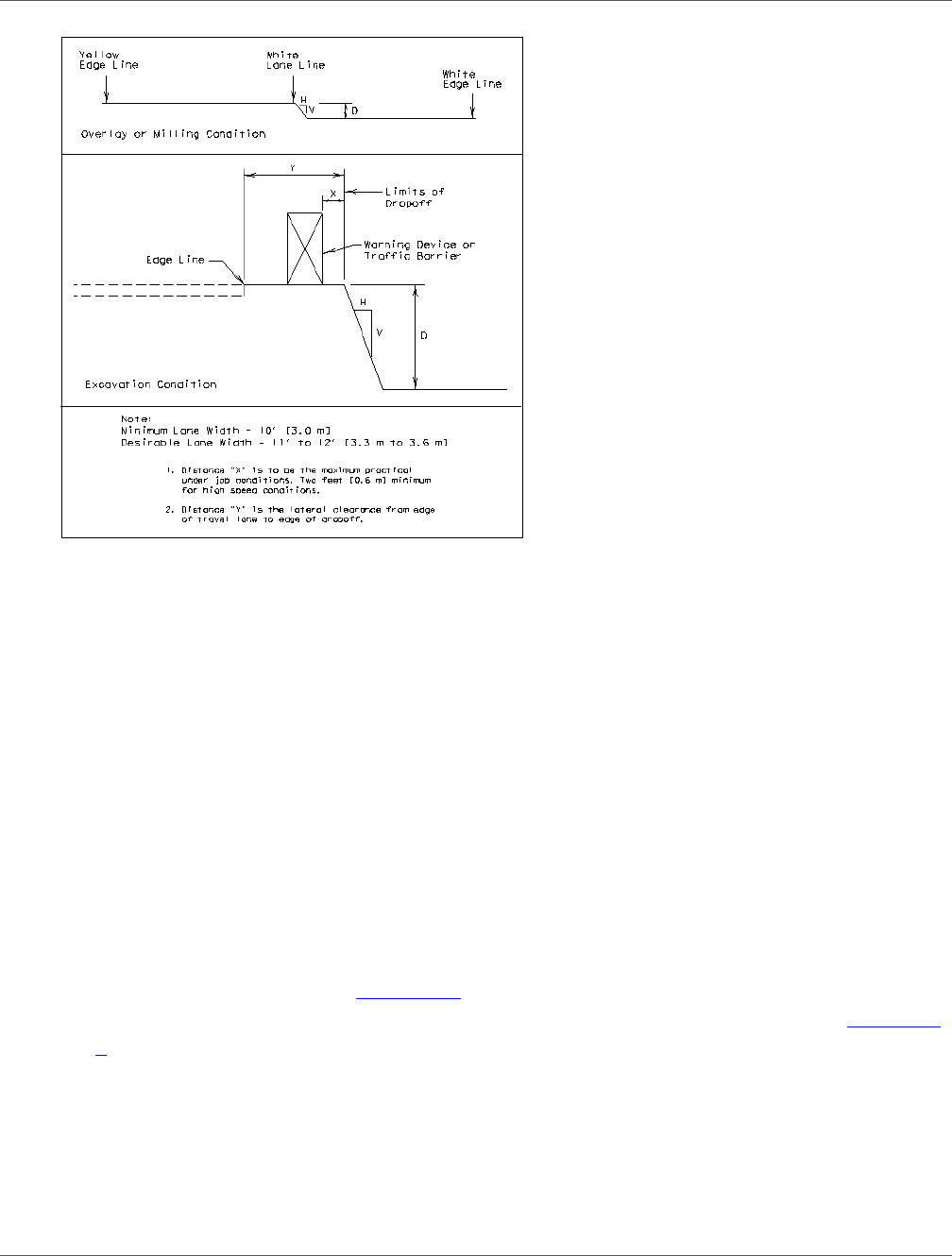
Roadway Design Manual B-3 TxDOT 04/2018
Appendix B — Treatment of Pavement Drop-offs in
Work Zones
Figure B-1. Definition of Terms.
In addition to the factors considered in the guidelines, each construction zone drop-off situation
should be analyzed individually, taking into account other variables, such as:
traffic mix
posted speed in the construction zone
horizontal curvature
practicality of treatment options.
In urban areas where speeds of 30 mph [50 km/h] or less can be predicted for traffic in a partic-
ular construction zone, there may be a lesser need for signing, delineation, and barriers. Even
so, sharp 90 degree edges greater than 2 inches [50 mm] in height, if located within a lateral
offset distance of 6 feet [1.8 m] or less from a traffic lane, may indicate a higher level of treat-
ment.
If distance Y (as described in Figure B-1) must be less than 3 feet [0.9 m], use of positive bar-
rier may not be feasible. In such a case, if a positive barrier is needed (according to Figure B-
2), then consider one of the following:
moving the lane of travel laterally to provide the needed space
providing an edge slope such as Edge Condition I.
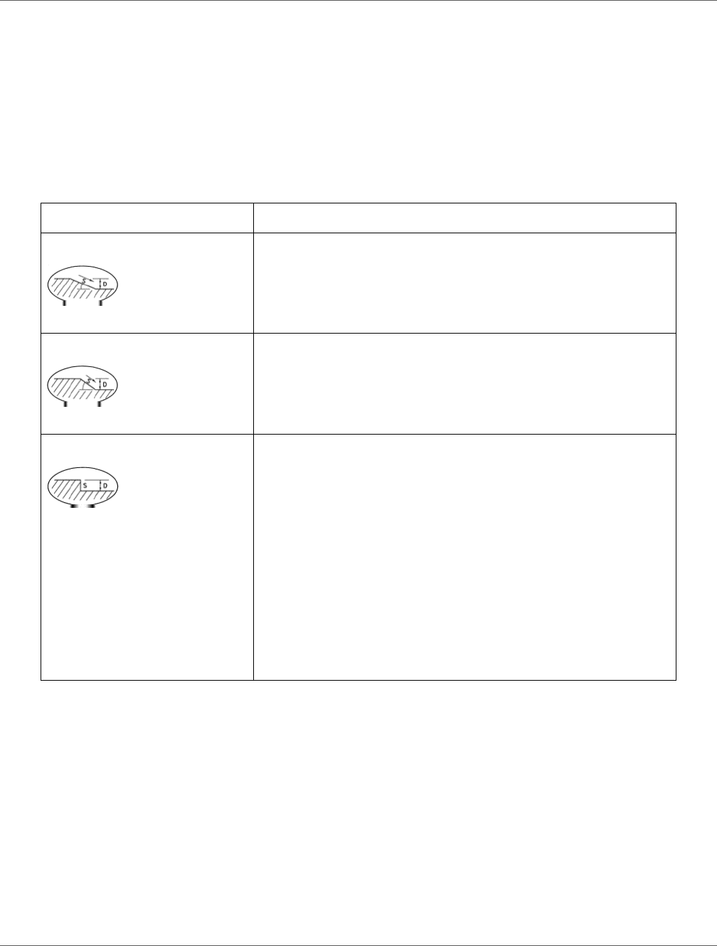
Roadway Design Manual B-4 TxDOT 04/2018
Appendix B — Treatment of Pavement Drop-offs in
Work Zones
Edge Condition
“Edge condition” refers to the slope of the drop-off. The following table describes three edge con-
dition types used in these guidelines. These edge conditions may be present between shoulders and
travel lanes, between adjacent or opposing travel lanes, or at intermediate points across the width of
the paved surface. Due to the variability in construction operations, tolerances in the dimensions
shown in the figures may be allowed by the engineer.
Guidelines for Treatment
The following guidelines show the recommended treatment for given combinations of edge condi-
tion, lateral clearance, and edge height. Remember to consider other factors listed above and use
engineering judgment.
Edge Condition Types
Condition Type & Description Notes
Edge Condition I
S = 3:1 or flatter slope rate (H:V)
Most vehicles are able to traverse an edge condition with a slope rate of 3
to 1 (horizontal to vertical) or flatter. The slope must be constructed with
a compacted material capable of supporting vehicles.
Edge Condition II
S = 2.99:1 to 1:1 slope rate (H:V)
Most vehicles are able to traverse an edge condition with a slope
between 2.99 to 1 and 1 to 1 (horizontal to vertical) as long as D does not
exceed 5 inches [125 mm]. Undercarriage drag on most automobiles will
occur as D exceeds 6 inches [150 mm]. As D exceeds 24 inches [0.6 m],
the possibility of rollover is greater for most vehicles.
Edge Condition III
S is steeper than 1:1 slope rate
(H:V)
Slopes steeper than 1 to 1 (horizontal to vertical) where D is greater than
2 inches [50 mm] can present a more difficult control factor for some
vehicles, if not properly treated. For example, in the zone where D is
greater than two up to 24 inches [50 mm to 0.6 m] different types of
vehicles may experience different steering control at different edge
heights. Automobiles might experience more steering control differential
in the greater than 2 up to 5 inch [50 to 125 mm] zone. Trucks, particu-
larly those with high loads, have more steering control differential in the
greater than 5 up to 24 [50 mm to 0.6 m] zone. As D exceeds 24 inches
[0.6 m], the possibilities of rollover is greater for most vehicles.
NOTE: Milling or overlay operations that result in Edge Condition III
should not be in place without appropriate warning treatments,
and these conditions should not be left in place for extended
periods of time.

Roadway Design Manual B-5 TxDOT 04/2018
Appendix B — Treatment of Pavement Drop-offs in
Work Zones
Treatment Guidelines for Pavement Drop-offs in Construction Work Zones
Edge Condition Lateral Clearance Edge Height Usual Treatment (See Note 3)
I
(slope is 3:1 or
flatter)
30 ft. [ 9 m] 0 to 1 in.
[0 to 25 mm]
no treatment
- -- >1 to 2 in.
[>25 to 50 mm]
CW 8-11 signs
- -- > 2 in.
[> 50mm]
CW 8-9a or CW 8-11 signs plus channelizing
devices
- > 30 ft. [> 9 m] Any height no treatment
II
(slope is between
2.99:1 and 1:1)
20 ft. [ 6 m] 0 to 1 in.
[0 to 25 mm]
no treatment
- - >1 to 2 in.
[>25 to 50 mm]
CW 8-11 signs
- - >2 to 5 in.
[>50 to 125 mm]
CW 8-9a or CW 8-11 signs plus channelizing
devices
- - >5 to 24 in.
[>125 to 600 mm]
CW 8-9a or CW 8-11 signs plus drums
(see Note 1)
- - > 24 in.
[> 600 mm]
Check indications for positive barrier
(See Note 2)
- > 20 ft. but 30 ft.
[> 6 m but 9 m] 0 to 1 in.
[0 to 25 mm]
no treatment
- - >1 to 2 in.
[>25 to 50 mm]
CW 8-11 signs
- - > 2 in.
[> 50mm]
CW 8-9a or CW 8-11 signs plus channelizing
devices
- > 30 ft. [> 9 m] Any height no treatment
III
(slope is steeper
than 1:1)
20 ft. [ 6 m] 0 to 1 in.
[0 to 25 mm]
no treatment
- - >1 to 2 in.
[>25 to 50 mm]
CW 8-11 signs
- - >2 to 24 in.
[>50 to 600 mm]
CW 8-9a or CW 8-11 signs plus drums
(see Note 1)

Roadway Design Manual B-6 TxDOT 04/2018
Appendix B — Treatment of Pavement Drop-offs in
Work Zones
Use of Positive Barriers
provides a practical approach to the use of positive barriers for the protection of vehicles from
pavement drop-offs. Other factors, such as the presence of heavy machinery, construction workers,
or the mix and volume of traffic, may make positive barriers appropriate, even when the edge con-
dition alone may not justify the barrier.
NOTE: An approved end treatment should be provided for any positive barrier end located within
a lateral offset of 20 feet [6.0 m] from the edge of the travel lane.
- - > 24 in.
[> 600 mm]
Check indications for positive barrier
(See Note 2)
- > 20 ft. but 30 ft.
[> 6 m but 9 m]
0 to 1 in.
[0 to 25 mm]
no treatment
- - >1 to 2 in.
[>25 to 50 mm]
CW 8-11 signs
- - > 2 in.
[> 50mm]
CW 8-9a or CW 8-11 signs plus channelizing
devices
- > 30 ft. [>9 m] Any height no treatment
NOTE: Where restricted space precludes the use of drums, use channelizing devices. An edge fill may be
provided to change the edge slope to that of the preferable Edge Condition I.
NOTE: Check indications for positive barrier (Figure B-2). Where positive barrier is not indicated, CW 8-9a
or CW 8-11 signs plus drums may be used (with Note 1 also applying) after consideration of other
applicable factors.
NOTE: Channelizing devices for the purpose of dropoff conditions are defined as: vertical panels, edge-line
channelizers, or drums.
Treatment Guidelines for Pavement Drop-offs in Construction Work Zones
Edge Condition Lateral Clearance Edge Height Usual Treatment (See Note 3)
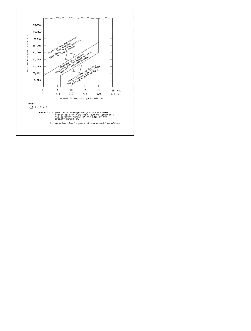
Roadway Design Manual B-7 TxDOT 04/2018
Appendix B — Treatment of Pavement Drop-offs in
Work Zones
Figure B-2. Conditions Indicating Use of Positive Barrier.


Roadway Design Manual C-2 TxDOT 04/2018
Appendix C — Driveway Design Guidelines
Section 1 — Purpose
The purpose of this Appendix is to provide guidance on the location and design of driveway
connections.
Because field conditions are highly variable with respect to driveways, the guidance provided
herein may not always be completely applicable. Therefore, departures from this design guidance
for driveways to meet field conditions are expected and do not require or constitute a need for any
type of design exception or design waiver.
Additional information can also be found in the Access Management Manual for permitting guide-
lines and for additional access discussion.

Roadway Design Manual C-3 TxDOT 04/2018
Appendix C — Driveway Design Guidelines
Section 2 — Introduction
General Guidelines
Driveways provide the physical transition between the public highway and the abutting property.
Driveways should be located and designed to minimize negative impacts on traffic operations
while providing safe entry and exit from the development served. The location and design of the
driveway should take into account characteristics of the roadway, the abutting property and the
potential users. In order to assure that driveways provide for safe and efficient traffic movements, it
is necessary to consider the driveway's critical dimensions and design features. This Appendix
applies to new driveways, and modification of existing driveways
Definitions
1. Apron: On curb and gutter sections, that part of a driveway from the pavement to a selected
point that is usually 6 inches in elevation above the edge of pavement (although it may vary by
location or roadway) or to the right-of-way, which ever is greater. On sections with a drainage
ditch, that part of a driveway from the edge of pavement to the right-of-way line.
2. Delivery Driveway: A driveway for use by trucks (typically SU or larger design vehicles as
defined by AASHTO) to deliver merchandise to a retail outlet and/or for use by service vehi-
cles, such as for solid waste collection.
3. Divided Driveway: A driveway providing a raised or depressed median, between the ingress/
egress sides of a driveway. Medians can be painted (fully traversable) when curbing is not
allowed within the right-of-way, slightly raised curb (mountable) when U-turns are allowed or
curbed (traversable) when U-turns are not allowed.
4. Driveway: Facility for entry and/or exit such as driveway, street, road, or highway that con-
nects to the road under the jurisdiction of the department or municipality.
5. Effective Turning Radius: The minimum radius appropriate for turning from the right-hand
travel lane on the approach street to the appropriate lane of the receiving street. This radius is
determined by the selection of a design vehicle appropriate for the streets being designed and
the lane on the receiving street into which that design vehicle will turn. Desirably this should
be at least 7.5 m [25 ft].
6. Farm/Ranch Driveway: A driveway providing ingress/egress for vehicles and farm/ranch
equipment associated with the operation of the farm/ranch. Such driveways may also serve the
residence of persons living and working on the farm/ranch and the other associated buildings.
7. Field Driveway: A limited-use driveway for the occasional/infrequent use by equipment used
for the purpose of cultivating, planting and harvesting or maintenance of agricultural land, or
by equipment used for ancillary mineral production.

Roadway Design Manual C-4 TxDOT 04/2018
Appendix C — Driveway Design Guidelines
8. Non-Residential/Commercial Driveway: Driveway having a traffic volume in excess of 20
vehicles per day and is not a Public Street/Road or a Residential Driveway.
9. Non-simultaneous Two-Way Driveway: A driveway intended to accommodate both entering
and exiting traffic but not at the same time. For example, if an exiting vehicle is present in the
driveway, the entering vehicle must wait until the exiting vehicle has cleared the driveway.
10. One-way Driveway: A driveway designed for either an ingress/egress maneuver but not both.
11. Public Driveway (Streets and Roads): A driveway providing ingress/egress from a roadway
for which the right-of-way is deeded to and the roadway maintenance is performed by a vil-
lage, town, city, county or municipal utility district.
12. Radial Return or Flare Drop Curb: For Residential Driveways onto Collector and Local
streets is Maximum of 10 feet and minimum of 3 feet. A radial return is always used where the
posted or operating speed is greater than 45 mph and the design vehicle type exceeds 30 feet in
length.
13. Residential Driveway: A driveway serving a single-family residence or duplex and has less
than 20 vehicles per day using the driveway.
14. Service Driveway: A driveway for occasional or infrequent use by vehicles or equipment to
service an oil or gas well, electric substation, water well, water treatment plant, sewage lift sta-
tion, waste water treatment plant, detention basin, water reservoir, emergency services,
automated or remotely controlled pumping station, logging road, and other activities that may
be identified by TxDOT.
15. Shared Driveway: A driveway shared by adjacent owners.
16. Simultaneous Two-Way Driveway: A driveway designed with a combination of return radius
and throat width that allows a selected design vehicle to enter at the same time that another
selected design vehicle is exiting the driveway.
17. Throat Length: The distance parallel to the centerline of a driveway to the first on-site loca-
tion at which a driver can make a right turn or a left turn; measured on roadways with curb and
gutter, from the face of the curb, and on roadways without a curb and gutter, from the edge of
the shoulder.
18. Throat Width: The driveway width measured at the end of the return radii. Refer to Figure C-
2.
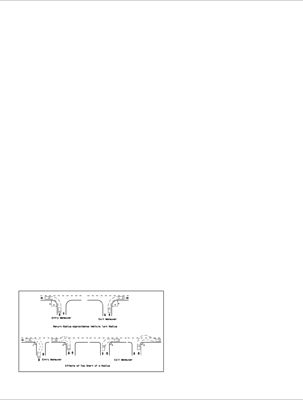
Roadway Design Manual C-5 TxDOT 04/2018
Appendix C — Driveway Design Guidelines
Section 3 — Driveway Design Principles
General Guidelines
The following guidelines apply to all driveways to a state highway.
1. The driveway placement should be such that drivers approaching from the main roadway will
have sufficient sight distance to ascertain the driveway’s location in order to safely decelerate
and complete the entry maneuver. Also, the driveway placement should be such that an exiting
driver will have sufficient sight distance to judge a safe gap in oncoming traffic. For selecting
appropriate driveway spacing distance, refer to the TxDOT Access Management Manual.
2. Each driveway radius should accommodate the appropriate design vehicle. This will generally
be the passenger car (AASHTO P design vehicle) unless the driveway will routinely be
expected to handle more than four larger vehicles per hour. Examples of facilities for which a
larger design vehicle would normally be appropriate include truck terminals, bus terminals,
and connections that serve the loading docks of shopping centers. Figure C-1 illustrates the
effects of the radius on the right-turn entry and exit maneuver.
3. Figure C-2 illustrates various driveway design elements including return radius, entry width,
exit width, throat width, and throat length.
4. With the exception of private residential driveways, farm/ranch driveways, field driveways,
and driveways that are designed and signed for one-way operation (i.e. ingress or egress only
but not both), driveways should be designed to accommodate simultaneous entry and exit by
the appropriate design vehicle.
5. Driveways that cross sidewalks are located in a developing area where pedestrian traffic can be
expected, should be designed to maintain an accessible route that is at least four feet wide
across the driveway.
6. One-way driveways should have a minimum throat length of 50 feet (15 m) and preferably 75
feet (23 m).
Figure C-1. Effects of Return Radius on the Right-Turn Maneuver
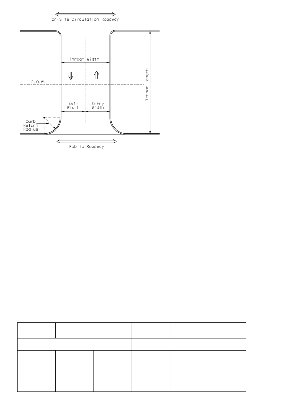
Roadway Design Manual C-6 TxDOT 04/2018
Appendix C — Driveway Design Guidelines
Figure C-2. Driveway Design Elements
Geometrics for Two-Way Driveways
The following are standards for two-way driveways.
1. Private Residential Driveway – Driveways serving single-family or duplex residences are nor-
mally designed as non-simultaneous two-way driveways. Standard design criteria for private
residential driveways are provided in Table C-1. However, for existing cases where the criteria
cannot be obtained, every attempt should be made to match the existing driveway width at the
ROW line.
2. Commercial Driveways – At locations where the expected volume of large vehicles is four or
more per hour, the design should be based on the appropriate design vehicle. Such situations
include, but are not limited to, truck stops, warehouses, concrete batch plants, sources of
aggregate, RV sales/truck sales and RV parks. The design should also consider future roadway
traffic and local conditions and incorporate simultaneous two-way driveways if justified.
Table C-1. Design Criteria for Private Residential Driveways
Radius Throat Width Radius Throat Width
US Customary Units Metric Units
(ft.) Standard
(ft.)
Maximum
(ft.)
(m) Standard
(m)
Maximum
(m)
15
1. 14 24 4.5 4.2 7.2

Roadway Design Manual C-7 TxDOT 04/2018
Appendix C — Driveway Design Guidelines
Two exit lanes are recommended when the expected driveway exit volume exceeds 200 vph.
In cases where one-way operation is appropriate, a condition of the driveway permit should
require that appropriate one-way signing be installed and maintained.
Table C-2 provides standard design criteria for two-way commercial driveways that would be
expected to accommodate only P and SU design vehicles.
3. Service Driveways – Service driveways should be designed considering the vehicle type and
frequency of use, current and future traffic operations on the state highway, and other local
conditions.
4. Field Driveways – The distance from the edge of the shoulder to a gate should be sufficient to
accommodate the longest vehicle (or combination of vehicles such as a truck and trailer)
expected. At a minimum, this will normally be a truck with trailer.
1. Reference the Access Management Manual for suggested minimum values.
Table C-2. Designs for Two-Way Commercial Driveways
US Customary Units Metric Units
Condition Radius
(R)
(ft)
Throat
Width
(W)
(ft)
Radius
(R)
(m)
Throat
Width
(W)
(m)
One entry lane and one exit lane,
fewer than 4 large vehicles per
hour (see Fig. C-3)
25 28 7.5 8.4
One entry lane and one exit lane,
4 or more SU vehicles3 per day
(see Fig. C-3)
30 30 9.0 9.0
One entry lane and two exit lanes,
without divider (see Fig. C-4) 25 40 7.5 12.0
One entry lane and two exit lanes,
with divider (see Fig. C-5) 25 44(1)-50(2) 7.5 13.2(1)-15.0(2)
Two entry lanes and two exit
lanes, with divider (see Fig. C-6) 25 56(1)-62(2) 7.5 16.8(1)-18.9(2)
(1)4 ft. [1.2 m] wide divider, face-to-face of curbs
(2)10 ft. [3.0 m] wide divider, face-to-face of curbs
(3)Driveway designs for larger vehicles will be considered on a case by case basis
Table C-1. Design Criteria for Private Residential Driveways
Radius Throat Width Radius Throat Width
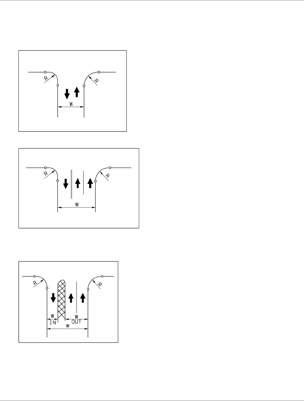
Roadway Design Manual C-8 TxDOT 04/2018
Appendix C — Driveway Design Guidelines
5. Farm/Ranch Driveway – A typical design for a farm/ranch driveway should provide a 25-foot
return radii and a 20-foot throat width. The distance from the edge of pavement must be suffi-
cient to store the longest vehicle, or combination of vehicles, expected. At a minimum, this
will normally be a truck with trailer.
Figure C-3. One Entry Lane/One Exit Lane
Figure C-4. One Entry Lane/Two Exit Lanes (Without a Divider)
See Table C-2 for Suggested Dimensions Based on Conditions.
Figure C-5. One Entry Lane/Two Exit Lanes (With a Divider)
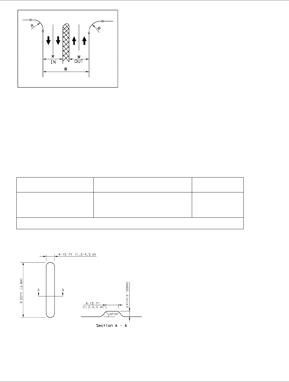
Roadway Design Manual C-9 TxDOT 04/2018
Appendix C — Driveway Design Guidelines
Figure C-6. Two Entry Lanes/Two Exit Lanes (With a Divider)
See Table C-2 for Suggested Dimensions Based on Conditions.
Divided Driveways
A raised or depressed separation between the entry and exit sides of a divided driveway needs to be
visible to drivers. Suggested treatments and divider sizes are shown in Table C-3:
Figure C-7 illustrates a slightly raised divider (height 4 inches [100 mm]).
Figure C-7. Illustration of Slightly Raised Divider
A divided driveway is desirable in the following situations:
1. There are a total of four or more entering and exiting lanes.
2. A large number of pedestrians (30 or more in a one-hour interval) routinely cross the driveway.
Table C-3. Dimensions for Dividers in the Driveway Throat to Separate Entry and Exit Sides
of the Driveway
Treatment Width Length
Slightly raised(1) (4in [100
mm]) with contrasting
surface(1)
4 –15 ft [1.2 – 4.5 m] 20 ft [6.0 m]
(1)For Rural - Rounded edges, 30o to 45o slope. (See Figure C-7)

Roadway Design Manual C-10 TxDOT 04/2018
Appendix C — Driveway Design Guidelines
Locating signing and lighting within a divider may assist approaching drivers in determining the
driveway’s location and geometrics.
An excessively wide divider may confuse drivers and cause them to think there are two closely
spaced, two-way driveways. To avoid this problem, the recommended maximum width of a divider
is 15 feet [4.5 m]. On the other hand, a divider that is too small may not be adequately visible to the
motorist. Therefore the recommended minimum width of a slightly raised divider (height > 4
inches) is 4 feet [1.2 m].

Roadway Design Manual C-11 TxDOT 04/2018
Appendix C — Driveway Design Guidelines
Section 4 — Profiles
Public driveways and commercial driveways should be constructed with a vertical curve between
the pavement cross-slope and the driveway approach and between changes in grade within the
driveway throat length. A private residential driveway may be constructed without vertical curves
provided that a change in grade does not adversely affect vehicle operations. Typically a change in
grade of three percent (3%) or less and a distance between changes in grade of at least eleven feet
[3.3 m] accommodates most vehicles. However, literature suggests that a six percent (6%) to eight
percent (8%) change in grade may operate effectively. Individual site conditions should be evalu-
ated to accommodate the vehicle fleet using the driveway.
Driveway Grades
To achieve satisfactory driveway profiles, some of the significant factors to be considered are:
1. Abrupt grade changes, which cause vehicles entering and exiting driveways to move at
extremely slow speeds, can create:
-The possibility of rear end collisions for vehicles entering the driveway.
-The need for large traffic gaps that may be unavailable or infrequent, causing drivers to
accept inadequate gaps.
2. Where sidewalks are present, or in developing areas where pedestrians may be expected now
or in the future, slower turning speeds may be beneficial and special design requirements
apply. See Section 6 for more information.
3. The comfort of vehicle occupants and potential vehicle damage, (i.e., prevent the dragging of
center or overhanging portion of passenger vehicles).
4. Grades must be compatible with the site requirements for sight distance and drainage, to pre-
vent excessive drainage runoff from entering the roadway or adjacent property.
Because a large combination of slopes, tangent lengths, and vertical curves will provide satisfac-
tory driveway profiles, some generalizations should be considered relative.
On curb and gutter sections, placement of vertical curves should be at the extended gutter line and
not closer to the travel lanes unless curb and gutter returns and proper drainage are provided. On
curb and gutter sections, the entire curb and gutter for the length of the curb cut should be removed
and the gutter pan recast as an integral part of the driveway apron.
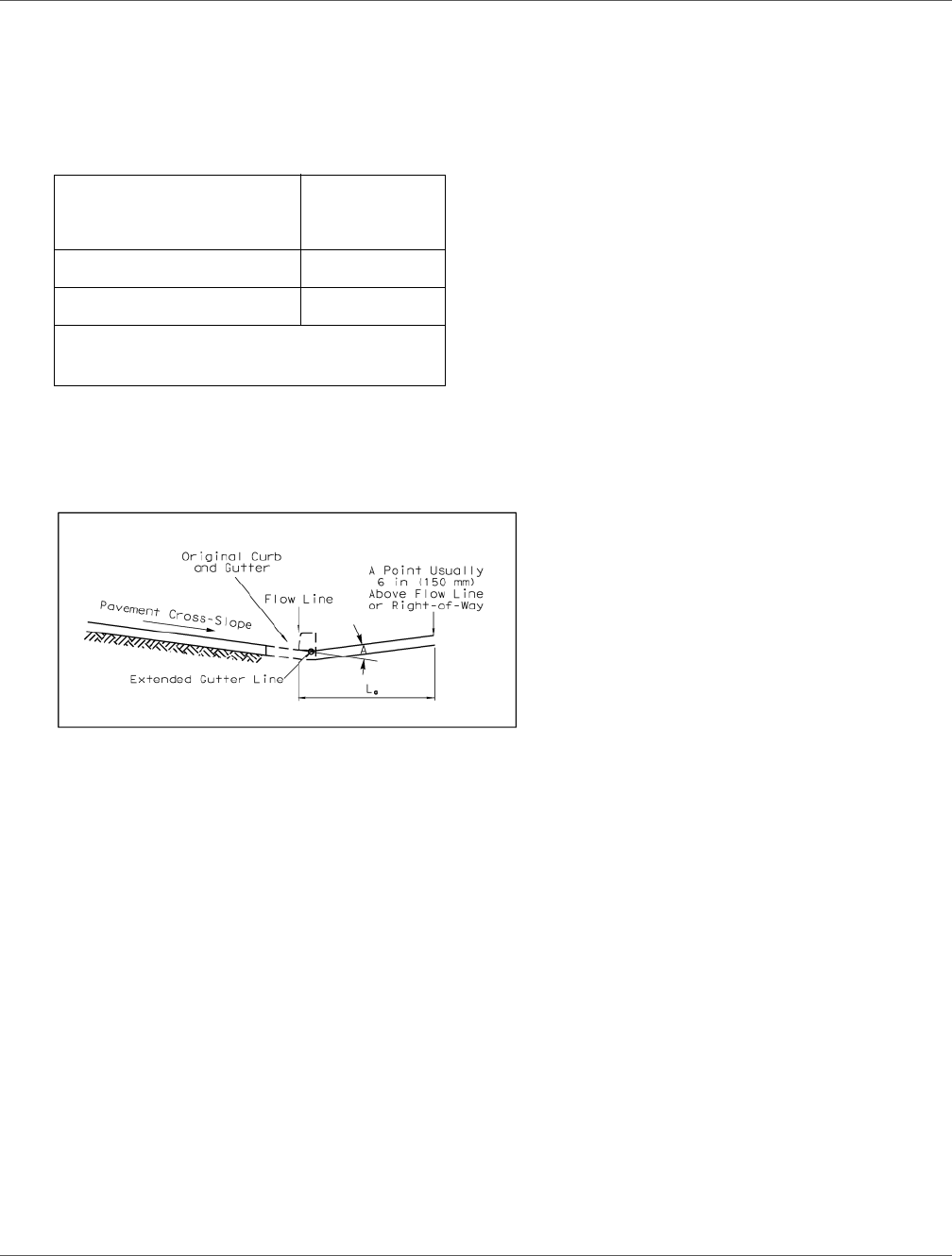
Roadway Design Manual C-12 TxDOT 04/2018
Appendix C — Driveway Design Guidelines
As shown in Table C-4, the suggested changes in driveway grades with a vertical curve (between
the pavement cross slope and the driveway apron slope) are approximately 10 percent for private
residential driveways and approximately 8 percent for all other driveways.
Construction practice can provide a suitable sag vertical curve between the pavement cross-slope
and the driveway apron when the apron length La (see Figure C-8) is equal to or greater than 20 feet
[7 m].
Figure C-8. Suggested Dimensions to Achieve an Appropriate Vertical Curve
Maximum driveway grades should be limited to 12 percent for private residential driveways and to
8 percent for other driveways. Where possible, the driveway grade should be limited to 6 percent or
less within the roadway right-of-way.
A construction easement is required for construction beyond the right-of-way line. For construction
beyond the right-of-way, it is necessary for the property owner to furnish the construction easement
or right of entry required.
Also, within the limits of curb return radii, no drop curb should be allowed except as required for
curb ramps.
Table C-4. Suggested Change in Grade with a
Vertical Curve
Driveway
Change
in Grade (A)(1)
Private Residential Driveways 10%
All Other Driveways 8%
(1)Change in grade between the pavement cross-
slope and the driveway apron slope
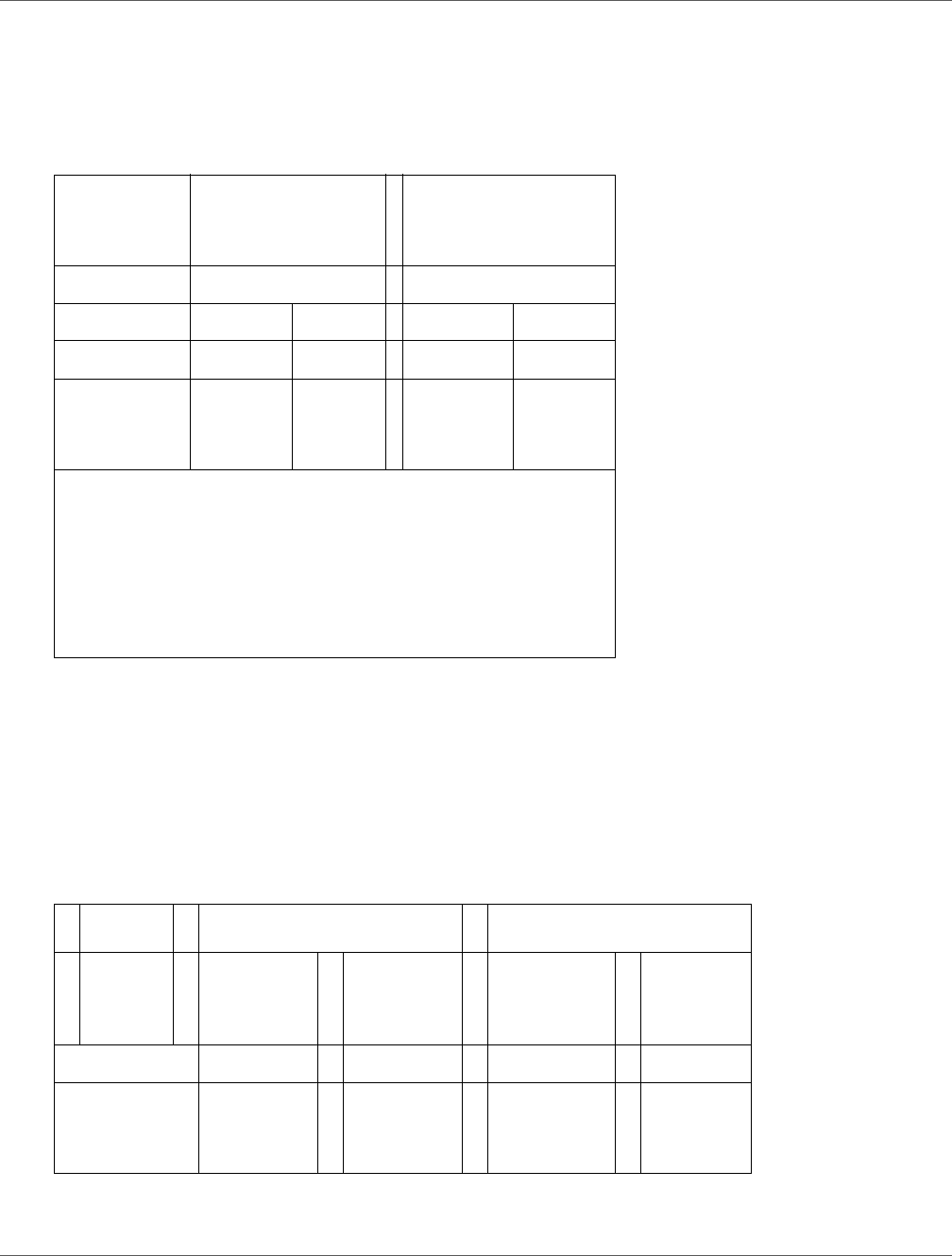
Roadway Design Manual C-13 TxDOT 04/2018
Appendix C — Driveway Design Guidelines
The length of the vertical curve between the pavement cross-slope and the driveway apron is a
function of the algebraic difference in the grades. Table C-5 provides the desirable and minimum
lengths for these vertical curves.
The length of the vertical curve at other points of driveway grade change is also a function of the
algebraic difference in the grades. Table C-6 provides the typical lengths for these vertical curves.
Figures C-9 through C-11 illustrate typical driveway profiles.
Table C-5. Length of Vertical Curve L (feet) For a Change in Grade
Between the Pavement Cross-Slope and the Driveway Apron Slope
Change in
Grade,
A
Crests Sags
Des. Min. Des. Min.
ft (m) ft (m) ft (m) ft (m)
4-5%
6-7%
8-10%
5 (1.5)
6 (1.8)
8 (2.4)
3 (0.9)
4 (1.2)
5 (1.5)
7 (2.1)
8 (2.4)
10 (3.0)
4 (1.2)
5 (1.5)
7 (2.1)
Rounded: Parabolic curvature. The plans may specify a particular type
of curvature.
Des.: Desirable Minimum Length
Min.: Minimum Length
Where practical, greater lengths should be provided to achieve a flatter
and smoother profile.
C-9 through C-11 illustrate typical driveway profiles.
Table C-6. Typical Length of Vertical Curve, L,
For Change in Grade in Driveway Profile
Crest Sag
Change
in Grade
A
Private
Residential
Driveways
Other
Driveways
Private
Residential
Driveways
Other
Driveways
ft (m) ft (m) ft (m) ft (m)
4-5%
6-7%
8-10%
2 (0.6)
3 (0.9)
4 (1.2)
5 (1.5)
5 (1.5)
6 (1.8)
3 (0.9)
5 (1.5)
6 (1.8)
6 (1.8)
7 (2.1)
8 (2.4)
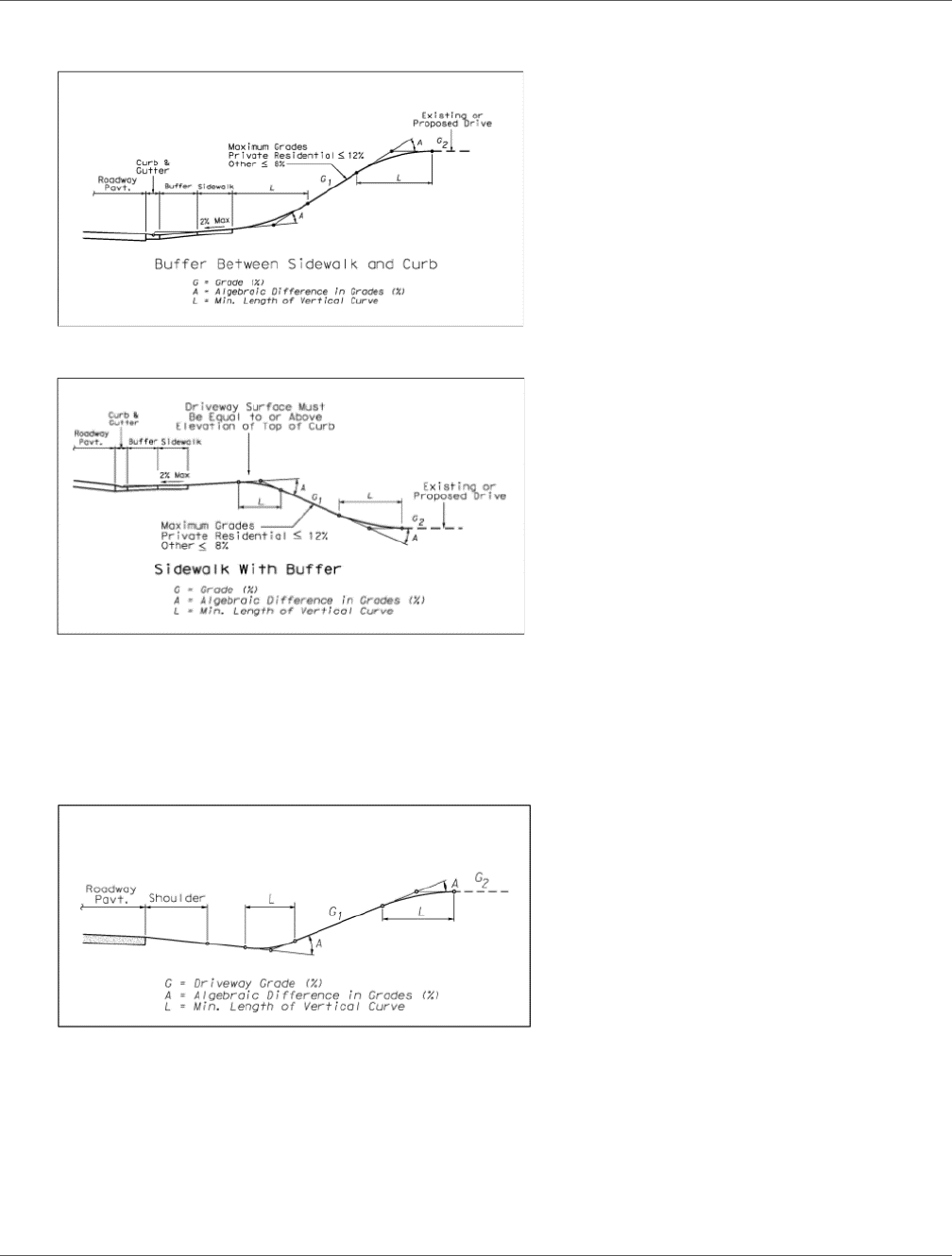
Roadway Design Manual C-14 TxDOT 04/2018
Appendix C — Driveway Design Guidelines
Profiles on Curb and Gutter Sections
Figure C-9. Roadway with Curb and Gutter, Driveway Profiles on an Upgrade
Figure C-10. Roadway with Curb and Gutter, Driveway Profiles on a Downgrade
See Tables C-5 and C-6 for lengths of vertical curves.
Profiles with Drainage Ditch
Figure C-11. Driveway Profiles on Roadway with Drainage Ditch
See Tables C-5 and C-6 for lengths of vertical curves.

Roadway Design Manual C-15 TxDOT 04/2018
Appendix C — Driveway Design Guidelines
Section 5 — Driveway Angle
Two-way driveways should intersect the roadway at an angle of ninety degrees unless it is deter-
mined that a lesser angle will provide satisfactory traffic operations for the highway. Suggested
limiting values on driveway angles are:
Residential Driveway: 75o
Commercial Driveway: 75o; commercial driveways expected to have a volume of 400 vehicles
per day or two or more trucks/large vehicles in a one-hour period shall be designed as normal inter-
sections (public driveway).
Normal Intersection (Public Driveway), Service Driveway and Field Driveway: 80o.
The angle of intersection between the centerline of a one-way driveway and the edge of pavement
of the public roadway may be between forty-five (45o) and ninety degrees (90o). Sixty degrees
(60o) is a commonly used angle for one-way driveways.
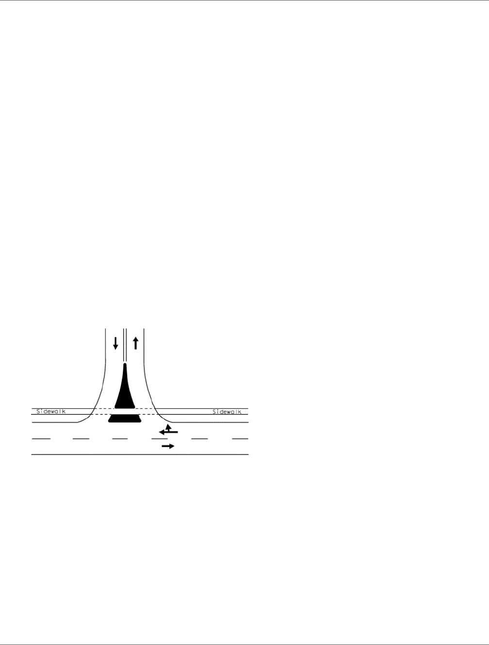
Roadway Design Manual C-16 TxDOT 04/2018
Appendix C — Driveway Design Guidelines
Section 6 — Pedestrian Considerations
General Guidelines
Accommodating pedestrians and vehicular traffic at the junctions of sidewalks and driveways pres-
ents a variety of challenges. Some general principles are:
The maximum cross-slope at any point on a sidewalk (including the crossing of a driveway) is
two percent (2%)
Consider using right-turn deceleration/storage lanes so that right-turning drivers can safely
wait in the auxiliary lane, clear of through traffic, while pedestrians are present in, or near, the
driveway.
Consider using a triangular island for pedestrian refuge in a high-volume driveway. The mini-
mum refuge area is 5 feet x 5 feet and preferably larger. (See Figure
C-12).
Locate sidewalks far enough from the curb, or edge of pavement, to provide a suitable vertical
curve transition between the pavement cross-slope and the driveway apron and to allow the
driveway to cross the sidewalk at the sidewalk’s normal elevation (see Section 4, Profiles on
Curb and Gutter Sections for illustrations of driveway profiles.)
Figure C-12. Channelizing Island to Provide Pedestrian Refuge
Where driveways are closely spaced, consider the use of right-in/right-out driveways to elimi-
nate conflicts between left-turning vehicles and pedestrians and bicyclists. In this case it is
recommended that provisions be made for the left-turns only at locations where the vehicular-
pedestrian conflict can be safely addressed by appropriate design and traffic control.
Provide adequate throat length so that a vehicle backing out of a space does not back over the
sidewalk (see Figure C-13). Vehicles should not block the sidewalk when parked in driveway.
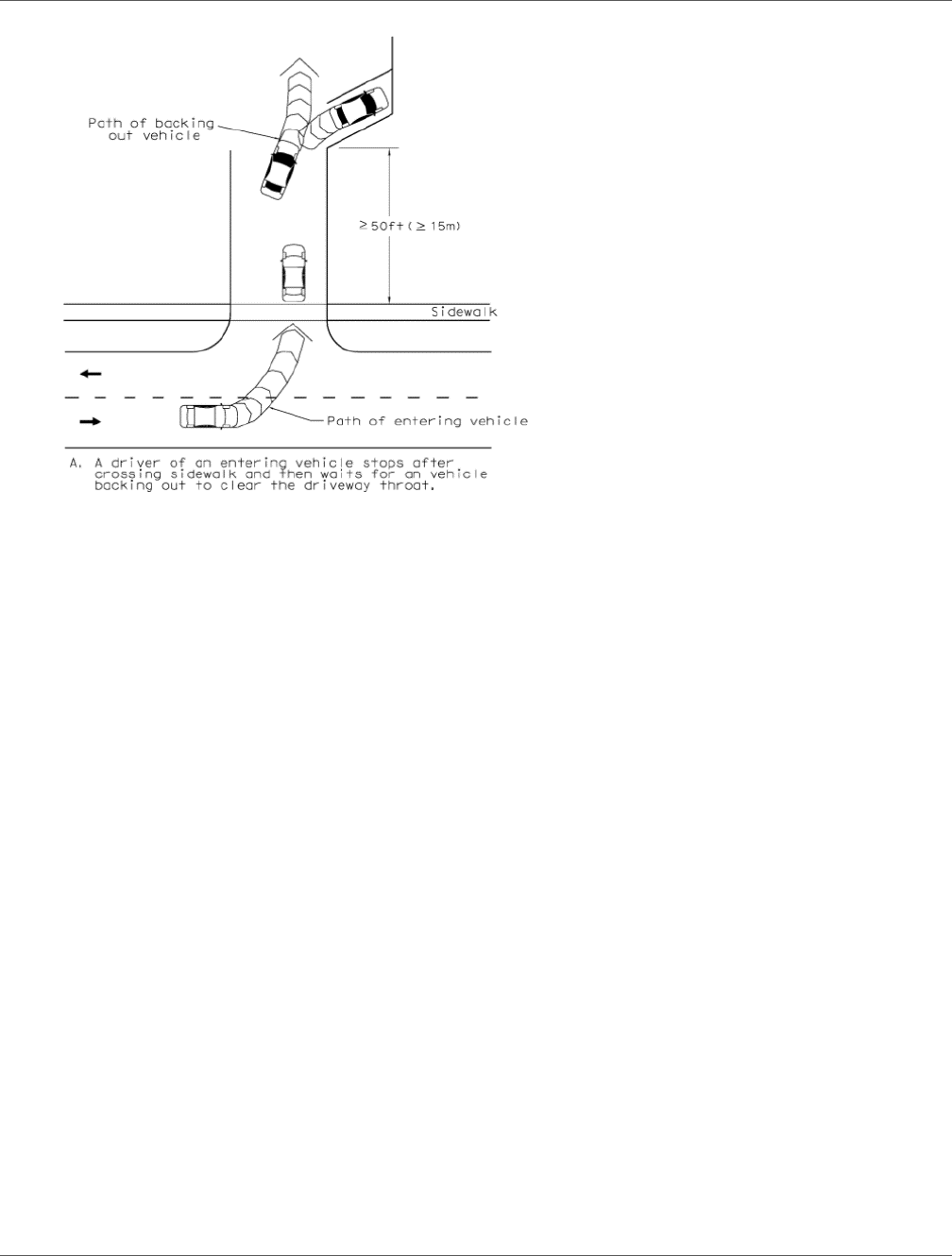
Roadway Design Manual C-17 TxDOT 04/2018
Appendix C — Driveway Design Guidelines
Figure C-13. Throat Length is of Sufficient Length to Allow Entering Vehicle to Clear the Through
Traffic Lane
Sidewalk and Driveway Intersections
Driveways crossing a sidewalk should be designed so that both pedestrians and drivers are able to
negotiate the sidewalk-driveway crossing efficiently and safely. When the change in cross slope is
too severe, one wheel of a wheelchair or one leg of a walker may lose contact with the ground.
Pedestrians are also more prone to stumble on surfaces with rapidly changing cross slopes. For this
reason, the maximum cross-slope at any point on a sidewalk (including the crossing of a driveway)
is two percent (2%). Wherever possible the sidewalk should be carried across the driveway without
a change with respect to the normal sidewalk profile. When the sidewalk abuts the back of the curb,
a “walk-around” (see Figure C-14) should be considered. This design transitions the sidewalk later-
ally to provide greater distance between the flow line of the gutter and the sidewalk. This allows the
sidewalk to remain at normal elevation without requiring an excessive driveway slope. The “walk
around” design may not be possible if there is insufficient right-of-way available. In this case, the
sidewalk grade must be lowered but preferably not all the way to street grade so that drainage in the
gutter is maintained.
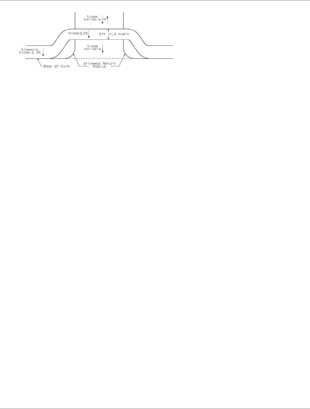
Roadway Design Manual C-18 TxDOT 04/2018
Appendix C — Driveway Design Guidelines
Figure C-14. Illustration of a “Walk-Around” Design

Roadway Design Manual C-19 TxDOT 04/2018
Appendix C — Driveway Design Guidelines
Section 7 — Visibility
Drivers must be able to locate a driveway in time to reduce speed and negotiate the entry maneuver.
Signing and lighting can be used to provide drivers with information regarding driveway opening
locations a considerable distance in advance. On divided driveways, the sign should be located
within the divider separating the entrance and exit sides of the driveway. Lighting can illuminate
the junction of the driveway and the highway.

Roadway Design Manual C-20 TxDOT 04/2018
Appendix C — Driveway Design Guidelines
Section 8 — References
1. A Policy on the Geometric Design of Highways and Streets, American Association of High-
way and Transportation Officials, 2001.
2. Transportation and Land Development, Institute of Transportation Engineers, 2002.
3. Access Management Manual, Transportation Research Board, 2003.
4. Draft Guidelines for Accessible Public Rights-of-Way, November 25, 2003.
5. R. J. Jaeger, Guidelines for the Investigation and Remediation of Potentially Hazardous Bicy-
cle and Pedestrian Locations, Traffic Engineering and Safety Management Branch, North
Carolina Department of Transportation, August 2003.
6. Charles V. Zegeer, Cara Seiderman, Peter Lagerway, Mike Cynecki, Michael Ronkin and Rob-
ert Schneider, “Pedestrian Facilities Users Guide – Providing Safety and Mobility,”
Publication No. FHWA No. FHWA-RD-01-102, Federal Highway Administration, US Depart-
ment of Transportation, March 2002
