Robotics Build Guide V2
User Manual:
Open the PDF directly: View PDF ![]() .
.
Page Count: 11
Control of Mobile Robots
The PiBot
Build Guide
Conner Wulf
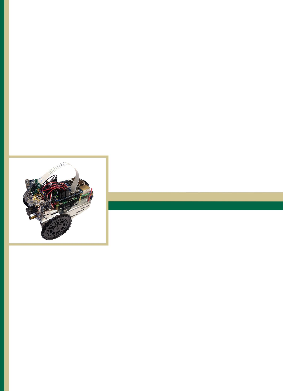
Put the Raspberry Pi on
top of the sheet metal. Using
A small pen or screw driver,
carefully mark where to drill
on the metal. Then drill the 4
corners marked on the metal.
Make sure the Pi does not shift
when marking so the Pi will line
up correctly later.
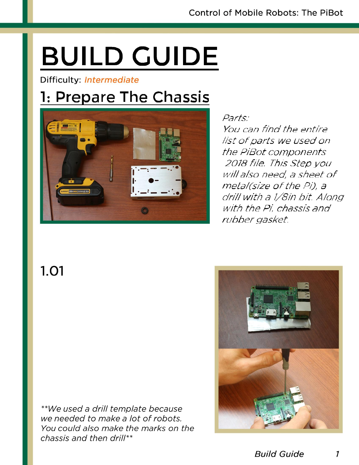
After the template is made, lay it
on top if the chassis. When deciding
where to drill, we suggest you line
them up so that the back of the Pi
is close to the back of the chassis.
Once a spot is chosen, clamp down
the template metal and drill the holes.
Put the rubber stopper in the
hole in the center of the chassis.
Make sure to do this before you
mount the Raspberry Pi or it will
be harder to access.
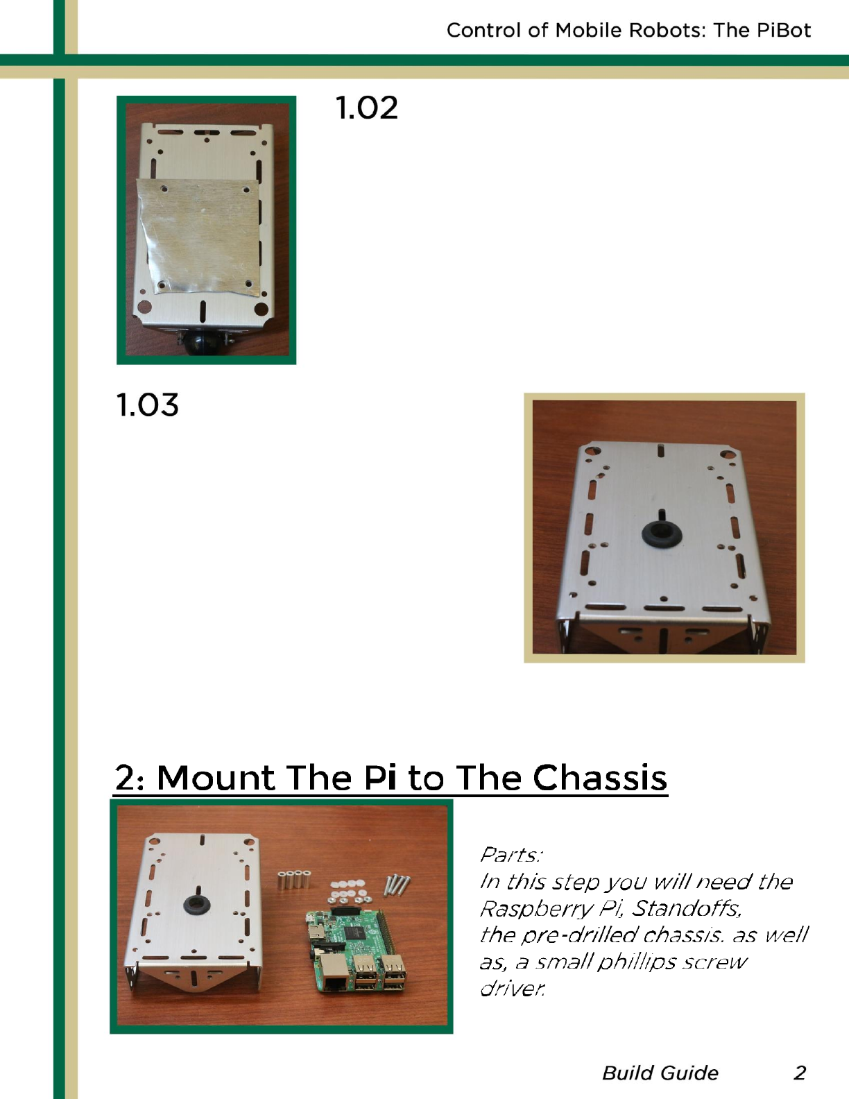
Take one of the screws and place a small plastic washer
on it. Then thread the screw through one of the Pi’s four
mounting holes. Do this for every hole, making sure there
is a washer between each screw and the Pi.
Take one of the plastic bolts and put them on the other
side screws used on the Pi. Make sure they are snug as it
will help with the stability of the Pi once mounted.
Then add the metal spacers to the screws.
While holding the Pi upside-
down, line the holes you drilled
with the screw on the Pi. Then,
Take the metal bolts and fasten
the Pi to the chassis.
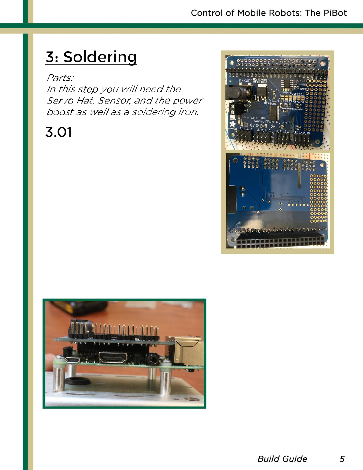
Solder the Servo Hat as shown
to the right. Note the GPIO pin
connector must be on the
bottom while the rest of the
pins are on the top. We used
a breadboard to help keep the
pins straight.
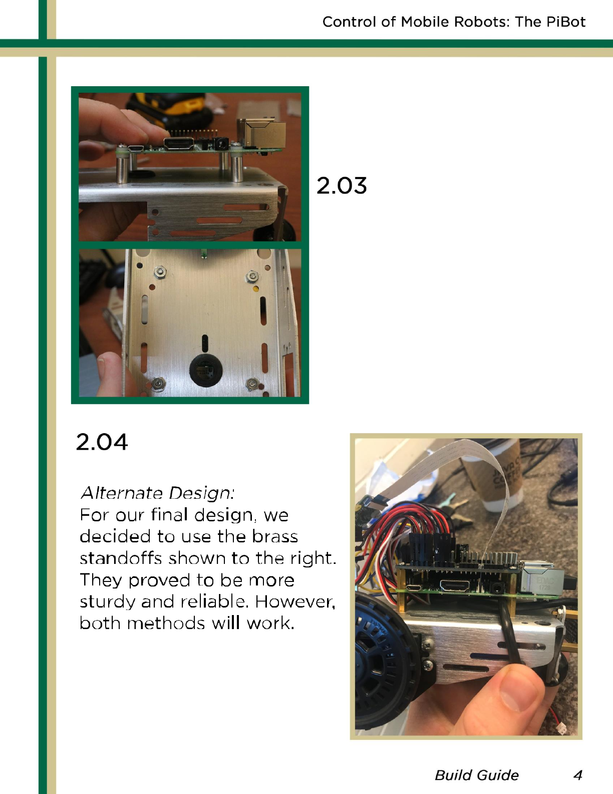
Once soldering is done,
attach the servo hat to
the top of the mounted
Pi using the GPIO pins,
as shown here. If using
the brass standoffs, you
can also add them here
for more stability.
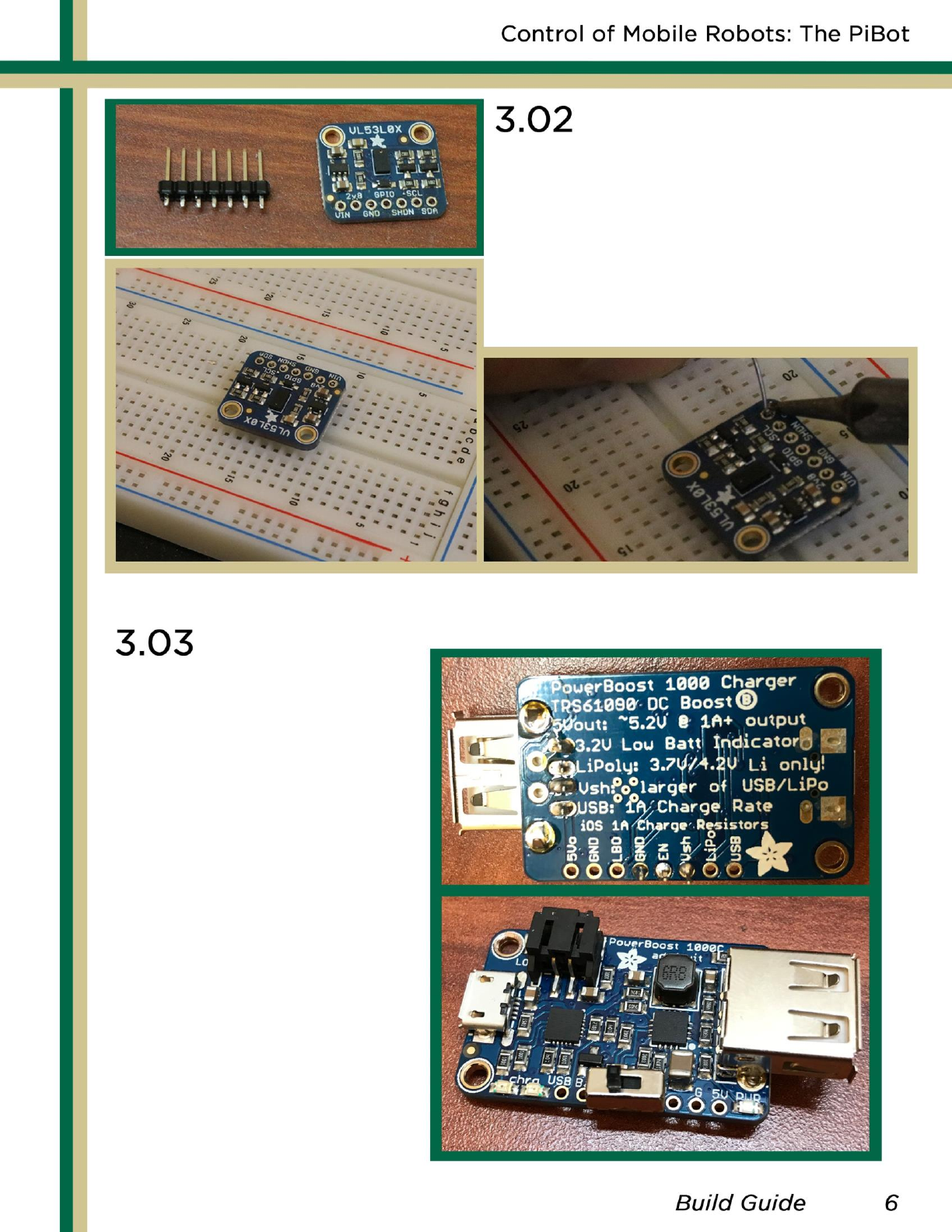
The next soldering step it to
solder the laser sensors. Using
the same method with the
breadboard, solder the seven
contacts to the sensor.
Repeat this for all 3 sensors.
The last soldering
step is to solder the
power boost.
Solder
the USB
contacts to the
chip and then
solder the on/off
switch to the chip
with the middle pin
of the switch
assigned to the
enable input.
The EN pin on the
power boost stands
for Enable.
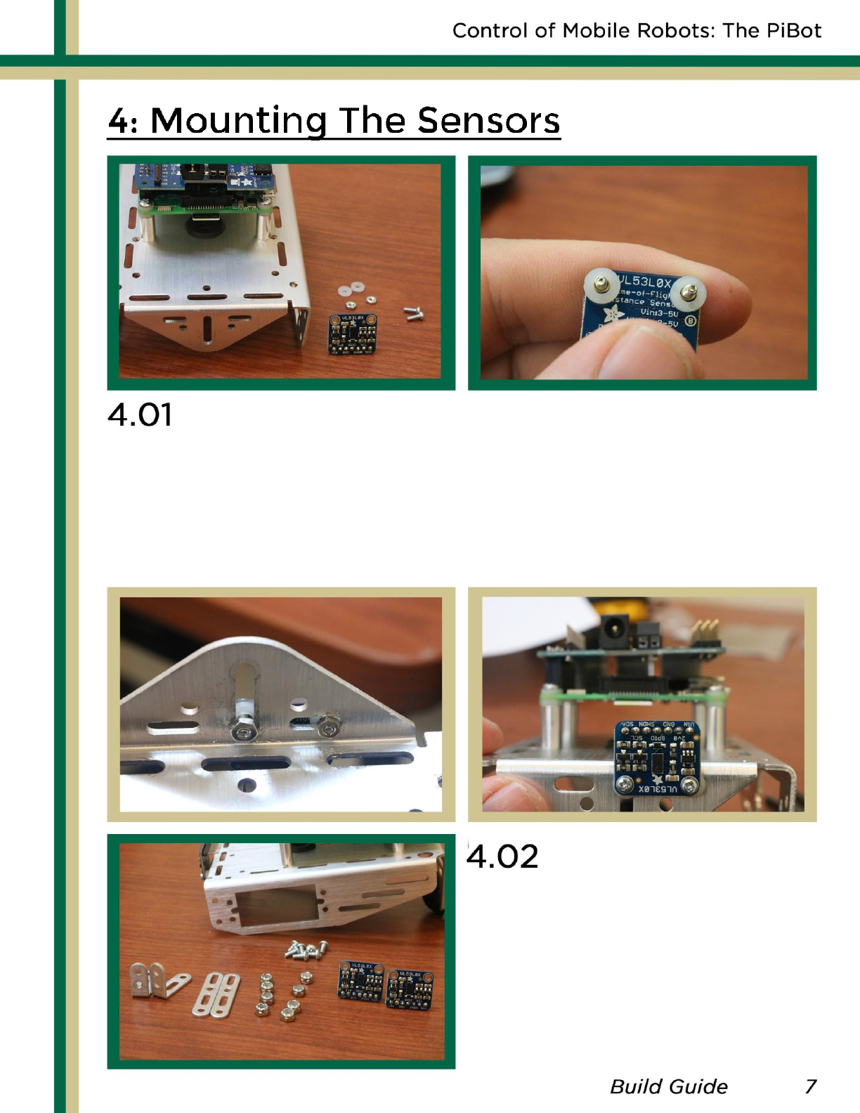
To attach the front sensor to the PiBot, thread two small
screws through the laser and then add a plastic washer.
Then thread the screws on the laser through the chassis
and bolt it down. Make sure the laser is upside-down as
seen below. Brass standoff may also be used.
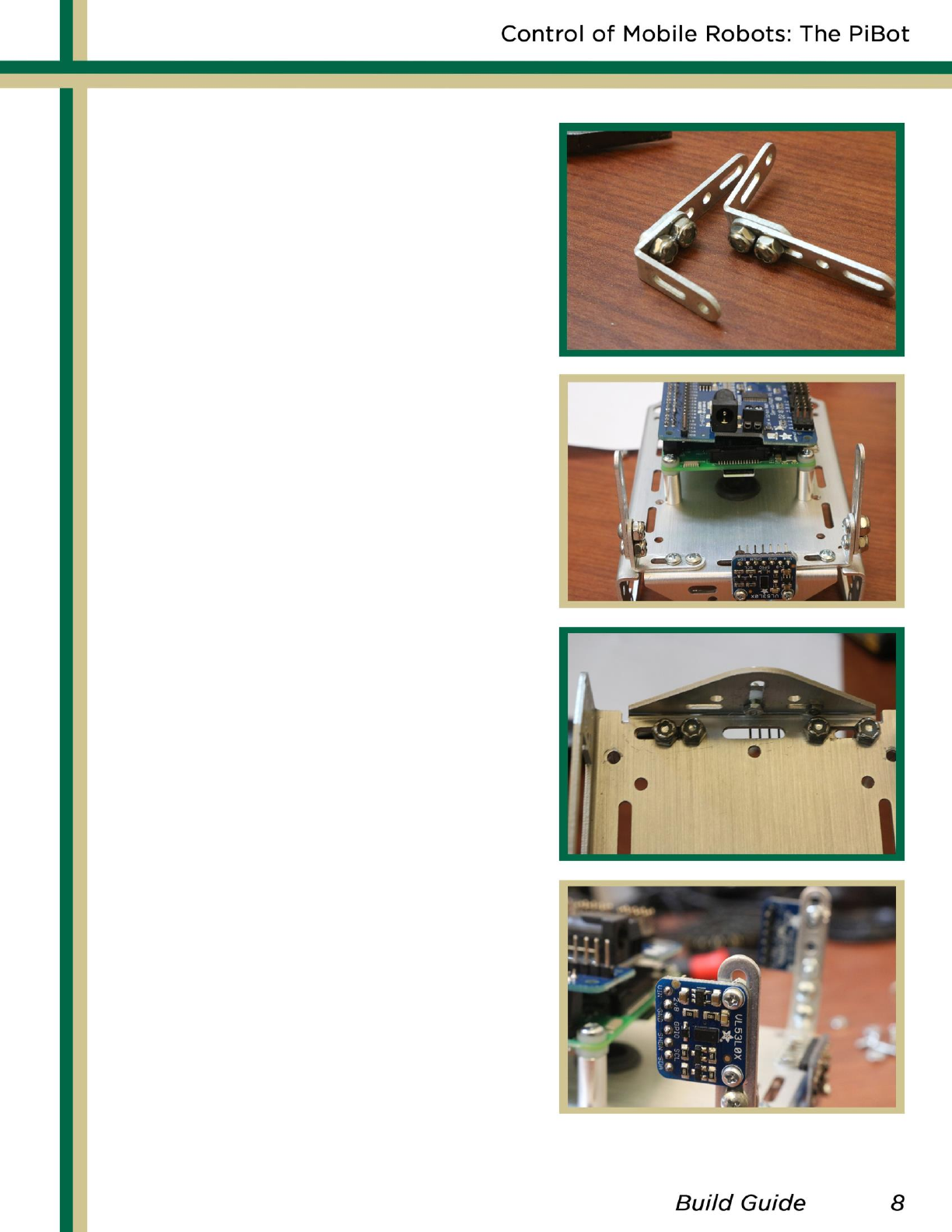
To setup the left and right
sensors make sure you have
the parts in the picture to
the left.
-
Fasten the angle and straight
brackets together as shown
in the top picture.
-
Fasten the two brackets
made to the chassis as
shown in the next two pictures.
-
Lastly, fasten a laser sensor
on each side, making sure
the sensors pins are facing the
inside of the robot.
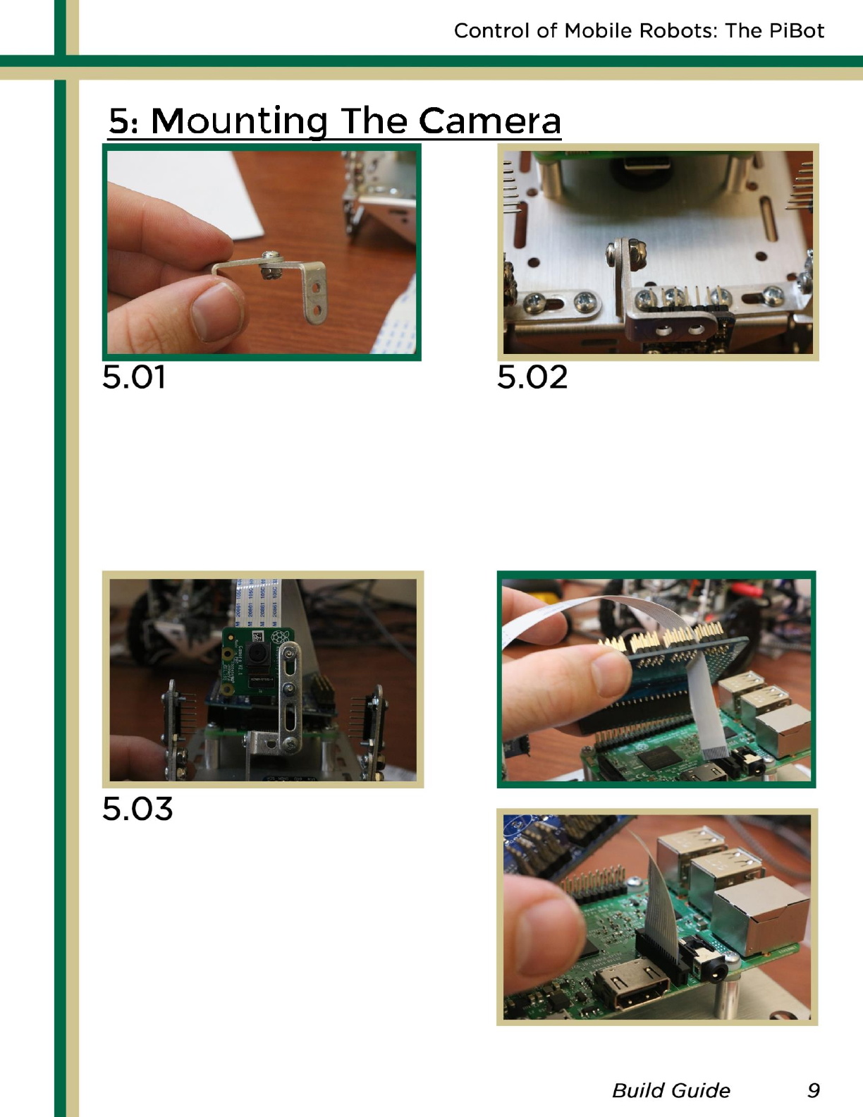
To setup the bracket for
the camera, take two right
angle brackets and fasten
them together on the top
hole of the longer side.
Using one straight bracket,
mount the camera to the Pi
as shown above. Make sure to
put a washer between the
camera and metal.
Then, hook up the camera to
the Pi, as shown on the right.
Take the new bracket and
fasten it to the chassis,
underneath the front
sensor
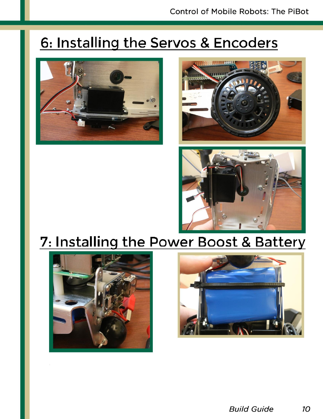
Insert a servo and encoder
and bolt them down as seen
in the picture above. Thread
the wires through the small
rubber gasket on the chassis.
Finally screw the wheel on
the servo. Repeat for other.
Using washers and a long
metal bracket, mount the
soldered power boost to
the chassis as shown in
the picture.
Fix the LiPo battery to the
bottom of the robot in a
way to make sure it is snug.
We used a zip tie for ours.
