Rock Shox Reba
User Manual: Rock Shox Reba
Open the PDF directly: View PDF ![]() .
.
Page Count: 57

FORK SPRING WHEEL
SIZE MODEL <140 LBS
(<63 KG)
140-160
LBS
(63-72 KG)
160-180
LBS
(72-81 KG)
180-200
LBS
(81-90 KG)
200-220
LBS
(90-99 KG)
MAX PSI
Argyle Solo Air 26” RCT 120-135 psi 135-150 psi 150-165 psi 165-180 psi 180+ psi 220 psi
BoXXer Solo Air 26” World Cup 40-55 psi 55-70 psi 70-85 psi 85-100 psi 100-115 psi 200 psi
Lyrik
Dual
Position
Air
26” RC2L, RC2 DH,
RC, R 45-65 psi 65-85 psi 85-105 psi 105-125 psi 125-145 psi 248 psi
Solo Air 26” RC2L, RC2 DH,
RC, R 45-55 psi 55-65 psi 65-75 psi 75-85 psi 85-95 psi 148 psi
Reba Dual Air 29” RLT, RL, RLT, RL 70-90 psi 90-105 psi 105-120 psi 120-135 psi 135+ psi 200 psi
Recon Gold
80mm Solo Air
26” RL, TK, R
90-110 psi 110-125 psi 125-140 psi 140-160
psi 175+ psi 225 psi
29” TK
Recon Gold
100-120mm Solo Air
26” RL, TK, R
50-70 psi 70-85 psi 85-100 psi 100-120 psi 135+ psi 225 psi
29” TK
Recon
Silver
80mm
Solo Air
26” TK, R
90-110 psi 110-125 psi 125-140 psi 140-160 psi 175+ psi 225 psi
29” TK
Recon
Silver
100-120mm
Solo Air
26” TK, R
50-70 psi 70-85 psi 85-100 psi 100-120 psi 135+ psi 225 psi
29” TK
Revelation
Dual Air
26” World Cup, XX,
RCT3, RLT, RL, 70-90 psi 90-105 psi 105-120 psi 120-135 psi 135+ psi 200 psi
29” XX, RCT3, RLT, RL
Dual
Position
Air
26”
World Cup, World
Cup XX, XX, RCT3,
RLT, RL <110 psi 110-125 psi 125-140 psi 140-155 psi 155-170 psi 250 psi
29” XX, RCT3, RLT, RL
Sektor Solo Air 26” RL, TK 50-70 psi 70-85 psi 85-100 psi 100-115 psi 115-130+
psi 225 psi
SID Dual Air
26”
World Cup XX,
World Cup, XX,
RTC3, RLT, RL
70-90 psi 90-105 psi 105-120 psi 120-135 psi 135+ psi 200 psi
29”
World Cup XX,
World Cup, XX
29, RCT3, RLT, RL
Totem
Dual
Position
Air
26” RC, RC2 DH 35-40 psi 40-55 psi 55-75 psi 75-90 psi 90-110 psi 186 psi
Solo Air 26” RC2 DH 20-35 psi 35-50 psi 50-65 psi 65-80 psi 80-95 psi 148 psi
SUSPENSION FORK
Air Spring Chart
2012
GEN.0000000004148)Rev)A

2013
Reba Service Manual
GEN.0000000004216 Rev A © 2012 SRAM LLC

SRAM LLC WARRANTY
EXTENT OF LIMITED WARRANTY
!"#$%&'()'*&+$,-.)$')$&'/*,&+'+$,$.01'2345'-(,,(0&)'.&)'%,*67#&)'&*'8$'/,$$'/,*9'6$/$#&)'.0'9(&$,.(:)'*,'-*,;9(0)+.%'/*,'('%$,.*6'*/'&-*'<$(,)'(/&$,'
*,.=.0(:'%7,#+()$>''?+.)'-(,,(0&<'*0:<'(%%:.$)'&*'&+$'*,.=.0(:'*-0$,'(06'.)'0*&'&,(0)/$,(8:$>'@:(.9)'706$,'&+.)'-(,,(0&<'97)&'8$'9(6$'&+,*7=+'&+$',$&(.:$,'
-+$,$'&+$'8.#<#:$'*,'&+$'2345'#*9%*0$0&'-()'%7,#+()$6>'A,.=.0(:'%,**/'*/'%7,#+()$'.)',$B7.,$6>'Except'as'described'herein,'SRAM'makes'no'
other'warranties,'guaranties,'or'representations'of'any'type'(express'or'implied),'and'all'warranties'(including'any'implied'warranties'of'
reasonable'care,'merchantibility,'or'fitness'for'a'particular'purpose)'are'hereby'disclaimed.
LOCAL LAW
7KLVZDUUDQW\VWDWHPHQWJLYHVWKHFXVWRPHUVSHFL¿FOHJDOULJKWV7KHFXVWRPHUPD\DOVRKDYHRWKHUULJKWVZKLFKYDU\IURPVWDWHWRVWDWH86$IURP
SURYLQFHWRSURYLQFH&DQDGDDQGIURPFRXQWU\WRFRXQWU\HOVHZKHUHLQWKHZRUOG
7RWKHH[WHQWWKDWWKLVZDUUDQW\VWDWHPHQWLVLQFRQVLVWHQWZLWKWKHORFDOODZWKLVZDUUDQW\VKDOOEHGHHPHGPRGL¿HGWREHFRQVLVWHQWZLWKVXFKODZXQGHU
VXFKORFDOODZFHUWDLQGLVFODLPHUVDQGOLPLWDWLRQVRIWKLVZDUUDQW\VWDWHPHQWPD\DSSO\WRWKHFXVWRPHU)RUH[DPSOHVRPHVWDWHVLQWKH8QLWHG6WDWHV
RI$PHULFDDVZHOODVVRPHJRYHUQPHQWVRXWVLGHRIWKH8QLWHG6WDWHVLQFOXGLQJSURYLQFHVLQ&DQDGDPD\
(>'C,$#:76$'&+$'6.)#:(.9$,)'(06':.9.&(&.*0)'*/'&+.)'-(,,(0&<')&(&$9$0&'/,*9':.9.&.0='&+$')&(&7&*,<',.=+&)'*/'&+$'#*0)79$,''
HJ8QLWHG.LQJGRP
8>'A&+$,-.)$',$)&,.#&'&+$'(8.:.&<'*/'('9(07/(#&7,$,'&*'$0/*,#$')7#+'6.)#:(.9$,)'*,':.9.&(&.*0)>
For'Australian'customers:
7KLV65$0OLPLWHGZDUUDQW\LVSURYLGHGLQ$XVWUDOLDE\65$0//&1RUWK.LQJVEXU\WKÀRRU&KLFDJR,OOLQRLV86$7RPDNHDZDUUDQW\
FODLPSOHDVHFRQWDFWWKHUHWDLOHUIURPZKRP\RXSXUFKDVHGWKLV65$0SURGXFW$OWHUQDWLYHO\\RXPD\PDNHDFODLPE\FRQWDFWLQJ65$0$XVWUDOLD
5(,#*'@*7,&1'3*-D.::$'EFGH1'47)&,(:.(>'I*,'D(:.6'#:(.9)'2345'-.::1'(&'.&)'*%&.*01'$.&+$,',$%(.,'*,',$%:(#$'<*7,'2345'%,*67#&>''40<'$"%$0)$)'.0#7,,$6'.0'
PDNLQJWKHZDUUDQW\FODLPDUH\RXUUHVSRQVLELOLW\7KHEHQH¿WVJLYHQE\WKLVZDUUDQW\DUHDGGLWLRQDOWRRWKHUULJKWVDQGUHPHGLHVWKDW\RXPD\KDYH
706$,':(-)',$:(&.0='&*'*7,'%,*67#&)>''A7,'=**6)'#*9$'-.&+'=7(,(0&$$)'&+(&'#(00*&'8$'$"#:76$6'706$,'&+$'47)&,(:.(0'@*0)79$,'J(->''K*7'(,$'$0&.&:$6'&*'
(',$%:(#$9$0&'*,',$/706'/*,'('9(L*,'/(.:7,$'(06'/*,'#*9%$0)(&.*0'/*,'(0<'*&+$,',$()*0(8:<'/*,$)$$(8:$':*))'*,'6(9(=$>''K*7'(,$'(:)*'$0&.&:$6'&*'+(D$'&+$'
=**6)',$%(.,$6'*,',$%:(#$6'./'&+$'=**6)'/(.:'&*'8$'*/'(##$%&(8:$'B7(:.&<'(06'&+$'/(.:7,$'6*$)'0*&'(9*70&'&*'('9(L*,'/(.:7,$>
LIMITATIONS OF LIABILITY
7RWKHH[WHQWDOORZHGE\ORFDOODZH[FHSWIRUWKHREOLJDWLRQVVSHFL¿FDOO\VHWIRUWKLQWKLVZDUUDQW\VWDWHPHQWLQQRHYHQWVKDOO65$0RULWVWKLUGSDUW\
)7%%:.$,)'8$':.(8:$'/*,'6.,$#&1'.06.,$#&1')%$#.(:1'.0#.6$0&(:1'*,'#*0)$B7$0&.(:'6(9(=$)>'
LIMITATIONS OF WARRANTY
?+.)'-(,,(0&<'6*$)'0*&'(%%:<'&*'%,*67#&)'&+(&'+(D$'8$$0'.0#*,,$#&:<'.0)&(::$6'(06M*,'(6L7)&$6'(##*,6.0='&*'&+$',$)%$#&.D$'2345'7)$,'9(07(:>'?+$'2345'
7)$,'9(07(:)'#(0'8$'/*706'*0:.0$'(&'),(9>#*91',*#;)+*">#*91'(D.68.;$>#*91'&,7D(&.D>#*91'*,'N.%%>#*9>
?+.)'-(,,(0&<'6*$)'0*&'(%%:<'&*'6(9(=$'&*'&+$'%,*67#&'#(7)$6'8<'('#,()+1'.9%(#&1'(87)$'*/'&+$'%,*67#&1'0*0O#*9%:.(0#$'-.&+'9(07/(#&7,$,)'
VSHFL¿FDWLRQVRIXVDJHRUDQ\RWKHUFLUFXPVWDQFHVLQZKLFKWKHSURGXFWKDVEHHQVXEMHFWHGWRIRUFHVRUORDGVEH\RQGLWVGHVLJQ
7KLVZDUUDQW\GRHVQRWDSSO\ZKHQWKHSURGXFWKDVEHHQPRGL¿HGLQFOXGLQJEXWQRWOLPLWHGWRDQ\DWWHPSWWRRSHQRUUHSDLUDQ\HOHFWURQLFDQG
$:$#&,*0.#',$:(&$6'#*9%*0$0&)1'.0#:76.0='&+$'9*&*,1'#*0&,*::$,1'8(&&$,<'%(#;)1'-.,.0='+(,0$))$)1')-.&#+$)1'(06'#+(,=$,)>
?+.)'-(,,(0&<'6*$)'0*&'(%%:<'-+$0'&+$')$,.(:'0798$,'*,'%,*67#&.*0'#*6$'+()'8$$0'6$:.8$,(&$:<'(:&$,$61'6$/(#$6'*,',$9*D$6>
?+.)'-(,,(0&<'6*$)'0*&'(%%:<'&*'0*,9(:'-$(,'(06'&$(,>'P$(,'(06'&$(,'%(,&)'(,$')78L$#&'&*'6(9(=$'()'(',$)7:&'*/'0*,9(:'7)$1'/(.:7,$'&*')$,D.#$'(##*,6.0='
&*'2345',$#*99$06(&.*0)'(06M*,',.6.0='*,'.0)&(::(&.*0'.0'#*06.&.*0)'*,'(%%:.#(&.*0)'*&+$,'&+(0',$#*99$06$6>
:HDUDQGWHDUSDUWVDUHLGHQWL¿HGDV
Notwithstanding'anything'else'set'forth'herein1'&+.)'-(,,(0&<'.)':.9.&$6'&*'*0$'<$(,'/*,'(::'$:$#&,*0.#'(06'$:$#&,*0.#',$:(&$6'#*9%*0$0&)'.0#:76.0='
9*&*,)1'#*0&,*::$,)1'8(&&$,<'%(#;)1'-.,.0='+(,0$))$)1')-.&#+$)1'(06'#+(,=$,)>'?+$'8(&&$,<'%(#;'(06'#+(,=$,'-(,,(0&<'6*$)'0*&'.0#:76$'6(9(=$'/,*9'
%*-$,')7,=$)1'7)$'*/'.9%,*%$,'#+(,=$,1'.9%,*%$,'9(.0&$0(0#$1'*,')7#+'*&+$,'9.)7)$>
?+.)'-(,,(0&<')+(::'0*&'#*D$,'6(9(=$)'#(7)$6'8<'&+$'7)$'*/'%(,&)'*/'6.//$,$0&'9(07/(#&7,$,)>
?+.)'-(,,(0&<')+(::'0*&'#*D$,'6(9(=$)'#(7)$6'8<'&+$'7)$'*/'%(,&)'&+(&'(,$'0*&'#*9%(&.8:$1')7.&(8:$'(06M*,'(7&+*,.)$6'8<'2345'/*,'7)$'-.&+'2345'
#*9%*0$0&)>
7KLVZDUUDQW\VKDOOQRWFRYHUGDPDJHVUHVXOWLQJIURPFRPPHUFLDOUHQWDOXVH
Q7)&')$(:)
R7)+.0=)
4.,')$(:.0='*O,.0=)
S:.6$',.0=)
3788$,'9*D.0='%(,&)
I*(9',.0=)
3$(,')+*#;'9*70&.0='+(,6-(,$'
(06'9(.0')$(:)
8SSHUWXEHVVWDQFKLRQV
6WULSSHGWKUHDGVEROWVDOXPLQLXP
WLWDQLXPPDJQHVLXPRUVWHHO
R,(;$'):$$D$)
R,(;$'%(6)
@+(.0)
2%,*#;$&)
@())$&&$)
6KLIWHUDQGEUDNHFDEOHVLQQHU
DQGRXWHU
T(06:$8(,'=,.%)
2+./&$,'=,.%)
U*#;$<'-+$$:)
Q.)#'8,(;$',*&*,)
P+$$:'8,(;.0=')7,/(#$)
R*&&*9*7&'%(6)
R$(,.0=)
R$(,.0=',(#$)
C(-:)
?,(0)9.)).*0'=$(,)
2%*;$)
I,$$'+78)
4$,*'8(,'%(6)
@*,,*).*0
?**:)
5*&*,)
R(&&$,.$)
TABLE OF CONTENTS
REBA EXPLODED VIEW ................................................................................................................................................................... 4
ROCKSHOX SUSPENSION SERVICE ............................................................................................................................................... 5
PARTS AND TOOLS NEEDED FOR SERVICE ............................................................................................................................................................................5
LOWER LEG REMOVAL ..................................................................................................................................................................... 6
LOWER LEG SEAL SERVICE ............................................................................................................................................................................................................ 8
SOLO AIR SPRING SERVICE .......................................................................................................................................................... 10
OPTIONAL TRAVEL CHANGE ADJUSTMENT ........................................................................................................................................................................10
SOLO AIR SPRING REMOVAL ........................................................................................................................................................................................................10
SOLO AIR SPRING INSTALLATION .............................................................................................................................................................................................. 13
DAMPER SERVICE ............................................................................................................................................................................15
COMPRESSION DAMPER REMOVAL ..........................................................................................................................................................................................15
REBOUND DAMPER SERVICE ....................................................................................................................................................................................................... 17
COMPRESSION DAMPER INSTALLATION ...............................................................................................................................................................................20
LOWER LEG INSTALLATION ...........................................................................................................................................................21
PUSHLOC™ REMOTE SERVICE .....................................................................................................................................................24
CABLE REMOVAL ...............................................................................................................................................................................................................................24
CABLE INSTALLATION ....................................................................................................................................................................................................................25

SAFETY FIRST!
We care about YOU. Please, always wear your safety glasses and
protective gloves when servicing RockShox products.
Protect yourself! Wear your safety gear!

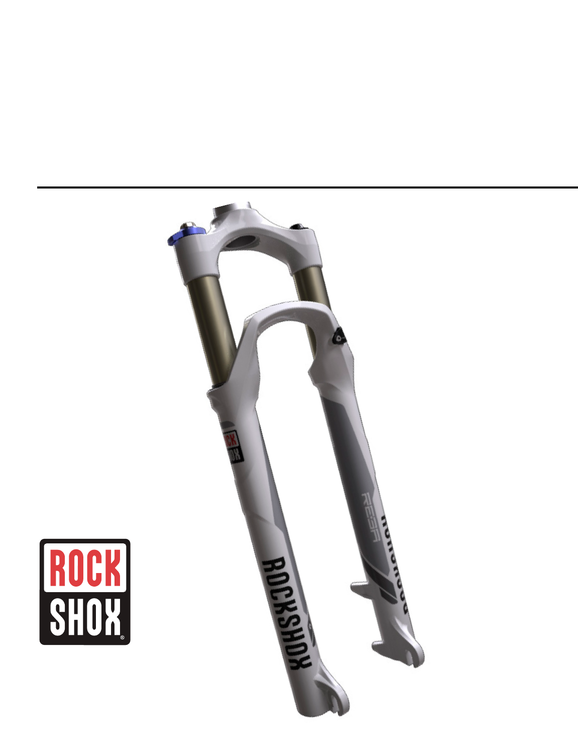
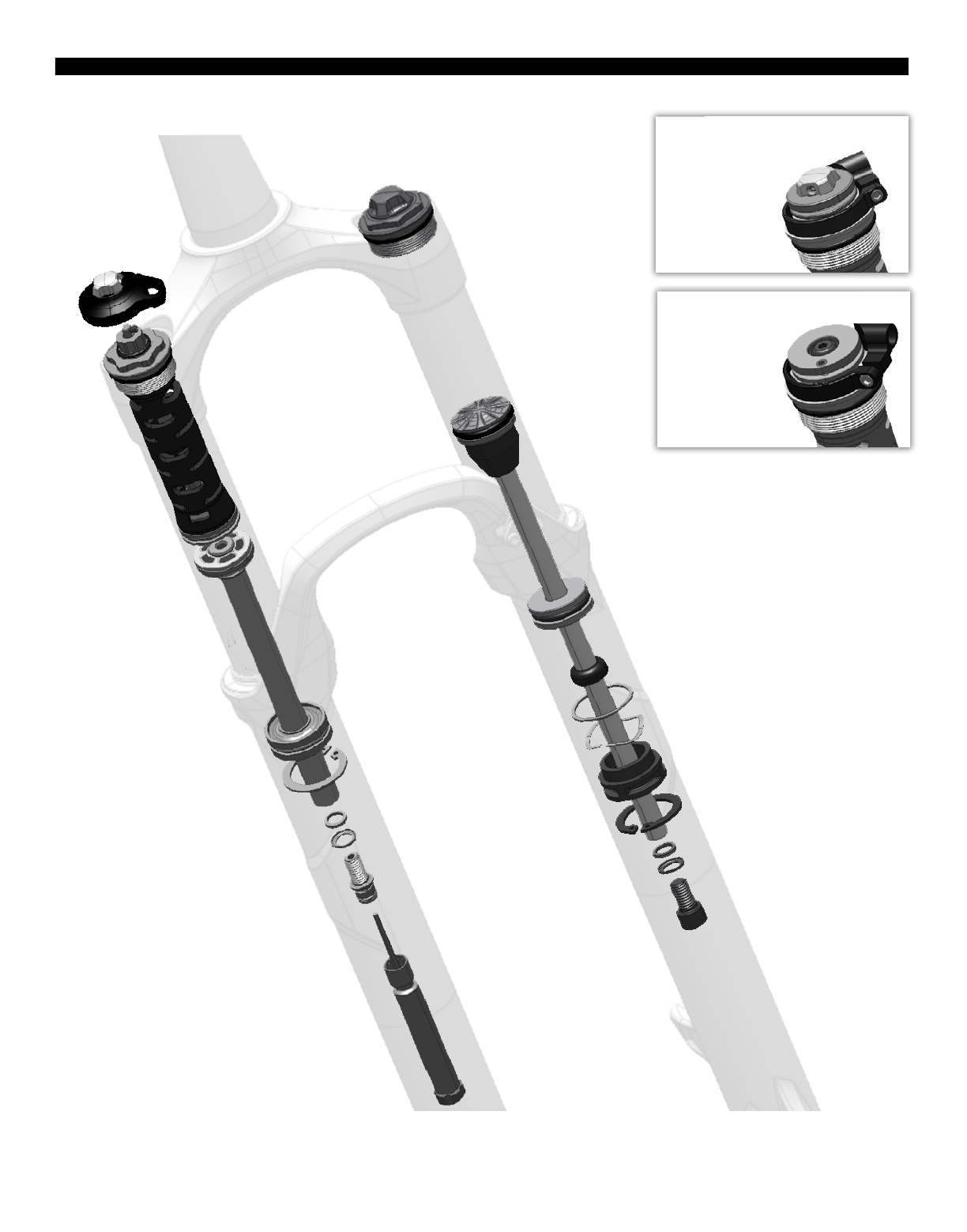
REBA EXPLODED VIEW
4REBA EXPLODED VIEW
RLT Remote
Rebound Piston
Compression Adjuster or Lockout
Damper Shaft
Air Shaft
Air Piston
Air Valve Cap
Floating Seal Head Topout Bumper
Topout Bumper
Cone
Spool
Spool
Cable Stop Collar
Cable Stop Collar
Floating Seal Head
Aluminum Support Washer
Wavy Washer
Air Shaft Guide
Rebound Seal Head
Snap Ring
Snap Ring
Crush Washer
Crush Washer
Crush Washer Retainer
Crush Washer Retainer
Shaft Bolt
Shaft Bolt
Rebound Adjuster
Lower Leg
RL Remote
Compression Damper
Gate Adjuster
Steerer Tube
Crown
Top Cap
Compression Piston

ROCKSHOX SUSPENSION SERVICE
We recommend that you have your RockShox suspension serviced by a qualified bicycle mechanic. Servicing RockShox suspension
requires knowledge of suspension components as well as the special tools and fluids used for service.
For exploded diagram and part number information, please refer to the Spare Parts Catalog available on our website at
sram.com/service. For order information, please contact your local SRAM distributor or dealer.
Information contained in this publication is subject to change at any time without prior notice. For the latest technical information,
please visit our website at sram.com/service.
Your product‘s appearance may dier from the pictures contained in this publication.
PARTS AND TOOLS NEEDED FOR SERVICE
đƫ Safety glasses
đƫ Nitrile gloves
đƫ Apron
đƫ Clean, lint-free rags
đƫ Oil pan
đƫ Isopropyl alcohol
đƫ RockShox 15wt suspension fluid
đƫ RockShox 5wt suspension fluid
đƫ Liquid O-Ring® PM600 military grease
đƫ Buzzy's® Slick Honey bike grease
đƫ Shock pump
đƫ Seal installation tool
đƫ Downhill tire lever
đƫ Rubber mallet
đƫ Schrader valve core tool
đƫ 1.5, 2, 2.5, and 5 mm hex wrench
đƫ 1.5, 2, 2.5, and 5 mm hex bit socket
đƫ 24 mm socket wrench
đƫ Torque wrench
đƫ Large internal snap ring pliers
đƫ Pick
đƫ Long plastic or wooden dowel
đƫ Syringe
đƫ Optional travel change solo air spring assembly
SAFETY INSTRUCTIONS
Always wear safety glasses and nitrile gloves when working with suspension fluid.
Place an oil pan on the floor underneath the area where you will be working on the fork.
NOTICE
Do not scratch any sealing surfaces when servicing your suspension. Scratches can cause leaks.
When replacing o-rings, use your fingers or a pick to remove the o-ring. Clean the o-ring groove and apply grease to the new o-ring.
5ROCKSHOX SUSPENSION SERVICE
LOWER LEG REMOVAL
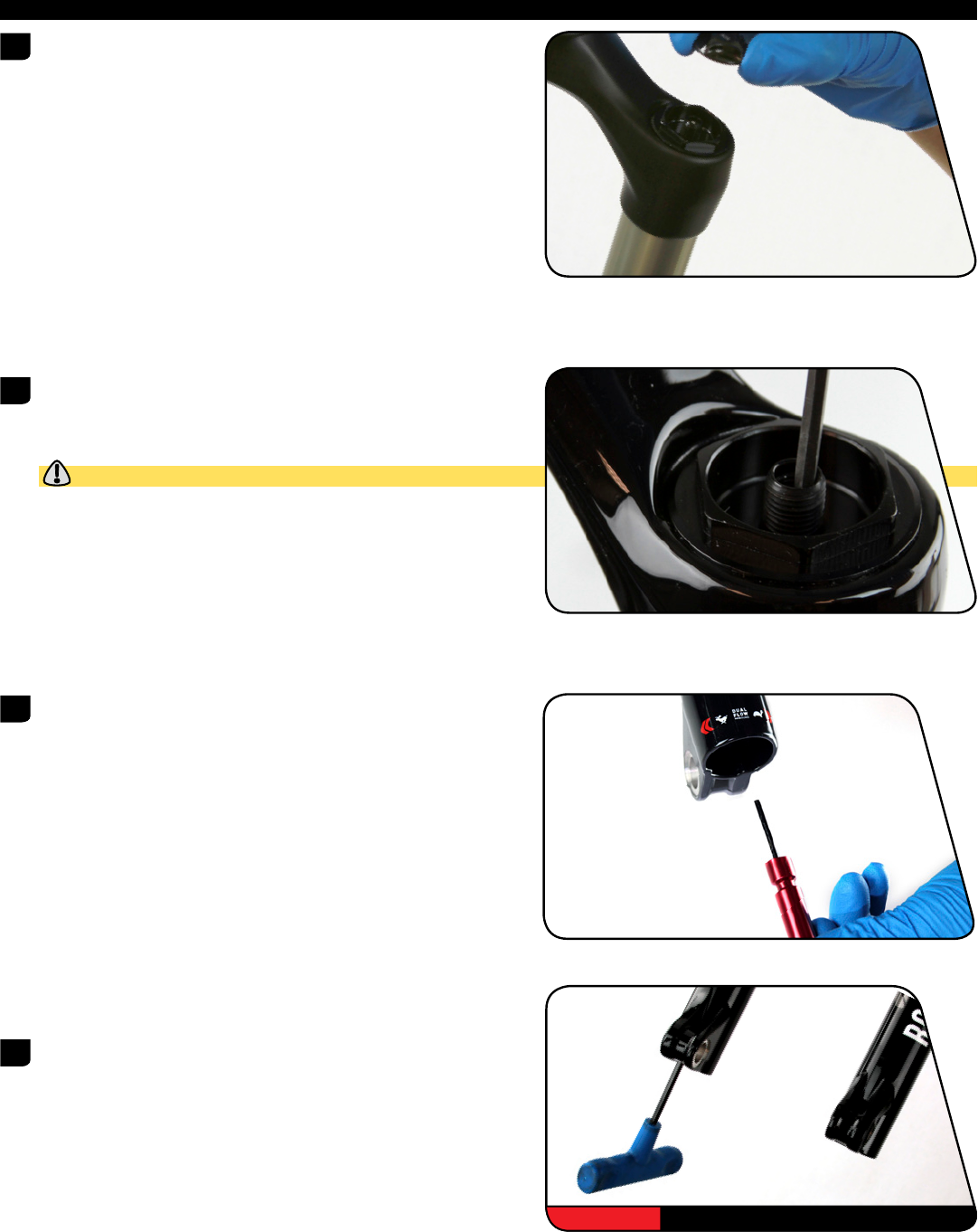
1 Remove the air valve cap from the top cap located on the
non-drive side fork leg.
2 Use a small hex wrench to depress the Schrader valve and release
all of the air pressure from the air chamber.
Use a Schrader valve tool to remove the valve core from the valve
body. Install a new Schrader valve.
CAUTION- EYE HAZARD
Verify all pressure is removed from the fork before proceeding.
Failure to do so can result in injury and/or damage to the fork.
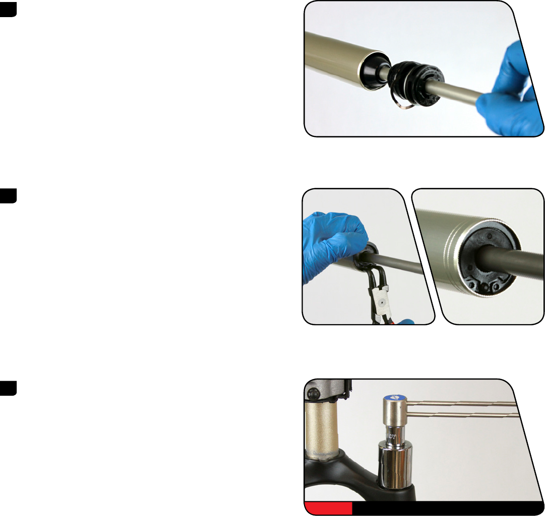
3 Remove the external rebound adjuster knob by pulling it from the
shaft bolt at the bottom of the drive side fork leg.
4 Use a 5 mm hex wrench to loosen both shaft bolts 3 to 4 turns.
5 mm
6LOWER LEG REMOVAL
5 Place an oil pan beneath the fork to catch any draining fluid.
Insert a 5 mm hex wrench into the one of the shaft bolts. Use a
plastic mallet to firmly strike the wrench and free the bolt from the
lower leg. Remove the shaft bolt from the lower leg. Repeat this
procedure for the other shaft bolt.
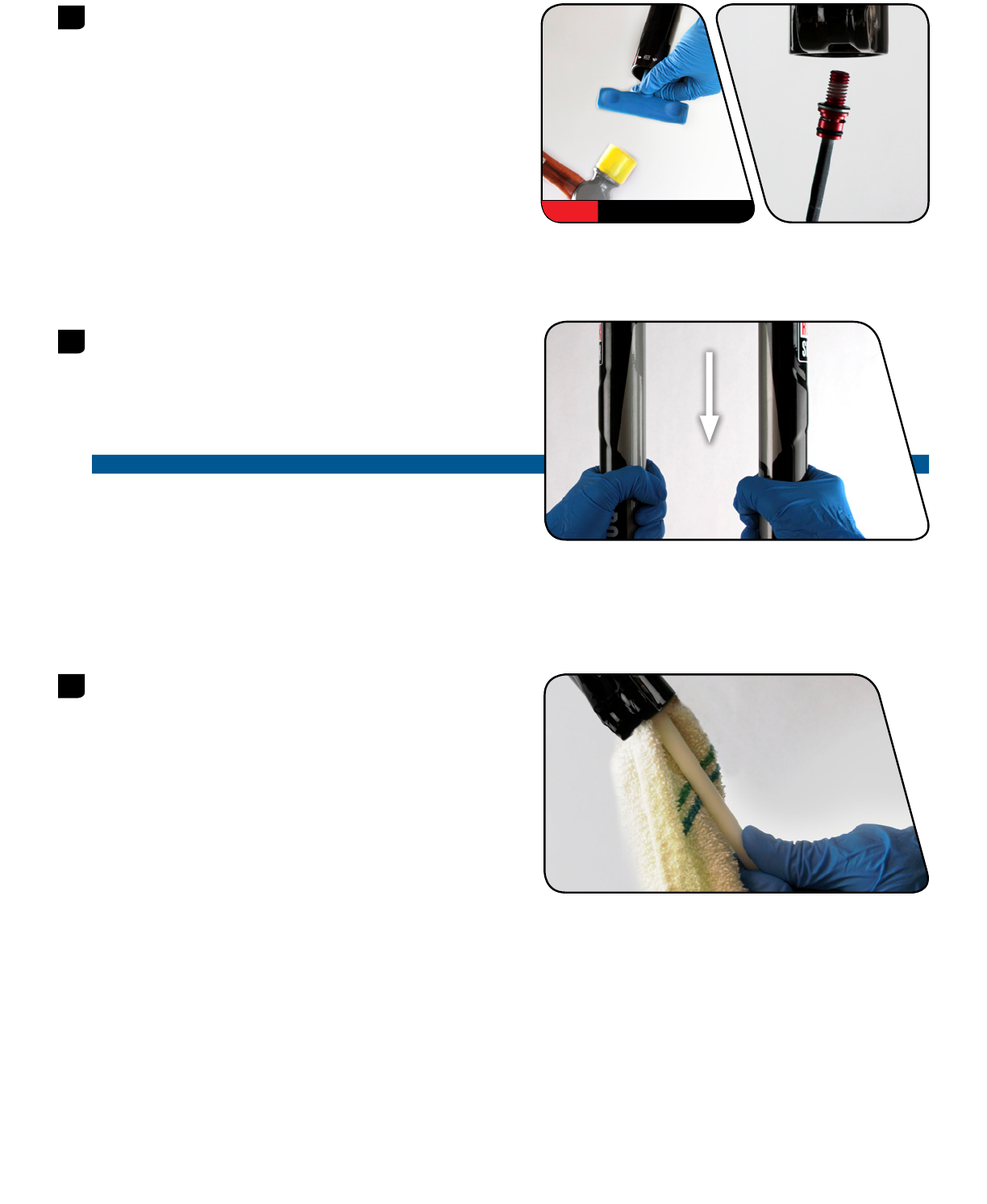
6 Firmly pull the lower legs downward until fluid begins to drain.
Remove the lower leg from the fork by pulling it downward,
holding onto both legs or the brake arch.
If the lower legs do not slide out of the upper tubes or if fluid
doesn’t drain from either side, the press fit of the shaft(s) to the
lower leg may still be engaged. Reinstall the shaft bolts 2 to 3 turns
and repeat the previous step.
NOTICE
Do not hit the brake arch with any tool when removing the lower
leg as this could damage the fork.
7 Spray isopropyl alcohol on the inside and outside of the lower leg.
Wipe the outside of the lower leg with a rag.
Wrap a rag around a long dowel and insert it into the lower leg to
clean the inside of each lower leg.
5 mm
7LOWER LEG REMOVAL

LOWER LEG SEAL SERVICE
1 Place the tip of a downhill tire lever underneath the lower lip of the
dust wiper seal.
NOTICE
If using a flat head screwdriver, make sure it has a round shaft. A
screwdriver with a square shaft will damage the fork leg.
2 Stabilize the lower legs on a bench top or on the floor. Hold the
lower legs firmly and use downward force on the tool handle to
leverage the dust wiper seal out. Repeat on the other side.
NOTICE
Keep the lower leg assembly stable. Do not allow the lower legs
to twist in opposite directions, compress toward each other, or
be pulled apart. This will damage the lower leg.
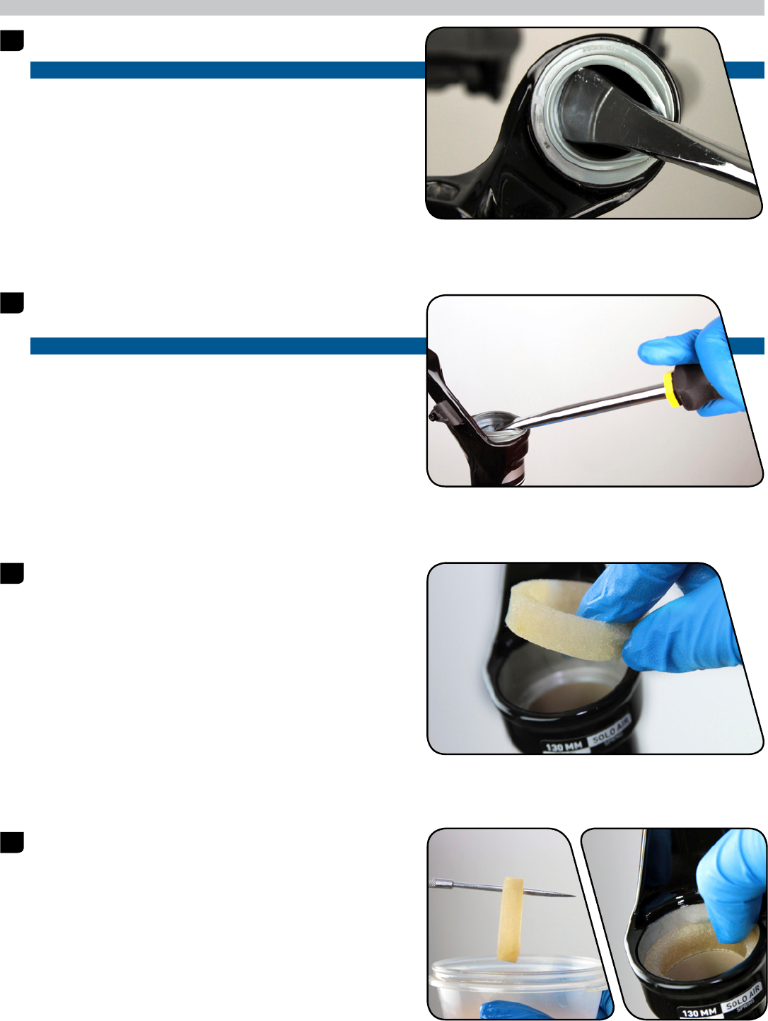
3 Use your fingers to remove and discard the foam rings inside the
lower legs.
4 Soak the new foam rings in RockShox 15wt suspension fluid.
Reinstall new foam rings on the top bushings in the lower legs.
8LOWER LEG SEAL SERVICE

5 Use a seal installation tool to install the new dust wiper seals.
Position the dust wiper into the recessed side of the tool, so the
grooved side of the seal is visible.
6 Hold one of the lower legs and use the seal installation tool to push
the dust wiper seal evenly into the lower legs until there is no gap
between the dust wiper seal and lower legs.
9LOWER LEG SEAL SERVICE

SOLO AIR SPRING SERVICE
OPTIONAL TRAVEL CHANGE ADJUSTMENT
To change the travel in your suspension fork, replace the entire solo air spring assembly according to the directions below. For part
number information, please refer to the Spare Parts Catalog available on our website at sram.com/service. For ordering information,
please contact your local SRAM distributor or dealer.
Desired Travel Required Solo Air Spring Assembly Length for 26" Required Solo Air Spring Assembly Length for 27.5" and 29"
80 147.2 182.2
90 157.2 192.2
100 167.2 202.2
110 177.2 212.2
120 187.2 222.2
SOLO AIR SPRING REMOVAL
1 Use a small hex wrench to depress the Schrader valve and release
all of the air pressure from the air chamber.
CAUTION- EYE HAZARD
Verify all pressure is removed from the fork before proceeding.
Failure to do so can result in injury and/or damage to the fork.
2 Use a 24 mm socket wrench to remove the air spring top cap.
Once removed, clean the upper tube threads with a rag.
3 Use a pick to remove the top cap o-ring. Apply a small amount of
grease to a new top cap o-ring and install it. Apply a small amount
of grease to the top cap threads.
Do not scratch the top cap. Scratches can cause leaks.
24 mm
10 SOLO AIR SPRING SERVICE
4 Use a pick to remove and replace the air valve cap o-ring.
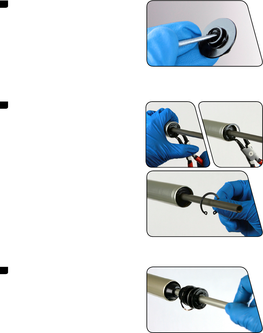
5 Place the tips of large internal snap ring pliers into eyelets of the
snap ring, located at the bottom of the non-drive side upper tube.
Press firmly on the pliers to push the air shaft guide into the upper
tube enough to compress and remove the snap ring.
Guide the snap ring over the air shaft to prevent scratching.
Scratches on the air shaft will allow air to bypass the seal head
into the lower legs, resulting in reduced spring performance.
6 Firmly pull on the air shaft to remove the air shaft assembly from
the upper tube. Clean and inspect the assembly for damage.
11 SOLO AIR SPRING REMOVAL

7 Spray isopropyl alcohol on the inside and outside of the upper
tube. Wipe the outside of the upper tube with a clean rag.
Wrap a rag around a long dowel and insert it into the upper tube
to clean inside the upper tube.
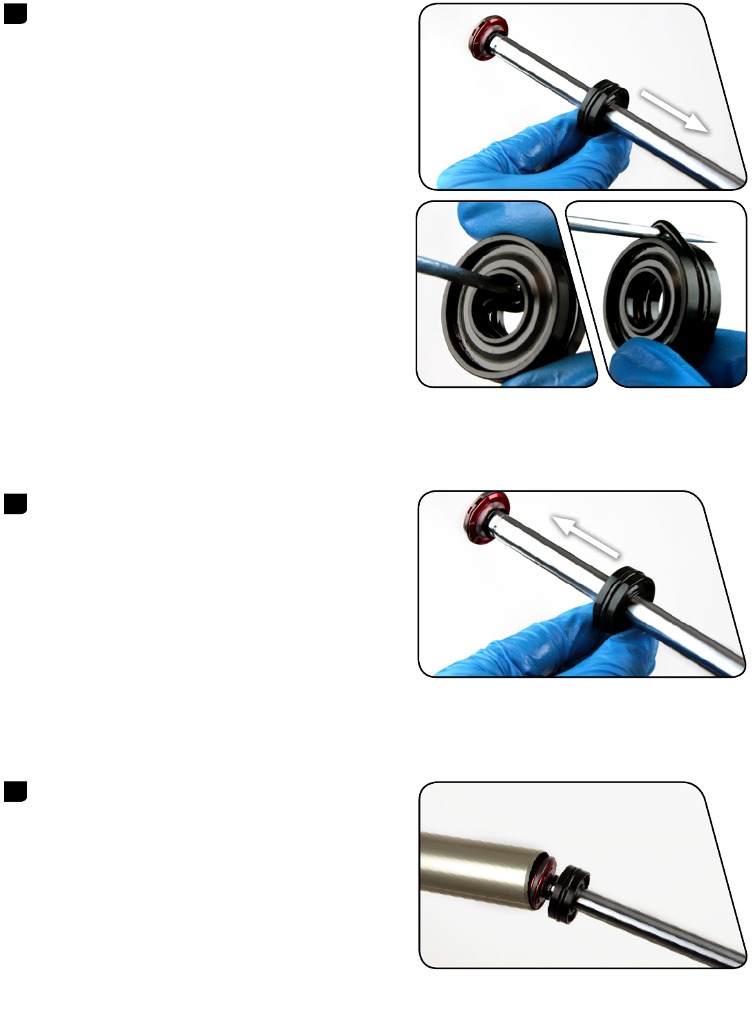
8 Remove the floating seal head, washers, floating seal head topout
bumper, and air shaft guide from the air shaft.
Spray isopropyl alcohol on the air shaft and clean it with a rag.
9 Use a pick to remove the inner and outer floating seal head o-rings.
Inspect the seal head for scratches. Spray isopropyl alcohol on the
seal head and clean it with a rag.
Apply a liberal amount of grease to the new o-rings and install
them.
Do not scratch the floating seal head. Scratches can cause leaks.
10 Use a pick to remove the air piston outer o-ring.
Inspect air piston for scratches. Spray isopropyl alcohol on the air
piston and clean it with a rag.
Apply a liberal amount of grease to the new o-ring and install it.
Do not scratch the air piston. Scratches can cause leaks.
12 SOLO AIR SPRING REMOVAL
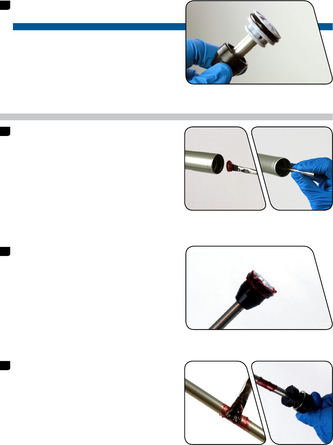
11 Use your fingers to remove the bumper cone from the air shaft.
Install a new bumper cone onto the air shaft so it covers the
tension pin hole.
NOTICE
If the pin tension is protruding or not centered, replace the piston
assembly.
SOLO AIR SPRING INSTALLATION
1 Apply a liberal amount of grease to the inside of the upper tube,
from the end of the tube to approximately 60 mm into the tube.
2 Apply a liberal amount of grease to the air piston.
3 Apply a liberal amount of grease 40-60 mm around the air shaft.
Install the floating seal head, a new floating seal head topout
bumper, new aluminum support washer, new wavy washer and the
air shaft guide, in that order, onto the air shaft.
13 SOLO AIR SPRING INSTALLATION
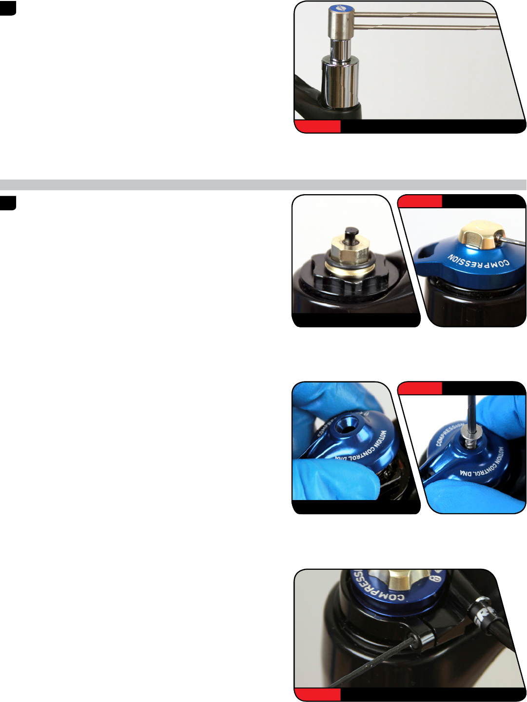
4 Firmly push the air assembly into the bottom of the upper tube
while gently rocking the air shaft side to side.
Orient the washers so that the aluminum support washer goes into
the upper tube first, followed by the wavy washer.
5 Install the snap ring onto internal snap ring pliers. Use the pliers to
push the air shaft into the upper tube while installing the snap ring
into its groove. The air shaft guide should be situated between the
snap ring eyelets.
Make sure the snap ring is securely fastened in the snap ring
groove. Check this by using the snap ring pliers to rotate the
snap ring back and forth a couple of times, then firmly pulling
down on the air shaft.
Snap rings have a sharper-edged side and a rounder-edged side.
Installing snap rings with the sharper-edged side facing the tool
will allow for easier installation and removal.
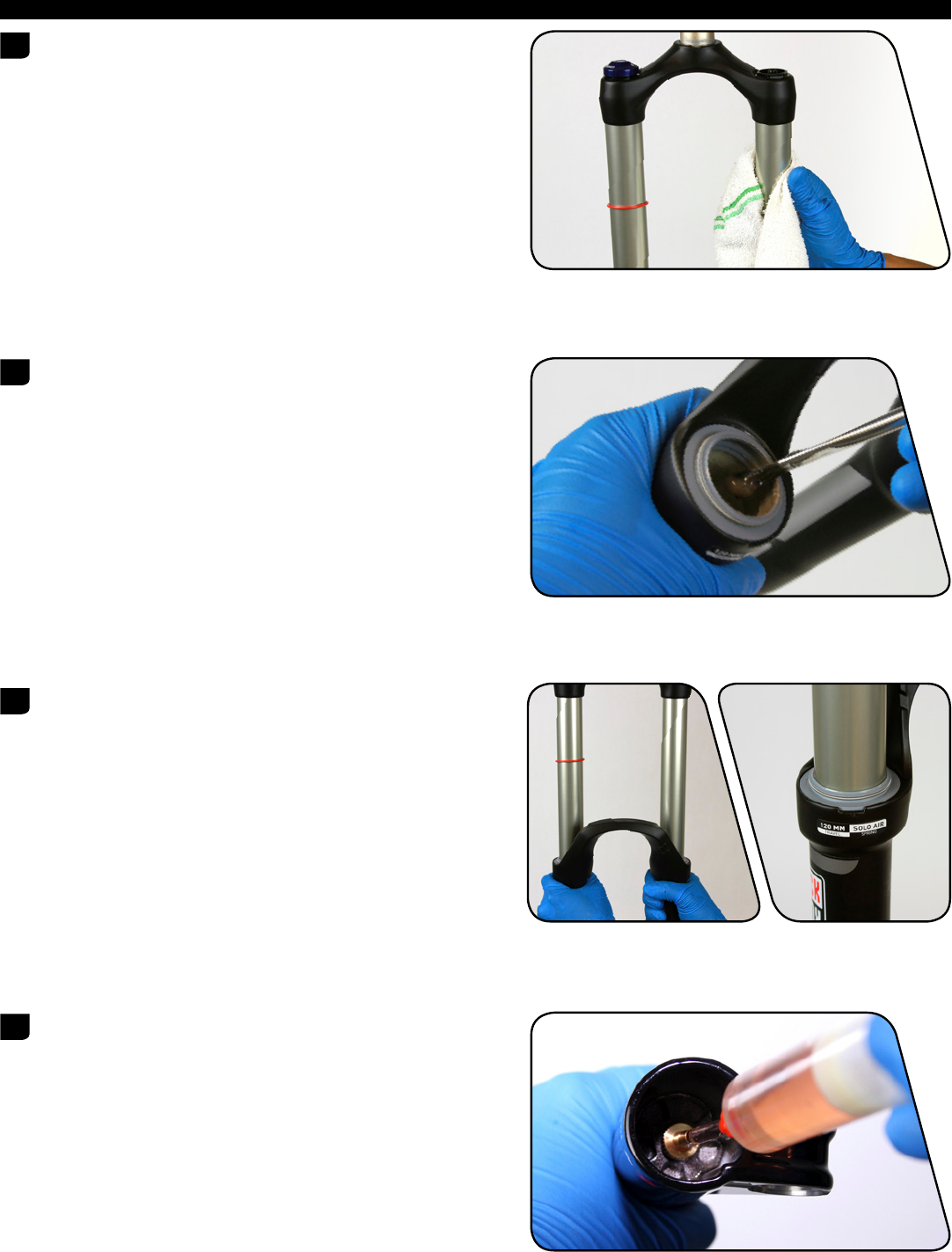
6 Insert the top cap into the top of the upper tube. Use a torque
wrench with a 24 mm socket to tighten the top cap to
7.3 N·m (65 in-lb).
24 mm 7.3 N·m (65 in-lb)
14 SOLO AIR SPRING INSTALLATION
DAMPER SERVICE
COMPRESSION DAMPER REMOVAL
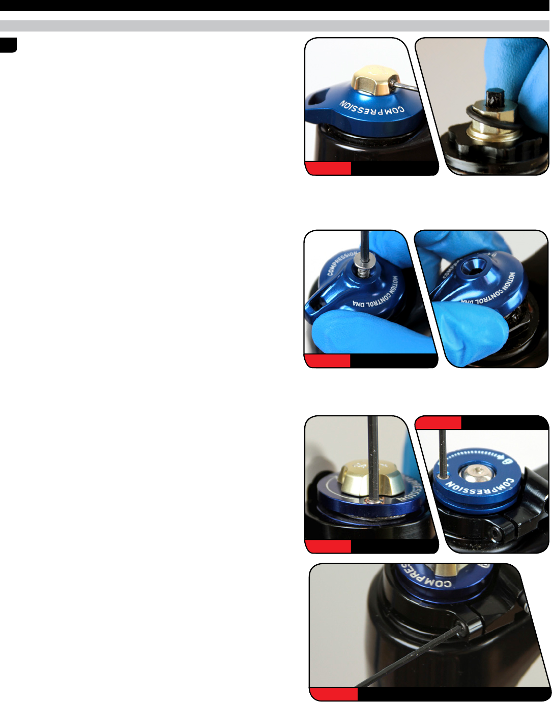
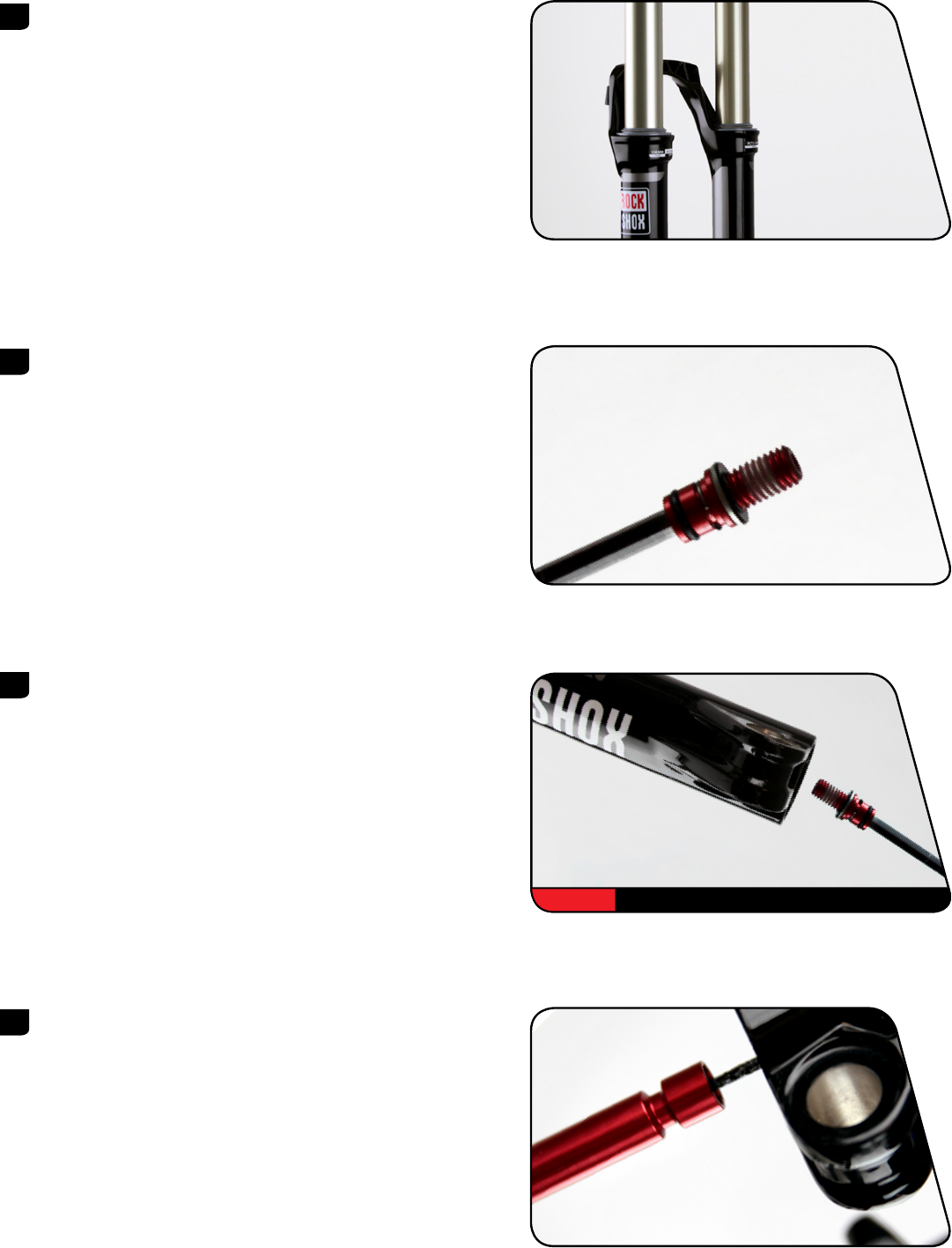
1 RLT: Use a 1.5 mm hex wrench to remove the gate adjuster set
screw. Remove the gate adjuster, compression adjuster knob, and
the o-ring seal.
RL: Use a 2.5 mm hex wrench to remove the compression adjuster
knob retention screw. Remove the compression adjuster knob.
Remote Only: Use a 2 mm hex wrench to loosen the cable pinch
bolt and remove the cable.
Use a 2 mm hex wrench to loosen the cable stop collar clamping
bolt. Remove the cable stop collar.
You do not need to remove the remote cable spool.
2.5 mm RL
1.5 mm RLT
2 mm RLT
2 mm RL
2 mm
15 DAMPER SERVICE
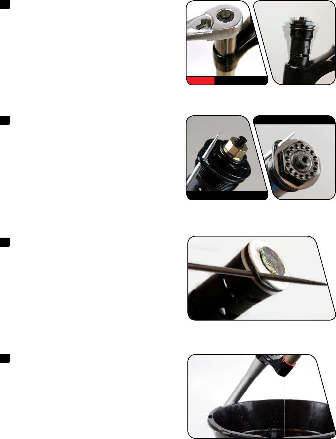
2 Use a 24 mm socket to loosen the compression damper top cap.
Remove the compression damper by pulling up and gently rocking
side to side. Clean the upper tube threads with a rag.
3 Use a pick or your fingers to remove the compression damper top
cap o-ring. Apply grease to the new o-ring and install it.
RLT Only: Install a new o-ring on the cam.
Do not scratch the top cap. Scratches can cause leaks.
4 Use a pick or your fingers to remove the compression damper
piston o-ring. Apply suspension fluid to the new o-ring and install
it.
Do not scratch the piston. Scratches may cause air to leak.
5 Remove the fork from the bicycle stand and pour the suspension
fluid into an oil pan.
24 mm
RLT
RL
16 COMPRESSION DAMPER REMOVAL
REBOUND DAMPER SERVICE
1 Clamp the fork into the bicycle stand. From the bottom of the
upper tube, push the rebound shaft in until enough shaft is
exposed to hold onto with your fingers.
Use internal snap ring pliers to remove the rebound damper seal
head snap ring.
2 Remove the rebound damper and seal head assembly from the
upper tube.
3 Spray isopropyl alcohol on the inside and outside of the upper
tube. Wipe the outside of the upper tube with a rag.
Wrap a rag around a long dowel and insert it into the upper tube
to clean inside the upper tube.
4 Install a new piston glide ring on the rebound damper.
17 REBOUND DAMPER SERVICE
5 Remove the rebound seal head from the damper shaft.
Use a pick to remove the inner and outer rebound seal head
o-rings. Inspect the rebound seal head for scratches and wipe it
with a rag.
Apply suspension fluid to the new o-rings and install.
Spray isopropyl alcohol on the rebound damper shaft and clean it
with a rag.
Do not scratch the seal head. Scratches can cause leaks.
6 Spray isopropyl alcohol on the rebound damper shaft and clean it
with a rag.
Install the rebound seal head onto the shaft.
7 Insert the rebound damper piston into the bottom of the upper
tube at an angle with the side opposite the glide ring split entering
first. Continue to angle and rotate until the glide ring is in the
upper tube.
18 REBOUND DAMPER SERVICE

8 Push the rebound seal head firmly into the upper tube until the
retaining ring groove is visible.
Push the rebound damper shaft into the seal head, until enough
shaft is exposed to hold onto with your fingers.
9 Use internal snap ring pliers to secure the snap ring into the
retaining ring groove.
Make sure the snap ring is securely fastened in the snap ring
groove. Check this by using the snap ring pliers to rotate the
snap ring back and forth a couple of times, then firmly pulling
down on the air shaft.
Snap rings have a sharper-edged side and a rounder-edged side.
Installing snap rings with the sharper-edged side facing the tool
will allow for easier installation and removal.
10 Clamp the fork vertically in the bicycle stand. Pull the rebound
damper shaft down to the fully extended position.
Use the chart to determine the amount of RockShox 5wt
suspension fluid to measure and pour into the drive side upper
tube.
Reba
RLT, RL 106 mL
RL3 111 mL
Suspension fluid volume is critical. Too much suspension fluid
reduces available travel, too little suspension fluid decreases
damping performance.
11 Turn the hex shaft to the unlocked position. Insert the compression
damper into the upper tube. Press down and rock side to side until
the damper is installed.
19 REBOUND DAMPER SERVICE
12 Use a torque wrench with a 24 mm socket to tighten the
compression damper to 7.3 N·m (65 in-lb).
COMPRESSION DAMPER INSTALLATION
1 RLT: Install a new o-ring on the cam, then install the compression
adjuster knob so the knob dial is against the hard stop.
Use a 1.5 mm hex bit socket to tighten the gate adjuster knob set
screw to 0.6 Nm (5 in-lb).
RL: Install the compression adjuster knob with the knob dial
against the hard stop.
Use a 2.5 mm hex bit socket to install the compression adjuster
knob retention screw to 1.4 Nm (12 in-lb).
Remote Only: Install the cable stop collar onto the top cap with
the cable stop facing toward the front of the fork, perpendicular to
the crown. Use a 2 mm hex bit socket to tighten the collar clamp
bolt to 1.4 Nm (12 in-lb).
24 mm 7.3 N·m (65 in-lb)
RLT
1.5 mm 0.6 Nm (5 in-lb)
RL
2.5 mm 1.4 Nm (12 in-lb)
2 mm 1.4 N·m (12 in-lb)
20 COMPRESSION DAMPER INSTALLATION
LOWER LEG INSTALLATION
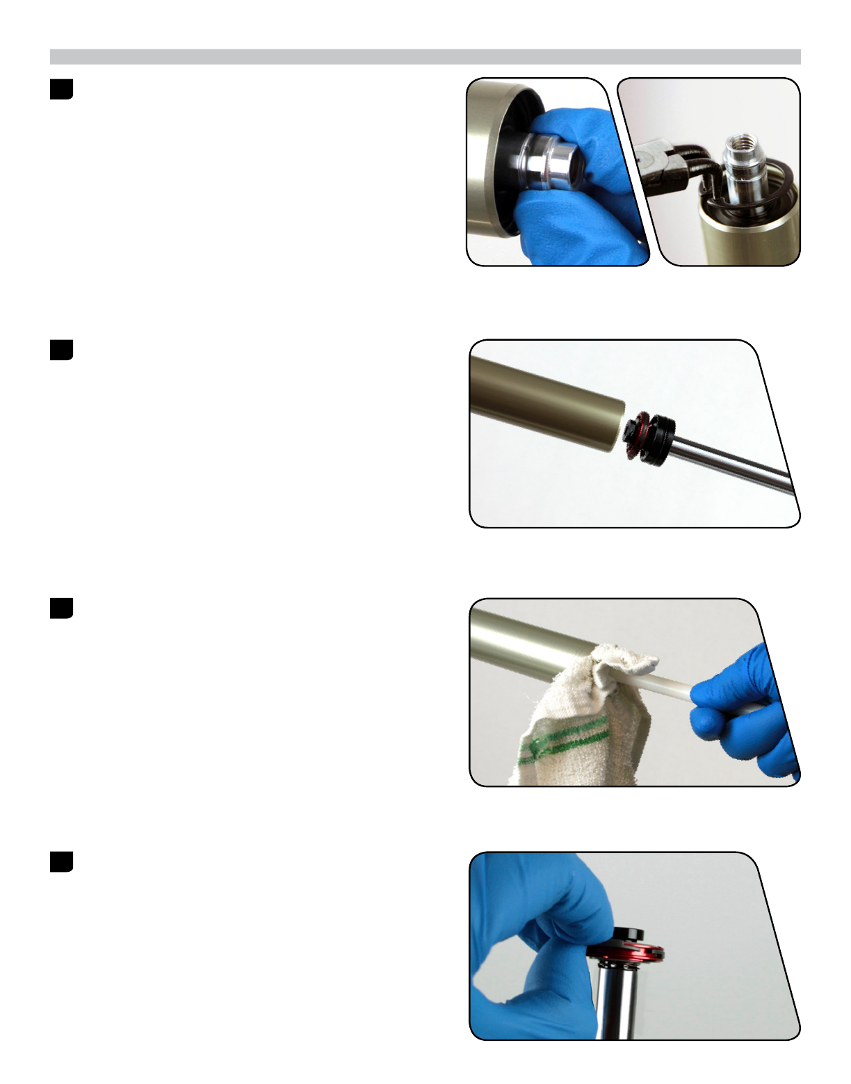
1 Spray isopropyl alcohol on the upper tubes and clean them with a
rag.
2 Apply a liberal amount of Buzzy's® Slick Honey grease to the inner
surfaces of the dust wiper seals.
Dust wipers may already be pregreased from the factory. If that is
the case, do not apply more grease.
3 Slide the lower leg assembly onto the upper tube assembly just
enough to engage the upper bushing with the upper tubes.
Make sure both dust wiper seals slide onto the tubes without
folding the outer lip of either seal.
4 Position the fork at a slight angle with the shaft bolt holes oriented
upward, then inject 5 mL of RockShox 15wt suspension fluid into
each lower leg through the shaft bolt hole.
21 LOWER LEG INSTALLATION
5 Slide the lower leg assembly along the upper tubes until it stops
and the spring and damper shafts are visible through the shaft bolt
holes. Wipe all excess fluid from the outer surface of the lower
legs.
6 Install a new o-ring into the top gland of a new shaft bolt. Install a
new spring clip in the lower gland of the shaft bolt.
Apply a thick layer of grease around the diameter of the bolt head
and o-ring.
Replace the crush washers and crush washer retainers.
Dirty or damaged crush washers can cause leaks.
7 Insert the shaft bolts into the lower legs through the threaded
shaft bolt holes.
Use a torque wrench with a 5 mm hex bit socket to tighten the
bolts to 7.3 N·m (65 in-lb).
8 Insert the external rebound damper knob into the rebound damper
shaft bolt until it is secure. Adjust the rebound.
5 mm 7.3 N·m (65 in-lb)
22 LOWER LEG INSTALLATION

9 Refer to the air chart on the fork lower leg and pressurize the air
spring to the appropriate pressure for your rider weight.
You may see a drop in the indicated air pressure on the pump gage
while filling the air spring, this is normal. Continue to fill the air
spring to the recommended air pressure.
10 Spray isopropyl alcohol on the entire fork and clean it with a rag.
23 LOWER LEG INSTALLATION

PUSHLOC™ REMOTE SERVICE
CABLE REMOVAL
1 Push the remote lever until it returns toward you.
2 RLT: Use a 2 mm hex wrench to loosen the cable pinch bolt on the
spool and pull the cable out of the cable end slot. Use pliers to
remove the cable end.
RL: Use a 2 mm hex wrench to loosen the cable pinch bolt on the
spool. Use pliers to remove the cable end.
3 Disconnect the cable from the damper and pull the cable housing
o the cable.
4 Use a 2 mm hex wrench to open the cable hatch cover.
Push the cable through the remote until the cable head is far
enough out of the lever to access.
2 mm RLT
2 mm RL
2 mm
24 PUSHLOC™ REMOTE SERVICE
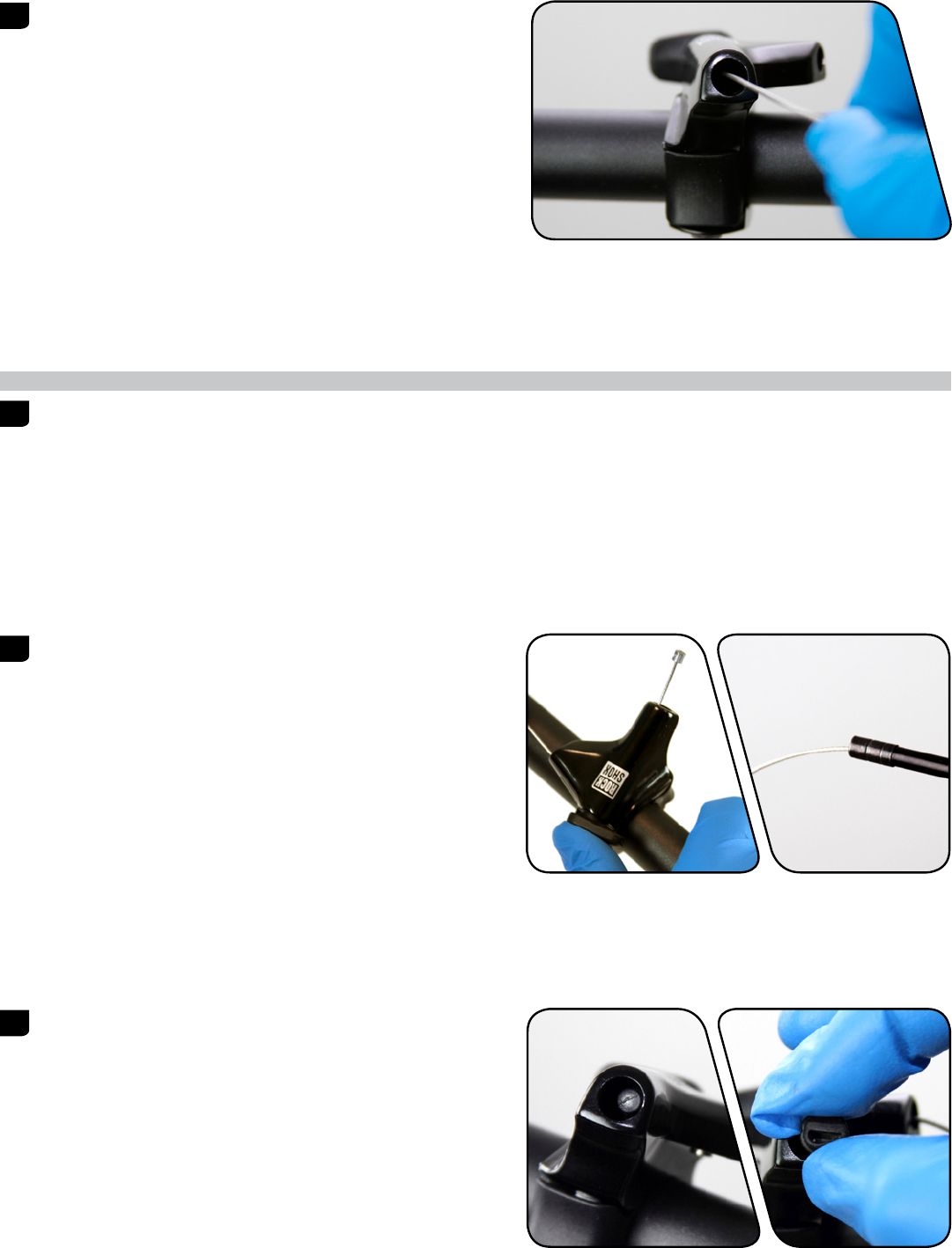
5 Pull the cable head to remove the cable from the remote system.
CABLE INSTALLATION
1 If replacing the cable housing, detach the cable housing and end
caps from the lever and the cable housing stop on the fork.
Attach the new housing and end caps to the remote lever and the
cable housing stop on the fork. Cut a length of shifter housing to
accommodate travel and suspension movement.
2 Hold the remote lever in and install the new shifter cable through
remote. Install the cable housing onto the new shifter cable.
3 Pull the cable until the cable head is seated in the remote lever.
With the cable head seated in the remote lever, close the cable
hatch cover and push the lever to return it to the unlocked
position.
25 CABLE INSTALLATION

4 RLT: Wrap the cable around the spool and insert it through the
cable fixing port. While firmly pulling the cable, use a 2 mm hex
wrench to tighten the cable pinch bolt to 0.9 Nm (8 in-lb).
Cut the excess cable, leaving 30 mm protruding from the cable
fixing port. Install a cable end fitting and tuck the cable end into
the slot in the spool.
RL: Wrap the cable around the spool. While firmly pulling the
cable, use a 2 mm hex wrench to tighten the cable pinch bolt to
0.9 Nm (8 in-lb).
Cut the excess cable and install a cable end fitting.
This concludes the service for RockShox Reba front suspension forks.
2 mm RLT
2 mm RL
26 CABLE INSTALLATION
www.sram.com
2013
Reba Service Manual
GEN.0000000004216 Rev A © 2012 SRAM LLC

SRAM LLC WARRANTY
EXTENT OF LIMITED WARRANTY
!"#$%&'()'*&+$,-.)$')$&'/*,&+'+$,$.01'2345'-(,,(0&)'.&)'%,*67#&)'&*'8$'/,$$'/,*9'6$/$#&)'.0'9(&$,.(:)'*,'-*,;9(0)+.%'/*,'('%$,.*6'*/'&-*'<$(,)'(/&$,'
*,.=.0(:'%7,#+()$>''?+.)'-(,,(0&<'*0:<'(%%:.$)'&*'&+$'*,.=.0(:'*-0$,'(06'.)'0*&'&,(0)/$,(8:$>'@:(.9)'706$,'&+.)'-(,,(0&<'97)&'8$'9(6$'&+,*7=+'&+$',$&(.:$,'
-+$,$'&+$'8.#<#:$'*,'&+$'2345'#*9%*0$0&'-()'%7,#+()$6>'A,.=.0(:'%,**/'*/'%7,#+()$'.)',$B7.,$6>'Except'as'described'herein,'SRAM'makes'no'
other'warranties,'guaranties,'or'representations'of'any'type'(express'or'implied),'and'all'warranties'(including'any'implied'warranties'of'
reasonable'care,'merchantibility,'or'fitness'for'a'particular'purpose)'are'hereby'disclaimed.
LOCAL LAW
7KLVZDUUDQW\VWDWHPHQWJLYHVWKHFXVWRPHUVSHFL¿FOHJDOULJKWV7KHFXVWRPHUPD\DOVRKDYHRWKHUULJKWVZKLFKYDU\IURPVWDWHWRVWDWH86$IURP
SURYLQFHWRSURYLQFH&DQDGDDQGIURPFRXQWU\WRFRXQWU\HOVHZKHUHLQWKHZRUOG
7RWKHH[WHQWWKDWWKLVZDUUDQW\VWDWHPHQWLVLQFRQVLVWHQWZLWKWKHORFDOODZWKLVZDUUDQW\VKDOOEHGHHPHGPRGL¿HGWREHFRQVLVWHQWZLWKVXFKODZXQGHU
VXFKORFDOODZFHUWDLQGLVFODLPHUVDQGOLPLWDWLRQVRIWKLVZDUUDQW\VWDWHPHQWPD\DSSO\WRWKHFXVWRPHU)RUH[DPSOHVRPHVWDWHVLQWKH8QLWHG6WDWHV
RI$PHULFDDVZHOODVVRPHJRYHUQPHQWVRXWVLGHRIWKH8QLWHG6WDWHVLQFOXGLQJSURYLQFHVLQ&DQDGDPD\
(>'C,$#:76$'&+$'6.)#:(.9$,)'(06':.9.&(&.*0)'*/'&+.)'-(,,(0&<')&(&$9$0&'/,*9':.9.&.0='&+$')&(&7&*,<',.=+&)'*/'&+$'#*0)79$,''
HJ8QLWHG.LQJGRP
8>'A&+$,-.)$',$)&,.#&'&+$'(8.:.&<'*/'('9(07/(#&7,$,'&*'$0/*,#$')7#+'6.)#:(.9$,)'*,':.9.&(&.*0)>
For'Australian'customers:
7KLV65$0OLPLWHGZDUUDQW\LVSURYLGHGLQ$XVWUDOLDE\65$0//&1RUWK.LQJVEXU\WKÀRRU&KLFDJR,OOLQRLV86$7RPDNHDZDUUDQW\
FODLPSOHDVHFRQWDFWWKHUHWDLOHUIURPZKRP\RXSXUFKDVHGWKLV65$0SURGXFW$OWHUQDWLYHO\\RXPD\PDNHDFODLPE\FRQWDFWLQJ65$0$XVWUDOLD
5(,#*'@*7,&1'3*-D.::$'EFGH1'47)&,(:.(>'I*,'D(:.6'#:(.9)'2345'-.::1'(&'.&)'*%&.*01'$.&+$,',$%(.,'*,',$%:(#$'<*7,'2345'%,*67#&>''40<'$"%$0)$)'.0#7,,$6'.0'
PDNLQJWKHZDUUDQW\FODLPDUH\RXUUHVSRQVLELOLW\7KHEHQH¿WVJLYHQE\WKLVZDUUDQW\DUHDGGLWLRQDOWRRWKHUULJKWVDQGUHPHGLHVWKDW\RXPD\KDYH
706$,':(-)',$:(&.0='&*'*7,'%,*67#&)>''A7,'=**6)'#*9$'-.&+'=7(,(0&$$)'&+(&'#(00*&'8$'$"#:76$6'706$,'&+$'47)&,(:.(0'@*0)79$,'J(->''K*7'(,$'$0&.&:$6'&*'
(',$%:(#$9$0&'*,',$/706'/*,'('9(L*,'/(.:7,$'(06'/*,'#*9%$0)(&.*0'/*,'(0<'*&+$,',$()*0(8:<'/*,$)$$(8:$':*))'*,'6(9(=$>''K*7'(,$'(:)*'$0&.&:$6'&*'+(D$'&+$'
=**6)',$%(.,$6'*,',$%:(#$6'./'&+$'=**6)'/(.:'&*'8$'*/'(##$%&(8:$'B7(:.&<'(06'&+$'/(.:7,$'6*$)'0*&'(9*70&'&*'('9(L*,'/(.:7,$>
LIMITATIONS OF LIABILITY
7RWKHH[WHQWDOORZHGE\ORFDOODZH[FHSWIRUWKHREOLJDWLRQVVSHFL¿FDOO\VHWIRUWKLQWKLVZDUUDQW\VWDWHPHQWLQQRHYHQWVKDOO65$0RULWVWKLUGSDUW\
)7%%:.$,)'8$':.(8:$'/*,'6.,$#&1'.06.,$#&1')%$#.(:1'.0#.6$0&(:1'*,'#*0)$B7$0&.(:'6(9(=$)>'
LIMITATIONS OF WARRANTY
?+.)'-(,,(0&<'6*$)'0*&'(%%:<'&*'%,*67#&)'&+(&'+(D$'8$$0'.0#*,,$#&:<'.0)&(::$6'(06M*,'(6L7)&$6'(##*,6.0='&*'&+$',$)%$#&.D$'2345'7)$,'9(07(:>'?+$'2345'
7)$,'9(07(:)'#(0'8$'/*706'*0:.0$'(&'),(9>#*91',*#;)+*">#*91'(D.68.;$>#*91'&,7D(&.D>#*91'*,'N.%%>#*9>
?+.)'-(,,(0&<'6*$)'0*&'(%%:<'&*'6(9(=$'&*'&+$'%,*67#&'#(7)$6'8<'('#,()+1'.9%(#&1'(87)$'*/'&+$'%,*67#&1'0*0O#*9%:.(0#$'-.&+'9(07/(#&7,$,)'
VSHFL¿FDWLRQVRIXVDJHRUDQ\RWKHUFLUFXPVWDQFHVLQZKLFKWKHSURGXFWKDVEHHQVXEMHFWHGWRIRUFHVRUORDGVEH\RQGLWVGHVLJQ
7KLVZDUUDQW\GRHVQRWDSSO\ZKHQWKHSURGXFWKDVEHHQPRGL¿HGLQFOXGLQJEXWQRWOLPLWHGWRDQ\DWWHPSWWRRSHQRUUHSDLUDQ\HOHFWURQLFDQG
$:$#&,*0.#',$:(&$6'#*9%*0$0&)1'.0#:76.0='&+$'9*&*,1'#*0&,*::$,1'8(&&$,<'%(#;)1'-.,.0='+(,0$))$)1')-.&#+$)1'(06'#+(,=$,)>
?+.)'-(,,(0&<'6*$)'0*&'(%%:<'-+$0'&+$')$,.(:'0798$,'*,'%,*67#&.*0'#*6$'+()'8$$0'6$:.8$,(&$:<'(:&$,$61'6$/(#$6'*,',$9*D$6>
?+.)'-(,,(0&<'6*$)'0*&'(%%:<'&*'0*,9(:'-$(,'(06'&$(,>'P$(,'(06'&$(,'%(,&)'(,$')78L$#&'&*'6(9(=$'()'(',$)7:&'*/'0*,9(:'7)$1'/(.:7,$'&*')$,D.#$'(##*,6.0='
&*'2345',$#*99$06(&.*0)'(06M*,',.6.0='*,'.0)&(::(&.*0'.0'#*06.&.*0)'*,'(%%:.#(&.*0)'*&+$,'&+(0',$#*99$06$6>
:HDUDQGWHDUSDUWVDUHLGHQWL¿HGDV
Notwithstanding'anything'else'set'forth'herein1'&+.)'-(,,(0&<'.)':.9.&$6'&*'*0$'<$(,'/*,'(::'$:$#&,*0.#'(06'$:$#&,*0.#',$:(&$6'#*9%*0$0&)'.0#:76.0='
9*&*,)1'#*0&,*::$,)1'8(&&$,<'%(#;)1'-.,.0='+(,0$))$)1')-.&#+$)1'(06'#+(,=$,)>'?+$'8(&&$,<'%(#;'(06'#+(,=$,'-(,,(0&<'6*$)'0*&'.0#:76$'6(9(=$'/,*9'
%*-$,')7,=$)1'7)$'*/'.9%,*%$,'#+(,=$,1'.9%,*%$,'9(.0&$0(0#$1'*,')7#+'*&+$,'9.)7)$>
?+.)'-(,,(0&<')+(::'0*&'#*D$,'6(9(=$)'#(7)$6'8<'&+$'7)$'*/'%(,&)'*/'6.//$,$0&'9(07/(#&7,$,)>
?+.)'-(,,(0&<')+(::'0*&'#*D$,'6(9(=$)'#(7)$6'8<'&+$'7)$'*/'%(,&)'&+(&'(,$'0*&'#*9%(&.8:$1')7.&(8:$'(06M*,'(7&+*,.)$6'8<'2345'/*,'7)$'-.&+'2345'
#*9%*0$0&)>
7KLVZDUUDQW\VKDOOQRWFRYHUGDPDJHVUHVXOWLQJIURPFRPPHUFLDOUHQWDOXVH
Q7)&')$(:)
R7)+.0=)
4.,')$(:.0='*O,.0=)
S:.6$',.0=)
3788$,'9*D.0='%(,&)
I*(9',.0=)
3$(,')+*#;'9*70&.0='+(,6-(,$'
(06'9(.0')$(:)
8SSHUWXEHVVWDQFKLRQV
6WULSSHGWKUHDGVEROWVDOXPLQLXP
WLWDQLXPPDJQHVLXPRUVWHHO
R,(;$'):$$D$)
R,(;$'%(6)
@+(.0)
2%,*#;$&)
@())$&&$)
6KLIWHUDQGEUDNHFDEOHVLQQHU
DQGRXWHU
T(06:$8(,'=,.%)
2+./&$,'=,.%)
U*#;$<'-+$$:)
Q.)#'8,(;$',*&*,)
P+$$:'8,(;.0=')7,/(#$)
R*&&*9*7&'%(6)
R$(,.0=)
R$(,.0=',(#$)
C(-:)
?,(0)9.)).*0'=$(,)
2%*;$)
I,$$'+78)
4$,*'8(,'%(6)
@*,,*).*0
?**:)
5*&*,)
R(&&$,.$)
TABLE OF CONTENTS
REBA EXPLODED VIEW ................................................................................................................................................................... 4
ROCKSHOX SUSPENSION SERVICE ............................................................................................................................................... 5
PARTS AND TOOLS NEEDED FOR SERVICE ............................................................................................................................................................................5
LOWER LEG REMOVAL ..................................................................................................................................................................... 6
LOWER LEG SEAL SERVICE ............................................................................................................................................................................................................ 8
SOLO AIR SPRING SERVICE .......................................................................................................................................................... 10
OPTIONAL TRAVEL CHANGE ADJUSTMENT ........................................................................................................................................................................10
SOLO AIR SPRING REMOVAL ........................................................................................................................................................................................................10
SOLO AIR SPRING INSTALLATION .............................................................................................................................................................................................. 13
DAMPER SERVICE ............................................................................................................................................................................15
COMPRESSION DAMPER REMOVAL ..........................................................................................................................................................................................15
REBOUND DAMPER SERVICE ....................................................................................................................................................................................................... 17
COMPRESSION DAMPER INSTALLATION ...............................................................................................................................................................................20
LOWER LEG INSTALLATION ...........................................................................................................................................................21
PUSHLOC™ REMOTE SERVICE .....................................................................................................................................................24
CABLE REMOVAL ...............................................................................................................................................................................................................................24
CABLE INSTALLATION ....................................................................................................................................................................................................................25

SAFETY FIRST!
We care about YOU. Please, always wear your safety glasses and
protective gloves when servicing RockShox products.
Protect yourself! Wear your safety gear!
REBA EXPLODED VIEW
4REBA EXPLODED VIEW
RLT Remote
Rebound Piston
Compression Adjuster or Lockout
Damper Shaft
Air Shaft
Air Piston
Air Valve Cap
Floating Seal Head Topout Bumper
Topout Bumper
Cone
Spool
Spool
Cable Stop Collar
Cable Stop Collar
Floating Seal Head
Aluminum Support Washer
Wavy Washer
Air Shaft Guide
Rebound Seal Head
Snap Ring
Snap Ring
Crush Washer
Crush Washer
Crush Washer Retainer
Crush Washer Retainer
Shaft Bolt
Shaft Bolt
Rebound Adjuster
Lower Leg
RL Remote
Compression Damper
Gate Adjuster
Steerer Tube
Crown
Top Cap
Compression Piston

ROCKSHOX SUSPENSION SERVICE
We recommend that you have your RockShox suspension serviced by a qualified bicycle mechanic. Servicing RockShox suspension
requires knowledge of suspension components as well as the special tools and fluids used for service.
For exploded diagram and part number information, please refer to the Spare Parts Catalog available on our website at
sram.com/service. For order information, please contact your local SRAM distributor or dealer.
Information contained in this publication is subject to change at any time without prior notice. For the latest technical information,
please visit our website at sram.com/service.
Your product‘s appearance may dier from the pictures contained in this publication.
PARTS AND TOOLS NEEDED FOR SERVICE
đƫ Safety glasses
đƫ Nitrile gloves
đƫ Apron
đƫ Clean, lint-free rags
đƫ Oil pan
đƫ Isopropyl alcohol
đƫ RockShox 15wt suspension fluid
đƫ RockShox 5wt suspension fluid
đƫ Liquid O-Ring® PM600 military grease
đƫ Buzzy's® Slick Honey bike grease
đƫ Shock pump
đƫ Seal installation tool
đƫ Downhill tire lever
đƫ Rubber mallet
đƫ Schrader valve core tool
đƫ 1.5, 2, 2.5, and 5 mm hex wrench
đƫ 1.5, 2, 2.5, and 5 mm hex bit socket
đƫ 24 mm socket wrench
đƫ Torque wrench
đƫ Large internal snap ring pliers
đƫ Pick
đƫ Long plastic or wooden dowel
đƫ Syringe
đƫ Optional travel change solo air spring assembly
SAFETY INSTRUCTIONS
Always wear safety glasses and nitrile gloves when working with suspension fluid.
Place an oil pan on the floor underneath the area where you will be working on the fork.
NOTICE
Do not scratch any sealing surfaces when servicing your suspension. Scratches can cause leaks.
When replacing o-rings, use your fingers or a pick to remove the o-ring. Clean the o-ring groove and apply grease to the new o-ring.
5ROCKSHOX SUSPENSION SERVICE

LOWER LEG REMOVAL
1 Remove the air valve cap from the top cap located on the
non-drive side fork leg.
2 Use a small hex wrench to depress the Schrader valve and release
all of the air pressure from the air chamber.
Use a Schrader valve tool to remove the valve core from the valve
body. Install a new Schrader valve.
CAUTION- EYE HAZARD
Verify all pressure is removed from the fork before proceeding.
Failure to do so can result in injury and/or damage to the fork.
3 Remove the external rebound adjuster knob by pulling it from the
shaft bolt at the bottom of the drive side fork leg.
4 Use a 5 mm hex wrench to loosen both shaft bolts 3 to 4 turns.
5 mm
6LOWER LEG REMOVAL

5 Place an oil pan beneath the fork to catch any draining fluid.
Insert a 5 mm hex wrench into the one of the shaft bolts. Use a
plastic mallet to firmly strike the wrench and free the bolt from the
lower leg. Remove the shaft bolt from the lower leg. Repeat this
procedure for the other shaft bolt.
6 Firmly pull the lower legs downward until fluid begins to drain.
Remove the lower leg from the fork by pulling it downward,
holding onto both legs or the brake arch.
If the lower legs do not slide out of the upper tubes or if fluid
doesn’t drain from either side, the press fit of the shaft(s) to the
lower leg may still be engaged. Reinstall the shaft bolts 2 to 3 turns
and repeat the previous step.
NOTICE
Do not hit the brake arch with any tool when removing the lower
leg as this could damage the fork.
7 Spray isopropyl alcohol on the inside and outside of the lower leg.
Wipe the outside of the lower leg with a rag.
Wrap a rag around a long dowel and insert it into the lower leg to
clean the inside of each lower leg.
5 mm
7LOWER LEG REMOVAL
LOWER LEG SEAL SERVICE
1 Place the tip of a downhill tire lever underneath the lower lip of the
dust wiper seal.
NOTICE
If using a flat head screwdriver, make sure it has a round shaft. A
screwdriver with a square shaft will damage the fork leg.
2 Stabilize the lower legs on a bench top or on the floor. Hold the
lower legs firmly and use downward force on the tool handle to
leverage the dust wiper seal out. Repeat on the other side.
NOTICE
Keep the lower leg assembly stable. Do not allow the lower legs
to twist in opposite directions, compress toward each other, or
be pulled apart. This will damage the lower leg.
3 Use your fingers to remove and discard the foam rings inside the
lower legs.
4 Soak the new foam rings in RockShox 15wt suspension fluid.
Reinstall new foam rings on the top bushings in the lower legs.
8LOWER LEG SEAL SERVICE
5 Use a seal installation tool to install the new dust wiper seals.
Position the dust wiper into the recessed side of the tool, so the
grooved side of the seal is visible.
6 Hold one of the lower legs and use the seal installation tool to push
the dust wiper seal evenly into the lower legs until there is no gap
between the dust wiper seal and lower legs.
9LOWER LEG SEAL SERVICE
SOLO AIR SPRING SERVICE
OPTIONAL TRAVEL CHANGE ADJUSTMENT
To change the travel in your suspension fork, replace the entire solo air spring assembly according to the directions below. For part
number information, please refer to the Spare Parts Catalog available on our website at sram.com/service. For ordering information,
please contact your local SRAM distributor or dealer.
Desired Travel Required Solo Air Spring Assembly Length for 26" Required Solo Air Spring Assembly Length for 27.5" and 29"
80 147.2 182.2
90 157.2 192.2
100 167.2 202.2
110 177.2 212.2
120 187.2 222.2
SOLO AIR SPRING REMOVAL
1 Use a small hex wrench to depress the Schrader valve and release
all of the air pressure from the air chamber.
CAUTION- EYE HAZARD
Verify all pressure is removed from the fork before proceeding.
Failure to do so can result in injury and/or damage to the fork.
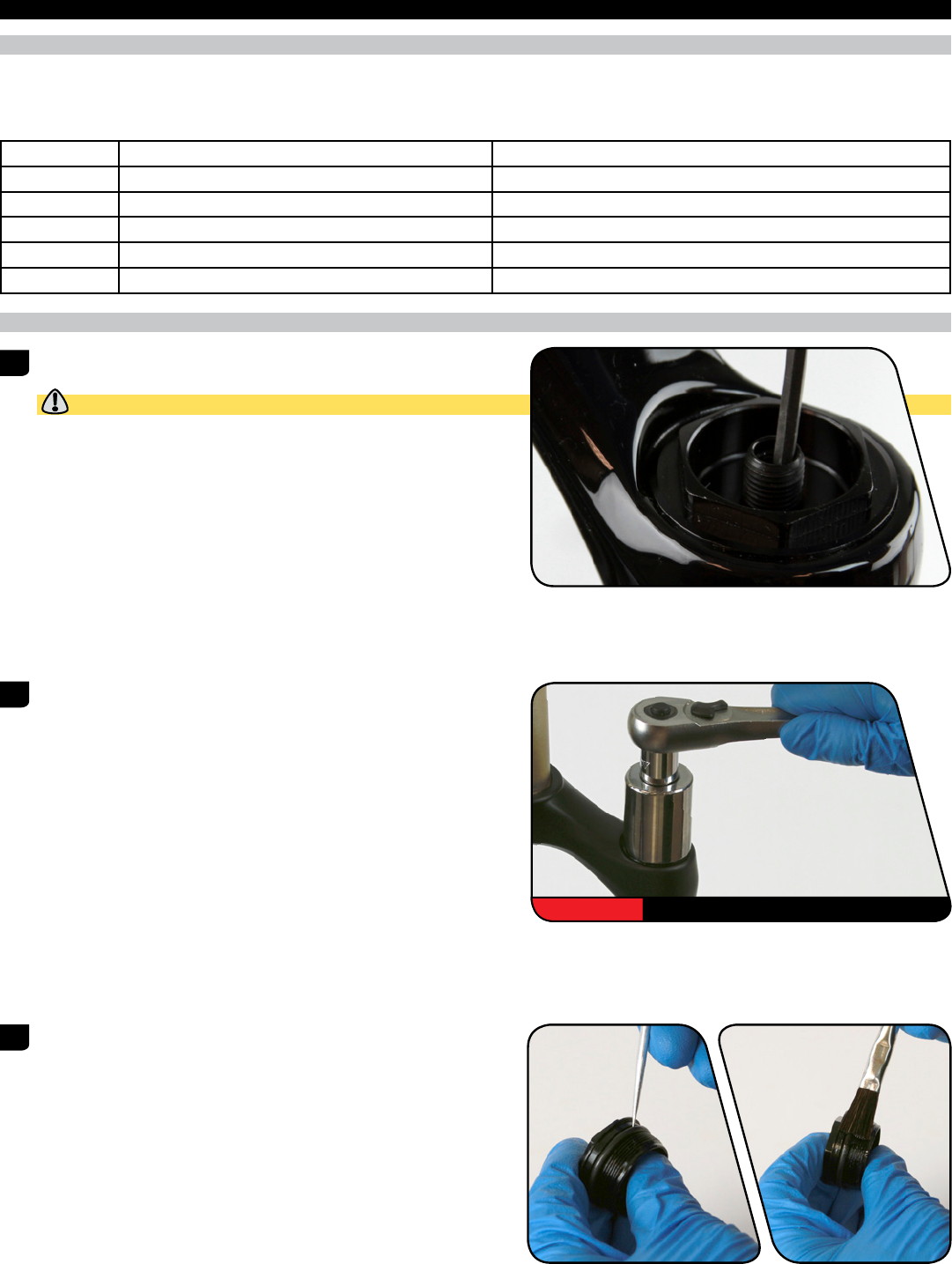
2 Use a 24 mm socket wrench to remove the air spring top cap.
Once removed, clean the upper tube threads with a rag.
3 Use a pick to remove the top cap o-ring. Apply a small amount of
grease to a new top cap o-ring and install it. Apply a small amount
of grease to the top cap threads.
Do not scratch the top cap. Scratches can cause leaks.
24 mm
10 SOLO AIR SPRING SERVICE

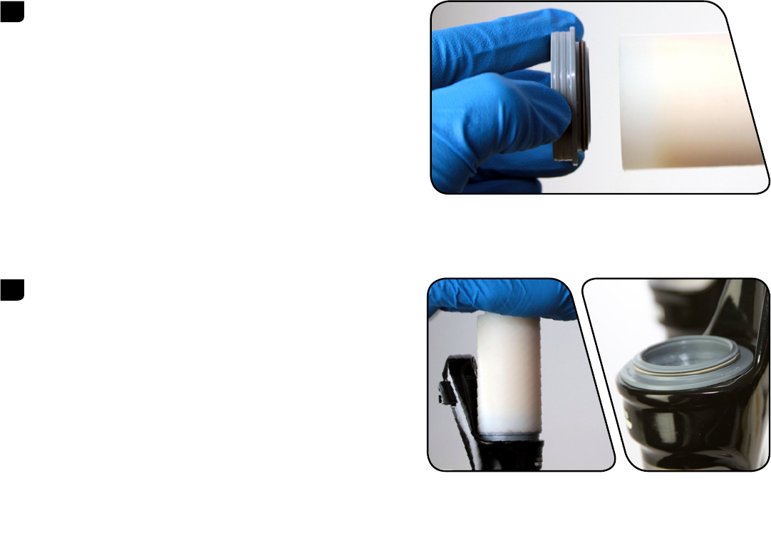
4 Use a pick to remove and replace the air valve cap o-ring.
5 Place the tips of large internal snap ring pliers into eyelets of the
snap ring, located at the bottom of the non-drive side upper tube.
Press firmly on the pliers to push the air shaft guide into the upper
tube enough to compress and remove the snap ring.
Guide the snap ring over the air shaft to prevent scratching.
Scratches on the air shaft will allow air to bypass the seal head
into the lower legs, resulting in reduced spring performance.
6 Firmly pull on the air shaft to remove the air shaft assembly from
the upper tube. Clean and inspect the assembly for damage.
11 SOLO AIR SPRING REMOVAL
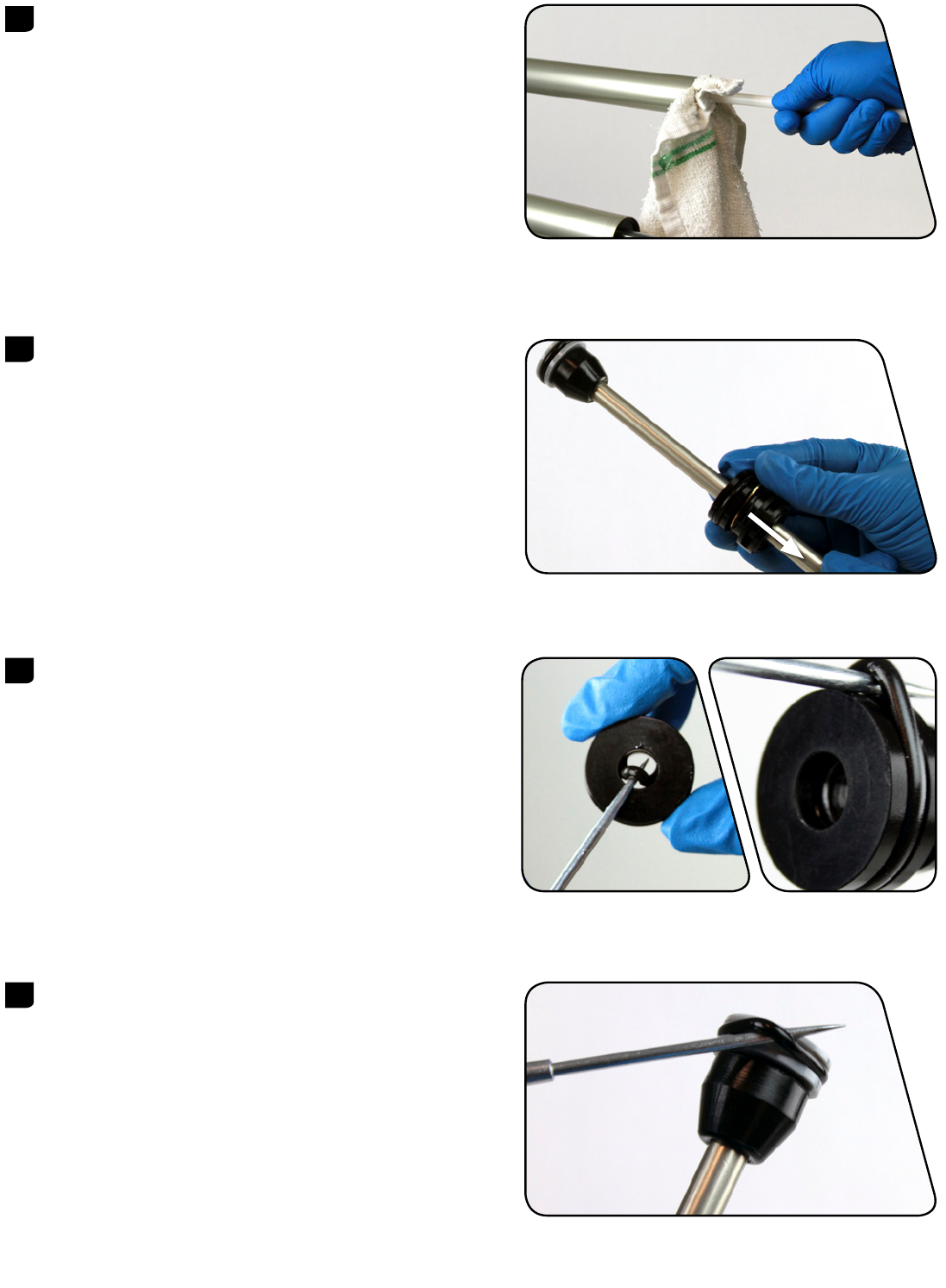
7 Spray isopropyl alcohol on the inside and outside of the upper
tube. Wipe the outside of the upper tube with a clean rag.
Wrap a rag around a long dowel and insert it into the upper tube
to clean inside the upper tube.
8 Remove the floating seal head, washers, floating seal head topout
bumper, and air shaft guide from the air shaft.
Spray isopropyl alcohol on the air shaft and clean it with a rag.
9 Use a pick to remove the inner and outer floating seal head o-rings.
Inspect the seal head for scratches. Spray isopropyl alcohol on the
seal head and clean it with a rag.
Apply a liberal amount of grease to the new o-rings and install
them.
Do not scratch the floating seal head. Scratches can cause leaks.
10 Use a pick to remove the air piston outer o-ring.
Inspect air piston for scratches. Spray isopropyl alcohol on the air
piston and clean it with a rag.
Apply a liberal amount of grease to the new o-ring and install it.
Do not scratch the air piston. Scratches can cause leaks.
12 SOLO AIR SPRING REMOVAL

11 Use your fingers to remove the bumper cone from the air shaft.
Install a new bumper cone onto the air shaft so it covers the
tension pin hole.
NOTICE
If the pin tension is protruding or not centered, replace the piston
assembly.
SOLO AIR SPRING INSTALLATION
1 Apply a liberal amount of grease to the inside of the upper tube,
from the end of the tube to approximately 60 mm into the tube.
2 Apply a liberal amount of grease to the air piston.
3 Apply a liberal amount of grease 40-60 mm around the air shaft.
Install the floating seal head, a new floating seal head topout
bumper, new aluminum support washer, new wavy washer and the
air shaft guide, in that order, onto the air shaft.
13 SOLO AIR SPRING INSTALLATION

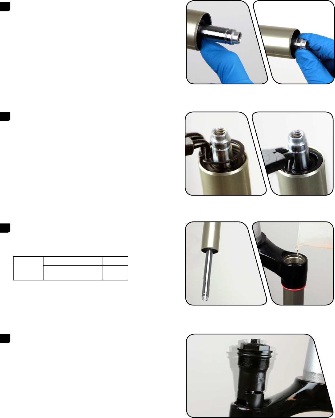
4 Firmly push the air assembly into the bottom of the upper tube
while gently rocking the air shaft side to side.
Orient the washers so that the aluminum support washer goes into
the upper tube first, followed by the wavy washer.
5 Install the snap ring onto internal snap ring pliers. Use the pliers to
push the air shaft into the upper tube while installing the snap ring
into its groove. The air shaft guide should be situated between the
snap ring eyelets.
Make sure the snap ring is securely fastened in the snap ring
groove. Check this by using the snap ring pliers to rotate the
snap ring back and forth a couple of times, then firmly pulling
down on the air shaft.
Snap rings have a sharper-edged side and a rounder-edged side.
Installing snap rings with the sharper-edged side facing the tool
will allow for easier installation and removal.
6 Insert the top cap into the top of the upper tube. Use a torque
wrench with a 24 mm socket to tighten the top cap to
7.3 N·m (65 in-lb).
24 mm 7.3 N·m (65 in-lb)
14 SOLO AIR SPRING INSTALLATION

DAMPER SERVICE
COMPRESSION DAMPER REMOVAL
1 RLT: Use a 1.5 mm hex wrench to remove the gate adjuster set
screw. Remove the gate adjuster, compression adjuster knob, and
the o-ring seal.
RL: Use a 2.5 mm hex wrench to remove the compression adjuster
knob retention screw. Remove the compression adjuster knob.
Remote Only: Use a 2 mm hex wrench to loosen the cable pinch
bolt and remove the cable.
Use a 2 mm hex wrench to loosen the cable stop collar clamping
bolt. Remove the cable stop collar.
You do not need to remove the remote cable spool.
2.5 mm RL
1.5 mm RLT
2 mm RLT
2 mm RL
2 mm
15 DAMPER SERVICE

2 Use a 24 mm socket to loosen the compression damper top cap.
Remove the compression damper by pulling up and gently rocking
side to side. Clean the upper tube threads with a rag.
3 Use a pick or your fingers to remove the compression damper top
cap o-ring. Apply grease to the new o-ring and install it.
RLT Only: Install a new o-ring on the cam.
Do not scratch the top cap. Scratches can cause leaks.
4 Use a pick or your fingers to remove the compression damper
piston o-ring. Apply suspension fluid to the new o-ring and install
it.
Do not scratch the piston. Scratches may cause air to leak.
5 Remove the fork from the bicycle stand and pour the suspension
fluid into an oil pan.
24 mm
RLT
RL
16 COMPRESSION DAMPER REMOVAL

REBOUND DAMPER SERVICE
1 Clamp the fork into the bicycle stand. From the bottom of the
upper tube, push the rebound shaft in until enough shaft is
exposed to hold onto with your fingers.
Use internal snap ring pliers to remove the rebound damper seal
head snap ring.
2 Remove the rebound damper and seal head assembly from the
upper tube.
3 Spray isopropyl alcohol on the inside and outside of the upper
tube. Wipe the outside of the upper tube with a rag.
Wrap a rag around a long dowel and insert it into the upper tube
to clean inside the upper tube.
4 Install a new piston glide ring on the rebound damper.
17 REBOUND DAMPER SERVICE

5 Remove the rebound seal head from the damper shaft.
Use a pick to remove the inner and outer rebound seal head
o-rings. Inspect the rebound seal head for scratches and wipe it
with a rag.
Apply suspension fluid to the new o-rings and install.
Spray isopropyl alcohol on the rebound damper shaft and clean it
with a rag.
Do not scratch the seal head. Scratches can cause leaks.
6 Spray isopropyl alcohol on the rebound damper shaft and clean it
with a rag.
Install the rebound seal head onto the shaft.
7 Insert the rebound damper piston into the bottom of the upper
tube at an angle with the side opposite the glide ring split entering
first. Continue to angle and rotate until the glide ring is in the
upper tube.
18 REBOUND DAMPER SERVICE
8 Push the rebound seal head firmly into the upper tube until the
retaining ring groove is visible.
Push the rebound damper shaft into the seal head, until enough
shaft is exposed to hold onto with your fingers.
9 Use internal snap ring pliers to secure the snap ring into the
retaining ring groove.
Make sure the snap ring is securely fastened in the snap ring
groove. Check this by using the snap ring pliers to rotate the
snap ring back and forth a couple of times, then firmly pulling
down on the air shaft.
Snap rings have a sharper-edged side and a rounder-edged side.
Installing snap rings with the sharper-edged side facing the tool
will allow for easier installation and removal.
10 Clamp the fork vertically in the bicycle stand. Pull the rebound
damper shaft down to the fully extended position.
Use the chart to determine the amount of RockShox 5wt
suspension fluid to measure and pour into the drive side upper
tube.
Reba
RLT, RL 106 mL
RL3 111 mL
Suspension fluid volume is critical. Too much suspension fluid
reduces available travel, too little suspension fluid decreases
damping performance.
11 Turn the hex shaft to the unlocked position. Insert the compression
damper into the upper tube. Press down and rock side to side until
the damper is installed.
19 REBOUND DAMPER SERVICE

12 Use a torque wrench with a 24 mm socket to tighten the
compression damper to 7.3 N·m (65 in-lb).
COMPRESSION DAMPER INSTALLATION
1 RLT: Install a new o-ring on the cam, then install the compression
adjuster knob so the knob dial is against the hard stop.
Use a 1.5 mm hex bit socket to tighten the gate adjuster knob set
screw to 0.6 Nm (5 in-lb).
RL: Install the compression adjuster knob with the knob dial
against the hard stop.
Use a 2.5 mm hex bit socket to install the compression adjuster
knob retention screw to 1.4 Nm (12 in-lb).
Remote Only: Install the cable stop collar onto the top cap with
the cable stop facing toward the front of the fork, perpendicular to
the crown. Use a 2 mm hex bit socket to tighten the collar clamp
bolt to 1.4 Nm (12 in-lb).
24 mm 7.3 N·m (65 in-lb)
RLT
1.5 mm 0.6 Nm (5 in-lb)
RL
2.5 mm 1.4 Nm (12 in-lb)
2 mm 1.4 N·m (12 in-lb)
20 COMPRESSION DAMPER INSTALLATION

LOWER LEG INSTALLATION
1 Spray isopropyl alcohol on the upper tubes and clean them with a
rag.
2 Apply a liberal amount of Buzzy's® Slick Honey grease to the inner
surfaces of the dust wiper seals.
Dust wipers may already be pregreased from the factory. If that is
the case, do not apply more grease.
3 Slide the lower leg assembly onto the upper tube assembly just
enough to engage the upper bushing with the upper tubes.
Make sure both dust wiper seals slide onto the tubes without
folding the outer lip of either seal.
4 Position the fork at a slight angle with the shaft bolt holes oriented
upward, then inject 5 mL of RockShox 15wt suspension fluid into
each lower leg through the shaft bolt hole.
21 LOWER LEG INSTALLATION

5 Slide the lower leg assembly along the upper tubes until it stops
and the spring and damper shafts are visible through the shaft bolt
holes. Wipe all excess fluid from the outer surface of the lower
legs.
6 Install a new o-ring into the top gland of a new shaft bolt. Install a
new spring clip in the lower gland of the shaft bolt.
Apply a thick layer of grease around the diameter of the bolt head
and o-ring.
Replace the crush washers and crush washer retainers.
Dirty or damaged crush washers can cause leaks.
7 Insert the shaft bolts into the lower legs through the threaded
shaft bolt holes.
Use a torque wrench with a 5 mm hex bit socket to tighten the
bolts to 7.3 N·m (65 in-lb).
8 Insert the external rebound damper knob into the rebound damper
shaft bolt until it is secure. Adjust the rebound.
5 mm 7.3 N·m (65 in-lb)
22 LOWER LEG INSTALLATION

9 Refer to the air chart on the fork lower leg and pressurize the air
spring to the appropriate pressure for your rider weight.
You may see a drop in the indicated air pressure on the pump gage
while filling the air spring, this is normal. Continue to fill the air
spring to the recommended air pressure.
10 Spray isopropyl alcohol on the entire fork and clean it with a rag.
23 LOWER LEG INSTALLATION
PUSHLOC™ REMOTE SERVICE
CABLE REMOVAL
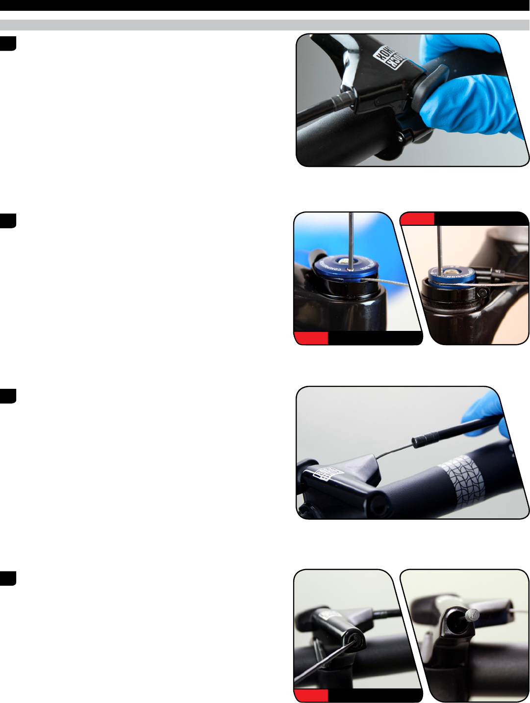
1 Push the remote lever until it returns toward you.
2 RLT: Use a 2 mm hex wrench to loosen the cable pinch bolt on the
spool and pull the cable out of the cable end slot. Use pliers to
remove the cable end.
RL: Use a 2 mm hex wrench to loosen the cable pinch bolt on the
spool. Use pliers to remove the cable end.
3 Disconnect the cable from the damper and pull the cable housing
o the cable.
4 Use a 2 mm hex wrench to open the cable hatch cover.
Push the cable through the remote until the cable head is far
enough out of the lever to access.
2 mm RLT
2 mm RL
2 mm
24 PUSHLOC™ REMOTE SERVICE

5 Pull the cable head to remove the cable from the remote system.
CABLE INSTALLATION
1 If replacing the cable housing, detach the cable housing and end
caps from the lever and the cable housing stop on the fork.
Attach the new housing and end caps to the remote lever and the
cable housing stop on the fork. Cut a length of shifter housing to
accommodate travel and suspension movement.
2 Hold the remote lever in and install the new shifter cable through
remote. Install the cable housing onto the new shifter cable.
3 Pull the cable until the cable head is seated in the remote lever.
With the cable head seated in the remote lever, close the cable
hatch cover and push the lever to return it to the unlocked
position.
25 CABLE INSTALLATION
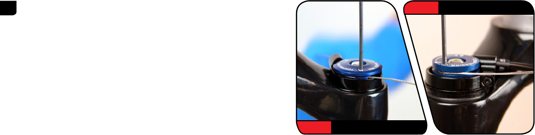
4 RLT: Wrap the cable around the spool and insert it through the
cable fixing port. While firmly pulling the cable, use a 2 mm hex
wrench to tighten the cable pinch bolt to 0.9 Nm (8 in-lb).
Cut the excess cable, leaving 30 mm protruding from the cable
fixing port. Install a cable end fitting and tuck the cable end into
the slot in the spool.
RL: Wrap the cable around the spool. While firmly pulling the
cable, use a 2 mm hex wrench to tighten the cable pinch bolt to
0.9 Nm (8 in-lb).
Cut the excess cable and install a cable end fitting.
This concludes the service for RockShox Reba front suspension forks.
2 mm RLT
2 mm RL
26 CABLE INSTALLATION
www.sram.com
