Rock Shox Yari Service Manual
User Manual: RockShoxYariServiceManual
Open the PDF directly: View PDF ![]() .
.
Page Count: 37
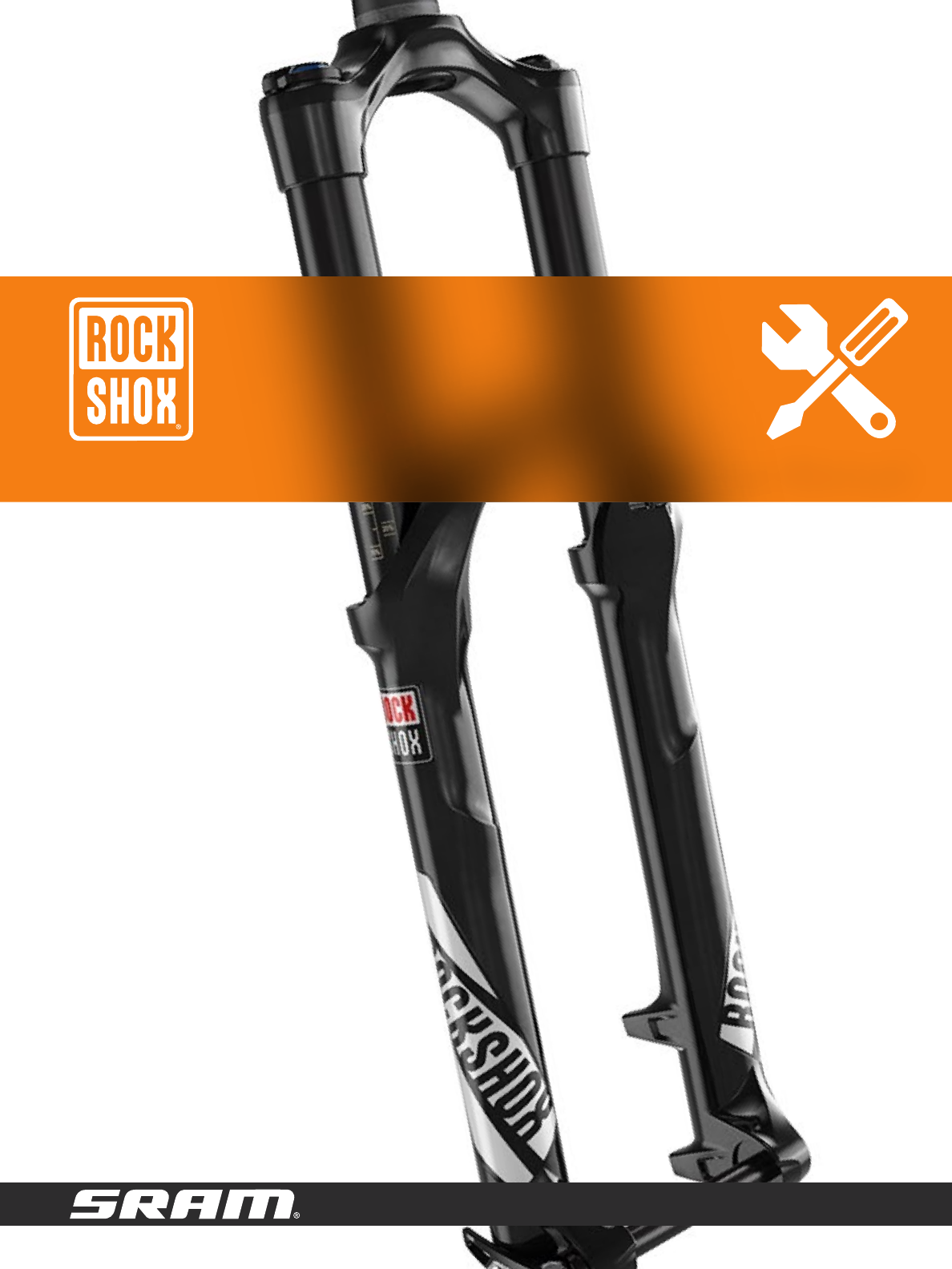
2016-2017 Yari
GEN.0000000005021 Rev E
© 2016 SRAM, LLC
Service Manual

SRAM® LLC WARRANTY
EXTENT OF LIMITED WARRANTY
Except as otherwise set forth herein, SRAM warrants its products to be free from defects in materials or workmanship for a period of two years after
original purchase. This warranty only applies to the original owner and is not transferable. Claims under this warranty must be made through the
retailer where the bicycle or the SRAM component was purchased. Original proof of purchase is required. Except as described herein, SRAM makes
no other warranties, guaranties, or representations of any type (express or implied), and all warranties (including any implied warranties of
reasonable care, merchantibility, or fitness for a particular purpose) are hereby disclaimed.
LOCAL LAW
This warranty statement gives the customer specific legal rights. The customer may also have other rights which vary from state to state (USA), from
province to province (Canada), and from country to country elsewhere in the world.
To the extent that this warranty statement is inconsistent with the local law, this warranty shall be deemed modified to be consistent with such law,
under such local law, certain disclaimers and limitations of this warranty statement may apply to the customer. For example, some states in the United
States of America, as well as some governments outside of the United States (including provinces in Canada) may:
a. Preclude the disclaimers and limitations of this warranty statement from limiting the statutory rights of the consumer
(e.g. United Kingdom).
b. Otherwise restrict the ability of a manufacturer to enforce such disclaimers or limitations.
For Australian customers:
This SRAM limited warranty is provided in Australia by SRAM LLC, 1000 W. Fulton Market, 4th Floor, Chicago, IL, 60607, USA. To make a warranty
claim please contact the retailer from whom you purchased this SRAM product. Alternatively, you may make a claim by contacting SRAM Australia, 6
Marco Court, Rowville 3178, Australia. For valid claims SRAM will, at its option, either repair or replace your SRAM product. Any expenses incurred in
making the warranty claim are your responsibility. The benefits given by this warranty are additional to other rights and remedies that you may have
under laws relating to our products. Our goods come with guarantees that cannot be excluded under the Australian Consumer Law. You are entitled
to a replacement or refund for a major failure and for compensation for any other reasonably foreseeable loss or damage. You are also entitled to
have the goods repaired or replaced if the goods fail to be of acceptable quality and the failure does not amount to a major failure.
LIMITATIONS OF LIABILITY
To the extent allowed by local law, except for the obligations specifically set forth in this warranty statement, in no event shall SRAM or its third party
suppliers be liable for direct, indirect, special, incidental, or consequential damages.
LIMITATIONS OF WARRANTY
This warranty does not apply to products that have been incorrectly installed and/or adjusted according to the respective SRAM user manual. The
SRAM user manuals can be found online at sram.com, rockshox.com, avidbike.com, truvativ.com, or zipp.com.
This warranty does not apply to damage to the product caused by a crash, impact, abuse of the product, non-compliance with manufacturers
specifications of usage or any other circumstances in which the product has been subjected to forces or loads beyond its design.
This warranty does not apply when the product has been modified, including, but not limited to any attempt to open or repair any electronic and
electronic related components, including the motor, controller, battery packs, wiring harnesses, switches, and chargers.
This warranty does not apply when the serial number or production code has been deliberately altered, defaced or removed.
This warranty does not apply to normal wear and tear. Wear and tear parts are subject to damage as a result of normal use, failure to service
according to SRAM recommendations and/or riding or installation in conditions or applications other than recommended.
Wear and tear parts are identified as:
• Dust seals
• Bushings
• Air sealing o-rings
• Glide rings
• Rubber moving parts
• Foam rings
• Rear shock mounting hardware
and main seals
• Upper tubes (stanchions)
• Stripped threads/bolts
(aluminium, titanium, magnesium
or steel)
• Brake sleeves
• Brake pads
• Chains
• Sprockets
• Cassettes
• Shifter and brake cables (inner
and outer)
• Handlebar grips
• Shifter grips
• Jockey wheels
• Disc brake rotors
• Wheel braking surfaces
• Bottomout pads
• Bearings
• Bearing races
• Pawls
• Transmission gears
• Spokes
• Free hubs
• Aero bar pads
• Corrosion
• Tools
• Motors
• Batteries
Notwithstanding anything else set forth herein, the battery pack and charger warranty does not include damage from power surges, use of improper
charger, improper maintenance, or such other misuse.
This warranty shall not cover damages caused by the use of parts of dierent manufacturers.
This warranty shall not cover damages caused by the use of parts that are not compatible, suitable and/or authorised by SRAM for use with SRAM
components.
This warranty shall not cover damages resulting from commercial (rental) use.

TABLE OF CONTENTS
EXPLODED VIEW RC/DUAL POSITION AIR™ DPA .....................................................................................................................................5
EXPLODED VIEW RC/SOLO AIR™ SA ...........................................................................................................................................................6
ROCKSHOX SUSPENSION SERVICE ................................................................................................................................................................ 7
Parts, Tools, and Supplies.............................................................................................................................................................................................................................. 7
Recommended Service Intervals ................................................................................................................................................................................................................8
Record Your Settings .......................................................................................................................................................................................................................................8
Torque Values ....................................................................................................................................................................................................................................................8
Fluid Volume ......................................................................................................................................................................................................................................................8
LOWER LEG ASSEMBLY ......................................................................................................................................................................................9
50/200 Hour Service
Lower Leg Removal..........................................................................................................................................................................................................................................9
50 Hour Service
Lower Leg Service ........................................................................................................................................................................................................................................... 11
200 Hour Service
Lower Leg Seal Service ................................................................................................................................................................................................................................ 12
AIR SPRING SERVICE ........................................................................................................................................................................................15
200 Hour Service
Air Spring Removal......................................................................................................................................................................................................................................... 15
Air Spring Travel Change and Bottomless Tokens (optional) .......................................................................................................................................................... 20
Solo Air Travel Options and Bottomless Token Tuning .....................................................................................................................................................................20
Dual Position Air Travel Options and Bottomless Token Tuning ....................................................................................................................................................20
Bottomless Token Installation (optional) ................................................................................................................................................................................................. 21
Air Spring Installation ................................................................................................................................................................................................................................... 22
DAMPER SERVICE ............................................................................................................................................................................................ 25
200 Hour Service
Compression Damper Removal ................................................................................................................................................................................................................ 25
Rebound Damper Removal ........................................................................................................................................................................................................................26
Rebound Damper Installation .................................................................................................................................................................................................................... 29
Compression Damper Installation ............................................................................................................................................................................................................. 31
LOWER LEG ASSEMBLY ................................................................................................................................................................................... 33
50/200 Hour Service
Lower Leg Installation .................................................................................................................................................................................................................................. 33

SAFETY FIRST!
We care about YOU. Please, always wear your safety glasses and
protective gloves when servicing RockShox® products.
Protect yourself! Wear your safety gear!
5
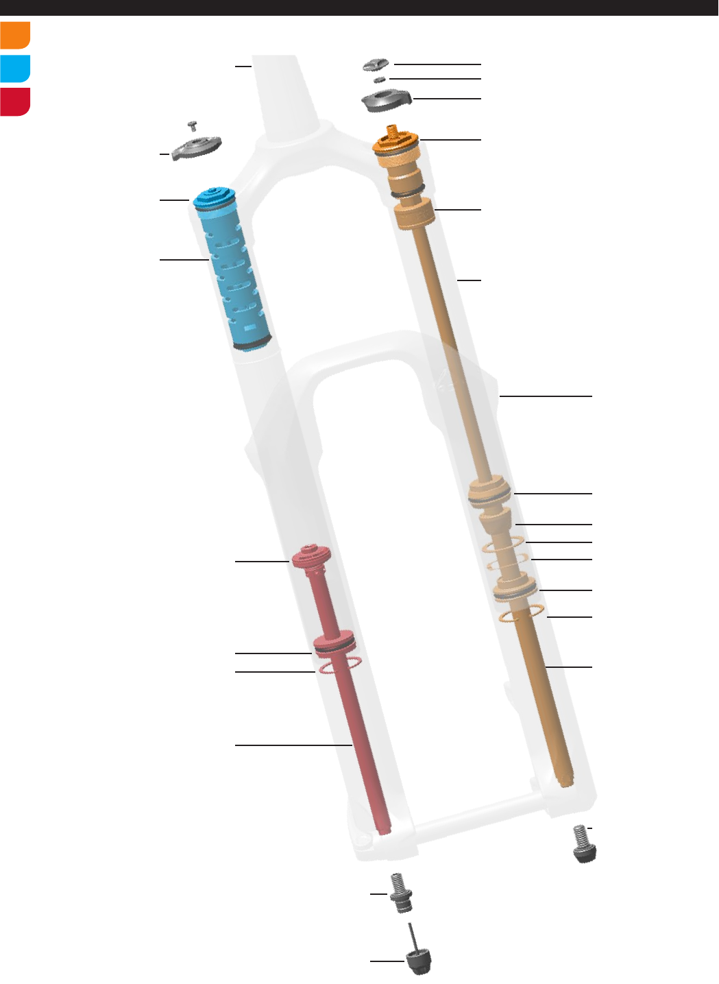
Exploded View - RC/Dual Position Air™ (DPA)
Exploded View - RC/Dual Position Air™ (DPA)
Air Shaft Assembly
Compression Damper
Assembly
Rebound Damper
Assembly
Top Out Bumper
DPA Piston
Backup Ring
Wave Spring
DPA Seal Head
Retaining Ring
Air Shaft
Bottom Bolt
Bottom Bolt
Rebound Adjuster Knob
Knob Retaining Nut
DPA Adjuster Knob
Air Valve Cap
DPA Top Cap
Bottomless Token™(s)
Compression Top Cap
Compression Damper
Compression Adjuster
Knob
Steerer Tube
Rebound Damper Shaft
Damper Seal Head
Retaining Ring
Rebound Piston
Upper Tube
Lower Leg
6
Exploded View - RC/Solo Air™ (SA)
Exploded View - RC/Solo Air™ (SA)
Air Shaft Assembly
Compression Damper
Assembly
Rebound Damper
Assembly
Compression Top Cap
Rebound Damper Shaft
Damper Seal Head
Bottom Bolt
Rebound Adjuster Knob
Compression Adjuster Knob
Steerer Tube
Top Out Bumper
SA Piston
Backup Ring
Wave Spring
SA Seal Head
Retaining Ring
Air Shaft
Bottom Bolt
Air Valve Cap
SA Top Cap
Bottomless Token™(s)
Retaining Ring
Rebound Piston
Compression Damper Upper Tube
Lower Leg
7
RockShox Suspension Service
RockShox Suspension Service
We recommend that you have your RockShox® suspension serviced by a qualified bicycle mechanic. Servicing RockShox suspension requires
knowledge of suspension components, as well as the use of specialized tools and lubricants.
Visit www.sram.com/service for the latest RockShox Spare Parts catalog and technical information. For order information, please contact your local
SRAM® distributor or dealer.
For recycling and environmental compliance information, please visit www.sram.com.
Information contained in this publication is subject to change at any time without prior notice. Your product's appearance may dier from the pictures
contained in this publication.
Parts, Tools, and Supplies
Parts
• Yari™ Service Kit - 200 Hour
Safety and Protection Supplies
• Apron
• Clean, lint-free rags
• Nitrile gloves
• Oil pan
• Safety glasses
Lubricants and Fluids
• Isopropyl alcohol
• Loctite® Threadlocker Blue 242®
• RockShox suspension oil 0W-30
• RockShox suspension oil 5wt
• SRAM® Butter (grease)
RockShox® Tools
• RockShox Bleed syringe
• RockShox 35 mm dust seal installation tool
Bicycle Tools
• Bicycle stand
• Downhill bicycle tire lever
• Schrader valve removal tool
• Shock pump
• Park Tool® AV-4 or AV-5 Axle and Spindle Vise Insert
Common Tools
• 2, 3 and 5 mm hex wrenches
• 2, 3 and 5 mm hex bit sockets
• 10 and 24 mm socket wrenches
• 15 mm open end wrench
• 15 mm crow foot wrench
• Flat blade screwdriver
• Graduated cylinder (mL)
• Large internal retaining ring pliers
• Long plastic or wooden dowel
• Needle nose pliers
• Pick
• Plastic or Rubber mallet
• Socket wrench
• Torque wrench
SAFETY INSTRUCTIONS
Always wear safety glasses and nitrile gloves when working with suspension oil.
Place an oil pan on the floor underneath the area where you will be working on the fork.
NOTICE
For the most eective access to the fork while servicing, clamp the fork steerer tube into a bicycle work stand.
8
Recommended Service Intervals
Recommended Service Intervals
Regular service is required to keep your RockShox® product working at peak performance. Follow this maintenance schedule and install the service
parts included in each service kit that corresponds with the Service Hours Interval recommendation below. For spare part kit contents and details,
refer to the RockShox Spare Parts Catalog at www.sram.com/service.
Service Hours Interval Maintenance Benefit
Every ride Clean dirt from upper tubes and wiper seals
Extends wiper seal lifespan
Minimizes damage to upper tubes
Minimizes lower leg contamination
Every 50 Hours Perform lower leg service
Restores small bump sensitivity
Reduces friction
Extends bushing lifespan
Every 200 Hours
or yearly Perform damper and spring service
Extends suspension lifespan
Restores small bump sensitivity
Restores damping performance
Record Your Settings
Use the charts below to record your shock settings to return your shock to its pre-service settings. Record your service date to track service intervals.
Service Hours Interval Date of Service Air Pressure
Rebound setting
- count the number of clicks while
turning the rebound adjuster fully
counter-clockwise.
Compression setting
- count the number of clicks
while turning the compression
adjuster fully counter-clockwise.
50
100
150
200
Torque Values
Part Tool Torque
Top caps (spring and compression damper) 24 mm socket 28 N•m (250 in-lb)
Compression knob screw 2 mm hex bit socket 1.2 N•m (10.6 in-lb)
DPA knob retainer nut 10 mm socket 1.7-2.6 N•m (15-20 in-lb)
Bottom bolts 5 mm hex bit socket 7.3 N•m (65 in-lb)
Fluid Volume
Damper Side Spring Side
Damper
Technology
Upper Tube Lower Leg
Spring
Technology
Upper Tube Lower Leg
Fork Model Fluid Volume
(mL) Fluid Volume
(mL) Fluid Volume
(mL) Fluid Volume
(mL)
Yari RC Motion
Control 5wt 180 0w-30 10
Solo Air
Grease 0w-30 10
Dual
Position
Air
9
Lower Leg Assembly
Lower Leg Assembly
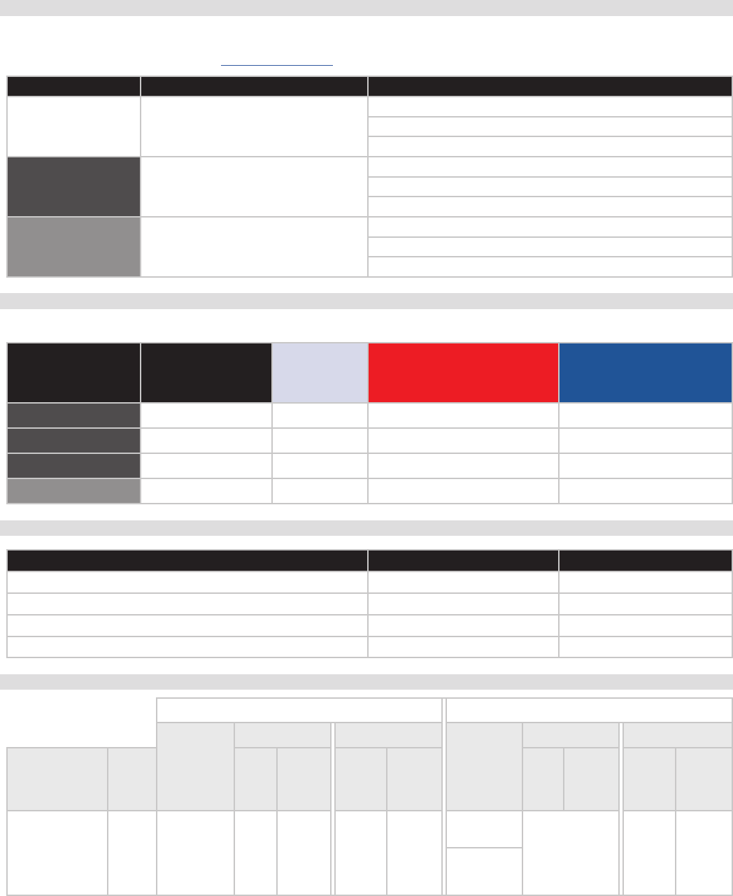
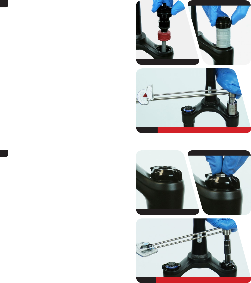
50/200 Hour Service Lower Leg Removal
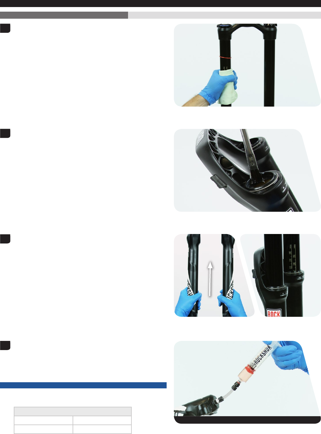
Remove the air valve cap from the top cap located on the spring side
fork leg.
Use a small hex wrench to depress the Schrader valve and release all
air pressure from the air chamber.
⚠CAUTION EYE HAZARD
Verify all pressure is removed from the fork before proceeding. Failure
to do so can result in injury and/or damage to the fork. Wear safety
glasses.
Remove the rebound adjuster knob by pulling it from the bottom bolt.
Use a 5 mm hex wrench to loosen both bottom bolts 3 to 4 turns.
1
DPA
SA
2
DPA
SA
3
4
5 mm
10
Lower Leg Removal
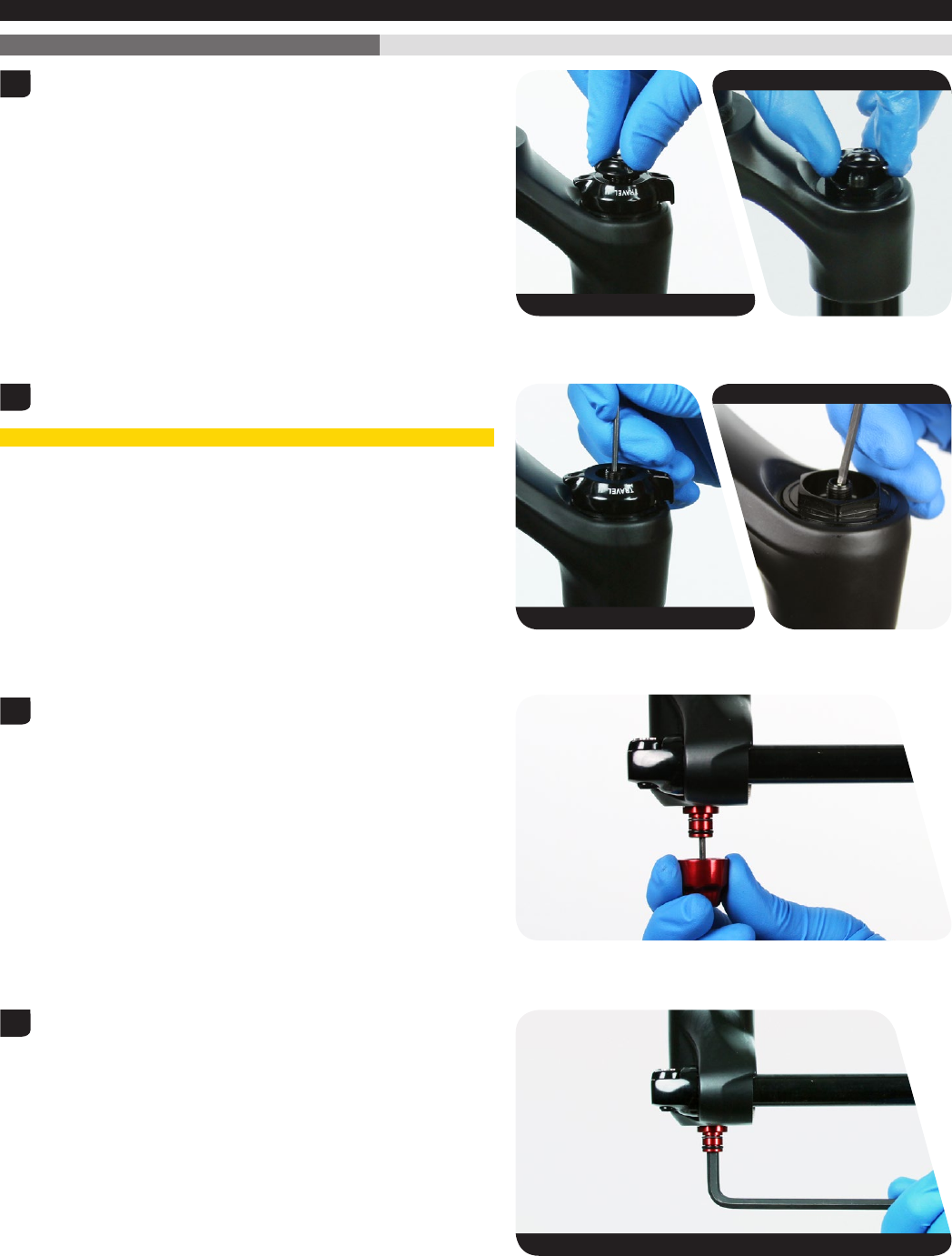
Place an oil pan beneath the fork to catch any draining oil.
Use a rubber mallet to firmly strike each bottom bolt to dislodge the air
and damper shafts from the lower leg.
Use a 5 mm hex wrench to remove the bottom bolts from the lower leg.
Firmly pull the lower leg downward until oil begins to drain. Continue
pulling downward to remove the lower leg from the fork.
If the lower leg does not slide off of the upper tubes or if oil does
not drain from either side, the press fit of the shaft(s) to the lower
leg may still be engaged. Reinstall the bottom bolts 2 to 3 turns and
repeat the previous step.
NOTICE
Do not hit the fork arch with any tool when removing the lower leg as
this could damage the fork.
200 Hour Service Go to Lower Leg Seal Service to continue with the 200 Hour Service.
5
5 mm
6
11
Lower Leg Service
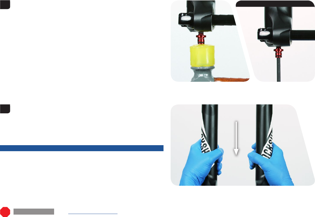
50 Hour Service Lower Leg Service
Remove the foam rings and clean them with isopropyl alcohol and a
clean rag.
Soak the foam rings in RockShox® 0w-30 suspension oil.
Spray isopropyl alcohol on the inside and outside of the lower leg and
wiper seals.
Install the foam rings back into the lower leg under the wiper seals.
50 Hour Service To continue with the 50 Hour Service, proceed to Lower Leg Installation.
1
2
3
4
12
Lower Leg Seal Service
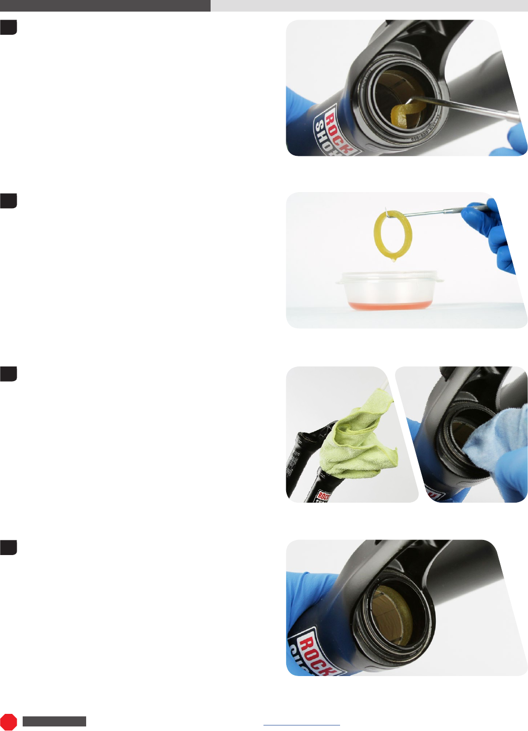
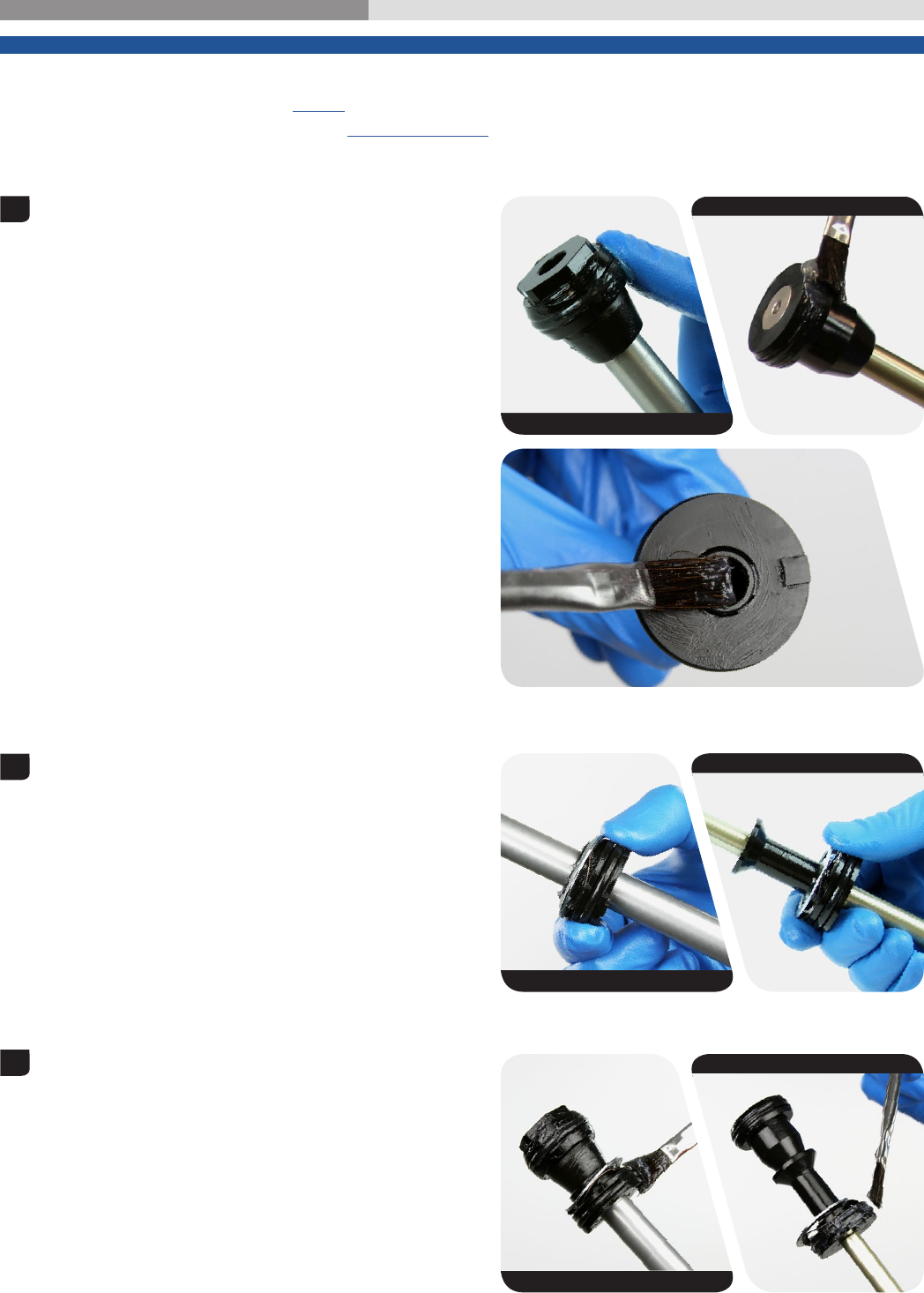
200 Hour Service Lower Leg Seal Service
Place the tip of a downhill tire lever underneath the lower lip of the
dust wiper seal.
NOTICE
If using a flat blade screwdriver, make sure it has a round shaft. A
screwdriver with a square shaft will damage the fork leg. Wrap a rag
around the screwdriver to protect the lower leg.
Stabilize the lower leg on a bench top or on the floor. Press down on
the tire lever handle to remove the dust wiper seal.
Repeat on the other side.
Discard the dust seals after they are removed.
NOTICE
Keep the lower leg assembly stable. Do not allow the lower leg to twist
in opposite directions, compress toward each other, or be pulled apart.
This will damage the lower leg.
Use your fingers to remove and discard the foam rings from the
lower leg.
Soak the new foam rings in RockShox 0w-30 suspension oil.
1
2
3
4
13
Lower Leg Seal Service
Spray isopropyl alcohol on the inside and outside of the lower leg.
Clean the outside of the lower leg with a rag.
Wrap a rag around a long dowel and insert it into each lower leg to
clean the inside of the lower leg.
Install the new foam rings into the lower leg.
Remove the wire spring from the new dust wiper seal and set it aside.
Insert the narrow end of a new dust wiper seal into the recessed end of
the RockShox® 35 mm dust seal installation tool.
5
6
7
8
RockShox Dust Seal Installation Tool
14
Lower Leg Seal Service
Hold the lower leg steady and use the RockShox® 35 mm dust seal
installation tool to press the dust wiper seal evenly into the lower leg
until the seal surface is flush with the top of the lower leg surface.
Reinstall the wire spring onto the dust wiper seal.
Repeat steps 7, 8, and 9 for the other side of the lower leg.
NOTICE
Only press the dust wiper seal into the lower leg until it is flush with the
top surface of the lower leg. Pressing the dust wiper seal past the top
surface of the lower leg can damage the foam rings.
9
15
Air Spring Service
Air Spring Service
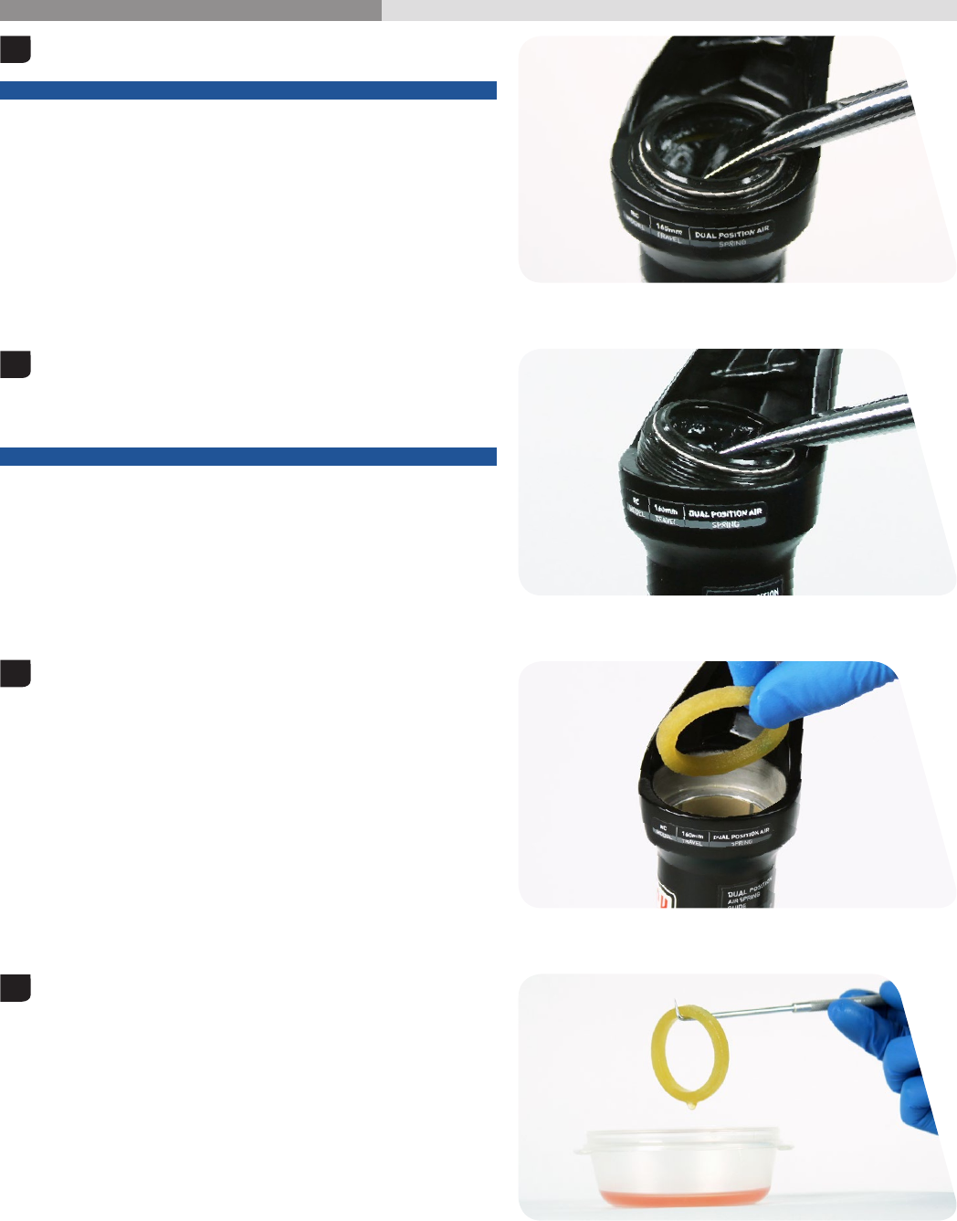
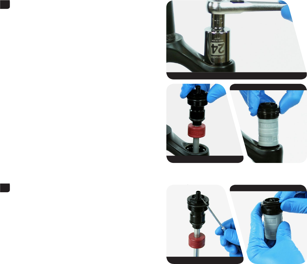
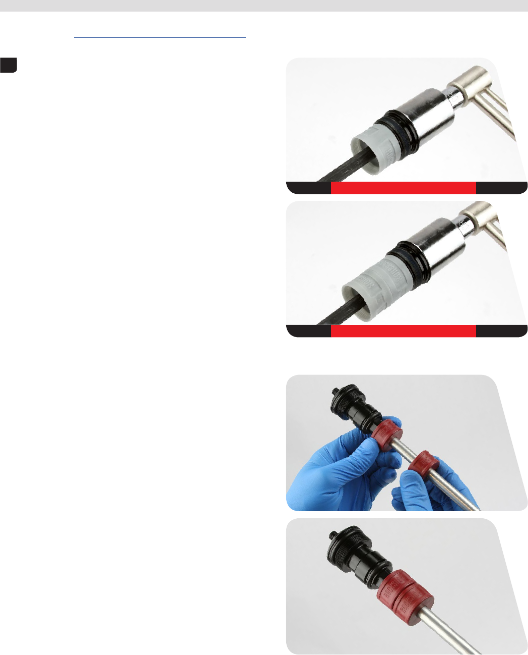
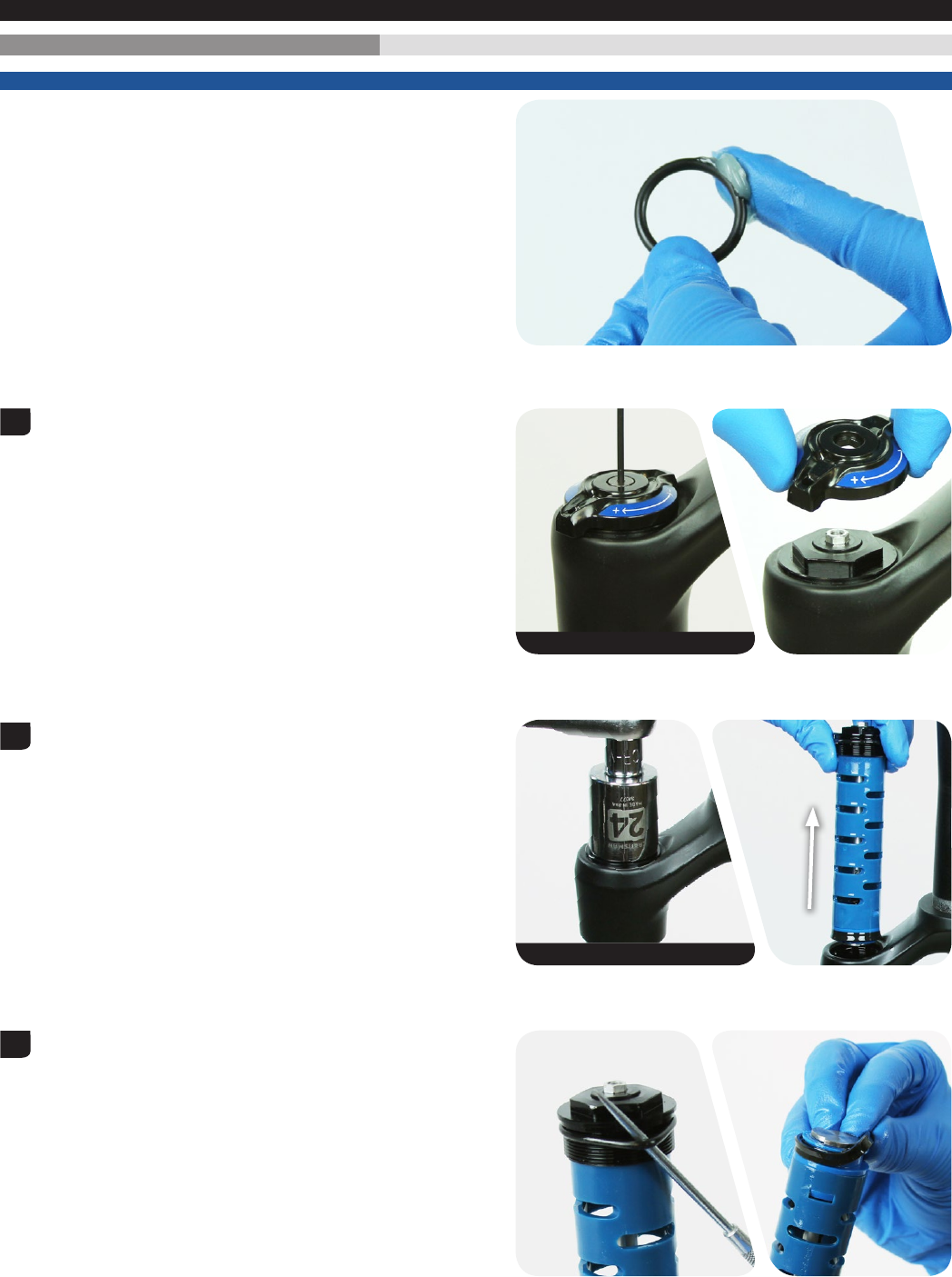
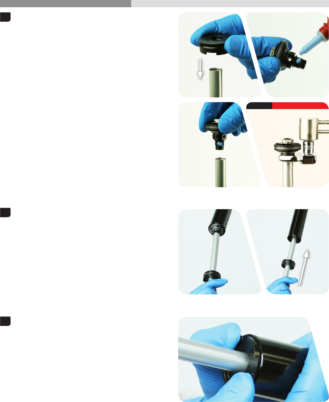
200 Hour Service Air Spring Removal
NOTICE
Inspect each part for scratches. Do not scratch any sealing surfaces
when servicing your suspension. Scratches can cause leaks.
When replacing seals and o-rings, use your fingers or a pick to remove
the seal or o-ring. Spray isopropyl alcohol on each part and clean with
a rag. Apply SRAM® Butter grease to the new seals and o-rings.
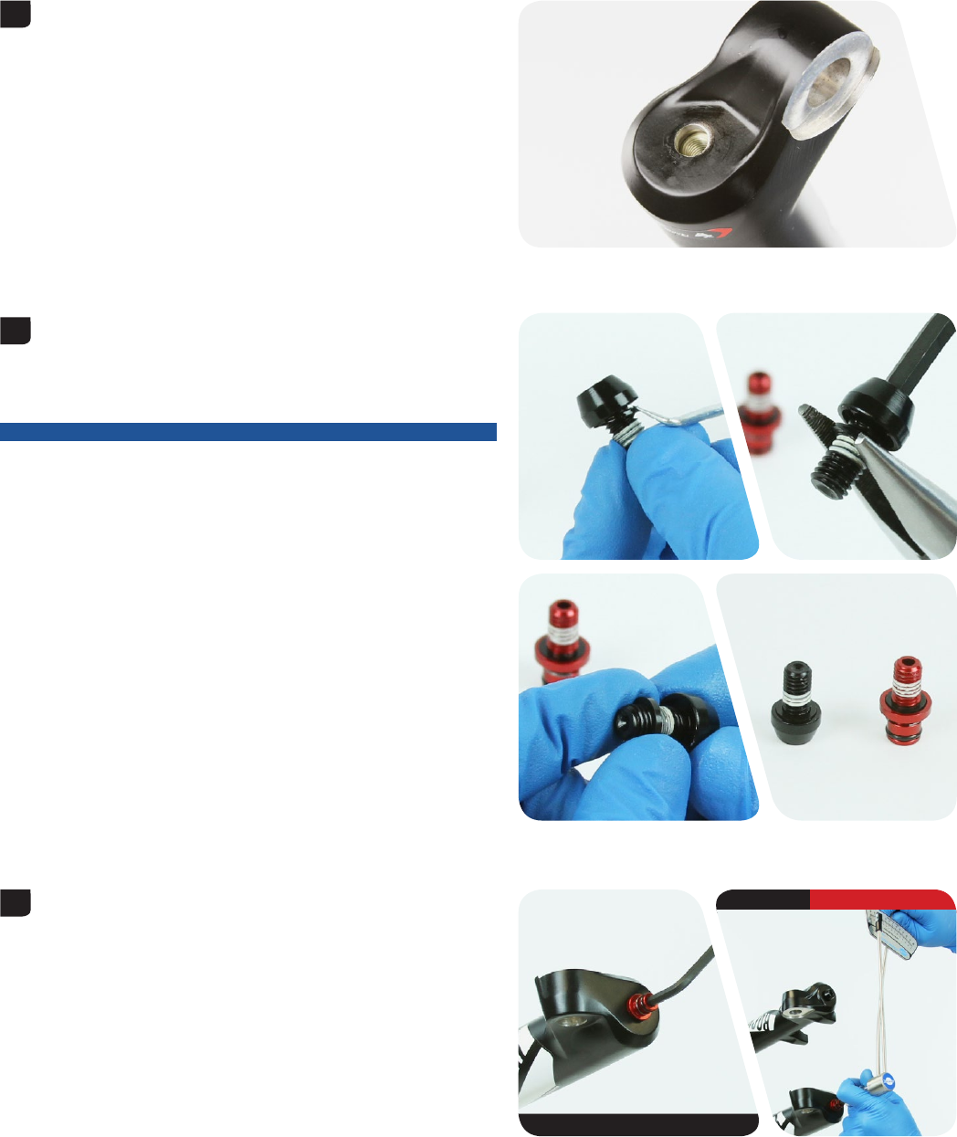
Dual Position Air™: Use a 10 mm socket wrench to remove the DPA
travel adjuster knob retaining nut. Remove the DPA travel
adjuster knob.
1
10 mm
16
Air Spring Removal
Use a 24 mm socket wrench to remove the top cap from the upper
tube.
Spray isopropyl alcohol on the upper tube threads and clean the
threads with a rag.
Use your fingers or a pick to remove the top cap o-ring.
Use your fingers to install a new o-ring.
Do not apply grease to the top cap threads.
2
24 mm
DPA
SA
3
DPA
SA
17
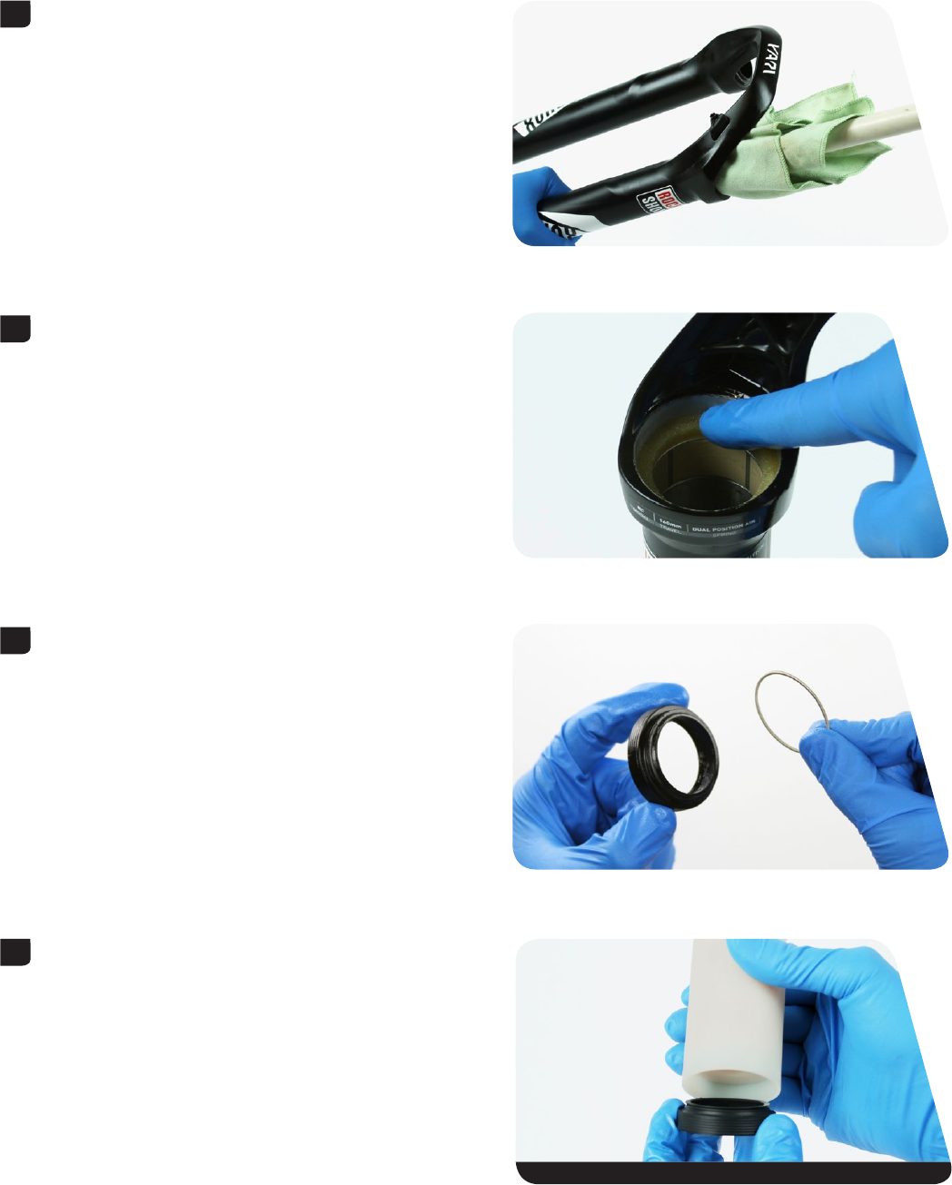
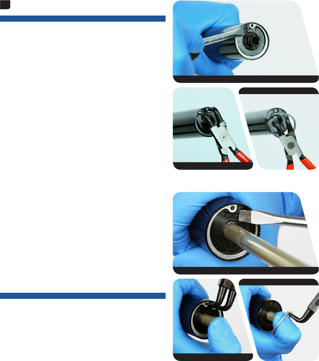
Air Spring Removal
Dual Position Air™: Push the air shaft into the upper tube to prevent it
from getting scratched while removing the retaining ring.
NOTICE
Scratches on the air shaft will allow air to bypass the seal head into the
lower leg, resulting in reduced spring performance.
Use a flat blade screwdriver to push the DPA seal head tab under the
retaining ring.
Place the tips of large internal retaining ring pliers into the eyelets of
the retaining ring. Press firmly on the pliers to push the seal head into
the upper tube enough to compress and remove the retaining ring.
Solo Air™: Use a flat blade screwdriver to push the SA seal head tab
under the retaining ring.
Place your finger over the end of the air spring shaft to prevent it from
getting scratched while removing the retaining ring.
NOTICE
Scratches on the air shaft will allow air to bypass the seal head into the
lower leg, resulting in reduced spring performance.
Place the tips of large internal retaining ring pliers into the eyelets of
the retaining ring. Press firmly on the pliers to push the SA seal head
into the upper tube enough to compress and remove the retaining ring.
Slide the retaining ring onto your finger and release the air spring shaft.
4
DPA
DPA
DPA
SA
SA
SA
18
Air Spring Removal
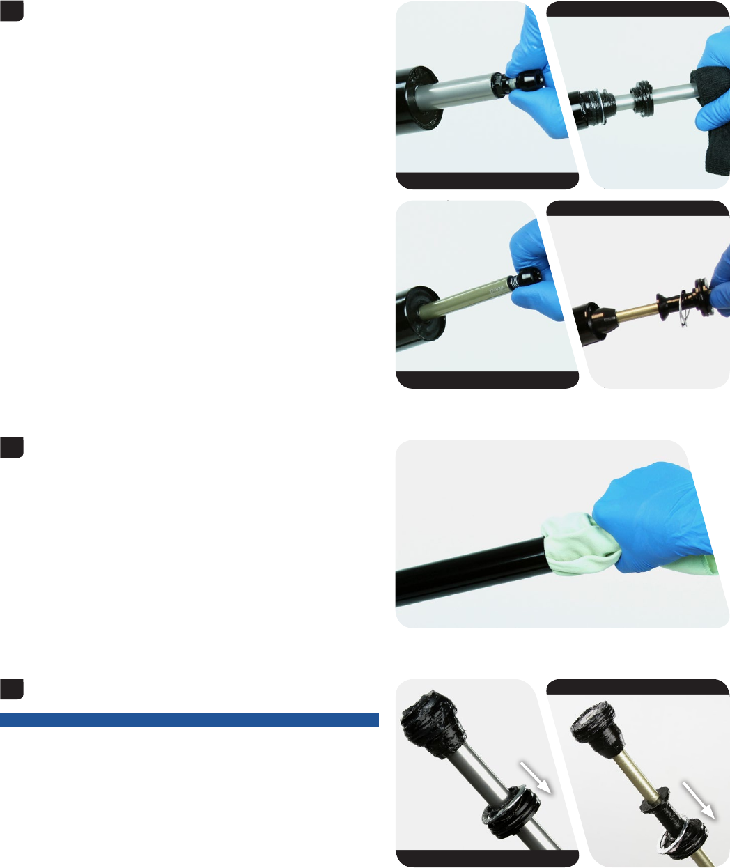
Use your fingers to install the bottom bolt into the air shaft.
Firmly pull on the shaft and bottom bolt to remove the air shaft
assembly from the upper tube.
Unthread and remove the bottom bolt from the air shaft.
Clean and inspect the assembly for damage.
Spray isopropyl alcohol on the inside and outside of the upper tube
and clean it with a rag.
Wrap a rag around a long dowel and insert it into the upper tube to
clean inside the upper tube.
Remove the seal head, wave spring, and backup ring from the air shaft.
Discard the seal head assembly and wave spring.
NOTICE
Do not install a new seal head at this time. The seal head will be
replaced in the Installation section.
5
DPA
DPA
SA
SA
6
7
DPA
SA
19
Air Spring Removal
Dual Position Air™: Use your fingers or a pick to remove the outer air
piston o-ring. Use a pick to pierce and remove the inner o-ring. Discard
the o-rings.
Use your fingers to install new o-rings.
Solo Air™: Use your fingers or a pick to remove the air piston quad ring,
and discard it.
Use your fingers to install a new quad ring.
8
DPA
DPA
SA
20
Air Spring Travel Change and Bottomless Tokens (optional)
Air Spring Travel Change and Bottomless Tokens (optional)
To increase or decrease the travel in your RockShox® Yari™ fork, the
air spring must be replaced with the correct length air spring shaft
assembly. For example, to change a Yari with a maximum of 140 mm
of travel to a maximum of 160 mm of travel, a 160 mm air spring shaft
assembly must be installed. Fork travel can be identified at the bottom
of the air spring shaft.
Bottomless Tokens™ can be added to, or removed from, the Solo Air™
(SA) top cap or the Dual Position Air™ (DPA) air spring assembly to
fine-tune the bottom-out feel and spring curve. Use the chart below to
help determine the number of Bottomless Tokens that can be used with
each maximum fork travel option. If fork travel is changed from stock, it
may be necessary to add or remove Bottomless Tokens. Red (DPA) and
grey (SA) Bottomless Tokens are compatible with all Yari forks.
Refer to the RockShox Spare Parts Catalog available on our website at
www.sram.com/service for spare part kit details.
For part ordering information, please contact your local SRAM®
distributor or dealer.
Solo Air Travel Options and Bottomless Token Tuning
29"+ Wheel 27.5"+ / 29" / 29" Boost Wheel 27.5" / 27.5" Boost Wheel
Fork Travel
(etched on
air shaft)
Bottomless
Tokens
Factory Installed
Maximum
Bottomless
Tokens
Fork Travel
(etched on
air shaft)
Bottomless
Tokens
Factory Installed
Maximum
Bottomless
Tokens
Fork Travel
(etched on
air shaft)
Bottomless
Tokens
Factory Installed
Maximum
Bottomless
Tokens
---LYRIK/YARI
180 0 4 LYRIK/YARI
180 0 4
---LYRIK/YARI
170 1 4 LYRIK/YARI
170 1 4
LYRIK/YARI
160 2 5 LYRIK/YARI
160 2 5 LYRIK/YARI
160 2 5
LYRIK/YARI
150 2 5 LYRIK/YARI
150 2 5 LYRIK/YARI
150 2 5
LYRIK/YARI
140 3 6 LYRIK/YARI
140 3 6 LYRIK/YARI
140 3 6
LYRIK/YARI
130 3 6 LYRIK/YARI
130 3 6 LYRIK/YARI
130 3 6
LYRIK/YARI
120 4 7 LYRIK/YARI
120 4 7 LYRIK/YARI
120 4 7
LYRIK/YARI
110 5 7 - - - - - -
LYRIK/YARI
100 5 7 - - - - - -
Dual Position Air Travel Options and Bottomless Token Tuning
29"+ Wheel 27.5"+ / 29" / 29" Boost Wheel 27.5" / 27.5" Boost Wheel
Fork Travel
(etched on
air shaft)
Bottomless
Tokens
Factory Installed
Maximum
Bottomless
Tokens
Fork Travel
(etched on
air shaft)
Bottomless
Tokens
Factory Installed
Maximum
Bottomless
Tokens
Fork Travel
(etched on
air shaft)
Bottomless
Tokens
Factory Installed
Maximum
Bottomless
Tokens
------LYRIK/YARI
180 0 4
------LYRIK/YARI
170 0 5
LYRIK/YARI
160 1 5 LYRIK/YARI
160 1 5 LYRIK/YARI
160 1 5
LYRIK/YARI
150 1 6 LYRIK/YARI
150 1 6 LYRIK/YARI
150 1 6
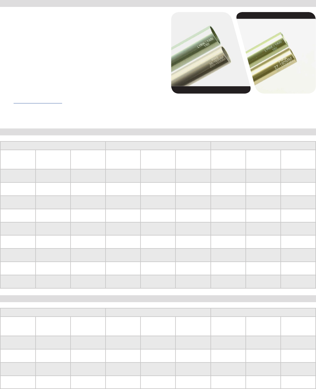
DPA air spring shaft identification
SA air spring shaft identification
21
Bottomless Token Installation (optional)
Bottomless Token Installation (optional)
Bottomless Tokens™ reduce the air volume in your fork to create greater ramp at the end of the fork travel. Add tokens to maintain your fork's
bottomless feel. See Air Spring Travel Change and Bottomless Tokens for the maximum number of tokens for your fork.
Solo Air™: Thread a Bottomless Token into another token or into the the
bottom of the top cap. Use an 8 mm hex wrench and a torque wrench
with a 24 mm socket to tighten the token to 3.4-4.5 N•m (30-40 in-lb).
Dual Position Air™: Install additional Bottomless Tokens onto the DPA
air spring shaft, as desired.
8 mm 3.4-4.5 N•m (30-40 in-lb) 24 mm
1
8 mm 3.4-4.5 N•m (30-40 in-lb) 24 mm
22
Air Spring Installation
200 Hour Service Air Spring Installation
NOTICE
It is optional to change maximum fork travel by replacing the stock air spring shaft assembly with a shorter or longer air spring shaft assembly. If
maximum travel is increased or reduced, use the new complete air spring shaft assembly in the following installation steps. It may also be necessary
to add or remove Bottomless Tokens™. Refer to page 20 for details.
Refer to the RockShox® Spare Parts Catalog available at www.sram.com/service for the required spare part kit kits. For part ordering information,
please contact your local SRAM® distributor or dealer.
Apply a liberal amount of SRAM Butter to the air piston and seal head
seals.
Install the backup ring, a new wave spring, and a new seal head
assembly, in that order, onto the air shaft.
Apply a liberal amount of SRAM Butter grease to the seal head.
1
DPA
SA
2
DPA
SA
3
DPA
SA
23
Air Spring Installation
Firmly push the air shaft assembly into the bottom of the upper tube
while gently rocking the air shaft side to side. Make sure the shaft
remains fully extended.
Use your thumbs or fingers to firmly press the seal head into the upper
tube until it snaps into place.
Use your fingers to position the retaining ring into the bottom of
the upper tube retaining ring groove. The seal head tab should be
positioned between the retaining ring eyelets.
Place the tips of large internal retaining ring pliers into the eyelets of
the retaining ring, then use the pliers to push the seal head into the
upper tube while installing the retaining ring into the groove.
Use your finger or thumb to hold the retaining ring in place while
seating the retaining ring eyelets on either side of the seal head tab.
NOTICE
Do not scratch the air spring shaft. Scratches on the air shaft will allow
air to bypass the seal head into the lower leg, resulting in reduced
spring performance.
Confirm the retaining ring is properly seated in the retaining ring
groove by using the retaining ring pliers to rotate the retaining ring
and seal head back and forth a few times, then firmly pull down on
the air shaft.
Retaining rings have a sharper-edged side and a rounder edged side.
Installing retaining rings with the sharper-edged side facing the tool
will allow for easier installation and removal.
4
DPA
DPA
SA
SA
5
DPA
SA
24
Air Spring Installation
Install the air spring top cap into the top of the upper tube and tighten
with a 24 mm socket wrench.
Use a torque wrench with a 24 mm socket to tighten the top cap to
28 N·m (250 in-lb).
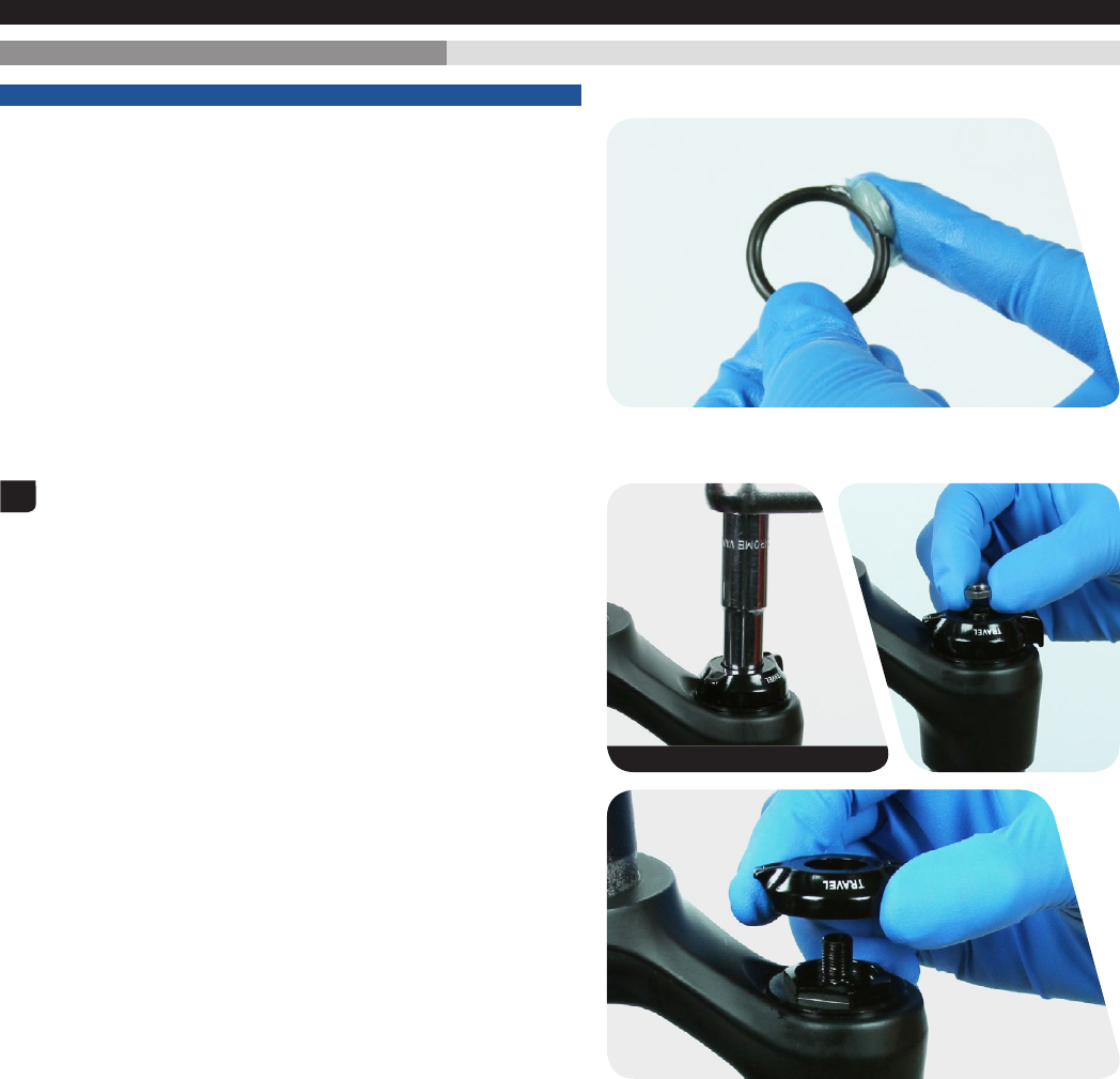
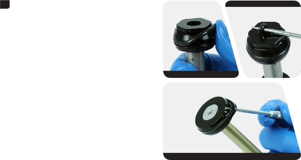
Dual Position Air™: Place the DPA adjuster knob and the knob retaining
nut onto the top cap with the long tab near the front of the crown.
Turn the DPA adjuster knob counter-clockwise until it engages the first
detent space.
Thread the knob retaining nut onto the threaded air valve body.
Use a torque wrench with a 10 mm socket to tighten the knob retaining
nut to 1.7-2.2 N•m (15-20 in-lb).
6
DPA
SA
24 mm 28 N•m (250 in-lb)
7
DPA
DPA
10 mm 1.7-2.2 N•m (15-20 in-lb)
25
Damper Service
Damper Service
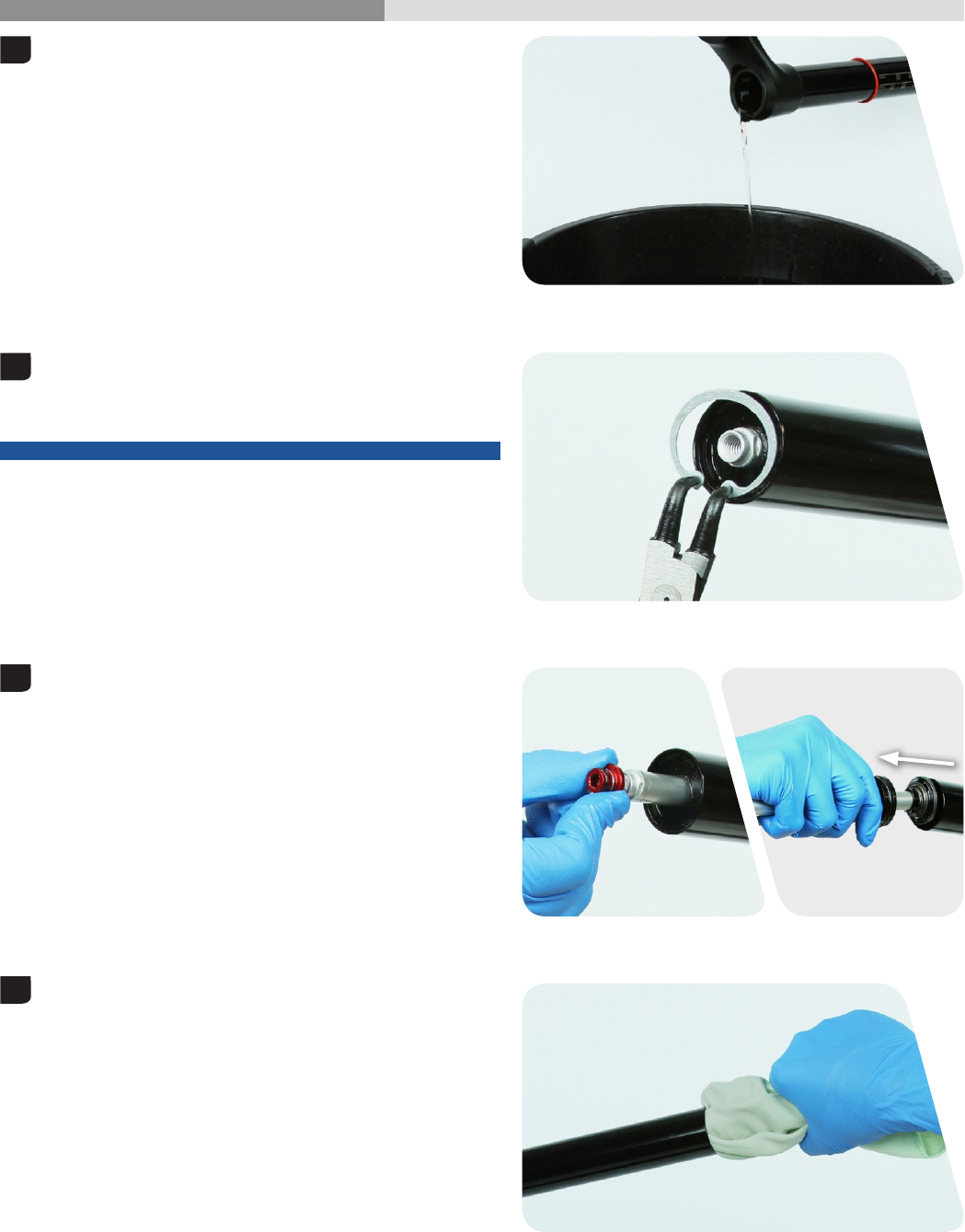
200 Hour Service Compression Damper Removal
NOTICE
Inspect each part for scratches. Do not scratch any sealing surfaces
when servicing your suspension. Scratches can cause leaks.
When replacing seals and o-rings, use your fingers or a pick to remove
the seal or o-ring. Spray isopropyl alcohol on each part and clean with
a rag. Apply SRAM® Butter grease to new seals and o-rings.
Use a 2 mm hex wrench to remove the compression adjuster
knob screw.
Remove the compression adjuster knob.
Use a 24 mm socket wrench to loosen the compression damper
top cap.
Remove the compression damper by pulling up firmly while gently
rocking side to side.
Clean the upper tube threads with a rag.
Use your fingers or a pick to remove the compression damper top cap
o-ring. Use your fingers to install a new top cap o-ring.
Use your fingers or a pick to remove the compression damper piston
u-cup seal. Use your fingers to install a new u-cup seal.
1
2 mm
2
24 mm
3
26
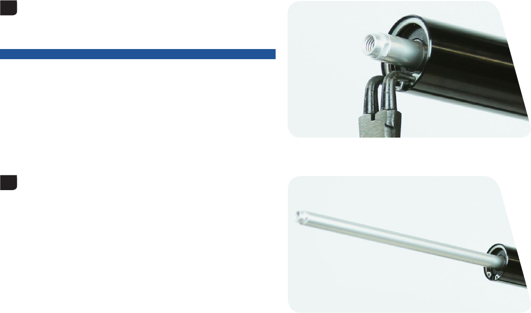
Rebound Damper Removal
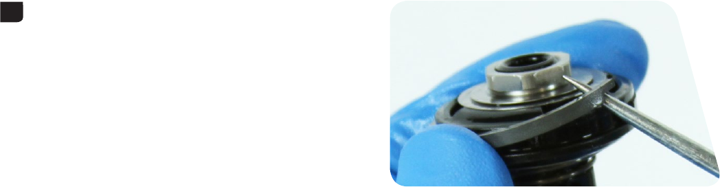
200 Hour Service Rebound Damper Removal
Remove the fork from the bicycle work stand and pour the suspension
oil into an oil pan.
Push the rebound damper shaft into the seal head to avoid scratching
the shaft while removing the retaining ring.
Use internal retaining ring pliers to remove the retaining ring from the
bottom of the upper tube.
NOTICE
Do not scratch the rebound damper shaft. Scratches will allow oil to
bypass the seal head into the lower leg resulting in reduced spring
performance.
Thread the rebound damper shaft bolt onto the rebound damper shaft
2 to 3 turns. Hold the bolt and pull the rebound damper shaft out of the
seal head.
Pull and remove the rebound damper and seal head assembly from the
upper tube.
Spray isopropyl alcohol on the inside and outside of the upper tube
and clean it with a rag.
Wrap a rag around a long dowel and insert it into the upper tube to
clean inside the upper tube.
1
2
3
4

27
Rebound Damper Removal
Insert the rebound adjuster knob into the rebound damper shaft end
and turn it counter-clockwise until it stops. This is the full-open position
(fastest rebound damping).
Remove the knob.
NOTICE
The rebound damper must be in the full-open position before the
piston is removed. Failure to do so will cause damage to the rebound
damper internals during piston removal.
The Yari™ rebound damper seal head cannot be removed from the end
of the damper shaft. The rebound piston must be removed first.
Clamp the bottom of the rebound damper shaft into the 9/16" opening
of a Park Tool® AV-4 or AV-5 aluminum axle and spindle vise insert.
NOTICE
Clamp the damper at the bottom of the shaft, near the threaded shaft
bolt insert to avoid scratching or damaging the shaft.
Use a 15 mm open end wrench and remove the rebound damper
piston.
Remove the seal head.
Spray isopropyl alcohol on the rebound damper shaft and clean it with
a rag.
Inspect the shaft for scratches. If scratched, replace the rebound
damper assembly.
Use your fingers or a pick to remove the outer seal head o-ring. Use a
pick to pierce and remove the inner seal head shaft scraper seal.
Use your fingers to install a new outer seal head o-ring and inner seal
head wiper seal.
5
6
15 mm
7
28
Rebound Damper Removal
Use your fingers or a pick to remove the glide ring from the rebound
damper piston.
Use your fingers to install a new glide ring.
8
29
Rebound Damper Installation
200 Hour Service Rebound Damper Installation
Install the seal head onto the rebound damper shaft with the flat end
facing the rebound damper piston.
Add a small drop of Loctite® Threadlocker Blue 242® to the rebound
damper piston threads.
Use your fingers to thread the rebound damper piston onto the
rebound damper shaft.
Use a torque wrench with 15 mm crow foot wrench and tighten to 2.4-4
N•m (21.2-35.4 in-lb).
Insert the rebound damper piston into the bottom of the upper tube at
an angle with the side opposite the glide ring entering first. Continue to
angle and rotate the piston until the glide ring is in the upper tube.
Use your thumbs to push the rebound seal head into the upper tube
until the retaining ring groove is visible.
1
15 mm 2.4-4 N•m (21.2-35.4 in-lb)
2
3
30
Rebound Damper Installation
Push the rebound damper shaft into the upper tube to prevent it from
getting scratched while installing the retaining ring.
Place the tips of the internal retaining ring pliers into the eyelets of the
retaining ring and install the retaining ring into the groove.
NOTICE
Do not scratch the rebound damper shaft. Scratches will allow oil to
bypass the seal head into the lower leg resulting in reduced spring
performance.
Confirm the retaining ring is properly seated in the retaining ring
groove by using the retaining ring pliers to rotate the retaining ring
and seal head back and forth a few times.
Retaining rings have a sharper-edged side and rounder-edged side.
Installing retaining rings with the sharper-edged side facing the tool
will allow for easier installation and removal.
Pull the rebound damper shaft out to the fully extended position.
4
5
31
Compression Damper Installation
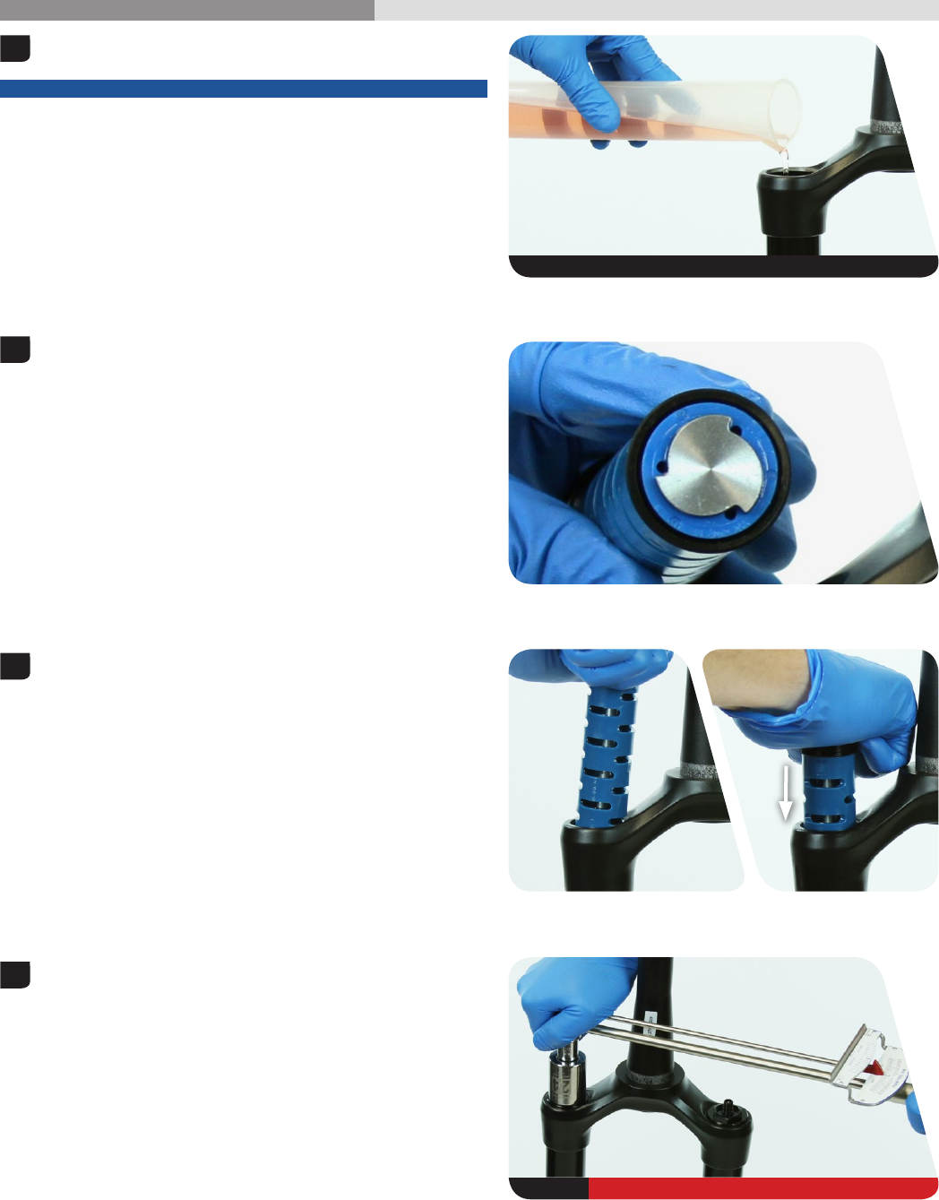
200 Hour Service Compression Damper Installation
Pour 180 mL RockShox® 5wt suspension oil into the damper side
upper tube.
NOTICE
Suspension oil volume is critical. Too much suspension oil reduces
available travel. Too little suspension oil decreases damping
performance.
Turn the compression valve at the bottom of the compression damper
to the open position.
Insert the compression damper into the upper tube. Press down slowly
and rock side to side until the damper is installed.
Use a torque wrench with a 24 mm socket to tighten the compression
top cap to 28 N•m (250 in-lb).
1
5wt 180 mL
2
3
4
24 mm 28 N•m (250 in-lb)
32
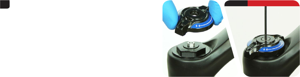
Compression Damper Installation
Install the compression adjuster knob with the large tab toward the
front of the crown (open position).
Use a torque wrench with a 2 mm hex bit socket to tighten the low
speed compression adjuster knob retaining screw to
1.2 N
•m (10.6 in-lb).
5
2 mm 1.2 N•m (10.6 in-lb)
33
Lower Leg Assembly
Lower Leg Assembly
50/200 Hour Service Lower Leg Installation
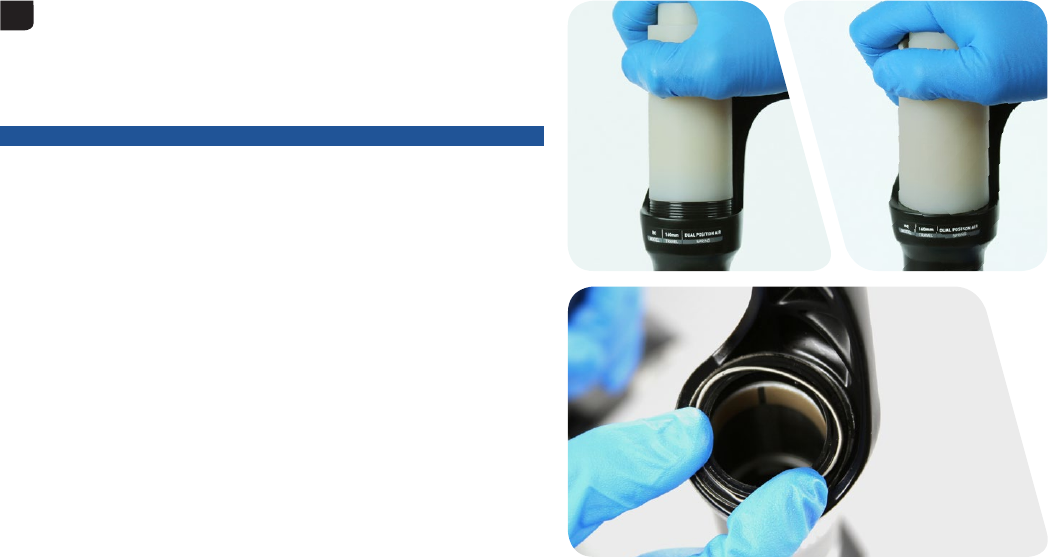
Spray isopropyl alcohol on the upper tubes and clean them with a rag.
Apply a liberal amount of SRAM® Butter grease to the inner surfaces of
the dust wiper seals.
Slide the lower leg assembly onto the upper tube assembly just
enough to engage the upper bushing with the upper tubes. The lower
leg bottom should not contact the spring or damper shaft.
Make sure both dust wiper seals slide onto the tubes without folding
the outer lip of either seal.
Position the fork at a slight angle with the bottom bolt holes oriented
upward. Angle the syringe fitting into each lower leg bolt hole so the oil
will only contact the inside of the lower leg and not fill the shaft.
Using a RockShox® bleed syringe, inject 10 mL of RockShox 0w-30
suspension oil into the damper side leg, and 10 mL of RockShox 0w-30
suspension oil into the spring side leg shaft holes.
NOTICE
Do not exceed the recommended oil volume per leg as this can
damage the fork.
Lower Leg Oil Volume
Spring Side 10 mL
Damper Side 10 mL
1
2
3
4
0w-30 10 mL
34
Lower Leg Installation
Slide the lower leg assembly along the upper tubes until it stops and
the spring and damper shafts are visible through the lower leg bolt
holes.
Use a rag to clean all excess oil from the outer surface of the lower leg.
Use a pick and needle nose pliers to remove the old crush washers
from each bottom bolt.
Hold the crush washer with needle nose pliers and unthread the crush
washer from the bolt by turning the bolt counter-clockwise with a 5 mm
hex wrench.
NOTICE
Dirty or damaged crush washers can cause leaks.
Install a new crush washer on each bottom bolt.
Use a 5 mm hex wrench to install the black bottom bolt into the spring
side lower leg. Use a 5 mm hex wrench to install the red bottom bolt
into the damper side lower leg.
Use a torque wrench with a 5 mm hex bit socket to tighten each bolt to
7.3 N·m (65 in-lb).
5
6
7
5 mm
5 mm 7.3 N•m (65 in-lb)
Install the rebound adjuster knob onto the rebound damper bottom
bolt. Press the knob firmly onto the bolt.
Refer to the air chart on the fork lower leg and pressurize the air spring
to the appropriate pressure for your rider weight.
You may see a drop in the indicated air pressure on the pump gauge
while filling the air spring; this is normal. Continue to fill the air spring to
the recommended air pressure.
NOTICE
Pressure in the positive and negative air chambers must be equalized
after inflation to get an accurate pressure reading. Cycle the fork three
to five times and re-check the pressure. Add air pressure as needed.
Thread the air valve cap onto the top cap of the spring side fork leg
until it stops.
Spray isopropyl alcohol on the entire fork and clean it with a rag.
This concludes service for the RockShox® Yari™ front suspension fork.
8
9
10
DPA
SA
11
This publication includes trademarks and registered trademarks of the following companies:
Loctite® and 242® are regsistered trademarks of Henkel Corp.
Park Tool® is a registered trademark of Park Tool Co.

ASIAN HEADQUARTERS
SRAM Taiwan
No. 1598-8 Chung Shan Road
Shen Kang Hsiang, Taichung City
Taiwan R.O.C.
WORLD HEADQUARTERS
SRAM LLC
1000 W. Fulton Market, 4th Floor
Chicago, Illinois 60607
USA
EUROPEAN HEADQUARTERS
SRAM Europe
Paasbosweg 14-16
3862ZS Nijkerk
The Netherlands
www.sram.com
