Rockchip Linux Camera Developer Guide V1.1
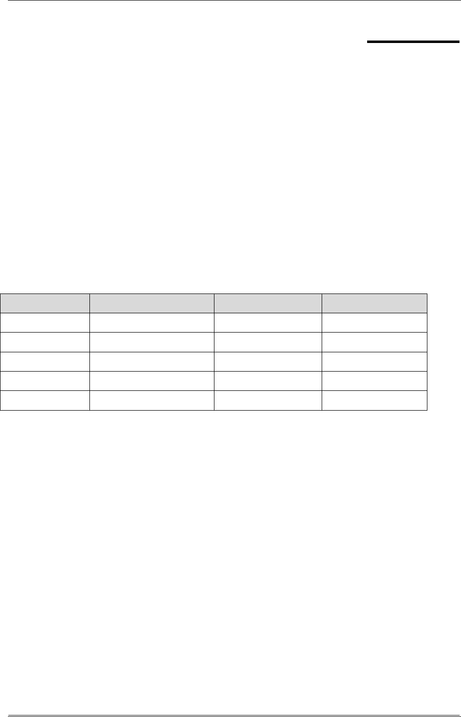
User Manual:
Open the PDF directly: View PDF ![]() .
.
Page Count: 57
Rockchip
Linux Camera Developer Guide
Release version: V1.1
Date: 2019.03

Rockchip Developer Guide
Warranty Disclaimer
The products, services, or characteristics you purchase shall be subject to the
commercial contract and terms of Rockchip. All or part of the products, services or
characteristics described in this document may not be within your purchase or use.
Unless otherwise agreed in the contract, Rockchip does not make any express or implied
warranty of the content of this document.
This document will be updated periodically due to product version upgrades or other
reasons. Unless otherwise agreed, this document serves only as usage guidance, and all
statements, information and recommendations in this document do not constitute any
express or implied warranties.
Brand Statement
Rockchip, RockchipTM icon, Rockchip and other Rockchip trademarks are trademarks of
Fuzhou Rockchip electronics., ltd., and are owned by Fuzhou Rockchip electronics co.,ltd.
All other trademarks or registered trademarks mentioned in this document are owned
by their respective owners.
Copyright © 2019 Fuzhou Rockchip Electronics Co., Ltd.
Without the written permission, any unit or individual shall not extract or copy part or
all of the content of this document, and shall not spread in any form.
Fuzhou Rockchip Electronics Co., Ltd
Address: No.18 Building, A District, No.89 Software Boulevard, FuZhou, FuJian, PRC
Website: www.rock-chips.com
Customer service Tel.: +86-591-83991906
Customer service Fax: +86-591-83951833
Customer service e-Mail: fae@rock-chips.com
Copyright © 2019 Fuzhou Rockchip Electronics Co., Ltd.
III
Rockchip Developer Guide
Preface
Overview
This document mainly introduces the new driver structure of CIF and ISP of Rockchip
chipset, and how to write/port sensor driver, how to apply demos and tools test in the
upper layer base on it.
In order to meet customization needs, the CIF, ISP and Camera drivers described in
this document all meet V4L2 standard interface as much as possible, providing a richer
configuration. At the same time, there are higher requirements for customers writing and
porting drivers. Customers need to know more about the underlying topology, V4L2
related concepts and so on.
Product version
Chipset
Kernel
CIF
ISP
PX3SE
4.4
Yes
NO
RK312x
4.4
Yes
NO
RK3288
4.4
Yes
Yes
RK332x
4.4
Yes
Yes
RK3399
4.4
NO
NO
Applicable to object
This document is mainly suitable for the following engineers:
- Field application engineers
- Software development engineers

Copyright © 2019 Fuzhou Rockchip Electronics Co., Ltd.
IV
Rockchip Developer Guide
Revision history
Date
Version
Author
Revision Description
2019.7.10
V1.0
ZSQ
Initial Release
2019.3.12
V1.1
Leo Wen
Update isp driver description
Add gstreamer application programming
Update 3A function description, etc.
Agreement
- Code and commands: the code and commands in this document are filled with gray
background
- Command format: the operation commands in the examples in this document use
the escape character '\' to split a line into multiple lines when there are multiple
lines. You can directly copy and paste when using, but if you put the command on
one line, please remove the escape character '\'

5
Rockchip Developer Guide Camera and driver introduciton
Copyright © 2019 Fuzhou Rockchip Electronics Co., Ltd.
Table of content
1 Camera and driver introduction ............................................................................... 9
1.1 Driver version ........................................................................................... 9
1.2 Acronyms ................................................................................................ 9
2 CIF driver and dts configuration ............................................................................. 11
2.1 CIF driver code introduction ......................................................................... 11
2.2 CIF dts configuration ................................................................................. 12
2.2.1 Board level configuration ....................................................................... 12
2.3 CIF Driver debug and frequently asked questions ................................................. 14
2.3.1 Whether cif probes successfully or not ........................................................ 14
2.3.2 Determine if sensor and CIF are bound ....................................................... 15
2.3.3 Turn on debug switch ........................................................................... 15
2.3.4 Frequently ask questions and answers ........................................................ 16
3 RKISP1 driver and dts configuration ........................................................................ 17
3.1 RKISP1 Driver code structure and its block diagram .............................................. 17
3.2 RKISP1 dts configuration ............................................................................ 19
3.2.1 Board level configuration of Rkisp1 dts ....................................................... 19
3.3 RKISP1 debug and frequently asked questions .................................................... 21
3.3.1 Driver probe status judgement ................................................................ 22
3.3.2 Judge whether sub-device is successfully bound ............................................. 23
3.3.3 Turn on debug switch ........................................................................... 23
3.3.4 Frequently ask questions and answers ........................................................ 24
4 Sensor driver development and port ........................................................................ 25
4.1 Power-on timing sequence ......................................................................... 26
4.1.1 Wether power-on sequence is correct......................................................... 27
4.2 Sensor initialization registers list ................................................................... 27
4.3 V4l2_subdev_ops callback function ................................................................. 27
4.4 V4l2 controller ........................................................................................ 28
4.5 Probe function and media entity, v4l2 subdev registration ....................................... 28
4.6 A dts example ......................................................................................... 29
4.7 Sensor debug and frequently ask questions ........................................................ 30
4.7.1 Is the sensor registered successfully? ......................................................... 30
4.7.2 Is there data output from sensor? ............................................................. 30
4.7.3 Check if controls are in effect .................................................................. 30
4.7.4 Frequently asked questions and answers ..................................................... 30
5 The v4l-utils tool and applications .......................................................................... 32
5.1 Obtain and compile v4l-utils ......................................................................... 32
5.2 FourCC ................................................................................................. 32
5.3 mbus-fmt .............................................................................................. 33
5.4 Media-ctl and topology ............................................................................... 33
5.4.1 Media-ctl: topology .............................................................................. 34
5.4.2 Case 1: CIF topology ............................................................................. 34
5.4.3 Case 2: ISP camera topology ................................................................... 36

6
Rockchip Developer Guide Camera and driver introduciton
Copyright © 2019 Fuzhou Rockchip Electronics Co., Ltd.
5.4.4 Media-ctl: entity, pad and link .................................................................. 38
5.4.5 Media-ctl: In-/Active Link ...................................................................... 39
5.4.6 Media-ctl: modify fmt/size ..................................................................... 40
5.5 The fmt, controls and grab frames Configurations by v4l2-ctl ................................... 41
5.5.1 Set fmt and grab frames ........................................................................ 42
5.5.2 Set control sush as exposure, gain, etc. ........................................................ 43
5.5.3 Play back frames on Ubuntu with mplayer ................................................... 43
5.5.4 Set fmt and grab raw data of Raw Bayer ...................................................... 44
5.5.5 Bayer Raw gragh converted to PGM ........................................................... 45
6 GStreamer preview ........................................................................................... 46
6.1 gst-launch-1.0 command ............................................................................. 46
6.1.1 gst-launch-1.0 command preview ............................................................. 46
6.1.2 Save a file by gst-launch-1.0 command ........................................................ 46
6.2 GStreamer application programming ............................................................... 46
7 3A Function integration ...................................................................................... 53
7.1 Applications development and demo ............................................................... 54
7.2 Gstreamer-1.0 3A plug-in ........................................................................... 54
7.3 Media device development demo ................................................................... 56
7.4 Video device development demo .................................................................... 56
7.5 V4l-subdev device development demo ............................................................. 56
8 Rk-isp10 driver introduction ................................................................................ 57

7
Rockchip Developer Guide Camera and driver introduciton
Copyright © 2019 Fuzhou Rockchip Electronics Co., Ltd.
List of figures
Figure 1 RKISP1 brief block diagram ........................................................................... 18
Figure 2 CIF topology ............................................................................................... 35
Figure 3 ISP Dual Camera topology ............................................................................ 39
Figure 4 The gst-video application preview .................................................................. 49
Figure 5 rkv4l2src plug-in information ......................................................................... 55

8
Rockchip Developer Guide Camera and driver introduciton
Copyright © 2019 Fuzhou Rockchip Electronics Co., Ltd.
List of tables
Table 1 Driver version ................................................................................................. 9
Table 2 CIF verification of each chip ............................................................................ 11
Table 3 MP and SP output function comparison ............................................................. 18
Table 4 ISP dts node information of each chip .............................................................. 19
Table 5 Rkisp1 registered video devices ....................................................................... 22
Table 6 Commonly used FourCC code in this document .................................................. 33
Table 7 Several mbus-fmt commonly used in this document ........................................... 33

9
Rockchip Developer Guide Camera and driver introduciton
Copyright © 2019 Fuzhou Rockchip Electronics Co., Ltd.
1 Camera and driver introduction
1.1 Driver version
Camera in this document refers to CIF or ISP of Rockchip chips and the sensor
connected to them. And the CIF and ISP driver described in this document refer to new
version driver for V4L2 Framework Standards which are based on Media Controller, Async
sub device, vb2.
The driver versions and support list are as follows.
Driver name
Type
Kernel version
Platform
Whether it was
decribed in this
document
Rkisp1
ISP
4.4
Linux
Yes
Rkcif
CIF
4.4
Linux
Yes
Oneframe
CIF
3.10 or 4.4
Linux
No
Rk-isp10
ISP
4.4
Linux
Yes, see the note for
details [1]
Table 1 Driver version
1.2 Acronyms
- 3A, refers to auto focus (AF), auto exposure (AE) and auto white balance (AWB)
algorithms, or algorithms .so library
- Async Sub Device, specifically refers to V4L2 sub-device under Media Controller
structure.
- Bayer Raw, or Raw Bayer, indicates the format of RGGB, BGGR, GBRG, GRBG
output by device (Sensor or ISP), or the data frame of the format.
- Buildroot, specifically refers to a series of Linux SDK base on Buildroot[
2
] released
by Rockchip.
- CIF, that is camera interface which is used to receive data from sensor and save it
to memory.
- DVP, is a parallel interface, short for Digital Video Port
- Entity, in this document, it refers to each node under Media Controller framework.
1
[] Rk-isp10 is still in support, but it does not use the structure of media controller, async sub
device, is not the focus of this document.
2
[] Buildroot see its official website: https://buildroot.org/

10
Rockchip Developer Guide Camera and driver introduciton
Copyright © 2019 Fuzhou Rockchip Electronics Co., Ltd.
- FCC or FourCC, that is Four Character (FCC) codes, and it refers to the image
format represented by 4 characters in Linux Kernel. For details, see FourCC.
- HSYNC, Line sync signal
- ISP, Image Signal Processing, used to receive and process images
- IOMMU, Input-Output Memory Management Unit, in this document, it means iohmu
module in Rockchip chips, it is used to map physically fragmented memory pages
into visible contiguous memory of cif or isp.
- IQ, Image Quality, in this document, it refers to the xml corresponding to IQ or IQ
debugged by bayer raw camera. It is used for 3A tunning
- Media Controller, a media framework for Linux kernel
- MIP, refers to MIPI protocol in this document.
- MIPI-DPHY refers to MIPI-DPHY protocol, or the controller that complies with MIPI-
DPHY protocol of Rockchip chips in this document.
- MP, Main Path, refers to an output node of Rockchip ISP, which can output full-
resolution images and generally used for taking pictures and grabing Raw graphs.
- PCLK is Pixel clock
- Pipeline refers to the link formed by the interconnection of each entity under media
controller in this document.
- SP, Self Path, refers to an output node of Rockchip ISP, which can only output
1080p resolution and generally used for preview.
- Userspace, that is Linux user space (relative to Linux kernel space), specifically
refers to user layer or the program executed at user layer in this document.
- V4L2, Video4Linux2, the video processing module of Linux kernel
- VIP refers to Video Input Processor in Rockchip chips, it once used as an alias for
CIF and it is no longer used.
- VSYNC, Field sync signal

11
Rockchip Developer Guide CIF driver and dts configuration
Copyright © 2019 Fuzhou Rockchip Electronics Co., Ltd.
2 CIF driver and dts configuration
This chapter mainly introduces CIF driver and dts configurations and the test
verification of CIF driver on each chip in detail.
CIF is a camera interface, once used the name of VIP (Video Input Processor) in
Rockchip series chips. Both of them refer to camera interface.
CIF support information on Linux SDK of each chip is as follows:
Platform
DVP
interface
MIPI CSI
Crop
Scale
Mode
Maximum
resolution
iommu
PX3SE
support
Not support
support
Not support
Oneframe
No
RK3288
support
Waiting for
verification
support
Not support
Oneframe
Yes
RK3326
support
Waiting for
verification
support
Not support
Oneframe
Yes
Table 2 CIF verification of each chip
Notice:
- In oneframe mode, if image resolution is higher, such as 1080p, fps may only
reach 15fps.
- MIPI CSI, on some platforms, CIF can receive images transmitted from MIPI CSI
- If there is no iommu function and buffer is allocated in mmap mode during reqbuf,
kernel is required to retain a larger CMA size。You can modify in kernel defconfig
as follows:
CONFIG_CMA_SIZE_MBYTES=64
2.1 CIF driver code introduction
The CIF kernel driver code is located in drivers/media/platform/rockchip/cif/ directory,
and the corresponding device tree binding document is located in
Documentation/devicetree/bindings/media/rockchip-cif.txt. Whether to compile is
controled by compiling switch CONFIG_VIDEO_ROCKCHIP_CIF.
The CIF driver performs hardware configuration, frame interrupt processing, and buffer
rotation according to media controller, v4l2, and vb2 frameworks. The function contents
of each file are as follows

12
Rockchip Developer Guide CIF driver and dts configuration
Copyright © 2019 Fuzhou Rockchip Electronics Co., Ltd.
$ tree drivers/media/platform/rockchip/cif/
drivers/media/platform/rockchip/cif/
├── capture.c //Mainly perform hardware configuration, related callback under v4l2,
vb2 framework, frame interrupt processing
├── dev.c // Mainly perform probe, sub-device asynchronous (Async) registration,
iommu and clk management
├── dev.h // Driver related structure definition
├── regs.h // Register macro definition
- CIF oneframe mode, in oneframe mode, each time the driver receives a frame
interrupt, the next frame buffer address is set in the interrupt handler function, and
then the next frame data is collected.
- CIF pingpong(Double buffers)mode. The driver has not been implemented.
2.2 CIF dts configuration
Please refer to Documentation/devicetree/bindings/media/rockchip-cif.txt first. This
document will be updated as the driver code is updated. In dtsi of the chip, the basic
information of cif is generally configured, including but not limited to:
- Reg, register offset address
- Clocks, the clocks needed. Clock-names need to be the same as defined in the
driver
- Reset, CIF can be reset with CRU software
- Interrupts
- Iommu, if there is iommu in cif, iommu will be enabled.
2.2.1 Board level configuration
Firstly, confirm whether there is a new cif driver node definition in the corresponding
chip-level dtsi. Please use compatible to distinguish between old and new cif drivers.
- The old cif drive

13
Rockchip Developer Guide CIF driver and dts configuration
Copyright © 2019 Fuzhou Rockchip Electronics Co., Ltd.
compatible = "rockchip,cif";
- The new cif driver
compatible = "rockchip,rk3xxx-cif";
Then confirm whether cif has iommu function. If there is an iommu node, it needs to be
set to "okay" state.
Finally, you need to define Remote Port[
1
] which connects sensor to CIF. During kernel
initialization process, sensor registers asynchronously with CIF. The two are finally bound
according to Remote Port information in dts.
Example 1, cif dts configuration on px3se evb board
CIF nodes are defined in arch/arm/boot/dts/rk312x.dtsi,
cif_new: cif-new@1010a000 {
compatible = "rockchip,rk3128-cif";
reg = <0x1010a000 0x200>;
clocks = <&cru ACLK_CIF>, <&cru HCLK_CIF>,
<&cru SCLK_CIF_OUT>;
clock-names = "aclk_cif", "hclk_cif",
"sclk_cif_out";
resets = <&cru SRST_CIF0>;
reset-names = "rst_cif";
interrupts = <GIC_SPI 8 IRQ_TYPE_LEVEL_HIGH>;
/* rk312x has not iommu attached */
/* iommus = <&cif_mmu>; */
power-domains = <&power RK3128_PD_VIO>;
status = "disabled";
};
Board level configuration is in arch/arm/boot/dts/px3se-evb.dts, need to reference
cif_new, and modify status state to okay, and finally add port sub-node.
&cif_new {
status = "okay";
1
[] More information about Remote Port see Documentation/devicetree/bindings/media/video-
interfaces.txt
14
Rockchip Developer Guide CIF driver and dts configuration
Copyright © 2019 Fuzhou Rockchip Electronics Co., Ltd.
port {
cif_in: endpoint {
remote-endpoint = <&adv7181_out>;
vsync-active = <0>;
hsync-active = <1>;
};
};
};
The Port subnode defines cif_in node and declares that the remote node to which it is
linked is adv7191_out. Because adv7181 uses dvp interface, it also specifies the valid
state of vsync, hsync here, where 0 means active low and 1 means active high.
2.3 CIF Driver debug and frequently asked questions
This chapter describes how to judge the status of CIF device, how to turn on debug
switch, and use v4l2-ctl to capture frames, use mplayer to play back images, gstreamer
previews, and frequently asked questions.
Commands in this chapter are based on px3se-evb boards. Other boards may be
different. In particular, the serial numbers of /dev/media0 and /dev/video0 device nodes
may be different. Even the serial number of video0 device may be changed on px3se-evb
board. Please refer to the method of how to obtain video device number in the chapter of
whether cif probes successfully or not.
2.3.1 Whether cif probes successfully or not
If CIF probes succesfully, there will be video and media devices in /dev/ directory. For
example, /dev/media0[
1
] device.
There may be several /dev/video devices in a system. You can query video node
corresponding to cif through the node under /sys.
[root@px3se:/]# grep -H '' /sys/class/video4linux/video*/name
/sys/class/video4linux/video0/name:stream_cif
It can be seen that cif device corresponds to video0 node, in other words, /dev/video0
1
[]If there are multiple media devices, the number is not necessarily 0. For example, if CIF and
ISP are enabled at the same time on 3288, there will be two media devices: /dev/media0 and
/dev/media1.

15
Rockchip Developer Guide CIF driver and dts configuration
Copyright © 2019 Fuzhou Rockchip Electronics Co., Ltd.
is cif device.
In addition, you can also print topology through media-ctl to see if pipeline is normal.
Please refer to media-ctl and topology.
If there are bugs, please check cif-related error log from kernel log. E.g,
[root@px3se:/]# dmesg | grep -i cif
Note:
- If you need to report cif bugs or issues to Rockchip, please provide the full kernel
log. The more complete the Log, the more helpful to analyze problems.
2.3.2 Determine if sensor and CIF are bound
As mentioned above, CIF and sensor are asynchronously loaded (probe) respectively. If
both drivers are loaded successfully, they will be bound together. At this point, it will
prompt accordingly in kernel log.
[root@px3se:/]# dmesg | grep Async
[ 2.681364] rkcif: Async subdev notifier completed
If you see “Async subdev notifier completed”, it means sensor and CIF are successfully
bound.
At the same time, users can still view media topology, there should be cif and sensor
two entities. Please refer to media-ctl and topology.
If asynchronous registration is found to be unsuccessful, that is, there is no "Async
subdev notifier completed" log, please check whether cif and sensor probe are wrong.
Frequently encountered case is sensor driver power-on timing is wrong, Sensor I2C
communication failure.
2.3.3 Turn on debug switch
The CIF driver contains some v4l2_dbg() logs. The log switch can be turned on by
command, as follows.
echo 1 > /sys/module/video_rkcif/parameters/debug
Turned on vb2 related log which mainly includes buffer rotation, such as reqbuf, qbuf,
dqbuf and buffer state changes, as follows. Note that vb2 module switch is a general

16
Rockchip Developer Guide CIF driver and dts configuration
Copyright © 2019 Fuzhou Rockchip Electronics Co., Ltd.
switch. Other related logs that use vb2 (such as VPU/ISP, etc.) will also enable output.
echo 7 > /sys/module/videobuf2_core/parameters/debug
Turn on v4l2 related log, such as ioctl call. The following command will turn on all v4l2
related logs.
echo 0x1f > /sys/class/video4linux/video0/dev_debug
It is also possible to turn on only a small part of log. The following macro[
1
] defines
which logs each bit will enable. Turn on the bit corresponding to required log.
/* Just log the ioctl name + error code */
#define V4L2_DEV_DEBUG_IOCTL 0x01
/* Log the ioctl name arguments + error code */
#define V4L2_DEV_DEBUG_IOCTL_ARG 0x02
/* Log the file operations open, release, mmap and get_unmapped_area */
#define V4L2_DEV_DEBUG_FOP 0x04
/* Log the read and write file operations and the VIDIOC_(D)QBUF ioctls */
#define V4L2_DEV_DEBUG_STREAMING 0x08
/* Log poll() */
#define V4L2_DEV_DEBUG_POLL 0x10
2.3.4 Frequently ask questions and answers
1
[]These macros are defined in kernel header file include/media/v4l2-ioctl.h

17
Rockchip Developer Guide RKISP1 driver and dts configuration
Copyright © 2019 Fuzhou Rockchip Electronics Co., Ltd.
3 RKISP1 driver and dts configuration
ISP is more complicated than CIF, and its functions are richer. This chapter mainly
introduces driver code structure, dts configuration, and debug method of RKISP1. Like
CIF, ISP driver conforms to media controller, v4l2, and vb2 frameworks, and is
independent of mipi-dphy and sensor and is registered asynchronously.
3.1 RKISP1 Driver code structure and its block diagram
RKISP1 driver code described in this chapter is located in
driver/media/platform/rockchip/isp1/ directory of kernel. It mainly implements hardware
configuration, interrupt processing, control buffer rotation, control subdevice (such as
mipi dphy and sensor) to power on and off according to v4l2 / media framework. Briefly
introduce the contents of each file in the driver as follows.
$ tree drivers/media/platform/rockchip/isp1/
drivers/media/platform/rockchip/isp1/
├── capture.c // Include mp/sp configuration and vb2, frame interrupt processing
├── dev.c // Contains probe, asynchronous registration, clock, pipeline, iommu and
media/v4l2 framework
├── isp_params.c // 3A Related parameters setting
├── isp_stats.c // 3A Related statistics
├── regs.c // Registers related read and write operations
├── rkisp1.c // Corresponding to isp_sd entity node, including receiving data from
mipi, crop function
$ ls drivers/phy/rockchip/phy-rockchip-mipi-rx.c
drivers/phy/rockchip/phy-rockchip-mipi-rx.c # mipi dphy driver
The block diagram below briefly describes the internal structure of ISP.

18
Rockchip Developer Guide RKISP1 driver and dts configuration
Copyright © 2019 Fuzhou Rockchip Electronics Co., Ltd.
Figure 1 RKISP1 brief block diagram
The above block diagram is mainly used to reflect the functional characteristics of ISP
input and output for users to understand.
- ISP can adapt DVP interface
- ISP can adapt MIPI interface, but need mipi dphy
- After an image is input to ISP, it can be divided into two MP and SP output. MP and
SP are the same image, but resize, crop can be different, and the output format
can be different.
- MP, MP is short for Main Path. It can output full resolution images up to 4416x3312
- MP can output yuv or raw images, and only MP can output raw images
- SP, that is Self Path. Supports up to 1920x1080 resolution
- SP can output yuv or rgb images, but can not output raw images
- Both MP and SP have the function of crop and resize, and they do not affect each
other.
Output device
Maximum
resolution
Support format
Crop/Resize
SP
1920 x 1080
YUV, RGB
Support
MP
4416 x 3312
YUV, RAW
Support
Table 3 MP and SP output function comparison

19
Rockchip Developer Guide RKISP1 driver and dts configuration
Copyright © 2019 Fuzhou Rockchip Electronics Co., Ltd.
3.2 RKISP1 dts configuration
Like CIF, there is also a complete document of RKISP1 DTS binding located in
Documentation/devicetree/bindings/media/rockchip-isp1.txt. Please refer to this
document first, it will keep up with the driver update. When a RK Linux SDK is released,
if the chip supports ISP, the rkisp1 node is already defined in dtsi, such as the isp node in
rk3288-rkisp1.dtsi, the rkisp1_0, rkisp1_1 node in rk3399.dtsi. The following table
describes the information of each chip ISP.
ISP
quantity
Dts node name
Corresponding mipi
dphy
Iommu node
RK3288
1
isp
RX0 or RX1
Support, isp_mmu
RK3399
2
rkisp1_0
RX0
Support, isp0_mmu
rkisp1_1
TX1RX1
Support, isp1_mmu
Table 4 ISP dts node information of each chip
Note:
- RK3288.dtsi also registered isp node, but it corresponds to the old driver. The new
driver is registered in the rk3288-rkisp1.dtsi file. Please include this file in board
configuration
- Multiple isp nodes are also registered in RK3399.dtsi. Please note what this chapter
described are rkisp1_0 and rkisp1_1.
- Iommu needs to be enabled or disabled with isp
- If there are multiple isp (such as rk3399), please note to choose the right iommu
node
3.2.1 Board level configuration of Rkisp1 dts
The board-level configuration is similar to CIF. The isp, mipi-dphy, and sensor are
separately defined nodes. The three are connected to each other through remote
endpoints. On the block diagram, mipi-dphy connects isp and sensor. The following
example is based on the dts board level configuration on RK3399 excavator and can be
found in the file rk3399-sapphire-excavator-edp.dts. On this board, both ISPs of RK3399
are enabled, only take rkisp1_0 as an example here.
First, set rkisp1_0 node to "okay" state.

20
Rockchip Developer Guide RKISP1 driver and dts configuration
Copyright © 2019 Fuzhou Rockchip Electronics Co., Ltd.
&isp0 {
status = "disabled";
};
&rkisp1_0 {
status = "okay";
port {
#address-cells = <1>;
#size-cells = <0>;
isp0_mipi_in: endpoint@0 {
reg = <0>;
remote-endpoint = <&dphy_rx0_out>;
};
};
};
Note,
- The node state of other versions of isp driver needs to be disabled. Otherwise two
different drivers will conflict
- The rkisp1_0 is defined in the Port node to be interconnected with dphy_rx0_out
node.
Secondly, the iommu corresponding to rkisp1_0 also needs to be "okay" status.
&isp0_mmu {
status = "okay";
};
Thirdly, sensor is mipi interface, so mipi dphy needs to be enabled as well.
&mipi_dphy_rx0 {
status = "okay";
ports {
#address-cells = <1>;
#size-cells = <0>;
port@0 {

21
Rockchip Developer Guide RKISP1 driver and dts configuration
Copyright © 2019 Fuzhou Rockchip Electronics Co., Ltd.
reg = <0>;
#address-cells = <1>;
#size-cells = <0>;
mipi_in_ucam0: endpoint@1 {
reg = <1>;
remote-endpoint = <&ucam_out0>;
data-lanes = <1 2>;
};
};
port@1 {
reg = <1>;
#address-cells = <1>;
#size-cells = <0>;
dphy_rx0_out: endpoint@0 {
reg = <0>;
remote-endpoint = <&isp0_mipi_in>;
};
};
};
};
Note:
- Dphy connects both isp and Sensor. So it has two endpoints. Mipi_in_ucam0 is
connected to Sensor, and dphy_rx0_out is connected to isp
- The data-lanes is declared in mipi_in_ucam0, indicating that sensor uses two lanes.
If there are 4 lanes, it should be defined as <1 2 3 4>. And so on. At last, board-
level sensor node is defined, and the port sub node needs to be declared to connect
to dphy_rx0_out of mipi dphy.
3.3 RKISP1 debug and frequently asked questions
This chapter mainly introduces how to debug ISP and judge whether driver is loaded
successfully and frequently asked questions and answers. Because ISP is similar to CIF in

22
Rockchip Developer Guide RKISP1 driver and dts configuration
Copyright © 2019 Fuzhou Rockchip Electronics Co., Ltd.
structure and uses the same framework, users can also refer to CIF driver debug and
frequently asked questions.
3.3.1 Driver probe status judgement
If RKISP1 probe succesfully, there will be video and media devices in /dev/ directory.
There may be multiple /dev/video devices in a system. You can query the video node
registered by RKISP1 through /sys. The following is the execution command and result[
1
]
(with deletion) on RK3399 Dru Chrome Table.
localhost ~ # grep '' /sys/class/video4linux/video*/name
/sys/class/video4linux/video3/name:rkisp1_selfpath
/sys/class/video4linux/video4/name:rkisp1_mainpath
/sys/class/video4linux/video5/name:rkisp1-statistics
/sys/class/video4linux/video6/name:rkisp1-input-params
The RKISP1 driver registers four devices, selfpath, mainpath, statistics, and input-
params. The first two are for frame output, and the last two are for 3A parameter setting
and statistics. By looking up the sys node under video4linux, we got RKISP1 information
of RK3399 Dru as shown in the following table.
Device node
Name
Functions
/dev/video3
SP(Self Path)
Video output
/dev/video4
MP(Main Path)
Video output
/dev/video5
Statistics
3A statistics
/dev/video6
Input-params
3A parameter settings
Table 5 Rkisp1 registered video devices
Note:
- Rkisp1 driver registers four /dev/video devices with continuous numbers.
- If the two isps of RK3399 platform are enabled at the same time, a total of 8
/dev/video devices will be registered. The first 4 belong to one isp and the last 4
belong to another isp. It is not possible to distinguish the order of two isp
1
[] 不同的板子返回会有差异,特别是当 VPU/CIF 等设备也有启用时。他们都是基于 v4l2 框架。

23
Rockchip Developer Guide RKISP1 driver and dts configuration
Copyright © 2019 Fuzhou Rockchip Electronics Co., Ltd.
registrations by software.
- In this example, the video number starts with 3. Because there are still vpu devices
occupying 0, 1, 2 three video nodes
Users can also print topology through media-ctl to see if pipeline is normal. Please refer
to media-ctl and topology.
If the above two methods return errors, please check kernel log for cif-related error
log. E.g,
[root@px3se:/]# dmesg | grep -i isp
Note:
- If users need to report ralated bugs or issues to Rockchip, please provide the full
kernel log. The more complete the Log, the more helpful to analyze problems.
3.3.2 Judge whether sub-device is successfully bound
Please use media-ctl print topology to see if the sensor registered by dts are
asynchronously registered as an Entity. And when all sensors are registered, kernel will
print the following log.
localhost ~ # dmesg | grep Async
[ 0.682982] rkisp1: Async subdev notifier completed
If there is no Async subdev notifier completed this line log in kernel, or the topology
does not match expected, please first check whether the sensor has an error, and
whether I2C communication is successful.
3.3.3 Turn on debug switch
We will introduce three debugging switches, v4l2_dbg switch for rkisp1 driver, log
switch for vb2 module, and log switch for v4l2 frame layer.
The Rkisp1 driver contains some v4l2_dbg, such as format, size parameter settings,
and dropped frames in interrupt, as follows
echo 1 > /sys/module/video_rkisp1/parameters/debug
The log switch of Vb2 module and v4l2 frame layer is the same as CIF. Please refer to
turn on debug switch. The two points as follows have to note.
- All modules that use vb2, such as isp, vpu, cif, are enabled and output by vb2 log
switch.

24
Rockchip Developer Guide RKISP1 driver and dts configuration
Copyright © 2019 Fuzhou Rockchip Electronics Co., Ltd.
- Log of V4l2 framework layer is for a specific /dev/video node, so only certain video
devices are enabled. For information on how to find video device required by users,
please refer to the probe driver status judgment chapter.
3.3.4 Frequently ask questions and answers

25
Rockchip Developer Guide Sensor driver development and port
Copyright © 2019 Fuzhou Rockchip Electronics Co., Ltd.
4 Sensor driver development and port
The sensor driver is located in drivers/media/i2c directory. Note that the sensor driver
described in this chapter are with media controller attribute, so the driver in the
drivers/media/i2c/soc_camera directory is not applicable.
The sensor driver is completely independent of CIF or RKISP1 driver, the two are
registered asynchronously, and finally the connection is established via remote-endpoint.
Therefore, the sensor driver described in this chapter applies to both CIF and RKISP1.
Under Media Controller structure, sensor is generally used as a sub-device and linked
to cif, isp or mipi phy via a pad. This chapter mainly introduces the sensor driver code[
1
],
dts configuration, and how to verify the correctness of sensor driver.
This chapter summarizes the development of sensor driver development into five parts.
- Write power-on sequence according to the datasheet, including vdd, reset,
powerdown, clk, etc.
- Configure sensor registers to output the desired resolution and format.
- Write the callback function required by struct v4l2_subdev_ops, generally including
set_fmt, get_fmt, ov5695_s_stream
- Add v4l2 controller to set such as fps, exposure, gain, test pattern
- Write .probe() function and add media control and v4l2 sub device initialization
code
As a good habit, after completing driver encoding, you need to add the corresponding
documentation. You can refer to Documentation/devicetree/bindings/media/i2c/. The
board level dts can be quickly configured according to this document.
In the board level dts, following items are generally required when using sensor driver:
- Configure correct clk, io mux
- Set regulator and gpio required for power-on sequence according to the schematic
- Add a port sub node to establish a connection with cif or isp
This chapter will take ov5695 and ov2685 as examples, and simply analyzes sensor
driver.
1
[] Sensor driver development requires users to understand some basic knowledge of v4l2
framework. This chapter only briefly analyzes and describes outline based on the existing code. In
the actual development process, you may encounter various problems, most of which cannot be
explained here.

26
Rockchip Developer Guide Sensor driver development and port
Copyright © 2019 Fuzhou Rockchip Electronics Co., Ltd.
4.1 Power-on timing sequence
Different sensors have different power-on timing requirements, such as OV Camera.
Most of OV Camera may not have strict timing requirements. As long as mclk, vdd, reset
or powerdown status is correct, I2C communication can be performed correctly and
images can be output. However, there are still a small number of sensors that have strict
requirements for power-on. For example, OV2685 must be powered on in strict timing
sequence.
In dataSheets provided by sensor manufacturer, there are usually power-on sequence
diagrams, which only need to be configured in order. Take OV5695 as an example, where
__ov5695_power_on() is used to power up sensor. As follows (with deletion).
static int __ov5695_power_on(struct ov5695 *ov5695)
{
ret = clk_prepare_enable(ov5695->xvclk);
if (!IS_ERR(ov5695->reset_gpio))
gpiod_set_value_cansleep(ov5695->reset_gpio, 1);
ret = regulator_bulk_enable(OV5695_NUM_SUPPLIES, ov5695->supplies);
if (!IS_ERR(ov5695->reset_gpio))
gpiod_set_value_cansleep(ov5695->reset_gpio, 0);
if (!IS_ERR(ov5695->pwdn_gpio))
gpiod_set_value_cansleep(ov5695->pwdn_gpio, 1);
/* 8192 cycles prior to first SCCB transaction */
delay_us = ov5695_cal_delay(8192);
usleep_range(delay_us, delay_us * 2);
return 0;
}
The power-on sequence of OV5695 is briefly described as follows
- First provide xvclk (mclk)
- Next enable reset pin
- Each VDD power on. Regulator_bulk is used here for vdd, vodd, avdd are not
strictly ordered. If there are strict requirements between vdd, it need to be handled

27
Rockchip Developer Guide Sensor driver development and port
Copyright © 2019 Fuzhou Rockchip Electronics Co., Ltd.
separately, please refer to OV2685 driver code.
- After Vdd is powered on, cancel Sensor Reset and powerdown status. Reset and
powerdown may only need one, if sensor package is different, there may be
differences
- Finally, according to timing requirements, after 8192 clk cycles, power-on is
completed.
Note that although many sensors can work when do not follow the datasheet
requirements, the timings recommended by manufacturer are undoubtedly the most
reliable.
Similarly, there will be a Power Down Sequence in the datasheet, which is also
available on request.
4.1.1 Wether power-on sequence is correct
During .probe() process, it will try to read chip id, such as ov5695_check_sensor_id()
of ov5695. If chip id can be read correctly, it is generally considered that power-on
sequence is correct and sensor can perform i2c communication normally.
4.2 Sensor initialization registers list
In OV5695 and OV2685, struct ov5695_mode and struct ov2685_mode are defined to
indicate different initialization modes of sensor. Mode can include resolution, mbus code,
register initialization list, and so on.
Registers initialization list, please fill in directly according to manufacturers. It should
be noted that the list ends with REG_NULL.
4.3 V4l2_subdev_ops callback function
V4l2_subdev_ops callback function is the core of logic control in sensor driver. The
callback function includes a lot of functions, you can check the kernel code
include/media/v4l2-subdev.h for details. It is recommended that sensor driver include at
least the following callback function.
- .open, in this way the upper layer can open /dev/v4l-subdev? node. When the
upper layer needs to set v4l control separately for sensor, .open() must be
implemented.
- .s_stream, that is, set stream, including stream on and stream off, generally

28
Rockchip Developer Guide Sensor driver development and port
Copyright © 2019 Fuzhou Rockchip Electronics Co., Ltd.
configure registers here to output images.
- .enum_mbus_code, enumerate driver-supported mbus_code
- .enum_frame_size, enumeration driver supported resolution
- .get_fmt, returns format/size selected by current sensor. If .get_fmt is missing,
media-ctl tool cannot view the fmt currently configured by sensor entity.
- .set_fmt, set format/size of sensor
In the above callback, .s_stream stream_on is more complicated. In ov5695 driver
code, it includes pm_runtime enable (wake up and power up), configure control
information (v4l2 control may be configured when sensor is powered off) that is
v4l2_ctrl_handler_setup(), and finally write to stream on of register.
4.4 V4l2 controller
When fps, exposure, gain, and blanking need to be configured, the part of v4l2
controller is necessary. In the OV5695 driver code,
- ov5695_initialize_controls(), used to declare which controls are supported, and set
the maximum and minimum information.
- Struct v4l2_ctrl_ops, contains ov5695_set_ctrl() callback function to respond to the
settings of upper layers
4.5 Probe function and media entity, v4l2 subdev
registration
In the Probe function, firstly parse the dts to get the information such as regulator,
gpio, clk, etc. which is used to sensor power on and off. Secondly, register media entity,
v4l2 subdev, and v4l2 controller information. Note that the registration of v4l2 subdev is
asynchronous. Below are some key functions call.
- v4l2_i2c_subdev_init(), register as a v4l2 subdev with a callback function in the
parameter
- ov5695_initialize_controls(), initialize v4l2 controls
- media_entity_init(), registered as a media entity, OV5695 has only one output that
is Source Pad
- v4l2_async_register_subdev(), declare that sensor needs to be registered
asynchronously. Since RKISP1 and CIF both use asynchronous registration of sub

29
Rockchip Developer Guide Sensor driver development and port
Copyright © 2019 Fuzhou Rockchip Electronics Co., Ltd.
devices, this call is required.
4.6 A dts example
The dts configurations of snsor are similar. According to the hardware design, it is
mainly included pinctl (iomux), clk, gpio, and remote port.
The following example is OV5695 dts node on RK3399 Dru Chrome Tablet
wcam: camera@36 {
compatible = "ovti,ov5695";
reg = <0x36>;
pinctrl-names = "default";
pinctrl-0 = <&wcam_rst &test_clkout1>;
clocks = <&cru SCLK_TESTCLKOUT1>;
clock-names = "xvclk";
avdd-supply = <&pp2800_cam>;
dvdd-supply = <&pp1250_cam>;
dovdd-supply = <&pp1800_s0>;
reset-gpios = <&gpio2 5 GPIO_ACTIVE_LOW>;
port {
wcam_out: endpoint {
remote-endpoint = <&mipi_in_wcam>;
data-lanes = <1 2>;
};
};
};
Note:
- Pinctrl, declares the necessary pinctrl, which includes reset pin initialization and clk
iomux
- Clock, the specified name is xvclk (driver will read clock named xvclk), that is, 24M
clock.
- Vdd supply, OV5695 need three power supplies.

30
Rockchip Developer Guide Sensor driver development and port
Copyright © 2019 Fuzhou Rockchip Electronics Co., Ltd.
- Port subnode defines an endpoint that declares a connection to mipi_in_wcam.
Similarly mipi dphy will reference wcam_out
- Data-lanes specifies that OV5695 uses two lanes
4.7 Sensor debug and frequently ask questions
4.7.1 Is the sensor registered successfully?
The first key point for sensor debugging is whether i2c can communicate successfully
and chip id check is correct. If so, it can generally indicate that there is no problem with
power-on sequence.The related log will usually be printed out in driver. Logs of different
sensors are not the same, it will not take examples here. Second, check media-ctl
topology to see if sensor is already registered as an entity. If so, sensor has been
registered successfully.
4.7.2 Is there data output from sensor?
Direct measurement of hardware MIPI signal CLK and Data Lane is the most accurate
method if conditions permit. Is there a signal output, and whether the signal amplitude is
correct, etc.
If there is an interruption in CIF or ISP can be judged by software. For example, if
kernel log has errors reported by CIF or ISP.
4.7.3 Check if controls are in effect
The v4l2-ctl can be used to set related parameters, such as gain, exposure, blanking
and generate images to see if controls of sensors are in effect. For example, increase
gain or exposure, whether the brightness of pictures increases; when increase blanking,
whether frame rate drops.
4.7.4 Frequently asked questions and answers
Q: It has been repeatedly checked that power-on sequence meets the datasheet
requirements, but I2c communication is unsuccessful.
A: It has encountered several reasons before, as follows
- Io domain setting is incorrect, causing i2c clk and data output amplitudes to be
incorrect (although there are waveforms). For example, power supply is 1.8v, but
the io domain is set to 3.3v.

31
Rockchip Developer Guide Sensor driver development and port
Copyright © 2019 Fuzhou Rockchip Electronics Co., Ltd.
- Regulator start up delay is too large, resulting in the fact that although power-up
sequence configured in the code is correct, the actual measurement still does not
meet the requirements. For example, the regulator used by OV2685 pp1250_dvdd
on a board is valid from input to output, and has a delay of 740 us, causing power
on is too slowly and timing sequence is error.
- I2C slave address configuration is wrong

32
Rockchip Developer Guide The v4l-utils tool and applications
Copyright © 2019 Fuzhou Rockchip Electronics Co., Ltd.
5 The v4l-utils tool and applications
The v4l-utils tool is a V4L2 development kit maintained by Linuxtv[1]. It provides a set
of V4L2 and media framework related tools for configuring V4L2 sub-device properties,
testing V4L2 devices, and providing development libraries such as libv4l2.so and so on.
This chapter mainly introduces two command-line tools in v4l-utils: media-ctl and v4l2-
ctl
- media-ctl, used to view and configure topology
- v4l2-ctl, used to configure v4l2 controls, capture frames, set cif, isp, sensor
parameters
The format code of different versions of v4l-utils will be different, especially mbus-fmt
part. The version used in this document is v4l-utils-1.14.1 integrated in Linux SDK.
5.1 Obtain and compile v4l-utils
In the Linux SDK released by Rockchip, v4l-utils package has been integrated by
default. Users can turn v4l-utils package on or off with buildroot compile switch. In the
buildroot/configs/rockchip_px3se_defconfig file of SDK directory, the following line opens
v4l-utils compile option:
BR2_PACKAGE_LIBV4L_UTILS=y
Users can also get the source code compilation on Linuxtv official website. Please refer
to wiki for compilation.
4l-utils package is under ubuntu system, it can also be installed directly through apt
tool, as follows
$ sudo apt-get install v4l-utils
5.2 FourCC
FourCC is short for Four Character Codes, uses 4 characters (that is 32bit) to name
image format. In Linux Kernel, it is a macro, and defined as follows:
#define v4l2_fourcc(a,b,c,d) \
(((__u32)(a)<<0)|((__u32)(b)<<8)|((__u32)(c)<<16)|((__u32)(d)<<24))
The format defined by FourCC is the format in which image videos are stored in
memory. This point should be distinguished from mbus-fmt below.

33
Rockchip Developer Guide The v4l-utils tool and applications
Copyright © 2019 Fuzhou Rockchip Electronics Co., Ltd.
The following are a few of formats commonly used in this document. See videodev2.h
of kernel code for details.
Image format
FourCC
V4L2_PIX_FMT_NV12
NV12
V4L2_PIX_FMT_NV21
NV21
V4L2_PIX_FMT_NV16
NV16
V4L2_PIX_FMT_NV61
NV61
V4L2_PIX_FMT_NV12M
NM12
V4L2_PIX_FMT_YUYV
YUYV
V4L2_PIX_FMT_YUV420
YU12
V4L2_PIX_FMT_SBGGR10
BG10
V4L2_PIX_FMT_SGBRG10
GB10
V4L2_PIX_FMT_SGRBG10
BA10
V4L2_PIX_FMT_SRGGB10
RG10
Table 6 Commonly used FourCC code in this document
5.3 mbus-fmt
The mbus-fmt is short for Media Bus Pixel Codes which describes the format used for
transmission over physical bus, such as the image format that sensor transmits to ISP
via mipi dphy, or the format transmitted between submodules within ISP. In particular, it
is necessary to distinguish Mbus-fmt from FourCC of the previous chapter, which is
specifically the image format stored in Memory.
The following table lists several Mbus-fmts commonly used in this document.
Name
Type
Bpp
Bus width
Sampes per
Pixel
MEDIA_BUS_FMT_SBGGR10_1X10
Bayer Raw
10
10
1
MEDIA_BUS_FMT_SGBRG10_1X10
Bayer Raw
10
10
1
MEDIA_BUS_FMT_YUYV8_2X8
YUV:422
16
8
2
MEDIA_BUS_FMT_YUYV8_1_5X8
YUV:420
12
8
1.5
Table 7 Several mbus-fmt commonly used in this document
The latest media-ctl can list the supported mbus code as follows:
media-ctl --known-mbus-fmts
5.4 Media-ctl and topology
Media-ctl is a tool in v4l-utils package. It is mainly used to configure fmt, size, and link

34
Rockchip Developer Guide The v4l-utils tool and applications
Copyright © 2019 Fuzhou Rockchip Electronics Co., Ltd.
nodes of media framework. Users can query the usage method by the following help.
This chapter will also introduce several common examples.
[root@px3se:/]# media-ctl --help
media-ctl [options]
-d, --device dev Media device name (default: /dev/media0)
-e, --entity name Print the device name associated with the given entity
-V, --set-v4l2 v4l2 Comma-separated list of formats to setup
--get-v4l2 pad Print the active format on a given pad
--set-dv pad Configure DV timings on a given pad
-h, --help Show verbose help and exit
-i, --interactive Modify links interactively
-l, --links links Comma-separated list of link descriptors to setup
--known-mbus-fmts List known media bus formats and their numeric values
-p, --print-topology Print the device topology. If an entity
is specified through the -e option, print
information for that entity only.
--print-dot Print the device topology as a dot graph
-r, --reset Reset all links to inactive
-v, --verbose Be verbose
...................
5.4.1 Media-ctl: topology
If driver supports Media Controller, a media device such as /dev/media0 will be created
after CIF or ISP is successfully loaded. Media-ctl is used to print out the current pipeline
link.
The next few chapter describe some cases of CIF and ISP topologies.
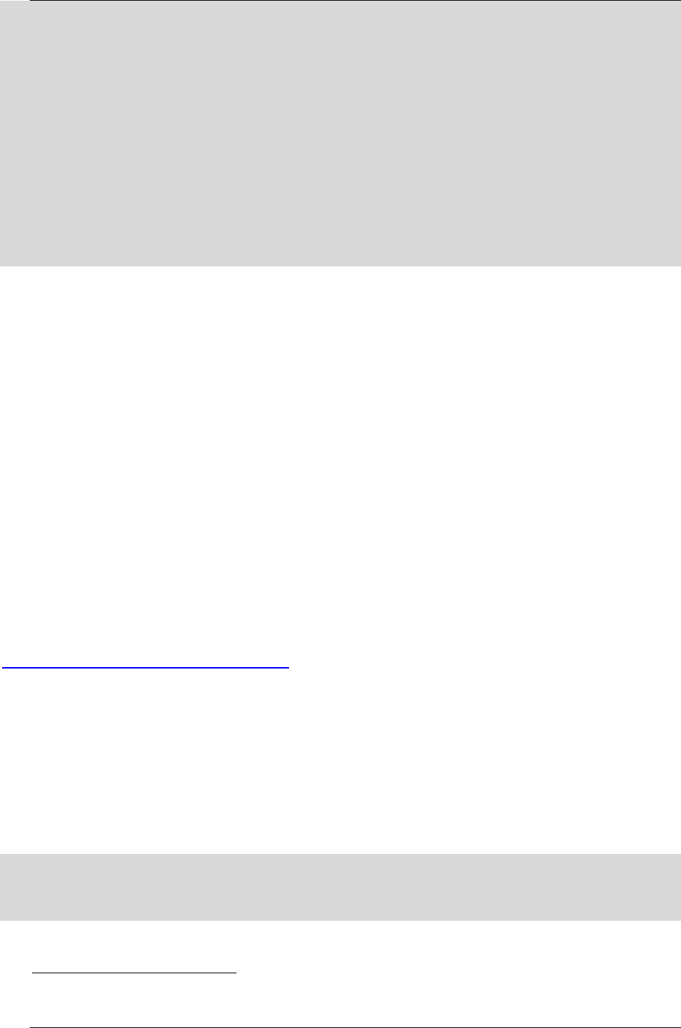
5.4.2 Case 1: CIF topology
CIF topology in figure 2 is cif topological structure of px3se evb board. ADV7181 is
linked to CIF Sink as a sub-device source.
35
Rockchip Developer Guide The v4l-utils tool and applications
Copyright © 2019 Fuzhou Rockchip Electronics Co., Ltd.
Figure 2 CIF topology
Topology can be printed out via media-ctl as follows (with deletion).
[root@px3se:/]# media-ctl -p /dev/media0
Media controller API version 0.1.0
------------------------
driver rkcif
Device topology
- entity 1: stream_cif (1 pad, 1 link)
type Node subtype V4L flags 0
device node name /dev/video0
pad0: Sink
<- "adv7181 2-0021":0 [ENABLED]
- entity 2: adv7181 2-0021 (1 pad, 1 link)
type V4L2 subdev subtype Sensor flags 0
device node name /dev/v4l-subdev0
pad0: Source
[fmt:UYVY8_2X8/720x480 field:none colorspace:smpte170m]
-> "stream_cif":0 [ENABLED]

36
Rockchip Developer Guide The v4l-utils tool and applications
Copyright © 2019 Fuzhou Rockchip Electronics Co., Ltd.
5.4.3 Case 2: ISP camera topology
Taking RK3326 EVB as an example, sensor Ov5695 is connected to mipi dphy via mipi
bus; after ISP collects mipi data, the corresponding image processing is performed by isp
entity, such as demosaicing; mp, sp can configure the format and resolution of
respective output frame data.
Print out more information through media-ctl, such as the input and output format and
size of current entity, whether it has crop and resize capabilities. The following is the
media topology of RK3326 EVB
[root@rk3326_64:/]# media-ctl -d /dev/media1 -p
Media controller API version 0.1.0
Media device information
------------------------
driver rkisp1
model rkisp1
serial
bus info
hw revision 0x0
driver version 0.0.0
Device topology
- entity 1: rkisp1-isp-subdev (4 pads, 5 links)
type V4L2 subdev subtype Unknown flags 0
device node name /dev/v4l-subdev0
pad0: Sink
[fmt:SBGGR10_1X10/2592x1944 field:none
crop.bounds:(0,0)/2592x1944
crop:(0,0)/2592x1944]
<- "rockchip-mipi-dphy-rx":1 [ENABLED]
pad1: Sink

37
Rockchip Developer Guide The v4l-utils tool and applications
Copyright © 2019 Fuzhou Rockchip Electronics Co., Ltd.
<- "rkisp1-input-params":0 [ENABLED]
pad2: Source
[fmt:YUYV8_2X8/2592x1944 field:none
crop.bounds:(0,0)/2592x1944
crop:(0,0)/2592x1944]
-> "rkisp1_selfpath":0 [ENABLED]
-> "rkisp1_mainpath":0 [ENABLED]
pad3: Source
-> "rkisp1-statistics":0 [ENABLED]
- entity 2: rkisp1_mainpath (1 pad, 1 link)
type Node subtype V4L flags 0
device node name /dev/video1
pad0: Sink
<- "rkisp1-isp-subdev":2 [ENABLED]
- entity 3: rkisp1_selfpath (1 pad, 1 link)
type Node subtype V4L flags 0
device node name /dev/video2
pad0: Sink
<- "rkisp1-isp-subdev":2 [ENABLED]
- entity 4: rkisp1-statistics (1 pad, 1 link)
type Node subtype V4L flags 0
device node name /dev/video3
pad0: Sink
<- "rkisp1-isp-subdev":3 [ENABLED]
- entity 5: rkisp1-input-params (1 pad, 1 link)
type Node subtype V4L flags 0
device node name /dev/video4

38
Rockchip Developer Guide The v4l-utils tool and applications
Copyright © 2019 Fuzhou Rockchip Electronics Co., Ltd.
pad0: Source
-> "rkisp1-isp-subdev":1 [ENABLED]
- entity 6: rockchip-mipi-dphy-rx (2 pads, 2 links)
type V4L2 subdev subtype Unknown flags 0
device node name /dev/v4l-subdev1
pad0: Sink
[fmt:SBGGR10_1X10/2592x1944 field:none]
<- "ov5695 2-0036":0 [ENABLED]
pad1: Source
[fmt:SBGGR10_1X10/2592x1944 field:none]
-> "rkisp1-isp-subdev":0 [ENABLED]
- entity 7: ov5695 2-0036 (1 pad, 1 link)
type V4L2 subdev subtype Sensor flags 0
device node name /dev/v4l-subdev2
pad0: Source
[fmt:SBGGR10_1X10/2592x1944@10000/300000 field:none]
-> "rockchip-mipi-dphy-rx":0 [ENABLED]
5.4.4 Media-ctl: entity, pad and link
Entity represents a node in Media Controller. It contains one or more input and output
pads. Link represents a link that connects multiple different pads. Multiple links form a
complete pipeline.
The name of Entity can be viewed from topology. For example, the following are the
names of entity.
- ov5695 2-0036
- rkisp1-isp-subdev
- rkisp1_mainpath
Pad is represented by a number. An Entity can contain multiple pads, either Source or

39
Rockchip Developer Guide The v4l-utils tool and applications
Copyright © 2019 Fuzhou Rockchip Electronics Co., Ltd.
Sink.
Link connects two "entities": pad, such as the link shown below,
- "rkisp1-isp-subdev":2->"rkisp1_mainpath":0
- "rkisp1-isp-subdev":3->"rkisp1-statistics":0
The status of link can be Active or In-Active.
Media Controller provides a flexible configuration of pipeline. In CIF and ISP driver
initialization process, Link is completely established according to configurations. If there
are multiple sensors, one of them will be activated.
You can use media-ctl command to modify active state of Link. You can also modify
format and size of Pad.
5.4.5 Media-ctl: In-/Active Link
The following error: The reference source is not found, two sensors are connected to
the same mipi dphy, and sensor can be enabled or disabled by userspace. Ov5695 and
Ov2685 sensors are connected to mipi dphy via mipi bus. The two sensors in this Case
can only have one be enabled at a time.
Figure 3 ISP Dual Camera topology
Error: The reference source was not found. There are multiple sensors connected to the
same Mipi D-Phy, and only one of them can be active. The following example sets
ov2659 to active

40
Rockchip Developer Guide The v4l-utils tool and applications
Copyright © 2019 Fuzhou Rockchip Electronics Co., Ltd.
#First set ov5695 to In-Active
media-ctl -d /dev/media1 -l '"ov5695 2-0036":0->"rockchip-mipi-dphy-rx":0[0]'
#Then set ov2685 to Active
media-ctl -d /dev/media1 -l '"ov2685 2-003c":0->"rockchip-mipi-dphy-rx":0[1]'
Note:
- Format: media-ctl -l '"entity name":pad->"entity name":pad[Status]'
- The entire link needs to use single quotes because there are special characters
like > [ ]
- Entity name needs to use double quotes because there is a space in between
- Status with 0 or 1 indicates Active or In-Active and need to use brackets [ ]
5.4.6 Media-ctl: modify fmt/size
Error: reference source is not found, the following example shows how to modify
fmt/size
Example 1, modify the size of ov5695 output to 640x480 (The precondition is that
ov5695 driver already supports 640x480 output, otherwise the setting will not succeed),
and set the input and output resolution of the entire pipeline to 640x480, and the format
of isp entity is YUYV.
# Set the sensor output to 640x480
media-ctl -d /dev/media0 \
--set-v4l2 '"ov5695 7-0036":0[fmt:SBGGR10_1X10/640x480]'
# Set isp receiving (from mipi dphy) format and size, the format requirements are the
same as sensor output
media-ctl -d /dev/media0 \
--set-v4l2 '"rkisp1-isp-subdev":0[fmt:SBGGR10_1X10/640x480]'
# isp Receiving size can be cropped, but still keep 640x480 here
media-ctl -d /dev/media0 \
--set-v4l2 '"rkisp1-isp-subdev":0[crop:(0,0)/640x480]'
# Set isp output, YUV format can only be YUYV2X8
media-ctl -d /dev/media0 \

41
Rockchip Developer Guide The v4l-utils tool and applications
Copyright © 2019 Fuzhou Rockchip Electronics Co., Ltd.
--set-v4l2 '"rkisp1-isp-subdev":2[fmt:YUYV8_2X8/640x480]'
# isp output also has crop function, but also keep 640x480
media-ctl -d /dev/media0 \
--set-v4l2 '"rkisp1-isp-subdev":2[crop:(0,0)/640x480]'
Note:
- Different versions of v4l-utils may have different fmt codes, preferably use media-
ctl
media-ctl --known-mbus-fmts
- Pay attention to special characters, single or double quotes is needed
- Be careful not to leave spaces in quotes, and don't leave more spaces.
- Please use media-ctl --help to see more detailed help
5.5 The fmt, controls and grab frames Configurations by
v4l2-ctl
The operation of Media-ctl tool is through media devices such as /dev/medio0, which
manages the format, size, and link of each node in the topology of media. V4l2-ctl tool is
for video devices such as /dev/video0, /dev/video1, and it performs set_fmt, reqbuf,
qbuf, dqbuf, stream_on, stream_off and other operations on video devices.
In this document, we mainly use v4l2-ctl to collect frame data, and set v4l2_control
such as exposure, gain, VTS, etc.
First of all, it is recommended to first check the help file of v4l2-ctl. Help document
contents are so much and divided into many parts, we are more concerned about
streaming, vidcap.
View help document outline as follows
$ v4l2-ctl --help
See the full help document below with a lot of contents.
$ v4l2-ctl --help-all
View the parameters related to streaming as follows.
$ v4l2-ctl --help-streaming
View parameters related to vidcap as follows. It mainly includes get-fmt, set-fmt and

42
Rockchip Developer Guide The v4l-utils tool and applications
Copyright © 2019 Fuzhou Rockchip Electronics Co., Ltd.
so on.
$ v4l2-ctl --help-vidcap
5.5.1 Set fmt and grab frames
For specific use of V4l2-ctl, please refer to v4l-utils tool and application. Only px3se-
evb board is taken as an example here. Generally, CIF media topology is very simple,
with only one sensor and cif two entities. If the output format and size of sensor do not
need to be modified and the default value is used, you do not need media-ctl
configuration to grab a frame directly using v4l2-ctl. The following only need to specify
the related parameters such as fmt, count.
v4l2-ctl -d /dev/video0 \
--set-fmt-video=width=720,height=480,pixelformat=NV12 \
--stream-mmap=3 \
--stream-skip=3 \
--stream-to=/tmp/cif.out \
--stream-count=1 \
--stream-poll
Note of the parameters:
- -d, specify the operation object as /dev/video0 device
- --set-fmt-video, specify width and height and pxielformat
- NV12, that is, pixelformat represented by FourCC. See FourCC code above for
details.
- --stream-mmap, specified buffer type as mmap, which is physical continuous or
iohmu mapped buffer allocated by kernel.
- --stream-skip, specify the first 3 frames of discard (not saved to file)
- --stream-to, specify the file path where frame data is saved
- --stream-count, specifies the number of frames to grab, excluding the number of --
stream-skip drops
- --stream-poll, this option indicates v4l2-ctl uses asynchronous IO, in other word,
using the select until frame data is complete before dqbuf to ensure that dqbuf
does not block. Otherwise dqbuf will block until a data frame arrives.

43
Rockchip Developer Guide The v4l-utils tool and applications
Copyright © 2019 Fuzhou Rockchip Electronics Co., Ltd.
5.5.2 Set control sush as exposure, gain, etc.
If sensor driver has implemented v4l2 control, such as exposure, gain, etc. can be set
by v4l2-ctl before an image is acquired.
CIF or ISP will inherit control of sub device, so you can see v4l2 control of sensor
through /dev/video3. The following are the related settings of OV5695 viewed on Dru
machine, including exposure, gain, blanking, test_pattern, etc.
localhost /tmp # v4l2-ctl -d /dev/video3 -l
User Controls
exposure (int) : min=4 max=2020 step=1 default=1104 value=1104
gain (int) : min=0 max=16383 step=1 default=1024 value=1024
Image Source Controls
vertical_blanking (int) : min=40 max=31795 step=1 default=40 value=80
horizontal_blanking (int) : min=1664 max=1664 step=1 default=1664
analogue_gain (int) : min=16 max=248 step=1 default=248 value=248
Image Processing Controls
link_frequency (intmenu): min=0 max=0 default=0 value=0 flags=read-only
pixel_rate (int64) : min=0 max=180000000 step=1 default=180000000
value=180000000 flags=read-only
test_pattern (menu) : min=0 max=4 default=0 value=0
These controls can be modified with v4l2-ctl. Such as modifying exposure and
analogue_gain as follows
v4l2-ctl -d /dev/video3 --set-ctrl 'exposure=1216,analogue_gain=10'
Note:
- If there are special characters, it require single quotes
- If multiple cameras are connected to the same ISP, only the control of the first
sensor can be viewed and modified. Are there bugs in V4l2-ctl, or is it because the
driver does not implement G/S_INPUT?
5.5.3 Play back frames on Ubuntu with mplayer
After the captured frame data is saved to a file, images can be played back on PC. For

44
Rockchip Developer Guide The v4l-utils tool and applications
Copyright © 2019 Fuzhou Rockchip Electronics Co., Ltd.
example, on ubuntu you can play with mplayer.
W=720; H=480; mplayer /tmp/cif.out -loop 0 -demuxer rawvideo -fps 25 \
-rawvideo w=${W}:h=${H}:size=$((${W}*${H}*3/2)):format=nv12
For more detailed usage of mplayer, please refer to mplayer manual[
1
], or online
tutorial.
5.5.4 Set fmt and grab raw data of Raw Bayer
The rkisp driver will synchronize format/size information of currently connected sensor,
and set on nodes of each pipeline. You do not need to go through the upper layer
settings. If you need to set custom format/size to each pipeline, refer to the following
example.
For example, grab raw data of Raw Bayer from sensor OV5695 output. The format is
SBGGR10_1X10 and the size is 2592x1944.
media-ctl -d /dev/media1 --set-v4l2 '"ov5695 2-0036":0[fmt:SBGGR10_1X10/2592x1944]'
media-ctl -d /dev/media1 --set-v4l2 '"rkisp1-isp-subdev":0[fmt:SBGGR10_1X10/2592x1944]'
media-ctl -d /dev/media1 --set-v4l2 '"rkisp1-isp-subdev":0[crop:(0,0)/2592x1944]'
media-ctl -d /dev/media1 --set-v4l2 '"rkisp1-isp-subdev":2[fmt:SBGGR10_1X10/2592x1944]'
media-ctl -d /dev/media1 --set-v4l2 '"rkisp1-isp-subdev":2[crop:(0,0)/2592x1944]'
v4l2-ctl -d /dev/video1 --set-ctrl 'exposure=1216,analogue_gain=10' \
--set-selection=target=crop,top=0,left=0,width=2592,height=1944 \
--set-fmt-video=width=2592,height=1944,pixelformat=BG10 \
--stream-mmap=3 --stream-to=/tmp/mp.raw.out --stream-count=1 --stream-poll
Note:
- media-ctl in Line 4 sets the isp-subdev output format to be consistent with sensor
- Lines 3 and 5 set crop to be the same size as sensor, in other word, not cropped.
- On line 6, if the graph is too dark, you can adjust exposure and gain to increase
brightness. Optional, and sensor driver needs to implement v4l2 control
- On line 7, v4l2-ctl sets selection not to crop, and output pixelformat FourCC is
BG10.
1
[] If mplayer is installed on Ubuntu, use the command man mplayer to view mplayer manual.

45
Rockchip Developer Guide The v4l-utils tool and applications
Copyright © 2019 Fuzhou Rockchip Electronics Co., Ltd.
- It is important to note that although ISP does not process raw graph, it will still fill
the low bit of 10 bit data with 0 to form 16bit. Regardless of whether sensor input
is 10bit, 12bit, the upper layer is always 16bit per pixel.
5.5.5 Bayer Raw gragh converted to PGM
Adding PGM sign to the head of Bayer Raw file to change to pgm graph which can be
directly opened under Ubuntu[
1
], only need to add three rows of PGM headers. Users often
get a carriage return error when adding a pgm header. One more empty line will cause
failing to open pgm graph. The following command can be used directly to generate pgm
header and append raw to the end of pgm header. Append bayer raw data to the end of
raw.pgm as follows. In this way /tmp/raw.pgm can be viewed directly. Note that file
appends require two '>'s.
You can write raw2pgm.sh script as follows
#!/bin/bash
cat > /tmp/raw.pgm << EOF
P5
2592 1944
65535
cat $1 >> /tmp/raw.pgm
Note,
- Line 1, P5 is a fixed identifier
- Line 2, which represents the resolution of Raw graph, that is length and width,
separated by a space character.
- Line 3, indicating depth, 65535 is 16 bits. If it is 8bit, change it to 255 accordingly.
Just add a frame of RAW file to be converted after script.
./raw2gpm.sh mp.raw
1
[] It seems to need to install other tools to find pgm files under Windows. You can also open the
bayer raw map with photoshop, but you also need to set the width and height, bpp.

46
Rockchip Developer Guide GStreamer preview
Copyright © 2019 Fuzhou Rockchip Electronics Co., Ltd.
6 GStreamer preview
6.1 gst-launch-1.0 command
Under Rockchip latest Linux SDKs, GStreamer commands are the same. Whether they
are CIF/ISP or UVC Cameras, GStreamer can capture camera images from V4L2 devices.
For preview tests without 3A effects, you can use the following command to preview
camera images with GStreamer, the precondition is that it can use v4l2-ctl to capture
images. RKISP1 driver layer will configure pipeline according to the properties of
connected sensor, set isp-subdev input and output size, etc. If you need to customize
resolution format and other attributes, please read the previous chapter.
6.1.1 gst-launch-1.0 command preview
export XDG_RUNTIME_DIR=/tmp/.xdg
gst-launch-1.0 --gst-debug=3 v4l2src device=/dev/video1 ! videoconvert ! \
video/x-raw,format=NV12,width=640,height=480 ! kmssink
Please refer to docs documents published with SDK for the use of GStreamer.
--gst-debug=3: Print level, the higher the value, the higher the print information.
Device=/dev/video1: specifies camera device node that is open, is video0 by default
Videoconvert: converts src data format to a data format that sink can display
Video/x-raw, format=NV12, width=640, height=480: display data format of sink
Kmssink: display plugin
6.1.2 Save a file by gst-launch-1.0 command
To save a local file, just replace sink plugin, take 10 frames of data as an example:
gst-launch-1.0 v4l2src device=/dev/video1 num-buffers=10 ! \
video/x-raw,format=NV12,width=640,height=480, framerate=30/1 ! \
videoconvert ! filesink location=/tmp/test.yuv
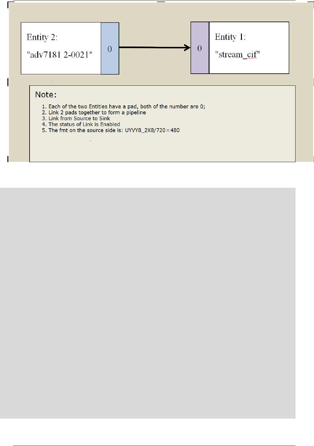
6.2 GStreamer application programming
The Linux SDKs released by Rockchip are integrated with GStreamer and can be used
to preview images. This chapter describes how to write a simple camera preview program
using GStreamer.

47
Rockchip Developer Guide GStreamer preview
Copyright © 2019 Fuzhou Rockchip Electronics Co., Ltd.
First, you should call gst_init() in the main function to complete the corresponding
initialization works, so that the parameters input by users from command line are passed
to GStreamer function library. One typical GStreamer initialization application is as
follows:
#include <gst/gst.h>
int main(int argc, char *argv[]) {
/* Initialize GStreamer */
gst_init (&argc, &argv);
}
Create a GMainLoop object with g_main_loop_new().
/* create main loop, start to loop after running g_main_loop_run */
loop = g_main_loop_new(NULL, -1);
Pipeline is used to contain and manage element in GStreamer framework. The following
code creates a new pipeline called uvc-camera:
pipeline = gst_pipeline_new("uvc-camera");
Create a data source element by using v4l2src, the element is responsible for obtaining
data from camera
source = gst_element_factory_make("v4l2src", "camera-input");
Set some properties of v4l2src
/* set source parameters */
g_object_set(G_OBJECT(source), "device", argv[1], NULL);
source_capsfilter = gst_element_factory_make("capsfilter", "source_capsfilter");
source_caps = gst_caps_new_simple ("video/x-raw",
"format", G_TYPE_STRING, "YUY2",
"width", G_TYPE_INT, 640,
"height", G_TYPE_INT, 480,
NULL);
g_object_set(G_OBJECT(source_capsfilter),"caps", source_caps, NULL);
Create converter element and sink element.
/* create converter element */

48
Rockchip Developer Guide GStreamer preview
Copyright © 2019 Fuzhou Rockchip Electronics Co., Ltd.
converter = gst_element_factory_make("videoconvert", "video-converter");
/* create sink element */
sink = gst_element_factory_make("autovideosink", "camera-output");
Add a message handler function bus_call to monitor the generated message.
/* Wait until error or EOS */
bus = gst_element_get_bus (pipeline);
gst_bus_add_watch(bus, bus_call, loop);
gst_object_unref(bus);
The three elements that have been created need to be all added to pipeline and
connected in order.
/* add elements to pipeline */
gst_bin_add_many(GST_BIN(pipeline), source, source_capsfilter, converter, sink, NULL);
/* connect elements sequentially */
gst_element_link_many(source, source_capsfilter, converter, sink, NULL);
After all the preparations are completed, you can start the data processing of the entire
pipeline by switching the state of pipeline to PLAYING state.
gst_element_set_state(pipeline, GST_STATE_PLAYING);
Enter the main loop, it will block here until it is allowed to exit. When there is an event,
it deals with the event and sleeps when there is no event.
/* start to loop */
g_main_loop_run(loop);
Quit pipeline and release resources
/* quit loop and return */
g_print("Returned,stopping playback\n");
gst_element_set_state(pipeline, GST_STATE_NULL);
gst_object_unref(GST_OBJECT(pipeline));
You can test the program directly with a PC and the compile command is as follows.
The development board test has to use the cross-compilation toolchain to complie.
gcc gst-video.c -o gst-video `pkg-config --cflags --libs gstreamer-1.0`
49
Rockchip Developer Guide GStreamer preview
Copyright © 2019 Fuzhou Rockchip Electronics Co., Ltd.
Figure 4 The gst-video application preview
The whole code is as follows
#include <gst/gst.h>
#include <glib.h>
#include <stdio.h>
#include <stdbool.h>
/* message processing */
static gboolean bus_call(GstBus * bus, GstMessage * msg, gpointer data)
{
GMainLoop *loop = (GMainLoop *) data;
switch (GST_MESSAGE_TYPE(msg))
{
case GST_MESSAGE_EOS:
g_print("End of stream\n");
g_main_loop_quit(loop);
break;
case GST_MESSAGE_ERROR:

50
Rockchip Developer Guide GStreamer preview
Copyright © 2019 Fuzhou Rockchip Electronics Co., Ltd.
{
gchar *debug;
GError *error;
gst_message_parse_error(msg, &error, &debug);
g_free(debug);
g_printerr("ERROR:%s\n", error->message);
g_error_free(error);
g_main_loop_quit(loop);
break;
}
default:
break;
}
return 1;
}
int main(int argc, char *argv[]) {
GMainLoop *loop;
GstElement *pipeline, *source, *converter, *sink, *vqueue;
GstElement *source_capsfilter;
GstCaps *source_caps;
GstBus *bus;
/* Initialize GStreamer */
gst_init (&argc, &argv);
if (argc < 2)
{
g_printerr("Usage:%s [camera device name] for camera capture. eg(./gst-video
/dev/video0)\n", argv[0]);

51
Rockchip Developer Guide GStreamer preview
Copyright © 2019 Fuzhou Rockchip Electronics Co., Ltd.
return -1;
}
/* create main loop, start to loop after running g_main_loop_run */
loop = g_main_loop_new(NULL, -1);
/* create pipeline and element */
pipeline = gst_pipeline_new("uvc-camera");
source = gst_element_factory_make("v4l2src", "camera-input");
/* set source parameters */
g_object_set(G_OBJECT(source), "device", argv[1], NULL);
source_capsfilter = gst_element_factory_make("capsfilter", "source_capsfilter");
source_caps = gst_caps_new_simple ("video/x-raw",
"format", G_TYPE_STRING, "YUY2",
"width", G_TYPE_INT, 640,
"height", G_TYPE_INT, 480,
NULL);
g_object_set(G_OBJECT(source_capsfilter),"caps", source_caps, NULL);
/* create converter element */
converter = gst_element_factory_make("videoconvert", "video-converter");
/* create sink element */
sink = gst_element_factory_make("autovideosink", "camera-output");
if (!pipeline || !source || !source_capsfilter || !converter || !sink)
{
g_printerr("One element could not be created.Exiting.\n");
return -1;
}
/* Wait until error or EOS */
bus = gst_element_get_bus (pipeline);
gst_bus_add_watch(bus, bus_call, loop);

52
Rockchip Developer Guide GStreamer preview
Copyright © 2019 Fuzhou Rockchip Electronics Co., Ltd.
gst_object_unref(bus);
/* add elements to pipeline */
gst_bin_add_many(GST_BIN(pipeline), source, source_capsfilter, converter, sink, NULL);
/* connect elements sequentially */
gst_element_link_many(source, source_capsfilter, converter, sink, NULL);
gst_element_set_state(pipeline, GST_STATE_PLAYING);
g_print("Running\n");
/* start to loop */
g_main_loop_run(loop);
/* quit loop and return */
g_print("Returned,stopping playback\n");
gst_element_set_state(pipeline, GST_STATE_NULL);
gst_object_unref(GST_OBJECT(pipeline));
return 0;

53
Rockchip Developer Guide 3A function integration
Copyright © 2019 Fuzhou Rockchip Electronics Co., Ltd.
7 3A Function integration
The sensor output is Bayer Raw which is converted to YUV format application case after
ISP processing, later need to use ISP's 3A function tuning IQ. IQ tuning requires
customers to submit an application to Rockchip via sales window, providing typical
modules and machines to be debugged by Rockchip. Please consult sales for details.
The compilation, installation and use of the main 3A libraries in this chapter are
described in the docs/Develop reference documents/CAMERA/
"camera_engine_rkisp_user_manual_v1.0.pdf" document published with Linux SDK.
Please read this document first, no detailed explanation will be given here.
Finally, an xml file is generated for sensor (including lens) (assuming it is named
OV5695.xml). At the same time, four so libraries will be provided which is generated by
the camera_engine_rkisp project and located in the external directory[
1
], Buildroot will
automatically copy the four libraries to the corresponding directory, If there is no 3A
library in Debian, please install it by yourself.
- OV5695.xml: 3A tuning IQ file. Please put it in the /etc/files/ directory. The
etc/init.d/S50link_iq script in buildroot will match the name of the sensor connected by
ISP after booting, match the xml of the same name in the /etc/files/ directory, and
create a link file cam_iq.xml, for squash read-only file systems, script is invalid.
- librkisp.so: The main function of core engine is to obtain driving data stream and
implement upper layer frame parameter control, such as 3A mode. The 3A statistics are
obtained from ISP driver, and 3A library is called to implement 3A adjustment. The class
interface provided for upper layer is DeviceManager which is saved in a /usr/lib/ directory
on development boards.
- librkisp_aec.so: The auto-exposure library implemented by RK is implemented as a
dynamic loading library with a standard interface, which is saved in /usr/lib/rkisp/ae/
directory on development boards.
- librkisp_af.so: The autofocus library implemented by RK is implemented as a
dynamic loading library with a standard interface, which is saved in /usr/lib/rkisp/af/
directory of development boards.
1
[] If there is no rkisp_demo in user's Linux SDK, please update or request the source code from
FAE.

54
Rockchip Developer Guide 3A function integration
Copyright © 2019 Fuzhou Rockchip Electronics Co., Ltd.
- librkisp_awb.so: The white balance library implemented by RK is implemented as a
dynamic load library with a standard interface. Which is saved in /usr/lib/rkisp/awb/
directory on development boards.
How applications calls 3A related functions, can also refer to the docs/Develop
reference documents/CAMERA/ "camera_engine_rkisp_user_manual_v1.0.pdf" released
with Linux SDK. Simple demo, you can also refer to Applications development and demo.
7.1 Applications development and demo
There is an external/camera_engine_rkisp repository with the Linux SDK released, the
camera_engine_rkisp/tests/rkisp_demo.c simply uses v4l2 interface to configure device
and simply calls 3A interface. Please refer to the source code directly.
Applications development, you can also directly refer to v4l2-utils source package
(libv4l-1.14.1/utils/v4l2-ctl), the the so provided by which can also be used directly.
Or simply refer to the official website https://linuxtv.org/downloads/v4l-dvb-apis-
new/uapi/v4l/v4l2.html
Note: The above buff type of the official website application only supports
V4L2_BUF_TYPE_VIDEO_CAPTURE, and the buff type used by RKisp driver layer is
V4L2_BUF_TYPE_VIDEO_CAPTURE_MPLANE which is used for video capture devices in
multi-plane storage format, so the buff of application layer also has to match this type,
and rkisp_demo.c and v4l2-ctl also add this type.
7.2 Gstreamer-1.0 3A plug-in
Rockchip has integrated 3A function into plug-in. The above
"camera_engine_rkisp_user_manual_v1.0" document described the use of 3A library and
the included gstreamer plug-in (libgstrkisp.so) in details.
A new plug-in rkv4l2src based on gstreamer-1.14 has been wrote by Rockchip. The
project is located in external/gst-plugins-rockchip. The rkv4l2src is a simple elements
plug-in which collects data based on v4l2 protocol and adds 3A function provided by
camera_engine_rkisp. This plug-in can be run under Buildroot and Debian (gstreamer
upgrade 1.14).

55
Rockchip Developer Guide 3A function integration
Copyright © 2019 Fuzhou Rockchip Electronics Co., Ltd.
1. Whether it is Buildroot or Debian, you must first confirm whether the 3A library
exists. For rkisp1 driver, there are four 3A libraries: librkisp.so, librkisp_aec.so,
librkisp_af.so, librkisp_awb.so.
2. Storage path of Gstreamer plugin of Buildroot and Debian are different, Buildroot is
stored in /usr/lib/gstreamer-1.0/libgstrkv4l2.so, Debian is stored in /usr/lib/aarch64-
linux-gnu/gstreamer-1.0/libgstrkv4l2.so. After confirming that libgstrkv4l2.so exists, you
can view the plugin details through gst-inspect-1.0 rkv4l2src
gst-inspect-1.0 rkv4l2src
Figure 5 rkv4l2src plug-in information
3, After confirming that v4l2src can be previewed, you can test 3A plugin preview
directly with gst-launch-1.0.
gst--launch-1.0 rkv4l2src device=/dev/video1 xml-path=/etc/cam_iq.xml ! video/x-
raw,format=NV12,width=640,height=480, framerate=30/1 ! videoconvert ! kmssink
xml-path=/etc/cam_iq.xml: Specify 3A xml file, the default path is /etc/cam_iq.xml

56
Rockchip Developer Guide 3A function integration
Copyright © 2019 Fuzhou Rockchip Electronics Co., Ltd.
7.3 Media device development demo
7.4 Video device development demo
7.5 V4l-subdev device development demo

57
Rockchip Developer Guide rk-isp10 driver introduction
Copyright © 2019 Fuzhou Rockchip Electronics Co., Ltd.
8 Rk-isp10 driver introduction
Rk-isp10 does not use media-controller and async sub device, but supports vb2 and
v4l2 interfaces. And the rk-isp10 driver integration and the most simplified sensor
development. For rk-isp10 (the other name is cif-isp10) driver, please refer to
"CIF_ISP10_Driver_User_Manual_v1.0.pdf" and
"RK_ISP10_Camera_User_Manual_v2.2.pdf" released with Linux SDKs.
It mainly introduces the difference between rkisp1 and rk-isp10 here.
First, they are different driver implementations of the same hardware IP.
RKISP1 is based on media controller, async sub device, vb2 and v4l2 interfaces. RK-
ISP10 does not have a media controller and async sub device. Therefore, RKISP1 can be
considered to provide a more rich and free pipeline setting, while RK-ISP10 provides
users with the simplest and quickest use.
RK-ISP10 combines CIF and ISP into one driver. The CIF and ISP described in this
document are independent of each other.
RK-ISP10 has a set of sensor-driven frameworks, the code is located at
drivers/media/i2c/soc_camera/rockchip/. The CIF and ISP described in this document use
the drivers that match async sub device in drivers/media/i2c/ directory.
The Rkisp1 driver coding style is more pithily, and the number of lines of code is only
half that of rk-isp10.
