Rockchip Developer Guide Linux4.4 USB
Rockchip-Developer-Guide-linux4.4-USB
Rockchip-Developer-Guide-linux4.4-USB
Rockchip-Developer-Guide-linux4.4-USB
Rockchip-Developer-Guide-linux4.4-USB
Rockchip-Developer-Guide-linux4.4-USB
User Manual:
Open the PDF directly: View PDF ![]() .
.
Page Count: 47

芯片名称 内核版本
RK3399、RK3368、RK3366、RK3328、RK3288、RK312X、RK3188、RK30XX Linux4.4
日期 版本 作者 修改说明
2017-12-22 v1.0 吴良峰、王明成、孟东阳
USB开发指南
发布版本:1.0
作者邮箱:wulf@rock-chips.com、frank.wang@rock-chips.com、daniel.meng@rockchip.com
日期:2017.12
文档密级:公开资料
前言
概述
产品版本
读者对象
软件工程师,硬件工程师,FAE
修订记录
USB开发指南
1 概述
1.1 RK平台USB控制器方案
1.2 USB2.0 Host
1.3 USB2.0 OTG
1.4 USB2.0 PHY
1.5 USB OTG3.0
1.6 TypeC PHY
2 硬件电路及信号
2.1 USB HOST控制器硬件电路
2.1.1 USB2.0 HOST控制器硬件电路
2.2 USB OTG控制器硬件电路
2.2.1 USB 2.0 OTG控制器硬件电路
2.2.2 USB 3.0 OTG控制器硬件电路
3 Kernel模块配置
3.1 USB PHY相关配置
3.2 USB HOST相关配置

3.3 USB OTG相关配置
3.4 USB Gadget配置
3.5 USB其它模块配置
3.5.1 Mass Storage Class(MSC)
3.5.2 USB Serial Converter
3.5.3 USB HID
3.5.4 USB Net
3.5.5 USB Camera
3.5.6 USBAudio
3.5.7 USBHUB
3.5.8 其他USB设备配置
4 Device Tree开发
4.1 USB PHY DTS
4.1.1 USB2.0 PHY DTS
4.1.2 USB3.0 PHY DTS
4.2 USB2.0 Controller DTS
4.2.1 USB2.0 HOST Controller DTS
4.2.2 USB2.0 otg Controller DTS
4.3 USB3.0 Controller DTS
4.3.1 USB3.0 HOST Controller DTS
4.3.2 USB3.0 OTG Controller DTS
5 驱动开发
5.1 USB PHY drivers
5.1.1 USB2.0 PHY driver
5.1.2 USB3.0 PHY driver
5.2 USB Controller drivers
5.2.1 USB3.0 OTG drivers
5.2.2 USB2.0 OTG drivers
5.2.3 USB2.0 HOST drivers
6 Android Gadget配置
6.1 Gadget驱动配置
6.2 BOOT IMG配置
7 常见问题分析
7.1 设备枚举日志
7.1.1 USB2.0 OTG正常开机日志
7.1.2 USB2.0 Device连接
7.1.3 USB2.0 Device断开连接
7.1.4 USB2.0 HOST-LS设备
7.1.5 USB2.0 HOST-FS设备
7.1.6 USB2.0 HOST-HS设备
7.1.7 USB2.0 HOST-LS/FS/HS设备断开log
7.1.8 USB3.0 Device连接
7.1.9 USB3.0 HOST-SS设备
7.2 USB 常见问题分析
7.2.1 软件配置
7.2.2 硬件电路
7.2.3 Device功能异常分析
7.2.4 Host功能异常分析
7.2.5 USB Camera异常分析
7.2.6 USB充电检测
7.3 PC驱动问题
8 USB信号测试

控制器芯
片
USB2.0
HOST(EHCI&OHCI)
USB
HSIC(EHCI)
USB2.0/3.0
OTG(DWC3/XHCI)
USB2.0 OTG
(DWC2)
RK3399 ×2 ×1 ×2 0
RK3368 ×1 ×1 0 ×1
RK3366 ×1 0 ×1 ×1
RK3328 ×1 0 ×1 ×1
RK3288 0 ×1 0 ×2(host+otg)
RK312X ×1 0 0 ×1
RK3188 ×1 ×1 0 ×1
RK30XX ×1 0 0 ×1
1 概述
1.1 RK平台USB控制器方案
Rockchip SOC通常内置多个USB控制器,不同控制器互相独立,请在芯片TRM中获取详细信息。由于部分USB控
制器有使用限制,所以请务必明确方案的需求及控制器限制后,再确定USB的使用方案。各芯片内置的USB控制器
如表1-1所示:
表 1‐1 RK平台USB控制器列表
1.2 USB2.0 Host
Compatible Specification
Universal Serial Bus Specification, Revision 2.0
Enhanced Host Controller Interface Specification(EHCI), Revision 1.0
Open Host Controller Interface Specification(OHCI), Revision 1.0a
Features
Support high-speed(480Mbps), full-speed(12Mbps) andlow-speed(1.5Mbps)
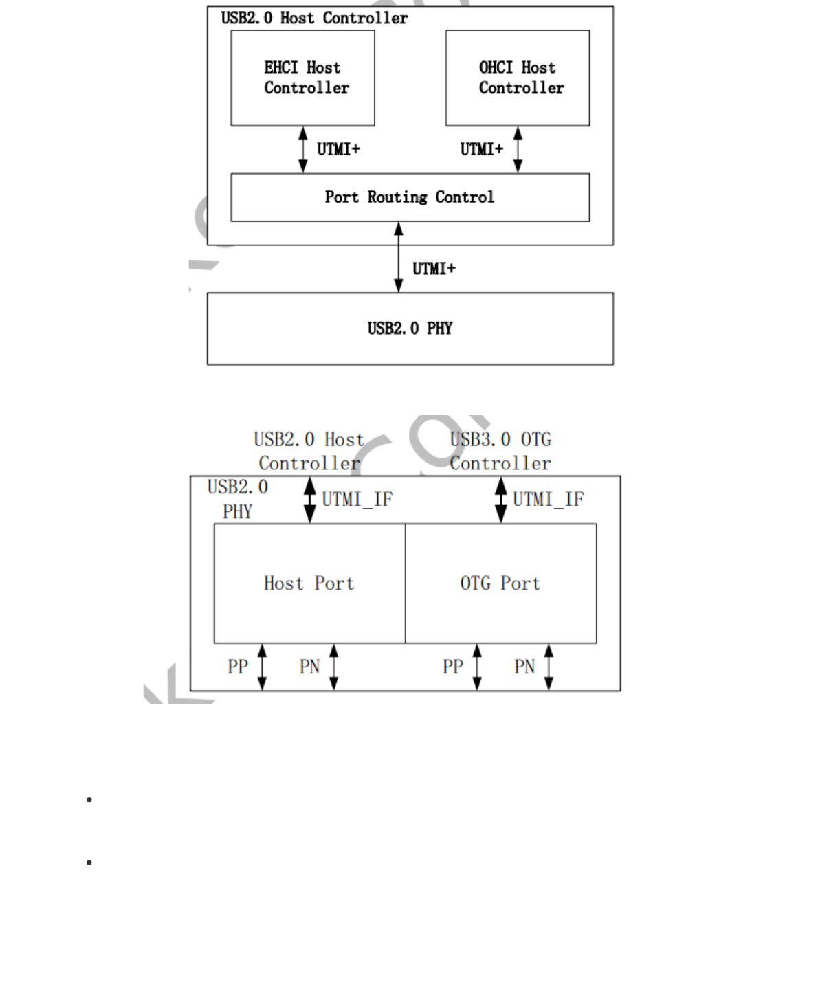
图 1‐1 USB2.0 Host Controller Block Diagram
图 1‐2USB2.0 USB2.0 PHY Block Diagram
1.3 USB2.0 OTG
Compatible Specification
Universal Serial Bus Specification, Revision 2.0
Features
Operates in High-Speed and Full-Speed mode
Support 9 channels in host mode
9 Device mode endpoints in addition to control endpoint 0, 4 in, 3 out and 2 IN/OUT
Built-in one 1024x35 bits FIFO
Internal DMA with scatter/gather function
Supports packet-based, dynamic FIFO memory allocation for endpoints for flexible, efficient use of RAM
Support dynamic FIFO sizing
Support Battery Charge in device role
Support Uart Bypass Mode
图 1‐3 USB2.0 OTG Block Diagram
1.4 USB2.0 PHY
Host Port: used for USB2.0 host controller
OTG Port: used for USB3.0 OTG controller with TypeC PHY to compriseas fully feature TypeC
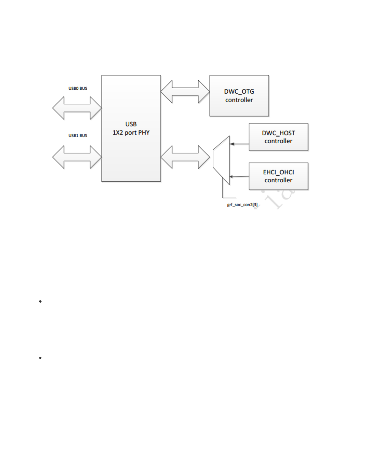
1.5 USB OTG3.0
Compatible Specification
Universal Serial Bus 3.0 Specification, Revision 1.0
Universal Serial Bus Specification, Revision 2.0
eXtensible Host Controller Interface for Universal Serial Bus(xHCI), Revision 1.1
Features
DWC3 Features:
Support Control/Bulk(including stream)/Interrupt/IsochronousTransfer
Simultaneous IN and OUT transfer for USB3.0, up to 8Gbps bandwidth
Descriptor Caching and Data Pre-fetching
USB3.0 Device Features
Up to 7 IN endpoints, including control endpoint 0

Up to 6 OUT endpoints, including control endpoint 0
Up to 13 endpoint transfer resources, each one for each endpoint
Flexible endpoint configuration for multiple applications/USBset-configuration modes
Hardware handles ERDY and burst
Stream-based bulk endpoints with controller automatically initiatingdata movement
Isochronous endpoints with isochronous data in data buffers
Flexible Descriptor with rich set of features to support bufferinterrupt moderation, multiple transfers,
isochronous, control, and scatteredbuffering support
USB 3.0 xHCI Host Features:
Support up to 64 devices
Support 1 interrupter
Support 1 USB2.0 port and 1 Super-Speed port
Concurrent USB3.0/USB2.0 traffic, up to 8.48Gbps bandwidth
Support standard or open-source xHCI and class driver
Support xHCI Debug Capability
USB 3.0 Dual-Role Device (DRD) Features
Static Device operation
Static Host operation
USB3.0/USB2.0 OTG A device and B device basing on ID
UFP/DFP and Data Role Swap Defined in USB TypeC Specification
Not support USB3.0/USB2.0 OTG session request protocol(SRP), hostnegotiation protocol(HNP) and Role
Swap Protocol(RSP)
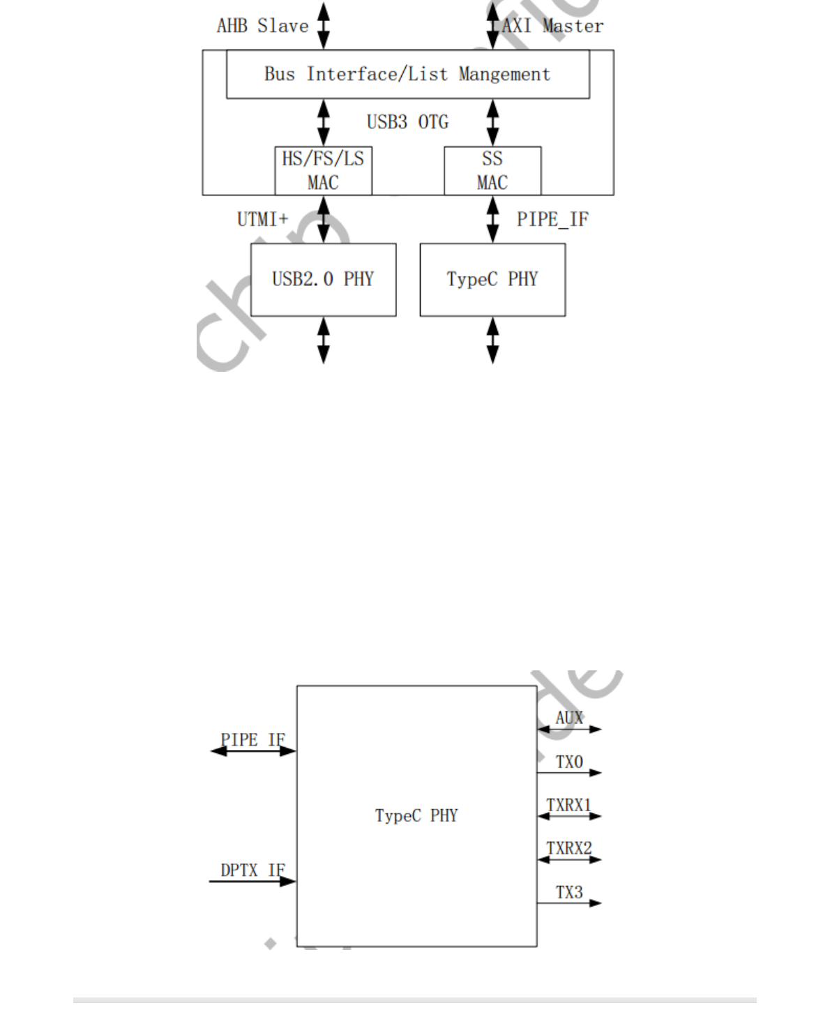
图 1‐4 USB3.0 OTG Block Diagram
1.6 TypeC PHY
Support USB3.0 (SuperSpeed only)
Support DisplayPort 1.3 (RBR, HBR and HBR2 data rates only)
Support DisplayPort AUX channel
Support USB TypeC and DisplayPort Alt Mode
Support DisplayPort Alt Mode on TypeC A, B, C, D, E and F pinassignments
Support Normal and Flipped orientation
图 1‐5 TypeC PHY Block Diagram
2 硬件电路及信号
2 硬件电路及信号
2.1 USB HOST控制器硬件电路
USB Host控制器分别包含USB2.0 Host和HSIC,其硬件电路及信号分别说明如下:
2.1.1 USB2.0 HOST控制器硬件电路
USB2.0的工作时钟高达480MHz,所以layout时需要特别注意,USB走线宽度为7-8MIL,做90Ω阻抗差分走线,最
好在表层走线并有包地,边上无干扰源,正对的上下层不能有其他信号走线。
USB HSIC使用240MHz DDR信号,传输速率与USB2.0同为480Mbps,典型的走线阻抗为50Ω,建议最大走线长度
不要超过10cm。
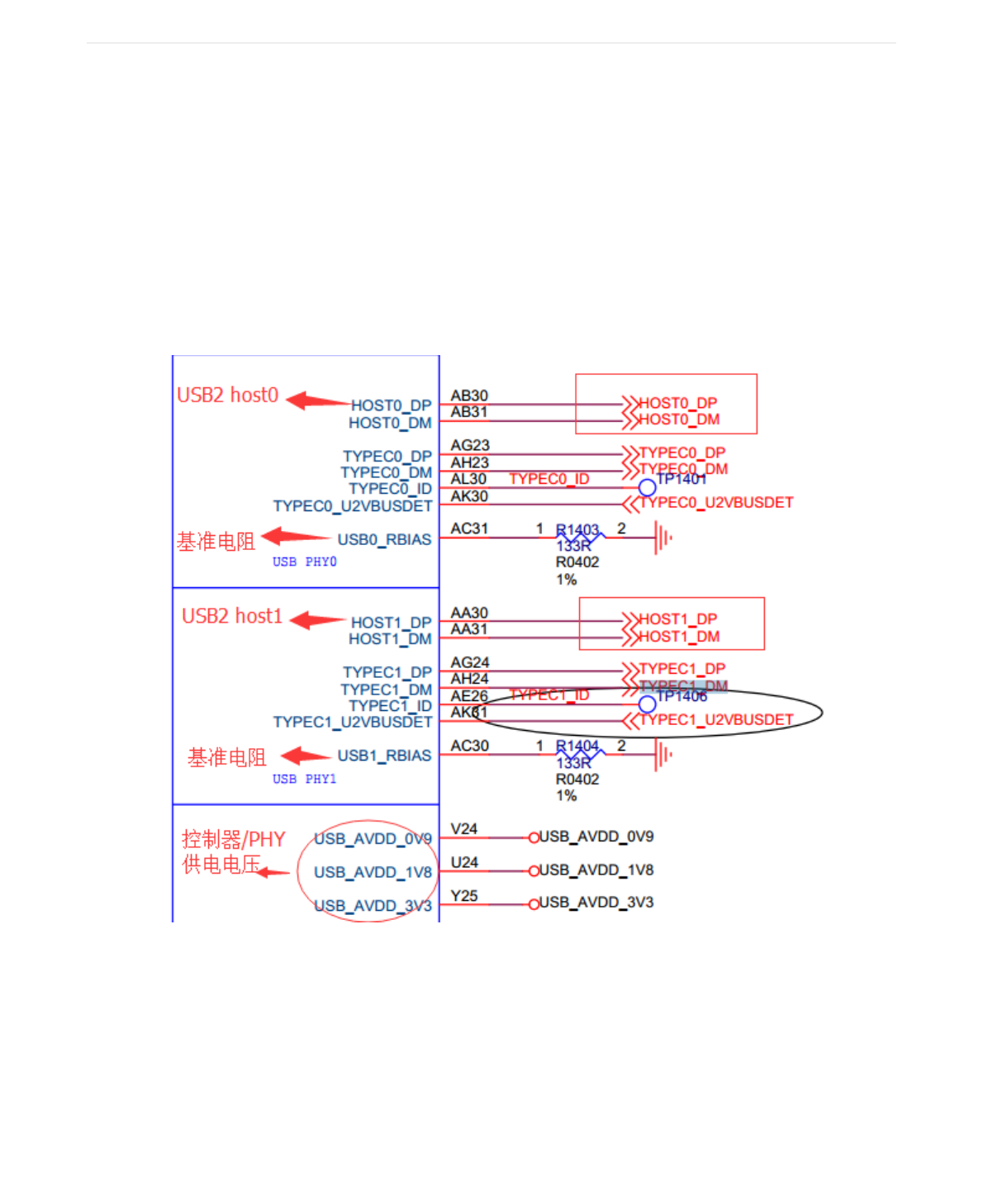
USB2.0HOST控制器硬件信号参考电路如图1-1和图1-2所示,完整的USB 2.0 HOST电路如图2-1 , 图2-3所示:
图 2‐1 USB2.0 HOST SoC信号引脚
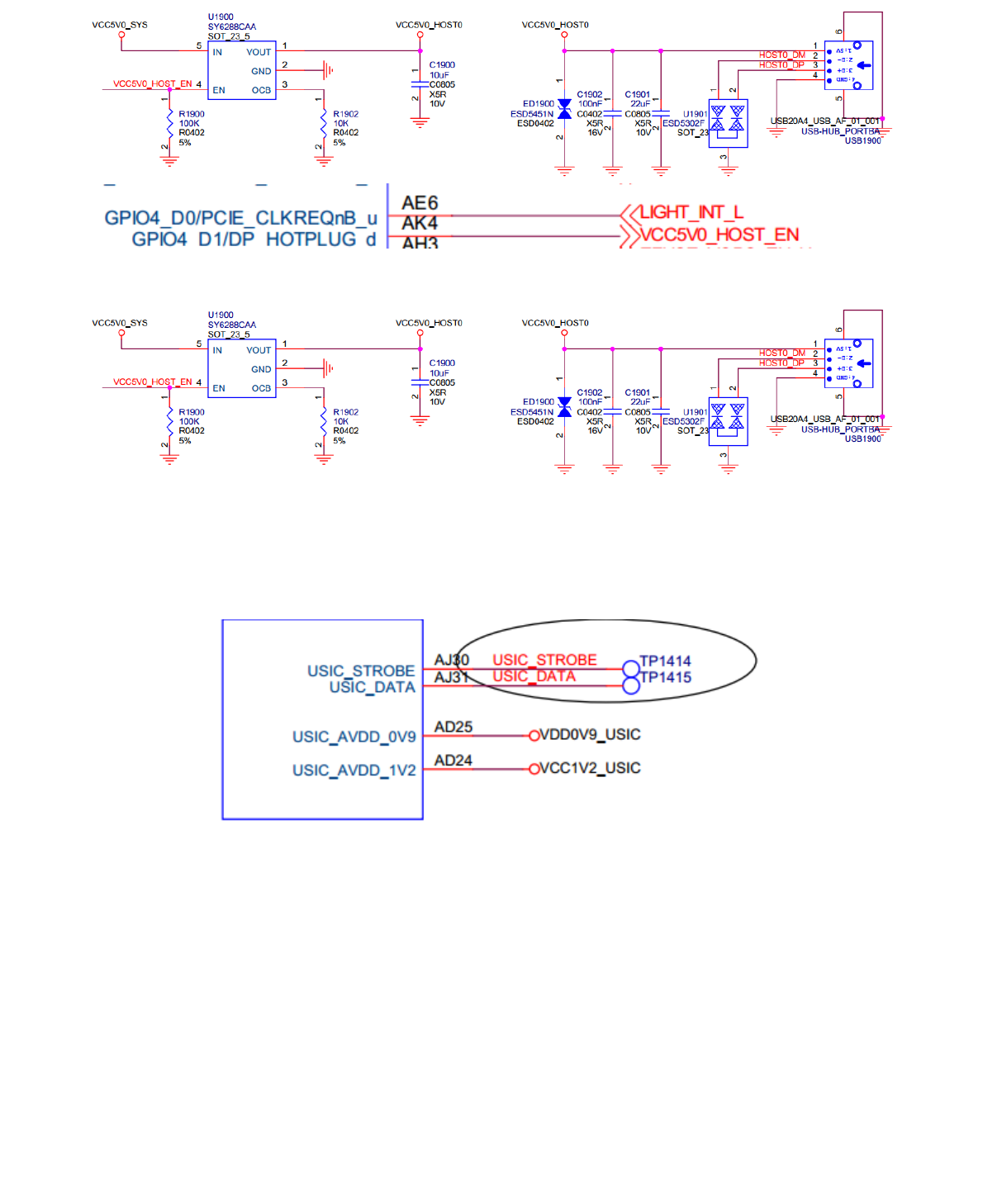
图 2‐2 USB2.0 HOST VBUS GPIO控制脚
图 2‐3 HSIC控制器硬件电路
HSIC是具有与USB2.0相同的带宽(480Mbps)的2引脚芯片间互连接口,HSIC去除了为USB2.0设计的模拟收发器
(PHY),供电电压为0.9V和1.2V, 信号传输的标准电压为1.2V,降低了系统的功耗,最大的走线长度为
10cm(4英寸)。
图 2‐4 HSIC硬件电路
2.2 USB OTG控制器硬件电路
2.2.1 USB 2.0 OTG控制器硬件电路
RK3399没有独立的USB2.0 OTG控制器,但有独立的USB3.0 OTG控制器,并且可以向下兼容USB2.0 OTG的完整
功能,而RK3368、RK3366、RK3328、RK3288、RK312X、RK3188、RK30XX有独立的USB2.0 OTG控制器。
完整的 USB 2.0 OTG 参考电路如图2-5 ~ 图2-8所示:
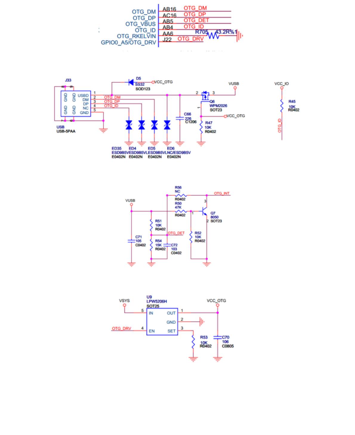
图 2-5 USB 2.0 控制器硬件信号
图 2-6 OTG PORT 电路图
图 2-7 OTG DET 电路图
图 2-8 OTG DRV 电路图
OTG_VBUS:输入信号,用于 USB DEVICE 检测 VBUS 电平, 0:低电平约 0V, 1:高电平约 3V。默认无连接时
电平为低,连接至 PC 或充电器时电平为高。
OTG_ID:输入信号,由 USB OTG 协议定义,用于识别 USB 口所接设备的默认角色(HOST or device)。 USB_ID 默
认上拉,处于 device 状况,如果要控制器进入 HOST 状态,需外接 mini-A 口或 micro-A 口将 USB_ID 短接到地。
OTG_RKELVIN:参考电阻默认 43.2 欧到地,可通过调节该电阻阻值来调整 USB 信号质量。 不同芯片,该参考电
阻的阻值不同, 具体请见相应的 SDK 参考设计原理图。
OTG_DRVVBUS:该信号由 USB OTG 控制器的 HOST 寄存器控制,硬件上通过该信号来控制HOST 所需 5V VBUS
输出。
OTG_DP/OTG_DM:即 Data+, Data-, USB 的两根差分信号线。
2.2.2 USB 3.0 OTG控制器硬件电路
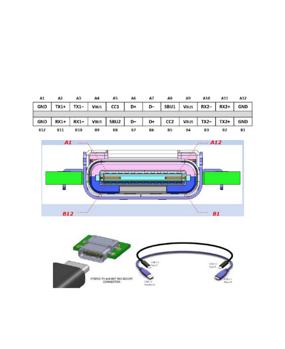
USB3.0 OTG具有USB3.0 OTG功能,且向下兼容USB2.0 OTG功能,最大传输速率为5Gbps,物理接口为Type-C,
支持正反插。在传输线方面,USB3.0支持长达3米的四线差分信号线及11英寸PCB。5Gbps信号在长线缆上采用的
是差分信号方式传输,从而避免信号被干扰及减少电磁干扰问题。
图 2‐5 Type-C 接口定义
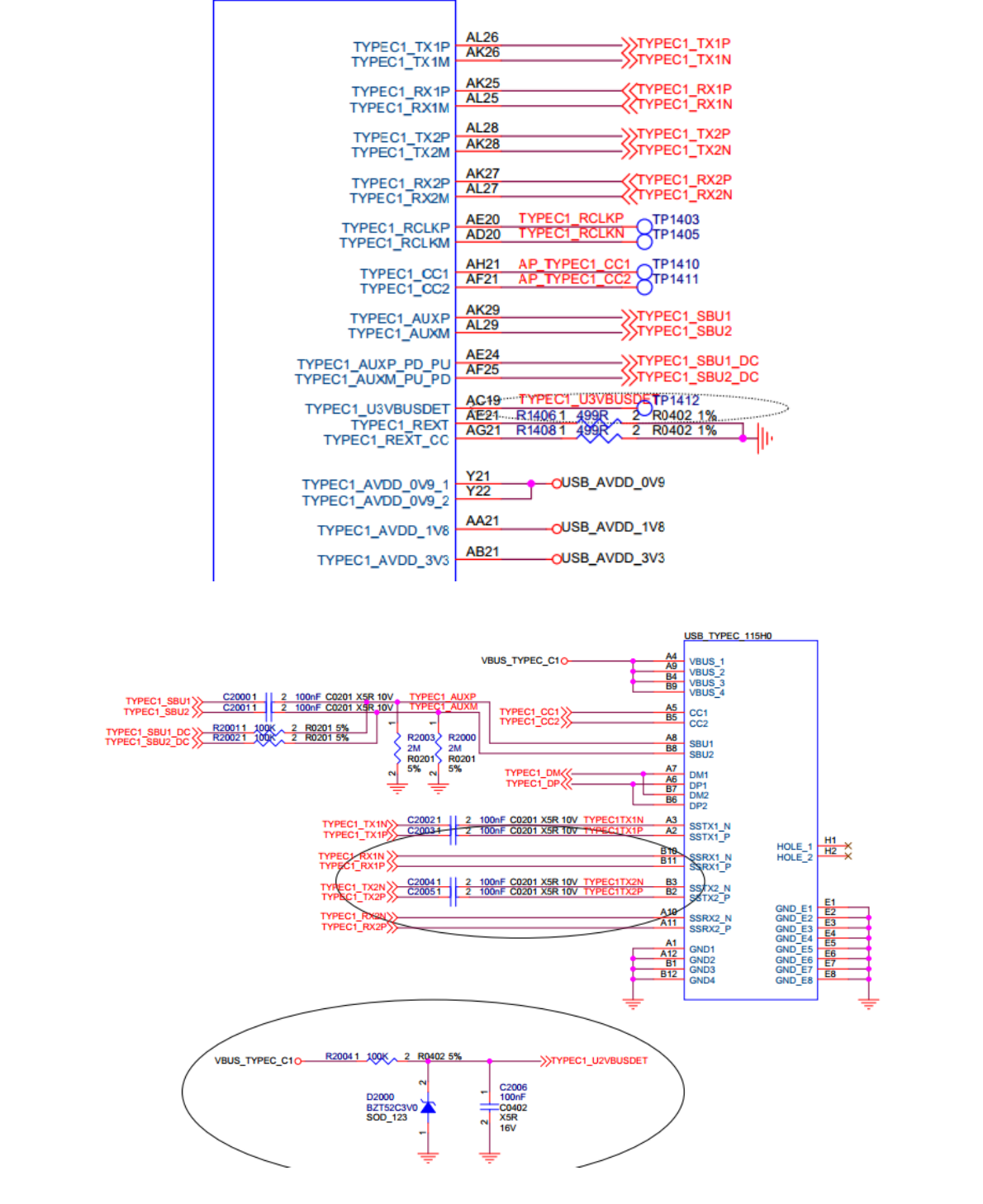
图 2‐6 USB3 OTG控制器 SoC信号引脚

选择Kernel配置:
保存default配置:
保存default配置,然后用defconfig替换rockchip_defconfig。
3.1 USB PHY相关配置
USB PHY模块的配置位于
USB2.0 PHY使用的是Innosilicon IP,所以应选择“Rockchip INNO USB2PHY Driver”。
RK3399 RK3366 USB3.0PHY使用的是Type-C,所以应选择“Rockchip TYPEC PHY Driver”。
RK3328 USB3.0PHY 使用的是Innosilicon USB3.0 PHY,所以应选择“Rockchip INNO USB 3.0 PHY Driver”。
3.2 USB HOST相关配置
Makemenuconfig得到Kernel配置界面后,USB模块的配置位于
必须选上USB Support项后才能支持USB模块并进行进一步的配置。
makeARCH=arm64menuconfig
makeARCH=arm64savedefconfig
DeviceDrivers‐‐‐>
PHYSubsystem‐‐‐>
...
<*> RockchipINNOUSB2PHYDriver
...
<*> RockchipTYPECPHYDriver
...
<*> RockchipINNOUSB3.0PHYDriver
DeviceDrivers‐‐‐>
‐*‐ SupportforHost‐sideUSB
[*]USBsupport‐‐‐>
...
<*> xHCIHCD(USB3.0)support
‐*‐ GenericxHCIdriverforaplatformdevice
...
<*> EHCIHCD(USB2.0)support
[] RootHubTransactionTranslators
[*]ImprovedTransactionTranslatorscheduling
<*> GenericEHCIdriverforaplatformdevice
...
<*> OHCIHCD(USB1.1)support
<>OHCIsupportforPCI‐busUSBcontrollers
<*> GenericOHCIdriverforaplatformdevice
1
1
1
2
3
4
5
6
7
8
1
2
3
4
5
6
7
8
9
10
11
12
13
14
15

需要支持USB HOST,首先需要选上<*>Supportfor Host-side USB项,然后会现如下的HOST相关的配置,其中,
HOST1.1 选择OHCI Driver 配置,HOST2.0 选择EHCI Driver 配置,HOST3.0选择XHCI Driver配置。
3.3 USB OTG相关配置
3.4 USB Gadget配置
Make menuconfig得到Kernel配置界面后,USB模块的配置位于
RK3399目前支持MTP、PTP、Accessory、ADB、MIDI、Audio等Gadget功能。
3.5 USB其它模块配置
3.5.1 Mass Storage Class(MSC)
U盘属于SCSI设备,所以在配置USB模块之前需要配置SCSI选项(默认配置已经选上)。
SCSI 其他相关配置:
DeviceDrivers‐‐‐>
‐*‐ SupportforHost‐sideUSB
[*]USBsupport‐‐‐>
...
<*> DesignWareUSB2DRDCoreSupport
DWC2ModeSelection(DualRolemode)
...
<*> DesignWareUSB3DRDCoreSupport
DWC3ModeSelection(DualRolemode)
DeviceDrivers‐‐‐>
[*]USBsupport‐‐‐>
[*]USBGadgetSupport‐‐‐>
...
USBGadgetDrivers(USBfunctionsconfigurablethroughconfigfs)‐‐‐>
DeviceDrivers‐‐‐>
SCSIdevicesupport‐‐‐>
...
<*>SCSIdisksupport
...
DeviceDrivers‐‐‐>
SCSIdevicesupport‐‐‐>
<*>SCSIdevicesupport
[]SCSI:useblk‐mqI/Opathbydefault
[*]legacy/proc/scsi/support
***SCSIsupporttype(disk,tape,CD‐ROM)***
<*>SCSIdisksupport
<>SCSItapesupport
<>SCSIOnStreamSC‐x0tapesupport
<>SCSICDROMsupport
<*>SCSIgenericsupport
1
2
3
4
5
6
7
8
9
1
2
3
4
5
1
2
3
4
5
1
2
3
4
5
6
7
8
9
10

配置完SCSI Device Support后,可以在USB Support中找到如下选项,选上即可。
3.5.2 USB Serial Converter
支持USB 3G Modem
USB 3G Modem使用的是USB转串口,使用时需要选上如下选项:
支持PL2303
如果要使用PL2303输出数据到串口,需要选择如下选项:
支持USB GPS
如果要支持USB GPS,如u-blox 6 - GPS Receiver设备,需要选择如下选项:
3.5.3 USB HID
USB键鼠的配置选项如下:
<*>SCSIgenericsupport
<*>SCSImediachangersupport
[*]VerboseSCSIerrorreporting(kernelsize+=75K)
[*]SCSIloggingfacility
[*]AsynchronousSCSIscanning
SCSITransports‐‐‐>
[*]SCSIlow‐leveldrivers‐‐‐>
[]PCMCIASCSIadaptersupport‐‐‐‐
[]SCSIDeviceHandlers‐‐‐‐
DeviceDriver‐‐‐>
[*]USBsupport‐‐‐>
<*>USBMassStoragesupport
DeviceDriver‐‐‐>
[*]USBsupport‐‐‐>
...
[*]USBdriverforGSMandCDMAmodems
...
<*>USBSerialConvertersupport‐‐‐>
<*>USBProlific2303SinglePortSerialDriver
DeviceDriver‐‐‐>
[*]USBsupport‐‐‐>
...
<*>USBSerialConvertersupport‐‐‐>
<*>USBProlific2303SinglePortSerialDriver
DeviceDrivers ‐‐‐>
[*]USBsupport ‐‐‐>
[*]USBModem(CDCACM)support
11
12
13
14
15
16
17
18
19
1
2
3
1
2
3
4
5
6
7
1
2
3
4
5
1
2
3

3.5.4 USB Net
USB Bluetooth
USB Wifi
通常直接使用Vendor提供的驱动和配置。
USB Ethernet
DeviceDrivers ‐‐‐>
[*]HIDsupport
[*]USBHIDtransportlayer
[]PIDdevicesupport
[*]/dev/hiddevrawHIDdevicesupport
[*]Networkingsupport‐‐‐>
...
<*> Bluetoothsubsystemsupport‐‐‐>
Bluetoothdevicedrivers‐‐‐>
...
<*>HCIUSBdriver
[*]Broadcomprotocolsupport(NEW)
[*]Realtekprotocolsupport(NEW)
...
DeviceDriver‐‐‐>
[*]Networkdevicesupport‐‐‐>
<*> USBNetworkAdapters‐‐‐>
<*> USBCATCNetMate‐basedEthernetdevicesupport
<*> USBKLSIKL5USB101‐basedethernetdevicesupport
<*> USBPegasus/Pegasus‐IIbasedethernetdevicesupport
<*> USBRTL8150basedethernetdevicesupport
<*> RealtekRTL8152/RTL8153BasedUSBEthernetAdapters
<>MicrochipLAN78XXBasedUSBEthernetAdapters
<*> Multi‐purposeUSBNetworkingFramework
<*> ASIXAX88xxxBasedUSB2.0EthernetAdapters
<*> ASIXAX88179/178AUSB3.0/2.0toGigabitEthernet
‐*‐ CDCEthernetsupport(smartdevicessuchascablemodems)
<*> CDCEEMsupport
‐*‐ CDCNCMsupport
<>HuaweiNCMembeddedATchannelsupport
<*> CDCMBIMsupport
<*> DavicomDM96xxbasedUSB10/100ethernetdevices
<>CoreChip‐szSR9700basedUSB1.110/100ethernetdevices
<>CoreChip‐szSR9800basedUSB2.010/100ethernetdevices
<*> SMSCLAN75XXbasedUSB2.0gigabitethernetdevices
<*> SMSCLAN95XXbasedUSB2.010/100ethernetdevices
<*> GeneSysGL620USB‐Abasedcables
<*> NetChip1080basedcables(Laplink,...)
<*> ProlificPL‐2301/2302/25A1/27A1basedcables
<*> MosChipMCS7830basedEthernetadapters
<*> HostforRNDISandActiveSyncdevices
1
2
3
4
5
1
2
3
4
5
6
7
8
9
1
2
3
4
5
6
7
8
9
10
11
12
13
14
15
16
17
18
19
20
21
22
23
24
25
26

3.5.5 USB Camera
3.5.6 USBAudio
3.5.7 USBHUB
如果要支持USB HUB,请将“Disable external HUBs”配置选项去掉。
3.5.8 其他USB设备配置
其他有可能用到的USB设备还有很多,如GPS,Printer等,有可能需要Vendor定制的驱动,也有可能是标准的
Class驱动,如需支持,可直接在网络上搜索Linux对该设备支持要做的工作,RK平台并无特殊要求,可直接参考。
<*> HostforRNDISandActiveSyncdevices
<*> SimpleUSBNetworkLinks(CDCEthernetsubset)
[*]ALiM5632based'USB2.0DataLink'cables
[*]AnchorChips2720basedcables(XircomPGUNET,...)
[*]eTEKbasedhost‐to‐hostcables(Advance,Belkin,...)
[*]EmbeddedARMLinuxlinks(iPaq,...)
[*]Epson2888basedfirmware(DEVELOPMENT)
[*]KTTechnologyKC2190basedcables(InstaNet)
<*> SharpZaurus(stockROMs)andcompatible
<*> ConexantCX82310USBethernetport
<*> SamsungKalmiabasedLTEUSBmodem
<*> QMIWWANdriverforQualcommMSMbased3GandLTEmodems
<*> OptionUSBHighSpeedMobileDevices
<*> IntellonPLCbasedusbadapter
<*> AppleiPhoneUSBEthernetdriver
<*> USB‐to‐WWANDriverforSierraWirelessmodems
<>LGVL600modemdongle
<>QingHengCH9200USBethernetsupport
DeviceDriver‐‐‐>
<*>Multimediasupport‐‐‐>
[*]MediaUSBAdapters‐‐‐>
***Webcamdevices***
<*> USBVideoClass(UVC)
[*]UVCinputeventsdevicesupport
DeviceDriver‐‐‐>
<*>Soundcardsupport ‐‐‐>
<*> AdvancedLinuxSoundArchitecture‐‐‐>
...
[*]USBsounddevices ‐‐‐>
[*]USBAudio/MIDIdriver
DeviceDrivers‐‐‐>
[*]USBsupport ‐‐‐>
‐*‐ SupportforHost‐sideUSB
...
[*]Disableexternalhubs
27
28
29
30
31
32
33
34
35
36
37
38
39
40
41
42
43
44
1
2
3
4
5
6
1
2
3
4
5
6
1
2
3
4
5

4 Device Tree开发
ARM Linux内核在Linux-3.x内核取消了传统的设备文件而用设备树(DT)取代,因此,现在内核有关硬件描述的
信息都需要放入DT中配置,下面对涉及到USB模块的DT开发做以详细说明。
4.1 USB PHY DTS
USB2.0 PHY的配置主要包括PHY的时钟、中断配置和VBUS Supply的配置。
USB3.0 PHY的配置主要包括PHY的时钟、中断配置、Reset和Type-CPHY状态寄存器地址。
4.1.1 USB2.0 PHY DTS
USB2.0 PHY详细配置可参考内核Documentation/devicetree/bindings/phy目录文档说明。
Innosilicon PHY对应的文档为:
Documentation/devicetree/bindings/phy/phy-rockchip-inno-usb2.txt
具体分为DTSI和DTS两部分配置,下面以RK3399上一个Host Port的PHY为例说明。
下面所示为DTSI的配置,DTSI主要配置PHY的公有属性。
首先,USB PHY Driver中都是在操作GRF,所以USB PHY的节点必须作为GRF的一个子节点。
其次,USB PHY节点中包括USB PHY的硬件属性和PHY port的硬件属性,其中PHY的属性为所有port的共有属性,
比如Input时钟;port属性主要包括各个port所拥有的中断,比如Linestate中断、otg-id中断,otg-bvalid等。
最后,需要注意的是port的名称,HOST对应的port要求命名为“host-port”,OTG对应的命名为“otg-port”,因为
Driver中根据这两个名称做不同port的初始化。下面所示为DTS的配置。
grf:syscon@ff770000{
compatible="rockchip,rk3399‐grf","syscon","simple‐mfd";
reg=<0x00xff7700000x00x10000>;
#address‐cells=<1>;
#size‐cells=<1>;
u2phy0:usb2‐phy@e450{
compatible="rockchip,rk3399‐usb2phy";
reg=<0xe4500x10>;
clocks=<&cruSCLK_USB2PHY0_REF>;
clock‐names="phyclk";
#clock‐cells=<0>;
clock‐output‐names="clk_usbphy0_480m";
status="disabled";
u2phy0_host:host‐port{
#phy‐cells=<0>;
interrupts=<GIC_SPI27IRQ_TYPE_LEVEL_HIGH0>;
interrupt‐names="linestate";
status="disabled";
};
};
1
2
3
4
5
6
7
8
9
10
11
12
13
14
15
16
17
18
19
20
21
22

DTS的配置,主要根据不同的产品形态,配置PHY的私有属性。目前SDK-DTS的配置,主要包括phy-port的Enable
以及phy-Supply即Vbus Supply的配置。
vbus supply的配置有两种方式,一种是配置成GPIO形式,直接在驱动中控制GPIO,进而控制的供给;另外一种
是目前内核比较通用的Regulator配置。
下面以Host Vbus的配置,详细讲述regulator的配置方法。其主要分为Regulator及pinctrl两个节点的配置。
如上面所示,这是一个vbus-host-regulator的配置实例,“enable-active-high”属性标识GPIO拉高使能;“pinctrl-0
= <&host_vbus_drv>;”Property代表这个regulator所引用的Pinctrl中节点的名称,具体regulator的配置可参考
LinuxKernel相关regulator的文档。通过对于USB模块而言,vbus-regulator应该在DTS中(而不是DTSI中)做配
置。
如上面所示,这是hostvbus-drv的pinctrl属性,rockchip,pins属性即GPIO信息,需要从硬件原理图获知。这个节
点作为Pinctrl的子节点,通过在DTSI(而不是DTS中)做配置。
4.1.2 USB3.0 PHY DTS
USB3.0 PHY为Type-C PHY,详细的配置说明请查看:
Documentation/devicetree/bindings/phy/phy-rockchip-typec.txt
Example:
u2phy0_host:host‐port{
phy‐supply=<&vcc5v0_host>;
status="okay";
};
vcc5v0_host:vcc5v0‐host‐regulator{
compatible="regulator‐fixed";
enable‐active‐high;
gpio=<&gpio425GPIO_ACTIVE_HIGH>;
pinctrl‐names="default";
pinctrl‐0=<&host_vbus_drv>;
regulator‐name="vcc5v0_host";
regulator‐always‐on;
};
usb2{
host_vbus_drv:host‐vbus‐drv{
rockchip,pins=
<425RK_FUNC_GPIO&pcfg_pull_none>;
};
};
tcphy0:phy@ff7c0000{
compatible="rockchip,rk3399‐typec‐phy";
reg=<0x00xff7c00000x00x40000>;
rockchip,grf=<&grf>;
#phy‐cells=<1>;
clocks=<&cruSCLK_UPHY0_TCPDCORE>,
<&cruSCLK_UPHY0_TCPDPHY_REF>;
1
2
3
4
1
2
3
4
5
6
7
8
9
1
2
3
4
5
6
1
2
3
4
5
6

4.2 USB2.0 Controller DTS
USB2.0控制器主要包括EHCI、OHCI、OTG。其中EHCI和OHCI Rockchip采用Linux 内核Generic驱动,一般开发
时只需要对DT作相应配置,即可正常工作。
4.2.1 USB2.0 HOST Controller DTS
下面所示为一个EHCI控制器的典型配置,主要包括register、interrupts、clocks的配置。需要注意,EHCI相关的
时钟,通常需要配置EHCI控制器和EHCI/OHCI仲裁器两个时钟。此外,phys直接配置对应phy-port的名称即可。
下面所示为一个OHCI控制器的配置,其内容基本跟EHCI相同。
<&cruSCLK_UPHY0_TCPDPHY_REF>;
clock‐names="tcpdcore","tcpdphy‐ref";
assigned‐clocks=<&cruSCLK_UPHY0_TCPDCORE>;
assigned‐clock‐rates=<50000000>;
power‐domains=<&powerRK3399_PD_TCPD0>;
resets=<&cruSRST_UPHY0>,
<&cruSRST_UPHY0_PIPE_L00>,
<&cruSRST_P_UPHY0_TCPHY>;
reset‐names="uphy","uphy‐pipe","uphy‐tcphy";
rockchip,typec‐conn‐dir=<0xe580016>;
rockchip,usb3tousb2‐en=<0xe580319>;
rockchip,usb3‐host‐disable=<0x2434016>;
rockchip,usb3‐host‐port=<0x24341228>;
rockchip,external‐psm=<0xe5881430>;
rockchip,pipe‐status=<0xe5c000>;
rockchip,uphy‐dp‐sel=<0x62681919>;
status="disabled";
tcphy0_dp:dp‐port{
#phy‐cells=<0>;
};
tcphy0_usb3:usb3‐port{
#phy‐cells=<0>;
};
};
usb_host0_ehci:usb@fe380000{
compatible="generic‐ehci";
reg=<0x00xfe3800000x00x20000>;
interrupts=<GIC_SPI26IRQ_TYPE_LEVEL_HIGH0>;
clocks=<&cruHCLK_HOST0>,<&cruHCLK_HOST0_ARB>,
<&cruSCLK_USBPHY0_480M_SRC>;
clock‐names="hclk_host0","hclk_host0_arb","usbphy0_480m";
phys=<&u2phy0_host>;
phy‐names="usb";
power‐domains=<&powerRK3399_PD_PERIHP>;
status="disabled";
};
7
8
9
10
11
12
13
14
15
16
17
18
19
20
21
22
23
24
25
26
27
28
29
30
31
32
1
2
3
4
5
6
7
8
9
10
11
12

4.2.2 USB2.0 otg Controller DTS
如下所示,为一个DWC2控制器的典型配置,主要包括register、interrupts、clocks的配置。需要注意,DWC2相
关的时钟,通常需要配置HCLK和PMUCLK两个时钟。此外,phys直接配置对应phy-port的名称即可。
详细的配置说明请查看:
Documentation/devicetree/bindings/usb/dwc2.txt
4.3 USB3.0 Controller DTS
4.3.1 USB3.0 HOST Controller DTS
USB3.0 HOST控制器为XHCI,集成于DWC3 OTG IP中,所以不用单独配置dts,只需要配置DWC3,并且设置
DWC3的dr_mode属性为dr_mode = "otg"或者dr_mode = "host",即可以enable XHCI控制器。
4.3.2 USB3.0 OTG Controller DTS
USB3.0 OTG的详细配置方法,请查看:
Documentation/devicetree/bindings/usb/dwc3-rockchip.txt
Example:
usb_host0_ohci:usb@fe3a0000{
compatible="generic‐ohci";
reg=<0x00xfe3a00000x00x20000>;
interrupts=<GIC_SPI28IRQ_TYPE_LEVEL_HIGH0>;
clocks=<&cruHCLK_HOST0>,<&cruHCLK_HOST0_ARB>,
<&cruSCLK_USBPHY0_480M_SRC>;
clock‐names="hclk_host0","hclk_host0_arb","usbphy0_480m";
phys=<&u2phy0_host>;
phy‐names="usb";
power‐domains=<&powerRK3399_PD_PERIHP>;
status="disabled";
};
usb20_otg:usb@ff580000{
compatible="rockchip,rk3328‐usb","rockchip,rk3066‐usb",
"snps,dwc2";
reg=<0x00xff5800000x00x40000>;
interrupts=<GIC_SPI23IRQ_TYPE_LEVEL_HIGH>;
clocks=<&cruHCLK_OTG>,<&cruHCLK_OTG_PMU>;
clock‐names="otg","otg_pmu";
dr_mode="otg";
g‐np‐tx‐fifo‐size=<16>;
g‐rx‐fifo‐size=<275>;
g‐tx‐fifo‐size=<256128128646432>;
g‐use‐dma;
phys=<&u2phy_otg>;
phy‐names="usb2‐phy";
status="disabled";
};
1
2
3
4
5
6
7
8
9
10
11
12
1
2
3
4
5
6
7
8
9
10
11
12
13
14
15
16

5 驱动开发
目前,EHCI、OHCI、DWC3均采用Linux Upstream的代码,因此驱动本身修改的可能性很少,只需要对DT做正确
配置即可;DWC2使用内部版和Upstream 版两个版本,内部版使用的时间较久,稳定性相对较好,Upstream版
主要和Upstream同步更新;USB2.0PHY的驱动也已经upstream,后续开发仅需对芯片做适配即可。
5.1 USB PHY drivers
5.1.1 USB2.0 PHY driver
Driver代码路径:
drivers/phy/phy-rockchip-inno-usb2.c
USB2.0PHY采用Innosilicon IP,SoC上有两个USB2.0的PHY,每个PHY有两个port,一个port用于支持USB2.0
HOST控制器,另一个port用于支持USB2.0 OTG控制器。
对于Innosilicon IP USB2.0 PHY特性,目前已开发并upstream了相应的PHY驱动代码,针对host-port,主要涉及
到suspend/resume、sm_work相关的配置;具体register说明可参考代码(drivers/phy/phy-rockchip-inno-
usb2.c)中注释。
NOTE:请参照代码阅读以下内容。
usbdrd3:usb@ff600000{
compatible="rockchip,rk3328‐dwc3";
clocks=<&cruSCLK_USB3OTG_REF>,<&cruSCLK_USB3OTG_SUSPEND>,
<&cruACLK_USB3OTG>;
clock‐names="ref_clk","suspend_clk",
"bus_clk";
#address‐cells=<2>;
#size‐cells=<2>;
ranges;
status="disabled";
usbdrd_dwc3:dwc3@ff600000{
compatible="snps,dwc3";
reg=<0x00xff6000000x00x100000>;
interrupts=<GIC_SPI67IRQ_TYPE_LEVEL_HIGH>;
dr_mode="host";
phys=<&u3phy_utmi>,<&u3phy_pipe>;
phy‐names="usb2‐phy","usb3‐phy";
phy_type="utmi_wide";
snps,dis_enblslpm_quirk;
snps,dis‐u2‐freeclk‐exists‐quirk;
snps,dis_u2_susphy_quirk;
snps,dis‐u3‐autosuspend‐quirk;
snps,dis_u3_susphy_quirk;
snps,dis‐del‐phy‐power‐chg‐quirk;
snps,tx‐ipgap‐linecheck‐dis‐quirk;
status="disabled";
};
};
1
2
3
4
5
6
7
8
9
10
11
12
13
14
15
16
17
18
19
20
21
22
23
24
25
26
27
28
29

对于新功能的开发,首先应清楚该功能是针对phy还是phy-port,然后对应操作struct rockchip_usb2phy和struct
rockchip_usb2phy_port两个数据结构,第一个用于管理phy的成员属性;第二个用于管理phy-port的成员属性。
同时,配合上面两个数据结构,还有struct rockchip_usb2phy_cfg 和struct rockchip_usb2phy_port_cfg两个用于
配置的数据结构。如下是一个典型的USB2.0 host port的配置。
下面是USB2.0 otg-port phy配置参考,port_cfgs主要用于插拔和otg mode 检测,chg_det主要用于充电类型检
测:
staticconststructrockchip_usb2phy_cfgrk3399_phy_cfgs[]={
{
.reg =0xe450,
.num_ports =2,
.phy_tuning =rk3399_usb2phy_tuning,
.clkout_ctl ={0xe450,4,4,1,0},
.port_cfgs ={
[USB2PHY_PORT_HOST]={
.phy_sus ={0xe458,1,0,0x2,0x1},
.ls_det_en ={0xe3c0,6,6,0,1},
.ls_det_st ={0xe3e0,6,6,0,1},
.ls_det_clr ={0xe3d0,6,6,0,1},
.utmi_ls ={0xe2ac,22,21,0,1},
.utmi_hstdet ={0xe2ac,23,23,0,1}
}
},
staticconststructrockchip_usb2phy_cfgrk3399_phy_cfgs[]={
{
.reg =0xe450,
.num_ports =2,
.phy_tuning =rk3399_usb2phy_tuning,
.clkout_ctl ={0xe450,4,4,1,0},
.port_cfgs ={
[USB2PHY_PORT_OTG]={
.phy_sus={0xe454,8,0,0x052,0x1d1},
.bvalid_det_en ={0xe3c0,3,3,0,1},
.bvalid_det_st ={0xe3e0,3,3,0,1},
.bvalid_det_clr ={0xe3d0,3,3,0,1},
.bypass_dm_en ={0xe450,2,2,0,1},
.bypass_sel ={0xe450,3,3,0,1},
.idfall_det_en ={0xe3c0,5,5,0,1},
.idfall_det_st ={0xe3e0,5,5,0,1},
.idfall_det_clr ={0xe3d0,5,5,0,1},
.idrise_det_en ={0xe3c0,4,4,0,1},
.idrise_det_st ={0xe3e0,4,4,0,1},
.idrise_det_clr ={0xe3d0,4,4,0,1},
.ls_det_en ={0xe3c0,2,2,0,1},
.ls_det_st ={0xe3e0,2,2,0,1},
.ls_det_clr ={0xe3d0,2,2,0,1},
.utmi_avalid ={0xe2ac,7,7,0,1},
.utmi_bvalid ={0xe2ac,12,12,0,1},
.utmi_iddig ={0xe2ac,8,8,0,1},
.utmi_ls ={0xe2ac,14,13,0,1},
1
2
3
4
5
6
7
8
9
10
11
12
13
14
15
16
1
2
3
4
5
6
7
8
9
10
11
12
13
14
15
16
17
18
19
20
21
22
23
24
25
26

5.1.2 USB3.0 PHY driver
Driver代码有两个版本,3228H、3328的USB3.0 PHY使用Innosilicon IP。
代码路径:
drivers/phy/rockchip/phy-rockchip-inno-usb3.c
Innosilicon IP 只包含一个USB3.0 PHY 端口,支持USB3.0 底层数据传输、LFPS通信和物理信号检测等功能。
对于Innosilicon IP USB3.0 PHY特性,目前已开发了相应的PHY驱动代码,暂时还未upstream,对端口的控制,
主要涉及suspend/resume、power和detective等,具体register说明可参考代码(drivers/phy/phy-rockchip-
inno-usb3.c)中注释。
NOTE:请参照代码阅读以下内容。
对于新功能的开发,主要操作struct rockchip_u3phy和struct rockchip_u3phy_port两个数据结构,第一个用于管
理phy的成员属性;第二个用于管理phy-port的成员属性。
同时,配合上面两个数据结构,还有struct rockchip_u3phy_cfg 、struct rockchip_u3phy_grf_cfg和 struct
rockchip_u3phy_apbcfg三个用于配置的数据结构。struct rockchip_u3phy_apbcfg主要用于保存USB物理信号
tuning的相关参数,在tuning 函数中直接赋值给相关寄存器;struct rockchip_u3phy_cfg和struct
rockchip_u2phy_grf_cfg则是用于USB底层协议相关的功能性相关属性配置,如下是一个典型的
rockchip_u3phy_cfg的配置。
.utmi_ls ={0xe2ac,14,13,0,1},
.vbus_det_en={0x449c,15,15,1,0},
},
},
.chg_det={
.opmode ={0xe454,3,0,5,1},
.cp_det ={0xe2ac,2,2,0,1},
.dcp_det ={0xe2ac,1,1,0,1},
.dp_det ={0xe2ac,0,0,0,1},
.idm_sink_en ={0xe450,8,8,0,1},
.idp_sink_en ={0xe450,7,7,0,1},
.idp_src_en ={0xe450,9,9,0,1},
.rdm_pdwn_en ={0xe450,10,10,0,1},
.vdm_src_en ={0xe450,12,12,0,1},
.vdp_src_en ={0xe450,11,11,0,1},
},
},
staticconststructrockchip_u3phy_cfgrk3328_u3phy_cfgs[]={
{
.reg =0xff470000,
.grfcfg ={
.um_suspend ={0x0004,15,0,0x1452,0x15d1},
.u2_only_ctrl ={0x0020,15,15,0,1},
.um_ls ={0x0030,5,4,0,1},
.um_hstdct ={0x0030,7,7,0,1},
.ls_det_en ={0x0040,0,0,0,1},
.ls_det_st ={0x0044,0,0,0,1},
.pp_pwr_st ={0x0034,14,13,0,0},
.pp_pwr_en ={{0x0020,14,0,0x0014,0x0005},
27
28
29
30
31
32
33
34
35
36
37
38
39
40
41
42
43
1
2
3
4
5
6
7
8
9
10
11

其余芯片的USB3.0 PHY 为Cadence IP,
代码路径:
drivers/phy/rockchip/phy-rockchip-typec.c
Cadence IP 只有一个端口,支持USB3.1、DisplayPort1.3,可以工作在USB、DisplayPort、USB+DisplayPort三
种模式,DisplayPort部分在显示部分的文档描述,这里我们只关心USB部分,Cadence IP同样支持USB3.0 底层数
据传输、LFPS通信和物理信号检测等功能。
对于Cadence IP USB3.0 PHY特性,目前已开发并upstream了相应的PHY驱动代码,针对端口的控制,主要涉及
到suspend/resume、power、DP USB模式切换等,具体register说明可参考代码(drivers/phy/rockchip/phy-
rockchip-inno-usb3.c)中注释。
对于新功能的开发,主要操作struct rockchip_typec和stuct rockchip_usb3phy_port_cfg 两个数据结构,第一个用
于管理phy的成员属性;第二个用于管理phy-port的成员属性。rockchip_usb3phy_port_cfg的配置参数在驱动初
始化时通过DTS传入,运行过程中通过调用tcphy_get_mode获取实际连接状态进行实时配置。
除此之外驱动中新建了struct phy_reg usb3_pll_cfg用于保存PLL相关的寄存器配置,常见的配置参数如下:
5.2 USB Controller drivers
5.2.1 USB3.0 OTG drivers
.pp_pwr_en ={{0x0020,14,0,0x0014,0x0005},
{0x0020,14,0,0x0014,0x000d},
{0x0020,14,0,0x0014,0x0015},
{0x0020,14,0,0x0014,0x001d}},
.u3_disable ={0x04c4,15,0,0x1100,0x101},
},
.phy_pipe_power =rk3328_u3phy_pipe_power,
.phy_tuning =rk3328_u3phy_tuning,
.phy_cp_test =rk322xh_u3phy_cp_test_enable,
},
{/*sentinel*/}
};
structphy_regusb3_pll_cfg[]={
{0xf0,CMN_PLL0_VCOCAL_INIT},
{0x18,CMN_PLL0_VCOCAL_ITER},
{0xd0,CMN_PLL0_INTDIV},
{0x4a4a,CMN_PLL0_FRACDIV},
{0x34,CMN_PLL0_HIGH_THR},
{0x1ee,CMN_PLL0_SS_CTRL1},
{0x7f03,CMN_PLL0_SS_CTRL2},
{0x20,CMN_PLL0_DSM_DIAG},
{0,CMN_DIAG_PLL0_OVRD},
{0,CMN_DIAG_PLL0_FBH_OVRD},
{0,CMN_DIAG_PLL0_FBL_OVRD},
{0x7,CMN_DIAG_PLL0_V2I_TUNE},
{0x45,CMN_DIAG_PLL0_CP_TUNE},
{0x8,CMN_DIAG_PLL0_LF_PROG},
};
12
13
14
15
16
17
18
19
20
21
22
23
1
2
3
4
5
6
7
8
9
10
11
12
13
14
15
16

Driver代码路径: drivers/usb/dwc3/* drivers/usb/host/xhci*
目前USB3.0 OTG使用Synopsys 方案,即XHCI扩展的DWC3控制器,Host功能在XHCI框架下实现,而Device功能
由DWC3扩展部分实现。
USB3.0 OTG控制器核心驱动使用Upstream版 IP厂商开源代码,包括XHCI和DWC3两个部分,目前已经完善核心
驱动,开发并upstream了核心驱动的引导代码,主要实现引导XHCI+DWC3_Gadget控制器初始化,OTG各种模式
之间的切换、runtime suspend 相关的初始化等功能。具体实现可查看引导代码drivers/usb/dwc3/dwc3-
rockchip.c 。
dwc3-rockchip在sys/kernel/debug/目录下建了几个节点,用于调试和配置:
接口功能:
host_testmode: Enables USB2/USB3 HOST Test Modes (U2: J, K SE0 NAK, Test_packet,Force Enable; U3:
Compliance mode)
For example, set testmodes for RK3399 board USB:
1. set Test packet for Type-C0 USB2 HOST:
2. set compliance mode for Type-C0 USB3 HOST normal orientation:
3. set compliance mode for Type-C0 USB3 HOST flip orientation:
4. check the testmode status:
The log maybe like this: U2: test_packet /* means that U2 in test mode */ U3: compliance mode /* means
that U3 in test mode */
rk_usb_force_mode: force dr_mode of DWC3 controller (the dr_mode of DTS must be "otg" and extcon of
DTS must be config to null.
For example, set force mode for RK3399 board USB:
1. Force host mode:
2. Force peripheral mode:
rk3399_box:/sys/kernel/debug/usb@fe800000#ls
host_testmoderk_usb_force_mode
echotest_packet>/sys/kernel/debug/usb@fe800000/host_testmode
echotest_u3>/sys/kernel/debug/usb@fe800000/host_testmode
echotest_flip_u3>/sys/kernel/debug/usb@fe800000/host_testmode
cat/sys/kernel/debug/usb@fe800000/host_testmode
echohost>sys/kernel/debug/usb@fe800000/rk_usb_force_mode
1
2
1
1
1
1
1

3. Force otg mode:
drivers/usb/dwc3 目录下的文件主要包括厂商引导驱动,Host Device通用DWC3控制器驱动和Device驱动,其中
文件名带厂商名字的为产商引导驱动,RK驱动文件名为dwc3-rockchip.c,core.c是DWC3控制器核心驱动,负责
加载XHCI驱动初始化XHCI控制器、加载Device驱动和初始化DWC3 Device控制器,gadget.c是DWC3 Device驱动
文件,主要实现控制器相关的Device初始化、中断处理和数据传输等功能。
重要的接口实现函数:
DWC3 在sys/kernel/debug目录下增加了几个调试接口,主要针对device,debug接口如下:
接口功能:
ep*in/out: Directory of EP debug files
mode: dr_mode read or store
link_state: Link state read or store
regdump: Dump registers of DWC3
descriptor_fetch_queue: Dump the available DescFetchQ space of EP
rx_info_queue: Dump the available RXInfoQ space of EP
trb_ring: Dump the TRB pool of EP
event_queue: Dump the avaliable EventQ space of EP
rx_request_queue: Dump the avaliable RxReqQ space of EP
tx_fifo_queue: Dump the avaliable TxFIFO space of EP
echoperipheral>sys/kernel/debug/usb@fe800000/rk_usb_force_mode
echootg>sys/kernel/debug/usb@fe800000/rk_usb_force_mode
staticconststructusb_gadget_opsdwc3_gadget_ops={
.get_frame =dwc3_gadget_get_frame,
.wakeup =dwc3_gadget_wakeup,
.set_selfpowered =dwc3_gadget_set_selfpowered,
.pullup =dwc3_gadget_pullup,
.udc_start =dwc3_gadget_start,
.udc_stop =dwc3_gadget_stop,
};
rk3399_box:/sys/kernel/debug/fe800000.dwc3#ls
ep0inep1inep2inep3inep4inep5inep6inmodetestmode
ep0outep1outep2outep3outep4outep5outlink_stateregdump
rk3399_box:/sys/kernel/debug/fe800000.dwc3/ep0in#ls
descriptor_fetch_queuerx_info_queuetrb_ring
event_queuerx_request_queuetx_fifo_queue
rx_fifo_queuetransfer_typetx_request_queue
1
1
1
2
3
4
5
6
7
8
1
2
3
4
5
6
7
8

rx_fifo_queue: Dump the avaliable RxFIFO space of EP
transfer_type: Print the Transfer Type of EP
tx_request_queue: Dump the abaliable TxReqQ space of EP
drivers/usb/host目录下文件名含有“xhci“的为XHCI控制器相关驱动,其中xhci-plat.c是注册驱动的初始化文件,
xhci.c是控制器基础文件,实现USB core层HCD接口和USB传输控制的相关操作,xhci-ring.c是控制器数据结构
TRB以及传输机制相关的文件,实现具体的传输功能,xhci-hub.c是控制器自带的USB3.0 root Hub驱动。
重要的接口实现函数:
staticconststructhc_driverxhci_hc_driver={
.description="xhci‐hcd",
.product_desc="xHCIHostController",
.hcd_priv_size=sizeof(structxhci_hcd*),
/*
*generichardwarelinkage
*/
.irq=xhci_irq,
.flags=HCD_MEMORY|HCD_USB3|HCD_SHARED,
/*
*basiclifecycleoperations
*/
.reset=NULL,/*setinxhci_init_driver()*/
.start=xhci_run,
.stop=xhci_stop,
.shutdown=xhci_shutdown,
/*
*managingi/orequestsandassociateddeviceresources
*/
.urb_enqueue=xhci_urb_enqueue,
.urb_dequeue=xhci_urb_dequeue,
.alloc_dev=xhci_alloc_dev,
.free_dev=xhci_free_dev,
.alloc_streams=xhci_alloc_streams,
.free_streams=xhci_free_streams,
.add_endpoint=xhci_add_endpoint,
.drop_endpoint=xhci_drop_endpoint,
.endpoint_reset=xhci_endpoint_reset,
.check_bandwidth=xhci_check_bandwidth,
.reset_bandwidth=xhci_reset_bandwidth,
.address_device=xhci_address_device,
.enable_device=xhci_enable_device,
.update_hub_device=xhci_update_hub_device,
.reset_device=xhci_discover_or_reset_device,
/*
*schedulingsupport
*/
.get_frame_number=xhci_get_frame,
/*
*roothubsupport
*/
.hub_control=xhci_hub_control,
.hub_status_data=xhci_hub_status_data,
1
2
3
4
5
6
7
8
9
10
11
12
13
14
15
16
17
18
19
20
21
22
23
24
25
26
27
28
29
30
31
32
33
34
35
36
37
38
39
40
41
42

XHCI驱动没有文件系统下的debug接口,但是可以通过在内核编译的config文件中增加
CONFIG_DYNAMIC_DEBUG,打开debug信息。
5.2.2 USB2.0 OTG drivers
Driver 代码路径:
upstream 版:drivers/usb/dwc2/*
内部版:drivers/usb/dwc_otg_310/*
USB2.0 OTG使用的是Synopsys 方案,即使用DWC2控制器同时实现Host和Device功能,DWC2控制器通过检测
OTG口上ID脚的电平判断切换为何种模式,ID脚的电平变化触发控制器ID脚中断,然后由软件切换到对应模式。
目前使用两种驱动版本,一个是upstream 版,驱动在dwc2目录下,主要从upstream开源项目更新代码,另一个
是内部版,驱动在dwc_otg_310目录下,由RK内部自行维护,还未upstream。
DWC2驱动没有切换dr_mode的节点,但是RK的USB2.0 PHY驱动在sys/devices/platform/下建立了一个
otg_mode节点用于切换:
接口功能:
otg_mode: Show & store the current value of otg mode for otg port
For example, set force mode for RK3399 board USB:
1. Force host mode
2. Force peripheral mode
3. Force otg mode
.hub_status_data=xhci_hub_status_data,
.bus_suspend=xhci_bus_suspend,
.bus_resume=xhci_bus_resume,
/*
*callbackwhendeviceconnectedandaddressed
*/
.update_device=xhci_update_device,
.set_usb2_hw_lpm=xhci_set_usb2_hardware_lpm,
.enable_usb3_lpm_timeout=xhci_enable_usb3_lpm_timeout,
.disable_usb3_lpm_timeout=xhci_disable_usb3_lpm_timeout,
.find_raw_port_number=xhci_find_raw_port_number,
};
rk3399_box:/sys/devices/platform/ff770000.syscon/ff770000.syscon:usb2‐phy@e450#ls
driverdriver_overridemodaliasof_nodeotg_modephypowersubsystemuevent
echohost>/sys/devices/platform/<u2phydevname>/otg_mode
echoperipheral>/sys/devices/platform/<u2phydevname>/otg_mode
echootg>/sys/devices/platform/<u2phydevname>/otg_mode
43
44
45
46
47
48
49
50
51
52
53
54
1
2
1
1
1

Legacy Usage:
1. Force host mode
2. Force peripheral mode
3. Force otg mode
drivers/usb/dwc2目录下的文件可以分成三类,一类是文件名包含“hcd”的Host相关驱动,负责Host初始化、Host
中断处理和Host数据传输操作,一类是Device相关文件gadget.c,负责Device初始化、中断处理、数据传输的工
作,其余的文件是控制器core层和引导驱动,包括通用接口、通用中断处理和控制器初始化等功能。
重要的接口实现函数:
echo1>/sys/devices/platform/<u2phydevname>/otg_mode
echo2>/sys/devices/platform/<u2phydevname>/otg_mode
echo0>/sys/devices/platform/<u2phydevname>/otg_mode
staticstructhc_driverdwc2_hc_driver={
.description="dwc2_hsotg",
.product_desc="DWCOTGController",
.hcd_priv_size=sizeof(structwrapper_priv_data),
.irq=_dwc2_hcd_irq,
.flags=HCD_MEMORY|HCD_USB2|HCD_BH,
.start=_dwc2_hcd_start,
.stop=_dwc2_hcd_stop,
.urb_enqueue=_dwc2_hcd_urb_enqueue,
.urb_dequeue=_dwc2_hcd_urb_dequeue,
.endpoint_disable=_dwc2_hcd_endpoint_disable,
.endpoint_reset=_dwc2_hcd_endpoint_reset,
.get_frame_number=_dwc2_hcd_get_frame_number,
.hub_status_data=_dwc2_hcd_hub_status_data,
.hub_control=_dwc2_hcd_hub_control,
.clear_tt_buffer_complete=_dwc2_hcd_clear_tt_buffer_complete,
.bus_suspend=_dwc2_hcd_suspend,
.bus_resume=_dwc2_hcd_resume,
.map_urb_for_dma =dwc2_map_urb_for_dma,
.unmap_urb_for_dma =dwc2_unmap_urb_for_dma,
};
staticconststructusb_gadget_opsdwc2_hsotg_gadget_ops={
.get_frame =dwc2_hsotg_gadget_getframe,
.udc_start =dwc2_hsotg_udc_start,
.udc_stop =dwc2_hsotg_udc_stop,
1
1
1
1
2
3
4
5
6
7
8
9
10
11
12
13
14
15
16
17
18
19
20
21
22
23
24
25
26
27
28
29
30

Upstream版DWC2驱动在sys/kernel/debug/目录下增加了debug接口:
接口功能:
ep*in/out: Shows the state of the given endpoint (one is registered for each available).
fifo: Show the FIFO information for the overall fifo and all the periodic transmission FIFOs.
state: shows the overall state of the hardware and some general information about each of the endpoints
available to the system.
regdump: Gets register values of core.
testmode: Modify the current usb test mode.
drivers/usb/dwc_otg_310目录下有多个dwc_otg开头的文件,分成三类,一类是文件名包含“hcd”的host相关驱动
文件,主要负责Host初始化、Host中断处理和Host数据传输相关操作,一类是文件名包含“pcd”的Device相关驱
动,主要负责Device初始化、Device中断处理和Device数据传输相关操作,还有一类是Host Device通用驱动,主
要包括通用属性配置、通用中断处理、通用控制器接口、控制器初始化以及“usbdev”开头的PHY相关的设置文件。
重要的接口实现函数:
.udc_stop =dwc2_hsotg_udc_stop,
.pullup=dwc2_hsotg_pullup,
.vbus_session =dwc2_hsotg_vbus_session,
.vbus_draw =dwc2_hsotg_vbus_draw,
};
rk3328_box:/sys/kernel/debug/ff580000.usb#ls
ep0ep2outep4outep6outep8inep9infifostate
ep1inep3inep5inep7inep8outep9outregdumptestmode
staticstructhc_driverdwc_otg_hc_driver={
.description=dwc_otg_hcd_name,
.product_desc="DWCOTGController",
.hcd_priv_size=sizeof(structwrapper_priv_data),
.irq=dwc_otg_hcd_irq,
.flags=HCD_MEMORY|HCD_USB2,
/*.reset=*/
.start=hcd_start,
/*.suspend=*/
/*.resume=*/
.stop=hcd_stop,
.urb_enqueue=urb_enqueue,
.urb_dequeue=urb_dequeue,
.endpoint_disable=endpoint_disable,
#ifLINUX_VERSION_CODE>=KERNEL_VERSION(2,6,30)
.endpoint_reset=endpoint_reset,
#endif
.get_frame_number=get_frame_number,
.hub_status_data=hub_status_data,
.hub_control=hub_control,
.bus_suspend=hcd_suspend,
.bus_resume=hcd_resume,
31
32
33
34
35
1
2
3
1
2
3
4
5
6
7
8
9
10
11
12
13
14
15
16
17
18
19
20
21
22

内部版的DWC2驱动在sys/devices/platform目录下实现了多个可配置属性,也可用于调试
接口功能:
busconnected: Gets or sets the Core Control Status Register.
fr_interval: On read, shows the value of HFIR Frame Interval. On write, dynamically reload HFIR register
during runtime. The application can write a value to this register only after the Port Enable bit of the Host
Port Control and Status register (HPRT.PrtEnaPort) has been set.
gsnpsid: Gets the value of the Synopsys ID Regester.
regoffset: Sets the register offset for the next Register Access.
buspower: Gets or sets the Power State of the bus (0 - Off or 1 - On).
guid: Gets or sets the value of the User ID Register.
.bus_resume=hcd_resume,
};
staticconststructdwc_otg_pcd_function_opsfops={
.complete=_complete,
#ifdefDWC_EN_ISOC
.isoc_complete=_isoc_complete,
#endif
.setup=_setup,
.disconnect=_disconnect,
.connect=_connect,
.resume=_resume,
.suspend=_suspend,
.hnp_changed=_hnp_changed,
.reset=_reset,
#ifdefDWC_UTE_CFI
.cfi_setup=_cfi_setup,
#endif
#ifdefDWC_UTE_PER_IO
.xisoc_complete=_xisoc_complete,
#endif
};
rk3328_box:/sys/devices/platform/ff580000.usb#ls
busconnectedfr_intervalgsnpsidmodaliasregoffsetuevent
buspowergadgetguidmoderegvalueusb5
bussuspendggpiogusbcfgmode_ch_tim_enremote_wakeupwr_reg_test
devspeedgnptxfsizhcd_frrempoolsspramdump
disconnect_usgotgctlhcddumppowersubsystem
drivergpvndctlhprt0rd_reg_testtest_sq
enumspeedgrxfsizhptxfsizregdumpudc
rk3328_box:/sys/devices/platform/ff580000.usb/driver#ls
binddwc_otg_conn_enforce_usb_modeueventvbus_status
debuglevelff580000.usbop_stateunbindversion
23
24
25
26
27
28
29
30
31
32
33
34
35
36
37
38
39
40
41
42
43
44
1
2
3
4
5
6
7
8
9
10
11
12

regvalue: Gets or sets the value of the register at the offset in the regoffset attribute.
bussuspend: Suspends the USB bus.
ggpio: Gets the value in the lower 16-bits of the General Purpose IO Register or sets the upper 16 bits.
gusbcfg: Gets or sets the Core USB Configuration Register.
mode_ch_tim_en: This bit is used to enable or disable the host core to wait for 200 PHY clock cycles at the
end of Resume to change the opmode signal to the PHY to 00 after Suspend or LPM.
remote_wakeup: On read, shows the status of Remote Wakeup. On write, initiates a remote wakeup of the
host. When bit 0 is 1 and Remote Wakeup is enabled, the Remote Wakeup signalling bit in the Device
Control Register is set for 1 milli-second.
wr_reg_test: Displays the time required to write the GNPTXFSIZ register many times (the output shows the
number of times the register is written).
devspeed: Gets or sets the device speed setting in the DCFG register.
gnptxfsiz: Gets or sets the non-periodic Transmit Size Register.
spramdump: Dumps the contents of core registers.
disconnect_us: On read, shows the status of disconnect_device_us. On write, sets disconnect_us which
causes soft disconnect for 100us. Applicable only for device mode of operation.
gotgctl: Gets or sets the Core Control Status Register.
hcddump: Dumps the current HCD state.
gpvndctl: Gets or sets the PHY Vendor Control Register.
hprt0: Gets or sets the value in the Host Port Control and Status Register.
rd_reg_test: Displays the time required to read the GNPTXFSIZ register many times (the output shows the
number of times the register is read).
test_sq: Gets or sets the usage of usb controler test_sq attribute.
enumspeed: Gets the device enumeration Speed.
grxfsiz: Gets or sets the Receive FIFO Size Register.
hptxfsiz: Gets the value of the Host Periodic Transmit FIFO.
regdump: Dumps the contents of core registers.
wc_otg_conn_en: Enable or disable connect to PC in device mode.
force_usb_mode: Force work mode of core (0 - Normal, 1 - Host, 2 - Device).
vbus_status: Gets the Voltage of VBUS.
debuglevel: Gets or sets the driver Debug Level.
op_state: Gets or sets the operational State, during transations (a_host>>a_peripherial and
b_device=>b_host) this may not match the core but allows the software to determine transitions.
version: Gets the Driver Version.

5.2.3 USB2.0 HOST drivers
Driver代码路径:
drivers/usb/host/ehci*
drivers/usb/host/ohci*
EHCI控制器使用的是Upstream 版驱动,host 目录下文件名包含“ehci”的为EHCI控制器相关文件,其中文件名包含
厂商名字的为产商引导文件,目前RK没有使用厂商引导文件,而是使用通用引导文件ehci-platform.c进行驱动的加
载与初始化。ehci-hcd.c负责控制整个控制器,实现USB core层HCD控制器接口,ehci-mem.c与ehci-sched.c是控
制器数据传输结构与传输调度的相关代码,ehci-hub.c是EHCI控制器root hub驱动代码。
重要的接口实现函数:
staticconststructhc_driverehci_hc_driver={
.description=hcd_name,
.product_desc="EHCIHostController",
.hcd_priv_size=sizeof(structehci_hcd),
/*
*generichardwarelinkage
*/
.irq=ehci_irq,
.flags=HCD_MEMORY|HCD_USB2|HCD_BH,
/*
*basiclifecycleoperations
*/
.reset=ehci_setup,
.start=ehci_run,
.stop=ehci_stop,
.shutdown=ehci_shutdown,
/*
*managingi/orequestsandassociateddeviceresources
*/
.urb_enqueue=ehci_urb_enqueue,
.urb_dequeue=ehci_urb_dequeue,
.endpoint_disable=ehci_endpoint_disable,
.endpoint_reset=ehci_endpoint_reset,
.clear_tt_buffer_complete=ehci_clear_tt_buffer_complete,
/*
*schedulingsupport
*/
.get_frame_number=ehci_get_frame,
/*
*roothubsupport
*/
.hub_status_data=ehci_hub_status_data,
.hub_control=ehci_hub_control,
.bus_suspend=ehci_bus_suspend,
.bus_resume=ehci_bus_resume,
.relinquish_port=ehci_relinquish_port,
.port_handed_over=ehci_port_handed_over,
/*
*devicesupport
*/
1
2
3
4
5
6
7
8
9
10
11
12
13
14
15
16
17
18
19
20
21
22
23
24
25
26
27
28
29
30
31
32
33
34
35
36
37
38
39

EHCI驱动在sys/kernel/debug目录下增加了几个debug接口(需要在内核编译的config文件中增加
CONFIG_DYNAMIC_DEBUG),具体接口如下:
接口功能:
async: Dump a snapshot of the Async Schedule.
bandwidth: Dump the HS Bandwidth Table.
periodic: Dump a snapshot of the Periodic Schedule.
registers: Dump Capability Registers, Interrupt Params and Operational Registers.
OHCI控制器使用的也是Upstream版驱动,host目录下文件名包含“ohci”的是OHCI控制器相关文件,其中文件名包
含厂商名字的为厂商引导文件,与EHCI一样,RK使用ohci-platform.c进行驱动加载和初始化。类似的,ohci-hcd.c
实现USB core层的HCD控制器接口,ohci-mem.c和ohci-q.c是传输数据结构和传输调度相关代码,ohci-hub.c是
OHCI控制器root hub驱动代码。
重要的接口实现函数:
*/
.free_dev=ehci_remove_device,
};
rk3399_box:/sys/kernel/debug/fe380000.usb#ls
asyncbandwidthperiodicregisters
staticconststructhc_driverohci_hc_driver={
.description=hcd_name,
.product_desc="OHCIHostController",
.hcd_priv_size=sizeof(structohci_hcd),
/*
*generichardwarelinkage
*/
.irq=ohci_irq,
.flags=HCD_MEMORY|HCD_USB11,
/*
*basiclifecycleoperations
*/
.reset=ohci_setup,
.start=ohci_start,
.stop=ohci_stop,
.shutdown=ohci_shutdown,
/*
*managingi/orequestsandassociateddeviceresources
*/
.urb_enqueue=ohci_urb_enqueue,
.urb_dequeue=ohci_urb_dequeue,
.endpoint_disable=ohci_endpoint_disable,
/*
*schedulingsupport
*/
.get_frame_number=ohci_get_frame,
/*
*roothubsupport
40
41
42
1
2
1
2
3
4
5
6
7
8
9
10
11
12
13
14
15
16
17
18
19
20
21
22
23
24
25
26
27

OHCI驱动在sys/kernel/debug/usb/目录增加了几个debug接口,具体如下:
接口功能:
async: Display Control and Bulk Lists together, for simplicity
periodic: Dump a snapshot of the Periodic Schedule (and load)
registers: Dump driver info, then registers in Spec order and other registers mostly affect Frame Timings
6 Android Gadget配置
LinuxKernel4.0,Android5.0及其后版本,Gadget均采用ConfigFs配置,同时内核也删除了Gadget目录下
android.c文件。因此Gadget与之前配置方式有所差异。
关于如何使能Android ConfigFs Gadgets功能,请参考Linaro官网的说明:
https://wiki.linaro.org/LMG/Kernel/AndroidConfigFSGadgets
6.1 Gadget驱动配置
请参阅3.4章节
6.2 BOOT IMG配置
在Android boot.img中与USB相关的script主要有:
init.usb.rc
init.usb.configfs.rc
init.rk30board.usb.rc
fstab.rk30board.bootmode.emmc
1) init.usb.rc、[init.usb.configfs.rc为Android标准rc文件,一般不需要改动。
2) init.rk30board.usb.rc为我们平台Gadget功能的配置管理文件,其内容主要包括usb_gadget configfs的创建,
Gadget描述符的定义(VID/PID)、Gadget function节点的定义等,如下所示:
*roothubsupport
*/
.hub_status_data=ohci_hub_status_data,
.hub_control=ohci_hub_control,
#ifdefCONFIG_PM
.bus_suspend=ohci_bus_suspend,
.bus_resume=ohci_bus_resume,
#endif
.start_port_reset=ohci_start_port_reset,
};
rk3399_box:/sys/kernel/debug/usb/ohci/fe3a0000.usb#ls
asyncperiodicregisters
28
29
30
31
32
33
34
35
36
37
1
2

其中,Serialnumber、manufacturer、product三个属性由Android配置。如果Serialnumber没有配置成功,可
能会造成ADB无法使用。
onboot
mkdir/dev/usb‐ffs0770shellshell
mkdir/dev/usb‐ffs/adb0770shellshell
mountconfigfsnone/config
mkdir/config/usb_gadget/g10770shellshell
write/config/usb_gadget/g1/idVendor0x2207
write/config/usb_gadget/g1/bcdDevice0x0310
write/config/usb_gadget/g1/bcdUSB0x0200
mkdir/config/usb_gadget/g1/strings/0x4090770
write/config/usb_gadget/g1/strings/0x409/serialnumber${ro.serialno}
write/config/usb_gadget/g1/strings/0x409/manufacturer${ro.product.manufacturer}
write/config/usb_gadget/g1/strings/0x409/product${ro.product.model}
mkdir/config/usb_gadget/g1/functions/accessory.gs2
mkdir/config/usb_gadget/g1/functions/audio_source.gs3
mkdir/config/usb_gadget/g1/functions/ffs.adb
mkdir/config/usb_gadget/g1/functions/mtp.gs0
mkdir/config/usb_gadget/g1/functions/ptp.gs1
mkdir/config/usb_gadget/g1/functions/rndis.gs4
write/config/usb_gadget/g1/functions/rndis.gs4/wceis1
mkdir/config/usb_gadget/g1/functions/midi.gs5
mkdir/config/usb_gadget/g1/configs/b.10770shellshell
mkdir/config/usb_gadget/g1/configs/b.1/strings/0x4090770shellshell
write/config/usb_gadget/g1/os_desc/b_vendor_code0x1
write/config/usb_gadget/g1/os_desc/qw_sign"MSFT100"
write/config/usb_gadget/g1/configs/b.1/MaxPower500
symlink/config/usb_gadget/g1/configs/b.1/config/usb_gadget/g1/os_desc/b.1
mountfunctionfsadb/dev/usb‐ffs/adbuid=2000,gid=2000
setpropsys.usb.configfs1
setpropsys.usb.controller"fe800000.dwc3"
onproperty:sys.usb.config=none&&property:sys.usb.configfs=1
write/config/usb_gadget/g1/os_desc/use0
setpropsys.usb.ffs.ready0
onproperty:init.svc.adbd=stopped
setpropsys.usb.ffs.ready0
onproperty:sys.usb.config=mtp&&property:sys.usb.configfs=1
write/config/usb_gadget/g1/functions/mtp.gs0/os_desc/interface.MTP/compatible_id"MTP"
write/config/usb_gadget/g1/os_desc/use1
write/config/usb_gadget/g1/idProduct0x0001
onproperty:sys.usb.config=mtp,adb&&property:sys.usb.configfs=1
write/config/usb_gadget/g1/functions/mtp.gs0/os_desc/interface.MTP/compatible_id"MTP"
write/config/usb_gadget/g1/os_desc/use1
write/config/usb_gadget/g1/idProduct0x0011
1
2
3
4
5
6
7
8
9
10
11
12
13
14
15
16
17
18
19
20
21
22
23
24
25
26
27
28
29
30
31
32
33
34
35
36
37
38
39
40
41
42
43
44
45
46
47

setprop sys.usb.controller用来使能Gadget对应的USB控制器,RK3399有两个OTG控制器,都可以支持USB
Gadget功能,但由于当前USB Gadget driver内核架构只支持一个USB控制器,所以需要根据实际的产品需求来配
置使能对应的USB控制器,如RK3399 Android SDK,默认使能Type-C 0 port的USB Gadget功能:
如果要使能Type-C 1 port的USB Gadget 功能,则修改为init.rk30board.usb.rc的sys.usb.controller为
fe900000.usb,参考修改如下:
内核提供了设备节点来查看USB Gadget的关键配置信息,在根目录如下:
大部分节点的功能,可以直观地看出来,这里就不再赘述。
“UDC”可以确认当前Gadget对应的usb controller, 也可以用于手动选择对应的usb controller。如默认使用Type-C
0 USB Controller,要切换为使用Type-C 1 USB Controller,则手动执行如下的命令:
3) fstab.rk30board.bootmode.emmc为Android fstab文件,可以用于配置sdcard、usb的mount路径,RK3399
平台的vold和kernel已经可以做到自动搜索和匹配usb mount路径,不需要再做修改。
# for usb2.0
# for usb3.0
7 常见问题分析
7.1 设备枚举日志
7.1.1 USB2.0 OTG正常开机日志
开机未连线,默认为device模式。
setpropsys.usb.controller"fe800000.usb"
setpropsys.usb.controller"fe900000.usb"
root@rk3399:/#cdconfig/usb_gadget/g1/
root@rk3399:/config/usb_gadget/g1#ls
UDCbDeviceProtocolbMaxPacketSize0bcdUSBfunctionsidVendorstrings
bDeviceClassbDeviceSubClassbcdDeviceconfigsidProductos_desc
echonone>config/usb_gadget/g1/UDC
echofe900000.dwc3>config/usb_gadget/g1/UDC
/devices/platform/*.usb*autovfatdefaultsvoldmanaged=usb:auto
/devices/platform/usb@*/*.dwc3*autovfatdefaultsvoldmanaged=usb:auto
1
1
1
2
3
4
5
1
2
1
1

7.1.2 USB2.0 Device连接
7.1.3 USB2.0 Device断开连接
7.1.4 USB2.0 HOST-LS设备
7.1.5 USB2.0 HOST-FS设备
7.1.6 USB2.0 HOST-HS设备
[8.764441]otgidchglastid‐1currentid67108864
[8.764925]PortPoweroff
[8.866923]UsingBufferDMAmode
[8.867280]PeriodicTransferInterruptEnhancement‐disabled
[8.867787]MultiprocessorInterruptEnhancement‐disabled
[8.868294]OTGVERPARAM:0,OTGVERFLAG:0
[8.868700]^^^^^^^^^^^^^^^^^DeviceMode
[133.368479]***vbusdetect*
[133.500590]UsingBufferDMAmode
[133.500886]PeriodicTransferInterruptEnhancement‐disabled
[133.501391]MultiprocessorInterruptEnhancement‐disabled
[133.501875]OTGVERPARAM:0,OTGVERFLAG:0
[133.502255]^^^^^^^^^^^^^^^^^DeviceMode
[133.502630]***************softconnect!!!*******************
[133.618581]USBRESET
[133.710877]android_work:sentueventUSB_STATE=CONNECTED
[133.714269]USBRESET
[133.947001]configfs‐gadgetgadget:high‐speedconfig#1:b
[133.947649]android_work:sentueventUSB_STATE=CONFIGURED
[133.995447]mtp_open
[187.085682]********sessionend,softdisconnect***********
[187.086486]android_work:sentueventUSB_STATE=DISCONNECTED
[187.087217]mtp_release
[325.412454]usb2‐1:newlow‐speedUSBdevicenumber2usingohci‐platform
[325.619507]usb2‐1:NewUSBdevicefound,idVendor=046d,idProduct=c077
[325.620116]usb2‐1:NewUSBdevicestrings:Mfr=1,Product=2,SerialNumber=0
[325.620809]usb2‐1:Product:USBOpticalMouse
[325.621222]usb2‐1:Manufacturer:Logitech
[370.896519]usb2‐1:newfull‐speedUSBdevicenumber3usingohci‐platform
[371.109574]usb2‐1:NewUSBdevicefound,idVendor=1915,idProduct=0199
[371.110183]usb2‐1:NewUSBdevicestrings:Mfr=1,Product=2,SerialNumber=0
[371.110832]usb2‐1:Product:Memsartcontroller
[371.111251]usb2‐1:Manufacturer:Memsart
[371.123172]input:MemsartMemsartcontrolleras/
1
2
3
4
5
6
7
1
2
3
4
5
6
7
8
9
10
11
12
13
1
2
3
1
2
3
4
5
1
2
3
4
5
6

7.1.7 USB2.0 HOST-LS/FS/HS设备断开log
7.1.8 USB3.0 Device连接
7.1.9 USB3.0 HOST-SS设备
7.2 USB 常见问题分析
7.2.1 软件配置
[405.400521]usb1‐1:newhigh‐speedUSBdevicenumber5usingehci‐platform
[405.536569]usb1‐1:NewUSBdevicefound,idVendor=0951,idProduct=1687
[405.537178]usb1‐1:NewUSBdevicestrings:Mfr=1,Product=2,SerialNumber=3
[405.537815]usb1‐1:Product:DTR400
[405.538151]usb1‐1:Manufacturer:Kingston
[405.538533]usb1‐1:SerialNumber:0018F3D97D02BB91517E017D
[405.541111]usb‐storage1‐1:1.0:USBMassStoragedevicedetected
[405.542472]scsihost1:usb‐storage1‐1:1.0
[406.584573]scsi1:0:0:0:Direct‐AccessKingstonDTR400PMAPPQ:0ANSI:0CCS
[406.586425]sd1:0:0:0:Attachedscsigenericsg0type0
[408.171256]sd1:0:0:0:[sda]15646720512‐bytelogicalblocks:(8.01GB/7.46GiB)
[408.172788]sd1:0:0:0:[sda]WriteProtectisoff
[408.173970]sd1:0:0:0:[sda]NoCachingmodepagefound
[408.174453]sd1:0:0:0:[sda]Assumingdrivecache:writethrough
[408.223001]sda:sda1
[408.229280]sd1:0:0:0:[sda]AttachedSCSIremovabledisk
[443.151067]usb1‐1:USBdisconnect,devicenumber3
[72.310531]android_work:sentueventUSB_STATE=CONNECTED
[72.689120]configfs‐gadgetgadget:super‐speedconfig#1:b
[72.690110]android_work:sentueventUSB_STATE=CONFIGURED
[72.767950]mtp_open
[26.715320]usb8‐1:newSuperSpeedUSBdevicenumber2usingxhci‐hcd
[26.732190]usb8‐1:NewUSBdevicefound,idVendor=0bc2,idProduct=2320
[26.732812]usb8‐1:NewUSBdevicestrings:Mfr=2,Product=3,SerialNumber=1
[26.733515]usb8‐1:Product:Expansion
[26.733885]usb8‐1:Manufacturer:Seagate
[26.734263]usb8‐1:SerialNumber:NA45HT1K
[26.738410]usb‐storage8‐1:1.0:USBMassStoragedevicedetected
[26.740446]scsihost0:usb‐storage8‐1:1.0
[27.745028]scsi0:0:0:0:Direct‐AccessSeagateExpansion0608PQ:0ANSI:6
[27.753066]sd0:0:0:0:[sda]1953525167512‐bytelogicalblocks:(1.00TB/932GiB)
[27.754245]sd0:0:0:0:[sda]WriteProtectisoff
[27.754982]sd0:0:0:0:Attachedscsigenericsg0type0
[27.755281]sd0:0:0:0:[sda]Writecache:enabled,readcache:enabled,doesn'tsupport
DPOorFUA
[27.783395]sda:sda1
[27.791561]sd0:0:0:0:[sda]AttachedSCSIdisk
1
2
3
4
5
6
7
8
9
10
11
12
13
14
15
16
1
1
2
3
4
1
2
3
4
5
6
7
8
9
10
11
12
13
14
15

首先必须明确项目中USB控制器是如何分配的,并确保kernel的配置是正确的,请参考第三章配置说明,需要根据
项目的实际使用情况进行配置。主要注意下面几点:
1、如果使用USB2.0 HOST控制器,请配置对EHCI/OHCI配置,否则不支持。
2、OTG // TODO:
7.2.2 硬件电路
在同时使用多个控制器对应同一个USB口,或者一个控制器对应多个USB口时,可能会使用电子开关来切换USB信
号及电源。需要确保不同控制器的电源控制是互相独立的,通过电子开关后,控制器与USB口之间的连接是有效
的。
场景一:
1个硬件USB口同时支持host和device功能,使用USB2.0 HOST控制器作为host和USB2.0 OTG控制器作为
device,通过硬件电子开关进行切换。
需要保证工作于host状态时,USB信号是切换到USB2.0 HOST控制器,而VBUS是由HOST供电电路提供,而不影
响device的VBUS电平检测电路。工作于device状态时,USB信号是切换到USB2.0 OTG控制器,VBUS由PC通过
USB线提供。
场景二:
使用一个USB2.0 OTG控制器,对应使用两个硬件USB口分别是host和device。通过电子开关进行信号切换。
工作于HOST状态时,USB2.0 OTG的DP/DM信号线是切换到HOST口,且HOST口VBUS提供5V 500MA的供电;工
作于device状态时DP/DM信号是切换到device口,VBUS电平检测电路只检测PC提供的5V供电。
7.2.3 Device功能异常分析
USB Device正常连接至PC的现象主要有:
1. 串口输出正常log见7.1.2 USB2.0 Device连接](#_6.1.2_Device连接);
2. PC出现盘符,但默认不能访问;(Windows 7和MAC OS可能只出现在设备管理器);
3. 设备UI状态栏出现”USB已连接”标识;
4. 打开USB已连接的提示窗口,默认为charger only模式,选择“MTP”或者“PTP”后,PC可以访问盘符。
常见异常排查:
1、 连接USB时串口完全没有log:
(1) USB硬件信号连接正确; (2) USB控制器确保工作在device状态; (3) 测量USB_DET信号电压,USB连接时应该
由低到高。
2、 连接失败,PC显示不可识别设备,log一直重复打印:
但是没有正常log中的后面几条信息。一般为USB硬件信号差,无法完成枚举。
3、 连接PC后,kernel log正常,并且设备为出现USB已连接”标识,但PC无法访问设备
[36.682587]DWC_OTG:********softconnect!!!*****************************************
[36.688603]DWC_OTG:USBSUSPEND
[36.807373]DWC_OTG:USBRESET
1
2
3

驱动工作正常,请先确认是否有选择USB为“MTP”或“PTP”,如果已选择,则可能是Android层异常,请截取logcat
内容,并请负责维护vold/mtpserver代码的Android工程师帮忙debug。
4、 连接PC正常,并能正常访问,拷贝文件过程中提示拷贝失败。
可能原因是:
(1) USB信号质量差。可测试下USB眼图,并使用USB分析仪抓取数据流后分析。
(2) Flash/SD卡读写超时,log一般为连接Window XP时约10S出现一次重新连接的log。
(3) Flash/SD磁盘分区出错,导致每次拷贝到同一个点时失败。可使用命令检查并修复磁盘分区。假设挂载的磁盘
分区为E,则打开Windows命令提示符窗口,输入命令:chkdsk E: /f
5、 USB线拔掉后UI状态栏仍然显示“USB已连接”,或USB线拔掉时只有以下log:
而没有下面的log:
VBUS异常,一直为高,会影响USB检测及系统休眠唤醒,请硬件工程师排查问题。
7.2.4 Host功能异常分析
USB HOST正常工作情况如下:
1. 首先 HOST电路提供5V,至少500mA的供电;
2. 如果有USB设备连接进来,串口首先会打印HOST枚举USB设备的log(见7.1.4至7.1.7),表明USB设备已经通过
HOST的标准设备枚举;
常见异常及排查:
1. HOST口接入设备后,串口无任何打印:
(1) 首先需要确认通过电子开关后的电路连接正确;
(2) 确认控制器工作于HOST状态,并确认供电电路正常。
2. 串口有HOST枚举USB设备内容,但是没有出现class驱动的打印信息。
Kernel没有加载class驱动,需要重新配置kernel,加入对应class驱动支持。
3. kernel打印信息完整(USB标准枚举信息及CLASS驱动信息),已在Linux对应位置生成节点,但是Android层无
法使用。
Android层支持不完善,如U盘在kernel挂载完成/dev/block/sda节点后,需要Android层vold程序将可存储介质挂
载到/udisk提供媒体库,资源管理器等访问,同样鼠标键盘等HID设备也需要Android层程序支持。
U盘枚举出现/dev/block/sda后仍然无法使用,一般是vold.fstab中U盘的mount路径有问题,如果vold.fstab代码
如下(系统起来后可直接cat/system/etc/vold.fstab 查看):
而实际的device路径可能是在usb20_OTG控制器下或者最后的字段为usb1.
[25.330017]DWC_OTG:USBSUSPEND
[25.514407]DWC_OTG:sessionendintr,softdisconnect
dev_mountudisk/mnt/udisk1/devices/platform/usb20_HOST/usb2
1
1
1

如果设备属于这种情况的无法正常使用,需要联系Android工程师帮忙debug。
4. 串口一直打印如下提示字节没有对齐的类似log:
RK平台的USB驱动要求在提交URB传输请求时, URB的成员transfer_buffer地址必须为四字节对齐,否则会提示
上述错误log。
如:函数usb_control_msg的data参数必须要四字节对齐。
5. OTG口作为host时,无法识别接入的设备
(1) 检查Kernel的OTG配置是否正确;
(2) 检查OTG电路的ID电平(作host,为低电平)和VBUS 5V供电是否正常;
(3) 如果确认1和2都正常,仍无法识别设备,请提供设备插入后无法识别的错误log给我们。
7.2.5 USB Camera异常分析
1. 使用Camera应用,无法打开USB camera
首先,检查/dev目录下是否存在camera设备节点video0或video1,如果不存在,请检查kernel的配置是否正确,
如果存在节点,请确认USB camera是在系统开机前插入的,因为RK平台的SDK,默认是不支持USB camera热拔
插的。如果要支持USB camera热拔插,请联系负责camera的工程师修改Android相关代码,USB驱动不需要做修
改。 如果仍无法解决,请提供log给负责USB驱动工程师或者负责camera的工程师,进一步分析。
2. 出现概率性闪屏、无图像以及camera应用异常退出的问题
可能是USB驱动丢帧导致的。需要使用USB分析仪抓实际通信的数据进行分析,如果无法定位,请联系负责USB驱
动的工程师。
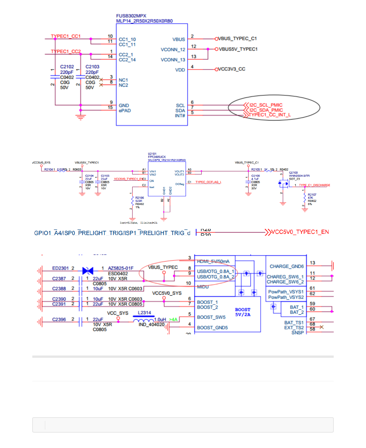
7.2.6 USB充电检测
USB2 PHY支持BC1.2标准的充电检测,代码实现请参考drivers/phy/rockchip/phy-rockchip-inno-usb2.c, 可以
检测SDP/CDP/标准DCP(D+/D-短接)/非标准DCP(D+/D-未短接)四种充电类型。
l SDP —— Standard Downstream Port
根据USB2.0规范,当USB外设处于未连接(un-connect)或休眠(suspend)的状态时,一个Standard Downstream
Port可向该外设提供不超过2.5mA的平均电流;当外设处于已经连接并且未休眠的状态时,电流可以至最大
100mA(USB3.0 150mA);而当外设已经配置(configured )并且未休眠时,最大可从VBUS获得500mA(USB3.0
900mA)电流。
l CDP —— Charging Downstream Port
即兼容 USB2.0 规范,又针对 USB 充电作出了优化的下行USB 接口,提供最大1.5A的供电电流,满足大电流快速
充电的需求。
l DCP —— Dedicated Charging Port (USB Charger)
BC1.2 spec要求将USB Charger中的D+和D-进行短接,以配合USB外设的识别动作,但它不具备和USB设备通信的
能力。
USB充电类型检测流程见下图所示:
DWC_OTG:dwc_otg_hcd_urb_enqueueurb‐>transfer_bufferaddressnotalignto4‐byte0xd6eab00a
DWC_OTG:dwc_otg_hcd_urb_enqueueurb‐>transfer_bufferaddressnotalignto4‐byte0xccf6140a
1
2
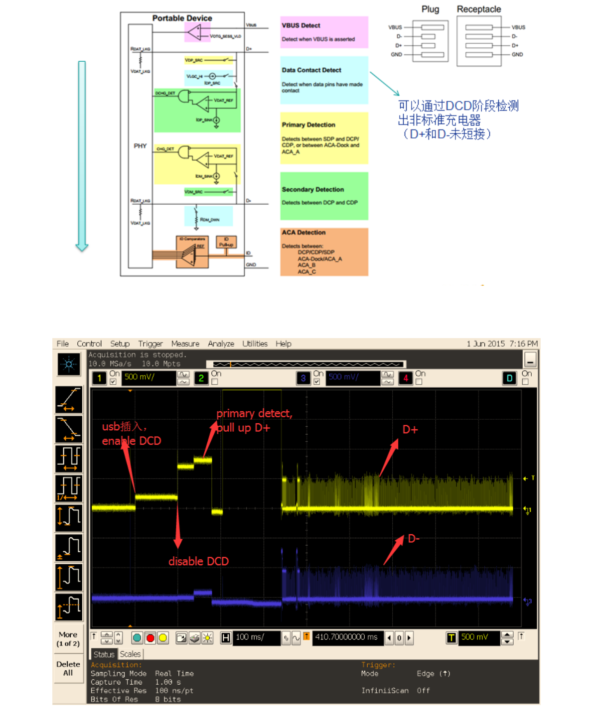
图 7‐1 USB充电检测流程
典型的SDP 检测过程中,D+/D-波形如下图所示:
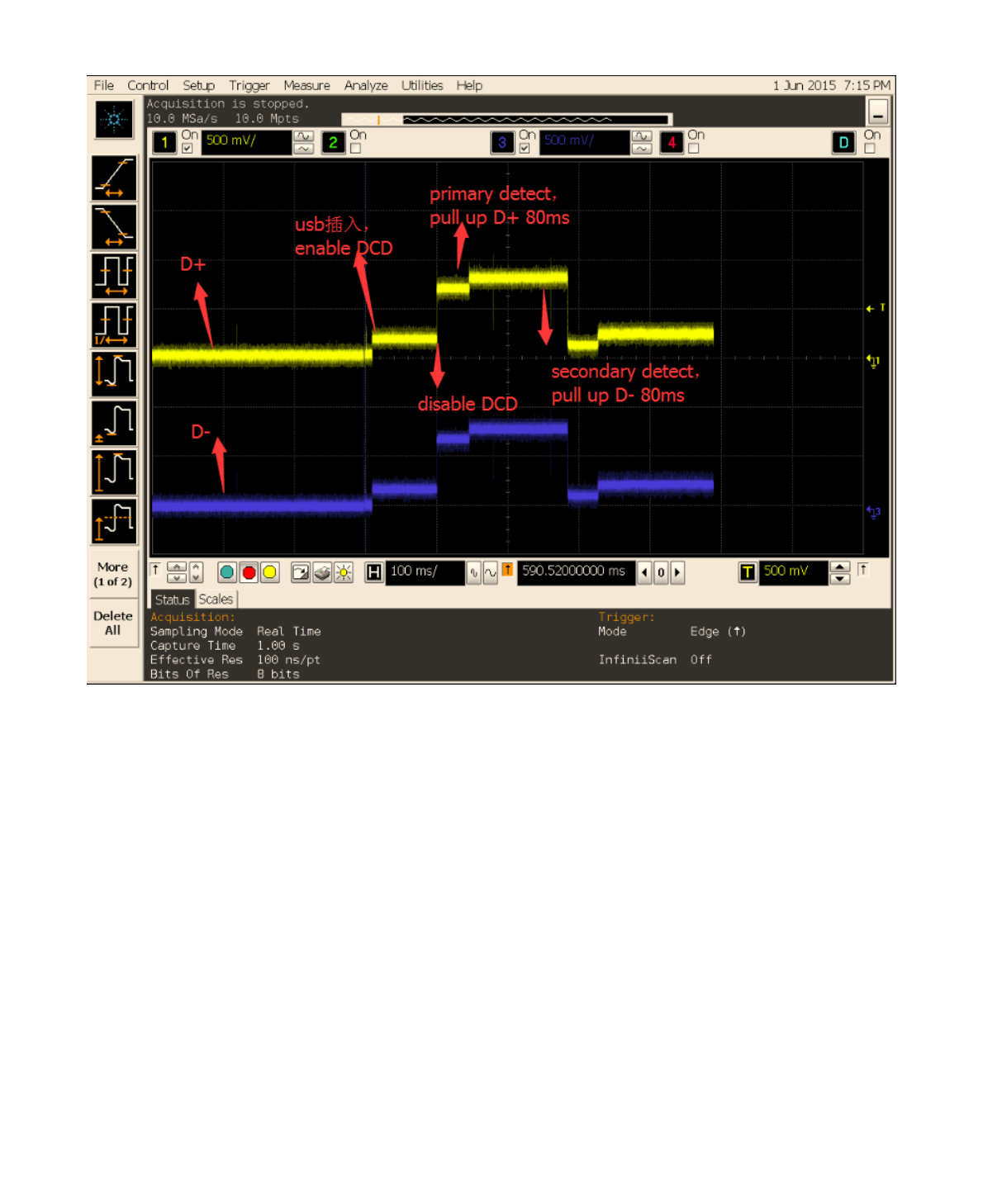
图 7‐2 SDP检测波形
典型的DCP 检测过程中,D+/D-波形如下图所示:
图 7‐3 DCP检测波形
如果连接USB充电器,发现充电慢,有可能是DCP被误检测为SDP,导致充电电流被设置为500mA。当USB线连接
不稳定或者充电检测驱动出错,都可能会产生该问题。解决方法:
抓取USB充电器连接的log,通过log的提示判断检测的充电类型,正常应为DCP;
如果连接的是USB充电器,但log提示为SDP,则表示发生了误检测。请先更换USB线测试,并使用万用表确认
D+/D-是否短接。如果仍无法解决,请将检测的log发给我们测试。同时,如果有条件,请使用示波器抓USB插入时
的D+/D-波形,并连同log一起发送给我们分析和定位问题。
如果连接的是USB充电器,并且log提示为DCP,但充电仍然很慢,则表明软件检测正常,可能是充电IC或者电池的
问题。
7.3 PC驱动问题
所有USB设备要在PC上正常工作都是需要驱动的,有些驱动是标准且通用的,而有些驱动是需要额外安装的。对于
RK的设备连接到PC后,需要安装驱动的情况有两种的设备,需要分别选择对应的驱动。
1. 生成后未烧写的裸片或者进入升级模式后的RK设备,会以rockUSB的模式连接到PC,需要在PC端使用RK平台
专门的驱动安装助手DriverAssitant(RK3399需要v4.4支持)安装驱动才能识别到USB设备;
2. RK的设备正常运行时,在设置里面打开了USB debugging选项,连接时会以ADB的模式连接PC,同样需要在
PC端使用RK平台专门的驱动安装助手DriverAssitant安装ADB驱动后,才能正常识别到ADB设备。