Roland SH101 Nova Mod
Roland Corporation SH-101 Nova Mod sh-101_novamod Roland Corporation - SH-101 - Nova Mod
Roland Electronic Keyboard SH-101 RolandSH101NovaMod
Roland Corporation SH-101 Nova Mod sh-101_novamod Roland Corporation - SH-101 - Nova Mod
User Manual: RolandSH101-NovaMod
Open the PDF directly: View PDF ![]() .
.
Page Count: 13
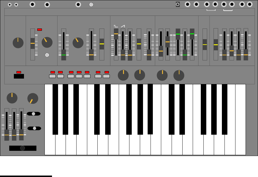
<<<NOVA-MOD>>>
SEQUENCER ARPEGGIO LEGATO REST
POWER
VOLUME PORTAMENTO
PORTAMENTO
TRANSPOSE
BENDER
TUNE WAVEFORM RANGE
LFO/CLK
RATE MOD PULSEWIDTH SUB OSC NOISE FREQ RES ENV MOD KEYBD A DSR
MODULATOR VCO SOURCE MIXER
VCF
VCA ENVELOPE
SH-101
LFO
MAN
ENV
-1
-2 ENV
GATE
GATE
Trig
LFO
ROLAND
CV GATE CV GATE
IN OUT
PHONES OUTPUT
EXT CLK
IN HOLDDC IN
EXT AUDIO
IN
VCF CV
IN
LFO CLK
IN
PW SOURCE EXT AUDIO FM SOURCE AMOUNT
NORM LO HI
-2
NOVA
FM Filter
Features:
• VCF FM: Amazing new sounds are now added through this feature. Six FM sources are
available.
• LFO Clock Input: Syncing the Arpeggiator and LFO to external drum modules and
sequencers is now possible. As well, interesting feedback loops can be created.
• PW Modulation Source Selection: Now you can choose a pulse width source. It is
independent from the LFO’s waveform setting. OSC sources are included.
• Pulse width to near 0%: Pulse width effects are now made more extreme and powerful.
• External Audio Input: The ability to do FM of the VCF by an external audio source or to
simply route a signal into the audio path is now provided. Don’t forget feedback loops!!
• VCF CV Input: Just plug in a foot pedal or a CV from a midi converter and your SH-101
will sing!
• LFO Rate Scalar: Ever hear a bell sound out of a 101? Try this on Hi!! Want a really slow
sweep...you got it too!
• 1/4” CV/Gate In/Out Jacks: Aren’t we all tired of those miniphono plugs? They should
only exist on walkmans.

NOVA-MOD Details:
Pulse width to near 0%
By closing the pulsewidth to a spike, new sounds can be attained by the SH-101. This “spike” wave source is very
useful for brightening a bass patch. (A bass patch, with only the sub Osc waveform assigned, can be brightened, but
not raised in pitch, by adding a little pulsewidth signal with a manual setting of less than 1% duty cycle.)
In another application, in which only full ramp waveform is assigned, manually raising and lowering the spike
waveform’s amplitude has been compared to sounding like a wavetable sweep.
As well, LFO modulation of the pulsewidth is made more dramatic because of the closer approach to 0%.
Pulsewidth Modulation Source Selection
A six-way rotary switch enables you to chose the pulsewidth modulation sources independently of the LFO’s waveform
setting. This modulation source makes many new and interesting sounds. A randomly modulated pulsewidth is
especially unique and pleasant.
The PW modulation sources are:
LFO Triangle
LFO Square
LFO Random
Sub Osc -1 Octave Square*
Sub Osc -2 Octave Pulse *
LFO Noise
* The Sub Osc Mod sources creates a unique bass enhancement because of their higher frequency and keytracking.
The result is a richer and deeper sound. As well, although there are only two sub Osc sources, changing the sub Osc
switch -1/-2/-2 results in even further modulation effects.
LFO Rate Scalar
A three-way toggle switch scales the overall range of the SH-101’s internal LFO Clk (the existing LFO rate slider still
functions normally). The scalar settings are Normal/Low/High.
In the Low setting, a cycle of 30 seconds can be attained. This is great for mild changes in “trance” type music.
In the High mode, up to 1200Hz can be used to create interesting cross-mod bell like sounds. Perfect for “industrial”
music and clanging metallic sounds. High mode works especially well when creating a synthetic kick drum patch or
short-wave radio sounds a la Kraftwerk’s Electric Cafe and Radioactivity albums respectively.
LFO Clock Input
A 1/4” jack allows the insertion of an external clock signal to drive the 101’s LFO. This injected signal triggers the LFO
but does not change it’s waveform. Buy applying a clock, LFO AND arpeggiator are both synced to the external
source. This makes for very moving and groovy patterns with only a drum box and NOVA-MODed 101. A particularly
nice application is to modulate the VCF Cutoff with a Random LFO while playing the sequencer. Of course you can,
at the same time, inject a separate clock into the arpeggiator via the 101’s Ext. Clk In Jack. This will enable you to run
the arpeggiator and LFO at different speeds (hopefully related in some way).
As a bonus, audio can be injected to drive the LFO. A simple trick is to patch the headphone output into the Ext. LFO
Input. This feedback loop makes for sounds that can be mildly distorted to heavily distorted by simply adjusting the
VCF’s Mod amount. [No need for an external distortion processor!] This effect is great for slow sweeps with a
resonating filter setting. Very minimoog-ish.
External Audio Input
A 1/4” jack and toggle switch allows external audio to be injected. A rotary pot controls the amplitude of the injected
signal. It can be routed to one of two sources:
1. directly into the filter along with the OSC’s waveforms. External processing of audio through the VCF and ENV is
a typical feature on some synths however a separate trigger can be applied to fire the SH-101’s envelope.
2. into the VCF’s cutoff modulation point. (An external FM source)
VCF CV Input
An external CV can be applied to the 101 via this 1/4” jack. This feature is typical on a Juno-60, Jupiter 4 and Pro-
One. A MIDI controller converted to a CV or an “expression” foot pedal are typically connected here.

VCF FM
VCF FM is the most powerful NOVA-MOD feature. It can be used in moderation to simply add brightness to a bass
patch with low frequencies (due to subtractive synthesis). Or it can be used to create powerful cross-mod sounds that
are difficult to explain...they must be heard. These sounds are somewhat aggressive, distorted, bell like but most
importantly, not attainable on a regular SH-101. These sounds are similar to those heard on a MiniMoog with its third
LFO assigned.
One example: Dial a patch with only a ramp waveform assigned but at the same time, modulate the VCF Cutoff with
the Pulsewidth. Manually change the pulsewidth to vary the FM effect. It is quite unique. You can then switch in Sub
Osc -2 Oct. Pulse as the FM source then adjust the -1oct/-2oct/-2oct switch to change the sound further. Finally swing
the Pulsewidth waveform as the FM source but switch from Manual to LFO modulation and then play with the PW
Mod’s waveform.
A rotary pot controls the amount of modulation. A six-way rotary switch selects the FM Source:
Pulse waveform
Ramp waveform
-1 Octave Sqr waveform*
-2 Octave Sqr waveform*
-2 Octave Pulse waveform*
Noise waveform
* As well, although there are only two Sub Osc Sources, the sub Osc switch -1/-2/-2 changes the sound, giving
even more variety.
ENV #2
A second Attack/Decay envelope. (To be developed). This is in the works but hopefully will be available soon.
1/4” CV/Gate In/Out Jacks
The existing 1/8” jacks are replaced by 1/4” jacks. Nothing special here except convenience.

NOVA-MOD Parts List
2 6 position Rotary Switches (Radio Shack units work fine but 3” long shafts must be cut. As well, pins must be
flattened to prevent interference with keyboard action, shims may be required to lower keyboard.)
Roland 4 position switches (pn 13119303 SRM1034-K15) may be used also but the switches must be
“adjusted” to swing 6 positions. The same clearance considerations must be made with respect to the key action
however these switches will accept the correct Roland knobs.
2 100K Rotary Pots. (Radio Shack units work fine but 3” long shafts must be cut. As well, pins must be
flattened to prevent interference with keyboard action, shims may be required to lower keyboard.)
Roland pots (pn 13219274 EVH-5XAP20A15) may be used. The same clearance considerations
must be made with respect to the key action however these pots will accept the correct Roland knobs.
1 DPDT Switched 1/4” jack.
2 1/4” Jacks with shorting contact
4 1/4” Jacks
1 SPDT toggle switch with center off position
1 4.7 uF 10V cap.
1 150K resistor
3 100k resistor
1 50k resistor
4 knobs (Roland PN 016H071)

NOVA-MOD Instruction:
note: There are only four circuit board assemblies inside an SH-101 that will be referred to in this instruction.. They
are formally referred to as the Control Board, Synth Board, Bender Board, and Jack Board (a). (The Control Board
contains most of the sliders and switches. The Synth Board contains most of the electronic components. The Bender
Board is small and resides near the bender. The Jack Board has the CV and Gate 1/8” jacks connected to it). There is
also the Keyboard (the assembly with the black and white piano keys). Read Important Points before starting!!
Tools: solder iron, de-solder tool, knife, modellers saw, drill press, wire strippers and cutters.
1. Remove all knobs.(rotary and linear)
2. Remove back panel. (two of these black screws have a fine thread, note their position)
3. Remove screws to Synth Board and Bender Board.
4. Cut two wire ties (one on Keyboard, one on Synth Board near battery holder and Jack Board)
5. Disconnect two header connectors on Synth Board (these headers are on the battery holder side of the Synth
Board. All other header connectors and wire interconnects can remain connected)
6. Disconnect the two header connectors that run to the Keyboard. (disconnect at Keyboard end of cables)
7. Gently bend the Synth Board up and remove screws holding Control Board.
8. Remove all screws to Bender Board
9. Remove Synth and Control board assembly. (now is a good time to clean/repair any pots/switches)
10. Remove Keyboard.
11. Drill out holes. (see figure XX) <<Use pilot holes for accuracy and watch for the bit grabbing the plastic!>>
12. De-solder cv gate 1/4” jacks then cut away Jack Board to facilitate 1/4” CV/Gate jack upgrade. Reconnect cut
traces. (see figure XX)
13. Pre-wire pots, switches, jacks and install. ( It is easiest to attach leads to components before installing. Please
color code or label the wires so that you will be able to connect them to the correct locations)
14. Cut trace on control board for pulsewidth mod. (see figure XX)
15. Remove IC3 from synth board, bend pins 2 and 3 up then reinstall. (see figure XX)
16. Connect pre-wired, pots, switches, and jacks to the appropriate locations (as per figures XX to XX).
17. Reassemble synth and test. Trouble-shoot any problems.
18. Calibrate synth.
Important Points:
1. It is difficult to remove the control board unless the bender board is free. It can be done but it is easier to do with
the bender board free.
2. It is very difficult to install the control board unless the bender board is free. Also, placing the power switch and
associated LED in the correct holes is made easier if you try to focus your attention on this task while installing the
control board. A slight nudging of the Power LED may be needed help to seat the board.
3. There is very little clearance between the keyboard mechanism and pots/switches (FM source, FM Amount, Audio
Level, PW Source). It is necessary to flatten all leads from these devices, insulate all leads to prevent shorts, run
leads away from the keyboard. As well, the keyboard may require two washers (teflon preferred) between it’s
mounting posts and metal body to allow enough clearance for these devices. (see figure XXX)
4. Plastic structural bracing will have to be trimmed away in the vicinity of the pots and switches. Use a sharp Xacto
knife to score the plastic then bend it away until it breaks. Do this after the holes are drilled so that you know
exactly where to cut.
5. Clearances are very tight for the 1/4” CV/Gate mod, as well, cutting a sizable chunk out of a circuit board is no
easy task. I recommend this task to be done by experienced or very clever people.
6. Many SH-101’s have battery acid damage. If you have this misfortune, be sure to clean it from the circuit boards
and repair any damaged traces.
7. SH-101 sliders are very easy to disassemble and repair once de-soldered. Typically the spring metal contacts get
bent away from the resistive elements making the slider useless. To repair, simply disassemble the slider, taking
care to note the orientation of parts, bend back the spring metal contacts, clean the resistive elements and
reassemble.

Calibration Procedure
This calibration is very easy to do. All that you need is a digital voltmeter capable of reading DC with an accuracy of
1mV. It is highly recommended to connect the voltmeter to a 1/8” plug. (best done by sacrificing a cable with 1/8” plug
at one end and using alligator clips to connect the voltmeter). Use 1/4” plug if NOVA-MOD was done :) A guitar
tuner or frequency counter is also needed.
1. Remove back panel of synth.
2. Adjust SH-101 knobs as follows.
Tune Pot in center position
VCO Mod slider at 0
Range at 8’
Pulse width at 0
Pulse waveform off
Ramp waveform at Max.
Sub-Osc waveform at 0
Noise at 0
Freq. at Max.
Res. at 0
Env at 0
Mod at 0
Kybd at Max.
VCA at Gate
Portamento at Off
Transpose at M
Volume at 10
VCO/VCF/MOD bender assignments at 0
3. Connect voltmeter to CV output jack. Measure DC voltage
4. Power up SH-101 while holding LOAD and KEY TRANSPOSE buttons down. (These LEDS should stay lit)
5. Voltmeter will now read approx. 0.000V. Adjust VR-2 on Synth Board to achieve 0.000V.
6. Press PLAY button.
7. Voltmeter will now read approx. 2.750V. Adjust VR-1 on Synth Board to achieve 2.750V.
8. Press ARPEGGIO DOWN button.
9. Voltmeter will now read approx. 2.500V. Adjust VR-3 on Synth Board to achieve 2.500V
10. Repeat steps 5-9 until all measurements are within 1mV. (note, you can press the LOAD button to return to the
state required for step 5 rather than re-powering.
11. De-power the Synth.
12. Re-power the synth and connect a guitar tuner or frequency counter to its output.
13. Alternate playing the lowest key (F3) and highest key (F5). while looking at the tuner/counter.
14. Adjust VR-6 until both notes are exactly 2 octaves apart. VR-6 adjusts the frequency spacing (width) between the
two notes. It should be exactly 2 octaves however VR-6 can make it greater or less that this amount. If you have
good ears, you may be able to adjust VR-6 without an instrument. (use keys G3 and G4 if you use a guitar tuner
that reads only EADGBE notes) Note :you may have to adjust VR-7 slightly to retune. Unfortunately VR-6
adjusts the width AND the overall tuning. TIP: Play the lowest note and set it to reference point using VR-7 (i.e.
G3 for the guitar tuner) Next press the G4 key and note where it sounds. If it is too high, then adjust VR-6 so that
the G4 note increases in pitch (YES INCREASES). Next, play G3 again and adjust VR-7 to re-center the guitar
tuner. Press G4 and see how close you have come. If G4 is too low then lower the pitch through VR-6. Repeat
this until You get your octave spacing.
15. Press an A key and adjust VR7 until the guitar tuner is centered on A (221/442/884 on a counter).
16. Repeat 14 and 15 until happy or crazy. (Actually SH-101’s are easy compared to Moogs!!!)
17. De-power the Synth
18. Re-power again holding the TRANSPOSE and LOAD keys.
19. Press the U&D button then press the UP button. Adjust VR-5 until the output is at the same pitch for each button.
20. De-power then re-power synth.
21. Adjust sliders so that:
all waveforms and noise levels are 0.
Res. is at Max.
VCF Env and VCF Mod are 0
Cutoff is approx. 8 (adjust so that a tone is hear from the self oscillation of the filter)
22. Alternately play two notes exactly 1 octave apart.
23. Adjust VR-8 until the two notes played sound 1 octave apart. Use a freq. counter or tuner or ear to measure.
24. Measure the DC voltage across the two test points on the Bender Board. (The test points are the wires accessed
through the two holes drilled in the circuit board.) Adjust VR-3 on the bender board for a 0.000V dc reading.
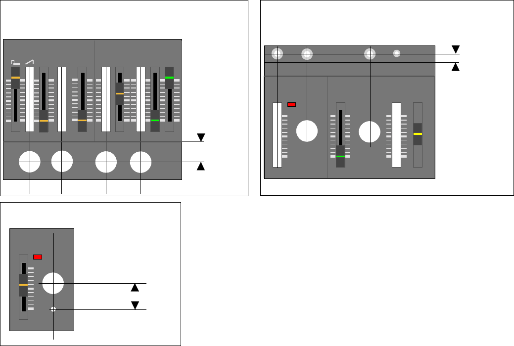
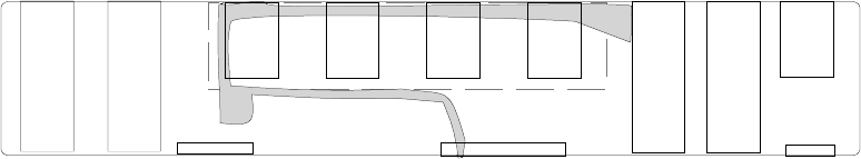
NORM LO HI
WAVEFORM
LFO/CLK
RATE
MODULATOR
2.30 cm
LFO Scalar Switch Location
WAVEFORM RANGE
LFO/CLK
RATE MOD PULSEWIDTH
MODULATOR VCO
LFO
MAN
ENV
EXT AUDIO
IN
VCF CV
IN
LFO CLK
IN
1.15 cm
Ext. LFO/ Ext VCF CV/ Ext Audio Jack/
Audio Switch Loctaions
FM Filter
Drill Locations
SUB OSC NOISE FREQ RES ENV MOD KEYBD
SOURCE MIXER
VCF
-1
-2
PW SOURCE EXT AUDIO FM SOURCE AMOUNT
-2
2.00cm
PW Source / Ext. audio / FM Source/
FM Amount Switch and Pot Locations
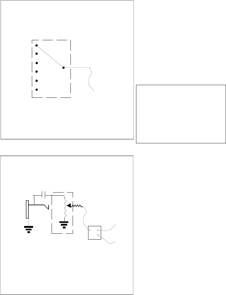
LFO Rate Extender
R15
Norm
Fast
DPST (center off)
150k
Slow
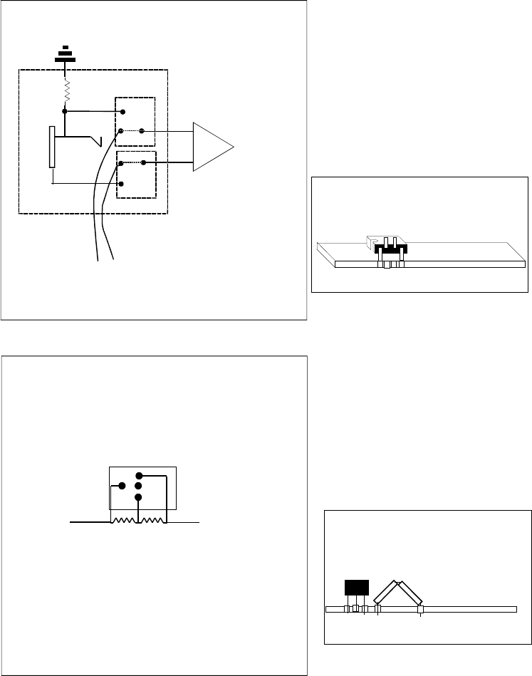
Ext LFO/Clk Mod
2
3
2
6
5
1
7
3
4
1ook
+
-IC3
To solder pad
under U3a pin 2
To solder pad
under U3a pin 3
NC
NC
DPDT
Switched 1/4" Jack
To do this mod, one must remove IC3 from
the circuit board, bend pens 2 and 3 up 180°
and resolder back into place.
TR4 Desolder and lift end of R15 on TR4 side.
Solder the 150K Resistor in series.
150K
R15
U3
1 2 3 4
TR-4
Use 200k or 300k resistor in place of the 150k resistor
if LFO cycles longer than 30sec are needed
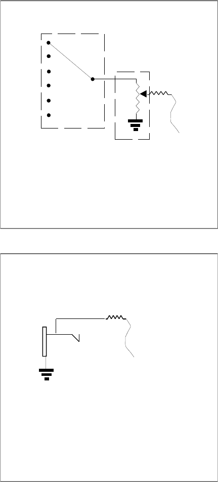
Ext FM CV Input
FM Mod
1ook
100k
To junction
of R184, 185,
186,187..etc on
Control Board
6 position
rotary switch
1ook
To junction
of R184, 185,
186,187..etc on
Control Board
100K
Pot
Audio
1
2
3
4
5
6
com
Pulse
Ramp
-1Oct Sqr
-2Oct Sqr
-2Oct Pulse
Noise
PW Mod Source
6 position
rotary switch
1
2
3
4
5
6
com
Tri
Sqr
Rnd
-1oct sqr
-2Oct pulse
Noise
To R176
Ext Audio Input
50k
To junction
of R109, 110,
111,112 on
Synth Board
1ook
100K
Pot
Audio
Cut Trace on control board between
R176 and Jumper.
4.7uF 10V Cap
To junction
of R184-187on
Control Board
SPDT
Switch
Locate hole for Ext audio Amount
Pot, directly below the Sub Osc -1/-1/-2
Switch at a distance of 2.00cm
from the groove that runs left to right
across the control surface.
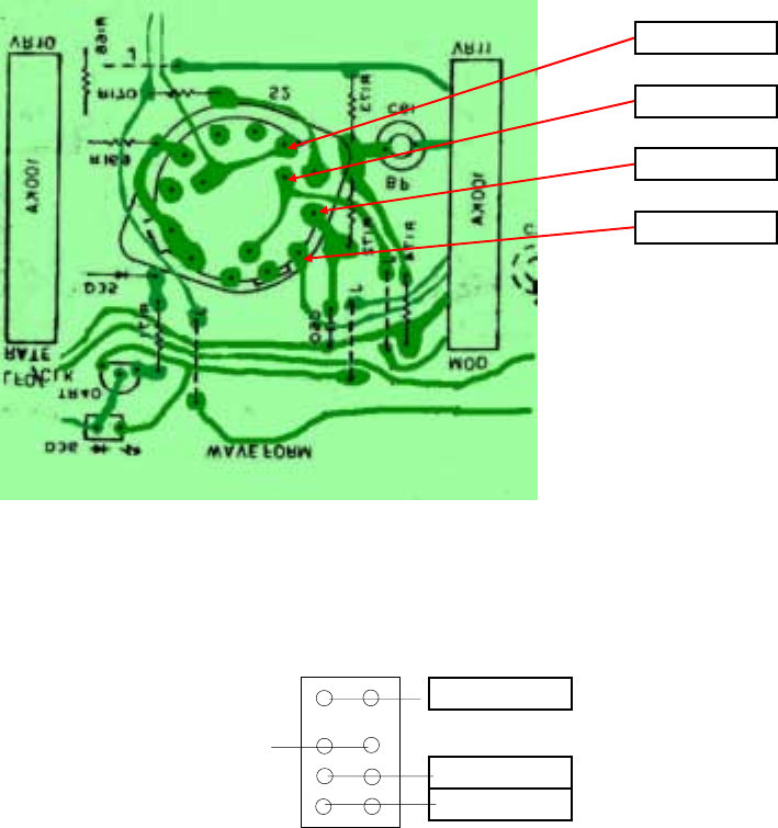
Waveform Tap Points:
LFO Waveform Switch
S5
Sub-Osc Waveshape Switch
LFO Square
LFOTriangle
LFO Noise
LFO Random
-2 Oct Pulse
-2 Oct Square
-1 Oct Square
49
40
GateOut
CV Out
CVIn
Gate In
1/8" to 1/4" Jack Upgrade
1. Desolder and remove Gate and CV Jacks.
2. Cut out circuit board as indicated by dashed line
3. Attach jacks as follows:
Gate out is a 1/4" 2 conductor jack. Its sleeve goes to ground. It's tip goes to pin46.
CV out is a 1/4" 2 condutcor jack. Its sleeve goes to ground. It's tip goes to pin 43.
Gate in is a 1/4" 2 conducor jack with shorting contact (Contact opens upon inserting
a 1/4" plug. Its sleeve goes to ground, it's tip goes to pin 44 and its shorting contact
goes to pin 46.
CV in is a 1/4" 2 conducor jack with shorting contact (Contact opens upon inserting
a 1/4" plug. Its sleeve goes to ground, it's tip goes to pin 45 and its shorting contact
goes to pin 43.
4. Jumper across ground trace that was cut during circuit board cutting.trace is indicated in figurexx.
5. Install and test for clearance b
y
insertin
g
1/4"
p
lu
g
s
.
Jackboard
