31030 S04JC
User Manual: 31030
Open the PDF directly: View PDF ![]() .
.
Page Count: 6
October 20, 2004
Dear Blue Bird Owner:
You will find enclosed Service Bulletin S04JC regarding a modification to the Multiplex
system on certain Blue Bird "Vision" school buses. We recommend that Service Bulletin S04JC
be performed to reduce battery draw, thus maintaining battery reserve. Please review the list of
buses provided with Service Bulletin S04JC carefully to determine if this modification should be
performed on your bus (es).
A qualified repair technician should perform Service Bulletin S04JC. You may contact your
appropriate Blue Bird distributor for assistance.
Parts required to perform this modification are available from your Blue Bird distributor.
Time required to modify Version 1 Multiplex systems is 0.5 hours per bus. Time required to
modify Version 2 Multiplex systems is 0.3 hours per bus.
Service Bulletin S04JC expires one year from date of issue.
If you no longer own the bus (es) identified on the enclosed cover sheet, please indicate new
owner in the “sold to” section of the cover sheet and return to us at the address below:
BLUE BIRD BODY COMPANY
P.O. BOX 937
FT. VALLEY GA 31030
ATTN: TECHNICAL PUBLICATIONS
Should you have any questions concerning this bulletin, please contact your Blue Bird
distributor.
Sincerely,
Bill Coleman
Blue Bird Corporation

ADDENDUM TO SERVICE BULLETIN S04JC
Since S04JC-BBCV Multiplex System Modification addresses a sensitive issue, battery
draw, which may affect engine starting in cold climate conditions, and not all Visions are
affected, a heads up to you to inform you with the facts might be beneficial.
SUMMARY
There are currently three versions of the multiplex system in operation in the BBCV.
Version 1- This version is a dual multiplex module system that does not go into “sleep
mode” when the ignition is switched off. This version was installed on buses
with factory service numbers 0122012 through 0154520.
Version 2- Version 2 is a single module system that goes into “modified sleep mode”
when the ignition is switched off. This version is on buses with factory
service numbers 0154530 through 0160375. These buses were not equipped
with a battery disconnect switch as standard equipment.
Version 3- This version is a single multiplex module system on all BBCV with factory
service numbers greater than 00167915, that goes into “sleep mode” when the
ignition is switched off.
BBCV INCLUDED IN SERVICE BULLETIN S04JC
All Version 1- Service Bulletin S04JC provides for a wiring harness that will allow the
multiplex system on these buses to go into “sleep mode” when the ignition is switched
off. This dramatically reduces battery draw and on average increases the number of days
of battery reserve significantly when the bus is not being operated. (Note: Version 1
multiplex modules are not to be replaced by Versions 2 or 3 modules under Service
Bulletin S04JC.)
Version 2- BBCV included in S04JC are busses that (1) are not equipped with a battery
disconnect switch, and (2) are subject to be operated in sub zero temperatures. S04JC
will provide for replacement of the Version 2 multiplex module with the Version 3
multiplex module which reduces the battery draw to a level comparable to the All
American when the bus is not being operated.
BBCV NOT INCLUDED IN SERVICE BULLETIN S04JC
Version 2- BBCV not included are busses that (1) are equipped with a battery disconnect
switch, or (2) are not operated in sub zero temperature conditions.
Version 3- All BBCV with Version 3 multiplex modules are designed to go into “sleep
mode” and have very low continuous battery draws when the bus is not in operation.
L
page of
BULLETIN
SERVICE BULLETIN SO4JC
MPX Modication
MODELS AFFECTED:
All Blue Bird Visions with Version 1 multiplex systems, and certain Blue Bird Visions with Version 2 multiplex systems.
ISSUE
In operations where buses are commonly left parked for extended
periods, the current draw of the multiplex system in non-sleep
mode may drain batteries.
CORRECTIVE ACTION
On Version 1 units, the wiring harness modication described
below results in a signicantly reduced current draw during sleep
mode. On Version 2 units, the MPX module is replaced with the
model used in Version 3 units.
PROCEDURE
1 Disconnect the negative terminal of the battery. Remove
the four screws securing the PDU cover, and remove the cover.
Determine if the unit is equipped with a Version 1, Version 2, or
Version 3 MPX system. The version is easily identiable by the fol-
lowing criteria:
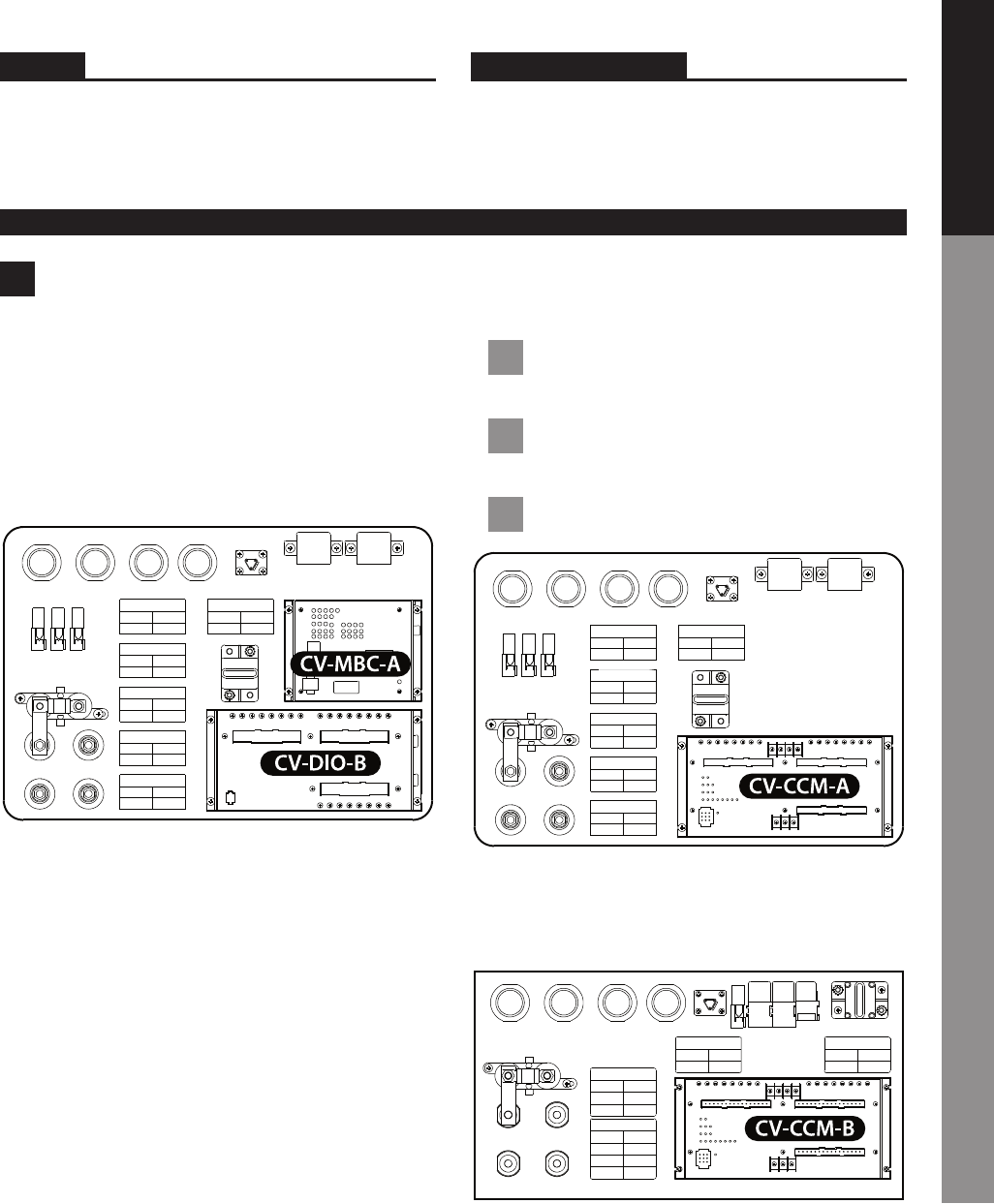
Version 1 units have two separate multiplex modules; a DIO mod-
ule and a MBC module. If the vehicle is Version 1, go to step 2 of this
procedure to perform the necessary wiring harness modication.
Version 2 units have one MPX module, and its model designation
is CV-CCM-A. If the vehicle is Version 2, proceed as follows:
1.1 Unplug the harness blocks from the module. Re-
move the four mounting screws, and remove the module.
1.2 Mount the new module. Reconnect the harness
blocks. This is the only modication required.
1.3 Go to step 12 of this procedure.
Version 3 units have one MPX module, and its model designation
is CV-CCM-B. If the vehicle is Version 3, no modication is neces-
sary. Replace the PDU cover.
L
page of
BULLETIN
SERVICE BULLETIN SO4JC
2 Steps 2–10 of this procedure apply only to Vision buses
with Version 1 Multiplex systems. Version 1 systems are those with
two separate MPX modules in the PDU, as shown, with Main Bus
Controller module model number CV-MBC-A.
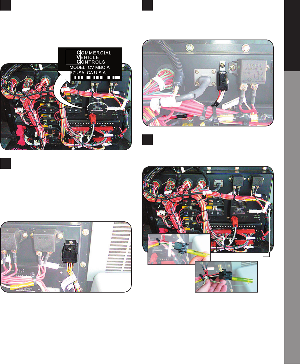
3 Drill a ⁄ hole to attach the Diode Block connector of the
new harness to the PDU box in the location shown. Attach with a
short #10 self tapping sheet metal screw. Insert the Diode Block
(0081525) into the connector.
[CAUTION] Use a short drill bit. Drill slowly and only
through the sheet metal, being mindful of components
which may be on other side of the panel.
4 Similarly mount the Micro Relay Socket of the new harness
in the location shown. Insert Micro Relay (1746387) into the sock-
et. Take the same precaution to avoid drilling deeply and possibly
damaging components on other side of the panel.
5 Unplug MBC Power connector (far right side of image).
Slide yellow pin removal tool over the pin of the green wire
(labeled SYS WAKE). Pull the green wire from the connector.
MBC Power Connector
L
page of
BULLETIN
SERVICE BULLETIN SO4JC
6 Insert the green wire of the new harness labeled SYS WAKE
into the socket from which the original green wire was removed in
step 4. Reconnect the MBC Power connector.
7 The green wire removed in step 4 is spliced into a white
wire, labeled Wake Up, at a yellow butt connector located a few
inches from the MBC Power Connector. Cut the white wire on both
sides of the yellow butt connector. Discard the yellow butt con-
nector and the green wire end. Then reconnect the two cut ends
of the white wire back together with a new butt connector.
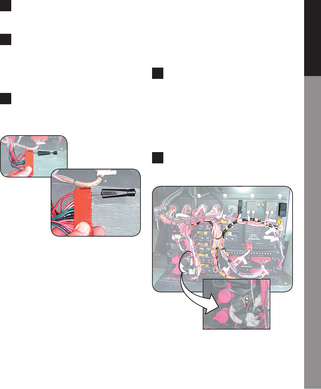
8 The photos below show how to use the black pin removal
tool. The tool is inserted over the pin to be removed. This retracts
the lock tabs of the connector pin. Then depressing the tool’s
plunger pushes the pin out of the connector block.
Use the black pin removal tool to remove the wires at the follow-
ing six locations. Replace each removed wire with the correspond-
ing wire of the new harness:
• Remove wire labeled B1-O14 from Port B1 connector, pin
14. Insert wire labeled B1-O14A from new harness into
same socket.
• Remove wire labeled B2-O08 from Port B2 connector, pin
08. Insert wire labeled B2-O08A from new harness into
same socket.
• Remove wire labeled B2-I02 from Port B2 connector, pin
02. Insert wire labeled B2-I02A from new harness into
same socket.
• Remove wire labeled B3-O04 from Port B3 connector, pin
04. Insert wire labeled B3-O04A from new harness into
same socket.
Insert the tool to release the pin’s lock
tabs…
…then push the tool’s
plunger pin to push the
wire out of the connector
socket.
• Remove wire labeled B3-O05 from Port B3 connector, pin
05. Insert wire labeled B3-O05A from new harness into
same socket.
• Remove wire labeled B3-O14 from Port B3 connector, pin
14. Insert wire labeled B3-O14A from new harness into
same socket.
9 The 6 wires just removed will now be connected to the cor-
responding butt connectors on the new harness. Before making
these connections, plan the routing of harness so it can be neatly
bundled when nished. Then route the six removed wires toward
the harness. For each of the six original wires, cut the pin o, leav-
ing an appropriate length of wire for connecting to the new har-
ness butt connector. The wires of the new harness with the butt
connectors attached are labeled identically to the original wires
you are connecting.
10 Connect the ground wire of the new harness, labeled STP
GND A, to the Chassis Ground Post at the lower left of the PDU.
Neatly bundle the harness and wires with cable ties.
L
page of
BULLETIN
SERVICE BULLETIN SO4JC
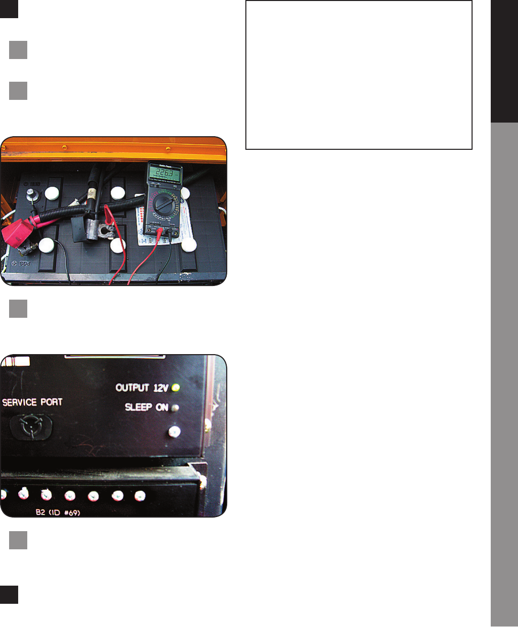
11 Before replacing the PDF cover, test the connections by
measuring current draw during sleep mode as follows:
11.1 Make sure ignition is o. (Leaving it on may blow
the meter’s fuse).
11.2 Set a multimeter to measure milliamps. Connect
the multimeter between negative battery post and nega-
tive battery cable.
11.3 Wait 30 minutes for the system to go to sleep. Sleep
mode is indicated by the LED labeled Sleep On, located on
the MBC module.
11.4 When the system indicates Sleep Mode, check the
current draw. Draw should be between 80 –100 mA, de-
pending upon optional equipment installed.
12 Replace the PDU cover. Reconnect the battery. Check the
circuits for which wiring has been modied in this procedure for
proper operation. The procedure is complete.
Version 1 Units
PART NUMBER QUANTITY DESCRIPTION
0068940 1 Harness
0081525 1 Diode Block
1746387 1 Micro Relay
Version 2 Units
PART NUMBER QUANTITY DESCRIPTION
0077446 1 Module, MPX,
CV-MBC/DIO,
low current
