S04 SCP 400B C_Multi Port_Serial_Card C Multi Port Serial Card
S04-SCP-400B-C_Multi-Port_Serial_Card S04-SCP-400B-C_Multi-Port_Serial_Card
User Manual: S04-SCP-400B-C_Multi-Port_Serial_Card
Open the PDF directly: View PDF ![]() .
.
Page Count: 35
Instruction Manual
Model
SCP400B,C
Multi-port
Serial Card
For
the
S-100
Bus
Rev.
B,C
~-
eattle
Computer Products,
Inc.
~
1114 Industry Drive, Seattle, WA. 98188
(206) 575-1830
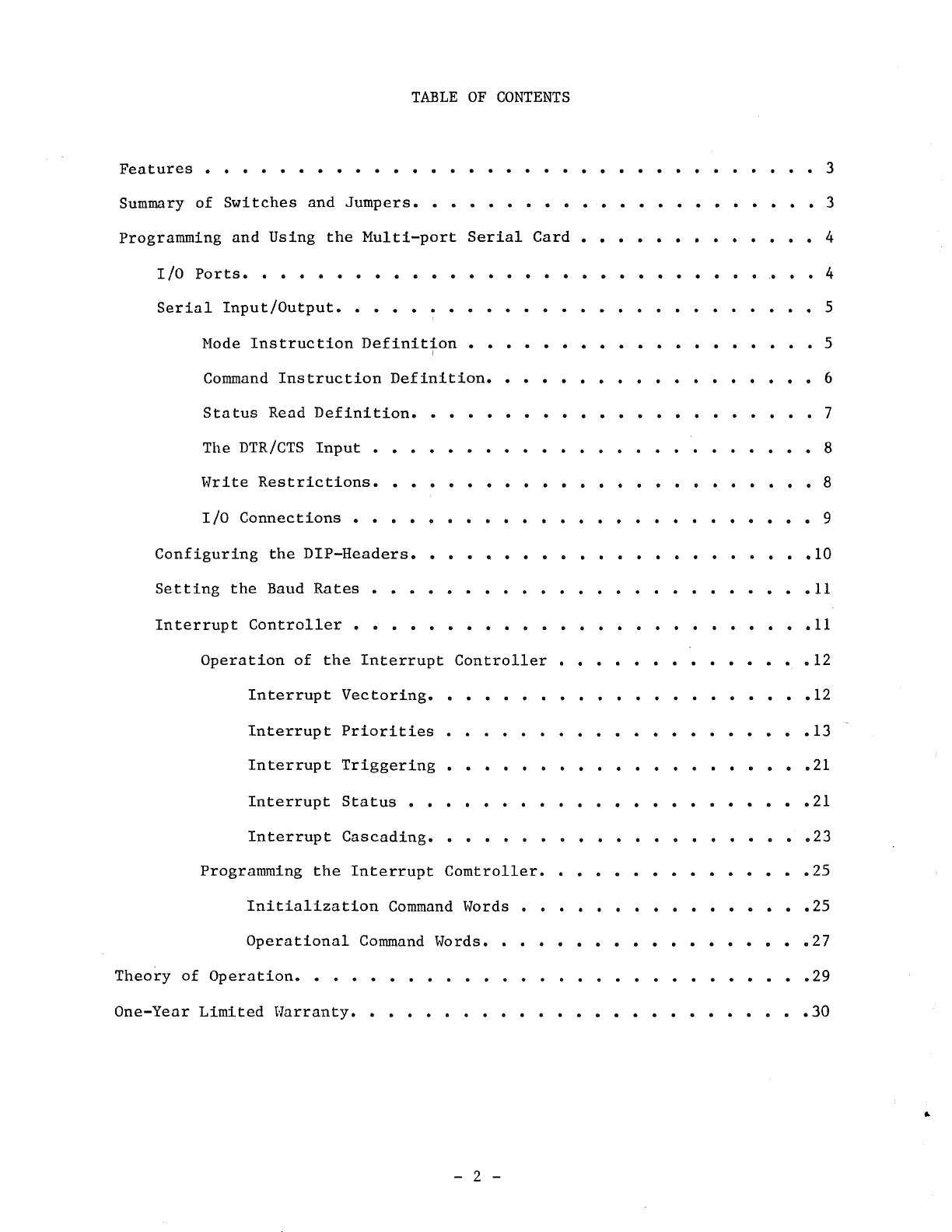
TABLE
OF
CONTENTS
Features
. . . . . . . . . . . . . . . . . . . . . . . . . . • . . . . . . 3
Summary
of
Switches
and
Jumpers.
. . . . . . . . . . . . . . . • . . . . . 3
Programming
and
Using
the
Multi-port
Serial
Card
. . . . . . • . . . . . . 4
I/0
Ports.
. . . . . . . . . . . . . . . . . . . . . . . . . . .
..
. . 4
Serial
Input/Output.
. . . . . . . . . . . . . . . . . . . . . . . . • 5
Mode
Instruction
Definition
. . . . . . . . . . . . . . . . . . . 5
I
Command
Instruction
Definition.
. . . . . . . . . . . . . . . . . 6
Status
Read
Definition.
. . . . . . . . . . . . . . . . . . . . . 7
The
DTR/CTS
Input
. . . . . . . . . . . . . . . . . . . . . . . . 8
Write
Restrictions.
. . . . . . . . . . . . . . • . . . . . . . . 8
I/0
Connections
. . . . . . . . . . . . . . . . . . . . . . . . . 9
Configuring
the
DIP-Headers.
. . . . . . . . . . . . . . . . . . . .
.10
Setting
the
Baud
Rates
. . . . . . . . . . . . . . . . . . . . . . . •
11
Interrupt
Controller
. . . . . . . . . . . . . . . . . . . . . . . .
.11
Operation
of
the
Interrupt
Controller
. . . . . . . . . . . . .
.12
Interrupt
Vectoring.
. . . . . . . . . . . . . . . . . . .
.12
Interrupt
Priorities
. . . . . . . . . . . . . . . . . . . •
13
Interrupt
Triggering
. . . . . . . . . . . . . . . . . . .
.21
Interrupt
Status
. . . . . . . . . . . . . . . . . . . . .
.21
Interrupt
Cascading.
. . . . . . . . . . . . . . . . . . .
.23
Programming
the
Interrupt
Comtroller.
. . . . . . . . . . . . . •
25
Initialization
Command
Words . . . . . . . . . . . . . . .
.25
Operational
Command
Words. . . . . . . . . . . . . . . . .
.27
Theory
of
Operation.
. . . . . . . . . . . . . . . . . . . . . . . . . .
.29
One-Yenr
Limited
Warranty.
. . . . . . . . . . . . . . . . . . . . . . . • 30
..
- 2 -
}
)
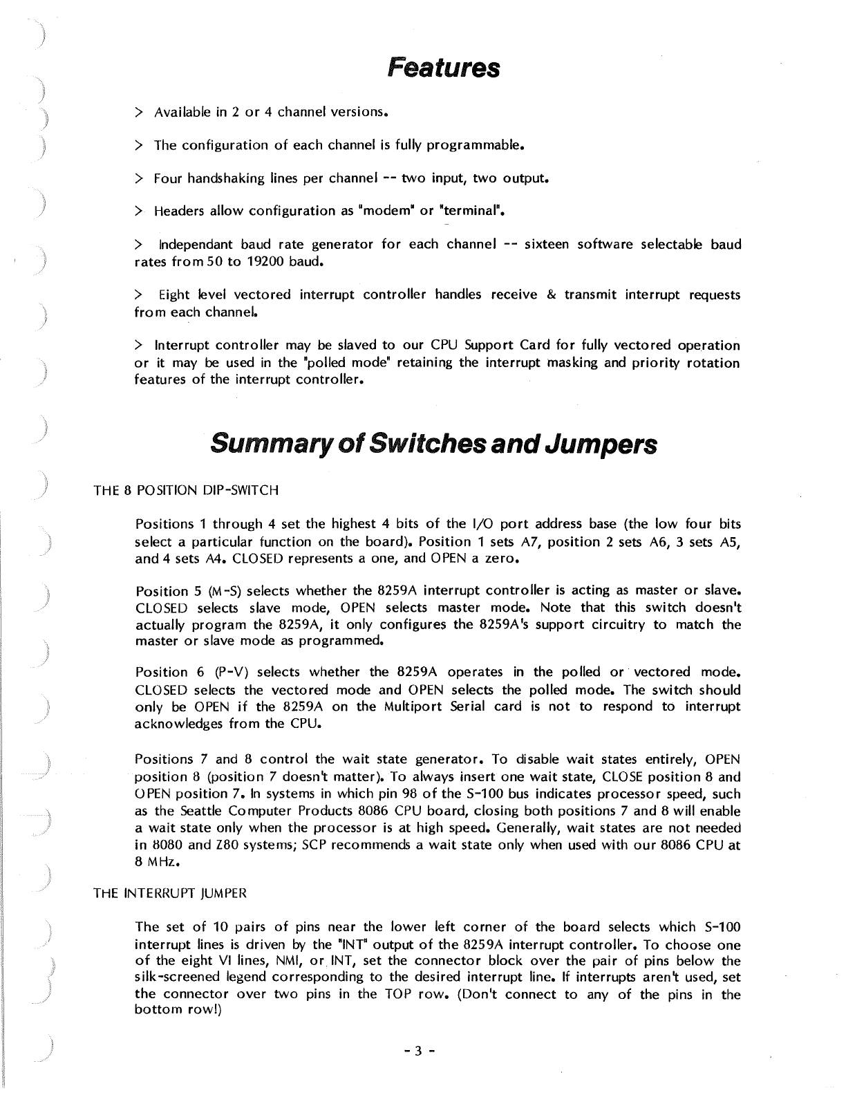
Features
> Available in 2
or
4 channel versions.
> The
configuration
of
each channel
is
fully
programmable.
> Four handshaking lines per channel
--
two
input,
two
output.
> Headers
allow
configuration
as
"modem"
or
"terminal".
> lndependant baud rate
generator
for
each channel
--
sixteen
software
selectable baud
rates
from
50
to
19200 baud.
> Eight level
vectored
interrupt
controller
handles receive &
transmit
interrupt
requests
from
each channel.
>
Interrupt
controller
may be slaved
to
our
CPU
Support Card
for
fully
vectored
operation
or
it
may be used in the "polled mode" retaining the
interrupt
masking and
priority
rotation
features
of
the
interrupt
controller.
Summary
of
Switches
and
Jumpers
THE 8 POSITION DIP-SWITCH
Positions 1
through
4 set the highest 4 bits
of
the 1/0
port
address
base
(the
low
four
bits
select a
particular
function
on the
board).
Position
1 sets A7,
position
2
sets
A6, 3 sets
AS,
and 4 sets A4.
CLOSED
represents a one, and
OPEN
a
zero.
Position
5 (M-S) selects
whether
the 8259A
interrupt
controller
is
acting
as
master
or
slave.
CLOSED selects slave mode,
OPEN
selects master
mode.
Note
that
this
switch
doesn't
actually
program
the 8259A,
it
only
configures
the 8259A
's
support
circuitry
to
match the
master
or
slave mode
as
programmed.
Position
6 (P-V) selects whether the 8259A operates in the polled
or
vectored
mode.
CLOSED selects the
vectored
mode and
OPEN
selects the polled mode. The
switch
should
only
be
OPEN
if
the 8259A on the
Multiport
Serial card
is
not
to
respond
to
interrupt
acknowledges
from
the CPU.
Positions 7 and 8
control
the
wait
state
generator.
To disable
wait
states entirely,
OPEN
position
8
(position
7 doesn't
matter).
To always
insert
one
wait
state,
CLOSE
position
8 and
OPEN
position
7.
In
systems in which pin 98
of
the S-100
bus
indicates
processor
speed, such
as
the Seattle
Computer
Products 8086
CPU
board,
closing
both
positions
7 and 8
will
enable
a
wait
state
only
when the
processor
is
at
high speed. Generally,
wait
states are
not
needed
in
8080 and Z80 systems;
SCP
recommends a
wait
state only when used
with
our
8086 CPU
at
8 MHz.
THE
INTERRUPT
JUMPER
The
set
of
10 pairs
of
pins near the
lower
left
corner
of
the board selects
which
S-100
interrupt
lines
is
driven
by
the "INT"
output
of
the
8259A
interrupt
controller.
To choose
one
of
the
eight
VI
lines,
NMI,
or.
INT, set the
connector
block
over
the
pair
of
pins
below
the
silk-screened legend
corresponding
to
the desired
interrupt
line. If interrupts
aren't
used, set
the
connector
over
two
pins in the
TOP
row.
(Don't
connect
to
any
of
the pins in the
bottom
row!)
- 3 -
THE DIP-HEADERS
For
normal
operation,
each pin
on
the
dip-headers
should
be
connected
to
the
pin on
the
opposite
side,
i.e.,
pin
1
to
pin 14, pin 2
to
pin 13,
etc.
Wiring the
dip-headers
tor
any
other
mode
of
operation
is
too
complex
to
be included in this summary,
refer
to
the
section
"CONFIGURING
THE
DIP-HEADERS".
Programming
and
Using the Multi-port Serial
Card
l!OPorts
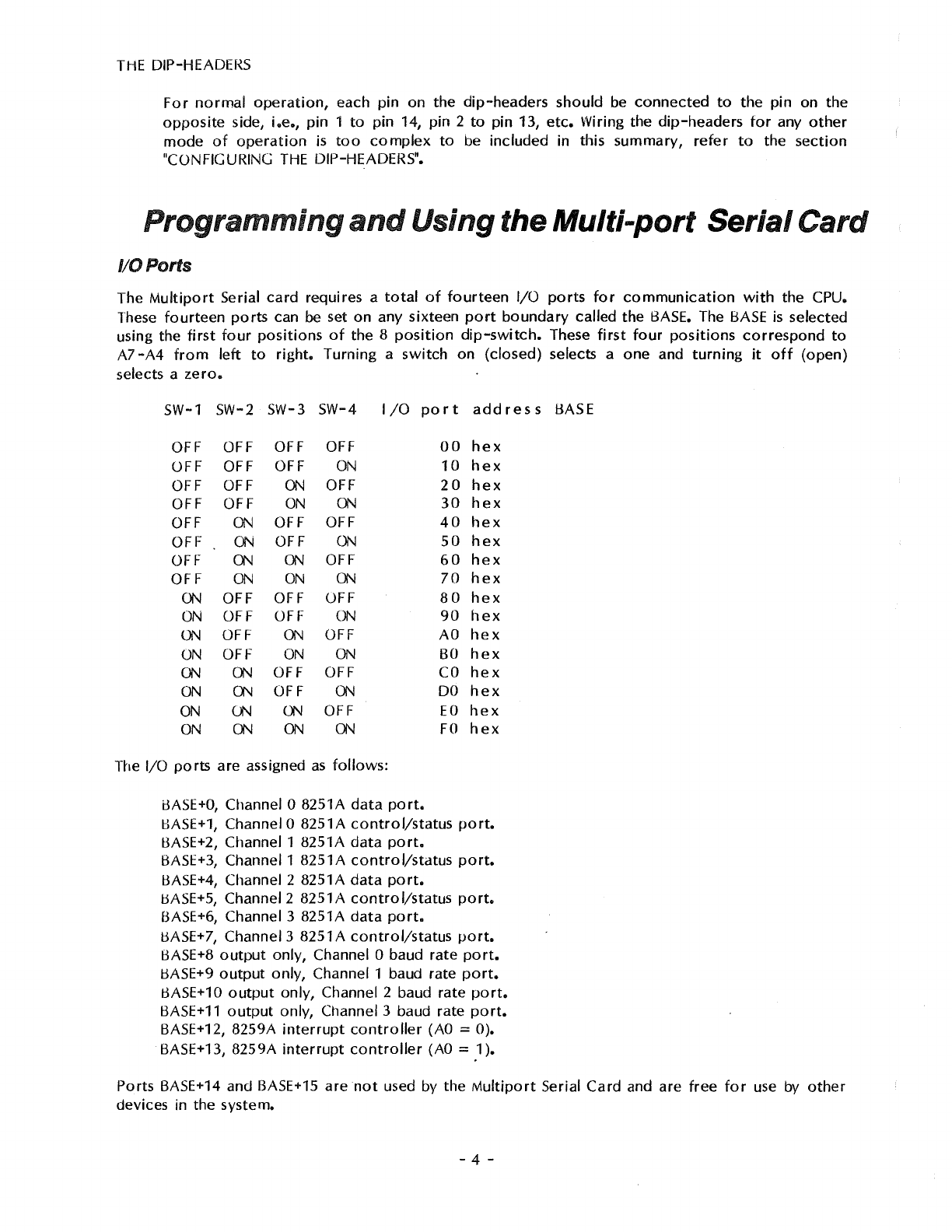
The
Multiport
Serial
card
requires a
total
of
fourteen
1/0
ports
for
communication
with
the CPU.
These
fourteen
ports
can be set
on
any sixteen
port
boundary
called
the
BASE. The
BASE
is
selected
using the
first
four
positions
of
the 8
position
dip-switch.
These
first
four
positions
correspond
to
A7
-A4
from
left
to
right.
Turning
a
switch
on
(closed)
selects a
one
and
turning
it
off
(open)
selects a
zero.
SW-1 SW-2 SW-3 SW-4 I
/0
port
address
BASE
OFF OFF OFF OFF
OFF OFF OFF
ON
OFF OFF
ON
OFF
OFF OFF
ON
ON
OFF
ON
OFF OFF
OFF
ON
OFF
ON
OFF
ON ON
OFF
OFF
ON
ON
ON
ON
OFF OFF OFF
ON
OFF OFF
ON
ON
OFF
ON
OFF
ON
OFF
ON
ON
ON
ON
OFF OFF
ON
ON
OFF
ON
ON
ON
ON
OFF
ON
ON ON ON
The 1/0
ports
are assigned
as
follows:
iJASE+O,
Channel O 8251A
data
port.
00
hex
10
hex
20
hex
30
hex
40
hex
50
hex
60
hex
70
hex
80
hex
90
hex
AO
hex
BO
hex
CO
hex
DO
hex
EO
hex
FO
hex
BASE+1,
Channel O 8251A
control/status
port.
BASE+2, Channel 1 8251A
data
port.
BASE+3, Channel 1 8251A
control/status
port.
l:3ASE+4,
Channel 2 8251A
data
port.
BASE+S,
Channel 2 8251A
control/status
port.
BASE+6, Channel 3 8251A
data
port.
BASE+
7,
Channel 3 8251 A
control/status
port.
BASE+8
output
only, Channel O baud rate
port.
8ASE+9
output
only,
Channel 1 baud rate
port.
BASE+10
output
only, Channel 2 baud rate
port.
BASE+11
output
only, Channel 3 baud rate
port.
BASE+12, 8259A
interrupt
controller
(AO
::::
0).
BASE+13, 8259A
interrupt
controller
(AO
::::
1 ).
Ports BASE+14 and BASE+15 are
not
used by
the
Multiport
Serial
Card
and are
free
for
use by
other
devices in the system.
- 4 -
i
j
Serial Input/Output
The
Multiport
Serial
card
has
either
two
or
four
8251A-type
USARTs
for
RS-232
communication.
The
two
channel
version
uses
ports
O and 1, the
four
channel
version
uses
ports
O
through
3
•.
The
transmit
and receive baud rates are always the same
on
any given channel, but each channel is
independently
programmable.
See
the
section
on baud
rate
generators
for
complete
details
on
how
to
program
the desired baud rate
for
each channel.
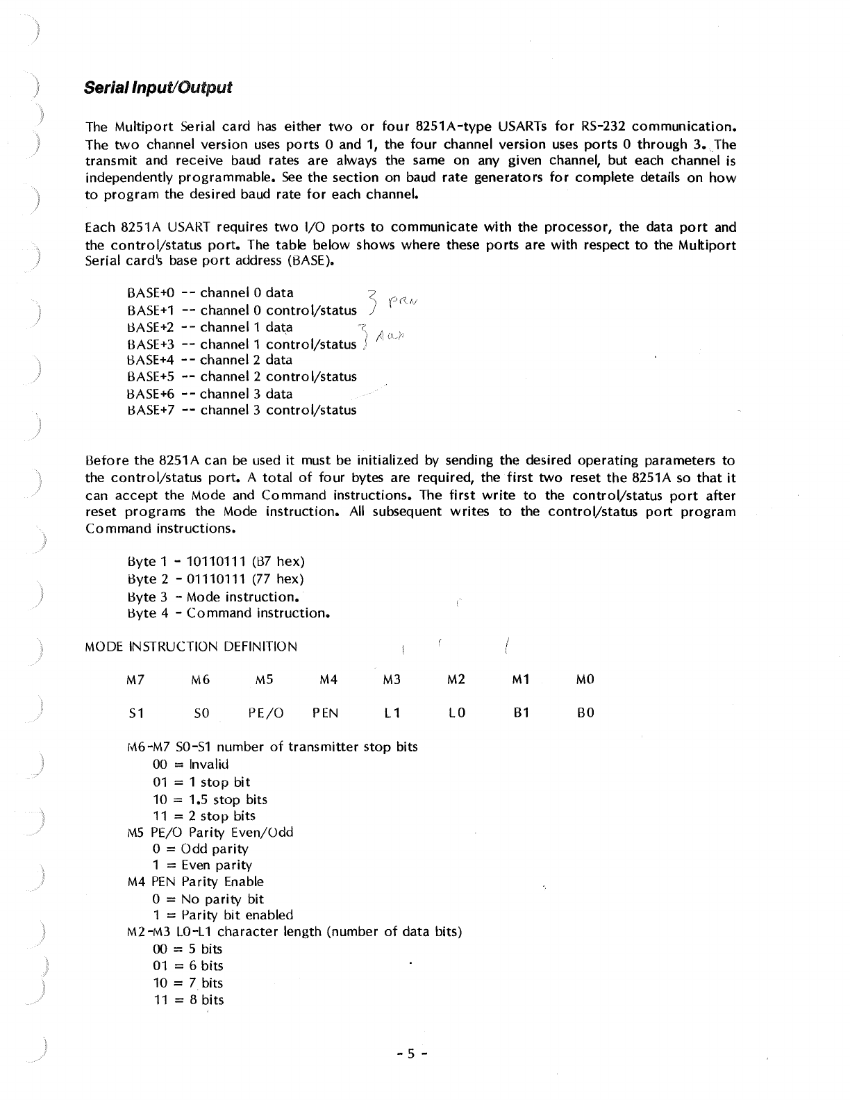
Each 8251A
USART
requires
two
1/0
ports
to
communicate
with
the processor, the data
port
and
the
control/status
port.
The table below shows where these
ports
are
with
respect
to
the
Multiport
Serial card's base
port
address (BASE).
BASE+O
--
channel O
data
<
'('
((
/,/
BASE+1
--
channel O
control/status
J
BASE+2
- - channel 1
dat.a
-z,
I' . ,
BASE+3
--
channel 1
control/status
J
,,
L'-
1'
1:3ASE+4
- - channel 2 data
BASE+S
--
channel 2
contro
I/status
BASE+6
--
channel 3 data
11ASE+7
--
channel 3
control/status
Before
the 8251A can
be
used
it
must be
initialized
by sending the desired
operating
parameters
to
the
control/status
port.
A
total
of
four
bytes are required, the
first
two
reset
the
8251A
so
that
it
can
accept
the Mode and Command
instructions.
The
first
write
to
the
control/status
port
after
reset
programs
the Mode
instruction.
All subsequent
writes
to
the
control/status
port
program
Command
instructions.
l:3yte
1 - 10110111
(B7
hex)
i3yte 2 - 01110111 (77 hex)
Byte 3 - Mode
instruction.
l:3yte
4 -
Command
instruction.
MODE
INSTRUCTION DEFINITION
M7
51
M6
so
MS
PE/0
M4
PEN
M3
L1
M6-M7 50-51 number
of
transmitter
stop bits
00 = Invalid
01
= 1
stop
bit
10 = 1.5 stop bits
11
= 2
stop
bits
MS
PE/0
Parity Even/Odd
0 = Odd
parity
1 =
Even
parity
M4
PEN
Parity Enable
0 = No
parity
bit
1 = Parity
bit
enabled
M2
LO
M2-M3
LO-L
1
character
length (number
of
data bits)
00 = 5 bits
01
= 6 bits
10 = 7 bits
11=8bits
- 5 -
I
i
M1
B1
MO
BO
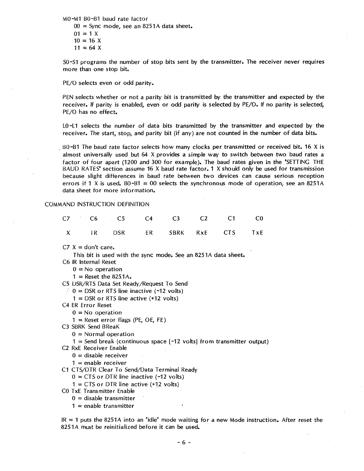
MO-M1
BO-B1
baud rate
factor
00
=
Sync
mode,
see
an 8251 A data sheet.
01
= 1 X
10 = 16 X
11
=
64
X
SO-S1
programs
the number
of
stop
bits sent by the
transmitter.
The
receiver
never
requires
more
than one stop
bit.
PE/0
selects even
or
odd
parity.
PEN
selects
whether
or
not
a
parity
bit
is
transmitted
by the
transmitter
and expected by the
receiver.
If
parity
is
enabled, even
or
odd
parity
is
selected
by
PE/0.
If
no
parity
is
selected,
PE/0
has
no
effect.
LO-L 1 selects the number
of
data
bits
transmitted
by the
transmitter
and expected by the
receiver.
The
start,
stop,
and
parity
bit
(if
any)
are
not
counted
in the number
of
data bits •
. BO-B1 The baud rate
factor
selects
how
many
clocks
per
transmitted
or
received
bit.
16
Xis
almost universally used but 64 X provides a simple way
to
switch
between
two
baud rates a
factor
of
four
apart
(1200 and 300
for
example). The baud rates given
in
the
"SETTING
THE
BAUD
RATES"
section
assume 16 X baud rate
factor.
1 X should
only
be
used
for
transmission
because slight
differences
in baud rate between
two
devices can cause serious
reception
errors
if
1 X
is
used. B0-81 =
00
selects the synchronous mode
of
operation,
see
an 8251A
data
sheet
for
more
information.
COMMAND INSTRUCTION DEFINITION
C7
X
C6
IR
cs
DSR
C7 X =
don't
care.
C4
ER
C3
SBRK
C2
RxE
C1
CTS
This
bit
is
used
with
the sync mode.
See
an
8251A
data
sheet.
C6
IR
Internal Reset
0 =
No
operation
1 = Reset
the
825J
A.
CS
OSR/RTS
Data Set l<eady /Request To
Send
i O =
DSR
or
RTS
line
inactive
(-12
volts)
1 =
DSR
or
RTS
line
active
(+12 volts)
C4
ER
Error
Reset
0 =
No
operation
1 = Reset
error
flags
(PE,
OE,
FE)
C3
SBRK
Send
BReaK
0 =
Normal
operation
co
TxE
1 =
Send
break
(continuous
space
[-12
volts]
from
transmitter
output)
C2
RxE
Receiver Enable ·
0 = disable
receiver
1 = enable
receiver
C1
CTS/DTR Clear To Send/Data Terminal Ready
0 = CTS
or
DTR line
inactive
(-12
volts)
1 =
CTS
or
DTR
line
active
(+12 volts)
CO
TxE
Transmitter
Enable ·
0 = disable
transmitter
1 = enable
transmitter
IR
= 1 puts the 8251A
into
an
"idle" mode
waiting
for
a
new
Mode
instruction.
After
reset the
8251A must
be
reinitialized
before
it
can
be
used.
- 6 -
j
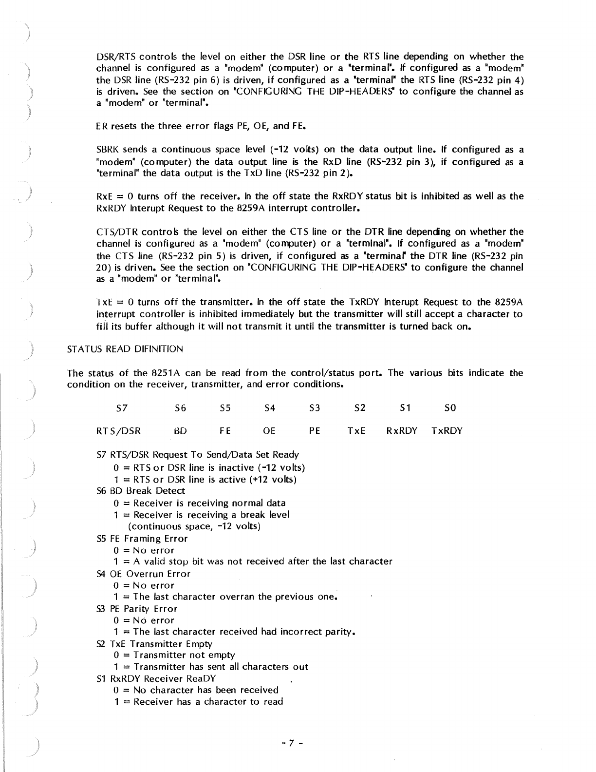
DSR/RTS
controls
the level on
either
the
DSR
line
or
the
RTS
line depending on
whether
the
channel
is
configured
as
a "modem"
(computer)
or
a "terminal".
If
configured
as
a "modem"
the
DSR
line (RS-232
pin
6)
is driven,
if
configured
as
a "terminal" the
RTS
line
(RS-232
pin
4)
is
driven.
See
the
section
on "CONFIGURING
THE
DIP-HEADERS"
to
configure
the channel
as
a "modem"
or
"terminal".
ER
resets the
three
error
flags
PE,
OE,
and
FE.
SBRK
sends a
continuous
space level (-12
volts)
on the data
output
line.
If
configured
as
a
"modem"
(computer)
the data
output
line
is
the RxD line (RS-232
pin
3),
if
configured
as
a
"terminal" the
data
output
is the TxD line (RS-232
pin
2 ).
RxE
= 0 turns
off
the
receiver.
In
the
off
state the RxRDY status
bit
is
inhibited
as
well
as
the
RxRDY
lnterupt
Request
to
the 8259A
interrupt
controller.
CTS/DTR
controls
the level on either the CTS line
or
the
DTR line depending on
whether
the
channel
is
configured
as
a "modem"
(computer)
or
a "terminal". If
configured
as
a "modem"
the CTS line (RS-232
pin
5)
is
driven,
if
configured
as
a
"terminar
the
DTR line (RS-232 pin
20)
is
driven.
See
the
section
on 'CONFIGURING
THE
DIP-HEADERS"
to
configure
the channel
as a "modem"
or
"terminal".
TxE
= 0 turns
oft
the
transmitter.
In
the
off
state the TxRDY
lnterupt
Request
to
the 8259A
interrupt
controller
is
inhibited immediately but the
transmitter
will
still
accept a
character
to
fill
its
buffer
although
it
will
not
transmit
it
until
the
transmitter
is
turned
back
on.
ST
A
TUS
READ
DIFIN ITION
The status
of
the
8251A can
be
read
from
the
control/status
port.
The various bits
indicate
the
condition
on the
receiver,
transmitter,
and
error
conditions.
S1
SO
S7
RTS/DSR
S6
BO
55
FE
S4
OE
S3
PE
S2
TxE
RxRDY TxRDY
S7
RTS/DSR
Request
To
Send/Data Set Ready
0 =
RTS
or
DSR
line
is
inactive
(-12
volts)
1 =
RTS
or
DSR
line
is
active
(+12 volts)
56
BO
Break
Detect
0 = Receiver
is
receiving
normal
data
1 = Receiver
is
receiving a break level
(continuous
space, -12 volts)
SS
FE
Framing
Error
0 =
No
error
1 = A valid
stoµ
bit
was
not
received
after
the last
character
54
OE
Overrun
Error
0 =
No
error
1 = The last
character
overran
the previous one.
S3
PE
Parity
Error
0 =
No
error
1 = The last
character
received had
incorrect
parity.
S2
TxE
Transmitter
Empty
0 =
Transmitter
not
empty
1 =
Transmitter
has
sent all characters
out
51
RxRDY Receiver ReaDY
O = No
character
has
been received
1 = Receiver
has
a character
to
read
- 7 -
SO
TxRDY
Transmitter
ReaDY
0 =
Transmitter
is
not
ready
to
accept a
character
1 =
Transmitter
can accept a
character
RTS/DSR
indicates the level on
either
the
RTS
line
or
the
DSR
line depending on
whether
the
channel
is
configured
as
a "modem•
(computer)
or
a "terminal". If
configured
as
a "modem"
the
level
on
the
RTS
line (RS-232
pin
4) is indicated,
if
configured
as
a "terminalw the level
on
the
DSR
line (RS-232 pin 6)
is
indicated.
See
the
section
on "CONFIGURING
THE
DIP-HEADERS"
to
configure
the channel
as
a "modem•
or
~terminal".
BD
is
high when
the
8251A detects a
continuous
break level
(-12
volts)
on the data
input
line.
If
configured
as
a "modem"
(computer)
the data
input
line is the TxD line (RS-232
pin
2),
if
configured
as
a "terminal" the data input line
is
the RxD line (RS-232
pin
3 ).
FE
indicates
framing
error.
If this
bit
is
high, the
receiver
didn't
detect
a valid
stop
bit
after
the data and
parity
bits.
OE
indicates
overrun
error.
If
this
bit
is high, the
CPU
didn't
read the
character
received
before
the last
character.
PE
indicates
parity
error.
If this
bit
is high,
parity
of
the last
character
didn't
match its
parity
bit.
TxE
= 1 indicates the
transmitter
is
empty.
It
has
sent all
the
data
given
to
it.
RxRDY
= 1 indicates the receiver
has
a
character
to
read.
TxRDY = 1 indicates the
transmitter
is ready
to
accept
a
character
for
transmission.
THE
DTR/CTS INPUT
The DTR/CTS
input
can't
be
read
as
part
of
the status
as
the
RTS/DSR
input
can. Instead, the
DTR/CTS input
has
direct
control
over
the
operation
of
the
transmitter.
It
has
the same
effect
as
the
Transmitter
Enable
bit
of
the Command
instruction.
When
this line goes
inactive
(-12
volts)
the
transmitter
will
stop
transmitting
after
it
transmits the
contents
of
its
buffer.
The
transmitter
will
accept
a
character
to
fill its
buffer
although
it
will
not
transmit
it
till
DTR/CTS goes
active
once
more.
When
the channel
is
configured
as
a "modem"
(computer)
the
DTR line (RS-232 pin 20)
controls
the
transmitter,
when the channel
is
configured
as
a "terminal" the
CTS
line (RS-232
pin
5)
controls
the
transmitter.
See
the
section
on "CONFIGURING
THE
DIP-HEADERS'
for
more
information.
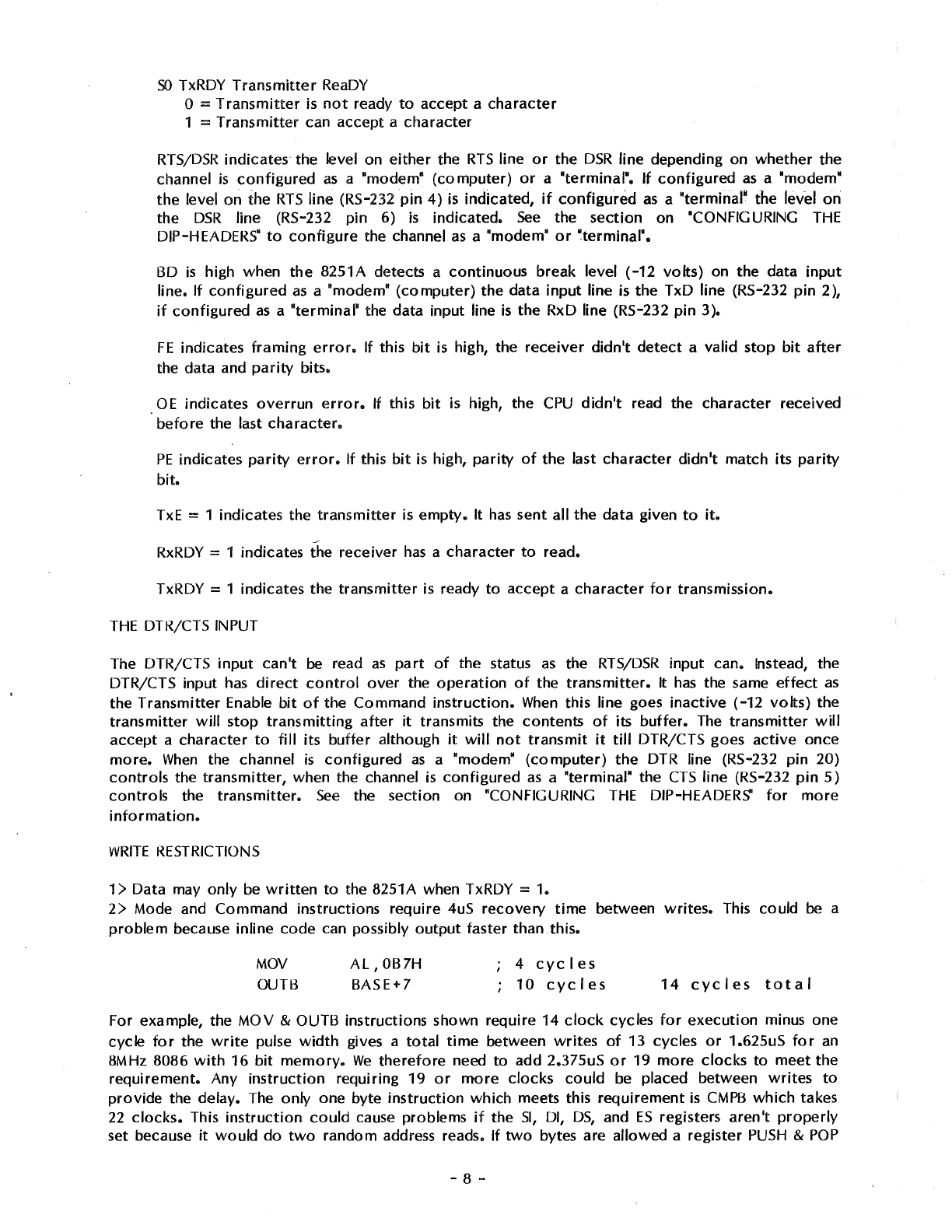
WRITE
RESTRICTIONS
1 > Data may
only
be
written
to
the 8251A when TxRDY = 1.
2>
Mode and Command
instructions
require
4uS
recovery
time
between
writes.
This could
be
a
problem
because inline
code
can possibly
output
faster
than.this.
MOV
OUTB
AL,
OB7H
BASE+7
4
cycles
10
eye
I
es
14
cycles
total
For example, the
MOV
& OUTB instructions shown require 14
clock
cycles
for
execution
minus one
cycle
for
the
write
pulse
width
gives a
total
time
between
writes
of
13 cycles
or
1.625uS
for
an
8MHz 8086
with
16
bit
memory.
We
therefore
need
to
add 2.375uS
or
19
more
clocks
to
meet
the
requirement.
Any
instruction
requiring
19
or
more
clocks
could
be placed between
writes
to
provide
the delay. The only one byte
instruction
which meets this
requirement
is
CMPB
which
takes
22
clocks.
This
instruction
could
cause problems if the
SI,
DI,
OS,
and
ES
registers
aren't
properly
set because
it
would
do
two
random address reads. If
two
bytes are allowed a register
PUSH
&
POP
- 8 -
)
J
takes 19
clocks
but requires a valid stack. Possibly
the.
least
offensive
instruction
is
an
AAD
instruction.
This requires
two
bytes and only modifies the AX register.
AAD
requires 60 clocks
which
is a
bit
excessive but does meet the requirement. With a 4MHz 8086
only
3
clocks
are
required. A NOP fills the requirement nicely. If
you
are
ever
planning
to
upgrade
to
an 8MHz 8086
it's a
good
idea
to
make the
software
8MHz compatible so
it
won't
have
to
be
modified
in the
future.
Possibly the best
solution
is
to
use
a
loop
to
initialize:
MOV
CX,4
MOV
S I , I N I TAB L E
IN
I TLOOP:
SEG
cs
LODB
OUTB BASE+7
LOOP
INITLOOP
The actual
loop
takes
41
clocks
(5.125uS @ 8MHz)
which
solves the
write
recovery
time
requirement. The
whole
routine
requires
only
16 bytes including the table
compared
to
22 bytes
for
inline
code
with
two-byte
delays.
A
4MHZ
ZBO
doesn't
require any delays because 18 clocks satisfy the requirements (including
two
for
the
write
pulse). lnline requires
18
clocks, seven
for
the load and eleven
for
the
output.
OTIR
requires
21
per
loop.
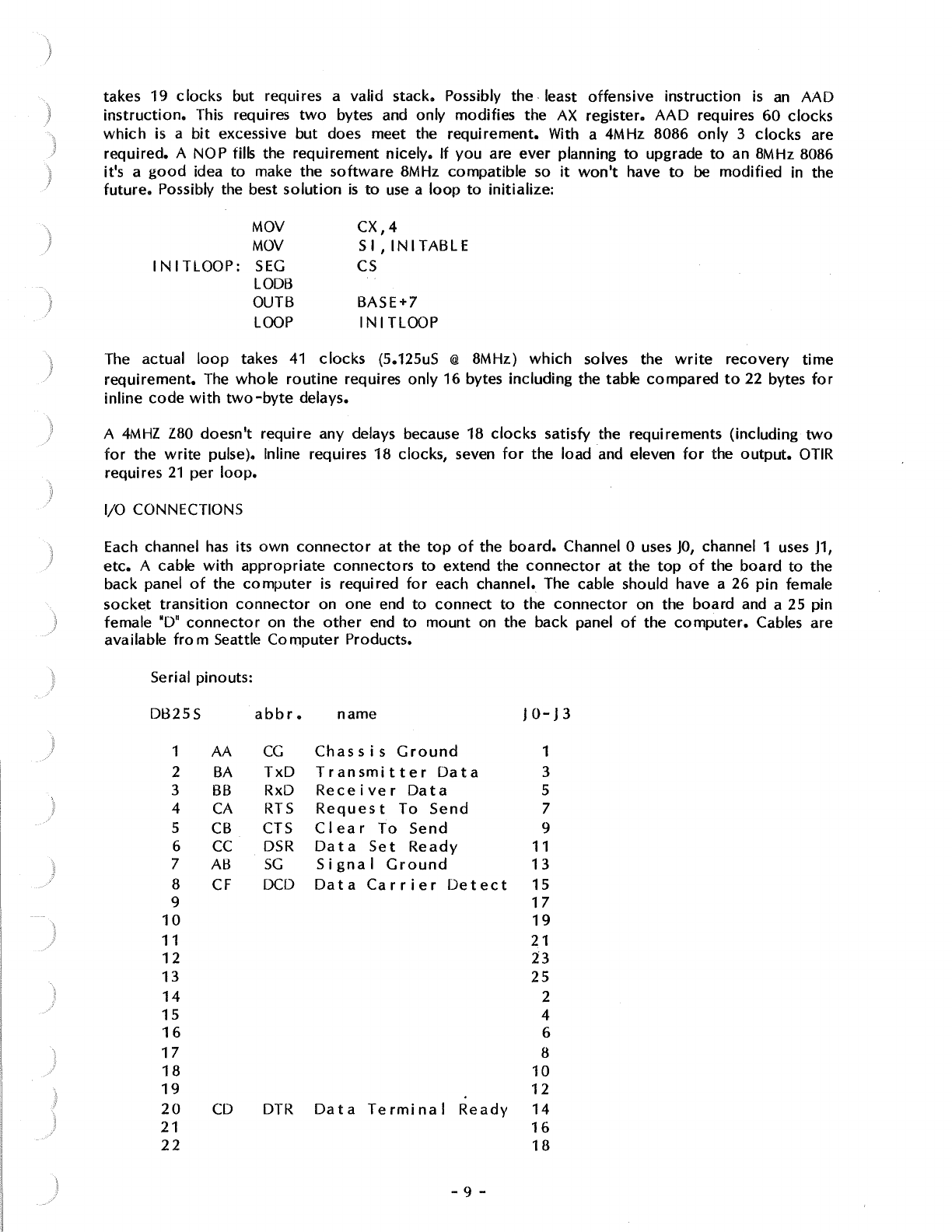
1/0 CONNECTIONS
Each channel
has
its
own
connector
at
the
top
of
the
board.
Channel O uses
JO,
channel 1 uses
J1,
etc.
A cable
with
appropriate
connectors
to
extend the
connector
at
the
top
of
the
board
to
the
back panel
of
the
computer
is
required
for
each channel. The cable should have a 26
pin
female
socket
transition
connector
on one end
to
connect
to
the
connector
on the
board
and a 25 pin
female
"D"
connector
on the
other
end
to
mount
on the back panel
of
the
computer.
Cables are
available
from
Seattle
Computer
Products.
Serial pinouts:
Dl325S
abbr.
name
JO-J3
1 AA
CG
Chassis
Ground
1
2
BA
TxD
Transmitter
Data
3
3
BB
RxD
Receiver
Data
5
4
CA
RTS
Request
To
Send
7
5
CB
CTS
Clear
To
Send
9
6 cc
DSR
Data
Set
Ready
11
7 AB
SG
Signal
Ground
13
8
CF
DCD
Data
Carrier
Detect
15
9
17
10 19
11 21
12
23
13
25
14
2
15
4
16
6
17
8
18
10
19
12
20
CD
DTR
Data
Terminal
Ready
14
21
16
22
18
- 9 -
23
24
25
no
connection
20
22
24
26
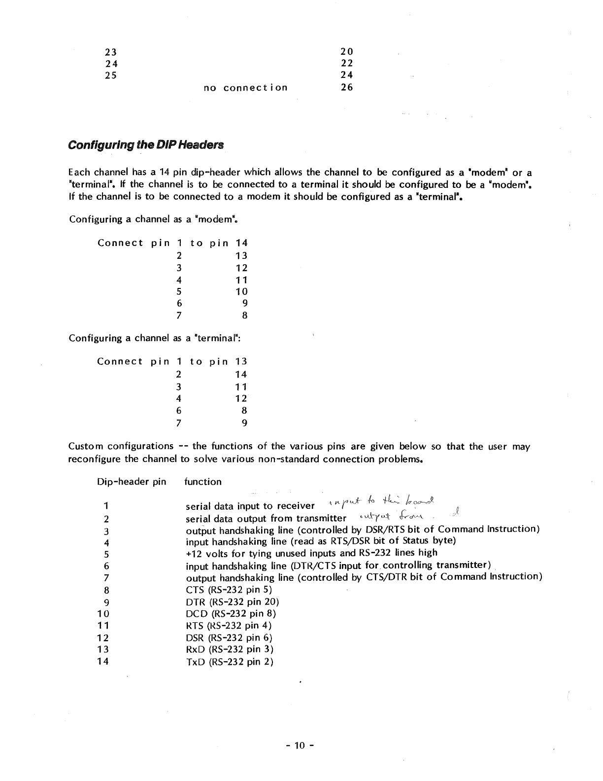
Configuring
the DIP Headers
Each channel
has
a 14
pin
dip-header
which
allows
the
channel
to
be
configured
as
a "modem"
or
a
'terminal".
If the channel
is
to
be
connected
to
a
terminal
it
should
be
configured
to
be
a "modem".
If
the
channel is
to
be
connected
to
a
modem
it
should
be
configured
as
a
"terminal".
Configuring
a channel
as
a
"modem".
Connect
pin
1
to
pin
14
2
13
3
12
4
11
5
10
6 9
7 8
Configuring
a channel as a "terminal":
Connect
pin
1
to
pin
13
2
14
3
11
4
12
6 8
7 9
Custom
configurations
--
the
functions
of
the
various
pins are given
below
so
that
the
user may
reconfigure
the
channel
to
solve
various
non-standard
connection
problems.
Dip-header
pin
1
2
3
4
5
6
7
8
9
10
11
12
13
14
function
serial data
input
to
receiver
\
IA
r J
l~
+L~
/,,
.
serial
data
output
from
transmitter
•
1.,\,\-y
'-'t
J:,,fv'~'-
(~
output
handshaking line
(controlled
by DSR/RTS
bit
of
Command
Instruction)
input
handshaking line (read
as
RTS/DSR
bit
of
Status
byte)
+12
volts
for
tying
unused inputs and RS-232 lines
high
input
handshaking line (DTR/CTS
input
for
controlling
transmitter)
output
handshaking line
(controlled
by CTS/DTR
bit
of
Command
Instruction)
CTS (RS-232
pin
5)
DTR (RS-232
pin
20)
DCD
(RS-232
pin
8)
RTS
(KS-232
pin
4)
DSR
(RS-232
pin
6)
RxD (RS-232
pin
3)
TxD
(RS-232 pin
2)
-10 -
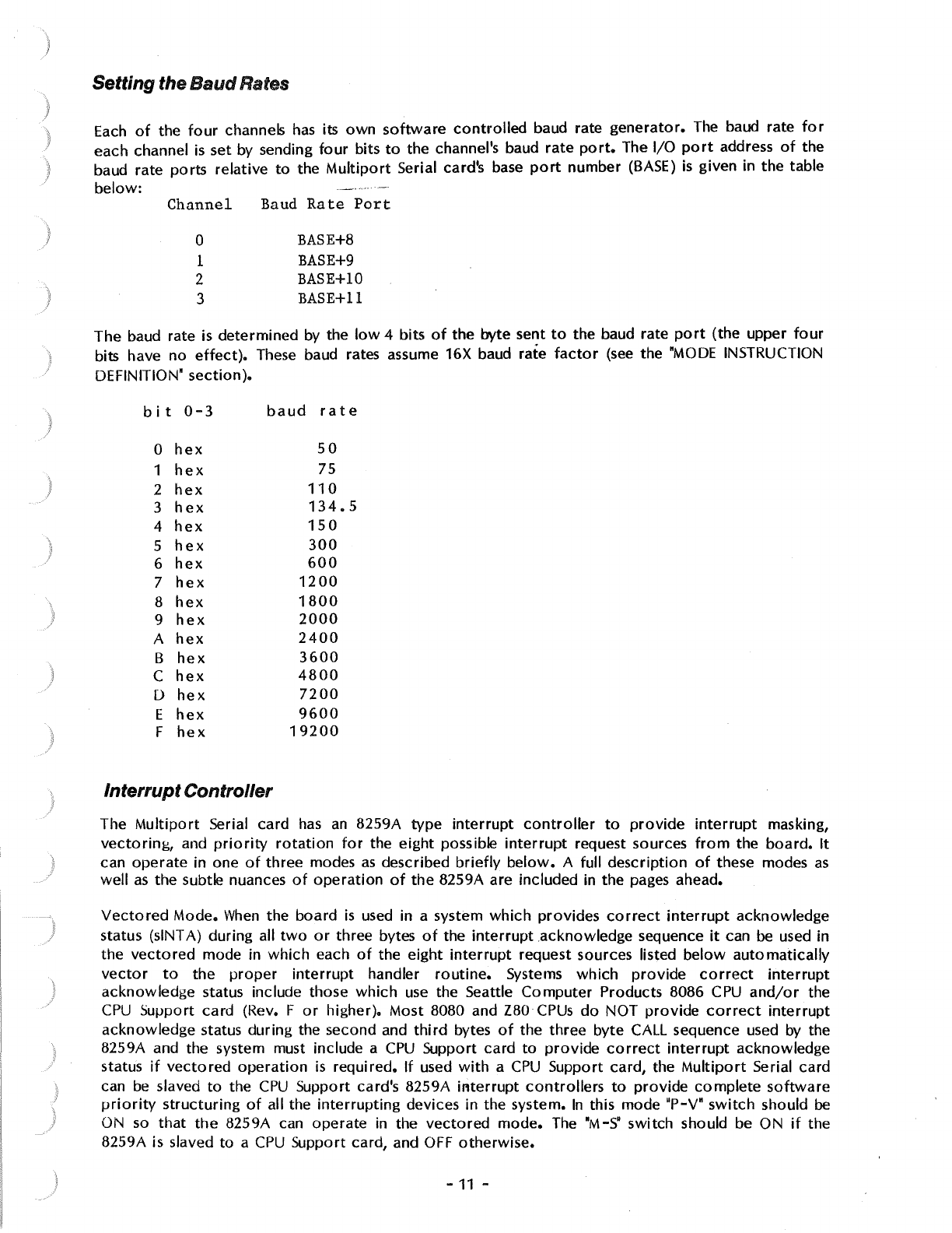
Setting the
Baud
Rates
Each
of
the
four
channels
has
its
own
software
controlled
baud rate
generator.
The
baud rate
for
each channel
is
set by sending
four
bits
to
the channel's baud
rate
port.
The 1/0
port
address
of
the
baud rate
ports
relative
to
the
Multiport
Serial card's base
port
number
(BASE)
is
given in
the
table
below:
Channel
0
1
2
3
Baud
Rate
Port
BASE+8
BASE+9
BASE+lO
BASE+ll
The
baud rate is determined by the
low
4 bits
of
the byte sent
to
the baud rate
port
(the upper
four
bits have
no
effect).
These baud rates assume 16X baud rate
factor
(see
the
"MODE
INSTRUCTION
DEFINITION"
section).
bit
0-3
baud
rate
0
hex
50
1
hex
75
2
hex
110
3
hex
134.5
4
hex
150
5
hex
300
6
hex
600
7
hex
1200
8
hex
1800
9
hex
2000
A
hex
2400
B
hex
3600
C
hex
4800
D
hex
7200
E
hex
9600
F
hex
19200
Interrupt Controller
The
Multiport
Serial card
has
an
8259A
type
interrupt
controller
to
provide
interrupt
masking,
vectoring,
and
priority
rotation
for
the
eight
possible
interrupt
request sources
from
the
board.
It
can
operate
in one
of
three
modes
as
described
briefly
below.
A full
description
of
these modes
as
well
as
the subtle nuances
of
operation
of
the
8259A are included in the pages ahead.
Vectored
Mode.
When
the
board
is
used in a system
which
provides
correct
interrupt
acknowledge
status (slNT A) during all
two
or
three bytes
of
the
interrupt
acknowledge sequence
it
can be used in
the
vectored
mode in
which
each
of
the
eight
interrupt
request sources listed
below
automatically
vector
to
the
proper
interrupt
handler
routine.
Systems
which
provide
correct
interrupt
acknowledge status include those
which
use
the Seattle
Computer
Products 8086
CPU
and/or
the
CPU
Support card (Rev. F
or
higher). Most 8080 and Z80
CPUs
do
NOT
provide
correct
interrupt
acknowledge
status during the second and
third
bytes
of
the
three
byte CALL sequence used by the
8259A and the system must include a
CPU
Support card
to
provide
correct
interrupt
acknowledge
status
if
vectored
operation
is
required.
If
used
with
a
CPU
Support card, the
Multiport
Serial card
can
be
slaved
to
the
CPU
Support card's 8259A il'lterrupt
controllers
to
provide
complete
software
priority
structuring
of
all the
interrupting
devices in the system.
In
this mode "P-V"
switch
should
be
ON
so
that
the
8259A can
operate
in the
vectored
mode.
The "M-S" switch should be ON
if
the
8259A is slaved
to
a
CPU
Support card, and OFF
otherwise.
-
11
-
Z80 Mode
1.
If the
Multiport
Serial card
is
to
be used in a Z80 system,
interrupt
driven
operation
can be acheived
without
a
CPU
Support
card
by using the Z80
interrupt
mode
1.
In
this
mode
the
Z80
automatically
CALLs
location
0038 hex
without
the need
for
an
interrupt
acknowledge
sequence. The
interrupt
handler
routine
at
0038 hex must
poll
the 8259A
to
find
out
which
interrupt
request was responsible
for
the
interrupt
and
act
accordingly.
In
this mode the "P-V"
switch
should
be
OFF
because
interrupt
vectoring
isn't used. Since
the
8259A
can't
be used
as
a slave in this
position;
the "M-S"
switch
should be OFF.
Polled
Mode.
If
interrupt
driven
operation
isn't
possible
or
isn't
desired, the 8259A can
still
be used
in the polled
mode.
In
this
mode
all the masking,
priority
rotation,
and
other
special features
of
the
8259A
are
available
to
simplify
the
software
drivers
for
the
Multiport
Serial
card.
The "P-V"
switch
should be
OFF
because
interrupt
vectoring
isn't used. The "M-S"
switch
should also be
OFF
because
the 8259A
can't
be used
as
a slave in this
mode.
The
eight
interrupt
request inputs
to
the 8259A
interrupt
controller
are
as
follows:
IRO
-RxRDY O (Receiver Ready
from
channel
0).
IR1
-
RxRDY
1.
IR2
-RxRDY 2.
IR3
-
RxRDY
3.
IR4
-TxRDY O
(Transmitter
Ready
from
channel
0).
IRS
-TxRDY 1.
IR6
-TxRDY
2.
IR7
-TxRDY 3.
The 8259A requires
two
of
the
Multiport
Serial card's sixteen 1/0
ports
for
communication
with
the
processor.
BASE+12
(AO
= 0)
BASE
+13
(AO
= 1 )
OPERATION
OF
THE
INTERRUPT CONTROLLER
Interrupt
operation
of
the
8259A falls under five main
categories:
vectoring,
priorities,
triggering,
status, and cascading. Each
of
these
categories
use
various
modes and commands. This
section
will
explain the
operation
of
these modes and commands. For
clarity
of
explanation,
however,
the
actual
programming
of
the 8259A isn't
covered
in this
section
but in "PROGRAMMING
THE
INTERRUPT CONTROLLER".
INTERRUPT VECTORING
Each
IR
input
of
the 8259A
has
an
individual
interrupt-vector
address in
memory
associated
with
it.
Designation
of
each address depends upon the
initial
programming
of
the
8259A.
The
interrupt
sequence and addressing
of
an
8080 system
differs
from
that
of
an
8086 system. Thus, the 8259A
must be intially
programmed
in either
the
8080
or
8086 mode
of
operation
to
insure the
correct
interrupt
vectoring.
8080
MOOE
This mode applies
to
8080, 8085, and Z80
microprocessors.
After
an
interrupt
request in the 8080
mode,
the
8259A
will
output
to
the data
bus
the
opcode
for
a CALL
instruction
and the address
of
the
desired
routine.
This
is
in response
to
a sequence
of
three
INT A
(Interrupt
Acknowledge)
pulses
issued by the CPU
after
the master 8259A
has
activated
the
INT line
of
the S-100 bus.
-12 -
The
first
INT A pulse
to
the 8259A enables the CALL
opcode
CD hex
onto
the data bus. It also
resolves
IR
priorities
and effects
operation
in the cascade mode,
which
will
be
covered
later.
During
the
second and
third
INT A pulses, the 8259A conveys a
16-bit
interrupt-vector
address
to
the
8080. The
interrupt-vector
addresses
for
all
eight
levels are selected when
initially
programming
the
8259A.
However,
only
one address
is
needed
for
programming.
Interrupt-vector
addresses
of
IRO-IR7 are
automatically
set at equally spaced intervals based on the one programmed address.
Address intervals are user definable
to
4
or
8 bytes
apart.
If
the service
routine
for
a device
is
short
it
may be possible
to
fit
the
entire
routine
within
an
8-byte
interval.
Usually, though, the
service
routines require
more
than 8 bytes.
So,
a 4
byte
interval
is used
to
store
a
Jump
intruction
which
directs the
CPU
to
the
appropriate
routine.
The
8-byte
interval maintains
compatibility
with
current
8080 Restart
(RST)
instruction
software,
while the
4-byte
interval is best
for
a
compact
jurrp table. If
the
4-byte
interval
is
selected, then
the
8259A
will
automatically
insert bits AO-A4.
This leaves AS-A15
to
be
programmed
by the user. If
the
8-byte
interval
is selected, the 8259A
will
automatically
insert bits AO-AS. This leaves only
A6-A15
to
be
programmed by the user.
The
LSB
of
the
interrupt-vector
address
is
placed on the data
bus
during the second INT A pulse.
The
MSB
of
the
interrupt-vector
address
is
placed on the data
bus
during the
third
INTA pulse.
8086 MODE
Upon
interrupt
in the 8086 mode, the 8259A
will
output
a single
interrupt-vector
byte
to
the data
bus. This
is
in response
to
two
INT A (Interrupt
Acknowledge)
pulses issued
by
the
8086
after
the
master 8259A
has
activated the INT line
of
the S-100 bus.
The
first
INT A pulse
is
used only
for
set-up purposes internal
to
the
8259A.
As
in
the
8080 mode,
this
set-up
includes
priority
resolution and cascade mode
operations
which
will
be
covered
later.
Unlike
the
8080 mode,
no
CALL
opcode
is
placed on the data bus.
The second INT A pulse
is
used
to
enable the single
interrupt-vector
byte
onto
the data bus. The
8086
uses
this
interrupt-vector
byte
to
select one
of
256
interrupt
"types" in 8086
memory.
Interrupt
type selection
for
all eight
IR
levels
is
made when intially
programming
the
8259A.
However,
reference
to
only one
interrupt
type
is
needed
for
programming.
The
upper 5 bits
of
the
interrupt
vector
byte are user definable.
The
lower
3 bits are
automatically
inserted by the 8259A
depending upon the
IR
level.
Contents
of
the
interrupt-vector
byte
for
8086
type
selection
is
put on the data
bus
during the
second INT A pulse.
INTERRUPT
PRIORITIES
A
variety
of
modes and commands are available
for
controlling
interrupt
priorities
of
the 8259A.
All
of
them are programmable, that is, they may be changed dynamically under
software
control.
With these modes and commands, many possibilities are conceivable, giving the user enough
versatility
for
almost any
interrupt-controlled
application.
FULLY
NESTED
MODE
The fully nested mode
of
operation
is
a general purpose
priority
mode. This mode supports a
multilevel-interrupt
structure in which
priority
order
of
all
eight
IR
inputs are arranged
from
highest
to
lowest.
Unless
otherwise
programmed, the fully nested mode
is
entered
by
default upon
intialization.
At
this
time,
IRO
is
assigned the highest
priority
through
IR7
the lowest.
The
fully nested mode,
however,
is
not
confined
to
this
IR
structure
alone. Once past
initialization,
other
IR
inputs can
be
assigned highest
priority
also, keeping the
multilevel-interrupt
structure
of
the fully nested
mode.
-13 -
Further
explanation
of
the fully nested mode, in this
section,
is linked
with
information
of
general
8259A
interrupt
operations.
This
is
done
to
ease
explanation
to
the user in
both
areas.
In
general, when
an
interrupt
is acknowledged, the highest
priority
request
is
determined
from
the
IRR
(Interrupt
Request Register). The
interrupt
vector
is
then placed
on
the data bus.
In
addition,
the
corresponding
bit
in the
ISR
(In-Service Register) is set
to
designate the
routine
in
service.
This
ISR
bit
remains set until an
EOI
(End-Of-Interrupt)
command
is
issued
to
the
8259A. EOl's
will
be
explained in
greater
detail
shortly.
In
the fully nested mode,
while
an
ISR
bit
is
set, all
further
requests
of
the same
or
lower
priority
are
inhibited
from
generating
an
interrupt
to
the
microprocessor.
A higher
priority
request,
though, can generate
an
interrupt,
thus
vectoring
program
execution
to
its
service
routine.
Interrupts are only acknowledged,
however,
if
the
microprocessor
has
previously
executed
an
"Enable Interrupts"
instruction.
This
is
because the
interrupt
request
pin
on the
microprocessor
gets
disabled
automatically
after
acknowledgement
of
any
interrupt.
The assembly language
instruction
used
to
enable
interrupts
is
"El". Interrupts can be disabled by using "DI".
When
a
routine
is
completed
a "return"
instruction
is
executed,
"RET"
for
8080 and
"IRET"
for
8086.
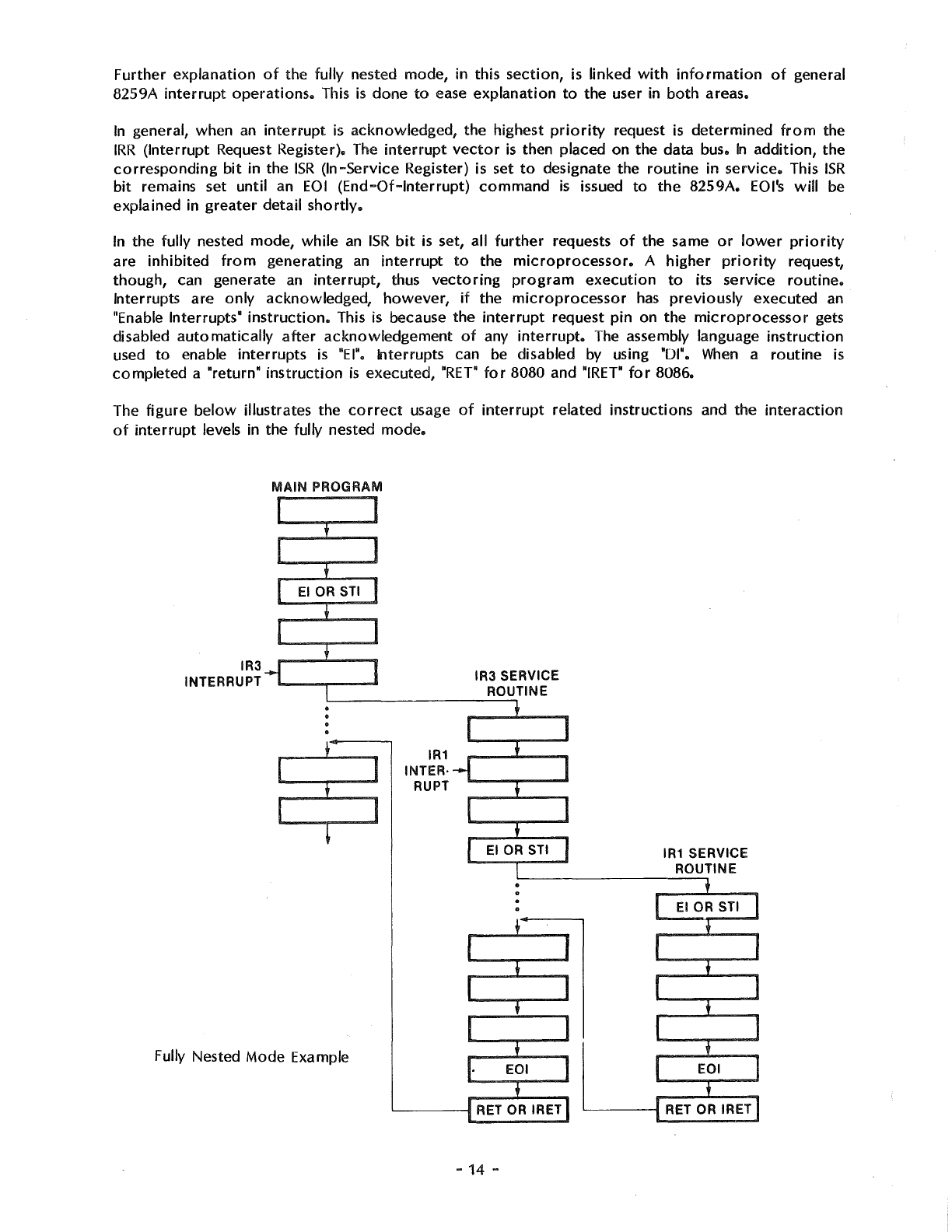
The
figure
below
illustrates the
correct
usage
of
interrupt
related
instructions
and the
interaction
of
interrupt
levels in the fully nested
mode.
IR3
INTERRUPT
MAIN PROGRAM
Fully Nested Mode Example
IR1
INTER·
RUPT
IR3 SERVICE
ROUTINE
'--------1
RET
OR
IRET
-
14
-
IR1
SERVICE
ROUTINE
---,
El
OR STI
EOI
,__
___
RET
OR
IRET
)
)
Assuming
IRO
has
the highest
priority
and
IR7
the
lowest,
the sequence
is
as
follows.
During the
main
program,
IR3
makes a request. Since
interrupts
are enabled, the
microprocessor
is
vectored
to
the
IR3
service
routine.
During the
IR3
routine,
IR1
asserts a request. Since
IR1
has higher
priority
than
IR3,
an
interrupt
is
generated.
However,
it
is
not
acknowledged because
the
microprocessor
disabled
interrupts
in response
to
the
IR3
interrupt.
The
IR1
interrupt
is
not
acknowledged
until the "Enabled Interrupts"
instruction
is
executed.
Thus
the
IR3
routine
has
a
"protected"
section
of
code
over
which
no
interrupts
(except
non-maskable)
are
allowed.
The
IR1
routine
has
no
such "protected"
section
since
an
"Enable Interrupts"
instruction
is
the
first
one
in its
service
routine.
Note
that
in this example the
IR1
request must stay
active
until
it
is acknowledged.
This
is
covered
in
more
depth in the "Interrupt Triggering"
section.
What
is
happening
to
the
ISR
register? While in the main
program,
no
ISR
bits
are set since there
aren't
any
interrupts
in
service.
When
the
IR3
interrupt
is
acknowledged,
the
ISR3
bit
is
set.
When
the
IR1
interrupt
is
acknowledged,
both
the
ISR1
and the
ISR3
bits
are
set,
indicating
that
neither
routine
is
complete.
At
this
time,
only
IRO
could generate
an
interrupt
since
it
is
the only input
with
a
higher
priority
than those
previously
in
service.
To
terminate
the
IR1
routine,
the
routine
must
inform
the
8259A
that
it
is
complete
by
resetting its
ISR
bit.
It does this
by
executing
an
EOI
command.
A "return"
instruction
then transfers
execution
back
to
the
IR3
routine.
This allows
IRO-IR2
to
interrupt
the
IR3
routine
again, since
ISR3
is
the highest
ISR
bit
set. No
further
interrupts
occur
in the example so the
EOI
command
resets
ISR3
and the
"return'
instruction
causes the main
program
to
resume
at
its
pre-interrupt
location,
ending the example.
A single 8259A is essentially always in the fully nested mode unless
certain
programming
conditions
disturb
it.
The
following
programming
conditions
can cause
the
8259A
to
go
out
of
the high
to
low
priority
structure
of
the fully nested mode.
The
automatic
EOI
mode
The special mask mode
A slave
with
a master
not
in the special fully nested mode
These modes
will
be
covered
in
more
detail later,
however,
they are
mentioned
now
so
the user
can be
aware
of
them.
As
long
as
these
program
conditions
aren't
inacted, the fully nested mode
remains undisturbed.
END
OF
INTERRUPT
Upon
completion
of
an
interrupt
service
routine
the 8259A needs
to
be
notified
so its
ISR
can be
updated. This
is
done
to
keep
track
of
which
interrupt
levels are in the process
of
being serviced
and
their
relative
priorities.
Three
different
End-Of-Interrupt
(EOI)
formats
are available
for
the
user. These are: the
non-specific
EOI
command, the
specific
EOI
command, and the
automatic
EOI
Mode.
Selection
of
which
EOI
to
use
is
dependent upon
the
interrupt
operations
the user wishes
to
perform.
Non-Specific
EOI
Command
A
non-specific
EOI
command
sent
from
the
microprocessor
lets the 8259A
know
when a service
routine
has
been completed,
without
specification
of
its
exact
interrupt
level. The 8259A
automatically
determines the
interrupt
level and resets the
correct
bit
in the
ISR.
To
take
advantage
of
the
non-specific
EOI
the
8259A must be in a mode
of
operation
in
which
it
can
predetermine
in-service
routine
levels.
For
this reason the
non-specific
EOI
command
should
only
be used when the
most
recent level acknowledged and serviced
is
always the highest
priority
level.
When
the
8259A receives a
non-specific
EOI
command,
it
simply resets the highest
priority
ISR
bit, thus
confirming
to
the 8259A
that
the highest
priority
routine
of
the routines in
service
is
finished.
-15 -
The main advantage
of
using the
non-specific
EOI
command
is
that
IR
level
specification
isn't
necessary
as
in the "Specific
EOI
Command",
covered
shortly.
However,
special
consideration
should be taken when
deciding
to
use
the
non-specific
EOI
• Here are
two
program
conditions
in
which
it
is
best
not
used:
Using the set
priority
command
within
an
interrupt
service
routine.
Using a special mask
mode.
These
conditions
are
covered
in
more
detail in
their
own
sections,
but
are
listed here
for
the users
reference.
Specific
EOI
Command
A specific
EOI
command
sent
from
the
microprocessor
lets the 8259A
know
when a
service
routine
of
a
particular
interrupt
level
is
completed.
Unlike a
non-specific
EOI
command,
which
automatically
resets the highest
priority
ISR
bit,
a
specific
EOI
command
specifies
an
exact
ISR
bit
to
be
reset. One
of
the
eight
IR
levels
of
the
8259A can
be
specified in the
command.
The reason the
specific
EOI
command
is
needed,
is
to
reset the
ISR
bit
of
a
completed
service
routine
whenever
the
8259A isn't able
to
automatically
determine
it.
An example
of
this
type
of
situation
might be
if
the
priorities
of
the
interrupt
levels
were
changed during
an
interrupt
routine
("Specific Rotation").
In
this case,
if
any
other
routines
were
in
service
at
the same
time,
a
non-specific
EOI
might
reset the
wrong
ISR
bit.
Thus the
specific
EOI
command
is
the best bet in
this case,
or
for
that
matter,
any
time
in
which
confusion
of
interrupt
priorities
may
exist.
The
specific
EOI
command
can be used in all
conditions
of
8259A
operation,
including those
that
prohibit
non-specific
EOI
command
usage.
Automatic
EOI
Mode
When
programmed
in the
automatic
EOI
mode, the
microprocessor
no
longer
needs
to
issue a
command
to
notify
the
8259A
if
it
has
completed
an
interrupt
routine.
The 8259A accomplishes this
by
performing
a
non-specific
EOI
automatically
at
the
trailing
edge
of
the last INT A pulse
(third
pulse
in
8080, second
in
8086).
The
obvious
advantage
of
the
automatic
EOI
mode
over
the
other
EOI
command
is
that
no
command
has
to
be issued.
In
general, this simplifies
programming
and
lowers
code
requirements
within
interrupt
routines.
However,
special
consideration
should be taken when deciding
to
use
the
automatic
EOI
mode
because
it
disturbs the fully nested mode.
In
the
automatic
EOI
mode
the
ISR
bit
of
a
routine
in
service
is
reset
right
after
it's acknowledged, thus leaving
no
designation in the
!SR
that
a
service
routine
is
being executed. If any
interrupt
request
occurs
during
this
time
(and interrupts are
enabled)
it
will
get serviced regardless
of
its
priority,
low
or
high. The
problem
of
"over
nesting"
is
when an
IR
input keeps
interrupting
its
own
routine,
resulting
in
unnecessary stack pushes
which
could
fill the stack in a
worst
case
condition.
This
is
not
usually a desired
form
of
operation!
So
what
good
is
the
automatic
EOI
mode
with
problems like those just covered?
Well,
again, like
the EOls, selection
is
dependent upon the
application.
On
the
Multiport
serial card, all the
IR
inputs
are
connected
to
TxRD.)' o'l RxRDY outputs
from
the
8251A USARTs. Usually these
interrupt
requests are serviced
a~'d
thus turned
off
before
executing
an
"El"
instruction
so
that
the
"over
nesting"
problem
doesn't
happen.
AUTOMATIC
ROT
A TION -EQUAL
PRIORITY
Automatic
rotation
of
priorities
serves in applications
where
the
interrupting
devices are
of
equal
priority,
such
as
communications
channels.
The
concept
is
that
once a
peripheral
is
serviced, all
other
equal
priority
peripherals should be given a chance
to
be
serviced
before
the
original
-
16
-
.\
J
peripheral
is
serviced again. This
is
accomplished
by
automatically
assigning a peripheral
the
lowest
priority
after
being
serviced.
Thus, in
worst
case, the
device
would
have
to
wait
until all
other
devices are
serviced
before
being serviced again.
There
are
two
methods
of
accomplishing
automatic
rotation.
One is used in
conjunction
with
the
non-specific
EOI,
"non-specific
EOI
with
priority
rotation
command". The
other
is
used
with
the
automatic
EOI
mode,
"rotate
in
automatic
EOI
mode".
Non-specific
EOI
with
priority
rotation
command
When
the
non-specific
EOI
with
priority
rotation
command
is issued,
the
highest
ISR
bit
is reset
as
in a
normal
non-specific
EOI
command.
After
it's reset though,
the
corresponding
IR
level
is
assigned
lowest
priority.
Other
IR
priorities
rotate
to
conform
to
the fully nested mode based on
the newly assigned
low
priority.
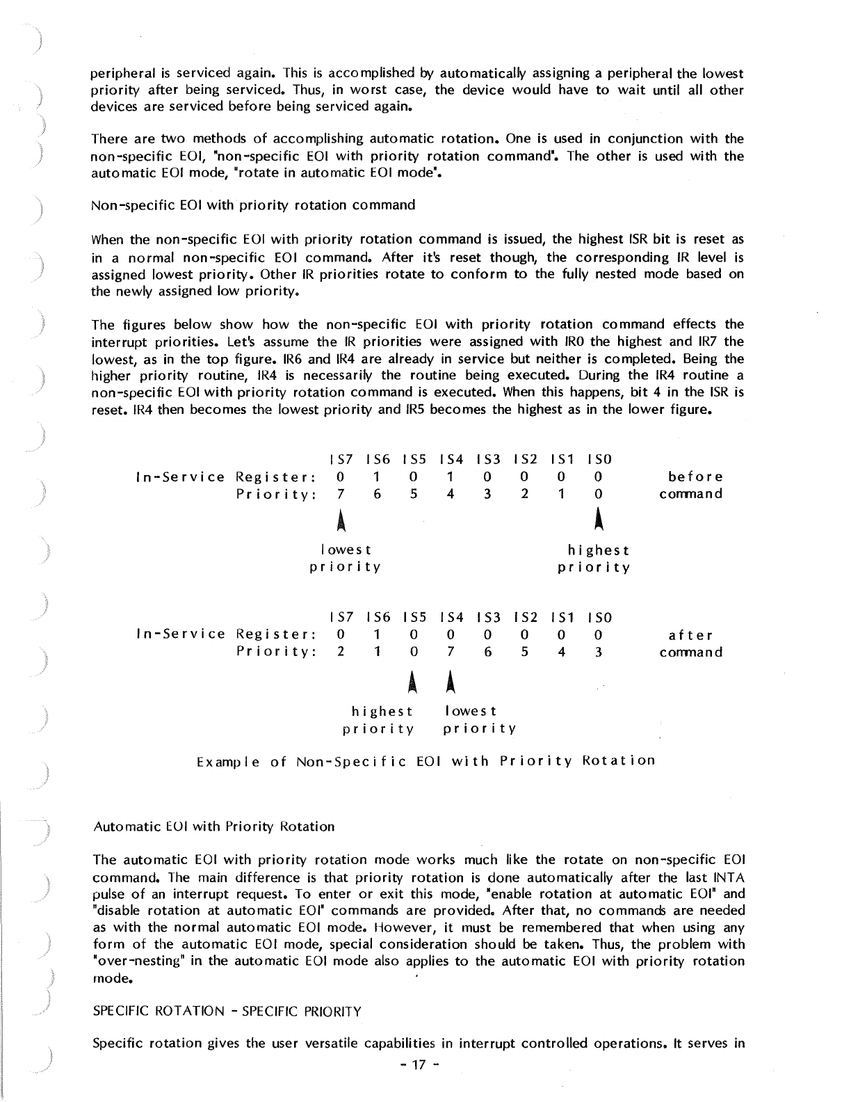
The figures
below
show
how
the
non-specific
EOI
with
priority
rotation
command effects the
interrupt
priorities.
Let's assume
the
IR
priorities
were
assigned
with
IRO
the highest and
IR7
the
lowest,
as
in the
top
figure.
IR6
and
IR4
are already in
service
but
neither
is
completed.
Being the
higher
priority
routine,
IR4
is
necessarily the
routine
being executed. During
the
IR4
routine
a
non-specific
EOI
with
priority
rotation
command
is
executed.
When
this happens,
bit
4 in the
ISR
is
reset.
IR4
then becomes the lowest
priority
and
IRS
becomes the highest
as
in
the
lower
figure.
IS7
IS6
I
SS
IS4
IS3
I
S2
IS1
ISO
In-Service
Register:
0 1 0 1 0 0 0 0
before
Priority:
7 6 5 4 3 2 1 0
command
• •
lowest
highest
priority
priority
157
IS6
ISS
IS4
IS3 IS2
IS
1 ISO
In-Service
Register:
0 1 0 0 0 0 0 0
after
Priority:
2 1 0 7 6 5 4 3
command
• •
highest
lowest
priority
priority
Example
of
Non-Specific
EOI
with
Priority
Rotation
Automatic
EUI
with
Priority
Rotation
The
automatic
EOI
with
priority
rotation
mode
works
much like the
rotate
on
non-specific
EOI
command.
The
main
difference
is
that
priority
rotation
is
done
automatically
after
the last INT A
pulse
of
an
interrupt
request. To enter
or
exit
this mode, "enable
rotation
at
automatic
EOI"
and
"disable
rotation
at
automatic
EOI"
commands are
provided.
After
that,
no
commands are needed
as
with
the
normal
automatic
EOI
mode.
However,
it
must be remembered
that
when using any
form
of
the
automatic
EOI
mode, special
consideration
should be taken. Thus, the
problem
with
"over-nesting"
in the
automatic
EOI
mode also applies
to
the
automatic
EOI
with
priority
rotation
mode.
SPECIFIC
ROTATION -
SPECIFIC
PRIORITY
Specific
rotation
gives the user versatile capabilities in
interrupt
controlled
operations.
It serves in
-17 -
those applications in
which
a specific device's
interrupt
priority
must be altered. As opposed
to
automatic
rotation
which
automatically
sets
priorities,
specific
rotation
is
completely
user
controlled.
That is, the user selects
which
interrupt
level
is
to
receive
lowest
or
highest
priority.
This can be
done
during
the main
program
or
within
interrupt
routines.
Two
specific
rotation
commands are available
to
the user, the "set
priqrity•
command
and the
"specific
EOI
with
priority
rotation"
command.
'
Set
Priority
Command
The set
priority
command
allows the
programmer
to
assign
an
IR
level the
lowest
priority.
All
other
interrupt
levels
will
conform
to
fully nested mode based on
newly
assigned
low
priority.
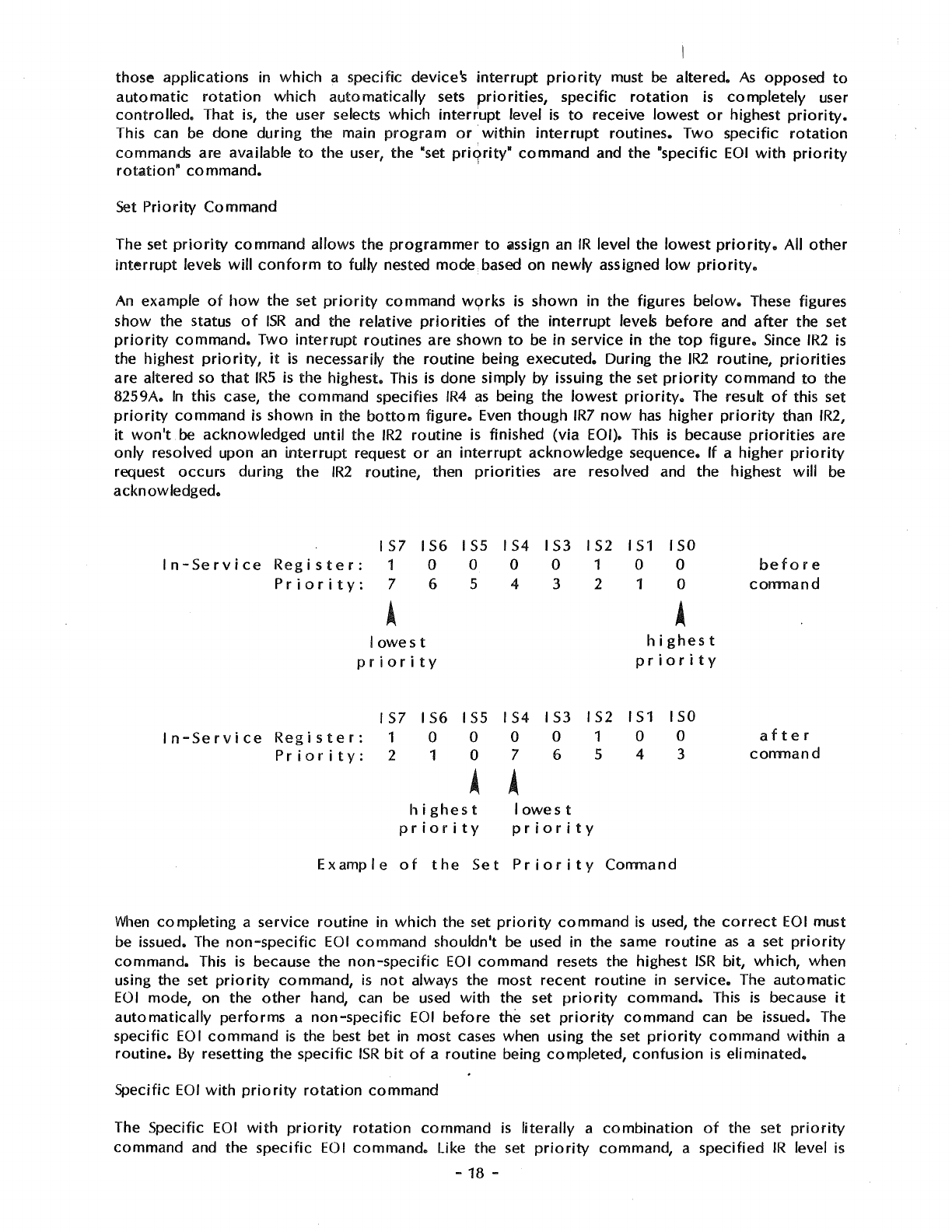
An
example
of
how
the set
priority
command
w9rks
is
shown in the figures
below.
These figures
show the status
of
ISR
and the
relative
priorities
of
the
interrupt
levels
before
and
after
the set
priority
command.
Two
interrupt
routines are shown
to
be in
service
in the
top
figure.
Since
IR2
is
the highest
priority,
it
is
necessarily the
routine
being
executed.
During
the
IR2
routine,
priorities
are
altered so
that
IRS
is
the highest. This
is
done simply by issuing the set
priority
command
to
the
8259A.
In
this case, the
command
specifies
IR4
as
being the
lowest
priority.
The result
of
this set
priority
command
is
shown in the
bottom
figure.
Even
though
IR7
now
has
higher
priority
than
IR2,
it
won't
be acknowledged
until
the
IR2
routine
is finished
(via
EOI). This
is
because
priorities
are
only
resolved upon
an
interrupt
request
or
an
interrupt
acknowledge
sequence.
If
a
higher
priority
request occurs
during
the
IR2
routine,
then
priorities
are
resolved and the highest
will
be
acknowledged.
IS7
IS6
ISS
IS4
IS3
IS2
IS1
ISO
In-Service
Register:
1 0 0 0 0 1 0 0
before
Priority:
7 6 5 4 3 2 1 0
comnand
A A
lowest
highest
priority
priority
IS7
IS6
ISS
IS4
IS3 IS2
IS1
ISO
In-Service
Register:
1 0 0 0 0 1 0 0
after
Priority:
2 1 0 7 6 5 4 3
comnand
• •
highest
lowest
priority
priority
Example
of
the
Set
Priority
Comnand
When
completing
a service
routine
in
which
the set
priority
command
is
used, the
correct
EOI
must
be issued. The
non-specific
EOI
command
shouldn't be used in the same
routine
as
a set
priority
command.
This
is
because the
non-specific
EOI
command
resets the highest
ISR
bit,
which,
when
using the set
priority
command,
is
not
always the most
recent
routine
in
service.
The
automatic
EOI
mode, on the
other
hand, can be used
with
the set
priority
command.
This
is
because
it
automatically
performs
a
non-specific
EOI
before
the set
priority
command
can be issued. The
specific
EOI
command
is
the best bet in
most
cases when using the set
priority
command
within
a
routine.
By
resetting the specific
ISR
bit
of
a
routine
being
completed,
confusion
is
eliminated.
Specific
EOI
with
priority
rotation
command
The Specific
EOI
with
priority
rotation
command
is
literally
a
combination
of
the set
priority
command
and the
specific
EOI
command.
Like the set
priority
command, a
specified
IR
level
is
-
18
-
assigned
lowest
priority.
Like the
specific
EOI
command,
a specified level
will
be reset in the
ISR.
Thus
the
specific
EOI
with
priority
rotation
command
accomplishes
both
tasks in only
one
command.
If
it
is
not
necessary
to
change
IR
priorities
prior
to
the end
of
an
interrupt
routine,
then this
command
is
advantageous. Since
an
EOI
command must be executed
anyway
(unless in
the
automatic
EOI
mode),
why
not
do
both
at
the same time?
INTERRUPT MASKING
Disabling
or
enabling
interrupts
can
be
done
by
other
means than just
controlling
the
microprocessor's
interrupt
request
pin.
The 8259A
has
an
IMR
(Interrupt Mask Register)
which
enhances
interrupt
control
capabilities. Rather than all
interrupts
being disabled
or
enabled
at
the
same
time,
the
IMR
allows
individual
IR
masking. The
IMR
is
an
8-bit
register, bits
0-7
directly
correspond
to
IRO
-IR7.
There
are
various
uses
for
masking
off
individual
IR
inputs. One example
is
when a
portion
of
a
main
routine
wishes only
to
be
interrupted
by
specific
interrupts.
Another
might
be disabling higher
priority
interrupts
for
a
portion
of
a
lower
priority
service
routine.
If
you
have a
two
channel
version
of
the
Multiport
Serial card, the unused
IR
inputs
to
the
8259A can be masked
off.
The
possibilities are many.
When
an
interrupt
occurs
while
its
IMR
bit
is set,
it
isn't necessarily
forgotten.
For,
as
stated earlier,
the
IMR
acts
only
on the
output
of
IRR.
Even
with
an
IR
input masked
it
is
still possible
to
set the
!RR.
Thus, when resetting
an
IMR,
if
its
IRR
bit
is
set
it
will
then generate
an
interrupt.
This
is
providing,
of
course,
that
other
priority
factors
are taken
into
consideration
and
the
IR
request
remains
active.
If the
IR
request
is
removed
before
the
IMR
is
reset,
no
interrupt
will
be
acknowledged.
Special Mask Mode
In
various
cases,
it
may be desirable
to
enable interrupts
of
a
lower
priority
than the
routine
in
service.
Or, in
other
words, allow
lower
priority
devices
to
generate
interrupts.
However,
in
the
fully nested mode, all
lR
levels
of
priority
below
the
routine
in service are
inhibited.
So
what
can be
done
to
enable them?
Well,
one
method
could
be
using
an
EOI
command
before
the actual
completion
of
a
routine
in
service. ~ut beware,
doing
this may cause
an
"over
nesting" problem,
similar
to
in the
automatic
EOI
mode.
In
addition,
resetting
an
ISR
bit
is
irreversible
by
software
control,
so
lower
priority
IR
levels
could
only
be later disabled by setting
the
IMR.
A much
better
solution
is
the special mask mode. Working in
conjunction
with
the
IMR,
the special
mask
mode
enables interrupts
from
all levels except the level in service. This
is
done by masking
the level
that
is
in service and then issuing the special mask mode
command.
Once the special mask
mode
is
set,
it
remains
in
effect
until reset.
The
figure
below
shows
how
to
enable
lower
priority
interrupts
by
using the Special Mask Mode
(Slv\M).
Assume
that
IRO
has
highest
priority
when the main
program
is
interrupted
by IR4.
In
the
IR4
service
routine
an
enable
interrupt
instruction
is executed. This
only
allows higher
priority
interrupt
requests
to
interrupt
IR4
in the
normal
fully nested mode. Further
in
the
IR4
routine,
bit
4
of
the
IM
R is masked and the special mask mode
is
entered.
Priority
operation
is
no
longer
in the fully
nested mode. All
interrupt
levels are enabled
except
for
IR4. To leave the special mask mode,
the
sequence
is
executed in reverse.
-19 -
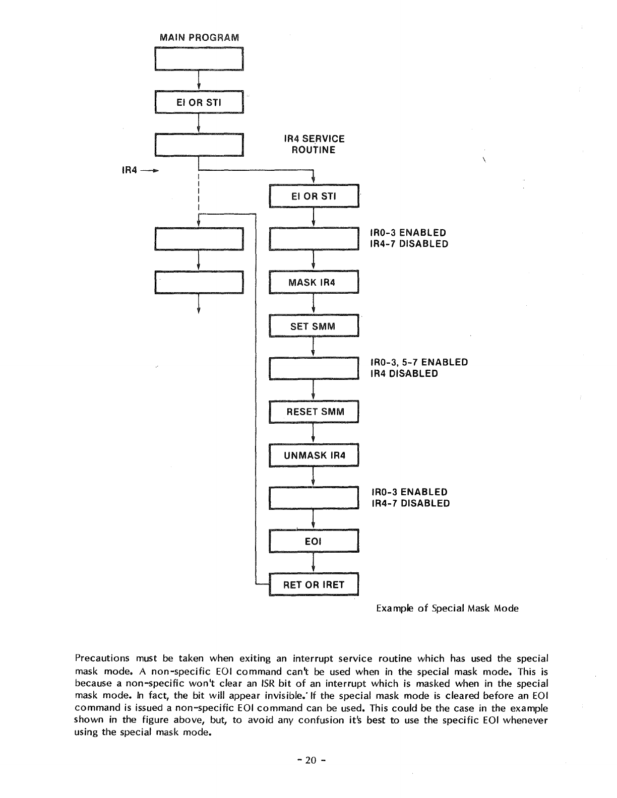
MAIN
PROGRAM
~
EIOP
IR4-
I
~
I I I
IR4 SE.RVICE
ROUTINE
1
~·
I l l
I
MASI
IR4
SET SMM I
1
[ L I
RESET SMM
L
UNMASK
IR4
C l
EOI
l
RET OR IRET
IR0-3
ENABLED
IR4-7
DISABLED
IR0-3,
5-
7 ENABLED
IR4 DISABLED
IR0-3
ENABLED
IR4-7
DISABLED
Example
of
Special Mask Mode
Precautions must
be
taken when
exiting
an
interrupt
service
routine
which
has used the special
mask
mode.
A
non-specific
EOI
command
can\
be used when in the special mask
mode.
This
is
because a
non-specific
won't
clear
an
ISR
bit
of
an
interrupt
which
is masked when in the special
mask
mode.
In
fact, the
bit
will
appear invisible." If the special mask mode
is
cleared
before
an
EOI
command
is
issued a
non-specific
EOI
command
can
be
used. This
could
be the case in the example
shown in the figure above, but,
to
avoid
any
confusion
it's best
to
use
the
specific
EOI
whenever
using the special mask mode.
-
20
-
)
it
must be remembered
that
the speciai mask
mode
applies
to
all masked levels when set. Take,
for
instance,
IR1
interrupting
IR4
in the previous example. If this happened
while
in the special mask
mode, and the
IR1
routine
masked itself, all
interrupts
would
be enabled
except
IR1
and
IR4
which
are masked.
INTERRUPT TRIGGERING
There
are
two
classical ways
of
sensing
an
active
interrupt
request: a level sensitive
input
or
an
edge sensitive
input.
The 8259A gives the user the
capability
for
either
method
with
the edge
triggered
mode and the level
triggered
mode.
Selection
of
one
of
these
interrupt
triggering
methods
is
done
during the
programmed
initialization
of
the
8259A.
LEVEL
TRIGGERED
MODE
When
in the level
triggered
mode the 8259A
will
recognize
any
active
level on
an
IR
input
as
an
interrupt
request. If
the
IR
input remains
active
after
an
EOI
command
has
been issued (resetting its
ISR
bit),
another
interrupt
will
be generated. This is
providing,
of
course, the
processor
INT pin
is
enabled. Unless repetitous
interrupt
generation
is
desired,
the
IR
input must be
brought
to
an
inactive
state
before
an
EOI
command
is issued in its
service
routine.
Caution
should be taken when using the
automatic
EOI
mode and the level
triggered
mode
together.
Since in the
automatic
EOI
mode
an
EOI
is
automatically
performed
at
the end
of
the
interrupt
acknowledge sequence,
if
the
processor
enables interrupts
while
an
IR
input
is
still
active,
an
interrupt
will
occur
immediately.
To
avoid
this
situation
interrupts
should be kept disabled until
the end
of
the service
routine
or
until
the
IR
input
goes
inactive.
EDGE
TRIGGERED MODE
\
)
When
in the edge
triggered
mode, the 8259A
will
only
recognize
interrupts
if
generated by
an
inactive
to
active
transition
on an
IR
input.
The edge
triggered
mode
incorporates
an
edge
lockout
method
of
operation.
This means
that
after
the rising edge
of
an
interrupt
request and the
acknowledgement
of
the request, the
active
level
of
the
IR
input
won't
generate
further
interrupts
on
this level. The user needn't
worry
about
quickly
removing
the request
after
acknowledgement
in
fear
of
generating
further
interrupts
as
might be the case in the level
triggered
mode.
Before
another
interrupt
can be generated the
IR
input
must return
to
the
inactive
state.
Like the level
triggered
mode, in the edge
triggered
mode the request on
the
IR
input must remain
active
until
after
the falling edge
of
the
first
INTA pulse
for
that
particular
interrupt.
Unlike the
level
triggered
mode, though,
after
the
interrupt
request
is
acknowledged
its
IRR
latch
is
disarmed.
Only
after
IR
input
goes
inactive
will
the
IRR
latch
again
become
armed, making
it
ready
to
receive
another
interrupt
request (in the level
triggered
mode, the
IRR
latch
is
always
armed).
One
possible advantage
to
the edge
triggered
input mode is
that
it
can be used
with
the
automatic
EOI
mode
without
the cautions in the level
triggered
mode.
Overall,
in
most
cases, the edge
triggered
mode simplifies
operation
for
the user, since the
duration
of
the
interrupt
request
at
a
positive
level
is
not
usually
factor.
INTERRUPT STATUS
By
means
of
software
control,
the user can
interrogate
the status
of
the 8259A. This allows the
reading
of
the internal
interrupt
registers,
which
may
prove
useful
for
interrupt
control
during
service
routines.
It also
provides
for
a
modified
status
poll
method
of
device
monitoring,
by using
the
poll
command.
This makes the status
of
the internal
IR
inputs available
to
the user
via
software
control.
The
poll
command
offers
an
alternative.
to
the
interrupt
vector
method, especially when
used in a system in
which
the
interrupt
vector
method
doesn't
work
due
to
incorrect
interrupt
acknowledge
status
provided
by the CPU.
-
21
-
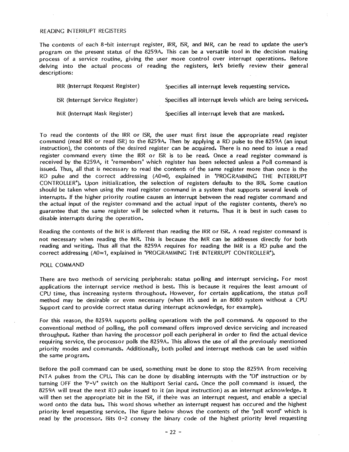
READING
INTERRUPT
REGISTERS
The contents
of
each
8-bit
interrupt
register,
!RR,
ISR,
and
IM
R,
can be read
to
update
the
user's
program
on the present: status
of
the
8259A. This can be a versatile
tool
in the
decision
making
process
of
a service
routine,
giving
the user
more
control
over
interrupt
operations.
Before
delving
into
the actual process
of
reading the registers, let's
briefly
review
their
general
descriptions:
IRR
(Interrupt Request Register)
ISR
(Interrupt Service Register)
IMR
(Interrupt Mask Register)
Specifies all
interrupt
levels requesting
service.
Specifies all
interrupt
levels
which
are being
serviced.
Specifies all
interrupt
levels
that
are masked.
To
read the contents
of
the
IRR
or
!SR,
the user must
first
issue the
appropriate
read register
command
(read
IRR
or
read
ISR)
to
the
8259A. Then by applying a
RD
pulse
to
the
8259A (an input
instruction),
the contents
of
the desired register can be
acquired.
There is
no
need
to
issue a read
register
command
every
time
the
IRR
or
ISR
is
to
be read. Once a read register
command
is
received by the 8259A,
it
"remembers"
which
register
has
been selected unless a Poll
command
is
issued. Thus, all
that
is
necessary
to
read the contents
of
the same register
more
than
once
is
the
RD
pulse and the
correct
addressing
(AO=O,
explained in "PROGRAMMING
THE
INTERRUPT
CONTROLLER"). Upon
initialization,
the selection
of
registers defaults
to
the
IRR.
Some
caution
should be taken when using the read register
command
in a system
that
supports several levels
of
interrupts.
If the higher
priority
routine
causes
an
interrupt
between the read register
command
and
the
actual input
of
the register command and the actual
input
of
the register contents, there's
no
guarantee
that
the same register
will
be selected when
it
returns.
Thus
it
is
best in such cases
to
disable interrupts during the
operation.
Reading the contents
of
the
IMR
is
different
than reading the
IRR
or
ISR.
A read register
command
is
not
necessary when reading
the
IMR.
This
is
because
the
IMR
can
be
addresses
directly
for
both
reading and
writing.
Thus
all
that
the 8259A requires
for
reading the
IMR
is
a
RD
pulse and the
correct
addressing (A0=1, explained in "PROGRAMMING
THE
INTERRUPT
CONTROLLER").
POLL
COMMAND
There are
two
methods
of
servicing
peripherals: status
polling
and
interrupt
servicing.
For
most
applications the
interrupt
service
method
is
best. This
is
because
it
requires the least
amount
of
CPU
time,
thus increasing systems
throughout.
However,
for
certain
applications, the status
poll
method
may
be
desirable
or
even necessary (when it's used in an 8080 system
without
a
CPU
Support card
to
provide
correct
status during
interrupt
acknowledge,
for
example).
For this reason, the 8259A supports polfing
operations
with
the
poll
command.
As
opposed
to
the
conventional
method
of
polling,
the
poll
command
offers
improved
device
servicing and increased
throughput.
Rather than having the
processor
poll
each
peripheral
in
order
to
find the
actual
device
requiring
service, the
processor
polls the
8259A.
This allows the
use
of
all the
previously
mentioned
priority
modes and commands.
Additionally,
both
polled and
interrupt
methods can be used
within
the
same
program.
Before
the
poll
command can
be
used, something must be
done
to
stop
the 8259A
from
rece1vmg
INT A pulses
from
the CPU. This can be
done
by disabling interrupts
with
the
•or•
instruction
or
by
turning
OFF
the
"P-V"
switch
on
the
Multiport
Serial
card.
Once the
poll
command
is
issued, the
8259A
will
treat
the
next
RD
pulse issued
to
it
(an input
instruction)
as
an
interrupt
acknowledge.
It
will
then set the
appropriate
bit
in the
ISR,
if
the"re was
an
interrupt
request, and enable a special
word
onto
the data bus. This
word
shows
whether
an
interrupt
request
has
occured
and the highest
priority
level requesting
service.
The figure
below
shows the contents
of
the "poll
word"
which
is
read by the
processor.
Bits
0-2
convey
the binary
code
of
the highest
priority
level requesting
-
22
-
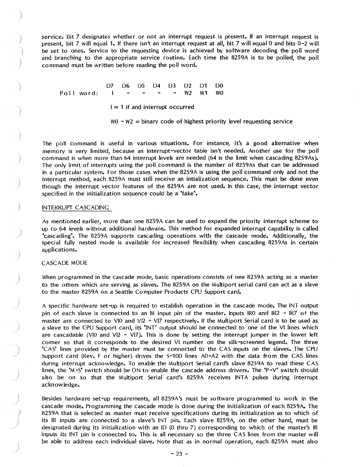
I
I
}
service.
Bit 7 designates
whether
or
not
an
interrupt
request is present. If
an
interrupt
request
is
present,
bit
7
will
equal 1. If
there
isn't
an
interrupt
request
at
all,
bit
7
will
equal O and bits
0-2
will
be
set
to
ones. Service
to
the requesting
device
is achieved by
software
decoding
the
poll
word
and
branching
to
the
appropriate
service
routine.
Each
time
the 8259A
is
to
be
polled, the
poll
command
must be
written
before
reading the
poll
word.
Po
11
word:
07
06
D5
I
04
03 02
01
W2
W1
I = 1
if
and
interrupt
occurred
DO
WO
WO
-
W2
= binary code
of
highest
priority
level requesting service
The
poll
command
is
useful in various
situations.
For instance, it's a
good
alternative
when
memory
is
very
limited, because
an
interrupt-vector
table isn't needed.
Another
use
for
the
poll
command
is
when
more
than 64
interrupt
levels are needed (64
is
the
limit
when cascading 8259As).
The
only
limit
of
interrupts using the
poll
command
is
the number
of
8259As
that
can be addressed
in
a
particular
system. For those cases when
the
8259A
is
using the
poll
command
only and
not
the
interrupt
method, each 8259A must still receive
an
intialization
sequence. This must
be
done even
though
the
interrupt
vector
features
of
the
8259A are
not
used.
In
this case, the
interrupt
vector
specified
in
the
initialization
sequence
could
be a "fake".
INTEKRUPT CASCADING
As
mentioned
earlier,
more
than one 8259A can be used
to
expand the
priority
interrupt
scheme
to
up
to
64
levels
without
additional
hardware. This
method
for
expanded
interrupt
capability
is
called
"cascading". The 8259A supports cascading
operations
with
the cascade
mode.
Additionally,
the
special fully nested mode
is
available
for
increased
flexibility
when cascading 8259As in
certain
applications.
CASCADE
MODE
When
programmed
in the cascade mode, basic
operations
consists
of
one 8259A acting
as
a master
to
the others
which
are serving
as
slaves. The 8259A on the
Multiport
serial card can
act
as
a slave
to
the master 8259A
on
a Seattle
Computer
Products
CPU
Support
card.
A
specific
hardware
set-up
is
required
to
establish
operation
in the cascade
mode.
The INT
output
pin
of
each slave
is
connected
to
an
IK
input
pin
of
the master. Inputs
IRO
and
IR2
-
IR7
of
the
master are
connected
to
VIO
and Vl2 -Vl7 respectively.
If
the
Multiport
Serial
card
is
to
be
used
as
a slave
to
the
CPU
Support card, its "INT"
output
should be
connected
to
one
of
the
VI lines
which
are cascadable
(VIO
and Vl2 -Vl7). This
is
done by setting the
interrupt
jumper in the
lower
left
corner
so
that
it
corresponds
to
the desired VI
number
on the silk-screened legend. The
three
"CAS"
lines
provided
by
the master must
be
connected
to
the CAS inputs on the slaves. The
CPU
Support
card (Kev. F
or
higher) drives the 5-100 lines AO-A2
with
the data
from
the
CAS
lines
during
interrupt
acknowledge. To enable the
Multiport
Serial card's slave 8259A
to
read these CAS
lines,
the
"M-5"
switch
should be ON
to
enable the cascade address
drivers.
The "P-V"
switch
should
also be
on
so
that
the Multi
po
rt Serial card's 8259A receives INT A pulses during
interrupt
acknowledge.
Besides
hardware
set-up
requirements, all 8259A's must
be
software
programmed
to
work
in the
cascade
mode.
Programming the cascade mode
is
done
during
the
initialization
of
each 8259A. The
8259A
that
is
selected
as
master must receive SJ?ecifications during its
initialization
as
to
which
of
its
IR
inputs are connected
to
a slave's INT pin.
Each
slave 8259A, on the
other
hand, must be
designated
during
its
initialization
with
an
ID
(0
thru
7)
corresponding
to
which
of
the master's
IR
inputs its INT pin
is
connected
to.
This
is
all necessary
so
the three CAS lines
from
the master
will
be able
to
address each individual slave.
Note
that
as
in
normal
operation,
each 8259A must also
-23 -
be
initialized
to
give
IR
inputs a unique
interrupt
vector.
More
detail
on the necessary
programming
of
the cascade mode
is
explained in "PROGRAMMING
THE
INTERRUPT CONTROLLER".
Now,
with
background
information
on
both
hardware and
software
for
the cascade mode, let's go
over
the sequence
of
events
that
occur
during a valid
interrupt
request
from
a slave. Suppose a
slave
IR
input
has
received
an
interrupt
request. Assuming this request
is
higher
priority
than
other
requests and
in-service
levels
on
the slave,
the
slave's INT
pin
is
driven
high. This signals the master
of
the request by causing
an
interrupt
request on a designated
IR
pin
of
the master. Again, assuming
that
this request
to
the master
is
higher
priority
than
other
master requests and
in-service
levels
(possibly
from
other
slaves), the master's INT pin
is
pulled high,
interrupting
the
processor.
The
interrupt
acknowledge sequence appears
to
the
processor
the same
as
the
non-cascading
interrupt
acknowledge sequence;
however,
it's
different
among
the
8259As. The
first
INT A pulse is
used by all the 8259As
for
internal
set-up
purposes and,
if
in
the 8080 mode,
the
master
will
place
the CALL
opcode
on the data bus. The
first
INT A pulse also signals the master
to
place
the
requesting slave's ID
code
on
the CAS lines and hence on AO-A2
of
the S-100 bus. This turns
control
over
to
the slave
for
the
rest
of
the
interrupt
acknowledge sequence, placing the
appropriate
pre-programmed
interrupt
vector
on the data bus,
completing
the
interrupt
request.
During the
interrupt
acknowledge sequence, the
corresponding
ISR
bit
of
both
the master and the
slave get set. This means
two
EOI
commands must be issued
(if
not
in the
automatic
EOI
mode),
one
for
the master and one
for
the slave.
Special
consideration
should be taken when mixed
interrupt
requests are assigned
to
a master
8259A;
that
is,
when some
of
the master's
IR
inputs are used
for
slave
interrupt
requests and some
are used
for
individual
interrupt
requests.
In
this type
of
structure,
the master's
IRO
must
not
be
used
for
a slave. This
is
because when an
IR
input
that
isn't
initialized
as
a slave receives
an
interrupt
request, the
three
CAS lines
won't
be
activated,
thus staying in the default
condition
addressing
for
IRO
(slave
IRO).
If a slave
is
connected
to the master's
IRO
when a
non-slave
interrupt
occurs
on
another
master
IR
input,
erroneous
conditions
may result.
Thus
IRO
should
be
the last
choice
when assigning slaves
to
IR
inputs.
SPECIAL
FULLY
NESTED
MODE
Depending on the application, changes in the nested
structure
of
the cascade
mode
may be desired.
This
is
because the nested
structure
of
a slave 8259A
differs
from
that
of
the
normal
fully nested
mode.
In
the cascade mode,
if
a slave receives a higher
priority
interrupt
request than one
which
is
in
service
(through the same slave),
it
won't
be recognised by the master. This
is
because
the
master's
ISR
bit
is
set,
ignoring
all requests
of
equal
or
lower
priority.
Thus, in this case, the higher
priority
slave
interrupt
won't
be serviced until
after
the master's
ISR
bit
is
reset by
an
EOI
command.
This
is
most likely
after
the
completion
of
the
lower
priority
routine.
If the user wishes
to
have a
truly
fully nested
structure
within
a slave 8259A, the special fully nested
mode should be used. The special fully nested mode
is
programmed
in the master
only.
This is done
during the master's
initialization.
In
this mode the master
will
ignore
only those
interrupt
requests
of
lower
priority
than the set
ISR
bit
and
will
respond
to
all requests
of
equal
or
higher
priority.
Thus
if
a slave receives a higher
priority
request than one
which
is
in service,
it
will
be
recognized.
To insure
proper
interrupt
operation
when using the special fully nested mode,
the
software
must
determine
if
any
other
slave
interrupts
are still in service
before
issuing
an
EOI
command
to
the
master. This
is
done
by resetting
the
appropriate
slave
ISR
bit
with
an
EOI
and then reading its
ISR.
If the
ISR
contains all zeros,
there
aren't
any
other
interrupts
from
the slave in service and
an
EOI
command
can
be
sent
to
the master. If the
ISR
isn't
all
zeros,
an
EOI
command
shouldn't be sent
to
the master. Clearing the master's
ISR
bit
with
an
EOI
command
while
there
are still slave
interrupts
in
service
would
allow
lower
priority
interrupts
tQ be
recognized
at
the master.
-24 -
PROGRAMMING
THE
INTERRUPT
CONTROLLER
Programming
the
8259A
interrupt
controller
is
accomplished by using
two
types
of
command
words:
Initialization
Command Words
(ICWs)
and
Operational
Command Words (OCWs). All the
modes and commands explained in the previous
section,
"OPERATION
OF
THE
INTERRUPT
CONTROLLER", are programmable using the
ICWs
and OCWs. The
ICWs
are issued
from
the
)
processor
in
a sequential
format
and are
used
to
set
up
the
8259As in
an
initial
state
of
operation.
· The
OCWs
are issued
as
needed
to
vary and
control
8259A
operation.
Both
ICWs
and
OCWs
are sent
by
the
processor
to
the 8259A
via
output
commands
from
the
processor.
The 8259A distinguishes between the
different
ICWs
and
OCWs
by
the state
of
its
AO
pin,
the sequence
they're
issued in
(ICWs
only), and some dedicated bits among the
ICWs
and OCWs. The
state
of
the
AO
pin
is
defined
by
which
port
the
ICW
or
OCW
is
sent
to.
For the
Multiport
Serial
card,
AO
= 0 corresponds
to
BASE+12
and
AO
= 1 corresponds
to
BASE+13. Those bits
which
are
dedicated are indicated so
by
fixed values (0
or
1)
in the
corresponding
ICW
or
OCW
programming
formats
which
are
covered
shortly.
Note:
when issuing
either
ICWs
or
OCWs,
the interrupts should
be
disabled
at
the
processor
(using
the
DI
function
of
the CPU).
INITIALIZATION COMMAND
WORDS
Before
normal
operation
can begin, each 8259A in the system must
be
initialized
by a sequence
of
four
ICWs.
Note
that
once
initialized,
if
any
programming
changes
within
the
ICWs
are
to
be made,
all
four
ICWs
must
be
reprogrammed in sequence.
Certain
internal set
up
conditions
occur
automatically
within
the 8259As
after
the
first
ICW
has
been issued. These are:
1 > The In-Service Register and
Interrupt
Mask Register are
both
cleared. (Clearing the
IMR
enables all
eight
interrupt
request inputs).
2>
The special mask mode
is
reset.
3>
Rotation at
Automatic
End
Of
Interrupt
is
disabled.
4>
The
Interrupt
Request Register is selected
for
the read register
command.
5>
The
fully nested mode
is
entered
with
an
initial
priority
assignment
of
IRO
highest
through
IR7
lowest.
6>
The edge
sense
latch
of
each
IR
input
is
cleared thus requmng
an
active
transition
to
generate
an
interrupt
if
the edge
triggered
input mode
is
chosen in
ICW1.
-
25
-
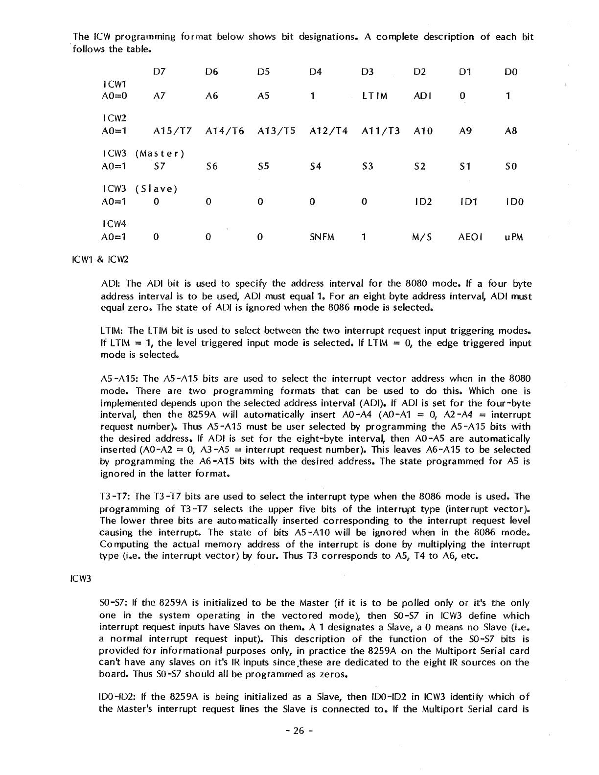
The
ICW
programming
format
below
shows
bit
designations.
A
complete
description
of
each
bit
follows
the
table.
ICW1
AO=O
07
A7
06
A6
05
AS
04
1
03
LTIM
02
ADI
ICW2
A0=1
A15/T7
A14/T6
A13/T5
A12/T4 A11/T3
A10
ICW3
(Master)
A0=1
57
I
CW3
( S I
ave
)
A0=1
0
ICW4
A0=1
0
56
55
0 0
0 0
54
53
52
0 0
102
SNFM 1
M/S
01
0
A9
51
101
AEOI
DO
1
AB
so
100
uPM
ICW1
&
ICW2
ICW3
ADI: The ADI
bit
is used
to
specify
the
address
interval
for
the
8080
mode.
If
a
four
byte
address
interval
is
to
be used,
ADI
must
equal
1.
For
an
eight
byte
address
interval,
ADI
must
equal
zero.
The
state
of
ADI is
ignored
when
the
8086
mode
is
selected.
L TIM: The
LTIM
bit
is
used
to
select
between
the
two
interrupt
request
input
triggering
modes.
If
L
TIM
= 1,
the
level
triggered
input
mode
is
selected.
If
L
TIM
= 0,
the
edge
triggered
input
mode
is
selected.
A5-A15:
The
A5-A15
bits
are
used
to
select
the
interrupt
vector
address
when
in
the
8080
mode.
There
are
two
programming
formats
that
can be used
to
do
this.
Which
one
is
implemented
depends
upon
the
selected
address
interval
(ADI).
If
ADI is
set
for
the
four-byte
interval,
then
the
8259A
will
automatically
insert
AO-A4
(AO-A1 =
O,
A2-A4
=
interrupt
request
number).
Thus
A5-A15
must be user
selected
by
programming
the
A5-A15
bits
with
the
desired
address. If
ADI
is
set
for
the
eight-byte
interval,
then AO-AS
are
automatically
inserted
(AO-A2
= 0,
A3-A5
=
interrupt
request
number).
This leaves
A6-A
15
to
be
selected
by
programming
the
A6-A15
bits
with
the
desired
address. The
state
programmed
for
AS
is
ignored
in
the
latter
format.
T3-T7:
The
T3-T7
bits
are
used
to
select
the
interrupt
type
when
the
8086
mode
is used. The
programming
of
T3-T7
selects
the
upper
five
bits
of
the
interrupt
type
(interrupt
vector).
The
lower
three
bits
are
automatically
inserted
corresponding
to
the
interrupt
request
level
causing
the
interrupt.
The
state
of
bits
AS
-A
10
will
be
ignored
when in
the
8086
mode.
Computing
the
actual
memory
address
of
the
interrupt
is
done
by
multiplying
the
interrupt
type
(i.e.
the
interrupt
vector)
by
four.
Thus
T3
corresponds
to
AS, T4
to
A6,
etc.
S0-57: If
the
8259A
is
initialized
to
be
the
Master
(if
it
is
to
be
polled
only
or
it's
the
only
one
in
the
system
operating
in
the
vectored
mode),
then
50-57
in
ICW3
define
which
interrupt
request inputs have Slaves
on
them.
A 1 designates a Slave, a O means
no
Slave
(i.e.
a
normal
interrupt
request
input).
This
description
of
the
function
of
the
50-57
bits is
provided
for
informational
purposes
only,
in
practice
the
8259A
on
the
Multiport
Serial
card
can't
have any slaves
on
it's
IR
inputs since .these are
dedicated
to
the
eight
IR
sources
on
the
board.
Thus
50-57
should
all be
programmed
as
zeros.
100-102: If
the
8259A
is
being
initialized
as
a Slave,
then
100-102
in
ICW3
identify
which
of
the
Master's
interrupt
request lines
the
Slave is
connected
to.
If
the
Multiport
Serial
card
is
-
26
-
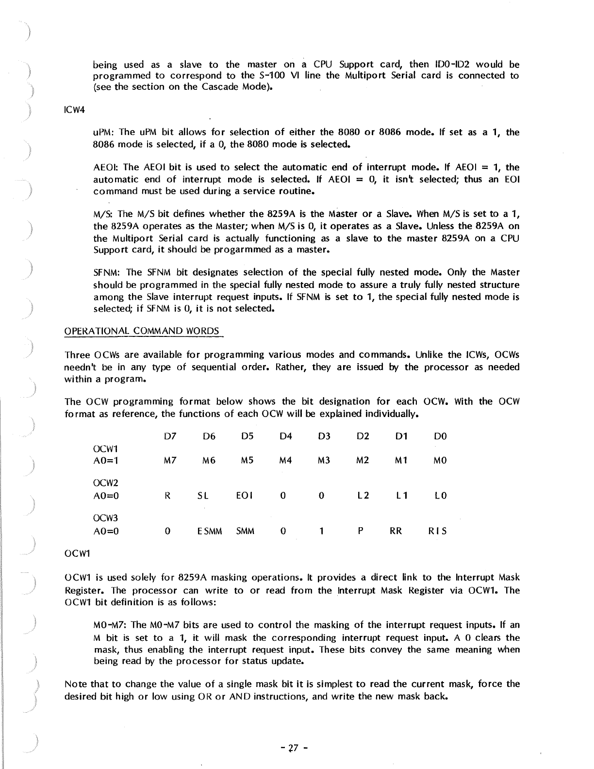
)
ICW4
being used
as
a slave
to
the master on a
CPU
Support card, then IDO-ID2
would
be
programmed
to
correspond
to
the S-100
VI
line the
Multiport
Serial
card
is
connected
to
(see the section on
the
Cascade Mode).
uPM:
The
uPM
bit
allows
for
selection
of
either
the
8080
or
8086
mode.
If
set
as
a 1, the
8086 mode
is
selected,
if
a
O,
the
8080 mode
is
selected.
AEOI: The
AEOI
bit
is
used
to
select
the
automatic
end
of
interrupt
mode.
If
AEOI
=
1,
the
automatic
end
of
interrupt
mode
is
selected. If AEOI =
O,
it
isn't selected; thus
an
EOI
command
must
be
used during a service
routine.
M/S:
The
M/S
bit
defines whether
the
8259A
is
the Master
or
a Slave.
When
M/S
is
set
to
a 1,
the
8259A operates
as
the Master; when M/S is
O,
it
operates
as
a Slave. Unless the 8259A
on
the
Multiport
Serial
card
is
actually
functioning
as
a slave
to
the
master 8259A on a
CPU
Support card,
it
should be
progarmmed
as
a master.
SFNM:
The
SFNM
bit
designates selection
of
the special fully nested mode. Only the Master
should
be
programmed
in the special fully nested mode
to
assure a
truly
fully nested
structure
among
the
Slave
interrupt
request inputs. If
SFNM
is
set
to
1, the special fully nested mode
is
selected;
if
SFNM
is
0,
it
is
not
selected.
OPERATIONAL COMMAND
WORDS
Three
OCWs
are available
for
programming
various modes and commands. Unlike the
ICWs,
OCWs
needn't
be
in any
type
of
sequential
order.
Rather, they are issued
by
the processor
as
needed
within
a
program.
The OCW
programming
format
below
shows the
bit
designation
for
each OCW. With the
OCW
format
as
reference, the
functions
of
each
OCW
will
be explained individually.
D7
06
05
04 03 02
01
DO
OCW1
A0=1
M7
MG
M5
M4
M3 M2
M1
MO
OCW2
AO=O R
SL
EOI 0 0
L2
L1
LO
OCW3
AO=O 0
ESMM
SMM
0 1 p
RR
RIS
OCW1
OCW1
is used solely
for
8259A masking
operations.
It provides a
direct
link
to
the
Interrupt
Mask
Register.
The
processor
can
write
to
or
read
from
the Interrupt Mask Register via OCW1. The
OCW1
bit
definition
is
as
follows:
MO-M7: The
MO-M7
bits are used
to
control
the masking
of
the
interrupt
request inputs. If
an
M
bit
is
set
to
a
1,
it
will
mask the
corresponding
interrupt
request input. A O clears
the
mask, thus enabling the
interrupt
request
input.
These bits
convey
the same meaning when
being read
by
the
processor
for
status update.
Note
that
to
change the value
of
a single mask
bit
it
is simplest
to
read the
current
mask,
force
the
desired
bit
high
or
low
using
OR
or
AND
instructions, and
write
the
new
mask back.
-'P -
OCW2
OCW2
is used
for
end
of
interrupt,
automatic
rotation,
and specific
rotation
operations.
Associated commands and modes
of
these
operations
(with
exception
of
AEOI
initialization),
are
selected using the bits
of
OCW2
in
a
combined
fashion
as
explained
below.
A
complete
explanation
of
the
different
modes and commands
is
given in the
previous
section "OPERATION
OF
THE
INTERRUPT CONTROLLER".
OCW3
R
SL
EOI
0 0 0 Disable
rotation
at
automatic
end
of
interrupt
(AEOI).
0 0 1
Non-specific
end
of
interrupt.
0 1 0
No
operation.
0 1 1 Specific end
of
interrupt.
LO-L2
is
the
ISR
bit
to
reset.
1 0 0 Enable
rotation
at
automatic
end
of
interrupt
(AEOI).
1 0 1
Non-specific
end
of
interrupt
with
priority
rotation.
1 1 0
Set
priority
using LO-L2.
1 1 1 Specific end
of
interrupt
with
priority
rotation.
R:
The R
bit
is
used
to
control
all 8259A
rotation
operations.
If
the R
bit
is
set
to
a
1,
a
form
of
priority
rotation
will
be executed depending on the state
of
the
SL
and
EOI
bits.
If
R is 0,
rotation
won't
be
executed.
SL:
The
SL
bit
is
used
to
select a specific level
for
a given
operation.
If
SL
is set
to
a 1, the
LO-L2
bits are enabled.
The
operation
selected
by
the
EOI
and R bits
will
be executed on the
specified
interrupt
level. If
SL
is
O,
the
LO-L2
bits
are
disabled.
EOI:
The
EOI
bit
is
used
for
all end
of
interrupt
commands
(not
automatic
end
of
interrupt
mode).
If
set
to
a 1, a
form
of
an
end
of
interrupt
command
will
be executed depending on
the state
of
the
SL
and R bits. If
EOI
is
0,
an
end
of
interrupt
command
won't
be executed.
LO-L2: The LO-L2 bits are used
to
designate
an
interrupt
level
(0-7)
to
be acted upon
for
the
operation
selectedby
the
EOI,
SL,
and R bits
of
OCW2. The level designated
will
either
be used
to
reset a
specific
Interrupt
Service Register
(ISR)
bit
or
to
set a specific
priority.
The LO-L2
bits are enabled
or
disabled by the
SL
bit.
OCW3
is used
to
issue
various
modes and commands
to
the 8259As. There are
two
main
categories
of
operation
associated
with
OCW3:
interrupt
status and
interrupt
masking. Bit
definition
of
OCW3
is
as
fo flows:
ESMM:
The
ESMM
bit
is used
to
enable
or
disable the
effect
of
the
SMM
bit.
If
ESMM
is
set
to
a
1,
SMM
is
enabled.
If
ESMM
is
0,
SMM
is
disabled. This
bit
is
useful
to
prevent
interference
of
mode
and
command
selections in OCW3.
SMM:
The
SMM
bit
is
used
to
set the special mask
mode.
If
SMM
is set
to
a
1,
the special mask
mode
is
enabled. If
it
is
O,
it
is
disabled. The state
of
the
SMM
bit
is
only
honored
if
it
is
enabled by the
ESMM
bit.
P:
The P
bit
is
used
to
issue the
poll
command.
If
P is set
to
a 1, the
poll
command
is
issued.
If
it
is
0,
the
poll
command
isn't issued.
The
poll
command
will
override
a read register
command
if
set simultaneously.
RR:
The
RR
bit
is used
to
execute the read register
command.
If
RR
is set
to
a
1,
the read
register
command
is
issued and the state
of
RIS
determines the register
to
be read. If
RR
is
0,
the read register
command
isn't issued.
-28 -
)
RIS:
The
RIS
bit
is
used
to
select the
ISR
or
IRR
for
the read register command. If
RIS
is
set
to
a
1,
the
In-Service Register
is
selected. If
RIS
is
O,
the
Interrupt Request Register
is
selected.
The state
of
the
RIS
bit
is
only honored
if
the
RR
bit
is
a 1.
Theory
of
Operation
The functions
of
this card are implemented
with
MOS
LSI
microprocessor
support chips,
with
TIL
used
for
S-100
bus
interface. Most
of
the
circuitry
is
very straight
forward
and requires no
explanation, so only selected
portions
of
the
circuit
are discussed below.
Wait State Generator
When
a
wait
state
is
to
be
generated, the
circuit
simply gates inverted
pSYNC
from
the
CPU
onto
the
ROY
line
with
a
driver
wired
for
open-collector
operation.
The
use
of
pSYNC
to
generate a
wait
state may
not
work
with
all
CPU
cards, although
it
should according
to
the
IEEE
S-100
standard. It does
work
with
the
SCP
8086
CPU
card, which when
run
at
8 MHz
is
the only card we
know
of
that needs the
wait
state.
Pulse
Stretcher
This
circuit
is
formed
primarily
by U19, pins 1 - 7 and 15, U20 pins 8 - 13, and
U21
pins 8 - 10.
Its
purpose
is
to
stretch the
RD
(read),
WR
(write), and
INT
A (interrupt acknowledge)
pulses
to
meet
the minimum pulse width requirements
of
the
MOS
LSI
parts.
When
pSTVAL goes high during
pSYNC,
one
of
the flip-flops
of
U19
is
cleared. This allows inverted
copies
of
slNP,
sOUT,
and
slNT A
to
be gated through
as
the
control
lines
RD,
WR,
and
INT
A,
respectively.
One
of
these
control
lines stays active until the trailing edge
of
either
pWR*
or
pDBIN
clocks the
flip-flop
and
gates
it
off.
The "trailing edge"
means
the rising edge
of
pWR*
or
the falling
edge
of
pDBIN.
Thus
the
control
pulse terminates just about the
time
it
would have
if
pDBIN
or
pWR
had been
used,
but
it
starts considerably earlier.
The
"M
-S"
Switch
When
the 8259A interrupt
controller
on the Multiport Serial card
is
slaved
to
the master 8259A on a
SCP
CPU
Support card (Rev. F
or
higher), the
CPU
Support card provides three "cascade" address
lines
to
indicate which
of
the
up
to
eight slaves
is
enabled during
interrupt
acknowledge.
The
data
from
the three "cascade" lines
is
available on the lowest three bits
of
the address bus.
When
the M-S
switch is on, three sections
of
U24
drive
the three
"CAS"
inputs
of
the 8259A
with
data
from
AO-A2. If
the
8259A
is
used
as
a master, the M-S switch should be
off
to
disable the three
CAS
drivers since the 8259A
will
be
trying
to
drive these lines
as
outputs.
The
Uaud
Rate Generators
The
Multiport
Serial card
uses
a
pair
of
Western Digital BR1941L-5
or
BR2941L-5 dual baud rate
generator chips
to
provide the
four
baud rates required
by
the
four
channels.
The
baud
rate
is
programmed
into
the generators
by
setting the binary combination desired on the
"R"
or
"T"
inputs
and strobing the
"ST"
input
with
a
positive
pulse.
The
output baud rate
is
available on the
"F"
output
which connects
to
the
RxC
and
TxC
clock
in'puts
of
the 8251A
USARTs.
The
"X"
inputs are
two-phase
clock
inputs which are driven
by
a 4.9152
MHz
crystal
oscillator.
-
29
-
Ones Year
Limited
Warranty
WARRANTEE
AND
WARRANTY
PERIOD
The Seattle
Computer
Products
(hereinafter
referred
to
as
SCP)
warranty
for
this
product
extends
to
the original
purchaser
and all subsequent
owners
of
the
product
for a
period
of
one
year
from
the time
the
product
is
first
sold
at
retail and
for
such additional
time
as the
product
may be
out
of
the
owner's
possession
for
the
purpose
of
receiving
warranty
service
at
the
factory.
WARRANTY
COVERAGE
This
product
is
warranted
to
be free from
defects
of
material and workmanship and
to
perform
within its specifications as detailed
in
the
instruction
or
operating
manual during
the
period
of
the
warranty.
This warranty
does
not
cover
damage and
is
void if
the
product
has been
damaged
by
neglect, accident, unreasonable use,
improper
repair,
or
other
causes
not
arising
out
of
defects
in
material
or
workmanship.
WARRANTY
PERFORMANCE
During the
warranty
period,
SCP
will
repair
or
replace defective boards
or
products
or
components
of
boards
or
products
upon written
notice
that
a
defect
exists. Certain high value
parts
may
have
to
be returned
to
SCP
prior
to
replacement.
Other
components
will
be replaced
without
the
part
having
to
be returned
to
the
factory
with the
exception
the
SCP
retains the right
in
all
cases
to
examine the defective
board
or
other
products
prior
to
the items replacement under
the
warranty.
In
the
event
the return
of
the board,
product,
or
component
is
requested by
SCP
under this warranty, the
owner
shall ship the item prepaid
to
the
SCP
factory.
SCP
will pay for
shipment
of
replacement items back
to
the
owner.
All
repairs
or
replacements under this
warranty
will be
performed
by
SCP
within five working days
of
receipt
of
notice
of
defect
or
return
of
components
as called for under this
warranty.
WARRANTY
DISCLAIMERS
While
high reliability was a major design
factor
for
this
product
and
care
was used
in
its
manufacture, no certainty can be achieved than any particular
product
will
operate
correctly
for
any specific time.
No
representation
is
made
by
SCP
that
this
product
will
not
fail
in
normal use.
Because
of
the inability
to
guarantee
100%
reliability, SCP shall
not
be liable for any consequencial
damange the user
may
suffer because the
products
fails
to
fu,ction
reliably 100%
of
the
time.
Any
implied warranties arising from the sale
of
this
product
are
limited
in
duration
to
the
warranty
period
defined
above.
LEGAL
REMEDIES
This warranty gives the purchaser specific legal rights.
He
may
have additional rights which
vary from
state
to
state.
SHIPPING
INSTRUCTIONS
In
the
event
it
becomes
necessary
toreturn
the
product
or
component
to
SCP,
also return a
written explaination of the difficulty
enco4ntered
along with
your
name, address and
phone
number. Package the items
in
a
crushproof
container
with
adequate
packing material
to
prevent
damage and ship prepaid to:
-
30
-
Seattle
Computer
Products
1114 Industry Drive
Seattle, Washington 98188
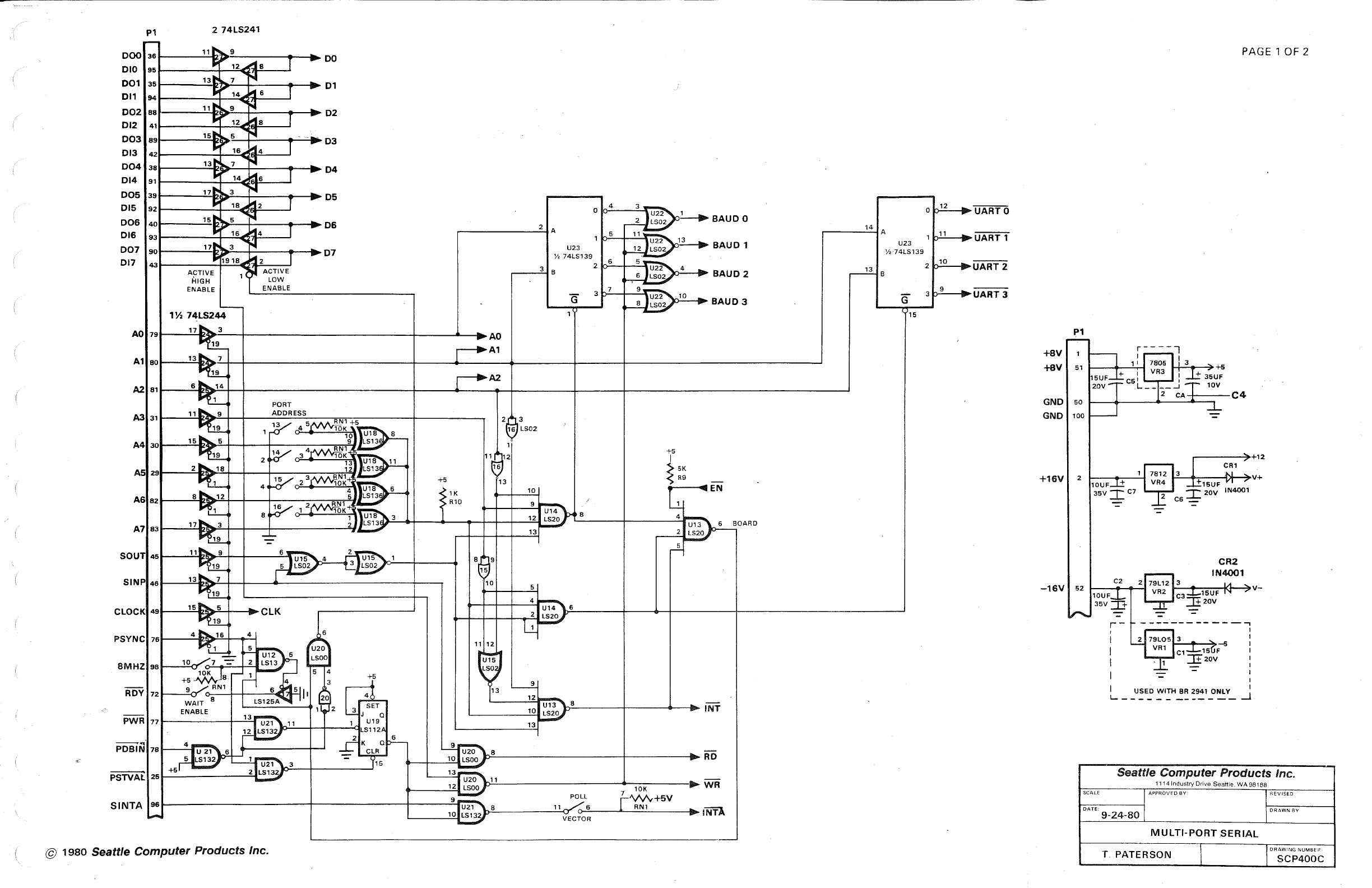
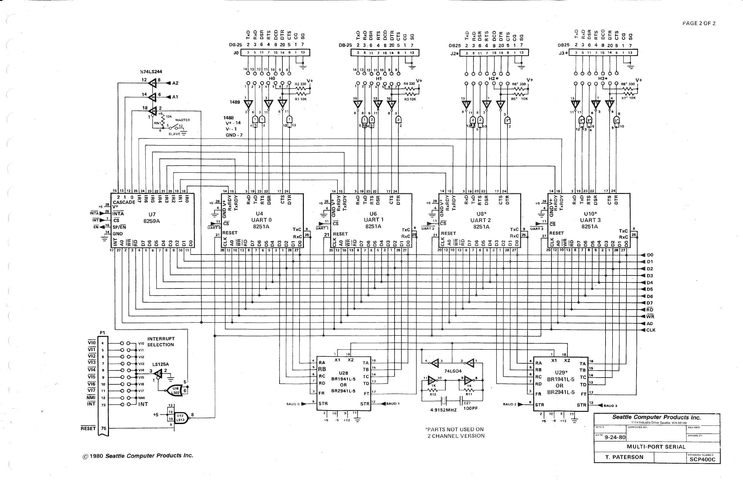

(