Form 3A Type ME Electronic Control Installation, Operation, And Ing Instructions 634R S280751
User Manual: 634R
Open the PDF directly: View PDF ![]() .
.
Page Count: 32
1
Printed in USA
Contents
Safety Information........................................................ 2
Product Information..................................................... 3
Introduction............................................................... 3
Acceptance and Initial Inspection............................. 3
Handling and Storage............................................... 3
Control Battery Storage and Charging .................... 3
Description of Control............................................... 4
Description of Control Operation.............................. 5
Control Battery ......................................................... 7
Temperature-Regulated Battery Charger................. 9
Programming and Operating the Control ................ 10
To Remove the Control from Service..................... 10
To Return the Control to Service............................ 10
Number of Operations Selectors............................ 10
Reclosing Interval Timing Delay Selectors............. 11
Minimum-Trip Resistor Cartridges.......................... 11
Ground- and Phase Trip Timing Plugs................... 12
Reset Delay Selector.............................................. 12
Reset Timed from First Trip Operation................... 13
Operating Switches and Indicators......................... 13
Installation Procedure ............................................... 15
Mounting the Control.............................................. 15
Grounding the Control............................................ 16
Control Cable ......................................................... 17
Shielding and Surge Protection of Remote Cables 17
Customer Connections Terminal Strip ................... 17
Control/Recloser Interchangeability ....................... 18
Accessories............................................................ 20
Verification Procedure Prior to Placing
Control and Recloser into Service.......................... 20
Testing Procedures.................................................... 21
Testing with Type MET Tester ............................... 21
Testing an Installed Control.................................... 21
Closing the Recloser .............................................. 22
Soldering-Gun Test ................................................ 24
Testing with Simulated Current .............................. 25
Testing with Low-Voltage Current .......................... 28
Maintenance Information........................................... 31
Service Information
Reclosers
Form 3A Type ME Electronic Control Installation,
Operation, and Testing Instructions S280-75-1
August 2002 • Supersedes 5/94
Applicable to Form 3A Controls above Serial Number 50070
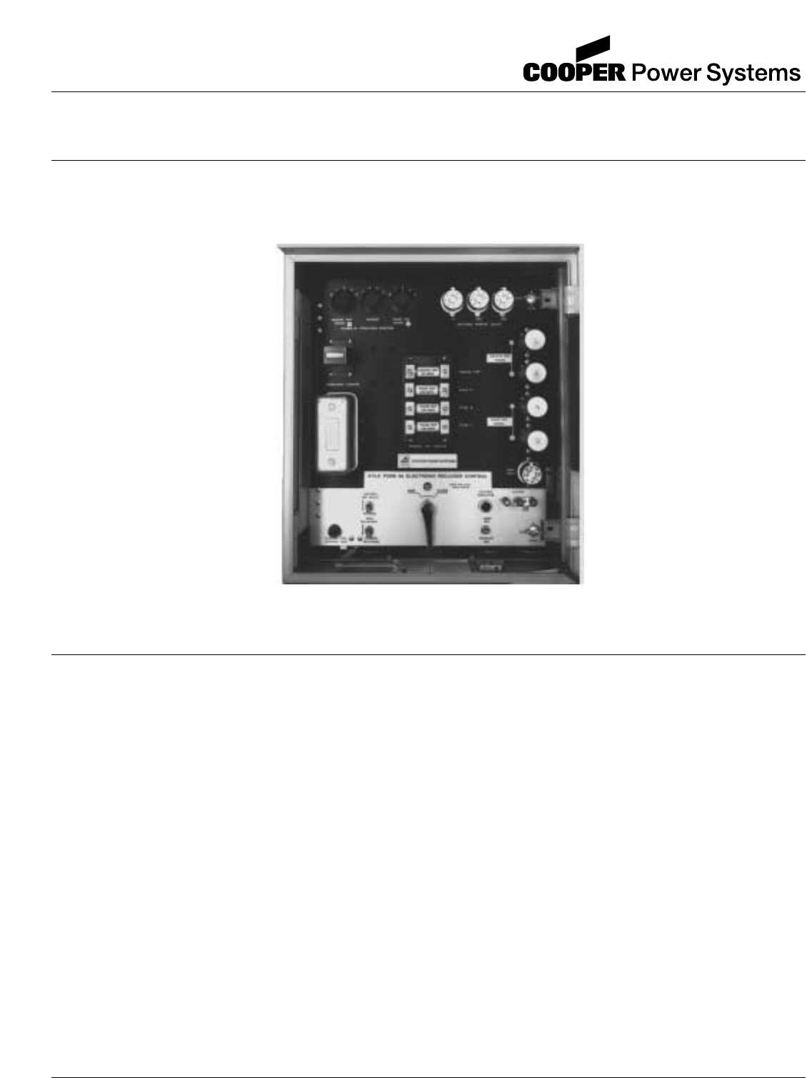
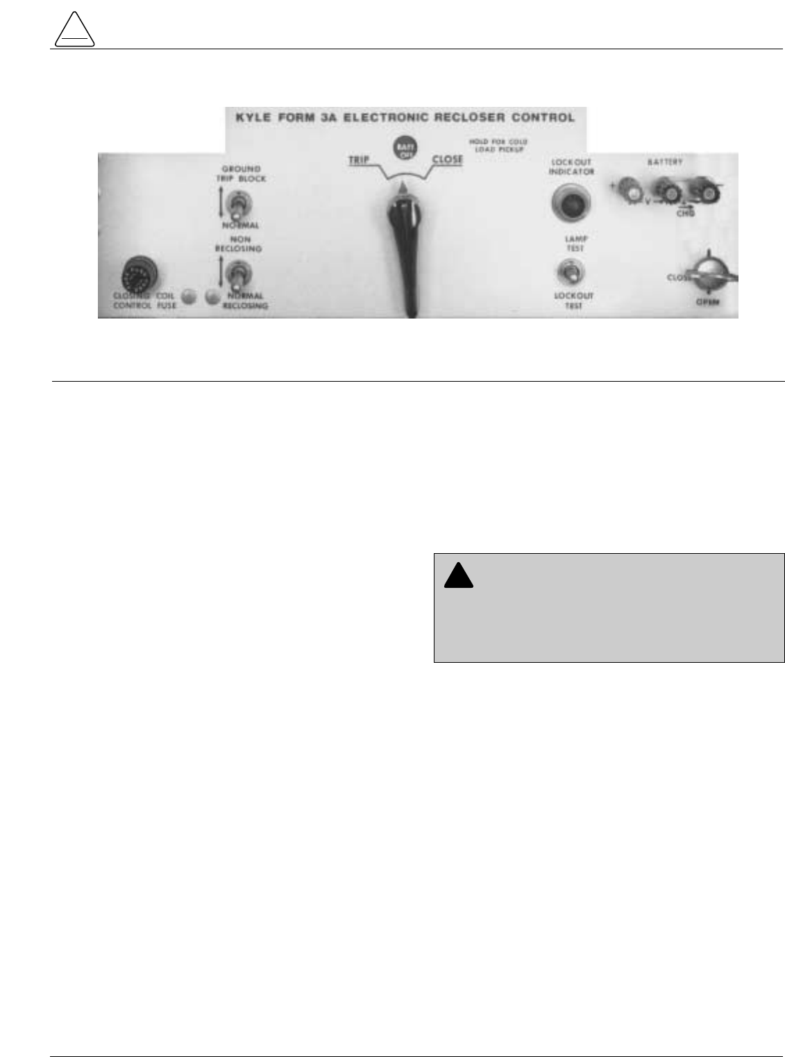
Figure 1.
Kyle®Form 3A Type ME Electronic Recloser Control.
911068KMA-F
Form 3A Type ME Electronic Control Installation, Operation, and Testing Instructions
2
The instructions in this manual are not intended as a sub-
stitute for proper training or adequate experience in the
safe operation of the equipment described. Only compe-
tent technicians who are familiar with this equipment
should install, operate, and service it.
A competent technician has these qualifications:
• Is thoroughly familiar with these instructions.
• Is trained in industry-accepted high- and low-voltage
safe operating practices and procedures.
• Is trained and authorized to energize, de-energize,
clear, and ground power distribution equipment.
• Is trained in the care and use of protective equipment
such as flash clothing, safety glasses, face shield,
hard hat, rubber gloves, hotstick, etc.
Following is important safety information. For safe instal-
lation and operation of this equipment, be sure to read
and understand all cautions and warnings.
Safety Instructions
Following are general caution and warning statements
that apply to this equipment. Additional statements,
related to specific tasks and procedures, are located
throughout the manual.
SAFETY FOR LIFE
Cooper Power Systems products meet or exceed all applicable industry standards relating to product safety. We actively
promote safe practices in the use and maintenance of our products through our service literature, instructional training
programs, and the continuous efforts of all Cooper Power Systems employees involved in product design, manufacture,
marketing, and service.
We strongly urge that you always follow all locally approved safety procedures and safety instructions when working
around high voltage lines and equipment and support our “Safety For Life” mission.
!
SAFETY
FOR LIFE
!
SAFETY
FOR LIFE
This manual may contain four types of hazard state-
ments:
DANGER: Indicates an imminently haz-
ardous situation which, if not avoided, will
result in death or serious injury.
WARNING: Indicates a potentially hazardous
situation which, if not avoided, could result in
death or serious injury.
CAUTION: Indicates a potentially hazardous
situation which, if not avoided, may result in
minor or moderate injury.
CAUTION: Indicates a potentially hazardous situ-
ation which, if not avoided, may result in equip-
ment damage only.
!
!
Hazard Statement Definitions
!
WARNING: This equipment is not intended to
protect human life. Follow all locally approved pro-
cedures and safety practices when installing or operat-
ing this equipment. Failure to comply can result in death,
severe personal injury and equipment damage.
G102.1
!
DANGER: Hazardous voltage. Contact with haz-
ardous voltage will cause death or severe per-
sonal injury. Follow all locally approved safety
procedures when working around high and low voltage
lines and equipment. G103.3
!
WARNING: Before installing, operating, main-
taining, or testing this equipment, carefully read
and understand the contents of this manual. Improper
operation, handling or maintenance can result in death,
severe personal injury, and equipment damage. G101.0
!
WARNING: Power distribution equipment must
be properly selected for the intended application. It
must be installed and serviced by competent personnel
who have been trained and understand proper safety
procedures. These instructions are written for such per-
sonnel and are not a substitute for adequate training and
experience in safety procedures. Failure to properly
select, install, or maintain power distribution equipment
can result in death, severe personal injury, and equip-
ment damage. G122.2
!
SAFETY INFORMATION
3
S280-75-1
PRODUCT INFORMATION
!
SAFETY
FOR LIFE
Introduction
Service Information S280-75-1 provides installation
instructions, operation information, and testing proce-
dures for the Kyle®Form 3A Type ME electronic recloser
control.
This control is used in conjunction with a Kyle electroni-
cally controlled recloser. If used with a Type VWE,
VWVE27, VWVE38, WE, or WVE recloser, refer to Ser-
vice Information S280-40-2. If used with a VSA12,
VSA16, or VSA20 recloser, refer to Service Information
S280-45-1. If used with a VSO12, VSO16, or VSO20
recloser, refer to Service Information S280-57-1.
The information contained in this manual is organized into
the following major categories: Safety Information, Prod-
uct Information, Programming and Operating the Control,
Installation Procedure, Testing, and Maintenance Infor-
mation. Refer to the table of contents for page numbers.
Read and understand the contents of this manual and fol-
low all locally approved procedures and safety practices
before installing or operating this equipment.
Additional Information
These instructions do not claim to cover all details or vari-
ations in the equipment, procedures, or process described
nor to provide directions for meeting every possible contin-
gency during installation, operation, or maintenance.
When additional information is desired to satisfy a problem
not covered sufficiently for the user's purpose, please con-
tact your Cooper Power Systems sales engineer.
Acceptance and Initial
Inspection
Each control (Figure 1) is completely assembled, tested,
and inspected at the factory. It is carefully calibrated,
adjusted, and in good condition when accepted by the
carrier for shipment.
Upon receipt, inspect the control thoroughly for damage
and loss of parts incurred during shipment. If damage or
loss is discovered, file a claim with the carrier immediately.
Handling and Storage
Take care during handling and storage to minimize the
possibility of damage. If the control is to be stored for any
length of time before installation, provide a clean, dry stor-
age area. If storage is in a humid atmosphere, make pro-
visions to keep the cabinet heater energized.
Note: To energize the cabinet heater, apply to 120 Vac to Ter-
minals 5 and 6 of the input terminal strip mounted verti-
cally on the back panel of the control cabinet. Refer to
Figure 4.
Control Battery Storage and
Charging
The nickel-cadmium control battery is fully charged prior
to shipment and is ready for use. The battery should only
be stored in a fully charged state. Permanent irreversible
damage will result if a battery is stored in a deeply dis-
charged state. The battery should be kept on a mainte-
nance charge of 15 mA until the control is put into service.
After three months of storage, check the open circuit volt-
age. The battery will require recharging if it is at or below
24 volts at 25˚C (77˚F). Never store batteries at tempera-
tures exceeding 47˚C (117˚F), as permanent damage can
result in one month. Storage at or below room tempera-
ture is recommended to prolong storage time and main-
tain capacity over time.
To maintain the battery charge, energize the control’s
built-in charger with AC power applied to the input termi-
nal block. If it is not possible to charge the battery with the
control’s built-in charger, a portable dual rate bench type
charger, catalog no. KA1142ME3, is available. The
charger provides a selectable output of either 15 mA for
maintaining a charged battery or 50 mA for charging a dis-
charged or partially discharged battery. Unless it the bat-
tery is known to be fully charged, it should be charged at
50 mA for 48 hours (CHARGE switch position) and then
maintained at 15 mA (MAINTAIN switch position) until the
battery is installed in the control and put into service.
Battery Connections
When the battery is shipped from the factory, the battery
source is disconnected and its output plug is taped to the
cabinet. Connect the battery plug into the mating connec-
tor to complete the battery circuit.
IMPORTANT: The battery must be disconnected prior
to shipping or storing the control.
IMPORTANT: Connect the control battery when AC
power is connected to the control’s AC supply Input
Terminal Block.
Form 3A Type ME Electronic Control Installation, Operation, and Testing Instructions
4
Description of Control
The Kyle Type ME Form 3A electronic recloser control is
comprised of a number of programmable, solid-state elec-
tronic circuits that perform the command functions
involved in automatic recloser operation.
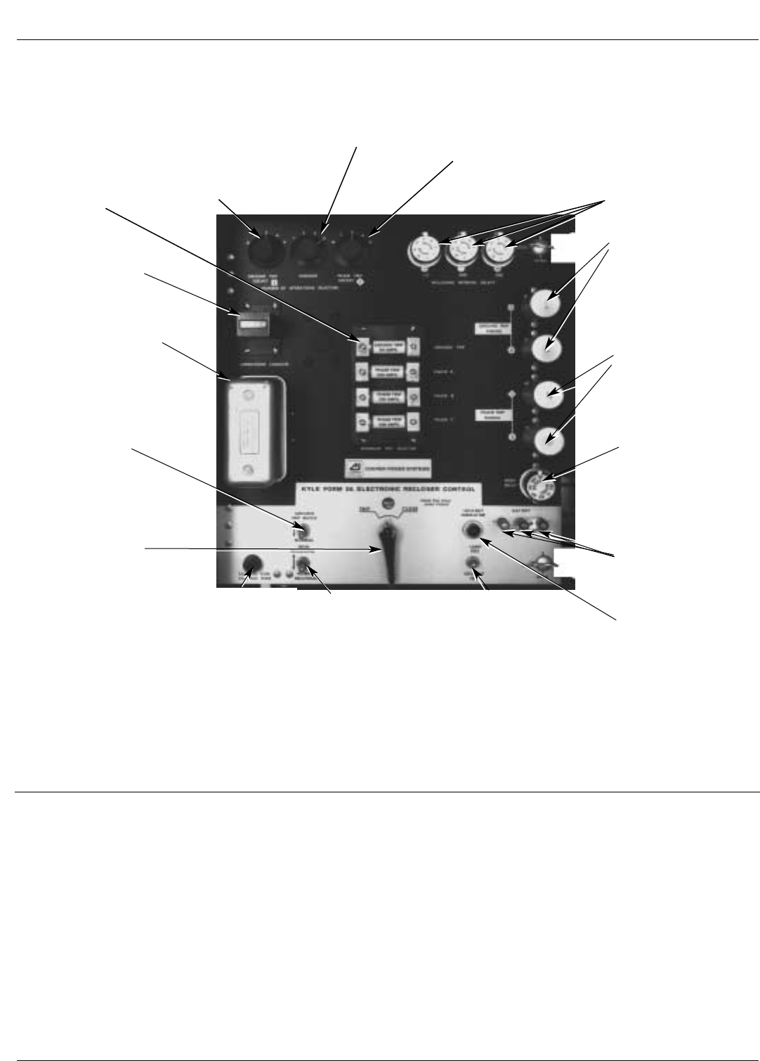
Control Panel
A swing-out front panel contains the programming and
operating elements of the control (Figure 2). The upper,
black portion of the front panel contains the plug-in com-
ponents and setting knobs for programming automatic
recloser operation. The switches and indicators used for
manual operation and service are grouped on the bottom,
light portion of the panel.
Minimum-Trip
Resistors
Establish the minimum-
trip current levels for
ground and each
phase; cartridges are
marked in primary
amps and clamped in
place.
Ground-Trip
Operation Switch
Blocks all ground tripping in the
BLOCK position: Prevents uninten-
tional tripping during single-phase
switching operations.
Ground-Trip Selector
Programs the number of fast
ground-trip operations as
defined by the timing plug in
Socket 1; the remaining
(slower) operations to lock-
out are defined by the plug in
ground-trip Socket 2.
Phase-Trip
Selector
Programs the number of fast
phase-trip operations as
defined by the timing plug in
Socket 1; the remaining
(slower) operations to lock-
out are defined by the plug in
Phase-trip Socket 2.
Reclosing Interval
Plugs
Determines the delay inter-
val for each closing opera-
tion. The delay value is
determined by the position
of the plug in the socket
adapter. An instantaneous
plug is available for the first
reclose interval only.
Ground-Trip Timing
Plugs
Provide a variety of current-
integrated timing curves on
individual plugs for coordi-
nating the ground-trip opera-
tion with backup and
downline protective devices.
Phase-Trip Timing
Plugs
Provide a variety of current-
integrated timing curves on
individual plugs for coordi-
nating the phase-trip opera-
tion with backup and
downline protective devices.
Reset-Delay Plug
Determines the delay inter-
val before the control
resets after a successful
reclosure during an opera-
tion sequence. The delay
value is determined by
position of the plug in the
socket adapter.
Battery Test
Terminals
Enable checking battery
voltage, charging rate, and
quiescent battery current
drain.
Lockout-Indicating
Signal Lamp
Provides visual indication
of control lockout.
Lockout Selector
Programs the total number
of operations to lockout.
Operation
Counter
Records the cumulative
trip operations of the
control.
Sequence Relay
Steps the control through
its operating sequence.
Manual Control
Switch
In the TRIP position, it
locks out the control,
advances the sequence
relay to lockout, and dis-
connects the battery
from the control circuits.
In the CLOSE position, it
moves the sequence
relay to the home posi-
tion, reconnects the bat-
tery, and closes recloser.
If held in the CLOSE
position, it will override
cold-load inrush; how-
ever, the control will lock
out for permanent faults.
Non-Reclosing
Switch
Sets the control for one-
trip to lockout without dis-
turbing the lockout setting
of the operations selector.
Lamp Test Lockout
Switch
Enables testing the signal
lamp and checking for
control lockout.
Control Fuse
Protects the closing solenoid
coil (on reclosers that employ
solenoid closing) if closing
voltage is too low. Connected
in series with the closing con-
tactor in the recloser on motor-
operated units; connected in
series with the contactor
rotary solenoid on reclosers
that employ solenoid closing.
Figure 2.
Front Panel of Form 3A Control.
911068KMA-E
S280-75-1
5
!
SAFETY
FOR LIFE
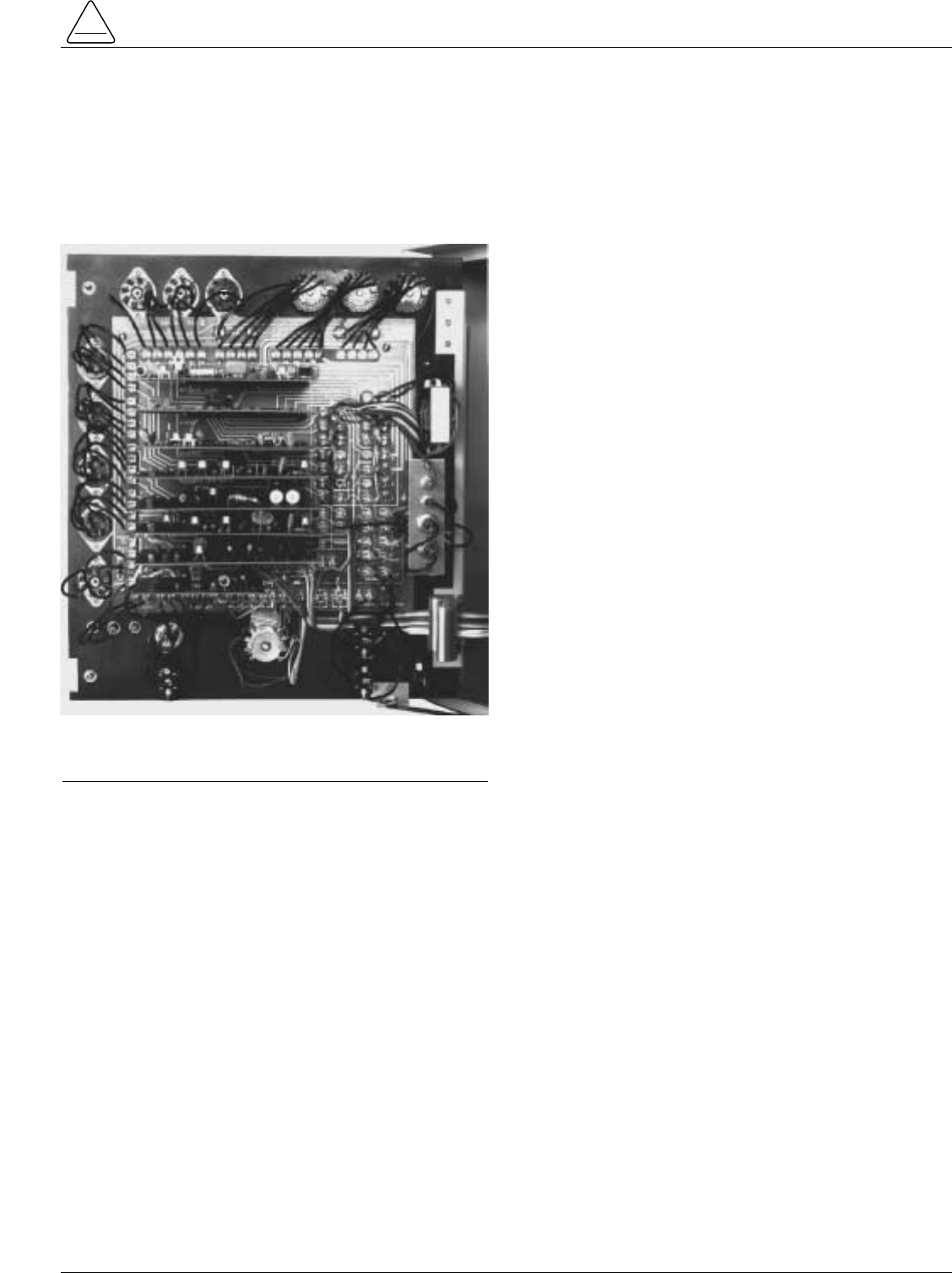
Tie Board
The front panel is backed by a printed-circuit tie board
which supports and interfaces the plug-in circuit boards
with other related circuit components (Figure 3). Program-
altering, remote-control, indicating, and general conve-
nience accessories can be added to further expand and
enhance the application capabilities of the control.
Phase- and Ground-Trip Protective Feature
The phase- and ground-trip protective feature extends the
maximum fault-current capability of the ME control to the
maximum interrupting rating of the recloser.
The phase- and ground-trip protection feature consists of
four Zener diodes bracket-mounted to the back panel
alongside the tie board (shown in Figure 3).
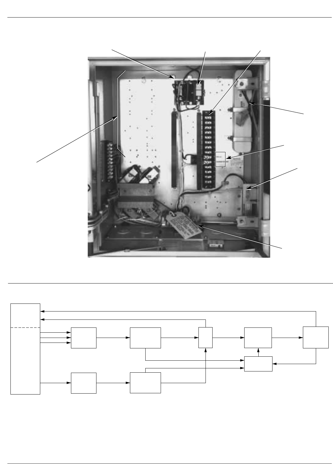
Back Panel
The control battery, cabinet heater, surge module for
auxiliary power supply, customer connections terminal
strip, and accessory boards are located inside the control
cabinet and on the back panel of the control as shown in
Figure 4.
Description of Control Operation
Line current flowing through the recloser is sensed
by three internally mounted bushing-current transformers
in the recloser, one on each phase. When the phase cur-
rent or the zero-sequence (ground) current exceeds its
programmed minimum-trip value, the electronic control
initiates the programmed sequence of recloser tripping
and reclosing operations. If the fault is temporary, the
control ceases to command recloser operations after the
successful reclosing, and the control resets to the start of
its operating sequence after a preset time delay. If the
fault is permanent, the control performs its complete pro-
grammed sequence of recloser commands and locks out
with the recloser open. Once locked-out, the control must
be manually reset to the start of its operating sequence,
which simultaneously closes the recloser.
Factory-calibrated timing plugs establish the time–current
characteristics for both phase and ground tripping. A set
of two individual timing curves provides dual timing for
both phase and ground.
A functional block diagram of the control operation is
shown in Figure 5. Line current conditions are monitored
continuously by three bushing-type current transformers
in the recloser, one on each phase. Output of these trans-
formers is fed to the trip network in the control, which
includes the minimum-trip resistors, isolation transform-
ers, and rectifier circuits.
When current above the selected minimum-trip level is
detected in one or more phases, the following chain of
events will occur for an operating sequence of two fast
and two delayed operations:
The overcurrent signal is integrated with time on the char-
acteristic curve of the timing plug in Socket 1 to produce
the signal which energizes the trip circuit. Energizing the
trip circuit connects the battery to the trip solenoid to trip
open the recloser. Simultaneously, the sequence relay
advances to energize the first reclosing interval-delay
plug. Upon expiration of this reclosing interval delay, a
closing signal from the control closes the recloser, and the
sequence relay sets up the circuitry for the second fast trip
operation.
If current remains above the minimum-trip level, the trip-
ping—reclosing sequence of fast and delayed operations
is repeated, as programmed, to lockout.
If the overcurrent is cleared before the operating
sequence reaches lockout, the reset-delay circuit starts
timing when the recloser closes into the un-faulted line.
When the reset-delay plug times out, the sequence relay
is reset to the start or home position and the control is
ready for another two-fast, two-delayed trips operating
sequence. However, should the fault recur before the
reset plug times out, the control will continue its operating
sequence where it left, and the reset delay timing will be
erased.
Ground-fault sensing and tripping operations occur
exactly the same as phase sensing and tripping, except
that zero-sequence (ground) current is sensed instead of
phase current. The ground-fault circuitry includes its own
minimum-trip resistor, fast and delayed trip timing plugs,
and number of fast operations setting. Reclose and reset
intervals and operations to lockout are common for both
phase-trip and ground-trip modes of operation.
Figure 3.
Tie Board on Back of Front Panel Mounts the
Individual Printed Circuit Boards.
911069KMA-F
6
Form 3A Type ME Electronic Control Installation, Operation, and Testing Instructions
Figure 5.
Functional Block Diagram of Form 3A Control.
RECLOSER
MECH-
ANISM
BCTs
PHASE
SENSING
NETWORK
GROUND
SENSING
NETWORK
LEVEL
DETECTION
AND
TIMING
LEVEL
DETECTION
AND
TIMING
TRIP SEQUENCE
RELAY
RESET
RECLOSE
Charger Ballast-Surge Protection
Circuit Board Battery Charger
Fuse Block Switch Customer Connections
Terminal Strip
Control
Battery
Battery
Plug
120 Vac
Input Terminals
Accessory
Mounting
Locations
Control Cable
Receptacle Card
Figure 4.
Inside Back Panel of Form 3A Control.
911070KMA-F
Control Battery
Power to operate the tripping and reclosing solenoids in
the recloser is provided by a 24 volt, nickel-cadmium bat-
tery located in the back, upper right corner of the control
cabinet. A temperature-regulated 120 Vac potential bat-
tery charger, built into the control circuitry, provides a tem-
perature compensated charging current to the battery. All
Form 3A controls require a 120 Vac input to the con-
trol to energize the battery charger.
If 120 Vac cannot be provided to the control, the recloser
must be equipped with a factory-installed battery charger
accessory.
A. In solenoid-operated reclosers (RVE, RXE, VWE,
VWVE27, VWVE38, WE, and VWE) a BCT accessory
must be added to the recloser to obtain charging
power from the line.
Note: Line current flow through the recloser must be a
minimum of 40 amps for at least 12 hours per day to
provide sufficient charging power.
B. In motor-operated reclosers (CXE, VSA12, VSA16,
VSA20, VSO12,VSO16, and VSML), a potential-type
battery charger accessory must be added to obtain
charging power from the 240 Vac auxiliary power
source of the recloser.
Battery Check Procedures
Follow the check battery procedures to check the battery
voltage, quiescent drain, and charging rate. The values in
the test procedure is based on testing at 25˚ C (77˚ F).
Note: The control does not need to be connected to a recloser
for the battery check tests.
Check Battery Voltage Procedure
1. Remove the control from service. Refer to the To
Remove Control from Service section in this manual.
2. Disable the control battery charger by opening the
fused switch or removing the AC power from the con-
trol. Wait 3 to 5 minutes to allow the battery voltage to
stabilize prior to testing the open circuit battery voltage.
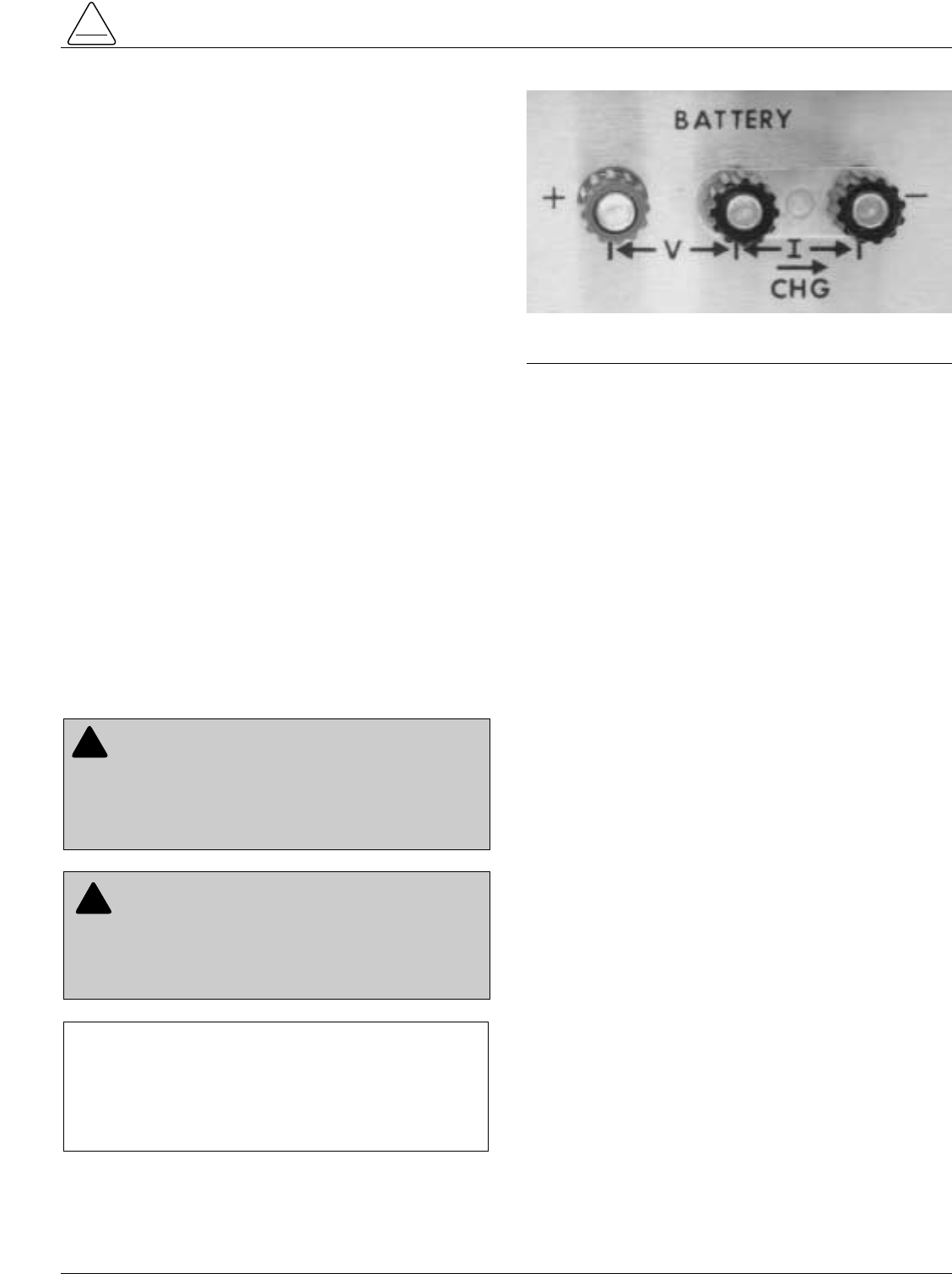
3. Three battery test terminals in the lower right corner of
the front panel are used to check the battery voltage,
quiescent drain, and charging rate (Figure 6). The left
hand pair of terminals (V) are connected directly
across the battery to check battery voltage. The red
terminal (far left) is battery positive (+).
4. The battery in the control will experience a steady
drain of approximately 1.5–2.5 mA (may be as high as
4.5 mA with certain accessories).
5. Measure the battery voltage from the battery test ter-
minals on the control front panel. If battery voltage is
below 24 volts, the battery is either low on charge or
failing. The battery should be removed for recharging
and retested before returning to service.
6. If battery voltage is above 24 volts, perform the fol-
lowing load test. While measuring battery voltage,
connect a 10Ω, 10 watt resistor across the battery test
terminals for approximately 2–3 seconds. For ambient
temperatures above -6˚C (20˚F), battery voltage
should drop by no more than 3 volts from the open cir-
cuit voltage.
Note: Either a KA638ME voltmeter accessory or a KMET
Tester can be used for the load test. Both devices
have a built in 10Ωload resistor.
7. If the temperature is below -6˚C (20˚F), the battery
voltage/temperature should follow the lower curve in
Service Information S280-75-2 Figure 53. If the volt-
age falls below the lower curve, the battery should be
removed for bench testing.
S280-75-1
7
!
SAFETY
FOR LIFE
CAUTION: Equipment damage. Shorting battery
positive to battery negative at the battery test ter-
minals on the control panel will cause damage to the
control. The control will be inoperative and possible
misoperation (unintentional operation of the recloser)
can result. T214.1
!
CAUTION: Recloser misoperation. The control
must be removed from service before disconnect-
ing the control battery. Disconnecting the control battery
from an in-service control may cause recloser misoper-
ation (unintentional operation). Failure to comply can
result in equipment damage and personal injury. T213.4
!
Figure 6.
Battery Test Terminals.
86847KMA-D
IMPORTANT: Battery voltage and charge current
measurements can be made while the control is in ser-
vice, from the test terminals provided on the face of the
control panel. The control must be taken out of service
for all other battery maintenance, battery replacement,
or battery drain tests.
Check Battery Quiescent Drain and Charging
Rate Procedure
The righthand pair of terminals (-I-) are connected in
series with the negative battery lead to check quiescent
drain and charging rate. Proceed as follows:
1. Remove the control from service. Refer to the To
Remove the Control from Service procedure in the
Programming and Operating the Control section of
this manual.
2. Set the control to the home (reset) position by moving
manual operator to CLOSE.
3. Plug a dc milliammeter into the current test terminals.
Loosen both terminals slightly and disconnect the
shorting link from between terminals.
4. With the battery charger de-energized, current will
flow opposite to the direction shown by CHG. Under
normal conditions, quiescent drain will be 1-1⁄2 to 2 mA.
However, the shorter time reset plugs and certain
accessories can, as shown in Table 1, increase the
quiescent drain above nominal value.
Note: To verify the charge/discharge polarity of the test
meter, momentarily actuate the LAMP TEST/LOCK-
OUT TEST toggle switch to LAMP TEST. The dis-
charge current is measured.
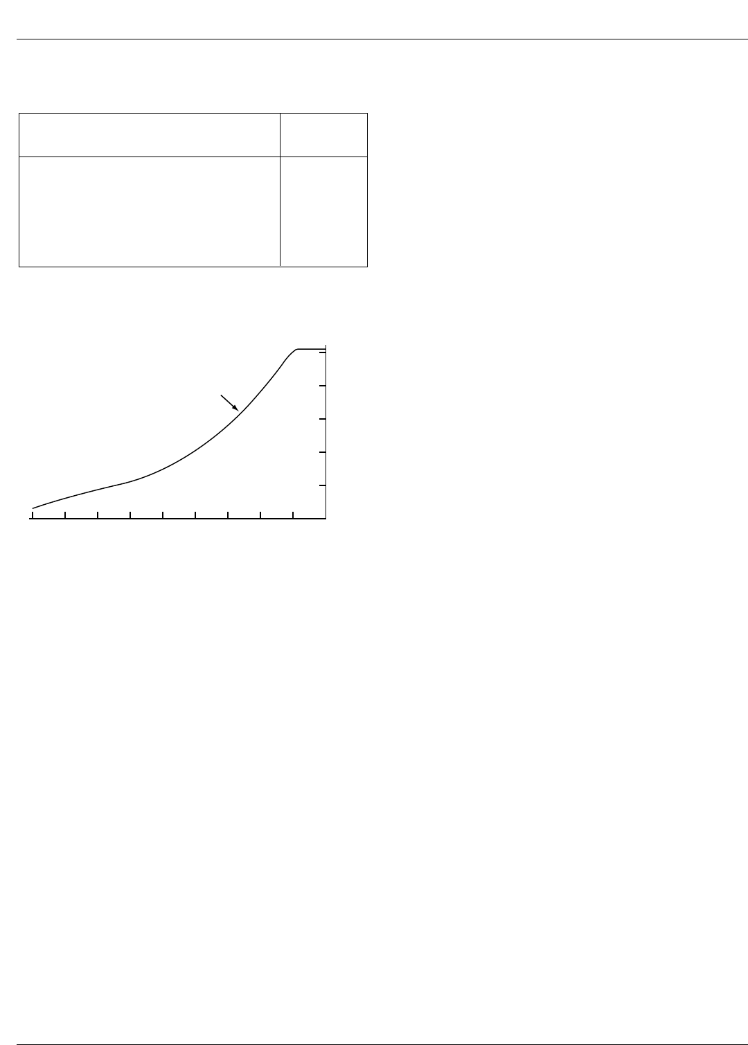
5. With the battery charger energized, current will flow in
the direction shown by CHG. The charging circuit
used in the control is temperature regulated. The
charging rate will vary depending on the internal con-
trol temperature, see Figure 7.
6. Replace and tighten the shorting link between the cur-
rent terminals before removing the ammeter.
Note: Bypass diodes in the battery circuit prevent the control
from being disabled if the link is inadvertently left
open.
8
Form 3A Type ME Electronic Control Installation, Operation, and Testing Instructions
DESCRIPTION DRAIN
(mA)
3-second reset plug
10-second reset plug
Sequence coordination accessory
(when control is in home position)
Remote minimum-trip doubler
(supervisory contacts closed)
Targets
2.3
0.8
0.8
6
1.9
Table 1
Quiescent Battery Drain Above Normal
0
10
20
30
40
50
120 -40 -20 0 20 40 60 80 100 140
INTERNAL CONTROL TEMPERATURE (°F)
CHARGING RATE (MA)
TEMPERATURE-
REGULATED
CHARGER
Figure 7.
Comparison of Charging Rates.
Temperature-Regulated Battery
Charger
All Form 3A Type ME controls, serial number 50070 and
above, are equipped with a temperature-regulated battery
charger as standard equipment.
Description
The temperature-regulated battery charger provides pro-
tection against battery drain and premature battery failure
at high ambient temperatures. As the temperature
increases, the self discharge rate of the control battery
increases. The temperature-regulated battery charger
compensates for this self-discharge by providing higher
charging rates at higher temperatures.
Operation
The temperature-regulated battery charger consists of a
charger ballast-surge protection card and a plug-in battery
charger circuit board. It provides an increased charging
rate proportional to the temperature inside the control cab-
inet (see Figure 7).
S280-75-1
9
!
SAFETY
FOR LIFE
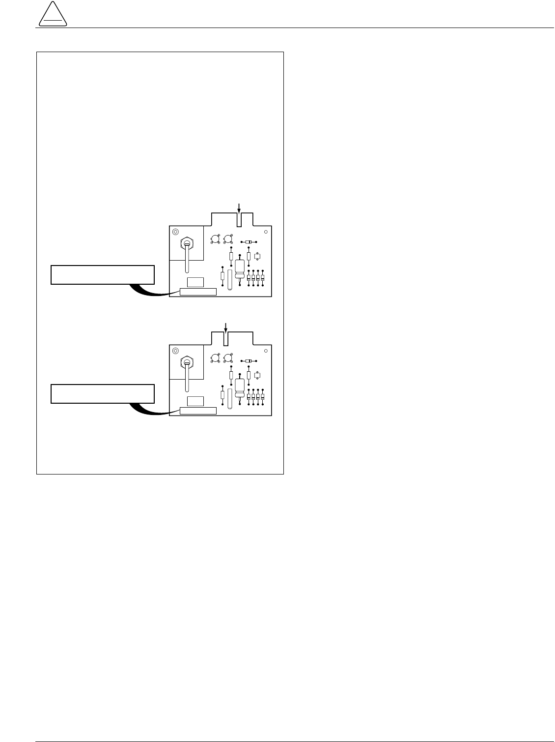
IMPORTANT
Beginning with control serial number 53381, the key
slot position of the battery charging board socket has
been changed. The key slot on the temperature-regu-
lated charging board (MEA1172, 120/240 Vac) has
been moved to match the socket arrangement. The
new charging board can be identified by the revision 6
or above marking adjacent to the part number. A blue
label affixed to the accessory list location guide label,
inside the control door, identifies the new temperature-
regulated battery charging board.
Note: Controls equipped with CT or potential charger in the
recloser are unaffected by this change. They will
continue to use the MEA 388-1 charging board, with
the key in the original position.
MEA 1172
BATT. CHARGER REV.
5
MEA 1172
BATT. CHARGER REV.
5
MEA 1172
BATT. CHARGER REV.
5
MEA 1172
BATT. CHARGER REV.
5
KEY SLOT C
OLD STYLE MEA 1172 REV. 5 AND BELOW
NEW STYLE MEA 1172 REV. 6 AND ABOVE KEY SLOT H
The Form 3A control is preset at the factory for an auto-
matic sequence of operations as specified on the order
and should not be disturbed by unauthorized personnel.
Changes in the control operating parameters should be
made only by a qualified technician or engineer. The con-
trol must be removed from service prior to making any
changes to programmed settings.
The plug-in components and selector switches for pro-
gramming the control are located on the black, upper por-
tion of the control panel.
To Remove the Control
from Service
Prior to changing plug-in components, performing control
maintainence, making programming changes, or replac-
ing the battery on an in-service control, the following
steps must be taken to prevent possible recloser misop-
eration.
1. Switch Ground Trip Block switch to BLOCK.
2. Disconnect control cable from control.
3. De-energize potential battery charger, by opening the
battery charger fuse block switch (shown in Figure 4).
4. Operate the Manual Control switch to OPEN.
5. Unplug the control battery.
To Return the Control to Service
After required work is completed, return the control to ser-
vice with the following steps:
1. Check that all plug-ins are properly installed and con-
trol settings are correct.
2. Connect control battery.
3. Close the battery charger fuse block switch to ener-
gize the potential battery charger.
4. Move Manual Control switch to CLOSE, to ensure that
control is reset to the home position.
5. Reconnect the control cable to the control.
6. Switch Ground Trip Block switch to NORMAL.
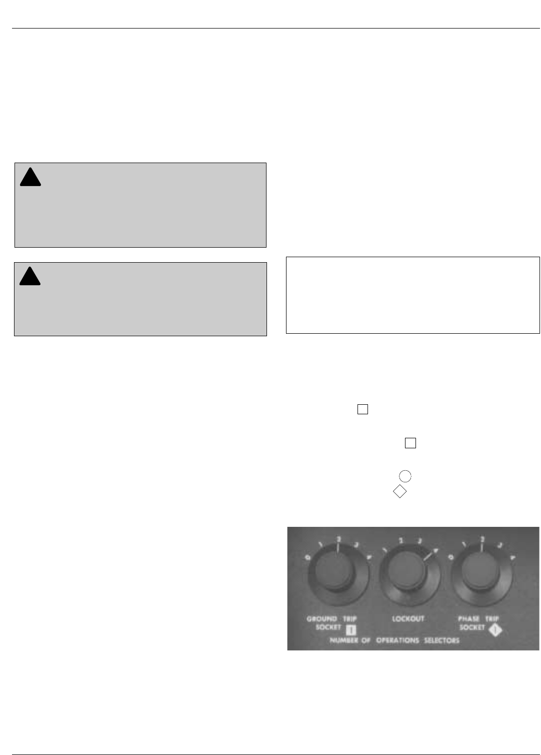
Number of Operations Selectors
The three selector knobs in the upper left corner of the
panel (Figure 8) establish the operating sequence of the
control. From one to four total operations to lockout can
be selected on the center LOCKOUT knob. GROUND
TRIP SOCKET 1 selector knob to the left establishes the
number of ground trip operations (0 to 4) according to the
time–current characteristic curve of the timing plug in
GROUND TRIP SOCKET 1 . The balance of the ground-
trip operations to lockout are then performed according to
the characteristic curve of the timing plug in GROUND
TRIP TIMING SOCKET 2 .
PHASE TRIP SOCKET 1 selector knob to the right per-
forms the same function for phase-trip sequence selection.
10
Form 3A Type ME Electronic Control Installation, Operation, and Testing Instructions
PROGRAMMING AND OPERATING THE CONTROL
IMPORTANT: Battery voltage and charge current
measurements can be made while the control is in ser-
vice from the test terminals provided on the face of the
control panel. The control must be taken out of service
for all other battery maintenance, battery replacement,
or battery drain tests.
CAUTION: Equipment damage. Never operate
the control without a full set of proper circuit boards
and time-current curve plugs in the no. 2 trip-timing
sockets for both phase and ground. Failure to comply
will result in misoperation of the control and recloser.
T215.1
!
CAUTION: Equipment misoperation. Do not con-
nect this control to an energized recloser until all
control settings have been properly programmed and
verified. Refer to the programming information for this
control. Failure to comply can result in control and
recloser misoperation, equipment damage, and per-
sonal injury. G110.3
!
Figure 8.
Ground-Trip, Lockout, and Phase-Trip Operation
Selectors.
911068KMA-A
S280-75-1
11
!
SAFETY
FOR LIFE
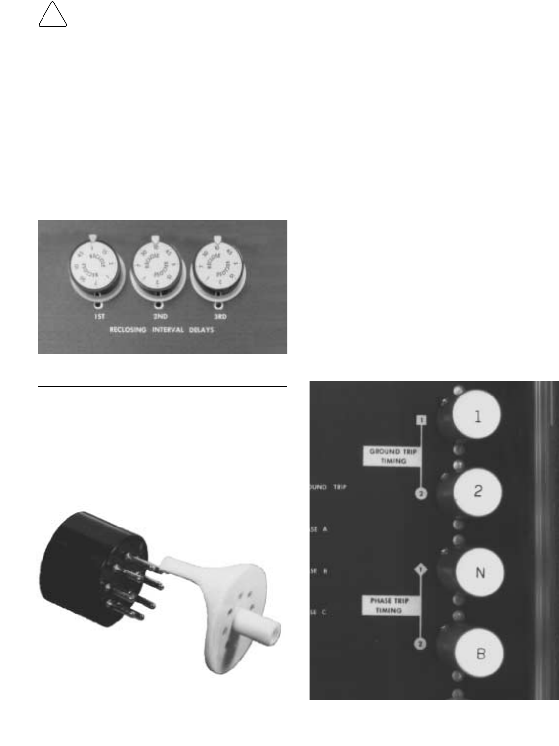
Reclosing Interval Timing Delay
Selectors
Depending upon the number of operations to lockout,
one, two, or three reclosing intervals (each individually
timed) can be programmed. The reclosing intervals are
established by the solid-state timing plugs in the upper
right corner of the panel (Figure 9). Times of 1, 2, 5, 7, 10,
15, 30, and 45 seconds are available on a multiple-setting
plug (Figure 9). The small white arrow at the top of the
plug indicates the value selected. Selection is determined
by the position of the plug in the socket adapter (Figure
10). INST (instantaneous) and 60 second, single-value
plugs are also available. Single value plugs do not use the
socket adapter.
The INST reclosing interval plug may be used only in the
first reclosing interval socket. The instantaneous reclos-
ing interval time will vary depending upon the recloser on
which the control is used; the approximate values are:
CXE recloser....................................................... .67 sec.
ME recloser......................................................... .63 sec.
RVE, RXE, VWE, VWVE27, VWVE38, WE,
WVE reclosers .................................................... .67 sec.
VSA12, VSA16, VSA20, reclosers ...................... .50 sec.
The INST reclosing interval plug must not be used with
the Type VSO recloser. No reclosing interval shorter
than 1⁄2 second should be programmed into the Type ME
control when it is used with the Type VSO recloser. A 1⁄2
second reclose plug is available (ordered by KA1177ME-
1). If an instantaneous (INST) plug is used for the first
reclosing interval, it will result in a 12 cycle reclosing time,
which may be too short to permit arc deionization at the
fault location.
Minimum-Trip Resistor
Cartridges
The recloser minimum-trip current ratings are established
with the plug-in resistor cartridges in the center of the con-
trol panel. The cartridges, labeled with their minimum-trip-
current values, are identified for GROUND TRIP (one
required), or PHASE TRIP (three required). All three
phase-trip cartridges should have the same current rating.
All Kyle electronic reclosers, except VSA20, VS020, and
discontinued Types ME and VSMT, use a yellow label
minimum-trip resistor cartridge. Blue label cartridges are
used with 2000:1 sensing CTs in the higher current rated
VSA20 and VS020 reclosers and are not interchangeable
with yellow label resistors.
Figure 9.
Reclosing Interval Plugs with Multiple Delay Settings.
86837KMA-B
Figure 10.
Time is Determined by Position of Plug in Socket
Adapter.
82288KMA-F
Figure 11.
Ground-and Phase-Trip Time-Current Curve Plugs.
911068KMA-D
12
Form 3A Type ME Electronic Control Installation, Operation, and Testing Instructions
Yellow label minimum-trip resistor cartridges are available
in the following minimum-trip-current ratings:
Ground: 25, 35, 50, 70, 100, 120, 140, 170, 200, 240,
280, 340, 400, 480, and 560 amps;
Phase: 100, 120, 140, 170, 200, 240, 280, 300, 340,
400, 480, 560, 600, 800, 960, and 1120 amps.
Blue label cartridges are available in the following mini-
mum-trip-current ratings:
Ground: 100, 140, 200, 240, 280, 340, 400, 480, 680,
800, 960, and 1120 amps;
Phase: 200, 240, 280, 340, 400, 480, 560, 600, 680,
800, 960, 1120, 1200, 1360, 1600, 1920,and 2240
amps.
Ground- and Phase-Trip Timing
Plugs
Time-current curves for both phase and ground tripping
are established by the four plugs along the right edge of
the control panel (Figure 11). Individual plugs for 20
phase-trip timing curves and 16 ground-trip timing curves
are available. (See Reference Data TCC Index R280-91
for time-current curves).
When dual-timing operation is programmed, the timing
characteristic curve in Socket 1 always precedes the
curve in Socket 2. When single-timing operation is pro-
grammed, the timing plug is installed in Socket 2 and the
number of fast operations selector knob is set on zero.
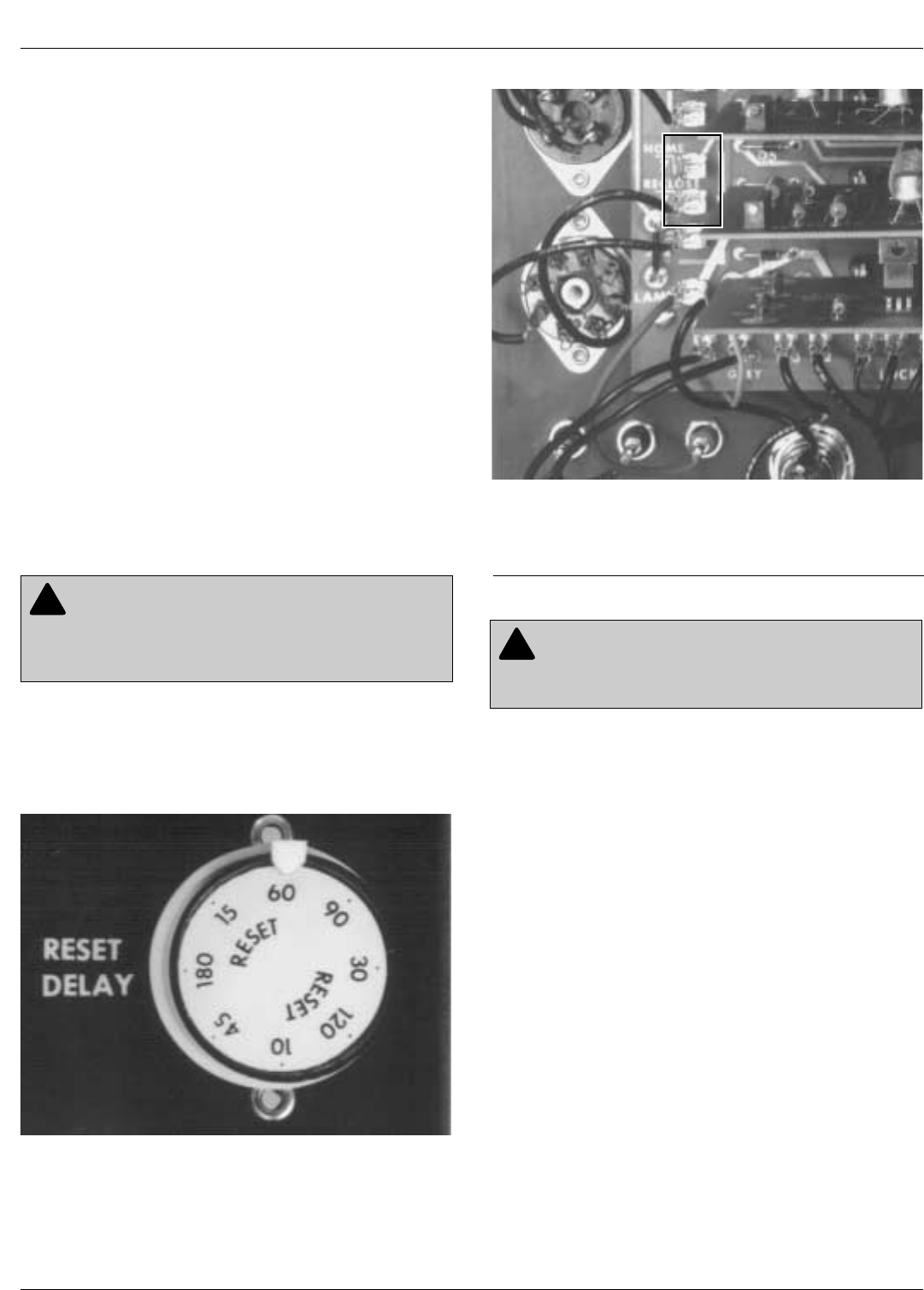
Reset Delay Selector
For temporary faults that are cleared before lockout
occurs, reset timing starts after a successful reclosure
(current is below minimum trip). The reset time is estab-
lished by a timing plug similar to, but not interchangeable
with, the reclosing interval plug. The reset delay plug (Fig-
ure 12) is located on the lower right hand portion of the
control panel. Times of 10, 15, 30, 45, 60, 90, 120, and
180 seconds are available on a multiple setting plug and
are determined by the position of the plug in the socket
adapter (Figure 10). A 20 second, single-value plug is
also available.
Note: The selected reset delay time must be longer than the
longest reclosing interval of any load- or source-side pro-
tective device with which the recloser is to coordinate.
CAUTION: Recloser misoperation. Socket 2
must always be provided with a timing plug; other-
wise phase tripping is blocked and ground tripping may
be instantaneous. T218.1
!
Figure 12.
Reset Delay Selector.
86847KMA-B
Figure 13.
Control Operation can be changed from “reset-timed-
from-successful-reclose” (standard) to “reset-timed-
from-first-trip-operation.”
911069KMA-B
CAUTION: Recloser misoperation. Ground- and
Phase-trip timing plugs are not interchangeable.
They must only be installed in the corresponding sock-
ets. Failure to comply will cause misoperation of the
control. T217.1
!
S280-75-1
13
!
SAFETY
FOR LIFE
Reset Timed from First
Trip Operation
The Form 3A control can be converted to reset-timed-
from-first-trip operation, if so desired, by removing a
jumper on the tie board and moving a lead from the push-
on tab labeled RECLOSE to an adjacent tab labeled
HOME (Figure 13). However, under this reset mode, the
time selected must exceed the longest possible tripping
and reclosing sequence that can be experienced. Mini-
mum-fault currents (which provide the longest tripping
times) must be considered.
Operating Switches and
Indicators
The switches and indicators for manual operation and
service are grouped on the lower, light colored portion of
the control panel (Figure 14).
Manual Control Switch
Located in the center of the lower panel, the manual con-
trol switch enables manual closing and tripping of the
recloser. Moving the switch to TRIP opens the recloser,
locks out the control, and disconnects the battery from the
control circuits. Moving the switch to CLOSE reconnects
the battery, resets the control to home, and closes the
recloser.
A cold-load pickup feature is built into this switch. Holding
the switch in CLOSE will disconnect the no. 1 timing plug
for both phase and ground trip and set the control to oper-
ate on the slower no. 2 plugs. While the switch is held in
this position, the control is still free to trip and lock out if
closed into a fault. However, all operations to lockout will
occur on the no. 2 trip-timing plugs.
Ground-Trip Operation Switch
The ground-trip operation of the control is disabled when
this switch is set to BLOCK. Blocking ground-trip opera-
tions is useful during known periods of three-phase load
unbalance and while performing single-phase testing or
switching.
Non-Reclosing/Normal Reclosing
Switch
To meet specific local safety requirements during startup
or service restoration, the control can be set to block
reclosing after an automatic trip (one-shot-to-lockout-
operation) by setting the operating mode switch to NON-
RECLOSING. Returning this switch to NORMAL
RECLOSING after a successful reclose will ready the
control for its full programmed operating sequence.
Figure 14.
Lower Portion of Front Panel of Control.
9110068KMA-CD
WARNING: This equipment is not intended to
protect human life. Follow all locally approved pro-
cedures and safety practices when installing or operat-
ing this equipment. Failure to comply can result in death,
severe personal injury and equipment damage.
G102.1
!

Lockout Indicator
Verification of control lockout consists of an indicator lamp
and a momentary double-throw toggle switch. In the
LOCKOUT TEST position, the lamp will light if the control
is locked out; the LAMP TEST position verifies the condi-
tion of the lamp.
Proper verification of the recloser status must include
examination of both the control lockout indicator and a
visual check of the position of the mechanical contact
position indicator on the recloser.
Battery Terminals
These terminals provide a means for checking the condi-
tion of the battery. Refer to the Battery Check Proce-
dures in the Control Battery section in this manual.
Closing Coil Control Fuse
On solenoid-operated reclosers, the fuse will open the
closing circuit to protect the potential closing coil in the
recloser if closing cannot be accomplished due to low
closing voltage. On motor-operated reclosers, the fuse is
connected in series with the closing circuit contactor in the
recloser.
A Buss Type MDQ-3/8 amp, 250 volt fuse, manufactured
by Bussman Manufacturing is used and a box of five
spare fuses is supplied with each control. Fuses of similar
ratings by other manufacturers have slightly different
characteristics and should not be used for replacement.
Note: In 1988, Buss redesigned the MDL-2.5 amp fuse that is
used on controls shipped with reclosers having "quick-
close" mechanisms such as Type VSO reclosers. The
characteristics of the new single element MDL-2.5 fuse
do not affect the application in the control. Buss will also
continue to manufacture the original dual element ver-
sion of the fuse under the new designation of MDQ-2.5.
The MDQ-2.5 amp fuse will be supplied with controls for
this application. Both the MDL-2.5 amp fuse and the
MDQ-2.5 amp fuse are acceptable for this application.
14
Form 3A Type ME Electronic Control Installation, Operation, and Testing Instructions
IMPORTANT: The lockout indicator will only accu-
rately reflect the state of the control. It does not monitor
the recloser mechanism and may not accurately reflect
the position of the recloser contacts.
IMPORTANT: Use only Buss Type MDQ-3/8 amp
fuses. Until 1988, all Form 3A and most earlier controls
were supplied with Buss Type MDL-3/8 amp fuses.
Buss has redesigned and changed the characteristics
of that fuse and it is no longer suitable for use on any
Form 3 or Form 3A control. Failure to use proper clos-
ing coil control fuse will result in unnecessary fuse oper-
ation and prevent the recloser from closing.
This control is used in conjunction with a Kyle electroni-
cally controlled recloser. Installation instructions for the
recloser are packed with the recloser. Refer to the appro-
priate recloser installation manual when installing the con-
trol and recloser.
Mounting the Control
The Form 3A Type ME electronic recloser control can be
mounted at any convenient, accessible location near, or
remote from, the recloser.
1. For pole-mounted installations, this is normally near
the base of the pole.
2. For substation installations, brackets are available as
a mounting frame accessory for mounting the control
to the substation frame.
Limits on control cable length determine the maximum
distance between the control and recloser: up to 125 feet
for solenoid-operated reclosers RVE, RXE, VWVE27,
VWVE38, WE, WVE; up to 35 feet for motor-operated
reclosers CXE, VSA12, VSA16, VSA20, and VSML.
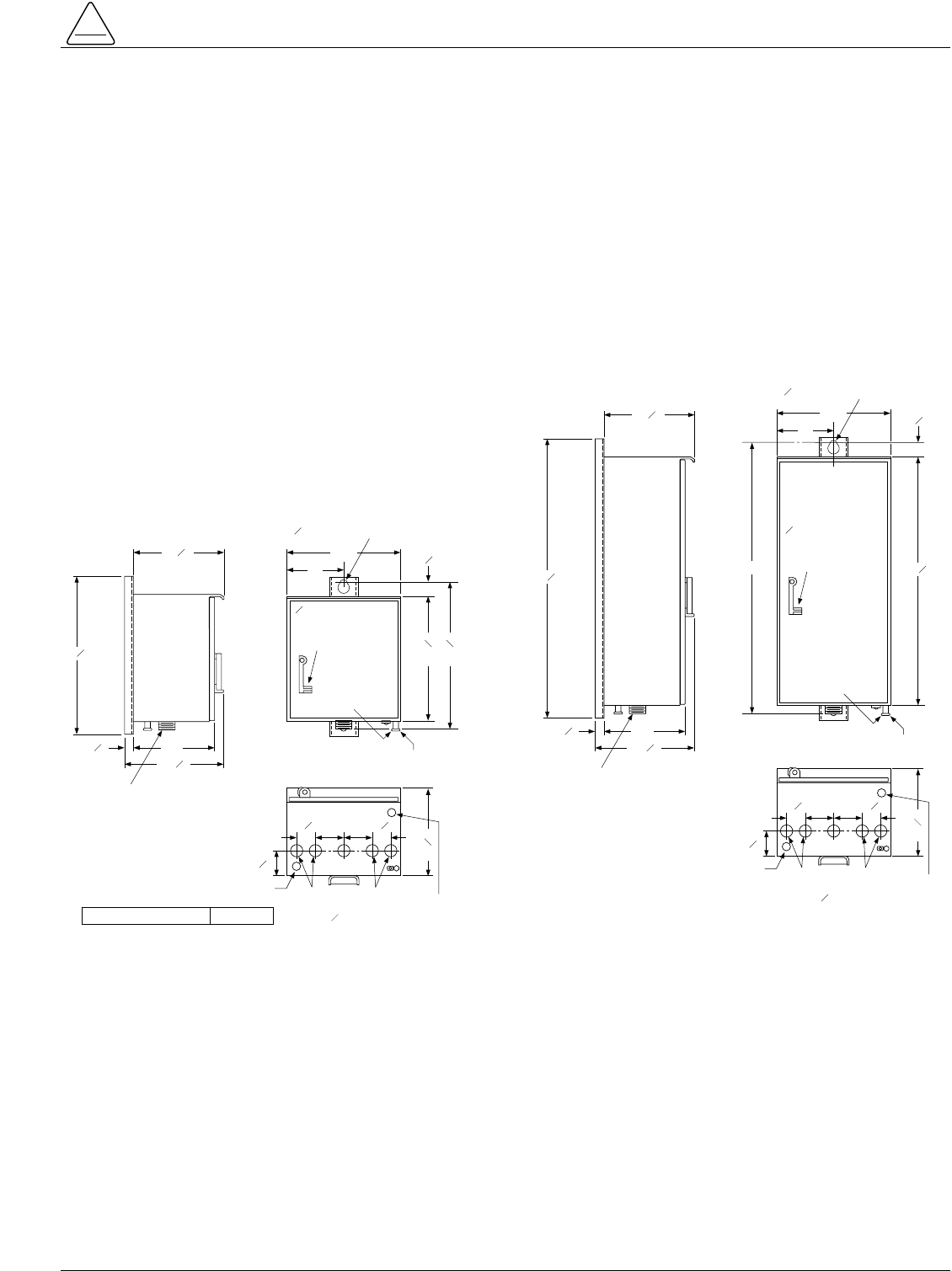
Outline, mounting, and knockout dimensions are shown in
Figure 15 for the standard control cabinet and Figure 16
for the double-size control cabinet.
15
S280-75-1
INSTALLATION PROCEDURE
!
SAFETY
FOR LIFE
12316
"
22532
"
11"
1312"
1516
"
MALE RECEPTACLE
FOR CONTROL CABLE
16"
8"112"
1778 "
DIAMETER
HOLE PROVIDED
FOR CUSTOMER
LOCK
2018"
GROUNDING
TERMINAL
LUG
NO. 14 TO NO. 4
STRANDED
MTG HOLES FOR
MAX BOLT DIA
58"
4-ELECTRICAL
KNOCKOUTS
( DIA)
12316
"
VENT
VENT
334"
58"
1316
"
21"442
1"
CONTROL WEIGHT 70 LBS.
22
Figure 15.
Standard Cabinet Mounting Dimensions. Figure 16.
Double-size Cabinet Mounting Dimensions.
1516
"
212"4"4"
4-ELECTRICAL
KNOCKOUTS
( DIA)
12316
"
VENT
VENT
334"
212"
12316
"
39132
"
11"
1312"
MALE RECEPTACLE
FOR CONTROL CABLE
1316
"
16"
8"112"
3434 "
DIAMETER
HOLE PROVIDED
FOR CUSTOMER
LOCK
37"
GROUNDING
TERMINAL
LUG
NO. 14 TO NO. 4
STRANDED
MTG HOLES FOR
MAX BOLT DIA
58"
58"
Form 3A Type ME Electronic Control Installation, Operation, and Testing Instructions
16
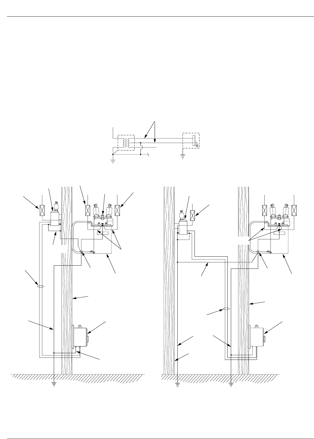
Grounding the Control
The control cabinet must be grounded. A grounding con-
nector on the underside of the cabinet will accommodate
no. 14 solid through no. 4 stranded conductors. (Figures
15 and 16). Be sure to follow all locally approved ground-
ing procedures when installing the control. Suggested
methods for grounding the control are shown in Figures
17 and 18.
The installation must meet the following requirements:
1. The recloser and transformer are protected with light-
ning arresters.
2. The transformer tank is grounded.
3. The recloser head is grounded.
4. Secondary cables must be shielded or Triplex cables.
Note: If the control is mounted on a recloser frame which
itself is grounded, a separate lead from the cabinet
to earth ground is not required but may be added.
Figure 17.
Recommended Grounding Method for Form 3A
Control with Local Supply Voltage Transformer.
Figure 18.
Recommended Grounding Method for Form 3A
Control with Remote Supply Voltage Transformer.
LIGHTNING
ARRESTER
RECLOSER
HEAD
GROUND
LIGHTNING
ARRESTER
TRANSFORMER
LIGHTNING
ARRESTER
SECONDARY
NEUTRAL ARRESTER
GROUND
RECLOSER
COMMON
GROUND
TIE POINT
POLE
SUPPLY
VOLTAGE
POLE
GROUND FORM 3A
CONTROL
CONTROL
GROUND
TRANSFORMER
LIGHTNING
ARRESTER
ARRESTER
GROUND
POLE
RECLOSER
COMMON
GROUND
TIE POINT
FORM 3A
CONTROL
POLE
POLE
GROUND
SUPPLY
VOLTAGE
* GROUND TIE
(#4 CONDUCTOR
OR LARGER)
** NEUTRAL WIRE
*3 WIRE UNIGROUNDED SYSTEM
** 4 WIRE SYSTEM
SUPPLY
VOLTAGE
TRANSFORMER ME CONTROL
TO NEUTRAL
OR GROUND TIE
ELECTRICAL CONNECTIONS
Control Cable
A 7 ft. cable is furnished as standard with the control-
recloser package. This length is sufficient for most sub-
station mounting frame installations. For other
installations, cable lengths as specified on the order are
provided.
The cable is fabricated with connectors which mate with
the female receptacle of the recloser on one end and the
male receptacle of the control on the other.
Note: The control cable must be supported along its length to
prevent repeated movement due to wind or other out-
side forces which can damage the cable.
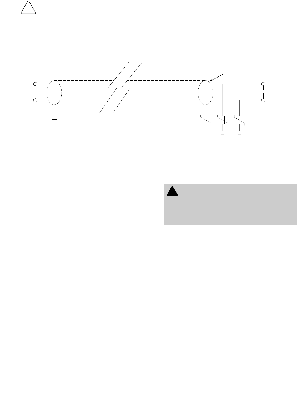
Shielding and Surge Protection
of Remote Cables
All remote operation and control monitor leads should be
protected within shielded cables. This is particularly
important if the remote cables are routed near other
cables or devices that emit strong magnetic fields. The
cable shield must be grounded at the Form 3A control
only, see Figure 19.
Note: In order to protect a remote device(s) from high-voltage
surges, all remote operation and monitor leads must be
protected with metal oxide varistors (MOV's), see Figure 19.
Use Harris V320LA40B varistors, (320 Vac, 160 J), or
equivalent.
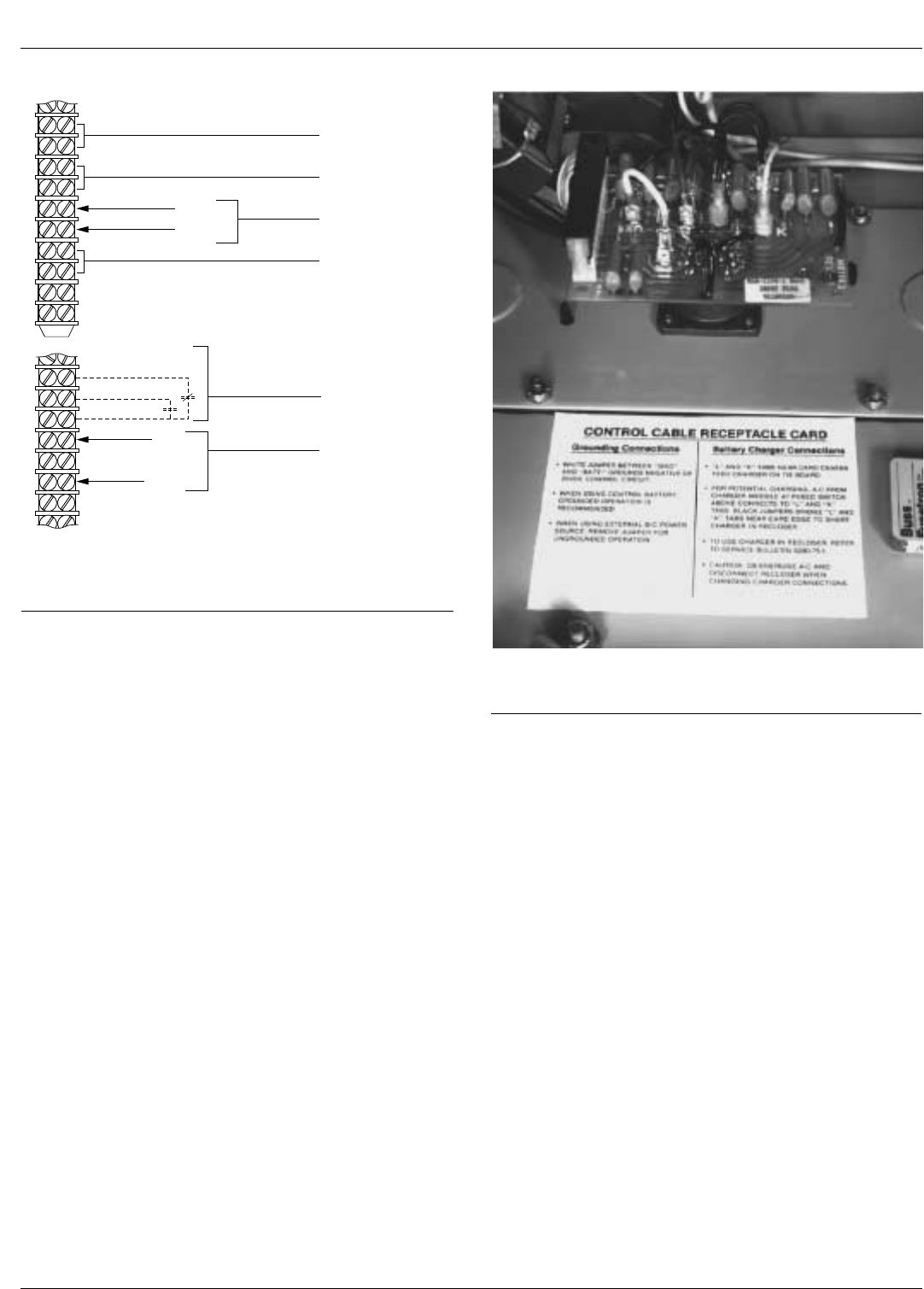
Customer Connections Terminal
Strip
All Form 3A controls require 120 Vac auxiliary power to
operate the battery charger and energize the control cab-
inet heater; both are standard features of the control.
Auxiliary power connections and connections for remote
operation of certain accessories are made on a 14 point
terminal strip mounted vertically on the back panel of the
control. Figure 20 shows two partial detail views of the ter-
minal strip to indicate the customary connection terminals
for the various accessories. However, deviations may
occur to accomodate certain combinations of acces-
sories. All terminals for required connections are clearly
marked.
The minus side of the 24 Vdc control circuit is grounded to
the cabinet at the input cable receptacle card in the bot-
tom of the cabinet by a white jumper lead connected
between tabs GND and BATT-. When an external dc
power source accessory is used instead of the battery,
remove the jumper to make sure there is no interaction
between station ground and earth ground.
Note: A 27 ohm resistor on the receptacle card, in series with
the grounding jumper lead, will limit the short-circuit cur-
rent to nondestructive levels in case of momentary acci-
dental grounding of the plus side of the circuit. A
sustained short will cause the resistor to overheat and
eventually burn out. This condition, however, will not
affect control operation.
17
S280-75-1
!
SAFETY
FOR LIFE
Figure 19.
Shielding and Surge Protection of Remote Cables.
FORM 3A CONTROL REMOTE
CABINET
SHIELD
MOV's
REMOTE
CONTACT
WARNING: Hazardous Voltage. The ac supply
common lead must be connected to the terminal
labeled COMMON AC GND. If supply connections are
reversed, the control cabinet will be at ac supply poten-
tial. Improper connection of the control supply could
result in contact with high voltage, which will cause
death or severe personal injury. T219.2
!
Form 3A Type ME Electronic Control Installation, Operation, and Testing Instructions
18
Control / Recloser
Interchangeability
Since a temperature-regulated, 120 Vac, potential-type
battery charger is a standard feature of the Form 3A elec-
tronic control, the battery charger is not included as a
standard feature of the companion electronically con-
trolled reclosers. It is, however, available as a factory
installed accessory for these reclosers. Care must be
exercised when interchanging "new-style" controls (Form
3A) and "old style" controls (Form 3) with "new style"
reclosers (without battery recharger) and "old style"
reclosers (with battery charger as standard) to make sure
that each combination has an operational battery charger.
The Form 3A control, or the Form 3 control equipped with
a battery charger accessory, is compatible with all old-
and new-style reclosers provided 120 Vac power is avail-
able at the control.
If 120 Vac is not available at the control, the Form 3A con-
trol can be made compatible with any old-style recloser by
changing the connections on the input receptacle card as
shown in Figure 21 to connect the battery charger in the
recloser to the control.
If 120 Vac is not available at the control, the new-style
recloser must be equipped with its battery charger acces-
sory to be compatible with the Form 3A control. The com-
bination of a Form 3 control, without the battery charger
accessory, and a new-style recloser does not have an
operational battery charger. To make this combination
compatible, either the control or the recloser must be
equipped with its battery charger accessory (depending
on whether 120 Vac is or is not available at the control).
Tables 2 and 3 summarize the various recloser/control
combinations.
123456789101134567891011
REMOTE CLOSE
KA316ME
REMOTE TRIP
DOUBLER-KA1002ME
AUXILIARY POWER
INPUT
REMOTE TRIP
KA1004ME or
REMOTE LOCKOUT
KA639ME
N.O.
CONTACT
N.O. or N.C.
CONTACT
N.O.
CONTACT
120 VAC
COMMON
AC GND
120 VAC
SIGNAL
COMMON
AC GND
REMOTE BLOCK OF
RECLOSE ACCY
KA333ME
CONTACT POSITION
INDICATING LAMPS
KA617ME
b
a
AUX SW IN
RECLOSER
Figure 20.
Typical Accessory Locations on Customer Connec-
tions Terminal Strip.
Figure 21.
To use Charger in Recloser, Jumpers on Control
Cable Receptacle Card must be changed.
911071KMA-F
19
S280-75-1
!
SAFETY
FOR LIFE
For identification, Table 4 lists the serial number breaks
between old-style and new-style reclosers. Below this
serial number, the recloser is equipped with a battery
charger as standard; above this serial number, there is no
battery charger in the recloser.
New-style reclosers without battery chargers are identified
with the following instruction label prominently displayed
on the sleet hood or the front of the operator cabinet:
If a new-style recloser is equipped with a battery charger,
the following label is used:
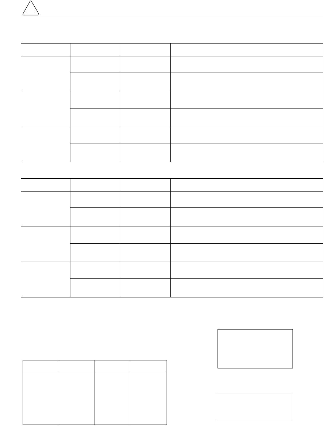
Control Recloser Compatible? Remarks
Form 3A
(Above Serial
No. 26000)
Form 3
With Battery
Charger Acces-
sory (Below Serial
No. 26000)
Form 3
Without Battery
Charger Acces-
sory (Below Serial
No. 26000)
New Style
(No Battery Charger) Yes
Yes
Yes
Yes
No
Yes
Old Style
(Battery Charger
Std)
Old Style
(Battery Charger
Std)
Old Style
(Battery Charger
Std)
New Style
(No Battery Charger
)
New Style
(No Battery Charger
)
Add battery charger accessory to control.
Control Recloser Compatible? Remarks
All
Form 3A
Form 3
With Battery
Charger Acces-
sory (Below Serial
No. 26000)
Form 3
Without Battery
Charger Acces-
sory (Below Serial
No. 26000)
New Style
(No Battery Charger) No
No
No
No
No
Yes
Old Style
(Battery Charger
Std)
Old Style
(Battery Charger
Std)
Old Style
(Battery Charger
Std)
New Style
(No Battery Charger
)
New Style
(No Battery Charger
)
Use recloser equipped with battery charger accessory.
Use recloser equipped with battery charger accessory; reconnect
input receptacle card in control for recloser charging.
Reconnect input receptacle card in control for recloser charging.
Use recloser equipped with battery charger accessory; disconnect
battery charger accessory in control; reconnect control for recloser
charging.
Disconnect battery charger accessory in control; reconnect control
for recloser charging.
Table 3
120 Vac Not Available At Control
Table 4
Serial Number Break for New Style Reclosers Without
Battery Chargers
Recloser
CXE
ME
MLE
MVE
RVE
RXE
VSA
VSO
VSAT
VSML
VSMT
VSR
VWE
VWVE
WE
WVE
1100
650
470
375
2500
900
2925
100
300
325
150
350
2100
1500
6800
1200
RecloserSerial No. Serial No.
NO BATTERY CHARGER
IN THIS RECLOSER.
USE WITH FORM 3A
OR CONTROL CONTAINING
POTENTIAL BATTERY CHARGER.
THIS RECLOSER
EQUIPPED WITH
BATTERY CHARGER
Table 2
120 Vac Available At Control
Form 3A Type ME Electronic Control Installation, Operation, and Testing Instructions
20
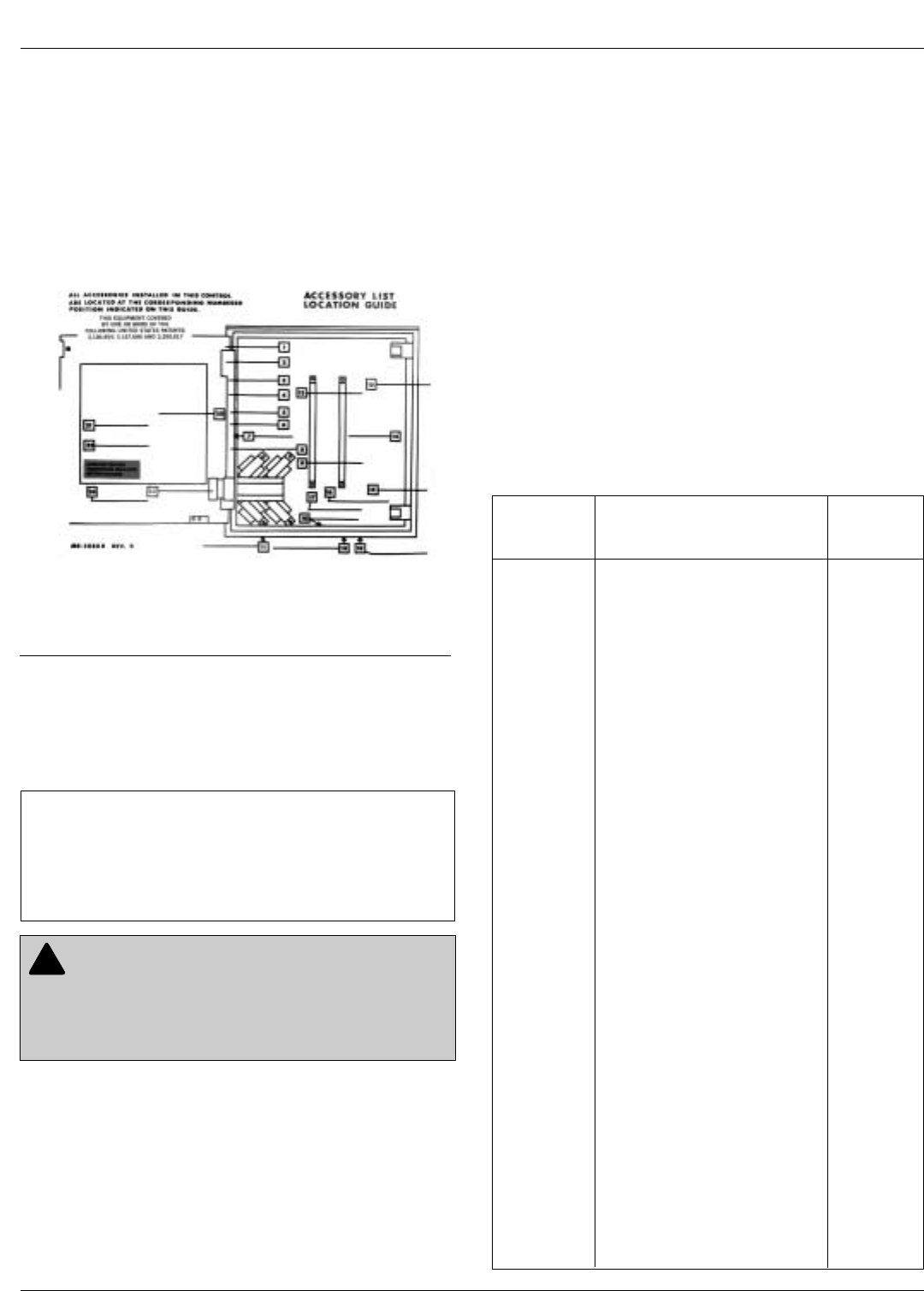
Accessories
A number of accessories are available to further extend
the operating flexibility of the Form 3A electronic control
and broaden its application capabilities. The Accessory
List Location Guide label attached to the inside of the cab-
inet door (Figure 22) lists the accessories included in the
control, shows their approximate physical location, and
identifies each accessory with a number corresponding to
the index number on the label.
Separate Service Information bulletins provide the instal-
lation, operating, testing, troubleshooting instructions for
the accessories furnished with each control.
Table 5 lists Form 3A control accessories, catalog num-
bers and Service Information bulletin numbers.
Verification Procedure Prior to
Placing Control and Recloser
into Service
Prior to placing the control and its recloser into service,
make sure that all the following installation procedures
have been properly completed and verified.
1. Control properly mounted for the installation.
2. Recloser installed according to all locally approved
utility practices.
3. Control and recloser properly grounded in accordance
with guidelines in this manual.
4. 120 Vac connected to control.
5. Control battery connected and tested for proper oper-
ation.
6. All control plug-in components properly installed and
programming verified by appropriate personnel.
7. Customer connections for remote and supervisory
operation checked and completed in accordance with
shielding and surge protection instructions in this
manual.
8. Control cable properly connected and supported.
Service
Accessory Accessory Information
Catalog No. Description Number
KA333ME Reclose-Blocking S280-75-36
KA418ME7 Sequence Coordination S280-75-37
KA531ME Fuse Elimination S280-75-44
KA542ME
Thermostatically Controlled
Heater
S280-75-39
KA1002ME Minimum-Trip Doubler S280-75-21
KA1036ME Instantaneous Lockout S280-75-33
KA1037ME Instantaneous Trip S280-75-25
KA1119ME Capacitor Backup Trip S280-75-48
KA1137ME Target Annunciator S280-75-41
KA1163ME Minimum Response Time S280-75-42
KA2003ME Remote Close with Cold Load
Pickup S280-75-49
KA2035ME2 Remote Non-Reclose and
Ground Trip Block
Maintained Contact S280-75-52
KA2039ME Recloser Status S280-75-51
KA2047ME Remote Battery Test and
Voltage Monitor S280-75-57
KA2070ME Remote Close with Cold-Load
Pickup, Remote Lockout, and
Recloser Status S280-75-55
KA2071ME Remote Non-Reclose and
Ground Trip Block
Momentary Contact S280-75-53
KA2072ME Remote Battery Test and
Voltage Monitor Analog Output S280-75-56
KA2075ME Closing Coil Control Fuse S280-75-62
KA2272ME Analog Current Metering S280-75-63
Table 5
Form 3A Type ME Electronic Control Accessory
Manuals
Figure 22.
Accessory Location Guide Label Mounted inside
Cabinet Door Identifies and Locates all Control
Accessories.
911072KMA-F
CAUTION: Equipment damage. Each remote
operation accessory installed in the control requires
two wires for operation. For example, if both remote
close and remote lockout are installed, they require four
wires. Using three wires will cause misoperation and/or
control damage. T220.0
!
IMPORTANT: Although it may be desirable under
certain conditions to operate control accessories in par-
allel from a single remote contact, this is generally not
possible. Cooper Power Systems does not advise inter-
connection between controls because of possible con-
trol interaction.
21
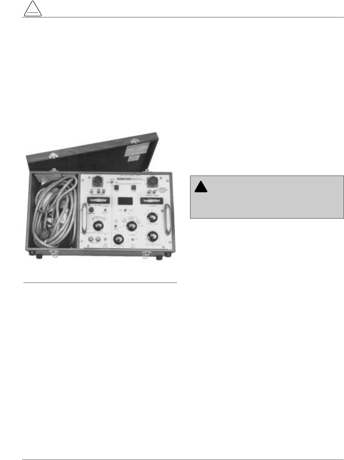
Testing with Type MET Tester
The Kyle Type MET Electronic Recloser Control Tester
(Figure 23) has been designed specifically for testing
Form 3A controls. The MET Tester is completely self-con-
tained, includes all necessary metering and interconnect-
ing cables, and is capable of performing all required
checks and tests from a simple verification of operation to
a complete verification of operation of all operating
parameters. Operating instructions for the Type MET
Tester are contained in Service Information S280-76-1.
If an MET Tester is not available, the following test pro-
cedures, ranging in complexity from a simple check of
coordinated control-recloser operation to a verification of
the various control settings, may be performed:
•For a simple check of coordinated control-recloser
operation, the output of a soldering gun (with the tip
removed) connected across a minimum-trip resistor
will provide a signal of sufficient strength to simulate a
fault current and operate the control. Refer to the Sol-
dering-Gun Test section in this manual.
•To verify minimum trip, timing, and operating
sequence, an equivalent test current which simulates
the output of the sensing CTs can be introduced
directly into the control. Refer to the Testing with
Simulated Current section of this manual.
•To verify the control settings and check the sensing
CTs, a variable, low-voltage test current simulating
fault conditions can be passed through one phase of
the recloser. Refer to the Testing with Low-Volt-
age Current section of this manual.
Testing an Installed Control
A recloser control can be taken out of service for testing
and placed back in service without deenergizing its
recloser and interrupting the system. However, during the
time the control is out of service, system fault protection
is lost.
To Remove Control from Service
Prior to testing, changing plug-in components, performing
control maintenance, making program changes, or bat-
tery replacement on an in-service control, the following
steps must be taken to prevent possible recloser misop-
eration.
1. Switch Ground Trip Block switch to BLOCK.
2. Disconnect control cable from control.
3. De-energize potential battery charger, by opening the
battery charger fuse block switch (shown in Figure 4.)
4. Operate the Manual Control switch to OPEN.
5. Unplug the control battery.
S280-75-1
TESTING PROCEDURES
!
SAFETY
FOR LIFE
Figure 23.
Kyle Type MET Electronic Recloser Control Tester.
86841KMA-F
CAUTION: Recloser misoperation. The control
must be removed from service prior to performing
any maintenance, testing or programming changes.
Failure to comply can result in misoperation (uninten-
tional operation) of the recloser. T216.2
!
To Return the Control to Service
After required work is completed, return the control to ser-
vice with the following steps:
1. Check that all plug-ins are properly installed and con-
trol settings are correct.
2. Connect control battery.
3. Close the battery charger fuse block switch to ener-
gize the potential battery charger.
4. Move Manual Control switch to CLOSE, to ensure that
control is reset to the home position.
5. Reconnect control cable to control.
6. Switch Ground Trip Block switch to NORMAL.
Closing the Recloser
Electrical Closing - RVE, RXE, VWE,
VWVE27, VWVE38, WE, and WVE
Reclosers
For automatic operation, line voltage is required to oper-
ate the closing solenoid of RVE, RXE, VWE, VWVE27,
VWVE38, WE, and WVE reclosers (except for reclosers
equipped with the low voltage closing accessory).
For on-line testing, bypass the recloser, open the load-
side disconnects, but keep the source-side disconnects
closed. This will remove the recloser from service, but will
keep line voltage supplied to the closing solenoid. See
Figure 24.
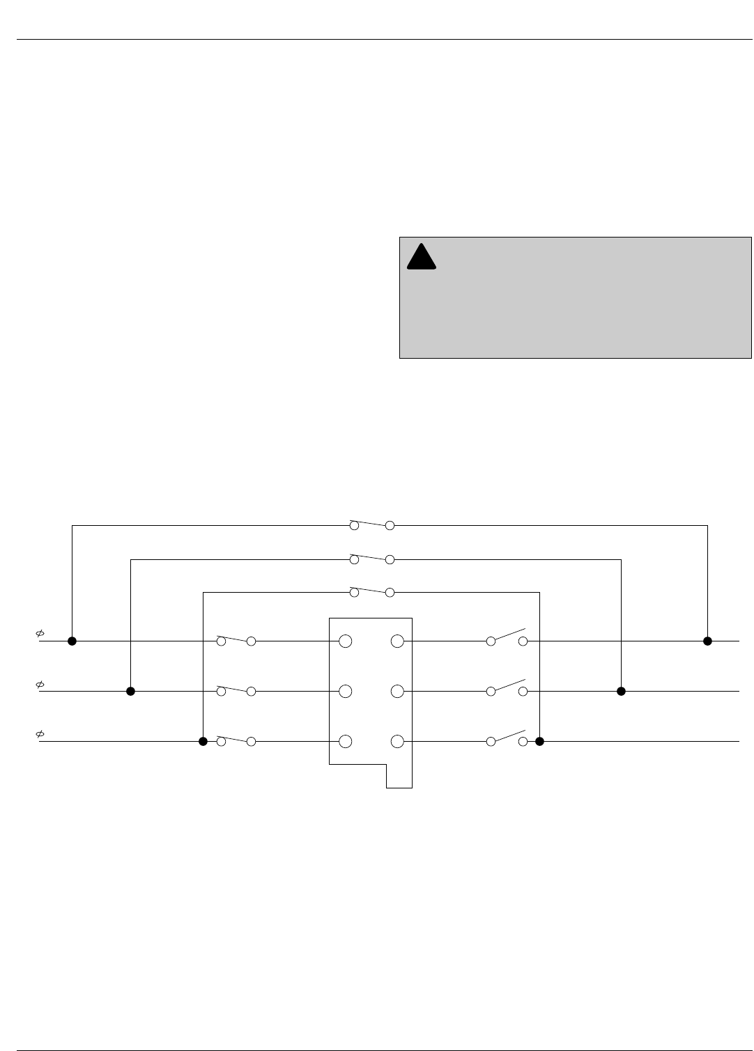
Form 3A Type ME Electronic Control Installation, Operation, and Testing Instructions
22
5 6
34
1 2
C
B
A
BYPASS SWITCHES
CLOSED
SOURCE SIDE DISCONNECT
(SWITCHES CLOSED)
LOAD SIDE
DISCONNECT
(SWITCHES)
OPEN
CLOSING
COIL
LOAD
SOURCE
SOURCE
LOAD
Figure 24.
Closing-Source Side Switches of a Bypassed, On-line Recloser will Provide Closing Solenoid Power for Auto-
matic Operation During Testing.
WARNING: Hazardous voltage. Interconnect
source leads X and Y and ground solidly to the
recloser tank. Do not connect lead Z to any other phase
or mechanical ground. Dangerous voltages to ground
exist on the phase connected to lead Z. Solidly ground
all equipment. Failure to comply can result in severe
personal injury and/or equipment damage. T224.1
!
23
For shop testing, the closing solenoid voltage can be
supplied by back-feeding a transformer with a low-side
rating equal to the voltage rating of an available power
source and a high-side rating equal to the voltage rating
of the recloser. This procedure is not to be used on
reclosers equipped with the low-voltage closing acces-
sory, see Figure 25. Make sure the solenoid coil operating
voltage is maintained at the recloser bushings during the
two-to-three cycle interval the closing coil is energized. In
general, a 75 kVA transformer of the proper voltage rating
with an impedance drop of about 3% will be satisfactory.
The source impedance must also be reasonably low. The
closing coil requirement is approximately 200 kVA during
the two-to-three cycle closing operation.
Electrical Closing - CXE, VSA, VSO,
and VSML Reclosers
CXE, ME, VSA, VSO, and VSML reclosers utilize a motor-
operated closing mechanism which is energized from a
230 Vac power source; no high-voltage is required.
S280-75-1
!
SAFETY
FOR LIFE
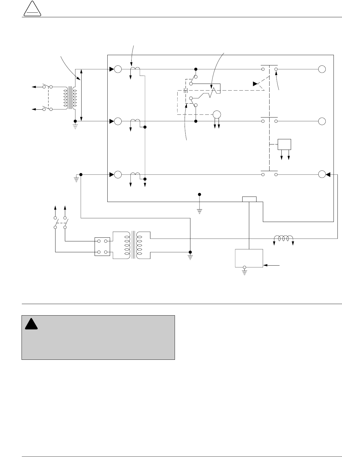
Figure 25.
Suggested Test Circuit for Solenoid Closing Reclosers.
3
6
4
T3 Y
H
X
Z
VOLTAGE RATING OF
RECLOSER CLOSING
SOLENOID COIL
SENSING C-T's (3) CLOSING
SOLENOID
CONTACTOR
ROTARY
SOLENOID
MAIN
CONTACTS (S)
GK
AB
EF
TO
240 OR
480 VAC
SOURCE
TO
240 VAC
SOURCE
CLOSING
SOLENOID
COIL
TRIP
SOLENOID
CONTROL
CABLE RECEPTACLE
W
ELECTRONIC
CONTROL
TO
AMMETER AND RELAY TO
OPERATE CYCLE COUNTER
OR OTHER TIMING DEVICE
120 VAC
VARIABLE
AUTOTRANSFORMER
240 VAC
20 AMPS
T2
12
5
WARNING: Hazardous voltage. The switchgear
and high-voltage transformer must be in a test
cage or similar protective device to prevent accidental
contact with the high-voltage parts. Solidly ground all
equipment. Failure to comply can result in death, severe
personal injury, and equipment damage. T221.3
!
Form 3A Type ME Electronic Control Installation, Operation, and Testing Instructions
24
Manual Closing - Solenoid-Operated
Reclosers
If high-voltage for operating the closing solenoid of RVE,
RXE, VWE, VWVE27, VWVE38, WE, and WVE reclosers
is not available, manual closing can be substituted for
electrical closing; however, not all control settings can be
checked since manual closing is not synchronized with
the closing coil control circuit in the control.
To manually close the recloser:
1. Remove the closing tool port cover and gasket from
the side of the recloser head casting.
2. Insert the KA90R T-handled tool (available as an
accessory) into the port, engaging the pin on the clos-
ing shaft. (Figure 26).
3. Close the recloser by placing the yellow operating
handle (under the sleet hood) into the up or CLOSED
position and turning the closing tool one-quarter turn
clockwise.
4. After each trip operation, about 1⁄2second will elapse
while the closing solenoid plunger is moving upward to
reset the main toggle latch.
5. After the main toggle latch resets, the recloser can be
closed again by operating the manual closing tool.
6. Replace the gasket and port cover on the recloser
head after testing has been completed.
7. Reinstall the control closing coil fuse.
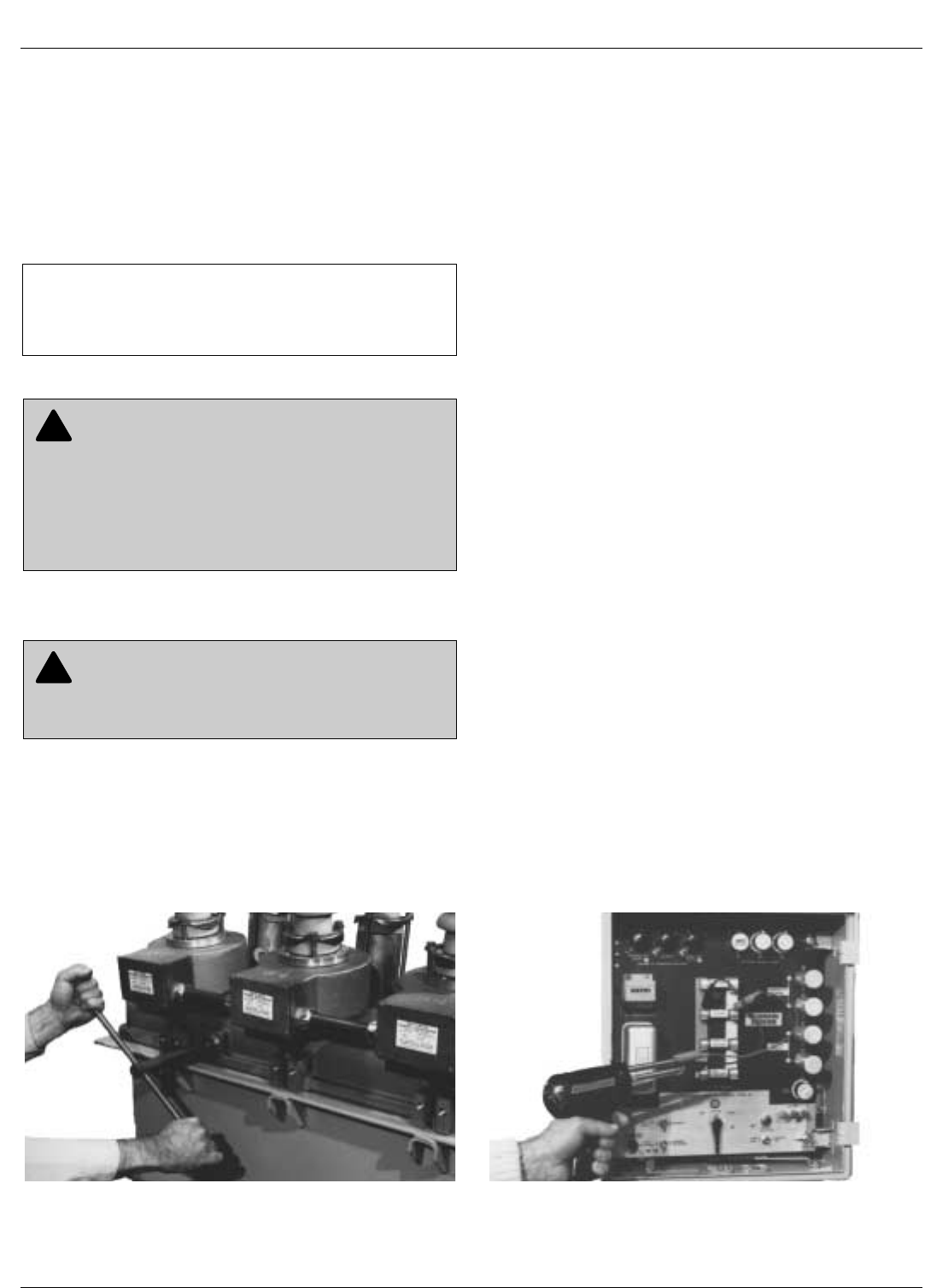
Soldering-Gun Test
The output of a soldering gun (Weller Model 550 or equiv-
alent) will produce a signal of sufficient strength to simu-
late a fault and check recloser-control operation. To
solder-gun test a control:
1. Set the Non-Reclose/Normal Reclose switch on the
control to NORMAL reclosing and the Ground Trip
Block switch to NORMAL.
2. Move the manual control switch on the control panel to
TRIP, to open the recloser contacts.
3. Remove the tip from the posts of the soldering gun by
loosening the hexagonal locking nuts.
4. Connect a short clip lead to each post and connect the
soldering gun across the Phase A minimum trip resis-
tor as shown in Figure 27.
5. Move the manual control switch on the control panel to
CLOSE. The recloser should close.
6. Energize the soldering gun by depressing and holding
the trigger until the recloser trips.
7. Immediately release the trigger to prevent instantan-
ious trips on succeeding reclosings.
8. When the recloser recloses, again energize the sol-
dering gun and repeat Steps 5 and 6 until the control
locks out. Count the number of fast and delayed trip
operations and compare the count with the control set-
tings. Verify lockout with the switch on the operator
panel.
9. Repeat on Phases B and C and Ground if desired.
WARNING: Explosion Hazard. Excessive Con-
tact Arcing. Do not use the manual closing tool to
close an oil-insulated energized recloser. Closing an
energized oil-insulated recloser with a manual closing
tool can cause excessive contact arcing, rapid build-up
of gas within the equipment, and possible explosion that
can cause death, severe personal injury, and equip-
ment damage. T203.2
!
CAUTION: Equipment damage. Do not turn the
manual closing tool more than one-quarter turn
clockwise. Forcing the tool beyond the mechanism stop
may shear the pin on the closing shaft of the recloser.T222.0
!
Figure 26.
Using a KA90R Manual Closing Tool to Operate the
Recloser.
82284KMA-F Figure 27.
The Output of a Soldering Gun can be used for a
Quick-Check of Control-Recloser Operation.
82290KMA-F
IMPORTANT: If manual closing is not performed
within the reclosing interval of the control, the closing
coil control fuse will blow. To prevent this from occuring,
remove the fuse during manual closing procedures.
25
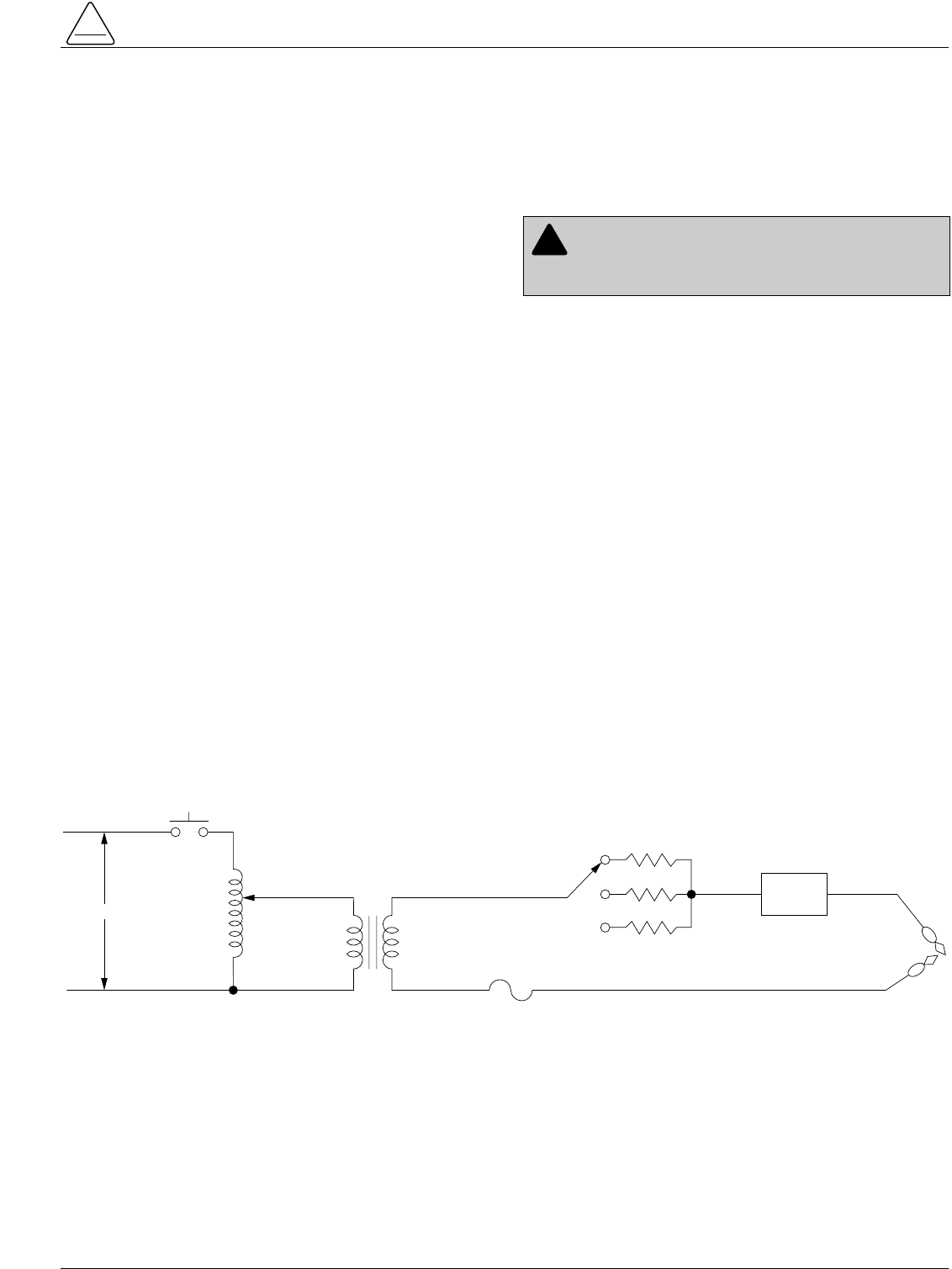
Testing with Simulated Current
The Form 3A electronic recloser control continuously
monitors line current conditions with three wye-con-
nected 1000:1 ratio current transformers mounted inter-
nally on the source-side bushings of the recloser. These
CTs are connected directly to three wye-connected
phase minimum-trip resistors on the control panel. A
fourth resistor (ground trip) is connected in the CT neutral
to monitor zero-sequence current flow.
The current through any one of the minimum-trip resistors
is 1/1000 of the line current. Therefore, if 1/1000 of the
line current is applied directly to the resistor, the control
will operate as if line current was flowing through the CT
primary and one milliamp of test current will be equivalent
to one amp of line current.
Note: The above applies to all but the VSA20, VSO20 and the
discontinued Type ME and VSMT reclosers. These
higher continuous-current-rated reclosers use 2000:1
ratio sensing CTs and special blue label minimum-trip
resistors. For Type VSA20 AND VSO20 reclosers, one
milliamp of test current is equivalent to two amps of line
current. When testing controls equipped with blue label
trip resistors, double the milliamp reading to obtain the
equivalent line current.
Test Equipment
A test circuit to produce a variable output in equivalent
amps is shown in Figure 28. This circuit will provide a
fairly complete test of the control and recloser. All parts
are standard and can be purchased through any elec-
tronics supply outlet.
Note: High voltage is required to operate the closing solenoid
of Type RVE, RXE, VWE, VWVE27, VWVE38, WE, and
WVE reclosers, unless they are equipped with the low
voltage closing accessory. A 240 Vac power source is
required to operate the motor of CXE, VSA, VSO, and
VSML Reclosers. Various closing schemes are dis-
cribed in the Closing the Recloser section.
Test Procedure
Coordinated Operation of Control and
Recloser
1. Make certain that closing power is available at the
recloser.
A. On solenoid-operated reclosers, move the yellow
manual operating handle (located under the sleet
hood) to the up position.
B. On motor-operated reclosers, move the TRIP-
RESET lever or rod (located in the recloser opera-
tor cabinet) to RESET.
2. Set the operating mode switch on the control to NOR-
MAL reclosing and the ground trip switch to NOR-
MAL.
3. Move the manual control switch on the control panel
to CLOSE. The recloser should close.
4. Move the manual control switch on the control panel
to TRIP. The recloser should open.
S280-75-1
!
SAFETY
FOR LIFE
WARNING: Hazardous voltage. Solidly ground all
equipment. Failure to comply can result in death,
severe personal injury, and equipment damage. T223.2
!
S1
120 VAC
FILAMENT
TRANSFORMER
12 VAC SEC.
1 AMP
VARIABLE
AUOTRANSFORMER
0 -120 VAC -1 AMP
FUSE
FAULT SWITCH
(MOMENTARY)
1A
10 Ω
25 Ω
200 Ω
120V
PRIMARY
12V SEC
DIGITAL
AC
AMMETER
ALLIGATOR
CLIPS
SELECT FIXED RESISTOR WHICH
GIVES APPROXIMATELY FULL
SCALE READING ON THE DIGITAL
AMMETER WITH VARIABLE AUTO-
TRANSFORMER SET AT MAXIMUM
RESISTOR IS USED FOR CURRENT
LIMITING; VALUE NOT CRITICAL.
Ω
Ω
Ω
Figure 28.
Simulated Current Test Circuit.

Minimum-Trip Current
The minimum-trip current test should be performed on a
fast time–current curve operation. The test will produce
misleading results if the control is operating on a delayed
TCC curve.
Note: If the control is equipped with the KA418ME7 sequence
coordination accessory, refer to Service Information
S280-75-37 for additional information.
To test minimum-trip current:
1. Move the manual control switch to CLOSE to close the
recloser.
2. Connect the output of the test circuit across the Phase
A minimum trip resistor.
3. While holding fault switch S1 on the tester closed,
slowly raise the test current from zero and note the
meter reading when the recloser trips. This reading in
milliamps should correspond to the trip resistor value
in amps. For example, a 280 amp resistor should trip
at 280 mA.
4. Release S1 before the recloser automatically recloses
to prevent instantaneous trips on succeeding reclos-
ings.
5. Repeat steps 1 through 4 for the Phase B, Phase C,
and Ground trip resistors.
Trip Time
The trip times of the fast timing plugs (Sockets 1 and 1 ),
are ordinarily too fast to check with a stopwatch with any
accuracy. However, the delayed timing plugs (Sockets
2 ) can be checked. To check the delayed timing plugs:
1. Move the manual control switch to TRIP to open the
recloser.
2Remove the RESET DELAY plug from the control
panel.
3. Connect the output of the test circuit across the Phase
A minimum trip resistor.
4. While holding Fault switch S1 closed, adjust the out-
put to produce an equivalent test current of at least
150% of minimum trip. For example, a 420 mA test
current for a 280 amp resistor.
5. Release S1 and move the manual control switch to
CLOSE to close the recloser.
6. Close S1; the recloser should trip in a very short time.
7. Release S1 immediately and allow the recloser to
close automatically.
8. Repeat Steps 6 and 7 for all fast operations to
advance control operation to the delayed time-current
curve.
Note: The number of fast operations is determined
by the setting of GROUND TRIP SOCKET 1
and PHASE TRIP SOCKET 1 switches in
the upper left corner of the panel.
9. Close S1 and, at the same time, start a stopwatch.
10. When the recloser trips, stop the watch and release
S1. Compare the time to the time at 150% of minimum
trip on the published time–current curve for the timing
plug being checked. For example, a B plug will clear in
about 2.8 seconds at 150% minimum trip.
11. Repeat Steps 9 and 10 to lockout.
12. Repeat Steps 3 through 11 for the GROUND TRIP
TIMING Plug 2 .
Reclosing Time
To check reclosing time (the open interval of the recloser
between trips):
1. Move the switch to CLOSE to close the recloser.
2. With the tester output connected across any one of
the minimum-trip resistors and adjusted to produce an
eqivalent test current of at least 150% of the minimum
trip rating, close Fault Switch S1.
3. When the recloser trips, release S1 and start timing
the interval the recloser is open, stopping when the
recloser recloses. The time should correspond to the
first RECLOSING INTERVAL DELAY plug setting.
4. Repeat Steps 2 and 3 to check the timing of the sec-
ond and third RECLOSING INTERVAL DELAY plugs.
5. Replace the RESET PLUG on the control panel.
Reset Time – Timed from Successful
Reclosure
Reset timed from a successful reclosure is standard on
the Type ME Form 3A control. To check the reset time:
1. Move the manual control switch to CLOSE to close the
recloser.
2. With the tester output connnected across any one of
the minimum-trip resistors and adjusted to produce an
equvalent test current of at least 150% of the min-
imun-trip rating, close Fault Switch S1.
3. When the recloser trips, release S1 and wait for the
recloser to reclose automatically.
4. Start timing when the recloser closes and stop when
the control resets automatically as indicated by an
audible clicking as the sequence relay returns to home
position.
5. The elapsed time should correspond to the setting of
the RESET DELAY plug.
Form 3A Type ME Electronic Control Installation, Operation, and Testing Instructions
26
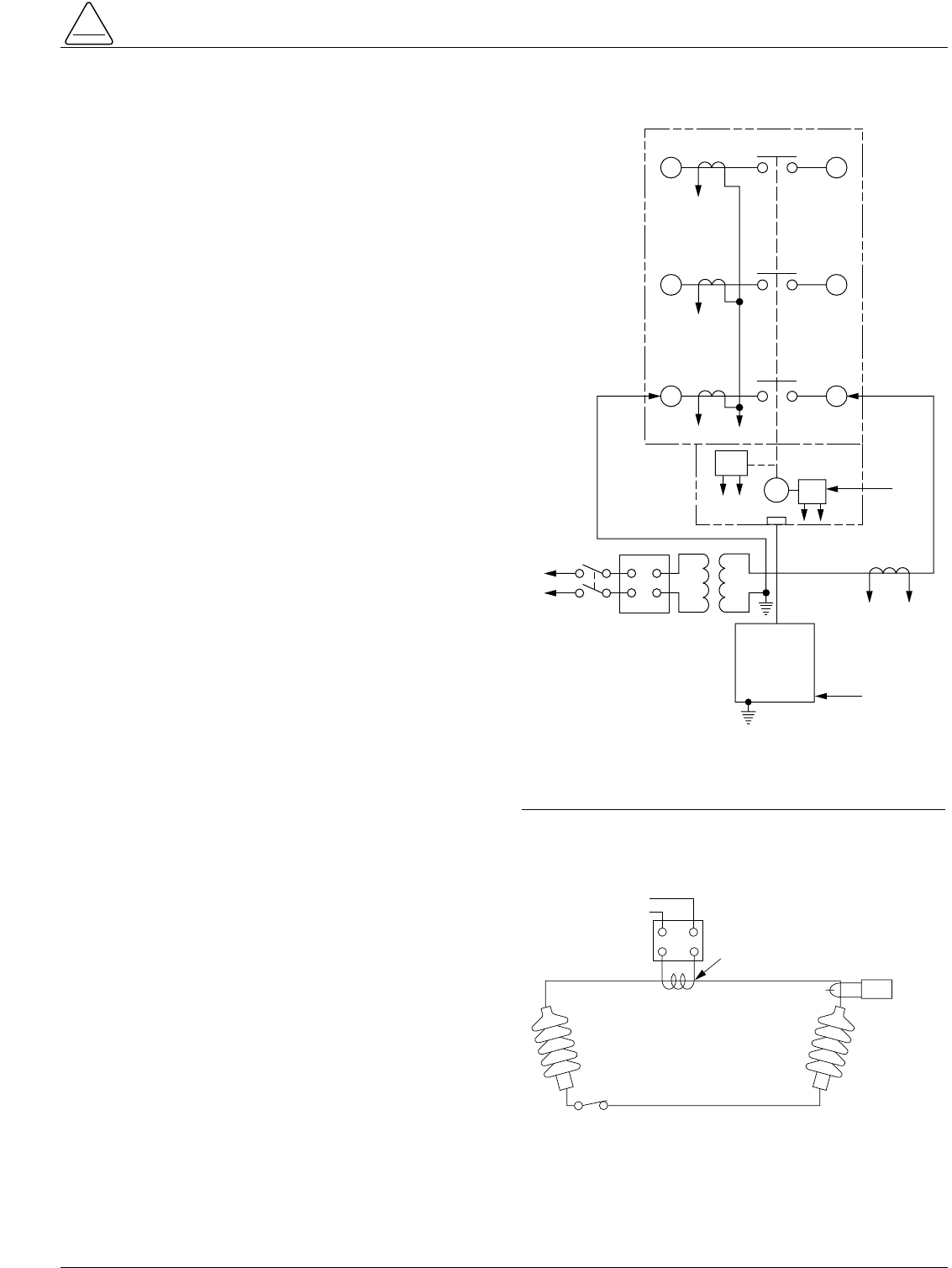
Reset Time-Timed From First Trip
Operation
The Form 3A control can be converted to reset-timed-
from-first-trip operation as described in the Reset Delay
Selector section.
To check the timing of this reset mode:
1. Move the manual control switch to CLOSE to close the
recloser.
2. With the tester output connected across any one of
the minimum-trip resistors and adjusted to produce an
equivalent test current of at least 150% of the mini-
mum-trip rating of the resistor, close Fault Switch S1.
3. When the recloser trips, release S1 and start timing.
4. Continue timing after the recloser automatically
recloses until the control resets automatically as indi-
cated by an audible clicking as the sequence relay
returns to its home position.
5. The elapsed time should correspond to the setting of
the RESET DELAY plug.
Operation of the Non-Reclosing
Switch
The non-reclosing switch provides one-trip-to-lockout
capability without disturbing the normal operating
sequence of the control. To check its operation:
1. Move the non-reclosing switch to NON-RECLOSING.
2. Move the manual control switch to CLOSE to close the
recloser.
3. With the tester output connected across any one of
the minimum-trip resistors and adjusted to produce an
equivalent test current of at least 150% of the mini-
mum-trip rating of the resistor, close Fault Switch S1.
4. The recloser should trip once and not reclose. The
control should indicate lockout position when the
LOCKOUT TEST switch is operated.
27
S280-75-1
!
SAFETY
FOR LIFE
Figure 30.
Alternate Method of Producing Variable Line Current
(Substitute for T2 and W-X Circuit in Figures 25 and
29).
115V
AC
12
CLAMP-ON
AMMETER
NOTE: USE AT
LEAST 2/0 CABLE
BETWEEN BUSHINGS
VARIABLE
AUTOTRANSFORMER
(10 AMP)
600:5
RECLOSER
BCT ON 600:5 TAP
THIS TEST CIRCUIT CAN
APPLY OVER 800 AMPS
TO THE RECLOSER
Figure 29.
Suggested Test Circuit for Motor Operated Reclosers.
65
43
21
ELECTRONIC
CONTROL
J
GK
H
XW
EF
A B
CLOSING
CONTACTOR
240 VAC
T1 T2
240 VAC
VARIABLE
AUTOTRANSFORMER
240 VAC-20 A
120 VAC
TO AMMETER
AND RELAY
TO OPERATE
CYCLE
COUNTER OR
OTHER TIMING
DEVICE
SENSING CTs (3) ON BUSHINGS
1, 3 AND 5 AS SHOWN FOR VSA,
VSML, AND CXE RECLOSERS.
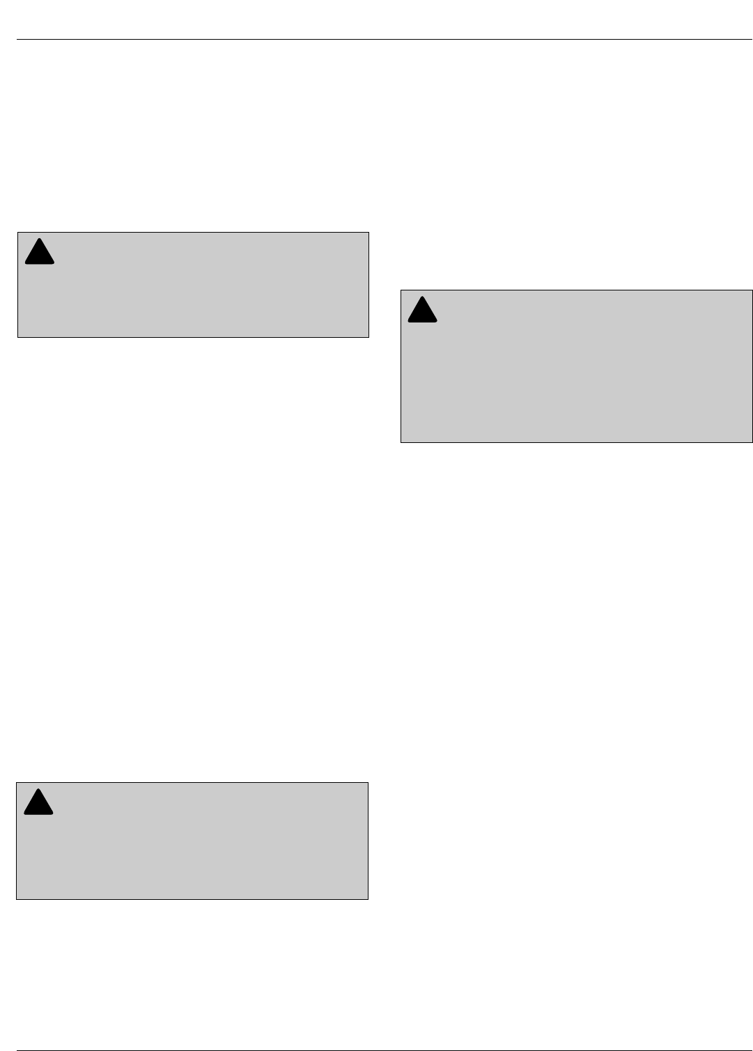
Testing with Low-Voltage
Current
The Form 3A recloser control-with its recloser-can be
tested with a variable low-voltage current passing through
one phase to simulate fault conditions.
Test Equipment RVE, RXE, VWE,
VWVE27, VWVE38, WE, AND WVE
Reclosers
A test circuit for these solenoid-closed reclosers is shown
in Figure 25. The following equipment is required for the
recommended test setup:
Note: Solenoid-closed reclosers equipped with a 120- or 240-
Vac low-voltage closing coil accessory can be tested as
shown in Figure 29.
•Variable Autotransformer T1, 230 volts, 20 amps.
•Low-Voltage transformer T2 to simulate fault conditions.
Ratio and size will depend upon the maximum current
to be used. The recloser presents a low impedance to
the transformer, so secondary voltage must be only
high enough to force the required current through the
secondary of the transformer and the recloser.
Note: An alternative method of providing the necessary
current through the transformer is shown in Figure
30.
•High-Voltage T3 to operate the closing solenoid. Refer
to the Closing the Recloser section for high voltage
transformer requirements.
•Ammeter with a rating based on the level of test current.
•Current-actuated timer or stopwatch.
Test Procedure
Test Current Applied to Phase A
1. Assemble and connect the equipment as shown in
Figure 25, which shows the test current being applied
to Phase A, the phase nearest the sleet hood.
2. Verify that closing power is available at the recloser.
3. Move the yellow manual operating handle, located
under the sleet hood, to the UP position.
4. Set the Non-Reclosing/Normal Reclosing switch on
the control panel to NORMAL RECLOSING and the
Ground Trip switch to BLOCK.
5. Move the manual control switch to CLOSE. The
recloser should close, indicating correct operation of
the control and recloser.
6. Move the manual control switch to TRIP. The recloser
should open, verifying the electrical operation of the
trip solenoid and the mechanical operation of the trip
mechanism.
Test Procedure
Test Current Applied to Phase B and C
1. De-energize the high-voltage closing source and
close the recloser manually before testing phase B
and C. Refer to the Manual Closing procedure in the
Closing the Recloser section of this manual.
2. Verify that closing power is available at the recloser.
3. Move the yellow manual operating handle, located
under the sleet hood, to the UP position.
4. Set the Non-Reclosing/Normal Reclosing switch on
the control panel to NORMAL RECLOSING and the
Ground Trip switch to BLOCK.
5. Move the manual control switch to CLOSE. The
recloser should close, indicating correct operation of
the control and recloser.
6. Move the manual control switch to TRIP. The recloser
should open, verifying the electrical operation of the
trip solenoid and the mechanical operation of the trip
mechanism.
Test Equipment CXE, VSA, VSO, and
VSML Reclosers
A test circuit for these motor-operated reclosers is shown
in Figure 29. Since these reclosers require only a 240 Vac
source for closing, High-Voltage Transformer T3 and its
associated protective cage is eliminated, but all other
equipment is the same as the test equipment shown in
Figure 25.
Test Procedure
Coordinated Operation of Control and Recloser
1. Assemble and connect the equipment as shown in
Figure 29.
2. Verify that closing power is available at the recloser.
3. Move the TRIP-RESET lever or rod, located in the
recloser operator cabinet, to RESET.
Form 3A Type ME Electronic Control Installation, Operation, and Testing Instructions
28
WARNING: Hazardous voltage. Interconnect
Source Leads X and Y and ground solidly to the
recloser tank. Do not connect Lead Z to any other phase
or mechanical ground. Dangerous voltages to ground
exist on the phase connected to Lead Z. Solidly ground
all equipment. Failure to comply can result in severe per-
sonal injury and/or equipment damage. T224.1
!
WARNING: Hazardous voltage. Dangerous volt-
ages to ground exist on the phase connected to
lead Z. De-energize high-voltage. Remove test leads Y
and Z and solidly ground recloser tank prior to applying
test current to phase B and C. Do not apply high-voltage
to recloser while applying test current to phase B and C;
transfer of high-voltage to low-voltage test circuitry will
result. Failure to comply can result in death, severe per-
sonal injury, and/or equipment damage. T305
!
WARNING: Hazardous voltage. The switchgear
and high voltage transformer must be in a test
cage or similar protective device to prevent accidental
contact with the high voltage parts. Solidly ground all
equipment. Failure to comply can result in death, severe
personal injury, and equipment damage. T221.3
!

29
4. Set the Non-Reclosing/Normal Reclosing switch on
the control panel to NORMAL RECLOSING and the
Ground Trip switch to BLOCK.
5. Move the manual control switch to CLOSE. The
recloser should close, indicating correct operation of
the control and recloser.
6. Move the manual control switch to TRIP. The recloser
should open, verifying the electrical operation of the
trip solenoid and the mechanical operation of the trip
mechanism.
Minimum-Trip Current
The minimum-trip test should be performed on a fast
time–current curve. The test will produce misleading
results if the control is operating on a delayed time–
current curve.
Note: If the control is equipped with the KA418ME7 sequence
coordination accessory, refer to Service Information
S280-75-37 for additional information.
To test the minimum-trip current:
1. Move the manual control switch to CLOSE to close
the recloser.
2. With the test circuit connected to Phase A, energize
T1, slowly raise the test current from zero, and note
the meter reading when the recloser trips. This read-
ing should correspond to the minimum current rating
of the Phase A trip resistor.
3. After the recloser trips, turn T1 back to zero and move
the manual control switch to TRIP to lockout the
recloser.
4. Repeat Steps 1 through 3 for Phase B and Phase C
trip resistors.
5. To check the minimum ground-trip resistor, place the
ground-trip switch to NORMAL and repeat Steps 1
through 3.
Note: The single-phase fault test current will appear as a
phase-to-ground fault to the control. Therefore, when
checking ground settings, jumper the minimum-trip resis-
tor of the energized phase to block phase-trip operations.
Trip Time
If an electrically operated timer is used, both the fast and
delayed time–current curves can be checked; however,
the trip times of the fast timing plugs (sockets 1 and 1 )
are ordinarily too fast to check with a stop watch with any
reasonable accuracy. To check the trip times:
1. Move the manual control switch to CLOSE to close
the recloser.
2. With the ground-trip switch set on BLOCK, connect a
short clip lead across the minimum-trip resistor of the
phase being tested to prevent tripping of the recloser
while the test current is being adjusted.
3. Energize T1 and adjust the current for 150% of mini-
mum-trip rating.
4. Without disturbing the setting of T1, deenergize T1.
5. Remove the jumper from across the minimum-trip
resistor.
6. Keeping T1 at the desired setting, energize T1 and
record the tripping times as the recloser operates
to lockout. These times should correspond to the
times at 150% of minimum-trip on the published
time–current curves for the timing plugs being
checked. Delayed times can be measured with a stop-
watch.
7. To check the ground-trip timing plugs, place the
ground-trip switch to NORMAL and repeat Steps 1
through 6.
Note: The single-phase fault test current will appear as a
phase-to-ground fault to the control. Therefore,
when checking ground settings, jumper to the mini-
mum-trip resistor of the energized phase to block
phase-trip operations.
8. Return the ground-trip switch to BLOCK after the test
has been completed.
S280-75-1
!
SAFETY
FOR LIFE
IMPORTANT: Before checking the Phase B and
Phase C trip resistors on solenoid-operating reclosers,
de-energize the high-voltage closing source and close
the recloser manually. Refer to the Manual Closing of
the Closing the Reclosers section of this manual.

Reclosing Time
To check reclosing time, which is the open interval of the
recloser between trips:
1. Move the manual control switch to CLOSE to close the
recloser.
2. Energize T1 and adjust T1 to produce a current in
excess of the phase minimum-trip value.
3. When the recloser trips, time the interval until the
recloser recloses.
4. Time the second and third open interval in the same
manner.
5. The times should correspond to the first, second, and
third RECLOSING INTERVAL DELAY plug settings,
respectively.
Reset Time Timed from Successful
Reclosure
Reset timed from successful reclosure is standard on the
Type ME Form 3A control. To check the reset time:
1. Move the manual control switch to CLOSE to close the
recloser.
2. With T1 adjusted to produce a current in excess of the
minimum-trip value, energize T1.
3. When the recloser trips, deenergize T1 and wait for
the recloser to reclose automatically.
4. Start timing when the recloser recloses and stop tim-
ing when the control resets automatically as indicated
by an audible clicking as the sequence relay returns to
the home position.
5. The elapsed time should correspond to the setting of
the RESET DELAY PLUG.
Operation of the Non-Reclosing
Switch
The non-reclosing switch provides one-trip-to-lockout
capability without disturbing the normal operating
sequence setting of the control. To check its operation:
1. Set the non-reclosing switch to NON-RECLOSING.
2. Move the manual control switch to CLOSE to close the
recloser.
3. With T1 adjusted to produce a current in excess of the
minimum-trip value, energize T1.
4. The recloser should trip once, and the control should
indicate lockout position when the LOCKOUT TEST
switch is operated.
Testing RVE, RXE, VWE, VWVE27,
VWVE38, WE, and WVE Reclosers with
Manual Closing
Testing procedures for minimum-trip current, time–current
curve time, reset time timed for successful reclose, reset
time timed from first operation, and operation of the non-
reclosing switch are the same as testing per the Testing
with Simulated Current procedure section except for
Type RVE, RXE, VWE, VWVE27, VWVE38, WE, and WVE
reclosers. These reclosers will not close automatically.
They must be manually closed after each trip operation.
For the Manual Closing Procedure, refer to the Closing
the Recloser section of this manual.
When testing reclosers with manual closing, the following
additional precautions must also be observed:
1. Since manual closing is not synchronized with the
closing coil control circuit in the control, the control
fuse will blow if manual closing is not performed within
the reclosing interval. To prevent damage, remove the
fuse during testing.
2. If the control is operating in the reset-after-first-trip
mode, the reset-delay plug may be removed from the
control for all testing except reset time timed from suc-
cessful reclose and reset time timed from first opera-
tion. If the reset-delay plug is not removed, the control
may reset before a test sequence is completed
because of the possible delays between trip opera-
tions when manual reclosing is used.
3. The variable autotransformer must be kept energized
at the proper setting while the recloser is closed man-
ually. Setting it properly before manual reclosing is ini-
tiated assures accurate timing values.
Form 3A Type ME Electronic Control Installation, Operation, and Testing Instructions
30

Maintenance Manuals
Maintenance instructions for the Form 3A, Type ME con-
trol are included in Service Information S280-75-2 and
S280-75-46.
Replacement Parts
Replacement parts for Kyle controls are available through
the factory Service Department. To order replacement
parts, refer to the applicable maintenance manual and
current Replacement Parts price list for catalog numbers
and pricing. Contact your Cooper Power Systems Division
sales representative for additional information and order-
ing procedures.
Repair Shops
Factory authorized repair shops are located throughout
the continental United States to provide maintenance,
repair, and testing services for Kyle controls and
reclosers. For further information, contact your Cooper
Power Systems Division sales representative.
Factory Maintenance Classes
The factory service department offers maintenance training
courses for Kyle recloser controls. These classes, taught by
experienced service technicians, are held at the factory's
in-house training facility. For additional information, contact
your Cooper Power Systems sales representative.
Video Cassette Training Program
A 29-minute video tape program; KSPV3 Kyle Type ME
control, Form 3A, Description and Operation is available
as a supplemental training aid for operating and service
personnel.
This video program, developed for use in the factory train-
ing school, is designed to be used in conjunction with
existing service literature. For additional information, con-
tact your Cooper Power Systems sales representative.
S280-75-1
31
CAUTION: This equipment requires routine
inspection and maintenance to ensure proper
operation. If it is not maintained, it can fail to operate
properly. Improper operation can cause equipment dam-
age and possible personal injury. G105.1
!
MAINTENANCE INFORMATION
Form 3A Type ME Electronic Control Installation, Operation, and Testing Instructions
©2002 Cooper Power Systems, Inc.
Kyle®is a registered trademark of Cooper Industries, Inc.
KA2048-99 Rev: 01 Printed on Recycled Paper KYLE
8/02
!
SAFETY
FOR LIFE
P.O. Box 1640
Waukesha, WI 53187
www.cooperpower.com
