S280 79 10 UUD S2807910
S280-79-10 to the manual 578efdee-fdbc-4371-b33c-fc455d2ef3ac
User Manual: S280-79-10
Open the PDF directly: View PDF ![]() .
.
Page Count: 56
Printed in USA
Safety Information . . . . . . . . . . . . . . . . . . . . . . . . . 2
Product Information . . . . . . . . . . . . . . . . . . . . . . . . 3
Introduction . . . . . . . . . . . . . . . . . . . . . . . . . . . . . . . 3
ANSI Standards . . . . . . . . . . . . . . . . . . . . . . . . . . . 3
Quality Standards . . . . . . . . . . . . . . . . . . . . . . . . . . 3
Acceptance and Initial Inspection . . . . . . . . . . . . . . 3
Handling and Storage . . . . . . . . . . . . . . . . . . . . . . . 3
Battery Replacement . . . . . . . . . . . . . . . . . . . . . . . 3
Control Power . . . . . . . . . . . . . . . . . . . . . . . . . . . . . 3
Initializing the Control . . . . . . . . . . . . . . . . . . . . . . . 4
Form 5 Control Description . . . . . . . . . . . . . . . . . . 5
Recloser Interface (RIF) Module . . . . . . . . . . . . . . 6
Central Processing Unit (CPU) Module . . . . . . . . . 6
Discrete Interface (DIF) Module . . . . . . . . . . . . . . . 6
Power Supply Module . . . . . . . . . . . . . . . . . . . . . . . 6
Form 5 Control Operator Panel . . . . . . . . . . . . . . . 7
Battery Test Procedure . . . . . . . . . . . . . . . . . . . . . . 14
Control Features . . . . . . . . . . . . . . . . . . . . . . . . . . . 14
Communications . . . . . . . . . . . . . . . . . . . . . . . . . . . 19
Auxiliary Power for Accessories . . . . . . . . . . . . . . 20
Recloser Interface (RIF) Module Configuration . . 20
Form 5 Universal Device Protection (UDP)
Control . . . . . . . . . . . . . . . . . . . . . . . . . . . . . . . . . . . 21
Form 5 DC NOVA Control . . . . . . . . . . . . . . . . . . . 22
Discrete Interface (DIF) Accessory . . . . . . . . . . . . 23
Customer Connection Information . . . . . . . . . . . . . 23
Standard and UDP DIF Module 1 Inputs . . . . . . . . 26
Standard and UDP DIF Module 1 Outputs . . . . . . . 28
Standard and UDP Module 2 Inputs . . . . . . . . . . . . 29
Standard and UDP Module 2 Outputs . . . . . . . . . . 30
Input Accuracy . . . . . . . . . . . . . . . . . . . . . . . . . . . . 31
Installation Procedure . . . . . . . . . . . . . . . . . . . . . . 32
Initial Programming Prior to Installation . . . . . . . . . 32
Control / Recloser Compatibility . . . . . . . . . . . . . . . 32
Control Cable . . . . . . . . . . . . . . . . . . . . . . . . . . . . . 32
Mounting the Control . . . . . . . . . . . . . . . . . . . . . . . 33
Grounding the Control . . . . . . . . . . . . . . . . . . . . . . 34
Customer Connections for AC Power . . . . . . . . . . . 38
Customer Connections for Metering . . . . . . . . . . . . 38
Before Placing Control and Recloser into Service . 42
Testing and Troubleshooting . . . . . . . . . . . . . . . . 43
Testing an Installed Control . . . . . . . . . . . . . . . . . . 43
Testing with Type MET Tester . . . . . . . . . . . . . . . . 43
Closing the Recloser During Testing . . . . . . . . . . . 44
Form 5 Control Default Test Procedure . . . . . . . . 47
Remove the Control from Service . . . . . . . . . . . . . 55
Return the Control to Service . . . . . . . . . . . . . . . . 55
Additional Information . . . . . . . . . . . . . . . . . . . . . . 56
1
Service Information
Reclosers
Kyle®Form 5, Form 5 UDP, Form 5 DC NOVA
Microprocessor-Based Recloser Controls
Installation and Operation Instructions S280-79-10
November 2001 • Supersedes 1/01
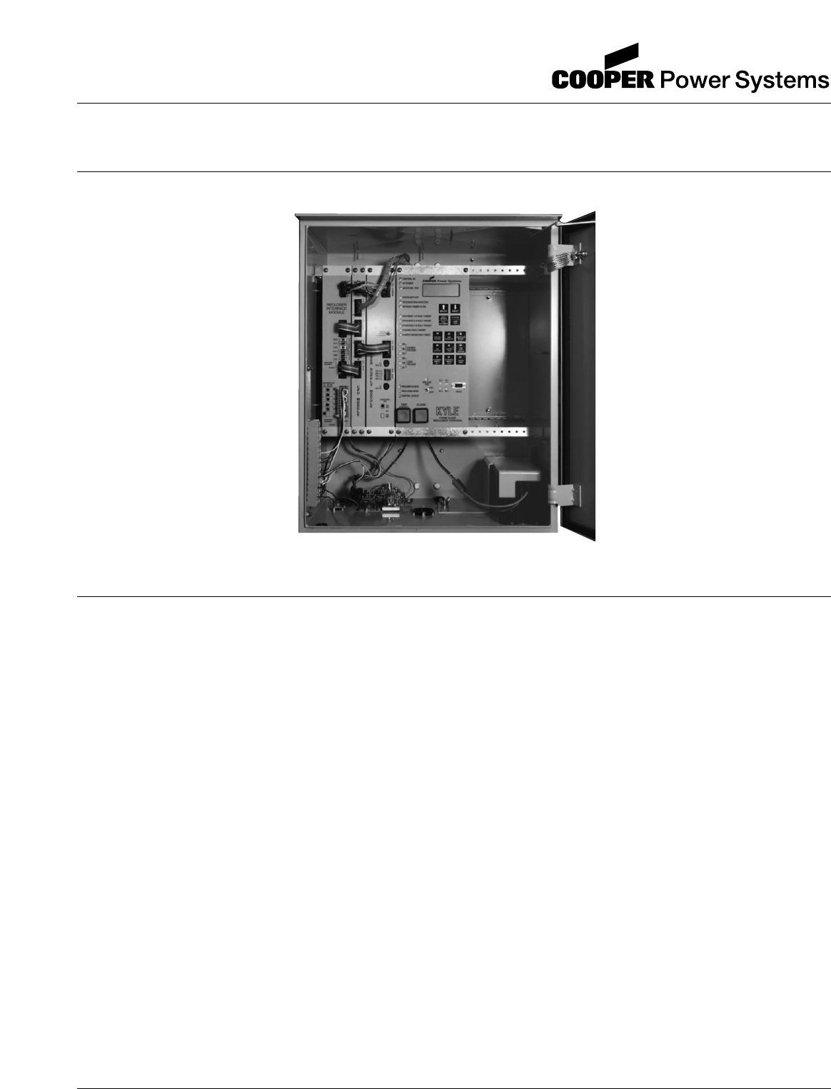
Figure 1.
Kyle®Form 5/UDP microprocessor-based recloser control.
99001KM
Contents
Applicable to serial numbers above 3000 or beginning with CP57.
Kyle Form 5, Form 5 UDP, Form 5 DC NOVA Recloser Control Installation and Operation Instructions
2
The instructions in this manual are not intended as a sub-
stitute for proper training or adequate experience in the
safe operation of the equipment described. Only compe-
tent technicians who are familiar with this equipment
should install, operate, and service it.
A competent technician has these qualifications:
• Is thoroughly familiar with these instructions.
• Is trained in industry-accepted high- and low-voltage
safe operating practices and procedures.
• Is trained and authorized to energize, de-energize,
clear, and ground power distribution equipment.
• Is trained in the care and use of protective equipment
such as flash clothing, safety glasses, face shield,
hard hat, rubber gloves, hotstick, etc.
Following is important safety information. For safe instal-
lation and operation of this equipment, be sure to read
and understand all cautions and warnings.
Safety Instructions
Following are general caution and warning statements
that apply to this equipment. Additional statements,
related to specific tasks and procedures, are located
throughout the manual.
SAFETY INFORMATION
SAFETY FOR LIFE
Cooper Power Systems products meet or exceed all applicable industry standards relating to product safety. We actively
promote safe practices in the use and maintenance of our products through our service literature, instructional training
programs, and the continuous efforts of all Cooper Power Systems employees involved in product design, manufacture,
marketing, and service.
We strongly urge that you always follow all locally approved safety procedures and safety instructions when working
around high voltage lines and equipment and support our “Safety For Life” mission.
!
SAFETY
FOR LIFE
!
SAFETY
FOR LIFE
WARNING: This equipment is not intended to
protect human life. Follow all locally approved pro-
cedures and safety practices when installing or operat-
ing this equipment. Failure to comply can result in death,
severe personal injury and equipment damage.
G102.1
!
DANGER: Hazardous voltage. Contact with haz-
ardous voltage will cause death or severe per-
sonal injury. Follow all locally approved safety
procedures when working around high and low voltage
lines and equipment. G103.3
!
WARNING: Before installing, operating, main-
taining, or testing this equipment, carefully read
and understand the contents of this manual. Improper
operation, handling or maintenance can result in death,
severe personal injury, and equipment damage. G101.0
!
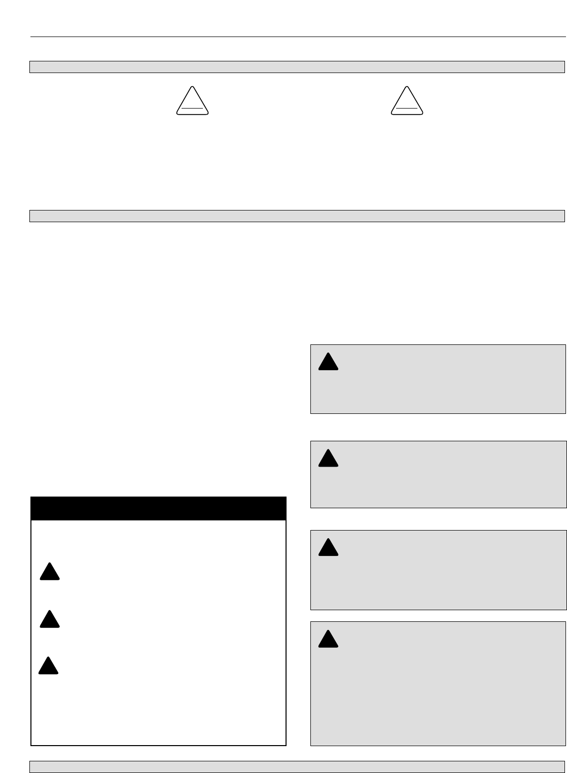
This manual may contain four types of hazard
statements:
DANGER: Indicates an imminently haz-
ardous situation which, if not avoided, will
result in death or serious injury.
WARNING: Indicates a potentially hazardous
situation which, if not avoided, could result in
death or serious injury.
CAUTION: Indicates a potentially hazardous
situation which, if not avoided, may result in
minor or moderate injury.
CAUTION: Indicates a potentially hazardous situ-
ation which, if not avoided, may result in equip-
ment damage only.
!
!
Hazard Statement Definitions
!
WARNING: Power distribution equipment must
be properly selected for the intended application. It
must be installed and serviced by competent personnel
who have been trained and understand proper safety
procedures. These instructions are written for such per-
sonnel and are not a substitute for adequate training
and experience in safety procedures. Failure to properly
select, install, or maintain power distribution equipment
can result in death, severe personal injury, and equip-
ment damage. G122.2
!

Introduction
Service Information S280-79-10 provides installation and
operation instructions for the Kyle Form 5 and Form 5
UDP microprocessor-based electronic recloser controls.
Read This Manual First
Read and understand the contents of this manual and fol-
low all locally approved procedures and safety practices
before installing or operating this equipment.
Additional Information
These instructions cannot cover all details or variations in
the equipment, procedures, or process described, nor
provide directions for meeting every possible contingency
during installation, operation, or maintenance. When
additional information is desired to satisfy a problem not
covered sufficiently for the user's purpose, please contact
your Cooper Power Systems sales representative.
ANSI Standards
Kyle reclosers are designed and tested in accordance
with the following ANSI standards: C37.60 and C37.85
and ANSI Guide C37.61.
Quality Standards
ISO 9001:2000-Certified Quality Management System
Acceptance and
Initial Inspection
Each Form 5 control is completely assembled, tested, and
inspected at the factory. It is carefully calibrated, adjusted
and in good condition when accepted by the carrier for
shipment.
Upon receipt, inspect the carton for signs of damage.
Unpack the control and inspect it thoroughly for damage
incurred during shipment. If damage is discovered, file a
claim with the carrier immediately.
Handling and Storage
Be careful during handling and storage of the control to min-
imize the possibility of damage. If the control is to be stored
for any length of time prior to installation, provide a clean,
dry storage area. If storage is in a humid atmosphere, make
provisions to keep the control circuitry energized.
Note: To energize the control, apply AC power to the AC sup-
ply input connector block TB1 located left of the
Recloser Interface (RIF) module within the control.
Refer to the Customer Connection for AC power sec-
tion in this manual.
Control Battery Storage and Charging
The 24 Vdc control battery in the Form 5 control is fully
charged prior to shipment and is ready for use. In order to
maintain sufficient charge to operate the control, the
sealed lead acid battery should be charged after no more
than three months of storage.
Note: Two 12 Vdc, 13 amp-hour batteries are available for
use with the Form 5 Distribution Automation upgrade
accessory.
Temperature has an effect on battery life. Sealed lead
acid batteries should be stored, fully charged, at room
temperature. Never store lead acid batteries at tempera-
ture exceeding 47°C (117°F), as damage can result in
approximately one month.
To keep the battery charged, energize the control’s built-
in charger with AC power applied to the user AC supply
input connector block TB1, located left of the RIF module
within the control cabinet.
Note: When shipped from the factory, the battery source is
disconnected and its output plugs are taped to the cab-
inet. Connect the battery plugs into the mating connec-
tors to complete the battery circuit.
Battery Replacement
The 24 Vdc control battery has a life expectancy of 4 to 6
years. It is recommended that the battery be replaced
after 4 years.
Control Power
The primary source of power is factory configured for 120 Vac
or 240 Vac. The 240 Vac version is available as an option
at time of order entry. Primary power is rectified to charge
the power capacitor and to power the dc/dc converter that
provides power to the control. A minimum of 500 mA of ac
current is required for heater operation, battery charging
current, and to keep all modules energized.
S280-79-10
3
!
SAFETY
FOR LIFE
PRODUCT INFORMATION
IMPORTANT: Connect the control battery when AC
power is connected to the control’s AC supply Input Ter-
minal Block. The battery must be disconnected prior to
shipping or storing the control.
IMPORTANT: To maintain sufficient charge to oper-
ate the control and prevent battery cell damage, the
sealed lead-acid batteries should be charged after no
more than three months of storage.
AC Reclosers
Power to operate the tripping and closing solenoids in the
recloser is provided by the power capacitor located
behind the operator panel of the control. A sealed, 24-volt,
lead acid battery is located in the lower portion of the con-
trol cabinet and is utilized to provide operating and trip-
ping energy when AC power is temporarily lost. The
control is equipped with an ac-powered, temperature-
compensated battery charger.
Operation Upon Loss Of AC Power
If the control is equipped with the standard 24 Vdc lead-
acid battery, the control maintains full operation from the
battery power supply for a minimum of 32 hours at 20°C
(24 hours at -40°C). To prevent battery damage, the con-
trol shuts down automatically upon detection of low bat-
tery voltage below 22.7 Vdc.
Control programming settings and parameters—including
event recorder, duty monitor, and data profile metering
parameters—are stored in non-volatile memory and
retained upon loss of control power. The time/date clock
resets to 0:00:00, 1970 upon loss of control power.
The AC power LED indicator on the operator panel of the
control will turn off after 15 seconds upon loss of AC
power. The indicator will illuminate immediately upon
return of ac power.
Initializing the Control
Two methods are available to initialize the Form 5 control.
Method 1: Connect AC power to the input connector ter-
minal TB-1. Refer to the Customer Connec-
tions for AC Power section of this manual.
Method 2: Connect the battery terminal on the control
and press the MANUAL BATTERY RECON-
NECT button located on the Form 5 power
supply. See Figure 4.
Note: Method 2 powers the control off the battery
and is not intended for long term operation.
In both methods, after initialization, set the control clock
via the interface software.
Kyle Form 5, Form 5 UDP, Form 5 DC NOVA Recloser Control Installation and Operation Instructions
4
CONTROL OK
AC POWER
ABOVE MIN TRIP
REVERSE POWER FLOW
RECLOSER MALFUNCTION
CHECK BATTERY
BUSHINGS 1-2 FAULT TARGET
BUSHINGS 3-4 FAULT TARGET
BUSHINGS 5-6 FAULT TARGET
GROUND FAULT TARGET
SENSITIVE-GROUND FAULT TARGET
BUSHINGS 1-2 VOLTAGE
BUSHINGS 3-4 VOLTAGE
BUSHINGS 5-6 VOLTAGE
RECLOSER CLOSED
RECLOSER OPEN
CONTROL LOCKOUT
BACK NEXT
LAMP
TEST
CHANGE
RESET
TARGETS
RESET
MAX CURRENT
GND TRIP
BLOCKED
NON
RECLOSING
SUPERVISORY
BLOCKED
COLD LOAD
PICK UP
BLOCKED
BATTERY
TEST
FAST
TRIPS
DISABLED
ALTERNATE
PROFILE
NO. 1
ALTERNATE
PROFILE
NO. 2
ALTERNATE
PROFILE
NO. 3
HOT LINE
TAG ON
OFF
TX 3
RX 3
CLOSE
TRIP
(LOCKOUT) KYLE®
FORM 5
RECLOSER CONTROL
RS232
TX 2
RX 2
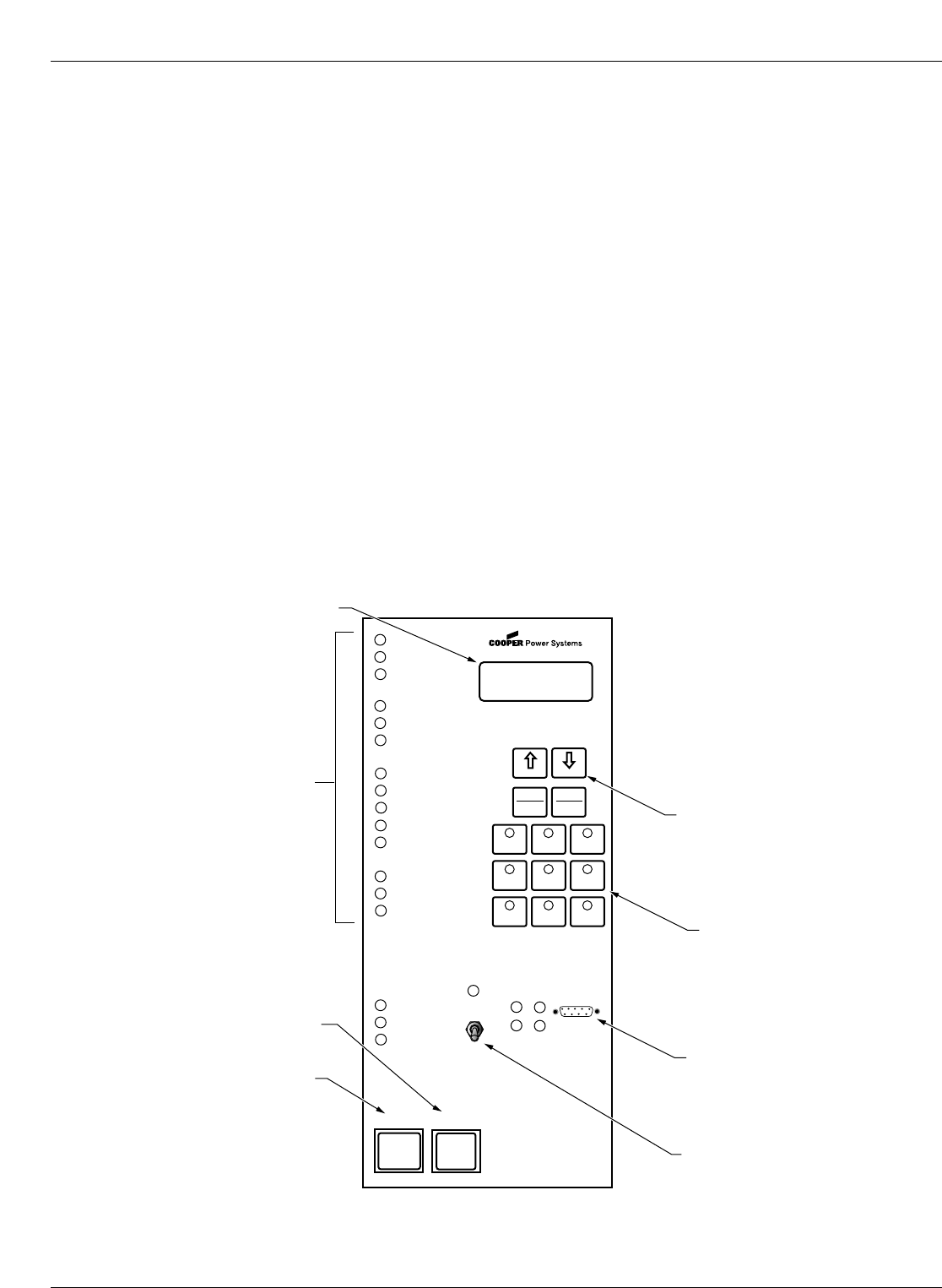
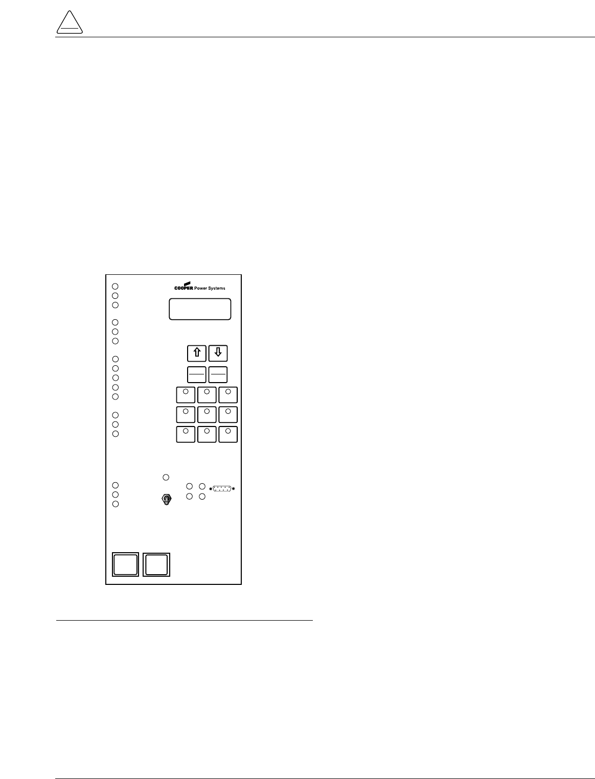
LED Indicators
LCD Display
TRIP (LOCKOUT)
Pushbutton
CLOSE Pushbutton
LCD Display Dedicated
Function Keys
Operation "Hot Keys"
RS232 Data Port
Hot Line Tag
Figure 2. 99005KM
Form 5 recloser control operator panel.
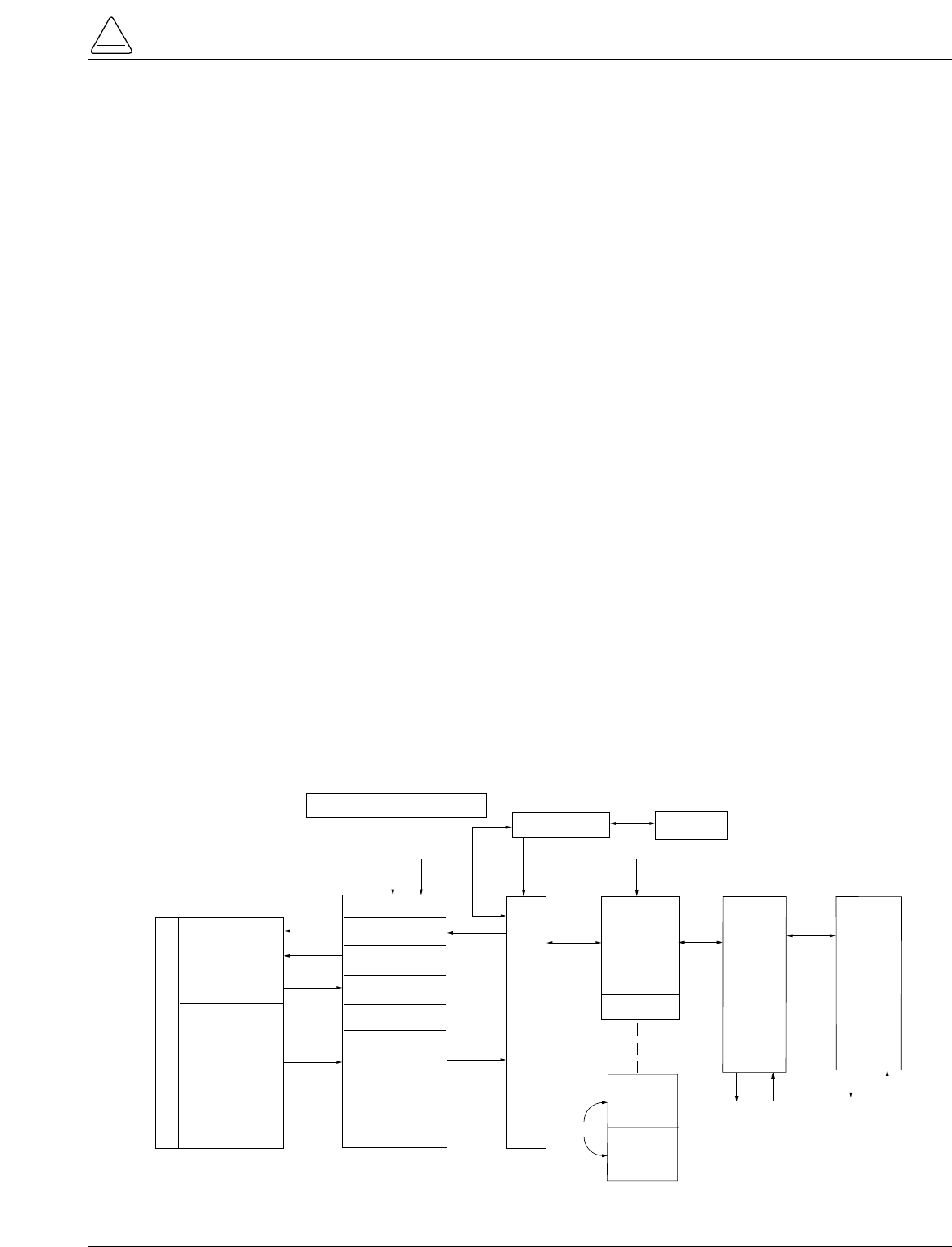
Current sensing is provided by three current transformers
located in the recloser and interfaced to the Form 5 control
via the control cable. This cable also supplies Trip, Close,
and Recloser status, and connects to the Recloser Inter-
face (RIF) module to provide isolation for reliable opera-
tion. Voltages for metering are also connected to the RIF
module via the connector terminal block, TB-1 (Figure 3).
A functional block diagram of the Form 5 control is shown
in Figure 3. Line current flowing through the recloser is
converted by the CPU module to a digital signal suitable
for metering and fault current calculations. Data sampling
occurs at a rate 32 times per cycle. The CPU contains a
data acquisition section that uses the acquired samples to
compute the fundamental currents and voltage for use in
overcurrent, under/over voltage and under/over frequency
protection, as well as currents and voltages for metering
functions. The current for overcurrent protection is calcu-
lated on a sub-cycle basis; it includes only the fundamen-
tal and DC component. For metering, the fundamental and
harmonic current and voltages are determined.
When the phase or ground current exceeds its pro-
grammed minimum-trip value and associated time-cur-
rent curve (TCC) timing, the control initiates the
programmed sequence of recloser tripping and reclosing
operations via the CPU and RIF modules. If the fault is
temporary, the control ceases to command recloser oper-
ations after a successful reclose, and the control resets to
the start of its operating sequence after a preset time
delay. If the fault is permanent, the control performs its
complete programmed sequence of reclose commands
and locks out with the recloser open. Once locked out, the
control must be closed via the operator panel or SCADA
communications. This resets the control to the start of the
operating sequence.
The following chain of events occurs for an operating
sequence of two trips to lockout:
1. The overcurrent signal is integrated with time on the
selected curve for the first trip operation (TCC1) to
produce the signal which energizes the trip circuit.
2. Energizing the trip circuit connects the battery and
capacitor to the trip solenoid to open the recloser.
3. Upon opening, the control starts timing on the first
reclosing interval-delay time.
4. Upon expiration of this reclosing interval-delay, a clos-
ing signal is issued from the control, closing the
recloser and selecting the time-current characteristics
for the second trip operation (TCC2).
5. If current remains above the minimum-trip level, the
tripping and reclosing sequence is repeated.
6. The control begins the reset-delay timer if the over-
current is cleared before the operating sequence
reaches lockout indicated by a closed recloser and
current below minimum trip.
7. When the reset-delay times out, the control is reset to
the home state and is ready for another programmed
operating sequence. If current rises above minimum
trip prior to the reset-delay timing out, the timer is
halted and the control resumes the operating
sequence while the accumulated reset-delay timing is
restarted.
S280-79-10
5
!
SAFETY
FOR LIFE
Figure 3.
Form 5 control operational flow diagram.
FORM 5 CONTROL DESCRIPTION
BATTERY
TRIP SOLENOID
CLOSE SOLENOID
A Ø CT
B Ø CT
C Ø CT
OPEN / CLOSE
SWITCHES
CT COMMON
RECLOSER RIF
OPTICAL
ISOLATION
OPTICAL
ISOLATION
OPTICAL
ISOLATION
OPTICAL
ISOLATION
MATCHING
TRANSFORMERS
AND SIGNAL
CONDITIONING
TB1 TERMINAL BLOCK
CUSTOMER P.T. INPUTS POWER SUPPLY
CPU
RS232
Or
FIBER-OPTIC
PORT
RS232
Or
FIBER-OPTIC
PCB
OPTIONS
OPERATOR'S
PANEL
KEYBOARD
LED's
LCD
RS232 PORT
DIF#1
(OPTIONAL)
DIF#2
(OPTIONAL)
USER
CONNECTIONS
6 unlatched outputs
6 latched outputs
12 inputs
12
12
USER
CONNECTIONS
6 unlatched outputs
6 latched outputs
12 inputs
12
12
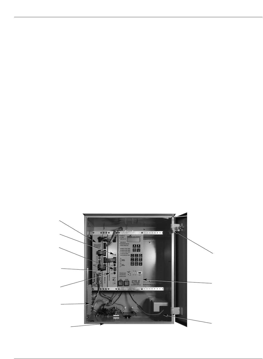
The Form 5 control is constructed in a modular fashion to
simplify service and the addition of accessories (Figure
4). The standard configuration incorporates a Central
Processing Unit (CPU) module, power supply module,
Recloser Interface (RIF) module, and an operator panel.
Discrete Interface (DIF) module(s), the fiber-optic board
and the RS-232 communication interface cards may be
ordered as accessories. Mounting provisions can be
provided to add customer-supplied radio and modem
modules.
Recloser Interface (RIF) Module
The Recloser Interface (RIF) Module provides the inter-
face between the recloser and the CPU module, as well
as the interface between the voltage sensors and the
CPU module. The RIF is designed to interface with the fol-
lowing reclosers: WE/WVE group, NOVA group,
VSA/VSO group, and KFME/KFVME (50Hz) group.
The recloser connector includes three current-trans-
former inputs, Open and Closed status sensing, and Trip
and Close controls. The voltage sensor connector
accepts six voltage inputs; three for source-side, and
three for load-side voltage. Two sets of dip switches,
located on the RIF front panel, utilize different switch posi-
tions to configure the desired voltage. See Figure 17.
The RIF board accepts either 12, 120, or 240 Vac voltage
inputs for metering. The factory configuration is outlined
on the module label and can be customized to user spec-
ification. See RECLOSER INTERFACE (RIF) MODULE
CONFIGURATION section of this manual.
Central Processing Unit (CPU)
Module
The CPU module is the center of the Form 5 control. The
CPU contains a 32-bit micro-controller, a Digital Signal
Processor, RAM and EEPROM memory, and a 16-bit
analog-to-digital converter. The CPU module accepts 16
analog inputs which it routes through the digital signal
processor, which samples 32 times per cycle, to compute
harmonic analysis to the 15th harmonic.
Discrete Interface (DIF) Module
The Discrete Interface (DIF) module allows users with
existing RTUs the ability to interface with the Form 5 con-
trol. The DIF module contains 12 inputs and 12 outputs
can be customized for a remote or supervisory function.
One Form 5 control can accommodate two DIF modules.
See DISCRETE INTERFACE (DIF) ACCESSORY sec-
tion of this manual.
Power Supply Module
The Power Supply module is designed to accept 100 to
134 Vac or 200 to 268 Vac user-supplied input power at
either 50 or 60 Hz.
The Power supply module (connection P9) provides aux-
iliary power to radio communications units, RTUs and
other accessories. The auxiliary output provides 24 Vdc
(12 Vdc is available) for user loads. The auxiliary power
supply has the capability to provide a load of up to 40 W
peak (1 second) and 3 W average. The auxiliary power is
fused and current-limited to prevent user loads from dis-
abling the control.
Kyle Form 5, Form 5 UDP, Form 5 DC NOVA Recloser Control Installation and Operation Instructions
6
Figure 4.
Form 5 UDP control operating panel with interface modules and radio mounting provisions.
99001KM
Control Cable Receptacle
and Control Grounding Lug
(located beneath cabinet) Control Battery
Central Processing
Unit (CPU) Module
Recloser Interface
(RIF) Module
TB1 Connector
Block
Power
Supply
Module
Power Capacitor
(Located behind operator
panel)
Grounding Strap
Manual Battery
Reconnect Button
Auxiliary Power
Connection (P9)
Form 5 Control Operator Panel
The Form 5 control operator panel (Figure 8) allows local
operation and status interrogation through built-in operator
controls and status displays. The operator panel contains
LED indicators, operational pushbuttons, membrane-type
functional/indication switches, backlit LCD display, and
Hot Line Tag switch with indication. An RS-232 port is also
provided to permit the temporary connection of a PC for
programming the parameters in the control.
All indicators with the exception of Hot Line Tag and
recloser status are automatically turned off after 5 minutes
of operator panel inactivity.
Reactivating is accomplished by pressing any operation
switch. The LCD messages will remain while in this
power-saving mode, although the illuminating backlight
will shut off.
LED Indicators
The operator panel LED indicators (Figure 5) give instant
information on the control and recloser status.
LED indicators include:
CONTROL OK
This green LED is illuminated when the continuous self-
diagnostics of the control have detected no CPU or mem-
ory malfunctions and indicate that the control is capable of
normal operation.
AC POWER
This green LED is illuminated when the presence of ac
input power to the control is sensed. The LED will turn off
if ac power is lost for more than 10 seconds.
ABOVE MIN TRIP
This red LED is illuminated when the control detects that
current is above the programmed minimum trip value for
Bushings 1-2, Bushings 3-4, Bushings 5-6, Ground, or
Sensitive Ground.
CHECK BATTERY
This red indicator illuminates for two conditions:
1. Battery voltage is below 20 Vdc or drops 2Vdc or more
during battery test.
2. The control fails a manual battery test. The LED will
remain on until a successful battery test is completed.
Refer to the Battery Test Procedure in this manual for
more information.
RECLOSER MALFUNCTION
This red indicator is illuminated when the control detects
a failure in a trip or close operation. It turns off automati-
cally if the recloser returns to the proper state.
REVERSE POWER FLOW
This red indicator illuminates when the control detects
power flow from the load side to the source side of the
recloser.
Note: Voltage sensor polarity and phase must be correct for
reverse power flow to function properly.
BUSHINGS 1-2 FAULT TARGET
BUSHINGS 3-4 FAULT TARGET
BUSHINGS 5-6 FAULT TARGET
GROUND FAULT TARGET
SENSITIVE GROUND FAULT TARGET
These red target LEDs illuminate when the control issues
an overcurrent trip signal while the respective phase cur-
rent or ground current exceeds the minimum pickup
value. Reset is accomplished automatically when Auto
Reset is activated and a successful close operation is per-
formed or manual reset is accomplished by pressing the
RESET TARGETS button on the control operator panel.
BUSHINGS 1-2 VOLTAGE
BUSHINGS 3-4 VOLTAGE
BUSHINGS 5-6 VOLTAGE
These red voltage LEDs illuminate when the control
detects the presence of voltage on the respective bush-
ings as connected to TB1. Refer to the Customer Con-
nections for AC Power section in these instructions to
determine the appropriate power connections.
RECLOSER CLOSED
This red indicator is illuminated when the control senses
that the recloser mechanism is in the closed position.
S280-79-10
7
!
SAFETY
FOR LIFE
Figure 5.
Form 5 control operator panel.
CONTROL OK
AC POWER
ABOVE MIN TRIP
REVERSE POWER FLOW
RECLOSER MALFUNCTION
CHECK BATTERY
BUSHINGS 1-2 FAULT TARGET
BUSHINGS 3-4 FAULT TARGET
BUSHINGS 5-6 FAULT TARGET
GROUND FAULT TARGET
SENSITIVE-GROUND FAULT TARGET
BUSHINGS 1-2 VOLTAGE
BUSHINGS 3-4 VOLTAGE
BUSHINGS 5-6 VOLTAGE
RECLOSER CLOSED
RECLOSER OPEN
CONTROL LOCKOUT
BACK NEXT
LAMP
TEST
CHANGE
RESET
TARGETS
RESET
MAX CURRENT
GND TRIP
BLOCKED
NON
RECLOSING
SUPERVISORY
BLOCKED
COLD LOAD
PICK UP
BLOCKED
BATTERY
TEST
FAST
TRIPS
DISABLED
ALTERNATE
PROFILE
NO. 1
ALTERNATE
PROFILE
NO. 2
ALTERNATE
PROFILE
NO. 3
HOT LINE
TAG ON
OFF
TX 3
RX 3
CLOSE
TRIP
(LOCKOUT) KYLE®
FORM 5
RECLOSER CONTROL
RS232
TX 2
RX 2

RECLOSER OPEN
This green indicator is illuminated when the control senses
that the recloser mechanism is in the open position.
CONTROL LOCKOUT
This green indicator is illuminated when the recloser is
open and a reclosing sequence is not in progress or when
the lockout handle on the recloser mechanism is in the
down position; i.e., trip and close circuits are open.
Note: The RECLOSER MALFUNCTION, RECLOSER OPEN,
RECLOSER CLOSED, and RECLOSER LOCKOUT
LEDs will flash upon detection of a trip failure. See the
Control Features section of this manual.
TRIP (Lockout) Pushbutton
The TRIP pushbutton (Figure 2) provides front-panel
access to trip (lockout) the recloser. When pressed, the
TRIP push-button opens the recloser and locks out the
control.
CLOSE Pushbutton
When pressed, the CLOSE pushbutton (Figure 2) returns
the control to the initial or home position, closing the
recloser. The control is ready for the start of a new
trip/close sequence.
Note: Pressing the CLOSE pushbutton from the Lockout posi-
tion, will initiate Cold Load Pickup (CLPU) protection, if
the feature is first enabled from the interface software
Protection Profile screen, and the COLD LOAD PICKUP
BLOCKED LED on the operator panel is not lit.
If the recloser is closed, pushing the CLOSE pushbutton
has no effect on the control. Depressing and holding the
CLOSE pushbutton does not activate the Cold Load
Pickup feature. See Cold Load Pickup in the Control
Features section of this manual.
The Form 5 control has a Manual Close Delay feature that
provides an interval of time from when the CLOSE push-
button is depressed to the time when manual close oper-
ation is performed. See Manual Close Delay in the
Control Features section of this manual.
LCD Display
The control operator panel has a large, backlit LCD dis-
play (Figure 6) used for viewing control parameters and
monitoring system conditions. Data is organized into
screens of information, with each display containing four
lines of information, with up to 20 characters per line.
Access to the screens is obtained through navigational
keys which permit the user to scroll through the menu in a
timely and efficient manner.
When an overcurrent trip occurs, the control automatically
displays the fault current values as shown on the LCD dis-
play as Screen 1. Refer to LCD Display Screens section
of this manual.
NEXT Key
Pressing the NEXT key causes the LCD display to scroll to
the next screen of available information. Pressing and hold-
ing the NEXT key causes the control to scroll to subsequent
screens at the rate of about two screens per second.
BACK Key
Pressing the BACK key causes the LCD display to scroll
to the previous screen of available information. Pressing
and holding the BACK key causes the control to scroll to
previous screen.
RESET TARGETS/RESET MAX
CURRENT Key
Pressing the RESET TARGETS/RESET MAX CURRENT
key resets the fault target indicators on the control opera-
tor panel. The fault current values shown on Screen 2 of
the LCD display will reset to values of zero.
Pressing and holding the RESET TARGETS/RESET
MAX CURRENT key for three seconds will reset the min-
imum and maximum current and histogram values in LCD
Display screens 34 through 37. This key will also reset the
Trip Failure Detection feature. See the Control Features
section of this manual.
CHANGE/LAMP TEST Key
Pressing this key for less than three seconds places the
control into a CHANGE mode for 10 seconds as indicated
by the LCD display. CHANGE mode permits the user to
change the state of the nine function/indicator switches on
the operator panel. Security is enhanced by permitting a
only one selection for each CHANGE mode period.
Pressing and holding the CHANGE/LAMP TEST key for
three seconds will cause the control to perform a front-
panel lamp test. In the Lamp Test Mode, the status indi-
cators flash three times (one second on, one second off).
All status indicators then return to their previous state.
While in the Lamp Test Mode, the control response to
operator panel keys is disabled, except for the TRIP
(LOCKOUT), CLOSE, and HOT LINE TAG switches.
Kyle Form 5, Form 5 UDP, Form 5 DC NOVA Recloser Control Installation and Operation Instructions
8
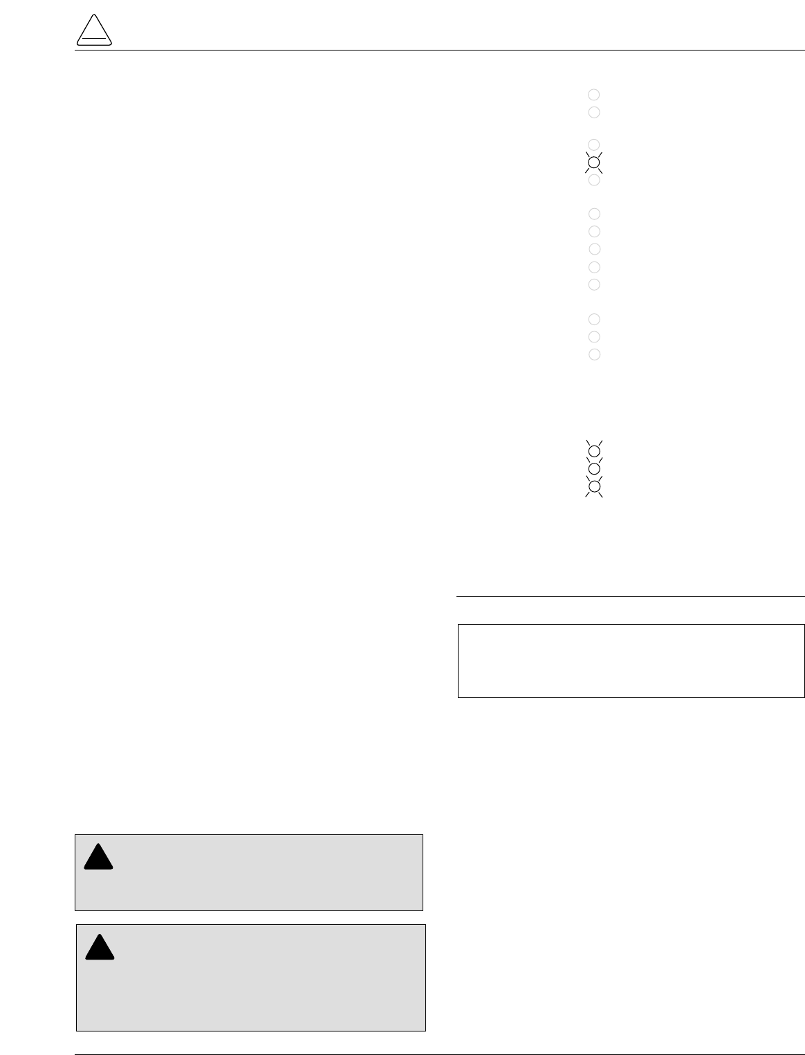
Figure 6.
LCD display and dedicated function keys.
NEXT BACK
RESET
TARGETS CHANGE
LAMP
TEST
RESET
MAX CURRENT

LCD Display Screens
Every LCD display screen contains a parameter name,
parameter value, and parameter units. If the control
detects that a parameter value is invalid, the LCD display
shows five dash characters (- - - - -) in the value field of the
screen. Demand metered values are indicated by (D) and
instantaneous values by (I).
S280-79-10
9
!
SAFETY
FOR LIFE
1 Gn d ____________ A
Ph1-2 ____________ A
Ph3-4 ____________ A
Ph5-6 ____________ A
2 Gnd Fault ____________ A
Ph1-2 Fault ____________ A
Ph3-4 Fault ____________ A
Ph5-6 Fault ____________ A
3 Freq Trip____________ Hz
Time Date
Present Freq ____________ Hz
4 Ph1-N VTrip ____________ V
Ph3-N VTrip ____________ V
Ph5-N VTrip ____________ V
Time Date
5 To t ____________ kWh
Ph1-2 ____________ kWh
Ph3-4 ____________ kWh
Ph5-6 ____________ kWh
6 Instant S1 Ph-N
Ph1-N ____________ V
Ph3-N ____________ V
Ph5-N ____________ V
7 Instant S1 Ph-Ph
Ph1-3 ____________ V
Ph3-5 ____________ V
Ph5-1 ____________ V
8 Instant S2 Ph-N
Ph2-N ____________ V
Ph4-N ____________ V
Ph6-N ____________ V
9 Instant S2 Ph-Ph
Ph2-4 ____________ V
Ph4-6 ____________ V
Ph6-2 ____________ V
Screen 1 – Instantaneous Load Current
Screen 1 displays line current values present for the last
overcurrent trip operation. Values are reset to zero when
the fault targets are reset.
Screen 2 – Fault Targets
Screen 3 – Frequency Trip
Screen 4 – Voltage Trip
Screen 8 – S2 Phase-to-Neutral, Instant. Voltage
Screen 5 – Power kWh
Screen 6 – S1 Phase-to-Neutral, Instant. Voltage
Screen 9 – S2 Phase-to-Phase, Instant. Voltage
Screen 7 – S1 Phase-to-Phase, Instant. Voltage
11 T ot ____________ kW
Ph1-2 ____________ kW
Ph3-4 ____________ kW
Ph5-6 ____________ kW
Screen 11 – Real Power
10 Instant S1-S2
Ph1-2 Dif ____________ V
Ph3-4 Dif ____________ V
Ph5-6 Dif ____________ V
Screen 10 – Instantaneous Voltage
12 T ot ____________ kVA
Ph1-2 ____________ kVA
Ph3-4 ____________ kVA
Ph5-6 ____________ kVA
Screen 12 – Instantaneous kVA

Kyle Form 5, Form 5 UDP, Form 5 DC NOVA Recloser Control Installation and Operation Instructions
10
14 T ot ____________ PF
Ph1-2 ____________ PF
Ph3-4 ____________ PF
Ph5-6 ____________ PF
15 G nd ____________ %THDI
Ph1-2 ____________ %THDI
Ph3-4 ____________ %THDI
Ph5-6 ____________ %THDI
16 Instant S1 Ph-N
Ph1-N ____________ %THDV
Ph3-N ____________ %THDV
Ph5-N ____________ %THDV
17 Demand S1 Ph-N
Ph1-N(d) ____________ V
Ph3-N(d) ____________ V
Ph5-N(d) ____________ V
19 Demand S2 Ph-N
Ph2-N(d) ____________ V
Ph4-N(d) ____________ V
Ph6-N(d) ____________ V
20 Demand S2 Ph-Ph
Ph2-4(d) ____________ V
Ph4-6(d) ____________ V
Ph6-2(d) ____________ V
13 T ot ____________ kVAr
Ph1-2 ____________ kVAr
Ph3-4 ____________ kVAr
Ph5-6 ____________ kVAr
Screen 17 – Demand Phase to Neutral Voltage
Screen 18 – Demand Phase-to-Phase Voltage
Screen 19 – Demand Phase-to-Neutral Voltage
Screen 13 – Instantaneous kVAR
Screen 20 – Demand Phase-to-Phase Voltage
Screen 14 – Instantaneous Power Factor
Screen 15 –Instantaneous Total Harmonic Distortion
Current
Screen 16 –Instantaneous Total Harmonic Distortion
Voltage
21 Demand S1-S2
Ph1-2(d) ____________ V
Ph3-4(d) ____________ V
Ph5-6(d) ____________ V
Screen 21 – Demand Voltage
18 Demand S1 Ph-Ph
Ph1-3 (d) ____________ V
Ph3-5(d) ____________ V
Ph5-1(d) ____________ V
22 G nd ____________ A
Ph1-2 (d) ____________ A
Ph3-4 (d) ____________ A
Ph5-6 (d) ____________ A
23 Tot (d) ____________ kW
Ph1-2(d) ____________ kW
Ph3-4 (d) ____________ kW
Ph5-6 (d) ____________ kW
24 T ot ____________ kVA
Ph1-2(d) ____________ kVA
Ph3-4(d) ____________ kVA
Ph5-6(d) ____________ kVA
Screen 22 – Demand Current
Screen 23 – Demand kW
Screen 24 – Demand kVA

S280-79-10
11
!
SAFETY
FOR LIFE
25 T ot ____________ kVAr
Ph1-2(d) ____________ kVAr
Ph3-4(d) ____________ kVAr
Ph5-6(d) ____________ kVAr
26 T ot ____________ PF
Ph1-2(d) ____________ PF
Ph3-4(d) ____________ PF
Ph5-6(d) ____________ PF
27 G nd ____________ %THDI
Ph1-2(d) ____________ %THDI
Ph3-4(d) ____________ %THDI
Ph5-6(d) ____________ %THDI
28 Demand S1 Ph-N
Ph1-N(d) ____________ %THDV
Ph3-N(d) ____________ %THDV
Ph5-N(d) ____________ %THDV
29 Gnd OC Trip ____________
Ph1-2 OC Trip ____________
Ph3-4 OCTrip ____________
Ph5-6 OC Trip ____________
30 SGF OC Trip ______
Operations ______
31 Battery Monitor
Normal _______ V
Normal _____ mA
Test _______ V
32 – Phase MT ______ A
ALT1 MT ______ A
ALT2 MT ______ A
ALT3 MT ______ A
Screen 25 – Total kVAr and kVAr per Phase
Screen 26 – Demand Power Factor
Screen 27 – Demand THD Current
Screen 28 – Demand THD Voltage
Screen 29 – Number of Trips for Ground and Phase
Screen 30 –Number of SGF Trips and Total Trip
Operations
Screen 31 – Battery Monitor
The Battery Monitor displays the battery voltage, current,
and voltage during a battery test. The Battery Monitor is
used with the Battery Test pushbutton. Refer to the Bat-
tery Test Procedure section of these instructions for
more information.
Screen 32 – Phase Minimum Trip Settings
Phase minimum trip settings are listed for the four protec-
tion profiles. Line 1 is the normal setting, ALT1 is profile
No. 1, ALT2 is profile No. 2, and ALT3 is profile No. 3.
Phase Minimum Trip Settings allow verification of trip set-
tings before selection of an alternate profile.
33 Gnd MT ______ A
Alt1 MT _______ A
Alt2 MT ______ A
Alt3 MT _______ A
Screen 33 – Ground Minimum Trip Settings
Ground minimum trip settings are listed for the four pro-
tection profiles. Line 1 is the normal setting, ALT1 is pro-
file No. 1, ALT2 is profile No. 2, and ALT3 is profile No. 3.
Ground Minimum Trip Settings allow verification of trip
settings before selection of an alternate profile.
34 Gnd Max ____________A
Time Date
Ph1-2 Max ____________A
Time Date
Screen 34 –Ground Max, Phase 1-2 Max Demand
Currents
35 Ph 3-4 Max ____________A
Time Date
Ph5-6 Max ____________A
Time Date
Screen 35 –Phase 3-4 Max, Phase 5-6 Max Demand
Currents
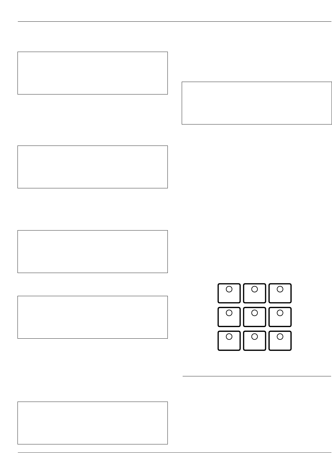
Operation/Indication Pushbuttons
Nine frequently used features are provided on the control
operator panel (Figure 7).
Note: These features are activated from the keypad, control
interface software or SCADA signal.
To initiate an operation from the operator panel, press the
CHANGE/LAMP TEST key to enter the CHANGE mode.
The operator has 10 seconds to select an operation and
modify settings. If no changes are made, the control will
return to its operational state prior to entering the
CHANGE mode. This prevents accidental changing of
settings.
Red LEDs located on each switch indicate the status of
the function, regardless of local or remote activation. For
example, if Cold Load Pickup was activated from a
SCADA signal, the red indicator would illuminate even
though it was not activated from the operator panel.
Note: Operation LEDs activated from local or remote sources
do not illuminate when the front panel is in the power-
save mode.
GND TRIP BLOCKED
Ground Trip Blocked is activated by pressing the
CHANGE/LAMP TEST key, then pressing the GND TRIP
BLOCKED key. The red indicator illuminates.
Kyle Form 5, Form 5 UDP, Form 5 DC NOVA Recloser Control Installation and Operation Instructions
12
GND TRIP
BLOCKED NON
RECLOSING
SUPERVISORY
BLOCKED
COLD LOAD
PICKUP
BLOCKED
BATTERY
TEST
FAST
TRIPS
DISABLED
ALTERNATE
PROFILE
NO. 1
ALTERNATE
PROFILE
NO. 2
ALTERNATE
PROFILE
NO. 3
Figure 7.
Operation/indication pushbuttons.
37 Ph3-4 Min ____________A
Time Date
Ph5-6 Min ____________A
Time Date
40 – Comm Port 2 ______
Protocol _______
Speed _______
Address _______
41 – Comm Port 3 ______
Protocol _______
Speed _______
Address _______
38 Fault Location
Distance ____________miles
<Control Identification>
Time Date
39 CPU Firmware X.XX
Firmware FW Database X
<Control Identification>
Time Date
Screen 38 – Fault Location
Screen 39 – Control Information
Screen 40 – Communication Port 2 Settings
This message displays the protocol settings (2179 or
DNP3.0), baud rate, and address for Serial Port #2.
Baud rate and address are set using the interface soft-
ware, while protocol is set at the factory based on user’s
specifications.
Screen 37 – Phase 3-4 Min, Phase 5-6 Min Currents
Screen 41 – Communication Port 3 Settings
This message displays the protocol settings (2179 or
DNP3.0), baud rate, and address for Serial Port #3.
Baud rate and address are set using the interface soft-
ware, while protocol is set at the factory based on user’s
specifications.
Note: Pressing and holding the RESET TARGETS/RESET
MAX CURRENT key for three seconds will reset the
minimum and maximum Demand values.
36 Gnd Min ____________A
Time Date
Ph1-2 Min ____________A
Time Date
Screen 36 –Ground Min, Phase 1-2 Min Demand
Currents
Note: Demand currents are a time integrated value and do not
reflect minimum or maximum instantaneous currents.
The demand integration time constant is set via the inter-
face software demand metering screen. These are the
same values displayed in the histogram screen.
NON RECLOSING
Non-reclosing mode disables any automatic reclosing
operations. Non-reclosing does not alter the active TCC.
The feature is activated by pressing the CHANGE/LAMP
TEST key, then pressing the NON RECLOSING key. The
red indicator illuminates.
SUPERVISORY BLOCKED
Supervisory Blocked disables supervisory SCADA and the
interface software; remote SCADA remains active. Opera-
tional data and metering information are available while
the control is in the SUPERVISORY BLOCKED position.
The TRIP and CLOSE pushbuttons are active indepen-
dently of the SUPERVISORY BLOCKED function.
Activation of the feature is restricted to the operator panel
keypad by pressing the CHANGE/LAMP TEST key, then
pressing the SUPERVISORY BLOCKED key.
COLD LOAD PICKUP BLOCKED
The Cold Load Pickup feature is blocked while the COLD
LOAD PICKUP BLOCKED is active. When CLPU is not
blocked, the control utilizes the Cold Load Pickup TCC,
reclose interval, operations to lockout and minimum trip set-
tings in lieu of the normal first operation protection settings.
Note:
The Cold Load Pickup Blocked key is replaced by the SEN-
SITIVE GROUND FAULT key on international controls.
BATTERY TEST
Depressing the BATTERY TEST key performs a control
battery test. The red indicator illuminates and turns off
automatically when the control has finished performing the
test. Refer to the Battery Test Procedure section of these
instructions for further details on testing the control battery.
FAST TRIPS DISABLED
Fast Trips Disabled commands the control to use the pro-
grammed Fast Trips Disabled time-current curve for all
tripping operations.
ALTERNATE PROFILE Indicator/Key
The control has four separate protection profiles; a normal
profile, and Alternate Profiles 1, 2, and 3. Each profile
changes all protection parameters for the control. Except for
the normal profile, each has an indication and selection key.
During control operation, if the three alternate profile indica-
tor lights are not illuminated, the normal profile is active.
To select an alternate profile, press the CHANGE/LAMP
TEST key, then press the desired alternate profile. To
return to the normal profile, simply turn off the active alter-
nate profile. These functions can also be operated
remotely via communications interfaces.
Note: Program all protection profiles. Program unused alter-
nate profiles should be programmed with the same set-
ting as one of the applicable profiles. Default settings on
unused alternate profiles can cause unnecessary out-
ages if they are below normal system requirements.
Note: The minimum trip values for each protection profile are
shown on Screens 32 and 33 of the LCD display. Check
these minimum trip values prior to changing an alternate
profile to avoid misoperation of the control under load
conditions.
Note: On Form 5 UDP controls, Alternate Profile 3 is replaced
with SWITCH MODE.
HOT LINE TAG Switch
Hot Line Tag is provided for live-line work applications. All
closing operations are disabled when the Hot Line Tag
feature is activated. While active, the control utilizes an
independent, user-selectable time-current curve for trip
operations.
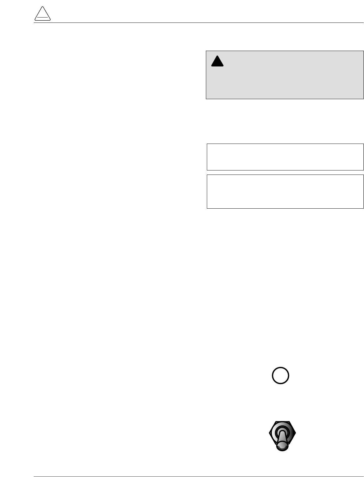
The Hot Line Tag feature (Figure 8) consists of a toggle
switch and an LED indicator which illuminates when the
function is active. When active, Hot Line Tag prevents all
closing attempts and shifts protection to one trip to lockout
on the programmed time-current curve. The Hot Line Tag
function takes precedence over Cold Load Pickup, Non
Reclosing, and Fast Trips Disabled.
Activation is accomplished by placing the operator panel
toggle switch to the ON position, or via SCADA command.
Hot Line Tag is activated from the operator panel, com-
munication Port 2, communication Port 3, or a Discrete
Interface Module (DIF). All sources must be off to de-acti-
vate Hot Line Tag.
The Hot Line Tag feature may only be reset by the source
which initiates the function. For example, if Hot Line Tag
is activated at the operator panel, resetting the function is
only possible at the operator panel, and not via SCADA
command. For SCADA, Hot Line Tag must be disabled
via the same port number where Hot Line Tag was origi-
nally enabled.
S280-79-10
13
!
SAFETY
FOR LIFE
HOT LINE
TAG ON
OFF
Figure 8.
Hot Line Tag Switch.
WARNING: Hazardous voltage. Do not use Hot
Line Tag as a substitute for a visible disconnect.
Always establish a visible disconnect prior to perform-
ing any work requiring a de-energized line. Failure to
comply may cause death, severe personal injury, or
equipment damage. T276.0
!
IMPORTANT: Hot Line Tag is intended solely for
live-line work applications, such as maintenance,
repairs or improvements to the distribution system, that
occur while the line remains energized.
IMPORTANT: Hot Line Tag activation does not
cause the recloser to trip open. It only prevents the
recloser from closing.
RS-232 Communication Port
The standard Form 5 control is equipped with a operator
panel RS-232 port for interface with a personal computer
running the Form 5 interface software program. This nine-
pin female data communication equipment (DCE) Port 1
permits the uploading of all programming information
stored in the control, including protection profiles, event
recorder, data profiles, alarms, counters, and metering
information. Port 1 provides a simple means to download
operating parameters from a personal computer to the
control.The protocol, baud rate and address for Port 1 are
identified from the LCD display.
If a fiber-optic or RS-232 accessory board is connected to
Port 2 (located on the back of the operator panel) any
external electrical connection from the operator panel will
disable the accessory board.
Note: The operator panel RS-232 port is intended only for
temporary connection of a personal computer. Perma-
nent serial communications must be made via the RS-
232 or fiber-optic accessory board.
Battery Test Procedure
The condition of the control battery is tested by depress-
ing the BATTERY TEST hot key on the operator panel. No
external current/voltage meter is necessary for testing.
The control performs a self-test every 12 hours or when
initiated by an external command. When a battery test is
initiated, the spurious charge is first drained to allow the
battery voltage to equalize. A 10-ohm, 55-watt resistor is
then placed across the battery terminals and a voltage
drop is calculated. If the drop from the equalized voltage
to the test voltage exceeds 2 volts, then the CHECK BAT-
TERY LED is illuminated.
To perform a battery test:
1. Using the Next and BACK keys, scroll through the
LCD display to Screen 31, the Battery Monitor screen.
2. Record the NORMAL VOLTS and NORMAL CUR-
RENT readings from the screen.
Note: Voltage should be between 25 to 31 volts with
higher readings at colder temperatures. Under nor-
mal conditions with ac connected and the battery
trickle charging, the current should read less than
20 mA. With ac connected and in bulk charging
mode, current will range from 12 to 600 mA. With ac
disconnected and the battery supplying the load,
current will read -180 mA to -600mA depending on
accessories connected.
3. Momentarily, press the CHANGE/LAMP TEST key,
then BATTERY TEST key.
Note: AC power can be either connected or disconnected
for Step 3.
4. Record the TEST VOLTS reading from the LCD and
the status of the CHECK BATTERY LED. Service the
battery if the CHECK BATTERY LED is illuminated.
Control Features
The Form 5 recloser control offers numerous standard
features and accessories that allow the user the utmost
flexibility in designing a control suitable for their applica-
tion requirements.
Under/Over Frequency Loadshedding
The Form 5 control includes provisions for frequency
loadshedding that trips the recloser for conditions of under
or over system frequency. Access to this feature is
through frequency threshold, trip time, and allowable volt-
age threshold.
With the auto-restoration feature, the Form 5 can be set to
close the recloser after the system frequency and voltage
have recovered. Parameters available for setting include
frequency and voltage thresholds and time delay.
A frequency alarm is available and can be configured for
notification.
Voltage Protection (120 Vac-based)
Voltage protection functionality is included as standard on
all Form 5 controls. A recloser trip will be issued for under
and over voltage conditions when the monitored voltage
falls outside user-specified limits for a selectable time.
Response mode includes any single-phase, all three
phases, and single-phase with three-phase inhibit.
Response mode facilitates protecting against a single
phase condition common when a high side fuse operates
on a distribution transformer. Parameters are also avail-
able to provide auto restoration after a trip. A voltage
alarm is available and can be configured for notification.
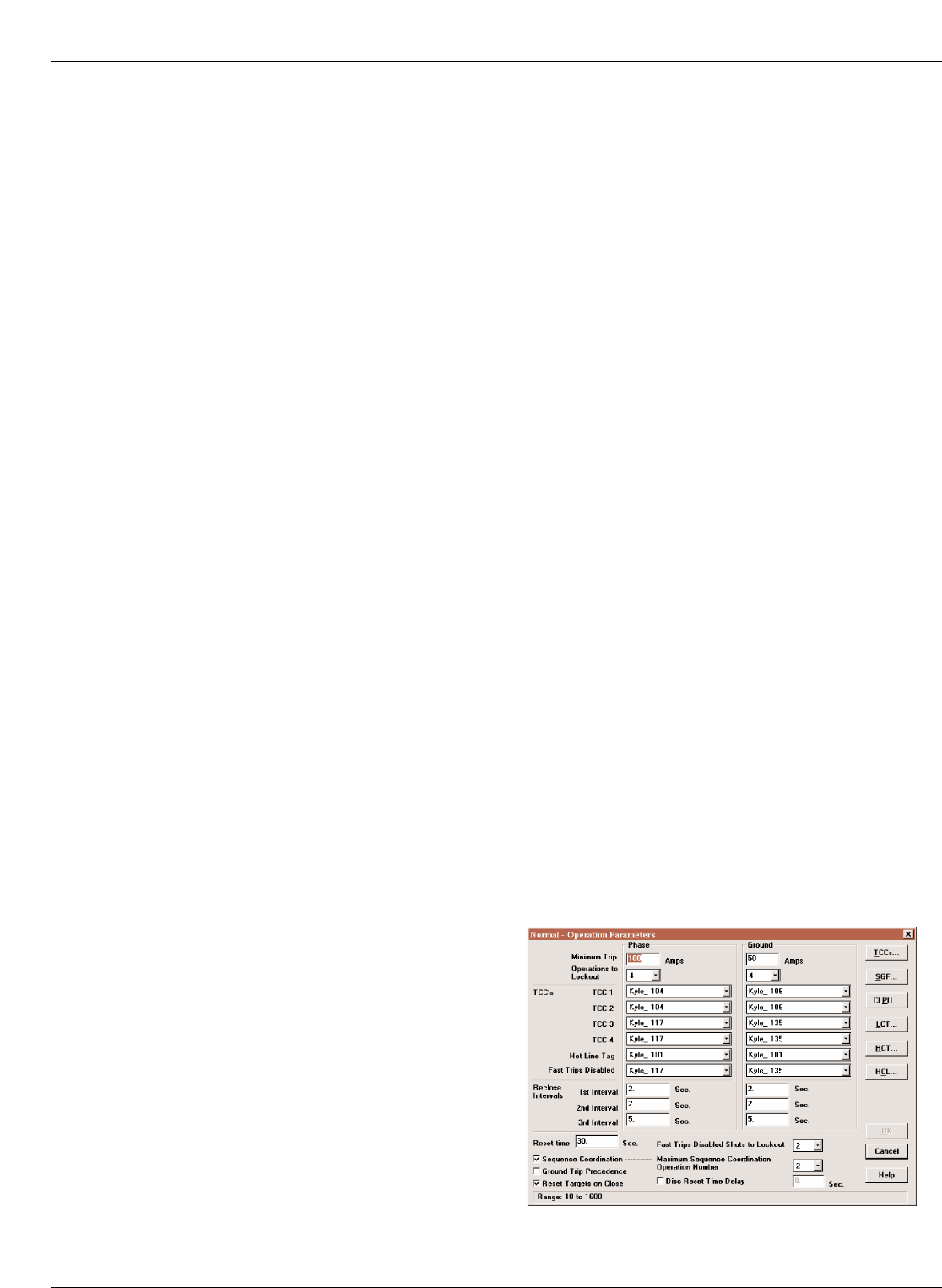
Protection Profiles
Four separate protection profiles are included to allow the
user to adapt overcurrent settings for varying system con-
ditions such as load, live line work or weather. The active
profile is selected from the operator panel or with the inter-
face software or SCADA (Figure 9). Each profile has 14
TCC specifications plus reclose intervals, sequence coor-
dination and reset times to maintain independent protec-
tion parameters.
Kyle Form 5, Form 5 UDP, Form 5 DC NOVA Recloser Control Installation and Operation Instructions
14
Figure 9.
Interface software sample protection profile.
Power Metering
Power metering includes single- and three-phase Watts,
VARS, KVARS, KWH measurements, and the per phase
and total system Power Factor (PF).
Power Factor Sign Metering
This feature allows a user to configure the sign that is
applied to the power factor. The user may select between
the standard definition of power factor (cosine of angle
between current and voltage) or the Cooper Power Sys-
tems default of the power factor sign following power flow.
Voltage Metering
Six voltages (3-source and 3-load) are metered as stan-
dard on the Form 5 control. The user selects either phase-
to-phase or phase-to-ground values from the control
operator panel, interface software, or serial communica-
tions. This reference is changed by selecting the voltage
sensor correction in the “Hardware” setup portion of the
interface software.
Fast Trips Disabled
Fast Trips Disabled provides the user a quick and effi-
cient method for reducing momentary interruptions or
“blinks”. When activated from the front keypad, pro-
grammed trips to lockout will time according to the
selected time-current curve for Fast Trips Disabled. This
curve is programmable for both phase and ground on
each protection profile. A separate trips-to-lockout setting
is also provided. See Figure 9.
Trip Failure Detection
The Trip Failure Detection feature is an internal diagnos-
tic alarm for verifying the proper operation of circuit trip-
ping and fault clearing of the recloser. Trip Failure
detection indicates the recloser has failed to trip all
phases following a trip signal from the control. Failure to
trip is assumed if a current of at least 10 Amps is detected
approximately 2 seconds after the trip signal is initiated.
Upon activation of the feature, these four LEDs flash 1
second on, 1 second off (Figure 10):
•RECLOSER MALFUNCTION
•RECLOSER CLOSED
•RECLOSER OPEN
•CONTROL LOCKOUT
The Trip Failure Detection alarm may be triggered from
many potential sources including mechanical, electrical,
control, or interrupter failure. Interrupter failure may
include loss of vacuum in a vacuum interrupter.
To clear Trip Failure Alarm, depress and hold the RESET
TARGETS/RESET MAX CURRENTS keypad for 3 sec-
onds. This also resets targets and demand currents.
Note: There is no remote reset available with the trip failure
detection feature. It cannot be remotely turned off.
When the trip failure alarm is activated, an event is
recorded and a status alarm activated (if enabled) and
preserved during system resets.
To test the Trip Failure Detection feature, see Testing
With Type MET Tester in the TESTING AND TROU-
BLESHOOTING section of this manual.
S280-79-10
15
!
SAFETY
FOR LIFE
AC POWER
ABOVE MIN TRIP
REVERSE POWER FLOW
RECLOSER MALFUNCTION
CHECK BATTERY
BUSHINGS 1-2 FAULT TARGET
BUSHINGS 3-4 FAULT TARGET
BUSHINGS 5-6 FAULT TARGET
GROUND FAULT TARGET
SENSITIVE-GROUND FAULT TARGET
BUSHINGS 1-2 VOLTAGE
BUSHINGS 3-4 VOLTAGE
BUSHINGS 5-6 VOLTAGE
RECLOSER CLOSED
RECLOSER OPEN
CONTROL LOCKOUT
Figure 10.
RECLOSER MALFUNCTION, RECLOSER CLOSED,
RECLOSER OPEN and CONTROL LOCKOUT LEDs
will blink for the affected phase as indication of Trip
Failure.
DANGER: Explosion. Stay clear of a recloser
that is in a trip failure mode. A recloser in trip fail-
ure mode may explode resulting in death or severe per-
sonal injury. T271.0
!
IMPORTANT: The recloser must be isolated and de-
energized immediately upon detection of trip failure.
Follow proper procedures and safety practices to iso-
late and de-energize the recloser.
WARNING: Hazardous voltage. This device is
not a substitute for a visible disconnect. Follow all
locally approved safety practices. Failure to follow
proper safety practices can result in contact with high
voltage, which will cause death or severe personal
injury. G112.1
!
Manual Close Delay
Manual Close Delay provides a delay from the time that
the manual CLOSE button is pushed to the time the man-
ual close operation is performed.
The delay is programmable from 0 to 60 seconds in 1 sec-
ond increments. A programmed delay value can be over-
ridden for immediate closing by pressing the CLOSE
button a second time.
An active Manual Close Delay can be canceled by press-
ing the TRIP/LOCKOUT button.
The default setting has the feature disabled (0 seconds).
The RECLOSER CLOSED LED indicates the status of the
feature. See Figure 11.
Harmonic Analysis
Extensive harmonic analysis is performed by the Form 5
control for both currents and voltages. Analysis is per-
formed on-line (updates every 30 seconds) or demand
integrated to user-specified time values. The Total Har-
monic Distortion (THD) for current and voltage is available
from the operator panel display (Figure 12) while com-
plete analysis, including graphing capabilities, is provided
from the Form 5 interface software.
Reverse Power Flow
Feeder load monitoring is enhanced with the inclusion of
the power flow monitoring feature. When power flow from
the load to the source side of the recloser is detected, the
control illuminates an operator-panel indicator. Response
time to a reverse power condition is one second. An alarm
is also available for remote interrogation.
Note: Voltage sensor polarity must be correct for reverse
power flow to function properly.
Event Recorder
The Event Recorder maintains a log of operating events
for later readout and analysis by the user. Approximately
500 events can be stored in non-volatile memory. For
each event type, time of occurrence, and other relevant
information is stored. When the event recorder has
reached is capacity, the oldest event is deleted as a new
event is added.
Histograms
Demand metered voltages and currents can be reported
using the histogram tool. It displays the number of occur-
rences of a variable versus its value in between user-
defined minimum and maximum limits. Date and time are
recorded for the maximum and minimum demand values.
Data Profiler
A fully configurable data profiler is available which allows
the user to collect information by sampling demand data
at selectable intervals. These time-stamped values can
then be plotted to determine weekly load profiles, daily
harmonic disturbances or hourly voltage fluctuations. The
data profiler can provide more than 200 days of informa-
tion, depending upon configuration parameters.
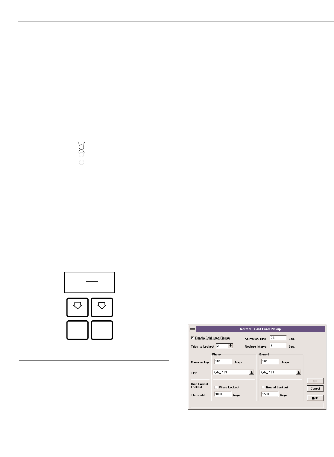
Cold Load Pickup
Cold Load Pickup (CLPU) must be enabled through the
interface software (Figure 13) before it can be activated
remotely or from the CLOSE pushbutton on the operator
panel. The CLPU feature provides the user with the abil-
ity to alter protection for abnormal system conditions. It is
active for a programmable time interval which begins with
each manual close. Once this time elapses, protection
reverts back to the programmed sequence. Use the Form
5 control interface software to program the activation time
and time-current characteristics applicable to Cold-Load
Pickup.
Note: When CLPU is active, the control utilizes the Cold Load
Pickup TCC, reclose interval, operations to lockout, and
minimum trip settings in lieu of the normal protection
settings.
Kyle Form 5, Form 5 UDP, Form 5 DC NOVA Recloser Control Installation and Operation Instructions
16
Figure 13.
Interface software Cold Load Pickup settings.
Figure 12.
Form 5 operator panel harmonic readout.
NEXT BACK
RESET
TARGETS CHANGE
Pg14 Gnd %THDI
Ph1-2 %THDI
Ph3-4 %THDI
Ph5-6 %THDI
RESET
MAX CURRENT
LAMP
TEST
RECLOSER CLOSED
RECLOSER OPEN
CONTROL LOCKOUT
Figure 11.
The blinking of the RECLOSER CLOSED LED indi-
cates Manual Close Delay is active.
Alarms
Status and data alarms are available for many control
parameters such as voltage, currents, thresholds. Data
alarm function compares metered data to user-pro-
grammed alarm high and low limits and issues an alarm of
user-specified priority if limits are exceeded. The status
alarm function monitors status and issues an alarm of
user-defined priority when the user programmed alarm
conditions are met. The alarms are reported via commu-
nication ports and can be configured to trigger a data pro-
file and event record. Alarms do not affect the protection
functions of the control.
Fault Location
Fault Location provides an approximate distance of a fault
from the the Form 5 Control The distance is based on the
current fault magnitude, the type of fault, and system
parameters entered by the user. The LCD display (Screen
38) identifies the estimated distance in miles or kilometers
(km) from the control.
The fault location algorithm performs an impedance cal-
culation based on:
•Single-phase to ground fault
•Phase-to-phase fault
•Double-line to ground fault
•Three-phase fault
This information is recorded as an event in the control
Event Recorder for retrieval. The fault location algorithm
does not require voltage sensing. If the location cannot be
determined, no event is recorded and dashes are dis-
played on the LCD screen.
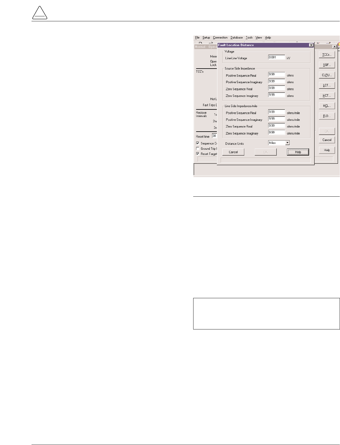
Setting the parameters for Fault Location is done through
the interface software. The user enters line impedance
parameters and system voltage information into the soft-
ware via the Protection Profile menu. See Figure 14.
The following system parameters must be entered via the
Protection Profile menu for each profile:
•Nominal system line-to-line voltage
Note: If the Fault Location feature is not desired, the nom-
inal system voltage parameter should be set at 1.
•Source-side zero sequence and positive sequence
impedance. This includes impedance up to the loca-
tion of the Form 5 control.
•Line-side zero sequence and positive sequence
impedance per mile or km.
•The distance units of the line impedance in miles or
km.
Refer to Service Information S280-79-2 Form 5 Micropro-
cessor-Based Recloser Control Programming Guide for
additional information.
S280-79-10
17
!
SAFETY
FOR LIFE
IMPORTANT: Fault Location is not a protection func-
tion. Its purpose is to define a fault and provide its
approximate location relative to the Form 5 control
detecting the fault.
Figure 14.
Fault Location configuration screen.
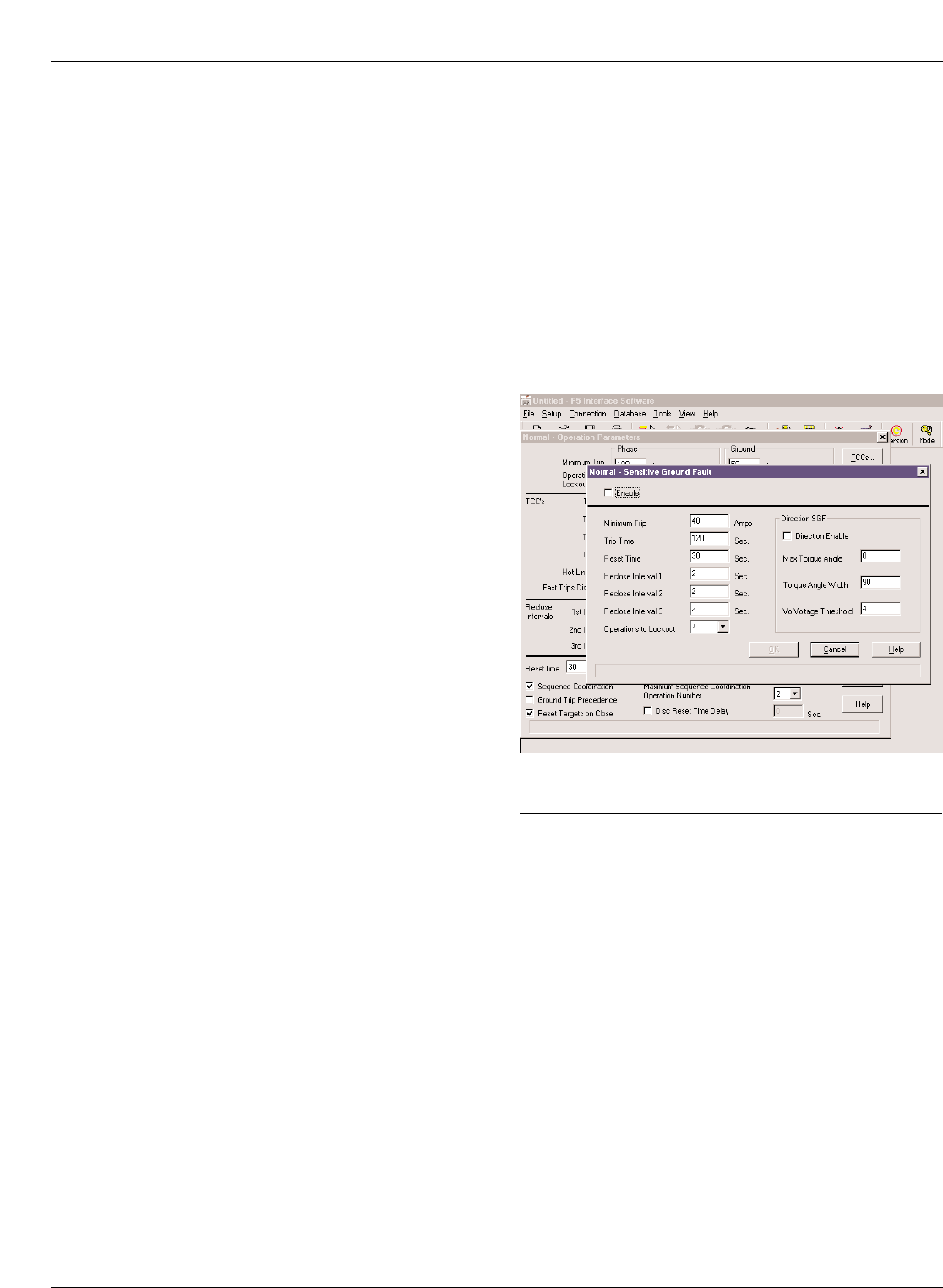
Directional Sensitive Ground/Earth
(SGF/SEF) Fault
The Directional SGF/SEF Fault feature adds directional
capabilities to the SGF/SEF protection features. It pro-
vides a sensitive ground/earth trip if the fault is downline
of the recloser on a radial distribution system. Directional
SGF/SEF is used on ungrounded Delta systems for sup-
pression of ground trips for faults occurring on other circuit
branches.
The user sets the parameters for Direction SGF/SEF
through the interface software via the Protection Profile
menu. See Figure 15. In addition to the normal (non-direc-
tional) SGF/SEF settings, the user enters the following
directional SGF/SEF parameters:
•Direction Enable
Note:
If Direction Enable is not selected, SGF/SEF tripping
occurs through normal (non-directional) settings.
•Maximum Torque Angle (-180°to 180°, in 1°increments)
•Torque Angle Width (10°to 90°, in 1°increments)
•Zero Sequence Voltage (V0)Threshold (4 to 130 V)
The Maximum Torque Angle parameter determines the
angle of maximum tripping sensitivity between the phase
angle of the zero sequence voltage and current at the time
of fault. The setting of this value depends on knowledge
of the power system. Typically, a resistive fault has a
value of 0°, and a capacitive fault has a value of 90°.
Torque Angle Width parameter restricts the tripping to an
angle of plus or minus the specified width about the
Torque angle setting. For example, if the Maximum
Torque Angle is 45°, and the Torque Angle Width is set for
10°, then the control will trip at angles between 35°and
55°.
The Zero Sequence Voltage Threshold is used to set the
threshold voltage below the disabled directional SGF/SEF
tripping voltage.
Note: In most cases, a default value of 4 is adequate.
Directional SGF/SEF Fault is recorded as an event in the
control Event Recorder for retrieval. Refer to Service Infor-
mation S280-79-2 Form 5 Microprocessor-Based Recloser
Control Programming Guide for additional information.
Kyle Form 5, Form 5 UDP, Form 5 DC NOVA Recloser Control Installation and Operation Instructions
18
Figure 15.
Directional SGF/SEF configuration screen.
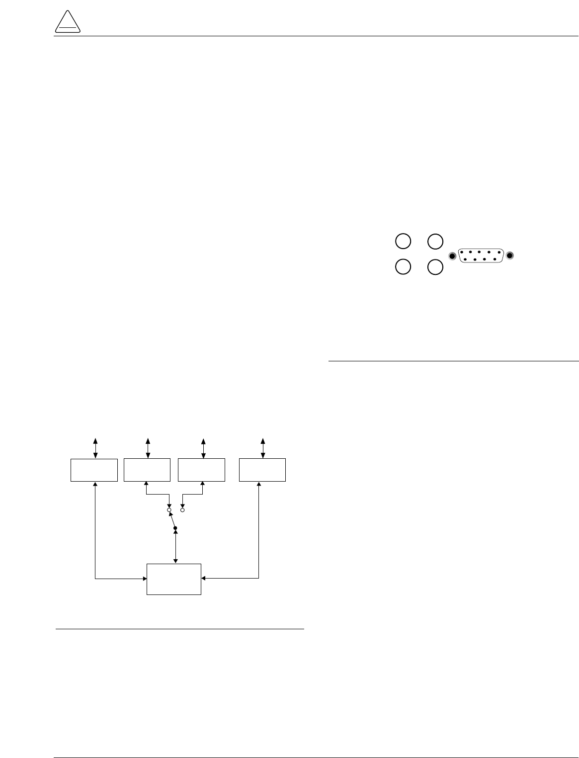
Communications
Communication Ports
The Form 5 control has three communication ports from
the CPU module. Two of the three ports are user-acces-
sible. Communication Port 1 is the operator panel LCD
display where data is exchanged between the CPU and
the operator panel. Though not user-configurable, Port 1
allows for flexible modifications to the front panel for cus-
tom applications.
The operator panel RS-232 communication Port 2 pro-
vides temporary local personal computer (PC) access
when connected with a standard 9-pin cable. Port 2 pro-
vides a dual communication interface for the user. The
port includes a software switch for two external connec-
tions; the operator panel RS-232 DB-9 connector, or the
fiber-optic/RS-232 communication accessories. Local
connection to the operator panel RS-232 connection
takes precedence over the communication accessory.
Disconnecting the operator panel RS-232 communication
automatically reconnects the communication accessory
to Port 2.
Accessory Ports 2 and 3 are resident on the back of the
operator panel and can be configured to either 2179 or
DNP3.0 protocols. Port 3 provides uninterrupted commu-
nication to the RS-232 or Fiber-Optic accessory, and is
not affected by any other port or physical connection.
Figure 16 illustrates the communication configuration for
serial ports1, 2, and 3.
Fiber-Optic/RS-232 Accessory
Two sets of receive and transmit LEDs (Figure 17) are
provided on the operator panel for fiber-optic and RS-232
communications. The TX2 and RX2 LEDs illuminate when
communicating with the operator panel RS-232 port. The
TX3 and RX3 LEDs illuminate when communicating with
either the fiber-optic or RS-232 interface accessory
boards on communication Port 3.
The RS-232 accessory board and the fiber-optic acces-
sory boards are located behind the operator panel. Each
accessory board can be connected to either Port 2 or Port
3; no two boards can use the same port. The operator
panel LEDs indicate the status of communication on the
accessory boards. Temporary connections to the operator
panel RS-232 port disables fiber-optic or RS-232 commu-
nication at Port 2.
Port 3 provides uninterrupted communication to a
remote terminal unit (RTU). Refer to S280-79-4 Form 5
Serial communications Accessory Operation Instruc-
tions for additional information.
Protocols
Three protocols are available for the Form 5 control and
are factory-configurable to communication Ports 2 and 3.
The protocols are:
•Cooper Power Systems 2179
•DNP3.0, Level 3
•S-Comm Protocol accessory
Protocol DNP3.0 includes “Unsolicited Report by Excep-
tion” functionality and Protocol 2179 includes 2-bit status
functionality.
Complete documentation for Cooper Power Systems pro-
tocols are:
•Reference Data R280-90-12, Serial Communication
Protocol 2179
•Reference Data R280-90-13, Communication Point
Database for Protocol 2179
•Reference Date R280-90-14, Communication Point
Database for Protocol DNP3.0
Control Information
Control information, including firmware version and
database version, is factory installed and can not be
altered by the user. This information is accessible from
the LCD display, Screen 39.
Communication Ports 2 and 3 settings can be referenced
from the LCD display, Screens 40 and 41 respectively.
(Port 1 shares the same settings as Port 2.)
S280-79-10
19
!
SAFETY
FOR LIFE
COMMUNICATIONS
PORT 1
(Internal Use Only)
COMMUNICATIONS
PORT 2
(Shared)
(Metering, Histograms
Profiles, Alarms, Targets)
CPU
TEMPORARY
ENGINEERING
(Local PC)
OPERATOR PANEL
DISPLAY AND
KEYPAD
OPERATIONS
OPERATOR
PANEL
RS-232
ENGINEERING
(Radio, Fiber-Optic, Modem)
RS-232 or
FIBER-OPTIC
ACCY
RS-232 or
FIBER-OPTIC
ACCY
SCADA SYSYEM
(Radio, Fiber-Optic, Modem)
COMMUNICATIONS
PORT 3
(Dedicated)
AUTO TRANSFER
SWITCH
(Operator Panel
Connection Disables
Accessory)
Figure 16.
Control communication port configuration.
TX 2
RX 2
TX 3
RX 3 RS232
Figure 17.
Fiber-Optic/RS-232 receive and transmit LEDs and
data port on the operator panel. The TX2 and RX2
LEDs illuminate during communication with the
operator panel RS-232 port.
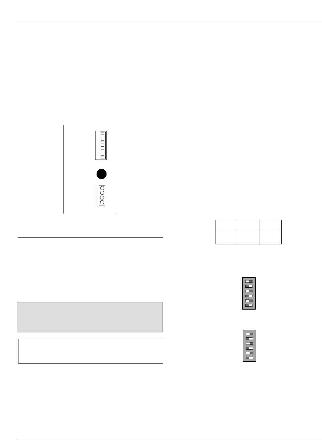
AUXILIARY POWER FOR
ACCESSORIES
Connection P9 (Figure 18) on the Power Supply module
provides 24Vdc (12Vdc is available) to power radio com-
munication units, RTUs and other accessories. The auxil-
iary power provides 40W peak load capability. Auxiliary
power is fused and current-limited to prevent user loads
from disabling the control.
Customer 28V connections for auxiliary power are made
to terminals 3 and 1 and are continually energized. Ter-
minal 2 and 4 are not used at this time.
RECLOSER INTERFACE (RIF)
MODULE CONFIGURATION
The Recloser Interface (RIF) Module is factory-configured
at 120Vac. For operating voltages other than 120Vac, the
RIF module must be removed from the control cabinet for
configuration.
To remove the RIF Module for configuration:
1. Disconnect the control battery.
2. Remove the four connectors from the front of the RIF
Module.
3. Remove the nut and disconnect the grounding strap to
the operator panel. See Figure 4.
4. Disconnect the wiring harness connectors from the
bottom of the RIF Module.
Note: Press the locking tabs to release the harness con-
nectors.
5. Remove the four 11mm (.437 in) screws securing the
board to the mounting bracket.
6. Pull the module out of the cabinet.
The dip switches are located on the side of the module.
7. Configure the RIF board as shown in Figure 19.
8. After configuration, place the module back into posi-
tion in the control cabinet and secure to the mounting
bracket with screws previously removed.
9. Replace nut securing the RIF Module grounding strap
10. Replace all connectors on the front and bottom of the
RIF Module.
Kyle Form 5, Form 5 UDP, Form 5 DC NOVA Recloser Control Installation and Operation Instructions
20
CAUTION: Equipment damage. Always wear a ground-
ing wrist strap to control static electricity before handling
circuit boards. Failure to use this strap may result in cir-
cuit board damage. T253.1
INPUT VOLTAGE
SELECTION
INPUT VOLTAGE
SELECTION
POLE 2
POLE 1
POLE 2
POLE 1
S7
S8
POLE 1
POLE 2
POLE 2
POLE 1
POLE 2
POLE 1
POLE 1
POLE 2
S7
BUSHING 2 (XØ)
BUSHING 4 (YØ)
BUSHING 6 (ZØ)
BUSHING 1 (AØ)
BUSHING 3 (BØ)
BUSHING 5 (CØ)
OFF ON
OFF ON
SENSOR
VOLTAGE POLE1 POLE2
12Vac OFF OFF
120Vac* OFF ON
240Vac ON ON
Example shown for 120Vac operation:
*120Vac is factory-set configuration
Figure 19.
Recloser Interface (RIF) Module indicates the fac-
tory-configured metering voltage (120Vac).
P
O
W
E
R
S
U
P
P
L
Y
P
9
A
U
X
F1
GDC-1A
P
8
C
P
U
SW (-) 4
28V (-) 3
SW (+) 2
28V (+) 1
Figure 18.
Power Supply Module Connection P9 provides
24Vdc power to radio communication units.
IMPORTANT: The Form 5 control must be com-
pletely de-energized prior to removing and configuring
the RIF board.
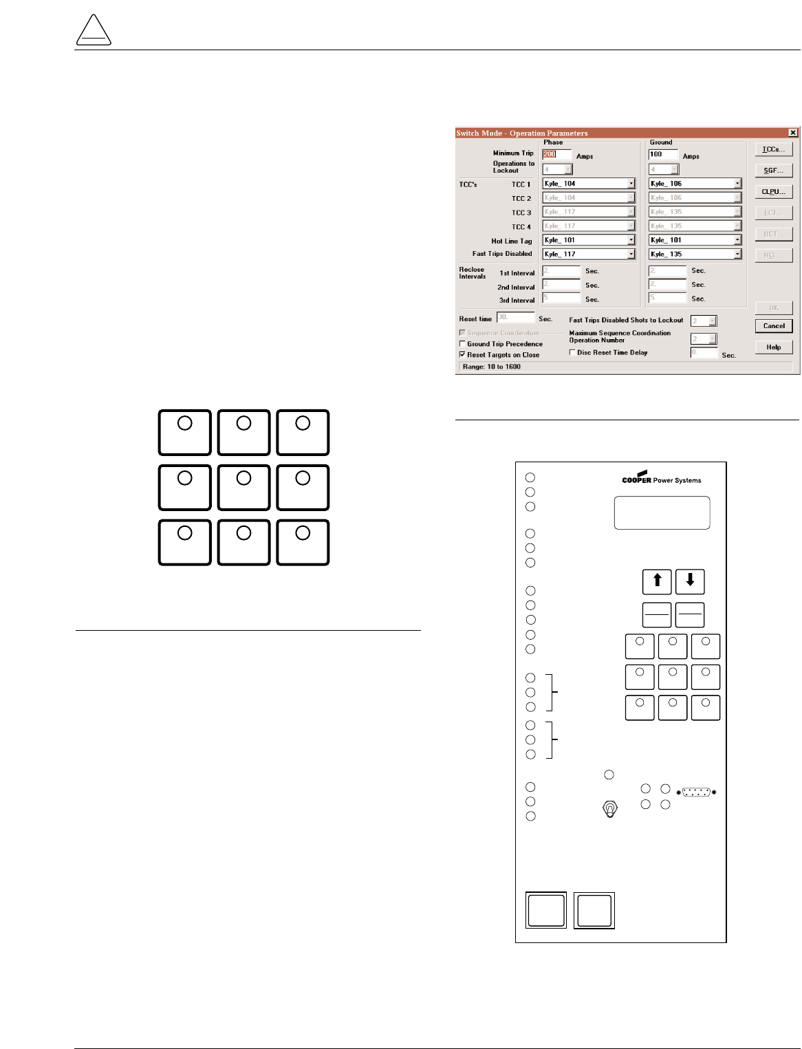
The UDP function allows the Form 5 control to become a
switch control to provide indication of overcurrent trip con-
ditions without issuing an overcurrent trip signal. The con-
trol is in the recloser mode when the feature is in the OFF
position, and in the switch mode when the feature is
ACTIVE.
While in the switch mode, all automatic open and close
operations of the recloser (including overcurrent voltage
and frequency) are blocked. Fault targeting, metering,
alarms, and event recording functions are active.
This non-tripping fault indication state is initiated via a
operator panel pushbutton (labeled SWITCH MODE), dig-
ital SCADA, or discrete SCADA. The UDP feature has
local indication at the operator panel (LED), digital indica-
tion, and remote indication via status contacts on the Dis-
crete Interface (DIF) module 1.
S280-79-10
21
!
SAFETY
FOR LIFE
Figure 21.
Interface software Switch Mode settings.
GND TRIP
BLOCKED NON
RECLOSING
SUPERVISORY
BLOCKED
COLD LOAD
PICKUP
BLOCKED
BATTERY
TEST
FAST
TRIPS
DISABLED
ALTERNATE
PROFILE
NO. 1
ALTERNATE
PROFILE
NO. 2
SWITCH
MODE
Figure 20.
Function/Indication pushbuttons for the Form 5
equipped with the UDP accessory.
FORM 5 UNIVERSAL DEVICE PROTECTION (UDP) CONTROL
CONTROL OK
AC POWER
ABOVE MIN TRIP
REVERSE POWER FLOW
RECLOSER MALFUNCTION
CHECK BATTERY
BUSHINGS 1-2 FAULT TARGET
BUSHINGS 3-4 FAULT TARGET
BUSHINGS 5-6 FAULT TARGET
GROUND FAULT TARGET
SENSITIVE-GROUND FAULT TARGET
AØ
BØ
CØ
RECLOSER CLOSED
RECLOSER OPEN
CONTROL LOCKOUT
BACK NEXT
LAMP
TEST
CHANGE
RESET
TARGETS
RESET
MAX CURRENT
GND TRIP
BLOCKED
NON
RECLOSING
SUPERVISORY
BLOCKED
COLD LOAD
PICK UP
BLOCKED
BATTERY
TEST
FAST
TRIPS
DISABLED
ALTERNATE
PROFILE
NO. 1
ALTERNATE
PROFILE
NO. 2
SWITCH
MODE
HOT LINE
TAG ON
OFF
TX 3
RX 3
CLOSE
TRIP
(LOCKOUT) KYLE®
FORM 5/UDP
RECLOSER CONTROL
RS232
TX 2
RX 2
SOURCE
VOLTAGE
XØ
YØ
ZØ
LOAD
VOLTAGE
Figure 22.
Form 5/UDP Operator Panel.
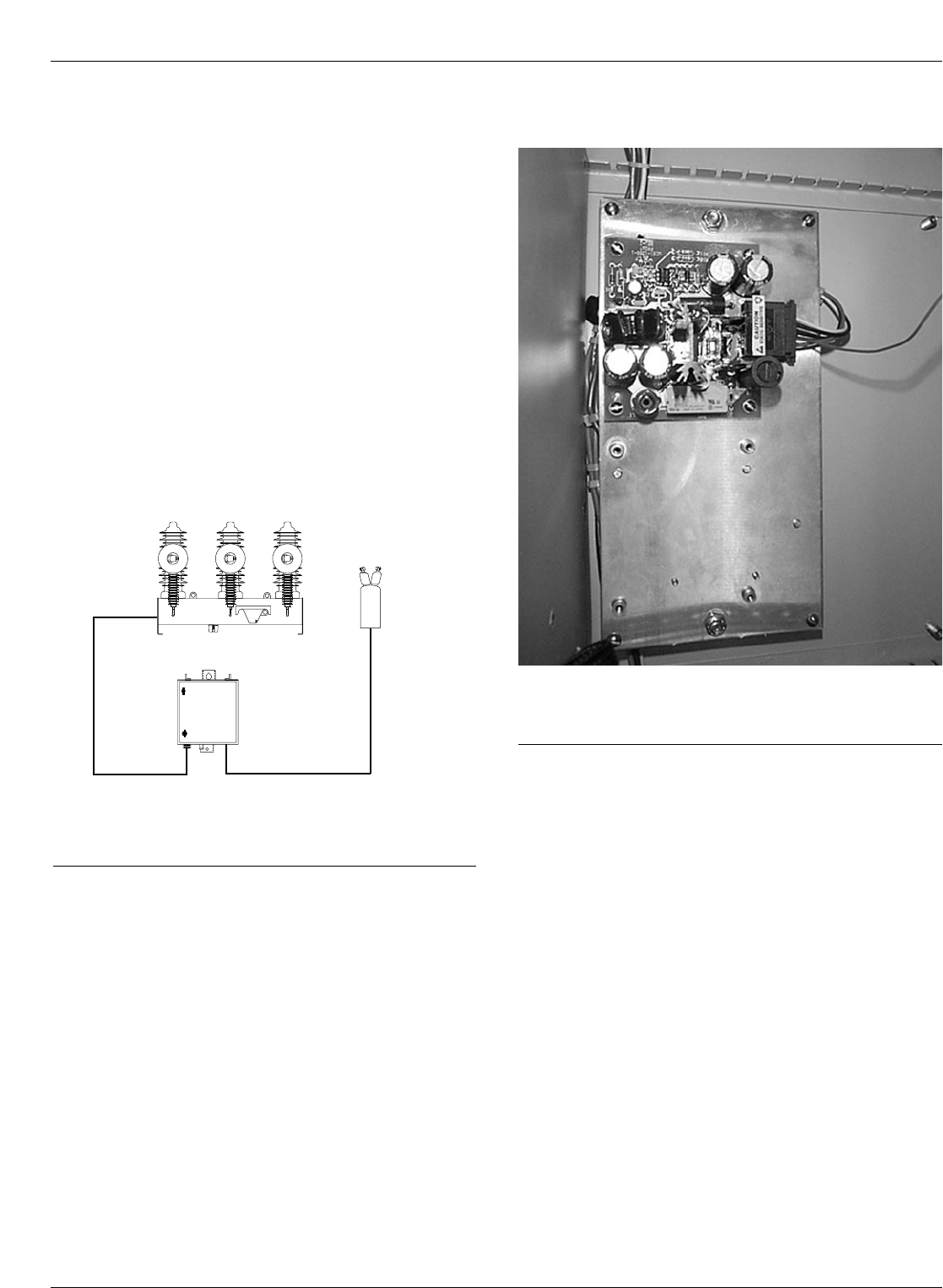
The Kyle Form 5 recloser control can be equipped with a
dc-to-dc converter, interface circuit, and a fully shielded
19-pin cable for use with a Type DC NOVA recloser. See
Figure 23.
The dc-to-dc converter board (Figure 24) converts the con-
trol’s 24 Vdc battery supply voltage to 53 Vdc to drive the
trip/close capacitors in the NOVA mechanism. The output
of the board is separately fused for operator indication.
The dc-to-dc converter houses voltage monitoring and
conditioning circuits which protect the battery from failure
and provides trip/close operations without AC power. The
19-pin control cable interfaces the NOVA dc recloser to
the Form 5 control through the interface circuit. The cable
also provides AC power from the control to the recloser
mechanism heater.
Kyle Form 5, Form 5 UDP, Form 5 DC NOVA Recloser Control Installation and Operation Instructions
22
FORM 5 DC NOVA CONTROL
Form 5
Control
Potential
Transformer
(120/240Vac)
120Vac/240Vac
Power Cable
19 Pin
Control Cable
O
P
E
N
dc NOVA
Figure 23.
Connections of a Form 5 control with dc NOVA
accessory to a dc NOVA recloser.
Figure 24. 99007KM
Dc-to-dc converter located behind Form 5 operator
panel (removed).
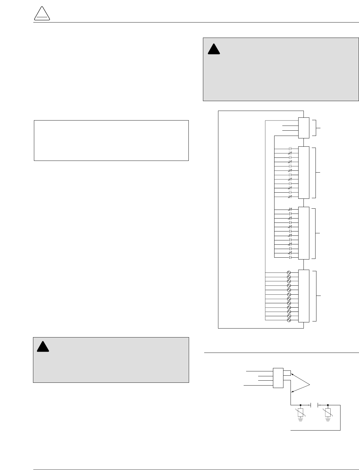
S280-79-10
23
!
SAFETY
FOR LIFE
DISCRETE INTERFACE (DIF)
ACCESSORY
The Discrete Interface (DIF) module accessory (Figure
25) permits connection of contact-type input devices
(switches, relays) and discrete indicating devices (relays,
LEDs, lamps) to the Form 5 control to effect local discrete
input/output (I/O). The DIF module accessory is used for
supplementing normal local controls and status indicators
for discrete SCADA functions. All DIF inputs and outputs
have been factory-set and are shown in Figure 27.
The DIF module contains 12 factory-set inputs and out-
puts for discrete SCADA functions. Each Form 5 control
can accommodate two DIF modules.
Whetting voltage for the DIF inputs can be supplied by the
DIF module or by the customer as shown in Figure 26.
Note: 28 Vdc (nominal) is provided from the DIF module via
connector P5 for use as whetting voltage for inputs to
P4. As an alternative, the user can supply whetting volt-
age from an auxiliary source, such as a RTU.
The input voltage range is 12 to 120 Vac or Vdc. The 12
outputs are Form C relay contacts. Six of the module out-
puts are latching and the other six are non-latching.
Note: Latching is defined as an output that retains its status
when control power is removed.
Non-latching is defined as an output that changes its
status when control power is removed.
Note: A remote function is not controlled by the SUPERVI-
SORY BLOCKED switch.
Customer Connection
Information
Figure 25 shows the customer-supplied wiring of whetting
voltage for DIF module inputs. Connection is made from
terminal P5 on the DIF module to the respective connec-
tions on P4 inputs 1 through 12.
Figure 27 shows customer connections to the DIF outputs
at P2 and P3.
4
3
2
1
4
3
2
1
8
7
6
5
12
11
10
9
6
5
4
3
2
1
4
3
2
1
8
7
6
5
12
11
10
9
12
11
10
9
8
7
4
3
2
1
8
7
6
5
12
11
10
9
INPUT COMMON
28V (–)
28V (+)
OUTPUT COMMON
P5
P3
P2
P4
DISCRETE
INTERFACE
MODULE
ACCESSORY
WHETTING
VOLTAGE
UNLATCHED
OUTPUTS
LATCHED
OUTPUTS
INPUTS
(12 TO 120
VAC OR VDC)
WHETTING
VOLTAGE
4
3
2
1
8
7
6
5
12
11
10
9
Figure 25.
Discrete Interface (DIF) Module.
4
3
2
1
INPUT COMMON
28V (-)
28V (+)
OUTPUT COMMON
To P4
Inputs 1 thru 12
P5
Customer-Supplied
Wiring for Whetting Voltage
REMOTE
CONTACTS
Note: Wiring to P5-2 and P5-3 can be
reversed if necessary.
Figure 26.
Customer connections for supplying whetting volt-
age to DIF inputs.
CAUTION: Equipment damage; misoperation.
External leads must be shielded and the shield
must be grounded at both ends. Terminate each lead
with a 320 Vac, 160 Joules metal oxide varistor (MOV),
or equivalent, at the remote end. Attach MOVs between
the leads and ground. Failure to properly shield and
protect leads can result in equipment damage and/or
unintentional operation. G117.3
!
CAUTION: Equipment damage. Do not drill con-
nection holes into the top of the cabinet. Connec-
tion holes in the top of the cabinet will allow moisture to
seep into the control and damage the components or
cause control misoperation. Failure to comply will void
the control’s factory warranty. T249.0
!
IMPORTANT: Do not use DIF module for overcurrent
protection. Digital SCADA can be used for this applica-
tion. The control gives priority to TCC timing and issu-
ing a trip signal rather than changing the status of a DIF
output or responding to a DIF input.
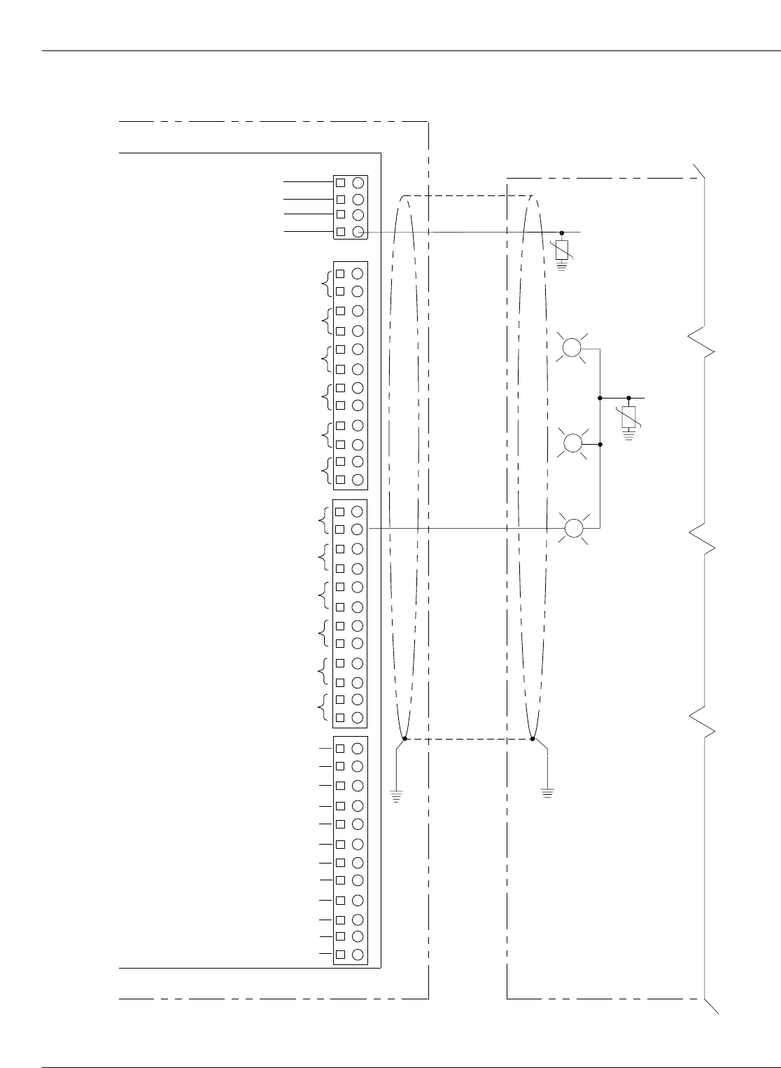
Kyle Form 5, Form 5 UDP, Form 5 DC NOVA Recloser Control Installation and Operation Instructions
24
R
R
FORM 5 CONTROL
Remote Terminal Unit (RTU)
NORMAL PROFILE
NON-RECLOSING
COLD LOAD PICKUP BLOCKED
INPUT COMMON
SUPV. CLOSE
SUPV. TRIP & L.O.
Not All Remote
Connections
Shown
INPUT
VOLTAGE
COMMON
67 8512 43910
11 12
Discrete Interface
Module (DIF)
REMOTE HOT LINE TAG
SUPERVISORY GROUND TRIP BLOCKED
SUPERVISORY ALTERNATE PROFILE 1
SUPERVISORY ALTERNATE PROFILE 2
SUPERVISORY ALTERNATE PROFILE 3*
(*SWITCH MODE ON FORM 5 UDP)
SUPERVISORY NORMAL PROFILE
SUPERVISORY NON-RECLOSING
SUPERVISORY COLD LOAD PICKUP BLOCKED
REMOTE TRIP AND RECLOSE
REMOTE TRIP AND LOCKOUT
SUPERVISORY BLOCKED
AC POWER
CONTROL OK
RECLOSER OPEN
HOT LINE TAG
GROUND TRIP BLOCKED
ALTERNATE PROFILE 1
ALTERNATE PROFILE 2
ALTERNATE PROFILE 3
P5
P3
P4
P2
G
*28V (–)
*28V (+)
OUTPUT COMMON
67 8512 43910
11 12
67 8512 43910
11 12
*28 Vdc (nominal)
supplied by
DIF module for
whetting voltage.
Figure 27.
Customer connections to DIF module outputs with shielding and surge protection.

S280-79-10
25
!
SAFETY
FOR LIFE
Standard and UDP Controls
Standard and UDP Form 5 control DIF inputs and outputs
are described in the following pages.
Maximum Switching Voltage: . . . . . 135 Vac 110 Vdc
Maximum Switching Loading: . . . . . 600 mA
Maximum Pickup-Release Time: . . 3 msec (does not count control response time)
Input Protection: . . . . . . . . . . . . . . . Shunting type using MOVs and capacitors
Minimum Detection Level: . . . . . . . . . . . . . . . . . . . . . . . . 8 Vac (50 or 60Hz) 10 Vdc
Maximum Operating Voltage: . . . . . . . . . . . . . . . . . . . . . 135 Vac (50 or 60Hz) 175 Vdc
Input Impedance: . . . . . . . . . . . . . . . . . . . . . . . . . . . . . . . 10 k minimum (inputs are current limited)
Maximum Input Loading: . . . . . . . . . . . . . . . . . . . . . . . . . 2 mA per input
Maximum Leakage Rejection: . . . . . . . . . . . . . . . . . . . . . 1 mA
Maximum Pickup Time: . . . . . . . . . . . . . . . . . . . . . . . . . . 10 msec (does not count control response time)
Minimum Input Pulse Time: . . . . . . . . . . . . . . . . . . . . . . . 100 msec
Minimum Transition Time between Pulse Inputs: . . . . . . 200 msec
Input Protection: . . . . . . . . . . . . . . . . . . . . . . . . . . . . . . . Shunting type using MOVs and capacitors.
Opto Isolation from input to system.
Voltage Level: . . . . . 28 Vdc (nominal)
Output Current: . . . . 30 mA maximum
TABLE 1
DIF Input Ratings
TABLE 2
Whetting Voltage Source
(Supplied by Internal Voltage Source of DIF Module)
TABLE 3
DIF Output Ratings
IMPORTANT: Each DIF contains a small, isolated
current source for use with external dry contacts. This
supply is intended for use with the DIF inputs only and
must not be used for powering external circuits. This is
considered a dry contact input for customer connection.

Kyle Form 5, Form 5 UDP, Form 5 DC NOVA Recloser Control Installation and Operation Instructions
26
Note: Supervisory Alternate Profile 3 replaced by Switch
Mode on UDP controls.
Standard and UDP Control DIF Module 1
Inputs
The DIF inputs are factory-configured as momentary (0.25 sec. duration) or maintained functions. Supervisory signals
do not have any effect when supervisory blocked is active. Remote inputs function when supervisory is blocked.
Input Connector Function Description
1 P4-1 Supervisory Trip and Lockout Supervisory Trip and Lockout trips the recloser open and locks out
the control. The control remains locked out until closed manually or
by the supervisory close feature. A momentary signal is required.
2 P4-2 Supervisory Close Supervisory Close initiates a closing signal to the recloser. A
momentary signal is required for proper operation.
3 P4-3 Remote Hot Line Tag Remote Hot Line Tag performs the same functions as the HOT
LINE TAG switch on the operator panel. Remote Hot line Tag is
activated by a maintained SCADA command, a serial command,
or locally via a operator panel switch. This input is active regardless
of the state of the supervisory function.
4 P4-4 Supervisory Ground Trip Block Supervisory Ground Trip Block provides supervisory operation of
ground trip block by a remote momentary signal.
This input performs the same function as the GND TRIP BLOCKED
key on the operator panel. This input is inactive if the Supervisory
function is disabled.
5 P4-5 Supervisory Alternate Profile 1
6 P4-6 Supervisory Alternate Profile 2
7 P4-7 Supervisory Alternate Profile 3*
8 P4-8 Supervisory Normal Profile Supervisory Normal Profile requires a momentary signal for proper
operation.
This input is active with a whetting voltage and causes the control
to select Normal Protection Profile. This input is inactive if the
Supervisory function is disabled.
Supervisory Alternate Profiles provides selection of alternate pro-
grammed values for phase and ground. This feature is activated by
a remote momentary signal.
These inputs are active with a momentary whetting voltage and
cause the control to select the respective Supervisory Alternate Pro-
file. The inputs are inactive if the Supervisory function is disabled.

S280-79-10
27
!
SAFETY
FOR LIFE
Standard and UDP Control DIF Module 1
Inputs (cont’d)
Input Connector Function Description
9 P4-9 Supervisory Non-Reclosing Supervisory Non-Reclosing provides supervisory non-reclosing
input by a remote momentary signal.
This input performs the same function as the NON-RECLOSING
key on the operator panel. This input is inactive if the Supervisory
function is disabled.
10 P4-10 Suprv Cold-Load Pickup Blocked This input performs the same function as the COLD LOAD
PICKUP BLOCKED key on the operator panel. This input is inac-
tive if the Supervisory function is disabled. A momentary signal is
required for proper operation.
11 P4-11 Remote Trip and Reclose Remote Trip and Reclose initiates a trip operation followed by a
reclose operation. A momentary signal is required for proper
operation.
This input is active with a whetting voltage and causes the control
to perform a trip operation followed by a reclose operation. This
input is active regardless of the state of the Supervisory function.
12 P4-12 Remote Trip and Lockout Remote Trip and Lockout trips the recloser open and locks out the
control. It can be used for tripping from external relays and alarms.
A momentary signal is required for proper operation.
This input performs the same function as the TRIP (LOCKOUT)
switch on the operator panel and is active regardless of the state
of the Supervisory function.

*Note: Supervisory Alternate Profile 3 replaced by Switch
Mode on UDP controls.
Kyle Form 5, Form 5 UDP, Form 5 DC NOVA Recloser Control Installation and Operation Instructions
28
Standard and UDP Control DIF Module 1
Outputs
The 12 outputs of the DIF Module are Form C relay contacts. Six of the outputs are latching and six are non-latching.
Note: Contacts shown in inactive mode.
Output Connector Function Type Description
1 P3-1 NC Normal Profile Non-Latched
P3-2 NO
2 P3-3 NC Non-Reclosing Non-Latched
P3-4 NO
3 P3-5 NC Cold-Load Pickup Blocked Non-Latched
P3-6 NO
4 P3-7 NC Supervisory Blocked Non-Latched
P3-8 NO
5 P3-9 NC AC power Non-Latched
P3-10 NO
6 P3-11 NC Control OK Non-Latched
P3-12 NO
7 P2-1 NO Recloser Open Latched
P2-2 NC
8 P2-3 NO Hot Line Tag Latched
P2-4 NC
9 P2-5 NO Ground Trip Blocked Latched
P2-6 NC
10 P2-7 NO Alternate Profile 1 Latched
P2-8 NC
11 P2-9 NO Alternate Profile 2 Latched
P2-10 NC
12 P2-11 NO Alternate Profile 3* Latched
P2-12 NC
Normal Profile is active only when Alternate Profiles are
inactive. Normal reclosing operations will follow.
This output is active when the NON-RECLOSING indicator
in the operator panel is illuminated.
This output is active when the COLD LOAD PICKUP
BLOCKED indicator on the operator panel is illuminated.
Supervisory Blocked prevents operation from supervisory
control. Programming is accessible from the operator panel.
This output is active when the SUPERVISORY BLOCKED
indicator on the operator panel is illuminated.
AC power indicator is active when the control detects the
presence of AC power. This output is active when the AC
power indicator on the operator panel is illuminated.
Control OK indicator is active when the control is able to per-
form protection operations. This output is active when the
CONTROL OK indicator on the operator panel is illuminated.
Recloser Open indicator is active when the recloser signals
the control that the recloser contacts are open. This output is
active when the RECLOSER OPEN indicator is illuminated.
These outputs are active when the respective ALTERNATE
PROFILE indicators on the operator panel is illuminated.
With Hot Line Tag active, close circuit is disabled and the
HOT LINE TAG indicator is illuminated. With Hot Line Tag
inactive, the control switched back to the previous time cur-
rent curve for the active profile, close circuit is enabled and
the HOT LINE TAG indicator is off. This output is active
when the operator panel indicator is illuminated.
Ground Trip Blocked causes the control to block ground trip-
ping operations. This output is active when the GND TRIP
BLOCKED INDICATOR on the operator panel is illuminated.

S280-79-10
29
!
SAFETY
FOR LIFE
Standard and UDP Control DIF Module 2
Inputs
The DIF inputs are factory-configured as momentary or maintained functions. Whetting voltage for the DIF inputs is
supplied by the DIF module or by the user. The input voltage range is 12 to 120 VAC or VDC.
Input Connector Function Description
1 P4-1 Supervisory Fast Trips Disabled This input performs the same function as the FAST TRIPS DIS-
ABLED key on the operator panel and is inactive if the Supervisory
function is disabled. This is a momentary function.
2 P4-2 Supervisory Reset Targets This input performs the same function as the RESET
TARGETS/RESET MAX CURRENT key on the operator panel.
This input is inactive if the Supervisory function is disabled. This is
a momentary function.
3 P4-3 Supervisory Operation Counter OFF The operation counter is disabled when this input is active with a
maintained whetting voltage. This input is inactive if the Supervi-
sory function is disabled.
4 P4-4 Supervisory Battery Test This input performs the same function as the BATTERY TEST key
on the operator panel. This input is inactive if the Supervisory func-
tion is disabled. This is a momentary function.
5 P4-5 Supervisory SGF Blocked This input is active with a momentary whetting voltage and causes
the control to block, or unblock sensitive ground fault operations.
The input is inactive if the Supervisory function is disabled.

Kyle Form 5, Form 5 UDP, Form 5 DC NOVA Recloser Control Installation and Operation Instructions
30
Standard and UDP Control DIF Module 2
Outputs
The 12 outputs of the DIF Module are Form C relay contacts. Six of the outputs are latching and six are non-latching.
Note: Contacts shown in inactive mode.
Output Connector Function Type Description
1 P3-1 (NC) Control Lockout Non-Latched
P3-2 (NO)
2 P3-3 (NC) Check Battery Non-Latched
P3-4 (NO)
3 P3-5 (NC) Reverse Power Flow Non-Latched
P3-6 (NO)
4 P3-7 (NC) Fast Trips Disabled Non-Latched
P3-8 (NO)
5 P3-9 (NC) Operation Counter Non-Latched
P3-10 (NO)
6 P3-11 (NC) Recloser Malfunction Non-Latched
P3-12 (NO)
7 P2-1 (NO) Bushings 1-2 Fault Target Latched
P2-2 (NC)
8 P2-3 (NO) Bushings 3-4 Fault Target Latched
P2-4 (NC)
9 P2-5 (NO) Bushings 5-6 Fault Target Latched
P2-6 (NC)
10 P2-7 (NO) Ground Fault Target Latched
P2-8 (NC)
11 P2-9 (NO) Sensitive Ground Fault Target Latched
P2-10 (NC)
12 P2-11 (NO) Sensitive Ground Fault Blocked Latched
P2-12 (NC)
This output is active when the CONTROL LOCKOUT
indicator is illuminated.
This output is active when the CHECK BATTERY indi-
cator is illuminated.
This output is active when the REVERSE POWER
FLOW indicator is illuminated.
This output is active when the FAST TRIPS DIS-
ABLED indicator is illuminated.
If the Supervisory function is enabled, this output is
active when the OPERATION COUNTER OFF inputs
from Comm Port 1-DIF2, Comm Port 2 and Comm Port
3 are not active.
This output is active when the RECLOSER MAL-
FUNCTION indicator is illuminated.
This output is active when the BUSHINGS 1-2 FAULT
TARGET indicator is illuminated.
This output is active when the BUSHINGS 3-4 FAULT
TARGET indicator is illuminated.
This output is active when the BUSHINGS 5-6 FAULT
TARGET indicator is illuminated.
Output is active when the GROUND FAULT TARGET
indicator is illuminated.
Output is active when the SENSITIVE GROUND
FAULT TARGET indicator is illuminated.
Output is active when Sensitive Ground Fault is
blocked.

Sensed Currents
Note: Control only, does not include sensor tolerance, but
does include the phase current summing process.
Phase Current—Individual Phase Currents:
Range: 1 A to 10,000 A for 500:1 CTs
2 A to 20,000 A for 1000:1 CTs
4 A to 40,000 A for 2000:1 CTs
Accuracy:± 1 mA from 10 mA to 125 mA
0.8% from 125 mA to 1600 mA
(Control only, does not include sensor
tolerance.)
Ground Current—Vector Sum of Three-Phase Currents:
Range: 1 A to 5,000 A for 500:1 CTs
2 A to 10,000 A for 1000:1 CTs
4 A to 20,000 A for 2000:1 CTs
Accuracy: ± 3 mA from 10 mA to 125 mA
2.4% from 125 mA to 1600 mA
Sensed Source Voltages
Three-phase voltages used in voltage, power and power-
factor related calculations:
Voltage measurement accuracy:
± 0.4V from 5V to 80V
0.5% from 80V to 135V
S280-79-10
31
!
SAFETY
FOR LIFE
INPUT ACCURACY
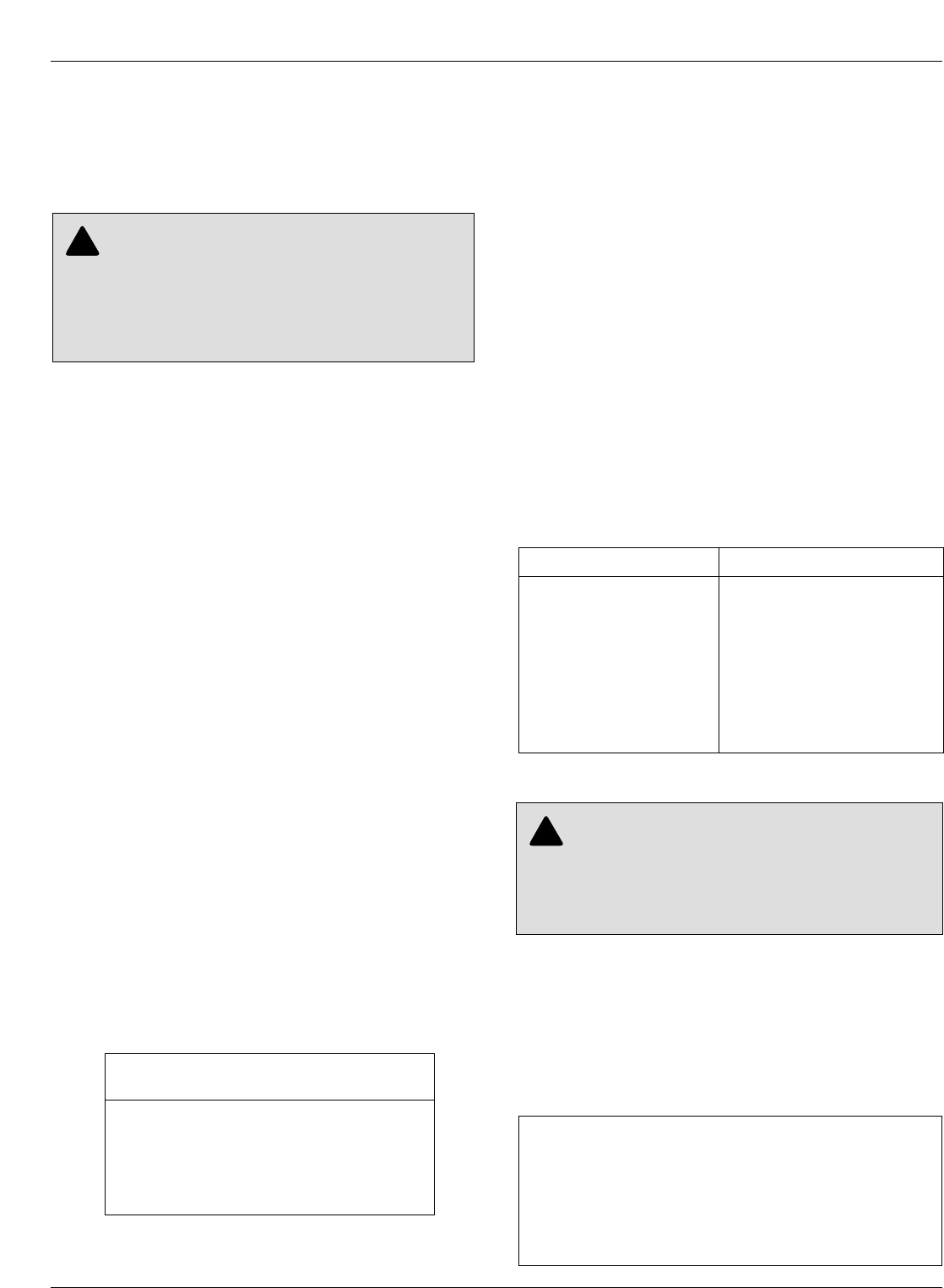
Initial Programming
Prior to Installation
The control must be programmed with all necessary oper-
ating settings, all alternate profiles, and parameters prior
to operation with an energized recloser.
Note: Program all protection profiles. Unused alternate pro-
files should be programmed with the same settings as
one of the applicable profiles. Default settings on
unused alternate profiles can cause unnecessary out-
ages if they are below normal system requirements.
Initial programming of the control is the responsibility of a
qualified technician or engineer familiar with control func-
tions and programming parameters required for the spe-
cific recloser installation.
The control must be programmed with the Form 5 inter-
face software.
Control / Recloser Compatibility
Reclosers manufactured prior to June 1989 are equipped
with Type A bushing current transformers. These
reclosers were designed for use with Form 2, Form 3, and
Form 3A controls. Because the Form 5 control is designed
for use with reclosers equipped with Type B current-sens-
ing Transformers, reclosers retrofitted with Form 5 con-
trols should be retrofitted with Type B current
transformers. All reclosers manufactured since 1989 are
equipped with Type B (1000:1, 1000/500:1, or 2000:1)
sensing CTs.
Reclosers equipped with Type B sensing CTs are com-
patible with all Kyle recloser controls (Form 2, Form 3,
Form 3A, Form 4A, Form 4C, FXA, FXB and Form 5, Form
5 LS/UDP controls), and are identified with the following
label prominently displayed on the recloser sleet hood or
the front of the operator cabinet:
The Form 5 control can be used with the old-style Type A
CTs; however, the event recorder, data profiler and duty
cycle monitor will have limited accuracy for currents
above 5000 Amps.
Retrofit kits with the new Type B sensing CTs are avail-
able to upgrade existing families of reclosers for operation
with Form 5 controls. For additional information, contact
your Cooper Power Systems representative.
For identification, Table 4 lists the serial number breaks
between old-style Type A and the new-style Type B sens-
ing CTs. Below this serial number, the recloser is
equipped with the Type A CTs.
Note: For reclosers shipped prior to June 1989 and not listed
below, please contact your Cooper Power Systems rep-
resentative with the recloser type and serial number for
verification of Type A or B bushing current transformers.
Control Cable
The control cable is fabricated with connectors which
mate with the female receptacle of the recloser on one
end and the male receptacle of the control on the other
end.
Note: The control cable must be supported along its length to
prevent repeated movement due to wind or other out-
side forces which can damage the cable.
Kyle Form 5, Form 5 UDP, Form 5 DC NOVA Recloser Control Installation and Operation Instructions
32
TABLE 4
Serial Number Break for Reclosers with Type A
Sensing CTs
Recloser Below Serial Number
RXE 5831
RVE 5894
WE 11199
WVE 3695
VWE 7199
VWVE27 7208
VWVE38 1204
NOTICE
RECLOSER IS EQUIPPED WITH
TYPE B SENSING CTs.
RECLOSER DOES NOT HAVE A
BATTERY CHARGER.
INSTALLATION PROCEDURE
CAUTION: Equipment Misoperation. Do not
connect this control to an energized recloser until
all control settings have been properly programmed
and verified. Refer to the programming information for
this control. Failure to comply can result in control and
recloser misoperation, equipment damage, and per-
sonal injury. G110.3
!
WARNING: Hazardous voltage. Recloser and
control must be solidly grounded. Follow all locally
approved procedures and safety practices when
grounding this equipment. Improper grounding can
result in contact with high voltage, which will cause
death or severe personal injury. G115.1
!
IMPORTANT: All external inputs to the Form 5 con-
trol must be routed within 8 inches of their correspond-
ing ground. During a surge, a potential of
approximately 1.5 kV per foot can develop in the con-
ductors. Differences between conductor and ground
path lengths can add additional stress to the control
components in the event of a power surge.
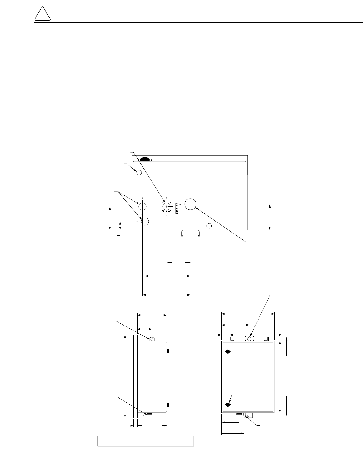
Mounting the Control
Mount the Form 5 recloser control in a convenient, acces-
sible location. Mounting dimensions are provided in Fig-
ure 28.
•For pole-mounted installation, a hole and keyway in
the control mounting bracket accommodates a 5/8”
bolt.
•For substation installation, brackets are available as
an accessory for mounting the control to a substation
frame.
Limits on control cable length are determined by the max-
imum distance between the control and recloser:
•Up to 410 m (125* ft) for solenoid-operated reclosers
(VWE, VWVE27, VWVE38X, WE, WVE27, WVE38X,
and NOVA).
•Up to 10,7 m (35* ft) for motor-operated reclosers
(VSA12, VSA12B, VSA16, VSA20, VSA20A, VSO12,
VSO16).
Up to 41 m (135* ft) for NOVA DC.
* These lengths are based on standard control cables.
Consult your Cooper Power Systems representative if
longer cable lengths are required.
S280-79-10
33
!
SAFETY
FOR LIFE
CONTROL WEIGHT 52 kg (115 LBS)
350mm
(13-13/16")
30mm
(1-1/8")
Male Receptacle
For Control Cable
685mm
(27")
Grounding Terminal
One Internal and
One External
Use No. 14 To No. 4
Stranded Wire
110mm
(4-3/8")
165mm
(6-1/2")
580mm (23")
640mm (25-1/4")
40mm (1-1/2")
380mm
(15")
30mm (1-1/8") Hole
In Lifting Lug 240mm
(9-1/2")
76mm
(3")
480mm
(19")
Mtg Hole For
15mm (5/8") Max
Bolt Dia.*
Die-cast-zinc latchable
Handle For User-
Provided Utility-Grade
Padlock
130mm
(5-1/8")
190mm
(7-3/8")
120mm (4-3/4")
45mm (1-3/4") Dia. Hole
For Automation Accessory
(Cap-Plug Installed)
Vent
Female Receptacle
For Control
Cable
* USER-PROVIDED HARDWARE
C
L
C
L
110mm
(4-1/4")
40mm
(1-1/2")
200mm
(7-7/8")
35mm (1-7/16") Dia. Hole
For User 120Vac
Input Connection
(Cap-Plug Installed)
160mm
(6-3/8")
Figure 28.
Control cabinet mounting dimensions.

Grounding the Control
The control cabinet must be grounded. A grounding con-
nector on the underside of the cabinet will accommodate
No. 14 solid through No. 4 stranded conductors.
Suggested methods for grounding the control and
recloser are shown in Figures 29, 30, and 31.
Figure 29 illustrates grounding methods for 3-wire
ungrounded and 4-wire multi-grounded systems with local
supply voltage transformer.
Figure 30 illustrates grounding methods for 3-wire
ungrounded and 4-wire multi-grounded systems with
remote supply voltage transformer.
Figure 31 illustrates grounding on a 3-wire uni-grounded
system.
For effective surge protection all control and power con-
ductors for the Form 5 must be routed parallel to a corre-
sponding ground path. For example, the AC power supply
for the control should be parallel to and equal in length to
the transformer ground path. The control cable should be
parallel to and routed close to the recloser ground path.
Kyle Form 5, Form 5 UDP, Form 5 DC NOVA Recloser Control Installation and Operation Instructions
34
WARNING: Hazardous Voltage. The recloser
and control must be solidly grounded. Follow all
locally approved procedures and safety practices when
grounding this equipment. Improper grounding can
result in contact with high voltage, which will cause
death, severe personal injury. G115.1
!
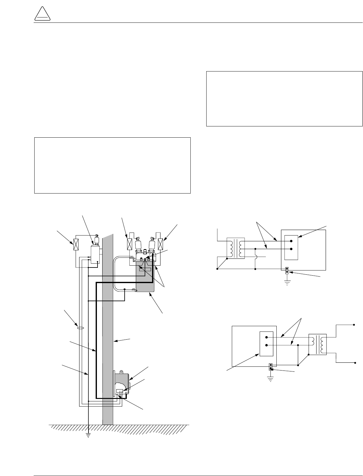
Installation of a Form 5 control with a local supply voltage
transformer must include the following:
•Protection of the recloser bushings and the supplying
transformer with lightning arresters.
•Grounding of the recloser head and tank.
•Grounding of the transformer tank.
•Grounding of the control cabinet.
•Grounding of the SCADA equipment.
4-Wire Multi-Grounded Systems
3-Wire Ungrounded and Impedance Grounded Systems
The use of a grounding mat may be required depending
upon the local safety regulations defining the permissible
step and touch potential levels. Consult local regulations
for proper grounding procedures.
S280-79-10
35
!
SAFETY
FOR LIFE
Surge
Arrester
Recloser
Head Ground
Surge
Arrester
Transformer
Surge
Arrester
Arrester Ground
Recloser
Pole
Supply
Voltage
Pole
Ground Form 5 LS
Control
Customer Ground Connection
At External Lug
NEU
AC
GND
NEU
AC
Input
Terminal
Block
Control
Cable
AC
NEUTRAL
Form 5 LS Control
Supply Voltage
Transformer
ELECTRICAL CONNECTIONS
Line to Neutral connected transformer
Form 5 LS Control
AC
NEUTRAL
Input Terminal
Block
Supply Voltage
Transformer
ELECTRICAL CONNECTIONS
Line to Line connected transformer
Line
to
Line
Voltage
External
Ground Lug
Input Terminal
Block External
Ground Lug
Figure 29.
Recommended grounding method for the Form 5 Control installed on 4-wire multi-grounded, 3-wire
ungrounded, or impedance-grounded systems with local supply voltage transformer.
IMPORTANT: In pole-mounted applications, a
ground connection must be made between the
recloser, transformer, recloser control, and SCADA
equipment for proper protection of the equipment. The
pole ground must be sized per local utility practices to
minimize the impedance between the recloser and the
control.
IMPORTANT: All external inputs to the Form 5 con-
trol must be routed within 8 inches of their correspond-
ing ground. During a surge, a potential of approximately
1.5 kV per foot can develop in the conductors. Differ-
ences between conductor and ground path lengths can
add additional stress to the control components in the
event of a power surge.
Grounding with a Local Supply Voltage Transformer; 4-Wire Multi-Grounded,
3-Wire Ungrounded, or Impedance-Grounded
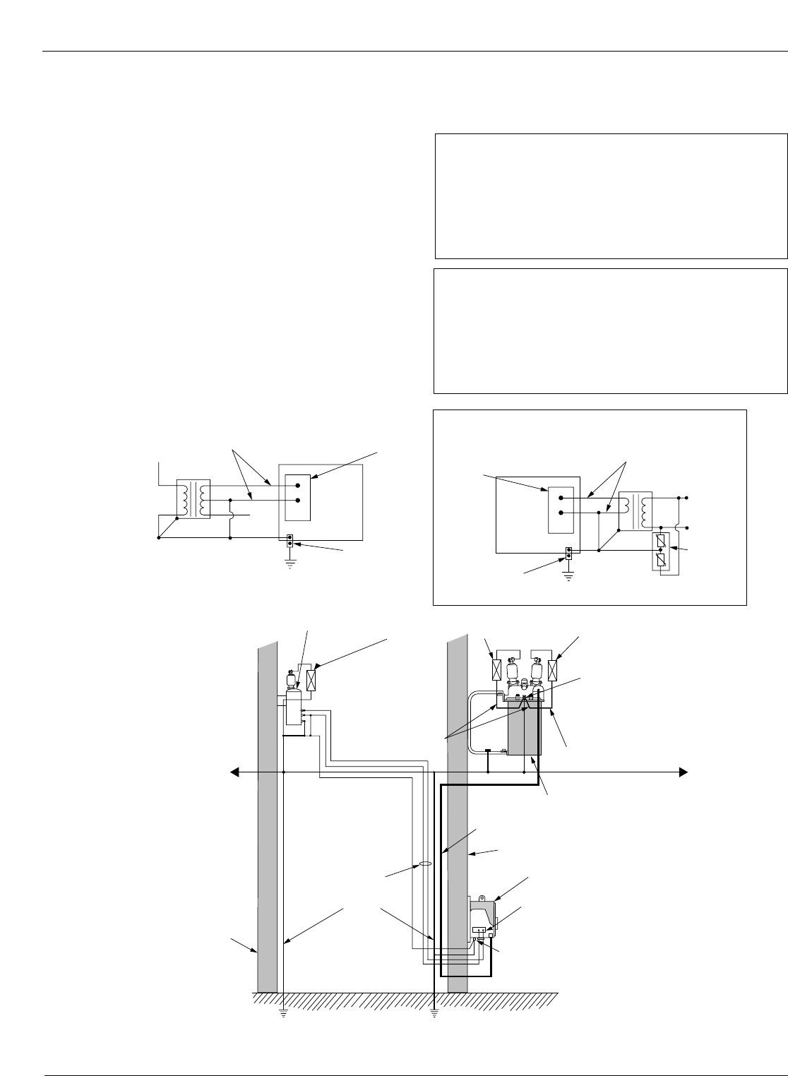
Installation of a Form 5 control with a remote supply volt-
age transformer must include the following:
•Protection of the recloser bushings and the supplying
transformer with lightning arresters.
•Grounding of the recloser head and tank.
•Grounding of the transformer tank.
•Grounding of the control cabinet.
•Grounding of the SCADA equipment
Kyle Form 5, Form 5 UDP, Form 5 DC NOVA Recloser Control Installation and Operation Instructions
36
Surge
Arrester
Recloser
Head
Ground
Supply
Voltage
Pole
Ground
Pole
Recloser
Pole
Surge
Arrester
Transformer
Arrester
Ground
Form 5 LS Control
HOT
NEU
GND
NEU
AC
Input Terminal Block
Control Cable
Surge
Arrester
Arrester
Ground
Customer Ground Connection
at External Lug
AC
NEUTRAL
Form 5 LS Control
Supply Voltage
Transformer
ELECTRICAL CONNECTIONS - Remote dedicated
supply transformer
Form 5 LS Control
AC
NEUTRAL
Input
Terminal
Block
115 Vac
Supply Voltage
Local Isolation
Transformer
ELECTRICAL CONNECTIONS - using isolation transformer
Customer
Supplied
Low Voltage
External
Ground Lug
Low Voltage
Arrester
Note: Distance between
transformer and
recloser should be
one pole span or
less
System
Neutral
External
Ground Lug
Input
Terminal
Block
Low Voltage Distribution Network
Figure 30.
Recommended grounding method for the Form 5 Control installed on 4-wire multi-grounded, 3-wire
ungrounded, or impedance-grounded systems with remote supply voltage transformer.
IMPORTANT: All external inputs to the Form 5 con-
trol must be routed within 8 inches of their correspond-
ing ground. During a surge, a potential of
approximately 1.5kV per foot can develop in the con-
ductors. Differences between conductor and ground
path lengths can add additional stress to the control
components in the event of a power surge.
IMPORTANT: In pole-mounted applications, a
ground connection must be made between the
recloser, transformer, recloser control, and SCADA
equipment for proper protection of the equipment. The
pole ground must be sized per local utility practices to
minimize the impedance between the recloser and the
control.
Grounding with a Remote Supply Voltage Transformer; 4-Wire Multi-Grounded,
3-Wire Ungrounded, or Impedance-Grounded
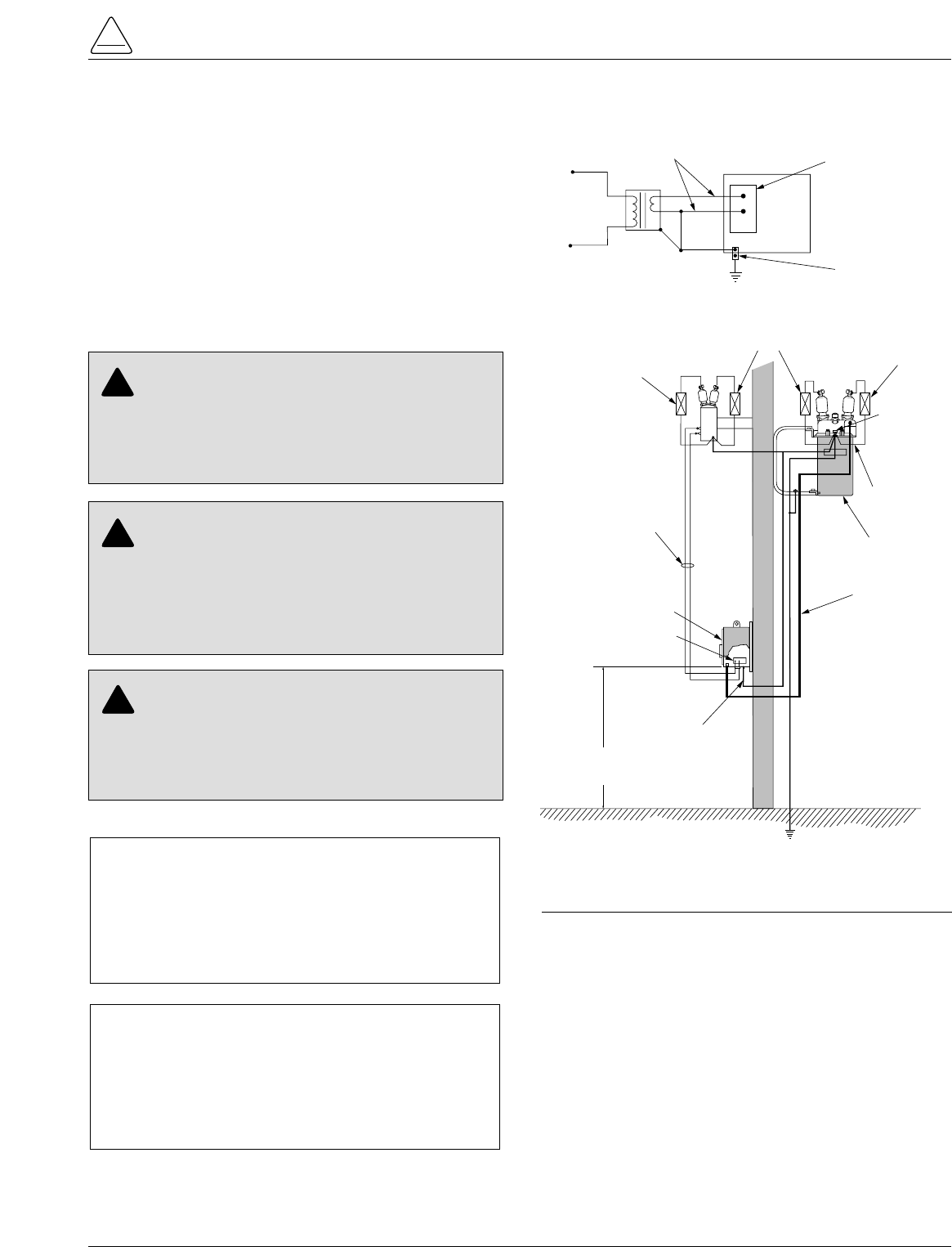
Installation of a Form 5 control on a 3-wire uni-ground sys-
tem must include the following:
•Protection of the recloser bushings and the supplying
transformer with lightning arresters.
•Grounding of the recloser head and tank.
•Grounding of the transformer tank.
•Grounding of the control cabinet.
•Grounding of the SCADA equipment.
S280-79-10
37
!
SAFETY
FOR LIFE
Surge
Arrester
Recloser
Head Ground
Surge
Arrester
Surge
Arrester
Arrester Ground
Recloser
Supply
Voltage
Pole
Ground
Form 5 LS
Control
Customer Ground
Connection
at External Lug
GND
NEU
HOT
Input Terminal Block
Control
Cable
AC
Neutral
Form 5 LS Control Input Terminal Block
Supply Voltage
Transformer
ELECTRICAL CONNECTIONS - Dedicated Supply
Transformer
Line
to
Line
Voltage
External Ground Lug
NEU
AC
Control Height must be
3 Meters (10 feet)
minimum above earth
Figure 31.
Recommended grounding method for the Form 5
Control installed on a 3-wire uni-grounded system.
IMPORTANT: All external inputs to the Form 5 con-
trol must be routed within 8 inches of their correspond-
ing ground. During a surge, a potential of
approximately 1.5kV per foot can develop in the con-
ductors. Differences between conductor and ground
path lengths can add additional stress to the control
components in the event of a power surge.
IMPORTANT: In pole-mounted applications, a
ground connection must be made between the
recloser, transformer, recloser control, and SCADA
equipment for proper protection of the equipment. The
pole ground must be sized per local utility practices to
minimize the impedance between the recloser and the
control.
WARNING: Hazardous Voltage. Use locally
approved operator safety procedures for proper
insulation when maintaining this equipment. High Volt-
age step and touch potential is characteristic in uni-
ground systems. Failure to comply can cause death or
severe personal injury. T262.0
!
CAUTION: Exported Potential. Do not make
direct electrical connections to remote devices. All
SCADA equipment must be mounted locally or con-
nected using the fiber-optic or radio communication
accessory. Direct connections to remote devices can
produce exported potential causing equipment damage
or personal injury. T263.0
!
CAUTION: Hazardous Voltage. Do not use a
shared low voltage network to power the recloser
control unless the network is specifically designed to
withstand maximum ground potential rise. Ground
faults on a high voltage network can create a rise in
ground potential. T264.0
!
Grounding on a 3-Wire Uni-Grounded System
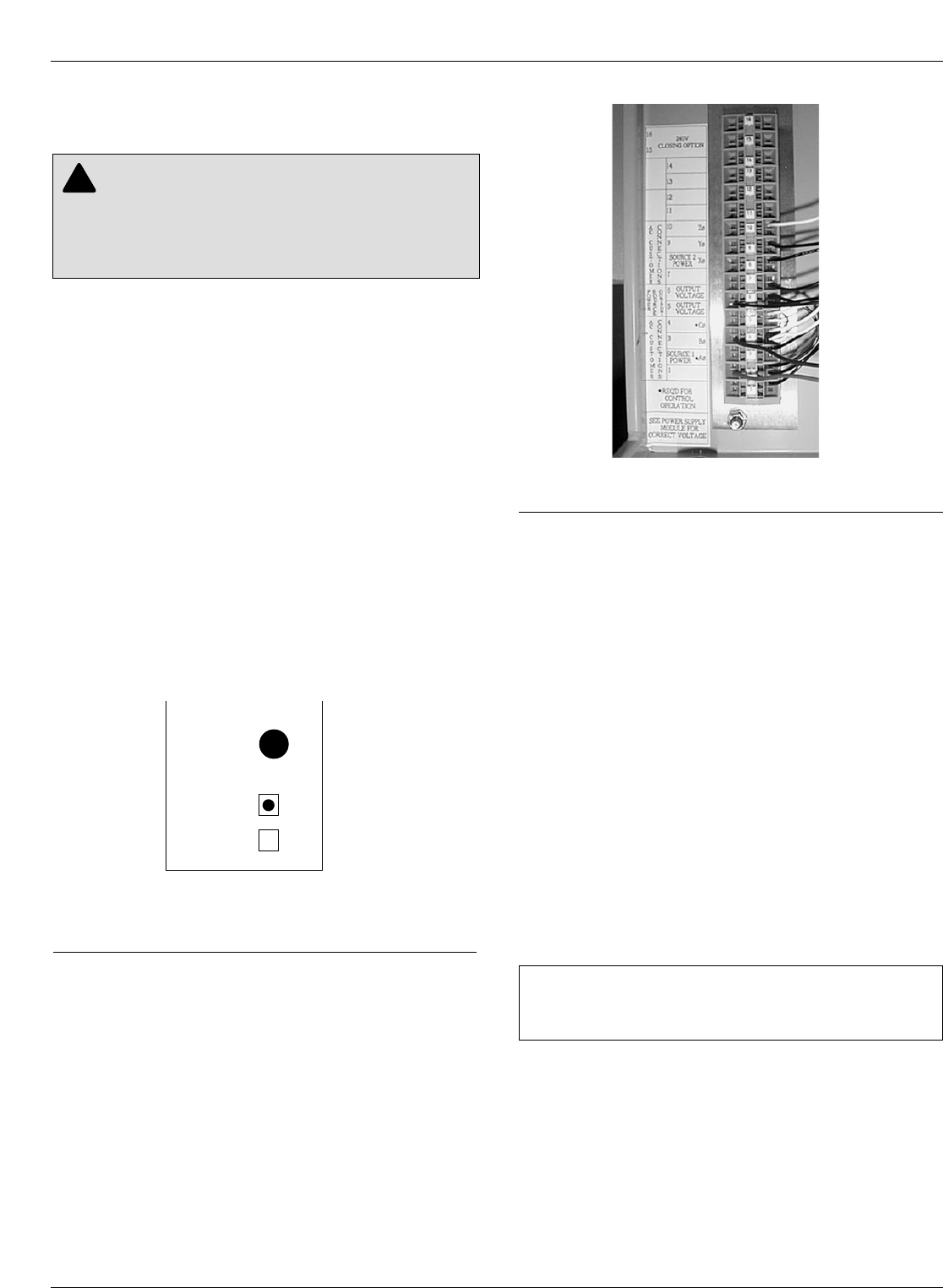
Customer Connections for AC
Power
Input power to the Form 5 control is connected to terminal
block TB1 (located behind the operator panel, on the left
side of the control). See Figure 33.
Input power is required:
•To power the control
•To provide voltage and power metering
•For voltage detection for loop scheme accessory
•For the low voltage closing accessory
•For the convenience outlet accessory
Power Supply Verification
Incoming power is routed to the Power Supply module
which is factory configured for either 120 or 240 volt oper-
ation. The power supply module is factory wired to TB-1
and protected by the 3.15 Amp fuse labeled F2 on the
power supply operator panel. A label on the Power Sup-
ply module indicates the proper voltage rating. See Figure
32.
Inserting and Releasing Wire
Connections
In Terminal Block TB1, each terminal has a wire locking
clamp that has to be opened to accept and secure the
wire. A 3/32 inch flat-blade screwdriver is inserted into
each terminal hole to open the locking clamp. Figure 34
provides the procedure for opening and securing the wire
connections.
The wire is inserted into the terminal connection hole
while the screwdriver is placed into the wire release and
locking hole.
Follow the same procedure to release wire connections.
Power Connections
Customer connections to TB1 vary upon application. TB1
connections provide power and metering inputs to the
control. Figures 34 through 39 show the customer con-
nections for 120 Vac and 240 Vac low voltage closing.
Figures 34 through 37 illustrate customer connections for
single-phase transformers. Figure 34 shows standard
wiring with BØ transformer connected to TB1-2 location.
Other phases should be connected from the single-phase
transformer by wiring the BLACK wire from the Power
Supply module to the terminal of the respective phase as
shown in Figure 38 and 39. For example, Figure 39 shows
connection from the Power Supply module to an AØ
transformer.
The transformer required for power should be a minimum
of 5kVA for low-voltage ac closing reclosers and 1kVA for
dc closing reclosers.
Note: An out-of-service Form 5 or Form 5 UDP control (for
either Wye or Delta) can be powered by connecting to
TB1-2 (hot) and TB1-4 (neutral) to an appropriate power
source.
Customer Connections for
Metering
Customer voltage inputs for metering are field config-
urable on the RIF module to accept 12, 120, or 240 Vac.
The incoming power supply must match the indication for
incoming power on the RIF module. The factory-config-
ured settings for the RIF are displayed on the module
panel. See Figure 19.
See RIF Module Configuration section of this manual.
Kyle Form 5, Form 5 UDP, Form 5 DC NOVA Recloser Control Installation and Operation Instructions
38
CAUTION: Equipment damage. Do not drill con-
nection holes into the top of the cabinet. Connec-
tion holes in the top of the cabinet will allow moisture to
seep into the control and damage the components or
cause control misoperation. Failure to comply will void
the control’s factory warranty. T249.0
!
Figure 33. 99003KM
Terminal Connector Block TB1.
IMPORTANT: Delta connections are not used on any
Form 5 control accessory that utilizes the low voltage
transfer relay.
Y
M
O
D
U
L
E
CONFIGURED
FOR
120
VAC
240
VAC
F2
GDC-3.15A
Figure 32.
Label on Power Supply module indicates factory-
configured voltage rating (120Vac).
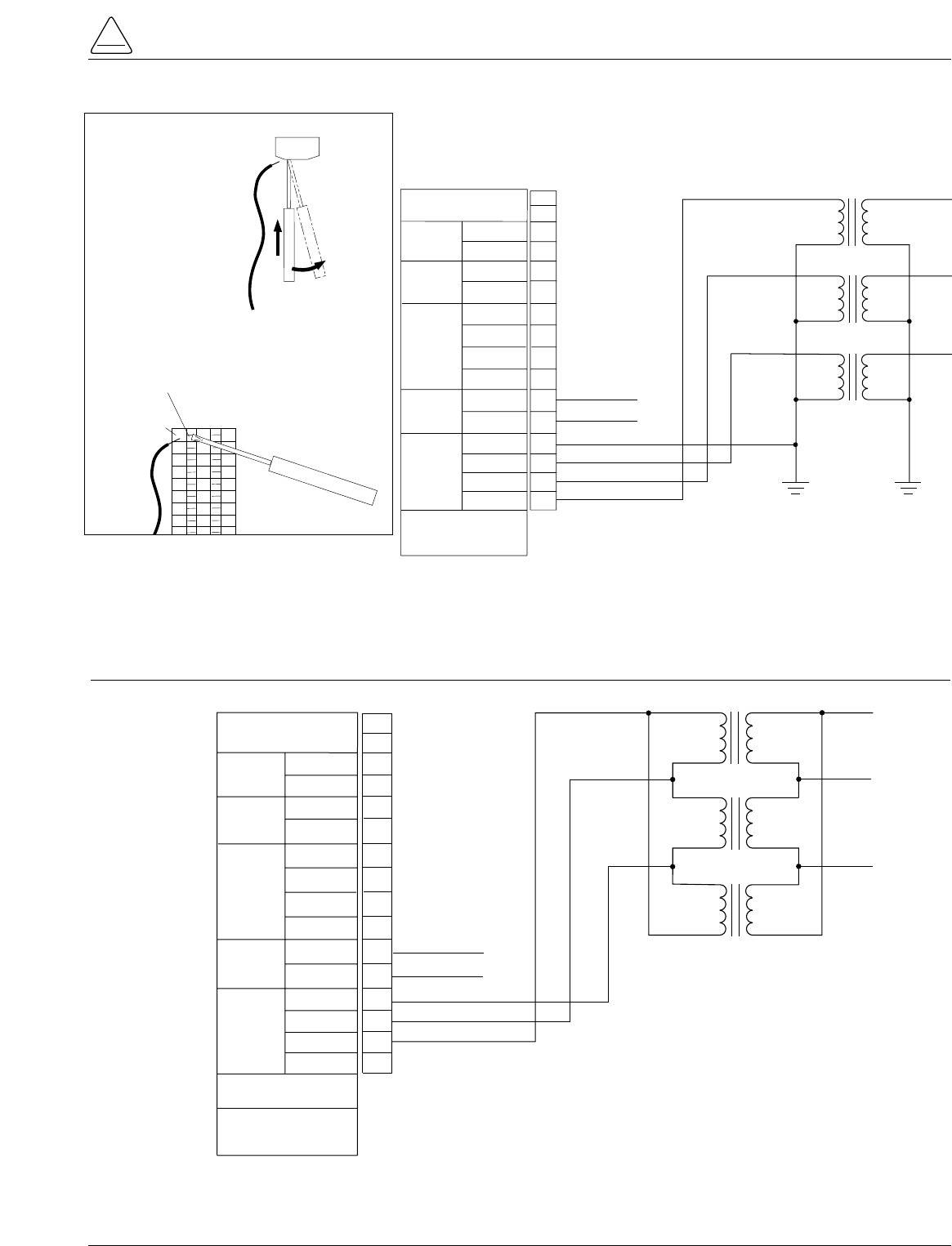
S280-79-10
39
!
SAFETY
FOR LIFE
TB1
Y' VOLTAGE
120Vac
B' VOLTAGE
120Vac
CLOSING
VOLTAGE
NEUTRAL
SOURCE 2
NEUTRAL
SOURCE 1
AC
CUSTOMER
CONNECTIONS
NEUTRAL
ZØ
YØ
SOURCE 2
POWER
XØ
OUTPUT
VOLTAGE
NEUTRAL
*NEUTRAL
POWER
SOURCE
OUTPUT
CØ
*BØ
AØ
AC
CUSTOMER
CONNECTIONS
SOURCE 1
POWER
*REQUIRED FOR
CONTROL OPERATION
1
2
3
4
5
6
7
8
9
10
11
12
13
14
240Vac CLOSING
OPTION
NEU
CØ
BØ
AØ
15
16 AØ
BØ
CØ
NEU (LV Closing Output)
HOT (LV Closing Output)
Figure 34.
Form 5 and Form 5 UDP Power and Low Voltage Closing customer connections to terminal block TB1
(120Vac or 240Vac Wye Connection).
AC
CUSTOMER
CONNECTIONS
ZØ
YØ
XØ
SOURCE 2
POWER
OUTPUT
VOLTAGE
OUTPUT
VOLTAGE
*CØ
POWER
SOURCE
OUTPUT
BØ
*AØ
AC
CUSTOMER
CONNECTIONS
SOURCE 1
POWER
*REQUIRED FOR
CONTROL OPERATION
SEE POWER SUPPLY
MODULE FOR
CORRECT VOLTAGE
TB1
1
2
3
4
5
6
7
8
9
10
11
12
13
14
CØ
BØ
AØ
240V CLOSING
OPTION 15
16
AØ
BØ
CØ
HOT (LV Closing Output)
HOT (LV Closing Output)
Figure 35.
Form 5 and Form 5 UDP Power and Low Voltage Closing customer connections to terminal block TB1
(120Vac or 240Vac Delta Connection).
TB1
16
15
14
13
12
11
10
9
8
1. Insert 3/32 inch flat-
blade screwdriver into
Wire Release and
Locking hole.
2. Carefully insert the
screwdriver along side
the locking clamp.
3. Pull toward the center
of terminal block TB1
until the locking clamp
opens.
4. Insert wire into Terminal
Connection hole.
5. Release screwdriver.
6. Carefully pull wire to be
sure it is secure.
To insert wire:
Terminal
Connection Hole
3/32 inch
Flat-Blade
Screwdriver
TB1
(Top View)
Connection
Wire
Wire Release
and Locking Hole
Note: Only slight pressure is
required to open the
locking clamp. Excessive
pressure can damage
the terminal block.
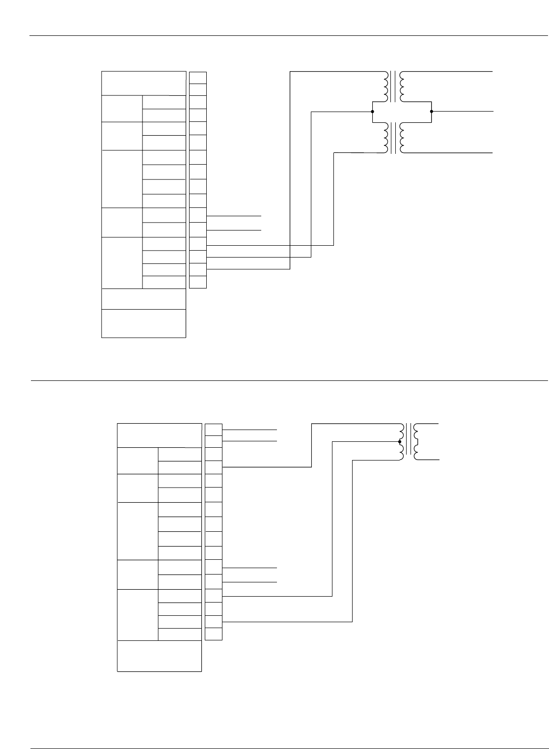
Kyle Form 5, Form 5 UDP, Form 5 DC NOVA Recloser Control Installation and Operation Instructions
40
AC
CUSTOMER
CONNECTIONS
ZØ
YØ
XØ
SOURCE 2
POWER
OUTPUT
VOLTAGE
OUTPUT
VOLTAGE
*CØ
POWER
SOURCE
OUTPUT
BØ
*AØ
AC
CUSTOMER
CONNECTIONS
SOURCE 1
POWER
*REQUIRED FOR
CONTROL OPERATION
SEE POWER SUPPLY
MODULE FOR
CORRECT VOLTAGE
TB1
1
2
3
4
5
6
7
8
9
10
11
12
13
14
CØ
BØ
AØ
240V CLOSING
OPTION 15
16
AØ
BØ
CØ
HOT (LV Closing Output)
HOT (LV Closing Output)
Figure 36.
Form 5 and Form 5 UDP Power and Low Voltage Closing customer connections to terminal block TB1
(120Vac or 240Vac Open-Delta Connection).
AC
CUSTOMER
CONNECTIONS
ZØ
YØ
XØ
SOURCE 2
POWER
OUTPUT
VOLTAGE
OUTPUT
VOLTAGE
CØ
POWER
SOURCE
OUTPUT
*BØ
AØ
AC
CUSTOMER
CONNECTIONS
SOURCE 1
POWER
*REQUIRED FOR
CONTROL OPERATION
TB1
1
2
3
4
5
6
7
8
9
10
11
12
13
14
240V CLOSING
OPTION 15
16
120Vac
Neutral
120Vac
NEU (120Vac LV Closing Output)
HOT (120Vac LV Closing Output)
HOT (240Vac LV Closing Output)†
HOT (240Vac LV Closing Output)†
Y' VOLTAGE
120Vac
B' VOLTAGE
120Vac
NEUTRAL
SOURCE 2
NEUTRAL
SOURCE 1
NEUTRAL
*NEUTRAL
CLOSING
VOLTAGE
† For use with accessories:
3-Wire Low-Voltage Closing with receptacle
or
3-Wire Low-Voltage Closing with inlet hole for hardwiring
Figure 37.
Form 5 and Form 5 UDP Power and Low Voltage Closing customer connections to terminal block TB1
(3-wire, 240Vac Connection).
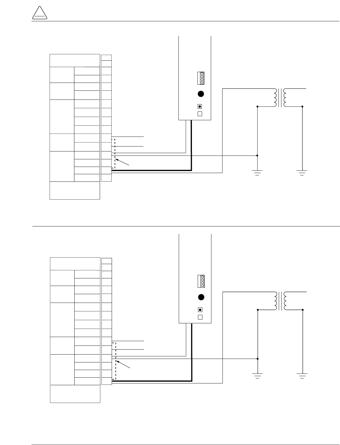
S280-79-10
41
!
SAFETY
FOR LIFE
TB1
YØ VOLTAGE
120Vac
BØ VOLTAGE
120Vac
CLOSING
VOLTAGE
NEUTRAL
SOURCE 2
NEUTRAL
SOURCE 1
AC
CUSTOMER
CONNECTIONS
NEUTRAL
ZØ
YØ
SOURCE 2
POWER
XØ
OUTPUT
VOLTAGE
NEUTRAL
*NEUTRAL
POWER
SOURCE
OUTPUT
CØ
*BØ
AØ
AC
CUSTOMER
CONNECTIONS
SOURCE 1
POWER
*REQUIRED FOR
CONTROL OPERATION
1
2
3
4
5
6
7
8
9
10
11
12
13
14
240Vac CLOSING
OPTION
NEU
BØ
15
16
BØ
NEU (LV Closing Output)
HOT (LV Closing Output)
P
O
W
E
R
S
U
P
P
L
Y
M
O
D
U
L
E
CONFIGURED
FOR
120
VAC
240
VAC
P
9
A
U
X
F2
GDC-3.15A
BLK
WHT
**Jumper necessary for use with Low-Voltage Closing Accessory
Jumper**
Figure 38.
Form 5 and Form 5 UDP Power and Low Voltage Closing customer connections to terminal block TB1 (Single-
Phase Connection, Standard BØ Input).
TB1
Y' VOLTAGE
120Vac
B' VOLTAGE
120Vac
CLOSING
VOLTAGE
NEUTRAL
SOURCE 2
NEUTRAL
SOURCE 1
AC
CUSTOMER
CONNECTIONS
NEUTRAL
ZØ
YØ
SOURCE 2
POWER
XØ
OUTPUT
VOLTAGE
NEUTRAL
*NEUTRAL
POWER
SOURCE
OUTPUT
CØ
*BØ
AØ
AC
CUSTOMER
CONNECTIONS
SOURCE 1
POWER
*REQUIRED FOR
CONTROL OPERATION
1
2
3
4
5
6
7
8
9
10
11
12
13
14
240Vac CLOSING
OPTION
NEU
15
16
AØ
NEU (LV Closing Output)
HOT (LV Closing Output)
P
O
W
E
R
S
U
P
P
L
Y
M
O
D
U
L
E
CONFIGURED
FOR
120
VAC
240
VAC
P
9
A
U
X
F2
GDC-3.15A
BLK
WHT
AØ
**Jumper necessary for use with Low-Voltage Closing Accessory
Jumper**
Figure 39.
Form 5 and Form 5 UDP Power and Low Voltage Closing customer connections to terminal block TB1 (Single-
Phase Connection, AØ Input).

Before Placing the Control and
the Recloser into Service
Prior to placing the control and recloser into service, the
following installation procedures must be properly com-
pleted and verified:
1. Control properly mounted for the installation.
2. Recloser installed according to all locally approved
standards and practices.
3. Control and recloser properly grounded in accordance
with guidelines in this manual.
4. AC power connected to the control. (AC power LED
indicator is illuminated.)
5. Control battery connected and tested for proper
operation.
6. All control programming entered and verified by
appropriate personnel.
7. Control clock set to the correct time.
8. Customer connections for remote and supervisory
operation checked and completed in accordance with
proper shielding and surge protection.
9. Control cable properly connected and supported.
Kyle Form 5, Form 5 UDP, Form 5 DC NOVA Recloser Control Installation and Operation Instructions
42
CAUTION: Equipment misoperation. Do not
connect this control to an energized recloser
until all control settings have been properly pro-
grammed and verified. Refer to the programming
information for this control. Failure to comply can
result in control and recloser misoperation, equip-
ment damage and personal injury. G110.3
!
WARNING: Hazardous voltage. Recloser and
control must be solidly grounded. Follow all
locally approved procedures and safety practices when
grounding this equipment. Improper grounding can
result in contact with high voltage, which will cause
death or severe personal injury. G115.1
!
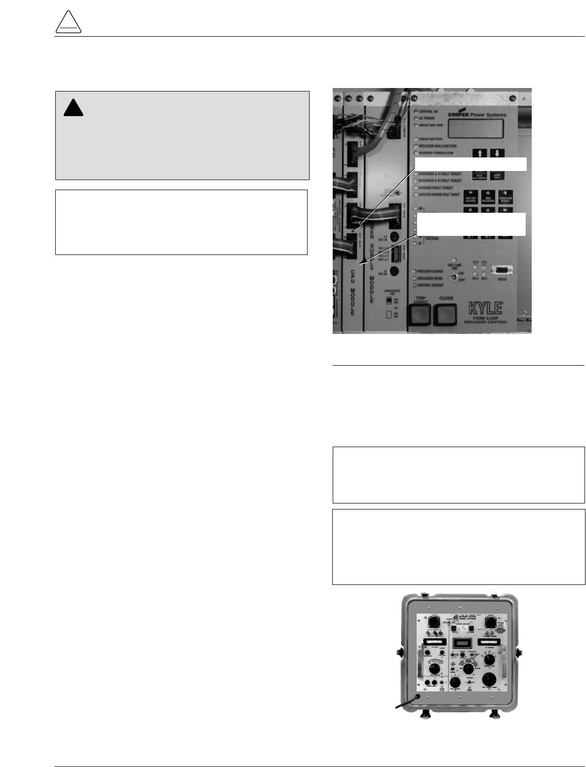
Testing an Installed Control
The following tests to determine initial operation of the
Form 5 control can be performed while connected to an
operating recloser. These are the only tests performed on
an installed, operating control. All other tests described in
this Testing and Troubleshooting section require the
Form 5 control to be removed from service, connected to
a bypassed recloser, or tested at a location where the
proper testing equipment is available.
1. Wake-up the operator panel display by pressing the
CHANGE/LAMP TEST button on the control operator
panel.
2. Scroll through the LCD display messages as
described in the LCD Display Messages section of
these instructions. Refer to Form 5 Control operator
panel section of this manual.
Check the operational values for currents, voltages,
and other metering information.
3. Check that the LED for AC power is illuminated on the
control operator panel. This indicates the presence of
AC power.
4. Test battery operation, using the procedures
described in the Battery Test Procedure section of
these instructions.
Check CPU Status
Check the operating status of the CPU module. Open the
cabinet door and locate the LED indicator (Figure 40).
The LED indicator on the CPU module should flash at a
rate of one flash per second for normal 60 Hz operation
(slightly faster for 50Hz).
Testing With Type MET Tester
The Kyle Type MET Electronic Recloser Control Tester
(Figure 41) is used for testing the Form 5 control.
The MET Tester is completely self-contained, includes all
necessary metering and interconnecting cables, and is
capable of performing all required checks and tests from
a simple verification of operation to a complete verification
of all operating parameters. Refer to Service Information
S280-76-1 Type MET Electronic Recloser Control Tester
Operator Instructions for proper setup and use of the MET
tester. Refer to Form 5 Control Default Test Procedure
section of this manual for specific tests requiring the
KMET Tester.
S280-79-10
43
!
SAFETY
FOR LIFE
IMPORTANT: The Form 5 recloser control can be
taken out of service for testing and placed back into
service without de-energizing its recloser and interrupt-
ing the system. However, during the time the control is
out of service, the recloser is inoperative.
CAUTION: Equipment misoperation. Do not
connect this control to an energized recloser
until all control settings have been properly pro-
grammed and verified. Refer to the programming
information for this control. Failure to comply can
result in control and recloser misoperation, equip-
ment damage and personal injury. G110.3
!
Figure 40.
Form 5 control CPU module.
99002KM
CPU Module
(Central Processing Unit)
CPU Module LED Indicator
Figure 41.
Kyle Type MET electronic recloser control tester.
010028KM
IMPORTANT: The Form 5 DC NOVA control cannot
be tested with the standard Kyle MET Tester. A junc-
tion box accessory for the MET tester is available for
testing the Form 5 DC NOVA control.
TESTING AND TROUBLESHOOTING
IMPORTANT: When the control is open and current
is present, the Trip Fail detection circuit in the Form 5
control will activate when the Kyle Type MET tester
CALIBRATE switch is ON. Depress and hold the
RESET TARGET keypad on the control for 3 seconds
to reset the condition.
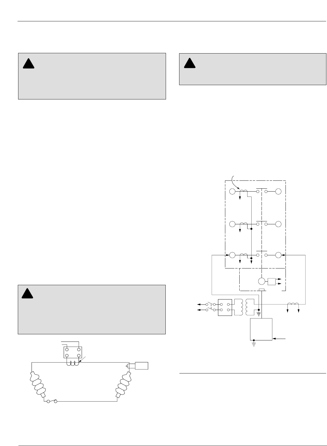
Closing the Recloser During
Testing
Electrical Closing—Solenoid-Operated
Reclosers
Line voltage is required for automatic recloser operation
during testing of reclosers equipped with a closing
solenoid (except for reclosers equipped with the low volt-
age closing accessory).
For on-line testing, bypass the recloser, open the load-
side disconnects and keep the source-side disconnects
closed. This will remove the recloser from service, but will
keep line voltage supplied to the closing solenoid (Figure
44).
For shop testing, the closing solenoid voltage is supplied
by back-feeding a transformer with a low-side rating equal
to the voltage rating of an available power source, and a
high-side rating equal to the voltage rating of the recloser
(Figure 45). A 75kVA transformer of the proper voltage
rating with an impedance drop of approximately 3% is sat-
isfactory. The ac source must have a comparable
impedance drop.
The closing coil requirement is approximately 200kVA
during the two-to-three cycle closing operation. The
solenoid coil operating voltage must be maintained at the
recloser bushings during the cycle interval the closing coil
is energized. This procedure is not used on reclosers
equipped with the low-voltage closing accessory.
Electrical Closing—Motor-Operated
Reclosers
High-voltage is not required for reclosers utilizing a motor-
operated closing mechanism energized from a 230VAC
power source. For information on energizing the recloser,
refer to the appropriate motor-operated recloser installa-
tion manual.
Figure 43 shows a test circuit for motor-operated and
solenoid-closing reclosers with low-voltage closing. Since
these reclosers require only a 240 Vac source for closing,
high-voltage transformer T3 and its protective cage is
eliminated. All other equipment is the same as the test
equipment shown in Figure 42.
Electrical Closing—NOVA Reclosers
Type NOVA 3-phase reclosers utilize an interface circuit
located in the mechanism housing. The electronic inter-
face circuit controls the opening and closing signals to the
magnetic actuator.
The Dc NOVA Recloser is tested with the dc-to-dc con-
verter and 19-pin cable connected to the dc power supply.
Kyle Form 5, Form 5 UDP, Form 5 DC NOVA Recloser Control Installation and Operation Instructions
44
WARNING: Hazardous voltage. Solidly ground
all equipment. Failure to comply can result in
death, severe personal injury, and equipment damage.
T223.2
!
Figure 43.
Suggested test circuit for motor-operated, solenoid-
closing reclosers with low-voltage closing.
65
43
21
Electronic
Control
J
GK
H
XW
240 Vac
Power
Supply
Closing
Motor
T1 T2
240 Vac
Variable
Autotransformer
240 Vac-20 A
120 Vac
To Ammeter
and Relay
to operate
cycle counter or
other timing
device
Sensing CTs (3)
WARNING: Hazardous voltage. Interconnect
source leads X and Y and ground solidly to the
recloser tank (Figure 45). Do not connect lead Z to any
other phase or mechanical ground. Dangerous voltages
to ground exist on the phase connected to lead Z. Solidly
ground all equipment. Failure to comply can result in
severe personal injury and/or equipment damage. T224.1
!
Figure 42.
Alternate method of producing variable line current
(substitute for T2 and W-X circuit in Figures 43 and
45).
600:5
Recloser
BCT ON 600:5 Tap
Note: This test circuit
can apply over
800 Amps to the
recloser.
Note: Use at least 2/0
cable between
bushings.
2
1
115Vac Variable
Autotransformer
(10 Amp)
Clamp-On
Ammeter
WARNING: Hazardous voltage. The switchgear
and high voltage transformer must be in a test
cage or similar protective device to prevent accidental
contact with the high voltage parts. Solidly ground all
equipment. Failure to comply can result in death,
severe personal injury, and equipment damage. T221.3
!
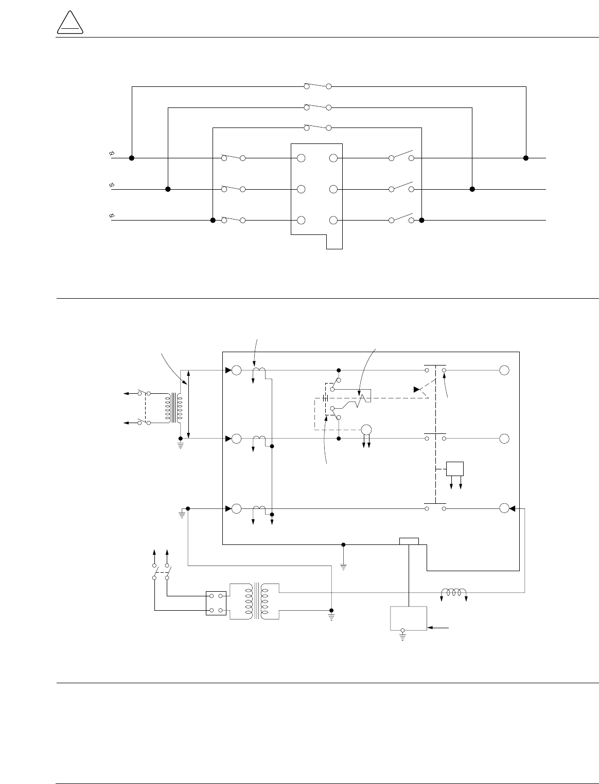
S280-79-10
45
!
SAFETY
FOR LIFE
3
6
4
T3 Y
H
X
Z
VOLTAGE RATING OF
RECLOSER CLOSING
SOLENOID COIL
SENSING CTs (3) CLOSING
SOLENOID
CONTACTOR
ROTARY
SOLENOID
MAIN
CONTACTS (S)
GK
AB
EF
TO
240 OR
480 VAC
SOURCE
TO
240 VAC
SOURCE
CLOSING
SOLENOID
COIL
TRIP
SOLENOID
CONTROL
CABLE RECEPTACLE
W
ELECTRONIC
CONTROL
TO
AMMETER AND RELAY TO
OPERATE CYCLE COUNTER
OR OTHER TIMING DEVICE
120 VAC
VARIABLE
AUTOTRANSFORMER
240 VAC
20 AMPS
T2
12
5
J
Figure 45.
Suggested test circuit for “shop-testing” solenoid-closing reclosers.
5 6
34
1 2
C
B
A
BYPASS SWITCHES
(CLOSED)
SOURCE SIDE
DISCONNECT SWITCHES
(CLOSED)
LOAD SIDE
DISCONNECT SWITCHES
(OPEN)
CLOSING
COIL
LOAD
SOURCE
SOURCE
LOAD
Figure 44.
Closing source-side switches of a bypassed “on-line” recloser provides closing solenoid power for automatic
operation during testing.
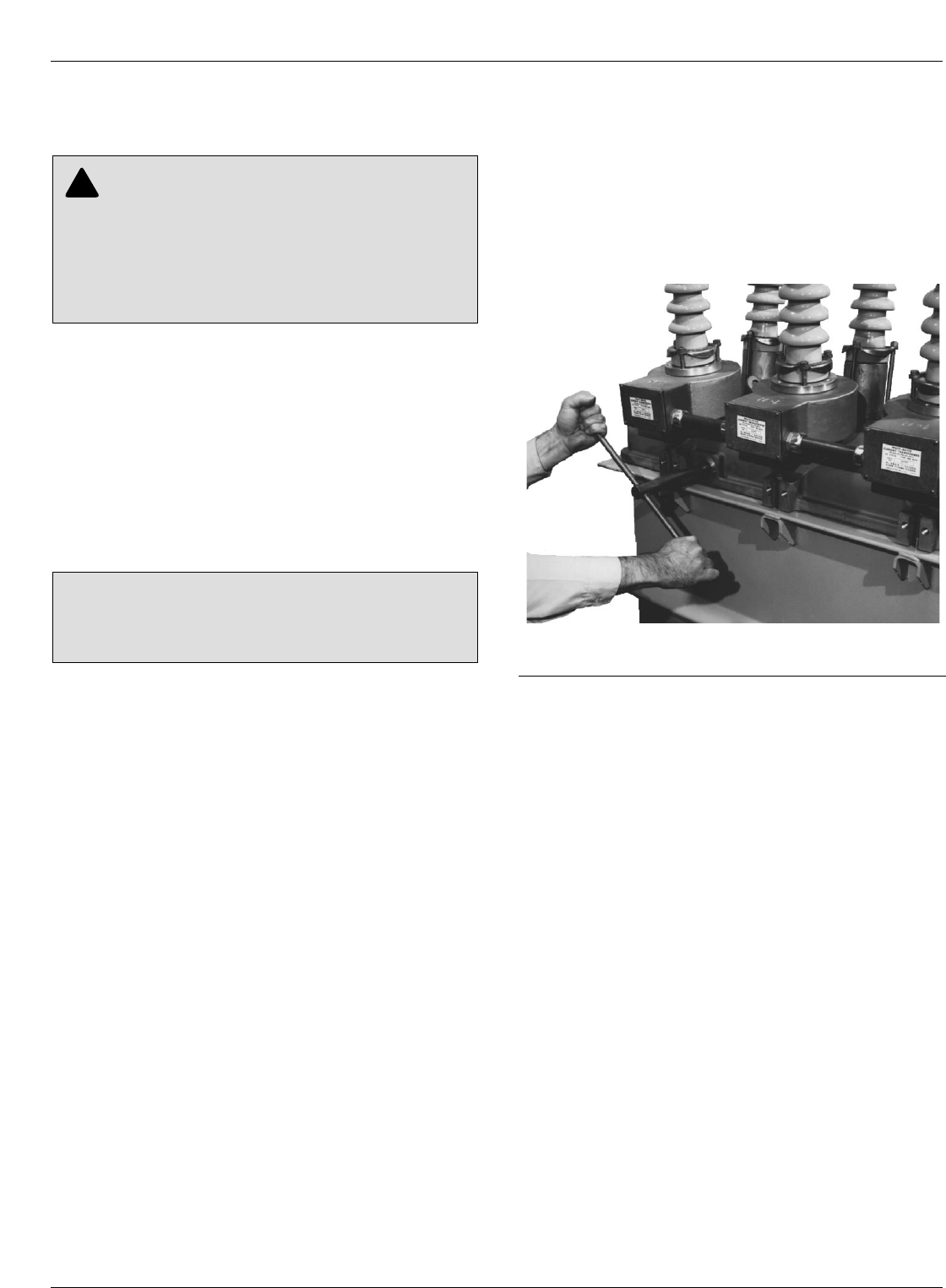
Manual Closing—Solenoid-Operated
Reclosers
If high-voltage for operating the closing solenoid is not
available, manual closing can be substituted for electrical
closing. However, not all control settings can be checked
since manual closing is not synchronized with the closing
coil control circuit in the control.
To manually close the recloser:
1. Remove the closing tool port cover and gasket from
the side of the recloser head casting.
2. Insert the tee-handled tool (available as an accessory)
into the port, engaging the pin on the closing shaft
(Figure 46).
3. Close the recloser by placing the yellow operating
handle (located under the sleethood) into the up or
CLOSED position and turning the closing tool one-
quarter turn clockwise.
4. After each trip operation, about 1/2 second elapses
while the closing solenoid plunger is moving upward to
reset the main toggle latch.
5. After the main toggle latch resets, the recloser can be
closed again by operating the manual closing tool.
6. Replace the gasket and port cover on the recloser
head after testing has been completed.
Kyle Form 5, Form 5 UDP, Form 5 DC NOVA Recloser Control Installation and Operation Instructions
46
WARNING: Explosion Hazard. Excessive Con-
tact Arcing. Do not use the manual closing tool to
close an oil-insulated, energized recloser. Closing an
energized oil-insulated recloser with a manual closing
tool can cause excessive contact arcing, rapid build-up
of gas within the equipment, and possible explosion
that can cause death, severe personal injury, and
equipment damage. T203.2
!
CAUTION: Equipment damage. Do not turn the man-
ual closing tool more than one-quarter turn clockwise.
Forcing the tool beyond the mechanism stop may shear
the pin on the closing shaft of the recloser. T222.0 Figure 46.
Using a manual closing tool to operate the recloser.
82284KMA-F
Use this procedure to test the Form 5 control with factory
default control settings. Follow all cautions and warnings
in these service instructions.
Before installation on an active feeder, the Form 5 con-
trol’s final control settings must be fully tested using an
appropriate test procedure. The Form 5 Control Default
Test Sheet follows these instructions. The Form 5 Control
Default Test Sheet Optimal Values gives the optimal val-
ues for the test results.
When performing these tests, change the Form 5 panel
settings by first pressing the CHANGE button and then
pressing the button of the function to be changed.
Initial Settings
1. Apply 120 (240) Vac to the control phase B and neu-
tral for standard controls.
2. Plug in battery.
3. Verify control is programmed for all default settings.
•Phase Minimum Trip is set to 100 amps.
•Ground Minimum Trip is set to 50 amps.
4. Disable Sequence Coordination in normal profile
using personal computer (PC).
5. Activate COLD LOAD PICKUP BLOCKED (LED is on)
on Form 5 display panel.
6. Activate GROUND TRIP BLOCK (LED is on) on Form
5 display panel.
Test Battery Circuitry
1. Press BACK button on display panel until Battery Test
Screen 31 appears.
2. Record values for all settings.
3. Press CHANGE button on the display panel.
4. Press BATTERY TEST button on display panel.
5. Record values for all readings.
Test Phase Minimum Trip Values
1. Verify Ground Trip Block LED is on.
2. Set KMET Phase Selector S5 to A.
3. Set KMET switch S4 to 300 milliampere range.
4. Set KMET Variac TR1 to zero.
5. Set KMET switch S2 to test fault current position.
6. Press the TRIP button on the display panel.
7. Press the CLOSE button on the display panel.
8. Slowly raise TR1 until Above Minimum Trip LED is on,
on display panel. Control should trip out quickly for
load currents above 105 milliamperes. Record value.
9. Repeat steps 4 – 8 for phases B and C (move KMET
S5 to B, then C).
10. Change Form 5 control from Normal Profile to Alter-
nate Profile 1.
11. Verify Cold Load Pickup Blocked (LED is on) on the
display panel.
12. Repeat steps 2 – 9 for Form 5 Alternate Profiles 1, 2,
and 3. The control is programmed to trip out at 200
milliamperes on the Alternate 1, 2, and 3 Profiles.
Note: If Cold Load Pickup LED is off, the control will trip on a
time delayed Time Current Curve with two trips to lock-
out for 30 seconds after closing in the control, per the
default Cold Load Pickup control settings.
Note: If Alternate Profiles 1, 2, and 3 have the sequence coor-
dination function enabled while testing the Form 5 con-
trol minimum trip values, it may result in the control
skipping past the fast TCC curves during the test for
minimum trip. The control will then lock out on the
delayed TCC curves.
Note: If the Form 5 control has Switch Mode rather than Pro-
file 3, the control will indicate current Above Minimum
Trip, but will not trip out.
S280-79-10
47
!
SAFETY
FOR LIFE
CAUTION: Equipment misoperation. Do not con-
nect this control to an energized recloser until all
control settings have been properly programmed and
verified. Refer to the programming information for this
control. Failure to comply can result in control and
recloser misoperation, equipment damage, and per-
sonal injury. G110.3
!
IMPORTANT: The Form 5 recloser control can be
taken out of service for testing and placed back into
service without de-energizing its recloser and interrupt-
ing the system. However, during the time the control is
out of service, the recloser is inoperative.
IMPORTANT: The Form 5 DC NOVA control can not
be tested with the standard Kyle MET Tester. A junction
box accessory for the MET tester is availble for testing
the Form 5 DC NOVA control.
FORM 5 CONTROL DEFAULT TEST PROCEDURE
IMPORTANT: The Battery Test procedure requires
large current drain. Overuse of this procedure will drain
the battery.

Test Ground Minimum Trip Values
1. Change the Form 5 control from an Alternate Profile to
the Normal Profile (all three Profile LEDs are off). Dis-
able Ground Trip Block (LED off).
2. Set KMET switch S4 to 100 milliampere range.
3. Set KMET Variac TR1 to zero.
4. Set KMET switch S2 to test fault position.
5. Verify the Form 5 phase minimum trip values are
higher than the ground trip values.
6. Set KMET Phase Selector S5 to A.
7. Press the TRIP button on the display panel.
8. Press the CLOSE button on the display panel.
9. Slowly raise TR1 until Above Minimum Trip shows on
Form 5 control. Control should trip out for load cur-
rents above 50 milliamperes. Record values.
10. Repeat steps 4 – 9 for the Form 5 Alternate Profiles 1,
2, and 3. The control is programmed to trip out at 100
milliamperes on the Alternate 1, 2, and 3 Profiles.
Note: If Cold Load Pickup is activated (LED off), the control will
trip on a time delayed TCC with two trips to lockout for
30 seconds after closing in the control, per the default
Cold Load Pickup control settings.
Test Phase Timing
1. Set the Form 5 control to Normal profile (all Alternate
Profile LEDs off).
2. Activate GROUND TRIP BLOCK (LED on). Ground
Trip is blocked.
3. Set KMET Phase Selector S5 to phase A.
4. Set KMET switch S4 to 300 milliampere range.
5. Press the Form 5 trip switch once to lock out the Form
5 control.
6. Set KMET phase selector S3 to Control Response.
7. While holding the KMET Test Fault Current Switch S2
in the Calibrate position, adjust the fault current to 200
percent fault (100 X 2 or 200 milliamperes).
Note: On newer controls, applying fault current while the
control is locked out will set the Recloser Malfunction
LED. This will not affect testing. To clear, press the
Reset Targets button after all tests are complete.
8. Press the TRIP button on the display panel.
9. Press the CLOSE button on the display panel.
10. Set KMET Fault Switch S2 to test fault current posi-
tion. Record timing readings from the KMET time
clock for all trips on the A 2X___ test sheet location.
11. Set KMET Test Set switch S4 to the 1A position.
12. Set KMET Phase Selector S5 to phase B.
13. Calibrate KMET fault current to 500 percent (100 X 5
or 500 milliamperes) using the KMET 1A range.
14. Press the TRIP button on the display panel.
15. Press the CLOSE button on the display panel.
16. Set KMET test set Fault Current Switch S2 to test fault
current position. Record timings from the KMET test
set for all trips on the B 5X ___ locations on the test
sheet.
17. Set KMET Phase Selector S5 to phase C.
18. Calibrate KMET Phase Selector S5 to 1000% of fault
(1000 milliamperes).
19. Press the TRIP button on the display panel.
20. Press the CLOSE button on the display panel.
21. Set KMET test set Fault Current Switch S2 to test fault
current position. Record timings from the KMET test
set for all trips on the C 10X ___ locations on the test
sheet.
22. Repeat steps 2 – 21 for Alternate Profiles 1, 2, and 3.
Note that the Phase minimum trip for the Alternate
Profiles is 200 amps. The 200% fault will then be 400
milliamperes or .4 amp, the 500% fault will then be
1000 milliamperes or 1 amp, and the 1000% fault will
then be 2000 milliamperes or 2 amps.
Test Ground Timing
1. Verify control is programmed for all default settings.
2. Disable GROUND TRIP BLOCK (LED off). Ground
Trip is active.
3. Activate the Normal Profile (Alternate Profile LEDs
off).
Note: When testing the ground trip timing circuit, the KMET
test set applies a phase to ground fault to the Form 5
control. If the applied fault current exceeds the phase
minimum trip value, the control may time out on the
phase time current curve, which may be shorter than the
proper ground time current curve. For this reason, the
Form 5 phase minimum trip value should be increased
to a higher value while testing Form 5 ground trip time
current curves.
4. Increase the Form 5 phase minimum trip value to
1600 amperes.
5. Set KMET Test Set switch S4 to the 300 milliampere
position.
6. While holding the Fault Current Switch S2 in the Cali-
brate position, adjust the fault current to 200 percent
fault (50 X 2 or 60 milliamperes).
7. Press the TRIP button on the display panel.
8. Press the CLOSE button on the display panel.
9. Set KMET test set Fault Current switch S2 in the test
fault current position. Record timings from the KMET
test set for all trips on the G 2X ___ locations on the
test sheet.
10. Calibrate KMET fault current to 500 percent, (50 X 5
or 250 milliamperes).
11. Press the TRIP button on the display panel.
12. Press the CLOSE button on the display panel.
Kyle Form 5, Form 5 UDP, Form 5 DC NOVA Recloser Control Installation and Operation Instructions
48

13. Set KMET test set Fault Current switch S2 in the test
fault current position. Record timings from the KMET
test set for all trips on the G 5X ___ locations on the
test sheet.
14. Set KMET Test Set switch S4 to the 1A position.
15. Calibrate KMET fault current to 1000 percent, (50 X 10
or 500 milliamperes).
16. Press the TRIP button on the display panel.
17. Press the CLOSE button on the display panel.
18. Set KMET test set Fault Current switch S2 in the test
fault current position. Record timings from the KMET
test set for all trips on the G 10X ___ locations on the
test sheet.
19. Repeat steps 4 – 18 for Alternate Profiles 1, 2, and 3.
Note that the ground minimum trip for the Alternate
Profiles is 100 amps. The 200% fault will then be 200
milliamperes, the 500% fault will then be 500 mil-
liamperes, and the 1000% fault will then be 1000 mil-
liamperes or 1 amps.
20. Return the Normal Profile Phase Minimum Trip Value
to the pretest value, 100 amps.
Test Non-Reclose
1. Activate NON-RECLOSING (LED on).
2. Activate GROUND TRIP BLOCK (LED on).
3. Set KMET Phase Selector switch S5 to phase A.
4. Set Form 5 control to Normal Profile (all Alternate Pro-
file LEDs off).
5. Adjust fault current to 200 percent or 200 mil-
liamperes.
6. Press the TRIP button on the display panel.
7. Press the CLOSE button on the display panel.
8. Set KMET test set Fault Current Switch S2 to fault
position.
9. Control should trip once, then indicate open and lock-
out. Record time value.
10. Disable NON-RECLOSE (LED off).
11. Repeat steps 5 – 8, to lockout. Record time value.
Test Cold Load Pickup Blocked
1. Disable COLD LOAD PICKUP BLOCKED (LED off).
2. CLOSE the Form 5 control.
3. Adjust fault current to 200 percent or 200 mil-
liamperes.
4. Within 30 seconds of Step 3, set KMET test set Fault
Current Switch S2 to fault position.
5. Control should trip twice on slow TCC curve, then indi-
cate open and lockout. Record timing value.
6. Activate COLD LOAD PICKUP BLOCKED (LED on).
7. Repeat steps 2 – 4. Record value.
Test Fast Trips Disabled
1. Activate FAST TRIPS DISABLED (LED on).
2. CLOSE the Form 5 control.
3. Adjust fault current to 200 percent or 200 mil-
liamperes.
4. Set KMET test set Fault Current Switch S2 to fault
position.
5. Control should trip two times to lockout, on all slow
TCCs, then indicate OPEN and lockout. Record value.
6. Deactivate Fast Trips Disabled (LED off).
7. Repeat steps 2 -4. Control should trip on two fast, two
slow TCCs. Record values.
Test Hot Line Tag
1. CLOSE the Form 5 control.
2. Activate HOT LINE TAG (LED on).
3. Adjust fault current to 200 percent or 200 mil-
liamperes.
4. Set KMET test set Fault Current Switch S2 to fault
position.
5. Control should trip out once on the 101 TCC curve,
then indicate open and lockout. Record value.
6. Verify that it is not possible to close the Form 5 control.
7. Deactivate HOT LINE TAG (LED off).
8. Verify that you can CLOSE the Form 5 control.
Test Reclose
1. Set KMET selector switch S3 to Control Reclose
Reset.
2. Reset the KMET Time Clock if required.
3. Adjust fault current to 200 percent or 200 mil-
liamperes.
4. Set KMET test set Fault Current Switch S2 to fault
position.
5. After trip, turn fault switch S2 off.
6. Record reclose time.
7. Repeat steps 2 – 6 until control locks out.
S280-79-10
49
!
SAFETY
FOR LIFE

Test Close Circuit Disable Fuse
This test is only applicable to Form 5 LS controls and stan-
dard Form 5 controls below Serial Number 3000.
1. Set KMET Fault Switch S2 to OFF.
2. CLOSE the Form 5 control.
3. Remove Close Circuit Disable fuse.
4. Adjust fault current to 200 percent or 200 mil-
liamperes.
5. Set KMET test set Fault Current Switch S2 to fault
position. The control will trip once.
6. Verify that it is not possible to close the Form 5 control.
7. Replace Close Circuit Disable fuse.
8. Verify it is now possible to CLOSE the Form 5 control.
Verify Instantaneous Demand
Metering
1. Enable GROUND TRIP BLOCK (LED on).
2. Set KMET switch S2 to OFF.
3. Set KMET Phase Selector S5 to A.
4. Set KMET Variac to zero.
5. Set KMET switch S4 to the 100 milliampere range.
6. CLOSE Form 5 control.
7. Set KMET switch S2 to ON.
8. Set KMET Variac to read 80 milliamperes.
9. Scroll the Form 5 LCD screen to screen 1.
10. Verify Instantaneous metering on Phase A and
Ground reads 80 milliamperes.
11. Set KMET Phase Selector S5 to B.
12. Verify Instantaneous metering on Phase B and
Ground reads 80 milliamperes.
13. Set KMET Phase Selector S5 to C.
14. Verify Instantaneous metering on Phase C and
Ground reads 80 milliamperes.
Kyle Form 5, Form 5 UDP, Form 5 DC NOVA Recloser Control Installation and Operation Instructions
50

S280-79-10
51
!
SAFETY
FOR LIFE
Form 5 Control Default Test Optimal Values
2. Volts 28.0 2.6 Volts 28.0
Battery Circuitry MA 35 2.6 MA 550
Volts 27.0 2.6 volts 24.2
3. Normal Profile Phase A Amps Phase B Amps Phase C Amps
100.5 100.3 100.7
Phase Profile #1 Phase A Amps Phase B Amps Phase C Amps
Minimum Trip 200.9 200.2 200.5
Profile #2 Phase A Amps Phase B Amps Phase C Amps
200.9 200.2 200.5
Profile #3 Phase A Amps Phase B Amps Phase C Amps
200.9 200.2 200.5
4. Normal Ground Amps 50.1
Ground Profile #1 Ground Amps 100.3
Minimum Trip Profile #2 Ground Amps 100.3
Profile #3 Ground Amps 100.3
5. Trip to Lockout Sequence 1st 2nd 3rd 4th
Phase Timing Normal Phase A 2X 0.161 0.164 1.416 1.421
Phase B 5X 0.018 0.017 0.278 0.280
Phase C 10X 0.016 0.014 0.088 0.086
Profile #1 Phase A 2X 0.153 0.154 1.443 1.441
Phase B 5X 0.015 0.014 0.273 0.275
Phase C 10X 0.011 0.009 0.087 0.087
Profile #2 Phase A 2X 0.153 0.154 1.443 1.441
Phase B 5X 0.015 0.014 0.273 0.275
Phase C 10X 0.011 0.009 0.087 0.087
Profile #3 Phase A 2X 0.153 0.154 1.443 1.441
Phase B 5X 0.015 0.014 0.273 0.275
Phase C 10X 0.011 0.009 0.087 0.087

Kyle Form 5, Form 5 UDP, Form 5 DC NOVA Recloser Control Installation and Operation Instructions
52
Form 5 Control Default Test Optimal Values
6. Trip Sequence 1st 2nd 3rd 4th
Ground Timing Normal Ground 2X 0.214 0.212 3.894 3.896
Ground 5X 0.012 0.016 1.097 1.099
Ground 10X 0.008 0.014 0.652 0.653
Profile #1 Ground 2X 0.214 0.212 3.894 3.896
Ground 5X 0.012 0.016 0.952* 0.954*
Ground 10X 0.008 0.014 0.280* 0.276*
Profile #2 Ground 2X 0.214 0.212 3.984 3.896
Ground 5X 0.012 0.016 0.952* 0.954*
Ground 10X 0.008 0.014 0.280* 0.276*
Profile #3 Ground 2X 0.214 0.212 3.894 3.896
Ground 5X 0.012 0.016 0.952* 0.954*
Ground 10X 0.008 0.014 0.280* 0.276*
7. Enabled Phase 2X 0.153 lockout lockout lockout
Non-Reclose Disabled Phase 2X 0.152 0.153 1.420 1.433
8. Cold Load Block Off Phase 2X 1.420 1.433 lockout lockout
PickUp Blocked Block On 0.158 0.154 1.420 1.433
9. Fast Trips Enabled Phase 2X 1.419 1.422 lockout lockout
Disabled Phase 2X 0.155 0.156 1.418 1.424
10. No Reclose Phase 2X 0.014 lockout lockout lockout
Hot Line Tag Enabled Phase 2X 0.155 0.156 1.148 1.424
11. Reclose Sequence 1st 2nd 3rd 4th
Test Reclose Reclose Times 1.975 1.974 4.968 lockout
12. Fuse Out Can’t Close? Yes No
Close Circuit XXX
Disable Fuse Fuse In Can Close? Yes No
XXX
13. Instantaneous Phase A Phase B Phase C
Demand Metering Amps 80 Amps 81 Amps 80
*Refer to the Test Ground Timing section of this manual.

S280-79-10
53
!
SAFETY
FOR LIFE
Form 5 Control Default Test Sheet
Date: Serial No:
2. Volts 2.6 Volts
Battery Circuitry MA 2.6 MA
Volts 2.6 volts
3. Normal Profile Phase A Amps Phase B Amps Phase C Amps
Phase Profile #1 Phase A Amps Phase B Amps Phase C Amps
Minimum Trip
Profile #2 Phase A Amps Phase B Amps Phase C Amps
Profile #3 Phase A Amps Phase B Amps Phase C Amps
4. Normal Ground Amps
Ground Profile #1 Ground Amps
Minimum Trip Profile #2 Ground Amps
Profile #3 Ground Amps
5. Trip to Lockout Sequence 1st 2nd 3rd 4th
Phase Timing Normal Phase A 2X
Phase B 5X
Phase C 10X
Profile #1 Phase A 2X
Phase B 5X
Phase C 10X
Profile #2 Phase A 2X
Phase B 5X
Phase C 10X
Profile #3 Phase A 2X
Phase B 5X
Phase C 10X

Kyle Form 5, Form 5 UDP, Form 5 DC NOVA Recloser Control Installation and Operation Instructions
54
Form 5 Control Default Test Sheet
6. Trip Sequence 1st 2nd 3rd 4th
Ground Timing Normal Ground 2X
Ground 5X
Ground 10X
Profile #1 Ground 2X
Ground 5X
Ground 10X
Profile #2 Ground 2X
Ground 5X
Ground 10X
Profile #3 Ground 2X
Ground 5X
Ground 10X
7. Enabled Phase 2X lockout lockout lockout
Non-Reclose Disabled Phase 2X
8. Cold Load Block Off Phase 2X lockout lockout
PickUp Blocked Block On
9. Fast Trips Enabled Phase 2X lockout lockout
Disabled Phase 2X
10. No Reclose Phase 2X
Hot Line Tag Enabled Phase 2X
11. Reclose Sequence 1st 2nd 3rd 4th
Test Reclose Reclose Times
12. Fuse Out Can’t Close? Yes No
Close Circuit
Disable Fuse Fuse In Can Close? Yes No
13.Instantaneous Phase A Phase B Phase C
Demand Metering Amps Amps Amps

REMOVE THE CONTROL
FROM SERVICE
1. Enable GND TRIP BLOCKED to allow for ground trip
to be disabled when re-energized.
A. Press the CHANGE/LAMP TEST key on the Oper-
ator Panel to enter the CHANGE mode.
Note: The LCD Display Screen will indicate the amount
of time available in CHANGE mode to make a
change.
B. Depress the GND TRIP BLOCKED key.
Note: After the GND TRIP BLOCKED key is
depressed, the red LED indicator will illuminate
to indicate GROUND TRIP BLOCKED is active.
2. Disconnect control cable from the control.
3. De-energize ac power from the control.
4. Unplug the control battery.
RETURN THE CONTROL TO
SERVICE
After the required work is completed, disconnect the con-
trol from the test set and follow this procedure to return the
control to service:
1. Plug in the control battery.
2. Apply ac power to the control.
3. Verify that all control settings are correct.
4. Reconnect the control cable to the control.
5. Disable GND TRIP BLOCKED.
A. Press the CHANGE/LAMP TEST key on the Oper-
ator Panel to enter the CHANGE mode.
Note: The LCD Display Screen will indicate the amount
of time available in CHANGE mode to make a
change.
B. Depress the GND TRIP BLOCKED key.
Note: After the GND TRIP BLOCKED key is
depressed, the red LED indicator will not be illu-
minated indicating GROUND TRIP BLOCKED is
not active.
6. Reset the control clock after AC power has been re-
applied. Refer to Setting the Control Clock in Service
Information S280-79-2 Form 5 Microprocessor-Based
Recloser Control Programming Guide.
S280-79-10
55
!
SAFETY
FOR LIFE
IMPORTANT: Disconnect switches for ac sensing
and power connections are necessary to isolate the
Form 5 Recloser Control for testing and servicing.
WARNING: Hazardous voltage. If the recloser
is energized while the control cable is discon-
nected, the CT secondaries can generate high volt-
ages. Contact with high voltage can cause severe
personal injury or death. T204.2
!
CAUTION: Equipment misoperation. Do not
connect this control to an energized recloser
until all control settings have been properly pro-
grammed and verified. Refer to the programming
information for this control. Failure to comply can
result in control and recloser misoperation, equip-
ment damage, and personal injury. G110.3
!
Replacement Kits
Replacement kits for the Kyle Form 5 Control are avail-
able through the factory Service Department. To order
these kits, refer to the Replacement Parts price list for cat-
alog numbers and pricing. Contact your Cooper Power
Systems representative for additional information and
ordering procedures.
Factory-Authorized Service
Centers
Factory-authorized service centers are located through-
out the continental United States to provide maintenance,
repair and testing services for Kyle controls and reclosers.
For further information, contact your Cooper Power Sys-
tems representative.
Factory Maintenance Classes
The factory service department offers a basic testing and
troubleshooting course for the Form 5 Microprocessor-
Based Electronic Recloser Control and Reclosers. This
course, taught by experienced service technicians, is
held at the factory‘s in-house training facility. For addi-
tional information, contact your Cooper Power Systems
representative.
Type MET Recloser Control Tester
A 30-minute video cassette program, KSPV7 Kyle®Type
MET Electronic Recloser Control Tester Operation and
Testing Procedures is available as a supplemental train-
ing aid for service personnel.
Kyle Form 5, Form 5 UDP, Form 5 DC NOVA Recloser Control Installation and Operation Instructions
56 KDL
5/05
1045 Hickory Street
Pewaukee, WI 53072
www.cooperpower.com
©2005 Cooper Power Systems or its affiliates.
Kyle®is a registered trademark of Cooper Power Systems or its affiliates.
KA2048-476 Rev: 02
!
SAFETY
FOR LIFE
ADDITIONAL INFORMATION
CAUTION: This equipment requires routine
inspection and maintenance to ensure proper
operation. If it is not maintained, it can fail to operate
properly. Improper operation can cause equipment
damage and possible personal injury. G105.1
!
