FJR1300 S5JW1AE5
User Manual: FJR1300
Open the PDF directly: View PDF ![]() .
.
Page Count: 44

2004
FJR1300(S)
FJR1300A(S)
5JW1-AE5
SUPPLEMENTARY
SERVICE MANUAL

FOREWORD
This Supplementary Service Manual has been prepared to introduce new service and data for the
FJR1300(S)/FJR1300A(S) 2004. For complete service information procedures it is necessary to
use this Supplementary Service Manual together with the following manuals.
FJR1300(N) 2001 SERVICE MANUAL: 5JW1-AE1
FJR1300(P) 2002 SUPPLEMENTARY SERVICE MANUAL: 5JW1-AE2
FJR1300(R)/FJR1300A(R) 2003 SUPPLEMENTARY SERVICE MANUAL: 5JW1-AE4
FJR1300(S)/FJR1300A(S) 2004
SUPPLEMENTARY
SERVICE MANUAL
© 2003 by Yamaha Motor Co., Ltd.
First edition, September 2003
All rights reserved.
Any reproduction or unauthorized use
without the written permission of
Yamaha Motor Co., Ltd.
is expressly prohibited.
EAS00002
NOTICE
This manual was produced by the Yamaha Motor Company, Ltd. primarily for use by Yamaha deal-
ers and their qualified mechanics. It is not possible to include all the knowledge of a mechanic in
one manual. Therefore, anyone who uses this book to perform maintenance and repairs on Yamaha
vehicles should have a basic understanding of mechanics and the techniques to repair these types
of vehicles. Repair and maintenance work attempted by anyone without this knowledge is likely to
render the vehicle unsafe and unfit for use.
Yamaha Motor Company, Ltd. is continually striving to improve all of its models. Modifications and
significant changes in specifications or procedures will be forwarded to all authorized Yamaha deal-
ers and will appear in future editions of this manual where applicable.
NOTE:
@
Designs and specifications are subject to change without notice.
EAS00004
IMPORTANT MANUAL INFORMATION
Particularly important information is distinguished in this manual by the following.
The Safety Alert Symbol means ATTENTION! BECOME ALERT! YOUR
SAFETY IS INVOLVED!
Failure to follow WARNING instructions could result in severe injury or death to
the motorcycle operator, a bystander or a person checking or repairing the
motorcycle.
A CAUTION indicates special precautions that must be taken to avoid damage
to the motorcycle.
A NOTE provides key information to make procedures easier or clearer.
WARNING
CAUTION:
NOTE:
EAS00007
HOW TO USE THIS MANUAL
This manual is intended as a handy, easy-to-read reference book for the mechanic. Comprehensive
explanations of all installation, removal, disassembly, assembly, repair and check procedures are
laid out with the individual steps in sequential order.
1The manual is divided into chapters. An abbreviation and symbol in the upper right corner of
each page indicate the current chapter.
Refer to “SYMBOLS”.
2Each chapter is divided into sections. The current section title is shown at the top of each page,
except in chapter 3 (“PERIODIC CHECKS AND ADJUSTMENTS”), where the sub-section title(s)
appears.
3Sub-section titles appear in smaller print than the section title.
4To help identify parts and clarify procedure steps, there are exploded diagrams at the start of
each removal and disassembly section.
5Numbers are given in the order of the jobs in the exploded diagram. A circled number indicates a
disassembly step.
6Symbols indicate parts to be lubricated or replaced.
Refer to “SYMBOLS”.
7A job instruction chart accompanies the exploded diagram, providing the order of jobs, names of
parts, notes in jobs, etc.
8Jobs requiring more information (such as special tools and technical data) are described sequen-
tially.
EAS00008
SYMBOLS
The following symbols are not relevant to
every vehicle.
Symbols 1 to 9 indicate the subject of each
chapter.
1General information
2Specifications
3Periodic checks and adjustments
4Chassis
5Engine
6Cooling system
7Fuel injection system
8Electrical system
9Troubleshooting
Symbols 0 to G indicate the following.
0Serviceable with engine mounted
AFilling fluid
BLubricant
CSpecial tool
DTightening torque
EWear limit, clearance
FEngine speed
GElectrical data
Symbols H to M in the exploded diagrams
indicate the types of lubricants and lubrication
points.
HEngine oil
IGear oil
JMolybdenum disulfide oil
KWheel bearing grease
LLithium soap base grease
MMolybdenum disulfide grease
Symbols N to O in the exploded diagrams
indicate the following.
NApply locking agent (LOCTITE®)
OReplace the part
12
34
56
78
90
AB
CD
EFG
HIJ
KLM
NO
GEN
INFO
SPEC
CHK
ADJ
CHAS
ENG
COOL
FI –+
ELEC
TRBL
SHTG
T
R
.
.
EGM
BLS M
LT
New

CONTENTS
GENERAL INFORMATION ..............................................................................1
FEATURES ...............................................................................................1
OUTLINE ...............................................................................................1
FI SYSTEM ...........................................................................................2
SPECIFICATIONS ............................................................................................3
GENERAL SPECIFICATIONS ..................................................................3
ENGINE SPECIFICATIONS ......................................................................3
ELECTRICAL SPECIFICATIONS .............................................................4
PERIODIC CHECKS AND ADJUSTMENTS ....................................................5
INTRODUCTION .......................................................................................5
PERIODIC MAINTENANCE AND LUBRICATION CHART .......................5
SEATS AND FUEL TANK .........................................................................7
FUEL TANK ..........................................................................................7
REMOVING THE FUEL TANK ..............................................................9
AIR FILTER CASE ..................................................................................10
FUEL INJECTION SYSTEM ...........................................................................12
FUEL INJECTION SYSTEM ...................................................................12
WIRING DIAGRAM (FJR1300) ...........................................................13
WIRING DIAGRAM (FJR1300A) .........................................................14
SUBSTITUTE CHARACTERISTICS OPERATION CONTROL
(FAIL-SAFE ACTION) .........................................................................16
THROTTLE BODIES ...........................................................................21
AIR INDUCTION SYSTEM ......................................................................25
INSTALLING THE REED VALVES .....................................................25
ELECTRICAL .................................................................................................26
ELECTRICAL COMPONENTS ...............................................................26
FUEL INJECTION SYSTEM ...................................................................28
CIRCUIT DIAGRAM (FJR1300) ..........................................................28
CIRCUIT DIAGRAM (FJR1300A) .......................................................29
CHECKING THE FUEL PUMP ...........................................................30
FJR1300 WIRING DIAGRAM
FJR1300A WIRING DIAGRAM
– 1 –
GEN
INFO
FEATURES
GENERAL INFORMATION
FEATURES
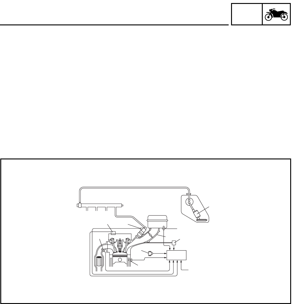
OUTLINE
The main function of a fuel supply system is to provide fuel to the combustion chamber at the opti-
mum air-fuel ratio in accordance with the engine operating conditions and the atmospheric tempera-
ture.
In the conventional carburetor system, the air-fuel ratio of the mixture that is supplied to the com-
bustion chamber is created by the volume of the intake air and the fuel that is metered by the jet that
is used in the respective carburetor.
Despite the same volume of intake air, the fuel volume requirement varies by the engine operating
conditions, such as acceleration, deceleration, or operating under a heavy load. Carburetors that
meter the fuel through the use of jets have been provided with various auxiliary devices, so that an
optimum air-fuel ratio can be achieved to accommodate the constant changes in the operating con-
ditions of the engine.
As the requirements for the engine to deliver more performance and cleaner exhaust gases
increase, it becomes necessary to control the air-fuel ratio in a more precise and finely tuned man-
ner. To accommodate this need, this model has adopted an electronically controlled fuel injection
(FI) system, in place of the conventional carburetor system. This system can achieve an optimum
air-fuel ratio required by the engine at all times by using a microprocessor that regulates the fuel
injection volume according to the engine operating conditions detected by various sensors.
The adoption of the FI system has resulted in a highly precise fuel supply, improved engine
response, better fuel economy, and reduced exhaust emissions. Furthermore, the air induction sys-
tem (AI system) has been placed under computer control together with the FI system in order to
realize cleaner exhaust gases.
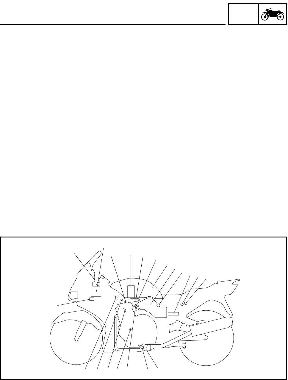
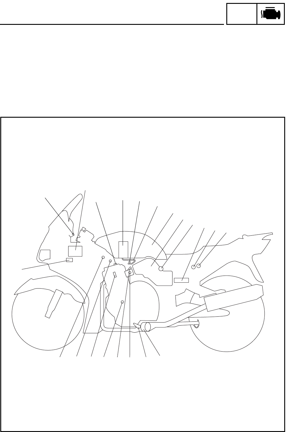
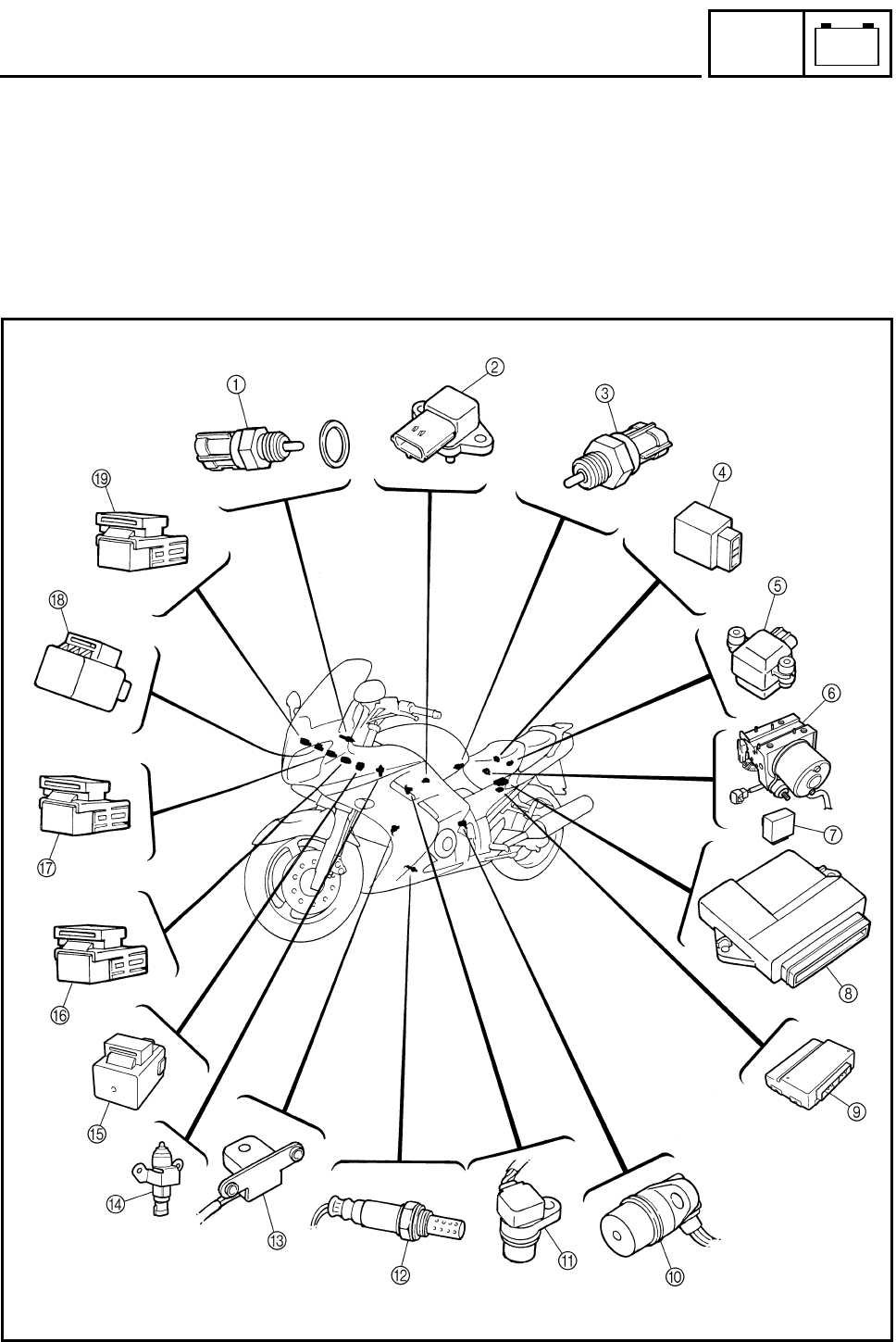
1Ignition coil
2Air filter case
3Intake air tempera-
ture sensor
4Fuel delivery hose
5Fuel tank
6Fuel pump
7Intake air pressure
sensor
8Throttle position sensor
9Fuel injector
0O2 sensor
ACatalytic converter
BCrankshaft position
sensor
CCoolant temperature
sensor
DSpark plug
ECylinder identifica-
tion sensor
FBattery
GECU
HFuel injection system
relay
IEngine trouble warn-
ing light
JLean angle cut-off
switch
KAir cut-off valve
6
8
4523GH
J
7
A
90
B
D
C
K
1
IF
E
– 2 –
GEN
INFO
FEATURES
FI SYSTEM
The fuel pump delivers fuel to the injector via the fuel filter. The fuel pump maintains the fuel pres-
sure that is applied to the injector at only 324 kPa (3.24 kg/cm2, 46.08 psi). Accordingly, when the
energizing signal from the ECU energizes the injector, the fuel passage opens, causing the fuel to
be injected into the intake manifold only during the time the passage remains open. Therefore, the
longer the length of time the injector is energized (injection duration), the greater the volume of fuel
that is supplied. Conversely, the shorter the length of time the injector is energized (injection dura-
tion), the lesser the volume of fuel that is supplied.
The injection duration and the injection timing are controlled by the ECU. Signals that are input from
the throttle position sensor, crankshaft position sensor, intake air pressure sensor, intake air tem-
perature sensor, coolant temperature sensor, and O2 sensor enable the ECU to determine the
injection duration. The injection timing is determined through the signals from the crankshaft posi-
tion sensor and the cylinder identification sensor. As a result, the volume of fuel that is required by
the engine can be supplied at all times in accordance with the driving conditions.
1Fuel pump
2Fuel injector
3Throttle body
4Intake air temperature
sensor
5Throttle position sen-
sor
6Intake air pressure
sensor
7ECU
8Coolant temperature
sensor
9O2 sensor
0Cylinder identification
sensor
ACrankshaft position
sensor
ÈFuel system
ÉControl system
Illustration is for reference only.
#4 #3 #2 #1 1
57
4
6
3
A
8
2
0
9
È
É
– 3 –
SPEC
SPECIFICATIONS
GENERAL SPECIFICATIONS
ENGINE SPECIFICATIONS
Item Standard Limit
Model code FJR1300: 5JWG (for Europe)
5JWH (for F)
5JWJ (for Oceania)
FJR1300A: 5VS7 (for Europe)
5VS8 (for F)
5VS9 (for Oceania)
----
----
----
----
----
----
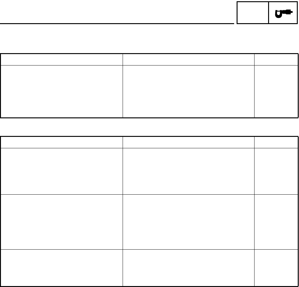
Item Standard Limit
Fuel pump
Pump type Electric ----
Model (manufacturer) 5JW 21 (DENSO) ----
Maximum consumption amperage 6.0 A ----
Output pressure 324 kPa (3.24 kg/cm2, 46.08 psi) ----
Throttle bodies
Model (manufacturer) × quantity 42EHS (MIKUNI) × 4 ----
Intake vacuum pressure 33.3 kPa (250 mmHg, 9.8 inHg) ----
Throttle cable free play (at the flange
of the throttle grip)
3 ~ 5 mm (0.12 ~ 0.20 in) ----
ID mark 5JW1 50 ----
Fuel injectors
Model INP-151 ----
Manufacturer NIPPON INJECTOR ----
Quantity 4 ----
GENERAL SPECIFICATIONS/
ENGINE SPECIFICATIONS
– 4 –
SPEC
ELECTRICAL SPECIFICATIONS
ELECTRICAL SPECIFICATIONS
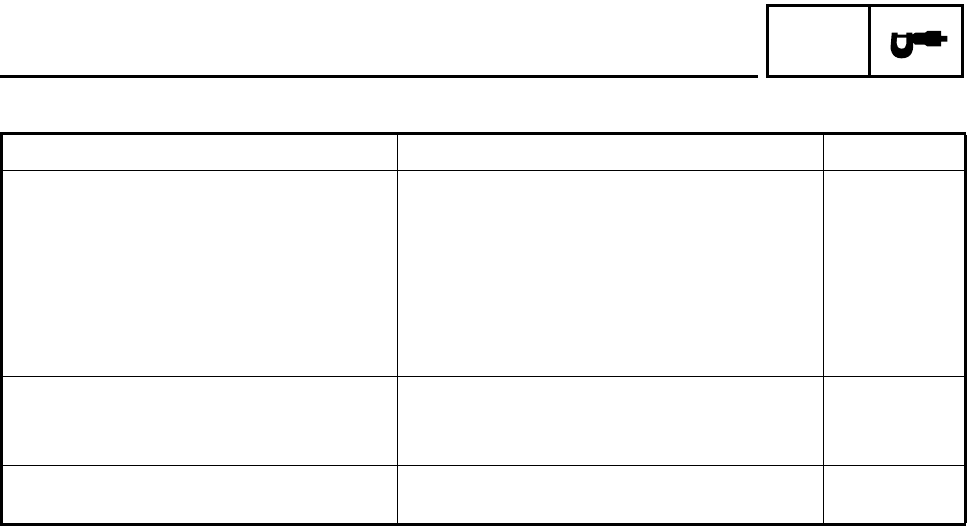
Item Standard Limit
Ignition system
Ignition system type Transistorized coil ignition (digital) ----
Ignition timing 5° BTDC at 1,050 r/min ----
Advancer type Electric ----
Pickup coil resistance/color 420.8 ~ 569.3 Ω/Gy–B ----
Transistorized coil ignition unit model
(manufacturer)
F8T818 (MITSUBISHI)
F8T819 (MITSUBISHI) (for F)
----
----
Starting circuit cut-off relay
Model (manufacturer) G8R-30Y-R (OMRON) ----
Coil resistance 180 Ω ----
Fuel injection system relay
Model (manufacturer) G8R-30Y-R (OMRON) ----
– 5 –
CHK
ADJ
INTRODUCTION/
PERIODIC MAINTENANCE AND LUBRICATION CHART
EAS00036
PERIODIC CHECKS AND ADJUSTMENTS
INTRODUCTION
This chapter includes all information necessary to perform recommended checks and adjustments.
If followed, these preventive maintenance procedures will ensure more reliable vehicle operation, a
longer service life and reduce the need for costly overhaul work. This information applies to vehicles
already in service as well as to new vehicles that are being prepared for sale. All service technicians
should be familiar with this entire chapter.
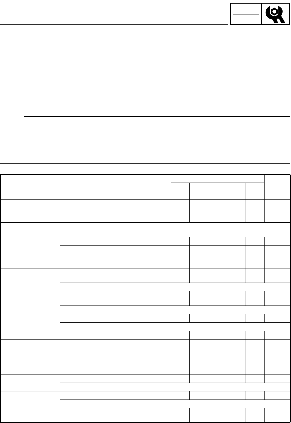
PERIODIC MAINTENANCE AND LUBRICATION CHART
NOTE:
•The annual checks must be performed every year, except if a kilometer-based maintenance
is performed instead.
•From 50,000 km, repeat the maintenance intervals starting from 10,000 km.
•Items marked with an asterisk should be performed by a Yamaha dealer as they require special
tools, data and technical skills.
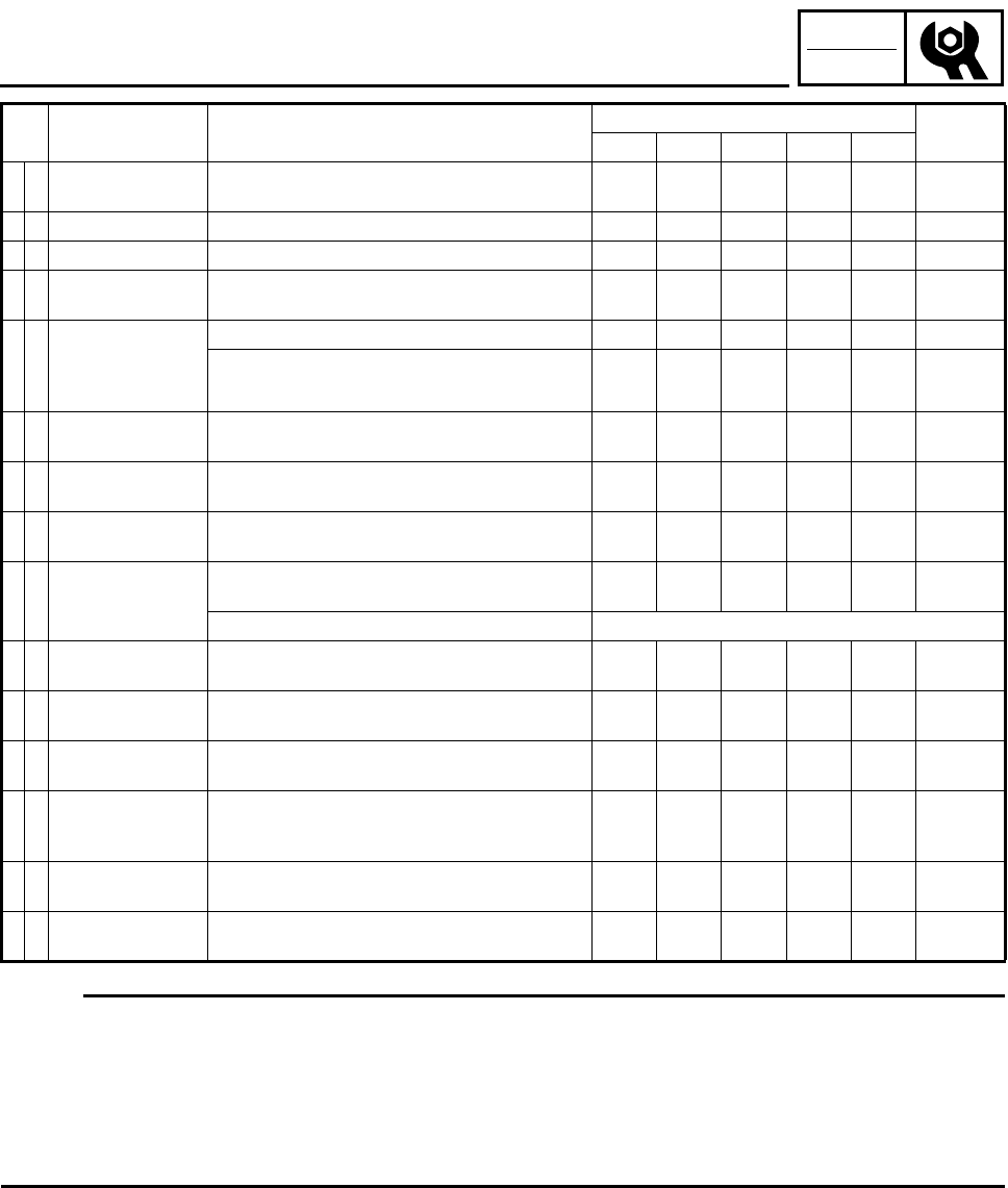
No. ITEM CHECK OR MAINTENANCE JOB ODOMETER READING (× 1,000 km) ANNUAL
CHECK
1 10203040
1 * Fuel line •Check fuel hoses for cracks or damage. √√√√ √
2 * Spark plugs
•Check condition.
•Clean and regap. √√
•Replace. √√
3 * Valves •Check valve clearance.
•Adjust. Every 40,000 km
4 Air filter element •Clean. √√
•Replace. √√
5*Clutch •Check operation, fluid level and vehicle for fluid
leakage. √√√√√
6 * Front brake
•Check operation, fluid level and vehicle for fluid
leakage. √√√√√ √
•Replace brake pads. Whenever worn to the limit
7 * Rear brake
•Check operation, fluid level and vehicle for fluid
leakage. √√√√√ √
•Replace brake pads. Whenever worn to the limit
8 * Brake hoses •Check for cracks or damage. √√√√ √
•Replace. Every 4 years
9 * Wheels •Check runout and for damage. √√√√
10 * Tires
•Check tread depth and for damage.
•Replace if necessary.
•Check air pressure.
•Correct if necessary.
√√√√ √
11 * Wheel bearings •Check bearing for looseness or damage. √√√√
12 * Swingarm •Check operation and for excessive play. √√√√
•Lubricate with lithium-soap-based grease. Every 50,000 km
13 * Steering bearings •Check bearing play and steering for roughness. √√√√√
•Lubricate with lithium-soap-based grease. Every 20,000 km
14 * Chassis fasteners •Make sure that all nuts, bolts and screws are
properly tightened. √√√√ √
– 6 –
CHK
ADJ
PERIODIC MAINTENANCE AND LUBRICATION CHART
NOTE:
•The air filter needs more frequent service if you are riding in unusually wet or dusty areas.
•Hydraulic brake and clutch service
•Regularly check and, if necessary, correct the brake and clutch fluid levels.
•Every two years replace the internal components of the brake master cylinders and calipers as
well as the clutch master and release cylinders, and change the brake and clutch fluids.
•Replace the brake and clutch hoses every four years and if cracked or damaged.
15 Sidestand, center-
stand
•Check operation.
•Lubricate. √√√√ √
16 * Sidestand switch •Check operation. √√√√√ √
17 * Front fork •Check operation and for oil leakage. √√√√
18 * Shock absorber
assembly
•Check operation and shock absorber for oil leak-
age. √√√√
19 *
Rear suspension
relay arm and con-
necting arm pivot-
ing points
•Check operation. √√√√
•Lubricate with lithium-soap-based grease. √√
20 * Electronic fuel
injection •Adjust engine idling speed and synchronization. √√√√√ √
21 Engine oil •Change.
•Check oil level and vehicle for oil leakage. √√√√√ √
22 Engine oil filter
cartridge •Replace. √√√
23 * Cooling system
•Check coolant level and vehicle for coolant leak-
age. √√√√ √
•Change. Every 3 years
24 Final gear oil •Check oil level and vehicle for oil leakage.
•Change. √√√√√
25 * Front and rear
brake switches •Check operation. √√√√√ √
26 Moving parts and
cables •Lubricate. √√√√ √
27 * Throttle grip hous-
ing and cable
•Check operation and free play.
•Adjust the throttle cable free play if necessary.
•Lubricate the throttle grip housing and cable.
√√√√ √
28 * Muffler and
exhaust pipe •Check the screw clamp for looseness. √√√√√
29 * Lights, signals and
switches
•Check operation.
•Adjust headlight beam. √√√√√ √
No. ITEM CHECK OR MAINTENANCE JOB ODOMETER READING (× 1,000 km) ANNUAL
CHECK
1 10203040
– 7 –
CHK
ADJ
SEATS AND FUEL TANK
SEATS AND FUEL TANK
EAS00040
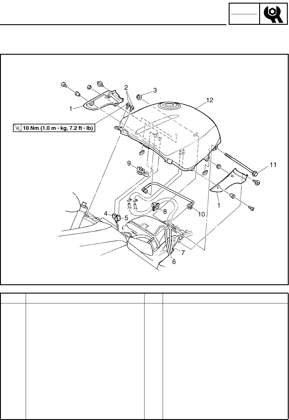
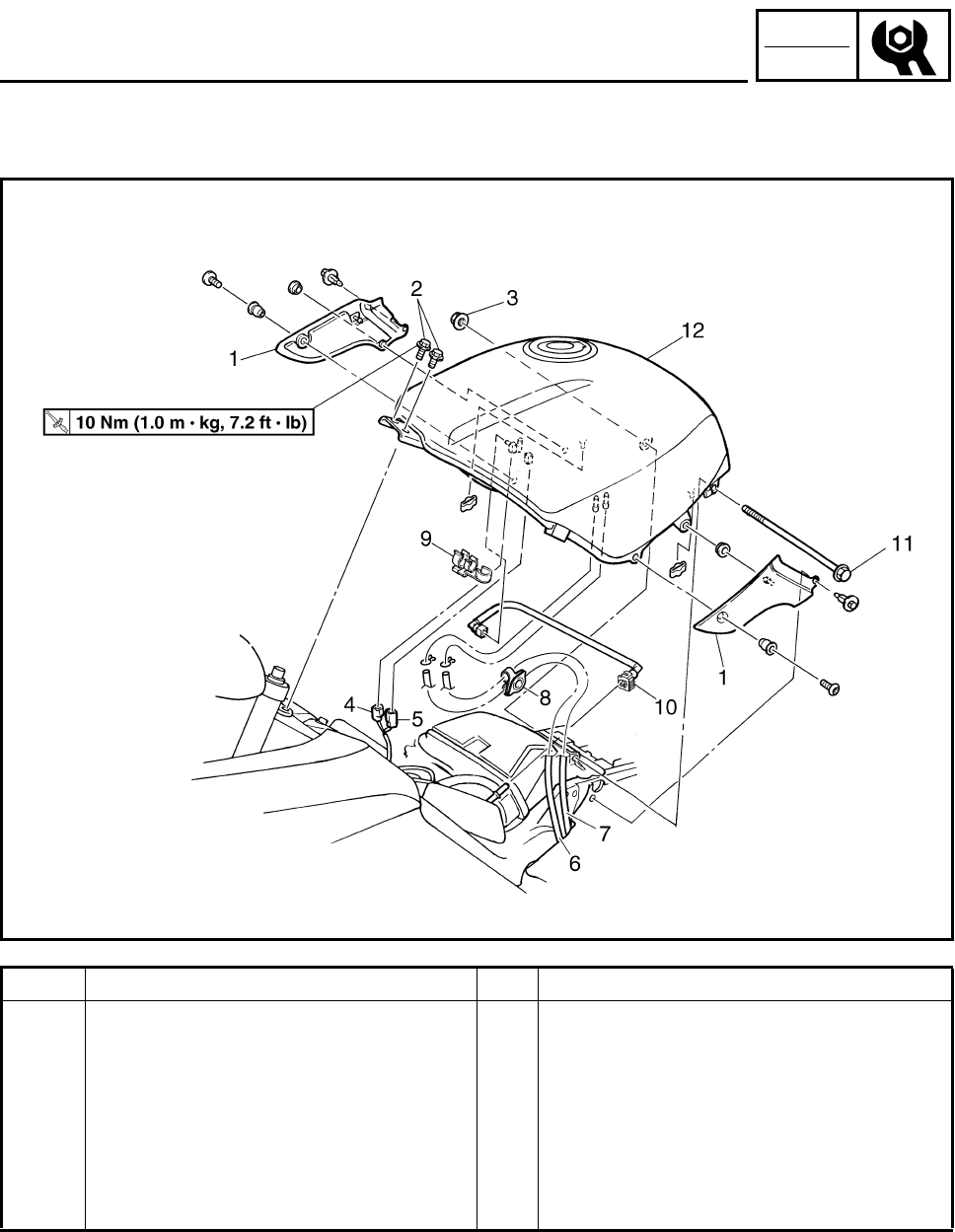
FUEL TANK
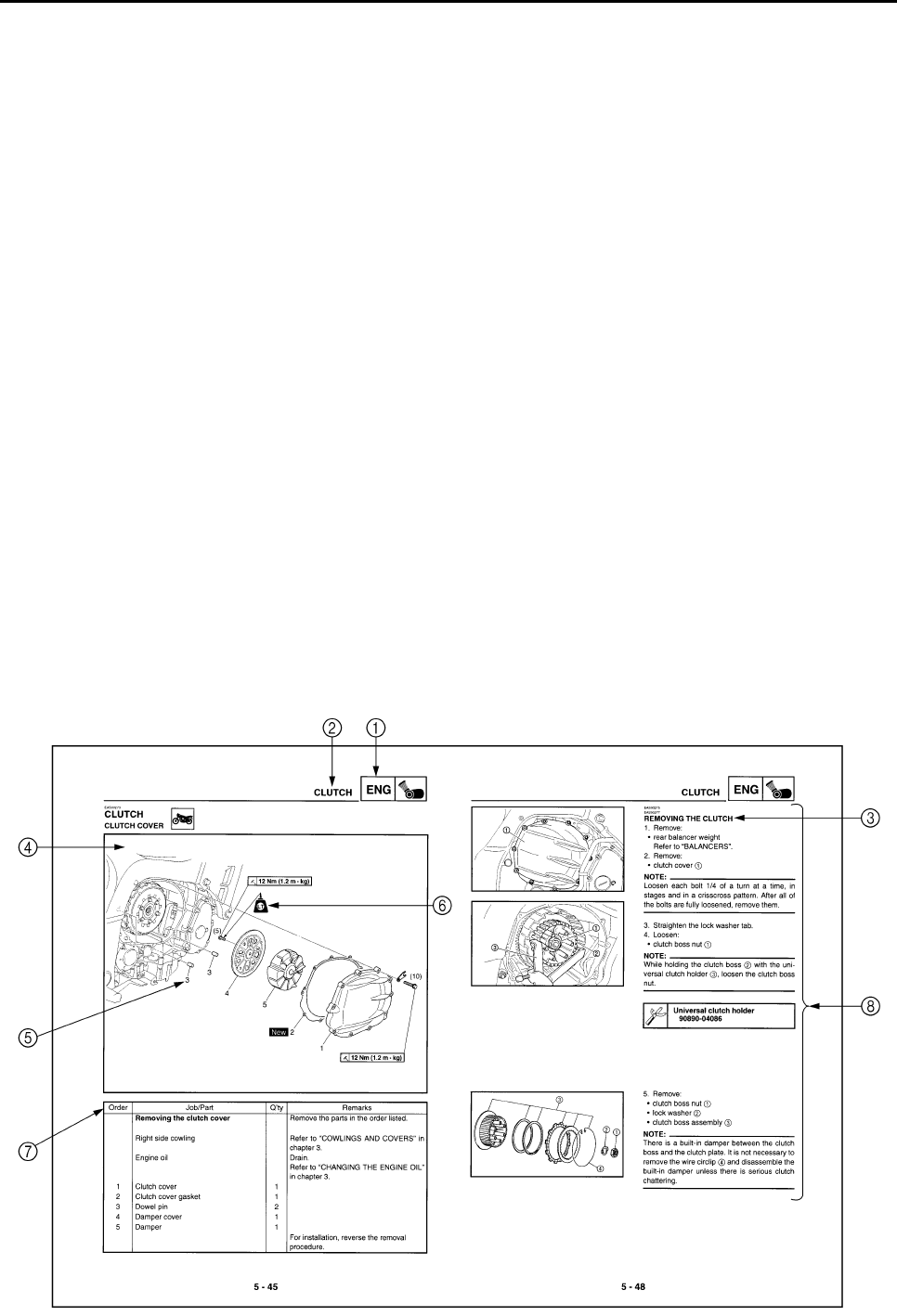
Order Job/Part Q’ty Remarks
Removing the fuel tank Remove the parts in the order listed.
Rider seat Refer to “SEATS AND FUEL TANK” in
chapter 3. (Manual No.: 5JW1-AE1)
Fuel Drain.
1 Fuel tank side panel (left and right) 1/1
2Bolt 2
3Nut 1
4 Fuel sender coupler 1
5 Fuel pump coupler 1
6 Fuel tank overflow hose 1
7 Fuel tank breather hose 1
8 Hose holder 1
9 Fuel hose holder 1
– 8 –
CHK
ADJ
SEATS AND FUEL TANK
Order Job/Part Q’ty Remarks
10 Fuel hose 1 Refer to “REMOVING THE FUEL TANK”.
Refer to “INSTALLING THE FUEL
HOSE” in chapter 3. (Manual No.: 5JW1-
AE1)
11 Bolt 1
12 Fuel tank 1 Refer to “REMOVING THE FUEL TANK”.
For installation, reverse the removal
procedure.
– 9 –
CHK
ADJ
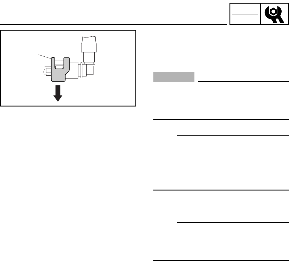
REMOVING THE FUEL TANK
1. Remove the fuel in the fuel tank through the
fuel tank filler hole with a pump.
2. Remove:
•fuel hose
CAUTION:
Although the fuel has been removed from
the fuel tank, be careful when removing the
fuel hose since there may be fuel remaining
in it.
NOTE:
•To remove the fuel hose from the fuel injec-
tion pipe, slide the cover a on the end of the
hose in the direction of the arrow shown, and
then remove the hose.
•Before removing the hose, place a few rags
in the area under the hose.
3. Remove:
•fuel tank
NOTE:
Do not set the fuel tank down on the installa-
tion surface of the fuel pump. Be sure to lean
the fuel tank up against a wall, etc., in an
upright position.
a
SEATS AND FUEL TANK

– 10 –
CHK
ADJ
EAS00043
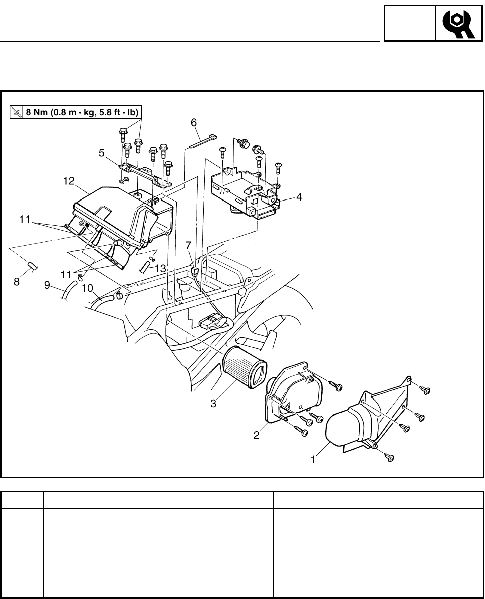
AIR FILTER CASE
Order Job/Part Q’ty Remarks
Removing the air filter case Remove the parts in the order listed.
Seats Refer to “SEATS AND FUEL TANK” in
chapter 3. (Manual No.: 5JW1-AE1)
Fuel tank Refer to “SEATS AND FUEL TANK”.
Side covers (left and right) Refer to “COWLINGS AND COVERS”.
(Manual No.: 5JW1-AE2)
1 Air shroud 1
2 Air filter case cover 1
3 Air filter element 1
4Tray 1
5 Fuel tank bracket 1
6 Plastic locking tie 1
7 Intake air temperature sensor coupler 1
8 Bypass air unit inlet hose 1 Disconnect.
9 Crankcase breather hose 1 Disconnect.
AIR FILTER CASE
– 11 –
CHK
ADJ
Order Job/Part Q’ty Remarks
10 Air induction system hose 5 1 Disconnect.
11 Clamp screw 4 Loosen.
12 Air filter case 1
13 Air filter case breather hose 1
For installation, reverse the removal
procedure.
AIR FILTER CASE
– 12 –
FI
FUEL INJECTION SYSTEM
FUEL INJECTION SYSTEM
FUEL INJECTION SYSTEM
1Ignition coil
2Air filter case
3Intake air tempera-
ture sensor
4Fuel delivery hose
5Fuel tank
6Fuel pump
7Intake air pressure
sensor
8Throttle position sensor
9Fuel injector
0O2 sensor
ACatalytic converter
BCrankshaft position
sensor
CCoolant temperature
sensor
DSpark plug
ECylinder identifica-
tion sensor
FBattery
GECU
HFuel injection system
relay
IEngine trouble warn-
ing light
JLean angle cut-off
switch
KAir cut-off valve
6
8
4
5
23GH
J
7
A
90
B
D
C
K
1
I
F
E
– 13 –
FI
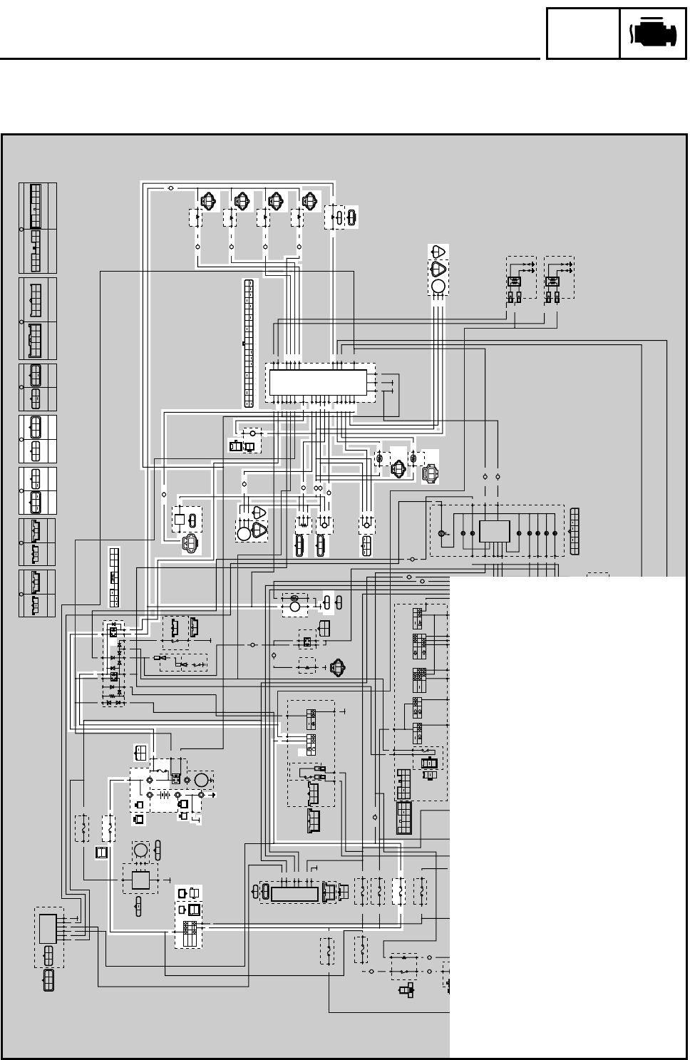
FUEL INJECTION SYSTEM
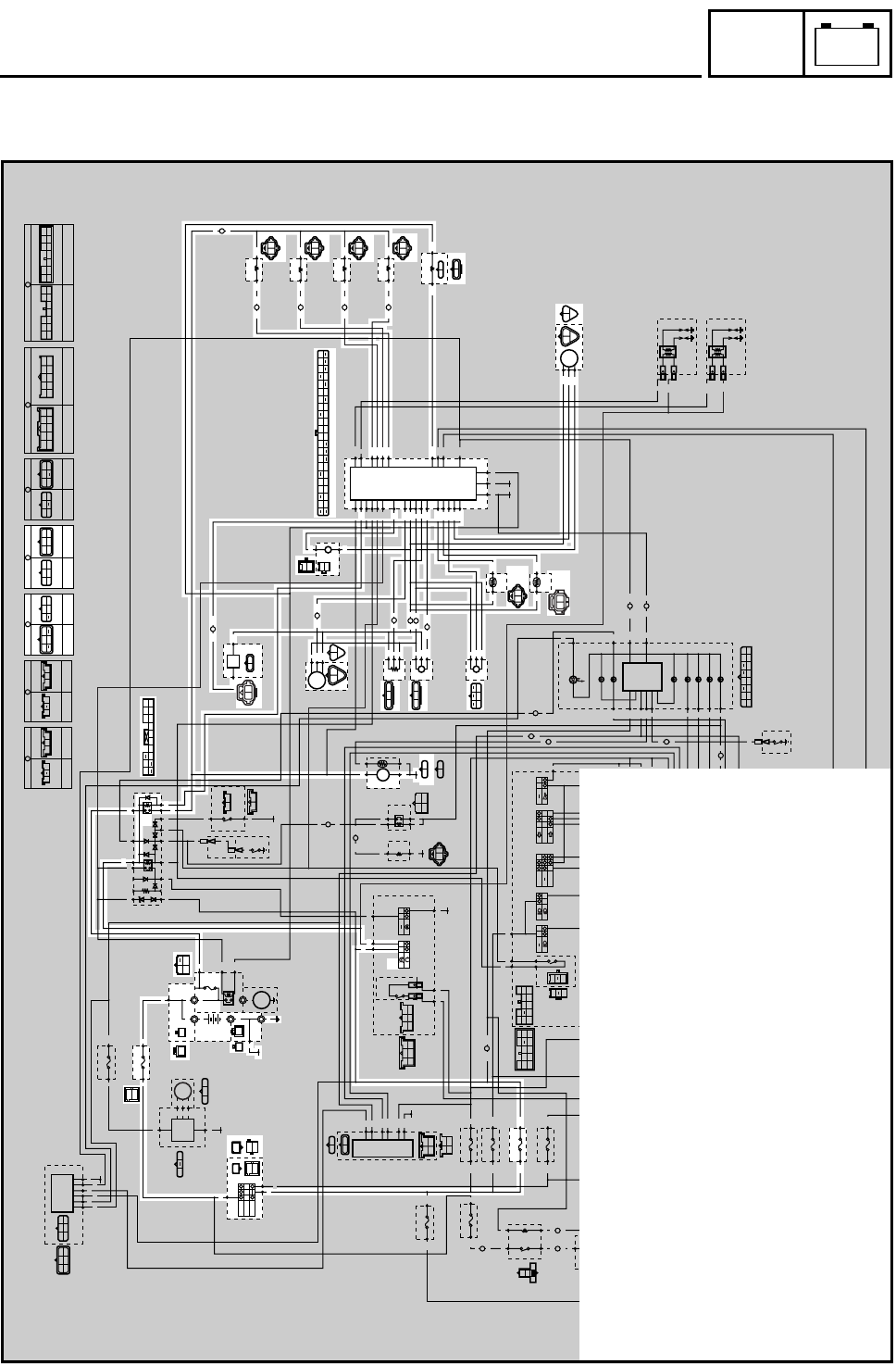
WIRING DIAGRAM (FJR1300)
ON
OFF
P
R
R R
Br/L
Br/R
BB1
BB2
BB4
BB3
G
/
YBr
BL
Y
Ch Dg
Y
Dg
BL/R
Ch
Dg
Ch
Br/WBr/W
Ch
Dg
Br/W
Br/G
B/R
R/B
B/R
R/B
R/B
B/R
B
B
L/Y
B/Y
B/Y
L/Y
(BLACK) (BLACK)
R
R
R
R
Br/L
Br/L
Br/RBr/R
(BLACK)
(GRAY)
W WW
B
G/W
BR/L
RB
B
B
R
R
R
R
R
Br/LBr/Y
B
B
B
R
R
R
B
L
/
W
R
/
G
BB
R
/
W
R/W
R
L/W
B
R
B
R
B
B
B
B
W
W
W
W
W
W
R
B
R/Y
G/L
G/L
R/Y
Y/B
Y/B Y/B
A
R/Y R/Y
A
A
L
/
WLg
L
/
G
L
/
G
Sb
Sb
Sb
Sb
B
/
Y
B
R
/
B
Lg
R/B
B/R
L/W
L/W
W/LR/L
R/WL/G
L
/
YSb B
/
Y
R
R
/
Y
BB
B2
Br/R
L/R
L/R
Br/G
Br/L R/W
Br/L R/Y
W/L
Br/L
Br/B
Br/B
Br/B
B
Sb/W
Sb/W
Sb/W
O/W O/W
O/W
O/W
Br Br
O/WSb/W
BrBr
A
Br/G
Br/G
A
Br/W
Br/W
A
G/B
G/BLg Sb Dg Ch
Br
P
Br/W
Br/R
R/W
R/G
G/W
Y/L Y/L
L
B/L
Gy/R
W/Y
B2 B2 B2
Y/L
G/B
Br/G
Br/W
A
L
L
R
L
A
G/Y
R/B
B/R
B/R
L/R L/R
G/B
R/B
G/Y
G/Y
B
B
B
B
B
Br/Y
Br/Y
Br/YBr/R
L
B
R
B
Lg
Sb
Lg
Sb
Lg
Sb
Br/B
Y
Br
B
B
B
A
Y
P
Y
Y
R/W
R/W
G/Y
L
Br/B
G/B
B
Y
G
G/L
Y/B
G/L
R/Y
R/Y
L
B
L
B
(BLACK) (BLACK)
Gy
B/L
B
Gy
(BLUE)
(DARK GRAY) (DARK GRAY)
(BLACK)
B
BLg
Br/R
Sb
Br/Y
R
Lg
Br/R
B
RBrSb
Lg
Y/L
R/GR/G
G/LR/WR/W
B
Y/L
B
BB B2
L/RCh Dg
Y
L/R
Br/W
Gy/G
Gy/R
Br/R
Br/W
W/Y
P/W
W/B
G/W
Y/G
B/L
B/L
L/RYG Y
BBB
YG
B
B
G
P
G
BY
G
BY
G/W
R/LO/BO/BO/B
B/L
(BLACK)
(BLACK)
G/WR/L
B
Dg
Dg
C
W
W
W
W
Y
Ch
Dg
Lg
A
Lg
Lg
C
A
C
R/G
R/G
B
G/W
G/W
B
Ch
Ch
B
L/R
Br/W
B/L
R/LO/B
B
L/R
Br
UP
DOWN
ON
OFF
Dg
Br/W
Ch
D
L L
E
Y Y
E
D
R/WBr/R
E
B/W R/WB3
Y
Gy
O/B
Y/B
G/Y
Y/L
R/B
G/B
L/B
L
O
O
L
R/L
R/L
D
B/L B/L
E
WL
B1
BB
B2
B2
B/L
W/BW/B W/B
E
P/W P/W
B/L
Gy
B/L
Y
L
B/L
Gy/G
Gy/GGy/G
W
L/Y
B/L
L
W/B
B/L
W
L/Y
B/L
L
W/Y
B/L
LYB/L
(BLACK)
(DARK GREEN)
L
B/L
P/W
P/WB/LL
(BLACK)
L
O/WB
(BLACK)
Y/G
B/L
Br/RR/W
Br
Br/R
(GRAY)
R/LL/BL/BL/B
R/LL/B
D
(GRAY)
R/LG/BG/BG/B
R/LG/B
D
(GRAY)
R/LR/BR/BR/B
R/LR/B
D
(GRAY)
R/B
R/GB2 Br/R
R/WG/W
Y
/
L
G
/
L
Lg Y L
Ch
W
Dg
(BLACK)
(BLUE)
(BLUE) (BLUE)
L/G
B
BB
BB1
BB2
BB4
BB3
B
B
B
B
R/W
R/B
L/WG/Y
Br B
R/W
R/B
W/LG/Y
Br
B
C
B/L
P/W
Gy/G
Y
W/B
B/L
P/W
W/B
Y
Gy/G
E
(BLACK) (BLACK)
WIRE HARNESS
SUB-WIRE
HARNESS 2
L/B O/BL
R/LR/B
G/B
O/BL L/B
G/B
R/BR/L
D
WIRE HARNESS
SUB-WIRE
HARNESS 2
C
WIRE HARNESS
SUB-WIRE
HARNESS 1
R/GG/LG/L
O/WO/W
WY/L
R/G
Y/LW
WIRE HARNESS
B
SUB-WIRE
HARNESS 1
L/R
G/W
Sb
Ch Lg
Br
Dg
Br/Y
Sb/W
B
L/R
G/W
Sb Ch
Lg Br
Dg
Br/YSb/W
B
A
SUB-WIRE
HARNESS 1
WIRE HARNESS
Y/B
Br/B
YLg
Br/W
R/WR/W
B2 B2
L
Br/B
L
G/Y
Y/B
G/Y
Br/G
Lg
Br/G
G/B
Y
G/B
R/Y
Br/W
R/Y
P
BLg
Sb
Br/W
L/BCh
Dg
B/Y
YR/Y
L/Y
P
B
Sb
Lg
Br/W
G/B
Ch
Dg
B/Y
Y
R/Y
B/R
B
/
R
B
/
Y
Br
R/W R/W
A
L
L
Y/GB/L
B/R
G/YY/GB/Y B/LY/BGyL/Y
R/W
Y/LR/L
Br/R
L/W
Y
W/YR/W
G/W
P/W
Br/W
B/WW/B
Gy/G
R/BLG/BL/BB3O/BO
Gy/R
(BLACK)
B
/
R L
/
Y
R
/
L
B
Y/L
R/W
G/L
R/G
L
/
W
R
/
WW
/
L
G/L
R/B
R/W
B
Br Br
G/W
B/L
Gy/G
B/L
R/B
OFF
(BROWN)
(BROWN)
Br
YBB
Ch
B
Dg
B
F
Dg
Dg
G
Ch
Ch
F
B
B
G
B
B
BCh
Dg
B
LB
Br/G
G
SUB-WIRE
HARNESS 3
SUB-WIRE
HARNESS 1
Ch
B
LB
Br/G
F
SUB-WIRE
HARNESS 3
SUB-WIRE
HARNESS 1
Dg
B
2
6
5
3
1
4
=
AB
8
9
7
D
E
C
J
K
G
F
L
M
I
N
O
W
Q
U
V
T
S
R
YZ
XZ
d
e
c
b
f
[\
^
a
ww
n
m
s
t
vv
r
kl
i
g
j
o
o
}
†
å
~
¢
ß
®
¶
£
•
™
µ
¥
©H
ç
§
|
x
y
z{
h
u
P
qp
]
R/W
B/Y
L/Y
R/L
B/R
L/W
2Main switch
6Main fuse
7Battery
8Fuel injection system fuse
CFuel injection system relay
HFuel pump
IO2 sensor
JCylinder identification sensor
KThrottle position sensor
LIntake air pressure sensor
MLean angle cut-off switch
NIntake air temperature sensor
OCoolant temperature sensor
PCrankshaft position sensor
QECU (engine)
RCylinder #1 - injector
SCylinder #2 - injector
TCylinder #3 - injector
UCylinder #4 - injector
VAir induction system solenoid
WSpeed sensor
£Ignition fuse
¥Engine stop switch
– 14 –
FI
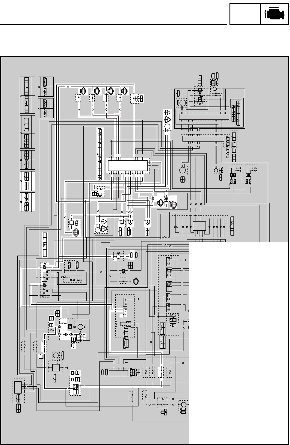
FUEL INJECTION SYSTEM
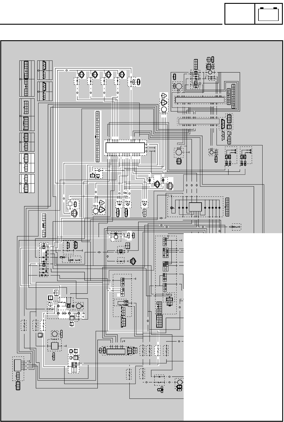
WIRING DIAGRAM (FJR1300A)
ON
OFF
P
R
RR
Br/L
Br/R
BB1
BB2
BB4
BB3
G
/
YBr
BL
Y
Ch Dg
Y
Dg
BL/R
Ch
Dg
Ch
Br/WBr/W
Ch
Dg
Br/W
Br/G
B/R
R/B
B/R
R/B
R/B
B/R
B
B
L/Y
B/Y
B/Y
L/Y
(BLACK) (BLACK)
R
R
R
R
Br/L
Br/L
B
B/W
R
R/L
B
B/W
R
R/L
Br/RBr/R
(BLACK)
(GRAY)
W WW
B
G/W
BR/L
RB
B
B
R
R
R
R
R
Br/LBr/Y
B
B
B
R
R
R
L
/
W
BB
R
/
W
R/W
R
L/W
B
B
B
B
W
W
W
W
W
W
R
B
R/Y
G/L
G/L
R/Y
Y/B
Y/B Y/B
A
R/Y R/Y
A
A
L
/
WLg
L
/
G
L
/
G
Sb
Sb
Sb
Sb
B
/
Y
B
R
/
B
R
/
Y
BB
B2
Br/R
L/R
L/R
Br/G
Br/L R/W
Br/L R/Y
W/L
Br/L
Br/B
Br/B
Br/B
B
Sb/W
Sb/W
Sb/W
O/W O/W
O/W
O/W
Br Br
O/WSb/W
BrBr
A
Br/G
Br/G
A
Br/W
Br/W
A
G/B
G/BLg Sb Dg Ch
Br
P
Br/W
Br/R
R/W
R/G
G/W
Y/L
L
B/L
Gy/R
W/Y
B2 B2 B2
G/B
Br/G
Br/W
A
L
L
R
L
A
G/Y
R/B
B/R
B/R
L/R L/R
G/B
R/B
G/Y
G/Y
B
B
B
B
B
Br/Y
Br/Y
Br/YBr/R
L
B
R
B
Lg
Sb
Lg
Sb
Lg
Sb
Br/B
Y
Br
B
B
B
A
Y
P
Y
Y
R/W
R/W
G/Y
L
Br/B
G/B
B
Y
G
G/L
Y/B
G/L
R/Y
R/Y
L
B
L
B
(BLACK) (BLACK)
(BROWN)
(BROWN)
Gy
B/L
B
Gy
(BLUE)
(DARK GRAY) (DARK GRAY)
(BLACK)
B
BLg
Br/R
Sb
Br/Y
R
Lg
Br/R
B
RBrSb
Lg
Y/L
R/GR/G
G/LR/WR/W
B
Y/L
B
BB B2
L/RCh Dg
Y
L/R
Br/W
Gy/G
Gy/R
Br/R
Br/W
W/Y
P/W
W/B
R/W
G/W
Y/G
B/L
B/Y
L/Y
R/L
B/L
L/RY G Y
BB
Ch
B
B
YG
B
B
G
P
G
BY
G
BY
G/W
R/LO/BO/BO/B
B/L
(BLACK)
(BLACK)
G/WR/L
Dg
B
B
Dg
Dg
C
W
W
W
W
Y
Ch
Dg
Lg
A
Lg
Lg
Y/L Y/L
C
A
C
R/G
R/G
B
G/W
G/W
B
Ch
Ch
F
Dg
Dg
G
Ch
Ch
F
B
B
G
B
B
B
L/R
Br/W
B/L
R/LO/B
B
L/R
Br
UP
DOWN
ON
OFF
Dg
Br/W
Ch
D
L L
E
Y Y
E
D
R/WBr/R
E
B/W R/WB3
Y
Gy
O/B
Y/B
G/Y
Y/L
R/B
G/B
L/B
L
O
O
L
R/L
R/L
D
B/L B/L
E
WL
B1
BB
B2
B2
B/L
W/BW/B W/B
E
P/W P/W
B/L
Gy
B/L
Y
L
B/L
Gy/G
Gy/GGy/G
W
L/Y
B/L
L
W/B
B/L
W
L/Y
B/L
L
W/Y
B/L
LYB/L
(BLACK)
(DARK GREEN)
L
B/L
P/W
P/WB/LL
(BLACK)
L
O/WB
(BLACK)
Y/G
B/L
Br/RR/W
Br
Br/R
(GRAY)
R/LL/BL/BL/B
R/LL/B
D
(GRAY)
R/LG/BG/BG/B
R/LG/B
D
(GRAY)
R/LR/BR/BR/B
R/LR/B
D
(GRAY)
R/B
R/GB2 Br/R
R/WG/W
Y
/
L
G
/
LG
/
R
Lg Y L
Ch
W
Dg
(BLACK)
(BLUE)
(BLUE) (BLUE)
L/G
B
BB
Br
YBB
Gy W
BB1
BB2
BB4
BB3
B
B
B
B
R/W
R/B
L/WG/Y
Br B
R/W
R/B
W/L
G/Y
Br
B
B/W
R/L
B
R/L
Y
Br/W
L/W
B1 Lg
SbB2
W1
G/R
Lg
Sb
B1
B2
W1
G/R
R
G
R
W
RB
W
WR
R
Y
Br/W
L/W
LB
Br/G
C
B/L
P/W
Gy/G
Y
W/B
B/L
P/W
W/B
Y
Gy/G
E
(BLACK) (BLACK) (BLACK) (BLACK)
WIRE HARNESS
SUB-WIRE
HARNESS 2
L/B O/BL
R/LR/B
G/B
O/BL L/B
G/B
R/BR/L
D
WIRE HARNESS
SUB-WIRE
HARNESS 2
G
SUB-WIRE
HARNESS 3
SUB-WIRE
HARNESS 1
C
WIRE HARNESS
SUB-WIRE
HARNESS 1
R/GG/L
G/RG/R
G/L
O/WO/W
WY/L
R/G
Y/LW
WIRE HARNESS
B
SUB-WIRE
HARNESS 1
L/R
G/W
Sb
Ch Lg
Br
Dg
Br/Y
Sb/W
B
L/R
G/W
Sb Ch
Lg Br
Dg
Br/YSb/W
B
A
SUB-WIRE
HARNESS 1
WIRE HARNESS
Y/B
Br/B
YLg
Br/W
R/WR/W
B2 B2
L
Br/B
L
G/Y
Y/B
G/Y
Br/G
Lg
Br/G
G/B
Y
G/B
R/Y
Br/W
R/Y
P
BLg
Sb
Br/W
L/BCh
Dg
B/Y
YR/Y
L/Y
BCh
Dg
B
P
B
Sb
Lg
Br/W
G/B
Ch
Dg
B/Y
Y
R/Y
B/R
B
/
R
B
/
Y
Br
R/W R/W
A
L
L
Y/GB/L
B/R
L/W
B
/
R L
/
Y
R
/
L
B
Y/L
R/W
G/L
R/G
L
/
W
R
/
WW
/
L
G/L
G/RG/R
R/B
R/W
B
Br Br
G/W
B/L
Gy/G
B/L
R/B
Br
/
WBr
/
L
Lg
R/B
B/R
L/W
L/W
W/LR/L
R/WL/G
L
/
YSb B
/
Y
R
B/R
G/YY/GB/Y B/LY/BGyL/Y
R/W
Y/LR/L
Br/R
L/W
Y
W/YR/W
G/W
P/W
Br/W
B/WW/B
Gy/G
R/BLG/BL/BB3O/BO
Gy/R
(BLACK)
B1
B2
Y Y
W1
B2
W1
B1
W1
W1 B1
Sb
Sb
Lg
Sb
Lg
Sb
Lg
B3
W2
Lg
R/L
B/W
R/L
B/W
R/W
W/R
L/W
Br/W
G/R
L/W
W/R
W/B
W/B
Br/W
L/W
Br/WBr/W
B
R
/
L
R
/
G
B
/
WB
G/R G/R
C
OFF
B1
G
G
B
B
R
R R
Y
B4
B5
B2
W1
B1
P/W
P/W
G/R R/L
B
R/W
R/W
R/W
W2 B3
Gy
W
WW
B4
B5
Sb
W
Y
G
R/W
RB
R/WW/B
R/L
G/R
P/WBr/W
Br/W
B2
B1 B3
W1 W2
Lg
L/WP/WW/BW/R
Sb
Lg
B
W/R
Ch
B
LB
Br/G
F
SUB-WIRE
HARNESS 3
SUB-WIRE
HARNESS 1
Dg
B
2
6
7
5
3
1
4
B
CD
0
A
9
8
F
G
E
\
Z[
]
^
L
M
I
H
N
O
K
P
QY
S
W
X
V
U
T
de
ce
b
n
o
m
l
p
fg
i
k
††
x
w
}
~
çç
|
{z
uv
s
q
t
y
y
ß
¥
©
®
µ
¬
…
¡
º
ø
¤
›
‹
ÕJ
™
æ
¶
¢
£
§•
a
h
j
r
R
å
2Main switch
7Main fuse
9Battery
0Fuel injection system fuse
EFuel injection system relay
JFuel pump
KO2 sensor
LCylinder identification sensor
MThrottle position sensor
NIntake air pressure sensor
OLean angle cut-off switch
PIntake air temperature sensor
QCoolant temperature sensor
RCrankshaft position sensor
SECU (engine)
TCylinder #1 - injector
UCylinder #2 - injector
VCylinder #3 - injector
WCylinder #4 - injector
XAir induction system solenoid
YSpeed sensor
ºIgnition fuse
‹Engine stop switch
– 15 –
FI
FUEL INJECTION SYSTEM
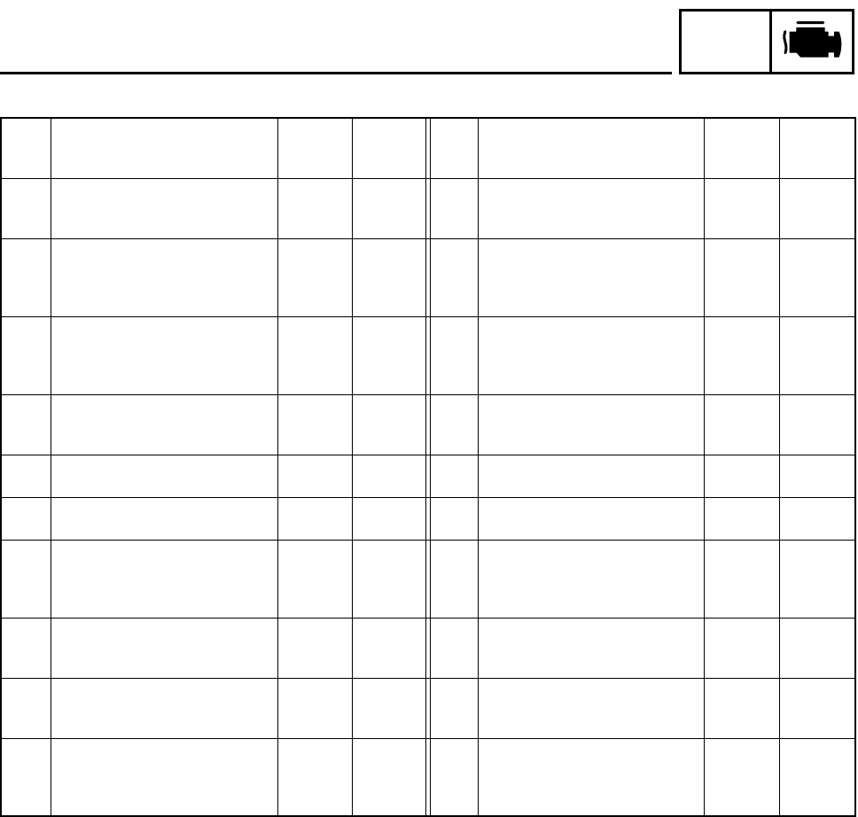
* Table of self-diagnostic fault code numbers displayed on meter
•How to erase the self-diagnostic fault code from memory:
If the ECU detects a normal signal upon the completion of the repair of the malfunction, the self-
diagnostic fault code disappears from the meter and is replaced by the normal clock display. How-
ever, the self-diagnostic fault code of the previous malfunction remains in the ECU memory as
part of the malfunction history. To erase the self-diagnostic fault code from the malfunction history,
the operation for diagnostic code 62 must be performed in the diagnosis mode.
No. Symptom
Able/
unable to
start
Able/
unable to
drive
No. Symptom
Able/
unable to
start
Able/
unable to
drive
11
No normal signals are received
from the cylinder identification
sensor.
Able Able 30
The motorcycle has overturned.
Unable Unable
12
No normal signals are received
from the crankshaft position sen-
sor. Unable Unable 31
The amount of air-fuel ratio feed-
back compensation is maintained
continuously in the vicinity of the
upper limit (lean air-fuel ratio).
Able Able
13
Intake air pressure sensor - open
or short circuit detected. Able Able 32
The amount of air-fuel ratio feed-
back compensation is maintained
continuously in the vicinity of the
lower limit (rich air-fuel ratio).
Able Able
14
Faulty intake air pressure sensor
pipe system; a hose is detached
or clogged.
Able Able 33
Open circuit detected in the pri-
mary wire of the ignition coil
(#1,4).
Able Able
15 Throttle position sensor - open or
short circuit detected. Able Able 34 Open circuit detected in the pri-
mary wire of the ignition coil (#2, 3). Able Able
16 A stuck throttle position sensor is
detected. Able Able 41 Lean angle cut-off switch - open
or short circuit detected. Unable Unable
19
A break or disconnection of the
black/red lead of the ECU is
detected. Unable Unable 42
No normal signals are received
from the speed sensor; or, an
open or short circuit is detected in
the neutral switch.
Able Able
21
Coolant temperature sensor -
open or short circuit detected. Able Able 43
The ECU is unable to monitor the
battery voltage (an open circuit in
the line to the ECU).
Able Able
22
Intake air temperature sensor -
open or short circuit detected. Able Able 44
An error is detected while reading
or writing on EEPROM (CO
adjustment value).
Able Able
24
No normal signals are received
from the O2 sensor. Able Able 50
Faulty ECU memory. When this
malfunction is detected, the code
number might not appear on the
meter.
Unable Unable
– 16 –
FI
FUEL INJECTION SYSTEM
SUBSTITUTE CHARACTERISTICS OPERATION CONTROL (FAIL-SAFE ACTION)
If the ECU detects an abnormal signal from a sensor while the motorcycle is being driven, the ECU
illuminates the engine trouble warning light and provides the engine with substitute characteristic
operation instructions that are appropriate for the type of the malfunction.
When an abnormal signal is received from a sensor, the ECU processes the specified values that
are programmed for every sensor, in order to provide the engine with substitute characteristics
operation instructions that enable the engine to continue to operate (or to stop its operation,
depending on circumstances).
The ECU takes fail-safe actions in two ways: one in which the sensor output is set to a prescribed
value, and the other in which the ECU directly operates an actuator. Details on the fail-safe actions
are given in the table below.
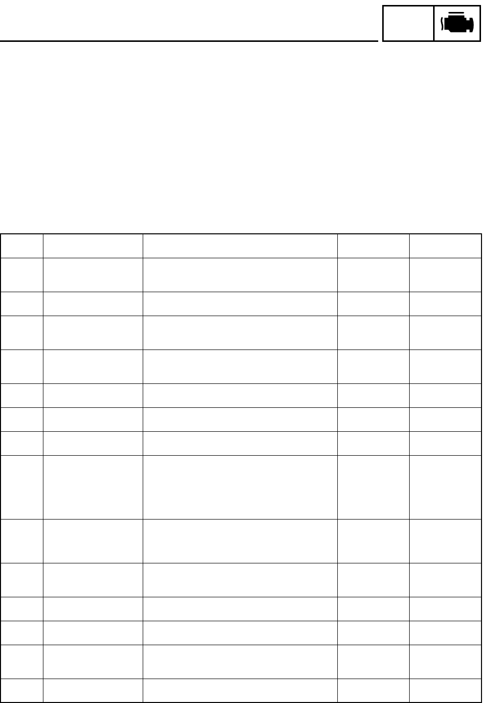
Table of substitute characteristic operation control by self-diagnostic fault code
Code No. Item Fail-safe action Able/unable to
start
Able/unable to
drive
11
Cylinder identification
sensor
Continues to operate the engine based on the results
of the cylinder identification that existed up to that
point.
Able Able
12 Crankshaft position sen-
sor
•Stops the engine (by stopping the injection and
ignition). Unable Unable
13
14
Intake air pressure sensor
(open or short circuit)
(pipe system)
•Fixes the intake air pressure to 760 mmHg.
Able Able
15
16
Throttle position sensor
(open or short circuit)
(stuck)
•Fixes the throttle position sensor to fully open.
Able Able
19 Broken or disconnected
black/red lead of the ECU.
-- (No start) Unable Unable
21 Coolant temperature sen-
sor
•Fixes the coolant temperature to 60 °C. Able Able
22 Intake air temperature
sensor
•Fixes the intake temperature to 20 °C. Able Able
24
31
32
O2 sensor
(inactive)
(compensation stuck to
upper limit)
(compensation stuck to
lower limit)
--
Able Able
33
34
Faulty ignition •Fuel is cut off only to the cylinder in which a mal-
function is detected.
Able
(depending on
the number of
faulty cylinders)
Able
(depending on
the number of
faulty cylinders)
30
41
Lean angle cut-off switch
(latch up detected)
(open or short circuit)
•Turns OFF the fuel injection system relay of the fuel
system. Unable Unable
42 Speed sensor, neutral
switch
•Fixes the gear to the top gear. Able Able
43 Fuel system voltage
(monitor voltage)
•Fixes the battery voltage to 12 V. Able Able
44
Error in writing the
amount of CO adjust-
ment on EEPROM
--
Able Able
50 ECU internal malfunction
(memory check error)
-- Unable Unable
– 17 –
FI
FUEL INJECTION SYSTEM
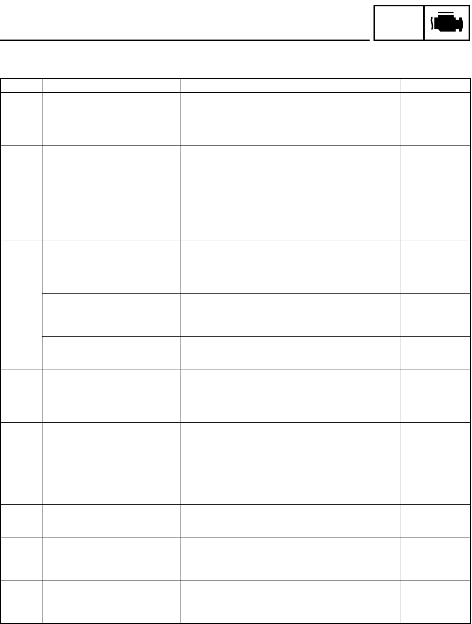
Self-diagnostic fault codes, symptoms, and probable causes
Diagnostic code indication
Code No. Symptom Probable cause of malfunction Diagnostic code
11
No normal signals are received from
the cylinder identification sensor.
•Open or short circuit in wiring sub lead.
•Open or short circuit in wiring harness.
•Defective cylinder identification sensor.
•Malfunction in ECU.
•Improperly installed sensor.
—
12
No normal signals are received from
the crankshaft position sensor.
•Open or short circuit in wiring harness.
•Defective crankshaft position sensor.
•Malfunction in pickup rotor.
•Malfunction in ECU.
•Improperly installed sensor.
—
13
Intake air pressure sensor - open or
short circuit detected.
•Open or short circuit in wiring sub lead.
•Open or short circuit in wiring harness.
•Defective intake air pressure sensor.
•Malfunction in ECU.
03
14
Faulty intake air pressure sensor pipe
system; a hose is detached or
clogged.
•Intake air pressure sensor hose is detached, clogged,
kinked, or pinched.
•Malfunction of the intake air pressure sensor in the interme-
diate electrical potential.
•Malfunction in ECU.
03
Or, intake air pressure sensor - open
or short circuit detected.
•Open or short circuit in wiring sub lead.
•Open or short circuit in wiring harness.
•Defective intake air pressure sensor.
•Malfunction in ECU.
03
Or, a stuck throttle position sensor is
detected.
•Open or short circuit in wiring sub lead.
•Open or short circuit in wiring harness.
•Defective sensor (stuck throttle position sensor).
01
15
Throttle position sensor - open or
short circuit detected.
•Open or short circuit in wiring sub lead.
•Open or short circuit in wiring harness.
•Defective throttle position sensor.
•Malfunction in ECU.
•Improperly installed throttle position sensor.
01
16
A stuck throttle position sensor is
detected.
Or,
Faulty intake air pressure sensor pipe
system; a hose is detached or
clogged.
•Open or short circuit in wiring sub lead.
•Open or short circuit in wiring harness.
•Defective sensor (stuck throttle position sensor).
•Intake air pressure sensor hose is detached, clogged,
kinked, or pinched.
•Malfunction of the intake air pressure sensor in the interme-
diate electrical potential.
•Malfunction in ECU.
01
03
19
A break or disconnection of the black/
red of the ECU is detected when the
start switch is pressed.
•Open circuit in wiring harness.
•Malfunction in ECU.
•Defective ECU coupler.
20
21
Coolant temperature sensor - open or
short circuit detected.
•Open or short circuit in wiring harness.
•Defective coolant temperature sensor.
•Malfunction in ECU.
•Improperly installed sensor.
06
22
Intake air temperature sensor - open
or short circuit detected.
•Open or short circuit in wiring harness.
•Defective intake air temperature sensor.
•Malfunction in ECU.
•Improperly installed sensor.
05
– 18 –
FI
FUEL INJECTION SYSTEM
24
No normal signals are received from
the O2 sensor.
•Open or short circuit in wiring harness.
•Defective O2 sensor.
•Malfunction in ECU.
•Improperly installed sensor.
—
30 The motorcycle has overturned. •Overturned.
•Malfunction in ECU. 08
31
The amount of air-fuel ratio feedback
compensation is maintained continu-
ously in the vicinity of the upper limit
(lean air-fuel ratio).
•Open or short circuit in wiring harness.
•Fuel pressure too low.
•Clogged injectors.
•Defective O2 sensor (unable to output a rich signal).
•Malfunction in ECU.
•Malfunction in other areas of the fuel system.
—
32
The amount of air-fuel ratio feedback
compensation is maintained continu-
ously in the vicinity of the lower limit
(rich air-fuel ratio).
•Open or short circuit in wiring harness.
•Fuel pressure too high.
•Faulty injectors (excessive injection volume).
•Defective O2 sensor (unable to output a lean signal).
•Malfunction in ECU.
•Malfunction in other areas of the fuel system.
—
33
Open circuit is detected in the primary
wire of the ignition coil (#1, 4).
•Open or short circuit in wiring harness.
•Malfunction in ignition coil.
•Malfunction in ECU.
•Malfunction in a component of ignition cutoff circuit system.
30
34
Open circuit is detected in the primary
wire of the ignition coil (#2, 3).
•Open or short circuit in wiring harness.
•Malfunction in ignition coil.
•Malfunction in ECU.
•Malfunction in a component of ignition cutoff circuit system.
31
41
Lean angle cut-off switch - open or
short circuit detected.
•Open or short circuit in wiring harness.
•Defective lean angle cut-off switch.
•Malfunction in ECU.
08
42
No normal signals are received from
the speed sensor; or, an open or
short circuit is detected in the neutral
switch.
•Open or short circuit in wiring harness.
•Defective speed sensor.
•Malfunction in vehicle speed sensor detected unit.
•Defective neutral switch.
•Malfunction in the engine side of the neutral switch.
•Malfunction in ECU.
07
21
43
The ECU is unable to monitor the bat-
tery voltage (an open circuit in the
monitor line to the ECU).
•Open circuit in wiring harness.
•Malfunction in ECU. —
44 An error is detected while reading or
writing on EEPROM.
•Malfunction in ECU. (The CO adjustment value is not prop-
erly written on or read from the internal memory). 60
50
Faulty ECU memory. When this mal-
function is detected, the code number
might not appear on the meter.
•Malfunction in ECU. (The program and data are not properly
written on or read from the internal memory.) —
Code No. Symptom Probable cause of malfunction Diagnostic code
– 19 –
FI
FUEL INJECTION SYSTEM
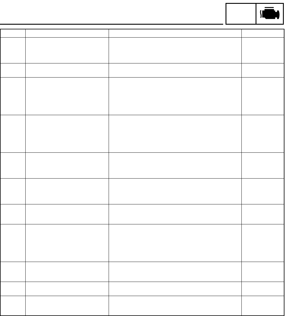
Sensor operation data display verification table
NOTE:
•Check the intake air temperature and coolant temperature as close as possible to the area in
which the respective sensor is mounted.
•If it is not possible to check the intake temperature, use the ambient temperature as reference
(use the compared values for reference).
Diag code Item Description of action Data displayed on meter
(reference value)
01
Throttle angle Displays the throttle angle.
•Check with throttle fully closed.
•Check with throttle fully open.
0 ~ 125 degrees
•Fully closed position (15 ~ 17)
•Fully open position (97 ~ 100)
03
Pressure difference
(atmospheric pres-
sure - intake air pres-
sure)
Displays the pressure difference (atmospheric pressure -
intake air pressure).
Engine stop switch is on.
* Generate the pressure difference by cranking the engine
with the starter, without actually starting the engine.
Before cranking: Atmospheric
pressure (standard pressure is
760 mmHg)
After cranking: Value is lower
than the atmospheric pressure
05 Intake air tempera-
ture
Displays the intake air temperature.
* Check the temperature in the air cleaner case.
Compare it to the value dis-
played on the meter.
06 Coolant temperature Displays the coolant temperature.
* Check the temperature of the coolant.
Compare it to the value dis-
played on the meter.
07
Vehicle speed pulse Displays the accumulation of the vehicle pulses that are gen-
erated when the tire is spun.
(0 ~ 999; resets to 0 after 999)
OK if the numbers appear on
the meter.
08 Lean angle cut-off
switch
Displays the lean angle cut-off switch values. Upright: 0.4 ~ 1.4 V
Overturned: 3.8 ~ 4.2 V
09 Fuel system voltage
(battery voltage)
Displays the fuel system voltage (battery voltage).
Engine stop switch is on.
0 ~ 18.7 V
Normally, approximately 12.0 V
20 Sidestand switch Displays that the switch is ON or OFF. (When the gear is in a
position other than neutral.)
Stand retracted: ON
Stand extended: OFF
21 Neutral switch Displays that the switch is ON or OFF. Neutral: ON
In gear: OFF
60
E2PROM fault code
display
•Transmits the abnormal portion of the data in the E2PROM
that has been detected as a self-diagnostic fault code 44.
•If multiple malfunctions have been detected, different codes
are displayed at 2-second intervals, and this process is
repeated.
(01 ~ 04) Displays the cylinder
number.
(00) Displays when there is no
malfunction.
61
Malfunction history
code display
•Displays the codes of the history of the self-diagnosis mal-
functions (i.e., a code of a malfunction that occurred once
and which has been corrected).
•If multiple malfunctions have been detected, different codes
are displayed at 2-second intervals, and this process is
repeated.
11 ~ 50
(00) Displays when there is no
malfunction.
62
Malfunction history
code erasure
•Displays the total number of codes that are being detected
through self diagnosis and the fault codes in the past his-
tory.
•Erases only the history codes when the engine stop switch
is turned from OFF to ON. If the engine stop switch is ON,
turn it OFF once, and then turn it back ON.
00 ~ 21
(00) Displays when there is no
malfunction.
70 Control number •Displays the program control number. 00 ~ 255
– 20 –
FI
FUEL INJECTION SYSTEM
Troubleshooting details
Troubleshooting the self-diagnostic fault code
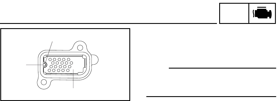
Code No. 19 Symptom A break or disconnection of the black/red lead of the ECU is detected.
Used diagnostic code No. 20 (sidestand switch)
Inspection operation item and probable cause Operation item and countermeasure Reinstatement
method
Defective sidestand switch Replace if defective.
Refer to “CHECKING THE SWITCHES” in
chapter 8. (Manual No.: 5JW1-AE1)
If the transmission
is in gear, it is rein-
stated by retracting
the sidestand.
If the transmission
is in neutral, it is
reinstated by
reconnecting the
wiring.
Open circuit in wiring harness or sub lead. Repair or replace if there is an open circuit.
(Between ECU and black/red lead)
Connected state of connector
Inspect the coupler for any pins that may
have pulled out.
Check the locking condition of the coupler.
If there is a malfunction, repair it and connect it
securely.
Main wiring harness ECU coupler
(black/red)
– 21 –
FI
FUEL INJECTION SYSTEM
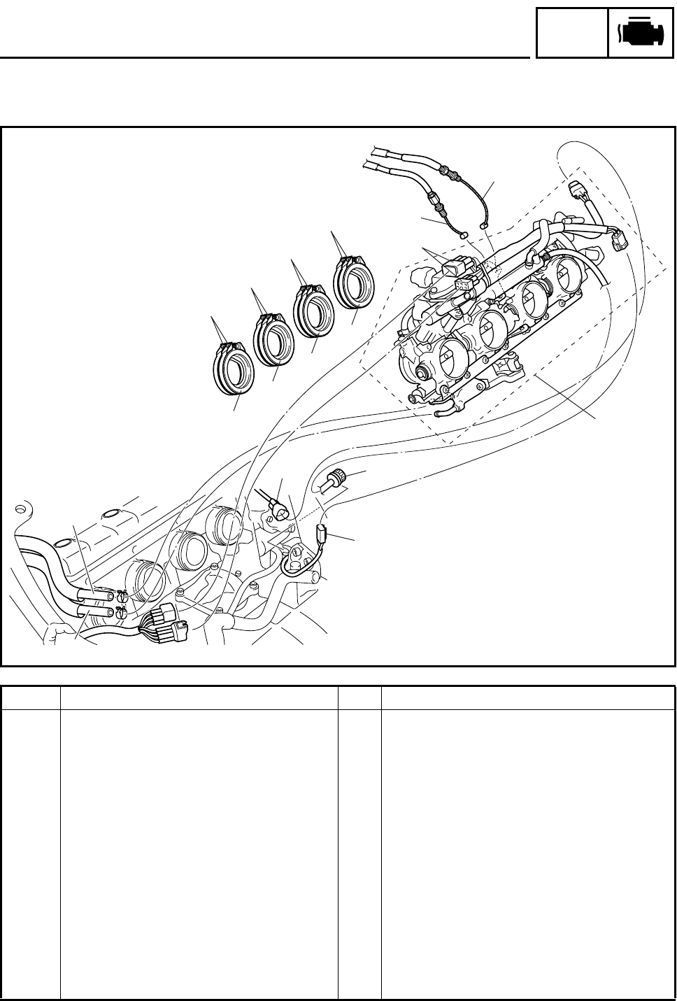
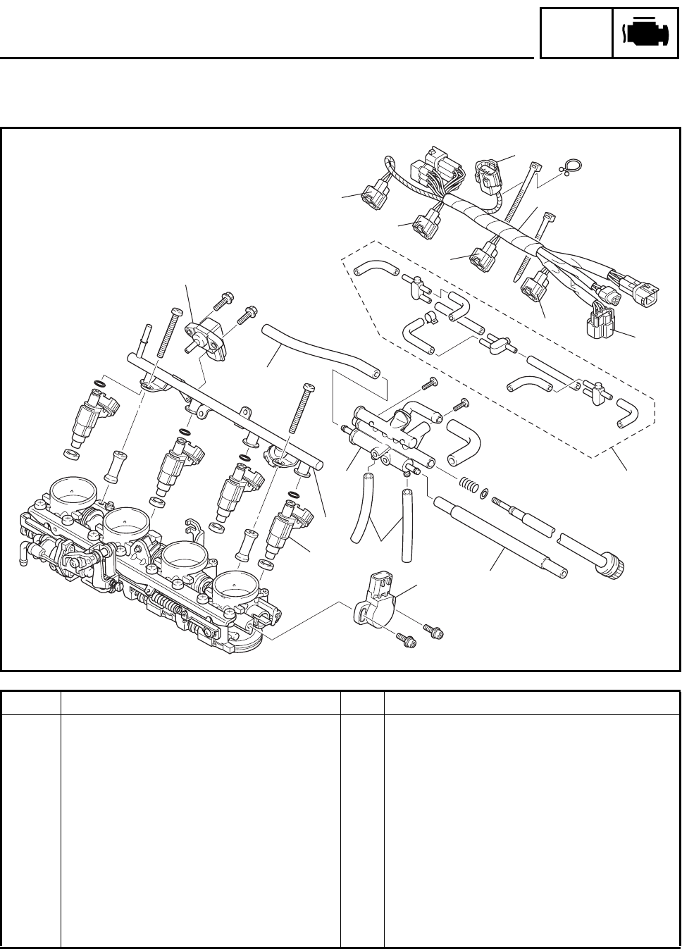
THROTTLE BODIES
8
9
24
1
5
5
5
5
10
10
3
7
7
6
10
10
Order Job/Part Q’ty Remarks
Removing the throttle bodies Remove the parts in the order listed.
Seats/T-bar/rubber sheet Refer to “SEATS AND FUEL TANK” in
chapter 3. (Manual No.: 5JW1-AE1)
Fuel tank Refer to “SEATS AND FUEL TANK”.
Air filter case Refer to “AIR FILTER CASE”.
Coolant Drain.
Refer to “CHANGING THE COOLANT” in
chapter 3. (Manual No.: 5JW1-AE1)
1O
2 sensor coupler 1 Disconnect.
2 Cylinder identification sensor coupler 1 Disconnect.
3 Sub-wire harness 2 coupler 2 Disconnect.
4 Throttle stop screw 1
5 Throttle body joint clamp screw 8
6 Throttle bodies 1
– 22 –
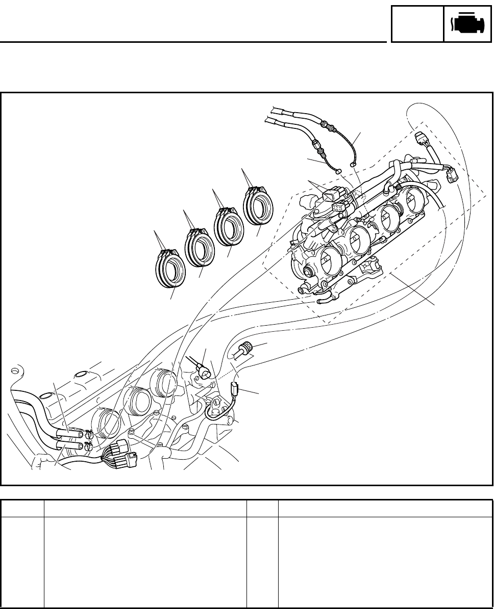
FI
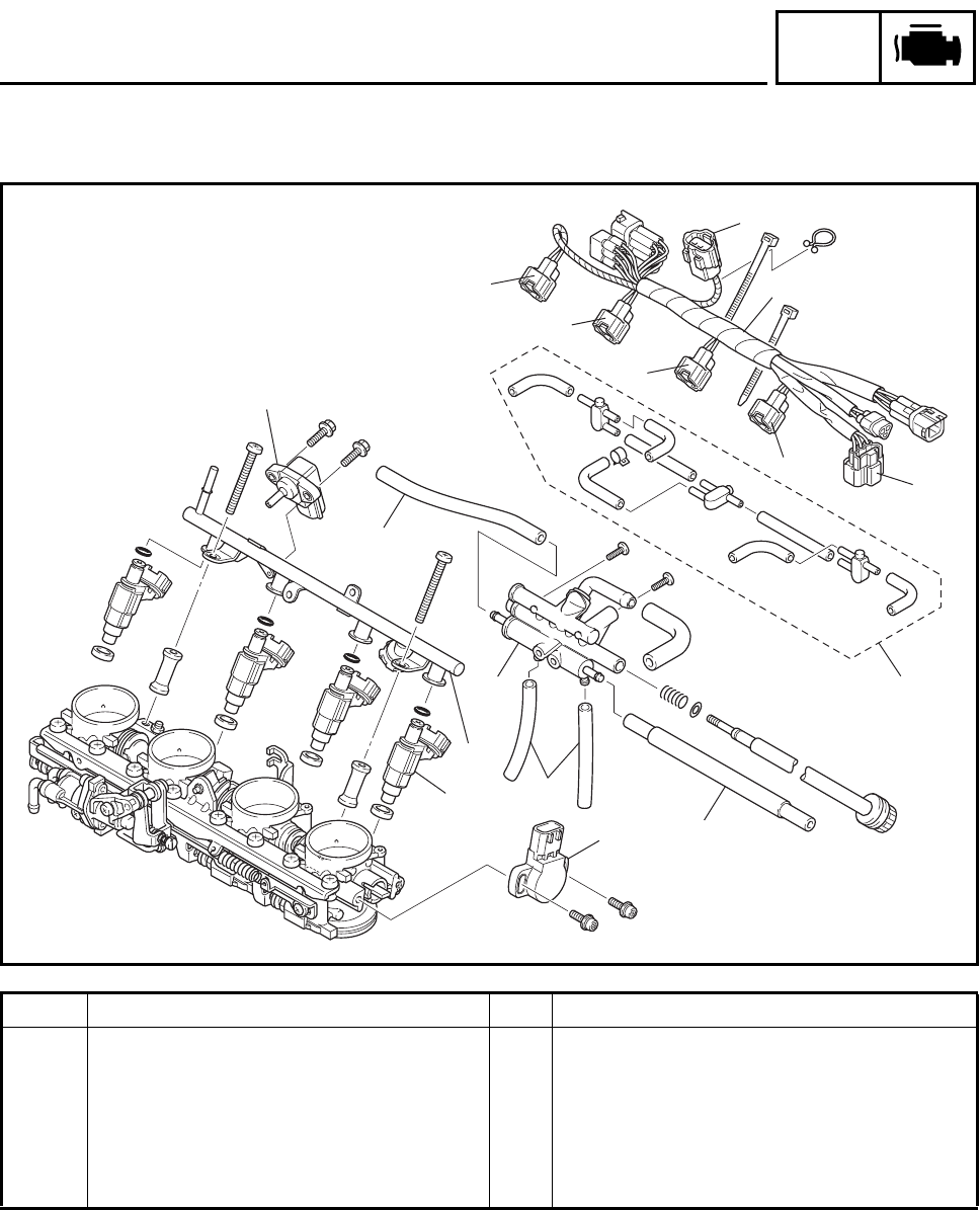
FUEL INJECTION SYSTEM
8
9
24
1
5
5
5
5
10
10
3
7
7
6
10
10
Order Job/Part Q’ty Remarks
7 Throttle cable 2 Disconnect.
8 Plunger control unit hose 1 1 Disconnect.
9 Plunger control unit hose 2 1 Disconnect.
10 Throttle body joint 4
For installation, reverse the removal
procedure.
– 23 –
FI
FUEL INJECTION SYSTEM
11
3
4
5
61
7
2
8
12
13
14
10
10
10
9
Order Job/Part Q’ty Remarks
Removing the injectors Remove the parts in the order listed.
1 Throttle position sensor coupler 1 Disconnect.
2 Intake air pressure sensor coupler 1 Disconnect.
3 Cylinder #1-injector coupler 1 Disconnect.
4 Cylinder #2-injector coupler 1 Disconnect.
5 Cylinder #3-injector coupler 1 Disconnect.
6 Cylinder #4-injector coupler 1 Disconnect.
7 Sub-wire harness 2 1
8 Negative pressure hose 1 Disconnect.
9 Bypass air unit 1
10 Bypass air unit outlet hose 4
– 24 –
FI
FUEL INJECTION SYSTEM
11
3
4
5
61
7
2
8
12
13
14
10
10
10
9
Order Job/Part Q’ty Remarks
11 Intake air pressure sensor 1
12 Fuel injection pipe 1
13 Injector 4
14 Throttle position sensor 1
For installation, reverse the removal
procedure.
– 25 –
FI
AIR INDUCTION SYSTEM
AIR INDUCTION SYSTEM
INSTALLING THE REED VALVES
1. Install:
•plate 1
NOTE:
Align the notch a in each plate with the pro-
jection b of each reed valve seat on the cylin-
der head cover.
b
a
1
– 26 –
–+
ELEC
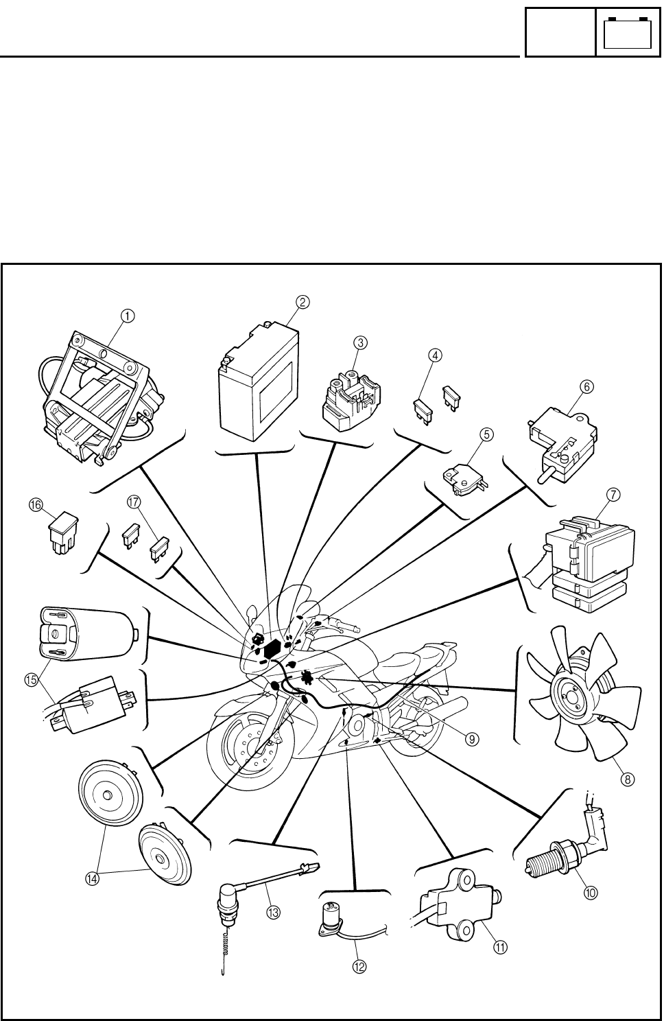
ELECTRICAL COMPONENTS
EAS00729
ELECTRICAL
ELECTRICAL COMPONENTS
1Windshield drive unit
2Battery
3Starter relay
4Fuel injection system fuse
5Front brake light switch
6Clutch switch
7Fuse box
8Radiator fan motor
9Wire harness
0Neutral switch
ASidestand switch
BOil level switch
CRear brake light switch
DHorn
EIgnition coil
FMain fuse
GABS motor fuse (FJR1300A)
– 27 –
–+
ELEC
ELECTRICAL COMPONENTS
1Coolant temperature sensor
2Intake air pressure sensor
3Intake air temperature sensor
4Relay unit
5Lean angle cut-off switch
6Hydraulic unit (FJR1300A)
7Fail-safe relay (FJR1300A)
8ECU (engine)
9ECU (ABS) (FJR1300A)
0Speed sensor
ACylinder identification sensor
BO2 sensor
CCrankshaft position sensor
DAccessory box solenoid
EAccessory box relay
FHeadlight relay 1
GRadiator fan motor relay
HTurn signal relay
IHeadlight relay 2
– 28 –
–+
ELEC
FUEL INJECTION SYSTEM
FUEL INJECTION SYSTEM
CIRCUIT DIAGRAM (FJR1300)
ON
OFF
P
R
R R
Br/L
Br/R
BB1
BB2
BB4
BB3
G
/
YBr
BL
Y
Ch Dg
Y
Dg
BL/R
Ch
Dg
Ch
Br/WBr/W
Ch
Dg
Br/W
Br/G
B/R
R/B
B/R
R/B
R/B
B/R
B
B
L/Y
B/Y
B/Y
L/Y
(BLACK) (BLACK)
R
R
R
R
Br/L
Br/L
Br/RBr/R
(BLACK)
(GRAY)
W WW
B
G/W
BR/L
RB
B
B
R
R
R
R
R
Br/LBr/Y
B
B
B
R
R
R
B
L
/
W
R
/
G
BB
R
/
W
R/W
R
L/W
B
R
B
R
B
B
B
B
W
W
W
W
W
W
R
B
R/Y
G/L
G/L
R/Y
Y/B
Y/B Y/B
A
R/Y R/Y
A
A
L
/
WLg
L
/
G
L
/
G
Sb
Sb
Sb
Sb
B
/
Y
B
R
/
B
Lg
R/B
B/R
L/W
L/W
W/LR/L
R/WL/G
L
/
YSb B
/
Y
R
R
/
Y
BB
B2
Br/R
L/R
L/R
Br/G
Br/L R/W
Br/L R/Y
W/L
Br/L
Br/B
Br/B
Br/B
B
Sb/W
Sb/W
Sb/W
O/W O/W
O/W
O/W
Br Br
O/WSb/W
BrBr
A
Br/G
Br/G
A
Br/W
Br/W
A
G/B
G/BLg Sb Dg Ch
Br
P
Br/W
Br/R
R/W
R/G
G/W
Y/L Y/L
L
B/L
Gy/R
W/Y
B2 B2 B2
Y/L
G/B
Br/G
Br/W
A
L
L
R
L
A
G/Y
R/B
B/R
B/R
L/R L/R
G/B
R/B
G/Y
G/Y
B
B
B
B
B
Br/Y
Br/Y
Br/YBr/R
L
B
R
B
Lg
Sb
Lg
Sb
Lg
Sb
Br/B
Y
Br
B
B
B
A
Y
P
Y
Y
R/W
R/W
G/Y
L
Br/B
G/B
B
Y
G
G/L
Y/B
G/L
R/Y
R/Y
L
B
L
B
(BLACK) (BLACK)
Gy
B/L
B
Gy
(BLUE)
(DARK GRAY) (DARK GRAY)
(BLACK)
B
BLg
Br/R
Sb
Br/Y
R
Lg
Br/R
B
RBrSb
Lg
Y/L
R/GR/G
G/LR/WR/W
B
Y/L
B
BB B2
L/RCh Dg
Y
L/R
Br/W
Gy/G
Gy/R
Br/R
Br/W
W/Y
P/W
W/B
G/W
Y/G
B/L
B/L
L/RYG Y
BBB
YG
B
B
G
P
G
BY
G
BY
G/W
R/LO/BO/BO/B
B/L
(BLACK)
(BLACK)
G/WR/L
B
Dg
Dg
C
W
W
W
W
Y
Ch
Dg
Lg
A
Lg
Lg
C
A
C
R/G
R/G
B
G/W
G/W
B
Ch
Ch
B
L/R
Br/W
B/L
R/LO/B
B
L/R
Br
UP
DOWN
ON
OFF
Dg
Br/W
Ch
D
L L
E
Y Y
E
D
R/WBr/R
E
B/W R/WB3
Y
Gy
O/B
Y/B
G/Y
Y/L
R/B
G/B
L/B
L
O
O
L
R/L
R/L
D
B/L B/L
E
WL
B1
BB
B2
B2
B/L
W/BW/B W/B
E
P/W P/W
B/L
Gy
B/L
Y
L
B/L
Gy/G
Gy/GGy/G
W
L/Y
B/L
L
W/B
B/L
W
L/Y
B/L
L
W/Y
B/L
LYB/L
(BLACK)
(DARK GREEN)
L
B/L
P/W
P/WB/LL
(BLACK)
L
O/WB
(BLACK)
Y/G
B/L
Br/RR/W
Br
Br/R
(GRAY)
R/LL/BL/BL/B
R/LL/B
D
(GRAY)
R/LG/BG/BG/B
R/LG/B
D
(GRAY)
R/LR/BR/BR/B
R/LR/B
D
(GRAY)
R/B
R/GB2 Br/R
R/WG/W
Y
/
L
G
/
L
Lg Y L
Ch
W
Dg
(BLACK)
(BLUE)
(BLUE) (BLUE)
L/G
B
BB
BB1
BB2
BB4
BB3
B
B
B
B
R/W
R/B
L/WG/Y
Br B
R/W
R/B
W/LG/Y
Br
B
C
B/L
P/W
Gy/G
Y
W/B
B/L
P/W
W/B
Y
Gy/G
E
(BLACK) (BLACK)
WIRE HARNESS
SUB-WIRE
HARNESS 2
L/B O/BL
R/LR/B
G/B
O/BL L/B
G/B
R/BR/L
D
WIRE HARNESS
SUB-WIRE
HARNESS 2
C
WIRE HARNESS
SUB-WIRE
HARNESS 1
R/GG/LG/L
O/WO/W
WY/L
R/G
Y/LW
WIRE HARNESS
B
SUB-WIRE
HARNESS 1
L/R
G/W
Sb
Ch Lg
Br
Dg
Br/Y
Sb/W
B
L/R
G/W
Sb Ch
Lg Br
Dg
Br/YSb/W
B
A
SUB-WIRE
HARNESS 1
WIRE HARNESS
Y/B
Br/B
YLg
Br/W
R/WR/W
B2 B2
L
Br/B
L
G/Y
Y/B
G/Y
Br/G
Lg
Br/G
G/B
Y
G/B
R/Y
Br/W
R/Y
P
BLg
Sb
Br/W
L/BCh
Dg
B/Y
YR/Y
L/Y
P
B
Sb
Lg
Br/W
G/B
Ch
Dg
B/Y
Y
R/Y
B/R
B
/
R
B
/
Y
Br
R/W R/W
A
L
L
Y/GB/L
B/R
G/YY/GB/Y B/LY/BGyL/Y
R/W
Y/LR/L
Br/R
L/W
Y
W/YR/W
G/W
P/W
Br/W
B/WW/B
Gy/G
R/BLG/BL/BB3O/BO
Gy/R
(BLACK)
B
/
R L
/
Y
R
/
L
B
Y/L
R/W
G/L
R/G
L
/
W
R
/
WW
/
L
G/L
R/B
R/W
B
Br Br
G/W
B/L
Gy/G
B/L
R/B
OFF
(BROWN)
(BROWN)
Br
YBB
Ch
B
Dg
B
F
Dg
Dg
G
Ch
Ch
F
B
B
G
B
B
BCh
Dg
B
LB
Br/G
G
SUB-WIRE
HARNESS 3
SUB-WIRE
HARNESS 1
Ch
B
LB
Br/G
F
SUB-WIRE
HARNESS 3
SUB-WIRE
HARNESS 1
Dg
B
2
6
5
3
1
4
=
AB
8
9
7
D
E
C
J
K
G
F
L
M
I
N
O
W
Q
U
V
T
S
R
YZ
XZ
d
e
c
b
f
[\
^
a
ww
n
m
s
t
vv
r
kl
i
g
j
o
o
}
†
å
~
¢
ß
®
¶
£
•
™
µ
¥
©H
ç
§
|
x
y
z{
h
u
P
qp
]
R/W
B/Y
L/Y
R/L
B/R
L/W
2Main switch
6Main fuse
7Battery
8Fuel injection system fuse
CFuel injection system relay
HFuel pump
IO2 sensor
JCylinder identification sensor
KThrottle position sensor
LIntake air pressure sensor
MLean angle cut-off switch
NIntake air temperature sensor
OCoolant temperature sensor
PCrankshaft position sensor
QECU (engine)
RCylinder #1 - injector
SCylinder #2 - injector
TCylinder #3 - injector
UCylinder #4 - injector
VAir induction system solenoid
WSpeed sensor
£Ignition fuse
¥Engine stop switch
– 29 –
–+
ELEC
FUEL INJECTION SYSTEM
CIRCUIT DIAGRAM (FJR1300A)
ON
OFF
P
R
RR
Br/L
Br/R
BB1
BB2
BB4
BB3
G
/
YBr
BL
Y
Ch Dg
Y
Dg
BL/R
Ch
Dg
Ch
Br/WBr/W
Ch
Dg
Br/W
Br/G
B/R
R/B
B/R
R/B
R/B
B/R
B
B
L/Y
B/Y
B/Y
L/Y
(BLACK) (BLACK)
R
R
R
R
Br/L
Br/L
B
B/W
R
R/L
B
B/W
R
R/L
Br/RBr/R
(BLACK)
(GRAY)
W WW
B
G/W
BR/L
RB
B
B
R
R
R
R
R
Br/LBr/Y
B
B
B
R
R
R
L
/
W
BB
R
/
W
R/W
R
L/W
B
B
B
B
W
W
W
W
W
W
R
B
R/Y
G/L
G/L
R/Y
Y/B
Y/B Y/B
A
R/Y R/Y
A
A
L
/
WLg
L
/
G
L
/
G
Sb
Sb
Sb
Sb
B
/
Y
B
R
/
B
R
/
Y
BB
B2
Br/R
L/R
L/R
Br/G
Br/L R/W
Br/L R/Y
W/L
Br/L
Br/B
Br/B
Br/B
B
Sb/W
Sb/W
Sb/W
O/W O/W
O/W
O/W
Br Br
O/WSb/W
BrBr
A
Br/G
Br/G
A
Br/W
Br/W
A
G/B
G/BLg Sb Dg Ch
Br
P
Br/W
Br/R
R/W
R/G
G/W
Y/L
L
B/L
Gy/R
W/Y
B2 B2 B2
G/B
Br/G
Br/W
A
L
L
R
L
A
G/Y
R/B
B/R
B/R
L/R L/R
G/B
R/B
G/Y
G/Y
B
B
B
B
B
Br/Y
Br/Y
Br/YBr/R
L
B
R
B
Lg
Sb
Lg
Sb
Lg
Sb
Br/B
Y
Br
B
B
B
A
Y
P
Y
Y
R/W
R/W
G/Y
L
Br/B
G/B
B
Y
G
G/L
Y/B
G/L
R/Y
R/Y
L
B
L
B
(BLACK) (BLACK)
(BROWN)
(BROWN)
Gy
B/L
B
Gy
(BLUE)
(DARK GRAY) (DARK GRAY)
(BLACK)
B
BLg
Br/R
Sb
Br/Y
R
Lg
Br/R
B
RBrSb
Lg
Y/L
R/GR/G
G/LR/WR/W
B
Y/L
B
BB B2
L/RCh Dg
Y
L/R
Br/W
Gy/G
Gy/R
Br/R
Br/W
W/Y
P/W
W/B
R/W
G/W
Y/G
B/L
B/Y
L/Y
R/L
B/L
L/RY G Y
BB
Ch
B
B
YG
B
B
G
P
G
BY
G
BY
G/W
R/LO/BO/BO/B
B/L
(BLACK)
(BLACK)
G/WR/L
Dg
B
B
Dg
Dg
C
W
W
W
W
Y
Ch
Dg
Lg
A
Lg
Lg
Y/L Y/L
C
A
C
R/G
R/G
B
G/W
G/W
B
Ch
Ch
F
Dg
Dg
G
Ch
Ch
F
B
B
G
B
B
B
L/R
Br/W
B/L
R/LO/B
B
L/R
Br
UP
DOWN
ON
OFF
Dg
Br/W
Ch
D
L L
E
Y Y
E
D
R/WBr/R
E
B/W R/WB3
Y
Gy
O/B
Y/B
G/Y
Y/L
R/B
G/B
L/B
L
O
O
L
R/L
R/L
D
B/L B/L
E
WL
B1
BB
B2
B2
B/L
W/BW/B W/B
E
P/W P/W
B/L
Gy
B/L
Y
L
B/L
Gy/G
Gy/GGy/G
W
L/Y
B/L
L
W/B
B/L
W
L/Y
B/L
L
W/Y
B/L
LYB/L
(BLACK)
(DARK GREEN)
L
B/L
P/W
P/WB/LL
(BLACK)
L
O/WB
(BLACK)
Y/G
B/L
Br/RR/W
Br
Br/R
(GRAY)
R/LL/BL/BL/B
R/LL/B
D
(GRAY)
R/LG/BG/BG/B
R/LG/B
D
(GRAY)
R/LR/BR/BR/B
R/LR/B
D
(GRAY)
R/B
R/GB2 Br/R
R/WG/W
Y
/
L
G
/
LG
/
R
Lg Y L
Ch
W
Dg
(BLACK)
(BLUE)
(BLUE) (BLUE)
L/G
B
BB
Br
YBB
Gy W
BB1
BB2
BB4
BB3
B
B
B
B
R/W
R/B
L/WG/Y
Br B
R/W
R/B
W/L
G/Y
Br
B
B/W
R/L
B
R/L
Y
Br/W
L/W
B1 Lg
SbB2
W1
G/R
Lg
Sb
B1
B2
W1
G/R
R
G
R
W
RB
W
WR
R
Y
Br/W
L/W
LB
Br/G
C
B/L
P/W
Gy/G
Y
W/B
B/L
P/W
W/B
Y
Gy/G
E
(BLACK) (BLACK) (BLACK) (BLACK)
WIRE HARNESS
SUB-WIRE
HARNESS 2
L/B O/BL
R/LR/B
G/B
O/BL L/B
G/B
R/BR/L
D
WIRE HARNESS
SUB-WIRE
HARNESS 2
G
SUB-WIRE
HARNESS 3
SUB-WIRE
HARNESS 1
C
WIRE HARNESS
SUB-WIRE
HARNESS 1
R/GG/L
G/RG/R
G/L
O/WO/W
WY/L
R/G
Y/LW
WIRE HARNESS
B
SUB-WIRE
HARNESS 1
L/R
G/W
Sb
Ch Lg
Br
Dg
Br/Y
Sb/W
B
L/R
G/W
Sb Ch
Lg Br
Dg
Br/YSb/W
B
A
SUB-WIRE
HARNESS 1
WIRE HARNESS
Y/B
Br/B
YLg
Br/W
R/WR/W
B2 B2
L
Br/B
L
G/Y
Y/B
G/Y
Br/G
Lg
Br/G
G/B
Y
G/B
R/Y
Br/W
R/Y
P
BLg
Sb
Br/W
L/BCh
Dg
B/Y
YR/Y
L/Y
BCh
Dg
B
P
B
Sb
Lg
Br/W
G/B
Ch
Dg
B/Y
Y
R/Y
B/R
B
/
R
B
/
Y
Br
R/W R/W
A
L
L
Y/GB/L
B/R
L/W
B
/
R L
/
Y
R
/
L
B
Y/L
R/W
G/L
R/G
L
/
W
R
/
WW
/
L
G/L
G/RG/R
R/B
R/W
B
Br Br
G/W
B/L
Gy/G
B/L
R/B
Br
/
WBr
/
L
Lg
R/B
B/R
L/W
L/W
W/LR/L
R/WL/G
L
/
YSb B
/
Y
R
B/R
G/YY/GB/Y B/LY/BGyL/Y
R/W
Y/LR/L
Br/R
L/W
Y
W/YR/W
G/W
P/W
Br/W
B/WW/B
Gy/G
R/BLG/BL/BB3O/BO
Gy/R
(BLACK)
B1
B2
Y Y
W1
B2
W1
B1
W1
W1 B1
Sb
Sb
Lg
Sb
Lg
Sb
Lg
B3
W2
Lg
R/L
B/W
R/L
B/W
R/W
W/R
L/W
Br/W
G/R
L/W
W/R
W/B
W/B
Br/W
L/W
Br/WBr/W
B
R
/
L
R
/
G
B
/
WB
G/R G/R
C
OFF
B1
G
G
B
B
R
R R
Y
B4
B5
B2
W1
B1
P/W
P/W
G/R R/L
B
R/W
R/W
R/W
W2 B3
Gy
W
WW
B4
B5
Sb
W
Y
G
R/W
RB
R/WW/B
R/L
G/R
P/WBr/W
Br/W
B2
B1 B3
W1 W2
Lg
L/WP/WW/BW/R
Sb
Lg
B
W/R
Ch
B
LB
Br/G
F
SUB-WIRE
HARNESS 3
SUB-WIRE
HARNESS 1
Dg
B
2
6
7
5
3
1
4
B
CD
0
A
9
8
F
G
E
\
Z[
]
^
L
M
I
H
N
O
K
P
QY
S
W
X
V
U
T
de
ce
b
n
o
m
l
p
fg
i
k
††
x
w
}
~
çç
|
{z
uv
s
q
t
y
y
ß
¥
©
®
µ
¬
…
¡
º
ø
¤
›
‹
ÕJ
™
æ
¶
¢
£
§•
a
h
j
r
R
å
2Main switch
7Main fuse
9Battery
0Fuel injection system fuse
EFuel injection system relay
JFuel pump
KO2 sensor
LCylinder identification sensor
MThrottle position sensor
NIntake air pressure sensor
OLean angle cut-off switch
PIntake air temperature sensor
QCoolant temperature sensor
RCrankshaft position sensor
SECU (engine)
TCylinder #1 - injector
UCylinder #2 - injector
VCylinder #3 - injector
WCylinder #4 - injector
XAir induction system solenoid
YSpeed sensor
ºIgnition fuse
‹Engine stop switch
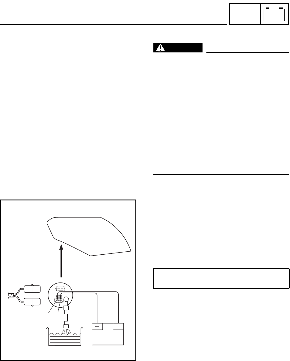
– 30 –
–+
ELEC
FUEL INJECTION SYSTEM
EAS00819
CHECKING THE FUEL PUMP
WARNING
@
Gasoline is extremely flammable and under
certain circumstances there can be a dan-
ger of an explosion or fire. Be extremely
careful and note the following points:
•Stop the engine before refueling.
•Do not smoke, and keep away from open
flames, sparks, or any other source of
fire.
•If you do accidentally spill gasoline, wipe
it up immediately with dry rags.
•If gasoline touches the engine when it is
hot, a fire may occur. Therefore, make
sure the engine is completely cool before
performing the following test.
1. Check:
•fuel pump operation
▼▼▼▼ ▼ ▼▼▼▼ ▼ ▼▼▼▼ ▼ ▼▼▼▼ ▼ ▼▼▼▼ ▼ ▼▼▼▼ ▼▼▼
a. Fill the fuel tank.
b. Put the end of the fuel hose into an open
container.
c. Connect the battery (12 V) to the fuel pump
terminals as shown.
d. If fuel flows out of the fuel hose, the fuel
pump is OK. If fuel does not flow, replace
the fuel pump.
▲▲▲▲ ▲ ▲▲▲▲ ▲ ▲▲▲▲ ▲ ▲▲▲▲ ▲ ▲▲▲▲ ▲ ▲▲▲▲ ▲▲▲
Battery positive lead → red/blue 1
Battery negative lead → black 2
G/W
B
B
R/L
+
12
FJR1300 WIRING DIAGRAM
1Immobilizer unit
2Main switch
3Rectifier/regulator
4Generator
5Backup fuse (odometer, clock and windshield)
6Main fuse
7Battery
8Fuel injection system fuse
9Starter relay
0Starter motor
ARelay unit
BStarting circuit cut-off relay
CFuel injection system relay
DNeutral switch
ESidestand switch
FAccessory box solenoid
GAccessory box relay
HFuel pump
IO2 sensor
JCylinder identification sensor
KThrottle position sensor
LIntake air pressure sensor
MLean angle cut-off switch
NIntake air temperature sensor
OCoolant temperature sensor
PCrankshaft position sensor
QECU (engine)
RCylinder #1 - injector
SCylinder #2 - injector
TCylinder #3 - injector
UCylinder #4 - injector
VAir induction system solenoid
WSpeed sensor
XCylinders #1, #4 - ignition coil
YCylinders #2, #3 - ignition coil
ZSpark plug
[Meter assembly
\Immobilizer system indicator light
]Oil level warning light
_Neutral indicator light
aMultifunction meter
bEngine trouble warning light
cHigh beam indicator light
dLeft turn signal indicator light
eRight turn signal indicator light
fMeter light
gOil level switch
hLeft handlebar switch
iClutch switch
jPass switch
kDimmer switch
lWindshield position switch
mTurn signal switch
nHorn switch
oHorn
pFront turn signal light (left)
qFront turn signal light (right)
rHazard switch
sHeadlight relay 1
tHeadlight relay 2
uHeadlight assembly
vAuxiliary light
wHeadlight
xTaillight assembly
yTail/brake light
zRear turn signal light (left)
{Rear turn signal light (right)
|Rear brake light switch
}Turn signal relay
~Windshield drive unit
åRadiator fan motor
çRadiator fan motor relay
†Parking lighting fuse
¢Hazard lighting fuse
£Ignition fuse
§Headlight fuse
•Signaling system fuse
¶Radiator fan motor fuse
ßWindshield motor fuse
®CYCLELOCK
©Right handlebar switch
™Front brake light switch
¥Engine stop switch
µStart switch
COLOR CODE
B.............Black
Br............Brown
Ch...........Chocolate
Dg...........Dark green
G.............Green
Gy...........Gray
L .............Blue
Lg ...........Light green
O.............Orange
P.............Pink
R.............Red
Sb ...........Sky blue
W............White
Y.............Yellow
B/L ..........Black/Blue
B/R .........Black/Red
B/W.........Black/White
B/Y..........Black/Yellow
Br/B ........Brown/Black
Br/G ........Brown/Green
Br/L.........Brown/Blue
Br/R ........Brown/Red
Br/W .......Brown/White
Br/Y ........Brown/Yellow
G/B .........Green/Black
G/L..........Green/Blue
G/W ........Green/White
G/Y .........Green/Yellow
Gy/G .......Gray/Green
Gy/R .......Gray/Red
L/B..........Blue/Black
L/G..........Blue/Green
L/R..........Blue/Red
L/W.........Blue/White
L/Y..........Blue/Yellow
O/B .........Orange/Black
P/W.........Pink/White
R/B .........Red/Black
R/G .........Red/Green
R/L..........Red/Blue
R/W ........Red/White
R/Y .........Red/Yellow
W/B.........White/Black
W/Y.........White/Yellow
Y/B..........Yellow/Black
Y/G .........Yellow/Green
Y/L ..........Yellow/Blue
FJR1300A WIRING DIAGRAM
1Immobilizer unit
2Main switch
3Rectifier/regulator
4Generator
5ABS fuse
6Backup fuse (odometer, clock and windshield)
7Main fuse
8ABS motor fuse
9Battery
0Fuel injection system fuse
AStarter relay
BStarter motor
CRelay unit
DStarting circuit cut-off relay
EFuel injection system relay
FNeutral switch
GSidestand switch
HAccessory box solenoid
IAccessory box relay
JFuel pump
KO2 sensor
LCylinder identification sensor
MThrottle position sensor
NIntake air pressure sensor
OLean angle cut-off switch
PIntake air temperature sensor
QCoolant temperature sensor
RCrankshaft position sensor
SECU (engine)
TCylinder #1 - injector
UCylinder #2 - injector
VCylinder #3 - injector
WCylinder #4 - injector
XAir induction system solenoid
YSpeed sensor
ZSub-wire harness (ABS)
[ECU (ABS)
\Rear wheel sensor
]Fail-safe relay
_Hydraulic unit
aABS test coupler
bFront wheel sensor
cCylinders #1, #4 - ignition coil
dCylinders #2, #3 - ignition coil
eSpark plug
fMeter assembly
gImmobilizer system indicator light
hOil level warning light
iNeutral indicator light
jABS warning light
kMultifunction meter
lEngine trouble warning light
mHigh beam indicator light
nLeft turn signal indicator light
oRight turn signal indicator light
pMeter light
qOil level switch
rLeft handlebar switch
sClutch switch
tPass switch
uDimmer switch
vWindshield position switch
wTurn signal switch
xHorn switch
yHorn
zFront turn signal light (left)
{Front turn signal light (right)
|Hazard switch
}Headlight relay 1
~Headlight relay 2
åHeadlight assembly
çAuxiliary light
†Headlight
¢Taillight assembly
£Tail/brake light
§Rear turn signal light (left)
•Rear turn signal light (right)
¶Rear brake light switch
ßTurn signal relay
®Windshield drive unit
©Radiator fan motor
™Radiator fan motor relay
¥Parking lighting fuse
µHazard lighting fuse
ºIgnition fuse
æHeadlight fuse
øSignaling system fuse
¡Radiator fan motor fuse
¬Windshield motor fuse
…CYCLELOCK
ÕRight handlebar switch
¤Front brake light switch
‹Engine stop switch
›Start switch
COLOR CODE
B.............Black
Br............Brown
Ch...........Chocolate
Dg...........Dark green
G.............Green
Gy...........Gray
L .............Blue
Lg ...........Light green
O.............Orange
P.............Pink
R.............Red
Sb ...........Sky blue
W............White
Y.............Yellow
B/L ..........Black/Blue
B/R .........Black/Red
B/W.........Black/White
B/Y..........Black/Yellow
Br/B ........Brown/Black
Br/G ........Brown/Green
Br/L.........Brown/Blue
Br/R ........Brown/Red
Br/W .......Brown/White
Br/Y ........Brown/Yellow
G/B .........Green/Black
G/L..........Green/Blue
G/W ........Green/White
G/Y .........Green/Yellow
Gy/G .......Gray/Green
Gy/R .......Gray/Red
L/B..........Blue/Black
L/G..........Blue/Green
L/R..........Blue/Red
L/W.........Blue/White
L/Y..........Blue/Yellow
O/B .........Orange/Black
P/W.........Pink/White
R/B .........Red/Black
R/G .........Red/Green
R/L..........Red/Blue
R/W ........Red/White
R/Y .........Red/Yellow
W/B.........White/Black
W/Y.........White/Yellow
Y/B..........Yellow/Black
Y/G .........Yellow/Green
Y/L ..........Yellow/Blue

YAMAHA MOTOR CO., LTD.
2500 SHINGAI IWATA SHIZUOKA JAPAN
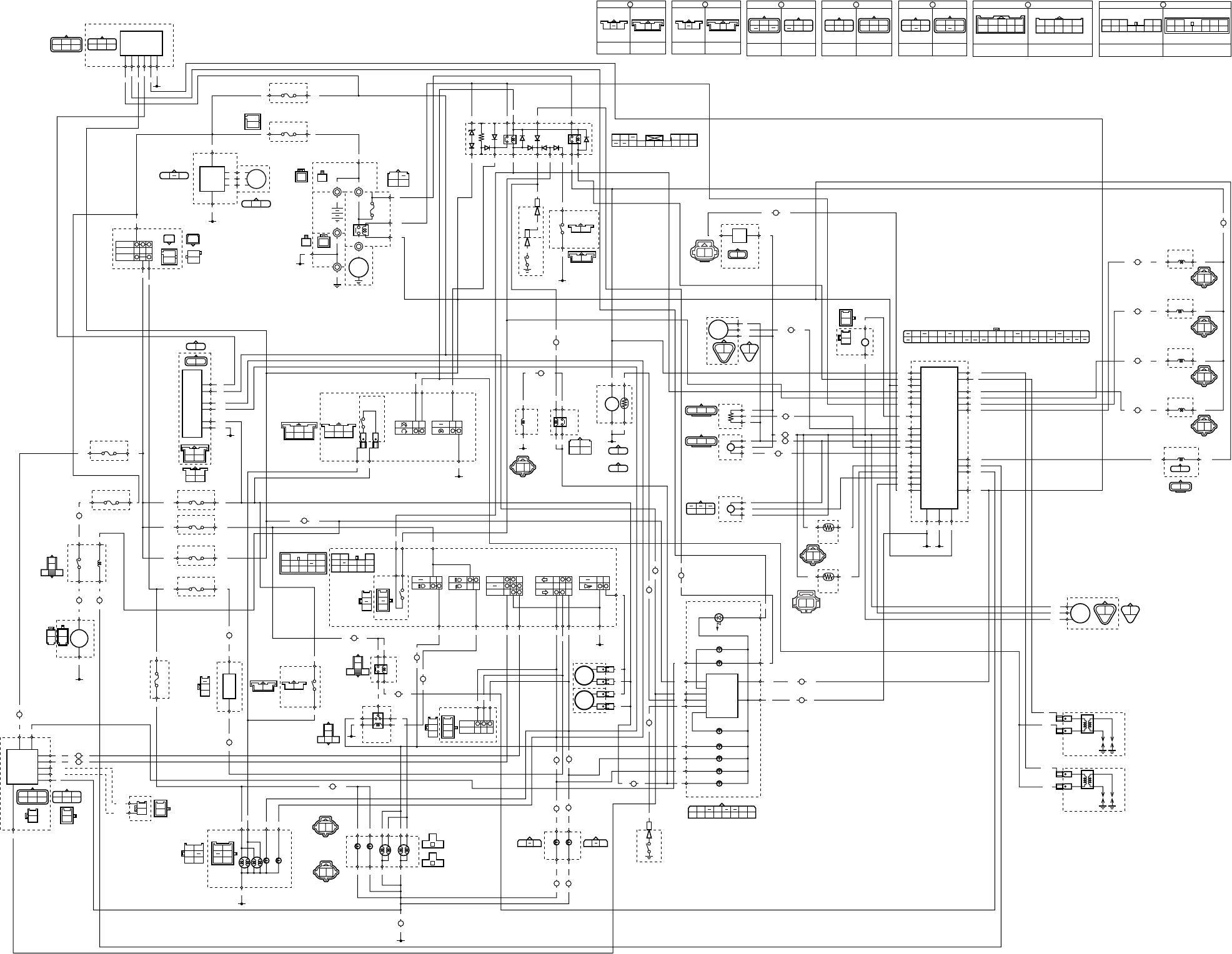
ON
OFF
P
R
R R
Br/L
Br/R
BB1
BB2
BB4
BB3
G
/
Y Br
BL
Y
Ch Dg
Y
Dg
BL/R
Ch
Dg
Ch
Br/WBr/W
Ch
Dg
Br/W
Br/G
B/R
R/B
B/R
R/B
R/B
B/R
B
B
L/Y
B/Y
B/Y
L/Y
(BLACK) (BLACK)
R
R
R
R
Br/L
Br/L
Br/RBr/R
(BLACK)
(GRAY)
W WW
B
G/W
BR/L
RB
B
B
R
R
R
R
R
Br/LBr/Y
B
B
B
R
R
R
B
L
/
W
R
/
G
BB
R
/
W
R/W
R
L/W
B
R
B
R
B
B
B
B
W
W
W
W
W
W
R
B
R/Y
G/L
G/L
R/Y
Y/B
Y/B Y/B
A
R/Y R/Y
A
A
L
/
WLg
L
/
G
L
/
G
Sb
Sb
Sb
Sb
B
/
Y
B
R
/
B
Lg
R/B
B/R
L/W
L/W
W/LR/L
R/WL/G
L
/
YSb B
/
Y
R
R
/
Y
BB
B2
Br/R
L/R
L/R
Br/G
Br/L R/W
Br/L R/Y
W/L
Br/L
Br/B
Br/B
Br/B
B
Sb/W
Sb/W
Sb/W
O/W O/W
O/W
O/W
Br Br
O/WSb/W
BrBr
A
Br/G
Br/G
A
Br/W
Br/W
A
G/B
G/B Lg Sb Dg Ch
Br
P
Br/W
Br/R
R/W
R/G
G/W
Y/L Y/L
L
B/L
Gy/R
W/Y
B2 B2 B2
Y/L
G/B
Br/G
Br/W
A
L
L
R
L
A
G/Y
R/B
B/R
B/R
L/R L/R
G/B
R/B
G/Y
G/Y
B
B
B
B
B
Br/Y
Br/Y
Br/Y Br/R
L
B
R
B
Lg
Sb
Lg
Sb
Lg
Sb
Br/B
Y
Br
B
B
B
A
Y
P
Y
Y
R/W
R/W
G/Y
L
Br/B
G/B
B
Y
G
G/L
Y/B
G/L
R/Y
R/Y
L
B
L
B
(BLACK) (BLACK)
Gy
B/L
B
Gy
(BLUE)
(DARK GRAY) (DARK GRAY)
(BLACK)
B
B Lg
Br/R
Sb
Br/Y
R
Lg
Br/R
B
RBrSb
Lg
Y/L
R/GR/G
G/LR/WR/W
B
Y/L
B
BB B2
L/R Ch Dg
Y
L/R
Br/W
Gy/G
Gy/R
Br/R
Br/W
W/Y
P/W
W/B
R/W
G/W
Y/G
B/L
B/Y
L/Y
R/L
B/L
L/RY G Y
BBB
YG
B
B
G
P
G
BY
G
BY
G/W
R/LO/BO/BO/B
B/L
(BLACK)
(BLACK)
G/WR/L
B
Dg
Dg
C
W
W
W
W
Y
Ch
Dg
Lg
A
Lg
Lg
C
A
C
R/G
R/G
B
G/W
G/W
B
Ch
Ch
B
L/R
Br/W
B/L
R/LO/B
B
L/R
Br
UP
DOWN
ON
OFF
Dg
Br/W
Ch
D
L L
E
Y Y
E
D
R/WBr/R
E
B/W R/WB3
Y
Gy
O/B
Y/B
G/Y
Y/L
R/B
G/B
L/B
L
O
O
L
R/L
R/L
D
B/L B/L
E
WL
B1
BB
B2
B2
B/L
W/BW/B W/B
E
P/W P/W
B/L
Gy
B/L
Y
L
B/L
Gy/G
Gy/G Gy/G
W
L/Y
B/L
L
W/B
B/L
W
L/Y
B/L
L
W/Y
B/L
LYB/L
(BLACK)
(DARK GREEN)
L
B/L
P/W
P/WB/LL
(BLACK)
L
O/WB
(BLACK)
Y/G
B/L
Br/RR/W
Br
Br/R
(GRAY)
R/LL/BL/BL/B
R/LL/B
D
(GRAY)
R/LG/BG/BG/B
R/LG/B
D
(GRAY)
R/LR/BR/BR/B
R/LR/B
D
(GRAY)
R/B
R/GB2 Br/R
R/WG/W
Y
/
L
G
/
L
Lg Y L
Ch
W
Dg
(BLACK)
(BLUE)
(BLUE) (BLUE)
L/G
B
BB
BB1
BB2
BB4
BB3
B
B
B
B
R/W
R/B
L/WG/Y
Br B
R/W
R/B
W/L
G/Y
Br
B
C
B/L
P/W
Gy/G
Y
W/B
B/L
P/W
W/B
Y
Gy/G
E
(BLACK) (BLACK)
WIRE HARNESS
SUB-WIRE
HARNESS 2
L/B O/BL
R/LR/B
G/B
O/BL L/B
G/B
R/BR/L
D
WIRE HARNESS
SUB-WIRE
HARNESS 2
C
WIRE HARNESS
SUB-WIRE
HARNESS 1
R/GG/LG/L
O/WO/W
WY/L
R/G
Y/LW
WIRE HARNESS
B
SUB-WIRE
HARNESS 1
L/R
G/W
Sb
Ch Lg
Br
Dg
Br/Y
Sb/W
B
L/R
G/W
Sb Ch
Lg Br
Dg
Br/YSb/W
B
A
SUB-WIRE
HARNESS 1
WIRE HARNESS
Y/B
Br/B
YLg
Br/W
R/WR/W
B2 B2
L
Br/B
L
G/Y
Y/B
G/Y
Br/G
Lg
Br/G
G/B
Y
G/B
R/Y
Br/W
R/Y
P
BLg
Sb
Br/W
L/BCh
Dg
B/Y
YR/Y
L/Y
P
B
Sb
Lg
Br/W
G/B
Ch
Dg
B/Y
Y
R/Y
B/R
B
/
R
B
/
Y
Br
R/W R/W
A
L
L
Y/GB/L
B/R
L/W
B/R
G/YY/GB/Y B/LY/BGyL/Y
R/W
Y/LR/L
Br/R
L/W
Y
W/YR/W
G/W
P/W
Br/W
B/WW/B
Gy/G
R/BLG/BL/BB3O/BO
Gy/R
(BLACK)
B
/
R L
/
Y
R
/
L
B
Y/L
R/W
G/L
R/G
L
/
W
R
/
WW
/
L
G/L
R/B
R/W
B
Br Br
G/W
B/L
Gy/G
B/L
R/B
OFF
(BROWN)
(BROWN)
Br
YBB
Ch
B
Dg
B
F
Dg
Dg
G
Ch
Ch
F
B
B
G
B
B
BCh
Dg
B
LB
Br/G
G
SUB-WIRE
HARNESS 3
SUB-WIRE
HARNESS 1
Ch
B
LB
Br/G
F
SUB-WIRE
HARNESS 3
SUB-WIRE
HARNESS 1
Dg
B
2
6
5
3
1
4
=
AB
8
9
7
D
E
C
J
K
G
F
L
M
I
N
O
W
Q
U
V
T
S
R
YZ
XZ
d
e
c
b
f
[\
^
a
ww
n
m
s
t
vv
r
kl
i
g
j
o
o
}
†
å
~
¢
ß
®
¶
£
•
™
µ
¥
©H
ç
§
|
x
y
z{
h
u
P
qp
]
FJR1300 WIRING DIAGRAM
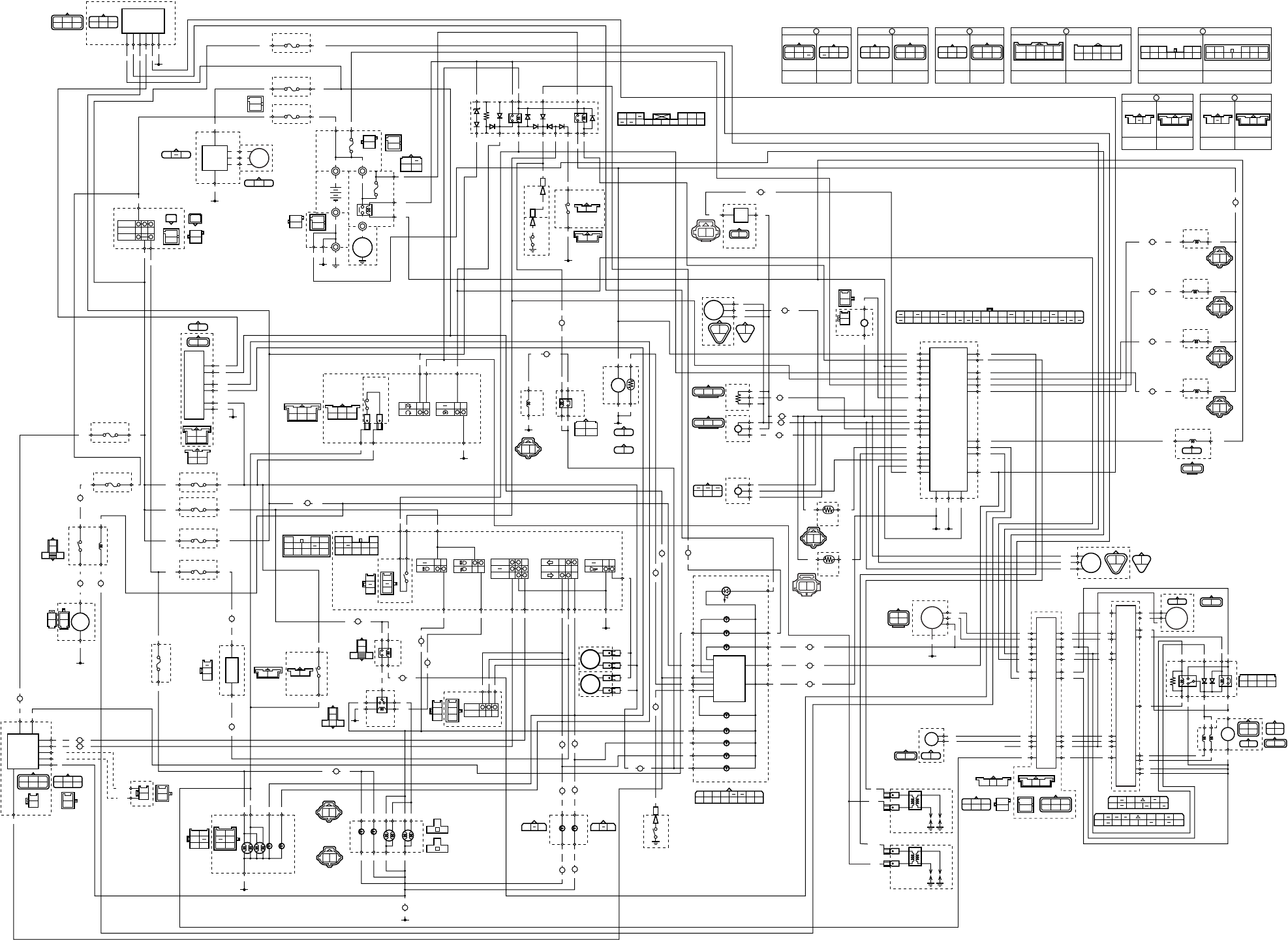
FJR1300A WIRING DIAGRAM
ON
OFF
P
R
RR
Br/L
Br/R
BB1
BB2
BB4
BB3
G
/
Y Br
BL
Y
Ch Dg
Y
Dg
BL/R
Ch
Dg
Ch
Br/WBr/W
Ch
Dg
Br/W
Br/G
B/R
R/B
B/R
R/B
R/B
B/R
B
B
L/Y
B/Y
B/Y
L/Y
(BLACK) (BLACK)
R
R
R
R
Br/L
Br/L
B
B/W
R
R/L
B
B/W
R
R/L
Br/RBr/R
(BLACK)
(GRAY)
W WW
B
G/W
BR/L
RB
B
B
R
R
R
R
R
Br/LBr/Y
B
B
B
R
R
R
L
/
W
BB
R
/
W
R/W
R
L/W
B
B
B
B
W
W
W
W
W
W
R
B
R/Y
G/L
G/L
R/Y
Y/B
Y/B Y/B
A
R/Y R/Y
A
A
L
/
WLg
L
/
G
L
/
G
Sb
Sb
Sb
Sb
B
/
Y
B
R
/
B
R
/
Y
BB
B2
Br/R
L/R
L/R
Br/G
Br/L R/W
Br/L R/Y
W/L
Br/L
Br/B
Br/B
Br/B
B
Sb/W
Sb/W
Sb/W
O/W O/W
O/W
O/W
Br Br
O/WSb/W
BrBr
A
Br/G
Br/G
A
Br/W
Br/W
A
G/B
G/B Lg Sb Dg Ch
Br
P
Br/W
Br/R
R/W
R/G
G/W
Y/L
L
B/L
Gy/R
W/Y
B2 B2 B2
G/B
Br/G
Br/W
A
L
L
R
L
A
G/Y
R/B
B/R
B/R
L/R L/R
G/B
R/B
G/Y
G/Y
B
B
B
B
B
Br/Y
Br/Y
Br/Y Br/R
L
B
R
B
Lg
Sb
Lg
Sb
Lg
Sb
Br/B
Y
Br
B
B
B
A
Y
P
Y
Y
R/W
R/W
G/Y
L
Br/B
G/B
B
Y
G
G/L
Y/B
G/L
R/Y
R/Y
L
B
L
B
(BLACK) (BLACK)
(BROWN)
(BROWN)
Gy
B/L
B
Gy
(BLUE)
(DARK GRAY) (DARK GRAY)
(BLACK)
B
B Lg
Br/R
Sb
Br/Y
R
Lg
Br/R
B
RBrSb
Lg
Y/L
R/GR/G
G/LR/WR/W
B
Y/L
B
BB B2
L/RCh Dg
Y
L/R
Br/W
Gy/G
Gy/R
Br/R
Br/W
W/Y
P/W
W/B
R/W
G/W
Y/G
B/L
B/Y
L/Y
R/L
B/L
L/RY G Y
BB
Ch
B
B
YG
B
B
G
P
G
BY
G
BY
G/W
R/LO/BO/BO/B
B/L
(BLACK)
(BLACK)
G/WR/L
Dg
B
B
Dg
Dg
C
W
W
W
W
Y
Ch
Dg
Lg
A
Lg
Lg
Y/L Y/L
C
A
C
R/G
R/G
B
G/W
G/W
B
Ch
Ch
F
Dg
Dg
G
Ch
Ch
F
B
B
G
B
B
B
L/R
Br/W
B/L
R/LO/B
B
L/R
Br
UP
DOWN
ON
OFF
Dg
Br/W
Ch
D
L L
E
Y Y
E
D
R/WBr/R
E
B/W R/WB3
Y
Gy
O/B
Y/B
G/Y
Y/L
R/B
G/B
L/B
L
O
O
L
R/L
R/L
D
B/L B/L
E
WL
B1
BB
B2
B2
B/L
W/BW/B W/B
E
P/W P/W
B/L
Gy
B/L
Y
L
B/L
Gy/G
Gy/G Gy/G
W
L/Y
B/L
L
W/B
B/L
W
L/Y
B/L
L
W/Y
B/L
LYB/L
(BLACK)
(DARK GREEN)
L
B/L
P/W
P/WB/LL
(BLACK)
L
O/WB
(BLACK)
Y/G
B/L
Br/RR/W
Br
Br/R
(GRAY)
R/LL/BL/BL/B
R/LL/B
D
(GRAY)
R/LG/BG/BG/B
R/LG/B
D
(GRAY)
R/LR/BR/BR/B
R/LR/B
D
(GRAY)
R/B
R/GB2 Br/R
R/WG/W
Y
/
L
G
/
LG
/
R
Lg Y L
Ch
W
Dg
(BLACK)
(BLUE)
(BLUE) (BLUE)
L/G
B
BB
Br
YBB
Gy W
BB1
BB2
BB4
BB3
B
B
B
B
R/W
R/B
L/WG/Y
Br B
R/W
R/B
W/L
G/Y
Br
B
B/W
R/L
B
R/L
Y
Br/W
L/W
B1 Lg
SbB2
W1
G/R
Lg
Sb
B1
B2
W1
G/R
R
G
R
W
RB
W
WR
R
Y
Br/W
L/W
LB
Br/G
C
B/L
P/W
Gy/G
Y
W/B
B/L
P/W
W/B
Y
Gy/G
E
(BLACK) (BLACK) (BLACK) (BLACK)
WIRE HARNESS
SUB-WIRE
HARNESS 2
L/B O/BL
R/LR/B
G/B
O/BL L/B
G/B
R/BR/L
D
WIRE HARNESS
SUB-WIRE
HARNESS 2
G
SUB-WIRE
HARNESS 3
SUB-WIRE
HARNESS 1
C
WIRE HARNESS
SUB-WIRE
HARNESS 1
R/GG/L
G/RG/R
G/L
O/WO/W
WY/L
R/G
Y/LW
WIRE HARNESS
B
SUB-WIRE
HARNESS 1
L/R
G/W
Sb
Ch Lg
Br
Dg
Br/Y
Sb/W
B
L/R
G/W
Sb Ch
Lg Br
Dg
Br/YSb/W
B
A
SUB-WIRE
HARNESS 1
WIRE HARNESS
Y/B
Br/B
YLg
Br/W
R/WR/W
B2 B2
L
Br/B
L
G/Y
Y/B
G/Y
Br/G
Lg
Br/G
G/B
Y
G/B
R/Y
Br/W
R/Y
P
BLg
Sb
Br/W
L/BCh
Dg
B/Y
YR/Y
L/Y
BCh
Dg
B
P
B
Sb
Lg
Br/W
G/B
Ch
Dg
B/Y
Y
R/Y
B/R
B
/
R
B
/
Y
Br
R/W R/W
A
L
L
Y/GB/L
B/R
L/W
B
/
R L
/
Y
R
/
L
B
Y/L
R/W
G/L
R/G
L
/
W
R
/
WW
/
L
G/L
G/RG/R
R/B
R/W
B
Br Br
G/W
B/L
Gy/G
B/L
R/B
Br
/
WBr
/
L
Lg
R/B
B/R
L/W
L/W
W/LR/L
R/WL/G
L
/
YSb B
/
Y
R
B/R
G/YY/GB/Y B/LY/BGyL/Y
R/W
Y/LR/L
Br/R
L/W
Y
W/YR/W
G/W
P/W
Br/W
B/WW/B
Gy/G
R/BLG/BL/BB3O/BO
Gy/R
(BLACK)
B1
B2
Y Y
W1
B2
W1
B1
W1
W1 B1
Sb
Sb
Lg
Sb
Lg
Sb
Lg
B3
W2
Lg
R/L
B/W
R/L
B/W
R/W
W/R
L/W
Br/W
G/R
L/W
W/R
W/B
W/B
Br/W
L/W
Br/WBr/W
B
R
/
L
R
/
G
B
/
WB
G/R G/R
C
OFF
B1
G
G
B
B
R
R R
Y
B4
B5
B2
W1
B1
P/W
P/W
G/R R/L
B
R/W
R/W
R/W
W2 B3
Gy
W
WW
B4
B5
Sb
W
Y
G
R/W
RB
R/WW/B
R/L
G/R
P/WBr/W
Br/W
B2
B1 B3
W1 W2
Lg
L/WP/WW/BW/R
Sb
Lg
B
W/R
Ch
B
LB
Br/G
F
SUB-WIRE
HARNESS 3
SUB-WIRE
HARNESS 1
Dg
B
2
6
7
5
3
1
4
B
CD
0
A
9
8
F
G
E
\
Z[
]
^
L
M
I
H
N
O
K
P
QY
S
W
X
V
U
T
de
ce
b
n
o
m
l
p
fg
i
k
††
x
w
}
~
çç
|
{z
uv
s
q
t
y
y
ß
¥
©
®
µ
¬
…
¡
º
ø
¤
›
‹
ÕJ
™
æ
¶
¢
£
§•
a
h
j
r
R
å
