S7 Distributed Safety S7300DS GS E
User Manual: S7
Open the PDF directly: View PDF ![]() .
.
Page Count: 42
- Title
- Step 1: Wiring
- Step 2: Configuration of the CPU 315F-2 DP using HW Config
- Step 3: Configuration of an ET 200S Distributed I/O System Using HW Config
- Step 4: Configuration of an F-DI Module for Connecting an Emergency Stop Switch and the Position Switches for Monitoring a Safety Door
- Step 5: Configuration of an F-DO Module for Connecting a Motor
- Step 6: Configuration of a Standard DI Module for User Acknowledgment and the Feedback Loop
- Step 7: Configuration of a SIGUARD LS4-4/P1 Laser Scanner (fail-safe DP standard slave)
- Step 8: Save, Compile and Download the Hardware Configuration
- Step 9: Creating an F-FB with the F-FBD Programming Language
- Step 10: Edit and Save the F-FB in the FBD Editor
- Step 11: Programming the Safety Door Function
- Step 12: Programming the Emergency Stop Function
- Step 13: Programming the Feedback Loop Monitoring
- Step 14: Programming the Selection of the Laser Scanner Protection Area
- Step 15: Programming the User Acknowledgment for Reintegration of the F-I/O
- Step 16: Specify the F-Runtime Group
- Step 17: Compile the Safety Program
- Step 18: Call the Safety Program in the Cyclic Program
- Step 19: Download the Complete Safety Program to the F-CPU and Activate the Safety Mode
- Appendix 1: Modifying the Safety Program
- Appendix 2: Acceptance Support for the Safety Program
- Appendix 3: Typical Configuration and Programming Mistakes and the Causes
- Feedback

s
SIMATIC
S7 Distributed Safety
Getting Started Edition 10/2004
Copyright © Siemens AG 2004 All rights reserved
The reproduction, transmission, or use of this document or its
contents is not permitted without express written authority.
Offenders will be liable for damages. All rights, particularly
rights resulting from patent grant or registration of a utility
model, are reserved.
Siemens AG
Automation and Drives
Industrial Automation Systems
P.O. Box 4848, D- 90327 Nuremberg, Federal Republic of
Germany
Disclaimer of Liability
We have checked the contents of this manual for agreement with the
hardware and software described. Since deviations cannot be precluded
entirely, we cannot guarantee full agreement. However, the
specifications in this manual are revised regularly, and any necessary
corrections are included in subsequent editions. Suggestions for
improvement are welcomed.
© Siemens AG 2004
Technical specifications subject to change
Siemens Aktiengesellschaft A5E00320726-01
Safety Guidelines
This manual contains notices that you should observe to ensure your own personal safety, as well as to
protect the product and connected equipment from damage. These notices are highlighted in the
manual by a warning triangle and are marked as follows according to the level of danger:
! Danger
Indicates that death, severe physical injury, or substantial property damage will result if proper
precautions are not taken.
! Warning
Indicates that death, severe physical injury, or substantial property damage can result if proper
precautions are not taken.
! Caution
Indicates that minor physical injury or property damage can result if proper precautions are not taken.
Caution
Indicates that property damage can result if proper precautions are not taken.
Notice
Indicates important information relating to the product or draws special attention to part of the
documentation.
Qualified Personnel
This device/system may only be set up and operated by qualified personnel. Qualified personnel are
defined as persons who are authorized to commission, to ground, and to tag circuits, equipment, and
systems in accordance with established safety practices and standards.
Proper Use
Note the following:
! Warning
This device and its components may only be used for the applications described in the catalog or the
technical description, and only in connection with devices or components from other manufacturers
which have been approved or recommended by Siemens.
This product can only function correctly and safely if it is transported, stored, set up, and installed
correctly, and operated and maintained as recommended.
Trademarks
SIMATIC®, SIMATIC HMI®, and SIMATIC NET® are trademarks of Siemens AG.
Other names in this publication might be trademarks, the use of which by third parties for their own
purposes may violate the rights of the registered holder.
이 기기는 업무용(A급) 전자파 적합기기로서 판매자 또는 사용자는 이 점을 주의하시기 바라며 가정 외의 지역에서 사용하는 것을 목적으로 합니다.
S7 Distributed Safety
A5E00320726-01 3
Introduction
These instructions will guide you step-by-step through the configuration and programming
with S7 Distributed Safety based on a concrete example.
You will learn about basic functions and the special properties of S7 Distributed Safety.
It should take one or two hours to work through this example depending on your
experience.
Requirements for the Example
The following requirements must be met:
• In order to understand these Getting Started instructions, you need general knowledge
about automation technology and also need to be familiar with the base software,
STEP 7.
• You need an S7-300 station consisting of:
- Power supply (PS) with 2 A
- CPU 315F-2 DP with an inserted MMC
- Distributed I/O system ET 200S with:
- Interface module IM 151-1 HIGH FEATURE
- Power module PM-E 24-48 V DC
- Terminal modules such as TM-E30S44-01 and TM-E30C44-01
- Fail-safe digital input module ET 200S 4/8 F-DI DC24V
- Fail-safe digital output module ET 200S 4 F-DO DC24V / 2A
- Power module PM-E 24 V DC
- Digital electronic module 2DI 24 V DC ST
- SIGUARD laser scanner LS4-4/P1 with PROFIBUS interface
• The following software packages must be correctly installed on your programming
device featuring an MPI interface:
- STEP 7 as of version 5.3, service pack 1
- S7 Distributed Safety as of version V5.3
- GSD file of the laser scanner (this is included in the product package of the laser
scanner; the file is also available in the Internet at
http://www.siemens.com/automation/service&support).
• If the hardware components are not available, you can also use the add-on package
S7-PLCSIM (hardware simulation program) as of version 5.3. This add-on package
will enable you to simulate the hardware components as described in these Getting
Started instructions.
• The programming device must be connected to the F-CPU via the MPI/DP interface
(187.5 Kbps baud rate).
• The hardware must be fully installed and wired. Relevant information for this is
provided in the manual, ET 200S Distributed I/O System, Fail-Safe Modules
• A description of the installation and wiring of the CPU 315F-2 DP is provided in the
Getting Started Collection, Automation System S7-300, CPU 31x: Commissioning.
S7 Distributed Safety
4 A5E00320726-01
!
Warning
As a component in plants and systems, the S7-300 is subject to special standards and
regulations depending on the area of application. Please observe current regulation on
safety and accident prevention such as IEC 60204-1 (Emergency Stop Equipment),
EN 954-1 (Safety Related Parts of Control Systems) and IEC 61508 (Functional Safety).
The example in these Getting Started instructions serves as an introduction to
configuring and programming with S7 Distributed Safety. It does not lead to effective
operation in every case. Before you do this, we highly recommend that you refer to the
latest version of the manual, S7 Distributed Safety, Configuring and Programming. The
warnings and additional notes this manual contains must be heeded at all times even if
they are not repeated in this document!
Serious injury and damage to machines and equipment may result if these regulations
are neglected.
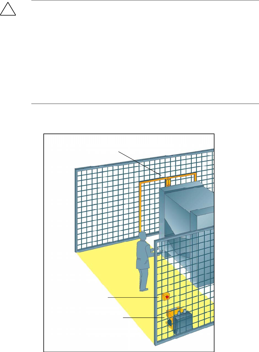
Design and Tasks in the Example
Emergency
stop
Laser scanner
Safety door
S7 Distributed Safety
A5E00320726-01 5
Production cell with access protection
The walk-in production area is monitored with a laser scanner. The service area is
secured by a safety door.
Entering the production area or opening the safety door results in a stop or shutdown of
the production cell similar to an emergency stop.
The system can only be started when the emergency stop is interlock deactivated, the
safety door is closed and the laser scanner detects no one in the protected area. User
acknowledgment is required on site to restart production after the emergency stop has
been activated or the safety door has been opened.
Procedure
Configuration
Using HW Config you configure an ET 200S fail-safe digital input module to connect an
emergency stop switch and the position switches for monitoring a safety door, an
ET 200S fail-safe digital output module to connect a motor, an ET 200S digital standard
electronic module for user acknowledgment and feedback loop, and a laser scanner.
The configuration is described in steps 1 to 8.
Programming
Once the configuration is successfully completed, you can program your safety program.
In our example, a fail-safe block is programmed with an emergency stop, a safety door
function, a feedback loop (as restart protection when there is an incorrect load) and user
acknowledgment for the reintegration. The block is then compiled to a safety program.
The programming is described in steps 9 to 19.
Acceptance test
Supporting measures for acceptance are described in the appendix.
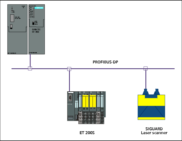
Installation on the PROFIBUS DP
S7 Distributed Safety
6 A5E00320726-01
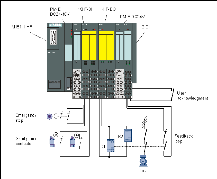
Wiring Overview for ET 200S

S7 Distributed Safety
A5E00320726-01 7
Step 1: Wiring
!
Warning
You may come into contact with live electrical wires connected to the power mains. Only
wire the S7-300 and ET 200S when they are disconnected from the mains.
A description of the installation and wiring of the CPU 315F-2 DP is provided in the
Getting Started Collection, Automation System S7-300, CPU 31x: Commissioning.
Configuration of the Hardware
Using HW Config, you configure:
• CPU 315F-2 DP
• Distributed I/O system ET 200S with:
- Interface module IM 151-1 HIGH FEATURE
- Fail-safe digital input module ET 200S for connecting an emergency stop switch and
the position switches for monitoring a safety door
- Fail-safe digital output module ET 200S for connecting a motor
- Digital standard electronic module ET 200S for user acknowledgment and feedback
loop
• Laser scanner for area monitoring (fail-safe DP standard slave).
Step 2: Configuration of the CPU 315F-2 DP using HW Config
Sequence Action Result
1
Create a new project in the SIMATIC Manager (for example,
"DS_Getting Started") and insert a SIMATIC 300 station.
The SIMATIC 300 station
appears in the SIMATIC
Manager.
2 Open HW Config by selecting the SIMATIC 300 station and
open the object (for example, with Ctrl+Alt+O).
HW Config opens.
3 In the "Hardware Catalog” window, select the ”Standard”
hardware profile from the "Profile” pull-down list .
4 Drag and drop a rail from the hardware catalog into the HW
Config window, the power supply module (for example, PS307
2A) and the desired F-CPU (for example, CPU 315F-2 DP).
Required path:
1.) Rail: \SIMATIC 300\RACK-300
2.) Power supply: \SIMATIC 300\PS-300
3.) CPU 315F: \SIMATIC 300\CPU-300\CPU 315F-2 DP
(6ES7 315-6FF01-0AB0).
A dialog box opens for setting
the PROFIBUS properties of the
new subnet.
5 Click on "New”.
The dialog box for setting the PROFIBUS properties of the new
subnet shows the newly created PROFIBUS subnet. Close the
dialog box with "OK."
The fail-safe module will be
later connected to the F-CPU
over the new PROFIBUS
subnet.
6 Double-click on the CPU 315F-2 DP in the configuration window
to set the properties of the F-CPU.
The dialog box "Properties -
CPU 315F-2 DP” opens.
S7 Distributed Safety
8 A5E00320726-01
Sequence Action Result
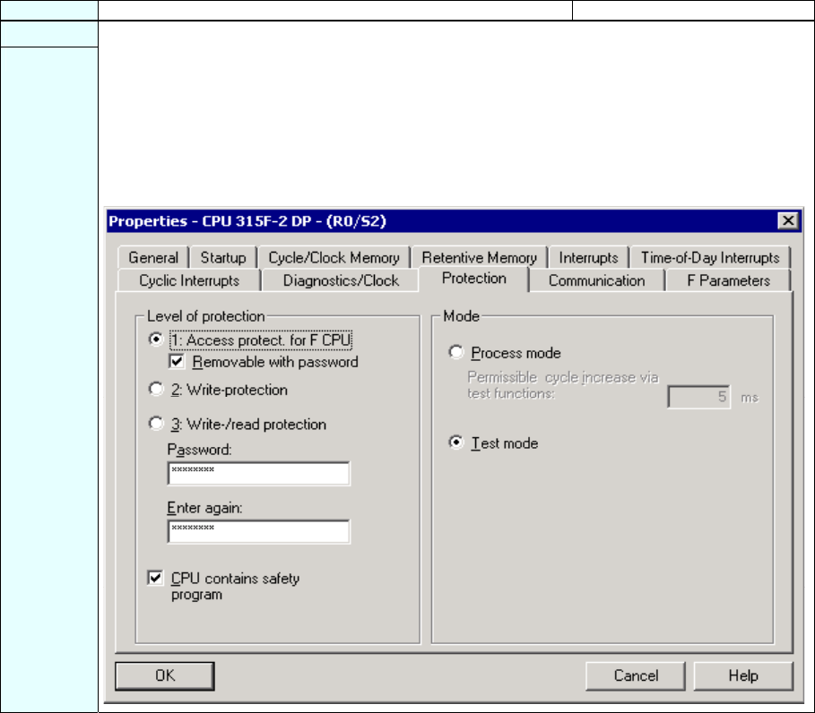
7
Select the "Protection" tab. Make the following settings in the "Level of protection" field:
1.) Press the option button "1: Access protection for F-CPU" and select the option
"Removable with password".
2.) Press the option button "3: Write/read protection" and enter a max. 8-digit password for
the F-CPU, for example, "pw_fcpu". Type your password again in the field "Enter again".
3.) Mark the check box "CPU contains safety program".
The dialog box should now appear as follows:
S7 Distributed Safety
A5E00320726-01 9
Sequence Action Result
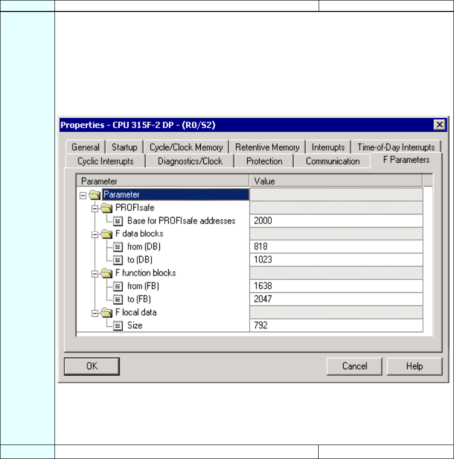
8 Change to the "F-Parameters" tab.
Here, you can change the following parameters or accept the default settings:
- Basis for the PROFIsafe addresses
- Number range for F-data blocks
- Number range for F-function blocks
- Amount of local data used by the F-system.
Leave the default values for our example.
The dialog box appears as follows:
Note: F-blocks are automatically added during the compilation of the safety program to ensure that
it is runtime capable. You must reserve a range of numbers for the automatically added F-blocks.
Use the default settings for our example. If the configured band of numbers is insufficient, S7
Distributed Safety signals this with an error message. You must then increase the size of the
number band accordingly.
9 Click "OK" to confirm. The message window closes.
S7 Distributed Safety
10 A5E00320726-01
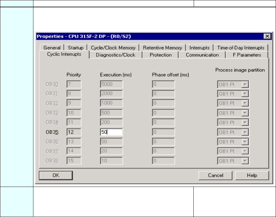
Sequence Action Result
10 Change to the "Cyclic Interrupts" tab and set the call time for the cyclic interrupt OB 35 to 50 ms.
(The safety program is called and run at fixed time intervals in the cyclic interrupt OB.)
The dialog box should now appear as follows:
11 Click "OK" to confirm. The dialog box "Properties -
CPU 315F-2 DP” closes.
The configuration of the F-CPU
is now completed.
S7 Distributed Safety
A5E00320726-01 11
Step 3: Configuration of an ET 200S Distributed I/O System Using HW Config
Sequence Action Result
1 In the "Hardware Catalog” window, select the ”Standard”
hardware profile from the "Profile” pull-down list.
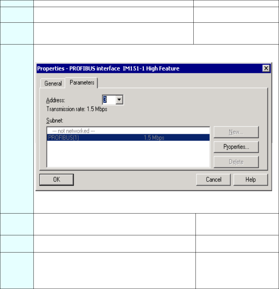
2 Drag and drop the IM 151-1 HIGH FEATURE interface module
from the hardware catalog (PROFIBUS DP\ET 200S) onto the
PROFIBUS subnet in the HW Config window.
A dialog box opens for setting
the PROFIBUS interface
properties.
3 Enter "3" as the address.
The dialog box should now appear as follows:
Close the dialog box with "OK".
You have now set up a DP station with the address 3 on PROFIBUS subnet "(1)".
4 Double-click on the IM 151-1 HIGH FEATURE in the
configuration window to set the properties of the interface
module.
The dialog box "Properties - DP
slave” opens.
5 Confirm your settings with "OK".
The dialog box "Properties - DP
slave” closes.
6 Drag and drop a PM-E 24-48 V DC power module from the
hardware catalog to slot 1 of the IM 151-1 HIGH FEATURE
interface module.
Required path:
1.) \PROFIBUS DP\ET200S\IM151-1 HIGH FEATURE\PM
The configuration of the IM151-
1 HIGH FEATURE is now
completed.
S7 Distributed Safety
12 A5E00320726-01
Step 4: Configuration of an F-DI Module for Connecting an Emergency Stop Switch
and the Position Switches for Monitoring a Safety Door
Sequence Action Result
1 Drag and drop a 4/8 F-DI DC24V fail-safe digital input module
from the hardware catalog to slot 2 of the ET 200S.
Required path:
1.) \PROFIBUS DP\ET200S\IM151-1 HIGH FEATURE\DI
(6ES7 138-4FA01-0AB0)
2 Double-click on the 4/8 F-DI DC24V in the configuration window
to set the properties of the input module.
The dialog box "Properties - 4/8
F-DI DC24V” opens.
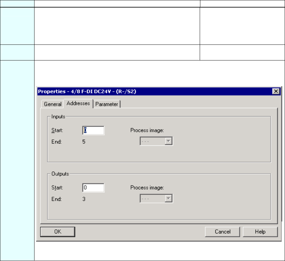
3 Select the "Addresses" tab.
Leave the default address "0" for our example.
The dialog box appears as follows:
Note: If you wish to change the values, you need to ensure that the start addresses of the input
and output data range are assigned identical values.
S7 Distributed Safety
A5E00320726-01 13
Sequence Action Result
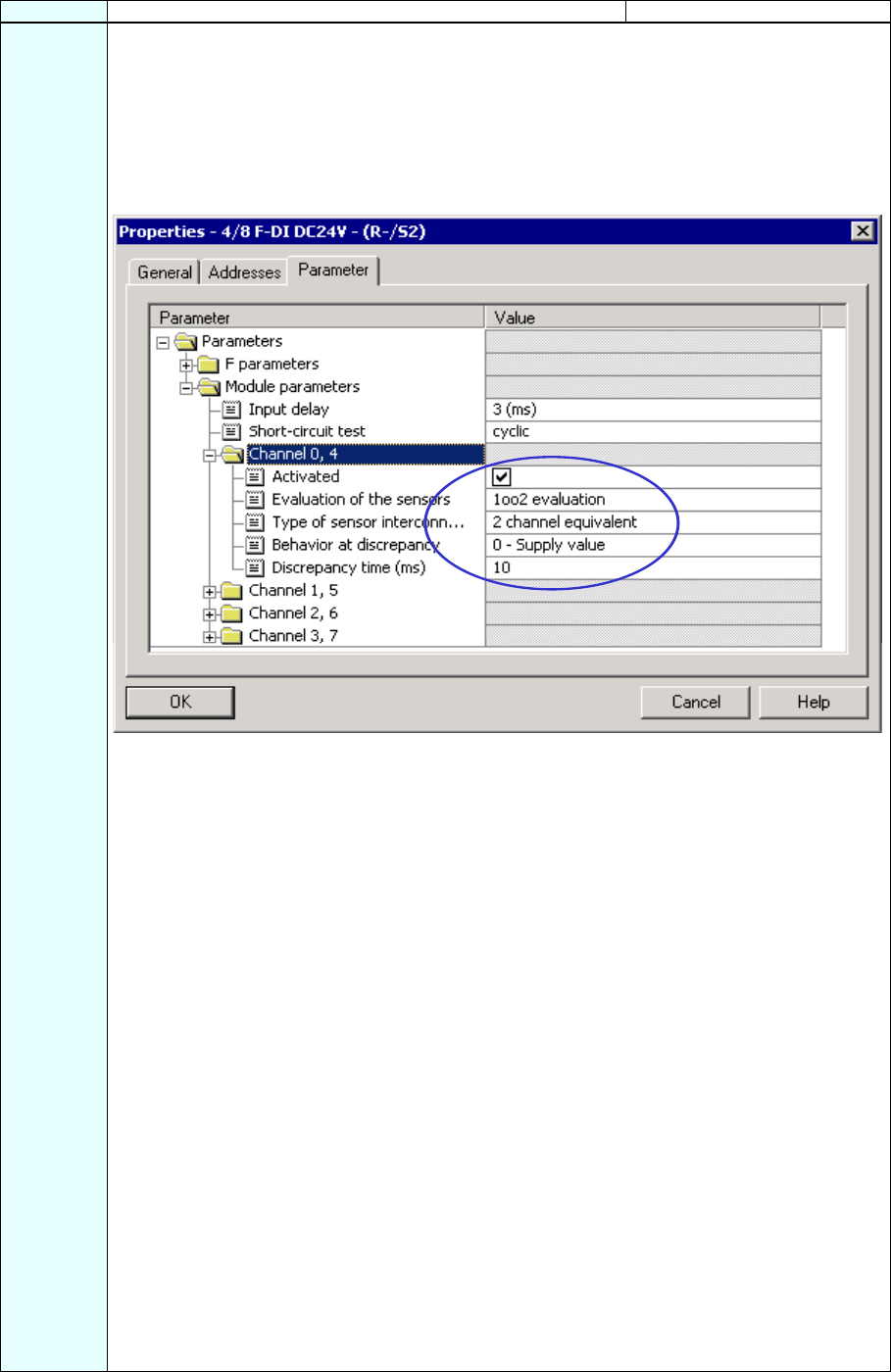
4 Change to the "Parameter" tab. Here, you can change the following parameters or accept the
default settings:
- F-parameters (PROFIsafe parameters)
- Module parameters (global module parameters)
- Channel-specific parameters.
In our example, channels 0 and 4 should be connected to a two-channel emergency stop switch
(emergency stop). Make the following settings (as highlighted in the figure):
Note about "F-Parameters": The PROFIsafe addresses must be unique throughout the network
and for all stations. The addresses are assigned automatically to prevent incorrect assignment of
parameters. The PROFIsafe destination address must be set per DIL switch on the F-module. The
PROFIsafe source address is assigned by the F-CPU ("Base for PROFIsafe addresses" F-
parameter).
A valid current safety message frame must be received by the F-CPU within the fail-safe
monitoring time. Otherwise, the fail-safe module goes to the safe state.
The fail-safe monitoring time must be set high enough for the message frame delay to be tolerated
on the one hand, and low enough for the process to react as fast as possible and without
impairment when an error occurs on the other. The calculation table 'S7cotia.xls‘ can aid you in
determining the optimal time. This file is available on the Internet:
http://www4.ad.siemens.de/ww/view/de/ under the contribution ID 19138505.
Leave the default settings for the F-parameters unchanged for our example.
Note about "Module parameters": For a cyclic short-circuit test, you have to use the internal
sensor supplies for all sensors connected to the F-module and deactivate any unused channels.
Otherwise, errors will be detected on these channels.
Leave the default settings for the module parameters unchanged for our example.
Note about "Channel x, y" parameters: The "evaluation of the sensors" and "type of sensor
interconnection" should be configured according to the sensor wiring. The sensor wiring and the
safety quality of the sensor are decisive for the safety class that can be achieved.
Deactivate the channels that are not used.
Note about "1oo2 evaluation", "Behavior at discrepancy" and "Discrepancy time" (see
highlight in figure): The "Discrepancy time" configure here starts when different levels (or same
levels with nonequivalence testing) are detected for two associated input signals ("1oo2
evaluation” of the sensor). When discrepancy time expires within the module and depending on
the configuration of the discrepancy response, the "last, valid value" or "0" from the affected input
channel is made available to the F-CPU.
S7 Distributed Safety
14 A5E00320726-01
Sequence Action Result
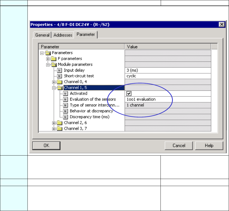
5 In our example, channels 1 and 5 should be connected to the position switches for monitoring a
two-channel safety door. Make the following settings (as highlighted in the figure):
6 Deactivate the unused channels 2, 6 and 3, 7 by unmarking the
"Activated" check boxes and confirm your changes with "OK".
A message window opens
informing you that the safety
program must be compiled
again due to your change.
7 Click "Close" to confirm. The message window closes.
8 Confirm your settings with "OK". The dialog box "Properties - 4/8
F-DI DC24V” closes.
The configuration of the F-input
module is now completed.
S7 Distributed Safety
A5E00320726-01 15
Step 5: Configuration of an F-DO Module for Connecting a Motor
Sequence Action Result
1 Drag and drop a 4 F-DO DC24V / 2A fail-safe digital input
module from the hardware catalog to slot 3 of the ET 200S.
Required path:
1.) \PROFIBUS DP\ET200S\IM151-1 HIGH FEATURE\DO
(6ES7 138-4FB01-0AB0)
2 Double-click on the 4 F-DO DC24V / 2A in the configuration
window to set the properties of the output module.
The dialog box "Properties -
4 F-DO DC24V / 2A” opens.
3 Select the "Addresses” tab (See F-DI Configuration above).
Leave the default address "6" for our example.
Note: If you wish to change the values, you need to ensure that
the start addresses of the input and output data range are
assigned identical values.
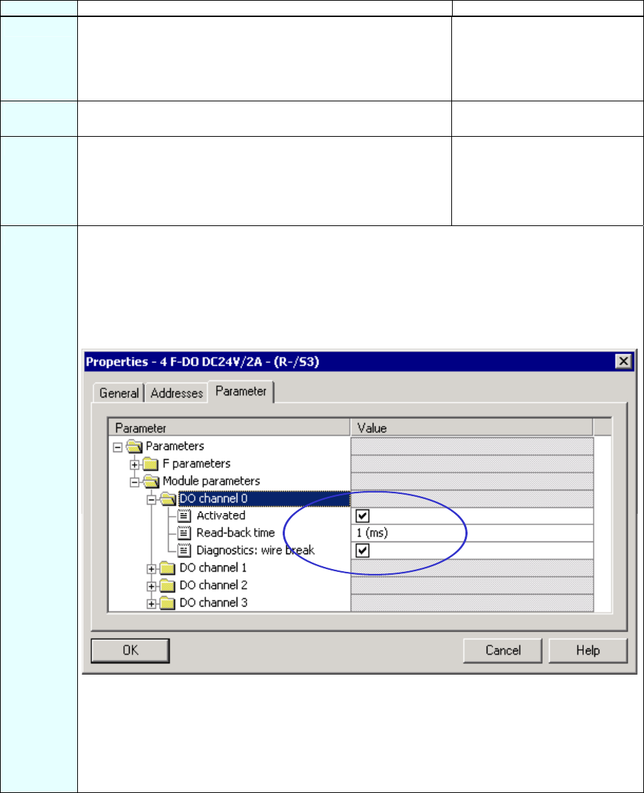
4 Change to the "Parameter" tab. Here, you can change the following parameters or accept the
default settings:
- F-parameters (PROFIsafe parameters)
- Channel-specific parameters.
In our example, a motor should be indirectly switched on channel 0 through two contactors. Make
the following settings (as highlighted in the figure):
Note about "F-Parameters": See Step 4.
Leave the default settings for the F-parameters unchanged for our example.
Note about "DO channel x" parameters: Each output channel has its own configurable readback
time. This time specifies the maximum duration of the shutdown test for the corresponding channel
and it therefore also specifies the readback time for the shutdown cycle of the channel.
You use a wire break test for monitoring the connection of the output to the load.

S7 Distributed Safety
16 A5E00320726-01
Sequence Action Result
5 Deactivate the unused DO channels 1, 2 and 3 and confirm your
changes with "OK".
A message window opens
informing you that the safety
program must be compiled
again due to your change.
6 Click "Close" to confirm. The message window closes.
7 Confirm your settings with "OK". The dialog box "Properties -
4 F-DO DC24V / 2A” closes.
The configuration of the F-
output module is now
completed.
Step 6: Configuration of a Standard DI Module for User Acknowledgment and the
Feedback Loop
Sequence Action Result
1 Drag and drop a PM-E 24 V DC power module from the
hardware catalog to slot 4 of the standard DI module.
Note: The power module has to be configured because a
combination of F-DI / F-DO modules and standard DI / DO / FM
modules is not allowed within a voltage group for
AK6/SIL3/Cat.4 applications. A new voltage group must always
begin with a power module.
2 Drag and drop a 2DI 24 V DC ST digital electronic module from
the hardware catalog to slot 5 of the ET 200S for non-safe
signals (user acknowledgment and feedback loop) and set the
start address to "11" for our example (same procedure as for the
standard program).
Required path:
1.) \PROFIBUS DP\ET200S\IM151-1 HIGH FEATURE\DI
The configuration of the
electronic module 2DI 24 V DC
ST is now completed.
Step 7: Configuration of a SIGUARD LS4-4/P1 Laser Scanner (fail-safe DP standard
slave)
Sequence Action Result
1 In the "Hardware Catalog” window, select the ”Standard”
hardware profile from the "Profile” pull-down list .
2 Drag and drop a laser scanner (for example, "SIGUARD Laser
Scanner LS4-4/P1") from the hardware catalog (PROFIBUS
DP\Additional Field Devices\General) into the window of HW
Config.
Note: The GSD file for the laser scanner must be already
installed on the PG/PC.
A dialog box opens for setting
the PROFIBUS interface
properties.
3 Enter "4" as the address and confirm with "OK".
You have now configured a DP station with address 4 on the
PROFIBUS subnet "(1)" (See Step 3, IM 151-1 Configuration).
The dialog box "Properties -
PROFIBUS Interface” closes.
4 Select the laser scanner in the configuration window and
double-click in the line of the laser scanner below in the detail
view to set its properties.
The dialog box "Properties - DP
slave” opens.
S7 Distributed Safety
A5E00320726-01 17
Sequence Action Result
5 Select the "Address/ID" tab.
Leave the default address "12" for our example.
Note: If you wish to change the values, you need to ensure that
the start addresses of the input and output data range are
assigned identical values.
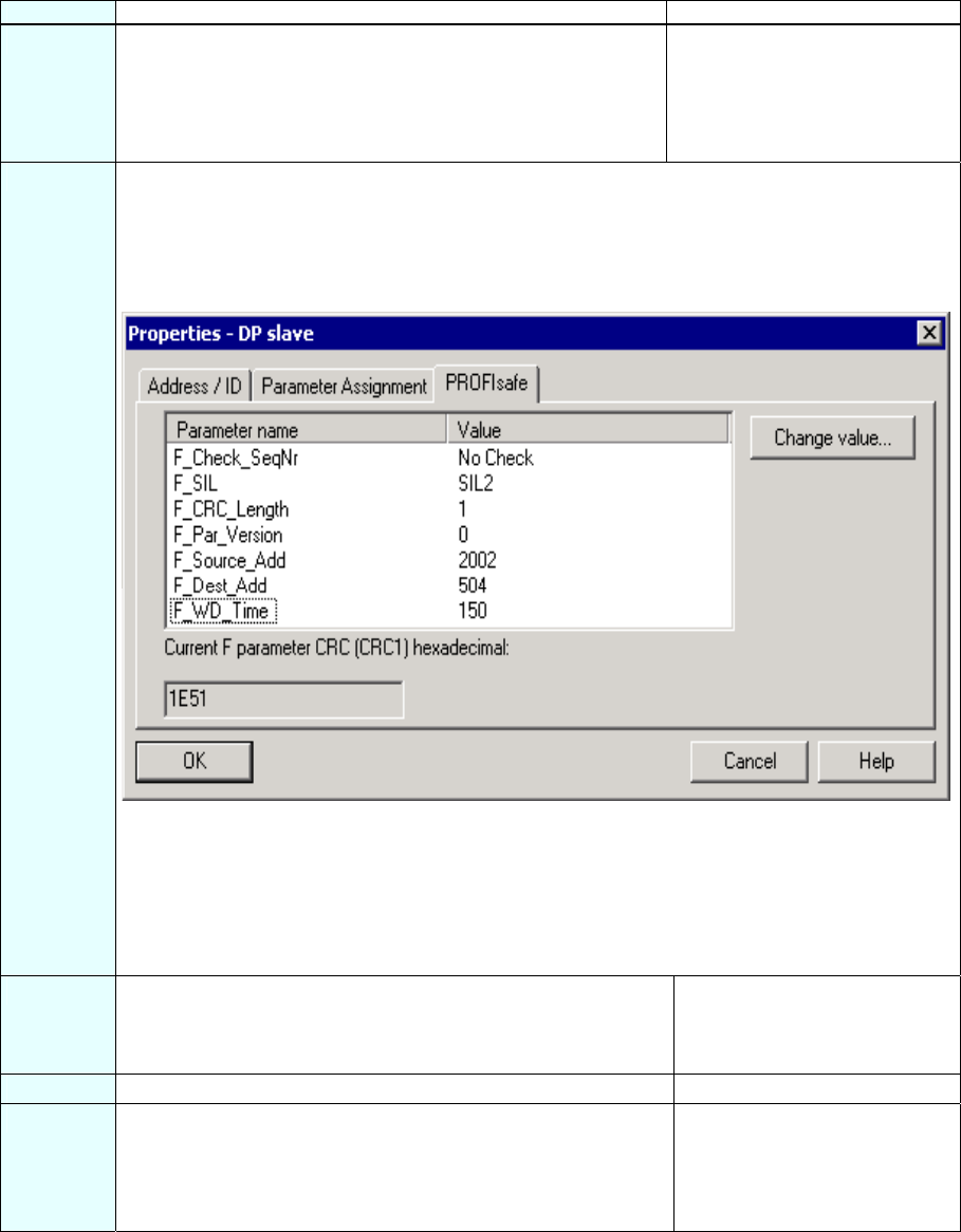
6 Change to the "PROFIsafe" tab and make the following settings:
1.) Select the "F_Dest_Add" parameter, click on the "Change value" button and enter (500 +
DP address =) "504". Close the dialog box with "OK".
2.) Select the "F_WD_Time" parameter, click on the "Change value" button and enter a value
in ms for the F-monitoring time in the fail-safe DP standard slaves, for example, "150".
The dialog box should now appear as follows:
Note about F_WD_Time: A valid current safety message frame must be received by the F-CPU
within the fail-safe monitoring time.
The fail-safe monitoring time must be set high enough for the message frame delay to be tolerated
on the one hand, and low enough for the process to react as fast as possible and without
impairment when an error occurs on the other.
The "F_WD_Time" parameter can be set in 1 ms increments. The range of the "F_WD_Time"
parameter is specified by the device database file (*.GSD file).
7 Confirm your change with "OK". A message window opens
informing you that the safety
program must be compiled
again due to your change.
8 Click "Close" to confirm. The message window closes.
9 Confirm your settings with "OK". The dialog box "Properties -
DP slave” closes.
The configuration of the
SIGUARD LS4-4/P1 laser
scanner is now completed.

S7 Distributed Safety
18 A5E00320726-01
Step 8: Save, Compile and Download the Hardware Configuration
Sequence Action Result
1 Close the hardware configuration by calling the menu command
Station > Save and Compile.
Your project is compiled.
2 Transfer the configuration when the F-CPU is in STOP with the
menu command PLC > Download to Module.
The "Select Station Address”
dialog box opens.
3 Select the F-CPU and confirm with "OK". The data are transferred from the
PG to the F-CPU.
You have now finished
configuration of the hardware for
the tasks involved in the
example.
Summary: Configuration of the Hardware
Up until now, you have used HW Config to configure:
• CPU 315F-2 DP
• Distributed I/O system ET 200S with:
- Interface module IM 151-1 HIGH FEATURE
- Fail-safe digital input module ET 200S for connecting an emergency stop switch and
the position switches for monitoring a safety door
- Start addresses of the output and input data ranges: both 0
- Channels 0 and 4 for emergency stop
- Channels 1 and 5 for safety door position switches
- Fail-safe digital output module ET 200S for connecting a motor
- Start address of the output and input data ranges: both 6
- Channel 0 for indirect switching of a motor through two contactors
- Digital standard electronic module ET 200S for user acknowledgment and feedback
loop
- Start address: 11
• Laser scanner for area monitoring (fail-safe DP standard slave)
- Start address of the output and input data ranges: both 12.
Now you are ready to program the safety program.
S7 Distributed Safety
A5E00320726-01 19
Programming the Safety Program
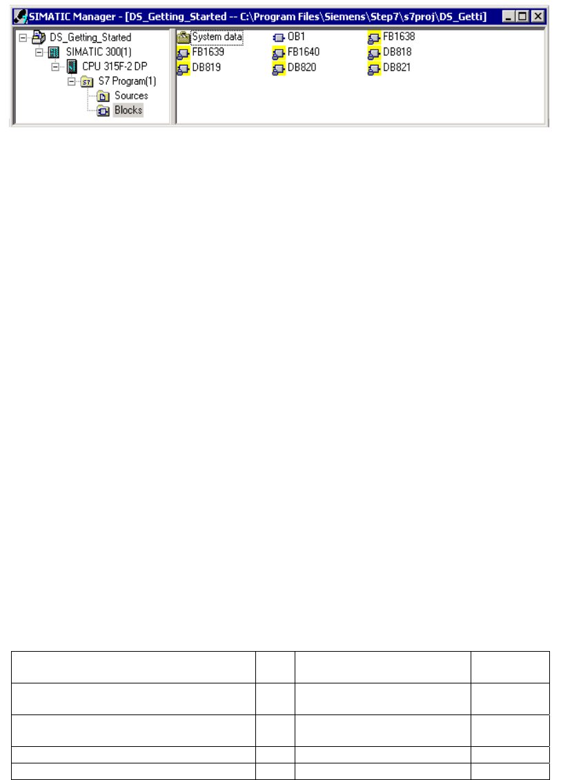
F-I/O Data Blocks
For each compilation in HW Config, an "F-I/O DB" is automatically created for each F-I/O
and a symbolic name is entered for it in the symbol table. You can view the F-I/O DBs
generated for the example I/O in the block container. These are the F-data blocks
DB 819, DB 820 and DB 821.
The symbolic name of the F-I/O DB is made up of the fixed prefix "F," the start address of
the F-I/O, and the names (maximum 17 characters) entered in the F-I/O object properties
in HW Config.
Symbolic name in our example:
- "F00000_4_8_F_DI_DC24V": fail-safe digital input module 4/8 F-DI DC24V
(= DB 819)
- "F00006_4_F_DO_DC24V_2A": fail-safe digital output module 4 F-DO DC24V / 2A
(= DB 820)
- "F00012_196": SIGUARD LS4-4/P1 laser scanner (= DB 821).
You can access the variables of the F-I/O DB with "fully qualified DB access" (that is, by
specifying the symbolic name of the F-I/O DB and by specifying the name of the variable).
F-Shared DB
The "DB 818" in the block container of our example is "F-Shared-DB". The F-shared data
block is a fail-safe block that is automatically inserted and contains all of the shared data
of the safety program and additional information needed by the F-system.
Procedure
In our example, a fail-safe block should be programmed with a safety door function, an
emergency stop function (safety circuit for shutdown when an emergency stop occurs,
when the safety door is open or when someone enters the protected area monitored by
the laser scanner), a feedback loop (as restart protection when there is an incorrect load)
and user acknowledgment for the reintegration. The block should then compiled to a
safety program.
Inputs and outputs in the safety program
Following the configuration of the hard as described in steps 1 to 8, the following fail-safe
I/O DBs are available for programming the example safety program:
Configured Hardware Start
add.
Symbolic name F-I/O DB
Fail-safe digital input module 4/8 F-DI
DC24V (6ES7 138-4FA01-0AB0)
0 F00000_4_8_F_DI_DC24V DB 819
Fail-safe digital output module 4 F-DO
DC24V / 2A (6ES7 138-4FB01-0AB0)
6 F00006_4_F_DO_DC24V_2A DB 820
Digital electronic module 2DI 24 V DC ST 11 - -
SIGUARD LS4-4/P1 laser scanner 12 F00012_196 DB 821

S7 Distributed Safety
20 A5E00320726-01
Specify symbolic names for the fail-safe input and outputs (as you do in the standard
program). In our example, these are:
Inputs and outputs in the safety program Symbolic name
I0.0 for emergency stop Emergency stop
I0.1 for safety door position switch Safety door contact 1
I0.5 for safety door position switch Safety door contact 2
Q6.0 for motor starter Load
I11.0 for acknowledgment Ack. button
I11.1 for feedback loop Feedback loop
Q12.0 for protected area control LS4_Protected_field_bit_0
Q12.1 for protected area control LS4_Protected_field_bit_1
Q12.2 for protected area control LS4_Protected_field_bit_2
I12.7 for safe shutdown LS4_OSSD
Note: Adhere to the rules for creating the program structure as described in the chapter
"Defining the Program Structure" of the S7 Distributed Safety, Configuring and
Programming manual.
S7 Distributed Safety
A5E00320726-01 21
Step 9: Creating an F-FB with the F-FBD Programming Language
Sequence Action Result
1 Insert a F-FB. Open the block container of the
SIMATIC Manager and select the menu command Insert > S7
Block > Function Block. You can also use the "Insert New
Object" shortcut menu.
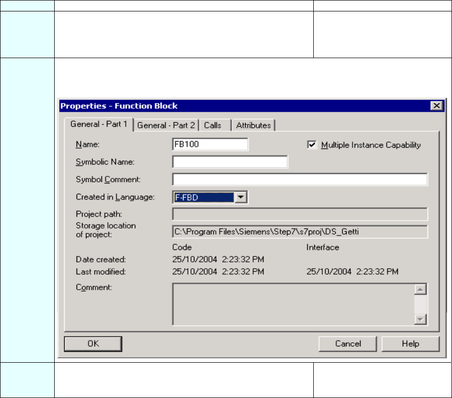
The dialog box "Properties -
Function Block” opens.
2 In the "General - Part 1" tab, enter a name for the F-FB (for example, "FB100"). Select "F-FBD" as
the programming language.
The dialog box should now appear as follows:
3 Close the dialog box with "OK". The F-FB is generated in the
block container and highlighted
with a yellow background.
S7 Distributed Safety
22 A5E00320726-01
Step 10: Edit and Save the F-FB in the FBD Editor
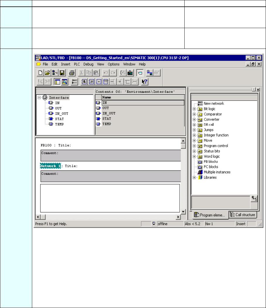
Sequence Action Result
1 Double-click on the F-FB in SIMATIC Manager. The dialog box for assigning a
password for the safety program
opens.
2 Enter (2x) a max. 8-digit password for the safety program, for
example, "pw_fprog".
The FBD/LAD Editor opens, see
figure below.
3
Note: The F-FBD and F-LAD programming languages correspond in principle to the standard
FBD/LAD languages. The standard FBD/LAD editor in STEP 7 is used for programming.
The primary differences between the F-FBD and F-LAD programming languages and their
standard counterparts are limitations in the operation set and the data types and the address areas
that can be used (see S7 Distributed Safety, Configuring and Programming manual).
The following are displayed in the F-Program Elements Catalog:
• Supported operations
• F-FBs and F-FCs from the block container of your S7 program
• F-blocks from F-libraries, e.g., F-application blocks of Distributed Safety F-library (V1), for
safety door monitoring etc.
• Multiple instances.
S7 Distributed Safety
A5E00320726-01 23
Sequence Action Result
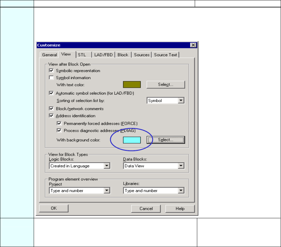
4 Assign special colors for non-safe data in the F-block.
To do this, select the menu command Options > Customize, open the "View" tab, press the
"Select" button and select a "Background Color"; In our example, this is 'light blue' (as highlighted
in the figure below).
5 Confirm your change with "OK". The "Customize” dialog box
closes. Now non-safe data will
be highlighted in light blue in the
safety program.
S7 Distributed Safety
24 A5E00320726-01
Step 11: Programming the Safety Door Function
Sequence Action Result
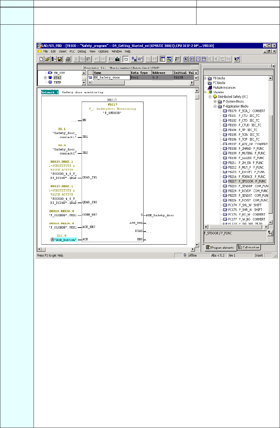
1 Insert the following statical variable for the F-FB:
- "EN_Safety_door" (enable safety door).
2 Insert an FB 217 "F_SFDOOR" (safety door monitoring) into the fail-safe application block from the
F-application blocks container and supply the inputs and outputs as shown in the figure below.
The non-safe "Acknowledgment button" signal in the standard program has a light blue
background.
Connect the FB 217
Inputs/outputs Parameters Data type Description Default
I0.1 IN1 BOOL Input 1 0
I0.5 IN2 BOOL Input 2 0
DB819.DBX2.1 QBAD_ IN1 BOOL QBAD signal from the F-I/O 0
DB of the input IN1*
DB819.DBX2.1 QBAD_ IN2 BOOL QBAD signal from the F-I/O 0
DB of the input IN2*
DB818.DBX36.4 OPEN_NEC BOOL Fully qualified access to 1
Variable RLO1 from F-shared DB**
DB818.DBX36.4 ACK_NEC BOOL Fully qualified access to 1
Variable RLO1 from F-shared DB**
I11.0 ACK BOOL User acknowledgment (per button) 0
#EN_
Safety_door Q BOOL Output (enable safety door) 0
ACK_REQ BOOL Acknowledgment request 0
DIAG BYTE Service information B#16#0
* = Both the inputs QBAD_IN1 and QBAD_IN2 must be interconnected. In our example, they are
interconnected to the QBAD signal from the F-I/O DB of the 4/8 F-DI to which the safety door
position switches are connected. You can see the block number of the F-I/O DB from the symbolic
name in the symbol table or in the SIMATIC Manager.
** = OPEN_NEC: 1 = Opening required at startup / ACK_NEC: 1 = Acknowledgment necessary.
S7 Distributed Safety
A5E00320726-01 25
Sequence Action Result
Note: If you require Boolean constants "0" and "1" in your safety program to assign parameters
during block calls, you can access the "RLO0" and "RLO1" variables in the F-shared DB using fully
qualified DB access. In our example, the F-shared DB in the block container has the number
"DB 818" ("F_GLOBDB".VKE1).
Note: In fail-safe programming, you cannot interconnect, supply with "0" or evaluate the enable
input EN or the enable output ENO.
3 Save the F-FB and confirm the message with "Yes". The F-block is subjected to a
consistency test and saved
once it completes the test
successfully.
The programming of the safety
door function is now completed.
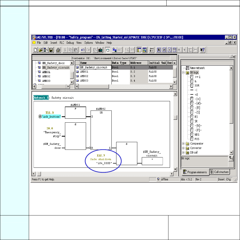
Step 12: Programming the Emergency Stop Function
Sequence Action Result
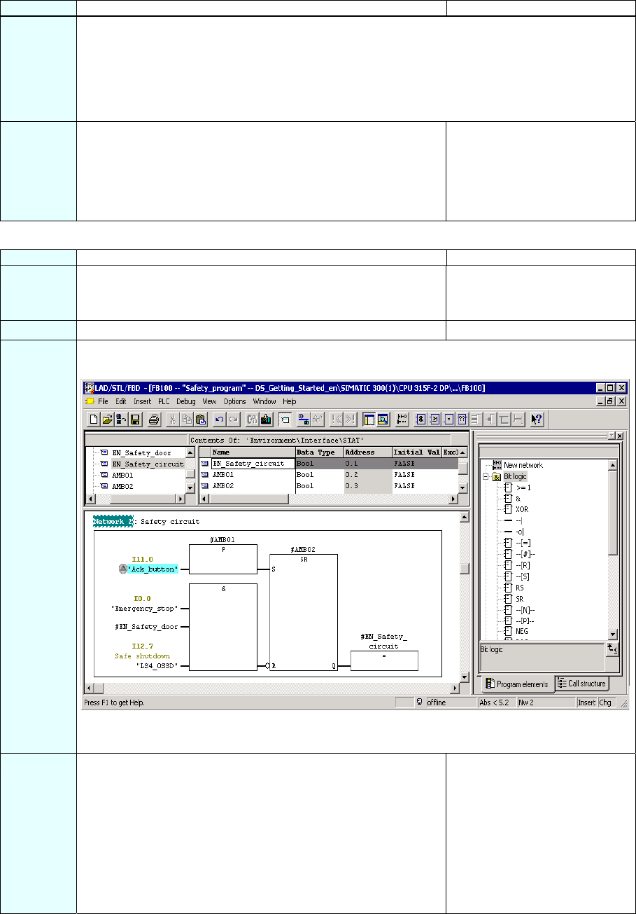
1 Insert the following statical variables for the F-FB:
- "EN_Safety_circuit" (enable safety circuit) and
- the auxiliary memory bits "AMB01" and "AMB02".
2 Insert a new network.
3 Insert the required operations from the program element catalog ("Bit Logic") and supply the inputs
and outputs as illustrated in the figure.
The non-safe "Acknowledgment button" signal in the standard program has a light blue
background.
4 Save the F-FB. The F-block is subjected to a
consistency test and saved
once it completes the test
successfully.
The programming of the
emergency stop function
(shutdown at emergency stop,
open safety door, violation of
the laser scanner's protected
area ) is now completed.
S7 Distributed Safety
26 A5E00320726-01
Step 13: Programming the Feedback Loop Monitoring
Sequence Action Result
1 Open the F-Library Distributed Safety (V1) and copy the F-
application block F_TOF (FB 186) from the F-Application
Blocks\Blocks block container into the block container of your S7
program.
The block container of your S7
program contains the F-
application block F_TOF (FB
186).
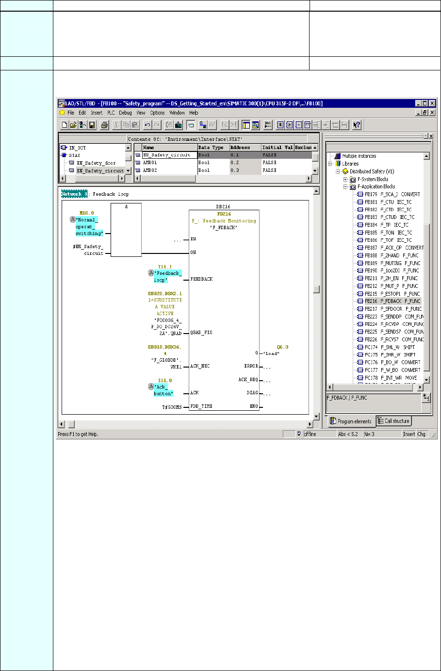
2 Insert a new network.
3 Insert an FB 216 "F_FDBBACK" (feedback loop monitoring) into the fail-safe application block from
the F-application blocks container and supply the inputs and outputs as shown in the figure below.
The non-safe signals in the standard program have a light blue background.
Connect the FB 216
Inputs/outputs Parameters Data type Description Default
M10.0 ON BOOL 1=activate output 0
I11.1 FEEDBACK BOOL Readback input 0
DB820.DBX2.1 QBAD_FIO BOOL QBAD signal from F-I/O 0
DB of output Q*
DB818.DBX36.4 ACK_NEC BOOL Fully qualified access to 1
variable RLO1 from F-shared DB**
I11.0 ACK BOOL User acknowledgment (per button) 0
T#500MS FDB_TIME TIME Readback time T#0 ms
Q6.0 Q BOOL Output 0
ERROR BOOL Readback error 0
ACK_REQ BOOL Acknowledgment request 0
DIAG BYTE Service information B#16#0
* = In our example, this is the QBAD signal from the F-I/O DB of the F-DO to which the load is
connected (the contactors). You can see the block number of the F-I/O DB from the symbolic
name in the symbol table or in the SIMATIC Manager.
** = ACK_NEC: 1 = acknowledgment required.
S7 Distributed Safety
A5E00320726-01 27
Sequence Action Result
Note: If you require Boolean constants "0" and "1" in your safety program to assign parameters
during block calls, you can access the "RLO0" and "RLO1" variables in the F-shared DB using fully
qualified DB access. In our example, the F-shared DB in the block container has the number
"DB 818" ("F_GLOBDB".VKE1).
Note: In fail-safe programming, you cannot interconnect, supply with "0" or evaluate the enable
input EN or the enable output ENO.
4 Save the F-FB. The F-block is subjected to a
consistency test and saved
once it completes the test
successfully. The programming
of the feedback loop monitoring
is now completed.
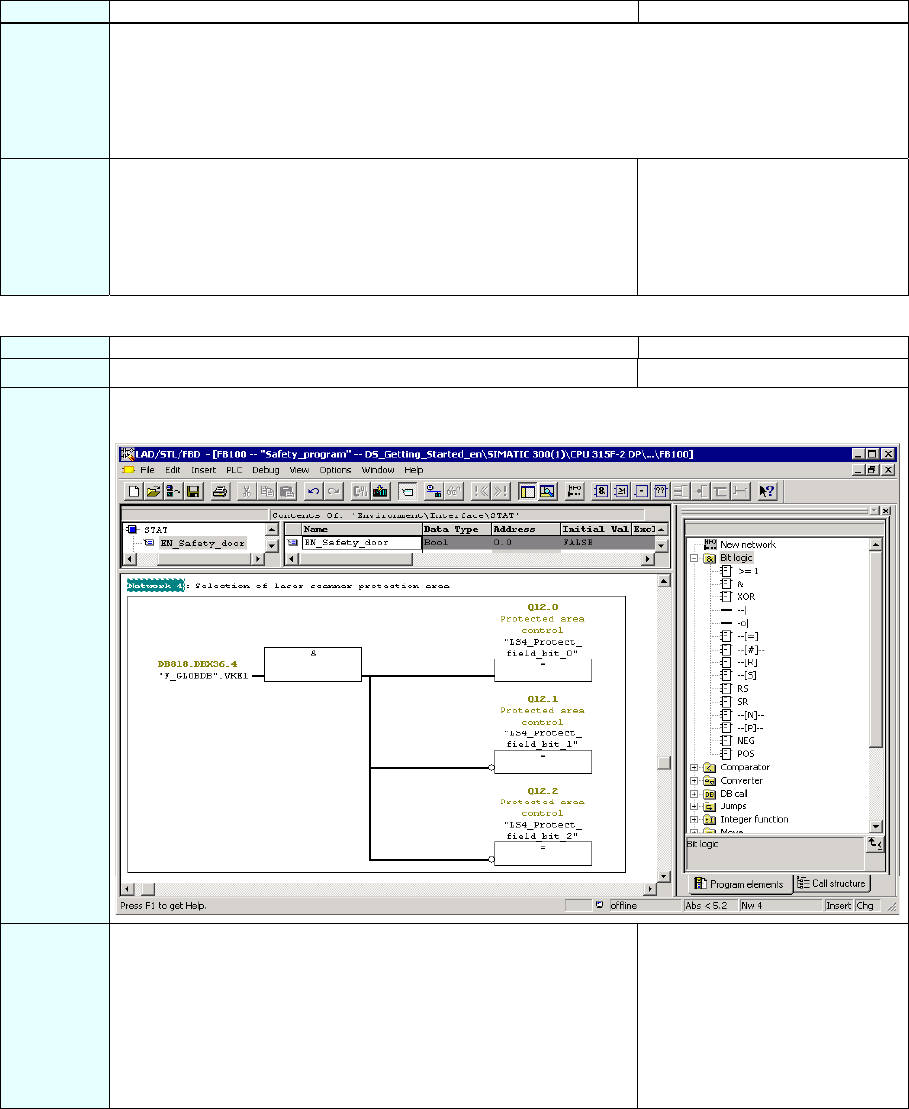
Step 14: Programming the Selection of the Laser Scanner Protection Area
Sequence Action Result
1 Insert a new network.
2 Insert the required operations from the program element catalog ("Bit logic") and supply the inputs
and outputs as illustrated in the figure.
3 Save the F-FB. The F-block is subjected to a
consistency test and saved
once it completes the test
successfully.
The programming for the
selection of the laser scanner
protection area is now
completed.
S7 Distributed Safety
28 A5E00320726-01
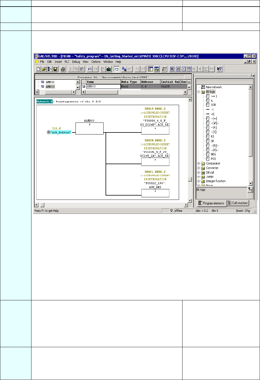
Step 15: Programming the User Acknowledgment for Reintegration of the F-I/O
Sequence Action Result
1 Insert the following statical variable for the F-FB:
- auxiliary memory bit "AMB03".
2 Insert a new network.
3 You need to provide a user acknowledgment for each F-I/O in your safety program for the
reintegration through the ACK_REI variable of the respective F-I/O DB as shown in the figure
below.
The non-safe "Acknowledgment button" signal in the standard program has a light blue
background.
Symbolic name in our example:
- "F00000_4_8_F_DI_DC24V": fail-safe digital input module 4/8 F-DI DC24V (= DB 819)
- "F00006_4_F_DO_DC24V_2A": fail-safe digital output module 4 F-DO 24 V DC / 2A (= DB 820)
- "F00012_196": SIGUARD LS4-4/P1 laser scanner (= DB 821).
Note: A user acknowledgment with a positive edge at the ACK_REI variable of the F-I/O DB is
required for the reintegration of the F-I/O (i.e. for switching from fail-safe values (0) to process
data) after an error is corrected:
- After every communication error
- After F-I/O errors or channel errors when the parameter ACK_NEC = 1.
4 Save the F-FB and ensure that no errors have occurred by
checking the "Error" output window of the FBD/LAD Editor.
The F-block is subjected to a
consistency test and saved
once it completes the test
successfully.
The programming of the user
acknowledgment is now
completed.
5 Close the F-FB and the FBD/LAD Editor. You have programmed the
functionality for the task
involved in the example and can
now specify the F-runtime
group.
S7 Distributed Safety
A5E00320726-01 29
Step 16: Specify the F-Runtime Group
Sequence Action Result
1 In the SIMATIC Manager, select the Options > Edit Safety Program menu command. The
"Safety Program" dialog box appears.
2 Click on the "Runtime Groups..." button.
Note: F-blocks must not be called directly in an OB; rather, they
must be inserted into one (or two) F-runtime groups.
The dialog box "Edit F-Runtime
Groups” opens.
S7 Distributed Safety
30 A5E00320726-01
Sequence Action Result
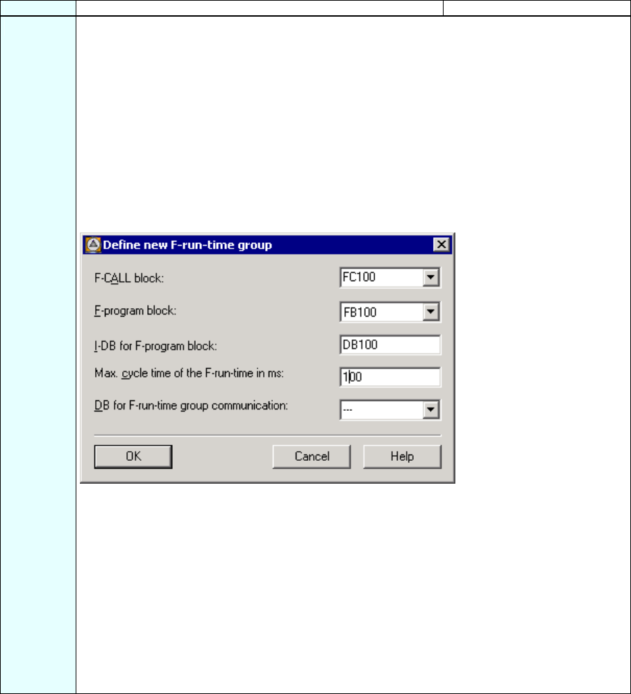
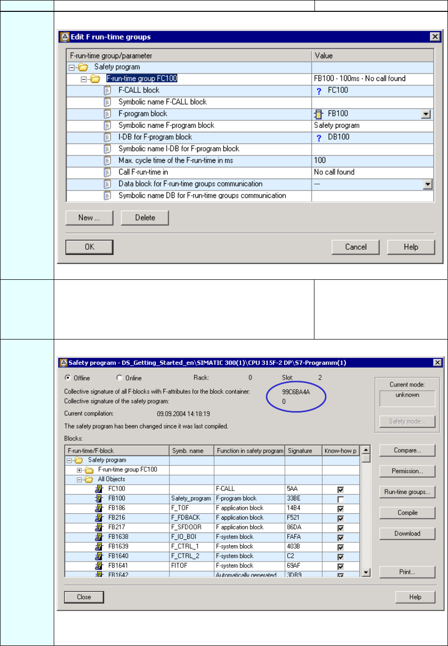
3 Click on the "New..." button to open the "Define New F-Runtime Group" dialog box.
Make the following settings for the F-runtime group:
• Enter "FC100" as the F-CALL call block for the new F-runtime group. This FC is automatically
created as soon as you exit the "Edit F-Runtime Groups" dialog with "OK."
• Define the F-program block of the F-runtime group by selecting the previously programmed F-
FB from the drop-down list that you want to define as the F-program block for the F-runtime
group, "FB100" in our example.
• Since the F-program block is a function block in our example, assign an instance DB to it (for
example, "DB 100"). This I-DB is automatically created as soon as you exit the "Edit F-
Runtime Groups" dialog with "OK."
• Set the maximum cycle time of the F-runtime group to "100 ms".
The dialog box should now appear as follows.
Note: The F-CALL is the F-block for calling the F-runtime group from the standard user program.
The F-CALL includes the call for the F-program block and the calls for the automatically added F-
blocks of the F-runtime group.
You create the F-CALL, but you cannot edit it.
Note: The F-program block is an F-FC or F-FB (with instance DB) that becomes the F-program
block when assigned to the F-CALL. You can do the following in the F-program block:
• Program the safety program with F-FBD or F-LAD
• Call other created F-FBs/F-FCs for structuring the safety program
• Insert F-blocks from the F-Application Blocks block container from the Distributed Safety F-
library (V1)
• Insert F-blocks from "custom F-libraries"
The user defines the call sequence of the F-blocks within the F-program block.
Close the dialog box with "OK".
S7 Distributed Safety
A5E00320726-01 31
Sequence Action Result
4 You return to the "Edit F-Runtime Groups” dialog which now appears as follows:
Close the dialog box with "OK".
5 A message window opens asking if you wish to create any other
blocks that are still needed. In our example, these are the F-
CALL ("FC100") and the I-DB for the F-program block
("DB 100").
Confirm by clicking on "Yes".
The remaining blocks are
created and saved. The
message window then closes.
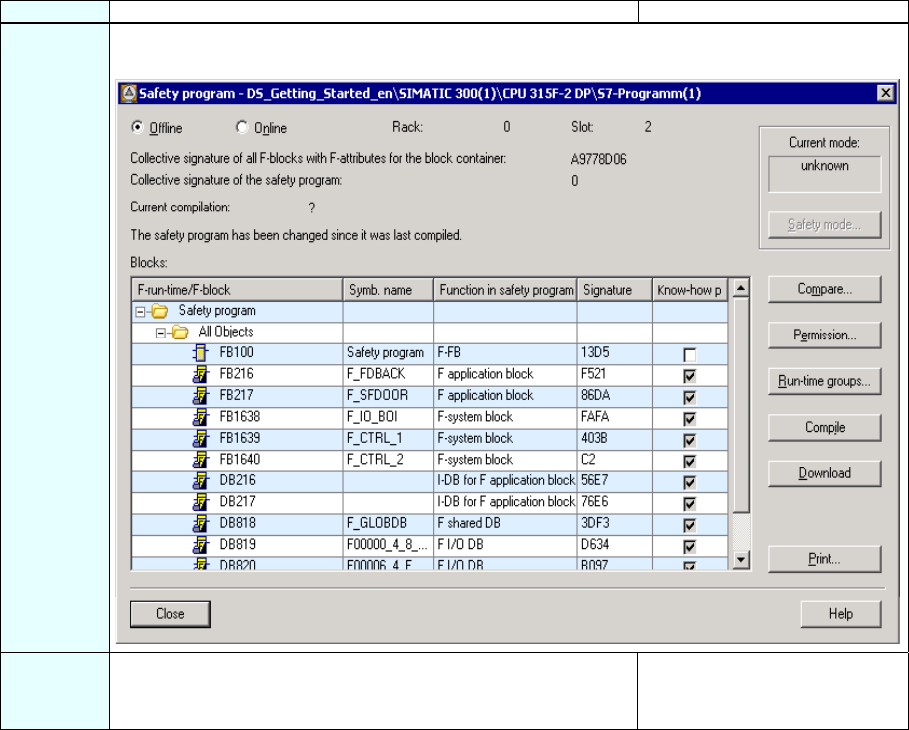
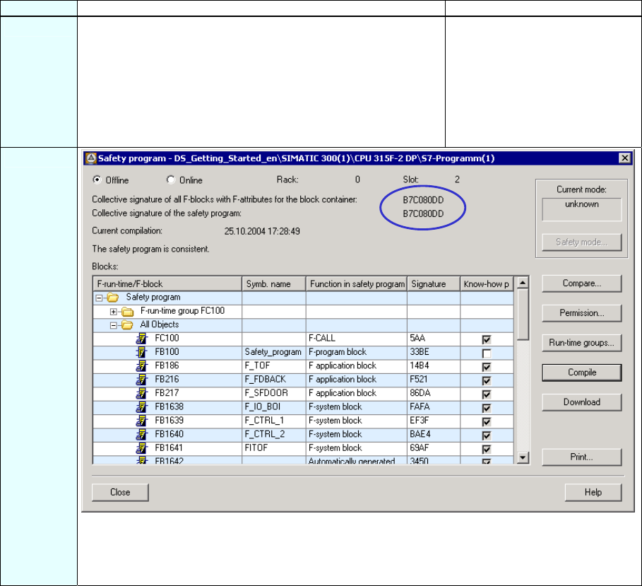
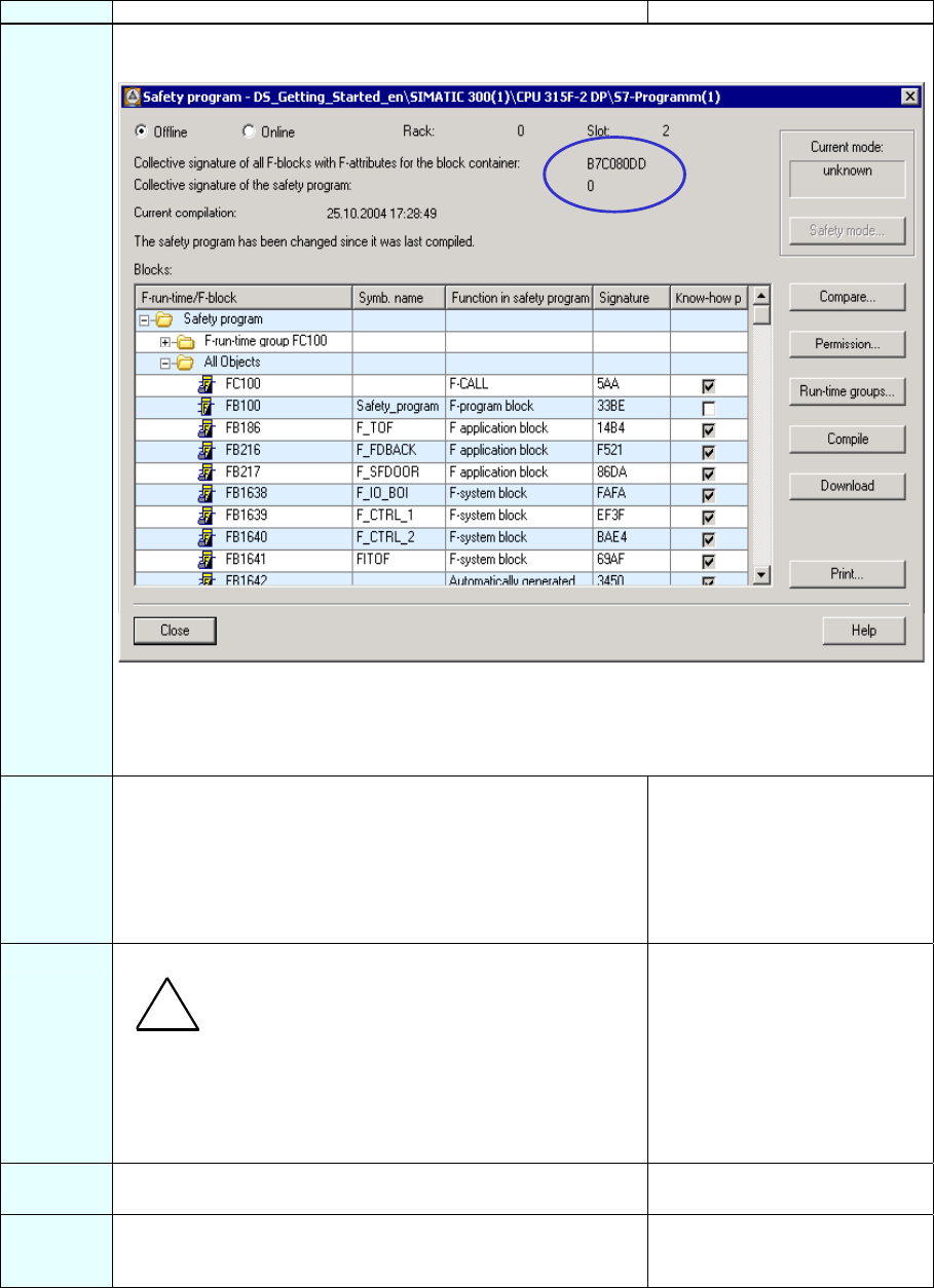
6 You return to the "Safety Program” dialog which now appears as follows:
The safety program has now been created but has not yet been compiled. The collective signature
of all F-blocks with the F-attribute in the block container and the collective signature of the safety
program differ (as highlighted in the figure).
S7 Distributed Safety
32 A5E00320726-01
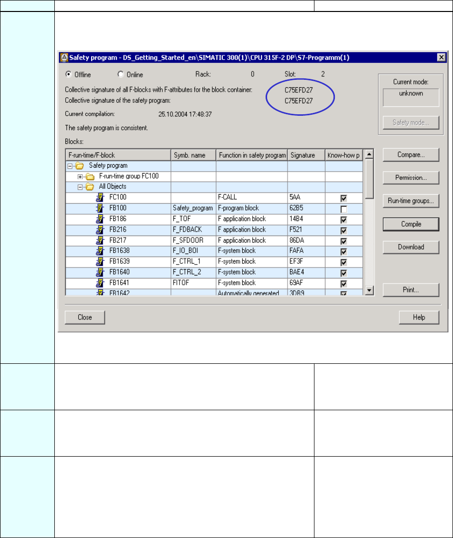
Step 17: Compile the Safety Program
Sequence Action Result
1 Click on the "Compile" button in the "Safety Program" dialog.
A consistency test is performed on the F-blocks involved in the
runtime when the safety program is compiled, in other words
the safety program is checked for errors. Any error messages
are output in an error window. Once the consistency test is
successfully completed, the additionally required F-system
blocks are generated automatically and inserted into the
runtime group to create an executable safety program.
Following a successful
compilation, the block container
always contains a consistent
safety program composed
entirely of F-blocks with the F-
attribute. See figure below.
2
The collective signature of all F-blocks with the F-attribute of the block container and the collective
signature of the safety program must match (as highlighted in the figure); in other words, a
consistent and executable safety program has been generated.
Click "Close" to confirm. The "Safety Program” dialog box closes.
S7 Distributed Safety
A5E00320726-01 33
Step 18: Call the Safety Program in the Cyclic Program
Sequence Action Result
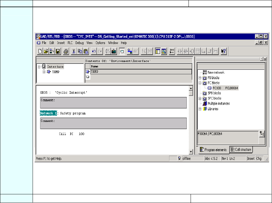
1 The safety program is accessed by calling F-CALL from the standard user program. Call the F-
CALL in the cyclic interrupt OB 35 as shown in the figure.
Note: You need to insert the cyclic interrupt OB 35 beforehand in the SIMATIC Manager.
Note: Cyclic interrupt OBs have the advantage of interrupting the cyclic program execution in OB1
of the standard user program at fixed time intervals; that is, a safety program is called and
executed at fixed time intervals in a cyclic interrupt OB.
Once the safety program is executed, the standard user program resumes.
2 Save and close OB 35. The block is saved.
S7 Distributed Safety
34 A5E00320726-01
Step 19: Download the Complete Safety Program to the F-CPU and Activate the Safety
Mode
Sequence Action Result
1 In the SIMATIC Manager, select the Options > Edit Safety
Program menu command.
The "Safety Program" dialog box
appears.
2 Activate the "Download" button. All F-blocks with the F-attribute
belonging to the safety program
are identified and downloaded to
the F-CPU.
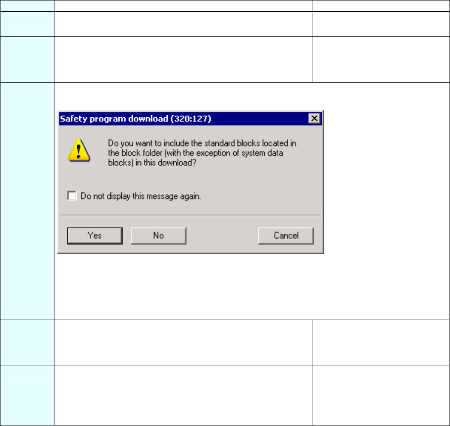
3 A note is displayed offering you the option of downloading the standard user program in addition to
the safety program.
Confirm by clicking on "Yes".
Note: If you are downloading F-blocks only, the block in which the F-CALL block is called (cyclic
interrupt OB35 in our example) is not downloaded. You then have to download this OB the same
way as for a standard program.
Note: To download the entire safety program, the F-CPU has to be in STOP mode.
4 In the "Safety Program" dialog box, select the "Offline" and
"Online" option buttons in turn to check whether the collective
signatures of all F-blocks with F-attribute in the block container
match offline and online.
If they match, downloading was
successful. If not, repeat the
download operation.
5 To activate safety mode, switch the F-CPU from STOP to RUN
mode.
Note: Once a safety program has been created, you need to
perform a full function test for your automation tasks (see S7
Distributed Safety, Configuring and Programming manual).
You have now finished creating
the safety program for the tasks
involved in the example.
S7 Distributed Safety
A5E00320726-01 35
Appendix 1: Modifying the Safety Program
Sequence Action Result
1 Change the example safety program so that no user acknowledgment is required for an OSSD
signal (Output Signal Switching Device) from the laser scanner.
To do this, program the emergency stop function (Network 2) as shown in the figure.
Note: Changes to the safety program during operation (in RUN mode) can only be made in
deactivated safety mode. You make changes to F-blocks offline in FBD/LAD Editor in the same
way as for a standard program. F-blocks cannot be modified online.
Refer to the corresponding chapter describing how to modify and test the safety program and
deactivate the safety mode in the S7 Distributed Safety, Configuring and Programming manual.
2 Save the F-FB. The F-block is subjected to a
consistency test and saved
once it completes the test
successfully.
S7 Distributed Safety
36 A5E00320726-01
Sequence Action Result
3 In the SIMATIC Manager, select the Options > Edit Safety Program menu command.
The "Safety Program" dialog box appears.
Note: You have changed and saved an F-block of the safety program and therefore created an
inconsistent safety program. In other words, the collective signature of all F-blocks with the F-
attribute in the block container and the collective signature of the safety program differ (as
highlighted in the figure).
4 Note: You must deactivate safety mode of the safety program
to download changes to the safety program in RUN mode.
Safety mode remains deactivated until F-CPU is next switched
from STOP to RUN mode.
Check to see whether "Safety mode activated" is indicated as
the "Current mode". If it is, activate the "Safety mode" button
and enter the password for the safety program.
Another prompt will appear. This
prompt contains the collective
signature of the safety program
in the F-CPU.
5 Confirm the prompt to deactivate safety mode with "OK."
Warning
Deactivation of safety mode is intended only for test purposes,
commissioning, etc. Whenever safety mode is deactivated, the
safety of the system must be ensured by other organizational
measures, such as operation monitoring and manual safety
shutdown.
Safety mode will be deactivated.
6 Download the modified F-FB from the FDB/LAD Editor to the F-
CPU (same procedure as for the standard program).
The F-FB is loaded in the F-
CPU.
7 Test the changes to the system or view the "Program status
online".
Once the test is successfully
completed, continue by compiling
the safety program.
!
S7 Distributed Safety
A5E00320726-01 37
Sequence Action Result
8 To apply the changes to the safety program and get a consistent safety program again, press the
"Compile" button.
The dialog box should now appear as follows.
The collective signature of all F-blocks with the F-attribute of the block container and the collective
signature of the safety program must match; in other words, a consistent and executable safety
program has been generated (as highlighted in the figure).
9 Click on the "Download" button to download the modified safety
program to the F-CPU.
All F-blocks with the F-attribute
belonging to the safety program
are identified and downloaded to
the F-CPU.
10 In the "Safety Program" dialog box, select the "Offline" and
"Online" option buttons in turn to check whether the collective
signatures of all F-blocks with F-attribute in the block container
match offline and online.
If they match, downloading was
successful. If not, repeat the
download operation.
11 To activate safety mode, switch the F-CPU from STOP to RUN
mode.
Note: After creating a safety program, you must perform a full
function test for your automation tasks.
After modifying a safety program that has already be fully
tested, it is sufficient to only test the modifications (see S7
Distributed Safety, Configuring and Programming manual).
You have now finished adapted
the safety program for the
modified task (see Sequence 1
above).
S7 Distributed Safety
38 A5E00320726-01
Appendix 2: Acceptance Support for the Safety Program
Sequence Action Result
1 Note: The documentation of the safety program is part of the
acceptance documents in accordance with machine guidelines
or IEC 61508 for the process industry and correspondingly
applied standards.
Print out the safety program for the acceptance. Proceed as
follows:
1.) Activate the "Offline" button in the "Safety Program"
dialog in order for the signature of the symbols to be
included in the footer of the offline safety program
printout.
2.) Click on the "Print" button in the "Safety Program"
dialog.
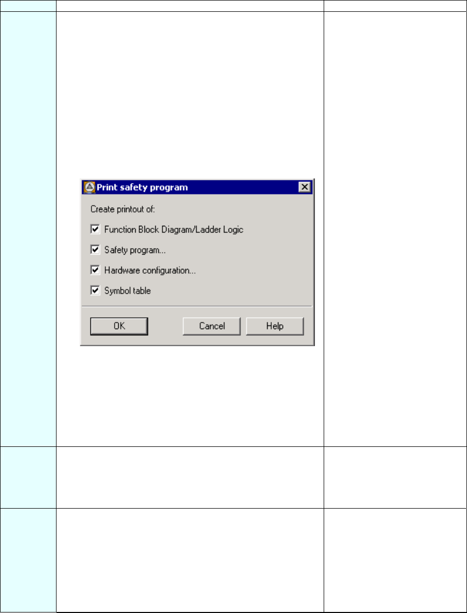
3.) Activate all four check boxes in the "Print Safety
Program" dialog.
4.) Click "OK" to confirm.
5.) Select "All" for the print range of the "Hardware
Configuration" and mark the option "With parameter
description.
Confirm with "OK".
Note: You need to archive all four printouts and logs of the
function tests.
The "Print Safety Program”
dialog box opens.
The safety program is printed.
2 Check the printout.
The collective signatures in the footer of the printout (each with
the collective signature of all F-blocks with an F-attribute in the
block container and signature of the symbols) must match in all
four printouts.
3 Activate the "Online" option to run a check in the "Safety
Program" dialog (the safety program must be loaded):
The online collective signature of all F-blocks with F-attribute in
the block container must match those in the accepted offline
printout and no unused F-CALL may be present in the online
safety program.
Note: Additional important notes and instructions about
acceptance of the safety program are available in the S7
Distributed Safety, Configuring and Programming manual.
If these checks reveal any
deviations or errors, recompile
the safety program and perform
the acceptance procedure again.

S7 Distributed Safety
A5E00320726-01 39
Appendix 3: Typical Configuration and Programming Mistakes and the Causes
Type Error Possible Cause / Remedy
Configuration
error
F-blocks cannot be downloaded to the F-CPU. F-CPU parameter "CPU contains
safety program" in the
"Protection” tab is not activated.
Configuration
error
SF LED on the F-module lights when the safety program is
not loaded.
ET 200M: System property
ET 200S: The PROFIsafe
address set on the DIL switch
does not match the one set in
HW Config.
Configuration
error
- SF-LED on the F-module lights and
- TIMEOUT error in the DIAG byte of the F-I/O DB
Monitoring time of the F-module
≤ cycle time of the F-CALL.
Configuration
error
- SF-LED on the F-module lights and
- CRC error in the DIAG byte of the F-I/O DB
- Loaded safety program does
not match the one loaded in HW
Config.
- Safety program is inconsistent.
- PIQ/PII of the F-module was
overwritten by the standard user
program.
Configuration
error
- SF-LED on the F-DI module lights and
- module reports short-circuit
Sensor connection does not
match configuration, for example:
- Only one switching contact is
connected to a channel with
1oo2 evaluation
- A sensor with non-equivalence
contacts is connected to a
channel configure for "two-
channel equivalence".
- Two switching contacts of a
single-channel or two-channel
non-equivalence sensor are
supplied via VS1 and VS2
Programming
error
After an F-block is edited and saved, the block cannot be
closed and the message "The block was not saved" appears.
Check for any programming or
syntax errors in the "Error" detail
tab of the FBD/LAD Editor.
Programming
error
F-PIQ/PII has not been updated. F-CALL is not called in the cyclic
OB3x.
F-module has been passivated.
Evaluate the QBAD and DIAG
byte parameters in the respective
F-I/O DB.
Programming
error
F-CPU goes to STOP due to data corruption in the safety
program.
- F-CALL is called more than
once in the cyclic program.
- The standard user program is
writing to F-DB addresses.
- Undeclared TEMP variables
are being used in the safety
program.
- Memory bits are being read in
the safety program that are
changing during the processing
of the F-CALL, for example,
clock memory bits.
- Overflow during INT
operations has not been
checked.
S7 Distributed Safety
40 A5E00320726-01

SIMATIC S7 Distributed Safety: feedback for Version 10/2004
A5E00297771-02
Siemens AG
A&D AS SM ID
Postfach 1963
D-92209 Amberg
Telefax: +49(9621)80-3103
mailto:doku@ad.siemens.de
Your Feedback as regards the S7 Distributed Safety (Version 10/2004)
Dear SIMATIC user,
Our goal is to provide you information with a high degree of quality and usability, and to continuously
improve the SIMATIC documentation for you. To achieve this goal, we require your feedback and
suggestions. Please take a few minutes to fill out this questionnaire and return it to me by Fax, e-mail or
by post.
We are giving out three presents every month in a raffle among the senders. Which present would you
like to have?
SIMATIC Manual Collection Automation Value Card Laser pointer
Dr. Thomas Rubach,
Head of Information & Documentation
General Questions
1. Are you familiar with the SIMATIC Manual
Collection?
yes no
2. Have you ever downloaded manuals from the
internet?
yes no
3. Do you use Getting Starteds?
yes no
if yes, which:
4. How much experience do you have with the
S7 Distributed Safety?
Expert
Experienced user
Advanced user
Beginner
Your
Address:
Name:
Company:
Position:
Street:
Postal code / Place:
Email:
Phone:
Fax:

SIMATIC S7 Distributed Safety: feedback for Version 10/2004
A5E00297771-02
Please specify the documents, for which you want to answer the questions below:
A: Manual S7 Distributed Safety, D: Manual ET 200eco, Distributed I/O
Configuring and Programming Fail-Safe I/O Module
B: Manual S7-300, Fail-Safe E: System Description
Signal Modules Safety Engineering inSIMATIC S7
C: Manual ET 200S, Distributed I/O System
Fail-Safe Modules
1. In which project phase do you use this
document frequently?
Information Assembly
Planning Commissioning
Configuration Maintenance &
Service
Programming others:
2. Finding the required information in the
document:
How quickly can you find the desired information in
the document?
immediately not at all
after a brief after a long
search search
Which search method do you prefer?
Table of contents Index
Full-text search others:
Which supplements/improvements would you like
in order to help you find the required information quickly?
3. Your judgement of the document as regards
content.
How satisfied are you with this document
Totally satisfied not very satisfied
Very satisfied not satisfied
Satisfied
Were able to find the required information?
yes no
which was not:
4. What is the scope of the information?
Just right
Not enough - which topic:
Too detailed – which topic:
5. Is the information easy to understand (texts,
figures, tables)?
yes no
if no, which was not:
6. Are examples important to you?
no, of less importance
yes, important –were the examples
enough?
yes no
if no, on which topic:
7. What are your suggestions as regards the
contents of the document?
Thank you for your cooperation
F: Getting Started
S7 Distributed Safety
