Radio Shack Hardware Manual SA800 801 Diskette Drive OEM 1977 Shugart Text
User Manual: manual pdf -FilePursuit
Open the PDF directly: View PDF ![]() .
.
Page Count: 50

TABLE OF CONTENTS
1.0 Introduction 1
1.1 General Description 1
1.2 Specification Summary 2
1.2.1 Performance Specifications 2
1.2.2 Functional Specifications 2
1.2.3 Physical Specifications 2
1.2.4 Reliability Specifications 3
2.0 Functional Characteristics 5
2.1 General Operation 5
2.2 Read/Write and Control Electronics 5
2.3 Drive Mechanism 5
2.4 Positioning Mechanism 5
2.5 Read/Write Head 5
2.6 Recording Format 6
2.7 Optional Features 6
2.8 Model Differences 6
3.0 Functional Operations 7
3.1 Power Sequencing 7
3.2 Drive Selection 7
3.3 Track Accessing 7
3.3.1 Step Out 7
3.3.2 Step In 7
3.4 Read Operation 7
3.5 Write Operation 9
3.6 Sequence of Events 9
4.0 Electrical Interface 13
4.1 Signal Interface 13
4.1.1 Input Lines 13
4.1.1 Input Line Termination 15
4.1 .1 .2 Drive Select 1-4 15
4.1 .1 .3 Direction Select 15
4. 1.1.
4
Step 15
4.1 .1 .5 Write Gate 15
4.1.1.6 Write Data 16
4.1.1.7 Head Load (Alternate Input). 16
4.1 .1 .8 In Use (Alternate Input) 16
4.1 .2 Output Lines 16
4.1 .2.1 Track 00 16
4.1.2.2 Index 16
4.1 .2.3 Sector (SA801 only) 17
4.1 .2.4 Ready 17
4.1 .2.5 Read Data 17
4.1 .2.6 Sep Data 17
4.1 .2.7 Sep Clock 17
4.1 .2.8 Write Protect (Optional on SA800) 17
4.1 .2.9 Disk Change (Alternate Output) 18
4.1.3 Alternate I/O Pins 18
4.2 Power Interface 18
4.2.1 AC Power 18
4.2.2 DC Power 19
5.0 Physical Interface 21
5.1 J1/P1 Connector 21
5.2 J5/P5 Connector 22
5.3 J4/P4 Connector 22
6.0 Drive Physical Specifications 23
6.1 Drive Dimensions 23
6.2 Mounting Recommendations 23
6.2.1 Vertical Mounting 23
6.2.3 Upright Mounting 23
6.3 Chassis Slide 25
6.4 Decorative Face Plate 25
7.0 Customer Installable Options 27
7.1 Drive Select -One to Eight Drives 30
7.2 Select Drive Without Loading Head or Enabling Stepper Motor 31
7.3 Select Drive and Enable Stepper Without Loading Head 32
7.4 Load Head Without Selecting Drive or Enabling Stepper 32
7.5 Radial Ready 33
7.6 Radial Index/Sector 34
7.7 Eight, 16, Or 32 Sectors 35
7.8 In Use Alternate Input (Activity LED) 36
7.9 Write Protect Optional Use 36
7.10 Disk Change (Alternate Output) 37
8.0 Operation Procedures 38
8.1 Diskette Loading and Handling 38
8.2 Write Protecting aDiskette 39
9.0 Error Detection and Correction 40
9.1 Write Error 40
9.2 Read Error 40
Appendix A-Models and Features 41
LIST OF ILLUSTRATIONS
Figure 1.SA800/801 Diskette Storage Drive iv
2. SA800/801 Functional Diagram 4
3. Track Access Timing 8
4. Read Initiate Timing 8
5. Read Signal Timing 9
6. Write Initiate Timing 10
7. Write Data Timing 10
8. General Control and Data Timing Requirements 11
9. Interface Connections 14
10. Interface Signal Driver/Receiver 16
1 1
.
Index Timing 16
12. Sector Timing 17
13. J1 Connector Dimensions 21
14. J5 Connector .22
15. J4 Connector 22
16. Interface Connectors- Physical Location Diagram 22
17. Head Load Actuator Mounting Prerequisites 23
18. SA800/801 Diskette Storage Drive Dimensions 24
19. Slide Mounting Dimensions 25
20. SA800/801 RDimensions 26
21
.
Component Locations Standard PCB 28
22. Component Locations LSI PCB ..29
23. Drive Select Circuitry 30
24. Select Drive Without Loading Head Circuit 31
25. Stepper Motor Enable Circuit 32
26. Load Head Without Selecting Drive or Enabling Stepper Circuit 33
27. Radial Ready Circuit 34
28. Radial Index/Sector Circuit 34
29. Sector Timing Relationships 35
30. Sector Divide Circuit 35
31. In Use/Activity LED Circuit 36
32. Write Protect Circuit 36
33. Disk Change Timing 37
34. Disk Change Circuit 37
35. Loading SA800/801 .38
36. Diskette Write Protected 39
37. Write Inhibit Notch Specifications 39
Wm !.:|IEB= J
wSK&i :
<^:'«BgB»;'.i
-MaBsi%<' j:'sf$iag£.*:i
;
'• '|lgl&'.
'W$sBw:'- E=:-^» ;
i
&i&$ •|-.'":gS9E-j
3»&
S*1Ib!P;;v'nBF
iflH Sfcl
kasl
V
HHBi
Hi
^3^
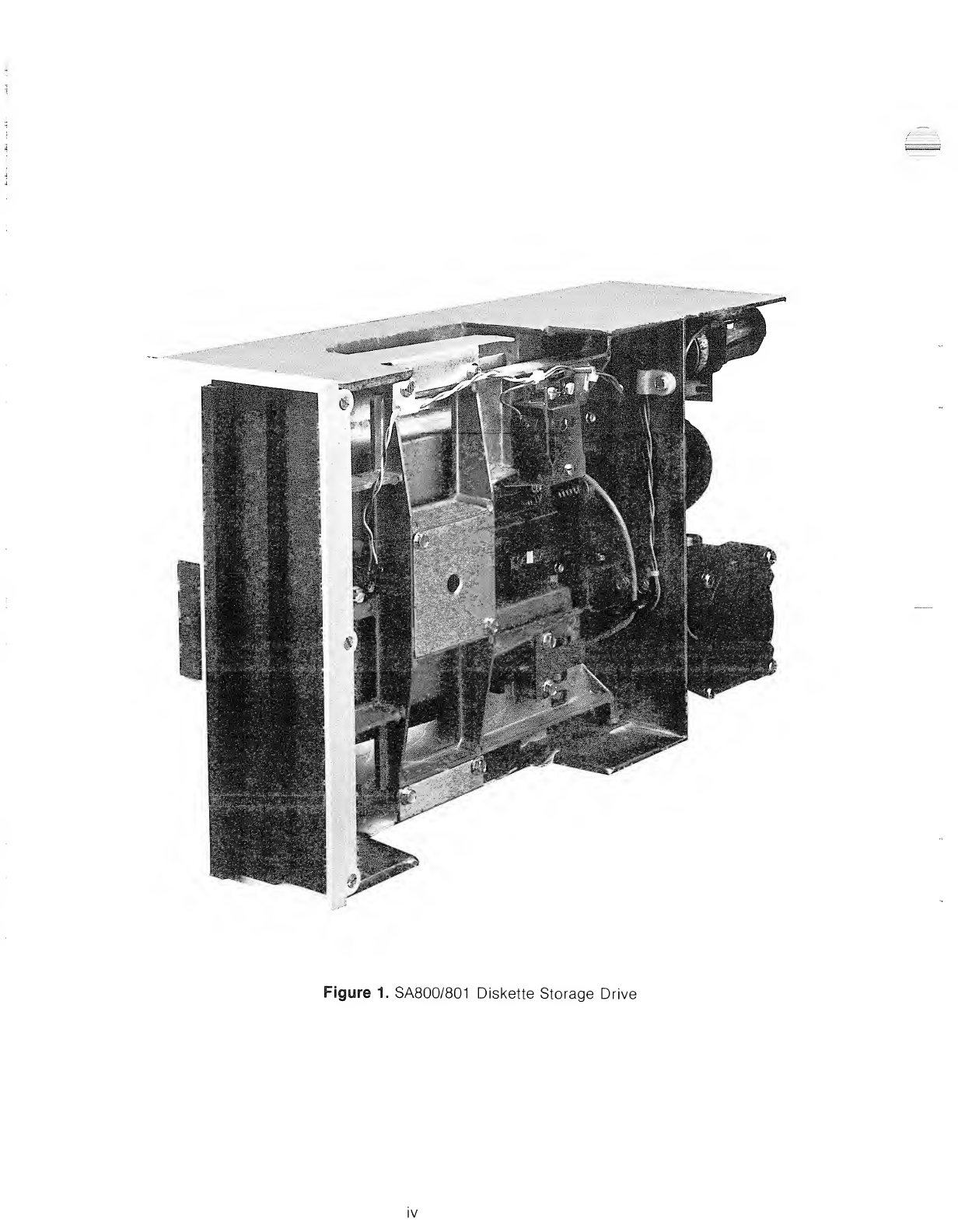
Figure 1. SA800/801 Diskette Storage Drive
IV

1.0 INTRODUCTION
1.1 General Description
The SA800/801 are enhanced versions of the successful SA900/901 Diskette Storage Drive. The SA800/801
provides the customer with amature and reliable product, manufactured to the same high standard of ex-
cellence as the 900/901, but with additional featuress.
The SA800 Diskette Storage Drive can read and write diskettes for interchange with other SA800's, the
SA900, IBM 3741, 3742 or 3540 and with the IBM System 32.
The SA801 provides the same features as the SA800 with additional flexibility for those requirements which
preclude IBM compatibility.
The SA800/801 Diskette Storage Drives have as standard features: apatented diskette clamping/registra-
tion design which eliminates the possibility of damage to the diskette due to misregistration and quarantees
over 30,000 interchanges with each diskette; single and double density capability on the same drive for the
same price; aproprietary ceramic R/W head designed and manufactured by Shugart Associates to provide
media life exceeding 3.5 million passes/track and head life exceeding 15,000 hours; an activity light which
indicates drive in use; and ribbon cable or twisted pair connector for ease of packaging. All of these features
and more are available with the SA800/801
.
SA800/801 Diskette Storage Drive provide the system designer solutions to his applications requirements
with greater performance and reliability than cassette or cartridge drives, and lower cost with increased
function over I/O and reel-to-reel tape drives.
Applications for the SA800/801 Diskette Storage Drive are key entry systems, point of sale recording
systems, batch terminal data storage microprogram load and error logging, minicomputer program and aux-
iliary data storage, word processing systems and data storage for small business systems.
The SA100 Diskette, IBM Diskette or equivalent, can be read and written interchangeably between any
SA800and IBM 3741/42, 3747 and 3540. The SA1 01 Diskette can be read or written interchangeably on any
SA801. The SA102 and SA103 are used for double density applications.
As aproduct enhancement, to improve reliability and serviceability, Shugart is incorporating into the SA800
serves drives aPCB Large Scale Integration (LSI) components. These components are:
#Control Chip
•Write Channel
•Read Channel
The LSI Control chip performs the following functions:
@TRK 00 detector
#Index detector
®Stepper logic
®FM clock/data separator and data window
®Sector separator
®Write Protect detector
®Door open/close detector
®Disk change circuit
®Ready signal
The functions listed above are either detected from the drive mechanics or from the Host Interface. As a
result, the proper logic generated by the LSI chip either will be used within the drive electronic circuit to per-
form stepping, read/write operations or will be fed back to the Host Interface.
Also, an internal FM data separator is incorporated inside the chip. Ajumper option will allow the user to
select the data separator to perform as its predecessor SA800 (jumper FS) or to select the separator to be
compatible with the IBM System 3740 data separator (jumper TS). Thus IBM compatibility will allow direct in-
terfacing with LSI single chip floppy disk controllers.
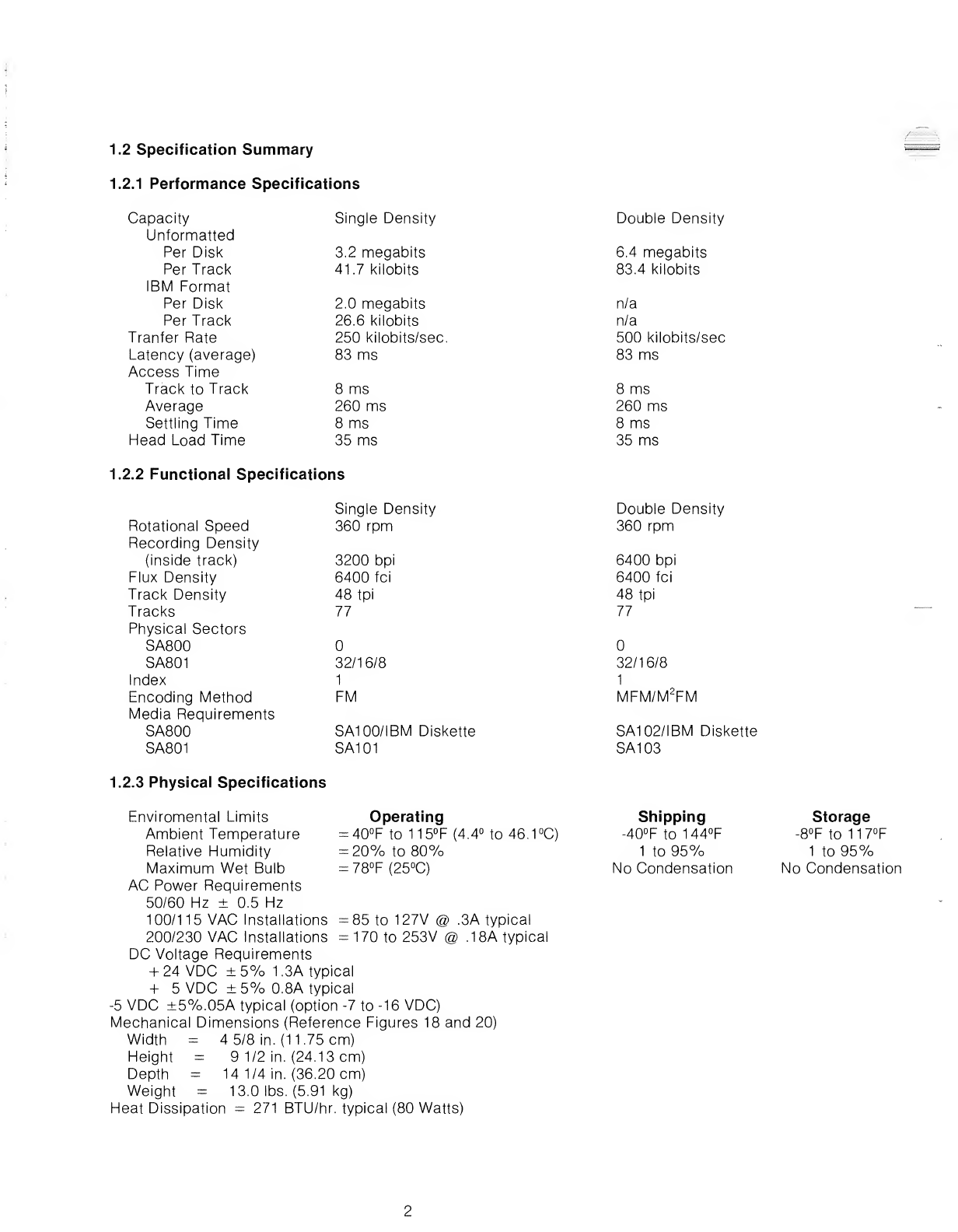
1.2 Specification Summary
1.2.1 Performance Specifications
Capacity
Unformatted
Per Disk
Per Track
IBM Format
Per Disk
Per Track
Tranfer Rate
Latency (average)
Access Time
Track to Track
Average
Settling Time
Head Load Time
1.2.2 Functionai Specifications
Rotational Speed
Recording Density
(inside track)
Flux Density
Track Density
Tracks
Physical Sectors
SA800
SA801
Index
Encoding Method
Media Requirements
SA800
SA801
1.2.3 Physical Specifications
Enviromental Limits
Ambient Temperature
Relative Humidity
Maximum Wet Bulb
AC Power Requirements
50/60 Hz ±0.5 Hz
100/115 VAC Installations
200/230 VAC Installations
DC Voltage Requirements
+24 VDC ±5% 1.3A typical
+5VDC ±5% 0.8A typical
-5 VDC ±5%.05A typical (option -7 to -16 VDC)
Mechanical Dimensions (Reference Figures 18 and 20)
Width =45/8 in. (11.75 cm)
Height =91/2 in. (24.13 cm)
Depth =14 1/4 in. (36.20 cm)
Weight =13.0 lbs. (5.91 kg)
Heat Dissipation =271 BTU/hr. typical (80 Watts)
Single Density Double Density
3.2 megabits
41.7 kilobits
6.4 megabits
83.4 kilobits
2.0 megabits
26.6 kilobits
250 kilobits/sec.
83 ms
n/a
n/a
500 kilobits/sec
83 ms
8ms
260 ms
8ms
35 ms
8ms
260 ms
8ms
35 ms
IS
Single Density
360 rpm
Double Density
360 rpm
3200 bpi
6400 fci
48 tpi
77
6400 bpi
6400 fci
48 tpi
77
32/16/8 32/16/8
1
1
FM
I
MFM/M2FM
SA100/IBM Diskette
SA101
SA102/IBM Diskette
SA103
Operating
=40°Fto 115°F(4.4°
=20% to 80%
=78°F (25°C)
to46.1°C)
Shipping
-40°F to 144°F
1to 95%
No Condensation
Storage
-8°F to 117°F
1to 95%
No Condensation
=85 to 127V @.
=170 to 253V @3A typical
.18A typical
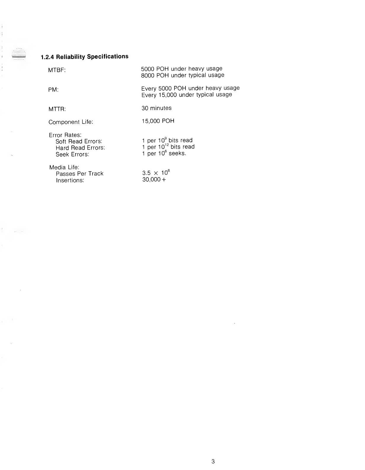
1.2.4 Reliability Specifications
MTBF:
PM:
MTTR:
Component Life:
Error Rates:
Soft Read Errors:
Hard Read Errors:
Seek Errors:
Media Life:
Passes Per Track
Insertions:
5000 POH under heavy usage
8000 POH under typical usage
Every 5000 POH under heavy usage
Every 15,000 under typical usage
30 minutes
15,000 POH
1per 109bits read
1per 1012 bits read
1per 106seeks.
3.5 x10fc
30,000 +
LU
>
DC
Q
<
Q
Q
<
DC
O
o
_l
o
D_
LU
CO
DC
V\1 H
DC DC
DC LU
LU CO
>LU
<DC
o
Q_
/. j U
CO
LU
7
I
o_l
LU ^<—».
_l -
—
T
—
LU h- o
CO o
III <
z. 1CO
OLU o
Q_
h-
o
II
1
CO
LU
-•> X
LU Q
DC
o
LU DC <n<. <J
h- LL nr zLU LU
CO UUh- LL CO
\'1
r1'f
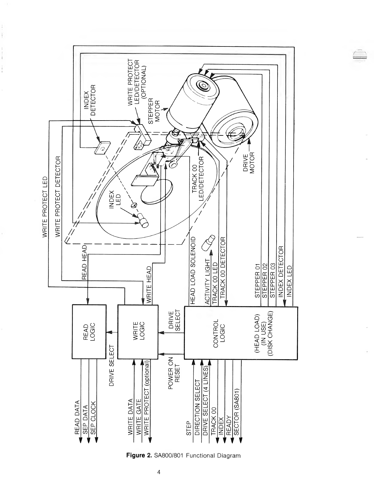
Figure 2. SA800/801 Functional Diagram

2.0 FUNCTIONAL CHARACTERISTICS
2.1 General Operation
The SA800/801 Diskette Storage Drive consists of read/write and controls electronics, drive mechanism,
read/write head, track positioning mechanism, and the removable diskette. These components perform the
following functions:
Interpret and generate control signals.
Move read/write head to the selected track.
Read and write data.
The relationship and interface signals for the internal functions of the SA800/801 are shown in Figure 2.
The Head Positioning Actuator positions the read/write head to the desired track on the diskette. The Head
Load Actuator loads the diskette against the read/write head and data may then be recorded or read from
the diskette.
2.2 Read/Write and Control Electronics
The electronics are packaged on one PCB. The PCB contains:
1
.
Index Detector Circuits. (Sector/Index for 801).
2. Head Position Actuator Driver.
3. Head Load Actuator Driver.
4. Read/Write Amplifier and Transition Detector.
5. Data/Clock Separation Circuits.
6. Write Protect.
7. Drive Ready Detector Circuit.
8. Drive Select Circuits.
2.3 Drive Mechanism
The Diskette drive motor rotates the spindle at 360 rpm through abelt-drive system. 50 or 60 Hz power is ac-
commodated by changing the drive pulley and belt. Aregistration hub, centered on the face of the spindle,
positions the Diskette. Aclamp that moves in conjunction with the cartridge guide fixes the Diskette to the
registration hub.
2.4 Positioning Mechanism
An electrical stepping motor (Head Position Actuator) and lead screw positions the read/write head. The
stepping motor rotates the lead screw clockwise or counterclockwise in 15° increments. A15° rotation of the
lead screw moves the read/write head one track position. The using system increments the stepping motor
to the desired track.
2.5 Read/Write Head
The SA800/801 head is asingle element ceramic read/write head with straddle erase elements to provide
erased areas between data tracks. Thus normal interchange tolerances between media and drives will not
degrade the signal to noise ratio and insures Diskette interchangeability.
The read/write head is mounted on acarriage which is located on the Head Position Actuator lead screw.
The Diskette is held in aplane perpendicular to the read/write head by aplaten located on the base casting.
This precise registration assures perfect compliance with the read/write head. The Diskette is loaded
against the head with aload pad actuated by the head load solenoid.
The read/write head is in direct contact with the Diskette. The head surface has been designed to obtain
maximum signal transfer to and from the magnetic surface of the Diskette with minimum head/Diskette
wear.
2.6 Recording Format
The format of fhe data recorded on the disk is totally afunction of the host system, and can be designed
around the users application to best take advantage of the total available bits that can be written on any one
track.
For adetailed discussion of various recording formats, the systems designer should read one of the follow-
ing:
1. IBM Compatibility Manual.
2. Shugart Associates Double Density Design Guide.
3. SA801/901 Track Formats.
2.7 Optional Features
1
.
-1 2to -1 5Volt DC to replace -5 Volt DC requirement.
2. Dust Cover, Not available on "FTseries.
3. Write Protect for SA800. Standard on SA801
.
4. Door Lock. Will lock the door when drive is selected or through alternate I/O pin.
5. Horizontal mounting with door opening up.
6. SA800/801 "R" Series. Allows two drives to be horizontally installed in astandard 19" Ret-
ma rack. Reference figure 20.
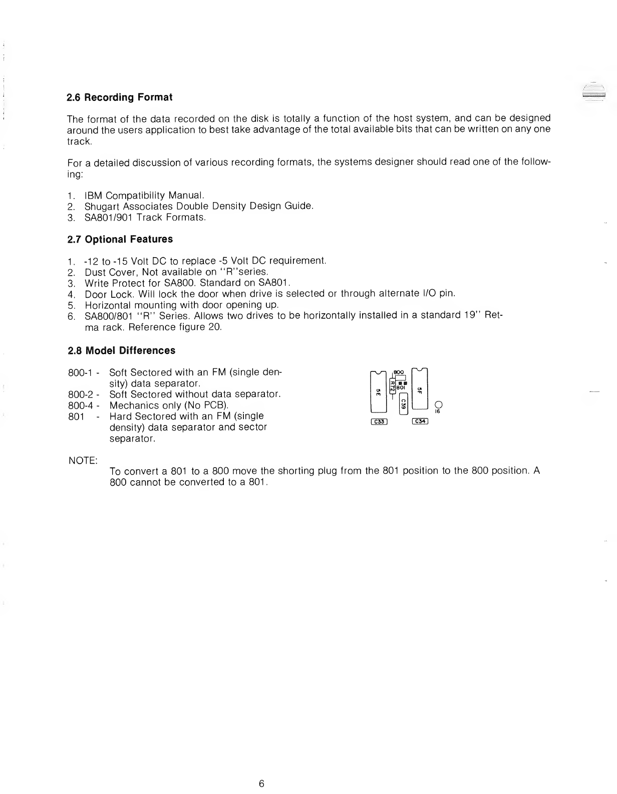
2.8 Model Differences
800-1 -Soft Sectored with an FM (single den- l^irz]
sity) data separator.
800-2 -Soft Sectored without data separator.
800-4 -Mechanics only (No PCB).
801 -Hard Sectored with an FM (single
density) data separator and sector
separator.
tOIB
3801
O
NOTE:
To convert a801 to a800 move the shorting plug from the 801 position to the 800 position. A
800 cannot be converted to a801
.
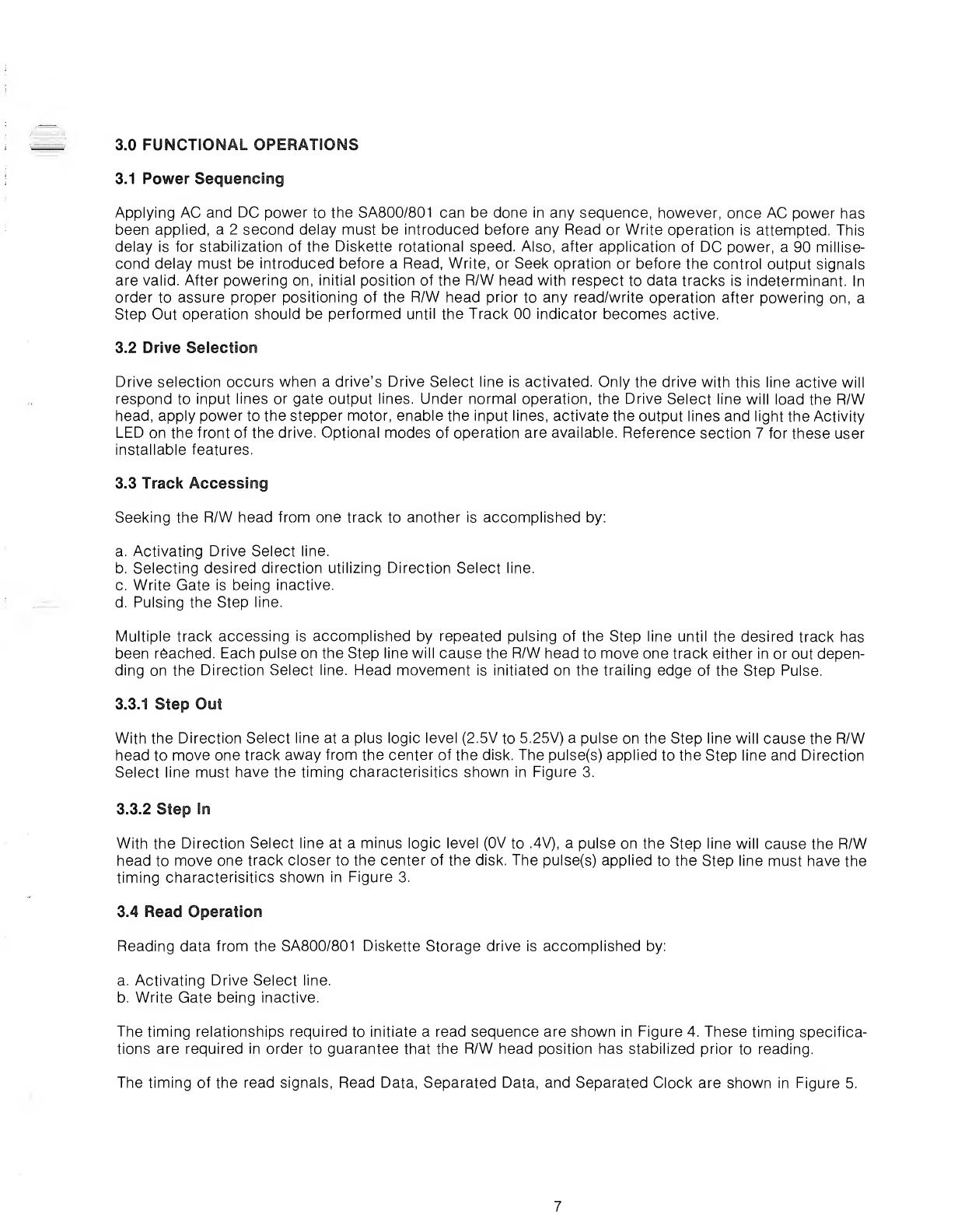
3.0 FUNCTIONAL OPERATIONS
3.1 Power Sequencing
Applying AC and DC power to the SA800/801 can be done in any sequence, however, once AC power has
been applied, a 2 second delay must be introduced before any Read or Write operation is attempted. This
delay is for stabilization of the Diskette rotational speed. Also, after application of DC power, a90 millise-
cond delay must be introduced before aRead, Write, or Seek opration or before the control output signals
are valid. After powering on, initial position of the R/W head with respect to data tracks is indeterminant. In
order to assure proper positioning of the R/W head prior to any read/write operation after powering on, a
Step Out operation should be performed until the Track 00 indicator becomes active.
3.2 Drive Selection
Drive selection occurs when adrive's Drive Select line is activated. Only the drive with this line active will
respond to input lines or gate output lines. Under normal operation, the Drive Select line will load the R/W
head, apply power to the stepper motor, enable the input lines, activate the output lines and light the Activity
LED on the front of the drive. Optional modes of operation are available. Reference section 7for these user
installable features.
3.3 Track Accessing
Seeking the R/W head from one track to another is accomplished by:
a. Activating Drive Select line.
b. Selecting desired direction utilizing Direction Select line.
c. Write Gate is being inactive.
d. Pulsing the Step line.
Multiple track accessing is accomplished by repeated pulsing of the Step line until the desired track has
been reached. Each pulse on the Step line will cause the R/W head to move one track either in or out depen-
ding on the Direction Select line. Head movement is initiated on the trailing edge of the Step Pulse.
3.3.1 Step Out
With the Direction Select line at aplus logic level (2.5V to 5.25V) apulse on the Step line will cause the R/W
head to move one track away from the center of the disk. The pulse(s) applied to the Step line and Direction
Select line must have the timing characterisitics shown in Figure 3.
3.3.2 Step In
With the Direction Select line at aminus logic level (0V to .4V), apulse on the Step line will cause the R/W
head to move one track closer to the center of the disk. The pulse(s) applied to the Step line must have the
timing characterisitics shown in Figure 3.
3.4 Read Operation
Reading data from the SA800/801 Diskette Storage drive is accomplished by:
a. Activating Drive Select line.
b. Write Gate being inactive.
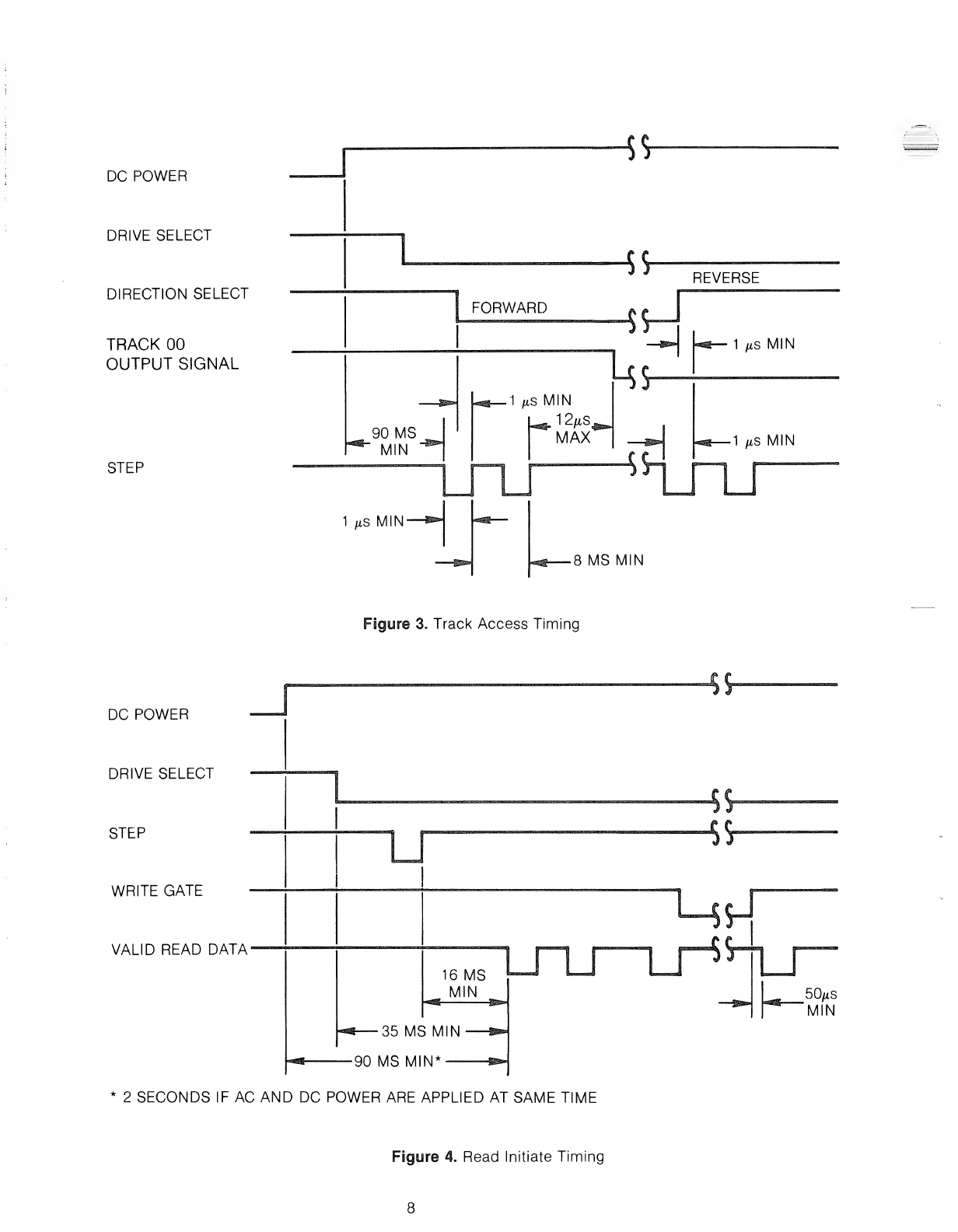
The timing relationships required to initiate aread sequence are shown in Figure 4. These timing specifica-
tions are required in order to guarantee that the R/W head position has stabilized prior to reading.
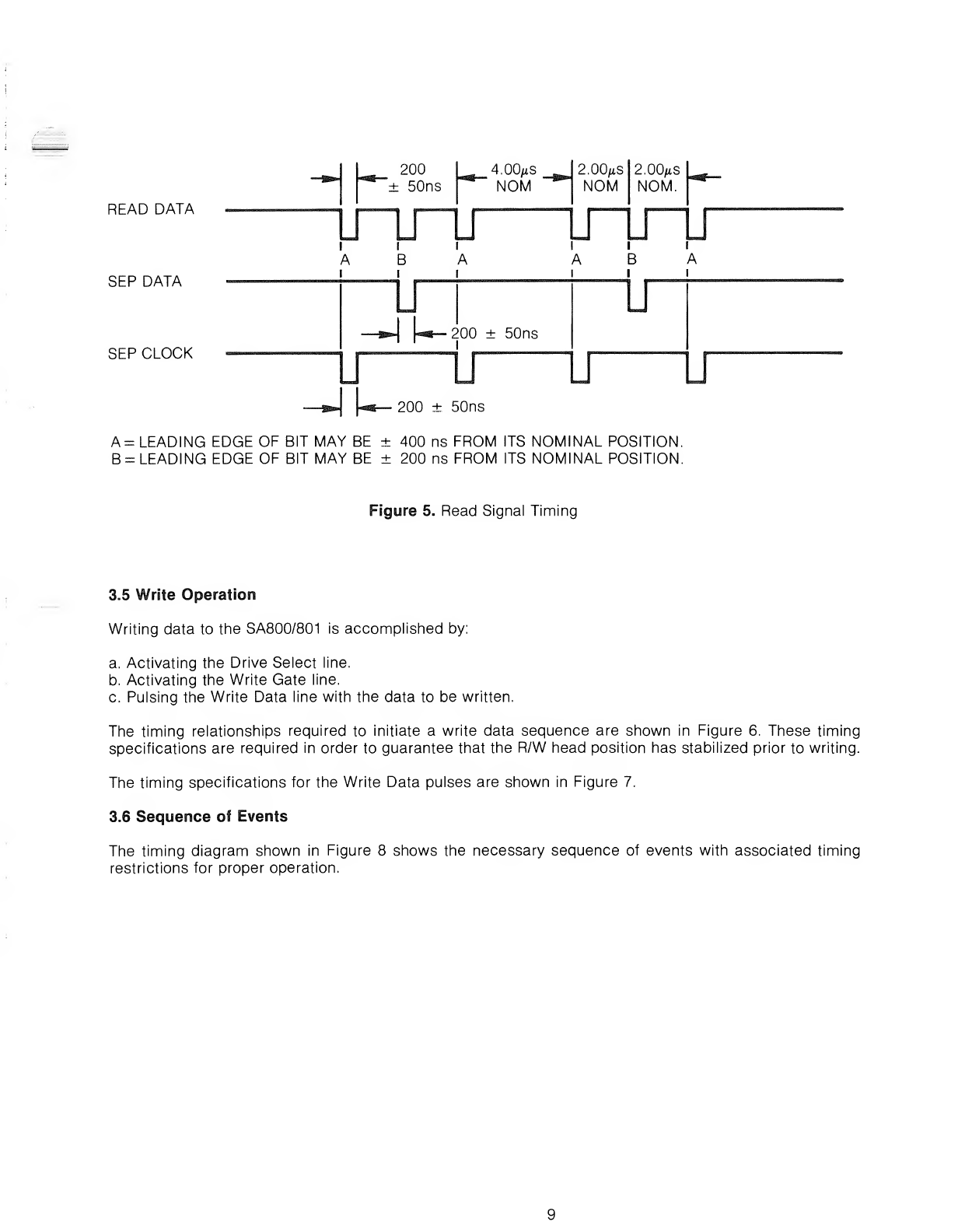
The timing of the read signals, Read Data, Separated Data, and Separated Clock are shown in Figure 5.
DC POWER
DRIVE SELECT
DIRECTION SELECT
TRACK 00
OUTPUT SIGNAL
STEP
90 MS
"MIN
1fiS MIN'
"5 V
^REVERSE
FORWARD
1fiS MIN
i- 12HS4
MAX
J
4S
rr\
4
•8MS MIN
1/.s MIN
1fts MIN
DC POWER
DRIVE SELECT
STEP
WRITE GATE
VALID READ DATA'
Figure 3. Track Access Timing
16 MS
MIN
i—35 MS MIN
90 MS MIN*
2SECONDS IF AC AND DC POWER ARE APPLIED AT SAME TIME
50/xS
MIN
Figure 4. Read Initiate Timing
READ DATA
SEP DATA
SEP CLOCK
A= LEADING EDGE OF BIT MAY BE
B=LEADING EDGE OF BIT MAY BE
200 ±50ns
400 ns FROM ITS NOMINAL POSITION.
200 ns FROM ITS NOMINAL POSITION.
Figure 5. Read Signal Timing
3.5 Write Operation
Writing data to the SA800/801 is accomplished by:
a. Activating the Drive Select line.
b. Activating the Write Gate line.
c. Pulsing the Write Data line with the data to be written.
The timing relationships required to initiate awrite data sequence are shown in Figure 6. These timing
specifications are required in order to guarantee that the R/W head position has stabilized prior to writing.
The timing specifications for the Write Data pulses are shown in Figure 7.
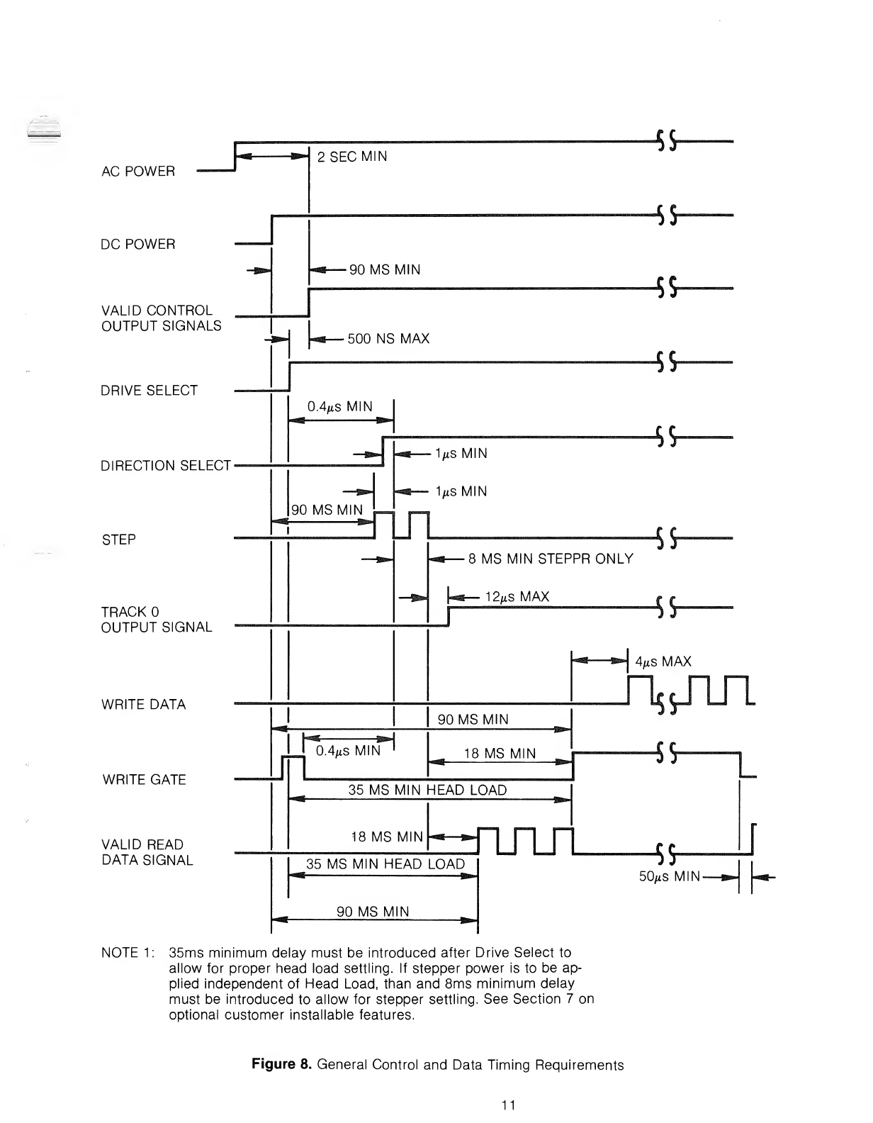
3.6 Sequence of Events
The timing diagram shown in Figure 8shows the necessary sequence of events with associated timing
restrictions for proper operation.

DC POWER
DRIVE SELECT
STEP
WRITE GATE
WRITE DATA U—Li
2SECONDS IF AC AND DC POWER ARE APPLIED AT SAME TIME.
Figure 6. Write Initiate Tinning
WRITE DATA CD
150 ns MIN
1100ns MAX -&»
4.00,is ±20ns
D
2.00/xs
±10ns
Qr—
LJ
Figure 7. Write Data Timing
10
AC POWER
DC POWER
VALID CONTROL
OUTPUT SIGNALS
DRIVE SELECT
2SECMIN 4*
DIRECTION SELECT-
STEP
TRACK
OUTPUT SIGNAL
WRITE DATA
WRITE GATE
VALID READ
DATA SIGNAL
^J.
90MSMIN
"5 V
500 NS MAX
"5S"
0.4/iS MIN
«fr-
90 MS MIN
Us
VsMIN
VsMIN
49
Ul
8MS MIN STEPPRONLY
12/*s MAX
$&
U
4/xS MAX
90 MS MIN
0.4/tS MIN
—»>
18 MS MIN
<m
^- 35 MS MIN HEAD LOAD
18 MS MIN
-^
nrLT
35 MS MIN HEAD LOAD
90 MS MIN -g^»
~5S
jj$" j
50^s MIN.
NOTE 1: 35ms minimum delay must be introduced after Drive Select to
allow for proper head load settling. If stepper power is to be ap-
plied independent of Head Load, than and 8ms minimum delay
must be introduced to allow for stepper settling. See Section 7on
optional customer installable features.
Figure 8. General Control and Data Timing Requirements
11

12
4.0 ELECTRICAL INTERFACE
The interface of the SA800/801 Diskette drive can be divided into two categories:
1. Signal
2. Power
The following sections provide the electrical definition for each line.
Reference Figure 9for all interface connections.
4.1 Signal Interface
The signal interface consists of two categories:
1. Control
2. Data Transfer
All lines in the signal interface are digital in nature and either provide signals to the drive (input), or provide
signals to the host (output), via interface connector P1/J1.
4.1.1 Input Lines
There are ten signal input lines, eight are standard and two are user installable options (reference section 7).
The input signals are of two types, those intended to be multiplexed in amultiple drive system and those
which will perform the multiplexing. The input signals to be multiplexed are:
1. Direction Select
2. Step
3. Write Data
4. Write Gate
The input signals which are intended to do the multiplexing are:
1. Drive Select 1
2. Drive Select 2
3. Drive Select 3
4. Drive Select 4
The input lines have the following electrical specifications. Reference Figure 10 for the recommended cir-
cuit.
True =Logical zero =Vin ±0.0V to +0.4V
@tin =40 ma (max)
False =Logical one =Vin +2.5V to +5.25V
@lin =ma (open)
Input Impedence =150 ohms
13
HOST SYSTEM
ii-
i" -
\y
JT
DCGND T
FFWS
AC GND
<$-
FLAT RIBBON OR
TWISTED PAIR
MAX 10 FEET
DISK CHANGE*
IN USE'
HEAD LOAD'
16
™i§8Sa|
INDEX
READY
SECTOR (801 ONLY)
DRIVE SELECT 1
DRIVE SELECT 2
DRIVE SELECT 3
DRIVE SELECT 4
DIRECTION SELECT
STEP
WRITE DATA
WRITE GATE
TRACK 00
WRITE PROTECT (OPTIONAL)
20
22
24
26
28
30
32
34
36
38
40
42
44
READ DATA
SEP DATA
46
48
SEP CLOCK 50
+5VDC
-5 VDC(-7 to -16 VDC)
+24 VDC
+24 VRETURN
AC INPUT
FRAME GROUND
AC INPUT •^m
TWISTED PAIR
SA800/801
J1
X
y
y
y
y
y
y
y
y
y
y
y
y
y
y
y
y
y
J5
y
y
y
J4
FRAME GND
11
15
17
19
21
23
25
27
29
4
31
33
35
37
39 -+
41 -O
43 -<)
45 -0
47 0
49 <>
-#
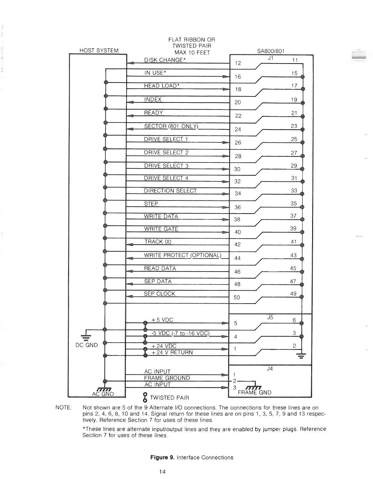
NOTE: Not shown are 5of the 9Alternate I/O connections. The connections for these lines are on
pins 2, 4, 6, 8, 10 and 14. Signal return for these lines are on pins 1, 3, 5, 7, 9and 13 respec-
tively. Reference Section 7for uses of these lines.
*These lines are alternate input/output lines and they are enabled by jumper plugs. Reference
Section 7for uses of these lines.
Figure 9. Interface Connections
14
4.1.1 Input Line Termination
The SA800/801 has been provided with the capability of terminating the four input lines, which are meant to
be multiplexed, by jumpering traces. The four lines and their respective jumpering traces are:
1. Direction Select Trace "T3"
2. Step , . Trace "T4"
3. Write Data Trace "T5"
4. Write Gate Trace "T6"
In order for the drive to function properly, the last drive on the interface must have these four lines ter-
minated. Termination of these four lines can be accomplished by either of two methods.
1. As shipped from the factory, jumpers are installed on the terminator posts T3, T4, T5, and T6. Remove
these shorting plugs from all drives except the last one on the Interface.
2. External termination may be used provided the terminator is beyond the last drive. Each of the four lines
should be terminated by using a150 ohm, Va watt resistor, pulled up to +5 VDC.
4.1.1.2 Drive Seiect 1-4
Drive Select when activated to alogical zero level, activates the multiplexed I/O lines and loads the R/W
head. In this mode of operation only the drive with this line active will respond to the input lines and gate the
output lines.
Four separate input lines, Drive Select 1,Drive Select 2, Drive Select 3, and Drive Select 4, are provided so
that up to four drives may be multiplexed together in asystem and have separate Drive Select lines. Traces
'DS1 ', 'DS2', 'DS3', and 'DS4' have been provided to select which Drive Select line will activate the inter-
face signals for aunique drive. As shipped from the factory, ashorting plug is installed on 'DS1 '. To select
another Drive Select line, this plug should be moved to the appropriate 'DS' pin. For additional methods of
selecting drives, see section 7.1.
4.1.1.3 Direction Select
This interface line is acontrol signal which defines direction of motion the R/W head will take when the Step
line is pulsed. An open circuit or logical one defines the direction as "out" and if apulse is applied to the
Step line the R/W head will move away from the center of the disk. Conversely, if this input is shorted to
ground or alogical zero level, the direction
of motion is defined as "in" and if apulse is applied to the step line, the R/W head will move towards the
center of the disk.
4.1.1.4 Step
This interface line is acontrol signal which causes the R/W head to move with the direction of motion as
defined by the Direction Select line.
The access motion is initiated on each logical zero to logical one transition, or the trailing edge of the signal
pulse. Any change in the Direction Select line must be made at least 1/*s before the trailing edge of the Step
pulse. The read/write head may be prevented from stepping past track 00 by using the "NFO" trace option
on LSI PCB. Refer to Figure 3for these timings. Note: When going from a reverse seek to aforward seek or
vice versa and additional 8ms delay must be induced before changing direction.
4.1.1.5 Write Gate
The active state of this signal, or logical zero, enables Write Data to be written on the diskette. The inactive
state, or logical one, enables the read data logic (Separated Data, Separated Clock, and Read Data) and
stepper logic. Refer to Figure 6for timings.
15
4.1.1.6 Write Data
This interface line provides the data to be written on the diskette. Each transition from alogical one level to a
logical zero level, will cause the current through the R/W head to be reversed thereby writing adata bit. This
line is enabled by Write Gate being active. Refer to Figure 7for timings.
4.1.1.7 Head Load (Alternate Input)
This customer installable option, when enabled by jumpering Trace 'C and activated to alogical zero level
and the diskette access door is closed, will load the R/W head load against the diskette. Refer to section 7
for uses and method of installation.
4.1.1.8 In Use (Alternate Input)
This customer installable option, when enabled by jumpering Trace 'D' and activated to alogical zero level
will turn on the Activity LED in the door push button. This signal is an "OR" function with Drive Select. Refer
to section 7.8 for uses and method of installation.
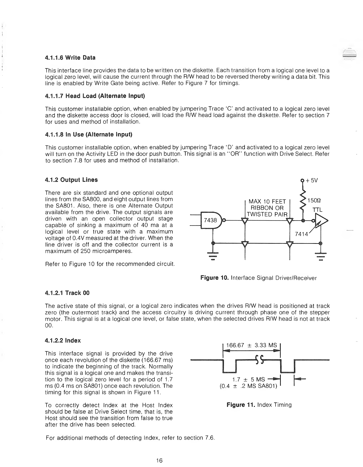
4.1.2 Output Lines
There are six standard and one optional output
lines from the SA800, and eight output lines from
the SA801. Also, there is one Alternate Output
available from the drive. The output signals are
driven with an open collector output stage
capable of sinking amaximum of 40 ma at a
logical level or true state with amaximum
voltage of 0.4V measured at the driver. When the
line driver is off and the collector current is a
maximum of 250 microamperes.
Refer to Figure 10 for the recommended circuit.
+5V
MAX 10 FEET
RIBBON OR
TWISTED PAIR
4.1.2.1 Track 00
Figure 10. Interface Signal Driver/Receiver
The active state of this signal, or alogical zero indicates when the drives R/W head is positioned at track
zero (the outermost track) and the access circuitry is driving current through phase one of the stepper
motor. This signal is at alogical one level, or false state, when the selected drives R/W head is not at track
00.
4.1.2.2 Index
This interface signal is provided by the drive
once each revolution of the diskette (166.67 ms)
to indicate the beginning of the track. Normally
this signal is alogical one and makes the transi-
tion to the logical zero level for aperiod of 1.7
ms (0.4 ms on SA801) once each revolution. The
timing for this signal is shown in Figure 11.
To correctly detect Index at the Host Index
should be false at Drive Select time, that is, the
Host should see the transition from false to true
after the drive has been selected.
166.67 ±3.33 MS
E=lk ^Kl
1.7 ±5MS -*
(0.4 ±.2 MSSA801)
Figure 11. Index Timing
For additional methods of detecting Index, refer to section 7.6.
16
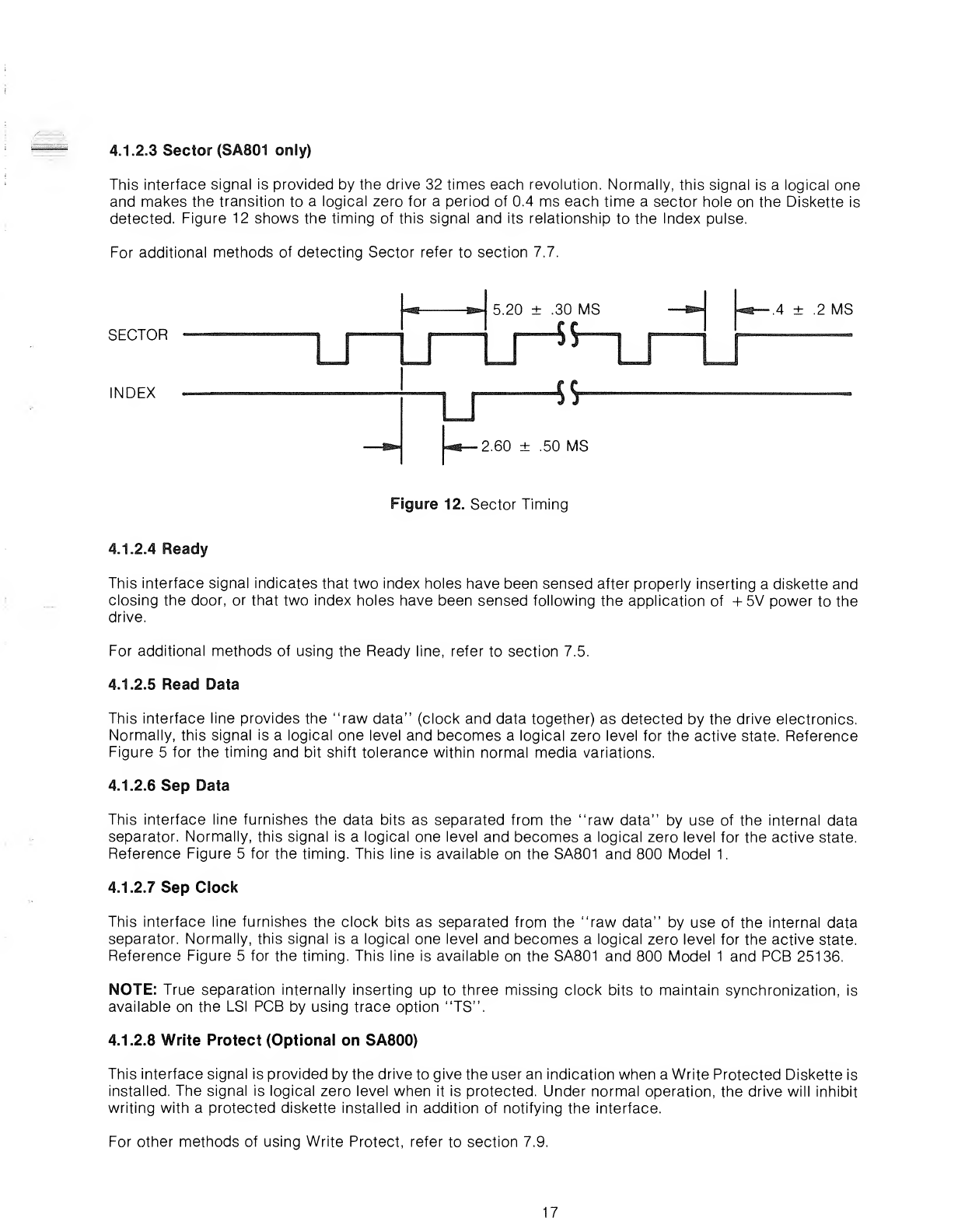
4.1.2.3 Sector (SA801 only)
This interface signal is provided by the drive 32 times each revolution. Normally, this signal is alogical one
and makes the transition to alogical zero for aperiod of 0.4 ms each time asector hole on the Diskette is
detected. Figure 12 shows the timing of this signal and its relationship to the Index pulse.
For additional methods of detecting Sector refer to section 7.7.
SECTOR
INDEX
r
5.20 ±.30 MS
S
—
45-
2.60 ±.50 MS
.4 ±.2 MS
Figure 12. Sector Timing
4.1.2.4 Ready
This interface signal indicates that two index holes have been sensed after properly inserting adiskette and
closing the door, or that two index holes have been sensed following the application of +5V power to the
drive.
For additional methods of using the Ready line, refer to section 7.5.
4.1.2.5 Read Data
This interface line provides the "raw data" (clock and data together) as detected by the drive electronics.
Normally, this signal is alogical one level and becomes alogical zero level for the active state. Reference
Figure 5for the timing and bit shift tolerance within normal media variations.
4.1.2.6 Sep Data
This interface line furnishes the data bits as separated from the "raw data" by use of the internal data
separator. Normally, this signal is alogical one level and becomes alogical zero level for the active state.
Reference Figure 5for the timing. This line is available on the SA801 and 800 Model 1.
4.1.2.7 Sep Clock
This interface line furnishes the clock bits as separated from the "raw data" by use of the internal data
separator. Normally, this signal is alogical one level and becomes alogical zero level for the active state.
Reference Figure 5for the timing. This line is available on the SA801 and 800 Model 1and PCB 25136.
NOTE: True separation internally inserting up to three missing clock bits to maintain synchronization, is
available on the LSI PCB by using trace option "TS".
4.1.2.8 Write Protect (Optional on SA800)
This interface signal is provided by the drive to give the user an indication when a Write Protected Diskette is
installed. The signal is logical zero level when it is protected. Under normal operation, the drive will inhibit
writing with aprotected diskette installed in addition of notifying the interface.
For other methods of using Write Protect, refer to section 7.9.
17
4.1.2.9 Disk Change (Alternate Output)
Reference section 7.10.
4.1.3 Alternate I/O Pins
These interface pins have been provided for use with customer installable options. Refer to section 7for
methods of use.
4.2 Power Interface
The SA800/801 Diskette Storage Drive requires both AC and DC power for operation. The AC power is used
for the spindle drive motor and the DC power is used for the electronics and the stepper motor.
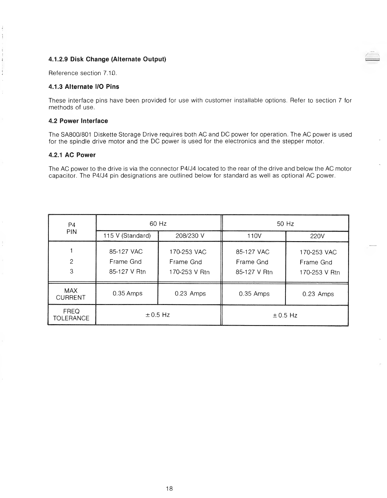
4.2.1 AC Power
The AC power to the drive is via the connector P4/J4 located to the rear of the drive and below the AC motor
capacitor. The P4/J4 pin designations are outlined below for standard as well as optional AC power.
P4
PIN
60 Hz 50 Hz
115 V(Standard) 208/230 V110V 220V
1
2
3
85-1 27 VAC
Frame Gnd
85-127 VRtn
170-253 VAC
Frame Gnd
170-253 VRtn
85-127 VAC
Frame Gnd
85-127 VRtn
170-253 VAC
Frame Gnd
170-253 VRtn
MAX
CURRENT 0.35 Amps 0.23 Amps 0.35 Amps 0.23 Amps
FREQ
TOLERANCE ±0.5 Hz ±0.5 Hz
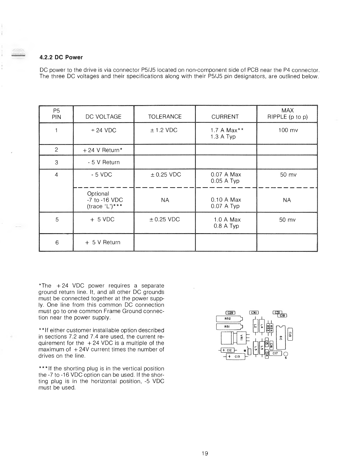
4.2.2 DC Power
DC power to the drive is via connector P5/J5 located on non-component side of PCB near the P4 connector.
The three DC voltages and their specifications along with their P5/J5 pin designators, are outlined below.
P5
PIN DC VOLTAGE TOLERANCE CURRENT MAX I
RIPPLE (p to p)
J
1+24 VDC ±1.2 VDC 1.7 AMax**
1.3 ATyp
100 mv
2+24 VReturn*
3-5VReturn
4-5 VDC
Optional
-7 to -16 VDC
(trace 'L')***
±0.25 VDC
NA
0.07 AMax
0.05 ATyp
0.10 AMax
0.07 ATyp
50 mv
NA
5+5VDC ±0.25 VDC 1.0 AMax
0.8 ATyp
50 mv
6+5VReturn
*The +24 VDC power requires aseparate
ground return line. It, and all other DC grounds
must be connected together at the power supp-
ly. One line from this common DC connection
must go to one common Frame Ground connec-
tion near the power supply.
**lf either customer installable option described
in sections 7.2 and 7.4 are used, the current re-
quirement for the +24 VDC is amultiple of the
maximum of +24V current times the number of
drives on the line.
***lf the shorting plug is in the vertical position
the -7 to -1 6VDC option can be used. If the shor-
ting plug is in the horizontal position, -5 VDC
must be used.
-|4 CI3 "}
19

20

5.0 PHYSICAL INTERFACE
The electrical interface between the SA800/801 and the host system is via three connectors. The first con-
nector, J1, provides the signal interface; the second connector, J5, provides the DC power; and the third
conector, J4, provides the AC power and frame ground.
This section describes the physical connectors used on the drive and the recommended connectors to be
used with them. Refer to Figure 16 for connector locations.
5.1 J1/P1 Connector
Connection to J1 is through a50 pin PCB edge card connector. The dimensions for this connector are shown
in Figure 13. The pins are numbered 1through 50 with the even numbered pins on the component side of the
PCB and the odd numbered pins on the non-component side. Pin 2is located on the end of the PCB connec-
tor closest to the AC motor capacitor and is labeled 2. Akey slot is provided between pins 4and 6for op-
tional connector keying.
The recommended connectors for P1 are tabulated below.
TYPE OF CABLE MANUFACTURER CONNECTOR P/N CONTACT P/N
Twisted Pair, #26
(crimp or solder) AMP 1-583717-1
583616-5 (crimp)
58354-3 (solder)
Twisted Pair, #26
(solder term.) VIKING 3VH25/1JN-5 NA
Flat Cable 3M "Scotchflex" 3415-0001 NA
KEY SLOT
.400 ±.010"
.050" NOM
050" NOM .100" NOM
2.575 ±.010"
.063"
NOM (2X)
BOARD THICKNESS .062 ±.007'
Figure 13. J1 Connector Dimensions
21
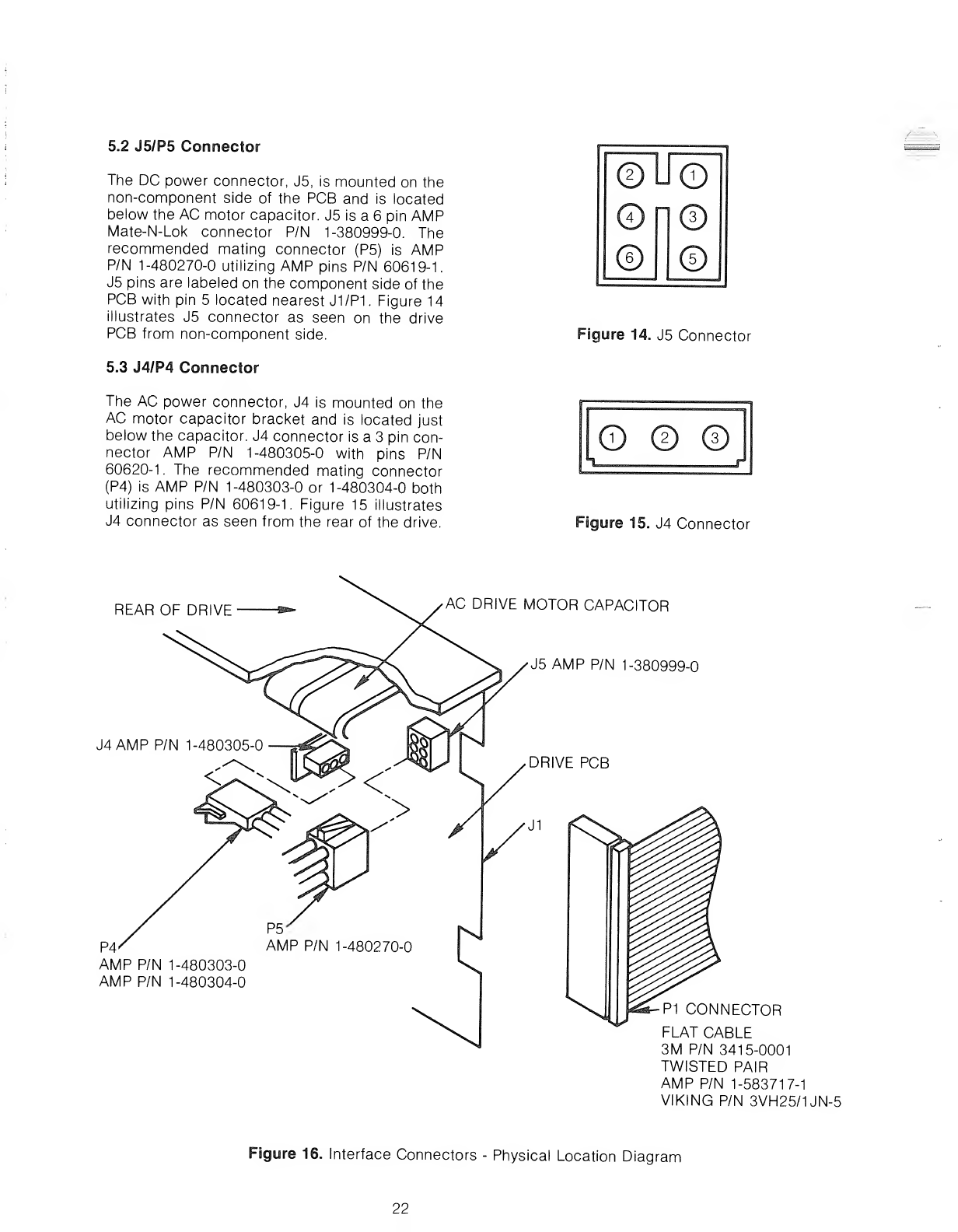
5.2 J5/P5 Connector
The DC power connector, J5, is mounted on the
non-component side of the PCB and is located
below the AC motor capacitor. J5 is a6pin AMP
Mate-N-Lok connector P/N 1-380999-0. The
recommended mating connector (P5) is AMP
P/N 1-480270-0 utilizing AMP pins P/N 60619-1.
J5 pins are labeled on the component side of the
PCB with pin 5located nearest J1/P1. Figure 14
illustrates J5 connector as seen on the drive
PCB from non-component side.
5.3 J4/P4 Connector
The AC power connector, J4 is mounted on the
AC motor capacitor bracket and is located just
below the capacitor. J4 connector is a3pin con-
nector AMP P/N 1-480305-0 with pins P/N
60620-1. The recommended mating connector
(P4) is AMP P/N 1-480303-0 or 1-480304-0 both
utilizing pins P/N 60619-1. Figure 15 illustrates
J4 connector as seen from the rear of the drive.
©Uo
©
©©
©
Figure 14. J5 Connector
© © ©
Figure 15. J4 Connector
REAR OF DRIVE AC DRIVE MOTOR CAPACITOR
J5 AMP P/N 1-380999-0
J4AMP P/N 1-480305-0
<
P4
AMP P/N 1-480303-0
AMP P/N 1-480304-0
P1 CONNECTOR
FLAT CABLE
3M P/N 3415-0001
TWISTED PAIR
AMP P/N 1-583717-1
VIKING P/N 3VH25/1JN-5
Figure 16. Interface Connectors -Physical Location Diagram
22
6.0 DRIVE PHYSICAL SPECIFICATIONS
This section describes the mechanical dimensions and mounting recommendations for the SA800/801.
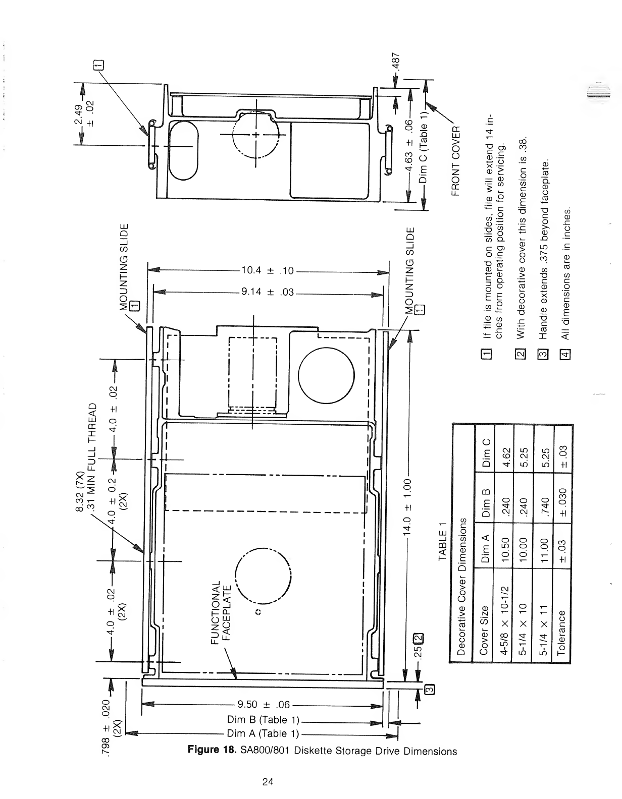
6.1 Drive Dimensions
Reference Figure 18 for dimensions of the SA800/801
.
6.2 Mounting Recommendations
The SA800/801 is capable of being mounted in one of the following positions:
1. Vertical-Door opening to the left or right.
2. Horizontal-Door opening up or down.
3. Upright-Door opening towards the front or rear.
6.2.1 Vertical Mounting
The drive, as shipped from the factory, is ready to be mounted in the vertical position, door opening left or
right, without any adjustments.
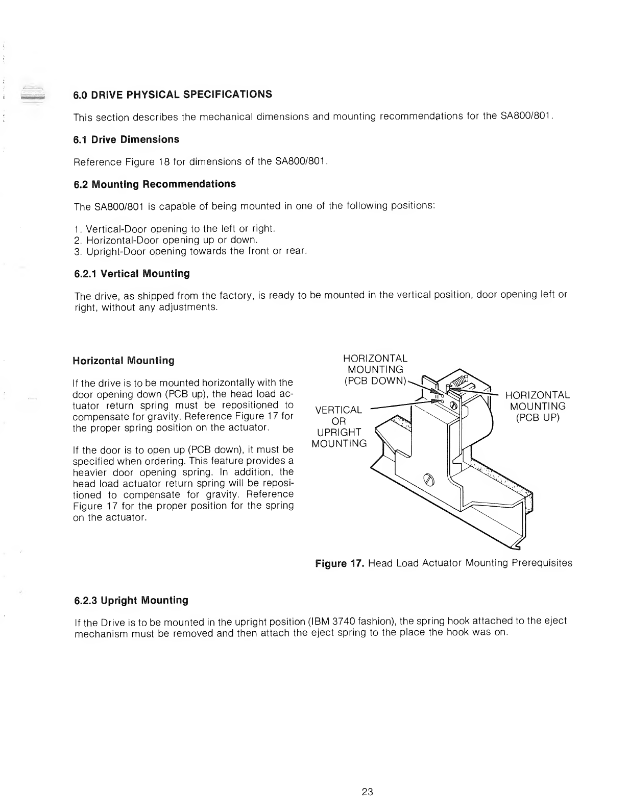
Horizontal Mounting
If the drive is to be mounted horizontally with the
door opening down (PCB up), the head load ac-
tuator return spring must be repositioned to
compensate for gravity. Reference Figure 17for
the proper spring position on the actuator.
If the door is to open up (PCB down), it must be
specified when ordering. This feature provides a
heavier door opening spring. In addition, the
head load actuator return spring will be reposi-
tioned to compensate for gravity. Reference
Figure 17 for the proper position for the spring
on the actuator.
HORIZONTAL
MOUNTING
(PCB DOWN)
VERTICAL
OR
UPRIGHT
MOUNTING
HORIZONTAL
MOUNTING
(PCB UP)
Figure 17. Head Load Actuator Mounting Prerequisites
6.2.3 Upright Mounting
If the Drive is to be mounted in the upright position (IBM 3740 fashion), the spring hook attached to the eject
mechanism must be removed and then attach the eject spring to the place the hook was on.
23
LU
QLU
Q
CD •—
CD >
=CD
-co
_CD O
^c
wg
-rj co
=O
co Q-
co>
Oc
"D
CD CO
S. Q
o°
E E
CO 2
CD CO
=CD
i= o
00
CO
CO
JZ
o
o
CD
a
B
jo
Cl
CD
O
CO
H
—
"O
cz
o
CD
_Q
LO
r^
CO
CO
c
B
X
CD
_CD
T3
C
CO
X
CO
CD
sz
o
<
o
ECM
CD LO
CM LO
CM
CO
o
Q«3- mLO +1
mo
EOooCO
q
QCM CM r^ +1
CO
cz
'
III o
_l CO <. O o oCO
o
+1
LU
<
1-
cz
CD
EE
b
lo
do
CD o
a
CD
>CM
o
o""7
CD CD oo-I—
>N1">
—
CD
00 CD XXXO
c
k_ CO
joCD 00 ^f •«s(-
o>CD
1CD oLO T1— o
1
Qu^"1 »h-
Fsgure 18. SA800/801 Diskette Storage Drive Dimensions
24
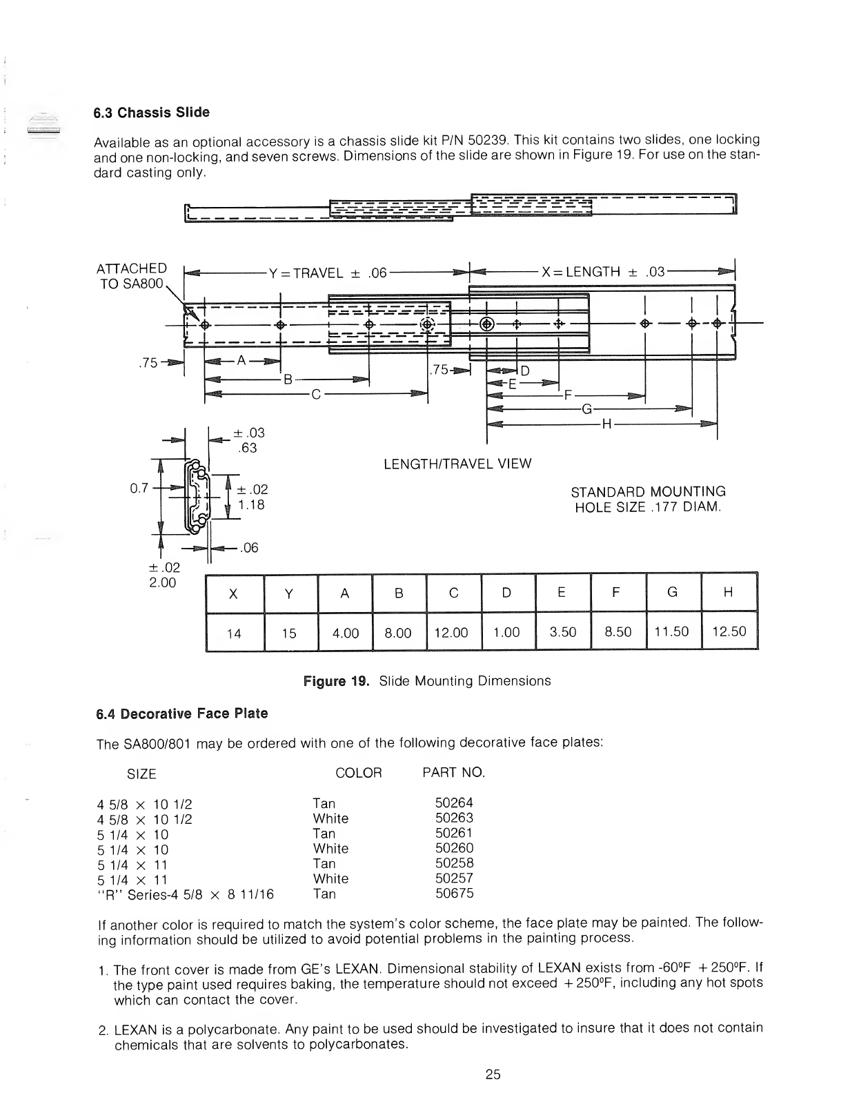
6.3 Chassis Slide
Available as an optional accessory is achassis slide kit P/N 50239. This kit contains two slides, one locking
and one non-locking, and seven screws. Dimensions of the slide are shown in Figure 19. For use on the stan-
dard casting only.
MIUJIIIO* IIM»"'"l!fflM* *limB''" ^U^"liM« ".HiMM BUM'1''MMfrfflliMlfahyifff'^^
n
ATTACHED
TOSA800,
.75
Y=TRAVEL ±.06' -S23-HSJ- X= LENGTH ±.03-
4--&
A.
r—
C
<& I11
75-^»)
«^g~p ^»
LENGTH/TRAVEL VIEW
ffi •$* Tr*"
-G- -^m-
STANDARD MOUNTING
HOLE SIZE .177 DIAM.
XYABCDEFGH
14 15 4.00 8.00 12.00 1.00 3.50 8.50 11.50 12.50
Figure 19. Slide Mounting Dimensions
6.4 Decorative Face Plate
The SA800/801 may be ordered with one of the following decorative face plates:
SIZE COLOR PART NO.
45/8 X10 1/2 Tan 50264
45/8 X10 1/2 White 50263
51/4 X10 Tan 50261
51/4 X10 White 50260
51/4x11 Tan 50258
51/4X11 White 50257
"R" Series-4 5/8 X811/16 Tan 50675
If another color is required to match the system's color scheme, the face plate may be painted. The follow-
ing information should be utilized to avoid potential problems in the painting process.
1. The front cover is made from GE's LEXAN. Dimensional stability of LEXAN exists from -60°F +250°F. If
the type paint used requires baking, the temperature should not exceed +250°F, including any hot spots
which can contact the cover.
2. LEXAN is apolycarbonate. Any paint to be used should be investigated to insure that it does not contain
chemicals that are solvents to polycarbonates.
25
0)
_c
CO
CO
o
CD
CO
CO
X3
T3
C
CD
E
o
Q
B
"CD
x:
'CD TJ
CD 03 CD
>>
OQ. C)
oo
-^ cz -^
cocr
oO
oCO
co
o
CD CD
EoF
CO cCO
(J 3o
uLL O
cd
05
CL
C
o
CO
c
o
o
c:
L±_
CO
CO
CD
c:
o
x:
a>
E
CO
o
O
CO
CO
c
J*:
o
0)
JO
CL
o
CO
XX
CM "*
^Q_
oa
LO
^+1 CM
X^
SLg X
g° CM
CO
c
o
CO
CD
E
o
o
o
o
o
CD
>
o
o
CO
o
o
B
1L
r*—450 ±02"^—**l
1.00 ±.01
54 ±.02
CO LO
CO CM
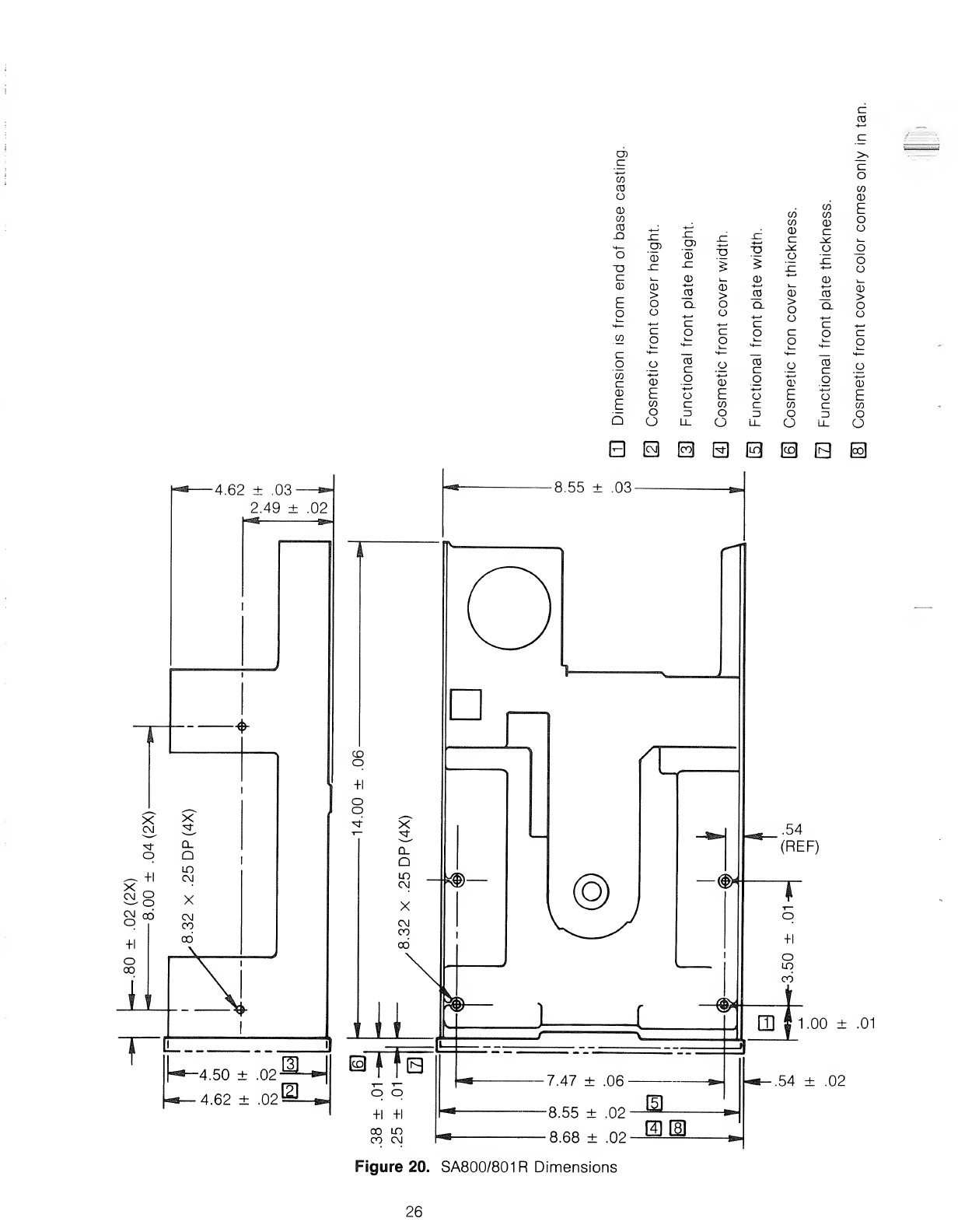
Figure 20. SA800/801R Dimensions
26

7.0 CUSTOMER INSTALLABLE OPTIONS
The SA800/801 can be modified by the user to function differently than the standard method as outlined in
sections 3and 4. These modifications can be implemented by adding or deleting traces and by use of the
Alternate I/O pins. Some traces are capable of being connected by use of ashorting plug, Shugart P/N 15648
or AMP P/N 5301 53-2. This section will discuss afew examples of modifications and how to install them. The
examples are:
1
.
Drive Select one to eight drives.
2. Select drive without loading head or enabling stepper.
3. Select drive and enable stepper without loading the head.
4. Load head without selecting drive or enabling stepper.
5. Radial Ready.
6. Radial Index/Sector.
7. Eight, 16, or 32 Sector option.
8. In Use (Activity L.E.D.) optional input.
9. Write Protect options.
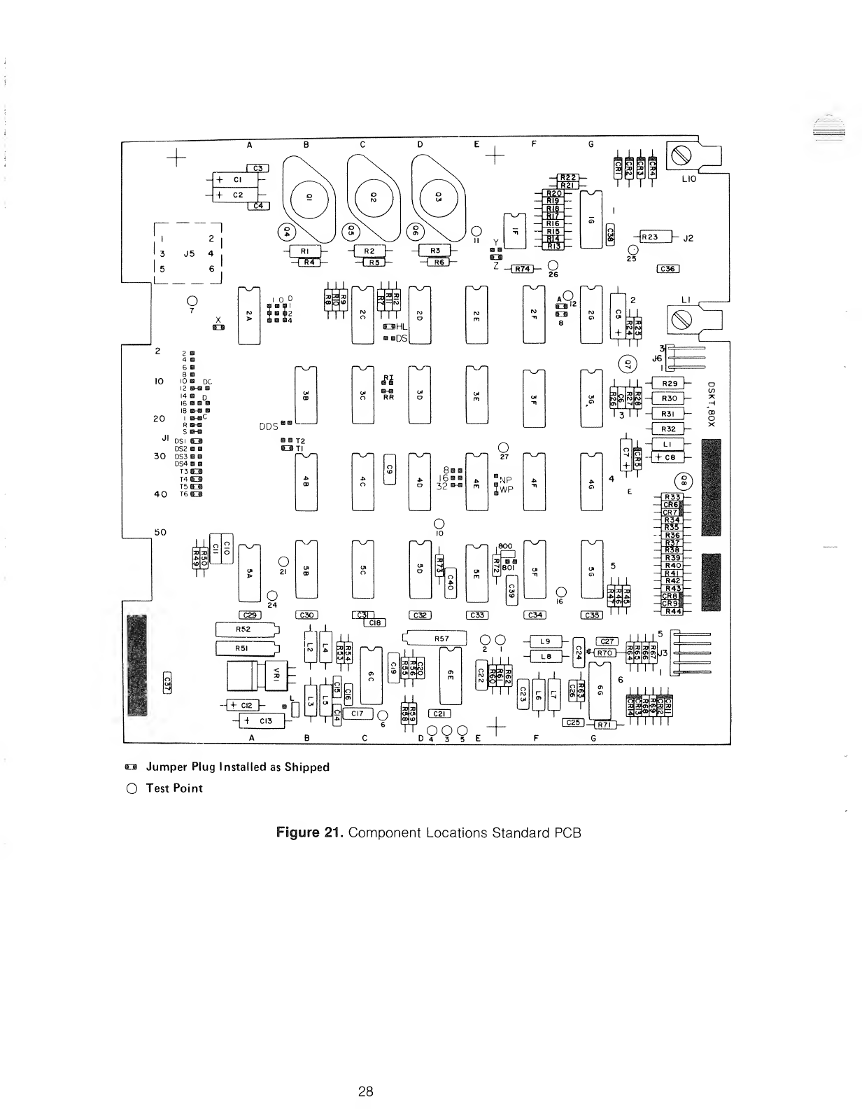
Tabulated below are the trace options with the condition of the trace as it is shipped from the factory. Figure
21 shows the location of these traces on the PCB.
CUSTOMER CUT/ADD TRACE OPTIONS
TRACE
DESIGNATOR DESCRIPTION
SHIPPED FROM FACTORY!
OPEN SHORT
T3,T4,T5,T6 Terminations for Multiplexed Inputs Plugged
T1 Terminator for Drive Select Plugged
T2 Spare Terminator for Radial Head Load X
DS1,DS2,DS3,DS4 Drive Select Input Pins XDS1 is
Plugged
RR Radial Ready X
Rl Radial Index and Sector X
R,I,S Ready, Index, Sector Alternate Output Pads X
HL Stepper Power From Head Load Plugged
DS Stepper Power From Drive Select X
WP Inhibit Write When Write Protected X
NP Allow Write When Write Protected X
8,16,32 8, 16, 32 Sectors (SA801 Only) 8& 16 32
DAlternate Input-In Use X
2,4,6,8,10,12,14,16,18 Nine Alternate I/O Pins X
D1,D2,D4,DDS Customer Installable Decode Drive Select Option X
A,B,X Radial Head Load Plugged
CAlternate Input-Head Load X
ZIn Use from Drive Select Plugged
YIn Use from HD LD X
DC Alternate Output-Disk Change X
NFO Non Force Out X
TS True FM Data Separation X
27
-*~iR4 f——
|
R5r*~"
—[HIT
-riitr
-389
_a
Rl?
Big
o-n
-mf
RI6
RI5
II yHi
ftlS
LIO
HR23 hJ2
O
ca Jumper Plug Installed as Shipped
OTest Point
Figure 21. Component Locations Standard PCB
28
II+»
HOd-d-d
R.qn
o
o
„„ o
DCo
Doo
c
ioo
'oo
R
Soo XJ-
DS1 ,™ UL
DS2 |f°°i
DS3 §gT2 9\
DS4 oo
T3 06
T4
T5
T6
06
66 D-D
00 RR
IIIII
n-n
Rl TS
D
DD
NFO
16
i, i, i,
i
1
86
OD
o801
o
o
DSo
hl!
lool [ool lool
ABX, .
(ool
Tl
3t
D-DD B
WPNP9
oo
12 26
i, i, i, i,i ,
i
6
o
11
II IIII
ofo'ol
YZ
258
oo
izr
T
i i ii1 1
iiiiFt
DL
o
I, I, I, I, J.
+
I, I, I, I,
I
LA
JJUJU
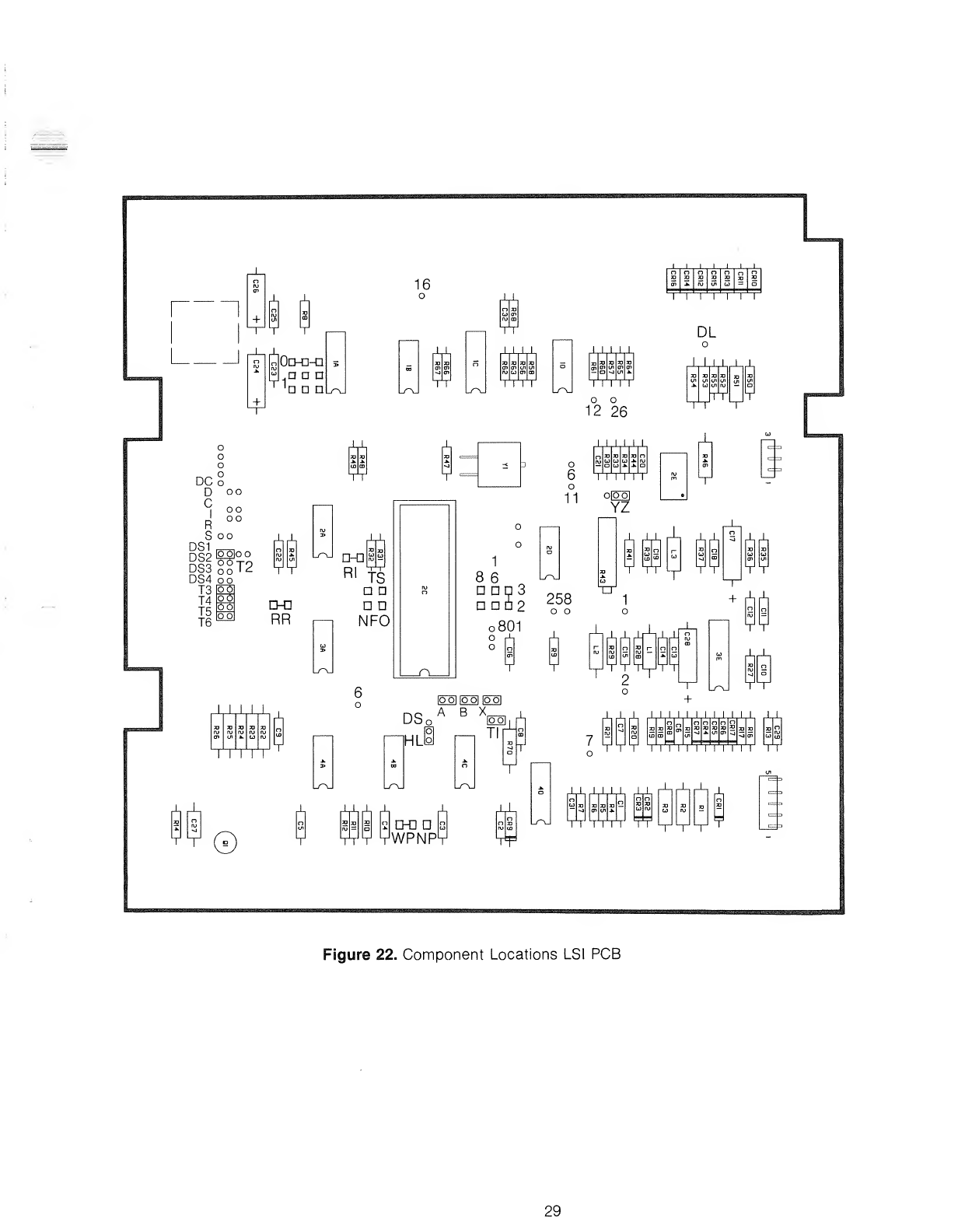
Figure 22. Component Locations LSI PCB
29
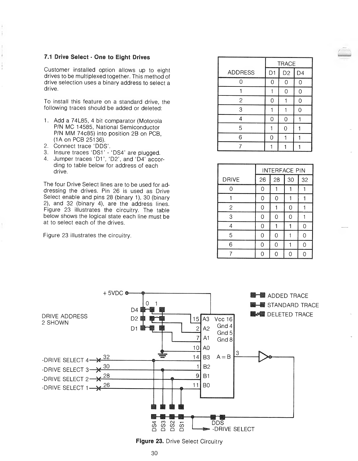
7.1 Drive Select •One to Eight Drives
Customer installed option allows up to eight
drives to be multiplexed together. This method of
drive selection uses abinary address to select a
drive.
To install this feature on astandard drive, the
following traces should be added or deleted:
1.
2.
3.
4.
Add a74L85, 4bit comparator (Motorola
P/N MC 14585, National Semiconductor
P/N MM 74c85) into position 2B on PCB,
(1Aon PCB 25136).
Connect trace 'DDS'.
Insure traces 'DS1' -'DS4' are plugged.
Jumper traces 'D1\ 'D2\ and 'D4' accor-
ding to table below for address of each
drive.
The four Drive Select lines are to be used for ad-
dressing the drives. Pin 26 is used as Drive
Select enable and pins 28 (binary 1), 30 (binary
2), and 32 (binary 4), are the address lines.
Figure 23 illustrates the circuitry. The table
below shows the logical state each line must be
at to select each of the drives.
Figure 23 illustrates the circuitry.
ADDRESS
TRACE
D1 D2 D4
11
21
311
41
511
611
7111
DRIVE
INTERFACE PIN
26 28 30 32
111
111
21 1
31
411
51
61
7
+5VDC O-
DRIVE ADDRESS
2SHOWN
-DRIVE SELECT 4
-DRIVE SELECT 3
-DRIVE SELECT 2
-DRIVE SELECT 1
-3- 00 C\J t-
CO CO CO CO
Q Q QQ
ADDED TRACE
STANDARD TRACE
mDELETED TRACE
DDS
-DRIVE SELECT
Figure 23. Drive Select Circuitry
30
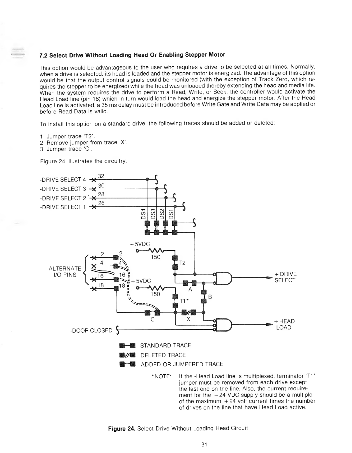
7.2 Select Drive Without Loading Head Or Enabling Stepper Motor
This option would be advantageous to the user who requires adrive to be selected at all times. Normally,
when adrive is selected, its head is loaded and the stepper motor is energized. The advantage of this option
would be that the output control signals could be monitored (with the exception of Track Zero, which re-
quires the stepper to be energized) while the head was unloaded thereby extending the head and media life.
When the system requires the drive to perform aRead, Write, or Seek, the controller would activate the
Head Load line (pin 18) which in turn would load the head and energize the stepper motor. After the Head
Load line is activated, a35 ms delay must be introduced before Write Gate and Write Data may be applied or
before Read Data is valid.
To install this option on astandard drive, the following traces should be added or deleted:
1. Jumper trace T2\
2. Remove jumper from trace 'X'.
3. Jumper trace 'C.
Figure 24 illustrates the circuitry.
-DRIVE SELECT 4
-DRIVE SELECT 3
-DRIVE SELECT 2
-DRIVE SELECT 1
ALTERNATE
I/O PINS +DRIVE
SELECT
-DOOR CLOSED $
+HEAD
LOAD
__STANDARD TRACE
m/M DELETED TRACE
ADDED OR JUMPERED TRACE
NOTE: If the -Head Load line is multiplexed, terminator 'TV
jumper must be removed from each drive except
the last one on the line. Also, the current require-
ment for the +24 VDC supply should be amultiple
of the maximum +24 volt current times the number
of drives on the line that have Head Load active.
Figure 24. Select Drive Without Loading Head Circuit
31
7.3 Select Drive and Enable Stepper Without Loading Head
This option is useful to the user who wishes to select adrive and perform aseek operation without the head
being loaded or with door open. An example use of this option is that at power on time, an automatic
recalibrate (reverse seek to track zero) operation could be performed with the drive access door open. Nor-
mally for aseek to be performed, the door must be closed and the head loaded. Other advantages are those
listed in section 7.2 in addition to being able to monitor Track Zero. When aRead or Write operation is to be
performed, the head must be loaded (pin 18). After the Head Load line is activated, a35 ms delay must be in-
troduced before Write Gate and Write Data may be applied or before Read Data is valid.
To install this option on astandard drive, the following traces should be added or deleted:
1. Jumper trace 'T2'.
2. Remove jumper from trace 'B'.
3. Remove jumper from trace 'HL'.
4. Jumper trace 'DS'.
5. Jumper trace 'C
Figures 24 and 25 illustrate the circuitry.
7.4 Load Head Without Selecting Drive Or Enabling Stepper
This option is useful in disk to disk copy operations. It allows the user to keep the heads loaded on all drives
thereby eliminating the 35 ms head load time. The head is kept loaded on each drive via an Alternate I/O pin.
Each drive may have its own Head Load line (Radial or Simplexed) or they may share the same line
(Multiplexed). When the drive is selected, an 8ms delay must be introduced before aRead or Write opera-
tion can be performed. This is to allow the R/W head to settle after the stepper motor is energized. With this
option installed, adrive can only be selected with both Drive Select and Head Load active.
To install this option on standard drive, the following traces should be added or deleted:
1. Jumper trace T2\
2. Remove jumper from trace 'A'.
3. Remove jumper from trace 'HL'.
4. Jumper trace 'DS'.
*5. Jumper trace 'C.
*lf the -Head Load line is multplexed, terminator 'TV jumper must be removed from each drive except the
last one on the line.
Figures 25 and 26 illustrate the circuitry.
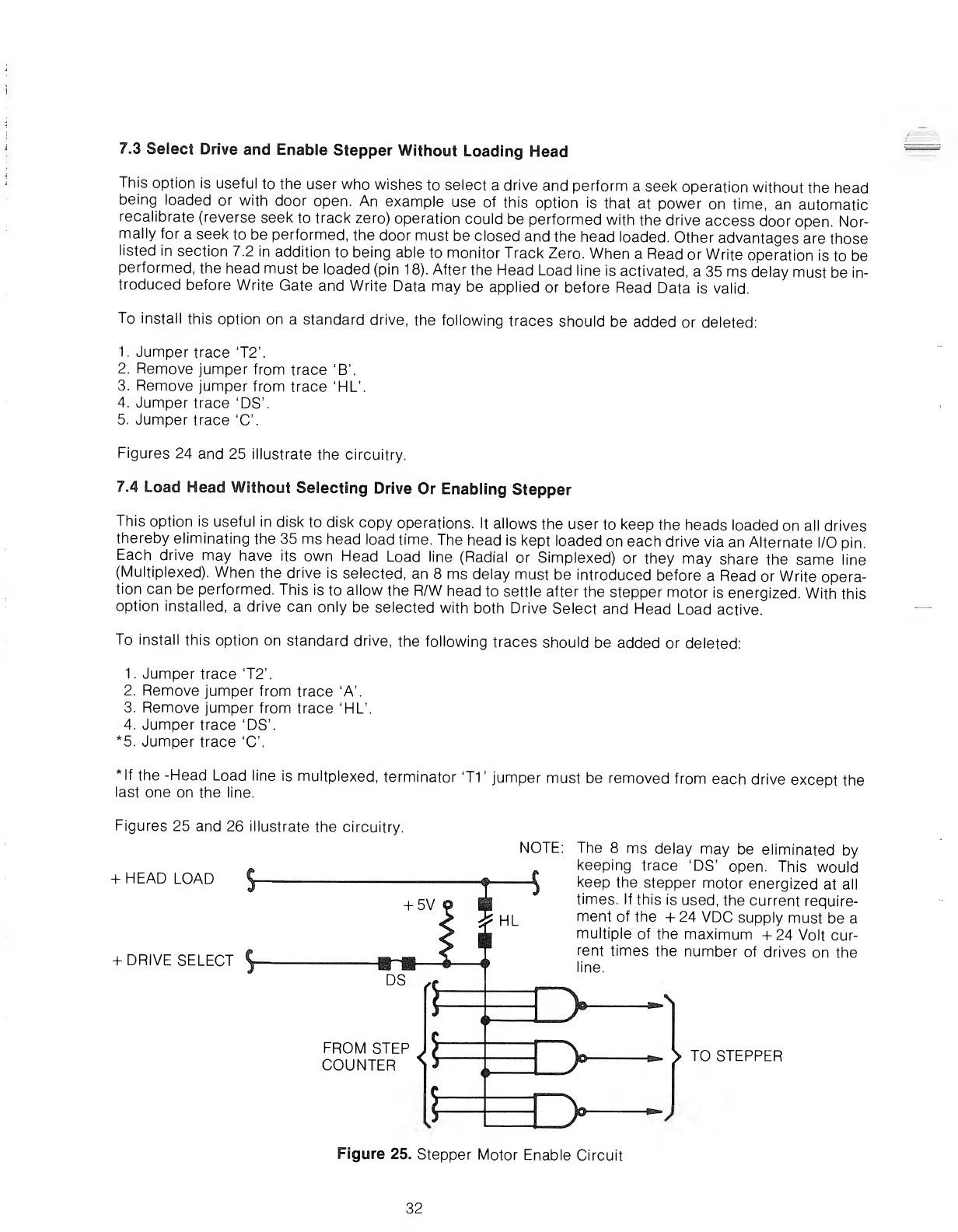
+HEAD LOAD
+DRIVE SELECT
NOTE:
FROM STEP
COUNTER
The 8ms delay may be eliminated by
keeping trace 'DS' open. This would
keep the stepper motor energized at all
times. If this is used, the current require-
ment of the +24 VDC supply must be a
multiple of the maximum +24 Volt cur-
rent times the number of drives on the
ne.
>TO STEPPER
Figure 25. Stepper Motor Enable Circuit
32
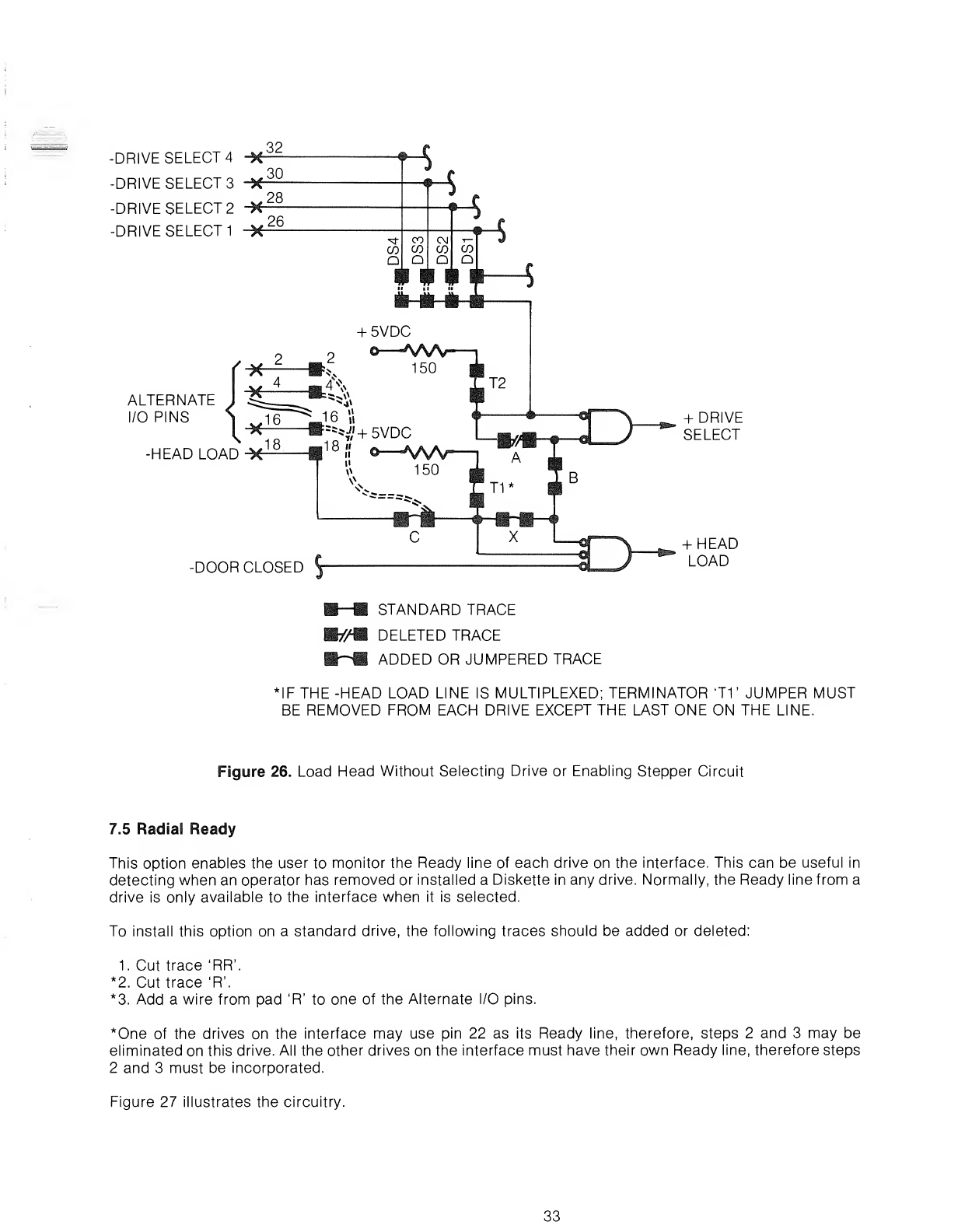
-DRIVE SELECT 4-X 32
-DRIVE SELECT 3-* 30
-DRIVE SELECT 2-H 28
-DRIVE SELECT 1-X 26
ALTERNATE
I/O PINS
-HEAD LOAD^
4?\
©^
III
+5VDC
150
;=5 4'+5VDC
18-
W150
O"^S/S^Sf^
-DOOR CLOSED
tT2
+DRIVE
SELECT
+HEAD
LOAD
STANDARD TRACE
WM DELETED TRACE
ADDED OR JUMPERED TRACE
IF THE -HEAD LOAD LINE IS MULTIPLEXED; TERMINATOR 'T1 'JUMPER MUST
BE REMOVED FROM EACH DRIVE EXCEPT THE LAST ONE ON THE LINE.
Figure 26. Load Head Without Selecting Drive or Enabling Stepper Circuit
7.5 Radial Ready
This option enables the user to monitor the Ready line of each drive on the interface. This can be useful in
detecting when an operator has removed or installed aDiskette in any drive. Normally, the Ready line from a
drive is only available to the interface when it is selected.
To install this option on a standard drive, the following traces should be added or deleted:
1. Cut trace 'RR'.
*2. Cut trace 'R\
*3. Add awire from pad 'R' to one of the Alternate I/O pins.
*One of the drives on the interface may use pin 22 as its Ready line, therefore, steps 2 and 3may be
eliminated on this drive. All the other drives on the interface must have their own Ready line, therefore steps
2and 3must be incorporated.
Figure 27 illustrates the circuitry.
33
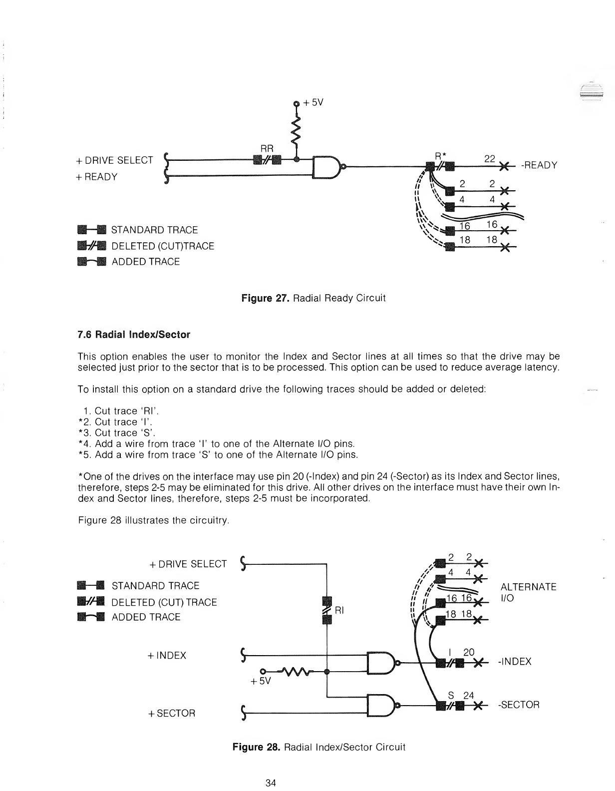
+5V
+DRIVE SELECT
+READY
STANDARD TRACE
WM DELETED (CUT)TRACE
ADDED TRACE
-READY
Figure 27. Radial Ready Circuit
7.6 Radial Index/Sector
This option enables the user to monitor the Index and Sector lines at all times so that the drive may be
selected just prior to the sector that is to be processed. This option can be used to reduce average latency.
To install this option on astandard drive the following traces should be added or deleted:
1. Cut trace 'Rl\
*2. Cut trace 'I'.
*3. Cut trace 'S'.
*4. Add awire from trace 'I' to one of the Alternate I/O pins.
*5. Add awire from trace 'S' to one of the Alternate I/O pins.
*One of the drives on the interface may use pin 20 (-Index) and pin 24 (-Sector) as its Index and Sector lines,
therefore, steps 2-5 may be eliminated for this drive. All other drives on the interface must have their own In-
dex and Sector lines, therefore, steps 2-5 must be incorporated.
Figure 28 illustrates the circuitry.
+DRIVE SELECT $-
STANDARD TRACE
#DELETED (CUT) TRACE
ADDED TRACE
+INDEX
©-—^WV"^-i^
+5V
+SECTOR
ALTERNATE
I/O
-INDEX
-SECTOR
Figure 28. Radial Index/Sector Circuit
34
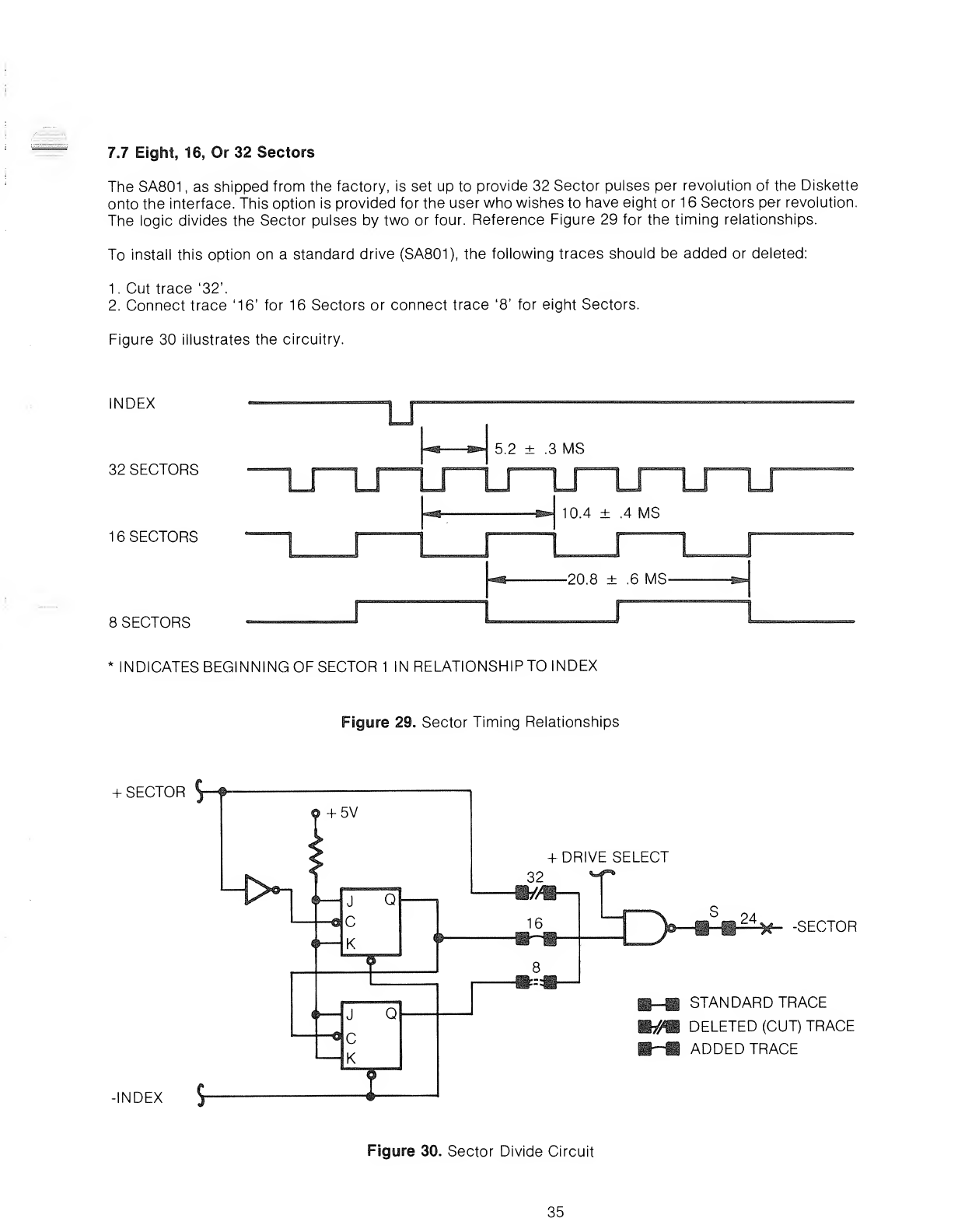
7.7 Eight, 16, Or 32 Sectors
The SA801 ,as shipped from the factory, is set up to provide 32 Sector pulses per revolution of the Diskette
onto the interface. This option is provided for the user who wishes to have eight or 16 Sectors per revolution.
The logic divides the Sector pulses by two or four. Reference Figure 29 for the timing relationships.
To install this option on astandard drive (SA801), the following traces should be added or deleted:
1. Cut trace '32'.
2. Connect trace '16' for 16 Sectors or connect trace '8' for eight Sectors.
Figure 30 illustrates the circuitry.
INDEX
32 SECTORS
16 SECTORS
8SECTORS
U
5.2 ±.3 MS
10.4 ±.4 MS
-20.8 ±.6 MS-
*INDICATES BEGINNING OF SECTOR 1IN RELATIONSHIP TO INDEX
Figure 29. Sector Timing Relationships
+SECTOR 5—f
+DRIVE SELECT
-INDEX J
-SECTOR
STANDARD TRACE
DELETED (CUT) TRACE
ADDED TRACE
Figure 30. Sector Divide Circuit
35
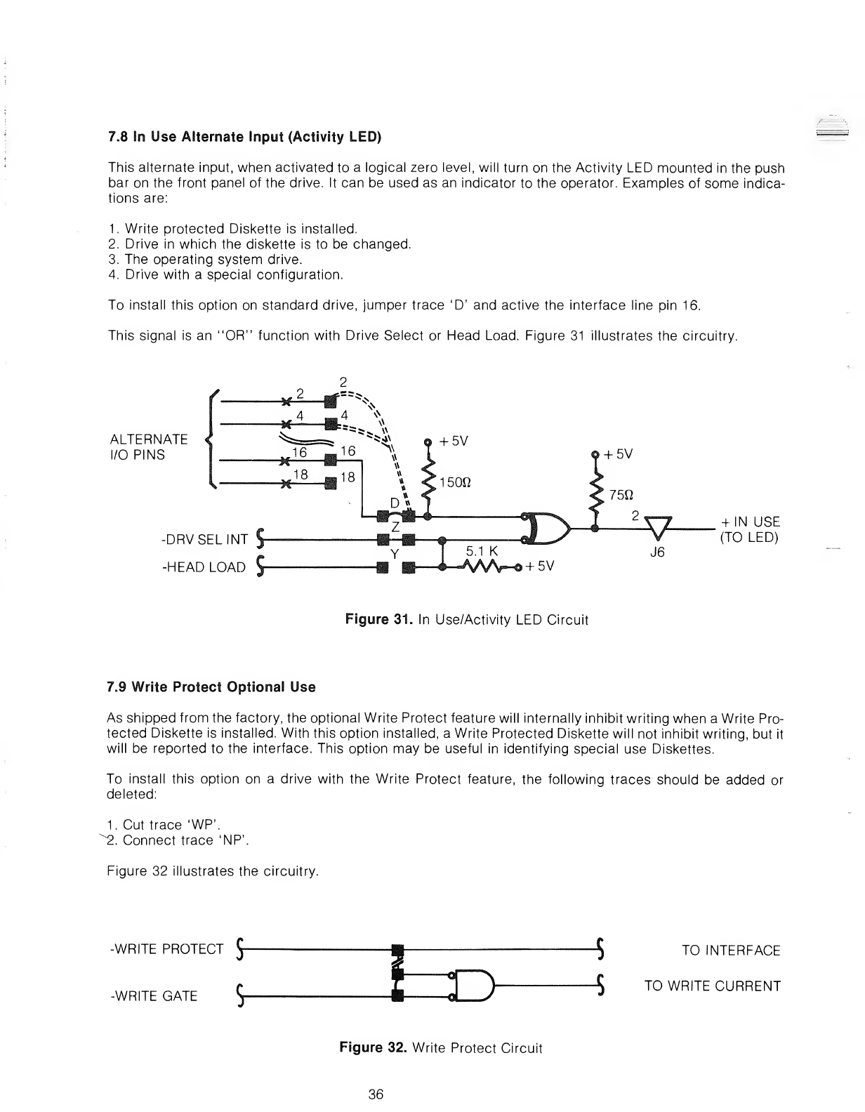
7.8 In Use Alternate Input (Activity LED)
This alternate input, when activated to alogical zero level, will turn on the Activity LED mounted in the push
bar on the front panel of the drive. It can be used as an indicator to the operator. Examples of some indica-
tions are:
1. Write protected Diskette is installed.
2. Drive in which the diskette is to be changed.
3. The operating system drive.
4. Drive with aspecial configuration.
To install this option on standard drive, jumper trace 'D' and active the interface line pin 16.
This signal is an "OR" function with Drive Select or Head Load. Figure 31 illustrates the circuitry.
ALTERNATE
I/O PINS
-DRVSELINT $
-HEAD LOAD J
5.1 K
«AAAr-@ +5V
+IN USE
(TO LED)
Figure 31. In Use/Activity LED Circuit
7.9 Write Protect Optional Use
As shipped from the factory, the optional Write Protect feature will internally inhibit writing when aWrite Pro-
tected Diskette is installed. With this option installed, aWrite Protected Diskette will not inhibit writing, but it
will be reported to the interface. This option may be useful in identifying special use Diskettes.
To install this option on adrive with the Write Protect feature, the following traces should be added or
deleted:
1. Cut trace 'WP\
^2. Connect trace 'NP'.
Figure 32 illustrates the circuitry.
-WRITE PROTECT Jj-
-WRITE GATE J
TO INTERFACE
TO WRITE CURRENT
Figure 32. Write Protect Circuit
36
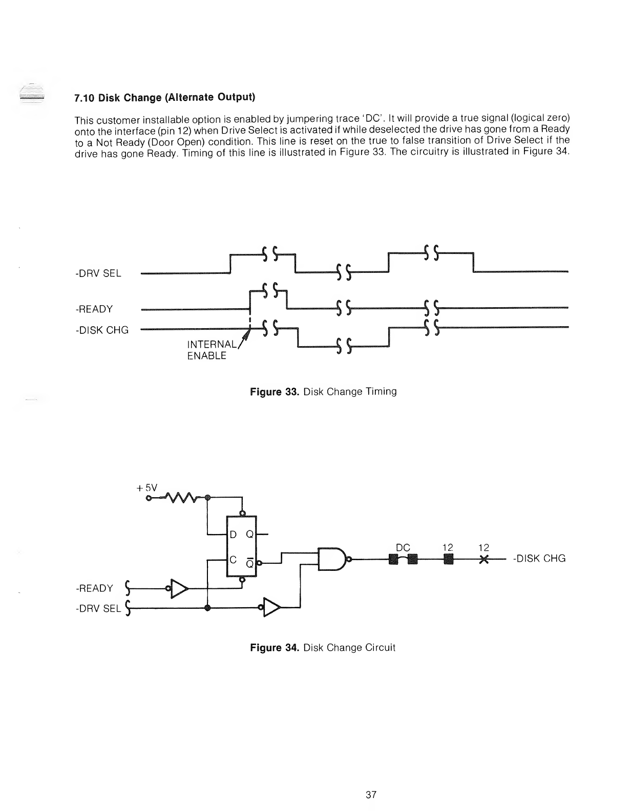
7.10 Disk Change (Alternate Output)
This customer installable option is enabled by jumpering trace 'DC. It will provide atrue signal (logical zero)
onto the interface (pin 12) when Drive Select is activated if while deselected the drive has gone from aReady
to aNot Ready (Door Open) condition. This line is reset on the true to false transition of Drive Select if the
drive has gone Ready. Timing of this line is illustrated in Figure 33. The circuitry is illustrated in Figure 34.
-DRV SEL
-READY
-DISKCHG
—5S—
|
INTERNAL
ENABLE
3!r
*fr
45-
$$
Figure 33. Disk Change Timing
+5V
-READY J°[^>
-DRV SEL 5
fi.
DQ
CQ&-
I"X.
I1/
H>
DC 12 12
XDISKCHG
Figure 34. Disk Change Circuit
37
8.0 OPERATION PROCEDURES
The SA800/801 was designed for ease of operator use to facilitate awide range of operator oriented applica-
tions. The following section is aguide for the handling and error recovery procedures on the diskette and
diskette drive.
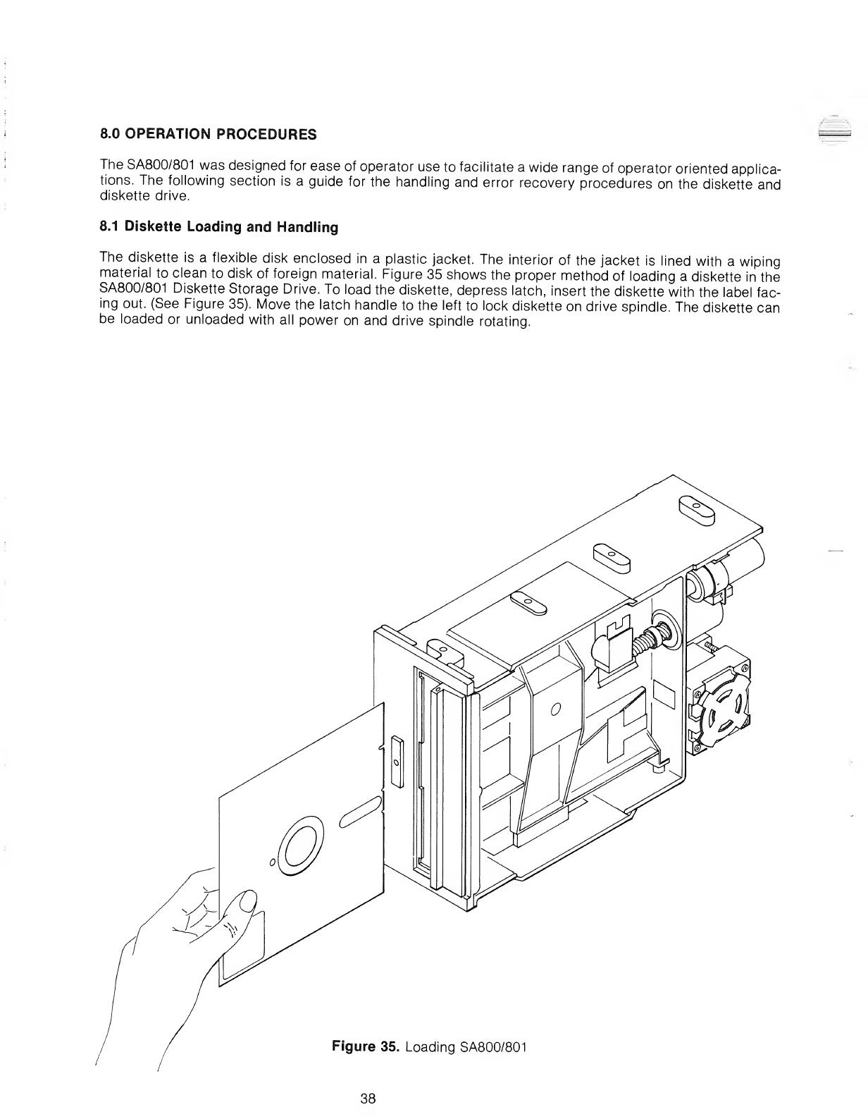
8.1 Diskette Loading and Handling
The diskette is aflexible disk enclosed in aplastic jacket. The interior of the jacket is lined with awiping
material to clean to disk of foreign material. Figure 35 shows the proper method of loading adiskette in the
SA800/801 Diskette Storage Drive. To load the diskette, depress latch, insert the diskette with the label fac-
ing out. (See Figure 35). Move the latch handle to the left to lock diskette on drive spindle. The diskette can
be loaded or unloaded with all power on and drive spindle rotating.
Figure 35. Loading SA800/80
38
When removed from the drive, the diskette is stored in an envelope. To protect the diskette, the same care
and handling procedures specified for computer magnetic tape apply. These precautionary procedures are
as follows:
1. Return the diskette to its storage envelope.
2. Keep cartridges away from magnetic fields and from ferromagnetic materials which might become
magnetized. Strong magnetic fields can distort recorded data on the disk.
3. Replace storage envelopes when they become worn, cracked or distorted. Envelopes are designed to pro-
tect the disk.
4. Do not write on the plastic jacket with alead pencil or ball-point pen. Use afelt tip pen.
5. Heat and contamination from acarelessly dropped ash can damage the disk.
6. Do not expose diskette to heat or sunlight.
7. Do not touch or attempt to clean the disk surface. Abrasions may cause loss of stored data.
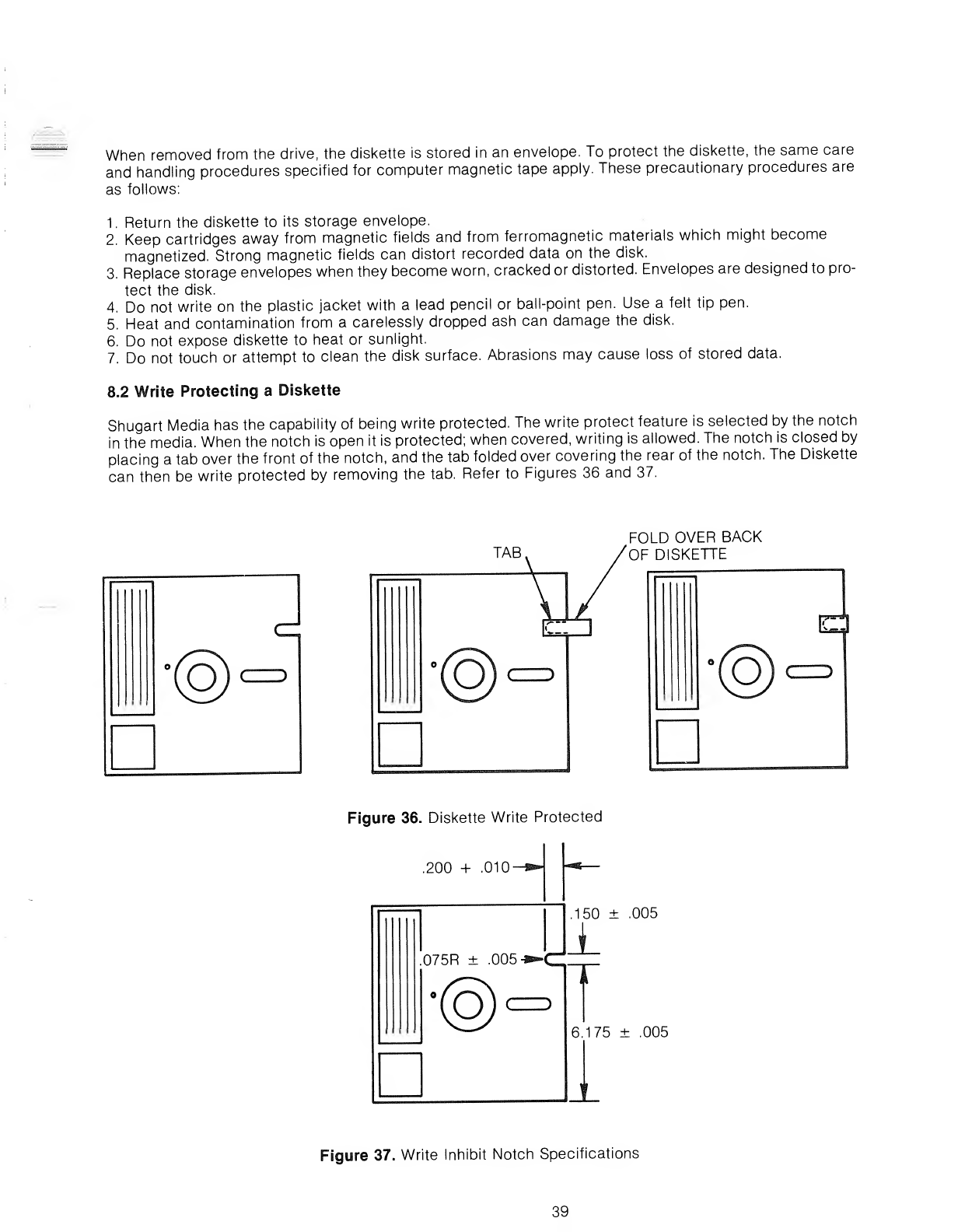
8.2 Write Protecting aDiskette
Shugart Media has the capability of being write protected. The write protect feature is selected by the notch
in the media. When the notch is open it is protected; when covered, writing is allowed. The notch is closed by
placing atab over the front of the notch, and the tab folded over covering the rear of the notch. The Diskette
can then be write protected by removing the tab. Refer to Figures 36 and 37.
FOLD OVER BACK
OF DISKETTE
©r)
Figure 36. Diskette Write Protected
.200 +.010-
075R ±.005 -s^C
CZZ)
@
.150 ±.005
6.175 ±.005
Figure 37. Write Inhibit Notch Specifications
39
9.0 ERROR DETECTION AND CORRECTION
9.1 Write Error
If an error occurs during awrite operation, it will be detected on the next revolution by doing aread opera-
tion, commonly called a"write check." To correct the error, another write and write check operation must
be done. If the write operation is not successful after ten attempts have been made, aread operation should
be attempted on another track to determine if the media or the drive is failing. If the error still persists the
disk should be considered defective and discarded.
9.2 Read Error
Most errors that occur will be "soft" errors; that is, by performing an error recovery procedure the data will
be recovered.
Soft errors are usually caused by:
1. Airborne contaminants that pass between the read/write head and the disk. These comtaminants will
generally be removed by the cartridge self-cleaning wiper.
2. Random electrical noise which usually lasts for afew ^sec.
3. Small defects in the written data and/or track not detected during the write operation which may cause a
soft error during aread.
The following procedures are recommended to recover from the above mentioned soft errors:
1. Reread the track ten times or until such time as the data is recovered.
2. If data is not recovered after using step 1, access the head to the adjacent track in the same direction
previously moved, then return to the desired track.
3. Repeat step 1
.
4. If data is not recovered, the error is not recoverable.
40
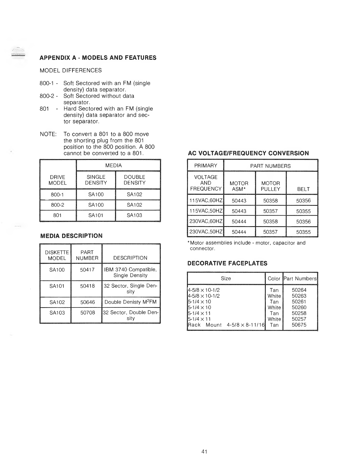
APPENDIX A-MODELS AND FEATURES
MODEL DIFFERENCES
800-1 -Soft Sectored with an FM (single
density) data separator.
800-2 -Soft Sectored without data
separator.
801 -Hard Sectored with an FM (single
density) data separator and sec-
tor separator.
NOTE: To convert a801 to a800 move
the shorting plug from the 801
position to the 800 position. A800
cannot be converted to a 801
.
DRIVE
MODEL
MEDIA
SINGLE
DENSITY
DOUBLE
DENSITY
800-1 SA1 00 SA102
800-2 SA100 SA102
801 SA101 SA103
MEDIA DESCRIPTION
DISKETTE
MODEL PART
NUMBER DESCRIPTION
SA1 00 50417 IBM 3740 Compatible,
Single Density
SA101 50418 32 Sector, Single Den-
sity
SA1 02 50646 Double Denisty M2FM
SA1 03 50708 32 Sector, Double Den-
sity
AC VOLTAGE/FREQUENCY CONVERSION
PRIMARY PART NUMBERS
VOLTAGE
AND
FREQUENCY MOTOR
ASM* MOTOR
PULLEY BELT
115VAC,60HZ 50443 50358 50356
115VAC.50HZ 50443 50357 50355
230VAC.60HZ 50444 50358 50356
230VAC50HZ 50444 50357 50355
*Motor assemblies include -motor, capacitor and
connector.
DECORATIVE FACEPLATES
Size Color Part Numbers
4-5/8x10-1/2 Tan 50264
4-5/8x10-1/2 White 50263
5-1/4x10 Tan 50261
5-1/4x10 White 50260
5-1/4x11 Tan 50258
5-1/4x11 White 50257
Rack Mount 4-5/8x8-11/16 Tan 50675
41