SAFE Key Features And Terminology
User Manual: SAFE Key Features and Terminology
Open the PDF directly: View PDF ![]() .
.
Page Count: 77
- Title
- Copyright
- Disclaimer
- Contents
- Chapter 01 Welcome to SAFE
- Chapter 02 Getting Started
- Chapter 03 The SAFE System
- Chapter 04 SAFE Modeling Features
- Chapter 05 SAFE Analysis Features
- Chapter 06 SAFE Design Features
- Chapter 07 SAFE Detailing Features
- Chapter 08 The SAFE "Screen"
- Chapter 09 Key Topics

Key Features and Terminology

SAFE®
DESIGN OF SLABS, BEAMS AND FOUNDATIONIS
REINFORCED AND POST-TENSIONED CONCRETE
Key Features and Terminology
ISO SAF112816M1 Rev. 0
Proudly developed in the United States of America
November 2016

Copyright
Copyright Computers & Structures, Inc., 1978-2016
All rights reserved.
The CSI Logo® and SAFE® are registered trademarks of Computers &
Structures, Inc. Watch & LearnTM is a trademark of Computers & Structures,
Inc. Adobe and Acrobat are registered trademarks of Adobe Systems
Incorported. AutoCAD is a registered trademark of Autodesk, Inc.
The computer program SAFE® and all associated documentation are
proprietary and copyrighted products. Worldwide rights of ownership rest
with Computers & Structures, Inc. Unlicensed use of this program or
reproduction of documentation in any form, without prior written
authorization from Computers & Structures, Inc., is explicitly prohibited.
No part of this publication may be reproduced or distributed in any form or
by any means, or stored in a database or retrieval system, without the prior
explicit written permission of the publisher.
Further information and copies of this documentation may be obtained from:
Computers & Structures, Inc.
www.csiamerica.com
info@csiamerica.com (for general information)
support@csiamerica.com (for technical support)
DISCLAIMER
CONSIDERABLE TIME, EFFORT AND EXPENSE HAVE GONE INTO THE
DEVELOPMENT AND TESTING OF THIS SOFTWARE. HOWEVER, THE
USER ACCEPTS AND UNDERSTANDS THAT NO WARRANTY IS
EXPRESSED OR IMPLIED BY THE DEVELOPERS OR THE DISTRIBUTORS
ON THE ACCURACY OR THE RELIABILITY OF THIS PRODUCT.
THIS PRODUCT IS A PRACTICAL AND POWERFUL TOOL FOR
STRUCTURAL DESIGN. HOWEVER, THE USER MUST EXPLICITLY
UNDERSTAND THE BASIC ASSUMPTIONS OF THE SOFTWARE
MODELING, ANALYSIS, AND DESIGN ALGORITHMS AND COMPENSATE
FOR THE ASPECTS THAT ARE NOT ADDRESSED.
THE INFORMATION PRODUCED BY THE SOFTWARE MUST BE CHECKED
BY A QUALIFIED AND EXPERIENCED ENGINEER. THE ENGINEER MUST
INDEPENDENTLY VERIFY THE RESULTS AND TAKE PROFESSIONAL
RESPONSIBILITY FOR THE INFORMATION THAT IS USED.

Contents
1 Welcome to SAFE
1.1 Introduction 1-1
1.2 History and Advantages of SAFE 1-2
1.3 What SAFE Can Do! 1-3
1.4 An Integrated Approach 1-4
1.5 Modeling Features 1-5
1.6 Analysis Features 1-5
1.7 Design Features 1-6
1.8 Detailing Features 1-7
1.9 An Intuitive Process 1-7
1.10 Work Flow 1-8
2 Getting Started
2.1 Installing SAFE 2-1
2.2 If You are Upgrading 2-1
2.3 About the Manuals 2-2
2.4 “Watch & LearnTM Movies” 2-3
2.5 CSI Knowledge Base 2-3
2.6 Technical Support 2-4
2.7 Help Us to Help You 2-4
i

SAFE – Key Features and Terminology
3 The SAFE System
3.1 Physical Modeling Terminology 3-1
3.2 Structural Objects 3-2
3.3 Properties 3-3
3.4 Load Patterns 3-4
3.4.1 Vertical Loads 3-4
3.4.1.1 Arrangement of Live Load 3-5
3.4.2 Lateral Loads 3-5
3.4.3 Dynamic Loads 3-6
3.4.4 Temperature Loads 3-6
3.5 Load Cases 3-7
3.6 Load Combinations 3-7
3.7 Design Procedures 3-8
3.8 Detailing Procedures 3-8
3.9 More Information 3-9
4 SAFE Modeling Features
4.1 Overview of the Modeling Process 4-1
4.2 Slab Types 4-2
4.2.1 Two-Way Slabs 4-2
4.2.2 Flat Slabs 4-3
4.2.3 Ribbed Slabs 4-3
4.2.4 Waffle Slabs 4-4
4.3 Mat Foundations and Footings 4-4
4.4 Slabs with Discontinuities 4-5
4.5 Beam Types 4-5
4.6 Post-tensioning 4-5
4.7 Models Exported from ETABS 4-6
4.8 More Information 4-7
5 SAFE Analysis Features
5.1 Overview of the Analysis Process 5-1
5.2 The Analysis Model 5-2
5.3 Linear Static Analysis 5-4
5.4 Nonlinear Analysis for Uplift 5-4
5.5 Nonlinear Analysis for Cracking 5-5
ii

Contents
5.6 Nonlinear Analysis for Long-Term Cracking 5-6
5.7 Modal Analysis 5-7
5.8 Hyperstatic Analysis 5-7
5.9 More Information 5-7
6 SAFE Design Features
6.1 Overview of the Design Process 6-1
6.2 Slab Flexural Design 6-2
6.2.1 Design Strips 6-2
6.2.2 Integration of Moments – Wood-Armer 6-2
6.2.3 Required Reinforcement – Strip Based 6-3
6.2.4 Required Reinforcement – FEM Based 6-4
6.2.5 Slab Rebar Objects 6-4
6.3 Slab Punching Shear Check 6-4
6.4 Beam Flexural, Shear, and Torsion Design 6-7
6.5 Results Output 6-8
6.6 More Information 6-9
7 SAFE Detailing Features
7.1 Overview of the Detailing Process 7-1
7.2 Detailing Preferences 7-2
7.3 Drawing Component Views 7-3
7.3.1 View Properties 7-3
7.3.2 View Text 7-4
7.4 Drawing Sheets 7-4
7.5 Reinforcement Editing 7-4
7.6 Synchronization 7-5
7.7 More Information 7-5
8 The SAFE “Screen”
8.1 The Graphical User Interface 8-1
8.2 File Menu 8-3
8.3 Edit Menu 8-4
8.4 View Menu 8-5
8.5 Define Menu 8-6
8.6 Draw Menu 8-7
8.7 Select Menu 8-7
iii

SAFE – Key Features and Terminology
8.8 Assign Menu 8-8
8.9 Design Menu 8-9
8.10 Run Menu 8-9
8.11 Display Menu 8-10
8.12 Detailing Menu 8-11
8.13 Options Menu 8-11
8.14 Help Menu 8-12
8.15 More Information 8-12
9 Key Topics
9.1 Select or Draw Mode 9-1
9.2 Templates and Defaults 9-2
9.3 Coordinate Systems and Grids 9-3
9.4 Overlapping Area Objects 9-4
9.5 Keyboard Shortcuts 9-5
9.6 Time Saving Options 9-6
9.7 More Information 9-7
iv

Chapter 1
Welcome to SAFE
1.1 Introduction
SAFE is a sophisticated, yet easy to use, special purpose analysis, de-
sign, and detailing program developed specifically for concrete slab and
basemat systems. SAFE couples powerful object-based modeling tools
with an intuitive graphical interface, allowing the quick and efficient
modeling of slabs of regular or arbitrary geometry with openings, drop
panels, post-tensioning, ribs, edge beams, and slip joints, supported by
columns, walls, or soil. Design is seamlessly integrated with the model-
ing and analysis, and provides comprehensive reporting of the required
reinforcement calculated based on a chosen design code. Detailed draw-
ings may be produced effortlessly for slabs and beams designed using
SAFE. SAFE may be used as a stand-alone application, or may be used
in conjunction with ETABS to complete analysis, design, and detailing
of concrete floor plates created in ETABS.
Introduction 1 - 1

SAFE – Key Features and Terminology
1.2 History and Advantages of SAFE
Slab systems are a very special class of structures. They are character-
ized by their simplicity in geometry and loading. They are typically hori-
zontal plates supported vertically by beams, columns, and walls. The
loading is typically comprised of vertical point, line, and surface loads
along with in-plane post-tensioning. Basemats share the same character-
istics as those of elevated slabs, with the exception that basemats are
supported on soil and loaded by columns and walls.
Recognition of the unique characteristics of slab systems led to the orig-
inal development of the SAFE program more that three decades ago.
Early releases of SAFE provided input, output, and numerical solution
techniques that took into consideration the modeling and analysis needs
specific to concrete slabs, providing a tool that offered significant sav-
ings in time over general purpose finite element programs and that in-
creased accuracy in comparison to equivalent frame methods.
As computers and computer interfaces evolved, so did SAFE, adding
computationally complex analytical options such as cracked section
analysis, and powerful CAD-like drawing tools in a graphical and ob-
ject-based interface. Although the current version looks radically differ-
ent from its predecessors of 30 years ago, its mission remains the same:
to provide the profession with the most efficient and comprehensive
software for the analysis and design of slab systems. SAFE automates
the analysis and design process for the structural engineer, resulting in
more sophisticated designs produced with less engineering labor.
Creation and modification of the slab model, execution of the analysis,
checking and optimization of the design, detailing of reinforcement, and
display of graphical results are all controlled through a single interface,
and all aspects of the program are linked via a common database.
SAFE also serves up the latest developments in numerical techniques,
solution algorithms, and design codes, including automatic finite element
meshing of complex object configurations, very accurate shell elements,
sophisticated post-tensioning loads, and the most recent concrete design
codes from around the world.
1 - 2 History and Advantages of SAFE

Welcome to SAFE
1.3 What SAFE Can Do!
SAFE offers the widest assortment of analysis and design tools available
for the structural engineer working on concrete slabs. The following list
represents just a portion of the types of systems and analyses that SAFE
can easily handle:
Flat slabs
Flat slabs with perimeter beams
Slabs with post-tensioning tendons
Basemats
Two-way slabs
Waffle slabs
Ribbed slabs
Rectangular or circular slabs
Geometrically complex slabs with multiple coordinate systems
T-beam effects
Spread footings
Combined footings
Slabs subjected to any number of vertical load patterns and com-
binations
Pattern live loads
Foundation uplift
Cracked section analysis
Walls with out-of-plane bending stiffness
Slab reinforcement calculated based on user-defined design strips
User controlled placement of slab rebar
What SAFE Can Do! 1 - 3

SAFE – Key Features and Terminology
Flexural, shear, and torsion design of beams
Punching shear checks and punching reinforcement design
Dynamic analysis of floor systems and foundations by exporting
response spectrum analysis results from ETABS to SAFE
Design for twisting moments
Reinforcement contours calculated using Finite Element forces
Automatic transfer of geometry, loading, and support distortions
from ETABS
Post-tensioning and mild reinforcement detailing
Material quantity takeoffs
And much, much more!
1.4 An Integrated Approach
SAFE is a completely integrated system. Embedded beneath the simple,
intuitive user interface are very powerful numerical methods and design
procedures, all working from a single comprehensive database. This in-
tegration means that only one model is necessary to analyze, design, and
detail the entire slab.
Everything is integrated into one versatile package with a single Win-
dows-based graphical user interface. No external modules need to be
maintained, and data transfer between analysis, design, and detailing is
worry free. The effects on one part of the slab from changes in another
part are instantaneous and automatic. The integrated modules include the
following:
Drafting module for model generation.
Finite element based analysis module.
Output display and table generation module.
Concrete slab and beam design module.
1 - 4 An Integrated Approach

Welcome to SAFE
Concrete slab and beam reinforcement detailing module.
1.5 Modeling Features
The SAFE slab is idealized as an assemblage of area, line, tendon, and
point objects. Area objects are used to model slabs, openings, soil sup-
ports, walls, ramps, and surface loads. Line objects model beams, col-
umns, braces, and loads. Tendon objects are used to input post-
tensioning loads. Point objects are used for concentrated loads. With rel-
atively simple modeling techniques, very complex slab systems can easi-
ly be considered.
The geometry of the slab can be unsymmetrical and arbitrary, and the
thickness of the slab may vary. Locations of supports and loads may be
completely random and are not limited to the uniform spans typically as-
sociated with equivalent frame techniques.
Construction or expansion joints may be modeled with or without shear
transfer by assigning bending and shear releases to either or both sides of
the line object that represents the joint.
Columns and walls provide both vertical stiffness and rotational stiffness
to give a more accurate representation of the distribution of forces in the
slab.
1.6 Analysis Features
Static analyses, including the effects due to post-tensioning, can be car-
ried out for any number of user-defined load cases, and the load cases
may be combined into any number of load combinations. Forces and de-
flections calculated may include those for both elastic and cracked sec-
tions, and load cases may include creep and shrinkage factors for nonlin-
ear cracked deflection analyses. Hyperstatic analysis is also available
and is based on a predefined static load case.
Basemats and foundations may be subjected to overturning moments that
cause uplift. SAFE offers a nonlinear solution that accounts for zero ten-
Modeling Features 1 - 5

SAFE – Key Features and Terminology
sion in soil springs, as well as allowing soil moduli to vary throughout
the model.
To account for orthotropic effects, different thicknesses may be specified
in the local 1 and 2 directions when defining slab properties. This can be
useful to model slabs that have primarily one-way behavior, where
cracking may be predominant in one direction.
The analysis output may be viewed graphically, displayed in tabular out-
put, sent to a printer, exported to a database or spreadsheet file, exported
to a CAD file, or saved in an ASCII file. Types of output include slab,
beam, and wall forces, reactions, displacements, and design reinforce-
ment.
SAFE also provides dynamic analysis capabilities through modal fre-
quency analysis and handling of response spectrum results exported
from ETABS into SAFE. These capabilities allow for investigation of
things such as floor vibrations and machine foundations.
SAFE utilizes the SAPFireTM analysis engine, the state-of-the-art equa-
tion solver that powers all of CSI’s software. This proprietary solver ex-
ploits the latest in numerical technology to provide incredibly rapid solu-
tion times and virtually limitless model capacity.
1.7 Design Features
Flexural and shear design of reinforced and post-tensioned concrete
slabs and basemats and the flexural, shear, and torsion design of beams
can be performed based on a variety of international design codes. De-
sign accounts not only for the stresses in the members due to post-
tensioning, but also incorporates the tendons as reinforcement. Slab rein-
forcement location and layout is controlled using design strips that can
be user-defined such that they may be non-orthogonal. Associated with
these design strips are widths that can be automated or user-defined, and
both column and middle strips may be specified. Design strip moments
are obtained by integrating the finite element stresses using an algorithm
that accounts for the effects of twisting moments. Users may also draw
1 - 6 Design Features

Welcome to SAFE
their own slab reinforcement, and then ask the program to report where
additional reinforcement is required. Code-based punching shear checks
and if necessary, punching shear reinforcement design, are performed at
columns, supports, and point loads.
1.8 Detailing Features
Drawings showing detailed reinforcement may be produced for both
slabs and beams. The detailing may be based on program defaults, which
represent general detailing based on the designed reinforcement, or on
user-defined preferences. Any number of drawings may be prepared,
containing plan views of reinforcement and tendon layouts, sections, el-
evations, tables, and schedules. Control over reinforcement bar sizes,
minimum and maximum spacing, along with cut-off (curtailment)
lengths is provided through detailing preferences. Drawings may be
printed directly from SAFE or exported to DXF or DWG files for further
refinement.
1.9 An Intuitive Process
The basic approach for using SAFE is very straightforward. The user es-
tablishes grid lines, places structural objects relative to the grid lines us-
ing columns, beams, tendons, walls, and slabs, and assigns loads and
structural properties to those structural objects. Analysis, design, and de-
tailing are then performed based on the structural elements and their as-
signments. Results are generated in graphical or tabular form that can be
printed to a printer or saved to a file for use in other programs.
In using SAFE, you manage the File, Edit the model, change the View,
Define properties or load patterns, Draw new objects in the model, Se-
lect existing objects, Assign properties or loads, Run the analysis and
Design of the model, Display analysis results for checking, detail the
structure by running the Detailing, and apply various Options to achieve
the desired outcome with minimum effort. These actions are the basis for
the program menu structure. Thus, familiarity with the menu commands
and their function is vital to expanding your ability to use SAFE.
Detailing Features 1 - 7

SAFE – Key Features and Terminology
Subsequent chapters of this manual and the Defining
the Work Flow manual describe many of the menu
commands in greater detail. Familiarity with the sub-
menus will enable creation of models for complex Flat
Slabs with Openings, Slabs with Beams, Footings, and
Mats.
The SAFE design manuals explain how SAFE per-
forms concrete beam and slab design with both post-
tensioning and mild reinforcement, in accordance with
applicable design codes.
Information regarding the creation of detailed drawings
may be found in the Defining the Work Flow manual.
1.10 Work Flow
In the manual entitled, Defining the Work Flow, a basic work flow is de-
fined that covers the typical steps necessary for the majority of projects.
Each of the items listed below is discussed in detail and provides a broad
overview of the basic modeling process:
1. Set the Units
2. Begin a Model
3. Define Materials
4. Define Properties
5. Draw Objects
6. Select Objects
7. Assign Properties to the Model
8. Load the Model
9. Define Load Cases
10. View & Edit Model Geometry
11. Analysis and Design
SAFE Menu
Commands:
File
Edit
View
Define
Draw
Select
Assign
Design
Run
Display
Detailing
Options
Help
1 - 8 Work Flow

Welcome to SAFE
12. Reinforcement Detailing
13. Display Results
14. Output Results and Reports
Work Flow 1 - 9

Chapter 2
Getting Started
2.1 Installing SAFE
Please follow the installation instructions provided in the separate instal-
lation document included in the SAFE package or ask your system ad-
ministrator to install the program and provide you access to it.
2.2 If You are Upgrading
If you are upgrading from an earlier version of SAFE, you should be
aware that the model is now defined in terms of objects, which are auto-
matically and internally meshed into elements during analysis.
This significant change drastically improves the capability of SAFE, and
we recommend that you read the remainder of this manual to familiarize
yourself with this and the many other new features.
Installing SAFE 2 - 1
SAFE – Key Features and Terminology
2.3 About the Manuals
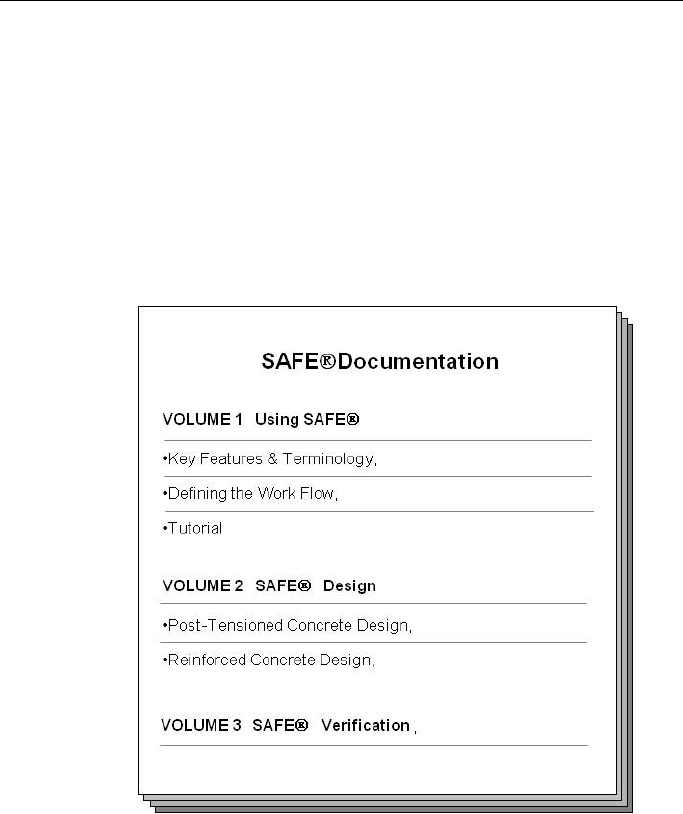
The SAFE documentation consists of three volumes. Volume I “Using
SAFE” in turn consists of three manuals: Key Features and Terminolo-
gy, Defining the Work Flow, and Tutorial. Volume II “SAFE Design”
contains two manuals: Post-Tensioned Concrete Design and Mild Rein-
forced Concrete Design. Volume III is a single document entitled
“SAFE Verification.” Figure 2-1 provides a graphical representation of
the SAFE documentation structure.
Figure 2-1 SAFE Documentation
This manual, Key Features and Terminology, provides overviews of the
SAFE modeling, analysis, design, and detailing techniques, along with
detailed descriptions of the SAFE interface. The Defining the Work Flow
document offers an ordered description of the workflow process in-
volved in using SAFE, from starting a model to detailing the designed
structure. The Tutorial takes the user through the creation, analysis, and
design of an example models.
2 - 2 About the Manuals

Getting Started
Information covering the design theory and methods, in accordance with
various international design codes, is provided in Volume II. Reinforced
Concrete Design and Post-Tensioned Concrete Design features chapters
on the various design codes included in SAFE, including the American,
Australian, British, Canadian, Chinese (requires Chinese license), Euro-
pean, Indian, Hong Kong, New Zealand, and Singapore codes.
The SAFE Verification manual provides comparisons of SAFE output
with independently produced or published results.
It is strongly recommended that you read this volume and view the tuto-
rial movies (see “Watch & Learn
Movies”) before attempting to com-
plete a project using SAFE.
Additional information can be found in the Help facility that is accessi-
ble from within the SAFE graphical user interface.
2.4 “Watch & Learn™ Movies”
One of the best resources available for learning about the features of
SAFE is the “Watch & Learn
Movies” series, which may be accessed
on the CSI website at https://www.csiamerica.com. These movies con-
tain a wealth of information for both the first-time user and the experi-
enced expert, covering a wide range of topics from basic operation to
complex modeling. The movies range from a few minutes to more than a
half hour in length.
2.5 CSI Knowledge Base
CSI maintains a knowledge base containing answers to frequently asked
support questions as well as additional insights on program operation.
This is a good first stop before contacting technical support because
many of the most common, as well as some esoteric questions are an-
swered here. This page is fully indexed and searchable, and may be
found at https://wiki.csiamerica.com.
“Watch & Learn™ Movies” 2 - 3

SAFE – Key Features and Terminology
2.6 Technical Support
If you have questions regarding use of the software, please:
Consult the documentation and other printed information included
with your product.
Check the on-line Help facility in the software.
Visit the CSI Knowledge Base at https://wiki.csiamerica.com.
If you have a current Maintenance Agreement you may request support
in one of the following ways:
Send an email and your model file to support@csiamerica.com or
your local CSI Partner.
Visit CSI’s website and Customer Support Portal at
https://www.csiamerica.com.
Call CSI or your local CSI Partner. Contact details are available at
https://www.csiamerica.com/contact.
Be sure to include the necessary information listed in the ‘Help Us to
Help You’ section whenever you contact technical support.
2.7 Help Us to Help You
Whenever you contact us with a technical support question, please pro-
vide us with the following information to help us help you:
The product level (Standard or P/T) and version number that you are
using. This can be obtained from inside the software using the Help
menu > About SAFE command.
A description of your model, including a picture, if possible.
A description of what happened and what you were doing when the
problem occurred.
The exact wording of any error messages that appeared on your
screen.
A description of how you tried to solve the problem.
2 - 4 Technical Support

Getting Started
The computer configuration (make and model, processor, operating
system, hard disk size, and RAM size).
Your name, your company’s name, and how we may contact you.
If calling, please be at your computer where you can run the soft-
ware.
Help Us to Help You 2 - 5

Chapter 3
The SAFE System
SAFE analyzes, designs, and details concrete slab systems that are creat-
ed using the various drawing tools or imported into the graphical user in-
terface. The key to successfully implementing SAFE is to understand the
unique and powerful approach the program takes in modeling, designing,
and detailing slabs. This chapter provides an overview of some of the
special features and their associated terminology.
3.1 Physical Modeling Terminology
In SAFE, reference is often made to objects, members, and elements.
Objects represent the physical structural members in the model. Ele-
ments, on the other hand, refer to the finite elements used internally by
SAFE to generate the stiffness matrices. In many cases, objects and
physical members will have a one-to-one correspondence, and it is these
objects that the user “draws” in the SAFE interface. Objects are intended
to be an accurate representation of the physical members. Users typically
need not concern themselves with the meshing of these objects into the
elements required for the mathematical, or analysis model. For example,
a single area object can model an entire slab, regardless of the number of
Physical Modeling Terminology 3 - 1

SAFE – Key Features and Terminology
spans and variety of loadings. With SAFE, both model creation, as well
as the reporting of results, is achieved at the object level.
This differs from a traditional analysis program, where the user is re-
quired to define a sub-assemblage of finite elements that comprise the
larger physical members. In SAFE, the objects, or physical members
drawn by the user, are typically meshed internally during the analysis,
into the greater number of finite elements needed for the analysis model,
without user input. Because the user is working only with the physical
member-based objects, less time is required both to create the model and
interpret the results.
The concept of objects in a structural model may be new to you. It is ex-
tremely important that you grasp this concept as it is the basis for creat-
ing models in SAFE. After you understand the concept and have worked
with it for a while, you should recognize the simplicity of physical ob-
ject-based modeling, the ease with which you can create models using
objects, and the power of the concept when editing and creating complex
models.
3.2 Structural Objects
As previously stated, SAFE uses objects to represent physical structural
members. When creating a model, start by drawing the geometry and
then assign properties and loads to completely define the slab structure.
The following object types are available, listed in descending order of
geometrical dimension:
Slab/Area objects are used to model slabs, drop panels, column ge-
ometry, openings, soil supports, and surface loads.
Wall/Ramp objects are used to model walls and ramps.
Beam/Line objects are used to model beams and line loads.
Column objects are used to model columns and braces.
3 - 2 Structural Objects

The SAFE System
Tendon objects are used to model post-tensioning tendons and tendon
loads. Even though they are drawn in plan similar to a beam object,
they differ from beam objects in that they have a shape profile through
the slab thickness.
Point objects are automatically created at the corners or ends of all
other types of objects and also can be added anywhere in the model.
Point objects are used to model point loads and point displacements,
as well as for applying point restraints and springs.
As a general rule, the geometry of the object should correspond to that of
the physical member. This simplifies the visualization of the model and
reduces the chances of input error.
3.3 Properties
Properties are assigned to each object to define the structural or support
behavior of that object in the model. Properties under the Define menu,
namely slab, beam, reinforcing bar, tendon, column, wall, soil, and
spring properties, are named entities that must be specified before as-
signing them to objects. If a property is assigned to an object, for exam-
ple a beam property, any changes to the definition of the property will
automatically apply to the beam objects with this property assigned. A
named property has no effect on the model unless it is assigned to an ob-
ject.
Soil subgrade support properties may be assigned to slab/area objects,
and for these properties, SAFE generates spring elements at each mesh
location.
Other properties, such as releases or point restraints, found under the As-
sign menu, are assigned directly to objects. Those properties can be
changed only by making another assignment of that same property to the
object; they are not named entities and they do not exist independently
from the objects.
Properties 3 - 3

SAFE – Key Features and Terminology
3.4 Load Patterns
Static loads represent actions upon the structure, and include force, pres-
sure, temperature, and support displacement. A spatial distribution of
loads upon the structure is called a load pattern.
Any number of load patterns can be defined. Typically, a model will
have separate load patterns for dead load, live load, post-tensioning, pat-
tern live load, static earthquake load, wind load, snow load, temperature
load, and so on. Loads that need to vary independently, either for design
purposes or because of how they are applied to the slab, should be de-
fined as separate load patterns.
After defining a load pattern name, you must assign specific load values
to the objects as part of the load pattern. The load values you assign to an
object specify the type of load (e.g., force or displacement), the magni-
tude, and the direction. Different loads can be assigned to different ob-
jects as part of a single load pattern and each object can be subjected to
multiple load patterns.
3.4.1 Vertical Loads
Vertical loads may be applied to point, beam, and slab objects. Vertical
loads are typically input in the down, or −Z direction. Point objects can
accept concentrated forces or moments. Beam objects may have uniform
or trapezoidal distributed forces, moments, and torsions, as well as con-
centrated point loads, moments, and torsions. Uniform and non-uniform
surface loads can be applied directly to slab objects, including openings.
Vertical load patterns also may include element self weight.
Some typical vertical load patterns used for slabs might include:
Dead load
Superimposed dead load
Live load
Pattern live load
3 - 4 Load Patterns

The SAFE System
Snow load
3.4.1.1 Arrangement of Live Load
It is often desirable to apply live loads in varied geometric arrangements
to model how these loads are applied to the real structure. Arranging live
loads in critical patterns can increase the negative and positive moments
in certain panels and columns. Common arrangements of loading include
geometric patterns such as live loads on two adjacent panels and live
loads on alternate panels.
SAFE allows for live loads to be geometrically arranged using two dif-
ferent options. Loading may be arranged using patterns defined by the
user or by patterns created automatically by SAFE. In either case, the
first step is to create a load pattern with a type of Pattern Live or Auto
Pattern Live. If the pattern type is Pattern Live, SAFE will take each Pat-
tern Live load pattern and combine them using the “Range Add” load
combination feature described later. Multiple load patterns are typically
required to capture alternate and adjacent panel loading arrangements for
user-defined cases.
If the pattern type is Auto Pattern Live, the loads associated with the pat-
tern will automatically be divided up internally into smaller “single pan-
el” load patterns based on the panel grid created by the layout of the grid
lines. Results from each of these “single panel” loads are then combined
automatically by SAFE using the Range Add load combination type.
Using the Auto Pattern Live option, rather than the user Pattern Live op-
tion, allows for a varied arrangement of live loads to be generated with a
single load pattern versus the multiple load pattern definitions required
with the user option.
3.4.2 Lateral Loads
SAFE allows deformations in both the in-plane and out-of-plane direc-
tions of the slab. It can handle vertical loads as described previously or
horizontal loads such as internal post-tensioning or external wind. Be-
Load Patterns 3 - 5

SAFE – Key Features and Terminology
cause in-plane deformations can occur, SAFE is appropriate for dia-
phragm studies. Effects caused by lateral loads may be considered using
load and displacement assignments. For suspended slabs, specified slab
deformations (rotations and displacements) may be assigned to columns
and walls to account for frame behavior under lateral loads. If using
ETABS to perform a 3-D building analysis, ETABS allows for the direct
export of floor loads and distortions to SAFE for further analysis and de-
sign.
Overturning of basemats or foundations resulting from lateral loads may
be modeled by applying moments or moment couples to walls and mo-
ments and vertical loads to columns. SAFE provides an explicit nonline-
ar solution to model no-tension (uplift) behavior in the soil.
3.4.3 Dynamic Loads
If dynamic response spectrum loads are exported from ETABS along
with a slab that is imported into SAFE, an additional set of load patterns
will be imported. A separate load pattern will be defined for each mode,
defined as type Other. These load patterns are used by an automatically
generated response spectrum load case that is created during the import
process. Note that response spectrum load cases can not be defined di-
rectly in SAFE.
3.4.4 Temperature Loads
SAFE allows temperature loads to be applied to slab objects, which re-
sults in thermal strains. These strains are given by the product of the Ma-
terial coefficient of thermal expansion and the temperature change of the
slab object. The temperature change may be specified as a gradient
through the thickness of the object, or as a constant, if the top and bot-
tom temperature changes are the same.
3 - 6 Load Patterns

The SAFE System
3.5 Load Cases
A load case defines how loads are to be applied to the structure, and how
the structural response is to be calculated. SAFE automatically generates
a load case for each load pattern that is defined. In addition, user-defined
load cases containing multiple load patterns can be created. Any number
of named load cases may be defined.
Analyses are classified in the broad sense as either linear or nonlinear,
depending upon how the model responds to the loading. The results of
linear analyses may be superposed, i.e., added together after analysis us-
ing combinations (see “Combinations” later in this chapter).
In addition to the typical static load cases, SAFE also provides the capa-
bility to carry out modal and hyperstatic analyses. Response spectrum
load cases can also exist if imported from ETABS.
The results of nonlinear analyses normally should not be superposed. In-
stead, all loads acting together on the structure should be combined di-
rectly within a load case.
3.6 Load Combinations
Load combinations combine the results of previously defined load cases
in an additive or enveloped manner. SAFE allows load combinations to
be named. When a load combination is defined, it applies to the results
for every object in the model.
The design is always based on load combinations, rather than directly on
load cases or load patterns. A combination containing only a single load
case can be created. The design algorithm creates its own default load
combinations based on the selected design code, which can be supple-
mented with any number of user-defined load combinations if required.
If a load pattern with a type of Pattern Live has been created, force quan-
tities will be combined automatically using the Range Add load combi-
Load Cases 3 - 7

SAFE – Key Features and Terminology
nation type. The Range Add combination calculates minimum and max-
imum force quantities for each element.
3.7 Design Procedures
SAFE has two integrated design post-processors, namely Post-Tensioned
Concrete Design (if licensed) and Reinforced Concrete Design; both de-
sign slabs and beams. The concrete slab design procedure is applicable
to slab objects and the beam design procedure is available for beam ob-
jects. Punching shear checks are also carried out at column object loca-
tions, point loads, and supports. Stud rail and rebar tie design options are
available when the punching shear capacity of the slab is not adequate.
Design can be affected by the following:
The design code, e.g., ACI 318-08, Eurocode 2-2004, or BS8110-97,
among others.
The post-tensioning loads.
The design method and strength reduction factors.
The combinations for which the design is carried out.
Pattern Live load patterns; these load patterns are used only in strength
design.
A and B design strips for the slabs, which determine the layout of the
calculated reinforcement. The total moment at each section of the
strips is used to calculate the required flexural reinforcement.
The punching perimeter.
3.8 Detailing Procedures
SAFE includes the capability of generating detailed reinforcement draw-
ings for slabs and beams. The detailing utilizes the analysis and design
results to determine the required reinforcement quantities. For slabs, the
3 - 8 Design Procedures

The SAFE System
design strips define the orientation of the reinforcement. The detailed re-
inforcement can be modified as desired and detailed component views
can be compiled into drawing sheets that can be printed directly from
SAFE or exported to CAD software for further manipulation.
3.9 More Information
This chapter provides a brief overview of the basic components of the
SAFE system. Additional information can be found in the program Help
and in the “Watch & Learn
Movies” series. The other chapters of this
and the other manuals provide more detailed explanation of the compo-
nents introduced in this chapter.
More Information 3 - 9

Chapter 4
SAFE Modeling Features
SAFE offers an extensive and diverse range of tools to model a wide va-
riety of slab systems. Slab models can be created directly in the SAFE
interface, imported from ETABS, or defined using a drawing imported
from a CAD application. This chapter illustrates a few of the techniques
to make modeling quick and easy using SAFE.
4.1 Overview of the Modeling Process
A model developed using SAFE is different from models produced in
many other structural analysis programs for two main reasons:
SAFE is optimized for modeling slab systems through tailored model-
ing procedures and design capabilities for concrete slabs and beams.
SAFE models are object-based and consist of point, line, tendon, and
area objects, to which assignments are made to define structural mem-
bers, such as slabs, walls, ramps, beams, tendons, columns, braces,
and supports, as well as to define loads.
In its simplest form, developing a model requires four basic steps:
Overview of the Modeling Process 4 - 1

SAFE – Key Features and Terminology
Define materials using the Define menu.
Define slab, wall (ramp), beam, column (brace), and tendon properties
(sections) and supports using the Define menu.
Draw a series of slab, wall, beam, column, tendon, and point objects
that represent your slab system, using the various drawing tools avail-
able within the graphical interface.
Assign structural properties, supports, and loads to objects using the
Assign menu commands. Note that the assignment of structural prop-
erties and supports may be completed concurrently with the drawing
of the objects using the floating forms that appear when the draw
commands are used.
When the model is complete, the analysis may be run.
Note: When a form "floats," the form will remain visible when the cur-
sor is moved over the active window or the mouse button is clicked. This
means that changes can be made to the form without reusing the com-
mand required to bring up the form, which differs from other types of
forms. Floating forms are used in the draw mode so that the type of ob-
ject being drawn, the properties, and other associated attributes can be
changed easily while drawing objects for the model.
4.2 Slab Types
SAFE can be used to model almost any type of elevated slab or basemat/
foundation system, including two-way slabs, flat slabs, ribbed slabs, and
waffle slabs.
4.2.1 Two-Way Slabs
Two-way slabs (flat plates and flat slabs) are probably the most common
concrete slab systems and are easily modeled using SAFE. Because
SAFE is finite element based, when a two-way slab of arbitrary shape is
drawn, SAFE automatically meshes the area objects into isotropic or or-
4 - 2 Slab Types

SAFE Modeling Features
thotropic shell bending elements. These elements are three- or four-node
elements, with six degrees of freedom at each node. The shell elements
capture out-of-plane bending and shear behavior, as well as in-plane de-
formations due to post-tensioning and other loads. Thus, two-way slab
action is automatically accounted for in the SAFE model and unlike
equivalent frame techniques, requires no additional assumptions or cal-
culations.
4.2.2 Flat Slabs
Flat slabs are typically two-way slabs with drop panels at the column lo-
cations to increase the shear capacity of the slab. It is usually advisable
to model the geometric plan dimensions of the drops with area objects so
that the slabs will have the correct span lengths, keeping in mind that
moment varies directly with the square of the span length.
Drop panels modeled using area objects are easily generated by SAFE
using the Draw menu > Quick Draw Areas Around Points command.
Drop panels also can be defined as part of the column property defini-
tion, in which case they are automatically generated when columns are
drawn.
4.2.3 Ribbed Slabs
Ribbed slabs are stiffened by ribs running in one predominant direction.
Modeling this type of system in a conventional finite element program
can be extremely difficult and time consuming because of the meshing
effort involved. However, with SAFE’s object oriented approach and au-
tomated meshing capability, ribbed slabs can be modeled simply by
drawing the area object representing the slab, and assigning a “Ribbed”
slab property type.
Ribs are defined by specifying their depth, their widths at the top and
bottom, and their spacing. SAFE then calculates equivalent slab proper-
ties, such as the moment of inertias and self weight, using the slab and
rib definitions. This calculation takes into account the T-beam behavior
Slab Types 4 - 3

SAFE – Key Features and Terminology
occurring when the slab and ribs work together, with the slab acting as a
flange.
Although an equivalent slab property is used internally when performing
the analysis, the actual geometry of the slab and ribs is used for design
and detailing purposes.
4.2.4 Waffle Slabs
Waffle slabs are similar to ribbed slabs, but instead of ribs in only one
direction, the waffle slab ribs are laid out in an intersecting orthogonal
arrangement. Waffle slabs can easily be modeled by drawing the area
object representing the slab and assigning a “Waffle” slab property type.
In addition, waffle slabs often use drop panels at the column locations.
Similar to ribbed slabs, ribs in a waffle slab are defined by specifying
their depth, their widths at the top and bottom, and their spacing. Again,
SAFE uses equivalent slab properties for the analysis, accounting for T-
beam behavior, while maintaining the slab and rib geometries for design
and detailing.
4.3 Mat Foundations and Footings
Similar to elevated slabs, basemats and footings can be drawn using slab
objects. The shell element in SAFE incorporates shear deformation,
therefore handling slabs that have a large depth-to-span ratio, as is often
the case with foundations. Working in 3-D allows for the accurate repre-
sentation of stiffness and loading from walls and columns, including
overturning moments.
Soil springs can be added quickly to the model. Any number of soil
properties may be defined, so that the subgrade modulus can vary
throughout the foundation. An explicit nonlinear process to model no-
tension (uplift) in the soil springs is available.
4 - 4 Mat Foundations and Footings

SAFE Modeling Features
4.4 Slabs with Discontinuities
The slab release capability of SAFE allows for the convenient modeling
of discontinuities. Releases allow jumps in moment or shear across a
specific line of discontinuity. Releases are assigned to line objects, to ei-
ther one or both sides. Shear and moment releases also can be assigned
to specific slab edges.
4.5 Beam Types
The majority of beams in concrete construction are formed in a rectangu-
lar shape. However, beams can come in other shapes, and SAFE, in addi-
tion to providing the rectangular beam, offers a number of other geomet-
ric beam options, including T-beams, inverted T-beams, L-beams, in-
verted L-beams, and a general beam option that can be used to model
beams not reflected by one of the other categories. If the slab is to be in-
cluded in the bending of any beam, it can be modeled as either a flanged
or rectangular beam. If a rectangular beam is used, SAFE will automati-
cally account for the T-beam action provided by the slab. If a flanged
beam is modeled, SAFE ignores the flange of the T-beam or L-beam
where it is duplicated by the slab, and uses the slab to account for the T-
beam action.
4.6 Post-Tensioning
Post-tensioning places concrete in compression to reduce the tensile
stresses due to flexure. Post-tensioning typically reduces deflections and
the amount of standard reinforcement required.
The post-tensioning option in SAFE allows for prestressing loads to be
applied to the model. Post-tensioning tendons may be drawn either ex-
plicitly by the user, in which case the tendon layout, force and profile are
specified, or the post-tensioning layout can be determined by SAFE. The
tendon distribution is specified as banded or distributed, and acceptable
ranges for both the concrete precompression level and percentage of self
weight to be balanced are input. SAFE then iterates to determine the pro-
Slabs with Discontinuities 4 - 5

SAFE – Key Features and Terminology
file of the tendons that best satisfies the stress and balancing require-
ments.
With the load-balancing method, tendons are selected to directly coun-
teract a percentage of the self weight load. The force in the tendon with
an eccentricity generates a moment that is opposite of the imposed mo-
ment. If the moments were to be perfectly balanced, the net stress in the
member would be just the axial compressive stress from the post-
tensioning. In reality, imposed and post-tensioning moments do not bal-
ance, and the net stress on the section is a combination of axial stress and
unbalanced bending moment stress. This net stress is used in design to
determine the amount of mild reinforcement required.
4.7 Models Exported from ETABS
Often times a concrete floor system defined in ETABS will require fur-
ther refinement during analysis (e.g., deflections based on cracked sec-
tions), as well as design and detailing. This can be accomplished easily
using the link provided between ETABS and SAFE. ETABS allows for
the export of any story level as a SAFE *.f2k text file.
In addition to the geometry and property assignments of the objects,
ETABS provides two additional export options:
Export floor loads only.
Export floor loads and loads from above.
Upon importing the ETABS generated model, additional modifications
can be made to the model using the SAFE tools. It should be noted that
changes in SAFE can not be exported back to ETABS, so any changes to
the slab that may affect the ETABS global building model also should be
applied to the ETABS model.
4 - 6 Models Exported from ETABS

SAFE Modeling Features
4.8 More Information
This chapter provides an overview of the modeling features that SAFE
offers for simulating slab systems. Additional information may be found
in the program Help and in the “Watch & Learn
Movies” series.
More Information 4 - 7

Chapter 5
SAFE Analysis Features
This chapter provides an overview of the key analysis features available
within SAFE. The analysis features described include linear static analy-
sis, nonlinear analysis for uplift, and nonlinear analysis for cracking.
In a given run, any number of different analyses may be performed, in-
cluding both linear and nonlinear analyses.
5.1 Overview of the Analysis Process
At the time of analysis, SAFE converts the object-based model into a fi-
nite element model, referred to as the analysis model. The finite element
mesh used in the analysis is based on a user-defined maximum element
size. However, additional meshing lines are automatically introduced at
all locations of objects, object boundaries, and gridlines. Additional user-
defined meshing lines can be introduced at specified locations by adding
additional gridlines or adding line objects with NONE properties and
then assigning them to be included in the analysis mesh.
Overview of the Analysis Process 5 - 1

SAFE – Key Features and Terminology
SAFE automatically creates slab elements by subdividing all of the slab
objects. SAFE also creates beam elements by subdividing all of the beam
objects.
Column and wall objects provide vertical, as well as lateral support to
the slab structure. Alternatively, point or line springs can be used to sup-
port the slab structure.
Soil subgrade modulus properties assigned to area objects are lumped in-
to discrete springs and applied to all of the mesh points that exist on the
area, based on the tributary area associated with each mesh point.
Point loads assigned to point objects are assigned directly to the corre-
sponding finite element mesh point. Point and distributed loads assigned
to beam objects are discretized and applied to the mesh points that exist
on the beam, based on the tributary length associated with each mesh
point. Similarly, surface loads assigned to slab objects are discretized
and applied to all of the mesh points that exist on the slab, based on the
tributary area associated with each mesh point.
The internal meshing performed by SAFE does not alter the number or
size of the objects, which allows for simple revisions and modifications
to be executed at the object level, as well as simple extraction of analysis
results.
5.2 The Analysis Model
The analysis model consists of slab, beam, column, wall, tendon, and
support elements.
Each slab element is an isotropic or orthotropic, shell element. The key
features of the shell elements are as follows:
Each element node has six degrees of freedom.
The material property within each element is constant.
The element includes shear deformation.
5 - 2 The Analysis Model

SAFE Analysis Features
The thickness of each element is constant, unless orthotropic effects
are considered, for which it is possible to specify three different effec-
tive thicknesses: local 1-axis bending, local 2-axis bending, and twist-
ing.
The element must lie in the horizontal XY plane.
The calculation of the self weight of the element is based on the thick-
ness, the planar area, and the unit weight of the material associated
with the element.
The element moments and shears are calculated at the nodes of the el-
ement.
The beam element in SAFE is based on linear elastic beam theory and
can have properties based on specified cross-section dimensions or on
specified cross-sectional properties, such as area and moment of inertia.
The key features of the beam elements are as follows:
Beam elements are prismatic.
The calculation of the self weight of the element is based on the actual
area for rectangular or general sections, and the stem area for flanged
sections, the element length, and the unit weight of the material asso-
ciated with the element.
The beam moments, shears, and torques are calculated at the two ends
of each element, corresponding to each mesh point.
The beam must lie in the horizontal XY plane.
The column/brace element is similar in formulation to the beam element.
The main difference is that columns/braces must be vertical/diagonal,
design results are not presented for them, and therefore they are not de-
signed in SAFE.
Wall/ramp elements are modeled as shell elements, similar to the slabs.
Similar to columns/braces, walls/ramps must be vertical/inclined, are not
designed, and do not have design results presented.
The Analysis Model 5 - 3

SAFE – Key Features and Terminology
For soil supports, SAFE generates equivalent linear elastic springs at
mesh points. Compression only (zero tension) conditions in the soil sup-
ports are modeled using nonlinear gap elements. The key features of the
support elements are as follows:
The support elements are weightless.
Soil supports have a single vertical degree of freedom.
The support reaction values are calculated at every supported mesh
point.
5.3 Linear Static Analysis
A linear static load case is automatically created for each load pattern
that is defined. Any number of load patterns and load cases may be de-
fined. Load cases can include multiple load patterns, each with an asso-
ciated scale factor. The results of different static load cases can be com-
bined using load combinations. A linear static analysis is the default and
most common load case type in SAFE.
5.4 Nonlinear Analysis for Uplift
SAFE has an option to request that a nonlinear load case be used to con-
sider soil supports as providing compression only. This capability can be
extremely useful for analyzing basemats and footings.
If the nonlinear uplift analysis type is specified for a load case, nonlinear
gap elements are automatically activated in the soil support springs. The
gap elements can transfer only compressive loads, hence capturing any
uplift behavior. This analysis type requires that any loads acting in com-
bination be added together in the load case, and not in combinations.
5 - 4 Linear Static Analysis

SAFE Analysis Features
5.5 Nonlinear Analysis for Cracking
A nonlinear cracking analysis for slabs may be executed based on user-
specified rebar using Slab Rebar objects, on reinforcing calculated by the
program using the Finite Element Based design, or on reinforcement
specified using the Quick Rebar Specification option.
In the design of slabs, it is generally recognized that the distribution of
moments obtained from an elastic analysis is appropriate for design pur-
poses. However, an elastic analysis may significantly underestimate the
true deflections resulting from cracking.
The estimation of true deflections is a complex task. Guidelines are
available in some design codes, such as ACI 318 Section 9.5. For non-
prestressed, one-way construction, ACI 318 recommends the calculation
of an effective stiffness to obtain the cracked deflections and further ap-
plication of modification factors to account for long-term deflections.
SAFE has the capability to use the recommendation described above for
calculating the effective stiffness of slabs and beams of floor systems
when doing analysis. This technique requires that the reinforcement be
known. Slab reinforcement may be calculated by SAFE or be user-
defined. The automated procedure for calculating the effective stiffness
is as follows:
Perform an elastic (uncracked) analysis.
Determine the slab reinforcement from the Finite Element Based de-
sign or from user input.
Design the beam reinforcement.
Calculate the cracking moment and cracked moment of inertia for each
element, for each direction of moment, and for top and bottom rein-
forcement.
Calculate the ratio of effective stiffness to gross-section stiffness for
both local 1 and 2 directions for the slab and beam elements.
Nonlinear Analysis for Cracking 5 - 5

SAFE – Key Features and Terminology
Reanalyze the structure using the effective stiffness calculated for each
element.
The results for nonlinear cracked analyses include both the displace-
ments and stresses, although again, most design codes allow for the use
of stresses from elastic, or uncracked analyses.
5.6 Nonlinear Analysis for Long-Term Cracking
A nonlinear, long-term cracking analysis can be carried out in a manner
similar to the normal cracking analysis. The long-term analysis requires
creep coefficient and shrinkage strain values in order to account for
creep and shrinkage.
5.7 Modal Analysis
A modal analysis load case can be defined to compute the modal fre-
quencies or periods of the structure. This analysis type is best used with
vertical mass. The modes can be based on Eigen or Ritz vectors, and a
minimum and maximum number of requested modes can specified.
5.8 Hyperstatic Analysis
A hyperstatic analysis can be defined as a load case. This type of analy-
sis is based on an already defined static load case, in which the reactions
from the static load case are applied as loads to an unsupported structure.
5.9 More Information
This chapter provides a general introduction to the primary analytical
features that SAFE offers for linear and nonlinear analysis of slabs.
Much more information may be found in the program Help and in the
“Watch & Learn
Movies” series.
5 - 6 Nonlinear Analysis for Long-Term Cracking

Chapter 6
SAFE Design Features
This chapter provides an overview of the key design features available
within SAFE. The design features described include slab flexural design
with or without post-tensioning, slab punching shear checks and rein-
forcement design, and beam flexural, shear, and torsion design with or
without post-tensioning.
6.1 Overview of the Design Process
After the analysis is complete, the design can be performed. Strength de-
sign loads are generated from built-in default combinations for the cur-
rently selected design code (user-defined load combinations also can be
defined, if needed). Default serviceability combinations also are availa-
ble if the model includes post-tensioning. Using these combinations,
SAFE designs both slabs and beams, and reports the required reinforce-
ment.
For slabs, SAFE uses either design strips or the finite element based de-
sign to calculate the slab flexural reinforcement in accordance with the
selected design code. SAFE also designs the flexural, shear, and torsion
reinforcement of any beam object.
Overview of the Design Process 6 - 1

SAFE – Key Features and Terminology
6.2 Slab Flexural Design
Similar to conventional design, the flexural design of slabs in SAFE in-
volves defining sets of strips in two directions (A and B), integrating the
strip moments and shears (on the basis of the Wood-Armer technique),
and then designing the required reinforcement for each strip in accord-
ance with the selected design code. As an alternative to this strip based
method, SAFE also offers a FEM based design, which is useful for ir-
regular slabs where strip based techniques may not be appropriate.
6.2.1 Design Strips
SAFE provides two principal strip layers used for analysis and design,
namely Layer A design strips and Layer B design strips. The strips are
defined as polylines with associated widths that can vary along the
length of the strip.
The strips need not be mutually perpendicular. The extent of the design
strips is defined by the edges of the area objects defining the slab, and
strips can overlap if needed. The location of the design strips is usually
governed by the support or grid locations. Design strips may be defined
as either Column Strips or Middle Strips – models with post-tensioning
typically have column strips only.
6.2.2 Integration of Moments – Wood-Armer
Use of the Wood-Armer method for the integration of design moments
results in the following steps:
For a particular combination or load case, for each finite element within
the design strip, SAFE calculates the design moments per unit width us-
ing the internal forces. Internal forces are converted to design moments
per unit width in the following manner:
bB B AB
mmm= +
bA A AB
mmm= +
6 - 2 Slab Flexural Design

SAFE Design Features
tB B AB
mmm= +
tB A AB
mmm= +
where mA, mB, and mAB are internal moments per unit width, and mbA and
mbB are design moments per unit width for the bottom of the slab in the
A and B directions, respectively, and mtA and mtB are the design moments
for the top of the slab in the A and B directions, respectively. Design
moments may be factored combinations for strength design, or unfac-
tored moments for service load checks when post-tensioning is present.
The design moments calculated using the Wood-Armer integration will
most likely not completely satisfy equilibrium of the applied loads, but
for a mesh that accurately captures the overall behavior of the slab, this
integration scheme provides a good design. This is the case because the
Wood-Armer integration scheme effectively calculates design moments
when cracking occurs diagonally to the design strip directions.
6.2.3 Required Reinforcement – Strip Based
If post-tensioning is present, stresses are checked at the slab top and bot-
tom for unfactored service level loads. Stress checks are carried out at
three stages, namely at transfer of the prestress load (transfer), after all
losses have occurred and service loads are applied (normal), and after all
losses have occurred and long-term service loads are applied (long term).
These stress checks are carried out at each transverse mesh line along the
length of the strips. The moments are integrated across all elements of
like property in the strip to determine the service moments, which are
converted to stresses assuming a linear strain variation through the sec-
tion depth. If the stress limits are exceeded, mild reinforcement is added
to carry the tensile stresses, as long as they are below the code specified
limits, which can be adjusted in the Design Preferences. Any added mild
reinforcement is then used with the user-defined post-tensioning tendons
to calculate a nominal moment capacity, which is checked against the
factored moments from the strength combinations.
The design of the mild reinforcement for slabs without post-tensioning
also is carried out for a particular strip at each transverse mesh line loca-
Slab Flexural Design 6 - 3

SAFE – Key Features and Terminology
tion along the length of the strip. The moments are integrated across all
elements of like property in the strip to determine the factored design
moments. The required reinforcement for slabs is computed for each set
of elements with the same property type, and then summed to give the
total required reinforcement for the strip. The maximum required top and
bottom strip reinforcement for a particular mesh line is obtained, along
with the corresponding controlling combinations.
As an option, minimum reinforcement requirements may be enforced in
accordance with the selected design code.
6.2.4 Required Reinforcement – FEM Based
The FEM Based design determines the required reinforcement on an el-
ement-by-element basis and is therefore independent of design strips.
Several options are available for refining the display of the required rein-
forcement, including averaging, which will flatten peaks and provide an
averaged required reinforcement over a particular area of the slab.
6.2.5 Slab Rebar Objects
SAFE allows users to place the size, quantity, and location of slab rein-
forcing using Slab Rebar objects. Although this user-defined reinforcing
does not directly affect design results, it can be used when performing a
nonlinear cracking analysis, as well as compared to the required rein-
forcing calculated by the program using the Strip Based or FEM Based
methods.
6.3 Slab Punching Shear Check
The distribution of stresses close to concentrated loads or reaction points
in reinforced and prestressed concrete slabs is quite complex. Punching
shear is one particular failure mode recognized by design codes for
which an elastic plate bending analysis may not provide adequate stress
distribution. Most codes use empirical methods based on experimental
verification to check against punching shear failures. SAFE automates
6 - 4 Slab Punching Shear Check

SAFE Design Features
this check for common geometries. If the check results in a punching
shear ratio greater than unity (i.e., punching failure), SAFE will design
punching shear reinforcement. The SAFE procedure for the punching
shear check carried out for each column, for each design combination is
as follows:
Locate the critical section around the column or point load. SAFE re-
ports whether it assumed the column to be an interior, edge, or corner
column. This determination is based on whether the slab is present
within 10 times the slab thickness along the column edges. A column
is classified as a corner column when two slab edges are found within
10 times the slab thickness. A column with only one slab edge within
10 times the slab thickness is classified as an edge column, and a col-
umn is classified as interior when no slab edges are found within 10
times the slab thickness. For single footings, this determination is
based on the minimum area of the critical section.
Check that each slab element in the area enclosed between the face of
the column and the critical section for punching shear has the same
slab property label. If this is not the case, the slab thickness from
the smallest area within the punching shear perimeter is used.
Use the net shear to check punching shear if a point load or column
(call it load/column A) is within the critical section for punching shear
for another point load or column (call it load/column B).
Calculate punching shear based on net forces in the slab when line ob-
jects (beams, walls, or releases) frame into a column.
Calculate the reactive force and moments at the column for the com-
bination. The shear and moment values used in the punching shear
check are reduced by the load (or reaction) that is included within the
boundaries of the punching shear critical section.
Calculate the distribution of shear stress around the critical section.
Obtain the shear capacity of the critical section.
Slab Punching Shear Check 6 - 5
SAFE – Key Features and Terminology
Compare the shear stress distribution with the shear capacity. The
comparison is reported as a ratio for the worst combination. A value
above 1.0 indicates failure.
SAFE designs rebar ties or stud rails when such options are activated in
the punching shear design overwrites. The details of rebar ties or stud
rails are documented in the Reinforced Concrete Design Manual and the
Post-Tensioned Concrete Design Manual.
Design overwrites are available to modify the location type, punching
shear perimeter, openings in the slab, and reinforcement pattern, when
the punching shear parameters computed need to be changed.
For computing the punching parameters, the following assumptions are
used:
Punching shear is calculated for columns punching through a slab or a
drop panel. SAFE also checks the drop panel punching through a slab.
The effect of column capitals is included in the punching shear calcu-
lation.
SAFE uses the effective depth for computing the punching shear. The
concrete cover to rebar is taken from the design preferences unless a
design strip is present. In that case, the rebar cover is taken from the
design strip.
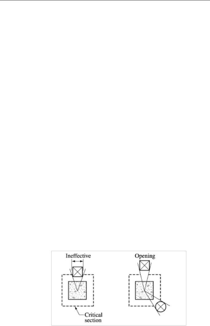
Openings within 10 times the slab thickness are automatically includ-
ed in the punching shear calculations. The slab edge within the punch-
ing zone radius is subtracted from the punching shear perimeter.
6 - 6 Slab Punching Shear Check

SAFE Design Features
The vertical component of prestressing force is currently ignored in
computing the punching shear capacity.
6.4 Beam Flexural, Shear, and Torsion Design
In the design of concrete beams, SAFE calculates and reports the re-
quired areas of reinforcement for flexure, shear, and torsion based on the
beam moments, shears, torsion, and load combination factors. The beam
design is executed on an element-by-element basis considering the mo-
ments, shears, and torsion at each nodal point of the element. Following
are some of the assumptions associated with the beam design:
The beams are designed for major axis moment, shear, and torsion on-
ly. Design for axial force or minor axis moment and shear that may
exist in the beams must be investigated independently by the user.
The required reinforcement reported by SAFE does not consider ser-
viceability requirements.
If post-tensioning is present, stresses are checked at the beam top and
bottom for unfactored service level loads. Stresses are checked at the
transfer of the prestress load without losses, with all service loads after
losses, and with sustained service loads after losses. These checks are
done assuming a linear strain variation through the section depth. If
necessary, reinforcement is added to carry tensile stresses. Any added
reinforcement is used with the user-defined post-tensioning tendons to
calculate a nominal moment capacity, which is checked against the
factored moments from the strength combinations.
The beam section is designed for the maximum positive and maxi-
mum negative factored moment envelopes obtained from all strength
combinations.
Negative beam moments produce tension in the top fibers. For all but
the inverted flanged beam, the beam is designed as a rectangular sec-
tion.
Beam Flexural, Shear, and Torsion Design 6 - 7

SAFE – Key Features and Terminology
Positive beam moments produce tension in the bottom fibers. In such
cases, the beam can be designed as a rectangular or a flanged beam.
For the design of flexural reinforcement in beams without post-
tensioning, the beam is first designed as a singly reinforced beam. If
the beam section is not adequate, the required compression reinforce-
ment is calculated.
In designing the shear reinforcement for a particular element, the steps
include the determination of the factored shear force, calculation of
the shear force that can be resisted by the concrete, and calculation of
the shear reinforcement required to carry the balance. The effects of
post-tensioning are included.
In designing the torsion reinforcement for a particular element, the
steps typically include the determination of the factored torsion, calcu-
lation of the critical torsion below which torsion reinforcement is not
required, calculation of special torsion section properties, calculation
of the torsion reinforcement required as closed stirrups, and a check of
the shear and torsion interaction.
6.5 Results Output
The design results can be viewed and saved in many different ways, in-
cluding:
Display and printing of two- and three-dimensional views of the mod-
el showing design results
Design results output in tables, compatible with Microsoft Excel or
Access
Design results tables printed to RTF, HTML, and text files
Custom reports with design results tables, graphics, and text
Export of model to DXF, including design results
6 - 8 Results Output

SAFE Design Features
Summary design information on an object-by-object basis by right
clicking an object while design results are displayed. This information
can be printed or saved to a RTF file.
6.6 More Information
This chapter provides a general introduction to the primary design fea-
tures that SAFE offers for concrete slabs and beams. Additional infor-
mation may be found in the program Help and in the “Watch & Learn
Movies” series. Please also refer to the Reinforced Concrete Design
Manual or the Post-Tensioning Concrete Design manual for information
about code-specific design.
More Information 6 - 9

Chapter 7
SAFE Detailing Features
This chapter provides an overview of the key detailing features available
within SAFE. The detailing features described include detailing prefer-
ences, drawing component views, and drawing sheets, as well as how
these can be edited within the SAFE interface, printed, or exported to
CAD software.
7.1 Overview of the Detailing Process
Detailing can be run after the analysis and design have been completed.
The detailing is run using the Run menu > Run Detailing command.
The first time the detailer is run for a particular model, SAFE will gener-
ate a default set of drawings. Those drawings can be viewed, custom-
ized, printed, and exported from the Detailing tab of the Model Explorer
window or the Detailing menu > Show Detailing command. Additional
drawing sheets can be added and component views can be added or de-
leted from drawing sheets to create a customized set of drawings. If
modifications are made to the model, including geometry, loading, or
properties, the detailing can be rerun with the option of generating a new
Overview of the Detailing Process 7 - 1

SAFE – Key Features and Terminology
set of drawings from scratch or synchronizing the new results with the
previously customized drawings.
7.2 Detailing Preferences
To complete detailing in SAFE, analysis and design data and detailing
preferences are required. Default detailing preferences are built into
SAFE. These default preferences are typical values that should satisfy
the majority of projects, but should be reviewed to ensure they are rele-
vant for the project under consideration.
Some of the key detailing preferences that can be set in SAFE include
the following:
Dimension and material quantity units
Bar callout style and content
Drawing size, layout, scale, and so forth
Rebar selection rules, including min/max bar sizes, spacing, and the
like
Preferred rebar sizes
Curtailment rules
Drawing display styles, including line type, weight, color and text
size, font, alignment, color, and so on, for each type of drawing entity
The Detailing menu > Detailing Preferences command allows specifi-
cation of the units and bar mark styles. The Detailing menu > Slab/Mat
Reinforcing Preferences and Beam Reinforcing Preferences each
provide selection rules, curtailment rules, and rebar call notations for
slabs and beams, respectively. The Detailing menu > Drawing Sheet
Setup command allows the properties of the drawing sheet to be set, in-
cluding size, margins, and scales. Finally, the Detailing menu > Draw-
ing Format Properties provides settings for all of the display styles,
such as line types, weight, color, and text properties.
7 - 2 Detailing Preferences

SAFE Detailing Features
7.3 Drawing Component Views
Drawing component views are the building blocks of drawing sheets.
Each view exists only once, but can be included on multiple drawings. A
selection of the component views available include the following:
Slab plans – framing, top bars, bottom bars, all bars
Slab sections
Beam framing plan
Beam elevations
Beam sections
Slab rebar table
Slab rebar schedule
Beam rebar table
Beam rebar schedule
Tendon layout plan
Tendon schedule
Additional component views can be found on the Detailing tab of the
Model Explorer window. The component views generated depend on the
objects in the model.
7.3.1 View Properties
Each drawing component view has a set of properties defining the scale,
text and line sizes, and the caption. These properties can be set in the de-
tailing tree of the Model Explorer by right clicking on a drawing compo-
nent view and choosing the Edit View Properties command. The prop-
erties also can be set for each component view on the drawing sheets in
the same way.
Drawing Component Views 7 - 3

SAFE – Key Features and Terminology
7.3.2 View Text
The text on each component view can be edited and rearranged (moved)
by right clicking on the component view in the tree of the Model Explor-
er and choosing the Edit View Text command. Additional text, dimen-
sion lines, and notes also can be added. This feature should be used to
rearrange overlapping text and add any additional notes or dimensions as
necessary.
7.4 Drawing Sheets
A drawing sheet in SAFE is defined with a certain size, containing one
or more drawing component views and is used in a manner consistent
with other CAD programs. Additional drawing sheets can be added or
existing sheets can be deleted.
Drawing component views can be added, deleted, or moved around on
the drawing sheets. Multiple component views can be added to a draw-
ing by right clicking on the drawing and using the various Add Views
commands. Alternatively, while a drawing sheet is in the display, draw-
ing component views can quickly and easily be added by dragging and
dropping them from the tree in the Model Explorer window.
Drawing sheets can be printed directly from SAFE, saved, or exported to
DXF or DWG files for use in CAD software.
7.5 Reinforcement Editing
SAFE provides capability for editing the detailed reinforcement that is
shown in the drawing component views and drawing sheets. For slabs
this is accomplished on a strip-by-strip basis while beams are handled
one beam at a time. Using the edit reinforcement commands, the rein-
forcement location and length can be modified with simple click and
drag mouse operations. The bar size and spacing also can be edited by
clicking on any bar call (mark) and making the necessary changes. Note,
changes should be made with care to ensure that the reinforcement quan-
tity satisfies the required reinforcement for the design loads.
7 - 4 Drawing Sheets

SAFE Detailing Features
7.6 Synchronization
After the detailing has been generated the first time for a model, SAFE
has the ability to synchronize and update the existing component views
and drawings for subsequent runs of the detailing. The synchronization
process maintains previous modifications and edits, to the extent practi-
cable. The following is a summary of the situations when synchroniza-
tion is carried out:
Changes to the detailing results caused by changes to the detailing
preferences, drawing preferences, or component view properties.
Editing of section cuts, where possible.
Editing of text location, where possible. This is determined based on a
comparison of the unedited text position on the previous and new de-
tailed items.
Editing of reinforcement, as long as the object geometry has not been
changed.
In general, it is recommended that if using the synchronization capabil-
ity, the final drawings be reviewed for correctness.
7.7 More Information
This chapter provides a general introduction to the primary detailing fea-
tures that SAFE offers. Additional information may be found in the pro-
gram Help and in the “Watch & Learn
Movies” series.
Synchronization 7 - 5

Chapter 8
The SAFE “Screen”
This chapter provides an overview of the key features of the graphical
user interface (GUI). As the model is developed using the graphical user
interface, a database file is created concurrently by SAFE. If desired, the
database can be directly edited using the Edit menu > Interactive Da-
tabase Editing command. While this feature is well suited to some sit-
uations, the vast majority of model creation and modification is complet-
ed using the graphical user interface.
8.1 The Graphical User Interface
The graphical user interface, shown in Figure 8-1, includes the main
window, main title bar, menu bar, toolbars, model explorer, display win-
dow, display title bar, status bar, mouse pointer coordinates, and a units
button. Each of these items is described as follows.
Main Window – This window may be moved, resized, maximized, min-
imized, or closed using standard Windows operations. Refer to Windows
help, available on the Start menu for additional information on perform-
ing these actions.
The Graphical User Interface 8 - 1

SAFE – Key Features and Terminology
Main Title Bar – The main title bar includes the program and model
names. The main title bar is highlighted when the program is in use.
Move the main window by left clicking in the main title bar and holding
down the mouse button to drag the window.
Figure 8-1 SAFE graphical user interface
Menu Bar – The menu bar contains the program menus from which var-
ious commands can be selected to perform specific actions.
Toolbars – Toolbars are made up of buttons. Buttons provide "single-
click" access to commonly used commands. Hovering the mouse pointer
over a toolbar button for a few seconds without clicking or holding down
any mouse buttons will display a short description of the button's func-
tion.
Model Explorer – The model explorer allows easy access to model def-
inition data, including property forms, load definitions, and object forms,
as well as analysis and design results. These items are grouped in three
tabs in the Model Explorer, namely Model, Display, and Detailing. Dou-
ble clicking on an item in the tree with the left mouse button will bring
8 - 2 The Graphical User Interface

The SAFE “Screen”
up the associated form or display, while a right click generates a context
menu with additional options.
Display Window – A display window shows the geometry of the model
and also may include displays of properties, loading, and analysis or de-
sign results. A maximum of four windows may be displayed simultane-
ously.
Display Title Bar – The display title bar is located at the top of the dis-
play window. The display title bar is highlighted when the associated
display window is active. The text in the display title bar typically in-
cludes the type of the current view along with any other relevant data,
such as load pattern, load combination, and so forth.
Status Bar – The status bar is located at the bottom of the main window.
Text describing the current status of the program is displayed on the left
side of the status bar.
Mouse Pointer Coordinates – The mouse pointer coordinates are dis-
played on the right-hand side of the status bar. A window does not need
to be active for the mouse pointer coordinates to be displayed. It is only
necessary that the mouse pointer be over the window.
Units Button – Clicking the Units button displays the Units form which
lists the units associated with all input and display items; units are not
typically consistent, i.e., stress may be displayed in ksi units, while ap-
plied loads may be done in psf units. Unit selections may be changed at
any time.
8.2 File Menu
File operations are used to start a new model, open or import an existing
model for display or modification, to import an architectural plan for
tracing, to save or export the current model for use in SAFE or other ap-
plications, and to produce output. File operations are selected from the
File menu.
File Menu 8 - 3

SAFE – Key Features and Terminology
New models can be started from scratch or from predefined templates
built into SAFE.
In addition to opening files in the standard SAFE database format (*.fdb
extension), SAFE also allows import of the following file formats:
SAFE text files (*.$sf and *.f2k extensions), MS Access Database files
(*.mdb extension), MS Excel Spreadsheet files (*.xls extension), or
DXF/DWG files (geometry import only) and DXF/DWG Architectural
Plan.
Models created in SAFE are saved in the database *.fdb and the text
*.$sf formats by default – both of these files contain the complete model.
They may also be exported to the following formats: SAFE text (*.f2k),
MS Access Database (*.mdb), MS Excel Spreadsheet (*.xls), and Auto-
CAD (*.DXF/*.DWG – geometry only).
8.3 Edit Menu
Editing is used to make changes to the model. Most editing operations
work with one or more objects that are selected immediately before us-
ing the edit commands. Editing operations on the Edit menu include the
following:
Cut and Copy geometry of selected objects to the Windows clipboard.
Geometry information on the clipboard can be pasted into other pro-
grams, such as spreadsheets.
Paste object geometry from the Windows clipboard into the model.
The geometry can be edited in a spreadsheet application before being
copied and pasted into SAFE.
Interactive editing of the model in a database format.
Delete objects.
Replicate objects in a linear or radial array, or mirror them.
Move points, which also modifies connected objects.
8 - 4 Edit Menu

The SAFE “Screen”
Merge points, which also modifies connected objects.
Align points and their connected objects to specified ordinates or se-
lected lines; this includes trimming or extending selected beam, strip
or tendon objects.
Divide selected beam or slab objects into smaller objects.
Join selected line objects at a common joint.
Merge selected area objects.
Expand or shrink the size of area objects.
Add tendon objects to selected design strips and beams.
Adjust the horizontal layout and vertical profile of selected tendons.
Add user-defined slab reinforcing.
Generate design strips based on grid lines or support locations.
8.4 View Menu
View options, which affect the active display, may be set for each dis-
play window individually. The options listed below are available on the
View menu and from the toolbar.
Set Default 3D View – A 3-D view shows the entire model from a
vantage point. The default view provides a perspective view of the en-
tire model and can be rotated using the Rotate 3D View button.
Set Plan View – A plan view is generated in a single plane parallel to
the X-Y coordinate plane.
Set Elevation View – An elevation view is generated in a single verti-
cal plane
Set Display Options – Various options are available to control how
objects appear in a display window. These options primarily affect
View Menu 8 - 5

SAFE – Key Features and Terminology
views of the undeformed shape, including changing visibility, labeling
of objects, showing an extruded view, as well as others.
Zoom Features – Zoom In to see more detail, or Zoom Out to see
more of the structure. A rubber-band zoom also can be used to draw a
window to zoom into. Restore Full View zooms in or out, as neces-
sary, to fit the view of the entire model in the active window.
Pan – Panning allows dynamic movement of the structure around the
display window by clicking and moving the mouse.
8.5 Define Menu
Define operations are used primarily to create named entities that are not
part of the geometry of the model. These entities, accessed from the De-
fine menu, include the following:
Material properties
Slab and beam section properties and design parameters
Reinforcing bar sizes
Tendon properties
Column and wall properties
Soil subgrade properties
Point and line spring properties
Coordinate/grid systems
Group names
Mass source
Load patterns
Load cases
8 - 6 Define Menu

The SAFE “Screen”
Load combinations
Definition of these entities does not require prior selection of any ob-
jects, and some of these entities also can be defined during the assign-
ment operations from the Assign menu.
8.6 Draw Menu
Drawing is used to add new objects to the model or to modify one object
at a time. Objects include beams, columns, slabs, walls, tendons, design
strips, gridlines, dimension lines, and slab rebar. To draw, SAFE must be
in Draw Mode, which is activated by clicking one of the draw buttons
on the toolbar or using a Draw menu command.
In Draw Mode, the left mouse button is used to draw and edit objects,
and the right mouse button terminates the current drawing action.
Depending on the type of object to be drawn, a floating properties form
appears that can be used to specify various structural and support proper-
ties for the object. For example, as column objects are drawn, column
properties can be assigned simultaneously, beam objects may be as-
signed beam structural properties, and similar options exist when draw-
ing other object types.
8.7 Select Menu
SAFE uses a “noun-verb” concept; that is, a selection is made and then
an operation is performed. Certain editing, assigning, printing, and dis-
play operations require a prior selection of objects. Selection is used to
identify those objects to which the next operation will apply.
To make a selection, SAFE must first be in Select Mode, which is acti-
vated by clicking one of the select buttons on the toolbar. Alternatively,
selecting any command from the Select menu puts SAFE into Select
Mode.
Several types of selection are available in SAFE, including:
Draw Menu 8 - 7

SAFE – Key Features and Terminology
Selecting individual objects.
Drawing a window or polygon around objects.
Drawing line segments that intersect objects.
Selecting objects by material property.
Selecting beam, column, slab, wall, or tendon objects by property.
Selecting objects by soil subgrade or point and line spring properties.
Selecting objects by groups.
Selecting objects by labels.
Selecting all objects.
Reselecting previously selected objects.
In Select Mode, the left mouse button is used to select/deselect objects,
and the right mouse button is used to review the properties of objects.
8.8 Assign Menu
Certain assignments may be made when drawing an object, such as beam
structural properties when drawing a beam object. However, additional
assignments or changes to assignments may be made to selected objects
using the Assign menu commands. Some of the assignment operations
available from the Assign menu include:
Assigning slab properties.
Assigning openings to area objects.
Assigning vertical offsets to slabs.
Assigning rib locations for ribbed and waffle type slabs.
Assigning beam properties.
8 - 8 Assign Menu

The SAFE “Screen”
Assigning tendon properties.
Assigning column/brace properties.
Assigning wall/ramp properties.
Assigning soil subgrade properties to area objects.
Assigning releases to slab, beam, and column objects.
Assigning point, beam, tendon, and surface loads.
Assigning objects to named groups.
Assigning points and lines to be included in the analysis mesh.
8.9 Design Menu
The Design menu is used both before and after running the analysis and
design. Before running the design, the design preferences and design
combinations are accessed from the Design menu. The design prefer-
ences specify the design code to be used, cover to reinforcement, stress
check limits, and other relevant parameters. The combinations to be con-
sidered for design also are specified from the Design menu.
Design overwrites can be applied to the structural objects to adjust the
design input values and parameters on an object-by-object basis. Over-
writes can be applied to slabs, beams, and punching checks. These over-
writes can be applied before or after design.
8.10 Run Menu
Before running the analysis and design, the desired maximum mesh size
should be set. This can be accomplished using the Run menu > Auto-
matic Slab Mesh Options command. If performing a nonlinear cracking
analysis, the reinforcement used for calculating the cracked moment of
inertia should be specified using the Run menu > Cracking Analysis
Options command.
Design Menu 8 - 9

SAFE – Key Features and Terminology
The analysis and design can be run together using the Run menu > Run
Analysis & Design command or by clicking the Run Analysis & De-
sign button on the toolbar.
The program saves the model in a SAFE database file, then checks and
analyzes the model. When the analysis is complete, a deformed shape
will be displayed. The cursor can be moved over the slab to view the
displacements for any location on the slab.
8.11 Display Menu
The Display menu commands are used to view the model and the results
of the analysis. Graphical and tabular displays are available in SAFE.
Display types may be chosen from the Display menu and most of them
also can be accessed using toolbar buttons.
Graphical Displays – Different types of graphical displays may be se-
lected for each display window. Each window also may have its own
view orientation and display options. Available displays of the model
input include the undeformed geometry and applied loads. Analysis
results can be displayed graphically for any case that has been run, and
include deformed shapes, beam moment and shear diagrams, slab
force and stress contour plots, integrated force and moment diagrams
for design strips, and reaction forces, including bearing pressures.
Design results can be displayed for slabs and beams in the form of
required reinforcement. Additional options are available to refine the
required reinforcement display if desired. Additionally, deformed
shape plots may include mode shapes if a dynamic analysis is per-
formed, and all shapes can be animated.
Tabular Displays – Tabular information can be displayed for selected
objects using the Display menu > Display Tables command. Choose
the tables to be viewed and for which load patterns and load cases the
data should be presented. If objects are selected, only data for the
selected objects will be displayed. If no objects are selected, the tables
include data for the entire model. Advanced options exist to control
8 - 10 Display Menu

The SAFE “Screen”
the format of the tables and to create filters that will display only data
that satisfy specified criteria.
Tabular data also can be directly exported or printed from the tabular
display, or by using commands available on the File menu.
8.12 Detailing Menu
After a complete structural model has been analyzed and designed, the
reinforcement can be detailed. Before running the detailing, the Detail-
ing menu commands should be used to define the detailing preferences,
including items such as drawing size and layout, curtailment rules, de-
sired bar sizes, rebar call (mark) notations, rebar shapes, min and max
bar size and length, and so on.
After the detailing has been completed, additional commands on the De-
tailing menu can be used to edit the reinforcement, add or modify sec-
tion cuts, and add or modify drawing sheets. Several other detailing
commands are available from the right click context menus, when right
clicking on drawing component views or the items on the detailing tree
in the Model Explorer window.
8.13 Options Menu
The Options menu provides various commands that affect the overall
operation of SAFE. Input, output, and display units can be reviewed and
modified here. A set of global preferences define the merge tolerance,
screen font size, zoom increment, and similar parameters. Colors of in-
dividual items, as well as general color schemes may be controlled. The
number of windows to display, along with which layers of an architec-
tural plan should be shown, can be set using this menu. SAFE also offers
the user the choice between two graphics modes, Standard and DirectX;
DirectX provides a rendered look to the model but may not be supported
by all computers.
Detailing Menu 8 - 11

SAFE – Key Features and Terminology
8.14 Help Menu
The program Help is available from this menu. Documentation and veri-
fication manuals in PDF format are accessed through the Help menu as
well. A link to the CSI website, as well as information about the current-
ly installed version of SAFE and its associated license file, also are
available from the Help menu.
8.15 More Information
This chapter provides a general introduction to the SAFE graphical user
interface and main menu structure. Additional information may be found
in the program Help by pressing the F1 function key on the keyboard.
8 - 12 Help Menu

Chapter 9
Key Topics
This chapter provides information on some of the key topics and features
available in SAFE. It briefly describes the two modes of user operation
for SAFE, the templates and defaults, the coordinate systems and grid
lines, the slab overlap hierarchy, some of the useful keyboard shortcuts,
and some time saving options.
9.1 Select or Draw Mode
The two distinct modes in SAFE are the Select mode and the Draw
mode. The select mode allows selection of objects and is used for editing
operations, making assignments to objects, and viewing or printing re-
sults. The draw mode allows drawing objects. By default, the program is
in select mode.
The draw mode is automatically enabled when one of the drawing com-
mands from the Draw menu or the corresponding toolbar buttons is
clicked. The available drawing commands include the following:
Draw Column/Point Objects
Select or Draw Mode 9 - 1
SAFE – Key Features and Terminology
Draw Beam/Line Objects or
Draw Wall Objects
Draw Design Strips
Draw Tendon Objects
Draw Slab/Area Objects , , , or
Draw Grids
Draw Dimension Lines
Draw Slab Rebar Objects
The draw mode remains enabled until one of the following actions is car-
ried out to return to the select mode:
Click the Select Object button on the toolbar
Press the Esc key on the keyboard.
Select a command from the Select menu.
9.2 Templates and Defaults
SAFE provides a number of templates that allow for the rapid generation
of models for a range of slab and foundation systems. These templates
serve as a good starting point because they can be modified easily or ap-
pended to as needed. SAFE includes default parameters, some of which
are building code specific. These defaults are accessed using "Prefer-
ences" throughout the various aspects of the program.
By using the built-in templates and defaults, a model can be created in a
matter of minutes. Even if the template does not exactly match the struc-
ture under consideration, it can act as a good starting point for building
9 - 2 Templates and Defaults

Key Topics
the desired model. The SAFE Help topics contain additional information
on using the templates and modifying the program defaults.
9.3 Coordinate Systems and Grids
All locations in the model are ultimately defined with respect to a single
global coordinate system. This is a three-dimensional, right-handed, Car-
tesian (rectangular) coordinate system. The three axes, X, Y, and Z, are
mutually perpendicular and satisfy the right-hand rule. SAFE always
considers the +Z direction as upward. By default, a positive load acts in
the –Z (downward) gravity direction.
All slab, beam, and point objects lie on the XY (horizontal) plane. Ten-
don objects also are laid out on the XY plane, but also have a profile in
the Z-direction. Vertical offsets may be assigned in SAFE to slabs and
beams (called cardinal points).
Additional coordinate systems may be defined to aid in developing and
viewing the model. For each coordinate system, you can define a three-
dimensional grid system consisting of “construction” lines used for lo-
cating objects in the model. Each coordinate/grid system may be of Car-
tesian (rectangular) or cylindrical definition, and is positioned relative to
the global system origin. Any number of gridlines in the X or Y direc-
tions with arbitrary spacing can be defined, as well as arbitrary general
gridlines.
When starting a new model from a template, grid spacing must be uni-
form. Thereafter, grid lines can be added, moved, and deleted. When a
grid line is moved, it is possible to specify that points located on the grid
line should or should not be moved with it.
Setting up one or more grid systems for a model has many benefits. If
the grid is set up to match the architectural grid, it will allow for easier
transfer of data between architectural drawings and the model. Drawing
operations also tend to “snap” to gridline intersections (default) unless
this feature is turned off. When the analysis is run and the internal finite
Coordinate Systems and Grids 9 - 3

SAFE – Key Features and Terminology
element mesh is created, the defined gridlines are used to help guide the
meshing.
9.4 Overlapping Area Objects
Area objects are used not only to model slabs, but also drops and the
stiffened area objects directly above columns and walls. Modeling drops
and these stiffened regions using area objects ensures that the geometry
of the structure is accurately represented, i.e., that the span lengths are
correct. Thus, overlapping area objects often occur at support locations,
where it is not uncommon to have a slab, a drop, and a stiffened member
at the same plan position. Drop panels and stiff area objects also are de-
fined using the Define menu > Slab Properties command, and when
drawing the area objects to represent these members, SAFE knows to use
the following hierarchy when the objects overlap.
An area object that is completely embedded within another area object
takes precedence, e.g., SAFE will use the property of the stiff area object
when it lies completely within a drop, and the property of the drop when
it lies within the slab. On the occasion where a drop or stiff area object is
not completely embedded within a single area object, but rather spans
between two or more area objects, SAFE will assign a hierarchy based
on the Analysis Property Data Type. An area object with a stiff type will
replace an area object with a drop type, which in turn will replace an ar-
ea object with a slab type.
Thus, for a model containing slab and stiff area objects, SAFE will use
only the stiff area properties in the stiff area locations when generating
the internal finite element mesh and will ignore the overlapping slab
properties. Area objects that have an analysis property data type of Stiff
have a modification factor of 100 applied to the bending stiffnesses, and
are flagged for no design.
Occasionally multiple slab area objects (as opposed to drops and stiff ar-
ea objects) may be drawn such that they overlap. Again, a slab area ob-
ject completely embedded within another slab area object takes prece-
9 - 4 Overlapping Area Objects

Key Topics
dence. In the case where one slab area object does not lie completely
within another object, the last object drawn takes priority.
Important Note: Only the properties of the overlapping area objects are
ignored; any surface loads applied to those redundant objects are not
omitted and will be applied in an additive manner. Therefore, although
the areas of overlap typically are small in comparison to the total area of
the slab, it is generally recommended that load assignments be made to
only one object at any given location. Typically the load should be as-
signed to the primary slab area objects, and surface loads should not be
assigned to drops or column area objects.
It also should be noted that any area object drawn as an opening or as-
signed as an opening using the Assign menu > Slab Data > Opening
command will take precedence over an area object at the same location
with a property assignment. Area objects used as openings are by default
unloaded. However, an option exists to load openings with the same sur-
face loading as the area objects they replace, which can be done when
drawing the opening or by using the Assign menu > Slab Data > Open-
ing command.
9.5 Keyboard Shortcuts
SAFE includes several keyboard and mouse shortcuts for quickly and
easily carrying out various operations. The following list summarizes
some of the available keyboard and mouse shortcuts:
Various key combinations for accessing menu commands, many of
which are typical Windows keyboard shortcuts, such as CTRL +S to
save, CTRL +C to copy, and many others. The shortcut key combina-
tions are listed next to the menu items.
Use the mouse roller wheel to zoom in and zoom out.
Press down and hold the mouse roller wheel while in a Display Win-
dow, then drag the mouse to Pan the model.
Keyboard Shortcuts 9 - 5

SAFE – Key Features and Terminology
While holding the Shift keyboard key, press down and hold the mouse
roller wheel while in a Display Window, then drag the mouse to rotate
the model.
Visual copying can be carried out by first selecting a set of objects,
then while holding the CTRL keyboard key, click and hold the left
mouse button and drag the mouse pointer to a new location to copy the
selected objects.
While drawing, pressing the ‘N’ keyboard key will toggle through the
activated snap options.
9.6 Time Saving Options
SAFE includes several options that help minimize the time spent creat-
ing models. A selection of these options is described in the following:
Model Explorer – Allows quick access to model definition data,
analysis
results, design results, and detailed drawings through an expandable
hierarchical tree menu system.
Quick Drawing – Allows drawing of point, line, and area objects us-
ing a single mouse click, including slabs, beams, drop panels, and col-
umns.
Snap To – Allows placement of structural objects with accuracy, us-
ing an extensive set of customizable snap settings.
Draw {Object Type} Form – Allows assignment of attributes to the
object while drawing the object.
Import .DXF/.DWG Architectural Plans – Allows import of archi-
tectural plans that can then be used as a reference for defining SAFE
models. The plans themselves are not part of the structural model, but
rather act as templates that can be traced, using snap features, to gen-
erate a model.
9 - 6 Time Saving Options

Key Topics
Create Report – Generates a summary report for the model, with a
single button click, including model geometry, assignments, proper-
ties, analysis results, and design results.
9.7 More Information
This chapter provides a selection of the key topics within SAFE. Addi-
tional information on these topics and other aspects of the program may
be found in the program Help, the other manuals, and in the “Watch &
Learn
Movies” series.
More Information 9 - 7
