SM842_I_KMRV76EH_BA Sanyo Air Conditioner SAP CMRV1926EH KRV 186 246 EH TECH DATA OM & SERVICE
User Manual: Sanyo Air Conditioner SAP-CMRV1926EH
Open the PDF directly: View PDF ![]() .
.
Page Count: 117 [warning: Documents this large are best viewed by clicking the View PDF Link!]
- TECHNICAL & SERVICE MANUAL
- Important!
- Table of Contents
- APPLICABLE MULTI-OUTDOOR UNITS
- 1. OPERATING RANGE
- 2. SPECIFICATIONS
- 3. DIMENSIONAL DATA
- 4. REFRIGERANT FLOW DIAGRAM
- 5. PERFORMANCE DATA
- 6. ELECTRICAL DATA
- 7. FUNCTIONS
- 8. TROUBLESHOOTING
- APPENDIX A INSTRUCTION MANUAL
- APPENDIX B INSTRUCTION MANUAL
- APPENDIX C INSTALLATION INSTRUCTIONS
- APPENDIX D INSTALLATION INSTRUCTIONS
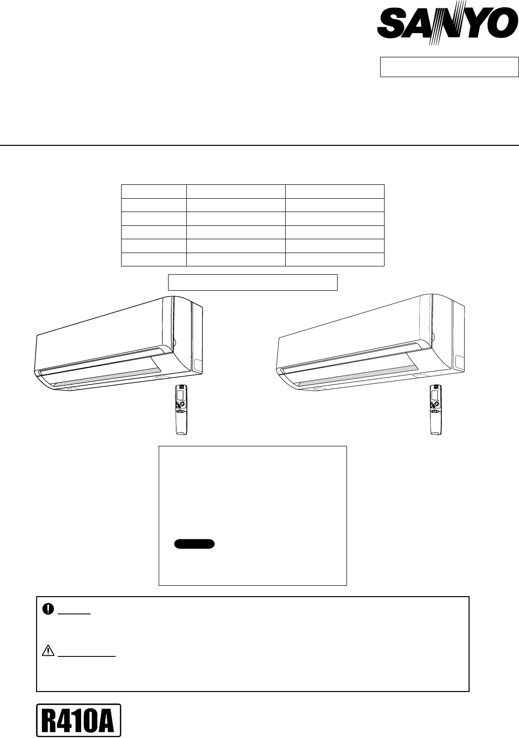
DC INVERTER MULTI-SYSTEM AIR CONDITIONER
Destination: Europe
RoHS
WARNING
• This product does not contain any hazardous substances prohibited by the RoHS Directive.
• You are requested to use RoHS compliant parts for maintenance or repair.
• You are requested to use lead-free solder.
Do not vent R410A into atmosphere : R410A is a fluorinated greenhouse gas,
covered by Kyoto Protocol, with a Global Warming Potential (GWP) = 1975.
F-GAS REGULATION (EC) No 842 / 2006
TECHNICAL & SERVICE MANUAL
INDOOR UNIT:SAP-KMRV76EH
SAP-KMRV96EH
SAP-KMRV126EH
SAP-KRV186EH
SAP-KRV246EH
Indoor Model No.Capacity
2.20 kW
2.65 kW
3.50 kW
5.15 kW
7.10 kW
Product Code No.
1 852 346 78
1 852 346 79
1 852 346 80
1 852 354 94
1 852 354 95
< Applicable Multi-Outdoor Units >
SAP-CMRV1426EH (2-room multi unit)
SAP-CMRV1926EH (2-room multi unit)
SAP-CMRV1936EH (3-room multi unit)
SAP-CMRV2446EH (4-room multi unit)
SAP-CMRV3146EH (4-room multi unit)
SAP-CMRV3656EH (5-room multi unit)
For details about the combinations, refer
to "Unit Combination Table" in the T. Service
Manual for the Multi Outdoor Units.
NOTE
SAP-KMRV76EH-C
SAP-KMRV96EH-C
SAP-KMRV126EH-C
SAP-KRV186EH-C
SAP-KRV246EH-C
Wall Mounted Type Indoor Unit
SAP-KMRV76EH
SAP-KMRV96EH
SAP-KMRV126EH
SAP-KRV186EH
SAP-KRV246EH
REFERENCE NO. SM700842
FILE NO.
When Wiring
ELECTRICAL SHOCK CAN CAUSE
SEVERE PERSONAL INJURY OR DEATH.
ONLY A QUALIFIED, EXPERIENCED
ELECTRICIAN SHOULD ATTEMPT TO
WIRE THIS SYSTEM.
SPECIAL PRECAUTIONS
This symbol refers to a hazard
or unsafe practice which can
result in severe personal
injury or death.
This symbol refers to a hazard
or unsafe practice which can
result in personal injury or
product or property damage.
CAUTION
CAUTION
WARNING
WARNING
Important!
Please Read Before Starting
This air conditioning system meets strict safety and
operating standards. As the installer or service person, it
is an important part of your job to install or service the
system so it operates safely and efficiently.
For safe installation and trouble-free operation, you
must:
Carefully read this instruction booklet before beginning.
Follow each installation or repair step exactly as shown.
Observe all local, state, and national electrical codes.
Pay close attention to all warning and caution notices
given in this manual.
If Necessary, Get Help
These instructions are all you need for most installation
sites and maintenance conditions. If you require help for
a special problem, contact our sales/service outlet or
your certified dealer for additional instructions.
In Case of Improper Installation
The manufacturer shall in no way be responsible for
improper installation or maintenance service, including
failure to follow the instructions in this document.
Do not supply power to the unit until all wiring and
tubing are completed or reconnected and checked.
Highly dangerous electrical voltages are used in this
system. Carefully refer to the wiring diagram and these
instructions when wiring. Improper connections and
inadequate grounding can cause accidental injury or
death.
Ground the unit following local electrical codes.
Connect all wiring tightly. Loose wiring may cause
overheating at connection points and a possible fire
hazard.
Install a protective leakage breaker depending on the
installation location (especially a damp or humid
location). If a leakage breaker is not installed, electric
shock can occur.
When Transporting
Be careful when picking up and moving the indoor and
outdoor units. Get a partner to help, and bend your knees
when lifting to reduce strain on your back. Sharp edges or
thin aluminum fins on the air conditioner can cut your
fingers.
When Installing
In a Ceiling or Wall
Make sure the ceiling/wall is strong enough to hold the
unit’s weight. It may be necessary to construct a strong
wood or metal frame to provide added support.
In a Room
Properly insulate any tubing run inside a room to prevent
"sweating" that can cause dripping and water damage to
walls and floors.
In Moist or Uneven Locations
Use a raised concrete pad or concrete blocks to provide a
solid, level foundation for the outdoor unit. This prevents
water damage and abnormal vibration.
In an Area with High Winds
Securely anchor the outdoor unit down with bolts and a
metal frame. Provide a suitable air baffle.
In a Snowy Area (for Heat Pump-type Systems)
Install the outdoor unit on a raised platform that is higher
than drifting snow. Provide snow vents.
When Connecting Refrigerant Tubing
Use the flare method for connecting tubing.
Apply refrigerant lubricant to the matching surfaces of
the flare and union tubes before connecting them, then
tighten the nut with a torque wrench for a leak-free
connection.
Check carefully for leaks before starting the test run.
When Servicing
Turn the power off at the main power box (mains) before
opening the unit to check or repair electrical parts and
wiring.
Keep your fingers and clothing away from any moving
parts.
Clean up the site after you finish, remembering to check
that no metal scraps or bits of wiring have been left
inside the unit being serviced.
Others
Ventilate any enclosed areas when installing or testing
the refrigeration system. Escaped refrigerant gas, on
contact with fire or heat, can produce dangerously toxic
gas.
Confirm upon completing installation that no refrigerant
gas is leaking. If escaped gas comes in contact with a
stove, gas water heater, electric room heater or other
heat source, it can produce dangerously toxic gas.
•
•
•
•
•
•
•
•
•
•
•
•
•
2

APPLICABLE MULTI-OUTDOOR UNITS
1. OPERATING RANGE
2. SPECIFICATIONS
2-1. Unit Specifications
2-2. Major Component Specifications
2-3. Other Component Specifications
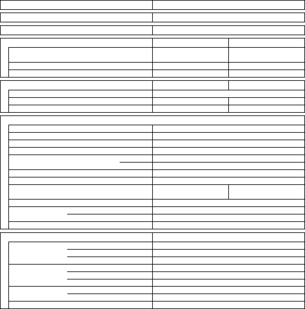
3. DIMENSIONAL DATA
4. REFRIGERANT FLOW DIAGRAM
4-1. Refrigerant Flow Diagram
5. PERFORMANCE DATA
5-1. Air Throw Distance Charts
6. ELECTRICAL DATA
6-1. Electric Wiring Diagrams
7. FUNCTIONS
7-1. Operation Functions
7-2. Protective Functions
8. TROUBLESHOOTING
8-1. Precautions before Performing Inspection or Repair
8-2. Method of Self-Diagnostics
8-3. Checking the Indoor and Outdoor Units
8-4. Trouble Diagnosis of Fan Motor
8-5. Noise Malfunction and Electromagnetic Interference
APPENDIX AINSTRUCTION MANUAL
(SAP-KMRV76EH, SAP-KMRV96EH, SAP-KMRV126EH)
APPENDIX BINSTRUCTION MANUAL
(SAP-KRV186EH, SAP-KRV246EH)
APPENDIX CINSTALLATION INSTRUCTIONS
When combined with SAP-CMRV1426EH, SAP-CMRV1926EH,
SAP-CMRV1936EH, SAP-CMRV2446EH or SAP-CMRV3146EH
APPENDIX D INSTALLATION INSTRUCTIONS
When combined with SAP-CMRV3656EH
Table of Contents
4
5
6
11
16
17
19
20
25
27
29
30
30
32
33
34
A-1
A-2
A-3
A-4
.....................................................................................
...................................................................................................................
.............................................................................................................
.......................................................................................
.......................................................................................
.....................................................................................................................
...................................................................................................
.................................................................................................
....................................................................................................
...........................................................................................................
...........................................................................................................
...........................................................
.................................................................................................
..............................................................................
...........................................................................................
..........................................................
......................................
........................................................................
.............................................................................
.............................................................................
Page
()
()
3
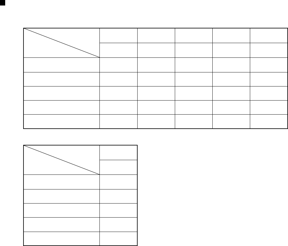
APPLICABLE MULTI-OUTDOOR UNITS
SAP-KMRV76EH
Indoor Unit
Multi-Outdoor Unit
YES YES YES YES YES
SAP-KMRV96EH YES YES YES YES YES
SAP-KMRV126EH YES YES YES YES YES
SAP-KRV186EH NO YES YES YES YES
SAP-KRV246EH NO NO NO YES YES
2-Room 2-Room 3-Room 4-Room 4-Room
SAP-
CMRV1426EH
SAP-
CMRV1926EH
SAP-
CMRV1936EH
SAP-
CMRV2446EH
SAP-
CMRV3146EH
SAP-KMRV76EH
Indoor Unit
Multi-Outdoor Unit
YES
SAP-KMRV96EH YES
SAP-KMRV126EH YES
SAP-KRV186EH YES
SAP-KRV246EH YES
5-Room
SAP-
CMRV3656EH
4
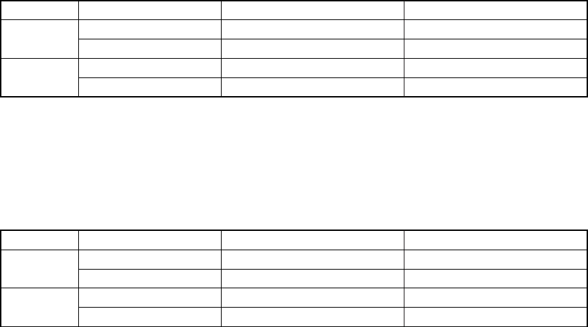
1. OPERATING RANGE
Maximum
Minimum
Maximum
Minimum
32 °C D.B. / 23 °C W.B.
19 °C D.B. / 14 °C W.B.
27 °C D.B.
16 °C D.B.
Temperature Indoor Air Intake Temp.
43 °C D.B.
– 5 °C D.B.
24 °C D.B. / 18 °C W.B.
– D.B. / – 15 °C W.B.
(*1)
Outdoor Air Intake Temp.
Cooling
Heating
(1) Outdoor Unit : SAP-CMRV1426EH, SAP-CMRV1926EH, SAP-CMRV1936EH
SAP-CMRV2446EH, SAP-CMRV3146EH
Indoor Unit : SAP-KMRV76EH, SAP-KMRV96EH, SAP-KMRV126EH
SAP-KRV186EH, SAP-KRV246EH
(*1) 0 °C D.B. : When combined with SAP-KRV186EH or SAP-KRV246EH
Maximum
Minimum
Maximum
Minimum
32 °C D.B. / 23 °C W.B.
19 °C D.B. / 14 °C W.B.
27 °C D.B.
16 °C D.B.
Temperature Indoor Air Intake Temp.
43 °C D.B.
– 10 °C D.B.
24 °C D.B. / 18 °C W.B.
– D.B. / – 15 °C W.B.
Outdoor Air Intake Temp.
Cooling
Heating
(2) Outdoor Unit : SAP-CMRV3656EH
Indoor Unit : SAP-KMRV76EH, SAP-KMRV96EH, SAP-KMRV126EH
SAP-KRV186EH, SAP-KRV246EH
5

2. SPECIFICATIONS
2-1. Unit Specifications
Indoor Unit SAP-KMRV76EH
DATA SUBJECT TO CHANGE WITHOUT NOTICE.
Vertical
dB-AIndoor : Hi/Me/Lo/Qt*
Air Filter
Refrigerant
0.11
25
0.11
25
2.2
7,500
2.5
8,500
Shipping Volume
Cooling Heating
440
1.3
Cooling Heating
Depth
Net
Shipping
Package Dimensions
Weight
Width
Depth
Height
Width
mm
kg
kg
m3
mm
mm
mm
mm
220 to 240V Single-Phase 50Hz
mm
480
-
198 to 264
Dimensions & Weight
(*Qt = Quiet mode)
Refrigerant Tubing Connections
Unit Dimensions Height
Operation Sound
Electrical Rating
Air Circulation (High)
Moisture Removal (High)
WPower Input
V
A
Available Voltage Range
Running Amperes
Refrigerant Tube Kit / Accessories
Narrow tube
Wide tube
Refrigerant mm (in.)
Tube Diameter mm (in.)
350
10.0
12.0
0.08
825
213
270
900
Indoor Unit
285
6.35 (1/4)
9.52 (3/8)
Flare Type
33 / 30 / 27 /2233 / 30 / 27 / 22
R410A
Washable, Anti-Mold
Manual
Auto
Timer
Indoor Fan Speeds
24-Hour ON or OFF Timer, 1-Hour OFF Timer
Auto and 3 steps
Airflow Direction (Indoor) Horizontal
Controls / Temperature Control
Control Unit
Microprocessor / I.C. Thermister
Wireless Remote Control Unit
Features
Optional / Air Clean Filter
kW
Performance
Type
Power Source
Liters/h
BTU/h
Capacity
m3/h
Wall Mounted Type Indoor Unit
230VVoltage Rating
6

Indoor Unit SAP-KMRV96EH
DATA SUBJECT TO CHANGE WITHOUT NOTICE.
Vertical
dB-AIndoor : Hi/Me/Lo/Qt*
Air Filter
Refrigerant
0.15
35
0.15
35
2.65
9,000
3.6
12,300
Shipping Volume
Cooling Heating
460
1.6
Cooling Heating
Depth
Net
Shipping
Package Dimensions
Weight
Width
Depth
Height
Width
mm
kg
kg
m3
mm
mm
mm
mm
220 to 240V Single-Phase 50Hz
mm
480
-
198 to 264
Dimensions & Weight
(*Qt = Quiet mode)
Refrigerant Tubing Connections
Unit Dimensions Height
Operation Sound
Electrical Rating
Air Circulation (High)
Moisture Removal (High)
WPower Input
V
A
Available Voltage Range
Running Amperes
Refrigerant Tube Kit / Accessories
Narrow tube
Wide tube
Refrigerant mm (in.)
Tube Diameter mm (in.)
350
10.0
12.0
0.08
825
213
270
900
Indoor Unit
285
6.35 (1/4)
9.52 (3/8)
Flare Type
34 / 31 / 28 / 2234 / 31 / 28 / 22
R410A
Washable, Anti-Mold
Manual
Auto
Timer
Indoor Fan Speeds
24-Hour ON or OFF Timer, 1-Hour OFF Timer
Auto and 3 steps
Airflow Direction (Indoor) Horizontal
Controls / Temperature Control
Control Unit
Microprocessor / I.C. Thermister
Wireless Remote Control Unit
Features
Optional / Air Clean Filter
kW
Performance
Type
Power Source
Liters/h
BTU/h
Capacity
m3/h
Wall Mounted Type Indoor Unit
230VVoltage Rating
7

Indoor Unit SAP-KMRV126EH
DATA SUBJECT TO CHANGE WITHOUT NOTICE.
Vertical
dB-AIndoor : Hi/Me/Lo/Qt*
Air Filter
Refrigerant
0.15
35
0.15
35
3.5
11,900
4.2
14,300
Shipping Volume
Cooling Heating
480
2.0
Cooling Heating
Depth
Net
Shipping
Package Dimensions
Weight
Width
Depth
Height
Width
mm
kg
kg
m3
mm
mm
mm
mm
220 to 240V Single-Phase 50Hz
mm
500
-
198 to 264
Dimensions & Weight
(*Qt = Quiet mode)
Refrigerant Tubing Connections
Unit Dimensions Height
Operation Sound
Electrical Rating
Air Circulation (High)
Moisture Removal (High)
WPower Input
V
A
Available Voltage Range
Running Amperes
Refrigerant Tube Kit / Accessories
Narrow tube
Wide tube
Refrigerant mm (in.)
Tube Diameter mm (in.)
350
10.0
12.0
0.08
825
213
270
900
Indoor Unit
285
6.35 (1/4)
9.52 (3/8)
Flare Type
34 / 31 / 29 / 2536 / 33 / 29 / 25
R410A
Washable, Anti-Mold
Manual
Auto
Timer
Indoor Fan Speeds
24-Hour ON or OFF Timer, 1-Hour OFF Timer
Auto and 3 steps
Airflow Direction (Indoor) Horizontal
Controls / Temperature Control
Control Unit
Microprocessor / I.C. Thermister
Wireless Remote Control Unit
Features
Optional / Air Clean Filter
kW
Performance
Type
Power Source
Liters/h
BTU/h
Capacity
m3/h
Wall Mounted Type Indoor Unit
230VVoltage Rating
8
Indoor Unit SAP-KRV186EH
DATA SUBJECT TO CHANGE WITHOUT NOTICE.
Vertical
dB-AIndoor : Hi/Me/Lo/Qt*
Air Filter
Refrigerant
0.29
32
0.29
32
Shipping Volume
Cooling Heating
840
2.3
Cooling Heating
Depth
Net
Shipping
Package Dimensions
Weight
Width
Depth
Height
Width
mm
kg
kg
m3
mm
mm
mm
mm
220 to 240V Single-Phase 50Hz
mm
880
-
198 to 264
Dimensions & Weight
(*Qt = Quiet mode)
Refrigerant Tubing Connections
Unit Dimensions Height
Operation Sound
Electrical Rating
Air Circulation (High)
Moisture Removal (High)
WPower Input
V
A
Available Voltage Range
Running Amperes
Refrigerant Tube Kit / Accessories
Narrow tube
Wide tube
Refrigerant mm (in.)
Tube Diameter mm (in.)
379
12.0
15.0
0.13
1,065
234
302
1,140
Indoor Unit
298
6.35 (1/4)
12.7 (1/2)
Flare Type
40 / 37 / 34 / 2841 / 38 / 34 / 28
R410A
Washable, Anti-Mold
Manual
Auto
Timer
Indoor Fan Speeds
24-Hour ON or OFF Timer, 1-Hour OFF Timer
Auto and 3 steps
Airflow Direction (Indoor) Horizontal
Controls / Temperature Control
Control Unit
Microprocessor / I.C. Thermister
Wireless Remote Control Unit
Features
Optional / Air Clean Filter
kW
Performance
Type
Power Source
Liters/h
BTU/h
Capacity
m3/h
Wall Mounted Type Indoor Unit
230VVoltage Rating
5.15
17,600
6.0
20,500
9

Indoor Unit SAP-KRV246EH
DATA SUBJECT TO CHANGE WITHOUT NOTICE.
Vertical
dB-AIndoor : Hi/Me/Lo/Qt*
Air Filter
Refrigerant
0.32
36
0.32
36
Shipping Volume
Cooling Heating
890
2.3
Cooling Heating
Depth
Net
Shipping
Package Dimensions
Weight
Width
Depth
Height
Width
mm
kg
kg
m3
mm
mm
mm
mm
220 to 240V Single-Phase 50Hz
mm
930
-
198 to 264
Dimensions & Weight
(*Qt = Quiet mode)
Refrigerant Tubing Connections
Unit Dimensions Height
Operation Sound
Electrical Rating
Air Circulation (High)
Moisture Removal (High)
WPower Input
V
A
Available Voltage Range
Running Amperes
Refrigerant Tube Kit / Accessories
Narrow tube
Wide tube
Refrigerant mm (in.)
Tube Diameter mm (in.)
379
12.0
15.0
0.13
1,065
234
302
1,140
Indoor Unit
298
6.35 (1/4)
15.88 (5/8)
Flare Type
43 / 40 / 37 / 3044 / 41 / 38 / 30
R410A
Washable, Anti-Mold
Manual
Auto
Timer
Indoor Fan Speeds
24-Hour ON or OFF Timer, 1-Hour OFF Timer
Auto and 3 steps
Airflow Direction (Indoor) Horizontal
Controls / Temperature Control
Control Unit
Microprocessor / I.C. Thermister
Wireless Remote Control Unit
Features
Optional / Air Clean Filter
kW
Performance
Type
Power Source
Liters/h
BTU/h
Capacity
m3/h
Wall Mounted Type Indoor Unit
230VVoltage Rating
7.1
24,200
8.5
29,000
10

2-2. Major Component Specifications
2-2-1. Indoor Unit
Indoor Unit SAP-KMRV76EH
Flap Motor
Type Stepping Motor
Coil Resistance Ohm
(Ambient Temp. 25 °C)
Each Pair of Terminal : 400 +/- 7%
Aluminum Plate Fin / Copper Tube
2
1.3
0.188 Face Area
Coil
Rows
Fin Pitch
Heat Exchanger Coil
m2
mm
DATA SUBJECT TO CHANGE WITHOUT NOTICE.
Rating DC 12V
Model 24BYJ48-962
Over-Heat Protection
Yes
Control PCB
Control Circuit Fuse
Controls
Part No.
Microprocessor
250V 3.15A
CB-KMRV76EH
1 ... D94 / L634
RCS-6MHVPUS4E
Cross-Flow
DC Motor
SIC-39CVL-D847-4 ... 1
8
-
47
1,050 / 1,100
Internal Controller
Yes
-
-
Fan
Remote Control Unit
Q'ty ... Dia. and Length
Type
mm
Fan Motor
Nominal Output
Coil Resistance
Rough Measure RPM (Cool / Heat)
Type
Model ... Q'ty
No. of Poles
Safety Device
Type
Over- Current Protection
(Ambient Temp. 20 °C)
Run Capacitor Micro F
VAC
W
Ohm
11

Indoor Unit SAP-KMRV96EH
Flap Motor
Type Stepping Motor
Coil Resistance Ohm
(Ambient Temp. 25 °C)
Each Pair of Terminal : 400 +/- 7%
Aluminum Plate Fin / Copper Tube
2
1.3
0.188 Face Area
Coil
Rows
Fin Pitch
Heat Exchanger Coil
m2
mm
DATA SUBJECT TO CHANGE WITHOUT NOTICE.
Rating DC 12V
Model 24BYJ48-962
Over-Heat Protection
Yes
Control PCB
Control Circuit Fuse
Controls
Part No.
Microprocessor
250V 3.15A
CB-KMRV96EH
1 ... D94 / L634
RCS-6MHVPUS4E
Cross-Flow
DC Motor
SIC-39CVL-D847-4 ... 1
8
-
47
1,100 / 1,100
Internal Controller
Yes
-
-
Fan
Remote Control Unit
Q'ty ... Dia. and Length
Type
mm
Fan Motor
Nominal Output
Coil Resistance
Rough Measure RPM (Cool / Heat)
Type
Model ... Q'ty
No. of Poles
Safety Device
Type
Over- Current Protection
(Ambient Temp. 20 °C)
Run Capacitor Micro F
VAC
W
Ohm
12
Indoor Unit SAP-KMRV126EH
Flap Motor
Type Stepping Motor
Coil Resistance Ohm
(Ambient Temp. 25 °C)
Each Pair of Terminal : 400 +/- 7%
Aluminum Plate Fin / Copper Tube
2
1.3
0.188 Face Area
Coil
Rows
Fin Pitch
Heat Exchanger Coil
m2
mm
DATA SUBJECT TO CHANGE WITHOUT NOTICE.
Rating DC 12V
Model 24BYJ48-962
Over-Heat Protection
Yes
Control PCB
Control Circuit Fuse
Controls
Part No.
Microprocessor
250V 3.15A
CB-KMRV126EH
1 ... D94 / L634
RCS-6MHVPUS4E
Cross-Flow
DC Motor
SIC-39CVL-D847-4 ... 1
8
-
47
1,150 / 1,150
Internal Controller
Yes
-
-
Fan
Remote Control Unit
Q'ty ... Dia. and Length
Type
mm
Fan Motor
Nominal Output
Coil Resistance
Rough Measure RPM (Cool / Heat)
Type
Model ... Q'ty
No. of Poles
Safety Device
Type
Over- Current Protection
(Ambient Temp. 20 °C)
Run Capacitor Micro F
VAC
W
Ohm
13

Indoor Unit SAP-KRV186EH
Flap Motor
Type Stepping Motor
Coil Resistance Ohm
(Ambient Temp. 25 °C)
Each Pair of Terminal : 400 +/- 7%
Aluminum Plate Fin / Copper Tube
2
1.3
0.285 Face Area
Coil
Rows
Fin Pitch
Heat Exchanger Coil
m2
mm
DATA SUBJECT TO CHANGE WITHOUT NOTICE.
Rating DC 12V
Model MP24Z3
Over-Heat Protection
Yes
Control PCB
Control Circuit Fuse
Controls
Part No.
Microprocessor
250V 3.15A
CB-KRV186EH
1 ... D94 / L845
RCS-6MHVPUSW4E
Cross-Flow
DC Motor
SIC-39CVL-D847-2 ... 1
8
-
30
1,200 / 1,200
Internal Controller
Yes
-
-
Fan
Remote Control Unit
Q'ty ... Dia. and Length
Type
mm
Fan Motor
Nominal Output
Coil Resistance
Rough Measure RPM (Cool / Heat)
Type
Model ... Q'ty
No. of Poles
Safety Device
Type
Over- Current Protection
(Ambient Temp. 20 °C)
Run Capacitor Micro F
VAC
W
Ohm
14

Indoor Unit SAP-KRV246EH
Flap Motor
Type Stepping Motor
Coil Resistance Ohm
(Ambient Temp. 25 °C)
Each Pair of Terminal : 400 +/- 7%
Aluminum Plate Fin / Copper Tube
2
1.3
0.285 Face Area
Coil
Rows
Fin Pitch
Heat Exchanger Coil
m2
mm
DATA SUBJECT TO CHANGE WITHOUT NOTICE.
Rating DC 12V
Model MP24Z3
Over-Heat Protection
Yes
Control PCB
Control Circuit Fuse
Controls
Part No.
Microprocessor
250V 3.15A
CB-KRV246EH
1 ... D94 / L845
RCS-6MHVPUSW4E
Cross-Flow
DC Motor
SIC-39CVL-D847-2 ... 1
8
-
30
1,250 / 1,250
Internal Controller
Yes
-
-
Fan
Remote Control Unit
Q'ty ... Dia. and Length
Type
mm
Fan Motor
Nominal Output
Coil Resistance
Rough Measure RPM (Cool / Heat)
Type
Model ... Q'ty
No. of Poles
Safety Device
Type
Over- Current Protection
(Ambient Temp. 20 °C)
Run Capacitor Micro F
VAC
W
Ohm
15
2-3. Other Component Specifications
10
1
2
3
4
5
6
7
8
9
10
15 20 25 30 35 40
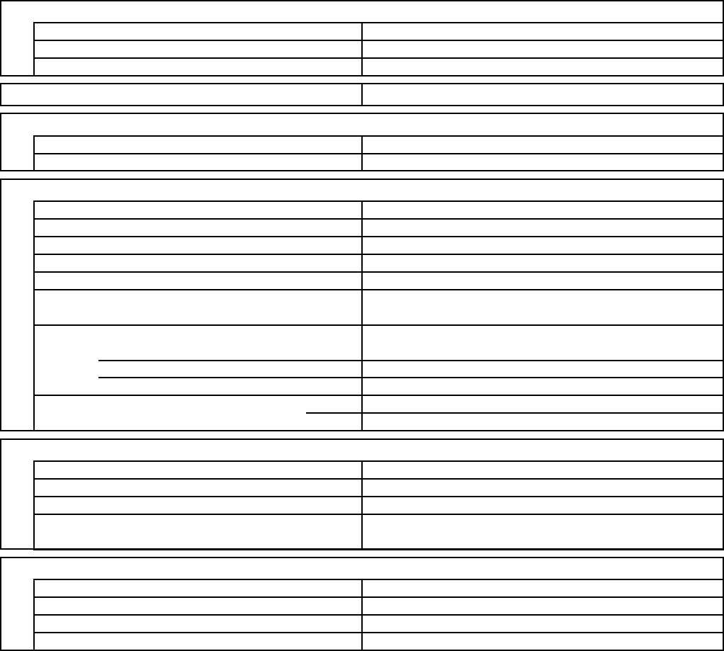
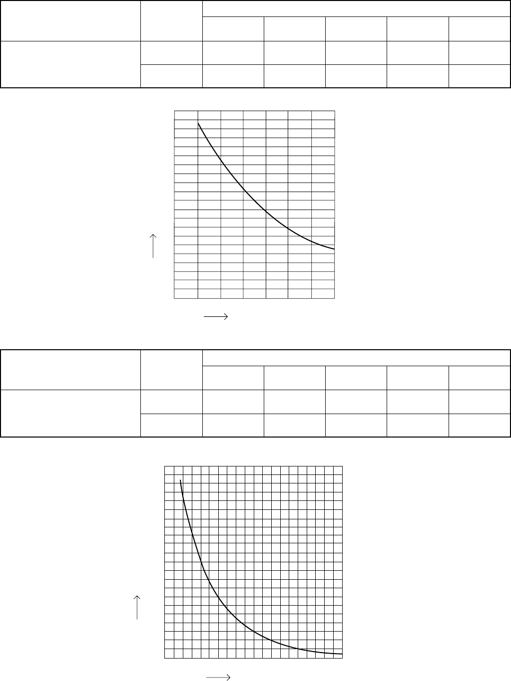
Resistance (k ohm)
Temperature (°C)
00102030405060708090
40
60
80
100
120
140
160
180
200
20
Resistance (k ohm)
Temperature (°C)
Indoor air temp sensor
DTN-
TKS451S
Model No.
of sensor
Sensor Name
111
Quantity of Sensor
00
1FA4V2E
042600 TH2 00011
SAP-
KMRV76EH
SAP-
KMRV96EH
SAP-
KMRV126EH
SAP-
KRV186EH
SAP-
KRV246EH
Indoor heat exchanger sensor
DTN-
TKS451S
Model No.
of sensor
Sensor Name
111
Quantity of Sensor
00
1FA4V2E
042600 TH1 00011
SAP-
KMRV76EH
SAP-
KMRV96EH
SAP-
KMRV126EH
SAP-
KRV186EH
SAP-
KRV246EH
16
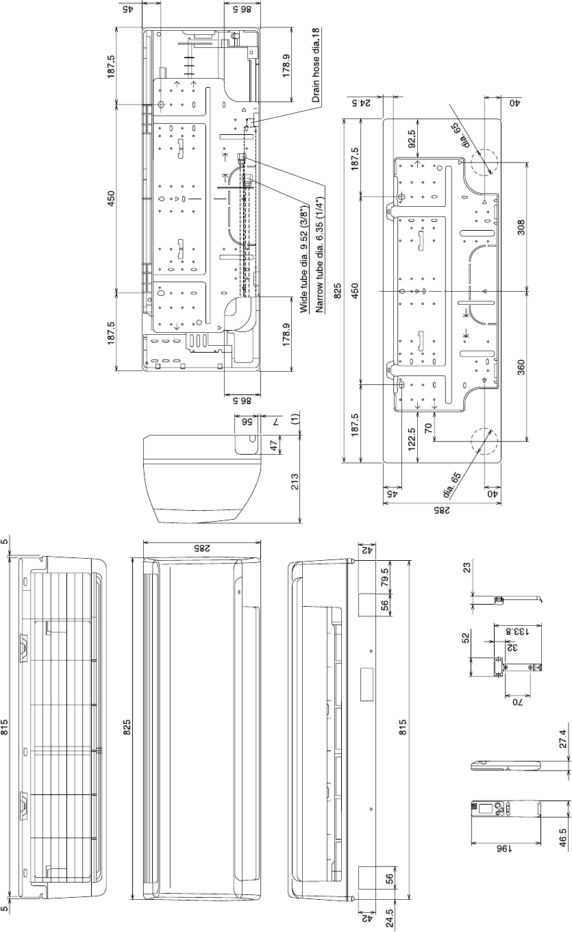
3. DIMENSIONAL DATA
Indoor Unit SAP-KMRV76EH
SAP-KMRV96EH
SAP-KMRV126EH
Unit: mm
(852-0-0010-15500-0)
17
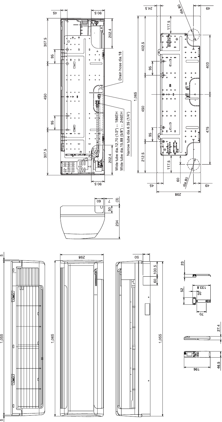
Indoor Unit SAP-KRV186EH
SAP-KRV246EH
Unit: mm
(852-0-0010-16200-0)
18
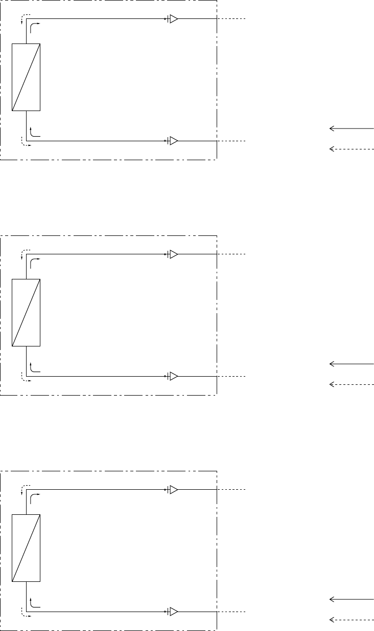
Indoor heat
exchanger
O.D. 9.52 mm (3/8")
O.D. 6.35 mm (1/4") Cooling cycle
Heating cycle
Indoor unit
Indoor heat
exchanger
O.D. 12.7 mm (1/2")
O.D. 6.35 mm (1/4") Cooling cycle
Heating cycle
Indoor unit
Indoor heat
exchanger
O.D. 15.88 mm (5/8")
O.D. 6.35 mm (1/4") Cooling cycle
Heating cycle
Indoor unit
4. REFRIGERANT FLOW DIAGRAM
4-1. Refrigerant Flow Diagram
Indoor Unit SAP-KMRV76EH
SAP-KMRV96EH
SAP-KMRV126EH
Indoor Unit SAP-KRV186EH
Indoor Unit SAP-KRV246EH
19
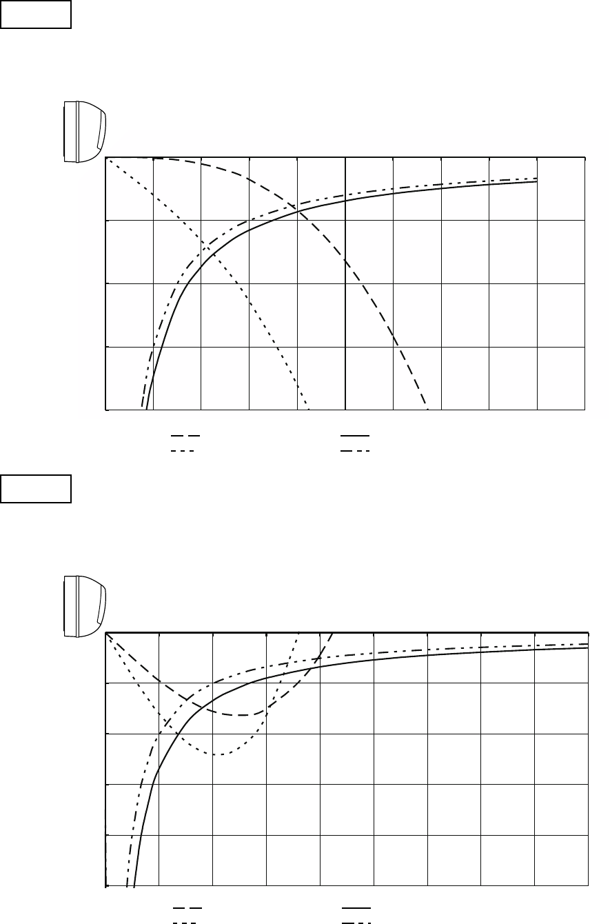
Horizontal distance (m)
Axis air velocity (m/s)
Vertical distance (m)
Room air temp. :20°C
Fan speed : High
Heating
Horizontal distance (m)
Axis air velocity (m/s)
Vertical distance (m)
Room air temp. :27°C
Fan speed : High
Cooling
: Flap angle 0
°
, : Axis air velocity 0
°
: Flap angle 30
°
, : Axis air velocity 30
°
: Flap angle 45
°
, : Axis air velocity 45
°
: Flap angle 60
°
, : Axis air velocity 60
°
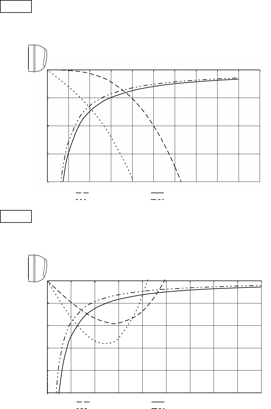
5. PERFORMANCE DATA
5-1. Air Throw Distance Charts
Indoor Unit SAP-KMRV76EH
0
1
2
3
4
0 1 2 3 4 5 6 7 8 9 10
: Flap angle 0 , : Axis air velocity 0
: Flap angle 30, : Axis air velocity 30
0
1
2
3
4
5
0123456789
: Flap angle 45 , : Axis air velocity 45
: Flap angle 60 , : Axis air velocity 60
20
Horizontal distance (m)
Axis air velocity (m/s)
Vertical distance (m)
Room air temp. :20°C
Fan speed : High
Heating
Horizontal distance (m)
Axis air velocity (m/s)
Vertical distance (m)
Room air temp. :27°C
Fan speed : High
Cooling
: Flap angle 0
°
, : Axis air velocity 0
°
: Flap angle 30
°
, : Axis air velocity 30
°
: Flap angle 45
°
, : Axis air velocity 45
°
: Flap angle 60
°
, : Axis air velocity 60
°
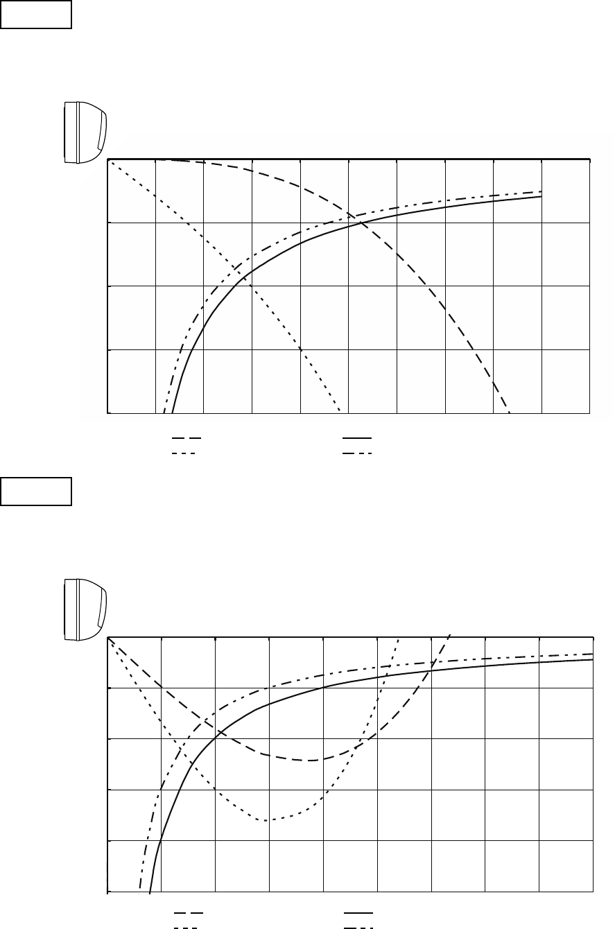
Indoor Unit SAP-KMRV96EH
0
1
2
3
4
0 1 2 3 4 5 6 7 8 9 10
: Flap angle 0 , : Axis air velocity 0
: Flap angle 30, : Axis air velocity 30
0
1
2
3
4
5
0123456789
: Flap angle 45 , : Axis air velocity 45
: Flap angle 60 , : Axis air velocity 60
21
Horizontal distance (m)
Axis air velocity (m/s)
Vertical distance (m)
Room air temp. :20°C
Fan speed : High
Heating
Horizontal distance (m)
Axis air velocity (m/s)
Vertical distance (m)
Room air temp. :27°C
Fan speed : High
Cooling
: Flap angle 0
°
, : Axis air velocity 0
°
: Flap angle 30
°
, : Axis air velocity 30
°
: Flap angle 45
°
, : Axis air velocity 45
°
: Flap angle 60
°
, : Axis air velocity 60
°
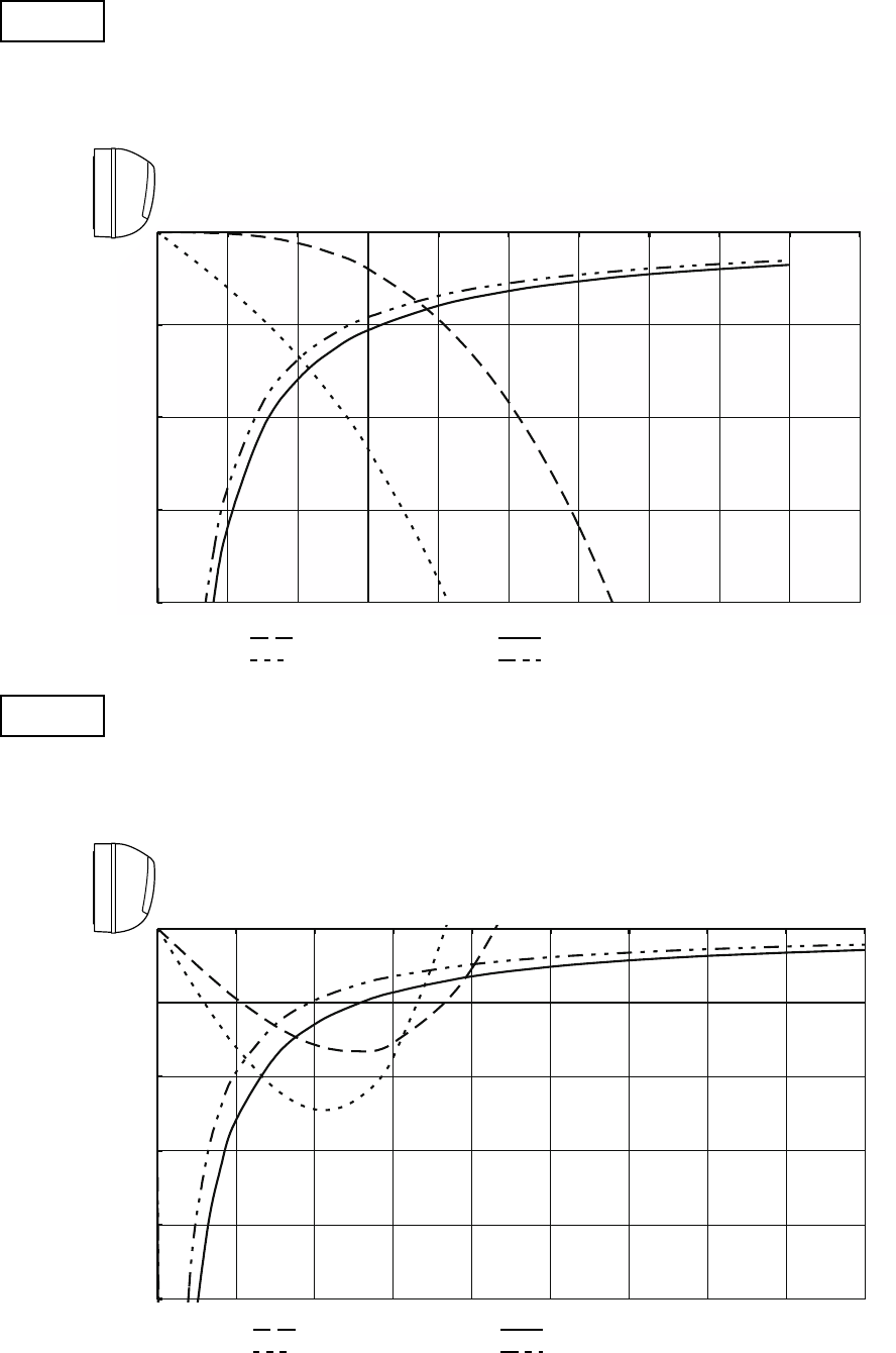
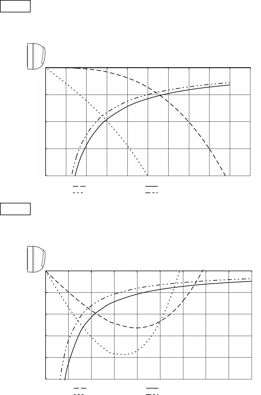
Indoor Unit SAP-KMRV126EH
0
1
2
3
4
0 1 2 3 4 5 6 7 8 9 10
: Flap angle 0 , : Axis air velocity 0
: Flap angle 30, : Axis air velocity 30
0
1
2
3
4
5
0123456789
: Flap angle 45 , : Axis air velocity 45
: Flap angle 60 , : Axis air velocity 60
22
Horizontal distance (m)
Axis air velocity (m/s)
Vertical distance (m)
Room air temp. :20°C
Fan speed : High
Heating
Horizontal distance (m)
Axis air velocity (m/s)
Vertical distance (m)
Room air temp. :27°C
Fan speed : High
Cooling
: Flap angle 0
°
, : Axis air velocity 0
°
: Flap angle 30
°
, : Axis air velocity 30
°
: Flap angle 45
°
, : Axis air velocity 45
°
: Flap angle 60
°
, : Axis air velocity 60
°
Indoor Unit SAP-KRV186EH
0
1
2
3
4
0 1 2 3 4 5 6 7 8 9 10
: Flap angle 0 , : Axis air velocity 0
: Flap angle 30, : Axis air velocity 30
0
1
2
3
4
5
0123456789
: Flap angle 45 , : Axis air velocity 45
: Flap angle 60 , : Axis air velocity 60
23
Horizontal distance (m)
Axis air velocity (m/s)
Vertical distance (m)
Room air temp. :20°C
Fan speed : High
Heating
Horizontal distance (m)
Axis air velocity (m/s)
Vertical distance (m)
Room air temp. :27°C
Fan speed : High
Cooling
: Flap angle 0
°
, : Axis air velocity 0
°
: Flap angle 30
°
, : Axis air velocity 30
°
: Flap angle 45
°
, : Axis air velocity 45
°
: Flap angle 60
°
, : Axis air velocity 60
°
Indoor Unit SAP-KRV246EH
0
1
2
3
4
0 1 2 3 4 5 6 7 8 9 10
: Flap angle 0 , : Axis air velocity 0
: Flap angle 30, : Axis air velocity 30
0
1
2
3
4
5
0123456789
: Flap angle 45 , : Axis air velocity 45
: Flap angle 60 , : Axis air velocity 60
24
8FA-2-5250-29700-2
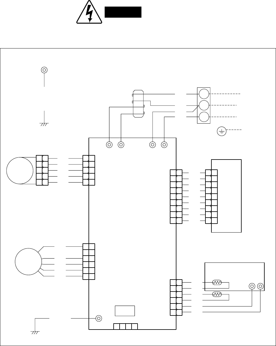
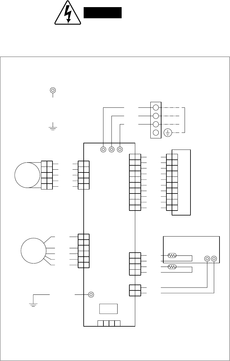
6. ELECTRICAL DATA
6-1. Electric Wiring Diagrams
Indoor Unit SAP-KMRV76EH
SAP-KMRV96EH
SAP-KMRV126EH
WARNING
To avoid electrical shock hazard, be sure to
disconnect power before checking, servicing
and/or cleaning any electrical parts.
1
2
3
4
5
1
2
3
4
5
FLAP MOTOR
CONNECTOR
CONTROLLER
UV ASSY
ROOM THERMISTOR
COIL THERMISTOR
EVAPORATOR
FLAP
GRN/YEL
1
2
3
4
5
6
1
2
3
4
5
6
FAN MOTOR
FM
BLU
YEL
WHT
BLK
RED
RED
PNK
BLU
BRN
YEL
FLAP
5P (WHT)
E
DCM
6P (BLU)
1
2
3
4
5
6
7
8
9
1
2
3
4
5
6
7
8
9
IND LAMP ASSY
RED
WHT
WHT
WHT
WHT
WHT
WHT
WHT
WHT
LAMP
9P (WHT)
1 1
2
3
4
5
2
3
4
5
1 2 3 4
HA
JEM-A
4P (WHT)
TERMINAL BASEFERRITE CORE
TO OUTDOOR UNIT
RED
WHT
WHT
BLK 1
2
3
AC
AC SIIN-2
IN SI-2
1
2
3
4
5
6
BLK
BLK
ORG
ORG
RED
BLK
ROOM/COIL/UV
6P (WHT)
1
2
3
4
5
6
1
2
3
4
5
6
7
8
9
1
2
3
4
6
7
8
9
5
GRN/YEL
25
Indoor Unit SAP-KRV186EH
SAP-KRV246EH
WARNING
To avoid electrical shock hazard, be sure to
disconnect power before checking, servicing
and/or cleaning any electrical parts.
8FA2-5250-27700-1
EVAPORATOR
TERMINAL BASE
WHT
BLK
RED
1
2
3
4
GRN/YEL
LAMP
10P(WHT)
FLAP
5P(WHT)
FLAP
CONNECTOR
FLAP MOTOR
RED
PNK
BLU
BRN
YEL
1
2
3
4
5
1
2
3
4
5
1
2
3
4
5
1
2
3
4
5
AC1 AC2 SI
BLK
WHT
BLK
BLK
BLK
BLK
BLK
BLK
BLK
BLK
1
2
3
4
5
6
7
8
9
10
1
2
3
4
5
6
7
8
9
10
1
2
3
4
5
6
7
8
9
10
1
2
3
4
5
6
7
8
9
10
IND LAMP ASSY
DCM
6P(BLU)
CONTROLLER
FM
FAN MOTOR
RED 1
2
3
4
5
6
1
2
3
4
5
6
WHT
BLK
YEL
BLU
GRN/YEL E
HA
JEM-A
4P(WHT)
1 2 43
ROOM/COIL
4P(WHT)
UV
2P(RED)
ROOM THERMISTOR
UV ASSY
BLK
BLK
RED
BLK
ORG
ORG
COIL THERMISTOR
1
2
3
4
1
2
1
2
1
2
3
4
TO OUTDOOR UNIT
26
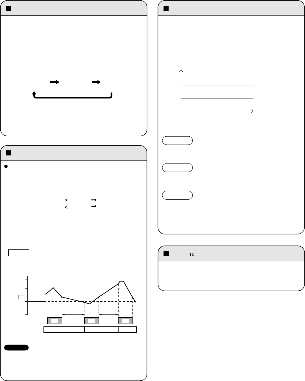
Emergency operation SENSOR DRY
AUTO cooling/heating operation
Selecting the operation mode
During DRY operation, the system adjusts the room
temperature and fan speed according to the conditions in the
room, in order to maintain a comfortable room environment.
SENSOR DRY operation
• DRY operation is as shown in the figure below.
PAM- control
• In order to further improve inverter performance, control is
switched between PWM control at low operation speeds, and
PAM control at high operation speeds, making the most
effective use of power.
The compressor operation frequency varies.
The indoor fan operates with 1/f fluctuation.
The compressor operates at a low operating frequency.
The indoor fan operates with 1/f fluctuation.
• Monitoring operation takes place when the room temperature
is below 15 °C, or more than 3 °C below the set temperature.
• When the monitoring range is entered, the compressor stops,
and the indoor fan operates with 1/f fluctuation.
DRY A
DRY B
Monitor
Conditions are monitored at all
times when the room temperature
is below 15 °C.
Load
COOL zone
A zone
B zone
Emergency operation is available when the remote
controller malfunctions, has been lost, or otherwise
cannot be used.
• The set temperature is 2 °C below the detected room
temperature in the case of cooling operation, and 2 °C
above the room temperature in the case of heating
operation. The flap and fan speed settings are AUTO.
(GREEN) (RED) (Lamp Off)
COOL HEAT STOP
• When AUTO mode is selected, the microprocessor calculates
the difference between the set temperature and the room
temperature, and automatically switches to Cooling or
Heating mode.
• As shown by the example in the figure below, with AUTO
cooling/heating operation, the mode changes between
Heating and Cooling mode according to changes in the
relationship between the current room temperature and the
set temperature.
Room temp. Set temp. COOL
Room temp. Set temp. HEAT
23
Zone A
Zone B
Zone C
Zone C
Zone B
Zone A
OFF OFF
Compressor
Operation mode
Room temp.
HeatingCooling Cooling
ON ON ON
More than
1 hour
Within
1 hour
Set temp.
Example
Example of operation in AUTO mode with the set room temperature
at 23 °C.
When multiple indoor units are used and units in other rooms are
already operating, they will be set to the same mode of operation
as the operating indoor units.
To operate the system, press the OPERATION button,
which is also used as the receiver, below the unit display.
Each time this button is pressed, the OPERATION lamp
changes color to indicate the type of operation. Select the
desired type of operation.
7. FUNCTIONS
7-1. Operation Functions
NOTE
27
• When NIGHT SETBACK operation is set, the temperature and
fan speed settings will be adjusted automatically to allow
comfortable sleep.
• When NIGHT SETBACK operation is set, " mark" appears on
the remote controller. The main unit display lamp also becomes
dimmer.
COOL and DRY modes
When the night setback mode is selected, the air conditioner
automatically raises the temperature setting 1°C when 30
minutes have passed after the selection was made, and then
another 1°C after another 30 minutes have passed, regardless
of the indoor temperature when night setback was selected.
This enables you to save energy without sacrificing comfort.
This function is convenient when gentle cooling is needed.
HEAT mode
When the night setback mode is selected, the air conditioner
automatically lowers the temperature setting 2°C when 30
minutes have passed after the selection was made, and then
another 2°C after another 30 minutes have passed, regardless
of the indoor temperature when night setback was selected.
This enables you to save energy without sacrificing comfort.
This function is convenient when gentle heating is needed.
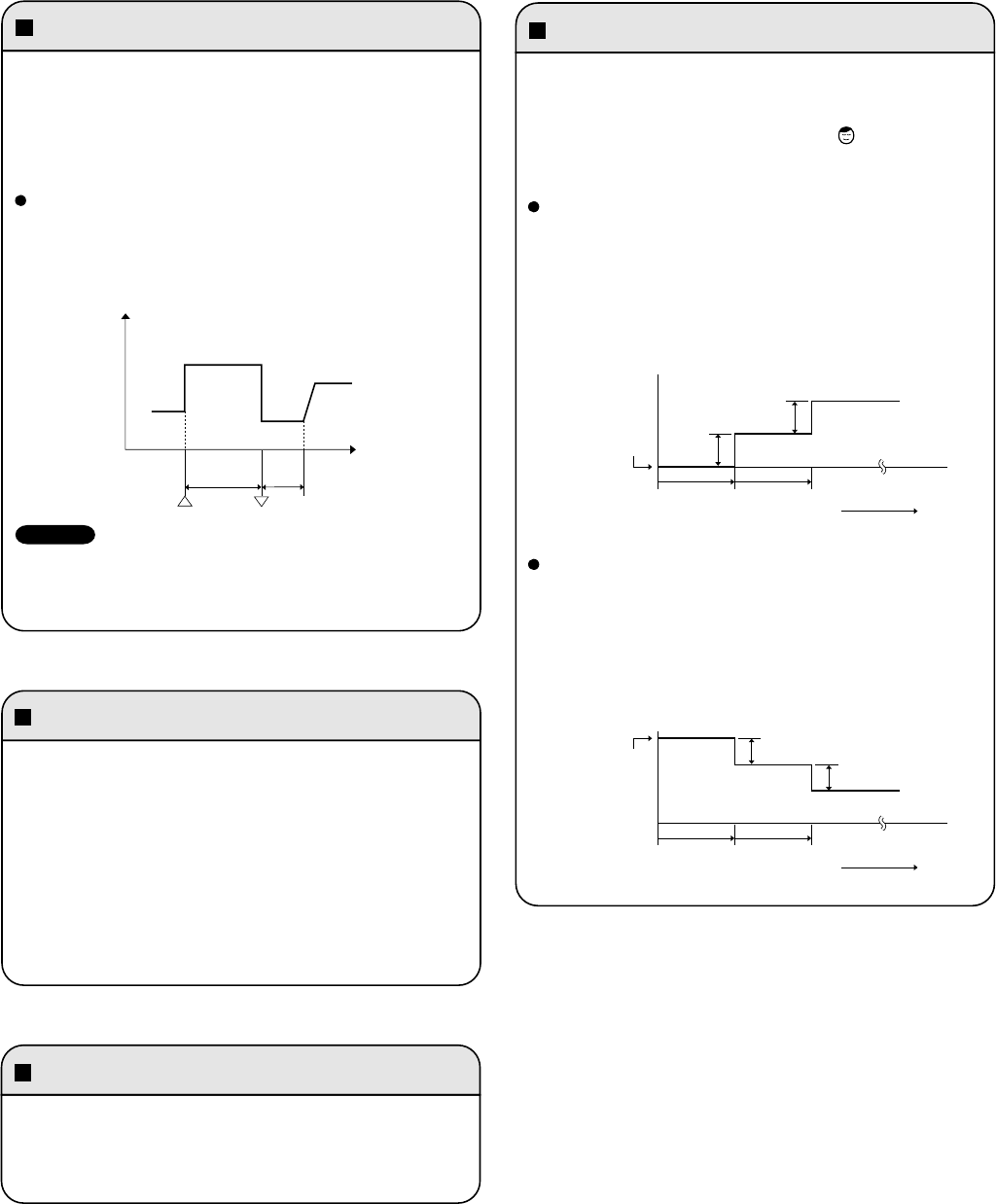
HIGH POWER NIGHT SETBACK
Lamp colors
Timer backup
This function acts to raise the power but keeps the AC system in
the same operating mode.
This function is set with the HIGH POWER button on the remote
controller.
(It can be set regardless of the temperature and fan speed
settings.)
HIGH POWER operation from remote controller
The unit operates at maximum output for 30 minutes,
regardless of the desired temperature.
The fan speed is 1 step above "High."
OPERATION lamp
• When HIGH POWER operation ends, the unit operates at low
Hz for 5 minutes, regardless of the thermostat OFF conditions.
• When in DRY mode, operation is in the cooling zone.
• Operation stops if there are no operator controls for 25 hours or
longer after unit operation switched from OFF to ON by use of
ON timer operation.
Frequency
MAX
0
Start End
Time
30 min. 5 min.
Setting
temperature
Press the NIGHT
SETBACK button
TIMER lamp Green
LED CLEAN lampGreen
HEAT operation Red
DRY operation Orange
COOL operation Green
DEFROSTING operation Red and Orange
alternately
NOTE
30 min. 30 min. Time
1°C(2°F)
Setting
temperature
Press the NIGHT
SETBACK button
30 min. 30 min. Time
1°C(2°F)
2°C(4°F)
2°C(4°F)
28
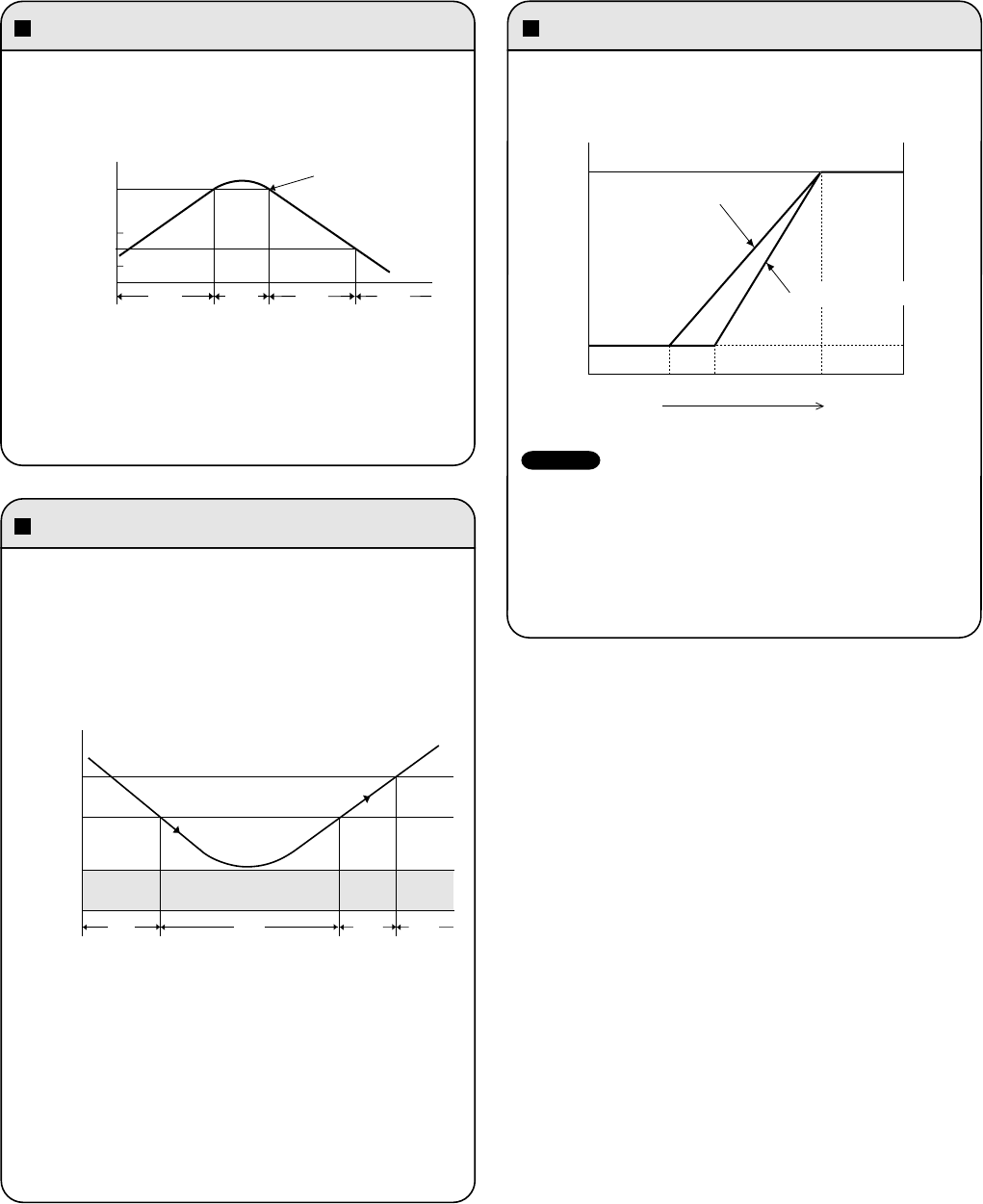
Overload prevention during heating
During HEAT operation, the temperature of the indoor heat
exchanger is used to control the frequency and lessen the load
on the compressor before the protective device is activated.
Cold-air prevention during heating
During heating, the fan speed is set to "LL" (very low) or stopped.
As the temperature of the indoor heat exchanger rises, the fan
speed is changed to the set speed.
Freeze prevention
During COOL or DRY operation, freezing is detected and
operation is stopped when the temperature of the indoor heat
exchanger matches the conditions below.
1.
Freeze-prevention operation is engaged when the
temperature of the indoor heat exchanger is below 6 °C.
2.
Restart after freeze-prevention operation occurs when the
temperature of the indoor heat exchanger reaches 8 °C or
above.
a.
Area: Automatic capacity control
b.
When Point A has been exceeded, the operation frequency is
reduced by a certain proportion.
c.
Area: Frequency increase is prohibited.
d.
At Point B and below, overload prevention is ended and
control is the same as in the
a
area.
a.
Area: Automatic capacity control
b.
When the temperature drops below Point A, the operation
frequency is reduced by a certain proportion.
c.
Area: Frequency increase is prohibited.
d.
When the temperature reaches Point C or above, freezing
prevention is ended and control is the same as in the
a
area.
* When the temperature drops to below 2 °C (continuously for 2
minutes or longer), the compressor stops.
Once the freeze condition is detected, the air conditioner will
work less than the maximum frequency until it is turned off.
Approx.
53 At stability of operation
At start of operation
AHigh
LL
Stopped
A
*
B
C
B
Indoor heat exchanger
A. Control start
B. Control end
Set fan speed
25 30 Approx. 40
abcd
abcd
Indoor heat exchanger
temperature (°C)
Indoor heat exchanger
temperature (°C)
Indoor heat exchanger
temperature (°C)
Approx.
47
2
6
8
• The fan speed is forcibly changed to "LL" beginning 30 seconds
after the thermostat turns OFF.
• At stability of operation refers to operation when the room
temperature has approached the set temperature.
• When HEAT operation starts, the indoor fan is stopped until the
temperature of the indoor heat exchanger reaches 20 °C or
higher, or until the room temperature reaches 15 °C or higher.
NOTE
7-2. Protective Functions
29
8. TROUBLESHOOTING
8-1. Precautions before Performing Inspection or Repair
NOTE
After checking the self-diagnostics monitor, turn the power OFF before starting inspection or repair.
High-capacity electrolytic capacitors are used inside the outdoor unit controller (inverter). They retain an electrical charge
(charging voltage DC 310V) even after the power is turned OFF, and some time is required for the charge to dissipate. Be
careful not to touch any electrified parts before the controller LED (red) turns OFF.
If the outdoor controller is normal, approximately 30 seconds will be required for the charge to dissipate. However, allow
at least 5 minutes for the charge to dissipate if there is thought to be any trouble with the outdoor controller.
1: If the operation lamp blinks every 0.5 seconds immediately when the
power is turned ON, there is an external ROM (OTP data) failure on the
indoor circuit board, or a ROM socket insertion problem, or the ROM
has not been installed.
2: The failure mode is stored in memory even when the power is not ON.
Follow the procedure below to perform diagnostics.
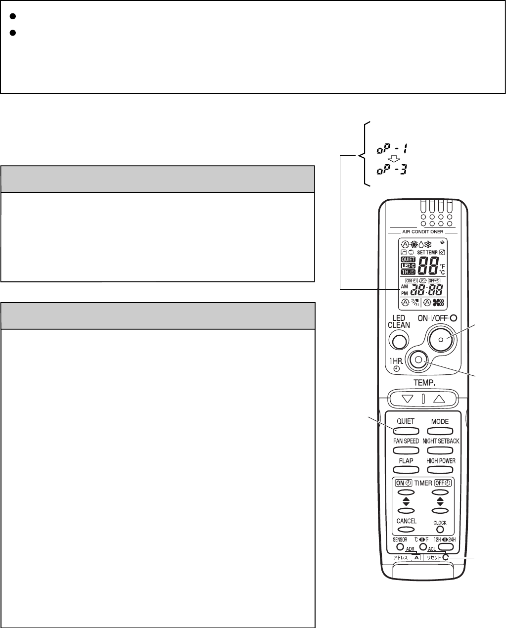
8-2. Method of Self-Diagnostics
Follow the procedure below to perform detailed trouble diagnostics.
< Clock display >
Test run mode
Self-diagnostics mode
PROCEDURE
Step 1: Press and hold the remote controller QUIET button and 1 HR
TIMER button. Then, press and hold the ACL (reset) button with a
pointed object such as the tip of a pen. After 5 seconds, release
ACL button first, then release QUIET and 1 HR TIMER buttons,
"oP-1" (test run) appears, blinking in the remote controller clock
display area.
Step 2: Next, press the 1 HR TIMER button once to change the display
from "oP-1" to "oP-3" (self-diagnostics). (The display continues to
blink.)
Step 3: Finally press the ON/OFF button to engage self-diagnostics mode.
• The self-diagnostics function utilizes the 3 indicator lamps on the main
unit, in combinations of ON lamps, blinking lamps, and OFF lamps, to
report the existence of sensor trouble or a protective operation. (The
lamps blink or remain ON for 5 seconds, then turn OFF for 2 seconds.)
Self-diagnostics is completed when the buzzer sounds 3 short beeps.
• A maximum of 3 self-diagnostics reports are displayed, for 5 seconds
each, beginning with the most recent report. Following this display the
lamps turn OFF. In order to view the self-diagnostics results again,
press the ON/OFF button again.
• The 3 lamps remain OFF if no trouble has occurred.
<IMPORTANT> After self-diagnostics is completed, be sure to press the
ACL (reset) button to return to normal mode. The air
conditioner will not operate if this is not done.
After turning on power to the air conditioner, use the remote controller and
follow the steps below to execute self-diagnostics.
1HR.
TIMER
button
ON/OFF
operation
button
ACL
(Reset)
button
QUIET
button
30
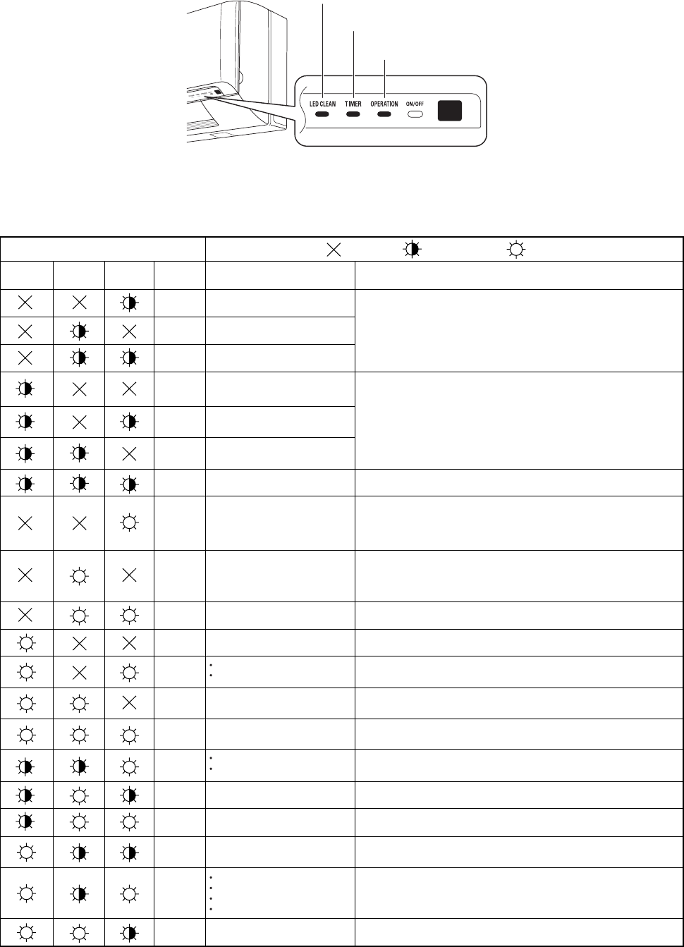
•
Since the indications cover various units, the corresponding parts listed below may not be present in some models.
(1) Self-diagnostics Lamps
Indication on indoor unit .... OFF
Timer Operation Code Diagnostics items Diagnostics contents
S01
Room temperature sensor failure
Indoor heat exchanger sensor failure
Humidity sensor failure
Compressor temperature sensor failure
Outdoor heat exchanger sensor failure
Outdoor air temperature sensor failure
Indoor/outdoor communications failure
(serial communications)
Outdoor unit external ROM (OTP data)
failure
Peak current cut-off
• HIC circuit failure
• Power Tr (transistor) circuit failure
PAM circuit failure
Active circuit failure
Outdoor system communications failure
OLR operation
Outdoor power supply open phase
Outdoor coil freezing
Compressor discharge overheat
prevention activated.
Indoor fan operating failure
No-refrigerant protection
DC compressor drive circuit failure
Outdoor fan operating failure
Freeze-prevention operation activated.
4-way valve switching failure
Indoor zero-cross failure
Outdoor electrical current detection
failure
S02
S03
S04
S05
S06
S07
E01
E02
E03
E04
E05
E06
E07
E08
E09
E10
E11
E12
E13
.... Blinking .... ON (Illuminated)
Quiet
(3)(2) (1)
(1) Sensor open circuit or short circuit
(2) Contact failure at connector or open circuit at terminal crimping location
(short-circuit detection only for the humidity sensor)
(3) Indoor/outdoor PCboard failure
(1) Sensor open circuit or short circuit
(2) Contact failure at connector or open circuit at terminal crimping location
(3) Outdoor PCboard failure
Outdoor PCboard failure
(1) Mis-wiring (2) AC power failure (3) Blown fuse (4) Power Relay failure
(5) Indoor or outdoor PCboard failure (6) Outdoor Fan Motor failure (7) Reactor failure
(8) High-Pressure Switch failure (9) Overload Relay failure (10) Magnetic Coil failure
* See detailed flowchart in this section.
(1) HIC or power Tr failure (2) Outdoor fan does not turn. (3) Instantaneous power outage
(4) Service valve not opened. (5) Outdoor fan blocked. (6) Continuous overload operation
(7) Compressor failure (8) Outdoor PCboard failure
(1) External ROM data failure (2) Outdoor PCboard failure
(1) Instantaneous power outage (2) HIC or power transistor failure
(3) Outdoor PCboard failure
(1) Outdoor PCboard failure (2) Outdoor power supply voltage failure
(1) Electric expansion valve failure (2) Capillaries choked (3) Shortage of refrigerant
(4) Continuous overload operation (5) Outdoor fan does not rotate (6) Outdoor
PCboard
failure
(1) Fan motor failure (2) Contact failure at connector (3) Indoor PCboard failure
(1) 4-way valve failure (heat pump model only)
(2) Outdoor PCboard failure
(1) Service valve not opened. (2) Shortage of refrigerant
(1) Open phase (2) Outdoor PCboard failure
(1) Fan motor failure (2) Contact failure at connector (3) Outdoor PCboard failure
(1) Mis-wiring (2) Blown fuse (3) Power Relay failure (4) Outdoor PCboard failure
(5) Compressor failure
* See detailed flowchart in this section.
(1) Indoor fan system failure (2) Shortage of refrigerant (3) Low-temperature operation
LED CLEAN lamp
TIMER lamp
OPERATION lamp
31
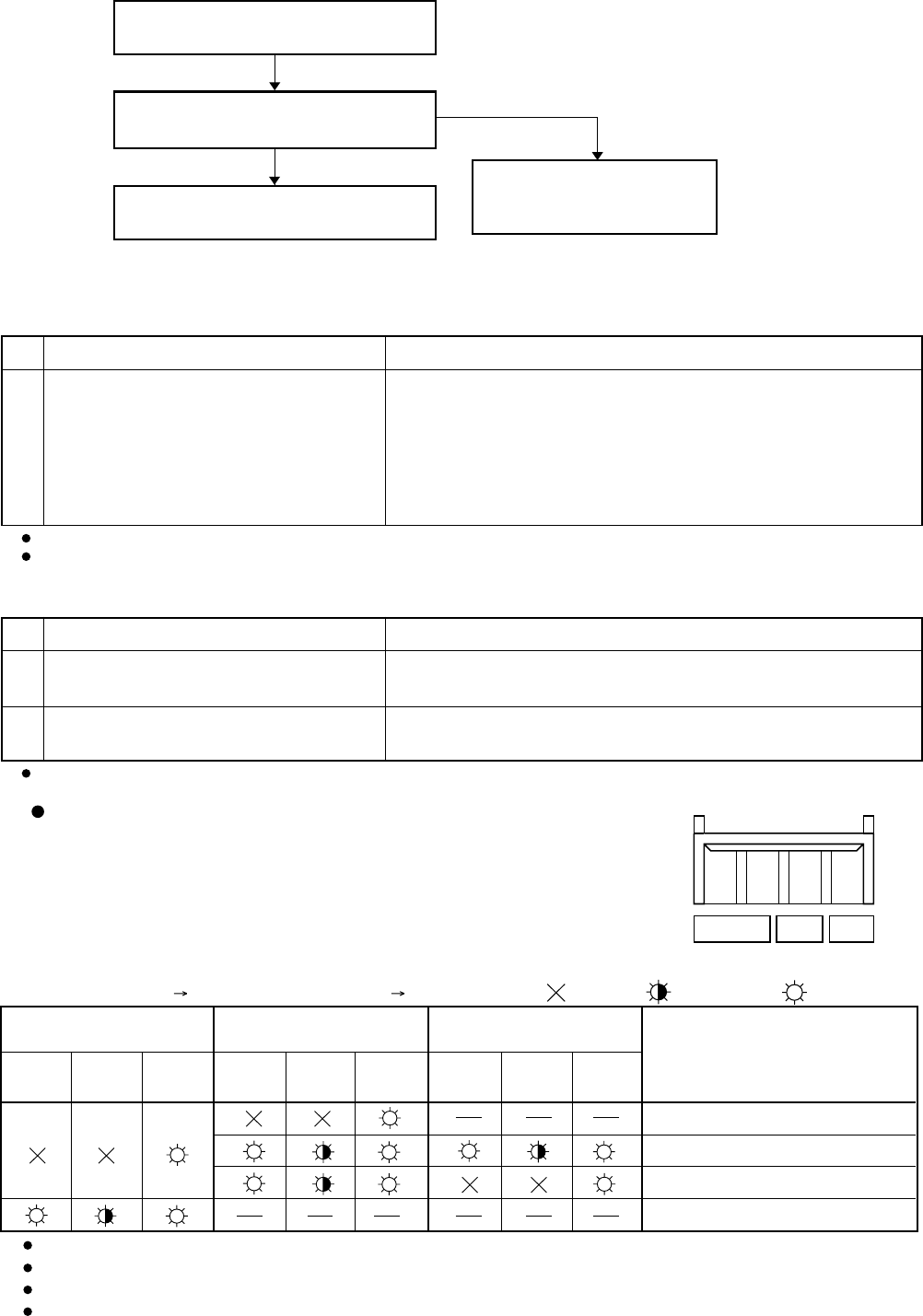
(2) If the self-diagnostics function fails to operate
8-3. Checking the Indoor and Outdoor Units
(1) Checking the indoor unit
(2) Checking the outdoor unit
(3) Checking the serial communications
Using the TEST/T-RUN terminals
Check the indoor unit.
Is the fuse blown?
ControlNo. Check items (unit operation)
Replace the controller.
Replace the circuit
board or the fuse.
No indicators illuminate and the
indoor fan does not rotate.
Check the power voltage.
•
•
T-RUN :Test run (compressor and fan motor turn ON).
TEST/MV : Compresses time to 1/60th (accelerates
operation by 60 times faster than normal).
Use the remote controller to operate the
unit in "TEST run" mode. To determine
whether the mode is currently in
"TEST run" mode, check the 4 indicator
lamps on the unit. If all 4 are blinking,
the current mode is "TEST run."
If there are no problems with the above, then check the outdoor unit.
1The rated voltage must be present between inter-unit wirings 1 and 2.
Connect a 5 k ohm resistor between inter-unit wirings 2 and 3. When the
voltage at both ends is measured, approximately 12 to 15V DC must
be output and the multimeter pointer must bounce once every 8
seconds.
Or instead of measuring the voltage, you can insert an LED jig and
check that the LED flickers once every 8 seconds.
•
•
ControlNo. Check items (unit operation)
Apply the rated voltage between outdoor
unit terminals L and N.
If there are no problems with the above, then check the indoor unit.
Turn the power OFF before performing short circuiting procedures.
Refer to the previous pages when performing system self-diagnostics.
So that the check can be made quickly, indicators blink at first communication after power ON.
Before performing the above checks, perform “TEST run” operation, and check that the rated voltage is output to terminals L and N
on the outdoor unit. If it is not output, there is a failure related to the indoor unit power.
1 The control panel LED (red) must illuminate.
Short-circuit the outdoor unit COM terminal
to the T-RUN terminal.
2 The compressor, fan motor, and 4-way valve must all turn on.
•
•
Normal
Blown
TEST/T-RUN terminals
(TEST)/MV T-RUN COM
For the "Test run" procedure, refer to 5. "HOW TO TEST RUN THE AIR CONDITIONER" on Appendix C.
Probable location of malfunction
Indoor unit circuit board failure
Outdoor unit circuit board failure
Failure (open circuit, contact failure, etc.)
in the inter-unit wirings
Outdoor unit circuit board failure
Short-circuit terminals 2 and 3 on
the outdoor unit terminal plate.
Short-circuit terminals 2 and 3 on
the indoor unit terminal plate.
Initial self-diagnostics
Control 1 Control 2
.... OFF .... Blinking .... Illuminated
Quiet
( 3 )
Timer
( 2 )
Operation
( 1 )
Quiet
( 3 )
Timer
( 2 )
Operation
( 1 )
Quiet
( 3 )
Timer
( 2 )
Operation
( 1 )
32
8-4. Trouble Diagnosis of Fan Motor
8-4-1. Indoor Fan Motor
This indoor DC fan motor contains an internal control PCB. Therefore, it is not possible to measure the coil
resistance, and the following procedure should be used to check the motor.
To perform diagnosis, operate the unit in cooling mode with indoor fan speed "High". Next, make sure that the
indoor unit receive the signals from the remote controller when the ON/OFF operation button is pressed.
[Trouble symptom 1]The fan does not stop when the unit stops. Indoor unit controller trouble.
[Trouble symptom 2] The fan motor does not rotate when the unit is operating.
(Diagnostic procedure)
* Disconnect the motor connectors and measure the voltage at the DC motor connectors on the indoor
unit controller (3 locations).
(Diagnostic results)
All of the above measured values are normal. Fan motor trouble (Replace the motor.)
Any one of the above measured values is not normal. Indoor unit controller trouble
(Replace the controller .)
(Reference)DC motor connector pin arrangement
Pin 1: Vm (red)
Pin 2: Not used
Pin 3: Gnd (black)
Pin 4: Vcc (white)
Pin 5: Vs (yellow)
Pin 6: PG (blue)
[Trouble symptom 3]Motor rotates for some time (several seconds), but then quickly stops, when the indoor
unit operates.
(There is trouble in the system that provides feedback of motor rotation speed from the
motor to the indoor unit controller.)
[Trouble symptom 4]Fan motor rotation speed does not change during indoor unit operation.
[Trouble symptom 5]Fan motor rotation speed varies excessively during indoor unit operation.
(Remedy for symptom 3 to 5)
It is not possible to identify whether the trouble is indoor unit controller trouble or motor trouble.
Therefore, first replace the indoor unit controller, then (if necessary) replace the DC motor.
Important: (A) Turn OFF the power before connecting or disconnecting the motor connectors.
(B) When performing voltage measurement at the indoor controller connector for (3) in the table
below, the DC motor will trip and voltage output will stop approximately 1 minute after operation
is started. For this reason, to measure the voltage again, turn OFF the unit once using the
remote controller, and then start the air conditioner again.
(1) Vm-Gnd: Between pin 1 and pin 3
(2) Vcc-Gnd: Between pin 4 and pin 3
(3) Vs-Gnd: Between pin 5 and pin 3
Measurement location
DC 230V or more
DC 14V or more
Fluctuation between DC 1.7 to 6.1V
Normal value
33
8-5. Noise Malfunction and Electromagnetic Interference
An inverter A/C operates using pulse signal control and high frequencies. Therefore, it is susceptible to the effects of external
noise, and is likely to cause electromagnetic interference with nearby wireless devices.
A noise filter is installed for ordinary use, preventing these problems. However, depending on the installation conditions, these
effects may still occur. Please pay attention to the points listed below.
(1) Noise malfunction
This refers to the application of high-frequency noise to the signal wires, resulting in abnormal signal pulses and malfunction.
Locations most susceptible to noise
1. Locations near broadcast stations where
there are strong electromagnetic waves
2. Locations near amateur radio (short wave)
stations
3. Locations near electronic sewing machines
and arc-welding machines
Correction
(The fundamental concept is to make the
system less susceptible to noise.)
- Insulate for noise or
distance from the noise source. -
1. Use shielded wires.
2. Move unit away from the noise source.
Trouble
Either of the following trouble may occur.
1. The unit may stop suddenly during
operation.
2. Indicator lamps may flicker.
(2) Electromagnetic interference
This refers to noise generated by high-speed switching of the microcomputer and compressor. This noise radiates through
space and returns to the electric wiring, affecting any wireless devices (televisions, radios, etc.) located nearby.
Locations most susceptible to noise
1. A television or radio is located near the
A/C and A/C wiring.
2. The antenna cable for a television or
radio is located close to the A/C and A/C
wiring.
3. Locations where television and radio
signals are weak.
Correction
1. Select a separate power source.
2. Keep the A/C and A/C wiring at least 1 meter
away from wireless devices and antenna cables.
3. Change the wireless device’s antenna to a high-
sensitivity antenna.
4. Change the antenna cable to a BS coaxial cable.
5. Use a noise filter (for the wireless device).
6. Use a signal booster.
Trouble
1. Noise appears in the television picture,
or the picture is distorted.
2. Static occurs in the radio sound.
34

INSTRUCTION MANUAL
SAP-KMRV76EH
SAP-KMRV96EH
SAP-KMRV126EH
(OI-852-6-4181-008-00-2)
APPENDIX A
A-1

© SANYO 2009
SAP-KMRV76EH
SAP-KMRV96EH
SAP-KMRV126EH
COOL/DRY/HEAT Model
Pub. OI-85264181008002
EG
ES
F
D
I
P
GR
This air conditioner uses
the new refrigerant R410A.
INSTRUCTION MANUAL
Inverter-Controlled Split System Air Conditioner
Save These Instructions!
Guarde estas instrucciones
Conserver ce mode d’emploi
Bewahren Sie bitte diese
Bedienungsanleitung auf.
Conservate queste istruzioni
Guarde estas instruções
Φυλάξτε τις οδηγίες αυτές
MANUAL DE INSTRUCCIONES
Acondicionador de aire de dos unidades
controlado por invertidor
MODE D’EMPLOI
Climatiseur de type séparé contrôlé par inverseur
BEDIENUNGSANLEITUNG
Splitsystem-Klimagerät mit Inverter-Steuerung
ISTRUZIONI PER L’USO
Condizionatore d’aria con sistema separato
controllato dall’invertitore
MANUAL DE INSTRUÇÕES
Aparelho de ar condicionado do sistema split com
inversor controlado
ΕΓΕΙΡΙ∆ΙO O∆ΗΓΙΩΝ
Κλιατιστικ συστήατoς χωρισoύ και
ελεγχενo απ αντιστρoφέα
00_SAP-KMRV76EH_Cover.fm Page 2 Friday, August 21, 2009 1:29 PM

2
FEATURES
This air conditioner is an inverter type unit that automatically adjusts capability as appropriate. Details on these functions are provided
below; refer to these descriptions when using the air conditioner.
• Microprocessor Controlled Operation
The interior compartment of the remote control unit
contains several features to facilitate automatic
operation, easy logically displayed for easy use.
• Simple One-touch Wireless Remote Control
The remote control unit has several features to facilitate
automatic operation.
• 24-Hour ON or OFF Timer
This timer can be set to automatically turn the unit on or
off at any time within a 24 hour period.
• 1-Hour OFF Timer
This timer can be set to automatically turn off the unit at
any time after one hour.
•Night Setback
This function saves energy by controlling operation to
provide a quieter operating sound than normal.
• Automatic and 3-step Fan Speed
Auto/High/Medium/Low
• Air Sweep Control
This function moves a flap up and down in the air outlet,
directing air in a sweeping motion around the room and
providing comfort in every corner.
• Auto. Flap Control
This automatically sets the flap to the optimum position
during heating, cooling, and drying operation.
• Hot Start Heating System
Right from the start, the air is warm and comfortable.
This system prevents any cold blasts at the beginning
while the heat pump is warming up, or even defrosting.
• Automatic Restart Function for Power Failure
Even when power failure occurs, preset programmed
operation can be reactivated once power resumes.
• High Power Operation
If not in Auto Operation, the unit operates at maximum
output for 30 minutes, regardless of the desired
temperature.
The fan speed is 1 step above “High”.
• Quiet Operation
The fan rotates slower than the fan speed setting to
provide a quieter operating sound.
• LED Clean Operation
During operation, the UV anti-bacteria unit is activated
for 30 minutes and cleans the air blown from the air
conditioner.
• Anti-Mold Filter
This unit is equipped with an anti-mold filter that inhibits
the growth of mold and bacteria.
• Air Clean Filter
An air filter that eliminates unpleasant odors and cleans
the air is available.
Purchase a replacement filter at your local dealer.
(model STK-FDXB)
CONTENTS
Page
FEATURES ......................................................................................................................................... 2
PRODUCT INFORMATION ................................................................................................................ 3
ALERT SYMBOLS.............................................................................................................................. 3
INSTALLATION LOCATION ................................................................................................................ 3
ELECTRICAL REQUIREMENTS........................................................................................................3
SAFETY INSTRUCTIONS .................................................................................................................. 3
NAMES OF PARTS.............................................................................................................................4
USING THE REMOTE CONTROL UNIT............................................................................................ 8
OPERATION WITH THE REMOTE CONTROL UNIT ........................................................................ 9
1. Automatic Operation............................................................................................................ 9
2. Manual Operation................................................................................................................ 9
3. Adjusting the Fan Speed ................................................................................................... 10
4. Night Setback Mode ..........................................................................................................10
5. QUIET Mode ..................................................................................................................... 10
6. HIGH POWER Mode......................................................................................................... 11
7. LED CLEAN Mode ............................................................................................................11
SPECIAL REMARKS........................................................................................................................ 11
SETTING THE TIMER...................................................................................................................... 12
USING THE 1-HOUR OFF TIMER...................................................................................................13
TIPS FOR ENERGY SAVING........................................................................................................... 13
ADJUSTING THE AIRFLOW DIRECTION .......................................................................................13
OPERATION WITHOUT THE REMOTE CONTROL UNIT............................................................... 14
CARE AND CLEANING.................................................................................................................... 14
TROUBLESHOOTING...................................................................................................................... 15
OPERATING RANGE ....................................................................................................................... 15
OI-008-2-EG
01_SAP-KMRV76EH_EN.fm Page 2 Thursday, August 27, 2009 10:51 AM
3
EG
PRODUCT INFORMATION
If you have problems or questions concerning your Air
Conditioner, you will need the following information.
Model and serial numbers are on the nameplate on the
bottom of the cabinet.
Model No. __________________________________
Serial No. ___________________________________
Date of purchase _____________________________
Dealer’s address _____________________________
Phone number ________________
DECLARATION OF CONFORMITY
This product is marked « » as it satisfies EEC
Directive No. 2004/108/EC, 2006/95/EC and 93/68/EEC.
This declaration will become void in case of mis-usage
and/or from non observance though partial of
Manufacturer’s installation and/or operating instructions.
ALERT SYMBOLS
The following symbols used in this manual, alert
you to potentially dangerous conditions to users,
service personnel or the appliance:
INSTALLATION LOCATION
• We recommend that this air conditioner be
installed properly by qualified installation
technicians in accordance with the Installation
Instructions provided with the unit.
• Before installation, check that the voltage of the elec-
tric supply in your home or office is the same as the
voltage shown on the nameplate.
Avoid:
To protect the air conditioner from heavy corrosion, avoid installing
the outdoor unit where salty sea water can splash directly onto it
or in sulphurous air near a spa.
ELECTRICAL
REQUIREMENTS
1. All wiring must conform to the local electrical codes.
Consult your dealer or a qualified electrician for
details.
2. Each unit must be properly grounded with a ground
(or earth) wire or through the supply wiring.
3. Wiring must be done by a qualified electrician.
SAFETY INSTRUCTIONS
• Read this Instruction Manual carefully before
using this air conditioner. If you still have any
difficulties or problems, consult your dealer for
help.
• This air conditioner is designed to give you
comfortable room conditions. Use this only for its
intended purpose as described in this Instruction
Manual.
This symbol refers to a hazard or
unsafe practice which can result in
severe personal injury or death.
This symbol refers to a hazard or
unsafe practice which can result in
personal injury or product or property
damage.
• Do not install this air conditioner
where there are fumes or flammable
gases, or in an extremely humid
space such as a greenhouse.
• Do not install the air conditioner
where excessively high heat-
generating objects are placed.
CAUTION
• Never use or store gasoline or other
flammable vapor or liquid near the
air conditioner — it is very
dangerous.
• This air conditioner has no ventilator
for intaking fresh air from outdoors.
You must open doors or windows
frequently when you use gas or oil
heating appliances in the same
room, which consume a lot of
oxygen from the air. Otherwise there
is a risk of suffocation in an extreme
case.
• Do not turn the air conditioner on
and off from the power mains switch.
Use the ON/OFF operation button.
• Do not stick anything into the air
outlet of the outdoor unit. This is
dangerous because the fan is
rotating at high speed.
• Do not let children play with the air
conditioner.
• Do not cool or heat the room too
much if babies or invalids are
present.
CAUTION
OI-008-3-EG
01_SAP-KMRV76EH_EN.fm Page 3 Thursday, August 27, 2009 10:51 AM
4
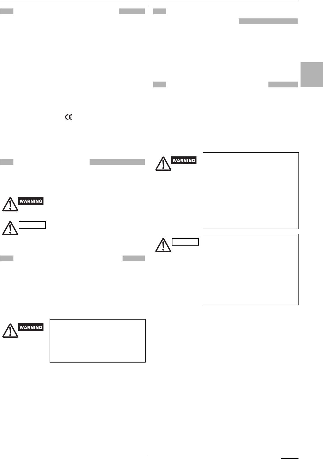
NAMES OF PARTS
This illustration is based on the external view of a standard model.
Consequently, the shape may differ from that of the air conditioner
which you have selected.
This air conditioner consists of an indoor unit and an outdoor unit.
You can control the air conditioner with the remote control unit.
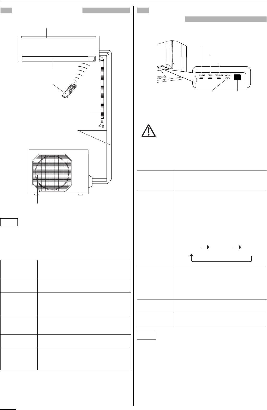
UNIT DISPLAY AND OPERATION
BUTTON
Avoid using radio equipment such as mobile phone near
(within 1 m) the remote control receiver. Some radio
equipment may cause malfunction of the unit.
If the trouble happens, disconnect power and restart the air
conditioner after a few minutes.
The unit’s display lamps are dimmed during operation in the
NIGHT SETBACK mode.
NOTE
Air Intake Air from the room is drawn into this section
and passes through air filters which remove
dust.
Air Outlet Conditioned air is blown out of the air
conditioner through the air outlet.
Remote
Control Unit
The wireless remote control unit controls
power ON/OFF, operation mode selection,
temperature, fan speed, timer setting, and air
sweeping.
Refrigerant
Tubes
The indoor and outdoor units are connected
by copper tubes through which refrigerant gas
flows.
Drain Hose Moisture in the room condenses and drains off
through this hose.
Outdoor
(Condensing)
Unit
The outdoor unit contains the compressor, fan
motor, heat exchanger coil, and other
electrical components.
INDOOR UNIT
Air intakes
Remote control unit
Air outlet
Refrigerant tubes
Drain hose
OUTDOOR UNIT
Air outlet
REMOTE
CONTROL
receiver
This section picks up infrared signals from the
remote control unit (transmitter).
OPERATION
button
When the remote control cannot be used,
pressing this button enables heating and
cooling operation.
Each time this button is pressed, the type of
operation conducted is indicated by the
changing color of the OPERATION lamp.
Press the button and select the lamp color
that suits your preference for operation.
OPERATION
lamp
This lamp lights when the system is in the
continuous AUTO (red or green), HEAT (red),
DRY (orange) and COOL (green) mode.
The OPERATION lamp lights up red and
orange alternately when the system is
defrosting.
TIMER lamp This lamp lights when the system is being
controlled by the timer.
LED CLEAN
lamp
This lamp lights during operation in the UV
anti-bacterial mode.
NOTE
REMOTE
CONTROL
receiver
OPERATION lamp
TIMER lamp
OPERATION button
(ON/OFF )
INDOOR UNIT
LED CLEAN lamp
IMPORTANT
Cooling
operation
(green)
Heating
operation
(red)
Stop
(lamp off)
OI-008-4-EG
01_SAP-KMRV76EH_EN.fm Page 4 Thursday, August 27, 2009 10:51 AM
5
EG
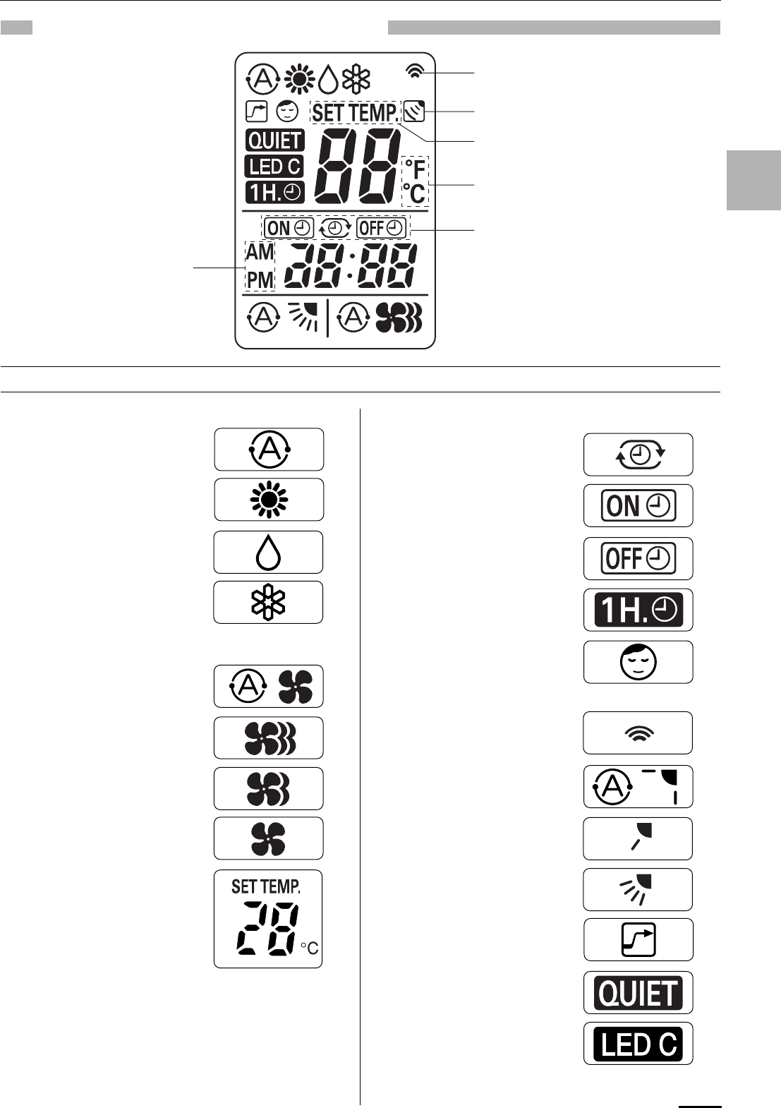
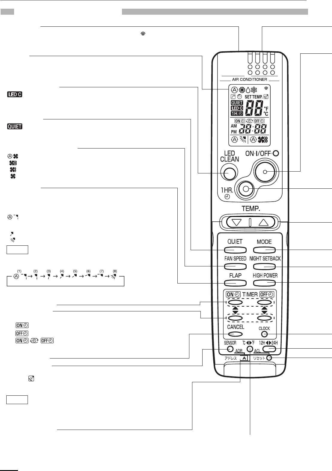
REMOTE CONTROL UNIT (DISPLAY)
(1) Operation mode
AUTO .....................................
HEAT......................................
MILD DRY ..............................
COOL.....................................
(2) Fan speed
Automatic operation ...............
HIGH .....................................
MEDIUM.................................
LOW .......................................
(3) Temperature setting
16–30°C
When set to 28 °C
temperature indication............
(4) Timer
24-hour clock with ON/OFF
program Timer .......................
ON Timer. ..............................
OFF Timer..............................
1-hour OFF Timer. .................
(5) NIGHT SETBACK..................
(6) Confirmation
of transmission.......................
(7) Auto. flap indication................
Flap angle indication..............
Sweep indication....................
(8) High power operation.............
(9) Quiet operation ......................
(10) LED CLEAN operation.........
Displayed when setting timer
Displayed when transmitting data
Displayed when indoor unit sensor is
in use
Displayed when setting temperature
Displayed when temperature is shown
Displayed when the time
display is set to 12-hour
time.
Symbols
OI-008-5-EG
01_SAP-KMRV76EH_EN.fm Page 5 Thursday, August 27, 2009 10:51 AM
6
REMOTE CONTROL UNIT
Transmitter
When you press the buttons on the remote control unit, the mark
appears in the display to transmit the setting changes to the receiver
in the air conditioner.
Display
Information on the operating conditions is displayed while the remote
control unit is switched on. If the unit is turned off, FLAP setting and
FAN SPEED setting are not displayed.
FAN SPEED selector button
: The air conditioner automatically decides the fan speeds.
: High fan speed
: Medium fan speed
: Low fan speed
FLAP button
Press this button either to select the setting of the airflow direction to the
auto. flap in each mode or one of the six possible positions manually or to
select the sweep function which moves the flap up and down
automatically.
: Auto flap setting: If selected in a heating operation, the flap is set
to position (3) in the following chart. If selected in a cooling or dry
operation, the flap is set at position (7) in the following chart.
: The airflow direction can be set manually. (six positions)
: The flap moves up and down automatically.
When you press the FLAP button, the air flow direction will be changed
one by one as follows.
NOTE
SWEEP
CANCEL button
SENSOR button
When you press this button (use a small-tipped object such as a ballpoint
pen), the mark will appear at the display. And the room temperature is
detected by the sensor which is built into the indoor unit and the air
conditioner is controlled accordingly.
If the remote control is located near a heat source, such as a space heater or
in direct sunlight, press the SENSOR button to switch to the sensor on the
indoor unit.
NOTE
LED CLEAN button
: If this button is pressed during AUTO, HEAT, DRY or COOL
operation, the UV anti-bacterial unit is activated for
30 minutes and cleans the air blown from the air conditioner.
ADDRESS switch
• The address switch changes to prevent mixing of signals from remote
control units when two air conditioners are installed next to each other.
Normally, the address switch is set to A. For more information, please
contact the dealer where you made the purchase.
• Normally, the tabs on the remote control unit should not be bent.
Temperature display selector button
This switches the temperature display
between °C and °F.
QUIET button
: When you press this button, the fan rotates slower than the
fan speed setting to provide a quieter operating sound.
ON TIME/OFF TIME setting buttons
Advance button
Return button
No display: The timer does not operate.
: The air conditioner starts at the set time.
: The air conditioner stops at the set time.
: The air conditioner stops and starts, or starts and
stops, at the set times every day. For details, see
“SETTING THE TIMER”.
OI-008-6-EG
01_SAP-KMRV76EH_EN.fm Page 6 Thursday, August 27, 2009 10:51 AM
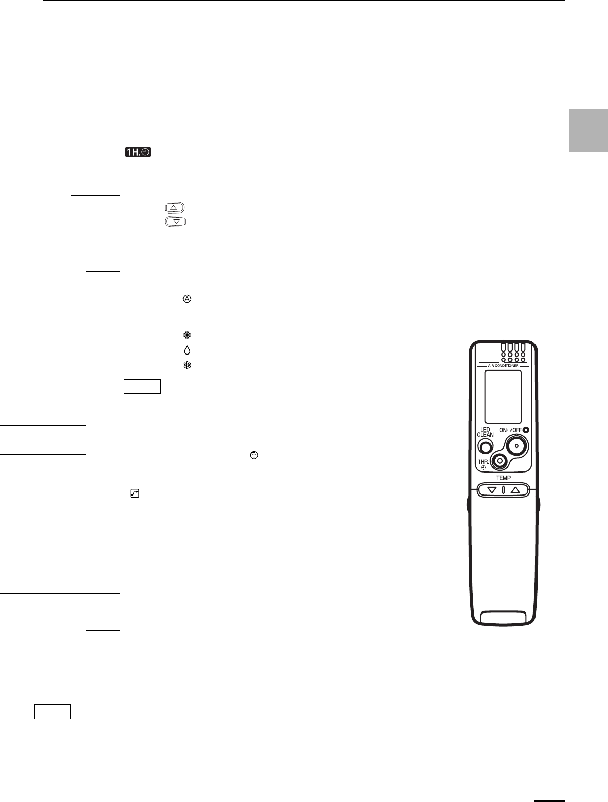
7
EG
Sensor
A temperature sensor inside the remote control unit senses the room
temperature.
(Cover closed)
CLOCK button
ACL button (ALL CLEAR)
Puts the remote control unit into pre-operation status. Always press this button
after replacing the batteries.
ON/OFF operation button
This button is for turning the air conditioner on and off.
1 HR. TIMER button (1-HOUR OFF TIMER)
: When you press this button, regardless of whether the unit is operating
or stopping, the unit operates for one hour and then shuts down.
Temperature setting buttons (TEMP.)
Press the button to increase the set temperature.
Press the button to reduce the set temperature.
The temperature setting changes by 1 °C or 2 °F each time one of the TEMP.
buttons is pressed. The set temperature appears in the display for only 3 seconds.
MODE selector button
Use this button to select AUTO, HEAT, DRY or COOL mode.
(AUTO) : The air conditioner calculates the difference between the
thermostat setting and room temperature, and automatically
selects ‘‘COOL’’ or ‘‘HEAT’’ mode as appropriate.
(HEAT) : The air conditioner makes the room warmer.
(DRY) : The air conditioner reduces the humidity in the room.
(COOL) : The air conditioner makes the room cooler.
When multiple indoor units are used and units in other rooms are already operating,
they will be set to the same mode of operation as the operating indoor units.
NOTE
NIGHT SETBACK button
For details, see “4. Night Setback Mode”. When you press this button in the
HEAT, DRY or COOL mode, the mark appears in the display, and the
remote control unit will automatically adjust the set temperature to save energy.
HIGH POWER button
: If this button is pressed during HEAT, DRY or COOL operation, the unit
operates at maximum output for 30 minutes, regardless of the desired
temperature.
The fan speed is 1step above ‘‘HIGH’’.
Time display selector button
This switches the time display between 24-hour time and 12-hour time.
The illustration above pictures the remote control unit after the cover has been opened.
The remote control unit sends the temperature signal to the air conditioner regularly at five minute intervals. If the signal from the
remote control unit stops for more than 15 minutes due to the loss of the remote control unit or other trouble, the air conditioner will
switch to the temperature sensor which is built into the indoor unit and control the room temperature. In these cases, the temperature
around the remote control unit may differ from the temperature detected at the air conditioner’s position.
NOTE
OI-008-7-EG
01_SAP-KMRV76EH_EN.fm Page 7 Thursday, August 27, 2009 10:51 AM
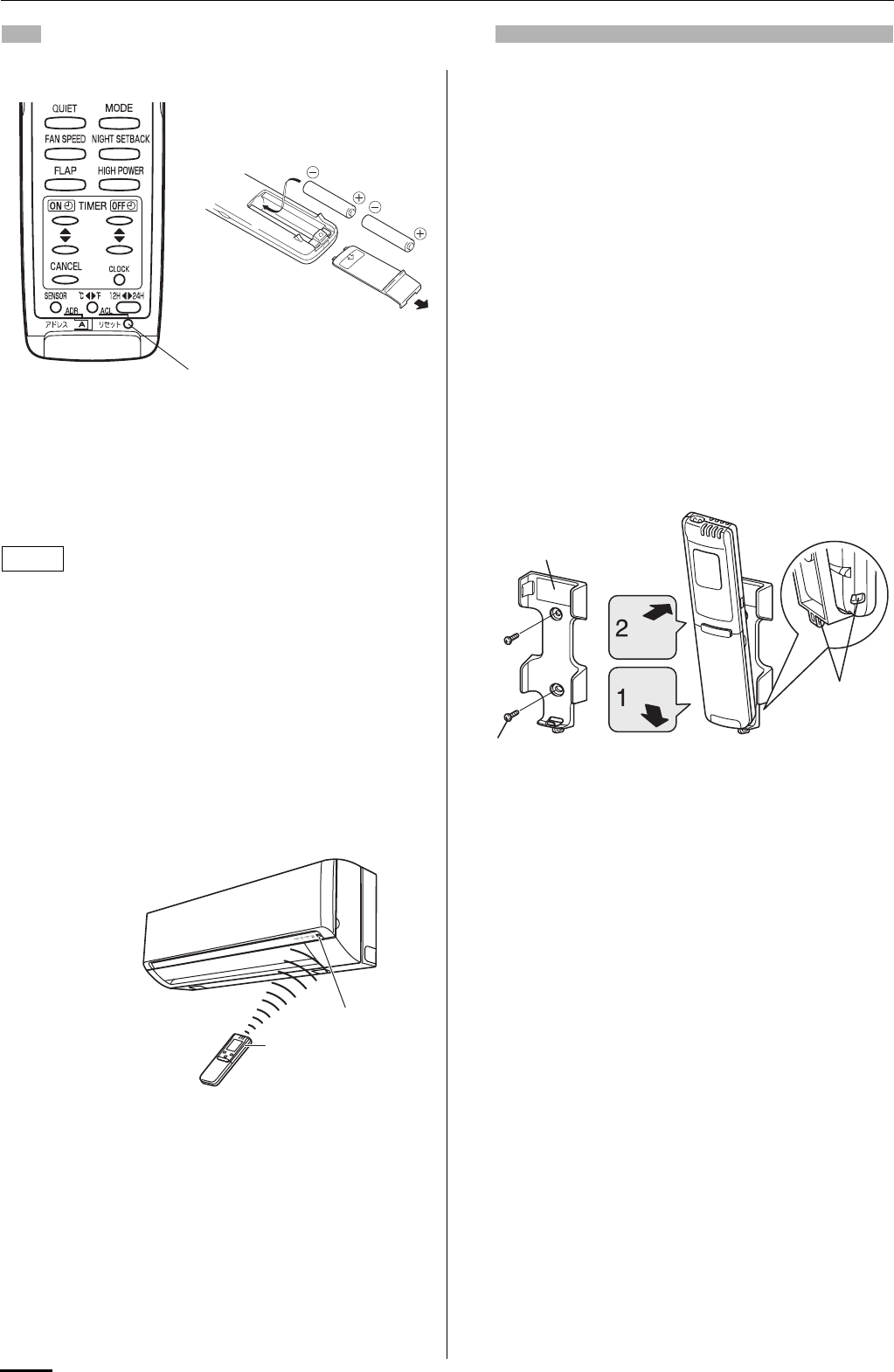
8
USING THE REMOTE CONTROL UNIT
HOW TO INSTALL BATTERIES
1. Slide the cover in the direction indicated by the arrow and
remove it.
2. Install two AAA alkaline batteries. Make sure the batteries point
in the direction marked in the battery compartment.
3. Use a thin object such as the tip of a pen to press the ACL
button.
• The batteries last about six months, depending on how
much you use the remote control unit. Replace the
batteries when the remote control unit’s display fails to
light, or when the remote control cannot be used to change
the air conditioner’s settings.
• Use two fresh leak-proof type-AAA alkaline batteries.
• In replacing batteries, follow the instructions as mentioned
in the sub-section “HOW TO INSTALL BATTERIES”.
• If you do not use the remote control unit more than 1
month, take out the batteries.
HOW TO USE THE REMOTE CONTROL UNIT
When using the remote control unit, always point the unit’s
transmitter head directly at the air conditioner’s receiver.
REMOTE CONTROL UNIT INSTALLATION
POSITION
The remote control unit may be operated either from a non-fixed
position or from a wall-mounted position. To ensure that the air
conditioner operates correctly, DO NOT install the remote control
unit in the following places:
DO NOT
• In direct sunlight
• Behind a curtain or other places where it is covered
• More than 8 m away from the air conditioner
• In the path of the air conditioner’s airstream
• Where it may become extremely hot or cold
• Where it may be subject to electrical or magnetic noise
• Where there is an obstacle between the remote control unit and
air conditioner (since a check signal is sent from the remote
control unit every 5 minutes)
MOUNTING THE REMOTE CONTROL UNIT
Before mounting the remote control unit, press the ON/OFF
operation button at the mounting location to make sure that the air
conditioner operates from that location. The indoor unit should
make a beeping sound to indicate that it has received the signal.
To take out the remote control unit, pull it forward.
WHEN HOLDING THE REMOTE CONTROL UNIT
• When using the remote control unit and during air conditioner
operation, the transmitter on the remote control unit should be
pointed towards the receiver on the indoor unit.
• Make sure that there are no objects between the remote control
unit and receiver which could block the signal.
ACL button
NOTE
Air conditioner
(Indoor unit)
Receiver
Remote control
unit (Transmitter head)
Remote control unit mount
Mounting screws
4 x 16 (included)
Rear side
Hole
• To prevent loss of the remote control
unit, you can connect the remote
control unit to the mount by passing
a string through the remote control
unit and attachment hole.
Press
Set in
place
OI-008-8-EG
01_SAP-KMRV76EH_EN.fm Page 8 Thursday, August 27, 2009 10:51 AM
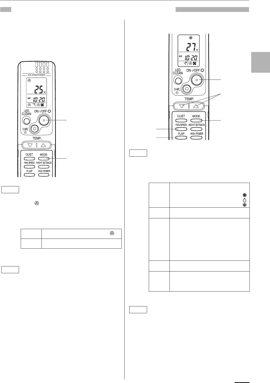
9
EG
OPERATION WITH THE REMOTE CONTROL UNIT
1. Automatic Operation
The air conditioner calculates the difference between the
thermostat setting and room temperature, and automatically
selects ‘‘COOL’’ or ‘‘HEAT’’ mode as appropriate. Then, the air
conditioner continuously operates under the mode selected at
initial operation.
2. Manual Operation
Check that the circuit breaker on the power panel is
turned on.
Once mode is selected and the unit is preset by
following the steps below, you can have the air
conditioner automatically bring the room to the
desired temperature simply by pressing the ON/OFF
operation button.
STEP 1 Press the MODE selector button to .
STEP 2 Press the ON/OFF operation button.
To stop the air conditioner, press the ON/OFF
operation button again.
• To change the temperature setting; press the
temperature setting buttons and change the setting
to the desired temperature.
STEP 2
STEP 1
NOTE
NOTE
Check that the circuit breaker on the power panel is
turned on.
If the automatic operation settings of the unit do not
meet your needs, press the setting buttons as
described below and change the settings as desired.
STEP 1 Press the MODE selector button
and select the desired mode.
For heating operation
For dehumidifying operation
For cooling operation
→
→
→
STEP 2 To start the air conditioner, press the ON/
OFF operation button.
STEP 3 Press the TEMP. setting buttons to
change the temperature setting to the
desired temperature. The set temperature
appears in the display for only 3 seconds.
Adjustable temperature range:
STEP 4 Set the FAN SPEED selector button to the
setting you want.
STEP 5 Press the FLAP button and set the airflow
direction as desired.
(Refer to “ADJUSTING THE AIRFLOW
DIRECTION” on page 13.)
To stop the air conditioner, press the ON/OFF
operation button again.
• When multiple indoor units are used and units in
other rooms are already operating, they will be set
to the same mode of operation as the operating
indoor units.
• Choose the best position in the room for the remote
control unit, which also acts as the sensor for room
comfort and transmits the operating instructions.
Once you’ve found this best position, always keep
the remote control unit there.
• This appliance has a built-in 5-minute time delay
circuit to ensure reliable operation. When the
operation button is pressed, the compressor will
start running within three minutes. In the event of
power failure, the unit will stop.
STEP 2
STEP 1
STEP 3
STEP 4
STEP 5
NOTE
30 °C max.
16 °C min. or 86 °F max.
60 °F min.
NOTE
OI-008-9-EG
01_SAP-KMRV76EH_EN.fm Page 9 Thursday, August 27, 2009 10:51 AM
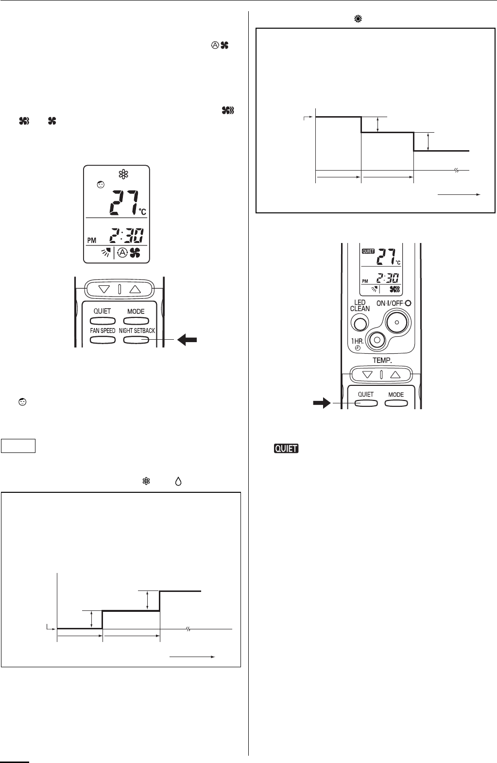
10
3. Adjusting the Fan Speed
A. Automatic fan speed
Simply set the FAN SPEED selector button to the
position.
This automatically sets the best fan speed for the room
temperature.
B. Manual fan speed
If you want to adjust fan speed manually during operation,
just set the FAN SPEED selector button as desired. [ ,
, or ]
4. Night Setback Mode
Night Setback Mode is used for saving energy.
Press the NIGHT SETBACK button while operation. (except AUTO
mode)
The mark appears in the display.
To release the night setback function, press the NIGHT SETBACK
button again.
Pressing the MODE selector button cancels Night Setback mode.
A. In Cooling and DRY Mode: ( and )
B. In Heating Mode: ( )
5. QUIET Mode
QUIET Mode is used to reduce the fan sound of the indoor unit.
Press the QUIET button.
The mark appears in the display.
To cancel, press QUIET button again.
• In QUIET Mode, the fan rotates at a slower speed than the fan
speed setting.
• If the unit is already operating with a very low airflow, the fan
sound may not change even if the QUIET button is pressed.
NOTE
When the night setback mode is selected, the air conditioner
automatically raises the temperature setting 1 °C when 30
minutes have passed after the selection was made, and then
another 1 °C after another 30 minutes have passed, regardless
of the indoor temperature when night setback was selected.
This enables you to save energy without sacrificing comfort.
This function is convenient when gentle cooling is needed.
Setting
temperature
Press the NIGHT
SETBACK button
30 min. 30 min. Time
1°C (2°F)
1°C (2°F)
When the night setback mode is selected, the air conditioner
automatically lowers the temperature setting 2 °C when 30
minutes have passed after the selection was made, and then
another 2 °C after another 30 minutes have passed, regardless
of the indoor temperature when night setback was selected.
This enables you to save energy without sacrificing comfort.
This function is convenient when gentle heating is needed.
Setting
temperature
Press the NIGHT
SETBACK button
30 min. 30 min. Time
2°C (4°F)
2°C (4°F)
OI-008-10-EG
01_SAP-KMRV76EH_EN.fm Page 10 Thursday, August 27, 2009 10:51 AM
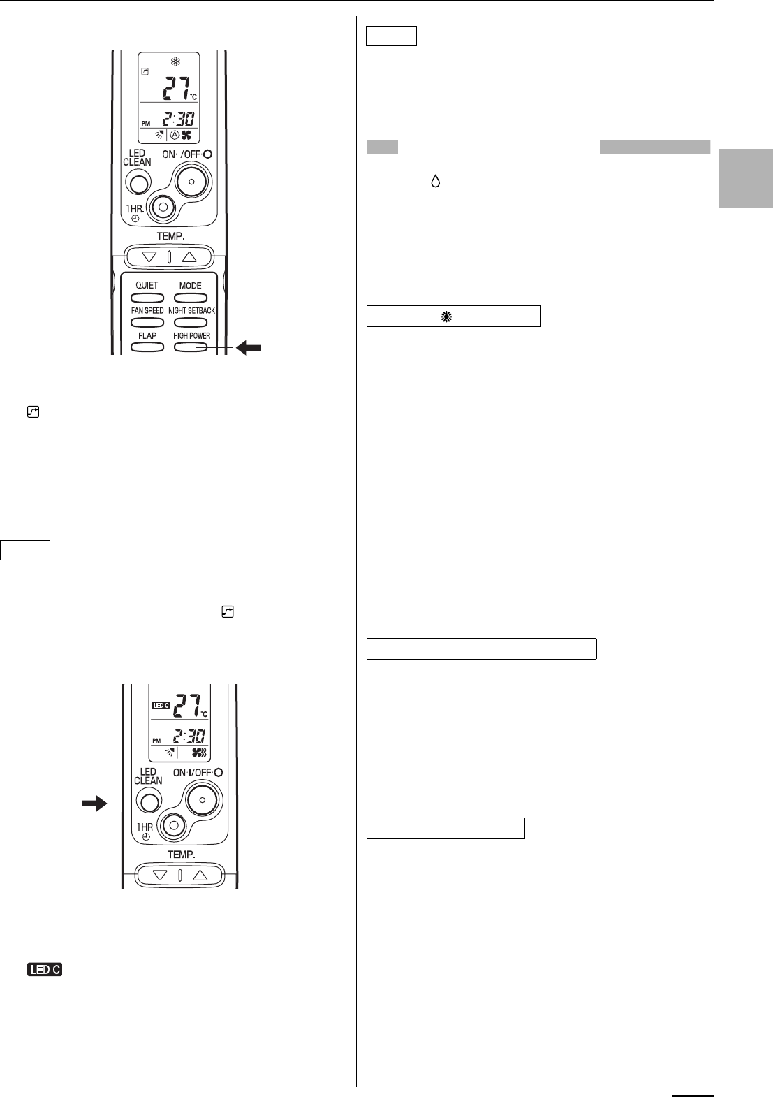
11
EG
6. HIGH POWER Mode
HIGH POWER mode can be used to increase the output of the
indoor unit for all operation modes except automatic operation.
Press the HIGH POWER button while operation.
The mark appears in the display.
To cancel, press HIGH POWER button again.
• When the HIGH POWER button is pressed, the unit operates at
maximum output for 30 minutes, regardless of the desired
temperature. The fan speed is 1 step above “High”.
• HIGH POWER Mode cannot be used when the operation mode
is Automatic Operation.
• QUIET Mode and HIGH POWER Mode cannot be used at the
same time.
• Pressing the MODE selector button cancels HIGH POWER
mode.
• When set to High fan speed during heating operation, the fan
runs at High fan speed even though the mark is displayed.
• Depending on the operating conditions, the fan speed may be
increased by a small amount only.
7. LED CLEAN Mode
In LED CLEAN mode, a UV anti-bacterial unit (including a LED
CLEAN lamp and anti-bacterial filter) in the indoor unit is used
during AUTO, HEAT, DRY or COOL operation to remove bacteria
from air blown from the air conditioner.
Press the LED CLEAN button while operation.
The mark appears in the display.
To cancel, press the LED CLEAN button again.
• When the LED CLEAN button is pressed, the UV anti-bacterial
unit operates for 30 minutes and cleans air blown from the air
conditioner.
• Pressing the MODE selector button cancels LED CLEAN mode.
• Do not open the front panel while the LED CLEAN lamp on the
display is on.
• Depending on the room brightness, light from the LED CLEAN
lamp may reflect inside the air conditioner and be visible. This is
not a malfunction.
SPECIAL REMARKS
How it works?
• Once the room temperature reaches the level that was set, the
unit’s operation frequency is changed automatically.
• During DRY operation, the fan speed automatically runs at lower
speed for providing a comfortable breeze.
• ‘‘DRY’’ operation is not possible if the indoor temperature is 15 °C
or less.
Heating performance
• Because this air conditioner heats a room by drawing in the heat
of the outside air (heat pump system), the heating efficiency will
fall off when the outdoor temperature is very low. If sufficient heat
cannot be obtained with this air conditioner, use another heating
appliance together with it.
Defrosting
• When the outdoor temperature is low, frost or ice may form on
the heat exchanger coil, reducing heating performance. When
this happens, a microcomputer defrosting system operates. At
the same time, the fan on the indoor unit stops and the
OPERATION lamp lights red and orange alternately until
defrosting is completed. Heating operation restarts after several
minutes. (This interval will vary slightly depending upon the
outdoor temperature and the way in which frost forms.)
Cold draft prevention
• For several minutes after the start of heating operation, the
indoor fan runs at a lower speed until the indoor heat exchanger
coil has warmed up sufficiently. However, the fan may remain
stopped when the room temperature is low. This is because the
COLD DRAFT PREVENTION SYSTEM is in operation.
• In the event of power failure, the unit will stop. When the power is
resumed, the unit will restart automatically within 15 minutes by
the remote control unit.
Clicking sound is heard from the air conditioner
• In heating or cooling operation, any plastic parts may expand or
shrink due to a sudden temperature change. In this event, a
clicking sound may occur. This is normal, and the sound will
soon disappear.
• The remote control unit sends the setting condition to the air
conditioner regularly at five minute intervals.
NOTE
NOTE
‘‘DRY’’ ( ) Operation
Heating ( ) Operation
Power failure during operation
Clicking Sound
Remote Control Unit
OI-008-11-EG
01_SAP-KMRV76EH_EN.fm Page 11 Thursday, August 27, 2009 10:51 AM
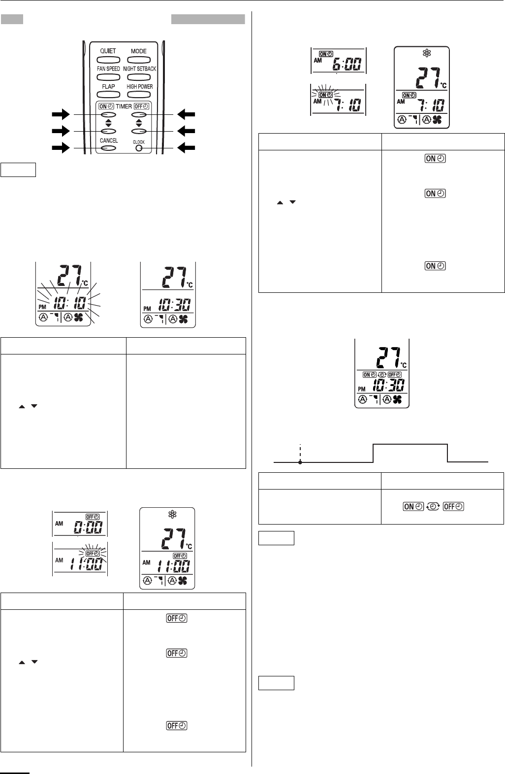
12
SETTING THE TIMER
In the descriptions below, the following settings are used for the
temperature and time indicator selector button on the bottom front
section of the remote control.
• Temperature: °C
• Time: AM, PM
1. How to set the present time
(Example) To set to 10:30 pm.
2. How to set the OFF time
(Example) To stop the air conditioner at 11:00 am.
3. How to set the ON time
(Example) To start operation at 7:10 am.
4. How to set daily ON/OFF repeat timer
(Example) To start operation at 7:10 am. and stop the air
conditioner at 11:00 am.
• The ON/OFF combination timer uses the current time as the
reference, and it is activated starting from whichever set time
comes first.
• With the ON/OFF combination timer, the settings are repeated
every day.
• You can check the timer ON/OFF times after you have set them
by pressing the ON TIME and OFF TIME setting buttons.
To cancel a timer program
• Press the CANCEL button.
• When either an ON or OFF timer is to be canceled, press the
button corresponding to the timer whose program is to be
canceled, and then press the CANCEL button.
• The airflow direction, fan speed and temperature setting can be
changed after a timer program has been set even when the unit
is stopped. Even when operation is stopped during an ON timer
program, the unit will start operating when the set time is
reached provided that the program is not canceled.
• When the ON timer and OFF timer are set to the same time, the
timer operates as if it is turned off.
NOTE
Operation Indication
1. Press the CLOCK button
once if the time indicator is
not flashing.
The time indication alone
flashes.
2. Press the Advance, Return
( , ) button until PM 10:30
is displayed.
The time can be set in 1-
minute increments. Holding
down the button advances the
time rapidly in 10-minute
increments.
3. Press the CLOCK button
again. This completes the setting of
the current time.
Operation Indication
1. Press the OFF TIME setting
button once. The timer indication is
displayed, and the present OFF
time is shown.
2. Press the Advance, Return
( , ) button until AM
11:00 is displayed.
The timer indication
blinks.
The time can be set in 10-
minute increments. Holding
down the button advances the
time rapidly in 10-minute
increments.
3. Wait a few seconds, and
then the setting is complete. The timer indication
stops blinking and the present
time is displayed.
Operation Indication
1. Press the ON TIME setting
button once. The timer indication is
displayed, and the present ON
time is shown.
2. Press the Advance, Return
( , ) button until AM 7:10
is displayed.
The timer indication
blinks.
The time can be set in 10-
minute increments. Holding
down the button advances the
time rapidly in 10-minute
increments.
3. Wait a few seconds, and
then the setting is complete. The timer indication
stops blinking and the present
time is displayed.
Operation Indication
1. Set the timer ON/OFF times
as shown in 2-1, 2, 3 and 3-
1, 2, 3.
The present time 10:30 pm.
and are
displayed.
NOTE
NOTE
7:10 am.
ON
11:00 am.
OFF
10:30 pm.
Present time
OI-008-12-EG
01_SAP-KMRV76EH_EN.fm Page 12 Thursday, August 27, 2009 10:51 AM
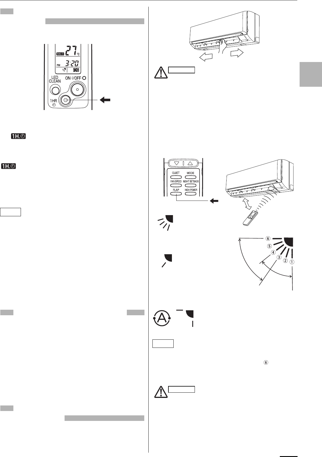
13
EG
USING THE 1-HOUR OFF
TIMER
1. 1-Hour OFF Timer
This function causes the unit to operate for one hour and
then stop, regardless of whether the unit is on or off when
this button is pressed.
The indicator in the display indicates that this function is
operating.
Setting procedure:
Regardless of whether the unit is operating or stopped, press the
1 HR. TIMER button.
appears in the display.
Cancellation procedure:
Press the ON/OFF operation button to turn the unit off, wait for the
unit to stop operating, and then press the ON/OFF operation
button again.
The 1-Hour Timer function is now cancelled and the unit operates
normally.
• If, while the 1-Hour Timer function is operating, the 1HR. TIMER
button is pressed once to cancel the function and then again, the
unit continues to operate for one hour from that point in time and
then stops.
• It is not possible to use the OFF Timer and 1-Hour OFF Timer
together. Whichever function is set last takes precedence. If the
1 HR. TIMER button is pressed while the TIMER OFF function
operates, the OFF Timer is cancelled and the unit will stop
operating one hour later.
2. Operation together with the daily ON/OFF
repeat timer
The 1-Hour OFF Timer setting is given priority over the DAILY ON/
OFF REPEAT setting.
TIPS FOR ENERGY SAVING
Do not
• Block the air intake and outlet of the unit. If they are
obstructed, the unit will not work well, and may be
damaged.
• Let direct sunlight into the room. Use sunshades, blinds or
curtains. If the walls and ceiling of the room are warmed by the
sun, it will take longer to cool the room.
Do
• Always try to keep the air filter clean. (Refer to “CARE AND
CLEANING”.) A clogged filter will impair the performance of the
unit.
• To prevent conditioned air from escaping, keep windows, doors
and any other openings closed.
ADJUSTING THE AIRFLOW
DIRECTION
1. Horizontal
The horizontal airflow can be adjusted by moving the vertical
vanes with your hands to the left or right.
When the humidity is high, the vertical vanes should be in the
front position during the cooling or dehumidifying operation.
If the vertical vanes are positioned all of the way to the right
or left, condensation may begin to form around the air vent
and drip down.
2. Vertical
The vertical airflow can be adjusted by moving the flap with the
remote control unit. Do not move the flap with your hands. Confirm
that the remote control unit has been turned on. Use the FLAP
button to set either the sweep function or one of the six airflow
direction settings.
• The flap automatically closes when the unit is off.
• During the heating operation, the fan speed will be very low and
the flap will be in the horizontal position (position ) until the air
being blown out of the unit begins to warm. Once the air warms
up, the flap position and fan speed change to the settings
specified with the remote control.
• Use the FLAP button on the remote control to adjust the
position of the flap. If you move the flap by hand, the flap
position according to the remote control and the actual flap
position may no longer match. If this should happen, shut
off the unit, wait for the flap to close, and then turn on the
unit again; the flap position will now be normal again.
• Do not have the flap pointed down during cooling
operation. Condensation may begin to form around the air
vent and drip down.
NOTE
NOTE
CAUTION
HEAT
SWEEP
SWEEP
A. Sweep function
The flap starts moving
up and down to deliver
air over the sweep
range.
B. Setting the airflow manually
Referring to the above
illustration, use the
FLAP button to set the
airflow direction within
the range used during
the heating, cooling, or
dehumidifying
operation.
C. Auto flap function
The flap is set
to the
recommended
position.
COOL
DRY
CAUTION
OI-008-13-EG
01_SAP-KMRV76EH_EN.fm Page 13 Thursday, August 27, 2009 10:51 AM
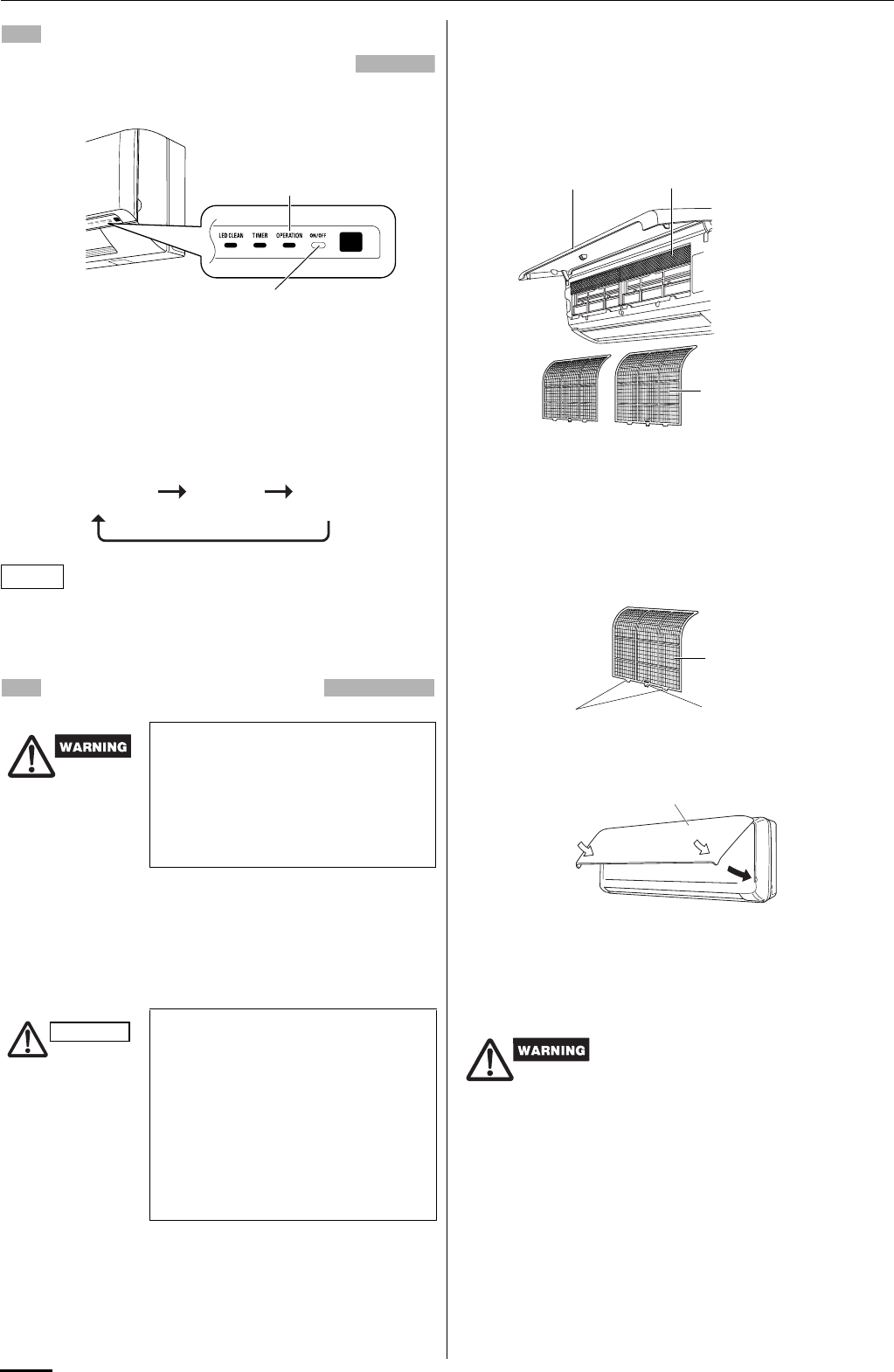
14
OPERATION WITHOUT THE
REMOTE CONTROL UNIT
If you have lost the remote control unit or it has trouble, follow the
steps below.
When the air conditioner is not running
Each time the OPERATION button is pressed, the type of
operation conducted is indicated by the changing color of the
OPERATION lamp. Press the button and select the lamp color that
suits your preference for operation.
The temperature is set to the room temperature minus 2°C during
the cooling operation and to the room temperature plus 2°C during
the heating operation, and the fan speed and flap are set to Auto.
CARE AND CLEANING
Casing and Grille (Indoor Unit)
Clean the casing and grille of the indoor unit with a vacuum
cleaner brush, or wipe them with a clean, soft cloth.
If these parts are stained, use a clean cloth moistened with a mild
liquid detergent. When cleaning the grille, be careful not to force
the vanes out of place.
Anti-Mold Filter
The anti-mold filter behind the front panel should be checked and
cleaned at least once every two weeks.
How to remove the anti-mold filter
Open the front panel until it is nearly horizontal. Lift the anti-mold
filter up slightly and then pull downward to remove the filter from
the unit.
Cleaning
Use a vacuum cleaner to remove light dust. If there is sticky dust
on the filter, wash the filter in lukewarm, soapy water, rinse it in
clean water, and dry it.
How to replace the anti-mold filter
1. Insert the top of the anti-mold filter, align the two protrusions
with the center hook at bottom, then mount the filter into place.
2. Press the locations marked by the arrows and close the front
panel.
Air Clean Filter
The air clean filter removes dust and dirt from the air, and reduces
odors and smoke from tobacco.
NOTE
1. For safety, be sure to turn the air
conditioner off and also to
disconnect the power before
cleaning.
2. Do not pour water on the indoor unit
to clean it. This will damage the
internal components and cause an
electric shock hazard.
1. Never use solvents, or harsh
chemicals when cleaning the indoor
unit. Do not wipe the plastic casing
using very hot water.
2. Some metal edges and the fins are
sharp and may cause injury if
handled improperly; be especially
careful when you clean these parts.
3. The internal coil and other
components of the outdoor unit
must be cleaned every year. Consult
your dealer or service center.
INDOOR UNIT
OPERATION button
(ON/OFF)
OPERATION lamp
Cooling operation
(green) Heating
operation (red) Stop
(lamp off)
CAUTION This air clean filter cannot remove
harmful gases or vapors nor ventilate
air in the room. You must open doors
or windows frequently when you use
gas or oil heating appliances.
Otherwise there is a risk of suffocation
in extreme cases.
Anti-mold filter
Front panel Air clean filter
Anti-mold filter
Protrusion Center hook
Front panel
OI-008-14-EG
01_SAP-KMRV76EH_EN.fm Page 14 Thursday, August 27, 2009 10:51 AM
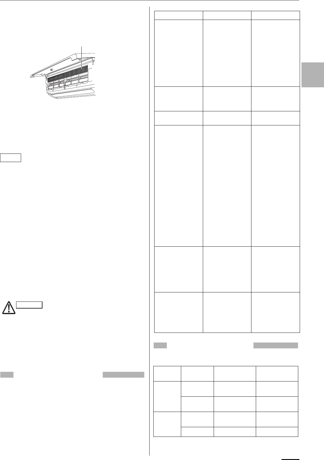
15
EG
How to install the air clean filter
The air clean filter needs to be installed behind the anti-mold filter.
Open the front panel and remove the anti-mold filters, then install
the air clean filter in the position shown in the figure. After that,
remount the anti-mold filters and close the front panel.
How to clean the air clean filter
• In general, the filter should be sucked to remove dust in low fan
speed of a vacuum cleaner once every three months.
• If there is heavily grime on the filter, soak the filter in lukewarm
water with neutral detergent diluted 1:500 for 1 to 2 minutes then
wash it.
• Rinse the filter in clean water, then let it dry on the towel in room
temperature.
• Do not bend nor give excessive force onto the air clean filter.
• If the filter surface is heavily blocked with dirt or damaged,
replace it with new one. Purchase a replacement filter at your
local dealer. (model STK-FDXB)
Cleaning the main unit and remote control unit
• Wipe clean using a soft, dry cloth.
• To remove stubborn dirt, moisten a cloth in warm water no hotter
than 40 °C, wring thoroughly, and then wipe.
• The front panel can be removed in order to wash it with water.
Removing and remounting the front panel
1. Open the front panel until it is nearly horizontal, grasp the
sections near the front panel arms on both sides, and then pull
forward to remove the front panel.
2. Grasp the sections near the front panel arms on both sides,
and hold the front panel so that it is nearly horizontal. Then
push firmly until the arm shafts click into place. After closing the
front panel, press firmly on the parts indicated by the arrows to
securely fasten the panel in place.
Also refer to the figure that shows “How to replace the anti-
mold filter”.
Washing the front panel with water
• Clean the front panel gently using a soft sponge, or the like.
Then wipe away any remaining moisture.
• Neutral detergent may be used to remove stubborn dirt. Then
rinse thoroughly with water and wipe away any remaining
moisture.
TROUBLESHOOTING
If your air conditioner does not work properly, first check the
following points before requesting service. If it still does not work
properly, contact your dealer or service center.
OPERATING RANGE
The air conditioner is operable within the temperature ranges as
listed below:
*Please refer to “Operating Range” on the sheet attached to the
outdoor unit.
NOTE
When using a footstool or the like, be
careful not to let it tip over.
Air clean filter
CAUTION
Trouble Possible Cause Remedy
Air conditioner does
not run at all. 1. Power failure. 1. Restore power.
2. Leakage circuit
breaker tripped. 2. Contact service
center.
3. Line voltage is too
low. 3. Consult your
electrician or
dealer.
4. Batteries in remote
control unit have
run down.
4. Replace batteries.
OPERATION lamp
blinks and air
conditioner does not
operate.
Trouble in system. Contact service
center.
Compressor runs but
soon stops. Obstruction in front of
condenser coil. Remove obstruction.
Poor cooling (or
heating)
performance.
1. Dirty or clogged air
filter. 1. Clean air filter to
improve airflow.
2. Heat source or
many people in
room.
2. Eliminate heat
source if possible.
3. Doors and/or
windows are open. 3. Shut them to keep
the heat (or cold)
out.
4. Obstacle near air
intake or air
discharge port.
4. Remove it to
ensure good
airflow.
5. Thermostat is set
too high for cooling
(or too low for
heating).
5. Set the
temperature lower
(or higher).
6. (Outdoor
temperature is too
low for heating.)
6. (Consult your
dealer or try to use
another heat
appliance.)
Clicking sound is
heard from the air
conditioner.
In heating or cooling
operation, any plastic
parts may expand or
shrink due to a
sudden temperature
change. In this event,
a clicking sound may
occur.
This is normal, and
the sound will soon
disappear.
OPERATION lamp
lights but outdoor unit
will not run.
The use of cellular
phones near the air
conditioner may
cause disturbance to
its normal operation.
1. Turn off the power
then restart the air
conditioner after a
while.
2. Consult your
dealer.
Temperature Indoor air
temperature Outdoor air
temperature
COOLING Max. 32 °C DB /
23 °C WB 43 °C DB
Min. 19 °C DB /
14 °C WB *
HEATING Max. 27 °C DB 24 °C DB /
18 °C WB
Min. 16 °C DB – DB/ –15 °C WB
OI-008-15-EG
01_SAP-KMRV76EH_EN.fm Page 15 Thursday, August 27, 2009 10:51 AM

INSTRUCTION MANUAL
SAP-KRV186EH
SAP-KRV246EH
(OI-852-6-4181-003-00-1)
APPENDIX B
A-2

Pub. OI-85264181003001
© SANYO 2008
SAP-KRV186EH
SAP-KRV246EH
COOL/DRY/HEAT Model
EG
ES
F
D
I
P
GR
INSTRUCTION MANUAL
Inverter-Controlled Split System Air Conditioner
Save These Instructions!
Guarde estas instrucciones
Conserver ce mode d’emploi
Bewahren Sie bitte diese
Bedienungsanleitung auf.
Conservate queste istruzioni
Guarde estas instruções
Φυλάξτε τις οδηγίες αυτές
MANUAL DE INSTRUCCIONES
Acondicionador de aire de dos unidades
controlado por invertidor
MODE D’EMPLOI
Climatiseur de type séparé contrôlé par inverseur
BEDIENUNGSANLEITUNG
Splitsystem-Klimagerät mit Inverter-Steuerung
ISTRUZIONI PER L’USO
Condizionatore d’aria con sistema separato
controllato dall’invertitore
MANUAL DE INSTRUÇÕES
Aparelho de ar condicionado do sistema split com
inversor controlado
ΕΓΕΙΡΙ∆ΙO O∆ΗΓΙΩΝ
Κλιατιστικ συστήατoς χωρισoύ και
ελεγχενo απ αντιστρoφέα
This air conditioner uses
the new refrigerant R410A.
00_SAP-KRV186EH_Cover.fm Page 2 Friday, February 1, 2008 8:53 PM

2
FEATURES
This air conditioner is an inverter type unit that automatically adjusts capability as appropriate. Details on these functions are provided
below; refer to these descriptions when using the air conditioner.
• Microprocessor Controlled Operation
The interior compartment of the remote control unit
contains several features to facilitate automatic
operation, easy logically displayed for easy use.
• Simple One-touch Wireless Remote Control
The remote control unit has several features to facilitate
automatic operation.
• 24-Hour ON or OFF Timer
This timer can be set to automatically turn the unit on or
off at any time within a 24 hour period.
• 1-Hour OFF Timer
This timer can be set to automatically turn off the unit at
any time after one hour.
•Night Setback
This function saves energy by controlling operation to
provide a quieter operating sound than normal.
• Automatic and 3-step Fan Speed
Auto/High/Medium/Low
• Air Sweep Control
This function moves a flap up and down in the air outlet,
directing air in a sweeping motion around the room and
providing comfort in every corner.
• Auto. Flap Control
This automatically sets the flap to the optimum position
during heating, cooling, and drying operation.
• Automatic Switching between Cooling and Heating
When the remote control’s S/M switch is at the “S”
(Single) position
This unit automatically switches between cooling
operation and heating operation according to the
difference between the room temperature and the
temperature setting.
When the remote control’s S/M switch is at the “M”
(Multiple) position
Unlike when the switch is at the “S” position as described
above, the function for automatically switching between
cooling and heating does not work. Then, the air
conditioner continuously operates under the mode
selected at initial operation.
• Hot Start Heating System
Right from the start, the air is warm and comfortable.
This system prevents any cold blasts at the beginning
while the heat pump is warming up, or even defrosting.
• Automatic Restart Function for Power Failure
Even when power failure occurs, preset programmed
operation can be reactivated once power resumes.
• High Power Operation
If not in Auto Operation, the unit operates at maximum
output for 30 minutes, regardless of the desired
temperature.
The fan speed is 1 step above “High”.
• Quiet Operation
The fan rotates slower than the fan speed setting to
provide a quieter operating sound.
• LED Clean Operation
During operation, the UV anti-bacteria unit is activated
for 30 minutes and cleans the air blown from the air
conditioner.
• Anti-Mold Filter
This unit is equipped with an anti-mold filter that inhibits
the growth of mold and bacteria.
• Air Clean Filter
An air filter that eliminates unpleasant odors and cleans
the air is available.
Purchase a replacement filter at your local dealer.
(model STK-FDXB)
CONTENTS
Page
FEATURES ......................................................................................................................................... 2
PRODUCT INFORMATION ................................................................................................................ 3
ALERT SYMBOLS.............................................................................................................................. 3
INSTALLATION LOCATION ................................................................................................................ 3
ELECTRICAL REQUIREMENTS........................................................................................................3
SAFETY INSTRUCTIONS .................................................................................................................. 3
NAMES OF PARTS.............................................................................................................................4
USING THE REMOTE CONTROL UNIT............................................................................................8
OPERATION WITH THE REMOTE CONTROL UNIT ........................................................................ 9
1. Automatic Operation............................................................................................................ 9
2. Manual Operation................................................................................................................ 9
3. Adjusting the Fan Speed ................................................................................................... 10
4. Fan Only............................................................................................................................ 10
5. Night Setback Mode ..........................................................................................................10
6. QUIET Mode ..................................................................................................................... 10
7. HIGH POWER Mode......................................................................................................... 11
8. LED CLEAN Mode ............................................................................................................11
SPECIAL REMARKS........................................................................................................................ 11
SETTING THE TIMER...................................................................................................................... 12
USING THE 1-HOUR OFF TIMER...................................................................................................13
TIPS FOR ENERGY SAVING........................................................................................................... 13
ADJUSTING THE AIRFLOW DIRECTION .......................................................................................13
OPERATION WITHOUT THE REMOTE CONTROL UNIT............................................................... 14
CARE AND CLEANING.................................................................................................................... 14
TROUBLESHOOTING...................................................................................................................... 15
OPERATING RANGE ....................................................................................................................... 15
OI-003-2-EG
01_SAP-KRV186EH_EN.fm Page 2 Wednesday, February 13, 2008 1:12 PM
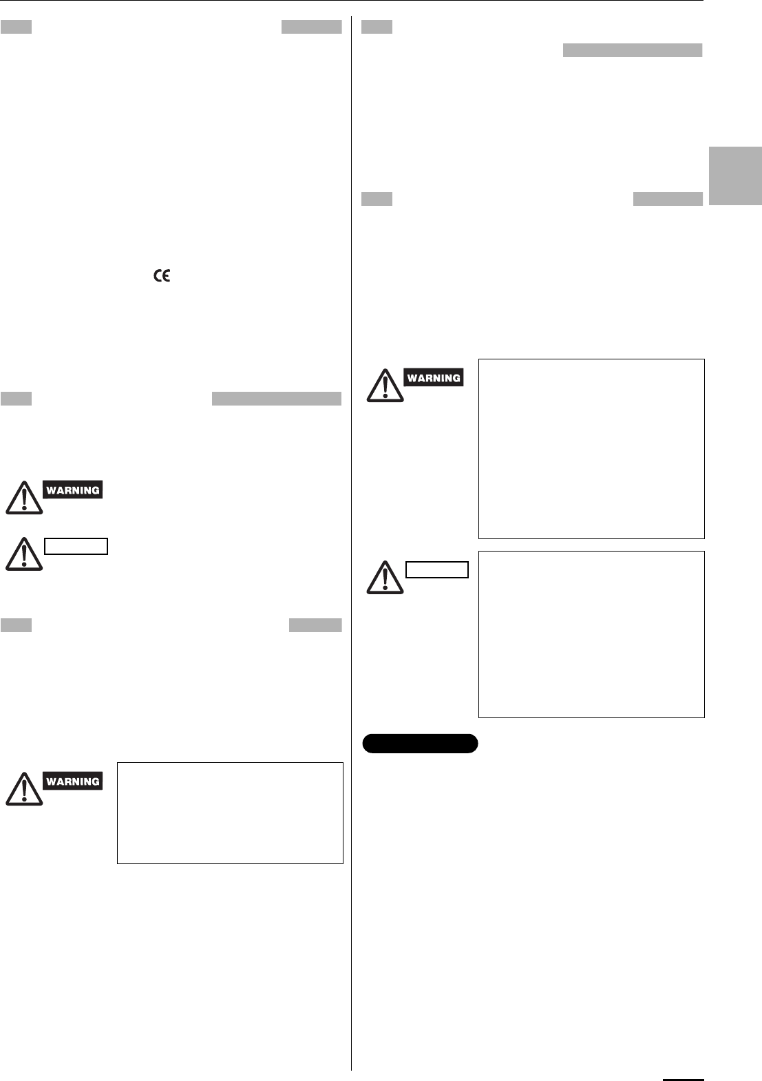
3
EG
PRODUCT INFORMATION
If you have problems or questions concerning your Air
Conditioner, you will need the following information.
Model and serial numbers are on the nameplate on the
bottom of the cabinet.
Model No. __________________________________
Serial No. ___________________________________
Date of purchase _____________________________
Dealer’s address _____________________________
Phone number ________________
DECLARATION OF CONFORMITY
This product is marked « » as it satisfies EEC
Directive No. 89/336/ EEC, 73/23/EEC, 93/68/EEC and
92/31/EEC.
This declaration will become void in case of mis-usage
and/or from non observance though partial of
Manufacturer’s installation and/or operating instructions.
ALERT SYMBOLS
The following symbols used in this manual, alert
you to potentially dangerous conditions to users,
service personnel or the appliance:
INSTALLATION LOCATION
• We recommend that this air conditioner be
installed properly by qualified installation
technicians in accordance with the Installation
Instructions provided with the unit.
• Before installation, check that the voltage of the electric supply
in your home or office is the same as the voltage shown on the
nameplate.
Avoid:
To protect the air conditioner from heavy corrosion, avoid installing
the outdoor unit where salty sea water can splash directly onto it
or in sulphurous air near a spa.
ELECTRICAL
REQUIREMENTS
1. All wiring must conform to the local electrical codes.
Consult your dealer or a qualified electrician for
details.
2. Each unit must be properly grounded with a ground
(or earth) wire or through the supply wiring.
3. Wiring must be done by a qualified electrician.
SAFETY INSTRUCTIONS
• Read this Instruction Manual carefully before
using this air conditioner. If you still have any
difficulties or problems, consult your dealer for
help.
• This air conditioner is designed to give you
comfortable room conditions. Use this only for its
intended purpose as described in this Instruction
Manual.
This symbol refers to a hazard or
unsafe practice which can result in
severe personal injury or death.
This symbol refers to a hazard or
unsafe practice which can result in
personal injury or product or property
damage.
• Do not install this air conditioner
where there are fumes or flammable
gases, or in an extremely humid
space such as a greenhouse.
• Do not install the air conditioner
where excessively high heat-
generating objects are placed.
CAUTION
• Never use or store gasoline or other
flammable vapor or liquid near the
air conditioner — it is very
dangerous.
• This air conditioner has no ventilator
for intaking fresh air from outdoors.
You must open doors or windows
frequently when you use gas or oil
heating appliances in the same
room, which consume a lot of
oxygen from the air. Otherwise there
is a risk of suffocation in an extreme
case.
• Do not turn the air conditioner on
and off from the power mains switch.
Use the ON/OFF operation button.
• Do not stick anything into the air
outlet of the outdoor unit. This is
dangerous because the fan is
rotating at high speed.
• Do not let children play with the air
conditioner.
• Do not cool or heat the room too
much if babies or invalids are
present.
• “Single use” means that only one indoor unit is con-
nected with one outdoor unit in a one-unit-to-one-unit
configuration and that the remote control’s S/M switch
is at the “S” (Single) position.
• “Multiple use” means that two or more indoor units are
connected with one outdoor unit in a multiple-unit-to-
one-unit configuration and that the remote control’s S/
M switch is at the “M” (Multiple) position. (Refer to
“USING THE REMOTE CONTROL UNIT” on page 8.)
CAUTION
IMPORTANT
OI-003-3-EG
01_SAP-KRV186EH_EN.fm Page 3 Wednesday, February 13, 2008 1:12 PM
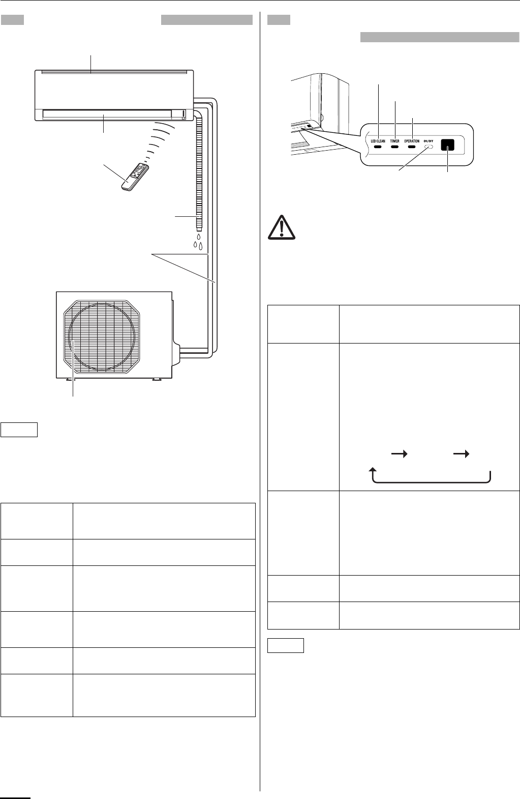
4
NAMES OF PARTS
This illustration is based on the external view of a standard model.
Consequently, the shape may differ from that of the air conditioner
which you have selected.
This air conditioner consists of an indoor unit and an outdoor unit.
You can control the air conditioner with the remote control unit.
UNIT DISPLAY AND OPERATION
BUTTON
Avoid using radio equipment such as mobile phone near
(within 1 m) the remote control receiver. Some radio
equipment may cause malfunction of the unit.
If the trouble happens, disconnect power and restart the air
conditioner after a few minutes.
The unit’s display lamps are dimmed during operation in the
NIGHT SETBACK mode.
NOTE
Air Intake Air from the room is drawn into this section
and passes through air filters which remove
dust.
Air Outlet Conditioned air is blown out of the air
conditioner through the air outlet.
Remote
Control Unit
The wireless remote control unit controls
power ON/OFF, operation mode selection,
temperature, fan speed, timer setting, and air
sweeping.
Refrigerant
Tubes
The indoor and outdoor units are connected
by copper tubes through which refrigerant gas
flows.
Drain Hose Moisture in the room condenses and drains off
through this hose.
Outdoor
(Condensing)
Unit
The outdoor unit contains the compressor, fan
motor, heat exchanger coil, and other
electrical components.
INDOOR UNIT
Air intakes
Remote control unit
Air outlet
Refrigerant tubes
Drain hose
OUTDOOR UNIT
Air outlet
REMOTE
CONTROL
receiver
This section picks up infrared signals from the
remote control unit (transmitter).
OPERATION
button
When the remote control cannot be used,
pressing this button enables heating and
cooling operation.
Each time this button is pressed, the type of
operation conducted is indicated by the
changing color of the OPERATION lamp.
Press the button and select the lamp color
that suits your preference for operation.
OPERATION
lamp
This lamp lights when the system is in the
continuous AUTO (red or green), HEAT (red),
DRY (orange), COOL (green) and FAN
(green) mode (but no FAN mode at M of the
S/M switch on the remote control unit).
The OPERATION lamp lights up red and
orange alternately when the system is
defrosting.
TIMER lamp This lamp lights when the system is being
controlled by the timer.
LED CLEAN
lamp
This lamp lights during operation in the UV
anti-bacterial mode.
NOTE
INDOOR UNIT
REMOTE
CONTROL
receiver
OPERATION lamp
TIMER lamp
OPERATION
button (ON/OFF)
LED CLEAN lamp
IMPORTANT
Cooling
operation
(green)
Heating
operation
(red)
Stop
(lamp off)
OI-003-4-EG
01_SAP-KRV186EH_EN.fm Page 4 Wednesday, February 13, 2008 1:12 PM
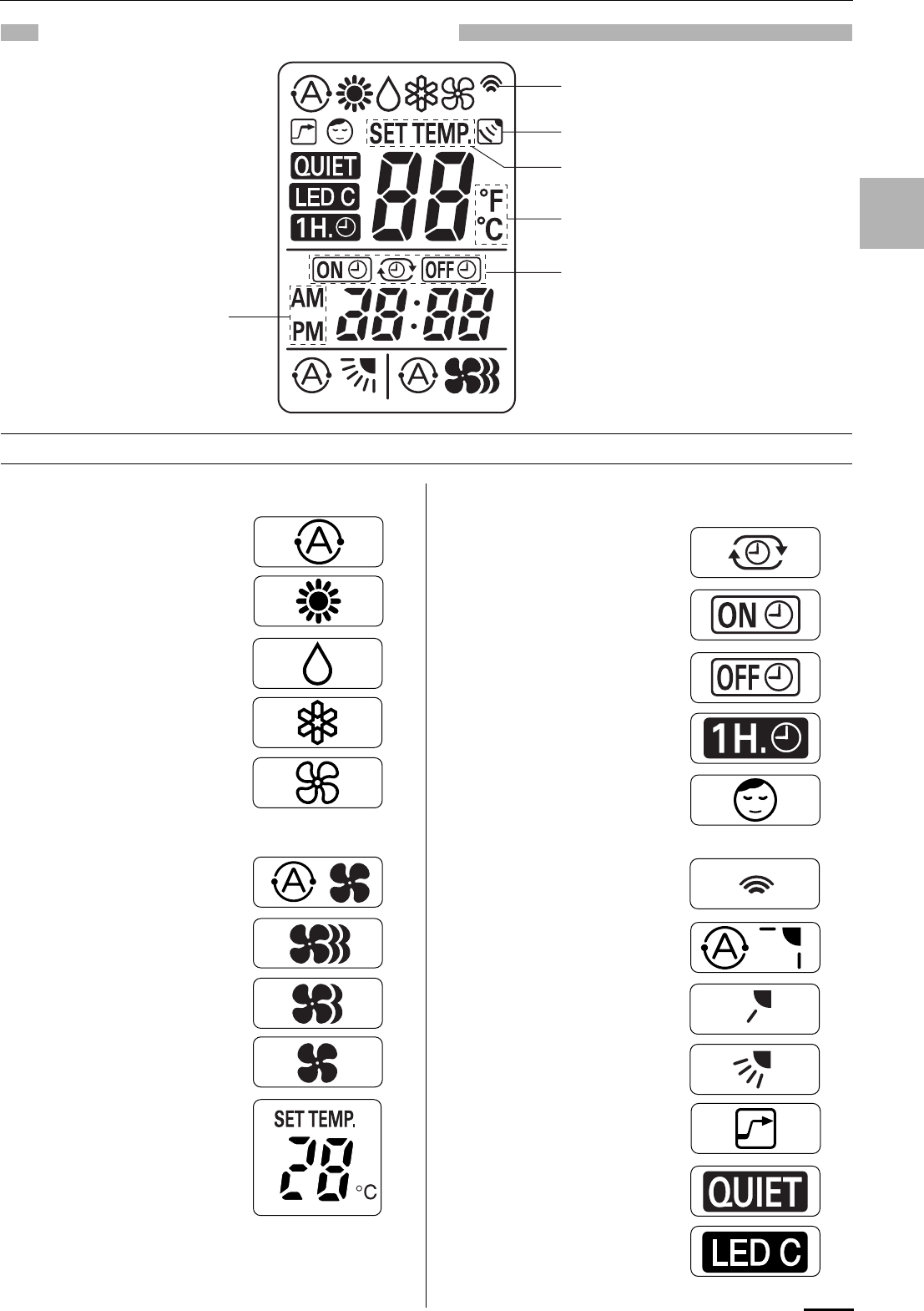
5
EG
REMOTE CONTROL UNIT (DISPLAY)
(1) Operation mode
AUTO .....................................
HEAT......................................
MILD DRY ..............................
COOL.....................................
FAN ........................................
(2) Fan speed
Automatic operation ...............
HIGH .....................................
MEDIUM.................................
LOW .......................................
(3) Temperature setting
16 – 30 °C
When set to 28 °C
temperature indication............
(4) Timer
24-hour clock with ON/OFF
program Timer .......................
ON Timer. ..............................
OFF Timer..............................
1-hour OFF Timer. .................
(5) NIGHT SETBACK..................
(6) Confirmation
of transmission.......................
(7) Auto. flap indication................
Flap angle indication..............
Sweep indication....................
(8) High power operation.............
(9) Quiet operation ......................
(10) LED CLEAN operation.........
Displayed when setting timer
Displayed when transmitting data
Displayed when indoor unit sensor is
in use
Displayed when setting temperature
Displayed when temperature is shown
Displayed when the time
display is set to 12-hour
time.
Symbols
OI-003-5-EG
01_SAP-KRV186EH_EN.fm Page 5 Wednesday, February 13, 2008 1:12 PM
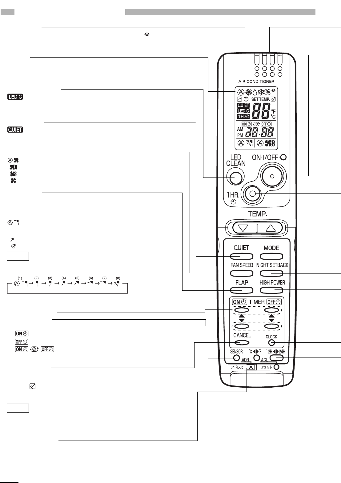
6
REMOTE CONTROL UNIT
SENSOR button
When you press this button (use a small-tipped object such as a ballpoint
pen), the mark will appear at the display. And the room temperature is
detected by the sensor which is built into the indoor unit and the air
conditioner is controlled accordingly.
If the remote control is located near a heat source, such as a space heater or
in direct sunlight, press the SENSOR button to switch to the sensor on the
indoor unit.
NOTE
Transmitter
When you press the buttons on the remote control unit, the mark
appears in the display to transmit the setting changes to the receiver
in the air conditioner.
Display
Information on the operating conditions is displayed while the remote
control unit is switched on. If the unit is turned off, FLAP setting and
FAN SPEED setting are not displayed.
FAN SPEED selector button
: The air conditioner automatically decides the fan speeds.
: High fan speed
: Medium fan speed
: Low fan speed
FLAP button
Press this button either to select the setting of the airflow direction to the
auto. flap in each mode or one of the six possible positions manually or to
select the sweep function which moves the flap up and down
automatically.
: Auto flap setting: If selected in a heating operation, the flap is set
to position (3) in the following chart. If selected in a cooling or dry
operation, the flap is set at position (7) in the following chart.
: The airflow direction can be set manually. (six positions)
: The flap moves up and down automatically.
When you press the FLAP button, the air flow direction will be changed
one by one as follows.
NOTE
SWEEP
CANCEL button
LED CLEAN button
: If this button is pressed during AUTO, HEAT, DRY, COOL or
FAN operation, the UV anti-bacterial unit is activated for
30 minutes and cleans the air blown from the air
conditioner.
ADDRESS switch
• The address switch changes to prevent mixing of signals from remote
control units when two air conditioners are installed next to each other.
Normally, the address switch is set to A. For more information, please
contact the dealer where you made the purchase.
• Normally, the tabs on the remote control unit should not be bent.
Temperature display selector button
This switches the temperature display
between °C and °F.
QUIET button
: When you press this button, the fan rotates slower than the
fan speed setting to provide a quieter operating sound.
ON TIME/OFF TIME setting buttons
Advance button
Return button
No display: The timer does not operate.
: The air conditioner starts at the set time.
: The air conditioner stops at the set time.
: The air conditioner stops and starts, or starts and
stops, at the set times every day. For details, see
“SETTING THE TIMER”.
OI-003-6-EG
01_SAP-KRV186EH_EN.fm Page 6 Wednesday, February 13, 2008 1:12 PM
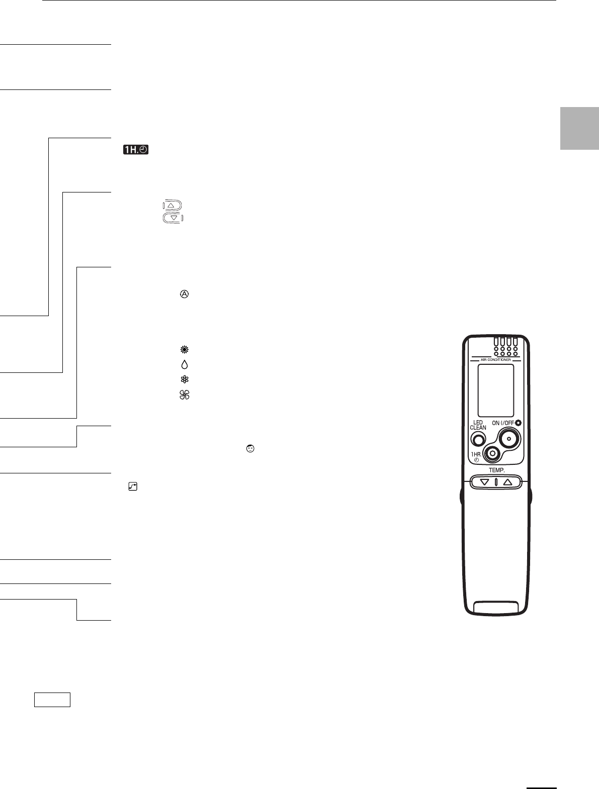
7
EG
Sensor
A temperature sensor inside the remote control unit senses the room
temperature.
(Cover closed)
CLOCK button
ACL button (ALL CLEAR)
Puts the remote control unit into pre-operation status. Always press this button
after replacing the batteries and setting the S/M switch.
ON/OFF operation button
This button is for turning the air conditioner on and off.
1 HR. TIMER button (1-HOUR OFF TIMER)
: When you press this button, regardless of whether the unit is operating
or stopping, the unit operates for one hour and then shuts down.
Temperature setting buttons (TEMP.)
Press the button to increase the set temperature.
Press the button to reduce the set temperature.
The temperature setting changes by 1 °C or 2 °F each time one of the TEMP.
buttons is pressed.
MODE selector button
Use this button to select AUTO, HEAT, DRY, COOL or FAN mode.
(AUTO) : When this setting is selected, the air conditioner
calculates the difference between the thermostat setting
and the room temperature and automatically switches to
the ‘‘COOL’’ or ‘‘HEAT’’ mode as appropriate except at “M”
of the S/M switch.
(HEAT) : The air conditioner makes the room warmer.
(DRY) : The air conditioner reduces the humidity in the room.
(COOL) : The air conditioner makes the room cooler.
(FAN) : The air conditioner works only as a circulation fan except
at “M” of the S/M switch.
NIGHT SETBACK button
For details, see “5. Night Setback Mode”. When you press this button in the
HEAT, DRY or COOL mode, the mark appears in the display, and the
remote control unit will automatically adjust the set temperature to save energy.
HIGH POWER button
: If this button is pressed during HEAT, DRY, COOL or FAN operation, the
unit operates at maximum output for 30 minutes, regardless of the
desired temperature.
The fan speed is 1step above ‘‘HIGH’’.
Time display selector button
This switches the time display between 24-hour time and 12-hour time.
The illustration above pictures the remote control unit after the cover has been opened.
The remote control unit sends the temperature signal to the air conditioner regularly at five minute intervals. If the signal from the
remote control unit stops for more than 15 minutes due to the loss of the remote control unit or other trouble, the air conditioner will
switch to the temperature sensor which is built into the indoor unit and control the room temperature. In these cases, the temperature
around the remote control unit may differ from the temperature detected at the air conditioner’s position.
NOTE
OI-003-7-EG
01_SAP-KRV186EH_EN.fm Page 7 Wednesday, February 13, 2008 1:12 PM
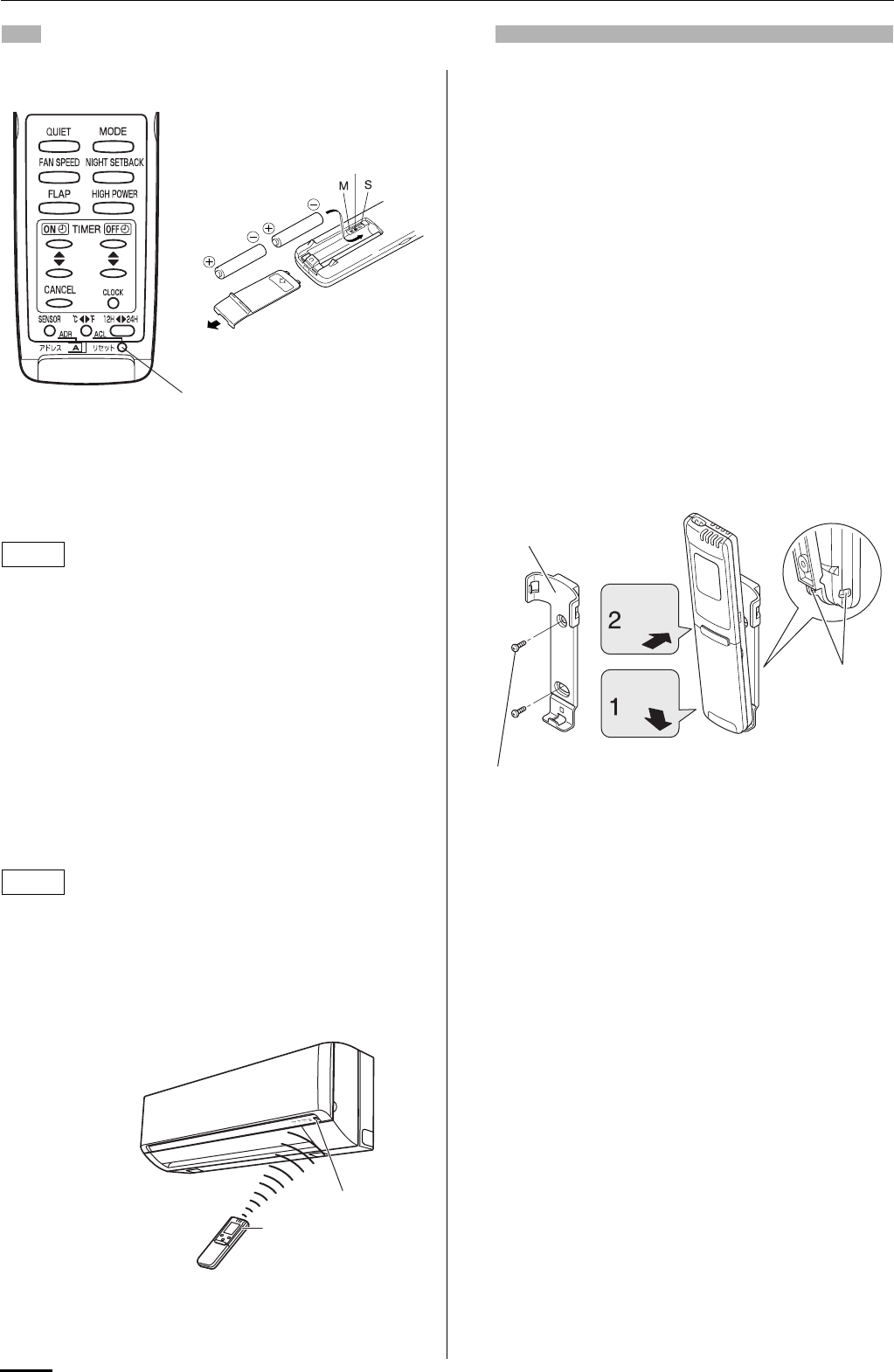
8
USING THE REMOTE CONTROL UNIT
HOW TO INSTALL BATTERIES
1. Slide the cover in the direction indicated by the arrow and
remove it.
2. Install two AAA alkaline batteries. Make sure the batteries point
in the direction marked in the battery compartment.
3. Use a thin object such as the tip of a pen to press the ACL
button.
• The batteries last about six months, depending on how
much you use the remote control unit. Replace the batteries
when the remote control unit’s display fails to light, or
when the remote control cannot be used to change the air
conditioner’s settings.
• Use two fresh leak-proof type-AAA alkaline batteries.
• In replacing batteries, follow the instructions as mentioned
in the sub-section “HOW TO INSTALL BATTERIES”.
• If you do not use the remote control unit more than 1
month, take out the batteries.
S/M (Single/Multiple) switch
• Initially, the S/M switch is set to S (Single).
• Set this switch to M (Multiple) for multiple operation.
• Always press ACL button by a thin object such as the tip of a pen
after setting the S/M switch.
•
When multiple indoor units are used and units in other rooms are
already operating, they will be set to the same mode of operation
as the operating indoor units.
HOW TO USE THE REMOTE CONTROL UNIT
When using the remote control unit, always point the unit’s
transmitter head directly at the air conditioner’s receiver.
REMOTE CONTROL UNIT INSTALLATION
POSITION
The remote control unit may be operated either from a non-fixed
position or from a wall-mounted position. To ensure that the air
conditioner operates correctly, DO NOT install the remote control
unit in the following places:
DO NOT
• In direct sunlight
• Behind a curtain or other places where it is covered
• More than 8 m away from the air conditioner
• In the path of the air conditioner’s airstream
• Where it may become extremely hot or cold
• Where it may be subject to electrical or magnetic noise
• Where there is an obstacle between the remote control unit and
air conditioner (since a check signal is sent from the remote
control unit every 5 minutes)
MOUNTING THE REMOTE CONTROL UNIT
Before mounting the remote control unit, press the ON/OFF
operation button at the mounting location to make sure that the air
conditioner operates from that location. The indoor unit should
make a beeping sound to indicate that it has received the signal.
To take out the remote control unit, pull it forward.
WHEN HOLDING THE REMOTE CONTROL UNIT
• When using the remote control unit and during air conditioner
operation, the transmitter on the remote control unit should be
pointed towards the receiver on the indoor unit.
• Make sure that there are no objects between the remote control
unit and receiver which could block the signal.
ACL button
S/M switch
NOTE
NOTE
Air conditioner
(Indoor unit)
Receiver
Remote control
unit (Transmitter head)
Remote control unit mount
Mounting screws
4 x 16 (included)
Rear side
Hole
• To prevent loss of the remote control
unit, you can connect the remote
control unit to the mount by passing
a string through the remote control
unit and attachment hole.
Press
Set in
place
OI-003-8-EG
01_SAP-KRV186EH_EN.fm Page 8 Wednesday, February 13, 2008 1:12 PM
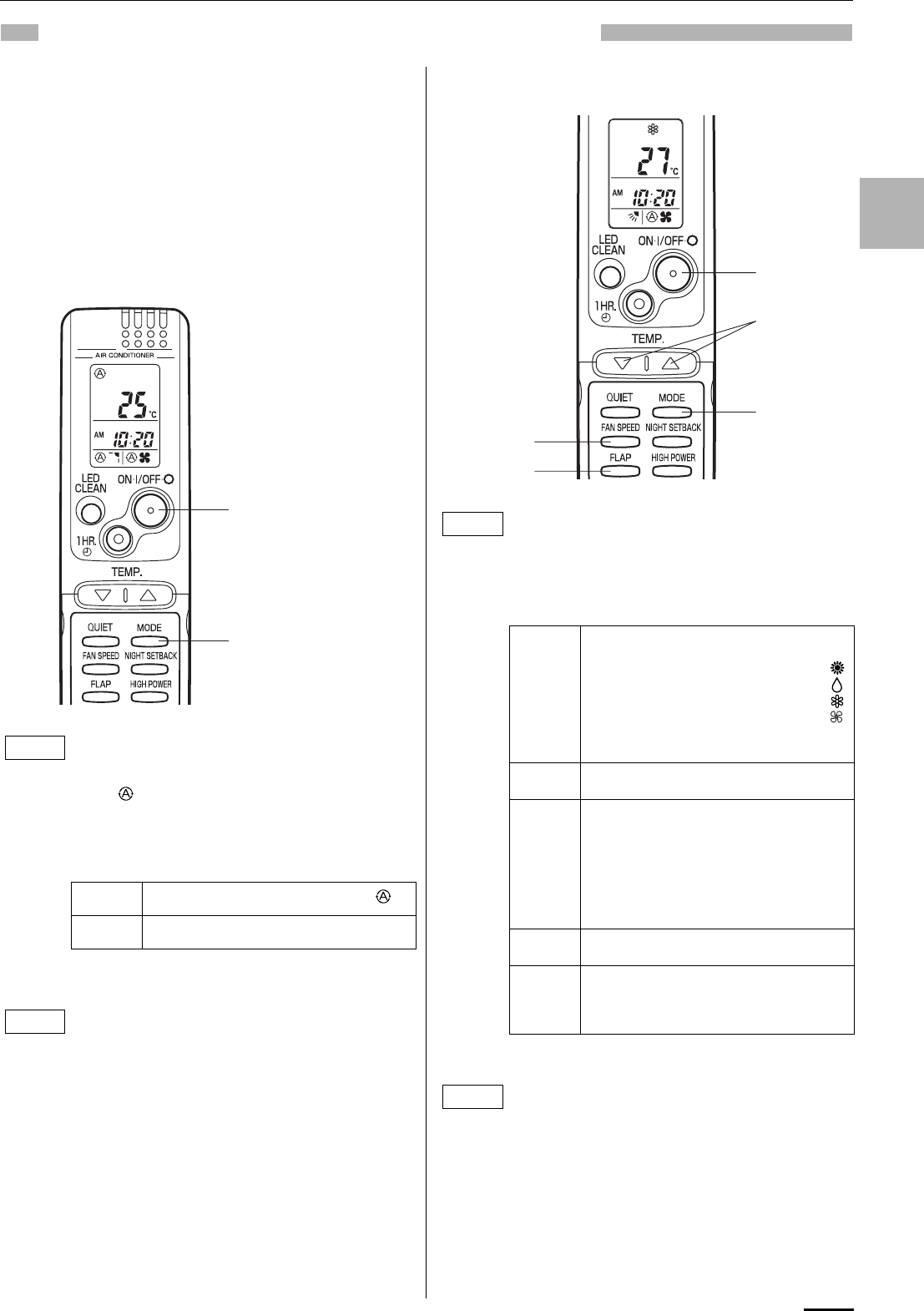
9
EG
OPERATION WITH THE REMOTE CONTROL UNIT
1. Automatic Operation
When the remote control’s S/M switch is at the “S”
(Single) position
This unit automatically switches between cooling operation and
heating operation according to the difference between the room
temperature and the temperature setting.
When the remote control’s S/M switch is at the “M”
(Multiple) position
Unlike when the switch is at the “S” position as described above,
the function for automatically switching between cooling and
heating does not work. Then, the air conditioner continuously
operates under the mode selected at initial operation.
2. Manual Operation
Check that the circuit breaker on the power panel is
turned on.
Once mode is selected and the unit is preset by
following the steps below, you can have the air
conditioner automatically bring the room to the
desired temperature simply by pressing the ON/OFF
operation button.
STEP 1 Press the MODE selector button to .
STEP 2 Press the ON/OFF operation button.
To stop the air conditioner, press the ON/OFF
operation button again.
• To change the temperature setting; press the
temperature setting buttons and change the setting
to the desired temperature.
STEP 2
STEP 1
NOTE
NOTE
Check that the circuit breaker on the power panel is
turned on.
If the automatic operation settings of the unit do not
meet your needs, press the setting buttons as
described below and change the settings as desired.
STEP 1 Press the MODE selector button
and select the desired mode.
For heating operation
For dehumidifying operation
For cooling operation
For fan only operation
→
→
→
→
(No FAN mode at M of the S/M switch on
the remote control unit.)
STEP 2 To start the air conditioner, press the ON/
OFF operation button.
STEP 3 Press the TEMP. setting buttons to
change the temperature setting to the
desired temperature.
Adjustable temperature range:
STEP 4 Set the FAN SPEED selector button to the
setting you want.
STEP 5 Press the FLAP button and set the airflow
direction as desired.
(Refer to “ADJUSTING THE AIRFLOW
DIRECTION” on page 13.)
To stop the air conditioner, press the ON/OFF
operation button again.
• Choose the best position in the room for the remote
control unit, which also acts as the sensor for room
comfort and transmits the operating instructions.
Once you’ve found this best position, always keep
the remote control unit there.
• This appliance has a built-in 5-minute time delay
circuit to ensure reliable operation. When the
operation button is pressed, the compressor will
start running within three minutes. In the event of
power failure, the unit will stop.
STEP 2
STEP 1
STEP 3
STEP 4
STEP 5
NOTE
30 °C max.
16 °C min. or 86 °F max.
60 °F min.
NOTE
OI-003-9-EG
01_SAP-KRV186EH_EN.fm Page 9 Wednesday, February 13, 2008 1:12 PM
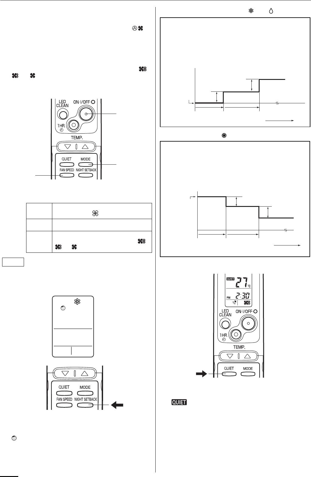
10
3. Adjusting the Fan Speed
A. Automatic fan speed
Simply set the FAN SPEED selector button to the
position.
This automatically sets the best fan speed for the room
temperature.
B. Manual fan speed
If you want to adjust fan speed manually during operation,
just set the FAN SPEED selector button as desired. [ ,
, or ]
4. Fan Only
5. Night Setback Mode
Night Setback Mode is used for saving energy.
Press the NIGHT SETBACK button while operation.
The mark appears in the display.
To release the night setback function, press the NIGHT SETBACK
button again.
A. In Cooling and DRY Mode: ( and )
B. In Heating Mode: ( )
6. QUIET Mode
QUIET Mode is used to reduce the fan sound of the indoor unit.
Press the QUIET button.
The mark appears in the display.
To cancel, press QUIET button again.
• In QUIET Mode, the fan rotates at a slower speed than the fan
speed setting.
• If the unit is already operating with a very low airflow, the fan
sound may not change even if the QUIET button is pressed.
If you want to circulate air without any temperature
control, follow these steps:
STEP 1 Press the MODE selector button to switch
to the fan mode .
STEP 2 Press the ON/OFF operation button.
STEP 3 Press the FAN SPEED selector button to
select the fan speed of your choice ( ,
or ).
• There is no FAN only function at M of the S/M switch
on the remote control unit.
STEP 2
STEP 1
STEP 3
NOTE
When the night setback mode is selected, the air conditioner
automatically raises the temperature setting 1 °C when 30
minutes have passed after the selection was made, and then
another 1 °C after another 30 minutes have passed, regardless
of the indoor temperature when night setback was selected.
This enables you to save energy without sacrificing comfort.
This function is convenient when gentle cooling is needed.
Setting
temperature
Press the NIGHT
SETBACK button
30 min. 30 min. Time
1°C (2°F)
1°C (2°F)
When the night setback mode is selected, the air conditioner
automatically lowers the temperature setting 2 °C when 30
minutes have passed after the selection was made, and then
another 2 °C after another 30 minutes have passed, regardless
of the indoor temperature when night setback was selected.
This enables you to save energy without sacrificing comfort.
This function is convenient when gentle heating is needed.
Setting
temperature
Press the NIGHT
SETBACK button
30 min. 30 min. Time
2°C (4°F)
2°C (4°F)
OI-003-10-EG
01_SAP-KRV186EH_EN.fm Page 10 Wednesday, February 13, 2008 1:12 PM
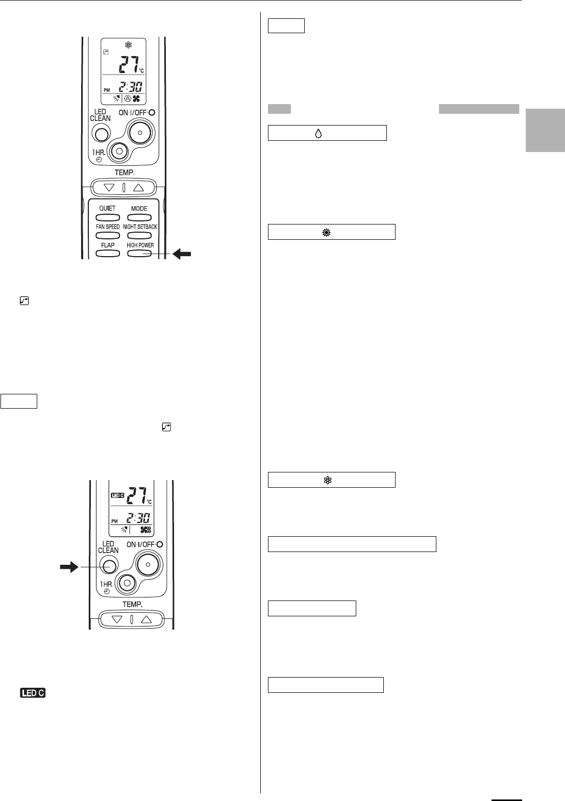
11
EG
7. HIGH POWER Mode
HIGH POWER mode can be used to increase the output of the
indoor unit for all operation modes except automatic operation.
Press the HIGH POWER button.
The mark appears in the display.
To cancel, press HIGH POWER button again.
• When the HIGH POWER button is pressed, the unit operates at
maximum output for 30 minutes, regardless of the desired
temperature. The fan speed is 1 step above “High”.
• HIGH POWER Mode cannot be used when the operation mode
is Automatic Operation.
• QUIET Mode and HIGH POWER Mode cannot be used at the
same time.
• When set to High fan speed during heating operation, the fan
runs at High fan speed even though the mark is displayed.
• Depending on the operating conditions, the fan speed may be
increased by a small amount only.
8. LED CLEAN Mode
In LED CLEAN mode, a UV anti-bacterial unit (including a LED
CLEAN lamp and anti-bacterial filter) in the indoor unit is used
during AUTO, HEAT, DRY, COOL, or FAN operation to remove
bacteria from air blown from the air conditioner.
Press the LED CLEAN button.
The mark appears in the display.
To cancel, press the LED CLEAN button again.
• When the LED CLEAN button is pressed, the UV anti-bacterial
unit operates for 30 minutes and cleans air blown from the air
conditioner.
• Pressing the MODE selector button cancels LED CLEAN mode.
• Do not open the front panel while the LED CLEAN lamp on the
display is on.
• Depending on the room brightness, light from the LED CLEAN
lamp may reflect inside the air conditioner and be visible. This is
not a malfunction.
SPECIAL REMARKS
How it works?
• Once the room temperature reaches the level that was set, the
unit’s operation frequency is changed automatically.
• During DRY operation, the fan speed automatically runs at lower
speed for providing a comfortable breeze.
• ‘‘DRY’’ operation is not possible if the indoor temperature is 15 °C
or less.
Heating performance
• Because this air conditioner heats a room by drawing in the heat
of the outside air (heat pump system), the heating efficiency will
fall off when the outdoor temperature is very low. If sufficient heat
cannot be obtained with this air conditioner, use another heating
appliance together with it.
Defrosting
• When the outdoor temperature is low, frost or ice may form on
the heat exchanger coil, reducing heating performance. When
this happens, a microcomputer defrosting system operates. At
the same time, the fan on the indoor unit stops and the
OPERATION lamp lights red and orange alternately until
defrosting is completed. Heating operation restarts after several
minutes. (This interval will vary slightly depending upon the
outdoor temperature and the way in which frost forms.)
Cold draft prevention
• For several minutes after the start of heating operation, the
indoor fan runs at a lower speed until the indoor heat exchanger
coil has warmed up sufficiently. However, the fan may remain
stopped when the room temperature is low. This is because the
COLD DRAFT PREVENTION SYSTEM is in operation.
• Sometimes the indoor unit may not get to the set fan speed such
as LOW and QUIET under cool operation at very low outdoor
temperatures due to the indoor unit being protected from ice or
frost.
• In the event of power failure, the unit will stop. When the power is
resumed, the unit will restart automatically within 5 minutes or
15 minutes at M position of the S/M switch on AUTO mode by the
remote control unit.
Clicking sound is heard from the air conditioner
• In heating or cooling operation, any plastic parts may expand or
shrink due to a sudden temperature change. In this event, a
clicking sound may occur. This is normal, and the sound will
soon disappear.
• The remote control unit sends the setting condition to the air
conditioner regularly at five minute intervals.
NOTE
NOTE
‘‘DRY’’ ( ) Operation
Heating ( ) Operation
Cooling ( ) Operation
Power failure during operation
Clicking Sound
Remote Control Unit
OI-003-11-EG
01_SAP-KRV186EH_EN.fm Page 11 Wednesday, February 13, 2008 1:12 PM
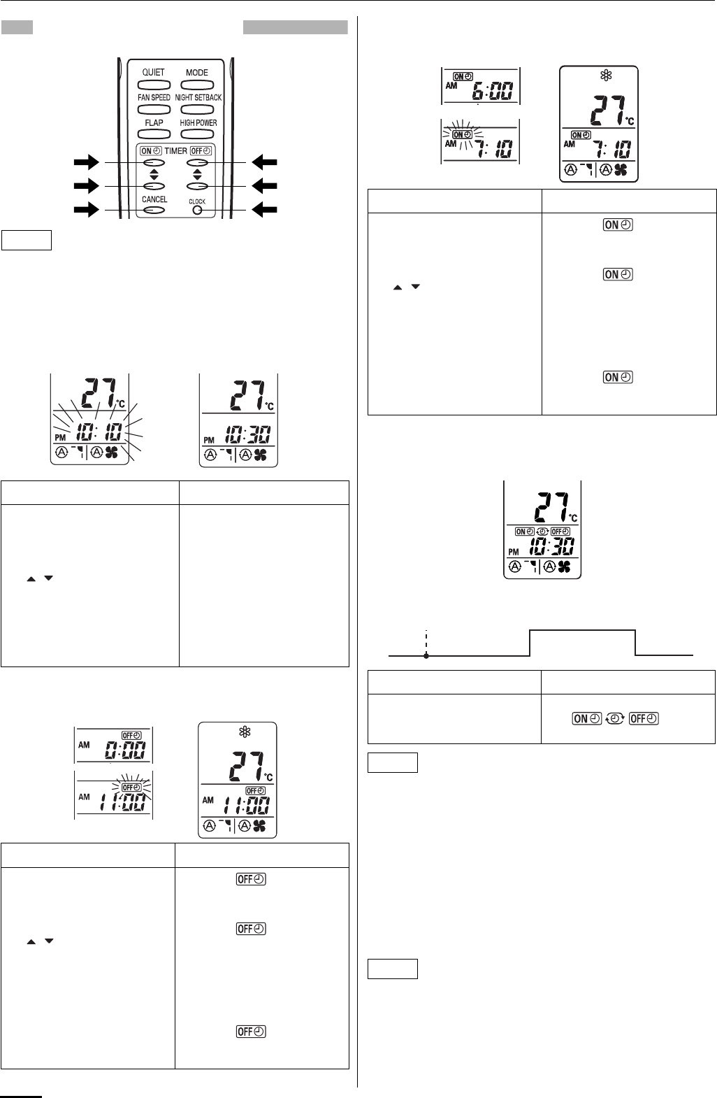
12
SETTING THE TIMER
In the descriptions below, the following settings are used for the
temperature and time indicator selector button on the bottom front
section of the remote control.
• Temperature: °C
• Time: AM, PM
1. How to set the present time
(Example) To set to 10:30 pm.
2. How to set the OFF time
(Example) To stop the air conditioner at 11:00 am.
3. How to set the ON time
(Example) To start operation at 7:10 am.
4. How to set daily ON/OFF repeat timer
(Example) To start operation at 7:10 am. and stop the air
conditioner at 11:00 am.
• The ON/OFF combination timer uses the current time as the
reference, and it is activated starting from whichever set time
comes first.
• With the ON/OFF combination timer, the settings are repeated
every day.
• You can check the timer ON/OFF times after you have set them
by pressing the ON TIME and OFF TIME setting buttons.
To cancel a timer program
• Press the CANCEL button.
• When either an ON or OFF timer is to be canceled, press the
button corresponding to the timer whose program is to be
canceled, and then press the CANCEL button.
• The airflow direction, fan speed and temperature setting can be
changed after a timer program has been set even when the unit
is stopped. Even when operation is stopped during an ON timer
program, the unit will start operating when the set time is
reached provided that the program is not canceled.
• When the ON timer and OFF timer are set to the same time, the
timer operates as if it is turned off.
Operation Indication
1. Press the CLOCK button
once if the time indicator is
not flashing.
The time indication alone
flashes.
2. Press the Advance, Return
( , ) button until PM 10:30
is displayed.
The time can be set in 1-
minute increments. Holding
down the button advances the
time rapidly in 10-minute
increments.
3. Press the CLOCK button
again. This completes the setting of
the current time.
Operation Indication
1. Press the OFF TIME setting
button once. The timer indication is
displayed, and the present OFF
time is shown.
2. Press the Advance, Return
( , ) button until AM
11:00 is displayed.
The timer indication
blinks.
The time can be set in 10-
minute increments. Holding
down the button advances the
time rapidly in 10-minute
increments.
3. Wait a few seconds, and
then the setting is complete. The timer indication
stops blinking and the present
time is displayed.
NOTE
Operation Indication
1. Press the ON TIME setting
button once. The timer indication is
displayed, and the present ON
time is shown.
2. Press the Advance, Return
( , ) button until AM 7:10
is displayed.
The timer indication
blinks.
The time can be set in 10-
minute increments. Holding
down the button advances the
time rapidly in 10-minute
increments.
3. Wait a few seconds, and
then the setting is complete. The timer indication
stops blinking and the present
time is displayed.
Operation Indication
1. Set the timer ON/OFF times
as shown in 2-1, 2, 3 and 3-
1, 2, 3.
The present time 10:30 pm.
and are
displayed.
7:10 am.
ON
11:00 am.
OFF
10:30 pm.
Present time
NOTE
NOTE
OI-003-12-EG
01_SAP-KRV186EH_EN.fm Page 12 Wednesday, February 13, 2008 1:12 PM
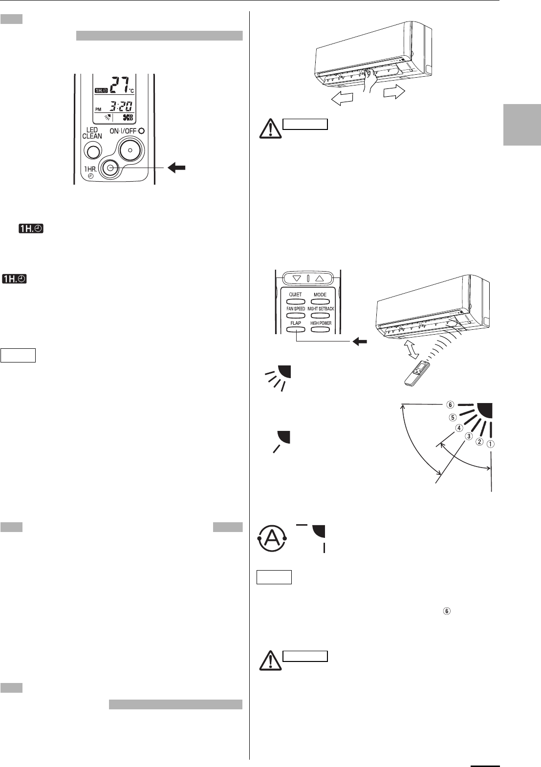
13
EG
USING THE 1-HOUR OFF
TIMER
1. 1-Hour OFF Timer
This function causes the unit to operate for one hour and
then stop, regardless of whether the unit is on or off when
this button is pressed.
The indicator in the display indicates that this function is
operating.
Setting procedure:
Regardless of whether the unit is operating or stopped, press the
1 HR. TIMER button.
appears in the display.
Cancellation procedure:
Press the ON/OFF operation button to turn the unit off, wait for the
unit to stop operating, and then press the ON/OFF operation
button again.
The 1-Hour Timer function is now cancelled and the unit operates
normally.
• If, while the 1-Hour Timer function is operating, the 1HR. TIMER
button is pressed once to cancel the function and then again, the
unit continues to operate for one hour from that point in time and
then stops.
• It is not possible to use the OFF Timer and 1-Hour OFF Timer
together. Whichever function is set last takes precedence. If the
1 HR. TIMER button is pressed while the TIMER OFF function
operates, the OFF Timer is cancelled and the unit will stop
operating one hour later.
2. Operation together with the daily ON/OFF
repeat timer
The 1-Hour OFF Timer setting is given priority over the DAILY ON/
OFF REPEAT setting.
TIPS FOR ENERGY SAVING
Do not
• Block the air intake and outlet of the unit. If they are
obstructed, the unit will not work well, and may be
damaged.
• Let direct sunlight into the room. Use sunshades, blinds or
curtains. If the walls and ceiling of the room are warmed by the
sun, it will take longer to cool the room.
Do
• Always try to keep the air filter clean. (Refer to “CARE AND
CLEANING”.) A clogged filter will impair the performance of the
unit.
• To prevent conditioned air from escaping, keep windows, doors
and any other openings closed.
ADJUSTING THE AIRFLOW
DIRECTION
1. Horizontal
The horizontal airflow can be adjusted by moving the vertical
vanes with your hands to the left or right.
When the humidity is high, the vertical vanes should be in the
front position during the cooling or dehumidifying operation.
If the vertical vanes are positioned all of the way to the right
or left, condensation may begin to form around the air vent
and drip down.
2. Vertical
The vertical airflow can be adjusted by moving the flap with the
remote control unit. Do not move the flap with your hands. Confirm
that the remote control unit has been turned on. Use the FLAP
button to set either the sweep function or one of the six airflow
direction settings.
• The flap automatically closes when the unit is off.
• During the heating operation, the fan speed will be very low and
the flap will be in the horizontal position (position ) until the air
being blown out of the unit begins to warm. Once the air warms
up, the flap position and fan speed change to the settings
specified with the remote control.
• Use the FLAP button on the remote control to adjust the
position of the flap. If you move the flap by hand, the flap
position according to the remote control and the actual flap
position may no longer match. If this should happen, shut
off the unit, wait for the flap to close, and then turn on the
unit again; the flap position will now be normal again.
• Do not have the flap pointed down during cooling
operation. Condensation may begin to form around the air
vent and drip down.
NOTE
CAUTION
HEAT
FAN
SWEEP
SWEEP
A. Sweep function
The flap starts moving
up and down to deliver
air over the sweep
range.
B. Setting the airflow manually
Referring to the above
illustration, use the
FLAP button to set the
airflow direction within
the range used during
the heating, cooling, or
dehumidifying
operation.
C. Auto flap function
The flap is set
to the
recommended
position.
COOL
DRY
NOTE
CAUTION
OI-003-13-EG
01_SAP-KRV186EH_EN.fm Page 13 Wednesday, February 13, 2008 1:12 PM
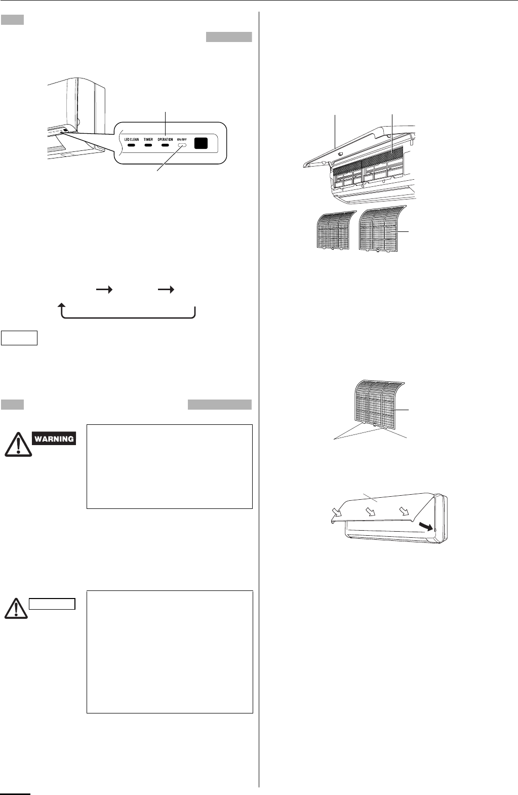
14
OPERATION WITHOUT THE
REMOTE CONTROL UNIT
If you have lost the remote control unit or it has trouble, follow the
steps below.
When the air conditioner is not running
Each time the OPERATION button is pressed, the type of
operation conducted is indicated by the changing color of the
OPERATION lamp. Press the button and select the lamp color that
suits your preference for operation.
The temperature is set to the room temperature minus 2°C during
the cooling operation and to the room temperature plus 2°C during
the heating operation, and the fan speed and flap are set to Auto.
CARE AND CLEANING
Casing and Grille (Indoor Unit)
Clean the casing and grille of the indoor unit with a vacuum
cleaner brush, or wipe them with a clean, soft cloth.
If these parts are stained, use a clean cloth moistened with a mild
liquid detergent. When cleaning the grille, be careful not to force
the vanes out of place.
Anti-Mold Filter
The anti-mold filter behind the front panel should be checked and
cleaned at least once every two weeks.
How to remove the anti-mold filter
1. Open the front panel until it is nearly horizontal, grasp the
sections near the front panel arms on both sides, and then pull
forward to remove the front panel.
2. Remove the anti-mold filter.
Cleaning
Use a vacuum cleaner to remove light dust. If there is sticky dust
on the filter, wash the filter in lukewarm, soapy water, rinse it in
clean water, and dry it.
How to replace the anti-mold filter
1. Insert the top of the anti-mold filter, align the two protrusions
with the center hook at bottom, then mount the filter into place.
2. Press the locations marked by the arrows and close the front
panel.
1. For safety, be sure to turn the air
conditioner off and also to
disconnect the power before
cleaning.
2. Do not pour water on the indoor unit
to clean it. This will damage the
internal components and cause an
electric shock hazard.
1. Never use solvents, or harsh
chemicals when cleaning the indoor
unit. Do not wipe the plastic casing
using very hot water.
2. Some metal edges and the fins are
sharp and may cause injury if
handled improperly; be especially
careful when you clean these parts.
3. The internal coil and other
components of the outdoor unit
must be cleaned every year. Consult
your dealer or service center.
INDOOR UNIT
OPERATION button
(ON/OFF)
OPERATION lamp
Cooling operation
(green) Heating
operation (red)
Stop
(lamp off)
NOTE
CAUTION
Anti-mold filter
Front panel Air clean filter
Anti-mold filter
Protrusion Center hook
Front panel
OI-003-14-EG
01_SAP-KRV186EH_EN.fm Page 14 Wednesday, February 13, 2008 1:12 PM
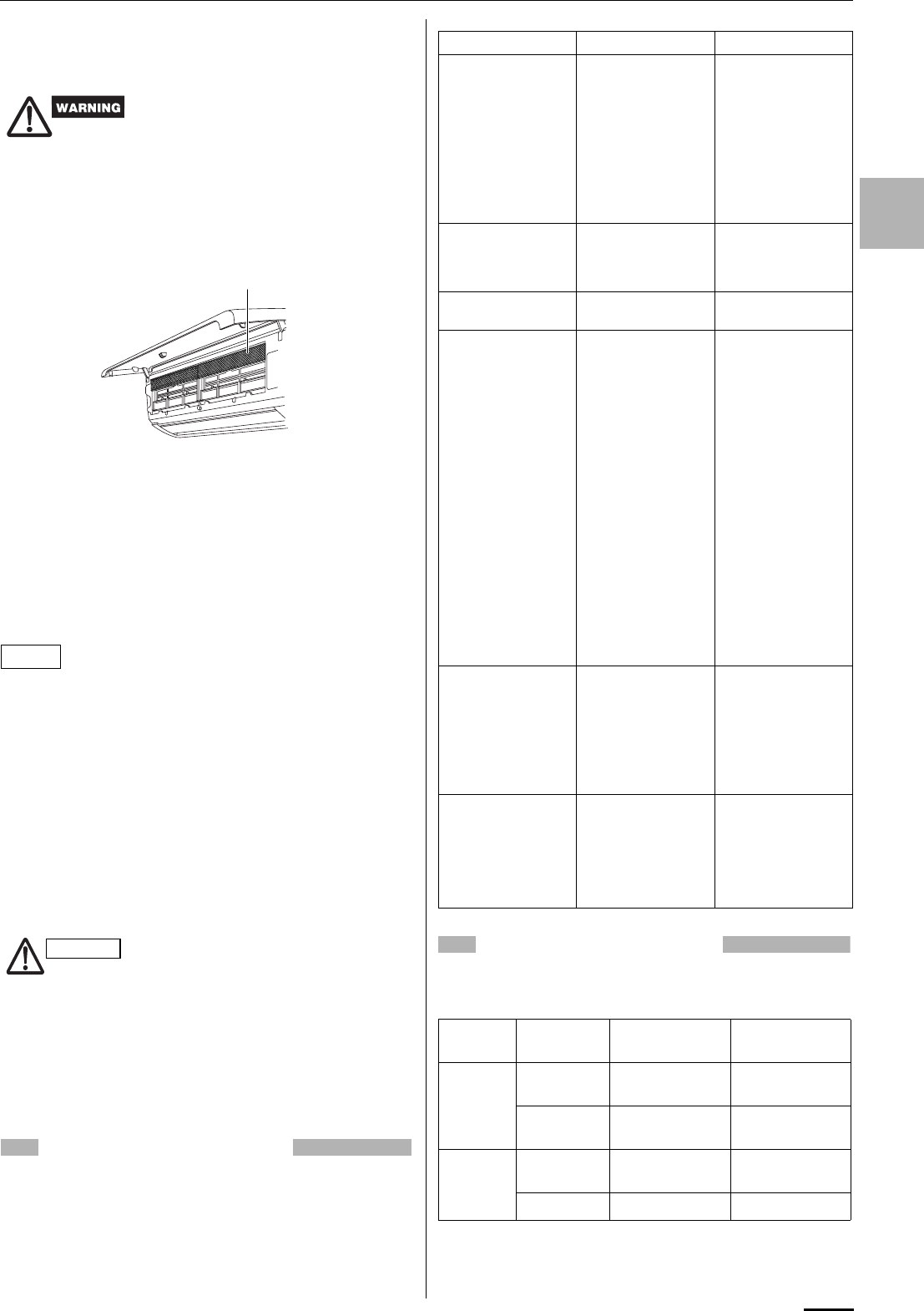
15
EG
Air Clean Filter
The air clean filter removes dust and dirt from the air, and reduces
odors and smoke from tobacco.
How to install the air clean filter
The air clean filter needs to be installed behind the anti-mold filter.
1. Remove the anti-mold filter.
2. Install the air clean filter in the position shown in the figure.
3. Remount the anti-mold filter.
How to clean the air clean filter
• In general, the filter should be sucked to remove dust in low fan
speed of a vacuum cleaner once every three months.
• If there is heavily grime on the filter, soak the filter in lukewarm
water with neutral detergent diluted 1:500 for 1 to 2 minutes then
wash it.
• Rinse the filter in clean water, then let it dry on the towel in room
temperature.
• Do not bend nor give excessive force onto the air clean filter.
• If the filter surface is heavily blocked with dirt or damaged,
replace it with new one. Purchase a replacement filter at your
local dealer. (model STK-FDXB)
Cleaning the main unit and remote control unit
• Wipe clean using a soft, dry cloth.
• To remove stubborn dirt, moisten a cloth in warm water no hotter
than 40 °C, wring thoroughly, and then wipe.
• The front panel can be removed in order to wash it with water.
Removing and remounting the front panel
Refer to “How to remove the anti-mold filter” and “How to replace
the anti-mold filter” on page 14.
Washing the front panel with water
• Clean the front panel gently using a soft sponge, or the like.
Then wipe away any remaining moisture.
• Neutral detergent may be used to remove stubborn dirt. Then
rinse thoroughly with water and wipe away any remaining
moisture.
TROUBLESHOOTING
If your air conditioner does not work properly, first check the
following points before requesting service. If it still does not work
properly, contact your dealer or service center.
OPERATING RANGE
For Single use:
The air conditioner is operable within the temperature ranges as
listed below:
For Multiple use:
Please refer to “Operating Range” on the sheet attached to the
outdoor unit.
This air clean filter cannot remove
harmful gases or vapors nor ventilate
air in the room. You must open doors
or windows frequently when you use
gas or oil heating appliances.
Otherwise there is a risk of suffocation
in extreme cases.
When using a footstool or the like, be
careful not to let it tip over.
Air clean filter
NOTE
CAUTION
Trouble Possible Cause Remedy
Air conditioner does
not run at all. 1. Power failure. 1. Restore power.
2. Leakage circuit
breaker tripped. 2. Contact service
center.
3. Line voltage is too
low. 3. Consult your
electrician or
dealer.
4. Batteries in remote
control unit have
run down.
4. Replace batteries.
OPERATION lamp
blinks and air
conditioner does not
operate.
Trouble in system. Contact service
center.
Compressor runs but
soon stops. Obstruction in front of
condenser coil. Remove obstruction.
Poor cooling (or
heating)
performance.
1. Dirty or clogged air
filter. 1. Clean air filter to
improve airflow.
2. Heat source or
many people in
room.
2. Eliminate heat
source if possible.
3. Doors and/or
windows are open. 3. Shut them to keep
the heat (or cold)
out.
4. Obstacle near air
intake or air
discharge port.
4. Remove it to
ensure good
airflow.
5. Thermostat is set
too high for cooling
(or too low for
heating).
5. Set the
temperature lower
(or higher).
6. (Outdoor
temperature is too
low for heating.)
6. (Consult your
dealer or try to use
another heat
appliance.)
Clicking sound is
heard from the air
conditioner.
In heating or cooling
operation, any plastic
parts may expand or
shrink due to a
sudden temperature
change. In this event,
a clicking sound may
occur.
This is normal, and
the sound will soon
disappear.
OPERATION lamp
lights but outdoor unit
will not run.
The use of cellular
phones near the air
conditioner may
cause disturbance to
its normal operation.
1. Turn off the power
then restart the air
conditioner after a
while.
2. Consult your
dealer.
Temperature Indoor air
temperature Outdoor air
temperature
COOLING Max. 32 °C DB /
23 °C WB 43 °C DB
Min. 19 °C DB /
14 °C WB –15 °C DB
HEATING Max. 27 °C DB 24 °C DB /
18 °C WB
Min. 16 °C DB – DB/ –15 °C WB
OI-003-15-EG
01_SAP-KRV186EH_EN.fm Page 15 Wednesday, February 13, 2008 1:12 PM

INSTALLATION INSTRUCTIONS
SAP-KMRV76EH
SAP-KMRV96EH
SAP-KMRV126EH
SAP-KRV186EH
SAP-KRV246EH
(II-852-6-4190-441-00-2)
APPENDIX C
When combined with SAP-CMRV1426EH, SAP-CMRV1926EH,
SAP-CMRV1936EH, SAP-CMRV2446EH or SAP-CMRV3146EH
()
A-3
Model Combinations
Combine indoor and outdoor units only as listed
below.
Indoor Unit Outdoor Unit
Power Source:
50 Hz, single-phase, 220 – 240 VAC
Combinations of indoor and outdoor units
Connect indoor and outdoor units only in the
combinations listed in the catalog or installation
manual.
Connecting any other model may result in
operation failure and system damage.
CAUTION
Español Français Deutsch Italiano Português EEÏÏÏÏËËÓÓÈÈÎο¿
English
85264190441002 © SANYO 2008 SANYO Electric Co., Ltd.
Osaka, Japan
Contents Page
IMPORTANT!
Please Read Before Starting .................................. 2
1. GENERAL .......................................................... 3
1-1. Tools Required for Installation (not supplied)
1-2. Accessories Supplied with Unit
1-3. Optional Copper Tubing Kit
1-4. Type of Copper Tube and Insulation Material
1-5. Additional Materials Required for Installation
2. INSTALLATION SITE SELECTION ................... 4
2-1. Indoor Unit
2-2. Embedding the Tubing and Wiring
3. HOW TO INSTALL THE INDOOR UNIT ............ 6
3-1. Remove the Rear Panel from the Unit
3-2. Make a Hole
3-3. Install the Rear Panel on the Wall
3-4. Removing and Installing the Grille
3-5. Shape the Indoor Side Tubing
3-6. Wiring Instructions
3-7. Wiring Instructions for Inter-unit Connections
3-8. Mounting
3-9. Drain Hose
4. MULTIPLE SWITCH ON THE REMOTE
CONTROL UNIT INDOOR UNIT TYPES
(SAP-KRV184EH, KRV244EH)
(SAP-KRV186EH, KRV246EH)
(SAP-KRV96EHDS, KRV126EHDS)................. 19
5. HOW TO TEST RUN THE AIR CONDITIONER ... 20
6. REMOTE CONTROL UNIT INSTALLATION
POSITION ......................................................... 22
6-1. Mounting on a Wall
7. ADDRESS SWITCH .......................................... 23
7-1. Address Setting of the Remote
Control Unit
8. CONNECTING A HOME AUTOMATION
DEVICE.............................................................. 24
9. INSTALLATION CHECK SHEET ...................... 24
INSTALLATION INSTRUCTIONS
– Inverter Split System Air Conditioner – COOL/DRY/HEAT Model
This air conditioner uses the new refrigerant R410A.
Be sure to read the yellow instruction sheet
attached to the outdoor unit for models using the
new refrigerant R410A.
The illustrations are based on the typical appearance
of a standard model. Consequently, the shape may
differ from that of the air conditioner that you are
installing.
NOTE
For Indoor Unit
SAP-KMRV74EH
SAP-KMRV94EH
SAP-KMRV124EH
SAP-KMRV76EH
SAP-KMRV96EH
SAP-KMRV126EH
SAP-KRV96EHDS
SAP-KRV126EHDS
SAP-KRV184EH
SAP-KRV244EH
SAP-KRV186EH
SAP-KRV246EH
SAP-CMRV1426EH
SAP-CMRV1926EH
SAP-CMRV1936EH
SAP-CMRV2446EH
SAP-CMRV3146EH
08-261 CMRV3146EH_IU EN 10/14/08 6:23 PM Page a

2
English
IMPORTANT!
Please Read Before Starting
This air conditioning system meets strict safety and oper-
ating standards. As the installer or service person, it is an
important part of your job to install or service the system
so it operates safely and efficiently.
For safe installation and trouble-free operation, you
must:
GCarefully read this instruction booklet before beginning.
GFollow each installation or repair step exactly as
shown.
GObserve all local, state, and national electrical codes.
GPay close attention to all warning and caution notices
given in this manual.
This symbol refers to a hazard
or unsafe practice which can
result in severe personal injury
or death.
This symbol refers to a hazard
or unsafe practice which can
result in personal injury or
product or property damage.
If Necessary, Get Help
These instructions are all you need for most installation
sites and maintenance conditions. If you require help for
a special problem, contact our sales/service outlet or
your certified dealer for additional instructions.
In Case of Improper Installation
The manufacturer shall in no way be responsible for
improper installation or maintenance service, including
failure to follow the instructions in this document.
SPECIAL PRECAUTIONS
When Wiring
ELECTRICAL SHOCK CAN CAUSE
SEVERE PERSONAL INJURY OR DEATH.
ONLY A QUALIFIED, EXPERIENCED
ELECTRICIAN SHOULD ATTEMPT TO
WIRE THIS SYSTEM.
• Do not supply power to the unit until all wiring and tub-
ing are completed or reconnected and checked.
• Highly dangerous electrical voltages are used in this
system. Carefully refer to the wiring diagram and these
instructions when wiring. Improper connections and
inadequate grounding can cause accidental injury or
death.
• Ground the unit following local electrical codes.
• Connect all wiring tightly. Loose wiring may cause
overheating at connection points and a possible fire
hazard.
• Install a protective leakage breaker depending on the
installation location (especially a damp or humid loca-
tion). If a leakage breaker is not installed, electric
shock can occur.
When Transporting
Be careful when picking up and moving the indoor and
outdoor units. Get a partner to help, and bend your knees
when lifting to reduce strain on your back. Sharp edges or
thin aluminum fins on the air conditioner can cut your fin-
gers.
When Installing…
…In a Ceiling or Wall
Make sure the ceiling/wall is strong enough to hold the
unit’s weight. It may be necessary to construct a strong
wood or metal frame to provide added support.
…In a Room
Properly insulate any tubing run inside a room to prevent
“sweating” that can cause dripping and water damage to
walls and floors.
…In Moist or Uneven Locations
Use a raised concrete pad or concrete blocks to provide
a solid, level foundation for the outdoor unit. This pre-
vents water damage and abnormal vibration.
When Connecting Refrigerant Tubing
• Do not add any refrigerant, air, or substance into the
refrigeration circuit other than the designated refriger-
ant (R410A). Adding anything other than the specified
refrigerant may cause the pressure to rise excessively
in the refrigeration circuit, rupturing the circuit and
causing injury or damage.
• Use all-new tubing and flare nuts to make the tubing
connections. Using any previous parts (from R22-
based systems) may result in damage to the equip-
ment, and may lead to the refrigeration circuit ruptur-
ing, causing a serious accident.
• Apply refrigerant lubricant to the matching surfaces of
the flare and union tubes before connecting them, then
tighten the nut with a torque wrench for a leak-free
connection.
• Check carefully for leaks before starting the test run.
When Servicing
• Turn the power OFF at the main power box (mains)
before opening the unit to check or repair electrical
parts and wiring.
• Keep your fingers and clothing away from any moving
parts.
• Clean up the site after you finish, remembering to
check that no metal scraps or bits of wiring have been
left inside the unit being serviced.
Others
• Ventilate any enclosed areas when installing or testing
the refrigeration system. Escaped refrigerant gas, on
contact with fire or heat, can produce dangerously
toxic gas.
• Confirm upon completing installation that no refrigerant
gas is leaking. If escaped gas comes in contact with a
stove, gas water heater, electric room heater or other
heat source, it can produce dangerously toxic gas.
WARNING
WARNING
CAUTION
CAUTION
08-261 CMRV3146EH_IU EN 10/14/08 6:23 PM Page 2
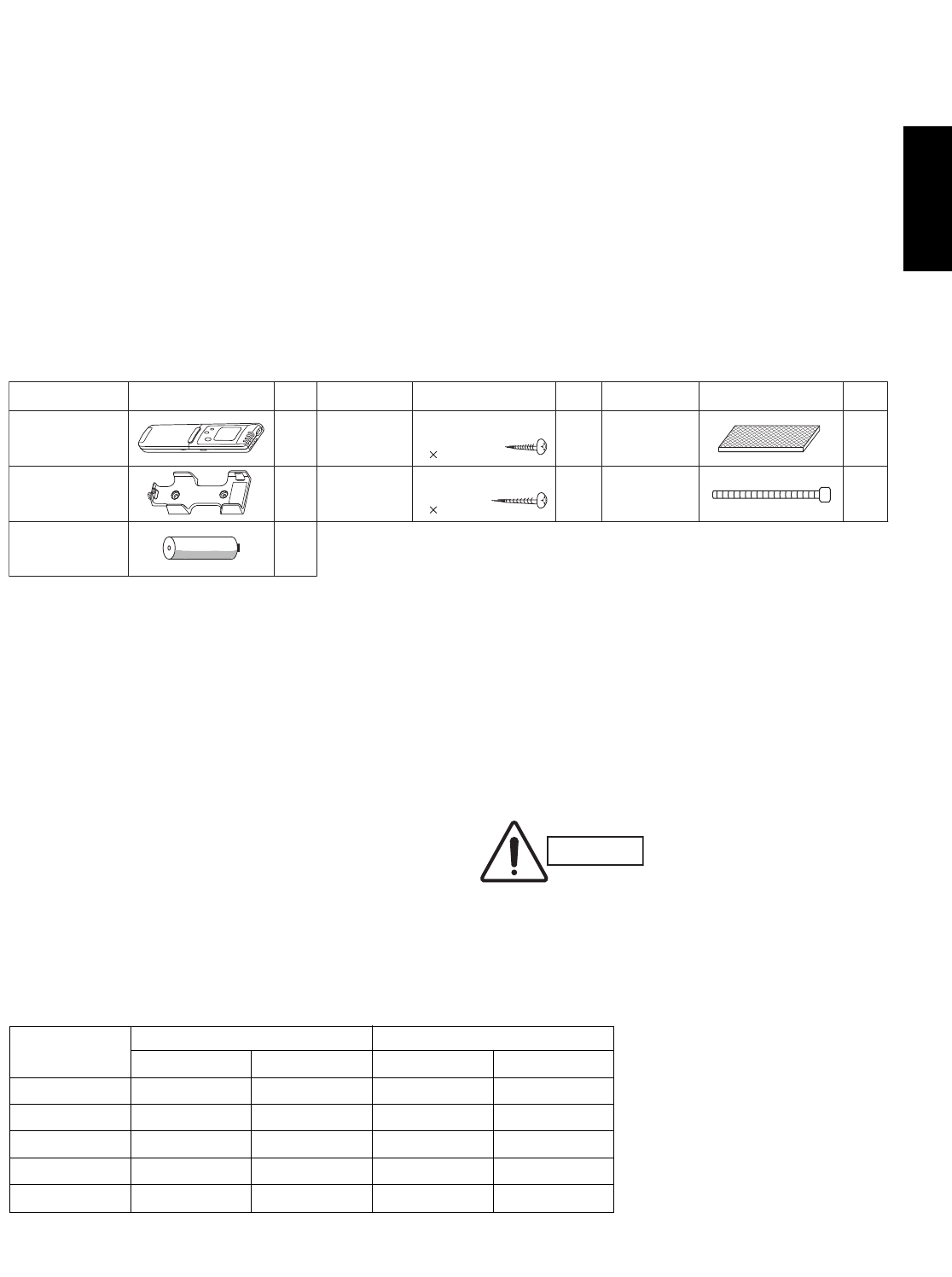
3
English
1. General
This booklet briefly outlines where and how to install
the air conditioning system. Please read over the
entire set of instructions for the indoor and outdoor
units and make sure all accessory parts listed are with
the system before beginning.
1-1. Tools Required for Installation (not supplied)
1. Standard screwdriver
2. Phillips head screwdriver
3. Knife or wire stripper
4. Tape measure
5. Carpenter’s level
6. Sabre saw or key hole saw
7. Hacksaw
8. Core bits
9. Hammer
10. Drill
11. Tube cutter
12. Tube flaring tool
13. Torque wrench
14. Adjustable wrench
15. Reamer (for deburring)
1-2. Accessories Supplied with Unit
Table 1
1-3. Optional Copper Tubing Kit
Copper tubing for connecting the outdoor unit to the
indoor unit is available in kits which contain the narrow
and wide tubing, fittings and insulation. Consult your
nearest sales outlet or air conditioning workshop.
1-4. Type of Copper Tube and Insulation Material
If you wish to purchase these materials separately
from a local source, you will need:
1. Deoxidized annealed copper tube for refrigerant
tubing as detailed in Table 2.
Cut each tube to the appropriate lengths +30 cm
to 40 cm to dampen vibration between units.
Table 2
2. Foamed polyethylene insulation for the specified
copper tubes as required to precise length of tub-
ing. Wall thickness of the insulation should be not
less than 8 mm.
3. Use insulated copper wire for field wiring. Wire
size varies with the total length of wiring. Refer to
3-6. Wiring Instructions for details.
Parts Figure
1
1
2
AAA alkaline
battery
Remote
control unit
Remote control
unit holder
Parts Figure
Tapping
screw Clamp**
Tapping
screw
Truss-head
Phillips
4 30 mm
Truss-head
Phillips
4 16 mm 2
8
Air clean
filter* 2
1
Parts Figure
Packed in the indoor unit.
* 1 only for KRV96, KRV126.
** Not applicable for KRV96, KRV126.
Q’ty Q’ty Q’ty
CAUTION
Check local electrical codes
and regulations before
obtaining wire. Also, check
any specified instructions or
limitations.
Model Narrow Tube Wide Tube
Outer Dia. Thickness Outer Dia. Thickness
KMRV74/94/124 6.35 mm 0.8 mm 9.52 mm 0.8 mm
KMRV76/96/126 6.35 mm 0.8 mm 9.52 mm 0.8 mm
KRV96/126 6.35 mm 0.8 mm 9.52 mm 0.8 mm
KRV184/186 6.35 mm 0.8 mm 12.70 mm 0.8 mm
KRV244/246 6.35 mm 0.8 mm 15.88 mm 1.0 mm
08-261 CMRV3146EH_IU EN 10/14/08 6:23 PM Page 3

4
English
1-5. Additional Materials Required for Installation
1. Refrigeration (armored) tape
2. Insulated staples or clamps for connecting wire
(See local codes)
3. Putty
4. Refrigeration lubricant
5. Clamps or saddles to secure refrigerant tubing
2. Installation Site Selection
2-1. Indoor Unit
AVOID:
Gdirect sunlight.
Gnearby heat sources that may affect performance of the
unit.
Gareas where leakage of flammable gas may be expected.
Gplacing or allowing any obstructions near the Air
Conditioner inlet or outlet.
Ginstalling in rooms that contain instant-on (rapid-start)
fluorescent lamps. (These may prevent the Air Conditioner
from receiving signals.)
Gplaces where large amounts of oil mist exist.
Ginstalling in locations where there are devices that
generate high-frequency emissions.
DO:
Gselect an appropriate position from which every corner of
the room can be uniformly cooled. (High on a wall is best.)
Gselect a location that will hold the weight of the unit.
Gselect a location where tubing and drain hose have the
shortest run to the outside. (Fig. 1)
Gallow room for operation and maintenance as well as
unrestricted air flow around the unit. (Fig. 2)
Ginstall the unit within the maximum elevation difference
(H1, H2, H3, H4) above or below the outdoor unit and
within a total tubing length (L1+L2, L1+L2+L3,
L1+L2+L3+L4) from the outdoor unit as detailed in Table 3
and Fig. 3a.
Drain hose
Indoor unit
Outside drainage
Fig. 1
5 cm
min.
5 cm
min.
15 cm min.
Front View
Fig. 2
INDOOR
UNIT (1)
INDOOR
UNIT (4)
INDOOR
UNIT (3)
INDOOR
UNIT (2)
Tubing length (L1)
L2
L3
L4
H2
H3
H4
OUTDOOR
UNIT
Elevation
difference (H1)
Fig. 3a
WARNING
To prevent abnormal heat generation
and the possibility of fire, do not
place obstacles, enclosures and
grilles in front of or surrounding the
air conditioner in a way that may
block air flow.
Indoor unit
Floor level
Wall
Minimum height
from floor level
1.5 m
Fig. 3b
For stable operation of the air
conditioner, do not install
wall-mounted type indoor
units less than 1.5 m from
floor level.
CAUTION
08-261 CMRV3146EH_IU EN 10/14/08 6:23 PM Page 4
5
English
GInstall the indoor unit more than 1 meter away from
any antenna or power lines or connecting wires used
for television, radio, telephone, security system, or
intercom. Electrical noise from any of these sources
may affect operation.
Ginstall in a sturdy manner to avoid increased operat-
ing noise.
Table 3
2-2. Embedding the Tubing and Wiring
GBefore beginning embedding installation work,
consult fully with agencies or offices related to the
building’s foundation, construction, electricity, and
water.
GWait to make connections to the embedded portion.
Each connection step is described later in this
manual.
GSecurely cover the end of the embedded tubing to
prevent intrusion of dirt or moisture.
GIf an embedded tube is to be left for a long time, fill
the tube with nitrogen and seal both ends securely.
If a tube is left open for an extended time, moisture
in the air inside the tubing may condense into water
droplets, and lead to water contamination of the
refrigerant circuit.
GIn order to prevent insulation breakdown and ground
faults, do not allow wiring ends to come in contact
with rainwater, or be subjected to condensation or
dew.
GApply sufficient thermal insulation to the refrigerant
tubing and drain pipes.
* If total tubing length becomes 45 to 60 m (max.) or 45 to 70 m (max.), charge additional refrigerant (R410A) by 20 g/m.
No additional charge of compressor oil is necessary.
Max. Allowable Max. Allowable Total Limit of Limit of Elevation Required Amount
Tubing Length Tubing Length Total Tubing Length Difference of Additional
Model per unit at shipment (L1+L2) or (L1+L2+L3) (H1, H2, H3, H4) Refrigerant
(m) (L1+L2) or (L1+L2+L3) or (L1+L2+L3+L4) (m) (g/m)*
or (L1+L2+L3+L4) (m)
(m)
CMRV1426 20 30 (L1+L2) 30 (L1+L2) 15 –
CMRV1926 25 45 (L1+L2) 45 (L1+L2) 15 –
CMRV1936 25 45 (L1+L2+L3) 45 (L1+L2+L3) 15 –
CMRV2446 25 45 (L1+L2+L3+L4) 60 (L1+L2+L3+L4) 15 20
CMRV3146 30 45 (L1+L2+L3+L4) 70 (L1+L2+L3+L4) 15 20
08-261 CMRV3146EH_IU EN 10/14/08 6:23 PM Page 5

English
Set screw only for transportation
Rear panel
marks
Left
tubing
Right tubing
Downward tubing
Right-rear
tubing
(recommended)
Left-rear
tubing
3. How to Install the Indoor Unit
3-1. Remove the Rear Panel from the Unit
(1) Remove and discard the set screw on the rear
panel except
SAP-KRV96EHDS, SAP-
KRV126EHDS, SAP-KMRV76EH,
SAP-
KMRV96EH and SAP-KMRV126EH. (Fig. 6)
(2) Press the 2 LLmarks on the frame cover and dis-
engage the stationary tabs from the frame. (Fig. 7)
(3) Remove the rear panel.
Tubing can be extended in 5 or 6 directions as shown
in Fig. 8a or 8b. Select the direction you need provid-
ing the shortest run to the outside unit.
GWhen left tubing is to be done, switch the drain
hose and drain cap. (For details, refer to “Switching
drain hose and drain cap” on page 17 and 18.)
3-2. Make a Hole
(1) Place the rear panel from the indoor unit on the
wall at the location selected. Make sure the panel
is horizontal, using a carpenter’s level or tape mea-
sure to measure down from the ceiling. Wait until
after cutting the hole before attaching the rear
panel to the wall.
(2) Determine which side of the unit you should make
the hole for tubing and wiring. (Fig. 9a, 9b or 9c)
In the case of left-rear tubing, use the measurement
points from the edge of the rear panel for precise
placement of the hose outlet. (Fig. 9a, 9b or 9c)
(3) Before making the hole, check carefully that no
studs or pipes are directly run behind the spot to
be cut.
The above precautions are also applicable if tub-
ing goes through the wall in any other location.
NOTE
NOTE
Fig. 9b
CAUTION
Also avoid areas where elec-
trical wiring or conduits are
located.
70 mm
Fig. 9a
(SAP-KMRV74, KMRV94, KMRV124)
(SAP-KMRV76, KMRV96, KMRV126)
60 mm
(SAP-KMRV74, KMRV94, KMRV124) (SAP-KRV184, KRV244)
(SAP-KRV186, KRV246)
Fig. 9c
340 278
42
42
Left
tubing
Right
tubing
Right-rear
tubing
(recommended)
Right-downward
tubing
Left-rear
tubing
Left-downward
tubing
Fig. 8b
6
Fig. 8a
Fig. 7
(SAP-KRV184, KRV244) (SAP-KRV186, KRV246)
Fig. 6
(SAP-KMRV74, KMRV94, KMRV124)
(SAP-KMRV76, KMRV96, KMRV126) (SAP-KRV96, KRV126)
(SAP-KRV184, KRV244)
(SAP-KRV186, KRV246)
(SAP-KRV96, KRV126)
08-261 CMRV3146EH_IU EN 10/14/08 6:23 PM Page 6
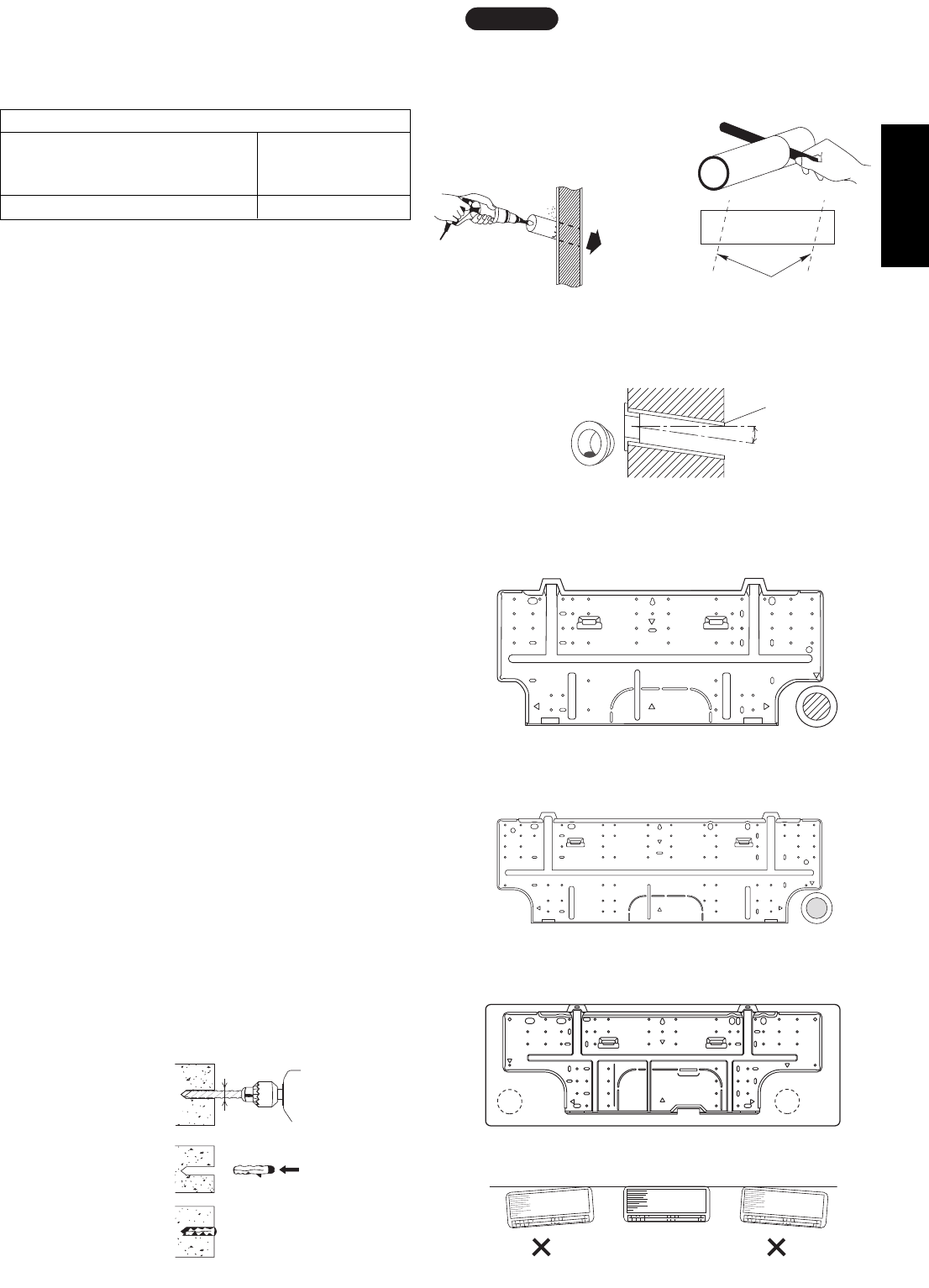
English
Hole should be made at a slight downward slant to the
outdoor side.
NOTE
Plastic cover
INSIDE OUTSIDE
Wall
Slight
angle
PVC pipe
(Locally purchased)
Fig. 12
PVC pipe (Locally purchased)
Cut at slight angle
Fig. 11
(4) Using a sabre saw, key hole saw or hole-cutting
drill attachment, cut a hole in the wall. See Table 4
and Fig. 10.
Table 4
(5) Measure the thickness of the wall from the inside
edge to the outside edge and cut PVC pipe at a
slight angle 6 mm shorter than the thickness of the
wall. (Fig. 11)
(6) Place the plastic cover over the end of the pipe (for
indoor side only) and insert the pipe in the wall.
(Fig. 12)
3-3. Install the Rear Panel on the Wall
Be sure to confirm that the wall is strong enough to
suspend the unit.
See either Item a) or b) below depending on the wall
type.
a) If Wooden Wall
(1) Attach the rear panel to the wall with the 8 screws
provided. (Fig. 13a, 13b or 13c)
If you are not able to line up the holes in the rear
panel with the beam locations marked on the wall,
use rawl plugs or toggle bolts to go through the
holes on the panel or drill 5 mm dia. holes in the
panel over the stud locations and then mount the
rear panel.
(2) Double check with a carpenter’s level or tape mea-
sure that the panel is level. This is important to
install the unit properly. (Fig. 14)
(3) Make sure the panel is flush against the wall. Any
space between the wall and unit will cause noise
and vibration.
b) If Block, Brick, Concrete or Similar Type Wall
Make 4.8 mm dia. holes in the wall. Insert rawl plugs
for appropriate mounting screws. (Fig. 15)
Hole Dia. (mm)
KMRV74 / KMRV94 / KMRV124 KRV184 / KRV244
KRV96 / KRV126 KRV186 / KRV246
KMRV76 / KMRV96 / KMRV126
65 80
Fig. 13b
Fig. 14
4.8 mm dia. hole
Rawl plug
(Locally purchased)
Fig. 15
Fig. 13a
(SAP-KMRV74, KMRV94, KMRV124)
(SAP-KMRV76, KMRV96, KMRV126)
(SAP-KRV184, KRV244) (SAP-KRV186, KRV246)
Fig. 13c
Indoor
side
Outdoor
side
Fig. 10
(SAP-KRV96, KRV126)
7
08-261 CMRV3146EH_IU EN 10/14/08 6:23 PM Page 7
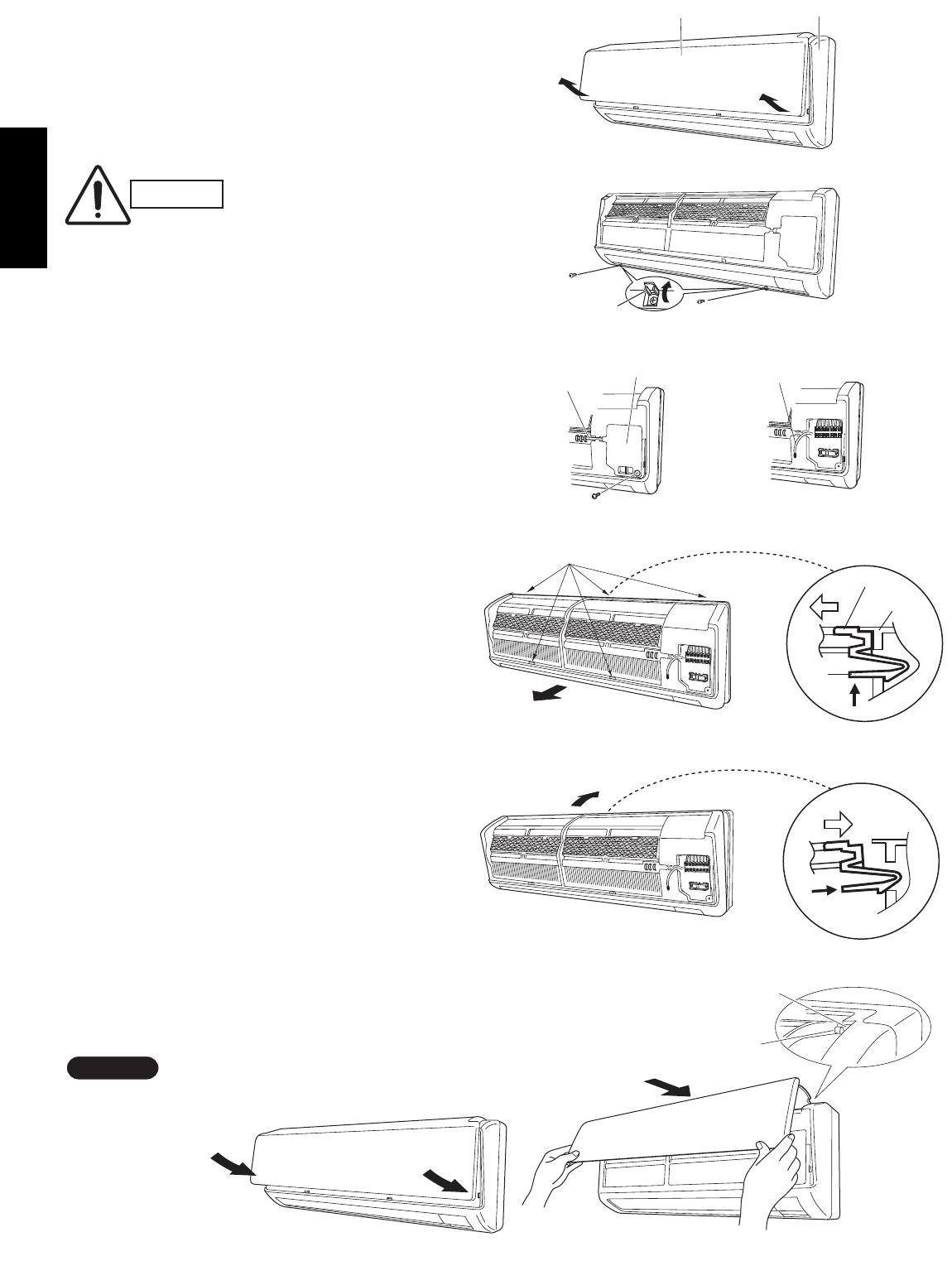
English
3-4. Removing and Installing the Grille
3-4-1. Indoor unit types
(SAP-KMRV74EH, KMRV94EH, KMRV124EH)
Basically, these models can be installed and wired without
removing the grille. If access to any internal part is needed,
follow the steps as given below.
How to remove the grille
(1) Grasp both ends of the air intake grille, and remove it
by opening towards the front and pulling towards you.
(Fig. 16a)
(2) Remove the 2 screws. (Fig. 16b)
(3) Remove the screw on the right side cover plate and
open the cover. (Fig. 17a)
(4) Take out the thermistor from the grille. (Fig. 17b)
(5) Pull the lower part of the grille towards you to remove.
(Fig. 18a)
(6) Use a standard screwdriver to push on the tabs to
remove the grille.
How to replace the grille
(1) Reinstall the grille into the lower part while aligning
its tabs on the upper part. (Fig. 18b) Insert the tabs
in the slots and push the lower part of the grille back
into position.
(2) Make sure that the grille and frame are firmly fitted
together by engaging the tabs.
(3) Attach the thermistor on the grille. (Fig. 17a)
(4) Close the cover and replace the screw. (Fig. 17a)
(5) Affix the grille with the 2 previously removed screws.
(Fig. 16b)
(6) Install the air intake grille.
(a) Allow the edge of the air intake grille to slide into
the top of the indoor unit, and then insert it all the
way inside. (Fig. 19a)
(b) Press the bottom right and left corners of the air
intake grille to attach it to the indoor unit. (Fig. 19b)
Attach so that the round pins at the top right and left
corners of the air
intake grille are
inserted into the
grooves at the top
right and left of the
indoor unit.
NOTE
Screw cover
Air intake grille Grille
Fig. 16a
Fig. 16b
Cover
Thermistor
Fig. 17a
Thermistor
Fig. 17b
Fig. 18a
Grille
Frame
Tab
Tab
*
*
Fig. 18b
*
*
Fig. 19b Fig. 19a
Pin
Groove
CAUTION
Be sure to wear work gloves
during installation to avoid being
cut by the sharp aluminum fins
of the heat exchanger.
8
08-261 CMRV3146EH_IU EN 10/14/08 6:23 PM Page 8
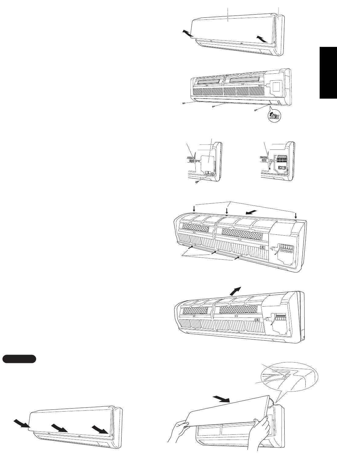
9
English
3-4-2. Indoor unit types
(SAP-KRV184EH, KRV244EH)
Basically, these models can be installed and wired
without removing the grille. If access to any internal
part is needed, follow the steps as given below.
How to remove the grille
(1) Grasp both ends of the air intake grille, and
remove it by opening towards the front and pulling
towards you. (Fig. 16a-1)
(2) Remove the 3 screws. (Fig. 16b-1)
(3) Remove the screw on the right side cover plate
and open the cover. (Fig. 17a-1)
(4) Take out the thermistor from the grille. (Fig. 17b-1)
(5) Press the 3 tabs at the top of the grille and the 3
tabs on the front face to separate the grille from
the frame. (Fig. 18a-1)
(6) Pull the grill towards you to remove it.
How to replace the grille
(1) When installing the grille, place the bottom of the
grille into the frame first. (Fig. 18b-1)
Then insert the tabs on the top of the grille and on
the front face into the frame.
(2) Make sure that the grille and frame are firmly fitted
together by engaging the tabs.
(3) Attach the thermistor on the grille. (Fig. 17a-1)
(4) Close the cover and replace the screw.
(Fig. 17a-1)
(5) Affix the grille with the 3 previously removed
screws. (Fig. 16b-1)
(6) Install the air intake grille.
(a) Allow the edge of the air intake grille to slide
into the top of the indoor unit, and then insert it
all the way inside. (Fig. 19a-1)
(b) Press the bottom right and left corners and
center of the air intake grille to attach it to the
indoor unit. (Fig. 19b-1)
Attach so that the round pins at the top right and left
corners of the air intake grille are inserted into the
grooves at the top right and left of the indoor unit.
NOTE
Air intake grille Grille
Fig. 16a-1
Fig. 16b-1
Cover
Thermistor
Fig. 17a-1
Thermistor
Fig. 17b-1
Fig. 18a-1
Tab
Tab
Fig. 18b-1
Fig. 19b-1 Fig. 19a-1
Pin
Groove
08-261 CMRV3146EH_IU EN 10/14/08 6:23 PM Page 9

10
English
3-4-3. Indoor unit type
(SAP-KRV96EHDS, KRV126EHDS)
Basically, these models can be installed and wired
without removing the grille. If access to any internal
part is needed, follow the steps as given below.
How to remove the grille
(1) Open the front panel until it is nearly horizontal,
grasp the sections near the front panel arms on
both sides, and then pull towards you to remove
the front panel. (Fig. 16-2)
(2) Remove the 3 screws from the frame. Also remove
the 2 screws where the screw covers are open.
(Fig. 17-2)
(3) Press the 3 tabs on the top of the grille to
disengage them. (Fig. 17-2)
(4) Pull the grille towards you to remove it. (Fig. 17-2)
How to replace the grille
(1) Insert the bottom of the grille into the flap, with the
flap at a more-or-less horizontal position.
(2) While aligning both edges of the grille with the
frame, move the panel horizontally and insert the
top and bottom into the frame.
(3) Press the air discharge outlet firmly with your hand
to ensure no gap exists between the main unit and
grille.
(4) Tighten the 2 screws and close the screw covers.
Also tighten the 3 screws of the frame.
(5) Grasp the sections near the front panel arms on
both sides, hold the front panel so that it is nearly
horizontal, bring the arm shafts into contact with
the top of the grooves on the right and left sides of
the air conditioner, and then push firmly until the
arm shafts click into place. (Fig. 18-2)
(6) After closing the front panel, press firmly on the
parts indicated by the arrows to securely fasten the
panel in place. (Fig. 19-2)
Check that no gap exists between the main unit and
grille.
NOTE
Fig. 16-2
Fig. 17-2
Front panel
Arm
Screw
Flap
Grille
Screw
Screw cover
Fig. 18-2
Fig. 19-2
Front panel
Pin
Arm
Groove
08-261 CMRV3146EH_IU EN 10/14/08 6:23 PM Page 10
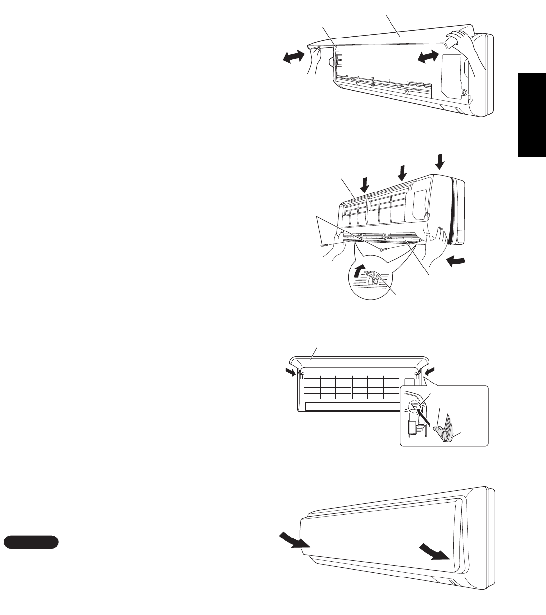
11
English
3-4-4. Indoor unit types
(SAP-KMRV76EH, KMRV96EH, KMRV126EH)
Basically, these models can be installed and wired
without removing the grille. If access to any internal
part is needed, follow the steps as given below.
How to remove the grille
(1) Open the front panel until it is nearly horizontal,
grasp the sections near the front panel arms on
both sides, and then pull towards you to remove
the front panel. (Fig. 16-3)
(2) Remove the 2 screws where the screw covers are
open. Grasp the grille on both bottom sides, and
pull it towards you slightly. (Fig. 17-3)
(3) Press the 3 tabs on the top of the grille to disen-
gage them. (Fig. 17-3)
(4) Pull the grille towards you to remove it. (Fig. 17-3)
How to replace the grille
(1) Insert the bottom of the grille into the frame.
(2) While aligning both edges of the grille with the
frame, move the grille
horizontally and insert the top and bottom into the
frame.
(3) Press the grille firmly with your hand to ensure no
gap exists between
the frame and grille.
(4) Tighten the 2 screws and close the screw covers.
(5) Grasp the sections near the front panel arms on
both sides, hold the front panel so that it is nearly
horizontal, bring the arm shafts into contact with
the top of the grooves on the right and left sides of
the air conditioner,
and then push firmly until the arm shafts click into
place. (Fig. 18-3)
(6) Press the bottom right and left corners of the front
panel to attach it to the indoor unit. (Fig. 19-3)
Check that no gap exists between the frame and the
grille.
NOTE
Fig. 16-3
Fig. 17-3
Arm
Front panel
Screw
Screw cover
Flap
Grille
Fig. 18-3
Fig. 19-3
Front panel
Arm
Pin
Groove
08-261 CMRV3146EH_IU EN 10/14/08 6:23 PM Page 11
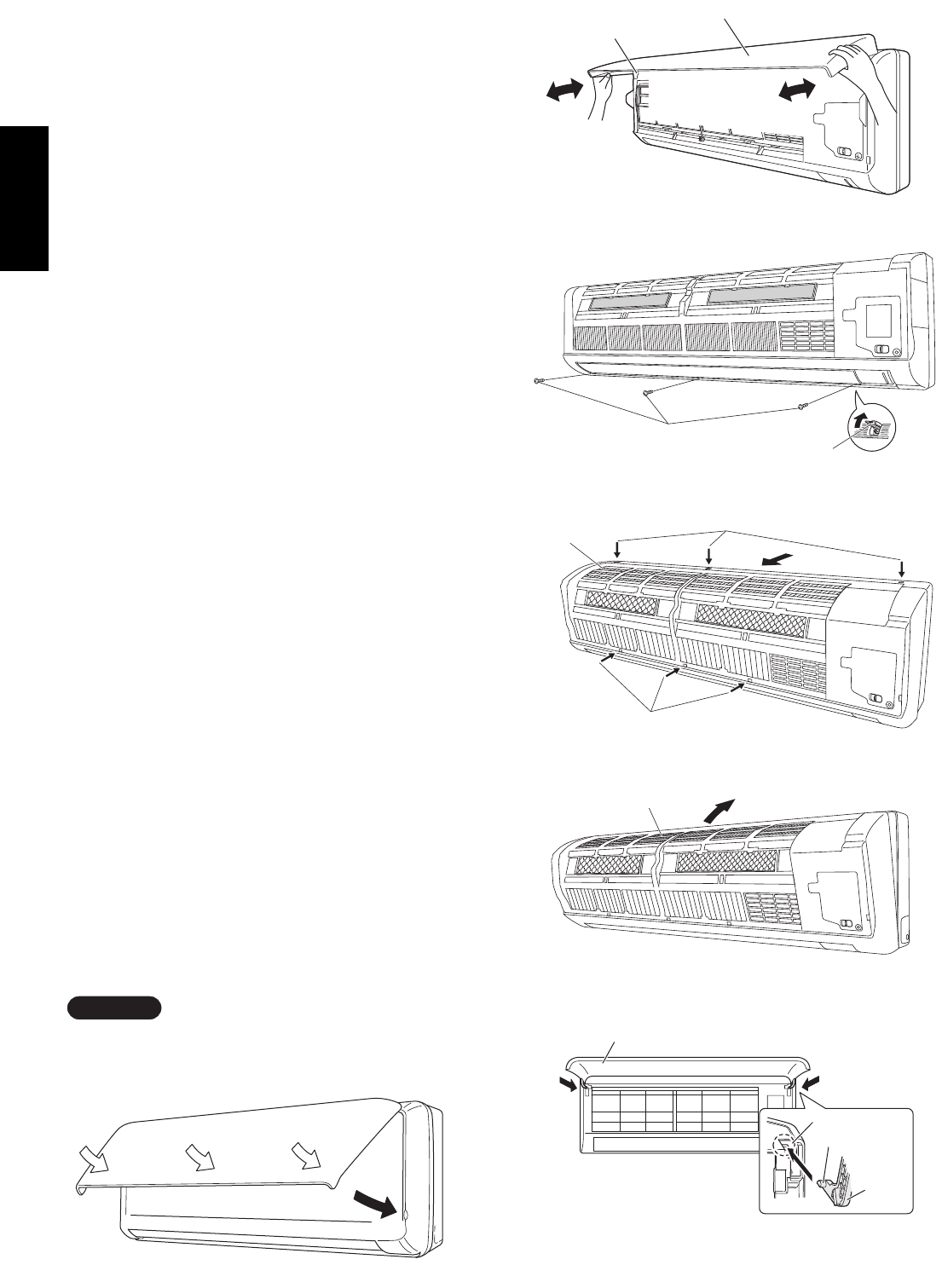
12
English
3-4-5. Indoor unit types
(SAP-KRV186EH, KRV246EH)
Basically, these models can be installed and wired
without removing the grille. If access to any internal
part is needed, follow the steps as given below.
How to remove the grille
(1) Open the front panel until it is nearly horizontal,
grasp the sections near the front panel arms on
both sides, and then pull towards you to remove
the front panel. (Fig. 16-4)
(2) Remove the 3 screws where the screw covers are
open. (Fig. 17-4)
(3) Press the 3 tabs at the top of the grille and the 3
tabs on the front face to separate the grille from
the frame. (Fig. 18a-4)
(4) Pull the grille towards you to remove it.
(Fig. 18a-4)
How to replace the grille
(1) When installing the grille, place the bottom of the
grille into the frame first. (Fig. 18b-4) Then insert
the tabs on the top of the grille and on the front
face into the frame.
(2) Make sure that the grille and frame are firmly fitted
together by engaging the tabs.
(3) Press the grille firmly with your hand to ensure no
gap exists between the frame and grille.
(4) Tighten the 3 screws and close the screw covers.
(5) Grasp the sections near the front panel arms on
both sides, hold the front panel so that it is nearly
horizontal, bring the arm shafts into contact with
the top of the grooves on the right and left sides of
the air conditioner,
and then push firmly until the arm shafts click into
place. (Fig. 18c-4)
(6) After closing the front panel, press firmly on the
parts indicated
by the arrows to securely fasten the panel in place.
(Fig. 19-4)
Check that no gap exists between the frame and the
grille.
NOTE
Fig. 16-4
Fig. 17-4
Arm
Front panel
Screw
Screw cover
Fig. 18c-4
Fig. 19-4
Front panel
Arm
Pin
Groove
Fig. 18a-4
Tab
Grille
Tab
Fig. 18b-4
Grille
08-261 CMRV3146EH_IU EN 10/14/08 6:23 PM Page 12

13
English
3-5. Shape the Indoor Side Tubing
(1) Arrangement of tubing by directions
a) Right or left tubing
Cut out the corner of the right/left frame with a
hacksaw or the like. (Figs. 20 and 21)
b) Right-rear or left-rear tubing
In this case, the corner of the frame need not
be cut.
(2) To mount the indoor unit on the rear panel:
Hang the 2 mounting slots of the unit on the
upper tabs of the rear panel. (Fig. 22)
3-6. Wiring Instructions
General precautions on wiring
(1) Before wiring, confirm the rated voltage of the unit
as shown on its nameplate, then carry out the
wiring closely following the wiring diagram.
(2) Provide a power outlet to be used exclusively for
each unit, with a power supply disconnect and cir-
cuit breaker for overcurrent protection provided in
the exclusive line.
(3) To prevent possible hazard due to insulation fail-
ure, the unit must be grounded.
(4) Each wiring connection must be done tightly and
in accordance with the wiring system diagram.
Wrong wiring may cause the unit to misoperate or
become damaged.
(5) Do not allow wiring to touch the refrigerant tubing,
compressor, or any moving parts of the fan.
(6) Unauthorized changes in the internal wiring can
be very dangerous. The manufacturer will accept
no responsibility for any damage or misoperation
that occurs as a result of such unauthorized
changes.
Frame
Right tubing
outlet
Frame
Left tubing
outlet
Fig. 21
Fig. 22
Fig. 20
08-261 CMRV3146EH_IU EN 10/14/08 6:23 PM Page 13

English
3-7. Wiring Instructions for Inter-unit Connections
25 cm
Wiring
Rear
panel
Plastic
cover
Fig. 25
Cover
Fig. 26a
Fig. 27
(SAP-KMRV74, KMRV94, KMRV124)
(SAP-KRV184, KRV244)
Fig. 24b
(SAP-KRV96, KRV126)
Fig. 24a
Fig. 26b
(SAP-KRV96, KRV126)
(1) Grasp both ends of the air intake grille, and
remove it by opening towards the front and
pulling towards you.
(2) Remove the screw on the right side cover
plate and open the cover.
(Fig. 24a, 24b, 24c or 24d)
(3) Insert the inter-unit wiring into the through-
the-wall PVC pipe. Lead the power wiring
into the room allowing approx. 25 cm to
extend from the wall face. (Fig. 25)
(4) Route the inter-unit wiring from the back of
the indoor unit and pull it towards the front
for connection. (Fig. 26a, 26b, 26c or 26d)
(5) Connect the inter unit wiring to the corre-
sponding terminals on the terminal plate
(Fig. 26a, 26b, 26c or 26d) while referring
to the wiring diagram.
(6) Be sure to secure the wiring with the pro-
vided clamp.
When closing the air intake grille, press the bot-
tom right and left corners and center. (Fig. 27)
Please refer to “How to replace the grille” on
page 8, 9, 10, 11 or 12 for installing the air
intake grille.
NOTE
Cover
Fig. 26c Fig. 26d
(SAP-KMRV76, KMRV96,
KMRV126) (SAP-KRV186, KRV246)
Cover
(SAP-KMRV76, KMRV96, KMRV126) (SAP-KRV186, KRV246)
Cover
Fig. 24c Fig. 24d
(SAP-KMRV74, KMRV94, KMRV124)
(SAP-KRV184, KRV244)
14
08-261 CMRV3146EH_IU EN 10/14/08 6:23 PM Page 14

15
English
When connecting each power wire to the correspond-
ing terminal, follow the instructions “How to connect
wiring to the terminal” and fasten the wire securely
tight with the fixing screw of the terminal plate.
How to connect wiring to the terminal
a) For Indoor Unit
(1) Cut the wire end with a cutting pliers, then strip
the insulation to expose the wire about 7 mm. See
the label (Fig. 28) near the terminal plate.
(2) Using a screwdriver, loosen the terminal screw on
the terminal plate.
(3) Insert the wire and tighten the terminal screw
completely using a screwdriver.
b) For Outdoor Unit
IFor solid core wiring (or F-cable)
(1) Cut the wire end with a cutting pliers, then strip
the insulation to expose the solid wire about 25
mm. (Fig. 29)
(2) Using a screwdriver, remove the terminal screw(s)
on the terminal plate.
(3) Using the pliers, bend the solid wire to form a loop
suitable for the terminal screw.
(4) Shape the loop wire properly, place it on the ter-
minal plate and fix it securely with the removed
terminal screw using a screwdriver.
IFor stranded wiring
(1) Cut the wire end with a cutting pliers, then strip
the insulation to expose the stranded wiring about
10 mm and tightly twist the wire ends. (Figs. 30
and 31)
(2) Using a screwdriver, remove the terminal screw(s)
on the terminal plate.
(3) Using a ring connector fastener or pliers, securely
clamp each stripped wire end with a ring connec-
tor. (Fig. 30)
(4) Place the ring connector wire, and replace and
tighten the removed terminal screw using a screw-
driver. (Fig. 32)
Solid wire
Loop
Insulation
Strip 25 mm
Fig. 29
STRIP
SIZE
7 mm (ACTUAL
SIZE)
Fig. 28
Stranded wire
Ring
connector
Strip 10 mm
Fig. 30
Screw
Ring connector
Te r mi nal plate
Wire
Special
washer
Fig. 32
Screw and
special washer
Ring
connector
Wire
WARNING
Loose wiring may cause the
terminal to overheat or result
in unit malfunction. A fire
hazard may also exist. There-
fore, be sure all wiring is
tightly connected.
Twist wire ends
Fig. 31
08-261 CMRV3146EH_IU EN 10/14/08 6:23 PM Page 15
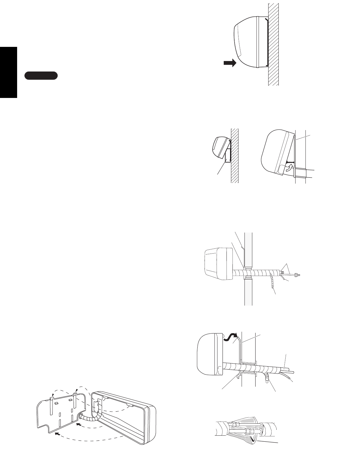
16
English
3-8. Mounting
(1) To install the indoor unit, mount the indoor unit
onto the 2 tabs on the upper part of the rear plate.
(2) Hold down the air discharge outlet and press the
lower part of the indoor unit until it clicks to
securely fasten to the 2 tabs on the lower part of
the rear plate. (Fig. 33)
For tubing, choose either the right or left tubing direc-
tion and follow the steps below. This work can be made
easier by placing padding material (such as styrofoam)
at the rear right side of the indoor unit. (Fig. 34a)
Or extend the support on the back of the indoor unit as
a stand to make your work easier. (Fig. 34b)
IRight-side tubing
(1) Shape the refrigerant tubing so that it can easily
go into the wall hole. (Fig. 35a or 35b)
(2) Push the wiring, refrigerant tubing, and drain hose
through the hole in the wall. Adjust the indoor unit
so it is securely seated on the rear panel. (Fig. 36)
(3) Carefully bend the tubing (if necessary) to run
along the wall in the direction of the outdoor unit
and then tape as far as the fittings. (See Caution
on page 10 or 15 in the outdoor unit installation
manual.) The drain hose should come straight
down the wall to a point where water runoff won’t
stain the wall.
(4) Connect the refrigerant tubing to the outdoor unit.
(After performing a leak test on the connecting
part, insulate it with the tubing insulation. (Fig. 37))
Also, refer to Section 3-6. Tubing connections in
the outdoor unit installation manual.
(5) Assemble the refrigerant tubing, drain hose, and
inter-unit wiring as shown in Fig. 37.
NOTE
Cover
Refrigerant
tubing
Rear panel
Drain hose
Inter-unit
wiring
Fig. 35a
Fig. 36
Fig. 33
Push
Insulation
Padding material
Fig. 34a
Rear panel
(SAP-KRV96, KRV126)
(SAP-KMRV74, KMRV94, KMRV124)
(SAP-KMRV76, KMRV96, KMRV126)
(SAP-KRV184, KRV244)
(SAP-KRV186, KRV246)
Fig. 34b
Fig. 37
Wall cap
Tab
Rear panel
Refrigerant
tubing
Inter-unit
wiring
Drain hose
Fig. 35b
(SAP-KMRV74, KMRV94, KMRV124)
(SAP-KMRV76, KMRV96, KMRV126)
(SAP-KRV184, KRV244)
(SAP-KRV186, KRV246)
(SAP-KRV96, KRV126)
08-261 CMRV3146EH_IU EN 10/14/08 6:23 PM Page 16
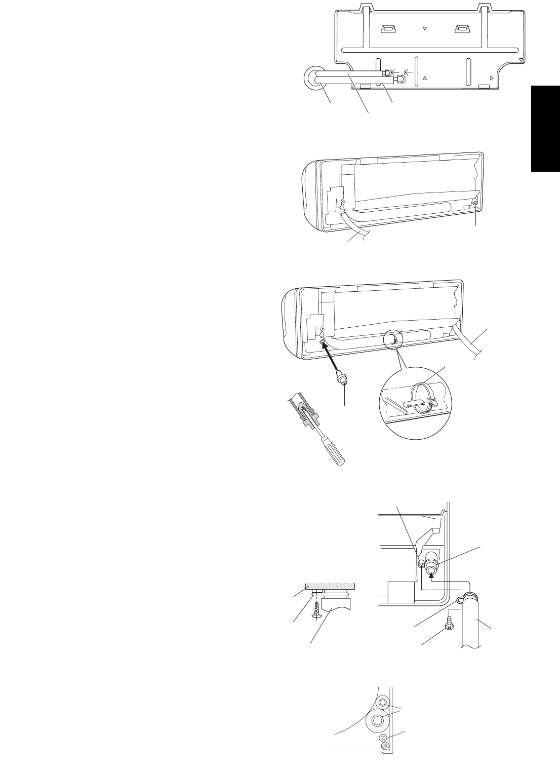
17
English
Hole in wall
Bent part
Narrow tube
Wide tube
Rear panel
Fig. 38a
Drain cap
Drain hose
Fig. 39a
ILeft-side tubing
(SAP-KMRV74EH, KMRV94EH, KMRV124EH,
KMRV76EH, KMRV96EH, KMRV126EH,
KRV184EH, KRV244EH, KRV186EH, KRV246EH)
(1) Lead the tubing and drain hose through the wall,
allowing sufficient length for connection. Then
bend the tubing using a tube bender to make the
attachment. (Fig. 38a)
(2) Switch the drain hose and drain cap.
Switching drain hose and drain cap
(a) Locate the drain hose and the drain cap.
(Fig. 39a)
(b) Remove the screws fastening the drain hose
on the right side, and pull out the drain hose
to remove it. (Fig. 39a)
(c) Apply moderate force to pull off the drain cap
on the left side. (If you cannot pull it off by
hand, use a long-nose pliers.)
(d) Reattach the drain hose to the left side and
the drain cap to the right side. (Fig. 40a)
Drain hose
Slide the drain hose fully onto the drain pan outlet
until the drain hose edge is pushed into the insu-
lation. Check that the screw holes in the drain
bracket and the drain pan outlet are aligned and
securely in contact, then fasten them with the
screw. (After attaching the drain hose, check that
it is attached securely.) (Fig. 40c)
Drain cap
Use a Phillips screwdriver to push the drain cap in
firmly. (If it is difficult to push in, wet the cap with
water first.)
(3) Install the indoor unit on the rear panel.
(4) Connect the tubing and wiring led inside from out-
doors.
(5) After completing a leak test, bundle the tubing
together with armoring tape and store it inside the
tubing storage area at the back of the indoor unit
and hold it with clamps. (Figs. 40a and 41a)
Fig. 40a
Fig. 40b
Fig. 40c
Fig. 41a
Refrigerant tubing
Inter-unit wiring
Screw
Drain hose
Drain pan outlet
Screw hole
Drain bracket
Drain cap
Clamp
Drain hose
Drain hose
Drain bracket
Insulation
08-261 CMRV3146EH_IU EN 10/14/08 6:23 PM Page 17

English
ILeft-side tubing
(SAP-KRV96EHDS, KRV126EHDS)
(1) Lead the tubing and drain hose through the wall,
allowing sufficient length for connection. Then
bend the tubing using a tube bender to make the
attachment. (Fig. 38b)
(2) Switch the drain hose and drain cap.
Switching drain hose and drain cap
(a) Grasp the corners of the bottom left and right
indoor unit covers, and press down on the
bottom while lifting each cover up to remove
it. (Fig. 39b)
(b) Locate the drain hose and the drain cap.
(Fig. 39c)
(c) When disconnecting the drain hose, remove
the drain fitting from the stopper, then check
the position of the drain fitting on the end of
the hose, and turn the hose while pulling to
remove it. (Fig. 39d)
(d) Screw the drain hose all the way inside. Turn
the hose so that the protruding part of the
drain fitting comes below the stopper as
shown in the figure. It will be easy to insert
when water is added. (Fig. 39d)
(e) Align the tabs of the removed cover with the
grille tabs, and then lower the cover to install
it.
Drain cap
Use a Phillips screwdriver to push the drain cap in
firmly. (If it is difficult to push in, wet the cap with
water first.)
(3) Install the indoor unit on the rear panel.
(4) Connect the tubing and wiring led inside from out-
doors.
(5) After completing a leak test, bundle the tubing
together with armoring tape and store it inside the
tubing storage area at the back of the indoor unit
and hold it with clamps. (Figs. 40d and 41b)
Fig. 38b
Bottom left cover
Fig. 39b
Fig. 39d
Fig. 41b
Refrigerant tubing
Inter-unit wiring
Drain cap
Drain cap
Clamp
Drain hose
Hole in wall
Rear panel
Bent part
Wide tube
Narrow tube
Fig. 40d
Stopper Drain fitting
Drain hose
Stopper Drain hose
Drain fitting
Drain cap
Drain hose
Fig. 39c
18
08-261 CMRV3146EH_IU EN 10/14/08 6:23 PM Page 18

19
English
To unmount indoor unit
Press the 2 LLmarks on the lower part of the indoor
unit and unlatch the tabs. Then lift the indoor unit and
unmount. (Fig. 42)
3-9. Drain Hose
a) The drain hose should be slanted downward to
the outdoors. (Fig. 43)
b) Never form a trap in the course of the hose.
c) If the drain hose will run in the room, insulate the
hose with insulation* so that chilled condensation
will not damage furniture or floors. (Fig. 44)
* Foamed polyethylene or its equivalent is recom-
mended.
WARNING
Risk of Electric Shock
Do not supply power to the
unit or operate it until all
tubing and wiring to the
outside unit are completed.
Condensation
Insulation material
(Locally purchased)
must be used.
Fig. 44
Push
Fig. 42
Slant
Drain
hose
Indoor
unit
Fig. 43
4. Multiple Switch on the Remote Control Unit
Indoor Unit Types
(SAP-KRV184EH, KRV244EH)
(SAP-KRV186EH, KRV246EH)
(SAP-KRV96EHDS, KRV126EHDS)
S/M (Single/Multiple switch)
GSlide the cover in the direction indicated by
the arrow and remove it.
GInitially, the S/M switch is set to S (Single).
GSet this switch to M (Multiple) for multiple
operation.
GAlways press ACL button by a thin object
such as the tip of a pen after setting the S/M
switch.
ACL button
08-261 CMRV3146EH_IU EN 10/14/08 6:23 PM Page 19

20
English
5. How to Test Run the Air Conditioner
IFor indoor unit types
(SAP-KMRV74EH, KMRV94EH, KMRV124EH,
KRV184EH, KRV244EH)
After turning on the power of the air conditioner, use
the remote controller and follow the steps below to
conduct the test run.
(1) Set the remote controller in Test Run mode.
(Fig. 59a)
a)Press and hold the ION button and the 1HR.
TIMER button.
b)Then press and hold the ACL (Reset) button
with a pointed object such as the tip of a pen.
After 5 seconds, release the ACL button first.
c)Then release the ION and 1HR. TIMER buttons.
d) appears and “oP-1” blinking in the remote
controller clock display area. (Fig. 59b)
(2) Start Cooling mode test run by pressing the
ON/OFF operation button of the remote controller.
(Fig. 59a)
• This starts the fan producing uncooled forced air
with the 4 indicator lamps (OPERATION lamp,
TIMER lamp, QUIET lamp, and ION lamp) on
the main unit blinking. (Fig. 60)
• After 3 minutes, the system shifts into cooling
operation, and cool air will start to be felt. Cool-
ing mode test run is unaffected by the room tem-
perature.
(3) Press the ON/OFF operation button of the remote
controller again to stop the test run. (Fig. 59a)
(4) Finally press the ACL (Reset) button of the remote
controller to release it from Test Run mode to
return to normal mode. (Fig. 59a)
• “ ” and “oP-1” will disappear from the remote
controller clock display area.
After the test run is completed, be sure to press
the ACL (Reset) button to return to normal mode.
The air conditioner will not operate correctly if
this is not done.
IMPORTANT
Fig. 59a
Fig. 59b
Fig. 60
1HR.
TIMER
ON/OFF
operation
ACL
(Reset)
ION
button
button
button
button
OPERATION lamp
ION lamp
TIMER lamp
QUIET lamp
OPERATION
OPERATION
TIMER
QUIET
ION
08-261 CMRV3146EH_IU EN 10/14/08 6:23 PM Page 20
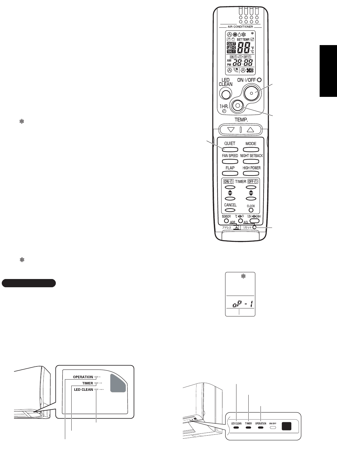
English
1HR.
TIMER
ON/OFF
operation
ACL
(Reset)
QUIET
button
button
button
button
LED CLEAN lamp
TIMER lamp
OPERATION lamp
Fig. 59a-1
Fig. 59b-1
Fig. 59c-1
LED CLEAN lamp
TIMER lamp
OPERATION lamp
Fig. 59c-2
(SAP-KMRV76, KMRV96, KMRV126)
(SAP-KRV186, KRV246)
(SAP-KRV96, KRV126)
21
IFor indoor unit type
(SAP-KMRV76EH, KMRV96EH, KMRV126EH)
(SAP-KRV96EHDS, KRV126EHDS)
(SAP-KRV186EH, KRV246EH)
After turning on the power of the air conditioner, use the remote
controller and follow the steps below to conduct the test run.
(1) Set the remote controller in Test Run mode. (Fig. 59a-1)
a)Press and hold the QUIET button and the 1HR. TIMER button.
b)Then press and hold the ACL (Reset) button with a pointed
object such as the tip of a pen. After 5 seconds, release the
ACL button first.
c)Then release the QUIET and 1HR. TIMER buttons.
d) appears and “oP-1” blinking in the remote controller clock
display area. (Fig. 59b-1)
(2) Start Cooling mode test run by pressing the ON/OFF operation
button of the remote controller. (Fig. 59a-1)
• This starts the fan producing uncooled forced air with the 3 indi-
cator lamps (OPERATION lamp, TIMER lamp, and LED CLEAN
lamp) on the main unit blinking. (Fig. 59c-1 or 59c-2)
• After 3 minutes, the system shifts into cooling operation, and
cool air will start to be felt. Cooling mode test run is unaffected
by the room temperature.
(3) Press the ON/OFF operation button of the remote controller again
to stop the test run. (Fig. 59a-1)
(4) Finally press the ACL (Reset) button of the remote controller to
release it from Test Run mode to return to normal mode.
(Fig. 59a-1)
• “ ” and “oP-1” will disappear from the remote controller clock
display area.
After the test run is completed, be sure to press the ACL (Reset)
button to return to normal mode. The air conditioner will not operate
correctly if this is not done.
IMPORTANT
08-261 CMRV3146EH_IU EN 10/14/08 6:23 PM Page 21

22
English
6. Remote Control Unit Installation Position
The remote control unit can be operated from either a
non-fixed position or a wall-mounted position.
To ensure that the air conditioner operates correctly,
do not install the remote control unit in the following
places:
GIn direct sunlight
GBehind a curtain or other place where it is covered
GMore than 8 m away from the air conditioner
GIn the path of the air conditioner’s airstream
GWhere it may become extremely hot or cold
GWhere it may be subject to electrical or magnetic
interference
GWhere there is an obstacle between the remote
control unit and the air conditioner (since a check
signal is sent from the remote control unit every 5
minutes)
6-1. Mounting on a Wall
Before mounting the remote control unit, press the
ON/OFF operation button at the mounting location to
make sure that the air conditioner operates from that
location. The indoor unit should make a beeping
sound to indicate that it has received the signal.
Press
Set in
place
Remote control
unit mount
Mounting screws
4 16 (included)
Rear side
Hole
Fig. 61
To take out the remote control unit, pull it forward.
To prevent loss of the remote control
unit, you can connect the remote
control unit to the mount by passing
a string through the remote control
unit and attachment hole.
08-261 CMRV3146EH_IU EN 10/14/08 6:23 PM Page 22

English
(4) Each time the 1HR. TIMER button is pressed,
the display changes as shown below.
Press this button 2 times to change the
display to “oP-7” (Address setting).
(Fig. 64a or 64b)
(5) “oP-7” has now been selected for address
setting.
(6) Press the ON/OFF operation button on the
remote controller. (Fig. 64a or 64b) Check
that the “beep”signal-received sound is heard
from the second indoor unit (approximately
5 times). The sound you hear is the signal
that the remote controller address has been
changed.
(7) Finally press the remote controller ACL (Reset)
button to cancel the blinking “oP-7” display.
(Fig. 64a or 64b)
Changing of the second remote controller address
is now completed.
Selfdiagnostic mode
Test run mode
Address setting mode
Fig. 62
Fig. 63
Tab
ACL button
ION
button
ADDRESS ACL (Reset)
button
ON/OFF
operation
button
1HR.TIMER
button
7. Address Switch
7-1. Address Setting of the Remote Control Unit
The address can be set in order to prevent interference between remote con-
trollers when 2 indoor units are installed near each other. The address is nor-
mally set to “A.” To set a different address, it is necessary to change the
address on the second remote controller.
Once changed, you cannot restore the original address setting of the air con-
ditioner.
(1) Switch on the power source.
(2) Break the address-setting tab marked “A” on the second remote controller
to change the address (Fig. 62). When the tab is removed, the address is
automatically set to B (Fig. 63).
(3) (SAP-KMRV74EH, KMRV94EH, KMRV124EH, KRV184EH, KRV244EH)
Press and hold the remote controller ION button and 1HR. TIMER button.
Then, press and hold the ACL (Reset) button with a pointed object such
as the tip of a pen. After 5 seconds, release the ACL button first, then
release the ION and 1HR. TIMER buttons. “oP-1” (Test Run) appears,
blinking in the remote controller clock display area.
NOTE
Fig. 64a
1HR.
TIMER
button
ON/OFF
operation
button
ACL
(Reset)
button
QUIET
button
Fig. 64b
(SAP-KMRV74, KMRV94, KMRV124,
KRV184, KRV244)
(SAP-KMRV76, KMRV96,
KMRV126, KRV96,
KRV126, KRV186, KRV246)
23
(SAP-KMRV76EH, KMRV96EH, KMRV126EH, KRV96EHDS, KRV126EHDS, KRV186EH, KRV246EH)
Press and hold the remote controller QUIET button and 1HR. TIMER button. Then, press and hold the ACL (Reset)
button with a pointed object such as the tip of a pen. After 5 seconds, release the ACL button first, then release the
QUIET and 1HR. TIMER buttons. “oP-1” (Test Run) appears, blinking in the remote controller clock display area.
08-261 CMRV3146EH_IU EN 10/14/08 6:23 PM Page 23

8. Connecting a Home Automation Device
The HA (white) 4P terminal is located on the indoor unit PCB. If a HA device will be used,
connect it to this terminal.
Also, refer to Section 9. Electric Wiring Diagram in the outdoor unit installation manual.
9. Installation Check Sheet
The strength of the installation location is sufficient to support the Air Conditioner weight.
The indoor and outdoor units are installed level and vertically.
The power and voltage are as specified.
Inter-unit cables are securely inserted into the terminal block.
Inter-unit cables are securely fixed.
The power cord and inter-unit cables are not connected anywhere along their paths.
The ground wire is securely connected.
Thermal insulation has been applied to the tubing connections.
Drain connections are secure and water drains properly.
Putty has been used to close the hole in the wall.
Remote controller signals are being positively received.
English
24
08-261 CMRV3146EH_IU EN 10/14/08 6:23 PM Page 24

INSTALLATION INSTRUCTIONS
SAP-KMRV76EH
SAP-KMRV96EH
SAP-KMRV126EH
SAP-KRV186EH
SAP-KRV246EH
(II-852-6-4190-479-00-1)
APPENDIX D
(When combined with SAP-CMRV3656EH)
A-4
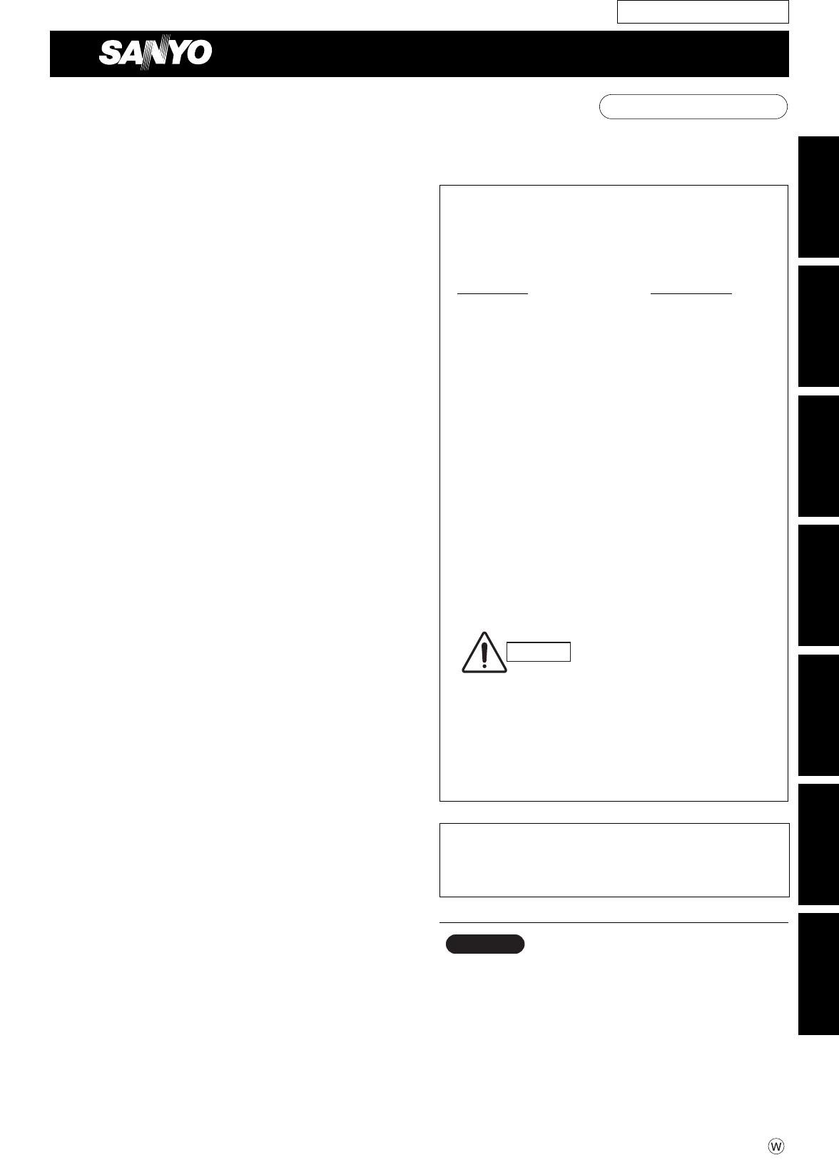
Model Combinations
Combine indoor and outdoor units only as listed
below.
Indoor Unit Outdoor Unit
Power Source:
50 Hz, single-phase, 220 – 240 VAC
Be sure to connect indoor and outdoor units
only in combinations that are listed in the
combination table(s) included in the outdoor
unit package.
Connecting any other model may result in
operation failure and malfunction.
CAUTION
Español Français Deutsch Italiano Português EEÏÏÏÏËËÓÓÈÈÎο¿
English
85264190479001 © SANYO 2009 SANYO Electric Co., Ltd.
Osaka, Japan
Contents
Page
IMPORTANT!
Please Read Before Starting .................................. 2
1. GENERAL .......................................................... 3
1-1. Tools Required for Installation (not supplied)
1-2. Accessories Supplied with Unit
1-3. Optional Copper Tubing Kit
1-4. Type of Copper Tube and Insulation Material
1-5. Additional Materials Required for Installation
2. INSTALLATION SITE SELECTION ................... 4
2-1. Indoor Unit
2-2. Embedding the Tubing and Wiring
3. HOW TO INSTALL THE INDOOR UNIT ............ 6
3-1. Remove the Rear Panel from the Unit
3-2. Make a Hole
3-3. Install the Rear Panel on the Wall
3-4. Removing and Installing the Grille
3-5. Shape the Indoor Side Tubing
3-6. Wiring Instructions
3-7. Wiring Instructions for Inter-unit Connections
3-8. Mounting
3-9. Drain Hose
4. MULTIPLE SWITCH ON THE REMOTE
CONTROL UNIT INDOOR UNIT TYPES
(SAP-KRV184EH, KRV244EH)
(SAP-KRV186EH, KRV246EH)
(SAP-KRV96EHDS, KRV126EHDS)................. 19
5. HOW TO TEST RUN THE AIR CONDITIONER... 20
6. REMOTE CONTROL UNIT INSTALLATION
POSITION ......................................................... 22
6-1. Mounting on a Wall
7. ADDRESS SWITCH .......................................... 23
7-1. Address Setting of the Remote
Control Unit
8. CONNECTING A HOME AUTOMATION
DEVICE.............................................................. 24
9. INSTALLATION CHECK SHEET ...................... 24
INSTALLATION INSTRUCTIONS
– Inverter Split System Air Conditioner – COOL/DRY/HEAT Model
This air conditioner uses the new refrigerant R410A.
Be sure to read the yellow instruction sheet
attached to the outdoor unit for models using the
new refrigerant R410A.
The illustrations are based on the typical appearance
of a standard model. Consequently, the shape may
differ from that of the air conditioner that you are
installing.
NOTE
For Indoor Unit
SAP-KMRV74EH
SAP-KMRV94EH
SAP-KMRV124EH
SAP-KMRV76EH
SAP-KMRV96EH
SAP-KMRV126EH
SAP-KRV96EHDS
SAP-KRV126EHDS
SAP-KRV184EH
SAP-KRV244EH
SAP-KRV186EH
SAP-KRV246EH
SAP-CMRV3656EH
08-324 CMRV3656EH_IU EN 6/15/09 5:27 PM Page a
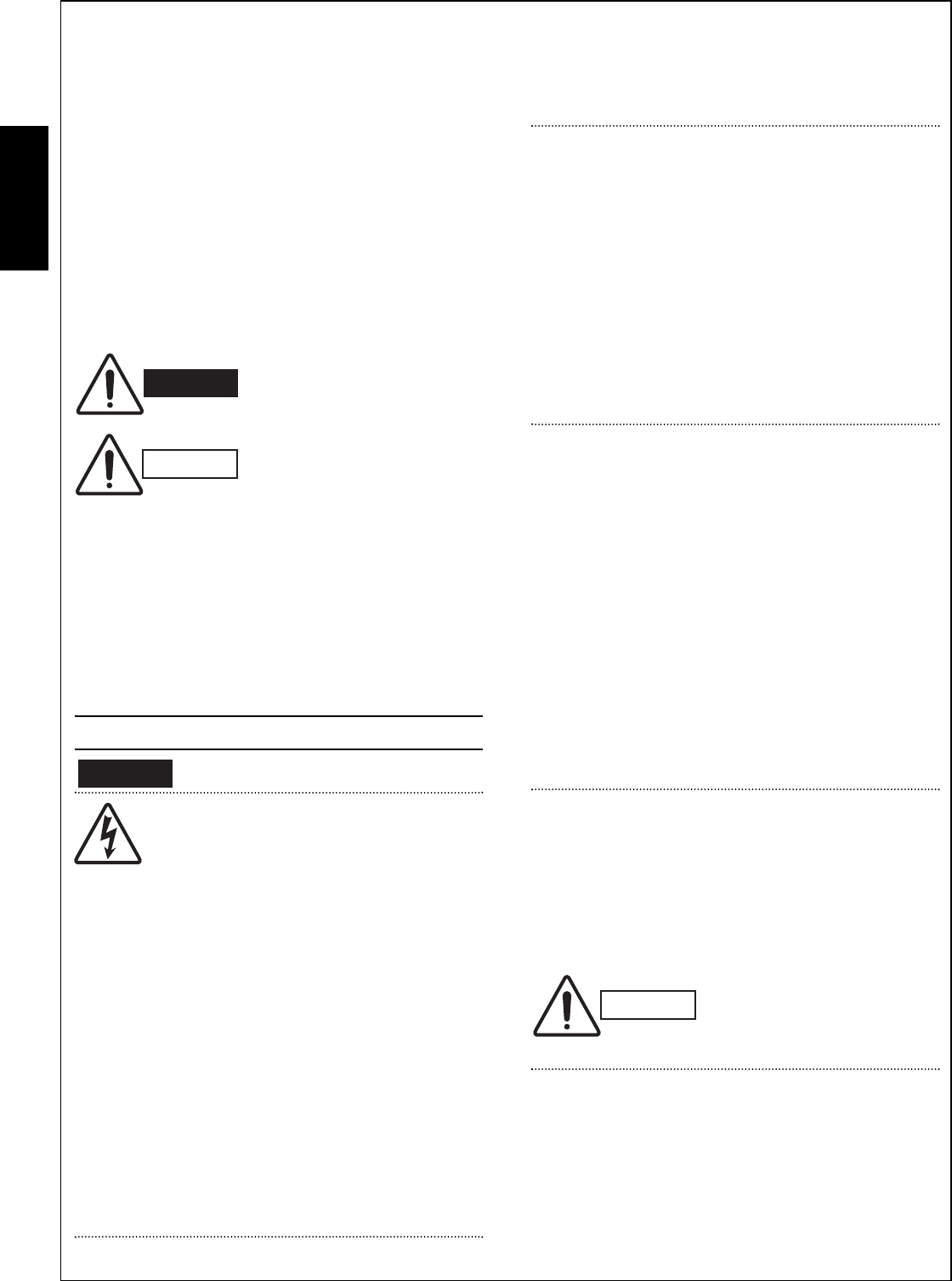
2
English
IMPORTANT!
Please Read Before Starting
This air conditioning system meets strict safety and oper-
ating standards. As the installer or service person, it is an
important part of your job to install or service the system
so it operates safely and efficiently.
For safe installation and trouble-free operation, you
must:
GCarefully read this instruction booklet before beginning.
GFollow each installation or repair step exactly as
shown.
GObserve all local, state, and national electrical codes.
GPay close attention to all warning and caution notices
given in this manual.
This symbol refers to a hazard
or unsafe practice which can
result in severe personal injury
or death.
This symbol refers to a hazard
or unsafe practice which can
result in personal injury or
product or property damage.
If Necessary, Get Help
These instructions are all you need for most installation
sites and maintenance conditions. If you require help for
a special problem, contact our sales/service outlet or
your certified dealer for additional instructions.
In Case of Improper Installation
The manufacturer shall in no way be responsible for
improper installation or maintenance service, including
failure to follow the instructions in this document.
SPECIAL PRECAUTIONS
When Wiring
ELECTRICAL SHOCK CAN CAUSE
SEVERE PERSONAL INJURY OR DEATH.
ONLY A QUALIFIED, EXPERIENCED
ELECTRICIAN SHOULD ATTEMPT TO
WIRE THIS SYSTEM.
• Do not supply power to the unit until all wiring and tub-
ing are completed or reconnected and checked.
• Highly dangerous electrical voltages are used in this
system. Carefully refer to the wiring diagram and these
instructions when wiring. Improper connections and
inadequate grounding can cause accidental injury or
death.
• Ground the unit following local electrical codes.
• Connect all wiring tightly. Loose wiring may cause
overheating at connection points and a possible fire
hazard.
• Install a protective leakage breaker/fuse link depend-
ing on the installation location (especially a damp or
humid location). If a leakage breaker/fuse link is not
installed, electric shock can occur.
When Transporting
Be careful when picking up and moving the indoor and
outdoor units. Get a partner to help, and bend your knees
when lifting to reduce strain on your back. Sharp edges or
thin aluminum fins on the air conditioner can cut your fin-
gers.
When Installing…
…In a Ceiling or Wall
Make sure the ceiling/wall is strong enough to hold the
unit’s weight. It may be necessary to construct a strong
wood or metal frame to provide added support.
…In a Room
Properly insulate any tubing run inside a room to prevent
“sweating” that can cause dripping and water damage to
walls and floors.
…In Moist or Uneven Locations
Use a raised concrete pad or concrete blocks to provide
a solid, level foundation for the outdoor unit. This pre-
vents water damage and abnormal vibration.
When Connecting Refrigerant Tubing
• Do not add any refrigerant, air, or substance into the
refrigeration circuit other than the designated refriger-
ant (R410A). Adding anything other than the specified
refrigerant may cause the pressure to rise excessively
in the refrigeration circuit, rupturing the circuit and
causing injury or damage.
• Use all-new tubing and flare nuts to make the tubing
connections. Using any previous parts (from R22-
based systems) may result in damage to the equip-
ment, and may lead to the refrigeration circuit ruptur-
ing, causing a serious accident.
• Apply refrigerant lubricant to the matching surfaces of
the flare and union tubes before connecting them, then
tighten the nut with a torque wrench for a leak-free
connection.
• Check carefully for leaks before starting the test run.
When Servicing
• Turn the power OFF at the main power box (mains)
before opening the unit to check or repair electrical
parts and wiring.
• Keep your fingers and clothing away from any moving
parts.
• Clean up the site after you finish, remembering to
check that no metal scraps or bits of wiring have been
left inside the unit being serviced.
Others
• Ventilate any enclosed areas when installing or testing
the refrigeration system. Escaped refrigerant gas, on
contact with fire or heat, can produce dangerously
toxic gas.
• Confirm upon completing installation that no refrigerant
gas is leaking. If escaped gas comes in contact with a
stove, gas water heater, electric room heater or other
heat source, it can produce dangerously toxic gas.
WARNING
WARNING
CAUTION
CAUTION
08-324 CMRV3656EH_IU EN 6/15/09 5:27 PM Page 2

3
English
1. General
This booklet briefly outlines where and how to install
the air conditioning system. Please read over the
entire set of instructions for the indoor and outdoor
units and make sure all accessory parts listed are with
the system before beginning.
1-1. Tools Required for Installation (not supplied)
1. Standard screwdriver
2. Phillips head screwdriver
3. Knife or wire stripper
4. Tape measure
5. Carpenter’s level
6. Sabre saw or key hole saw
7. Hacksaw
8. Core bits
9. Hammer
10. Drill
11. Tube cutter
12. Tube flaring tool
13. Torque wrench
14. Adjustable wrench
15. Reamer (for deburring)
1-2. Accessories Supplied with Unit
Table 1
1-3. Optional Copper Tubing Kit
Copper tubing for connecting the outdoor unit to the
indoor unit is available in kits which contain the narrow
and wide tubing, fittings and insulation. Consult your
nearest sales outlet or air conditioning workshop.
1-4. Type of Copper Tube and Insulation Material
If you wish to purchase these materials separately
from a local source, you will need:
1. Deoxidized annealed copper tube for refrigerant
tubing as detailed in Table 2.
Cut each tube to the appropriate lengths +30 cm
to 40 cm to dampen vibration between units.
Table 2
2. Foamed polyethylene insulation for the specified
copper tubes as required to precise length of tub-
ing. Wall thickness of the insulation should be not
less than 8 mm.
3. Use insulated copper wire for field wiring. Wire
size varies with the total length of wiring. Refer to
3-6. Wiring Instructions for details.
Parts Figure
1
1
2
AAA alkaline
battery
Remote
control unit
Remote control
unit holder
Parts Figure
Tapping
screw Clamp**
Tapping
screw
Truss-head
Phillips
4 30 mm
Truss-head
Phillips
4 16 mm 2
8
Air clean
filter* 2
1
Parts Figure
Packed in the indoor unit.
* 1 only for KRV96, KRV126.
** Not applicable for KRV96, KRV126.
Q’ty Q’ty Q’ty
CAUTION
Check local electrical codes
and regulations before
obtaining wire. Also, check
any specified instructions or
limitations.
Model Narrow Tube Wide Tube
Outer Dia. Thickness Outer Dia. Thickness
KMRV74/94/124 6.35 mm 0.8 mm 9.52 mm 0.8 mm
KMRV76/96/126 6.35 mm 0.8 mm 9.52 mm 0.8 mm
KRV96/126 6.35 mm 0.8 mm 9.52 mm 0.8 mm
KRV184/186 6.35 mm 0.8 mm 12.70 mm 0.8 mm
KRV244/246 6.35 mm 0.8 mm 15.88 mm 1.0 mm
08-324 CMRV3656EH_IU EN 6/15/09 5:27 PM Page 3
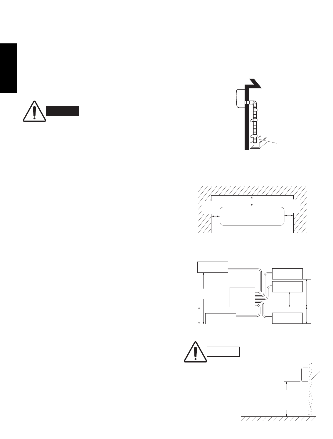
4
English
1-5. Additional Materials Required for Installation
1. Refrigeration (armored) tape
2. Insulated staples or clamps for connecting wire
(See local codes)
3. Putty
4. Refrigeration lubricant
5. Clamps or saddles to secure refrigerant tubing
2. Installation Site Selection
2-1. Indoor Unit
AVOID:
Gdirect sunlight.
Gnearby heat sources that may affect performance of the
unit.
Gareas where leakage of flammable gas may be expected.
Gplacing or allowing any obstructions near the air conditioner
inlet or outlet.
Ginstalling in rooms that contain instant-on (rapid-start)
fluorescent lamps. (These may prevent the air conditioner
from receiving signals.)
Gplaces where large amounts of oil mist exist.
Ginstalling in locations where there are devices that
generate high-frequency emissions.
DO:
Gselect an appropriate position from which every corner of
the room can be uniformly cooled. (High on a wall is best.)
Gselect a location that will hold the weight of the unit.
Gselect a location where tubing and drain hose have the
shortest run to the outside. (Fig. 1)
Gallow room for operation and maintenance as well as
unrestricted air flow around the unit. (Fig. 2)
Ginstall the unit within the maximum elevation difference
(H1, H2, H3, H4, H5) above or below the outdoor unit and
within a total tubing length (L1+L2+L3+L4+L5) from the out-
door unit as detailed in Table 3 and Fig. 3a.
Drain hose
Indoor unit
Outside drainage
Fig. 1
5 cm
min.
5 cm
min.
15 cm min.
Front View
Fig. 2
INDOOR
INDOOR INDOOR
INDOOR
Tubing length (L1)
L2
L5
L3
L4
H2
H3
H4
H5
Elevation
INDOOR
OUTDOOR
UNIT
difference (H1)
UNIT (3)
UNIT (1)
UNIT (2)
UNIT (5) UNIT (4)
Fig. 3a
WARNING
To prevent abnormal heat generation
and the possibility of fire, do not
place obstacles, enclosures and
grilles in front of or surrounding the
air conditioner in a way that may
block air flow.
Indoor unit
Floor level
Wall
Minimum height
from floor level
1.5 m
Fig. 3b
For stable operation of the air
conditioner, do not install
wall-mounted type indoor
units less than 1.5 m from
floor level.
CAUTION
08-324 CMRV3656EH_IU EN 6/15/09 5:27 PM Page 4
5
English
Ginstall the indoor unit more than 1 meter away from any
antenna or power lines or connecting wires used for
television, radio, telephone, security system, or inter-
com. Electrical noise from any of these sources
may affect operation.
Ginstall in a sturdy manner to avoid increased operat-
ing noise.
Table 3
2-2. Embedding the Tubing and Wiring
GBefore beginning embedding installation work,
consult fully with agencies or offices related to the
building’s foundation, construction, electricity, and
water.
GWait to make connections to the embedded portion.
Each connection step is described later in this
manual.
GSecurely cover the end of the embedded tubing to
prevent intrusion of dirt or moisture.
GIf an embedded tube is to be left for a long time, fill
the tube with nitrogen and seal both ends securely.
If a tube is left open for an extended time, moisture
in the air inside the tubing may condense into water
droplets, and lead to water contamination of the
refrigerant circuit.
GIn order to prevent insulation breakdown and ground
faults, do not allow wiring ends to come in contact
with rainwater, or be subjected to condensation or
dew.
GApply sufficient thermal insulation to the refrigerant
tubing and drain pipes.
* If total tubing length becomes 45 to 80 m (max.), charge additional refrigerant (R410A) by 20 g/m.
No additional charge of compressor oil is necessary.
Max. Allowable Max. Allowable Total Limit of Limit of Elevation Required Amount
Tubing Length Tubing Length Total Tubing Length Difference of Additional
Model per unit at shipment (L1+L2+L3+L4+L5) (H1, H2, H3, H4, H5) Refrigerant
(m) (L1+L2+L3+L4+L5) (m) (m) (g/m)*
(m)
CMRV3656 30 45 (L1+L2+L3+L4+L5) 80 (L1+L2+L3+L4+L5) 15 20
08-324 CMRV3656EH_IU EN 6/15/09 5:27 PM Page 5

English
Set screw only for transportation
Rear panel
marks
Left
tubing
Right tubing
Downward tubing
Right-rear
tubing
(recommended)
Left-rear
tubing
3. How to Install the Indoor Unit
3-1. Remove the Rear Panel from the Unit
(1) Remove and discard the set screw on the rear
panel except
SAP-KRV96EHDS, SAP-
KRV126EHDS,
SAP-KMRV76EH, SAP-
KMRV96EH and SAP-KMRV126EH. (Fig. 6)
(2) Press the 2 LLmarks on the frame cover and dis-
engage the stationary tabs from the frame. (Fig. 7)
(3) Remove the rear panel.
Tubing can be extended in 5 or 6 directions as shown
in Fig. 8a or 8b. Select the direction you need provid-
ing the shortest run to the outside unit.
GWhen left tubing is to be done, switch the drain
hose and drain cap. (For details, refer to “Switching
drain hose and drain cap” on page 17 and 18.)
3-2. Make a Hole
(1) Place the rear panel from the indoor unit on the
wall at the location selected. Make sure the panel
is horizontal, using a carpenter’s level or tape mea-
sure to measure down from the ceiling. Wait until
after cutting the hole before attaching the rear
panel to the wall.
(2) Determine which side of the unit you should make
the hole for tubing and wiring. (Fig. 9a, 9b or 9c)
In the case of left-rear tubing, use the measurement
points from the edge of the rear panel for precise
placement of the hose outlet. (Fig. 9a, 9b or 9c)
(3) Before making the hole, check carefully that no
studs or pipes are directly run behind the spot to
be cut.
The above precautions are also applicable if tub-
ing goes through the wall in any other location.
NOTE
NOTE
Fig. 9b
CAUTION
Also avoid areas where elec-
trical wiring or conduits are
located.
70 mm
Fig. 9a
(SAP-KMRV74, KMRV94, KMRV124)
(SAP-KMRV76, KMRV96, KMRV126)
60 mm
(SAP-KMRV74, KMRV94, KMRV124) (SAP-KRV184, KRV244)
(SAP-KRV186, KRV246)
Fig. 9c
340 278
42
42
Left
tubing
Right
tubing
Right-rear
tubing
(recommended)
Right-downward
tubing
Left-rear
tubing
Left-downward
tubing
Fig. 8b
6
Fig. 8a
Fig. 7
(SAP-KRV184, KRV244) (SAP-KRV186, KRV246)
Fig. 6
(SAP-KMRV74, KMRV94, KMRV124)
(SAP-KMRV76, KMRV96, KMRV126) (SAP-KRV96, KRV126)
(SAP-KRV184, KRV244)
(SAP-KRV186, KRV246)
(SAP-KRV96, KRV126)
08-324 CMRV3656EH_IU EN 6/15/09 5:27 PM Page 6
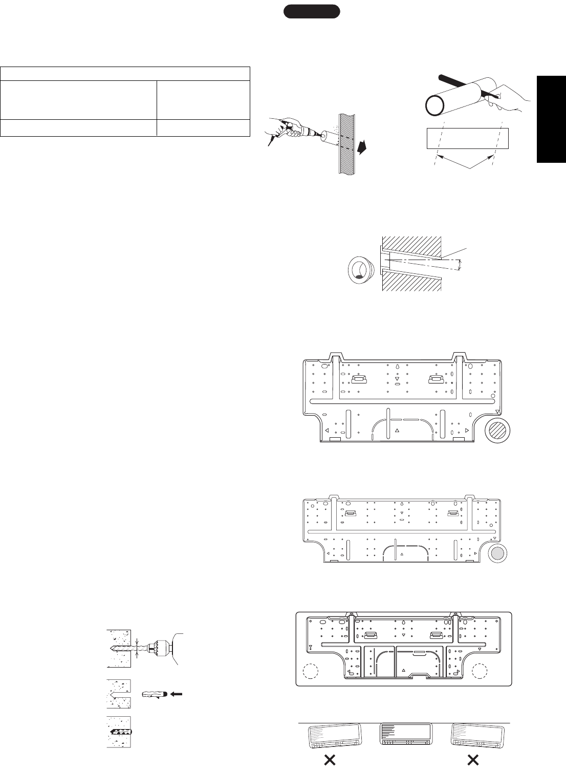
English
Hole should be made at a slight downward slant to the
outdoor side.
NOTE
Plastic cover
INSIDE OUTSIDE
Wall
Slight
angle
PVC pipe
(Locally purchased)
Fig. 12
PVC pipe (Locally purchased)
Cut at slight angle
Fig. 11
(4) Using a sabre saw, key hole saw or hole-cutting
drill attachment, cut a hole in the wall. See Table 4
and Fig. 10.
Table 4
(5) Measure the thickness of the wall from the inside
edge to the outside edge and cut PVC pipe at a
slight angle 6 mm shorter than the thickness of the
wall. (Fig. 11)
(6) Place the plastic cover over the end of the pipe (for
indoor side only) and insert the pipe in the wall.
(Fig. 12)
3-3. Install the Rear Panel on the Wall
Be sure to confirm that the wall is strong enough to
suspend the unit.
See either Item a) or b) below depending on the wall
type.
a) If Wooden Wall
(1) Attach the rear panel to the wall with the 8 screws
provided. (Fig. 13a, 13b or 13c)
If you are not able to line up the holes in the rear
panel with the beam locations marked on the wall,
use rawl plugs or toggle bolts to go through the
holes on the panel or drill 5 mm dia. holes in the
panel over the stud locations and then mount the
rear panel.
(2) Double check with a carpenter’s level or tape mea-
sure that the panel is level. This is important to
install the unit properly. (Fig. 14)
(3) Make sure the panel is flush against the wall. Any
space between the wall and unit will cause noise
and vibration.
b) If Block, Brick, Concrete or Similar Type Wall
Make 4.8 mm dia. holes in the wall. Insert rawl plugs
for appropriate mounting screws. (Fig. 15)
Hole Dia. (mm)
KMRV74 / KMRV94 / KMRV124 KRV184 / KRV244
KRV96 / KRV126 KRV186 / KRV246
KMRV76 / KMRV96 / KMRV126
65 80
Fig. 13b
Fig. 14
4.8 mm dia. hole
Rawl plug
(Locally purchased)
Fig. 15
Fig. 13a
(SAP-KMRV74, KMRV94, KMRV124)
(SAP-KMRV76, KMRV96, KMRV126)
(SAP-KRV184, KRV244) (SAP-KRV186, KRV246)
Fig. 13c
Indoor
side
Outdoor
side
Fig. 10
(SAP-KRV96, KRV126)
7
08-324 CMRV3656EH_IU EN 6/15/09 5:27 PM Page 7

English
3-4. Removing and Installing the Grille
3-4-1. Indoor unit types
(SAP-KMRV74EH, KMRV94EH, KMRV124EH)
Basically, these models can be installed and wired without
removing the grille. If access to any internal part is needed,
follow the steps as given below.
How to remove the grille
(1) Grasp both ends of the air intake grille, and remove it
by opening towards the front and pulling towards you.
(Fig. 16a)
(2) Remove the 2 screws. (Fig. 16b)
(3) Remove the screw on the right side cover plate and
open the cover. (Fig. 17a)
(4) Take out the thermistor from the grille. (Fig. 17b)
(5) Pull the lower part of the grille towards you to remove.
(Fig. 18a)
(6) Use a standard screwdriver to push on the tabs to
remove the grille.
How to replace the grille
(1) Reinstall the grille into the lower part while aligning
its tabs on the upper part. (Fig. 18b) Insert the tabs
in the slots and push the lower part of the grille back
into position.
(2) Make sure that the grille and frame are firmly fitted
together by engaging the tabs.
(3) Attach the thermistor on the grille. (Fig. 17a)
(4) Close the cover and replace the screw. (Fig. 17a)
(5) Affix the grille with the 2 previously removed screws.
(Fig. 16b)
(6) Install the air intake grille.
(a) Allow the edge of the air intake grille to slide into
the top of the indoor unit, and then insert it all the
way inside. (Fig. 19a)
(b) Press the bottom right and left corners of the air
intake grille to attach it to the indoor unit. (Fig. 19b)
Attach so that the round pins at the top right and left
corners of the air
intake grille are
inserted into the
grooves at the top
right and left of the
indoor unit.
NOTE
Screw cover
Air intake grille Grille
Fig. 16a
Fig. 16b
Cover
Thermistor
Fig. 17a
Thermistor
Fig. 17b
Fig. 18a
Grille
Frame
Tab
Tab
*
*
Fig. 18b
*
*
Fig. 19b Fig. 19a
Pin
Groove
CAUTION
Be sure to wear work gloves
during installation to avoid being
cut by the sharp aluminum fins
of the heat exchanger.
8
08-324 CMRV3656EH_IU EN 6/15/09 5:27 PM Page 8

9
English
3-4-2. Indoor unit types
(SAP-KRV184EH, KRV244EH)
Basically, these models can be installed and wired
without removing the grille. If access to any internal
part is needed, follow the steps as given below.
How to remove the grille
(1) Grasp both ends of the air intake grille, and
remove it by opening towards the front and pulling
towards you. (Fig. 16a-1)
(2) Remove the 3 screws. (Fig. 16b-1)
(3) Remove the screw on the right side cover plate
and open the cover. (Fig. 17a-1)
(4) Take out the thermistor from the grille. (Fig. 17b-1)
(5) Press the 3 tabs at the top of the grille and the 3
tabs on the front face to separate the grille from
the frame. (Fig. 18a-1)
(6) Pull the grill towards you to remove it.
How to replace the grille
(1) When installing the grille, place the bottom of the
grille into the frame first. (Fig. 18b-1)
Then insert the tabs on the top of the grille and on
the front face into the frame.
(2) Make sure that the grille and frame are firmly fitted
together by engaging the tabs.
(3) Attach the thermistor on the grille. (Fig. 17a-1)
(4) Close the cover and replace the screw.
(Fig. 17a-1)
(5) Affix the grille with the 3 previously removed
screws. (Fig. 16b-1)
(6) Install the air intake grille.
(a) Allow the edge of the air intake grille to slide
into the top of the indoor unit, and then insert it
all the way inside. (Fig. 19a-1)
(b) Press the bottom right and left corners and
center of the air intake grille to attach it to the
indoor unit. (Fig. 19b-1)
Attach so that the round pins at the top right and left
corners of the air intake grille are inserted into the
grooves at the top right and left of the indoor unit.
NOTE
Air intake grille Grille
Fig. 16a-1
Fig. 16b-1
Cover
Thermistor
Fig. 17a-1
Thermistor
Fig. 17b-1
Fig. 18a-1
Tab
Tab
Fig. 18b-1
Fig. 19b-1 Fig. 19a-1
Pin
Groove
08-324 CMRV3656EH_IU EN 6/15/09 5:27 PM Page 9
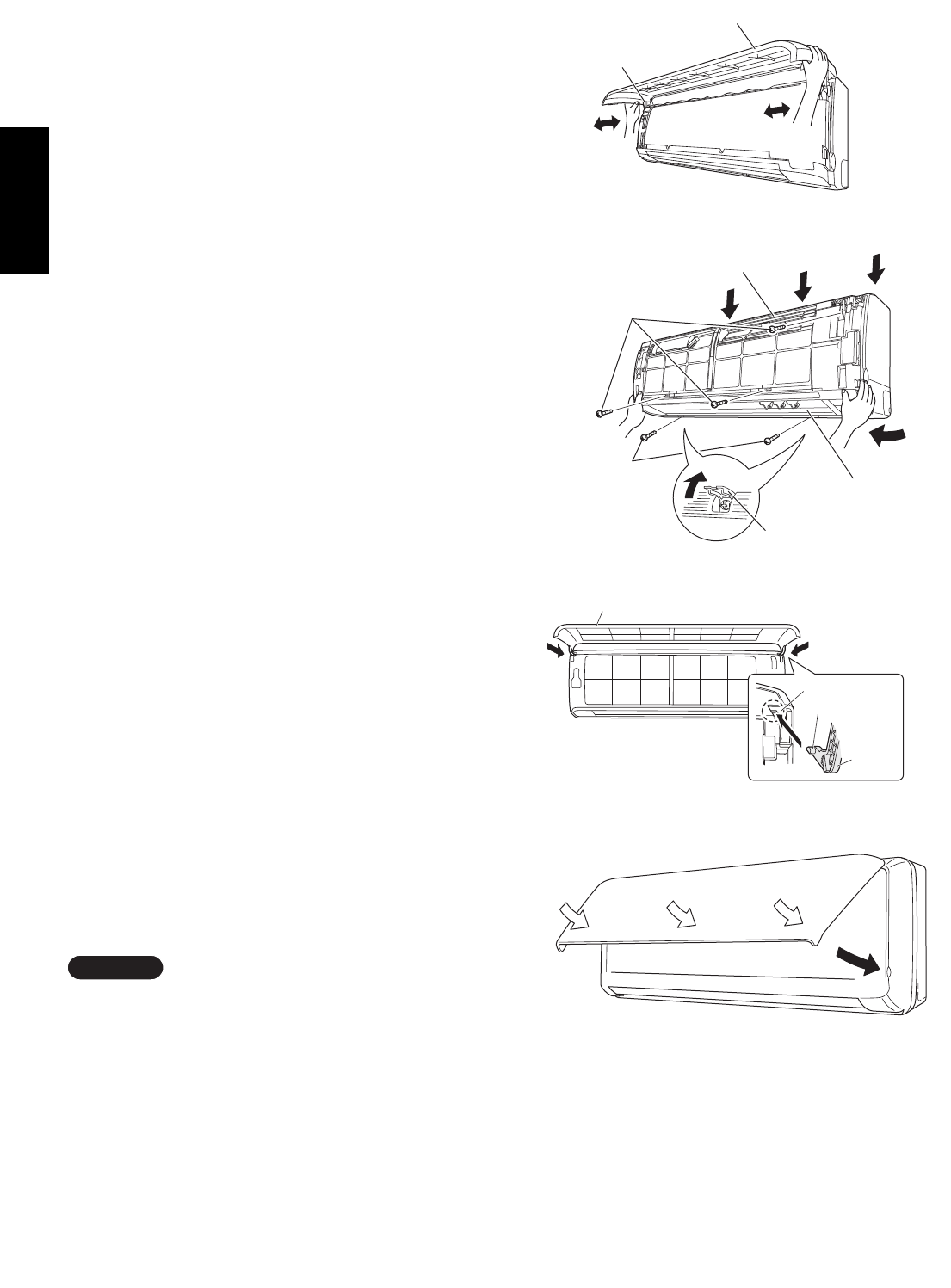
10
English
3-4-3. Indoor unit types
(SAP-KRV96EHDS, KRV126EHDS)
Basically, these models can be installed and wired
without removing the grille. If access to any internal
part is needed, follow the steps as given below.
How to remove the grille
(1) Open the front panel until it is nearly horizontal,
grasp the sections near the front panel arms on
both sides, and then pull towards you to remove
the front panel. (Fig. 16-2)
(2) Remove the 3 screws from the frame. Also remove
the 2 screws where the screw covers are open.
(Fig. 17-2)
(3) Press the 3 tabs on the top of the grille to
disengage them. (Fig. 17-2)
(4) Pull the grille towards you to remove it. (Fig. 17-2)
How to replace the grille
(1) Insert the bottom of the grille into the flap, with the
flap at a more-or-less horizontal position.
(2) While aligning both edges of the grille with the
frame, move the panel horizontally and insert the
top and bottom into the frame.
(3) Press the air discharge outlet firmly with your hand
to ensure no gap exists between the main unit and
grille.
(4) Tighten the 2 screws and close the screw covers.
Also tighten the 3 screws of the frame.
(5) Grasp the sections near the front panel arms on
both sides, hold the front panel so that it is nearly
horizontal, bring the arm shafts into contact with
the top of the grooves on the right and left sides of
the air conditioner, and then push firmly until the
arm shafts click into place. (Fig. 18-2)
(6) After closing the front panel, press firmly on the
parts indicated by the arrows to securely fasten the
panel in place. (Fig. 19-2)
Check that no gap exists between the main unit and
grille.
NOTE
Fig. 16-2
Fig. 17-2
Front panel
Arm
Screw
Flap
Grille
Screw
Screw cover
Fig. 18-2
Fig. 19-2
Front panel
Pin
Arm
Groove
08-324 CMRV3656EH_IU EN 6/15/09 5:27 PM Page 10
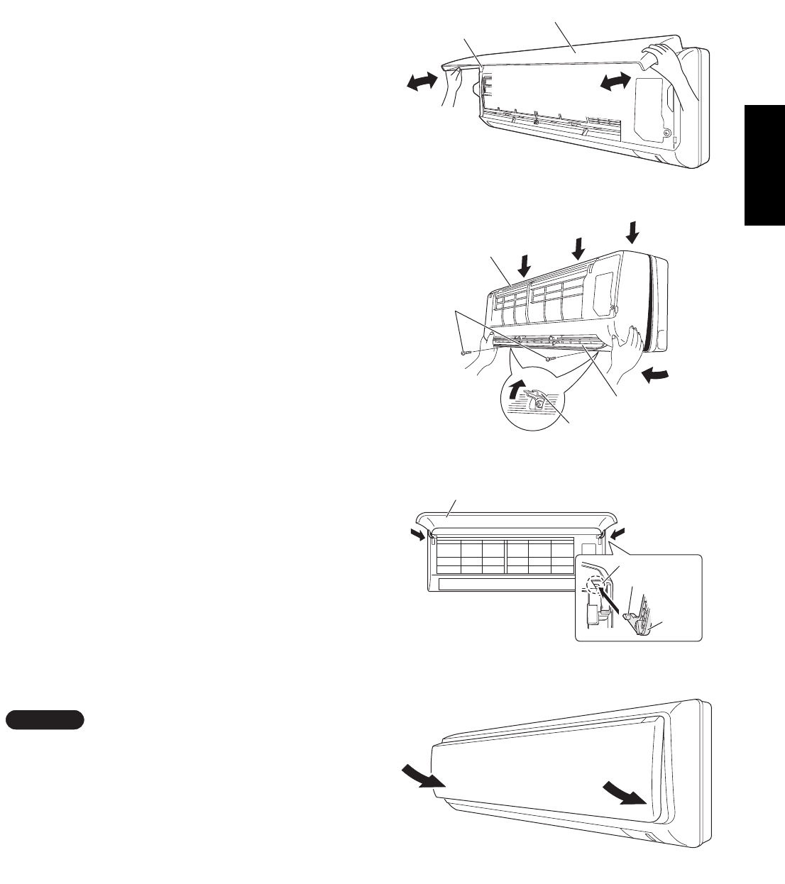
11
English
3-4-4. Indoor unit types
(SAP-KMRV76EH, KMRV96EH, KMRV126EH)
Basically, these models can be installed and wired
without removing the grille. If access to any internal
part is needed, follow the steps as given below.
How to remove the grille
(1) Open the front panel until it is nearly horizontal,
grasp the sections near the front panel arms on
both sides, and then pull towards you to remove
the front panel. (Fig. 16-3)
(2) Remove the 2 screws where the screw covers are
open. Grasp the grille on both bottom sides, and
pull it towards you slightly. (Fig. 17-3)
(3) Press the 3 tabs on the top of the grille to disen-
gage them. (Fig. 17-3)
(4) Pull the grille towards you to remove it. (Fig. 17-3)
How to replace the grille
(1) Insert the bottom of the grille into the frame.
(2) While aligning both edges of the grille with the
frame, move the grille horizontally and insert the
top and bottom into the frame.
(3) Press the grille firmly with your hand to ensure no
gap exists between the frame and grille.
(4) Tighten the 2 screws and close the screw covers.
(5) Grasp the sections near the front panel arms on
both sides, hold the front panel so that it is nearly
horizontal, bring the arm shafts into contact with
the top of the grooves on the right and left sides of
the air conditioner, and then push firmly until the
arm shafts click into place. (Fig. 18-3)
(6) Press the bottom right and left corners of the front
panel to attach it to the indoor unit. (Fig. 19-3)
Check that no gap exists between the frame and the
grille.
NOTE
Fig. 16-3
Fig. 17-3
Arm
Front panel
Screw
Screw cover
Flap
Grille
Fig. 18-3
Fig. 19-3
Front panel
Arm
Pin
Groove
08-324 CMRV3656EH_IU EN 6/15/09 5:27 PM Page 11

12
English
3-4-5. Indoor unit types
(SAP-KRV186EH, KRV246EH)
Basically, these models can be installed and wired
without removing the grille. If access to any internal
part is needed, follow the steps as given below.
How to remove the grille
(1) Open the front panel until it is nearly horizontal,
grasp the sections near the front panel arms on
both sides, and then pull towards you to remove
the front panel. (Fig. 16-4)
(2) Remove the 3 screws where the screw covers are
open. (Fig. 17-4)
(3) Press the 3 tabs at the top of the grille and the 3
tabs on the front face to separate the grille from
the frame. (Fig. 18a-4)
(4) Pull the grille towards you to remove it.
(Fig. 18a-4)
How to replace the grille
(1) When installing the grille, place the bottom of the
grille into the frame first. (Fig. 18b-4) Then insert
the tabs on the top of the grille and on the front
face into the frame.
(2) Make sure that the grille and frame are firmly fitted
together by engaging the tabs.
(3) Press the grille firmly with your hand to ensure no
gap exists between the frame and grille.
(4) Tighten the 3 screws and close the screw covers.
(5) Grasp the sections near the front panel arms on
both sides, hold the front panel so that it is nearly
horizontal, bring the arm shafts into contact with
the top of the grooves on the right and left sides of
the air conditioner, and then push firmly until the
arm shafts click into place. (Fig. 18c-4)
(6) After closing the front panel, press firmly on the
parts indicated by the arrows to securely fasten
the panel in place. (Fig. 19-4)
Check that no gap exists between the frame and the
grille.
NOTE
Fig. 16-4
Fig. 17-4
Arm
Front panel
Screw
Screw cover
Fig. 18c-4
Fig. 19-4
Front panel
Arm
Pin
Groove
Fig. 18a-4
Tab
Grille
Tab
Fig. 18b-4
Grille
08-324 CMRV3656EH_IU EN 6/15/09 5:27 PM Page 12
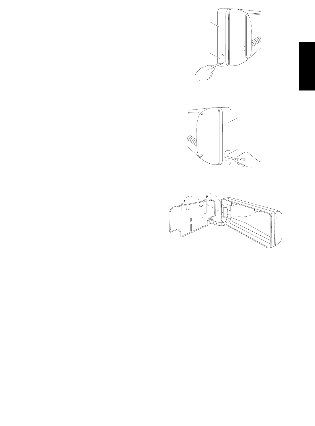
13
English
3-5. Shape the Indoor Side Tubing
(1) Arrangement of tubing by directions
a) Right or left tubing
Cut out the corner of the right/left frame with a
hacksaw or the like. (Figs. 20 and 21)
b) Right-rear or left-rear tubing
In this case, the corner of the frame need not
be cut.
(2) To mount the indoor unit on the rear panel:
Hang the 2 mounting slots of the unit on the
upper tabs of the rear panel. (Fig. 22)
3-6. Wiring Instructions
General precautions on wiring
(1) Before wiring, confirm the rated voltage of the unit
as shown on its nameplate, then carry out the
wiring closely following the wiring diagram.
(2) Provide a power outlet to be used exclusively for
each unit, with a power supply disconnect and
leakage breaker/ fuse link for overcurrent protection
provided in the exclusive line.
(3) To prevent possible hazard due to insulation fail-
ure, the unit must be grounded.
(4) Each wiring connection must be done tightly and
in accordance with the wiring system diagram.
Wrong wiring may cause the unit to misoperate or
become damaged.
(5) Do not allow wiring to touch the refrigerant tubing,
compressor, or any moving parts of the fan.
(6) Unauthorized changes in the internal wiring can
be very dangerous. The manufacturer will accept
no responsibility for any damage or misoperation
that occurs as a result of such unauthorized
changes.
Frame
Right tubing
outlet
Frame
Left tubing
outlet
Fig. 21
Fig. 22
Fig. 20
08-324 CMRV3656EH_IU EN 6/15/09 5:27 PM Page 13
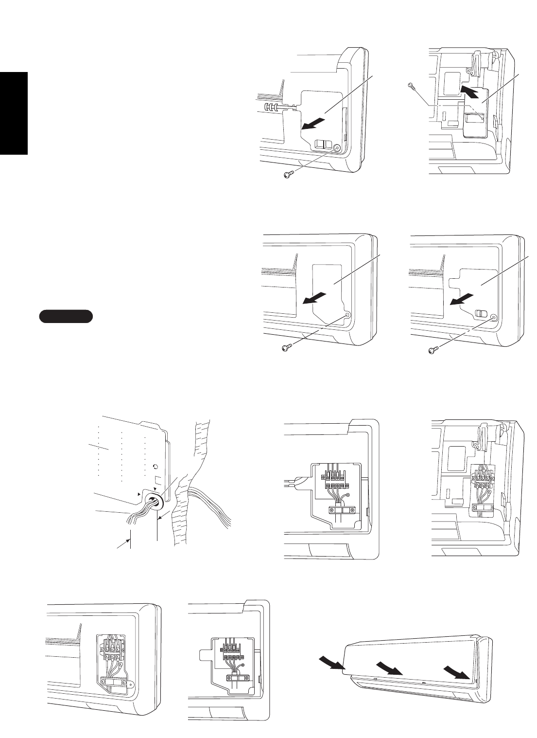
English
3-7. Wiring Instructions for Inter-unit Connections
25 cm
Wiring
Rear
panel
Plastic
cover
Fig. 25
Cover
Fig. 26a
Fig. 27
(SAP-KMRV74, KMRV94, KMRV124)
(SAP-KRV184, KRV244)
Fig. 24b
(SAP-KRV96, KRV126)
Fig. 24a
Fig. 26b
(SAP-KRV96, KRV126)
(1) Grasp both ends of the air intake grille, and
remove it by opening towards the front and
pulling towards you.
(2) Remove the screw on the right side cover
plate and open the cover.
(Fig. 24a, 24b, 24c or 24d)
(3) Insert the inter-unit wiring into the through-
the-wall PVC pipe. Lead the power wiring
into the room allowing approx. 25 cm to
extend from the wall face. (Fig. 25)
(4) Route the inter-unit wiring from the back of
the indoor unit and pull it towards the front
for connection. (Fig. 26a, 26b, 26c or 26d)
(5) Connect the inter unit wiring to the corre-
sponding terminals on the terminal plate
(Fig. 26a, 26b, 26c or 26d) while referring
to the wiring diagram.
(6) Be sure to secure the wiring with the pro-
vided clamp.
When closing the air intake grille, press the bot-
tom right and left corners and center. (Fig. 27)
Please refer to “How to replace the grille” on
page 8, 9, 10, 11 or 12 for installing the air
intake grille.
NOTE
Cover
Fig. 26c Fig. 26d
(SAP-KMRV76, KMRV96,
KMRV126) (SAP-KRV186, KRV246)
Cover
(SAP-KMRV76, KMRV96, KMRV126) (SAP-KRV186, KRV246)
Cover
Fig. 24c Fig. 24d
(SAP-KMRV74, KMRV94, KMRV124)
(SAP-KRV184, KRV244)
14
08-324 CMRV3656EH_IU EN 6/15/09 5:27 PM Page 14
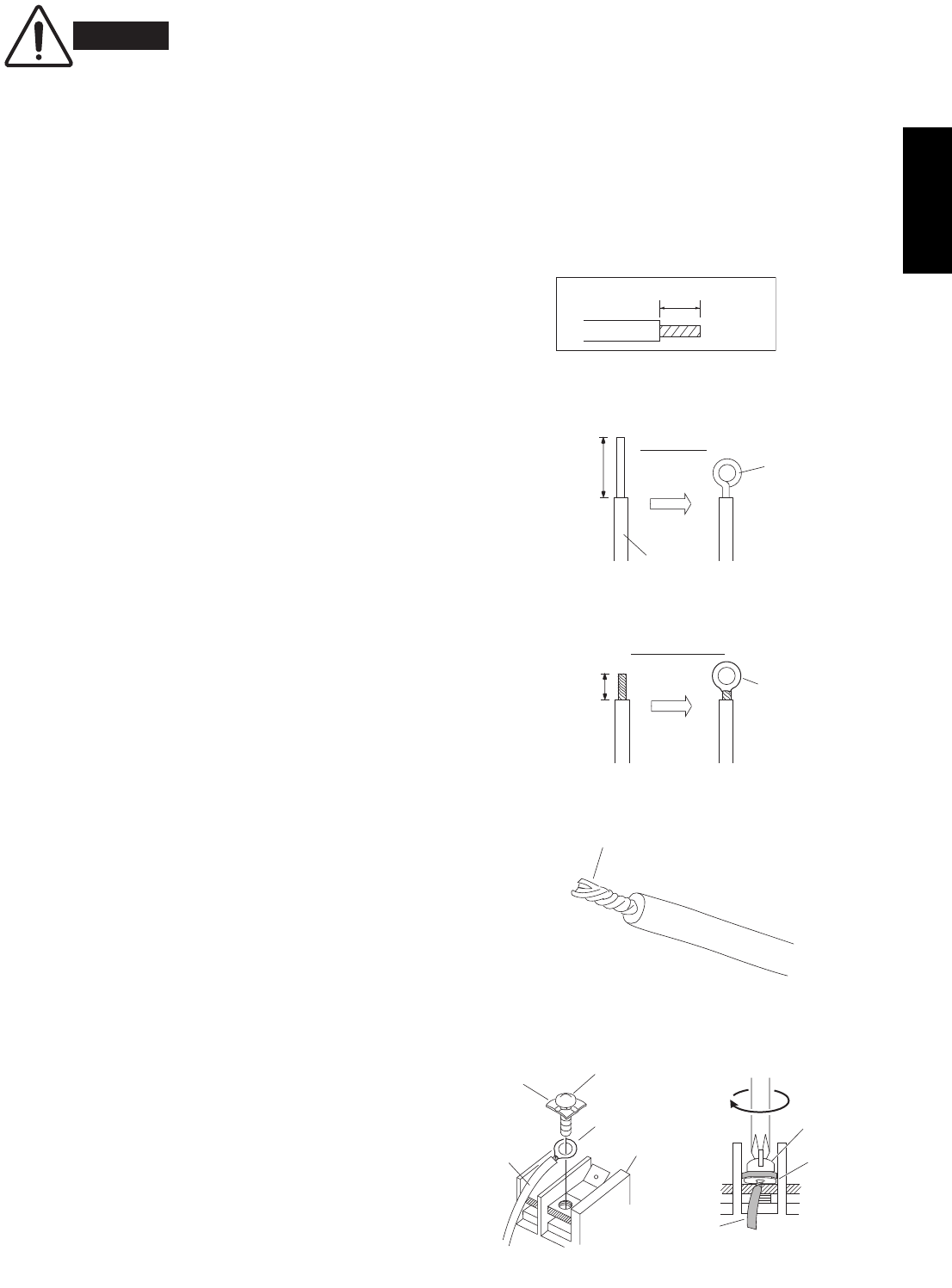
15
English
When connecting each power wire to the correspond-
ing terminal, follow the instructions “How to connect
wiring to the terminal” and fasten the wire securely
tight with the fixing screw of the terminal plate.
How to connect wiring to the terminal
a) For Indoor Unit
(1) Cut the wire end with a cutting pliers, then strip
the insulation to expose the wire about 7 mm. See
the label (Fig. 28) near the terminal plate.
(2) Using a screwdriver, loosen the terminal screw on
the terminal plate.
(3) Insert the wire and tighten the terminal screw
completely using a screwdriver.
b) For Outdoor Unit
IFor solid core wiring (or F-cable)
(1) Cut the wire end with a cutting pliers, then strip
the insulation to expose the solid wire about
25 mm. (Fig. 29)
(2) Using a screwdriver, remove the terminal screw(s)
on the terminal plate.
(3) Using the pliers, bend the solid wire to form a loop
suitable for the terminal screw.
(4) Shape the loop wire properly, place it on the termi-
nal plate and fix it securely with the removed ter-
minal screw using a screwdriver.
IFor stranded wiring
(1) Cut the wire end with a cutting pliers, then strip
the insulation to expose the stranded wiring about
10 mm and tightly twist the wire ends. (Figs. 30
and 31)
(2) Using a screwdriver, remove the terminal screw(s)
on the terminal plate.
(3) Using a ring connector fastener or pliers, securely
clamp each stripped wire end with a ring connec-
tor. (Fig. 30)
(4) Place the ring connector wire, and replace and
tighten the removed terminal screw using a screw-
driver. (Fig. 32)
Solid wire
Loop
Insulation
Strip 25 mm
Fig. 29
STRIP
SIZE
7 mm (ACTUAL
SIZE)
Fig. 28
Stranded wire
Ring
connector
Strip 10 mm
Fig. 30
Screw
Ring connector
Terminal plate
Wire
Special
washer
Fig. 32
Screw and
special washer
Ring
connector
Wire
WARNING
Loose wiring may cause the
terminal to overheat or result
in unit malfunction. A fire
hazard may also exist. There-
fore, be sure all wiring is
tightly connected.
Twist wire ends
Fig. 31
08-324 CMRV3656EH_IU EN 6/15/09 5:28 PM Page 15

16
English
3-8. Mounting
(1) To install the indoor unit, mount the indoor unit
onto the 2 tabs on the upper part of the rear plate.
(2) Hold down the air discharge outlet and press the
lower part of the indoor unit until it clicks to
securely fasten to the 2 tabs on the lower part of
the rear plate. (Fig. 33)
For tubing, choose either the right or left tubing direc-
tion and follow the steps below. This work can be made
easier by placing padding material (such as styrofoam)
at the rear right side of the indoor unit. (Fig. 34a)
Or extend the support on the back of the indoor unit as
a stand to make your work easier. (Fig. 34b)
IRight-side tubing
(1) Shape the refrigerant tubing so that it can easily
go into the wall hole. (Fig. 35a or 35b)
(2) Push the wiring, refrigerant tubing, and drain hose
through the hole in the wall. Adjust the indoor unit
so it is securely seated on the rear panel. (Fig. 36)
(3) Carefully bend the tubing (if necessary) to run
along the wall in the direction of the outdoor unit
and then tape as far as the fittings. (See Caution
on page 11 in the outdoor unit installation
manual.) The drain hose should come straight
down the wall to a point where water runoff won’t
stain the wall.
(4) Connect the refrigerant tubing to the outdoor unit.
(After performing a leak test on the connecting
part, insulate it with the tubing insulation. (Fig. 37))
Also, refer to Section 3-6. Tubing connections in
the outdoor unit installation manual.
(5) Assemble the refrigerant tubing, drain hose, and
inter-unit wiring as shown in Fig. 37.
NOTE
Cover
Refrigerant
tubing
Rear panel
Drain hose
Inter-unit
wiring
Fig. 35a
Fig. 36
Fig. 33
Push
Insulation
Padding material
Fig. 34a
Rear panel
(SAP-KRV96, KRV126)
(SAP-KMRV74, KMRV94, KMRV124)
(SAP-KMRV76, KMRV96, KMRV126)
(SAP-KRV184, KRV244)
(SAP-KRV186, KRV246)
Fig. 34b
Fig. 37
Wall cap
Tab
Rear panel
Refrigerant
tubing
Inter-unit
wiring
Drain hose
Fig. 35b
(SAP-KMRV74, KMRV94, KMRV124)
(SAP-KMRV76, KMRV96, KMRV126)
(SAP-KRV184, KRV244)
(SAP-KRV186, KRV246)
(SAP-KRV96, KRV126)
08-324 CMRV3656EH_IU EN 6/15/09 5:28 PM Page 16

17
English
Hole in wall
Bent part
Narrow tube
Wide tube
Rear panel
Fig. 38a
Drain cap
Drain hose
Fig. 39a
ILeft-side tubing
(SAP-KMRV74EH, KMRV94EH, KMRV124EH,
KMRV76EH, KMRV96EH, KMRV126EH,
KRV184EH, KRV244EH, KRV186EH, KRV246EH)
(1) Lead the tubing and drain hose through the wall,
allowing sufficient length for connection. Then
bend the tubing using a tube bender to make the
attachment. (Fig. 38a)
(2) Switch the drain hose and drain cap.
Switching drain hose and drain cap
(a) Locate the drain hose and the drain cap.
(Fig. 39a)
(b) Remove the screws fastening the drain hose
on the right side, and pull out the drain hose
to remove it. (Fig. 39a)
(c) Apply moderate force to pull off the drain cap
on the left side. (If you cannot pull it off by
hand, use a long-nose pliers.)
(d) Reattach the drain hose to the left side and
the drain cap to the right side. (Fig. 40a)
Drain hose
Slide the drain hose fully onto the drain pan outlet
until the drain hose edge is pushed into the insu-
lation. Check that the screw holes in the drain
bracket and the drain pan outlet are aligned and
securely in contact, then fasten them with the
screw. (After attaching the drain hose, check that
it is attached securely.) (Fig. 40c)
Drain cap
Use a Phillips screwdriver to push the drain cap in
firmly. (If it is difficult to push in, wet the cap with
water first.)
(3) Install the indoor unit on the rear panel.
(4) Connect the tubing and wiring led inside from out-
doors.
(5) After completing a leak test, bundle the tubing
together with armoring tape and store it inside the
tubing storage area at the back of the indoor unit
and hold it with clamps. (Figs. 40a and 41a)
Fig. 40a
Fig. 40b
Fig. 40c
Fig. 41a
Refrigerant tubing
Inter-unit wiring
Screw
Drain hose
Drain pan outlet
Screw hole
Drain bracket
Drain cap
Clamp
Drain hose
Drain hose
Drain bracket
Insulation
08-324 CMRV3656EH_IU EN 6/15/09 5:28 PM Page 17
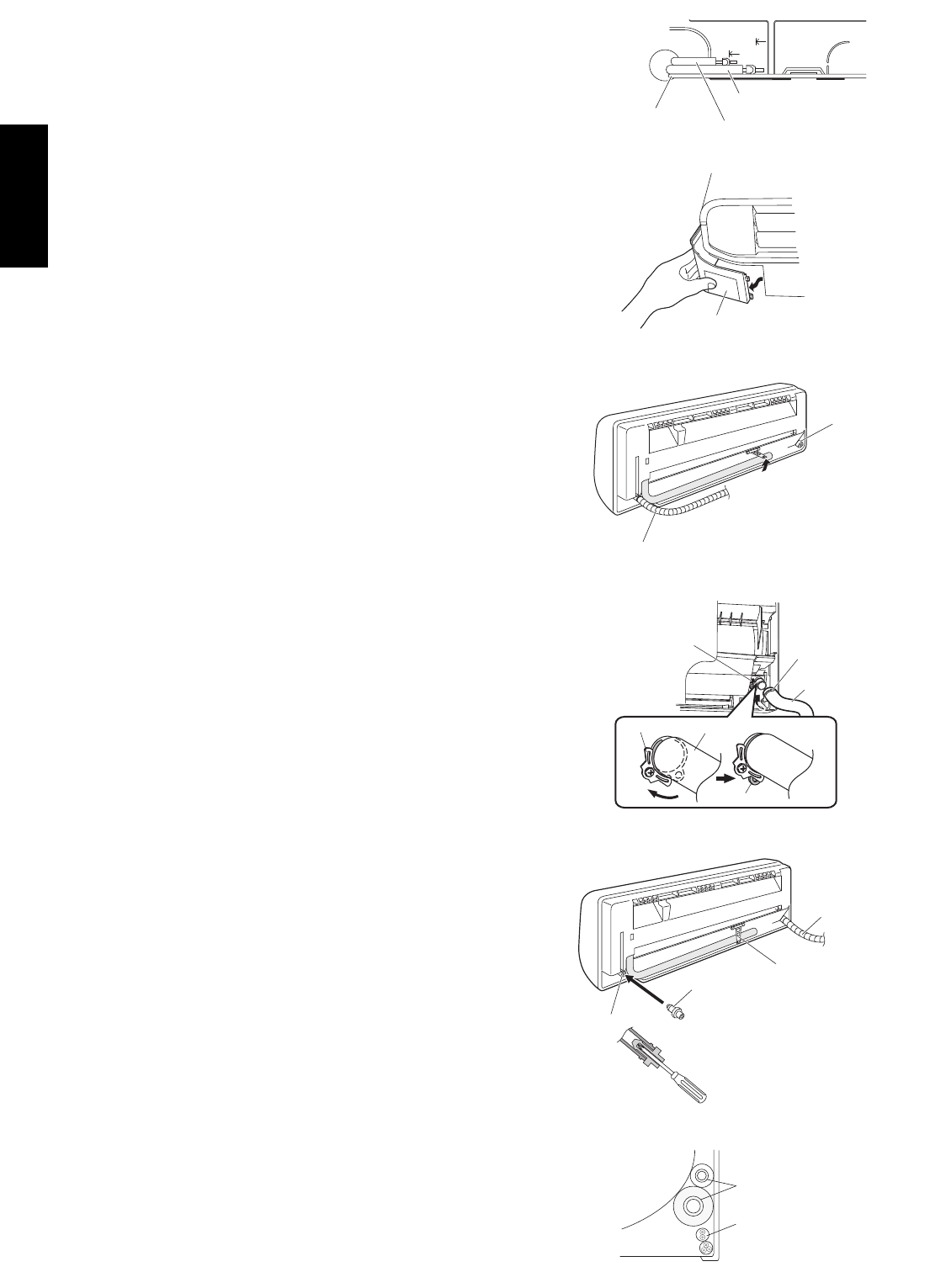
English
ILeft-side tubing
(SAP-KRV96EHDS, KRV126EHDS)
(1) Lead the tubing and drain hose through the wall,
allowing sufficient length for connection. Then
bend the tubing using a tube bender to make the
attachment. (Fig. 38b)
(2) Switch the drain hose and drain cap.
Switching drain hose and drain cap
(a) Grasp the corner of the bottom left indoor unit
cover, and press down on the bottom while
lifting the cover up to remove it. (Fig. 39b)
(b) Locate the drain hose and the drain cap.
(Fig. 39c)
(c) When disconnecting the drain hose, remove
the drain fitting from the stopper, then check
the position of the drain fitting on the end of
the hose, and turn the hose while pulling to
remove it. (Fig. 39d)
(d) Screw the drain hose all the way inside. Turn
the hose so that the protruding part of the
drain fitting comes below the stopper as
shown in the figure. It will be easy to insert
when water is added. (Fig. 39d)
(e) Align the tabs of the removed cover with the
grille tabs, and then lower the cover to install it.
Drain cap
Use a Phillips screwdriver to push the drain cap in
firmly. (If it is difficult to push in, wet the cap with
water first.)
(3) Install the indoor unit on the rear panel.
(4) Connect the tubing and wiring led inside from out-
doors.
(5) After completing a leak test, bundle the tubing
together with armoring tape and store it inside the
tubing storage area at the back of the indoor unit
and hold it with clamps. (Figs. 40d and 41b)
Fig. 38b
Bottom left cover
Fig. 39b
Fig. 39d
Fig. 41b
Refrigerant tubing
Inter-unit wiring
Drain cap
Drain cap
Clamp
Drain hose
Hole in wall
Rear panel
Bent part
Wide tube
Narrow tube
Fig. 40d
Stopper Drain fitting
Drain hose
Stopper Drain hose
Drain fitting
Drain cap
Drain hose
Fig. 39c
18
08-324 CMRV3656EH_IU EN 6/15/09 5:28 PM Page 18
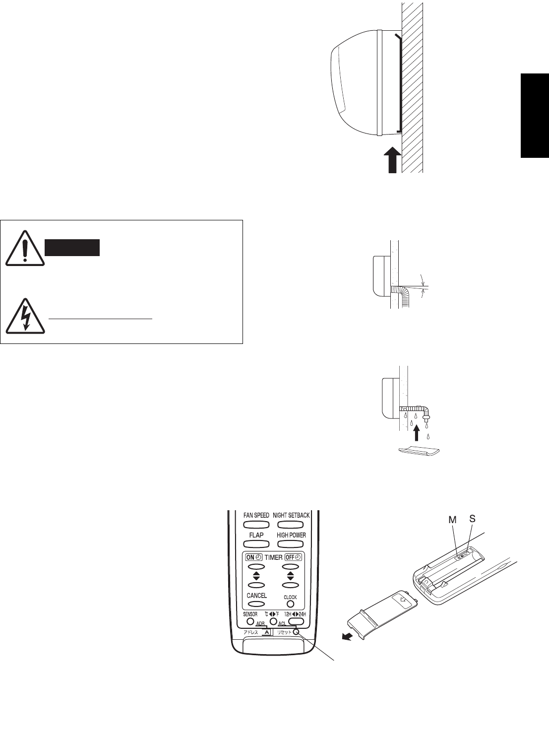
19
English
To unmount indoor unit
Press the 2 LLmarks on the lower part of the indoor
unit and unlatch the tabs. Then lift the indoor unit and
unmount. (Fig. 42)
3-9. Drain Hose
a) The drain hose should be slanted downward to
the outdoors. (Fig. 43)
b) Never form a trap in the course of the hose.
c) If the drain hose will run in the room, insulate the
hose with insulation* so that chilled condensation
will not damage furniture or floors. (Fig. 44)
* Foamed polyethylene or its equivalent is recom-
mended.
WARNING
Risk of Electric Shock
Do not supply power to the
unit or operate it until all
tubing and wiring to the
outside unit are completed.
Condensation
Insulation material
(Locally purchased)
must be used.
Fig. 44
Push
Fig. 42
Slant
Drain
hose
Indoor
unit
Fig. 43
4. Multiple Switch on the Remote Control Unit
Indoor Unit Types
(SAP-KRV184EH, KRV244EH)
(SAP-KRV186EH, KRV246EH)
(SAP-KRV96EHDS, KRV126EHDS)
S/M (Single/Multiple switch)
GSlide the cover in the direction indicated by
the arrow and remove it.
GInitially, the S/M switch is set to S (Single).
GSet this switch to M (Multiple) for multiple
operation.
GAlways press ACL button by a thin object
such as the tip of a pen after setting the S/M
switch.
ACL button
08-324 CMRV3656EH_IU EN 6/15/09 5:28 PM Page 19
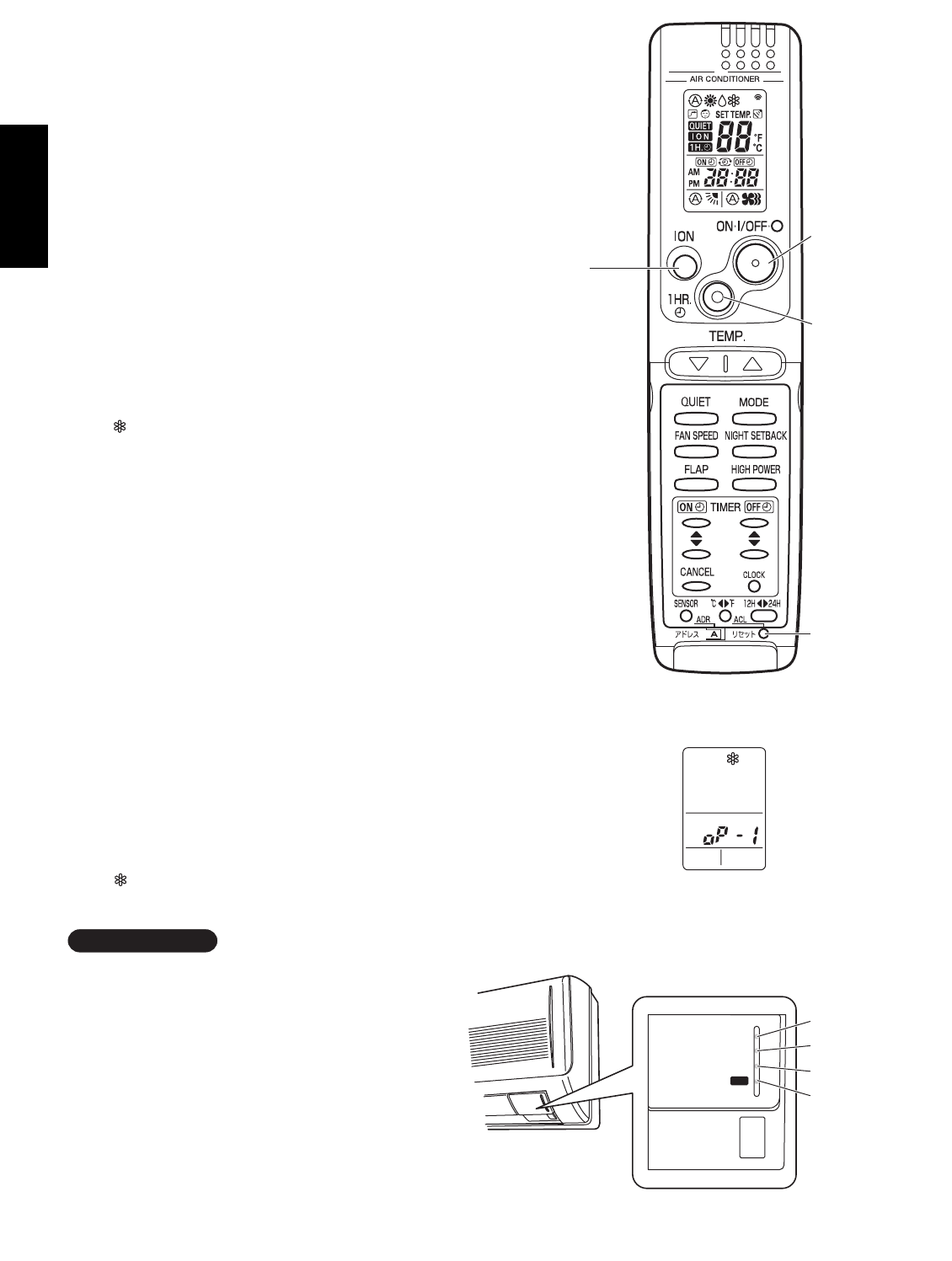
20
English
5. How to Test Run the Air Conditioner
IFor indoor unit types
(SAP-KMRV74EH, KMRV94EH, KMRV124EH,
KRV184EH, KRV244EH)
After turning on the power of the air conditioner, use
the remote controller and follow the steps below to
conduct the test run.
(1) Set the remote controller in Test Run mode.
(Fig. 59a)
a)Press and hold the ION button and the 1HR.
TIMER button.
b)Then press and hold the ACL (Reset) button
with a pointed object such as the tip of a pen.
After 5 seconds, release the ACL button first.
c)Then release the ION and 1HR. TIMER buttons.
d) appears and “oP-1” blinking in the remote
controller clock display area. (Fig. 59b)
(2) Start Cooling mode test run by pressing the
ON/OFF operation button of the remote controller.
(Fig. 59a)
• This starts the fan producing uncooled forced air
with the 4 indicator lamps (OPERATION lamp,
TIMER lamp, QUIET lamp, and ION lamp) on
the main unit blinking. (Fig. 60)
• After 3 minutes, the system shifts into cooling
operation, and cool air will start to be felt. Cool-
ing mode test run is unaffected by the room tem-
perature.
(3) Press the ON/OFF operation button of the remote
controller again to stop the test run. (Fig. 59a)
(4) Finally press the ACL (Reset) button of the remote
controller to release it from Test Run mode to
return to normal mode. (Fig. 59a)
• “ ” and “oP-1” will disappear from the remote
controller clock display area.
After the test run is completed, be sure to press
the ACL (Reset) button to return to normal mode.
The air conditioner will not operate correctly if
this is not done.
IMPORTANT
Fig. 59a
Fig. 59b
Fig. 60
1HR.
TIMER
ON/OFF
operation
ACL
(Reset)
ION
button
button
button
button
OPERATION lamp
ION lamp
TIMER lamp
QUIET lamp
OPERATION
OPERATION
TIMER
QUIET
ION
08-324 CMRV3656EH_IU EN 6/15/09 5:28 PM Page 20

English
1HR.
TIMER
ON/OFF
operation
ACL
(Reset)
QUIET
button
button
button
button
LED CLEAN lamp
TIMER lamp
OPERATION lamp
Fig. 59a-1
Fig. 59b-1
Fig. 59c-1
LED CLEAN lamp
TIMER lamp
OPERATION lamp
Fig. 59c-2
(SAP-KMRV76, KMRV96, KMRV126)
(SAP-KRV186, KRV246)
(SAP-KRV96, KRV126)
21
IFor indoor unit types
(SAP-KMRV76EH, KMRV96EH, KMRV126EH)
(SAP-KRV96EHDS, KRV126EHDS)
(SAP-KRV186EH, KRV246EH)
After turning on the power of the air conditioner, use the remote
controller and follow the steps below to conduct the test run.
(1) Set the remote controller in Test Run mode. (Fig. 59a-1)
a)Press and hold the QUIET button and the 1HR. TIMER button.
b)Then press and hold the ACL (Reset) button with a pointed
object such as the tip of a pen. After 5 seconds, release the
ACL button first.
c)Then release the QUIET and 1HR. TIMER buttons.
d) appears and “oP-1” blinking in the remote controller clock
display area. (Fig. 59b-1)
(2) Start Cooling mode test run by pressing the ON/OFF operation
button of the remote controller. (Fig. 59a-1)
• This starts the fan producing uncooled forced air with the 3 indi-
cator lamps (OPERATION lamp, TIMER lamp, and LED CLEAN
lamp) on the main unit blinking. (Fig. 59c-1 or 59c-2)
• After 3 minutes, the system shifts into cooling operation, and
cool air will start to be felt. Cooling mode test run is unaffected
by the room temperature.
(3) Press the ON/OFF operation button of the remote controller again
to stop the test run. (Fig. 59a-1)
(4) Finally press the ACL (Reset) button of the remote controller to
release it from Test Run mode to return to normal mode.
(Fig. 59a-1)
• “ ” and “oP-1” will disappear from the remote controller clock
display area.
After the test run is completed, be sure to press the ACL (Reset)
button to return to normal mode. The air conditioner will not operate
correctly if this is not done.
IMPORTANT
08-324 CMRV3656EH_IU EN 6/15/09 5:28 PM Page 21
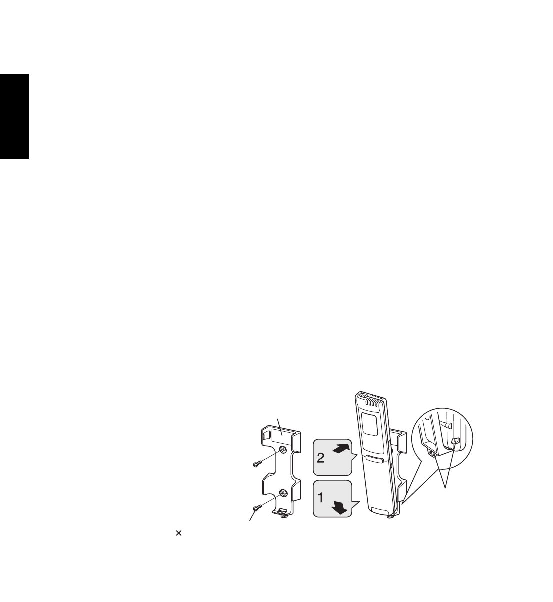
22
English
6. Remote Control Unit Installation Position
The remote control unit can be operated from either a
non-fixed position or a wall-mounted position.
To ensure that the air conditioner operates correctly,
do not install the remote control unit in the following
places:
GIn direct sunlight
GBehind a curtain or other place where it is covered
GMore than 8 m away from the air conditioner
GIn the path of the air conditioner’s airstream
GWhere it may become extremely hot or cold
GWhere it may be subject to electrical or magnetic
interference
GWhere there is an obstacle between the remote
control unit and the air conditioner (since a check
signal is sent from the remote control unit every 5
minutes)
6-1. Mounting on a Wall
Before mounting the remote control unit, press the
ON/OFF operation button at the mounting location to
make sure that the air conditioner operates from that
location. The indoor unit should make a beeping
sound to indicate that it has received the signal.
Press
Set in
place
Remote control
unit mount
Mounting screws
4 16 (included)
Rear side
Hole
Fig. 61
To take out the remote control unit, pull it forward.
To prevent loss of the remote control
unit, you can connect the remote
control unit to the mount by passing
a string through the remote control
unit and attachment hole.
08-324 CMRV3656EH_IU EN 6/15/09 5:28 PM Page 22
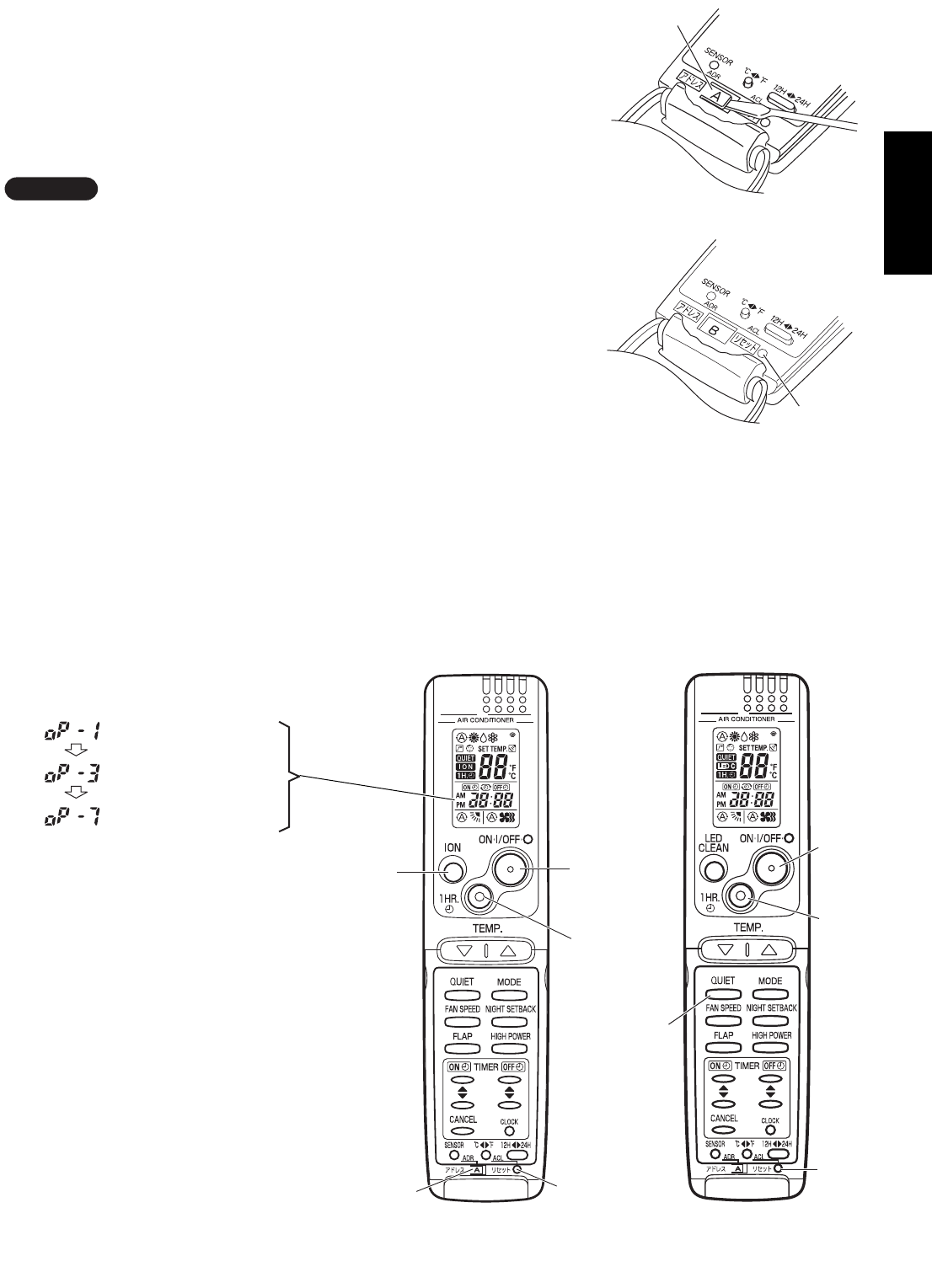
English
(4) Each time the 1HR. TIMER button is pressed,
the display changes as shown below.
Press this button 2 times to change the
display to “oP-7” (Address setting).
(Fig. 64a or 64b)
(5) “oP-7” has now been selected for address
setting.
(6) Press the ON/OFF operation button on the
remote controller. (Fig. 64a or 64b) Check
that the “beep”signal-received sound is heard
from the second indoor unit (approximately
5 times). The sound you hear is the signal
that the remote controller address has been
changed.
(7) Finally press the remote controller ACL (Reset)
button to cancel the blinking “oP-7” display.
(Fig. 64a or 64b)
Changing of the second remote controller address
is now completed.
Selfdiagnostic mode
Test run mode
Address setting mode
Fig. 62
Fig. 63
Tab
ACL button
ION
button
ADDRESS ACL (Reset)
button
ON/OFF
operation
button
1HR.TIMER
button
7. Address Switch
7-1. Address Setting of the Remote Control Unit
The address can be set in order to prevent interference between remote con-
trollers when 2 indoor units are installed near each other. The address is nor-
mally set to “A.” To set a different address, it is necessary to change the
address on the second remote controller.
Once changed, you cannot restore the original address setting of the air con-
ditioner.
(1) Switch on the power source.
(2) Break the address-setting tab marked “A” on the second remote controller
to change the address (Fig. 62). When the tab is removed, the address is
automatically set to B (Fig. 63).
(3) (SAP-KMRV74EH, KMRV94EH, KMRV124EH, KRV184EH, KRV244EH)
Press and hold the remote controller ION button and 1HR. TIMER button.
Then, press and hold the ACL (Reset) button with a pointed object such
as the tip of a pen. After 5 seconds, release the ACL button first, then
release the ION and 1HR. TIMER buttons. “oP-1” (Test Run) appears,
blinking in the remote controller clock display area.
NOTE
Fig. 64a
1HR.
TIMER
button
ON/OFF
operation
button
ACL
(Reset)
button
QUIET
button
Fig. 64b
(SAP-KMRV74, KMRV94, KMRV124,
KRV184, KRV244)
(SAP-KMRV76, KMRV96,
KMRV126, KRV96,
KRV126, KRV186, KRV246)
23
(SAP-KMRV76EH, KMRV96EH, KMRV126EH, KRV96EHDS, KRV126EHDS, KRV186EH, KRV246EH)
Press and hold the remote controller QUIET button and 1HR. TIMER button. Then, press and hold the ACL (Reset)
button with a pointed object such as the tip of a pen. After 5 seconds, release the ACL button first, then release the
QUIET and 1HR. TIMER buttons. “oP-1” (Test Run) appears, blinking in the remote controller clock display area.
08-324 CMRV3656EH_IU EN 6/15/09 5:28 PM Page 23

8. Connecting a Home Automation Device
The HA (white) 4P terminal is located on the indoor unit PCB. If a HA device will be used,
connect it to this terminal.
Also, refer to Section 9. Electric Wiring Diagram in the outdoor unit installation manual.
9. Installation Check Sheet
The strength of the installation location is sufficient to support the air conditioner weight.
The indoor and outdoor units are installed level and vertically.
The power and voltage are as specified.
Inter-unit cables are securely inserted into the terminal block.
Inter-unit cables are securely fixed.
The power cable and inter-unit cables are not connected anywhere along their paths.
The ground wire is securely connected.
Thermal insulation has been applied to the tubing connections.
Drain connections are secure and water drains properly.
Putty has been used to close the hole in the wall.
Remote controller signals are being positively received.
English
24
08-324 CMRV3656EH_IU EN 6/15/09 5:28 PM Page 24

SANYO Electric Co., Ltd.
Osaka, Japan
Feb. / 2010
Printed in Japan (T)
